Hydraulic Ram Pumps - Doc-Developpement-Durable
753
Hydraulic ram pumps and Sling Pumps Hydraulic Ram Pumps Low maintenance pumping of water without electricity! Click HERE if there is no button bar on the left side of your screen! Hydraulic ram pumps are a time-tested technology that use the energy of a large amount of water falling a small height to lift a small amount of that water to a much greater height. In this way, water from a spring or stream in a valley can be pumped to a village or irrigation scheme on the hillside. Depending on the difference in heights between the inlet pipe and the outlet pipe, these water pumps will lift 1-20 percent of the water that flows into it. In general, a ram can pump approximately one tenth of the received water volume to a height ten times greater than the intake. A hydraulic ram pump is useful where the water source flows constantly and the usable fall from the water source to the pump location is at least 91 cm (3 ft). Since ram pumps can only be used in situations where falling water is available, their use is restricted to three main applications: ● lifting drinking water from springs to settlements on higher ground. ● pumping drinking water from streams that have significant slope. ● lifting irrigation water from streams or raised irrigation channels. http://www.lifewater.ca/ram_pump.htm (1 of 4) [1/13/2005 12:42:28 PM]
-
Upload
khangminh22 -
Category
Documents
-
view
17 -
download
0
Transcript of Hydraulic Ram Pumps - Doc-Developpement-Durable

Hydraulic ram pumps and Sling Pumps
Hydraulic Ram PumpsLow maintenance pumping of water without
electricity!
Click HERE if there is no button bar on the left side of your screen!
Hydraulic ram pumps are a time-tested technology that use the energy of a large amount of water falling a small height to lift a small amount of that water to a much greater height. In this way, water from a spring or stream in a valley can be pumped to a village or irrigation scheme on the hillside.
Depending on the difference in heights between the inlet pipe and the outlet pipe, these water
pumps will lift 1-20 percent of the water that flows into it. In general, a ram can pump approximately one tenth of the received water volume to a height ten times greater than the intake. A hydraulic ram pump is useful where the water source flows constantly and the usable fall from the water source to the pump location is at least 91 cm (3 ft).
Since ram pumps can only be used in situations where falling water is available, their use is restricted to three main applications:
● lifting drinking water from springs to settlements on higher ground.
● pumping drinking water from streams that have significant slope.● lifting irrigation water from streams or raised irrigation channels.
http://www.lifewater.ca/ram_pump.htm (1 of 4) [1/13/2005 12:42:28 PM]

Hydraulic ram pumps and Sling Pumps
Ram Pump Advantages include:
1. Inexpensive2. Very simple construction and easy to install yourself.3. Does not consume petrol, diesel or electricity.4. Minimum maintenance.5. Pollution free.6. Quiet pumping 24 hours per day.
Hydraulic Ram Pump Links
● Designing a Hydraulic Ram Pump (Water for the World)● Ram pump History and Design (Center for Alternative
Technology - UK)● Hydraulic Ram Book - How & Where They Work (Atlas
Publications - North Carolina)● Ram Pump Technical Notes (Dev. Technology Unit - UK)● Build Your own Ram Pump (Clemson University)● Ramp Pump Design Specifications (Institute for Appropriate
Technology)● Highlifter Ram Pump (25 page book providing step-by-step
instructions on designing, making, installing and operating a hydraulic ram waterpumping system)
● Hydraulic ram pumps Engineering Principles (North Carolina Extension Service)
● Hydraulic Ram Pump System Design and Application (Research, Development and Technology Adaptation Center, Addis Ababa, Ethiopia)
● Pictures of Ram Pumps (D. Burger - UK)● Ram Pumps (Internet Glossary of Pumps)● Gravi-Chek Pump (Updated Ram Design)
http://www.lifewater.ca/ram_pump.htm (2 of 4) [1/13/2005 12:42:28 PM]

Hydraulic ram pumps and Sling Pumps
Suppliers of Hydraulic Ram Pumps
● "Highlifter" and Ram water pumps (California)● Aquatic Ecosystems Inc (Florida)● Folk Ram Pump Supplier (USA) ● York Industries (Pennsylvania)● Alternative Energy Engineering (California)
Sling Pump Links
● Sling Pump● Sling Pump for Agricultural Watering● Sling Pump Fact Sheet for Agriculture● Sling Pumps for Sale● Rife Sling Pumps
http://www.lifewater.ca/ram_pump.htm (3 of 4) [1/13/2005 12:42:28 PM]

Hydraulic ram pumps and Sling Pumps
http://www.lifewater.ca/ram_pump.htm (4 of 4) [1/13/2005 12:42:28 PM]

Use a hydraulic ram pump to continuously pump water
Home
Problem
About Us
Wells & Washrooms
On-Line Resources
How to Help
Contact Us
Links
Site Updates
Site Map
Search
Hydraulic Ram PumpsLow maintenance pumping of water without
electricity!
Click HERE if there is no button bar on the left side of your screen!
Hydraulic ram pumps are a time-tested technology that use the energy of a large amount of water falling a small height to lift a small amount of that water to a much greater height. In this way, water from a spring or stream in a valley can be pumped to a village or irrigation scheme on the hillside.
Depending on the difference in heights between the inlet pipe and the outlet pipe, these water
pumps will lift 1-20 percent of the water that flows into it. In general, a ram can pump approximately one tenth of the received water volume to a height ten times greater than the intake. A hydraulic ram pump is useful where the water source flows constantly and the usable fall from the water source to the pump location is at least 91 cm (3 ft).
Since ram pumps can only be used in situations where falling water is available, their use is restricted to three main applications:
● lifting drinking water from springs to settlements on higher ground.
● pumping drinking water from streams that have significant slope.● lifting irrigation water from streams or raised irrigation channels.
Ram Pump Advantages include:
http://www.lifewater.ca/ndexram.htm (1 of 3) [1/13/2005 12:42:38 PM]

Use a hydraulic ram pump to continuously pump water
1. Inexpensive2. Very simple construction and easy to install yourself.3. Does not consume petrol, diesel or electricity.4. Minimum maintenance.5. Pollution free.6. Quiet pumping 24 hours per day.
Hydraulic Ram Pump Links
● Designing a Hydraulic Ram Pump (Water for the World)● Ram pump History and Design (Center for Alternative
Technology - UK)● Hydraulic Ram Book - How & Where They Work (Atlas
Publications - North Carolina)● Ram Pump Technical Notes (Dev. Technology Unit - UK)● Build Your own Ram Pump (Clemson University)● Ramp Pump Design Specifications (Institute for Appropriate
Technology)● Highlifter Ram Pump (25 page book providing step-by-step
instructions on designing, making, installing and operating a hydraulic ram waterpumping system)
● Hydraulic ram pumps Engineering Principles (North Carolina Extension Service)
● Hydraulic Ram Pump System Design and Application (Research, Development and Technology Adaptation Center, Addis Ababa, Ethiopia)
● Pictures of Ram Pumps (D. Burger - UK)● Ram Pumps (Internet Glossary of Pumps)● Gravi-Chek Pump (Updated Ram Design)
Suppliers of Hydraulic Ram Pumps
● "Highlifter" and Ram water pumps (California)● Aquatic Ecosystems Inc (Florida)● Folk Ram Pump Supplier (USA)
http://www.lifewater.ca/ndexram.htm (2 of 3) [1/13/2005 12:42:38 PM]

Use a hydraulic ram pump to continuously pump water
● York Industries (Pennsylvania)● Alternative Energy Engineering (California)
Sling Pump Links
● Sling Pump● Sling Pump for Agricultural Watering● Sling Pump Fact Sheet for Agriculture● Sling Pumps for Sale● Rife Sling Pumps
http://www.lifewater.ca/ndexram.htm (3 of 3) [1/13/2005 12:42:38 PM]

Designing a Hydraulic Ram Pump
Water For The World
Designing a Hydraulic Ram Pump
Technical Note No. RWS.4.D.5
[ Index | Bottom ]
A hydraulic ram or impulse pump is a device which uses the energy of falling water to lift a lesser amount of water to a higher elevation than the source. See Figure 1. There are only two moving parts, thus there is little to wear out. Hydraulic rams are relatively economical to purchase and install. One can be built with detailed plans and if properly installed, they will give many trouble-free years of service with no pumping costs. For these reasons, the hydraulic ram is an attractive solution where a large gravity flow exists. A ram should be considered when there is a source that can provide at least seven times more water than the ram is to pump and the water is, or can be made, free of trash and sand. There must be a site for the ram at least 0.5m below the water source and water must be needed at a level higher than the source.
Factors in Design
Before a ram can be selected, several design factors must be known. These are shown in Figure 1 and include: 1. The difference in height between the water source and the pump site (called vertical fall). 2. The difference in height between the pump site and the point of storage or use (lift). 3. The quantity (Q) of flow available from the source. 4. The quantity of water required. 5. The length of pipe from the source to the pump site (called the drive pipe). 6. The length of pipe from the pump to the storage site (called the delivery pipe).
Once this information has been obtained, a calculation can be made to see if the amount of water needed can be supplied by a ram. The formula is: D=(S x F x E)/L Where:
D = Amount delivered in liters per 24 hours. S = Quantity of water supplied in liters per minute. F = The fall or height of the source above the ram in meters. E = The efficiency of the ram (for commercial models use 0.66, for home built use 0.33 unless otherwise indicated).
http://www.lifewater.org/wfw/rws4/rws4d5.htm (1 of 5) [1/13/2005 12:42:40 PM]

Designing a Hydraulic Ram Pump
L = The lift height of the point of use above the ram in meters.
Table 1 solves this formula for rams with efficiencies of 66 percent, a supply of 1 liter per minute, and with the working fall and lift shown in the table. For supplies greater than 1 liter/minute, simply multiply by the number of liters supplied.
Table 1. Ram Performance Data for a Supply of 1 liter/minute Liters Delivered over 24 Hours
Working Fall (m)Lift - Vertical Height to which Water is Raised Above the Ram (m)
5 7.5 10 15 20 30 40 50 60 80 100 125
1.0 144 77 65 33 29 19.5 12.5
1.5 135 96.5 70 54 36 19 15
2.0 220 156 105 79 53 33 25 19.5 12.5
2.5 280 200 125 100 66 40.5 32.5 24 15.5 12
3.0 260 180 130 87 65 51 40 27 17.5 12
3.5 215 150 100 75 60 46 31.5 20 14
4.0 255 173 115 86 69 53 36 23 16
5.0 310 236 155 118 94 71.5 50 36 23
6.0 282 185 140 112 93.5 64.5 47.5 34.5
7.0 216 163 130 109 82 60 48
8.0 187 149 125 94 69 55
9.0 212 168 140 105 84 62
10.0 245 187 156 117 93 69
12.0 295 225 187 140 113 83
14.0 265 218 167 132 97
16.0 250 187 150 110
18.0 280 210 169 124
20.0 237 188 140
Components of Hydraulic Ram
A hydraulic ram installation consists of a supply, a drive pipe, the ram, a supply line and usually a storage tank. These are shown in Figure 1. Each of these component parts is discussed below:
Supply. The intake must be designed to keep trash and sand out of the supply since these can plug up the ram. If the water is not naturally free of these materials, the intake should be screened or a settling basin provided.
http://www.lifewater.org/wfw/rws4/rws4d5.htm (2 of 5) [1/13/2005 12:42:40 PM]

Designing a Hydraulic Ram Pump
When the source is remote from the ram site, the supply line can be designed to conduct the water to a drive pipe as shown in Figure 2. The supply line, if needed, should be at least one pipe diameter larger than the drive pipe.
Drive pipe. The drive pipe must be made of a non-flexible material for maximum efficiency. This is usually galvanized iron pipe, although other materials cased in concrete will work. In order to reduce head loss due to friction, the length of the pipe divided by the diameter of the pipe should be within the range of 150-1,000. Table 2 shows the minimum and maximum pipe lengths for various pipe sizes.
Table 2. Range of Drive Pipe Lengths for Various Pipe Diameters
Drive Pipe Size (mm)Length (meters)
Minimum Maximum
13 2 13
20 3 20
25 4 25
30 4.5 30
40 6 40
50 7.5 50
80 12 80
100 15 100
The drive pipe diameter is usually chosen based on the size of the ram and the manufacturer's recommendations as shown in Table 3. The length is four to six times the vertical fall.
Table 3. Drive Pipe Diameters by Hydram Manufacturer's Size Number
Hydram Size 1 2 3 3.5 4 5 6
Pipe Size (mm) 32 38 51 63.5 76 101 127
Ram. Rams can be constructed using commercially available check valves or by fabricating check valves. They are also available as manufactured units in various sizes and pumping capacities. Rams can be used in tandem to pump water if one ram is not large enough to supply the need. Each ram must have its own drive pipe, but all can pump through a common delivery pipe as shown in Figure 3.
In installing the ram, it is important that it be level, securely attached to an immovable base, preferably concrete, and that the waste-water be drained away. The pump can-not operate when submerged. Since the ram usually operates on a 24-hour basis the size can be determined for delivery over a 24-hour period. Table 4 shows hydraulic ram capacities for one manufacturer's Hydrams.
http://www.lifewater.org/wfw/rws4/rws4d5.htm (3 of 5) [1/13/2005 12:42:40 PM]

Designing a Hydraulic Ram Pump
Table 4. Hydram Capacityby Manufacturer's Size Number
Size of Hydram
1 2 3 3.5 4 5X 6X 5Y 6Y
Volume of Drive Water Needed (liters/min)
7-16 12-25 27-55 45-96 68-137 136-270 180-410 136-270 180-410
Maximum Lift (m) 150 150 120 120 120 105 105 105
Delivery Pipe. The delivery pipe can be of any material that can withstand the water pressure. The size of the line can be estimated using Table 5.
Table 5. Sizing the Delivery Pipe
Delivery Pipe Size (mm) Flow (liters/min)
30 6-36
40 37-60
50 61-90
80 91-234
100 235-360
Storage Tank. This is located at a level to provide water to the point of use. The size is based on the maximum demand per day.
Sizing a Hydraulic Ram
A small community consists of 10 homes with a total of 60 people. There is a spring l0m lower than the village which drains to a wash which is 15m below the spring. The spring produces 30,000 liters of water per day. There is a location for a ram on the bank of the wash. This site is 5m higher than the wash and 35m from the spring. A public standpost is planned for the village 200m from the ram site. The lift required to the top of the storage tank is 23m. The following are the steps in design.
Identify the necessary design factors:
1. Vertical fall is 10m.
2. Lift is 23m to top of storage tank.
3. Quantity of flow available equals 30,000 liters per day divided by 1,440 minutes per day (30,000/1,440) = 20.8 liters per minute.
4. The quantity of water required assuming 40 liters per day per person as maximum use is 60 people x 40 liters per day = 2,400 liters per day.
http://www.lifewater.org/wfw/rws4/rws4d5.htm (4 of 5) [1/13/2005 12:42:40 PM]

Designing a Hydraulic Ram Pump
2,400/1,440 = 1.66 liters per minute (use 2 liters per minute)
5. The length of the drive pipe is 35m.
6. The length of the delivery pipe is 200m.
The above data can be used to size the system. Using Table 1, for a fall of 10m and a lift of 80m, 117 liters can be pumped a day for each liter per minute supplied. Since 2,400 liters per day is required, the number of liters per minute needed can be found by dividing 2,400 by 117:
2,400/117 = 20.5 liters per minute supply required.
From item 3 above, the supply available is 20.8 liters per minute so the source is sufficient.
Table 3 can now be used to select a ram size. The volume of driving water or supply needed is 20.5 liters per minute. From Table 4, a No. 2 Hydram requires from 12 to 25 liters per minute. A No. 2 Hydram can lift water to a maximum height of 150m according to Table 4. This will be adequate since the lift to the top of the storage tank is 23m. Thus, a No. 2 Hydram would be selected.
Table 3 shows that for a No. 2 Hydram, the minimum drive pipe diameter is 38mm. Table 2 indicates that the minimum and maximum length for a 40mm pipe (the closest size to 38mm) is 6m-40m. Since the spring is 35m away, the length is all right. Table 5 can be used to select a delivery pipe 30mm in diameter which fits the supply needed, 20.5 liters per minute.
Posted 11/05/97 FLP [ Top | Index | Lifewater Home]
US AID Water for the World Technical Notes are made available online by
PO Box 3131 San Luis Obispo, CA 93403 USA Email us at [email protected]
This document is not copyrighted, so you are free to print and distribute it. However, we do request that any such re-distribution be on a non-commercial basis only.
Kindly reference US AID, 1982 as the author and this Lifewater web site, http://www.lifewater.org, as the source.
http://www.lifewater.org/wfw/rws4/rws4d5.htm (5 of 5) [1/13/2005 12:42:40 PM]

CAT Publications at www.ecobooks.co.uk
Sometimes a sheet of A4 is all you need to supply bright ideas.
Description Description of an elegant device that uses the power of water to pump some of that water.
Retail Price £0.50 Format A4 210 x 297mm black on tinted paper, printed both sides
http://www.cat.org.uk/catpubs/display.tmpl?sku=ts_hr&cart=11021292602271318 [1/13/2005 12:42:44 PM]

Atlas Publications-inexpensive how-to books for the homestead.
Cheap Web Hosting | Web Hosting | Credit Cards | Web Hosting | Debt Consolidation | Web Hosting
Popular Searches: dvd airfare music
Atlas Publications produces several unusual books for homesteaders and people interested in learning how to raise or farm giant freshwater American or Australian crayfish on a small or large scale, or how to build or install an Atlas Ram Pump or how one works.The books listed below are available
direct from the publisher.
Home Hydraulic Ram Pumps Crayfish Farming Red Claw Crayfish Farming
All About Hydraulic Ram PumpsHow and Where They Work
(ISBN 0-9631526-2-9)The ram pump, or water ram, is a very useful 'old-tech' device that has been around for many years and is as useful today as ever. It can pump water from a flowing source of water to a point ABOVE that source with no power requirement other than the force of gravity. Invented before electric water pumps, this rugged, simple and reliable device works continuously with only 2 moving parts and very little maintenence. Typically installed at remote home sites for domestic water supply, watering livestock, gardens, decorative lily and fish ponds, water wheels and fountains. Because it uses no power, a ram pump can be used where water would normally not be used and would flow on downstream. This book explains in simple terms and with illustrations how the ram pump works, where and how it can be set up, and how to keep it going. The second section of the book gives step-
by-step plans for building a fully operational Atlas Ram Pump from readily available plumbing fittings and which require NO welding, drilling, tapping or special tools to fabricate. The final chapter shows how to build an inexpensive ferro-cement water storage tank up to 15,000 gallon capacity. More about ram pumps here: Hydraulic Ram Pumps
Order book RMB, only $9.95 plus $1.00 ($3.00 Canada) First Class Shipping (U.S. funds).
http://atlaspub.20m.com/ (1 of 4) [1/13/2005 12:42:50 PM]

Atlas Publications-inexpensive how-to books for the homestead.
BOOK REVIEWS
Reviewer: [email protected] from Lander, Wyoming: "A great little book!!! I have built and bought hydraulic ram pumps. I have bought the books from England, called ram builders all over the US, and searched the net. Don Wilson's book has the clearest directions I have seen."
From: e.j. samson ([email protected]) Hi again. I thought I would let you know how I made out with your ram pump plans....as you can see-GREAT! I was skeptical at first; didn't see how it could work. After hooking it all up, we are pumping water 125 ft. high and over 400 ft. away.. not a lot of water, but enough: around 12 to 15 gallons an hour! Thanks again!-------------- Sincerely, Ernie Samson.-------------
Reviewer: Jimmy Martin, Williamson, NY: "I received your book today and immediately read it from cover to cover. As a manufacturing engineer for over 30
years, I have been keenly interested in finding information on the Hydraulic Ram Pump. I would like to thank you for your very informative book. It is well written, very well illustrated...and the best investment I have made in years!"
Small Scale Crayfish Farming for food and profit(ISBN 0-9631526-1-0)
This useful book--a bare bones, how to manual--explores how to raise crayfish in a small country setting. It is a surprisingly complete (for its size) factual compilation of years of University and industry research as well as individual findings on the culture of freshwater crayfish. It is well known that farmed crayfish will grow to a much larger size than the wild ones, and much more rapidly, if given optimum conditions. These conditions are easily reached, and are much less strict than most aquaculture species. Prepared in a number of tasty ways, freshwater crayfish are highly regarded as a delicacy both here and abroad. They are similar to lobster and shrimp in taste and texture, and are an excellent source of high quality, low-fat protein. Targeting the small farmer or backyard hobbyist,
this book outlines specific guidelines for pond construction and efficiency, food and environmental needs, tank culture, sources of supply Crayfish Suppliers, egg & juvenile production for stocking, processing & sale...of the best species of freshwater crayfish for aquaculture in all areas of the US. More about crayfish farming here: Crayfish Farming
Order book CRB; only $9.95 plus $1.00 ($3.00 Canada) First Class Shipping. (U.S. funds.)
Two of the most popular varieties for culture. Both grow to over 1 oz. in weight in one growing season, under optimum conditions of temperature, aeration, density, turbidity and feeding. All easily reached conditions!
from 'BACKWOODS HOME MAGAZINE' by Dave Duffy, http://atlaspub.20m.com/ (2 of 4) [1/13/2005 12:42:50 PM]

Atlas Publications-inexpensive how-to books for the homestead.
editor: "This is a small but useful book..a bare bones 'how-to' manual on how to raise crayfish in a small country setting. Wilson is a clear, informative writer, and this book is in that vein..short and to the point. No fluff. I like it a lot."
From 'WHOLE EARTH REVIEW' by Kevin Kelly, editor: "Crayfish look and taste like small lobsters, but can be grown in a back lot pond. They can be raised anywhere in the 48 states, and thrive on almost any kind of feed. They require only a shallow pool of fresh water, are self-replenishing and easily caught. There is backyard gourmet protein for homesteaders here. This self-published how-to booklet will guide your crustacean dreams."
RED CLAW! Raising the Giant Australian Crayfish(ISBN 0-9631526-3-7).
The Red Claw crayfish is a new and very promising aquaculture species. The Red Claw is very similar to the native American species, except that it grows to a HUGE size--almost to that of a lobster! There are several other notable differences, such as year-round breeding, awesome fecundity... often over 700 eggs per breeder! They also have a non-aggressive nature, which allows many more Red Claw crayfish to live happily in a given space than would the native American crayfish.This book is one of the few sources for complete information on all aspects of the culture of this lobster sized freshwater crayfish. Compiled from leading edge research direct from Australia as well as individual and University findings from all over the U.S.,this book dispels the hype and furnishes the facts about this little known but highly prized new aquaculture
species. Fish farmers have managed to become major players in this bottomless market in only a couple of years. Small scale family run operations are harvesting 'short lobsters' in less than a year, and the startup costs are relatively low. There are not many Red Claw crayfish reference books, and this book packs all the info you may need into a small price. Included in the book are photos from down under, food and feeding regimens needed to raise the Red Claw to giant size, well managed pond and tank factors, hatching and juvenile production, stocking methods, sources of supply--Redclaw and Crayfish Suppliers. -- processing & sales tips, and marketing recommendations.
More about the Red Claw here: Red Claw Crayfish Farming Order book AUC only $9.95 plus $1.00 ($3.00 Canada) First Class Shipping (U.S. funds).
From 'AQUACULTURE MAGAZINE' by James W. Avault Jr., book review editor: "This book is compiled from information from David O'Sullivan of the University of Tasmania, David Rouse of Auburn University, and several private companies growing Red Claw in America and Australia. It is developed as a manual for the crayfish farmer. It covers all of the important topics a beginning farmer would need to know. This book is easy to read and should be a help to anyone who wants a book of Red Claw aquaculture in a condensed version. David O'Sullivan and David Rouse are highly respected researchers of Red Claw."
Reviewer: Charles Showalter ([email protected]) from Pittsburgh, Penn. "First off, I would like to thank the author for writing this book on Red Claw Culture and especially for including the section on information resources. The book was able to bring a lot of great information together, and presented it in a manner that made the average 'water farmer' comfortable with Red Claw production. This must not have been an easy task, considering the lack of available information. After reading the book I decided to dig deeper and became excited with the possibilities. The book was correct in stating that this industry is in it's infancy and quite likely will grow fast. I now operate the Red Claw Crayfish Hatchery in Pittsburgh and have a very successful web site. And this book got me
http://atlaspub.20m.com/ (3 of 4) [1/13/2005 12:42:50 PM]

Atlas Publications-inexpensive how-to books for the homestead.
started!"
Home Ram Pumps Red Claw Farming Crayfish Farming
These books contain much hard-to find info!!
To place an order for any of these books,send check or MO for $10.95 per book to:
(please indicate which book)
Atlas Publications P.O. Box 265
Murphy, N.C. 28906
OR use this handy PRINTABLE ORDER FORM
©2001 Atlas Publications E-mail author / publisher.
http://atlaspub.20m.com/ (4 of 4) [1/13/2005 12:42:50 PM]

The Development Technology Unit
Animal Traction
Building Materials
Landmine Clearance
Rainwater Harvesting
Water Lifting
DTU Publications
The DTU concerns itself with the development and transfer of technologies appropriate to rural areas of tropical countries. It also studies "bottom up" industrialisation in those countries.
Started in 1987, to complement the Engineering Design and Appropriate Technology (EDAT) degree course offered by Warwick University, the DTU has been engaged in highly varied research in the broad fields of development and intermediate technology.
The DTU conducts its own research programmes and also works in collaboration with non-governmental organisations (NGOs), aid agencies, government bodies, private enterprise and private individuals in a about 20 countries. We are always interested to hear from prospective partners particularly those institutes specialising in impact studies (economic/ social/ gender/ micro-enterprise) of new technology in their own country, potential manufacturers of rural development equipment and NGOs engaged in promoting income-generating measures.
A number of post-graduate students are currently working with the DTU on PhD and MSc-by-research programmes. Enquiries from potential future research students are welcomed and should be addressed to Dr. Terry Thomas in the first instance at the email address below.
For further information about the DTU or any of the areas covered in the following pages please contact us.
Our email address is: [email protected]
Fax Number: +44 24 7641 8922;
Telephone Number: +44 24 7652 3122 or +44 24 7652 2339
Our Address is:Development Technology Unit,
http://www.eng.warwick.ac.uk/dtu/ (1 of 2) [1/13/2005 12:42:52 PM]

The Development Technology Unit
Search the DTU website
School of Engineering, University of Warwick, Coventry, CV4 7AL, UK
In the interests of making our site more accessible, we are collecting statistics on its use through eXTReMe Tracking
http://www.eng.warwick.ac.uk/dtu/ (2 of 2) [1/13/2005 12:42:52 PM]

Home-made Hydraulic Ram Pump
Home-made Hydraulic Ram Pump
This information is provided as a service to those wanting to try to build their own hydraulic ram pump. The data from our experiences with one of these home-made hydraulic ram pumps is listed in Table 4 near the bottom of this document. The typical cost of fittings for an 1-1/4" pump is currently $120.00 (U.S.A.) regardless of whether galvanized or PVC fittings are used.
Click here to see a picture of an old-style assembled ram pump with a threaded plug(see notes below concerning glue cap (#16) versus threaded plug)
Table 1. Image Key
1 1-1/4" valve 10 1/4" pipe cock
2 1-1/4" tee 11 100 psi gauge
3 1-1/4" union 12 1-1/4" x 6" nipple
4 1-1/4" brass swing check valve (picture) 13 4" x 1-1/4" bushing
5 1-1/4" spring check valve 14 4" coupling
6 3/4" tee 15 4" x 24" PR160 PVC pipe
7 3/4" valve 16 4" PVC glue cap
8 3/4" union 17 3/4" x 1/4" bushing
9 1-1/4" x 3/4" bushing
http://www.clemson.edu/irrig/Equip/ram.htm (1 of 7) [1/13/2005 12:42:54 PM]

Home-made Hydraulic Ram Pump
All connectors between the fittings are threaded pipe nipples - usually 2" long or shorter. This pump can be made from PVC fittings or galvanized steel. In either case it is recommended that the 4" diameter fittings be PVC fittings to conserve weight.
Conversion Note: 1" (1 inch) = 2.54 cm; 1 PSI (pound/square inch) = 6.895 KPa or 0.06895 bar; 1 gallon per minute = 3.78 liter per minute. PR160 PVC pipe is PVC pipe rated at 160 psi pressure.
Assembly and Operation Notes:
Pressure Chamber - A bicycle or "scooter tire" inner tube is placed inside the pressure chamber (part 15) as an "air bladder" to prevent water-logging or air-logging. Inflate the tube until it is "spongy" when squeezed, then insert it in the chamber. It should not be inflated very tightly, but have some "give" to it. (No information is available concerning pressure chamber sizes for the various sizes of ram pump. Make one somewhat larger for larger pumps - for instance, try a 6 inch diameter x 24 inch long pressure chamber for a 3 inch ram.)
A 4" threaded plug and 4" female adapter were originally used instead of the 4" glue-on cap shown in the image, This combination leaked regardless of how tightly it was tightened or how much teflon tape sealant was used, resulting in water-logging of the pressure chamber. This in turn dramatically increased the shock waves and could possibly have shortened pump life. If the bicycle tube should need to be serviced when using the glue cap the pipe may be cut in half then re-glued together using a coupling.
Valve Operation Descriptions - Valve #1 is the drive water inlet for the pump. Union #8 is the exit point for the pressurized water. Swing check valve #4 is also known as the "impetus" or "waste" valve - the extra drive water exits here during operation. The "impetus" valve is the valve that is operated manually at the beginning (by pushing it in with a finger) to charge the ram and start normal operation.
Valves #1 and #7 could be ball valves instead of gate valves. Ball valves may withstand the shock waves of the pump better over a long period of time.
The swing check valve (part 4 - also known as the impetus valve) can be adjusted to vary the length of stroke (please note that maximum flow and pressure head will be achieved with this valve positioned vertically with the opening facing up). Turn the valve on the threads until the pin in the clapper hinge of the valve is in line with the pipe (instead of perpendicular to it). Then move the tee the valve is attached to slightly from vertical, making sure the clapper hinge in the swing check is toward the top of the valve as you do this. The larger the angle from vertical, the shorter the stroke period (and the less potential pressure, since the water will not reach as high a velocity before shutting the valve). For maximum flow and pressure valve #4 should be in a vertical position (the outlet pointed straight up).
Swing check valve #4 should always be brass (or some metal) and not plastic. Experiences with plastic or PVC swing check valves have shown that the "flapper" or "clapper" in these valves is very light weight and therefore closes much earlier than the "flapper" of a comparable brass swing check. This in turn would mean lower flow rates and lower pressure heads.
The pipe cock (part 10) is in place to protect the gauge after the pump is started. It is turned off after the pump has been started and is operating normally. Turn it on if needed to check the outlet pressure, then
http://www.clemson.edu/irrig/Equip/ram.htm (2 of 7) [1/13/2005 12:42:54 PM]

Home-made Hydraulic Ram Pump
turn it back off to protect the gauge.
Drive Pipe - The length of the drive pipe (from water source to pump) also affects the stroke period. A longer drive pipe provides a longer stroke period. There are maximum and minimum lengths for the drive pipe (see the paragraph below Table 2). The drive pipe is best made from galvanized steel (more rigid is better) but schedule 40 PVC can be used with good results. The more rigid galvanized pipe will result in a higher pumping efficiency - and allow higher pumping heights. Rigidity of the drive pipe seems to be more important in this efficiency than straightness of the drive pipe.
Drive pipe length and size ratios are apparently based on empirical data. Information from University of Georgia publications (see footnote) provides an equation from Calvert (1958) describing the output and stability of ram pump installations in relation to the ratio of the drive pipe length (L) to the drive pipe diameter (D). The best range is an L/D ratio of between 150 and 1000 (L/D = 150 to L/D = 1000). Equations to use to determine these lengths are:
Minimum inlet pipe length: L = 150 x (inlet pipe size)
Maximum inlet pipe length: L = 1000 x (inlet pipe size)
If the inlet pipe size is in inches, then the length (L) will also be presented in inches. If inlet pipe size is in mm, then L will be presented in mm.
Drive Pipe Length Example: If the drive pipe is 1-1/4 inches (1.25 inches) in diameter, then the minimum length should be L = 150 x 1.25 = 187.5 inches (or about 15.6 feet). The maximum length for the same 1-1/4 inch drive pipe would be L = 1000 x 1.25 = 1250 inches (104 feet). The drive pipe should be as rigid and as straight as possible.
Stand pipe or no stand pipe? Many hydraulic ram installations show a "stand pipe" installed on the inlet pipe. The purpose of this pipe is to allow the water hammer shock wave to dissipate at a given point. Stand pipes are only necessary if the inlet pipe will be longer than the recommended maximum length (for instance, if the inlet pipe were to be 150 feet in length in the above example where the maximum inlet length should only be 104 feet). The stand pipe - if needed - is generally placed in the line the same distance from the ram as the recommended maximum length indicated.
The stand pipe must be vertical and extend vertically at least 1 foot (0.3 meter) higher than the elevation of the water source - no water should exit the pipe during operation (or perhaps only a few drops during each shock wave cycle at most). Many recommendations suggest that the stand pipe should be 3 sizes larger than the inlet pipe. The supply pipe (between the stand pipe and the water source) should be 1 size larger than the inlet pipe.
The reason behind this is simple - if the inlet pipe is too long the water hammer shock wave will travel farther, slowing down the pumping pulses of the ram. Also, in many instances there may actually be interference with the operation of the pump due to the length of travel of the shock wave. The stand pipe simply allows an outlet to the atmosphere to allow the shock wave somewhere to go. Again this is not necessary unless the inlet pipe will have to be longer than the recommended maximum length.
Another option would be to pipe the water to an open tank (with the top of the tank at least 1 foot (0.3
http://www.clemson.edu/irrig/Equip/ram.htm (3 of 7) [1/13/2005 12:42:54 PM]

Home-made Hydraulic Ram Pump
meter) higher than the vertical elevation of the water source), then attach the inlet pipe to the tank. The tank will act as a dissipation chamber for the water hammer shock wave just as the stand pipe would. This option may not be viable if the tank placement would require some sort of tower, but if the topography allows this may be a more attractive option.
Click here to view sketches of these types of hydraulic ram pump installations(loads in 70 seconds over 28.8 modem)
Operation - The pump will require some back pressure to begin working. A back pressure of 10 psi or more should be sufficient. If this is not provided by elevation-induced back pressure from pumping the water uphill to the delivery point (water trough, etc.), use the 3/4" valve (part 7) to throttle the flow somewhat to provide this backpressure.
As an alternative to throttling valve part 7 you may consider running the outlet pipe into the air in a loop and then back down to the trough to provide the necessary back pressure - a total of 23 feet of vertical elevation above the pump outlet should be sufficient. This may not be practical in all cases, but adding 8 feet of pipe after piping up a hill of 15 feet in elevation should not be a major problem. This will allow you to open valve #7 completely, preventing stoppage of flow by trash or sediment blocking the partially-closed valve. It is a good idea to include a tee at the outlet of the pump with a ball valve to allow periodic "flushing" of the sediment just in case.
Initially the pump will have to be manually started several times to remove all the air. Start the pump by opening valve 1 and leaving valve 7 closed. Then, when the swing check (#4) shuts, manually push it open again. The pump will start with valve 7 closed completely, pumping up to some maximum pressure before stopping operation. After the pump begins operation slowly open valve 7, but do not allow the discharge pressure (read on gauge #11) to drop below 10 psi. You may have to push valve #4 open repeatedly to re-start the pump in the first few minutes (10 to 20 times is not abnormal) - air in the system will stop operation until it is purged.
The unions, gate (or ball) valves, and pressure gauge assembly are not absolutely required to make the pump run, but they sure do help in installing, removing, and starting the pump as well as regulating the flow.
Pump Performance - Some information suggests that typical ram pumps discharge approximately 7 gallons of water through the waste valve for every gallon pressurized and pumped. The percentage of the drive water delivered actually varies based on the ram construction, vertical fall to pump, and elevation to the water outlet. The percentage of the drive water delivered varies from approximately 22% when the vertical fall to the pump is 1/2 (50%) of the elevation to the water outlet down to 2% when the vertical fall is 0.04 (4%) of the elevation to the water outlet. Rife Hydraulic Engine Manufacturing Company literature (http://www.riferam.com/) offers the following equation:
0.6 x Q x F/E = D
Q is the available drive flow in gallons per minute, F is the fall in feet from the water source to the ram, E is the elevation from the ram to the water outlet, and D is the flow rate of the delivery water in gallons per minute. 0.6 is an efficiency factor and will differ somewhat between various ram pumps. For instance, if 12 gallons per minute is available to operate a ram pump, then pump is placed 6 feet below
http://www.clemson.edu/irrig/Equip/ram.htm (4 of 7) [1/13/2005 12:42:54 PM]

Home-made Hydraulic Ram Pump
the water source, and the water will be pumped up an elevation of 20 feet, the amount of water that may be pumped with an appropriately-sized ram pump is
0.6 x 12 gpm x 6 ft / 20 ft = 2.16 gpm
The same pump with the same drive flow will provide less flow if the water is to be pumped up a higher elevation. For instance, using the data in the previous example but increasing the elevation lift to 40 feet:
0.6 x 12 gpm x 6 ft / 40 ft = 1.08 gpm
Table 2. Typical Hydraulic Ram specifications (Expected water output will be approximately 1/8 of the input flow, but will vary with installation fall (F) and elevation lift (E) as noted above. This chart is based on 5 feet of lift (E) per 1 foot of fall (F).)
Drive PipeDiameter(inches)
Delivery PipeDiameter(inches)
At Minimum Inflow At Maximum Inflow
Pump Inflow(gallons per minute)
Expected Output(gallons per minute)
Pump Inflow(gallons per minute)
Expected Output(gallons per minute)
3/4 1/2 3/4 1/10 2 1/4
1 1/2 1-1/2 1/5 6 3/4
1-1/4 1/2 2 1/4 10 1-1/5
1-1/2 3/4 2-1/2 3/10 15 1-3/4
2 1 3 3/8 33 4
2-1/2 1-1/4 12 1-1/2 45 5-2/5
3 1-1/2 20 2-1/2 75 9
4 2 30 3-5/8 150 18
6 3 75 9 400 48
8 4 400 48 800 96
Table 3. Test Installation Information
Drive Pipe Size 1-1/4 inch Schedule 40 PVC
Outlet Pipe Size 3/4 inch Schedule 40 PVC
Pressure Chamber size 4 inch PR160 PVC
Pressure Chamber Length 36 inches
Inlet Pipe Length 100 feet
Outlet Pipe Length 40 feet
Drive Water (Inlet) elevation above pump 4 feet
http://www.clemson.edu/irrig/Equip/ram.htm (5 of 7) [1/13/2005 12:42:54 PM]

Home-made Hydraulic Ram Pump
Elevation from pump outlet to delivery outlet 12 feet
Click here to see pictures of the test installation (loads in 38 seconds over 28.8 modem)
Table 4. Trial 1 Performance Data
Expected
PerformanceAt Installation
(5/17/99)
After Installation(with water-log)
(5/21/99)
After Clearing Water-log (6/20/99)
Shutoff Head 5 to 17 psi 22 psi 50 psi 22 psi
Operating Head 10 psi 10 psi 10 psi 10 psi
Operating Flow Rate 0.50 to 1.00 gpm 0.28 gpm 1.50 gpm 0.33 gpm
Note that we used a 4" threaded plug and a 4" female adapter for our test pump (instead of the recommended 4" glue cap (#16) shown in the figure). Two days after installation the pump air chamber was effectively water-logged due to leakage past the threads of these two fittings, which was shown by the pronounced impulse pumping at the outlet discharge point. If the pump were allowed to remain waterlogged it would shortly cease to operate - and may introduce damage to the pipe or other components due to pronounced water hammer pressure surges.
The large range of expected values for shutoff head is due to the unknown efficiency of the pump. Typical efficiencies for ram pumps range from 3 feet to 10 feet of lift for every 1 foot of elevation drop from the water inlet to the pump.
Hydraulic Ram Web Sites
Bamford PumpsCAT Tipsheet 7Green and CarterLifewater RamsNC State's EBAE 161-92, "Hydraulic Ram Pumps"RamPumps.comRife RamsSolar ElectricThe Ram CompanyUniversity of Warwick (UK) Ram Pump PublicationsUniversity of Warwick (UK) Ram pump system design notes
Some information for this web page - and the initial information concerning construction of a home-made hydraulic ram pump - was provided by University of Georgia Extension publications #ENG98-002 and #ENG98-003 (both Acrobat "pdf" files) by Frank Henning. Publication #ENG98-002 also describes the pumping volume equations for
http://www.clemson.edu/irrig/Equip/ram.htm (6 of 7) [1/13/2005 12:42:54 PM]

Home-made Hydraulic Ram Pump
hydraulic ram pumps.
Welcome! You are visitor
since 11/28/00
Last modified on 10/06/03 This page created and maintained by Bryan Smith,
Clemson University Cooperative Extension, Laurens County.
The Clemson University Cooperative Extension Service offers its programs to people of all ages regardless of race, color, sex, religion, national origin, or disability and is an equal opportunity employer.
http://www.clemson.edu/irrig/Equip/ram.htm (7 of 7) [1/13/2005 12:42:54 PM]

Hydraulic Ram Pump
Hydraulic Ram Pump
A hydraulic ram or impulse pump is a device which uses the energy of falling water to lift a lesser amount of water to a higher elevation than the source. See Figure 1. There are only two moving parts, thus there is little to wear out. Hydraulic rams are relatively economical to purchase and install. One can be built with detailed plans and if properly installed, they will give many trouble-free years of service with no pumping costs. For these reasons, the hydraulic ram is an attractive solution where a large gravity flow exists. A ram should be considered when there is a source that can provide at least seven times more water than the ram is to pump and the water is, or can be made, free of trash and sand. There must be a site for the ram at least 0.5m below the water source and water must be needed at a level higher than the source.
Factors in Design
Before a ram can be selected, several design factors must be known. These are shown in Figure 1 and include:
1. The difference in height between the water source and the pump site (called vertical fall). 2. The difference in height between the pump site and the point of storage or use (lift). 3. The quantity (Q) of flow available from the source. 4. The quantity of water required. 5. The length of pipe from the source to the pump site (called the drive pipe).
http://www.i4at.org/lib2/hydrpump.htm (1 of 6) [1/13/2005 12:42:56 PM]

Hydraulic Ram Pump
6. The length of pipe from the pump to the storage site (called the delivery pipe).
Once this information has been obtained, a calculation can be made to see if the amount of water needed can be supplied by a ram. The formula is: D=(S x F x E)/L Where:
D = Amount delivered in liters per 24 hours. S = Quantity of water supplied in liters per minute. F = The fall or height of the source above the ram in meters. E = The efficiency of the ram (for commercial models use 0.66, for home built use 0.33 unless otherwise indicated). L = The lift height of the point of use above the ram in meters.
Table 1 solves this formula for rams with efficiencies of 66 percent, a supply of 1 liter per minute, and with the working fall and lift shown in the table. For supplies greater than 1 liter/minute, simply multiply by the number of liters supplied.
Table 1. Ram Performance Data for a Supply of 1 liter/minute Liters Delivered over 24 Hours
Working Fall (m)Lift - Vertical Height to which Water is Raised Above the Ram (m)
5 7.5 10 15 20 30 40 50 60 80 100 1251.0 144 77 65 33 29 19.5 12.5
1.5 135 96.5 70 54 36 19 15
2.0 220 156 105 79 53 33 25 19.5 12.5
2.5 280 200 125 100 66 40.5 32.5 24 15.5 12
3.0 260 180 130 87 65 51 40 27 17.5 123.5 215 150 100 75 60 46 31.5 20 144.0 255 173 115 86 69 53 36 23 165.0 310 236 155 118 94 71.5 50 36 236.0 282 185 140 112 93.5 64.5 47.5 34.57.0 216 163 130 109 82 60 488.0 187 149 125 94 69 559.0 212 168 140 105 84 62
10.0 245 187 156 117 93 6912.0 295 225 187 140 113 8314.0 265 218 167 132 9716.0 250 187 150 11018.0 280 210 169 12420.0 237 188 140
http://www.i4at.org/lib2/hydrpump.htm (2 of 6) [1/13/2005 12:42:56 PM]

Hydraulic Ram Pump
Components of Hydraulic Ram
A hydraulic ram installation consists of a supply, a drive pipe, the ram, a supply line and usually a storage tank. These are shown in Figure 1. Each of these component parts is discussed below:
Supply. The intake must be designed to keep trash and sand out of the supply since these can plug up the ram. If the water is not naturally free of these materials, the intake should be screened or a settling basin provided. When the source is remote from the ram site, the supply line can be designed to conduct the water to a drive pipe as shown in Figure 2. The supply line, if needed, should be at least one pipe diameter larger than the drive pipe.
Drive pipe. The drive pipe must be made of a non-flexible material for maximum efficiency. This is usually galvanized iron pipe, although other materials cased in concrete will work. In order to reduce head loss due to friction, the length of the pipe divided by the diameter of the pipe should be within the range of 150-1,000. Table 2 shows the minimum and maximum pipe lengths for various pipe sizes.
Table 2. Range of Drive Pipe Lengths for Various Pipe Diameters
Drive Pipe Size (mm)Length (meters)
Minimum Maximum13 2 1320 3 2025 4 2530 4.5 3040 6 4050 7.5 5080 12 80100 15 100
The drive pipe diameter is usually chosen based on the size of the ram and the manufacturer's recommendations as shown in Table 3. The length is four to six times the vertical fall.
Table 3. Drive Pipe Diameters by Hydram Manufacturer's Size Number
http://www.i4at.org/lib2/hydrpump.htm (3 of 6) [1/13/2005 12:42:56 PM]

Hydraulic Ram Pump
Hydram Size 1 2 3 3.5 4 5 6Pipe Size (mm) 32 38 51 63.5 76 101 127
Ram. Rams can be constructed using commercially available check valves or by fabricating check valves. They are also available as manufactured units in various sizes and pumping capacities. Rams can be used in tandem to pump water if one ram is not large enough to supply the need. Each ram must have its own drive pipe, but all can pump through a common delivery pipe as shown in Figure 3.
In installing the ram, it is important that it be level, securely attached to an immovable base, preferably concrete, and that the waste-water be drained away. The pump can-not operate when submerged. Since the ram usually operates on a 24-hour basis the size can be determined for delivery over a 24-hour period. Table 4 shows hydraulic ram capacities for one manufacturer's Hydrams.
Table 4. Hydram Capacity by Manufacturer's Size Number
Size of Hydram
1 2 3 3.5 4 5X 6X 5Y 6YVolume of Drive Water Needed (liters/min) 7-16 12-25 27-55 45-96 68-137 136-270 180-410 136-270 180-410
Maximum Lift (m) 150 150 120 120 120 105 105 105
Delivery Pipe. The delivery pipe can be of any material that can withstand the water pressure. The size of the line can be estimated using Table 5.
Table 5. Sizing the Delivery Pipe
http://www.i4at.org/lib2/hydrpump.htm (4 of 6) [1/13/2005 12:42:56 PM]

Hydraulic Ram Pump
Delivery Pipe Size (mm) Flow (liters/min)30 6-3640 37-6050 61-9080 91-234
100 235-360
Storage Tank. This is located at a level to provide water to the point of use. The size is based on the maximum demand per day.
Sizing a Hydraulic Ram
A small community consists of 10 homes with a total of 60 people. There is a spring l0m lower than the village which drains to a wash which is 15m below the spring. The spring produces 30,000 liters of water per day. There is a location for a ram on the bank of the wash. This site is 5m higher than the wash and 35m from the spring. A public standpost is planned for the village 200m from the ram site. The lift required to the top of the storage tank is 23m. The following are the steps in design.
Identify the necessary design factors:
1. Vertical fall is 10m.
2. Lift is 23m to top of storage tank.
3. Quantity of flow available equals 30,000 liters per day divided by 11,440 minutes per day (30,000/11,440) = 20.8 liters per minute.
4. The quantity of water required assuming 40 liters per day per person as maximum use is 60 people x 40 liters per day = 2,400 liters per day. 2,400/1,440 = 1.66 liters per minute (use 2 liters per minute)
5. The length of the drive pipe is 35m.
6. The length of the delivery pipe is 200m.
The above data can be used to size the system. Using Table 1, for a fall of 10m and a lift of 80m, 117 liters can be pumped a day for each liter per minute supplied. Since 2,400 liters per day is required, the number of liters per minute needed can be found by dividing 2,400 by 117:
2,400/117 = 20.5 liters per minute supply required.
From item 3 above, the supply available is 20.8 liters per minute so the source is sufficient.
http://www.i4at.org/lib2/hydrpump.htm (5 of 6) [1/13/2005 12:42:56 PM]

Hydraulic Ram Pump
Table 3 can now be used to select a ram size. The volume of driving water or supply needed is 20.5 liters per minute. From Table 4, a No. 2 Hydram requires from 12 to 25 liters per minute. A No. 2 Hydram can lift water to a maximum height of 250m according to Table 4. This will be adequate since the lift to the top of the storage tank is 23m. Thus, a No. 2 Hydram would be selected.
Table 3 shows that for a No. 2 Hydram, the minimum drive pipe diameter is 38mm. Table 2 indicates that the minimum and maximum length for a 40mm pipe (the closest size to 38mm) is 6m-40m. Since the spring is 35m away, the length is all right. Table 5 can be used to select a delivery pipe 30mm in diameter which fits the supply needed, 20.5 liters per minute.
This document is not copyrighted, so you are free to print and distribute it. However, we do request that any such re-distribution be on a non-commercial basis only. Kindly reference US AID, 1982 as the author.
http://www.i4at.org/lib2/hydrpump.htm (6 of 6) [1/13/2005 12:42:56 PM]

Real Goods Catalog - Library & Office
Outdoor Home
Indoor Home
Library & OfficeEarth & Enviro BooksShelter & Energy BooksFood & Farming BooksCDs/VideosHome OfficeLibrary Gifts
Energy Efficiency
Gifts & Toys
Chelsea Green
Healthy Lifestyles
Sale Items
View Cart Help
More Shelter & Energy Books Products:
Solar Living Sourcebook 11th Edition
A Place In The Sun
All About Hydraulic Ram Pumps
Architectural Resource Guide
Battery Book For Your Pv Home
Build Your Own Earth Oven
Buildings Of Earth & Straw
Built By Hand book
Circle Houses
Consumer Guide to Home Energy Savings, 8th Ed.
Ecological Design
Energy Efficient Houses
From Fryer To Fuel Tank 2nd Ed
Hammer Nail Wood
High Noon for Natural Gas - The New Energy Crisis book
Home Work: Handbuilt Shelter book
Hydrogen: Hot Stuff, Cool Science Book
More Small Houses
Natural Home Heating book
New Independent Home
Pocket Ref
Power With Nature: Solar and Wind energy Demystified
Powerdown book
Rainwater Collection for the Mechanically-Challenged
All About Hydraulic Ram Pumps Utilizing the simple physical laws of inertia, the
hydraulic ram can pump water to a higher
point using just the energy of falling water.
The operation sequence is detailed with easy-
to-understand drawings. Drive pipe
calculations, use of a supply cistern, multiple
supply pipes, and much more are explained in
a clear, concise manner. The second half of
the booklet is devoted to detailed plans and
drawings for building your own 1" or 2" ram
pump. Constructed out of commonly available
cast iron and brass plumbing fittings, the
finished ram pump will provide years of low-
maintenance water pumping for a total cost of
$50 to $75. No tapping, drilling, welding,
special tools, or materials are needed. This
pump design requires a minimum flow of three
to four gallons per minute, and three to five
feet of fall. It is capable of lifting as much as
200' with sufficient volume and fall into the
pump. The final section of the booklet contains
a set-up and operation manual for the ram
pump. Paperback, 25 pages. USA.
All About Hydraulic Ram Pumps
Price: $9.95
Qty:
http://www.realgoods.com/shop/shop4.cfm?dv=4&dp=406&ts=1080501&kw=ram%20pump (1 of 2) [1/13/2005 12:42:59 PM]

Real Goods Catalog - Library & Office
Real Goods Solar Living Sourcebook - 12th Edition
Serious Straw Bale
Solar Electric House
Solar Electric Independent Home Book
Stone House
Straw Bale Details
The Beauty Of Straw Bale Homes
The Fuel Savers: A Kit of Solar Ideas for Your Home
The Home Water Supply
The Natural House
The Natural Plaster Book
The New Ecological Home
The Not So Big House
The Party's Over book
The Return of the Solar Cat
Wind Energy Basics
Wind Power: Renewable Energy for Home, Farm and Business
Home | Checkout | Customer Service | Free Catalog | About Us
Retail Store | Readers Forum | Design & Consulting
Order securely online or call 800.762.7325
© 2005, Gaiam.com, Inc.
Terms of Use
http://www.realgoods.com/shop/shop4.cfm?dv=4&dp=406&ts=1080501&kw=ram%20pump (2 of 2) [1/13/2005 12:42:59 PM]

Hydraulic Ram Pumps EBAE 161-92
Hydraulic Ram Pumps
Prepared by:Gregory D.Jennings
Agricultural Engineering Extension Specialist
Published by: North Carolina Cooperative Extension Service
Publication Number: EBAE 161-92
Last Electronic Revision: March 1996 (JWM)
A hydraulic ram (or water ram) pump is a simple, motorless device for pumping water at low flow rates. It uses the energy of flowing water to lift water from a stream, pond, or spring to an elevated storage tank or to a discharge point. It is suitable for use where small quantities of water are required and power supplies are limited, such as for household, garden, or livestock water supply. A hydraulic ram pump is useful where the water source flows constantly and the usable fall from the water source to the pump location is at least 3 feet.
http://www.bae.ncsu.edu/programs/extension/publicat/wqwm/ebae161_92.html (1 of 9) [1/13/2005 12:43:01 PM]

Hydraulic Ram Pumps EBAE 161-92
Principles of Operation
Components of a hydraulic ram pump are illustrated in Figure 1. Its operation is based on converting the velocity energy in flowing water into elevation lift. Water flows from the source through the drive pipe (A) and escapes through the waste valve (B) until it builds enough pressure to suddenly close the waste valve. Water then surges through the interior discharge valve (C) into the air chamber (D), compressing air trapped in the chamber. When the pressurized water reaches equilibrium with the trapped air, it rebounds, causing the discharge valve (C) to close. Pressurized water then escapes from the air chamber through a check valve and up the delivery pipe (E) to its destination. The closing of the discharge valve (C) causes a slight vacuum, allowing the waste valve (B) to open again, initiating a new cycle.
The cycle repeats between 20 and 100 times per minute, depending upon the flow rate. If properly installed, a hydraulic ram will operate continuously with a minimum of attention as long as the flowing water supply is continuous and excess water is drained away from the pump.
System Design
A typical hydraulic ram pump system layout is illustrated in Figure 2. Each of the following must be considered when designing a hydraulic ram pump system:
1. available water source 2. length and fall of the drive pipe for channeling water from the source to the pump 3. size of the hydraulic ram pump 4. elevation lift from the pump to the destination 5. desired pumping flow rate through the delivery pipe to the destination.
http://www.bae.ncsu.edu/programs/extension/publicat/wqwm/ebae161_92.html (2 of 9) [1/13/2005 12:43:01 PM]

Hydraulic Ram Pumps EBAE 161-92
A hydraulic ram pump system is designed to deliver the desired pumping flow rate for a given elevation lift. The range of available flow rates and elevation lifts is related to the flow quantity and velocity from the water source through the drive pipe. The mathematical relationship for pumping flow rate is based
http://www.bae.ncsu.edu/programs/extension/publicat/wqwm/ebae161_92.html (3 of 9) [1/13/2005 12:43:01 PM]

Hydraulic Ram Pumps EBAE 161-92
upon the flow rate through the drive pipe, the vertical fall from the source through the drive pipe, and the vertical elevation lift from the pump to the point of use. These variables are illustrated in Figure 2. Equation 1 is used to calculate pumping rate:
where:
Q=pumping rate in gallons per day (gpd)E=efficiency of a hydraulic ram pump installation, typically equal to 0.6S=source flow rate through the drive pipe in gallons per minute (gpm)L=vertical elevation lift from the pump to the destination in feetF=vertical fall from the source through the drive pipe in feet.
To convert the p~umping rate expressed in gallons per day(gpd) to gallons per minute(gpm), divide by 1440. The following example illustrates an application of Equation 1.
Example.A hydraulic ram will be used to pump water from a stream with an average flow rate of 20 gpm up to a water tank located 24 feet vertically above the pump. The vertical fall through the drive pipe in the stream to the pump is 4 feet. Assume a pumping efficiency of 0.6. What is the maximum pumping rate from the hydraulic ram pump?
In this example, E = 0.6, S = 20 gpm, L = 24 feet, and F = 4 feet. The resulting pumping rate, Q, is calculated as:
The maximum pumping rate delivered by the hydraulic ram pump operating under these conditions is 2880 gallons per day, or 2 gallons per minute.
The example shows how the pumping rate, Q, is directly related to the source flow rate, S. If S were to double from 20 gpm to 40 gpm, the resulting pumping rate would also double to 5760 gpd, or 4 gpm.
The example also shows how the pumping rate, Q, is inversely related to the ratio of vertical elevation
http://www.bae.ncsu.edu/programs/extension/publicat/wqwm/ebae161_92.html (4 of 9) [1/13/2005 12:43:01 PM]

Hydraulic Ram Pumps EBAE 161-92
lift to vertical fall, L/F. If L were to double from 24 feet to 48 feet, the lift to fall ratio, L/F, would double from 6 to 12. The resulting pumping rate would decrease by half to 1440 gpd, or 1 gpm.
Table 1 lists maximum pumping rates, Q, for a range of source flow rates, S, and lift to fall ratios, L/F, calculated using Equation 1 with an assumed pumping efficiency, E, of 0.6. To illustrate the use of Table 1, consider a hydraulic ram system with S = 30 gpm, L = 150 feet, and F = 5 feet. The calculated lift to fall ratio, L/F, is 30. The resulting value for Q is 864 gpd, or 0.6 gpm.
Table 1. Maximum pumping rates for a range of source flow rates and lift to fall ratios assuming a pumping efficiency of 0.6.
http://www.bae.ncsu.edu/programs/extension/publicat/wqwm/ebae161_92.html (5 of 9) [1/13/2005 12:43:01 PM]

Hydraulic Ram Pumps EBAE 161-92
Hydraulic ram pumps are sized based upon drive pipe diameter. The size of drive pipe selected depends upon the available source water flow rate. All makes of pumps built for a given size drive pipe use about the same source flow rate. Available sizes range from 3/4-inch to 6-inch diameters, with drive pipe water flow requirements of 2 to 150 gpm. Hydraulic ram pumps typically can pump up to a maximum of 50 gpm (72,000 gpd) with maximum elevation lifts of up to 400 feet.
Approximate characteristics of hydraulic ram pumps for use in selecting pumps are listed in Table 2. The recommended delivery pipe diameter is normally half the drive pipe diameter. For the system described in the example above, the available source water flow rate is 10 gpm. From Table 2, a pump with a 1-inch drive pipe diameter and a 1/2-inch delivery pipe diameter is selected for this system.
Table 2. Hydraulic ram pump sizes and approximate pumping characteristics.Consult manufacturer's literature for specific pumping characteristics.
-------Pipe Diameter------- ---------------Flow rate--------------
Min. Drive Min. Discharge Min. Required Source Maximum Pumping
-----------inches---------- ---------gpm-------- ------gpd------
3/4 1/2 2 1,0001 1/2 6 2,0001 1/2 3/4 14 4,0002 1 25 7,0002 1/2 1 1/4 35 10,0003 1 1/2 60 20,0006 3 150 72,000
http://www.bae.ncsu.edu/programs/extension/publicat/wqwm/ebae161_92.html (6 of 9) [1/13/2005 12:43:01 PM]

Hydraulic Ram Pumps EBAE 161-92
Installation
The location of the water source in relation to the desired point of water use determines how the hydraulic ram pump will be installed. The length of drive pipe should be at least 5 times the vertical fall to ensure proper operation. The length of delivery pipe is not usually considered important because friction losses in the delivery pipe are normally small due to low flow rates. For very long delivery pipes or high flow rates, friction losses will have an impact on the performance of the hydraulic ram pump. The diameter of the delivery pipe should never be reduced below that recommended by the manufacturer.
To measure the available source water flow rate from a spring or stream, build a small earthen dam with an outlet pipe for water to run through. Place a large bucket or barrel of known volume below the outlet pipe, and measure the number of seconds it takes to fill the container. Then calculate the number of gallons per minute flowing through the outlet. For example, if it takes 30 seconds to fill a 5-gallon bucket, the available source water flow rate is 10 gpm. The lowest flow rates are typically in the summer months. Measure the flow rate during this period to ensure that the year-round capacity of the system is adequate.
Purchasing a System
Prices for hydraulic ram pumps range from several hundred to several thousand dollars depending on size and performance characteristics. Contact manufacturers to determine prices and ordering specifications. Send the information listed in Table 3 to the manufacturer to assist in sizing your system properly.
Table 3: Information to provide to the manufacturer for sizing your system.
1. Available water supply in gpm _________2. Vertical fall in feet measured from the source water level to the foundation on which the ram pump will rest _________
http://www.bae.ncsu.edu/programs/extension/publicat/wqwm/ebae161_92.html (7 of 9) [1/13/2005 12:43:01 PM]

Hydraulic Ram Pumps EBAE 161-92
3. Distance from the water source to the ram pump in feet _________4. Vertical elevation lift in feet measured from the ram pump foundation to the highest point to which water is delivered ________5. Distance from the ram pump to the destination tank in feet _________6. Desired pumping flow rate to the destination tank in gpd _________
This fact sheet adapted from materials prepared by the California, Florida, and South Carolina Cooperative Extension Services.
A partial list of hydraulic ram pump suppliers is below:
Columbia Hydraulic RamSkookum Co., Inc.8524 N. Crawford St.Portland, OR 97203
Blake HydramAr & Do Sales Co.4322 Mt. Vernon Rd. SECedar Rapids, IA 52403Pacific Hydro Corp.400 Forbes Blvd.San Francisco, CA 94080
Rife Hydraulic Engine Mfg. Co.316 W. Poplar St.PO Box 790Norristown, PA 19401C.W. Pipe, Inc.PO Box 698Amherst, VA 24521
Distributed in furtherance of the Acts of Congress of May 8 and June 30, 1914. Employment and program opportunities are offered to all people regardless of race, color, national origin, sex, age, or
http://www.bae.ncsu.edu/programs/extension/publicat/wqwm/ebae161_92.html (8 of 9) [1/13/2005 12:43:01 PM]

Hydraulic Ram Pumps EBAE 161-92
disability. North Carolina State University, North Carolina A&T State University, U.S. Department of Agriculture, and local governments cooperating.
EBAE 161-93
http://www.bae.ncsu.edu/programs/extension/publicat/wqwm/ebae161_92.html (9 of 9) [1/13/2005 12:43:01 PM]

Hydraulic Ram Pump System Design and Application
HYDRAULIC RAM PUMP SYSTEM DESIGN AND APPLICATIONDr. Abiy Awoke TessemaHead, Equipment Design
Research, Development and Technology Adaptation CenterBasic Metals and Engineering Industries Agency, P.O. Box 1180, Addis Ababa, Ethiopia
ESME 5th Annual Conference on Manufacturing and Process Industry, September 2000Reprinted with ESME permission by the African Technology Forum
ABSTRACT
Hydraulic ram pumps are water-lifting devices that are powered by filling water. Such pumps work by using the energy of water falling a small height to lift a small part of that amount of water to a much greater height. In this way, water from a spring or stream in a valley can be pumped to a village or irrigation scheme on the hillside. The main and unique advantage of hydraulic ram pumps is that with a continuous flow of water, a hydram pump operates automatically and continuously with no other external energy source - be it electricity or hydrocarbon fuel. It uses a renewable energy source (stream of water) mid hence ensures low running cost. It imparts absolutely no harm to the environment Hydraulic ram pumps are simple, reliable and require minimal maintenance. All these advantages make hydraulic ram pumps suitable to rural community water supply mud backyard irrigation in developing countries. In this paper, different aspect of designing a hydraulic-rain pump system is discussed. Application and limitation of hydraulic-ram pump is presented. Alternative technologies which compete with hydraulic ram pump, are highlighted. Finally, the Research, Development and Technology Adaptation Center (RDTAC) work on hydraulic-rain pump is presented and discussed.
IntroductionHydraulic Ram Pump SystemWorking Principle of Hydraulic Ram PumpsApplications and Limitations of Hydraulic Ram PumpsConsiderations in Hydraulic Ram Pump System DesignHydraulic Rain Pump Design ConsiderationsRDTAC's Work on Hydraulic Ram PumpsHydraulic Ram Pump Development Work of RDTACConclusion
INTRODUCTION
Ram Pumps have been used for over two centuries in many parts of the world. Their simplicity and reliability made them commercially successful, particularly in Europe, in the days before electrical
http://home.att.net/~africantech/ESME/hydram2/HydRam2.htm (1 of 12) [1/13/2005 12:43:03 PM]

Hydraulic Ram Pump System Design and Application
power and the internal combustion engine become widely available. As technology advanced and become increasingly reliant on sources of power derived from fossil fuels, the ram pump was neglected. It was felt to have no relevance in an age of national electricity grids and large - scale water supplies. Big had become beautiful and small-scale ram pump technology was unfashionable. In recent years an increased interest in renewable energy devices and an awareness of the technological needs of a particular market in developing countries have prompted a reappraisal of ram pumps. In hilly areas with springs and streams, the potential for a simple and reliable pumping device is large. Although there are some examples of successful ram pump installation in developing countries, their use to date has merely scratched at the surface of their potential.
The main reason for this being, lack of wide spread local knowledge in the design and manufacture of ram pumps. Hence, the wide spread use of ram pumps will only occur if there is a local manufacturer to deliver quickly; give assistance in system design, installation, and provide an after-sales service.
HYDRAULIC RAM PUMP SYSTEM
Hydraulic Ram Pumps are water pumping devices that are powered by falling water. The pump works by using the energy of a large amount of water falling a small height to lift a small amount of that water to a much greater height. In this way, water from a spring or stream in a valley can be pumped to a village or irrigation scheme on the hillside. Wherever a fall of water can be obtained, the ram pump can be used as a comparatively cheap, simple and reliable means of raising water to considerable heights.
The diagram in Fig. 1 shows all the main components of a hydraulic ram pump system. Water is diverted from a flowing river or taken from intake structure of a spring. A drive tank is usually built between the ram pump and the intake to insure constant flow of water to the ram pump. The ram pump lifts part of the water coming through the drive pipe to a higher level at the delivery tank. A pump house is built to protect the ram pump and fittings from theft or accidental damage.
http://home.att.net/~africantech/ESME/hydram2/HydRam2.htm (2 of 12) [1/13/2005 12:43:03 PM]

Hydraulic Ram Pump System Design and Application
Fig. 1 Components of a Hydraulic Ram Pump Station
WORKING PRINCIPLE OF HYDRAULIC RAM PUMPS
Although hydraulic ram pumps come in a variety of shapes and sizes, they all have the same basic components as shown in Fig. 2. The main parts of a ram pump are Hydram body, Waste value snifter valve, delivery valve, air chamber and relief valve. Ram Pumps have a cyclic pumping action that produces their characteristic beat during operation. The cycle can be divided into three phases; acceleration, delivery and recoil.
Acceleration - When the waste valve is open, water accelerates down the drive pipe and discharges through the open valve. As the flow increases it reaches a speed where the drag force is sufficient to start closing the valve. Once it has begun to move, the valve closes very quickly.
Delivery - As the waste valve slams shut, it stops the flow of water through it. The water that has been flowing in the drive pipe has considerable momentum which has to be dissipated. For a fraction of a second, the water in the body of the pump is compressed causing a large~ surge in pressure. This type of pressure rise is known as water hammer. As the pressure rises higher than that in the air chamber, it forces water through the delivery valve (a non-return valve). The delivery valve stays open until the
http://home.att.net/~africantech/ESME/hydram2/HydRam2.htm (3 of 12) [1/13/2005 12:43:03 PM]

Hydraulic Ram Pump System Design and Application
water in the drive pipe has almost completely slowed and the pressure in the pump body drops below the delivery pressure. The delivery valve then closes, stopping any back flow from the air vessel into the pump and drive pipe.
Fig. 2 Hydraulic Ram Pump
Recoil - The remaining flow in the drive pipe recoils against the closed delivery valve - rather like a ball bouncing back. This causes the pressure in the body of the pump to drop low enough for the waste vale to reopen. The recoil also sucks a small amount of air in through the snifter valve. The air sits under the delivery valve until the next cycle when it is pumped with the delivery water into the air vessel. This ensures that the air vessel stays full of air. When the recoil energy is finished, water begins to accelerate down the drive pipe and out through the open waste valve, starting the cycle again. Throughout the cycle the pressure in the air vessel steadily forces water up the delivery pipe. The air vessel smoothes the pulsing in flow through the delivery valve into an even outflow up the delivery pipe. The pumping cycle happens very quickly, typically 40 to 120 times per minute.
During each pumping cycle only a very small amount of water is pumped. However, with cycle after cycle continuing over 24 hours, a significant amount of water can be lifted. While the ram pump is operating, the water flowing out the waste valve splashes onto the floor or the pump house and is considered' waste' water. The term' waste' water needs to be understood. Although waste' water is not
http://home.att.net/~africantech/ESME/hydram2/HydRam2.htm (4 of 12) [1/13/2005 12:43:03 PM]

Hydraulic Ram Pump System Design and Application
delivered by the ram pump, it is the energy of this water that pumps the water which is delivered.
APPLICATIONS AND LIMITATIONS OF HYDRAULIC RAM PUMPS
For any particular site, there are usually a number of potential water lifting options. Choosing between them involves consideration of many different factors. Ram pumps in certain conditions have many advantages over other forms of water-lifting, but in others, it can be completely inappropriate. The main advantages of ram pumps are:
● Use of a renewable energy source ensuring low running cost● Pumping only a small proportion of the available flow has little environmental impact● Simplicity and reliability give a low maintenance requirement● There is good potential for local manufacture in the rural villages● Automatic, continuous operation requires no supervision or human input.
The main limitations are:
● They are limited in hilly areas with a year-round water sources● They pump only a small fraction of the available flow and therefore require source flows larger
than actual water delivered● Can have a high capital cost in relation to other technologies● Are limited to small-scale applications, usually up to 1kW, but this requires economical and
other considerations.
Specific situations in which other technologies may prove more appropriate are:
● In terrain where streams are falling very rapidly, it may be possible to extract water at a point above the village or irrigation site and feed it under gravity.
● If the water requirement is large and there is a large source of falling water (head and flow rate) nearby, turbine-pump sets can provide the best solution. Many ram pumps could be used in parallel to give the required output but at powers over 2kW, turbine-pump systems are normally cheaper.
● In small-scale domestic water supply, the choice can often be between using a ram pump on a stream or using cleaner groundwater. Surface water will often need to be filtered or treated for human consumption, increasing the cost of a system and requiring regular filter maintenance. Under these conditions, to select a hydram pump, economical considerations compared to other technologies has to be looked at.
http://home.att.net/~africantech/ESME/hydram2/HydRam2.htm (5 of 12) [1/13/2005 12:43:03 PM]

Hydraulic Ram Pump System Design and Application
CONSIDERATIONS IN HYDRAULIC RAM PUMP SYSTEM DESIGN
The following factors need to be considered in hydraulic Ram pump system design.
● Area suitability (head and flow rate)● Flow rate and head requirement● Floods consideration● Intake design● Drive system● Pump house location● Delivery pipes routing● Distribution system
For these considerations reference 1 is a good guide.
HYDRAULIC RAM PUMP DESIGN CONSIDERATIONS
● Manufacturing considerations - A choice between casting and welding method of manufacture has to be made. Cast ram pumps are less susceptible to corrosion and have longer life. On the other hand, cast ram pumps are costly and cannot be made in a simple rural setting workshop. Usually, for low and medium sized ram pumps welding method of manufacture is preferred because of simplicity and less cost.
● Maintenance and service life considerations - The critical parts that require frequent maintenance are bolts, studs and nuts. Therefore, it is usually preferable to have stainless steel bolts, studs and nuts, even though they are costly and difficult to source.
● Material availability● General considerations
❍ Shape of hydram has little effect on performance❍ Valve design considerations. The correct design of valves is a critical factor in the overall
performance of ram pumps. Hence, this needs special consideration.❍ Strength considerations. This determines thickness of hydram body and air chamber.❍ Others - such as size of air chamber, size of valves, tuning devices need special
considerations. Reference 2 is a good guide for design of hydraulic rain pump dimensions.
RDTAC'S WORK ON HYDRAULIC RAM PUMPS
http://home.att.net/~africantech/ESME/hydram2/HydRam2.htm (6 of 12) [1/13/2005 12:43:03 PM]
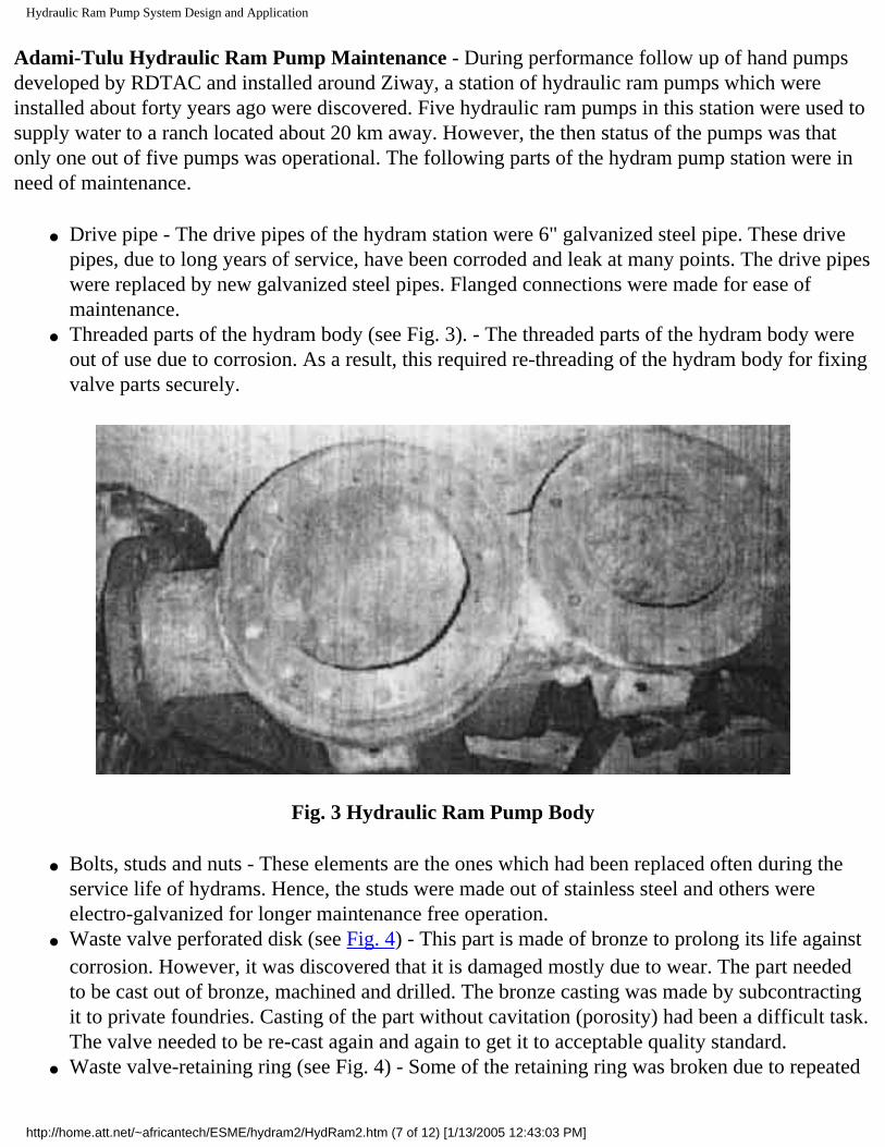
Hydraulic Ram Pump System Design and Application
Adami-Tulu Hydraulic Ram Pump Maintenance - During performance follow up of hand pumps developed by RDTAC and installed around Ziway, a station of hydraulic ram pumps which were installed about forty years ago were discovered. Five hydraulic ram pumps in this station were used to supply water to a ranch located about 20 km away. However, the then status of the pumps was that only one out of five pumps was operational. The following parts of the hydram pump station were in need of maintenance.
● Drive pipe - The drive pipes of the hydram station were 6" galvanized steel pipe. These drive pipes, due to long years of service, have been corroded and leak at many points. The drive pipes were replaced by new galvanized steel pipes. Flanged connections were made for ease of maintenance.
● Threaded parts of the hydram body (see Fig. 3). - The threaded parts of the hydram body were out of use due to corrosion. As a result, this required re-threading of the hydram body for fixing valve parts securely.
Fig. 3 Hydraulic Ram Pump Body
● Bolts, studs and nuts - These elements are the ones which had been replaced often during the service life of hydrams. Hence, the studs were made out of stainless steel and others were electro-galvanized for longer maintenance free operation.
● Waste valve perforated disk (see Fig. 4) - This part is made of bronze to prolong its life against corrosion. However, it was discovered that it is damaged mostly due to wear. The part needed to be cast out of bronze, machined and drilled. The bronze casting was made by subcontracting it to private foundries. Casting of the part without cavitation (porosity) had been a difficult task. The valve needed to be re-cast again and again to get it to acceptable quality standard.
● Waste valve-retaining ring (see Fig. 4) - Some of the retaining ring was broken due to repeated
http://home.att.net/~africantech/ESME/hydram2/HydRam2.htm (7 of 12) [1/13/2005 12:43:03 PM]

Hydraulic Ram Pump System Design and Application
fatigue loading and corrosion. Hence, they were replaced as new.● Rubber parts - Besides bolts and nuts, these parts were the ones which needed to be replaced
often. When found, all the delivery and waste valve rubber parts were damaged due to wear and tear. To manufacture them, a rubber mold was designed and manufactured. Addis Tyre Enterprise made the rubber valve parts to the required standard using the molds.
Fig. 4 Waste Valve, Retainer Ring and Rubber Parts of Adami-Tulu Hydraulic Ram Pump
● Other - Parts such as diversion canal gate, header pipes, intake valves were re-designed and manufactured.
The hydram pumps after renovated successfully are shown in Fig. 5.
http://home.att.net/~africantech/ESME/hydram2/HydRam2.htm (8 of 12) [1/13/2005 12:43:03 PM]

Hydraulic Ram Pump System Design and Application
Fig.5 Renovated Adami-Tulu Hydraulic Ram Pumps
HYDRAULIC RAM PUMP DEVELOPMENT WORK OF RDTAC
Design - The design of hydraulic ram pump developed by RDTAC is shown in Fig. 2. The pump was 4" drive pipe designed to supply 80 litre/mm at a head of 45 m. This is sufficient for a village of 500 people and their cattle. In the design, casting technology was preferred for the main parts of the hydraulic ram pump for resistance to corrosion and long term maintenance free operation. Parts which are more prone to failure as a result of corrosion were made out of stainless steel or bronze based on experience obtained from the Adami-Tulu hydram maintenance project. Bolts and nuts were designed to be electro-galvanized. Parts of the hydram, the body, elbow and air chamber were made in separate pieces to facilitate easy handling during transportation and machining operation. Provisions for stroke and weight adjustment has been incorporated. The waste valve was designed for simple and less costly manufacturing method.
http://home.att.net/~africantech/ESME/hydram2/HydRam2.htm (9 of 12) [1/13/2005 12:43:03 PM]
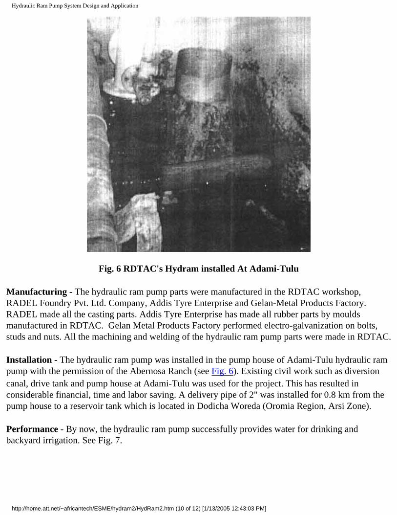
Hydraulic Ram Pump System Design and Application
Fig. 6 RDTAC's Hydram installed At Adami-Tulu
Manufacturing - The hydraulic ram pump parts were manufactured in the RDTAC workshop, RADEL Foundry Pvt. Ltd. Company, Addis Tyre Enterprise and Gelan-Metal Products Factory. RADEL made all the casting parts. Addis Tyre Enterprise has made all rubber parts by moulds manufactured in RDTAC. Gelan Metal Products Factory performed electro-galvanization on bolts, studs and nuts. All the machining and welding of the hydraulic ram pump parts were made in RDTAC.
Installation - The hydraulic ram pump was installed in the pump house of Adami-Tulu hydraulic ram pump with the permission of the Abernosa Ranch (see Fig. 6). Existing civil work such as diversion canal, drive tank and pump house at Adami-Tulu was used for the project. This has resulted in considerable financial, time and labor saving. A delivery pipe of 2" was installed for 0.8 km from the pump house to a reservoir tank which is located in Dodicha Woreda (Oromia Region, Arsi Zone).
Performance - By now, the hydraulic ram pump successfully provides water for drinking and backyard irrigation. See Fig. 7.
http://home.att.net/~africantech/ESME/hydram2/HydRam2.htm (10 of 12) [1/13/2005 12:43:03 PM]

Hydraulic Ram Pump System Design and Application
Fig.7 Water Supply System at Dodicha Woreda, Arsi Zone, Oromia Region from RDTAC's Hydram
CONCLUSION
The following conclusions can be made from RDTAC's project work on Hydraulic Ram pumps.
● There is broad prospect of utilizing the country's abundant surface water run off potential for various purposes or requirements using locally designed and manufactured hydraulic ram pumps and other similar appropriate technologies.
● To disseminate hydrams at potential sites throughout the country, there is a need to create awareness through training and seek integrated work with rural community, government institutions like water, energy and mines bureau of local regions and non-governmental organizations.
● Hydraulic Ram pumps made by casting have many advantages, but they could be expensive. In addition, considering the cost of civil work and pipe installation, the initial investment could be very high. To reduce cost of hydrams made by casting, there is a need for standardization. Standardizing hydram pump size will also have an advantage to reduce cost of spare parts and facilitate their easy access when they are needed.
http://home.att.net/~africantech/ESME/hydram2/HydRam2.htm (11 of 12) [1/13/2005 12:43:03 PM]

Hydraulic Ram Pump System Design and Application
● The use of appropriate means of treating river water should be looked at in conjunction with any development project of domestic water supply using hydrams.
Acknowledgement
RDTAC would like to take the opportunity to express its sincere appreciation to the Ethiopian Science and Technology Commission for the unreserved assistance and encouragement rendered.
REFERENCES
1. Jeffery, T. D., "Hydraulic Ram Pumps - A Guide to Ram Pumps Water Supply System", Intermediate Technology Publications, 1992.
2. Teferi Taye, "Hydraulic Ram Pump", Journal of the Ethiopian Society of Mechanical Engineers, Vol. II, No. l, July 1998.
Go back to the updated ATF site or to the main ATF home page at MIT.
http://home.att.net/~africantech/ESME/hydram2/HydRam2.htm (12 of 12) [1/13/2005 12:43:03 PM]

Picture Gallery
Search the web with Hotbot Build an online Photo Album
!!!Warning: This page may take a moment to download!!!
Please be patient!
My Collection!
These are some of my pump collection!
Click on the thumbnails to view the full size pictures!
1. 2.
3. 4. 5.
These are just a few of my collection. They are several different kinds and sizes.1.This is a #2 3/4 Inch Davey Ram.2.This is a #3 1 Inch ram, origin unknown.3.This is a #4 1 1/4 Inch Humphryes.4.This is a #3 1 Inch Davey Ram.5.This is a #3 1 Inch ram, origin unkown.
This page is Under Construction, so come on back in a day or two!
LINKS to other sites!:My home pageThe history of the Hydraulic RamHow water rams workAll About Pumps Ram Page
http://members.tripod.com/~dburger/pictures (1 of 2) [1/13/2005 12:43:05 PM]

Picture Gallery
All About Pumps Pump Glossary Page
Back to my Home Page
http://members.tripod.com/~dburger/pictures (2 of 2) [1/13/2005 12:43:05 PM]

Ram Pump (from Internet Glossary of Pumps)
Ram Pump
Ram Pumps only have two moving parts, making them virtually maintenance-free.
Water enters the lower of two chambers through a pipe from an elevated water source. This pipe must be relatively long and thick so that significant force (inertia) is developed as the water moves down it to the chamber.
As water rushes in it starts the pump. The chamber fills and the ESCAPE VALVE (on the left here) shuts. The DELIVERY VALVE to the AIR DOME opens.
http://www.animatedsoftware.com/pumpglos/ram_pump.htm (1 of 5) [1/13/2005 12:43:09 PM]

Ram Pump (from Internet Glossary of Pumps)
The momentum of the rushing water pushes some water into the air dome and compresses the air that partially fills that chamber. When the pressure is great enough it opposes the force of the incoming water and the second valve drops shut.
After the delivery valve shuts, air pressure pushes water up the outlet pipe. In the first chamber, all valves are closed and no water can move, so the escape valve drops open and the cycle begins to repeat, about once a second.
This is an ideal pump when a plentiful water source is available. Roughly 3/4's of the water that passes through the system exits via the escape valve.
(This is a still
representation and possibly also a low-resolution image of a pump which is fully animated in the CD-ROM version of this glossary.)
Related Material Outside this Web Site:
http://www.animatedsoftware.com/pumpglos/ram_pump.htm (2 of 5) [1/13/2005 12:43:09 PM]

Ram Pump (from Internet Glossary of Pumps)
The Ram Company. Manufacturers of several non-electric pumping solutions.
The Ram Company1-800-227-8511 (Virginia)512 Dillard Hill RoadLowesville, VA 22967Email: [email protected]
Grove Enterprises, Inc. Distributors for Atlas Publications, who have published a book by Don. R. Wilson called All About Hydraulic Ram Pumps -- How and Where They Work (ISBN 0-9631526-2-9). It describes how to design, build, and install a simple, efficient hydraulic ram pump.
Rife Hydraulic Engine Mfg. Co., Inc. is the manufacturer of the DAVEY ram pump shown above. They have been manufacturing "water pumps and related products" since 1884 and have a wide variety of sizes and models to choose from. They are located at:Line & Grove Streets / PO Box 95Nanticoke, PA 18634
Tel 570-740-1100 Fax 570-740-11011-800-RIFE-RAM (orders only please)
Email Rife at: [email protected]
B & L Associated Industries / B& L Ram PumpsHas "been manufacturing rams since 1989"... "The B& L Hydro-Ram is an efficient, lightweight, dependable and inexpensive hydraulic ram pump made possible by modern technology. It works on the same principles of physics that enabled its cumbersome predecessors to water the farmlands of Europe, the Mid-East and Asia over the past two hundred plus years." (They have a lovely animation of a ram pump at their web site!) B & L Associated Industries is located in Rusk, TX and ships their pumps worldwide.
http://www.animatedsoftware.com/pumpglos/ram_pump.htm (3 of 5) [1/13/2005 12:43:09 PM]

Ram Pump (from Internet Glossary of Pumps)
Phone: (903) 743-5555Fax: (903) 743-5556Email Bill Tosh at: "Bill Tosh" <[email protected]>
Donald Burger, collector of Hydraulic Water Rams. (Unfortunately, this site appears to be inaccessible at this time). Mr. Burger's site contains additional links to other sites with more information about these marvelous pumps.
GREEN AND CARTER
www.greenandcarter.com
The Vulcan Hydraulic Ram Pump is still their only product -- after more than 200 years. As noted on their web site, they were "the inventors and patentees of the hydraulic ram principle in 1774". Green and Carter now make over 60 varieties of Vulcan Hydraulic Ram Pumps, including models that can pump water to heads of over 1000 feet, with drive pipe sizes of 3/4 of an inch (1.9cm)
to 30 inches (76.2cm) (or more to order). According to the Green and Carter web site: "Units are heavily constructed of cast iron and gunmetal. There is no substitute for this material. Imitators use plastics (which are subject to UV degradation), steel (which corrodes) and nylon seals and O-rings which become useless with the slightest wear."
http://www.animatedsoftware.com/pumpglos/ram_pump.htm (4 of 5) [1/13/2005 12:43:09 PM]

Ram Pump (from Internet Glossary of Pumps)
CD-ROM -- only $59.95!● This Glossary is a part of a complete educational tutorial about pumps!● Mechanical pumps are the second most common machine in the world (after electric motors).● Most people are unfamiliar with how the many different kinds of pumps work! ● Call us toll free to order the program on CD-ROM! Satisfaction Guaranteed!
● Written, animated, and programmed by:Russell D. Hoffman, Owner and Chief Programmer, The Animated Software Company
● Click here for more information!
Catalog / Site Map / Company Home page / Contact / Product Home Page
Last modified Nov., 2004Webmaster: Russell D. Hoffman
Copyright (c) Russell D. Hoffman
http://www.animatedsoftware.com/pumpglos/ram_pump.htm (5 of 5) [1/13/2005 12:43:09 PM]

Motorless Water Pump--Gravi-Chek
THE MOTORLESS WATER PUMP
The Gravi-Chek pump is the newest technology available in the ram pump industry (patent # 4,911,613). This pump is designed to supply water up-hill without a motor: the force of water flowing down into the pump provides all the energy needed.
The Gravi-Chek pumps have been tested by the Center for Irrigation Technology at the California Agricultural Technology Institute. There are three models available, providing water at rates from 20 to 16,000 gallons per day, depending on the installation.
Easy to use:
● Lightweight (35 lbs. or less), easy to carry and install in remote areas.
● Quick start up, no energy costs.● Little or no maintenance.
Efficient and powerful:
● Running water supplies pumping energy.● Durable, only two moving parts.● Made from tempered marine aluminum.
We welcome all inquiries from potential dealers and Distributors
Contact InformatonAddress:
CBG EnterprisesA Carlson & Beauloye Co.2143 Newton Ave.San Diego CA 92113USA
Telephone:
(619) 234-2256(619) 232-5719(619) 234-2095 (Fax)
E-mail:
[email protected]@[email protected]
[Home] [About] [Installation] [How It Works] [Models] [En Espanol]
http://www.gravi-chek.com/ (1 of 2) [1/13/2005 12:43:10 PM]

Motorless Water Pump--Gravi-Chek
http://www.gravi-chek.com/ (2 of 2) [1/13/2005 12:43:10 PM]

AEE update/title>
Power to the People
Alternative Energy Engineering
We are in the process of updating our web site. www.alt-energy.com
Please update your bookmarks to our home page address and check back later.
http://www.asis.com/aee/catalog/waterpoweredpumps.html [1/13/2005 12:43:12 PM]

AEE Renewable Energy Supersource
Put 26 Years of Renewable Energy Expertise to Work for You!
Founded in 1979 as Alternative Energy Engineering, AEE Solar Supersource serves the dealer trade with:
The industry's widest selection of solar, wind and hydroelectric systems, parts and components
Highly competitive prices on all the top brands
Unsurpassed technical expertise and support
Personal, friendly, prompt customer service
If you are already an AEE dealer, AEE Store login here. If not, read more about AEE — and how and why to become an AEE dealer.
ONLINE ORDERING IS HERE!
Use "Dealer Login" above to order online!
Contact AEE for Login credentials.
Welcome to Our New Website.
● Please note and bookmark our new URL: www.aeesolar.com
●
We've also revised our name
and updated our look.
Watch for featured sale items in this space soon!
Home | About AEE | Become a Dealer | End-Users | Our Partners | Catalog | Dealer Login | Links | Site Map | Privacy Policy |
Contact Us
http://www.alt-energy.com/index.html [1/13/2005 12:43:14 PM]

Aquatic Eco-Systems - Aquaculture Supplies and service for over 25 years.
Aeration
Algae & Zooplankton Culture
Chemicals
Cleaning
Complete Systems
Electrical
Environmental
Feeds/Feeders
Filtration
Fish Hatchery Supplies
Heaters & Chillers
Hydroponics
Lab Equipment
Lake Aeration
Lighting
Live Organisms
Nets
Odds & Ends
Paint & Safety
Plumbing
Predator Control
Pumps
Reference
Tanks
For suggestions, questions, problems contact the webmaster
Orbit™ Compact Fluorescent Fixtures
> High-quality housing.> Simulates 24-hour cycle.> Includes SunPaq™ lamps.click here for more info
Satellite™ Compact Fluorescent Fixtures
> Slimline design.> Simulates 24-hour cycle.> Includes SunPaq™ lamps.click here for more info
About Aquatic Eco-SystemsAquatic Eco-Systems, Inc. is the world’s largest distributor of aquatic equipment and supplies. In business for over 25 years, AES carries over 13,000 items for:
> Aquaculture > Lake and Wastewater Aeration> Toxicology and Biopharmaceutical Research> Public Aquariums and Zoological Exhibits> Water Gardens and Koi Ponds> Hydroponics and Aquaponics> Bait and Seafood Holding
We take pride in stocking a complete inventory of the lowest-priced products in the industry, as well as a reputation for shipping most items on the same day they are ordered. A full staff of biologists and technicians is available to answer customers' questions, ranging from help on choosing the right product for a certain application to sizing and designing a complete aquaculture or water garden system.
FREE With any Web Purchase Over $30Don't hold a flashlight, use your head! Would you like to use both of your hands while working in the dark? click here for more info
1.Tropical Lamp, 15" - 14W
2.Gauge, 15 psi, installed
3.pH Tester w/ATC4.Commercial Duty
Hose, 1"5.Clear Glass
Boston Bottles, 1000 ml/32 oz
Clearance Items
AES's Aquatic Eco Depot helps clear the shelf of inventory overstocks. Find great bargains on aquarium supplies today.
http://www.aquaticeco.com/index.cfm (1 of 2) [1/13/2005 12:43:24 PM]

Aquatic Eco-Systems - Aquaculture Supplies and service for over 25 years.
Premier Buys
XE30 - Gen-X
Magnetic Drive Pump - 825 gph
AZ80136 - Wheat
Germ, 1 kg (2.2 lbs)
PD1 - Floating De-
icer, 1500W
NEW Catalog for 2005!Our new 2005 master catalog is packed with AES supplies and Tech Talks. Order the World's Largest Selection of Aquatic Tools today.
Cart | Check Out | Quick Buy | About Us | Contact | Downloads | Technical Services | Specials
http://www.aquaticeco.com/index.cfm (2 of 2) [1/13/2005 12:43:24 PM]

Real Goods - Folk Ram Pumps
Home PageCheckoutCustomer ServiceFree CatalogAbout UsRetail StoresReaders ForumDesign & ConsultingDemo HomesSystem Sizing
View Cart Help
Folk Ram Pumps
The Folk is the most durable and most efficient ram
pump available. It is solidly built of rustproof cast
aluminum alloy and uses all stainless steel hardware.
With minimal care, it will probably outlast your
grandchildren. It is more efficient because it uses a
diaphragm in the air chamber, preventing loss of air
charge, and eliminating the need for a snifter valve
in the intake that cuts efficiency.
Folk rams require a minimum of 2 gpm and 3 feet of drive pipe fall to operate. The largest units can
accept up to 75 gpm, and a maximum of 50 feet of drive pipe fall. Delivery height can be up to 15 times
the drive fall, or a maximum of 500 feet lift. The drive pipe should be galvanized Schedule 40 steel, and
the same size the entire length. Recommended drive pipe length is 24 feet for 3 feet of fall, with an
additional 3 feet length for each additional one foot of fall. Be absolutely sure you have enough water to
meet the minimum gpm requirements of the ram you choose. Rams will stop pumping and simply dump
water if you can’t supply the minimum gpm.
To estimate delivery volume, multiply fall in feet times supply in gpm, divide by delivery height in feet,
then multiply by 0.61. Example: a ram with 5 gpm supply, a 20-foot drive pipe fall, and delivering to a
tank 50 feet higher. 20ft x 5gpm ÷ 50ft x 0.61 = 2.0gpm x 0.61 = 1.22gpm, or 1,757 gallons per day
delivery. Warranted by manufacturer for one year. USA.
All Folk Rams are drop-shipped via UPS from the manufacturer in Georgia.
Folk Ram Pump 1"
Price: $795.00
Qty:
Folk Ram Pump 1-1/4"
Price: $795.00
Qty:
Folk Ram Pump 1-1/2"
Price: $795.00
Qty:
Folk Ram Pump 2"
Price: $1,095.00
Qty:
Folk Ram Pump 2-1/2"
Price: $1,095.00
Qty:
Folk Ram Pump 3"
Price: $1,095.00
Qty:
Comparison Table(s):
Folk Ram Pump Capacity
http://www.realgoods.com/renew/shop/product.cfm?dp=1904&ts=1041815&kw=ram%20pump (1 of 2) [1/13/2005 12:43:25 PM]

Real Goods - Folk Ram Pumps
<< Previous Page
Home | Free Catalog | About Us | Retail Stores | Sale Items
Order securely online or call 800.919.2400
© 2005, Gaiam.com, Inc.
Privacy Policy | Terms of Use
http://www.realgoods.com/renew/shop/product.cfm?dp=1904&ts=1041815&kw=ram%20pump (2 of 2) [1/13/2005 12:43:25 PM]

Hand Pumps
HAND PUMPS
AN6201 AN6248
Pump, Hydraulic, Ram, Hand Driven. Designed in accordance with MIL-P-5515
AN6201 - 1500 psig operating pressure
AN6248 - 3000 psig operating pressure
● 3/4 cubic inch displacement per stroke● -65 degree to 160 degree Farenheit operating range
1-800-998-YORK (9675)
[Home] [Aerospace] [Industry] [Defense] [About YII] [Contact YII] [News]
http://www.yorkind.com/html/hand_pumps.html [1/13/2005 12:43:26 PM]

Sling Pump (from Internet Glossary of Pumps)
Sling PumpThe Sling Pump, with only one moving part, is a modern application of an Archimedes Snail Pump. A helical intake coil is wrapped around and around the inside surface of a cone. The coil is connected to an output tube via a water-lubricated swivel coupling at the extreme upstream side of the pump and is open at the downstream (fat) end. The downstream end of the cone has slats to let water in but keep debris out. A rope or pair of ropes holds it in place.
The pump floats partially submerged, being largely of plastic, with aluminum propeller blades and bouyant styrofoam in the nose. With each revolution of the cone, the coil picks up air during the top portion of the cycle and water during the bottom portion. This causes a pulsed output, and also means the output water is highly oxygenated. The Rife Hydraulic Engine Mfg. Co., Inc. claims some models of their Sling Pumps (inset) can raise water over 80 feet high or move it a mile horizonally, from a stream moving at just 1.5 feet per second. (Head doesn't change with speed, only volume.) The unit weighs about 44 lbs. and uses a 1/2" hose.
http://www.animatedsoftware.com/pumpglos/gl_sling.htm (1 of 3) [1/13/2005 12:43:29 PM]

Sling Pump (from Internet Glossary of Pumps)
(This is a still representation and possibly also a low-resolution image of a fully animated pump.)
For more information about this pump...Visit The Rife Hydraulic Engine Mfg. Co., Inc. World Wide Web site: www.riferam.com
CD-ROM -- only $59.95!● This Glossary is a part of a complete educational tutorial about pumps!● Mechanical pumps are the second most common machine in the world (after electric motors).● Most people are unfamiliar with how the many different kinds of pumps work!
http://www.animatedsoftware.com/pumpglos/gl_sling.htm (2 of 3) [1/13/2005 12:43:29 PM]

Sling Pump (from Internet Glossary of Pumps)
● Call us toll free to order the program on CD-ROM! Satisfaction Guaranteed!
● Written, animated, and programmed by:Russell D. Hoffman, Owner and Chief Programmer, The Animated Software Company
● Click here for more information!
Catalog / Site Map / Company Home page / Contact / Product Home Page
Last modified February, 2002 Webmaster: Russell D. Hoffman
Copyright (c) Russell D. Hoffman
http://www.animatedsoftware.com/pumpglos/gl_sling.htm (3 of 3) [1/13/2005 12:43:29 PM]

1
PB 1641
Agricultural Extension ServiceThe University of Tennessee

2
Table of Contents
Introduction _________________________________________________________________ 4Controlled Direct Access _______________________________________________________ 4
Figure 1. Full Stream Crossing_____________________________________________ 5Figure 2. Cattle Access Area ______________________________________________ 5
Gravity Systems ______________________________________________________________ 5Figure 3. Equipment Tire Tank _____________________________________________ 5Figure 4. Insulated Tank __________________________________________________ 6
AC Electric Pumping Systems ___________________________________________________ 6Ram Pumps__________________________________________________________________ 7
Figure 5. Ram Pump Components __________________________________________ 7Figure 6. Ram Pump _____________________________________________________ 7
Solar DC Pumping Systems _____________________________________________________ 8Figure 7. Solar Panels ____________________________________________________ 8Figure 8. Pressure Tank & Batteries _________________________________________ 8
Sling Pumps _________________________________________________________________ 8Figure 9. Operating Sling Pump ____________________________________________ 9Figure 10. Sling Pump ___________________________________________________ 9Figure 11. Inside of Sling Pump ____________________________________________ 9
Nose Pumps _________________________________________________________________ 9Figure 12. Nose Pump ___________________________________________________ 9
Summary___________________________________________________________________ 10Table 1 - Comparison of Alternative Livestock Watering Systems ________________ 10Table 2 - Installation Considerations for Livestock Watering Systems _____________ 11

3
Introduction
Due to efforts to use improved grazing strategies, such as intensive rotational or pad-dock grazing, livestock producers need dependable and economically alternative methods ofproviding water to livestock. In addition, efforts to improve water quality have resulted in anew emphasis on the establishment of buffer strips and riparian zones along streams. In mostcases, the establishment of these zones requires the exclusion of livestock. Livestock produc-ers who rely on streams to provide water for their animals must develop alternative wateringsystems before they can rotate animals into grazing paddocks that do not adjoin streams orponds, or before they can implement best management practices that require livestockexclusion from streams.
Several options are available to producers when choosing a livestock watering sys-tem. These systems can be divided into three basic types: direct access, gravity flow andpressure systems. The best system type for a particular producer will depend on manyfactors, including site layout, water requirement, availability and cost of utility water andelectricity, as well as water source type and location. This publication provides basicdescriptions of some livestock watering system alternatives, and discusses some of thepositive and negative aspects of each.
Controlled Direct Access
Allowing animals to water directly from a stream or pond is historically themost commonly used livestock watering method. While this method is simple andinexpensive, it has limitations. Animals may have to travel long distances to drinkwhen only one water access point is available in a large pasture. This is particularlya problem in rotational or paddock grazing systems. In scenarios where direct accessis a viable option, benefits may be gained by the use of controlled access pointsdesigned to better facilitate livestock watering. Benefits such as reduced streambank damage, reductions in erosion and the resulting sedimentation, improvedriparian areas along streams and safer animal access to streams can be realized byexcluding animals from all areas of the stream except well-designed and constructedimproved access points.
Examples of improved access points are geotextile and aggregate reinforcedstream crossings or access points. These crossings are constructed in full crossing
Selection of AlternativeLivestock Watering Systems
Robert T. Burns, Assistant ProfessorMichael J. Buschermohle, Associate Professor
Agricultural and Biosystems Engineering

4
and limited access configurations.Figure 1 illustrates a full streamcrossing that can be used by animalsas a water access point and alsoserves as an equipment crossingpoint. The crossing is underlain withsynthetic geotextile material andfinished with gravel to provide anall-weather stream access andcrossing area. Figure 2 illustrates acattle access area in a stream. Theelectrified chains prevent cattlefrom going up or down the streamfrom the access area provided. Seethe Agricultural and BiosystemsEngineering departmental publica-tion Construction of Farm HeavyUse Areas Using Geotextiles (WQ-01-00) , for information on usinggeotextiles to construct heavy-use orhigh-traffic areas such as improvedlivestock access areas to streams.
Figure 1. Full Stream Crossing
Figure 2. Cattle Access Area
Figure 3. Equipment Tire Tank
Gravity Systems
When a water source is higher thanthe deliver or usage point, gravity flowsystems may be a good choice. Likedirect access systems, gravity systemsare relatively simple and inexpensive,since no external power source isrequired to move the water. Every 2.31feet in elevation change is equal to 1psi (pounds per square inch) in pres-sure. So, if 5 psi of pressure is requiredto operate a livestock water-tank float-valve, 12 feet of fall from the waterline to the usage point is required.
Most gravity systems are simply tanks equipped with float valves located lowerthan the water source, which is usually a pond. The water delivery pipe should besized appropriately, so adequate flow into the tank is achieved. When building a pond,the outlet pipe should be installed during construction of the pond. It is difficult toinstall a pipe through a pond berm or levee after construction due to potential leakageproblems. Figure 3 shows a heavy equipment tire modified as a livestock water tank.Used pan and large rock quarry truck tires of this size can be converted into livestockwater tanks that hold approximately 300 gallons of water. These tires can usually be
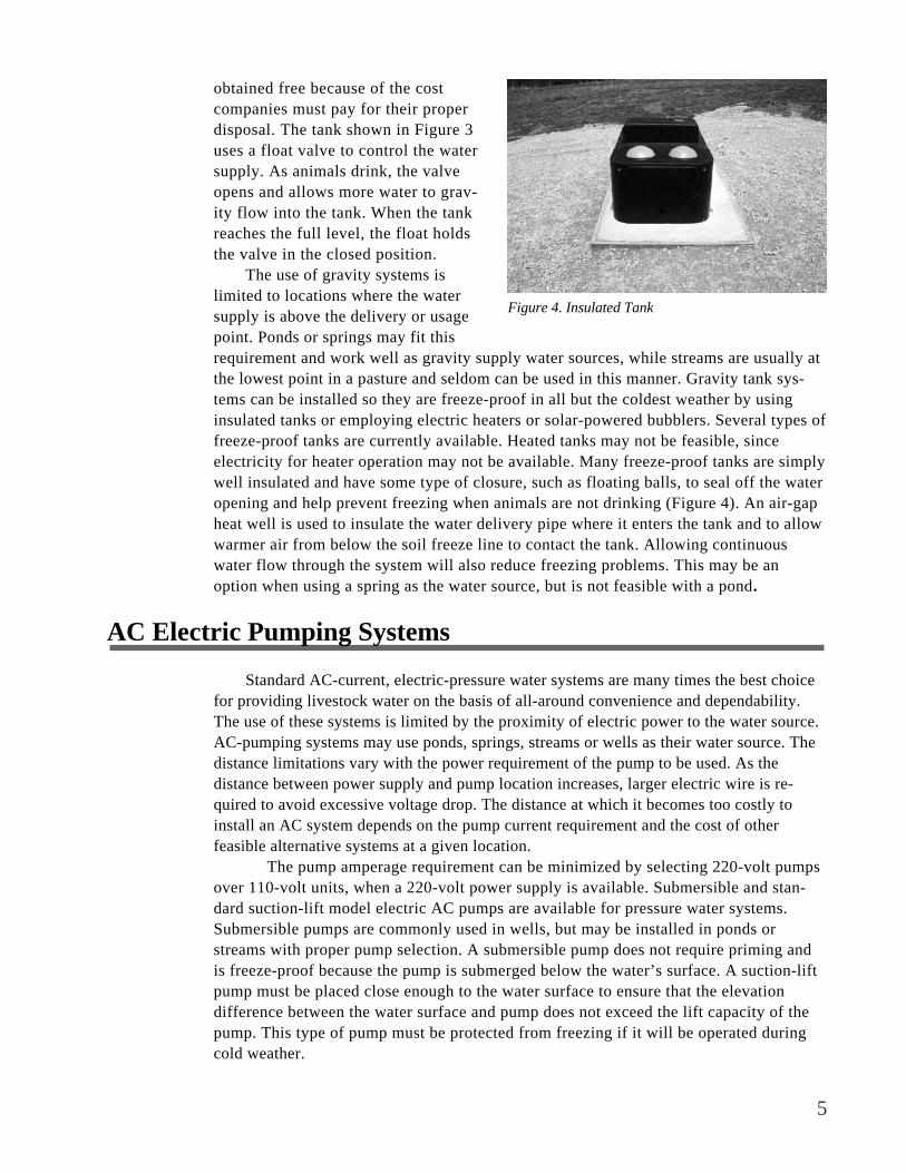
5
obtained free because of the costcompanies must pay for their properdisposal. The tank shown in Figure 3uses a float valve to control the watersupply. As animals drink, the valveopens and allows more water to grav-ity flow into the tank. When the tankreaches the full level, the float holdsthe valve in the closed position.
The use of gravity systems islimited to locations where the watersupply is above the delivery or usagepoint. Ponds or springs may fit thisrequirement and work well as gravity supply water sources, while streams are usually atthe lowest point in a pasture and seldom can be used in this manner. Gravity tank sys-tems can be installed so they are freeze-proof in all but the coldest weather by usinginsulated tanks or employing electric heaters or solar-powered bubblers. Several types offreeze-proof tanks are currently available. Heated tanks may not be feasible, sinceelectricity for heater operation may not be available. Many freeze-proof tanks are simplywell insulated and have some type of closure, such as floating balls, to seal off the wateropening and help prevent freezing when animals are not drinking (Figure 4). An air-gapheat well is used to insulate the water delivery pipe where it enters the tank and to allowwarmer air from below the soil freeze line to contact the tank. Allowing continuouswater flow through the system will also reduce freezing problems. This may be anoption when using a spring as the water source, but is not feasible with a pond.
AC Electric Pumping Systems
Standard AC-current, electric-pressure water systems are many times the best choicefor providing livestock water on the basis of all-around convenience and dependability.The use of these systems is limited by the proximity of electric power to the water source.AC-pumping systems may use ponds, springs, streams or wells as their water source. Thedistance limitations vary with the power requirement of the pump to be used. As thedistance between power supply and pump location increases, larger electric wire is re-quired to avoid excessive voltage drop. The distance at which it becomes too costly toinstall an AC system depends on the pump current requirement and the cost of otherfeasible alternative systems at a given location.
The pump amperage requirement can be minimized by selecting 220-volt pumpsover 110-volt units, when a 220-volt power supply is available. Submersible and stan-dard suction-lift model electric AC pumps are available for pressure water systems.Submersible pumps are commonly used in wells, but may be installed in ponds orstreams with proper pump selection. A submersible pump does not require priming andis freeze-proof because the pump is submerged below the water’s surface. A suction-liftpump must be placed close enough to the water surface to ensure that the elevationdifference between the water surface and pump does not exceed the lift capacity of thepump. This type of pump must be protected from freezing if it will be operated duringcold weather.
Figure 4. Insulated Tank

6
Ram Pumps
Ram pumps are very simplehydraulic pumps that use the energyin falling water to pump a portion ofthe water to a height greater than thesource. Ram pumps are very depend-able when installed under the correctconditions. The diagram shown inFigure 5 outlines the basic parts of aram pump. As water flows throughthe poppet, or clack valve, it iswasted until the flow reaches avelocity sufficient to close the valve.The water then travels through a checkvalve into the compression chamber. Thecompression chamber is filled with airthat is compressed by the force of thewater rushing in. The compressed airthen forces the water out of the compres-sion chamber. Due to the check valve, theonly available flow path is out throughthe delivery pipe. Figure 6 shows apicture of a small ram pump that providesapproximately two gallons per minute toa cattle water tank approximately 75 feethigher than the pump.
Ram pumps require no electricalpower to operate and are inexpensive, considering that the original cost of the pumpinstallation and infrequent maintenance are the only costs associated with the units. Theamount of water a ram pump will provide is directly proportional to the available elevationhead from the water source to the pump location and the volume of inflow water availableto the pump. A ram pump will pump from 2 to 20 percent of the pump inflow volume,depending on the vertical fall to the pump and the elevation increase to the delivery point.While ram pumps can provide water to considerable elevations (up to 500 feet), the outputflow is generally low. Although ram pumps will operate with very little fall, a minimum ofabout 10 feet of fall is required to achieve flows useful for livestock-watering needs.
A typical ram pump installation in a small stream or spring might provide one totwo gallons per minute of output flow with a 10-foot vertical fall (driving head). Rampumps provide low flows, but the flow is continuous. To take advantage of this continu-ous flow, tanks large enough to store water when livestock are not drinking are used toprovide adequate water in higher water consumption periods. The pipe used to deliverwater to the ram pump, called the drive pipe, must be mounted rigidly for proper opera-tion. The drive pipe should be three to six times as long as the vertical head operatingthe pump. Drive pipes for ram pump sets with driving heads of 15 feet or less should beabout six times the length of the drive head. Higher driving head installations of morethan 25 feet should use about three times the driving head in drive-pipe length.
Clack or Poppet Valve
Water LostThrough Valve
Check Valve
Drive Line
CompressionChamber
Delivery Pipe
Figure 5. Ram Pump Components
Figure 6. Ram Pump

7
Solar DC-Pumping Systems
Solar pumping systems provide an alternativemethod to water livestock in areas where utility ACpower is not available. Solar-pumping systems canbe used to provide pressurized water from low-lyingstreams or ponds to locations of higher elevation.Solar DC-current pumping systems can be operatedas either 12- or 24-volt systems, with or withoutbatteries. University of Tennessee agriculturalengineering Extension specialists have found 24-voltsystems that use batteries to store the energy pro-vided by the solar panels to be the most dependablecombination under Tennessee conditions.
Two solar panels, as shown in Figure7, are used to charge a pair of deep-cycle, marine batteries. These batteriesare wired in series to provide 24 volts toa DC-powered submersible pump. Apressure tank and pump control switch(shown in Figure 8) are used to controlthe water flow to a tank fitted with afloat valve. The pressure tank and pumpcontrol switch control the water flowlike they would in a home well system.These systems provide flow rates in thetwo- to three- gallon per minute range.While AC-pumping systems would bepreferred over solar-powered DC systems on the basis of simplicity and capacity, solar-pumping systems can provide pressure water-delivery systems to areas where no othersystem could be operated. For more information concerning solar-livestock wateringsystems, see The University of Tennessee Agricultural Extension Service publication SolarPowered Livestock Watering Systems (PB1640). This publication gives specific informa-tion about the design, component selection and installation of solar- powered, DC-current,water-pumping systems designed to provide water for up to 50 beef animals.
Sling Pumps
Sling pumps provide an alternative means of pumping water in areas where electricalpower is not available. Sling pumps use the energy provided by a flowing stream of waterto pump water to a higher elevation. The sling pump is placed in the stream, as shown inFigure 9. Sling pumps are available in several sizes, but require a minimum of approxi-mately 2.5 feet of water to operate in. Sling pumps also require a minimum stream velocityof approximately 1.5 feet per second to operate. A stream meeting both of these require-ments will usually be substantial in size. The pumps are approximately 4 feet long and 2feet in diameter at the large end. The unit has a series of blades attached to the nose of thesling pump body, as shown in Figure 10. The flowing water turns the blades and rotates the
Figure 7. Solar Panels
Figure 8. Pressure Tank and Batteries

8
entire pump body.The pump body haspipe wound in a coilinside the unit, asshown in Figure 11.As the pump bodyrotates, water isforced through thepipe and pumped tothe delivery location.The water-deliverypipe is connected tothe nose of the sling pump and isrouted from the pump through thestream and on to the water tanklocation.
Flow rates of one to two gallonsper minute can be expected from slingpumps and can be provided to heightsgreater than 50 feet. Larger slingpumps provide larger flows, but alsorequire higher stream velocities tooperate. Like a ram pump, a sling pumpwill provide a low flow rate continu-ously. Storage tanks are usually used tostore enough water to meet the live-stock water requirements.
Although sling pumps have no operating costs in terms of electrical energy, they dohave high maintenance requirements. Any floating debris caught in the blades, such astrash, sticks and leaves, can stop the pump from rotating. The pump must be well securedto prevent loss during high-water events. Frequent monitoring and periodic cleaning of theunit are required for dependable operation.
Nose Pumps
Nose pumps are simple diaphragm pumps thatprovide water when operated by livestock. When ananimal pushes the pump arm or paddle with its nose, abouta quart of water is pumped into a small drinking bowl bythe animal’s action. Nose pumps provide water to oneanimal at a time at a low flow rate, so their use is limitedto small numbers of animals. These units must be setreasonably close to the water’s surface in terms of eleva-tion. Most nose pumps can lift water approximately 15feet. Manufacturers suggest that the units be protectedfrom freezing, which limits their use to warm months.Figure 12 shows a typical nose pump installation.
Figure 9. Operating Sling Pump
Figure 10. Sling Pump
Figure 11. Inside of Sling Pump
Figure 12. Nose Pump

9
Summary
The type of livestock watering system that will perform the best for you will dependon the specific situation at your farm. Table 1 provides a comparison of the system typescovered in this publication. Each system type is rated as low, medium or high acrossseveral categories. These ratings can be used as a basic guide to determining whichsystem types could be considered for use on your farm. For example, if you have a largenumber of cattle and require high water-flow rates, you can quickly exclude thosesystem types indicated as having low flow rates by the table. Do not confuse low andhigh to mean bad and good. A pump system may be listed as both “low” for cost andwater flow rate, which would indicate that it was inexpensive, but did not provide muchwater when compared to the other systems listed.
It is also important to note that the low, medium and high ratings are meant to berelative ratings within this group of listed systems. The cost comparisons assume that awater source already exists. For example, for a gravity-flow system, the cost of a pond isnot considered, only the components needed to construct the system using an existingpond. It should also be noted that relative costs are compared on a per-system basis.Different system types can provide water to different numbers of animals under anygiven set of conditions. For this reason, two systems with a “low” cost might be requiredto provide water to the same number of animals as a single “high” cost system mighthandle. Each system has requirements that limit the locations at which it could besuccessfully installed. Table 2 indicates basic site requirements for each system typescovered by this publication.
Table 1. Comparison of Alternative Livestock Watering Systems
System Type Initial*Cost
OperatingCost
Maintenance ReliabilityAbility to
Freeze-Proof
WaterFlow
Potential
Direct Access(Ponds & Streams)
Low Low Med High Med High
Gravity Flow(Tank Systems)
Low Low Low High Med Med
Utility Power(AC Electric)
Med High Med High High High
Solar(DC Electric)
High Med Med Med High Low
Ram Pump(Water Storage)
Med Low Med High Med Low
Sling Pump(Water Storage)
Med Low High Med Med Low
Nose Pump(Mechanical)
Low Low Low Med Low Low
* Cost comparisons assume an available water source is already present and are based on individual system cost and not a per-animal basis.

10
For additional information and assistance concerning alternative livestock watering systems,contact your county Agricultural Extension office or your county Natural Resources ConservationService (NRCS) office.
Table 2 - Installation Considerations for Alternative Livestock Watering Systems
System Type Considerations
Direct Access(Ponds & Streams)
Water source should be within reasonable distance from pasture location(preferably < 2000 feet) and must supply water year round.
Gravity Flow(Tank Systems)
Water source must be located at a higher elevation than livestockwatering area. (10 feet suggested minimum elevation head).
Utility Power(AC Electric)
Utility electric power must be within a reasonable distance to watersource. (Distance limit depends upon pump current requirements).
Solar(DC Electric)
Clear view of horizon for solar panel location. Area out of flood plain forconstruction of freeze-proof dry housing for electronic components andbatteries.
Ram Pump(Water Storage)
Water source must be located at a higher elevation than pump set (> 10feet), and adequate flow from spring or stream must exist (> 10 GPM).
Sling Pump(Water Storage)
Stream with adequate velocity (> 1.5 ft/sec) and depth (> 30 inches)nearby.
Nose Pump(Mechanical)
Pump must be located < 15 feet higher than water source.
Disclaimer Statement Use of trade or brand names or companies in this publication is for clarity and information;
it does not imply approval of the product or the vendor to the exclusion of others that may be ofsimilar, suitable composition, nor does it guarantee or warrant the standard of the product.

11
PB1641-2M-4/00 E12-2015-00-159-00
Visit the Agricultural Extension Service Web site at:http://www.utextension.utk.edu/
The Agricultural Extension Service offers its programs to all eligible persons regardless of race,color, national origin, sex, age, disability, religion or veteran status and is an Equal Opportunity Employer.
COOPERATIVE EXTENSION WORK IN AGRICULTURE AND HOME ECONOMICS The University of Tennessee Institute of Agriculture, U.S. Department of Agriculture,
and county governments cooperating in furtherance of Acts of May 8 and June 30, 1914. Agricultural Extension Service
Charles L. Norman, Dean
More information on ram, sling and nose pumps may be obtained from:
Rife Hydraulic Engine Manufacturing CompanyP.O. Box 70
Wilkes-Barre, PA 18703
1-800-RIFE RAM717-823-5730
More information on solar pumping systems may be obtained from:
Solar Water Technologies, Inc426-B Elm Avenue
Portsmouth, Virginia 23704
www.solarwater.com
1-800-952-7221757-398-0098

Page 1 of 4
Livestock Watering Order No. 590.306-6 July 2004
USING STREAM-POWERED PUMPS TO PUMP LIVESTOCK WATER
Introduction Coil Pump
Livestock water pumping options are selected with pump-driving energy as the limiting factor, especially remote systems. Where grid-supplied electricity is not available, gravity is usually the first energy option to consider. In this Factsheet, using gravity energy in the form of a flowing stream is considered. Like most livestock water pumping systems, the site plays a big part in the energy choice. For a stream-powered pump to be viable, the sites stream and terrain must be favorable, having
► a water supply deep enough to properly submerge the pump, and ► a gradient sufficient to generate the water velocity required
Pumping water using water flow has similarities to pumping using wind. For small systems, the higher density of water and continuous 24-hour flow offer significant advantages. (For larger systems, wind power may be the choice.) This pump is commonly known by its commercial name of Sling Pump. It is based on a principle similar to the Archimedean screw, except it operates in a horizontal position with coiled pipe, rather than a sloped and open screw. The basic coil pump is illustrated in Figure 1, below.
Figure 1 Coil Pump From: Water Pumping Devices by Peter Fraenkel, 1995
This factsheet looks at using gravity energy in the form of a flowing stream to move water in the low volumes usually required for livestock use. Pumps discussed include the Coil (Sling) Pump and the Paddle Wheel Pump.
THIS FACTSHEET IS INFORMATIONAL ONLY AND NOT PRODUCT ENDORSEMENT BY THE MINISTRY.
Delivery Pipe
Rotary SealRotation
Drive

Page 2 of 4
Sling Pump
Figure 4 Sling Pump with the
Back Removed
Coil Pump Operation. One end of the coiled pipe is open and dips into the stream taking a “gulp” of water with each revolution, sufficient to fill the lower part of a coil, while trapping air in the coil. With each revolution, this water moves along the coil and a new “gulp” of water is taken. As long as the delivery pipe height is no higher than the specified maximun elevation, water (and air) go in with each revolution and water (and air) comes out. This design is limited in available water lift and volume, but is a very simple device, as well as being portable and easy to set up. The one wearing part is the rotary seal in the delivery line (allowing the pumping pipe to rotate while the delivery pipe is stationary). The Sling Pump is a commercial adaptation of the coil pump principle. It has a casing around the coiled pipe and the drive is via a propeller facing into the stream current, as shown in Figures 2 to 4, below. The pump rotates slowly.
Figure 2 Sling Pump Operating in a Stream Various water lifts and volumes are possible with different sized coiled pipe. The Sling Pump shown above has 32mm (1.25 inch) polyethylene pipe for the internal coil. It will pump 15,000 litres (4,000 USgal) per day up 7.6m (25 ft).
1 Back Plate (water entry). 2 Pipe Inlet. 3 Coiled Pipe. 4 Rotary Seal. 5 Delivery Pipe Connection and Anchor Cable Point. 6 Delivery Pipe. 7 Flotation Material. 8 Propeller. Figure 3 Sling Pump Cutaway Sketch from Ktech Products
Anchor Cable
Stream Flow
620 mm
1360 mm 55 inch
25 inch
Delivery Pipe
20kg (44lbs) Delivery Line to Trough
Coiled Polyethylene
Pipe Pipe Inlet

Page 3 of 4
Figure 5 Sling Pump Installation Options
5a Anchored to a Bridge
5b Anchored to a Streamside Post
5c Current Moves Pump into
Stream, away from Bank
5d Adjustable Streambank Arm
5e Adjustable Streambank Arm
5f Streambank Arm Detail
Sling Pump Installation. Like all such pumps, the Sling Pump requires specific conditions to operate:
► a depth of water sufficient to submerge the pump • the pump must be half submerged, as shown in Figure 2, page 2 • 400mm (16 inches) minimum water depth required
► a water velocity sufficient to power the pump • 0.6 m/sec (2 ft/sec) to obtain the design output • visually, this is not a “lazy” stream flow but an “active” one
As well, installation must ensure the pump is kept in the “active” portion of the stream to maximize rotational energy. The pump reacts to the force on the propeller by moving sideways. The stream current must flow in such a way not to allow the pump to move out of the “active” portion, or to move to shallow water areas, to maintain rotation, as shown in Figures 5b and 5c. Various installation possibilities include setting the anchor cable:
► to a bridge (allows multiple stream positions), Figure 5a ► to streambank post (a typical method), Figure 5b
• the stream current is turning away from the bank, Figure 5c ► to a streambank arm, Figure 5d, 5e and 5f
• the pump can be set in multiple stream positions to catch the current • note steel pin to limit extension of arm • also note round “roller” for ease of movement • driven posts maintain arm position by resisting stream current
Sling Pump Plumbing. The water delivery is continuous 24 hours a day, but livestock use is not. Oversized water troughs are a good idea to allow a short time, high rate use that may be greater than the pump output. The trough can be drawn down at such times and be refilled by the pump later. However, sooner or later the trough(s) will be filled. To avoid spillage, excess water must be handled. Environmentally, trough locations are set well back from the stream so excess water would require a second (overflow) pipe back to the stream. In place of this pipe, a pressure relief valve that opens at a low pressure (5 psi or so) can be teed into the delivery pipe at the pump, as shown in Figure 6, below. When the water trough float valve closes on filling, pressure will build and this relief valve will open, spilling water back into the stream. When livestock use the trough water, the float valve will open. Delivery pressure is then reduced, the relief valve will close, and pump delivery water goes to the trough, until filled. With this system, when the trough float is closed, “head” is added to the pump. The total head must not exceed the specified amount or the pump will stall.
Figure 6 Pressure Relief Valve
Relief Valve Steel
Pin
Roller

Page 4 of 4
For further information on related topics, please visit our websiteResource Management Branch
www.agf.gov.bc.ca/resmgmt Linking to our
Publications and Conceptual Plans
For further information on the Sling Pump, please contact the supplier at 604-596-2007
For further information on the Little River Paddle Pump,
please contact the supplier toll free at 877-748-3048
NO ENDORSEMENT IS IMPLIED BY THE MINISTRY IN PROVIDING THIS SUPPLIER INFORMATION.
Paddle Wheel Pump
A second pump that uses the energy of a flowing stream is the Paddle Wheel or Paddle Pump. A frame that contains the rotating drive paddles and the pump floats in the stream and is anchored to the shore, as shown in Figure 7, below. The depth the paddles are immersed into the stream can be adjusted. This pump may operate in less water depth than the Sling Pump, but would need paddles and stream width sufficient to pump the same amount of water. The paddle pump size may be built to pump larger volumes than the Sling Pump but like it, specific operating conditions are required:
► a depth of water sufficient to submerge the paddles • this will vary with the depth adjustment of the paddles
► a water velocity sufficient to rotate the paddles • this flow may be a “lazy” flow as the paddles can be wide to capture a
large portion of stream flow for pumping energy
Figure 7 Paddle Pump from Little River Little River Paddle Pump. Little River Company is developing a paddle pump which has two pumps that are driven with the shaft of the rotating paddles. Outputs of 20 litres (5 USgpm) and 6m (20 ft) lifts are reported. Contact the supplier noted below for more information.
FOR FURTHER INFORMATION CONTACT RESOURCE MANAGEMENT BRANCH Lance Brown, Engineering Technologist Ministry of Agriculture, Food and Fisheries 162 Oriole Road, Kamloops, BC V2C 4N7 Phone: (250) 371-6064 1767 Angus Campbell Road Email: [email protected] Abbotsford, BC V3G 2M3 Phone: (604) 556-3100

Real Goods - Pump water from streams without power
Home PageCheckoutCustomer ServiceFree CatalogAbout UsRetail StoresReaders ForumDesign & ConsultingDemo HomesSystem Sizing
View Cart Help
Pump water from streams without power
Sling pumps deliver water from streams without electricity. Use the force of your river or creek to pump
up to 4000 gallons per day and up to 82' of head. The force of the flowing water rotates the anchored
pump and pushes air and water through the feeder hose into your storage tank. No gasoline or electricity
required! Only one moving part. Also great for aerating fish ponds because pumped mixture half water
half air.
JWP735 specifications
Maximum head: 26 feet
Gallons/day @ 2 feet/sec flow rate: 832
Required depth: 12 inches
JWP736 specifications
Maximum head: 82 feet
Gallons/day @ 2 feet/sec flow rate: 1056
Required depth: 18 inches
JWP737 specifications
Maximum head: 49 feet
Gallons/day @ 2 feet/sec flow rate: 1585
Required depth: 18 inches
Sling Pump 832 gallons/day
Price: $550.00
Qty:
Sling Pump 1056 gallons/day
Price: $750.00
Qty:
Sling Pump 1585 gallons/day
Price: $750.00
Qty:
<< Previous Page
Home | Free Catalog | About Us | Retail Stores | Sale Items
Order securely online or call 800.919.2400
© 2005, Gaiam.com, Inc.
Privacy Policy | Terms of Use
http://www.realgoods.com/renew/shop/product.cfm/dp/1900/sd/1902/ts/3630735 [1/13/2005 12:43:42 PM]

Slingpumps
SlingpumpsSlingpumps How It Works Model Specs
Water Pumps
Quick Move System
Water Filtration
Order Info
Contact Us
FAQ
History of Rife
● Pumps water from flowing streams, creeks, or rivers without electricity of fuel
● Lift water up to 82 feet vertically● Install in minutes ● No maintenance● Durable construction ● Proven technology ● Reliable performance ● Safe operation● Available in three water powered to fit most flow and lift
requirements
The RIFE Slingpump is a self supporting system for pumping water. It is completely mechanical and operates without electricity or fuel. The power to drive is provided by flowing water.
There is only one moving part, the swivel coupling, and it is water-lubricated. All parts are non-corrosive and designed to withstand a high degree of stress. There is virtually no maintenance.
Water pumped by the RIFE Slingpump can be used for household needs, irrigation, ponds, and gardening. It is especially useful in aerating stock tanks and fish tanks since it pumps half water and half air.
The RIFE Slingpump will pump all year through flash floods and frost. In areas with severe winters and danger of damage from floating ice-floes, the Slingpump must be removed from operation.
[How It Works] [Model Specs]
http://www.riferam.com/sling/index.htm (1 of 2) [1/13/2005 12:43:43 PM]

Slingpumps
Rife Hydraulic Engine Mfg. Co. Inc.PO Box 95, Nanticoke, PA 18634Tel 570-740-1100 Fax 570-740-1101
Copyright (c) 1999Site Designed and Hosted by Image Web Publishing
http://www.riferam.com/sling/index.htm (2 of 2) [1/13/2005 12:43:43 PM]

Lifewater Canada: Sponsor a Well
Lifewater WellsHelping provide safe drinking water
In West Africa, many people are forced to use unsafe water that makes
them sick. Young children and elderly people are particularly vulnerable, and often die when they contract water-born illnesses. Since we became active in 1994, our focus has been on empowering local people to do something about this problem. Our approach is 3-fold:
1. We provide on-line resources, including a 100-page manual to help those who want to drill a well or repair a handpump;
2. A key part of our strategy is training and equiping local drill teams.
3. We help drill teams find sponsors to help poor villages afford safe well supplies.
Ordinary people together are making an extraordinary difference.
Thousands of people now have access to safe drinking water:
Liberia: Following years of civil war, there is an overwhelming need for clean water in Liberia. However, over 100 wells have now been drilled in this country.
Nigeria: We have started drilling wells in Nigeria, and there are many more villages without safe water waiting for someone to sponsor a new well.
We are also busy with a variety of other tasks.
http://www.lifewater.ca/wells.htm (1 of 2) [1/13/2005 12:43:54 PM]

Lifewater Canada: Sponsor a Well
If you are interested, there are many ways that YOU CAN HELP.
http://www.lifewater.ca/wells.htm (2 of 2) [1/13/2005 12:43:54 PM]

Lifewater Canada: Who We Are
What is the Problem?
The failure to provide safe water & adequate sanitation to all people is perhaps the greatest development failure of the 20th century 1 .
One-sixth of the people on earth are without safe water and two-fifths (2.4 billion people) lack access to improved sanitation
In Africa, less than half of the people have access to improved water and sanitation.
30,000 people die everyday from diseases related to bad water.
If we do nothing, up to 135 million people will die from water-related diseases by 2020!
80% of sickness and death among CHILDREN is caused by unsafe water.
A child dies every 15 seconds from poor sanitation and water supply.
This is equivalent to a jumbo jet crashing every 90 minutes!
In WAR , the situation is even more critical.
http://www.lifewater.ca/lif_prob.htm (1 of 3) [1/13/2005 12:44:07 PM]

Lifewater Canada: Who We Are
"Oh Child" by John Moore ... A mother cries over child's future
According to UNICEF, rural African women and girls spend as many as 40 billion hours each year hauling water!
This leaves women & girls with little time for education or home-based industries.
Canada's foreign aid budget dropped to its lowest level in thirty years!! Since 1991, Canada's aid allocation has dropped 41% -- more than any other government program.
Clearly, we can't count on the government to deal with this problem alone. The SOLUTION is simple: People working together to equip the rural poor to help themselves.
http://www.lifewater.ca/lif_prob.htm (2 of 3) [1/13/2005 12:44:07 PM]

Lifewater Canada: Who We Are
Contact Us if you want to make a Donation to help provide an
African Village with the water and sanitation they need to stay healthy.
http://www.lifewater.ca/lif_prob.htm (3 of 3) [1/13/2005 12:44:07 PM]

Handpump & Drilling Resources: Pitcher pumps, Tara direct action handpumps, Tara handpumps, Unimade hand pumps, Volanta handpumps, solar pumps
Handpumps Resources
Keeping Development Workers informed of current handpumps, drilling and water development techniques
Click HERE if there is no button bar on the left side of your screen!
Resource Materials
● On-Line Training Manuals© and Technical Links ● Overseas Travel Information ● Links to Water Organizations ● Lifewater International: Many water projects and resources! ●
Lifewater Handpumps & drilling resources:
(Click Here for notes on using these Documents)
● Drilling & Handpump Construction (Test Yourself On-Line!!) ● Water Well Record (Blank) ● Community Water Supply Agreement (Example) ● Making Water Safe to Drink (Technical Bulletin) ● Make an Electric Water Level Meter! (Technical Bulletin)
http://www.lifewater.ca/manuals.htm (1 of 8) [1/13/2005 12:44:08 PM]

Handpump & Drilling Resources: Pitcher pumps, Tara direct action handpumps, Tara handpumps, Unimade hand pumps, Volanta handpumps, solar pumps
● Assess Natural Clay for Use As Drill Mud (Technical Bulletin) ● Methods for Grouting Casing (Technical Bulletin) ● Bush Pump (Technical Bulletin) ● Water for the World (US AID technical notes now on-line!) ●
● Overseas Travel Information (Travel Tips and Links for
Development Workers)
Handpumps and drinking water supply links
● Positive displacement handpumps ❍ Afridev hand pumps ❍ Afri-pump ❍ Bush hand pumps ❍ Consallen handpumps ❍ India Mark II Pumps ❍ Kardia handpumps ❍ Rope Pumps ❍ Tara direct action pumps ❍ Unimade pumps ❍ Vergnet hand pumps ❍ Volanta handpumps
● Inertia lift handpumps ● Suction lift hand pumps ● Hydraulic ram pumps ● Solar pumps ● Other handpump links
● Drilling Water Wells ● Other water supply techniques
❍ Spring capping ❍ Digging wells ❍ Collecting rainwater ❍ Fog collection ❍ Water storage tanks
● Water quality testing/treatment ● Sanitation ● Health & Hygiene ● Water conservation
Hand Pumps:
"Handpumps continue to be the principal technology used to supply
http://www.lifewater.ca/manuals.htm (2 of 8) [1/13/2005 12:44:08 PM]

Handpump & Drilling Resources: Pitcher pumps, Tara direct action handpumps, Tara handpumps, Unimade hand pumps, Volanta handpumps, solar pumps
water to rural people in developing countries. This is because, in most cases, handpumps represent the most cost-effective option for supplying safe water to low-income small communities. Handpumps are environmentally friendly, relatively simple to operate, and manageable by the community itself." (Source: Rural Water Supply Network).
Positive Displacement Pumps (10-50 meters lift) (Back to Index)
● Bush Hand Pump (International) ● Afridev Hand Pump (International) ● Mark II Pump (International) ● Kardia Handpump (Germany) ● Vergnet Hand Pump (France) ● Volanta handpump (Netherlands) ● Consallen Handpump (United Kingdom) ● Heller-Aller Pumps (USA) ● Awassa Hand Pump (Canada) ● Tara Direct Action Handpumps (Back to Index)
❍ Overview (India) ❍ Performance Data (India) ❍ Construction Details (India) ❍ Tara Export Company (India) ❍ Another TARA Supplier (India)
● Unimade Pumps (Back to Index)
❍ Unimade pump (Malaysia)❍ Unimade pump - Design & Testing (Sri Lanka, Thailand,
Philippines, Malaysia)❍ PVC Handpump Project (Tailand)
Inertia Lift Pumps (3-10 meters lift) (Back to Index)
http://www.lifewater.ca/manuals.htm (3 of 8) [1/13/2005 12:44:08 PM]

Handpump & Drilling Resources: Pitcher pumps, Tara direct action handpumps, Tara handpumps, Unimade hand pumps, Volanta handpumps, solar pumps
● Inertia-Lift Village pump (New Zealand)
Suction Lift Hand Pumps (1-3 meters lift) (Back to Index)
● Rower Pump (United Kingdom) ● Shallow Well Handpump (India) ● Pitcher pump (Canada) ● Pitcher pump (USA) ● Pitcher pump and Installation Kit (USA) ● Sigma handpumps (Fill overhead tanks 7-90 lpm - Canada) ● Guzzler handpump (12 ft lift/10-30 gpm: develop & test wells) ● Treadle Irrigation Pump (India) ● Treadle Pumps (Industrial Dev. Enterprises)
Hydraulic Ram Pumps (lift 1-20 % of inflow water) (Back to Index)
Solar Pumps (10-100 meters lift) (Back to Index)
● Solar Submersible pumps (Netherlands) ● Sun Ultra Light - many links! (Denmark)
Other Handpump Links (Back to Index)
● Handpump Overview (WaterAid - UK) ● Human Powered Lifters (ITDG) ● Handpump Technology Network (Switzerland) ● Handpump Standardization (WEDC - England) ● Are Hand Pumps Affordable? (WEDC - England) ● Internet Pump Glossary ● Why Handpumps Should be Fenced (WHO) ● Key Factors for Sustainable Cost Recovery for Community
Water Projects (IRC - 79 Page Manual)
http://www.lifewater.ca/manuals.htm (4 of 8) [1/13/2005 12:44:08 PM]

Handpump & Drilling Resources: Pitcher pumps, Tara direct action handpumps, Tara handpumps, Unimade hand pumps, Volanta handpumps, solar pumps
● Connecting with the Community (IRC - Netherlands)
Drilling Water Wells:
● Overview Comparison of Simple Drilling Methods (WELL Resource Network, UK)
● LS-100 Portable Mud-Rotary Drilling Rig ● Eureka Port-a-Rig - Air and Mud Rotary (Malawi) ● Drilling Water Wells by Hand (Int'l Health Care Foundation) ● Hand Powered Percussion Drill (Liberia) ● Sludger Technique (Nepal) ● Well-Jetting Technique (Nigeria) ● Forager Drill ● Cable Tool Drilling
(Back to Index)
Other Water Supply Techniques:
● Spring Capping (Back to Index) ❍ Spring Protection (N. Carolina Coop Extension Service) ❍ Gravity Village Water Supply (Sierra Leone) ❍ Development and Protection of Remote Springs (Bhutan) ❍ Spring Protection (Uganda)
● Digging Wells (Back to Index) ❍ Hand Dug Wells - Overview (WaterAid - UK) ❍ Digging Wells: Modified Chicago Method ❍ Hand Dug Village Wells (Uganda)
● Collecting Rainwater (Back to Index) ❍ Roof Catchment - 89 Page Manual (Germany) ❍ Rainwater Harvesting Network (UK)
http://www.lifewater.ca/manuals.htm (5 of 8) [1/13/2005 12:44:08 PM]

Handpump & Drilling Resources: Pitcher pumps, Tara direct action handpumps, Tara handpumps, Unimade hand pumps, Volanta handpumps, solar pumps
❍ Harvested Rainwater: Sustainable Sourcebook (Texas) ❍ Rainwater Harvesting (India) ❍ Rainwater Harvesting: Pros and Cons ❍ Computer Optimization of Rain Collection (Jordan)
● Fog Collection (Back to Index) ❍ Fog Water Collection System (IDRC) ❍ Fog Harvesting (Organization of American States) ❍ Fog Quest - Sustainable Solutions (Canada) ❍ Chile: The 350 residents of the mountainous village of
Chungungo used an old tanker truck to haul drinking water from a town 50km away. A simple system of 75 fog-water collectors now supplies the village with 11,000 litres/day of clean drinking water:
■ Collecting Mists (Compass Magazine) ■ Clouds on Tap (IDRC) ■ Tapping Into Fog (IDRC) ■ Fog-Catching Nets for Fresh Water (IDRC) ■ Water Innovations: Chile's Camanchaca (UNEP) ■ Global Heroes Adventure Quiz (Excellent for Kids!)
❍ Ecuador: Pachamama Grande is a village of 100 isolated on a small plateau 12,000 feet up in the Andes Mountains. Canadian scientists solved their long-standing drinking water problem by designing a set of fog-catching sails that convert evening mountain mist into abundant supplies of safe drinking water. See Fog Catcher Photos.
● Water Storage Tanks (Back to Index) ❍ Reinforced Blockwork Water Storage Tanks (Tanzania) ❍ Emergency Water Supply in Cold Regions (WELL - UK)
Water Quality Testing and Treatment:
● Water Quality Testing
http://www.lifewater.ca/manuals.htm (6 of 8) [1/13/2005 12:44:08 PM]

Handpump & Drilling Resources: Pitcher pumps, Tara direct action handpumps, Tara handpumps, Unimade hand pumps, Volanta handpumps, solar pumps
● Slow gravity sand filters (Center for Alternative Technology) ● Activated Carbon from Moringa Husks and Pods ● Iron Removal Technology ● Iron and Manganese Removal Network ● Solar Disinfection Network ● Solar Disinfection with Pop Bottles (SANDEC - Switzerland) ● Solar Roof Top Disinfection (GTZ - Germany) ● Defluoridation: Nalgonda Technique ● International Desalination Association (Bermuda) ● Water Treatment with Moringa oleifera (Germany)
(Back to Index)
Sanitation:
● Water & Sanitation Related Diseases Fact Sheets (WHO) ● WaterLines: Special Sanitation Issue ● Blair Ventilated Pit Latrine Design (Zimbabwe) ● Sketches of Basic, low-cost latrine designs ● Basic Sanitation - Latrines (GTZ - Germany) ● School Sanitation & Hygiene Education (IRC - Netherlands) ● Pit Latrines Network ● Hygiene Behaviour Studies ● Hygiene Behaviour Network ● Affordable Sanitation for Low-income Communities
Health & Hygiene:
● Sanitation & Health (World Health Organization) ● Hygiene Education (WaterAid - UK) ● Health & Hygiene Promotion (World Water Day)
http://www.lifewater.ca/manuals.htm (7 of 8) [1/13/2005 12:44:08 PM]

Handpump & Drilling Resources: Pitcher pumps, Tara direct action handpumps, Tara handpumps, Unimade hand pumps, Volanta handpumps, solar pumps
● Key Objectives for Hygiene Promotion Programmes (IRC)
Water Conservation:
● Trickle Irrigation (Dept. Rural Engineering) ● Drip Irrigation Kits Available! (ECHO) ● International Water Management Institute (Sri Lanka)
(Back to Index)
Notes on Using Lifewater's Technical Documents
1. We encourage you to print and disseminate copies of documents listed above. Please note that Lifewater's documents are copyrighted and we remind you to cite the source and organization when using specific documents.
2. We suggest that you link to this page (http://www.lifewater.ca/ndexman.htm) and check back prior to using a specific document since many of them are "living documents" that are updated and revised on an on-going basis!
3. Finally, We request that Academic institutions making use of Lifewater's technical documents kindly consider making a donation to help cover the cost of their development and continuous improvement.
(Back to Index)
http://www.lifewater.ca/manuals.htm (8 of 8) [1/13/2005 12:44:08 PM]

Lifewater Canada: The Solution
Lifewater Solution"With Overwhelming Need for Safe Water,
Do the Easy Ones First" (Bill Ashe)
Click HERE if there is no button bar on the left side of your screen!
Over the past decade, governments and donor agencies such as the
World Bank have spent an average of $130/person to provide safe drinking water in underdeveloped areas (Read Article). Lifewater has kept the cost to less than $50/person by focusing on low cost technologies and empowering local people.
There are many ways to improve rural water supplies: upgrade
existing systems, develop rainfall catchments, cap springs & pipe water, implement water conservation measures or DRILL WELLS.
Lifewater maximizes the benefits of each donor dollar by looking for
the easiest, cheapest, locally supported approach for each location.
All water systems sponsored by lifewater supporters remain in use
even years after they were installed. This is because Lifewater projects have:
http://www.lifewater.ca/lif_stra.htm (1 of 3) [1/13/2005 12:44:08 PM]

Lifewater Canada: The Solution
A Local Presence: Lifewater helps people help themselves. We empower local people rather than doing the work and leaving. Wherever possible, lifewater partners with in-country organizations who have experience with water projects. Our focus is providing the equipment, knowledge and training they need to solve their communities water problems.
Self-sufficiency: Lifewater works to break the cycle of long-term dependence on foreign donors by teaching local businesses how to make parts and equipment in-country. By balancing work-for-profit with work-for-aid, we strive to make local water crews economically self-sufficient within five years.
Active Community Participation: For water projects to be successful in the long-term, communities must be united in their desire to improve their water supply. People must be willing to work together and give of their time, energy & resources. Communities must take ownership of water projects by asking for a hand, not a hand-out. Careful attention must be given to women and men's perspectives/needs with respect to water access & use (see "Women, Men and Water-Resource Management in Africa")
Lifewater works with community leaders to develop a Water Supply Agreement which specifies details of local involvement. Users participate in the design and construction of the water system, establish rules for its use, perform routine maintenance and raise funds for the annual maintenance service.
http://www.lifewater.ca/lif_stra.htm (2 of 3) [1/13/2005 12:44:08 PM]

Lifewater Canada: The Solution
Project Management: Lifewater projects are led by water professionals with hands-on water development experience. Good project management ensures that projects are efficiently implemented and effectively maintained.
On-going Follow-up: Lifewater monitors project status through written reports, photographs, video, fax and telephone calls. Projects are followed beyond their completion to insure long-term sustainability. Local workers visit wells annually to inspect maintenance work performed by the community and to complete any outstanding repairs. Lifewater volunteers from North America periodically visit previously completed projects to observe their status and to ensure that full and fair access is being afforded to all in the community.
Local lifewater worker testing pump
http://www.lifewater.ca/lif_stra.htm (3 of 3) [1/13/2005 12:44:08 PM]

safe water - the gift of life - give safe drinking water to an african village
Safe water: lasting gift"Whoever gives to one of these little ones a
cup of cold water because he is a disciple, truly I say to you,he shall not lose his reward" (Matt. 10:42).
Click HERE if there is no button bar on the left side of your screen!
● Who Donates to Lifewater Canada? ● How Much Should I give? ● How Much Does it a Well Cost? ● How Can I Make a Donation? ❍ Send a Cheque or Money Order ❍ Through United Way ❍ On-Line with your Credit Card
● What If I Have Questions Before I Consider Giving?
Who Donates to Lifewater Canada?
Many people have already chosen to be part of Lifewater's grass-roots effort by sponsoring a village well. Wells have been sponsored by:
● People in memory of a loved one... a lasting legacy; ● Children who focused their birthday party gifts on those in need; ● Companies who decided to make a difference in our global
community; ● Schools who mobilized to provide safe water for a school
overseas;
http://www.lifewater.ca/donate.htm (1 of 7) [1/13/2005 12:44:11 PM]

safe water - the gift of life - give safe drinking water to an african village
● Families who dug deep in their pockets to help people overseas dig deep for water;
● Churches and Sunday School Classes who followed Christ's example of caring for those in need;
● Individuals motivated by human compassion to save lives.● People motivated by their personal faiths and motives to act, to
make a difference.
We invite you to join this group of people who want to make a difference and consider helping a community get the safe drinking water they so very much need. On behalf of the children, women and men who are waiting for a safe water supply to come to their community, we thank you for your consideration.
How Much Should I Give?
Lifewater Canada is a Federally incorporated, non-profit charitable organization (charitable number: 885420737RR0001). Every donation makes a difference to those without safe water and a tax receipt will be issued for every donation of $20 or more. It is important to us that each donor have complete freedom in specifying how they want their money invested. Some safe water ideas include:
● $10,000: Provide a New Drill Rig. Supply a hard-
working team with a new LS-100 mud rotary drill rig. After several years of continuous service drilling safe water supplies, these small drill rigs wear-out and need to be replaced. A very worth-while investment since one machine can drill approximately 50 safe water wells before it needs to be replaced. Without this machine, the National drill teams can not provide safe water for their families, their neighbours and nearby villages.
http://www.lifewater.ca/donate.htm (2 of 7) [1/13/2005 12:44:11 PM]

safe water - the gift of life - give safe drinking water to an african village
● $7,000: Provide a Pick-up Truck One of the main
logistical problems in developing countries is transportation. The used pick-up trucks are constantly loaded to the limit and need to be driven in extreme heat and over very rough roads. Without reliable transport, the safe water drilling program grinds to a halt. Your donation will purchase a used but sturdy pick-up truck to transport all their drilling equipment and supplies to the villages in need of safe drinking water.
● $3,000: Provide required training. Equipment, trucks and supplies alone do not provide safe drinking water. Local people need hands-on training and support from knowledgeable volunteers to effectively drill boreholes, complete wells and build handpumps. A Liberian bishop helped dedicate the first well drilled by Lifewater in Liberia by saying "Give a man a fish, and you feed him for a day.... Teach him to fish, and you feed him for a lifetime." Help empower local people by supporting volunteers who travel overseas using their vacation time to provide required training and teaching.
● $1,000-$2,000: Sponsor a safe village well. This
gift includes a borehole, casing and screen, a cement pad and hand pump. Your gift will have lasting benefits as it provides an average of 500 people with a nearby supply of clean, safe water.
The total program cost of constructing wells averages $2,000 USD/well. If you can not afford to donate the entire $2,000, you will still be honoured as the sponsor for a specific well if you reach the following sponsorship levels:
❍ $1,000 minimum for individuals/families; ❍ $1,500 minimum for corporate sponsorships; ❍ $2,000+ minimum for institutional sponsors.
http://www.lifewater.ca/donate.htm (3 of 7) [1/13/2005 12:44:11 PM]

safe water - the gift of life - give safe drinking water to an african village
● $1,000: Fix an Existing Well and Handpump. Rehabilitating an existing water system is the fastest, cheapest way of providing safe water to a community. You know that there is enough water and the people are used to getting the water from there. Your gift will create safe water by providing a new handpump, a sanitary cement seal and cement pad. The repaired well will be disinfected and tested to ensure the people have safe water!
● $750: Sponsor a Borehole. We will use your gift to
cover the cost of a 12.19 m (40 ft) deep, 15.24 cm (6 in) diameter borehole. This includes a well screen, 7.62 cm (3 in) diameter casing, filter pack and sanitary cement grout. Your money goes into the ground so that clean, safe water can come out!
● $500: Provide a village with a Handpump. Your
donation will will provide a community of 100-500 people with safe water by covering all materials and labour required to build a complete Bush handpump. This includes the pump stand, rising main and pump cylinder.
● $250: Enable villagers to build a Cement Pad. The cement pad is critical to long-term provision of safe water. It helps ensure that no contaminated surface runoff can enter the well and it reduces the amount of mud around the pump.
● $125: Donate a Pump Cylinder. The pump cylinder is what actually does the work, pumping safe water from the ground up into the waiting bucket. Quality cylinders are essential since cylinder failure is the number one cause of pump breakdown.
http://www.lifewater.ca/donate.htm (4 of 7) [1/13/2005 12:44:11 PM]

safe water - the gift of life - give safe drinking water to an african village
● $100: Support the Workers. This generous gift covers
the money paid to the National workers to drill a borehole or to construct and install a handpump. This stipend provides food, shelter and clothing for their families, thus enabling them to focus on providing safe water for those in need.
● $75: Give a Life-time supply of safe water! Your
gift of safe water will bring a life-time of blessings to a family like yours that used to have to go far to draw water that made them sick. Thank-you for sharing safe water with those in need!
● $50: Support annual Pump/Well Maintenance. Your money will enable trained workers to visit a well twice per year to replace cup leathers and do other maintenance work to ensure that the well continues to provide an uninterrupted supply of safe water for the community.
● $50: Check water quality by Testing. Your donation
will ensure that water quality in 5 new or existing wells can be checked for harmful bacteria and to ensure that people are drinking safe water. Well water should be checked following well completion and after each time that maintenance work is done on the pump (2x per year).
● $25: Ensure that water supplies are Safe. Your
money will be used to disinfect the well and pump after construction. Without this critical step, bacteria could be introduced into a safe water supply from the materials used in constructing the well.
http://www.lifewater.ca/donate.htm (5 of 7) [1/13/2005 12:44:11 PM]

safe water - the gift of life - give safe drinking water to an african village
How Can I Make a Donation?
There are three ways that you can make a donation to actively support this life-saving work:
1. Make-out a cheque or money order to "Lifewater" and send it to: Lifewater Canada PO Box 44 Kakabeka Falls, ON P0T 1W0 CANADA
2. You can direct your United Way donation to Lifewater Canada. To designate your funds, under the United Way Pledge Form heading "How I Would Like to Help the Community" (at the bottom of the form), tick the "Other" box, specify your donation amount and fill-in the following information: Charity: Lifewater Canada City: Kakabeka Falls, ON, P0T 1W0 Charitable Business Number: 885420737 RR 0001
Please note that United Way does not send us an individual donor list, so please send us an email letting us know of your donation so that we can send you a thank-you letter.
3. You can donate on-line with your credit card in three ways:
❍ Use Lifewater's secure online credit card form to make a one-time donation or set up an automated monthly gift. Please ensure that you designate your gift to the Liberia project. You can use Visa, Master Card or American Express.
❍ Use the secure PayPal service:
http://www.lifewater.ca/donate.htm (6 of 7) [1/13/2005 12:44:11 PM]

safe water - the gift of life - give safe drinking water to an african village
❍ If you prefer not to use your card online, you may call
Lifewater International at 888-543-3426 and provide the information directly to one of their staff. If you want your donation to go to our work in Liberia, please ensure that you specify that your donation is for Lifewater Canada or for the Liberia project.
What if I have Questions Before I Consider Giving?
Contact us for more INFORMATION or to make a
DONATION.
If you know of anyone who might be interested in designating their support to this safe drinking water project, please forward this web page to them. Thank-you!
http://www.lifewater.ca/donate.htm (7 of 7) [1/13/2005 12:44:11 PM]

Liberia communities with safe drinking water
Liberia villages withSafe Drinking Water
| Click below to see wells listed by year of completion || 2004 | | 2003 | | 2002 | | 2001 | | 2000 | | 1999 | | 1998 | | 1997 | | 1996 | | 1995 |
1995
● Jacob Town (Montserrado County) ● 24th St (Abandoned: well not developed to turbid-free state) ● MVTC Refugee Camp (Montserrado County) ● Brewerville VOA Muslim Agri-Farm (Montserrado County) ● Swagger Island Rd (Abandoned: casing blocked with debris)
1996
● 24th Street Day Care, Sinkor (Montserrado County) ● Kpallah Town (Montserrado City) ● Duazohn Village, Lower Mt. Gibi (Montserrado County) ● Swagger Island United Church (Montserrado County) ● Swagger Island Orphanage (Montserrado County) ● Snow Hill (Abandoned: low yield) ● ELWA Hospital Compound (Montserrado County)
1997
● Garbah Town (Margibi County) ● Gardnersville, Kessley Blvd (Montserrado County)
http://www.lifewater.ca/communit.htm (1 of 5) [1/13/2005 12:44:12 PM]

Liberia communities with safe drinking water
● Ben Town School (Margibi County) ● ELWA Radio Campus (Montserrado County) ● Henry's Town (Margibi County) ● Foddy's Town (Margibi County) ● Kpakakon Town (Margibi County) ● Garbeh Town - Second Well (Margibi County) ● Floko Town (Margibi County) ● Dean's Town, Kokoyah, Well #1 (Bong County) ● Dean's Town Northwest (Bong County)
1998
● 10 Wells & Communal Septic Systems - Work for UNICEF ● Eva McGil Orphanage (Montserrado County) ● Bassa Town - Gardnersville (Montserrado County) ● Swaggar Island AICF(Montserrado County) ● Lutheran World Services Compound (Montserrado County) ● Rhoda Z. Tubman School (Montserrado County) ● Goodrich Community (Montserrado County) ● Parker Paint Community (Montserrado County) ● Zayzay Community (Paynesville City) ● Suah's Compound (Private Well for Profit) ● Tolomania Town (Bong County)
1999
● 6 Wells & Septic Systems - for UNICEF (Margibi County) ● Du-port Road (Montserrado County) ● St Kizito Parish Compound (Montserrado County) ● Garpa Orphanage (Nimba County) ● Guenajah Village (Cape Mount County)
http://www.lifewater.ca/communit.htm (2 of 5) [1/13/2005 12:44:12 PM]

Liberia communities with safe drinking water
● Konjah Town (Cape Mount County)
2000
● Masade Town (Margibi County) ● Kporyou Town (Margibi County) ● Kpor Town (Margibi County) ● Esther Bacon Community School (Montserrado County) ● Clara Town Mosque (Montserrado County) ● Muslim Mosque (Montserrado County) ● Robertsfield Childrens Orphanage (Margibi County) ● Joe Blow Town (Margibi County) ● Warta Town (Bong County) ● Warta Bible Mission (Bong County) ● Domah's Village (Margibi County)
2001
● Key Hole Old Road (Montserrado County) ● Barnersville Old Field (Montserrado County) ● 72nd Community (Montserrado County) ● Chocolate City Community (Montserrado County) ● Gbarnga Siah Kolleh (Bong County) ● Nyargbarnla Community (Bong County) ● Gbankonah Town (Bong County) ● Kparah Town (Margibi County) ● GarmaimuTown (Margibi County) ● Neja Town (Lower Margibi County) ● John Komba Town (Margibi County) ● Blojah Town (Margibi County) ● Sarkpa Wein Town (Margibi County)
http://www.lifewater.ca/communit.htm (3 of 5) [1/13/2005 12:44:12 PM]

Liberia communities with safe drinking water
2002
● Beo Yoolar Town Well #1 (Nimba County) ● Beo Yoolar Town Well #2 (Nimba County) ● Flehla Community Clinic (Bong County) ● Great Commission Compound (Montserrado County) ● Gborplay Town (Nimba County) ● Beaplay Town (Nimba County) ● Ganta Children Recovery Orphanage (Nimba County) ● Blemmie Town (Nimba County) ● Yourpea Town #1 (Nimba County) ● Salulu Town (Bong County) ● Behwalay Town (Nimba County) ● Yourpea Town #2 (Nimba County) ● Truplay Town (Nimba County) ● KPU Jimmy Town (Grand Bassa County) ● Gbiahgaye Town (Grand Bassa County)
2003
● Soul Clinic Community (Montserrado County) ● H. Gessner School & C. Andrews Orphanage (Montserrado) ● Gbarmue Town (Bong County) ● Kpelekpaliah Town (Bong County) ● Cooper Town (Bong County) ● Gohn's Town (Grand Bassa County) ● Soul Clinic Orphanage (Montserrado County) ● Wai-glone Town (Grand Bassa County)
http://www.lifewater.ca/communit.htm (4 of 5) [1/13/2005 12:44:12 PM]

Liberia communities with safe drinking water
2004
● Gwee Town (Montserrado County) ● Assembly of God High School (Montserrado County) ● St. Mathew Luthern School (Montserrado County) ● Wedee Town (Montserrado County) ● Wilmount Town (Margibi County) ● Jinca Town (Margibi County)
Click here to save lives!: help sponsor a new drilled well and pump.Priority areas are villages, orphanages and schools without safe water.
Back to Liberia Main Page
http://www.lifewater.ca/communit.htm (5 of 5) [1/13/2005 12:44:12 PM]

Liberia water and sanitation (watsan)
Liberia watsan:(water & sanitation)
"Water is More Precious Than Goldand More Crucial to our Survival than Any Other Resource on Earth!"
CLICK HERE if there is no button bar on the left side of your screen
No one knows the value of water and sanitation
(watsan) more then the people of Liberia. In 1990, a bloody civil war erupted, 150,000 were killed, half Liberia's population was displaced, and an acute shortage of safe drinking water developed. Most wells were contaminated, up to 5,000 people relied on 1 hand pump, and many people were forced to draw water from stagnant swamps. With the destruction of water and sanitation (watsan) facilities, water-borne diseases (dysentery, cholera, infectious hepatitis) became common. More About Liberia's water and sanitation (watsan) problem.
In 1995, Lifewater responded to the Liberia crisis by helping start a
grass-roots water and sanitation (watsan) program.
The most important part of our response was helping Liberian's select
appropriate drilling and pump technologies and helping train a team of five Liberian men to construct & repair wells and hand pumps. Meet the Liberian Team.
http://www.lifewater.ca/liberia.htm (1 of 2) [1/13/2005 12:44:12 PM]

Liberia water and sanitation (watsan)
To-date, 50,000 people have benefited from our water and sanitation
(watsan) work in Liberia! We have also hosted a water education conference, taught Liberians how to make Bush hand pumps, rehabilitated 12 poorly constructed wells, tested/inspected 150 communal wells and helped initiate an on-going program to effectively disinfect wells. More About What We Have Done.
With your support, the Liberia
workers drill wells where displaced villagers are rebuilding their homes.
Priority areas for water and sanitation (watsan) work are orphanages, schools, church's, mosques and other communal sites without safe water.
How Can I Help?
Liberia Links
● Liberia Page (U. Penn)● Search for "Liberia" to find Situation Reports (ReliefWeb)● Up-to-Date Liberia News (Africa On-Line)● Friends of Liberia Organization● Liberia Links
http://www.lifewater.ca/liberia.htm (2 of 2) [1/13/2005 12:44:12 PM]

Lifewater Canada: What Lifewater Canada is Doing
Lifewater's ActivitiesHelping provide safe drinking water
Since we became active in 1994, our focus has been on helping train
and equip development workers in Liberia. Following 7 years of civil war, there is an overwhelming need for clean water everywhere in this country. We have helped empower skilled, hard working, local people who have accomplished amazing things. What's Going On in Liberia?
We are also busy with a variety of other tasks including:
Specialized training of development workers in simple solutions to common water problems; Accomplishments to-date include:
● Giving a plenary session presentation on the water needs in West Africa at CanWell '96 - Canada's National Well Drilling Conference and trade show;
Undertaking research to improve water well drilling equipment & techniques and field testing results; Accomplishments include:
● the durability of locally-made BUSH pumps was improved by re-designing the spout mounting plate to minimize stress on the well casing (see picture at right).
● development of newly drilled wells was dramatically improved using a 7.62 cm (3 in) diameter bailer which is
http://www.lifewater.ca/lif_do.htm (1 of 3) [1/13/2005 12:44:13 PM]

Lifewater Canada: What Lifewater Canada is Doing
approximately 2 m (6.56 ft) long. This process was improved by designing a tripod-based pulley system which is assembled using lengths of drill pipe already available on-site.
● various techniques for placing filter packs were tested. Most effective results were obtained by floating" gravel down the annular space while circulating chlorinated water up through the well screen.
Keeping development workers informed of recommended water development equipment & techniques through preparation and dissemination of technical manuals and bulletins; Accomplishments to-date include:
● preparing a number of technical bulletins which have been printed and distributed to drill teams in over 20 countries.
● creating this internet site as a means of making these documents readily available to water development workers around the world.
Assisting development workers to educate local water users through the preparation and distribution of water and sanitation-related educational materials which address the unique needs of specific communities. Accomplishments to-date include:
● Hosting a 3-day water conference in Monrovia, the capital of Liberia;
● Broadcasting two half-hour radio messages on key water and sanitation principles on Liberian National Radio.
http://www.lifewater.ca/lif_do.htm (2 of 3) [1/13/2005 12:44:13 PM]

Lifewater Canada: What Lifewater Canada is Doing
Helping development workers select and obtain the appropriate technologies they need to train and equip people to provide safe water to others in their communities. Priority is given to communities in Canada, Commonwealth countries and elsewhere who could otherwise not afford safe water; Accomplishments include providing advanced well drilling training to Nationals in Kenya and helping train & equip drillers from the Maranatha Evangelistic Association of Liberia who recognized how essential water is to the rebuilding of their country.
Building awareness within the Canadian public concerning the potential to help people in undeveloped areas meet their families' water needs. Accomplishments include:
● Being interviewed for 20 minutes on CBC North Ontario radio;● Giving water talks and slide shows to church groups, rotary clubs,
school groups and university classes.
http://www.lifewater.ca/lif_do.htm (3 of 3) [1/13/2005 12:44:13 PM]

Handpumps and water well drilling training for safe drinking water
Lifewater Canada
We are a Christian, non-profit organization training & equipping the rural poor in Africa to drill wells and build washrooms
We exist because 1 billion people do not have enough safe drinking water.
Because we are volunteers working from home, our overhead is under 5%
Thank-you! to our donors who have sponsored many washrooms and 100+ wells in Liberia and Nigeria .
Training others is a key priority for us. On-line resources include a 165-page well drilling tutorial!
Can YOU Make A Safe Drinking Water Supply? Test Yourself Here!
Contact Us if you want to make a Donation to help provide an
African Village with the water and sanitation they need to stay healthy.
http://www.lifewater.ca/main.htm (1 of 2) [1/13/2005 12:44:21 PM]

Handpumps and water well drilling training for safe drinking water
| Click Here if there is no button bar on the left of your screen |
| New | | Site Map | | Search | | We Are | | Problem | | Solution | | Projects | | Liberia | | Resources | | Links | | Thanks | | Help! | | Contact |
Copyright ©2005 by Lifewater Canada. All rights reserved. Lifewater Canada is not responsible for the authenticity or accuracy of information contained within this site. Products, services and documents that are mentioned or advertised within this site do not carry any kind of endorsement by Lifewater Canada.
Click here to see the countries where visitors to our web site have come from
The WaterWeb Ring [ Prev 5 | Prev | Random | Next | Next 5 ]
[ List | Add ]
http://www.lifewater.ca/main.htm (2 of 2) [1/13/2005 12:44:21 PM]

Lifewater Canada: Who We Are
About Lifewater Canada
Our Mission is to provide the rural poor in Africa with the Training, Equipment and Support they need to drill wells and build washrooms.
Lifewater Canada is a Christian , non-profit humanitarian organization (charitable number: 885420737RR0001).
Our Strategy is simple: Volunteers train & equip African crews. Crews Drill Wells & build Washrooms. Donors help villages afford these necessities.
We started working in 1995 and are currently active in Liberia and in Nigeria
Read our Newsletters.
Review our Financial Statements
Download our Brochure
Contact Us if you want to make a Donation to help provide an
African Village with the water and sanitation they need to stay healthy.
http://www.lifewater.ca/lif_who.htm [1/13/2005 12:44:22 PM]

Lifewater Canada: You Can Help!
YOU CAN HELP!"Make a Difference: One Well At a Time"
A father and daughter are walking
along a beach full of thousands of stranded starfish which lie dying in the sun. The girl periodically stops to throw one back into the water where it can live and thrive. Finally the father asks her, "Why do you keep doing that? Can't you see how many there are? What difference does it make to throw a few back?" The daughter replies, "It makes a difference to the ones I throw back".
We recognize that we can't bring clean water to everyone in need. But
we have seen what a difference a new water supply makes to those who used to depend on polluted water which made them sick.
When clean, cool water pours out of a new water spout, it is only
because many people in different places gave of themselves, their time or their money. While we all have been gifted in different ways, collectively we have the resources needed to continue bringing health and hope to those in need. We need people to:
Donate Funds: We need many to give a little, a few to give a lot
http://www.lifewater.ca/lif_help.htm (1 of 5) [1/13/2005 12:44:23 PM]

Lifewater Canada: You Can Help!
and all to give gladly in support of communities which are eager to sweat in the searing sun to obtain clean water for their children ... but can't afford even the most basic materials
Donate Equipment & Supplies: We need people and companies to help support the drilling program by donating hand tools, 2 Japanese motorcycles and helmets, a used pick-up truck (Mitsubishi, Toyota, Mazda or Datsun), drilling polymer (powder), 7.62 cm (3 in) diameter PVC bailers (2), 6.4 mm (1/4" in) and 3.2 mm (1/8 in) sieve screen, pump cylinders, electric water level tapes (2), 7.62 cm (3 in) and 3.18 cm (1.25 in) diameter PVC pipe & threaded couplers (lots).
Commit to Prayer: We need people with the gift of prayer to pray for this work. We believe that through prayer, all things are possible. Time and again, we have faced impossible road blocks in making travel arrangements, shipping supplies, staying in communication, raising funds etc. Yet each time we have clearly seen God open doors and accomplish things that were even better then we had hoped for. CONTACT US for an updated list of specific prayer concerns.
Translate Documents: We need people with language skills to translate key Training Manuals into French, Spanish and Portuguese so that they can be more effectively used by National workers around the world. Set yourself a goal of doing one document or suggest this as a project for your language class!
Conduct Research: We need people with science skills to investigate methods for assessing the suitability of local clays for use as drilling mud.
Prepare Educational Pictures: We need people with artistic skills to prepare pictures which clearly depict sound health practices. Pictures form the framework for education in traditional oral societies. While writing disempowers those who are illiterate, everyone can see and
http://www.lifewater.ca/lif_help.htm (2 of 5) [1/13/2005 12:44:23 PM]

Lifewater Canada: You Can Help!
understand a picture.
Assess Technology: We need people with drilling experience to examine options for improving our drilling practices. In particular, we are interested in rock drilling techniques which do not involve large air compressors (water hammer drilling??).
Prepare Training Material: We need people with skills in adult education to help take the Training Manuals and prepare an integrated 3-day training curriculum for use at home and abroad. Drill training and hand pump construction sessions should be 2-3 days in length and should involve 10-20 people.
Prepare Water Education Modules: We need people with teaching skills to prepare water and sanitation materials. An educational foundation has been established in Liberia and there is an urgent need for water-related educational material to be prepared for all levels of the school system.
Write Technical Notes: We need people with writing skills to help write technical bulletins on portable, affordable water quality test equipment, on pit toilet design and on repair tips for common hand pumps. We are always interested in feedback on how we can simplify and clarify existing Documents.
Improve Project Evaluations: People with project management skills are needed to help develop a more structured approach to project evaluations. The methodology should clearly respond to the Issues Identified HERE.
Develop Well Construction Standards: People with hydrogeological, well construction or regulatory experience are needed to help develop well construction standards for Liberia. This need has been expressed by the government in response to the widely varying practices currently
http://www.lifewater.ca/lif_help.htm (3 of 5) [1/13/2005 12:44:23 PM]

Lifewater Canada: You Can Help!
being followed in the country.
Search the Internet: People with computer experience are needed to regularly surf the Internet looking for useful facts and links such as basic health & sanitation, water supplies, simple water testing and purification, and water borne diseases. Also, look for related sites and ask that they post links to our home page.
Assess Drip Irrigation Systems: People who love details and gardening are needed to evaluate drip irrigation systems. Purchase a drip irrigation system ($30) and test it in your vegetable garden. Send us the results comparing water use and plant growth in the drip irrigation plot versus a conventionally watered plot.
Prepare Certificates: People with graphic design skills are needed to prepare official looking certificates which can be proudly presented to newly trained workers We also need thank-you certificates to present to donors who helped sponsor a specific well.
Raise Cultural Awareness: We need people with overseas travel experience to help us prepare comprehensive lists of cultural differences which people traveling to other parts of the world need to be aware of.
Create Business Plans: People with financial and business skills are needed to help workers in underdeveloped areas develop management strategies and business plans which help them become financially independent. This is critical if they are to become self-sufficient and break their dependency on the whim of foreign donors.
Develop Water Treatment Options: People with water treatment backgrounds are needed to develop low technology water purification options for iron & hardness. While these parameters will not make water unsafe, their unpleasant taste can cause people to go back to more
http://www.lifewater.ca/lif_help.htm (4 of 5) [1/13/2005 12:44:23 PM]

Lifewater Canada: You Can Help!
familiar tasting but potentially lethal water supplies.
Simplify Equipment Designs: People with engineering skills are needed to simplify pump and drill equipment designs so that they are more robust and easier to maintain. More work on pump cylinders is needed so that they can be built and repaired with a variety of locally available supplies.
Advertise: People with media experience are needed to help create ways in which Lifewater could be recognized through the printed and visual media (newspaper articles, magazine articles, press releases, videos etc).
Prepare Masonry Bulletin: People with concrete working experience are needed to help write a technical bulletin summarizing key tips which should be followed in constructing a good looking, long-lasting concrete pump pad.
Make Special Tools: Tool and Die Makers are needed to build specialized drilling tools on an as needed basis. Special tools are periodically required to retrieve equipment lost down a borehole, to help finish complex wells etc.
Host Special Events: People with organizational skills are needed to help set-up and host water education days at local schools or community fairs. What we can do is only limited by our imagination!
Become a Trainer: People who are gifted in drilling, pump construction or engineering, who like to help others, who have an interest in traveling, and who can raise support for their travel are encouraged to CONTACT US.
http://www.lifewater.ca/lif_help.htm (5 of 5) [1/13/2005 12:44:23 PM]

Lifewater Canada: Contact Information
Contact Lifewater"Helping People Help Themselves"
One of the goals of Lifewater Canada is to train and equip people to
help themselves. Please carefully read the following contact options so that your needs are effectively addressed:
Well Problems: Our focus is on helping people in third world countries gain access to clean water supplies. Please help our volunteers use their time efficiently by carefully selecting from the following options:
● If you live in Canada or the United States, feel free to use the on-line material to construct your own well. If you need more assistance, please contact your local government agency or look in the yellow pages consult a locally licenced well contractor.
● To suggest web site changes, contact our webmaster (Stan): ● If you need advice reqarding a well construction problem in a
developing country, please E-mail Julia: ● If you have questions about pumps, E-mail Glenn: ● For help with hydraulic ram pumps, E-mail Brian: ● If you want a well constructed in Liberia, E-mail Jim: ● If you need a well elsewhere in the world, use this E-mail:
Well Construction Manual: We have put all our technical information on-line so that updated versions are constantly available.
http://www.lifewater.ca/contact.htm (1 of 3) [1/13/2005 12:44:23 PM]

Lifewater Canada: Contact Information
You can download the entire manual for free. If you would like a printed copy, please mail us your request along with a cheque for $100. You will receive a printed copy of the manual along with a tax receipt for $75.
Volunteer: Lifewater is a non-profit organization that is staffed entirely by volunteers. No one is paid for their efforts. There are a number of ways that you can help:
● Training: You may wish to start by receiving hands-on training. We have partnered with Living Water International and Lifewater International to create a training center in Houston, Texas. There volunteers learn how to repair handpumps from countries around the world and learn how to drill with the LS-100 drill rig. Click Here for more information or to register for one of the quarterly training sessions.
● Helping at Home: If you are interested, please Click Here ● Traveling Overseas:
❍ Before traveling, volunteers must have hands-on training. ❍ They are usually gifted in drilling, education, pump
construction, engineering or business management. ❍ Volunteers raise money to cover their travel cost. ❍ Volunteers who travel overseas representing Lifewater
should feel comfortable with the Christian principles on which Lifewater is founded.
❍ If you meet these criteria and are interested in participating in a 2-3 week training trip to Liberia, please E-mail us:
❍ If you want to volunteer in another country, Lifewater International organizes trips during its annual meeting in California. Here new volunteers are introduced to Lifewater's vision, what is involved with volunteering, how to prepare etc. In addition, presentations on many different
http://www.lifewater.ca/contact.htm (2 of 3) [1/13/2005 12:44:23 PM]

Lifewater Canada: Contact Information
projects are made and volunteers can determine if, when and where God would like them to serve. If you are interested, visit: the Lifewater International Web Site.
Other: If you have other questions regarding water development in Third World Countries, would like to make a donation or would like to join a prayer support chain, please : us or write to us at the following address:
Lifewater CanadaP.O. Box 44
Kakabeka Falls, ONP0T 1W0
Glenn StronksTreasurer/Donations
Jim GehrelsPresident/Information
Lifewater Canada is a Federally incorporated, non-profit charitable organization (charitable number: 885420737RR0001).
Enter your Internet e-mail address to receive e-mail when this site is updated:
http://www.lifewater.ca/contact.htm (3 of 3) [1/13/2005 12:44:23 PM]

Lifewater Canada: Links to Other Sites
Water LinksInteresting Water and Development Links
Scroll down the page or click on the category of your choice:
● Water-Focused Organizations (Annotated) ● Canadian Water Sites (Annotated)● United States Water Sites ● Environmental and Development Sites ● Corporate Homepages Linking to Lifewater Canada ● Educational Institutions Linking to Lifewater ● Construction and Survival Sites Linking to Lifewater ● Christian Sites Linking Back to Lifewater Canada ● Personal Homepages Linking Back to Lifewater Canada
Water Focused Non-Governmental Organizations
(see "Water and NGO's Workshop)
● Action contre la Faim (ACF)written in French (France) or Action Against Hunger (USA). ACF responds to emergencies and assists rehabilitation efforts after crises. They work in four areas, including water and sanitation projects such as building or restoring water distribution systems, constructing wells, and developing sanitation programs.
● Aqua Para La Vida (USA). Helps small, rural communities of Nicaragua develop and maintain access to safe drinking water,
http://www.lifewater.ca/links.htm (1 of 8) [1/13/2005 12:44:24 PM]

Lifewater Canada: Links to Other Sites
primarily through gravity-feed water systems. Operates a work-study school (Escuela Tecnica Agua Potable) which has a three-year Water Project Director curriculum.
● American Water Relief (USA). Devoted to bringing clean, safe water system to poorer communities in Central and South America. Designs and constructs water systems consisting of both water supply and fecal waste disposal elements, with a focus on community participation and sustainability.
● Care Water Projects (USA). Works to reduce the health risks of water-related diseases in developing countries and save time spent gathering water. Provides assistance and training to rural communities and urban neighbourhoods to help them construct and manage low-cost water and santation systems. This web site includes evaluations of recent water and sanitation projects in developing countries.
● Children's Cup International Relief (USA). Provides chlorine generation equipment for water purification in southeast Asia and Africa.
● Chlorine Industry Water Relief Network (USA). Donates chlorine-based water disinfection products through the Red Cross during emergencies such as natural disasters.
● Christian Relief Services (USA). Administers water supply projects in the US and Africa, including well drilling and gravity flow distribution system construction.
● Community Aid Abroad (Australia). Supports community-based self help projects in 30 countries around the world in seven different areas, including agriculture, health, environmental protection, and human rights.
● Doctors Without Borders (USA) OR MSF: Médecins Sans Frontières Int'l (Holland). Provides emergency health care and water supplies/santitation assistance around the world.
● El Porvenir (Nicaragua). Works in the country of Nicaragua to support self-help community projects in sustainable infrastructure,
http://www.lifewater.ca/links.htm (2 of 8) [1/13/2005 12:44:24 PM]

Lifewater Canada: Links to Other Sites
including well and latrine construction and reforestation. ● Ghana West Africa Fund (Church of Christ USA). Dedicated to
developing safe drinking water supplies in Ghana, where infestations of Guinea worm and other parasites are endemic and severly degrade the health of rural populations. The Fund supports drilling and construction of wells with handpumps.
● Global Water Inc. (USA). Describes US military-spec equipment used on water supply and purification projects around the world, including satellite and GIS equipment for locating wells and water purifiers such as portable RO units and others that treat turbidity and microbial contamination. Emphasizes solar and other sustainable power alternatives.
● Lifewater International (USA) Lifewater Canada's sister site, which contains project updates, USAID technical notes on water supply development issues, and information on training relevant to rural water supply development.
● Living Water International (USA). Provides training and equipment to assist developing countries in producing clean, healthy drinking water. Current projects in Kenya, Ghana, and several Central American countries are described.
● MCC: Mennonite Central Committee Searchable (Canada). This is a link to the MCC site's search engine. The site includes descriptions of drinking water-related projects, including dam building efforts.
● Servants in Faith & Technology (Southern Institute for Appropriate Technology). Site describes appropriate technologies for developing communities, including low-tech pump, construction, and agricultural technologies. Plus great international recipes!
● VSO: Voluntary Service Overseas (Canada). Site for persons who wish to volunteer on water, education, and other development projects in the Third World.
● WaterAid (UK). Site contains case studies of water development
http://www.lifewater.ca/links.htm (3 of 8) [1/13/2005 12:44:24 PM]

Lifewater Canada: Links to Other Sites
projects, anticipated sanitation crises in urban areas, and community participation. Site has a cool kid's educational game on water supply.
● WaterCan (Canada). Organization funds and manages small-scale clean water and sanitation projects with an emphasis on sustainability and community participation.
● Water for Children Africa (USA). Site describes safe drinking water and cottage industry develeopment, as well as volunteer opportunities. One theme is development of cultural bridges between American and African communities.
● Water for Life (USA) and Water for Survival (New Zealand). Provides well construction references.
● Water For People (Canada and USA). An organization founded by AWWA in 1991 to fund water treatment, supply, and hygiene projects. Works in 35 countries around the world.
● Water Partners International (USA). Works in Central America to develop surface water supplies and gravity distribution systems. Emphasizes financing and O&M fund development, source protection, and health education.
● Wells of Hope (Canada). Led by Ted Van der Zalm, this small non-profit group is working to drill 30 wells/year to provide rural Guatemalan communities with sustainable fresh water supplies. The cost of one well is approximately $10,000.
● Well Spring Africa (USA). Promotes water well drilling with a 3000-year old technology, the hand-powered percussion drill. Book and video are available for US$12.
● World Vision (Canada or USA). Christian organization working in 90 countries in natural disaster relief response, child sponsorship, and other types of development and emergency projects.
Canadian Water Sites
http://www.lifewater.ca/links.htm (4 of 8) [1/13/2005 12:44:24 PM]

Lifewater Canada: Links to Other Sites
● Groundwater Homepage (British Columbia Government) ● Knowledge in Action (Global Heroes Water Site). This site
contains links to several international and Canadian-based water and infrastructure development sites.
● The Green Lane (Environment Canada). This website has general information about water supply and water quality via its Clean Water link.
● Canadian Water Resources Association (CWRA). Canada's water management professional organization. The site coveres water resource management issues with special attention to irrigation and education strategies. The water news section contains much of interest to developing countries, including recent articles on management issues in Egypt, Oman, Colombia, Ecuador, Indonesia, Sri Lanka, and Malaysia.
● Freshwater Web Site (Environment Canada). This site can also be reached from the Green Lane. It covers many topic areas, ranging from water policy to management issues such as floods, water quality, and economics. Information is available from provincial, national, and international sources.
● Well Drilling Training Program (Sir Stanford Fleming College). Site describes a two-year degree program for training well drilling professionals.
● Groundwater Education of Canada (GEOCAN)
United States Water Sites
● National Groundwater Association (GW On-line: Large Searchable Database for Members)
● US AID (Environmental Health Project) ● Earth and Environmental Science Internet Resources (USGS) ● Universities Water Information Network (WetList) ● Water Wiser (Water Efficiency Center)
http://www.lifewater.ca/links.htm (5 of 8) [1/13/2005 12:44:24 PM]

Lifewater Canada: Links to Other Sites
● American Water Works Association (AWWA) ● Middle East Water Information Network ● Water Environment Federation ● Hydrology Web (Pacific NW National Lab's Env. Tech. Division) ● Hydrogeologist's Home Page ● UNL Water Center (University of Nebraska-Lincoln) ● Water Quality Homepage (Agri. Network Info. Center) ● Water Resources Center Archives (WRCA) ● Water - A Never Ending Story (Water Cycle - Grades 3-8) ● Water Science for Schools (USGS) ● US Water News ● EPA Office of Water ● Water Librarian's Home Page ● American Water Resources Association (AWRA) ● Groundwater and Geologic Links (US Military) ● (Inter-American Water Resources Network) ● Understanding Groundwater - Tutorial (GW Education in
Michigan) ● Africa Data Dissemination Service
Other Interesting Water Sites
● Water and Sanitation in Developing Countries (SANDEC - Switzerland)
● UN Development Program (Water & Sanitation Program) ● Pumping - Energy for Rural Water Supply (World Bank) ● The Water Page (South Africa) ● International Association of Hydrogeologists (Norway) ● International Irrigation Management Institute (Sri Lanka) ● GARNET: Global Applied Research Network (Water &
Sanitation) (WEDC - UK)
http://www.lifewater.ca/links.htm (6 of 8) [1/13/2005 12:44:24 PM]

Lifewater Canada: Links to Other Sites
● Drinking Water amp; Sanitation (Panamerican Health Organization - Peru)
● Water Links Page (This One's in German!) ● Water Quality Theme Page (Community Learning Network) ● Panta Rhei - Wet Links (Belgium) ● Rural Water Supply Network (Switzerland) ● Properties of Water (Environment Canada) ● Global Water Partnership Forum (Sweden) ● World Water Watch (Australia) ● Water, International Conflict and Cooperation (Belgium) ● Drinking Water Resources (Annotated links to water web sites) ● Shallow Wells Information (Ron Gingerich's Home Page) ● Water Index (ELA Productions) ● Other Interesting Water Sites (International Water Sites) ● InterWater Guide to Information Sources (Netherlands) ● Water Business Center (Listing of Water-Related Manufacturers) ● EE Organizations and Projects - Water (Environmental Education
on the Internet) ● World Water Day (22 March) ● Centre for Groundwater Studies (Australia) ● Pumpmate - Nuisance Bacteria Control (Australia) ● Water Issues, Policy and Management (International Arid Lands
Consortium) ● WEDC: Water Engineering and Development Center (UK) ● Educating Young People About Water ● Search ICRC Water Publications (Switzerland) ● The World's Water ● Malaysian Water Association (Malaysia)
http://www.lifewater.ca/links.htm (7 of 8) [1/13/2005 12:44:24 PM]

Lifewater Canada: Links to Other Sites
CLICK HERE for more links including:
● Environmental and Development Sites ● Corporate Homepages Linking to Lifewater Canada ● Educational Institutions Linking to Lifewater ● Construction and Survival Sites Linking to Lifewater ● Christian Sites Linking Back to Lifewater Canada ● Personal Homepages Linking Back to Lifewater Canada
http://www.lifewater.ca/links.htm (8 of 8) [1/13/2005 12:44:24 PM]

Lifewater Canada: What's New on Our Site??
What is New?
Site updated December, 2004
Enter your Internet e-mail address to receive e-mail when this site is updated:
The following updates have been made to this site:
● Wells can now be sponsored in Nigeria (September 2004) ● You can now use your credit card to Donate On-line (June 2004) ● What would the world be like if there were only 100 people? (Jan 2004) ● Tips for safe driving overseas were added to the Travel Page (Nov 2003) ● Maintenance proceedures were updated for the LS100 Swivel/Quill
Assemply (Sep 2003) ● New Links were added to the Travel Page (Aug 2003) ● Additional specifications were added for Bush Pumps (August 2003) ● Suppliers were updated for Mark II handpumps (July 2003) ● 4 More Communities received safe drinking water (June '03) ● Our first well in Nigeria was drilled and sponsored! (April '03) ● Sponsorship information for 4 New Wells was put on-line (April '03) ● The 2002 Newsletter is now on-line: (Oct '02) ● Records and photos for 15 New Wells were put on-line (Sept. '02) ● The 2001 Newsletter is now on-line: newsletter_2001.htm (Dec '01) ● The drill and handpump manual is now downloadable as manual.exe (self-
extracting) or manual.zip (zipped file) (September 2001)
http://www.lifewater.ca/new.htm (1 of 2) [1/13/2005 12:44:25 PM]

Lifewater Canada: What's New on Our Site??
● Records and photos for New Wells were put on-line (July 2001) ● Well Construction Manual was re-formatted and hypertext links were
renamed to enable easier use when printed (May 2001) ● Information on New Wells in Liberia was put on-line (Mar 2001) ● The Bulletin Use natural clay for drilling was updated (Dec 2000) ● A year-end Newsletter was put on-line (Nov 2000) ● Suppliers were updated for Afridev & Mark II handpumps (Oct 2000) ● A new advanced Search Engine was added (Oct 2000) ● Preliminary French pages were uploaded to the internet (Sep 2000) ● Web site converted to metric. E-Mail us if you can update our figures! (June) ● A low cost Water Level Tape was designed (May 2000) ● Our Links page was organized and annotated (Jan 2000) ● Lifewater Canada posted its 1999 year-end Newsletter (Nov 1999) ● The Vergnet Handpump page was updated (Jun 1999) ● A detailed list of Contact Options was added to the site (Feb 1999) ● A Map was added showing where world "hits" come from (Sep 1998) ● The Links Page was updated (Aug 1998) ● Updates were made to the Zimbabwe Bush Pump Manufacturing
Specifications and Installation Guides (August 25, 1998) ● A new page was made for the Hydraulic Ram Pump (Aug 1998) ● TARA Direct Action Pump links were added (Aug 1998) ● Drinking Water from Fog links were added (Jul 1998) ● Several new Bush Pump Links were added (Jul 1998) ● Handpump Links were re-organized and updated (Jul 1998) ● A Well Drilling & Handpump Test was put on-line (Feb 1998) ● Many updates were made to the Water Well Tutorial (Feb 1998) ● A page was added: "Why is Lifewater Christian ?" (Jan 1998) ● Links were added to the What is the Problem? page. (Jan 1998) ● Handpump Links were added to the Resources Page (Jan 1998)
http://www.lifewater.ca/new.htm (2 of 2) [1/13/2005 12:44:25 PM]

Lifewater Canada: Site Map
Lifewater CanadaSite Map
● Home Page● Who Are We?
❍ Why Christian?● What is the Problem?● What is The Solution?
❍ Lifewater Drilling Program❍ BUSH Handpump
● What is Lifewater Canada Doing?❍ Liberia Homepage
■ More About The Problem■ Communal Well Survey■ A Vision For Liberia■ Meet The Liberian Workers■ Communities With New Safe Water Supplies!■ Accomplishments
● On-Line Training Manuals & Bulletins❍ Drilling & Pump Construction Tutorial❍ Water Well Record Form❍ Community Water Supply Agreement❍ Making Water Safe to Drink❍ Iron, Managanese and Turbidity Treatment❍ Assessment of Natural Clays for use as Drilling Mud❍ Proceedures for Grouting Well Casing❍ Afridev/Aquadev Handpumps
http://www.lifewater.ca/site_map.htm (1 of 2) [1/13/2005 12:44:26 PM]

Lifewater Canada: Site Map
❍ Zimbabwe Bush Pump❍ Kardia Handpump❍ Mark II/III Handpumps❍ Vergnet Handpump❍ Hydraulic Ram Pumps
● Water Links● Overseas Travel Information
❍ Lifewater Packing List❍ Healthy Flying Tips
● What's New on This Site?● Thank-You's!● How Can I Help?
❍ Donations
http://www.lifewater.ca/site_map.htm (2 of 2) [1/13/2005 12:44:26 PM]

Lifewater Canada: Search for information on handpumps, well drilling and safe drinking water
Search Lifewater's Web Site
Conduct a Simple Search
Advanced Search Options Search For:
Match: Any word All words Exact phrase
Sound-alike matchingDated:
From: ,
To: , Within:
Show: results summariesSort by:
Click HERE to go back to our main page!
http://www.lifewater.ca/search.htm [1/13/2005 12:44:27 PM]
Dirty Water: Estimated Deaths from Water-Related Disease 2000-2020, Peter H. Gleick
Pacific Institute for Studies in Development, Environment, and Security • www.pacinst.org • page 1/12
Dirty Water: Estimated Deaths from Water-Related Diseases 2000-2020
Pacific Institute Research Report
Peter H. Gleick August 15, 2002
Abstract The failure to provide safe drinking water and adequate sanitation services to all people is perhaps the greatest development failure of the 20th century. The most egregious consequence of this failure is the high rate of mortality among young children from preventable water-related diseases. This paper examines different scenarios of activities in the international water arena and provides three estimates of the overall water-related mortality likely to occur over the next two decades. If no action is taken to address unmet basic human needs for water, as many as 135 million people will die from these diseases by 2020. Even if the explicit Millennium Goals announced by the United Nations in 2000 are achieved1 – unlikely given current international commitments – between 34 and 76 million people will perish from water-related diseases by 2020. This problem is one of the most serious public health crisis facing us, and deserves far more attention and resources than it has received so far.
Introduction A wide range of water problems faces nations and individuals around the world. These problems include international and regional disputes over water, water scarcity and contamination, unsustainable use of groundwater, ecological degradation, and the threat of climate change. At the heart of the world’s water problems, however, is the failure to provide even the most basic water services for billions of people and the devastating human health problems associated with that failure. The United Nations, in collaboration with individual nations, regularly monitors access to water and sanitation. The most recently completed assessment, published in 2000 by the World Health Organization (WHO 2000), is the most comprehensive to date, providing information for 89 percent of the world’s population. According to this assessment, 1.1 billion people around the world lacked access to “improved water supply” and more than 2.4 billion lacked access to “improved sanitation.” Previous assessments were released in 1994, 1990, and during the International Safe Drinking Water Supply and Sanitation Decade of the 1980s. While each of these assessments offers a picture of the populations without access to water services, different rates of response to surveys, inconsistent definitions of “access” and “adequate,” and poor data availability make it difficult, and ill-advised, to draw conclusive trends over time. At the same time, despite problems with the data, it is evident that while progress has been made in providing water services to specific regions and areas, limited resources and rapidly growing populations have made it difficult to 1 To halve, by 2015, the proportion of people who are unable to reach or to afford safe drinking water.

Dirty Water: Estimated Deaths from Water-Related Disease 2000-2020, Peter H. Gleick
Pacific Institute for Studies in Development, Environment, and Security • www.pacinst.org • page 2/12
provide comprehensive and complete water coverage for all. The most serious consequence of this failure is widespread water-related disease and death.
Water-Related Diseases Although water-related diseases have largely been eliminated in wealthier nations, they remain a major concern in much of the developing world. While data are incomplete, the World Health Organization estimated in the 2000 assessment that there are four billion cases of diarrhea each year in addition to millions of other cases of illness associated with the lack of access to clean water. Since many illnesses are undiagnosed and unreported, the true extent of these diseases is unknown. Water-related diseases are typically placed in four classes: waterborne, water-washed, water-based, and water-related insect vectors. The first three are most clearly associated with lack of improved domestic water supply. Table 1 lists the diseases associated with each class.
Table 1: Water-Related Diseases Waterborne diseases: caused by the ingestion of water contaminated by human or animal faeces or urine containing pathogenic bacteria or viruses; include cholera, typhoid, amoebic and bacillary dysentery and other diarrheal diseases. Water-washed diseases: caused by poor personal hygiene and skin or eye contact with contaminated water; include scabies, trachoma and flea, lice and tick-borne diseases. Water-based diseases: caused by parasites found in intermediate organisms living in contaminated water; include dracunculiasis, schistosomiasis, and other helminths. Water-related diseases: caused by insect vectors, especially mosquitoes, that breed in water; include dengue, filariasis, malaria, onchocerciasis, trypanosomiasis and yellow fever. Waterborne diseases include those where transmission occurs by drinking contaminated water, particularly contamination by pathogens transmitted from human excreta. These include most of the enteric and diarrheal diseases caused by bacteria and viruses. Waterborne diseases also include typhoid and over 30 species of parasites that infect the human intestines. Seven of these are distributed globally or cause serious illness: ameobiasis, giardiasis, Taenia solium taeniasis, ascariasis, hookworm, trichuriasis, and strongyloidiasis. Table 2 lists the current estimates of the prevalence of these diseases. Evidence also suggests that waterborne disease contributes to background rates of diseases not detected or reported explicitly as outbreaks. Water-washed diseases occur when there is insufficient clean water for washing and personal hygiene, or when there is contact with contaminated water. These include trachoma, typhus, and diarrheal diseases that can be passed from person to person.

Dirty Water: Estimated Deaths from Water-Related Disease 2000-2020, Peter H. Gleick
Pacific Institute for Studies in Development, Environment, and Security • www.pacinst.org • page 3/12
Water-based diseases come from hosts that live in water or require water for part of their life cycle. These diseases are usually passed to humans when they drink contaminated water or use it for washing. The most widespread examples in this category are schistosomiasis and dracunculiasis. Schistosomiasis currently infects 200 million people in 70 countries. The final category – water-related insect vectors – includes those diseases spread by insects that breed or feed near contaminated water, such as malaria, onchocerciasis, and dengue fever. These diseases are not typically associated with lack of access to clean drinking water or sanitation services, and they are not included here in estimates of water-related deaths. It must be noted, however, that their spread is often facilitated by the construction of large-scale water systems that create conditions favorable to their hosts.
Table 2: Selected Water-Related Disease Morbidity and Mortality *
Diseases Estimated Morbidity (episodes per year or
people infected)
Estimated Mortality (deaths
per year)
Relationship of Disease to Water and Sanitation
Conditions Diarrheal diseases 1,000,000,000 2,200,000 to
5,000,000 Strongly related to unsanitary excreta disposal, poor personal and domestic hygiene, unsafe drinking water
Intestinal helminths 1,500,000,000 (people infected)
100,000 Strongly related to unsanitary excreta disposal, poor personal and domestic hygiene
Schistosomiasis 200,000,000 (people infected)
200,000 Strongly related to unsanitary excreta disposal and absence of nearby sources of safe water
Dracunculiasis 150,000 (in 1996) --- Strongly related to unsafe drinking water
Trachoma 150,000,000 (active cases)
--- Strongly related to lack of face washing, often due to absence of nearby sources of safe water
Poliomyelitis 114,000
--- Related to unsanitary excreta disposal, poor personal and domestic hygiene, unsafe drinking water
Trypanosomiasis 275,000 130,000 Related to the absence of nearby sources of safe water
Notes to Table 2: This Table excludes mortality and morbidity associated with water-related insect vectors, such as malaria, onchocerciasis, and dengue fever. Trachoma: This is the number of cases of the active disease. Approximately 5,900,000 cases of blindness or severe complications of Trachoma occur annually.

Dirty Water: Estimated Deaths from Water-Related Disease 2000-2020, Peter H. Gleick
Pacific Institute for Studies in Development, Environment, and Security • www.pacinst.org • page 4/12
Source: World Health Organization (1996) and others (see Table 3 notes)
Mortality from Water-Related Diseases Deaths from water-related diseases are inadequately monitored and reported. A wide range of estimates is available in the public literature, ranging from 2 million to 12 million deaths per year (see Table 3). Current best estimates appear to fall between 2 and 5 million deaths per year. Most of those dying from water-related disease are small children struck by virulent but preventable diarrheal diseases.
Table 3: Estimates of Water-Related Mortality Source Deaths per Year World Health Organization 2000 2.2 million (diarrheal diseases only) World Health Organization 1999 2.3 million WaterDome 2002 more than 3 million World Health Organization 1992 4 million World Health Organization 1996 more than 5 million Hunter et al. 2000 more than 5 million UNDP 2002 more than 5 million Johannesburg Summit 2002 more than 5 million Hinrichsen et.al, 1997 12 million Notes: • WHO 1996. “Every year more than five million human beings die from illnesses linked to unsafe
drinking water, unclean domestic environments and improper excreta disposal.” • Johannesburg Summit 2002. “More than 5 million people die each year from diseases caused by unsafe
drinking water, lack of sanitation, and insufficient water for hygiene. In fact, over 2 million deaths occur each year from water-related diarrhea alone. At any given time, almost half of the people in developing countries suffer from water-related diseases.”
• WHO World Health Report 1999. Statistical Annex. Totals of 2.3 million excluding several water-related diseases.
• WaterDome 2002. “More than 3 million die from diseases caused by unsafe water.” • Hunter et al. 2000. “Currently, about 20% of the world's population lacks access to safe drinking water,
and more than 5 million people die annually from illnesses associated with unsafe drinking water or inadequate sanitation. If everyone had safe drinking water and adequate sanitation services, there would be 200 million fewer cases of diarrhea and 2.1 million fewer deaths caused by diarrheal illness each year.”
• UNDP 2002. “We know it is the poor who are most affected, with 800 million people undernourished and 5 million dying each year because of polluted water, lack of sanitation, and waterborne diseases alone…”
• WHO. 1992. “Lack of sanitary conditions contributes to about two billion human infections of diarrhoea with about four million deaths per year, mostly among infants and young children.”
• Hinrichsen, D., Robey, B., and Upadhyay, U.D. 1997. “Water-borne diseases are "dirty-water" diseases—those caused by water that has been contaminated by human, animal, or chemical wastes. Worldwide, the lack of sanitary waste disposal and of clean water for drinking, cooking, and washing is to blame for over 12 million deaths a year.”
Other Health Consequences of Water-Related Diseases As tragic and unnecessary as are water-related deaths, there are other significant health consequences that stem from the failure to provide adequate water services. These

Dirty Water: Estimated Deaths from Water-Related Disease 2000-2020, Peter H. Gleick
Pacific Institute for Studies in Development, Environment, and Security • www.pacinst.org • page 5/12
include lost work days, missed educational opportunities, official and unofficial health care costs, and the draining of family resources. These are poorly understood and even more poorly measured and assessed. The focus of this research note is mortality, so we do not discuss these broader health consequences except to note their importance and to urge that better data be collected on the true economic and social costs of the failure to provide adequate water of appropriate quality.
Estimates of Future Deaths from Water-Related Diseases The number of deaths anticipated from water-related diseases over the next two decades depends on many factors, including total global population, the relative rates of mortality from various diseases, the incidence of those diseases, interventions on the part of the health community, and future efforts to changes these factors. According to the U.S. Bureau of the Census international data group and UN population estimates, global population between 2000 and 2020 will grow from just over 6 billion to as much as 7.5 billion, with most of the increase in developing countries of Africa and Asia (UN 2000a, US Census 2002). Projections of future water-related deaths will depend on these future population estimates as well as a wide range of other factors. Excluding deaths from malaria and other diseases carried by water-related insect vectors, the best current international estimates of total water-related disease mortality range from 2.2 to 5 million annually, as shown in Table 3. We use this range in our calculations of future mortality to represent the uncertainty in projections. No “best estimate” is provided. The wide range of this estimate is, by itself, a strong indicator of the need for better monitoring and data collection on this public health problem. Below are three model calculations of the total water-related deaths likely to occur between 2000 and 2020. The first assumes that water-related deaths continue to occur in direct proportion to global population. The second assumes that water-related deaths are more directly related to the population without access to adequate water services – a more realistic estimate – and that those numbers increase as global population increases. The third estimate assumes that the official United Nations Millennium targets for water services are reached in 2015 and efforts continue to 2020. These goals are defined below.
Estimate 1: No Action; Simple Proportional Projection The simplest estimate of future deaths from water-related diseases comes from assuming that the proportion of deaths to total global population experienced today will be maintained in the future. As total population grows, total water-related deaths will grow annually. This can be seen in Equation 1, which applies a simple proportional assessment of water-related deaths to official median estimates of future population growth to 2020.

Dirty Water: Estimated Deaths from Water-Related Disease 2000-2020, Peter H. Gleick
Pacific Institute for Studies in Development, Environment, and Security • www.pacinst.org • page 6/12
Equation 1: Deaths from Water-Related Diseases 2000 to 2020:
Simple Proportional Assessment TD1 = Σt=2000 to 2020 (D/P)2000(Pt) Where TD1 = Total water-related deaths, 2000 to 2020. Σt=2000 to 2020 = Sum over the period 2000 to 2020. (D/P)2000 = Water-related deaths in 2000/Global population in 2000. Pt = Population in a given year. The value for D is assumed to range from 2.2 to 5 million deaths per year, as described above. Using this range and the medium population path for 2020 leads to a projection that between 59 and 135 million people, mostly children, will die between now and 2020 from preventable water-related diseases.
Estimate 2: No Action; Relative Proportional Projection A more sophisticated approach calculates water-related deaths as a proportion of the population without access to clean water, rather than as a proportion of the total global population. This also is more realistic, since water-related deaths primarily occur within this subset of the population. Equation 2 shows this approach, which assumes no additional international efforts are made to improve access. The population without access to water-services in any given year is assumed to be proportional to that in 2000. This approach leads to estimates that between 52 and 118 million people, mostly children, will die between now and 2020 from preventable water-related diseases.
Equation 2: Deaths from Water-Related Diseases 2000 to 2020, Proportional to Population Without Access to Adequate Drinking Water (No Millennium Goal)
TD2 = Σt=2000 to 2020 (D/PWA) 2000(PWA1t) TD2 = Total water-related deaths from 2000 to 2020 (no Millennium Goal). Σt=2000 to 2020 = Sum over the years 2000 to 2020. (D/PWA) 2000 = Water-related deaths in 2000/Population without access to improved water supply in 2000. PWA1t = Population without access to improved water supply in a given year (t), no Millennium Goal. PWA1t = Pt (PWA2000/P2000) P2000 = Global population in 2000. Pt = Global population in year t.

Dirty Water: Estimated Deaths from Water-Related Disease 2000-2020, Peter H. Gleick
Pacific Institute for Studies in Development, Environment, and Security • www.pacinst.org • page 7/12
Estimate 3: Meeting the UN Millennium Goals It is reasonable to assume that additional actions will be taken in the next few years to accelerate the rate at which access to safe water is provided. An increasing number of nations, international water conferences, and aid organizations have announced efforts to improve global access to water. For example, the recent ministerial statement from the World Water Forum in 2000 in The Hague (Hague 2000) called for efforts to guarantee
“that every person has access to enough safe water at an affordable cost to lead a healthy and productive life and that the vulnerable are protected from the risks of water-related hazards.…”
In September of the same year, the United Nations General Assembly adopted The Millennium Goals (UN 2000b), which among other explicit targets called for the world community:
“To halve, by the year 2015…the proportion of people who are unable to reach or to afford safe drinking water.
Efforts to meet this Millennium Goal will lead to a decrease in the total population without access to safe drinking water, but it will not come close to eliminating the problem. Meeting the goal will reduce total population without access by approximately 30 million people per year from an estimated 1.1 billion in 2000 to 650 million in 2015 and 500 million in 2020 if the effort continues past 2015. If today’s water-related death rate is applied to this decreasing population, the total number of deaths between 2000 and 2020 will drop substantially. Equation 3 computes the number of deaths from water-related diseases estimated to occur if the death rate remains proportional to the population without access to adequate drinking water (as in Equation 2), but that population size decreases in line with the Millennium Goal requirements to 2015 and beyond.
Equation 3: Deaths from Water-Related Diseases 2000-2020, Proportional to Population Without Access to Adequate Drinking Water (Meeting Millennium Goal)
TDMG = Σt=2000 to 2020 (D/PWA) 2000(PWA2t) TDMG = Total water-related deaths from 2000 to 2020 (meeting Millennium Goal). Σt=2000 to 2020 = Sum over the years 2000 to 2020 (D/PWA) 2000 = Water-related deaths in 2000/Population without access to improved water supply in 2000 PWA2t = Population without access to improved water supply in year “t”, meeting Millennium Goal PWA2t = (PWAt-1-∆PtMG) PWAt-1 = Population without access to improved water supply in year “t-1” (PWAt=2000 = 1.1 billion). ∆PtMG = Change in annual population without access to improved water supply to meet Millennium Goal. This value is computed using a linear rate of improvement between now and 2015 – approximately 30 million people per year.

Dirty Water: Estimated Deaths from Water-Related Disease 2000-2020, Peter H. Gleick
Pacific Institute for Studies in Development, Environment, and Security • www.pacinst.org • page 8/12
Equation 3 leads to estimates that between 34 and 76 million people, mostly children, will die between now and 2020 from preventable water-related diseases. Figure 1 shows the upper and lower limits for total water-related deaths as estimated by Equations 2 and 3.
Total Water-Related Deaths: With/Without Millennium Goals
-
20,000,000
40,000,000
60,000,000
80,000,000
100,000,000
120,000,000
140,000,000
2000
2002
2004
2006
2008
2010
2012
2014
2016
2018
2020
Tota
l Dea
ths
No Millennium Goal: LowNo Millennium Goal: HighMillennium Goal: LowMillennium Goal: High
Figure 1: Total water-related deaths between 2000 and 2020. The red lines (top and third from top) show the range of deaths likely to occur without the UN Millennium Goals. The blue lines (second from top and bottom) show the range of deaths even if the Millennium Goals are achieved. This range is 34 to 76 million deaths total by 2020.
Other Factors These estimates can and will be refined with additional data. For example, improvements in water supply may not be linear but may start out slowly and accelerate over time. This would increase the number of deaths annual in the short run (compared to Estimate 3) and decrease them toward the end of the period. In addition, better medical care could reduce overall mortality as a fraction of morbidity. These interventions by the medical community are indeed improving, but not at easily modeled rates.

Dirty Water: Estimated Deaths from Water-Related Disease 2000-2020, Peter H. Gleick
Pacific Institute for Studies in Development, Environment, and Security • www.pacinst.org • page 9/12
Solutions: What Do We Do? While this research paper does not allow for a detailed discussion of approaches for solving the devastating problem of water-related illness and death, we offer some thoughts for consideration. Millions of deaths will continue to occur every year from water-related diseases unless far more aggressive actions are taken to meet basic human needs for safe water and sanitation. The UN Millennium Goals, while important quantitative targets, are inadequate alone: they must be coupled with specific and aggressive commitments on the part of countries and international organizations. The approaches chosen by international aid organizations have so far not solved the problem of access to safe water. Far too much money has been spent on centralized, large-scale water systems that cannot be built or maintained with local expertise or resources, while traditional and community-scale systems have been inadequately funded and supported. It is time to change direction, toward a “soft path” that relies on smaller-scale systems designed, built, and operated by local groups.2 Outside assistance in the form of information, funding, and expertise is certainly still required, but this assistance must be directed in new and different ways. Finally, a new and different commitment is needed on the part of the international water community. Priority should be given to meeting unmet human needs for water rather than large-scale irrigation or hydroelectric facilities. A recommitment to the elimination of certain water-related diseases, such as dracunculiasis, is needed. Research into inexpensive, small-scale technologies is likely to lead to new and exciting breakthroughs that can be implemented quickly and cheaply. And education on hygiene, sanitation, and water quality should be expanded worldwide. Only by a combination of these methods can real progress be made.
Conclusions The failure to meet basic human needs for water is widely acknowledged to be a major development failure of the 20th century. Yet efforts to provide universal coverage for water and sanitation continue to be largely rhetorical and piecemeal. The price for this failure will be paid by the poorest populations of the world in sickness, lost educational and employment opportunities, and for a staggeringly large number of people, early death. Even if the official United Nations Millennium Goals set for water are met – which is unlikely given the current level of commitments by national governments and international aid agencies – as many as 76 million people will die by 2020 of preventable water-related diseases. This is morally unacceptable in a world that values equity and decency, but at the present time, it appears unavoidable unless we rethink our approach to providing water and sanitation services and redouble international efforts to aid those lacking this most basic of human needs.
2 A more detailed description of the “soft path” for water can be found in Wolff and Gleick (2002).

Dirty Water: Estimated Deaths from Water-Related Disease 2000-2020, Peter H. Gleick
Pacific Institute for Studies in Development, Environment, and Security • www.pacinst.org • page 10/12
References Hague 2000. Ministerial Declaration of The Hague on Water Security in the 21st Century. The Hague, Netherlands. Available at http://www.waternunc.com/gb/secwwf12.htm Hinrichsen, D., Robey, B., and Upadhyay, U.D. 1997. Solutions for a Water-Short World. Population Reports, Series M, No. 14. Baltimore, Johns Hopkins School of Public Health, Population Information Program, December 1997. Hunter, P.R., J.M. Colford, M.W. LeChevallier, S. Binder, P.S. Berger. 2000. Emerging Infectious Diseases Journal, Vol. 7, No.3 Supplement, pp. 544-545. Panel on Waterborne Diseases Panel Summary from the 2000 Emerging Infectious Diseases Conference in Atlanta, Georgia. http://www.cdc.gov/ncidod/eid/vol7no3_supp/hunter.htm Johannesburg Summit 2002. Johannesburg Summit Secretary-General Calls for Global Action on Water Issues. http://www.johannesburgsummit.org/html/media_info/pressrelease_prep2/global_action_water_2103.pdf (downloaded August 2002). United Nations. 2000a. World Population Prospects: The 2000 Revision. Volume III. Analytical Report ST/ESA/SER.A/200. http://www.un.org/esa/population/publications/wpp2000/wpp2000_volume3.htm United Nations. 2000b. The Millennium Goals. United Nations Millennium Declaration A/RES/55/2 8 Sept. 2000 United Nations Development Programme (UNDP) 2002. Statement by UNDP Administrator Mr. Mark Malloch Brown. Available at http://www.undp.org.mk/nivogore/undp_press_releases.htm#ENVIRONMENT (downloaded August 2002). United States Census Bureau. 2002. http://www.census.gov/ipc/www/world.html WaterDome. 2002. Johannesburg Summit. Available at http://www.waterdome.net/ (downloaded August 2002). Wolff, G. and P.H. Gleick. 2002. “A Soft Path for Water.” In The World’s Water 2002-2003 (Island Press, Washington, D.C.), pp. 1-32. World Health Organization (WHO). 1992. Our Planet, our Health: Report of the WHO Commission on Health and Environment, Geneva, World Health Organization. http://www.ku.edu/~hazards/foodpop.pdf. Cited in R. Hopfenberg and D. Pimentel. 2001. Human Population Numbers as a Function of Food Supply. Environment, Development and Sustainability Vol. 3, pp. 1–15, 2001.

Dirty Water: Estimated Deaths from Water-Related Disease 2000-2020, Peter H. Gleick
Pacific Institute for Studies in Development, Environment, and Security • www.pacinst.org • page 11/12
WHO. 1995. Community Water Supply and Sanitation: Needs, Challenges and Health Objectives. 48th World Health Assembly, A48/INEDOC./2, April 28, Geneva, Switzerland. WHO 1996. Water and Sanitation. http://www.who.int/inf-fs/en/fact112.html. WHO Information Fact Sheet No. 112. Geneva. (downloaded August 2002). WHO World Health Report 1999. Available at http://www.who.int/whr/1999/en/pdf/StatisticalAnnex.pdf (downloaded August 2002). WHO. 2000. Global Water Supply and Sanitation Assessment 2000 Report. Available in full at http://www.who.int/water_sanitation_health/Globassessment/GlobalTOC.htm. (downloaded August 2002).

Dirty Water: Estimated Deaths from Water-Related Disease 2000-2020, Peter H. Gleick
Pacific Institute for Studies in Development, Environment, and Security • www.pacinst.org • page 12/12
About the Author
Peter H. Gleick Dr. Peter H. Gleick is co-founder and President of the Pacific Institute for Studies in Development, Environment, and Security in Oakland, California. The Institute is one of the world’s leading non-partisan policy research groups addressing global environment and development problems. Dr. Gleick is an internationally recognized expert on global freshwater resources, including the hydrologic impacts of climate change, sustainable water use, privatization and globalization, and international conflicts over water resources. Dr. Gleick received a B.S. from Yale University in 1978 and an M.S. (1980) and Ph.D. (1986) from the University of California, Berkeley. In 1988 he received a MacArthur Foundation Research and Writing Fellowship for research on global climate change, water, and international security. In 1999, Gleick was elected an Academician of the International Water Academy, in Oslo, Norway, in 1999. In 2001 he was appointed to the Water Science and Technology Board of the National Academy of Sciences, Washington, D.C. Dr. Gleick is the author of many scientific papers and four books, including the biennial water report The World’s Water published by Island Press (Washington, D.C.).
About The Pacific Institute The Pacific Institute for Studies in Development, Environment, and Security (a 501(c)(3)) is a leading independent think tank committed to finding solutions to the related problems of regional and global environmental degradation, unsustainable development, and political conflict through interdisciplinary research, policy analysis, and public outreach. In the 15 years since the Institute’s founding in 1987, it has become one of the most highly regarded policy research institutes in the nation, working on integrated environment, development, and security issues, especially in the area of freshwater resources, where the Institute is considered one of the best policy centers in the world.
In the past few years we have come to understand that humans now have the
power to change fundamental aspects of the geophysical cycle, to cause the extinction of whole species, and to modify global processes once thought to be invulnerable to human action. The Pacific Institute was founded in response to these challenges. Our careful research, combined with innovative outreach and education strategies, make the Pacific Institute one of the most efficient and effective of international think tanks. For more background on the Institute and its staff, visit www.pacinst.org.

Global water supply and sanitation Assessment 2000 report - Chapter 1
Return to Water, Sanitation and Health web site
Global Water Supply and Sanitation Assessment 2000 Report
1. The Global Water Supply and Sanitation Assessment 2000
This chapter presents the main findings of the Global Water Supply and Sanitation Assessment 2000. It also outlines the background, methodology and limitations of the Assessment.
1.1 Main findings
The percentage of people served with some form of improved water supply rose from 79% (4.1 billion) in 1990 to 82% (4.9 billion) in 2000. Over the same period the proportion of the world's population with access to excreta disposal facilities increased from 55% (2.9 billion people served) to 60% (3.6 billion). At the beginning of 2000 one-sixth (1.1 billion people) of the world's population was without access to improved water supply (Figure 2.1) and two-fifths (2.4 billion people) lacked access to improved sanitation (Figure 2.2). The majority of these people live in Asia and Africa, where fewer than one-half of all Asians have access to improved sanitation and two out of five Africans lack improved water supply. Moreover, rural services still lag far behind urban services. Sanitation coverage in rural areas, for example, is less than half that in urban settings, even though 80% of those lacking adequate sanitation (2 billion people) live in rural areas – some 1.3 billion in China and India alone. These figures are all the more shocking because they reflect the results of at least twenty years of concerted effort and publicity to improve coverage.
One positive finding of the Assessment 2000 is that sanitation coverage appears to be higher than would be expected from the findings of earlier assessments. This is because the consumer-based survey data in the Assessment 2000 account for households that provided their own sanitation facilities, especially in Asia and Africa. These facilities were not covered by the provider-based data used in previous assessments.
Although an enormous number of additional people gained access to services between 1990 and 2000, with approximately 816 million additional people gaining access to water supplies and 747 million additional people gaining access to sanitation facilities, the percentage increases in coverage appear modest because of global population growth during that time. Unlike urban and rural sanitation and rural water supply, for which the percentage coverage has increased, the percentage coverage for urban water supply appears to have decreased over the 1990s. Furthermore, the numbers of people who lack access to water supply and sanitation services remained practically the same throughout the decade.
The water supply and sanitation sector will face enormous challenges over the coming decades. The urban populations of Africa, Asia, and Latin America and the Caribbean are expected to increase dramatically. The African urban population is expected to more than double over the next 25 years, while that of Asia will almost double. The urban population of Latin America and the Caribbean is expected to increase by almost 50% over the same period.
http://www.who.int/docstore/water_sanitation_health/Globassessment/Global1.htm (1 of 4) [1/13/2005 12:44:42 PM]

Global water supply and sanitation Assessment 2000 report - Chapter 1
Although the greatest increase in population will be in urban areas, the worst levels of coverage at present are in rural areas. In Africa, Asia, and Latin America and the Caribbean, rural coverage for sanitation is less than one-half that of urban areas. In those three regions alone, just under 2 billion people in rural areas are without access to improved sanitation, and just under 1 billion are without access to improved water supply.
This report uses international development targets to highlight the challenges faced by the sector in reducing the coverage gap (see Box 1.1). To achieve the 2015 target in Africa, Asia and Latin America and the Caribbean alone, an additional 2.2 billion people will need access to sanitation and 1.5 billion will need access to water supply by that date. In effect, this means providing water supply services to 280 000 people and sanitation facilities to 384 000 people every day for the next 15 years.
Projected urban population growth, especially in Africa and Asia, suggests that urban services will face great challenges over the coming decades to meet fast-growing needs. At the same time, rural areas also face the daunting task of meeting the existing large service gap. To reach universal coverage by the year 2025, almost 3 billion people will need to be served with water supply and more than 4 billion with sanitation.
Poor water supply and sanitation have a high health toll (Boxes 1.2 and 1.3), whereas improving water and sanitation brings valuable benefits to both social and economic development (Box 1.4). The simple act of washing hands with soap and water can reduce diarrhoeal disease transmission by one-third. Hygiene promotion, therefore, is an important priority.
BOX 1.1 INTERNATIONAL DEVELOPMENT TARGETS FOR WATER SUPPLY ANDSANITATION COVERAGE
Indicative targets for water supply and sanitation coverage were developed by the Water Supply and Sanitation Collaborative Council (WSSCC) as part of the process leading up to the Second World Water Forum, The Hague, 17–22 March 2000. The targets were presented in the report VISION 21: A shared vision for hygiene, sanitation and water supply and a framework for action (1). The targets to be achieved are: • By 2015 to reduce by one-half the proportion of people without access to hygienic sanitation facilities, which was endorsed by the Second World Water Forum, The Hague, March 2000. • By 2015 to reduce by one-half the proportion of people without sustainable access to adequate quantities of affordable and safe water, which was endorsed by the Second World Water Forum and in the United Nations Millennium Declaration. • By 2025 to provide water, sanitation, and hygiene for all.
The VISION 21 report stresses the indicative nature of these targets and the need to consider them in local context. Such targets are nevertheless helpful in assessing the magnitude of the task ahead in meeting the water and sanitation needs of the poor. These targets build upon the target of universal coverage established for the International Drinking Water Supply and Sanitation Decade 1981–1990, which was readopted as the target for the year 2000 at the World Summit for Children in 1990.
Coverage targets themselves have been criticized as failing to focus on the changes that contribute progressively to health and development and as being too simplistic, dividing the world into those who "have" and those who "have not." The Assessment 2000 report represents a first step in moving towards a breakdown according to means of provision, in addition to overall coverage estimation.
http://www.who.int/docstore/water_sanitation_health/Globassessment/Global1.htm (2 of 4) [1/13/2005 12:44:42 PM]

Global water supply and sanitation Assessment 2000 report - Chapter 1
BOX 1.2 HEALTH HAZARDS OF POOR WATER SUPPLY AND SANITATION● Approximately 4 billion cases of
diarrhoea each year (2) cause 2.2 million deaths, mostly among children under the age of five (3). This is equivalent to one child dying every 15 seconds, or 20 jumbo jets crashing every day. These deaths represent approxi-mately 15% of all child deaths under the age of five in developing countries. Water, sanitation, and hygiene interventions reduce diarrhoeal disease on average by between one-quarter and one-third (4).
● Intestinal worms infect about 10% of the population of the developing world (2). These can be controlled through better sanitation, hygiene and water supply (5). Intestinal parasitic infections can lead to malnutrition, anaemia and retarded growth, depending upon the severity of the infection.
● It is estimated that 6 million people are blind from trachoma and the population at risk from this disease is approximately 500 million. Considering the more rigorous epidemiological studies linking water to trachoma, Esrey et al. (4)
found that providing adequate quantities of water reduced the median infection rate by 25%.
● 200 million people in the world are infected with schistosomiasis, of whom 20 million suffer severe consequences. The disease is still found in 74 countries of the world. Esrey et al. (4), in reviewing epidemiological studies, found a median 77%reduction from well-designed water and sanitation interventions.
● Arsenic in drinking water is a major public health threat. According to data from about 25 000 tests on wells in Bangladesh, 20% have high levels of arsenic (above 0.05 mg/l). These wells were not, however, selected at random and may not reflect the true percentage (6). Many people are working hard in Bangladesh, West Bengal and other affected areas to understand the problem and identify the solution.
BOX 1.3 CHOLERA EPIDEMICSCholera is a worldwide problem that can be prevented by ensuring that everyone has access to safe drinking-water, adequate excreta disposal systems and good hygiene behaviours. Major health risks arise where there are large concentrations of people and hygiene is poor. These conditions often occur in refugee camps, and special vigilance is needed to avoid outbreaks of disease. Most of the 58057 cases of cholera reported in Zaire in 1994 occurred in refugee camps near the
Rwandan border. A decrease to 553 cases in Zaire in 1995 reflected the stabilization of refugee movement. A cholera epidemic that began in Peru in 1990 spread to 16 other countries in Latin America. A total of 378 488 cases were reported in Latin America in 1991. Ten years later, cholera remains endemic following its absence from the continent for nearly a century Source: (7)
BOX 1.4 HEALTH BENEFITS OF IMPROVED WATER SUPPLY AND SANITATION
http://www.who.int/docstore/water_sanitation_health/Globassessment/Global1.htm (3 of 4) [1/13/2005 12:44:42 PM]

Global water supply and sanitation Assessment 2000 report - Chapter 1
Water supply and health Lack of improved domestic water supply leads to disease through two principal transmission routes (8):
• Waterborne disease transmission occurs by drinking contaminated water. This has taken place in many dramatic outbreaks of faecal–oral diseases such as cholera and typhoid. Outbreaks of waterborne disease continue to occur across the developed and developing world. Evidence suggests that waterborne disease contributes to background rates of disease not detected as outbreaks. The waterborne diseases include those transmitted by the faecal–oral route (including diarrhoea, typhoid, viral hepatitis A, cholera, dysentery) and dracunculiasis. International efforts focus on the permanent eradication of dracunculiasis (guinea worm disease).• Water-washed disease occurs when there is a lack of sufficient quantities of water for washing and personal hygiene. When there is not enough water, people cannot keep their hands, bodies and domestic environments clean and hygienic. Without enough water, skin and eye infections (including trachoma) are easily spread, as are the faecal–oral diseases. • Diarrhoea is the most important public health problem affected by water and sanitation and can be both waterborne and water-washed.
Adequate quantities of safe water for consumption and its use to promote hygiene are complementary measures for protecting health. The quantity of water people use depends upon their ease of access to it. If water is available through a house or yard connection people will use large quantities for hygiene, but consumption drops significantly when water must be carried for more than a few minutes from a source to the household (9).
Sanitation and health
Sanitation facilities interrupt the transmission of much faecal–oral disease at its most important source by preventing human faecal contamination of water and soil. Epidemiological evidence suggests that sanitation is at least as effective in preventing disease as improved water supply. Often, however, it involves major behavioural changes and significant household cost. Sanitation is likely to be particularly effective in controlling worm infections. Adults often think of sanitation in adult terms, but the safe disposal of children's faeces is of critical importance. Children are the main victims of diarrhoea and other faecal–oral disease, and also the most likely source of infection. Child-friendly toilets, and the development of effective school sanitation programmes, are important and popular strategies for promoting the demand for sanitation facilities and enhancing their impact.
Adequate quantities of safe water and good sanitation facilities are necessary conditions for healthy living, but their impact will depend upon how they are used. Three key hygiene behaviours are of greatest likely benefit: it:
● Hand washing with soap (or ash or other aid). ● Safe disposal of children's faeces. ● Safe water handling and storage.
Back to table of contents | Continue
http://www.who.int/docstore/water_sanitation_health/Globassessment/Global1.htm (4 of 4) [1/13/2005 12:44:42 PM]

Global Water Supply and Sanitation Assessment 2000 Report - 6.1
Return to Water, Sanitation and Health web site
Global Water Supply and Sanitation Assessment 2000 Report
6. Africa
This chapter presents water supply and sanitation coverage data for Africa. Urban and rural water and sanitation coverage figures are shown by country, area or territory for both 1990 and 2000. Maps of current coverage are also presented. Graphs illustrate the regional changes in coverage over time, as well as coverage targets associated with projected changes in population.
6.1 Overview
Africa has the lowest total water supply coverage of any region, with only 62% of the population having access to improved water supply. This figure is based on estimates from countries that represent approximately 96% of Africa's total population. The situation is much worse in rural areas, where coverage is only 47%, compared with 85% coverage in urban areas. Sanitation coverage in Africa also is poor, with only Asia having lower coverage levels. Currently, only 60% of the total population in Africa has sanitation coverage, with coverage varying from 84% in urban areas to 45% in rural areas.
In global terms, the continent contains 28% of the world's population without access to improved water supply (Figure 2.1). It also contains 13% of people without access to improved sanitation worldwide (Figure 2.2). It is predicted that Africa will face increased population growth over the coming decades, with the greatest increase coming in urban areas. As a result, approximately 210 million people in urban areas will need to be provided with access to water supply services, and 211 million people with sanitation services, if the international coverage targets for 2015 are to be met. A similar number of people in rural areas will also need to gain access (see Table 5.1). Given the Assessment's findings concerning change in coverage over the 1990s, it appears that future needs for rural services may continue to be the most difficult to meet.
Back to table of contents | Continue
http://www.who.int/docstore/water_sanitation_health/Globassessment/Global6-1.htm [1/13/2005 12:44:42 PM]

WaterAid
WaterAid is an international non governmental organisation dedicated exclusively to the provision of safe domestic water, sanitation and hygiene education to the world's poorest people.
Please select your country of residence:
© Copyright WaterAid - All rights reserved.
http://www.wateraid.org.uk/landingpage.asp?Mo...2Fwhat%5Fwe%5Fdo%2Fthe%5Fneed%2F361%2Easp&QS= [1/13/2005 12:44:47 PM]

6
“Access to safe water is a fundamental human need and, therefore, a basic human right.Contaminated water jeopardizes both the physical and social health of all people. It is an affront to human dignity.”Kofi Annan, United Nations Secretary-General.
Water is the essence of life.Without water, human beings cannot live for more than afew days. It plays a vital role in nearly every function of the body, protecting theimmune system – the body’s natural defences – and helping remove waste matter.
But to do this effectively, water must be accessible and safe. Lack of safe water is acause of serious illnesses such as diarrhoeal diseases, which kill over 2 million peopleevery year (the vast majority children, mostly in developing countries). Contaminatedwater, whether drunk or used to cook food, harms people’s health.Water is alsoessential for hygiene, growing food, keeping animals, rest, exercise and relaxation andfor a variety of social and cultural reasons.
Water as a Human RightChapterOne
Napoga Gurigo lives in Tambuoog of Tengzuk in rural Ghana. She does not knowher age, but is probably about 12. She comes to this water hole at 05:30 every dayto collect water and it takes about three hours to collect the water she needs forher family. Napoga does not go to school. She likes the taste of the water eventhough it is very muddy. Napoga does not boil the water before drinking it (aman standing nearby said that there was no need to boil the water as it did notcontain any living things).Animals also drink from the same waterhole.
Wat
erAid
/Car
oline
Pen
n
Doc. OMS WATER 11/03/03 10:32 Page 6

Access to a regular supply of safe water is a basic human right, as is access to unadul-terated food. But as with other human rights, too many people miss out. Of theworld’s population of 6 billion people, at least 1.1 billion do not have available sourcesof clean drinking-water, such as protected springs and wells.
Lack of access to safe water has a major effect on people’s health. Poor health con-strains development and poverty alleviation. Poor water and sanitation have an impacton education, but when safe water and appropriate sanitation are provided in schools,increased attendance and a reduction in drop-out rates results.
Water is essential for farming and for manufacturing services. Making more wateravailable to communities can improve families’ incomes, for instance by boosting cropproduction and the health of livestock.
Water sources have been put under great pressure by population increases in devel-oped and developing countries, through pollution by agricultural, domestic andindustrial waste, and by environmental change.
What is a human right?
Human rights are protected by internationally guaranteed standards that ensure thefundamental freedoms and dignity of individuals and communities.They include civil,cultural, economic, political and social rights. Human rights principally concern the rela-tionship between the individual and the State. Governmental obligations with regard tohuman rights can broadly be categorized in obligations to respect, protect, and fulfil(WHO, 2002).
7
● In the past 10 years, diarrhoea haskilled more children than all thoselost to armed conflict in almost 60years since the Second World War.
● A child dies every 15 seconds fromdiarrhoea, caused largely by poorsanitation and water supply.
● In 1998, 308 000 people died fromwar in Africa, but more than 2 mil-lion (six times as many) died of diar-rhoeal disease.
● The death toll from diarrhoeaamong children far exceeds that forHIV/AIDS among children.
WHO/UNICEF Joint MonitoringProgramme on Water Supply andSanitation,Assessment 2000 Report.
Respect. The obligation to respect requires that States Parties (that is, governmentsratifying the treaty) refrain from interfering directly or indirectly with the enjoy-ment of the right to water.Protect. The obligation to protect requires that States Parties prevent third partiessuch as corporations from interfering in any way with the enjoyment of theright to water.Fulfil. The obligation to fulfil requires that States Parties adopt the necessarymeasures to achieve the full realization of the right to water.
Everyone has the right to a standard of liv-ing adequate for the health and well-beingof himself and of his family.— Article 25, Universal Declaration ofHuman Rights (1948)
Doc. OMS WATER 11/03/03 10:32 Page 7

8
Evolution of water and health-related human rights
The range of human rights has been enshrined in a number of international conven-tions and declarations.The right to health was recognized as early as 1946, when theConstitution of the World Health Organization, stated that the enjoyment of thehighest attainable standard of health is one of the fundamental rights of every humanbeing (WHO, 1946).The Universal Declaration of Human Rights of 1948 (UN,1948) adopted two years later guaranteed all people a right to a standard of livingadequate for their health and well-being.Article 12 of the International Covenant onEconomic, Social and Cultural Rights recognizes “the right of everyone to the enjoy-ment of the highest attainable standard of physical and mental health.” Article 24 ofthe Convention on the Rights of the Child (1989) further guaranteed that childrenare entitled to the enjoyment of the highest attainable standard of health, whichrequires States Parties to take appropriate measures to combat disease and malnutri-tion, including within the framework of primary health care (which includes the pro-vision of clean drinking-water) (UNHCHR, 1989).
In 2000, the United Nations Committee on Economic, Social and Cultural Rights,the Covenant’s supervisory body, adopted a General Comment on the right to healththat provides a normative interpretation of the right to health as enshrined in Article12 of the Covenant.This General Comment interprets the right to health as an inclu-sive right that extends not only to timely and appropriate health care but also tothose factors that determine good health.These include access to safe drinking-waterand adequate sanitation, a sufficient supply of safe food, nutrition and housing, healthyoccupational and environmental conditions, and access to health-related educationand information.
In 2002, the Committee further recognized that water itself was an independentright. Drawing on a range of international treaties and declarations, it stated:“theright to water clearly falls within the category of guarantees essential for securing anadequate standard of living, particularly since it is one of the most fundamental condi-tions for survival.”
Wat
erAid
/Jim
Holm
es
Doc. OMS WATER 11/03/03 10:32 Page 8

Regardless of their available resources, all States Parties have an immediate obligationto ensure that the minimum essential level of a right is realized. In the case of water,this minimal level includes ensuring people’s access to enough water to prevent dehy-dration and disease. Other immediate and inexpensive obligations include non-dis-crimination and the respect and protection of the existing enjoyment of rights.
The recognition that the realization of human rights is dependent upon resources isembodied in the principle of progressive realization.This principle mandates the realiza-tion of human rights within the constraints of available resources. It also creates aconstant and continuing duty for States to move quickly and effectively towards thefull realization of a right.This neither requires nor precludes any particular form ofgovernment or economic system being used to bring about such change. Stepstowards the full realization of rights must be deliberate, concrete and targeted as clear-ly as possible towards meeting the human rights obligations of a government (WHO,2002) and may include legislative, administrative, financial, educational and socialmeasures or the provision of remedies through the judicial system.
Why does defining water as a human right make a difference?
Ensuring that access to sufficient safe water is a human right constitutes an importantstep towards making it a reality for everyone. It means that:● fresh water is a legal entitlement, rather than a commodity or service provided on a
charitable basis;● achieving basic and improved levels of access should be accelerated;● the “least served” are better targeted and therefore inequalities decreased;● communities and vulnerable groups will be empowered to take part in decision-
making processes;● the means and mechanisms available in the United Nations human rights system
will be used to monitor the progress of States Parties in realizing the right to waterand to hold governments accountable.
A rights-based approach to development
Approaching development from a rights perspective informs people of their legalrights and entitlements, and empowers them to achieve those rights. Rather than see-ing people as passive recipients of aid, the rights-based approach puts the individual atthe centre of development.
9
In the Millennium Declaration, 2000,delivered at the close of theMillennium Summit of the UnitedNations in New York, 150 heads ofstate and government pledged to“reduce by half the proportion of peo-ple without sustainable access to safedrinking water”.The JohannesburgDeclaration adopted at the WorldSummit of Sustainable Development inSeptember 2002 extended this goal toinclude sanitation as well.
Doc. OMS WATER 11/03/03 10:32 Page 9

10
A rights-based approach has implications for a range of actors concerned directly orindirectly with water issues. Governments, as primary duty-bearers, must take con-crete steps to respect, protect and fulfil the right to water and other water-relatedrights and to ensure that anyone operating within their jurisdiction - individuals,communities, civil society, and the private sector - do the same.This means payingattention to these rights also in processes, ensuring the right of beneficiaries to partic-ipate in decision-making that affects them and guaranteeing transparency so that indi-viduals have access to information and are able to understand, interpret, and act onthe information available to them.
A rights-based approach is also premised upon the principle of freedom from dis-crimination and equality between men and women.This is closely linked to the issueof accessibility. For example, the right to water specifically rules out exclusion fromneeded services according to ability to pay.This is crucial in ensuring the delivery ofservices to the poor.
A central feature of a rights-based approach is the notion of accountability, which inpractice requires the development of adequate laws, policies, institutions, administra-tive procedures and practices, and mechanisms of redress.This calls for the translationof the internationally recognized right to water into locally determined benchmarksfor measuring progress, thereby enhancing accountability.
A rights-based approach may deliver more sustainable solutions because decisions arefocused on what communities and individuals require, understand and can manage,rather than what external agencies deem is needed.
What is meant by a rights-basedapproach to development?
A rights-based approach to develop-ment is a conceptual framework for theprocess of human development that isnormatively based on internationalhuman rights standards and opera-tionally directed towards promotingand protecting human rights.
A rights-based approach integrates thenorms, standards and principles of theinternational human rights system intothe plans, policies and processes ofdevelopment.
The norms and standards are thosecontained in the wealth of internationaltreaties and declarations.The principlesinclude equality and equity, accounta-bility, empowerment and participation.A rights-based approach to develop-ment includes:
● Express linkage to rights ● Accountability ● Empowerment ● Participation ● Non-discrimination and attention to
vulnerable groups.
(Source: OHCHR athttp://www.unhchr.ch/development/approaches-04.html)
General Comment 15 on the right to water proscribes any discrimination onthe grounds of race, colour, sex, age, language, religion, political or other opin-ion, national or social origin, property, birth, physical or mental disability,health status (including HIV/AIDS), sexual orientation and civil, political,social or other status, which has the intention or effect of nullifying or impair-ing the equal enjoyment or exercise of the right to water.
Doc. OMS WATER 11/03/03 10:32 Page 10

11
MONITORING HUMAN RIGHTS
Treaty:International Covenant on
Economic, Social and Cultural Rights
ratified by 146 countries
Setting legal obligations for States Parties
Setting up a monitoring body
Treaty Body:The Committee on
Economic Social and Cultural Rights
(CESCR)
Regular monitoring of implementation of the treaty
by individual countries
State Party:Legally responsible
for realization of the rights guaranteed.
Realization of the rights
General Comments:Clarification of the rights
guaranteed and State responsibilitiesunder the treaty.
WHO:
Establishing internationalnormative values, monitoring
of health and waterin countries
Technical support for implementation
Interaction withCESCR
Doc. OMS WATER 11/03/03 10:32 Page 11

WELL - Resource Centre Network for Water, Sanitation and Environmental Health
SOURCES AND REFERENCES
HOME | ABOUT WELL | CONTACT WELL | WELL ACTIVITIES | LINKS | SITE MAP WELL INTRANET
Go back
WELL FACTSHEET
Some global statistics for water and sanitation related disease
Author: Sarah Parry-Jones and Pete Kolsky (Revised: Sandy Cairncross, January 2003)Quality assurance: Ian Smout
An estimated 2.4 billion people lack adequate sanitation and 1.2 billion people are without access to safe water (WHO-UNICEF, 2000). The number of people without access to adequate sanitation rose by around 150 million in the period 1990 to 2000.
Diarrhoea causes 2 million deaths/year, mostly amongst children under the age of five (WHO, 2002). This is equivalent to one child dying every fifteen seconds, or a jumbo jet crashing every 90 minutes. This is estimated as about a third of total child deaths under the age of five in developing countries.
There are approximately a billion cases of diarrhoea each year (Bern et al. 1992). Water, sanitation, and hygiene interventions have been shown to reduce sickness from diarrhoea on average by between a quarter and a third in practice, (Esrey, 1991), though potentially almost all diarrhoea deaths are attributable to inadequate water, sanitation and hygiene (Pruss et al. 2002).
In reducing the toll of sickness and death from diarrhoea, the supply of adequate quantities of water is usually more important than improving its quality. This is because the organisms that cause diarrhoea can be spread through many routes besides drinking water, and increased quantities of water can improve household and personal hygiene to prevent these.
http://www.lboro.ac.uk/orgs/well/resources/fact-sheets/fact-sheets-htm/sgswsrd.htm (1 of 3) [1/13/2005 12:44:55 PM]

WELL - Resource Centre Network for Water, Sanitation and Environmental Health
Figure 1: Transmission of disease from faeces
About a third of the population of the developing world is infected with intestinal worms which can be controlled through better sanitation, hygiene and water. (Chan, 1997) These parasites can lead to malnutrition, anaemia and retarded growth, depending upon the severity of the infection.
6-9 million people are estimated to be blind from trachoma and a "population at risk" from this disease is approximately 500 million. Considering the more rigorous epidemiological studies linking water to trachoma, Esrey (1991) found a median reduction of 25% of this disease through provision of adequate quantities of water. Recent research (Emerson, 2001) suggests that sanitation also helps to prevent trachoma, by reducing the number of flies which transmit it.
200 million people in the world are infected with schistosomiasis, of whom 20 million suffer severe consequences. The disease is still found in 74 countries of the world. Esrey et al. (1991) in reviewing epidemiological studies, found a median 77% reduction from well-designed water and sanitation interventions.
Guinea worm eradication has made dramatic progress over the past ten years, with the number of new cases reported per year dropping by 95% from 890,000 in 1989 to less than 35,000 in 1996 (Periès and Cairncross,1997). The disease is found in a band across sub-Saharan Africa including Sudan, Nigeria, Ghana, Senegal, Chad, Uganda, and Ethiopia. Pakistan, India and Senegal have recently been certified as "Guinea worm free".
Sources and References
Bern, C, J. Martines, I. deZoysa, and R.I. Glass (1992). The magnitude of the global problem of diarrhoeal disease: a ten-year update. Bull. WHO 70 (6) 705-714.
http://www.lboro.ac.uk/orgs/well/resources/fact-sheets/fact-sheets-htm/sgswsrd.htm (2 of 3) [1/13/2005 12:44:55 PM]

WELL - Resource Centre Network for Water, Sanitation and Environmental Health
Chan, M-S. (1997). The Global Burden of Intestinal Nematode Infections-Fifty Years On. Parasitology Today, vol 13, No 11. pp 438-443.
Emerson, P. M. (2001). PhD thesis, Dept. of Biological Sciences, University of Durham.
Esrey, S.A., J.B. Potash, L. Roberts, & C. Shiff, (1991). Effects of improved water supply and sanitation on ascariasis, diarrhoea, dracunculiasis, hookworm infection, schistosomiasis, and trachoma. Bull. WHO 69 (5), pp 609-621.
Kawata, K. (1978). Water and other environmental interventions -the minimum investment concept. American Journal of Clinical Nutrition, Volume 31, (November). 2114-2123.
Martines, J, Phillips, M., Feachem RGA (1993). Diarrheal Diseases, Chapter 5 in Disease-Related Control Priorities in Developing Countries, edited by Jamison, DT, Morsley WH et al., Oxford University Press: Oxford.
Periès, H. & S. Cairncross (1997). Global eradication of guinea worm. Parasitology Today, vol 13, No 12. pp 431-437.
Pruss, A., D. Kay, L. Fewtrell & J. Bartram (2002). Estimating the Burden of Disease from Water, Sanitation and Hygiene at a Global Level. Environmental Health Perspectives, Vol 110, No.5, pp 537-542.
WHO (2002). World Health Report 2002; Reducing Risks, Promoting Healthy Life. WHO: Geneva.
WHO - UNICEF (2002). Global Water Supply and Sanitation Assessment: 2000 Report.
BACK TO TOP
Home > Resources > Fact sheets > Some global statistics for water and sanitation related disease
HOME | ABOUT WELL | CONTACT WELL | WELL ACTIVITIES | LINKS | SITE MAP
http://www.lboro.ac.uk/orgs/well/resources/fact-sheets/fact-sheets-htm/sgswsrd.htm (3 of 3) [1/13/2005 12:44:55 PM]

War and water
About the ICRC | ICRC activities | The ICRC worldwide | Focus | Humanitarian law | Info resources | News
Français Español Português
Advanced Search Contacts | Site map | Index
Home > News
Print this page25-03-1999 ICRC News 99/12 War and water
War and water have always been inextricably linked. The logic is clear: destroy your opponents' access to water and you reduce their ability to fight. In the arid Middle East, many analysts believe that one of the region's more intractable, underlying disputes is over the control of water courses. Yitzhak Rabin, the former Israeli Prime Minister, once said that "if we solve every other problem in the Middle East, but do not satisfactorily resolve the water problem, our region will explode". The poor state of Afghan agriculture - and hence the poverty of the bulk of the population - is in no small measure due to the destruction of the centuries old irrigation canals following the Soviet invasion in 1979.
“For the last thousand years, every Thursday at noon seven men in solemn black have taken their places on high thrones before one of the side doors of the Cathedral of Valencia, Spain”, writes Liesl Graz in the ICRC's latest publication, War and Water. These men, the judges of the "Water Tribunal", are elected to preside over the water channels that bring life to the city and richness to the surrounding countryside, which would otherwise be a barren plain. It is said to be the oldest judicial institution still functioning in Europe, if not in the world.
In parched areas, control over water means power.
Disagreements between States on how to share water from the rivers Jordan, Tigris and Euphrates have compounded broader political differences. Questions of access to water from the Ganges, Mekong and Nile have the potential to increase tension between upstream and downstream States.
However, predictions that future wars will be fought over water, rather than, for instance, oil, have fallen short of the mark. This despite, as the World Bank points out, the fact that about 40% of the world’s population lives in the 250 river basins shared by more than one country.
The truth appears, as ever, more complex. While possession of water represents power, its scarcity can foreshadow deeper, societal problems. “Shortages reduce food production, aggravate poverty and disease, spur large migrations and undermine a State’s moral authority and capacity to govern. Over time, these stresses can tear apart a poor society’s social fabric, causing chronic popular unrest and violence”, writes Thomas Homer-Dixon, of the University of Toronto.
“Scarcity of water will not so much be the source of conflict as will be the inability of governments to reconcile contending interests”, writes Randolph Kent, a policy adviser on humanitarian matters. “There is a growing concern that more and more States no longer have the capacity to resolve the contending interests that have emerged in modern, complex societies”, he adds.
Water is synonymous with life. Even during war and its aftermath water and access to water must be treated with at least a modicum of respect.
War and Water is the first issue of an annual ICRC publication called Forum. The articles,
http://www.icrc.org/Web/Eng/siteeng0.nsf/iwpList74/451C87A1F12EDC2CC1256B66005C9DF2 (1 of 2) [1/13/2005 12:44:59 PM]

War and water
commissioned from journalists and experts in the field, are designed to stimulate debate on a vital humanitarian issue.
This publication can be ordered from the ICRC's Public Information Centre.
Other documents in this section: News In other sections:ICRC Activities\Assistance\Water and habitat
Back to previous page
Copyright © 2005 International Committee of the Red Cross 25-03-1999
http://www.icrc.org/Web/Eng/siteeng0.nsf/iwpList74/451C87A1F12EDC2CC1256B66005C9DF2 (2 of 2) [1/13/2005 12:44:59 PM]

WaterAid
Text only | font | Sitemap | Bookmark homepage | Add to favourites | Enewsletter
>> What we do \ The need \ Women's problems
Search WaterAid:
Imagine a life without safe water flowing from your tap. Imagine then, if every morning you had to get up at the crack of dawn and walk for miles down uneven paths to the nearest water hole to collect your family's water. Then imagine the state of the water, filthy, dirty with flies buzzing around and animals drinking at the same source. But you have no other choice. In many countries it would take you over six hours every day to collect enough water for your family. Having returned from this grueling journey you could start the rest of your day.
Then imagine that you had nowhere safe and clean to go to the toilet. In many cultures you would have to wait until it was dark before you could relieve yourself. This would expose you to the danger of sexual harassment, assault and animal attacks, never mind discomfort, loss of dignity and sometimes illness.
This is the daily reality of life for many women and children in developing countries.
Women's workIn most developing countries the task of collecting water falls to women. In rural Africa women often walk ten miles or more every day to fetch water. In the dry season it is not uncommon for women to walk twice this distance. The tragedy is that, having spent so much time and effort in reaching a source of water, the water itself is often dirty, polluted and a health hazard. Unclean water causes illnesses such as diarrhoea and dysentery, which are responsible worldwide for the deaths of thousands of children under the age of five every day.
The wells at the end of these journeys are often little more than waterholes dug out deeper and deeper as the dry season progresses. They can be very difficult to reach, with steep sides, which sometimes can collapse, killing women and children. The paths to these wells are narrow and slippery and many accidents occur. Imagine the frustration of walking three miles towards home with a heavy water pot, falling and losing all the water you so carefully collected, and probably breaking the pot as well.
As well as travelling such long distances, women often have to wait in turn to collect water. Waiting times can add five hours onto the journey. Some traditional sources almost dry out for several months each year and it can take up to an hour for one woman to fill her bucket as she waits for the water to slowly filter through the ground. To avoid such long waits many women get up in the middle of the night to get to the water source when
there is no queue.
http://www.wateraid.org.uk/what_we_do/the_need/241.asp (1 of 2) [1/13/2005 12:45:04 PM]
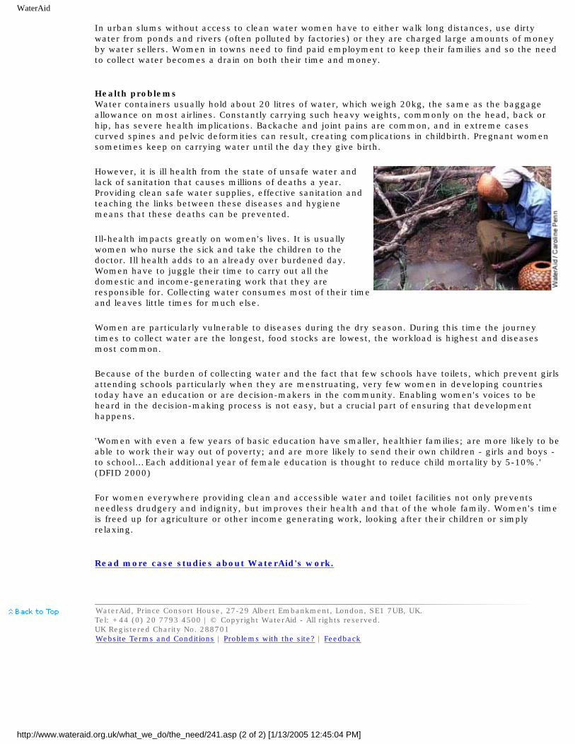
WaterAid
In urban slums without access to clean water women have to either walk long distances, use dirty water from ponds and rivers (often polluted by factories) or they are charged large amounts of money by water sellers. Women in towns need to find paid employment to keep their families and so the need to collect water becomes a drain on both their time and money.
Health problemsWater containers usually hold about 20 litres of water, which weigh 20kg, the same as the baggage allowance on most airlines. Constantly carrying such heavy weights, commonly on the head, back or hip, has severe health implications. Backache and joint pains are common, and in extreme cases curved spines and pelvic deformities can result, creating complications in childbirth. Pregnant women sometimes keep on carrying water until the day they give birth.
However, it is ill health from the state of unsafe water and lack of sanitation that causes millions of deaths a year. Providing clean safe water supplies, effective sanitation and teaching the links between these diseases and hygiene means that these deaths can be prevented.
Ill-health impacts greatly on women's lives. It is usually women who nurse the sick and take the children to the doctor. Ill health adds to an already over burdened day. Women have to juggle their time to carry out all the domestic and income-generating work that they are responsible for. Collecting water consumes most of their time and leaves little times for much else.
Women are particularly vulnerable to diseases during the dry season. During this time the journey times to collect water are the longest, food stocks are lowest, the workload is highest and diseases most common.
Because of the burden of collecting water and the fact that few schools have toilets, which prevent girls attending schools particularly when they are menstruating, very few women in developing countries today have an education or are decision-makers in the community. Enabling women's voices to be heard in the decision-making process is not easy, but a crucial part of ensuring that development happens.
'Women with even a few years of basic education have smaller, healthier families; are more likely to be able to work their way out of poverty; and are more likely to send their own children - girls and boys - to school… Each additional year of female education is thought to reduce child mortality by 5-10%.' (DFID 2000)
For women everywhere providing clean and accessible water and toilet facilities not only prevents needless drudgery and indignity, but improves their health and that of the whole family. Women's time is freed up for agriculture or other income generating work, looking after their children or simply relaxing.
Read more case studies about WaterAid's work.
WaterAid, Prince Consort House, 27-29 Albert Embankment, London, SE1 7UB, UK.Tel: +44 (0) 20 7793 4500 | © Copyright WaterAid - All rights reserved.UK Registered Charity No. 288701Website Terms and Conditions | Problems with the site? | Feedback
http://www.wateraid.org.uk/what_we_do/the_need/241.asp (2 of 2) [1/13/2005 12:45:04 PM]

Lifewater Canada: Drinking water well drilling & handpump training manual
Home
Problem
About Us
Wells & Washrooms
On-Line Resources
How to Help
Contact Us
Links
Site Updates
Site Map
Search
Handpumps Resources
Keeping Development Workers informed of current handpumps, drilling and water development techniques
Click HERE if there is no button bar on the left side of your screen!
Resource Materials
● On-Line Training Manuals© and Technical Links ● Overseas Travel Information ● Links to Water Organizations ● Lifewater International: Many water projects and resources! ●
Lifewater Handpumps & drilling resources:
(Click Here for notes on using these Documents)
● Drilling & Handpump Construction (Test Yourself On-Line!!) ● Water Well Record (Blank) ● Community Water Supply Agreement (Example) ● Making Water Safe to Drink (Technical Bulletin) ● Make an Electric Water Level Meter! (Technical Bulletin) ● Assess Natural Clay for Use As Drill Mud (Technical Bulletin) ● Methods for Grouting Casing (Technical Bulletin) ● Bush Pump (Technical Bulletin)
http://www.lifewater.ca/ndexman.htm (1 of 8) [1/13/2005 12:45:13 PM]

Lifewater Canada: Drinking water well drilling & handpump training manual
● Water for the World (US AID technical notes now on-line!) ●
● Overseas Travel Information (Travel Tips and Links for
Development Workers)
Handpumps and drinking water supply links
● Positive displacement handpumps ❍ Afridev hand pumps ❍ Afri-pump ❍ Bush hand pumps ❍ Consallen handpumps ❍ India Mark II Pumps ❍ Kardia handpumps ❍ Rope Pumps ❍ Tara direct action pumps ❍ Unimade pumps ❍ Vergnet hand pumps ❍ Volanta handpumps
● Inertia lift handpumps ● Suction lift hand pumps ● Hydraulic ram pumps ● Solar pumps ● Other handpump links
● Drilling Water Wells ● Other water supply techniques
❍ Spring capping ❍ Digging wells ❍ Collecting rainwater ❍ Fog collection ❍ Water storage tanks
● Water quality testing/treatment ● Sanitation ● Health & Hygiene ● Water conservation
Hand Pumps:
"Handpumps continue to be the principal technology used to supply water to rural people in developing countries. This is because, in most cases, handpumps represent the most cost-effective option for supplying safe water to low-income small communities. Handpumps are environmentally friendly, relatively simple to operate, and manageable by the community itself." (Source: Rural Water Supply Network).
http://www.lifewater.ca/ndexman.htm (2 of 8) [1/13/2005 12:45:13 PM]

Lifewater Canada: Drinking water well drilling & handpump training manual
Positive Displacement Pumps (10-50 meters lift) (Back to Index)
● Bush Hand Pump (International) ● Afridev Hand Pump (International) ● Mark II Pump (International) ● Kardia Handpump (Germany) ● Vergnet Hand Pump (France) ● Volanta handpump (Netherlands) ● Consallen Handpump (United Kingdom) ● Heller-Aller Pumps (USA) ● Awassa Hand Pump (Canada) ● Tara Direct Action Handpumps (Back to Index)
❍ Overview (India) ❍ Performance Data (India) ❍ Construction Details (India) ❍ Tara Export Company (India) ❍ Another TARA Supplier (India)
● Unimade Pumps (Back to Index)
❍ Unimade pump (Malaysia)❍ Unimade pump - Design & Testing (Sri Lanka, Thailand,
Philippines, Malaysia)❍ PVC Handpump Project (Tailand)
Inertia Lift Pumps (3-10 meters lift) (Back to Index)
● Inertia-Lift Village pump (New Zealand)
Suction Lift Hand Pumps (1-3 meters lift) (Back to Index)
● Rower Pump (United Kingdom) ● Shallow Well Handpump (India) ● Pitcher pump (Canada) ● Pitcher pump (USA)
http://www.lifewater.ca/ndexman.htm (3 of 8) [1/13/2005 12:45:13 PM]

Lifewater Canada: Drinking water well drilling & handpump training manual
● Pitcher pump and Installation Kit (USA) ● Sigma handpumps (Fill overhead tanks 7-90 lpm - Canada) ● Guzzler handpump (12 ft lift/10-30 gpm: develop & test wells) ● Treadle Irrigation Pump (India) ● Treadle Pumps (Industrial Dev. Enterprises)
Hydraulic Ram Pumps (lift 1-20 % of inflow water) (Back to Index)
Solar Pumps (10-100 meters lift) (Back to Index)
● Solar Submersible pumps (Netherlands) ● Sun Ultra Light - many links! (Denmark)
Other Handpump Links (Back to Index)
● Handpump Overview (WaterAid - UK) ● Human Powered Lifters (ITDG) ● Handpump Technology Network (Switzerland) ● Handpump Standardization (WEDC - England) ● Are Hand Pumps Affordable? (WEDC - England) ● Internet Pump Glossary ● Why Handpumps Should be Fenced (WHO) ● Key Factors for Sustainable Cost Recovery for Community
Water Projects (IRC - 79 Page Manual) ● Connecting with the Community (IRC - Netherlands)
Drilling Water Wells:
● Overview Comparison of Simple Drilling Methods (WELL Resource Network, UK)
● LS-100 Portable Mud-Rotary Drilling Rig ● Eureka Port-a-Rig - Air and Mud Rotary (Malawi) ● Drilling Water Wells by Hand (Int'l Health Care Foundation) ● Hand Powered Percussion Drill (Liberia)
http://www.lifewater.ca/ndexman.htm (4 of 8) [1/13/2005 12:45:13 PM]

Lifewater Canada: Drinking water well drilling & handpump training manual
● Sludger Technique (Nepal) ● Well-Jetting Technique (Nigeria) ● Forager Drill ● Cable Tool Drilling
(Back to Index)
Other Water Supply Techniques:
● Spring Capping (Back to Index) ❍ Spring Protection (N. Carolina Coop Extension Service) ❍ Gravity Village Water Supply (Sierra Leone) ❍ Development and Protection of Remote Springs (Bhutan) ❍ Spring Protection (Uganda)
● Digging Wells (Back to Index) ❍ Hand Dug Wells - Overview (WaterAid - UK) ❍ Digging Wells: Modified Chicago Method ❍ Hand Dug Village Wells (Uganda)
● Collecting Rainwater (Back to Index) ❍ Roof Catchment - 89 Page Manual (Germany) ❍ Rainwater Harvesting Network (UK) ❍ Harvested Rainwater: Sustainable Sourcebook (Texas) ❍ Rainwater Harvesting (India) ❍ Rainwater Harvesting: Pros and Cons ❍ Computer Optimization of Rain Collection (Jordan)
● Fog Collection (Back to Index) ❍ Fog Water Collection System (IDRC) ❍ Fog Harvesting (Organization of American States) ❍ Fog Quest - Sustainable Solutions (Canada) ❍ Chile: The 350 residents of the mountainous village of
Chungungo used an old tanker truck to haul drinking water from a town 50km away. A simple system of 75 fog-water collectors now supplies the village with 11,000 litres/day of clean drinking water:
http://www.lifewater.ca/ndexman.htm (5 of 8) [1/13/2005 12:45:13 PM]

Lifewater Canada: Drinking water well drilling & handpump training manual
■ Collecting Mists (Compass Magazine) ■ Clouds on Tap (IDRC) ■ Tapping Into Fog (IDRC) ■ Fog-Catching Nets for Fresh Water (IDRC) ■ Water Innovations: Chile's Camanchaca (UNEP) ■ Global Heroes Adventure Quiz (Excellent for Kids!)
❍ Ecuador: Pachamama Grande is a village of 100 isolated on a small plateau 12,000 feet up in the Andes Mountains. Canadian scientists solved their long-standing drinking water problem by designing a set of fog-catching sails that convert evening mountain mist into abundant supplies of safe drinking water. See Fog Catcher Photos.
● Water Storage Tanks (Back to Index) ❍ Reinforced Blockwork Water Storage Tanks (Tanzania) ❍ Emergency Water Supply in Cold Regions (WELL - UK)
Water Quality Testing and Treatment:
● Water Quality Testing ● Slow gravity sand filters (Center for Alternative Technology) ● Activated Carbon from Moringa Husks and Pods ● Iron Removal Technology ● Iron and Manganese Removal Network ● Solar Disinfection Network ● Solar Disinfection with Pop Bottles (SANDEC - Switzerland) ● Solar Roof Top Disinfection (GTZ - Germany) ● Defluoridation: Nalgonda Technique ● International Desalination Association (Bermuda) ● Water Treatment with Moringa oleifera (Germany)
(Back to Index)
Sanitation:
http://www.lifewater.ca/ndexman.htm (6 of 8) [1/13/2005 12:45:13 PM]

Lifewater Canada: Drinking water well drilling & handpump training manual
● Water & Sanitation Related Diseases Fact Sheets (WHO) ● WaterLines: Special Sanitation Issue ● Blair Ventilated Pit Latrine Design (Zimbabwe) ● Sketches of Basic, low-cost latrine designs ● Basic Sanitation - Latrines (GTZ - Germany) ● School Sanitation & Hygiene Education (IRC - Netherlands) ● Pit Latrines Network ● Hygiene Behaviour Studies ● Hygiene Behaviour Network ● Affordable Sanitation for Low-income Communities
Health & Hygiene:
● Sanitation & Health (World Health Organization) ● Hygiene Education (WaterAid - UK) ● Health & Hygiene Promotion (World Water Day) ● Key Objectives for Hygiene Promotion Programmes (IRC)
Water Conservation:
● Trickle Irrigation (Dept. Rural Engineering) ● Drip Irrigation Kits Available! (ECHO) ● International Water Management Institute (Sri Lanka)
(Back to Index)
Notes on Using Lifewater's Technical Documents
1. We encourage you to print and disseminate copies of documents listed above. Please note that Lifewater's documents are copyrighted and we remind you to cite the source and
http://www.lifewater.ca/ndexman.htm (7 of 8) [1/13/2005 12:45:13 PM]

Lifewater Canada: Drinking water well drilling & handpump training manual
organization when using specific documents.
2. We suggest that you link to this page (http://www.lifewater.ca/ndexman.htm) and check back prior to using a specific document since many of them are "living documents" that are updated and revised on an on-going basis!
3. Finally, We request that Academic institutions making use of Lifewater's technical documents kindly consider making a donation to help cover the cost of their development and continuous improvement.
(Back to Index)
http://www.lifewater.ca/ndexman.htm (8 of 8) [1/13/2005 12:45:13 PM]

Lifewater Canada: Overseas Travel Packing Tips (BEFORE you go!)
Overseas Travel Links"An ounce of prevention is better
than a pound of cure" (ancient sage)
When traveling overseas to construct wells, the 5 greatest health & safety risks are:
1. Heat Stroke;2. Gastro-Intestinal Illness;3. Traffic Accident and/or Transfusion with Tainted Blood;4. Injury on the Job and/or Transfusion with Tainted Blood (not working safely!5. Mugged (in cities) or Attacked (in remote areas);
To be safe when driving overseas in urban areas:
● Always keep your doors locked and window rolled up. If you want to hear what is going on around you, crack your window, but just enough to hear; Turn down the volume on the radio.
● Keep your head on a swivel, always paying attention to people walking around your vehicle when it is stopped. Check your rearview mirrors frequently. Street kids and vendors have been seen testing door handles and trunk to see if they were unlocked.
● Maintain a reactionary gap between your vehicle and the vehicle in front in front of you. A good standard to follow is to maintain just enough distance between your vehicle and the next so that you can just see the rear tires of the front vehicle touching the road. This gap is not too much space to allow anther vehicle to cut off yours, but it is enough to give you an escape route.
● Try to think ahead and position your vehicle in a lane that will allow you another escape route. If someone tries to open your door, accelerate and get out of the area.
What To Take:
http://www.lifewater.ca/travel.htm (1 of 3) [1/13/2005 12:45:14 PM]

Lifewater Canada: Overseas Travel Packing Tips (BEFORE you go!)
● Lifewater Packing List ● Packing Tips from Others ● The Universal Packing List ● Whatever you take, keep in mind that weight is very important. It
is our experience most airlines allow two pieces of luggage (50 pounds maximum each) to be checked free of charge. Bags exceeding 50 pounds but less than 70 pounds will be assessed an excess-baggage fee of arund $25 per bag. Bags between 70 and 100 pounds will be charged about $80 per bag.
Health (First Aid and Water Treatment):
● Water & Sanitation Related Diseases Fact Sheets (WHO) ● International Travelers Clinic● Worldwide Directory of English Speaking Doctors● Preventing Traveler's Diarrhea● Travel and Health Advice (WHO)● Tropical Diseases Information (WHO)● TealBrook Water Filters (PentaPure)● AAA Recommended Water Treatment and First Aid Kits
Other Travel Stuff:
● Air Travel Consolidators● Find Your Airlines Website● Healthy Flying Tips● Air Travel Tips● Travel Tips● Currency Converter● CNN World Weather
http://www.lifewater.ca/travel.htm (2 of 3) [1/13/2005 12:45:14 PM]

Lifewater Canada: Overseas Travel Packing Tips (BEFORE you go!)
● US State Dept. Travel Warnings (By Country)● Swahili Pronunciation Guide (a MUST for Kenya travelers!)● Clickable Time and Holiday Map● Travel Document Expedited (Washington, DC)● Washington Passport and Visa Service (Washington, DC)
http://www.lifewater.ca/travel.htm (3 of 3) [1/13/2005 12:45:14 PM]

Lifewater Home Page
Lifewater International
Christians helping the rural poor
obtain safe water
"A child dies every 15 seconds from diarrhoea, caused largely by poor sanitation and water supply. "
You can do something about it!
Click here for info on Lifewater's response to the Asian Tsunami Disaster
Please go to our "Gifts" page to donate online. Thank you!
Find out about Lifewater and what you can do
Get HELP for your water
problems Get training for rural water supply development
Receive the Lifewater Newsletter
Give a gift of water and give life!
Read Water for the World
Tech Notes for more help
Visit the Lifewater Canada web site
Enter the Volunteers' Corner (Username and password
required)
Follow links to water-related web sites and books
Search the Lifewater site for: Search powered by WebGlimpse Copyright © 1996, University of Arizona
Call toll free 888-543-3426 or Email [email protected]
For staff phone numbers and email adddresses, please see our Contact Us page.
Last modified 01/05/05
http://www.lifewater.org/ [1/13/2005 12:45:15 PM]

Lifewater Drilling & Well Construction Manual: Test Your Water Development Knowledge!
Well & Handpump Construction Test
1. Preparing For Your Overseas Trip2. Mud Rotary Drilling Overview3. Drilling with the LS-100 Mud Rotary Drill Rig4. Well Completion5. Cement Pad Construction6. Overview of Handpump Basics7. Bush Handpump
Preparing For Your Trip
1. What are 9 key things to take overseas? (Answer)2. In addition to items listed above, what 6 things would you take if
you were a trainer for a new project start-up? (Answer)3. What 5 qualities should affect who you choose to train? (Answer)4. How do you decide which trainees should be hired? (Answer)5. What 5 factors contribute to "per well" cost estimates? (Answer)6. How can overseas crews reduce reliance on foreign aid?
(Answer)7. When overseas, how do you make your drinking water safe if you
have no water treatment unit/device? (Answer)8. What are the 7 most important points which should be included in
a "community agreement" prior to drilling a well? (Answer)9. What are the 5 greatest health/safety risks when you travel
overseas and drill wells? (Answer)
http://www.lifewater.ca/Section_Test.htm (1 of 5) [1/13/2005 12:45:16 PM]

Lifewater Drilling & Well Construction Manual: Test Your Water Development Knowledge!
M ud Rotary Drilling Well Construction Overview
1. What 3 well drilling supplies are hard to get overseas? (Answer)2. What are 7 factors to consider in siting a new welll? (Answer)3. What is a drill log? (Answer)4. What must be done after using polymer to drill a well? (Answer)5. How can you minimize drilling fluid loss from mud pits?
(Answer)6. What 7 functions does drilling mud serve? (Answer)7. How is a marsh funnel used to check mud viscosity? (Answer)8. What is a Roller Bit and when do you use it? (Answer)9. What is a Drag Bit and when do you use it? (Answer)
10. How do you use a 4 in vs a 6 in drilling bit? (Answer)11. What determines the penetration rate of the drill bit? (Answer)12. What 6 signs show an aquifer has been reached? (Answer)13. What is happening if drilling fluid comes up through the drill pipe
when you disconnect the swivel? (Answer)14. What are the 5 most common problems leading to unsuccessful
well completion? (Answer)
D rilling with the LS-100 Drill Rig
1. What is the most valuable benefit of the 3-way valve? (Answer)2. What is the purpose for the swivel assembly? (Answer)3. What is the purpose of the pipe slips? (Answer)4. What part on the LS-100 uses grease? (Answer)5. What parts on the LS-100 use oil? (Answer) 6. Why does the winch come equipped with a hand brake? (Answer)7. What borehole depth & diameter can the LS-100 drill? (Answer)8. What should you know before operating a LS-100? (Answer)
http://www.lifewater.ca/Section_Test.htm (2 of 5) [1/13/2005 12:45:16 PM]

Lifewater Drilling & Well Construction Manual: Test Your Water Development Knowledge!
9. What should you arrange in advance in order to maximize drilling efficiency? (Answer)
10. What should you check before leaving for a drill site? (Answer)11. What should you do before starting the engines on either the
rotary or mud pumps? (Answer)12. What should you do if you encounter a hard formation? (Answer)
Borehole Completion
1. How do you know where to set the screen? (Answer)2. What is the purpose for gravel packing? (Answer)3. What is the most effective way to place a gravel pack? (Answer)4. What is does "developing a well" mean and what are 3 reasons for
doing it prior to pump installation? (Answer)5. What is the main purpose of sealing the well annulus with cement
grout and how do you do it? (Answer)6. What cement/sand ratio should be used for grout? (Answer)7. How do you disinfect a newly constructed well? (Answer)
Cement Pad Construction
1. In designing a cement pad, you should keep in mind its two (2) main functions... What are they? (Answer)
2. Is it better to build a wooden form or to use cement blocks to shape the outer edge of the pad? (Answer)
3. What optional features may be included in pad designs? (Answer)4. What dimensions (width, length, height) and shape should a
cement pad be? (Answer)5. What is the most important thing to check when examining gravel
for use in making a pad? (Answer)6. What cement/sand/gravel ratio should be used to mix concrete for
http://www.lifewater.ca/Section_Test.htm (3 of 5) [1/13/2005 12:45:16 PM]

Lifewater Drilling & Well Construction Manual: Test Your Water Development Knowledge!
a pump pad? (Answer)7. How much concrete would you need to make a 2m x 2m x 10cm
thick pad (# bags)? (Answer)8. How long should pads cure before installing a cylinder? (Answer)9. How do you help concrete cure completely? (Answer)
10. Should concrete be mixed slightly wet or slightly dry? (Answer)
Handpump Overview
1. What should you inspect on wells & handpumps? (Answer)2. What is the most common problem resulting in handpumps not
working anymore? (Answer)3. If a pump is not producing water, what 3 things should you check
before you attempt pump repair? (Answer)4. What is the difference between a "working barrel" and a "down
hole cylinder"? (Answer)5. If you have to pump very fast for a long time before water comes
out the spout, what is the most likely problem? (Answer)6. If you have to pump very hard to make water come out the spout,
but it comes as soon as you pump, what is the problem? (Answer)7. If the pump handle is very hard to push down and it "snaps" back
up without producing water, what is the problem? (Answer)8. If a pump's handle is very easy to move up & down and no water
comes out, what is the problem? (Answer)9. If you pump and it feels okay, but little or no water comes out the
spout, what is the most likely problem? (Answer)10. If a pump produces water for a little while before sputtering dry,
and the works again an hour later, what can you do? (Answer)11. Why are centralizers for the pump rod and casing important and
how can you make them? (Answer)12. What is the key thing to do after fixing a pump? (Answer)
http://www.lifewater.ca/Section_Test.htm (4 of 5) [1/13/2005 12:45:16 PM]
Lifewater Drilling & Well Construction Manual: Test Your Water Development Knowledge!
13. What is the last thing you should do before you start drinking water from a new well? (Answer)
Bush Handpump
1. What is the most difficult and the most expensive parts to get for a Bush handpump? (Answer)
2. What are 4 advantages of using a Bush handpump? (Answer)3. What are the 2 main factors that you should consider when
deciding whether or not to use a Bush handpump in a particular community? (Answer)
4. What is the hardest task when installing a Bush pump? (Answer)5. When could you just put a handle on the sucker (pump) rod and
not build a complete Bush handpump? (Answer)6. How far above ground should the well casing be cut?(Answer)7. What tools do you need to install a Bush handpump? (Answer)8. How can you install a Bush pump on a dug well? (Answer)9. What do you do when the cup leathers are worn-out? (Answer)
10. How do you adjust the Bush handpump so that the piston (plunger) does not strike the top or bottom of the cylinder when the handpump is pumped? (Answer)
http://www.lifewater.ca/Section_Test.htm (5 of 5) [1/13/2005 12:45:16 PM]

Appendix F: Lifewater Canada Well Record
Appendix F
Lifewater Canada Well Record
Well Location
Country: Location Sketch
N^
Scale:
Province/State:
Easting:
Northing:
Site Description:
Distance to nearest pollution sources (ft) - describe:
Depth (m)
Soil Type (Describe)
Thickness (m)
Drilling Notes (Drilling Speed, bit vibration, water
temperature etc)
Depth at which water encountered:
Depth to Water Table:
http://www.lifewater.ca/Appendix_F.htm (1 of 4) [1/13/2005 12:45:17 PM]

Appendix F: Lifewater Canada Well Record
Depth of Borehole:
Borehole Yield
Yield: Duration of Test (minutes):
Describe how yield measured:
Well Screen & Casing
Material (PVC, Other): Casing/screen diameter:
Thickness (Schedule 40 or 80): Length of screen sump:
Number of slot columns: Vertical spacing between slots:
Length of slots: Screen Length:
Installed length of casing: Total length of screen/casing:
Describe screen centralizers (number, where/how attached):
Describe drive shoe (shape, material, size etc):
Well Completion
Gravel pack material diameter (inches): Gravel pack volume:
Type of stabilizer material: Stabilizer material volume:
Grout mix (sand:cement ratio): Grout volume:
Pad concrete mix (sand:gravel:cement): Thickness of cement pad:
Size of cement pad: Well protected by fencing (Y/N):
Distance from ground to pump cylinder: Cylinder diameter:
Well Development
Technique Used: Development Time (hours):
Describe process (turbidity in discharge water over time and depth):
Chlorination
http://www.lifewater.ca/Appendix_F.htm (2 of 4) [1/13/2005 12:45:17 PM]

Appendix F: Lifewater Canada Well Record
Type of chlorine used: Volume of chlorine used:
Length of disinfection period: Chlorine odour in discharge water (Y/N):
Describe how chlorine was mixed with well water:
Water Quality
Colour: Turbidity:
Odour: Taste:
Bacteria test type: Bacteria Test Results:
Other tests or characteristics (pH, Total Dissolved Solids, nitrate, staining etc):
Completed Well Performance
Piston clearing cylinder top&bottom (Y/N): Waste water drainage:
Sustainable pumping rate (Gal/min): Pump stable:
Other (cylinder secured with safety rope? etc):
Date Drilling Started:
Date Work Completed:
Number of Workers:
Construction Foreman's Name (Print):
Foreman's Signature:
Action Agency/Lifewater Inspector Confirmation
Name (Print):
Signature:
Inspection Date:
http://www.lifewater.ca/Appendix_F.htm (3 of 4) [1/13/2005 12:45:17 PM]

Appendix F: Lifewater Canada Well Record
Well Record Copies:1) Lifewater Canada2) Local Drill Team3) Local Government
PHOTOGRAPHS: (Well Overview Required. Pump close-up, Surroundings, People Desirable)
Choose Another Well Construction Module:
http://www.lifewater.ca/Appendix_F.htm (4 of 4) [1/13/2005 12:45:17 PM]
Appendix R: Community Water Supply Agreement
Appendix R
Village Well Agreement
Prior to work beginning in a new village, community leaders must sign
a water supply agreement which specifies community involvement including:
1. an agreed upon financial contribution towards project cost.
2. In poor communities which have little money, some goods and services can be contributed instead (coconuts, dry fish, palm butter, mangoes, charcoal etc). However, we have learned that some cash payment (even $50 or $100) must still be required. Money can usually be raised for funerals for people who died from drinking contaminated water. Raising and giving cash money for a safe drinking water supply is an important sign of committment. For villagers to carry produce to market, sell it, and then hand over the money is a critical step towards communities taking ownership of their new water supply. Handpumps are rarely broken in communities which have payed money towards the project. They helped buy it, they help care for it. Conversely, hand pumps are frequently not working for extended periods of time in villages which did not contribute cash money... as the villagers grow frustrated with Lifewater for not coming to "fix our handpump that we planted in their community";
3. continuous night time security for all equipment and supplies. If items are stolen, the project will be terminated;
4. continuous supplies of clean water for drilling fluid. Hours and quantities which must be carried to the drill site are specified since disruptions to the supply of water can lead to serious drilling problems;
http://www.lifewater.ca/Appendix_R.htm (1 of 2) [1/13/2005 12:45:17 PM]

Appendix R: Community Water Supply Agreement
5. Details on donor thank-you letters to be written by village leaders;
6. free and open access to the water by all people, regardless of race, religion, sex, political persuasion or status within the local community. The agreement should stress that the community and not any single influential person in the village owns the well;
7. two people to be trained in routine pump maintenance. Since women have a major responsibility for water-related activities in most developing countries, their involvement in the repair team should be of primary concern;
8. $20/year to cover the cost of annual maintenance parts and labour.
In addition, the following items are often included:
● quantities of materials which must be collected and brought to the site ahead of time. While the community's ability to pay must be considered, keep in mind that each well requires key tools and supplies which must be acquired prior to workers leaving for the selected drill site (see Table 3 - Section 3.3)
● 4 labourers to work under the direction of the Lifewater team;
● accommodation and meals for the Lifewater team during the period of well construction (usually 2-6 days);
Choose Another Well Construction Module:
http://www.lifewater.ca/Appendix_R.htm (2 of 2) [1/13/2005 12:45:17 PM]

Appendix T: Making safe drinking water!
Appendix T
Making Safe Drinking Water
The first choice is to bring water treatment devices with you whenever you travel to a developing country. However, if you have forgotten to bring one, consider the following options to make safe drinking water:
Boiling: Vigorously boil water for 5 minutes. The flat taste of boiled water can be improved by pouring it back and forth from one CLEAN container to another. Also, a small pinch of salt can be added to each quart of water boiled;
Chlorination: Add 5-10 drops chlorine bleach per quart of clear water, thoroughly mixing it and allowed to stand for at least 30 minutes. The treated water should have a slight chlorine odour; if it doesn't, the dosage should be repeated and the water should stand for 15 minutes more. If this treated water has too strong a chlorine taste, it can be made more drinkable by allowing the water to stand exposed to the air (should be a light cover over the top to prevent insects, etc. from falling into the water). Pouring it back and forth between two CLEAN containers will also help.
As a last resort, if the above options are not available, consider the following:
UV Exposure: Make safe drinking water by putting clear water in a clean container and expose it to bright, hot sun for at least 8 hours;
pH Adjustment: Add lime to bring the pH above 10 for several hours. Expose the water to atmosphere for several hours to allow natural CO2
reactions to bring the pH back down to at least 8.5 prior to drinking. Please note that this should only be used as a last resort since the validity of this method to make safe drinking water has not been scientifically investigated.
http://www.lifewater.ca/Appendix_T.htm (1 of 2) [1/13/2005 12:45:18 PM]

Appendix T: Making safe drinking water!
Choose Another Well Construction Module:
http://www.lifewater.ca/Appendix_T.htm (2 of 2) [1/13/2005 12:45:18 PM]

Well Water Level and TDS Sensor
Lifewater Canada
In association with
Build Your Own Water Level and TDS Sensor
One of the challenges in drilling wells is finding the depth of the water, the water recovery rate and the quality of the water. Normally, two measuring devices are used. One, an Electric Water Level Tape, and the other, a TDS or Total Dissolved Solids Meter are used. Both are very expensive instruments which use fragile electric meter movements to detect electric current. The challenge facing those drilling wells in third world countries is to have something that does the same thing in an inexpensive rugged instrument.
One option is to build an astable multivibrator using a TLC555 timer. This timer is ideal because of its extremely low power consumption. The circuit can be built right into an older style telephone handset with all components (probe excepted) included in
the handset . The circuit works by sensing the resistance of the probe. If the probe is open (not touching water) the circuit will produce an audio frequency around 400 hz. When the probe touches quality water, the frequency doubles (approximately) increasing the tone by about one octave. If the water has dissolved solids in solution, the tone will quickly go higher giving the person measuring an approximation of the mineral quality of the water. A fairly high note, nearing a squeal would indicate the detection of brine or extremely high levels of hardness etc. If, for some reason the probe shorts, the circuit will produce a very high pitched whistle that will not change when the probe comes in contact with water. Though this circuit does give a approximate estimate of the hardness of water, it will not give a good estimate of the SAFETY of the water. For a further explanation of its limitations, please go to Frequently Asked Questions
(If you go to a picture, or diagram via a link or camera, just hit your Back Button to return to the place you came from.)
The circuit once attached will fit nicely under the speaker with the speaker unit in place. A miniature momentary push button switch
should be used between the 9V Alkaline battery and the circuit . This ensures that the unit cannot accidentally be left in the on position. The switch is best mounted near the ear speaker where it can be easily depressed by the thumb or index finger. The battery can then be installed where the microphone and microphone socket were installed.
The probe wires can exit out of the original curly cord inlet. Once the wires are installed, this hole should be sealed with silicone (Do NOT use Mono as a sealant since it has electrical properties that enable the flow of current which messes up the reliability of the circuit.) The probe wire can be from 50' - 500'. In our first model, we used standard 24 gauge speaker wire because of its flexibility, size and price. 100' of probe speaker wire can nicely be wrapped around a piece of wood siliconed to the back of the handset for easy
storage and portability . A round non porous rock, approximately 1" in diameter works well as a weight for the probe . Using a little silicone and an elastic band will attach the wire to the rock. Make sure that you do not cover the tinned wire ends with silicone.
http://www.pbv.thunder-bay.on.ca/WellSensor.html (1 of 12) [1/13/2005 12:45:27 PM]

Well Water Level and TDS Sensor
Parts List
Quantity Description
1 Northern Electric Style G3 Telephone Handset with ear and mouth covers
1 HHMR-80V(U-1) Receiver Unit, Diode must be Removed (clip it off if necessary) Other possible part numbers (1182, ?)
2 1/4" Long Connecting Screws for the above Receiver. These will be used to mount and connect the circuit board to the receiver unit. If you have an older reciever unit, 1/4" screws will already be on the reciever. If however you have a newer unit, 1/4" screws will have to be obtained since the included 1/8" screws are not long enough.
4 #12 lock washers to improve the connection between the receiver and prevent shorts on the foil side of the circuit board.
1 Momentary On Push Button Switch (i.e.. push to talk switch, the smaller the better) The quality of this switch is essential since it is the one moving part in the entire unit.
1 100' (or more) 24 gauge multi-stranded or braided speaker wire (flexibility, size and durability are essential considerations)
1 Water Sensor Printed Circuit Board (make it if you have the resources, skills and equipment, or order it directly from us. Mask information is included below if you choose to make your own circuit board)
1 TLC 555 Timer
1 10K Ohm Resistor (brown-black-orange) 1/4 or 1/8th watt
1 1K Ohm Resistor (brown-black-red) 1/4 watt
1 2.2K Ohm Resistor (red-red-red) 1/4 or 1/8th watt
2 .1uF capacitor
1 1 foot black stranded internal connecting wire
1 1 foot red stranded internal connecting wire
1 9V Battery Connector
1 9V Alkaline Battery
Tub and Tile Silicone Sealant
1 Wooden Wire holder shaped as pictured below made to fit the back side of the telephone hand set.
3 General Purpose Elastic Bands
1 Round Rock 1"
Step by Step Building Instructions
1. Printed Circuit Board Preparations
http://www.pbv.thunder-bay.on.ca/WellSensor.html (2 of 12) [1/13/2005 12:45:27 PM]

Well Water Level and TDS Sensor
A. Obtain the "Well Sensor Printed Circuit Board" and proceed to install the parts as shown in the graphic immediately below.
This view has the copper foil on the bottom side. All parts should be installed right on the circuit board without extra lead length. This encourages ruggedness.
1. Install the 1K Ohm Resistor (black-brown-red) tight against the circuit board in position R1. 2. Install the 2.2K Ohm Resistor (red-red-red) tight against the circuit board in position R2. 3. Install the 10K Ohm Resister (black-brown-orange) tight against the circuit board in position R3. 4. Install the TLC555 timer snugly on the top of the circuit board. Make sure that Pin #1 is situated as marked below! Pin #1
is usually marked by a dimple on the printed circuit that cannot be worn off (like print). Make sure that all 8 pins are protruding through the circuit board! Bend two pins at opposite corners of the TLC555 to hold it in position until you solder it.
5. Install an insulated jumper wire as shown. 6. Install two .1uF Capacitor at C1 and CAdj
B. Turn the printed circuit board over, carefully place it in a small vice to keep it secure and solder the components onto the
board. Because of the size of this circuit, it is recommended that a person with electronics experience do this task. Overheating can damage the circuit board or its components. Under heating can cause the solder to bead and make a poor connection. Quality soldering equipment makes a world of difference! A site that shows and teaches you how to solder is http://www.epemag.wimborne.co.uk/solderpix.htm Once the parts have been properly soldered in position, clip off any excess lead length, as close to the circuit board as possible without clipping the actual soldering itself. Clipping the soldering can break the solder bond between the lead and the foil. Leaving the leads too long will cause the unit to short once it is mounted on the back of the receiver.
http://www.pbv.thunder-bay.on.ca/WellSensor.html (3 of 12) [1/13/2005 12:45:27 PM]

Well Water Level and TDS Sensor
R1 = 1000 Ohms C1 = .1uF
R2 = 2200 Ohms C2 = ~.1uF
R3 = 10K Ohms
Your Circuit board should look like this once the parts have been soldered in place.
2. Handset Preparations
1. Remove microphone, microphone socket, curly cord and wires from the G3 Telephone Handset. Retain the receiver (speaker) as it will be used in the set. If you have not already done so, REMOVE THE DIODE FROM THE BACK
TERMINALS OF THE RECEIVER (SPEAKER).
2. Drill a 5/16" hole in the neck of the handset near the ear piece as shown below. 3. Take the Miniature Momentary On Push Button Switch and connect a 3" stranded RED wire to one terminal and a 9"
stranded RED wire to the other terminal. Make sure that these connections are properly soldered. 4. Place the 3" wire through the Vdd terminal on the circuit board from the top side. Solder the wire in place. 5. Connect a 12" BLACK stranded wire to the GROUND terminal of the Well Sensor Circuit Board, soldering it in place. 6. Take the Telephone handset and insert the probe wire into the original curly cord hole near the mouth piece. Slide the wire
through the handset to the Receiver compartment. Run a little extra through so that you will be able to attach it to the circuit board with ease.
7. Strip 1/4" off of the end of each of the probe wires, twist and tin them. Insert them in the above probe connection locations, solder in place, clip off ANY excess wire on the foil side of the circuit board.
3. Attach the circuit board to the receiver.
1. Insert the two #12 X 1/4" screws through the circuit board from the component side. (They should fit through the holes snugly).
2. On the foil side of the circuit board, with the screws protruding, place 2 lock washers on each screw. These lock washers will ensure a connection to the receiver and offset the circuit board so that the soldered copper foils will not short on the
back side or metal portions of the receiver.
3. Mount the circuit board on the receiver. . Tighten the screws so that they are just snug and the lock washers have been compressed. This will ensure a continuous and secure connection.
4. Putting the Handset Together
http://www.pbv.thunder-bay.on.ca/WellSensor.html (4 of 12) [1/13/2005 12:45:27 PM]

Well Water Level and TDS Sensor
1. Mount the Push Button Switch in the 5/16" hole making sure that the RED 9" stranded wire proceeds through the handset to the battery compartment (mouth area) of the unit.
2. String the BLACK 12" stranded wire through the handset so that it also protrudes from the battery compartment. 3. Attach the 9 Volt Battery connector - Red wire to red wire, Black wire to black wire. Solder the connections and cover
them with a dollop of silicone. Let the silicone dry. 4. Attach the battery taking note to make sure you are attaching it with correct polarity. This circuit is not protected against
those who try to put on batteries backwards while pushing the power button! 5. Once the battery is installed, push the power button. You should hear a frequency that would compare to a middle "C" on a
piano. If you hear this sound - Congratulations - you have passed test #1. 6. Double check your connections. 7. Carefully insert the 9 Volt battery in the mouth side of the Telephone handset aiming the end of the battery down the throat
of the handset. It should "just fit!" If it is a little tight, you might choose to scrape a little out of the opening edges of the throat of the handset with a sharpe knife. DO NOT CUT THE WIRES BY ACCIDENT! Newer handsets should easily have enough room. Once the battery is in place, screw on the microphone/battery cover.
8. Carefully guide any excess wire into the ear section of the Telephone handset as you insert the Receiver with the circuit board mounted on its back side. The receiver should fit flush with the edge of the handset opening. If you find it does not want to fit, take it out again. You may be pinching a wire if you force it into place. If it fits properly, place the ear cover over the receiver. Once again, push the power button, you should hear the same frequency. If you hear the same sound -
Congratulations - you have passed test #2.
5. Preparing the probe.
1. At the end of your probe wire (100' or more), strip off 1/2" and tin the wires with solder. This will give the copper some protection from corrosion (salt water corrodes almost everything).
2. Take a permanent marker (Sharpie Permanent Markers work very well for this.) Starting from the tinned end of the probe, mark with a black marker at 1' increments the entire length of wire. Once this is done, go back to the tinned end, and then with a red maker, add a blue line at every ten foot increment, with an extra line or each additional 10' increment. In between, at 5', 15', 25' 35' 45' 55' etc... place a line with red marker to indicate the 5s on the wire. This will help to measure the depth of the sensed water.
http://www.pbv.thunder-bay.on.ca/WellSensor.html (5 of 12) [1/13/2005 12:45:27 PM]

Well Water Level and TDS Sensor
The probe can be weighted with a 1 inch marble or even a simple non porous rock, tied between the leads with an elastic band or siliconed between the leads. If you happen to loose the rock, replacements should not be hard to come by!
6. Preparing the Probe Storage Block
Put your well water sensor to the side. Find a piece of wood approximately 1" wide. If you use lighter wood, it is easier to cut and shipping costs less! Cut it to the shape shown below. You may want to use the template provided below. Print it out, it should print out to the right dimensions. Once you have cut it out, sanded and or finished it to your pleasure, silicon it to the back of the
handset. Let the silicone cure. Once the storage block is secure, carefully wrap the well water probe wire around it. Want to Print out the block we made to scale - Click here to Go to WoodBlock Diagram
7. Test your Well Water Sensor
1. Pressing the power button should produce approximately a "middle C." 2. While pressing the power button, dip the probe in pure water, the tone should go up about 1 octave. 3. Start adding a little salt to your sample of water and stir the water slightly. Notice how quickly the unit detects salt in
solution.
8. Calibrate Your Probe
http://www.pbv.thunder-bay.on.ca/WellSensor.html (6 of 12) [1/13/2005 12:45:27 PM]

Well Water Level and TDS Sensor
The advantage of using musical tones for the purpose sensing water and water quality is that musical tones are understood throughout the world. This Well Water and TDS sensor can be relatively calibrated very simply. The procedure for calibration is follows:
1. Find a pure sample of water. This need not be distilled H2O, it should be, however water that would be regarded as high
quality by Hydrology standards. 2. Make sure you have your rock or other non - metallic weight permanently attached to your probe wires. 3. Depress the activator button and slowly dip your probe into quality water. The tone should progressively go up about 1
octave. If it does not quite go up an octave, you either are using extremely low TDS water, or your exposed probe length is not long enough. Feel free to strip a little more insulation off of the probe wires and re-tin the exposed strands. Go back to step #2.
4. If you the tone goes up more than an octave, you can trim the length of the exposed probe lead with a scissors in small increments. Repeat this procedure until you have achieved a tonal change of one octave.
5. Now for the sake of coming to know how to measure TDS, add a measured amount of salt to the water, record the number of notes, in excess of 1 octave that the tone increases.
The Well Water Sensor Circuit Board
This circuit board is designed to be mounted directly to the back of a standard telephone speaker (with the original diode removed). The exact distance from center to center of the mounting holes should be 15/16". Accurately scaled 1-1 and 2-1 positive and negative foil photo masks are linked below. When mounted on the back of the speaker, the foil side of the circuit board should be toward the speaker for purposes of contact with the speaker contacts. Lock washers should be between the circuit board and the speaker contact to provide spacing and better contact.
Foil Side of Circuit Board Drawn to Scale
Under this color diagram are links to accurately scaled 1-1 and 2-1 positive and negative foil photo masks that should print out in exact dimensions.
http://www.pbv.thunder-bay.on.ca/WellSensor.html (7 of 12) [1/13/2005 12:45:27 PM]
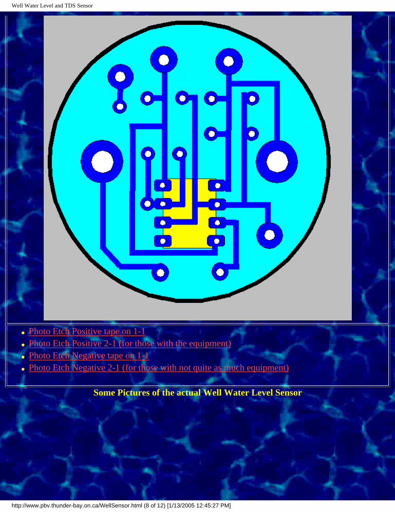
Well Water Level and TDS Sensor
● Photo Etch Positive tape on 1-1
● Photo Etch Positive 2-1 (for those with the equipment)
● Photo Etch Negative tape on 1-1
● Photo Etch Negative 2-1 (for those with not quite as much equipment)
Some Pictures of the actual Well Water Level Sensor
http://www.pbv.thunder-bay.on.ca/WellSensor.html (8 of 12) [1/13/2005 12:45:27 PM]

Well Water Level and TDS Sensor
This is the view of the constructed Well Water Level Sensor. The Rock would normally be attached with an elastic band and some
silicone.
The 1 inch thick wooden block on the back of the handset nicely holds about 100 Feet of #24 guage speaker wire. If you silicone it to the back of the handle, the connection should be
quite durable.
An exploded view of the Well Water Level Sensor from the side. This exploded view shows the momentary push button switch location. Here the circuit board has been removed from the
receiver. (Back).
http://www.pbv.thunder-bay.on.ca/WellSensor.html (9 of 12) [1/13/2005 12:45:27 PM]

Well Water Level and TDS Sensor
A view of the circuit board attached to the receiver. (Back)
A view of the foil side of the circuit board and the receiver. Notice that the diode has been removed from the back side of the receiver. The 1/4 inch screws should fit snuggly through the circuit board. Notice the two lock washers on one of the
screws in this picture. These lock washers should be placed on both screws before mounting on the back of the receiver.
http://www.pbv.thunder-bay.on.ca/WellSensor.html (10 of 12) [1/13/2005 12:45:27 PM]

Well Water Level and TDS Sensor
The circuit board mounted on the back of the receiver. Notice that the capacitors or positioned to take a minimum of vertical height as there is little room in the receiver compartment once the unit is put
together. Look closely and you will see the two lock washers separating the circuit board from the receiver. (Back)
The battery fits nicely in the throat of the hand unit.
Circuit Diagram and Technical Details
http://www.pbv.thunder-bay.on.ca/WellSensor.html (11 of 12) [1/13/2005 12:45:27 PM]

Well Water Level and TDS Sensor
"The TLC555 is a monolithic timing circuit fabricated using the Lin-CMOS* process. Due to its high impedance inputs (typically 1012 Ohms), it is capable of producing accurate time delays and oscillations while using less expensive, smaller timing capacitors then the NE555. Like the NE555, the TLC555 achieves both mono stable (using one resistor and one capacitor and astable (using two resistors and one capacitor) operation. In addition, 50% duty cycle astable operation is possible using only a single resistor and one capacitor. It operates at frequencies up to 2 Mhz and is fully compatible with CMOS, TTL, and MOS logic. It also provides very low power consumption (typically 1 mW at VDD = 5V) over a wide range of supply voltages ranging from 2 volts to
18 volts.
Like the NE555, the threshold and trigger levels are normally two thirds and one third respectively of VDD. These levels can be
altered by use of the control voltage terminal. When the trigger input falls below trigger level, the flip-flop is set and the output goes high. If the trigger input is above the trigger level and the threshold input is above the threshold level, the flip-flop is reset and the output is low. The reset input can override all other inputs and can be used to initiate a new timing cycle. When the reset input goes low, the flip-flop is reset and the output goes low. Whenever the output is low, a low impedance path is provided between the discharge terminal and ground.
While the complementary CMOS output is capable of sinking over 100mA and sourcing over 10 mA, the TLC555 exhibits greatly reduced supply current spikes during output transitions. This minimizes the need for the large decoupling capacitors required by the NE555."
(Quoted from the TLC555 Technical Data supplied by Radio Shack, Catalog #276-1718)
Template for wooden block
Frequently Asked Questions:
Have Questions About this Unit - Email Me, I'll try answer them.
1. Does this sensor detect the quality of water so that I can tell it is Safe to Drink?
Response: The sensor's qualitative measure of Total Dissolved Solids (TDS) is a side bonus that has nothing to do with the safety of the water. TDS measures the presence of minerals such as calcium & magnesium (which determine the hardness of water), sulphate, chloride and alkalinity. Lifewater teaches and practices the use of pathoscreen (bacteria) and nitrate tests to routinely determine whether or not water is safe to drink. The qualitative TDS capability of the electric water level tape will be usefull when drilling near the ocean since it will give a rough indication whether or not high salt may be present in the water. This will help drillers decide whether to spend extra money and complete the well, or whether a certain water bearing vein needs to be blocked off etc. The presence of sodium chloride (salt) does not make the water unsafe to drink, but can give it an unpleasant taste and cause premature corrosion of certain pump parts.
http://www.pbv.thunder-bay.on.ca/WellSensor.html (12 of 12) [1/13/2005 12:45:27 PM]

Appendix H: Assessing natural clays for use as drilling mud
Appendix H
Assessing Natural Clays:For Use as Drilling Mud
In many situations in remote parts of third world countries, bentonite or polymer is not available. Without these substances, holes often start to cave in and wells can not be successfully completed. Where industry-grade bentonite or polymer is not available, the suitability of locally available clays should be assessed prior to the start of drilling. This can be done using a Free-Standing Swell Test.
What You Need:
1. One Free Standing Swell Test Kit, containing: ❍ 4 - 100 ml.round free-standing graduated cylinders (self-
supporting)❍ 1 - Hand Sieve Set:
■ 1 - #73 O-Ring (2 spares included) ■ 1 - 2" diameter 48 Mesh screen cloth ■ 1 - 2" diameter 200 Mesh screen cloth ■ 1 - PVC fines container (male threads) (Genova
Products 2" Fitting #71820) ■ 1 - PVC Screen cloth Holder (female threads) (Genova
Products 2" Fitting Cleanout body #71619)❍ 49 assorted Ziplock bags (small) ❍ 24 1.5 ml. Snap-top bottles ❍ 1 - 30 gm. Container of Reference Bentonite ❍ 1 - Hand Balance Beam (black wire) ❍ ? - 2.0 gm. Reference Weights
http://www.lifewater.ca/Appendix_H.htm (1 of 6) [1/13/2005 12:45:28 PM]

Appendix H: Assessing natural clays for use as drilling mud
2. The following items should be found on-site: ❍ Fresh, clean, "soft" water ❍ Clay samples ❍ Small, thin spatula ❍ Hot oven ❍ Grinding stone or rolling pin
3. If the following items are available, they can be substituted as necessary:
❍ Accurate low-weight scale AND/or ❍ Balance with 2 gm. weight AND/or ❍ Accurate teaspoon-size measuring spoon
Sample Collection:
The best deposits of sodium bentonite are found in areas formed from old volcanic ash deposits. Therefore, if possible, collect clay samples from areas affected by ancient volcanic activity. If these deposits are not found in the country, try collecting clay samples from brackish swamps. Collect several hands-full of each clay to be tested.
Hand Sieve Set Assembly:
To assemble the hand sieve set:
1. Position the Screen Cloth Holder (larger diameter PVC part) with the treads up.
2. Place one O-ring into the recess just below the threads. 3. Place the screen cloth gently on top of the O-Ring, and start
twisting the Fines Container (smaller diameter part) into place. 4. Turn the device over, such that the O-Ring and the screen cloth
are visible. 5. As you tighten the Fines Container, you may need to nudge the O-
Ring outward into the recess.
http://www.lifewater.ca/Appendix_H.htm (2 of 6) [1/13/2005 12:45:28 PM]

Appendix H: Assessing natural clays for use as drilling mud
6. Finish tightening the fines Container, until it is HAND TIGHT (Please use only one O-Ring as there are three O-Rings provided with the Test Kit, but the extra two are intended as spares. You will need to dis-assemble this to remove the fines.)
Sample Preparation:
1. Take a small amount of the collected sample (1-2 cups). Flatten it as much as possible and break it into small pieces.
2. Dry it in a hot oven (200-300 degrees F) for 1 hour. 3. Then crush it as fine as possible. 4. Place it back in the oven and continue to dry and periodically
crush the sample with rolling pins or flat stones. 5. Periodically place the crushed sample into the hand sieve Set and
rap the Sieve Set aggressively until you observe that material no longerfalls through the screen cloth.
6. Transfer the coarse material back to the grinding step. 7. Continue this process until the sample is a fine, dry powder which
can be easily blown off of an open, outstretched hand. 8. It is Very Important to thoroughly dry and powder clay samples
prior to weighing them since bentonite in chunks weighs only 68 lbs/ft3 while powdered bentonite weighs only 55 lbs/ft3 or 0.88gms/cm3 (there are more air voids in powdered clay).
9. To remove the ground material from the Sieve Set, first remove any remaining traces of coarse particles from above the screen cloth.
10. Then twist apart the two PVC pieces carefully to collect the ground powder.
11. When finished, gently wash and dry the parts of the Sieve Set. 12. The screen cloth may be dried in the oven, (just a minute or two
should do) before grinding the next sample.
Water Source:
http://www.lifewater.ca/Appendix_H.htm (3 of 6) [1/13/2005 12:45:28 PM]

Appendix H: Assessing natural clays for use as drilling mud
1. Use water which is as pure as possible. Ideally, fresh rainwater should be used. Water should be sediment free and should be as soft as possible (calcium and magnesium can interfere with the swelling of sodium bentonite clays). If possible, use water with a relatively high pH (8-9) to reduce the calcium and magnesium content. If necessary, use soda ash to raise the pH of the water.
2. If water is run through a water treatment filter to purify it, ensure that it is passed through an activated carbon filter to remove any residual chlorine or iodine prior to the test.
3. To minimize variability, collect sufficient water in one container to test all the samples and then draw water for each test from the same container.
Free Standing Swell Test Procedure:
1. Just prior to the test, measure out a 2 gram sample of powdered clay.
❍ Option 1: ■ Hang the Balance beam on a branch or a nail. ■ place a 2 gram reference weight on one side of the
Balance beam. ■ Punch a hole in one of the included Ziplock Bags, and
hang it on the other side of the Balance Beam. ■ Then, fill the Ziplock bag with dry, finely ground
sample until the Balance Beam hangs level.
❍ Option 2: ■ Estimate the proper weight by measuring 2.3 cm3 clay
(0.5 tsp.clay or the equivalent volume of 46 drops of water). This amount of clay would fill TWO of the 1.5 ml. snap-top bottles to just over 2/3 full.(If possible, use all four graduated cylinders so that up to four clay samples can be tested at the same time.)
■ Fill the cylinders to the 100 ml. mark with the clean
http://www.lifewater.ca/Appendix_H.htm (4 of 6) [1/13/2005 12:45:28 PM]

Appendix H: Assessing natural clays for use as drilling mud
water.■ Transfer small amounts (0.25 gm.) of the powdered
clay onto the surface of the water using the thin spatula. Without Stirring, wait for it to absorb the water and sink on its own. Be patient, this might take as much as 4-5 minutes.)
■ As soon as the last clay has disappeared from the surface of the water, gently drop the next small amount of powdered clay into the cylinder.
■ Continue this process until all of the 2 grams of clay has been added to the sample.
Assessment:
1. Wait 18 hours, then measure the thickness of the layer of clay sludge on the bottom of the cylinder.
2. Do not shake or otherwise disturb the sample during this waiting or measuring process.
3. Clays which are suitable for use as drilling mud should have swelled to the 12-16 ml. (cm3) mark on the cylinder.
4. If clays have swelled only to the 4-6 ml. mark, they will not effectively coat the side of your borehole during the drilling process and should not be used as the thickening agent.
Last Resort Options:
1. If you cannot buy bentonite or find any suitable clay deposit, try drilling a borehole in clay soils without any thickening agents.
2. Drilling in sandy soils has a very low chance of success and will likely collapse prior to the casing, gravel pack and cement grout being in place.
3. If all other options have failed, try using finely ground seeds from
http://www.lifewater.ca/Appendix_H.htm (5 of 6) [1/13/2005 12:45:28 PM]

Appendix H: Assessing natural clays for use as drilling mud
guar plants (guar gum). It must be extremely finely ground (0.0001 microns). as a last resort, try adding potato starch (corn Starch is not quite as good) to the drilling water to enhance the performance of your drilling mud. However, it must be emphasized that these organic starches provide an ideal food source for bacteria and will quickly rot and start fermenting once introduced into the borehole!
4. Add starch as late in the drilling process as possible and ensure that the well is completed and starch pumped out within 6 hours of it being added to the hole.
5. Thoroughly rinse the hole with chlorinated water just prior to setting the well screen and casing and float the gravel pack into the hole while running chlorinated water up the annular space.
6. Once the well is complete, pump it for as long as possible and then shock-chlorinate it before leaving it for the night.
Choose Another Well Construction Module:
http://www.lifewater.ca/Appendix_H.htm (6 of 6) [1/13/2005 12:45:28 PM]

Appendix I: Methods for Grouting Casing
Appendix I
Methods For Grouting Casing
In general, it is good practice to place a grout seal around the upper
portion of well casing to help prevent contaminated surface water from entering the well. In other situations, grout may be placed around the entire length of casing or within the casing itself. These situations are outlined below and various techniques for placing grout are described.
Tremie Line
The most common use of grout is to seal the annular space between the top of the filter pack and the ground surface. For shallow wells the water table does not extend far above the filter pack, it is often possible to mix cement and water (no sand or gravel) into a thin paste and pour it into the annular space. However, in deep wells in which the gravel filter pack is far below the level of water in the annulus, this procedure would lead to separation of the sand and cement leading to formation of a poor seal. To prevent this, the following procedure can be followed:
● Ream-out the borehole to 18 cm (7 in) diameter.
● Insert a 7.6 cm (3 in) diameter well screen and casing and "float-in" your gravel pack.
● Insert a 1 inch diameter "tremie" pipe down the annular space to the top of the gravel filter pack (the outer diameter of the couplings for the 7.6 cm (3 in) PVC schedule 40 pipe is 10.8 cm
http://www.lifewater.ca/Appendix_I.htm (1 of 6) [1/13/2005 12:45:29 PM]

Appendix I: Methods for Grouting Casing
(4.25 in). In a 18 cm (7 in) borehole, this will leave a 3 cm (1.25 in) gap to insert your tremie pipe)
● Using a funnel, slowly pour cement grout into the tremie line. Gradually lift the line ensuring that the bottom of the line stays below the level of cement accumulating in the annular space.
● When the annular space is filled, remove and wash the tremie line.
Modified Halliburton Wiper Plug Method
When heavily contaminated soil or a severely polluted surficial aquifer are encountered, well casing should be securely grouted into an underlying rock or clay layer. This should also be done when moving from mud rotary to air hammer drilling to ensure that the hole does not cave-in. In order to securely grout a casing, the following procedure should be followed:
● Unless you have special small bits, ensure that you use 10 cm (4 in) diameter casing ... you will not be able to drill-out the cement inside 7.6 cm (3 in) diameter casing!!
● Make sure that the seals on the drill rig and mud pump hoses are in good condition and that they are tight.
● Make an adaptor so that the drill pipe fitting on the LS-100 can be attached with a water-tight seal onto the top of the casing. If this is not possible, have an extra 3m (10 ft) length of casing with a glued-on coupler and a 3 m (10 ft) ladder ready.
● Calculate the volume of the inside of the casing. The volume of a 10 cm (4 in) diameter casing is 8 litres/meter (0.09 ft3/ft or 0.64 USG/ft). Subtract 8 litres from this estimated volume and then measure-out this amount of water into a barrel.
● Calculate the volume of the annular space. The annular space for a 15.24 cm (6 in) diameter borehole with a 10.16 cm (4 in) diameter
http://www.lifewater.ca/Appendix_I.htm (2 of 6) [1/13/2005 12:45:29 PM]

Appendix I: Methods for Grouting Casing
casing is 8 litres/meter (0.09 ft3/ft or 0.64 USG/ft). Multiply this number by 1.3 (30%) to allow for wash-out down hole etc. If you suspect that there has been much caving in the hole, increase the volume by up to 100%.
● Place the well casing into the hole, ensuring that it is suspended about 0.3 meters (1 ft) about the bottom of the borehole.
● Mix-up a volume of cement equal to the volume estimated above. Neat cement grout yields about 37 litres (9.7 USG or 8.1 IMG) of slurry per 94 lb bag (1 ft3) which is mixed with 23 litres (6 USG or 5 IMG) water. Do NOT add any sand or gravel. Mix it smooth (no lumps) until it is like thin pudding or thin yogurt.
● Pour the cement grout down the inside of the casing.● After the cement is placed in the casing, lower the drill rig
swivel/quill until the drill pipe fitting makes a water tight seal with the adaptor on top of the well casing. Then pump the measured volume of water down into the well casing behind the cement. This can be done by filling all the hoses with water and then placing both the suction hose and the recirculation hose into the barrel containing the measured volume of water. Start the mud pump and then use the 3-way valve on the drill rig to control the rate at which water is pumped into the casing. SLOW pumping is GOOD!
● If it is not possible to create a water tight seal with the drill pip fitting, wait until the cement is inside the casing and then tightly push or glue on the extra 3.05 m (10 ft) length of well casing. Ensure that you accounted for this extra length of casing when you calculated the volume of water to add. Standing on top of the ladder, slowly add water into the casing until the entire measured volume of water has been added. Since cement weighs 14 lbs/gallon and water weighs 8.3 lbs/gallon, the extra 3.05 m (10 ft) of water will push the cement down an extra meter (3 feet).
● Once all the water has been added, gently push the casing downward to ensure that it is seated in the rock or confining clay
http://www.lifewater.ca/Appendix_I.htm (3 of 6) [1/13/2005 12:45:29 PM]
Appendix I: Methods for Grouting Casing
layer. This helps ensure that there is a complete seal at the bottom of the casing.
● Then use several shovel full of dirt to plug-off the ditch leading from the borehole to the mud pits.
● If water is leaking out of the plumbing joints and/or drilling mud is draining back down into the annulus, then cement is leaking back up the casing. Tighten joints to reduce leakage. While some leakage is not desirable, it is not a crisis either... it will merely require the drilling out of a little extra cement.
● Wait 24 hours before you start to drill inside the casing. If in doubt, wait longer rather than shorter. If you start drilling and find that the cement is not set-up, wait another 12 hours.
● Drill-out the cement using a 10.16 cm (4 in) roller bit.
Wiper Plug Method
If for some reason the Modified Halliburton Wiper Plug Method described above will not work, consider the following method which uses a plug to push the grout down into the casing and up the annular space:
● Take 1 or 2 empty cement sacks and wad them into a tight ball.● Once the measured volume of grout is placed in the casing, insert
the cement sack ball (the "wiper plug") in the casing.● Use drill pipe to slowly force the wiper plug down the casing until
it is just above the bottom of the casing.● Use several shovels full of dirt to plug-off the ditch leading from
the borehole to the mud pits.● Leave the drill pipe in-place for 1-2 hours to let the cement set
enough so that it wouldn't come back up the casing when the drill pipe is removed.
● Do not leave the drill pipe in the casing for an extended period of time. If you do and some cement leaks back through or around the
http://www.lifewater.ca/Appendix_I.htm (4 of 6) [1/13/2005 12:45:29 PM]

Appendix I: Methods for Grouting Casing
wiper plug .... it will set around the drill pipe and make it a permanent installation!
● After 1-2 hours, slowly start to pull-up of the drill pipe. If drilling mud ponded around the top of the borehole starts to drain back down into the annulus, then cement is leaking back up the casing. Leave the drill pipe in the hole for another 15-30 minutes and try removing it again. Remember... some leakage is better then cementing your drill pipe into the casing!
Cement "Plastic Bag Plug" Method
Sometimes a borehole is drilled into poor quality water and it is determined that the best course of action is to backfill the lower portion of the hole and set the well screen at a higher elevation where better quality water is expected. When a wooden drive shoe is used at the bottom of a casing string, it is desirable to place a 30 - 61 cm (1 - 2 ft) cement plug in the bottom of the well to ensure that sediment cannot enter the well when the plug rots out. Both these procedures nvolve all or some of the following steps:
● Backfill the hole with cuttings until you are 61 cm (2 ft) below the desired completion depth of the borehole where you want the bottom of the screen to be.
● Mix-up 0.4 ft3 (11 litres) of real thick cement & water mixture (no sand or gravel).
● Pour the cement into small plastic bags the easily fit down inside the borehole.
● Run the drill pipe with a blade bit down the borehole and move the pipe up and down to chop-up the bags and mix-up the cement.
● Remove the drill pipe and wait 1 hour for the cement to set.● Insert the well screen and casing (with casing bottom plug) down
into the borehole. Suspend the casing 6 inches off the bottom of the borehole and then put in the filter pack.
http://www.lifewater.ca/Appendix_I.htm (5 of 6) [1/13/2005 12:45:29 PM]

Appendix I: Methods for Grouting Casing
Choose Another Well Construction Module:
http://www.lifewater.ca/Appendix_I.htm (6 of 6) [1/13/2005 12:45:29 PM]

Section 13: Bush Handpump Overview
Section 13
Bush Handpump Overview
Click HERE if there is no button bar on the left side of your screen!
Make a bush pump (Appendix K)
Bush Pump Installation (Section 14)
Bush pump Maintenance (Section 17)
More Bush pump info. (HTN Network)
Advantages of using the Bush Pump
http://www.lifewater.ca/Section_13.htm (1 of 5) [1/13/2005 12:45:30 PM]

Section 13: Bush Handpump Overview
Over the past decade or two, the bush pump has become the world's most robust
and widely used locally made handpump. Benefits of this hand pump include:
● create desperately needed local jobs;
● low cost;
● maintenance - what's locally built can be locally repaired;
● removable parts have minimal resale value (an important consideration where expensive imported pumps are looted).
Because the Bush pump is locally made, it has also picked-up many
different names. Besides being called a modified Guinea-Bissau Pump, it is also called:
● POV-RO 2000 Pump (Nepal)● Zimbabwe hand pump (Zimbabwe)● Simple hand pump (Kenya)● Bush Pump (Liberia)
http://www.lifewater.ca/Section_13.htm (2 of 5) [1/13/2005 12:45:30 PM]

Section 13: Bush Handpump Overview
These pumps have several key common Design Specifications:
● Wood Block Bearing: Usually three pieces of 5.08 x 15.24 cm (2 x 6 in) wood are laminated together to form the pivot bearing. An extra set of 2 holes is drilled in the block so that when the holes wear significantly over time, the block can be quickly rotated and the bolts inserted into the new holes.
● Pump or Pivot Support: A single strong pipe or a frame made of angle iron is embedded into concrete and used as the pivot support for the wood bearing.
● Outlet Pipe Assembly: An outlet pipe assembly made from local plumbing supplies rests on-top of the well casing cap or protective casing cover.
http://www.lifewater.ca/Section_13.htm (3 of 5) [1/13/2005 12:45:30 PM]

Section 13: Bush Handpump Overview
Deciding to use the Bush pump
When deciding whether or not to use a bush pump in a particular community,
it is important to consider the following factors:
● What is the projected use? In general, the bush pump is suitable for use in communities of up to 500 people. Where there are significantly more people, either a second well should be drilled or another handpump chosen (such as the Afridev hand pump, India Mark II, Kardia hand pump or Vergnet hand pump);
● What is the availability and cost of other hand pumps? In some countries, handpump use has been standardized to one or two types which are widely available at low cost. If this is the case and parts and trained repair people are locally available, the advantages of using these hand pumps will normally outweigh the benefits of introducing the bush pump.
● What is the pumping level? Bush pumps can be used for depths up to 100 metres. Pumping ease is maintained by counter-balancing the weight of the water column by putting concrete or sand inside the hollow pump handle.
http://www.lifewater.ca/Section_13.htm (4 of 5) [1/13/2005 12:45:30 PM]

Section 13: Bush Handpump Overview
Choose Another Well Construction Module:
http://www.lifewater.ca/Section_13.htm (5 of 5) [1/13/2005 12:45:30 PM]

Water for the World Index
Water For The World
A series of US AID technical notes covering all aspects of rural water supply and sanitation, made available online by Lifewater International.
The Water For The World Technical Notes were published in 1982 by the former Development Information Center of the US Agency for International Development (AID).
Although the original Notes are out of print, they still are very useful to anyone working in the field of rural water supply and sanitation. For this reason, Lifewater International has made all 160 of these Technical Notes available online in Adobe Acrobat "Portable Document Format." To view, search and print these documents, download and install the latest version of the free Acrobat ReaderTM.
Can you help us with translating these documents? If so, please contact the Lifewater International webmaster.
In any citation of these documents, refer to US AID (1982) as the author with this Lifewater International web site as the location where they may be obtained. Kindly direct any inquiries about this this web site to the Lifewater International webmaster, not US AID.
The following credits originally appeared on the back page of each Technical Note:
Technical Notes are part of a set of "Water for the World" materials produced under contract to the U.S. Agency for International Development by National Demonstration Water Project, Institute for Rural Water, and National Environmental Health Association. Artwork was done by Redwing Art Service. Technical Notes are intended to provide assistance to a broad range of people with field responsibility for village water supply and sanitation projects in the developing nations. For more detail on the purpose, organization and suggestions for use of Technical Notes, see the introductory Note in the series, titled "Using 'Water for the World' Technical Notes." Other parts of the "Water for the World" series include a comprehensive Program Manual and several Policy Perspectives. Further information on these materials may be obtained from the Development Information Center, Agency for International Development, Washington, D. C., 20523, USA.
Top Level Index [ Top | Bottom ]
HUMAN RESOURCES (HR) SANITATION (SAN)
http://www.lifewater.org/wfw/wfwindex.htm (1 of 8) [1/13/2005 12:45:32 PM]

Water for the World Index
● Community Participation ● Simple Excreta and Washwater Disposal● Operation and Maintenance Training ● Combined Excreta and Washwater DisposalRURAL WATER SUPPLY (RWS) ● Solid Waste Disposal● Surface Water DISEASE (DIS)● Ground Water ● Water Supply, Sanitation and Disease ● Water Treatment ● Specific Diseases● Water Distribution
● Water Storage How to Use Technical Notes (HR.G)
HUMAN RESOURCES [ Index | Bottom ]
Overview of Water and Sanitation System Development (HR.1) PDF/HTML
Community Participation (HR.2)
● Methods of Initiating Community Participation in Water Supply and Sanitation (HR.2.M) PDF● Community Participation in Planning Water Supply and Sanitation Programs (HR.2.P) PDF● Community Participation in Implementing Water Supply and Sanitation Programs (HR.2.I) PDF
Operation and Maintenance Training (HR.3)
● Methods of Operation and Maintenance Training (HR.3.M) PDF● Planning Operation and Maintenance Training (HR.3.P) PDF● Implementing Operation and Maintenance Training (HR.3.1) PDF ● Evaluating Operation and Maintenance Training (HR.3.I.2) PDF
RURAL WATER SUPPLY [ Index | Bottom ]
Overview of Rural Water Supply (RWS.G) PDF/HTML
Surface Water (RWS.1)
● Methods of Developing Sources of Surface Water (RWS.1.M) PDF/HTML● Planning How to Use Sources of Surface Water (RWS.1.P.1) PDF● Conducting Sanitary Surveys to Determine Acceptable Surface Water (RWS.1.P.2) PDF● Selecting a Source of Surface Water (RWS.1.P.3) PDF
http://www.lifewater.org/wfw/wfwindex.htm (2 of 8) [1/13/2005 12:45:32 PM]

Water for the World Index
● Choosing Where to Place Intakes (RWS.1.P.4) PDF● Evaluating Rainfall Catchments (RWS.1.P.5) PDF● Designing Structures for Springs (RWS.1.D.1) PDF● Designing Intakes for Ponds, Lakes and Reservoirs (RWS.1.D.2) PDF● Designing Intakes for Streams and Rivers (RWS.1.D.3) PDF● Designing Roof Catchments (RWS.1.D.4) PDF● Designing Small Dams (RWS.1.D.5) PDF● Constructing Structures for Springs (RWS.1.C.1) PDF● Constructing Intakes for Ponds, Lakes and Reservoirs (RWS.1.C.2) PDF● Constructing Intakes for Streams and Rivers (RWS.1.C.3) PDF● Constructing, Operating and Maintaining Roof Catchments (RWS.1.C.4) PDF● Constructing Small Dams (RWS.1.C.5) PDF● Maintaining Structures for Springs (RWS.1.O.1) PDF● Maintaining Intakes (RWS.1.O.2) PDF● Maintaining Small Dams (RWS.1.O.5) PDF
Ground Water (RWS.2) [ Index | Bottom ]
● Methods of Developing Sources of Ground Water (RWS.2.M) PDF● Planning How to Use Sources of Ground Water (RWS.2.P.1) PDF● Selecting a Method of Well Construction (RWS.2.P.2) PDF● Selecting a Well Site (RWS.2.P.3) PDF● Designing Dug Wells (RWS.2.D.1) PDF● Designing Driven Wells (RWS.2.D.2) PDF● Designing Jetted Wells (RWS.2.D.3) PDF● Designing Bored or Augered Wells (RWS.2.D.4) PDF● Designing Cable Tool Wells (RWS.2.D.5) PDF● Constructing Dug Wells (RWS.2.C.1) PDF● Constructing Driven Wells (RWS.2.C.2) PDF● Constructing Jetted Wells (RWS.2.C.3) PDF● Constructing Bored or Augered Wells (RWS.2.C.4) PDF● Constructing Cable Tool Wells (RWS.2.C.5) PDF● Maintaining Well Logs (RWS.2.C.6) PDF● Testing the Yield of Wells (RWS.2.C.7) PDF● Finishing Wells (RWS.2.C.8) PDF● Disinfecting Wells (RWS.2.C.9) PDF
Water Treatment (RWS.3) [ Index | Bottom ]
http://www.lifewater.org/wfw/wfwindex.htm (3 of 8) [1/13/2005 12:45:32 PM]

Water for the World Index
● Methods of Water Treatment (RWS.3.M) PDF● Determining the Need for Water Treatment (RWS.3.P.1) PDF● Taking a Water Sample (RWS.3.P.2) PDF● Analyzing a Water Sample (RWS.3.P.3) PDF● Planning a Water Treatment System (RWS.3.P.4) PDF● Designing Basic Household Water Treatment Systems (RWS.3.D.1) PDF● Designing a Small Community Sedimentation Basin (RWS.3.D.2) PDF● Designing a Slow Sand Filter (RWS.3.D.3) PDF● Designing a Small Community Disinfection Unit (RWS.3.D.4) PDF● Water Treatment in Emergencies (RWS.3.D.5) PDF● Constructing a Household Sand Filter (RWS.3.C.1) PDF● Constructing a Sedimentation Basin (RWS.3.C.2) PDF● Constructing a Slow Sand Filter (RWS.3.C.3) PDF● Constructing a Disinfection Unit (RWS.3.C.4) PDF● Operating and Maintaining Household Treatment Systems (RWS.3.O.1) PDF● Operating and Maintaining a Sedimentation Basin (RWS.3.O.2) PDF● Operating and Maintaining a Slow Sand Filter (RWS.3.O.3) PDF● Operating and Maintaining a Chemical Disinfection Unit (RWS.3.O.4) PDF
Water Distribution (RWS.4) [ Index | Bottom ]
● Methods of Delivering Water (RWS.4.M) PDF● Choosing Between Gravity Flow and Pumps (RWS.4.P.1) PDF● Choosing Between Community Distribution Systems and Household Water (RWS.4.P.2) PDF● Selecting Pipe Materials (RWS.4.P.3) PDF● Selecting a Power Source for Pumps (RWS.4.P.4) PDF● Selecting Pumps (RWS.4.P.5) PDF● Manufacturing Hand Pumps Locally (RWS.4.P.6) PDF● Designing a System of Gravity Flow (RWS.4.D.1) PDF● Determining Pumping Requirements (RWS.4.D.2) PDF● Designing a Transmission Main (RWS.4.D.3) PDF● Designing Community Distribution Systems (RWS.4.D.4) PDF● Designing a Hydraulic Ram Pump (RWS.4.D.5) PDF/HTML● Installing Pipes (RWS.4.C.1) PDF● Installing Mechanical Pumps (RWS.4.C.2) PDF● Installing Hand Pumps (RWS.4.C.3) PDF● Constructing Community Distribution Systems (RWS.4.C.4) PDF● Constructing a Distribution System with Household Connections (RWS.4.C.5) PDF● Detecting and Correcting Leaking Pipes (RWS.4.O.1) PDF
http://www.lifewater.org/wfw/wfwindex.htm (4 of 8) [1/13/2005 12:45:32 PM]
Water for the World Index
● Operating and Maintaining Mechanical Pumps (RWS.4.O.2) PDF● Operating and Maintaining Hand Pumps (RWS.4.O.3) PDF● Operating and Maintaining Household Water Connections (RWS.4.O.5) PDF
Water Storage (RWS.5) [ Index | Bottom ]
● Methods of Storing Water (RWS.5.M) PDF● Determining the Need for Water Storage (RWS.5.P.1) PDF● Designing a Household Cistern (RWS.5.D.1) PDF● Designing a Ground Level Storage Tank (RWS.5.D.2) PDF● Designing an Elevated Storage Tank (RWS.5.D.3) PDF● Constructing a Household Cistern (RWS.5.C.1) PDF● Constructing a Ground Level Storage Tank (RWS.5.C.2) PDF● Constructing an Elevated Storage Tank (RWS.5.C.3) PDF● Maintaining Water Storage Tanks (RWS.5.O.1) PDF
SANITATION [ Index | Bottom ]
Overview of Sanitation (SAN.G) PDF
Simple Excreta and Washwater Disposal (SAN.1)
● Simple Methods of Excreta Disposal (SAN.1.M.1) PDF● Simple Methods of Washwater Disposal (SAN.1.M.2) PDF● Planning Simple Excreta and Washwater Disposal Systems (SAN.1.P) PDF● Designing Slabs for Privies (SAN.1.D.1) PDF● Designing Pits for Privies (SAN.1.D.2) PDF● Designing Privy Shelters (SAN.1.D.3) PDF● Designing Aqua Privies (SAN.1.D.4) PDF● Designing Bucket Latrines (SAN.1.D.5) PDF● Designing Compost Toilets (SAN.1.D.6) PDF● Designing Sumps, Soakage Pits and Trenches (SAN.1.D.7) PDF● Constructing Slabs for Privies (SAN.1.C.1) PDF● Constructing Pits for Privies (SAN.1.C.2) PDF● Constructing Privy Shelters (SAN.1.C.3) PDF● Constructing Aqua Privies (SAN.1.C.4) PDF
http://www.lifewater.org/wfw/wfwindex.htm (5 of 8) [1/13/2005 12:45:32 PM]

Water for the World Index
● Constructing Bucket Latrines (SAN.1.C.5) PDF● Constructing Compost Toilets (SAN.1.C.6) PDF● Constructing, Operating & Maintaining Sumps, Soakage Pits & Trenches (SAN.1.C.7) PDF● Operating and Maintaining Privies (SAN.1.O.1) PDF● Operating and Maintaining Aqua Privies (SAN.1.O.4) PDF● Operating and Maintaining Bucket Latrines (SAN.1.O.5) PDF● Operating and Maintaining Compost Toilets (SAN.1.O.6) PDF
Combined Excreta and Washwater Disposal (SAN.2) [ Index | Bottom ]
● Methods of Combined Washwater and Excreta Disposal (SAN.2.M) PDF● Planning Combined Washwater and Excreta Disposal Systems (SAN.2.P.1) PDF● Estimating Sewage or Washwater Flows (SAN.2.P.2) PDF● Determining Soil Suitability (SAN.2.P.3) PDF● Designing Subsurface Absorption Systems (SAN.2.D.1) PDF● Designing Cesspools (SAN.2.D.2) PDF● Designing Septic Tanks (SAN.2.D.3) PDF● Designing Sewer Systems (SAN.2.D.4) PDF● Designing Stabilization Ponds (SAN.2.D.5) PDF● Designing a System of Stabilization Ponds (SAN.2.D.6) PDF● Designing Mechanically Aerated Lagoons (SAN.2.D.7) PDF● Designing Non-Conventional Absorption Disposal Systems (SAN.2.D.8) PDF● Constructing, Operating & Maintaining Subsurface Absorption Systems (SAN.2.C.1) PDF● Constructing Cesspools (SAN.2.C.2) PDF● Constructing Septic Tanks (SAN.2.C.3) PDF● Constructing Sewer Systems (SAN.2.C.4) PDF● Constructing Stabilization Ponds (SAN.2.C.5) PDF● Constructing Mechanically Aerated Lagoons (SAN.2.C.7) PDF● Constructing, Operating & Maintaining Non-Conventional Absorption Systems (SAN.2.C.8) PDF● Operating and Maintaining Septic Tanks (SAN.2.O.3) PDF● Operating and Maintaining Sewer Systems (SAN.2.O.4) PDF● Operating and Maintaining Stabilization Ponds (SAN.2.O.5) PDF● Operating and Maintaining Mechanically Aerated Lagoons (SAN.2.O.7) PDF
Solid Waste Disposal (SAN.3) [ Index | Bottom ]
● Methods of Solid Waste Management (SAN. 3. M) PDF● Planning Solid Waste Management Systems (SAN.3.P) PDF● Designing a Landfill (SAN.3.D.1) PDF
http://www.lifewater.org/wfw/wfwindex.htm (6 of 8) [1/13/2005 12:45:32 PM]

Water for the World Index
● Designing a Composting System (SAN.3.D.2) PDF● Designing a Solid Waste Collection System (SAN.3.D.3) PDF● Designing a Biogas System (SAN.3.D.4) PDF● Constructing a Biogas System (SAN.3.C.4) PDF● Operating and Maintaining a Landfill (SAN.3.O.1) PDF● Operating and Maintaining a Composting System (SAN.3.O.2) PDF● Operating a Solid Waste Collection System (SAN.3.O.3) PDF● Operating and Maintaining a Biogas System (SAN.3.O.4)PDF
DISEASE [ Index | Bottom ]
Overview of Diseases (DIS.G) PDF /HTML
Water Supply, Sanitation and Disease (DIS.1)
● Means of Disease Transmission (DIS.1.M.1) PDF● Methods of Improving Environmental Health Conditions (DIS.1.M.2) PDF● Planning Disease Control Programs (DIS.1.P.1) PDF
Specific Diseases (DIS.2)
● Methods of Controlling Schistosomiasis (DIS.2.M.1) PDF● Methods of Controlling African Trypanosomiasis (DIS.2.M.2) PDF● Methods of Controlling South American Trypanosomiasis (DIS.2.M.3) PDF● Methods of Controlling Enteric Diseases (DIS.2.M.4) PDF● Methods of Controlling Onchocerciasis (DIS.2.M.5) PDF
[ Index | Lifewater Home]
Home | About Lifewater | HELP | Training |
Water for the World | Gifts | Links
http://www.lifewater.org/wfw/wfwindex.htm (7 of 8) [1/13/2005 12:45:32 PM]

Water for the World Index
Contact UsLast modified 08/13/02
http://www.lifewater.org/wfw/wfwindex.htm (8 of 8) [1/13/2005 12:45:32 PM]

Afridev handpumps for safe drinking water
Afridev HandpumpPublic Domain Handpump
Click HERE if there is no button bar on the left side of your screen!
The afridev handpump is a public-domain pump which can pump water from up to 45-60 meters below ground surface. This pump is designed with a "working barrel" which allows the piston to be extracted without removing the rising main. A special "hook" tool is required to extract the foot valve from the bottom of the cylinder (the foot valve may be jamed tightly in-place by sand).
This hand pump uses imported neoprene rings as piston seals. This specialized part can not be easily made in-county. The $1 rings often wear-out in about a year and, if not locally available, render this pump unusable to the local community!
http://www.lifewater.ca/afridev.htm (1 of 6) [1/13/2005 12:45:33 PM]

Afridev handpumps for safe drinking water
afridev experience (Ghana)
Afridev Manual
There are many local manufactures of this water pump. The following
list is sorted by country:
INDIA Afridev SuppliersAjay Industrial Corporation
Mr. Akhil Jain4561 Deputy Ganj, Sadar Bazar
Delhi-110 006, IndiaPhone: 011-91-120-4770679/4770233/ 4770339
011-91-11-3545291Fax: 011-91-120-4770629, 91-11-3536205
E-mail: [email protected] OR [email protected]
AOV InternationalMr. O. P. Arora
http://www.lifewater.ca/afridev.htm (2 of 6) [1/13/2005 12:45:33 PM]

Afridev handpumps for safe drinking water
J-18 Sector 18Noida-201301
Phone: +91-118-4515566/77/88/99Fax: +91-118-4514269E-mail: [email protected]
Inalsa LtdMr. Lalit Khanna
9/51, Industrial AreaKirti Nagar
Dehli - 110 015, IndiaPhone: 011-91-11-53-33-27; Fax: 011-91-11-37-12-108
Karnataka Water Pumps Ltd.Mr. Shankaranarayana Gupta
13-B, Attibele Industrial Area, Attibele-562 107Anekai Taluk
Bangalore, IndiaPhone: 011-91-802-23-88-82; Fax: 011-91-802-22-57-74
Meera and Celko Pumps LtdMr. Mahesh Desai2153/5 Hill Street
Raniguj, Secunderabad500003 India
Phone: 011-91-40-7711131; Fax: 011-91-40-7614376
Newman Impex Private LimitedMr. Rashpal Singh
OPP.Shoor Market, Kala Sangha RoadBasti Sheikh, Jalandhar - 2 pb, India
Phone: +91 181 2439092, 2439038 Fax: +91 181 2439044E-mail: [email protected]
R.N.IndustriesMr. K.K.Jindal
10984, Dori WalanEast Park Road
New Delhi 110005India
Phone: 011-91-11-702-6197/789-1176; Fax: 011-91-11-722-5473E-mail: [email protected]
SPA WORLDWIDE
http://www.lifewater.ca/afridev.htm (3 of 6) [1/13/2005 12:45:33 PM]

Afridev handpumps for safe drinking water
Mr. Pawan SaxenaOwnerINDIA
Phone: +91-11-22048381 Office, or +91-11-2247098 ResidenceFAX: +91-11-22048381
E-mail: [email protected]
SPAN PUMPS PVT.LTDNitin Muthiyan- Director
(MANUFACTURERS & EXPORTERS]104, Arihant, 1187/26,
Near Balgandharva, Ghole Road,Shivajinagar,
Pune: 411 005, (Maharashtra State)INDIA.
Phone: 91-20-25536371, 25530499, 25539773Fax: 91-20-25536372
E-mail: [email protected]
KENYA Afridev SuppliersAfripumps (Kenya) Limited
PO Box 48624Nairobi, Kenya
Phone: (Nairobi) 802604; Fax: (Nairobi) 802885.
Kenya Water handpump LtdMr. Ravi GandhiP.O. Box 49745Nairobi, Kenya
Phone: 254-254-26-87; Fax: 254-255-20-48
Industrial Components (Kenya) Ltd. (Molded Plastic Parts)P.O. Box 65017Nairobi, Kenya
Phone: 802301; Fax: 803896
http://www.lifewater.ca/afridev.htm (4 of 6) [1/13/2005 12:45:33 PM]

Afridev handpumps for safe drinking water
MOZAMBIQUE Afridev SuppliersStenaks Trading & Shipping Ltd.
Mr. Jan van HoornCaixa Postal 1028
Maputo, MozambiquePhone: 258-146-57-33; Fax: 258-146-57-37
PAKISTAN Afridev SuppliersDacaar handpumps Factory
Mr. M. NugawelaMardan Road
Swabi, PakistanFax: 92-521-84-05-16
M/S Engineering Concern Ltd.Mr. M. Sarwat
39-C, Commercial AreaNazimabad-4
Karachi-18, PakistanPhone: 92-21-61-86-27; Fax: 92-21-50-61-401
Progressive Steel IndustriesMr. Khalid Aziz
Plot No.3 Street No. 1A Madina ColonySiddique Akbar Road, Lal Pul Moughalpura
Lahore-PakistanPhone: +92-42-6549549; Fax: +92-42-6542465
SWAZILAND Afridev Suppliers
http://www.lifewater.ca/afridev.htm (5 of 6) [1/13/2005 12:45:33 PM]

Afridev handpumps for safe drinking water
Tri-Manzi (PTY) LtdP.O. Box 1468
Mbabane, SwazilandPhone: +(268)-5057572; Fax: (268)-5057659 cell (268)-6057309
E-mail: [email protected]
TANZANIA Afridev SuppliersTWSSC Ltd.Mr. Suraj Kakar
P.O. Box 7Morogoro, Tanzania
Phone: 255-56-30-42; Fax: 255-56-44-26
UNITED KINGDOM AfridevIndustrial Components Inc. (Molded afridev plastic parts)
Mr. Abdalla IbrahimUnited Kingdom
Phone: 011-843-590181; Fax: 011-843-590881E-mail: [email protected]
Click here to learn more about well construction and hand pumps!
http://www.lifewater.ca/afridev.htm (6 of 6) [1/13/2005 12:45:33 PM]

http://www.handpump.org/afri_pump/index.htm
The simple & strong AFRI - Pump
What is new about modern handpumps ?
Unfortunately, most traditional donor handpumps (Afridev, India Pumps, etc. ) are not sustainable and are abandoned soon when the donor support has finished. This is mainly due to:
● Complicated handpump design, not understood by users
● Special spare parts not locally available, despite of many expensive donor efforts to set up spare part supply chains (especially piston seals are needed , but not available).
To make better use of donor funds for water projects, Rural Water Systems developed the AFRI-PUMP, a simple and strong design, based on local available materials. This pump is easy to install and can be sustainable maintained for a fraction of the price of the Afridev or India pumps.
● No rubber seals, but a maintenance free BEERS Piston
● Up to 80 meters of easy pumping● Bottom support for the PVC rising main● Cheaper and more reliable than
traditional handpumps● Also affordable for private wells
http://www.handpump.org/afri_pump/index.htm (1 of 2) [1/13/2005 12:45:34 PM]

http://www.handpump.org/afri_pump/index.htm
The AFRI - Pump design enables pumping from two (!) rising mains in the well, to double security and output, in case of high demand for livestock for example.
The 9 mm stainless steel rods are connected to the handle with a simple M-16 Bolt construction in an "U" profile, using standard bearings. Only one M-16 Spanner fits the whole pump.
The AFRI - Pump can be obtained with Jansen Venneboer International (JVI) B.V. For more information see www.volanta.nl
http://www.handpump.org/afri_pump/index.htm (2 of 2) [1/13/2005 12:45:34 PM]

Consallen Hand Pumps
Consallen HandpumpsMade in the United Kingdom
Click HERE if there is no button bar on the left side of your screen!
Consallen Hand Pumps GroupContact: D.V. Allen, Managing Director
P.O. Box 2993SUDBURY, Suffolk
CO10 0ZB, United KingdomTelephone/Fax/Ans: 44-0-1787-247770
E-mail: [email protected]
Newman Impex Private LimitedMr. Rashpal Singh
OPP.Shoor Market, Kala Sangha RoadBasti Sheikh, Jalandhar - 2 pb, India
Phone: +91 181 2439092, 2439038 Fax: +91 181 2439044E-mail: [email protected]
http://www.lifewater.ca/consallen.htm [1/13/2005 12:45:35 PM]

india mark II handpumps
India Mark II handpumps
Click HERE if there is no button bar on the left side of your screen!
Developing India Mark II handpumps
Construction Details and Performance Data (India)
India Mark II pumps in GERMANY
PumpenboeseGmbH & Co. KG
Moorebeerenweg 1D-31228 PEINE/GERMANY
SBF KARDIASTEFAN ERNST
Phone: +49 5171 294 123; Fax: +49 5171 294 111
http://www.lifewater.ca/mark2.htm (1 of 5) [1/13/2005 12:45:35 PM]

india mark II handpumps
E-mail: [email protected]
India Mark II pumps in INDIA
Ajay Industrial CorporationMr. Akhil Jain
4561 Deputy Ganj, Sadar BazarDelhi-110 006, India
Phone: 011-91-120-4770679/4770233/4770339; Fax: 011-91-120-4770629 91-11-3536205E-mail: [email protected]
E-mail: [email protected]
Balaji Industrial and Agricultural CastingsMr. P. Subba Raja
4-3-140, Hill Street,P.B. No. 1634
Secunderabad - 500 003Andra Pradesh, INDIA
Phone: 011-91-40-27711183; Cell: 011-91 98480 33696; Fax: 011-91-40-23078378E-mail: [email protected]
D.S.M. Industries TrichyDr. S. Vaidheesswaran/CEO
#20 Industrial Estate, AriyamangalamTiruchirappalli, Tamil Nadu - 620 010 India
Phone: +91-431-2441718; Fax: +91-431-2441258E-mail: [email protected]
E-mail: [email protected]
Inalsa LtdMr. Lalit Khanna
9/51, Industrial AreaKirti Nagar
Dehli - 110 015, IndiaPhone: 011-91-11-53-33-27; Fax: 011-91-11-37-12-108
Karnataka Water Pumps Ltd.
http://www.lifewater.ca/mark2.htm (2 of 5) [1/13/2005 12:45:35 PM]

india mark II handpumps
Mr. Shankaranarayana Gupta13-B, Attibele Industrial Area
Attibele-562 107Anekai Taluk
Bangalore, IndiaPhone: 011-91-802-23-88-82; Fax: 011-91-802-22-57-74
Meera and Celko Pumps LtdMr. Mahesh Desai
1-7-1054/A,B,Industrial Area
AzamabadHyderabad-500 020, India
Phone: 011-91-407-61-70-98; Fax: 011-91-407-61-43-76
Newman Impex Private LimitedMr. Rashpal Singh
OPP.Shoor Market, Kala Sangha RoadBasti Sheikh, Jalandhar - 2 pb, India
Phone: +91 181 2439092, 2439038 Fax: +91 181 2439044E-mail: [email protected]
Prem IndustriesMr. Harshdeep Singh
Sherpur, LadhianaINDIA
Phone: 011-91-161-456846; Fax: 011-91-161-450338, 671858E-mail: [email protected]
R.N.IndustriesMr. K.K.Jindal
10984, Dori WalanEast Park Road
New Delhi 110005India
Phone: 011-91-11-702-6197/789-1176; Fax: 011-91-11-722-5473E-mail: [email protected]
Shree S.K. Industries10, Abhishek Plaza,
Exhibition Road,
http://www.lifewater.ca/mark2.htm (3 of 5) [1/13/2005 12:45:35 PM]

india mark II handpumps
Patna 800001 INDIAPhone: 011-91-0612-427-402; Fax: 011-91-0612-427-671
E-mail: [email protected]
SPA WORLDWIDEMr. Pawan Saxena
OwnerINDIA
Phone: +91-11-22048381 OFFICE; OR +91-11-2247098 RESIDENCEFAX: +91-11-22048381
E-mail: [email protected]
SPAN PUMPS PVT.LTDNitin Muthiyan- Director
(MANUFACTURERS & EXPORTERS]104, Arihant, 1187/26,
Near Balgandharva, Ghole Road,Shivajinagar,
Pune: 411 005, (Maharashtra State)INDIA.
Phone: 91-20-25536371, 25530499, 25539773Fax: 91-20-25536372
E-mail: [email protected]
U.P. PUMPS LTDU.P. Pumps Pvt. Ltd.
1-B, Dada Nagar, Kanpur - 208 022, INDIATel : 91 - 512 - 2213363 , 2217129
Fax: 91- 512 - 2217130 E-mail: [email protected]
orE-mail: [email protected]
Website: uppumps.com
India Mark II handpumps in UGANDA
http://www.lifewater.ca/mark2.htm (4 of 5) [1/13/2005 12:45:35 PM]

india mark II handpumps
Victoria Pumps LtdMr. Patrik Buhenga
P.O. Box 620Kampala, Uganda
Phone: 256-41-34-24-83; Fax: 256-41-34-16-25
India Mark II hand pumps in UNITED STATES
Dempster PumpsMr. David P. Suey
P.O. Box 848Beatrice, Nebraska
68310, USAPhone: (402) 223-4026; Fax: (402) 228-4389
http://www.lifewater.ca/mark2.htm (5 of 5) [1/13/2005 12:45:35 PM]

Kardia hand pump
Kardia hand pumpMade in Germany
Click HERE if there is no button bar on the left side of your screen!
This hand pump is presision constructed for sustained, reliable performance in areas where there is little hand pump maintenance. Although expensive, children can easily use this hand pump to obtain a steady flow of water from depths greater than 30 meters. These factors makes this hand pump an ideal choice for use in large, remote villages and in crowded refugee camps.
PUMPENBOESEGmbH & Co. KG
Mr. Stefan Ernst, SBF Kardia
http://www.lifewater.ca/kardia.htm (1 of 2) [1/13/2005 12:45:36 PM]

Kardia hand pump
Moorebeerenweg 1D-31228 Peine, GermanyPhone: +49 5171 294 123Fax: +49 5171 294 [email protected]
Newman Impex Private LimitedMr. Rashpal Singh
OPP.Shoor Market, Kala Sangha RoadBasti Sheikh, Jalandhar - 2 pb, India
Phone: +91 181 2439092, 2439038 Fax: +91 181 2439044E-mail: [email protected]
http://www.lifewater.ca/kardia.htm (2 of 2) [1/13/2005 12:45:36 PM]

Bombas de Mecate
Home
Developments In Various CountriesWho Where and WhenWorkshops and ConferencesSustainabilityThe TechnologyTechnology Transfer ProgramWater and SanitationHistoryRope Pump ModelsRope Pump FirmRelevant links
The Rope PumpThe rope pump technology is a solution for water provision used at the family level as well as at the community level, and covering already 25 % of the rural population in Nicaragua. The technology was disseminated in a very short time over the whole country and part of Central America with more than 25.000 pumps installed in handdug wells and drilled wells. It is the national standard pump for the water & sanitation sector.
Information: Technology Transfer Division,Bombas de Mecate S.A.P.O.Box 3352, Managua, Nicaragua.Fax 00-505-2784045,E-mail: [email protected]
Through this website technical and managerial information is provided to interested persons or organizations.In the section "Developments In Various Countries" new information is regularly presented on rope pump developments around the world.This has proven to be an effective instrument to bring parties together.Everyone who would like to make new information available is strongly invited to contact us. We will try to include this information on the website as soon as possible.At this moment many initiatives are going on worldwide. By bringing this information together we intend to increase the attention for the technology and improve the international communication between interested parties.
http://www.ropepump.com/ [1/13/2005 12:45:44 PM]

vergnet handpumps
Vergnet handpumpsMade in France
Click HERE if there is no button bar on the left side of your screen!
Vergnet handpumps are made by ....
Vergnet S.A.6, Rue Henry Dunant
F-45140 IngreFrance
Phone: 011-33-2-38-22-75-00Fax: 011-33-2-38-22-75-22
CLICK HERE for technical iformation that explains how the Vergnet pump works.
Advantages of Vergnet handpumps include:
● easy technical access● installation of several pumps on the same dug well● installation on non-vertical boreholes
http://www.lifewater.ca/vergnet.htm (1 of 2) [1/13/2005 12:45:44 PM]

vergnet handpumps
● use on boreholes as deep as 100 metres
CLICK HERE to find the Vergnet dealer nearest you!
Click here for information on many other handpumps!
http://www.lifewater.ca/vergnet.htm (2 of 2) [1/13/2005 12:45:44 PM]

Volanta - Jansen Venneboer
HomeIntroduction
Jansen Venneboer
The conceptManual or solar
Irrigation
E-mailLinks
EnglishJansen Venneboer B.V.P.O. Box 128130 AA WijheTel. +31 570 52 25 25Fax. +31 570 52 36 18
Português
Français
Ontwerp & Design: Locosoft Automatisering, optimaal met Internet Explorer 4.x, resolutie 800x600x16bpp.
http://www.volanta.nl/ [1/13/2005 12:45:49 PM]

Rural Water Supply Network - The Handpump
Navigation
Welcome About RWSN's Strategy RWSN Actions Partnerships Focus on
Africa RWSN Flyers The Handpump Governance
The Handpump
http://depuran.mhs.ch/about/handpump/index_html/view?searchterm=handpump (1 of 3) [1/13/2005 12:45:57 PM]

Rural Water Supply Network - The Handpump
Secretariat Activities
Themes - RWSN Flagship Activities Membership Log in
Name
Password
Forgot your password?
Background information discussing the critical
rôle that the handpump
plays in providing
safe drinking water for
rural settlements
in the South.
http://depuran.mhs.ch/about/handpump/index_html/view?searchterm=handpump (2 of 3) [1/13/2005 12:45:57 PM]

Rural Water Supply Network - The Handpump
New user? Who is online
Current visitor(s): 1 No member online
http://depuran.mhs.ch/about/handpump/index_html/view?searchterm=handpump (3 of 3) [1/13/2005 12:45:57 PM]

Rural Water Systems and handpumps
RURAL WATER SYSTEMS
About RWS
Handpump optionin Afrika
Volanta pump
Afri - pump
Beers piston
Kisii water filter
Links
Contact us
Home
Rural Water Systems is a Dutch organization that aims at realistic sustainable solutions in Rural Water supply in developing countries and specializes on handpump Operation and Maintenance.
In the last century many organisations contributed to improve rural water supply in developing countries with the introduction of handpumps. However, many of these handpumps were soon out of order without external donor support. The major cause of the permanent breakdown of these donor handpumps is their poor design and low quality of used materials, together with the fact that they need many key-spare parts from outside the country, which are in general not available on the local market, or very expensive.
Human rights, are also daily water!
http://www.handpump.org/welcome.htm (1 of 2) [1/13/2005 12:45:59 PM]

Rural Water Systems and handpumps
Water projects have good intensions, however, most decision makers are still not aware of the long term impact of their activities as they tend to follow old standard procedures for various reasons. Also limited funds and targets that are more directed to numbers of handpumps than to their impact, can lead to the policy to rather buy cheap materials that last only for a while than invest in the future of water supply. With the experience of the last decades, we now know that this is not the way to sustainable development and independance for the rural zone in their water supply.
Rural Water Systems has a network of specialists with practical fieldexperience that can advise in what works and what does not work, what to do and what to avoid. We believe that with proper advise, water projects can have a better long term impact without increasing costs. We advise therefore on project management, Handpump Operation & Maintenance and spare parts supply, especially for handpumps in zones with deep groundwater.
http://www.handpump.org/welcome.htm (2 of 2) [1/13/2005 12:45:59 PM]

Hitzer, Inc: Heller-Aller Pumps
HELLER-ALLER PUMPS
Check out our complete line of Heller-Aller hand and windmill pumps. Hitzer, Inc. is the sole manufacture of the Heller-Aller Deep-Well windmill pumps. We have a complete inventory of all parts and assembled pumps on hand.
` ` ` ` ` ` ` ` ` ` ` ` ` ` ` ` ` ` ` ` ` ` ` ` ` ` ` ` ` ` ` ` `
QUICK PRODUCT INDEX:
PUMPS
- Model 50L
- Model 190A
- Model 192A
- Model 555 or 660
- Model FigT
- Model PHB
PRODUCTS:
Model 50L Model 190A Model 192A
Model 550 or 660 Model FigT Model PHB
http://www.hitzer.com/products/pumps/main.html (1 of 2) [1/13/2005 12:46:05 PM]

Hitzer, Inc: Heller-Aller Pumps
© Copyright 2002 Hitzer, Inc, All Rights Reserved | Site designed and maintained by: Reusser Design
http://www.hitzer.com/products/pumps/main.html (2 of 2) [1/13/2005 12:46:05 PM]

homepage
VILLAGE WATER SUPPLY
EMERGENCY PUMPING
UNIQUE DESIGN
DO IT YOURSELF
HYDRAULICALLY OPERATED
FLEXIBLE RISER PIPE
NO PUMP RODS
RURAL & COTTAGE SUPPLY
The remarkable AWASSA HAND PUMP is a brand new, patented concept for manually pumping domestic water in a wide variety of applications and locations.
Created to solve potable water shortages in rural areas of developing countries, the AWASSA HAND PUMP, constructed mostly with common materials, is also one of the simplest, least expensive solutions for self-sufficient people in industrialized countries as well.
A do-it-yourself manual is now available by printing and mailing the application form on this web site. The manual includes engineering drawings, material specifications, and instructions for installation, operation and maintenance. It is intended to provide all the information needed to enable the purchaser to build a pump, or have it built in part or in whole by a qualified mechanical contracter.
Comments and information concerning possible future requirements from anyone involved in the manufacture, distributon or installation of hand pumps would be greatly appreciated. Please contact us at the following:
The Awassa Hand Pump ProjectP.O.Box 790, 194 Memorial Ave.
Parksville, British ColumbiaCANADA V9P 2G8
http://members.shaw.ca/lsdillon/ (1 of 2) [1/13/2005 12:46:07 PM]

homepage
http://members.shaw.ca/lsdillon/ (2 of 2) [1/13/2005 12:46:07 PM]

403 Error - File Not Found
This page is no longer available
Please note: You might not have permission to view this
directory or page using the credentials you supplied.
Attention: HyperMart Free Hosting Customers On March 1st, 2004, HyperMart discontinued free Web hosting plans. If you had a free hosting account and
did not upgrade, your account has been taken offline. To
upgrade to a paid account and retrieve your account and
associated Web files, please visit:
http://www.hypermart.net/hypermart/upgrade_plans2.bml
HTTP 403 - File not found
http://www.hypermart.net/403error.html [1/13/2005 12:46:08 PM]
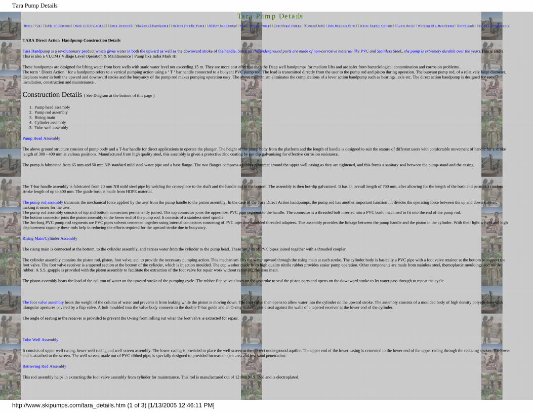
Tara Pump Details
Tara Pump Details
[Home] [Up] [Table of Contents] [Mark II/III/VLOM 50] [Extra Deepwell] [Shallowell Handpump] [Malawi Treadle Pump] [Afridev handpump] [Metal Treadle Pump] [Centrifugal Pumps] [General Info] [Info Request Form] [Water Supply Options] [Guest Book] [Working of a Handpump] [Downloads] [SS/PVC components]
TARA Direct Action Handpump Construction Details
Tara Handpump is a revolutionary product which gives water in both the upward as well as the downward stroke of the handle. Since all the underground parts are made of non-corrosive material like PVC and Stainless Steel., the pump is extremely durable over the years.This is also a This is also a VLOM ( Village Level Operation & Maintainence ) Pump like India Mark III
These handpumps are designed for lifting water from bore wells with static water level not exceeding 15 m. They are more cost effective than the Deep well handpumps for medium lifts and are safer from bacteriological contamination and corrosion problems.The term ‘ Direct Action ‘ for a handpump refers to a vertical pumping action using a ‘ T ‘ bar handle connected to a buoyant PVC pump rod. The load is transmitted directly from the user to the pump rod and piston during operation. The buoyant pump rod, of a relatively large diameter, displaces water in both the upward and downward stroke and the buoyancy of the pump rod makes pumping operation easy. The above mechanism eliminates the complications of a lever action handpump such as bearings, axle etc. The direct action handpump is designed for esey installation, construction and maintenance .
Construction Details ( See Diagram at the bottom of this page )
1. Pump head assembly2. Pump rod assembly3. Rising main4. Cylinder assembly5. Tube well assembly
Pump Head Assembly
The above ground structure consists of pump body and a T-bar handle for direct applications to operate the plunger. The height of the pump body from the platform and the length of handle is designed to suit the stature of different users with comfortable movement of handle for a stroke length of 300 - 400 mm at various positions. Manufactured from high quality steel, this assembly is given a protective zinc coating by hot dip galvanising for effective corrosion resistance.
The pump is fabricated from 65 mm and 50 mm NB standard mild steel water pipe and a base flange. The two flanges compress a rubber grommet around the upper well casing as they are tightened, and this forms a sanitary seal between the pump-stand and the casing.
The T-bar handle assembly is fabricated from 20 mm NB mild steel pipe by welding the cross-piece to the shaft and the handle nut to the bottom. The assembly is then hot-dip galvanised. It has an overall length of 760 mm, after allowing for the length of the bush and permits a random stroke length of up to 400 mm. The guide bush is made from HDPE material.
The pump rod assembly transmits the mechanical force applied by the user from the pump handle to the piston assembly. In the case of the Tara Direct Action handpumps, the pump rod has another important function : it divides the operating force between the up and down strokes, making it easier for the user.The pump rod assembly consists of top and bottom connectors permanently joined. The top connector joins the uppermost PVC pipe segment to the handle. The connector is a threaded bolt inserted into a PVC bush, machined to fit into the end of the pump rod. The bottom connector joins the piston assembly to the lower end of the pump rod. It consists of a stainless steel spindle .The 3m-long PVC pump rod segments are PVC pipes solvent cemented together using internal connectors consisting of PVC injection moulded threaded adapters. This assembly provides the linkage between the pump handle and the piston in the cylinder. With their light weight and high displacement capacity these rods help in reducing the efforts required for the upward stroke due to buoyancy.
Rising Main/Cylinder Assembly
The rising main is connected at the bottom, to the cylinder assembly, and carries water from the cylinder to the pump head. These are 3 m of PVC pipes joined together with a threaded coupler.
The cylinder assembly contains the piston rod, piston, foot valve, etc. to provide the necessary pumping action. This mechanism lifts the water upward through the rising main at each stroke. The cylinder body is basically a PVC pipe with a foot valve retainer at the bottom to support the foot valve. The foot valve receiver is a tapered section at the bottom of the cylinder, which is injection moulded. The cup washer made from high quality nitrile rubber provides easier pump operation. Other components are made from stainless steel, themoplastic mouldings and nitrile rubber. A S.S. grapple is provided with the piston assembly to facilitate the extraction of the foot valve for repair work without removing the riser main.
The piston assembly bears the load of the column of water on the upward stroke of the pumping cycle. The rubber flap valve closes on the upstroke to seal the piston parts and opens on the downward stroke to let water pass through to repeat the cycle.
The foot valve assembly bears the weight of the column of water and prevents it from leaking while the piston is moving down. The foot valve then opens to allow water into the cylinder on the upward stroke. The assembly consists of a moulded body of high density polyethylene with triangular apertures covered by a flap valve. A bolt moulded into the valve body connects to the double T-bar guide and an O-ring makes a static seal against the walls of a tapered receiver at the lower end of the cylinder.
The angle of seating in the receiver is provided to prevent the O-ring from rolling out when the foot valve is extracted for repair.
Tube Well Assembly
It consists of upper well casing, lower well casing and well screen assembly. The lower casing is provided to place the well screen at the correct underground aquifer. The upper end of the lower casing is cemented to the lower end of the upper casing through the reducing socket. The lower end is attached to the screen. The well screen, made out of PVC ribbed pipe, is specially designed to provided increased open area and less sand penetration.
Retrieving Rod Assembly
This rod assembly helps in extracting the foot valve assembly from cylinder for maintenance. This rod is manufactured out of 12 mm M.S. Rod and is electroplated.
http://www.skipumps.com/tara_details.htm (1 of 3) [1/13/2005 12:46:11 PM]

Tara Pump Details
Tara Pump Complete Assembly
[ Up ]
http://www.skipumps.com/tara_details.htm (2 of 3) [1/13/2005 12:46:11 PM]

Tara Pump Details
Send sales related email to [email protected] and questions or comments about this website to [email protected]
Home / Table of Contents / Mark II/III/VLOM 50 / Extra Deepwell / Tara Handpump / Shallowell Handpump /MALAWI TREADLE PUMP / Afridev handpump / Treadle Pumps / Centrifugal Pumps / CASTINGS / General Info / Info Request Form / Water Supply Options / Working of a Handpump / Downloads / SS/PVC components
http://www.skipumps.com/tara_details.htm (3 of 3) [1/13/2005 12:46:11 PM]

Grinding Mills,Deep Well Hand Pumps,Hand Water Pump,Weighing Scale Exporters,Grain Grinding Mills,Flour Mills,Exporters India
The high quality grinding mills, deep well hand pumps and weighing scales come in various designs and models.
GRINDING MILL 1-A, 2-A
DIAMOND TYPE FLOUR MILL & EMERY MILL STONES
http://www.lovson.com/grinding-mill.html (1 of 3) [1/13/2005 12:46:13 PM]

Grinding Mills,Deep Well Hand Pumps,Hand Water Pump,Weighing Scale Exporters,Grain Grinding Mills,Flour Mills,Exporters India
INDIA MARK II & III DIRECT ACTION HAND PUMP
No. 314Cast - Iron model "B"
No. 301Steel - Plate model "D"
"SPECIFICATIONS ARE SUBJECT TO CHANGE WITHOUT NOTICE"
http://www.lovson.com/grinding-mill.html (2 of 3) [1/13/2005 12:46:13 PM]

Grinding Mills,Deep Well Hand Pumps,Hand Water Pump,Weighing Scale Exporters,Grain Grinding Mills,Flour Mills,Exporters India
Home -||- E Mail -||- QueryLight Engineering Goods -||- Textiles -||- Vehicles -||- Agro Commodities -||- Auto Parts
Sports Goods & Equipments -||- Safety Matches & Tooth Pastes -||-HDPE & PP Sacks -||- Ethnic Indian Gifts
Copyright © 2000,Lovson Exports Ltd. All Rights ReservedSite Developed by IndiaMART IInterMESH Limited
http://www.lovson.com/grinding-mill.html (3 of 3) [1/13/2005 12:46:13 PM]

Technology Bank: International Development Research Centre
IDRC.CA > Publications > Archives > Technologies
Topic Explorer
Technologies Agriculture Communication Economics Education Energy Engineering Environment Fishery Forestry Health
Participate
Editor(s)
Bill Carman
ID: 2640Added: 2002-05-28 10:32Modified: 2004-10-15 12:47
Technology Bank
nayudamma.jpg
The Nayudamma Technology Bank provides easy access and information to technologies supported by IDRC — technologies from the South for the South. This collection, which provides contact names for all the technologies described, is a way of sharing and updating information on technological advancements for international development.
The technology bank has been named in honour of the late Dr Yelavarthy Nayudamma, a man who dedicated his life to demonstrating how science and technology can and should be used for human benefit. Dr. Nayudamma, who joined the IDRC Board of Governors in 1981, lost his life in the tragic Air India disaster in 1985.
Dr Nayudamma deeply believed in the concept of "technologies for humanity" and the need to "bring modern science to bear upon the problems and needs of the rural poor." Though internationally recognized as an organic chemist, specializing in the complex polyphenol-protein interactions upon which leather manufacture is based (in 1965 he received the K.G. Naik Gold Medal for his research), Dr Nayudamma was ultimately a practical technologist. As director of the Central Leather Research Institute (CLRI) in Madras from 1958 to 1971, Dr Nayudamma made important contributions to the development of India's leather industry. In 1971, he became director of the Committee on Science and Technology in Developing Countries ( COSTED ), spearheading a movement for the appropriate integration of traditional and emerging technologies. Dr Nayudamma's accomplishments are numerous and varied. It is out of admiration for his vision and in honour of his memory that IDRC has named this bank of technologies for development the Nayudamma Technology Bank.
● Agriculture
● Communication and Information
● Economics
● Education
● Energy
● Engineering
http://web.idrc.ca/en/ev-2640-201-1-DO_TOPIC.html (1 of 2) [1/13/2005 12:46:16 PM]

Technology Bank: International Development Research Centre
● Environment
● Fishery
● Forestry
● Health
guest (Read)(Ottawa) Login Important Notices | Copyright 1995 - 2004 © International Development Research Centre
http://web.idrc.ca/en/ev-2640-201-1-DO_TOPIC.html (2 of 2) [1/13/2005 12:46:16 PM]

The IDRC Library: International Development Research Centre
IDRC.CA > Library
Topic Explorer
Library Collections Contact Us Research Projects Resources for Projects Search Tools
Participate
Editor(s)
Sylvie Cormier
Barbara Porrett
ID: 8564Added: 2002-08-30 7:34Modified: 2005-01-12 13:51
The IDRC Library
The International Development Research Centre Library is the gateway to the corporate memory and research information services of IDRC.
The IDRC corporate memory can be accessed through the Library databases: BIBLIO, the Library Catalogue; IDRIS, a database of project information, and IMAGES, the IDRC photo library. An increasing number of titles in the collection are available in electronic format.
The primary clients of the Library's research information services are the Centre's staff and IDRC-funded researchers. Other members of the international development research community are invited to use our Web site and to visit the library Monday to Friday, between 11:00 a.m. and 4:00 p.m.
Follow the links to discover more about the services, collections, and research tools on the site. Enquiries can be sent to [email protected].
● Collections
Research material related to international development
● Contact Us
● Project Summaries
Short summaries of project objectives and methodologies
● Research Resources for IDRC Projects
● Search Tools
Library databases providing access to IDRC project and
research information.
Website(s)
BIBLIOSearch the Library CatalogueRead more...
IDRISSearch for Project InformationRead more...
IDRC — The Beginnings
IDRC's path from dream to practical action is told in the archival documents of IDRC. The story and documents have been posted for all to read in a new collection on the IDRC public web site.
http://web.idrc.ca/en/ev-8564-201-1-DO_TOPIC.html (1 of 2) [1/13/2005 12:46:17 PM]

The IDRC Library: International Development Research Centre
IMAGESSearch the Photo LibraryRead more...
guest (Read)(Ottawa) Login Important Notices | Copyright 1995 - 2004 © International Development Research Centre
http://web.idrc.ca/en/ev-8564-201-1-DO_TOPIC.html (2 of 2) [1/13/2005 12:46:17 PM]

NZ Pump - Shallow Well Village Pump
[ HOME | PRODUCTS | DISTRIBUTORS | ABOUT | NEWSLETTERS | CONTACT ]
[ DRUM PUMP | POWDER MEASURE | MARINE/KAYAK PUMP | SHALLOW WELL PUMP ]
EZI-ACTION SHALLOW WELL PUMP
When it comes to taking water from Shallow Wells up to (80ft) 25 metres deep to the water, the EZI-action Shallow Well Pump has many benefits.
● in a Kitset form it is easy to install (up to 20 minutes).● Kitset comes with pipe connection for the water level.● pipe sections are connected by threaded joints that are
only hand tightened.● made from uPVC - there is nothing to rust or corrode.● low cost pump that has been thoroughly tested.
Easy to install Kitset packageThe pump is made from PVC plastic which makes it light to handle. Each section is threaded for easy assembly. 2 people will take between 15 and 20 minutes to install a 52ft pump. No additional piping or plumbing required.
20 to 35 litres per minute (5 to 8 Gallons)You will pump between 5 and 8 gallons per minute depending on the depth of the pump and speed of operation. Water is delivered on both the up and down stroke. An ergonomical pumping action using the legs is shown in the installation instructions. (Some say it is better exercise than going to the gym).
Tested to 10 million cyclesDuring research a shallow well pump with this patented pumping principle was continuously run for 10 million pumping cycles. At the end of the test the pump was delivering the same amount of water per cycle as at the beginning, and when dis-assembled little or no wear could be detected.
Patented pumping actionThe unique factor about this pump is that it is neither a piston nor a vacuum pump. It incorporates a unique pumping principle that does not have to overcome any friction in the pumping action.
http://www.nzpump.co.nz/village-pump.html (1 of 2) [1/13/2005 12:46:22 PM]

NZ Pump - Shallow Well Village Pump
[ DRUM PUMP | POWDER MEASURE | MARINE/KAYAK PUMP | SHALLOW WELL PUMP ]
[ HOME | PRODUCTS | DISTRIBUTORS | ABOUT | NEWSLETTERS | CONTACT ]
Copyright © 2000 - 2004 by
Last updated September 2004
http://www.nzpump.co.nz/village-pump.html (2 of 2) [1/13/2005 12:46:22 PM]

SWS Rower Pumps
The SWS Rower pump is a manually operated, suction piston pump used for drawing water from shallow wells, river bed filters and open water. It is ideal for irrigation, village water supply and livestock watering
SWS Filtration’s involvement with Rower Pumps started in 1982 when we introduced them to an agricultural development project in North Nigeria.
The Rower pump is most unusual in appearance. The cylinder is not upright like most pumps, but is placed into the ground at an angle of about 30o to the horizontal so it looks more like a rocket launcher than a pump!
The operator holds a wide T-handle and pulls and pushes directly on the piston rod as the water pours out of the top of the cylinder so the pumping action is like rowing a boat. Although when one first sees a Rower Pump it looks rather weird, all of the main pump components are still present including a traditional foot valve, piston valve and pump cylinder.
Rower Pumps are very easy to make, operate and maintain. They are suction pumps so are
limited to areas where the water is within 6 metres or 20 ft of the surface. Rower Pumps are ideal for lifting water from low level springs, shallow wells, or river beds. The Rower Pump does not filter the water itself, but it can be connected to a sub-sand filter. By drawing water directly from a protected low level spring, the water will be much cleaner than if the spring is open for people and animals to contaminate.
http://ds.dial.pipex.com/swsfilt/rower/index.htm (1 of 2) [1/13/2005 12:46:26 PM]

SWS Rower Pumps
SWS can either sell complete pumps or help you set up assembly workshops if ther is sufficient demand. SWS Filtration also has a charity account which allows us to give some pumps and water filtration equipment free of charge to bona fide development projects. Funding for this account is limited but we would be very pleased to help you if we can. Alternatively, if you would like to support this work, your donations would be gratefully appreciated by those we are seeking to help. (SWS Water Charity Account)
Over the years a lot has been written about Rower Pumps. We have included and updated a number of these articles for you to browse through, but if you have any specific questions please email us and tell us something about your project. We are also involved with a lift pump (NZ Pump) but if neither of these is appropriate we will gladly put you in touch with other organisations involved with water development and hand pumps.
For more information on SWS Rower Pumps click on one of the following options....
● SWS Rower Pumps - Your Questions Answered ● SWS Rower Pumps - What the users think ● SWS Pompes "Rower" (Francais) ● Rower Pump Testing by the Consumer Association ● Bangladeshi Rower Travels To Africa Article published in World
Water ● The Rower Pump Article first published in Developing World Water
in 1988 ● SWS Water Charity Account ● Rower Pump with delivery option
© 1997 SWS Filtration | Page maintained by Hal Last updated 2:06 PM 3/21/97 | Contact details
http://ds.dial.pipex.com/swsfilt/rower/index.htm (2 of 2) [1/13/2005 12:46:26 PM]

Boshart Industries : Hand Pumps and Leathers
HOME PRODUCTS CONTACT NEWS ABOUT
PLUMBING WATER WELL SUMP & SEWAGE NEW PRODUCTS Surplus
Water Well >> Hand Pumps and Leathers
Product Image
Hand Pump (pdf, 34.5 KB)
Product Image
Cup Leathers (pdf, 24.8 KB)
Comments? Please click here.
View our Privacy Policy.
© 2004 Boshart Industries Inc.
HOME | PRODUCTS | CONTACT US | NEWS | ABOUT US
http://www.boshart.com/products/waterwell/section15/index.html [1/13/2005 12:46:30 PM]

Hand Pumps - PlumbingSupply.com
Hand Pump
- we are the largest and most popular Internet mail order plumbing supplier since 1995 - to home page - to email us - to how to order - to customer testimonials - to FAQ's - to shipping FAQ's - to return policy Find plumbing supplies starting with: A B C D E F G H I J K L M N O P Q R
S T U V W X Y Z
to our pump index page to pond and fountain pumps - to Sequence brand pond pumps to recirculating pumps - to sewage ejector pumps (pumps for up-flush toilets) and ejection systems to budget water-powered pump - to large sump pumps - to float switches and high water alarms to water-
powered and battery-powered back up sump pumps - to top quality coiled garden hose for indoor/outdoor use
This beautifully constructed hand pump is both functional and decorative. We have sold hundreds to home owners as a back-up during power outages and to gardeners for the perfect finishing touch to their fountain, pond or other garden displays.
Hand operated pitcher pump
● Heavy cast iron construction● Open spout 15 3/4" high ● Tapped for 1 1/4" drop pipe● Rated for depths up to 24' ● Easily installed● Primer enamel paint finish (chips fairly easily)
Hand Operated Pump #HPP-1 = $59.98
- Or -Click here to view items already in your shopping cart
http://www.plumbingsupply.com/handpump.html (1 of 2) [1/13/2005 12:46:32 PM]

Hand Pumps - PlumbingSupply.com
handpump
"Do you sell or know a source for hand pumps that pump from deeper wells?" Sorry but what we show is all that we sell as far as hand pumps. Pumps for deeper wells can get very complicated and they require a two-pipe system.
"Do I need to prime your pump each time?" Because this is for shallow wells, there is no need to prime it. Sometimes when the pump arrives you will need to run some water into the pump to wet the leather. Sometimes (and certainly after time) you will need to use some quality basic faucet grease #LU020 on the diaphragm.
"My hand pump used to work fine. Now it won't pump anymore. Any suggestions?" Try using some quality basic faucet grease #LU020 on the diaphragm. Many times this will expand the rubber/leather enough that it will work for you again. Make sure to use grease that is approved for drinking water (ours is).
"I'm told that installing a check valve on the inlet side of any brand of hand pump is a good idea. What do you think?" On a fairly new pump we don't think it matters much. But on an older pump a good spring check valve in an accessible vertical section of your drop pipe may work wonders for the pump's operation. It can keep you from the sometimes-aggravating need to prime it after each use.
"To pump water will I need anything besides the HPP-1 pump?" You will need some 1 1/4" pipe (along with threads on at least one end). With PVC plastic pipe you will need a 1 1/4" male adapter #PVC436 (as well as your PVC pipe). With steel pipe you need 1 1/4" pipe with threads. You can also adapt from 1 1/4" to 1" and use 1" pipe. You can use almost any kind of potable (drinking water) grade pipe as long as it is fairly straight and reaches into your water source (and your water level is not deeper than 24' below the pump). Your pipe can be longer than 24'.
"I have an old hand pump that I purchased elsewhere. Do you know where I can get parts for it?" There are many different brands, with all different parts. We cannot stock or find parts for other brands. The hand pumps that we sell are pretty rugged. They do change parts every so often and so we cannot supply parts for the ones we sell either. It is extremely rare that one of ours fails within 3 years. Generally all that ever goes wrong is that the leather cup dries up. For that we recommend using some quality faucet grease (#LU020) on the leather diaphragm. If you bought your hand pump elsewhere we do not wish to ship you parts that fit to ours. We make this rule based on experience. We have found that our parts do not fit other brands of hand pumps and the return rate is simply too great for parts that people think might "fit" and then won't. We do not offer parts for hand pumps.
We hope that we have helped you on this page with hand pumps and that you will always be pleased with us.
Click Here to go to Our Fun Quotes Page, with quotes such as: "Fame is a vapor, popularity is an accident, money takes wings, those who cheer you today may curse you tomorrow.
The only thing that endures is character." -- Horace Greeley
Is there something else that you are looking for?
Enter what you're looking for here:
OR - find plumbing supplies starting with: A B C D E F G H I J K L M N O P Q R S T U V W X Y Z
Homepage | About Us | Contact Us | How to Order | View Shopping Cart | Testimonials | Q and A | Return Policy Copyright© since 1995
PlumbingSupply.com
http://www.plumbingsupply.com/handpump.html (2 of 2) [1/13/2005 12:46:32 PM]

0243-2kstore.com, Water pump
Mountain Creek Ranch Supply
Honda- powered
SALE! Save on House Fans Now
Search This Web Site
Click HereThe Ultimate
Popcorn Lovers Gift Pack
Summer Basket Sale Now
CLICK-HERE!!
Company Privacy, Order and Return Policies
Item #HRF01318 Old-fashioned water pump. Requires no electric power and will lift water 25 feet. This pump can be a life saver for retrieving water from a shallow well, cistern or storage tank and add a touch of charm to the duty !
Price $51.77 plus S&H. NOW on Sale for $39.90 + S&H
For Information or to Order Call Toll Free 1-877-365-3880
http://www.2kstores.com/general_store/gs4.htm (1 of 2) [1/13/2005 12:46:35 PM]

0243-2kstore.com, Water pump
Cowboy Dinner Bell
Portable Camp Fire
Elk Whisperer Video's & Music
Great Die Cast Models For Christmas
Item #1318ik - Installation kit for the best results with your water pump. Add the 1 1/4" poly pipe purchased from your local hardware store, or from us to this kit ( a spring loaded check valve, clamps and poly pipe adapters for the valve and the pump) to make an easy installation with the water held
ready at the pump.
Kit Price $24.50 plus S&H.
For Information or to Order Call Toll Free 1-877-365-3880
Water StorageStorage Containers
Click Here
Hand CrankGrain Mill
We strive to keep this Web Site updated but due to constant price changes the prices in this Internet catalog are subject to change without Notice.
We Honor These Cards
2kstore.com/Division of Poole & Sons, Inc.Phone # (208) 365-3880 * Fax # (208) 365-3044
TOLL FREE ORDER # 1-877-365-38801398 N. Washington Ave. Emmett, Idaho 83617
©Copyright by Poole & Sons Inc. email [email protected]
http://www.2kstores.com/general_store/gs4.htm (2 of 2) [1/13/2005 12:46:35 PM]

Sigma K2
Welcome toRintoul's
Hand PumpsTobermory,
Ontario
THE SIGMA K2 Price: $182.95 Cdn($150.00 US)
Item 29 on Order Form Item 29 on Price List
"For numerous industrial, marine and domesticapplications, a Sigma pump remains the solution."
"Proven Technology"
Used extensively in Europe today. They werepopular in Ontario about 35 years ago, andsome are presently still in use.
The ultimate hand operated water pumpfor areas without electricity.
Cut-away view
Double Acting Semi-Rotary Hand Wing Pump
● The simple robust design using quality materials and workmanship guarantees a long and effective service life.
● The body is cast iron, the wing piston assembly and suction divider are brass and the shaft is steel.
OPERATION:
● The handle moves back and forth in a 110 degree arc, which in turn causes the wing piston with flaps (4) to semi-rotate within the body.
● The suction divider with flaps (5) operates as the inlet check valve.● The unit discharges fluid on both strokes of the handle.
http://www.handpumps.com/sigma.htm (1 of 6) [1/13/2005 12:46:52 PM]

Sigma K2
● It must be bolted to a strong vertical surface with the letters "ISH" at the top - two mounting lugs are provided.
● The handle can be installed either pointing up, down, left or right.
1. Casing
2. Cover
3. Gland Nut
4. Wing Piston with
Flaps & Shaft
5. Suction Divider
with flaps
6. Handle
7. Gland
Packing
8. Gland Ring
9. Shaft Nut
10. Washer
11. Counter flange
12. Flange Bolt & Nut
13. Cover Bolt & Nut
14. Flange Joint
FEATURES:
This pump incorporates many original technical features which make it the best of its type.
● The reinforced inlet flange, outlet flange and mounting lugs prevent breakage even when subjected to rough treatment.
● The tapered internal body is a unique design which assures automatic settlement of the wings, thus guaranteeing smooth efficient operation for many years.
● Each pump is tested to a suction lift of 7 meters of water and 20 meters of discharge head.
● A drain plug allows water to be drained if the unit will be unused for extended periods of time, or if there is a risk of freezing.
CAUTION: Sigma pumps used for water must be protected from rust whenever they will be unused for extended periods of time. Cooking oil, glycerine, or mineral oil (U.S.P. heavy - sold in pharmacies) are nontoxic and can be pumped through the unit via the drain plug for this purpose.
SPECIFICATIONS:
● Weight: 8 kg (18 lbs.)● Capacity: 5 G.P.M (22.5 L.P.M.) at 55 double strokes per minute● Plumbing Connection: 1" female pipe thread● Maximum Discharge Pressure: 37.5 P.S.I.
http://www.handpumps.com/sigma.htm (2 of 6) [1/13/2005 12:46:52 PM]
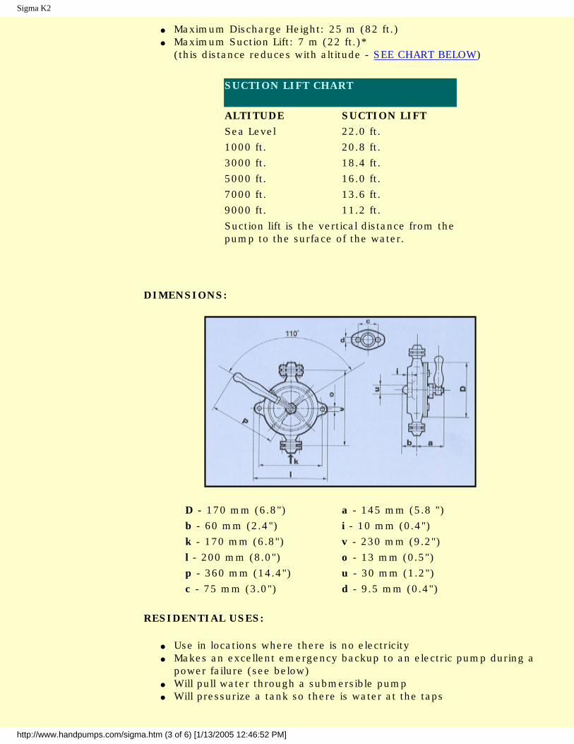
Sigma K2
● Maximum Discharge Height: 25 m (82 ft.)● Maximum Suction Lift: 7 m (22 ft.)*
(this distance reduces with altitude - SEE CHART BELOW)
SUCTION LIFT CHART
ALTITUDE SUCTION LIFTSea Level 22.0 ft.1000 ft. 20.8 ft.3000 ft. 18.4 ft.5000 ft. 16.0 ft.7000 ft. 13.6 ft.9000 ft. 11.2 ft.Suction lift is the vertical distance from the pump to the surface of the water.
DIMENSIONS:
D - 170 mm (6.8") a - 145 mm (5.8 ")b - 60 mm (2.4") i - 10 mm (0.4")k - 170 mm (6.8") v - 230 mm (9.2")l - 200 mm (8.0") o - 13 mm (0.5")p - 360 mm (14.4") u - 30 mm (1.2")c - 75 mm (3.0") d - 9.5 mm (0.4")
RESIDENTIAL USES:
● Use in locations where there is no electricity● Makes an excellent emergency backup to an electric pump during a
power failure (see below)● Will pull water through a submersible pump● Will pressurize a tank so there is water at the taps
http://www.handpumps.com/sigma.htm (3 of 6) [1/13/2005 12:46:52 PM]

Sigma K2
● See the SPECIFICATIONS section for capabilities
INDUSTRIAL AND MARINE USES:
Sigma Type 'K' pumps meet all major European industrial standards. Sigma Type 'K' hand pumps have numerous industrial applications.
They can be used:
● to transfer clear light fluids in the marine, petrochemical, construction, agriculture and automotive industry
● to handle fluids up to 80 degrees C. (176 degrees F.)● as manual bilge pumps in commercial ships● as a completely reliable backup to an electric pump
OTHER SIZES AND MODELS WITH BRONZE BODIES ARE AVAILABLEFROM THE FACTORY BY SPECIAL ORDER.
CONTACT US FOR PRICING AND SHIPPING INFORMATION.
http://www.handpumps.com/sigma.htm (4 of 6) [1/13/2005 12:46:52 PM]

Sigma K2
Complete this form to order any of the Sigma K2 Series pumps and accessories.
Customer Information
Name: Address:
Address: City:
Prov./State: Postal/Zip:
Country: Phone:
Fax: E-mail:
Order Information
The Sigma K2 Series
Model: Qty: Accessories: (29) K2
Payment Information
Payment Method:
Please click on the Submit button to e-mail your order to Rintoul's Handpumps.
All orders will receive an e-mail confirmation within 24 hours excluding weekends and holidays with shipping date, total charges due (including tax
and shipping) and payment instructions.
http://www.handpumps.com/sigma.htm (5 of 6) [1/13/2005 12:46:52 PM]

Sigma K2
Hand operated water pumps for the home, cottage, cabin, camp, farm, boat, commercial ship and industry etc. We also have a dock adjusting
tool, waterline anchor bracket and plastic pipe connectors.
RINTOUL'S HAND PUMPSRR#2, Tobermory, Ontario - NOH 2R0
Telephone/Fax: 519-596-2612 E-mail: [email protected]
http://www.handpumps.com/sigma.htm (6 of 6) [1/13/2005 12:46:52 PM]

Real Goods - Guzzler Hand Pumps
Home PageCheckoutCustomer ServiceFree CatalogAbout UsRetail StoresReaders ForumDesign & ConsultingDemo HomesSystem Sizing
View Cart Help
Guzzler Hand Pumps
These high-volume, low-lift pumps are driven by simple, dependable muscle
power. Reinforced diaphragms and flapper valves ensure durable, dependable
pumping. Both models have up to 10 ft. of suction lift, and about 12 ft. of
delivery head. They make excellent emergency sump pumps, bilge pumps, or
simple water delivery systems. Model 400 delivers up to 10 gpm, and uses 1"
hose. Model 500 delivers up to 15 gpm, and uses 1.5" hose. Don’t use garden hose with these pumps. It’s
too small, and will restrict delivery. USA.
Guzzler 400 Hand Pump
Price: $49.00
Qty:
Guzzler 500 Hand Pump
Price: $59.00
This item is on backorder.
Qty:
Comparison Table(s):
Guzzler Hand Pump
<< Previous Page
Home | Free Catalog | About Us | Retail Stores | Sale Items
Order securely online or call 800.919.2400
© 2005, Gaiam.com, Inc.
Privacy Policy | Terms of Use
http://www.realgoods.com/renew/shop/product.cfm?dp=1902&ts=1041151&kw=guzzler [1/13/2005 12:46:53 PM]

Tech Gallery - Treadle Pump
FrenchSpanish
The Treadle Pump consists of two metal cylinders with pistons that are operated by a natural walking motion on two treadles. The pump can be manufactured locally in simple metalworking shops. The treadles and support structure are made of bamboo or other inexpensive, locally available material. It is easily maintained with standard replacement parts available in local markets at a low cost. The efficient step-action operation makes it possible to pump the large volumes of water necessary for irrigation. All household members are able to operate the pump, allowing farmers to make efficient use of family labour.
The pump's low cost makes it accessible to even very poor farmers who can use it to grow dry-season vegetables for home consumption and for sale. On average, farmers are able to generate more than US$100 per year in extra income. Since 1985, when IDE first began promoting the treadle pump in Bangladesh, about two million treadle pumps have been installed worldwide.
Discharge 1 to 2 L/s depending on cylinder diameter and pumping depth.
Maximum pumping depth Approximately 7 m
Area irrigated 1 acre (0.4 hectares)
Cost of pump head* US$9
Cost of tubewell* US$25 to US$50
* Typical costs in South and Southeast Asia
River Pump
Mounted on a portable metal stand so that it is easily moved from one water source to another. Pumps from surface water sources. Inlet hose required for suction. No borehole required.US$18 to US$35*
http://www.ideorg.org/html/gallery/treadle.html (1 of 2) [1/13/2005 12:46:57 PM]

Tech Gallery - Treadle Pump
Metal Treadle Pump
Permanently attached metal treadles increases portability. Can be mounted on a borehole (like the basic Treadle Pump) to draw from groundwater sources. Can be mounted on a metal frame (like the River Pump) to draw from surface water sources.US$20 to US$26*
Concrete Pump
PVC cylinders embedded in a concrete body. Prevents corrosion in regions with saline groundwater. Mounted on a borehole to draw from groundwater.US$17*
Plastic Pump
All plastic construction prevents corrosion in regions with saline groundwater. Mounted on a borehole to draw from groundwater.US$17*
http://www.ideorg.org/html/gallery/treadle.html (2 of 2) [1/13/2005 12:46:57 PM]

T.E.MANNING, NETHERLANDS, ADVANCED SOLAR AND HAND PUMPING TECHNOLOGIES FOR DEVELOPING COUNTRIES
T.E.(Terry) ManningSchoener 50
1771 ED WieringerwerfThe Netherlands
Tel/fax 0031-227-604128Homepage: http://www.flowman.nl
E-mail:[email protected]
FLOWMAN
ADVANCED PUMP TECHNOLOGIESEdition 06 : 22 December, 2002
SOLAR SPRING SOLAR SUBMERSIBLE PUMPS
DETAILED SPECIFICATIONS OF THE SOLAR SPRING PUMPS APPLICATIONS COMPONENTS DESCRIPTION
SUN-CATCHING PUMP TECHNOLOGYThe patented horizontal axis piston technology used for the Solar Spring pumps needs less than 300 Watts of solar-electric or wind power in the world’s most rugged operating conditions to pump water as high as 200m (600 vertical feet) with a flow of up to 27 liters/minute (7 gallons/minute). It can be used with or without batteries. It is the cheapest solution to small-scale pumping problems in off-grid applications including water for livestock, alternative living, nurseries, micro-horticultural and industrial projects, high pressure washing, water for missions, schools, hospitals, refugee camps, nomadic groups, DRINKING WATER SUPPLY IN RURAL LOCATIONS, mobile units with batteries, fountains, week-end and holiday houses and camps, and isolated locations generally. It positively enjoys service in the world’s roughest operating conditions where competing technologies cannot be used and thrives
http://www.flowman.nl/solprese.htm (1 of 4) [1/13/2005 12:46:59 PM]

T.E.MANNING, NETHERLANDS, ADVANCED SOLAR AND HAND PUMPING TECHNOLOGIES FOR DEVELOPING COUNTRIES
effectively on low power.i
The pump is made from stainless steel, with highly resistant parts, but it is not specifically designed for use with salt water or waters containing particularly aggressive elements, which may shorten the duration of some parts. If in doubt, consult your supplier.
FEATURES
Uses power of one light-bulb
Positive displacement
Pumps from 200m (600 ft)
Capacity up to 11m3 per day
Submergence to 50m (150ft)
Air-cooled motor can run dry
Made from stainless steel
Up to 60% subsystem efficiency
Easy to install
Fits in a 4 inch well casing
Tolerates sand and aggressive water
No trackers or batteries needed
HIGHLY COST EFFECTIVE
Solar pumping systems
Photovoltaic (PV) panels generate electricity directly from the sun’s light, with no moving parts. They may be mounted on a fixed structure or on a solar tracker which follows the sun to extend daily operation. The solar array may be mounted some distance away from the water source. Most systems are designed to pump only during the daytime to fill a storage tank or pond. This is usally more economical and reliable than using batteries. Solar Spring systems use an electronics device to connect the photovoltaic (PV) panels directly with the pump motor, eliminating the need for inverters and/or battery storage, but they also work with batteries and with wind generators.
How is the Solar Spring pump technology possible?
http://www.flowman.nl/solprese.htm (2 of 4) [1/13/2005 12:46:59 PM]

T.E.MANNING, NETHERLANDS, ADVANCED SOLAR AND HAND PUMPING TECHNOLOGIES FOR DEVELOPING COUNTRIES
THE PUMP
Inside the patented Solar Spring pump there is an oval camshaft which drives two large horizontally opposed pistons which operate over a very short single action stroke. The pump mechanisms are bathed in non-toxic oil and are separated from the water in the system by means of stress-free gaskets. The pulsating flow of the single action system is made smooth by an internal damper and by the use of flexible drop pipe. All parts of the pump work within their normal materials stress levels to a depth of 150m (450 ft).
THE MOTOR
The specially developed 4 inch permanent magnet DC motor works efficiently at variable speeds. A brush type motor was chosen for reasons of efficiency, reliability and economy (brushless motors need complex electronics). Motor brushes, with normal solar daytime use, usually last 4 to 7 years. They can be replaced within a few minutes in the field without disturbing the wiring. The motor can turn at from 0-3000 rpm and is optimised to work best at 2000rpm.
THE CONTROLLER
The patented Sunprimer controller provides a surge to start the motor and boosts the current in low sun conditions to prevent stalling. Its simple and robust circuitry is placed in a water tight enclosure which is usually fitted behind the photovoltaic panels. The controller is fitted with wires enabling float switches to be connected.
THE INERTIA AMPLIFIER
The Hyboost inertia amplifier is fitted to the shallow well model of the Solar Spring which is used for installations where the water level is not greater than 60m (180 ft). The Hyboost is advanced but simple technology enabling missmatch in the hydraulic system to be absorbed and returned to system at the appropriate moment of the pumping cycle. Available power from the photovoltaic panels can be fully used and motor absorption and pump capacity in some cases more than doubled.
THE SOLAR ARRAY
Any combination of photovoltaic panels with a nominal power of up to 400Wp placed in series or in parallel can be used with the Solar Spring pump. Voltage can be anywhere between 24V and 80V. Direct current is fed directly from the photovoltaic panels ( or through batteries) to the pump motor. Neither inverters nor batteries are necessary.
http://www.flowman.nl/solprese.htm (3 of 4) [1/13/2005 12:46:59 PM]

T.E.MANNING, NETHERLANDS, ADVANCED SOLAR AND HAND PUMPING TECHNOLOGIES FOR DEVELOPING COUNTRIES
THE REST OF THE SYSTEM
The system is completed by a flexible polyethylene drop-pipe supplied in one continuous length to enable installation by hand within a few minutes; by good quality submersible resin packed leak-proof electric cable; and by an appropriate length of good quality safety cord. Tracking systems for the photovoltaic panels are optional. Supports for photovoltaic panels can be ground, pole, or lattice type according to requirements imposed by prevailing climatic conditions.
FOR A MORE DETAILED PRESENTATION OF THE SOLAR SPRING PUMPS PLEASE GO TO:
DETAILED SPECIFICATIONS OF THE SOLAR SPRING PUMPS APPLICATIONS COMPONENTS DESCRIPTION
FOR MORE INFORMATION ON THE SOLAR SPRING PUMPS PLEASE GO TO:
GENERAL COVER PAGE PHOTOGRAPH AND DRAWING OF THE SOLAR SPRING PUMPS LAYOUT OF A TYPICAL INSTALLATION PERFORMANCE TABLES OF SOLAR SPRING PUMPS INSTALLATION OF SOLAR SPRING PUMPS MAINTENANCEOF SOLAR SPRING PUMPS
RETURN TO:
PRODUCTS OFFERED
If you cannot find the information you require on these pages, please contact Terry Manningby e-mail on : [email protected] or
telephone or fax him at 0031-227-604128.
E-mail Terry Manning
http://www.flowman.nl/solprese.htm (4 of 4) [1/13/2005 12:46:59 PM]

New address:
New address:
http://s.u.l.homepage.dk
please bookmark or edit bookmark
http://www.sul.dk/ [1/13/2005 12:47:00 PM]

New Page 2
home
about us
Intruduction to U.V. light as disinfection
agent
Solar Disinfection of
Drinking Water
links
Homepage of Sun Ultra Light
Solar Disinfection of Drinking Water.
It is possible to purify drinking water from bacteria and virus by the ultraviolet rays in
SunlightIf you are situated between the degrees of latitude from Tunis in the North to Capetown in the South, you can take a clear glass or plastic bottle and fill it with the cleanest water you can get. This bottle should be placed in direct sunlight for 3-4 hours.Now this water will be safe to drink. The ultraviolet in
sunlight radiation kills bacteria and virus. HOW ? ? ? Although this method has been known for thousands of years and has been scientifically proven to work and UNICEF has published the book " Solar Disinfection of DrinkinWater" in 1984 - it seems that very few people know about this.
Background:
One of the greatest environmental and health hazards in the third world is shortage of water for domestic use: In 1993 there were still more than 1000 million humans without access to clean safe water.This causes more than 80 % of all cases of illness. Diarrhoea causes death of more than 6 million children and 18 million adults every year. (This number equals the number of persons dying of starvation.)
● To disinfect one liter of water by boiling will require approx. one kg of firewood.
● This is an economical and ecological impossibility in most developing countries.
Sufficient supply of clean safe water is probably the most basic human right. Already back in 1978 The Declaration of Alma-Ata stated that one of the minimum goals which the world community should have, was that everybody should have this access before the year 2000.
http://s.u.l.homepage.dk/ (1 of 2) [1/13/2005 12:47:03 PM]

New Page 2
Since then it has been a water-decade. In this period lot of declarations of intent have been adopted and the task to see that everybody has clean water by the year 2000 has been given to UNESCO. Although the number of people having access to clean water has increased, there are now due to the growth in population even more people without this access.
It would be ideal if everybody could get safe water, but everything indicates that this will take many years. Therefore it is necessary to transfer appropiate and cheap technology and knowledge to the developing countries: a technology which they themselves are able to control and which matches their ressources. . Sunlight is one of the few ressources that most people in the developing world have in abundance and which nobody can take away from them.
back to the top
http://s.u.l.homepage.dk/ (2 of 2) [1/13/2005 12:47:03 PM]

WaterAid
WaterAid is an international non governmental organisation dedicated exclusively to the provision of safe domestic water, sanitation and hygiene education to the world's poorest people.
Please select your country of residence:
© Copyright WaterAid - All rights reserved.
http://www.wateraid.org.uk/landingpage.asp?Mode...in%5Fdepth%2Ftechnology%5Fnotes%2F299%2Easp&QS= [1/13/2005 12:47:06 PM]

HUMAN-POWEREDWATER-LIFTERSThe choice of water lifters available is large and varied, making the selection of anappropriate device difficult. In America and Europe during the 19th century the design ofmass-produced hand pumps evolved by trial and error rather than through scientificresearch and development. There is now a large number of adequate, rather thanoptimum, designs conceived by local manufacturers, and it is hard to know which pump isthe best for each application. This brief presents an overview of the types of human-powered water-lifters available, the applications appropriate to them and their comparativeadvantages.
Water-lifters can be broken down into the following categories:
• Groundwater (open-well, shallow-well and deep-well pumps)• Surface Water (shadouf, dhone, chain and washer and archimedean screw)
GroundwaterWhen rain falls, it seeps into the ground and collects in an underground reservoir knownas groundwater. The upper limit of this reservoir, the "water-table", may vary in depth, fromjust below the surface (like in a spring or oasis) to well over 100 metres. The only way toget at this water is to dig down.
Open-wellThe simplest and cheapest method of lifting groundwater remains the rope and bucket in awide, shallow well. These can operate to a depth of 100 metres, although they rarelyexceed 45 metres, and can last for a very long time without maintenance. It is worthconsidering this design before proceeding with more complicated methods.
It may not be possible to construct an open-well if the water table is too deep or if thefoundations are very hard (such as rock) or very soft (such as fine running sands). Theserestrictions also depend on the method of construction.
If the groundwater can only be accessed through a bore, then a groundwater pump mustbe used. Groundwater pumps can be split into two categories, shallow-well and deep-well.
Shallow-well pumpsMost types of groundwater pump havea piston that moves back and forthinside a two-valve cylinder (a valveallows water to pass in only onedirection - in this case, upwards):
Suction pumps have the cylindersituated above ground or near thesurface. This means that they canonly be used for shallow wells. It iscalled a suction pump because pullingup on the piston creates a lowpressure ("suction") in the cylinder,causing the atmospheric pressureoutside to push the water up to thesurface. Because atmosphericpressure is fairly low, the pressure difference between inside and outside the cylinder is only large
Figure 1: How most types of pump cylinders work

Human Powered Water Lifting Devices Intermediate Technology Development Group
2
enough to raise water from a maximum depth of about 7 metres.
It should also be noted that if a shallow-well is used too much, the water-table may fall as theunderground reservoir of water is reduced. If this level falls below 7 metres, the pump will notwork.
Four types of shallow-well pumps are shown below: rower, piston, diaphragm and semi-rotary.
RowerThe rower pump is a simpler andcheaper version of the traditionalpiston pump (see below). Itssimple design means it can be easily manufactured andmaintained using locally availableskills and materials. This type ofpump may require "priming",which means pouring water intothe cylinder so that the sealaround the piston is airtight. It isvery important that clean water isused, to avoid contamination ofthe pump and the spread ofwater-borne diseases.
Figure 2: Rower pumpPistonPiston pumps, based on the same design asshown in Figure 1, are more widely used. Thereis a similar risk of contamination from dirtypriming water. In cases where the water is to bedelivered under pressure (such as to a villagewater mains) or to a point higher than thecylinder (such as a water storage tank), a "force"pump is required. The operation is the same, butthe design is slightly altered so that the top isairtight. This is done by putting a valve on thespout and adding a "trap tube" and air chamberwhich maintains the pressure (and therefore theflow) during the up-stroke.
Figure 3: Shallow-well piston pump
DiaphragmThis design is often used for fuel pumps incars. The Vergnet pump is an adaptationof this principle for deep-well use, whichcan be used in crooked wells, where a rod-operated pump would have problems, andwhich is fairly easy to maintain.
Figure 4: Diaphragm pump

Human Powered Water Lifting Devices Intermediate Technology Development Group
3
Treadle pumpBecause leg muscles are stronger than arm muscles, this design is less tiring to use.Most of the parts can be manufactured locally, the exceptions being the cylinders andpulley.
Figure 5: Treadle pump
Deep-well pumpsDeep-well pumps can be used for depths over 7 metres because the cylinder or lifting device isbelow ground, as shown in Figure 6, often below the groundwater line. They are often known as"lift" pumps because they do not rely on suction to raise the water. As a result of their depth, theyare harder to maintain than surface pumps, since the pump-rod must be removed to get at thecylinder. Like suction pumps, lift pumps can be made into force pumps by the addition of a spoutvalve, air chamber and trap tube. Three types of deep-well pump are described below: piston,helical rotor and direct action.
PistonThe design is very similar to the shallow-well pump and is capable of lifting water from depths of upto 50 metres. However, the cylinder is situated deep underground, below the groundwater-line,connected to the pump handle via a long rod called a "pump rod" (see Figure 6). Sometimes theoutside pipe, called the "rising main", is of a larger diameter so that it is possible to pull the wholecylinder up to the surface for repair without taking the pump apart. However, this is moreexpensive.
Helical rotor (or "progressive cavity")Helical rotors are capable of lifting water from depths of up to 100 metres. Instead of a piston,there is a metal "rotor" which has a corkscrew shape and which turns inside a rubber "stator" orsleeve (see Figure 6). The lever is replaced with one or two turning handles.
Direct action ( or "direct drive")This design is capable of lifting from a depth of 12 metres. The narrow pump rod is replaced by ahollow plastic pipe which displaces water as the pump handle is pushed down. During the up-stroke, the pipe acts as a pump rod, the valve on the pistoncloses and water is lifted up. The pump is therefore capable of pushing water up the rising mainduring both strokes. Because the pipe is hollow, it floats, so the handle does not have to be pulledup so hard.

Human Powered Water Lifting Devices Intermediate Technology Development Group
4
Figure 6: Types of deep-well lift pumps - piston, helical rotor and direct action
Surface WaterSurface water lifters are generally less complicated than groundwater lifters, because the water isso much more accessible. Four types are described below: shadouf, dhone, chain and washerand archimedean screw.
Shadouf (picottah)The basic shadouf consists of a rope, pole, bucket and counterweight and is capable of liftingwater up to 4 metres. The counterweight can be just a heavy rock, but in the more advanced"picottah" design, one person guides the bucket while the other acts as a moving counterweight.

Human Powered Water Lifting Devices Intermediate Technology Development Group
5
DhoneThis design replaces the bucket with a channel. It can also be adapted for picottah-styleoperation.
Figure 7: Picottah-style shadouf and dhone
Chain/rope and washer (or "paternoster")These pumps have been used in China and Europefor many centuries. Water is lifted by close-fittingwashers in a pipe. Although in theory it is possibleto construct a vertical chain and washer pump toraise water to any height, most do not exceed 20metres. A variation of this design is called the"dragon-spine" pump, which lies at a shallow angleto the horizontal. In this case, lifting height israrely more than 6 metres. However, the design isvery flexible and can easily be adapted tocircumstances.
Figure 8: Chain and washer pump
Archimedean screwAlthough this design looks quite complicated, it is fairly easy to build using local materials and isreadily transportable. The inside, which is shaped like a corkscrew, is turned by a handle, trappingwater in the cavities as shown in Figure 9. Although on a much larger scale, this is very similar tothe operation of the helical rotor. However, the lifting range is much smaller.

Human Powered Water Lifting Devices Intermediate Technology Development Group
6
Figure 9: Archimedean screw
Selecting a water-lifterThe choice of water-lifter is determined by the application and the resources available to theusers. Demand for water may come from domestic, community, industrial and agriculturalneeds. It is first necessary to determine:• where the water will come from (the source)• where it will go to (the destination)Figure 10 shows the types of source and destination to be considered.
Once the source and destination has been determined, it is possible to narrow down the choiceof water-lifter. The table below summarises the options available for different combinations of sourceand destination.
DestinationSource1. (> 7m) 2. (<7m) 3. (river/pool)
4 (Surface) Deep-well Lift Pump Shallow well suctionpump or open-well
Shallow-well suctionpump
5 (hill/tank) Deep-well lift & ForcePump
Shallow-well forcepump
Surface water systemor suction & force
6 (village) Dee-well lift & ForcePump
Shallow-well forcepump
Shallow well forcepump
Figure 10: Sources anddestinations of water

Human Powered Water Lifting Devices Intermediate Technology Development Group
7
Table 1: Water-lifter options
Apart from the source and destination of the water, there are many other criteria which should beconsidered before making a selection. Where possible, the lifter should be suitable for VillageLevel Operation and Maintenance (VLOM) or Management of Maintenance (VLOMM). Thisreduces the reliance of the villagers upon large institutions to sustain the development of the watersupply. A check-list of things to consider when choosing a pump is shown below.
Capital cost How much does the lifter cost initially?Will a loan be needed, or does the village have sufficient funds?
Running costWhat is the on-going cost of operating the lifter?Does the village have sufficient manpower available to operate the lifter for all the time it isneeded?
Maintenance costWhat is the cost of and skill required for the maintenance of the lifter?Can the pump be repaired in the village or somewhere nearby?Are spare parts available?Can the villagers afford them? How often is it likely to need repair?How long would it take to repair the lifter and what will the villagers do in the meantime?
NB Maintenance is an integral part of lifter management. For more complicated designs, such asthe deep-well pumps, it is important that this maintenance is preventative. Problems should beavoided by regular inspection and servicing of the mechanical parts. Wear and tear will be lesssevere this way, and any problems will be solved before they cause more damage.
Manufacture and materialsCan the lifter be manufactured locally using local skills and materials?
Life expectancyHow long is the lifter expected to last before it has to be replaced?How resistant is the lifter to abuse?
Lift height and flow rateHow much water does the community need? The maximum flow capacity of the lifter should bematched to the demand from the community, including home, industrial and irrigation needs. (Inthe case of pumps, this flow rate given by the flow-rate/lift-height, or "Q/h", curve, which shouldbe supplied by the manufacturer)How high does the lifter have to raise the water?How deep is the groundwater and is it likely to fall in future (such as from over-use)?
OperatorsIs the lifter suitable and acceptable to the people who will actually operate it?Are there health and safety considerations, such as dangerous machinery or risk ofcontamination?Is the operation ergonomic (comfortable to use)? For instance, are the average and maximumhandle forces required realistic for women and children?
CommunityIs there a capable community organisation which can oversee maintenance and management ofthe device and the water?Will the users be instructed how to use and look after the device?
Table 2 below gives a summary of some of these criteria for each of the designs. The values givenare very approximate, and should be taken only as a rough guide. As lift height increases, flow

Human Powered Water Lifting Devices Intermediate Technology Development Group
8
rate falls, so at maximum lift, the actual flow rate will be much less than the maximum flow rate. Also, the flow rates are given for one person operating the pumps, except in the case of thepicottah, which requires a minimum of two.
Table 2: Assessment criteriaType Construction
(Traditional/Industrial)
Maximumlift height(metres)
Maximumflow rate(m3/hour)
SUCTIONRowerSuction pistonDiaphragmTreadle
TraditionalIndustrialIndustrialTraditional
7777
381018
LIFTRope and bucketLift pistonHelical rotorDirect action
TraditionalIndustrialIndustrialIndustrial
1005010015
151.51.51
SURFACE WATERShadoufPicottahDhoneChain and washerArchimedean screw
TraditionalTraditionalTraditionalTrad / IndustrialTraditional
481.5151.5
6662525
References and resourcesResources• Human and Animal-powered Water-lifting Devices: A state-of-the-art survey
by W. K. Kennedy & T. A. Rolgers. ITDG Publishing, 1985.• Water pumping devices - A handbook for users and choosers
by Peter Fraenkel, ITDG Publishing, 1986.• Tools for Agriculture - a buyer's guide to appropriate equipment
Introduction by Iab Carruthers & Marc Rodriguez, ITDG Publishing, 1992.• How To Make and Use The Treadle Irrigation Pump
by Carl Bielenberg and Hugh Allen, ITDG Publishing, 1995.• How to Make a Rope-and-Washer Pump by Robert Lambert, ITDG Publishing, 1990.
ITDG Publishing103-105 Southampton RowLondon, WC1B 4HH, UKTel: +44 (0)20 7436 9761Fax: +44 (0)20 7436 2013E-mail: [email protected]: http://www.developmentbkookshop.com

Human Powered Water Lifting Devices Intermediate Technology Development Group
9
Organisations
Sue SherryWELLLondon School of Hygiene & Tropical MedicineKeppel Street, London, WC1E 7HT, United KingdomTel: +44(0)20 7927 2214Fax: +44(0)20 7636 7843E-mail: [email protected] page: http://www.lboro.ac.uk/well/WELL is a resource centre funded by the DfID to promote environmental health and well being indeveloping and transitional countries. It is managed by the London School of Hygiene andTropical Medicine (LSHTM) and the Water, Engineering and Development Centre (WEDC),Loughborough University for British & Southern NGOs working in water & sanitation.
WaterAidPrince Consort House, 27-29 Albert Embankment, London, SE1 7UB, UKTel: +44 (0)20 7793 4500Fax: +44 (0)20 7793 4545E-mail: [email protected] Page: http://www.wateraid.org.uk
VITAVolunteers in Technical Assistance1600 Wilson Boulevard - Suite 710Arlington, Virginia 22209, USATel: +1 703 276 1800Fax: +1 703 243 1865E-mail: [email protected] Page: http://www.vita.org
The World Health OrganizationHeadquarters Office in Geneva (HQ)Avenue Appia 201211 Geneva 27SwitzerlandTel: +41 22 791 21 11Fax: +41 22 791 3111Website: http://www.who.int
ManufacturersThis is a selective list of suppliers and does not imply ITDG endorsement. There is a very largenumber of manufacturers in India; more can be found in "Tools for Agriculture" (see below).
Steelman IndisutriesShanti Dham, Kankarbagh Main Road, Patna (Bihar) - 800 020, IndiaTel: +91-612-352530Fax: +91-612-352872E-mail: [email protected] page: http://www.geocities.com/Eureka/park/4967/Produce the following handpumps: India Mark II, India Mark III, India Mark IV, Rawman shallow &force handpump, Rawman special Lift & force VLOM handpump
Ajay Industrial Corporation4561 Deputy Ganj, Sadar Bazar, Delhi-110006, IndiaTel: +91 11 3545291/ 3611140/ 3612204/ 3612206/ 3616816

Human Powered Water Lifting Devices Intermediate Technology Development Group
10
Fax: +91 11 3536205E-mail: [email protected] page: http://www.ajayindcorp.com/Manufacture a wide variety of handpumps including: India Mark II, India Mark III, Afridev, Treadle pump.
Manufacturers
Van Reekum Materials bvP. O. Box 98, 7300 AB Apeldoorn, NetherlandsTel: +31 55 533 54 66Fax: +31 55 533 54 88E-mail: [email protected] page: www.reekum.nlProducers of a range of pumping equipment
Mono Pumps LimitedMartin Street, Audenshaw, Manchester M34 5DQ, England, United KingdomTel: +44 (0)161 339 9000Fax :+44 (0)161 344 0727Email:[email protected] site: http://www,mono.pumps.comProducers of helical rotor and piston lift device
Monoflo Incorporated16503 Park Row, Houston, Texas 77084, U.S.A.Tel: +1 281 599 4700Fax: +1 281 599 4733Email: [email protected]
SWS Filtration Ltd.The Bakers Chest, Hartburn, Morpeth, Northumberland NE61 4JB, United KingdomTel +44 (0)1670 772214 Fax +44 (0)1670 772363E-mail: [email protected] of Rower and other low-technology pumps
H.J.Godwin Ltd.Quenington, Cirencester, Glos, GL7 5BX, United KingdomTel +44 (0)1285 750271Fax +44 (0)1285 750352Deep-well and shallow-well pumps
Prodorite (Pvt) Ltd21 Leyland Road, Arbennie Industrial Sites, PO Box 2887, Harare, ZimbabweTel: +263 4 663691/4Fax: +263 4 663696Products include hand pumps for wells, water storage tanks, Blair vent pipes and sanitary pans
Consallen Group of Companies, P.O. Box 2993, Sundury, Suffolk, CO10 0TY, United KingdomTel/Fax: +44 (0)1787 881115E-mail: [email protected]: http://ourworld.compuserve.com/homepages/dvallen/Specialists in Rural Water Supply & VLOM Handpumps

site has moved...
This site has moved....
If your browser does not take you to the new RWSN-Web in a few moments, please click on the link below.
http://www.rwsn.ch
http://www.skat.ch/htn/ [1/13/2005 12:47:10 PM]

http://depuran.mhs.ch/
Navigation
Welcome About Governance
Secretariat Activities
Themes - RWSN Flagship Activities Membership Log in
Name
Password
Welcome to the Rural Water Supply Network
A Global
News
More Functionality Needed 02-12-2004 New RWSN
Website 01-12-2004More... Upcoming Events
RWSN Flagship Coordination Meeting Uganda, 24-02-2005
http://depuran.mhs.ch/ (1 of 2) [1/13/2005 12:47:17 PM]

http://depuran.mhs.ch/
Forgot
your password? New user?
Who is online
Current visitor(s): 1 No member online
Knowledge Network for Rural Water Technologies
Skat Foundation
« January 2005
»
SuMoTuWeThFr Sa 12 3 4 5 6 7 89 10 1112 1314151617 1819 2021222324 2526 2728293031
http://depuran.mhs.ch/ (2 of 2) [1/13/2005 12:47:17 PM]

D WATER RESOURCES AND USE: SKINNER
208
22nd WEDC Conference New Delhi, India, 1996
Handpump standardisation
Brian Skinner, WEDC
REACHING THE UNREACHED: CHALLENGES FOR THE 21ST CENTURY
• Makes effective spares supply to communities, or areamechanics, very difficult.
• Makes national handpump campaigns difficult be-cause they can have no clear focus.
Improved situation with standardisationClearly if a country can standardise on just one or twohandpumps the negative aspects mentioned above willno longer apply.
As the number of installed pumps of one type increaseseveral benefits arise:
• If the pump is of a non-patented design which isalready internationally manufactured to a standardspecification, the pump, or parts for it can be obtainedfrom any manufacturer in the world. This is alreadythe case with such pumps as the Afridev and IndiaMark II and III, which are produced in a number ofcountries in Africa and Asia. However, the feasibilityof in-country production should be considered beforepurchasing internationally. The existence of a specifi-cation makes quality assurance a possibility so thatthe quality of the spares is maintained.
• There is an increased potential for sales of standardpumps and spares. Consequently manufacturers, sup-pliers and traders are more likely to want to becomeinvolved.
• Handpump maintenance training and managementsystems will be easier to organise and sustain.
• Local mechanics will become more interested in themoney that can be earned from carrying out repairsand preventive maintenance.
Problems Governments face whendeciding to standardiseIn recent years a number of governments have seen thebenefits of standardisation and have specified a restrictednumber of handpumps for use in their country. Stand-ardisation can be a difficult step to make because:
• Donors that use tied-aid often require handpumps tobe purchased from a manufacturer in the donor’scountry. The recipient government finds it hard torefuse a ‘gift’ of handpumps which at first appear tomake a positive contribution to meeting the objectivesof ‘reaching the unreached’ with water supply. Deci-sion makers in the recipient country should insteadconsider the long term sustainability of such waterpoints, and realise that non-standard pumps are likelyto give only short term gains.
ONE COST-EFFECTIVE technology which has an importantrole in ‘reaching the unreached’ with potable water is theuse of handpumps on boreholes and hand-dug wells.
Unfortunately handpump programmes have often notshown themselves to be sustainable. This failure has oftenresulted because reliance has been placed on costly cen-tralised maintenance systems which have not been af-fordable. However as Fonseka and Baumann (1994) re-port from experience in west Africa, even where commu-nity management of maintenance is practised, often 3-5years after a project ends only 60-70 per cent of handpumpsare operational, usually because preventive maintenancehas not being carried out.
From their study in Ghana the same authors concludethat the most determining factor for the cost of maintain-ing handpumps is not the organisational structure (i.e.whether it is centralised or community based) but is thenumber of pumps covered by the maintenance system.
When a country uses a wide variety of handpumps thenumber of pumps of any one type is relatively small. Insuch countries, standardisation on the use of just one ortwo types of handpumps is a necessary step to increasethe number of pumps of a particular type to a level atwhich a sustainable maintenance structure is possible.
In this paper I will consider various aspects relating tothe standardisation of handpumps.
Situation with no standardisationThe worst scenario occurs where there are many differenttypes of pump spread all around a country. It is thenvirtually impossible to set up a sustainable handpumpmaintenance system, in particular, because the market forsales is so small:
• There is no incentive for in-country manufacture ofany pump or pump spares.
• Pump manufacturers from overseas are unlikely to bewilling to guarantee the availability of spares.
• Private traders will not be interested in setting upimportation and distribution systems, nor will it becost-effective for anyone else to do this.
• Local traders in rural areas will not be interested instocking spares because of the small turnover.
Also the variety of pumps:• Increases maintenance training costs since the train-
ing has to focus on more than one pump.• Makes it difficult for area mechanics because they
need to be competent and have the specialist tools torepair a number of different pumps (see above).

D WATER RESOURCES AND USE: SKINNER
209
• The situations in which a handpump will be used mayvary across the country. In particular the groundwaterlevel, the corrosivity of the groundwater and thewater demand at the water point may at first indicatethat for cost effectiveness and technical reasons anumber of different pumps are needed.
• The best choice of handpump may be one which,although it has proved itself in other countries, is notyet widely used in the country wanting to standard-ise. The problems associated with introducing a newpump may be discouraging. There is obviously a costimplication, particularly when eventually existing non-standard pumps have to be replaced.
• Governments may want to avoid being seen to favourone manufacturer’s or one country’s product overanother. They may also fear that once they havestandardised, a manufacturer of the chosen pump will‘corner’ the handpump market and will artificiallyraise prices to make more profit. (This latter problemdoes not occur for pumps like the Afridev, the Taraand the India Mark II & III which have designs in thepublic domain).
The need to consider sustainability notpump costThe cost of the handpumps forms only a very small partof the whole cost of a rural water supply programme.When choosing a particular type of pump it is thereforenot sensible to base the choice only on the capital cost ofthe pump. Rather emphasis should be put on whichpump is likely to be sustainable. Producing a borehole hasa high investment cost (e.g. US$15,000) whereas the capi-tal cost of a handpump is typically less than US$1,000. Theborehole investment can no longer provide benefits if thepump used on it fails and can not be repaired.
How many standard types?As mentioned above the operating conditions forhandpumps often vary across a country and this maysuggest that a number of pumps are needed. However,pumps designed to cope with difficult operating condi-tions are usually also suitable for less onerous conditions.In particular this means that:
• a deepwell pump (typically able to lift water > 25m)can usually replace a suction pump (able to lift watera maximum of about 7.5m) or replace a direct actionpump (able to lift water by about 12m). That is, adeepwell pump is also suitable for drawing waterfrom shallow or intermediate depths of groundwater.The capital cost of the deepwell pump may be greaterthan for either of the other pumps, but it may be moresustainable to standardise on just the deepwell pumpinstead of choosing three standard pumps, one of eachtype.
• Similarly a direct action handpump is suitable forshallow groundwater levels so it can replace any
suction pump. Indeed it has other advantages over thesuction pump, particularly that it does not lose itsprime (so there is no risk of contamination from usingpolluted priming water). If there is a danger that in thefuture groundwater levels will fall to near the limit ofthe suction pump (about 7.5m maximum lift) then it iswiser to choose a direct action or a deepwell pump.
• A corrosion resistant pump is of course suitable fornon-aggressive groundwater as well as for aggressivewater.
I believe that serious consideration should be given tochoosing just one corrosion resistant deepwell pump tobe used for all installations in a country.
Standardising on corrosion resistant pipesand rods
Stainless SteelIf a country standardises on the use of stainless steelpump rods and rising main pipes instead of using galva-nised steel this will make the pump suitable for aggres-sive groundwater. It could be argued that money iswasted when the corrosion resistant stainless steel is alsoused in waters which are considered to be non-aggres-sive, but:
• Even in non-aggressive groundwater galvanised mildsteel rods and pipes will eventually corrode, particu-larly where galvanic (or bimetalic) corrosion can takeplace.
• Stainless steel pipes are lighter, making it easier to liftthe rising mains (this operation is necessary to reachthe valves and piston seals of traditional designs ofdeepwell pump).
Glass-fibre rodsThe use of glass fibre rods may soon also become attrac-tive as increased international demand leads to a reduc-tion in price.
PlasticPlastic rising mains are corrosion resistant and have beensuccessfully used in the design of a number of pumpssuch as the Afridev, Tara and Nira AF85 pumps. They aremuch cheaper than stainless steel pipes. Only high qual-ity pipes and solvent can produce a good solvent ce-mented PVCu pipe joint. Thin walled PVCu pipe can notbe successfully threaded but coarse threaded screwedcouplings can be solvent cemented, glued with resin, orfixed in other ways to the pipe to create a joint suitable fordis-assembly during maintenance. These joints usuallyhave rubber ‘O’ -rings to ensure water-tightness. Air-filled plastic pipes are usually used for the operating rodsof direct action pumps.
In Sri-Lanka PVCu rising main pipes have been suc-cessfully used to replace the small and large diametergalvanised iron mains normally used with the India MarkII and III respectively.

D WATER RESOURCES AND USE: SKINNER
210
AdvantagesStandardising on the use of only corrosion resistantmaterials reduces the stocks of spares needed because nonon-corrosion resistant spares are required. Also, themaintenance task of replacing corroded rods and pipeswill become unnecessary, avoiding the cost of the vehiclewhich is needed to bring these long items to site. The useof non-corrosive materials also has the advantage ofeliminating the problem of bad taste which can resultfrom corrosion products in the water.
Standardising on open-top cylindersDeepwell reciprocating piston pumps designed with open-top cylinders (OTCs) use a rising main with a slightlylarger internal diameter than the cylinder. The rod andpiston can therefore be withdrawn through the water inthe rising main without the need to remove any pipes.This is a very much easier task than lifting the weight ofthe whole length of the water-filled pipe, the operatingrod it contains, and removing sections one by one. Gooddesigns of OTC also allow the footvalve at the bottom ofthe cylinder to be withdrawn through the rising main.This is clearly a major advantage since the rising main willnever need to be lifted during maintenance. This makes itfeasible to use PVCu plastic rising main with solvent-cemented spigot and socket joints (as used in the Afridev)or solvent cemented couplings. Such joints are muchcheaper than screwed joints. A rope connection frombelow the cylinder to the pumphead (as in the Afridev)will guard against the loss of pipework should a ce-mented joint fail.
Sharing spares between deepwell anddirect action handpumpsIf, despite the contrary arguments already presented,there are advantages to standardising on both a directaction and a deepwell pump it may be possible to stand-ardise on a pump of each type that share many of the samespares. This is not as attractive as it first sounds becausemany parts will still need to be totally different, but atleast some the main wearing parts such as the piston sealsand both the valves can be identical.
The Nira AF2000 (a deepwell pump) and the Nira AF85(a direct action pump) already use the same piston,footvalve, and rising main. However, the pumphead,handle, operating rod (an air filled pipe rather than thesteel rod) and other parts of the Nira AF85 are different tothose of the Nira 2000.
Identical plastic mouldings and rubber poppet valvesare already used for the piston and footvalve in thenormal deepwell Afridev pump since this reduces manu-facturing costs and allows the use of identical spares.People in a number of countries, including Malawi, haveworked on the production of a direct-action handpumpwhich uses the Afridev piston, footvalve and deepwellcylinder. The field testing of prototypes has not yet fin-ished.
Fitting standard parts to existing pumpsThe commonest type of deepwell handpump is the recip-rocating piston pump. In this type of pump the cylinder ispositioned at the bottom of the rising main. It pumps waterwhen the rod in the rising main causes the piston in thecylinder to move up and down. For a particular cylinder itdoes not matter what type of pumphead is used to providethe reciprocating movement as long as:
• The movement of the piston does not exceed the limitsof the cylinder (allowing for dynamic and long-termchanges in the length of plastic rising mains whereappropriate).
• Sufficient force can be applied for the size of the piston.• The discharge rate of the pump will not, in the opinion
of the users, be adversely affected by any reduction inthe length of the piston stroke which results from adifferent pumphead being used.
Thus it is possible to adapt some deepwell reciprocatingpumps already installed by using parts of a new standardpump. This can be used as an interim measure beforecomplete standardisation comes into force.
Hence it should usually be possible to connect a newpumphead to an existing rising main and rods. Likewisenew standardised rods could replace existing rods (al-though pipe or rod adapters will be needed where theexisting and standardised pump do not have compatiblejoints).
In a similar way an existing pumphead may be retainedand a new standard rising main, rods and cylinder can befitted. However, if the new cylinder is smaller in diameterthan the existing one, users will have to be willing to accepta lower discharge rate.
Changing just parts of existing pumps could make avaluable contribution to reducing the capital cost of thetransition to a new standard pump.
Fitting standard pumps to existingboreholesWhere the standard pumpstand needs to be bolted downonto a concrete apron slab its baseplate may not have holespacing to suit the bolts already at the borehole. There arefour ways to overcome this problem:
• If there is space, additional holes can be drilled in thebaseplate to suit the existing holding down bolts. If itis done after manufacture the holes need protectingwith corrosion resistant paint.
• An adapter with two drilled flanges separated by apiece of large diameter pipe can be manufactured toconvert to the required bolt spacing.
• The old bolts can be cut off and new bolts can be fixed(using resin based glue) into holes drilled into theconcrete.
• The apron slab can be reconstructed.
Where an existing pump pedestal is cast-in (as is the casefor the India Mark II and III pumps) it may be possible to

D WATER RESOURCES AND USE: SKINNER
211
bolt the new pump onto the existing high level flange(using an adapter where necessary). The Afridev pumpalready uses a flange designed for bolting onto an IndiaMark II or III pedestal if one exists.
Establishing local manufacture of pumpsStandardisation increases the feasibility of local manufac-ture of handpumps. However, for widely used, interna-tionally available pumps such as the India Mark II or III(and to a lesser extent the Afridev) it is very hard for localproducers to compete with the very large scale govern-ment supported production being practised in India(Baumann 1992).
Governments wishing to encourage in-country produc-tion may have to intervene in the market by increasingimport tariffs on pumps and reducing import tariffs onthose raw materials (such as stainless steel and chemicalsfor plastics) to be used for local pump manufacture.
Donors and international agencies can play an impor-tant part in encouraging local manufacture in its earlystages by being willing to procure pumps locally eventhough they may be more expensive than ones imported(sometimes tax free). Large programmes can help by at anearly stage entering into contracts ordering specified quan-tities of quality controlled pumps for a number of futureyears. Where necessary, they can also help by using for-eign currency to purchase pumps locally; the manufactur-ers can then use this foreign exchange to buy imported rawmaterials.
Contracts for the supply of handpumps to governments,donors or NGOs can contain special clauses which set outthe basis on which imported and locally produced pumpswill be compared during tender analysis. For example thecontract can state that during tender evaluation, the priceof locally produced pump will be reduced by a certainpercentage (e.g. by 15 - 20 per cent) in recognition of thebenefits of local production.
It is best if some form of pre-qualification of suppliers iscarried out to check the capabilities of any supplier. Pre-qualification lists should be reviewed annually at whichstage the performance of the supplier/ manufacturer canbe evaluated.
The local production of just some parts of the standard-ised handpump may be feasible, although this is usuallyless financially attractive to manufacturers.
Contracts for pumps, installation and sup-ply of sparesIn recent years there has been increasing interest in attract-ing manufacturers/suppliers of handpumps to becomeinvolved in more than just pumps and spares supply.There are advantages to be gained from offering them achance to profit from the added value of pump installation,and spares supply and distribution. Supply and distribu-tion is not usually financially attractive on its own, buttying it in with handpump supply and installation makesit a more viable business for local entrepreneurs. It isparticularly attractive where standardisation leads to large
numbers of identical pumps. Training communities andlocal mechanics so they can maintain the pump can also bea contractual responsibility of the supplier.
Some governments insist that pump suppliers havefeasible plans for spare parts distribution network set upbefore they can become pump suppliers. Renewal of thesupply contract is based on a satisfactory annual review ofthe performance of the pump and the availability of sparesin rural areas.
Some donor supported projects put a contractual de-mand on suppliers to provide after sales service but usu-ally this is not enforceable after the project ends.
Countries which have standardisedThe advantages to standardisation described above haveencouraged an ever increasing number of countries tofollow India’s lead and to standardise.
Ghana has standardised on four pumps: Nira AF85,Ghana modified India Mark II, Afridev and Vergnet. Fromthese pumps it has recommended specific ones to be usedin each region (Fonseka and Baumann 1994).
Cambodia approached the subject of standardisation byorganising a two day workshop where interested partiesconsidered the advantages and disadvantages of a numberof pumps for public water supply points. The workshoprecommended three pumps: the No.6 pump for suctionlifts (<7m), the Tara pump for medium lifts, the Afridevpump for deep lifts. Kjellerup and Ockelford’s (1993)paper about the preparation for and organisation of theworkshop will be useful to any country considering stand-ardisation.
Sudan has for some time considered the India Mark II tobe the standard handpump for their country althoughmore recently experts have been considering whether ornot the Afridev would be a better choice.
Pakistan has chosen to standardise on, and is manufac-turing, the Afridev (alias “Afridi”) pump.
ConclusionA large number of factors need to be considered whenchoosing standardisation for handpumps but there areclear advantages to the adoption of this objective. Nowthat international specifications for good handpumps ofnon-patented design are available, production of thesepumps is increasing world-wide and a move towardsstandardisation in more countries is likely in the next fewyears. This should make a positive contribution to reach-ing the unreached with sustainable water supplies.
ReferencesBaumann E. (1992), Local Manufacture and Distribution
of Handpumps in Ghana, World bank/ UNDP Re-gional Water and Sanitation Group Discussion Paper,Accra, Ghana.
Fonseka J. and Baumann E. (1994), Evaluation of Mainte-nance systems in Ghana, SKAT, St. Gallen, Switzerland.
Kjellerup B. and Ockelford J. (1993), Handpump Stand-ardisation in Cambodia, Waterlines Vol.12 No.1, Inter-mediate Technology Publications, London, pp23 -25.

WEDC - Conference Paper
20th WEDC Conference: Colombo, Sri Lanka, 1994
Are handpumps really affordable?
Michael Wood, CARE, Ethiopia
DURING THE INTERNATIONAL Drinking Water Supply and Sanitation Decade of the 1980s many thousands of handpumps were installed in developing countries as part of the United Nations-led drive to provide safe drinking water and adequate sanitation for all by 1990.
Since then, thousands more handpumps of many different types have been put in by donors and governments.
Handpumps have been given a high profile in the quest to provide potable water to the world's burgeoning rural population by leading players in development like the World Bank, UNICEF and a plethora of international non-government organizations. Handpumps were vigorously promoted as being the best option by which communities could enjoy a safe and reliable water supply, based on the following set of assumptions:
That handpumps were:
● Low cost ● Affordable ● Easy to maintain ● An appropriate technology ● Readily available ● Easy to install ● User friendly ● Efficient
It has been generally accepted that handpumps render a shallow well or borehole safe against surface contamination based on the belief that the water will be contaminated to an unacceptable degree (having an E-Coli count of more than 10) if alternative extraction methods are used e.g. rope and bucket.
This paper will point out that handpumps have not lived up to earlier expectations, particularly in the area
http://info.lboro.ac.uk/departments/cv/wedc/papers/wood.html (1 of 7) [1/13/2005 12:47:19 PM]

WEDC - Conference Paper
of affordability, and that donors and recipient governments would be well advised to consider other less politically correct options, under certain circumstances.
A brief history of handpumps
The first generation of handpumps included such stalwarts as the British made Godwin, which were installed in the 1930s,40s and 50s. They used super heavy duty materials like cast iron and hardened steel in the belief that one had, in the colonial era, to make pumps virtually indestructible so as to withstand constant use and abuse by people in the Third World who could not be expected to maintain, let alone repair, such advanced pieces of technology.
To their credit, many such pumps continued to pump water for many years beyond their original life expectancy, but many also broke down and stayed that way for months or years because government mechanics did not come to repair them for a variety of well-documented reasons.
During the 1960s and 70s a second generation of handpumps emerged, of which the India Mark II is the most notable example. With over five million installed worldwide, this is undoubtably the world's most widely used handpump. At the time of its development in India in the early 1970s, the Mark II was heralded as being the answer to the myriad problems of rural water supply.
However, this pump relied on a three-tier maintenance system. Although such a system was developed in India, in 1986 it was reported (World Water Conference, Nairobi) that over one million India Mark II pumps were broken down on the sub-continent.
The pump was, however, considered an affordable option at least in the Indian context where intense competition in the burgeoning manufacturing sector kept costs down.
It is still probably the most cost-effective handpump for depths up to 45 metres, even in Africa where high freight costs have always made imported pumps more expensive than they are in India.
But in Africa, the Mark II has not been a sustainable solution to rural water supply problems, mainly because the Indian-style tiered maintenance system frequently failed or simply was not there in the first place.
Development of the Afridev
During the 1970s, the World Bank/UNDP pioneered the concept of a simple handpump which could be maintained at the village level in Africa. The Bank financed the development of what became known as the Afridev, based on the belief that handpumps must be made and maintained locally, by local people. The Afridev design featured state-of-the-art light weight, non-corrosive, easy-to-assemble materials
http://info.lboro.ac.uk/departments/cv/wedc/papers/wood.html (2 of 7) [1/13/2005 12:47:19 PM]

WEDC - Conference Paper
developed in co-operation with the Swiss multinational company, Dupont. Ironically, manufacture of the Afridev has never really taken off in Africa. One of the reasons being the extremely high price of the mould needed to produce the nylon bearing-bushes and the footvalve/plunger. Also, high import tariffs on raw materials make the manufacture of Afridevs in African countries expensive.
The Afridev is, however, being made in large numbers at competitive prices in India and Pakistan and is being sold for installation in African countries cheaper than African-made Afridevs !
One of the main reasons is that in most African countries the small scale industrial base is not nearly as developed as is the case in India or Pakistan. The price of a European-made Afridev landed in an African country right now is about US$900.00; about double what an Indian-made Afridev costs!
The handpump option
The donor community throughout the Water Decade, did much to persuade governments of developing countries that handpumps per se offered the best option in making safe water available to burgeoning rural populations.
The advent of the Village Level Operation and Maintenance handpumps in the late 1970s to early 1980s did much to further the handpump option, particularly in Africa with the Afridev leading the way toward the goal of affordable village-based maintenance.
Are handpumps sustainable?
Sustainability may be defined as an intervention which is capable of being supported and maintained by a community or individual over an extended period of time with an absolute minimum of outside assistance.
VLOM handpumps were developed and installed in remote rural areas because it was assumed that the users themselves would be able to maintain them. In many cases in Africa this has proved impractical due to a number of technical problems with the Afridev pump concerning:
● The PVC rising main ● The method of joining pump rods ● The nitrile rubber seal and O ring ● Fishing tools ● The supply of spare parts kits
Rising main
http://info.lboro.ac.uk/departments/cv/wedc/papers/wood.html (3 of 7) [1/13/2005 12:47:19 PM]

WEDC - Conference Paper
The Afridev blueprint specifies a 63mm O.D. PVC riser pipe having bell joints glued together. Originally it was thought that it would be unnecessary to remove these pipes once installed in the well. This is a big selling point. However, experience in Malawi, Ghana and Ethiopia has revealed that in some types of Afridev, the rod connector wears a hole in the riser pipes, necessitating their removal by sawing and re-gluing using PVC sockets. This operation is beyond the means of handpump caretakers. Also, PVC risers installed in wide-diameter wells tend to flex during pumping causing joint fatigue leading to cracking of the PVC pipe. Little thought has been given as to how to secure PVC pipes in the well.
Pump rod joining
Some manufacturers use a plastic clip-on device for joining the rods. These can and do come off after a few months use, necessitating the use of a fishing tool to extricate the fallen rods. The type of fishing tool supplied by the manufacturer is not able to do this job, so a special tool has to be fabricated. This too is beyond the means of handpump caretakers in the village.
Plunger seal and O ring
Experience has shown that the nitrile rubber plunger seal and footvalve O ring actually absorb water over time, and expand. This makes their removal difficult, especially in the case of removing the footvalve.
Supply of spare-parts kits
It is recommended by Afridev manufacturers that the plunger seal, bearing bushes and footvalve bobbins and O ring be replaced annually as a preventive maintenance strategy. However, the issue of how the spare-parts kits are going to be supplied to the village caretaker has not been fully addressed. Difficulties arise when donors try to supply spare parts at the village level. Who is to look after them? Is the village expected to pay? Who is going to collect and keep the money? Are parts to be given freely or should a nominal charge be levied ?
Handpump caretakers
Many thousands of handpump caretakers, many of them women, have been trained to maintain handpumps like the Afridev. But this pump still has its problems. Can caretakers and their assistants fully repair this type of handpump? Experience to date suggests that they cannot. Most water supply projects have convenient showpiece communities not far from project headquarters where groups of highly trained women impress visitors by whipping out the rods and changing the plunger seal in textbook fashion.
What is less well known, but just as common, is that VLOM handpumps have failed in remote rural areas because problems have arisen beyond the means of the trained caretakers to repair.
http://info.lboro.ac.uk/departments/cv/wedc/papers/wood.html (4 of 7) [1/13/2005 12:47:19 PM]

WEDC - Conference Paper
Beautiful wells have been rendered useless and people have been forced back to traditional, unprotected sources because the VLOM handpumps have broken down, typically with rising main problems.
In Africa, the India Mark II does not enjoy an impressive record of sustainability mainly because there are not the village level mechanics available that are commonly found in rural areas of India, where the popularity of the ubiquitous bicycle has encouraged a culture of village bicycle repair shops whose mechanics are ideally suited to repair handpumps, a technology on a par with that of bicycles. As the bicycle makes inroads into the African countryside we can expect an upsurge in the repair business which will augur well for the continued sustainability of handpumps.
Affordability of handpumps
When we talk of affordability we must ask, affordable to whom? Who is paying? It has been said, for example, that the Afridev is an affordable handpump for Ethiopia. (Second National Handpumps Workshop, Addis Ababa, UNICEF, Jan.92). But is it?
In 1992 a bilateral aid project in Ethiopia imported 165 Afridevs from India costing US$660 each including airfreight. If the cost of clearing, transport to the site and installation costs are included, the installed cost comes to around $700. Each handpump serves about 55 households. The World Bank states that the average per capita income in Ethiopia is $120. Therefore, if the users were paying, each family head would have to pay $12.72 or 11 per cent of their annual income. This is more than double the five per cent guideline that the Bank has said is the maximum that families should have to pay for safe water. Clearly, in this scenario handpumps were not an affordable option.
The technical shortcomings mentioned above and the expense involved call into question whether handpumps, such as the Afridev, are the most appropriate and sustainable solution to potable water supply problems in rural areas. In isolated rural communities in the Tigrayan mountains of Ethiopia, or across the savannah lands of the Sahel, where outside technical assistance may be weeks or months in arriving, communities have been left without a safe water supply because their so-called VLOM pump failed and they couldn't fix it.
Alternatives
Having shown that handpumps may not be affordable or technically sustainable, we have to ask, What is the alternative?
One answer is Back to Basics!
Back, in fact, to the age-old rope and bucket system. But that is not the whole solution if contamination is
http://info.lboro.ac.uk/departments/cv/wedc/papers/wood.html (5 of 7) [1/13/2005 12:47:19 PM]

WEDC - Conference Paper
to be kept to a minimum.
Coupled with this simple approach, must come improved well-head design featuring a large, well-drained concrete apron, a protective parapet and a simple windlass to which the rope is attached. Having a dedicated bucket, be it half an inner tube or a proper bucket, will further reduce the risk of contamination.
Hygiene education
An integral part of a rope and bucket system must also incorporate a hard-hitting hygiene education program which focusses on women, the main users and managers of household water, and children, who are the most receptive to behavioural change.
Hygiene messages should be simple, to the point and unambiguous. The user community must be targeted with a well-thought out, ongoing education program, NOT just a blitz-like campaign that is here today gone tomorrow.
VLOM handpumps cost from $US400 to 800 each. The money saved by NOT installing a handpump could be used:
● To finance improved well-head works ● To conduct ongoing and effective hygiene education programs ● To build more wells in other communities thus making potentially safe water more available to
more people.
Conclusions
Some people will undoubtably think that the rope and bucket system is taking a step backwards; that it is too primitive; that rural communities deserve something better.
In some cases handpumps are indeed viable and sustainable, even affordable. But in many isolated rural communities in the emerging countries of the South, many millions of people still live and die of preventable diseases associated with unsafe water supply and inadequate sanitation facilities.
In order to increase coverage; to scale up to the levels required, we should not put all our faith in handpumps, but rather concentrate on more sustainable and more affordable solutions to the problems of rural water supply, so as to transform the goal of Health for All by the year 2000 into an achievable reality.
http://info.lboro.ac.uk/departments/cv/wedc/papers/wood.html (6 of 7) [1/13/2005 12:47:19 PM]

WEDC - Conference Paper
Return to WEDC Conference Papers: Table of Contents
http://info.lboro.ac.uk/departments/cv/wedc/papers/wood.html (7 of 7) [1/13/2005 12:47:19 PM]

The Internet Glossary of Pumps
Glossary Home Page
ATTENTION ALL USERS!We have created a new version of this free online
Glossary, with greatly increased functionality (FLASH MX-based!)
Please change your links to go to the ALL ABOUT PUMPS tutorial MX version home page, where a NEW AND IMPROVED version of this glossary is available,
along with links to our other FLASH-MX products.
URL for the new online FLASH-based elearning portal:
http://www.animatedsoftware.com./elearning/index.html
THANK YOU FOR USING OUR PRODUCTS!
Note: This version of our Internet Glossary of Pumps will be left online for those with slow Internet connections and for the search Engine "Bots" (which don't search FLASH files very well), but it will not be upgraded to the look and feel of the MX project, and new definitions will link directly to the MX version.. We regret any
inconvenience and stongly urge you to try out the MX version! A CD with the entire MX version of the Glossary of Pumps can be purchased for just $10.00.
http://www.animatedsoftware.com/pumpglos/pumpglos.htm (1 of 6) [1/13/2005 12:47:20 PM]

The Internet Glossary of Pumps
This Glossary of Pumps is from ALL ABOUT PUMPS by Russell D. Hoffman. All entries are animated in the CD-ROM version of ALL ABOUT PUMPS (entries with asterisks are animated in this Internet version).
Air Lift Pump Archimedes Screw Archimedes Snail Ball Piston Pump* Bent-Axis Piston Pump* Bilge Pump, Hand-Operated Bucket Pump Crescent Pump* Ctesibian PumpCylindrical Energy Module (tm)*Diaphragm Pump* Discflo (tm) Pump Double Diaphragm Pump* Drum-Mate (tm) Drum Pump Duplex Pump* Dutch Pumps* Ericsson Hot Air Pump* Finger Pump* Fireboat Fish Tank Diaphragm Pump Force Pump, Double Acting* Gear Pump* Gear Pump, Balanced Gear Pump, 2-lobe Gear Pump, 3-Lobe*
Gear Pump, Reversing Global Pump (tm) Gravi-Chek (tm) Pump Hand Pump* Impeller Mechanism, Basic* Impeller, Single Lobe Impeller Mechanism, 2-Lobe Impeller Diffuser Pump Impeller Diffuser, Multi-Stage Infusion Pump Jet Pump (Wells)* Lift Disk Pump Lift Pump Magnetic Flux Pump Newby's Minimum Fluid Technique Pump Peristaltic Pump* Piston Pump* Progressive Cavity Pump Propeller Pump Pulser Pump Pumper Truck Quimby Screw Pump Radial Piston Pump* Rag Pump
Ram Pump Recessive Spiral Pump Rotary Cam Pump Scoopwheel Pump Screw Pump Simplex Pump* Sling Pump Spiral Pump Squeeze Bulb Star Pump* Sucker Rod Pump Swash Plate Piston Pump* Tesla Turbine Pump Tire Pump Turbine Pump Tympanum Drum Vacuum Pump Vane Pump Volute Pump Watergun, Super Soaker (tm) Wobble Plate Piston Pump* Wolfhart Principle Pump*
http://www.animatedsoftware.com/pumpglos/pumpglos.htm (2 of 6) [1/13/2005 12:47:20 PM]

The Internet Glossary of Pumps
CD-ROM -- only $59.95!● This Glossary is a part of a complete educational tutorial about pumps!● Mechanical pumps are the second most common machine in the world (after electric motors).● Most people are unfamiliar with how the many different kinds of pumps work! ● Call us toll free to order the program on CD-ROM! Satisfaction Guaranteed!
● Written, animated, and programmed by:Russell D. Hoffman, Owner and Chief Programmer, The Animated Software Company
● Click here for more information!
Other Internet sources for pump information:
Fluid Power Journal
Fluid Power Journal is the official publication of the Fluid Power Society. Their web site includes many sources for more information.
Hydraulic Institute
A non-profit industry (trade) association established in 1917. HI and its members are "dedicated to excellence in the engineering, manufacture, and application of pumping equipment. The Institute has a leading role in the development of pump standards in North America and worldwide."
http://www.animatedsoftware.com/pumpglos/pumpglos.htm (3 of 6) [1/13/2005 12:47:20 PM]

The Internet Glossary of Pumps
Lifewater
Sponsored by Lifewater Canada, a Federally incorporated (Canada) non-profit charitable organization. Lifewater volunteers build pumps in poor communities around the world. Their web site contains information about a variety of low-cost, easy-to-maintain, easy-to-build, human-powered, solar-powered and animal-powered pumps. While most of them fall into one or two broad categories (lift pumps, ram pumps, etc.), YES, they describe some pumps I don't have in this glossary (at least, not yet)! A valuable resource, with links to pump manufacturers and descriptive information for building pumps. They have been operational since 1994.
Flow Control Network
Flow Control Network -- A powerful source of fluid handling product and application information for engineers. Includes
searchable database of more than 1,000 companies and more than 450 product categories. All back issues of Flow Control magazine are available online and keyword searchable! More than 20,000 registered fluid handling professionals utilize the Flow Control Network web site.
Pumpbiz.Com
Pumpbiz.com is a pump distributor (over 9000 pumps!) and also contains a pump selection program for automated help in choosing a pump.
Pump Zone
Sponsored by Pumps & Systems Magazine. Includes additional Internet pump connections and has an enormous amount of pump-related material as well. (J. Robert Krebs reviewed ALL ABOUT PUMPS and THE HEART, THE ENGINE OF LIFE in the March, 1996 issue of the printed version of Pumps & Systems.)
http://www.animatedsoftware.com/pumpglos/pumpglos.htm (4 of 6) [1/13/2005 12:47:20 PM]

The Internet Glossary of Pumps
KEOHPS
KEOHPS -- Knowledge Engineering on Hydraulics and Pneumatic Systems. The project originated out of a work intitled "Artificial Intelligence Applied to Fluid Power Design- An Integrating Approach". This site is available in both English and Portuguese.
PUMP-FLO.COM
PUMP-FLO.com is "the global pump selection portal". PUMP-FLO.com is a FREE service to all users.
PUMPS-PROCESSES.COM
Pumps and Processes magazine is "devoted to the needs of the mechanics, operators and engineers who work with pumps". At their web site you can learn about the magazine, view articles from their current issue, apply for a subscription, contact their staff, etc..
NATIONAL GROUND WATER ASSOCIATION
As described at their web site, "The mission of NGWA is to enhance the skills and credibility of all ground water
professionals, develop and exchange industry knowledge and promote the ground water industry and understanding of ground water resources."
http://www.animatedsoftware.com/pumpglos/pumpglos.htm (5 of 6) [1/13/2005 12:47:20 PM]

The Internet Glossary of Pumps
Please do not place this Glossary on another web server without prior permission of the author (please link to it instead!). It will always be here, and always be free, and always be the latest version.
You may download it for offline browsing or printing as long as you do not remove our copyright notices and authorship notices. It is recommended that you redownload it occasionally since we will update it periodically.
If you add a link to it from another web site THANK YOU and please let us know!
Images for this glossary are captured from our ALL ABOUT PUMPS animated educational tutorial using software from AndroSoft.
Catalog / Site Map / Company Home page / Contact / Product Home Page
Last modified June, 2003Webmaster: Russell D. Hoffman
Copyright (c) Russell D. Hoffman
http://www.animatedsoftware.com/pumpglos/pumpglos.htm (6 of 6) [1/13/2005 12:47:20 PM]

WWD Photosheets
WWD home
2001 Home
About WWD 2001
News
Advocacy guide
Thematic articles
Disease fact sheets
Photos / Posters
Events
Other agencies
Links
Contact WHO
En français
WWD Photosheets
Index page
Not fencing the area around a handpump can cause damage and pollution by cattle
Picture: WHO
© 2001–2004 WHO, implemented by IRC.
http://www.worldwaterday.org/2001/photos/WATER0028.html [1/13/2005 12:47:23 PM]

WHO Collaborating Centre since 1968
Key Factors for Sustainable Cost Recovery in the Context of Community-Managed Water Supply
Occasional Paper Series OP 32 E


Key Factors for Sustainable Cost Recovery
in the context of community-managed water supply
by François Brikké and Johnny Rojas
Occasional Paper Series 32-E
November 2001
IRC International Water and Sanitation Centre Delft, The Netherlands

Copyright © IRC International Water and Sanitation Centre (2001) IRC enjoys copyright under Protocol 2 of the Universal Copyright Convention. Nevertheless, permission is hereby granted for reproduction of this material, in whole or part, for educational, scientific, or development related purposes except those involving commercial sale, provided that (a) full citation of the source is given and (b) notification is given in writing to IRC, P.O. Box 2869, 2601 CW Delft, the Netherlands.

iii
Table of contents Acknowledgements v Introduction 1 Context and historical perspective 1 Is there a right strategy for cost recovery? 2 1. Planning for cost recovery 5 1.1 Demand-driven approach 5 1.2 Costs and cost recovery 8 1.3 Willingness to pay 15 1.4 Setting an adequate institutional framework 21 1.5 Accompanying measures and capacity-building 25 2. Cost recovery in practice 26 2.1 Setting an appropriate tariff 26 2.2 Optimising costs 32 2.3 Access to other sources of funding 36 2.4 Effective financial management 43 2.5 Service efficiency 49 Figures: Figure 1 Cost recovery options 13 Figure 2 Defining a tariff according to the distance between water point and household location 27 Boxes: Box 1 An example of facilitation by an institution in designing a cost recovery system 7 Box 2 Vicious circles and cost recovery 11 Box 3 The use of the marginalisation index in Mexico 11 Box 4 Cross subsidy in Venezuela favours the poor 12 Box 5 An alternative way to measure WTP: community workshops 20 Box 6 Operation and maintenance costs 33 Box 7 Bangladesh, the Grameen Bank 42 Tables: Table 1 Strategies for improving cost recovery 3 Table 2 Factors influencing technology choice with their specific O&M criteria 9 Table 3 Overview of various cost analysis tools 15 Table 4 Community management and cost recovery 22 Table 5 Gradual transfer of managerial and financial responsibilities from government to communities of existing rural water supply systems, in Namibia 23 Table 6 Operation & maintenance tasks for a handpump 23 Table 7 Operation & maintenance tasks for a pump or diesel engine 24 Table 8 Distribution of responsibilities for administrative and support activities linked to O&M 24 Table 9 Different ways of defining a tariff (Senegal River Basin project) 27 Table 10 The distribution of costs and periodicity of expenditure for a public standpost with pump 33 Table 11 Overview of characteristics of main micro-credit options 41 Table 12 Basic financial management issues for budgeting 44 Table 13 Basic financial management issues in organising financial flows 46 Table 14 Basic financial issues for good financial administration 47 Table 15 Financial management issues and possible options 49

iv
Annexes: Annex 1 Example of tariff calculation for a handpump 52 Annex 2 Example of tariff calculation for a piped system with treatment 54 Annex 3 Format of a water service bill 59 Annex 4 Format for budgeting 60 Annex 5 Forms for bookkeeping, financial administration and control and monitoring 61 Annex 6 Example of a behaviour study 64 Annex 7 Bibliography 66

v
Acknowledgements Special thanks should be given to the professionals who have actively contributed to the development of this document, in particular, Hanington Odame, Elisabeth Lucas, Christine van Wijk, Dick de Jong, Teun Bastemeyer, Bob Boydell and Jan Teun Visscher. The ideas described in this paper have been developed through an extensive bibliographical research and a survey of 12 projects worldwide. It has been subsequently discussed in an international meeting of experts on cost recovery, held in Delft (The Netherlands) in January 2001, and organised jointly by IHE and IRC. The Ministry of Housing, Spatial Planning and Environment (VROM) of the Netherlands provided financial support for the organisation of this meeting. IRC International Water and Sanitation Centre

vi

Key Factors for Sustainable Cost Recovery
1
Introduction
Context and historical perspective Cost recovery is still today one of the major obstacles to achieving a sustainable drinking water supply in developing countries, despite major efforts in the sector over the past decades. The Expert Meeting on Cost Recovery1 held in Delft, in January 2001, and a literature review of the subject, have highlighted a number of major problems concerning cost recovery: • obtaining good cost data on water supply and sanitation, • the need to differentiate between capital and recurrent costs, • lack of awareness by communities of the costs of safe water and sanitation and who is responsible
for meeting them, • methodological problems with studies on willingness to pay and demand, • knowing how to derive equitable tariffs from willingness to pay and demand studies, • tariffs do not cover all costs, • equity objectives are rarely taken into account in existing cost recovery principles, • poor regulation and enforcement, • monopoly problems, political interference and cultures of non-payment, • poor management capacity of communities, • misuse of funds. It was thought2 for a time in the 1970s that appropriate technology that communities could afford would contribute to solving the problem. The 1980s brought an understanding of community involvement that grew later into community management and gender awareness. Community financing came to be considered as a community affair, which communities could resolve, if they were given responsibility for it, and if they participated in the whole project cycle. In the early 1990s, the International Community stated in Dublin that “water has an economic value in all its competing uses and that it should be recognised as an economic good”. This was the springboard for a new era during which professionals took various positions. Economists argue that “the basic principle behind user charges (urban or rural) is that users should pay the economic cost of water services, as the economic price of water should ensure the optimum economic efficiency of water charges. The appropriate cost for users to pay is the long run marginal economic cost, which is approximated by the average incremental cost derived from the least cost method analysis3”. However, rural or low-income urban communities who are managing their system have problems in understanding this language and applying its concept. Social scientists give an “emphasis on water as a basic need4” and fear the economic approach as a possible threat to equity, as it does not fully allow for the social dimension. Environmentalists agree that “managing water as an economic good is an important way of encouraging conservation and protection of water resources5”, mainly by including the cost of preserving water in user charges and by applying the principle of the polluter pays. Governments and municipalities, who are going bankrupt because consumers don’t pay for services, apply the “principle of ‘user pays’ so strictly that the plight of the poor is overlooked6”.
Furthermore, when considering specifically drinking water and not water resources in general, sector professionals today prefer to mention water as a social and economic good rather than only as an economic good. According to this view, it is not water but the services involved in providing safe water that have a price; hence water should be considered as a commodity rather than as a good.
1 Organised by IHE and IRC 2 Adapted from Poverty and water supply and sanitation services, by Len Abrams, 1999 3 From Handbook for the Economic Analysis of Water Supply Projects, Asian Development Bank, 1999. Page
190. 4 From Water as an economic good, by Desmond Mc Neil. In: Vision 21 : Water for People. 5 From Dublin Statement, 1992, extract of principle 4. 6 From Cost recovery at all costs ? in Maru A Pula, Issue N. 16, March 2000.

OP-32-E
2
Clearly, however, the concept of water as an economic good has helped considerably to trigger the principle that water services have a price which consumers should pay, and this has been a definite, not yet sufficient, step towards improved cost recovery. More recently, specialists and governments have understood that development had to be demand–driven, in order to encourage feelings of ownership and willingness to pay. Finally, today, there is a trend towards believing that the involvement of the private sector is essential for financial efficiency and sustainability. So, what has to be done to reach sustainable cost recovery? One would be tempted to say that the solution lies in a balanced application of all the concepts and principles mentioned above, a sort of syncretism where everything mixes in a melting pot. Decades of conceptual evolution, directly or indirectly linked with cost recovery, have managed to highlight some commonly accepted basic principles, such as the fact that users should pay for water services, and that communities should have a role in managing their water supply and adopt a gender perspective. At the same time, one of the results of this evolution has been to show that there are no blueprints generally applicable to all situations and contexts. There are however certain factors which can contribute to sustainable cost recovery, and which can be adjusted or adapted to local circumstances. These problems become even more crucial, as communities are progressively made responsible, or co-responsible, for the financial management of their water supply system, and as consumers begin to pay for a service they were not paying for in the past. Is there a right strategy for cost recovery? The Business Partners for Development (BPD) Water and Sanitation Cluster7 has recently made an interesting survey on eight water supply projects world-wide8 (see Table 1), and came up with the following conclusions:
"One reason that cost recovery is a difficult goal to achieve is that it is affected by so many factors and so many different parts of project design and operation. Many water and sanitation projects begin without fully acknowledging the importance of these interrelationships. The service level (e.g. public standposts, in-house taps, etc) or the institutional structure, for example, is often chosen before a project even begins – either because the project aims to reform an existing water or sanitation system or because the project planners felt they had identified the best technical solution. In this situation, the cost recovery problem is seen as the need to collect enough revenue from users to cover the cost of the system that was installed. The challenge then becomes getting people to use the system and getting people to pay. ( In this non optimal situation), strategies might include: 1. education and awareness campaigns for consumers, 2. improved customer relations, 3. introducing disconnection for non-payment, 4. altering institutional structures to change incentives to charge and to pay, or 5. revising tariff structures and connection fees; possibly through implementing different tariff structures for the poor. Getting people to cover the cost of a specific service is important, but is not the only approach to improving cost recovery. Changing the cost or the characteristics of that service can also contribute to improving cost recovery. This perspective introduces another set of possible strategies for achieving cost recovery: 1. changing technologies or service levels,2. improving service quality or reliability, or 3. reducing operational costs."
7 Business Partners for Development - Water and Sanitation Cluster. E-mail: [email protected] C/o Water Aid, First Floor, Prince Consort House, 27 - 29 Albert Embankment, London SE1 7UB, United
Kingdom 8 By Kristin Komives and Linda Stalker Propoky (October 2000). Cost Recovery in the focus projects: Results,
Attitudes, Lessons and Strategies (draft).

Key Factors for Sustainable Cost Recovery
3
Table 1: Strategies for improving cost recovery (from the BPD research and survey report)
Cost Recovery Strategy Projects with stand-posts
Projects with private connections and standposts
Projects with private household connections
Haiti
Senegal
S. Africa:
BoTT
S. Africa:
Kw
aZulu
Argentina
Bolivia
Colom
bia
Indonesia
Rewards and sanctions • Rewards for households that pay ! • Cut-off in case of non-payment !1 ! 2 ! ! ! !Tariff and fee structure • Payment options/pay over time !3 ! ! ! ! !• Block tariff with low price first block • Means-tested subsidy (for poor households) • Targeted subsidy (for poor neighbourhoods) ! • Lower connection fee ! ! ! !Billing, charging, payment • Change frequency of payments
! • Improve billing system & delivery
! ! • Increase/change payment points
! ! ! ! !Customer relations / education • Improve customer relations
! ! ! ! ! ! !• Pre-project information
! ! ! ! ! • Education campaigns
! ! ! ! ! ! !Institutions and organisations • Problem solving committees ! • Village committees to run system ! ! • Group households into single customer ! • Train/create standpost vendors ! !4 Service, technology and costs • Improve quality or type of service ! ! ! ! ! ! ! !• Pre-payment technology ! ! • Lower cost technology ! ! ! • Reduce O & M costs !
1. If the standpost operator does not pay for the bulk water, the standpost is turned off and is not turned back on again
until the operator pays her debt. 2. Penalties exist on paper but are rarely enforced. 3. After first 50% of the fee is paid. 4. In standpost projects financed by ENDA.

OP-32-E
4
The BPD Report mentions also that: “A few projects are trying to improve cost recovery, not by improving revenue collection but by increasing water consumption. These projects are using hygiene education programs to explain the importance of using water for bathing and washing, and of having sanitation technologies (e.g. toilet) in the home”. The report shows that there are no set formula to improve cost recovery, but rather a blend of possibilities which should be adapted to local circumstances and context. This report wishes, however, to propose that setting an appropriate strategy for cost recovery can be seen in a wider perspective. Cost recovery should not only be seen as trying to apply a series of corrective measures for insufficient revenue collection, but rather that it is part of an integral approach which can be planned for right from the start. It relies on a series of mutually dependent factors, which have been grouped into two main chapters: 1. Planning for cost recovery; and 2. Putting cost recovery into practice. Planning for cost recovery includes:
• the way the project has been introduced; demand-driven projects respond better to local realities and expectations;
• a decision about what costs should be recovered and by whom, in an equitable way; technological choices have a definite impact on level of recurrent costs;
• an analysis about the willingness to pay of communities; • the setting of an adequate institutional framework in order to manage the system in a financially
sustainable way; • defining accompanying measures, such as setting an appropriate legal and policy framework,
educational and/or promotional campaigns and capacity-building activities. Putting cost recovery into practice includes:
• setting an appropriate tariff; there are different types of tariffs which communities can choose from, according to the context;
• optimising costs; this means being able to identify and estimate costs as well as to minimise them; • access to other sources of funding; tariffs in most cases do not cover all costs, making it essential
to analyse other potential financial sources; • effective financial management; this encompasses budgeting; revenue collection, bookkeeping
and accountability; financial control and monitoring; • service efficiency as the best passport for an operator; this will cover system performance and
reductions in unaccounted for water, as well as improving relationship with users. This report will review each one of these elements, and try to highlight their key characteristics and advantages / disadvantages. The objective of this report is to provide the reader with sufficient insight into the various factors affecting cost recovery, so that they can subsequently be discussed and tested within a project team and with communities. Finally, IRC together with other sector professionals wish to develop this Occasional Paper into a Technical Guide that will include a wide variety of examples from the field.

Key Factors for Sustainable Cost Recovery
5
1. Planning for cost recovery
1.1 Demand - driven approach 1.1.1 The importance of demand Expressed demand by communities and consumer groups for an improved water supply service can have a direct influence on cost recovery, in two ways. The first is related to the consumer's habits and expectations, and the second to the water committee that will be managing a water supply system. At consumer level Projects which take into consideration consumer demand, analyse in a participatory way the habits and expectations of consumers, in terms of water use and volume of consumption. The presence of alternative sources of water and the desired service level will be assessed and projects designed correspondingly. These projects are better adjusted to real life situations and can be based on realistic estimates of water consumption with predictable revenues from the sale of water. However, projects are still not adequately assessing community demand. Projects are developed where it becomes clear that demand for the service, measured by volume of consumption, is too low to achieve cost recovery. A great number of field reports mention that with current prices and low consumption levels, operators are unable to collect enough revenue to cover costs. This is particularly a problem in areas where there are alternative sources of cheap water. Competition from alternative sources is not a problem in areas where the primary alternative is water sold at a high-cost by water vendors9.
"When demand is not sufficient to achieve cost recovery, system operators are stuck with the problem of having to increase demand in order to achieve cost recovery. Some projects are trying to use education campaigns to increase water demand. Others have considered lowering prices. However, lowering water prices is a dangerous way to improve cost recovery, unless the price elasticity of demand is known. Price decreases could actually reduce revenue collection if the quantity of water sold does not increase enough to compensate for the lower price"10.
In addition, projects which match the desired service levels of communities while at the same time creating a full awareness of the financial implications, are likely to influence willingness to pay by communities and therefore contribute positively to cost recovery. At water committee level Participatory assessments of water demand imply that communities make a committed contribution towards designing an improved water supply system. This commitment can generate a feeling of ownership of and responsibility for the system, expressed through the community or user group managing it (for example, a Water Committee). The Committee will strive to run the system in an effective and efficient way.
9 BPD Report 10 BPD Report

OP-32-E
6
1.1.2 Findings of a study involving 88 services in 15 countries
Research was conducted in 15 countries by several institutions (listed below11). It had the following two main objectives: • to investigate possible linkages between sustained, well used, community-managed rural water
services and participatory approaches which respond to demand and encourage equity with regard to gender and the poor;
• to develop and test a participatory methodology, now called Methodology for Participatory Assessment (MPA), which allows women and men in the community to take part in assessing their service and quantifies the outcomes of participatory tools for statistical analysis. Participatory tools are tools used for the empowerment of communities by development workers. Possible outcomes range from improved community management, improved willingness to pay and financial management, as well as improved service.
The study covered 88 community-managed water services in 18 projects in 15 countries. Services were selected at random but the projects volunteered. This affected the distribution of the services, which was skewed towards services with relatively better results. Nevertheless, there was enough variation to find significant differences. Significant linkages were indeed found. The most important findings on cost recovery were as follows: • The more demand responsive the projects, the better the services were sustained (with both
women and men have a say decisions about service planning, including arrangements for local financing).
• The more communities were empowered (i.e., they had authority and local control during construction and management and they had been trained), and the better they accounted for the use of this power to the users, who were also the tariff payers, the better the services were sustained.
• Well-sustained services were also better used, with higher percentages of people having access to the water and a greater shift towards using only improved services, at least for drinking water.
• Users contributed to investment costs, through cash in 62% of the cases, and with their labour in 90% of the services.
• In half of the services, user payments covered operation and maintenance (O&M) costs; one quarter also paid for repairs and one quarter made some profit.
• The study found significant associations between more effective cost recovery and democratic decision-making on technology choice and maintenance arrangements, the involvement of women, better accounting and budgeting, and more timely payments.
• All the communities included better-off, intermediate and poor households, yet only 9 of the 88 services had differential tariffs.
• Within households, it was common for drinking water to be used for productive purposes, and this was seldom reflected in tariffs. Poor and better-off households both used water productively, when they could, but the better-off households had more opportunity to benefit from such uses. Through involving small amounts, they were one of the reasons for water shortages. On 88 water services, 28% had seasonal shortages and 10% never supplied enough water to meet primary household needs. In some services, productive uses were banned. In many cases it would have been better to design for these uses and their payment in participatory planning, as they could have generated income to sustain the service.
• Agency policies and approaches have significant influence on effective and sustainable service delivery.
11 Organisations involved: IRC International Water and Sanitation Centre and World Bank Water and
Sanitation Program with partners or consultants CINARA, Latin America; PAID, West Africa; ITN Philippines, The Philippines; Socio-Economic Unit Foundation, India; ICON, Nepal; Marga Institute, Sri Lanka; University of Indonesia, Indonesia; Institute of Water Development, Zimbabwe; Ministry of Water Resources and CMTS-East Africa, Kenya; Department of Water Affairs and Forestry, South Africa; Dept. of Water Cabinet’s Office, Zambia.

Key Factors for Sustainable Cost Recovery
7
1.1.3 Implementing a demand-driven approach A demand-driven approach plans and designs a project taking the point of view and desire of communities as a starting point. It is effective when implemented in a participatory way. In a conventional working methodology, a ‘top-down’ approach, the planner presents a prepared project to the communities. In a participatory ‘sharing’ approach, the planner becomes a facilitator, promoting a process whereby communities design, learn and make decisions. The planner uses his/her own experience, and those of community members, to raise their awareness and to make them fully responsible for the choices they make. Many professionals will be unfamiliar with facilitation as a working style. Facilitation works best when certain values are accepted and practised not only by the facilitator, but also by the entire group. These include: • Democracy, in which each actor (men, women, planner and communities) has an opportunity to
participate without discrimination; • Responsibility, by which each actor is responsible for his/her experiences and behaviour; and • Cooperation, so that the facilitator and the communities work together to achieve one collective
goal.
Box 1: An example of facilitation by an institution in designing a cost recovery system
The majority of the population of the community of El Hormiguero, in Colombia are black people, with a low educational level. Their main economical activity is the extraction of sand from the Cauca River. The water is provided through a deep well pump, using high levels of electricity. The community receives water for eight hours a day, and has to pump water for four hours every day. A support institution, Cinara, has facilitated the process since the water system was developed. The system was managed by a community organisation and by 1997 it was not receiving enough money to cover recurrent costs. Users paid a monthly flat rate of US$ 0.95. The water board was considering an increase in the tariff, but they knew that many users were reluctant to pay more, and they did not have information about the real costs of the water service. The first step was to develop a cost and tariff study for the water supply system. The conclusion was that tariffs should be raised but users had to make the decision. The water board decided to call a general meeting. Cinara was the facilitator to that meeting. The first step during the meeting was a role-play known as ‘the bus dynamic’, using a scenario with similar costs problems. After the role-play, participants were asked about the similarities between the water service and the transportation service. The dynamics allowed the participants to identify the main costs for the water service and to calculate the tariffs for their water pumping system. Cinara then showed the cost and tariffs study for the system considering different stages of cost recovery, from the recovery of recurrent costs up to full cost recovery. The community saw the necessity of covering the total costs of the system through higher tariffs in order to keep a good quality service. They decided to pay a monthly flat rate of US$ 2.2, which represented an increase of more than 100% of the initial tariff.
Source: Cinara
The effectiveness of a participatory approach depends on having a good working attitude, and on the use of participatory techniques12. The participation of communities, both men and women, in the design and implementation of improved services can contribute to a greater commitment to taking responsibility for the service, since they will have to manage, operate and maintain it, as well as pay for its functioning. Designing a cost recovery system is a community concern and the community should be involved in all stages of its design, if the system is to be accepted, and sustainable. Gender considerations are especially relevant for cost recovery because men and women have unequal access to and control over water and other resources including land, time and credits. It is also important because women do more domestic work than men, including handling and paying for water. Finally, it is important because men and women have different productive uses of water.
12 See for references on participatory techniques: Dayal, R. ; Wijk-Sijbesma, C.A. van; Mukherjee, N. (2000). Methodology for
participatory assessments with communities, institutions and policy makers : linking sustainability with demand, gender and poverty. Washington, DC, USA, UNDP-World Bank Water and Sanitation Program

OP-32-E
8
Ideally, setting a cost recovery system using a demand-driven approach would encompass the following steps: • Community requests The community requests the agency to support an improvement in the water service, possibly preparing the way through promotion and mobilisation campaigns. Men’s and women’s expectations, preferences and motivation should be assessed in a participatory way. • Participatory baseline survey A needs and problem analysis with the community would, in this case, focus on cost recovery. Questions would include: • What are the economic activities of men and women within the community?
• What is the income level of these activities?
• Is this income sufficient to cover costs of possible improved system?
• Are there important seasonal variations?
• Who is paying for water, men or women?
• What has been the habit of the community in paying for water?
• What is the community’s perception of the improved water supply system? • Discussions with the community Discussion should identify the most sustainable technology, and consider all O&M issues, financial implications and commitment to long-term management. Clarification should be made about any necessary adjustments to the existing O&M system, defining the responsibilities of the various in the development of the project. • Formal agreement on technology selection Agreement is between the community and all partners, once the community has made its informed choice. Is the technology and service level affordable, manageable and agreed between all partners? • Definition of tariff and rules The community becomes aware of costs they have to cover, determines a tariff and submits it to an Assembly for approval. The community will establish rules on billing and collection. • Support During the development of the project, the community receives support for training in financial management and monitoring.
1.2 Costs and cost recovery 1.2.1 Technology choice The choice of technology has an impact on O&M costs. Communities should be made aware of the financial implications of operating, maintaining, managing, rehabilitating and replacing a given technology. The emphasis should not always be on minimising investment costs, but also on analysing the O&M costs that community can afford and are willing to pay. Table 2 provides a list of criteria generally used in the process of choosing technology and highlights specific O&M criteria. The challenge for the planner will be to give proper financial weight to the O&M criteria, and to assess the ability and willingness of the consumers to pay these costs. The capacity of communities to manage the complexity of a particular system might require strengthening.

Key Factors for Sustainable Cost Recovery
9
Table 2: Factors influencing technology choice with their specific O&M criteria13 General criteria Specific O&M criteria
Technical factors • Demand (present and future consumption
patterns) versus supply • Capital costs • Extension capacity • Compatibility with norms and legal
framework • Compatibility with existing water supply
systems • Comparative advantages • Technical skills needed within or outside the
community
• Dependence on fuel, power, chemicals • Quality and durability of materials • Availability / cost of spare parts and raw material • Operation and maintenance requirements • Compatibility with users (men and women)
expectations and preferences • Availability of trained personnel within the community • Availability of mechanics, plumbers, carpenters,
masons in or outside of the community • Potential for local manufacturing • Potential for standardisation
Environmental factors • Availability, accessibility and reliability of
water sources (springs, ground water, rainwater, surface water, streams, lakes and ponds)
• Seasonal variations • Water quality and treatment needed • Water source protection
• O&M implications of water treatment • O&M implications of water source protection and
wastewater drainage • Existence and use of alternative traditional water
sources • Waste water drainage
Institutional factors • Legal framework • National strategy • Existing institutional set up • Support from government, Non Government
Organisations, External Support Agencies • Stimulation of private sector • Practice of know-how transfer
• Roles of different stakeholders and ability/willingness to take responsibilities (O&M system)
• Availability of local artisans • Potential involvement of private sector • Training and follow-up • Availability and capacity of training • Skills requirement • Monitoring
Community and managerial factors • Local economy • Living patterns and population growth • Living standards and gender balance • Household income and seasonal variations • Users preferences • Historical experience in collaborating with
different partners • Village organisation and social cohesion
• Managerial capacity and need for training • Capacity of organisation • Acceptance of Committee by the community • Gender balance in committee • Perception of benefits from improved water supply • Felt need • Availability of technical skills • Ownership
Financial factors • Capital costs • Budget allocations and subsidy policy • Financial participation of users • Local economy
• Ability and willingness to pay • Level of recurrent costs • Tariff design and level of costs to be met by the
community • Costs of spare parts and their accessibility • Payment and cost recovery system to be put in place • Financial management capacity (bookkeeping etc;) of
the community Experience shows that non-technical issues play a considerable role in determining the effectiveness of O&M. For this reason, those involved in O&M assessment and development should have skills in a range of relevant disciplines: social development, economics, health and management, as well as engineering. It is important that the process is consultative and carried out in partnership with the operators and users of schemes.
13 Brikké F. (2001) Linking Technology Choice with Operation and Maintenance for Low-Cost Water
Supply and Sanitation

OP-32-E
10
Restoring defective schemes (rehabilitation) can provide an economic alternative to investment in new projects, but that decision should not be automatic. Just as with a new scheme, the rehabilitation option has to be evaluated by balancing community needs, preferences and its capacity to sustain the project, with the potential for support by the water agency. In assessing scope for rehabilitation, the community and the agency need to review together what made the system break down, analyse the problems and recommend feasible technologies. Furthermore, rehabilitation should not simply be a matter of replacing broken equipment or infrastructure. The most common cause of failure is organisational. If a risk analysis is carried out for each water supply option, an attempt can be made to anticipate factors that may change and affect O&M. This will not be easy, especially in unstable economies where inflation and the availability of imported equipment and spare parts are difficult to predict. A comparison of technologies can indicate the degree of risk attached to each option. It is difficult to find comparable and accurate data on recurrent costs. Indeed, recurrent costs vary widely from one project or country to another, in terms of what has been included in the calculations. Moreover there are large differences in wage, equipment and material costs. The data is only valid for the context in which a particular project has been developed, but it can give an idea of the importance of these costs. Another difficulty mentioned in reports, is deciding how to present recurrent costs, (e.g. cost per m3, cost per capita, cost per year, cost per household). The most relevant way to present recurrent costs in the context of community-managed water supply systems would be cost per household, since households are the basic economic unit, and costs could be compared to affordability for each household. However, cost per m3 can allow a better comparison between projects and countries, since the size of households and their consumption can vary greatly from one country to another. 1.2.2 Aiming for equity
What is the scope of equity ? “Something that is equitable is fair and reasonable in a way that it gives equal treatment to everyone”14. In the context of community water supply equity implies that all social groups in a community can have access to the benefits of an improved water supply system, proportionally to their basic needs. The potential benefits of an improved water supply are as follows: • accessibility (both physically and financially), • convenience (comfort and cultural acceptance), • continuity (both in quality and in quantity), • impact (on health and possibly income generation). Financial accessibility means that the amount of water needed for drinking, cooking, essential hygiene and production of subsistence food should be affordable. By “all social groups of a community” we mean the rich and the poor, men and women. There are within communities several social groups that are particularly vulnerable socially, economically and culturally. These groups are composed of women (especially single heads of families), elderly people, people with disabilities, children, and indigenous groups. Everyone within the range of an improved service, whatever their social status or economic condition, should therefore be able to have access to its benefits, as water is recognised worldwide as a basic human need. In some way, this already gives a social dimension to water supply, which planners and decision-makers cannot deny. Recognising this means integrating a social dimension into a cost recovery strategy. This will require an ability to evaluate the needs and priorities of different social groups.
14 According to the Collins Cobuild English Dictionary

Key Factors for Sustainable Cost Recovery
11
Box 2: Vicious circles and cost recovery15 Determining which costs users, especially poor users, should cover is a tricky issue. Global experience suggests that there are two vicious cycles that water projects can fall into if insufficient attention is paid to tariff levels, cost recovery and revenue collection. The first cycle details what happens when revenue collection is low, because there is a full-cost recovery tariff that few users pay.16 Low revenue collection means there is insufficient income to make necessary repairs, which leads to a run-down service. As the service level deteriorates, consumers become less and less willing to continue paying for the service, and the cycle perpetuates itself The second type of cycle begins when projects set low tariffs for poor consumers to address their concern about affordability, and offset these low tariffs with subsidies.17 Both the low tariffs and the reliance on subsidies in this scenario can cause problems.
There is much evidence to suggest that when households pay low amounts for services they have a lower sense of ownership, do not respect the service and are more likely to inadvertently damage the facilities. As a result of this damage, people become less willing to continue paying even the token tariff. A similar argument regarding ‘sense of ownership’ can be made for requiring households to pay at least nominal amounts for infrastructure / connection fees. Requiring households to pay some type of up front fee can lead to a greater appreciation and respect for the project. Even if the low tariff does not encourage misuse or neglect of the system, the reliance on subsidies can set off this second type of vicious cycle. If the subsidies that were expected to make up for the lower tariff dry up, maintenance often suffers.18 Households are in turn less likely to want to pay for a worse level of service. Cost recovery then takes a double hit, with losses from subsidy revenue as well as user fees.
There are several ways to measure marginalisation and poverty. As the Inter-American Development Bank points out (1998): “Measuring poverty is not so simple. Not only is it difficult to pinpoint the number of poor and their location, but also the definitions of poverty and methodologies used to measure it vary widely. Most methodologies use minimum income or expenditure measures as a proxy for the ability of a household or individual to meet basic consumption needs. But poverty is not just an economic condition; it is a human condition”. This broader definition of poverty cannot be measured in dollars and cents. Consequently, in addition to income-based measures of poverty, should also be used other quality-of-life indicators, such as the Human Development Index or a Marginalisation Index. Box 3: The use of the marginalisation index in Mexico As an example, the Government of Mexico has applied a marginalisation index in its policy towards the poor in the rural water supply and sanitation sector (1998-2002). This index is constructed on the basis of several indicators: education (% of illiteracy in people older than 15 years old); economic activity (% of people occupied in the primary sector); habitat (% of people with drinking water, % with sanitation, % with electricity, % with land). In Mexico, all communities < to 2,500 inhabitants (i.e. more than 200,000 communities) have been categorised using this marginalisation index. There are five grades of marginalisation: 1) very low, 2) low, 3) medium, 4) high, 5) very high. This classification has allowed the federal, state and local governments of Mexico to adapt their social policy and subsidy strategy in the rural water supply and sanitation sector, being sure that the communities in greatest need receive greater attention and priority.
15 From BPD Report 16 The low payment rate can be due to a variety of causes including lack of penalties for non-payment, a
cultural belief that water should be free, inability to pay, etc. 17 Governments are often understandably cautious about charging consumers for the actual costs of providing
them with water services because they believe that this amount is unaffordable and an unjust hardship to poor households. However, evidence suggests that poor households are often used to paying high prices for unimproved water – either in time or money. Many poor households traditionally pay large sums to water vendors, or else they walk for several hours for water of questionable quality. While improved water services do impose a formal billing system on these consumers, they do not necessarily cost more.
18 Direct government or donor subsidies can dry up with financial hardship or altered priorities. Cross-subsidies can also become insufficient, if the number of cross-subsidisers versus cross-subsidised consumers declines.

OP-32-E
12
However, differences within communities need to be looked at closely as well, as mentioned above. Giving a gender perspective to a project design can contribute hugely to improving equity. This perspective takes into account the social and economic differences between men and women. However, it cannot be separated from other social differences, notably those in marital status, class and income (van Wijk, 1998). In some communities women pay for the water, so a gender perspective looks at affordability and willingness to pay from the perspectives of men and of women. A gender perspective also pays attention to the management capacity of both men and women, notably in the case of financial management and bookkeeping. How can equity be reached ? Price mechanisms should, in theory, effectively lead to a better distribution of resources among industrial, agricultural and domestic groups. However, the poor do not have access to the market at the same level as other stakeholders, and prices can be a barrier to market accessibility, especially because of low affordability. Demand for improved services remains, however, high. There are other possible ways to try to provide water services in an equitable way, which could be grouped into the following three approaches: Application of a social targeted policy by: " using cross subsidies, where tariffs of more affluent parts of the community cover part of the costs
from poorer neighbourhoods; " using government subsidies as part of the implementation of a social programme, as described
above in the Mexican example; " setting a minimum ‘basic’ tariff for the first 20 to 40 litres of drinking water per capita and per day,
as well as for small-scale irrigation for farming. Participation in service management by: " involving the poor in all stages of the project cycle and involving them in deciding on a cost
recovery system best suited to their needs and capacity; " using local organisations that represent poor people in low-income urban areas to buy water in bulk
directly from the water enterprise, under-cutting the high prices of kiosk owners and re-vendors. Introducing competition can, in the long run, ensure an optimum allocation of resources.
Improving payment facilities by: " facilitating access to the payment site, which is often not convenient and too far from many
communities; " allowing people to pay small amounts more frequently, since low-income households can rarely
pay large lump sums; " allowing the community to pay partly in kind within the local economy; " developing or improving access to alternative financial sources, such as micro-credit schemes; • developing income-generating activities with the introduction of a new water point, to help poorer
communities to be better able to afford their system. Box 4. Cross subsidy in Venezuela favours the poor In Caracas, Venezuela, users living in poor sections of the city pay a social tariff of 50 percent of the standard tariff for a consumption level between 1 and 15 m3 per month and 75 percent when they consume less than 40 m3. Other residential users are also subsidised paying 75 percent of the tariff if they consume less than 15 m3 per month. However, all users including the poor pay 1.5 times the standard tariff over their total consumption if they use more than 40 m3 and twice the tariff if they consume more than 100 m3. Industries and commercial users pay 1.5 times the tariff up to a consumption of 100 m3 and twice the tariff if they consume more.
Source: Rubinstein, J. (1999)

Key Factors for Sustainable Cost Recovery
13
1.2.3 What costs should be recovered? Once costs have been identified, it is essential to determine how and to what extent the community will cover or recover these. The following questions can be discussed with the community right from the start of the project and should preferably result in a mutual agreement: " Should only basic O&M costs be recovered? " Should initial investment costs be recovered? " Should replacement and rehabilitation costs be recovered? " Should costs of sanitation and wastewater management be included in the recovery cost system? If
yes, is the community aware of the financial implications of integrating sanitation and water supply costs?
" Should the provision of the service aim for full cost recovery? If yes, can it be done in phases? The question of cost recovery of wastewater management should preferably be considered as part of an integral strategy to ensure the availability of clean and safe water sources in the long term. If wastewater management is not taken into account, many water supply systems may have to treat water at incremental costs (because of pollution and/or depletion of water sources), making it necessary to recover a major percentage of it from users and therefore raising tariffs. The inclusion of wastewater management costs in a water tariff is very rare in rural and low-income urban areas, and this is the reason why the inclusion of wastewater and water management in one single tariff is not discussed here. It does not mean that wastewater management should not be considered; in fact, it should be discussed together between planners and communities, in order to determine its outcome. However, appropriate domestic and collective behaviour can contribute to better wastewater management particularly within the close habitat surroundings. The question of which costs should be recovered is often a dilemma for both planners and communities. The way out of the dilemma is to try to discuss this question, and to review various possible options. In the discussion below, “full cost recovery” means recovering O&M and replacement costs, as well as part or all of investment costs, and “O&M costs” means coverage of recurrent costs of operation and maintenance only. Figure 1: Cost recovery options
Time
AABBCC
DDEE
Full costrecovery
Recoveryof O&Mcosts only
Immediate full cost recovery
} Progressive full costrecovery
Recovery of O&M costs only
$
Recovery of O&M costsonly, with initial use ofsubsidies

OP-32-E
14
• Option A: Immediate full cost recovery Introducing full cost recovery right at the beginning of the project can be done with communities that have a good record of paying for services, and where community organisations managing the service have proper management skills. Introducing this strategy requires that communities and community organisations are fully aware of its financial implications, and are both able and willing to pay. This option is rarely chosen, because in many countries it is still considered that covering the initial investment and the replacement costs is a government responsibility. • Options B & C: Progressive full cost recovery In these cases full cost recovery is introduced progressively either through phases or through a continuous adjustment. In option B, only O&M costs only are covered to start with. In a second phase, community organisations become responsible for full cost recovery. It is difficult to define with accuracy the proper timing to “switch” to full cost recovery. It is therefore essential that community organisations managing the service, and male and female users, are aware right from the start that they will eventually be responsible for full cost recovery, and that they accept this principle. The timing may be determined according to agreed steps in a process of increasing managerial responsibility and ownership. Assistance from the agency may be an incentive to accept an additional financial burden provided the conditions have been agreed in advance. In option C, the agreement allows for periodic adjustment of the tariff structure and financial responsibilities over time, which leads to a more permanent improvement in cost recovery. It is important to avoid lack of clarity or too frequent changes that could discourage communities. During the period when communities recover only some of the costs, it is essential to define who will cover or recover the other costs, and how. • Option D: Recovery of O&M costs only This option accepts that community organisations will not aim for full cost recovery, but will recover only O&M costs at community level. This is widely practised in the provision of rural water supplies in developing countries, because of the assumption that, in most cases, it is difficult to ask communities to recover all the costs through a tariff. Even in these situations, it is of paramount importance to reach formal agreements about who is financially responsible and for what. In fact, there should be clarity about the reasons why part of the costs are not or cannot be covered by the communities. This should be part of the agreement, as conditions may change later on. • Option E: Recovery of O&M costs only, with initial use of subsidies This consists of introducing progressively an “O&M costs recovery only”, mainly by subsidising costs (for example the price of spare parts, the cost of fuel) at the beginning, and providing free technical support for some maintenance. Although this approach can be necessary for poor communities, the use of subsidies can send wrong signals to a market, especially for spare parts. Just as in D, some arrangement will need to be made about who will recover the other costs that the community will not cover, and how. 1.2.4 Analysing costs and benefits Cost can be analysed during various phases of the project cycle, although cost studies are very often carried out during the planning and evaluation phases. Cost records and cost comparisons can be used as monitoring tools, both by project staff and communities. One of the major drawbacks of cost analysis though, is that it often requires experienced and skilled professionals. Analysing costs is often associated with the analysis of benefits, since benefits are seen as somehow justifying costs. Benefits associated with a project intervention refer to a wide range of outcomes such as: a) Health: Reductions in water-borne diseases, fewer work days or school days lost to illness, less
money spend on medical care; b) Social gains: May stimulate community uptake of other, unrelated projects connected with
environmental health or the position of women; c) Economic and financial gains: Saves cash, as the new system replaces water vendors and delivers
water at the lowest cost, improves agriculture, attracts external sources of revenue into the village; d) Institutional impact: The reorganisation or creation of structures and management capacity will
strengthen institutions.

Key Factors for Sustainable Cost Recovery
15
Table 3: Overview of various cost analysis tools
Cost analysis tools
Application in the project cycle
Cost recording Expenditure is recorded in books. It is advisable to group costs by category, as this makes it easier to analyse, when monitoring expenses or unusual increases.
Monitoring
Cost comparisons Cost can be compared by time, across similar alternative projects or by specific cost item, such as equipment, lifecycle of materials, construction costs etc.
Planning Monitoring Evaluation
Cost-benefit analysis This is expressed as a ratio of costs (in monetary terms) versus benefits (also quantified in monetary terms). Benefits such as health and social improvements are difficult to quantify in monetary terms.
Planning Evaluation
Cost-effectiveness analysis This Is expressed as the ratio of the costs (quantified in monetary terms) versus effects (not quantified in monetary terms). The definition of effectiveness and effects can be difficult and is often subjective.
Implementation Monitoring Evaluation
Cost utility analysis This is expressed as the ratio of costs versus outcomes (not necessarily in monetary terms), while the outcomes are ranked. This is similar to the perceived cost-benefit analysis (ratio) where groups of users, often divided into men and women, rich/poor, different ethnic groups, identify the level of benefits and costs for themselves from a system or project. From their own perspective, they answer the question: Are the benefits greater than costs?
Planning Evaluation
Least cost analysis Estimates the costs of alternative schemes or different possible outcomes.
Planning
Marginal cost analysis Looks at the cost of additional outputs or inputs in a project or programme (discounting the cost of what has already been done). A typical question is: What will be the additional output of this additional input?
Planning
Sensitivity analysis Estimates the expected outcome of the project according to different scenarios.
Planning
1.3 Willingness to pay Willingness to pay (WTP) is an expression of the demand for a service, and it is a strong pre-requisite for cost recovery because it is a measure of user satisfaction of a service and of the desire of users to contribute to its functioning. This desire is normally associated with the users’ willingness to contribute in monetary terms, but it can also be in kind. Some users cannot contribute cash for investment, but can for example provide voluntary labour for trench digging, transport, pipe laying, and can provide local materials, such as gravel and sand. This approach can be seen also in their contribution to maintenance activities through free labour. There is no systematic correlation between willingness and ability to pay. In numerous urban and even rural areas, the poor are paying much more for their water than the water costs paid by better-off communities. It is therefore necessary to determine the conditions affecting demand and willingness to pay. Direct techniques for the estimation of WTP are based on the observation of what people actually do in order to ensure water provision, including how much money they have to pay for it. Indirect ways draw conclusions from users’ responses to hypothetical questions about their willingness to pay for water and sanitation (W&S) services. WTP studies are carried out to understand what level of W&S services people want, why and how much they are willing to pay for it. If people would be happy to pay more for a better service, or are not willing to pay because the existing service does not match their expectations, this information can be used to find ways to improve the service and increase revenue. Another way to improve willingness to pay is to improve relationships between consumers and the organisation managing the water supply service. Increased mutual trust and confidence that the service will be delivered as promised can be achieved through better information and communication. This

OP-32-E
16
often has a positive influence on a user’s satisfaction and willingness to pay, as is found by numerous urban utilities. Social marketing strategies and techniques can help to forge better relationships between service providers and consumers in urban areas. Social marketing is less frequently applied in the context of rural and low-income urban water and sanitation provision. It is, nevertheless, sometimes feasible to introduce some basic concepts of social marketing to improve relationships between community organisations and users. As Yakubu (1997) pointed out, marketing and total customer service can be effective ways to recognise customer needs and to stimulate willingness to pay. This also applies to community-based services providers. 1.3.1 Identifying factors influencing WTP19 Communities differ between rural and urban areas and within regions. Nevertheless, there are common factors determining WTP, as literature and field studies have pointed out. These factors can be classified into two main categories: community factors and service factors. Community factors Community factors are linked to an attitude or a characteristic of the community and they can be subdivided as follows: • demand and participation of communities, • prevailing local customs and legislation, • perceived benefits derived from improved services, • levels of income. Maximising willingness to pay means ensuring that these factors contribut positively to a community’s attitude and capacity. • Demand and participation of communities A project initiated because of community demand and in which the community has been involved right from the start, can contribute to a greater WTP. It increases the feeling of ownership and responsibility of communities as well as their commitment towards a financially sustainable service. There is a tendency to ask communities to contribute to the initial investment, in cash or in kind, without which a project would not start. The expression of this demand by a project in cash or in kind is considered as a willingness to pay. However, it does not guarantee that WTP will be permanent, as sustainability depends also on many other factors. • Prevailing local customs and legislation Water is often considered a gift of God, and post-independence policies often promoted the provision of water free of charge to rural areas. However, it can be argued that it is not water that has to be paid for, but water services. It should be noted that many communities and their leaders are well aware of the dilemma, and use local customs and traditional law to address this issue. • Perceived benefits derived from improved service Where users perceive that new facilities provide a level of service higher than the existing level, they will be more inclined to pay. This is particularly the case if they are not satisfied with their present level of service. It is however important to realise that agencies and communities may not share the same perception of benefits. Similarly, differences may exist within communities and between different community groups. The perceived benefits can be the following: • Convenience can be perceived in terms of easy access and a short distance between a water point
and the household, but also applies to the comfort, and ease of using and operating the new water supply system. Decreasing the physical burden of walking long distances carrying water is likely to influence WTP.
• Social status can strongly motivate people to upgrade their service to a level which corresponds better to their way of living and their pattern of consumption.
• Health is a motivator. A strong health awareness of the potential risks of using traditional sources is a proven factor in motivating people to pay for an improved service.
19 From The New Delhi Statement (1990).

Key Factors for Sustainable Cost Recovery
17
• Quantity of water is a factor when it is available in a continuous and reliable manner (with appropriate yield or pressure) and not subject to seasonal variations.
• Opportunity cost of time, in terms of the value that users attach to the time they spend in collecting water, in comparison to other activities they could be busy with.
• Potential of income-generating activities. Water use can be linked to productive activities such as garden irrigation and livestock watering.
• Level of income Communities with low incomes and a low ability to pay are less willing to pay for improved water supply service, because they need their financial resources for other basic needs such as food, health care, education and shelter. However, various studies have shown that the correlation between ability to pay and willingness to pay is not always direct. Indeed, it is not rare to see that poor communities in low-income urban areas pay water bills which are much higher per m3 than in the well-off neighbourhood of the same city. This is due to the nature of water for which there is no substitute. It is generally accepted that water bills should not exceed 3% to 5% of total household income. However, it is not unusual to find that local governments, agencies, public offices or influential individuals do not pay their water bills. Service factors Services factors are linked to the nature and characteristic of the water supply system and can be subdivided as follows: • presence of alternative sources of water supply, • costs of an improved water supply system, • management efficiency of the service. Maximising willingness to pay in this case will consist in assessing how each factor could affect willingness to pay, positively or negatively. • Presence of alternative sources of water supply If an existing traditional water supply, such as wells, surface water, is more convenient and supply water free of charge, WTP for new systems could be affected. This is why it is advisable to assess the use and acceptance of existing water supply systems, before planning improved ones. • Costs of an improved water supply system Costs are always a concern for rural and low-income urban communities. Certain costs like operation and maintenance costs, or costs of spare parts, are directly observable and generally accepted if benefits are visible and constant. However, the benefits of paying off capital cost debts and replacement costs are not immediately observable. Communities also often do not understand why they still have to pay for water, when they see significant amounts are being saved for the future in a bank account. The more these costs influence the total tariff, the higher their potential to create resistance to pay. • Management efficiency of the service WTP may be high in the beginning of a project, but if there is poor management and the system is inadequately run and maintained, users may refuse to pay to express their dissatisfaction and to protest. Good accountancy and transparency are essential to create trust and confidence in a community managed system. Communities should be informed on a regular basis about general expenditure, and should see the accounts at meetings. Service breakdowns need to be taken care of rapidly, or, at the very least, users should be kept informed about what is going on. 1.3.2 Measuring WTP As pointed out, WTP is a crucial factor for sustainable cost recovery, and project planners, advisors and communities themselves need WTP assessment data or the ability to measure it themselves. There are direct and indirect methods in measuring WTP as described below. We have classified direct methods as methods which give direct information about the actual and proven willingness to pay, and indirect methods as methods of estimating or measuring potential willingness to pay.

OP-32-E
18
Analysing actual habits and behaviour Direct measures are based on observing what people actually do (behaviour) and how much people are actually paying for water services. Three types of tools are used to measure directly WTP: • actual payment habits studies; • initial contribution to investment, • actual behaviour studies. • Actual payment habits studies These studies assess the present behaviour of consumers, such as cash payment to caretaker or water point committee, as well as to vendors. Advantages and disadvantages of actual payment habits studies
Advantages Disadvantages • Can be done using available socio-economic
survey teams or staff • Can use some of the information already
gathered during initial survey or feasibility study • Results are easy to analyse and understand
• Not all observed behaviour is necessarily directly linked to water supply
• Answers during surveys might be biased through lack of experience on the part of the questioner or by the use of a questionnaire which is too prescriptive
• Initial contribution to investment One way to measure WTP at the beginning of a project is to assess the direct financial contribution of communities towards the construction costs of a new water supply scheme. This contribution can be done in cash or in kind.
Advantages and disadvantages of initial contribution to investment Advantages Disadvantages
• Monetary contribution is a direct expression of demand and possibly WTP
• Easy to measure and appreciate
• Initial contributions does not necessarily prove a long term WTP, as WTP depends also on many other factors
• Contributions in kind are not easy to estimate, and are not always taken into account
• Actual behaviour studies Actual behaviour studies assess the present payment behaviour of consumers, such as direct cost savings, indirect cost savings (calories, time, money) and opportunity cost of time. Time spent in collecting water, and the effort required to collect water is often used as a measure of WTP. Field work for actual behaviour studies can include: 1) observation of the present water sources, 2) interviews with water providers, 3) mapping the routes used for providers to deliver water and the routes used for users to fetch it, and 4) household interviews (WASH, 1988b). Using discrete choice models it is possible to describe the probability of a household choosing each of the water sources as a function of the source and that household’s characteristics (WASH, 1988b). Advantages and disadvantages of actual behaviour studies
Advantages Disadvantages • Behaviour of users is an indicator of the
amounts they would be willing to pay • Allows an assessment of the impact of
different factors on the likelihood of a household making a particular choice
• Planners can use the information about WTP to design policies (about credits, tariffs, subsidies), allocate resources, and design water supply systems
• Due to the long time period needed for study it could be much more expensive than contingent valuation study
• Requires a long study period because it is difficult to know about the behaviour of people
• Correlation between factors studied and WTP not always straight forward

Key Factors for Sustainable Cost Recovery
19
Analysing potential behaviour The indirect approach draws conclusions about potential behavioural changes that an improved system is likely to bring in relation to WTP. This approach draws part of its conclusions from responses to hypothetical questions. Some of these tools can be complex in their application and require experienced professionals. • Benefit Transfer Methodology According to Boyle and Bergstrom (cited by Brookshire, 1992) benefit transfer is “the transfer of existing estimates of non-market values to a new study which is different from the study for which the values were originally estimated”. In other words, the behaviour of a group that already has been studied is projected onto a second group to predict the second group’s willingness to pay for the good or service in question (Briscoe et al, 1995). The strategy of benefit transfer depends on the validity of models used to extrapolate from behaviour or valuation of benefits in one area to populations of known characteristics in other areas. The application of benefit transfer studies should be done following three criteria: 1) population characteristics should be similar for both areas; 2) the non-market commodities have to be the same, and 3) the researcher cannot switch welfare measurements from willingness to pay to willingness to accept. Advantages and disadvantages of benefit transfer methodology
Advantages Disadvantages • May reduce the biases of the contingent
valuation method because it does not use surveys
• Requires little additional data collection • It is cheaper because it does not require a
long fieldwork • Produces quick information about
household’s WTP
• Comparison across time without new information is problematic, since observed variables in the equation may have changed
• The estimates are valid only for the range of variables occurring in the sample observed in the first site
• Predictable component of behaviour may be overwhelmed by unobservable effects
• It does not consider household opinions • Hypothetical behaviour studies (contingent valuation method) Another approach is to ask users directly what would be their choice given a specific price, termed the contingent valuation (CV) method, since user responses are contingent, or dependent on pre-determined conditions. As Whittington (1998) pointed out the CV studies “try to determine the maximum amount the respondents would be willing to pay for the proposed (or hypothetical) good or service in the context of the existing institutional regime within which individuals are free to allocate their personal financial resource”. WTP surveys frequently include three parts: 1) socio-demographic information collection about users (education, family size, education, work
category, and so on; 2) information collection about the project (benefits, costs, level of service, way of payment,
financing) and WTP; and, 3) economic situation of users (incomes, expenditures, sources of incomes and expenditures, etc) as
well as their perception about the provision of the good or service. Once the survey is carried out, models are used to estimate benefits via a demand function, used to derive an individual’s maximum willingness to pay. By varying the price and assessing the demand response, price and demand elasticity ratios can be determined. Data availability and (perceived) non-rational behaviour severely limits this approach in rural areas (See Annex 6 for an example of a hypothetical behaviour study).

OP-32-E
20
Advantages and disadvantages of hypothetical behaviour studies Advantages Disadvantages
• If carefully designed and conducted, produces reliable estimates of the future demand for water
• Users have the opportunity to choose what they want and what they are able and willing to pay
• If behavioural models are used, it is possible to estimate the impact of changes in prices, policies, and welfare on the demand
• Planners can use the information about WTP to design policies (about credits, tariffs, subsidies), allocate resources, and design water supply systems
• Hypothetical bias: because the user is not well aware of the nature of the good or service surveyed
• Strategic bias: when users think they could influence the decision about the project with their answers
• Compliance bias: users give replies they believe the questioners would find most satisfactory
• Expensive method which requires good knowledge about the communities
• The bidding game method and the referendum method The bidding game method is also an hypothetical behaviour study, presented as a negotiation between the interviewer and the respondent, moving within a range of potential prices for a water supply improvement until bidding settles at a final value. The summation of WTP bids for all the households served by a project is an estimate of the total benefits of a project and can be compared with the costs of the project to decide whether the investment is justified. Models derived from the bidding game describe the probability that a particular family will use a new water source. This method causes some problems because responses could be influenced in some way by the interviewer. The answers about WTP are always around the first price mentioned or starting point of the survey. The Referendum method uses an ended question, such as: ‘Would you be willing to pay X monthly for the provision of drinking water supply?’ It could be argued that this method is more suitable because people act as they do in a market place. • Community Workshops The development of studies to assess a community’s demand or willingness to pay for water supply projects is often expensive. Contingent valuation or actual behaviour studies require complex techniques and procedures that a community cannot carry out by itself. For this reason it may be better to support and guide communities to carry out more simple studies to obtain general data and a good insight into their own WTP. One possibility is the development of community workshops where institutions act as facilitators and users express their WTP through voting. Box 5. An alternative way to measure WTP: community workshops Studies like the bidding game require sound procedures and experienced interviewers. An alternative approach that works particularly well if the community has confidence in the agency staff facilitating the project and in rural areas are community workshops. One or two meetings can be held with user groups to discuss with different kind of users about their willingness to pay for improved services. The starting point of the meeting should be the presentation of clear information about cost, tariffs, benefits and the financial arrangements required for each technology or level of service. At this point some special techniques can be used (for example pictures, films, drawing, charts) to help users to understand the dimension of the project. In addition, the language used by field staff has to be simple and understandable. Users then can vote on the different options, and facilitators will ask users to explain the reasons why they are willing to pay or not (users can write down their opinions or facilitators can provide some cards that users can choose). This approach requires the ability of both men and women to take part in votes and a high level participation by users. If the improvement proves to be financially feasible, a formal agreement has to be established with all users before the system is introduced.
This technique requires the participation of a representative sample of users (in quantity and quality) and the provision of clear and understandable information for users about cost, tariffs, benefits, financial options, etc.

Key Factors for Sustainable Cost Recovery
21
Advantages and disadvantages of community workshops Advantages Disadvantages
• An easy and fast method to obtain household’s WTP
• Does not require complex techniques and programs
• Considers broadly household opinions • Can be carried out by the community itself
• More difficult to carry out in large communities • Household opinions can be influenced by community
leaders • Difficult for women to participate in decision making
process or their participation can be highly influenced by men
• Responses do not give any information about reason why households decide to pay or not
1.4 Setting an adequate institutional framework 1.4.1 Management and cost recovery Appropriate management capacity and skills are required to run a service efficiently, especially those skills related to budgets, organising bills, collection, recording expenses and revenue, monitoring, and applying sanctions. An assessment of the management capacity of the community is therefore crucial. If capacity building activities are too complex to organise for a given technology, it might be necessary to consider another technology that requires fewer management skills. The management structure will influence the way that cost recovery is going to be organised, as described in table 4. These options show the implications that each type of community management structure has on the organisation of cost recovery. In order to contribute to efficiency, planners and communities will have to determine which management structure is the most appropriate considering the choice of technology and the capacity of the community. 1.4.2 Partnership and cost recovery Although the tendency today is to promote full cost recovery at community level, it is a fact that tariffs alone are usually not sufficient to cover all costs. Given this situation, there is a need to define clearly the financial responsibilities of each of the actors involved: the community, the national government, the local authority, NGOs, donor-supported projects, and possibly others such as churches, individuals or the private sector. Partnership and cost-sharing arrangements can be sought. The role of various actors in financing is closely related to their managerial and operational/technical responsibilities. The more complex the technology, the more communities depend on partnerships with other main stakeholders, while the Government or local authorities retain the job of defining a subsidy and pricing policy. The financial arrangements of cost sharing require all the various bodies to define their responsibilities precisely, and to seal these in an agreement or a contract. Financial arrangements can be quite different depending on whether we are dealing with new schemes or with existing schemes. For new schemes, responsibilities can be discussed right from the beginning and be a pre-condition for the project. One should however realise that agreements and contracts are not always sufficient to guarantee that financial arrangements will be respected. Indeed, the legal status of communities needs to be specified so that communities can fight for their rights and be empowered. Even in these circumstances, administrative and jurisdictional procedures might be too expensive, cumbersome and time consuming for communities. In addition to agreements, communities also need to be able to turn for help to a department accredited to defend them. For existing schemes, responsibilities can evolve over time. The task of dividing financial, managerial and operational responsibilities among government agencies, local authorities and communities for existing systems can be cumbersome. Demand responsive processes whereby communities have a say in the selection of technology are not relevant in these cases, as the technology exists already. For example, in order to overcome this problem, the Government of Namibia has chosen to transfer responsibilities gradually through in three phases over a period of seven to ten years, as follows: 1. Capacity-building; 2. Operation and maintenance; 3. Full-cost recovery (Table 5).
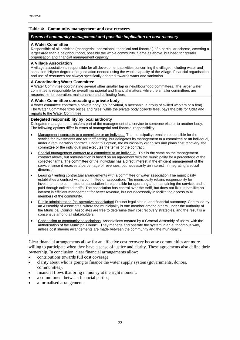
OP-32-E
22
Table 4: Community management and cost recovery
Forms of community management and possible implication on cost recovery
A Water Committee Responsible of all activities (managerial, operational, technical and financial) of a particular scheme, covering a larger area than a neighbourhood, possibly the whole community. Same as above, but need for greater organisation and financial management capacity.
A Village Association A village association is responsible for all development activities concerning the village, including water and sanitation. Higher degree of organisation needed using the whole capacity of the village. Financial organisation and use of resources not always specifically oriented towards water and sanitation. A Coordinating Water Committee A Water Committee coordinating several other smaller tap or neighbourhood committees. The larger water committee is responsible for overall managerial and financial matters, while the smaller committees are responsible for operation, maintenance and collecting fees.
A Water Committee contracting a private body A water committee contracts a private body (an individual, a mechanic, a group of skilled workers or a firm). The Water Committee fixes prices and rules, while the private body collects fees, pays the bills for O&M and reports to the Water Committee.
Delegated responsibility by local authority Delegated management transfers part of the management of a service to someone else or to another body. The following options differ in terms of managerial and financial responsibility.
• Management contracts to a committee or an individual The municipality remains responsible for the service for investments and for tariff setting, but delegates its management to a committee or an individual, under a remuneration contract. Under this option, the municipality organises and plans cost recovery; the committee or the individual just executes the terms of the contract.
• Special management contract to a committee or an individual This is the same as the management contract above, but remuneration is based on an agreement with the municipality for a percentage of the collected tariffs. The committee or the individual has a direct interest in the efficient management of the service, since it receives a percentage of revenues, but necessarily an interest in integrating a social dimension.
• Leasing / renting contractual arrangements with a committee or water association The municipality establishes a contract with a committee or association. The municipality retains responsibility for investment; the committee or association is responsible for operating and maintaining the service, and is paid through collected tariffs. The association has control over the tariff, but does not fix it. It has like an interest in efficient management for better revenue, but not necessarily in facilitating access to all members of the community.
• Public administration (co-operative association) Distinct legal status, and financial autonomy. Controlled by an Assembly of Associates, where the municipality is one member among others, under the authority of the Municipal Council. Associates are free to determine their cost recovery strategies, and the result is a consensus among all stakeholders.
• Concession to community associations Associations created by a General Assembly of users, with the authorisation of the Municipal Council. They manage and operate the system in an autonomous way, unless cost sharing arrangements are made between the community and the municipality.
Clear financial arrangements allow for an effective cost recovery because communities are more willing to participate when they have a sense of justice and clarity. These agreements also define their ownership. In conclusion, clear financial arrangements allow: • contributions towards full cost coverage, • clarity about who is going to finance the water supply system (governments, donors,
communities), • financial flows that bring in money at the right moment, • a commitment between financial parties, • a formalised arrangement.

Key Factors for Sustainable Cost Recovery
23
Table 5: Gradual transfer of managerial and financial responsibilities from government to communities of existing rural water supply systems, in Namibia
Responsibilities Phase 1 Capacity-building
Phase 2 Operation & Maintenance
Phase 3 Full Cost Recovery
Ownership of installations ! : 100% Leasehold agreement ": 100 %
Buying of consumables (fuel,
oil, grease) ! : 100%
Gradual phasing out ! : 75% ": 25%
! : 50% ": 50%
! : 25% ": 75 %
": 100 %
Financing of routine
maintenance ! : 100% ! : 75% ": 25 % ": 100 %
Major repairs and replacement
Operational responsibility ! : 80% # : 20%
Financial responsibility ! : 100%
Operational responsibility ! : 80% # : 20% Financial responsibility
! : 100%
Operational responsibility "80% # : 20%
Financial responsibility
"100%
Legenda Source: Directorate of the rural water supply of Namibia (1998)
! = Government (Rural Water Supply Directorate)
" = Community (Water Point Association, including local caretaker)
# = Private sector (Workshops with specialised equipment and staff) Possible distribution of responsibility for the O&M of a handpump The following example corresponds to a situation where communities own and manage their handpumps. Communities still depend on specialised mechanics for technical know-how and services, for which they have to pay. Moreover, transferring some responsibilities to communities still leaves the government with responsibility for water quality control, development of an effective spare parts distribution system, and in many cases, rehabilitation and replacement. Unfortunately, water quality control is rarely, if at all, done in rural areas, and it may be necessary to include simple water quality control devices which communities can afford. Table 6: Operation & maintenance tasks for a handpump
O&M tasks Operational responsibility
Financial responsibility
Monitor handpump use and encourage proper use; check all nuts and bolts, and tighten if necessary; measure output per stroke and compare with expected output; check and adjust pump handle and stuffing box; grease or oil all hinge pins, bearings, or sliding parts; clean the pump, well head, concrete apron, and drainage area; check well head, concrete apron, drainage area; repair cracks; record all operation and maintenance activities in notebook.
" "
Disassemble pump, check drop pipe, cylinder, leathers and foot valve. Check corrosion and wear. Repair or replace if necessary.
"& # " Conduct water test for micro-biological contamination; conduct water level check and well yield test. ! ! In case of contamination, locate and correct source of contamination, and disinfect; adjust cylinder setting if necessary; reconditioning or replacement of handpump when fully worn
# or ! "& !
Manage a stock of spare parts, tools and supplies "& # & !
Legenda Source : Adapted from Wash (1993) " = Community # = Local mechanic / private sector ! = Government

OP-32-E
24
Possible distribution of responsibilities for the O&M of a pump, diesel engine and standpost This following example corresponds to a system which is managed by communities. The government remains responsible for major repairs, replacement and water quality control. This distribution of responsibilities may not stay the same for ever. If communities are to be empowered to become fully responsible, these financial responsibilities are likely to change. Table 7: Operation & maintenance tasks for a pump or diesel engine
O&M tasks Operational Responsibility
Financial responsibility
Operate engine daily safely and efficiently; perform regular checks and adjustments (fuel, oil, filters, belts etc.); regularly replace engine oil, filters and pump oil if applicable; check all pipelines, tanks, valves for leaks breaks, and repair; monitor standpost use to encourage proper use; check all standposts for leaks, wear, tear, and repair if needed; flush all pipes periodically; clean standpost concrete aprons and drainage area, and repair; record all operation and maintenance activities in log book; manage a stock of fuel and oil, ensuring proper storage and security. Maintain special fuel log. Develop schedules for preventive maintenance
" "
Perform regular checks and adjustments on alternator, starter, radiator, valves and injectors; "& # " Conduct water test for micro-biological contamination; locate and correct source of contamination; disinfect; establish historical records of all engines, pumps and other ! ! Measure water output periodically, at well head and standpost. Assess leakage and initiate leak detection needed and repairs; periodically conduct complete overhauls on engine, pumps and associated equipment; conduct well engine/pump rehabilitation and / or replacement
"& # "& ! Management of a stock of parts, tools, and supplies "& # & !
Source: Adapted from Wash (1993) " = Community # = Local mechanic / private sector ! = Government Administrative and support activities linked to O&M The following example shows how administrative tasks and support activities can be distributed between the community and the Government agency. It shows clearly that most of the tasks that are related directly to the community or within the community’s boundaries can become the community’s operational and financial responsibility. Support activities are the operational responsibility of other organisations, government agencies or NGOs. This situation has evolved in recent projects, where the community is also asked to pay for support services once the project has been handed over. The debate is not yet closed on this issue. Table 8: Distribution of responsibilities for administrative and support activities linked to O&M
Administrative and support tasks linked to O&M Operational responsibility
Financial responsibility
Conduct technical and socio-economic participatory studies "& $ $ Prepare annual budgets and long term financial estimates; analyse O&M tasks for use in planning and budgeting; collect, analyse, monitoring results, and conduct follow-up support or training of necessary
"& $ "& $ Develop and evaluate technical & management training for water system operators; develop and evaluate financial & management training for community managers provide on-going technical training for operators; provide on-going financial and management training for community managers; develop information and materials on hygiene education; provide technical and management support to community managers
$ $
Select and appoint operators/ contractors for O&M; delegate task responsibilities, supervise and pay salaries; keep archives, inventories and log books; collect water fees and manage revenues; make payments for purchases, loans and other obligations; respond to users complaints; organise and conduct general meetings for discussions, elections; organise community contributions for upgrading or extending the system; report urgent problems to government agency
" " Legenda Source: Adapted from Wash (1993) " = Community $ = Government and/or Non-Governmental Organizations

Key Factors for Sustainable Cost Recovery
25
1.4.3 Formalising distribution of responsibilities The next step consists of sealing the distribution of financial responsibilities through an agreement or contract which describes the rights and obligations of each party, and defines the mechanisms for dealing with breaches of this agreement. In many countries, the Water Committee does not have a proper legal status. This puts the Water Committee in a vulnerable position in the event of any material, financial, contractual or legal problem, and is a reason why the legal status of the Water Committee should be part of the agreement. The usual forms of legal status include the following: • The Municipality officially registers a Committee which has been elected by a General Assembly
of users. The Assembly must produce a “constituting” Act. • The Water Committee is registered at the Chamber of Commerce as a non-profit making
association. • The Water Committee is registered at the Chamber of Commerce as an association with an
economic interest, which gives it the right to operate under a concession and to make contractual arrangements with local authorities.
• The Water Committee operates under the legal mandate of a Development Association.
1.5 Accompanying measures and capacity-building 1.5.1 Establishing an enabling environment Government agencies and sector NGOs can play a major role in supporting activities at local level and national level, which can contribute to improved financial sustainability. This support can include establishing a clear legal framework and policy on cost recovery, by which Governments clarify the “rules of the game” for communities, water enterprises and local authorities, so that each is aware of its rights and obligations. The sector policy should either specify the level of water rates or outline the legal parameters within which communities can determine their own water rates. Governments can also give incentives to private or local operators. Today, governments are beginning to promote education campaigns about the benefits of safe drinking water, the need to protect water resources and the beneficial effects of the proper use of water. Other support can include giving clear and accurate information before the start of a project and promoting hygiene education. These steps make users more aware of their responsibilities for their own water supply. This can contribute to willingness to pay. 1.5.2 Capacity-building Training community members, especially members of the Water Committee, in financing and other issues is very important to sustain services. Training needs to be adjusted to ensure it is not too far from the community, it is not too long, and it matches the appropriate level of education for community members. These issues, and others, are especially important to ensure that women as well as men are trained. In many cases, communities need training on bookkeeping and financial management. They might need to discuss with local authorities what to do in the event of major problems, and will need to rely on support from the private sector. Communities must be ready and able to fight for their rights. Training might also be needed for project staff, who often see cost recovery as secondary to technical issues. They will need to be aware that cost recovery is a key factor in sustainable water supplies and that it needs to be planned for right from the start. This implies that some provision has been made by support organisations for training and capacity building, in order to achieve sustainable cost recovery.

OP-32-E
26
2. Cost recovery in practice
2.1 Setting an appropriate tariff “Although tariffs cannot remedy all financial deficiencies and ensure complete viability of a water or wastewater system, they do go a long way to achieving financial sustainability” WASH (1991). The use of tariffs as a mechanism to cover the cost of water supply services has increased in rural and low-income areas, mainly due to the following factors: • an acknowledgement that the service of water should be paid by users, • the general and progressive implementation of new development models, whereby communities
are responsible for and own, (or are co-responsible for and co-own) their water supply scheme, • the trend towards decentralising the management of public services, • decreases in government recurrent costs funding. A tariff is the price a user is expected to pay for a service. It should preferably meet all costs, or at least cover operation and maintenance costs, depending on the chosen strategy. A tariff is also a mechanism used to regulate demand by, for instance, discouraging wasting water. It can also be used to promote the supply of water for the poor, by applying a ‘social’ price. It can further be used as a tool to protect the environment by including, for instance, a pollution penalty, or the costs of environmental protection and conservation. Finally, water tariffs are often used as a political tool in local communities, which can create a situation where they are no longer realistic, and do not meet all costs. It is therefore important to sensitise local politicians to the importance of tariffs that are able to cover costs. Consumers have, in theory, a predictable behaviour pattern in the event of price variations, analysed in terms of price elasticity. Price elasticity is the relationship between demand for water and the price for water20. Demand can be elastic, which means that demand increases when prices decrease; the sensitivity of demand to price variation in this case is high. Or, demand can be rigid, which means that demand does not increase significantly with price variations; the sensitivity of demand for water to price variations in this case is low. However, due to the very nature of water, which has no substitute as a good, people are ready to pay for improved services, especially if benefits are proven, and so price variations do not always affect demand. It has been reported that poor people in low-income areas often pay higher tariffs than better-off social groups in better-off areas. 2.1.1 Types of tariff It is proposed to describe two elements in tariff classification: • classification by user or usage; • classification of tariffs by rate category. • Classification by user or usage Classification by user or usage can be useful since it takes into consideration their different characteristics such as: consumption levels, productive use of water, domestic use of water, ability to pay, type of household, and number of family members. Furthermore, classification of users can clarify information for the water enterprise or water committee. The number and designation of user classes can vary, but almost every utility has the following categories: a) residential, b) commercial, c) industrial, d) institutional, e) government, f) wholesale. In some densely populated rural areas, consumption patterns can be similar to the one in urban areas and users can therefore be classified into various categories which need to be defined. A sub-classification of residential areas can also be made according to socio-economic strata, and the tariff level defined accordingly.
20 Definition in page 87 of Economie Générale, Tome 1, by Michel Bialès. Foucher, Paris, 1990.
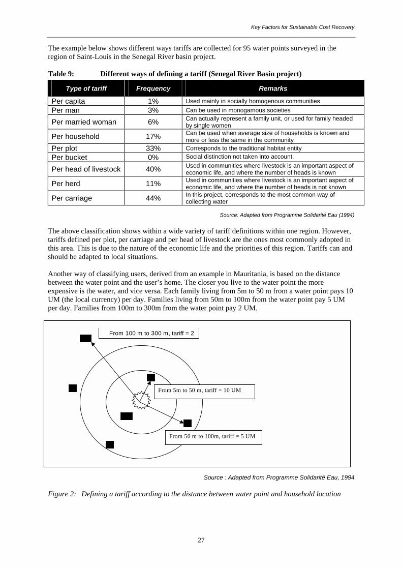
Key Factors for Sustainable Cost Recovery
27
The example below shows different ways tariffs are collected for 95 water points surveyed in the region of Saint-Louis in the Senegal River basin project. Table 9: Different ways of defining a tariff (Senegal River Basin project)
Type of tariff Frequency Remarks
Per capita 1% Used mainly in socially homogenous communities Per man 3% Can be used in monogamous societies
Per married woman 6% Can actually represent a family unit, or used for family headed by single women
Per household 17% Can be used when average size of households is known and more or less the same in the community
Per plot 33% Corresponds to the traditional habitat entity Per bucket 0% Social distinction not taken into account.
Per head of livestock 40% Used in communities where livestock is an important aspect of economic life, and where the number of heads is known
Per herd 11% Used in communities where livestock is an important aspect of economic life, and where the number of heads is not known
Per carriage 44% In this project, corresponds to the most common way of collecting water
Source: Adapted from Programme Solidarité Eau (1994)
The above classification shows within a wide variety of tariff definitions within one region. However, tariffs defined per plot, per carriage and per head of livestock are the ones most commonly adopted in this area. This is due to the nature of the economic life and the priorities of this region. Tariffs can and should be adapted to local situations. Another way of classifying users, derived from an example in Mauritania, is based on the distance between the water point and the user’s home. The closer you live to the water point the more expensive is the water, and vice versa. Each family living from 5m to 50 m from a water point pays 10 UM (the local currency) per day. Families living from 50m to 100m from the water point pay 5 UM per day. Families from 100m to 300m from the water point pay 2 UM.
Source : Adapted from Programme Solidarité Eau, 1994 Figure 2: Defining a tariff according to the distance between water point and household location
From 100 m to 300 m, tariff = 2
From 50 m to 100m, tariff = 5 UM
From 5m to 50 m, tariff = 10 UM

OP-32-E
28
• Classification of tariffs by rate category The community can choose different options for rates21: • non-metered flat rates; • non-metered graded rates; • metered rates; • mixed system rates. • Non-metered flat rates In a non-metered flat rate system, each user or household pays a fixed a mount of money, regardless of the volume of water consumed. In its simplest form, the total amount of money needed for the upkeep of the improved water supply system, is divided equally over the number of households using the system. Payment may be per month, per season, or per year, depending on what is most convenient within a local economy. Flat rates are easy to organise where there are private taps or group connections. In these cases it is clear who is the user. Advantages and disadvantages of non-metered flat rates
Conditions for application Advantages Disadvantages
All users should be known, and their water needs and consumption patterns should be similar.
" Relatively easy to administer. " No overheads for metering. " Easy to calculate " Easily understood by
consumers " Provides a secure revenue " Collecting the money is cheap
" Charges may not reflect access to supply or level of consumption
" Rates may not reflect the ability to pay of all users
" Does not discourage the waste of water " Equity is not taken into account " Differences between users (houses,
amenities, incomes, family members, etc) not taken into account
Source: Adapted from Evans (1992) • Non metered graded rates Users and households are classified into several categories, based on estimated differences of water use and income. This is also a way to build in rough estimations of consumption volume, without investing in a metering system. The introduction of graded rates is easiest when clear and valid indicators of water use and income level can be found (land, herd, size of house). An alternative system to graded rates is to raise a levy on cash crops on top of the existing rates, which will be used to maintain the water supply system. However disputes may arise over the basis for grading, as some people may feel others have been favoured. Advantages and disadvantages of non-metered graded rates
Conditions for application Advantages Disadvantages
Community with broad differences in income, welfare and economical status; availability of suitable indicators for grading.
" Charges reflect (estimated) consumption and ability to pay
" Poorer members of the community can be subsidised by better off
" Rates can better reflect actual service level
" Disputes may arise over basis for grading
" Higher rate payers may have disproportionate influence over management of the scheme
" More complex to manage
Source: Adapted from Evans (1992) • Metered rates Water meters enable suppliers to charge according to the actual volume consumed and are considered to create an equitable system. However, there are many difficulties and conditions attached to efficient metering. The first is related to the technical characteristics of the system. However, other problems are greater than the technical ones. According to the WHO: “Local conditions and acceptability by the community of the proposed changes should be fully taken into account” (WHO, 1988). Among the many difficulties in making meters function in an appropriate way in developing countries, are:
21 Adapted from “What price water ?”, Occasional paper No.10, IRC International Water and Sanitation Centre

Key Factors for Sustainable Cost Recovery
29
a) low reliability of the water supply; b) difficulties in reading the meters; c) the frequency with which users break meters or make illegal by-pass connections; d) high demands on administrative capacities (reading, billing, collecting, control, etc…); e) lack of familiarity with the concept in rural and low-income urban areas, lack of information, and
a belief that water is unlimited. If properly reinforced, metering induces users to avoid water wastage, which will reduce long-term costs or unaccounted water losses. Individual household meters are not only expensive to install, they also need to be read regularly and they make the administration more complex. Staff are needed to read meters, write bills and accept payments. Metering therefore requires administrative and management capacity. The added cost of installing and operating meters, as well as billing and collecting the money, may outweigh the benefits, notably in rural areas. A major constraint to user participation in piped systems with metered connections, is the high connection fee which water agencies charge to individual households wishing to install a private tap. One way to alleviate this problem is to spread the connection fee over time, and include it in the monthly water rate. Block rates are rates metered by “blocks” that vary according to consumption levels. Apart from a basic rate, which is fixed at a point where it is affordable by the poor, consumers may be charged a price proportionate to the volume consumed, with ranges or “blocks” (from 0 to 10 m3; from 10 to 20 m3, etc.). It is sometimes argued that rates for each block should decline at higher rates of consumption because of possible economies of scale. It is doubtful, however, that there are significant economies of scale on a per consumer basis. Considering the growth in services needed in developing countries, the most appropriate policy is an increasing block structure, with progressively increasing tariffs. Advantages and disadvantages of metered rates
Conditions for application Advantages Disadvantages Should have sufficient demand and willingness to pay for house connections. Good management capacity is needed as well as efficiency to ensure: a) cost-effectiveness and consumer satisfaction; b) efficient maintenance and leakage control.
" Charges reflect volume of water consumed
" Helps to reduce the consumption of water
" Makes it possible for poor people to access a minimum level of water consumption
" Demand can be regulated, and water resources conserved, by use of progressive rates
" Only one parameter: cost per m3 " Accounting made easier
" Raises cost of service due to higher overheads for meter reading, billing, collecting payments, policing delinquency
" Feasible, if reliable water supply " Difficult to define what is the
minimum level of water consumption for poor people
" Users frequently break meters or make illegal by-pass connections
" Meters need maintenance " Long delays in payment
Source: Adapted from Evans (1992) • Mixed system rates House connections together with standposts Another option to cover costs is to combine private paid connections with free public standposts. When there are enough private connections it becomes possible to finance the cost of public taps for the lowest income groups from a surplus of the rates paid by the private users. However, households which can afford to take a house connection do not always do so, when there are enough free standposts. This system should be accompanied by sensitisation and information campaigns promoting private tap connections.

OP-32-E
30
Advantages and disadvantages of a mixed system (house connections together with standpost)
Conditions Advantages Disadvantages Suitable where there is adequate demand for, and willingness to pay for, household connections, and where poor households cannot afford individual connections.
" Offers consumers choice of service level
" Rates reflect level of service " Poor can benefit from subsidised
or free basic service
" May be difficult to optimise balance between house connections and standpost
" Higher rate payers may have disproportionate influence over management of the scheme
Source: Adapted from Evans (1992) Water re-vending Water may be obtained by small-scale vendor groups, or individuals, from private or municipal taps, and sold either from a public vending kiosk or sold door-to-door. In this system, users pay for water by container or bucket purchased, at a price that is higher than the price paid originally. Profit margins can be outrageously high, especially in low-income urban areas, where communities do not have an alternative. Furthermore, the quality of water is not guaranteed through all these intermediary steps. The main disadvantage of water re-vending is its high price. Often users pay more for 20 litres of water with this system than those who are supplied 500 litres per day from a piped system (Whittington, 1989). Advantages or disadvantages of a mixed system (Water vending)
Conditions Advantages Disadvantages
High demand for water; very little alternative in water provision.
" Users buy the quantity of water at a negotiated price
" Water distribution is easy " Users who live far from alternative
water sources can save time and effort
" Generation of employment and demand of local products
" Risk of pollution during water transport and manipulation
" Users pay high prices compared with the prices in water systems with private taps
" There are no rules and policies for regulation
Source: Adapted from Evans (1992)
2.1.2 Tariff calculation Non metered flat rates (See Annex 1 for example)
As mentioned earlier, tariffs are linked to the costs of supplying and treating water. However, the amount is linked to a specific cost recovery strategy or is the result of a social policy. It is proposed to distinguish two types of tariffs: a) basic tariff; b) real cost tariff. Basic Tariff includes only the recovery of basic operation, maintenance and administration costs, called ‘functioning costs’. These costs are divided by the number of households.
Basic Tariff = Functioning costs per month Number of households
If such a tariff is chosen it will be appropriate to consider with the community how the other costs will be covered. Real Cost Tariff includes not only the functioning costs, but also replacement and extension costs, which have been estimated in this example as representing 25% of functioning costs. These costs vary considerably from one technology to another.
Real Cost Tariff = Functioning costs + replacement and extension costs = 1.25 x functioning costs per month Number of households Number of households

Key Factors for Sustainable Cost Recovery
31
Real cost tariffs sometimes also include: a) environmental costs (costs of protecting and conserving water source, or treatment of used water
discharge); b) costs for ‘unaccounted for’ water (in some countries, unaccounted for water can represent up to
60% of total water produced, which represented a considerable loss in revenues; this loss can be recovered in the tariff, while correcting measures are put in place);
c) investment costs; d) depreciation costs. Metered graded rate applying a subsidy factor (see Annex 2 for example) Although tariff calculations are often developed on a project by project basis, tariffs formulas can also be determined at government level, as is the case in Colombia, which uses average costs to determine tariffs. A tariff requires information to be collected and then is determined through several steps: • calculating various costs, • defining the tariff, • setting the bill. Information required
• Classification of users by social strata In Colombia, the Public Services Law (142/1994) classifies residential users, according to their socio-economic conditions, into 6 strata with the poorest at strata 1 and richest at strata 6. Industries and institutions are classified as industrial and official users, respectively.
• Consumption ranks I. Basic consumption satisfies the basic needs of a family, fixed at 20 m3 per user per month; II. Complementary consumption, between 20 m3 and 40 m3 per user per month; III. Luxury consumption over 40 m3.
• Subsidies (Sub) and extra-charges according to consumption ranks and strata. For each strata there is a subsidy (highest for the lowest strata). Official users receive no subsidy. Industries face an extra charge and receive no subsidies.
• Calculating various costs Average Investment Cost (AIC): is the cost of present and future investments in order to produce and distribute one cubic meter of water. It includes the initial and future investment (INI and FIN), the Total Water Produced in m3 during 30 years (TWP) and the cost sharing of investments recovered by connection (variable C).
AIC($/m3) = INI + FIN * (1 – C)
TWP Average Operation and Maintenance Cost (AOMC): is the operating and maintenance cost of one cubic meter of water during the year. It takes into account the volume of water produced and the leakage index (P=30%) for the same year.
AOMC ($/m3) = Total O&M costs M3 produced * (1 – P)
Long Term Average Cost (LTAC): is the operating and maintenance cost of producing one cubic meter of water, taking into account the actual and future treatment capacity of the water supply system.
LTAC = AIC + AOMC
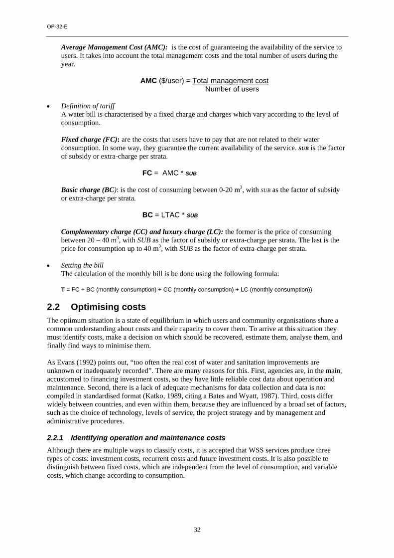
OP-32-E
32
Average Management Cost (AMC): is the cost of guaranteeing the availability of the service to users. It takes into account the total management costs and the total number of users during the year.
AMC ($/user) = Total management cost Number of users
• Definition of tariff
A water bill is characterised by a fixed charge and charges which vary according to the level of consumption.
Fixed charge (FC): are the costs that users have to pay that are not related to their water consumption. In some way, they guarantee the current availability of the service. SUB is the factor of subsidy or extra-charge per strata.
FC = AMC * SUB
Basic charge (BC): is the cost of consuming between 0-20 m3, with SUB as the factor of subsidy or extra-charge per strata.
BC = LTAC * SUB
Complementary charge (CC) and luxury charge (LC): the former is the price of consuming between 20 – 40 m3, with SUB as the factor of subsidy or extra-charge per strata. The last is the price for consumption up to 40 m3, with SUB as the factor of extra-charge per strata.
• Setting the bill
The calculation of the monthly bill is be done using the following formula: T = FC + BC (monthly consumption) + CC (monthly consumption) + LC (monthly consumption))
2.2 Optimising costs The optimum situation is a state of equilibrium in which users and community organisations share a common understanding about costs and their capacity to cover them. To arrive at this situation they must identify costs, make a decision on which should be recovered, estimate them, analyse them, and finally find ways to minimise them. As Evans (1992) points out, “too often the real cost of water and sanitation improvements are unknown or inadequately recorded”. There are many reasons for this. First, agencies are, in the main, accustomed to financing investment costs, so they have little reliable cost data about operation and maintenance. Second, there is a lack of adequate mechanisms for data collection and data is not compiled in standardised format (Katko, 1989, citing a Bates and Wyatt, 1987). Third, costs differ widely between countries, and even within them, because they are influenced by a broad set of factors, such as the choice of technology, levels of service, the project strategy and by management and administrative procedures. 2.2.1 Identifying operation and maintenance costs Although there are multiple ways to classify costs, it is accepted that WSS services produce three types of costs: investment costs, recurrent costs and future investment costs. It is also possible to distinguish between fixed costs, which are independent from the level of consumption, and variable costs, which change according to consumption.

Key Factors for Sustainable Cost Recovery
33
Box 6: Operation and maintenance costs include: • Material costs – consumables, chemicals, energy, tools, spare parts and equipment • Works personnel - staff involved in operation, maintenance, routine preventive maintenance,
repairs, and construction for minor rehabilitation • Management personnel - staff involved in planning, supervision, financial management,
administration, and monitoring • Financial costs - interest, amortisation, depreciation, exchange rate variations, inflation • Environmental costs - water source protection and conservation, waste water treatment • Support costs – training support, technical assistance, institutional strengthening, monitoring
and evaluation • Future investment costs - Major overhauls (rehabilitation), replacement, and extension • Other costs – transport, services paid to a private contractor, unaccounted for water due to
leakage, bad administration and vandalism As well as falling into the categories above, costs can also be characterised by time, sometimes called ‘periodicity’, meaning that they occur at intervals which can be different for each cost. The example below shows clearly this distinction. Table 10: The distribution of costs and periodicity of expenditure for a public standpost with
pump
Cost item Cost details Type of costs Periodicity of expenditure
Energy, consumables
• Diesel • Electricity connection fee • Electricity consumption • Oil • Chlorine
Variable Fixed
Variable Variable Variable
Week Once
2 months Month Week
Labour
• Caretaker • Operator • Administrator • Plumber (contract) • Mechanic (contract) • Management committee • Fee collectors
Fixed Fixed Fixed Fixed Fixed Fixed Fixed
Month Month
Quarter Month Week Year Year
Administration
• Paper, etc.. • Rent of office • Accountant • Transport
Fixed Fixed Fixed
Variable
Year Quarter
Year Month
Provision
• Engine • Solar panels • Pump • Main pipes • Main civil engineering
Variable Variable / Fixed
Variable Variable / Fixed Variable / Fixed
5 years 5 years
10 years 30 years 30 years
Financial costs • Bank fees • Interests • Provision for losses & depreciation
Fixed Fixed Fixed
Month Quarter
Year
Source: Adapted from Programme Solidarité Eau (1994) The same exercise can be done with a handpump. This helps to clarify with community organisations and communities, that different costs have a different nature and timescale. This is an essential step in determining tariffs.

OP-32-E
34
It should be noted that expenditure on spare parts is irregular and varies according to the quality of operation and maintenance, and to the type of spare parts. Spare parts can be divided into three categories: 1) frequently needed which should be kept as close as possible to the village (shop, mechanic); 2) occasionally needed (every six months or year), which can be at a major centre close by; 3) those needed for major rehabilitation or replacement (every few years) which can be kept at the
local region or state capital. Finally, operation and maintenance costs are not only subject to a certain periodicity, they are also subject to variations due to the economic environment, inflation or exchange rate fluctuations which can influence the price of spare parts or energy. While identifying costs, it is therefore important to highlight not only cost items, but also their periodicity and possible variations over time. 2.2.2 Estimating costs Estimating investment costs is not difficult, as manufacturers advertise the price of equipment and labour wage costs are known. However, estimating recurring costs just by using experience from other similar projects can be misleading, as recurring costs vary widely from one project to another. One common method of estimating O&M costs is to use a percentage of capital costs, with the percentages used ranging from 5 to 20%. This approach frequently results in an underestimation of recurrent cost (WASH, 1988a). In this section we show how to estimate real O&M costs as accurately as possible. The main costs of O&M were showed in Box 6, as: personnel, materials, chemicals, energy and communication, transport and private contractors. Based on this list, recurrent cost can be estimated as follows22: Estimating Personnel costs a) Full time • determine O&M activities, • estimate the minimum number of personnel, • proceed with an agreement on the size and classification of all staff involved in O&M, • determine the average wage paid for each class of personnel, • sum up all wages. b) Over time • determine O&M activities that require additional time, • estimate number of personnel required for additional time, • determine the average wage paid for this personnel, • sum up all wages. Estimating Material Costs • consider two categories of materials: supplies and spare parts, • detail all the equipment, facilities and components of the water supply system, • detail the nature and frequency of O&M of each piece of equipment, facility, and component, • determine the need for each, • identify the cost of each, • determine the whole cost (and possibly determine unit costs/ m3). Estimating Chemical Costs • identify which chemicals are needed (type, form, and quantities), • identify chemical costs by using unit price information for each chemical, • calculate the annual total cost by multiplying the unit cost by the annual quantity needed.
22 Adapted from WASH (1988).

Key Factors for Sustainable Cost Recovery
35
Estimating Energy and Communication Costs a) Electrical Power • identify the characteristics of the engine and electrical devices, • determine daily running time and power consumption, • identify the unit cost of electricity and determine total (and per unit) cost. b) Fuel Costs • identify the characteristics of engines and devices which use fuel, • determine daily running time and fuel consumption, • identify cost of fuel and determine total (and per unit) cost. c) Communications Costs • list all communication equipment, • identify monthly fee per device / piece of equipment, • sum up the monthly fees. Estimating Transport Costs • identify tasks which require transport (transport of personnel and of material/supplies), • define the transport needs for each tasks, including the type of vehicle required (bus, pick-up, so
on) and the round trip distance in km or miles, • estimate the frequency of trips (by season if relevant), • estimate transport cost per kilometre or mile including fuel, lubricants, tyres, insurance,
maintenance, drivers’ wages, paying back the capital cost, • estimate the total monthly costs for transport using this information.
Estimating private contractor costs • establish which maintenance tasks will be performed by which private contractors (it is helpful to
differentiate between regular maintenance tasks and unforeseen repairs), • estimate the frequency at which each will occur, • estimate the cost per incident, preferably after discussions with private contractors, • establish an agreement with the private contractor, if possible. 2.2.3 Minimising costs An important aspect of optimising costs is reducing O&M costs. These can be significantly reduced in the following way: • Choosing a technology with low cost spare parts or low cost operation and maintenance costs.
Minimising O&M costs should be more of a priority than minimising capital investment, especially where the replacement cost will not be borne by communities. However, if a full cost recovery is agreed, planners and communities should try to minimise both capital and recurrent costs.
• Economies of scale can make an expensive water supply system more attractive financially, where costs can be spread over a large number of actual or potential users. However, this does not usually apply to wells or handpumps, which are designed for a certain number of users. Economies of scale are more applicable in the context of piped water supply.
• One way to reduce costs is to monitor with care changes in variable costs such as energy, consumables, maintenance and repair. Unusual increases in these costs should swiftly alert the organisation managing the service to possible misuse or mismanagement.
• Fixed costs cannot normally be reduced. However, like all costs, at times they can be subject to variations. One way to protect a project from unpredictable increases is to fix them in a contractual agreement between personnel and the organisation.
• It is possible to reduce transport costs by making spare parts and chemicals more accessible and available to the community.
• Planners should try, where possible, to reduce dependence on chemical use, using for example alternative water treatment technology such as a multi-stage filtration system.
• Reduce dependence on fuel or electric consumption, by using solar, gravity, or wind energy.

OP-32-E
36
• Try to firmly install a maintenance culture within the community and amongst professional staff to keep the service in good working condition and so increase the life cycle of the equipment.
• Organise preventive maintenance activities involving the users, helping to increase their sense of responsibility, and involve them in constant monitoring of the system, which leads to better functioning and may reduce expenditures on repairs.
• Organise systematic control of unaccounted for water, where users are involved in leakage control and there is a system of checks and balances in place for administrative losses.
• Install proper administrative and financial control mechanisms to avoid mismanagement of funds. One easy and effective way to do this, is to keep communities regularly informed with detailed figures, about the financial status of the organisation.
2.3 Access to other sources of funding “New strategies should aim towards increased efficiency in the use of available funds and in increased mobilisation of additional funds”23. This proposition from The New Delhi Statement (1990) was subsequently reinforced by all major sector meetings during the nineties, and is particularly valid in the context of a community-managed water supply. It will indeed be important to plan and determine financial mechanisms which cover all costs, if these are not fully covered by user’s fees. As seen earlier, tariffs are often based on the recovery of basic operation and maintenance costs, and rarely include the cost for major repairs, rehabilitation and replacement. Communities will need to tap into alternative sources, and it is proposed that planners take this into account, and facilitate /organise access to these sources. Possible alternative financial sources are: • existing community sources, • private or corporate financing, • subsidies and taxes, • credit–loan mechanisms, • grants, • specific funds. This section gives an overview of these possible alternatives to tariffs. Planners need to assess the availability, reliability and sustainability of these sources and, where they are non-existent, the possibility of developing them. 2.3.1 Tapping into existing community sources In communities with significant seasonal variations in income, it is difficult to recover costs through regular payments. An alternative is to cover the costs through community fund raising where “families do not pay regular contributions towards the cost of the community water system. Instead, money is periodically accumulated in other ways.” (van Wijk, 1989) Community fundraising options include voluntary funds, general community revenue and payment in kind. Voluntary funds Voluntary funds are built up by voluntary contributions from local leaders or community groups through public meetings, bazaars, lotteries, festivals and similar social activities. These are common to finance construction and major repairs in communities which have a tradition of fund raising and seasonal income. People contribute to finance a particular project or activity. The success of this option depends on a certain social cohesion which ensures that users contribute according to their use of water and ability to pay.
23 From The New Delhi Statement (1990).

Key Factors for Sustainable Cost Recovery
37
Advantages and disadvantages of voluntary funds
Advantages Disadvantages • Users decide on the amount of the
contribution according to their ability to pay and commitment to the project.
• Appropriate in communities with a tradition of social projects.
• Can be matched to seasonal income. • Encourages a sense of ownership. • Appropriate to finance a small proportion
of investments, minor repairs and recurrent cost particularly in communities with low-income levels and for short periods of time.
• Difficult to finance recurrent cost of water supply or sanitation systems over a long period of time.
• Difficult to know who is contributing and who is not. • Can cause disputes between users as people who
contributed the most want to make decisions in their favour.
• Some users contribute without taking into account their use of water and the benefits provided by the system.
• The total amount that can be collected is uncertain because contributions are decided by users on a voluntary basis.
General community revenue Communities can develop communal productive activities, such as cash crops or a village shop, and pay water bills with their profits. Disputes may arise over the priorities to give to the use of these resources, especially when users do not have equal access to water supply. Advantages and disadvantages of community general revenues
Advantages Disadvantages • Community members do not have to use
their income to pay WSS instalments. • Will meet the cost of a big share of the
investments if high profits are generated. • A sense of commitment and unity within
the community can be increased. • This can be the first step towards the
future development of social projects • It makes it possible to support
developments of water supply or sanitation systems.
• Equity is not ensured, if all users do not receive the same level of service
• Disputes may arise about priorities to give to the use of resources
• The level of available resources depends on the level of profits.
Payment in kind Households are sometimes given the opportunity to pay part of their contribution to the construction of their water supply in kind, by providing voluntary labour for trench digging, transport, sand pipe laying, or by providing local materials, such as gravel and sand. Payment of part of the construction costs in labour instead of money makes the system more affordable to a larger number of households than when all the payments have to be made in cash. Advantages and disadvantages of payment in kind
Advantages Disadvantages • Adapted to the local capacity and
resources. • Increases user participation and
commitment to the project. • Project takes into account the real
contribution of communities.
• Difficult to give a monetary estimation of payments in kind.
• Does not solve cash or financial problems. • Villagers can be exploited as free labour.
2.3.2 Private or cooperative financing There is an increasing trend for a greater involvement of the private sector in the provision and /or management of WSS services. There are two kinds of private interventions: through private capital and through cooperative funds.

OP-32-E
38
Private capital Private capital can be channelled into the construction of a WSS scheme, or to meet replacement, extension or recurrent costs. However, those who provide the capital involvement look for high rates of return to justify their investment, often through future contracts or ownership. It is difficult to apply this option in rural and low-income urban areas where users are not able to pay a “full-costs recovery” tariff which would include repaying investment costs and providing this rate of return. Advantages and disadvantages of private capital
Advantages Disadvantages • Effective cost recovery through clear
managerial practices. • Availability of resources to carry out large
investments. • Increases capacity to negotiate with
governments and institutions.
• Users are unlikely to participate in decision making.
• Users pay a high tariff a) to repay the investment cost, and b) to provide a profit.
• Does not necessarily take into account ability to pay, making it difficult for poor people to access the service.
Cooperative funds Cooperative funds result from an initiative by a group of users or individuals who get together to finance productive activities, not in the first place always related to WSS. The initial capital comes from contributions in cash or in kind from the members of the cooperative. Once the group has sufficient revenue, members may decide to use part of their funds to finance WSS services. However, the amount of capital available in this option depends on the results of the first stage investments. With good financial and organisational practices, this is a good way to administer WSS services. Advantages and disadvantages of cooperative funds
Advantages Disadvantages • Allows the financing of a part of major
investments such as construction or extension.
• Encourages productive activities which can produce large resources.
• Well-organised cooperatives use sound financial and organisational practices.
• Access to cooperative systems could be difficult for poor people who do not have the money to pay the instalment or registration costs.
• Financing productive activities can become more important than financing water related activities.
• They only benefit members of the cooperative.
2.3.3 Subsidies and taxes
Direct government subsidies Central government and local authorities allocate part of their budget towards constructing, operating and maintaining public services. Subsidies can also come through reducing the price of spare parts and chemicals. Authorities may also, at the request of the community, provide free technical advice, technical staff or staff for community organisation and education. The use of public resources to subsidise poor users depends on government policies and the legal framework, and also on the availability of funds. Subsidies need to be arranged in such a way that they do not discourage efficient use of water, nor send wrong economic signals to a market. Indeed, the subsidised price of parts or equipment for a particular project can compete with similar products available for sale, and therefore distort a market. Subsidies can be used as promotion tools for a particular professional group, for instance the informal and formal private sector. They can also be used to promote access to water services by marginalised groups, with subsidies adapted to various levels of marginalisation.

Key Factors for Sustainable Cost Recovery
39
Advantages and disadvantages of subsidies Advantages Disadvantages
• Allows users with low ability to pay to access WSS services.
• Tool for income redistribution. • Availability of resources to carry out large
investments.
• It is difficult to keep subsidies going for long periods due to lack of resources of governments.
• There is a trend towards cutting off public resources.
• Discourages community responsibility. • There is a tendency for political reasons to
dominate resource allocation and distribution. Taxes Municipalities can collect the necessary funds through local taxes. Payment can be linked to income level or properties, but charges may not reflect the level of water consumption. Governments are not always clear and transparent in the management of this type of resources and users are reluctant to accept new taxes. Advantages and disadvantages of taxes
Advantages Disadvantages • Takes into account the ability of users to
pay. • Does not require additional administrative
procedures because taxes are already collected at local or national level.
• Not expensive.
• Users hardly participate in decision making. • Users hardly participate in management and
allocation of resources. • High rate of non-payment of taxes, especially in
developing countries. • Bureaucracy delays resource allocation and
payment making it difficult to get money at the right time.
• There is a tendency for political reasons to dominate resource allocation and distribution.
Cross-subsidy One way to make the service equitable and affordable for all is to subsidise the poor and surcharge high-income consumers. However, in rural and low-income urban areas the majority of users have low-income levels, so funds raised from surcharging richer users in that area will not cover their subsidies. Advantages and disadvantages of taxes Advantages and disadvantages of cross-subsidies
Advantages Disadvantages • Allows users with low ability to pay to
access water supply and sanitation services.
• A tool for income redistribution.
• Requires the management of complex information about tariffs structures, consumption, users, water uses, etc. It makes community management difficult.
• Can send wrong signals about prices to subsidised users, leading to waste of water.
• Industries which are surcharged look for alternative water sources.
• Difficult to keep this financial option for a long period.
• Encourages corruption as users want to be classified to pay lower tariffs
2.3.4 Grants NGOs and donors have used grants as a type of financing mechanism for the construction of WSS systems. Nowadays, this approach conflicts with the new approach under which donors and NGOs demand an active role from communities. Grants rarely pay for recurrent costs. However, donations are still made to support water and sanitation services.

OP-32-E
40
Donations from former residents or through twinning Donations can come through former inhabitants of a village who live in a city or abroad, or in some cases where villages are twinned with other villages and cities of other countries. Advantages and disadvantages of donations
Advantages Disadvantages • Poor rural and peri-urban communities can
benefit from these funds. • Availability of resources to carry out large
investments.
• Donations can be targeted to produce political benefits.
• Can discourage the community from building up its own resources.
• Difficult to sustain these funds during political or economic changes in donor countries.
2.3.5 Credit–loan mechanisms (micro-credits) Micro-credit is financing through lending mechanisms, similar to credits given by banks, except for their nature and size. Micro-credits are generally small in volume and respond directly to the specific needs of rural or low-income urban communities. It is possible to distinguish three types of micro-credit systems (see also Table 11): • micro-credit through a bank, • micro-credit through an association, • micro-credit through individuals. A micro-credit system can be used to: • contribute to investments, • purchase material and equipment for replacement, extension and rehabilitation, • finance major unforeseen repairs, • cover short-term cash-flow problems;, • develop a stock of spares, parts and tools. The development of a micro-credit system through an association or individuals to finance important capital investments is difficult, due to the small amount of money and the short-term nature of the credit. They have, however, been instrumental in financing small individual devices, such as rooftop harvesting or a hammer and pulley system for wells. For major investments, communities still need to contact banks or rural development funds. Funds to purchase materials and equipment for replacement, extension and rehabilitation differ from initial capital investment in that their need can be foreseen. Some projects cover future replacement costs in their tariffs. In these cases, this part of the payments can be used as savings or as guarantees for possible credit. Financing unforeseen repairs and damage, together with cash flow problems, are perhaps the most frequent financial needs, because of fluctuations in income or because tariffs fail to cover costs. It is of utmost importance to ensure alternative financing to meet these contingencies. Micro-credit systems through associations would be particularly appropriate where the amounts needed are not too large. The development of a stock of spare parts and tools can be critical to sustain a rural water supply, especially when communities are isolated and geographically remote from major trading centres. Developing a micro-credit system for this type of expenditure can be most beneficial. In general, micro-credit systems can overcome financial obstacles and promote development in areas out of reach for the conventional banking system. Micro-credits, furthermore, represent a strong tool to alleviate poverty, and to offer marginal groups within a community a possible access to finance.

Key Factors for Sustainable Cost Recovery
41
Table 11: Overview of characteristics of main micro-credit options Characteristics Micro-credit through a bank
(Grameen Bank type) Micro – credit through an
association (Cooperatives, revolving funds, tontines)
Micro-credit through individuals (Wealthy individuals, shop owners, lenders)
Origin of funds Deposits made by communities. Bank’s own resources. Subsidies.
Contributions by the members of the association. Subsidies and contributions to the initial capital by projects.
Own savings and income from profit margins and interests. Some lenders give credits in kind.
Lending conditions
The Borrower has to open and regularly deposit into a savings account. Certain credits are ear-marked for particular populations or activities. The main condition is the collective responsibility of the group of people who ask for credit (in the Grameen bank, this is a minimum of five people). The group imposes its own social control to meet the payments, and group members are trained in credit procedure and financial management.
To become a member, an initial fee ( $4 US in Kenya) is paid, with monthly or occasional contributions. The initial contribution can be to buy shares in the venture. In the case of tontines in West Africa, members rotate their role as borrower or lender. In other tontines, available funds are made accessible through an auction system. In cooperatives, people’s ability to repay loans is systematically assessed.
Mutual agreement between two individuals, which can be either oral or written, based on urgency of need, amount needed, capacity to reimburse, and delay in repaying. Some shops open a credit line for consumers who are in need of material or equipment.
Interest rate 10% to 20% per year or > 10% per day. Usually 5% to 10% a month, but can be much
higher. In some tontines the interest rate can be decided through an auction.
Can reach up to 100% per month.
Guaranty against risks
Collective responsibility, with a guarantee of solidarity. In the Grameen bank system, only two candidates out of the group of five receive a credit, and the others get their loans if the two meet their commitments. A co-signature from an influential and trusted person is sometimes required.
Prior evaluation of reimbursement capacity, based on savings habits. Moral sanctions and social control from the group. Assistance from the group for people who experience difficulties.
System mainly relies on confidence and personal trust or relationship. Shop owners keep books which can be called on as evidence in case of non-reimbursement.
Loan reimbursement
Payment can be adapted to seasonal revenues in rural areas and spread over time. To encourage repayment in full there are sanction for late payments.
Repayment periods are adapted to seasonal variations of rural incomes. However, associations prefer regular and frequent reimbursement (every week or month) at the occasion of the meetings of the association.
Delays vary according to the type of loan contracted. But it can be said that loans are well adapted to each case and needs. Rural communities are used to this type of credit.
Limits
Many banks are still not interested in small and dispersed financial operations, which they see as risky due to the poor economy in rural areas. The system is only accessible to communities who live not too far from a bank.
Small size and short term financing. Not appropriate for large or expensive needs. Some associations have a lack of financial management and know-how. A large proportion of micro-credit is used for pro-social activities.
Short-term and expensive source of funding, because of very high interest rates. Exploitation of families and individuals, due to a quasi-situation of monopoly in certain areas.
Source: Tchaptche and Brikké (1995)

OP-32-E
42
Box 7: Bangladesh, the Grameen Bank The Grameen Bank has been created in Bangladesh on the assumption that lack of access to finance is one of the major causes of poverty. Its mechanisms rely on a system of reciprocity and mutual guarantee which replaces the usual system of material guarantee. Groups of 5 candidates are created, with similar economic status. In order to obtain a credit, candidates have to follow a two week course during which they are exposed to the philosophy, regulations and procedures of the Grameen Bank. Candidates have to submit simple plans showing how activities financed by the credit will generate enough revenue to allow the loan to be repaid. At first, only two of the five candidates can access a loan. If the repayment schedules are correctly followed than the other candidates can borrow as well. However, the goods acquired with the loan remain Bank property until the loan has been totally repaid. Repayments are usually weekly for a period not exceeding a year. So far, 56% of credits have been given to women, and the rate of full repayment is above 95%. The experience of the Grameen bank shows that rural populations are credible customers and partners.
2.3.6 Specific funds
Social and development funds Different types of funds have been established to help the water sector, most of them with a social and development aim. The principal points of attraction for these funds are low interest rates and long periods for repayment. Governments can provide credits at lower interest rates than the financial market, and these funds can be used to promote social development. Credits are allocated to institutions or local governments and it is not easy for users or community groups to access them. There is, however, a trend today to create funds which better respond to the needs of rural populations. A good example can be found in the Social Investment Funds promoted by the Inter American Development Bank. A strong feature of the Funds is their ability to tailor themselves to changing circumstances without sacrificing their efficiency and effectiveness. Through their closer contact with communities, the Funds have opened new avenues for social action and have increased public awareness of poverty issues. However, the funds respond mainly to investment needs for new construction or for major overhauls, and are not necessarily available to finance short-term needs and unforeseen breakdowns. Moreover, past experience has shown that communities still have great difficulty in accessing resources from these Funds, while project reports often mention mis-management as a major obstacle to efficiency. Since access is easier for local authorities and municipalities than for communities, it is important that communities and municipalities work in partnership. Access to these funds can be eased through the payment of a regular fee, which gives the payer a better chance of receiving a loan. Advantages and disadvantages of social and development funds
Advantages Disadvantages • Provides an enabling environment to
strengthen community capacities. • Optimises the use of resources because
financial institutions supervise construction. • Working in partnership with financial
institutions, governments and other institutions allows long-term project design and programmes.
• Credits are cheap and repayment periods are long.
• It is difficult for communities to access these funds without institutional support.
• They can produce a high degree of dependency on institutions by communities.
• Mis-management of funds.

Key Factors for Sustainable Cost Recovery
43
Village or local funds Villagers can be encouraged to create a fund at local or village level for the maintenance of their water supply. An initial deposit is put into a bank account, which is replenished through monthly or yearly contributions. The bank account attracts interest on savings, and opens access to credits, deficits, and overdrafts. Account holders can use their savings as a financial guarantee. The fund operates as a savings bank account managed by the bank. The fund can also be managed within a village or area setting, without passing through a bank. Deposits and savings operate as a revolving fund, which works as micro-credit system through an association, as described above. The principal obstacle in this situation is lack of financial management skills. 2.4 Effective financial management A great number of communities and, in some remote areas, municipalities as well, lack the financial management skills which are essential to organise, implement and efficiently control a cost recovery system. A financial management system can be said to be effective when managers can: • estimate the revenue that the service will produce over defined periods of time and the expenditure
it will need (budgeting); • collect fees from users (billing and collection); • keep all financial information and records (financial administration); and, • use indicators to control and monitor the financial performance of the enterprise (financial control
and monitoring). 2.4.1 Budgeting Budgeting is a basic aspect of financial management because it allows managers to: • plan revenue and expenditure for a determined period of time (usually one year); • determine in advance the amount of money required to cover total expenditure (wages, chemicals,
fuel, repairs, interest, and so on); • estimate the revenue that the enterprise expects to receive for tariffs, registration, connections,
loans and donations; • control actual expenditure and to compare it with planned expenditure, and to reveal possible
sources of imbalance (positive or negative) between actual and planned expenditure; • visualise the future of the committee, and answer such questions as: Where does the committee
want to go? What financial alternatives does the committee have?
This process could be separated in four main stages: 1. determining expenditure, 2. estimating expenditure over a period of time, 3. planning revenue, 4. comparing revenue and expenditure. 1. Determining expenditure This should define total expenditure and identify how much money is necessary to cover it. There are four main types of recurrent expenditure (costs) in the provision of water supply services: operation, maintenance, management (administration) and provision for future replacement (rehabilitation). In some projects, replacement costs are not considered as recurrent costs, but as future investment costs. Investment costs can be included in the budget if necessary, for example, when an enterprise has to pay off a loan for the construction of the system by instalments. One way to determine total expenditure is to list all the activities required to operate, maintain and to manage the water supply service, and then to estimate personnel, inputs and purchases required for each activity and their prices. There are two important conditions for doing this: The person doing the budgeting has to have good knowledge about all the activities needed to operate, maintain and manage the water supply system, and the prices that are paid in the market for each item. The budget should be for a defined period of time - usually one year.

OP-32-E
44
2. Estimating expenditure over shorter periods of time The overall budgeting provides a clear idea of the total amount of finance which is going to be needed over a period of time (usually one year), but does not give information about the cash flow required over short periods of time (monthly). Estimates need to be made about how much money is going to be needed at what time. Usually, this estimate is made for each month. It is impossible to provide a good service unless you know when money is needed to pay bills on time. 3. Planning revenue Revenue can be classified according to the source and the time when the money is expected to be received. Sometimes, estimates have to be made because there is a high level of uncertainty about revenue sources. To estimate revenue accurately it is necessary to have information about: the total number of users (legally and illegally connected), the number in each category of user (residential, commercial, industrial, institutions), the number of users who do not pay on time, tariffs by type of user, connection and registration costs by type of user, income from alternative financial sources, other than tariffs, the number of users estimated to connect to the system over a year. 4. Comparing revenues and expenditure A revenue and expenditure comparison allows a committee to determine the financial viability of the service. This comparison tells committees, when expenditure is higher than income, that there is a need for new income sources or a need to reduce costs. If there is a balance or a surplus the financial viability of the service has become a reality. Another important comparison is between the revenue cash flow and expenditure over a short period of time. These two financial flows should be in balance if the enterprise is to receive enough money (from users for example) to pay its bills on time. It is not possible for a system to keep functioning if the revenue money is not received in time to meet bills.
Table 12: Basic financial management issues for budgeting
Financial management issues Possible options
What costs to budget for?
• Remuneration • Tools and spare parts • Small repairs only • All repairs • Extension, rehabilitation or replacement • Fuel, power, etc. • Depreciation • Initial investment
What sources of revenue should be counted?
• Regular user payments • Village funds • Voluntary contributions • Credit schemes • Government subsidy • Private sector involvement
Does the enterprise have enough revenue to cover total costs?
• Yes, there is surplus • No, there is a deficit • There is a small deficit, so there is a need to look for
alternative financial sources or to raise tariffs • There is a big deficit, so special contributions may be
considered or the project may need to be revised 2.4.2 Revenue collection The aim of organising financial flows is to ensure that resources arrive in time to guarantee sustainable functioning of the water service. For this reason it is useful to think about: • ways of presenting bills to water users, • what the billing and collection periods will be, • providing one or more places where water bills can be paid,

Key Factors for Sustainable Cost Recovery
45
• clearly identifying a person or institution who is going to collect the money, and • identifying where the income is going to be kept (in a bank account, in cash, both, etc). For effective billing, the first requirement is to know how many users the system has and who they are. This makes it necessary to register each user. A registration form must clearly identify the user, including their name, address and category (residential, commercial, industrial). It should register whether there is a meter, and if there is, record the water consumption. It should note what bills are due to be paid by that user (eg. for registration, connection or debts from a previous water bill), and the total value of the water bill for a given period of time. The second requirement is to set an appropriate tariff structure. Where there is a water meter, the tariffs should be based on water consumption. Where there is no meter, the tariff should be based on flat rate charges or on estimates of consumption through indirect indicators, such as the number of people living in a household. The most common way of billing is by producing a water bill. Whatever the system used for billing, the most important principle is clarity: bills must contain enough information for users to understand how much they have to pay and why. Once the billing system has been defined, it is necessary to determine an appropriate collection schedule. This depends on two factors: the need for cash flow to cover expenditure, and the timescale over which the users receive their own incomes. An effective system for cost recovery always considers the timing of users’ incomes and fixes collection periods accordingly. For example, in agricultural areas, the main income is probably from seasonal crops, so those farmers receive their income once or twice a year. In such communities, it is appropriate to collect money at these same longer intervals (every six months). In areas where people receive their money more frequently, the collection intervals should be shorter (monthly). It is also important to take account of the payment culture of users – are people in this community accustomed to saving up money to pay bills, or do they prefer a ‘pay as you go’ approach? The clear identification of one or more places where users can pay their bills is a key factor towards creating a `client centred service’. At the same time, having a clear agreement about who will collect the money makes control and handling easier. The point where users pay should be both easily accessible and secure, so that users can get there without spending a lot of time on it, and without taking any risks. The person or institution who is collecting the money needs to pay attention to the hours when bills can be paid, so that they take into account people’s working hours and free time. They have to create confidence amongst users, to minimise non-payment. Depending on whether metering is in use, it is possible to use the following collection systems24: Metered connections (assuming an accurate and controllable meter reading) • In many developing countries, there is one meter for several users. This is one is meant here. • After taking account of any direct bills already sent out to individual users or group of users using
the same meter, and of any connection charges already paid, the water agency sends a formal statement to a tap committee detailing its water consumption over the preceding three months and the tariff applying to this group.
• The water agency organises separate meter-reading, billing and collection for each user. With non-metered connections: • A common system is to collect user payments through home visits. • Users and communities can decide to pay their rates at regular meetings or at the office or house
of a local functionary. • A neighbourhood collection system can be introduced, by which a central collector collects the
funds from each neighbourhood.
24 Adapted from van Wijk (1989)

OP-32-E
46
Money collected has to be kept in such a way that it is available when needed by an authorised person to meet costs. Information about the use of revenue should be given to users on a regular basis. Table 13: Basic financial management issues in organising financial flows
Financial management issues Possible options
How to collect money?
- Billing and charging group of users - Collection at water point - Home visits - In meetings - Users go to a public office - Users go to the house of the treasurer
When to collect money?
- Each time a service is provided - Monthly - After harvest - Beginning of financial year - Every sixth months
Who collects the money?
- Care taker - Operator - User group - Village Water Committee - Community leaders - Staff from an institution - Treasurer
Where to keep the money?
- In a safe - In the village account - In a bank account - In a development fund - In the house of the treasurer - In an official account
2.4.3 Bookkeeping Financial administration covers the keeping of all records, documents, information and books concerned with financial and accounting aspects. A simple but reliable system of financial records can greatly improve community management. The production of records, documents and information is necessary to: • keep clear and accurate accounts about the resources needed to provide the water service, • control income and expenditure, • make decisions based on clear and accurate information, • provide information to users who are interested in checking the financial management, • maintain the confidence and trust of users. The person who is going to keep the records should be able to do the job. This means that he/she must have some financial background or must receive training. If a committee is going to keep complex records, it should be taken into account that: • the bookkeeper will need a stronger financial background; • complicated administrative procedures (which demand more stationery and equipment) cost
more; • there could be a need to train the community to improve its understanding of more complex
figures and data. The records must be clear, simple, complete and understandable: • clear, in the sense that they show the information without hiding anything; • simple, because they have to be easy to carry out and appropriate for the type of administration; • complete, in the sense that they provide enough information to make good decisions possible, and • understandable, because they have to be easy to read and understand for all users, institutions,
water committee members, and so on.

Key Factors for Sustainable Cost Recovery
47
Records will depend on the level of information that the committee wants to provide and the legal requirements of governments about water enterprises, according to size and type. In a simple administrative structure for rural or peri-urban areas the following records could be used : • user registration forms • a diary • a bank book • budgeting records. If there is a need for more in-depth information, the following additional records can be included: • an income book • an expenditure book • an unpaid account book • a record of bills to collect • a general balance. Once funds have been collected, and regular expenses have been met, any surplus is normally kept in a safe place, such as a bank account. Many communities wonder about how to use this surplus, which may lie idle in an account, while the community has great financial needs. On this point, there are two schools of thought: 1. the surplus should be used for water projects only; 2. the surplus can be used to develop other activities, provided this money is reimbursed over time. It may be advisable to propose that the community uses part of its surplus to develop income-generating activities, working on the same principle as a revolving fund, provided that an effective system is put in place for reimbursement and for sanctions on people who do not pay, and that the persons or group who manage the fund have the capacity to do so. Table 14 contains a list of useful questions to clarify some aspects of financial administration. Table 14: Basic financial issues for good financial administration
Financial management issues Possible options
How is expenditure and income recorded?
- Log book - Daily journal - Bank book - Bookkeeping - Bank statements
Who administers the funds? Men or women
- The Committee Treasurer - A village accountant - Bank accountant - Community leaders
What are funds used for?
- Payment of expenditures related to O&M of water point
- Payment of total cost - Generating bank interest - Profit rate - Use for other development projects
Who authorizes payments?
- Operator - Treasurer - Water Committee - Village leaders - Assembly of users
Source: van Wijk (1989)

OP-32-E
48
2.4.4 Financial control and monitoring Making the management organisation accountable to users is important factor in sustaining services. This includes transparent financial management, and regular reports and accounts to community meetings. Effective control and monitoring is an on-going, regular necessity as part of financial management. This relies on accurate information, which will be mainly found in the records and books kept by the community. Control and monitoring are effective if they use clear, reliable, impartial and good quality information as a starting point. One way to be impartial is to establish a supervision committee to audit the accounts once a year. This committee should include members of the community. Sound control and monitoring includes the use of indicators that provide a good overview of what is happening, without the possibility of misunderstanding or manipulation. The final objective of control and monitoring is to inform users about the financial situation of the water supply service. Control and monitoring has three stages: 1. developing indicators and checking and analysing information, 2. presenting information to users, 3. discussing information and decision making. Example of some indicators: • Monthly revenue: shows the capacity to recover costs (should be greater than 1); • Monthly expenditure • Payment received: shows the rate of payment and therefore of non-payment; • Payment due • Average O&M cost per user: can be compared with the average tariff paid; • Level of expenditure per category : can help to detect abnormal expenditures.
Defaulting is common in most rural and peri-urban areas, and enterprises have implemented various measures to control and reduce this. Introducing educational programs to inform users and make them aware of the need to pay on time is always a good strategy. However, when educational programs do not work there is the need to implement other measures. Some of the strategies used in developing countries against defaulting were: • In the Dominican Republic, commercial agents were hired, each one responsible for 15 piped
water supplies. Agents audit the books with treasurers, collect loan repayments and accompany the treasurer on home visits to households whose payment is in arrears.
• In Honduras, users of a group, yard or house connections related to a rural water supply pay a safety margin of up to 100% of their monthly bill to cover defaulters., a sort of advance payment for the next month
• In Guatemala, names of debtors have been announced in the general meetings of the community. • Users’ group in Malawi have to maintain a safety credit with the water agency of up to a
maximum of 120% of their monthly group rate. In other cases payment in advance is encouraged through a small reduction on the user rates.
• In Colombia, the rural supply piped water programme used a simple record to register household contributions, which everyone understands and sees. This makes easy to identify families lagging behind and creates a certain degree of competition between households.

Key Factors for Sustainable Cost Recovery
49
Table 15: Financial management issues and possible options Financial management issues Possible options
What type of financial control?
− Receipts from book-keeping − Regular meetings of water committee − Double signature required to pay our from funds − Feed back to users − Cross-checking bill against meter reading − Cross-checking against bank statements − Registered auditors
How to monitor?
− Use log book − Make a quarterly review and overview of the situation on
expenditures, incomes, % of people who do not pay − Establish an independent committee to check accounts − Use indicators
How to inform users?
− Regular meetings of users − Annual meetings − Notice boards; leaflets − House to house visits − Through newspaper or radio reports
What to do with bad payers ? Particularly crucial if they include influential members of society or
public institutions.
− Analyse reasons for bad payment − Improve service − Improve relationship with the users − Campaign to increase awareness of benefits of prompt
payment − Reschedule debt − Introduce sanctions or cut-off supplies
2.5 Service efficiency Service efficiency is the direct outcome of appropriate management and is therefore a key factor in user satisfaction, willingness to pay and effective cost recovery. Efficiency implies good performance from a service that provides the best benefits/outputs for a minimum cost. 2.5.1 Performance Achieving a good performance does not mean only looking at all possible ways to reduce costs, but rather involves looking for ways to get the most benefits and best results at a cost people can afford. The difference is significant, because in the first case, the priority is given to costs, while in the second priority is given to benefits at a given cost. Appropriate management capacity and skills are necessary to run a service efficiently. Crucial skills include all those linked to budgeting, organising bills, collecting and recording expenses or revenue, monitoring, and applying sanctions. An assessment of the management capacity of the community is therefore crucial. If capacity building activities are too complex to organise for a given technology, it might be necessary to consider another technology that requires fewer management skills. A high level of unaccounted for, or non-revenue, water is an indicator of poor efficiency. According to WASH (1991) “Unaccounted for water is the difference between the volume of water produced or delivered into the network and the volume of water consumed, whether metered or not”. Many factors can produce unaccounted for water: leakage, wastage, fraud, illegal tapping, inaccurate meter readings, poor billing, and poor identification of payment centres. These factors are not only of a physical nature, but also administrative, and hence are strongly related to the managerial practices of the organisation running the service. Levels of unaccounted for water can be as high as 30% to 50%. According to WHO (1994), control of unaccounted for water is a result of efficient management, which helps the organisation managing the service to attain its objectives at the lowest cost. A programme to reduce levels of unaccounted for

OP-32-E
50
water must not only address faults, but also investigate their causes and ways to reduce them. Such a programme can be composed of the following elements: • reducing water losses to a minimum, • meeting additional demand from water made available from reducing losses (with possible
benefits for fringe areas), • ensuring that the water supply system functions as efficiently as possible for as long as possible, • increasing the useful lifetime of facilities, having an impact on O&M and replacement costs, • distributing water to as many users as possible, and ensuring that costs are minimised, • minimising the cost of production and distribution of water, • improving the billing and collection system. The problem of unaccounted for water can be reduced by involving communities in identifying sources of wastage or leaks and promoting the benefits of conservation and the rational use of water. 2.5.2 Improving relationships with users/consumers One of the possible constraints on cost recovery is the poor relationship between users and organisations managing the water service. This is partly due to lack of information on both sides, but is mainly because organisations do not consider the users as customers. The traditional approach has been to ”estimate” users’ needs, provide a level of service considered of good enough quality and then expect the users to pay. Organisations, including village committees, do not sufficiently understand (until they start suffering from financial problems) how users’ opinions and user satisfaction play a major role in defining service levels and willingness to pay. The link between users and the water committee relies on a proper flow of information on both sides. Consumers and community organisations managing and operating a water supply service each have to be aware of their rights and obligations. Consumers have the right to receive a good service and to be informed about its quality (pressure, quantity, tariffs structures, changes to tariffs, financial aspects, contracts, etc.), and also have an obligation to pay for the service according to their ability to pay. Community organisations have an obligation to deliver those rights to users and to manage and operate the system in an efficient way. Organisations should also use information from users as feedback to improve the level of service above the basic requirement. There are some questions organisations can ask themselves to address the minimum conditions for optimising the relationship between a water committee and the community. • Does the committee give users full information about the water service? • Does the committee have a mechanism for informing users about levels of service and costs? • Does the committee know user opinions and satisfaction levels with the level of service? • Does the committee have a mechanism to address consumers’ complaints? • Is the committee taking into account users’ complaints and suggestions? • Does the committee have indicators that measure the quality of the service? Improving the communication process should not be the only objective of a water committee. Such committees also have to consider users as customers and to promote the benefits of the service they provide. Social marketing is a potential tool for improving communication between users and a committee but the main idea behind this approach is to consider users as customers. As Yakubu (1997) pointed out, marketing and “total customer service” can be effective ways to recognise customer needs and to stimulate their willingness to pay. The combination of WTP studies alongside with social marketing techniques is a possible way to improve the relationship between users and enterprises, contributing to improved WTP and a higher level of cost recovery.

Key Factors for Sustainable Cost Recovery
51
Annexes

OP-32-E
52
Annex 1: Example of tariff calculation for a handpump (flat rate) a) Brief description In this example, the handpump can reach a depth of between 15-45 m. Water delivery yield is 0.30 l/s and the handpump is used by a rural community of 250 inhabitants. The majority of beneficiaries are poor and they have a water committee to manage the service. The handpump is operated by users and maintained by a caretaker. When necessary, the water committee hires a mechanic to perform major repairs. The costs are the following: Investment costs include construction costs, equipment, tools, spare parts and the drilling of the well. The main parts of the handpump are the cylinder, plunger, footvalve and pumping head (construction costs). All of these parts have a life cycle of about 10 years with proper maintenance. The equipment, tools and spare parts include: buckets, broom, brush, lubricator, spanner, screwdriver, wrench, knife, pipe threader, tackle, trowel. These tools have to be replaced every year. A private contractor does the drilling of the well. Investment cost for a deep well handpump Type of cost Value in US$ Construction costs 2000 Equipment, tools and spare parts 500 Drilling 1000 Total investment costs cost 3500
Recurrent costs include the maintenance of the handpump and the administrative tasks for the management of the system. The former includes payment of caretaker wages, the purchase of tools (bucket, spanners, wrench, trowel, screwdriver, etc), materials (grease, paint, uniform, gravel sand, cement) and spare parts (nuts, bolts, cupseals, bearings, main tubing, threads, pipe threads), and payments for a mechanic to perform major repairs. Once a year a private contractor does a maintenance service on the well to keep it functioning in a proper manner. The treasurer of the water committee manages the system. He does not receive a salary, but receive a commission. Expenditure on administrative tasks is low because bills are written by the treasurer on a simple sheet and he collects the money at his home. The treasurer delivers bills at the handpump site and does the bookkeeping every week. The total time the treasurer allocates to the system is four hours every day. Recurrent cost for one year Type of cost Value Maintenance Wage (caretaker) 150 Tools 10 Materials 40 Spare parts 100 Mechanic (big repairs) 150 Private contractors (maintenance of the well) 50 Total Maintenance 500 Management Commission (treasurer) 100 Paper 50 Unforeseen expenses 50 Total Management 200 Total recurrent cost 700
Future investment costs. In order to increase the capacity of the system for the growing number of users, an additional well will need to be drilled in ten years time. The main parts of the well will require replacement, also in ten years.

Key Factors for Sustainable Cost Recovery
53
b) Tariff calculation Basic information on yearly costs: Investment cost = US $3500 Functioning cost per year = US $700 Approximation of replacement-extension costs = 25% of functioning costs = 25% * 700 = US $200 Funds for the recovery of investment costs (RIC) = estimated 10% investment cost = 10% * 3500 = US $350 Depreciation25 = Cost (equipment, facilities, construction, buildings) / life cycle = 2000 / 10 = US $200 Provision for risk and inflation26 = 15% * depreciation = 15% * 200 = US $35 Minimum tariff (covering O&M and basic management costs)
Basic Tariff = Functioning costs per month = 700/12 = 67 = 0.27 US$ per user / month
Number of users 250 250
Real cost tariff (covering all costs)
Real Cost Tariff = Functioning costs + replat & ext. costs + RIC + Depreciation + provision for risk and inflation Number of users = (700/12) + (200/12) + (350/12) + (200/12) + (35/12) = 0.53 US$ per user / month 250
25 In this case, the depreciation affects only the main parts of the handpump (construction cost), because the equipment
(tools etc.) is replaced every year. The formula for calculating depreciation is therefore simple. 26 Provisions for risk and inflation include an annual rate of 5% for risk and 10% for inflation.

OP-32-E
54
Annex 2: Example of tariff calculation for a piped system with treatment (Metered graded rates)
a) Description A rural community in Colombia, is supplied with water and a Multi Stage Filtration System for the treatment of water, which produces drinking water for 500 users, all of them with private taps. The water service is continuous and drinking water reaches the parameters required by the Colombian law. The community manages the system through a water committee, which hired one person of the community with moderate educational level to manage the service. An operator and caretaker operate and maintain the system. The community, which is responsible for the most important decisions, elects the water committee. The costs of the water supply system are assessed for 30 years, using a discount rate of 12%. The costs are as follows (in Colombian currency of 1996): Investment costs are the initial costs and include construction of infrastructure, land, equipment, pre-feasibility studies and so on.
Initial Investment Costs (IIC) (pesos 1996) Intake 170,905.00
Sand Trap 4,533,619.00
Raw Water Main 7,363,188.00
River Crossings 8 6,414.00
Sedimentation 16,435,600.00
Upflow Roughing Filter 19,514,075.00
Dynamic Roughing Filter 7,595,377.00
Slow Sand Filter 59,071,822.00
Drainage 893,653
Water Storage Tank 26,766,841
Distribution Network 37,748,853
Water Storage Tank 2-3 7,500,000
Sand Storage 7,000,000
Design 7,000,000
Metering 91,000,000
TOTAL 292,600,347
Recurrent costs include operation, maintenance and management costs. Operation and maintenance costs are related to the functioning of the technical components of the system, and include wages for the operator and caretaker, salaries for outside experts (for example to resand filters), payments for water quality analysis, materials for minor repairs, expenditure on inputs, etc.

Key Factors for Sustainable Cost Recovery
55
Operation and Maintenance Costs (pesos 1996)
1. TOTAL EXPENDITURE IN WAGES AND SALARIES
6,076,860 1.1 Operator (1)
2,160,000 1.2 Social security (2)
471,312 1.3 Tax 3)
585,900 1.4 Caretaker (4)
1,920,000 1.5 Social security (5)
418,944 1.6 Tax
520,704 2. Outside experts (6)
180,000 3. Chemicals (7)
960,000 4. Minor repairs and maintenance (8)
240,000 5. Equipment and spare parts (9)
120,000 6. Clothing (10)
120,000 7. Water quality analysis
500,000TOTAL OPERATION AND MAINTENANCE EXPENDITURE 8,196,860 (1) Monthly salary $180.000 (2) It is 21.82% of monthly salary
(3) 27% of monthly salary (4) Monthly salary $160.000
(5) 21.82% of monthly salary (6) Hired for especial tasks, for example resanding filters (7) Chlorine $ 80.000 / month (8) $20.000/ month (9) $50.000/ month (10) $20.000/ month in uniforms for operator and caretaker

OP-32-E
56
Management costs. They include the salary of the manager, the maintenance of the computer (which is used to produce water bills and to keep invoices, registration forms and books), stationery, public services (in the office of the water committee), etc. Management Costs
1. TOTAL EXPENDITURE IN WAGES AND SALARIES 2,923,680 1.1 Manager (1) 2,400,000 1.2 Social security (2) 471,312 1.3 Tax (3) 585,7922. Billing and Collection cost(4) 780,0003. Public services(5) 120,0004. Stationery (6) 180,0005. Computer maintenance (7) 120,000 TOTAL MANAGEMENT COST 4,123,1680 (1) Monthly salary $ 200.000 (2) 21.82% of monthly
(3) 27.12% of monthly salary (4) Billing and collection cost $65000/ month (5) Public services $20.000/ month (6) Monthly expenditure in stationery $20.000 (7) Yearly maintenance contract $120,000 Future investment costs (FIN) considers the amount of money required to replace and to extend the main components of the system. In this case, it will not be necessary to extend the system because the capacity is twice the required capacity to supply the locality. Only the replacement of some components will be necessary.
Future Investment costs Component Investment value Period Treatment plant 147,210,173 Every 15 years Distribution Network 28,482,984 Every 10 years Net Present Value of Future Investment (FIN) 142,786.285
b) Cost calculation according to Colombian public services law Average investment cost (AIC) is the cost of investing now and in the future in order to produce and distribute one cubic meter of water. It includes the initial and future investment (INI and FIN), the total water produced during 30 years (TWP = 2’566.053 m3) and the shared of investment recovered through connection cost that users should pay (variable C, which is 0 in this case)
AIC = INI + FIN * (1 – C) TWP
AIC = (294’420.347 + 142’786.285) * (1-0) = $170/ m3
2’566.054 Average operation and maintenance cost (AOMC) is the cost of operating and maintaining one cubic meter of water during the year in which the cost analysis has been done. It includes the water production (284.824 m3) and the leakage index (P=30%) for the same year.
AOMC =Total operation and maintenance cost M3 produced * (1 – P)
AOMC = 8’196.860 = $ 41/ m3 284.824 * (1-0.30)
Long term average cost (LTAC) is the cost of operating, maintaining and producing one cubic meter of water, taking into account the actual and future treatment capacity of the water supply system

Key Factors for Sustainable Cost Recovery
57
LTAC = AIC + AOM
LTAC = 170 + 41 = $211/ m3 Average management cost (AMC) is the cost of guaranteeing the availability of the service to users. It includes the total management cost and the total number of users during the year in which the analysis is done.
AMC = Total management cost Number of users
AMC = 4’297.104 = $8611/user-year, 8611 = $718/user-month
499 12 c) Tariffs according to Colombian Public Services Law27 Information required Classification of users by strata28
Strata 1 = 169 users Strata 2 = 297 users Strata 3 = 163 users Official = 10 users Commercial and Industrial = 24 users
Consumption ranks Basic consumption to satisfy the basic needs of a family, fixed at 20 m3/user a month Complementary consumption is the consumption between 20 m3 to 40 m3/user a month. Luxury consumption is consumption above 40 m3. Subsidies and extra-charges according to consumption ranks and strata Strata 1 50% subsidy for fixed charges and basic consumption Strata 2 40% subsidy for fixed charges and basic consumption Strata 3 15% subsidy for fixed charges and basic consumption Official Does not receive any subsidy and does not pay any surcharge Industrial & Commercial Surcharge of 20% over all consumption ranks Charges Fixed charge (FC): this is the amount of money that users have to pay without considering their water consumption. It is to guarantee the current availability of service.
FC = AMC * SUB, where SUB is the factor of subsidy or extra-charge per strata, For our case the fixed charges are: FC1 = 718 * 0.5 = 359 FC2 = 718 * 0.6 = 431 FC3 = 718 * 0.85 = 610 FC official = 718 FC ind-com = 718 * 1.20 = 862 Basic charge (BC) is the price for consumption between 0-20 m3 and its calculation is: BC = LTAC * SUB, where SUB is the factor of subsidy or extra-charge per strata
In this case basic charges are: BC1 = 211 * 0.5 = 105 27 Tariffs and cost have been calculated according to the legal framework of the water supply service. 28 In Colombia, the Public Services Law (142/1994) established the classification of residential users into 6 strata
according to socioeconomic conditions. The poorest are classified as strata 1 and richest as an strata 6. Industries and institutions are classified as industrial and official users, respectively.

OP-32-E
58
BC2 = 211 * 0.6 = 127 BC3 = 211 * 0.85 = 179 BC official = 211 BC ind-com = 211 * 1.20 = 253 Complementary charge (CC) and luxury charge (LC): the former is the price charged for consumption between 20 and 40 m3 and the latest is the price for consumption over 40 m3. CC1,2,3 and official = LTAC = 211 CC ind-com = LTAC * 1.20 = 253 LC1,2,3 and official = LTAC = 211 LC ind-com = LTAC * 1.20 = 253 Monthly tariff The calculation of tariffs should be done using the formula:
T = FC + BC * consumption (m3/month) + CC * consumption (m3/month) + LC * consumption (m3/month) If each user consumes 45 m3/ month, the total tariff (in Colombian pesos) would be:
TS1 = 359 + (105 * 20) + (211* 20) + (211 * 5) = 7734 pesos TS2 = 431 + (127 * 20) + (211* 20) + (211 * 5) = 8,246 pesos TS3 = 610 + (179 * 20) + (211* 20) + (211 * 5) = 9,465 pesos
TS official = 718 + (211 * 20) + (211 * 20) + (211 * 5) = 10,213 pesos TS ind-com = 862 + (253 * 20) + (253 * 20) + (253 * 5) = 12,247 pesos

Key Factors for Sustainable Cost Recovery
59
Annex 3: Format of a water service bill
WATER SERVICE BILL
User name: Address:
Type of user: Date:
User code: Meter No.:
Water consumption (m3)
Actual Previous Average Month 1 Month 2 Month 3
Price per cubic meter
Fixed charge Basic consumption Another consumption
Tariffs for water consumption Other payments
Fixed charge (1) Bills (7)
Basic consumption (2) Registration (8)
Another consumption (3) Connection (9)
Total value (4=1+2+3) Fines (10)
Subsidy (5) Meter (11)
Interest (12)
Others (13)
Net payment for consumption (6=4-5)
Total Other payments
(14= 7+8+9+10+11+12+13)
TOTAL BILL AMOUNT (15=6+14)
DATE OF PATMENT TO RECEIVE DISCOUNT
LATEST DATE OF PATMENT

OP-32-E
60
Annex 4: Format for budgeting
Description Amount Amount INCOME EXPENDITURE Tariffs Personnel - Fixed Charge - Salaries - Consumption - Social security - Connection - Holidays - Training Registration - Transport Interest Fines Raw materials Reconnection - Chemicals - Spare parts Other Contributions - Power - Central government - Tools - Municipality - Donors Rent - NGOs Stationery - Other Institutions Public services Furniture Equipment Computers Interest Loan repayment Insurance
TOTAL INCOME TOTAL EXPENDITURE

Key Factors for Sustainable Cost Recovery
61
Annex 5: Forms for bookkeeping, financial administration and control and monitoring INCOME BOOK
Date Description Type of income Amount Balance Tariffs Fines Interest Registration Other Cash Kind Check
EXPENDITURE BOOK Date Description Type of expenditure Amount Balance
Operation Maintenance Management Investment Other Cash Kind Check
DIARY BOOK Date Description Income Expenditure Amount

OP 32-E
62
BANK BOOK
Date Description Draw Deposit Amount Balance Cash Cheque Cash Cheque
UNPAID ACCOUNT Date Description Amount Payment Balance Date of next payment
OUTSTANDING BILLS Date Description Amount Payment Balance Date of next charge

Key Factors for Sustainable Cost Recovery
63
BALANCE SHEET
ASSETS LIABILITIES CASH Cash Providers Banking account Contractors DEBTS Subsidy Outstanding bills Other Others STAFF COST INVENTORY Salaries and social security Raw materials Spare parts and tools TOTAL LIABILITIES BUILDINGS, SCHEME AND EQUIPMENT
Land Buildings PATRIMONY Treatment plant Capital investment Pipe lines Accumulated profit Machinery Profit over period Equipment Valuation Furniture TOTAL PATRIMONY Computers Depreciation (cr) TOTAL ASSETS TOTAL LIABILITIES AND
PATRIMONY

OP 32-E
64
Annex 6: Example of a behaviour study This study was developed in two stages. In 1988, families in Kerala State in India were surveyed about their willingness to pay for household connections to a piped water supply system and to establish future trends in their behaviour, using the Contingent Valuation Method. In 1991, the same families were surveyed again, observing their actual behaviour, to see if they behaved as they said they would (benefit revelation), and to ascertain the accuracy of the predictions. 1988 study: contingent valuation In both A and B communities, households were asked about their willingness to pay if the reliability of the service was improved. The bidding game was used to estimate WTP of the head of the household. The results were: • Monthly tariff and connection costs were determinants of WTP. An increase of 10 rupee in the
monthly tariff would cause a fall of 27% in the probability that a family would connect: while the same increase in the connection cost would cause a probability decline of 82%.
• The decision to connect had a positive correlation with high income levels, assets and schooling. • Families living in water scarce zones were probably more willing to connect than those living in
water abundant zones • A more reliable service was an important factor for those who were connected at the time of the
survey. It was not an issue for those who were not connected. 1991 study: actual behaviour This study tried to re-survey the same families of the 1988 study. There was a sample change by which they lost 25 of 200 households in B communities. However, the change affected all income groups equally, and the survey retained the original income distribution. Criteria used to establish the validity of predictions were: • The right proportion of connectors, without considering if the behaviour of the families was
accurately described • Analysis of whether families behaved as they said they would, considering three elements:
1) the proportion of the sample whose actual behaviour was correctly predicted (gross accuracy), 2) the proportion of those families who connected, whose decision was correctly predicted (specificity), 3) the proportion of families who said would not connect, and did not (sensitivity).
To answer to these questions the authors of the study compared the results of both 1988 and 1991 studies. The most important results were: • 14.9% of the families did connect (22/148), while the authors’ predictions said that 14.2 % of the
families would connect. The prediction was accurate. • 91% of the families ((15+120)/148) behaved as they said they would (gross accuracy). • The percentage of those predicted to connect who actually did connect was 71% (15/22)
(specificity). • 94% of those predicted not to connect (120/127) did not connect (sensitivity). • 75% of non-connectors indicated inability to pay the connection cost as the first reason for not
connecting. The authors predicted in 1988 that this would be the most important reason for non-connectors.
• All the families who had connected in 1991 were dissatisfied with the reliability of the system, while only 13% of non-connectors gave this as a reason for their decision not to connect.
Benefit Transfer The study tried to predict the behaviour of the families in type B communities in water scarce zones by using behavioural models to extrapolate from results in type A communities with the same problem (water scarcity). Although the communities are similar the results were disappointing, and the use of behavioural models to predict behaviour in B communities gave completely inaccurate results. For example, authors predicted that 76% of families in sites B would connect while only 16.6% of them

Key Factors for Sustainable Cost Recovery
65
did so). Gross accuracy was 41%, the accuracy of predicting connectors was 22% (specificity) while the sensitivity of predicting non-connectors was 100%. In conclusion, the contingent valuation method predicted accurately the behaviour of users and was shown to be a useful tool for this kind of studies. The benefit transfer technique produced inaccurately results and its usefulness is limited by possible differences between communities, even though similar.

OP 32-E
66
Annex 7: Bibliography Abugre, C. (1993). ‘When credit is not due to-financial services by NGO’s in Africa’. In: Small enterprise development, vol. 4, no. 4. Baldwin, G. (1983). ‘Why present value calculations should not be used in choosing rural water supply technology’. In: World development, vol 11, no. 12, p. 1075-1081. Bates, T. and Wyatt, A. (1988). The operation and maintenance of water supply systems in developing countries : a cost study. Rev.ed. Arlington, VA, USA: Water and Sanitation for Health Project.. by Kristin Komives and Linda Stalker Prokopy. (2000). Cost recovery in the Focus Projects : results, Attitudes, Lessons and Strategies (Draft). Research and Surveys series. BDP (Business Partners for Development - Water and sanitation Cluster) London, UK. Brikké, F. et al. (2001). Linking technology choice with operation and maintenance for low cost water supply and sanitation. Delft, The Netherlands, IRC International Water Supply and Sanitation Centre. Briscoe, J. et al. (1990). ‘Toward equitable and sustainable rural water supplies : a contingent valuation study in Brasil’. In: World Bank economic review, vol. 4, no. 2: 115-134.. Briscoe, J. et al. (1991). Rural water supply in Kerala, India : how to emerge from a low-level equilibrium trap. Washington, DC, USA, World Bank. Briscoe, J. et al. (1995). ‘Contingent valuation and actual behavior : predicting connections to new water systems in the state of Kerala, India’. In: World Bank economic review, vol. 9, no. 2, 373-395. Brookshire, D.and Neill, H. (1992). ‘Benefit transfers : conceptual and empirical issues’. In: Water resource research, vol. 28, no. 3, p. 651-655. Calorama (1995). Handpumps. Elburg, The Netherlands, Calorama Rural Development Service. (Low cost water supply series; no. 4) CAPRE and ANDESAPA (1996). Análisis del agua no contabilizada en sistemas de agua potable (Bajo el marco del proyecto de promoción CAPRE, ANDESAPA y sus miembros). Collignon, B and Allely, D. (1994). La gestion du service de l’eau dans les centres secondaries du bassin du fleuve Sénégal.. Paris, France, Programme Solidarité Eau Editions du Gret. (Collection études et travaux). Coyaud, D.P. (1988). Private and public alternatives for providing water supply and sewerage services. Washington, DC, USA, World Bank. (Infrastructure and urban development report; no. INV 31) Comisión de Regulación de Agua Potable y Saneamiento (1995). Resoluciones varias sobre costos y tarifas. Bogotá, Colombia, Comisión de Regulación de Agua Potable y Saneamiento. Director of the Rural Water Supply Namibia (1998). Namibia rural water supply strategy papers. Windhoek, Namibia, Director of the Rural Water Supply Namibia. Evans, P. (1992). Paying the piper. The Hague, The Netherlands, IRC International Water and Sanitation Centre. (Ocasional paper 18). Franceys, R. (1999). Strategic management and public private partnership module. Unpublished lecture notes on SUM and UIM Course. Delft, The Netherlands, IHE.

Key Factors for Sustainable Cost Recovery
67
Hofkes, E.H. (1983). Handpump maintenance : guidelines for organizing handpump maintenance systems. The Hague, The Netherlands, IRC International Water and Sanitation Centre. IRC (1989). Cost-recovery of village water supplies : a training guide for community development assistants. The Hague, The Netherlands, IRC International Water and Sanitation Centre. IRC (1997). Water resources management in rural areas: the role of institutional development. The Hague, The Netherlands, IRC International Water and Sanitation Centre. (Draft Occasional Paper). IWSA (1986). How to work in water supply: finance and billing and collection. London, UK, IWSA. IWSA (1986). How to work in water supply: finance and budgeting and control. London, UK, IWSA. IWSA (1987). How to work in water supply: finance and financial administration. London, UK, IWSA. Katko, T. (1989). The role of cost recovery in water supply in developing countries. Tampere, Finland, Tampere University of Technology. (Publication series A; no. 41). Katko, T. (1990). ‘Cost recovery in water supply in developing countries’. In: International journal of Water resource development, vol 6, no. 2, p. 86-94 Katko, T. (1991). Paying for water in developing countries. Tampere, Finland, Tampere University of Technology. Levine, H. (1990). Cost effectiveness: a primer. London, UK, SAGE Publications. (New perspectives in evaluation; vol. 4). Lundvist, J. (1992). Water scarcity in abundance : management and policy challenges. Ecodecision. SIDA, Stockholm, Sweden. Ministerio de Desarrollo Económico Colombia (1998). Servicios sostenibles de agua y saneamiento: marco conceptual. Bogotá, Colombia, Ministerio de Desarrollo Económico. OECD (1985). Cost recovery objectives and project experience in world bank-assisted water supply operations. Paris, France, Organization for Economic Co-operation and Development. OECD (1987). Pricing of water services. Paris, France, Organization for Economic Co-operation and Development.. Okun, D. and Zaroff, B. (1984). ‘Water vending in developing countries’. In: Aqua, vol. 33, no. 5, p. 289-295. PAHO (1976). Tariff manual for rural water supplies. Tegucigalpa, Honduras, Panamerican Health Organization. Palmer, I. (1998). Mvula Trust: an independent approach to rural water supply and sanitation in South Africa. UNDP-World Bank Conference. Washington, DC, USA. Pérez, M. (1996). ‘Financiación comunitaria’. In: CINARA and IRC. Curso taller internacional sobre gestión para la sostenibilidad de proyectos de abastecimiento de agua y saneamiento, Cali, 15 al 26 Abril. Cali, Colombia, CINARA.

OP 32-E
68
Pérez, M. (1997a). ‘Elementos para una política tarifaria en el sector de abastecimiento de agua y saneamiento en la zona rural’. In: Curso taller internacional gestión para la sostenibilidad en programas de abastecimiento de agua y saneamiento, Cali, 22 Sep-3 Oct 1997. Cali, Colombia, CINARA. Pérez, M. (1997b). ‘La gestión comunitaria en la prestación de servicios de abastecimiento de agua y saneamiento’. In: Curso taller internacional estión para la Sostenibilidad en programas de abastecimiento de agua y saneamiento, Cali, 22 Sep-3 Oct 1997. Cali, Colombia, CINARA. Pérez, M. (1997). ‘Recuperación de costos y financiamiento comunitario’. In: Curso taller internacional gestión para la Sostenibilidad en programas de abastecimiento de agua y saneamiento, Cali, 22 Sep-3 Oct 1997. Cali, Colombia, CINARA. Reiter, E. (1986). ‘Water meters and metering : the state of the art and future developments’. In: Aqua, vol. 35, no. 5, p. 255-258. Rogers, P.; Bhatia, R. and Huber, A. (1998). Water as a social and economic good : how to put the principle into practice. Stockholm, Sweden, Global Water Partnership. (TAC Background papers; no. 2). Rubinstein, J. (1999). The Venezuelan experience : successful tariff structure in Caracas 1993-1999. Paper presented in Special GWP seminar in water pricing, Stockholm August 1999. Serageldin, I. (1994). Water supply, sanitation, and environmental sustainability : the financing challenge. Washington, DC, USA, The World Bank. (Directions in development) Tchaptche, C and Brikké, F (1995). Le micro-crédit pour l’eau et l’assainissement.. The Hague, The Netherlands, IRC International Water and Sanitation Centre. (Série de documents occasionnels; no. 28). Tjen-A-Kwoei, H. (1986). Revenue collection for piped water supply systems : serving rural and low-income communities. The Hague, The Netherlands, IRC International Water and Sanitation Centre. UNCHS (HABITAT) (1980). Human settlements finance and management. Nairobi, Kenya, United Nations Centre for Human Settlements (Habitat). (Occasional Papers). Vaidya, C. (1994). Demand and willingness to pay for urban water and sanitation services in Baroda. (Study sponsored as a part of research cycle by HSMI, HUDCO). New Delhi, India, Community Consulting International. Vaidya, C. (1995). Urban poor's willingness to pay for water and sanitation services : a case study. New Delhi, India, Community Consulting International. WASH (1988a). Estimating operations and maintenance costs for water supply systems in developing countries. Arlington, VA, USA, Water and Sanitation for Health Project. (WASH technical report; no. 48). WASH (1988b). Water vending and development : lessons from two countries. Arlington, VA, USA, Water and Sanitation for Health Project. (WASH technical report; no. 45). WASH (1991). Principles of tariff design for water and wastewater services. Arlington, VA, USA, Water and Sanitation for Health Project. (WASH field report; no. 348). WASH (1993). Helping communities manage their water finances : a manual for extension personnel working in rural or peri-urban communities. Arlington, VA, USA, Water and Sanitation for Health Project. (WASH technical report; no. 93).

Key Factors for Sustainable Cost Recovery
69
Whittington, D. et al. (1989). Willingness to pay for water in Newala District, Tanzania : strategies for cost recovery. Arlington, VA, USA, Water and Sanitation for Health Project. ( WASH field report; no. 246). Whittington, D. et al. (1990). Cost recovery strategy for rural water delivery in Nigeria. Washington, DC, USA, World Bank. (Policy, research, and external affairs working papers urban development; no. 369). Whittington, D., Altaf, M. and Jamal, H. (1992). Willingness to pay for water in rural Punjab, Pakistan. Washington, DC, USA, UNDP- World Bank Water and Sanitation Program. (Water and sanitation repor;, no. 4). Whittington, D. (1998).’ Administering contingent valuation surveys in developing countries’. In: World development, vol. 26, no. 1, p. 21-30. WHO (1988a). Managerial and financial principles for water supply and sanitation agencies : report of the fourth consultation on institutional development : Working Group on Cost Recovery, Geneva, 21-25 November 1988. Geneva, Switzerland, World Health Organization. WHO (1988b). Draft guidelines on cost recovery in community water supply and sanitation : report on the third informal consultation on institutional development, Geneva,11-15 April 1988. Geneva, Switzerland, World Health Organization. WHO (1990). Handbook of financial principles and methods. Geneva, Switzerland, World Health Organisation. Wijk - Sijbesma, C. van (1989). What price water? : user participation in paying for community-based water supply. The Hague, The Netherlands, IRC International Water and Sanitation Centre. (Occasional paper series; no. 10). Wijk - Sijbesma, C. van (1991). Community financing and financial management. The Hague, The Netherlands, IRC International Water and Sanitation Centre. Wilson, H. (1988). Costs and financing of water supply and sanitation activities. New York, NY, USA, UNICEF. Winpenny, J. (1994). Managing water as an economic resource. London, UK, Routledge. WHO and Zambia Department of Water Affairs (1989). Sub-regional working group meeting on cost recovery and resources coverage : Mongu, Western Province, Zambia, 30 January - 3 February 1989 : working group report. Lusaka, Zambia, Zambia, Department of Water Affairs. World Bank (1983). Tariffs for water and sanitation services. Draft. Washington, DC, USA, World Bank,Transportation and Water Department. World Bank (1985). Tariff analysis. Washington, DC, USA, World Bank. World Bank (1986). World Bank policy on cost recovery in water supply. (Annex A). Washington, DC, USA, World Bank. World Bank (1998). ‘Innovative financing session overview’ In: Water and Sanitation Program. Community water supply and sanitation conference , the World Bank, Washington DC, May 5-8, 1998 : proceedings. Washington, DC, USA. World Bank. P. 22. World Bank (1999a). Making subsidies work harder. Paper presented at the 1999 Water supply and sanitation forum. Washington, DC, USA, World Bank.

OP 32-E
70
World Bank (1999b). Allocating and mitigating risk to mobilize financing. Paper presented at the 1999 Water supply and sanitation forum. Washington, DC, USA, World Bank. World Water (1988). ‘Ghana’s tariffs have mixed effects’. In: World Water; vol. 11, no. 7, p. 32-35. World Water (1986). ‘How users can contribute to rural schemes’. In: World Water; vol. 9, no. 9, p. 14-21. Yacubu, N. (1997). Water supply services: Keduna State Nigeria. Loughborough, UK, Loughborough University.

Key Factors for Sustainable Cost Recovery
71
IRC International Water and Sanitation Centre IRC facilitates the sharing, promotion and use of knowledge so that governments, professionals and organisations can better support poor men, women and children in developing countries to obtain water and sanitation services they will use and maintain. It does this by improving the information and knowledge base of the sector and by strengthening sector resource centres in the South. As a gateway to quality information, the IRC maintains a Documentation Unit and a web site with a weekly news service, and produces publications in English, French, Spanish and Portuguese both in print and electronically. It also offers training and experience-based learning activities, advisory and evaluation services, applied research and learning projects in Asia, Africa and Latin America; and conducts advocacy activities for the sector as a whole. Topics include community management, gender and equity, institutional development, integrated water resources management, school sanitation, and hygiene promotion. IRC staff work as facilitators in helping people make their own decisions; are equal partners with sector professionals from the South; stimulate dialogue among all parties to create trust and promote change; and create a learning environment to develop better alternatives. IRC International Water and Sanitation Centre PO Box 2869 2601 CW Delft The Netherlands Tel: +31 (0)15 2192939 Fax: +31 (0)15 2190955 E-mail: [email protected] Http: www.irc.nl

Appendix: Advocacy Papers - IRC International Water and Sanitation Centre
Appendix: Advocacy Papers
● Towards a Communication Culture in the Water and Sanitation Sector
● Does Communication really make a difference?
● Making Partnerships and Convincing Allies
● Building the Capacity of the Sector and its Allies
● Connecting with the Community
● Convincing the Sector and Convincing the World
Towards a Communication Culture in the Water and Sanitation SectorThe Water and Sanitation Sector has an ambitious aim; striving to offer every community, in every country on earth, at least the possibility of safe water and sanitation. This immense human challenge is not simply technological. It demands a change in the orientation of the whole sector.
The Decade which ended in 1990 brought safe water and sanitation to 2.1 billion people, but ended with the job less than half done. Faced with increasing populations, higher levels of pollution, and resources which are stagnant or falling, the sector now has the task of bringing these benefits to another 2.9 billion people. Achieving success on this scale means changing the way that people think and act. The sector must develop new ways of working so that policy makers, the water and sanitation sector and users work towards common goals.
An important component of these new methods is a commitment to communicate. Communication in its broadest sense begins with listening and learning. It involves looking at situations from the viewpoint of other people. It means understanding obstacles to change. It means presenting relevant and practical options, and it means telling people what the effect is of the choices they make. This is true in the international arena when seeking funds or political commitment, and it is true when installing a pump in a community.
http://www.irc.nl/page/6245 (1 of 10) [1/13/2005 12:47:34 PM]

Appendix: Advocacy Papers - IRC International Water and Sanitation Centre
Communication is the golden thread that draws together the sector with policy makers, officials who carry out policy, natural allies in health, agriculture and other sectors, and the community itself. It ensures that policy makers and communities alike are committed to projects and their success. It makes partnerships possible and prevents expensive mistakes. Communication is not a substitute for technical expertise, but allows that expertise to be applied more effectively, by helping to change human attitude and behaviour. When the problem is creating a new understanding in human beings, communication is the right tool for the job. Communication in this broad sense means:
● mobilising key sectors of society, the policy makers, government officials, non-government agencies, the media and others in support of the sector and its broad objectives;
● creating dialogue with men and women in the community to find out what they believe, want, and are able to sustain; and involving them in finding a range of solutions, from which they can choose;
● working with allied sectors, notably health, agriculture and environment, so that each understands the other, and so that complementary efforts are co-ordinated;
● ensuring that sector people learn what works and what does not.
Responsibility for changing the agenda, so that communication is put first, lies with the sector itself. The more that this communication culture penetrates the sector, the better will its people become advocates for its work internationally, mobilisers of policy makers within developing countries, allies of sectors with complementary aims, and trusted partners of the community.
Does Communication really make a difference?
http://www.irc.nl/page/6245 (2 of 10) [1/13/2005 12:47:34 PM]

Appendix: Advocacy Papers - IRC International Water and Sanitation Centre
Survey Identifies Perception GapThe Indian Market Research Bureau surveyed 7,900 water users and talked to those implementing a safe water programme. Four out of five had access to a handpump, but only a third used it as their main supply.
Some pumps were too far from home. Users judged pump water by look, smell and taste, and sometime chose polluted water instead. A quarter believed they would see germs in impure water and fewer than one in five understood the link with diarrhoea and cholera.
Two thirds of women judged water by whether it 'cooked well', a concept alien to those planning and installing wells. Implementors underestimated how far communities were willing to contribute towards installation or maintenance of pumps.
Understanding how the community thinks is a key communication requirement and in India has led policy makers to change their own thinking about how to plan and implement water programmes.
There is strong evidence inside and outside the sector that communication brings results. The global effort to immunise children against common killer diseases is one of the most successful communication efforts the world has ever seen. In many poor countries immunisation rates now rival those of the affluent west. The campaign
http://www.irc.nl/page/6245 (3 of 10) [1/13/2005 12:47:34 PM]

Appendix: Advocacy Papers - IRC International Water and Sanitation Centre
for universal immunisation did not succeed by focusing on technical aspects of syringes and vaccines. It mobilised communities, policy makers, the media and every level of society to prevent children dying needlessly. Efficient service delivery was essential, but first the campaign had to make communities want and demand vaccines for their children. The water and sanitation sector has the same agenda, and can use the same means.
Inside the sector there are also solid examples where communication transformed a programme. Guinea worm disease affected 10m people across the world, but until an international campaign gained momentum, barely one case in 20 was known. Now eradication of the disease in Nigeria and Ghana is likely by the end of 1995.
● At international level former US President Jimmy Carter acted as ambassador for the campaign, opening doors to ministers and other key figures.
● At national level political leaders played a crucial role. In Ghana, the Head of State visited 21 endemic villages to launch the campaign. In Nigeria, the Vice President told local government to allocate 10% of health budgets to eradication.
● At community level advocacy was translated into action. In Nigeria and Ghana a village by village search identified more than 800,000 cases in a year, and village health workers made monthly reports. Health education was tackled on a wide front, with radio jingles, school lessons and village meetings.
Both Nigeria and Ghana reported a drop in incidence of over 30% between 1989 and 1990, and in one district in Ghana there was a 77% reduction in the disease after the installation of 150 wells. The eradication programme is one of the success stories of the decade.
Making Partnerships and Convincing AlliesThe sector has to convince all sections of society that changes are desirable and achievable and that each section has a vital role to play. Before society can be mobilised it must be convinced. The New Delhi Statement, drawn up in 1990, and subsequently endorsed by 71 Heads of State at the World Summit for Children, and by the UN General
http://www.irc.nl/page/6245 (4 of 10) [1/13/2005 12:47:34 PM]

Appendix: Advocacy Papers - IRC International Water and Sanitation Centre
Assembly, said: "Political commitment is essential and must be accompanied by intensive efforts to raise awareness through communication and mobilisation of all sections of society."
● Political leaders and policy makers need to be convinced to put the water sector high on their agendas;
● Fund givers need to be convinced that the sector has a convincing strategy which will make effective and efficient use of money;
● Social, religious and traditional leaders need to see how the aim of providing safe water and sanitation fits with their own welfare aims for communities;
● The mass media needs to be shown that this is an exciting and relevant story which should be near the forefront of its coverage;
● Other sectors, including health, environment and agriculture, need to be convinced of the need to collaborate;
● Communities need to be convinced that they can have confidence in the sector.
The sector needs a plan to mobilise groups and individuals. Sector people need to know:
Who is going to be approached?
How will they be approached?
What will they be asked to do?
How long will their support be needed?
Each target group needs its own plan. Making partnerships with communities needs long term commitment and repeated approaches, while there may be only one opportunity to convince a political leader to give the sector the same profile as health or education. Examples of necessary approaches are:
● Convincing political leaders to establish a national task force, or to
http://www.irc.nl/page/6245 (5 of 10) [1/13/2005 12:47:34 PM]

Appendix: Advocacy Papers - IRC International Water and Sanitation Centre
widen the brief of an existing body;
● Seminars for senior civil servants to discuss legislative or administrative change, and field visits to show the reality behind the discussions;
● Discussions with religious leaders to show how the aims of the sector fits with their religious teachings;
● Briefings and field visits for journalists to help them gather accurate and persuasive information;
● Community surveys to discover what people know and believe about the water supplies they use;
● Approaches to other sectors who are trying to mobilise sectors of society in related fields to ensure that messages support each other.
These approaches require the development of high quality communication training, as outlined on the next page. Successful communication also includes feeding back results so that each success strengthens and confirms the message that the sector has been giving.
Building the Capacity of the Sector and its Allies People who work in the water and sanitation sector are proud of their existing skills, but are often unsure how they can put this new communication approach into practice. They are used to practical methods of working, and want to know how this new method is applied. They need skills, for example, to help them:
● Approach and convince political leaders;
● Listen to women and men at community level;
● Approach the health or planning sector, to bridge any gap between them that could be damaging work.
These skills can be acquired in the same way as the existing skills of the sector - through training and practice. A comprehensive training programme should be drawn up for sector staff and the partners who are being mobilised to work with them.
http://www.irc.nl/page/6245 (6 of 10) [1/13/2005 12:47:34 PM]

Appendix: Advocacy Papers - IRC International Water and Sanitation Centre
The first step is to identify who needs to be trained, and what new skills they will need. The sector must also identify who is available to provide the training. Most universities and national training centres have communication departments, and other sectors may have experience in communication training. However, it is important that the training is practical, interesting and relevant to the sector.
If the purpose of training is to help staff to develop skills for a participatory approach to communities, the best way to achieve this is to make the training itself interactive and participatory. Guidelines on how to set up and conduct such training exists and is available to people in the sector.
The sector needs to offer quality high quality training to its own people in communication, and also needs to build the capacity of its new allies. The communication activities on the previous page will be improved where the training on sector issues is offered to civil servants, religious leaders, journalists, community leaders and others. Real partnerships can of course only be fully developed in the real world, but they can be prepared and practised at seminars and courses.
Capacity building should follow the same path as the mobilising strategy drawn up by the sector. Political leaders may not need or want lengthy seminars, but will probably value tailor-made briefings which will arm them with the knowledge they need to convince their colleagues.
New knowledge and approaches need reinforcing. Training needs to be followed up so that those who are implementing new skills can discuss and overcome problems.
The immediate nature and sheer scale of the task facing the sector means that there is pressure to 'get on with it' so that communication and mobilisation can be speeded up. However, the scope and quality of training will determine the improvement in the capacity of the sector.
Preparing communication courses and materials, and providing the resources for developing skills is an essential pre-requisite for success.
Connecting with the CommunityMany communities have learned how to survive in difficult
http://www.irc.nl/page/6245 (7 of 10) [1/13/2005 12:47:34 PM]

Appendix: Advocacy Papers - IRC International Water and Sanitation Centre
circumstances, and the water and sanitation sector should respect the knowledge and beliefs that have allowed them to do so. When outsiders comes to the community with plans and agenda for change, they must first be prepared to listen and learn.
● What is it that people already know, do and believe?
● What is that they want?
● Who are the main users of water and the main decision makers about sanitation?
● Who are the key people within a community who influence its actions?
This involves an approach that is acceptable to both men and women. In many communities the men play a leadership role in discussions with outside people and in decision taking. However, in most parts of the world it is the women who fetch, carry and use the water, and who teach the children where to drink, where to go to the toilet and how to wash. Community participation is very much more effective when it involves key people from both groups in taking decisions.
This process takes time but pays dividends. Communities need to trust those making an approach before they will be willing to share the whole of their thinking. It may be that a previous initiative from the sector, or from a sector that is seen by the community as being similar, failed, and that this has made the community distrustful. This trust will take time to regain. Communication is essential to those who are trying to build cost recovery into a programme, or who are developing hygiene education messages. In these two areas there have been many false starts. Only a sector which understands what a community knows, believes and practices can hope to succeed.
Where costs recovery has become a priority, it is for the community to make a realistic estimate of what it can afford to sustain. It is for the sector to offer options for solutions, including real choices at different costs. If behaviour change is the objective, then the target audience needs to be defined and understood, and the message needs to be precisely drawn.
http://www.irc.nl/page/6245 (8 of 10) [1/13/2005 12:47:34 PM]

Appendix: Advocacy Papers - IRC International Water and Sanitation Centre
Materials, whether posters or leaflets, must be carefully prepared and tested before being introduced. Mass or traditional media can be enlisted to support a new approach or to help change community thinking, but first it is important to be clear about which media are popular within a community and which have influence with those people whose behaviour has been targeted. In most cases a TV drama or a traditional play will succeed in delivering a message more effectively than a leaflet from a sanitation official. Detailed guidelines are available on preparing messages for use in a community. Monitoring the success of work within a community is also important and has a double benefit. It protects against failure, by allowing the community and the sector to correct programmes that are going wrong. It also reinforces success, by providing materials that can be fed back to those who are supporting a community effort.
Convincing the Sector and Convincing the WorldA key objective for the rest of the 90s is to change the way that the water and sanitation sector is perceived nationally and internationally, to secure its proper share of resources and attention. To achieve this, the sector has to change its image from an industry mainly concerned with hardware, to a movement concerned with people and their health, children and their growth, women and their welfare, families and their enrichment. The sector must show that its main concern is meeting human need and solving human problems.
This was one of the lessons which flowed from the successes and weaknesses of the Water and Sanitation Decade, and which must now become part of the knowledge of the whole sector. Sector people must show that community orientation has reached every part of their work, so that they become leading advocates for its promotion. In this way they take responsibility for convincing policy makers of the importance of the sector to their plans, and for convincing communities of the need to share the responsibility for water and sanitation decisions.
Of themselves, pumps, pipes, boreholes, and latrines have a limited appeal outside the sector. However, health and the eradication of disease are of universal interest, and the water and sanitation sector is involved as deeply as the health sector in achieving these aims. When people learn that a community has removed a health risk, or that women no longer have to walk ten kilometres to fill their water buckets, or that an urban community has begun to agitate to remove the smell and filth of inadequate sewers, then they understand more clearly
http://www.irc.nl/page/6245 (9 of 10) [1/13/2005 12:47:34 PM]

Appendix: Advocacy Papers - IRC International Water and Sanitation Centre
the human dimension of the sector's work.
As this approach becomes part of the everyday knowledge of sector people and influences their day to day work, then they can become advocates for the sector in the outside world. If the sector is to arm its people to do this work it must monitor its work closely.
A Water Supply and Sanitation Collaborative Council joint report* with the World Health Organisation and UNICEF concluded: Due to inadequate advocacy and promotion of the sector in the past, the unserved population continues to grow. Therefore to reach 'universal access' advocacy will have to be aggressively pursued to attract a larger share of national and external resources to the sector in future. Effective sector monitoring can play a vital role in advocacy by providing updated relevant information.
When it is seen by politicians and civil servants, and by those who hold the purse strings for development, that the sector is reaching out to the community, and to other related sectors such as health and environment, then the prospects for water and sanitation will be transformed.
This will lead, for the first time, to the possibility of bringing safe water and sanitation within the reach of every family on the planet.
* Water Supply and Sanitation Sector Monitoring Report 1990. Produced Nov 92 by the WHO, Water Supply and Sanitation Collaborative Council, and UNICEF.
IRC © 2004 Terms & conditions.
http://www.irc.nl/page/6245 (10 of 10) [1/13/2005 12:47:34 PM]

41
��� ����������� �������
In many developing countries, water is obtained from handpumps installed above shallow (less than60m deep) boreholes. It can be expensive to drill the borehole, however, if traditional machine-drilling rigs are used. This Technical Brief outlines simple, low-cost drilling methods which may beused in various situations. Each can be used and maintained easily.
Drilling constraintsWhatever drilling method is used, there are severalconsiderations which must be taken into account:
� The amount of energy required to drill is governed bythe rock type. Unconsolidated formations such assand, silt or clay are weak and much easier to drill thanconsolidated rocks such as granite, basalt or slatewhich are hard, strong and dense.
� For hard rocks, cutting tools will need cooling andlubrication.
� Rock cuttings and debris must be removed.� Unconsolidated formations will require support to
prevent the hole from collapse.
Drilling methodsThe following low-cost, appropriate drilling methods aredescribed and illustrated on the following pages:
� Percussion drilling� Hand-auger drilling� Jetting� Sludging� Rotary-percussion drilling� Rotary drilling with flush
The table below may be used as a guide in the selectionof the most appropriate drilling method.
Jetting Sludging
Gravel
Sand
Silt
Clay
Sand with pebbles or boulders
Shale
Sandstone
Limestone
Igneous (granite, basalt)
Metamorphic (slate, gneiss)
Rock with fractures or voids
Above water-table
Below water-table
Unconsolidatedformations
Medium tohigh-strength
formations
Low to medium-strength
formations
�
�
�
?
�
�
�
�
�
�
�
�
�
�
�
�
�
�
�
�
�
�
�
�
�
Hand-augerdrilling
?
�
�
�
�
�
�
�
�
�
�
�
�
Percussiondrilling
�?
�?
��slow
�?
�
�
��slow
��slow
�
�
��v slow
Rotary drillingwith flush
�
�
�
�
�
�
�
�
�
�
��slow
�
�!
Rotarypercussion
drilling
�?
�?
��slow
�
�
�
��slow
�
�
�
�
Hand-auger drilling for boreholes up to 10m deep
�?
�?
?
�= Suitable drilling method �? = Danger of hole collapsing �! = Flush must be maintained to continue drilling ? = Possible problems ✖ = Inappropriate method of drillling
�?
�
Table 1. Drilling-method selection

42
����������� �������
Hand-auger drillingPercussion drilling
Method: The lifting and dropping of a heavy (50kg+)cutting tool will chip and excavate material from a hole. Thisdrilling method has been used in China for over 3000 years.The tool can be fixed to rigid drill-rods, or to a rope or cable.With a mechanical winch, depths of hundreds of metrescan be reached.
Method: The cutting tool (known as the auger head) isrotated to cut into the ground, and then withdrawn toremove excavated material. The procedure is repeateduntil the required depth is reached. Note: This method isonly suitable for unconsolidated deposits.
Advantages of hand-auger drilling:
• Inexpensive.• Simple to operate and maintain.
Disadvantages of hand-auger drilling:
• Slow, compared with other methods.• Equipment can be heavy.• Problems can occur with unstable rock formations.• Water is needed for dry holes.
Useful contacts:Van Reekum Materials b.v., 115 Kanaal Noord, PO Box98, AB Apeldoorn, The Netherlands.Tel: +31 555 335466 Fax: +31 555 313335
V & W Engineering Ltd. (Vonder Rig), PO Box 131,Harare, Zimbabwe. Tel: +263 4 64365/63417Fax: +263 4 64365
Advantages of percussion drilling:
• Simple to operate and maintain.• Suitable for a wide variety of rocks.• Operation is possible above and below the water-table.• It is possible to drill to considerable depths.
Disadvantages of percussion drilling:
• Slow, compared with other methods.• Equipment can be heavy.• Problems can occur with unstable rock formations.• Water is needed for dry holes to help remove cuttings.

43
Jetting
Method: Water is pumped down thecentre of the drill-rods, emerging as ajet. It then returns up the borehole ordrill-pipe bringing with it cuttings anddebris. The washing and cutting ofthe formation is helped by rotation,and by the up-and-down motion ofthe drill-string. A foot-powered trea-dle pump or a small internal-combus-tion pump are equally suitable.
Sludging (reverse jetting)
Method: This method has been de-veloped and used extensively in Bang-ladesh. A hollow pipe of bamboo orsteel is moved up and down in theborehole while a one-way valve – yourhand can be used to improvise suc-cessfully – provides a pumping ac-tion. Water flows down the boreholeannulus (ring) and back up the drill-pipe, bringing debris with it. A smallreservoir is needed at the top of theborehole for recirculation. Simple teethat the bottom of the drill-pipe, prefer-ably made of metal, help cutting effi-ciency.
Advantages of sludging:
• The equipment can be made from local,low-cost materials, and is simple to use.
Disadvantages of sludging:
• Water is required for pumping.• Suitable for unconsolidated rocks only.• Boulders can prevent further drilling.
Advantages of jetting:
• The equipment is simple to use.• Possible above and below the water-table.
Disadvantages of jetting:
• Water is required for pumping.• Suitable for unconsolidated rocks only (e.g. sand, silt, clay)• Boulders can prevent further drilling.
����������� �������

44
Prepared by Bob Elson and Rod Shaw
WEDC Loughborough University Leicestershire LE11 3TU UKwww.lboro.ac.uk/departments/cv/wedc/ [email protected]
Rotary-percussion drilling
Method: In very hard rocks, such as granite, the only way todrill a hole is to pulverize the rock, using a rapid-actionpneumatic hammer, often known as a 'down-the-hole ham-mer' (DTH). Compressed air is needed to drive this tool. Theair also flushes the cuttings and dust from the borehole.Rotation of 10-30 rpm ensures that the borehole is straight,and circular in cross-section.
Rotary drilling with flush
Method: A drill-pipe and bit are rotated to cut the rock. Air,water, or drilling mud is pumped down the drill-pipe to flushout the debris. The velocity of the flush in the boreholeannulus must be sufficient to lift the cuttings.
Further readingAllen, D.V., Low-Cost Hand Drilling, Consallen Group Sales Ltd., Loughton, 1993.Ball, P., Bringing Water to the People: Technical brochure, Eureka UK Ltd., Hassocks, 1994.Mutwalib, W., Evaluation of the Muyembe Rural Water Supply, Loughborough University of Technology, Loughborough, 1994.
Advantages of rotary drilling(with flush):
• Most rock formations canbe drilled.
• Water and mud supportsunstable formations.
• Fast.• Operation is possible above
and below the water-table.• Possible to drill to depths of
over 40 metres.• Possible to use compressed-
air flush.
Disadvantages of rotary drilling (with flush):
• Requires capital expenditure in equipment.• Water is required for pumping.• There can be problems with boulders.• Rig requires careful operation and maintenance.
Useful contacts:Eureka UK Ltd., 11 The Quadrant, Hassocks, West SussexBN6 8BP, UK. Tel: +44 273 846333 Fax: +44 273 846332
PAT Co. Ltd., 1016 Taskin Road, Thonburi, Bangkok, Thailand.Tel: +66 2 476 1845 Fax: +66 2 476 5316
Advantages of rotary-percussion drilling:
• Drills hard rocks.• Possible to penetrate gravel.• Fast.• Operation is possible
above and below thewater-table.
Disadvantages of rotary-percussion drilling:
• Higher tool cost than other tools illustrated here.• Air compressor required.• Requires experience to operate and maintain.
Useful contacts:Consallen Group Sales Ltd., 23 Oakwood Hill Industrial Estate,Loughton, Essex, IG10 3TZ, UK. Tel/Fax: +44 81 508 5006
Eureka UK Ltd., 11 The Quadrant, Hassocks, West SussexBN6 8BP, UK. Tel: +44 273 846333 Fax: +44 273 846332
����������� �������

Lone Star Bit Company: LS-100 Mud Rotary Rig
LS-100Portable Mud Rotary Drill Rig
line
The LS-100 is the first fully MAN PORTABLE rotary drilling machine designed to drill 6 inch diameter boreholes to depths equal to & greater then 100 feet.
The LS-100 is presently being used in 25 countries around the world to expedite relief efforts and provide clean drinking water in drought stricken areas. Because of its unique design and simple parts, the LS-100 has many advantages including that it:
● is inexpensive● weighs 850 lbs and can be easily taken apart and carried or
transported by pick-up truck, trailer or animal to areas inaccessible to larger rigs.
● is capable of being assembled in minutes● is easy to maintain● can be operated by 1 person with minimal Training.
Key Components of the LS-100 include:
● drill frame with drilling table and stabilizer bars: acts as structural support for drilling equipment
● power head: the drill pipe (1.25 inch dia.) and drill bit are rotated by a 5-HP Gas or 4.5-HP Diesel engine with a 25:1 gear reduction transmission and a centrifugal clutch.
● water entry swivel: used to channel drilling fluid down the rotating drill pipe● drill pipe: hollow, strengthened steel pipe that channels drilling mud down to the bit.● drill bit: the cutting tool attached to the end of the drill pipe that allows the drill to bore a hole
http://www.lifewater.ca/lonestarbits/ls-100.htm (1 of 2) [1/13/2005 12:47:37 PM]

Lone Star Bit Company: LS-100 Mud Rotary Rig
through soil and rock.
Also needed is a mud pump (5-HP Gas or 4.5-HP Diesel engine drives a 2-inch Monarch pump) to circulate mud down the drill bit and back up to mud pits. Without this separate piece of equipment, the drill rig cannot be used for conventional "Mud Rotary" Drilling.
Click Here for Detailed LS100Information, Prices, Weights & Dimensions
http://www.lifewater.ca/lonestarbits/ls-100.htm (2 of 2) [1/13/2005 12:47:37 PM]

37
Introduction of Low Cost Rotary Drilling to Malawi:Specifically the Eureka Port-a-RigDavid Hillyard and Masauko Mthunzi, Concern Universal_____________________________________________________________________________
OutlineFrom 1989 onwards, Concern Universal (Malawi) was involved in drilling boreholes through subcontracting, use of the Vonder rig (hand-operated auger) and Shallow well construction. In 1995,Concern Universal began its investigations into the use of the Eureka Port-a-Rig. This was as aresult of Concern Universal’s own experience in the water sector in Malawi and a recognition of thehigh cost of engaging commercial contractors. The Water Department and UNICEF was alsodeveloping its programme plan of action for the period 1997-2001 and also recognised the needfor alternative technologies, and stated:
‘Given the present coverage and technologies available, Malawi urgently needs to find a means ofaccelerating its population’s access to clean water and adequate sanitation facilities. Investigationsare necessary to find the technologies that are quickest and most cost-effective for installing bothwater and sanitation facilities.’
And specifically, ‘(I) To identify appropriate and low cost existing and new technologies in waterand sanitation, such as alternative drilling methods.’
Concern Universal experience in the sector concurred with the Water department/UNICEF. TheEureka Port-a-rig was identified as one such possible appropriate technology. The Port-a-rig is arotary, diesel-operated, compressed air/fluid flush rig that is assembled on site and is carried fromsite to site in a 4WD Pick-up truck.
As a result, Concern Universal approached the British Government for funding to pilot test theEureka Port-a-Rig in Malawi. This proposal was supported and pilot testing of the rig began inNovember 1995 in Central Malawi, with an initial 30 holes.
The test period was successful with a variety of geological conditions encountered requiring mudand air drilling. All of these holes remain within areas where Concern Universal are operating anda check of all pumps in April 1997 (on average 18 months after construction) found them workingeffectively. A further eight holes had their pumps removed for more detailed inspection and depthmeasurements.
Having initially tested the rig with good results, it was promoted as an appropriate drillingtechnology that could be used more widely. Therefore, operation of the rig continued andspecifically on a Ministry of Education Primary Community Schools Project, since this projectcovered the whole country.
There are now three rigs in operation in Malawi, two by Concern Universal and one by Action Aid.
Construction methodology adopted with the Eureka Port-a-RigIn fractured basement, holes are not fully cased (only the top unstable or weathered section iscased) and drilling at a smaller diameter of 95mm is undertaken, sufficient to allow installation of

38
the Afridev and Malda handpumps. This is what contributes to the significant cost saving inborehole construction, since the Port-a-Rig is a rotary diesel operated compressed air/fluid flushrig with the other associated running costs (although on a smaller scale and with a 12bar, 275cfmcompressor), but of a much lower capital cost and drilling capacity. In any unstable or softformation, drilling occurs at 150mm to allow installation of 110mm PVC casing as per currentMalawi standards (i.e. borehole construction standards set in the early 1980’s with support fromBritish Geological Survey). It is worth noting that drilling technology and construction methodssince then have improved and, hence, current advice from British Geological Survey indicate thatthe methodology adopted for the Port-a-Rig is sound.
Successes• Operation. Drilling operations are entirely operated and managed by National staff after a six-
week training period. To date over 100 new boreholes drilled and operational.
• Maintenance. Effective operation and maintenance established and maintained.
• Low cost. The nominal cost per hole using the Port-a-Rig currently stands at approximately£1,200 or MK36, 000. This is a very considerable saving over the use of commercialcontractors, where total construction costs exceed MK100, 000. The Port-a-Rig can replace agood number of holes traditionally drilled by commercial contractors.
• Effective communication and support. Peter Ball of Eureka UK Ltd has been efficient in thesupply of spare parts and in providing ongoing technical support as drilling experience wasdeveloped.
• Integration. The Port-a-Rig allows for a good deal of community participation in terms of itstransport and erection on site, as well as during the construction period. It is able to accessthose areas where communities live but cannot be reached by larger rigs.
• Flexibility. The rig can be flexibly operated by CU to take into account community aspects (e.g.waiting for community to mobilise, ensuring participation, delays for funerals). This ties in wellwith community-based management and the need for maximum participation and ownership.
• Complimentarity. The rig is operated in conjunction with a number of Vonder rigs and use ofcommercial contractors. This allows most appropriate technology choice for differingcircumstances.
• Construction methodology. Low-cost, alternative construction methodology re-introduced toMalawi, which can be monitored for its appropriateness.
• NGO “Friendly”. The rig and its operation have shown itself to be within the managementcapacity of a small NGO with relatively little prior direct experience of borehole drilling.
• Drilling rates. Completion of drilling takes approximately two days, competitive with larger rigs.Further low-cost technology at present in Malawi is in the form of the Vonder Rig, which has alimited application as far as geology is concerned and can take in excess of two weeks tocomplete a hole.
• Rig performance. The rig exceeded its expected performance criteria, with many holes goingbeyond 35m in basement complexes.
• Larger diameter drilling. Current compressed air drilling in basement at 150mm diameter isproving effective against expectations.
Constraints• Acceptance. Despite regular communication, government is not willing to accept any
modification to borehole construction methodologies. This has necessitated the development ofupgrades to the rig (see Lessons learned).

39
• Drilling. Limited to maximum depth of 50m with air and 36m with current mud pump (not aproblem in Malawi as few boreholes exceed 45m and average depth is 35m). Cannot cope withcomplex or difficult geological/drilling conditions.
• Construction methodology. Due to lightweight, mechanical nature of the rig, sometimesdifficult to ensure fractured basement has been reached and there is therefore a danger ofleaving unstable sections of the hole uncased.
• Spares. Many spares have to be supplied by Eureka UK Ltd Despite efforts to source locally orin the region, these often turn out to be more expensive than Eureka supply. UK supply meansit is necessary to carry a comprehensive spares stock to ensure rig is not held on stop awaitingspares.
• Operation and maintenance. Despite the simple technology, Local NGO partners wouldprobably still have difficulty in effectively running the rig. This is more a reflection of therelatively weak local NGO sector than complexity of operations.
Lessons learned• Operation and management. As with all drilling operations, good logistics support and efficient
field management is essential for success. Project Field Engineer required on site frequently.
• Borehole Monitoring Requirement. Due to refusal of government to accept partially casedholes and lack of proper documentation of their performance in Malawi’s geological conditions,it has been necessary to develop a monitoring programme and also upgrade the rig for theinterim period. As a result, a Borehole Camera and VCR has been procured which will allowrecording and viewing of boreholes constructed. Any indications that the boreholes are notperforming and/or siting/collapsing will result in revision of the construction methodology or areduction in terms of the areas of effective operation of the rig. This will allow forcomprehensive testing and reporting.
• Currently Proposed Upgrades to the Rig. In light of current experience with the rig and alsoin response to some of the concerns raised by the Water Department with respect toconstruction methodology, Concern Universal with Eureka UK Ltd has undertaken efforts toconsider improvements to the rig in order to try to enhance its capacity and performance. Someof these are outlined below and constitute part of the ongoing testing of the technology and it’sadaptation to the Malawi conditions. These upgrades will be developed within the context of themonitoring programme.
Rig modifications/upgrades
150mm compressed air button bit combined with a high pressure foam pumpThe variable rock hardness found in some areas had resulted in the need to abandon some sitesas a result of drilling with compressed air (at 95mm diameter) through hard laterite layers and lessweathered basement into softer formations below, which subsequently collapse and cannot becased.
Since the 150mm dragblade bits used with a mud flush does not have the capacity to penetratethese harder laterite layers or less weathered basement complexes, it was deemed necessary totry to establish a method of penetrating the harder formations at 150mm diameter through airdrilling and use of button bits that would subsequently allow for casing at 110m.
In order to enable air drilling to be carried out without casing the top section of the hole (to preventhole collapse and probable loss of the down-the-hole hammer), it was necessary to be able to

40
inject stable foam into the hole while drilling with the button bits. The rig was equipped with amanual foam pump, which limited the potential for creating the stable foam required. Therefore,provision of a high-pressure (100 bar) foam pump, together with a 150mm button bit, would allowdrilling with compressed air and stable foam without fear of collapse of the hole. It would alsoincrease the penetration capacity of the rig at larger diameter.
It was hoped that this additional capacity and facility on the rig would improve the application of therig and ensure that all potentially unstable formations can be fully cased with 110mm PVC casing.This would reduce the number of sites that have to be abandoned due to drilling difficulties.
Field testing of this technique began in September 1997 and to date results have been verysuccessful, although only seven holes have been drilled so far and further testing is required.
Hydraulic feed/hoist to drilling operationsThe manual operation of the hoist and light weight of rig limits the speed of drilling operations andalso the available load applied to the dragblade bit during drilling operations. Therefore, addition ofhydraulics to the rig would serve two functions:
1) Provide a feed weight during drilling therefore potentially increasing the penetration potentialduring mud/dragblade drilling.
2) Make drilling operations quicker and less labour intensive on the drill crew since the hydraulichoist would be used to lift the drill stem from the hole - particularly relevant on the deeper holes.
New drilling rig – upgraded/up-sized Port-a-RigEureka UK Ltd, having designed two appropriate technology drilling rigs (the ‘Port-a-Rig’ and thelarger ‘drill system’), is proposing to combine elements of both rigs in the design of a newintermediate rig which will be an up-sized Port-a-Rig costing approximately £12,000. The new rigwould be fitted with hydraulics and deliver more power to drilling operations. Keyimprovements/differences to the Port-a-Rig would include:
• trailer mounted rig as opposed to loading rig components onto a pick-up
• hydraulic hoist/feed fitted as standard
• larger drill mast, gearboxes, components etc.
• 11Hp engine versus the current 5Hp engine on the Port-a-Rig.
It is expected that this rig would be able to demonstrate a clear improvement in performance anddrilling capacity over the port-a-rig. It would also fit into the existing infrastructure of the project andConcern Universal. It would remain a low-cost drilling option, with drilling parameters establishedduring design but likely to be very appropriate to Malawi conditions.
• Government. High personnel turnover has resulted in a change in level of co-operation atMinistry level. There is limited commitment to develop appropriate drilling technologies andresearch capacity at the Ministry is weak. Government drilling programmes are donor-fundedand cost-effectiveness is not a key issue. Possible strong lobby from commercial contractorsagainst introduction of low-cost alternatives.

http://www.ghanamission.org/PDF%20Files/Microsoft_Word__AA_Drilling_Manual.pdf
Embedded Secure Document
The file http://www.ghanamission.org/PDF%20Files/Microsoft_Word__AA_Drilling_Manual.pdf is a secure document that has been embedded in this document. Double click the pushpin to view.
http://www.ghanamission.org/PDF%20Files/Microsoft_Word__AA_Drilling_Manual.pdf [1/13/2005 12:48:14 PM]
APPROPRIATE TECHNOLOGY
Drilling Water Wells by Hand
IHCF
Volume
1
International Health Care Foundation
Visage eXPert PDF Copyright © 1998,2002 Visage SoftwareThis document was created with free TRIAL version of Visage eXPert PDF.This watermark will be removed
after purchasing the licensed full version of Visage eXPert PDF. Please visit http://www.visagesoft.com for more details
D R I L L I N G W A T E R W E L L S B Y H A N D
International Health Care Foundation
International Health Care Foundation102 N. Locust
Searcy, AR 72143Phone 800-293-6449 • Fax 501-268-3811
Visage eXPert PDF Copyright © 1998,2002 Visage SoftwareThis document was created with free TRIAL version of Visage eXPert PDF.This watermark will be removed
after purchasing the licensed full version of Visage eXPert PDF. Please visit http://www.visagesoft.com for more details
Table of ContentsIntroduction i
C H A P T E R 1
F I N D I N G W A T E R
General Information 1
Where Should You Drill 3
What Is A Well? 4
How Do You Know When You’veHit Water? 5
Finishing The Well 5
Installing The Casing 6
The Platform 6
Installing The Pump 7
C H A P T E R 2
T H E D R I L L I N G P R O C E S S
Setup 9
Drilling 10
Measure the Hole 11
A Well Log 11
Shutting Down for the Day 12
C H A P T E R 3
P R O B L E M S A N D P R E C A U T I O N S
P R O B L E M S
Cave Ins 13
No Progress 14
Visage eXPert PDF Copyright © 1998,2002 Visage SoftwareThis document was created with free TRIAL version of Visage eXPert PDF.This watermark will be removed
after purchasing the licensed full version of Visage eXPert PDF. Please visit http://www.visagesoft.com for more details
Debris Not Loading Into Bailer 14
Rope Breaks/Hammer or BailerStuck in Hole 14
P R E C A U T I O N S
People 16
Keep Your Tools Clean 17
C H A P T E R 4
M A N U F A C T U R I N G T H E T O O L S
Tools 18
The Hammer 19
The Bailer 20
Making The Bailer 21
The Pulley 22
The Tripod 23
The Rope 24
Safety Hook 25
Speed Hook 25
Fishing Hook 26
Test Pump 26
C H A P T E R 5
R E L I E F , D E V E L O P M E N T , A N D T H E C U L T U R E
Cross-Cultural Awareness 29
Cross-Cultural Heartbreaks 31
Christian Relief and Development:Comparing Principles 33
Four Dimensions of ChristianDevelopment Ministry 34
C H A P T E R 6
A G R E E M E N T S W I T H T H E V I L L A G E
Agreement Form 37
Visage eXPert PDF Copyright © 1998,2002 Visage SoftwareThis document was created with free TRIAL version of Visage eXPert PDF.This watermark will be removed
after purchasing the licensed full version of Visage eXPert PDF. Please visit http://www.visagesoft.com for more details
Introduction
The purpose of this booklet is to help you use communal labor, along with relatively inexpensive and simple-to-make equipment to drill water wells for villages and individuals, and/or schools, clinics or other benevolent efforts with which you might be involved. We are attempting to show you how to make the equipment and how to use it once you have it manufactured.
We believe everything you need to make the equipment, as described in this booklet, is available in every country of the world. The expertise for welding, etc. is also available, and can be found in any country where your work is located. You may have to go to a big city, but it should be obtainable.
Water is as important as food for the life of the individual. In fact, a person can go many days without eating, but can go dramatically fewer without water. Our bodies are made up mostly of water, and the loss of it can kill us very quickly. There is no one in the world that lives without water, but there are many who live without GOOD water. One of the purposes we have in drilling a water well is to offer the village or individual a source of good, clean, contaminant-free drinking and cooking water. The World Health Organization estimates that 80% of the 3rd world’s diseases come directly from their drinking water. If we could give everyone clean water to drink we would eliminate most of the sicknesses, and almost all of the parasites they encounter, which would dramatically improve their health. Improved health gives them the opportunity to be more productive, thus better able to care for their families. Statistics demonstrate that good water is a life-sustaining thing. In the villages of Northern Ghana, where people drink from contaminated ponds and other water sources, the infant mortality rate is three out of every ten children dying before their fifth birthday. Where we have drilled a well, and the people are drinking exclusively from the well water, the infant mortality rate has dropped to less than one out of ten! This is significant.
i
Visage eXPert PDF Copyright © 1998,2002 Visage SoftwareThis document was created with free TRIAL version of Visage eXPert PDF.This watermark will be removed
after purchasing the licensed full version of Visage eXPert PDF. Please visit http://www.visagesoft.com for more details
I have often gone into villages where a child has died from dehydration caused by diarrhea, which was brought on by the bacteria and contaminants in the drinking water. I’ve watched as people march toward a graveyard. The leader, usually an uncle of the family, would be carrying a rag-wrapped body of a small child, while the rest of the family and friends follow behind crying and moaning over their loss. When they arrived at the site, they would quickly dig a shallow grave, carefully lay the body in it, then cover it over with dirt, then finish with a layer of heavy rocks. There would be no marker, other than the rocks, and soon the grave is unrecognizable. Another little soul lost to history, and this could easily have been prevented if fresh, clean water had been available.
This booklet will show you how to change this situation. You will be able to organize the villagers themselves to drill a well that will provide good, clean water, which will make their lives easier and healthier as a result.
It is our prayer you will use this information for the common good of the people you are working among. We also pray you will share it with as many as are interested, so more and more people might have access to good clean water.
This information can also help individuals to find a source of income. Natives can take what they learn, go from village to village and drill water wells for the people, and, for their expertise, charge them a nominal fee. By doing this, more and more families throughout the world can be helped in many ways.
Let us be eager to share and ready to do whatever it takes to make the world a better place than we found it. “As we have therefore opportunity, let us do good to all men, especially those of the household of faith.” Remember, freely you have received, freely give.
Josiah TiltonInternational Health Care Foundation102 N. LocustSearcy, AR 72143
ii
Visage eXPert PDF Copyright © 1998,2002 Visage SoftwareThis document was created with free TRIAL version of Visage eXPert PDF.This watermark will be removed
after purchasing the licensed full version of Visage eXPert PDF. Please visit http://www.visagesoft.com for more details
I H C F D R I L L I N G W A T E R W E L L S B Y H A N D
1
Finding Water
There is no shame in not knowing; the shame lies in not finding out.
Russian proverb
One of the most difficult things to do when you are drilling water wells is to actually find water. This section will give you some general information to follow when searching for good, clean water.
General Information
od has been gracious to mankind and has offered him all he needs to sustain his physical life. Perhaps, apart from the air we breathe, there is nothing we
need more than water. We can live many days without food, but we cannot live long without water. We have to rehydrate ourselves regularly.
Water falls to the earth through rain or snow. It travels to streams, rivers and lakes. There it evaporates, forming more clouds for more rain, or it seeps into the earth to form an
underground aquifer. Scientists estimate there is thirty times more water underground than on top. That is an interesting statistic. In addition, although 70% of the earth is covered by water, only about 3% of the water supply is fresh water. A good portion of that is frozen at the north and south poles. In addition, the Great Lakes contain 95% of the fresh
surface water in the U.S., and about 20% of the fresh
surface water on the planet. That leaves precious little for the world to find and consume.
Chapter
1
G
Visage eXPert PDF Copyright © 1998,2002 Visage SoftwareThis document was created with free TRIAL version of Visage eXPert PDF.This watermark will be removed
after purchasing the licensed full version of Visage eXPert PDF. Please visit http://www.visagesoft.com for more details
I H C F D R I L L I N G W A T E R W E L L S B Y H A N D
2
Fortunately, almost everywhere in the world there is an underground aquifer that can be tapped for fresh, clean, contaminate-free water. Underground water is found in three general formations:
Sand
Gravel
Porous rock, or cracks in rock
As the water travels underground it is filtered by the sand and gravel that it flows through. This cleans the water and makes it potable. There are, of course, certain cases where water has flowed through rocks that contain minerals that are leeched from the rocks. This taints the water and gives it a bad taste, odor, or both. Most of the time, however, the water is excellent quality and better than any city water, which is treated with chemicals to cleanse or for some other use.
As a general rule, most of the good, clean, pleasant tasting water comes from layers of sand and/or gravel, and can be found at many different depths throughout the world.
The following comes from the U.S. Geological Survey site: http://ga.water.usgs.gov/edu/earthgwaquifer.html
One of our most valuable resources is the water beneath our feet - something you can't see and may not even know is there! As you may have read, most of the void spaces in the rocks below the water table are filled with water. But rocks have different porosityand permeability characteristics, which means that water does not move around the same way in all rocks.
When a water-bearing rock readily transmits water to wells and springs, they are called aquifers. Wells can be drilled into the aquifers and water can be pumped out. Precipitation eventually adds water (recharge) into the porous rock of the aquifer. The rate of recharge is not the same for all aquifers, though, and that must be considered when pumping water from a well. Pumping too much water too fast draws down the water in the aquifer and eventually causes a well to yield less and less water and even run dry. In fact, pumping your well too fast can even cause your neighbor's well to run dry if you both are pumping from the same aquifer.
In the diagram below, you can see how the ground below the water table (the blue area) is saturated with water. The "unsaturated zone" above the water table (the darker area) still contains water (after all, plants' roots live in this area), but it is not totally saturated with water. You can see this in the two drawings at the bottom of the diagram, which show a close-up of how water is stored in between underground rock particles.
Visage eXPert PDF Copyright © 1998,2002 Visage SoftwareThis document was created with free TRIAL version of Visage eXPert PDF.This watermark will be removed
after purchasing the licensed full version of Visage eXPert PDF. Please visit http://www.visagesoft.com for more details
I H C F D R I L L I N G W A T E R W E L L S B Y H A N D
3
Sometimes the porous rock layers become tilted in the earth. There might be a confining layer of less porous rock both above and below the porous layer. This is an example of a confined aquifer. In this case, the rocks surrounding the aquifer confine the pressure in the porous rock and its water. If a well is drilled into this "pressurized" aquifer, the internal pressure might (depending on the ability of the rock to transport water) be enough to push the water up the well and up to the surface without the aid of a pump, sometimes completely out of the well. This type of well is called artesian. The pressure of water from an artesian well can be quite dramatic.
Where Should You Drill?
The general answer to this question is: You should ask the village Chief, elders, or population where they wish for the well to be. That is where you should make the first attempt to drill. Each village must have the understanding that the water well is THEIRS. If you wish to help the people, without appearing as the Great White Father, you have to allow the villagers to have input. (See the sections on “Village Contract” and “Development and Relief”) Let the villagers tell you where they wish for the well to be.
Fortunately, most of the fresh water beneath the surface of the ground occurs within 200
Visage eXPert PDF Copyright © 1998,2002 Visage SoftwareThis document was created with free TRIAL version of Visage eXPert PDF.This watermark will be removed
after purchasing the licensed full version of Visage eXPert PDF. Please visit http://www.visagesoft.com for more details
I H C F D R I L L I N G W A T E R W E L L S B Y H A N D
4
feet. Unless the area you are drilling in is famous for deep, dry holes, the chances are that by a little exploratory drilling you can find a good water-bearing stratum at a modest depth. In fact, the average depth of all U.S. domestic water wells is slightly less than 50 feet! (Due to surface contaminants, it is better NOT to drill a well that is less than 45-50 feet in depth) We drill wells in Ghana, West Africa. Our average depth is 105’. (We never drill past 200’ – as the water becomes too heavy. When one “pumps” water, you are not actually pumping but lifting the water. Hand pumps set deeper than 200’ become too heavy for women and children to pump. Since it is the women and children who generally go to fetch water for the family, you must consider them when setting a hand pump. We have a 60%+ success ratio. We recommend, therefore, that you allow whomever you are drilling for to choose the first site to attempt a well.
One of the things you should consider is the natural slope of the ground (you don't want your well site flooded by rain water), and of course you want to stay at least 50 feet away from septic fields, cesspools, or areas where the villagers generally go to the bathroom. Also, stay away from areas that are regularly frequented by animals. Other than that, one site is just about as good as any other for your first try.
The most important thing to remember is that you are not alone in your desire to help. God is deeply concerned and involved. Jesus demonstrated God’s care for people by feeding, healing and serving. Jesus came to show us the Father. NEVER leave God out of the search for water. Before drilling PRAY! When you hit water GIVE THANKS! Remember: “Every good gift and every perfect gift is from above, and cometh down from the Father of lights . . . “ James 1:17
What is a Well?
The most basic definition is: A well is a hole or shaft drilled down through the earth to a water bearing stratum of sand, gravel, or a crack in the rock. The chart at the right shows you a well. Note that the top section is sealed off by cement. This prevents contaminants from entering the well from above. Any surface water must travel through the earth itself to reach the aquifer, rather than down the shaft. The earth, as we have already stated, cleanses the water making it safe to enter the aquifer. Also note: the well is cased with PVC (we case ours with schedule 40 four inch PVC). After the casing is in the hole, rock chippings or some porous type of gravel should be poured alongside the casing to help keep the hole open, and the well clean.
Visage eXPert PDF Copyright © 1998,2002 Visage SoftwareThis document was created with free TRIAL version of Visage eXPert PDF.This watermark will be removed
after purchasing the licensed full version of Visage eXPert PDF. Please visit http://www.visagesoft.com for more details
I H C F D R I L L I N G W A T E R W E L L S B Y H A N D
5
How Do You Know When You’ve Hit Water?
As you drill with the hand drilling system, you are constantly pouring water down into the hole (see the section on the Drilling Process). As you use the Bailer to bring the cutting up to the surface to clean out the hole, you will see what type of strata you are going through. Remember, sand and gravel are the most likely stratum from which you will get an aquifer. If you begin to see sand and/or gravel coming up, then you should check to see if you have hit water. One way to tell is if you are bringing up much more water than you have poured into the well. If you can tell that this is so, take your measuring line/tape and check the water level, as well as the depth of the hole. If you have a hole that is 60’ deep and water that comes up to the 40’ level, you can trust that you have a good well. Another indicator is the temperature of the water coming up. If it is cooler than the water you are pouring into the hole, then you can also assume the water is from the aquifer, rather than the water you are pouring in.
To determine for sure if you have a well or not, I recommend you do the following:
Set your “Test Pump” frame (see section on Test Pump) over the hole so that it is secure and level.
Begin lowering your foot-valve, first pipe section, and sucker rod through the pump base into the hole.
Add pipes and sucker rod as needed until you are no closer than two feet from the bottom of the hole.
Place the pump head assembly onto the pipe and sucker rod and then begin pumping.
If you can pump continuously without the water in the hole getting finished, you have a good well. If not, disassemble the hand pump and continue drilling.
While this is a time consuming way to test, we have found it to be the best way.
Finishing The Well
Once you have determined you have a good well, the first thing to do is "case" the well, which simply means inserting a (we recommend) 4” schedule 40 PVC casing to keep the well from collapsing at some future time. At the bottom of your well, you will use a "well screen" or strainer (we often make ours by using a power saw and sawing slots into the PVC. We usually cut three or four slots vertically, leaving about a foot from the bottom uncut, and two to three feet from the top uncut. You can also purchase ready-made screen) to keep the sand and gravel out of your well.
Visage eXPert PDF Copyright © 1998,2002 Visage SoftwareThis document was created with free TRIAL version of Visage eXPert PDF.This watermark will be removed
after purchasing the licensed full version of Visage eXPert PDF. Please visit http://www.visagesoft.com for more details
I H C F D R I L L I N G W A T E R W E L L S B Y H A N D
6
Installing the Casing
The illustration on the left shows a typical completed well in a water-bearing stratum. Solid casing is joined to the well screen and continued all the way to the top. Some small pea gravel (Villagers are required to communally collect this) is poured on the outside of the pipe to within 20 feet of ground level. The pea gravel helps filter the sand out of the water before it enters the screen and casing. It also serves as a conduit or passageway for water from a stratum above the screened area to work its way down to the screen filtering through the gravel pack all the way. If you drill through a water-bearing stratum along the way and don't notice it, you haven't cut off the supply from the stratum. This is why we recommend only one section of screen
and a good gravel pack. The top three to four feet of your well must be sealed with cement around the outside of your casing to prevent water contamination.
The Platform
After Casing the well, a platform must be constructed. The picture at right gives you an example of what we mean. The woman pumping is standing on the cement platform. The platform does not NEED to be as big as the one in the picture, and it does not have to have the lip around it. Most of the platforms we make are three by five feet, without the lip.
The arrow points to the pump base. This must be cemented into the platform. It MUST be LEVEL. Once the platform is constructed and the base installed, you should wait about five days for the platform to cure before trying to install the rest of the hand pump.
Visage eXPert PDF Copyright © 1998,2002 Visage SoftwareThis document was created with free TRIAL version of Visage eXPert PDF.This watermark will be removed
after purchasing the licensed full version of Visage eXPert PDF. Please visit http://www.visagesoft.com for more details
I H C F D R I L L I N G W A T E R W E L L S B Y H A N D
7
Installing the Pump
I am assuming that the wells you will be drilling are for remote villages that have no electricity, and will not have electric pumps on them. This is why I am describing the installation of a hand pump.
You will need a set of tools to install the hand pump assembly. The tools include (We got ours free from UNICEF. I suggest you go to your UNICEF office and ask them to get them for you. If they cannot, you will have to buy them. The people at UNICEF can, most likely, tell you where to get them.)
A vise – this will hold the pipe and sucker rod, as you lower them into the hole and put them together.
NOTE: The part of the hand pump that goes at the bottom of the well is called the “foot valve.” Inside the “foot valve” are two valves that open when the pump handle is lifted. They allow water to flow into the valve assembly. The valves close when the pump handle is pushed down. They close so that the water can be lifted up to the surface. With each stroke of the handle the valves alternately open and close so that water can fill the pipe leading to the surface, and can then spill out of the spout and into your bucket, or other receptacle.
Onto the foot valve a length of pipe and a length of sucker rod must be attached.
Place the sucker rod into the pipe
Lay the pipe horizontally
Hold the foot valve assembly up to the sucker rod and pipe and attach the sucker rod first
Attach the pipe next.
Slowly lower the entire assembly through the vise, which is attached to, the pump base into the well.
When the pipe has about a foot left above the vise, close the vise.
Attach the next section of sucker rod and pipe
Continue this until the foot valve is at the bottom of the well, at least a foot above the bottom (You will probably have more pipe sticking out of the well than you need. If this is the case, cut the pipe and sucker rod. Thread them both, so they can attach to the pump head. You will understand what I mean when you are in the process of installing the hand pump.)
Visage eXPert PDF Copyright © 1998,2002 Visage SoftwareThis document was created with free TRIAL version of Visage eXPert PDF.This watermark will be removed
after purchasing the licensed full version of Visage eXPert PDF. Please visit http://www.visagesoft.com for more details
I H C F D R I L L I N G W A T E R W E L L S B Y H A N D
8
Assemble the pump head onto the pipe and sucker rod
Pump! AHHHHH Good, Clean WATER!
Wait a minute – the water is NOT clean! When you first begin to pump water from the well it will, most likely, not be clean, but will appear muddy. After several hours, perhaps days, of use, the water will begin to clear and the well will be clean. Prior to that time, the water is still good to drink; it will just taste a little muddy. Compare it to the pond where the people have been fetching their water and see if it is not much cleaner than what they got from there. Do not worry about the muddy water. The villagers will not be worried about it at all. They will be happy to have the well, and it won’t be long before the mud will go away.
Visage eXPert PDF Copyright © 1998,2002 Visage SoftwareThis document was created with free TRIAL version of Visage eXPert PDF.This watermark will be removed
after purchasing the licensed full version of Visage eXPert PDF. Please visit http://www.visagesoft.com for more details
I H C F D R I L L I N G W A T E R W E L L S B Y H A N D
9
The Drilling Process
You don't just luck into things as much as you'd like to think you do. You build step by step, whether it's friendships or opportunities.
Barbara Bush
Setup
The drilling process, like everything else, is a step-by-step process. This section will teach you the various steps you need to take to set everything up and begin the drilling of a water well.
Once you have all of the tools needed for drilling, determine where you will drill thewell (see page two – “Where to Drill”). Consider your helpers. You do not want those who will be pulling the rope to have to pull uphill. They should be on flat ground, or on the downhill side of your operation. This will make their job, which is the most difficult, as far as physical labor is concerned, much easier. At the same time, you have to have a place to empty the mud from the hole, as you remove it. The mud and water will have a tendency to flow downhill. You do not want it to flow into the same area that your pullers are standing. It would make their job hazardous, as well as messy. On one side of the tripod dig a hole where you will empty the contents of the bailer. As you empty the bailer, the hole will begin to fill with water and mud. The mud and debris will settle to the bottom of the hole, and you will be able to reuse the water. This will keep you from having to go for more water. To make it easier to empty the bailer, place a rock or log beside the mud hole and tip the bailer over it to raise the bottom of the bailer higher than the top. This will aid you as you empty the bailer.
Next, set the tripod up where you want to drill your well. The tripod does not have to be completely level, as the hammer will come down in the same spot each time anyway. You should, however, make the tripod as level as possible for ease of operation.
Chapter
2Visage eXPert PDF Copyright © 1998,2002 Visage Software
This document was created with free TRIAL version of Visage eXPert PDF.This watermark will be removedafter purchasing the licensed full version of Visage eXPert PDF. Please visit http://www.visagesoft.com for more details
I H C F D R I L L I N G W A T E R W E L L S B Y H A N D
10
Attach the rope over the pulley, and hook the hammer to the rope. Attach the other end of the rope to a tree, a car bumper, log or some other immovable object. Have your crew pull on the rope, raising the hammer off the ground. Once the hammer stops swinging, have them slowly lower it until it just touches the ground. Making sure the spot where it touched is well marked, have them lift it slightly, move it to one side, and lower it to the ground, laying it down.
Take your posthole digger and dig a four or five foot hole at the spot where the hammer touched. The deeper you can dig the better it will be, as the first few feet with the hammer are the most difficult.
Drilling
The first few feet will be the most challenging to drill because the hammer will have a tendency to move around more, and the driller will have a difficult job keeping it centered. Also, because the hammer is close to the surface, when the hammer is dropped into the water and mud it will have a tendency to splash some out of the hole. The driller will, most likely, be the recipient of the mud! If it is proving difficult, try lifting the hammer only a foot to eighteen inches, then release it. As the hole gets deeper, you can raise the hammer higher for each blow. Starting with shorter lifts and drops will help the driller to have greater control.
Remember: The hole will be wider at the top, but will narrow as it gets deeper, and this will eventually keep the hole straight.
Once your starter hole is finished, have the crew raise the hammer and then lower it into the hole. Pour in some water – about a gallon, and begin drilling. To drill, have your crew raise the hammer a couple of feet – less at first, as your hole will be too shallow to raise it too far – then release the rope, letting it slide through their hands (they should be wearing gloves to keep their hands from rope burns, cuts, etc.). They should keep their hands around the rope, so they can then grip it again, pull it up and let it drop. Over and over – raise and drop. You, or someone, should stand over the hole guiding the hammer to keep it going into the hole. Add water regularly so the cutting will make mud.
Once you have gone down a ways – after you have done this for a while, you will be better equipped to determine how far you should drill before cleaning the hole – lift the hammer completely out of the hole and, unhooking it, lay it aside. Hook the bailer in its place and allow it to drop into the hole. The bailer will fill with the mud and cutting. Quickly raise it to the surface and empty it by tipping it over and allowing the mud and water to flow out. Make sure the flap valve is clear of obstruction and lower the bailer into the hole again and again until the hole is clean. Once you have cleaned the mud from the hole, remove the bailer. Next, hook the hammer back on and repeat the process over and over until you have a good well.
Visage eXPert PDF Copyright © 1998,2002 Visage SoftwareThis document was created with free TRIAL version of Visage eXPert PDF.This watermark will be removed
after purchasing the licensed full version of Visage eXPert PDF. Please visit http://www.visagesoft.com for more details
I H C F D R I L L I N G W A T E R W E L L S B Y H A N D
11
This is a very simple process, and with a little practice you can do it!
Measure the Hole
You should regularly measure the hole to determine your progress. This is invaluable when making a well log (see the next section), and when trying to retrieve a tool that is stuck in the bottom of the hole. By measuring regularly you will know the depth of the hole. This will help you in many ways, which you will see as you continue through this manual.
A Well Log
In Ghana, the government requires us to keep a record of the geology of the holes we drill. This is called a well log. It works like this: As you drill you will go through various layers of soil and rock types. You should keep a measurement and record of the various soils and what depth they began and ended. The well log should also record the depth of the well, and the static water level (this is the highest point of the well where the water rises).
The well log will give the government vital information about the geology of the area where you are drilling. It will also give you some guidance for the additional wells you may drill in the area. The more you know about the geology the easier it will make the job of drilling a well. You will see the benefit of this after you have drilled several wells in an area.
Another benefit of keeping a log is that it will give you a regular progress report. If you take a reading every half hour you will be able to tell how fast you are drilling. If your well is twenty feet deep at the beginning of the hour, and it is twenty-two feet deep at the half hour, you know you are drilling four feet per hour. This would be tremendous, but don’t count on going that fast. If you are able to drill twenty feet per day you will be doing very well indeed.
How To Tell
One of the tools you are supposed to have made is a sand screen. This is just a frame with mosquito netting (screen) stretched across it. When you bring a bailer load of mud up from the hole, pour it into the screen. Take some clean water and wash it. Check and see what type of soil, rock, etc. is left. Are there rocks? Do they appear to be whole, or are they chips off a larger rock? Do they compare with anything you have already taken from the hole? Do they compare with rocks that may be lying on the ground around you? Is it clay, or coarse sand? Is it fine sand? Determine what you are bringing out and make a record of it.
Visage eXPert PDF Copyright © 1998,2002 Visage SoftwareThis document was created with free TRIAL version of Visage eXPert PDF.This watermark will be removed
after purchasing the licensed full version of Visage eXPert PDF. Please visit http://www.visagesoft.com for more details
I H C F D R I L L I N G W A T E R W E L L S B Y H A N D
12
Shutting Down for the Day
It may be that you are a very fast driller, and the geology of the material you are drilling through is just the right type of stuff to allow you to drill 100 feet and get a good well in just a few hours. I doubt this will ever happen, however, and therefore you need to take some precautions against losing your tools needlessly.
At the end of the day, or when you are taking a break, even if just for a few minutes, remove your hammer or bailer from the hole. If you leave it in the hole the water may dry and the tool become stuck fast in the dried mud. The hole could also cave in and trap your tool at the bottom. Neither of these will happen as long as you remove the tools when quitting or taking a break.
In addition, cover the hole with a strong piece of wood, and pile some bricks or heavy rocks on top of the wood. This will prevent children from throwing things into the hole, and it will keep people from accidentally stepping into the hole and possibly breaking a leg.
It is always better to be safe than sorry. Removing tools and covering the hole will keep you safe, and keep you from being sorry.
Visage eXPert PDF Copyright © 1998,2002 Visage SoftwareThis document was created with free TRIAL version of Visage eXPert PDF.This watermark will be removed
after purchasing the licensed full version of Visage eXPert PDF. Please visit http://www.visagesoft.com for more details
I H C F D R I L L I N G W A T E R W E L L S B Y H A N D
13
Problems and Precautions
We are continually faced with a series of great opportunities brilliantly disguised as insoluble problems.
John W. Gardner
Problems
CAVE INS
One problem you may have is the one of cave-ins. You may be drilling and drilling, and bringing up lots of mud and debris, but every time you measure the hole is the same depth. This is an indication that the hole is caving in. This problem may call for casing to be put into the hole. If so, you will have to install the casing and drill inside the casing. Obviously, if your bailer is six inches in diameter, the inside diameter of the casing must be larger than that.
The casing should be steel, with threaded ends, which will join together with couplings. The first section of casing to go into the hole should have a special end fitted on to it. The end should be like the bottom of the bailer, having a thicker boot attached. This will keep the casing from bending as it goes through the hole. If you are using casing that is very strong, you may be able to just use the casing, and it might not bend.
Often, the casing will slide into the hole under its own weight. At other times you will have to pound it into the hole. The one thing you do not want is for the casing to go in so fast that it slips out of your hands and slides all the way to the bottom of the hole. In order to lower the casing with control, you need to have some “casing clamps” around the casing. (See casing clamps in tools list) A minimum of two clamps with two or more people holding each clamp is a necessity, as the casing will soon get to be very heavy. After a couple of lengths of casing are installed, you should have at least three clamps holding the casing, and several people around the casing holding on to the various clamps. You will begin to understand how to use the clamps when you have to use casing. Be prepared, however, and have the casing and clamps available.
Chapter
3Visage eXPert PDF Copyright © 1998,2002 Visage Software
This document was created with free TRIAL version of Visage eXPert PDF.This watermark will be removedafter purchasing the licensed full version of Visage eXPert PDF. Please visit http://www.visagesoft.com for more details
I H C F D R I L L I N G W A T E R W E L L S B Y H A N D
14
NO PROGRESS
A lack of progress could be caused from several things:
Caving in – Unless you can case the well, you will not be able to do much about the caving in problem. I spoke of this above.
Especially hard rock – This and the next problem are more difficult and would be better answered by just picking everything up and moving twenty or thirty feet from your original hole and starting over.
Rounded rock – the hammer is slipping off the edge of the rock and not going straight into the hole
Hammer bit is dull/bending – either you have used the bit for a very long time, or you made it from too soft steel. If the former, sharpen the bit with a file. If the latter, you really need to go back and have a bit made from hardened steel. Steel taken from the springs of automobiles is tempered so that it can withstand heavy loads and pressure without bending or breaking. Be sure you use this type of steel or you will be making very slow drilling progress, and will be sharpening the bit often.
DEBRIS NOT LOADING INTO BAILER
When you are hammering through solid rock, there are times when, even though you are pouring water into the hole, you drop the bailer down to clean out the hole and nothing comes out but water. How do you clear the rock chippings out of the hole? One thing you can try is to pour some mud into the hole. The chippings are heavier than the water, and, with nothing to stick to, they drop to the bottom of the hole. When the bailer is lowered, it opens and allows the water to enter it, but, since the rocks are not suspended in the water, they do not enter the bailer. If you pour some mud down the hole and then lift and lower the bailer a few times, the rocks will be stirred up and will mix with the mud, which will then go into the bailer allowing you to raise them to the surface for emptying. You may have to do this several times to clear rock chippings.
ROPE BREAKS/HAMMER OR BAILER STUCK IN HOLE
There will, more than likely, come a time when you will say something like, “OOPS! The rope broke and the Hammer is at the bottom of the hole.” What do you do when that happens?
One of the tools you were supposed to make is called a fishing hook. The hook is attached to a rope and lowered into the hole. Because the hammer or bailer has the big looped end, where the rope is normally attached, you should have pretty good success in retrieving the hammer or bailer from the well. Once you lower the hook, and the rope has slack in it, begin to raise the hook. The point is to try and hook the tool onto
Visage eXPert PDF Copyright © 1998,2002 Visage SoftwareThis document was created with free TRIAL version of Visage eXPert PDF.This watermark will be removed
after purchasing the licensed full version of Visage eXPert PDF. Please visit http://www.visagesoft.com for more details
I H C F D R I L L I N G W A T E R W E L L S B Y H A N D
15
the loop. Once you have done so, pull the rope slowly out of the hole and retrieve the tool. In order to keep the tool from binding up on the side of the hole, it is always best to loop the rope through the pulley, as the rope will then be over the center of the hole.
A word of caution is necessary here. Do not waste time. The hole has a tendency to dry out. You do not want the mud at the bottom of the hole to dry and encase your tool, making it more difficult to retrieve than it already is. So work quickly. If the hole seems to be drying out, add more water to keep it moist. This will allow the mud to stay pliable, and the tool to be pulled out easier.
REMEMBER: Check your rope and attachments often. If there are any frayed parts, replace that section immediately. Don’t let the rope break, if you can help it! You are there to find water, not to fish!
As you are trying to fish the hammer/bailer out of the hole, and you are not able to hook it, listen as the fishing hook is being lowered. Can you hear the hook hitting the lost tool? If not, the hole may have caved in and buried the tool. If you suspect this to be the case, measure the hole. Is the hole much shallower than it is supposed to be? This would indicate a cave in. This is bad, but it does not mean you have lost your hammer for good.
If indeed it is the hammer lost in the hole it may be possible to clear the hole with the bailer, at least, enough to allow you to hook the fishing hook onto the loop of the hammer. Try the following:
Pour water down the hole, and then tie the bailer onto the rope, lowering it into the hole.
Work the bailer up and down, trying to mix the water with the dirt that has caved in, add more water
Retrieve the bailer and empty it. If you are getting a good amount out of the hole, repeat over and over
If, after several tries at clearing the debris from the hole, you hear the bailer hit the hammer, retrieve the bailer and attach the fishing hook. Lower it and try hooking the loop of the hammer once again.
It is possible to add a weight of some kind onto the rope, above the hook, and lower the hook into the hole. The weight may be heavy enough to force the hook into the soft dirt, which has caved in, onto the hammer. It may go in far enough to allow the hook to catch the hammer’s loop, and give you the opportunity to raise the hammer from the hole.
Visage eXPert PDF Copyright © 1998,2002 Visage SoftwareThis document was created with free TRIAL version of Visage eXPert PDF.This watermark will be removed
after purchasing the licensed full version of Visage eXPert PDF. Please visit http://www.visagesoft.com for more details
I H C F D R I L L I N G W A T E R W E L L S B Y H A N D
16
As you are trying to raise the hammer past the caved in area, it would be good to tie a loop in the rope and put a pipe or strong stick through it. Then you can get people on both sides of the pipe to help lift the hammer past the debris. This will give you greater leverage than just trying to raise the hammer with the rope over the pulley.
It also may be that the strain on the rope is too great. Try doubling the rope. Try to unhook the fishing hook, raise it to the surface and tie a second rope to it. Rehook the tool to the loop and try lifting again. The double rope may give you just the leverage you need to lift your hammer or bailer out of the hole.
One more thing you might try is to attach the fishing hook to a strong chain, catch the loop on your hammer or bailer, and then place a railroad tie, or similar strong board across the middle of the hole. Get a hydraulic jack and, by whatever means you are able, attach the loose end of the chain to it, and then try jacking the tool out of the hole. Don’t give up too soon.
One final attempt: If the hole is not too deep, it may be worth digging down and trying to get the hammer out. If the hole is too deep, however, you will just have to fill in the hole, make a new hammer, and start over. It is not an easy decision to make, but eventually you may have to make it.
Seriously! Prayer helps in all cases!
Precautions
PEOPLE
Paul admonishes the Corinthian Christians with the following:
“What do you have that you did not receive?And if you did receive it, why do you boast as though you did not?”
1 Corinthians 4:7
Whoever you are and whatever you have done the gift of life and the ability to do what you do is a gift from God. We are nothing without the Father of “lights” giving us our daily and regular blessings. If we have received everything we have and are, we need to humble ourselves and act as if we believed this.
The people you will be working among are just like you. They are no more nor are they less. They are just people. In all their ways they are weak, strong, smart, dumb, ignorant and knowledgeable, just as you are. They deserve respect as people made in the image of God. With respect for them, you will be able to gain the cooperation
O LORD my God. Hear the cry and the
prayer that your servant is praying in your presence this
day. 1 Kings 8:28 NIV
Visage eXPert PDF Copyright © 1998,2002 Visage SoftwareThis document was created with free TRIAL version of Visage eXPert PDF.This watermark will be removed
after purchasing the licensed full version of Visage eXPert PDF. Please visit http://www.visagesoft.com for more details
I H C F D R I L L I N G W A T E R W E L L S B Y H A N D
17
needed to accomplish the tasks set before you. You will get them to join in with you, and share your dreams.
Just because you are there to give something, you cannot lord it over them, or treat them as if they were less than you. They are not! With the proper respect, great things can be accomplished, and God will be glorified.
I am offering this as the greatest precaution: Treat others as you would like to be treated. The respect you pay others will come back to you a hundred-fold, and your work will be made much, much easier!
KEEP YOUR TOOLS CLEAN
ROPE: After ending the day’s work, take the time to clean your tools, most especiallythe rope. Sand and mud can become caked on the rope. The more you use the rope, the more the sand acts as an abrasive and cuts into the rope. If you clean it regularly you will prevent premature wearing of the rope.
TOOLS: Cleaning all of your other tools should include a light coating of oil from time to time. After washing the various metal tools, take the time to wipe them off with a rag that has been soaked in used motor oil. Instead of just allowing the tools to rust, and deteriorate, clean and oil them and they will last much longer.
PULLEY: If you make your pulley from a bicycle or motorcycle wheel, take the time to grease it also. The bearings will last a long time if you occasionally take the wheel apart and grease them.
Visage eXPert PDF Copyright © 1998,2002 Visage SoftwareThis document was created with free TRIAL version of Visage eXPert PDF.This watermark will be removed
after purchasing the licensed full version of Visage eXPert PDF. Please visit http://www.visagesoft.com for more details
I H C F D R I L L I N G W A T E R W E L L S B Y H A N D
18
Manufacturing the Tools
We find greatest joy, not in getting, but expressing what we are. Men do not really live for honors or for pay; their gladness is not in the taking and holding, but in the doing, the striving, the building, the living. It is a higher joy to teach than to be taught. It is good to get justice, but better to do it; fun to have things, but more to make them. The happy man is he who lives the life of love, not for the honors it may bring, but for the life itself.
R. J. Baughan
The next several pages are going to teach what tools you will need in order to drill, and how to manufacture those tools. Taking the time to make good tools will be a blessing in the long run. One of the men I admire most in the entire world, who is like a father to me, is George Chisholm, an Elder in the church in Traverse City, Michigan. He told me to spend as much money as I could afford whenever buying anything. The old adage, “You get what you pay for,” was something he deeply believed, and tried to convince me of. I found it to be true in every case. Take time to make the best tools you can make. They will last through many operations, and reward you with good service.
TOOLS
There are seven major pieces of equipment needed for drilling water wells by hand.
Drilling Hammer
Chapter
4Visage eXPert PDF Copyright © 1998,2002 Visage Software
This document was created with free TRIAL version of Visage eXPert PDF.This watermark will be removedafter purchasing the licensed full version of Visage eXPert PDF. Please visit http://www.visagesoft.com for more details
I H C F D R I L L I N G W A T E R W E L L S B Y H A N D
19
Bailer
Pulley and tripod assembly
Rope
Fishing hook
Test pump setup
Measuring string/tape
The Hammer
The hammer is used to break through the soil and make a hole that will eventually break into an underground aquifer giving you a source of fresh, clean water. The hammer is heavy, somewhere between 80 and 120 pounds. It has a cutting bit on one
end and a steel loop, to attach it to the rope, on the other end. (See Fig. 1A)
The Body of the hammer is made from a solid piece of 4” steel, and should be between 3 and 4 feet long, depending upon how heavy you want it to be. On the top of the body (see Fig. 2A) a Loop of 1/2” steel rod is bent and shaped into a U, then welded onto the 4” steel hammer. NOTE: Do not use soft steel for the loop, as it will bend easily and wear quickly. The loop will be used for lifting the hammer as you drill the borehole.
The Bit, (see Figs. 3A, and 4-5A) must be made of extremely strong steel. We recommend making it from the springs of an automobile or truck. This type of steel is readily available, and is very strong. You will be hammering into rocks and other debris, and soft steel will lose its edge quickly and have to be sharpened often. DO NOT USE SOFT STEEL. The outside edges of the bit should extend beyond the sides of the hammer itself. This is so the mud can have room to move around the bit as it is being dropped into the hole. A 1/4 to 1/2 inch gap should be plenty.
When you weld the bit onto the hammer use great care, and see to it that it is strongly secured. If it breaks off in a hole you
have just spent two days drilling, it would be a great waste. You would have a useless
Fig. 1A
Fig. 2A
Visage eXPert PDF Copyright © 1998,2002 Visage SoftwareThis document was created with free TRIAL version of Visage eXPert PDF.This watermark will be removed
after purchasing the licensed full version of Visage eXPert PDF. Please visit http://www.visagesoft.com for more details
I H C F D R I L L I N G W A T E R W E L L S B Y H A N D
20
hammer, and it would be all but impossible to drill past the broken pieces. The hole would have to be abandoned and the entire process started again.
As you look again at Fig. 3A, note that the teeth (circled) are actually on the outside, and not at the center. You want to take small bites as you chew up the earth. If your bit has but one point in the center it will prove a very difficult job to drill a hole. The bits on the outside help chew the hole so the debris can be broken up and retrieved with the bailer. A pointed bit will stick into the earth and will be much harder to use, causing more labor and slower progress. Remember when you stuck the point of a knife into a hunk of wood? It stuck and you had to wiggle it back and forth to remove it. That is how it will be with a single point hammer. (see Figs. 4A, 5A, 5B)
The bits must be large enough so they will not bend and the hammer will not be pushed sideways by a rock or other obstruction. Also, the bit must be sharpened on
both sides. This also keeps the hammer from sliding to one side or the other.
THE BAILER
The bailer (see Fig. 7A) is a hollow tube used to lift the mud and debris from the bottom of the hole to the surface, where it can be discarded. It is called a “bailer” because it actually “BAILS” out the hole, much as one bails out a boat.
The bailer is made up of three parts:
1. The tube, made of six inch steel casing
2. The flap valve, opens to allow mud, water and debris into the bailer tube,
Fig. 3A
Fig. 4A
Fig. 5B
Fig. 5A
The two half bits (Fig. 5A) weld onto the solid, two toothed, bit (Fig. 4A), so as to make a four toothed bit (Figs. 3A and 4A)
Visage eXPert PDF Copyright © 1998,2002 Visage SoftwareThis document was created with free TRIAL version of Visage eXPert PDF.This watermark will be removed
after purchasing the licensed full version of Visage eXPert PDF. Please visit http://www.visagesoft.com for more details
I H C F D R I L L I N G W A T E R W E L L S B Y H A N D
21
and closes to trap it there when the bailer is lifted out of the hole
3. The loop at the top of the bailer (Fig. 7B) is used to attach the rope to the bailer, so that it can be lowered into the hole and lifted out.
Looking in from the bottom of the bailer you will notice the flap valve. It is partially open, and it opens upward. As you drop the bailer into the hole, it will contact the mud at the bottom of the hole. When it hits the mud, it will be forced open by the mud trying to go up the tube. As you pull the bailer to the surface, the flap valve will close holding all of the mud inside. Once you have the bailer all the way out of the hole, you merely tip the bailer over a rock or log,
allowing the bottom to be raised higher than the top, and the contents will pour out the top of the bailer. If mud gets stuck inside, take a stick, pole or other long object and poke the contents out.
The bailer is made from a 4-foot section of six inch steel casing. NOTE: If you are going to be drilling in rock, the Bailer MUST be the same size as the hammer or it will not fit into the hole. If you are drilling in soft material, however, it is better if the bailer is six inch and the hammer four inch. This helps to keep the hole straight.
Making the bailer:
The bailer can be the same size as the hammer, and it must be if you are drilling through rock. If you are drilling in unconsolidated material, however, the bailer can be bigger than the hammer. When the hammer is dropped through soft material it will gouge out more than just the size of the hammer, so a larger bailer is useful for cleaning out the hole.
The bailer should be made of lightweight steel, but not so light that it easily bends. The purpose of the light weight is to keep the weight down when you are lifting debris out of the hole. You do not want it to be so heavy you cannot lift it. Keeping the bailer as light as possible will help. A ÿ- inch casing should be adequate for the bailer.
In the bottom of the bailer is a flap valve. This valve opens up, in the direction of the top of the hole, when the bailer is
Fig. 7A
Fig. 7B
Visage eXPert PDF Copyright © 1998,2002 Visage SoftwareThis document was created with free TRIAL version of Visage eXPert PDF.This watermark will be removed
after purchasing the licensed full version of Visage eXPert PDF. Please visit http://www.visagesoft.com for more details
I H C F D R I L L I N G W A T E R W E L L S B Y H A N D
22
dropped into the hole. This allows the debris to flow into the bailer. The flap then closes, to trap the debris, when the bailer is lifted. The flap valve is made in the following way:
Start with a 3 1/4 inch pipe with an outside diameter of 1/2 in and inside of 1/4 inch. Cut into 3 pieces: 1 = 1 1/4”; 2 = 1”. Use a 4 inch length of 1/4 inch round steel for the hinge pin. Assemble the pipe pieces with the larger 1 1/4” piece in the middle of the two smaller 1” pieces. Put the 1/4” steel rod in the center of the pieces. Next, cut the two flap parts (see Fig. 8A) from a single 5” round piece of 1/4” flat steel. Trim the edges so the flap can stand upright at the side of the 6” casing. Next, Weld the two smaller hinge pieces to the smaller piece of steel, and the larger hinge piece to the flap itself. (Fig. 9A below) (Figure 9B shows a flap valve from the bottom of the
bailer.)
Next, cut a 2 ÿ- inch piece of the six inch steel casing. Then cut a 1 1/4 inch vertical strip from the piece. (See Fig. 10A) Bend the piece, trying to keep it as round as possible, until the two sides meet. (See Figs. 10B—C) Weld the two sides together in order to make a tube section that will fit inside the six inch steel casing. Next, place the hinged flap onto this section, and weld the smaller flap so it is securely fastened. Make sure the flap valve moves up and down freely. Next, push the flap valve assembly into the steel casing. Lay the casing on the ground and look inside to make certain the flap valve opens, and does not bind up on the side of the casing. If it binds, and does not open 90 degrees, take the assembly out and file the straight edges until the valve works freely. Once this is done, weld the valve in place.
Finally, weld a loop on the top of the bailer so the rope can be hooked to the bailer for use. (Look again at Fig. 7:A)
THE PULLEY
The pulley is used to allow the rope to move freely lifting the hammer or the bailer in and out of the
hole with ease. The object is to use a pulley that will allow you to work with as little physical labor as possible. You want your crew to stay with you through the whole process, not to chase them away by making their job too difficult.
Fig. 8A
Fig. 9A
Fig. 9B
Visage eXPert PDF Copyright © 1998,2002 Visage SoftwareThis document was created with free TRIAL version of Visage eXPert PDF.This watermark will be removed
after purchasing the licensed full version of Visage eXPert PDF. Please visit http://www.visagesoft.com for more details
I H C F D R I L L I N G W A T E R W E L L S B Y H A N D
23
There are many different types of pulleys, and most hardware stores sell them. I know of some who have tried to use pulleys that were much too small, and they failed miserably, and believed this was not a good system. It was not the system itself, however, but their choice of pulleys. The pulley in Fig. 12A below is a sample of the type of pulley we made. (See also figure 12B)
It is made from square steel stock, a front motorcycle wheel and axle, and four inch steel casing. The picture gives you enough information to make one for yourself. Because you might make one from a bicycle wheel, or a wheel of a different size, I will not try to give you any dimensions.
Note, though, we have welded a bar across the tops of the four-inch casings. The casings are used to hold pipes, large bamboo, or wooden poles, to form a tripod on which the pulley sits. It should sit some eight to ten feet above thehole you are drilling. This is to give the driller (person) room to work, and to give enough clearance for the hammer and the bailer.
THE TRIPOD
As you look at figure 12B you note there are three places where the legs of the tripod are attached. Each of these 4-inch casings is about 4 inches long, and topped with a steel plate to
Figures 10A—C are cardboard cutouts showing you how to make the base for the flap valve, which goes inside the bailer
Fig. 10A
Fig. 10B
Fig. 10C
Side View
Fig. 12A
Visage eXPert PDF Copyright © 1998,2002 Visage SoftwareThis document was created with free TRIAL version of Visage eXPert PDF.This watermark will be removed
after purchasing the licensed full version of Visage eXPert PDF. Please visit http://www.visagesoft.com for more details
I H C F D R I L L I N G W A T E R W E L L S B Y H A N D
24
keep the legs to the tripod from slipping through. Each of the casings is also welded at a small angle so the tripod can stretch outward, making a sturdier base.
If you choose a different type of pulley, one that hangs from a chain, or is hooked into a platform, etc., then you will have to design your own type of tripod. If you use this type of pulley, you can use any of a number of materials for the legs of the
tripod. If you are in an area that produces large bamboo, you can use ten foot long pieces of 3 1/2—4 inch bamboo for the legs. Bamboo is very strong, and will last a long time. In addition, it is not too heavy. You could also purchase 2 ù to 3 inch steel pipes for the legs, or two 2 X 4’s nailed together and trimmed at the top so they fit into the 4-inch casing, for each leg. Whatever you use, please be certain it is strong, and the legs are spread far enough to make a sturdy base for the pulley, as you will be putting much stress on the tripod when you pull the hammer up.
THE ROPE
It may sound silly to talk about a rope, but there are choices to make and things to think about. In most third world countries it is the hand woven ropes that are most readily available. The half-inch size is quite strong, and will be adequate for lifting and lowering the hammer and bail. However, these also wear out quickly, and must be checked often. If they break while the hammer or bailer is down in the hole, you will have to spend much time trying to fish either part back out of the hole. Also, the hand made type of rope has a tendency to unwind, and must be rewound often otherwise it loses much strength.
A better choice is the braided nylon rope. A good half-inch nylon rope will last for a long, long time. A braided rope will not unwind, and does not fray as easily as twisted rope. Of course, the nylon rope is more expensive, and might have to be imported or carried into the country where you will be using it. This can be a problem, especially if you hope to make this a village level type of work. It is always better to use locally available materials, so when you are gone the people there can still get what is needed to carry on with the work.
The rope must have a metal insert (rope eye—see Fig. 14A) tied into the end of the rope. This is for strength, to keep the end of the rope from wearing out quickly.
Fig. 14A
Top View
Visage eXPert PDF Copyright © 1998,2002 Visage SoftwareThis document was created with free TRIAL version of Visage eXPert PDF.This watermark will be removed
after purchasing the licensed full version of Visage eXPert PDF. Please visit http://www.visagesoft.com for more details
I H C F D R I L L I N G W A T E R W E L L S B Y H A N D
25
There is going to be some type of hook hung between the rope and the hammer or bailer, and it will hang on the rope eye. If you merely tied the rope to either the bailer or hammer, it would quickly wear out, as it would be getting a great deal of pressure on the one spot where the loops hang. With the metal eyes the pressure is spread out and there is less wear and tear on any one given spot.
Rope eyes are very common and can be found in most hardware stores, or, once a metal worker in any country knows them, can be manufactured quite easily. They come in various sizes to fit all rope widths. There are several ways to attach the rope eye. You can merely tie it on with a knot—which I do not recommend, as knots tend to untie easily. You can weave it together by weaving the end of the rope just above the metal eye. You can take the rope and tie it by wrapping smaller rope or twine around and around it. This is a very secure way of fixing it. Also, you can buy clamps of several different types and clamp it in. The choice is yours, but remember to make it village level, if you intend to have the villagers carry on the work once you are gone.
SAFETY HOOK
You need some type of safety hook to hook between the rope eye and the speed hook. I use a “C” type hook that screws together. (Fig. 14B) I put the rope eye through, and then the speed hook, and then I bring the screw part down and screw the ends of the clamp/hook together. (Sorry—I don’t know what this is called, but it looks like a “C” with threads on the ends and a nut that
attaches to both ends of the “C”.)
SPEED HOOK
Finally, you will need a speed hook to quickly attach or remove the bailer and/or hammer. I use a regular, heavy weight hook, with a spring latch that keeps the hook securely attached to the loop on the hammer or bailer. (Fig. 14C)
FISHING HOOK
The fishing hook is a simple tool. If you are a fisherman, you are familiar with the treble hook that is often used in fishing. (Fig. 15A) The hook you need to make is the same design,
Fig. 14B
Fig. 14C
Fig. 15A
Visage eXPert PDF Copyright © 1998,2002 Visage SoftwareThis document was created with free TRIAL version of Visage eXPert PDF.This watermark will be removed
after purchasing the licensed full version of Visage eXPert PDF. Please visit http://www.visagesoft.com for more details
I H C F D R I L L I N G W A T E R W E L L S B Y H A N D
26
except it is much bigger. Take three 1-foot sections of 3/8” steel rod and bend them
into a J shape. Take another 1-foot section of 3/8” steel rod and bend it to make a
loop. Weld the three J pieces together with the loop to form a hook similar to the one
in fig. 15A.
Test Pump
In order to determine if you truly have a producing well, I recommend you build a testpump platform, and have a test pump with you. The platform is necessary so you can have your hand pump stable and level as you attempt to pump water from your well. You can certainly design one yourself, but the following is my design.
TOP VIEW SIDE VIEW
You may want to make the feet a little more pointed, so you can push it into the dirt easier, and it will be more secure. Make it large enough so it will be stable when you bolt the hand pump onto it. Remember, you will be assembling the hand pump in the same way you assemble it for a regular well, only you will be bolting it to the metal platform you will make. The platform is made out of ÿ inch square tube steel welded together to form the bed and the legs. You will have to drill four holes in it to bolt the pump base on, then you set the platform over the hole and install the foot valve, pipe and sucker rod as explained earlier in this manual.
Visage eXPert PDF Copyright © 1998,2002 Visage SoftwareThis document was created with free TRIAL version of Visage eXPert PDF.This watermark will be removed
after purchasing the licensed full version of Visage eXPert PDF. Please visit http://www.visagesoft.com for more details
I H C F D R I L L I N G W A T E R W E L L S B Y H A N D
27
RELIEF, DEVELOPMENT, AND THE CULTURE
"Leadership is action, not position."--Donald H. McGannon
"What's a Sun-Dial in the shade?"--Benjamin Franklin
Recently I read an article about some relief work that was being done by Australians in Indonesia. Their purpose was to set up food distribution centers where the people could go to buy food at extremely discounted prices. As money was being raised, so were many questions. There were as many ideas about what to do, as there were people involved. Half of the people believed there should be some long term solution to the food shortages, while the other half believed something had to be done immediately in order to ward off starvation for thousands. The more they argued, the less they accomplished. Wouldn’t they be amazed to know that almost everybenevolent organization in the world goes through the same type of arguments? Which is best “relief” or “development?” Shouldn’t we care if people are starving to death? Wouldn’t it be better to just go in and feed people, then worry about the long term later? Will this issue ever be settled?
Chapter
5Visage eXPert PDF Copyright © 1998,2002 Visage Software
This document was created with free TRIAL version of Visage eXPert PDF.This watermark will be removedafter purchasing the licensed full version of Visage eXPert PDF. Please visit http://www.visagesoft.com for more details
I H C F D R I L L I N G W A T E R W E L L S B Y H A N D
28
There are times when someone needs your attention immediately, and they need a rapid response. For instance, we often hear that if someone is hurt in an accident we should not move him or her until medical help arrives. What if, however, someone is in an accident and his or her car catches on fire? Should you remove them from the car, and get them a safe distance from the fire, or should you wait until the medics arrive and let them worry about the person? Of course, you remove them from the car, even if it means you might increase their original injury. If you do not remove them, they will die in the fire! Something has to be done immediately, and you will worry about the long term later.
At the same time, it is a foolish thing to concentrate only on the short term, without considering what will happen in the future. A flood may have harmed a remote village, and all of their crops washed away. If they have to wait until the following year’s harvest to get any food, obviously, they will starve to death. They will surely need immediate care. This is relief. You raise the funds, buy the food, and distribute it to those in immediate need. While supplying their immediate need, however, you NEED to be about the business of development. That is, helping them to help themselves so that the lack of food situation does not happen again. There may be more floods in the future, but careful planning and work can eliminate the need for outside help. This is development.
Now consider the question: “Which is most important, relief or development?”
The problem with this question is the same as the one that asks the question, “Can God make a rock so big that He cannot pick it up?” The reasonable man or woman cannot answer the question. Relief is ultimately important – if the person is about to drown, or be burned in a fire, or starve to death. If they are naked, hungry, cold, sick, or dying, they need immediate relief. If their needs are not immediate, yet they still need help to develop, is the development not vitally important? Of course. So the answer cannot be “one or the other.” It must be both. We relieve the immediate need and care for the long term.
Short term: The cripple at the Pool of Siloam was asked if he wanted to be made whole. After hearing why that was not possible, Jesus took care of the man’s immediate need – “Rise, take up thy bed, and walk.” (John 5:8). Surely Jesus knew what He was doing when He cared for the man’s immediate need. Jesus gave the man “relief.” The man was crippled, and needed to be able to walk. He had his immediate need fulfilled.
Long term: Later, after the man was questioned about the “sinful” act of carrying his bed on the Sabbath, Jesus met the man in the temple. I don’t know everything that
The grandest of all laws is
the law of progressive dev-elopment. Under it, in the wide sweep of things, men grow wiser as they grow
older, and societies better.John Christian
Visage eXPert PDF Copyright © 1998,2002 Visage SoftwareThis document was created with free TRIAL version of Visage eXPert PDF.This watermark will be removed
after purchasing the licensed full version of Visage eXPert PDF. Please visit http://www.visagesoft.com for more details
I H C F D R I L L I N G W A T E R W E L L S B Y H A N D
29
happened when they met. I don’t know if the man saw Jesus and went to Him in gratitude, or if he ever thanked Him. What I do know is this: Jesus talked to the man and told him, “Behold, thou art made whole: sin no more, lest a worse thing come unto thee.” (John 5:14) Jesus was taking care of the long term. Perhaps the reason the man was lying on his bed to begin with was because of some sin he had committed. To heal him would not have taken care of anything but the immediate. Jesus was inclined to care for the immediate need, but He was looking to help the long term also. Therefore, Jesus took the opportunity to teach the man what he needed to keep himself from a worse fate. Sin was the problem, and with sin prevented, so
would be a “worse thing.”
No matter what our mission is, we need to consider the wisdom in this. If the need is immediate, we must care for the need right then, but we must also help in such a way the need does not arise again, or if it does arise it will not be so acute. We give the fish and teach to fish, so they eat today and then feed themselves for as long as they live.
As we serve, we need to be aware of our plans and goals. We need to consider carefully what we want to do. Is it practical and reasonable, or is it quixotic? Can our plans be implemented, and do the people we want to help with our plans even want what we are offering? Do they really need what we are offering? Have we asked them what their felt needs are, or have we gone in and made our own “extremely limited” assessment? If we are to truly help a person or people in the long term, we have to involve them in each stage of the development. They have to share our dreams and goals. Our service must be in fulfillment of what they believe are their real needs. Otherwise, they will share in it only as long as we are there, then, once our input ends, the whole thing will collapse. There is little glory for God in that!
Cross Cultural Awareness
One of the major problems we as Americans have is our inconsideration of the cultures of other people. We do not consider that others have practices or traditions different than ours. Because of this, we often fail to examine what we do in the lands of others. We try to force American ways into a world where America is just a name. It is essential for us to know something of the culture we are going into, and to include that culture in our thinking and work. If we are to help a people, we have to help them within the framework of their culture. Being culturally sensitive is the Christian way to do our service. Remember what Paul told the brethren at Corinth:
Though I am free and belong to no man, I make myself a slave to everyone, to win as many as possible. To the Jews I became like a Jew, to win the Jews. To those under the law I became like one under the law (though I myself am not under the law), so as to win those
Visage eXPert PDF Copyright © 1998,2002 Visage SoftwareThis document was created with free TRIAL version of Visage eXPert PDF.This watermark will be removed
after purchasing the licensed full version of Visage eXPert PDF. Please visit http://www.visagesoft.com for more details
I H C F D R I L L I N G W A T E R W E L L S B Y H A N D
30
under the law. To those not having the law I became like one not having the law (though I am not free from God's law but am under Christ's law), so as to win those not having the law. To the weak I became weak, to win the weak. I have become all things to all men so that by all possible means I might save some. I do all this for the sake of the gospel that I may share in its blessings.
1 Corinthians 9:19-23
We become like the people we work among if we are to have a successful ministry among them. Look at the following bloopers made by large companies in advertising campaigns:
Coors put its slogan, "Turn it Loose," into Spanish, where it was read as "Suffer From Diarrhea."
Clairol introduced the "Mist Stick," a curling iron, into Germany only to find that "mist" is slang for manure. Not too many people had use for the "manure stick".
Scandanavian vacuum manufacturers Electrolux used the following in an American campaign: Nothing Sucks Like An Electrolux.
The American slogan for Salem cigarettes, "Salem-Feeling Free", was translated into the Japanese market as "When smoking Salem, you feel so refreshed that your mind seems to be free and empty."
When Gerber started selling baby food in Africa, they used the same packaging as in the U.S., with the beautiful baby on the label. Later, they learned that in Africa,, companies routinely put pictures on the label of what's inside, since most people can't read English.
Colgate introduced a toothpaste in France called Cue, the name of a notorious porno magazine.
An American T-Shirt maker in Miami printed shirts for the Spanish market which promoted the Pope's visit. Instead of "I saw the Pope"(el Papa), the shirts read "I saw the potato"(la papa).
In Italy, a campaign for Schweppes Tonic Water translated the name into "Schweppes Toilet Water".
Pepsi's "Come Alive with the Pepsi Generation" translated into "Pepsi brings your ancestors back from the grave," in Chinese.
Frank Perdue's chicken slogan, "it takes a strong man to make a tender chicken" was translated into Spanish as "it takes an aroused man to make a chicken affectionate".
When Parker Pen marketed a ball-point pen in Mexico, its ads were supposed to have read "it won't leak in your pocket and embarrass you". Instead, the company thought that the word "embarazar"(to impregnate) meant to embarrass, so the ad read: "It won't leak in your pocket and make you pregnant".
Did you know people in the Dominican Republican are very animated and freely use gestures in conversation? In El Salvador that is considered poor manners. Czechs consider the home to be very private. They do not visit each other unannounced, and even spontaneous visitors call ahead. In Guinea, to pass by a friend's home without stopping briefly is an insult.
Visage eXPert PDF Copyright © 1998,2002 Visage SoftwareThis document was created with free TRIAL version of Visage eXPert PDF.This watermark will be removed
after purchasing the licensed full version of Visage eXPert PDF. Please visit http://www.visagesoft.com for more details
I H C F D R I L L I N G W A T E R W E L L S B Y H A N D
31
Because of ignorance, the advertisements were not accepted well, and the products did not get the desired attention. They were recognized, of course, but for the wrong reasons. As you go about your duties in the foreign fields, be constantly aware of how people do things. Ask questions. Consider the feelings of those you are working among. You are not there to make a name for yourself, but to serve the Lord with gladness, and help those who need your help.
So, as you begin a drilling work in whatever country you will be working in, and among the various peoples of that country, be culturally sensitive. Make sure the thing you are doing is what they feel is needed. Your wants and desires take second place to theirs, for you are not working for yourself, but for them.
Cross-Cultural Heartbreaks
He was just a young boy, perhaps ten or eleven. I doubt that he had ever been to school. He couldn't go. He wasn't free. He was "employed", that’s a poor word for it,full-time. He worked hard too. Put in many hours. His job? He was a guide for a blind beggar. The problem was, his employer was his father, grandfather, uncle or someone his parents had given him to. He was unpaid, and required to be the guide. So the employment was (is it fair to say?) a form of slavery.
It was in Ghana, West Africa. I lived there for a while. I was walking through town one day when the boy led the man up to me. The beggar began singing and holding his hands out to me, pleading for some money. My heart broke, not for the blind man, but for the child. I thought of the young boy, his child's heart, and what must have been a lonely life. There were other children playing nearby. The boy kept looking at them with longing in his eyes. I could tell he wanted to go and join in. He wanted to laugh, jump and run. He wanted to be a child. He never would be.
As I looked at the boy, the blind man, and the situation, I wanted to shout. This is crazy, I thought to myself. How can people do this to a child? After I passed by, and cooled down, I began to take a hard look at culture. Who did I think I was? God never told me to go into all the world and make people into Americans. That was not my mission. My mission was to help them find God and become His children. God is not interested in making Americans. He is interested in adoption.
As you go into the world, you will find dozens, perhaps hundreds of situations you think are terribly wrong, and in desperate need of change. You must consider, however, whether your perceptions are American or Biblical. If they are Biblical then, of course, you need to do some teaching and correcting. If they are American,
Visage eXPert PDF Copyright © 1998,2002 Visage SoftwareThis document was created with free TRIAL version of Visage eXPert PDF.This watermark will be removed
after purchasing the licensed full version of Visage eXPert PDF. Please visit http://www.visagesoft.com for more details
I H C F D R I L L I N G W A T E R W E L L S B Y H A N D
32
however, you have to mind your own business. Many things we see as foolish, immature, or simply wrong, are things they have seen, known, or done their whole lives. To the people you work among, they are normal and natural. They would not understand why you would find them silly. They would find you quite narrow if you complained to them about their practices. Therefore, take time to explore the right and wrong of a situation before you make a judgment and condemn the action. It is better to say nothing than to make enemies of those you would help.
Every culture has its distinctive and normal system of government. Yours is democracy, moderated by corruption. Ours is totalitarianism, moderated by assassination.
Unknown Russian
We merely want to live in peace with all the world, to trade with them, to commune with them, to learn from their culture as they may learn from ours, so that the products of our toil may be used for our schools and our roads and our churches and not for guns and planes and tanks and ships of war.
Dwight D. Eisenhower (1890 - 1969)
Visage eXPert PDF Copyright © 1998,2002 Visage SoftwareThis document was created with free TRIAL version of Visage eXPert PDF.This watermark will be removed
after purchasing the licensed full version of Visage eXPert PDF. Please visit http://www.visagesoft.com for more details
I H C F D R I L L I N G W A T E R W E L L S B Y H A N D
33
Following is a chart created by Monte Cox, Director for Center for World Missions, Harding University, Searcy, Arkansas.
As you read through it you will be able to better visualize the differences between “Relief” and “Development.”
I am deeply thankful to Professor Cox for allowing me to reproduce it here.
CHRISTIAN RELIEF AND DEVELOPMENT: COMPARING PRINCIPLES
Monte Cox, Ph.D.
DEVELOPMENT RELIEF
GOAL
Facilitate change Deliver services
Attacks root causes Treats Symptoms
Prevention Cure
Long term objectives Short term objectives
Inspire cooperation Finish project
Independence Meet immediate need
Build capacity Stop-gap solutions
Transformation Temporary relief
World view change Behavioral change
Holistic and integrated Reductionistic and compartmentalized
PRIMARY PARTNERS
Community focus Individual focus
Church as "healing community" Individual recipients
ORGANIZATION
Decentralized Centralized
Uses existing structures Uses donor's structures
Much local ownership Little local ownership
Participatory Hierarchical
Uses local resources Uses foreign resources
Indigenous leadership style Expatriate leadership style
Visage eXPert PDF Copyright © 1998,2002 Visage SoftwareThis document was created with free TRIAL version of Visage eXPert PDF.This watermark will be removed
after purchasing the licensed full version of Visage eXPert PDF. Please visit http://www.visagesoft.com for more details
I H C F D R I L L I N G W A T E R W E L L S B Y H A N D
34
Volunteers/Non-professionals Salaried staff
Generalists Specialists
SCALE
Small Big
Grass roots Institutional
Personal Impersonal
Low appropriate tech High Tech
INTERACTION OF LEADERS/CHANGE AGENTS AND PRIMARY PARTNERS
Fraternalistic Paternalistic
Incarnational Extractionistic
Reciprocal relationship Donor-recipient relationship
Begin with locals' perceived needs Begin with expats' perceived needs
Participatory appraisal/evaluation Top-down appraisal and evaluation
On-the-job training Centralized training
Moves at local pace Moves at expat's pace
Emphasizes flexible process Follows standard blue-print
PERPETUATION
Sustainable (reproducible) Non-sustainable
Empowerment Continued dependency
"Help others help themselves" "Help others"
Nonformal "problem-posing" education Formal Western education
Uses contextualized media Uses alien media
Emphasizes stewardship Ongoing donor mentality
FOUR DIMENSIONS OF CHRISTIAN DEVELOPMENT MINISTRY
HEIGHT*motivated by God's mission to reconcile all things to Himself*facilitated through the church as the "healing community"*integrated vertically with all other types of ministry*infused with wisdom and power from above
DEPTH*goal is transformation on deepest level of being
Visage eXPert PDF Copyright © 1998,2002 Visage SoftwareThis document was created with free TRIAL version of Visage eXPert PDF.This watermark will be removed
after purchasing the licensed full version of Visage eXPert PDF. Please visit http://www.visagesoft.com for more details
I H C F D R I L L I N G W A T E R W E L L S B Y H A N D
35
*aims at worldview change as key to transformation*attacks root causes, especially sin, not just symptoms
BREADTH*broad holistic agenda*focuses on a few but with intent to impact everyone*decentralized organization spreads ownership*participatory leadership empowers more people
LENGTH*begins with the end in mind*long-term objectives include establishing a church that will serve as agent of reconciliation until the Lord comes*inclined against short-sighted use of outside funds*concern for appropriate scale with sustainability in mind*sustainability balanced by sense of global responsibility and stewardship
Visage eXPert PDF Copyright © 1998,2002 Visage SoftwareThis document was created with free TRIAL version of Visage eXPert PDF.This watermark will be removed
after purchasing the licensed full version of Visage eXPert PDF. Please visit http://www.visagesoft.com for more details
I H C F D R I L L I N G W A T E R W E L L S B Y H A N D
36
Agreements With the Village
You will find that the mere resolve not to be useless, and the honest desire to help other people, will, in the quickest and delicatest ways, improve yourself.
John Ruskin (1819 - 1900)
When you begin to work with the villagers, it is imperative that you go to them with your idea of them working with you to get a well for their village. You cannot just go in and tell them you are going to drill a well for them. You have to let it be their decision. You are making an offer. Allow them to accept it. The following is what we normally do when we go into a village to offer a water well:
1. Pay our respects to the Chief and his elders
2. Present our reason for visiting him
Chapter
6Visage eXPert PDF Copyright © 1998,2002 Visage Software
This document was created with free TRIAL version of Visage eXPert PDF.This watermark will be removedafter purchasing the licensed full version of Visage eXPert PDF. Please visit http://www.visagesoft.com for more details
I H C F D R I L L I N G W A T E R W E L L S B Y H A N D
37
a. Ask if they would like to work with us in providing a water well
b. Negotiate their part in the effort
i. They have to provide the site (cannot be someone’s property but must be communal property)
ii. Communally, they must provide sand and gravel for the base
iii. Communally provide two (2) bags of cement
iv. Elect/Appoint a well caretaker, and a five-person well committee
v. If there is no road to the village, communally clear a road
vi. Communally collect $500 for, Government required, maintenance fund (When pump is repaired the money comes from the fund and the village is expected to replace that money. If we ever quit the work, we turn all equipment and the maintenance fund over to the government. They take care of maintenance from that point on.)
3. Both parties sign agreement form: Following is a copy of our contract:
AGREEMENT FORMAPPENDIX F
The following is the only binding, written agreement between the Church of Christ Rural Water Development Project, hereafter called the PROJECT and ______________________________________, hereafter called the COMMUNITY. This agreement covers the drilling of a deep-water borehole and the installation, on going maintenance and a repair of the hand pump. This agreement securely binds the PROJECT and the COMMUNITY to abide by ALL of the conditions stated in it.
Any and all other written or verbal agreements, discussions, etc. between the PROJECT and the COMMUNITY have no binding force on either party.
The borehole will be drilled at ______________________ in the _________________ District in the Region.
Visage eXPert PDF Copyright © 1998,2002 Visage SoftwareThis document was created with free TRIAL version of Visage eXPert PDF.This watermark will be removed
after purchasing the licensed full version of Visage eXPert PDF. Please visit http://www.visagesoft.com for more details
I H C F D R I L L I N G W A T E R W E L L S B Y H A N D
38
It is meant to serve the needs of the people and as such is the PROJECT OF THE COMMUNITY. The community is responsible for:
1. The drilling of the borehole;2. The installation, and 3. The operation and maintenance of the borehole.
The PROJECT will drill the borehole in the best location, keeping in mind sanitation, availability of water and the distance from the center of the community. The PROJECT has the right to select the actual drilling site.
The PROJECT is responsible to drill a borehole, which yields water at the time the pump is installed. The PROJECT accepts no responsibility, financial or otherwise, for a borehole that goes dry after the pump is installed.
THIS AGREEMENT WILL LOSE IT’S BINDING FORCE, AND WILL THUS BE NULL AND VOID, IF EITHER THE PROJECT OR THE COMMUNITY DOES NOT FULFILL ALL THE POINTS AGREED UPON HEREIN, UNLESS IT IS AMENDED BY A WRITTEN DOCUMENT BY THE PROJECT.
The PROJECT will keep the original of this agreement while the COMMUNITY will receive a copy of it.
On behalf of the Rural Water Development Project and the Community, we hereby give our full approval and consent through the signing of this agreement.
_____/_____/_____Date
________________________________ ________________________________COMMUNITY REPRESENTATIVE COMMUNITY WITNESS
________________________________ ________________________________PROJECT DIRECTOR PROJECT WITNESS
________________________________
________________________________
________________________________
CHURCH OF CHRISTRURAL WATER DEV. PROJECTPO BOX AN 6017ACCRA - NORTH
Visage eXPert PDF Copyright © 1998,2002 Visage SoftwareThis document was created with free TRIAL version of Visage eXPert PDF.This watermark will be removed
after purchasing the licensed full version of Visage eXPert PDF. Please visit http://www.visagesoft.com for more details
Microsoft_Word__AA_Drilling_Manual.pdf

APPROPRIATE TECHNOLOGY
Drilling Water Wells by Hand
IHCF
Volume
1
International Health Care Foundation
Visage eXPert PDF Copyright © 1998,2002 Visage SoftwareThis document was created with free TRIAL version of Visage eXPert PDF.This watermark will be removed
after purchasing the licensed full version of Visage eXPert PDF. Please visit http://www.visagesoft.com for more details

D R I L L I N G W A T E R W E L L S B Y H A N D
International Health Care Foundation
International Health Care Foundation102 N. Locust
Searcy, AR 72143Phone 800-293-6449 • Fax 501-268-3811
Visage eXPert PDF Copyright © 1998,2002 Visage SoftwareThis document was created with free TRIAL version of Visage eXPert PDF.This watermark will be removed
after purchasing the licensed full version of Visage eXPert PDF. Please visit http://www.visagesoft.com for more details

Table of ContentsIntroduction i
C H A P T E R 1
F I N D I N G W A T E R
General Information 1
Where Should You Drill 3
What Is A Well? 4
How Do You Know When You’veHit Water? 5
Finishing The Well 5
Installing The Casing 6
The Platform 6
Installing The Pump 7
C H A P T E R 2
T H E D R I L L I N G P R O C E S S
Setup 9
Drilling 10
Measure the Hole 11
A Well Log 11
Shutting Down for the Day 12
C H A P T E R 3
P R O B L E M S A N D P R E C A U T I O N S
P R O B L E M S
Cave Ins 13
No Progress 14
Visage eXPert PDF Copyright © 1998,2002 Visage SoftwareThis document was created with free TRIAL version of Visage eXPert PDF.This watermark will be removed
after purchasing the licensed full version of Visage eXPert PDF. Please visit http://www.visagesoft.com for more details

Debris Not Loading Into Bailer 14
Rope Breaks/Hammer or BailerStuck in Hole 14
P R E C A U T I O N S
People 16
Keep Your Tools Clean 17
C H A P T E R 4
M A N U F A C T U R I N G T H E T O O L S
Tools 18
The Hammer 19
The Bailer 20
Making The Bailer 21
The Pulley 22
The Tripod 23
The Rope 24
Safety Hook 25
Speed Hook 25
Fishing Hook 26
Test Pump 26
C H A P T E R 5
R E L I E F , D E V E L O P M E N T , A N D T H E C U L T U R E
Cross-Cultural Awareness 29
Cross-Cultural Heartbreaks 31
Christian Relief and Development:Comparing Principles 33
Four Dimensions of ChristianDevelopment Ministry 34
C H A P T E R 6
A G R E E M E N T S W I T H T H E V I L L A G E
Agreement Form 37
Visage eXPert PDF Copyright © 1998,2002 Visage SoftwareThis document was created with free TRIAL version of Visage eXPert PDF.This watermark will be removed
after purchasing the licensed full version of Visage eXPert PDF. Please visit http://www.visagesoft.com for more details

Introduction
The purpose of this booklet is to help you use communal labor, along with relatively inexpensive and simple-to-make equipment to drill water wells for villages and individuals, and/or schools, clinics or other benevolent efforts with which you might be involved. We are attempting to show you how to make the equipment and how to use it once you have it manufactured.
We believe everything you need to make the equipment, as described in this booklet, is available in every country of the world. The expertise for welding, etc. is also available, and can be found in any country where your work is located. You may have to go to a big city, but it should be obtainable.
Water is as important as food for the life of the individual. In fact, a person can go many days without eating, but can go dramatically fewer without water. Our bodies are made up mostly of water, and the loss of it can kill us very quickly. There is no one in the world that lives without water, but there are many who live without GOOD water. One of the purposes we have in drilling a water well is to offer the village or individual a source of good, clean, contaminant-free drinking and cooking water. The World Health Organization estimates that 80% of the 3rd world’s diseases come directly from their drinking water. If we could give everyone clean water to drink we would eliminate most of the sicknesses, and almost all of the parasites they encounter, which would dramatically improve their health. Improved health gives them the opportunity to be more productive, thus better able to care for their families. Statistics demonstrate that good water is a life-sustaining thing. In the villages of Northern Ghana, where people drink from contaminated ponds and other water sources, the infant mortality rate is three out of every ten children dying before their fifth birthday. Where we have drilled a well, and the people are drinking exclusively from the well water, the infant mortality rate has dropped to less than one out of ten! This is significant.
i
Visage eXPert PDF Copyright © 1998,2002 Visage SoftwareThis document was created with free TRIAL version of Visage eXPert PDF.This watermark will be removed
after purchasing the licensed full version of Visage eXPert PDF. Please visit http://www.visagesoft.com for more details

I have often gone into villages where a child has died from dehydration caused by diarrhea, which was brought on by the bacteria and contaminants in the drinking water. I’ve watched as people march toward a graveyard. The leader, usually an uncle of the family, would be carrying a rag-wrapped body of a small child, while the rest of the family and friends follow behind crying and moaning over their loss. When they arrived at the site, they would quickly dig a shallow grave, carefully lay the body in it, then cover it over with dirt, then finish with a layer of heavy rocks. There would be no marker, other than the rocks, and soon the grave is unrecognizable. Another little soul lost to history, and this could easily have been prevented if fresh, clean water had been available.
This booklet will show you how to change this situation. You will be able to organize the villagers themselves to drill a well that will provide good, clean water, which will make their lives easier and healthier as a result.
It is our prayer you will use this information for the common good of the people you are working among. We also pray you will share it with as many as are interested, so more and more people might have access to good clean water.
This information can also help individuals to find a source of income. Natives can take what they learn, go from village to village and drill water wells for the people, and, for their expertise, charge them a nominal fee. By doing this, more and more families throughout the world can be helped in many ways.
Let us be eager to share and ready to do whatever it takes to make the world a better place than we found it. “As we have therefore opportunity, let us do good to all men, especially those of the household of faith.” Remember, freely you have received, freely give.
Josiah TiltonInternational Health Care Foundation102 N. LocustSearcy, AR 72143
ii
Visage eXPert PDF Copyright © 1998,2002 Visage SoftwareThis document was created with free TRIAL version of Visage eXPert PDF.This watermark will be removed
after purchasing the licensed full version of Visage eXPert PDF. Please visit http://www.visagesoft.com for more details

I H C F D R I L L I N G W A T E R W E L L S B Y H A N D
1
Finding Water
There is no shame in not knowing; the shame lies in not finding out.
Russian proverb
One of the most difficult things to do when you are drilling water wells is to actually find water. This section will give you some general information to follow when searching for good, clean water.
General Information
od has been gracious to mankind and has offered him all he needs to sustain his physical life. Perhaps, apart from the air we breathe, there is nothing we
need more than water. We can live many days without food, but we cannot live long without water. We have to rehydrate ourselves regularly.
Water falls to the earth through rain or snow. It travels to streams, rivers and lakes. There it evaporates, forming more clouds for more rain, or it seeps into the earth to form an
underground aquifer. Scientists estimate there is thirty times more water underground than on top. That is an interesting statistic. In addition, although 70% of the earth is covered by water, only about 3% of the water supply is fresh water. A good portion of that is frozen at the north and south poles. In addition, the Great Lakes contain 95% of the fresh
surface water in the U.S., and about 20% of the fresh
surface water on the planet. That leaves precious little for the world to find and consume.
Chapter
1
G
Visage eXPert PDF Copyright © 1998,2002 Visage SoftwareThis document was created with free TRIAL version of Visage eXPert PDF.This watermark will be removed
after purchasing the licensed full version of Visage eXPert PDF. Please visit http://www.visagesoft.com for more details

I H C F D R I L L I N G W A T E R W E L L S B Y H A N D
2
Fortunately, almost everywhere in the world there is an underground aquifer that can be tapped for fresh, clean, contaminate-free water. Underground water is found in three general formations:
Sand
Gravel
Porous rock, or cracks in rock
As the water travels underground it is filtered by the sand and gravel that it flows through. This cleans the water and makes it potable. There are, of course, certain cases where water has flowed through rocks that contain minerals that are leeched from the rocks. This taints the water and gives it a bad taste, odor, or both. Most of the time, however, the water is excellent quality and better than any city water, which is treated with chemicals to cleanse or for some other use.
As a general rule, most of the good, clean, pleasant tasting water comes from layers of sand and/or gravel, and can be found at many different depths throughout the world.
The following comes from the U.S. Geological Survey site: http://ga.water.usgs.gov/edu/earthgwaquifer.html
One of our most valuable resources is the water beneath our feet - something you can't see and may not even know is there! As you may have read, most of the void spaces in the rocks below the water table are filled with water. But rocks have different porosityand permeability characteristics, which means that water does not move around the same way in all rocks.
When a water-bearing rock readily transmits water to wells and springs, they are called aquifers. Wells can be drilled into the aquifers and water can be pumped out. Precipitation eventually adds water (recharge) into the porous rock of the aquifer. The rate of recharge is not the same for all aquifers, though, and that must be considered when pumping water from a well. Pumping too much water too fast draws down the water in the aquifer and eventually causes a well to yield less and less water and even run dry. In fact, pumping your well too fast can even cause your neighbor's well to run dry if you both are pumping from the same aquifer.
In the diagram below, you can see how the ground below the water table (the blue area) is saturated with water. The "unsaturated zone" above the water table (the darker area) still contains water (after all, plants' roots live in this area), but it is not totally saturated with water. You can see this in the two drawings at the bottom of the diagram, which show a close-up of how water is stored in between underground rock particles.
Visage eXPert PDF Copyright © 1998,2002 Visage SoftwareThis document was created with free TRIAL version of Visage eXPert PDF.This watermark will be removed
after purchasing the licensed full version of Visage eXPert PDF. Please visit http://www.visagesoft.com for more details

I H C F D R I L L I N G W A T E R W E L L S B Y H A N D
3
Sometimes the porous rock layers become tilted in the earth. There might be a confining layer of less porous rock both above and below the porous layer. This is an example of a confined aquifer. In this case, the rocks surrounding the aquifer confine the pressure in the porous rock and its water. If a well is drilled into this "pressurized" aquifer, the internal pressure might (depending on the ability of the rock to transport water) be enough to push the water up the well and up to the surface without the aid of a pump, sometimes completely out of the well. This type of well is called artesian. The pressure of water from an artesian well can be quite dramatic.
Where Should You Drill?
The general answer to this question is: You should ask the village Chief, elders, or population where they wish for the well to be. That is where you should make the first attempt to drill. Each village must have the understanding that the water well is THEIRS. If you wish to help the people, without appearing as the Great White Father, you have to allow the villagers to have input. (See the sections on “Village Contract” and “Development and Relief”) Let the villagers tell you where they wish for the well to be.
Fortunately, most of the fresh water beneath the surface of the ground occurs within 200
Visage eXPert PDF Copyright © 1998,2002 Visage SoftwareThis document was created with free TRIAL version of Visage eXPert PDF.This watermark will be removed
after purchasing the licensed full version of Visage eXPert PDF. Please visit http://www.visagesoft.com for more details

I H C F D R I L L I N G W A T E R W E L L S B Y H A N D
4
feet. Unless the area you are drilling in is famous for deep, dry holes, the chances are that by a little exploratory drilling you can find a good water-bearing stratum at a modest depth. In fact, the average depth of all U.S. domestic water wells is slightly less than 50 feet! (Due to surface contaminants, it is better NOT to drill a well that is less than 45-50 feet in depth) We drill wells in Ghana, West Africa. Our average depth is 105’. (We never drill past 200’ – as the water becomes too heavy. When one “pumps” water, you are not actually pumping but lifting the water. Hand pumps set deeper than 200’ become too heavy for women and children to pump. Since it is the women and children who generally go to fetch water for the family, you must consider them when setting a hand pump. We have a 60%+ success ratio. We recommend, therefore, that you allow whomever you are drilling for to choose the first site to attempt a well.
One of the things you should consider is the natural slope of the ground (you don't want your well site flooded by rain water), and of course you want to stay at least 50 feet away from septic fields, cesspools, or areas where the villagers generally go to the bathroom. Also, stay away from areas that are regularly frequented by animals. Other than that, one site is just about as good as any other for your first try.
The most important thing to remember is that you are not alone in your desire to help. God is deeply concerned and involved. Jesus demonstrated God’s care for people by feeding, healing and serving. Jesus came to show us the Father. NEVER leave God out of the search for water. Before drilling PRAY! When you hit water GIVE THANKS! Remember: “Every good gift and every perfect gift is from above, and cometh down from the Father of lights . . . “ James 1:17
What is a Well?
The most basic definition is: A well is a hole or shaft drilled down through the earth to a water bearing stratum of sand, gravel, or a crack in the rock. The chart at the right shows you a well. Note that the top section is sealed off by cement. This prevents contaminants from entering the well from above. Any surface water must travel through the earth itself to reach the aquifer, rather than down the shaft. The earth, as we have already stated, cleanses the water making it safe to enter the aquifer. Also note: the well is cased with PVC (we case ours with schedule 40 four inch PVC). After the casing is in the hole, rock chippings or some porous type of gravel should be poured alongside the casing to help keep the hole open, and the well clean.
Visage eXPert PDF Copyright © 1998,2002 Visage SoftwareThis document was created with free TRIAL version of Visage eXPert PDF.This watermark will be removed
after purchasing the licensed full version of Visage eXPert PDF. Please visit http://www.visagesoft.com for more details

I H C F D R I L L I N G W A T E R W E L L S B Y H A N D
5
How Do You Know When You’ve Hit Water?
As you drill with the hand drilling system, you are constantly pouring water down into the hole (see the section on the Drilling Process). As you use the Bailer to bring the cutting up to the surface to clean out the hole, you will see what type of strata you are going through. Remember, sand and gravel are the most likely stratum from which you will get an aquifer. If you begin to see sand and/or gravel coming up, then you should check to see if you have hit water. One way to tell is if you are bringing up much more water than you have poured into the well. If you can tell that this is so, take your measuring line/tape and check the water level, as well as the depth of the hole. If you have a hole that is 60’ deep and water that comes up to the 40’ level, you can trust that you have a good well. Another indicator is the temperature of the water coming up. If it is cooler than the water you are pouring into the hole, then you can also assume the water is from the aquifer, rather than the water you are pouring in.
To determine for sure if you have a well or not, I recommend you do the following:
Set your “Test Pump” frame (see section on Test Pump) over the hole so that it is secure and level.
Begin lowering your foot-valve, first pipe section, and sucker rod through the pump base into the hole.
Add pipes and sucker rod as needed until you are no closer than two feet from the bottom of the hole.
Place the pump head assembly onto the pipe and sucker rod and then begin pumping.
If you can pump continuously without the water in the hole getting finished, you have a good well. If not, disassemble the hand pump and continue drilling.
While this is a time consuming way to test, we have found it to be the best way.
Finishing The Well
Once you have determined you have a good well, the first thing to do is "case" the well, which simply means inserting a (we recommend) 4” schedule 40 PVC casing to keep the well from collapsing at some future time. At the bottom of your well, you will use a "well screen" or strainer (we often make ours by using a power saw and sawing slots into the PVC. We usually cut three or four slots vertically, leaving about a foot from the bottom uncut, and two to three feet from the top uncut. You can also purchase ready-made screen) to keep the sand and gravel out of your well.
Visage eXPert PDF Copyright © 1998,2002 Visage SoftwareThis document was created with free TRIAL version of Visage eXPert PDF.This watermark will be removed
after purchasing the licensed full version of Visage eXPert PDF. Please visit http://www.visagesoft.com for more details

I H C F D R I L L I N G W A T E R W E L L S B Y H A N D
6
Installing the Casing
The illustration on the left shows a typical completed well in a water-bearing stratum. Solid casing is joined to the well screen and continued all the way to the top. Some small pea gravel (Villagers are required to communally collect this) is poured on the outside of the pipe to within 20 feet of ground level. The pea gravel helps filter the sand out of the water before it enters the screen and casing. It also serves as a conduit or passageway for water from a stratum above the screened area to work its way down to the screen filtering through the gravel pack all the way. If you drill through a water-bearing stratum along the way and don't notice it, you haven't cut off the supply from the stratum. This is why we recommend only one section of screen
and a good gravel pack. The top three to four feet of your well must be sealed with cement around the outside of your casing to prevent water contamination.
The Platform
After Casing the well, a platform must be constructed. The picture at right gives you an example of what we mean. The woman pumping is standing on the cement platform. The platform does not NEED to be as big as the one in the picture, and it does not have to have the lip around it. Most of the platforms we make are three by five feet, without the lip.
The arrow points to the pump base. This must be cemented into the platform. It MUST be LEVEL. Once the platform is constructed and the base installed, you should wait about five days for the platform to cure before trying to install the rest of the hand pump.
Visage eXPert PDF Copyright © 1998,2002 Visage SoftwareThis document was created with free TRIAL version of Visage eXPert PDF.This watermark will be removed
after purchasing the licensed full version of Visage eXPert PDF. Please visit http://www.visagesoft.com for more details

I H C F D R I L L I N G W A T E R W E L L S B Y H A N D
7
Installing the Pump
I am assuming that the wells you will be drilling are for remote villages that have no electricity, and will not have electric pumps on them. This is why I am describing the installation of a hand pump.
You will need a set of tools to install the hand pump assembly. The tools include (We got ours free from UNICEF. I suggest you go to your UNICEF office and ask them to get them for you. If they cannot, you will have to buy them. The people at UNICEF can, most likely, tell you where to get them.)
A vise – this will hold the pipe and sucker rod, as you lower them into the hole and put them together.
NOTE: The part of the hand pump that goes at the bottom of the well is called the “foot valve.” Inside the “foot valve” are two valves that open when the pump handle is lifted. They allow water to flow into the valve assembly. The valves close when the pump handle is pushed down. They close so that the water can be lifted up to the surface. With each stroke of the handle the valves alternately open and close so that water can fill the pipe leading to the surface, and can then spill out of the spout and into your bucket, or other receptacle.
Onto the foot valve a length of pipe and a length of sucker rod must be attached.
Place the sucker rod into the pipe
Lay the pipe horizontally
Hold the foot valve assembly up to the sucker rod and pipe and attach the sucker rod first
Attach the pipe next.
Slowly lower the entire assembly through the vise, which is attached to, the pump base into the well.
When the pipe has about a foot left above the vise, close the vise.
Attach the next section of sucker rod and pipe
Continue this until the foot valve is at the bottom of the well, at least a foot above the bottom (You will probably have more pipe sticking out of the well than you need. If this is the case, cut the pipe and sucker rod. Thread them both, so they can attach to the pump head. You will understand what I mean when you are in the process of installing the hand pump.)
Visage eXPert PDF Copyright © 1998,2002 Visage SoftwareThis document was created with free TRIAL version of Visage eXPert PDF.This watermark will be removed
after purchasing the licensed full version of Visage eXPert PDF. Please visit http://www.visagesoft.com for more details

I H C F D R I L L I N G W A T E R W E L L S B Y H A N D
8
Assemble the pump head onto the pipe and sucker rod
Pump! AHHHHH Good, Clean WATER!
Wait a minute – the water is NOT clean! When you first begin to pump water from the well it will, most likely, not be clean, but will appear muddy. After several hours, perhaps days, of use, the water will begin to clear and the well will be clean. Prior to that time, the water is still good to drink; it will just taste a little muddy. Compare it to the pond where the people have been fetching their water and see if it is not much cleaner than what they got from there. Do not worry about the muddy water. The villagers will not be worried about it at all. They will be happy to have the well, and it won’t be long before the mud will go away.
Visage eXPert PDF Copyright © 1998,2002 Visage SoftwareThis document was created with free TRIAL version of Visage eXPert PDF.This watermark will be removed
after purchasing the licensed full version of Visage eXPert PDF. Please visit http://www.visagesoft.com for more details

I H C F D R I L L I N G W A T E R W E L L S B Y H A N D
9
The Drilling Process
You don't just luck into things as much as you'd like to think you do. You build step by step, whether it's friendships or opportunities.
Barbara Bush
Setup
The drilling process, like everything else, is a step-by-step process. This section will teach you the various steps you need to take to set everything up and begin the drilling of a water well.
Once you have all of the tools needed for drilling, determine where you will drill thewell (see page two – “Where to Drill”). Consider your helpers. You do not want those who will be pulling the rope to have to pull uphill. They should be on flat ground, or on the downhill side of your operation. This will make their job, which is the most difficult, as far as physical labor is concerned, much easier. At the same time, you have to have a place to empty the mud from the hole, as you remove it. The mud and water will have a tendency to flow downhill. You do not want it to flow into the same area that your pullers are standing. It would make their job hazardous, as well as messy. On one side of the tripod dig a hole where you will empty the contents of the bailer. As you empty the bailer, the hole will begin to fill with water and mud. The mud and debris will settle to the bottom of the hole, and you will be able to reuse the water. This will keep you from having to go for more water. To make it easier to empty the bailer, place a rock or log beside the mud hole and tip the bailer over it to raise the bottom of the bailer higher than the top. This will aid you as you empty the bailer.
Next, set the tripod up where you want to drill your well. The tripod does not have to be completely level, as the hammer will come down in the same spot each time anyway. You should, however, make the tripod as level as possible for ease of operation.
Chapter
2Visage eXPert PDF Copyright © 1998,2002 Visage Software
This document was created with free TRIAL version of Visage eXPert PDF.This watermark will be removedafter purchasing the licensed full version of Visage eXPert PDF. Please visit http://www.visagesoft.com for more details

I H C F D R I L L I N G W A T E R W E L L S B Y H A N D
10
Attach the rope over the pulley, and hook the hammer to the rope. Attach the other end of the rope to a tree, a car bumper, log or some other immovable object. Have your crew pull on the rope, raising the hammer off the ground. Once the hammer stops swinging, have them slowly lower it until it just touches the ground. Making sure the spot where it touched is well marked, have them lift it slightly, move it to one side, and lower it to the ground, laying it down.
Take your posthole digger and dig a four or five foot hole at the spot where the hammer touched. The deeper you can dig the better it will be, as the first few feet with the hammer are the most difficult.
Drilling
The first few feet will be the most challenging to drill because the hammer will have a tendency to move around more, and the driller will have a difficult job keeping it centered. Also, because the hammer is close to the surface, when the hammer is dropped into the water and mud it will have a tendency to splash some out of the hole. The driller will, most likely, be the recipient of the mud! If it is proving difficult, try lifting the hammer only a foot to eighteen inches, then release it. As the hole gets deeper, you can raise the hammer higher for each blow. Starting with shorter lifts and drops will help the driller to have greater control.
Remember: The hole will be wider at the top, but will narrow as it gets deeper, and this will eventually keep the hole straight.
Once your starter hole is finished, have the crew raise the hammer and then lower it into the hole. Pour in some water – about a gallon, and begin drilling. To drill, have your crew raise the hammer a couple of feet – less at first, as your hole will be too shallow to raise it too far – then release the rope, letting it slide through their hands (they should be wearing gloves to keep their hands from rope burns, cuts, etc.). They should keep their hands around the rope, so they can then grip it again, pull it up and let it drop. Over and over – raise and drop. You, or someone, should stand over the hole guiding the hammer to keep it going into the hole. Add water regularly so the cutting will make mud.
Once you have gone down a ways – after you have done this for a while, you will be better equipped to determine how far you should drill before cleaning the hole – lift the hammer completely out of the hole and, unhooking it, lay it aside. Hook the bailer in its place and allow it to drop into the hole. The bailer will fill with the mud and cutting. Quickly raise it to the surface and empty it by tipping it over and allowing the mud and water to flow out. Make sure the flap valve is clear of obstruction and lower the bailer into the hole again and again until the hole is clean. Once you have cleaned the mud from the hole, remove the bailer. Next, hook the hammer back on and repeat the process over and over until you have a good well.
Visage eXPert PDF Copyright © 1998,2002 Visage SoftwareThis document was created with free TRIAL version of Visage eXPert PDF.This watermark will be removed
after purchasing the licensed full version of Visage eXPert PDF. Please visit http://www.visagesoft.com for more details

I H C F D R I L L I N G W A T E R W E L L S B Y H A N D
11
This is a very simple process, and with a little practice you can do it!
Measure the Hole
You should regularly measure the hole to determine your progress. This is invaluable when making a well log (see the next section), and when trying to retrieve a tool that is stuck in the bottom of the hole. By measuring regularly you will know the depth of the hole. This will help you in many ways, which you will see as you continue through this manual.
A Well Log
In Ghana, the government requires us to keep a record of the geology of the holes we drill. This is called a well log. It works like this: As you drill you will go through various layers of soil and rock types. You should keep a measurement and record of the various soils and what depth they began and ended. The well log should also record the depth of the well, and the static water level (this is the highest point of the well where the water rises).
The well log will give the government vital information about the geology of the area where you are drilling. It will also give you some guidance for the additional wells you may drill in the area. The more you know about the geology the easier it will make the job of drilling a well. You will see the benefit of this after you have drilled several wells in an area.
Another benefit of keeping a log is that it will give you a regular progress report. If you take a reading every half hour you will be able to tell how fast you are drilling. If your well is twenty feet deep at the beginning of the hour, and it is twenty-two feet deep at the half hour, you know you are drilling four feet per hour. This would be tremendous, but don’t count on going that fast. If you are able to drill twenty feet per day you will be doing very well indeed.
How To Tell
One of the tools you are supposed to have made is a sand screen. This is just a frame with mosquito netting (screen) stretched across it. When you bring a bailer load of mud up from the hole, pour it into the screen. Take some clean water and wash it. Check and see what type of soil, rock, etc. is left. Are there rocks? Do they appear to be whole, or are they chips off a larger rock? Do they compare with anything you have already taken from the hole? Do they compare with rocks that may be lying on the ground around you? Is it clay, or coarse sand? Is it fine sand? Determine what you are bringing out and make a record of it.
Visage eXPert PDF Copyright © 1998,2002 Visage SoftwareThis document was created with free TRIAL version of Visage eXPert PDF.This watermark will be removed
after purchasing the licensed full version of Visage eXPert PDF. Please visit http://www.visagesoft.com for more details

I H C F D R I L L I N G W A T E R W E L L S B Y H A N D
12
Shutting Down for the Day
It may be that you are a very fast driller, and the geology of the material you are drilling through is just the right type of stuff to allow you to drill 100 feet and get a good well in just a few hours. I doubt this will ever happen, however, and therefore you need to take some precautions against losing your tools needlessly.
At the end of the day, or when you are taking a break, even if just for a few minutes, remove your hammer or bailer from the hole. If you leave it in the hole the water may dry and the tool become stuck fast in the dried mud. The hole could also cave in and trap your tool at the bottom. Neither of these will happen as long as you remove the tools when quitting or taking a break.
In addition, cover the hole with a strong piece of wood, and pile some bricks or heavy rocks on top of the wood. This will prevent children from throwing things into the hole, and it will keep people from accidentally stepping into the hole and possibly breaking a leg.
It is always better to be safe than sorry. Removing tools and covering the hole will keep you safe, and keep you from being sorry.
Visage eXPert PDF Copyright © 1998,2002 Visage SoftwareThis document was created with free TRIAL version of Visage eXPert PDF.This watermark will be removed
after purchasing the licensed full version of Visage eXPert PDF. Please visit http://www.visagesoft.com for more details

I H C F D R I L L I N G W A T E R W E L L S B Y H A N D
13
Problems and Precautions
We are continually faced with a series of great opportunities brilliantly disguised as insoluble problems.
John W. Gardner
Problems
CAVE INS
One problem you may have is the one of cave-ins. You may be drilling and drilling, and bringing up lots of mud and debris, but every time you measure the hole is the same depth. This is an indication that the hole is caving in. This problem may call for casing to be put into the hole. If so, you will have to install the casing and drill inside the casing. Obviously, if your bailer is six inches in diameter, the inside diameter of the casing must be larger than that.
The casing should be steel, with threaded ends, which will join together with couplings. The first section of casing to go into the hole should have a special end fitted on to it. The end should be like the bottom of the bailer, having a thicker boot attached. This will keep the casing from bending as it goes through the hole. If you are using casing that is very strong, you may be able to just use the casing, and it might not bend.
Often, the casing will slide into the hole under its own weight. At other times you will have to pound it into the hole. The one thing you do not want is for the casing to go in so fast that it slips out of your hands and slides all the way to the bottom of the hole. In order to lower the casing with control, you need to have some “casing clamps” around the casing. (See casing clamps in tools list) A minimum of two clamps with two or more people holding each clamp is a necessity, as the casing will soon get to be very heavy. After a couple of lengths of casing are installed, you should have at least three clamps holding the casing, and several people around the casing holding on to the various clamps. You will begin to understand how to use the clamps when you have to use casing. Be prepared, however, and have the casing and clamps available.
Chapter
3Visage eXPert PDF Copyright © 1998,2002 Visage Software
This document was created with free TRIAL version of Visage eXPert PDF.This watermark will be removedafter purchasing the licensed full version of Visage eXPert PDF. Please visit http://www.visagesoft.com for more details

I H C F D R I L L I N G W A T E R W E L L S B Y H A N D
14
NO PROGRESS
A lack of progress could be caused from several things:
Caving in – Unless you can case the well, you will not be able to do much about the caving in problem. I spoke of this above.
Especially hard rock – This and the next problem are more difficult and would be better answered by just picking everything up and moving twenty or thirty feet from your original hole and starting over.
Rounded rock – the hammer is slipping off the edge of the rock and not going straight into the hole
Hammer bit is dull/bending – either you have used the bit for a very long time, or you made it from too soft steel. If the former, sharpen the bit with a file. If the latter, you really need to go back and have a bit made from hardened steel. Steel taken from the springs of automobiles is tempered so that it can withstand heavy loads and pressure without bending or breaking. Be sure you use this type of steel or you will be making very slow drilling progress, and will be sharpening the bit often.
DEBRIS NOT LOADING INTO BAILER
When you are hammering through solid rock, there are times when, even though you are pouring water into the hole, you drop the bailer down to clean out the hole and nothing comes out but water. How do you clear the rock chippings out of the hole? One thing you can try is to pour some mud into the hole. The chippings are heavier than the water, and, with nothing to stick to, they drop to the bottom of the hole. When the bailer is lowered, it opens and allows the water to enter it, but, since the rocks are not suspended in the water, they do not enter the bailer. If you pour some mud down the hole and then lift and lower the bailer a few times, the rocks will be stirred up and will mix with the mud, which will then go into the bailer allowing you to raise them to the surface for emptying. You may have to do this several times to clear rock chippings.
ROPE BREAKS/HAMMER OR BAILER STUCK IN HOLE
There will, more than likely, come a time when you will say something like, “OOPS! The rope broke and the Hammer is at the bottom of the hole.” What do you do when that happens?
One of the tools you were supposed to make is called a fishing hook. The hook is attached to a rope and lowered into the hole. Because the hammer or bailer has the big looped end, where the rope is normally attached, you should have pretty good success in retrieving the hammer or bailer from the well. Once you lower the hook, and the rope has slack in it, begin to raise the hook. The point is to try and hook the tool onto
Visage eXPert PDF Copyright © 1998,2002 Visage SoftwareThis document was created with free TRIAL version of Visage eXPert PDF.This watermark will be removed
after purchasing the licensed full version of Visage eXPert PDF. Please visit http://www.visagesoft.com for more details

I H C F D R I L L I N G W A T E R W E L L S B Y H A N D
15
the loop. Once you have done so, pull the rope slowly out of the hole and retrieve the tool. In order to keep the tool from binding up on the side of the hole, it is always best to loop the rope through the pulley, as the rope will then be over the center of the hole.
A word of caution is necessary here. Do not waste time. The hole has a tendency to dry out. You do not want the mud at the bottom of the hole to dry and encase your tool, making it more difficult to retrieve than it already is. So work quickly. If the hole seems to be drying out, add more water to keep it moist. This will allow the mud to stay pliable, and the tool to be pulled out easier.
REMEMBER: Check your rope and attachments often. If there are any frayed parts, replace that section immediately. Don’t let the rope break, if you can help it! You are there to find water, not to fish!
As you are trying to fish the hammer/bailer out of the hole, and you are not able to hook it, listen as the fishing hook is being lowered. Can you hear the hook hitting the lost tool? If not, the hole may have caved in and buried the tool. If you suspect this to be the case, measure the hole. Is the hole much shallower than it is supposed to be? This would indicate a cave in. This is bad, but it does not mean you have lost your hammer for good.
If indeed it is the hammer lost in the hole it may be possible to clear the hole with the bailer, at least, enough to allow you to hook the fishing hook onto the loop of the hammer. Try the following:
Pour water down the hole, and then tie the bailer onto the rope, lowering it into the hole.
Work the bailer up and down, trying to mix the water with the dirt that has caved in, add more water
Retrieve the bailer and empty it. If you are getting a good amount out of the hole, repeat over and over
If, after several tries at clearing the debris from the hole, you hear the bailer hit the hammer, retrieve the bailer and attach the fishing hook. Lower it and try hooking the loop of the hammer once again.
It is possible to add a weight of some kind onto the rope, above the hook, and lower the hook into the hole. The weight may be heavy enough to force the hook into the soft dirt, which has caved in, onto the hammer. It may go in far enough to allow the hook to catch the hammer’s loop, and give you the opportunity to raise the hammer from the hole.
Visage eXPert PDF Copyright © 1998,2002 Visage SoftwareThis document was created with free TRIAL version of Visage eXPert PDF.This watermark will be removed
after purchasing the licensed full version of Visage eXPert PDF. Please visit http://www.visagesoft.com for more details

I H C F D R I L L I N G W A T E R W E L L S B Y H A N D
16
As you are trying to raise the hammer past the caved in area, it would be good to tie a loop in the rope and put a pipe or strong stick through it. Then you can get people on both sides of the pipe to help lift the hammer past the debris. This will give you greater leverage than just trying to raise the hammer with the rope over the pulley.
It also may be that the strain on the rope is too great. Try doubling the rope. Try to unhook the fishing hook, raise it to the surface and tie a second rope to it. Rehook the tool to the loop and try lifting again. The double rope may give you just the leverage you need to lift your hammer or bailer out of the hole.
One more thing you might try is to attach the fishing hook to a strong chain, catch the loop on your hammer or bailer, and then place a railroad tie, or similar strong board across the middle of the hole. Get a hydraulic jack and, by whatever means you are able, attach the loose end of the chain to it, and then try jacking the tool out of the hole. Don’t give up too soon.
One final attempt: If the hole is not too deep, it may be worth digging down and trying to get the hammer out. If the hole is too deep, however, you will just have to fill in the hole, make a new hammer, and start over. It is not an easy decision to make, but eventually you may have to make it.
Seriously! Prayer helps in all cases!
Precautions
PEOPLE
Paul admonishes the Corinthian Christians with the following:
“What do you have that you did not receive?And if you did receive it, why do you boast as though you did not?”
1 Corinthians 4:7
Whoever you are and whatever you have done the gift of life and the ability to do what you do is a gift from God. We are nothing without the Father of “lights” giving us our daily and regular blessings. If we have received everything we have and are, we need to humble ourselves and act as if we believed this.
The people you will be working among are just like you. They are no more nor are they less. They are just people. In all their ways they are weak, strong, smart, dumb, ignorant and knowledgeable, just as you are. They deserve respect as people made in the image of God. With respect for them, you will be able to gain the cooperation
O LORD my God. Hear the cry and the
prayer that your servant is praying in your presence this
day. 1 Kings 8:28 NIV
Visage eXPert PDF Copyright © 1998,2002 Visage SoftwareThis document was created with free TRIAL version of Visage eXPert PDF.This watermark will be removed
after purchasing the licensed full version of Visage eXPert PDF. Please visit http://www.visagesoft.com for more details

I H C F D R I L L I N G W A T E R W E L L S B Y H A N D
17
needed to accomplish the tasks set before you. You will get them to join in with you, and share your dreams.
Just because you are there to give something, you cannot lord it over them, or treat them as if they were less than you. They are not! With the proper respect, great things can be accomplished, and God will be glorified.
I am offering this as the greatest precaution: Treat others as you would like to be treated. The respect you pay others will come back to you a hundred-fold, and your work will be made much, much easier!
KEEP YOUR TOOLS CLEAN
ROPE: After ending the day’s work, take the time to clean your tools, most especiallythe rope. Sand and mud can become caked on the rope. The more you use the rope, the more the sand acts as an abrasive and cuts into the rope. If you clean it regularly you will prevent premature wearing of the rope.
TOOLS: Cleaning all of your other tools should include a light coating of oil from time to time. After washing the various metal tools, take the time to wipe them off with a rag that has been soaked in used motor oil. Instead of just allowing the tools to rust, and deteriorate, clean and oil them and they will last much longer.
PULLEY: If you make your pulley from a bicycle or motorcycle wheel, take the time to grease it also. The bearings will last a long time if you occasionally take the wheel apart and grease them.
Visage eXPert PDF Copyright © 1998,2002 Visage SoftwareThis document was created with free TRIAL version of Visage eXPert PDF.This watermark will be removed
after purchasing the licensed full version of Visage eXPert PDF. Please visit http://www.visagesoft.com for more details

I H C F D R I L L I N G W A T E R W E L L S B Y H A N D
18
Manufacturing the Tools
We find greatest joy, not in getting, but expressing what we are. Men do not really live for honors or for pay; their gladness is not in the taking and holding, but in the doing, the striving, the building, the living. It is a higher joy to teach than to be taught. It is good to get justice, but better to do it; fun to have things, but more to make them. The happy man is he who lives the life of love, not for the honors it may bring, but for the life itself.
R. J. Baughan
The next several pages are going to teach what tools you will need in order to drill, and how to manufacture those tools. Taking the time to make good tools will be a blessing in the long run. One of the men I admire most in the entire world, who is like a father to me, is George Chisholm, an Elder in the church in Traverse City, Michigan. He told me to spend as much money as I could afford whenever buying anything. The old adage, “You get what you pay for,” was something he deeply believed, and tried to convince me of. I found it to be true in every case. Take time to make the best tools you can make. They will last through many operations, and reward you with good service.
TOOLS
There are seven major pieces of equipment needed for drilling water wells by hand.
Drilling Hammer
Chapter
4Visage eXPert PDF Copyright © 1998,2002 Visage Software
This document was created with free TRIAL version of Visage eXPert PDF.This watermark will be removedafter purchasing the licensed full version of Visage eXPert PDF. Please visit http://www.visagesoft.com for more details

I H C F D R I L L I N G W A T E R W E L L S B Y H A N D
19
Bailer
Pulley and tripod assembly
Rope
Fishing hook
Test pump setup
Measuring string/tape
The Hammer
The hammer is used to break through the soil and make a hole that will eventually break into an underground aquifer giving you a source of fresh, clean water. The hammer is heavy, somewhere between 80 and 120 pounds. It has a cutting bit on one
end and a steel loop, to attach it to the rope, on the other end. (See Fig. 1A)
The Body of the hammer is made from a solid piece of 4” steel, and should be between 3 and 4 feet long, depending upon how heavy you want it to be. On the top of the body (see Fig. 2A) a Loop of 1/2” steel rod is bent and shaped into a U, then welded onto the 4” steel hammer. NOTE: Do not use soft steel for the loop, as it will bend easily and wear quickly. The loop will be used for lifting the hammer as you drill the borehole.
The Bit, (see Figs. 3A, and 4-5A) must be made of extremely strong steel. We recommend making it from the springs of an automobile or truck. This type of steel is readily available, and is very strong. You will be hammering into rocks and other debris, and soft steel will lose its edge quickly and have to be sharpened often. DO NOT USE SOFT STEEL. The outside edges of the bit should extend beyond the sides of the hammer itself. This is so the mud can have room to move around the bit as it is being dropped into the hole. A 1/4 to 1/2 inch gap should be plenty.
When you weld the bit onto the hammer use great care, and see to it that it is strongly secured. If it breaks off in a hole you
have just spent two days drilling, it would be a great waste. You would have a useless
Fig. 1A
Fig. 2A
Visage eXPert PDF Copyright © 1998,2002 Visage SoftwareThis document was created with free TRIAL version of Visage eXPert PDF.This watermark will be removed
after purchasing the licensed full version of Visage eXPert PDF. Please visit http://www.visagesoft.com for more details
I H C F D R I L L I N G W A T E R W E L L S B Y H A N D
20
hammer, and it would be all but impossible to drill past the broken pieces. The hole would have to be abandoned and the entire process started again.
As you look again at Fig. 3A, note that the teeth (circled) are actually on the outside, and not at the center. You want to take small bites as you chew up the earth. If your bit has but one point in the center it will prove a very difficult job to drill a hole. The bits on the outside help chew the hole so the debris can be broken up and retrieved with the bailer. A pointed bit will stick into the earth and will be much harder to use, causing more labor and slower progress. Remember when you stuck the point of a knife into a hunk of wood? It stuck and you had to wiggle it back and forth to remove it. That is how it will be with a single point hammer. (see Figs. 4A, 5A, 5B)
The bits must be large enough so they will not bend and the hammer will not be pushed sideways by a rock or other obstruction. Also, the bit must be sharpened on
both sides. This also keeps the hammer from sliding to one side or the other.
THE BAILER
The bailer (see Fig. 7A) is a hollow tube used to lift the mud and debris from the bottom of the hole to the surface, where it can be discarded. It is called a “bailer” because it actually “BAILS” out the hole, much as one bails out a boat.
The bailer is made up of three parts:
1. The tube, made of six inch steel casing
2. The flap valve, opens to allow mud, water and debris into the bailer tube,
Fig. 3A
Fig. 4A
Fig. 5B
Fig. 5A
The two half bits (Fig. 5A) weld onto the solid, two toothed, bit (Fig. 4A), so as to make a four toothed bit (Figs. 3A and 4A)
Visage eXPert PDF Copyright © 1998,2002 Visage SoftwareThis document was created with free TRIAL version of Visage eXPert PDF.This watermark will be removed
after purchasing the licensed full version of Visage eXPert PDF. Please visit http://www.visagesoft.com for more details

I H C F D R I L L I N G W A T E R W E L L S B Y H A N D
21
and closes to trap it there when the bailer is lifted out of the hole
3. The loop at the top of the bailer (Fig. 7B) is used to attach the rope to the bailer, so that it can be lowered into the hole and lifted out.
Looking in from the bottom of the bailer you will notice the flap valve. It is partially open, and it opens upward. As you drop the bailer into the hole, it will contact the mud at the bottom of the hole. When it hits the mud, it will be forced open by the mud trying to go up the tube. As you pull the bailer to the surface, the flap valve will close holding all of the mud inside. Once you have the bailer all the way out of the hole, you merely tip the bailer over a rock or log,
allowing the bottom to be raised higher than the top, and the contents will pour out the top of the bailer. If mud gets stuck inside, take a stick, pole or other long object and poke the contents out.
The bailer is made from a 4-foot section of six inch steel casing. NOTE: If you are going to be drilling in rock, the Bailer MUST be the same size as the hammer or it will not fit into the hole. If you are drilling in soft material, however, it is better if the bailer is six inch and the hammer four inch. This helps to keep the hole straight.
Making the bailer:
The bailer can be the same size as the hammer, and it must be if you are drilling through rock. If you are drilling in unconsolidated material, however, the bailer can be bigger than the hammer. When the hammer is dropped through soft material it will gouge out more than just the size of the hammer, so a larger bailer is useful for cleaning out the hole.
The bailer should be made of lightweight steel, but not so light that it easily bends. The purpose of the light weight is to keep the weight down when you are lifting debris out of the hole. You do not want it to be so heavy you cannot lift it. Keeping the bailer as light as possible will help. A ÿ- inch casing should be adequate for the bailer.
In the bottom of the bailer is a flap valve. This valve opens up, in the direction of the top of the hole, when the bailer is
Fig. 7A
Fig. 7B
Visage eXPert PDF Copyright © 1998,2002 Visage SoftwareThis document was created with free TRIAL version of Visage eXPert PDF.This watermark will be removed
after purchasing the licensed full version of Visage eXPert PDF. Please visit http://www.visagesoft.com for more details

I H C F D R I L L I N G W A T E R W E L L S B Y H A N D
22
dropped into the hole. This allows the debris to flow into the bailer. The flap then closes, to trap the debris, when the bailer is lifted. The flap valve is made in the following way:
Start with a 3 1/4 inch pipe with an outside diameter of 1/2 in and inside of 1/4 inch. Cut into 3 pieces: 1 = 1 1/4”; 2 = 1”. Use a 4 inch length of 1/4 inch round steel for the hinge pin. Assemble the pipe pieces with the larger 1 1/4” piece in the middle of the two smaller 1” pieces. Put the 1/4” steel rod in the center of the pieces. Next, cut the two flap parts (see Fig. 8A) from a single 5” round piece of 1/4” flat steel. Trim the edges so the flap can stand upright at the side of the 6” casing. Next, Weld the two smaller hinge pieces to the smaller piece of steel, and the larger hinge piece to the flap itself. (Fig. 9A below) (Figure 9B shows a flap valve from the bottom of the
bailer.)
Next, cut a 2 ÿ- inch piece of the six inch steel casing. Then cut a 1 1/4 inch vertical strip from the piece. (See Fig. 10A) Bend the piece, trying to keep it as round as possible, until the two sides meet. (See Figs. 10B—C) Weld the two sides together in order to make a tube section that will fit inside the six inch steel casing. Next, place the hinged flap onto this section, and weld the smaller flap so it is securely fastened. Make sure the flap valve moves up and down freely. Next, push the flap valve assembly into the steel casing. Lay the casing on the ground and look inside to make certain the flap valve opens, and does not bind up on the side of the casing. If it binds, and does not open 90 degrees, take the assembly out and file the straight edges until the valve works freely. Once this is done, weld the valve in place.
Finally, weld a loop on the top of the bailer so the rope can be hooked to the bailer for use. (Look again at Fig. 7:A)
THE PULLEY
The pulley is used to allow the rope to move freely lifting the hammer or the bailer in and out of the
hole with ease. The object is to use a pulley that will allow you to work with as little physical labor as possible. You want your crew to stay with you through the whole process, not to chase them away by making their job too difficult.
Fig. 8A
Fig. 9A
Fig. 9B
Visage eXPert PDF Copyright © 1998,2002 Visage SoftwareThis document was created with free TRIAL version of Visage eXPert PDF.This watermark will be removed
after purchasing the licensed full version of Visage eXPert PDF. Please visit http://www.visagesoft.com for more details

I H C F D R I L L I N G W A T E R W E L L S B Y H A N D
23
There are many different types of pulleys, and most hardware stores sell them. I know of some who have tried to use pulleys that were much too small, and they failed miserably, and believed this was not a good system. It was not the system itself, however, but their choice of pulleys. The pulley in Fig. 12A below is a sample of the type of pulley we made. (See also figure 12B)
It is made from square steel stock, a front motorcycle wheel and axle, and four inch steel casing. The picture gives you enough information to make one for yourself. Because you might make one from a bicycle wheel, or a wheel of a different size, I will not try to give you any dimensions.
Note, though, we have welded a bar across the tops of the four-inch casings. The casings are used to hold pipes, large bamboo, or wooden poles, to form a tripod on which the pulley sits. It should sit some eight to ten feet above thehole you are drilling. This is to give the driller (person) room to work, and to give enough clearance for the hammer and the bailer.
THE TRIPOD
As you look at figure 12B you note there are three places where the legs of the tripod are attached. Each of these 4-inch casings is about 4 inches long, and topped with a steel plate to
Figures 10A—C are cardboard cutouts showing you how to make the base for the flap valve, which goes inside the bailer
Fig. 10A
Fig. 10B
Fig. 10C
Side View
Fig. 12A
Visage eXPert PDF Copyright © 1998,2002 Visage SoftwareThis document was created with free TRIAL version of Visage eXPert PDF.This watermark will be removed
after purchasing the licensed full version of Visage eXPert PDF. Please visit http://www.visagesoft.com for more details

I H C F D R I L L I N G W A T E R W E L L S B Y H A N D
24
keep the legs to the tripod from slipping through. Each of the casings is also welded at a small angle so the tripod can stretch outward, making a sturdier base.
If you choose a different type of pulley, one that hangs from a chain, or is hooked into a platform, etc., then you will have to design your own type of tripod. If you use this type of pulley, you can use any of a number of materials for the legs of the
tripod. If you are in an area that produces large bamboo, you can use ten foot long pieces of 3 1/2—4 inch bamboo for the legs. Bamboo is very strong, and will last a long time. In addition, it is not too heavy. You could also purchase 2 ù to 3 inch steel pipes for the legs, or two 2 X 4’s nailed together and trimmed at the top so they fit into the 4-inch casing, for each leg. Whatever you use, please be certain it is strong, and the legs are spread far enough to make a sturdy base for the pulley, as you will be putting much stress on the tripod when you pull the hammer up.
THE ROPE
It may sound silly to talk about a rope, but there are choices to make and things to think about. In most third world countries it is the hand woven ropes that are most readily available. The half-inch size is quite strong, and will be adequate for lifting and lowering the hammer and bail. However, these also wear out quickly, and must be checked often. If they break while the hammer or bailer is down in the hole, you will have to spend much time trying to fish either part back out of the hole. Also, the hand made type of rope has a tendency to unwind, and must be rewound often otherwise it loses much strength.
A better choice is the braided nylon rope. A good half-inch nylon rope will last for a long, long time. A braided rope will not unwind, and does not fray as easily as twisted rope. Of course, the nylon rope is more expensive, and might have to be imported or carried into the country where you will be using it. This can be a problem, especially if you hope to make this a village level type of work. It is always better to use locally available materials, so when you are gone the people there can still get what is needed to carry on with the work.
The rope must have a metal insert (rope eye—see Fig. 14A) tied into the end of the rope. This is for strength, to keep the end of the rope from wearing out quickly.
Fig. 14A
Top View
Visage eXPert PDF Copyright © 1998,2002 Visage SoftwareThis document was created with free TRIAL version of Visage eXPert PDF.This watermark will be removed
after purchasing the licensed full version of Visage eXPert PDF. Please visit http://www.visagesoft.com for more details

I H C F D R I L L I N G W A T E R W E L L S B Y H A N D
25
There is going to be some type of hook hung between the rope and the hammer or bailer, and it will hang on the rope eye. If you merely tied the rope to either the bailer or hammer, it would quickly wear out, as it would be getting a great deal of pressure on the one spot where the loops hang. With the metal eyes the pressure is spread out and there is less wear and tear on any one given spot.
Rope eyes are very common and can be found in most hardware stores, or, once a metal worker in any country knows them, can be manufactured quite easily. They come in various sizes to fit all rope widths. There are several ways to attach the rope eye. You can merely tie it on with a knot—which I do not recommend, as knots tend to untie easily. You can weave it together by weaving the end of the rope just above the metal eye. You can take the rope and tie it by wrapping smaller rope or twine around and around it. This is a very secure way of fixing it. Also, you can buy clamps of several different types and clamp it in. The choice is yours, but remember to make it village level, if you intend to have the villagers carry on the work once you are gone.
SAFETY HOOK
You need some type of safety hook to hook between the rope eye and the speed hook. I use a “C” type hook that screws together. (Fig. 14B) I put the rope eye through, and then the speed hook, and then I bring the screw part down and screw the ends of the clamp/hook together. (Sorry—I don’t know what this is called, but it looks like a “C” with threads on the ends and a nut that
attaches to both ends of the “C”.)
SPEED HOOK
Finally, you will need a speed hook to quickly attach or remove the bailer and/or hammer. I use a regular, heavy weight hook, with a spring latch that keeps the hook securely attached to the loop on the hammer or bailer. (Fig. 14C)
FISHING HOOK
The fishing hook is a simple tool. If you are a fisherman, you are familiar with the treble hook that is often used in fishing. (Fig. 15A) The hook you need to make is the same design,
Fig. 14B
Fig. 14C
Fig. 15A
Visage eXPert PDF Copyright © 1998,2002 Visage SoftwareThis document was created with free TRIAL version of Visage eXPert PDF.This watermark will be removed
after purchasing the licensed full version of Visage eXPert PDF. Please visit http://www.visagesoft.com for more details

I H C F D R I L L I N G W A T E R W E L L S B Y H A N D
26
except it is much bigger. Take three 1-foot sections of 3/8” steel rod and bend them
into a J shape. Take another 1-foot section of 3/8” steel rod and bend it to make a
loop. Weld the three J pieces together with the loop to form a hook similar to the one
in fig. 15A.
Test Pump
In order to determine if you truly have a producing well, I recommend you build a testpump platform, and have a test pump with you. The platform is necessary so you can have your hand pump stable and level as you attempt to pump water from your well. You can certainly design one yourself, but the following is my design.
TOP VIEW SIDE VIEW
You may want to make the feet a little more pointed, so you can push it into the dirt easier, and it will be more secure. Make it large enough so it will be stable when you bolt the hand pump onto it. Remember, you will be assembling the hand pump in the same way you assemble it for a regular well, only you will be bolting it to the metal platform you will make. The platform is made out of ÿ inch square tube steel welded together to form the bed and the legs. You will have to drill four holes in it to bolt the pump base on, then you set the platform over the hole and install the foot valve, pipe and sucker rod as explained earlier in this manual.
Visage eXPert PDF Copyright © 1998,2002 Visage SoftwareThis document was created with free TRIAL version of Visage eXPert PDF.This watermark will be removed
after purchasing the licensed full version of Visage eXPert PDF. Please visit http://www.visagesoft.com for more details

I H C F D R I L L I N G W A T E R W E L L S B Y H A N D
27
RELIEF, DEVELOPMENT, AND THE CULTURE
"Leadership is action, not position."--Donald H. McGannon
"What's a Sun-Dial in the shade?"--Benjamin Franklin
Recently I read an article about some relief work that was being done by Australians in Indonesia. Their purpose was to set up food distribution centers where the people could go to buy food at extremely discounted prices. As money was being raised, so were many questions. There were as many ideas about what to do, as there were people involved. Half of the people believed there should be some long term solution to the food shortages, while the other half believed something had to be done immediately in order to ward off starvation for thousands. The more they argued, the less they accomplished. Wouldn’t they be amazed to know that almost everybenevolent organization in the world goes through the same type of arguments? Which is best “relief” or “development?” Shouldn’t we care if people are starving to death? Wouldn’t it be better to just go in and feed people, then worry about the long term later? Will this issue ever be settled?
Chapter
5Visage eXPert PDF Copyright © 1998,2002 Visage Software
This document was created with free TRIAL version of Visage eXPert PDF.This watermark will be removedafter purchasing the licensed full version of Visage eXPert PDF. Please visit http://www.visagesoft.com for more details

I H C F D R I L L I N G W A T E R W E L L S B Y H A N D
28
There are times when someone needs your attention immediately, and they need a rapid response. For instance, we often hear that if someone is hurt in an accident we should not move him or her until medical help arrives. What if, however, someone is in an accident and his or her car catches on fire? Should you remove them from the car, and get them a safe distance from the fire, or should you wait until the medics arrive and let them worry about the person? Of course, you remove them from the car, even if it means you might increase their original injury. If you do not remove them, they will die in the fire! Something has to be done immediately, and you will worry about the long term later.
At the same time, it is a foolish thing to concentrate only on the short term, without considering what will happen in the future. A flood may have harmed a remote village, and all of their crops washed away. If they have to wait until the following year’s harvest to get any food, obviously, they will starve to death. They will surely need immediate care. This is relief. You raise the funds, buy the food, and distribute it to those in immediate need. While supplying their immediate need, however, you NEED to be about the business of development. That is, helping them to help themselves so that the lack of food situation does not happen again. There may be more floods in the future, but careful planning and work can eliminate the need for outside help. This is development.
Now consider the question: “Which is most important, relief or development?”
The problem with this question is the same as the one that asks the question, “Can God make a rock so big that He cannot pick it up?” The reasonable man or woman cannot answer the question. Relief is ultimately important – if the person is about to drown, or be burned in a fire, or starve to death. If they are naked, hungry, cold, sick, or dying, they need immediate relief. If their needs are not immediate, yet they still need help to develop, is the development not vitally important? Of course. So the answer cannot be “one or the other.” It must be both. We relieve the immediate need and care for the long term.
Short term: The cripple at the Pool of Siloam was asked if he wanted to be made whole. After hearing why that was not possible, Jesus took care of the man’s immediate need – “Rise, take up thy bed, and walk.” (John 5:8). Surely Jesus knew what He was doing when He cared for the man’s immediate need. Jesus gave the man “relief.” The man was crippled, and needed to be able to walk. He had his immediate need fulfilled.
Long term: Later, after the man was questioned about the “sinful” act of carrying his bed on the Sabbath, Jesus met the man in the temple. I don’t know everything that
The grandest of all laws is
the law of progressive dev-elopment. Under it, in the wide sweep of things, men grow wiser as they grow
older, and societies better.John Christian
Visage eXPert PDF Copyright © 1998,2002 Visage SoftwareThis document was created with free TRIAL version of Visage eXPert PDF.This watermark will be removed
after purchasing the licensed full version of Visage eXPert PDF. Please visit http://www.visagesoft.com for more details

I H C F D R I L L I N G W A T E R W E L L S B Y H A N D
29
happened when they met. I don’t know if the man saw Jesus and went to Him in gratitude, or if he ever thanked Him. What I do know is this: Jesus talked to the man and told him, “Behold, thou art made whole: sin no more, lest a worse thing come unto thee.” (John 5:14) Jesus was taking care of the long term. Perhaps the reason the man was lying on his bed to begin with was because of some sin he had committed. To heal him would not have taken care of anything but the immediate. Jesus was inclined to care for the immediate need, but He was looking to help the long term also. Therefore, Jesus took the opportunity to teach the man what he needed to keep himself from a worse fate. Sin was the problem, and with sin prevented, so
would be a “worse thing.”
No matter what our mission is, we need to consider the wisdom in this. If the need is immediate, we must care for the need right then, but we must also help in such a way the need does not arise again, or if it does arise it will not be so acute. We give the fish and teach to fish, so they eat today and then feed themselves for as long as they live.
As we serve, we need to be aware of our plans and goals. We need to consider carefully what we want to do. Is it practical and reasonable, or is it quixotic? Can our plans be implemented, and do the people we want to help with our plans even want what we are offering? Do they really need what we are offering? Have we asked them what their felt needs are, or have we gone in and made our own “extremely limited” assessment? If we are to truly help a person or people in the long term, we have to involve them in each stage of the development. They have to share our dreams and goals. Our service must be in fulfillment of what they believe are their real needs. Otherwise, they will share in it only as long as we are there, then, once our input ends, the whole thing will collapse. There is little glory for God in that!
Cross Cultural Awareness
One of the major problems we as Americans have is our inconsideration of the cultures of other people. We do not consider that others have practices or traditions different than ours. Because of this, we often fail to examine what we do in the lands of others. We try to force American ways into a world where America is just a name. It is essential for us to know something of the culture we are going into, and to include that culture in our thinking and work. If we are to help a people, we have to help them within the framework of their culture. Being culturally sensitive is the Christian way to do our service. Remember what Paul told the brethren at Corinth:
Though I am free and belong to no man, I make myself a slave to everyone, to win as many as possible. To the Jews I became like a Jew, to win the Jews. To those under the law I became like one under the law (though I myself am not under the law), so as to win those
Visage eXPert PDF Copyright © 1998,2002 Visage SoftwareThis document was created with free TRIAL version of Visage eXPert PDF.This watermark will be removed
after purchasing the licensed full version of Visage eXPert PDF. Please visit http://www.visagesoft.com for more details

I H C F D R I L L I N G W A T E R W E L L S B Y H A N D
30
under the law. To those not having the law I became like one not having the law (though I am not free from God's law but am under Christ's law), so as to win those not having the law. To the weak I became weak, to win the weak. I have become all things to all men so that by all possible means I might save some. I do all this for the sake of the gospel that I may share in its blessings.
1 Corinthians 9:19-23
We become like the people we work among if we are to have a successful ministry among them. Look at the following bloopers made by large companies in advertising campaigns:
Coors put its slogan, "Turn it Loose," into Spanish, where it was read as "Suffer From Diarrhea."
Clairol introduced the "Mist Stick," a curling iron, into Germany only to find that "mist" is slang for manure. Not too many people had use for the "manure stick".
Scandanavian vacuum manufacturers Electrolux used the following in an American campaign: Nothing Sucks Like An Electrolux.
The American slogan for Salem cigarettes, "Salem-Feeling Free", was translated into the Japanese market as "When smoking Salem, you feel so refreshed that your mind seems to be free and empty."
When Gerber started selling baby food in Africa, they used the same packaging as in the U.S., with the beautiful baby on the label. Later, they learned that in Africa,, companies routinely put pictures on the label of what's inside, since most people can't read English.
Colgate introduced a toothpaste in France called Cue, the name of a notorious porno magazine.
An American T-Shirt maker in Miami printed shirts for the Spanish market which promoted the Pope's visit. Instead of "I saw the Pope"(el Papa), the shirts read "I saw the potato"(la papa).
In Italy, a campaign for Schweppes Tonic Water translated the name into "Schweppes Toilet Water".
Pepsi's "Come Alive with the Pepsi Generation" translated into "Pepsi brings your ancestors back from the grave," in Chinese.
Frank Perdue's chicken slogan, "it takes a strong man to make a tender chicken" was translated into Spanish as "it takes an aroused man to make a chicken affectionate".
When Parker Pen marketed a ball-point pen in Mexico, its ads were supposed to have read "it won't leak in your pocket and embarrass you". Instead, the company thought that the word "embarazar"(to impregnate) meant to embarrass, so the ad read: "It won't leak in your pocket and make you pregnant".
Did you know people in the Dominican Republican are very animated and freely use gestures in conversation? In El Salvador that is considered poor manners. Czechs consider the home to be very private. They do not visit each other unannounced, and even spontaneous visitors call ahead. In Guinea, to pass by a friend's home without stopping briefly is an insult.
Visage eXPert PDF Copyright © 1998,2002 Visage SoftwareThis document was created with free TRIAL version of Visage eXPert PDF.This watermark will be removed
after purchasing the licensed full version of Visage eXPert PDF. Please visit http://www.visagesoft.com for more details

I H C F D R I L L I N G W A T E R W E L L S B Y H A N D
31
Because of ignorance, the advertisements were not accepted well, and the products did not get the desired attention. They were recognized, of course, but for the wrong reasons. As you go about your duties in the foreign fields, be constantly aware of how people do things. Ask questions. Consider the feelings of those you are working among. You are not there to make a name for yourself, but to serve the Lord with gladness, and help those who need your help.
So, as you begin a drilling work in whatever country you will be working in, and among the various peoples of that country, be culturally sensitive. Make sure the thing you are doing is what they feel is needed. Your wants and desires take second place to theirs, for you are not working for yourself, but for them.
Cross-Cultural Heartbreaks
He was just a young boy, perhaps ten or eleven. I doubt that he had ever been to school. He couldn't go. He wasn't free. He was "employed", that’s a poor word for it,full-time. He worked hard too. Put in many hours. His job? He was a guide for a blind beggar. The problem was, his employer was his father, grandfather, uncle or someone his parents had given him to. He was unpaid, and required to be the guide. So the employment was (is it fair to say?) a form of slavery.
It was in Ghana, West Africa. I lived there for a while. I was walking through town one day when the boy led the man up to me. The beggar began singing and holding his hands out to me, pleading for some money. My heart broke, not for the blind man, but for the child. I thought of the young boy, his child's heart, and what must have been a lonely life. There were other children playing nearby. The boy kept looking at them with longing in his eyes. I could tell he wanted to go and join in. He wanted to laugh, jump and run. He wanted to be a child. He never would be.
As I looked at the boy, the blind man, and the situation, I wanted to shout. This is crazy, I thought to myself. How can people do this to a child? After I passed by, and cooled down, I began to take a hard look at culture. Who did I think I was? God never told me to go into all the world and make people into Americans. That was not my mission. My mission was to help them find God and become His children. God is not interested in making Americans. He is interested in adoption.
As you go into the world, you will find dozens, perhaps hundreds of situations you think are terribly wrong, and in desperate need of change. You must consider, however, whether your perceptions are American or Biblical. If they are Biblical then, of course, you need to do some teaching and correcting. If they are American,
Visage eXPert PDF Copyright © 1998,2002 Visage SoftwareThis document was created with free TRIAL version of Visage eXPert PDF.This watermark will be removed
after purchasing the licensed full version of Visage eXPert PDF. Please visit http://www.visagesoft.com for more details

I H C F D R I L L I N G W A T E R W E L L S B Y H A N D
32
however, you have to mind your own business. Many things we see as foolish, immature, or simply wrong, are things they have seen, known, or done their whole lives. To the people you work among, they are normal and natural. They would not understand why you would find them silly. They would find you quite narrow if you complained to them about their practices. Therefore, take time to explore the right and wrong of a situation before you make a judgment and condemn the action. It is better to say nothing than to make enemies of those you would help.
Every culture has its distinctive and normal system of government. Yours is democracy, moderated by corruption. Ours is totalitarianism, moderated by assassination.
Unknown Russian
We merely want to live in peace with all the world, to trade with them, to commune with them, to learn from their culture as they may learn from ours, so that the products of our toil may be used for our schools and our roads and our churches and not for guns and planes and tanks and ships of war.
Dwight D. Eisenhower (1890 - 1969)
Visage eXPert PDF Copyright © 1998,2002 Visage SoftwareThis document was created with free TRIAL version of Visage eXPert PDF.This watermark will be removed
after purchasing the licensed full version of Visage eXPert PDF. Please visit http://www.visagesoft.com for more details

I H C F D R I L L I N G W A T E R W E L L S B Y H A N D
33
Following is a chart created by Monte Cox, Director for Center for World Missions, Harding University, Searcy, Arkansas.
As you read through it you will be able to better visualize the differences between “Relief” and “Development.”
I am deeply thankful to Professor Cox for allowing me to reproduce it here.
CHRISTIAN RELIEF AND DEVELOPMENT: COMPARING PRINCIPLES
Monte Cox, Ph.D.
DEVELOPMENT RELIEF
GOAL
Facilitate change Deliver services
Attacks root causes Treats Symptoms
Prevention Cure
Long term objectives Short term objectives
Inspire cooperation Finish project
Independence Meet immediate need
Build capacity Stop-gap solutions
Transformation Temporary relief
World view change Behavioral change
Holistic and integrated Reductionistic and compartmentalized
PRIMARY PARTNERS
Community focus Individual focus
Church as "healing community" Individual recipients
ORGANIZATION
Decentralized Centralized
Uses existing structures Uses donor's structures
Much local ownership Little local ownership
Participatory Hierarchical
Uses local resources Uses foreign resources
Indigenous leadership style Expatriate leadership style
Visage eXPert PDF Copyright © 1998,2002 Visage SoftwareThis document was created with free TRIAL version of Visage eXPert PDF.This watermark will be removed
after purchasing the licensed full version of Visage eXPert PDF. Please visit http://www.visagesoft.com for more details

I H C F D R I L L I N G W A T E R W E L L S B Y H A N D
34
Volunteers/Non-professionals Salaried staff
Generalists Specialists
SCALE
Small Big
Grass roots Institutional
Personal Impersonal
Low appropriate tech High Tech
INTERACTION OF LEADERS/CHANGE AGENTS AND PRIMARY PARTNERS
Fraternalistic Paternalistic
Incarnational Extractionistic
Reciprocal relationship Donor-recipient relationship
Begin with locals' perceived needs Begin with expats' perceived needs
Participatory appraisal/evaluation Top-down appraisal and evaluation
On-the-job training Centralized training
Moves at local pace Moves at expat's pace
Emphasizes flexible process Follows standard blue-print
PERPETUATION
Sustainable (reproducible) Non-sustainable
Empowerment Continued dependency
"Help others help themselves" "Help others"
Nonformal "problem-posing" education Formal Western education
Uses contextualized media Uses alien media
Emphasizes stewardship Ongoing donor mentality
FOUR DIMENSIONS OF CHRISTIAN DEVELOPMENT MINISTRY
HEIGHT*motivated by God's mission to reconcile all things to Himself*facilitated through the church as the "healing community"*integrated vertically with all other types of ministry*infused with wisdom and power from above
DEPTH*goal is transformation on deepest level of being
Visage eXPert PDF Copyright © 1998,2002 Visage SoftwareThis document was created with free TRIAL version of Visage eXPert PDF.This watermark will be removed
after purchasing the licensed full version of Visage eXPert PDF. Please visit http://www.visagesoft.com for more details

I H C F D R I L L I N G W A T E R W E L L S B Y H A N D
35
*aims at worldview change as key to transformation*attacks root causes, especially sin, not just symptoms
BREADTH*broad holistic agenda*focuses on a few but with intent to impact everyone*decentralized organization spreads ownership*participatory leadership empowers more people
LENGTH*begins with the end in mind*long-term objectives include establishing a church that will serve as agent of reconciliation until the Lord comes*inclined against short-sighted use of outside funds*concern for appropriate scale with sustainability in mind*sustainability balanced by sense of global responsibility and stewardship
Visage eXPert PDF Copyright © 1998,2002 Visage SoftwareThis document was created with free TRIAL version of Visage eXPert PDF.This watermark will be removed
after purchasing the licensed full version of Visage eXPert PDF. Please visit http://www.visagesoft.com for more details

I H C F D R I L L I N G W A T E R W E L L S B Y H A N D
36
Agreements With the Village
You will find that the mere resolve not to be useless, and the honest desire to help other people, will, in the quickest and delicatest ways, improve yourself.
John Ruskin (1819 - 1900)
When you begin to work with the villagers, it is imperative that you go to them with your idea of them working with you to get a well for their village. You cannot just go in and tell them you are going to drill a well for them. You have to let it be their decision. You are making an offer. Allow them to accept it. The following is what we normally do when we go into a village to offer a water well:
1. Pay our respects to the Chief and his elders
2. Present our reason for visiting him
Chapter
6Visage eXPert PDF Copyright © 1998,2002 Visage Software
This document was created with free TRIAL version of Visage eXPert PDF.This watermark will be removedafter purchasing the licensed full version of Visage eXPert PDF. Please visit http://www.visagesoft.com for more details

I H C F D R I L L I N G W A T E R W E L L S B Y H A N D
37
a. Ask if they would like to work with us in providing a water well
b. Negotiate their part in the effort
i. They have to provide the site (cannot be someone’s property but must be communal property)
ii. Communally, they must provide sand and gravel for the base
iii. Communally provide two (2) bags of cement
iv. Elect/Appoint a well caretaker, and a five-person well committee
v. If there is no road to the village, communally clear a road
vi. Communally collect $500 for, Government required, maintenance fund (When pump is repaired the money comes from the fund and the village is expected to replace that money. If we ever quit the work, we turn all equipment and the maintenance fund over to the government. They take care of maintenance from that point on.)
3. Both parties sign agreement form: Following is a copy of our contract:
AGREEMENT FORMAPPENDIX F
The following is the only binding, written agreement between the Church of Christ Rural Water Development Project, hereafter called the PROJECT and ______________________________________, hereafter called the COMMUNITY. This agreement covers the drilling of a deep-water borehole and the installation, on going maintenance and a repair of the hand pump. This agreement securely binds the PROJECT and the COMMUNITY to abide by ALL of the conditions stated in it.
Any and all other written or verbal agreements, discussions, etc. between the PROJECT and the COMMUNITY have no binding force on either party.
The borehole will be drilled at ______________________ in the _________________ District in the Region.
Visage eXPert PDF Copyright © 1998,2002 Visage SoftwareThis document was created with free TRIAL version of Visage eXPert PDF.This watermark will be removed
after purchasing the licensed full version of Visage eXPert PDF. Please visit http://www.visagesoft.com for more details

I H C F D R I L L I N G W A T E R W E L L S B Y H A N D
38
It is meant to serve the needs of the people and as such is the PROJECT OF THE COMMUNITY. The community is responsible for:
1. The drilling of the borehole;2. The installation, and 3. The operation and maintenance of the borehole.
The PROJECT will drill the borehole in the best location, keeping in mind sanitation, availability of water and the distance from the center of the community. The PROJECT has the right to select the actual drilling site.
The PROJECT is responsible to drill a borehole, which yields water at the time the pump is installed. The PROJECT accepts no responsibility, financial or otherwise, for a borehole that goes dry after the pump is installed.
THIS AGREEMENT WILL LOSE IT’S BINDING FORCE, AND WILL THUS BE NULL AND VOID, IF EITHER THE PROJECT OR THE COMMUNITY DOES NOT FULFILL ALL THE POINTS AGREED UPON HEREIN, UNLESS IT IS AMENDED BY A WRITTEN DOCUMENT BY THE PROJECT.
The PROJECT will keep the original of this agreement while the COMMUNITY will receive a copy of it.
On behalf of the Rural Water Development Project and the Community, we hereby give our full approval and consent through the signing of this agreement.
_____/_____/_____Date
________________________________ ________________________________COMMUNITY REPRESENTATIVE COMMUNITY WITNESS
________________________________ ________________________________PROJECT DIRECTOR PROJECT WITNESS
________________________________
________________________________
________________________________
CHURCH OF CHRISTRURAL WATER DEV. PROJECTPO BOX AN 6017ACCRA - NORTH
Visage eXPert PDF Copyright © 1998,2002 Visage SoftwareThis document was created with free TRIAL version of Visage eXPert PDF.This watermark will be removed
after purchasing the licensed full version of Visage eXPert PDF. Please visit http://www.visagesoft.com for more details

Wellspring Africa
A non-profit organization committed to researching and promoting appropriate technology for water development in rural Africa
1005 Penkridge Drive Iowa City, IA 52246U.S.A.
(319) 338-8542
Email: [email protected]
http://www.wellspringafrica.org/ (1 of 3) [1/13/2005 12:48:15 PM]

Wellspring Africa
Wellspring Africa is a small non-profit organization that was founded to promote water procurement in rural Africa.
Since 1984 we have been researching simple well drilling technology and training drillers. The well drilling technology we promote -- hand-powered percussion drilling -- dates back to 1100 B.C. and the drilling methods have been used successfully throughout history in China, Europe, and the Americas. Made by local craftspeople from locally-available scrap materials, the tools have proved to be cheap (about $250 for a set of tools) and very effective.
A Description of our Hand Powered Percussion Drill
In 1985 Wellspring Africa volunteers spent nine months in Liberia, West Africa, training technicians in rural villages to drill deep wells. In 1999-2000 we trained drillers in central Nigeria.
Our goal is to promote these simple technologies so that the villagers themselves can become self-sufficient in creating their own water sources.
We have produced a manual and video to teach these water well drilling practices. These are available in traditional formats as well as a CD.
We are currently looking for other demonstration projects to train more drillers. Our goal is to work with those who have a long-term commitment to building a sustainable small-scale well drilling industry.
We believe that the only way we are going to see broad-based and sustainable potable water development in the rural areas of lesser developed countries is through small scale technologies like the ones we are rediscovering, wherein the villagers themselves decide when and where and how the well is to be made and have the means to carry out their wishes themselves.
The United Nations Water Decade of the 1980s demonstrated that the fancy and expensive technology of truck mounted drills have little use in the remote areas of the Third World, where the bulk of its population lives. We believe that this simple drilling technology is the best answer to this predicament and our research has shown that it has been used for ages throughout the world, in almost every type of soil and stone, with great success.
http://www.wellspringafrica.org/ (2 of 3) [1/13/2005 12:48:15 PM]

Wellspring Africa
For further information, read my 1990 paper:
Appropriate Technology Strategies for Rural Water Development After the Decade
-- Cliff Missen
Last updated April 28, 2004 by DEDI330\missenc
http://www.wellspringafrica.org/ (3 of 3) [1/13/2005 12:48:15 PM]

The "Sludger Technique" for constructing 49 Tubewells in the Pipra Pokhariya Scheme, Nepal
The "Sludger Technique" for constructing 49 Tubewells in the Pipra Pokhariya Scheme, Nepal
$15,121.20 recently donated by New Zealand Water and Wastes Association members supplemented with the NZ Government Voluntary Agency Support Scheme subsidy was sent to Nepal via UK on Monday 9 October where a 6,325 pound UNICEF grant was added. Gratitude and appreciation of the NZ Water and Wastes Association members support was made in a fax just received from Greg Whiteside, the WaterAid Country Representative for Nepal based in Kathmandu. Greg is a water engineer who has given generously over a number of years to Water for Survival as his money returns to Nepal usually quadrupled in value!
The Pipra Pokhariya Tubewells scheme will benefit 486 school students and 3,325 village people who are subsistence level farmers in the Rautahat district of Terai region in Central Nepal. Objectives of the project are to provide sustainable improvements to the quality and quantity of water available, to reduce journey times for water collection, to encourage improvements in the sanitation and hygiene behavior of the community and improve the management capabilities of the local implementing agency, Jana Sewa Yuba Club. The project includes the training of caretakers for each well, three health motivators and one sanitation worker who will encourage better health and hygiene including the construction of latrines and drying racks.
The 49 tubewells will be constructed using the "sludger technique", a traditional low-cost well sinking method appropriate to the area. The cost of drilling by sludger and well pointing techniques rarely exceeds NZ$3.00 per person benefiting, while the methods are simple allowing villagers to participate fully in the planning and installation of their facility. Sludging is used extensively in many parts of Asia to bore holes of 25mm to 150mm in diameter to depths of up to 60 meters. The water table must lie within 6.5m of the surface and the strata must be soft alluvial deposits such as those found in the river flood plains of Bangladesh, Nepal and northern India.
Sludging most often uses a 40mm galvanized iron pipe which is moved up and down by the action of a bamboo lever pivoted about a simple frame. Drilling starts initially from a small excavated pit filled with a mixture of water and cow dung used as a drilling mud which helps to stabilize the bore during the sludging operation. The pipe is raised and lowered by two assistants, usually villagers, using the bamboo lever. On each upstroke the Mistri (technician) uses his hand to seal the top end of the open pipe. This creates a vacuum causing the column of water inside the pipe to be lifted as the pipe is raised. On the down stroke the Mistri removes his hand as the pipe drops faster than the column of water inside it. The cycle is repeated with the column of water moving upwards relative to the pipe until it begins to be pumped out at the top. The weight of the pipe acting on a case- hardened cutting socket on the bottom of
http://www.lifewater.ca/wfs/wwarslud.html (1 of 3) [1/13/2005 12:48:16 PM]

The "Sludger Technique" for constructing 49 Tubewells in the Pipra Pokhariya Scheme, Nepal
the pipe helps to fluidize the soil in the bore on each down-stroke. The soil is then sucked up with the pipe and spills out of the top a few cycles later. Sinking rates of up to 20m per hour may be achieved.
At 1.5m intervals the discharge is sampled and the strata layer identified and usually logged. An experienced mistri is able to gauge this not only visually but also by the feel and note of the boring pipe impacting in the hole. Additional pipe lengths are added as the sinking continues to a depth of about 2m below the preferred screen depth. The galvanized iron pipe is then withdrawn and replaced by a PVC rising main fitted with a sand trap at 1m and well screen at 2m above the bottom. The PVC pipe is joined to a galvanized pipe within 3m of the ground surface where it is fitted with a mild steel cross and firmly concreted into the pump platform. A suction handpump is then fitted and a drained concrete apron slab constructed to keep well area clean and hygienic.
A constraint to the sludging technique is the difficulty of penetrating through hard materials. A single small stone in the path of the boring pipe may cause problems, but a simple technique to avoid the abandonment of a borehole uses a modification of the well pointing technique known locally as "hammering". This involves a simple fabricated driver acting on the boring pipe. The boring pipe is fitted with an oversized cone at its lower end and a driving socket at its upper end. The outside diameter of the cone should be the same as the sludging socket.
If further stones are anticipated, then hammering is used to the desired depth. In these circumstances it is usually not possible to withdraw the pipes and they have to be left in place to form the rising main incorporating a well screen. A 32mm PVC spiral-cut screen is inserted into a pre-drilled 40mm galvanized pipe located by flanges top and bottom. The upper flange butting the lowest joint in the rising main is secured using a standard socket, while the lower flange of slightly smaller diameter seals the bottom of the screen allowing a natural gravel pack to develop over time in the space between the PVC and galvanized iron pipes. This arrangement ensures the screen is protected during driving and allows considerable cost savings over commercially fabricated metal screens.
A drawback of the procedure is that there is little knowledge of the aquifer and the relative position of the screen during driving. Test pumping at regular intervals during hammering will help determine the presence of water and the quantity available.
Information and diagrams on sludging and well pointing techniques were obtained from a paper by Greg Whiteside and Simon Trace published in Waterlines Magazine January 1993. If you would like more
http://www.lifewater.ca/wfs/wwarslud.html (2 of 3) [1/13/2005 12:48:16 PM]

The "Sludger Technique" for constructing 49 Tubewells in the Pipra Pokhariya Scheme, Nepal
information on this technique or any of the other interesting Water for Survival projects, please contact John La Roche at P O Box 6208, Wellesley Street, Auckland, or phone 09-528-9759. Water for Survival is a voluntary charity which raises money for water supply and sanitation projects in developing countries.
Contact John La Roche Phone/Fax 09 528 9759 or Email [email protected]
http://www.lifewater.ca/wfs/wwarslud.html (3 of 3) [1/13/2005 12:48:16 PM]

The SWS Well-Jetting Technique
The SWS Well-Jetting Technique
Introduction
Before summarising the applications and advantages of the various well jetting techniques let us tell you something about our involvement with one particular project. In 1982 SWS was invited to demonstrate well-jetting to the World Bank funded Kano Agricultural and Rural Development Programme in Northern Nigeria. This is an area crossed by many seasonal rivers, that is, rivers which only flow for a short time following storms, but for the rest of the year they appear to be just broad sandy dry river beds.
During October and November Richard Cansdale, SWS Filtration’s Director, taught four teams of project staff how to insert well points deep into these sandy river beds using portable engine pumps. Within twelve months several hundred wells had been installed using this technique, and now fifteen years later, not only have thousands of these small wells been installed, but “washbore” the word describing them, has entered the local language. The majority of these wells are put down by farmers to irrigate their crops during the dry season, but others are used for domestic water supplies.
During a return visit in 1987 Richard Cansdale saw the need for a modified wellscreen and SWS Filtration can now offer a self-jetting wellscreen which is even easier to install than the original type. Please now study the various applications and advantages of well-jetting and if you would like further information please contact SWS.
Well-jetting is a simple technique for inserting small diameter wellscreens into shallow sandy water bearing aquifers. Unlike conventional boreholes which require heavy drilling equipment, well-jetting is carried out by hand using just one or two portable engine pumps to produce a powerful jet of water.
Where can Well-Jetting be used?
http://ds.dial.pipex.com/swsfilt/tech/tech3.htm (1 of 3) [1/13/2005 12:48:18 PM]

The SWS Well-Jetting Technique
Well-jetting is particularly suitable for sandy river beds, wadis or river banks where water can be found close to the surface. In some flood plains it is possible to jet through more than 30 m of silt before reaching a sandy aquifer but most commonly well-jetting penetrates no more than 6 or 10 metres.
Applications
Well-jetting may be used to supply water for:-
Irrigation - large or small scale.
Domestic water supplies - for individual households, villages or small towns.
Livestock watering - particularly from dry river beds.
De-watering - lowers water table before laying down foundations.
Filtered sea water - when drawing from sandy sea beaches.
Advantages of the Well-Jetting technique
Easy installation - individual teams can install up to 6 wells/day.
Inexpensive equipment - quite affordable by individual farmers or families.
Lightweight equipment - does not require heavy drilling rig.
Easy transportation - can be carried in just a pick up or Landrover.
http://ds.dial.pipex.com/swsfilt/tech/tech3.htm (2 of 3) [1/13/2005 12:48:18 PM]

The SWS Well-Jetting Technique
Cleaner water - the water is much cleaner than in polluted open wells. Usually it is quite safe to drink.
Saves land and labour
- instead of digging a large pit which may have to be deepened throughout the dry season a single small diameter well takes up no significant space.
Reduces water loss - no water is lost through evaporation from open pits.
Different Well-Jetting techniques
Just as ground conditions vary, so the well-jetting technique itself may be varied to suit a particular situation. Screens with different diameters or slot sizes may be used while in fine sand they may be wrapped with a geotextile. With deeper wells a temporary tripod or truck mounted hoist can sometimes assist while for easy installation and speed the SWS self-jetting screen has proved most successful.
© 1997 SWS Filtration | Page maintained by Hal Last updated 18:59 16/03/97 | Contact details
http://ds.dial.pipex.com/swsfilt/tech/tech3.htm (3 of 3) [1/13/2005 12:48:18 PM]

Trailer tripod deep well drill for water wells and other bored holes
CONSALLEN FORAGER 200 RANGE
rotary hydraulic top drive drilling rigs
Features
FAQs
Ready to drill
Ready for towing: The folded tripod in trailer mode will carry 60 metres of 3m (10-ft) drill pipe in racks
❍ Rugged universal trailer tripod folding drill rigs - for use with compressed air/water/mud/foam flush, including down-the-hole (DTH) hammer for hard rock drilling.
❍ Designed for economic drilling of low cost water wells in rural water development programmes. A simple design and very strong - intended for use by people with limited experience of machine ownership and operation. No unnecessary or wasteful powered functions that can just as easily be done by hand.
❍ 1000 lbs-ft torque variable speed (hydrostatic) hydraulic rotary system - plenty of 'grunt'. Hoist and pull-down capacity 1600 Kg and 2000 kg respectively. When fitted with an hydraulic powered wire winch, the machine illustrated will additionally perform the full range of cable tool functions. This will often mean that hard ground can be drilled without using compressed air equipment, avoiding the logistical complications of compressor operation in remote and environmentally difficult locations.
❍ Drill rods of 60mm or 70mm diameter for either 2-inch or 3-inch DTH hammers using common 1 or 2-tool contractors' compressors. A Consallen hand pump can be installed in an 85mm rock hole, cased or uncased.
❍ Highly manoeuvrable with a wide track, will not fall over in rough terrain - can be man-handled between village sites and to places where truck mounted rigs cannot reach. Can be delivered and serviced by a 1-ton pickup anywhere, and is canoe portable.
❍ Ask about the 'Rental' mini and kits, but tell us about your plans. Rental Option
http://www.consallen.com/forager/forager-200.htm (1 of 5) [1/13/2005 12:48:23 PM]

Trailer tripod deep well drill for water wells and other bored holes
FEATURES
❍ Rotary hydraulic top drive, 1000 lbs-ft torque, variable speed employing an axial piston oil pump; no valves, clutches, gears, cylinders or rods to collect dirt. Hydraulic system - Powered swivel options
❍ Base machine has 1600 kg. high power hoisting by hand operated winch, but ❍ Can be supplied with a hydraulically driven free-fall winch as an alternative, allowing all standard
cable tool operations in addition to all the rotary functions. General set-up - on site Uganda ❍ Diesel powered for reliable hand starting & long life; engines from 6 to 18 hp. ❍ 10 foot stroke 60mm (2-3/8") or 70mm (2¾") dia. flush jointed drill rods. ❍ All flushing methods supported including modified stable foam, air & mud and down-the-hole (DTH)
hammers - 2" or 3" sizes suggested operating at low pressure (7 bar/100 psi) using standard contractors' 1 or 2-tool compressors.
❍ Portable foam generators, foam and auxiliary compressors supplied. Good foam ❍ Folds down to form a trailer carrying all the equipment. The long format gives stable fast towing. ❍ Can be moved by hand between village sites off road, and is canoe portable. See also some
alternative methods of use: Hand bailing ❍ A version of the system is available, for mounting on a pickup truck, or assembled on the ground
using kit parts and locally available standard components - available for temporary rental in some markets, in conjunction with rented hydraulic power packs.
FAQs - Frequently Asked Questions
HOW DEEP WILL IT DRILL?The depth capacity of a rotary rig is governed by the load it will hoist/lower. It is usual to take about 80% of the available hoist capacity and convert this to depth by calculating the weight of the drill string. The Forager hoist has a Safe Working Load (SWL) capacity of 1600 Kg. (3500 lbs) and the 3-metre rods weigh 25 Kg each. So 80% of 1600 divided by 25 Kg = 51 rods, or 510 feet (153 m). However, one 250 Kg drill collar weighs as much as 10 rods, and the drive head weighs 50 Kg, so the net effective drilling depth would then be 390 feet feet (120 m). If it is necessary to use more than one drill collar the effecive drilling depth is again reduced. When steel casing is employed, the weight of casing that the rig can handle may dictate the depth. A 10-ft. length of 4-inch steel casing with a 6mm wall weighs 50 Kg, or twice as much as our drill rods. This means that the rig would be limited to a cased hole depth at which it could safely control the lowering of such casing. On the basis that our equipment is intended mainly for use in the tropics, we suggest using plastic casing when possible, in order toavoid problems caused by corrosion of steel casing. Plastic casing is easier and lighter to handle, but is not as tough as steel, and cannot normally be driven. It is necessary to use plastic casing differently from the use of steel.
The depth to which it is possible to drill is also a function of the skill and experience of the driller, and the nature of the material being drilled. The rig manufacturer cannot provide a guarantee as to drilling depth. He can only offer a machine with stated abilities in terms of power, torque, speed and hoisting capacity. Whatever figure you request for any of these parameters can be supplied - within the general
http://www.consallen.com/forager/forager-200.htm (2 of 5) [1/13/2005 12:48:23 PM]

Trailer tripod deep well drill for water wells and other bored holes
purpose, size and scope of machines we make.
HOW BIG WILL IT DRILL?Designed for drilling to a size suitable for 4-inch casings in unconsolidated (soft) ground. This usually means a drilled hole size - allowing for a cemented sanitary seal - of about 8" to 9" diameter in unconsolidated ground. The available torque is such that larger holes can be drilled, depending on the ground conditions.
For hard rock drilling, we suggest the use of a 3-inch DTH valved hammer working on a 7 Bar air supply. Under normal circumstances this means using a drilling bit of about 90mm diameter. Reaming to a bigger size is possible with foam injection and special bits. Smaller hammers can also be used with appropriate sized drill rods. We suggest that 60mm rods be used with nominal 2-inch hammers (usually about 2½" actual diameter) drilling at 70/75mm dia.. This size of hole is suitable for Consallen hand pumps, and is very economical. This size of hammer will operate using a standard building contractor's 1-tool compressor, which is a common feature of hire fleets - there may be no need to buy one. Such compressors provide about 80 to 100 cfm FAD at 7 bar or 100 psi and is adequate for the size of hammer drilling at 75mm diameter; such hammers pass about 70 cfm while working at this pressure.
HOW FAST WILL IT DRILL?Speed of drilling advance in unconsolidated ground depends on the material, driller skill, choice of drill bit, weight on the bit and speed of rotation, but mainly on efficient cuttings removal. Probably the most efficient means is using stable foam flush, and the speed of cuttings removal is a function of the amount of foam supplied - within reason, and assuming good quality foam. An example of the use of foam might be when injecting enough to produce an up-hole velocity of 8m/min. (26 ft/min) in a 150mm (6-inch) hole, using about 5.2 cfm of compressed air and injecting 3.7 ltrs (1 US gpm) per minute of slurry (water & foamer with any modifying additives) and with the correct tools, progress of up to 12.3 m/hr (39 ft/hr) might be expected. Increasing the flow of foam would normally increase this figure.
WHY DIESEL ENGINES?Generally because they are tough and long lasting, but also self governing and automatically respond to fluctuations in load and power demand. Lister diesels are supported all over the World and we think they provide good value. Gas engines will run away if the load is thrown off suddenly and the throttle needs adjusting for all changes in demand. It is our experience that a gas engine should be about double the 'nameplate' power to compare with a diesel engine. Having no electrics, diesels are easier to manage and more reliable in rough conditions.
WHY the TRIPOD ARRANGEMENTIt is stable and high strength in use, easily transported over roungh country, and is the only format that will allow hand operated hoisting using a powerful hand winch, in addition to cable-tool drilling operations.
WHAT ABOUT SPARES?All the wearable or maintainable components of the machines are standard parts stocked by Engineers Merchants world wide. Major elements of the system like the engine are by makers who support their products everywhere - Lister engines and spares are available in every country of the world. All hydraulic equipment is unified and interchangeable with standard fittings, enabling substitutes to be fitted immediately. The machines are delivered with a manual giving details of all components and original equipment manufacturers. Details are also provided on acceptable alternatives, where appropriate, and how they should be selected.
http://www.consallen.com/forager/forager-200.htm (3 of 5) [1/13/2005 12:48:23 PM]

Trailer tripod deep well drill for water wells and other bored holes
HOW IS IT DELIVERED?The machines can be delivered either with the long legs complete as on the illustrations at the top of this page or with split legs that are simply bolted together on site. Long component lengths will fit into a standard 20-ft shipping container. Splitting the legs allows the complete machine to be delivered on a single steel pallet with the largest dimension of 10ft.3in. (3.15 m). Total weight of the pallet depends on the amount of drill rodding and other equipment delivered with the machine. Delivering a single package is more secure and components are less likely to be mislayed.
WHAT ARE THE DIMENSIONS?Height when set up and working = 5,500mm (18 ft)Length when towing = 7,500mm (24ft-7in)Width over wheels = 1,750mm (5ft-9in)Weight of rotary version 750 kg (1650 lbs)Max all-up weight with drill pipe 1500 Kg (3300 lbs)Max capacity of wheel set 1780 Kg (3900 lbs)
HOW MUCH IS IT?That depends on what you want it to do, how deep you need to drill, in what material and by what method. When we know the task, and are able to agree a method of undertaking the work with you - including the borehole design - we will be able to make an offer for equipment and the cost. The nature of your organisation might influence the method of working, and may also need to be taken into account.
The cost of the tooling will also be influenced by the design of the borehole. Some designs are more economical than others - in both materials and tools. An example is in well construction for hand pump water supplies where the pump output cannot normally exceed 1000 litres (264 USgal.) per hour. This is because of the physical limits to the rate of working of people. So there is little point in making hand pump wells that are designed to yield much more than this figure, plus a factor of safety. Every hand pump in current production will comfortably work in a 4-inch casing (100mm inside diameter). Consallen hand pumps will operate in casings as small as 63 mm. Jet pumps are made which will operate in 2-inch pipes. A drilled hole size of 6 inches (150mm) dia. for the installation of a 4-inch casing requires the removal of only 56% of the material contained in an 8-inch hole. There is thus an important relationship between the final purpose of a well and the drill tooling cost. If the intention is to drill a large number of holes for hand pump supplies, selecting a pump which will work in a smaller casing could save large amounts on the cost of both equipment and in drilling - the savings will more than pay the cost of the better pump - which will deliver even greater long term benefits.
The importance of the previous paragraph is most evident in those holes which need to be drilled in rock using compressed air tools. An 80mm diameter hole in hard rock will accept a plastic pipe as a casing, which will accommodate a Consallen hand pump. The air required to operate a 2-inch down-the-hole hammer to perform this task can be supplied by a normal contractor's 1-tool portable compressor - commonly seen being used to break concrete and tarmac roads, and having an output of only 67 cfm (31 litres/sec.). Such compressors are almost universally available for hire. The size of compressor needed to drill a 125mm hole in rock for a 4-inch casing is not available for hire, normally requires a separate truck to move it (them) around and is very uncommon - it would need to be purchased as part of the drilling equipment, and will cost more than the rig shown here.
Finally, the diameter of a drilled hole has little inflence on the water output - so the smaller, the better - just big enough to get the pump in and out is ideal!
http://www.consallen.com/forager/forager-200.htm (4 of 5) [1/13/2005 12:48:23 PM]

Trailer tripod deep well drill for water wells and other bored holes
Top of this page
Consallen Group Sales Ltd., P.O. Box 2993, Sudbury, Suffolk CO10 0ZB, United Kingdom.Tel/Fax: +44-(0)1787-247770; e-mail: [email protected]
This page is part of the website at the URL: http://www.consallen.com/
http://www.consallen.com/forager/forager-200.htm (5 of 5) [1/13/2005 12:48:23 PM]

Profile -- Cable Tool Drilling, 9/18/94
Found at, http://w3.pnl.gov:2080/WEBTECH/voc/cabtool.html
RETURN
Cable Tool Drilling
Common Name of Technology: Cable Tool
● Need ● Process Description● Technology Advantages● Technology Challenges● Related Technology
Principal Investigator:
Profile prepared by G.W. McLellan, (509) 376-2260; additional contact: Jerry Bultena (509) 376-2956
http://www.drilshop.com/holes/cabtool.html (1 of 13) [1/13/2005 12:48:35 PM]

Profile -- Cable Tool Drilling, 9/18/94
Affiliation:
Westinghouse Hanford Company
Technology Category:
Drilling
Developed by:
This is a baseline technology.
What is the need for the technology?
This is a baseline technology
Technology Objectives:
What are the objectives of this technology?
The objectives of this technology are to limit public and worker exposure to hazards, obtain representative geologic samples, and minimize the amount of secondary waste generated. A secondary objective both during drilling and after the completion of a boring or well is to place instruments, sensors, and other devices underground to be used in characterization, remediation, and monitoring.Cable tool drills operate by repeatedly lifting and dropping a heavy string of drilling tools into the borehole. There are five components on a full string of cable tool drilling equipment: a drill bit or shoe, a drill stem, drilling jars, a swivel socket, and a cable. The drill bit transmits the force to the earth. The drill stem is the longest section, and it connects the bit to the drilling jars. The drilling jars are like a pair of links in a chain and are used to jar the drill bit free of the formation. The swivel socket connects the rest of the drill tools to the cable. And the cable is strung up over a pulley on the mast to the drill motor. A drill casing is often used in unconsolidated formations to keep the walls of the well from collapsing.
To take core samples, a split-spoon sampler with a drill shoe can be added to the drill stem in place of the drill bit. A core catcher is placed at the bottom of the sampler to keep the core from falling out before it is retrieved at the surface. After the sampler is driven into the formation by the cable tool drill, it is removed from the hole and the sampler is split in half lengthwise to extract the core sample.
Two types of cable tool drilling methods are used at Hanford: hard tooling or percussion drilling and drive barrel or dry drilling. Hard tooling or percussion drilling is the most common form of cable tool
http://www.drilshop.com/holes/cabtool.html (2 of 13) [1/13/2005 12:48:35 PM]

Profile -- Cable Tool Drilling, 9/18/94
drilling and can be used in any formation including basalt. The percussive action of the drill bit crushes the formation. Water is used to create a slurry (an average of 10 to 20 gallons of water are added, if no water is present in the formation). A device called a bailer removes the slurry from the hole before drilling continues. Samples obtained using hard tooling are low in quality because liquids are added and because the cuttings are pulverized; therefore, the samples are not useful for geological analysis. In addition, since water has flushed the sample, identifying contaminants will be difficult.
The other type of cable tool drilling used at Hanford is the drive barrel technique, also called dry drilling. This method is much like pile driving in that a drill casing is driven into the soil by the cable tool rig. The soil goes up the inside of the casing and can be collected in a split spoon sampler or core barrel. Sample quality using this technique is far superior to that of the hard tooling method because no water is added to the borehole.
When the core barrel is removed, it can be easily contained using plastic sleeves taped over both ends. The core barrel is then knocked with a hammer so that the soil drops into the plastic sleeve. When the barrel is empty the sleeve can be closed and placed in a drum if the soil is suspected to be contaminated. Thus public and worker exposure to contaminants is minimized.
This technique does not use any fluid to soften the formation or remove drill cuttings. It is a completely dry method, which prevents the spreading of contamination and improves sample quality.
The drive barrel technique is best used in relatively dry, unconsolidated soils such as the sands and gravels often found in the unsaturated zone (the soil above the water table) of the Hanford formation. At Hanford, hard tooling must be used below the water table, in areas where unsaturated zone soils become consolidated, or in areas where there are large boulders.
What is the technology that is currently used for this application?
This is a baseline technology
Process Description:
Two types of cable tool drilling methods are used at Hanford: hard tooling or percussion drilling and drive barrel or dry drilling. Hard tooling or percussion drilling is the most common form of cable tool drilling and can be used in any formation including basalt. The percussive action of the drill bit crushes the formation. Water is used to create a slurry (an average of 10 to 20 gallons of water are added, if no water is present in the formation). A device called a bailer removes the slurry from the hole before drilling continues. Samples obtained using hard tooling are low in quality because liquids are added and because the cuttings are pulverized; therefore, the samples are not useful for geological analysis. In addition, since water has flushed the sample, identifying contaminants will be difficult.
The other type of cable tool drilling used at Hanford is the drive barrel technique, also called dry drilling.
http://www.drilshop.com/holes/cabtool.html (3 of 13) [1/13/2005 12:48:35 PM]

Profile -- Cable Tool Drilling, 9/18/94
This method is much like pile driving in that a drill casing is driven into the soil by the cable tool rig. The soil goes up the inside of the casing and can be collected in a split spoon sampler or core barrel. Sample quality using this technique is far superior to that of the hard tooling method because no water is added to the borehole.
When the core barrel is removed, it can be easily contained using plastic sleeves taped over both ends. The core barrel is then knocked with a hammer so that the soil drops into the plastic sleeve. When the barrel is empty the sleeve can be closed and placed in a drum if the soil is suspected to be contaminated. Thus public and worker exposure to contaminants is minimized.
This technique does not use any fluid to soften the formation or remove drill cuttings. It is a completely dry method, which prevents the spreading of contamination and improves sample quality.
The drive barrel technique is best used in relatively dry, unconsolidated soils such as the sands and gravels often found in the unsaturated zone (the soil above the water table) of the Hanford formation. At Hanford, hard tooling must be used below the water table, in areas where unsaturated zone soils become consolidated, or in areas where there are large boulders
Where (in-situ/ex-situ): This technology operates in situ
Media: This technology is used in the vadose zone and groundwater
Targeted Contaminants: Drilling is required for retrieval and treatment of chemical and radioactive waste at Hanford.
What is the status of the technology's development?
This is a baseline technology
Summary of technology advantages:
Not applicable to a baseline technology
Summary of technology limitations:
Not applicable to a baseline technology
Major technical challenges for the technology:
The major technical challenge of cable tool drilling is its slow penetration rate. Its slowness limits the use
http://www.drilshop.com/holes/cabtool.html (4 of 13) [1/13/2005 12:48:35 PM]

Profile -- Cable Tool Drilling, 9/18/94
of cable tool drilling to shallow wells of less than 800 feet for practical reasons. Though the ancient Chinese used this method to drill wells as deep as 3000 feet, they took generations to complete. Other limitations of cable tool rigs are that they can only drill vertical, not angled or horizontal, wells and that long strings of casing may be difficult to pull back in some geologic conditions unless special equipment is used.
Technical Effectiveness:
Performance Criteria:
What contamination will remain after the technology is applied?
Cable tool drilling often requires the addition of water (10-20 gallons) to the borehole in cemented and hard formations.
Adding water may spread contamination and create more waste because the slurry must be bailed out of the hole and disposed of. For example, if 10 gallons of water per foot were used for hard tool drilling of an 8-inch-diameter borehole in a 35% porosity formation, the water would only migrate about 21 inches from the center of the borehole into the soil. Also, under difficult drilling conditions when water is added, approximately 6 times more waste could be generated than if dry drilling were used.
Process Waste:
What process waste (secondary waste) does the technology produce?
Wells and borings result from drilling.
Drill cuttings are in the form of dry soil or, in the case of hard tooling, slurry.
If it is contaminated, this waste is drummed. When drilling an 8-inch-diameter hole, one 55-gallon drum of cuttings is produced for every 10 feet of hard tool drilling and one drum of cuttings is produced for every 60 feet of drive barrel drilling.
Describe the treatment or storage needed for the secondary waste and its availability:
The treatment and handling of secondary waste depend on the waste type: radiological, chemical, or mixed. But management by treatment or storage is available.
Describe the requirements for decontamination or decommissioning of equipment:
In contaminated sites any equipment or tools that go down the hole will be decontaminated (core
http://www.drilshop.com/holes/cabtool.html (5 of 13) [1/13/2005 12:48:35 PM]
Profile -- Cable Tool Drilling, 9/18/94
tubes/samplers, drill bits, core barrels, and drill rods).
The entire drill rig must be decontaminated before work begins. The shoe, liner, and core catcher of the split spoon sampler must be chemically decontaminated before each sample is taken. In contaminated sites, samples are taken every 5 feet or continuously. When drilling proceeds 5 feet beyond the area of contamination, all the drilling tools are decontaminated. It is not usually necessary to decommission any equipment.
How must the secondary waste be disposed of? Is disposal available?
For the small quantities of drilling waste, disposal depends on the type of contamination. Hard tooling creates greater amounts of waste.
Practicality:
What future cleanup options are precluded by this technology?
This technology is very practical, and it does not foreclose future cleanup options.
How reliable is the technology?
This method is one of the most reliable drilling techniques. There are very few equipment failures.
Failure in casing and drill tools occurs 4% to 8% of the time the drill is in use.
If the technology fails, how are the effects of the failure controlled?
This question is not applicable to drilling technology.
How easy is the technology to use?
The technology is easy to use.
Rigs are simple in design and require little sophisticated maintenance. Though a cable tool rig can be operated by one person, at Hanford a helper is required for safety reasons.
What infrastructure is needed to support the technology?
One person is required to operate the rig. Cable tool drills are powered by engines that run on gasoline, diesel, or propane.
http://www.drilshop.com/holes/cabtool.html (6 of 13) [1/13/2005 12:48:35 PM]

Profile -- Cable Tool Drilling, 9/18/94
How versatile is the technology?
Cable tool drilling can be used in any kind of formation and can be operated in rugged inaccessible terrain.
Because of its small size, cable tool drilling can be used in areas where space is limited.
Describe the technology's compatibility with other elements of the system?
Cable tool drilling is compatible with other elements of the system. 14.3.8. Can the technology be procured "off-the-shelf"? (Is it an innovative use of an existing technology?) Which components are available and which must be developed?
Cable tool drilling is an off-the-shelf technology.
How difficult is the technology equipment to maintain?
The technology is known for its simple design and easy maintenance.
What equipment safety measures are needed and in place to protect workers and the public?
Cable tool drilling has an outstanding safety record at Hanford. Standard mechanical and chemical safety measures are required.
What are the scale-up issues and how are they being addressed?
Describe the technology's ability to function as intended.
Cable tool drilling is a common method of well drilling and works consistently.
Cost:
What is the start-up cost of the technology?
Rigs are common and relatively inexpensive.
What are the operations and maintenance costs of the technology?
Maintenance is simple and inexpensive.
http://www.drilshop.com/holes/cabtool.html (7 of 13) [1/13/2005 12:48:35 PM]

Profile -- Cable Tool Drilling, 9/18/94
Drilling costs range from $250/ft in areas of low contamination to $1600/ft in high contamination. Also the costs of energy and maintenance are relatively low because of the machine's simplicity.
What are the life cycle costs of the technology?
Drilling costs range from $250/ft in areas of low contamination to $1600/ft in high contamination.
Time:
When will the technology be available for commercial use or use at other sites?
This baseline technology is available now.
What is the speed or rate of the technology?
Cable tool drilling is relatively slow and varies from 20 ft/day in areas of low contamination to 10 ft/day and less in areas of high contamination.
At the speed or rate identified above, what is the total time required for the technology to achieve its objectives?
Not applicable to drilling technologies.
Environmental Safety and Health:
Worker Safety:
What potential is there for workers to be exposed to hazardous materials and/or other hazards? Describe those materials and hazards:
The cable tool method has no circulation system and controls waste at the collar of the hole, minimizing personnel exposure.
When the core barrel is removed, it can be easily contained using plastic sleeves taped over both ends. The core barrel is then knocked with a hammer so that the soil drops into the plastic sleeve. When the barrel is empty the sleeve can be closed and placed in a drum if contamination is suspected. In a similar way, slurry can be contained when hard tooling is being used. Thus public and worker exposure to contaminants is minimized.
In contaminated areas slower drilling rates improve contamination control. Though other technologies drill wells faster, in contaminated areas the need to control and limit public and worker exposure to
http://www.drilshop.com/holes/cabtool.html (8 of 13) [1/13/2005 12:48:35 PM]

Profile -- Cable Tool Drilling, 9/18/94
contaminants is of the utmost importance. For this reason drilling using any method should be slowed to allow for greater control of the hazardous material being extracted from the hole.
What are the physical requirements for workers?
The noise level is 53 to 115 dBa [decibels adjusted], so hearing protection is required. Standard protective gear is adequate at non-contaminated sites. Workers must be able to handle heavy equipment.
Standard protective gear is adequate at non-contaminated sites. Workers must be able to handle heavy equipment.
How many people are required to operate the technology?
Though a cable tool rig can be operated by one person, at Hanford a helper is required for safety reasons and to handle tooling.
A geologist is also employed at most Hanford drilling sites to log samples. In areas of medium to high contamination a Health Physics Technician (HPT) and a Site Safety Officer are needed to monitor contamination levels. In areas of high contamination, an additional laborer is needed for contamination control and to decontaminate equipment.
Public Health and Safety:
What is the technology's history of accidents?
No accident hazard to the public exists from operating this technology.
If drilling in hazardous areas, use of proper containment techniques can eliminate hazardous releases. Infrequent releases of VOC vapor may occur at sites where the cable tool technique is used to drill through VOC-contaminated soil.Infrequent releases of VOC vapor may occur at sites where the cable tool technique is used to drill through VOC-contaminated soil.
Does this technology produce routine releases of contaminants?
If drilling in hazardous areas, use of proper containment techniques can eliminate hazardous releases.
Are there potential impacts from transportation of equipment, samples, waste, or other materials associated with the technology?
There are no impacts from transporting the drill rig. Contaminated cuttings and samples will be put in drums and may need to be transported for disposal or treatment.
http://www.drilshop.com/holes/cabtool.html (9 of 13) [1/13/2005 12:48:35 PM]

Profile -- Cable Tool Drilling, 9/18/94
Environmental Impacts:
What impact will this technology have on the ecology of the area?
As with all drilling technologies, an area must be cleared for a drill pad, but no permanent effects will result from using this technology.
What aesthetic impacts does the technology have?
The cable tool rig is approximately the same height as other drill rigs, but less massive. The percussion of the tool is loud (53-115 dBa) and vibrates the soil.
What natural resources are used in the technology's development, manufacture, or operation?
No natural resources are used for this technology, other than those required to manufacture the equipment.
What are the technology's energy requirements?
Cable tool drills are powered by engines that run on gasoline, diesel, or propane.
Socio-Political Interests:
Public Perception:
What is the reputation of the technology's developer and/or user?
Not applicable.
How familiar is the technology to the public?
As the oldest drilling technology, cable tool drilling is the simplest to understand and until the past century, the most common.
How easy is the technology to explain to the public?
Tribal Rights/Future Land Use:
What is the reputation of the technology's developer and/or user?
http://www.drilshop.com/holes/cabtool.html (10 of 13) [1/13/2005 12:48:35 PM]

Profile -- Cable Tool Drilling, 9/18/94
A pad must be graded for the drill rig, but grading does not preclude revegetation.
Socio-Economic Interests:
What are the potential economic impacts of this technology?
A cable tool rig requires the least capital investment and the least maintenance but has the slowest drilling rates.
Cable tool drilling will have no major economic impact on the area in which it is used.
How will the technology affect labor force demands?
At Hanford, union workers are employed in cable tool drilling, and it creates no unusual demands on the labor force.
Regulatory Objectives:
Describe the technology's compatibility with cleanup milestones:
Cable tool drilling is compatible with cleanup milestones and is the basis for many of the existing milestones.
How familiar are regulators with this or a similar technology?
What is the technology's regulatory track record?
Cable tool drilling has an extensive track record and has been accepted by regulators.
How does the technology comply with applicable regulations?
This system complies with all regulations.
Industrial Partnerships:
What is the name of the industrial partner?
This section is not applicable; cable tool drilling is a baseline technology.
What is the rationale for this partnership?
http://www.drilshop.com/holes/cabtool.html (11 of 13) [1/13/2005 12:48:35 PM]

Profile -- Cable Tool Drilling, 9/18/94
What is the contract mechanism?
Are there other potential partners?
Are there potential international partners?
Intellectual Property:
Who owns the patent for this technology?
Are there other patent owners?
Is there a patent number for this technology?
Cost Sharing:
What is the background of this technology?
Developed in China about 4000 years ago, cable tool drilling is the oldest drilling method. Until the twentieth century it was also one of few drilling methods, and it is still in common use today. The drive barrel method of cable tool drilling is a relatively new development. It first appeared in the early 1940s in southeastern Washington state where many areas of unconsolidated soil exist above the unsaturated zone (the soil above the water table). In the Hanford formation, the unsaturated zone is composed mostly of unconsolidated soils such as sands and gravels, ideally suited for drive barreling.
This method has been further developed at Hanford. In the early 1970s, heavy 5-inch- outside-diameter split spoon samplers were first developed to improve the quality (representativeness) of geologic samples. After Hanford changed its mission to focus on environmental cleanup, the drive barrel method of cable tool drilling was further adapted for use in contaminated zones. This method is especially well suited for contaminated areas because it is one of the few drilling methods that does not use any circulation fluids which would spread contamination. The only other such methods are auger drilling and sonic drilling. Of these two, only sonic is able to contain the contaminants as effectively as cable tool does. Cable tool drilling is also being used at other DOE sites such as Fernald, Idaho National Engineering Laboratory, and Rocky Flats, but nowhere is it being used to the extent that it is used at Hanford.
References:
Driscoll, F. G., Groundwater and Wells, 2nd Edition, St. Paul, Minnesota: Johnson Filtration Systems Inc., 1986, pp. 268-277.
http://www.drilshop.com/holes/cabtool.html (12 of 13) [1/13/2005 12:48:35 PM]

Profile -- Cable Tool Drilling, 9/18/94
Vogel, H. U., "The Great Well of China," Scientific American, June, 1993, pp. 116-121.
WHC-SD-EN-TRP-002, "Results of Testing the Sonic Drilling System at the Hanford Site (September 1991 to May 1992)," Revision 0, dated October 26, 1992.
http://www.drilshop.com/holes/cabtool.html (13 of 13) [1/13/2005 12:48:35 PM]

Protecting Water Supply Springs
Protecting Water Supply Springs
Prepared by:Gregory D. Jennings
Extension Agricultural Engineering
Published by: North Carolina Cooperative Extension Service
Publication Number: AG 473-15
Last Electronic Revision: March 1996 (JWM)
A spring is a place on the earth's surface where groundwater emerges naturally. The water source of most springs is rainfall that seeps into the ground uphill from the spring outlet. While springs may seem like an ideal water supply, they need to be sel ected with care, developed properly, and tested periodically for contamination.
Spring water moves downhill through soil or cracks in rock until it is forced out of the ground by natural pressure. The amount, or yield, of available water form springs may vary with the time of year and rainfall. Groundwater obtained from springs is similar to water pumped from shallow wells. Like shallow wells, springs may be contaminated by surface water or other sources on or below the ground surface.
http://www.bae.ncsu.edu/programs/extension/publicat/wqwm/ag473-15.html (1 of 7) [1/13/2005 12:48:37 PM]

Protecting Water Supply Springs
Springs are susceptible to contamination because the water feeding them typically flows through the ground for only a short distance, limiting the amount of natural filtering that can occur. Springs may not be a good choice for a water supply if the area uphill where the water collects is used for industry, agriculture, or other potential sources of pollution.
Spring Development
Proper spring development helps protect the water supply form contamination. The objective of spring development is to collect the flowing water underground to protect it from surface contamination and store it in a sanitary spring box. Proper de velopment depends on whether the spring is a concentrated spring or a seepage spring.
http://www.bae.ncsu.edu/programs/extension/publicat/wqwm/ag473-15.html (2 of 7) [1/13/2005 12:48:37 PM]

Protecting Water Supply Springs
Concentrated springs occur along hillsides in mountain and piedmont areas at points where groundwater emerges naturally from openings in rock (Figure 1a). These are the easiest springs to develop and protect from contamination. Proper development for concentrated springs consists of intercepting water underground in its natural flowpath before it reaches the land surface. One type of concentrated spring found in valleys or other low areas is termed a low-area spring (Figure 1b). Low-area springs are not as easily protected as those located in higher areas where other surface water naturally drains away from the spring.
Seepage springs occur where groundwater "seeps" from the soil over large areas (Figure 2a). The development process for seepage springs consists of intercepting flowing groundwater over a wide area underground and channeling it to a collect ion point. Because seepage springs collect water over large areas, they are more difficult to protect from surface water contamination than concentrated springs.
To develop a concentrated spring you should take the following steps (Figures 1a and 1b):
1. Dig upslope from the spring outlet to a point where flowing water is at least 3 feet underground or where rock is encountered.
2. Install a rock bed to form an interception reservoir. On the downslope side, install a cutoff wall of concrete or plastic. The cutoff wall may not be necessary for a low-area spring, where the spring box may serve as the collector.
3. Insert a collector pipe low in the cutoff wall to guide water into the spring box. As much as possible, prevent water from backing up behind the wall.
http://www.bae.ncsu.edu/programs/extension/publicat/wqwm/ag473-15.html (3 of 7) [1/13/2005 12:48:37 PM]

Protecting Water Supply Springs
Follow these steps to develop a seepage spring (Figures 2a and b):
1. Dig test holes uphill from the seep to find a point where the impervious layer below the water-
http://www.bae.ncsu.edu/programs/extension/publicat/wqwm/ag473-15.html (4 of 7) [1/13/2005 12:48:37 PM]

Protecting Water Supply Springs
bearing layer is about 3 feet underground. Water flows on top of this layer in sand or gravel toward the surface seep.
2. Dig a 2-foot-wide trench across the slope to a depth of 6 inches below the water-bearing layer and extending 4 to 6 feet beyond the seep area on each side. Install a 4-inch collector tile and completely surround the tile with gravel.
3. Connect the collector tile to a 4-inch line leading to the spring box. The box inlet must be below the elevation of the collector tile.
The spring box should be watertight (most are made of reinforced concrete) and have a tight-fitting "shoebox" cover. (See figure 3.) It should be at least 4 feet tall and should extend at least 1 foot above ground level when buried. The size of the spring box depends on the amount of storage needed. Typically, it should be at least 3 feet square, which would provide storage of 135 gallons with water standing 2 feet deep. If the size were increased to 4 feet square, the amount of storage would increase to 240 gallons with water standing 2 feet deep.
The spring box should have and outlet pipe and an overflow pipe. The overflow pipe should be screened and located below the collector pipe or tile so that water will not back up behind the spring. The overflow may be a floating device conn ected to the outlet pipe. Install a drain for cleaning the box.
Spring Protection
Springs are susceptible to contamination by surface water, especially during rainstorms. Contamination sources include livestock, wildlife, crop fields, forestry activities, septic systems, and fuel tanks located upslope from the spring outlet. Changes in color, taste, odor, or flow rate indicate possible contamination by surface water. To protect springs you can take the following measures. (see Figure 4.)
1. Divert all surface water away from the spring as far as possible. Do no allow flooding near the spring.
2. Construct a U-shaped surface drainage diversion ditch or an earth berm at least 50 feet uphill form the spring to divert any surface runoff away from the spring. Be careful not to dig deep enough to uncover flowing groundwater. Prevent pounding in the d iversion ditch.
3. Construct an earth berm adjacent to the spring or a second U-shaped diversion ditch lined with concrete tile for added protection.
4. Fence an area at least 100 feet in all directions around the spring box to prevent contamination by animals and people who are unaware of the spring's location.
5. Avoid heavy vehicle traffic over the uphill water bearing layer to prevent compaction that may reduce water flow.
http://www.bae.ncsu.edu/programs/extension/publicat/wqwm/ag473-15.html (5 of 7) [1/13/2005 12:48:37 PM]

Protecting Water Supply Springs
Water Testing
Most spring contamination result from poor spring development construction of from direct flow of surface water into the shallow groundwater feeding the spring. Spring water should be tested before and after heavy rains each year for bacteria, pH, turbid ity, and conductivity to determine if surface-water contamination is a problem. If water levels change frequently when it rains, the spring is very susceptible to contamination. If bacteria are found at any time in the water, properly disinfect the syst em and retest the water before using it again.
Springs are susceptible to contamination by giardia, cryptosporidium, and other microorganisms that are not detected by standard bacterial tests. Test for these microorganisms if spring water is suspected as a source of illness.
Spring Disinfection
Springs are often contaminated with bacteria during construction or maintenance. All new and repaired water systems should be disinfected using shock chlorination. If bacterial contamination occurs on a regular basis because of surface sources ab ove the spring, continuous chlorination may be necessary.
Shock chlorination requires concentration of at least 200 parts per million (ppm) chlorine. (As a point or reference, 200 ppm is the same proportion as 1 pound of salt in about 600 gallons of water.) To obtain this concentration, add 3 pints of liqui d chlorine laundry bleach (such as "Chlorox," which is about 5 percent chlorine) for each 100 gallons of water to be disinfected. Other sources of chlorine are 1 pint of swimming pool disinfectant or concentrated bleach (at 12 to 17 percent ch lorine) per 100 gallons of water or 4 ounces of high-test calcium hypochlorite tablets or powder (at 65 to 75 percent chlorine) per 100 gallons of water.
Follow these steps to disinfect spring-fed water systems with chlorine:
1. Remove debris and sediment from the spring box and distribution system. Scrub all interior surface with a strong chlorine solution (1 gallon of liquid chlorine laundry bleach per 10 gallons of water). Be sure to wear gloves and other appropriate pro tective clothing
2. Disinfect the spring box by first allowing it to fill with fresh spring water. If the spring flow is small enough, plug the outlet pipe and add chlorine to the spring box to obtain the 200-part-per-million chlorine concentration as described above. Hold the chlorinated water in the spring box for at least 12 hours. Keep the overflow pipe open. If the flow rate is too high to retain water in the spring box, feed the chlorine solution into the spring box continuously for at least 12 hours.
3. Disinfect the water distribution system including pressure tanks, storage tanks, pipelines, valves, and faucets by pumping chlorinated water through the system. Open all faucets until a strong
http://www.bae.ncsu.edu/programs/extension/publicat/wqwm/ag473-15.html (6 of 7) [1/13/2005 12:48:37 PM]

Protecting Water Supply Springs
chlorine odor is detected at each one. Close the fauce ts to allow the chlorine solution to remain in the system for at least 12 hours.
4. Open all valves and faucets to allow fresh spring water to flow through the system until no chlorine odor or taste can be detected.
5. Test the spring water for bacterial contamination 24 hours after chlorine has been removed from the spring and household system.
Continuous chlorination is necessary if bacterial contamination continues after repeated shock chlorinations. In this system, equipment is used to feed chorine continuously in sufficient amounts to kill bacteria. Chlorine must be in contact with water at least 1 to 5 minutes to kill all bacteria. At the end of this time, a chlorine residual of about 3 to 5 ppm should remain to indicate that the disinfection is complete. Typical chlorine feed rates are about 1 cup of 5 percent laundry bleach per 300 gallons of water. This rate depends on water temperature, pH, and pumping rate. Use an inexpensive chlorine residual kit to determine if the feed rate should be increase of decreased to obtain the proper chlorine residual.
Distributed in furtherance of the Acts of Congress of May 8 and June 30, 1914. Employment and program opportunities are offered to all people regardless of race, color, national origin, sex, age, or disability. North Carolina State University, North Carolina A&T State University, U.S. Department of Agriculture, and local governments cooperating.
AG-473-15
Back up one Return to WQWM Home Page
http://www.bae.ncsu.edu/programs/extension/publicat/wqwm/ag473-15.html (7 of 7) [1/13/2005 12:48:37 PM]

GRAVITY VILLAGE WATER SUPPLY IN SIERRA LEONE
GRAVITY VILLAGE WATER SUPPLY IN SIERRA LEONE
By John La Roche
The 370 people of Gbewobu Village in the Kenema District of Sierra Leone are building their own gravity water supply with funds provided by New Zealand. Gbewobu is one of 15 gravity water supply schemes being supported by the British charity WaterAid, to provide desperately needed water supplies to 16,500 people. WaterAid has been working in the area since the late 1980's having completed 21 gravity schemes for a population if 45,000 people prior to the new program.
Sierra Leone in West Africa is a one of the world's poorest countries with an equivalent GNP per capita of US$210 (NZ US$12,350), with an under 5 child mortality rate of 249 /1000 (NZ 10/1000) where only 37% of the population have access to safe water.
During 1992 and again recently Sierra Leone has been wracked from incursions by rebel soldiers from Liberia causing many Sierra Leoneans to flee their homes. In one village threatened by rebel troops, the water supply caretaker, a volunteer, carefully removed all the taps and valves from the new gravity fed system and buried them in a safe place. Once the soldiers left he dug them up and restored the system to full working order. Although the situation had been relatively calm for the last 18 months fighting has occurred again in March when operations in the Kenema district had to be temporarily closed down. On Christmas Day the WaterAid Toyota truck was taken by 15 storm troopers and has not been seen again!
The village of Gbewobu a Water Committee was established to oversee the construction and long tern management of the scheme. The Community is responsible for;
* providing all necessary local materials used for construction (sand, stone, and time for water supply works; mud blocks and roofing materials for latrines);
* feeding and lodging all technical and health education personnel working with the project;
* providing all unskilled labour necessary for the project's completion;
* selecting from within the community two maintenance caretakers to work alongside the projects' health education staff and learn aspects of hygiene and sanitation education;
http://www.lifewater.ca/wfs/wwsieleo.html (1 of 3) [1/13/2005 12:48:37 PM]

GRAVITY VILLAGE WATER SUPPLY IN SIERRA LEONE
* participating fully in integrated health education workshops;
* establishing a tariff system for the regular collection of a maintenance fund and the payment of the maintenance caretakers.
The Sierra Leone Ministry of Energy and Power (MEP) Water Supply Division in partnership with WaterAid are responsible for the program implementation. The involvement of the community is considered to be a crucial feature in the success of the project, building on the strong traditional structure of Mende society.
Untreated gravity supply schemes are the preferred option in the area as they are simple, easy to maintain, lend themselves to a high degree of community participation. A small dam collects water from the stream at 70m elevation above the village. Water is piped through 770m of galvanized and MDPE pipe to a ferro-cement storage tank. Galvanized pipe is used in rocky areas, and where a trench can be dug, MDPE pipe is used. Distribution in the village is by a branch system with one tap for every 150 people which is approximately one for every 10 houses. The tap is usually less than 150 m from the consumer.
The sanitation program involves the provision of ventilated improved pit latrines (VIP). As part of the community commitment WaterAid requires a minimum of 30% of households to have duo latrine pits before construction of the dam is commenced. By 27 January all latrines had been completed.
Most of the trench line has been dug and the pipeline laid. WaterAid Resident Engineer Geoff Marks commented that the only problem with the Gbewobu community is that they work so fast that the installation team have difficulty keeping up! What can you say about a village which is pushing you?
Health education is of prime importance to the success of projects. The MEP/WaterAid traveling education and motivation campaign team visit all communities several times during the construction period. Two five day workshops have been conducted consisting of a series of entertainments and activities designed to encourage full community participation in construction and to improve water management and personal hygiene practices. Presentation techniques include stories, drama, songs, puppet plays, visual aid boards and drawing on the local culture , a roving WaterAid "spirit devil"!
Geoff and his NZ born partner Judy will complete their contract with WaterAid in August and will return to Christchurch to be married.
http://www.lifewater.ca/wfs/wwsieleo.html (2 of 3) [1/13/2005 12:48:37 PM]

GRAVITY VILLAGE WATER SUPPLY IN SIERRA LEONE
The Gbewobu project is being supported with funds raised by Wellington Regional Council staff and people from the Wellington region who have contributed to Water for Survival. You are invited to join Water for Survival and contribute to this or other similar projects throughout the developing world by contacting John La Roche, Phone and fax 09-5289-759 or by writing to P O Box 6208, Wellesley Street Auckland.
http://www.lifewater.ca/wfs/wwsieleo.html (3 of 3) [1/13/2005 12:48:37 PM]

D WATER RESOURCES AND USE: FELLINGA
180
22nd WEDC Conference: Discussion paper New Delhi, India, 1996
Development and protection of remote springs
Wouter Jan Fellinga, Bhutan
REACHING THE UNREACHED: CHALLENGES FOR THE 21ST CENTURY
BHUTAN IS A mountainous country in the Himalayas witha small and scattered population. Most people live insmall villages with 5 to 20 houses which are sometimesclustered together, but in many villages the houses arerather scattered on the mountain slopes. Also there aremany solitary houses far away from any village. Provid-ing water to all these scattered houses by means of theconventional techniques is very expensive due to the totallength of pipe required. Further more, it also puts a highworkload on the households because of the extensivelabour inputs required for trench digging. Fortunately, inmany cases small springs can be found relatively near tothese houses. Developing these small springs and tap-ping the water for distribution is the subject of this paper.In fact, the spring protection technique discussed here canalso be used for much bigger springs supplying water toGravity Flow Water Supply Systems.
History and problems
Problem oneTill 1994 all water supply projects required a minimum of5 user households and the design used by the departmentwas based on the standards for Gravity-flow brancheddistribution systems. Typically such scheme consists of:an intake structure, a collection/valve box, a ferro-ce-ment reservoir, some ferro-cement break pressure tanksand public tapstands. Treatment is normally not donealthough a few sedimentation tanks have been built. Thesource can be either spring or stream. Due to the require-ment of a minimum of 5 households and a maximuminvestment cost per households combined with the typi-cal village structure in Bhutan many households were noteligible for water supply from the Government managedRWS programme.
Problem twoAlmost all Rural Water Supply schemes in Bhutan areGravity-flow branched distribution systems. Smallstreams and springs are the sources. The traditionalmethod for collecting water from a spring was to build aV shaped wall a little below the natural spring outlet andcollect the water. The area between the wall is filled withgravel and stones but not sealed. The water collected bythe wall is led in a pipe which leads to a collectionchamber with control valves. However in this way solidmaterials are pick up and deposited in the collectionchamber. The removal of these deposits lead to extraundesired maintenance. Furthermore there is a high chance
of contamination of the water while exposed to the open.It was felt within PHE that this method needed improve-ment.
Alternative schemesTo provide water to single or few households with lessrisk of contamination than their traditional sources a newtype of scheme was introduced in 1994 which is referredto as “Open Fountain System”. A nearby spring is thesource and the system is smaller and relatively simplecompared to typical Gravity Flow Distribution Systems.Because of its simplicity the Open Fountain System caneven be cost effective for one or two households. In theintroduction stage the idea was to develop and protect anearby spring which most likely would already be thesource and collection point for the household. The projectwould improve the intake point by developing the springto avoid contamination. No pipe or tapstand would beprovided from the project near the house as to keep thecost low. In this way detailed technical survey and hy-draulic design with complicated calculations would beavoided. However, it soon appeared that the beneficiarieswere not very interested if water was not coming nearerto their house. To overcome this problem PHE decided toprovide a limited amount (maximum 300 meter) of HDPpipe (20 or 25 mm) and materials for the construction ofone or two tapstands, when required. These changes haveincreased the popularity but reduced the principle ad-vantage because of the increased cost. It is also clear thatcriteria like maximum pipe length are difficult to admin-ister since in some cases the pre-set maximum can just notbe met resulting in arbitrary decisions.
Development and protection of springsQuite some literature already exist on the developmentand protection of springs therefore I shall mainly discussour experiences and the problems we encountered. Asmentioned earlier the described technique for the protec-tion and development of a spring can be used for OpenFountain and Gravity-Flow Distribution Systems alike.The only differences are the yield and the sizes of pipeused for outlet and overflow.
Springs can be classified in two main types namelyGravity Springs and Artesian Springs. Since in Bhutangravity springs are most common the discussion willconcentrate on this type.
Gravity springs for the two types of rural water supplyschemes (Open-Fountain and Gravity-Flow) are devel-

D WATER RESOURCES AND USE: FELLINGA
181
oped in the same manner. The construction is brieflydescribed in the 8 different steps that follow below.
Step 1Site clearing is done to get a clear view of the actual layoutof the spring and at the same time it will create space fortemporary storage of construction materials. All bushesand trees including the roots are removed in the vicinityof the spring. Large trees are normally left untouched asit is felt that removing them will do more bad than good.At some places site clearance and excavation of the springis a very sensitive matter. People in Bhutan believe thatlocal deities reside near the spring and protect the conti-nuity and cleanliness of the water. Any human activitynear the spring may make the deities angry and will resultin drying up or shifting of the outlet. These feelingsshould never be taken lightly and discussions with thecommunity are needed to resolve these problems. Monksare often consulted because of their influence in thecommunity and their ability to perform religious ceremo-nies for the deities.
Step 2Before the excavation starts it is important to mark thepresent level of the spring water table. The level of over-flow should not be above this mark because else there willbe a chance that the spring will shift to a nearby outletwith a lower hydraulic resistance. Excavation is donewhile the water is freely flowing out of the spring. Duringexcavation no dams are built because an increase in theresistance (due to an increased outflow level) might causethe spring to disappear. For the same reason it is equallyimportant not to disturb the impermeable layer. Excava-tion should continue up to the point where the waterappears from the permeable layer. Depending on thelayout of the spring, side branches in the excavation haveto be made. This can result in a straight, Tee or Y shapedtrench system. During excavation the stability of theslopes should always be guaranteed and excavated mate-rials should be stored sufficiently away to avoid slopeoverloading resulting in collapsing of trenches. Duringexcavation guidance from a experienced technician isessential because it is difficult to predict the final layoutbeforehand.
Step 3Once trenching is done a final decision is made on thelayout of the spring protection and shape of strainer pipe.HDP strainers will be in all individual trenches when thetrench system is made in a Y or Tee shape. The outlet pipeand strainer(s) are placed in the trenches approximately2-3cm above the floor. A temporary clay wall is built tocreate a dry working environment for the construction ofthe final wall or barrage. This wall is made in stonemasonry with a strong plaster coat (Cement:Sand ratio1:2) on the inside. The outlet pipe will temporarily func-tion as drain during the construction. After the placing of
the outlet-pipe the overflow pipes are placed 10-20cmabove the outlet but not higher than the level mark of theoriginal spring water-table.
The materials for the spring development of OpenFountain Systems are standardised for reasons of simplic-ity. The outlet pipe and overflow pipe have fixed diam-eters regardless of the natural yield and distribution flow.For springs with a high yield the number of outlet pipesis doubled or even tripled (see Table 1). The outlet pipe isan approximately 2 meter long, slotted HDP strainer, of32mm diameter. The slots with a width of 3-4mm aremade with a hacksaw and are facing upward whenplaced in the trench. Burrs must be removed to reduceinflow resistance. The HDP strainer is shrunk over the 1”GI pipe. Also the overflow pipe is slotted because the pipeend is easily blocked. Both outlet and overflow pipeshould maintain a slope of 1-2 per cent down in theoutward direction.
When the yield is measured during the dry season anincrease in yield in the rainy season can be expected witha factor 3 to 6 depending on the topography, geology andland use of the catchment area. Since it is difficult topredict the maximum yield, it is better to design safe andprovide sufficient capacity for the overflow.
Table 1. Pipe sizes open fountain system
Expected maximumyield
< 1.5 l/s1.5 - 3.0 l/s3.0 - 5.0 l/s
Outlet pipeGI medium
1”1”1”
Overflow pipeHDP 6 kgf/cm2
1 x 63 mm2 x 63 mm3 x 63 mm
Figure 1. Schematic diagram of open fountain system

D WATER RESOURCES AND USE: FELLINGA
182
Figure 2. Cross section of spring under construction
Step 4The stone-masonry wall must seal off at three sides. At thefloor the stone dam is inserted for about 10-20cm in theimpermeable layer and at the sides the stone wall is atleast 20cm wider than the opening of the trench.. Thecement plaster should be in direct contact with the imper-meable clay layer to have maximum seal. An alternativeoption for the permanent wall is to built it completely outof clay. However, experiences have shown that this caneasily be bored by small crabs resulting in leakage fromthe dam. There are also doubts whether the GI or HDPpipes will have a good bond with the clay. These areserious problems because for repair the complete springneeds to be opened again. Therefore PHE has decided tomake the standard design with a stone masonry wallbecause cement solves both problems.
Step 5Once the permanent wall is completed and cured for aminimum of two days, the temporary clay dam can andshould be removed. Back filling behind the permanentwall is be done with stones of approximately 5-10cmdiameter. Special care should be given to places where thewater emerges from the ground. Here smaller gravel witha size of 1-2cm are placed to keep the water velocity as lowas possible. A low velocity will have less scour and lesssolids will be carried by the water flow. The stones shouldbe carefully placed around the outlet and overflow strain-ers and should reach a level of at least 10cm above the topof the overflow. On top of the stones a 5cm thick layer ofgravel with a size of 1-2cm is placed. Stones and gravelshould be clean (washed if necessary) and preferable
rounded. However also stone chips will do well as long asthey are strong and weathering resistant. Initially thedesign included a third layer of coarse sand on top of thegravel but this sand is normally difficult to get thus onlyfine sand is used. This sand can easily fall trough the poresbetween the gravel and is therefor not useful at all. As aresult PHE has started with the development of springswithout sand layer. The stone pack and the gravel layerneed to have a slope of approximately 3-5 per cent downin the direction of the permanent wall to ensure properdrainage and to avoid stagnant water in the soil layer ontop of the plastic sheet.
Step 6On top of the gravel two layers of plastic sheet are placed.While placing the plastic sheets care have to be taken notto puncture them. The sheet prevents rain water to pen-etrate directly from the top. Lastly on top of the plasticsheet a thick layer of at least 30 cm soil is placed andcompacted well. The growth of deep rooting shrubsshould be avoided but grass is essential.
Step 7The area directly around the spring and the collectionpoint are normally fenced to protect the spring intakeagainst damage from cows and wild boar. On the hillsideof the spring a drain is dug to divert surface water run offto the sides of the protected spring intake.
Step 8The end of the overflow pipe should be made in such away that the flow of water can not be tampered by others.

D WATER RESOURCES AND USE: FELLINGA
183
Figure 3. Cross section of completed spring
In the outlet pipe a few meters after the spring intake anadapter or union is provided as to allow for checking offlow and maintenance of the tapstands at the lower end.
ConclusionThe new method for the development of a spring has clearadvantages over the old open method. On the other hand
it is also clear that while developing a new technology,gained experiences ask for adjustments of initial ideas.Engineers must be flexible and willing to incorporate thisin the so called “standard design”. Any way a standarddesign for a spring intake is difficult because no twosprings are identical and the site condition is alwaysdifferent from the manual.

SPRING PROTECTION IN UGANDA
SPRING PROTECTION IN UGANDA
By John La Roche
Spring Protection is a widely used technique in developing countries to provide safe water supply. Conventional treatment of drinking water supplies as is common in New Zealand is not economically feasible for rural populations in developing countries. The ground is usually an excellent filter for removing bacterial contamination so springs are an ideal source of water supply. However springs can be easily contaminated by surface water and are often in boggy areas with difficult access.
The first step to protecting a spring is to clean up the whole site by digging drainage trenches. Because the site will probably be boggy, a hardcore working layer is placed first. Over this there is an impervious clay layer. Spring water is collected and channeled through a gravel layer to the discharge pipe in the concrete wall. The pipe is located at a convenient height to enable villagers to fill their containers. Above and to the sides of the gravel layer a further impervious clay layer is used to keep surface seepage water out. A perimeter drain is also dug to channel storm water away from the spring area. Paved access and concrete steps are constructed to enable villagers to walk down to fill their containers without the risk of slipping. A drain to channel excess water away is also important.
The improvement for villagers collecting their water is enormous. Before a spring is protected, villagers usually have had to cope with of a muddy hole with steep slippery banks, where filling of containers is extremely difficult. You can imagine the difficulties of lifting, and the risk of slipping with a 20 kg container of water out of such a location! With the new spring protections villagers can now walk down concrete steps, place their container under the discharge pipe and then walk out with their load in safety. Water quality of course is greatly improved by the elimination of surface contamination.
Villagers take great pride in looking after their new spring protections, often planting flowering shrubs to beautify the area. A fence is built to keep stock out and the grass surrounding the spring is kept well trimmed. A Village Committee who have been elected to represent all sections of the community including women, will coordinate the village firstly to apply for help, then to assist in construction and finally to be responsible for maintenance through appointed and trained caretakers.
Unimproved springs are often shallow ponds or a stretch of soggy ground. These are sources of contamination in which mosquitoes can breed - malaria is a real problem throughout Uganda!
http://www.lifewater.ca/wfs/ww595spu.html (1 of 3) [1/13/2005 12:48:39 PM]

SPRING PROTECTION IN UGANDA
Water for Survival with funds from New Zealand donors has assisted 55 villages in the Rukungiri District of Uganda with money for spring protections. Just $NZ156 raised in donations is enough to help 125 people gain a vastly improved water supply! This sum becomes subsidized by NZ Government and European Union funds to become the equivalent of $NZ625 by the time it reaches Uganda. However our funds are only part of the story; the villagers themselves make significant contributions.
I was able to visit this project last November where I saw much use being made of local stone to build the walls thus minimizing the use of expensive cement. Skilled "Fundis" (stonemasons) are trained to do the skilled work. 23 Fundis have been trained by the Church of Uganda's Water Unit especially for the work. The Fundi will be paid 85,000 Uganda Shillings = $NZ150 for each spring completed. Of this sum the community pay half and the other half is included in the funding from Water for Survival. Local people are responsible for gathering all the stones, breaking them up (by hand) for concrete aggregate and the gravel drainage layer. Often villagers will have to cover considerable distances to collect sufficient stones. Villagers also provide all the unskilled labour, accommodation and food for the Fundis and others during construction.
Rukungiri in the south west of Uganda is one of the most densely populated rural areas where most people earn a living through subsistence agriculture. The main sources of water supply are rivers, swamps, springs and rainwater. WaterAid, the United Kingdom charity through whom Water for Survival is able to channel funds to Africa and India, has formed a partnership with the Church of Uganda who have trained a number of their clergy to undertake water supply and sanitation projects. The program which commenced in 1991 aims to protect 1,000 springs assisting 120,000 people.
I met the staff involved, all Ugandans from the region who were very dedicated to their work and obviously extremely competent. The Rev Eric Kamuteera, the Project Administrator is responsible for receiving applications, procurement of materials and for issuing them to the job as required. Eric explained how the application procedure was handled and no village was disadvantaged by not having people competent to write good applications. Eric often helped them in this task. The Rev Richard Bamanya is the Project Officer responsible for technical maters. Richard spent 6 months on a Nuffield Scholarship at WEDC, The Water and Engineering Development Centre at Loughborough University in UK studying a specialist course in community water supplies for developing countries. After Eric received an application it was over to Richard to assess the technical and other issues related to each spring. I was most impressed with the quality of workmanship achieved and the innovative designs used. Each location is different and hence needed individual consideration. In some locations where spring flows were small, a reservoir chamber was incorporated to enable the water to accumulate in times of low usage such as through the night.
The Rev James Rulenti is responsible for promoting the sanitation program using san-plat slabs and VIP
http://www.lifewater.ca/wfs/ww595spu.html (2 of 3) [1/13/2005 12:48:39 PM]

SPRING PROTECTION IN UGANDA
type latrines. Sanitation coupled with health and hygiene education is an essential component along with better water supply needed to gain overall health improvements in villages.
Where villagers live a subsistence lifestyle, raising money to pay for materials such as cement, reinforcing steel and pipes is very difficult, so this is where our help comes in. The daily task for most Ugandan women and children of going to collect water is something few of us have ever had to cope with, and probably have never given a moment's thought! In Uganda it usually falls to women and children who stagger up steep hillsides with 20 kg of water on their heads! Sometime why don't you try just lifting a full 20 litter container of water up to your head level? Then imagine walking with it on your head up a steep hill every day! $156 will make the task of filling containers for 125 people in a Rukungiri village so much easier and the water they collect will not be contaminated. Please help by sending a donation to Water for Survival, P O Box 6208, Wellesley Street Auckland. All donations are tax deductible.
Contact John La Roche Phone/Fax 09 528 9759 or Email [email protected]
http://www.lifewater.ca/wfs/ww595spu.html (3 of 3) [1/13/2005 12:48:39 PM]

WaterAid
Text only | font | Sitemap | Bookmark homepage | Add to favourites | Enewsletter
>> In depth \ Technology notes \ Hand dug wells
Search WaterAid:
Introduction
The traditional method of obtaining groundwater in rural areas of the developing world, and still the most common, is by means of hand–dug wells. However, because they are dug by hand their use is restricted to suitable types of ground, such as clays, sands, gravels and mixed soils where only small boulders are encountered. Some communities use the skill and knowledge of local well–diggers, but often the excavation is carried out, under supervision, by the villagers themselves.
The volume of the water in the well below the standing water table acts as a reservoir, which can meet demands on it during the day and should replenish itself during periods when there is no abstraction.
Dimensions
Depths of hand-dug wells range from shallow wells, about 5 metres deep, to deep wells over 20 metres deep. Wells with depths of over 30 metres are sometimes constructed to exploit a known aquifer. It is impractical to excavate a well which is less than a metre in diameter; an excavation of about 1.5 metres in diameter provides adequate working space for the diggers and will allow a final internal diameter of about 1.2 metres after the well has been lined.
Digging with the sides of the excavation supported
There are several methods of supporting the sides of the excavation while digging proceeds:
(1) The safest method, and the one preferred by WaterAid, is to excavate within pre-cast concrete rings which later become the permanent lining to the sides of the well. The first ring has a cutting edge, and additional rings are placed on it as excavation proceeds. As material is excavated within the ring, it sinks progressively under its own weight and that of the rings on top of it. This method should always be used in unstable ground. When construction has finished, the joints between the rings which are above the water table should be sealed with cement mortar.
(2) In suitable ground, excavation may proceed for a short distance without support to the sides; these are then supported by means of concrete poured in situ from the top, between the sides of the excavation and temporary formwork, which becomes the permanent lining to the well. This process is repeated until the water table is reached.
(3) In suitably stable ground, excavation may proceed within the protection of vertical close-fitting timber boards, supported by horizontal steel rings. The timbers are hammered down as excavation proceeds and additional timbers are added progressively at ground level. The steel rings must be hinged, or in two parts bolted together, so that lower ones can be added as the excavation progresses. The vertical spacing between the rings will depend on the instability of the ground. The well is lined with bricks, or concrete blocks, from the water table upwards, within the timbers as they are withdrawn.
Digging with the sides of the excavation unsupported
http://www.wateraid.org.uk/site/in_depth/technology_notes/297.asp (1 of 4) [1/13/2005 12:48:44 PM]

WaterAid
In stable ground, wells are often excavated down to water level without a lining, and are lined with insitu concrete, or with pre-cast concrete rings, from this level upwards.
Wells safely dug during the dry season may become unstable when the water level rises in the wet season and therefore must be lined before this occurs to prevent a collapse.
Although in firm stable ground unlined wells may be safely excavated and may give long service in operation, it is prudent, and in most cases essential, to provide a permanent supporting lining which will support the sides of the excavation and prevent them from collapsing; suitable lining materials are concrete, reinforced concrete, ferrocement, masonry, brickwork, etc.
Excavation below the water level
Regardless of which method has been used to excavate the well to the water table, excavation below this level should never be attempted until the sides of the excavation have received the support of their permanent lining, from water table to ground level.
Excavation below the water table should be carried out within pre-cast concrete caisson rings of a smaller diameter than the rest of the well. The initial caisson ring is provided with a cutting edge and additional rings are placed on top of it; as the material within is excavated, the rings sink progressively under their own weight. To facilitate the ingress of water, these lower rings are often constructed with porous, or no-fines, concrete and their joints are left unpointed. See the following diagram:
Alternative ways of lining a well
Although WaterAid favours the use of pre-cast concrete rings, which become the permanent lining of the well after being sunk progressively as excavation proceeds within them, many other materials have been used successfully. Some of these are shown in the following diagrams:
http://www.wateraid.org.uk/site/in_depth/technology_notes/297.asp (2 of 4) [1/13/2005 12:48:44 PM]

WaterAid
Completion
After construction of the well shaft has been completed, the bottom is plugged with gravel. This helps to prevent silty material from clay soils, or fines from sandy materials, being drawn into the well. Any annular space between the pre-cast caisson well rings and theside of the excavation should also be filled with gravel; such filling behind the rings which are below the water helps to increase water storage and to prevent the passage of fine silts and sands into the well.
The space behind the top 3 metres, or so, of the well rings should be backfilled to ground level with puddled clay, or concrete, and the well rings should project about 1 metre above a concrete apron. This apron provides a sanitary seal to prevent polluted surface water seeping into the well and should slope away from it and drain into a channel which discharges into a soakaway.
Abstraction
It is desirable for the well to have a concrete cover slab, to reduce the possibility of contamination. Water is abstracted by means of either a bucket and windlass above an access hole, or a hand-pump, depending upon the yield of water available and the ability of the benefiting community to pay for ongoing maintenance for the handpump, spare parts, etc.
http://www.wateraid.org.uk/site/in_depth/technology_notes/297.asp (3 of 4) [1/13/2005 12:48:44 PM]

WaterAid
A hand-dug well fitted with a hand-pump can serve the needs of about 300 people.
The following diagram shows a typical layout for the well head of a well with a hand-operated windlass:
REFERENCES:
1. Hand Dug–Wells and their Construction S.B.Watt and W.E.Wood – IT Publications, 1985
2. WaterAid’s Health and Safety Policy July 2000
●
Click here to print this section.
●
Click here to print all sections.
WaterAid, Prince Consort House, 27-29 Albert Embankment, London, SE1 7UB, UK.Tel: +44 (0) 20 7793 4500 | © Copyright WaterAid - All rights reserved.UK Registered Charity No. 288701Website Terms and Conditions | Problems with the site? | Feedback
http://www.wateraid.org.uk/site/in_depth/technology_notes/297.asp (4 of 4) [1/13/2005 12:48:44 PM]

error default page
CONSALLENHand pumps & water wells
Handpumps
Economicaldrilling
Consallen Group Sales Ltd., P.O.Box 2993, Sudbury, Suffolk CO10 0ZB, UK. Tel/Fax: +44-(0)1787-247770 e-mail: [email protected]
Cable tool drilling Rotary drilling Hand pumps
The page you requested has either been relocated or amalgamated with another during periodic site re-organisation.Please navigate to the information you require using the above subject links.
CABLE TOOL (CABLE PERCUSSION) DRILLING
The photo illustrates cable tool drilling at nominally 5-inch diameter using a 4½ inch dia clay cutter to drill in a firm boulder clay in UK.
The machine is a Forager-55 trailer tripod rig designed for a tool string weight of 250 Kg (550 lbs). The standard version can reel 100 metres of 10mm dia. wire. See more details, including a video clip, under the 'Cable Tool' link above. A 9 minute video is included on our CD Brochure on drilling which shows working at this site.
'Blue shirt' is empying the clay cutter which is giving nominal progress of 7 to 8 metres (24 ft) per hour. They have achieved 30 metres (100 ft) per day on this site.
Water wells for rural development
We specialise in long term sustainable water supply for rural development. This can be achieved only by utilising materials and methods of a sufficient quality to suit the very considerable task. The Developing World is routinely given equipment selected entirely on the basis of cheapness. The result of this policy is always failure, wasted money - great disappointment - and the most expensive way of achieving nothing. Better economy is obtained by employing the best equipment; more people are served, using fewer pumps and wells - even the initial outlay is less. Better pumps are also more easily and affordably sustained in the long term.
PRINTER FRIENDLY BROCHURES
The following links are to down loadable brochures in pdf format:
Forager-55 cable (cable tool) percussion drilling rig - 559 Kb
http://www.consallen.com/404-error-page.html (1 of 2) [1/13/2005 12:48:48 PM]

error default page
Forager-200 rotary hydraulic top drive drill - 773 Kb
Consallen deepwell hand pumps for wells and boreholes - 397 Kb
Consallen Group Sales Ltd., e-mail: [email protected]
http://www.consallen.com/404-error-page.html (2 of 2) [1/13/2005 12:48:48 PM]
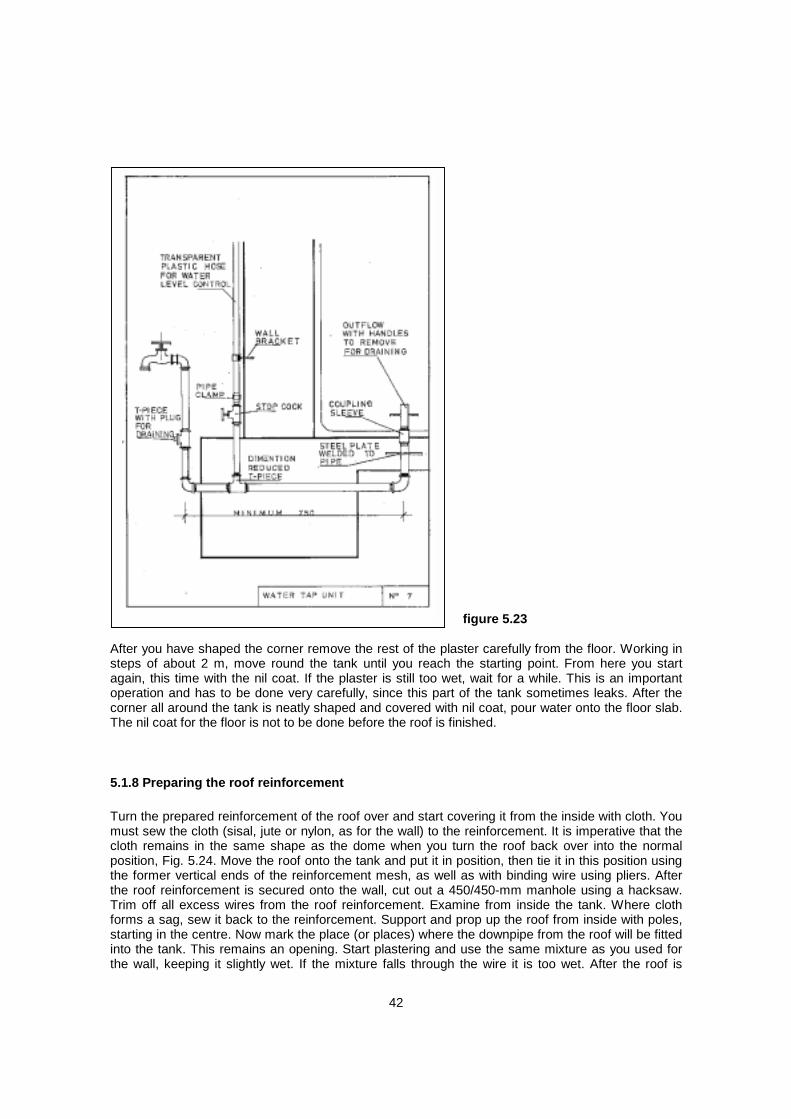
HAND DUG WELLS FOR VILLAGES IN UGANDA
HAND DUG WELLS FOR VILLAGES IN UGANDA
By John La Roche
Water from the ground has many advantages for rural people in developing countries. It is usually free from the bacterial contamination associated with surface water in regions where sanitation facilities are not common. In the May issue protection of spring sources in the Rukungiri region of Uganda was discussed. Hand dug wells are another source of water being developed in the Kabarole district of Uganda.
Uganda, a country which suffered in the 1970's and early 1980's under the repressive regimes of Amin and Obote 2, has a new optimism and determination to forget this difficult past. The Kabarole district of Western Uganda is within the great African rift valley which runs through a chain of lakes from Malawi, Tanzania, Rwanda and Uganda to Sudan and the Red Sea. The Kabarole District is a particularly poor area of Uganda where only 4% of people have access to safe water. Much of the area has been recently resettled after eradication of tetse fly and the return of political stability. Existing water sources are usually unprotected holes in the ground which dry up in the dry season leaving women to walk several hours to nearby lakes.
Water for Survival has been assisting the programme of hand dug wells in the Kabarole district for the last two years. To April 1995, 105 wells had been completed as part of a programme to construct 450 wells in the region bringing safe and accessible water to 90,0000 people. New Zealand funds have paid for 23 wells and two further wells have just been supported by the pupils of St Margaret's College in Christchurch and the members of Dunedin South Rotary Club. At the present exchange rate, NZ$805 in support funds, doubled by the NZ Government VASS subsidy and doubled again with a UK Government ODA grant will provide the œ1,320 needed to purchase a handpump, cement, reinforcing steel, and provide construction equipment, transport and skilled staff.
As has been found in many developing countries, involving local people to help themselves achieve the facilities they need is the best way to achieve long term success. Outside help is only a small part of the process which is designed to leave the local people with their own pride of ownership and the satisfaction of having made their own decisions and worked very hard to achieve their new well.
I was fortunate to be able to visit this project in December last year. All project staff are Ugandans led by Walude Mutwalibi, a most enthusiastic young engineer with a degree from Kampala University and a Diploma in Ground Water Management from the Water Engineering and Development Centre (WEDC) at Loughborough University, UK. Walude was responsible for a WaterAid team of technicians, drivers and health educators who liaise with local communities to help them with technical decisions and the expert help needed to construct the wells.
http://www.lifewater.ca/wfs/wwhdw795.html (1 of 3) [1/13/2005 12:48:48 PM]

HAND DUG WELLS FOR VILLAGES IN UGANDA
Walude explained that each well serves a community of 30 to 50 families - about 250 people who will decide where they want the well to be sited. Community decisions have led to a number of dry wells being dug but with greater experience from the initial phase of the programme, the success rate has improved from 33% to 75%. No external funds are used in unsuccessful wells - just the disappointment of villagers who have dug a dry hole but who are quick to learn!
The first process is the formation of a Water Committee including women who will be responsible for mobilising the community, planning and managing the unskilled labour for digging the well. Caretakers will be chosen and trained for the management and maintenance of the handpump, well and surroundings. At one completed well I visited the local community members were busy cutting the grass with bush knives and generally keeping the well clean and tidy. A health education programme is conducted at each village and it will be the Caretaker's responsibility to ensure the benefits of the new well are realised by good hygiene.
A handpump user fee of 100 Uganda shillings per month (NZ17 cents) is charged to help pay for the maintenance costs, although it is recognised that this will need to be increased as people better understand the advantages of their new well and gain economic advantages. There is concern however that some communities cannot afford even the basic contribution at this stage.
Wells are dug by hand using a tripod and hoisting bucket to dig through the clay surface layers to water bearing formations. A hand dug well, although more expensive and difficult to construct than a tube (drilled) well, has a number of advantages. If the hand pump fails and cannot be repaired, an access hatch in the concrete cover slab can be used to draw water with a bucket. If the water table drops it is usually possible to deepen the well whereas this is often not possible with a tube well. A hand dug well provides greater storage capacity and hence can utilise low permeability soils and a greater draw off during the day.
Prevention of contamination from surface water is important by forming a concrete surround with a good drainage channel taking wastewater away to garden areas. It is also important to seal off the lining near the surface to prevent surface water seepage down the lining. The Kabarole wells are lined with 8 segment precast concrete rings manufactured by the villagers using local materials. The direct action "Tara" handpumps made in Finland were being fitted to all the Kabarole wells. The Tara is a simple well balanced pump which is easy to use with corrosion resistant plastic and stainless steel parts.
While at the project I stayed at the construction camp at Mahyoro. A works camp built in traditional style from grass huts at a total cost of 600.00 pounds! As work in this area is almost complete the camp is soon to be handed over to the local community who plan to set up a number of income generating projects such as a grain mill and a pharmacy to sell medicines. Not far from the works camp is the village of Mahyoro on the shore of Lake George. Nile perch are caught from the lake by the villagers and Walude explained how he had tried to get the villagers to stop throwing the offal and algae- laden intestines back
http://www.lifewater.ca/wfs/wwhdw795.html (2 of 3) [1/13/2005 12:48:48 PM]

HAND DUG WELLS FOR VILLAGES IN UGANDA
into the lake where villagers were drawing water. He was told quite firmly by the villagers that the Fisheries Department had told them it was quite acceptable to do this because the fish from the lake would come in during the night and eat up all the algae laden offal! Walude said he no longer eats fish from the lake!
If you or your group would like to help 250 people by supporting a Kabarole well please contact John La Roche Phone/fax 09-5289-759.
Email [email protected]
http://www.lifewater.ca/wfs/wwhdw795.html (3 of 3) [1/13/2005 12:48:48 PM]

Rainwater Reservoirs above Ground Structures for Roof Catchment by Rolf Hasse A Publication of Deutsches Zentrum für Entwicklungstechnologien -GATE in: Deutsche Gesellschaft für Technische Zusammenarbeit (GTZ) GmbH - 1989
Preface This paper was written in the Botswana village of Romotswa in 1987, the seventh year of drought in Southern Africa. Romotswa has a history of rainwater catchment. Many of the private buildings as well as public buildings are equipped with reservoirs, most of them dating from the time before municipal water supply existed. In 1983 a large underground water source was detected here by geologists. The yield of the drilled wells is of such magnitude that for some time in 1984, the towns of Gaborone, the capital of Botswana, and Lobatse were both supplied with water from Romotswa. During my residence in this little border village in SouthEast Botswana, 30 km away from the capital, I noticed that rainwater catchment had lost momentum as a result of the centralized water supply. Many of the catchment facilities were poorly maintained so that much of the rainwater during the rare but heavy downpours was lost due to gutter leaks and/ or dislocated downpipes. At the same time newly built schools and other public buildings had been equipped with reservoirs which were much too small for the huge catchment areas. It became obvious that no calculations and no design for the systems had been made. Unprofessionally fixed gutters and downpipes were another problem. It should be mentioned that drought in Botswana, as in other parts of the world's desert belt, does not mean that no rain occurs at all. It simply means that the mean annual rainfall has not been reached and sometimes -just as serious - that the distribution of precipitation is extremely unequal. In such unfavourable climatic conditions heavy downpours of up to 100 mm in one hour do more harm than good to the arable land. The water does not penetrate the very dry and hard soil and the massive runoff results in severe soil erosion. Together with my experience gained as Town Architect in Lobatse, all these observations have influenced the structure of this paper. Originally planned as a technical manual for the construction of reinforced bricktanks, it became clear that the entire issue of rainwater catchment and storage should be put into a broader context. At the same time UNICEF, Kenya, had approached the Editor with the Laurie F. Childers manual for a ferro-cement tank. It was agreed that the accumulated knowledge in this paper should be used to provide an introduction of different techniques for building rainwater reservoirs. Since the possibilities of building rainwater reservoirs depend entirely on the availability of the required materials, it is the intention of this publication to cater for a variety of situations. N.J. Wilkinson of the Botswana Technology Centre has published a manual showing another technique of building a ferro-cement tank. This technique has advantages under certain circumstances. E.H. Robinson has erected structures for "Christian Action for Development in the Caribbean" using another technique. Each of the different structures has its advantages. Which one should be chosen depends on the situation at the specific site. Much emphasis is placed on material testing and mixing. Here the advice given by Childers matches the experience I have made with waterproof cement plaster and

2
which has not been mentioned in any other publication. Only a careful screening of river sand and uniform mixing will result in waterproof structures. The nit is an equally important coat often forgotten, and the necessity of curing cannot be overemphasized. An article by Kiran Mukerji in "Trialog" describes his experiences in India with the construction of a rainwater reservoir. He had chosen an interesting two leaf structure combining the ferro-cement technique with air-dried clay bricks, using the latter as permanent shuttering. He stresses the need for professional artisans and limits the possibilities for self-help construction. Having worked for seven years in different African countries, I can confirm that this reflects my own experience, and leads me to comment on appropriate technology. This term is often misunderstood for different reasons. The first is that too many academics from developing countries have been educated in the western industrialized world. Because of their academic orientation, they have little practical technical knowledge. They consider appropriate technology to be a second-class technology invented by the industrialized north, good enough for the poor south. More often than not they prefer to discard traditional technical knowledge. A second reason is that some aid organizations have indirectly supported these arguments by allowing their engineers sent to developing countries to use techniques which are not appropriate to the economical, technical and social background of these countries. The windmill designed and manufactured for borehole pumps will not replace the diesel pump if it costs 20 times more than the latter as long as cheap fuel is available at all times. The plough which is manufactured from scrap has the advantages of being labour-intensive and recycling material, but its success is only assured if a comparable industrial product is not available. This means that appropriate technology must first of all be a technology which is based on a cost-benefit analysis. Secondly it is difficult to create a motivation, which is needed to achieve the acceptance of any new technique. It is therefore of fundamental importance that the manufactured product works properly. Techniques which function poorly or not at all result in frustration, demotivation and resignation, and for many years people will be reluctant to accept any change. The consequence of this must be that appropriate technology also requires professional engineering. According to my experience it is more appropriate to train and instruct a contractor and his already qualified craftsmen than to use unskilled labour in self-help construction projects without professional supervision. In construction work there are many jobs which can be done by unskilled labour, but substituting casual labour for trained plasterers should not be tried. This manual offers advice on a more professional approach towards rainwater catchment and the construction of different types of reservoirs. It also offers a selection of the most appropriate reservoir types and gives technical advice for the construction work. As far as possible it has been kept on a level which would allow an experienced bricklayer to use the information or a building technician acting as Clerk of Works or Supervisor to advise bricklayers and plasterers on the site. It is not suitable for laymen in the construction field. Just as it is not possible to learn the technique of bricklaying by reading a book, it is not possible to write a construction manual imparting all the knowledge needed for people without the practical experience in the construction field. Finally I wish to thank Karin Bell who did the illustrations and Siggi Gross who took the photographs. Special thanks go to my colleague Frederick McKelton who corrected the manuscipt.
Rolf Hasse

3
Content
Preface....................................................................................................................1
1. Introduction......................................................................................................4
2. Catchment possibilities and choice of reservoir types..............................11
3. Material testing and mixing ..........................................................................21
4. Installation of a corrugated iron tank ..........................................................27
5. Construction of ferro-cement reservoirs......................................................30
6. The reinforced bricktank...............................................................................64
7. Gutters and downpipes.................................................................................81
Appendix: Technical drawings...........................................................................83

4
1. Introduction
1.1 Brief outline of the history of rainwater catchment technologies Rainwater harvesting and storage do not constitute a new technology. Small dams and runoff control means for agricultural purposes can be traced back to early history. An example of this are the rice terraces in the Philippines. In use for thousands of years, they still prove to be an efficient technique today. The use of earth dams to control runoff was also known in ancient Egypt. Archaeologists found a sophisticated rainwater collection and storage system on the island of Crete while working on the reconstruction of the Palace of Knossos (1700 B.C.). However, with the development of building construction based on new materials such as lime and burnt clay bricks, new construction techniques like arches and domes developed. The ancient Romans became masters in rainwater harvesting and the construction of reservoirs. It was this new technique of building closed cisterns, and at the same time the urbanization within the Roman Empire around the Mediterranean, which resulted in the development of a rainwater catchment culture at all those places where water resources were limited. This is why old rainwater cisterns are to be found on the islands of Capri and Malta and at places of historical interest in Spain and Turkey, in the Lebanon and on the island of Sicily. It appears that the rainwater harvesting technique used in the Roman houses was based on the experience gained in Knossos. "Through a small anteroom (vestibulum) a closed internal court is reached (atrium) which has a pool in the centre into which the rainwater from the roof flows. The pool is lined inside with ceramics and has sloping sides. The atrium is closed behind by the sitting room (tabunium) which leads into a larger internal court (perstilium) where a second pool collects water from the roofs of the rooms surrounding the court''. Many of the ancient systems, including the Roman rainwater catchment techniques for housing, served a double purpose. The evaporation of the water in the pools improved the microclimate through its air-conditioning effect, and the water was used for domestic purposes. As a result of urbanization, increased density of plot coverage and growing population, the consumption of water also increased. This led to the development of covered cisterns. These were built in the ground underneath the courts. This had two major advantages: firstly, the amount of water which could be stored was increased considerably and evaporation losses were reduced. Secondly, the cisterns served as a protection against pollution of the water. The more sophisticated houses still had the shallow pool in the atrium. All the rainwater from the roofs flowed into the pools and an overflow drained into the cisterns. At this time rainwater catchment techniques were decentralized, and this may be the reason why they lost momentum with the increasing consumption and the development of a centralized supply from springs channelled into the urban areas. However, few examples of centralized rainwater catchment and storage in cisterns are known. Probably the world's largest cistern is the Yerebatan Sarayi. On the European side of Istanbul in Turkey, it was constructed under Caesar Justinian (A.D. 527-565) and measures 140 by 70 metres. It can store 80,000 m³ water. The underground structure is based on intersecting vaults. Nowadays it has turned into a tourist attraction which can be visited by boat, drifting through a forest of columns. Another cistern in Istanbul is called Binbirdik and has a capacity of 50,000 m³. Sources are unclear as to which of the cisterns is the older. It could be the Binbirdik if constructed under Caesar Constantine (A.D. 329 - 337) as one source suggests. Both cisterns served as centralized storage. The water was collected from roofs and paved streets and a sophisticated system of filters assured clean water. However the municipal underground cisterns in Istanbul are probably the only examples of urban centralized rainwater harvesting of their kind. There are probably two major reasons why

5
this technique was no longer used. Firstly, the construction of underground cisterns is considerably more expensive than the construction of dams. Secondly, there is a danger of accidental pollution through human excrete in dense urban areas and therefore a risk of epidemics. Although rainwater harvesting and storage in closed cisterns were never used again to the same extent as in ancient Rome, they were occasionally employed where circumstances demanded an appropriate technology. This happened in semi-desert areas where people wanted to build homes without springs or wells in the vicinity. The technique was often used when Christian monks built their monasteries. Many of these examples still exist in the former Spanish Empire and monasteries in Mexico, for instance, provide evidence of the high standard of design and construction. The technique disappeared with increasing urbanization. It can be assumed that the technical means available during the industrial age, the need for supplies of large amounts of water for industry, the high standard of water hygiene achieved through central treatment and safe supply via pipes are all reasons for the reduced use of rainwater harvesting. But modern water technology not only has advantages. Its disadvantages are as follow: -The centralization of supply involves the risk of total cut-off in cases of natural disaster (earthquakes etc.), destruction through acts of war (bombing etc.), and source pollution (environmental pollution through chemicals). This is the vulnerability of a modern centralized water supply. - The consumption of water is not only based on need, but very much influenced by the convenience of access. It can be observed everywhere that water wastage is the rule rather than the exception. This is based on an economy which has made one source of life a commodity of consumption and represents the contradiction between the need for careful management of world resources and an economy based on permanent expansion. However' in general there can be no doubt that there is no alternative to a centralized water supply in urban areas nowadays. Rainwater harvesting is gaining importance again, this time in rural areas and especially so in many developing countries. The present situation in developing countries demands the utilization and development of all possible sources to ensure the supply of water. Much has been published about rainwater reservoirs for rural housing. Less emphasis is given to the construction of large reservoirs as stand-by facilities. Likewise not much is known about the possibility of using rainwater as raw. water and by doing so of reducing the consumption from centralized supply. The following section will show that the use of rainwater combined with the saving of water and reuse of waste water can be an economic solution when considering the rising cost of pipeborne water.
1.2 Rainwater catchment at public buildings in Lobatse, Botswana The following shows what can be done in a semi-desert country where water shortages are frequent, and how rainwater catchment and storage can become an economic solution. In April 1983 the drought in Botswana entered its third year. Lobatse, a small town with about 20,000 inhabitants situated 70 km south-west of the capital, Gaborone, is usually supplied with water from two nearby dams. The town is a "Waterworks Area" which means the supply is centralized and organized by the W.U.C. (Water Utilities Corporation). Although Lobatse has two groundwater basins, this water is not used in the central supply system. In April 1983 tight water consumption restrictions came into force, since both dams had dried up. The central supply system then received its water through a 70-km pipeline from Gaborone. The restrictions prohibited the use of water for

6
gardening, car washing, swimming pools and even construction work. The only three institutions in town in possession of their own boreholes were the B.M.C. (Botswana Meat Commission), the Zimbabwe Railways (now Botswana Railways) and the Town Council. However all boreholes raised water that was considered not fit for human consumption. The Council borehole was linked to an irrigation system for the lawn in the stadium. Since the groundwater in Lobatse was not included in the restrictions, the Council was also allowed to irrigate the stadium lawn. This was very fortunate since the development of the stadium lawn and the maintenance of it until then had already cost a lot of money. The major problems for the Town Council, however, were schools and clinics. At four primary schools, two clinics and one day care centre vegetable gardens were drying out. Traditionally, the diet of Botswana is carbohydrate-and protein-based. An extensive government programme made vegetable growing a compulsory educational subject for all primary schools. At the local clinics where special care is taken of children and their mothers, vegetables are grown and cooking is demonstrated. The big question was how all these activities could be maintained without sufficient water. Also, at the same time, hundreds of newly planted trees had to be watered. The Council owned two water trucks and after the stadium borehole had been provided with a standpipe, watering of trees was carried out with water trucks (bowzers). The schools and clinics were provided with old drums which had to be filled up once a day. The watering of trees worked because they were big enough to withstand short interruptions of the water supply without serious consequences. The supply for the four schools, two clinics and the day care centre was not satisfactory. A breakdown of a tractor could result in considerable problems. Since the borehole had to supply the stadium irrigation system and to fill all the bowzers, special arrangements for the staff had to be made. The first groups started working at 4 a.m. and bowzers were still on the road at 7 p.m. The bottleneck was the temporary storage of water in drums at the public buildings. The investment in drums became substantial since they were often stolen and had to be replaced. There was an obvious demand for better storage. This resulted in the development of the dual system as it was then called. The dual system meant that rainwater reservoirs were built at the public buildings and always kept half filled with borehole water. When it rained the reservoirs filled up with rainwater, and when they became empty they were filled with two or four bowzerloads, depending on their size, and this could be timed properly. Early in 1986, all primary schools, the day care centre and the clinics were equipped with reservoirs and catchment systems. In addition a newly built community centre was equipped with a 59-m3 reservoir. Within three years and with only limited funds, an overall storage capacity of about 437 m³ was achieved (see Table 1). Sizes of the reservoirs constructed differ due to the layout of the schools and the catchment possibilities. Only the Woodhall Community Centre, which was built in 1985, was designed according to the catchment needs. Although tight water restrictions were lifted in 1985, the system remained in use unchanged. The reason was the tariff policy of the Water Utilities Corporation. Water in Lobatse is sold for a higher price than in other towns because the supply is very expensive.

7
Table1: Rainwater reservoirs at public buildings in Lobatse, Botswana The reason for not fixing a uniform tariff throughout all towns (W.U.C. supplies water in urban areas only) is to keep people aware of the more or less permanent shortage of water with emphasis on areas where the supply becomes very expensive. As a result of growing urbanization (Botswana's urbanization rate in the past was 11.2% per year, one of the highest in the world) more and more investment was necessary for well drilling, dam raising and pipeline construction. As shown in Table 2 water tariffs have been increased each year since 1982. The tariff is stepped up and the table calculated on the amount of 50 m³ and more. The tariff for the first 10 m³ is much lower but was also raised from 2.30 pula in 1982 to 5.20 pula in 1987. That is equivalent to an increase of 126% within just five years. However, prices for water consumption of 20.50 m³ and more increased much more. As the table shows, 50 m³ in 1982 cost 30.10 pula; the 1987 cost is 80.10 pula. This means an increase of 166% which is more than two and a half times the cost of five years ago. It could be argued that another tariff policy would be more justified. However, the system in use has definitely supported water saving and the rainwater reservoirs at public buildings in Lobatse become more and more economical. The costs of filling given in Table 1 are based on the sizes of the reservoirs, not on the consumption. It is unfortunately not possible to state an average amount of consumption since gardening is of different intensity and gardening areas vary. Refilling of all reservoirs is done three times a year if there has been no rain. This suggests a consumption of about 1,300 m³ equivalent to costs of 2,150 pula. This amount would still cover the construction Cost of a reinforced bricktank capacity of 21 m³ As the example shows, this dual systems is economically efficient. At the same time, the reservoirs are an ideal stand-by facility. Given the case that the centralized system may be temporarily not functioning, the cisterns could supply the population in the area of location. As all reservoirs are closed, a treatment with chlorine could make the water safe for use. Since it can be observed everywhere that the highest consumption of water is in areas where drinking water quality is not imperative, raw water should be used as much as possible.

8
Finally it should be mentioned that tree planting and keeping are not primarily decoration, but satisfy an environmental demand. Botswana is very much affected by soil erosion. The Government therefore directs that all support should be given to tree planting. An annual tree planting day enjoys public attention and nurseries are being founded in many places. Therefore, any water consumption restriction has a substantial effect on environmental conservation. Hence unconventional ways had to be found to continue environmental conservation while at the same time saving as much water as possible.
Table 2: Development of water tariffs in Lobatsa
1.3 Water saving and reuse of water 1.3.1 Domestic water saving 1.3.2 Bath or shower 1.3.3 Reuse of domestic water 1.3.4 Conclusion Water saving in semi-desert countries is essential and should be encouraged as much as possible. To support saving, it is first important to understand how water is wasted. By way of example, let us consider a selfhelp housing area. In Botswana this area is supplied through standpipes on the side of streets, never more than 100 metres away from a house. Tenants are supposed to build pit latrines before they are allowed to construct dwelling rooms. People fill containers several times a day and carry the water home. Although the supply of water is much better than in villages and distances are much shorter, the water still has to be carried. One who has to carry water to the point of use will hardly waste it, and exactly this is the experience gained. It was observed that people became used to collecting their washing water after use, and watering their plants in the courtyard. As the water bills in Lobatse showed, consumption of water per standpipe in self-help housing areas, although used by 7-10 families, is lower than the consumption for one high cost house. It has been suggested that the consumption in residential houses rises with the number of taps and other sources connected to the central supply. Unfortunately, statistics are not available but observations appear to confirm this. However, the conclusion from the above should not be to propose public standpipes as a solution. The general conclusion can only be that the convenience of access to water raises consumption. If this is understood, we should have a close look at possibilities of saving domestic water.
1.3.1 Domestic water saving In domestic water use the waterborne toilet system, in general, is the highest consumer of water. Moreover, the water used is not fit for reuse and goes into the sewers. Recycling of sewer water is possible but expensive and can only be done in special ponds. It has been observed that at a school with water closets (12 toilets each consuming 10 litres per flush), the consumption of these flush toilets is higher than the consumption of 1000 pupils and their teachers for drinking, cooking one

9
meal a day and washing the dishes. Consumption reduction means first reducing the consumption by the toilets. Flushing valves consume less than flushing cisterns, but they are not appropriate since they require a permanent high water pressure not always available in developing countries. There are producers of toilets consuming 4 litres of water per flush in Sweden, Great Britain and West Germany. Imports of this highly appropriate system into developing countries, where there is a real need to save water, should be encouraged. In Botswana this was done by the Botswana Technology Centre in Gaborone. This institution had discussions with wholesalers whom they persuaded to import a reasonable number. At the same time the centre spread information about this new system. Introduction of a new system like this takes time since people have to be convinced that the higher investment really brings returns. But there is also something that can be done about the existing highly wasteful cisterns. Some can be adjusted to lower levels of filling by bending the bow of the cistern float downwards. This results in stopping the filling water at a lower level. It is also possible to put stones around the off-flow of the cistern. The volume of the stones (blocks) will be the volume of water saved, at the same time raising the water level to the adjusted cistern float. Depending on the type of cistern the consumption can be reduced to 7 or even 6 litres, but the cleaning effect of flushing is reduced since the toilet bowl is not designed for such low consumption.
1.3.2 Bath or shower It is often not realized that the amount of water consumed for one bath is sufficient for three showers. In consequence this would mean that houses should be furnished with showers rather than with baths. But baths have become a status symbol in many countries, and a high cost house must be furnished with a bath. The amazing thing is that baths in Europe are rather out of fashion and much less used than showers which produce savings in both water and time. From the hygiene point of view showers are better than baths. If a bath is installed this should always be done in such a way that a shower battery is fixed, so that the bath can also be used for showers. At the same time the built-in bath should be chosen carefully since the capacity varies substantially. Several devices are on the market designed to reduce water consumption. Spray nozzles for showers, push button taps etc. might reduce consumption, but should be studied before use. When deciding on water saving equipment one has also to consider the lime content of the water. Lime precipitates at 60 °C. This means that sensitive equipment in hot climates will soon clog.
1.3.3 Reuse of domestic water
figure 1.3
Major sources of water consumption in residential houses are the kitchen sink, the bath and/or shower, the basin in the bathroom and the toilet. While for obvious reasons the reuse of water from the toilet is not possible, the bathroom water, although contaiminated by soap and through laundry

10
by washing powder, can be used for cultivation, even for vegetables if directed at the soil. One vegetable gardening area of 150 m² at a clinic in Lobatse was irrigated with water from sinks and hand basins only for a period of one year, and showed very successful results. At this clinic only one sink was used for washing drug containers and equipment used for medical tests. This waste water was drained into the sewer. All other waste water was drained into drums dug into the ground (see Fig. 1.3). The water was then extracted with buckets and used for gardening. Experiments at private residential houses have shown that the reuse of water for gardening does not affect the plants, if the water is drained into the soil surface only. This does not generally apply to water running out of the kitchen sinks. Water from dishwashing usually contains too much grease and is therefore not suitable for most plants nor for vegetable gardening. But this water can be successfully used, for example, for cultivation of banana plants. Bananas should not be planted closer than 15 metres to a residential house because of mosquito breeding. There are two ways to reuse domestic water. The first, as stated, is to disconnect the pipes of the sink outlets and fit hoses draining the water into drums dug into the ground. These drums must be provided with lids because of the danger of mosquito breeding. Water is then lifted out with buckets. The other and more convenient method is to connect long hoses direct to the outlets and draw the water straight to the place of use. Where rainwater is available and not used for the household and as drinking water because of an existing centralized supply, it should be used for vegetable gardening and the waste water for cultivation of trees and other plants (see Fig. 1.3). Vegetable gardening with waste water requires the cultivation of vegetables where only the above-ground part of the plant is eaten, and the water is spread on the soil. and not sprayed onto the leaves.
1.3.4 Conclusion The water catchment possibility is always limited to the amount of rainfall, as is the storage capacity. Therefore, dependence on rainwater should always be seen in correlation with water conservation.

11
2. Catchment possibilities and choice of reservoir types
2.1 Cost-benefit ratio It is virtually impossible to provide a general cost-bereft analysis of the different types of reservoirs and storage capacity because of the many unknown factors. However, the following general indicators for decisionmaking can be given. 1. The value of rainwater rises with increased distance to or inaccessibility of other water sources. This means that if rainwater becomes the only source, its value is extremely high. Thus the high investment in a large reservoir becomes cheaper in relation to the value. of water. 2. If rainwater remains the only source of water, rainfall pattems must be studied carefully. If the pattern shows a more equal distribution over a long observation period, it is possible to choose the size of a reservoir according to the precipitation, even on a semi-annual basis. Where the rainfall is extremely unevenly distributed with frequent drought periods, a reservoir should be as large as possible, based on the maximum rainfall. This is expensive but still economic after taking all other factors into account. 3. It is imperative to analyse the purpose of water use and the volume of consumption in advance. Only rough indicators can be given since the consumption will vary from case to case. Rural households in Africa often manage with 40-60 litres of water per day. As mentioned earlier, since easy access does not encourage saving, but on the contrary consumption increases, arrangements should be made to provide additional amounts. Water consumption rates for cultivation cannot be given since this depends largely on the type of crop and soil conditions. If the planned reservoir is expected to serve as a stand-by facility because of frequent breakdowns of a centralized supply, the size can be smaller and the capacity limited to the consumption of a few weeks, depending also on the rainfall pattern. 4. Access to construction materials is another factor to be considered. For instance corrugated iron tanks which are usually very economical might be available only hundreds of kilometres away and therefore become too expensive. Or if reinforcement mesh is not available, a ferro-cement tank cannot be built (see Table 4, indicating the material needed for different types of reservoirs.) 5. Life expectancy and maintenance demands are other factors to be considered. As the example of rainwater catchment at public buildings in Lobatse (Chapter 1.2) shows, under certain circumstances high construction costs combined with long service life expectancy can pay off. Maintenance, usually a weak point in developing countries, has to be taken into consideration. A decision on the capacity and type of structure to be chosen should take all these factors into consideration. Attention should also be given to the following questions:
- For which purpose is the rainwater to be used? - What is the likely monthly consumption of water? - What amount of water can be harvested? - What is the rainfall pattern, and how is rainfall distributed during the year? - Which construction materials are available, which are unavailable? - How high is the financial amount to be invested? - By how much can costs of construction be reduced by self-help?
Answers to these questions will lead to a decision on the size and type of reservoir. Compromises must be made on the basis of the answers.

12
The following Table 3 offers assistance in decision-making. Costs are based on 1985 prices in Botswana where all materials are available.
2.2 Introduction of the different types of reservoirs and their advantages 2.2.1 The corrugated iron tank 2.2.2 The PVC foil tank 2.2.3 The ferro-cement tank without mould 2.2.4 The ferro-cement tank with a factory-made mould 2.2.5 The ferro-cement tank with a made-on-site mould 2.2.6 The reinforced brickwork tank Although we have learned that the most appropriate type of rainwater reservoir is an economic question, in many cases in developing countries the availability of building materials outweighs the economic factor.
2.2.1 The corrugated iron tank This is an industrial product manufactured in many countries Where the material for this tank is available, there are at least three capacity sizes of 2.25, 4.5 and 9.0 m³ Although usually the most economical, prices have to be compared with other suitable materials; the transport aspect can also increase costs substantially. The advantage of this tank is firstly the price, but certainly also the fast installation. The disadvantage is the limited lifetime, although this can be improved as explained in Chapter 4. One should remember at all times that the corrugated iron tank is vulnerable to manual force. Experience has shown that this tank should not be used at public places, especially not at schools, since vandalism is likely to damage the tanks beyond repair.
Table 3: Different types of reservoirs

13
2.2.2 The PVC foil tank Several industrial producers offer tanks of PVC foil. The foil is fixed inside a reinforcement mesh framework or galvanized sheet cylinders, screwed together from sections. The tanks are available from about 5.0 m³ up to 430 m³ Their considerable advantage lies in fast assembly and low transport costs. A reservoir of 9.25 m diameter (capacity 81.0 m³ can be transported on a small van and be assembled within a couple of hours. No foundation is needed. Dismantling and reassembly at another place can be carried out within a day or two. Apart from this advantage which is very valuable for cases requiring immediate action, for instance improvising a village water supply, the system has some weak points. Tanks of large capacity are uncovered, so evaporation is high and there is a danger of pollution. More important for permanent use is the problem of ultraviolet ray influence on the PVC foil. Systems in use show signs of ultraviolet light effect on the material after just a few years. Otherwise the vulnerability to external force is great and tanks should always be fenced in. For permanent rainwater catchment, although relatively cheap, this technique has its limitations.
2.2.3 The ferro-cement tank without mould This technique as explained by Laurie F. Childers of UNICEF Regional Office in Nairobi, Kenya, in 1985 has been chosen by the author because of the unique advantages of this appropriate technology. There are many examples of such reservoirs in Kenya. This technique depends on the availability of welded reinforcement mesh. Since this is not to be found everywhere, other methods can be substituted. Firstly close attention has to be given to the cost of the material and the transport to the site. Any other material used for this tank is more or less the same as for all ferro-cement tanks. The width of the roll of mesh or mats will be the height of the tank wall, about 1.80 m. This is certainly a restriction. Theoretically, it is possible to extend the height of the wall by using one and a half widths of the mesh, overlapping it on a minimum of three fields and tying it together with the bottom circle, but this is not recommended. The entire structure becomes unstable and any vibration during the process of plastering will make the work very difficult. In addition a scaffold is needed which might not always be available. The fixing of the scaffold requires skilled workers.
2.2.4 The ferro-cement tank with a factory-made mould The technique was described by N.J. Wilkinson, Botswana Technology Centre in his publication, and was chosen because of the considerable advantage it has for rainwater storage where all tanks are of the same size. Several examples of this are to be found in Botswana. This construction method can only be chosen if a factory or experienced workshop provides the facilities for bending corrugated sheets and welding them neatly together. The technique is highly appropriate in areas where a series of tanks are to be built. This is the case when new buildings like schools are put up, and the design of the buildings already includes provision for rainwater catchment. In such cases we can talk of a standardized tank. The mould can be used 10 - 15 times depending on the experience and careful handling of the staff. For larger projects it is advisable to have at least two moulds at the site. The advantage of this construction method lies in the rationalization of the work. The masons become experienced and work can be finished faster. With two moulds, the work can be organized with three crews. The first crew starts preparing the ground and then casts the foundation slab. The second erects the mould and reinforces it, and the third crew does the plastering. The roof slab can be made by a fourth crew or by the first, depending on the amount of ground to be cleared. This technique should not be introduced where only four or five reservoirs have to be constructed; in such a case the mould will
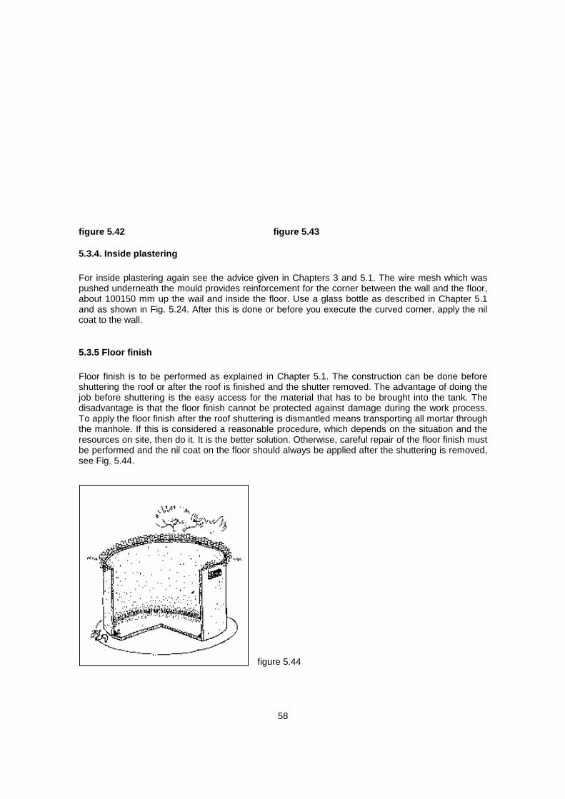
14
be too expensive.
2.2.5 The ferro-cement tank with a made-on-site mould E.H Robinson of the American Peace Corps describes this construction technique in the publication. It was tried by "Christian Action for Development in the Caribbean" (CADEC) in the Republic of Grenadines and chosen because of the advantages it offers over other methods. This technology for constructing reservoirs should be chosen where only a few tanks are required or even jut one, in other words where prefabricated moulds are not considered and welded reinforcement mesh is not available. All that is needed, in addition to the normal building materials for a ferro-cement structure, is some additional timber for the framework and a few corrugated iron sheets for shuttering. Fencing mesh is an additional reinforcement but could be replaced by other available mesh matrial.
2.2.6 The reinforced brickwork tank These were constructed by the author in Lobatse, Botswana, for public buildings. The reinforced bricktank is more expensive than the ferro-cement tank, although the cost per m³ reduces with increased capacity. It costs about twice as much as a ferro-cement tank. For this reason this tank should be chosen where the capacity needed is above 30 m³ and in all cases where the life of the structure is expected to be 20 years and more. The advantage of the construction method is the adaptability to the building design. Structures above 1.80 m in height are without problems, although plastering has to be done with great care. Especially at public buildings which are usually higher than residential houses, it is possible to use the height between gutter and ground, avoiding large diameters and thus saving space.
2.3 History of ferro-cement It is often heard that ferro-cement is a poor reinforced concrete and a second-class technology developed for Third World countries. Nothing could be more wrong.
Ferro-cement is a building material with some similarities to reinforced concrete. Indeed, both materials have the same source. Ferro-cement is produced by applying cement mortar composed of fine aggregate and cement onto wire reinforcement using plasterer techniques. As a result the property of ferro-cement distinguishes it from reinforced concrete. While of similar durability, it is more elastic than reinforced concrete.
A Frenchman, Joseph Monier (1823 - 1906), produced flower pots made of cement mortar reinforced with chicken wire and showed this product at the world exhibition held in Paris in 1867. J. Monier became known as the father of reinforced concrete. In Germany for many years reinforcement steel was called "Monier iron". In 1847, another Frenchman, Joseph-Luis Lambot, filed a patent for producing a cement boat, wire-reinforced, not long after the development of Portland cement. Which of the two men first had the idea of combining wire with cement mortar is of no interest. Probably the discovery technique happened by chance. At that time, the commonly known chicken wire was a handmade product and therefore soon too expensive in the fast growing industrial era. But the knowledge of the steel-concrete combination resulted in the development of reinforced concrete using large steel rods. During the First and also later during the Second World War, the technique of Lambot's ferro-cement boat was remembered in the U.S. and the U.K. and shipbuilders were encouraged to construct barges like this in order to save shipbuilding materials such as steel plates and timber. Although some of the boats built during the Second World War had an amazingly long life span, the technique did not really became widespread.

15
Table 4: Major materials needed for different types of reservoirs and possible substitutes

16
It was the famous Italian engineer and architect, Pier Luigi Nervi, who first undertook real research into ferro-cement technology. He observed that reinforcing concrete with layers of wire mesh resulted in a material with high impact resistance properties. This material differed from reinforced concrete in its flexibility and elasticity. After the Second World War, Nervi built a 165-ton motor sailer. This ship, "Irene", proved to be seaworthy. Similar ships were built in the U.K., New Zealand and Australia, and one circumnavigated the world without problems. But Nervi would not have been a structural engineer and architect if he had not also used this material for building construction. In 1947, he first built a storehouse of ferro-cement. Later he combined reinforced concrete with the ferro-cement technique and constructed the famous Turin Exhibition Hall with a roof system which spans 91 m. Nervi's work proved that ferro-cement is a high quality construction material. The question remains why ferro-cement is relatively seldom used as a building material in industrial countries. The answer lies in the process of industrialization of construction work. In order to minimize the labour cost, construction work has become more and more capital-intensive. As a result, working processes have been mechanized wherever possible. In this context the possibilities for mechanizing ferro-cement remain very limited. A high percentage of labour cost will always characterize this technology. While this is considered to be a disadvantage for industrialized countries, it is a positive factor in developing countries where the labour market is characterized by high unemployment and low labour costs.
It has therefore to be emphasized that ferro-cement is by no means a second-class technology, but rather highly appropriate especially for countries where labour costs are low.
2.4 Calculation of rainwater volume and choice of reservoirs
2.4.1 Reservoir capacity 2.4.2 Roof type and catchment 2.4.3 Roof finish 2.4.4 How to choose the size of a reservoir
figure 2.1
To calculate the rainwater amount which can be harvested, the mean annual rainfall figure is

17
commonly used. Mean annual is the statistical average calculated on the basis of measured rainfall over many years. It has to be understood that there is no guarantee that the calculated amount will be achieved, but there is a 95% likelihood that this amount can be expected. This near certainty diminishes to a probability if the rainfall pattern in a given area differs substantially. This is quite common in countries with drought periods. It can happen that the mean annual cannot be expected. It can certainly happen the other way round that considerably more rain falls than the mean annual. This makes the calculation of the storage capacity rather difficult. However, the mean annual is generally accepted as the basis. The size of, storage capacity chosen can be based on the mean annual, but should be greater if funds allow. Some countries provide maps where the mean annual rainfall is indicated along the line of occurrence. Fig. 2.1 shows the rainfall in Botswana; each line is marked with a figure giving the precipitation. The mean annual in a given area between two lines ranges from the lower amount, for instance 400 mm, to the higher average of 450 mm. For example the mean annual rainfall in Gweta is between 450 and 500 mm.
2.4.1 Reservoir capacity As an example let us consider a roof of 120 m² in an area with mean annual rainfall of 450 mm. We assume that less than 100% of the calculated amount of water will be collected. This is due to unavoidable small leakages in the gutter downpipe system, or rainfalls which are too light to produce sufficient runoff, or a possible overflow of gutters in the case of an extreme downpour. For this reason we can generally assume that only 90% of the rainwater can be collected.
figure 2.2 For calculation we take the following formula: mean annual rainfall in mm x area in m² x runoff factor = collected rainwater in litres. In our example

18
this means: 450 x 120 x 0.9 = 48 600 litres. In most cases it would be unrealistic to consider building a cistern of 48.6 m³ capacity for a house with only 120 m² roof area. However, as the situation differs from place to place, we cannot decide here whether a reservoir of this capacity will be realistic and economically efficient.
2.4.2 Roof type and catchment The shape of any given catchment area has a considerable influence on the catchment possibilities. Therefore different types of roofs provide different catchment possibilities. Of the most common roof types shown in Fig. 2.2 the single pitch roof is the most appropriate for rainwater harvesting, since the entire roof area can be drained into a single gutter on the lower side and one or two downpipes can be provided depending on the area. A more difficult roof for rainwater catchment is the tent roof. It requires a gutter on each side and at least two downpipes on opposite corners. If a tent roof is large enough, it could be drained into four tanks located at each corner of the house. The main problem is always the corner. A 90° angle in the gutter should be avoided. It is extremely difficult to adjust gutters in such a way that water really flows easily downwards. It seldom works well when downpours occur, and it is the heavy downpours that should be caught. The hip roof is not very efficient either, since it also needs gutters all around the building. Flat roofs can be used for catchment if they are furnished with an edge, keeping the water on the slab until it has drained through the gutter or downpipe. However, using a flat roof for rainwater harvesting is not very efficient because of the extended runoff-time and the evaporation losses. One way to improve the catchment is to provide the slab with a sloping cement screed. Constructing a waterproof edge on a flat roof is rather difficult because of the temperature expansion. The most useful roofs are the single and double pitch roofs. The double pitch roof offers many advantages. As the picture of Woodhall Community Centre in Lobatse, Botswana, shows, the gutter of the length of one side can be drained into a reservoir on the other side of the building by fixing the downpipe at the gable wall and sloping it towards the cistern.
2.4.3 Roof finish Not all materials used for roofing finishes are equally good; but the most commonly used material, metal sheeting (corrugated galvanized iron and aluminium sheets), is very suitable for rainwater catchment; likewise, brick tiles of all variations, and also thatch can be used, but these are less efficient.
2.4.4 How to choose the size of a reservoir Example I {see Fig 2.3}: A house with a roof area of 9.00 x 6.50 m is to be furnished with catchment and storage facilities. The mean annual rainfall is 450 mm. Calculation of rainwater:
9.00 x 6.50 x 450 x 0.9 = 23895 litres

19
figure 2.3 The height from the ground to the gutter outlet is 3.00 m. According to Table 5, a reservoir of 4.0 m diameter on a filling height of 1.80 m has a storage capacity of 23 000 litres. This means that one reservoir built' et one gable side of the house would be sufficient for nearly all the rainwater which can be collected if an average rainfall occurs. Two gutters along the sides of the building should be connected with downpipes fixed to the gable wall and then bridged into the tank. For this storage capacity a ferro-cement tank would be more economically efficient than the reinforced bricktank and serves the same purpose. But if a smaller storage capacity would be sufficient, or if funds are very limited, two corrugated iron tanks, each of 9 000 litres, would be cheaper. These two tanks could be located at each of the gable sides, collecting from each gutter, or next to each other on slightly different levels, draining 'the overflow from the ' tank connected to the pipes into the second tank. Fig. 2.4 shows this as an example with two corrugated iron tanks, but the same method is certainly possible with any other type of reservoir.
figure 2.4
Example 2 (see Fig. 2.5): Calculation of catchment area: Roof A: 20.0 x 10.0 x 450 x 0.9 = 81000 litres Roof B:
9.0 x 15.0 x 450 x 0.9 = 54 000 litres

20
figure 2.5 Total catchment per annum = 135 675 litres. About 136 m³ of rainwater can be caught within a year from 450 mm rainfall. The size of the chosen reservoir depends on the lowest inflow (see Fig. 2.5) and also on the ground space available. Block B has a gutter height of 3.00 m, Block A height of 3.30 m. The lowest inflow would come from Block B. Since gutters and downpipes must slope towards the inflow, the height has to be calculated. For the gutters a 0.3% slope is the minimum requirement (equivalent to 3 mm per metre). Block A has a gutter length of 20.0 m (20 x 3 = 60 mm), a downpipe with a minimum slope of 10% (10 mm per metre) to the middle of the gable wall 5.0 m, which means another 50 mm for sloping. We add the 60-mm slope of the gutters to the 50-mm slope of the downpipe resulting in 110 mm and add 15 mm for the distance from the gable wall to the tank inflow, resulting in 125 mm. For imprecise workmanship, measuring faults etc. we assume a total of 200 mm. These 200 mm have to be deducted from the height of 3.00 m between gutter and ground. This final measurement is 2.80 m and indicates the lowest inflow level and at the same time the filing height of the tank assuming that the bottom of the reservoir is level with the ground. The catchment capacity is about 135 000 litres at the most, with a filing height of 2.80 m. Table 5 shows a filling height of 2.65 m. With this filling height, we can build a reservoir with 133 000 litres with an internal diameter of 8.00m.

21
Table 5: Capacity of different tank sizes rounded to the next half m3 This cistern can only be built as a reinforced bricktank. It will be more economical to build one reservoir of this capacity rather than two reservoirs of about 66 0001, with a filing height of 2.0 m and an internal diameter of 6.5 metres. This example also shows that the correct siting of the building is essential for an economic rainwater reservoir. Taking the theoretical case that the entire rainfall occurs in only 5 days, that would mean that by dividing 135 0001 by 360 days per year, this reservoir would provide 375 litres per day throughout the whole year. Certainly this is theory and in reality the rainfall normally is spread over a period of some months. This also means that some of the collected water will already have been used when the next rain occurs and the reservoir will never be filled up to its maximum capacity, even if the rainfall reaches the annual mean. Or the other way round, since the mean annual rainfall is a statistical measure taken over many years, the chance is greater that an annual rainfall above the average but dispersed over a period of four months will occur and since consumption is constant, even this higher amount of rainwater can be stored.
3. Material testing and mixing

22
Most of this chapter has been taken from Laurie F. Childers publication on ferro-cement tanks, published by UNICEF Regional Office, Nairobi, Kenya, in 1985. Since the technique introduced is the same as the author has used for waterproof plastering of reinforced bricktanks, it is recommended for all types of ferro-cement tanks and the plastering of bricktanks. Let us start with some general remarks. The technique for preparing waterproof cement plaster is delicate, not in theory but in practice, because it is influenced by the site conditions. Therefore, it is imperative to first create favourable site conditions for good quality work. This means, for instance, that the place where the mortar is to be mixed is clean, flat, smooth and large enough. If possible, some flat metal sheets should be laid on the ground. If the working ground is only a soil surface, it must be swept like Africans clean their courts. If the soil surface is not hard, it is possible to prepare an area with stamped clay. The working area must be clean before the mixing of the sand and cement can start. Likewise, it is necessary for all material to be on site before the preparation of plaster is started. All material not only means the sand, cement and water for the entire job, but also all curing agents and tools. Tools have to be clean and free of old mortar; this also applies for all buckets to be used. If it is obvious that some sort of scaffold is needed, this has to be there and tried out before the work starts. It must always be remembered that once the plastering of a ferro-cement structure has started, there must be no break until the first coat is finished. The same applies for waterproof plastering of a bricktank. Curing the plaster on the structure is as essential as the right mixture. Organizing the job is also important to achieve smooth hand-in-hand working. Ignoring this important advice means risking a lot of money and almost certainly creating cracks and leakages. Although smaller faults can be repaired, it must be remembered that a leakage occurs after the reservoir has been filled with water. To repair it means draining the water and usually wasting it. Experience shows that negligence is often found if contractors are employed. The reason lies in the time factor where profit is expected. It is therefore better to stop the work entirely and employ another contractor than to allow an ill-prepared job to start. It should also be realized that leaking or cracking tanks give the whole technology a bad reputation. This is especially importent in all those places with no prior experience. Leaking reservoirs can discredit rainwater harvesting. Every finalized cistern construction must immediately be filled with water at least 10 cm high, irrespective of whether it is a bricktank or a ferro-cement structure. This water serves as a long-term curing agent and will keep the plaster moist.
3.1 Sand The sand to be used for ferro-cement is the same as is used for waterproof cement plaster applied to bricktanks. The sand has to be clean and well graded. This means having grains of many sizes, but 90% should still pass through a mosquito wire sieve. Sand must be clean, because like water it may have some impurities that weaken the cement bond, such as clay, silt and organic matter. Dirty sand can be washed by repeatedly rinsing with water. This should be done on a well-prepared sloping ground by pouring water on the sand while turning it with shovels. The dirt must run off, otherwise the effect is minimized. If sand has to be washed afterwards, it is too wet for ferro-cement plaster and should be given time to dry partly while turning it with shovels three times a day. There are two easy field tests for determining if the sand needs to be washed: 1. Rub a moist handful of sand between your palms. Suitable sand will leave hands only slightly dirty. 2. Fill a clear glass container 100 mm high with sand. Then fill with water. Shake the glass vigorously, place it on level ground and leave undisturbed for one hour. The sand settles immediately and any silt and clay settle as a dense layer on top. This layer is of another colour than the sand, often darker, and should not be more than 6% of the entire thickness of sand (Fig. 3.1). If you have had 100 mm sand, a 6-mm upper layer of silt or clay is acceptable; if it is more, the sand has to be washed.

23
If sand is not taken at the site but supplied, so-called river sand is likely to meet the quality demanded. Sand has to be stored close to the mixing area on cleared ground. Before the sand can be used for mixing, it has to be sifted. For this purpose a special sieve has to be made out of galvanized gauze wire supported by chicken wire (see Fig. 3.2). The frame of the sieve must be of boards about 100 mm high so that all material which does not pass the sieve remains on top and cannot fall onto the sifted sand. The sieve is to be used by shaking it. Two men hold the sieve, while another shovels sand onto it, not more than three or four shovel fuls at a time. The two men then shake the sieve backwards and forwards. The clean material will fall through the sieve. The rest has to be put aside in such a way that it cannot accidentally be mixed with either of the two piles of sand, the sifted or the unsifted one. Since shaking the sieve is hard work, it has been observed that people start to make mistakes after some time. It should therefore be made clear in advance that the sifting crews are to be changed. Sifting sand and preparing the mixture are just as important as plastering. The final product, the ferro-cement tank or the plaster of the bricktank, depends very much on the care taken by the staff preparing the mixture and in charge of the material.
figure 3.1 figure 3.2
3.2 Water Clay, silt, salt, mica or organic matter in the water will weaken concrete and ferro-cement, as will certain invisible chemicals. Water that is fit for drinking is usually fit for mixing cement mortar. The quality of an unknown water can be tested by comparing it with water known to be good. This is best done by using the known water (such as drinking water), making three cakes of cement paste, each approximately 20 mm thick and 60 mm in diameter. At the same time make three identical cakes using the unknown water, and compare setting and hardening times of the two. types. The cement paste is prepared like the nil coat, adding cement in a small container with water while constantly stirring the mixture. Cement should not be added fast to avoid clotting or the development of lumps. To achieve equal test cakes, a glass can be used for shaping. All cakes must be of equal size and shape. A chart should be prepared to record the test results (see Fig. 3.3). Mark on your chart that the sample has set when you can no longer make an indentation with your finger tip. Mark the samples with A for drinking water mixture and B for unknown quality. Test for hardening by marking whether or not you can scratch the sample with your fingernail (see Fig. 3.3). The samples must be

24
stored in the shade. If the chart shows that both samples are nearly equal, the water of unknown quality can be used for mixing cement plaster.
figure 3.3
3.3 Cement
Cement bonds and hardens in the presence of water. Therefore careful storage is imperative to avoid moisture reaching cement before use. The bags of cement should be stored in a closely packed pile, no more than ten bags high. The pile should be on a raised platform in a room with little air circulation. In rooms with open windows and doors, the pile should be covered with plastic sheeting. The same applies if the cement has to be stored outdoors. The platform must be made in such a way that moisture from the ground cannot affect the cement and the plastic sheeting has to be tied so that the wind cannot blow it away and rainwater does not affect the cement. As bagged cement ages and absorbs moisture from the air, it becomes lumpy. If lumpy cement is to be used, its proportion should be increased by half and bigger lumps be removed before mixing.
3.4 Reinforcement
The cement bond is easily broken by forces which pull it apart—tensile stresses. Thus it is necessary to use a material like steel inside the concrete or plaster for large water tanks. The weight of the water will stretch the tank walls. Barbed wire or weld mesh is heavy enough to withstand the stress and hold the tank together. (Straight wire can be used in place of barbed wire, but the barbs help grasp the plaster, and the two twisting wires are stronger than a single wire.) Chicken wire helps hold the plaster together between the stronger wire. Although the soil helps support the weight of the water, even the ground hemispherical tanks will stretch when full. Hard rocky soils provide better support. Loose or sandy soils should have more reinforcement (barbed wire) in the tanks. Upright water tanks receive most tensile stresses in the bottom third of the wall and in the joint between the floor and wall. Extra reinforcement wires in the wall and joint and thickening the plaster at the joint prevent cracking at these points of stress.

25
3.5 Mixing cement plaster The correct method of measuring the different aggregates of concrete or cement mortar is to weigh them. But this is not possible at most sites. The common way is to measure the volume. Although this is not a precise method, it is efficient enough if performed carefully. Measuring by the shovelful is not acceptable since this is too inaccurate. Measuring must be done with buckets or wooden boxes, all of equal size. A 1:3 mixture means three measurements of sifted sand to one measurement of cement. These two dry components have to be mixed (see Fig. 3.4) by shovelling a pile of sand with the required amount of cement added from one side of the mixing platform to the other and then back. This procedure has to be repeated 4-6 times until the dry mixture is of equal colour. Before adding water, prepare another pile of dry mixture. A second pile of dry mixture should always be ready before water is added to the first pile. This gives a certain guarantee that there will be no interruption of the supply of mortar for the plasterers. Water must be added very carefully. It is appropriate to make a test of a small amount first and let the plasterer try to work it. The mortar for ferro-cement must be moist, not wet. If you can take it in your hand and shape a ball without water running through your fingers, this indicates the right consistency. Water should never be visible in the mixture and the mortar should not look shiny. For waterproof plaster on bricktanks, the mortar is slightly wetter, but here, as with ferro-cement, the same problem occurs if too much water is added. In this case the mortar slides on the underground where it settles and horizontal cracks appear. The cracks indicate that the mortar is no longer homogeneous. Work should stop until proper mortar is supplied. The content of water in the mixture is a most sensitive issue. It is called water-cement ratio. For easy understanding it should be realized that where water is, no other material can be. But since water will eventually run off, it will contain cement. The structure will be weakened if too much water is added. It can be said that only 10% more water than necessary to make the plaster workable will reduce the strength of the plaster by 15%. If 50% more water is added, the plaster will lose 50% of its strength. The same applies for concrete, although it can be observed everywhere that concrete is considered to be good and workable if it runs out of the wheelbarrow. This consistency is wrong and creates a weaker concrete.
figure 3.4
3.6 Curing Therefore it must be realized that as little water as possible should be used for mixing, but the use of water should be generous for curing. It is not commonly known that cement plaster, ferro-cement and concrete have to be kept wet for at least 28 days, never being allowed to dry since the process of hardening will stop as soon as the mortar/ concrete dries, If, as in our case, waterproof plaster

26
has to be achieved, the material must be kept wet for one year. But even after a year cement plaster should not be allowed to dry off. Remember curing is as important as material testing and mixing the right composition of mortar or concrete. The chart gives an indication of how important curing is. The cured cement plaster achieved the following hardening results: After 3 days 20% of final hardness After 7 days 45% of final hardness After 28 days 60% of final hardness After 3 months 85% of final hardness After 6 months 95% of final hardness After 1 year 100% of final hardness

27
4. Installation of a corrugated iron tank When you order a corrugated galvanized iron tank, ask for the~measurements or find one from which you can take the measurement. The height between the gutter outlet (where the downpipe is connected) and the ground is your clear height. If the tank is 2.20 m high and you have 3.00 m clear height, prepare to build a plinth about 0.5 m above ground. If you can make a higher plinth, remember the advantage in case you want to connect a hose to distribute the water on a vegetable field. Pressure will be higher if the tank is elevated as high as possible. If the tank is supplied before you could build the plinth, make sure the tank is stored safely. The larger the tank, the more it is affected by storms. More than once, a tank not properly stored has been blown away by storms and as a result badly damaged. The supplier only has to guarantee safe transport with loading and unloading. Check the tank for damage. The plinth can easily be built of cement blocks. If they are hollow blocks use them upside down and fill the chambers of every course with concrete. Remove the topsoil on an area of slightly larger diameter than the tank and build a circular wall as high as needed (see Fig. 4.1). Place four steel anchors into the joint of the first or second course of the blockwork in such a way that they are opposite each other in pairs. This means one anchor at each quarter point of the circumference. They are used to fasten the tank with a steel rope. The space inside the circular wall should be filled with soil or gravel and be well compacted. Waste material is usually not suitable since it is very difficult to compact. Compaction should be done mechanically in layers not exceeding 300 mm, see Fig. 4.2. If possible the filled-up plinth should be compacted by water as well. Only after the filling is very well compacted should a concrete layer not less than 50 mm be applied. The top of the concrete must be flat, level and smooth.
figure 4.1 figure 4.2 It is common but not recommended to put the tank on top of the plinth. The problem is that after the tank is filled with water, occasionally depending on the difference in temperature between the water and the concrete plinth, condensation water will develop between the bottom of the tank and the concrete slab. This condensation water cannot evaporate easily because of the tied joint between tank and slab. Over the years, this water will cause corrosion to the tank's bottom. This can be avoided if a layer of 20-mm timber boards is placed on top of the plinth (see Fig. 4.3), before the tank is fixed in position. The advantage of this is double. Firstly, the timber will hinder the development of condensation and therefore this will occur less often. Secondly, if condensation

28
develops because of high humidity and air temperature but low temperature of the water tank, this condensation can easily evaporate through gaps between the timber boards which allow ventilation. Another advantage of this layer of timber is that it is a relatively soft material and will act as a buffer between the hard concrete and the hard but very thin tank bottom. The timber must be treated.
figure 4.3
The interior of corrugated iron tanks should always be painted with special water tank paint. This paint, usually black, is produced on a bitumen basis. The manufacturer indicates that the paint does not affect drinking water. Since most of these types of paints develop toxic fumes, painting inside the tank can only be done with breathing masks, but these are often not available. Another method is to pour paint into the horizontal tank through the inspection hole and to spread it by rolling the tank carefully. This protection paint reduces the corrosion of the metal from the inside and, by doing so, extends the life of the tank. The paint should also be used for the outside bottom of the tank and especially the soldered joints between bottom and corrugated tank wall covering, as well as two corrugations, before the tank is put up. Every corrugated iron tank must be fixed in position with steel ropes or heavy 16-gauge fence wire. The larger the tank the greater the risk of storm damage if the tank is empty and not tied down to the plinth (see Fig. 4.4). A tank supplied by two gutters is shown in Fig. 4.5.
figure 4.4 figure 4.5 If a corrugated iron tank is used not only for rainwater but also for raw water from boreholes or wells,

29
and if this water is considered to be contaminated, try to find out whether the contamination is caused by minerals. Water with a high content of salt or manganese accelerates the process of corrosion. Tanks used for corrosive water should be repainted at least every five years.

30
5. Construction of ferro-cement reservoirs
5.1 Reservoir without mould¹ 5.1.1 Preparation of ground 5.1.2 Preparation of reinforcement 5.1.3 Preparation of the floor 5.1.4 Preparing the wall reinforcement 5.1.5 Preparation of the tank roof reinforcement 5.1.6 Further procedure on the tank wall 5.1.7 Plastering the tank from the inside 5.1.8 Preparing the roof reinforcement
5.1.1 Preparation of ground Choose the tank capacity according to Chapter 2.4. Determine the location of the proposed tank taking all facts into consideration to achieve maximum catchment capability. Prepare the ground. Remove all garbage and scraps from the area where you intend to work, as well as loose stones, bricks, and smaller rocks. Check whether the chosen area is level. If you don't have a straight timber board to extend the spirit level, make yourself a simple level instrument as shown in Fig. 5.1. Take three timber boards, straight and if possible edge-shot. Fit the boards together in a rectangular triangle. This means the two short sides have to be equally long(example: a = 1.42m, b = 2.00m). Mark the centre, exactly half of the long side of the triangle. Fix a plumb-line in the centre of the right angle. If you turn this up with the long side on the ground, the plumb must be on your centre mark. If this is the case, the ground is level.
figure 5.1
The height of the wall depends on the size of the reinforcement mesh. If this exceeds 1.80 m, the wall should not be higher than 1.95 m. On the levelled ground mark the foundation slab circle by dividing the size given in Table 6 by two. To mark out the circle use a string and two sticks as shown in Fig. 5.2.

31
figure 5.2
Table 6: Dimensions for ferro-cement tanks Within the circle remove all topsoil (vegetable soil). If the depth of this layer is more than 100 mm, you have to refill with hardcore. Note no foundation should be made on topsoil. Refilling is also required if only part of the marked-out area has a deeper layer of topsoil. The refill must be compacted by pile-driving. It also helps to fill water on top of the compacted refill overnight and piledrive the next day. The same is required if the soil is very sandy. See also Chapter 5.2. Note: The structure of the tank can crack if it is built on unstable ground. Any structure is as strong as its foundation and the ground founded on.

32
Table 7: Schedule of material consumption If the most suitable place chosen is on sloping ground, you first have to level this area. Dig out an area which is between 1.00 and 1.50 m larger than the diameter of the foundation slab. Make sure the area is really on level ground. Before digging the tank foundation, save the sloping ground from sliding (see Fig. 5.3).
figure 5.3
This can be done by stepping the slope behind the proposed tank. The raiser can be made out of wooden poles rammed into the ground and horizontally saved by either round poles or boards fixed to the rammed poles. The wood should be treated. The cheapest way is to dip it in old engine oil and dry it in the sun before use. The steps should not be filled up with soil but with solid material like small rocks, bricks and similar objects. This is the place where leftover material like cement mortar should be poured in later. The soil above the steps should be saved by planting bushes. Proceed with the foundation as described. If the ground is rocky, remove the soil between the different rocks as much as possible, together with loose rocks. Fill up the gaps between the rocks with lean-mixed concrete, cover the area with empty cement bags and water them for at least three days, keeping the bags constantly wet.

33
5.1.2 Preparation of reinforcement On a flat area near the proposed tank, mark another circle with the radius of the foundation, then cut off pieces of reinforcement mesh as shown in Fig. 5.4, laying them out on the circle as shown. Trim off the comers lying outside the circle and save the pieces. Reinforcement mesh can easily be cut in a number of ways. The most efficient is to place a hard stone or large hammer or mattock beneath the reinforcement wire and then cut it using an old chisel and hammer or a panga. Cut another piece of reinforcement mesh from the roll and lay it over the remaining part of the circle. Make sure the overlap between the two pieces is at least one full square. Again trim and save the pieces outside the circle. Tie the two pieces together with short pieces of binding wire, Fig. 5.5. If there is still one final portion of the circle not yet covered with reinforcement mesh, this should be filled by tying the remaining corner pieces (cut earlier). Again make sure all overlaps are one full square as a minimum. The floor reinforcement is now complete.
figure 5.4
figure 5.5 For other technical solutions for reinforcing the foundation slab on unstable ground, see Chapter 5.2.
5.1.3 Preparation of the floor

34
Mix a part of cement with one part of sand and two parts of gravel (aggregate dia. 20). Check the material as described in Chapter 3 and follow the advice given there. Mix the entire amount dry, that means without water, until the colour is uniform and you can trace the cement on each shovel of material. Now add water carefully to make the mixture workable. This means the entire mixture should become moist. If your mixture flows off the shovel or even separates into material and water, your concrete is far too wet. This will result in the cement penetrating the ground together with the water. At the same time your mixture contains less cement than required. In general it can be said that concrete which is easy to work with is too wet. Working with concrete requires strength and good care. Clean a wheelbarrow of all the leftovers of formerly used concrete and transport the ready con" crete to the tank floor area. On the well" levelled 100-mm-deep area, fill in a layer of 50 mm. Level it as shown in Fig. 5.6 and compact it. Remember if the concrete does not need any compaction it is too wet.
figure 5.6
When the whole excavated foundation pit (floor) is covered with a well-compacted layer of 50 mm concrete, place the prepared reinforcement onto it. Mix the same amount of concrete as for the first layer. When you prepare the second layer keep a ring of 400 mm from the edge of the circle open, without concrete. Compact the concrete as you did for the first layer, see Fig. 5.7.
figure 5.7
Take your prefabricated draining pipe (tap unit), consisting of two elbows, one tee, three pieces of 3/4 inch pipe, and the tap. Stuff some paper into the open end of the pipe to keep cement out and fix

35
this part at that side of the floor where you want to tap water. Tie the pipe to the reinforcement to make sure it is fixed in position (see Fig. 5.8).
figure 5.8
5.1.4 Preparing the wall reinforcement Find the length of reinforcement mesh in Table 7 under BRC mesh. Cut the right amount of material from your roll and form into a cylinder with an overlap of two squares' minimum 300 mm. Tie the overlap together with binding wire as done with floor reinforcement (see Fig. 5.9).
figure 5.9
At the bottom of the cylinder made out of reinforcement mesh, bend the vertical wire segments horizontally. Bend them alternately inwards and outwards, forming right angles. Move the cylinder onto the floor of the proposed tank and tie it to the floor reinforcement. Make sure the vertical mesh forms a cylinder in good circular shape. This is achieved if the vertical reinforcement is at the same distance to the external floor circle (Fig. 5.9). Now use the last remaining concrete, filling in the space underneath the wall inside and outside the wall reinforcement. Stamp the concrete down carefully and firmly. After this work is finished, cover the floor and the edge outside with plastic, see Fig. 5.10, and keep it covered overnight. Do not work on the wall reinforcement. Next morning remove the cover and splash the concrete all over with water. This- must be repeated every three hours throughout the day and throughout the entire job, at least four times a day. Remember the strength of the concrete depends on good watering during the

36
construction period. Evaporation of the moisture contained in the concrete should be avoided since it is needed for the setting process. The water you splash on the concrete will evaporate and at the same time keep the concrete moist.
figure 5.10
5.1.5 Preparation of the tank roof reinforcement Mark a circle in your preparation area with the radius of the tank reinforcement. Put an upright cement block in the centre about 450 mm high. There are different ways of cutting the reinforcement mesh. The roof has to be a dome shape, so the cement block marks the highest point. Make sure an overlap of at least two squares, about 300 mm, is given and tie the reinforcement well together. Whether this has been achieved can be proved by lifting up the dome. It should be well stabilized in one piece. Fig. 5.11 shows one way of cutting the reinforcement mesh to save material. After all triangles extending the circle are cut off, cover the dome of rein" forcement mesh with chicken wire and tie it well to the mesh. Overlapping of the chicken wire is important. 200 mm is required, Fig. 5.12.
figure 5.11

37
figure 5.12
5.1.6 Further procedure on the tank wall First prepare some spreaders out of wood and fix them in the upper third part between the reinforcement mesh. This will prevent vibration and bending during the further work on the wall. The next step is to wrap the outside of the wall reinforcement mesh with one layer of chicken wire, from the uppermost horizontal wire to the concrete floor. Take the roll of chicken wire and push the top long edge over the free vertical mesh. While continuing to encircle the cylinder, keep pulling the chicken wire tight in both vertical and horizontal directions, Fig. 5.13. Try to do this job with three people, one carrying the roll and pulling the wire, one fixing it with prepared short pieces of binding wire on the mesh, and the third assisting him in pulling the chicken wire tightly into position. Overlap the two ends of the chicken wire by 200 mm and fasten it. The chicken wire has to cover the entire wall reinforcement. Depending on the size of the roll of wire and the height of the tank wall reinforcement, it might require three or more layers. It is imperative that each layer overlaps the other by at least 200 mm.
figure 5.13
After the chicken wire wrapping is completed and all sags and bulges are tightened up, take a roll of 16-gauge binding wire and wrap it four times around the top horizontal. This helps to support the roof. Then proceed to spiral the binding wire down every 100 mm for the next 600 mm of wall height, pulling it very tight. After you have completed wrapping the next 600 mm downwards, reduce the intervals between wraps to 80 mm for the 600 mm or more, but make sure the bottom 700 mm have an interval of only 50 mm. At the very bottom do the same as at the top, and wrap the wire round four times. It is most important that the wrapping of reinforcement with binding wire be done by pulling it with force and fixing the ends very tightly. If your roll of wire ends before the wall reinforcement is wrapped, tie the end around a vertical reinforcement wire of the mesh, using pliers,

38
Fig. 5.14. figure 5.14
Now the reinforcement of the wall is ready. It must be lined with cloth from the outside to hold the plaster which will be smeared on the reinforcement from the inside. The material you choose for this will be determined by availability. Clean sacks can be cut in straight pieces and sewn together. If you can get sugar sacks made of nylon, this will be best but jute sacks or sisal material are also suitable. The nylon sugar sacks have proved to be very good. Fix the cloth temporarily at the reinforcement, overlapping by about 50 mm. Then take a roll of sisal string and wrap the cloth from top to bottom at intervals of 50 mm in the same way you tied the gauge wire, but using a uniform interval all over, Fig. 5.15.
figure 5.15
After the tank is entirely wrapped, make sure there is no gap where the reinforcement is visible. Prepare a scaffold to bridge the wall without touching it. Remember all the plaster has to be transported via this scaffold and during all this procedure the wall will be protected from vibrations. Inside there should be enough space between the scaffold and the wall to allow one man to plaster it. In case material for stable scaffolding is not available, fix two ladders together at the top as shown in Fig. 5.16. Outside they should be spread to prevent transmitting vibrations to the wall. Remove the stabilization spreading from inside. Now it may be necessary to adjust the wall to make it stand straight and in a good circle. The foreman climbs the ladder or scaffold and inspects the shape. Where it is not in good cylindrical form, adjustments are made by fastening lengths of binding wire to the reinforcement mesh. Pull the wire with just the right strength to remove any sags or bulges (see Fig. 5.16). The next step is the preparation and mixing of the plaster, see Chapter 3.

39
figure 5.16
5.1.7 Plastering the tank from the inside Before you start plastering, remember that the entire first coat of the tank must be plastered in one day. It is not possible to keep the unfinished plaster overnight. Where the one-day-old plaster is joined with the fresh plaster, leaking will occur. Make sure you have enough labour for mixing the plaster and carrying it to the plasterers. If necessary have two plasterers and start on two opposite sides of the tank wall. Push or smear the plaster onto the wires from the inside of the tank. Starting at the bottom, no plaster should leak through the outside cover cloth. Plaster in this way until you reach the top horizontal reinforcement wire. However, leave two squares empty at the top underneath the future roof for construction of the overflow, Fig. 5.17. After the plastering is finished, hang plastic sheets from the top to the bottom to cover the inside plaster. The plastic should overlap and be protected against blowing away by the wind. This can be achieved by fixing sisal strings at the bent formerly vertical wires of the reinforcement mesh, and weighting them with bricks or stones at the end above the floor. If the outside cover material is nylon, no further action need be taken. In the case of sisal, just splash water on it until you leave the site in the evening. This material must be kept wet to prevent the plaster from drying out. Don't forget to keep splashing water on the floor; the floor concrete should never become dry.
figure 5.17 Only remove the plastic cover the day after you have plastered
the inside of the tank. Start the second coat by throwing plaster evenly. The plaster can be a slightly wetter mixture than you used the day before, but it should not be shiny. Remember that the wall thickness when finished is only 50 mm, 30 mm of which are on the inside. Fill up the sags and level them with the bulges. Finish with a wooden float. Work with two plasterers and finish the job in one

40
operation, see Fig. 5.18. After you have finished, cover the inside again with plastic like you did the day before.
figure 5.18
Now remove the cloth from the outside and start plastering as for the inside, but not more than 10 mm thick. Fill the sags and level them with the bulges, Fig. 5.19. Do not float. Allow the plaster to set (about 1-2 hours). After this job is finished, which can be done simultaneously with the inside plaster levelling, Fig. 5.18, cover the wall outside as well as inside again with plastic and keep covered for at least one night. Make sure the plastic cannot be blown away. Secure it with sisal string and stones as indicated above.
figure 5.19
The following day remove the plastic from the outside first. Throw on a light coat of plaster about 10 mm thick. Then smooth it with a wooden float until the entire outside is a smooth plumb wall. During outside plastering, prepare the overflow. Choose the place carefully. Under no circumstances should the overflow be at the same side as the tap. It is advisable to locate the overflow at a side where a slope (even a slight one) directs the flow-off away from the tank Make sure the water does not flow towards the house. With a hacksaw, cut the horizontal wires of the reinforcement mesh. The size of the opening should be slightly larger than the downpipe filling the tank. Bend down the piece of wall and wrap with several pieces of chicken wire. Place a flat board under the overflow and use one or two posts to support it. Plaster the top and smooth it. With the plaster form a gutter-shape, round or squared, whichever is easier. Do not cut through the top wires. This reinforcement is needed to keep the circle together, Fig. 5.20.

41
figure 5.20
Remove the plastic foil from the inside wall and prepare the nil. If possible, the nil coat should be applied on the wooden - float-finished plaster from inside on the same day you plaster. If this is not possible, the wall must be splashed with water before applying the nil. Mix pure cement with water until you have a thick soupy consistency. This is achieved by nearly equal parts of cement and water. Stir until smooth and free of lumps. This is done most easily by adding cement to the water, in small portions, while stirring constantly, not the other way around. The mixture is called nil. Use a steel rectangular trowel and smooth it very evenly onto the new plaster. If the nil is still too thin, add more cement. Leave a 100 mm strip around the bottom of the wall free of nil. These 100 mm should be marked first to make sure you always meet the right height, Fig. 5.21. After the nil is finalized, cover the wall again with plastic, clean the concrete floor of all leftover mortar, and splash with water to keep it wet. Next day, prepare the same 1:3 mixture as specified for plastering the floor. There should be no dust or loose material left on the concrete floor. The plaster is to slope towards the outflow. You should start on the opposite side with a thickness of about 40 mm and slope down towards the outflow, reducing the thickness to not less than 15 mm, Fig. 5.22. After you have finished the float, finish the plaster with a wooden float. Give the plaster a few hours before you start the next job. For this you need a clean, round glass bottle of about 100 mm in diameter. Cut a few straight timber boards for use as walkways on the still fresh floor plaster. Use a ladder to get onto the floor and the timber boards to step on. Start at that part of the floor which you plastered first. Prepare a very well mixed cement mortar of 1:3 with a minimum of water. This plaster is to be thrown into the corner between the wall and the floor up to the mark of the nil coat at the wall. Do this a few metres at a time. Then use the glass bottle to smooth it and at the same time to shape a round concave arch, Fig. 5.23. figure 5.21 figure 5.22

42
figure 5.23
After you have shaped the corner remove the rest of the plaster carefully from the floor. Working in steps of about 2 m, move round the tank until you reach the starting point. From here you start again, this time with the nil coat. If the plaster is still too wet, wait for a while. This is an important operation and has to be done very carefully, since this part of the tank sometimes leaks. After the corner all around the tank is neatly shaped and covered with nil coat, pour water onto the floor slab. The nil coat for the floor is not to be done before the roof is finished.
5.1.8 Preparing the roof reinforcement Turn the prepared reinforcement of the roof over and start covering it from the inside with cloth. You must sew the cloth (sisal, jute or nylon, as for the wall) to the reinforcement. It is imperative that the cloth remains in the same shape as the dome when you turn the roof back over into the normal position, Fig. 5.24. Move the roof onto the tank and put it in position, then tie it in this position using the former vertical ends of the reinforcement mesh, as well as with binding wire using pliers. After the roof reinforcement is secured onto the wall, cut out a 450/450-mm manhole using a hacksaw. Trim off all excess wires from the roof reinforcement. Examine from inside the tank. Where cloth forms a sag, sew it back to the reinforcement. Support and prop up the roof from inside with poles, starting in the centre. Now mark the place (or places) where the downpipe from the roof will be fitted into the tank. This remains an opening. Start plastering and use the same mixture as you used for the wall, keeping it slightly wet. If the mixture falls through the wire it is too wet. After the roof is

43
plastered with the first coat, cover the entire tank with plastic.
figure 5.24
Next day place the second coat on the roof, smooth it with a wooden float. Prepare the manhole cover using the same size and shape as the opening. Cut a piece of reinforcement mesh slightly smaller than the manhole cover. Shape a mould in the ground or shutter with wood to form handles as shown in Fig. 5.26. Make sure the manhole cover does not become more than 30 mm thick. You can put a piece of chicken wire on top of the reinforcement mesh and fix the end of the handles on the bottom side of the reinforcement. Put the reinforcement into the mould and pour 1 :3 concrete in it, lifting the reinforcement up slightly.
figure 5.25

44
figure 5.26 After two days you can remove the support poles from inside the tank and start plastering the dome from the inside. This plaster is mainly to cover the sags and the reinforcement and is not supposed to be entirely smooth. But it is important that all reinforcement still visible is covered by at least 10 mm plaster. Remember water in the tank will evaporate and condense inside the roof. The condensation creates corrosion of the reinforcement if it is not properly covered with cement mortar. While plastering cut a piece of galvanized gauze wire overlapping all sides of the overflow opening by 30 mm. Fix it in position with binding wire from inside, then plaster on top of the overlap, keeping the overflow opening uncovered, Fig. 5.27. If you need a scaffold inside the tank to reach the dome for plastering, make sure it does not damage the floor plaster. Always put straight timber boarding underneath the scaffold. After the roof plaster is finished, remove everything from inside the tank and clean the floor, using a broom -if available a wire broom. It is very important to clean the floor as well as possible. If there are marks or holes in the floor plaster, patch them with a 1: 3 mixture. Next prepare a mixture like nil, but add one part fine sand (two parts cement, one part fine sand) and water. The consistency should be slightly stiffer than the nil coat you used for the wall. Plaster this mixture on the floor inside the tank using a rectangular steel trowel. After you have finished the last coat, set the floor under water. However, use the water carefully Do not pour a bucket of water on the floor from the manhole. The water will spoil the smooth surface. If you have a hose, put the end on the bottom of the floor and open the tap. If a hose is not available, take a timber board covered at one end with some cloth, and place this end carefully on the floor through the manhole. The upper end must lean on the edge of the manhole. Then take a bucket of water and pour it along the board slowly, so that it runs down to the bottom. Repeat this until the floor is covered with water. After the
manhole cover has been inserted, the reservoir is ready. Downpipes should be connected but, before the crew leaves the site, water must be filled into the reservoir up to a level of at least 100 mm.

45
figure 5.27
5.2 Reservoir with factory-made mould¹ 5.2.1 General advice 5.2.2 The mould 5.2.3 Foundation slab 5.2.4 Foundation on unstable ground 5.2.5 Assembling the mould and placing the reinforcement 5.2.6 Placing wire reinforcement 5.2.7 External plastering of tank was 5.2.8 Removal of mould 5.2.9 Internal plastering of the tank wall 5.2.10 Screeding the tank floor 5.2.11 Roof support pier 5.2.12 Roof slab shutter 5.2.13 Roof reinforcement 5.2.14 Concreting roof slab 5.2.15 Removing shuttering 5.2.16 Alternative roof structure
5.2.1 General advice In Chapter 5.1, detailed advice was given on the entire procedure of building a ferro-cement structure. This and the following chapter will only mention the differences in the technique employed. This means there will be no advice on curing the plaster and concrete, including the repeated covering with plastic sheets and splashing with water. The general plastering technique will be named but not explained in detail. Mixing the plaster, testing, sifting the sand etc. are explained in Chapter 3, and remain the same for all types of ferro-cement tanks and waterproof plastering of reinforced bricktanks. The advantages or disadvantages of the various tank structures should first be established by consulting Chapter 2.
5.2.2 The mould The mould is an expensive capital investment which, if carefully handled, is good for ten to fifteen structures. Since it involves the bending of corrugated galvanized sheets as well as welding, it should be manufactured by a well-equipped.workshop experienced in this type of work. The mould is constructed in six sections. This is necessary to reduce the weight and make it easy to handle, especially when it has to be removed from inside the tank. The sections are fabricated from

46
rolled sheets of corrugated iron, joined together by mild steel angles (30 x 30 x 3 mm). These steel angles are fixed by spot welding to the corrugated sheets. Three of the sections have overlaps, being 30 mm wider on each side than one sixth of the circle, Fig. 5.29. The other three sections are exactly one sixth of the circumference. The example given in Fig. 5.29 shows a diameter of 4.00 m with a height of 1.85 m. This makes a tank of 20 m³ capacity. The sections are bolted together with timber spacers. These spacers are to be made after all the welding is done and the mould is to be assembled for testing. The timber spacers are made to cover up unequal parts of the mould and should therefore be made specifically for each joint. They also serve to ease the dismantling of the mould after the wall has been made. The overlapping of the mould sections are to prevent mortar passing through during plastering. Test assembly should be performed on an even and horizontal base, preferably a concrete floor. After all holes for bolts are drilled, the mould should be bolted together. The single parts of the assembled mould including the timber spacers must be marked clearly, so that after dismantling, reassembly is always done in the same way. It is best to number the parts and paint the numbers on the inside with oil paint. Do not forget to number the spacers as well. The spacers should be made of hardwood and oiled afterwards. If carefully handled they can last for some time, but are easily replaceable, Figs 5.28, 5.29.
figure 5.28
figure 5.29
5.2.3 Foundation slab Different soil conditions require different foundations. The foundation slab can be constructed as described in Chapter 5.1. If welded reinforcement mesh is not available, it can be substituted by one layer of fencing mesh combined with one layer of chicken wire. If reinforcement rods are available, any size above 4 mm diameter can be used to produce a mesh as shown in Fig. 5.30 by tying

47
crossed rods with binding wire. The squares should not exceed 150 mm. If only reinforcement bars of 10 mm or more diameter are available, the squares can be enlarged up to 200 mm, but in this case one layer of chicken wire should be fixed to the self-made mesh.
figure 5.30
If you intend to cover the reservoir with a concrete slab, there should be a pier in the centre of the tank to support it. This requires double reinforcement in the centre of the floor slab. The concrete slab can only be constructed if sufficient reinforcement is available. If this is not the case, the roof can be constructed as a ferro-cement dome, as described in Chapter 5.1. If you intend to choose this type of roof there is no need to double-reinforce the centre of the floor slab, since a pier to support the roof is not needed.
5.2.4 Foundation on unstable ground In general it must be said that any foundation on unstable ground remains a ask. Sometimes it is advisable to choose another place where ground conditions are more favourable. But, as explained already for reservoirs, there are not many suitable places if the best catchment position is to be achieved. In the case of unstable soil the best and usually cheapest method is to exchange the soil. After marking the area of the tank foundation, extend the radius for another 500 mm and excavate all soil which is not stable, even if you only reach the stable soil at a depth of 1.00 m. If, for instance, even at this depth stable soil occurs on one side but the other side is still unstable, continue to excavate until your entire ground appears to be stable enough for the structure. Now find backfilling material. This can be old bricks and gravel. Natural hardcore is preferred. Fill this material in layers of not more than 300 mm and compact mechanically by pile-driving. Do not backfill more than half a metre per day and fill the compaction with water overnight. Next morning first pile-drive the work from the day before. After the backfill is finished, keep compacting for one week, filling up with water once a day and recompacting the following day. Then construct a concrete slab foundation as described in Chapter 5.1. Another method to be applied whenever there is uncertainty about the soil conditions is the ring foundation. Mark the external diameter of the slab and then mark another circle reducing the radius by 500 mm. Between the external and internal circle dig out a trench of 400 mm depth, Fig. 5.31. Do the same in the centre in a square or circular shape of 600 mm (in case you need a pier). The bottom of the trench must be levelled and recompacted. The same applies to the area inside the

48
circle. The foundation and slab area is now ready for reinforcement. See Chapter 6 for reinforcement of foundation. Follow the advice given there for the construction of the slab too. Make sure it will be level and smooth, otherwise there will be problems in assembling the mould. Before concreting the slab, do not forget to place the water tap unit as shown in Fig. 5.8.
figure 5.31
5.2.5 Assembling the mould and placing the reinforcement The mould is in six sections, each marked to ensure that they are assembled in the correct order. Tapered wooden spacers are used between the frames to make it easier to remove the sections (Fig. 5.28). Assemble the mould loosely near the base and check that all the pieces are present and fit properly. This should be done before the mould is required. Find the centre of the slab and mark a circle on the slab the same size as the mould to ensure the mould is centred on the base. Take the first section A-B and place it on the line. Take the second section B-C, and place it on the line with the overlap outside the first section and the letters matching. Place the wooden spacers between the metal flanges and bolt them together loosely. Do not tighten until all sections are assembled. Bolt the remaining sections together in the correct order (B—C, C-D, etc.) until the mould is loosely assembled. Using the circle on the slab as a guide, move the sections until the mould is circular and in the centre of the slab. Tighten all bolts. Place paper at the bottom of the mould to prevent oil from spilling on the concrete. Using shutter oil

49
(or old engine oil) paint the outside of the mould. If oil does get on the concrete it should be cleaned off. Make sure the mould is oily, but that no oil runs off. Ensure the mould is in the right position. Check this by measuring the distance from the mould to the edge of the concrete slab. Do not start reinforcing until the mould is assembled and stable.
5.2.6 Placing wire reinforcement Wrap the chicken mesh around the bottom of the mould once with approximately SO mm tucked under the mould to the inside, Fig. 5.32.
figure 5.32
When you have reached your starting point, pull the chicken mesh, cut it and tighten it, overlapping by 100 mm, then start again above the first circle, overlapping the already fixed mesh by about 100 mm. If the height of the tank requires a third circle of wire mesh, do the same again, overlapping the second circle by 100 mm. Wrap the chicken mesh around the top of the mould. The top layer should overlap the mould by approximately 100 mm and the remainder is folded over the top of the mould. Wrap 8-gauge fencing wire around the outside of the chicken mesh, starting at the bottom. The corrugations are used to keep the spacing even. The wire should be wrapped with two wires in each corrugation for the first eight corrugations from the bottom, and then once per corrugation up to the top three, which again should have two strands each.
Use the thin tie wire to fasten the chicken wire to the fencing wire to prevent it from slipping, Fig. 5.33.

50
figure 5.33
5.2.7 External plastering of tank was Also see Chapter 5.1 and general advice for material and mixing in Chapter 3. Mix the first batch of mortar (1 :3 cement: sand, as stiff as possible). Make the first batch small, about one wheelbarrowful. Although the method of application is similar to plastering a wall, progress will be slow at the beginning. Make sure the mortar is stiff and not too wet. If it is too wet it will slip and leave cracks in the plaster which should not happen at all. Start plastering at the bottom and work up. Try to work evenly around the tank. But remember there will be another external coat so if the plaster is not very even and smooth this can be put right with the second coat. Apply the first coat thinly. Make sure all the corrugated iron is covered but some of the wire can still be left showing. You will experience that the more plaster you try to apply for the first coat, the more difficult it is to prevent the plaster from slipping. The right technique can only be learned by experience. Leave a hole at the top for the overflow, about 100 mm below the top of the mould. Ensure the mortar remains damp by covering the finished parts with plastic. This is especially important in bright sunlight and on hot summer days. The second coat can be applied as soon as the first coat is stiff enough, and so it is possible to do both on the same day. However if there is any doubt it is better to leave it until the following day. Remember that the mortar will require wetting and covering when finished. Mix the mortar in the same way as the first coat (1 :3 cement: sand; -stiff). Plaster up from the bottom uniformly. Plaster as thinly as possible but be sure all the wires are covered. Smooth the surface using a wooden float. This is the outside finish of the tank, so try to make a smooth surface. Keep plaster damp while you work —do not let it dry out. When the second layer is completed, dampen with water and cover with plastic immediately: Leave to cure for at least one full day.
5.2.8 Removal of mould Fig. 5.34 shows the ferro-cement wall with the mould still fixed. After completing the second layer of plaster, the tank should be left at least one full day before removing the mould.

51
figure 5.34
Remove all bolts. Remove all the timber spacers. Starting at joint A-A, pull the edge of the inner panel A-B. If the panel sticks, lever off gently using the flange of the adjacent panel. Do not knock the shutters as the plaster will still be soft and can be easily damaged. Remove panel A-B completely. Repeat with panels C-D and E-F. Remove panels B-C, D-E and F-A. Inspect plaster inside and outside for damage. Wet inside and outside of plaster.
5.2.9 Internal plastering of the tank wall Before you start this work remove all leftover oil visible on the plaster. This must be done very carefully, washing away with lots of water. It is possible to plaster inside the wall of the tank as soon as the mould is removed but, as before, remember that the plaster must be applied in one continuous layer. If you are not sure there is enough time for this, start the next morning. But do not forget to cover the wall. Access to the inside should be via a scaffold or ladders as shown in Fig. 5.16. Under no circumstances should the wall be exposed to any load. At this stage even vertical load should be avoided. Clean the overflow hole of mortar and put the pipe in position. The overflow should start about 100 mm below the top, since the reinforcement at the top should not be cut. Bend up the wire that was left inside at the bottom of the mould. Plaster only up to l 00 or 150 mm above the floor slab. Plaster inside the tank in the same way as the outside, using a 1 :3 mortar mix, as stiff as possible,

52
and applying the plaster as thinly as possible. The plaster should just be thick enough to fill the corrugations. Cover the wire completely and provide a smooth finish using a wooden float, Fig. 5.35.
figure 5.35
The chicken wire pulled underneath the mould should be tied in the corner. Prepare a mortar fillet in the corner between wall and floor as shown in Fig. 5.36 or apply the technique as shown in Fig. 5.23.
figure 5.36
Using additional mortar, ensure the top of the wall is smooth and level. Trim the high points if necessary, but do not cut off the chicken wire bent inwards. Make sure that all the plaster is damp and cover immediately with the plastic sheets as soon as it is finished.

53
Prepare the nil coat and apply it as described in Chapter 5.1.7.
5.2.10 Screeding the tank floor This layer acts as a final finish and seal to the tank base. Roughen the bottom of the wall to ensure a good bond between the screed and the wall, cleaning it of all dust. Wet the mortar filet and the base slab. Mix mortar using a dry mix of 1 :3 cement: sand. Apply a thin screed, approximately 15 mm thick over the floor slab, starting from the fillet and working inwards. Finish the surface of screed by 'shining', i.e. dusting the surface of the screed with cement and using a steel float to produce a very smooth surface. Dampen walls and floor and cover the tank completely with the plastic sheet. Alternatively apply the technique described in Chapter 5.1.
5.2.11 Roof support pier Leave floor screed to set for at least two days, covered in water, before starting the next stage. Mark the centre of the tank. Build a brick pier 230 mm wide in the centre up to the level of the top of the tank wall. Plaster the pier with 1: 3 mortar (cement: sand) to produce a smooth finish. Dampen all walls and the floor, and cover the tank with PVC sheeting.
5.2.12 Roof slab shutter Leave the pier and wall for at least a full day before starting work. Making the roof shuttering may damage the walls if it is done too soon after plastering. Check the inside diameter at the top of the tank. Mark a circle on the ground with the diameter of the inside of the tank Cut the sheets of shutter ply in half, lengthwise, to make strips 600 mm wide. Place the strips of ply over the circle to cover it as efficiently as possible and mark their positions. Construct the supporting structure of poles and rafters inside the tank, ensuring that the top surface of the ply will be level with the top of the wall. Nail the rafters to the vertical props. Starting at the side opposite the manhole, lay the sheets of shutter ply on the rafters and cut to shape. Nail the ply to the rafters.

54
Make an opening in the shutter ply at the manhole, as all the inside timber has to be removed through it later. The opening should be 650 x 650 mm. Fill all gaps in the shutter or between shutter and wall with paper or plastic. Lay a damp proof course on top of the tank wall. Cut hardboard into strips 300 mm wide, or use hardboard from the slab. Tie the hardboard around the top of the tank to form an edge shutter so that this edge is 100 mm above the wall. Form an edge shutter for the manhole. This should be 75 mm deep and slightly larger than the hole in the shutter (650 x 650 mm) so that it can rest on the shutter. Paint the shutter with shutter oil or old engine oil.
5.2.13 Roof reinforcement On the preparation area cut a piece of reinforcement mesh to the size of the circle. If this is not available use 6-mm reinforcement mild steel and tie together in the same way as the floor reinforcement. Place the reinforcement in the shutter and either support it with 20-mm plywood blocks or distribute about four wheelbarrows of concrete in the shutter and place the reinforcement on top of this concrete. Ensure that the reinforcement is 20 mm above shutter level. Double the reinforcement in the centre above the pier which will support the roof.
5.2.14 Concreting roof slab The concrete used must be of good quality and care should be taken in selecting the sand and stone. See Chapter 3. Start at the side furthest from the manhole and work evenly towards the manhole opening. Use a straight piece of timber, the edge shuttering and manhole shutter as guides to form a smooth surface as the concrete is laid (Fig 5.37)
figure 5.37

55
5.2.15 Removing shuttering Do not remove the shutter until seven days after the roof slab was cast. Remove the shutter as gently as possible, starting at the middle. Remove the shutter from next to the walls last and do not lever or strike the tank walls. Clean all shuttering material and remove all nails. Save the shuttering for reuse. After you have removed all shutter material, start to clean the floor carefully. There should be no dust left. If there is any damage in the floor, repair with mortar 1: 1 sand and cement using only sifted sand. Wet the floor for one day or night and apply the nil coat. Since the nil of the wall only goes down to the mortar fillet, this must also be covered with nil. After this job is done, the main structure is finalized. Prepare the manhole cover according to Fig. 5.26. Remember the tank now has to be filled with water at least to a level of 100 mm to keep it wet. If it is possible the entire structure of the reservoir should be sprayed with water twice a day for at least one week. If this cannot be assured, it should be covered entirely by plastic sheeting to avoid drying off.
5.2.16 Alternative roof structure If there is not enough reinforcement mesh or rods to be used for making a mesh on the site, it is possible to prepare a roof of ferro-cement by applying the technique described in Chapter 5.1. This type of dome roof does not need a pier to support it. Special care has to be taken when the dome reinforcement is placed on the wall. The bottom circle line must have a ring wire tightly fixed to the reinforcement. After the reinforcement dome has been placed in position on top of the wall, the ring reinforcement of the wall must be tied to the ring reinforcement of the dome using binding wire. The chicken wire projecting beyond the top of the wall should be neatly fixed to the dome reinforcement.
5.3 Reservoir with made-on-site mould¹ 5.3.1 Preparation of the mould or erecting the shutter 5.3.2 Fixing reinforcement 5.3.3 Plastering outside 5.3.4. Inside plastering 5.3.5 Floor finish 5.3.6 Roof shuttering 5.3.7 The roof concrete 5.3.8 Alternative The ferro-cement technique here remains the same as described in Chapters 5.1 and 5.2. The difference in this technique lies in the method of shuttering applied. In principle it is a made-on-site mould. By means of shuttering, therefore, it can be used in cases which are unsuitable for other techniques, see Chapter 2.2. In addition this technique uses fencing mesh which is also adequate for the technique explained in Chapter 5.2. Choose the tank size according to the advice given in Chapter 2.4. Choose the most suitable location of the tank according to the general advice given in Chapter 2.4.

56
Prepare the ground and dig the foundation. The different techniques required for the different soil conditions are explained in Chapters 5.1 and 5.2. Don't forget to place the water tap unit, see Chapter 5.1 and Fig. 5.8.
5.3.1 Preparation of the mould or erecting the shutter Keep the concrete covered with plastic for two days until the slab has set. This means keeping the slab wet. Mark the centre point of the tank and a circle corresponding to the inner diameter of the tank, see schedule Chapter 5.1. This circle is needed for positioning the framework. Prepare the supporter for the shutter as shown in Fig. 5.38. Using a spirit level make sure the upright rafters have strong support and are fixed in a vertical position. The base timber cross on the slab should be fixed in the centre to avoid dislocation. This can be done either with steel nails hammered into predrilled holes, or by putting pieces of 10-mm or 20-mm reinforcement steel into the still fresh concrete after the slab is poured or during this process. It is imperative that the timber structure to support the shutter be immovable. After you have prepared the four major supporters at right angles to each other, the four vertical rafters must form a square on the slab. All sides should be the same length. Now form an octagon by preparing intermediate supporters. Ensure that the octagon is equilateral, meaning all sides on the ground have the same length. Start fixing the corrugated roof sheets. These sheets must overlap each other by at least one corrugation. They should be fixed using short nails at the top and the bottom. Fix the sheet about 20 mm above the concrete slab. Keep the last sheet unnailed and use this opening to go inside and check the supporting structure. If necessary fix additional spreading stabilization, see Fig. 5.39.
5.38 5.39
5.3.2 Fixing reinforcement After the shutter is closed and the last roof sheet closely fixed, tie soft wire tightly around the galvanized sheets at least in the upper third and bottom third parts. Now the mould must be well stabilized and really fixed in position. If this is not the case, improve the support structure. Do not

57
start wrapping the mould with mesh wire before stability is achieved. Once this is done pull out all nails or as many as you can still pull. Then roll wire mesh around the mould as shown in Fig. 5.40. The wire mesh must extend under the sheet at least 150 mm to the inside of the tank, as shown in Fig. 5.32. It also must extend about 200 mm over the top of the sheets. Overlapping must be 200 mm. It will be difficult to push the mesh wire underneath the mould, so the 20-mm space must be kept between the slab and the sheets. Where the mesh is hindered by the vertical supporting structure inside the mould, cut the wire vertically in such a way that both of the cut sides can pass the supporting timber. If the fencing mesh is not tight to the mould, which is likely, use soft wire again to tie it round tightly. The next step is to increase the reinforcement by a layer of chicken wire, overlapping by 200 mm, Fig. 5.41. The chicken wire should be tied loosely to the mesh wire.
figure 5.40 figure 5.41 Prepare 10-mm mild steel reinforcement bars bending them at both ends after cutting them to the right length, as shown in Fig. 5.41. The bent ends are to be added to the height of the mould. These bars are loosely fixed in position by using soft wire and binding them to the fencing mesh. The vertical bars should be equidistant from each other, between 1.00 and 1.5 m. After this is achieved, start wrapping 16-gauge fencing wire around the outside, starting at the bottom. This is the same procedure as shown in Fig. 5.14 and spacing should be accordingly. Wrap the wire three times around the bottom, then coil the wire upwards with a 10-mm spacing for the first 600 mm above ground. From there you can increase the distance to 20 mm until you reach the upper 300 mm, when you should again narrow the distance to 10 mm and apply it again three times at the top.
5.3.3 Plastering outside After the reinforcement is finished, prepare for plastering. For this work, see Chapters 3 and 5.1. The first plastering coat is done one day, then the structure is covered with plastic foil. On the second day, the second coat is be plastered, Fig. 5.42. The second coat is float-finished using a wooden float. After the second coat is finished, the structure must be covered again with plastic sheeting to keep the plaster damp. Only after a period of about 12 hours (overnight) can the plastic be removed and the mould be dismantled. For this purpose a scaffold or two ladders joined together as shown in Fig. 5.16 must provide access to the inside without damaging the wall. Dismantling of the shutter must be carried out with great care, avoiding unnecessary hammering and anything which can affect the structure.

58
figure 5.42 figure 5.43
5.3.4. Inside plastering For inside plastering again see the advice given in Chapters 3 and 5.1. The wire mesh which was pushed underneath the mould provides reinforcement for the corner between the wall and the floor, about 100150 mm up the wail and inside the floor. Use a glass bottle as described in Chapter 5.1 and as shown in Fig. 5.24. After this is done or before you execute the curved corner, apply the nil coat to the wall.
5.3.5 Floor finish Floor finish is to be performed as explained in Chapter 5.1. The construction can be done before shuttering the roof or after the roof is finished and the shutter removed. The advantage of doing the job before shuttering is the easy access for the material that has to be brought into the tank. The disadvantage is that the floor finish cannot be protected against damage during the work process. To apply the floor finish after the roof shuttering is dismantled means transporting all mortar through the manhole. If this is considered a reasonable procedure, which depends on the situation and the resources on site, then do it. It is the better solution. Otherwise, careful repair of the floor finish must be performed and the nil coat on the floor should always be applied after the shuttering is removed, see Fig. 5.44.
figure 5.44

59
5.3.6 Roof shuttering Figs. 5.45 and 5.46 show different stages of the roof shutter based on a central pole. The platform for the pole should be 250 mm higher than the tank wall. The central pole is fixed in position by a cross of timber boards supported at the wall. It might be necessary to fix a second cross as for moulding the shutter, in such a way that the ends of the timber boards (or rather rafters) form an octagon where they are supported at the wall. If this is achieved, segments of chipboard or blockboard should be cut as shown in Fig. 5.46. These trapezoidal pieces of timber are to be supported against the supporting understructure. A manhole of 450 x 450 mm must be made by nailing a frame of this size onto the shutter boards at the desired place. Reinforcement of the roof can be performed with the rest of the reinforcement rods and fencing wire. This should be done in such a way that the reinforcement rods fixed with binding wire to the vertical steel bars of the wall will meet in the centre of the roof, where they are to be tied together. This reinforcement should be covered and tied to the fencing mesh. The extended mesh from the wall must be tied to the roof mesh.
figure 5.45 figure 5.46 figure 5.47
5.3.7 The roof concrete

60
After roof shuttering has been finished, the entire opening of the tank covered and gaps filled with paper to ensure that concrete cannot pass through, the roof can be concreted. The concrete should under no circumstances be wet and the mixture remains one part cement, two parts sand, one part ballast.
5.3.8 Alternative The roof structure described in Chapter 5.2 can also be used for this type of tank. But remember it requires a centre pier and the double reinforcement of the centre of the tank floor. This means the decision should be made before the construction work starts. It is also possible to use the roof structure of the tank described under 5.1 but this requires welded reinforcement mesh or reinforcement rods as described in this chapter.
5.4 Repair of ferro-cement reservoirs Repairing a ferro-cement tank is easy but should not encourage slipshod work. If the structure is finished and cured as described, then no leaks are likely to occur. Small leaks which create only a wet stain need not be attended to, since they will close after some time. Only leaks where water flows out have to be repaired. The major problem is not the repair work as such, but the fact that leaks usually cannot be identified until the reservoir is filled. As indicated earlier, the value of the water which is then wasted should be considered. As mentioned, curing after the structure is finished as well as while it is still under construction is just as important as the quality of craftsmanship and material. But, to make it entirely clear, no reservoir -and this applies to the bricktank as well -should ever become entirely dry. Only cement structures which never dry off remain waterproof in the long term. This means that, after the curing period ends, a reservoir has to be flied with water. If as is the case in Botswana there are long periods without rain, or even a drought, a reservoir cannot be kept without water until rain eventually occurs. Thus it is advisable to fill the cistern with borehole water. This will not only preserve the structure, making curing unnecessary, but also furnish immediate evidence of any leaks. If there is no rainfall some days after the structure is finished, and the necessary amount of borehole water is not available, a minimum filling of 100 mm is a must. Since reservoirs might be built in remote areas with almost no access to water and the likelihood of rainfall doubtful, the minimum fill must be provided. In addition, especially in hot arid climates, the structure must be covered on all sides with plastic foil in such a way that the moisture of the mortar cannot evaporate. This means the plastic sheets must be tied up with overlaps so that the wind cannot blow them away. If a leak appears when the tank is eventually filled with rainwater, it is more appropriate to consume the water than drain it to repair the leak. Two different methods of sealing an already filled reservoir from the outside can be tried, provided the material needed is available. However, there is no guarantee that these methods, or rather tricks, will seal the tank, but since they do not affect professional repair, they might be tried if large amounts of water are at risk.
Rapid setting cement If it is possible to obtain a few kgs of this cement, make a simple test before you buy it. Take a clean tin, pour in some clean water, and add some cement slowly, stirring it with a stick. When the water/cement mixture becomes plastic, take some of it in your hand and mould it. This cement must become very warm in your hand and by the time the heat disappears it must harden instantly. If this test fails to produce the required result, you have either got the wrong cement or the material is overdated, or has become moist, losing its property, and cannot be used. If the test is successful, buy the amount you estimate you will need. At the tank leak start to enlarge the hole where the water is running out. The hole should at least be 10 mm large and just touching the reinforcement. While

61
you enlarge the hole, more water will flow out. Therefore you should make all preparations in advance, having all tools and material at hand. The best way to do the job is with two people. One prepares the hole for sealing, the other prepares the material. As you have experienced during the test, there is a very short time span during which the cement is still plastic. This is the right time when the cement has to be forced into the hole. Experience has shown that the best tools for this job are a screwdriver used as a chisel, a light hammer, and a piece of timber a little bit smaller than the hole. With the chisel shape the hole like a swallow-tail, if possible, pressing the cement into the hole at the right moment using your thumb. Take the timber piece and the hammer at the last moment before the cement sets and press the plug in by hammering the timber. This trick is likely to work if the leak is not big and some tests are first made to find out the cement's exact setting time. A:ll that is required for this repair work is fast action.
Sodium silicate This is a water-clear viscous liquid. It can be tried to seal leaks if the water flows out without pressure. Prepare the base for the job using sandpaper to achieve a slightly rough surface of the cement wall. Open the bottle or container with sodium silicate only when you have completed preparations, since this chemical hardens on contact with the air. Use a spatula or a thin metal sheet to apply it, using the same technique as described for the nil coat. The sodium silicate should cover an area slightly larger than the leak. This method has often been used with much success.
Even if the two methods for sealing the tank from the outside remain unsuccessful, they have not done any harm to the structure and do not influence the professional repair work required for ferro-cement structures, since the rapid setting cement or the sodium silicate can be chipped off together with the-original cement mortar.
The repair work requires the same attention to the quality of material and mixing as the construction work. If the sand which was used for construction is not available, or if the source of sand is unknown since the repair work only becomes necessary years later, material must be tested in accordance with Chapter 3. It is again important to sift the sand through gauze wire mesh (mosquito wire mesh). Mixture should be three parts sand with one part cement. There is a considerable risk of creating a new leak since different mixtures result in different expansion of this material. This might lead to the patch cracking away and leaking at the edges. It has therefore also to be stressed that the original construction work should follow strictly the advice given. It can sometimes be observed that the amount of cement is increased to be on the safe side. This is unnecessary and can result in repair problems since after some years there will be nobody who remembers the original mixture. Repair of ferro-cement tanks should not be done using other than normal Portland cement. We can only warn against the use of e.g. rapid setting cement, since the property of this material differs greatly from the original Portland cement, as shown in the example above. Different expansion also creates problems likely to result in new leaks if the mortar for repair is wet. Although the usually small patches can be filled with mortar containing more water than the original material, this seal will not last since the material will shrink and by doing so will most likely result in another leak. Small leaks should be opened by using a chisel and hammer, chipping the mortar around the leak, down to the chicken wire. This must be done from inside the reservoir. It can happen that the leak inside the tank is not visible at the wall. In this case hammer a nail through the wall from the outside. This has to be done rather carefully, knocking the nail with short hammer movements. Use a thin 2 1/2 inch nail. Where the nail appears inside is not necessarily the point of leakage. In all those cases where this method has to be used, the surrounding area with a diameter of 150 mm should be chipped away. This job must be done carefully so that no cracks develop on the outside, since this part of the wall will remain untouched. The nail should be pulled out again.
Preparations to be made for the patch differ depending on whether the tank is in use, meaning water is purposely drained, or there is a minumum of water left and/or the leak occurs in an upper part of the wall where the ferro-cement is rather dry. If the area of repair is dry' it is necessary to wet it by

62
splashing it with water. This procedure has to be repeated several times from inside and outside until an area of at least half a square metre is really damp. Only then should the moist mortar be filled in with a trowel and the surface smoothed (trowel finish). The mortar must be stiff or it will drop at the top, creating a new leak. If a nail was used to find the location, the hole should be filled from the outside at the same time. It is important to protect the outside repair area of the tank from the sun. If possible a piece of plastic should be tied to the patch from the outside. If this is not possible the outside area has to be splashed with a lot of water every two hours, and the inside two times a day. This curing must be continued for weeks, unless the reservoir can be filled, although applying the nil coat on the patch should be done the next day, Fig. 5.48.
figure 5.48
Larger repairs require the same technique in principle. Because of the nature of the structure, such repairs are seldom and become necessary either immediately after the tank is filled for the first time (in which case they are the result of shoddy workmanship), or they are created by external force, for example if a car bumps the tank. If major damage has to be repaired, the area should be cleared of all material inside and outside of the wall by careful chipping and without damage to the reinforcement. If the reinforcement was damaged by external force, a larger area has to be cleared to make it possible to patch the reinforcement. If this is welded reinforcement mesh and is bent inside without a break, do not try to rebend. This will further damage the wall. If it is broken it can be rebent into position and tightly tied together using binding wire and pliers. The area then has to be cleared of all damaged chicken wire and a patch of two layers must be tied to the reinforcement mesh. If the external force has damaged the coiled fence wire, this should be rebent too. A serious
problem occurs only if this damage is close to the bottom. However, in these cases too a repair should be attempted, since there is a good chance that the tank can still be used. Before plastering can start, the surrounding area must be splashed with water as described above.

63
figure 5.49 Repair of large holes where all material has been removed from inside and outside must be performed using the same technique as originally used. That means, if the structure has been built on a mould, it is necessary to shutter the hole from the inside and to apply two coats of plaster from the outside. Cure each coat or cover the area with plastic. If the tank was built without a mould, the plastering to the damage should be done from inside using a shutter outside. Apply the nil coat after one day. Curing the patch for a long period is unnecessary if the reservoir can be filled above the repaired part again after two or three days. After all, this is the best way. Again if small leaks appear they usually close over, Fig. 5.50.
figure 5.50

64
6. The reinforced bricktank
6.1 The technology In most cases, it might be appropriate to engage a contractor to build the reservoir. There are several reasons why this is recommended. A contractor is accustomed to organizing material supplies and the work at the site. He knows his staff, and can arrange for the best artisans for the more complicated work. Usually, a contractor is equipped with the necessary scaffolding and shutter material. The larger the reservoir to be built, the more important these become. On the other hand, the contractor probably has no experience with this type of structure. To cope with the different possibilities, this chapter deals with aspects of the construction work in a similar way as with the ferro-cement tanks. Chapter 6.2 provides Standard Specifications and Bills of Quantities to allow tendering of the proposed reservoir. Chapter 6 should provide the necessary information for supervising the construction work. It should be stressed that, in all cases where tank structures are made at the site, qualified staff are needed. This means, first of all, experienced plasterers are required for ferro-cement structures, as well as for bricktanks. The bricktank requires bricklayers and plasterers, but as these are more or less the same trade, there are few differences between them. While ferro-cement reinforcement can be done by skilled artisans not necessarily experienced~ in the technique, it becomes more difficult-with bricktanks, as qualified reinforcement work must be executed. In many countries, reinforcement binding is a different trade. In this chapter, however, schedules and drawings have been made in such a way as to simplify reading them. The relatively heavy reinforced foundation for this type of tank may cause surprise, but one must remember concrete is not ferro-cement, and it differs in its properties. Reinforced concrete and brickwork are not as elastic as ferro-cement, It is important to know there are two different forces which influence the structure; one is the soil settlement, the other temperature expansion. Both forces should be controlled by the reinforcement. Cracks in the foundation must not occur because of slight soil settlement, as cracks lead immediately to leaking. Slight soil movement can occur even after years (e.g. tree roots can create soil movement). Temperature variations can be tremendous. In the sun, a reservoir can develop an outside surface temperature of 90°C or higher, while the water in the tank might be 25°C or less. Temperatures on the outside of the tank may also vary. For example, the side of the tank which is in the shade could reach only 30°C. The case becomes even more complicated depending on the amount of water in the tank. If the tank is filled to one-quarter capacity or less, the outside heat could warm up the entire thickness of the wall of the upper part of the tank. Therefore, as demonstrated, there could be totally different temperatures at different points of a reservoir at the same time, and these temperature tensions must be kept under control by reinforcing the brick wall. Experience has shown that the temperature influence becomes clearly visible if a reinforced brickwork reservoir is plastered outside with cement plaster. After some time, microcracks occur. These cracks are not structurally important, but influence the appearance. For this reason, if possible, brick reservoirs should not be plastered outside with cement mortar. Cement mortar also increases the cost of the project, and in most cases is not used, but is replaced with a white plaster limewash which reflects the sun and partially reduces temperature tensions. Plastering bricktanks is sometimes desirable, however. Such a case might arise if the bricktank was constructed together with a new house. The house should be located in line with catchment needs, and the reservoir, although a large structure, should harmonize with the house when covered with lime plaster with a rough surface. As lime is more elastic than cement, fewer cracks will result and, if the surface is rough, they may never be visible. Procedures for Construction Work:

65
-Choose the reservoir size according to the advice given in Chapter 2.4. Remember it is usually cheaper to build one large reservoir than two smaller ones which add up to the same capacity. Figure 6.1 shows a 68-m3 reservoir built at Hill School, Lobatse, Botswana, where rainwater from three roofs is drained into one tank. -Mark the diameter of the tank foundation on the ground to make sure no passage is blocked by the proposed reservoir. Methods of bridging downpipes are explained in Chapter 7. -In Tables 8-14 (p. 88-91) the amount of material required is specified, including a calculation for wastage. Sand for mortar and the number of bricks required are based on a brick size of 110 mm x 230 mm x 70 mm in Southern Africa. If your brick size differs considerably, you must recalculate the number of bricks and the amount of sand and cement required for bricklaying. Slight differences should be ignored. In Botswana, cement bricks have been used, but burned clay bricks can be used if available according to standard. As tests for quality need to be made in a laboratory, finding out about the quality of a brick on the work site is very difficult. If the supplier cannot submit a certificate, and there are doubts about the quality of the bricks, they should be sent for testing before they are used. For example, if a back is not as hard as it should be for brickwork, you can rub dust off it with your hand. Bricks should be hard-burned and blue in colouring, rather than red in colouring. Burned bricks often differ in size. This makes working with them more difficult and requires skilled bricklayers. If bricks differ in length, build up the wall from the inside to achieve a smooth surface, as this is the side where the waterproof plastering must be done. - When the material is on site, and arrangements have been made for securing storage space, mark the external diameter of the foundation on the ground. Different techniques for unstable ground are discussed in Chapter 5.2. In principle, these techniques are the same as those required for the reinforced bricktank. The foundation trench can be dug only after the topsoil inside the circle has been removed. All measurements given in the technical drawings assume the ground is stable. In cases where topsoil is not of equal depth, it must be removed to the greatest depth required to hit stable ground at all points (e.g. if the topsoil is about 300 mm in depth, it must be dug out entirely, as the foundation can only start at that depth). When all topsoil has been removed to stable ground, levelling can begin. If there is no topsoil, a foundation should be dug to 100 mm before the trench is dug. This is usually necessary to avoid soil erosion. If there are pockets of topsoil after a layer of 100 mm has been removed, they must be filled with lean concrete. When all topsoil has been removed and the stable ground has been levelled, the ring foundation should be dug as shown in Figure 5.3.1. Measurements for the size of the ring foundation and the thickness of the slab are the same for all tank sizes. All tanks with an internal diameter of 5.5 m or more require a centre pier to support the roof slab (for foundation see technical drawing). Reinforcement work must be done on site, but a metal workshop should probably bend the stirrups, as they must be of equal size and shape. Dimensions given for the rods are the minimum. It is always possible to increase the dimensions if the scheduled size is not available. For the wall reinforcement, this is crucial. Vertical rods in the wall and ring reinforcement, which can be done with 6-mm rods, should not exceed 10 mm in diameter. This is necessary, as rods cannot disturb the brick bond or the joints which are equal in size. As Figure 6.4 shows, the reinforcement must be placed in the centre of the wall. It is therefore imperative to fix the vertical rods precisely onto the foundation reinforcement and to make sure they are not dislocated during the process of concreting the foundation and ground slab. The horizontal ring reinforcement must be tied to the vertical bars from inside, using binding wire and pliers as shown in Figure 6.2. As the joints can be only 10 mm thick, and the reinforcement steel must be covered entirely by cement mortar, any dimension exceeding the one indicated will cause problems. Reinforcement not covered with cement mortar will rust. Therefore, flush-jointed bricklaying is necessary. To maintain the required height and assure an equal and. solidly filled brick wall, all courses should be indicated on a timber board which should be used as a control mechanism. As shown in Figure 6.5, keeping all vertical bars in position while bricklaying is usually difficult if the height of the tank exceeds 2.00 m. For taller structures, rods can be cut into two pieces, extending the one fixed into the foundation in such a way that it overlaps the other rod by at least 100 mm. The rods should be tied tightly together, above the

66
1.50-m mark.
figure 6.4
figure 6.5
Seating roof slabs is a crucial detail. As previously explained, temperature variations can be tremendous, and these create movement in the slab which is difficult to control. Therefore, provision must be made for this movement so that it does not create structural damage. A sliding joint is the best way to control this movement. Technical drawing No. 3 illustrates two different types of sliding joints. The first method is as follows: the top of the tank wall must be plastered with a smooth surface, and finished with a steel trowel. This plaster should be applied after the second coat of plaster has been applied to the inside of the tank, and then must be separated from the wall plaster by cutting through the fresh plaster in the form of a V-joint. In this method, shuttering the slab height should be done with hardboard strips nailed to the outside of the wall, exceeding the plaster slab seating by 60 mm or 80 mm, depending on the dimension of the slab. Two layers of thick plastic foil or bituminous roof felt must then be laid on the plastered seating. This will allow expansion of the slab without creating cracks in the wall. The second method can be used if hardboard for shuttering is not available, but requires strips of softboard or a material with similar properties. The shutter for the slab height is one course of half-stone, as shown in technical drawing No. 3. The remaining

67
half-width of the wall is sufficient as slab seating. Again, the seating must be plastered and two layers of plastic foil must be put under the slab. There must be 15 mm of softboard stripping between the wall and the fresh concrete to prevent the expanding slab from pushing the half-stone wall which acts as a permanent shutter. This material should be removed a few hours after finishing the concreting and the open space should be cleared. Although this method is not as good as the first method described, it will serve the purpose if it is properly implemented. If the slab still pushes the half-stone course, it is easy to remove the entire course and, by doing this, the problem of visibility of movement is eliminated It must be stressed that the seating for the slab on half the wall is sufficient, but the lintel must be seated on the whole width of the wall. Waterproof plaster should be handled with special care according to standards described in Chapter 3. Waterproof plaster consists of three coats, each applied to the previous coat while still fresh. Keeping the plaster fresh is often a major problem in hot, arid climates, but this can be done by covering the fresh plaster and by splashing it with water before applying the next coat. Plastic sheets make the best covers.
First Coat: Before plastering, make sure the wall is moist. Make sure there are as many labourers on site as required for the job, and organize the work in such a way that the mixing, delivery and application of the plaster can be accomplished in a continuous fashion. Remember even a large tank must be completely coated in one operation. This is best done by having two teams of plasterers working at the same time, but starting opposite each other, -working anti-clockwise towards the other team's starting point. Figure 6.6 shows two plasterers working in the same direction: one on the floor and the other on a scaffold. The plasterer on the floor starts plastering an area larger than the area covered by the scaffold. The scaffold is then moved to the wall and the second plasterer starts plastering the upper wall, while the first plasterer continues on the lower part of the wall. There should be no joint between the two working areas or at the meeting point. This might require extra curing of the meeting point until the coat of plaster is closed.
figure 6.6
The first coat of mortar should be composed of three parts river sand and one part cement, as described in Chapter 3. The river sand must be passed through a screen sieve not exceeding 3 mm. If a 3-mm sieve is not available, the sand used in the first coat can consist of the same core size as used in the second coat. The first coat should be a minimum of 10 mm thick and

68
wooden-floatfinished. Before the second coat is prepared, the wall must be covered from the inside with plastic sheeting to prevent it from drying out.
Second Coat: The second coat differs from the first, as the sand must be passed through a screen sieve of 1.5 mm, as required for ferro-cement. This process is described in Chapter 3. This coat should be a minimum of 5 mm thick, and wooden-float-finished. The working procedure is the same as that of the first coat. Before starting the second coat, the first coat must be wet, and the starting point should be changed so the meeting points of the first and second coats do not coincide.
Third Coat: If the second coat can be applied in less than a day' the third coat can be applied when the second coat has been finished. The third coat is the 'nil coat' composition, as described in Chapter 3. As the third coat is applied with a steel trowel, and is no thicker than 2 mm, it can be applied quite quickly. Remember the nil coat should be applied in one continuous process, and make sure enough cement is prepared before starting. as the nil coat consumes about one 50 kg bag of cement per five square metres. The nil coat should not cover the lower 100 mm of the wall, as the corner must be executed as shown in Figure 5.23. Floor screed mixture should be of the same composition as the first coat of plaster. After the screed is mixed, apply it to the corner with a glass bottle, as described in Chapter 5.1 and Figure 5.23. The nil coat should be applied to the floor the following day, and two-three hours after finishing the nil coat application, the floor should be covered with water for at least three days. When handling the formwork for the roof slab, make sure the floor is not damaged.
6.2 Tendering a reinforced bricktank
How to use the information in this section If a reinforced bricktank is to be tendered, the dimensions and amount of material required for building it can be selected from Tables 8-14. This information can then be written in the relevant space on the Bill of Quantities. This is not the place to explain the entire tendering process, but this brief information will assist you in reaching an agreement with a contractor. Tender documents should be given to at least three contractors, in order to receive competitive prices. There are three different tendering documents: Conditions of Contract, Standard Specifications and Bill of Quantities After the documents have been completed by the contractors, they should be compared to ascertain the differences in prices. The cheapest contractor is not always the best, however, and workmanship demonstrated on previous projects should be taken into consideration. Examples of the above-listed tendering documents follow.
Contract Conditions After the tender has been accepted, an agreement shall be made and entered into by and between (Name of Client)_____hereinafter called 'Employer' on the one part, and

69
(Name and address of contractor) _____hereinafter called 'Contractor' on the other part. Whereas the Employer is desirous of the erection and completion of a rainwater reservoir as a reinforced brickwork structure, and has caused drawings of the work to be prepared, and whereas said drawing Nos.____ have been signed by or on behalf of the Employer and the Contractor, the following is hereby agreed: 1. For consideration hereinafter mentioned, the Contractor will upon and subject to the conditions annexed hereto as Standard Specifications execute and complete the works shown and described upon the said drawings, and as quoted for in the Bill of Quantities. 2. The Employer will pay the Contractor the sum of____ (hereinafter referred to as the Contract Sum) for the erection of the reinforced brickwork. 3. Date of Completion Possession of the site shall be given to the Contractor on or before (Day, Month, Year) ____who shall thereupon and forthwith begin the works, and regularly proceed with and complete the same on or before (Day, Month, Year) ____ 4. Damage and Non-Completion If the Contractor fails to complete the works by (Day, Month, Year)____ or within any extended time given by the Employer in writing, the Contractor shall pay or allow to the Employer as liquidated and ascertained damages the sum of_____ for every day of non-completion. The Employer may deduct such damages from any money due to the Contractor. 5. Certificates of Payments The Contractor shall be entitled to a Certificate of Payment on the day of commencing the construction work, not exceeding 33% of the Contract Sum. Final payment shall be due the day of completion providing proof the mentioned structure is waterproof. Signed and deted by the Contractor_____________________________________ 1. As Witness (Date______________________ Signature ___________________) 2. As Witness (Date______________________ Signature ___________________) Signed and deted by the Employer_______________________________________ 1. As Witness (Date______________________ Signature ___________________) 2. As Witness (Date______________________ Signature ___________________) Standard Specifications for Reinforced Bricktanks
Material and Workmanship The whole of the works shall be carried out and completed in the best and most workmanlike manner, and with the best materials of the kind respectively specified. No second-hand materials shall be used. Protection The Contractor shall protect all materials and work from damage during the progress of the works, until completion and handover.

70
Excavation Nature of Soil The Contractor shall base his contract sum on excavations in 'pickable' materiel. Should soft or hard rock be encountered, the contract sum shall be adjusted in accordance with the schedule of rates and measurements taken on site. Hard Rock When used, the term 'hard rock' means granite, quartzite or other rock of similar hardness which, in the opinion of the Clerk of Works (Site Supervisor), can only be removed by wedging, drill splitting or blasting. Soft Rock The term 'soft rock' is understood to mean all hard ground such as ouklip, shale, decomposed rock and small loose boulders or large stones. Pickable Material The term 'pickable material' is understood to mean all earth, clay, gravel, soft shale, made-up ground, etc., which can be removed by means of a pick and shovel. Trenches/Excavations The foundation shall not be concreted until the Clerk of Works has signified his opinion in writing that proper bottom has been obtained' and reinforcement shall not be placed until all necessary variations have been measured. Any excavated matter taken out below the level shown as required to obtain a solid bottom shall be filled up by the Contractor with lean concrete. Measurements of the amount of lean concrete required shall be taken before backfilling begins. Backfilling Return and fill around foundations with selected clean, hard, dry earth from the excavation. Backfill should be watered and rammed. Filling under the Floor Slab Fill in under solid floor slabs with selected clean, hard, dry earth from the excavation. Water the fill and ram it in layers not exceeding a thickness of 250 mm. The fill should be consolidated and levelled as required. Should the earth from the excavation be unsuitable or insufficient for this purpose, the Contractor is to supply the required material. No pot clay should be used for filling. Concrete Work Concrete work shall consist of providing, placing, curing, etc., the concrete specified in terms of 28-day strength, inclusive of all formwork. Material Storage

71
All material shall be as described hereunder. Cement shall be stored in a cool, dry place and used in the order of delivery to the site. Cement which has become damp or has deteriorated in any way shall be removed from the site immediately. Sand and stones shall be stored in separate bays and heaps, and shall not be placed with earth, grass or other impurities. Cement Only Portland cement of an approved brand shall be used, and shall conform to latest British standard specifications in force at the time the tender is submitted. Stones Stones for concrete shall be clean, hard, durable particles without soft weathering properties, and shall vary in size from a minimum which fails to pass through a mesh sieve screen of 5 mm to the maximum of 20 mm. Sand (Concrete) Sand for concrete shall be clean, sharp, or other approved sand. It shall be graded free from soft particles, clay, organic matter or other impurities, and washed if so directed by the Clerk of Works. Crusher sand shall not be used. Water Clean, fresh water from an approved source shall be used throughout. The water shall be free of vegetable or organic matter, earth, clay, acid or alkaline substances, either in suspension or in solution. Mixing, Transport and Placing Concrete 1: 2: 1 = one part cement, two parts 20-mm aggregate, one part river sand shall be mixed in an appropriate concrete mixer at a time specified by the Clerk of Works, and shall not exceed the amount required for immediate use. Concrete shall be transported by suitable means without causing any segregation or loss of ingredients, and shall be placed within 10 minutes of leaving the mixer. The mixture shall be plastic in consistency, and under no circumstances be of a consistency which can be poured (chuted concrete). The Contractor shall be directed when and where to use mechanical vibrators. Tamping rods or other suitable means of compacting the concrete may be adopted. Curing The concrete shall be covered with a layer of sacking, canvas hessian or similar absorbent material, and shall be kept wet constantly for seven days. Alternatively, when thoroughly wet, the concrete may be covered by a layer of approved waterproof material, which shall be in contact with the concrete for seven days. Reinforcement Unless otherwise described, mild steel rod or bar reinforcement which complies with British standards shall be used, and shall be supplied truly straight. Fabric (mesh) reinforcement shall also comply with British standards, and all fabric reinforcement shall be held in place securely by welding. Fabric reinforcement shall be supplied in flat sheets, unless approved otherwise. If fabric reinforcement is supplied in rolls' it shall be cut to the required size immediately, placed on flat

72
ground and straightened for several days, by pressing it with a heavy weight. Reinforcement shall be bent to the required detail, and cold-formed by approved means. Reinforcement shall be free from loose mill scale, rust, oil, grease or other harmful matter. Unless otherwise directed, reinforcement shall be covered with the following: slab -15 mm, beam -25 mm, foundation -50 mm. Concrete covering for reinforcement shall be maintained as shown on detailed drawings, using all necessary spacers and other temporary supports as required. Formwork Formwork shall be approved and shall conform to the shape, lines, levels and dimensions of the concrete, as shown in the drawings, and shall be true, rigid, properly braced and sufficiently strong enough to prevent bulging or distortion. All joints shall be sufficiently tight to prevent loss of liquid from the concrete. Immediately before concreting, the area of timber in contact with the concrete shall be thoroughly wet or, preferably, treated with shutter oil. When shutter oil is used, none of it shall come into contact with the reinforcement. The Contractor shall be responsible for any damage to work and any consequent damage caused by negligent handling of formwork. Formwork for roof slab shall not be removed before permission to do so has been given by the Clerk of Works. The minimum period required before removal is 14 days, during which the slab shall be kept wet at all times, or covered with an approved waterproof material which shall be in contact with the concrete for the entire period. Brickwork Cement See Concrete Work above. Sand Pit sand free of clay and vegetable matter shall be mixed with fine river sand to produce a workable and strong mortar. Sand for mortar shall be fine-grained and, if required, shall be screened through a 3-mm sieve screen. Cement Mortar Cement mortar shall be made of three parts sand to one part cement by volume. Cement mortar shall be mixed in small quantities and shall be used within 30 minutes of mixing. Bricks The dimensions, crushing strength and absorption of clay bricks or cement bricks shall comply with standard specifications. Before use, all bricks shall be saturated with water. Brickwork Brickwork shall be well bedded and flushed up solid in mortar throughout the whole wall. No one portion of the wall shall be raised more than one metre above the remaining wall. Mortar joints shall be 10 mm thick. All wall reinforcement shall be covered entirely with cement mortar joints. Brickwork shall be built in cross bond; no false headers shall be used. Horizontal reinforcement shall be tied with binding wire on vertical rods from the inside. Cement Screed Cement screed shall comprise one part cement to three parts sand and shall be floated to a true plane surface with a wooden float. Sand used for screed shall be screened through a 3-mm mesh screen to expel all vegetable matter, pebbles, etc. Sand used shall be pure river sand with less than
73
6% clay, silt, etc. Before commencing work, the quality of the sand shall be proven by test, and submitted to the Clerk of Works. After the float-frushed screed has been watered for 24 hours, the nil coat shall be applied, using a steel trowel. Waterproof Plaster Three-Coat Plaster First Coat: 10 -15 mm cement plaster of one part cement and three parts river sand screened through a 3-mm sieve screen shall be wooden-float-finished. Second Coat: 5 -8 mm cement plaster mixture, as described in First Coat above, shall be screened through a 1.5-mm sieve screen. Third Coat: This shall be a nil coat composed of pure cement with a consistency of water, and shall be steel-trowel-finished. The plaster shall be cured after each coat has been applied, and when the third (nil) coat has been applied, it shall be covered with waterproof material or soaked thoroughly for seven days. Bill of Quantities Quantity Unit
Rate Amount Earth: Excavate oversite average 100 mm deep to remove vegetable soil, remove, and deposit according to Employer's advice, not exceeding 50 m
m²
Earth: Excavate foundation trench to 'Barth' not exceeding 0.50 m deep and remove, part-return, fill in and ram around foundation
m³
Earth: Additional excavations for trenches to reach stable ground m³ Earth: Additional excavation for inner circle to reach stable ground m³ Earth: Backfilling and ramming of hardcore approved material in layers not exceeding 200 mm
m³
Earth: Lean concrete for backfilling: 1 part cement: 2 parts river sand: 4 parts gravel m³ Reinforcement: Supply and place reinforcement cage for ring foundation and welded reinforcement mesh for bottom slab consisting of
Mild steel rods Ø 20 m² Mild steel rods Ø8 m Welded reinforcement mesh m Concrete: 1 :2 :1 -20-mm aggregate as specified in ring foundation and slab compacting by mechanical vibrator
m³
Reinforced Brickwork: 240-mm brick wall in cross bond reinforced vertically by 10-mm mild steel rods and horizontally by 6-mm mild steel rods
Brick wall m² Mild steel rods Ø10 m Mild steel rods Ø6 m Waterproof cement plaster consisting of 3 coats as specified, inclusive curing m² Concrete Slab Seating: Plaster of the wall top steel-trowel-finished and placing of 2 layers plastic sheeting to provide for sliding joint under roof slab
Reinforcement of Roof Slab: Supply and place mild steel reinforcement cage for roof lintel and welded reinforcement mesh for roof slab consisting of
Mild steel rods Ø6 m Mild steel rods Ø20 m Welded mesh m² Formwork and Concreting Roof Slab: Concrete 1: 2: 1 as specified compacting by mechanical vibrator
m²
Supply and place water tap unit according to drawing 1 Nº Supply and place overflow 150 mm Øasbestos pipe of 800 mm length provided with galvanized gauze wire cover
1 Nº
Supply and place manhole cover 600/450 mm cast iron painted 3 times with 1 Nº

74
bitumen-protected nontoxic paint Cement floor screed 1 = 3 inclusive concave moulding of corner m² Lime whitewash of 1 part lime and 1 part river sand for outside elevation m² Carried to Summary
6.3 Tables of material and quantities
Example 1
A reservoir of 76.0 m³ storage capacity is to be built. According to Table 5 this can have an inner diameter of 5.30 m and a filling height of 3.45 m. The construction work is to be performed by employed craftsmen of repute and labour provided through self-help. Supervision and technical advice are to be provided by a building technician who has fully understood the information given in this booklet. Material must be ordered on time and stored according to advice given in Chapter 3.
Portland cement:
Cement consumption is given in Table 8. The first column indicates the internal diameter. The construction height of the reservoir with filing height 3.45 m is 3.60 m. This is shown in the last column. According to this table the total cement consumption for a reservoir of the given size will be 113 bags of 50 kg each. This is the amount needed for the reinforced concrete, the mortar for bricklaying and the plaster, including a certain amount of waste. If the concrete and mortar are mixed following the advice, the amount of cement will be sufficient for the entire reservoir. The amount should be entered in a "Schedule of material for price comparison".
figure
Fine aggregate (river sand) Quality according to Chapter 3. Table 10 provides the amount of sand needed for concrete, the mortar for bricklaying and the plaster. The 12.50 m³ include a certain amount of waste. Coarse aggregate 20 mm Ø For foundation, floor slab and roof slab. The last column of Table 13 shows the amount needed: 5.50 m³

75
Cement bricks Burned clay bricks also possible if according to standard specification. Table 9 shows the number of bricks for wall height 3.52 m. This is equivalent to construction height of 3.60 m which includes the height of the roof slab. The wall of 3.52 m must be made of 44 courses, based on a brick size of 70 mm and 10-mm joint. This shows the number of bricks needed is 5960, that will be 6000 bricks. BRC welded mesh The quality definition 6" x 6" mesh No. 65 or 66 in rolls or sheets. Table 11 last column under internal diameter 5.30 m shows 74 m² for ground and roof slab reinforcement. Reinforcement rods 20 mm Ø This is the major reinforcement of the ring foundation. The amount needed is shown in Table 12, being 134 metre run. The next column indicates the distribution which is shown in drawing No. 1 for this diameter, the number being seven. In addition 20-mm rods are used for the lintel reinforcement. Table 13 provides the information in column six = 25.00 m which has to be added to the 134.0 m and entered in the schedule. Reinforcement rods 10 mm Ø It is assumed that rods of 8 mm Øare available and therefore 10-mm rods are only to be used where this diameter is needed. Table 11 indicates the amount for the vertical wall reinforcement, distribution shown in drawing No 2. The Table shows under construction height 3.60 m and internal diameter 5.30 m an amount of 66.0 m. Reinforcement rods 8 mm Ø To be used as horizontal wall reinforcement shown in drawing No. 4. Table 12 shows the amount of steel in columns two, three and four. The construction height of 3.60 m has to be provided with 14 ring reinforcements. For this 256 m are needed. In addition the stirrups for the ring foundation are of the same diameter and have to be added. In Table 12 the last two columns show the amount = 85.0 m and the number of stirrups = 56. The 85.0 m have to be added to the 256 m and to be indicated in the schedule of material. Reinforcement rods 6 mm Ø This is needed for stirrups of the lintel reinforcement cage only. If this dimension is not available, 8-mm rods can also be used. In this case the amount has to be added to the previous figures. Table 13 in column seven indicates the amount of 32.0 m and in column eight the number of stirrups to be bent. After the amount of major building material has been indicated in the schedule, it is recommended that the different prices be investigated. The more suppliers asked to give their rates, the better. It can be experienced that prices differ from item to item, and it might therefore be appropriate to order from different suppliers. Example 2 A large reservoir of 152 m³ capacity is to be tendered. According to Table 5 this reservoir a construction height of 3.45 m. For the process of tendering all information is provided in Chapter 6.2. To make use of the Bill of Quantities, it is necessary to find the quantities in the different tables and fill them in on the form.

76
a) Excavation of ground slab 100 mm Table 13 column two: 5.46 m³ b) Excavation of foundation trench Table 13 column three: 3.73 m³ c) Reinforcement for foundation and ground slab Mild steel rods 20 mm Ø , Table 12 column five: 214.0 m run Mild steel rods 8 mm Ø , Table 12 column seven: 120.0 m run Welded mesh No. 65 or 66. Table 11 last column gives the amount for ground and roof slab. For the purpose of this tender it is sufficient to divide this amount 2 = 68.5 m² d) Concrete as specified for foundation and ground slab. Table 13 columns two and three give the exact amount of excavation which is the same as for concrete: 5.46 m³ + 3.73 m³ =9.19 m³ e) Brick wall in square metres Table 14 shows the square metres of water- proof plaster for the different sizes of reservoirs. This is the same as the square metres of brick wall. The filling height of 3.45 m is equivalent to the height of the brick wall of 3.52 m. The table shows 82.9 m² Reinforcement for brick wall 10 mmØ This is the vertical reinforcement shown in drawing No. 2. Table 11 construction height 3.60 m, amount needed 89.0 m run. Reinforcement for brick wall 8 mm Ø This is the horizontal reinforcement, distribution shown in drawing No. 4. Table 12 shows the amount needed as 363.0 m run. f) Waterproof cement plaster Shown in Table 14: 82.9 m² g) Reinforcement for roof slab and lintel Mild steel rods 6 mm Ø for stirrups of the lintel cage Table 13 column seven: 43.0 m run. Mild steel rods 20 mm Ø main bars of lintel Table 13 column six: 42.50 m run.
h) Formwork and concreting roof slab in m² Height of the slab 80 mm
Table 13 column five: 49.80 m²
i) Cement floor screed Table 14 last column: 44.20 m²
1. Lime whitewash outside elevation
Table 14 shows the square metre inside plaster for the proposed 7.50 m diameter and wall height 3.52 m. The table shows 82.90 m² For the external elevation 5.5 m² have to be added (valid for all sizes): 88.40 m²

77
Table 8: Consumption of Portland cement for different sizes of reservoirs in number of 50-kg bags
Table 9: Number of bricks for different
sizes of reservoirs including 10% waste

78
Table 10: Consumption of sand for different sizes of reservoirs in m3 comprises sand for concrete bricklaying and plastering
Table 11: Vertical reinforcement of brickwall mild steel 10-m rods ( m run ) for different sizes of reservoirs

79
Table 12
Table 13

80
Table 14: Waterproof cement plaster for different sizes of reservoirs (m2)

81
7. Gutters and downpipes The efficiency of any rainwater catchment depends to a great extent on the gutter and downpipes. Qualified tinsmith's (or plumber's) work is demanded to fix gutters for catchment. Large roofs especially need precise workmanship. Often workers are seen using ladders, rather than scaffolding, but precise gutter fixing cannot be achieved without a scaffold on the overall length of the cave.
The slope of gutters should be about 0.3-0.5%. This first of all requires precise measuring. However in rainwater catchment, a slope of 0.3 -0.5% often remains theory. As an example: an eave length of 30.0 m would require an overall slope of 90-150 mm from the end to the outflow. But gutters fixed 90 mm below the eave are likely not to catch heavy runoff. Under normal circumstances the problem would not occur as one would furnish a roof eave of 30.0 m with at least three downpipes. This would not only solve the problem of sloping but also reduce the size of the gutter, as the catchment area per outflow is much smaller. In rainwater catchment maximum runoff is to be drained into the reservoir and compromises must be made.
After scaffolding has been erected under the roof overhang, the eave must be checked to see if it is horizontal. Sometimes this is not the case, particularly with long roofs. To measure and compromise the slope a thin wire is to be stretched tightly along the length of the eave and attached to a nail on both ends. If this method is used, a 50-mm overall slope could be obtained for the gutter. This is admittedly next to nothing. However the system will also work if the gutter is absolutely horizontal and straight. Whatever minimum slope can be achieved this first of all serves the purpose to ensure that there will be not even the slightest slope in the opposite direction. Large gutters are usually square. They should not be fixed on horizontal brackets but have a slight slope toward the outside (see drawing No. 8). This means viewing the cross-section of the gutter which must show a minimum slope from the eave corner toward the opposite corner. This will help to increase the rate of draining.
A common mistake observed is the underdimensioning of the gutter bracket. It has to be kept in mind that during heavy downpours gutters can suddenly be filled with water and their weight might increase up to 40 kg/m. To avoid deformation or even collapse of large gutters, brackets must be strong and at distances not exceeding 1.0 m. Brackets for large gutters should never be fixed on purlines only. If the distance between the rafters makes an intermediate support necessary there are two ways of solving the problem. One is to have two different strong types of brackets, the stronger fixed at the rafters, the weaker ones at the purline in between the rafters. The other, often easier, method is to exchange the purline for a much stronger and larger one. t14
In rainwater catchment downpipes often channel the water over long distances (from one gable side to the other) with a slope of sometimes only 1.5%. In all those cases they are not working as downpipes but rather as covered channels. As a result the downpipes sometimes develop a weight similar to the gutters and must therefore be securely fixed to the wall. Usually downpipes are of smaller dimension than gutters since water falls more or less vertically. In rainwater catchment this is often not the case and downpipes should be of the same dimension as the gutters they are linked to.
Reservoirs at public buildings are often large and, so as not to block the passage, sometimes more than 2.00 m away from the building. In those cases the downpipes must be bridged from the building wall to the tank inflow. It is necessary to suspend the bridged downpipes or to support them. Suspension is done if the wall above the bridge point is high enough. A steel clamp must be put around the downpipe in the centre of the pipe bridge and this fixed by a steel rope with a strong hook plugged into the wall. This has to be done in such a way that gable wall, pipe bridge and steel rope form a triangle. If it is not possible to suspend the pipe bridge, it must be supported. This is done by fixing a welded triangle of steel angles at the wall underneath the pipe bridge. Any pipe bridge must at least be supported or suspended in the centre if it exceeds 1 m in length.

82
Calculation of gutter and downpipe dimensions General rule 1.0 cm² cross-section of gutter and downpipe per m² catchment (roof) area.
Table 15
Table 16
Example: Catchment area 8.0 x 30.0 m = 240.0 m², cross-section of gutter and downpipe 240 cm². According to Table 15 you can choose a gutter of half-round shape, inner diameter 250 mm or following Table 16 a squared gutter, height 115 mm, width 190 mm.

83
Appendix: Technical drawings
figure

84
figure

85
figure

86
figure

87
figure
figure

88
figure

89
figure

GARNET - Global Applied Research Network - Roofwater harvesting
.
Networks
Resources
Partners
Links
Archive
Roofwater harvesting
Welcome to the GARNET research network for the theme 'Rainwater Harvesting' (henceforth RWH).
RWH has come to mean the control or utilisation of rainwater close to the point rain reaches the earth. Its practice effectively divides into domestic RWH - which is the concern of this network - and RWH for agriculture, erosion control, flood control and aquifer replenishment which this network and web page does not cover. (See however the contact points of the International Rainwater Collection Systems Association IRCSA.)
Domestic RWH, normally roofwater harvesting, has a long history having been used in the Middle East for about 3000 years and in other parts of Asia for at least 2000 years. In the 20th century it became largely restricted to a few specialised applications, for example water supply for small islands or for certain semi-arid rural areas. However since 1985 there has been a rapid growth in interest in domestic RWH, the formation of national RWH associations in some countries in every continent and an expansion in RWH research - the focus of this GARNET group and this web page.
RWH research can divided into 5 distinct topics (although of course there is some overlap). These are:
● Economics and Technology -research and design to assess or improve the cost-effectiveness of RWH for example by:
~.. economically-optimal sizing of system components;
.
~.. minimising the quantity or quality of materials needed to create any given volume of water storage;
.
~.. developing new designs for tanks, guttering and catchment; and
.
.
Join
What's new?
Feedback
Search
Home
.
http://www.lboro.ac.uk/departments/cv/wedc/garnet/tncrain.html (1 of 5) [1/13/2005 12:48:58 PM]

GARNET - Global Applied Research Network - Roofwater harvesting
~.. developing measuring instruments to assist RWH system management.
● Health and Water Quality - research to measure or improve the impact of RWH on health, especially by:
~.. understanding the likely causes of low RW quality (physical, chemical, biological) and assessing its impact on health;
.
~.. analysing actual RW quality as a function of user behaviour, system design and environmental conditions;
.
~.. analysing the technical and economic performance of existing devices and procedures to improve RW quality (e.g. filters, diverters, sterilisers, tank rotation);
.
~.. devising new techniques for reducing turbidity, reducing pathogens and improving taste;
.
~.. researching the links between RWH and the prevalence of disease vectors like mosquitoes and identifying cost-effective and sustainable vector control measures; and
.
~.. assessing the health benefits of reducing the carrying of domestic water from distant point sources.
http://www.lboro.ac.uk/departments/cv/wedc/garnet/tncrain.html (2 of 5) [1/13/2005 12:48:58 PM]

GARNET - Global Applied Research Network - Roofwater harvesting
● RWH Management and Water Security -measuring, modelling or innovating:
~.. strategies for managing RWH systems at household and small-community scales;
.
~.. household water security when using total or partial RWH;
.
~.. community water security where RWH is one of the water sources in use and the role of RWH in long-term regional water security; and
.
~.. availability of RWH to the urban or rural poor in different climates and economies.
● Water Policies, Regulations and Attitudes -as they affect uptake of RWH, including assessment of:
~.. current policies, priorities, rules and concerns of key stakeholders;
.
~.. RWH popularisation and dissemination techniques; and
.
~.. the optimal role of RWH alongside other water supplies in different economies.
● History of RWH -
http://www.lboro.ac.uk/departments/cv/wedc/garnet/tncrain.html (3 of 5) [1/13/2005 12:48:58 PM]

GARNET - Global Applied Research Network - Roofwater harvesting
up to say 1950, including:
~.. loss of community water autonomy in recent decades; and
.
~.. early history of RWH and human settlement.
For further information contact:Brett Martinson,Development Technology Unit,School of Engineering,University of Warwick,Coventry,CV4 7AL,United Kingdom.
Tel: +44 2476 522339Fax: +44 2476 418922Email: [email protected]: http://www.eng.warwick.ac.uk/dtu/
Resources
Warwick roofwater harvesting pages
UNEP Sourcebook of Alternative Technologies for Freshwater Augmentation
~.. Africa
.
~.. Asia
.
http://www.lboro.ac.uk/departments/cv/wedc/garnet/tncrain.html (4 of 5) [1/13/2005 12:48:58 PM]

GARNET - Global Applied Research Network - Roofwater harvesting
~.. Latin America
.
~.. Small Islands
Texas Rainwater Harvesting Guide
Guidance on the use of rainwater tanks (Australia)
International Rainwater Catchment Systems Association
Proceedings of International Conferences on Rainwater Catchment Systems
Ajit Foundation's SIM TANKA
Centre for Science and Environment rainwater harvesting page
Roofwater harvesting discussion forum
Updated 31/01/03
Maintained by [email protected] and [email protected]
http://www.lboro.ac.uk/departments/cv/wedc/garnet/tncrain.html (5 of 5) [1/13/2005 12:48:58 PM]

Sourcebook Harvested Rainwater
Harvested Rainwater
CleanAirGardening.com
Buy rain barrels and other environmentally friendly lawn and garden products online at
CleanAirGardening.com.
Free US ground shipping!
Do you supply goods or services that relate to Sustainable Building?Become a sponsor!
Visit all our sponsors
Harvested Rainwater Contents:
CSI NUMBERSDEFINITIONCONSIDERATIONS COMMERCIAL STATUSIMPLEMENTATION ISSUES
http://www.greenbuilder.com/sourcebook/rainwater.html (1 of 12) [1/13/2005 12:49:01 PM]

Sourcebook Harvested Rainwater
GUIDELINES
1) Capacity2) Rainwater for Irrigation
Example of Irrigation Requirement Estimation3) Subsystem Components
CatchmentConveyanceStorageFilteringDistribution
RESOURCES
PROFESSIONAL ASSISTANCECOMPONENTS / MATERIALS / SYSTEMSGENERAL ASSISTANCE
NET RESOURCES
CSI NUMBERS:
076 200131 520132 050151 100155 671027 400
Rainwater harvesting systems are required by law in new construction in Bermuda and the US Virgin Islands. California offers a tax credit for rainwater harvesting systems and financial incentives are offered in cities in Germany and Japan.
DEFINITION:
http://www.greenbuilder.com/sourcebook/rainwater.html (2 of 12) [1/13/2005 12:49:01 PM]

Sourcebook Harvested Rainwater
In this section, Harvested Rainwater is rainwater that is captured from the roofs of buildings on residential property. Harvested rainwater can be used for indoor needs at a residence, irrigation, or both, in whole or in part.
CONSIDERATIONS:
The Austin area receives an average of 32 inches of rain per year. A 2000 square foot area can capture 36,000 gallons of water, which would match up 100 gallons per day in water demand. This is a significant amount of water toward the needs of a water-conserving home.
The quality of rainwater can vary with proximity to highly polluting sources. However, in general, the quality is very good. The softness of rainwater is valued for its cleaning abilities and benign effects on water-using equipment. As an irrigation source, its acidity is helpful in the high PH soils of our region and, as one would expect, is the best water for plants.
Rainwater harvesting systems designed to fill all the water needs of a home can be similar in cost to the expense of putting in a well. Operating costs for a rainwater system can be less. Rainwater collection systems designed to supplement the water needs of a home already on the city system for irrigation purposes can be costly. The primary expense is in the storage tank (cistern). In our area, the cistern size for irrigation can be large due to the high temperatures and extended dry periods in the summer. If the system is not counted upon as the only source of irrigating water, building as large a cistern as one can afford is often the measuring gauge for cistern size.
CommercialStatus
ImplementationIssues
Rainwater Harvesting
Legend
http://www.greenbuilder.com/sourcebook/rainwater.html (3 of 12) [1/13/2005 12:49:01 PM]

Sourcebook Harvested Rainwater
Satisfactory
Satisfactory in most conditions
Satisfactory in Limited Conditions
Unsatisfactory or Difficult
COMMERCIAL STATUS
Technology:
Fairly well-developed; new products are being developed. Rainwater harvesting is an old tradition practiced in all parts of the world including Texas.
SUPPLIERS:
Suitable roof and gutter materials are common products in our region. Specialized products such as roof washers (pre-filters) are also available in our region. Storage tanks (cisterns) are available regionally and statewide. System designers and installers are present locally.
COST:
Rainwater harvesting systems are costly compared to a city hookup. Compared to a well, they are equal or, likely, greater in cost.
IMPLEMENTATION ISSUES
FINANCING:
Appraisers may not properly value a rainwater harvesting system and underwriters may not accept this system as the sole source of household water. If the owner provides a backup water source, such as an on-demand supply contract with a water hauler, lenders would be more favorably inclined to accept such systems. It has become more common for new homes with rainwater systems to receive conventional financing.
PUBLIC ACCEPTANCE:
http://www.greenbuilder.com/sourcebook/rainwater.html (4 of 12) [1/13/2005 12:49:01 PM]

Sourcebook Harvested Rainwater
In the Austin region, there are a small but increasing number of rainwater harvesting systems. A small segment of the population desires rainwater catchment systems for indoor water use. A larger portion of the population feels there is an advantage of using captured rainwater for irrigation. Rainwater harvesting presentations draw large crowds.
REGULATORY:
At present, there is no Texas regulation for rainwater for indoor or outdoor household use unless the system is backed up by publicly supplied waterlines. If a backup system is used, to avoid any cross-connection, an airgap must exist between the public water and rainwater. (An example is a city water line feeding into a rainwater cistern.) This airgap must exceed two diameters of the city line in width. The Health Department will require that the rainwater system does not contribute to mosquito breeding by having an uncovered cistern.
Guidelines
1) Capacity2) Rainwater for Irrigation
Example of Irrigation Requirement Estimation3) Subsystem Components
CatchmentConveyanceStorageFilteringDistribution
RESOURCES
PROFESSIONAL ASSISTANCE:
Add your company to this list!
See "Systems" suppliers below
http://www.greenbuilder.com/sourcebook/rainwater.html (5 of 12) [1/13/2005 12:49:01 PM]

Sourcebook Harvested Rainwater
Earthwise Design Contact - Scott Kellogg and Stacy Pettigrewp.o. box 462 Austin, TX 78767United States512.249.3191
Areas Served: central texas
Rainwater catchment - systems design and installation, backyard chickens, composting, fruit trees, sculpted arbors, bilogical mosquito control, garden beds, solar water heaters, sustainability consultation
COMPONENTS / MATERIALS / SYSTEMS:
Add your company to this list!
Sustainable Homesteads2701 S. Rainbow Ranch Rd.Wimberley, TX 78676(800) 643-6404(512) 832-0737systems, consultation
Farm & Ranch Service Supply Co.P. O. Box 10165San Antonio, TX 78210(800) 292-0007concrete tanks, roof washers, floating filters, more
Rain Man WaterworksP. O. Box 972Dripping Springs, TX 78620(512) 858-7020design & installation, systems
John Dorn Tank Building, Inc.PO Box 1833Vidor, Texas 77662(409) 769-5129
http://www.greenbuilder.com/sourcebook/rainwater.html (6 of 12) [1/13/2005 12:49:01 PM]

Sourcebook Harvested Rainwater
bolted, galvanized tanks
Austin Pump & Supply3803 Todd LaneAustin, Texas(512) 442-2348polyethylene tanks
Preload Inc.5710 LBJ Freeway, Suite 140Dallas, Texas 75240(800) 645-3195concrete tanks
Red Ewald Inc.PO Box 519Karnes City, Texas 78118-0519(800) 242-3524fiberglass reinforced tanks
L & F Mfg. PO Box 578, Hwy. 290 E.Giddings, Texas 78942(800) 237-5791fiberglass tanks
Midessa MembranesMidessa Industrial Vinyl Co.Rt. 4, 5203 W. 42dOdessa, TX 79764(915) 333-3055 PVC bladders
Water Filtration Company108-B Industry RoadMarietta, OH 45750(614) 373-6953 (800) 733-6953roof washers, floating filters, more
Tank Town1212 Quail RidgeDripping Springs, TX 78620
http://www.greenbuilder.com/sourcebook/rainwater.html (7 of 12) [1/13/2005 12:49:01 PM]

Sourcebook Harvested Rainwater
(512) 894-0861fiberglass cisterns
Rainwater Collection Over Texas201 Thurman Rd.San Marcos, TX 78666(800) 222-3614 (512) 353-4949rainwater systems,water conservation products
Water Works of Texas2206 Matterhorn LaneAustin, TX 78704(512) 326-4636rainwater systems
Bowerbird ConstructionP. O. Box 698Dripping Springs, TX 78620(512) 419-4555ferrocement tanks, systems
SkyWater SystemsP. O. Box 1218Dripping Springs, TX 78620(512) 264-1681rainwater systems
Phoenix FabricatorsPO Box 8527Ennis, Texas 75120(214) 875-9675welded steel elevated tanks
Smith Industries Inc.PO Box 7398Houston, Texas 77248(713) 869-1421fiberglass tanks
Gardener's Eden (catalog)100 North Pt. St.San Francisco, CA 94133
http://www.greenbuilder.com/sourcebook/rainwater.html (8 of 12) [1/13/2005 12:49:01 PM]

Sourcebook Harvested Rainwater
(800) 822-960035-gal. barrel w/ spigot
Barrel City USA8401 S. 1st St..Austin, Texas 78748(512) 282-1328recycled 55-gal. drums
Hoover Group, Inc.1800 Coleman Rd.Anniston, AL 36201(800) 737-8683Bulkdrum II "refill bottles"
Landmark Structures, Inc. 1103 East Price #102Keller, Texas 76248(817) 379-6816steel tanks - elevated
Travis County Rural Water Delivery Program(512) 473-9383will provide water to "prime" rainwater systems and/or after 90 days drought in Travis County, TX
Rainsoft11500 Metric Blvd. Ste. 290Austin, TX 78758(512) 837-2488 or 459-3131water treatment systems
A variety of galvanized and other tanks are available from farm supply stores. If such tanks are adapted, they must be covered.
GENERAL ASSISTANCE:
Add your information resource to this list!
National Small Flows Clearinghouse
http://www.greenbuilder.com/sourcebook/rainwater.html (9 of 12) [1/13/2005 12:49:01 PM]

Sourcebook Harvested Rainwater
West Virginia UniversityNRCCEP. O. Box 6064Morgantown, WV 26506-6064(800) 624-8301
American Waterworks Association (AWWA)Texas Section700 CardinalElgin, TX 78621(512) 285-2770
More Information:
Matlock, W. Gerald, "Water Harvesting for Urban Landscapes," Agricultural Engineering Department, The University of Arizona, Tuscon Water, 1985.
Woods, Paul, Choudhury, Iftekhar, "Potential for Rainwater Use in Texas," College of Architecture, Texas A&M, 1991.
Brittain, Richard G., DeCook, K. James, Foster, Kennith E., etal, "Summary Reports on Phase I and Phase III, Casa Del Agua: A Community Water Conservation Demonstration and Evaluation Project"University of Arizona, Tuscon, ArizonaJuly, 1986 and October, 1989.
"Captured Rainfall," The Resources AgencyDepartment of Water ResourcesState of CaliforniaMay, 1981.
Brittain, Richard G., DeCook, K. James, Foster, Kennith E.Water Harvesting and Reuse: Designing an Urban Residential DemonstrationOffice of Arid Lands StudiesCollege of Agriculture
http://www.greenbuilder.com/sourcebook/rainwater.html (10 of 12) [1/13/2005 12:49:01 PM]

Sourcebook Harvested Rainwater
University of ArizonaTuscon, ArizonaNovember, 1984.
Rainwater Harvesting : The Collection of Rainfall and Runoff in Rural Areas; Arnold Pacy; 1986
Rainwater Reservoirs Above Ground Structures for Roof Catchment : Most Common Rainwater Tanks in Comparison and Construction Manual by Rolf Hasse
Texas Guide to Rainwater Harvesting in PDF format (645k); Texas Water Development Board (note: this link will begin the download process.)
NET RESOURCES:
Add your internet resource to this list!
Rain Water System Design for the New Environmental Science and Engineering Building at the University of Waterloo, Canada
"Home Use of Graywater, Rainwater Conserves Water--and May Save Money" by Joe Gelt
Annual rainfall for the state of Florida and monthly rainfall for specific Florida cities, compliments of the Florida Agricultural Information Retrieval System
To the top of this page.
return to
http://www.greenbuilder.com/sourcebook/rainwater.html (11 of 12) [1/13/2005 12:49:01 PM]

Sourcebook Harvested Rainwater
Water EnergyBuildingMaterials
Solid Waste
Sourcebook Contents | Search Sustainable Sources | Green Building Conferences | Bookstore | Sustainable Building Calendar | Green Building Professionals Directory
Sustainable Building Sourcebook web version copyright Sustainable Sources 1994-2005.
This file last updated on Saturday, October 16, 2004
.
http://www.greenbuilder.com/sourcebook/rainwater.html (12 of 12) [1/13/2005 12:49:01 PM]

H MISCELLANEOUS: DIXIT and PATIL
364
22nd WEDC Conference: Discussion paper New Delhi, India, 1996
Rain water harvesting
Dr Medha J. Dixit and Prof Subhash M. Patil, India
REACHING THE UNREACHED: CHALLENGES FOR THE 21ST CENTURY
WATER, FOOD, CLOTHING and shelter are the basic needs ofevery human being. The two main sources of watersupply are surface water and ground water.
Water audit of IndiaIndia has been blessed with 113 rivers (14 major, 44medium and 55 minor rivers.) Lengthwise, these riverscover 45,000 kilometers. Three of the major rivers areinternational and the remaining 11 are national. Together,they contribute approximately 80 percent of India’s totalwater.
The average annual rainfall of India works out to about1.2 meters, (against 0.86 by the entire world). Out of 400M.ha-m of total precipitation, 115 M.ha-m has been esti-mated as true run-off.
Surface Run-off 115 M.ha-mEvaporation 70Percolation— Baseflow for rivers 45Ground water table 50Soil moisture 120 215Total 400 M.ha-m.
In addition to this precipitation of 400 M.ha-m, 10M.ha-m of run-off comes from outside India, thus pro-ducing a total run-off or stream flow in India = 115+45+10= 170 M.ha-m. Out of this only 31 M.ha-m is utilizedthrough pumping and storage in dams, lakes etc., and 139M.ha-m goes waste to join the seas. With proper planningand development of infrastructual facilities, a further 45M.ha-m of water can be easily utilized.
State welfare measuresAfter Independence the Government moved very slowlyin the matter of providing water to the rural masses. It wasonly in the Third Five Year Plan (1961-1966), that theCentral Government laid considerable stress on the needfor carrying out surveys in the States.
The surveys were aimed at providing a realistic assess-ment of the existing state of rural water supply, so that aconcrete programme of action could be prepared. Subse-quently, Rural Water Supply schemes were taken up inthe States under the programmes of community develop-ment, local development works, welfare of backwardclasses, etc. Over the years, several schemes have beenformulated and initiated, but unfortunately, have failedbecause of lack of a suitable water source.
Author’s experience and observationsThe second author had an opportunity to work in theState PHE (Public Health Engineering) Department(MWSSB) during 1971-76. He supervised three watersupply projects during a 2 year posting at the works site.
Mulaj rural water supply schemeMulaj,a village with a population of about 2000,is famousfor betel leaf production. With a local stream as a source,theproject at Mulaj had all the usual features of a rural watersupply scheme. After the work was completed and theproject handed over, it was noticed that the distributionsystem was faulty. Non-pressure R.C.C. pipes were laidat shallower depths in the distribution system, as againstpressure pipes at reasonable depths in accordance withspecifications in the tender.
Consequently, once the project was commisioned, leak-ages sprang up at different places. The entire distributionsystem was replaced with A.C. Pipes laid at appropriatedepth. The yield from the jackwell was not adequate andprovision of infiltration gallery and inspection well had tobe made in a revised estimate to augment the yield. Thematter was raised in the Legislative Assembly and hasmade headlines several times in newspapers.
Murum urban water supply schemeThe source of this scheme, designed to cater to a popula-tion of about 12,000, was a local river called Benitura,where a jackwell was constructed. The project was com-plete except for installation pumps, commissioning ofpumps and R.C.C. reservoir etc. The completion workwas done at a snail’s space and the project was handedover to the Municipal Council without a drop of water inthe jackwell.
Killari rural water supply schemeThe source of this scheme was a local river known asTerana —a source which had the capacity to meet theneeds of the people. The construction of jackwell, infiltra-tion gallery, inspection well, rising main, RCC reservoirup to 1st stage with raft foundation and distributionsystem were completed under the author’s supervisionduring a period of 1 year, 5 months. (The reservoir, inciden-tally, withstood the shock of the killer earthquake that hit theregion on September 30, 1993.)
Initially, the locals were not very happy with the schemeand regarded it is as wasteful expenditure by the Govern-ment. But they soon realised its value. A famine occuredin the area and the local population had to rely on the

H MISCELLANEOUS: DIXIT and PATIL
365
scheme for all their needs. Even the local sugar factory hadto make temporary arrangements to draw water for drink-ing purposes, as well as for construction, from the scheme.
InferencesLooking back on 5 years in the State PHE Deptt., 2 yearson site and 3 years in the Circle Office, the author feelsproud of fellow engineers who trudge to rural areas andexecute work under conditions that are often far fromideal. Unfortunately, their efforts are seldom lauded asthey fail to supply water during times of crisis— a failurewhich results from improper and inadequate selection ofthe water source. The source must yield a minimumquantum of water during the dry season of May and June.
Rain water harvestingThe collection and storage of rain from run-off areas suchas roofs and other surfaces has been practiced sinceancient times. It is particularly useful where water sup-ply is inadequate. If collection and storage are designedcarefully,it is possible for a family to live for a year in areaswith rainfall as little as 100mm per year. Several observa-tions made in Zimbabwe, Botswana and Israel show thatbetween 80 to 85 per cent of all measurable rain can becollected and stored from outside catchment areas. Thisincludes light drizzle and dew condensation which oc-curs in many parts of the country during the drier months.
The run-off from a catchment area can be worked out bythe simple formula,
Q = C x I x AWhere, Q = discharge in cu.m.
C = co-efficient of run-offI = Total rainfall per annum, mA = Catchment area, sq.m.
The co-efficient of run-off depends upon the shape,size, soil conditions, temperature, geological conditionsof the area of the catchment. However, on the basis ofaverage annual rainfall in the area the co-efficient an beassumed.
Dry tracts with annual rainfall 350 to 750 mm – 15 to 20 per centIntermediate Zones rain 750 to 1500 mm – 20 to 30 per centHigher Zone with rainfall above 1500 mm – 30 to 55 per centRoof and paved areas 80 to 90 per cent
As an example, if the rainfall is 635 mm per year the run-off from a suitable catchment area will be about 500 mm,and an area covering 1 hectare may yield 50,00,000 litresof water per year — enough for 500 heads of cattle for sixmonths. One millimeter of rain falling on one sq. m. of area willyield approximately one litre of water. The requirement forsolely domestic purposes may be 15 to 20 litres per headper day. For a family of of 5 persons, the daily require-ment would be 100 litres. If we assume that the longestperiod without rain would be 6 months, the volume ofwater required to last throughout the dry season wouldbe 180 x 10 = 18,000 litres.
All harvester surfaces, being exposed to the atmos-phere throughout the year, are subject to contamination
by dust, insects and birds. Harvester surfaces at groundlevel, however, can be fenced and kept clean. Storagetanks may be built below or above ground. The tanksshould be fully enclosed to prevent evaporation. Allapertures should be screened to prevent the access ofmosquitoes, rodents, lizards, etc. The first flush of thenew rains should be allowed to run waste. Sometimeswater is passed through a sand filter before it is con-sumed for drinking.
Artificial harvestersIf water is required where there is no roof or rockyoutcrop suitable for collection, the construction of animpervious surface can be undertaken on the grounditself. Reinforced concrete can be used to make the sur-face; chicken wire reinforcing should be used to preventcracking of the floor. An alternative technique is to lay alarge piece of plastic sheeting in a hollowed out andlevelled area of ground. A layer of sand is laid over thebottom of the excavated area and raked flat. The sheet ofplastic is laid out over the layer of sand and the edgesraised up against the side walls of the excavation.
A drainage system is now laid in the form of a slottedPVC pipe which drains away in the reservoir used forstorage. Finally, a layer of gravel or very coarse washedriver sand is laid on the bed. The edges of the area shouldbe raised with a rim of concrete work. No part of theplastic sheet should be exposed to the sun or it will perishwithin a year. The area should be fenced off to preventaccess to animals. The construction of the reservoir is thecostliest. It may be either in stone masonry or R.C.C. andconstructed either below or above ground. (A detaileddesign of the scheme along with drawings of the artificialharvesters discussed are available with the authors).
Cost of the projectDeveloping and maintaining harvesting area : 6750 sq.m.at Rs.20/- per sqm. = Rs. 135,000.
Constructing masonry underground or above groundtank of size 15x12x1.8 = 324,000 litres at the rate of Rs.2/- per litre = Rs.648,000.
Add 10 percent towards misc. = Rs.78,300Total Cost = Rs.861,300.Therefore cost per head = Rs.1725.
Conclusions• The efforts of state and central agencies to provide an
adequate water supply to rural people have failedmiserably due to non-availability of reliable sources ofwater. It is necessary to store water in lakes, ponds, andartificial ditches and improve the ground water table.
• It is also necessary to prepare a national water gridand connect the rivers. All irrigation projects must betaken up for completion immediately. Projects likeTalagu Ganga Project and Narmada Project must becompleted in priority. Similar projects should be con-ceptualized and implemented to overcome the prob-lems of drinking water in India.

Rainwater Harvesting
Rainwater Harvesting
What is rainwater harvesting?
Rainwater harvesting is the collection of raindrops. In most cases, a roof is used for this purpose. The rainwater then flows through the gutters, into a collection tank. The size of the tank is dependant of the amount and purpose of the water but also of the annual rainfall and the size of the roof. A normal sized tank for a roof of 20 to 40 square metres is 10 cubic metres.The collected water can be used for small scale irrigation (of vegetable gardens etc.), clothes washing, bathing and after treatment also for drinking and food preparation.
Where is Rainwater Harvesting used?
In areas where no piped water supply is available, a dug well is not apllicable (eg when there is no suitable aquifer) or when gray water is needed because potable (treated) water is too expensive, rainwater harvesting can be a good solution. Sometimes a river or stream is not close at hand or the soil is not deep enough to sink a well. In these cases rainwater harvesting can be the only way to provide water for domestic purposes. Rainwater harvesting is also used in addition to existing water supplies;
http://www.lifewater.ca/rain.htm (1 of 5) [1/13/2005 12:49:03 PM]

Rainwater Harvesting
think of the rainwater-barrel next to every old house in North-Western Europe!
Why use Rainwater Harvesting when you also can choose for a well or pipelines?
Very often the main objective of an aid-project is to 'improve health conditions through providing clean water'. A well can provide enough water for up to 250 people and would be a good water-supply for a small community. However, when families are scattered across the land and a dirty puddle or stream is nearer, those families might not use the clean well around the whole year. In these cases a personal supply system would be preferred. Within dense communities like (sub-) urban areas, a piped water supply system is usually the best option. In small, poor and scattered communities in the rural area, a piped system is much too expensive and maintenance could be a huge problem. Conclusive you can say that when pipelines are too expensive and one central well or pump would not be used all around the year, a 'personal' rainwater catchment system can be a very good solution.
The advantages of rainwater harvesting
● Rainwater harvesting systems are integrated with the house which makes the water easily accessible.
● Rainwater harvesting systems are personal which prevents arguments about who should take care of maintenance.
● Installation costs are low; roughly some 250 US$ per system including a slow sand filter while sustainability of the construction is larger than that of a pump or wel.
http://www.lifewater.ca/rain.htm (2 of 5) [1/13/2005 12:49:03 PM]

Rainwater Harvesting
● The required skills are present in ANY community which makes adaptation easy.
● The used materials can be kept simple, are obtainable nearly everywhere at local (low) cost price.
● The construction is easy and cheap in maintenance.
Disadvantages of Rainwater Harvesting
● The annual rainfall is limited to a minimum of roughly 2000 mm/year and should be spread in at least two (long) rain-periods of three months without total drought inbetween.
● Cost per capita is higher for a rainwater harvesting system than for a communal pump or well.
● Personal systems do not improve social activities (nor do they nessecarily spoil them).
● Some kind of organisation, structure or retailer should be and stay present after construction to supply the users of spare parts and repair materials.
Requirements
A workable social structure and an NGO or alike are recommended to be present in the target area. Most effective process has been proven to be to start with an example and then spread the technology around the area. It is therefore nessecary to spread information and knowledge from the project/NGO through a social structure (like a farmers association, women-group, etc.) When incomes are very low among members of the target group one
http://www.lifewater.ca/rain.htm (3 of 5) [1/13/2005 12:49:03 PM]

Rainwater Harvesting
can make use a finance system like a bank, a savings deposit of a farmers or womens group. Of course an outside finance programme is suitable but personal inputs enhance the 'bond' with the construction and thus strengthens the sustainability. Last but not least: someone is to teach the members of the target group how to construct a rainwater harvesting installation. This person or these people shall have to be very enthousiastic rather than skillfull and able to reflect this upon the target group.
Required materials
● Rain. And really lots of it, throughout the year, favouribly some two metres of it!
● A catchment area, usually a roof of 20 square metres or above is sufficient.
● Roof-gutters, those can consist of bent metal sheets or even large split bamboo 'tubes' (the gutters should have a large enough capacity to prevent overflow during rainfall).
● Pipelines or gutters (bamboo, PVC, etc.) that lead from the roof-gutters to the storage tank.
● A storage tank; because of the size (between 5.000 and 12.000 litres) a concrete, a ferrocement or a bamboo-cement structure is recommendable for relyability and sturdyness. Do mind that a man-hole should be present for inside-cleaning purposes. The tank can be built both super- or sub-surface but consider that the outlet is situated at the bottom and must remain accessible.
● A vessel or a piece of garden-hose can be used to transport water from the storage tank to the slow sand filter.
● For the slow sand filter you need: ❍ a clean empty oil drum with a lid (or equivalent) some 500
litres large,
http://www.lifewater.ca/rain.htm (4 of 5) [1/13/2005 12:49:03 PM]

Rainwater Harvesting
❍ clean (river) sand in different, separate granulities, ranging from medium coarse (2-4 mm) to very fine (20-100 um),
❍ partially perforated tubing (garden hose),❍ a tap,❍ three clean stones of appr. 15 cm diametre and a flat stone or
tile of some 30 cm accross.● everything else depends on time, handi-craft and enthusiasm.
http://www.lifewater.ca/rain.htm (5 of 5) [1/13/2005 12:49:03 PM]

IDRC BOOKS: Online and In Print: International Development Research Centre
IDRC.CA > Publications > Books Online
Topic Explorer
Books Online Economics Environment & Biodiversity Food & Agriculture General Health Information & Communication Natural Resources Science & Technology Social & Political Sciences All our books
Participate
Editor(s)
Bill Carman
Rodrigo Bonilla
Ms. Teuira Hoatua
ID: 8958Added: 2002-09-09 15:09Modified: 2004-10-29 9:22
IDRC BOOKS: Online and In Print
IDRC Books is the publishing arm of Canada's International Development Research Centre. We publish, both online and in print, the results of IDRC-supported research on global and regional issues related to sustainable and equitable development. As a specialist in development literature, IDRC Books contributes to the body of knowledge on these issues to further the causes of global understanding, equity, and well-being.
● ECONOMICS
IDRC Books: online and in print
● ENVIRONMENT AND BIODIVERSITY
IDRC Books: online and in print
● FOOD AND AGRICULTURE
IDRC Books: online and in print
● DEVELOPMENT, GENERAL
IDRC Books: online and in print
● HEALTH
IDRC Books: online and in print
FATAL INDIFFERENCE The G8, Africa, and Global Health
Ronald Labonte, Ted Schrecker, David Sanders, and Wilma Meeus
In_Focus: FIXING HEALTH SYSTEMS
Don de Savigny, Harun Kasale, Conrad Mbuya, and Graham Reid
In_Focus: HEALTH An Ecosystem Approach
Jean Lebel
In_Focus: SEEDS THAT GIVE Participatory Plant Breeding
http://web.idrc.ca/en/ev-8958-201-1-DO_TOPIC.html (1 of 3) [1/13/2005 12:49:05 PM]

IDRC BOOKS: Online and In Print: International Development Research Centre
● INFORMATION AND COMMUNICATION
IDRC Books: online and in print
● NATURAL RESOURCES
IDRC Books: online and in print
● SCIENCE AND TECHNOLOGY
IDRC Books: online and in print
● SOCIAL AND POLITICAL SCIENCES
IDRC Books: online and in print
● ALL OUR BOOKS
Document(s)
DEPOSITORY LIBRARIES 2004
DISTRIBUTION AND SALES POLICY 2003
INFORMATION FOR AUTHORS AND EDITORS 2003
ORDERING INFORMATION 2003
PARTNER PUBLISHERS 2003
RECENT PUBLICATIONS 2004
Ronnie Vernooy
In_Focus: WATER Local-level Management
David B. Brooks
ORGANIZATIONAL ASSESSMENT A Framework for Improving Performance
Charles Lusthaus, Marie-Hélène Adrien, Gary Anderson, Fred Carden, and George Plinio Montalván
http://web.idrc.ca/en/ev-8958-201-1-DO_TOPIC.html (2 of 3) [1/13/2005 12:49:05 PM]

IDRC BOOKS: Online and In Print: International Development Research Centre
guest (Read)(Ottawa) Login Important Notices | Copyright 1995 - 2004 © International Development Research Centre
http://web.idrc.ca/en/ev-8958-201-1-DO_TOPIC.html (3 of 3) [1/13/2005 12:49:05 PM]

1.3 Fog harvesting
1.3 Fog harvesting
This innovative technology is based on the fact that water can be collected from fogs under favorable climatic conditions. Fogs are defined as a mass of water vapor condensed into small water droplets at, or just above, the Earth's surface. The small water droplets present in the fog precipitate when they come in contact with objects. The frequent fogs that occur in the arid coastal areas of Peru and Chile are traditionally known as camanchacas. These fogs have the potential to provide an alternative source of freshwater in this otherwise dry region if harvested through the use of simple and low-cost collection systems known as fog collectors. Present research suggests that fog collectors work best in coastal areas where the water can be harvested as the fog moves inland driven by the wind. However, the technology could also potentially supply water for multiple uses in mountainous areas should the water present in stratocumulus clouds, at altitudes of approximately 400 m to 1 200 m, be harvested.
Technical Description
Full-scale fog collectors are simple, flat, rectangular nets of nylon supported by a post at either end and arranged perpendicular to the direction of the prevailing wind. The one used in a pilot-scale project in the El Tofo region of Chile consisted of a single 2 m by 24 m panel with a surface area of 48 m2. Alternatively, the collectors may be more complex structures, made up of a series of such collection panels joined together. The number and size of the modules chosen will depend on local topography and the quality of the materials used in the panels. Multiple-unit systems have the advantage of a lower cost per unit of water produced, and the number of panels in use can be changed as climatic conditions and demand for water vary.
The surface of fog collectors is usually made of fine-mesh nylon or polypropylene netting, e.g., "shade cloth," locally available in Chile under the brand name Raschel. Raschel netting (made of flat, black polypropylene filaments, 1.0 mm wide and 0.1 mm thick, in a triangular weave) can be produced in varying mesh densities. After testing the efficiency of various mesh densities, the fog collectors used at El Tofo were equipped with Raschel netting providing 35% coverage, mounted in double layers. This proportion of polypropylene-surface-to-opening extracts about 30% of the water from the fog passing through the nets.
As water collects on the net, the droplets join to form larger drops that fall under
http://www.oas.org/usde/publications/unit/oea59e/ch12.htm (1 of 16) [1/13/2005 12:49:10 PM]

1.3 Fog harvesting
the influence of gravity into a trough or gutter at the bottom of the panel, from which it is conveyed to a storage tank or cistern. The collector itself is completely passive, and the water is conveyed to the storage system by gravity. If site topography permits, the stored water can also be conveyed by gravity to the point of use. The storage and distribution system usually consists of a plastic channel or PVC pipe approximately 110 mm in diameter which can be connected to a 20 nun to 25 nun diameter water hose for conveyance to the storage site/point of use. Storage is usually in a closed concrete cistern. A 30 m3 underground cistern is used in the zone of Antofagasta in northern Chile. The most common type of fog collector is shown in Figure 6.
Storage facilities should be provided for at least 50% of the expected maximum daily volume of water consumed. However, because the fog phenomenon is not perfectly regular from day to day, it may be necessary to store additional water to meet demands on days when no fog water is collected. Chlorination of storage tanks may be necessary if the water is used for drinking or cooking purposes.
Extent of Use
Fog harvesting has been investigated for more than thirty years and has been implemented successfully in the mountainous coastal areas of Chile (see case study in Part C, Chapter 5), Ecuador, Mexico, and Peru. Because of a similar climate and mountainous conditions, this technology also can be implemented in other regions as shown in Figure 7.
Figure 6: Section of a Typical Flat, Rectangular Nylon Mesh Fog Collector. The water is collected in a 200 l drum.
Source: G. Soto Alvarez, National Forestry Corporation (CONAF), Antofagasta, Chile.
http://www.oas.org/usde/publications/unit/oea59e/ch12.htm (2 of 16) [1/13/2005 12:49:10 PM]
1.3 Fog harvesting
In Chile, the National Forestry Corporation (CONAF), the Catholic University of the North, and the Catholic University of Chile are implementing the technology in several regions, including El Toro, Los Nidos, Cerro Moreno, Travesía, San Jorge, and Pan de Azúcar. The results of the several experiments conducted in the northern coastal mountain region indicate the feasibility and applicability of this technology for supplying good-quality water for a variety of purposes, including potable water and water for commercial, industrial, agricultural, and environmental uses. These experiments were conducted between 1967 and 1988 at altitudes ranging from 530 m to 948 m using different types of fog water collectors. The different types of neblinometers and fog collectors resulted in different water yields under the same climatic conditions and geographic location. A neblinometer or fog collector with a screen containing a double Raschel (30%) mesh was the most successful and the one that is currently recommended.
In Peru, the National Meteorological and Hydrological Service (SENAMHI) has been cooperating with the Estratus Company since the 1960s in implementing the technology in the following areas: Lachay, Pasamayo, Cerro Campana, Atiquipa, Cerro Orara (Ventinilla-Ancón), Cerro Colorado (Villa María de Triunfo), and Cahuide Recreational Park (Ate-Vitarte), and in southern Ecuador the Center for Alternative Social Research (CISA) is beginning to work in the National Park of Machalilla on Cerro La Gotera using the Chilean installations as models.
Operation and Maintenance
Operating this technology is very simple after once the fog collection system and associated facilities are properly installed. Training of personnel to operate the system might not be necessary if the users participate in the development and installation of the required equipment. A very important factor in the successful use of this technology is the establishment of a routine quality control program. This program should address both the fog collection system and the possible contamination of the harvested water, and include the following tasks:
• Inspection of cable tensions. Loss of proper cable tension can result in water loss by failing to capture the harvested water in the receiving system. It can also cause structural damage to the collector panels.
• Inspection of cable fasteners. Loose fasteners in the collection structure can cause the system to collapse and/or be destroyed.
• Inspection of horizontal mesh net tensions. Loose nets will lead to a loss of harvesting efficiency and can also break easily.
• Maintenance of mesh nets. After prolonged use, the nets may tear.
http://www.oas.org/usde/publications/unit/oea59e/ch12.htm (3 of 16) [1/13/2005 12:49:10 PM]

1.3 Fog harvesting
Tears should be repaired immediately to avoid having to replace the entire panel. Algae can also grow on the surface of the mesh net after one or two years of use, accumulating dust, which will cloud the collected water and cause offensive taste and odor problems. The mesh net should be cleaned with a soft plastic brush as soon as algal growth is detected.
• Maintenance of collector drains. A screen should be installed at the end of the receiving trough to trap undesirable materials (insects, plants, and other debris) and prevent contamination of water in the storage tank. This screen should be inspected and cleaned periodically.
• Maintenance of pipelines and pressure outlets. Pipelines should be kept as clean as possible to prevent accumulation of sediments and decomposition of organic matter. Openings along the pipes should be built to facilitate flushing or partial cleaning of the system. Likewise, pressure outlets should be inspected and cleaned frequently to avoid accumulation of sediments. Openings in the system must be protected against possible entry of insects and other contaminants.
• Maintenance of cisterns and storage tanks. Tanks must be cleaned periodically with a solution of concentrated calcium chloride to prevent the accumulation of fungi and bacteria on the walls.
• Monitoring of dissolved chlorine. A decrease in the concentration of chlorine in potable water is a good indicator of possible growth of microorganisms. Monitoring of the dissolved chlorine will help to prevent the development of bacterial problems.
Figure 7: Locations Where Fog Harvesting Has Been or Can Be Implemented.
http://www.oas.org/usde/publications/unit/oea59e/ch12.htm (4 of 16) [1/13/2005 12:49:10 PM]

1.3 Fog harvesting
Source: W. Canto Vera, et al. 1993. Fog Water Collection System. IDRC, Ottawa, Canada.
Level of Involvement
In applying this technology, it is strongly recommended that the end users folly participate in the construction of the project. Community participation will help to reduce the labor cost of building the fog harvesting system, provide the community with operation and maintenance experience, and develop a sense of community ownership and responsibility for the success of the project. Government subsidies, particularly in the initial stages, might be necessary to reduce the cost of constructing and installing the facilities. A cost-sharing approach could be adopted so that the end users will pay for the pipeline and operating costs, with the government or an external agency assuming the cost of providing storage and distribution to homes.
Costs
Actual costs of fog harvesting systems vary from location to location. In a project in the region of Antofagasta, Chile, the installation cost of a fog collector was estimated to be $90/m2 of mesh, while, in another project in northern Chile, the cost of a 48 m2 fog collector was approximately $378 ($225 in materials, $63 in labor, and $39 in incidentals). This latter system produced a yield of 3.0 l/m2 of mesh/day. The cost of a fog harvesting project constructed in the village of
http://www.oas.org/usde/publications/unit/oea59e/ch12.htm (5 of 16) [1/13/2005 12:49:10 PM]

1.3 Fog harvesting
Chungungo, Chile, is shown in Table 2. The most expensive item in this system is the pipeline that carries the water from the fog collection panel to the storage tank located in the village.
Maintenance and operating costs are relatively low compared to other technologies. In the project in Antofagasta, the operation and maintenance cost was estimated at $600/year. This cost is significantly less than that of the Chungungo project: operating costs in that project were estimated at $4 740, and maintenance costs at $7 590 (resulting in a total cost of $12 330/year).
Both the capital costs and the operating and maintenance costs are affected by the efficiency of the collection system, the length of the pipeline that carries the water from the collection panels to the storage areas, and the size of the storage tank. For example, the unit cost for a system with an efficiency of 2.0 l/n^/day was estimated to be $4.80/1 0001. If the efficiency was improved to 5.0 l/m2/day, then the unit cost would be reduced to $1.90/1 0001. In the Antofagasta project, the unit cost of production was estimated at $1.41/1000 l with a production of 2.5 l/m2/day.
Table 2 Capital Investment Cost and Life Span of Fog Water Collection System Components
Component Cost ($) %of Total Cost Life Span (Years)Collection 27680 22.7 12Main pipeline 43787 35.9 20
Storage (100m3 tank) 15632 12.8 20
Treatment 2037 1.7 10Distribution 32806 26.9 20TOTAL 121 942 100.0
Source: Soto Alvarez, Q. National Forestry Corporation, Antofagasta, Chile.
Effectiveness of the Technology
Experimental projects conducted in Chile indicate that it is possible to harvest between 5.3 l/m2/day and 13.4 l/m2/day depending on the location, season, and type of collection system used. At El Tofo, Chile, during the period between 1987 and 1990, an average fog harvest of 3.0 l/n^/day was obtained using 50 fog collectors made with Raschel mesh netting. Fog harvesting efficiencies were found to be highest during the spring and summer months, and lowest during the winter months. The average water collection rates during the fog seasons in Chile
http://www.oas.org/usde/publications/unit/oea59e/ch12.htm (6 of 16) [1/13/2005 12:49:10 PM]

1.3 Fog harvesting
and Peru were 3.0 and 9.0 l/m2/day, respectively; the lengths of the fog seasons were 365 and 210 days, respectively. While this seems to indicate that higher rates are obtained during shorter fog seasons, the practical implications are that a shorter fog season will require large storage facilities in order to ensure a supply of water during non-fog periods. Thus, a minimum fog season duration of half a year might serve as a guideline when considering the feasibility of using this technology for water supply purposes; however, a detailed economic analysis to determine the minimum duration of the fog season that would make this technology cost-effective should be made. In general, fog harvesting has been found more efficient and more cost-effective in arid regions than other conventional systems.
Suitability
In order to implement a fog harvesting program, the potential for extracting water from fogs first must be investigated. The following factors affect the volume of water that can be extracted from fogs and the frequency with which the water can be harvested:
• Frequency of fog occurrence, which is a function of atmospheric pressure and circulation, oceanic water temperature, and the presence of thermal inversions.
• Fog water content, which is a function of altitude, seasons and terrain features.
• Design of fog water collection system, which is a function of wind velocity and direction, topographic conditions, and the materials used in the construction of the fog collector.
The occurrence of fogs can be assessed from reports compiled by government meteorological agencies. To be successful, this technology should be located in regions where favorable climatic conditions exist. Since fogs/clouds are carried to the harvesting site by the wind, the interaction of the topography and the wind will be influential in determining the success of the site chosen. The following factors should be considered in selecting an appropriate site for fog harvesting:
Global Wind Patterns: Persistent winds from one direction are ideal for fog collection. The high-pressure area in the eastern part of the South Pacific Ocean produces onshore, southwest winds in northern Chile for most of the year and southerly winds along the coast of Peru.
Topography: It is necessary to have sufficient topographic relief to
http://www.oas.org/usde/publications/unit/oea59e/ch12.htm (7 of 16) [1/13/2005 12:49:10 PM]
1.3 Fog harvesting
intercept the fogs/clouds; examples, on a continental scale, include the coastal mountains of Chile, Peru, and Ecuador, and, on a local scale, isolated hills or coastal dunes.
Relief in the surrounding areas: It is important that there be no major obstacle to the wind within a few kilometers upwind of the site. In arid coastal regions, the presence of an inland depression or basin that heats up during the day can be advantageous, as the localized low pressure area thus created can enhance the sea breeze and increase the wind speed at which marine cloud decks flow over the collection devices.
Altitude: The thickness of the stratocumulus clouds and the height of their bases will vary with location. A desirable working altitude is at two-thirds of the cloud thickness above the base. This portion of the cloud will normally have the highest liquid water content. In Chile and Peru, the working altitudes range from 400 m to 1 000 m above sea level.
Orientation of the topographic features: It is important that the longitudinal axis of the mountain range, hills, or dune system be approximately perpendicular to the direction of the wind bringing the clouds from the ocean. The clouds will flow over the ridge lines and through passes, with the fog often dissipating on the downwind side.
Distance from the coastline: There are many high-elevation continental locations with frequent fog cover resulting from either the transport of upwind clouds or the formation of orographic clouds. In these cases, the distance to the coastline is irrelevant. However, areas of high relief near the coastline are generally preferred sites for fog harvesting.
Space for collectors: Ridge lines and the upwind edges of flat-topped mountains are good fog harvesting sites. When long fog water collectors are used, they should be placed at intervals of about 4.0 m to allow the wind to blow around the collectors.
Crestline and upwind locations: Slightly lower-altitude upwind locations are acceptable, as are constant-altitude locations on a flat terrain. But locations behind a ridge or hill, especially where the wind is flowing downslope, should be avoided.
Prior to implementing a fog water harvesting program, a pilot-scale assessment of the collection system proposed for use and the water content of the fog at the proposed harvesting site should be undertaken. Low cost and low maintenance
http://www.oas.org/usde/publications/unit/oea59e/ch12.htm (8 of 16) [1/13/2005 12:49:10 PM]

1.3 Fog harvesting
measurement devices to measure the liquid water content of fog, called neblinometers, have been developed at the Catholic University of Chile (Carvajal, 1982). Figure 8 illustrates four different types of neblinometers: (a) a pluviograph with a perforated cylinder; (b) a cylinder with a nylon mesh screen; (c) multiple mesh screens made of nylon or polypropylene mesh; and (d) a single mesh screen made of nylon or polypropylene mesh. The devices capture water droplets present in the fog on nylon filaments that are mounted in an iron frame. The original neblinometer had an area of 0.25 m2 made up of a panel with a length and width of 0.5 m, and fitted with a screen having a warp of 180 nylon threads 0.4 mm in diameter. The iron frame was 1.0 cm in diameter and was supported on a 2.0 m iron pole. These simple devices can be left in the field for more than a year without maintenance and can be easily modified to collect fog water samples for chemical analysis.
In pilot projects, use of a neblinometer with single or multiple panels having a width and length of one meter, fitted with fine-mesh nylon or polypropylene netting is recommended. It should be equipped with an anemometer to measure wind velocity and a vane to measure wind direction. The neblinometer can be connected to a data logger so that data can be made available in computer-compatible formats.
Advantages
• A fog collection system can be easily built or assembled on site. Installation and connection of the collection panels is quick and simple. Assembly is not labor intensive and requires little skill.
• No energy is needed to operate the system or transport the water.
• Maintenance and repair requirements are generally minimal.
• Capital investment and other costs are low in comparison with those of conventional sources of potable water supply used, especially in mountainous regions.
• The technology can provide environmental benefits when used in national parks in mountainous areas, or as an inexpensive source of water supply for reforestation projects.
• It has the potential to create viable communities in inhospitable environments and to improve the quality of life for people in mountainous rural communities.
http://www.oas.org/usde/publications/unit/oea59e/ch12.htm (9 of 16) [1/13/2005 12:49:10 PM]

1.3 Fog harvesting
• The water quality is better than from existing water sources used for agriculture and domestic purposes.
Disadvantages
• This technology might represent a significant investment risk unless a pilot project is first carried out to quantify the potential rate and yield that can be anticipated from the fog harvesting rate and the seasonably of the fog of the area under consideration.
• Community participation in the process of developing and operating the technology in order to reduce installation and operating and maintenance costs is necessary.
• If the harvesting area is not close to the point of use, the installation of the pipeline needed to deliver the water can be very costly in areas of high topographic relief.
• The technology is very sensitive to changes in climatic conditions which could affect the water content and frequency of occurrence of fogs; a backup water supply to be used during periods of unfavorable climatic conditions is recommended.
• In some coastal regions (e.g., in Paposo, Chile), fog water has failed to meet drinking water quality standards because of concentrations of chlorine, nitrate, and some minerals.
• Caution is required to minimize impacts on the landscape and the flora and fauna of the region during the construction of the fog harvesting equipment and the storage and distribution facilities.
Figure 8: Types of Neblinometers.
http://www.oas.org/usde/publications/unit/oea59e/ch12.htm (10 of 16) [1/13/2005 12:49:11 PM]

1.3 Fog harvesting
Source: G. Soto Alvarez, National Forestry Corporation, Antofagasta, Chile.
Cultural Acceptability
This technology has been accepted by communities in the mountainous areas of Chile and Peru. However, some skepticism has been expressed regarding its applicability to other regions. It remains a localized water supply option, dependent on local climatic conditions.
Future Development of the Technology
To improve fog harvesting technology, design improvements are necessary to increase the efficiency of the fog collectors. New, more durable materials should be developed. The storage and distribution systems needs to be made more cost-effective. An information and community education program should be established prior to the implementation of this technology.
http://www.oas.org/usde/publications/unit/oea59e/ch12.htm (11 of 16) [1/13/2005 12:49:11 PM]

1.3 Fog harvesting
Information Sources
Contacts
Guido Soto A., Waldo Canto V., and Alejandro Cruzet, Corporación Nacional Forestal (CONAF), IV Región, Cordovez 281, La Serena, Chile. Tel. (56-51)22-6090/22-4306/21-3565. Fax (56-51)21-5073.
Hector Correa C., Corporación Nacional Forestal (CONAF), III Región, Avda. Atacama 898, Copiapo, Chile. Tel. (56-52)21-2571. Fax (5 6-5 2)21-25 71.
Roberta Espejo Guasp, Profesor, Departamento de Física, Facultad de Ciencias, Universidad Católica del Norte, Av. Angamos 0610, Casilla de Correo 1280, Antofagasta, Chile. Tel. (56-55)24-1148, anexos 211/287. Fax (56-55)24-1724/24-1756, E-mail: [email protected].
Pilar Cereceda T., Instituto de Geografia, Universidad Católica de Chile, Casilla 306, Correo 22, Santiago, Chile. Tel./Fax (56-2)552-6028.
Derek Webb, Coordinador del Proyecto CIID/IDRC, Universidad Católica de Chile, Casilla 106, Correo 22, Santiago, Chile. Tel/Fax (56-2)233-7414.
Christian Gischler, Consultant, Alvaro Casanova 294-B2A, La Reina, Casilla 206, Correo 12, Santiago, Chile. Tel. (56-2)273-1433.
Bibliography
Acosta Baladón, A. 1992. "Niebla potable." Conciencia Planetaria, 12. pp. 50-55.
----, and A. Gioda. 1991. "L'importance des précipitations occultes sous les tropiques secs," Sécheresse, 2(2), pp. 132-135.
Canto Vera, W. 1989. Proyecto Camanchacas-Chile (Construcción de Captadores en el Sector El Tofo): Informe Final de la Primera Fase. Antofagasta, Chile, CIID/Environment Service of Canada, Universidad de Chile, and Universidad Católica de Chile.
----, et al. 1993. Fog Water Collection System. Ottawa, IDRC.
Carlson, P.J., and R.M. Añazco. 1990. Establecimiento y Manejo de Prácticas Agroforestales en la Sierra Ecuatoriana. Quito, Red Agro-Forestal Ecuatoriana.
Cavelier, J., and G. Goldstein. 1989. "Mist and Fog Interception in Elfin Cloud
http://www.oas.org/usde/publications/unit/oea59e/ch12.htm (12 of 16) [1/13/2005 12:49:11 PM]

1.3 Fog harvesting
Forests in Colombia and Venezuela,." Journal of Tropical Ecology, 5, pp. 309-322.
Cereceda, P. 1983. Factores Geográficos que Determinan el Comportamiento Espacial y Temporal de la Camanchaca, Informe Final. Santiago, Dirección de Investigación de la Pontificia Universidad Católica de Chile.
----, and H. Larraín. 1981. Pure Water Flowing from the Clouds. Montevideo, UNESCO/ROSTLAC.
----, R.S. Schemenauer, and M. Suit. 1992. "Alternative Water Supply for Chilean Coastal Desert Villages," Water Resources Development, 8(1), pp. 53-59.
----, ----, and R. Valencia. 1992. "Posibilidades de Abastecimento de Agua de Niebla en la Región de Antofagasta, Chile," Revista de Geografia Norte Grande, 19, pp. 3-14.
----, et al. 1993. "El árbol fuente." Mundo Científico, 13(132), pp. 126-134.
----,Z. Hernández Martin, and E. Gonzales Garcia. 1993. Observatoires, Brouillards et arbres fontaines awe Canaries. Veille Climatique Satellitaire. (In press)
----, et al. 1993. "The Fountain Tree of Canary Islands and Others Fog Collectors." In Proceedings of the International Symposium on Tropical Mountain Cloud Forests, San Juan. Lawrence, Kan. U.S.A., Association for Tropical Biology. (In press)
Gischler, C. 1977. Camanchaca as a Potential Renewable Water Resource for Vegetation and Coastal Springs along the Pacific in South America. Cairo, Egypt, UNESCO/ROSTAS.
----. 1979. Reunión para Evaluación Preliminar de la Camanchaca (Neblinas Costeras) como Recurso Renovable no Convencional a lo largo de la Costa Desértica del Pacifico en Sudamérica (Tacna, Peru). Montevideo, UNESCO/ROSTLAC.
----. 1981. Informe sobre las Acciones Realizadas para la Formulación del Proyecto "Aprovechamiento de las Nieblas Costeras (Camanchacas) en la Zona Arida del Pacífico Sur". Montevideo, UNESCO/ROSTLAC.
----. 1981. Atrapanieblas para Fertilizar el Desierto. Paris, UNESCO. (Perspectivas de la UNESCO, No. 766)
http://www.oas.org/usde/publications/unit/oea59e/ch12.htm (13 of 16) [1/13/2005 12:49:11 PM]

1.3 Fog harvesting
----- -. 1991. The Missing Link in a Product! on Chain: Vertical Obstacles to Catch Camanchaca. Montevideo, UNESCO/ROSTLAC.
King, W.D., D.A. Parkin, and R.J. Handsworth. 1978. "A Hot-Wire Water Device Having Fully Calculable Response Characteristics," J. Appl. Meteor., 17, pp. 1809-1813.
Knollenberg, RG. 1972. "Comparative Liquid Water Content Measurements of Conventional Instruments with an Optical Array Spectrometer," J. Appl. Meteor., 11, pp. 501-508.
Larraín Barros, H. 1981. "Cosechando Camanchaca en El Tofo (IV Region, Chile)," CRECES, 2(10).
----.1982. "Hurgando en el Pasado Climático de Paposo," CRECES, 2.
----, et al. 1983. "Aprovechamiento de la Camanchaca, IV Region, Chile." In Informe Final de Actividades en 1982-1983 para la Intendencia Regional de Coquimbo, Chile. Santiago.
Lopez, J.M., W.V. Cantos, and R.R. Meneses. 1989. "Construcción de Atrapanieblas," Revista La Platina, 56, pp. 41-47.
López Ocaña, C. 1986. Estudio de las Condiciones Climáticas y de la Niebla en la Costa Norte de Lima. Lima, Universidad Nacional Agraria La Molina. (Tesis de grado)
Mejía E., S. 1993. "Cazadores de Niebla," Hoy Domingo (Quito), mayo 23, 184, pp. 2-3.
Mooney, M.J. 1995. "Come the Camanchaca," Américas, 47(4), pp. 30-37.
Nagel, J. F. 1959. "Fog Precipitation on Table Mountain," Quart. J. Roy. Meteor. Soc., 82, pp. 452-460.
Ramirez Fernández, J. 1982. "Cálculo del Potencial Hídrico de las Nubes Rasantes en el Desierto Costero Chileno," Revista Geográfica de Chile "Tierra Australia," 26.
Santana Pérez, L. 1990. "La Importancia Hidrológica de las Nieblas en las Cumbres del Parque Nacional de Garojonay." In P.L. Pérez de Paz, Parque Nacional de Garojonay, Madrid, ICONA. pp. 67-71.
Schemenauer, R.S. n.d. "Acidic Deposition to Forests: The 1985 Chemistry of
http://www.oas.org/usde/publications/unit/oea59e/ch12.htm (14 of 16) [1/13/2005 12:49:11 PM]

1.3 Fog harvesting
High Elevation Fog (CHEF) Project," Atmos. Ocean., 24, pp. 452 -460.
----. 1988. "Agua de la Niebla para Humedecer un Desierto Sediento." Boletín de la OMM (Geneva), 37(4).
----, and P. Cereceda. 1991. "Fog-Water Collection in Arid Coastal Locations." Ambio, 20(7), pp. 303-308.
----,and ----. 1992. "Water from Fog-Covered Mountains," Waterlines, 10(4), pp. 10-13.
----, and ----. 1992. "The Quality of Fog Water Collected for Domestic and Agricultural use in Chile." Journal of Applied Meteorology, 31(3), pp. 275-290.
----, ----,and N. Carvajal. 1987. "Measurement of Fog Water Deposition and their Relationships to Terrain Features," Journal of Climate and Applied Meteorology, 26(9), pp. 1285-1291.
----, -----, H. Fuenzalida, and P. Cereceda. 1988. "A Neglected Water Resource: The Camanchaca of South America." Bulletin of the American Meteorological Society, 69(2).
Soto A., G. 1992. Camanchaca: Alternativas de Utilización y Selección de Lugares en el Norte de Chile (El Tofo-Chungungo). La Serena, Chile, Corporación Nacional Forestal, IV Región.
Torres, G. J., and C. Lopez Ocaña. 1981. "Productividad Primaria en las Lomas de la Costa Central del Perú," Boletín de Lima, 14.
UNESCO. 1988. Final Report: II Meeting of the Major Regional Project (MRP) on Use and Conservation of Water Resources in Rural Areas of Latin America and the Caribbean, La Serena, Chile. Montevideo, UNESCO/ROSTLAC.
Universidad del Norte, Departamento de Ciencias Físicas. 1981. Datos Meteorológicos de la Ciudad de Antofagasta (ano 1980). Antofagasta, Chile.
Valvidia Ponce, J. 1972. Obtención de Agua Atmosférica en Lomas de Lachay. Lima, SENAMHI.
Zúñiga, I.J. 1977. "Un Relicto Boscoso Natural de Probable Origen Terciario en el Norte Chico de Chile." Atenea, 440.
http://www.oas.org/usde/publications/unit/oea59e/ch12.htm (15 of 16) [1/13/2005 12:49:11 PM]

1.3 Fog harvesting
http://www.oas.org/usde/publications/unit/oea59e/ch12.htm (16 of 16) [1/13/2005 12:49:11 PM]

FogQuest - Fog Collection / Water Harvesting Projects - Welcome
English | Español
Project InformationAbout FogQuest
You Can HelpBecome A Member
School Supporters | FundraisingFog Conferences
NewslettersPoster | Brochure | Movie
Members Area
Fog Collection - Rainwater Harvesting - Rural Water Projects
Dr. Robert Schemenauer, Executive Director
FogQuest is a non-profit, registered charity dedicated to planning and implementing water
projects for rural communities in developing countries. We utilize innovative fog collectors as
well as effective rainfall collectors to make optimum use of natural atmospheric sources of
water.
For further information about our organization or fog collection, please browse our site using the
links at the top right.
3rd International Conference onFog, Fog Collection and Dew11-15 October 2004
FogQuest • P.O. Box 151, 1054 Center Street, Thornhill Ontario, L4J 8E5 CanadaTel: 416-225-7794 • Fax: 416-225-9801 • e-Mail:[email protected]
New FogQuest Corporate Members: FogQuest is supported by:
http://www.fogquest.org/index.shtml [1/13/2005 12:49:12 PM]

http://www.gvanv.com/compass/arch/v1305/schemenr.html
Dossier, Volume 13 #5, Development: Small Steps
Collecting Mists from the Earth by Robert Schemenauer
Lakes and rivers, wells and the sea--these are the sources of water most people would list if asked.
Initially, though, the water in all these reservoirs comes from precipitation. And even this isn't the total answer, since there are also small contributions from dew and frost, and a larger hidden contribution from fog. For centuries people have known that trees collect the tiny water droplets that make up fog. This covert water input in the mountainous and coastal regions of our planet was called "occult precipitation" in the last century, and the terminology persists in some of the literature to this day.
The ever-growing need for fresh water in both developing and developed countries is indisputable, and both increasing populations and the contamination of existing supplies will lead to constantly escalating demands. As a result, we need to start considering the use of nontraditional water supplies such as the collection of fog. As clouds move over hills and mountains, the hilltops and ridgelines are enveloped in fogs. Just as the leaves and needles of trees can collect some of the water in these fogs, large artificial collectors, made of polypropylene mesh, can produce a flow of potable water.
This simple technology has its roots in antiquity. But there went up a mist from the earth, and watered the whole face of the ground (Gen 2:6). Is this a reference to fog? Some commentators think so. He holds in check the waterdrops that filter in rain through his mists (Job 36:27). In our desert projects, we work in fog but there is no rain. Is this the type of situation that the author of the book of Job was describing? Two thousand years ago, Pliny the Elder wrote about the Fountain Tree, or Holy Tree, on the island of El Hierro in the Canary Islands. From that time to at least 1800, the inhabitants obtained much of their water from fog that dripped from the leaves of one or more trees. In 1776 Gilbert White in England made astute observations on how trees collected water from the "swimming vapours" of fog.
Chungungo is a fishing village on the arid northern coast of Chile. In 1987, in the mountains a few kilometers inland, a project began to investigate the science and technology of fog collection. In 1992 a pipeline was completed and the fog water, from seventy-five collectors each measuring 48 square metres, began to flow down the mountain to Chungungo. The average daily production is 11,000 litres--enough to provide each of the 340 villagers with more than 30 litres.
The water supply has changed the inhabitants' lives, broadened their diets and enriched the community.
http://www.gvanv.com/compass/arch/v1305/schemenr.html (1 of 3) [1/13/2005 12:49:14 PM]

http://www.gvanv.com/compass/arch/v1305/schemenr.html
The villagers now have their own water authority, charge for the water consumed and maintain the lower part of the water system. Periodic surveys of the villagers have shown that they prefer the taste and availability of the fog water to the more expensive trucked-in water they depended on before.
The Chungungo project was a joint Chilean-Canadian effort, involving the Pontifical Catholic University of Chile, the University of Chile and the Chilean National Forestry Corporation. Most of the funding for the project came from the International Development Research Centre (IDRC) in Ottawa, with substantial support also from Environment Canada and the Canadian Embassy in Santiago. The knowledge gained in this project fed into my work in Canada on acidic deposition from fog. In turn there was a flow of knowledge and instrumentation into Chile and other countries. I have subsequently worked on fog projects in Oman, Peru and Ecuador. Funding sources have varied, but IDRC and the Canadian International Development Agency (CIDA) have been involved in many of them.
A fog collection project has just been completed in Ecuador at Pululahua north of Quito, and a new project is underway at Pachamama Grande, an indigenous community in the south of Ecuador at an elevation of 3,700 metres. The local people are participating in the project from the beginning and are delighted at the prospect of having a clean water supply. This is the first project where private-sector donations have played a major role in funding the fog water supply for a village. Volunteers from a Canadian NGO, the Centre Canadien d'Étude et de Coopération Internationale, are working with the villagers and will implement the project. IDRC is funding the initial technical evaluation of the site.
In the complexity of a project, it is sometimes easy to lose sight of the simplicity of the water source and how basic water is to the needs of the people. But there are moments when the villagers themselves bring one back to reality--when they call the spinning cups of the anemometers "butterflies" or when they tell you that even the animals get sick from drinking from the little canal by the village.
Fog collection will not be the total answer to the world's water shortages. However, it is an example of how we can work with what nature gives us and of how developing and developed countries can pool their skills to initiate low-technology water projects that are sustainable over periods of hundreds of years.
Robert Schemenauer is a research scientist with Environment Canada in Toronto.
http://www.gvanv.com/compass/arch/v1305/schemenr.html (2 of 3) [1/13/2005 12:49:14 PM]

http://www.gvanv.com/compass/arch/v1305/schemenr.html
Top of File | Previous | Next | Contents | Home Page | Backlist | Write Us | Order Desk
© 1996 Compass, A Jesuit Journal and Gail van Varseveld
http://www.gvanv.com/compass/arch/v1305/schemenr.html (3 of 3) [1/13/2005 12:49:14 PM]

IDRC REPORTS: Clouds on Tap: Harvesting Fog Around the World by Pattie LaCroix
Explore - Reports
Clouds on Tap: Harvesting Fog Around the World
Six years ago, fog collectors were used for the first time to supplement the water supply of Chungungo, a remote Chilean village. Today, this simple technology has more than doubled the amount of water available in Chungungo, while inspiring similar efforts in other communities around the world. The Chilean experiment was one of the highlights this summer at the First International Conference on Fog & Fog Collection in Vancouver, Canada.
[Photo: Fog collectors in Peru.]
ERRATUM
Thirteen years ago, scientists approached the International Development Research Centre with a proposal to collect fog to supplement the water supply of Chungungo, a remote Chilean village. In 1992, fog-water flowed out of local taps for the first time. Today, this simple technology has more than doubled Chungungo's per capita water supply, while inspiring similar efforts in other communities around the world.
The Chungungo experience was one of the highlights this summer at the First International Conference on Fog & Fog Collection in Vancouver, Canada. More than 160 scientists and water managers attended the event to share their research on fog collection in places ranging from the Sultanate of Oman to Hawaii, South Africa, the Canary Islands, Croatia, and Peru.
Solving water problems
Robert Schemenauer, the conference organizer and Emeritus Research Scientist at Environment Canada, played a key role in the development and evaluation of the Chilean project, as well as in expanding its applications to other regions of the world. "We are always going to need some way to solve water problems for rural villages, isolated villages, and clusters of remote homes in the uplands of developing countries. That's how the fog collector projects got started, by trying to solve water problems that couldn't be solved any other way," he explained.
A fog collector consists of ultraviolet-resistant polypropylene mesh, stretched horizontally between two upright poles. The net is positioned at right angles to the prevailing winds. As fog passes through the net, it forms larger water droplets. The droplets run down the mesh and drip into gutters. The water then flows into pipes, which feed into a reservoir.
Coastal desert
http://www.idrc.ca/reports/prn_report.cfm?article_num=284 (1 of 4) [1/13/2005 12:49:15 PM]

IDRC REPORTS: Clouds on Tap: Harvesting Fog Around the World by Pattie LaCroix
The idea of harnessing fog as a source of drinking water has been studied for decades, but it was in the mountains of the arid coastal desert of northern Chile where it was first put into practice. In 1987, there were 50 fog collectors — each one 4 metres wide and 12 metres long — located on a ridge line above the fishing village of Chungungo. Today, a total of 88 collectors are expected to provide more than 40 litres of water per person per day — compared with just 14 litres before the project began. The collectors are managed by a local committee, which charges a small fee to each household. If a household greatly exceeds the average monthly water consumption, the fee is much higher.
"This project was always designed to supplement the existing water supply, which was trucked-in water," said Pilar Cereceda, the project leader and a professor at the Pontificia Universidad Catolica of Chile. "But during the first year of the project the truck did not have to come to the village. Even during exceptionally dry years, the truck has only had to come from time to time. So now we believe that the main source of water for this area is the fog collectors," she told the Vancouver conference.
A village transformed
Chungungo has been virtually transformed by the presence of a dependable and affordable water supply. Before the collectors were installed, the village population was estimated at 350 people. Many people had left Chungungo in hopes of finding a livelihood in larger cities. Some of them have since returned and the population now exceeds 500. The fog collectors provide enough water for domestic consumption and for four hectares of community vegetable gardens, trees planted along the main road in the village, and a public park in the centre of the village.
One of the main conclusions of the Chilean experiment is that the participation of local people is vital. "It is so important to involve the community not only so that people know about the project, but so that they are involved in building the collectors, in maintaining the collectors, in organizing a local water committee, and in donating their labour to keep water costs at a minimum. This system depends on the clouds, but if people know how to use this simple technology and organize themselves well it will really work," stressed Professor Cereceda.
Pattie LaCroix is a Vancouver-based writer. (Photo: N. MacMillan, IDRC)
ERRATUM:
When this article was first published no mention was made of the contribution made by the United Nations Educational, Scientific and Cultural Organization (UNESCO) to the development of fogcatcher technology. Indeed, had it not been for UNESCO's early support of a dedicated group of Chilean and Peruvian professionals, it is unlikely this project would ever have come to IDRC's attention.
http://www.idrc.ca/reports/prn_report.cfm?article_num=284 (2 of 4) [1/13/2005 12:49:15 PM]

IDRC REPORTS: Clouds on Tap: Harvesting Fog Around the World by Pattie LaCroix
Resource Persons:
Pilar Cereceda, Instituto de Geografia, Pontificia Universidad Catolica de Chile, Casilla 306, Correo 22, Santiago, Chile; Tel: (56-2) 552-2375, ext.4721; E-mail: [email protected]
Robert Schemenauer, Atmospheric Environment Service, Environment Canada, 4905 Dufferin Street, Downsview, Ontario, M3H 5T4 Canada; Tel: (416) 739-4606; Fax: (416) 739-4211; E-mail: [email protected]
Links to explore ...
Spanish version of this article
Sidebar: Evaluating the Potential for Fog Collectors
Sidebar: Fog Collectors in Hawaii
Sidebar: Fog Collectors in South Africa
Combating Desertification: Rainwater Harvesting in Jordan, by Leila Deeb
Improving Access to Water on India's Deccan Trap Plateau, by Karen Twitchell
Laying the Foundation for Joint Management of the Israeli-Palestinian Mountain Aquifer, by John Eberlee
Reading Clouds in Chile, by Maria de Luigi
The University of Costa Rica's Masters Program in Water Resource Management and Hydrogeology, by John Eberlee
Tapping into Fog
http://www.idrc.ca/reports/prn_report.cfm?article_num=284 (3 of 4) [1/13/2005 12:49:15 PM]

IDRC REPORTS: Clouds on Tap: Harvesting Fog Around the World by Pattie LaCroix
E-mail subscriptions
By subscribing to REPORTS-DL you will receive a new feature article from IDRC Reports in your mailbox every week. Just send a message to [email protected] with the command SUBSCRIBE REPORTS-DL firstname lastname in the body of the message.
Feedback? Email us at [email protected]
Copyright © 2001International Development Research Centre
Reports online was conceived as a voice for Southern scientists and researchers. The opinions expressed in articles found on the site are those of the authors or the researchers. Publication on this site is not an endorsement of research findings by the International Development Research Centre (IDRC).
http://www.idrc.ca/reports/prn_report.cfm?article_num=284 (4 of 4) [1/13/2005 12:49:15 PM]

Water Innovations: Chile's Camanchaca
Water Innovations: Chile's Camanchaca
The climate of coastal northern Chile ranges from semi-arid to hyper-arid. The Atacama Desert
in far northern Chile is one of the driest places on Earth. The region's aridity is due to its physical geography: the high Andes mountains to the east block moisture-laden air masses from reaching the Pacific coast, and the cold Peruvian current and offshore upwelling in the Pacific Ocean strengthen a persistent stable air mass. This stable air limits cloud formation. Stratocumulus, or layered, clouds do form and a cover of fog, known locally as the camanchaca, often flows inland from offshore. However, the camanchaca and the stratocumulus clouds lack enough moisture to produce rainfall.
The camanchaca comes over the crest of a low coastal mountain
The small fishing village of Caleta Chungungo lies about 450 kilometers north of Santiago in an arid climate zone. This part of Chile, known as Norte Chico, is located between the extremely arid northern desert and the more moderate Mediterranean climate of central Chile.
http://www.nasm.si.edu/ceps/drylands/camanchaca.html (1 of 3) [1/13/2005 12:49:18 PM]

Water Innovations: Chile's Camanchaca
Space Shuttle Photograph of stratocumulus clouds over the mountains of Norte Chico
For several decades Caleta Chungungo was supplied with fresh water from a nearby iron mine. After the mine closed the village depended on tank trucks for a limited supply of poor quality fresh water. The people of Caleta Chungungo lived with a chronic water shortage for about twenty years.
Fog collection system at El Tofo
In 1987 a fog collecting system was installed on the slopes of the coastal mountains near the abandoned iron mine at El Tofo. The system consists of large nets arrayed across the slopes perpendicular to the landward flow of the camanchaca. The fog condenses on the mesh and the water drips into a trough. The collected water flows from the trough down through a pipe to a reservoir near Caleta Chungungo, about four miles away.
http://www.nasm.si.edu/ceps/drylands/camanchaca.html (2 of 3) [1/13/2005 12:49:18 PM]

Water Innovations: Chile's Camanchaca
Fresh water flows into a storage tank
The concept of harvesting water from the camanchaca came from local observation of condensation on the leaves of eucalyptus trees growing near El Tofo. Today Caleta Chungungo has a reliable supply of potable water, and enough water to irrigate small vegetable gardens. This successful grass-roots innovation has spread to other dryland regions with similar physical geography, such as Peru, Ecuador, and beyond South America in Oman, a mountainous country on the Arabian Sea.
Photo credit (except Space Shuttle photo): P. Cerceda and J. Betancourt
http://www.nasm.si.edu/ceps/drylands/camanchaca.html (3 of 3) [1/13/2005 12:49:18 PM]

Global Heroes
HTTP 404
Page not found or has movedclient tried to access a page not on the server
Please return to
or
http://www.globalheroes.com/tblazers/p1/tbp-01a0.html [1/13/2005 12:49:20 PM]

Fog Catcher Photos
Baobab: Stills and Photos #1 - Fog Catcher
Photos taken in February, 1998 in Pachamama Grande, Ecuador. All photos © 1998, Baobab Productions Inc.
Photos by Marlene Bedford or David Mowbray
Fog drifts in over the 12,000 foot plateau of Pachamama Grande in Ecuador. The dark sheets suspended in the path of the moving cloud condense it. Water drips into gutters and then is piped down to the village. Pachamama Grande has not had a safe, reliable drinking water supply until this project was completed in December of 1997
The fog catchers are a relatively simple technology that is now being used in parts of the world where there is a lot of fog or cloud, but little rain and no well water. The first large installation was in Chile. This one in Ecuador uses the clouds that actually form in the afternoon in the valley and then rise up over the mountain at night.
http://www.baobab.net/ph_fog.htm (1 of 3) [1/13/2005 12:49:21 PM]

Fog Catcher Photos
This woman and her daughter are small scale farmers. Their sheep and pigs root and graze in the steep mountain slopes around the fog catchers.
Pachamama Grande means "Great Earth Mother" and it is clear that the people who live here are very close to the land. While many villagers speak Spanish, they have also kept their original language alive.
It's thousands of feet to the valley bottom but the sure-footed sheep don't seem to mind.
Driving to this isolated location is an experience not to be believed. The track, which clings to the mountain side, is rock strewn, muddy and just about as wide as a compact car. There are no barriers of any kind to stop a vehicle from plunging into the valley below! Yet local people make this trip every day, often on horseback. After you see the view on the way up, you can understand why.
http://www.baobab.net/ph_fog.htm (2 of 3) [1/13/2005 12:49:21 PM]

Fog Catcher Photos
Even in a spot as remote as Pachamama Grande, children steal the show. The children greet rare visitors such as us very warmly.
We arrived just at the end of Carnival, the celebrations leading up to the Christian period of Lent. In Brazil there are parades, in New Orleans there are wild parties. In Pachamama Grande, the men dress as women and serenade the village with music.
About News Briefs Recent Training Software StocksStills Videos Clients Staff South Shoots Travel Tips Links
© 1998, Baobab Productions Inc., Ottawa, Canada
http://www.baobab.net/ph_fog.htm (3 of 3) [1/13/2005 12:49:21 PM]

D WATER RESOURCES AND USE: SHIRIMA
205
22nd WEDC Conference New Delhi, India, 1996
Reinforced blockwork water storage tanks
Laurent M. Shirima, Tanzania
REACHING THE UNREACHED: CHALLENGES FOR THE 21ST CENTURY
Blockwork construction is one of the appropriate tech-nologies in such a situation because it requires simpleskills and tools, it is labour intensive, may create jobs andis cheaper. Basic materials for the wall construction areconcrete blocks with grooves, cement mortar and rein-forcing bars, all of which are locally available.
Problems for designersThe major problem with the existing tanks is cracking andleakage that is accompanied with heavy water losses. Inorder to reduce the heavy losses it is recommended todesign future tanks by taking account of crack widthlimitations. The designers of existing tanks lacked ad-equate knowledge about the behaviour of reinforcedblockwork in tension, crack formation, and the control ofshrinkage and load induced crack widths. The majority oftanks were designed for ultimate limit state to bear thetensile ring forces caused by water pressure .
Research on reinforced blockworkIt is well known from reinforced concrete structures thatthe reinforcement ratio required for controlling crackwidths to specified sizes is significantly higher than thatrequired purely for the stability of the structure. This wasthe reason for conducting a research to investigate:
• tensile strength of blockwork;• crack formation, initial and final crack patterns;• tension stiffening after cracking has taken place;• crack widths in relation to steel stresses;• water flow through separation cracks in blockwork;• bond characteristics of reinforcing bars in mortar.
The investigations involved testing of 18 reinforcedblockwork wall panels in axial tension for which axialdeformation, crack widths and spacing, as well as rein-forcing steel stresses were measured. Bond stresses ofplain and deformed bars in mortar were investigated on45 specimens by pull-out tests and 21 beam splice testmethods. A total of 18 axial tensile tests on mortar andsmall aggregate concrete were carried out as well toinvestigate crack widths, crack spacing and their relationto bond stresses.
In addition water permeability of cracked blockworkwas performed by which the amount of water flowingthrough a crack of particular width and length was meas-ured. In such tests water pressure was varied and D’Arcysformula for lamina flow through parallel walls was ap-plied for the determination of flow coefficients.
ONE OF THE most important needs of any communitydevelopment is a safe and adequate supply of potablewater. Unfortunately, there is still a shortage of cleanwater supply in rural regions of many developing coun-tries like, for example, in Tanzania. A large proportion ofthe rural population in such countries rely on the avail-ability of man-made wells, natural springs and rivers,and recently on limited piped water supply schemes. Themajority of such sources are not at economical distancesfrom the dwellings.
The effectiveness of piped water supply depends on theavailability of water storage tanks. Reinforced blockworktanks are used as water distribution and storage facilitiesin some rural areas in Tanzania. They consist of rein-forced concrete roof and floor slabs while the walls aremade of reinforced blockwork. The blockwork is made ofconcrete blocks that contain grooves into which reinforc-ing bars are laid and embedded in cement mortar.
This paper will discuss matters related to design andconstruction of such tanks. Since severe cracking andleakage were observed physically to be the major prob-lems, the authors intend to present, in view of researchresults, ways by which the tanks can be designed tominimise crack widths and water losses through them.
Economic importance of storage tanksPiped water supply schemes are costly but necessaryinfrastructural requirement for the development of anycommunity. A survey which was conducted in Tanzania(Senyange, 1985) indicated that water storage tanks con-stitute about 30 per cent of the total cost of water schemes.The majority of large tanks are made of reinforced con-crete while smaller ones (< 150m³) are made of reinforcedblockwork walls and are mainly located in rural areas.
Suitability of blockwork for tank wallsRural areas of developing countries are characterized bylow technology in terms of skilled manpower, equipmentand transportation means. Construction of reinforcedconcrete walls for water retaining structures requires:
• adequate compaction of concrete by using surfacevibrators;
• low water-cement ratio by using admixtures for en-hancing flowability;
• sufficient curing under tropical temperatures, whichcan hardly be fulfilled in rural areas of developingcountries.

D WATER RESOURCES AND USE: SHIRIMA
206
Results of experimental investigationsThe results of the investigation were as follows (Shirima,1996):
• Self healing of cracks may take place only if theirwidths do not exceed 0.10mm. Therefore reinforcedblockwork tanks should be designed for cracks lessthan or equal to 0.15mm, to minimise losses due toleakage.
• A formula for the estimation of tensile strength ofblockwork in axial tension was derived from theresults of tensile tests on mortar and small aggregateconcrete. The tensile strength of blockwork can beestimated as follows:
ft = α
m f
tm + (1 − α
m) (1)
where αm
is the proportion of mortar in the overallcross section of the wall, f
tb and f
tm are tensile strength
of blocks and mortar, respectively. They can be esti-mated from the compressive strengths:
ftb
= 0.2 fcb
; ftm
= 0.1 fcm
(2)
where fcb
and fcm
are respective compressive strengthstrengths of blocks and mortar. A comparison withtest results is shown in Figure 1.
• The average gross strain of blockwork in axial tension∈m, depending on steel stress was derived and readsas follows:
εm = 0.60 = 0.60 (3)
for initial crack formation, e.g. shrinkage and
εm = 1 − 0.55 (4)
Figure 1. Strength of blockwork in tension
for final crack formation, where Es is the modulus of
elasticity of steel bars, ρ the reinforcement ratio, σsl is
the cracking stress, i.e. steel stress upon formation ofthe first cracks, and σ
s stands for service steel stress.
• Formulas for prediction of crack widths were deter-mined, from which design tables and charts can beproduced and used for the determination of bar sizesand reinforcement ratio required for bearing ringstresses in the walls. The average crack spacing maybe estimated by the equation:
sm = 50 + 1.5 [mm] (5)
where ds and τm stands for bar diameter and meanbond stress, respectively. The mean crack width wm
and characteristic crack width wk can be calculated:
wm = εm sm (6)
wk = k w
m(7)
where k = 1.3 for initial crack formation and 2.1 forfinal crack formation. Bond stresses τ
m to be used for
design are 1.6 for deformed bars and 0.7 for plain ones.
Comparison between test results and calculations us-ing the formulas above is shown in Figure 3.
Materials and constructionThe materials used for the construction of blockworkwater tanks should meet some basic requirement. Forexample, the compressive strength and density of con-crete blocks should correspond to concrete grade 15 orabove. This can be achieved by a mix proportion, 1 partcement: 3 parts sand: 6 parts course aggregates (< 8mm).Strong and dense mortar is necessary for the protection ofreinforcement against corrosion. A mix of 1 part cement
Figure 2. Load-deformation curveftb
2
2/32/3
σsl
Es
ft
ρ Es
σsl
σs)σs
Es( 1.5][
σsl ds
4 τm

D WATER RESOURCES AND USE: SHIRIMA
207
to 3 parts sand is recommended. All cross and bed jointsshould be completely filled with mortar and well com-pacted.
It is quite common to find plain bars in use in develop-ing countries. Whenever deformed bars are available, it ishighly recommended to use them in favour of plain ones.When only plain bars are available, then proper curtailingprocedure should be followed; the bars should be hookedat their ends for adequate anchorage.
Laying of concrete blocks should be conducted care-fully. All joints must be thoroughly flush and filled withmortar. Reinforcing bars should be fully embedded inmortar (recommended αm is about 0.30). Blocks should bewetted a short while before laying them, to allow a goodbond with mortar and reduce the risk of mortar losing thewater it requires for hydration to dry blocks.
Low water/cement ratio for the mortar will reduce thepore content and therefore the carbonation rate althoughit may bring about workability problems. Experiencedmasons are able to judge the proper consistency of mor-tar.
Surface finishingBlockwork surface is normally rough, therefore the inte-rior side of a blockwork tank requires plastering andscreed, in order to be smooth. The materials used for thepurpose should be inert and nontoxic; they should notform a breeding ground for fungi or other microorgan-isms.
Figure 3. Comparison of mean crack widths
Water tightness can be improved by using plasters orcoats that contain components which may dissolve inwater and deposit into small cracks. There are alreadyproducts for such purpose like, for example, HEY’D1slurry used in some northern parts of Tanzania. It is usedfor replastering of interior surfaces of tank walls and hasshown good results.
Another important reason for plastering both interiorand exterior surfaces is to reduce the danger of rapidshrinkage of mortar joints, especially when one considersthe climatic conditions in Africa which are hot and some-times dry.
ShadingPotable water should have a comfortable temperature.The practice of covering water tanks by soil, i.e. partialburying, is one way of insulating them in addition to thestructural benefits of reducing ring stresses and thereforecrack widths. Any shading of a water tank from direct sunradiation is a welcome step towards maintaining com-fortable temperature of the stored water.
ConclusionWhen properly designed and constructed, reinforcedblockwork tanks may perform well for storage of water indeveloping countries. It is therefore important to provideadequate reinforcement, by choosing suitable diameter ofbars and ensure that they are well anchored in the embed-ding mortar. Compaction of mortar, plastering ofblockwork surfaces, and proper design of joints are cru-cial considerations with regard to water tightness.
The equations presented in this paper enable the esti-mation of suitable bar size and reinforcement ratio forparticular crack widths. Further research is required,especially in the area of improving the durability ofreinforced blockwork tanks, since mortar cannot offeradequate protection against the corrosion of reinforcingbars.
ReferencesSenyange, K. (1985), ‘Design of Reinforced Blockwork
Storage Tanks,’ MSc Thesis, University of Dar es Sa-laam.
Shirima, L.M. (1996), ‘Design of Reinforced BlockworkWater Storage Tanks,’ Dissertation, University of Dort-mund.

117
During the 1990s events in the Balkans, the ex-Soviet republics, Afghanistan and NorthernIraq have demonstrated that human disasters are not limited to tropical regions of theworld. In cold or mountainous regions, relief workers are faced with particular technicalchallenges, such as the prevention of damage to pipes and equipment caused by freezingtemperatures. Following on from Technical Brief No. 44 (Emergency water supply) thisBrief provides additional material for emergency and post-emergency water and sanitationstaff working in regions with cool or cold climates, where freezing temperatures are likely.
General considerationsfor cold regions� Initial assessment procedures
should take into account climaticfactors, including the possibility ofseasonal freeze-ups, to determinewhether cold region technology maybe necessary.
� In some countries, a high level ofinfrastructure may have existedbefore the disaster. The repair ofcomplex urban systems requiresexperienced engineers.
� In cold regions ‘winterization studies’,should be carried out in the summer,where possible. These should bedesigned to predict the possibleeffects a harsh winter may have onthe provision of aid (see page 120).
Rivers and streamsWinter freezing of surface water run-offgreatly reduces flow volumes andincreases the concentration of ions, asmore of the flow originates fromgroundwater sources (springs) duringwinter. Spring thaws lead to temporarydeterioration in water quality as run-offwashes impurities into the system.
LakesIce is relatively pure. As surface waterfreezes, it rejects most salts anddissolved organic matter. Theseimpurities, however, are concentratedin the water beneath the ice.
� Winter conditions (snow and ice) canmake access routes impassable.Importing water into the disasterarea may not be a feasible option.Local water sources may have to beused — even if it is poor quality.
Water sourcesand water qualityGroundwaterIn winter, groundwater is usually warmerthan surface water. Using groundwater,therefore, will help to prevent waterfreezing in treatment systems, storagetanks and pipework. In all situations,however, levels of salinity or dissolvedmetals will determine whethergroundwater is a suitable source or not.
��� �������� �����������������������

118
� Tank designs should take into account
• the likelihood of water freezing over; and• the amount of damage that this causes.
� Heat lost to the air increases the likelihood of storedwater freezing over. The surface area to volume ratio ofthe tank will affect the rate of heat loss. So:
• a large tank will take longer to freeze over than asmall one;
• a round tank will lose heat more slowly than arectangular one of the same volume; and
• straight sides are better than corrugated sides asthey have a smaller surface area.
� If possible, some form of insulation should be used,e.g. spray-on polyurethane foam.
� Valves can be protected by being covered andinsulated where possible.
� Heat loss to the ground can cause structural instabilityif the frozen ground starts to thaw. Mounting the tank onan insulating concrete, or gravel, base will reduce heattransfer.
� Tank roofs should be designed to cope with extra loadsarising from snow falls. Steep-angle roofs, for example,allow the snow to slide off.
� Designs should take account of rising and fallingsurface ice within a tank, which can cause damage tointernal fittings (e.g. ladders). Internal fittings should beavoided if at all possible.
Locally made water storage tanks
Figure 1. Temporary water storage tank, showing useful features for cold regions
Small diameter (eg; 10-15mm)PVC pipe is split and used to fixliner onto edge of tank
Roof-support rope tied to side of tank
Roof-supporting ropesto take snow load
Steep roof avoidsbuild-up of snow
Straight steel sidescovered with liner
Central roof support
Liner
Air vents at ground level prevent ground from melting
Insulating concrete base
Spray-on foam orboard insulation
Insulated boxfor outlet valve
�������� ������������������������
119
Water treatmentLow temperatures affect the rates ofchemical reactions and biologicalprocesses.
SedimentationWhen treating water to removesediments by settlement, the size of thesettlement tank required can becalculated as a surface area.
Area (m2) = Design Flow Rate (m3/s)x Settlement Velocity (m/s)
� Jar tests are used to determine theSettlement Velocity;
� The Design Flow Rate iscalculated from the size of thepopulation.
Since settlement velocity depends onthe viscosity (thickness) of the water, it isimportant to use water at the correcttemperature. (Increased water viscosityimplies a slowing of the process by afactor of 1.75 for water at 1°C comparedto water at 20°C.)
Tests should be undertaken usingthe outside temperature to avoidunderestimating the size of settlementtank required.
Slow sand filtrationThe rate of flow will be slower in a coldclimate both because the biologicalaction of the ‘schmutzdecke’ layer isreduced and because of increasedwater viscocity.
ChlorinationThis reaction rate is seriously affected bytemperature (for every 6°C drop intemperature, the necessary contacttime increases by a factor of between1.5 and 3.5). Operators can use jar tests(for example using the Horrocks’ methodas described in Technical Brief No.46) todetermine a suitable contact time andamount of chlorine to be added providedthat the tests are done using watersamples at outside temperatures.
Water distributionsystemsThe forces exerted by water expandingas it freezes and becomes ice, are theequivalent of a static head of waterabout 25km high! Protection of pipesand valves against frost is essential.
Immediate measuresWater is more likely to freeze if it is notmoving, so:
� for a temporary supply, pipes shouldbe drained when water is not flowing.For a gravity flow system, continuousflow can be maintained by leavingsome distribution taps permanentlyopen.
� In a pumped system, the water canbe recirculated along dual pipearrangements that allow water tocontinue flowing.
Longer-term measures� If possible, pipes should be buried
deeper than the depth of maximumfrost penetration and lagged withinsulation.
� Care should be taken to locatedistribution points as close aspossible to where people live,and preferably indoors. As wellas preventing problems of tapsfreezing, exposure is a serioushealth risk, especially for the elderly,and shelter will avoid the need forpeople to queue in the open.
Pipe materialsUsing suitable materials will reduce theprobability of pipes splitting if the waterfreezes inside.
� Medium Density Polyethylene(MDPE) remains ductile even at verylow temperatures (to -60°C).
� PVC is more brittle at lowtemperatures and is therefore moreeasily damaged than MDPE.
PumpsHandpumps and mechanical pumps canbe protected by a pump-house, whichwill reduce the likelihood of waterfreezing inside the pumps and causingdamage.
Mechanical pumpsTo avoid running and maintenanceproblems:
� Make sure that the correct grade ofengine oil is used. (Oil more suitableto warmer climates may be so thickat low temperatures that it canprevent the engine from starting.)
� Use diesel suitable for cold regions.‘Gelling’ can be prevented bykeeping pumps indoors. (Diesel islikely to gel if transported from awarm region to a mountainous areawhere it is cold.)
Handpumps� A lift pump is less likely to suffer from
frost damage because the cylinder isunderground.
� A small hole (approximately 3mm indiameter) cut in the riser pipe nearthe base will let the pump drain atnight. (Note, however, that this willreduce the efficiency of the pumpand limit the maximum depth fromwhich water can be extracted).
Figure 2. Jar tests for sedimentation treatment
1 2
Measureclear depth, in metres
1. Fill the jar with water which has just been stirred vigorously.
2. Measure the amount of time it takes, in seconds, for some of the jar to become clear.
Settlement Velocity = clear depth + time taken
Note: If coagulant needs to be added to the water then several jar tests can be performed simultaneously, using different quantities of coagulant. The minimum amount to produce a realistic sedimentation velocity is determined.
�������� ������������������������

120
Prepared by Mark Buttle, Michael Smith and Rod Shaw
WATER AND ENVIRONMENTAL HEALTH AT LONDON AND LOUGHBOROUGH (WELL) is a resource centre fundedby the United Kingdom's Department for International Development (DFID) to promote environmental health and well-being in developing and transitional countries. It is managed by the London School of Hygiene & Tropical Medicine(LSHTM) and the Water, Engineering and Development Centre (WEDC), Loughborough University.
Phone: +44 1509 222885 Fax: +44 1509 211079 E-mail: [email protected] http://www.lboro.ac.uk/well/
Further readingButtle, M. and Smith, M.D., Out in the Cold: Emergency water supply and sanitation for cold regions, WEDC,
Loughborough University, Loughborough, 1999.Davis, J. and Lambert, R., Engineering in Emergencies, IT Publications, London, 1995.House, S. and Reed, R.A., Emergency Water Sources: Guidelines for assessment and treatment, WEDC,
Loughborough University, Loughborough, 1997.Jordan, T., A Handbook of Gravity-flow Water Systems, IT Publications, London, 1984.Reed, R.A. and Shaw, R.J., ‘Technical Brief No.44: Emergency Water Supply’, Waterlines, Vol.13, No.4, IT Publications,
London, 1995Smith, D. (ed.), Cold Regions Utilities Monograph, ASCE, New York, 1996.
Winterization studiesIf an emergency occurs during thesummer months, in regions wherewinters are cold, it will be essential tocarry out a winterization study. Suchstudies are designed to improve theefficiency of winter aid provision.They identify inadequate technology,possible logistical difficulties, andhealth issues that will be caused bythe forthcoming winter. Measurescan then be introduced to overcomepotential problems before they arise.
Consider the following:
How will a harsh winter affect:
� water supply systems;
� sanitation systems;
� logistics; and
� health and motivation?
Is it worth stockpiling:
� fuel;
� food;
� materials, tools and equipment;
� suitable bags for containing
wastes
� heaters, tents and blankets?
Working in cold climates� People work more effectively in cold climates when they are warm. The value
of dressing sensibly, eating enough and having regular hot drinks should notbe underestimated.
� Personal kit should include warm, waterproof clothes, hat and gloves andsturdy boots. Note that the ‘windchill factor’ can make the climate seem muchcolder than the thermometer reading.
� Personal medical kits should contain adequate medication for respiratorytract infections (coughs and colds).
� Vehicles should carry shovels, snow chains and tools as well as spare tyres.Carrying food, water and four-season sleeping bags is also advisable.
� Health risks include hypothermia, snow-blindness and carbon monoxidepoisoning (which can occur when small stoves are used in confined areas,with inadequate ventilation).
�������� ������������������������

CAT Publications at www.ecobooks.co.uk
Sometimes a sheet of A4 is all you need to supply bright ideas.
Description Ensuring a safe water supply if you live off the mains.
Retail Price £0.50 Format A4 210 x 297mm black on tinted paper, printed both sides
http://www.cat.org.uk/catpubs/display.tmpl?sku=ts_sf&cart=11021867362461901 [1/13/2005 12:49:27 PM]

F WATER QUALITY AND SUPPLY: McCONNACHIE, WARHURST, POLLARD and CHIPOFYA
279
22nd WEDC Conference New Delhi, India, 1996
Activated carbon from Moringa husks and pods
G.L. McConnachie, A.M. Warhurst, S.J. Pollard, UK and V. Chipofya, Malawi
REACHING THE UNREACHED: CHALLENGES FOR THE 21ST CENTURY
compared with more elaborate methods such as twostage processing for carbonisation and activation or chemi-cal activation methods. The overall aim was to establish asimple and least cost method which would be suitable forproduction of an effective carbon on a commercial scale.
• At Edinburgh, charges of the precursor (30g or so forthe husk material and 10g for the pods) were placed ina quartz combustion boat to a depth of 10mm, insertedinto a tube furnace of 65mm internal diameter and aflow of steam maintained at approximately 2mL (liq-uid water) per minute. The steam and evolved gasseswere condensed at the outlet. Heating was at approxi-mately 20oC per minute and the temperature of the airjust above the sample was monitored by thermocou-ple probe. For the husks the final air temperature waseither 500, 600, 700, 750 or 800oC (all ±10oC) and theduration at the final temperature either 30, 60 or 120minutes and for the pods, 500, 600, 650 or 700oC heldfor 30 minutes. Temperature higher than 700oC for thepods resulted in ash. After the furnace had cooled tobetween 200 and 300oC the carbonised material (char)was removed, allowed to cool for a few minutes andthen weighed to determine the yield. The char wasthen stored in a desiccator. Each char was producedtwice and before being tested for adsorptive capacityeach pair was mixed, homogenised and sieved to <250µm then dried in an oven overnight at 110oC. (Carbonof this nominal size can be regarded as in powderedform, granular being typically >400µm). Washing ofselected carbons was undertaken to remove ash. Also,regeneration was carried out on the 800oC/30 minutehusk carbon by repeating the heating sequence and itsadsorptive properties then reassessed.
• In Malawi the husk material was placed in a steelcontainer and then heated in a furnace. Initially therewas no control on the thickness of the raw material inthe container but it was decided that this may not giverepeatable results and the depth was restricted to auniform 10mm. Steam, generated by a domestic pres-sure cooker on a hot-plate, was injected continuouslyinto the container throughout the sequence of furnacewarming up and running at the desired temperature.Temperatures of 500, 600, 700 and 800 (all ±10oC) weremeasured by a thermocouple probe outside the steelcontainer and maintained for each of 30, 60 and 120minutes. The container was removed after the furnacehad cooled to 160oC. Initially, steaming was continued
MORINGA OLEIFERA IS the most widespread species of theplant family Moringaceae. It is a rapidly growing treenative to the sub-Himalayan regions of north-west Indiaand indigenous to many parts of Africa, South Americaand Asia, typically reaching a height of 3-4 metres, flow-ering and fruiting in one year from a 0.3 metre seedlingeven in poor quality soil (Sutherland, Folkard et al., 1994).It is known by different names around the world (Jahn,1986), for example in India “Drumstick” or “Horserad-ish” tree. The tree produces large seed pods which caneither be harvested when green for food or left to dry. Thedried seeds can be crushed to produce a high qualityvegetable oil and the resulting press-cake mixed withwater and strained to form a coagulant for water treat-ment (McConnachie, Mtawali et al., 1994). The residuecontaining seed husks is currently discarded as waste.The research presented here has been carried out at theUniversity of Edinburgh and the University of Malawiand demonstrates that a simple steam pyrolysis proce-dure can form high quality microporous activated car-bons from both the waste husks of Moringa oleifera and thepods. The work is part of an overall assessment of theviability of the establishment of Moringa oleifera planta-tions in tropical areas for the benefit of rural communitiesand is being carried out in collaboration with the Engi-neering Department, The University of Leicester, U.K.
Raw materialsThe seeds were produced in Moringa plantations in Ma-lawi and the husks supplied as whole seeds or as a wastematerial from crushed and winnowed seeds. For thewhole seeds it was possible to remove the kernels leavingonly husk material. The crushing of seeds is carried outfor water treatment as the kernals contain water solubleproteins which possess a net positive charge and act as aneffective coagulant. The winnowing process essentiallyseparates the less dense husk material although a propor-tion of the kernals is included.
Carbon production methodsActivated carbon has been produced by similar processesat the University of Edinburgh and the University ofMalawi comprising heating the precursor (husk materialor pods) in a furnace to eliminate volatiles (carbonisation)with concurrent activation from steam. This method hasbeen shown to be economical in producing effectivecarbons from materials such as apricot stones, grapeseeds and coconut shells (Gergova, Petrov et al., 1993)

F WATER QUALITY AND SUPPLY: McCONNACHIE, WARHURST, POLLARD and CHIPOFYA
280
while the container was further cooled with tap wateron the outside. The resultant carbon was moist and toavoid any resulting irreproducible ash removal it wasdecided to improve and simplify the procedure bystopping the steam injection when the temperaturefell to 200oC.
Carbon characterisationTwo adsorbates, phenol and methylene blue, were usedto establish the porosity characteristics of the Moringacarbons. Two commercial carbons, Acticarbone andEurocarb, were also phenol tested. Conventionally thepores of activated carbon are divided into three groups,micropores of less than 2 nano-metres in “width”,mesopores of 2-50 nm and macropores of greater than 50nm. Phenol molecules can penetrate down to the lowerrange of micropores whereas methylene blue requirespores of about 1.3nm so can only enter the largestmicropores and the mesopores.
For the adsorption tests, carbon samples (0.5 or 0.2g -see Figure 2) were added to 100mL of 0.01M solution ofthe methylene blue or the phenol adsorbate in 250mLErlenmeyer flasks, sealed with Suba-seals, then shaken at90 strokes per minute in a temperature controlled shakerbath at 25oC for 24 hours. The flask contents were thenvacuum filtered through Whatman No. 542 filter paper,acidified with a drop of 1M HCl and the residual adsorb-ate concentrations found by ultra-violet spectrophotom-etry at 665 nm for the methylene blue and 270nm for thephenol. All determinations were at least duplicated.
For the Edinburgh carbons, in addition to the phenoland methylene blue tests, nitrogen adsorption analysisfor surface area characterisation and pore size distribu-tion was carried out as well as iodine number determina-
tion to assess each carbon’s ability to remove low molecu-lar weight compounds (Warhurst, McConnachie et al., inpress), (Warhurst, McConnachie et al., in press).
ResultsThe results of the tests are given in Figures 1 and 2. Eachcarbon has been identified as, for example, EH700/30which is carbon derived from husk material used atEdinburgh and heated at 700oC for 30 minutes; M denotescarbon from husk material used at Malawi, and P iscarbon from pods.
The process of steam pyrolysis gives reproducible yieldswith duplicate runs differing by less than 1 per cent. Yieldtends to reduce as the heating temperature increases. Theduration of heating (soak time) has little effect on yield at500 or 600oC but tends to give reduced yield for longertimes at the higher temperatures. The pods were turnedto ash at temperatures >700oC whereas the husks ashedabove 800oC and also at 800oC when the time was 120minutes.
Both the methylene blue and the phenol results showthat the capacity for a carbon to adsorb impurities willtend to improve as the temperature and the soak time ofproduction are increased. A compromise must be reachedbetween obtaining a high yield and maximising theadsorptive capacity and these are compared in Figure 2.The cost of production of the carbon is likely to be thegoverning factor which requires assessment of the powerrequirements of the particular furnace used.
One difficulty which arose when carbon which hadbeen produced from the pods at 500 and 600oC was usedin the adsorption tests was that a brown colour wasimparted to the sample which prevented reliable spectro-photometer readings. Acid washing of the carbon coun-
Figure 1. Activated carbon yield as percentage of original mass.

F WATER QUALITY AND SUPPLY: McCONNACHIE, WARHURST, POLLARD and CHIPOFYA
281
Figure 2. Yield and comparative adsorption properties of activated carbons.(Note that the first group of four values are derived from 0.2g samples of carbon and the rest from 0.5g samples)
teracted this problem and the results shown for the podsin Figure 2 are from carbons treated in this way.
The BET surface areas derived from the nitrogen ad-sorption isotherms for EH800/30 was 713m2/g and afterrinsing, 931m2/g (Warhurst, McConnachie et al., in press).
Waste productThe composition of the derived gases and condensate hasnot been determined so far but other work on steampyrolysis volatiles from apricot stones and coconut husks(Razvigorova, Goranova et al., 1994) has identified thepresence of derivatives of phenol, guaicol, syringol,resorcinol, free fatty acids and the esters of fatty acids.Unless a use can be found for this material it will have tobe disposed of. Fortunately it is likely to be readilybiodegradable.
ApplicationsThe potential applications for activated carbon includethe adsorption of excessive concentrations of iron andmanganese from groundwater, taste and odour com-pounds, bacterial and viral pathogens as well as thetertiary treatment of wastewaters.
Seasonal problems of taste and odour in drinking waterfrom a number of lake sources in Malawi arise from algalblooms, mainly of the species Oscillatoria and Anabaena,which are difficult to remedy and it is planned to assessthe effectiveness of carbon treatment at the BlantyreWater Treatment Works. Current treatment there is asequence of microstraining, addition of potassium per-manganate as an algicide and to remove iron and manga-nese, addition of chemical coagulant, flow through amixing channel then rapid gravity filters. Chlorination isapplied at various points along the pipe distributionnetwork. The filter medium is sand obtained locally.
ConclusionsActivated carbons can be produced from Moringa husksand pods which compare favourably with commercialcarbons using a one stage steam pyrolysis process.
For husks the most economical process is likely to beat 800oC for 30 minutes and for the pods, 650oC for 30minutes.
For some applications a rinsing stage of treatment forthe carbon might be beneficial.
Further workAspects of the carbon work still to be undertaken are,• power requirements for various combinations of proc-
ess temperature and soak time• adsorption capacity of granular carbons after use and
regeneration• application of carbon in treating Malawi drinking
water supplies for removal of taste and odour• maximisation of carbon production.
AcknowledgementsThe financial support of the U.K. Overseas DevelopmentAdministration is acknowledged. The authors are alsograteful for assistance and technical support provided bypersonnel of the University of Malawi and the BlantyreWater Department and for the contribution to the work atEdinburgh and Malawi by Henrietta Ridgeon and EmmaPatey as part of B.Eng. project work.
ReferencesGergova, K., N. Petrov, et al. (1993). “Evolution of the
active surface of carbons produced from various raw

F WATER QUALITY AND SUPPLY: McCONNACHIE, WARHURST, POLLARD and CHIPOFYA
282
materials by steam pyrolysis/activation.” J. Chem. Tech.Biotechnol. 58: (321-330).
Jahn, S. (1986). Proper use of African natural coagulants forrural water supplies. Eschborn, Germany, German Agencyfor Technical Cooperation (GTZ).
McConnachie, G. L., A. Mtawali, et al. (1994). Designaspects of hydraulic flocculators. Affordable water supplyand sanitation, Proc. 20th WEDC Conf.,, Colombo, SriLanka, WEDC, Loughborough Univ. of Technology.
Razvigorova, M., M. Goranova, et al. (1994). “On thecomposition of volatiles evolved during the productionof carbon adsorbents from vegetable wastes.” Fuel 73:1718-1722.
Sutherland, J. P., G. K. Folkard, et al. (1994). Moringaoleifera as a natural coagulant. Affordable water supplyand sanitation, Proc. 20th WEDC Conf.,, Colombo, SriLanka, WEDC, Loughborough Univ. of Technology.
Warhurst, A. M., G. L. McConnachie, et al. (in press).“Continuous volumetric isothermal analysis of acti-vated carbon produced from the waste seed husks ofMoringa oleifera: Process optimisation and implica-tions for use.” Carbon.
Warhurst, A. M., G. L. McConnachie, et al. (in press).“Characterisation and applications of activated carbonproduced from Moringa oleifera seed husks by single-step steam pyrolysis.” Water Research.

WEDC - Conference Paper
20th WEDC Conference: Colombo, Sri Lanka, 1994
An appropriate iron removal technology
M.A.M.S.L. Attanayake and J.P. Padmasiri, Sri Lanka
EXCESSIVE IRON IN groundwater became a major setback for the continuation of the hand pump well programme of the FINNIDA assisted water project in Kandy during mid eighties. As a result of very high user sensitivity a considerable rejection level of handpumps was observed. Since then few types of iron removal plants (IRPS) employing different technologies were installed and tried out in the field between 1985-1987. During the testing FINNIDA Circular IRP type employing the treatment philosophy of biological iron removal showed promising results to bring down the iron content to an acceptable level to the user group. The main limitation in this model was seen as failure of maintenance, in the absence of a centralized repairing team. Based on the experience gained in testing, FINNIDA Square IRP was developed. Field testing was continued subsequently since 1988.
The main design consideration in this development had been community adaptability of the cleaning process with special features such as simplicity in construction, operation and maintenance. Also utilization of material and skills at village level were optimized. Field trials carried out for longer years has proved FINNIDA Square Type IRP as an appropriate technological option for iron removal at community level.
Background
In Kandy District a total of 2500 handpump wells had been completed by Kandy District Water Supply and Sanitation Project under FINNIDA assistance. High rejection rates of the handpump well programme by the recipient community was observed in mid eighties. This was due to high user sensitivity as a result of excessive iron content in water. There were two categories of causes for the problem namely:
● Occurrence of iron due to corrosion of below ground component of the handpump well in aggressive ground water.
● Occurrence of iron in ground water.
http://info.lboro.ac.uk/departments/cv/wedc/papers/attanay.html (1 of 5) [1/13/2005 12:49:28 PM]

WEDC - Conference Paper
The iron problem due to corrosion was solved by changing the below ground components of the handpumps with new non-corrosive parts. And the problem due to occurrence of iron in groundwater had to be dealt with an appropriate treatment technology at hand pump level. Few types of iron removal plants were installed and tested in order to solve this problem. Some limitations were observed in the application of these technological options. Therefore R&D work continued in order to establish a more appropriate iron removal technology manageable at community level for the future sustenance of the handpump well programme.
Experience on previous field trials (1985-1987)
Following types of iron removal plants had been installed at different locations and performance was monitored accordingly.
● FINNIDA Dual Unit Type ● FINNIDA Circular Type ● UNICEF Type
Different type of filter media such as charcoal, cement coated polystyrene balls leca particles were utilized in the upward filter for both Dual unit type and the circular type employing biological iron removal as the main operation philosophy. Out of these iron removal plants FINNIDA circular type has shown promising results bringing down the iron levels to the required standards.
However the main limitation observed in this model was the difficulty of frequent cleaning as the cover slab was too heavy and difficult to handle safely. Therefore many installations were dependent on the centralized maintenance unit, making maintenance expensive and cumbersome. The cement coated polystyrene balls used as a substitute for the imported leca pebbles used in the upward filter did not appear either to be durable in the long run or replaceable practically at the village level.
Development of a more appropriate IRP
Finnida square type IRP had been designed as a treatment unit meeting VLOM requirements based on the above experience in the iron removal. The water from the handpump wells was allowed to enter 700mm long 75mm diameter PVC pipes where the aeration will take place due to turbulence caused as a result of vanes provided.
The aeration process had the added advantage where the water column in the aeration pipe had a fluctuation of 300mm height over every discharge making aeration more effective.
Another PVC pipe of 50mm dia. with circular ports staggered at 60mm spacing was connected to the 75mm pipe to distribute the water evenly in the filter. Granite chips 10-25mm size were utilized as the filter media in the upward filter known as the Hopper chamber.
http://info.lboro.ac.uk/departments/cv/wedc/papers/attanay.html (2 of 5) [1/13/2005 12:49:28 PM]

WEDC - Conference Paper
The main feature in this treatment unit is allowing a growth of thriving band of iron bacteria in the upper layers of granite chips. The pH condition at the Hopper chamber becomes favourable for both microbiological oxidation as well as conversion of ferrous bicarbonates to ferric hydroxides. Also the accumulated ferric hydroxide flocs aggravate growth of iron bacteria. The enlarging cross section of the Hopper chamber allows for gradual decrease of velocities in the upward flow which will reduce the risk of flushing away of bacteria, which might reduce the bacteriological action.
The water from the upward filter is allowed to spill slowly over wider spilling perimeter of the Hopper chamber, evenly distributing the water to the 150mm thick sand filter. The sand filter bed acts as a strainer since the small suspended solids are retained at the top of the layer. The filtered water is collected through perforated pipes at the bottom of the filter and collected at the outlet pipe. The overall retention time of the whole unit seems to be in the order of 5-8 minutes.
Cleaning operation
Special emphasis was placed in the whole design to ease and simplify the cleaning process at village level. It is estimated that a frequent cleaning process could be very easily carried out by two women within a period of 30-45 minutes. The cover slab consists of three cast segments of concrete lids weighing only 10kg each which is easily liftable with handles provided.
The blocked hopper chamber with iron bacteria flocs could be washed out by opening outlet provided after filling the chamber with water and raking the granite chips. The cleaning of the sand filter was simplified with the provision of a commercially available non-woven fabric where the filtered materials blocking the filter operation could be taken out. In general, use of the fabric had increased the filter run length and also has decreased the ripening period for the Schmutzdecke after a cleaning process.
Construction
Simplicity in construction is one of the major advantages of the Design. This consists of a concrete base slab, a Hopper chamber (concrete) a brick outer chamber wall and pre-cast concrete cover slabs. Since the formwork and the layout is a standard one the works could be handled very satisfactorily employing intermediate level technicians or skilled labourers, with very little training.
The type of work available does not need any special equipment and could be completed at village level without having a centralized precast unit, as in the case of FINNIDA circular type.
The per capita cost of construction of such a unit could be completed at a very low cost of US$0.4. (Table 1)
http://info.lboro.ac.uk/departments/cv/wedc/papers/attanay.html (3 of 5) [1/13/2005 12:49:28 PM]

WEDC - Conference Paper
Monitoring of iron removal plants
Sixty handpump wells reported to have excessive iron in groundwater have been installed with both circular and square types over the last six years. This consists of 23 FINNIDA circular types installed in 1987-1988 and 37 FINNIDA square type installed since 1988.
The maintenance of these units had been completely handed over to the community. Intervention of the centralized maintenance unit had been completely stopped over the last six years limiting the project role to monitoring function only.
The detailed survey carried out on tall the sixty wells had revealed that out of the 23 Nos. of circular type, 37 Nos of square type IRPS 13 community. Intervention of the centralized maintenance unit had been completely stopped over the last six years limiting the project role to monitoring function only.
The detailed survey carried out on all the sixty wells had revealed 23 of circular type, 37 of square type IRPS 13 and 32 Nos respectively are in working order. The reason for the failures of the 13 Nos. of circular types IRPS are due to difficulties in frequent cleaning. On the other hand the balance survived in the operation are plants with low inlet loading which does not require frequent cleaning. The reasons given as causes of failures of five square type filters are unsuitable siting and lower yielding of handpump wells which are not dependent on iron removal technology.
The results of iron removal efficiency monitored over the last five years shows that the efficiency of the unit increases with increase of iron content of the inlet loading (Graph 1).
However, the following limitations are observed and needs further design development.
● Insect breeding under the concrete cover slab due to negligence of the consumers ● Damages caused on the edges of the cover slab due to frequent handling.
Conclusion
The FINNIDA square iron removal plant was found to be highly efficient in iron removal among taste sensitive communities. The technology of this unit seems to be more acceptable and adaptable at village level.
References
1. Ahmed F and Smith P.G. (1987) 'Design and Performance of a community type iron removal plant for hand pump tubewells.' Journal of the Institution of the Water Engineers and Scientists 41, 167-172.
http://info.lboro.ac.uk/departments/cv/wedc/papers/attanay.html (4 of 5) [1/13/2005 12:49:28 PM]

WEDC - Conference Paper
2. Padmasiri J P & Attanayake M A S L (1991). 'Reduction of iron in groundwater using a low cost filter unit.' Journal of the Geological Society of Sri Lanka Vol. 3 Page 68-77.
3. Sri Lankan Standards (1983) Specifications for potable water 614, Bureau of Ceylon Standards, Sri Lanka 19 P.
Return to WEDC Conference Papers: Table of Contents
http://info.lboro.ac.uk/departments/cv/wedc/papers/attanay.html (5 of 5) [1/13/2005 12:49:28 PM]

GARNET - Global Applied Research Network - Iron and manganese removal
.
Networks
Resources
Partners
Links
Archive
Iron and manganese removal
The aim of this network is to promote exchange of ideas, experience and research findings between individuals and organisations interested in the removal of iron and manganese from groundwater, with particular reference to technologies and practices relevant to less developed countries.
Objectives:
~.. to ensure that the research community is aware of the needs of practitioners faced with problems of groundwater contaminated with iron and manganese;
.
~.. to ensure that practitioners learn from each other (learning lessons from the field);
.
~.. to ensure that practitioners have access to the latest applied research in this field; and
.
~.. to establish the state of the art in iron and manganese removal and to ensure that future research starts from that point and that we avoid unnecessary duplication and replication of effort.
Types of information to be made available:
~.. contact details of interested individuals and organisations;
.
.
Join
What's new?
Feedback
Search
Home
.
http://www.lboro.ac.uk/departments/cv/wedc/garnet/tncironm.html (1 of 5) [1/13/2005 12:49:30 PM]

GARNET - Global Applied Research Network - Iron and manganese removal
~.. an I&M removal bibliography;
.
~.. case studies; and
.
~.. summaries of research project findings.
Research Findings
Thesis: Technology choice for sustainable development: research into an iron removal plant for Uganda - Sarah Hindle
Technical Abstract
As a drinking water source groundwater is often considered as better than surface water because it does not contain harmful pathogens and generally does not need treatment. However in many locations it contains iron, either from geological formations or from iron pump components. Iron is not harmful to health, but causes people to reject the water, mainly because it tastes bad and stains clothes, containers and skin. In rural areas in developing countries where groundwater is extracted by handpumps, rejection of this borehole water causes people to drink contaminated surface water and this can result in disease and death, especially for young children. Much research has been done to find a sustainable iron removal plant (IRP), but this has proved very difficult because of the maintenance required, which is arduous although not technically complicated.
Uganda has areas of very high iron content and the Government of Uganda plans to increase the use of groundwater throughout the country, therefore it is important to investigate the possibility of a sustainable method of iron removal.
My research fulfilled three objectives:
1. Evaluating the Performance of the Silsoe Filter in the Field.
http://www.lboro.ac.uk/departments/cv/wedc/garnet/tncironm.html (2 of 5) [1/13/2005 12:49:30 PM]

GARNET - Global Applied Research Network - Iron and manganese removal
A simple IRP that focussed on the action of bacteria in a filter to remove iron had been developed at Silsoe (Cranfield University – UK), but not tested extensively in the field. In 2000 three filters of this type were constructed in Western Uganda and monitored for a few months, but had not been visited since. I travelled to Uganda to evaluate the performance of these filters, to uncover any problems that had arisen during the two years of operation and to investigate ways to improve their performance. The tests showed that the filters were not performing as well as previous research had indicated. Iron concentrations of 40.5mg/l were reduced to 15.5mg/l which was not acceptable for drinking, but water of 14.1mg/l iron reduced to 6.0mg/l was drunk by villagers who were patient enough to join the queue at the borehole caused by the slow flow-rate through the filter. The filters were maintained by paid staff, who found cleaning them hard work and only cleaned the filters when the water quality was bad enough to cause complaints from the villagers. Tests were done to investigate the cause of the poor performance of the filters and to find out how to improve it. Four areas were studied and conclusions arrived at:
· The media size is not critical, but if the grains are too fine (less than about 1mm diameter) the filter clogs very quickly.
· The position of the Rest Water Level, either above or below the sand level, does not seem to make a big difference to the performance.
· Aeration is very important, especially with high iron concentrations.
· Installing an up-flow roughing filter before the sand filter increases iron removal to an acceptable level, even with high initial concentrations of 42mg/l.
2. Assessing the sustainability of IRP Technology for Rural Uganda
This part of the report draws on my fieldwork and also on an extensive literature review covering the experiences of engineers in many parts of the world who have developed their own designs of IRP. These were built in areas where the iron concentrations are less than in many parts of Uganda, but still encountered many problems. The reasons for the failure of these IRPs are studied and the most important considerations in IRP design are examined in detail: efficiency of iron removal, construction, operation (especially the challenge of slow flow-rate through the filter), maintenance (in the context of the institutional situation in Uganda) and hygiene. Maintenance is the most critical issue and IRPs will only be sustainable if
http://www.lboro.ac.uk/departments/cv/wedc/garnet/tncironm.html (3 of 5) [1/13/2005 12:49:30 PM]

GARNET - Global Applied Research Network - Iron and manganese removal
they are chosen by a community from a variety of water supply options. The community must be aware of the maintenance requirements and of their own responsibilities.
If a borehole yields water with high iron content the first concern is to check that the iron is from a geological source, not from iron pump components. In India vast numbers of IRPs have been built, but now this programme has been abandoned in favour of replacing Galvanised Iron pump parts with PVC and stainless steel. This has been effective in reducing the iron concentrations in borehole water in many cases and this course of action seems to be the most sustainable for Uganda, along with that of looking at alternative water sources such as rain water.
3. Suggesting an IRP design for Uganda
Despite these obstacles a design has been suggested, based on current IRPs and a literature review of the treatment processes involved in removing iron. The design contains three chambers and is modular. While the first chamber is a sedimentation chamber and the third a slow sand filter, the middle chamber can either be a second sedimentation chamber (for lower iron concentrations) or an up-flow roughing filter. This design takes into account the fact that different water conditions and user preferences mean that a generic solution to the iron removal problem is not possible, but also seeks to minimise maintenance requirements. The design is simple enough for villagers to construct under the guidance of one literate artisan and construction details are not specified.
For a summary of the thesis, click here.
Report: Iron removal from groundwater in Rakai District, Uganda: a minor field study - Andersson, Hanna and Jenny Johansson
To see the report, click here.
For further information, contact:Sean Tyrrel,Lecturer in Microbiology,Institute of Water and Environment,Cranfield University,Silsoe,Bedford,MK45 4DT,
http://www.lboro.ac.uk/departments/cv/wedc/garnet/tncironm.html (4 of 5) [1/13/2005 12:49:30 PM]

GARNET - Global Applied Research Network - Iron and manganese removal
United Kingdom.
Tel: +44 1525 863293Fax: +44 1525 863300Email: [email protected]
See also...
Silsoe's Biological Removal of Iron from Handpump water supplies
Fundamentals of media filtration for iron and manganese removal
Updated 17/07/03
Maintained by [email protected] and [email protected]
http://www.lboro.ac.uk/departments/cv/wedc/garnet/tncironm.html (5 of 5) [1/13/2005 12:49:30 PM]

GARNET - Global Applied Research Network - Solar disinfection and distillation
.
Networks
Resources
Partners
Links
Archive
Solar disinfection and distillation
This topic network is designed to facilitate the sharing of ideas, research results and new developments concerned with solar disinfection and solar distillation.
Recent activities:
~.. Solar DisinfectionThis network has shown increased networking amongst researchers working in higher education institutes. A number of enquiries have been channelled through the network from UNICEF in the Indian sub-continent, the National Research Council of Sri Lanka, and Latin America. Particular interest has been expressed about photo-voltaic powered water disinfection systems, and a number of papers have been recently published on the subject.
.
~.. Solar DistillationThis network has achieved widespread information exchange between researchers and those agencies applying technology in the field. Activities of note include collaboration between Brace Research Institute and Universidad de Salta, Argentina to install solar stills at a technical school in Chaco; work on modelling the performance of solar stills to improve performance; and testing / adapting construction materials for solar stills. Most enquiries to the network are derived from technical staff working for NGO's. A newsletter is planned for the network in late 1995.
For further information contact:
Martin Wegelin or Regula Meierhofer Dept. of Water and Sanitation in Developing Countries (SANDEC), EAWAG,P.O.Box 611, CH-8600 Duebendorf, Switzerland
Tel: +41-1-823 50 19 Fax: +41-1-823 53 99
.
Join
What's new?
Feedback
Search
Home
.
http://www.lboro.ac.uk/departments/cv/wedc/garnet/tncsolad.html (1 of 2) [1/13/2005 12:49:31 PM]

GARNET - Global Applied Research Network - Solar disinfection and distillation
e-mail: [email protected]
See also...
SANDEC's Solar Water Disinfection (SODIS) research
Brace Research Institute
Water Quality Associations technical brief: Improving the Quality of Water Through Disinfection
Updated 31/01/03
Maintained by [email protected] and [email protected]
http://www.lboro.ac.uk/departments/cv/wedc/garnet/tncsolad.html (2 of 2) [1/13/2005 12:49:31 PM]

Solar Water Disinfection
10 January 2005
englishfrench german turkish
Solar Water Disinfection
A Water Treatment Process used at Household Level
At least one third of the population in developing countries has no access to safe drinking water. The lack of adequate water supply and sanitation facilities causes a serious health hazard and exposes many to the risk of water-borne diseases:
There are about 4 billion cases of diarrhoea per year, out of which 2.5 million cases end in death. Every 15 seconds a child dies of dehydration due to diarrhoea.
SODIS, Solar Water Disinfection, improves the microbiological quality of drinking water:
It is a simple water treatment method using solar UV-A radiation and temperature
to inactivate pathogens causing diarrhoea.
SODIS is used at household level under the responsibility of the user. Therefore EAWAG is not liable for any harm caused by a faulty or inadequate application of the water
treatment process.
http://www.sodis.ch/ (1 of 2) [1/13/2005 12:49:35 PM]

Solar Water Disinfection
Southeast Asia earthquake of 26 December 2004: Safe drinking water a priority
Access to adequate supplies of safe drinking water is a priority for the health of the displaced populations in the aftermath of the Southeast Asia earthquake and tsunami remains . Additionally, pressing needs are sanitation and hygiene, shelter and access to basic medical supplies. With between three and five million people are estimated to be without access to such basic needs, sanitation, hygiene and shalter. Disease outbreaks could lead to a significant increase in casualties. More information on water treatment in emergencies see on the WHO factsheet on household water treatment and safe storage.
Contact information of local organisations with experience in SODIS community training in India, Indonesia and Sri Lanka:
In 1991 EAWAG (The Swiss Federal Institute for Environmental Science and Technology) and SANDEC (EAWAG's Department of Water and Sanitation in Developing Countries) conducted extensive laboratory and field tests to develop and test the Solar Water Disinfection Process (SODIS). The laboratory tests conduced as well as the practical experience gathered during the application in the field revealed a simple, low-cost technology with a great potential to improve the health of those still without access to safe drinking water.
Since 1995, SANDEC is engaged in providing information, technical support and advice to local institutions in developing countries for the worldwide promotion and dissemination of the Solar Water Disinfection Process, SODIS. In the last 4 years we have been coordinating the promotion and dissemination of SODIS in more than 20 countries.
Communication Box
Make a comment
we are looking forward to publishing your experiences made with the application of
SODIS on this webpage
Registration Form
Add me to your mailing list
Copyright © of all Texts, Pictures, Graphics by SANDEC (Water & Sanitation in Developing Countries) at EAWAG (Swiss Federal Institute for Environmental Science and Technology), CH-8600 Dübendorf, Switzerland.
Permission is granted for reproduction of this material in whole or part, for education, scientific or development related purposes except those involving commercial sale, provided that full citation of the source is given and written request is submitted to SANDEC.
http://www.sodis.ch/ (2 of 2) [1/13/2005 12:49:35 PM]

Technical Information W11e
gate Information Service / gtz, PO Box 5180, 65726 Eschborn, Germany Phone: +49 (0)6196 / 79-3093, Fax: +49 (0)6196 / 79-7352, Email: [email protected], Internet: http://www.gtz.de/gate/gateid.afp
Solar Distillation A. Scharl, K. Harrs (1993)
Technical Field: ! Energy / Environment (E) ! Water / Sanitation (W) ! Agriculture (A) ! Foodprocessing (F) ! Manufacturing (M)
This Technical Information is available in:
! English (e) ! French (f) ! German (g) ! Spanish (s) ! Other:..............................


F WATER QUALITY AND SUPPLY: DAHI, MTALO, NJAU and BREGNHJ
266
22nd WEDC Conference New Delhi, India, 1996
Defluoridation using the Nalgonda Technique in Tanzania
Eli Dahi, Felix Mtalo, Balthazar Njau and Henrik Bregnhj, Denmark
VARIOUS DEFLUORIDATION METHODS have been known toremove the excess of fluoride in drinking water in orderto avoid endemic fluorosis, i.e. mottling of teeth, stiffnessof joints and crippling. A comprehensive research pro-gramme has been carried out in the 60’s and 70’s at theNational Environmental Engineering Research Institute(NEERI) in Nagpur, India, to develop appropriate meth-ods for defluoridation of drinking water. As an importantoutcome of this programme it was concluded that theNalgonda Technique is preferable at all levels because ofthe low price and ease of handling (Bulusu et al 1979). TheNalgonda Technique has been introduced in Indian vil-lages and studied at pilot scale in e.g. Kenya, Senegal andTanzania (Gitonga 1984, Lagaude et al. 1988, Gumbo1987). This paper describes a modified design and anorganisational setup of the Nalgonda Technique in house-hold scale, as it has been introduced in Ngurdoto villagein Tanzania by the Defluoridation Technology Project (aresearch collaboration between the University of Dar esSalaam, the Tanzanian Water Authorities and the Techni-cal University of Denmark).
The Nalgonda techniqueIn the Nalgonda Technique two chemicals, alum (alu-minium sulphate or kalium aluminium sulphate) andlime (calcium oxide) are added to and rapidly mixed withthe fluoride contaminated water. Induced by a subse-quent gentle stirring, “cotton wool”-like flocs develop(aluminium hydroxides) and are subject to removal bysimple settling. The main contents of the fluoride isremoved along with the flocs, probably due to a combina-tion of sorption and ion exchange with some of theproduced hydroxide groups. The removal process, whichis still not fully understood, has by some authors beendesignated as a co-precipitation.
The Nalgonda Technique has been applied in India atdifferent levels. On household scale it is introduced inbuckets or drums and at community scale in fill and drawplants. For larger communities a waterworks-like flowsystem is developed, where the various processes ofmixing, flocculation and sedimentation are separated indifferent compartments (NEERI 1987).
In the guidelines for household defluoridation pub-lished by NEERI in 1987, alum is to be added as a 10 percent solution to a 40 litre bucket equipped with a tap. Thiswas a modification of the previously described method,where alum was added as tablets (Bulusu et al 1979). Theamount of chemicals required to reach 1 respectively 2
REACHING THE UNREACHED: CHALLENGES FOR THE 21ST CENTURY
mg/l fluoride are presented as a function of the fluorideconcentration and the alkalinity of the raw water in adosage design table, originally published by Nawlakhe etal. (1975). Unfortunately, the experiences gained in Tan-zania and Denmark have shown that the usability of thesedesign guidelines has two serious limitations: Many wa-ter sources have fluoride/alkalinity limits outside theranges presented in the table. Furthermore, the recom-mended addition of lime, as 5 per cent of the added alum,have shown to result in pH-values in the treated waterwhich are significantly different from what is optimumfor the fluoride removal (Lagaude et al. 1988, Dahi et al.1995).
Defluoridation in the two bucket systemThe designed defluoridator consists of two bucketsequipped with taps and a sieve on which a cotton cloth isplaced as illustrated in figure 1. Alum and lime are addedsimultaneously to the raw water bucket where it is dis-solved/suspended by stirring with a wooden paddle.The villagers are trained to stir fast while counting to 60(1 minute) and then slowly while counting to 300 (5minutes). The flocs formed are left for settling for aboutone hour. The treated water is then tapped through thecloth into the treated water bucket from where it tappedas needed for drinking and cooking.
Our investigations have shown that at least some of thefluoride, which has been captured in the flocs, is releasedslowly back to the water. The use of two buckets shouldthus ensure that the treated water is separated from thefluoride containing sludge directly after the defluoridation.All physico-chemical processes are thus performed in theraw water bucket, while the treated water bucket is keptonly for the storage of the defluoridated water.
Both containers are 20 litre plastic buckets, suppliedwith covers and equipped with one tap each, 5cm abovethe bottom to enable trapping of sludge. This type ofbucket is produced in Tanzania, robust, cheap and verycommon, used by almost every family in Ngurdoto forfetching and storage of water.
The two small brass taps are imported from India at alow cost and can be installed by a local craftsman using asimple tool for punching the plastic.
The sieve acts as an extra safety device collecting anyflocs which may escape through the tap in the raw waterbucket. Normally, the water is completely clear, evenmore clear than the raw water, because the flocculationand sedimentation also remove water turbidity.

F WATER QUALITY AND SUPPLY: DAHI, MTALO, NJAU and BREGNHJ
267
Distribution of chemicalsAlum and lime are sold to the consumers as powders insmall sealed plastic bags. The bag contents equals therequired dosage to defluoridate one bucket of the villagewater.
This chemical distribution system was selected in orderensure a skilled quality control, and a precise and repro-ducible dosage. The chemical bags are prepared at theNgurdoto Defluoridation Research Station and whole-saled to the chairman of the village’s women committeewho arranges for a low profit sale to the villagers.
Alum is available in Tanzania in 50kg bags containing5-15 cm bulky hard pieces, especially imported for waterworks practises. Alum is powdered manually in a stain-less steel mortar. A sieving is required in order to ensurea uniform bulk density and a smooth handling of chemi-cal. Lime is available locally in the markets, however invery different calcination qualities.
The bags are made from plastic film tube rolls, 4cm inwidth. The technology of distribution of materials inplastic rolls is locally well known and commonly used topack spices and to produce home frozen juice ice cream.The chemicals are measured using a calibrated spoon,and put into a 4cm piece of the roll already sealed in thebottom, and then sealed on top by bending the plastic andheating it by passing it slowly over a flame of a smallkerosene lamp. In order to avoid exchange of the twochemicals, lime is packed in black bags and alum intransparent ones. The two chemicals are always deliveredtogether in equal numbers.
Raw estimation of required dosageA preliminary estimate is made on the amounts of alumneeded using the reundlich based formula developed byDahi et al. 1995:
Where:A is the amount of alum required, g.Fr is the fluoride concentration in the raw water, mg/l.Ft is the residual fluoride concentration in the treated
water, mg/l.V is the volume of water to be treated in batch, l.a is the sorption capacity constant, l (1-1/b) mg 2/bg-1
b is the sorption intensity constant, -
Our results have shown that, for pH = 6.7 and requiredresidual fluoride between 1 and 1.5 mg/l, a = 6 and b=1.33. The amount of lime required is far more difficult toestimate theoretically as it depends on the quality of lime,the alkalinity and pH of the raw water and the fluorideremoval itself. Our experience have however shown thatlime addition may be 20-50 per cent of the alum dosage.
Jar test determination of dosageThe appropriate dosage of alum and lime are determinedexperimentally through a Jar Test on each raw watersource. The amount A is calculated for defluoridation of
A =(F
r - F
t) · V
a · Ft 1/b
the water to 1 mg/l fluoride. Six different combinations ofalum and lime are selected and tested. The chemicals areadded simultaneously and jars are stirred for about 20seconds at 100 RPM. Then for 5 minutes at 25 RPM beforeleaving to settle for ½ hour.
A series of jar tests were performed on raw watercontaining 12.5± 0.9 mg/l. Figure 2 illustrates the residualfluoride concentrations and corresponding pH obtainedwhere different dosages of alum and lime were applied.The results demonstrate the importance of ensuring a pHof 6-7 in order to obtain an optimised fluoride removal(Dahi et al. 1995). Thus an optimum fluoride removal isobtained in the same pH range which is known to beoptimum in usual waterworks flocculation.
Our experiences have shown that other factors like f. ex.the initial mixing time and intensity, the slow stirringtime and intensity, if any of the two chemicals is addedfirst and the shape of container are of minor importancefor the removal compared to the dosage of alum at theright pH.
Alternatively, the Jar Test may be carried out in villagebuckets.
Experiences from village treatmentSo far the defluoridation in Ngurdoto has been carried outfor 1½ year including 76 families. Some of the mainfindings may be summarised as follows:
• The concentration of fluoride in the raw water, whichis pipe schemed spring water, has been subject to bothseasonal as well as non-seasonal variations, between12.5 and 8.8 mg/l.
• The adopted dosages of 12.8g alum and 6.4g lime hasbeen reducing the fluoride concentration to 2.1±0.7mg/l in the villagers buckets.
• The villagers, have been capable of understandingand reproducing the treatment process.
• the price for 50kg of alum and 50kg of lime in Tanzaniais 17 and 2 US$ respectively, and the total cost of onepair of chemical bags is estimated to be 0.02 US$.
• The villagers seem to be motivated and willing to pay0.025 US$/pair of chemical bags, as they have beencarrying out the treatment daily, at least in the non-rain season.
Obviously, the sat up system has its built-in limitations.It is not possible to reach lower fluoride concentrationsunless excessive amounts of alum are applied. Hence theuse of a small bone char column instead of the cotton clothfilter is under testing. Similarly the organisational setupof the distribution of chemicals is still dependent of theproject. Its sustainability in a market oriented situation isstill to be proven.

F WATER QUALITY AND SUPPLY: DAHI, MTALO, NJAU and BREGNHJ
268
Figure 1.The two bucket Nalgonda defluoridation setup.
Figure 2.The effect of pH on defluoridation using700-900 mg/l alum and 75-350 mg/l lime.
Initial fluoride concentration was 12.5±0.9 mg/l.
ReferencesBulusu, K.R., Sundaresan, B.B., Pathak, B.N., Nawlakhe,
W.G. et al. Fluorides in Water, Defluoridation Methodsand Their Limitations. Journal of the Institution of Engi-neers (India), vol. 60, p. 1-25, 1979.
Dahi, E., Orio, L., Bregnhj, H. Sorption Isotherms ofFluoride on Flocculated Alumina. In Proceedings of the4th Workshop on Fluorosis and Defluoridation of Water,Ngurdoto, Tanzania, October 18-22 1995 (in Press).
Gitonga, J.N. Partial Defluoridation of Borehole Water.In: Flurosis Research Strategies, (ed Likimani, S.), Depart-ment of Dental Surgery, University of Nairobi, 1984.
Gumbo, F.J. Partial Defluoridation of Drinking Water inTanzania. In: Proceedings of the Second Workshop on Do-mestic Water Health Standards with Emphasis on Flurode,Arusha, Tanzania, 1987.
Lagaude, A., Kirsche, C., Travi, Y. Défluoruration desEaux Souterraines au Sénégal Travaux Préliminairessur L’eau du Forage de Fatick. (Eng Defluoridation ofground waters in Senegal preliminary work in the caseof Fatick waters). Techniques Sciénces Methodes (in French),vol. 83:9, p.449-452, 1988.
Nawlakhe, W.G., Kulkarni, D.N., Pathak, B.N., Bulusu,K.R. Defluoridation of Water by Nalgonda TechniqueIndian Journal of Environmental Health, vol. 17.1, p. 26-65,1975.
NEERI. Defluoridation. Technology mission on drinkingwater in villages and related water management.National Environment Engineering Research Institute.Nagpur 440020, India. 1987.
AcknowledgementsThe assistance of Rozina Mushi, Ann-Katrin Pedersenand Bjarne Kalleso Pulsen is highly appreciated. Thisstudy has been financed through the Danida Enrecaprogramme.

International Desalination Association
Membership
Conferences
Calendar
Organization
Committees
Publications
Scholarship
History
Affiliates
Featured Plants
Links
Contact Us
Job Opportunities
International Desalination AssociationMissionIDA is committed to the development and promotion of the appropriate use of
desalination and desalination technology world-wide . We endeavor to carry
out these goals by encouraging research and development, exchanging,
promoting communication and disseminating information. The IDA publishes
periodicals and related information on the desalination and water reuse
industry. We hold regularly scheduled Congresses every two years with an
accompanying exhibition. IDA also sponsors several specialized seminars and
workshops in different regions of the world during the year. We work together
with our regional and association affliates to coordinate activities that are of
benefit to our members.
MembershipIDA is a non-profit association of over 1000 members in fifty-eight countries.
The membership is comprised of scientists, end-users, engineers, consultants
and researchers from governments, corporations and academia. IDA is
associated with the United Nations as part of a growing international network
of nongovernmental organizations (NGOs).
WATER REUSE FORUM
featured plant
Taweelah Desalination FacilityClick here for more information
featured news No Featured News Tsunami Relief
http://www.idadesal.org/home.asp?Flash=no (1 of 2) [1/13/2005 12:49:45 PM]

International Desalination Association
IDA and the Techno Park (Dubai) will organize their first in a series of Water
Forums
March 12, 13, 2005 at the Dubai Chamber of Commerce and Industry in
Dubai, UAE. International and regional speakers will address the various
aspects of advanced reuse including public health, and impacts on water
resource management. On-line registration, exhibit and sponsorship
information should be available next week. For immediate response - Contact:
Patricia A. Burke at [email protected]
Tsunami ReliefAs time goes by our heartfelt concern grows for those affected by the
devastating Tsunami that struck South east Asia December 26th. Our
condolences go out to all those who have been affected by this catastrophic
event. Like everyone else we have been overwhelmed by the daily photos and
accompanying news stories relaying the monumental devastation suffered by
the people of South East Asia. More...
http://www.idadesal.org/home.asp?Flash=no (2 of 2) [1/13/2005 12:49:45 PM]

Technical Information W1e
JDWH Information Service / ���, PO Box 5180, 65726 Eschborn, GermanyPhone: +49 (0)6196 / 79-3093, Fax: +49 (0)6196 / 79-7352, Email: [email protected], Internet: http://www.gtz.de/gate/gateid.afp
1
Water Clarification usingMoringa oleifera
Gate Information ServiceDishna Schwarz
(June 2000)
Technical Field:c Energy / Environment (E)g Water / Sanitation (W)c Agriculture (A)c Foodprocessing (F)c Manufacturing (M)
This Technical Information isavailable in:g English (e)c French (f)c German (g)g Spanish (s)c Other:..............................
Water born diseases are one of the mainproblems in developing countries, about1,6 million people are compelled to usecontaminated water. However in manycommunities of these countries waterclarification methods like flocculation,coagulation and sedimentation are ofteninappropriate because of the high cost andlow availabity of chemical coagulants. Theuse of natural materials of plant origin toclarify turbid water is not a new idea.Among all the plant materials that havebeen tested over the years, the seedsfrom Moringa oleifeira have been shownto be one of the most effective as aprimary coagulant for water treatment andcan be compared to those as of alum(conventional chemical coagulant) .
General information about the tree
Moringa oleifera was originally anornamental tree in the Sudan, plantedduring British rule. That was where Dr.Samia Al azharia Jahn’s (a germanscientist) laboratory tests confirmed thepresence of a very efficient coagulant inseeds of Moringa oleifera. Moringaceae isa single-genus family with 14 knownspecies thus far, which are indigenous toAfrica (9) , Madagascar (2) , Arabia (1),and India (2). Half of them are relativeiycommon and already sporadicallycultivated, yet only Moringa oleifeira(horseradish or drummstick tree) becauseof its many uses, is planted in the wholetropical belt.
Botany
The Moringa oleifera Lam. is a small, fast-growing, drought deciduous tree thatranges in height from 5-12 m with anopen, umbrella shaped crown, straighttrunk (10-30cm thick) with corky, whitishbark. The evergreen foliage (depending onclimate ) has leaflets 1-2 cm in diameter;the flowers are white or craem coloured.The fruits (pods) are initially light green,slim and tender, eventually becpming darkgreen, firm and upto 120 cm long,
Moringa Tree

Technical Information W1e
JDWH Information Service / ���, PO Box 5180, 65726 Eschborn, GermanyPhone: +49 (0)6196 / 79-3093, Fax: +49 (0)6196 / 79-7352, Email: [email protected], Internet: http://www.gtz.de/gate/gateid.afp
2
depending on the variety. Fully mature,dried seeds are round or triangularshaped, the kernel being surrounded by alightly wooded shell with three paperywings. It tends to be deeply rooted, has awide open typically-umbrella shapedcrown and usually a single stem.
Cultivation
Moringa oleifera can be easily establishedby cutting or by seed. Seeds can be sowneither directly or in containers and no seedtreatment is required. The Plants raisedfrom 1m cutting beat pods from thesecond year and growth on wards withmaximun production at 4 to 5 years. In afavorable environment an individual treecan yield 50 to 70 kg of pods in one year.
Originally considered a tree of hot, semi-arid regions (annual rainfall 250–1500mm) it has also been found to be welladapted to hot, humid, wet conditions withannual rainfall in excess of 3000 mm.However It does best where temperatureranges from 26 to 40°C and annual totalrainfall at least 500 mm. It grows well fromsea level to 1000m in elevation. Its bigadaptability is also shown in the variety ofsoil conditions where it grows continuoslyunder water stress.
Coagulation with Moringa seeds
Generally, coagulants are used for(physical and chemical) purification ofturbid raw waters. At very high turbidity thewater can no longer be adequately treatedby using filters. Coagulants have to beapplied to transform water constituentsinto forms that can be seperated outphysically. In large scale treatment plantsAluminium Sulphate is used as aconventional chemical coagulant.
As an alternative to conventionalcoagulants, Moringa oleifera seeds can be
used as a natural coagulant (primarycoagulant) in household water treatmentas well as in the community watertreatment systems. Natural coagulantproperties were found in 6 differentMoringa species by laboratory studies.The seed kernels of Moringa oleiferacontain significant quantities of lowmolecular-weight, (water-soluble proteins)which carry a positive charge. When thecrusheed seeds are added to raw water,the proteins produce positive chargesacting like magnets and attracking thepredominantly negatively charged particles(such as clay, silk, bacterias, and othertoxic particles in water). The flocculationprocess occurs when the proteins bind thenegatives charges forming flocs throughthe aggregation of particles which arepresent in water. These flocs are easly toremove by settling or filtration. Thematerial can clarify not only highly turbidmuddy water but also water of mediumand low turbidity.
The level of turbidity influences therequired time for the floculation. As with all
Moringa leaves and seeds

Technical Information W1e
JDWH Information Service / ���, PO Box 5180, 65726 Eschborn, GermanyPhone: +49 (0)6196 / 79-3093, Fax: +49 (0)6196 / 79-7352, Email: [email protected], Internet: http://www.gtz.de/gate/gateid.afp
3
coagulants, the effectiveness of the seedsmay vary from one raw water to another.The practical application of dosingsolutions is exactly the same as for allother coagulants. Studies have beencarried out to determine the potential risksassociated with the use of Moringa seedsin water treatment. To date, no evidencehas found that the seeds causesecondary effects in humans, especially atthe low doses required for watertreatment.
Preparation of the coagulant solutionand the method of treatment
Seed solutions may be prepared fromeither seed kernels or the solid residue(presscake) obtained following extractionof seed oil.
Seed kernels
v matured seeds are removed from thepods, and shelled.
v Seed kernels are crushed and sieved(0.8 mm mesh or similar).
v The seed powder is mixed with a smallamount of clean water to form a paste.The paste is then diluted to therequired strength before using it(Dosing solutions can be preparedfrom 0.5 to 5% concentration, e.g. 0.5to 5 g/l.).
v Insoluble material is filtered out usingeither a fine mesh screen or muslincloth.
v The milky white suspension is addedto the turbid water and stirred fast atleast for half a minute.
v Then the water must be slowly andregularly stirred (15 to 20 rotation perminute) for about five minutes.
v After stirring the treated water shouldbe covered and left to settle for at leastone hour. If moved or shaken beforethen, clarification will take much longeror fail to reach completion.
Presscake
Presscake should be ground to a finepowder and sieved. Solution preparation isthe same as for seed kernels.
Note
Solution containers should be cleanedbetween batches to remove insoluble seedmaterial and fresh solution should beprepared every 8 hours. For practicalreasons of solution preparation, the use ofpowdered seed kernels is onlyrecommended for treatment systems up to10m³ /hour.
Dosage of the coagulant
Raw waterturbidity
NTU
Dose rangemg/l
<50 10 - 50
50-150 30 - 100
>150 50 - 200
The amount of seed required will varydepending on the raw water source and onthe raw water quality. The advantage ofseed use is that, there is a wide doserange over which effective treatment maybe achieved and maintained. The tableabove gives a rough guide to determinethe dose requirement. Dosages are givenas equivalent weight of seed powder orpresscake material required to make upthe dosing solution.

Technical Information W1e
JDWH Information Service / ���, PO Box 5180, 65726 Eschborn, GermanyPhone: +49 (0)6196 / 79-3093, Fax: +49 (0)6196 / 79-7352, Email: [email protected], Internet: http://www.gtz.de/gate/gateid.afp
4
Advantages and Disadvantages ofusing Moringa coagulant
Advantages:
C Cheap and easy method fordeveloping countries ( especially athousehold level).
C The efficiency is independent of rawwater pH.
C The processing doesn´t modify the pHof the water.
C It doesn´t alter the water taste ( unlessa very high dosis is added ).
C The low volume of sludge precipitatedis biodegradable and hence anenvironmentally sound technology.
Disadvantages:
D The treatment makes the water clearand drinkable but the purified watermight still carry some ( very few )pathegonic germs or microorganisms.
D A secondary increase of the bacterialafter the water coagulation could bepossible.
D Coagulant is not available in pure form( should be prepared fresh ).
Additional uses of M. oleifera
It is a multipurpose tree for semi-arid anddrought-prone areas. Even though it is anon nitrogen fixing tree, its different partscan be usefull for other purposes.
á Pods, leaves and seeds can be eatenas vegetable and are highly nutritious.
á The extracted oil from the seeds areused for cooking, soap making,cosmetics, fuels and lamps.
á Wood pulp may be used for papermaking.
á The wood is light and can´t be used forheavy constructions but it provides afairly good fuel for cooking.
á The leaves can be also used asfertilizer.
á Powered seeds are used to healbacterial skin infection (all parts of theplant are used in a variety of traditionalmedicines).
Conclusion
Application of plant flocculants such asMoringa oleifera is highly recommendedfor domestic water purification indeveloping countries, where people areused to drink contaminated turbid water.Moringa does not guarantee that the rawwater ends up completely (100%) free ofpathogenic germs. It is cleaned anddrinkable but not completely purified.Since it reduces the number of suspendedparticles drastically ( flocculates ) it alsoreduces the quantity of microorganisms inraw water automatically. Consequently,this method might reduce waterborndeseases in those countries considerably.Moringa o. trees can be cultivated verycheaply at the household level or in smallcommunal nuseries which is to beencouraged among the rural population .The harvest of a mature single tree ( 3 kg )will treat about 30000 liters of water.To guarantee coagulant supplies of highquality, along with speedy fruit production,big seed size, and rich yields, cultivationall over the tropical belt should becoordinated by global exchange of seedmaterials from the most suitable clones,special breeding efforts and subsequentlocal application of vegetative propagationand grafting.

Technical Information W1e
JDWH Information Service / ���, PO Box 5180, 65726 Eschborn, GermanyPhone: +49 (0)6196 / 79-3093, Fax: +49 (0)6196 / 79-7352, Email: [email protected], Internet: http://www.gtz.de/gate/gateid.afp
5
References and further Information:
• Fladerer F., Krist H., Rohowski G. ,Schneider W. 1995: A comparativestudy of Methods of DesinfectingDrinking water in DevelopingCountries. GTZ, Eschborn.
• Water lines: Technical brief No. 60,Water clarification using Moringaoleifera seed coagulant.
• Folkard G., Shaw R. and SutherlandJ. 1999: Technical brief No. 60., Vol17, Waterlines.
• Samia Al Azharia Jahn and HamidDirar.1979: Studies on natural watercoagulants in the Sudan, withspecial reference to Moringa oleiferaseeds. Vol. 5, No 2, WATER SA.
Useful Links
½ http://www.echonet.org/moringa
½ http://www.hort.purdue.edu/newcrop/duke_energy/moringa-oleifera.html
½ http://www.infolanka.com/org/diary/13.html
½ http://www.unv.org/projects/pdrca/pdrca22.htm
½ http://www.Iboro.ac.uk/departments/cv/wedc/garnet/allcase6.html
½ http://www.mobot.org/MOBOT/research/gradstudents/olson/moringa/html
½ http://agrss.sherman.hawaii.edu/onfarm/veg/veg0000a.html.
½ http://www.le.ac.uk/engineering/staff/sutherland/moringa/general/general.htm
½ http://www.winrock.org/forestry/factpub/factsh/moringa.htm

Technical Information W1e
JDWH Information Service / ���, PO Box 5180, 65726 Eschborn, GermanyPhone: +49 (0)6196 / 79-3093, Fax: +49 (0)6196 / 79-7352, Email: [email protected], Internet: http://www.gtz.de/gate/gateid.afp
6
Seed Distributors
Name Addresses Telephone, Fax and Mail Price
Aimers Seeds Aimers SeedsR.R.3Ilderton, Ontario Nom2A0USA
(1) 519-461-0011
www.aimers.on.ca/contact.html
On request
Silo National desGrainesForestieres(SNGF)
B.P. 5091 – AmbatobeAntananarivo(101)Madagascar
Fax (216.2) 351.18Tél. (261.2) 412.30Telex 22 300 AMSUIS [email protected]
http://madonline.com/sngf/ordering.htm
Kg 200 FF
CATIE CATIE7170 TurrialbaCosta Rica
(506) 556-6431 , (506) 506-1533 On request
SETRO Apdo.116, ResidencialLos Angeles,SiguatepequeHonduras
(504) 773-4827(504) [email protected]
www.catie.ac.cr/catie
Kg 20.00 $
CNSF 01 B.P 2682Ouagadougou 01Burkina Faso.
http://www.idrc.ca/books/reports/1997/23-02f.html
On request
AustraHort PtyLimited.
1) PO Box 1046,Bomaderry, NSW 2541.Australia
2) Box 595, ClevelandQld 4163. Australia.
1) (61) 2-4421-7966 (61) [email protected]
2) (61) 7-3821-0746 (61) [email protected]
www.shoalhaven.net.au/~farrar
25 g 5 $1 kg 125 $
Seeds TropicalPlants
Mr Thierry ALBERTO,PK 5, Colimacons,97436 St Leu, ReunionIslandFrance
www.guetali.fr/home/natural/SEEDS/seeds.htm
2 sds. 20 FF/* Min order 240FF

Technical Information W1e
JDWH Information Service / ���, PO Box 5180, 65726 Eschborn, GermanyPhone: +49 (0)6196 / 79-3093, Fax: +49 (0)6196 / 79-7352, Email: [email protected], Internet: http://www.gtz.de/gate/gateid.afp
7
Name Addresses Telephone, Fax and Mail Price
Seed Business(SBE)
SBE3421 Bream St,Gautier, MS 39553USA
(1) 228-497.6544(1) 800-336.2064 (nur USA)
www.datasync.com/sbe/info1.html
5 Seeds 1,50 $
Cyberseeds.Com.InternationalSupplier.B&T WordGuarantie.
Cyberseeds P.O Box171102 San AntonioTX . USA (oder)B&T SeedsPaguignan34210 OlonzacFrankreich
(1) 78217-1102(1) 888-466-3320 [email protected]
http://cyberseeds.com/cgibin/seeds/search2.cgi
1 kg 124,85 $
Echo
(Seeds from ownFarm)
17391 Durrance RdNorth FT MyersFl 33917USA
(1) 941 543 3246(1) 941 543 [email protected]
www.echonet.org/moringa
Packet 2,75 $Third WorlddevelopmentorganizationFree.
The Seed Saver’sNetwork
P.O.Box 975Byron Bay, NSW 2481Australia
Tel: + 2-6685 7560Fax:+ 2-6685 [email protected]@seedsavers.net
On request
Peter B Dow &Co. P.O Box 696Gisborne 3800New Zealand
(NZ) 79 78844 On request
KumarInternational
Ajtmal206121. EtawahUttar PradeschIndia
On request
Samuel RatnamInland & ForeignTrading Co.
Block 79A, Indus Road #04-418/420Singapore.
On request

WHO | Water and sanitation related diseases fact sheets
English | Español | Français
Search
Home
About WHO
Countries
Health topics
Publications
Research tools
WHO sites
WSH
Drinking Water Quality
Bathing Waters
Water Resources Quality
WS&S Monitoring
Developing WS&S & Hygiene
Water-related Disease
Wastewater Use
Healthcare Waste
Health in Water Resources
Emerging Issues
Publications
Water Sanitation and Health (WSH) About WSH | Databases | Guidelines | Training | Tools | Partnership
WHO > WHO sites > WSH > Water-related Disease printable version
Water and sanitation related diseases fact sheets
● Anaemia ● Arsenicosis See also: Arsenic in drinking-water● Ascariasis ● Campylobacteriosis. See other WHO related activities● Cholera. See also other WHO related activities● Cyanobacterial Toxins● Dengue and Dengue Haemorrhagic Fever. See other WHO related activities● Diarrhoea . See other WHO related activities● Drowning● Fluorosis● Guinea-Worm Disease (Dracunculiasis). See other WHO related activities● Hepatitis. See other WHO related activities● Japanese Encephalitis. See other WHO related activities● Lead Poisoning. See also lead in drinking-water● Leptospirosis ● Malaria . See also: WHO Activities on Malaria● Malnutrition . See also Global Database on Child Growth and Malnutrition● Methaemoglobinemia● Onchocerciasis (River Blindness). See other WHO related activities● Ringworm (Tinea)● Scabies ● Schistosomiasis. See other WHO related activities● Spinal Injury● Trachoma. See other WHO related activities● Typhoid and Paratyphoid Enteric Fevers. See WHO related activities
Employment | Other UN sites | Search | Suggestions | RSS | Privacy © World Health Organization 2005. All rights reserved
http://www.who.int/water_sanitation_health/diseases/diseasefact/en/ [1/13/2005 12:49:49 PM]

Environmental Sanitation - IRC International Water and Sanitation Centre
Environmental SanitationSanitation achievements are below the expectations of the sector agencies. About 2.4 billion people, or 40% of the world's population, lack adequate excreta disposal systems. This is one of the greatest failures of the last decades. Despite all the ideas and 'pilot' projects, the methods could not be replicated. Outside investments were often necessary and usually very limited, while local subsidies were not sustainable. Many organisations and governments are looking for new, innovative approaches to reverse the negative trend of non-achievement. In this project IRC aims to show that small-scale private sector and Community-based Organisations (CBOs), effectively contribute to the scaling-up of systems for human excreta disposal in rural and small town communities. The project will also contribute to the scaling-up of knowledge and information, and evidence-based advocacy.
NEW! Case study on CBO Management of Slum Neighbourhood Sanitation Services
Since October 1998 Population Services & Training Centre (PSTC), a Dhaka-based NGO, has been implementing a community based water supply, sanitation and hygiene promotion project in the poor urban slums of Dhaka, Bangladesh, with technical support from WaterAid Bangladesh.
This case study documents the PSTC-facilitated process of establishing a CBO-managed sanitation programme in Aynal’s Bastee, one of the slum neighbourhoods of Dhaka.
Fact sheet: Private Sector and CBO Participation in Human Waste Issues
Get quickly updated: check this short Fact Sheet.
All you ever wanted to know about the Environmental Sanitation thematic area.
WASPA
WASPA’s objective is to contribute to poverty alleviation through improved hygiene, and environmental sanitation, and through improving nutrition status and incomes of poor urban dwellers, by
http://www.irc.nl/themes/sanitation/waterlines.html (1 of 2) [1/13/2005 12:49:52 PM]

Environmental Sanitation - IRC International Water and Sanitation Centre
putting wastewater to productive use in peri-urban areas of large towns and secondary cities
Literature Review: Small-Scale Private Sector and CBO Participation in Human Excreta Management in Latin America
This literature review presents the literature available on private small-scale independent providers' (SSIPs) and community based organisations' (CBOs) involvement in the coverage, management and commercial (re-)use of human waste in Latin America.
Case studies
Documents
Documents on Environmental Sanitation other than available official IRC publications.
IRC © 2004 Terms & conditions.
http://www.irc.nl/themes/sanitation/waterlines.html (2 of 2) [1/13/2005 12:49:52 PM]

WaterAid
Text only | font | Sitemap | Bookmark homepage | Add to favourites | Enewsletter
>> In depth \ Technology notes \ Sanitation
Search WaterAid:
Introduction
Casual defecation “out in the bush” spreads disease. Any latrine, provided it is used, is an improvement on no latrine. In rural situations, family pit latrines can provide satisfactory and acceptable sanitation. They are all that most people in the developing world can afford. Given sensitive guidelines and a little technical help, families can build latrines for themselves, at very low cost.
Simple pit latrines
A family pit latrine should be about 1.2m diameter, or square, (the smallest dimension that can be dug conveniently), with the pit wholly above the water table. It should be at least 3m deep and, if necessary to attain this depth, the floor level of the building above it should be raised above ground level. With this capacity, the contents of the pit should digest and, in practice, the pit may never become full. By constructing twin pits, it should be possible to dig out a filled pit, after it has stood for a year, without any objectionable smell, whilst the other pit is in use.
Concrete cover slabs should not be cast over the pit. Casting the slab in two pieces can reduce the weight to be carried. As an absolute minimum, communities should be supplied with well-designed steel or timber shuttering for the casting of the slabs, and advice on concrete mix proportions. Well-trained local craftsmen must supervise the mixing and placing of the concrete in the slab.
Pit latrines should be sited at least 50m from the nearest well or borehole. When water is used for anal cleansing this rule can be difficult to enforce and hydrogeological advice should be sought.
A latrine is a permanent installation. In unstable ground the pit walls should be supported with timber, bricks or blocks. Struts spanning across the pit should be avoided as they will become fouled and will cause smells. The pit cover slab needs to be strong (for obvious reasons) and its top surface should be smooth and easy to keep clean. Concrete is the best material; structural strength can be achieved by a slightly domed shape, or by using steel reinforcement.
Various modifications of the standard pit latrine are available, depending on local conditions and customs. Sketches of some of these are shown below.
http://www.wateraid.org.uk/in_depth/technology_notes/303.asp (1 of 6) [1/13/2005 12:49:58 PM]

WaterAid
Pour flush latrines
In villages where people use water for anal cleansing, pour flush latrines can be constructed. The squatting slab can then be sited a metre or two away from the pit, to which it drains via a communication pipe. The squatting plate and pit cover are easier to construct and are just as satisfactory. To prevent smells rising from the pit a U-bend water seal can be incorporatedbut such seals are worse than useless if they are not properly flushed; a close-fitting squat-hole cover can do the job just as well. Raised “footpads” should be cast into the slab on each side of the squat hole and the surface of the slab should slope towards it.
http://www.wateraid.org.uk/in_depth/technology_notes/303.asp (2 of 6) [1/13/2005 12:49:58 PM]

WaterAid
Demonstration latrines
Full-scale demonstration latrines, preferably showing the range of designs for squat-holes, should be built in each village before the start of a sanitation project. It is vitally important that the families should be enabled to provide themselves with what they are happy with, not with what is thought good for them. Each family should be given detailed advice on siting (preferably downwind, away from trees and not too close to places where food is stored or prepared).
Superstructure
A superstructure (latrine house) is needed to give privacy and can be built of any local material.
The Ventilated Improved Pit (VIP) latrine
The ventilated improved pit latrine was introduced in Africa in the 1970s and has proved successful in rural areas in overcoming problems with flies and odours. Its essential features are illustrated in the following diagram:
http://www.wateraid.org.uk/in_depth/technology_notes/303.asp (3 of 6) [1/13/2005 12:49:58 PM]

WaterAid
The interior of the superstructure should be darker than the daylight outside and the superstructure building should be well ventilated so as to allow the flow of air into the pit. The pit should have a vent pipe which should be at least 100mm diameter and should extend from the pit to about 1 metre above the roof, and the top of it should be fitted with a fine-mesh stainless steel, GRP or aluminium fly-screen. Flies which are drawn by smell into the pit will be attracted up the vent pipe by the brightness of daylight at the top it, but cannot escape because of the screen. Wind passing over the vent pipe will cause an updraught, removing any smell and helping to draw flies up to the top of the pipe.
http://www.wateraid.org.uk/in_depth/technology_notes/303.asp (4 of 6) [1/13/2005 12:49:58 PM]

WaterAid
Small Scale Community Sewerage Schemes
In high-density population areas where properties have flushing toilets, it is sometimes possible to install a piped sewerage scheme. Advantages are improved health and a great reduction in smells. However, disadvantages are the relatively high capital cost, construction difficulties in congested areas and the disposal of the effluent at the end of the system. The topography of the area may well make or break this type of system.
Some schemes of this sort have been very effective where there has been strong community leadership and a real desire in the community to improve conditions.
REFERENCES:
1. Low-Cost Sanitation. John Pickford. IT Publications 1995
2. Sanitation without water. Uno Winblad and Wen Kilama. Macmillan Education 1985
3. Latrine Building. Bjorn Brandberg. IT Publications 1997
4. Sustainable Sewerage. R.A.Reed. IT Publications 1995
●
Click here to print this section.
●
http://www.wateraid.org.uk/in_depth/technology_notes/303.asp (5 of 6) [1/13/2005 12:49:58 PM]

WaterAid
Click here to print all sections.
WaterAid, Prince Consort House, 27-29 Albert Embankment, London, SE1 7UB, UK.Tel: +44 (0) 20 7793 4500 | © Copyright WaterAid - All rights reserved.UK Registered Charity No. 288701Website Terms and Conditions | Problems with the site? | Feedback
http://www.wateraid.org.uk/in_depth/technology_notes/303.asp (6 of 6) [1/13/2005 12:49:58 PM]

Technical Information W9e
gate Information Service / gtz, PO Box 5180, 65726 Eschborn, Germany
Phone: +49 (0)6196 / 79-3093, Fax: +49 (0)6196 / 79-7352, Email: [email protected], Internet: http://www.gtz.de/gate/gateid.afp
1
Basic sanitation and human excreta disposal in latrines Naturgerechte Technologien, Bau- und Wirtschaftsberatung (TBW) GmbH, Frankfurt, Germany December 2000
Technical Field: Energy / Environment (E) Water / Sanitation (W) Agriculture (A) Foodprocessing (F) Manufacturing (M)
This Technical Information is available in:
English (e) French (f) German (g) Spanish (s) Other:
1 Introduction The severe lack of even the most basic sanitation in many developing countries leads to a desolate hygienic situation causing numerous infectious diseases and deaths. In this context, the loss of biomass and nutrients for agriculture can only be considered as being of minor importance. The absence of toilets may be tolerable for very thinly populated areas, but very quickly becomes an uncontrollable risk with increasing population density. Only a few years ago, communal toilets were implemented in villages in West-Africa, consisting of a deep ditch with a long wooden beam installed alongside across, a handlebar and a straw roof against sun and rain. In spite of its simplicity, this concept was promoted as progressive innovation, showing that the existence of a toilet is not yet standard, especially not in rural areas and small municipalities of developing countries. Here, the construction of sewage treatment plants of a comparably high technological standard is even more inappropriate than for urban areas in the same countries, as often capital is more scarce and the infrastructure in many cases does not allow the introduction of systems that require the collection of wastewater in a sewerage system. Often, there is also a lack of required knowledge for operation and maintenance of even simple wastewater treatment plants, thus increasing the risks of low treatment performance and therefore water pollution.
This technical information will present different technological solutions for toilets. The systems range from simple pits up to sophisticated designs, varying decisively in expenditure, environmental and hygienic effects and costs. Generally speaking, all of them may be suitable for household as well as for communal implementation – however always depending on the given local circumstances.
2 General aspects Generally, faeces are contaminated with pathogens that can be significantly reduced after a retention time of about three months if no fresh material is added. Odour emissions will also be reduced to a minimum after a similar time frame. After another 18 months, the material will have soil quality. If no structure (lignin) material is added and the liquid fraction is not separated by a drainage system or quickly infiltrated into the underground (sand soil for example), the organic compounds will be degraded mainly by anaerobic bacteria. Only if the provisions named hereafter are taken, aerobic processes are possible (compost toilet, see chapter 3.4). An average of 15 g of minerals per person and day are contained in the faeces and will remain in the produced substrate. In addition, about twice the amount of minerals has to be assumed for paper, ash, grass or plant residues if they enter the treatment system.

Technical Information W9e
gate Information Service / gtz, PO Box 5180, 65726 Eschborn, Germany
Phone: +49 (0)6196 / 79-3093, Fax: +49 (0)6196 / 79-7352, Email: [email protected], Internet: http://www.gtz.de/gate/gateid.afp
2
The site for the construction of latrines should be chosen down stream and at a minimum distance of 30-50 m of wells to prevent the pollution of groundwater by seepage water from the latrines if their base is neither consolidated nor lined with brickwork. The site should further be located on slightly raised ground so that the majority of rain water will drain away rather than enter the latrine. The distance to the housing should be comparably short (about 5-20 m for single households), in case of communal toilets for villages or communities, it should not exceed 200 m. For population densities exceeding 150-200 inhabitants per hectare, special care has to be taken concerning drinking water reservoirs and groundwater pollution if latrines are built. Continuous investigation measures with respect to the hygienic situation have to be taken, if possible, the drinking water should be supplied by a piping system from unpolluted areas. The use of pit latrines has in general to be excluded in areas with a density of more than 250 inhabitants per hectare.
3 Different latrine concepts
3.1 Pit latrines Pit latrines are the simplest solution for human excreta disposal. They can be implemented not only in rural areas, but also in municipal districts. A pit latrine mainly consists of an excavated pit, a base slab and a superstructure. The pit should measure about one meter in diameter and up to three meters in depth. Rectangular design for the pit is possible, although round pits are more stable. Optimum depth choice depends on local parameters like soil structure and groundwater table. The bottom of the pit should be at least 20 cm above the yearly average groundwater level. Due to the danger of collapse, 3 m should not be exceeded. Otherwise, as the steep walls have to be safe in case of rain, brickwork may be necessary. The ground plate is normally neither consolidated nor lined
with brickwork so that all liquid substances like urine and cleaning water will seep into the subsoil. The solid substances will gradually pile up and have to be removed manually if two thirds of the height are filled up, because they will otherwise form an ideal breeding environment for insects as they are approaching the source of light. For the dimensioning of a pit, mean values for the volume required per capita and year can be assumed as 0.06 m³ per capita and year for dry pit latrines, 0.04 m³ for wet pit latrines, where degradation processes are faster, and 0.40 m³ for wet latrines without any infiltration in areas with impermeable soils (vault toilets). A dry pit with a diameter of 1 m and a depth of 3 m can be used by a five person family for a period of about six years (keeping in mind it has to be closed after 2/3 are filled up). Surface water should not be allowed to enter the pit, as it would then fill up with accumulating sediments. A cemented brick layer of some 20 cm around the pit should be enough as protection against rain water. Depending on the climate, groundwater may eventually enter the pit during rain season which can only be controlled by integrating an overflow, designed as ditch filled with stones for minimisation of loss of solid substances. The base slab covers the pit and provides the squatting hole. It is constructed of locally available building material. The surface should be smooth and easy to clean. The superstructure is basically a small hut with a height of about 2 m. The roof structure should not rest directly on the walls in order to allow ventilation, daylight should be able to illuminate the interior.

Technical Information W9e
gate Information Service / gtz, PO Box 5180, 65726 Eschborn, Germany
Phone: +49 (0)6196 / 79-3093, Fax: +49 (0)6196 / 79-7352, Email: [email protected], Internet: http://www.gtz.de/gate/gateid.afp
3
3.2 Ventilated Improved Pit Latrine The development of the ventilated improved pit (VIP) latrine managed to substantially reduce two main disadvantages of traditionally designed pit latrines as described in 3.1, namely the odour problem and fly nuisance. The pit is equipped with a vertical vent pipe at the highest level possible. To permit the installation of the pipe, the VIP latrine can either be slightly offset from the superstructure (see Fig. 1) or the pit can be displaced in relation to the latrine (see Fig. 2).
odours flies
flies
PIT
pit contents
air currents pit collar
Fig. 1: Ventilated improved pit (VIP) latrine.
[7]
Fig. 2: Ventilated improved pit (VIP) latrine
with displaced pit. [1] The pipe should be at least 15 cm in diameter (DN 150) and should allow the toilet gas to escape without obstruction or turbulence, this being significantly promoted by the length of the pipe and its exposure to sunlight (supported by black paint for improved heat absorption). During night time, odour problems may still occur as the vent pipe will not be warmed up and buoyancy will not be sufficient. The upper end of the vent pipe should be covered by an insect screen. If in addition the inside of the superstructure is kept comparably dark so that the main source of light in the pit is the pipe (phototrophism of insects!), this will prevent the development of fly nuisance in the surroundings of the VIP. The VIP concept still requires manual removal of the excreta after a considerable degradation period, removal conditions being significantly improved in case of displaced pits (see Fig. 2).

Technical Information W9e
gate Information Service / gtz, PO Box 5180, 65726 Eschborn, Germany
Phone: +49 (0)6196 / 79-3093, Fax: +49 (0)6196 / 79-7352, Email: [email protected], Internet: http://www.gtz.de/gate/gateid.afp
4
The superstructure as well as the base slab do generally not differ from those described above. In Zimbabwe, experiences were made with two different designs of VIP latrines, one suitable for peri-urban areas, the other for rural areas, being a low-cost version of the first. [7] The peri-urban VIP latrine (see Fig. 3) consists of a circular pit that is lined with cement mortar and covered by a concrete slab, and a spiral shaped superstructure constructed of ferrocement or brick with a flat roof slab placed on top. The vent pipe of asbestos cement (standard design in Zimbabwe), PVC (UV-stabilised), galvanised iron (danger of corrosion) or brickwork (in case of brickwork superstructure) is installed immediately adjacent to the outside of the superstructure.
Fig. 3: Exploded schematic diagram of
ferrocement spiral VIP latrine. [7]
The rural version (see Fig. 4) consists of a rectangular pit covered by a slab made of wooden logs, anthill soil and a thin layer of cement mortar. The spiral superstructure is made of either mud and wattle, thatch, soil or local brick, covered by a thatched roof, the vent pipe can be built using local reed rendered with cement mortar.
Fig. 4: Exploded schematic diagram of
mud and wattles spiral VIP latrine. [7]
3.3 Double ventilated pit latrine In order to avoid the necessity to move the site of the sanitation facility at regular intervals, a double VIP can be built, consisting of one superstructure for two neighbouring pits which are used

Technical Information W9e
gate Information Service / gtz, PO Box 5180, 65726 Eschborn, Germany
Phone: +49 (0)6196 / 79-3093, Fax: +49 (0)6196 / 79-7352, Email: [email protected], Internet: http://www.gtz.de/gate/gateid.afp
5
alternately. Only one of the pits at a time will be in use while the contents of the other is left for degradation – given a proper dimensioning, for a period of several years. The well degraded material will be a lot easier to remove than mixed rotted and fresh material. 3.4 Compost toilet Should the recycling of nutrients contained in the human excreta into agri- or horticulture be intended, a compost toilet may be an appropriate solution for basic sanitation if there are no culturally conditioned reservations against reutilisation of excrements. The composting of human excreta requires additional organic matter for a favourable nutrient ratio (C:N) in the substrate, which can be provided by regular addition of ash, sawdust, peat, straw, organic household waste or similar substances every time the toilet is used. To achieve an acceptable state of maturity of the compost, a retention time of two to five years has to be assumed. An important aspect to be taken into consideration is the pathogen content of the compost if directly applied to crop meant for human consumption. In order to minimise the health risk, it should not be applied later than three weeks before harvesting [1] and in general with focus on soil improvement rather than immediate fertilising. The available areas should be sufficient for the application of the produced compost. Compost toilets can be operated in batch or continuous mode. 3.4.1 Batch composting The design of batch compost toilets is comparable to pit latrines, usually consisting of a two-pit or a double-vault system (see Fig. 5) and a superstructure. The vaults are built next to each other and usually used alternately year by year, allowing longer composting periods. They are accessible from outside for substrate
removal which has to be done manually. A pit will be topped up with earth when it is filled up to 2/3 – 3/4 with excreta and additional organic matter. As neither aeration nor substrate mixing is realised in the pits, the composting process will partly be anaerobic and will only reach temperatures of approximately 35 °C.
Fig. 5: Double-vault composting toilet. [1] Prior to the first use, the base of a composting pit has to be covered with peat or humus and grass in order to provide proper conditions for a composting process. The volume approximately required per person is 0.4 m³, assuming 0.3 m³ of waste is produced per person and year and considering that the pit has to be emptied if it is filled up to 3/4. 3.4.2 Continuous composting For continuous operation, only one pit is required which is accessible for regular removal of compost. The different modifications are principally all based on a Swedish design, the so-called “multrum toilet” (see Fig. 6).

Technical Information W9e
gate Information Service / gtz, PO Box 5180, 65726 Eschborn, Germany
Phone: +49 (0)6196 / 79-3093, Fax: +49 (0)6196 / 79-7352, Email: [email protected], Internet: http://www.gtz.de/gate/gateid.afp
6
The main difference of the multrum toilet to double-vault compost toilets is the design of the pit, consisting of a composting chamber and a humus pit. The ground of the composting compartment is inclined by about 20°, the vault being traversed by grates separated by narrow slits. The excreta and additional organic matter is held back by the grates, aerobic conditions are maintained due to the slits. After composting, the degraded material will fall into the humus pit, having to be removed at regular intervals.
Fig. 6: Continuous composting toilet,
„Multrum“-design. [1], p. 19 The design allows aerobic degradation of the substrate with temperatures rising up to 50-70 °C during the composting process. This thermophilic environment substantially adds to removal of even resistant pathogen species. However, false or insufficient servicing may lead to anaerobic conditions and incomplete degradation. BAUMANN AND KARPE [1] recommend not to construct continuous composting toilets in any developing
countries as batch composting is simpler and safer from the hygienic point of view. 3.5 Biolatrine The biolatrine is in principle the centre part of a sanitary biogas unit for safe human faeces disposal, degrading the excreta anaerobically, thus producing biogas and digested substrate that may be utilised as fertiliser. The main focus is however mostly on sanitary aspects, i.e. clean toilets with low maintenance demand, rather than a high gas productivity. The soil conditions should however allow effluent and slurry absorption so as to prevent a disposal problem. Biolatrines are designed as integrated fixed-dome biogas plants (see Fig. 7), where up to 6 latrines can be installed around a dome.
Fig. 7: Fixed-dome biogas plant. [8] (1) digester; (2) expansion chamber.
The main advantage of biolatrines is that they are generally run without water (except for the start-up phase), i.e. also not in connection with flush toilets, thus substantially reducing water demand and related costs. The urine will provide sufficient liquid for the substrate to be able to flow. Both inlet and outlet of the biogas plant will have to be dimensioned accordingly to prevent clogging. Prior to be taken into operation, the toilet will once have to be filled with water – for a better and faster gas production, cow dung can be added in the beginning. Organic household waste and grey water can be added for joint treatment and will in addition further increase gas productivity by optimising the C:N ratio. Provided that

Technical Information W9e
gate Information Service / gtz, PO Box 5180, 65726 Eschborn, Germany
Phone: +49 (0)6196 / 79-3093, Fax: +49 (0)6196 / 79-7352, Email: [email protected], Internet: http://www.gtz.de/gate/gateid.afp
7
no sand or stones enter the plant, it can be operated without major maintenance demand for a period of 10 to 20 years. The toilet chamber is connected to a vent pipe corresponding to those of the VIP latrine as described in 3.2. For the main design criteria of the toilet, see Fig. 8.
Fig. 8: Construction details of toilets for a
biolatrine. [8] (a) toilet floor; (b) highest and (c) lowest slurry level; (1) inlet pipe; (2) bottom rim of inlet pipe ; (3) inlet piece always above highest slurry level; (4) feeding chamber; (6) down pipe; (7) vent pipe.
Due to a required minimum flow rate, a biolatrine may only be an appropriate solution if at least 25 people are connected to its use. The excreta of 25 people will produce an average of about 1 m³ of biogas per day (40 l per person and day), representing the approximate cooking energy demand of one household. Speaking of institutions with 500 or more attendants (depending on the type of institution and the mean time people spend at the location), the produced biogas may supply sufficient energy for a canteen. Application may occur for institutions like schools, prisons, religious centres, or for public facilities like markets.
Special attention has to be given to the daily cleansing of the slabs to avoid bad hygienic conditions. Fig. 9 shows a biolatrine under construction in Ghana
Fig. 9: Biolatrine for 2x3 toilets, 200 people
in Kumasi, Ghana (under constr.) front: digester, rear: influent shaft (Source: [3])
Two different strategies have been developed, the first one with a very short hydraulic retention time (HRT) of 1-3 days, where the digesters have roughly the same functions like a septic tank plus biogas production, the second with HRT of at least 30 days (usually about 60 days). For the first technology, solid substances will sediment to the bottom where anaerobic reduction processes take place. The gas collects in the upper part of the digester and displaces the slurry into the expansion chamber. As soon as the expansion chamber is full, the slurry can flow via a slurry channel to direct application as manure (not recommended due to the remaining content of pathogenic germs) – otherwise, the overflow will be conveyed into a drying bed, the material accumulating there being also suitable for use as fertiliser. The second technology does not require a slurry channel, but a larger digester volume, as the storage capacity includes the higher volume of liquid due to the longer retention time and an additional sludge volume of about 0.04 m³ per capita and year. Once a year, a tank lorry has to pump out the settled and partially

Technical Information W9e
gate Information Service / gtz, PO Box 5180, 65726 Eschborn, Germany
Phone: +49 (0)6196 / 79-3093, Fax: +49 (0)6196 / 79-7352, Email: [email protected], Internet: http://www.gtz.de/gate/gateid.afp
8
stabilised sludge for further treatment like composting before being used as fertiliser. Danger of clogging is avoided, as the whole sludge remains in the digester. Liquid overflow is usually infiltrated into the underground by a soak pit. In the context of dry sanitation concepts, biolatrines are the most cost-intensive solution concerning investment costs, but are at the same time the most common installations and also represent a highly appropriate option for simultaneous disposal of excreta and household wastewater in the absence of public disposal installations. Furthermore, the biolatrine concept allows the reduction of cooking costs by a partial substitution of firewood. This aspect will in future increase its importance due to a general lack of knowledge about sustainable timber production on one hand and overuse of natural wood resources on the other hand, occurring in the majority of the developing countries.
4 References and further information
[1] Baumann, W. Karpe, H.J.: Wastewater treatment and excreta disposal in developing countries. GATE Appropriate technology report, Eschborn, Germany 1980.
[2] Eggeling, G.; Mackensen, G.; Sasse, L.; Stephan, B.: Biogas – Community Plants. Manual. Bremen Overseas Research and Development Association (BORDA), Germany / GTZ, 1985.
[3] GTZ/TBW-Project “Anaerobtechnologie im Abwasser- und Abfallbereich in Ghana”. GTZ/TBW, Eschborn/Frankfurt, Germany, 1995.
[4] Lange, J.; Otterpohl, R.: Abwasser. Handbuch zu einer zukunftsfähigen Wasserwirtschaft. Mallbeton (publ.), Donaueschingen-Pfohren, Germany, 1997.
[5] Laver, S.: Blair latrines. Builders instruction manual. University of
Zimbabwe/Blair Research Laboratory, Ministry of Health, Harare, Republic of Zimbabwe.
[6] Kimaro, A.E.: Introduction to biolatrine technology and the design criteria. International Biogas Training Workshop 1990, Biogas Extension Service at Centre for Agricultural Mechanisation and Rural Technology (Camartec), Tanzania / GTZ, 1990.
[7] Morgan, P.R.; Mara, D.D.: Ventilated improved pit latrines: Recent developments in Zimbabwe. Technology Advisory Group Working Paper Number 2, World Bank Technical Paper Number 3, Washington, USA, 1992.
[8] Sasse, L.; Kellner, C. Kimaro, A.: Improved biogas unit for developing countries. GATE/GTZ, Eschborn, Germany, 1991.
4.1 Institutions and Organisations Deutsche Gesellschaft für Technische Zusammenarbeit (GTZ) GmbH, German Appropriate Technology Exchange GATE Information Service P.O. Box 5180 65726 Eschborn Germany Phone: ++49 (0)6196 / 79-3094 Fax: ++49 (0)6196 / 79-7352 Email: [email protected] Internet: http://www.gtz.de/gate/gateid.afp Naturgerechte Technologien, Bau- und Wirtschaftsberatung (TBW) GmbH Baumweg 10 60316 Frankfurt Germany Phone: ++49 (0)69 / 943507-0 Fax: ++49 (0)69 / 943507-11 Email: [email protected] Bremen Overseas Research and Development Association (BORDA), Industriestrasse 20 28199 Bremen Germany Phone: ++49 (0)421 / 13718
Technical Information W9e
gate Information Service / gtz, PO Box 5180, 65726 Eschborn, Germany
Phone: +49 (0)6196 / 79-3093, Fax: +49 (0)6196 / 79-7352, Email: [email protected], Internet: http://www.gtz.de/gate/gateid.afp
9
Fax: ++49 (0) 421 / 1655323 Email: [email protected] Blair Research Laboratory, Ministry of Health Republic of Zimbabwe P.O. Box 8105 Causeway Harare Zimbabwe 4.2 Useful links http://www.lboro.ac.uk/departments/cv/wedc/specialist-activities/ws/low-cost-sanitation.htm Water, Engineering and Development Centre (WEDC), Loughborough University, UK. Training, research, consultancy for planning, provision, management of infrastructure for development in low- and middle-income countries, rural water supply and sanitation (many latrine projects), urban infrastructure education. http://www.irc.nl/ IRC International Water and Sanitation Centre, Netherlands. Numerous publications and online documents. http://www.irc.nl/lgfr/projects/guinunicef/index.html Evaluation of community programme for latrinisation (French), final report. http://www.wsscc.org/ Water Supply and Sanitation Collaborative Council, c/o WHO. Further institutions, links, publications. http://www.wsscc.org/gesi/index.html Global Environmental and Sanitation Initiative (GESI). http://www.wsp.org/english/eap/sanitationladder/san_ladder.html http://www.wsp.org/english/eap/sanitationladder/san_ladderoptions.html Water and Sanitation Programme. The Sanitation Ladder: Rural Sanitation Options in Lao PDR (six options with increasingly higher levels of service options are presented) http://www.un-urbanwater.net/resources/pollution.html Joint initiative of United Nations Environment Programme (UNEP) and United Nations
Centre for Human Settlements UNCHS (Habitat): Managing Water for African Cities (MAWAC) http://207.158.226.219/profiles/prj.drylatrine.htm „Coffee Kids“ and AUGE (Desarrollo Autogestionario/Self-managed Development): Composting latrine project in Cosautlán, Veracruz, Mexico.

School Sanitation and Hygiene Education - IRC International Water and Sanitation Centre
Updated:
School Sanitation and Hygiene EducationMarielle Snel (IRC) (2003)
This TOP focuses on sanitation and hygiene education at the school level. It may be of relevance to practitioners and to academics who are working directly or indirectly on School Sanitation and Hygiene Education (SSHE). For example managers and trainers involved in SSHE programmes operating at the state, district or community level may find the paper useful and it may also assist teachers at the community level who are focusing on certain aspects of SSHE.
Although there are no predetermined steps to creating a successful SSHE programme, the TOP does give insight to a number of elements that the reader should keep in mind for an SSHE project.
The following pages describe:
● Some basic facts and challenges about school sanitation and hygiene education
● Some initiatives taken in SSHE
● The implications of SSHE across the range of levels from policy-making to field activity.
● Steps that can be taken to improve SSHE at the macro and micro level
● Lessons learned and issues which stakeholders should take into consideration
● Important information sources
● Case Studies
- Download:
sshe.pdf (172 kB)
http://www.irc.nl/page/3580 (1 of 2) [1/13/2005 12:50:06 PM]

School Sanitation and Hygiene Education - IRC International Water and Sanitation Centre
● Summary
● Why does SSHE really matter?
● The focus of SSHE
● Effective school sanitation and hygiene education
● Past Mistakes and Current Challenges
● Important lessons learned
● Some SSHE initiatives
● Issues in Planning and Implementation
● Programme monitoring
● Steps to improving SSHE outcomes
● Summary remarks
● TOP Resources
● About IRC
IRC © 2004 Terms & conditions.
http://www.irc.nl/page/3580 (2 of 2) [1/13/2005 12:50:06 PM]

GARNET - Global Applied Research Network - Pit latrines
.
Networks
Resources
Partners
Links
Archive
Pit latrines
The network will aim to provide members with recent information about a wide variety of topics relating to pit latrines, including aspects such as design, construction, operation, maintenance, and emptying in rural, urban or peri-urban environments. Of particular interest will be results of recently completed research, or interim findings from current projects.
Full text versions of network newsletters are available:
~.. Newsletter 1 (January 1996);
.
~.. Newsletter 2 (September 1996);
.
~.. Newsletter 3 (November 1997); and
.
~.. Newsletter 4 (November 1998).
For further information contact:Darren Saywell,Water, Engineering & Development Centre,Loughborough University,Leicestershire,LE 11 3TU,UNITED KINGDOM.
Fax: 0 (44) 1509 211079Email: [email protected]
New...
.
Join
What's new?
Feedback
Search
Home
.
http://www.lboro.ac.uk/departments/cv/wedc/garnet/tncpitl.html (1 of 2) [1/13/2005 12:50:07 PM]

GARNET - Global Applied Research Network - Pit latrines
Website for sanplat latrines
Compost latrines: Frequently asked questions study
WELL technical brief on financing of sanitation
Electronic discussion group on pit latrines
WHO / WSSCC Working Group's Sanitation Promotion Kit
Any interest in an electronic conference? Contact Frank Odhiambo or Julie Woodfield
Updated 31/01/03
Maintained by [email protected] and [email protected]
http://www.lboro.ac.uk/departments/cv/wedc/garnet/tncpitl.html (2 of 2) [1/13/2005 12:50:07 PM]

GARNET - Global Applied Research Network - Hygiene Behaviour Network Newsletter Issue no. 2: June 1995
.
Networks
Resources
Partners
Links
Archive
Garnet symbol (Global Applied Research Network)
Hygiene Behaviour Network Newsletter
Issue no. 2: June 1995
EditorialDear Colleague,
Here at last is our second newsletter. Several factors have contributed to its prolonged gestation. Among these were the general delay in getting members' news and funding uncertainties which kept us waiting for a longer than we anticipated. A number of you have sent us some news to share. We would like to thank you all. The exchange of news and sharing of ideas and research findings is the essence of networking. Please keep sending us your contributions and we will make sure they are shared among network members. We would especially like to hear from those of you who have made use of our first network newsletter to contact fellow members whose research areas have been of particular interest to you, and to establish links with them.
We would like to welcome new members who have joined by writing either directly to us through the GARNET headquarters at WEDC. Thanks are especially due to Eva Kaltenthaler who not only joined but also contributed some of her research results to share with you. The findings of the Leeds study may be of particular interest as very few hygiene behaviour studies have been reported from developed countries. The postal addresses and contact numbers of new members' are to be found at the back on the last page of this issue.
Along with members' news, this issue features more than ten references (with abstracts) of hygiene behaviour studies published in various academic journals during the last five years. We collected these references by searching through databases such as "Medline" and "Embase" using our desk-top computers which are connected to various electronic networks. We hope these references will be of interest and some use, especially to members who have no access to such electronic facilities. Author(s) contact addresses are included to enable you to send for reprints of articles that may be of particular interest to you. On the subject of electronic networks, GARNET is now on the interned Members who have access to electronic network facilities should contact Darren Saywell, the co-ordinator, at this address: [email protected]
.
Join
What's new?
Feedback
Search
Home
.
http://www.lboro.ac.uk/departments/cv/wedc/garnet/hybnews.html (1 of 20) [1/13/2005 12:50:12 PM]

GARNET - Global Applied Research Network - Hygiene Behaviour Network Newsletter Issue no. 2: June 1995
We wish you success in your work, and look forward to receiving your news, comments, and suggestions concerning the format, style and content of this newsletter. Thank you.
Astier Almedom and Caroline SmartEditors
Network News
Eva Kaltenthaler, a microbiologist who completed her doctoral research work last year has joined our network. Eva sent us the following contribution.
Studying hygiene behaviourMethods used to study hygiene behaviour can be applied to a variety of settings. The following two studies were very different yet were both successful in identifying hygiene problems specific to those settings. The first was a study of hygiene behaviour and its relationship to childhood diarrhoea in northern Botswana and the second involved investigating hygiene behaviour in primary schools in Leeds, England.
In Botswana, as in many developing countries diarrhoea continues to be a major cause of childhood morbidity and mortality. In order to investigate the relationship between hygiene behaviour and diarrhoea a variety of methods were used, both quantitative and qualitative. In order to gain information concerning what mothers felt were the causes, treatment and prevention of diarrhoea, focus groups, key informant interviews and in-depth interviews were used. Observations were conducted in order to determine what hygiene behaviours were actually occurring in the home. Ideas about handwashing were felt to be important and to explore this in depth interviews and focus groups were used. These simple methods were effective in gathering a large amount of information concerning traditional beliefs and practises relating to diarrhoea and hygiene behaviour. Such information should form an integral part of successful health education programmes.
In Leeds, many outbreaks of gastrointestinal infections have been associated with primary schools. In this study again a variety of quantitative and qualitative techniques were used to gain information on hygiene behaviour. The knowledge of young primary school children regarding hygiene was assessed by using a questionnaire. In-depth
http://www.lboro.ac.uk/departments/cv/wedc/garnet/hybnews.html (2 of 20) [1/13/2005 12:50:12 PM]

GARNET - Global Applied Research Network - Hygiene Behaviour Network Newsletter Issue no. 2: June 1995
interviews were conducted with teachers, nursery nurses and caretakers to identify hygiene problems. Observations were also carried out to identify hygiene problems. These findings were presented to the Department of Education and it is hoped that some of the recommendations in the report will be applied to primary schools to ensure more adequate provision of supplies as well as greater emphasis on teaching hygiene.
The main qualitative findings for the Botswana Study included information on the causes of diarrhoea and reasons for handwashing.
Table 1. Causes of diarrhoea
Traditional:
● pogwana (sunken anterior fontanelle);● child is bewitched;● bad breastmilk due to unfaithfulness of mother;● child meets someone taking traditional medicine; and● mother is pregnant.
Physical:
● teething;● measles;● malnutrition;● flu or other illnesses;● worms in the stomach;● fever; and● abdominal pain.
Food:
● watermelon;● dirty food or water (contaminated with germs);● eating dirt;● improper food or certain foods (spinach or cabbage for example);● corn soya milk with no oil added; and● too many different foods given in one day.
Environmental:
● cold weather.
http://www.lboro.ac.uk/departments/cv/wedc/garnet/hybnews.html (3 of 20) [1/13/2005 12:50:12 PM]

GARNET - Global Applied Research Network - Hygiene Behaviour Network Newsletter Issue no. 2: June 1995
Reasons for handwashing are described in table 2 below.
Table 2. Reasons for handwashing:
● to remove contamination or "dirt";● for cosmetic reasons;● for comfort; and● handwashing before meals is thought to be sufficient.
Adult human faeces and menstrual blood were among things perceived to be most contaminating. Infant faeces and cow dung were not considered to be dirty.
In the Leeds primary school study a story about Mr Smiley was used to assess hygiene knowledge among the reception class children.
The results for question c were 392 (72%) said wash his hands, 30 (6%) said something else and 122 (22%) said they didn't know. For question d 354 (65%) said he should wash his hands, 18 (3%) said something else and 172 (32%) said they didn't know. When asked why handwashing was important 175 (33%) said to remove germs, 56 (10%) said to remove dirt, 291 (54%) said they did not know why it was important and 15 (3%) said because their mother said so. Children's knowledge was strongly associated with what they learned at school.
Each child was given a hygiene knowledge score based on the number of correct answers. This was compared with the faecal contamination found on the child's hands. An association was found between this score and the hand counts: relative risk = 1.4, cl= 1.09-1.81, p= 0.005. From the interviews with teachers, caretakers and nursery nurses the following issues presented in table 3 were considered important.
Table 3. Problems identified through interviews
● lack of supervision in the toilets floors were often flooded due to taps being left running; (large quantities of toilet paper in the toilets often caused blockage);
● lack of hygiene knowledge in children at school and no backup from home; and
● inadequate provision of soap, hand towels and toilet paper in some schools.
References:
http://www.lboro.ac.uk/departments/cv/wedc/garnet/hybnews.html (4 of 20) [1/13/2005 12:50:12 PM]

GARNET - Global Applied Research Network - Hygiene Behaviour Network Newsletter Issue no. 2: June 1995
Kaltenthaler EC (1994). Hygiene behaviour and childhood diarrhoeal diseases. PhD thesis, London School of Hygiene and Tropical Medicine.
Kaltenthaler EC, Elsworth AM, Schweiger MS, Mara DD, Braunholtz DA (1994). Hygiene assessment in selected primary schools in Leeds. Final Report, Department of Civil Engineering, University of Leeds.
Koronel M.P. Kema, a public health engineer, sent the following description of his research.
Title: Hygiene behaviour, water use and sanitation practices.Subject: Water supply, sanitation, engineering and environment.
"The research looks into the existing water sources and sanitation options available in Dodoma Region, Tanzania. It looks at how these systems are being handled and utilised by the beneficiaries bearing in mind their cultural beliefs etc. For urban, it looks at solid-waste handling and drainage systems or on-site waste water disposal."
This work is being done despite the lack of funding support, out of Mr. Kema's interest and dedication to the subject. Mr. Kema's department provides some logistical assistance in the form of transportation as part of WaterAid-supported project activities.
Sarah Bradley, a medical sociologist, contributed the following information about her book entitled How People Use Pictures.
"All people develop skills in visual literacy. Yet because of cultural and social differences, we interpret visual symbols and representations in different ways. How People Use Pictures focuses on how and why people use visual images to represent ideas and processes. The first comprehensive literature review on visual literacy in over a decade, it is suitable for practitioners interested in communicating with local people using pictures and visual symbols, and for researchers interested in gaining a deeper appreciation of the "language of the visual". The book also provides detailed annotations of over 100 key references, as well as an extensive list of useful institutions and visual resources.
This book is part of the IIED Participatory Methodology Series. This series provides a range of materials on participatory learning and action
http://www.lboro.ac.uk/departments/cv/wedc/garnet/hybnews.html (5 of 20) [1/13/2005 12:50:12 PM]

GARNET - Global Applied Research Network - Hygiene Behaviour Network Newsletter Issue no. 2: June 1995
methodologies for development, and is aimed at trainers and practitioners alike. The series has grown out of work conducted by IlED's Sustainable Agriculture Programme, whose staff have been actively involved in braining and research since 1986. Theproduction of the book was supported by the British Council."
How People Use Pictures will be available from the end of July. To order a copy, contact:The Book Shop,International Institute for Environment and Development,3 Endsleigh Street,London,WC1H ODD,U.K.
Tel: +44-171-388 2117Fax: +44-171-388 2826
John Pinfold, a hygiene education specialist, wrote with an update on the WaterAid (Uganda) activities he is co-ordinating.
"We have been developing participatory methods for promoting hygiene behaviours. These methods have been adopted from some PRA/PROWWESS techniques for:-
● collecting information about traditional water sources and patterns of water use;
● discovering roles and activities of water and sanitation committees;● operation and maintenance;● community selection of hygiene behaviours in view of constraints to
behavioural change; and● monitoring and evaluation of water/sanitation activities.
Results thus far have been very encouraging and we will be developing a description and examples of all these methods for distribution shortly."
Sandy Cairncross, senior lecturer in public health engineering, is now back in the London School of Hygiene & Tropical Medicine after two-and-a-half years with UNICEF in a regional interagency team to support Guinea
http://www.lboro.ac.uk/departments/cv/wedc/garnet/hybnews.html (6 of 20) [1/13/2005 12:50:12 PM]

GARNET - Global Applied Research Network - Hygiene Behaviour Network Newsletter Issue no. 2: June 1995
worm eradication in West Africa. Guinea worm is disappearing fast, thanks to programmes which are successfully stimulating a simple change in hygiene behaviour: filtering water through a cloth.
Graphical evidence from this research shows how health education had at least as great an impact on Guinea worm disease as water supplies in Enugu State, Nigeria. The solid line shows the number of cases detected by active village-based surveillance in 77 villages where boreholes were drilled in the six months to April 1990, and the dotted line is for 30 comparable villages in a nearby district which was not covered by the water project. The boreholes are likely to have cost at least US$ 10,000 per village. All 107 villages were covered by a vigorous health education campaign costing US$ 110 per village per year, accompanied by the distribution of cloth filters.
The significant effect of the boreholes in reducing the number of cases one year after their installation is clearly demonstrated in this work (Guinea worm has an incubation period of one year), but is dwarfed by the greater and more sustained impact of the vigorous health education which covered both sets of villages. Of course water supply has other benefits besides Guinea worm prevention, but this work does show what can be achieved by behaviour modification alone.
Source: Braide E.l. et al. (1994) Impact of JICA boreholes on the incidence of Guinea worm disease and school attendance in Enugu State. Calabar, Nigeria: Nigeria Guinea Worm Eradication Programme.
Simon Cousens, a medical statistician/epidemiologist, has contributed the following detailed description of a project his research team is working on.
Project Saniya, Bobo-Dioulasso, Burkina Faso"Work on the development and implementation of a communications programme to change selected hygiene behaviours has been continuing in Bobo-Dioulasso with funding from UNICEF. Towards the end of 1994, a pilot scheme was established in one sector of the town, with a population of about 10,000 inhabitants. Initially a meeting was held with the Management Committee of the local health centre (which is one of the first health centres in Bobo-Dioulasso to implement the Bamako Initiative). Members of the Committee responsible for Liaising with the Women's Associations in the area informed women in the community of a "Djanjoba" (public meeting) to be held to introduce and discuss the Programme.
http://www.lboro.ac.uk/departments/cv/wedc/garnet/hybnews.html (7 of 20) [1/13/2005 12:50:12 PM]

GARNET - Global Applied Research Network - Hygiene Behaviour Network Newsletter Issue no. 2: June 1995
Following the "Djanjoba", the area was divided into 25 sub-areas and a rapid census of the area performed by the Agents de Liaison (project staff). At a second public meeting, elections were held at which each sub-area elected a "Responsable Saniya" (hygiene monitor) from among the women living in the sub-area, to promote and monitor the Programme's target behaviours. The 25 Responsables were given 3 days' training, focusing on inter-personal communication, leading of public discussions, visiting courtyards and recording observations, and knowledge of diarrhoea and its prevention. During the training the Responsables helped to design a simple observation form for use by non-literates.
After the training period, each Responsable went back to her own sub-area and called a meeting of residents at which she reported on the training she had received and on the activities that she would undertake.
During the first week of fieldwork the Responsables worked closely with project staff. After one week they began to work independently, going out three mornings each week in order to visit each courtyard in their sub-area once per week, encouraging mothers to adopt the target behaviours and making simple spot observations of the presence of potties and stools. In addition, once a fortnight they organise neighbourhood clean-ups of the streets in their sub-area. Subsequently, the Responsables Saniya received training on the home management of diarrhoea and on the signs which indicate that medical care should be sought. This training conformed with the policy of the National Diarrhoea Control Programme, which is very similar to WHO's own recommendations.
After 22 months of the pilot project, its activities were evaluated by a cross-sectional survey conducted among 50 randomly chosen mothers of young children. Five influential male members of the community were also interviewed individually. In addition, meetings were held separately with the Agents de Liaison and the Responsables Saniya to obtain their impressions of how the work had progressed.
The cross-sectional survey demonstrated a high level of coverage achieved by the pilot project. All but one of the women interviewed had heard of the project, while 44 out of 50 reported having been visited at home by their Responsable Saniya. A similar number reported having taken part in a neighbourhood clean-up. Four-fifths of the women could cite at least one of the messages of the project.
There was general agreement among the various people talked to that there had been a visible improvement in the tidiness of the area. It was felt
http://www.lboro.ac.uk/departments/cv/wedc/garnet/hybnews.html (8 of 20) [1/13/2005 12:50:12 PM]

GARNET - Global Applied Research Network - Hygiene Behaviour Network Newsletter Issue no. 2: June 1995
that stools were less evident, that rubbish was better confined to the designated sites, that mothers were paying more attention to keeping their living area clean and tidy. The problem most commonly identified was a lack of necessary infrastructure (lack of soakaways for the disposal of waste water leading some people to throw it out in the street, absence of communal latrines in public places (e.g. the market), too few rubbish skips too far apart). These problems, identified by the community itself, raise questions regarding the sustainability of the project in the absence of any accompanying measures to improve the infrastructure. They indicate that a programme focusing on just a few practices, without addressing other related problems identified by the community, may have only limited sustainability and impact. Contact has therefore been made with other organisations involved in the development of infrastructure to investigate how our activities might best be integrated."
Astler Almedom - I have two pieces of news to contribute:
Hygiene Evaluation Procedures (HEP) - a handbook for fieldworkersAs mentioned in the last newsletter, this project began as part of the ODA-funded Environmental Health Programme operational research activities. Phase I involved the trial/testing of appropriate methods for the systematic assessments of health/hygiene behaviour in the context of water supply, sanitation and health/hygiene education projects, by people working in such projects. A series of trial "hygiene evaluation studies" were carried out in Kenya, Tanzania and Ethiopia with the active participation of field-level project staff in the design as well as execution of the studies. The HEP handbook was then prepared on the basis of results of these consultative studies, particularly drawing on the practical lessons learned.
Additional ODA-funding has now been secured for the second phase of this project. This will involve field-testing the draft handbook in at least two sites different from those used in its development. The handbook will then be revised and peer-reviewed before final publication and dissemination. Those of you who have already expressed interest in field testing this handbook will have had individual letters from me. I shall be happy to send details of what field-testing might involve to anyone else who is interested. Please let me or Caroline Smart know.
WaterlinesThose of you who are regular readers of this practical journal will have seen the January issue which carried five articles on the topic of hygiene
http://www.lboro.ac.uk/departments/cv/wedc/garnet/hybnews.html (9 of 20) [1/13/2005 12:50:12 PM]

GARNET - Global Applied Research Network - Hygiene Behaviour Network Newsletter Issue no. 2: June 1995
behaviour. I was responsible for "minding" this issue which meant that I had to get five articles together on the theme of hygiene behaviour for the editors of Waterlines to do the layout and copy-editing. Unfortunately, despite considerable time spent in liaising with authors and editors/publishers, some errors were printed and had to be corrected by inserting a few lines in the April issue of the journal. Apologies to our colleagues in Kenya and Tanzania who spotted the errors. The lesson learned is, "make sure you can proof-read final versions of your articles before the editors send them off for printing"!
A brief summary of the contents might be helpful to those of you who have not seen this issue. An update of research progress on hygiene behaviour was outlined in the lead article (Almedom and Curtis). The second article proposed some effective and measurable indicators for sanitation and discussed their practical applicability and use (Almedom and Chatterjee). The third article described some important findings of a detailed study which investigated the socio-cultural constraints on the use and maintenance of improved water sources in Sukumaland, Tanzania (Drangert). The fourth contribution discussed a qualitative study of weaning food hygiene in Guatemala which formed the basis for an educational intervention (de Tejada and Cano). The fifth article described the process of developing an effective communication intervention in Guatemala aimed at improving handwashing practices with the aim of reducing diarrhoeal diseases (Hurtado and Booth).
Recent References (Medline, Embase, etc., 1990-95) with Abstracts
1. Aulia, H. Surapaty, SC, Bahar, E, Susanto, TA Roisuddin, Hamzah, M, Ismail, R (1994). Personal and domestic hygiene and its relationship to the incidence of diarrhoea in south Sumatera. J-Diarrhoeal-Dis-Res. 12(1): 42-8.
Abstract:The association of risk factors and diarrhoeal disease incidence among children less than 3 years of age in District Rambutan, South Sumatera, was investigated by a 20-week case-control study of 48 households with a high incidence of diarrhoeas diseases and 111 households with low incidence. Among socio-demographic characteristics, television ownership had a significant negative association with diarrhoeal disease incidence (odds ratio [OR] 3.22). The hygiene behaviour significantly associated with diarrhoeal diseases were: disposing of children's faeces in open places
http://www.lboro.ac.uk/departments/cv/wedc/garnet/hybnews.html (10 of 20) [1/13/2005 12:50:12 PM]

GARNET - Global Applied Research Network - Hygiene Behaviour Network Newsletter Issue no. 2: June 1995
rather than in a latrine (OR > 10.47); bathing children in rivers rather than at wells (OR 2.88); children eating with their hands rather than with spoons (OR 5.6); household members defecating in open places rather than a latrine (OR 2.56); house without sewage system (OR 6.98). To control diarrhoeal disease in the study area, we suggest targeting three groups of behaviour for modification: those related to a) faeces disposal, b) sanitary drainage, and c) handwashing with soap and using spoons for eating.
Address:Diarrhoeal Diseases Research and Study Group,School of Medicine,Sriwijaya University,Indonesia.
2. Rauyajin-O; Pasandhanatorn-V; Rauyajin-V; Na-nakorn-S; Ngarmyithayapong-J; Varothai-C.(1994) Mothers' hygiene behaviours and their determinants in Suphanburi, Thailand. J-Diarrhoeal-Dis-Res. 12(1): 25-34.
Abstract:The aim of this study was to identify the predisposing and enabling factors affecting mothers' hygiene behaviour in relation to childhood diarrhoeal diseases. Qualitative data were gathered by naturalistic observation of 12 mothers and focus group discussions involving 32 mothers. Mothers with children less than 2 years of age in both urban and rural areas of Suphanburi, a central province of Thailand, were sampled. Twelve local terms describing five different types of diarrhoea were identified. Childhood diarrhoea was classified into two groups depending upon perceived causes: contagious and preventable, and not contagious and unpreventable. To prevent diarrhoea in children, mothers reported that they avoid "taboo" food, avoid breast feeding with "hot" milk and visit local healers for a herbal paste treatment that is applied to the child's throat. Most mothers did not wash their hands before preparing milk or after disposal of children's faeces. However, they did wash their hands after cleaning the child following the child's defecation, and after their own defecation. Our findings suggest that health education programmes should utilise local terminology and work to counter common misunderstandings regarding childhood diarrhoeal disease and its prevention. Knowledge of the predisposing and enabling factors identified in this study will assist in the development of effective implementation programmes.
Address:Faculty of Social Sciences and Humanities,
http://www.lboro.ac.uk/departments/cv/wedc/garnet/hybnews.html (11 of 20) [1/13/2005 12:50:12 PM]

GARNET - Global Applied Research Network - Hygiene Behaviour Network Newsletter Issue no. 2: June 1995
Department of Social Sciences,Mahidol University,Bangkok,Thailand.
3. Ekanem-EE; Adedeji-OT; Akitoye-CO. (1994) Environmental and behavioural risk factors for prolonged diarrhoea in Nigerian children. J-Diarrhoeal-Dis-Res. 12(1): 19-24.
Abstract:Prolonged diarrhoea is a particular health concern because it contributes significantly to diarrhoea-related deaths. Studies of risk factors for prolonged or persistent diarrhoea are virtually non-existent in Africa. In the present study conducted in a semi-urban area of Lagos, we used a case-control design to evaluate the roles of household environment, mothers' food hygiene behaviour, and child-care practices as possible risk factors for prolonged diarrhoea in children 6-36 months old.
A total of 628 children were studied. During the 3 1/2 months surveillance period, 166 children became ill with diarrhoea and 20 of the 166 (12.0%) had prolonged episodes (> 7 days). Persistent diarrhoea (> 14 days) accounted for only 2.4% (6 of 251) of all episodes. This analysis of risk factors is focused on the 20 cases of prolonged diarrhoea and 206 randomly selected controls who experienced no diarrhoea during the surveillance period. A significantly high risk of prolonged diarrhoea was found among children who were given ogi, a maize pap, as the main diet (odds ratio = 4.13). Children who were fed mainly with foods bought from street vendors also had a significantly higher risk (odds ratio = 2.91) of prolonged diarrhoea. No association was found between domestic, environmental, and personal hygiene practices and prolonged diarrhoea. Foods from street vendors may serve as one source of diarrhoea illnesses in Lagos and such episodes could be prolonged following repeated exposure, especially in children who are fed mainly with a low-energy and low-nutrient-density diet such as ogi.
Address:Department of Community Health,College of Medicine,University of Lagos,Nigeria.
4. Kolsky-PJ. (1993) Diarrhoeal disease: current concepts and future challenges. Water, sanitation and diarrhoea: the limits of understanding. Trans-R-Soc-Trop-Med-Hva. 87 Suppl 3:43-6.
http://www.lboro.ac.uk/departments/cv/wedc/garnet/hybnews.html (12 of 20) [1/13/2005 12:50:12 PM]

GARNET - Global Applied Research Network - Hygiene Behaviour Network Newsletter Issue no. 2: June 1995
Abstract:This paper reviews the application of epidemiological understanding of diarrhoeas disease to interventions in water and sanitation. Over the past 20 years, great efforts have been made to elucidate the relationships between water supply, sanitation and diarrhoeal disease. At the outset, it was hoped that improved understanding of these relations could provide a rational framework for the planning of public health engineering interventions. This paper also reviews historical and recent perceptions of water, sanitation, and diarrhoea disease, and summarises progress to date. On the one hand, some fundamental ideas about the relative importance of water quality and quantity in the transmission of diarrhoeal disease have changed, and there is increased recognition of the complex interrelationships between interventions, hygiene behaviour and health. On the other hand, our understanding of the impact of interventions is painfully incomplete, and is unlikely to improve dramatically in the near future. While further research can usefully illustrate a variety of interactions in specific contexts, globally applicable planning guidelines and design criteria appear a dangerous will-o'-the-wisp. While we know more than ever before about water, sanitation and diarrhoea, much remains unknown, and is perhaps unknowable.
Address:London School of Hygiene and Tropical Medicine,UK.
5. Wilson-JM; Chandler-GN. (1993) Sustained improvements in hygiene behaviour amongst village women in Lombok, Indonesia. Trans-R-Soc-Trop-Med-Hva. 87(6): 615-6.
Abstract:Fifty-seven mothers in Indonesia were involved in a face-to-face health education programme which encouraged hand-washing with soap. The intervention spanned 4 months and comprised fortnightly visits by 2 community organisers, who supplied free soap. Two years after the intervention, 79% of mothers were still using hand soap, despite the fact that they now had to buy it themselves. The community seemed to be benefiting from a sustained reduction in diarrhoea episodes due to improved hygiene practices.
Address ?
6. Baltazar-JC; Tiglao-TV; Tempongko-SB. (1993) Hygiene behaviour and hospitalised severe childhood diarrhoea: a case-control study. Bull-World-
http://www.lboro.ac.uk/departments/cv/wedc/garnet/hybnews.html (13 of 20) [1/13/2005 12:50:12 PM]

GARNET - Global Applied Research Network - Hygiene Behaviour Network Newsletter Issue no. 2: June 1995
Health-Oraan. 71 (3-4): 323-8.
Abstract:The relationship between personal and domestic hygiene behaviour and hospitalised childhood diarrhoea was examined in a case-control study of 356 cases and 357 controls from low-income families in metropolitan Manila. Indices of hygiene behaviour were defined for overall cleanliness, kitchen hygiene, and living conditions. Only the indices for overall cleanliness and kitchen hygiene were significantly associated with diarrhoea. An increasing excess risk of hospitalisation with severe diarrhoea was noted as the ratings for standards of hygiene became lower, and this excess risk persisted even after controlling for confounding variables. The implications of our findings for the control of diarrhoeas disease are discussed.
Address:College of Public Health,University of the Philippines Manila,Ermita.
7. Sabchareon-A; Chongsuphajaisiddhi-T; Butraporn-P; Attanath-P; Pasuralertsakul-S; KitSkoon-P; Banchuin-K; Chanthavanich-P; Singhasivanon-V; Kunstadter-P. (1992) Maternal practices and risk factors for dehydration from diarrhoea in young children: a case-control study in central Thailand slums. J-Diarrhoeal-Dis-Res. 10(4): 221-6.
Abstract:To determine factors related to dehydration from diarrhoea, we conducted a hospital-based case-control study in children aged 24 months or younger who had acute watery diarrhoea and attended Chonburi Regional Hospital in central Thailand during November 1988 through May 1989. The study compared 48 cases who had moderate or severe dehydration with 48 controls who had no dehydration. Both cases and controls belonged to low socio-economic families and were living in urban slum areas. They had adequate health care facilities and access to ORS packets. Overall, 56% of the mothers used ORS solution at home. None of the mothers knew how to administer ORS, i.e. the fluid was not given at the onset of diarrhoea to prevent dehydration, and they gave no more than 60 ml over a 24-hour period to their dehydrated children. They also did not use home fluids. Multivariate analysis of data showed two factors significantly associated with dehydration: children's dirty fingernails that indicated inadequate maternal hygiene-related behaviour (Odds Rabo 6.4; 95% Confidence Intervals 1.5-27.6, p < 0.01), and frequency of vomiting in the
http://www.lboro.ac.uk/departments/cv/wedc/garnet/hybnews.html (14 of 20) [1/13/2005 12:50:12 PM]

GARNET - Global Applied Research Network - Hygiene Behaviour Network Newsletter Issue no. 2: June 1995
24 hours before rehydration (Odds Ratio 1.3; 95% Confidence Intervals 1.1-1.6, p < 0.001). Cases and controls had similar aetiologic agents and nutritional status. Providing proper education to mothers about oral rehydration therapy with special emphasis on the volume of ORS to be given, along with guidance to improve their personal hygiene should be considered important interventions in reducing the risk of dehydration and deaths from diarrhoea in these children.
Address:Department of Tropical Pediatrics,Faculty of Tropical Medicine,Mahidol University,Bangkok,Thailand.
8. Oladepo-O; Oyejide-CO; Oke-EA. (1991) Training field workers to observe hygiene-related behaviour. World-Health-Forum. 12(4): 472-5.
Abstract:A study is reported from Nigeria on the training of field workers in the making of structured observations on hygiene-related behaviour with a view to improving the control of diarrhoeal diseases. The programme led to a high degree of consistency in the perception and description of such behaviour by the participants.
Address:Department of Preventive and Social Medicine,University College Hospital,Ibadan,Nigeria.
9. Bailey-R; Downes-B; Downes-R; Mabey-D. (1991) Trachoma and water use; a case control study in a Gambian village. Trans-R-Soc-Trop-Med-Hva. 85(6): 824-8.
Abstract:Trachoma is prevalent in many arid areas but data assessing the relationship between water use and trachoma are very scarce. This study compared 18 families having one or more active trachoma cases among the children with 16 trachoma-free families in the same village with respect to water use. Potential confounders such as family size, distance to water source, socio-economic indicators, and hygiene behaviour were assessed in the 2 groups. The families with trachoma were found to use significantly less water per person per day for washing children than did the control
http://www.lboro.ac.uk/departments/cv/wedc/garnet/hybnews.html (15 of 20) [1/13/2005 12:50:12 PM]

GARNET - Global Applied Research Network - Hygiene Behaviour Network Newsletter Issue no. 2: June 1995
group (P = 0.033) with no evidence of confounding by the other measured variables. Low amounts of water for washing were also associated with unclean faces and impetigo in the children. if such a relationship can be substantiated it might provide the basis for effective and cheap interventions against trachoma.
Address:Department of Clinical Sciences,London School of Hygiene and Tropical Medicine,UK.
10. Moy-RJ; Booth-lW; Choto-RG; McNeish-AS. (1991) Risk factors for high diarrhoea frequency: a study in rural Zimbabwe. Trans-R-Soc-Trop-Med-Hya. 85(6): 814-8.
Abstract:Diarrhoea morbidity data were collected prospectively over 22 months from a cohort of young children living in a deprived community in rural Zimbabwe. Despite the general high prevalence of diarrhoeal disease, there was considerable individual variability in attack rates. Risk factors associated with high diarrhoea frequency were therefore sought by a questionnaire study on feeding, environmental, educational and socio-economic factors. This was supported by observation of living conditions, and water and sanitation facilities. Surprisingly, no association was found between diarrhoeal morbidity and any of these factors, suggesting that other factors such as individual hygiene behaviour or individual susceptibility to diarrhoea may play a role in determining the observed differences in diarrhoea rates in this community.
Address:Institute of Child Health,University of Birmingham,UK.
11. Ekanem-EE; Akitoye-CO; Adedeji-OT. (1991) Food hygiene behaviour and childhood diarrhoea in Lagos, Nigeria: a case-control study. J-Diarrhoeal-Dis-Res. 9(3): 219-26.
Abstract:We investigated food hygiene-related behaviour as well as other risk factors for diarrhoea in children 6-36 months of age in Iwaya community in Lagos, Nigeria. Between April and July 1989, a bi-weekly diarrhoea surveillance was maintained in 672 households. Following the surveillance, 273 (case = 67 and control = 206) families were visited twice,
http://www.lboro.ac.uk/departments/cv/wedc/garnet/hybnews.html (16 of 20) [1/13/2005 12:50:12 PM]

GARNET - Global Applied Research Network - Hygiene Behaviour Network Newsletter Issue no. 2: June 1995
each visit lasting for 3-4 hours. Detailed observations on food hygiene, water sanitation, and sanitary conditions of the home were made. There was no significant association between any of the observed food hygiene behaviours and the occurrence of diarrhoea. The presence of faeces in and around the toilet area (RR = 1.79), habit of defecating and urinating in chamber pots in dwelling units (RR = 1.80), indiscriminate disposal of waste (RR = 2.48), and source of domestic water (RR = 2.94) were the main factors significantly associated with the occurrence of diarrhoea in this community. These findings imply that diarrhoea might be reduced through an education programme which focuses on the proper care, handling and storage of defecation pots and proper disposal of waste.
Address:Department of Community Health,College of Medicine,University of Lagos,Nigeria.
12. Bergler-R. (1991) [Hygiene barriers in the hospital-psychological aspects] Zentralbl-Hva-Umweltmed. 191(2-3): 117-58.
Abstract:This study was made necessary due to the great extent of hospital infections p20,000 cases) in the Federal Republic of Germany and the fact that the nosocomial infection is the most common infectious disease. Starting with a theoretical explanatory model of hygiene behaviour in clinics, 25 senior physicians, 38 assistant doctors, 31 members of the nursing staff and 20 members of the cleaning personnel and domestic staff in university clinics (surgery, orthopaedics, anaesthesia, gnaecology, paediatrics) were examined in a two-stage socio-psychological investigation. To be checked was the hypothesis that the quality and intensity of hygiene behaviour in clinics rises with the extent of personal hygiene sensitivity, knowledge about hygiene essentials, hygiene risks, causes of infection and possibilities of prophylaxis, exemplary and supervisory behaviour on the part of principals and staff in the clinic, as well as the absoluteness, succinctness, clinic-specificity and compulsoriness of rules of hygiene. General findings: (1) During training hygiene was a subject which did not arouse much interest; 57% admit big deficiencies in training; 60.4% of all those asked saw a big lack of information concerning basic knowledge of hospital hygiene, use of non-reusable materials, disinfection of endoscopes, laser probes etc., antibiotic therapy and strategy, development of resistant germs and their disinfection, ways and chains of infection, asepsis in the operating theatre,
http://www.lboro.ac.uk/departments/cv/wedc/garnet/hybnews.html (17 of 20) [1/13/2005 12:50:12 PM]

GARNET - Global Applied Research Network - Hygiene Behaviour Network Newsletter Issue no. 2: June 1995
disposal of contaminated material, rules of hygiene in dealing with HlV-patients, sterilization of implants etc. (2) Doctors and nursing staff assume a relatively high incidence of hospital infections in their own clinic and in their wake an increase in psychological strain on the part of the patients, as well as higher costs in the health service. The most common hygiene deficiencies are lack of space and storage rooms, no separation of septic and aseptic patients, deficiencies in toilets and bathrooms, inadequate personal hygiene behaviour of staff, lack of protective clothing or no regular change of clothing, shortcomings in disinfection, incorrect use of syringes, stethoscopes, etc., no sterile dressings for wounds, no systematic hygiene control and no official consequences for wrong behaviour.(ABSTRACT TRUNCATED AT 400 WORDS).
Address:Abt. Sozial- und Organisationspsychologie,Universitat Bonn.
13. Lynch-M; West-SK; Munoz-B; Kayongoya-A; Taylor-HR; Mmbaga-BB. (1994) Testing a participatory strategy to change hygiene behaviour: face washing in central Tanzania. Trans-R-Soc-Trop-Med-Hyq. 88(5): 513-7.
Abstract:A participatory strategy to increase face washing was designed and tested in central Tanzania. Changing children's face-washing behaviour is postulated to be important in preventing the transmission of eye disease, particularly blinding trachoma. The strategy used non-formal adult education techniques at neighbourhood level meetings to build a community consensus to keep children's faces clean for the prevention of eye disease. Men, women, schoolchildren, traditional healers and village social groups participated in the intervention. The strategy was evaluated by observing changes in numbers of clean faces of a sample of pre-school children in the village. Clean faces increased from 9% to 33% over the course of a year. Factors which were related to sustained change in children's clean faces included distance to water, age of the child, and presence of a corrugated metal roof. Owning cattle was associated with lack of sustainable change in this population.
Address: none given.
New members:
http://www.lboro.ac.uk/departments/cv/wedc/garnet/hybnews.html (18 of 20) [1/13/2005 12:50:12 PM]

GARNET - Global Applied Research Network - Hygiene Behaviour Network Newsletter Issue no. 2: June 1995
Dr E. C. Kaltenthaler,27 Moor Oaks Road,Sheffield,S101 BX,U.K.
Tel. +44 (114) 2669726
Dr Sandy Cairncross,London School of Hygiene and Tropical Medicine,Keppel Street,London,WC1 E 7HT,UK.
Tel. +44 (171) 927 2087Fax. +44 (171) 636 7843
Ms Mangala Karanjit,Safe Water and Environment Conservation Group,P O Box 46,Dillibazaar,Kathmandu,Nepal.
Tel. 977-525689
Mr Abdullah Hadi,Senior Research Sociologist,Research and Evaluation Division,BRAC,66 Mohakhali,Dhaka 1212,Bangladesh.
Tel. +880 2 883542/883614Fax. +880 2 884180
Updated 03/03/03
Maintained by [email protected] and [email protected]
http://www.lboro.ac.uk/departments/cv/wedc/garnet/hybnews.html (19 of 20) [1/13/2005 12:50:12 PM]

GARNET - Global Applied Research Network - Hygiene Behaviour Network Newsletter Issue no. 2: June 1995
http://www.lboro.ac.uk/departments/cv/wedc/garnet/hybnews.html (20 of 20) [1/13/2005 12:50:12 PM]

GARNET - Global Applied Research Network - Hygiene behaviour
.
Networks
Resources
Partners
Links
Archive
Hygiene behaviour
This network is designed to facilitate the sharing of ideas, research results and new developments concerned with hygiene behaviour in relation to the water supply and sanitation sector.
Full text versions of past newsletters:
~.. Network Newsletter (No.2) - June 1995;
.
~.. Network Newsletter (No. 3) - April 1996; and
.
~.. Network Newsletter (No. 4) - January 1999.
School Sanitation
The School Sanitation and Hygiene Education (SSHE) Notes and News is part of the joing UNICEF /IRC global School Sanitationand Hygiene Education project. The notes and news focus on:
~.. The dissemination of good practices
.
~.. Current information; and
.
~.. Knowledge and expreinces
Follow this link to read more
For further information contact:
.
Join
What's new?
Feedback
Search
Home
.
http://www.lboro.ac.uk/departments/cv/wedc/garnet/tnchygie.html (1 of 2) [1/13/2005 12:50:13 PM]

GARNET - Global Applied Research Network - Hygiene behaviour
Dr Eva Kaltenthaler,ScHARR, University of Sheffield,Regent Court,30 Regent Street,SheffieldS1 4DA.UK.
Email: [email protected]
See also...
NEW! WSSCC links Why WS&S counts Health promotion poll (from 02/07/01)
Hygiene promotion: a practical manual for relief and development (2000)See ITDG Publishing
Waste disposal - local information makes hygiene promotion more effective LSHTM 22/02/01
Hygiene Behavior Improvement in Kinshasa Markets Project - Contact Chris McGahey [email protected]
Handwashing: Global Initiative launched at a workshop in Trivandrum, India, in Jan 2001 - Contact Param Iyer, [email protected]
SANTAG - KwaZulu-Natal Sanitation Task Group (S. Africa) produces newsletter/booklets/posters http://www.santag.org.za
WELL technical brief on hygiene promotion
AHRTAG
World Health Organisation
WHO Newsletters
WHO research tools
Now in print...Hygiene Evaluation Procedures Handbook
Updated 31/01/03
Maintained by [email protected] and [email protected]
http://www.lboro.ac.uk/departments/cv/wedc/garnet/tnchygie.html (2 of 2) [1/13/2005 12:50:13 PM]

WEDC - Conference Paper
20th WEDC Conference: Colombo, Sri Lanka, 1994
Affordable sanitation for low-income communities
John Pickford, WEDC, UK
WITH HALF THE world's population lacking adequate sanitation, WHO's goal of health for all by 2000 is unlikely to be achieved. A major difficulty, as in much other development, is shortage of funds. A postal survey conducted by WEDC in 1992 showed quite clearly that the most common reason for people not having latrines is that they cannot afford the cost of the types of sanitation being advocated in programmes and projects.
For many years affordability has been a major theme of international endeavour in our sector. Efforts have often been made to restrict the cost of providing water and sanitation to five per cent of average income, or the cost of sanitation alone to two or three per cent of income. In fact, many people pay much more than this when they perceive the value of what they get, or have no alternative. For example, the World Bank noted that in Onitsha, Nigeria, water cost slum-dwellers 18 per cent of the household income (World Bank, 1992). So it is now realized that willingness to pay is as crucial as affordability. The two must be considered together. What people say they can afford is usually what they are willing to pay.
Without outside funding, no expenditure on sanitation can be afforded by those with no income and by those at lowest sub-subsistence levels. They have to resort to open defecation, otherwise known as 'free-ranging' (Figure 1).
While this practice may be satisfactory for scattered rural communities, health hazards and difficulty in finding private places make it unsuitable for communities. Affordable improvement can be achieved by digging a hole and covering the excreta, as Moses commanded the children of Israel in the Sinai desert.
In some places low-income villagers set aside 'defecation fields' for open defecation. This leads to the danger of spread of hookworm unless sandals or other footwear can be afforded. Hookworm transmission can be reduced, at no cost except for labour, by forming ridges and furrows. People defecate in the furrows and walk on the ridges .
http://www.lboro.ac.uk/departments/cv/wedc/papers/pickford.html (1 of 8) [1/13/2005 12:50:14 PM]

WEDC - Conference Paper
In urban and peri-urban areas various forms of 'dry latrines' have often been considered as low cost. In terms of construction alone the expenditure is undoubtedly low, as little more than a shelter is required. A receptacle of some sort completes the initial cost. Cheap containers for faeces are common. In India baskets were once usual, and I have seen old car or lorry battery cases, paint tins and discarded cooking oil tins employed. However, when the true total cost of a dry system is calculated it turns out to be an expensive option. Regular emptying of the container involves time, either by a paid scavenger or by a member of the household. The system is now universally condemned, but for many millions of people in many countries it remains in use as an affordable system
A somewhat similar system is 'wrap and carry', which from the users' point of view costs little or nothing. It is practised in many places worldwide. Defecation is onto a leaf, paper or plastic sheet, which is wrapped and dumped on vacant land or a refuse tip. A book published in the United States (Meyer, 1989) recommends wrap and carry for people enjoying the open air, it is not suitable for developing countries, even though its cost may be low. An exception is wrapping infants' faeces and putting them in latrines.
Pit latrines
By far the most common sanitation system in developing countries is one form or other of pit latrine. Pit latrines can be low cost, but many donors and other agencies make designs that are too expensive for low income people. Much of this paper is concerned with selecting designs, materials and methods of construction to make pit latrines affordable.
The basic purpose of a pit latrine is to concentrate excreta in one place, a hole in the ground, rather than depositing it indiscriminately.
In the pit faeces decompose, gradually forming a residual humus-like material that has no smell and is free from the pathogens that transmit diseases such as diarrhoea and worms (Figure 3).
However, in a pit which remains in use the decomposed humus is covered by fresh excreta that may be malodorous, may contain pathogens and may provide an ideal breeding place for flies. Dealing with these three problems (smell, germs and flies) are the fundamental issues that have to be considered to make a pit latrine sanitary and satisfactory for users. Users also require privacy, so some form of shelter is required and the nature of the shelter drastically affects the cost (and hence the affordability) of a latrine.
The pit itself
In relation to the whole life cost of a latrine, the largest possible pit is usually cheapest. A single small pit is initially cheaper than a large pit, but will not last long. Dividing the construction cost by the years during which the latrine can be used, the annual cost of a small pit may be high. The total annual cost per
http://www.lboro.ac.uk/departments/cv/wedc/papers/pickford.html (2 of 8) [1/13/2005 12:50:14 PM]

WEDC - Conference Paper
household (TACH) of large pits is likely to be lower. If the soil in which a pit is dug is stable when wet and dry, the size can be large enough to last for many years. I have looked down large pits that have used by African families for more than twenty years. The accumulated excreta was still two or three metres below the top.
Pits in unstable soil must be lined to prevent collapse of the sides. 'Standard' designs by external agencies often show these made of bricks, concrete rings or mass concrete, but in many locations cheaper locally-available material is used. For example in 1993 for the more-or-less standard twin pit pour-flush latrine in India the government and agencies like UNICEF paid householders 2400 rupees. In a village near Mysore latrines with the same design were built for 750 rupees. The saving was due to lining pits with stone obtained during well-digging and using lime mixed with a little cement for mortar in the shelter (Paramasivan, 1993).
Excavation is difficult where a pit latrine is built on rock or boulders. Raising the lining and floor increases the volume available for storage of solids. A compensation is the use of excavated rock or boulders for the lining, reducing the cost. Recently I saw an example of this in Freetown on a steeply-sloping hillside (Figure 4).
The floor slab
Crude latrines are found in some places. A couple of boards or logs are placed across the pit for users to put their feet when defecating. This leaves the excreta exposed, with resultant smell and fly nuisance and chance of spread of disease (Figure 5).
A floor slab with a squat hole overcomes these problems (Figure 6). Where termite-resistant timber is available, an inexpensive floor can be made of logs, usually covered with a layer of gravel or mud. In many areas local craftsmen have developed techniques for making smooth hard mud floors which can be kept clean. Advantage should be taken of these skills, particularly where cement is expensive or difficult to obtain. Low cost improvements can be made with a thin 'skim' of mortar using a cooking oil tin-full of cement. SanPlat slabs can also be used' as discussed below.
Reinforced concrete (RC) slabs are normal for sanitation programmes where low cost is not a major issue. Costs become high for large diameter pits and we have already seen that in the long run large pits achieve savings. Three ways of providing cheaper concrete slabs for large pits are domed slabs, corbelling and enlarged excavation below the topsoil.
Domed slabs, as developed in Mozambique, need no steel reinforcement. They are thinner, lighter and cheaper than normal RC slabs and can be made by relatively unskilled people.
Corbelling with blocks, bricks or rock is suitable for linings that are circular in plan. A saving in the cost of RC slabs was obtained in low income areas of Karachi where fourteen sandcrete blocks (one part of
http://www.lboro.ac.uk/departments/cv/wedc/papers/pickford.html (3 of 8) [1/13/2005 12:50:14 PM]

WEDC - Conference Paper
cement to eighteen parts of sand) were used for the main lining and the corbelling reduced rings to seven blocks at the top.
Occasionally firm soil (or soft rock) is suitable for a large cavern-like excavation. A cost-saving small slab can be used with a lined shaft through soft soil near the ground surface (Figure 7).
Overcoming smell, flies and disease
Many users of crude pit latrines complain about bad odours and fly nuisance. Flies feeding on faeces are responsible for much transmission of disease. Flies, smells and health hazards are also, of course, major reasons for replacing indiscriminate defecation and dry latrines, and are associated with unsanitary emptying of full pits.
Three methods are commonly used for preventing nuisance from flies and smells in pit latrines. These are water seals between pits and latrine shelters, using tight-fitting lids and ventilating the pit in VIP latrines.
Water seals are the most effective of the three and are the first choice wherever water is used for anal cleaning and sufficient water for flushing is available. Lowest in initial cost is a slab and trap over a single pit. This system has been widely adopted in Bangladesh, where concrete rings are usual for the pit lining. Minimum cost, and hence maximum affordability, is for two rings. However, shallow two-ring pits have a short 'life', so may not be least cost in the long run..
Twin pits used alternately have become more-or-less standard 'best practice' in India. From technical and health points of view they are excellent and give best whole life value. Considerable subsidies were available in the past, but failed to benefit the poorest people.
In Medipur in West Bengal ten alternatives were offered at prices ranging from US$ 10 to $100.Ò All were pour-flush pit latrines. Apart from the two on the left, all can be upgraded by the householder, either by building a shelter or by constructing a second pit (Figure 8).
Past experience of wooden lids for squat holes has not been good, even in the United States (Wagner & Lanoix, 1958). However, the introduction of SanPlats in southern Africa has proved that tight-fitting concrete lids can be effective in controlling flies and smell. The secret lies in casting each lid in its own squat hole. Thin 600 mm square SanPlats reinforced with chicken wire can be made locally for a few dollars and are therefore generally affordable by low income communities. They only weigh about 35 kilograms (less than headloads carried every day by women) and can be fitted over traditional pole and mud floors. Where termite-proof wood is unobtainable SanPlats are made the same size as RC slabs. In addition to controlling flies and smells, they provide an easily-cleaned surface near the squat hole.
The ability of Ventilated Improved Pit (VIP) latrines to control flies was proved twenty years ago
http://www.lboro.ac.uk/departments/cv/wedc/papers/pickford.html (4 of 8) [1/13/2005 12:50:14 PM]

WEDC - Conference Paper
(Morgan, 1977). Since then thousands have given satisfactory service wherever solid material is used for anal cleaning. Some have rectangular shelters with doors, others are spiral in plan without doors (Figure 9).
Many VIP latrines are fine structures, of which the owners are very proud. Foreign donors are often anxious to give 'the best' to the people they are trying to help. Consequently it is not unusual for a project to provide a few dozen very good VIPs, each costing several hundred dollars. If the funds had been used to help householders build their own low-cost varieties the overall benefit would have been infinitely greater.
In Zimbabwe Peter Morgan has developed a range of VIP latrines in addition to the well-known spiral type. He has rectangular VIPs using one bag, two bags, three bags and four bags of cement, with corresponding reduced cost. The one bag VIP has sun-dried brick walls and a thatch roof.
Ingenious variations have been introduced elsewhere, such as the type shown in Figure 10. This was built in Tanzania entirely of 'bush sticks', mud, cow dung and thatch. A particular feature is ending the spiral wall at the vent pipe, which has an effective locally-made fly-proofing at the top (Mugenyi, 1993).
Alternating pits
Building latrines with small pits seems an obvious way to make them affordable. The trouble is that they only last a short time before becoming full. I recently saw the folly of this practice in Freetown, Sierra Leone, where the many householders I spoke to spent an average of twenty dollars a year to have their pits emptied. The method of emptying there is similar to that common in West and East Africa, Myanmar and elsewhere. Solids removed from the pit are dumped elsewhere on the plot or nearby, with or without a thin covering of soil. Because the solids include recently deposited faeces the practice is unpleasant, and may be malodorous, fly-ridden and a serious health hazard, especially where worm infection is prevalent.
Building twin or double pits is cost effective, sanitary and is a valid alternative to large long-life pits. Each of the pits (or each chamber of a double pit) is only large enough for two or three years' accumulation of solids (Figure 11).
Compost latrines
Compost latrines, like the Multrum, are high cost and not affordable by low income people. Batch types, as shown in Figure 12, have been successful in Vietnam and Guatemala, but are only appropriate where there is a positive demand for compost.
The latrine shelter
http://www.lboro.ac.uk/departments/cv/wedc/papers/pickford.html (5 of 8) [1/13/2005 12:50:14 PM]

WEDC - Conference Paper
Almost everywhere where there is a demand for latrines the main reason is not health benefit (or its converse a reduction of disease) but convenience and privacy. Convenience is best ensured by providing each household with its own latrine, although this is rarely possible for multi-occupancy buildings such as apartment blocks.
A screen made, for example, of bamboo and grass mats, provides privacy, which is especially important for women - there are many accounts of the distress experienced when women without latrines have to hold themselves until after dark. For UNICEF's programme in Bangladesh it was claimed that an affordable home-made bamboo shelter over a pit latrine should be the backbone of the sanitary revolution. In Botswana some concrete floor slabs were made with holes into which upright poles could be inserted by householders to make a simple shelter (Wilson, 1983).
However, in the early 1980s Bangladeshis were asked what they thought of latrines that were provided free. Most householders said the quality of the shelter was more important than the type of technology. Latrines were used more, especially by women, if the shelter was good (Gibbs, 1984).
Adding a roof provides protection from rain, sun and wind. In Srinagar many householders built shelters without roofs for pour-flush latrines. Wind-blown debris, leaves, twigs and the like caused malfunctioning (Sarma & Jansen, 1989)..
Because shelters are visible they provide status and a good shelter is often highly prized. This is fair enough where owners can afford to pay. Outside agencies also want status, so provide a few fine shelters which cannot be replicated by local people. It is not unusual to see blockwork latrine shelters well plastered and painted in villages where all dwellings are mud-walled and thatch roofed.
The following reasons have been given for the resistance of agencies to use appropriate cost-effective methods which lead to affordable sanitation (Amos, 1993):
● they are unwilling to adopt standards that are inferior to those in developed countries; ● professionals are reluctant to prepare schemes they regard as inferior to best practice; ● external funding agencies often insist on standards which they consider will protect their
investment; ● innovative schemes require substantial research and design investment and have more risk than
conventional designs.
Engineers, bureaucrats and politicians of national and local governments are often equally unwilling to adopt appropriate affordable practices for the same reasons.
Perhaps professionals should appreciate that the 'best practice' for preparing schemes is that which benefits the greatest number of people because they are affordable.
http://www.lboro.ac.uk/departments/cv/wedc/papers/pickford.html (6 of 8) [1/13/2005 12:50:14 PM]

WEDC - Conference Paper
With so many millions of low-income people in need of adequate sanitation it is absurd that considerations such as those listed above should stand in the way of achieving progress towards sanitation and health for all by 2000.
References
Amos Jim, 1993 Planning and managing urban services. In Managing fast growing cities (Ed. Devas & Rakodi). Longman Scientific & Technical, Harlow. Pages 132 - 152.
Brandberg Bjorn, 1991. The SanPlat system: lowest cost environmental sanitation. In Infrastructure, environment, water and people. Proc 17th WEDC Conference, Nairobi, 19 - 23 August. WEDC, Loughborough. Pages 193 - 196.
Gibbs Ken, 1984. Privacy and the pit privy: technology or technique. Waterlines, 3, 1, July, 19 - 21.
Meyer Kathleen, 1989. How to shit in the woods: an environmentally sound approach to a lost art. Ten Speed Press, Berkeley.
Morgan Peter, 1977. The pit latrine - revived. Central African J Medicine, 23, 1 - 4.
Mugenyi George, 1993. WEDC coursework
Paramasivan S., 1993. WEDC coursework.
Read Geoffrey H., 1980. Aspects of low cost sanitation in Africa. Report of the International Seminar on low-cost techniques for disposal of human wastes in urban communities. Calcutta, February. Annexure IXfc.
Sarma Sanjib and Jansen Marc, 1989. Use and maintenance of low cost sanitation facilities study of Srinagar city, Jammu and Kashmir. Human Settlement Management Institute, New Delhi.
Wagner E.G. and Lanoix J.N., 1958. Excreta disposal for rural areas and small communities. World Health Organization, Geneva.
Wilson James G., 1983. The implementation of urban and rural sanitation programmes in Botswana. In Sanitation and water for development in Africa. Proc 9th WEDC Conference, Harare, Zimbabwe, April 1983. WEDC, Loughborough. Pages 46 - 49.
World Bank, 1992. World development report, 1992: development and the environment. Oxford University Press, New York.
http://www.lboro.ac.uk/departments/cv/wedc/papers/pickford.html (7 of 8) [1/13/2005 12:50:14 PM]

WEDC - Conference Paper
This paper is based on parts of the author's book Appropriate sanitation for low-income people, to be published by IT Publications, London.
Return to WEDC Conference Papers: Table of Contents
http://www.lboro.ac.uk/departments/cv/wedc/papers/pickford.html (8 of 8) [1/13/2005 12:50:14 PM]

WHO | Water, Sanitation and Health
English | Español | Français
Search
Home
About WHO
Countries
Health topics
Publications
Research tools
WHO sites
WSH
Drinking Water Quality
Bathing Waters
Water Resources Quality
WS&S Monitoring
Developing WS&S & Hygiene
Water-related Disease
Wastewater Use
Healthcare Waste
Health in Water Resources
Emerging Issues
Publications
Water Sanitation and Health (WSH) About WSH | Databases | Guidelines | Training | Tools | Partnership
WHO > WHO sites > WSH
Water, Sanitation and Health
WHO works on aspects of water, sanitation and hygiene where the health burden is high, where interventions could make a major difference and where the present state of knowledge is poor:
● Drinking water quality● Bathing waters● Water resource quality● Water supply and sanitation monitoring● Water, sanitation and hygiene development● Water-related disease● Wastewater use● Healthcare waste● Health in water resources development● Emerging issues in water and infectious disease● Household water treatment and safe storage
Our work on water sanitation and hygiene includes the different types of activity of WHO:
● Policy● Research● Partnership● Databases and statistics● Guidelines and regulatory elements● Training materials● Good practice and tools for disease reduction
WSH disseminates the results of its work as widely as possible. All current WSH information products are published in full text on the internet as soon as they become available.
- Browse the WSH catalogue of current information products
- Browse the alphabetical list of documents available online
In addition, information is available here on:
● Our aim and objectives● Our present plan of work● Our collaborating centres
TSUNAMI-RELATED INFORMATION
Environmental sanitation in emergenciesFull text
SUBSCRIBE
Subscribe to the WATERSANITATION mailing list to be notified when new information on our work becomes available
JUST PUBLISHED
Fact sheets on environmental sanitationFull text
Water, Sanitation and Health electronic library3rd editionFull text
Water, sanitation and health links to healthFull text
Water for HealthWHO's Guidelines for Drinking-Water QualityFull text
DOCUMENTS FOR REVIEW
Most recent documentsChemical safety of drinking-water Nutrients minerals in drinking-water Protecting groundwater for health
More drafts for review
http://www.who.int/water_sanitation_health/en/ (1 of 2) [1/13/2005 12:50:16 PM]

WHO | Water, Sanitation and Health
● Water-related work of WHO Regional Offices
INFORMATION AND ADVOCACY
A selection of recent advocacy materialsMore information
EVENTS
World Health Day: Healthy Environments for ChildrenMore information
World Water Days
USEFUL LINKS
A selection of water-related institutionsMore information
RESEARCH
IWA-WHO Journal of Water and HealthMore information
Employment | Other UN sites | Search | Suggestions | RSS | Privacy © World Health Organization 2005. All rights reserved
http://www.who.int/water_sanitation_health/en/ (2 of 2) [1/13/2005 12:50:16 PM]

WaterAid
Text only | font | Sitemap | Bookmark homepage | Add to favourites | Enewsletter
>> In depth \ Technology notes \ Hygiene Education
Search WaterAid:
Introduction
Hygiene education is about helping people to understand, firstly, what causes some of their health problems and, secondly, what preventative measures might be possible. It needs to be approached in a very sensitive way, with a great deal of respect being shown to local beliefs and practices.
It is estimated that diarrhoea kills about three and a half million children each year in the developing world. Diarrhoea is frequently caused by pathogens from human faeces entering a person’s mouth. Much, but not all, of hygiene education is concerned with explaining this route, which is called the faecal-oral route, and suggesting ways in which it can be blocked.
These notes do not attempt to tackle the whole range of topics in hygiene education; they concentrate on providing information about the faecal-oral transmission route and how it might be blocked.
The faecal-oral transmission route, which causes diarrhoea
If pathogens from human faeces enter a person’s mouth and are swallowed, they will cause diarrhoea. If proper treatment is not given, this can prove fatal, particularly to children. The pathogens can enter the mouth in a number of ways; these include:
●
Directly from a person’s hands or fingers; pathogens get onto the hands or fingers if:❍
hands are not washed after a person has defecated, or❍
hands come into contact with someone else’s faeces on the ground(such as when small children are crawling, or playing, on the ground or when adults clear up a child’s faeces.)
●
Indirectly from a person’s hands, if not washed after defecation:❍
from food which has been prepared by them❍
from food which is eaten with dirty hands ❍
from cups or other utensils, handled by dirty hands●
From food: If this has been contaminated by flies which settle first onexcreta, in a latrine or on the ground, then transfer faecesto food by settling on it.
●
From water: If it has been contaminated by faeces.●
From soil: If this contains faeces, they can be transferred:❍
by hands which are not washed before eating, or
http://www.wateraid.org.uk/site/in_depth/technology_notes/807.asp (1 of 3) [1/13/2005 12:50:21 PM]

WaterAid
by crops which are not cleaned properly before cooking, or not cooked properly.
These routes are shown in the following diagram:
Blocking the faecal-oral transmission route
The likelihood of diarrhoea can be greatly reduced by blocking the various faecal-oral transmission routes. This can be achieved by a combination of building latrines which incorporate blocking mechanisms and hygiene education which is designed to result in changes to people’s personal behaviour. The process can be illustrated by using the same diagram as before, but adding vertical bars to represent the different blocking actions, as follows:
Measures required in addition to building latrines
Building latrines in a community is desirable, but will not be sufficient to prevent the occurrence of diarrhoea. It must be combined with hygiene education which is designed to encourage the changes in people’s patterns of personal behaviour which are necessary in order to block the faecal-oral
http://www.wateraid.org.uk/site/in_depth/technology_notes/807.asp (2 of 3) [1/13/2005 12:50:21 PM]

WaterAid
transmission route and reduce the spread of disease.
Therefore a sanitation project without accompanying hygiene education will have little impact on community health unless:
●
Most (preferably all) of the people use the new latrines.●
Children’s faeces are properly disposed of.●
Latrines are properly maintained and cleaned.●
Hands are washed by everyone at critical times; these are:❍
after defecation,❍
after clearing a child’s stools,❍
before eating, and❍
before preparing food.●
Water sources are protected, or water is purified before consumption.●
Food is prepared properly. This means:❍
cooked thoroughly,❍
re-heated thoroughly,❍
stored in a way that does not allow it to be contaminated by insects or small animals, and
❍
cleaned thoroughly before being eaten raw.
●
Click here to print this section.
●
Click here to print all sections.
WaterAid, Prince Consort House, 27-29 Albert Embankment, London, SE1 7UB, UK.Tel: +44 (0) 20 7793 4500 | © Copyright WaterAid - All rights reserved.UK Registered Charity No. 288701Website Terms and Conditions | Problems with the site? | Feedback
http://www.wateraid.org.uk/site/in_depth/technology_notes/807.asp (3 of 3) [1/13/2005 12:50:21 PM]

Health and Hygiene Promotion
WWD home
2001 Home
About WWD 2001
News
Advocacy guide
Thematic articles
Disease fact sheets
Photos / Posters
Events
Other agencies
Links
Contact WHO
En français
Index page
Health and Hygiene Promotion
● Organizations● Networks● Projects● Health and Hygiene Topics
❍ Overviews and Statistics ❍ Arsenic ❍ Cholera ❍ Diarrhoea | Fluoride ❍ Guinea Worm ❍ Hygiene Promotion ❍ School Sanitation
● Training● Publications
Organizations
American Public Health Association (APHA)
Asia/Pacific Cultural Centre for UNESCO (ACCU). ACCU implements various programmes in the fields of CULTURE, BOOK DEVELOPMENT and LITERACY PROMOTION through co-production of various materials and personnel training. in close co-operation with the UNESCO Member States, related organizations and experts in Asia and the Pacific. The Asia-Pacific Literacy Database contains illustrated abstracts of promotional materials of which 128 (as of 27/10/97) are on the subject of "health & sanitation".
Blair Research Institute Blair Research Institute (made up of Blair Research Laboratory in the capital Harare and De Beers Laboratory, a sister laboratory 450 km to the South - East of Harare) is a national centre of Biomedical and Essential Health Systems Research which targets research on malaria, schistosomiasis, communicable diseases, water and sanitation technology, health delivery systems, AIDS/HIV and STDs.
Carter Center (USA)
Center of Excellence in Education for Health (USA)
Centers for Disease Control (USA)
HealthWrights (USA) Non-profit organization focussing on community health, disability, child-to-child approaches, awareness raising about poor health, networking, and development and distribution of educational materials on health and human rights (e.g. David Werner's “Where There Is No Doctor “).
Healthlink Worldwide (UK) (formerly AHRTAG) Works to improve the health of poor and vulnerable communities by strengthening the provision, use and impact of information.
HELP - The Health Education Library for People India's first Consumer Health Education Resource Center. Includes: reading room, database, India file, news and links.
International Society for Fluoride Research
IUHPE - International Union for Health Promotion and Education
http://www.worldwaterday.org/2001/links/health.html (1 of 3) [1/13/2005 12:50:22 PM]

Health and Hygiene Promotion
Liverpool School of Tropical Medicine (UK)
London School of Hygiene & Tropical Medicine (UK)
WFPHA - World Federation of Public Health Associations
WHO - World Health Organization - Health Promotion
Networks
Hygiene Behaviour Network (GARNET) Includes full text of Hygiene Behaviour Network Newsletters and links to other organizations.
Projects
Project HOPE Project HOPE (Health Opportunities for People Everywhere) is the principal activity of the US-based People to People Health Foundation, Inc. It conducts medical training and health care education programs, policy research, and humanitarian assistance programs on five continents including North America. Project HOPE spends $80 million annually in 20-30 countries. This site links to brief descriptions of country programmes, policy research and the contents pages of Health Affairs journal.
Health and Hygiene Topics
Overviews and Statistics
Tropical Diseases (WHO/CTD)
WHO (1996). Water and sanitation. (Fact sheet ; no. 112). Includes statistics on water-related diseases
Arsenic
Arsenic in Drinking Water (WHO)
Arsenic Project (Harvard University) - Study and Remediation of Chronic Arsenic Poisoning Established in 1998 to study and address the arsenic problem faced by Bangladesh and other countries, building on existing work in Taiwan and in Inner Mongolia. Provides extensive list of references and links to arsenic problems worldwide, health effects and remediation methods.
US EPA - Office of Ground Water & Drinking Water - Arsenic page
West Bengal & Bangladesh Arsenic Crisis Information Centre
Cholera
Cholera and Epidemic Dysentery (WHO) Fact sheets, global data, news, documents including training materials
Prevention Guidelines (CDC)
Diarrhoea
Parasitic Pathways - Diarrhea (CDC)
Rehydration Project This non-profit international development group, based in Costa Rica, promotes the use of oral rehydration salts (ORS) in developing countries. Their site is claimed to be the world's largest knowledge base on diarrhoea and diarrhoea management. It provides access to all issues of Dialogue on Diarrhoea (1980-1995); fact sheets and background
http://www.worldwaterday.org/2001/links/health.html (2 of 3) [1/13/2005 12:50:22 PM]

Health and Hygiene Promotion
information on dehydration, rehydration, diarrhoea and breastfeeding; FAQs, news, and an extensive list of links.
Selected publications and documents on Diarrhoeal Diseases (including cholera) (WHO)
Fluoride
Fluorosis Research & Rural Development Foundation (India) The Foundation was established in 1993 to act as a "entre of Excellence to deal with all aspects of fluoride and fluorosis as well as to mitigate the disease in India". It operates a Fluorosis Diagnostic Facility, conducts research and provides training and information services. The website includes brief bcakground information fluorosis and its mitigation, frequently asked questions, and a list of publications on fluoride toxicity & fluorosis.
International Society for Fluoride Research
Guinea Worm (Dracunculiasis/Dracontiasis)
Guinea worm disease (CDC) Includes fact sheet, issues of Guinea Worm Wrap-Up, and Morbidity and Mortality Weekly Report (MMWR)
Dracunculiasis Eradication (WHO/TDR)
Hygiene Promotion
Hygiene Behaviour Network (GARNET)
Hygiene Promotion: The Need For Behavioural Change (IRC theme page)
School Sanitation
Global School Health Initiative (GSHI) (WHO)
Notes & News on School Sanitation (IRC)
School Sanitation and Hygiene Education (IRC)
School Sanitation and Hygiene Education (Unicef)
Training
Health Training: Postgraduate Training Programmes in International Health (Medicus Mundi)
Hygiene Education and Promotion: Planning and Management for Behavioural Change (IRC)
© 2001–2004 WHO, implemented by IRC.
http://www.worldwaterday.org/2001/links/health.html (3 of 3) [1/13/2005 12:50:22 PM]

Some key objectives for hygiene promotion programmes - IRC International Water and Sanitation Centre
Some key objectives for hygiene promotion programmes
Safe excreta disposal
Using only safe methods of human excreta disposal protects the quality of surface water. It reduces water treatment costs. Most importantly, it prevents the spreading of various types of diarrhoeas and worms, typhoid and paratyphoid and schistosomiasis (also known as bilharzia) and Bancroftian filariasis. Impacts depend on degree of universality - to what extent are safe methods used:
● By all people? Practised by the elderly, the adult men and women, adolescent girls and boys, and young children, and including safe disposal of babies' stools, in lower, middle and upper class households of any religion/caste/ethnic group?
● At all times? During all seasons and times of night and day?
● In all locations? At home, in the field, at school, when travelling?
Practising safe excreta disposal is always important. The greatest benefits are, however, for children under five (who run the greatest risks) and people in areas that are densely settled, areas in which children and grown-ups often use land and/or water sources for urination and defecation, and areas which have a wet and hot climate. Colwell (2001) showed, for example, that cholera epidemics in South America occurred when El Niño brought higher temperatures. To enhance safe excreta disposal practices, a range of facilities ( see: the sanitation ladder) can be promoted to suit different needs and demands (payment capacities).
Safe handwashingSoiled hands are an important source of transmitting diarrhoeas. There is ample proof that handwashing before preparing and eating food and after defecation and cleaning children's bottoms is an effective preventive habit (Boot & Cairncross, 1993). Benefits of safe handwashing habits are universal in all areas and with all groups, but children, and parents and siblings caring for young children are
http://www.irc.nl/page/3395 (1 of 3) [1/13/2005 12:50:36 PM]

Some key objectives for hygiene promotion programmes - IRC International Water and Sanitation Centre
especially important groups. Handwashing is best done with soap and enough water for rinsing. However, if soap is not available or affordable, ashes, clean mud or local plants are also possible. If nothing better is available, firm rubbing and rinsing under a flow is the best alternative. For a poll on a recent partnership between the public health sector and the private sector (soap manufacturers) to promote handwashing with soap.
Use of safe water sources
The scope and seriousness of health risks influences the need for campaigns on safe water uses. The (almost) eradication of guinea worm in Rajasthan, India and in West African countries is an example of effective programmes. It could be achieved by combining (1) protection of water sources, (2) massive education campaigns that combined mass approaches with interpersonal contacts, (3) treatment and (4) incidence monitoring (UNICEF, 1999).
A recent application is the promotion of safe water source use in arsenic contamination areas. The programme tests the water of each handpump, paints pumps with safe water green and with contaminated water red and encourages users to use only green pumps for drinking water. This is harder than it seems because green pumps may be at a greater distance, in another neighbourhood and/or belong to another household or households. Sharing is further complicated by greater crowding, longer waiting, more wear and tear and more frequent breakdowns, and differences in class and castes.
Frequently washing of children's eyesSkin and eye infections are especially common in arid areas. Both have health as well as socio-economic consequences. Washing more often can greatly reduce their spread. A restricting factor is that where water is scarce, using it frugally is a value, a norm and a habit. Young mothers who start washing their children's faces more often risk to be criticised by mothers-in-law, other women and husbands for 'wasting' water. A trachoma prevention programme in Tanzania used children's face washing competitions for mothers, mothers-in-laws and fathers to learn through practice that much less water was needed than thought. With one litre of water, mothers managed to wash 30-35 faces of children, fathers 12 (McCauley et al., 1990, 1992).
Social marketing for handwashing in Central America
http://www.irc.nl/page/3395 (2 of 3) [1/13/2005 12:50:36 PM]

Some key objectives for hygiene promotion programmes - IRC International Water and Sanitation Centre
A handwashing promotion programme in Guatemala found that parents saw clean children as more attractive and happier. Handwashing was considered good, but enabling factors were lacking. Soap, water and towels were scattered. Handwashing placed demands on mothers' scarce time and energy and the family's resources. Mothers were interested in hygiene education. They wanted short sessions and information materials in their own language and Spanish. Approval from fathers was crucial because they objected to higher water bills. The project introduced a 'happy corner' for handwashing in the home and spread information to mothers on proper ways of washing hands. Fathers and children had own messages to reinforce the desired behaviours (Booth & Hurtado, 1992). In a second campaign, a catalyst (in this case a bilateral project) brought together the governments (which wanted to reduce diarrhoeas) with the private sector (the soap companies) in five countries. The campaign promoted proper practices:
● washing both hands;
● at critical times;
Targeted were mothers in rural areas with low levels of education and socioeconomic status having children under five and primary schoolchildren from these families. Radio and television spots were the main media. In the evaluation, one in every three people could recall the campaign. This was less for rural and indigenous groups. In the before-after study in Guatemala, with an estimated outreach to 1,5 million children alone, the ability to mention all critical times and demonstrate the four proper practices increased by 10%., especially in urban areas. Again, a 'dedicated place' for handwashing supported good practice. Changes in the other countries were more modest (Saadé et al., 2001).
IRC © 2004 Terms & conditions.
http://www.irc.nl/page/3395 (3 of 3) [1/13/2005 12:50:36 PM]

ECHOs Global Bookstore
Top » Catalog » Books » Dryland Agriculture » Dryland Agriculture, general » BUCKET-KIT
My Account | Cart Contents | Checkout
Quick Find
Use keywords to find the product you
are looking for.Advanced Search
Categories
Books|__Agricultural Development|__Agro-Ecological References|__Agroforestry|__Animal Husbandry|__Appropriate Technology|__Bird Hobbies|__Cookbooks|__Crop Production|__Dryland Agriculture |__Dryland Agriculture, general |__Seed Production |__Soil Fertility|__Edible Landscape|__Educational Books for Children a|__Foreign Language|__Gardening|__Health & Medicine|__Herbs|__Microenterprise/Small Busin|__Missions|__Pest Control|__Seed Saving|__Tropical Agriculture|__Tropical Fruits
Donations
Gifts from the ECHO Bookstore
Seeds
Software
View All Items
Chapin Watermatics
The bucket drip irrigation kit is an excellent tool for growing a vegetable garden with minimal amounts of water and labor. The kits also reduce weeding and disease spread caused by wet leaves. With the kit comes 100 feet of drip tape, a filter plug and all the fittings and hoses to connect the tape to the bucket. The bucket is not included. Click on the picture for more information. NOTE: The picture depicts two bucket kits.
BUCKET KIT INSTRUCTIONS
NO. 1: PARTS FOR KIT:MALE ADAPTER, RUBBER WASHER, FEMALE ADAPTER, FILTER SCREEN, 2 BARBFITTINGS, 2 END CLOSERS, 2 SUPPLY TUBES, AND DRIP LINE FOR TWO 15 METERLENGTHS.
NO. 2:A. CUT A 1 3/8" (35 mm) HOLE IN THE BOTTOM OF THE BUCKET [WITH A HOLE SAWIF POSSIBLE. B. INSERT THE RUBBER WASHER INTO THE HOLE.C. SCREW THE MALE ADAPTER INTO THE RUBBER WASHER.D. SCREW THE FEMALE ADAPTER INTO THE MALE ADAPTER.E. INSERT THE TWO SUPPLY TUBES INTO THE BOTTOM OF THE FILTERSCREEN.F. PUSH THE FILTER SCREEN INTO THE BOTTOM OF THE FEMALE ADAPTER.
Shopping Cart
0 items
Log In
E-Mail Address:
Password:
Secure Log In
Password Forgotten?
Latest products
Guidelines for Small Farms in the Humid
Tropics$10.00
Information
Shipping and returnsPrivacyContact Us
http://www.echotech.org/bookstore/product_info.p...s_id=271&osCsid=a9fc0ba1dfee8ece7f64f4ae9841c18c (1 of 3) [1/13/2005 12:50:38 PM]

ECHOs Global Bookstore
Bestsellers
01. Guidelines for Small Farms in the Humid Tropics
02. Drip Irrigation Kit
03. Dryland Farming in Africa
04. Agroforestry in Dryland Africa
05. Small-Scale Irrigation
06. New Dryland Farming Technology
07. Vanishing Land and Water: Soil and Water Conservation in Dry Lan
Tell A Friend
Tell someone you know about this
product.
NO. 3: THE BUCKET SHOULD BE MOUNTED ON A STAND SO THAT THE BOTTOM OF THE BUCKET IS AT LEAST ONE METER ABOVE THE SOIL. ONE BUCKET IS USED FOR EACH BED.
NO. 4:G. PUSH THE BARB FITTING INTO THE LOWER END OF THE SUPPLY TUBE.H. PUSH THE BARB FITTING INTO THE DRIP LINE AND TURN THE COLLAR TO TIGHTEN
NO. 5: I. TO CLOSE THE OTHER END OF THE DRIP LINE, FOLD IT OVERLENGTHWISE.J. FOLD IT BACK OVER ITSELF TWICE.K. PLACE THE PLASTIC SLEEVE OVER THE FOLDED END OF THE DRIP LINE TO HOLD IT IN PLACE.
NO. 6: A 15 METER LONG BED SHOULD BE QUITE LEVEL. THE DRIP LINES ARE LAID ON TOP OF THE SOIL, WITH OUTLETS UP. ONE DRIP LINE SHOULD BE PLACED NEXT TO EACH ROW OF PLANTS.
NO. 7: THE BUCKET IS LOCATED AT ONE END OF THE BED.
NO. 8: TWO BUCKETS CAN BE HUNG FROM ONE STAND TO WATER TWO BEDS.
NO. 9: USUALLY TWO BUCKETS OF WATER DAILY FOR EACH BED PROVIDES ENOUGH MOISTURE. HOWEVER, EXTRA FILLINGS MAY BE NECESSARY IN EXTREMELY HOT WINDY WEATHER OR WHEN THE PLANTS ARE VERY LARGE.
This product was added to our catalog on Tuesday 13 January, 2004.
http://www.echotech.org/bookstore/product_info.p...s_id=271&osCsid=a9fc0ba1dfee8ece7f64f4ae9841c18c (2 of 3) [1/13/2005 12:50:38 PM]

ECHOs Global Bookstore
Thursday 13 January, 2005 260423 requests since Wednesday 26 November, 2003
ECHO, Inc. 17391 Durrance Rd. North Fort Myers, FL 33917 USA
239-543-3246Copyright © 2003 CRE Loaded Team
Powered by Oscommerce Supercharged by CRE Loaded TeamUsing Version [CRE Loaded6 v4]
osCommerce
http://www.echotech.org/bookstore/product_info.p...s_id=271&osCsid=a9fc0ba1dfee8ece7f64f4ae9841c18c (3 of 3) [1/13/2005 12:50:38 PM]

Welcome to the International Water Management Institute (IWMI)
Introduction Staff & Contact Info Vacancies PhD Scholarship ProgCentre Commissioned External Review ReportsNewsroom Library Services
Africa Pakistan,Central Asia & the Middle East South AsiaSoutheast Asia
IWMI Research Reports Comprehensive Assessment Research ReportsWorking PapersWater Policy BriefingPakistan ReportsLatin American SeriesNewslettersAnnual ReportsWorld Water VisionPubs. Catalogue 2004
What's new_______________________________
IWMI’S TSUNAMI RELIEF EFFORT IN SRI LANKASri Lanka hit by largest ever natural disasterA nation mourns as the catastrophic results of the massive tsunami which pounded the coastal regions of Sri Lanka on the 26th December, continue to unfold. This is the most devastating catastrophe the island has ever faced in its long history. The official death toll to date is reported at 30,178. UNICEF estimates 40% to be children.Read more...IWMI’s contributionMaps
STRATEGIC PLAN 2004-2008
4th Annual IWMI-Tata Partners' Meet-24th to 26th February 2005 More than 150 participants, over 90 research papers under 16 different research themes.
more...
Associated programs________________________
Recent publications__________________________
Search for research on agriculture, hunger,
poverty, and the environment
http://www.iwmi.cgiar.org/ (1 of 2) [1/13/2005 12:50:42 PM]

Welcome to the International Water Management Institute (IWMI)
African Water InvestmentDrought AssessmentMalaria ControlProPoor InterventionsSmallholder SolutionsWater User Associations
Irrigation BenchmarkingPODIUMSim-ModelingWater & Climate AtlasRS/GIS Data StorehouseEco_Hydrological dBase
Research Report 84An Assessment of Small-scale Users' Inclusion in Large-scale Water Users Associations of South AfricaNicolas FaysseThe management of water resources is being transformed in South Africa. All water users, especially the small-scale ones, are now invited to participate in this movement. This report reviews the process of inclusion of small-scale users in the new large-scale Water User Associations (WUA).Considering the difficulties encountered in this process, this report also recommend external monitoring after the transformation of an Irrigation Board into a WUA. This method may also facilitate assessment of the inclusion of small-scale users into catchment management agencies, and water resource management organizations.Full report...
Research Report 85The Use of Remote Sensing Data for Drought Assessment and Monitoring in Southwest Asia Thenkabail, P. S., Gamage, M. S. D. N. and Smakhtin, V. U.This report describes the development of the near real-time drought monitoring and reporting system for the region, which currently includes Afghanistan, Pakistan and western parts of India. The system is based on drought-related indices derived from high-resolution remote-sensing data (MODIS). The unique feature of the study is the development of regression relationships between drought-related indices obtained from MODIS and AVHRR data, which have different pixel-resolution and optical characteristics. The goal is to make the system available, via Internet, to all stakeholders in the region.Full report...
more research...
http://www.iwmi.cgiar.org/ (2 of 2) [1/13/2005 12:50:42 PM]