Human Resource Group Management
105
1 Final Project Report Online : Human Resource Group Management System of Silver Technology Company Project Supervisor Sir.Faisal Shahzad. Submitted By Muhammad Rashid Shafiq Roll # 211 Class Mcs (Evening-B) Session (2012-2014) Department of Computer Sciences and IT.
-
Upload
independent -
Category
Documents
-
view
0 -
download
0
Transcript of Human Resource Group Management
1
Final Project Report
Online: Human Resource Group ManagementSystem of
Silver Technology Company
Project Supervisor
Sir.Faisal Shahzad.
Submitted By
Muhammad Rashid Shafiq
Roll # 211Class Mcs (Evening-B)
Session (2012-2014)
Department of Computer Sciences and IT.

CERTIFICATE
This is to certify that Muhammad Rashid Shafique have worked on and completed their Software Project at Department of Computer Sciences and IT, The Islamia University of Bahawalpur, in partial fulfillment of the requirement for the degree of Master in Computer Sciences under my guidance and supervision.
In our opinion, it is satisfactory and up to the mark and therefore fulfills the requirements of MCS in Computer Sciences.
Supervisor / Internal Examiner
Sir. Faisal Shahzad.Supervisor,Department of Computer Sciences and ITThe Islamia University of Bahawalpur.
___________________(Signature)
External Examiner/Subject Specialist<<External Supervisor Name>>
___________________2

(Signature)
Accepted By:
_____________(For office use)
EXORDIUM
In the name of Allah, the Compassionate,the Merciful.
Praise be to Allah, Lord of Creation,The Compassionate, the Merciful,
King of Judgment-day!
You alone we worship, and to you alone wepray for help,
Guide us to the straight path
3

The path of those who you have favored,
Not of those who have incurred yourwrath,
Nor of those who have gone astray.
4

DEDICATION
This project is dedicated to our Parents who have never failedto give us financial and
Moral support, for giving all our need during the time westudied and developing our
System and for teaching us that even the largest task can beaccomplished if it is done
One step at a time.
5
ACKNOWLEDGEMENT
All praises be for ALLAH almighty who is the creator of the
heavens and earth and everything in between. Foremost, I would
like to start off with the expression of our most humble and
most reflective gratitude to almighty ALLAH for his merciful
beneficence, to make this project a success.
Similar to all projects, this one could not have been
completed without the help of some key people, who guides me
all the way throughout this period. First of all, i should
like to think the person, who gives the opportunity for me to
handle this project and his supervision,
“Sir. Faisal Shahzad”
My beloved teacher, who not only teach me, but also guide me
to meet the challenges, which I was facing during the
completion of this project.
I really feel highly indebted to all the respected Teachers of
DCS and IT. Department who gave me very effective guidance to
make this work successful.
6

I wish to express my gratitude to all the technical and non-
technical staff of Division of science & technology, The
Islamia University of Bahawalpur.
7

PREFACE
Now-a-days all the work of Human Resource Group Management is
done with the help of manual system and laptops in Companies.
“Online: Human Resource Group Management System” is a web
based application that will eliminate this kind of problem.
Through this a lot of time, expensive and difficulties for the
Candidates as well as for the Employee would be eliminated.
This will facilitate the Candidate to get the job in a company
through internet.
8

TABLE OF CONTENTS
Sr. # Topic
Page #
CHAPTER NO. 1
INTRODUCTION.............................................11
1.1INTRODUCTION
1.2 HUMAN RESOURCE PLAN
1.3OBJECTION OF THE PROJECT
1.4MODULES AND THEIR DESCRIPTION1.4.1 Home Module 1.4.2 Admin Module1.4.3 Employee Registration1.4.4 Recruitment
9
1.4.5 Question Entry1.4.6 Attendance Entry1.4.7 Result1.4.8 Salary Structure1.4.9 Salary Detail1.4.10 Send and Received Message1.4.11 View1.4.12 Employee Module1.4.13 Company Profile1.4.14 Attendance Detail1.4.15 Salary Detail1.4.16 Send And Receive Message1.4.17 Career Module1.4.18 Apply Job1.4.19 Search Job1.4.20 E-Test Module1.4.21 Candidate Registration1.4.22 Write Exam1.4.23 Result
CHAPTER NO. 2
SOFTWARE PROJECT PLAN....................................15
2.1 FUNCTIONAL AND NON FUNCTIONAL REQUIREMENTS
2.2 THE VARIOUS PHASES OF THE PROJECT
2.3 INTRODUCTION TO THE PLANNING PHASES
2.4 THE PURPOSE OF THE PROJECT PLANNING PHASE
2.5 METHODOLOGIES
2.5.1 Existing Methodologies
2.6 WHAT IS METHODOLOGY
2.7 WHY DO YOU NEED ONE
2.8 TRADITIONAL MODELS OR EXISTING METHODOLOGIES
2.8.1 Waterfall Method2.8.2 V-Shaped Model2.8.3 Incremental Model2.8.4 Spiral Model2.8.5 Object Oriented Methodologies2.8.6 Extreme Programming Model2.8.7 Rapid Prototyping Model
10

2.9 ADOPTED METHODOLOGIES
2.9.1 REASONS FOR CHOOSING THE METHODOLOGY2.10 USE CASE DIAGRAMS
2.10.1 Admin use case Diagrams2.10.2 Employee use case Diagram2.10.3 Candidate use case Diagram
CHAPTER NO. 3
CUSTOMER REQUIREMENTS DETERMINATION.................29
3.1 EXISTING SYSTEM
3.2 PURPOSED SYSTEM
CHAPTER NO.4
SOFTWARE REQUIREMENTS SPECIFICATION.................30
4.1 FUNCTIONAL REQUIREMENTS
4.2 PERFORMANCE REQUIREMENTS
4.3 INTERFACE REQUIREMENTS
4.3.1 Hardware Interfaces 4.3.2 Software Interfaces
4.4 OPERATIONAL REQUIREMENTS
4.5 RESOURCE REQUIREMENTS
4.5.1 Hardware Requirements4.5.2 Software Requirements
4.6 SECURITY REQUIREMENTS
4.7 DESIGN REQUIREMENTS
4.8 QUALITY AND RELIABILITY REQUIREMENTS
11
CHAPTER NO.5
SYSTEM ANALYSIS..........................................35
5.1 DATA FLOW DIAGRAM
5.1.1 Process5.1.2 Data Stores5.1.3 External Entities5.1.4 Data Flows
CHAPTER NO.6
SYSTEM DESIGN............................................42
6.1 INPUT DESIGN
6.2 OUTPUT DESIGN
6.3 INTERFACE DESIGN
6.4 TABLE AND DATABASE DESIGN
6.4.1 Normalization 6.4.1.1 First Normal Form 6.4.1.2 Second Normal Form
6.4.1.3 Third Normal Form 6.4.1.4
6.4.2 Table Design6.4.3 Database Design
6.5 FRONT END DESIGN
6.5.1 Features of Asp.net6.5.2 Data Access with Ado.net6.5.3 Interoperability6.5.4 Maintainability6.5.5 Performance6.5.6 Scalability6.5.7 Visual Stdio.net6.5.8 .Net Framework
6.6 OBJECTIVES OF .NET FRAME WORK
6.7 COMPONENTS OF .NET FRAMEWORK
6.7.1 The Common Language Runtime (CLR)
12

6.7.1.1 Features of Common Language Runtime (CLR)6.7.2 The .Net Framework Class Library
6.8 BACK END DESIGN
6.8.1 Features of SQL Server 6.8.2 Table6.8.3 View of Table6.8.4 Design View6.8.5 Datasheet View6.8.6 Query6.8.7 Forms6.8.8 View of Forms6.8.9 Report6.8.10 Macro6.8.11 Module
6.9 ALGORITHM USED
CHAPTER NO.7
SYSTEM TESTING...........................................58
7.1 TESTING
7.2 UNIT TESTING
7.3 INTEGRATION TESTING
7.4 VALIDATION TESTING
7.5 VERIFICATION TESTING
7.6 USER ACCEPTANCE TESTING
CHAPTER NO.8
USER INTERFACES..........................................61
8.1 OUTPUT SCREENS
CHAPTER NO.9
CONCLUSION...............................................77
9.1 PROBLEM FACED
13

9.2 FUTURE PLANS
9.3 CONCLUSION
CHAPTER1
INTRODUCTION
1.1 IntroductionA “human resource category” (for example, consultant,programmer, etc.) is a way of classifying skills that isuseful in matching resource requirements to particular peoplewhen developing the human resource plan for a project. TheHuman resource plan contains for each human resource category,information such as:
1. The number of staff required.
2. Costing information and assumptions.
3. When the staff are needed and for how long.
4. Any special skills required over and above those that
people in the category would normally be expected to
have, as well as the required level of proficiency and
the relative importance of these skills.
Training requirements needed specifically for the
project, for example in a new technology.
1. Office and materiel requirements
2. Plans for team-building activities. (Motivation
management)
14

The following column shows a sample portion of the Human
resource plan for a project.
1. Human Resource Category
2. Number of staff
3. Cost assumptions
4. When needed
5. Till what date the staff is needed
6. Special skills, if any
7. Special needs, if any
8. Training needs, if any
9. Office and material equipment
1.2 Human Resource Plan
The Human Resource Plan supports staff planning, staff acquisition, allocating resources to staff, and supervising project specific training activities. A summary Human resourceplan is created for the entire project and managed by the project manager.The formality with which the Human resource plan is created anddocumented is a reflection of the size and complexity of the project. Typically, small projects do not require a formal plan. On the other hand, large, multiyear, multilevel projectswith many participants may require multiple formal plans. The HRM plan is based on the project schedule.
1.3 Objection of the project:In Order to be able to define our system architecture, we
must first dearly state what our objective that will derive
15

system behavior at the same one of our objective is to create
an experience, which is not only unique to the (user) client,
but also makes him feel that he has loyal attachment to the
system and approaches us whenever he/she needs.
To achieve better results and success by implement
computerized process instead of manual process.
1.4 Modules and their Description This project contains five main modules:
1. Home Module
2. Admin Module
3. Employee Module
4. Careers Module
5. E-test Module
1.4.1 Home Module:It contains the details of the company.
1.4.2 Admin Module:Admin module consists of following options. They are
1.4.3 Employee Registration:
This module is used to register the details of the
new employee .Employee user creation is created to
the particular employee.
1.4.4. Recruitment:
This module is used to post the number of vacancies
of the company.16
1.4.5 Question Entry:
This module is used to post the questions and also
the correct answer based on the domain which is used in
the write exam module.
1.4.6 Attendance Entry:
Attendance entry of the particular employee is
maintained here.
1.4.7 Results:
It is used to view the results of the candidates who
attended the exams.
1.4.8 Salary Structure:
It is used to give the standard pay of the
employee based on the designation.
1.4.9 Salary Detail:
It is used to view all the salary details of the
employees and also used to give
the other allowances and deductions.
1.4.10 Send and Receive Message:
It is used to send and receive message from the
employees.
1.4.11 View:
It is used to view the Company profile, employee
profile, salary detail, attendance detail.
1.4.12 Employee Module:
The Employee creation consists of following
options. They are
17

1.4.13 Company profile
The company profile consists of company
details.
1.4.14 Employee profile
The Employee profile consists of Employee
details, employee id, and
employee name.
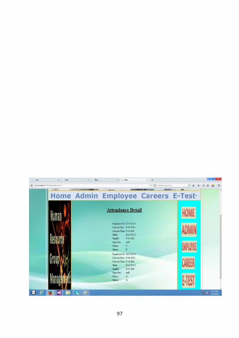
1.4.15 Attendance detail
The Attendance details consist of
employee daily attendance report.
1.4.15 Salary detail:
The salary module consists of salary detail of
employee.
1.4.16 Send and Receive Message:
It is used to send and receive message from the
employees.
1.4.17 Career Module:Career module consists of following options. They
are
1.4.18 Apply Job:
The apply job is used to apply their
resumes to the company.
1.4.19 Search Job:
It will help the people to search a job and is
used to apply their resumes to the company.
18

1.4.20 E-Test Module:E-Test consists of following options. They are
1.4.21 Candidate Registration:
This is used to register the details of the
candidates such as name, address, qualification etc.
1.4.22 Write Exam:
Registered candidates write their exams based on the
domain specified in the candidate registration.
1.4.23 Result:
It is used to give the marks of the candidates.
CHAPTER 2
19

SOFTWARE PROJECT PLAN
2.1 Functional and non-Functional Requirements
Basically, functional requirements directly support the user
requirements by describing the "processing" of the information
or materials as inputs or outputs. A Functional Requirement is
a requirement that, when satisfied, will allow the user to
perform some kind of function.
Non-functional requirements generally support all users in
that they describe the business standards and the business
environment, as well as the overall user's experience. A Non-
Functional Requirement is usually some form of constraint or
restriction that must be considered when designing the
solution.
NFR-01 System shall make sure the usability of the systemis user friendly.
NFR-02 The system needs to support 7 x 24 operations.NFR-03 System shall make sure the performance means
security and reliability. NFR-04 The system should be platform independent, being a
true web application it should operating systemand browser independent.
NFR-05 System should be accessible over the internet –hidden requirement – security
20

21

2.2 The Various Phases of the Project:
S.NO TASK DURATION
1 Requirement Specification 10 Day’s
2 Requirement document specification
10 Day’s
3 Design analysis 20 Day’s
4 Design Documentation 15 Day’s
5 Design Review 20 Day’s
6 Coding 15 Day’s
Total 90 Day’s
2.3 INTRODUCTION TO PLANNING PHASE:
The Project Planning Phase is the second phase in the projectlife cycle. It involves creating of a set of plans to helpguide your team through the execution and closure phases ofthe project. The plans created during this phase will help youto manage time, cost, quality, change, risk and issues. Theywill also help you manage staff and external suppliers, toensure that you deliver the project on time and within budget.
The Project Planning Phase is often the most challenging phasefor a Project Manager, as you need to make an educated guessof the staff, resources and equipment needed to complete yourproject. You may also need to plan your communications andprocurement activities, as well as contract any 3rd partysuppliers.
22

2.4 THE PURPOSE OF THE PROJECT PLANNING PHASE:
1. Establish Business Requirements.2. Establish Cost, Schedule, List of Deliverables and
Delivery Dates.3. Establish Resource Plan.4. Get Management Approval and proceed to next phases.
2.5 METHODOLOGIES
2.5.1 Existing Methodologies
Software development methodologies (SDM) have demonstrated to be successful in increasing speed to market of software engineering projects, lowering the development cost and providing better quality. These benefits particularly apply for those projects where the system requirements are complex.
System Development Life Cycle (SDLC) models help in the complete development of a system, right from the conceptual stage to the customer delivery stage. SDLC is very useful if one has a complicated system to build. SDLC is the overall process of developing information systems through a multi-stepprocess, from investigation of initial requirements to analysis, design, implementation and maintenance.
2.6 What is methodology?
It is a collection of processes, methods and tools for accomplishing an objective. Methodologies provide a checklist of key deliverables and activities to avoid or
23

missing key tasks. This consistency simplifies the process and reduces training.
A project methodology tells you what you have to do, to manageyour projects from start to finish. It describes every step inthe project life cycle in depth, so you know exactly which tasks to complete, when and how. Whether you're an expert or anovice, it helps you complete tasks faster than before.
2.7 Why do you need one?
As a Project Manager, you need a Project Management Methodology to steer your projects in the right direction and keep them on track. You also need it to help you manage your projects in a structured, repeatable fashion. That way, you can apply the same approach to every project you undertake.
2.8 Traditional models or Existing Methodologies
2.8.1) Waterfall Model
This is the most common and classic of life cycle models, alsoreferred to as a linear-sequential life cycle model. It isvery simple to understand and use. In a waterfall model, eachphase must be completed in its entirety before the next phasecan begin. At the end of each phase, a review takes place todetermine if the project is on the right path and whether ornot to continue or discard the project. Unlike what Imentioned in the general model, phases do not overlap in awaterfall model.
24

Waterfall Life Cycle Model
Advantages
1. Simple and easy to use.2. Easy to manage due to the rigidity of the model – each
phase has specific deliverables and a review process.3. Phases are processed and completed one at a time.4. Works well for smaller projects where requirements are
very well understood.
Disadvantages
1. Adjusting scope during the life cycle can kill a project.2. No working software is produced until late during the
life cycle.3. High amounts of risk and uncertainty.4. Poor model for complex and object-oriented projects.5. Poor model for long and ongoing projects.6. Poor model where requirements are at a moderate to high
risk of changing.
2.8.2) V-Shaped Model
25
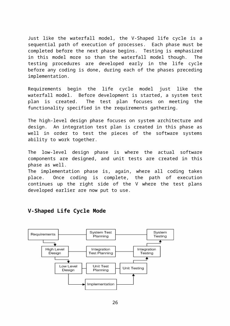
Just like the waterfall model, the V-Shaped life cycle is asequential path of execution of processes. Each phase must becompleted before the next phase begins. Testing is emphasizedin this model more so than the waterfall model though. Thetesting procedures are developed early in the life cyclebefore any coding is done, during each of the phases precedingimplementation.
Requirements begin the life cycle model just like thewaterfall model. Before development is started, a system testplan is created. The test plan focuses on meeting thefunctionality specified in the requirements gathering.
The high-level design phase focuses on system architecture anddesign. An integration test plan is created in this phase aswell in order to test the pieces of the software systemsability to work together.
The low-level design phase is where the actual softwarecomponents are designed, and unit tests are created in thisphase as well.The implementation phase is, again, where all coding takesplace. Once coding is complete, the path of executioncontinues up the right side of the V where the test plansdeveloped earlier are now put to use.
V-Shaped Life Cycle Mode
26

Advantages
1. Simple and easy to use.2. Each phase has specific deliverables.3. Higher chance of success over the waterfall model due to
the development of test plans early on during the lifecycle.
4. Works well for small projects where requirements areeasily understood.
Disadvantages
1. Very rigid, like the waterfall model.2. Little flexibility and adjusting scope is difficult and
expensive.3. Software is developed during the implementation phase, so
no early prototypes of the software are produced.4. Model doesn’t provide a clear path for problems found
during testing phases.
2.8.3) Incremental Model
The incremental model is an intuitive approach to thewaterfall model. Multiple development cycles take place here,making the life cycle a “multi-waterfall” cycle. Cycles aredivided up into smaller, more easily managed iterations. Eachiteration passes through the requirements, design,implementation and testing phases.A working version of software is produced during the firstiteration, so you have working software early on during thesoftware life cycle. Subsequent iterations build on theinitial software produced during the first iteration.Incremental Life Cycle Mode
27

Advantages
1. Generates working software quickly and early during thesoftware life cycle.
2. More flexible – less costly to change scope andrequirements.
3. Easier to test and debug during a smaller iteration.4. Easier to manage risk because risky pieces are identified
and handled during its iteration.5. Each iteration is an easily managed milestone.
Disadvantages
1. Each phase of an iteration is rigid and do not overlapeach other.
2. Problems may arise pertaining to system architecturebecause not all requirements are gathered up front forthe entire software life cycle.
3.
2.8.4) Spiral Model
The spiral model is similar to the incremental model, withmore emphases placed on risk analysis. The spiral model hasfour phases: Planning, Risk Analysis, Engineering andEvaluation. A software project repeatedly passes throughthese phases in iterations (called Spirals in this model). Thebaseline spiral starting in the planning phase, requirementsare gathered and risk is assessed. Each subsequent spiralbuilds on the baseline spiral.
Requirements are gathered during the planning phase. In therisk analysis phase, a process is undertaken to identify risk
28
and alternate solutions. A prototype is produced at the endof the risk analysis phase.
Software is produced in the engineering phase, along withtesting at the end of the phase. The evaluation phase allowsthe customer to evaluate the output of the project to datebefore the project continues to the next spiral.In the spiral model, the angular component representsprogress, and the radius of the spiral represents cost.
Advantages
1. High amount of risk analysis2. Good for large and mission-critical projects.3. Software is produced early in the software life cycle.
Disadvantages
1. Can be a costly model to use.2. Risk analysis requires highly specific expertise.3. Project’s success is highly dependent on the risk
analysis phase.4. Doesn’t work well for smaller projects.
29

Spiral Life Cycle Model
30

2.8.5) Object oriented Methodology
Object-oriented lifecycle models appreciate the need foriteration within and between phases. There are a number ofthese models. All of these models incorporate some form ofiteration, parallelism, and incremental development.
2.8.6) Extreme programming Model:
31
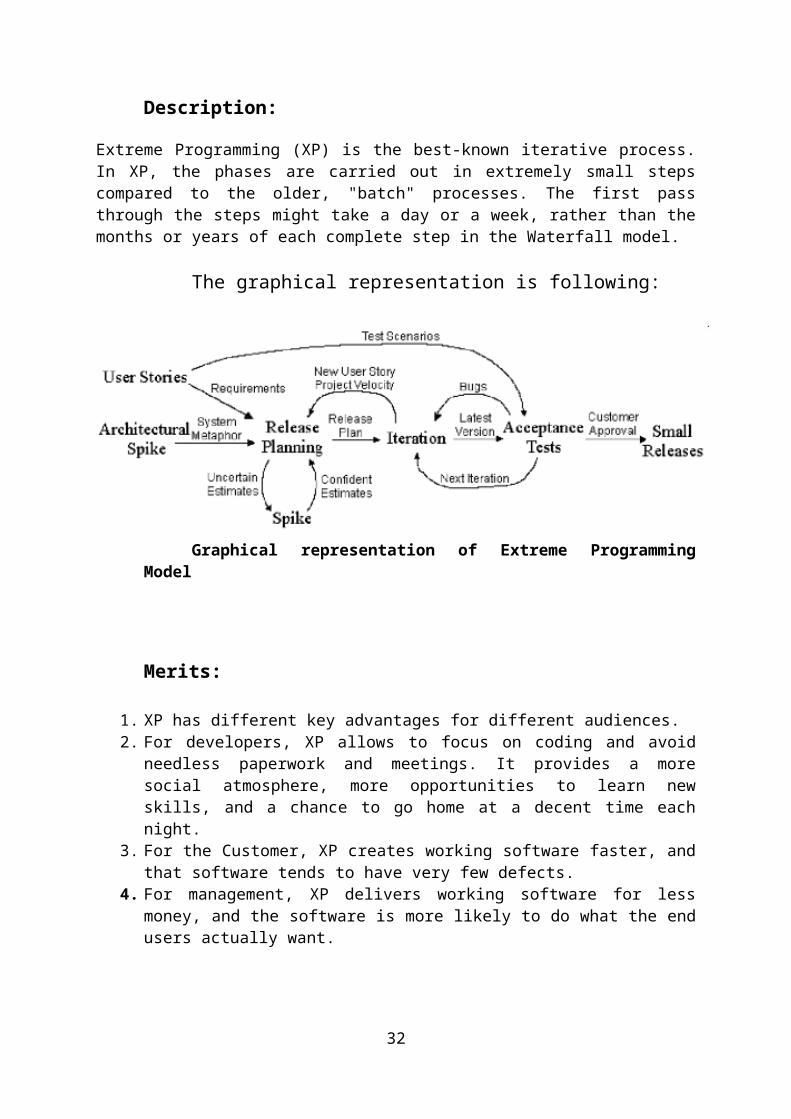
Description:
Extreme Programming (XP) is the best-known iterative process.In XP, the phases are carried out in extremely small stepscompared to the older, "batch" processes. The first passthrough the steps might take a day or a week, rather than themonths or years of each complete step in the Waterfall model.
The graphical representation is following:
Graphical representation of Extreme ProgrammingModel
Merits:
1. XP has different key advantages for different audiences.2. For developers, XP allows to focus on coding and avoid
needless paperwork and meetings. It provides a moresocial atmosphere, more opportunities to learn newskills, and a chance to go home at a decent time eachnight.
3. For the Customer, XP creates working software faster, andthat software tends to have very few defects.
4. For management, XP delivers working software for lessmoney, and the software is more likely to do what the endusers actually want.
32

Demerits:
1. The biggest disadvantage of Extreme Programming is hardto do. It's difficult to get many developers to acceptthe practices, and it takes a lot of discipline to keepdoing them all.
2. Customers may not like the idea of having to be soinvolved. Management may have trouble adapting to aprocess that, itself, adapts to the changing needs of thebusiness.
3. Certain people may feel their jobs are being threatened,particularly architects, testers, and project managers.
2.8.7) Rapid Prototyping Model:
The Rapid Prototyping Model is used to overcome issues relatedto understanding and capturing of user requirements. In thismodel a mock-up application is created “rapidly” to solicitfeedback from the user. Once the user requirements arecaptured in the prototype to the satisfaction of the user, aproper requirement specification document is developed and theproduct is developed from scratch.
2.9) ADOPTED METHODOLOGY
I have chosen combination of waterfall and spiral models forthe development of my project which will be lot easier andconvenient to implement. The basic principle of Waterfall andSpiral model is to emphasize on planning, time schedule,target dates, budgets and implementation of entire system atthe same time. Moreover, tight control might be maintainedover the life of the project through the use of extensivewritten documents as well as through formal reviews andapproval by the user and information technology managementoccurring at the end of the most phases before beginning thenext phase.
33

2.9.1) REASONS FOR CHOOSING THE METHODOLOGY
Selecting an appropriate methodology or a process model iscrucial because it can provide a basic framework to initiateand carry out a project to its conclusion. It also defines thepath for various project- related activities. Therefore I havechosen combinational of Spiral and Water Fall process model.The reason for choosing this is that my project is clearlydivided into discrete phases and each phase has defined numberof days and resources allocated. The Waterfall model requiresthe presence of defined phases and processes in each phase.Using Spiral model, we can to revert to an earlier phase toincorporate client feedback or user’s missing requirements andcomplete that phase.
There are several reasons for adopted methodology forthis project.
Salient features of waterfall are given below:
1. It is the formal method.2. It is type of top-down development.3. It is composed of independent phases to be done
sequentially.
Salient features of spiral model are given below:
1. In it resources can be held constant but the system sizegrows.
2. The spiral size corresponds to system size, while thedistance between the coils of the spiral indicatesresources.
2.10 USECASE DIAGRAMS:
34
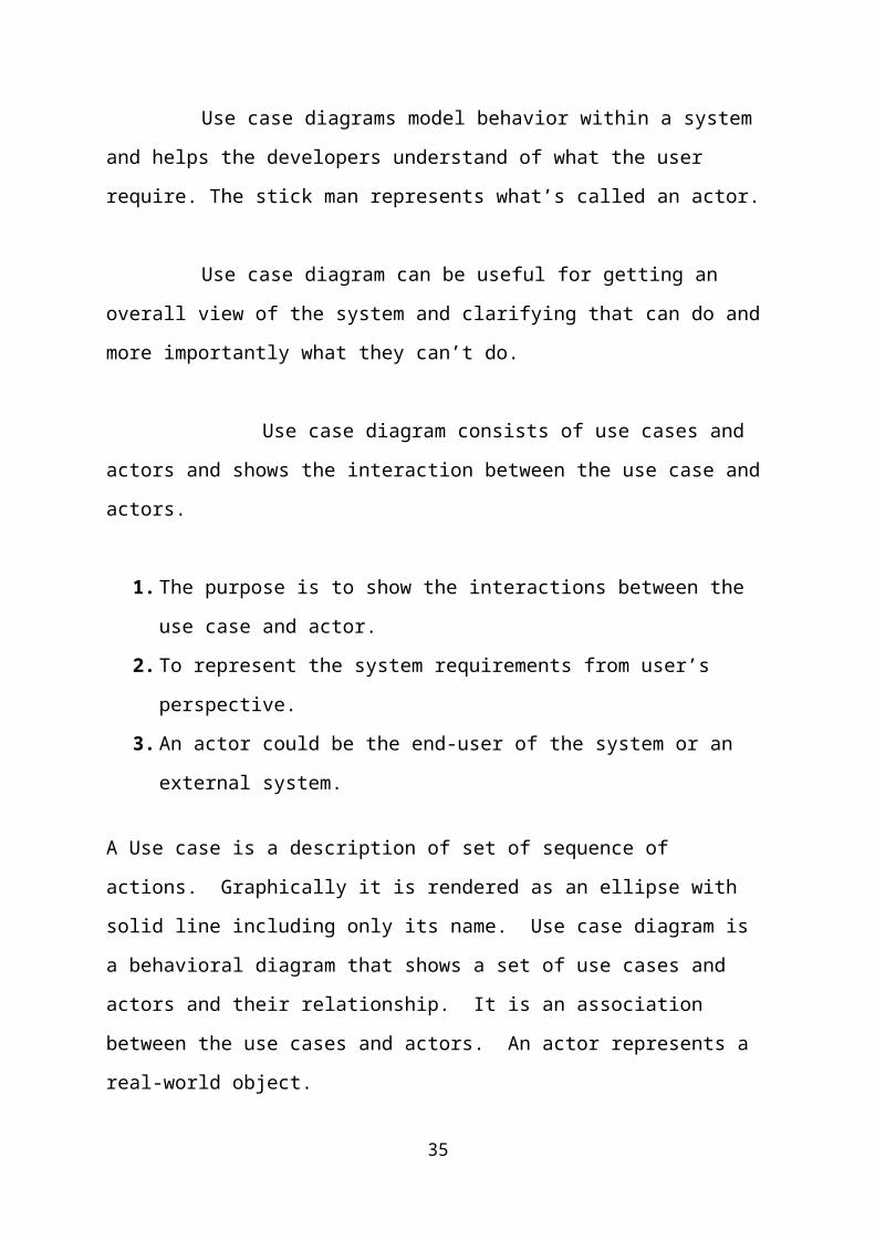
Use case diagrams model behavior within a system
and helps the developers understand of what the user
require. The stick man represents what’s called an actor.
Use case diagram can be useful for getting an
overall view of the system and clarifying that can do and
more importantly what they can’t do.
Use case diagram consists of use cases and
actors and shows the interaction between the use case and
actors.
1. The purpose is to show the interactions between the
use case and actor.
2. To represent the system requirements from user’s
perspective.
3. An actor could be the end-user of the system or an
external system.
A Use case is a description of set of sequence of
actions. Graphically it is rendered as an ellipse with
solid line including only its name. Use case diagram is
a behavioral diagram that shows a set of use cases and
actors and their relationship. It is an association
between the use cases and actors. An actor represents a
real-world object.
35
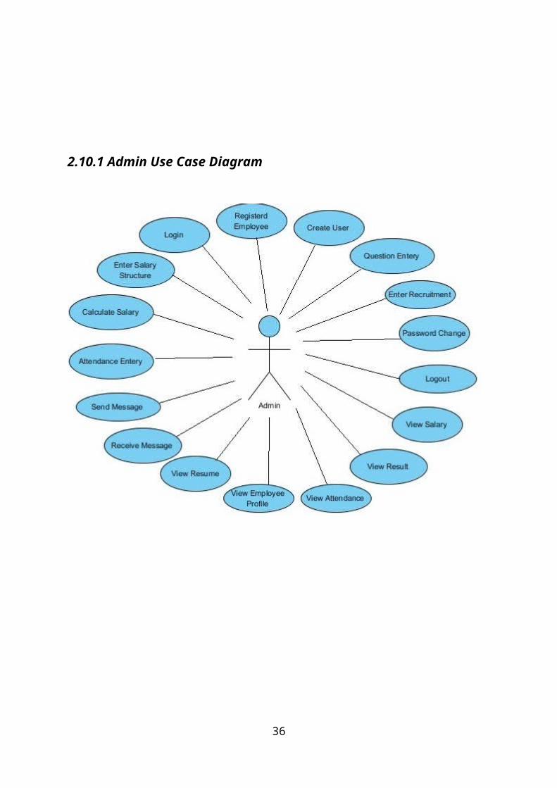
2.10.1 Admin Use Case Diagram
36

2.10.2 Employee Use Case Diagram
37

2.10.3 Candidate Use Case Diagram
38

CHAPTER 3
CUSTOMER REQUIREMENTS DETERMINATION
3.1 Existing SystemThe existing system is manual system. Here student
will attend exams to their company. It requires lot of
time. The proposed system will handle this problem.
Online examination is not handled here.
3.2 Proposed System
It is difficult to note down all the problems manually.
Instead it is decided to develop an ““Development of a web-
based Recruitment Process System for the HR group for a
company”” to ease the operation.
A system is required which is being capable of elimination all
the problems and become useful to jobseeker and thus the new
system is derived.
The company needs to manage the entire job to be appointed and
job seeker resumes details in a faster manner so that time is
saved. The user must exercise full control over these
activities. This project enables the web user to exercise full
39

freedom in browsing for their options. Online test is
conducted for the jobseeker.
CHAPTER 4
SOFTWARE REQUIREMENTS SPECIFICATION
Software Requirements Specification (SRS) is the starting
point of the software development activity. Little importance
was given to this phases in the early days of software
development. The emphasis was first on coding and then shifted
to design.
As systems grew more complex, it become evident that the
goal of the entire system cannot be easily comprehended. Hence
need for the requirements analysis phase arose. Now, for large
software systems, requirements analysis is perhaps the most
difficult activity and also the most error prone.
Some of the difficulty is due to the scope of this phase.
The software project is imitated by the client needs. In the
beginning these needs are in the minds of various people in 40
the client organization. The requirement analyst has to
identify the requirements by tacking to these people and
understanding there needs. In situations where the software is
to automated a currently manuals process, most of the needs
can be understood by observing the current practice.
The SRS is a means of translating the ideas in the minds
of the clients (the output) into formal document (the output
of the requirements phase). Thus the output of the phase is a
set of formally specified requirements, which hopefully are
complete and consistent, while the input has none of these
properties.
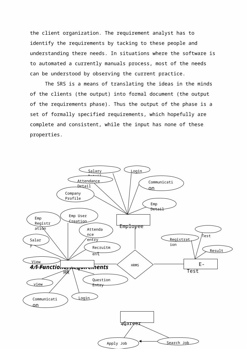
4.1 Functional Requirements
41
HRMS HR
Career
E-Test
Employee
Emp Registration
TestRegistration
Result
Emp User Creation
Attendance entry
Recruitment
Question Entry
View resume
Salary
view
Communication
Company Profile
Salary Detail
Attendance Detail
Apply Job Search Job
Emp Detail
Communication
Login
Login

42

4.2 Performance RequirementsThe project must the end user requirements. Accuracy and fast
must be imposed in the Project.
The project is development as easy as possible for the sake
of end user. The project has to be developed with view of
satisfying the future requirements and future enhancement.
The tool has been finally implemented satisfying the needs
specified by the company. As per the performance is concerned
this system said is performing
This processing as well as tine taken to generate well reports
were also even when large amount of data was used. The system
is designed in such a way that even when large amount of data
used for processing there would less performance degradation.
4.3 Interface Requirements
4.3.1 Hardware InterfaceThe stranded input device like keyboard and mouse are to get
input. The output will be generated and display in the
monitor. The reports can also be exported to a SQL-server
document are text file. The stranded printer in used to take
outputs.
4.3.2 Software InterfaceThe design part and interface id done the front end ASP.Net
and SQL server as a backend of the project.
43
4.4 Operational requirementsThe database or databases that are being failed over to the
stand by server cannot be used for anything else. but
databases on the standby server not being used for failover
can still be used normally.
When it comes time for actual failover, you much one of two
things to make your application work either rename the standby
server the same name as the failed production server(and the
IP address),or re-point your user’s applications to new
standby server in some cases, neither of this option is
practical.
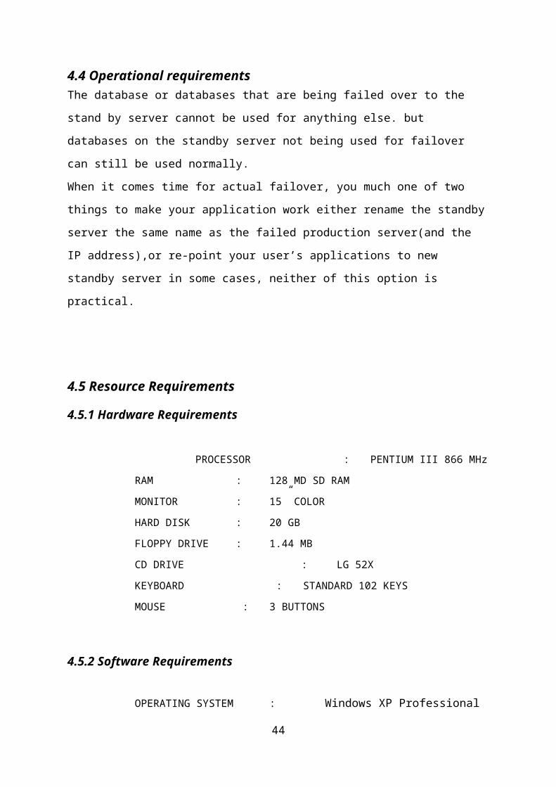
4.5 Resource Requirements
4.5.1 Hardware Requirements
PROCESSOR : PENTIUM III 866 MHz
RAM : 128 MD SD RAM
MONITOR : 15” COLOR
HARD DISK : 20 GB
FLOPPY DRIVE : 1.44 MB
CD DRIVE : LG 52X
KEYBOARD : STANDARD 102 KEYS
MOUSE : 3 BUTTONS
4.5.2 Software Requirements
OPERATING SYSTEM : Windows XP Professional
44

ENVIRONMENT : Visual Studio .NET
2008
.NET FRAMEWORK : Version 3.5LANGUAGE : C#.NET
WEB TECHNOLOGY : ASP.NET
BACKEND : SQL SERVER
2005
4.6 Security RequirementsWeb application are available via network access, it is a
difficult. If not possible, to limit the population of the
end-user who may access the applications? In order to product
sensitive connect and provide secure mode be implemented
throughout the infrastructure that the supports web
application and within the application itself.
Web Application have become heavy integrated with critical
corporate and database.
E-commerce application extracts and then store sensitive
customer information.
4.7 Design RequirementsTo create project, add base masters and masters to
the project, assign behaviors to the
master, create and assign behavior sets, and then apply, test
and validate those behaviors. It also shows how to create and
build a stencil to hold the shapes.
45

4.8 Quality and Reliability RequirementsA software component that is developed for reuse would be
correct and would contain no defects. In reality, formal
verification is not carried out routinely, and defects can add
to occur. However, with each reuse, defects are found
eliminated, and a components qualify improve as a result. Over
time the components virtually defect free.
Software reliability is defined in statically term as” the
probability of faultier-free operation of a computer program
in a specified environment for specified tine”. The software
quality and reliability, failure is nonconformance to software
requirements. Failure can be only anything or catastrophic.
one failure can be corrected within seconds while another
requirements week even mouths to correct. Complicating the
issue even further, the correction of the one failure may in
fact result in the introduction of the errors that ultimately
result in other failure.
Web
Correct link processing
Application Reliability Error recovery
Quality
Input validation and recovery
46
CHAPTER 5
SYSTEM ANALYSIS
In this section discussed about data flow diagram, Entity
relationship diagram. these things are represented as
diagrams with proper notation.
5.1 DATA FLOW DIAGRAMThe data flow diagram is one of the most improvement
tools used by the system analyst DeMacro (1978) Nad Gand
Sarson (1979) popularized the use if the data flow diagram as
modeling tools through their structured system analysis
methodologies.
A data flow diagram should be the first tool used by
system analyst to model system components. These components
47
are the system processes; the data used by this processes and
external entities that interact with the system and the
information flows in the system.
There are four kinds of system components
5.1.1. ProcessProcess show what system does. Each process has one or
more data inputs and produce one or more data output, Circles
in a data flow diagram represent process. Each process has
unique name and number. This name and number appear inside
the circle that represents the processes in a data flow
diagram.
This process is represented as circle
5.1.2. Data Stores
48

File or data store is depositary of data. They
contain data that is retained in the system. Processes can
enter the data into a data store or retrieve data from the
data store. Each data store is represented by thin line in
the data flow diagram and each data store has a unique name.
The data store is represented in form of a line
5.1.3 External Entities
External entities are outside the system but they
either supply input data into the system or use the system
output, they are entities which the designer has no control.
Square or rectangle may represent external entities that
supply data into a system or sometimes called sources.
External entities that use the system data are sometimes
called sinks.
5.1.4 Data Flows
Dataflow model the passage of data in the system and are
represented lines joining system components. An arrow
indicates the direction of the flow and the line labeled by
the name of the data flow.49

Admin Module
50
Admin
Employee registration
User creation
Recruitment
Question entry
Messages
Attendance entry
Salary structure
Salary details
Salary
View resumes
Results
View
Receive messages
Send messages
Admin
Employee
Recruitment
Attendance
Results
Questions
Resumes
Salary Details
Salary structure
Candidate Details
Communication

Employee Module
51
Employee
Salary details
Attendance
Employee
Communication
Employee Profile
Salary Details
Received Message
Send Message
Attendance
Details
Company profile
Employee

52
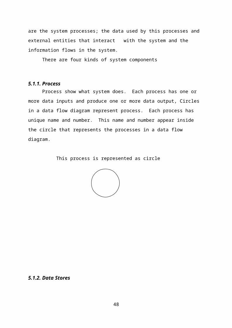
Career Module
E-Test Module
53
Apply Job
Career
Search Job
Job
ExamResult
Candidate
Registration
E-Test
Test Records
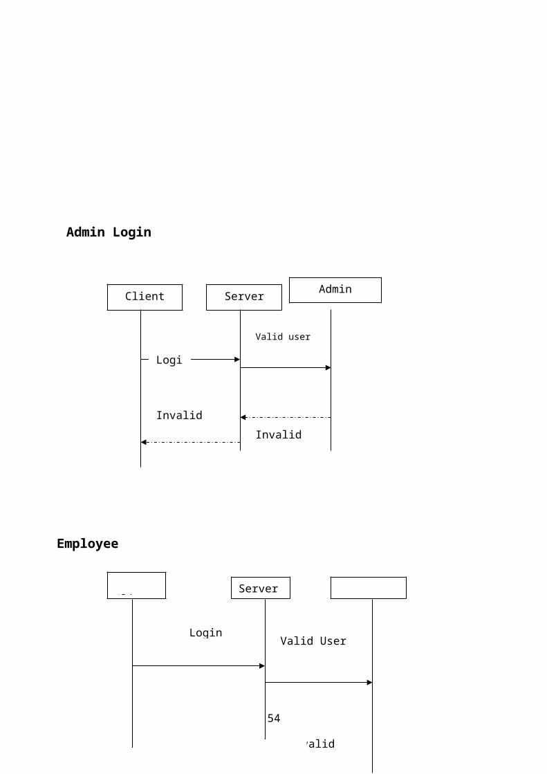
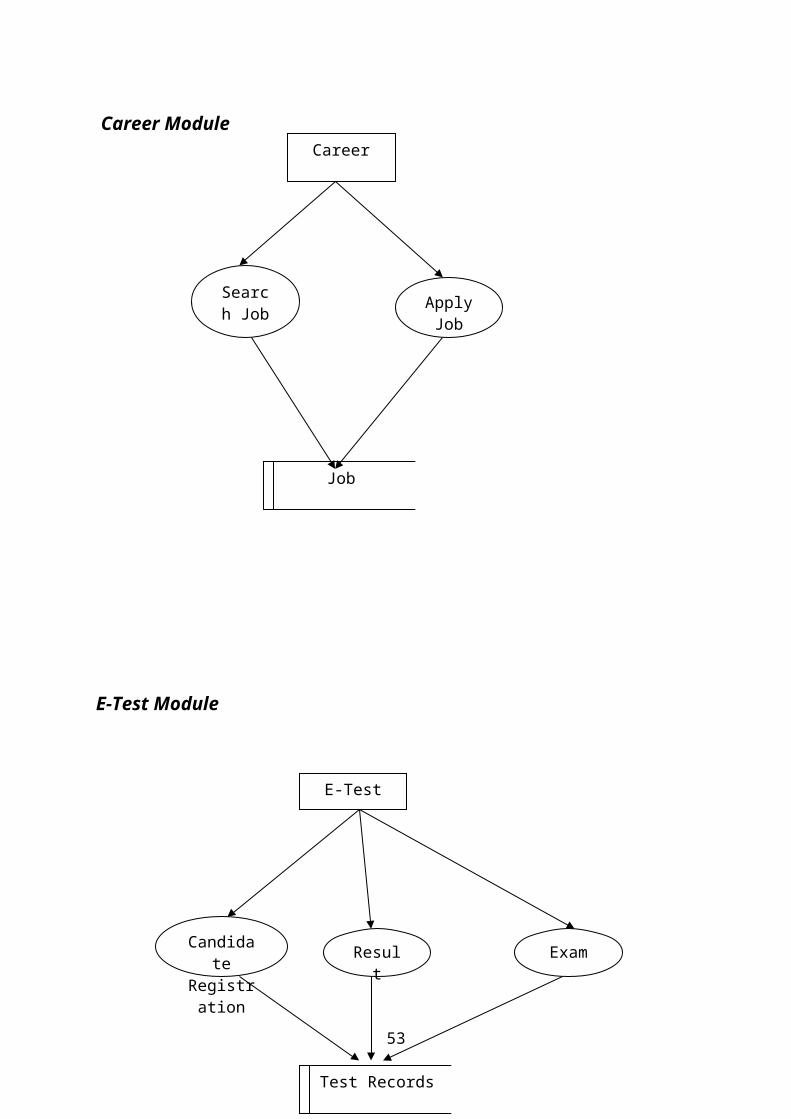
Admin Login
54
Client Server Admin
Login
Valid user
Invalid User
Invalid
Server
Login Valid User
Invalid
Employee
Client

Job:
55
Client ServerJob
Login
Valid Job entry
Invalid Job entry
Invalid
Client
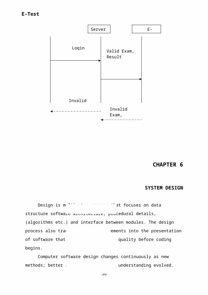
CHAPTER 6
SYSTEM DESIGN
Design is multi-step process that focuses on data
structure software architecture, procedural details,
(algorithms etc.) and interface between modules. The design
process also translates the requirements into the presentation
of software that can be accessed for quality before coding
begins.
Computer software design changes continuously as new
methods; better analysis and broader understanding evolved.
56
Server E-
Login Valid Exam,Result
Invalid Exam,
Invalid
E-Test

Software Design is at relatively early stage in its
revolution.
Therefore, Software Design methodology lacks the depth,
flexibility and quantitative nature that are normally
associated with more classical engineering disciplines.
However techniques for software designs do exist, criteria for
design qualities are available and design notation can be
applied.
6.1 INPUT DESIGN
Input design is the process of converting user-
originated inputs to a computer-based format. Input design is
one of the most expensive phases of the operation of
computerized system and is often the major problem of a
system.
In the project, the input design is made in various web
forms with various methods. For example, in the Admin form,
the empty username and password is not allowed. The username
if exists in the database, the input is considered to be
invalid and is not accepted.
6.2 OUTPUT DESIGN Output design generally refers to the results and
information that are generated by the system for many end-
users; output is the main reason for developing the system and
57
the basis on which they evaluate the usefulness of the
application.
In the project, if the employee has to communicate with other
employees they can communicate through send and
receive message.
6.3 INTERFACE DESIGNThe ODBC (Open Database Connectivity) interface is a pure .NET
to execute SQL statement. The ODBC provides a set classes and
interfaces that can be used by developers to write database
applications. Basic ODBC interactions in its simplest form,
can be broken down into four steps:
1. Open a connection to the database.
2. Execute a SQL statement
3. Process the result
4. Close the connection to the database
6.4 TABLE AND DATABASE DESIN:
6.4.1 Normalization:Normalization is the process of strutting relational database
schema such that most ambiguity is removed. The stage of
normalization are referred to as forms and progress from the
least restrictive(first normal form)through the most
restrictive(Fifth normal form), generally , most database
designers do not attempt to implement anything higher than
normal form of Boyce code Normal Form.
58

6.4.1.1FIRST NORMAL FORM: A relation is said to be in First normal form (INF)
if and each attributed of the relation is atomic. More simply,
to be INF, each column must contain only a single value and
each now contain in the same column.
6.4.1.2 SECOND NORMAL FORM:
In the Second normal Form, a relation must first
fulfill the requirement to be in first Normal Form.
Additional, each donkey attribute in the relation must be
functionality dependent upon the primary key.
6.4.1.3 THIRD NORMAL FORM:A table is said to be in third normal form and every non key
attribute is functionality dependent only on the primary key.
This normalization process is applied to this system and the
normalized tables are given in the above section.
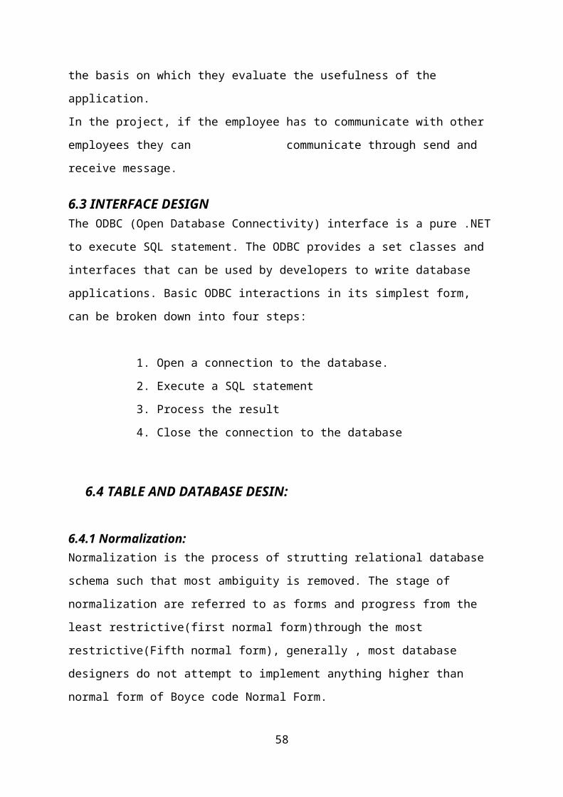
6.4.2 TABLE DESIGNAdmin Login Table
59
Attendance Detail
Communication
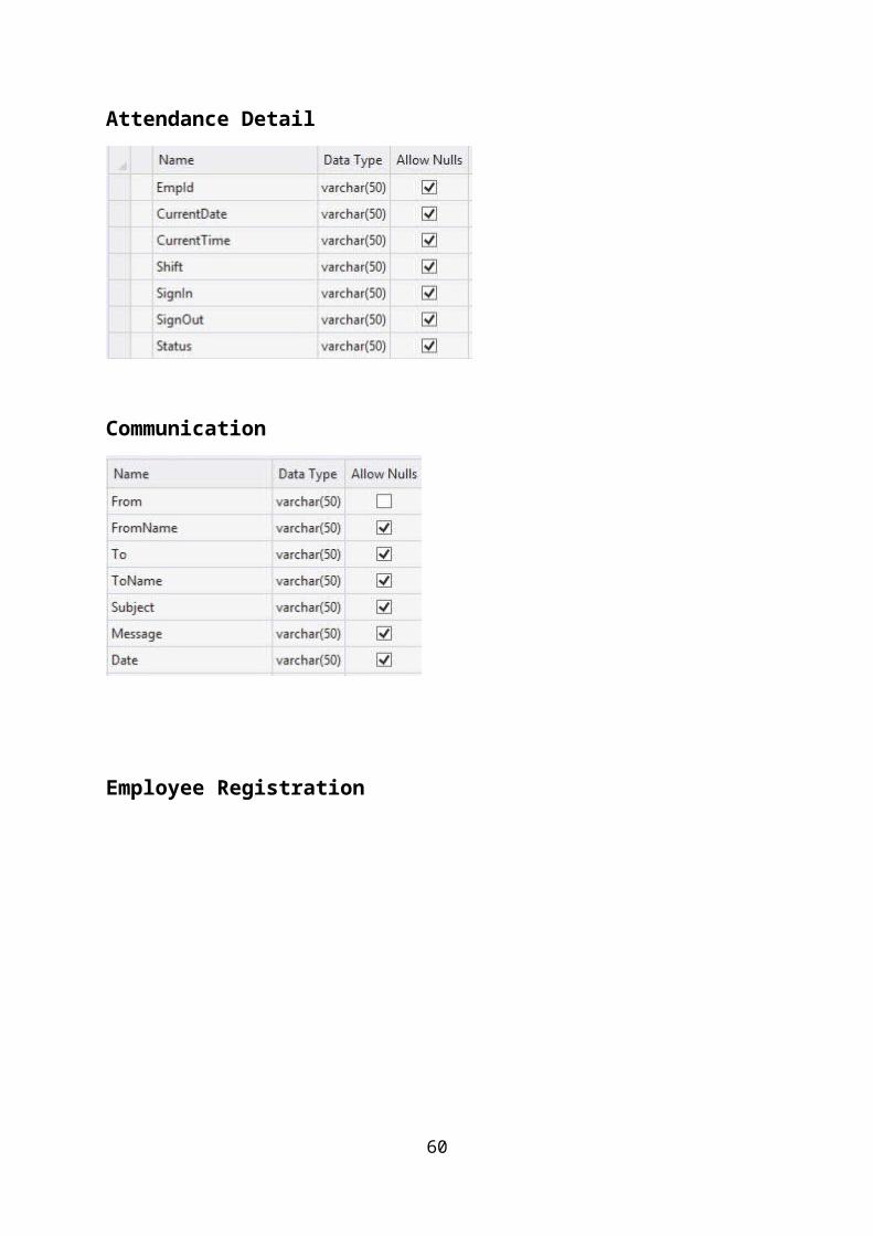
Employee Registration
60
Employee Login
Job Posted
61

Resume
Salary details
E-Test Login
62

Salary Calculation
63

6.4.3 Database Design:
The database design is a must for any application
developed especially more for the data store projects. Since
the chatting method involves storing the message in the table
and produced to the sender and receiver, proper handling of
the table is a must.
In the project, login table is designed to be unique in
accepting the username and the length of the username and
password should be greater than zero
The complete listing of the tables and their fields are
provided in the annexure under the title ‘Table Structure’.
6.5 FRONT END DESIGN
6.5.1FEATURES OF ASP.NET
ASP.NET is the next version of Active Server Pages
(ASP); it is a unified Web development platform that provides
the services necessary for developers to build enterprise-
class Web applications. While ASP.NET is largely syntax
compatible, it also provides a new programming model and
infrastructure for more secure, scalable, and stable
applications.
64

ASP.NET is a compiled, NET-based environment,
we can author applications in any .NET compatible language,
including Visual Basic .NET, C#, and JScript .NET.
Additionally, the entire .NET Framework is available to any
ASP.NET application. Developers can easily access the benefits
of these technologies, which include the managed common
language runtime environment (CLR), type safety, inheritance,
and so on.
ASP.NET has been designed to work seamlessly with
WYSIWYG HTML editors and other programming tools, including
Microsoft Visual Studio .NET. Not only does this make Web
development easier, but it also provides all the benefits that
these tools have to offer, including a GUI that developers can
use to drop server controls onto a Web page and fully
integrated debugging support.
Developers can choose from the following two
features when creating an ASP.NET application. Web Forms and
Web services, or combine these in any way they see fit. Each
is supported by the same infrastructure that allows you to use
authentication schemes, cache frequently used data, or
customize your application's configuration, to name only a few
possibilities.
Web Forms allows us to build powerful forms-based Web pages.
When building these pages, we can use ASP.NET server controls
to create common UI elements, and program them for common
tasks. These controls allow we to rapidly build a Web Form out
of reusable built-in or custom components, simplifying the
code of a page.
65
An XML Web service provides the means to access server
functionality remotely. Using Web services, businesses can
expose programmatic interfaces to their data or business
logic, which in turn can be obtained and manipulated by client
and server applications. XML Web services enable the exchange
of data in client-server or server-server scenarios, using
standards like HTTP and XML messaging to move data across
firewalls. XML Web services are not tied to a particular
component technology or object-calling convention. As a
result, programs written in any language, using any component
model, and running on any operating system can access XML Web
services
Each of these models can take full advantage of all ASP.NET
features, as well as the power of the .NET Framework and .NET
Framework common language runtime. Accessing databases from
ASP.NET applications is an often-used technique for displaying
data to Web site visitors. ASP.NET makes it easier than ever
to access databases for this purpose. It also allows us to
manage the database from your code.
ASP.NET provides a simple model that enables Web developers to
write logic that runs at the application level. Developers can
write this code in the global.aspx text file or in a compiled
class deployed as an assembly. This logic can include
application-level events, but developers can easily extend
this model to suit the needs of their Web application.
ASP.NET provides easy-to-use application and session-state
facilities that are familiar to ASP developers and are readily
compatible with all other .NET Framework APIs.ASP.NET offers
66

the Http Handler and Http Module interfaces. Implementing the
Http Handler interface gives you a means of interacting with
the low-level request and response services of the IIS Web
server and provides functionality much like ISAPI extensions,
but with a simpler programming model. Implementing the
IHttpModule interface allows you to include custom events that
participate in every request made to your application.
ASP.NET takes advantage of performance enhancements found in
the .NET Framework and common language runtime. Additionally,
it has been designed to offer significant performance
improvements over ASP and other Web development platforms. All
ASP.NET code is compiled, rather than interpreted, which
allows early binding, strong typing, and just-in-time (JIT)
compilation to native code, to name only a few of its
benefits. ASP.NET is also easily factorable, meaning that
developers can remove modules (a session module, for instance)
that are not relevant to the application they are developing.
ASP.NET provides extensive caching services (both built-in
services and caching APIs). ASP.NET also ships with
performance counters that developers and system administrators
can monitor to test new applications and gather metrics on
existing applications. Writing custom debug statements to your
Web page can help immensely in troubleshooting your
application's code. However, it can cause embarrassment if it
is not removed. The problem is that removing the debug
statements from your pages when your application is ready to
be ported to a production server can require significant
effort.
67

ASP.NET offers the Trace Context class, which allows us to
write custom debug statements to our pages as we develop them.
They appear only when you have enabled tracing for a page or
entire application. Enabling tracing also appends details
about a request to the page, or, if you so specify, to a
custom trace viewer that is stored in the root directory of
your application. The .NET Framework and ASP.NET provide
default authorization and authentication schemes for Web
applications. we can easily remove, add to, or replace these
schemes, depending upon the needs of our application .
ASP.NET configuration settings are stored in XML-based files,
which are human readable and writable. Each of our
applications can have a distinct configuration file and we can
extend the configuration scheme to suit our requirements.
6.5.2 DATA ACCESS WITH ADO.NET
As you develop applications using ADO.NET, you will have
different requirements for working with data. You might
never need to directly edit an XML file containing data - but
it is very useful to understand the data architecture in
ADO.NET.
ADO.NET offers several advantages over previous versions of
ADO
1. Interoperability
2. Maintainability
3. Programmability
4. Performance Scalability
68
6.5.3 INTEROPERABILITY
ADO.NET applications can take advantage of the
flexibility and broad acceptance of XML. Because XML is the
format for transmitting datasets across the network, any
component that can read the XML format can process data. The
receiving component need not be an ADO.NET component.
The transmitting component can simply transmit the
dataset to its destination without regard to how the receiving
component is implemented. The destination component might be a
Visual Studio application or any other application implemented
with any tool whatsoever.
The only requirement is that the receiving component
be able to read XML. SO, XML was designed with exactly this
kind of interoperability in mind.
6.5.4 MAINTAINABILITY
In the life of a deployed system, modest changes are
possible, but substantial, Architectural changes are rarely
attempted because they are so difficult. As the performance
load on a deployed application server grows, system resources
can become scarce and response time or throughput can suffer.
Faced with this problem, software architects can choose to
divide the server's business-logic processing and user-
interface processing onto separate tiers on separate machines.
69

In effect, the application server tier is replaced with
two tiers, alleviating the shortage of system resources. If
the original application is implemented in ADO.NET using
datasets, this transformation is made easier.
ADO.NET data components in Visual Studio encapsulate
data access functionality in various ways that help you
program more quickly and with fewer mistakes.
6.5.5 PERFORMANCE ADO.NET datasets offer performance advantages over
ADO disconnected record sets. In ADO.NET data-type conversion
is not necessary.
70

6.5.6 SCALABILITY ADO.NET accommodates scalability by encouraging
programmers to conserve limited resources. Any ADO.NET
application employs disconnected access to data; it does not
retain database locks or active database connections for long
durations.
6.5.7 VISUAL STUDIO .NET Visual Studio .NET is a complete set of development tools
for building ASP Web applications, XML Web services, desktop
applications, and mobile applications In addition to building
high-performing desktop applications, you can use Visual
Studio's powerful component-based development tools and other
technologies to simplify team-based design, development, and
deployment of Enterprise solutions.
Visual Basic .NET, Visual C++ .NET, and Visual C# .NET
all use the same integrated development environment (IDE),
which allows them to share tools and facilitates in the
creation of mixed-language solutions.
In addition, these languages leverage the functionality
of the .NET Framework and simplify the development of ASP Web
applications and XML Web services. Visual Studio supports
the .NET Framework, which provides a common language runtime
and unified programming classes; ASP.NET uses these components
to create ASP Web applications and XML Web services. Also it
includes MSDN Library, which contains all the documentation
for these development tools.
71

6.5.8 THE .NET FRAMEWORKThe .NET Framework is a new computing platform that
simplifies application development in the highly distributed
environment of the Internet.
6.6 OBJECTIVES OF . NET FRAMEWORK
1. To provide a consistent object-oriented programming
environment whether object codes is stored and executed
locally on Internet-distributed, or executed remotely.
2. To provide a code-execution environment to minimizes
software deployment and guarantees safe execution of code.
3. Eliminates the performance problems
There are different types of application, such as Windows-
based applications and Web-based applications.
To make communication on distributed environment to
ensure that code be accessed by the .NET Framework can
integrate with any other code.
6.7 COMPONENTS OF .NET FRAMEWORK
6.7.1 THE COMMON LANGUAGE RUNTIME (CLR)
The common language runtime is the foundation of the .NET
Framework. It manages code at execution time, providing
important services such as memory management, thread72

management, and remoting and also ensures more security and
robustness. The concept of code management is a fundamental
principle of the runtime. Code that targets the runtime is
known as managed code, while code that does not target the
runtime is known as unmanaged code
6.7.2 THE .NET FRAME WORK CLASS LIBRARY
It is a comprehensive, object-oriented collection of
reusable types used to develop applications ranging from
traditional command-line or graphical user interface (GUI)
applications to applications based on the latest innovations
provided by ASP.NET, such as Web Forms and XML Web services.
The .NET Framework can be hosted by unmanaged components
that load the common language runtime into their processes and
initiate the execution of managed code, thereby creating a
software environment that can exploit both managed and
unmanaged features. The .NET Framework not only provides
several runtime hosts, but also supports the development of
third-party runtime hosts.
Internet Explorer is an example of an unmanaged
application that hosts the runtime (in the form of a MIME type
extension). Using Internet Explorer to host the runtime to
enables embeds managed components or Windows Forms controls in
HTML documents.
6.7.1.1FEATURES OF THE COMMON LANGUAGE RUNTIME
73
The common language runtime manages memory; thread
execution, code execution, code safety verification,
compilation, and other system services these are all run on
CLR.
1. Security.
2. Robustness.
3. Productivity.
4. Performance.
SECURITY
The runtime enforces code access security. The security
features of the runtime thus enable legitimate Internet-
deployed software to be exceptionally featuring rich. With
regards to security, managed components are awarded varying
degrees of trust, depending on a number of factors that
include their origin to perform file-access operations,
registry-access operations, or other sensitive functions.
ROBUSTNESS
The runtime also enforces code robustness by implementing
a strict type- and code-verification infrastructure called the
common type system (CTS). The CTS ensures that all managed
code is self-describing. The managed environment of the
runtime eliminates many common software issues
PRODUCTIVITY
74
The runtime also accelerates developer productivity.
For example, programmers can write applications in their
development language of choice, yet take full advantage of the
runtime, the class library, and components written in other
languages by other developers.
PERFORMANCE
The runtime is designed to enhance performance. Although
the common language runtime provides many standard runtime
services, managed code is never interpreted. A feature called
just-in-time (JIT) compiling enables all managed code to run
in the native machine language of the system on which it is
executing. Finally, the runtime can be hosted by high-
performance, server-side applications, such as Microsoft® SQL
Server™ and Internet Information Services (IIS).
6.8 BACK END DESIGN
6.8.1 FEATURES OF SQL-SERVER 2000 The OLAP Services feature available in SQL
Server version 7.0 is now called SQL Server 2000 Analysis
Services. The term OLAP Services has been replaced with the
term Analysis Services. Analysis Services also includes a
new data mining component. The Repository component
available in SQL Server version 7.0 is now called Microsoft
SQL Server 2000 Meta Data Services. References to the
component now use the term Meta Data Services. The term
repository is used only in reference to the repository
engine within Meta Data Service
75
SQL-SERVER database consist of six type of objects,
They are,
1. TABLE
2. QUERY
3. FORM
4. REPORT
5. MACRO
6.8.2 TABLE:
A database is a collection of data about a
specific topic.
6.8.3 VIEWS OF TABLE:
We can work with a table in two types,
1. Design View
2. Datasheet View
6.8.4 Design View
To build or modify the structure of a table we
work in the table design view. We can specify what kind of
data will be hold.
76

6.8.5 Datasheet View
To add, edit or analyses the data itself we work
in tables datasheet view mode.
6.8.6 QUERY
A query is a question that has to be asked the
data. Access gathers data that answers the question from one
or more table. The data that make up the answer is either
dataset (if you edit it) or a snapshot (it cannot be
edited).Each time we run query, we get latest information in
the dataset. Access either displays the dataset or snapshot
for us to view or perform an action on it, such as deleting
or updating.
6.8.7 FORMS
A form is used to view and edit information in
the database record by record .A form displays only the
information we want to see in the way we want to see it.
Forms use the familiar controls such as textboxes and
checkboxes. This makes viewing and entering data easy.
6.8.8.Views of Form
We can work with forms in several primarily
there are two views,
They are,
1. Design View
77

2. Form View
6.8.9 REPORT
A report is used to vies and print information from
the database. The report can ground records into many levels
and compute totals and average by checking values from many
records at once. Also the report is attractive and
distinctive because we have control over the size and
appearance of it.
6.8.10 MACRO
A macro is a set of actions. Each action
in macros does something. Such as opening a form or printing
a report .We write macros to automate the common tasks the
work easy and save the time.
6.8.11 MODULE
Modules are units of code written in access
basic language. We can write and use module to automate and
customize the database in very sophisticated ways.It is a
personal computer based RDBMS. This provides most of the
features available in the high-end RDBMS products like
Oracle, Sybase, and Ingress etc.
78

6.9 Algorithm used
Step1: The username and password is entered it redirect to the admin welcome
page.
Step 2: User can register their details in the profile before logging in.
Step 3: The user can create a user id, password and confirm password.
Step 4: After the user can post the new job and view the all candidate resumes.
Step5: The employee attendance details, salary details, salary calculation can be
viewed.
Step 6: The employee can send the messages and received the messages to
another employee.
Step 7: After the user how to apply the job and the number of job vacancies to be
viewed.
Step 8: The user can be apply the job for online and then the user will be
participated in the e-test.
Step 9: Finally to view the e-test results and the new employee can register the
particular details.
79

CHAPTER 7
SYSTEM TESTING
System testing involves user training system testing and
successful running of the developed proposed system. The user
tests the developed system and changes are made according to
their needs. The testing phase involves the testing of
developed system using various kinds of data.
An elaborate testing of data is prepared and the system
is tested using the test data. While testing, errors are noted
and the corrections are made. The corrections are also noted
for the future use. The users are trained to operate the
developed system.
7.1 TESTING
System testing is the stage of implementation that is
aimed at ensuring that the system works accurately and
efficiently before live operation commences. Testing is vital
to the success of the system. System testing makes logical
assumption that if all the parts of the system are correct,
then the goal will be successfully achieved. A series of
testing are done for the proposed system before the system is
ready for the user acceptance testing.
The following are the types of Testing
1. Unit Testing
80

2. Integration Testing
3. Validation Testing
4. Verification testing
5. User acceptance testing
7.2 Unit TestingUnit testing focuses verification efforts on the smallest
unit of the software design, the module. This is also known as
“module testing”. The modules are tested separately. This
testing was carried out during programming stage itself. In
this testing each module is found to be working satisfactorily
as regards to the expected output from the module.
7.3 Integration TestingData can be lost across an interface: one module can have
adverse efforts on another. Integration testing is the
systematic testing for construction of program structure,
while at the same time conducting tests to uncover errors
associated within the interface. Here correction is difficult
because the isolation of cause is complicated by the cast
expense of the entire program. Thus in the integration testing
step, all the errors uncovered are corrected for the next
testing steps.
81

7.4 Validation TestingAt the conclusion of integration testing, software is
completely assembled as a package, interfacing errors have
been uncovered and corrected and a final series of software
tests begins validation test has been conducted one of the two
possible conditions exists. One is the function or performance
characteristics confirm to specification and are accepted and
the other is deviation from specification is uncovered and a
deficiency list is created.
7.5 Verification TestingVerification is a fundamental concept in software design.
This is the bridge between customer requirements and an
implementation that satisfies those requirements.
This is verifiable if it can be demonstrated that the testing
will result in an implementation that satisfies the customer
requirements.
Inadequate testing or non-testing leads to errors that
may appear few months later. This will create two problems
Time delay between the cause and appearance of the
problem.
The effect of the system errors on files and records
within the system.
82
7.6 User Acceptance TestingUser acceptance testing of a system is the key factor of
the success of any system. The system under study is tested
for the user acceptance by constantly keeping in touch with
the prospective system users at any time of developing and
making changes whenever required.
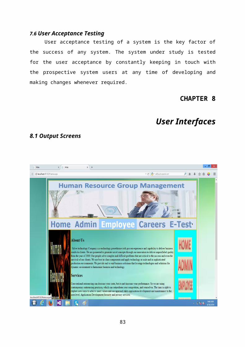
CHAPTER 8
User Interfaces8.1 Output Screens
83
Fig
1.Home
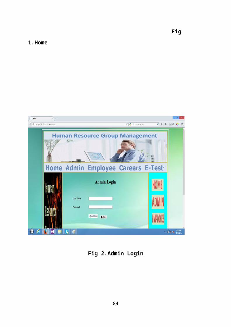
Fig 2.Admin Login
84

Fig 3.Admin Welcome Page
85
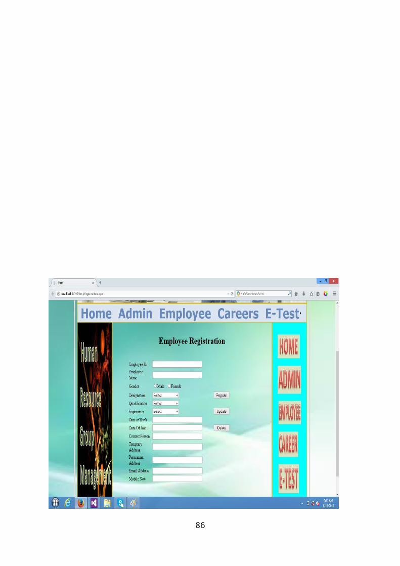
86

Fig4. Employee Registration
87
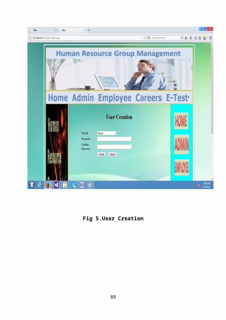
Fig 5.User Creation
88

Fig 6.New Job
post
89

Fig 7.Attendance entry
90

91

Fig 8.Salary Structure
92
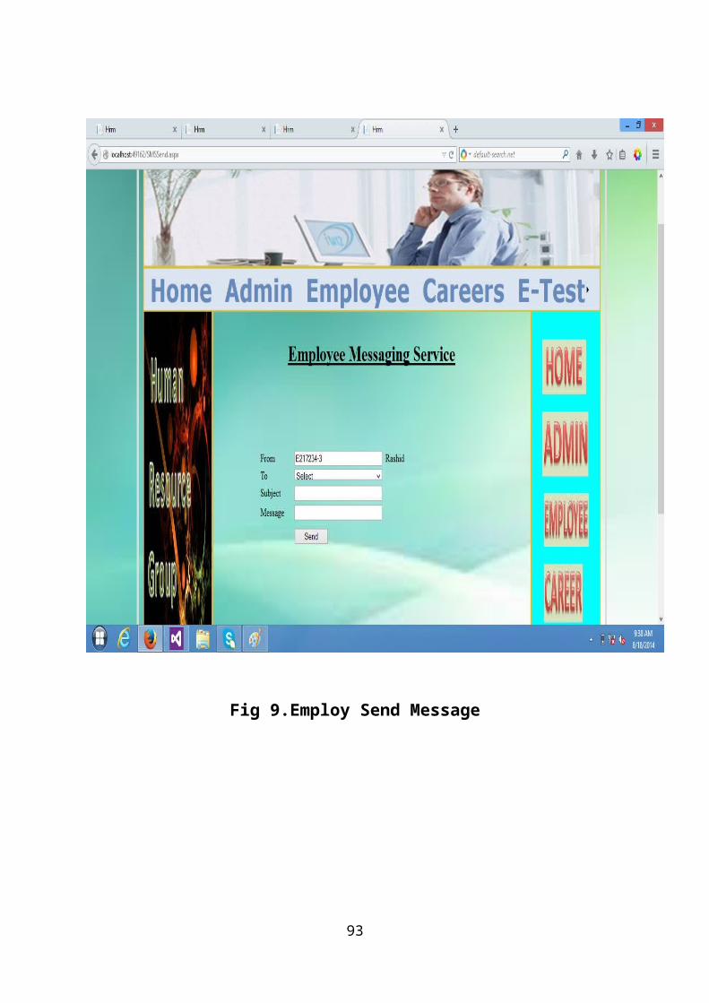
Fig 9.Employ Send Message
93

Fig 10.Employee Login
94

Fig 11.Employee Welcome
95
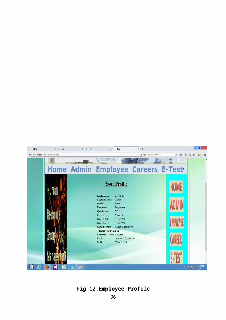
Fig 12.Employee Profile96
97
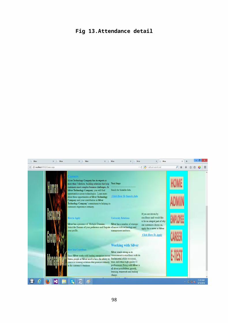
Fig 13.Attendance detail
98

Fig 14.Careers
99

Fig 15.Apply online
100
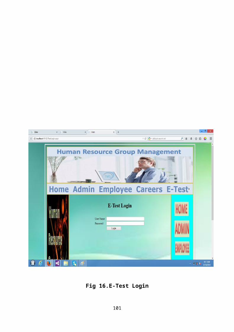
Fig 16.E-Test Login
101

CHAPTER 9
CONSLUSION 9.1 PROBLEMS FACED
When there is a clear goal in sight but no clear set of
directions or means to attain that goal, then it is called a
problem. Problems can be broken down into four aspects; goal,
givens, means of transforming conditions, and obstacles.
Goal – the goal is the desired end state which the problem
solving is being directed toward.
The hope is to reach that end state and be able to assess
whether or not you achieved what you wanted.
Givens- these are the objects, conditions, and constraints
that accompany a problem, and can be either explicit or
implicit.
Means of transforming conditions- there should be a way of
changing the initial state of the problem. This is most
usually a person’s knowledge or skill level. For instance, a
computer programmer presented with a problem would utilize his
or her knowledge of programming language to transform the
state of the problem.
102

Obstacles- the problem should present a challenge. If there
are no challenges involved and the situation can be easily
solved then it is not so a problem so much as a routine task.
Every problem has a problem faced, which is the whole
range of possible states and operators. Only some of these
states and operators will bring the person closer to the goal
state. The problem starts at the initial state and operators
are applied to change the state, creating a series of
intermediate states that should hopefully lead to the final
goal state
9.2 FUTURE PLANS
Every application has its own merits and demerits.
The project has covered almost all the requirements. Further
requirements and improvements can easily be done since the
coding is mainly structured or modular in nature. Changing the
existing modules or adding new modules can append
improvements. Further enhancements can be made to the
application, so that the web site functions very attractive
and useful manner than the present one
9.3 CONCLUSION
It is concluded that the application works well and
satisfy the company and students. The application is tested
103
very well and errors are properly debugged. The site is
simultaneously accessed from more than one system.
Simultaneous login from more than one place is tested.
The site works according to the restrictions provided in
their respective browsers. Further enhancements can be made to
the application, so that the web site functions very
interactive and useful to existing application .The
application satisfies both the company and students by
eliminating more input. The speed of the transactions become
more enough now.
104

105