
Crank Height-Adjustable Base Installation Instructions - Enwork
Upload
khangminh22Category
view
0download
0
1
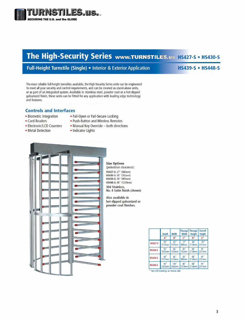
HS400 Series Single Full Height Turnstile
Service & Installation Manual
Note: Successful turnstile installation depends on reading this manual.
Important Note: Please keep this service manual after installation. If an installation is done by a
construction company or outside installer, please pass this book along to the end user. This
book is required for maintenance, troubleshooting, and repairs.

2
Table of Contents
3
5
6
7
9
10
11
16
17
18
19
20
21
22
23
25
26
27
29
30
31
HS400 Full Height Single Data Sheets
Parts Checklist
Fastener List
Pre-installation Tips
Concrete Pad Sizes
Concrete Anchor Installation Instructions
Turnstile Installation
Important Electrical Information
6500 Series Control Head Installation
Single Full Height Turnstile Rotor Alignment
6500 Series Control Head Mechanical Information
6500 Series Full Height Control Head Parts Breakdown
6500 Series Full Height Control Head Parts List
6500 Series Control Head Configurations
6500 Series Control Head Locking Bar Information
6500 Series Control Head Hydraulic Shock Information
6500 Series Control Head Electrical Information
6500 Series Control Head w/ XD10 Controller Standard Wiring
6500 Series Control Head w/ XD10 Controller Standard Turnstile Settings
6500 Series Control Head w/ XD10 Controller Standard Turnstile Testing
6500 Series Control Head Limit Switch Information
Maintenance & Cleaning
6500 Series Control Head w/ XD10 Controller Troubleshooting
Proper Turnstile Usage
Warranty Information
Appendix: Optional components and customized documents
32
33
36
37
38
3

4

5
Parts Checklist
Each turnstile should have the following components on the skid (per turnstile).
Mainframe (Main channel with 2 cross arms inside):
2x Yokes:
Barrier:
Rotor:
6500 series control head
Fastener kit / bearing block/ bearing (fastener list on next page)
Optional components such as card reader mounting plates, light arrays, counters
Custom / special components

6
FASTENER LIST
QTY 10- ½ x 1” SOCKET CAP BOLTS W/ LOCK WASHERS (HS439-GV/PC & HS448-GV/PC ONLY): ARM ASSEMBLIES TO ROTOR
QTY 4 - 3/8 x 1 ½” CARRIAGE BOLTS W/ NUTS, WASHERS & LOCK WASHERS: CONTROL HEAD TO MAIN FRAME
QTY 4 - 3/8 X 1 ½ CARRIAGE BOLTS W/ NUTS: YOKE TO BOX TUBING
QTY 2 - 3/8 X 1 ½ CARRIAGE BOTS W/ NUTS, WASHERS & LOCK WASHERS: BARRIER TO MAIN FRAME
QTY 4 - 3/8 X 3 CARRIAGE BOLTS W/ NUTS, WASHERS & LOCK WASHERS: BOX TUBING TO MAIN FRAME
QTY 6 - 3/8 X 4 WEDGE TYPE ANCHORS W/ NUTS & WASHERS: 4 FOR YOKES TO CONCRETE 2 FOR BARRIER TO CONCRETE
QTY 1 - 5/8 X 4 WEDGE TYPE ANCHOR W/ NUT, BEARING BLOCK & BEARING: CENTER COLUMN MOUNTING MAKE SURE BEARING IS GREASED

7
Pre-installation Tips When installing a new turnstile, there are several helpful hints that can be used in order to make
the installation go smoothly. It is highly recommended that these are reviewed before installation.
If pouring a new concrete pad, make certain it is level. If the turnstile is not level, it may not
operate correctly. If installing on an existing concrete pad, shim the turnstile so it is level.
If the turnstile is electronic, pre-plan how it will be wired. We provide several options for
running conduit into each turnstile.
o The end plates on the main frame have punch outs for conduit.
o The stationary barrier is hollow and has a hole in the top that goes through the
mainframe.
o If purchased with an optional card reader plate, the suggested method for running the
wire is through the yokes, into the cross arms and into the main channel. Use a shielded
2 conductor 22 gauge cable per direction.

8
Electronic turnstiles are operated from a provided 24VDC 3 amp power supply. Installing outlet
receptacles inside of the main channel through provided conduit access is required.
Access control devices, such as card readers, push buttons, biometric devices, etc. need to
operate on a normally open dry momentary contact of one second or less. If your access
control device is unable to provide a contact of one second or less, contact TURNSTILES.and ask about an additional one shot timer system to accommodate your existing system.
When installing a turnstile purchased with card reader plates, pay special attention when
working with the curved yoke pieces. One side of the yoke will be drilled specially for card
reader plate mounting.
Proper rotor alignment (left) is important for turnstile operation. Improper rotor alignment
(right) can lead to users becoming trapped inside of the turnstile.
Tools required for installation:
o Hammer drill
o 3/8 concrete bit
o 5/8 concrete bit
o Hammer
o Punch
o Marker
o Plumb-bob
o 9/16 wrench
o 15/16 wrench
o 1/8 allen wrench
o Level
o Grease gun
o Safety gloves
o Safety glasses
Card reader plates are mounted
on the strap across the center of
the yokes on the outside of the
turnstile

9
Concrete Pad Sizes
8641 S. Warhawk Rd. Conifer, CO 80433
(303) 670-1099 (303) 679-8949 fax
10
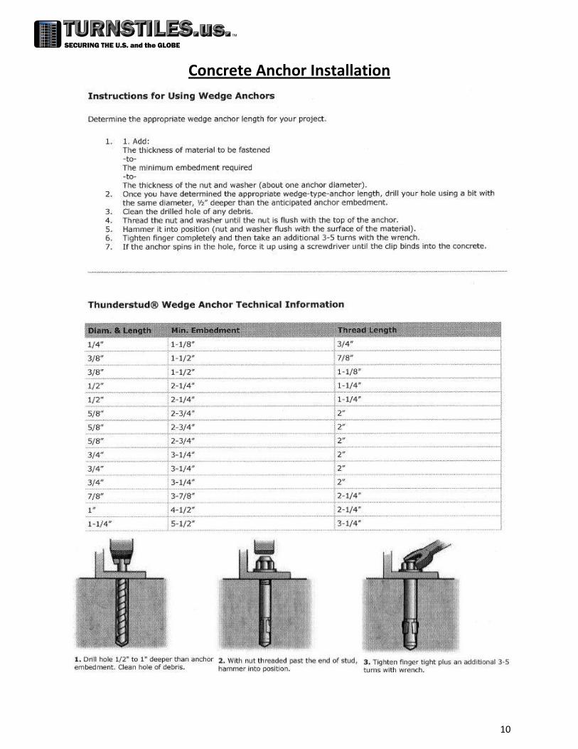
Concrete Anchor Installation
11
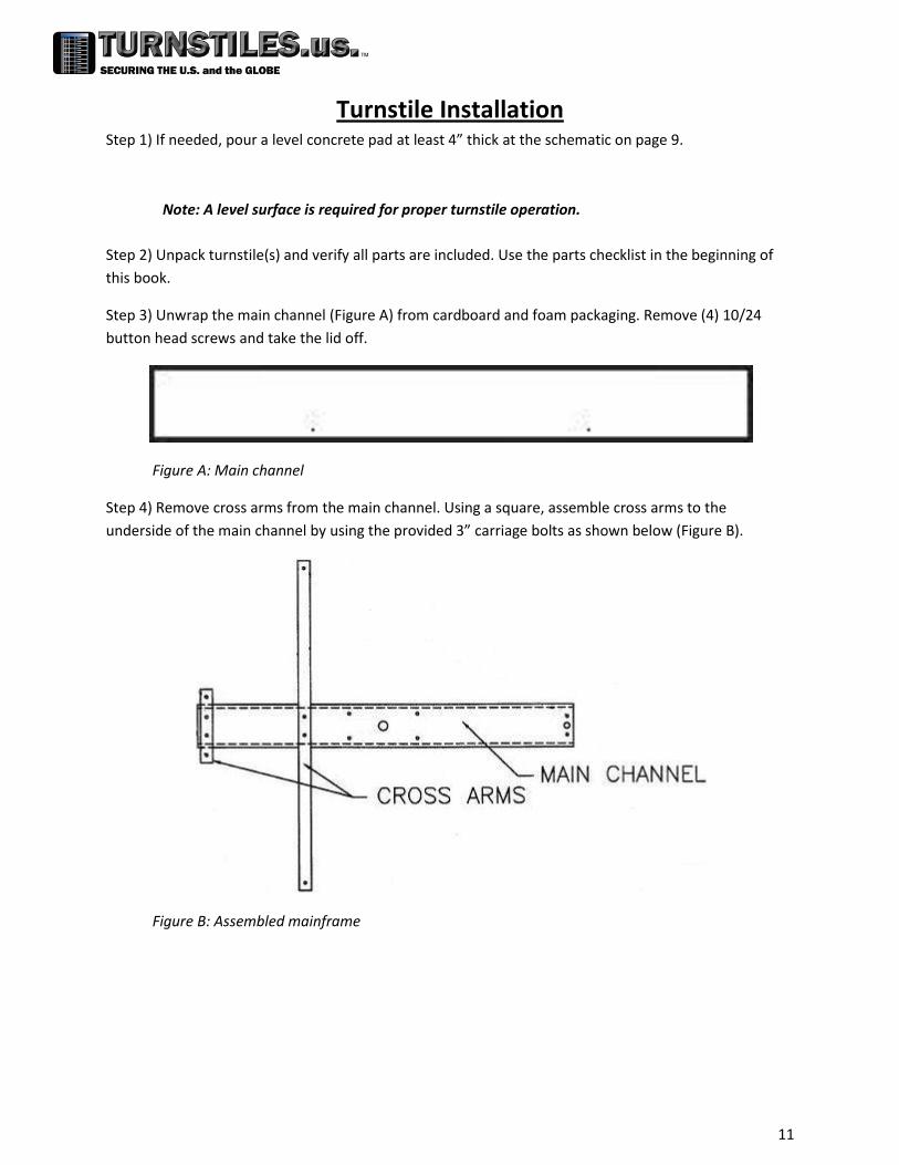
Turnstile Installation Step 1) If needed, pour a level concrete pad at least 4” thick at the schematic on page 9.
Note: A level surface is required for proper turnstile operation.
Step 2) Unpack turnstile(s) and verify all parts are included. Use the parts checklist in the beginning of
this book.
Step 3) Unwrap the main channel (Figure A) from cardboard and foam packaging. Remove (4) 10/24
button head screws and take the lid off.
Figure A: Main channel
Step 4) Remove cross arms from the main channel. Using a square, assemble cross arms to the
underside of the main channel by using the provided 3” carriage bolts as shown below (Figure B).
Figure B: Assembled mainframe
12
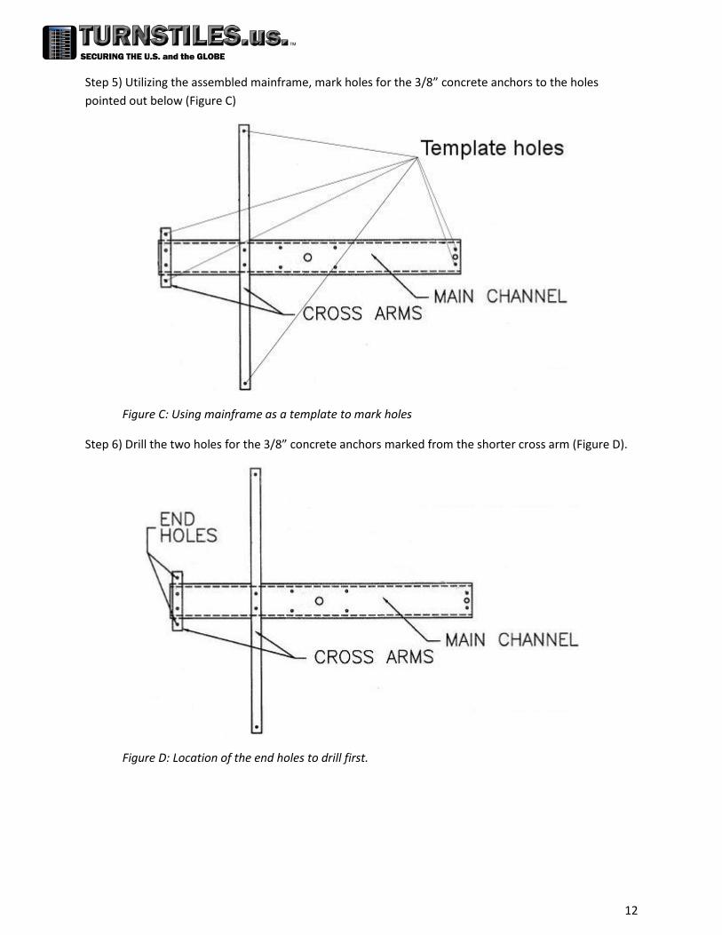
Step 5) Utilizing the assembled mainframe, mark holes for the 3/8” concrete anchors to the holes
pointed out below (Figure C)
Figure C: Using mainframe as a template to mark holes
Step 6) Drill the two holes for the 3/8” concrete anchors marked from the shorter cross arm (Figure D).
Figure D: Location of the end holes to drill first.

13
Step 7) Verify squareness of the cross arms to the mainframe and that the holes line up on the concrete
to the holes on the cross arms. After certainty of correctness, drill the remaining holes called out on
Figure C. Install anchors into holes. Refer to page 10 for concrete anchor installation help.
Step 8) Bolt curved yokes into the concrete (Figure E)
Note: Depending on how the turnstile was ordered, yokes may have holes for mounting card
reader plates. These holes should be pointing to the outside of the turnstile.
Figure E: Mounting the curved yoke pieces to the concrete.
Step 9) Mount the stationary barrier to the concrete (Figure F)
Figure F: Mounting the stationary barrier to concrete.

14
Step 10) Mount the mainframe on top of yokes and stationary barrier using 1 1/2” carriage bolts (Figure
G).
Figure G: Mounting the mainframe on top of the yokes and barrier.
Step 11) Check the levelness of turnstile. If necessary, shim from the floor to make turnstile level.
Step 12) Using a plumb-bob, mark the hole for the bearing and rotor (Figure H).
Note: This step requires as much precision as possible, or the turnstile may not operate
correctly. Do NOT rely on the mainframe as a template for this hole.
Figure H: Using a plumb-bob to mark hole for rotor placement.
15
Step 13) In the case of a HS439/448, bolt arm assemblies to the center column using the ½” x 1” socket
cap bolts. Make sure they are bolted on the same way as the one already bolted on.
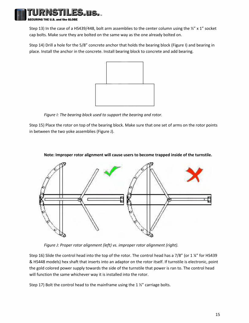
Step 14) Drill a hole for the 5/8” concrete anchor that holds the bearing block (Figure I) and bearing in
place. Install the anchor in the concrete. Install bearing block to concrete and add bearing.
Figure I: The bearing block used to support the bearing and rotor.
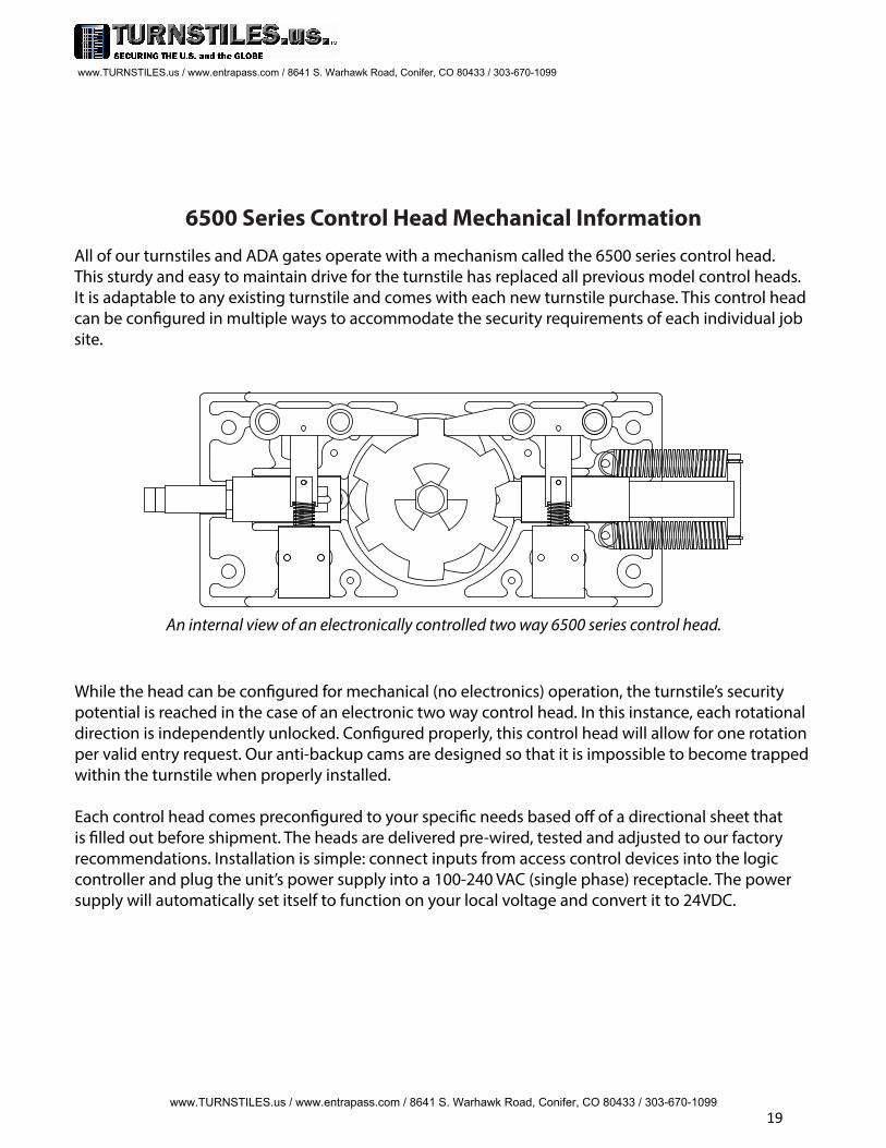
Step 15) Place the rotor on top of the bearing block. Make sure that one set of arms on the rotor points
in between the two yoke assemblies (Figure J).
Note: Improper rotor alignment will cause users to become trapped inside of the turnstile.
Figure J: Proper rotor alignment (left) vs. improper rotor alignment (right).
Step 16) Slide the control head into the top of the rotor. The control head has a 7/8” (or 1 ¼” for HS439
& HS448 models) hex shaft that inserts into an adaptor on the rotor itself. If turnstile is electronic, point
the gold colored power supply towards the side of the turnstile that power is ran to. The control head
will function the same whichever way it is installed into the rotor.
Step 17) Bolt the control head to the mainframe using the 1 ½” carriage bolts.

Important Electrical Information
Installation of the control head mechanism into the turnstile requires a grounding-type outlet recep-tacle installed inside of the frame or cabinet through the provided conduit access points.
To reduce the risk of electric shock, this equipment has a grounding type plug that has a third (grounding) pin. This plug will only t into a grounding type outlet. If the plug does not t into the outlet, contact a qualied electrician to install the proper outlet. Do not change this plug in any way.
Additionally, the P24-60W power supply from this appliance must be grounded to the frame of the turnstile. Utilize the green colored grounding screw threaded into the grounding tab located near the power supply along with the provided grounding wire from the power supply to ensure the equip-ment is properly grounded.
Do not connect to a receptacle controlled by a switch.
UL 294 Classication Declarations:
Feature LevelDestructive Attack Test ILine Security IEndurance IVStandby Power I
ULC S319, Class 1
Wiring methods shall be in accordance with: National Electrical Code, ANSI/NFPA 70Canadian Electrical Code, CSA C22.1, Part I, Safety Standard for Electrical Installations
The 6500 Series Control Head is suitable for indoor & outdoor use, within in an appropriate turnstile or gate model.
www.TURNSTILES.us / www.entrapass.com / 8641 S. Warhawk Road, Conifer, CO 80433 / 303-670-1099
www.TURNSTILES.us / www.entrapass.com / 8641 S. Warhawk Road, Conifer, CO 80433 / 303-670-1099
16

6500 Series Control Head InstallationTo reduce the risk of electrical shock, do NOT hard wire the power supply directly into input voltage. Only power this turnstile from a grounding-type receptacle. Should the turnstile be installed without a grounding-type receptacle, contact a qualied electrician to install one for you.
Waist High Installation:
New waist high turnstile already have the 6500 Series Control Head mounted in place.
However, should the need to replace the control head arise, follow these steps:
- Remove the arm assembly from the turnstile by unbolting the 3x 5/16-18 button head capscrews.- Remove the lid from the cabinet. Some models have a lock and key system while others aresecured with 10/24 button head cap screws located on the sides.- Unplug the control head from the grounded receptacle located inside of the cabinet.- Unbolt the 4x 5/16-18 carriage bolts holding the control head assembly in place.- Pull the control head out of the cabinet and disconnect any access control inputs from thecontrol board.- Place the new control head on top of the cabinet and connect the access control inputs to thenew control board (see wiring diagram).- Insert the control head into the cabinet with the locking bars facing upwards towards you andbolt it into place with the 4x 5/16-18 carriage bolts.- Ground the new power supply to the cabinet.- Plug in the control head to the grounded outlet receptacle.- Install arm assembly onto arm adapter with the 3x 5/16-18 button head cap screws.- Test functionality of turnstile. Adjust hydraulic shock as needed.- Reinstall lid.
Full Height Installation:
- Remove the cover from the mainframe by removing the 10/24 truss head screws.- If applicable, remove the existing control head from the mainframe:
- Unplug the existing control head from the grounded outlet receptacle.- Unbolt the 4x 3/8-16 carriage bolts holding the head in the main channel.- Disconnect access control inputs from the existing control board.- Pull the control head assembly straight up. The shaft will also come out after about 4”.
- Install the control head into the hex insert on the rotor so that the rotor is properly alignedwith one set of arms in between the two yokes (see rotor alignment information).- Bolt the control head into the main channel with the 4x 3/8-16 carriage bolts.- Connect access control inputs to new control board (see wiring diagram).- Ground the power supply to the frame utilizing the provided grounding tab located near thecontrol head.- Plug the control head into a grounded outlet receptacle.- Test functionality of turnstile. Adjust hydraulic shock as needed.- Replace the cover of the mainframe using the 10/24 truss head screws.
www.TURNSTILES.us / www.entrapass.com / 8641 S. Warhawk Road, Conifer, CO 80433 / 303-670-1099
www.TURNSTILES.us / www.entrapass.com / 8641 S. Warhawk Road, Conifer, CO 80433 / 303-670-1099
17

Mounting a new 6500 Series Control Head is very simple. Unbolt the existing control head fromwhatever turnstile it is installed in and mount the new one in its place. The 6500 Series Control Headis backwards compatible with nearly every turnstile we have ever made on it’s own. In units that thehole pattern does not match, an adapter plate is provided to make installation just as simple.
Installing a 6500 Series Control Head into a full height turnstile requires a little extra attention to detail when installing. The rotor itself needs to be properly aligned within the passage way beforeinstalling the control head or it will not function as intended. One set of arms on the rotor of the unitneeds to be pointing in the center of the two half-moon yoke assemblies, not meshed together withthe stationary barrier’s arms. See diagram below.
Single Full Height Turnstile Rotor Alignment
Incorrect Alignment
Rotor should NOT have one set of arms meshed with stationary arms on barrier with the other two sets of arms pointing to the outsides of the half-moon yokes.
Correct Alignment
Rotor has one set of arms in between two half-moon yokes in home position. Arms are not meshed with stationary arms on the barrier.
Note: Failure to properly align the rotor can cause inconsistent operation and the possibility tobecome trapped within the turnstile in some scenarios. If the rotor was installed incorrectly, the solution is to x the rotor alignment. Do not adjust access control or logic controller settings to accommodate the improper alignment.
Simply remove the four carriage bolts holding the 6500 Series Control Head to the mainframe, pull up on the control head to remove it as one assembly, spin the rotor to the correct position, then reinstall the control head into the mainframe.
www.TURNSTILES.us / www.entrapass.com / 8641 S. Warhawk Road, Conifer, CO 80433 / 303-670-1099
www.TURNSTILES.us / www.entrapass.com / 8641 S. Warhawk Road, Conifer, CO 80433 / 303-670-1099
18
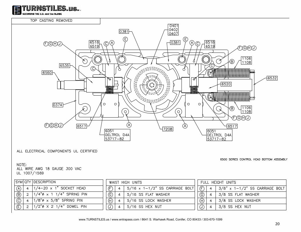
6500 Series Control Head Mechanical InformationAll of our turnstiles and ADA gates operate with a mechanism called the 6500 series control head.This sturdy and easy to maintain drive for the turnstile has replaced all previous model control heads. It is adaptable to any existing turnstile and comes with each new turnstile purchase. This control head can be congured in multiple ways to accommodate the security requirements of each individual jobsite.
An internal view of an electronically controlled two way 6500 series control head.
While the head can be congured for mechanical (no electronics) operation, the turnstile’s security potential is reached in the case of an electronic two way control head. In this instance, each rotational direction is independently unlocked. Congured properly, this control head will allow for one rotation per valid entry request. Our anti-backup cams are designed so that it is impossible to become trapped within the turnstile when properly installed.
Each control head comes precongured to your specic needs based o of a directional sheet that is lled out before shipment. The heads are delivered pre-wired, tested and adjusted to our factoryrecommendations. Installation is simple: connect inputs from access control devices into the logic controller and plug the unit’s power supply into a 100-240 VAC (single phase) receptacle. The power supply will automatically set itself to function on your local voltage and convert it to 24VDC.
www.TURNSTILES.us / www.entrapass.com / 8641 S. Warhawk Road, Conifer, CO 80433 / 303-670-1099
www.TURNSTILES.us / www.entrapass.com / 8641 S. Warhawk Road, Conifer, CO 80433 / 303-670-1099
19
www.TURNSTILES.us / www.entrapass.com / 8641 S. Warhawk Road, Conifer, CO 80433 / 303-670-1099 20

Complete control heads are available upon request.Contact us for pricing details.
Locking Bar Linkages6519 - Fail Open
6518 - Fail Lock
Locking Bar Assemblies0382 - Fail Open Assembly
0383 - Fail Lock Assembly
Limit Switch Cams2267 - Standard 2268 -
ADA 2269 - One-Way
Limit Switches2180 - Standard(Z-15GW2-B7-K) 1700 - One Way(BZ2RW825-A2)
0373 - Bottom Casting
0372 - Top Casting
Control Head Castings
6532 - Index Pin
Proximity Sensor & Accessories
7211 - 24VDC PNP Prox. Sensor w/ M12 Connector (Sick 1040763)
0766 - 3 Branch M12 Splitter
6589 - Turnstile Prox. Bracket w/ 3x Mounts - LH, RH & Home
Cam Assemblies0401 - 427/430/T80/WH (7/8 Hex)
0407 - 439/448/P60/HD (1.25" Hex)
0402 - ADA (Must specify model)
Shock Housing Assemblies6535 - WH/427/430/T80/ADA
6541 - 439/448/P60/HD
Indexing Springs
1106 - Waist High (Light) 1108 -
Full Height (Heavy) 07 - ADA
(Extra Heavy)
Solenoid Springs6510 - Fail Open Spring
6016 - Fail Lock Spring
6051 - Solenoid Deltrol D4A53717-82
Hydraulic Shock Absorbers6560 - WH/427/430/T80/ADA
6561 - 439/448/P60/HD
0381 - Locking Bar Casting w/ Oil Impregnated Bushings
6520 - Index Pin Tubing
+ –+ –L N
V Out
PS24-60W
0740 - Logic Controller (XD10)
Control Head Bearings7208 - Bottom Casting (6007RSNR)
1641 - 1” ID for HD Top Castings & All Pre-2018 Tops (1641-2RSNR) $
1640 - 7/8” ID for Standard Duty Top Castings (1640-2RSNR)
0750 - 24VDC Power Supply (60 W) w/ NEMA 5-15 Drop Cord
I1
A B OKESC
I2 IB IC ID IE+
+
–
–
01 02 03 04
XD10
www.TURNSTILES.us / www.entrapass.com / 8641 S. Warhawk Road, Conifer, CO 80433 / 303-670-1099
www.TURNSTILES.us / www.entrapass.com / 8641 S. Warhawk Road, Conifer, CO 80433 / 303-670-1099
21
6500 Series Control Head CongurationsThe 6500 Series Control Head can be congured in a number of dierent ways. All unitsoperating with the 6500 Series Control Head self-center with a spring driven indexing pinand hydraulically shock to the home position to prevent damage or injury.
Various congurations are available to suit the needs of any environment. These include:
Manual both ways: Unit rotates freely in both directions. This unsecured conguration is used as a means to direct trac through one area. Full height turnstiles can be also be purchased with an out of service lockout bar which would allow the end user to lock the turnstile with a standard pad lock.
Manual one way: Turnstile rotates in one direction but not the other. This is often used foregress only areas.
Electronic one way with free exit: Unit rotates freely in one direction but requires someform of access control in the other. This is a typical installation in many facilities that wantto control who is entering but want egress to be free owing.
Electronic one way with no exit: Turnstile is locked in both directions at all times, but in onedirection can be unlocked with access control. Typically, this would be installed in scenarioswhere there is an alternate means of exiting the facility.
Electronic two way: Turnstile requires access control for both entering and exiting a facility.This conguration oers the highest level of security and also exibility for installations.
Fail lock: Upon power failure, an electronically controlled direction would remain locked.This oers a high level of security but typically is not a good idea for egress unless alternatemethods of exiting are available. Unless equipped with key overrides, this is can be easilyconverted to fail open by ordering alternate parts. This is also known as fail secure.
Fail open: Upon power failure, an electronically controlled direction would remain open. This is the most common conguration as it allows for secure access controlled passage in normal situations but in power outages it free wheels. Unless equipped with key overrides, this can be easily converted to fail lock by ordering alternate parts. This is also known as fail safe.
Key overrides: This option is available on either electronic or manual two way models. Itcan allow for a quick reconguration of free owing passage or locking in either direction.The key override option is not intended for constant every day use. Should you require anadditional lock-down feature on your turnstile, a better option (on a full height turnstile) is an out of service lockout with a standard pad lock. Note that the key override option makesconversion between fail lock and fail open very dicult to accomplish and also may not beavailable for some turnstile or gate models.
www.TURNSTILES.us / www.entrapass.com / 8641 S. Warhawk Road, Conifer, CO 80433 / 303-670-1099
22

6500 Series Control Head Locking Bar InformationThe 6500 Series Control Head is built to order based on a direction set up sheet sent witheach quote. This sheet denes how each direction of passage functions.
Direction 1 is dened as clockwise rotation on a full height or with the cabinet on the right forwaist high. Direction 2 is dened as counter-clockwise rotation on a full height or with thecabinet on the left for waist high.
Possible congurations include: no passage, free passage (manual), fail lock and fail open. Fail lock and fail open are not eld reversible without additional components.
“No passage” directions include a fail lock locking bar assembly as well as an unwired solenoid. This adds the appropriate parts to the control head to prevent it from rotating in that direction.
“Free passage” (or manual) directions remove the solenoid and locking bar assembly, allowingthe cam to spin freely.
Each direction has a pair of holes on the locking bar and control head casting. These holesact as pivot points for the locking bar casting. The inner holes are fail lock and outer holesare fail open. A .5“ dowel pin slides through the entire assembly to hold everything in place.
Alternate linkages and springs are needed to convert a direction’s power failure status.
If optional key overrides are included, it becomes much more dicult to re-arrange theconguration. Typically it is best to send the control head into the factory to recongureany key override equipped head to ensure everything is done correctly.
Direction 1 SolenoidDirection 2 Solenoid
Fail OpenPivot Point
Fail LockPivot Point
Fail LockPivot Point
Fail OpenPivot Point
Fail LockPivot Point
Fail OpenPivot Point
0381Locking Bar Casting
Hardened 4140 tool steelcasting w/ oil impregnated
bronze bushings.
www.TURNSTILES.us / www.entrapass.com / 8641 S. Warhawk Road, Conifer, CO 80433 / 303-670-1099 23

The 6500 Series Control Head can be recongured from fail lock to fail open and vice versa.Extra components are required to do so.
If a control head has key overrides, we suggest sending it in for factory reconguration.
Locking bar assemblies are held together with 1/8” spring pins. Extracting these pins andreinstalling them can be tricky, so for convenience we also oer entire locking bar assemblies.
Replacing an entire locking bar assembly is simple, punch the .5” dowel pin from the pivotpoint through the head casting (via a small hole in the bottom casting for this purpose),pull out the old locking bar assembly and replace it with the new one.
If changing from fail lock to fail open or vice versa, install dowel pin in alternate hole.
6500 Series Control Head Locking Bar Information (Continued)
6519Fail Open Linkage
These have an approximatelength of 2.5” and do not
have the extra hole for thekey override option.
6510Fail Open Solenoid Spring
These look similar to fail lock, but are actually stronger in force.
Wire diameter is .041”.
6518Fail Lock Linkage
These have an approximatelength of 2.25” and also
include an extra hole thekey override option.
6010Fail Lock Solenoid Spring
These look the same as the fail open,but are actually much lighter in force
Wire diameter is .032”.This spring was also used
on the 6100 Series Control Head.
0383Fail Lock Locking Bar Assembly
Includes locking bar castingw/ oil impregnated bushings,solenoid spring, locking bar
linkage, and solenoid plunger.
0382Fail Open Locking Bar Assembly
Includes locking bar castingw/ oil impregnated bushings,solenoid spring, locking bar
linkage, and solenoid plunger.
Locking Bar Linkage
Spring Alignment Tabs
Solenoid Spring
Correct Alignment Incorrect Alignment
Make sure solenoid spring is between alignment tabs on linkage or the assembly maybind when pivoting.
www.TURNSTILES.us / www.entrapass.com / 8641 S. Warhawk Road, Conifer, CO 80433 / 303-670-1099
24

6500 Series Control Head Hydraulic Shock Information
The 6500 Series Control Head utilizes a spring loaded index pin for auto-centering the cam while a hydraulic shock oers counter resistance to slow the rotation down.
Set properly, the shock will allow a turnstile or gate to self-center while rotating smoothlywithout slamming.
Some turnstile models use a dierent shock than others. Waist highs and smaller full heightsuse a .75” diameter shock (Enidine brand) while larger full heights use a 1” diameter shock(ACE Controls brand).
Hydraulic ShockIndex Pin
Enidine Brand Shocks:
Setting:Loosen the set screw on the head of the dial and turn the knob. The dial can be set between 0 and 8. The higher the number, the stronger the shock is. Tightening the set screw can alter the shock strength so a good habit is to loosen the set screw, turn the dial, tighten the set screw then test your setting. Repeat until satised.
Replacement: Thread the new shock into the shock housing as far as it will turn while the cam is in the home position. Once it bottoms out, thread the shock back out 1.5 - 2 turns until the numbers on the dial are facing upright. Some models may require an additional turn or two outward if the arm does not self center on even the lowest setting.
ACE Controls Brand Shocks:
Setting:Loosen the set screw located on the end of the shock itself before the dial. The dial can be set between 0-8 and the set screw acts as indica-tor for the dial. The lower the number, the stronger the shock is.
Replacement:Thread the new shock into the housing as far as it will turn while the cam is in the home position. Once it bottoms out, thread the shock back out 1.5-2 turns until the set screw pointer is facing upright. Fasten the shock into the housing by snugging the 1/4-28 set screw into the bronze housing (snugly, but do not over tighten or the brass might start to tare).
Failure to turn the shock back out after threading it in all of the way will likely cause the partto wear out very quickly.
www.TURNSTILES.us / www.entrapass.com / 8641 S. Warhawk Road, Conifer, CO 80433 / 303-670-1099
25

6500 Series Control Head Electrical InformationEach electronic control head comes with a power supply, a programmable logic controller (PLC), limitswitches (or optionally, proximity sensors) and solenoids. For safety purposes, it is recommended that you read all literature on the electrical components before attempting to install the control head into a turnstile.
The 6500 Series Control Head is on the third generation of electronic components. The new XD10 logiccontroller is a direct replacement of both the 0789 control board and 6789 (Keyence KV-16DR) logiccontroller.
The latest enhancements provide a broader temperature range for outdoor installations (-4 to 131F)as well as a user friendly text based interface with a daylight visible display. With this also comessome new features such as on board testing buttons, turnstile statistics / information, etc.
While the wiring may be dierent, there are very few exceptions to when this board is compatiblewith installed products. If an installation has the old 0789 circuit board (PCB) and has the optionalproximity sensor upgrade, new proximity sensors will need to be purchased. This is because the0789 board had NPN inputs while the XD10 (and the KV-16DR) have PNP inputs.
The new PLC still requires relay contact closures for inputs just like all previous generations, so anyinstallation is compatible in one way or another. If assistance is needed with understanding howto convert the wiring from access control to the new logic controller, please view this manual orcall our technical support department for assistance.
I1
A B OKESC
I2 IB IC ID IE+
+
–
–
01 02 03 04
XD10
Inputs
To activate, apply local 24VDC + to desired input terminal.
Full Height Models: Dir 1 - ClockwiseDir 2 - Counter Clockwise
+24
VDC
-24
VDC
I1Dir 1Input
I2Dir 2Input
IBDir 1OR
ICDir 2OR
IDDir 1Limit
IEDir 2Limit Waist High Models:
Dir 1 - Right HandDir 2 - Left Hand
Outputs
Dir 1 Fail LockDir 1 Green Light
01
Dir 1 Fail OpenDir 1 Red Light
02
Dir 2 Fail LockDir 2 Green Light
03
Dir 2 Fail OpenDir 2 Red Light
04
XD10 Logic Controller0740
KV-16DR Logic Controller6789
Control Board0789
Lower Row Ports:To 24VDC- | Lim 1 Inp | Lim 2 Inp | Unused | Unused | Fire Alarm Inp
Upper Row Ports:Dir 1 Inp | Dir 2 Inp | Dir 1 OR Inp | Dir 2 OR Inp | UnusedConnect access control relays to 24VDC+ and desired input
Upper Row Ports:Unused | Dir 1 Sol | Dir 2 Sol | Dir 1 Lt Red | Dir 1 Lt Green
Lower Row Ports:24VDC+ | 24VDC- | Rly Com | Rly Com | Dir 2 Lt Red | Dir 2 Lt GreenDir 1 = CW on FH, RH on WH/ADA | Dir 2 = CCW on FH, LH on WH/ADA
www.TURNSTILES.us / www.entrapass.com / 8641 S. Warhawk Road, Conifer, CO 80433 / 303-670-1099
www.TURNSTILES.us / www.entrapass.com / 8641 S. Warhawk Road, Conifer, CO 80433 / 303-670-1099
26

6500 Series Control Head w/ XD10 Controller Standard Wiring Diagram
I1
A B OKESC
I2 IB IC ID IE+
+
–
–
01 02 03 04
XD10
Direction 1Solenoid
DeltrolD4A 53717-82
Direction 2Solenoid
DeltrolD4A 53717-82
COM
N.O.
N.C.
Limit Switch 2 Omron
Z-15GW2-B7-K
COM
N.O.
N.C.
Limit Switch 1Omron
Z-15GW2-B7-K
+ –+ –L N
V Out
PS24-60W
Direction 1 Access Control Relay
N.O.COM
Direction 2 Access Control Relay
N.O.COM
Direction 1 Override Relay
N.O.COM
Direction 2 Override Relay
N.O.COM
Black
Black
Brown
Brown
Blue BlueWhite (not used) White (not used)
(Optional)Direction 1
LED Indicator Light(Tri-color, day light visible)
Banner EngineeringS18DLGRYPQ
(Optional)Direction 2
LED Indicator Light(Tri-color, day light visible)
Banner EngineeringS18DLGRYPQ
if fail lock...if fail open...if fail lock...if fail open...
Input Voltage:100-240 VAC
1 Phase1.1 - .6A Max
50/60 Hz
Grounding Tabin Cabinet orMainframe
NeutralLoadGround
www.TURNSTILES.us / www.entrapass.com / 8641 S. Warhawk Road, Conifer, CO 80433 / 303-670-1099
www.TURNSTILES.us / www.entrapass.com / 8641 S. Warhawk Road, Conifer, CO 80433 / 303-670-1099
27

Input descriptions:24VDC + Positive output from the 24VDC power supply connects here.24VDC - Negative output from the 24VDC power supply connects here.
I1 - Direction 1 Input - Unlocks direction 1 for either one rotation or until the timer expires. Standard access control should terminate here.I2 - Direction 2 Input - Unlocks direction 2 for either one rotation or until the timer expires. Standard access control should terminate here.
IB - Direction 1 Override - Holds direction 1 unlocked for duration of contact closure. Mainly for re alarms and other temporary overrides.IC - Direction 2 Override - Holds direction 2 unlocked for duration of contact closure. Mainly for re alarms and other temporary overrides.
ID - Limit 1 Input - Cancels Direction 1 activation if triggered before timer expires, re-locking the unit after one rotation.IE - Limit 2 Input - Cancels Direction 2 activation if triggered before timer expires, re-locking the unit after one rotation.
Output descriptions:All 4 relay outputs have individual commons. 24VDC+ is distributed to each relay common to operate the turnstile. It is OK to add extra wiresto these relay commons to distribute voltage to other devices.
01 - Output 1 - Dual purpose output for Direction 1. If the direction is fail lock, it’s solenoid would connect here. If equipped with anindicator light, the green leg would connect here. Output switches from OFF to ON when directional input is triggered.
02 - Output 2 - Dual purpose output for Direction 1. If the direction is fail open, it’s solenoid would connect here. If equipped with anindicator light, the red leg would connect here. Output switches from ON to OFF when directional input is triggered.
03 - Output 3 - Dual purpose output for Direction 2. If the direction is fail lock, it’s solenoid would connect here. If equipped with anindicator light, the green leg would connect here. Output switches from OFF to ON when directional input is triggered.
04 - Output 4 - Dual purpose output for Direction 2. If the direction is fail open, it’s solenoid would connect here. If equipped with anindicator light, the red leg would connect here. Output switches from ON to OFF when directional input is triggered.
Indicator light information:Green Light - An indicator to inform pedestrians that they are allowed to pass through the unit. Uses black output wire from light’s cable.Red Light - An indicator to inform pedestrians that the unit is locked or that pedestrians require credentials to enter. Uses brown output wirefrom light’s cable.As a side note, indicator lights purchased from Controlled Access, Inc. can also be wired to glow yellow. If desired, this can be used instead of red with the unused white wire on the light’s cable to indicate to pedestrians they require credentials to enter. This is especially handy for multi-lane installations in which some directions are “no passage” instead of “controlled passage”. Likewise, green lights can also be wired to a red light output to constantly glow green to indicate “free passage”.
I1
A B OKESC
I2 IB IC ID IE+
+
–
–
01 02 03 04
XD10
Inputs
To activate, apply local 24VDC + to desired input terminal.
Full Height Models: Dir 1 - ClockwiseDir 2 - Counter Clockwise
+24
VDC
-24
VDC
I1Dir 1Input
I2Dir 2Input
IBDir 1OR
ICDir 2OR
IDDir 1Limit
IEDir 2Limit Waist High Models:
Dir 1 - Right HandDir 2 - Left Hand
Outputs
Dir 1 Fail LockDir 1 Green Light
01
Dir 1 Fail OpenDir 1 Red Light
02
Dir 2 Fail LockDir 2 Green Light
03
Dir 2 Fail OpenDir 2 Red Light
04
General denitions:Direction 1 - Clockwise on full height turnstiles or cabinet on right for waist high turnstiles & ADA gates.Direction 2 - Counter clockwise on full height turnstiles or cabinet on left for waist high turnstiles & ADA gates.Limit - A switch or sensor designed to detect rotation and lock the unit after a rotation. Fail Lock - Upon power failure, the direction is designed to remain locked. Also known as Fail Secure.Fail Open - Upon power failure, the direction is designed to remain opened. Also known as Fail Safe.
Each unit is built to order, preconfigured to function as specified at the time the order is placed. Some or all of the information listed may not be relevant to the installation.
Inputs are triggered with local 24VDC + (also known as PNP or sourcing).Connect relay output from access control device to turnstile by terminating 24VDC + to relay common and the desired input to the relay’s normally open terminal.
Be sure to disconnect power before wiring the board for safety.
Note: directional status outputs (lights) are unaected by optional key overrides as the override occurs outside of the logic controller.
6500 Series Control Head w/ XD10 Controller Standard Wiring Legend
www.TURNSTILES.us / www.entrapass.com / 8641 S. Warhawk Road, Conifer, CO 80433 / 303-670-1099 28

6500 Series Control Head w/ XD10 Controller Standard Turnstile SettingsThe XD10 logic controller on the 6500 Series Control Head has a text based menu screen to adjust settings and view statistics of the turnstile. Pressing the A button will cycle to each of the screens available on the device. Pressing B from any screen listed will return to the Home Screen.
Home Screen Timer Values Screen One-Shot Timers Screen
Swipe Queue Screen Direction 1 Counts Screen Direction 2 Counts Screen
General Info Screen
This screen is at the start of the menu cycle. The top section will give a read out of inputs that are currently receiving voltage. Thedisplay will return to this screenafter cycling through all windows, 5 minutes of inactivity or pressing the B button.
This screen allows for the each directional timer to be modied. Select which value you wish to edit by pressing the + & - key. Press OK to select the value then press + or - to modify. Save by pressing the OK button again. Each timer can have a value of 1 - 60 seconds. The timer will be canceled upon rotation of unit.
This screen allows for the two one-shot timer settings to be enabled or disabled. This setting prevents access control from holding open a direction on the standard direction inputs. Toggle Direction 1 by pressing + andDirection 2 by pressing -. Thisshould be set to “On” in almostevery installation.
This screen denes the maximum number of access control requests the unit will allow in queue. Each value can be set from between 1 (for maximum security) to 3 (for fast paced passage). The default is 2. The method to change these settings is the same as the Timer Values Screen.
This screen gives statistics about how many times direction 1 was activated and cycled. Since there is a limit to how many counts can be displayed, after 25000 cyclesthe rst counter resets and adds to the second counter.
This screen gives statistics about how many times direction 2 was activated and cycled. Since there is a limit to how many counts can be displayed, after 25000 cycles the rst counter resets and adds to the second counter.
Factory Setup Screen
This screen should only appear when rst set up in the factory or if something occurs to totally reset the logic controller. If this manages to occur and the order number (if known), enter it as a value then press B to save.
This screen displays when the PLC was initiated, the order number it was activated for (except for any revision suxes which are not needed for order lookup), and the PLC software version.
Testing Mode Screen
While this screen is active, the unit can be tested with push buttons to simulate access control inputs. See the page dedicated to testing for more information.
www.TURNSTILES.us / www.entrapass.com / 8641 S. Warhawk Road, Conifer, CO 80433 / 303-670-1099 29

6500 Series Control Head w/ XD10 Controller Standard Turnstile TestingThe XD10 logic controller on the 6500 Series Control Head can be activated by contact closuresbetween 24VDC+ and the relevant input. New technology allows for simpler on-board testingas well. To diagnose issues with the unit, press A on the keypad to cycle between screens untilthe testing mode screen appears.
Testing mode simulates valid access control inputs based on the settings dened on theother menu screens. The unit should unlock for the duration of the directional timer or untilthe unit is rotated. If the button is pressed twice, it should allow two rotations or time outbased on the mult-swipe setting. If the button is held and the one shot timers are disabled, the unit will continue to remain open until the button is released and another rotation or timeout occurs.
With the testing mode screen open, press and release + to activate in direction 1. The unitshould unlock and allow one rotation. If the unit successfully functions this way, repeat the same for direction 2 by pressing the - button.
If everything is functioning properly from the menu test but not with access control, eitheraccess control is not connected properly, is normally closed instead of normally open, or isnot properly congured. Contact a security integrator for assistance with help with theaccess control system.
If the unit successful unlocks but does not re-lock upon rotation, try to manually trigger the appropriate limit switch for the direction that is not working correctly. If this helps, itis likely that the limit switch is not properly being triggered by the limit switch cam. Eitheradjust the height of the limit switch cam or tweak the lever on the limit switch a bit closerto the limit switch cam’s tip.
If the unit does not successfully re-lock after manually triggering the limit switch, ensurethat it is wired properly. Return to the home screen and press / hold the limit switch. If theswitch is being held but the “Active Pins” display does not include the switch being held, itmay be necessary to replace the switch. Note that there is a short delay from when the switch is triggered to when the display will register it as active, however this is normal.
If there are other issues with operation, check out the troubleshooting guide for additionaldiagnostic procedures or call Controlled Access, Inc. for assistance.
www.TURNSTILES.us / www.entrapass.com / 8641 S. Warhawk Road, Conifer, CO 80433 / 303-670-1099 30

6500 Series Control Head Limit Switch InformationElectronically controlled 6500 Series Control Heads utilize limit switches (or optionally, proximity sensors) in order to detect rotation. Depending on the type of unit (turnstile or ADA gate), the limit switch for a direction may be on the left or the right hand side of the control head.
ADA Gate Control Head
LimitSwitch
1
LimitSwitch
2
Turnstile Control Head
LimitSwitch
1
LimitSwitch
2
ADA Gate control heads use an oblong lobe shaped limit switch cam. The point of the lobe needs to be facing the index pin (bar with two springs) when the cam is in the home position.
The limit switch for direction 1 is on the left and the limit switch for direction 2 is on the right. In this conguration, the limit switch relevant to the swing is triggered after the cam leaves home position, which re-engages the locking bar. The cam is still free to move until it swings back to the home position.
Turnstile control heads use a triangular shaped limit switch cam. One point of the triangle needs to be facing the index pin (bar with two springs) when the cam is in the home position. The two indents in the sides of the triangle are for jigging purposes. It does not matter which point is facing to the springs.
The limit switch for direction 1 is on the right and the limit switch for direction 2 is on the left. In this congu-ration, the rst limit switch triggered does not aect the unit. The second switch triggers after the half-way point of the rotation, which draws in the solenoid. This allows the rotation to go to home but prevents the rotor from backing in the other direction.
Options and congurations may alter the quantity or layout of the limit switches. Some examples of this would be electronically controlled one direction turnstiles, turnstiles with counters and turnstiles equipped with home position switches.
www.TURNSTILES.us / www.entrapass.com / 8641 S. Warhawk Road, Conifer, CO 80433 / 303-670-1099
www.TURNSTILES.us / www.entrapass.com / 8641 S. Warhawk Road, Conifer, CO 80433 / 303-670-1099
31

Maintenance & Cleaning
To ensure long life on any turnstile, the following maintenance is recommended. Note: these gures are assuming a maximum 75000 passages per year. Turnstiles with heavier trac should be main-tained more frequently.
Annual Servicing- Secure all nuts & bolts throughout each model. This includes concrete anchors, carriage bolts
holding together mainframes, and the bolts holding the control head assembly together.- Remove the index pin assembly from the control head by disconnecting the two extension springs& apply white lithium grease. Use 3-in-1 oil on the index pin roller.- If the unit is a High Security series full height turnstile, add grease to the rotor’s roller bearing byutilizing the grease tting fastened into the bottom of the rotor.
Bi-annual Servicing- Disassemble the control head by removing the 4x socket head cap screws holding the top casting
to the bottom casting (and the triangular limit switch cam if equipped). - Clean any loose debris / grease from the inside of the casting.- Inspect internal components for wear and replace as needed.- Apply 3-in-1 oil to the bronze bushings on the locking bar assemblies and shock piston.- Apply white lithium grease to the shock piston where it enters the bronze housing.- Reassemble the control head assembly, using removable strength (typically blue) thread sealer(such as Loctite 243) on the head bolts to ensure the assembly stays together.
Cleaning- Galvanized surfaces can be cleaned with soap and water. The nish may dull over time, but this is
normal.- Powder coated surfaces should be cleaned with a non-abrasive cleaner such as Formula 409. Inspectnish for chips and touch up as needed or the exposed steel may rust.- Stainless steel surfaces should be polished with a stainless steel wax or polish. Contrary to commonbelief, stainless steel is not rust proof. Exposure to certain chemicals and harsh environments such asocean air or chemical plants may cause surface corrosion. Minor discoloration can be removed with arust penetrating product (such as PB Blaster) along with non-scratching scouring pads. Severe casesof contamination may require the use of specialty products. We have had great success with productssuch as Stellar Solutions’ Citrisurf 2310 Rust Remover and Passivation Solution.- The decorative solid surface tops on our Executive models, Beacon models and some PassThrumodels should be polished with furniture polish (such as Scott’s Liquid Gold Wood Cleaner). Allowingthe product to soak into the material for a few minutes easily restores the surface’s luster.- Polycarbonate plastic should only be cleaned following the plastic manufacturer’s recommenda-tions. DO NOT USE ANY PRODUCTS THAT INCLUDE AMMONIA OR OTHER HIGH PH PRODUCTS. Ifthe model purchased includes polycarbonate plastic, see the section of the manual dedicated tocleaning it (starting on the next page). Failure to use appropriate cleaning methods will causeaesthetic and structural damage to the plastic which will not be covered under the warranty.
Control heads can be removed from the turnstile and shipped to the factory at any time for repairs and maintenance. Please include contact information so we can call to discuss any issues your control head may have. Please note that any repairs that cost under $500.00 will require a credit card payment before being returned.
www.TURNSTILES.us / www.entrapass.com / 8641 S. Warhawk Road, Conifer, CO 80433 / 303-670-1099 32

6500 Series Control Head w/ XD10 Controller Troubleshooting
Symptoms Causes Solutions
Turnstile does not power up orlogic controller’s display cycleson and o.
Power supply is not receivinginput voltage.
Power supply is not producing24VDC voltage, but is receivingAC.
Verify outlet receptacle installedin mainframe / cabinet isoperating correctly and that thepower supply is plugged in.Remove + lead from powersupply output. If output voltageresumes, there is a short circuitin the wiring. If not, the powersupply is faulty. Replace powersupply.
Short circuit in the wiring asdetermined in previous step.Loose wiring from power supplyto logic controller.
Refer to pages 13-15 forwiring information.
Short circuit in the wiring.
Solenoid(s) burnt out (will occurif main AC voltage is connecteddirectly to solenoid).
If wiring is correct, try todisconnect the solenoids fromoutputs 01 - 04. If system stopscycling, replace faulty solenoid.
Turnstile powers up but does notrespond.
Improper wiring from accesscontrol to logic controller.
Ensure one leg of access controloutput relay is connected to24VDC + and the other to thedesired input.
Access control devicemalfunction.
Disconnect access control fromlogic controller. Preform testingprocedures on page 16. If theturnstile works properly, contactmanufacturer of access controldevice.
Solenoid (-) wire(s) not properlyterminated.
Ensure solenoid negative wiresare properly terminated to 24VDC- input and that the 3 wiresplice (if equipped) is properlycrimped.
Solenoid tabs grounded outagainst control head castingafter being reassembled frommaintenance or reconguration.
Disassemble control head castingand ip solenoids so that thetabs with wires are facing awayfrom the center of the controlhead casting.
www.TURNSTILES.us / www.entrapass.com / 8641 S. Warhawk Road, Conifer, CO 80433 / 303-670-1099
www.TURNSTILES.us / www.entrapass.com / 8641 S. Warhawk Road, Conifer, CO 80433 / 303-670-1099
33

6500 Series Control Head w/ XD10 Controller Troubleshooting
Symptoms Causes Solutions
More than one person can getthrough turnstile.
Access control device outputconnected to override inputs.
Access control device output settoo long.
Loose wiring to the logiccontroller from limit switches.
Limit switches are broken.
Control head requiresmaintenance.
Limit switches are missing thetriangular top cam.
Wire access control to I1 or I2with one-shot timer enabled.
This can be avoided by enablingthe one-shot timers built into thelogic controller program. If thisis undesirable, ensure the outputfrom the access control system isone second or less.
Refer to pages 13-15 forwiring information.Inspect limit switches forbreakage, replace as needed.Refer to page 18 formore information.Adjust the top cam to theproper height and/or tweakthe triggers on the limitswitch. Refer to page 17 formore information.
People are becoming trappedinside of the turnstile(Full Height models)
Rotor was installed backwards.Refer to page 4 installation for visual diagram on how to install rotor properly.
Turnstile only rotates 30degrees.
Limit switches wired incorrectly.Refer to pages 13-15 for wiringinformation and page 17 forlimit switch placement.
Limit switch cam is misaligned.
The top cam should have onepoint facing the control board. Ifthis is not the case, readjust thetop cam. Refer to page 17 fortop cam information.
Unit remains unlocked untilaccess control is presented.
Fail open / fail lock congurationis wired incorrectly.
Refer to pages 13-15 for wiringinformation.
Turnstile is slamming into theclosed position.
Shock either needs adjusted or replaced. Refer to page 12 for
more information.Shock needs adjusted.
Turnstile is not centeringproperly. Binding in control head.
Turnstile seems to be bindingmechanically.
Rotor is not plumb / turnstilebody is not level.
Ensure mainframe is level andthe rotor is plumb. Shim the unitfrom the oor if necessary.
www.TURNSTILES.us / www.entrapass.com / 8641 S. Warhawk Road, Conifer, CO 80433 / 303-670-1099
www.TURNSTILES.us / www.entrapass.com / 8641 S. Warhawk Road, Conifer, CO 80433 / 303-670-1099
34

6500 Series Control Head w/ XD10 Controller Troubleshooting
Symptoms Causes Solutions
Unit remains locked after accesscontrol is presented until arm ispulled in.
Mechanical bind between lockingbar and cam assembly (typicallyfrom unit being out of plumb ornot level)
Remove locking bar assemblyfrom control head (easiest way onnon-key lock models is to punchout dowel pin pivot point frombottom side of head casting) andle down tip of locking bar to giveclearance.
Turnstile rotating the wrongdirection.
Improperly lled out directionsheet.
Directional inputs wiredincorrectly.
In some cases, the control headcan be recongured in the eld tooperate as needed. Refer to pages9-11 for information about howthe control head operates. Ifneeded, contol heads can bereturned to the factory for reconguration for a fee of laborplus parts (if required). Pleasecontact us before returning acontrol head in this instance.
Refer to wiring legend on page 15for direction port explanations.
Refer to page 11 for moreinformation. Additional parts willbe required to convert operation.The control head can be returnedfor reconguration for a fee of labor plus parts (if required).Please contact us before returninga control head in this instance.
Improperly lled out directionsheet.
Turnstile fails lock when neededto fail open or vice versa.
Unable to hold direction open toallow multiple people to passthrough the turnstile.
Override wired to incorrectinputs.
One-shot timers are enabled (onregular access control input).
Disable the one-shot timersettings on the logic controller.Be sure that your access controloutput is one second or lessduring regular secure operation orextra people may be able to passthrough. Refer to pages 18-19.
Other problems. Please contact us for any otherissues.
Ensure the access control devicededicated to overriding passage iswired to the override input insteadof the standard input for thatdirection.
www.TURNSTILES.us / www.entrapass.com / 8641 S. Warhawk Road, Conifer, CO 80433 / 303-670-1099
www.TURNSTILES.us / www.entrapass.com / 8641 S. Warhawk Road, Conifer, CO 80433 / 303-670-1099
35

Proper Turnstile UsageThe 6500 Series Control head is easy to use. There are a few things that users should be trained on and informed of.
- In the case of an electronic turnstile, approach the unit and present access control credentials.Do not push on the arms of the rotor until after the access control device successfully unlocks theturnstile. A sturdy click sound will be heard from the main channel when the solenoid pulls thelocking bar open.
- Note that the turnstile will not unlock if the rotor or arm is being pushed on before accesscontrol activates the solenoid. The unit should unlock once pressure is released but it is a betterpractice to wait until the unit is unlocked before pushing on the rotor.
- Once access has been granted, proceed through the turnstile immediately. Waiting too longcould cause the rotor to time out mid-rotation, forcing the user to back out of the turnstile. Thereare timer settings for adjusting how long it takes for this to occur. The default time provided is 7seconds. The reason for this is in case somebody swipes and walks away without passingthrough.
- Walk at a reasonable pace through the turnstile. Do not slam the rotor through the rotation.This can be unsafe and may cause unnecessary wear and tear to the control head.
- Try to be respectful of users wanting to pass through the opposite direction. Allow people whoare waiting an opportunity to pass through the turnstile.
- Avoid rotation the rotor of a full height without being in the passage. This will cause the rotorto re-lock before you have a chance to pass through the turnstile.
- Piggybacking : More than one user trying to squeeze through the turnstile on one rotationshould be avoided. Large bags and carts should be brought through an alternate means ofentrance.
www.TURNSTILES.us / www.entrapass.com / 8641 S. Warhawk Road, Conifer, CO 80433 / 303-670-1099
www.TURNSTILES.us / www.entrapass.com / 8641 S. Warhawk Road, Conifer, CO 80433 / 303-670-1099
36

37
Warranty Information
Seller warrants the goods against defective workmanship and materials provided that Buyer notify Seller within
one (1) year after receipt by Buyer of the goods of any claim under this Warranty. The liability of Seller shall be
limited to replacing or repairing defective goods returned by Buyer and delivered to the factory of the Seller,
transportation charges prepaid.
Replaced or repaired goods will be redelivered freight repaid to the address of Buyer shown hereon. Except for
the Warranty contained herein, there shall be no other warranties, such as warranties of fitness and
merchantability or otherwise express or implied, written or verbal, and Seller shall not be liable for
consequential damages in any event.

Part Names and Functions
Safety Precautions
• Do not perform any electrical wiring while electric current is applied. Failureto follow this may result in an electric shock or fire.
• Be sure to connect the grounding cable. Failure to follow this may resultin an electric shock or fire.
• Do not touch this unit within 1 minute after AC input is turned off. Failureto follow this may result in an electric shock.
• Do not modify or repair this unit. Failure to follow this may result in anelectric shock, accident, or product failure.
• Do not touch any terminal of this unit while electric current is applied.Use the unit with the terminal cover installed to avoid an electric shock.
• When this unit is used in a system that may cause a serious accident ordamage if the unit fails, be sure to install a safety device.
• Pay attention to prevent foreign matter such as metal particles, dust,paper or wood chips from entering the inside of this unit. Failure tofollow this may result in a fire or product failure.
• Do not touch any metallic part while electric current is applied orimmediately after input is shut off. Failure to follow this may result in aburn due to a high temperature.
• If a failure or abnormality occurs while this unit is in use, immediatelysuch off AC input and stop operation of this unit . Failure to follow thismay result in a fire or accident.
• Check that the AC input rated voltage of this unit is equal to the voltageof the AC power supply.
• Do not connect the AC power supply to the DC output terminals.• Do not disturb the convection of air near the vent of the casing.
Precautions for CE MarkingsKEYENCE has evaluated the conformity of the MS2 Series with the requirements of the EMCDirectives and Low-voltage Directives under the following condition, and confirmed that the MS2Series meets these requirements. For the Low-voltage Directives, the MS2 Series has obtainedcertification from TUV Rheinland for the following standards.<Precautions> EMC Directives (89/336/EEC)• Applicable standard (EMI) EN55011, Group 1, Class A• Applicable standard (EMS) EN61000-6-2 Low-voltage Directives (73/23/EEC) • Applicable standard EN60950-1
EN50178 • Overvoltage category II • Pollution degree 2
• The MS2 Series is designed as a Class I Equipment. Be sure to connect the protective earthingterminal on the terminal block to the protective earthing conductor in the building installation.
• The MS2 Series is an open-type device. Be sure to install it in an appropriate enclosure rated asIP54 or better.
• Use the MS2 Series according to the derating conditions and the installation conditions described inthis manual.
• The MS2 Series does not include a disconnecting device. Be sure to install a disconnecting devicesuch as a circuit breaker in the building installation wiring.
.8.8.8Display mode selection (MODE)Switches the display mode.
AC input terminal (N, L)An input cable is connected here. (100 to 240 VAC)
Protective earthing terminal ( )Connect to the protective earthing conductor in the buildinginstallation.
Digital display windowDisplays the current values of output current/voltage and other items.
DC output terminal (+, –) *A load is connected here. (24 VDC)
Output voltage adjustment trimmer (V.ADJ)Adjusts the output voltage within the range of ±5%.
Compact Switching Power Supply
MS2 Series
Instruction Manual
Precautions for UL StandardsThe MS2 Series meets the following UL standards and has obtained UL and C-UL certification. • Applicable standard UL508 Industrial Control Equipment
UL60950-1 Information Technology Equipment - SafetyCAN/CSA C22.2 No. 14-M95
Industrial Control EquipmentCAN/CSA C22.2 No. 60950-1-03
Information Technology Equipment - Safety • UL File No. E195940, E242533 • UL category NMTR, NMTR7 / QQGQ2, QQGQ8<Precautions> • Use wires that meet the following conditions for the terminal block.
(tightening torque : 1.2 N·m)Wire range AWG#14-22Wire Material Copper wire onlyWire type Stranded wire onlyTemperature rating 60ºC/75ºC
• The MS2 Series is designed as a Class I Equipment. Be sure to connect the protective earthingterminal on the terminal block to the protective earthing conductor in the building installation.
• The MS2 Series is an open-type device. Be sure to install it in an appropriate enclosure rated asIP54 or better.
• Use the MS2 Series according to the derating conditions and the installation conditions described inthis manual.
• The MS2 Series does not include a disconnecting device. Be sure to install a disconnecting devicesuch as a circuit breaker in the building installation wiring.
• The output of the MS2-H50 is regarded as Class 2 output specified in NEPA70 (NEC: NationalElectrical Code) in the U.S.A. (UL Category: EPBU2/EPBU8)
Installation Conditions Installation environment • Installation this unit indoors. • Do not install this unit in locations exposed to direct sunlight. • Do not install this unit in locations in which there is corrosive gas or flammable gas. • Do not install this unit in locations exposed to a lot of dust, soot, or stem. • Do not install this unit in locations in which water, oil, or chemicals may splash onto the unit. • When installing this unit in a location subject to vibration or impact, consider the vibration proof
mounting.
When installing this unit in a control console • The ambient temperature for this unit should not exceed the upper temperature limit (refer to the
derating characteristic). When the upper temperature limit may be exceeded, install a cooling fan orcooler so that the ambient temperature is below the upper temperature limit.
• Leave a sufficient ventilation space around this unit for head dissipation. • Do not install this unit just above a device with high head generation (transformer, inverter, servo
amplifier, etc.).
Installation Space around the unitThe MS2 Series uses natural air-cooling. To ensure sufficient convection of air to dissipate heat, provideenough space between the MS2 Series and the control panel or other nearby devices as shown below.
Installation orientationInstall this unit with the base A down as shown below. Do not install the unit in any other orientation.
Mounting bracket (optional)Make sure that the tightening torque for the mounting screw holes of this unit is 0.5 N•m or less.
WiringTerminals
Screw size Tightening torque
M4 1.2 N•m
Crimp termianls
CablesSelect cables with a wire diameter suited to the output rated current.
8.0 mm max. 8.0 mm max.
M4 size M4 size
20mm min.
20mm min.
20mm min. 20mm min.
Danger
Warning
Caution
*Only the MS-H300 has DC output of 4-terminal.
MS2-H50/H75/H100/H150
60mm min.
30mm min.
30mm min.30mm min.
MS2-H300
38

2
Method of OperationThe display mode changes each time when the MODE switch is pressed.
Output current display
Load factor display °
Peak current display
Output voltage display
• The MS2 Series is set to the output current display mode before shipment. It retains the displaymode that was used before the power was turned off.
• The maximum value for the peak current display mode is cleared when the power is turned off andthe display mode is changed.
• When the switch is held down for 3 seconds or more, the current mode is locked and cannot bechanged. To unlock the mode, hold down the switch again for 3 seconds or more.
Dimensions
Displays the output current down to 0.1 A.
Displays the load factor down to 1%.When the load factor is over 100% , displays "FFP".
Displays the maximum value of the output current down to0.1 A. The current and "PH" are displayed alternately.
Displays the output voltage down to 0.1 V.
WARRANTIES (MUST ACCOMPANY THE PRODUCTS): KEYENCE, at its sole option,will refund, repair or replace at no charge any defective Products within 1 year from thedate of shipment. Unless stated otherwise herein, the Products should not be usedinternally in humans, for human transportation, as safety devices or fail-safe systems.EXCEPT FOR THE FOREGOING, ALL EXPRESS, IMPLIED AND STATUTORYWARRANTIES, INCLUDING WARRANTIES OF MERCHANTABILITY, FITNESS FOR APARTICULAR PURPOSE AND NONINFRINGEMENT OF PROPRIETARY RIGHTS, AREEXPRESSLY DISCLAIMED. KEYENCE SHALL NOT BE LIABLE FOR ANY DIRECT,INDIRECT, INCIDENTAL, CONSEQUENTIAL OR OTHER DAMAGES, EVEN IFDAMAGES RESULT FROM THE USE OF THE PRODUCTS IN ACCORDANCE WITHANY SUGGESTIONS OR INFORMATION PROVIDED BY KEYENCE. In somejurisdictions, some of the foregoing warranty disclaimers or damage limitations may notapply.
Two holes only for OP-51624.
Two holes only for OP-51626.The side mounting bracket can be attached to either sides.
MS2-H150 When front mounted
When side mounted
F 15 1512.512.58E
1701225954
112159.5
4599
123.5
CBA
MS2-H150OP-42174
MS2-H75/H100OP-51627
MS2-H50OP-51624
Matching modelMounting bracket
D 20 30 40
MS2-H300MS2-H50/H75/H100
B
D
10
C
3
A
15F
(12) E
J
H 27.5 I
Nominal diameter 3 Tapping depth 4 max.
Screw hole for mounting
10
14.3
122.5
2.516.1
(12) 120
85.5 16.5
60 28
28
15.5
4-M3 Screw insertion depth 5 max.Screw hole for mounting
D
A
E
F
Bt=2
C
G
H
FCDE
A
Bt=2
When bottom mounted
BE
CD
A
t=2
12.5
4-φ5
4-φ5
15 15H12.512.58G
65
F 14.5 16 20.512.512.512.5E
45120.5
CBA
MS2-H150MS2-H75/H100OP-51623
MS2-H50OP-51626
Matching modelMounting bracket
7560157
7554
153.5
D 40 50 50
132.51605554
150122.5
45135
107.5
CBA
MS2-H50OP-42175
MS2-H75/H100OP-51628
MS2-H150OP-51625
Matching modelMounting bracket
D 20 30 40E 125 140 150
Model A99.5
114.5
B4052
C14.715.1
D14.617.1
E97
110
F6578
G33.441
H4052
I5
4.75
J30
42.5MS2-H50
MS2-H75/H100
G
35.9
59
43.3
35.9
75
4-M3 Screw insertion depth 5 max.Screw hole for mounting
78 21.5
120
10
35.9
46.5
96 16.5
131.5
70.5140
2
16.8
124
(10)
P=10
Input current (100/200 VAC) 1.3 A/0.7 A max. 1.9 A/0.9 A max. 2.1 A/1.3A max. 2.2 3.9 A/1.8 A max.
18 A/36 A max.
A/1.1 A max.Efficiency (100/200 VAC)Leakage current(100/200 VAC)
Starting timeOutput holding time
2.7 A min. 4.0 A min. 5.3 A min. 7.9 15.6 A minA min.
Display methodMemory backup timeDisplay resolutionSurrounding Air Temperature(for operation)
Surrounding Air Temperature(for storage)
Safety standard
Limits for harmonic current emissions
Approx. 27 0g Approx. 470g Approx. 490g Approx. 700gNatural air-cooling
Possible (OP-42207 is required.) ∗4Possible (External diode is required.) ∗4
EN61000-3-2 ∗3
FCC Part15B ClassA, EN55011 ClassA, EN61000-6-2
UL : UL508, UL60950-1C-UL : CSA C22.2 No.14-M95, CSA C22.2 No.60950-1-03
EN : EN60950-1, EN50178IEC : IEC60950-1
100 to 240 VAC ( 85 to 264 VAC, 110 to 370 VDC)Model
3-digit, 7-segment LED (Character height: 10 mm)Approx. 10 years (at 20°C)
50/60 Hz (47 to 63 Hz, DC )
82%/85% typ. (with 100% load)
25 A/50 A max. (with 100% load, at 25°C cold start)
24 VDC
180mVp-p max.
MS2-H50 MS2-H75 MS2-H100 MS2-H150 MS2-H300Rated Input voltage ∗1Rated Frequency ∗1
Rush current (100/200 VAC)
Rated output voltageAdjustable voltage rangeRated output current 2.1 A(Class2) 3.2 A 4.5 A 12.5 A6.5 ARipple/noise voltageInput fluctuationLoad fluctuationTemperature fluctuation
Overvoltage protection ∗2
Relative humidity
Shock
Vibration
Insulation resistance
EMC standard
Parallel operationSerial operationCooling methodWeight
) cIn X, Y, and Z directions, 2 hours respectively under the following conditions
10 to 57 Hz, 0.3 mm double-amplitude, 57 to 500 Hz, 19.6 m/s2 (2G , 5.5-minute ycle
t t ( t100 MΩ min. (with 500 VDC megohmmeter) (across input and output terminals)
(across input erminals and PE erminal) across output erminals and PE terminal)
0.4 mA/0.75 mA max. (with 100% load)
500 ms max. (at Surrounding Air Temperature of 0 to 55°C under rated I/O conditions)20 ms min. (at Surrounding Air Temperature of 25°C under rated I/O conditions)
± 5%(with V.ADJ)
Peak acceleration: 300 m/s2, in X, Y, and Z directions,2 times respectively
–10 to 55ºC, No condensation (See "Output Derating Characteristics".)
25 to 85%, No condensation
0.4 % max.1.5 % max.
Activates when the voltage reaches 26.4 V or more. Voltage turn-off.Operation resumes when the input power is turned on again.
t t t t
500 VAC 50/60 Hz 1 min (across output erminals and PE erminal)
3.0 kVAC 50/60 Hz 1 min (across input and output terminals),2.0 kVAC 50/60 Hz 1min (across input erminals and PE erminal)
0.02 %/ºC max.
Activates when the current reaches 125% or more of the rated output current.Constant current voltage limiting. Automatic reset
–20 to 70° o C, N condensation
0.1 A/0.1 V/1%
Overcurrent protection
Withstand voltage
Inpu
t con
dito
nsO
utpu
t con
dito
nsP
rote
ctio
nD
ispl
ayE
nviro
nmen
tA
pplic
able
sta
ndar
dO
ther
Approx. 1540g
∗1 For conforming to safety standards shown above, rated input voltage is 100 to 240 VAC 50/60 Hz.
∗2 To reset the unit, turn off the input power once, wait for 1 minute or more, and then turn on the input power again.
∗3 For MS2-H100, it is applied only when the load ratio is 70% or lower.
∗4 The Applicable standards do not apply for parallel and serial operations.
Output Derating CharacteristicsMS2-H50/H150 MS2-H75
MS2-H100 MS2-H300
Dimensions
.8.0.7
.3.5.P
.8.1.3
.2.4.0
Load
fact
or (
%)
Load
fact
or (
%)
Load
fact
or (
%)
Load
fact
or (
%)
Surrounding air temperature (°C)
Surrounding air temperature (°C)
Surrounding air temperature (°C)
Surrounding air temperature (°C)
1009080706050403020100
1009080706050403020100
1009080706050403020100
1009080706050403020100
-10 0 10 20 30 40 50 7060
-10 0 10 20 30 40 50 7060
-10 0 10 20 30 40 50 7060
-10 0 10 20 30 40 50 706039
C
510 Ω
4.3 kΩ
C
4.3 kΩ
1.6 kΩ 1/2 W
C
Input 000 to 007
000 to 007
Photocouplerinsulation
24 V/5 Vswitching
circuit
Inte
rnal
circ
uit
Photocouplerinsulation
Inte
rnal
circ
uit
008 or later
Input 008 or later
KV-xx DT/AT (NPN)
Insulated power supply
Insulated power supply
Internal circuit
R50x500 or later
KV-xx DTP/ATP (PNP)
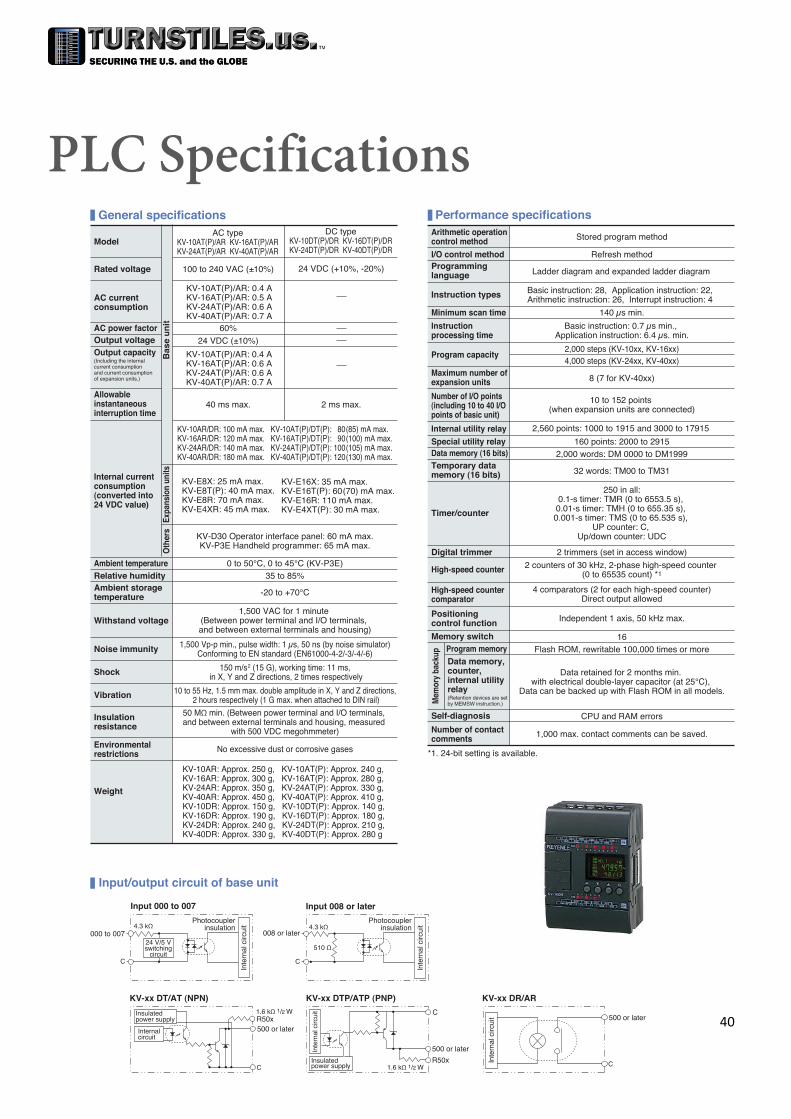
Inte
rnal
circ
uit
Input/output circuit of base unit
PLC Specifications
Rated voltage 100 to 240 VAC (±10%) 24 VDC (+10%, -20%)
AC current consumption
KV-10AT(P)/AR: 0.4 AKV-16AT(P)/AR: 0.5 AKV-24AT(P)/AR: 0.6 AKV-40AT(P)/AR: 0.7 A
AC typeKV-10AT(P)/AR KV-16AT(P)/ARKV-24AT(P)/AR KV-40AT(P)/AR
DC typeKV-10DT(P)/DR KV-16DT(P)/DRKV-24DT(P)/DR KV-40DT(P)/DR
Bas
e u
nit
Model
General specifications
KV-10AT(P)/AR: 0.4 AKV-16AT(P)/AR: 0.6 AKV-24AT(P)/AR: 0.6 AKV-40AT(P)/AR: 0.7 A
Output capacity (Including the internal current consumption and current consumption of expansion units.)
AC power factor 60%Output voltage 24 VDC (±10%)
Allowable instantaneous interruption time
40 ms max. 2 ms max.
Internal current consumption (converted into 24 VDC value)
KV-10AR/DR: 100 mA max. KV-10AT(P)/DT(P): 80(85) mA max.KV-16AR/DR: 120 mA max. KV-16AT(P)/DT(P): 90(100) mA max.KV-24AR/DR: 140 mA max. KV-24AT(P)/DT(P): 100(105) mA max.KV-40AR/DR: 180 mA max. KV-40AT(P)/DT(P): 120(130) mA max.
KV-E8X: 25 mA max.KV-E8T(P): 40 mA max.KV-E8R: 70 mA max.KV-E4XR: 45 mA max.
KV-E16X: 35 mA max.KV-E16T(P): 60(70) mA max.KV-E16R: 110 mA max.KV-E4XT(P): 30 mA max.
Expa
nsio
n un
its
Ambient storage temperature -20 to +70°C
Relative humidity 35 to 85%0 to 50°C, 0 to 45°C (KV-P3E)Ambient temperature
KV-D30 Operator interface panel: 60 mA max.KV-P3E Handheld programmer: 65 mA max.
Oth
ers
Noise immunity 1,500 Vp-p min., pulse width: 1 μs, 50 ns (by noise simulator)Conforming to EN standard (EN61000-4-2/-3/-4/-6)
1,500 VAC for 1 minute (Between power terminal and I/O terminals, and between external terminals and housing)
Withstand voltage
150 m/s2 (15 G), working time: 11 ms, in X, Y and Z directions, 2 times respectivelyShock
10 to 55 Hz, 1.5 mm max. double amplitude in X, Y and Z directions, 2 hours respectively (1 G max. when attached to DIN rail)Vibration
Insulation resistance
50 MΩ min. (Between power terminal and I/O terminals, and between external terminals and housing, measured
with 500 VDC megohmmeter)
Environmental restrictions No excessive dust or corrosive gases
KV-10AR: Approx. 250 g, KV-10AT(P): Approx. 240 g, KV-16AR: Approx. 300 g, KV-16AT(P): Approx. 280 g, KV-24AR: Approx. 350 g, KV-24AT(P): Approx. 330 g, KV-40AR: Approx. 450 g, KV-40AT(P): Approx. 410 g, KV-10DR: Approx. 150 g, KV-10DT(P): Approx. 140 g, KV-16DR: Approx. 190 g, KV-16DT(P): Approx. 180 g, KV-24DR: Approx. 240 g, KV-24DT(P): Approx. 210 g, KV-40DR: Approx. 330 g, KV-40DT(P): Approx. 280 g
Weight
Performance specificationsArithmetic operation control method Stored program method
Programming language Ladder diagram and expanded ladder diagram
I/O control method Refresh method
Basic instruction: 28, Application instruction: 22, Arithmetic instruction: 26, Interrupt instruction: 4Instruction types
Minimum scan time 140 μs min.
Instruction processing time
Basic instruction: 0.7 μs min., Application instruction: 6.4 μs. min.
Program capacity4,000 steps (KV-24xx, KV-40xx)2,000 steps (KV-10xx, KV-16xx)
8 (7 for KV-40xx)Maximum number of expansion units
Number of I/O points (including 10 to 40 I/O points of basic unit)
10 to 152 points (when expansion units are connected)
Internal utility relay 2,560 points: 1000 to 1915 and 3000 to 17915
Special utility relay 160 points: 2000 to 29152,000 words: DM 0000 to DM1999Data memory (16 bits)
Temporary data memory (16 bits) 32 words: TM00 to TM31
Timer/counter
250 in all:0.1-s timer: TMR (0 to 6553.5 s),
0.01-s timer: TMH (0 to 655.35 s), 0.001-s timer: TMS (0 to 65.535 s),
UP counter: C, Up/down counter: UDC
Digital trimmer 2 trimmers (set in access window)
High-speed counter 2 counters of 30 kHz, 2-phase high-speed counter (0 to 65535 count) *1
High-speed counter comparator
4 comparators (2 for each high-speed counter)Direct output allowed
Positioning control function Independent 1 axis, 50 kHz max.
Memory switch 16
Mem
ory
back
up
Program memory Flash ROM, rewritable 100,000 times or moreData memory, counter, internal utility relay(Retention devices are set by MEMSW instruction.)
Data retained for 2 months min. with electrical double-layer capacitor (at 25°C),
Data can be backed up with Flash ROM in all models.
Self-diagnosis
*1. 24-bit setting is available.
Number of contact comments
CPU and RAM errors
1,000 max. contact comments can be saved.
C
500 or later
KV-xx DR/AR
Inte
rnal
circ
uit
C
500 or later
R50x1.6 kΩ 1/2 W
40

Input specifications of base unit
Input/output specifications of expansion unit
Output specifications of basic unitKV-16xx KV-24xx KV-40xxModel
*1. Inputs 000 to 007 can be changed to 5 V input.
Input common COM is connected internally.
High-speed counter input response 30 kHz (24V±10%)
10 µs (Typical)Interrupt input response
Input time constant
10 ms (Typical)10 µs when HSP instruction is usedVariable in 7 steps from 10 µs to
10 ms while special utility relay 2813 is ON (Set by DM1940)
24 VDC, 5.3 mA/5 VDC, 1.0 mAInput voltage *1
26.4 VDCMaximum input rating
No. of inputs 10KV-10xx
6 16 24
8 16 4
86 16 6 8 16Model KV-16xT(P)
4
KV-10xT(P) KV-24xT(P) KV-40xT(P) KV-16xR4
KV-10xR KV-24xR KV-40xRNo. of outputs
Built-in serial resistance 1.6 kΩ 1/2W (R500 to R502)
Output frequency 50 kHz (500 to 502)Relay replacement Not allowed
Relay service life
Electrical service life: 100,000 times or more (20 times/min)
Mechanical service life: 20-million times or more
0.2 A (500 to 502)1 A (Other)
5 APeak load current
1 common Each common terminal is independent.Output commonOutput type Relay outputTransistor output (NPN or PNP)
Rated load250 VAC/30 VDC
2 A (Inductive load)4 A (Resistive load)
30 VDC0.3 A (503 and other)
0.1 A (500 to 502)
Input/output Input Output Input/output
External connection method Terminal block
KV-E8X KV-E8T(P) KV-E16T(P) KV-E8R KV-E16R KV-E4XT(P)/RKV-E16XModelNumber of inputsInput common 4 points/common 4 points/common
Maximum input rating 26.4 VDC 26.4 VDC
Input voltage 24 VDC, 5.3 mA 24 VDC, 5.3 mAMinimum ON voltage 19 V 19 V
Maximum OFF current 2 mA 2 mA
Input impedance 4.3 kΩ 4.3 kΩ
Input time constant (Changed in two steps by special utility relays 2609 to 2612)
For both rising (OFF ON) and falling (ON OFF) operations,
10 ms: 10 ms±20%, 10 µs: 10 µs±20%
For both rising (OFF ON) and falling (ON OFF) operations,
10 ms: 10 ms±20%, 10 µs: 10 µs±20%
Number of outputs 8 16 8 416NPN (PNP) Transistor Relay NPN (PNP) Transistor/RelayOutput type
Output common COM is connected internally. 4 points/common 4 points/common
30 VDC/, 250 VAC/30 VDC, 2 A (Inductive load), 4 A (Resistive load)
250 VAC/30 VDC, 2 A (Inductive load), 4 A (Resistive load)
30 VDCRated load voltage
Rated output current 0.5 (0.3) A/point 0.5 A/point/, 2 A/point (Inductive load),
4 A (Resistive load), 4 A/common2 A/point (Inductive load),
4 A/point (Resistive load), 4 A/common
50 mΩ or less / 50 mΩ or lessON resistance
100 µA max. 100 µA max./Leakage current at OFF
0.8 V max. 0.8 V max./ Residual voltage at ON
250 µs max./10 ms max.10 ms max.250 µs max.Falling operation time (ON OFF)
Rising operation time (OFF ON) 50 µs max. 10 ms max. 50 µs max./10 ms max.
Electrical: 100,000 times or more (20 times/min),
Mechanical: 20-million times or more
Electrical: 100,000 times or more (20 times/min),
Mechanical: 20-million times or moreRelay service life
/Not allowedNot allowedRelay replacementWeight Approx. 100 g/Approx. 120 gApprox. 100 g Approx. 130 g Approx. 100 g Approx. 130 g Approx. 130 g Approx. 190 g
X0
C
510 Ω
4.3 kΩ
Y0
C
Input/output circuit of expansion unit
Input
Photocouplerinsulation
Inte
rnal
circ
uit
Insulated power supply
Internal circuit
Output (NPN Transistor) Output (PNP Transistor)
Y0
C
Inte
rnal
circ
uit
Output (Relay)
Insulated power supply
Inte
rnal
circ
uit C
Y0
41
Copyright © 2022 FDOKUMEN