HPE UEFI System Utilities User Guide for HPE ProLiant Gen9 ...
115
HPE UEFI System Utilities User Guide for HPE ProLiant Gen9 Servers Abstract This guide details how to access and use the Unified Extensible Firmware Interface (UEFI) that is embedded in the system ROM of all UEFI-based ProLiant Gen9 servers. It details how to access and use both UEFI and Legacy BIOS options provided in BIOS/Platform Configuration menus that were formerly known as the ROM-Based Setup Utility (RBSU). All options and available responses are defined. This document is for the person who installs, administers, and troubleshoots servers and storage systems. Part Number: 794200-005 Published: April 2016 Edition: 1
-
Upload
khangminh22 -
Category
Documents
-
view
1 -
download
0
Transcript of HPE UEFI System Utilities User Guide for HPE ProLiant Gen9 ...

HPE UEFI System Utilities User Guidefor HPE ProLiant Gen9 Servers
AbstractThis guide details how to access and use the Unified Extensible Firmware Interface (UEFI) that is embedded in the systemROM of all UEFI-based ProLiant Gen9 servers. It details how to access and use both UEFI and Legacy BIOS options providedin BIOS/Platform Configuration menus that were formerly known as the ROM-Based Setup Utility (RBSU). All options andavailable responses are defined. This document is for the person who installs, administers, and troubleshoots servers andstorage systems.
Part Number: 794200-005Published: April 2016Edition: 1

© Copyright 2014, 2016 Hewlett Packard Enterprise Development LP
The information contained herein is subject to change without notice. The only warranties for Hewlett Packard Enterprise products and servicesare set forth in the express warranty statements accompanying such products and services. Nothing herein should be construed as constitutingan additional warranty. Hewlett Packard Enterprise shall not be liable for technical or editorial errors or omissions contained herein.
Confidential computer software. Valid license from Hewlett Packard Enterprise required for possession, use, or copying. Consistent with FAR12.211 and 12.212, Commercial Computer Software, Computer Software Documentation, and Technical Data for Commercial Items are licensedto the U.S. Government under vendor's standard commercial license.
Acknowledgments
Linux® is a U.S. registered trademark of Linus Torvalds.
Intel®, Itanium®, Pentium®, Intel Inside®, and the Intel Inside logo are trademarks of Intel Corporation in the United States and other countries.
Microsoft® and Windows® are either registered trademarks or trademarks of Microsoft Corporation in the United States and/or other countries.
® is a registered trademark of the UEFI Forum, Inc.

ContentsI Getting started....................................................................................................11
1 Introduction....................................................................................................12What is UEFI?...............................................................................................................................12
2 UEFI System Utilities overview.....................................................................13Launching the System Utilities .....................................................................................................13Navigating the System Utilities .....................................................................................................13
System Utilities key functions...................................................................................................13When a reboot is required.............................................................................................................14System Utilities menu overview.....................................................................................................14Common setup and configuration FAQs.......................................................................................15Updating firmware or system ROM...............................................................................................16
Updating firmware from the System Utilities............................................................................16II System Utilities main menu options..................................................................18
3 System Configuration....................................................................................19System Configuration menu options.............................................................................................19BIOS/Platform Configuration (RBSU)............................................................................................19Using the iLO 4 Configuration Utility.............................................................................................19
iLO 4 Configuration Utility options............................................................................................19Network Options.......................................................................................................................20Configuring Network Options...................................................................................................20Advanced Network Options......................................................................................................21Configuring Advanced Network Options..................................................................................21User Management....................................................................................................................21Add User..................................................................................................................................21Adding new user accounts.......................................................................................................22Edit/Remove User....................................................................................................................22Editing or removing user accounts...........................................................................................22Setting Options.........................................................................................................................23Configuring access settings.....................................................................................................23Set to factory defaults..............................................................................................................23Resetting iLO to the factory default settings ...........................................................................24Reset iLO.................................................................................................................................24Resetting iLO active connections.............................................................................................24About........................................................................................................................................25Viewing information about iLO.................................................................................................25
Embedded device information.......................................................................................................25Smart Array Controller information...........................................................................................25Viewing and configuring Smart Array Controller information...................................................25NIC and FCoE information.......................................................................................................26Viewing and configuring NIC and FCoE settings.....................................................................26NPAR configuration..................................................................................................................26Enabling NPAR on a NIC.........................................................................................................26
4 One-Time Boot Menu....................................................................................27One-Time Boot Menu options........................................................................................................27Selecting an option for a one-time boot.........................................................................................27
5 Embedded Applications.................................................................................28Embedded Applications options....................................................................................................28Embedded UEFI Shell...................................................................................................................28Launching the Embedded UEFI Shell...........................................................................................28
Contents 3

Integrated Management Log (IML)................................................................................................28Viewing or clearing the IML...........................................................................................................29Active Health System Log.............................................................................................................29Downloading an AHS log...............................................................................................................29Firmware Update...........................................................................................................................29Embedded Diagnostics..................................................................................................................30Launching Embedded Diagnostics................................................................................................30Intelligent Provisioning...................................................................................................................30Launching Intelligent Provisioning.................................................................................................30
6 System Information and System Health........................................................31System Information........................................................................................................................31Viewing System Information..........................................................................................................32System Health...............................................................................................................................32Viewing System Health..................................................................................................................32
7 Rebooting the system and selecting a language..........................................33Rebooting the system....................................................................................................................33
Exit and resume system boot...................................................................................................33Exiting and resuming system boot...........................................................................................33Reboot the System...................................................................................................................33Rebooting the system..............................................................................................................33
Selecting a language.....................................................................................................................33Select Language......................................................................................................................33Selecting a system language...................................................................................................33
III BIOS/Platform Configuration options...............................................................348 Configuring System Options..........................................................................35
System Options.............................................................................................................................35Serial Port Options........................................................................................................................35
Embedded Serial Port..............................................................................................................35Assigning an Embedded Serial Port........................................................................................35Virtual Serial Port.....................................................................................................................35Assigning a Virtual Serial Port..................................................................................................35
USB Options..................................................................................................................................36USB Control.............................................................................................................................36Setting USB Control.................................................................................................................36USB Boot Support....................................................................................................................36Setting USB Boot Support........................................................................................................36Removable Flash Media Boot Sequence.................................................................................37Selecting the Removable Flash Media Boot Sequence...........................................................37Virtual Install Disk.....................................................................................................................37Enabling or disabling the Virtual Install Disk............................................................................37
Embedded User Partition..............................................................................................................37Enabling or disabling the Embedded User Partition.................................................................37Internal SD Card Slot...............................................................................................................38Enabling or disabling the Internal SD Card Slot.......................................................................38USB 3.0 Mode..........................................................................................................................38Setting the USB 3.0 Mode........................................................................................................38
Processor Options.........................................................................................................................39Intel (R) Hyperthreading Options.............................................................................................39Enabling or disabling Intel Hyperthreading..............................................................................39Processor Core Disable...........................................................................................................39Setting the number of enabled processor cores .....................................................................39Processor x2APIC Support......................................................................................................39Enabling or disabling Processor x2APIC Support....................................................................40
4 Contents

SATA Controller Options................................................................................................................40Embedded SATA Configuration................................................................................................40Enabling embedded chipset SATA controller support..............................................................40SATA Secure Erase..................................................................................................................41Enabling SATA Secure Erase...................................................................................................41
Virtualization Options.....................................................................................................................41Virtualization Technology..........................................................................................................41Enabling or disabling Virtualization Technology.......................................................................41Intel (R) VT-d............................................................................................................................41Enabling or disabling Intel VT-d...............................................................................................42SR-IOV.....................................................................................................................................42Enabling or disabling SR-IOV..................................................................................................42
Boot Time Optimization.................................................................................................................42Dynamic Power Capping Functionality....................................................................................42Setting Dynamic Power Capping Functionality........................................................................42Extended Memory Test............................................................................................................43Enabling or disabling Extended Memory Test..........................................................................43Memory Fast Training..............................................................................................................43Enabling or disabling Memory Fast Training............................................................................43
Memory Operations—Advanced Memory Protection....................................................................43Configuring Advanced Memory Protection....................................................................................44
9 Configuring Boot Options..............................................................................45Boot Options..................................................................................................................................45Boot Mode.....................................................................................................................................45Selecting the boot mode................................................................................................................45UEFI Optimized Boot.....................................................................................................................45Enabling or disabling UEFI Optimized Boot..................................................................................46Boot Order Policy..........................................................................................................................46Setting the boot order policy..........................................................................................................46UEFI Boot Order............................................................................................................................46Changing the UEFI boot order.......................................................................................................46Advanced UEFI Boot Maintenance...............................................................................................47
Add Boot Option.......................................................................................................................47Adding a boot option to the UEFI Boot Order list.....................................................................47Delete Boot Option...................................................................................................................47Deleting boot options from the UEFI Boot Order list................................................................47
Legacy BIOS Boot Order...............................................................................................................47Changing the Legacy BIOS boot order.........................................................................................47
10 Configuring Network Options......................................................................49Network Options............................................................................................................................49Network Boot Options....................................................................................................................49
UEFI PXE Boot Policy..............................................................................................................49Setting the UEFI PXE Boot Policy............................................................................................49IPv6 DHCP Unique Identifier....................................................................................................50Setting the IPv6 DHCP Unique Identifier method....................................................................50Network Boot Retry Support....................................................................................................50Enabling or disabling Network Boot Retry Support..................................................................50Network Interface Cards (NICs)...............................................................................................50Enabling or disabling network boot for a NIC...........................................................................50PCIe Slot Network Boot...........................................................................................................51Enabling or disabling PCIe Slot Network Boot.........................................................................51
Pre-Boot Network Settings............................................................................................................51Configuring Pre-Boot Network Settings.........................................................................................52iSCSI Boot Configuration...............................................................................................................52
Contents 5

iSCSI Initiator Name.................................................................................................................53Adding an iSCSI initiator name................................................................................................53Add an iSCSI Boot Attempt......................................................................................................53Adding an iSCSI boot attempt..................................................................................................53Delete iSCSI Boot Attempts.....................................................................................................54Deleting iSCSI boot attempts...................................................................................................54iSCSI Attempts.........................................................................................................................54Viewing and modifying iSCSI boot attempt details...................................................................54
VLAN Configuration.......................................................................................................................54Configuring VLAN Configuration...................................................................................................54
11 Configuring Storage Options.......................................................................56Storage Options.............................................................................................................................56Fibre Channel/FCoE Scan Policy..................................................................................................56Changing the default Fibre Channel/FCoE scanning policy..........................................................56Embedded Storage Boot Policy....................................................................................................56Setting the embedded storage boot policy....................................................................................56PCIe Storage Boot Policy..............................................................................................................57Setting the PCIe storage boot policy.............................................................................................57
12 Configuring the Embedded UEFI Shell.......................................................58Embedded UEFI Shell options......................................................................................................58Embedded UEFI Shell...................................................................................................................58Enabling or disabling the Embedded UEFI Shell..........................................................................58Add Embedded UEFI Shell to Boot Order.....................................................................................58Adding the Embedded UEFI Shell to the UEFI Boot Order list.....................................................58UEFI Shell Script Auto-Start..........................................................................................................59Enabling or disabling automatic execution of the Embedded UEFI Shell startup script................59Shell Auto-Start Script Location.....................................................................................................59Setting the Embedded UEFI Shell startup script location..............................................................60Network Location for Shell Auto-Start Script.................................................................................60Setting the network location for the Shell auto-start script............................................................60
13 Configuring Power Management.................................................................61Power Management options..........................................................................................................61Power Profile.................................................................................................................................61Setting a power profile...................................................................................................................61Power Regulator............................................................................................................................61Setting the Power Regulator mode...............................................................................................61Minimum Processor Idle Power Core C-State...............................................................................62Setting the minimum processor idle power core C-State..............................................................62Minimum Processor Idle Power Package C-State........................................................................62Minimum Processor Idle Power Package C-State........................................................................63Advanced Power Options..............................................................................................................63
Intel QPI Link Power Management..........................................................................................63Enabling or disabling Intel QPI Link Power Management........................................................63Intel QPI Link Frequency..........................................................................................................64Setting the Intel QPI link frequency..........................................................................................64Energy/Performance Bias........................................................................................................64Setting the Energy/Performance Bias......................................................................................64Maximum Memory Bus Frequency..........................................................................................64Setting the maximum memory bus frequency..........................................................................65Channel Interleaving................................................................................................................65Enabling or disabling channel interleaving...............................................................................65Maximum PCI Express Speed.................................................................................................65Setting the maximum PCI-express speed................................................................................66
6 Contents

Dynamic Power Savings Mode Response...............................................................................66Setting the dynamic power savings mode response speed.....................................................66Collaborative Power Control....................................................................................................66Enabling or disabling collaborative power control....................................................................67Redundant Power Supply Mode..............................................................................................67Setting the redundant power supply mode...............................................................................67Intel DMI Link Frequency.........................................................................................................67Intel DMI Link Frequency.........................................................................................................68
14 Configuring Performance Options...............................................................69Performance Options.....................................................................................................................69Accessing Performance Options...................................................................................................69Intel (R) Turbo Boost Technology..................................................................................................69Enabling or disabling Intel Turbo Boost Technology......................................................................69ACPI SLIT Preferences.................................................................................................................69Enabling or disabling ACPI SLIT preferences...............................................................................69Advanced Performance Tuning Options........................................................................................69
Node Interleaving.....................................................................................................................70Enabling or disabling node interleaving...................................................................................70Intel NIC DMA Channels (IOAT)...............................................................................................70Enabling or disabling DMA acceleration on Intel NICs.............................................................70HW Prefetcher..........................................................................................................................70Enabling or disabling the Intel prefetch function......................................................................71Adjacent Sector Prefetcher......................................................................................................71Enabling or disabling the adjacent sector prefetch function.....................................................71DCU Stream Prefetcher...........................................................................................................71Enabling or disabling the DCU stream prefetch function.........................................................71DCU IP Prefetcher....................................................................................................................72Enabling or disabling the DCU IP stream prefetch function.....................................................72QPI Snoop Configuration.........................................................................................................72Setting the QPI snoop configuration........................................................................................72QPI Bandwidth Optimization (RTID).........................................................................................72Setting QPI Bandwidth Optimization (RTID)............................................................................72Memory Proximity Reporting for I/O.........................................................................................73Enabling or disabling Memory Proximity Reporting for I/O......................................................73I/O Non-posted Prefetching......................................................................................................73Enabling or disabling I/O Non-posted Prefetching...................................................................73NUMA Group Size Optimization...............................................................................................73Setting NUMA Group Size Optimization..................................................................................73Intel Performance Monitoring Support.....................................................................................74Enabling or disabling Intel Performance Monitoring Support...................................................74
15 Configuring Server Security........................................................................75Server Security options.................................................................................................................75Set Power On Password...............................................................................................................75Setting the power-on password.....................................................................................................75Set Admin Password.....................................................................................................................75Setting an administrator password................................................................................................75One-Time Boot Menu (F11 Prompt)..............................................................................................76Enabling or disabling the One-Time Boot Menu F11 prompt.........................................................76Intelligent Provisioning (F10 Prompt)............................................................................................76Enabling or disabling the Intelligent Provisioning F10 prompt.......................................................76Embedded Diagnostics..................................................................................................................76Setting Embedded Diagnostics to launch from the System Utilities..............................................76Embedded Diagnostics Mode.......................................................................................................77Setting the Embedded Diagnostics viewing mode........................................................................77
Contents 7
No-Execute Protection...................................................................................................................77Enabling or disabling no-execute virus protection.........................................................................77Processor AES-NI Support............................................................................................................77Enabling or disabling processor AES-NI support..........................................................................78Intel (R) TXT Support....................................................................................................................78Enabling or disabling Intel TXT support........................................................................................78Secure Boot...................................................................................................................................78Secure Boot Settings.....................................................................................................................79
Secure Boot Enforcement........................................................................................................79Enabling or disabling Secure Boot...........................................................................................79
Advanced Secure Boot Options....................................................................................................79Platform Key (PK) Options.......................................................................................................80Enroll PK..................................................................................................................................80Enrolling a PK certificate..........................................................................................................80Delete Platform Key (PK).........................................................................................................80Deleting a PK certificate...........................................................................................................80Key Exchange Key (KEK) Options...........................................................................................80Enroll KEK Entry.......................................................................................................................81Enrolling a KEK certificate........................................................................................................81Delete KEK Entry.....................................................................................................................81Deleting a KEK entry................................................................................................................81Allowed Signatures Database (DB) Options............................................................................81Enroll Signature (Allowed DB)..................................................................................................81Enrolling a signature in the Allowed Signatures Database......................................................82Delete Signature (Allowed DB)................................................................................................82Deleting a signature from the Allowed Signatures Database...................................................82Forbidden Signatures Database (DBX) Options......................................................................82Enroll Signature (Forbidden DB)..............................................................................................82Enrolling a signature in the Forbidden Signatures Database...................................................83Delete Signature (Forbidden DB).............................................................................................83Deleting a signature from the Forbidden Signatures Database...............................................83Delete all keys (PK, KEK, DB, DBX)........................................................................................83Deleting all keys ......................................................................................................................83Reset all keys to platform defaults...........................................................................................83Resetting all keys to platform defaults.....................................................................................83
Trusted Platform Module options...................................................................................................84Configuring Trusted Platform Module options...............................................................................84
16 Configuring PCI devices..............................................................................85PCI Device Enable/Disable...........................................................................................................85Enabling or disabling a PCI device................................................................................................85
17 Configuring Server Availability....................................................................86Server Availability options.............................................................................................................86ASR Status....................................................................................................................................86Enabling or disabling ASR.............................................................................................................86ASR Timeout.................................................................................................................................86Setting the ASR timeout................................................................................................................86Wake-On LAN................................................................................................................................87Enabling or disabling Wake-On LAN.............................................................................................87POST F1 Prompt...........................................................................................................................87Setting the POST F1 prompt delay................................................................................................87Power Button Mode.......................................................................................................................88Enabling or disabling momentary power button functionality........................................................88Automatic Power-On.....................................................................................................................88Setting the automatic power-on state............................................................................................88
8 Contents

Power-On Delay............................................................................................................................88Setting the power-on delay............................................................................................................88
18 Configuring BIOS serial console and EMS options.....................................90BIOS Serial Console and EMS options.........................................................................................90BIOS Serial Console Port..............................................................................................................90Configuring the BIOS serial console port......................................................................................90BIOS Serial Console Emulation Mode..........................................................................................90BIOS Serial Console Emulation Mode..........................................................................................91BIOS Serial Console Baud Rate....................................................................................................91Setting the BIOS serial console baud rate....................................................................................91EMS Console.................................................................................................................................91Configuring the EMS console........................................................................................................92
19 Configuring Server Asset Information.........................................................93Server Asset Information options..................................................................................................93Selecting Server Asset Information options..................................................................................93Server Information.........................................................................................................................93Entering server information...........................................................................................................93Administrator Information..............................................................................................................93Entering administrator information................................................................................................93Service Contact Information..........................................................................................................94Entering service contact information.............................................................................................94Custom POST Message ...............................................................................................................94Entering a custom POST message ..............................................................................................94
20 Configuring advanced platform configuration options.................................95Advanced Options.........................................................................................................................95ROM Selection..............................................................................................................................95Selecting a ROM image.................................................................................................................95Video Options................................................................................................................................95Configuring the video display........................................................................................................95Embedded Video Connection........................................................................................................96Configuring an embedded video connection.................................................................................96Fan and Thermal Options..............................................................................................................96Thermal Configuration...................................................................................................................96Setting the thermal configuration...................................................................................................96Thermal Shutdown........................................................................................................................97Enabling or disabling thermal shutdown........................................................................................97Fan Installation Requirements.......................................................................................................97Setting fan installation requirements messaging...........................................................................97Fan Failure Policy..........................................................................................................................97Setting the fan failure policy..........................................................................................................97Extended Ambient Temperature Support......................................................................................98Enabling or disabling higher ambient temperature support...........................................................98Advanced System ROM Options...................................................................................................98
NMI Debug Button....................................................................................................................99Enabling or disabling the NMI debug button............................................................................99PCI Bus Padding Options........................................................................................................99Enabling or disabling PCI Bus padding ...................................................................................99Consistent Device Naming.......................................................................................................99Enabling Consistent Device Naming........................................................................................99Mixed Power Supply Reporting..............................................................................................100Enabling or disabling mixed power supply reporting..............................................................100Serial Number........................................................................................................................100Re-entering a chassis serial number......................................................................................100
Contents 9
Product ID..............................................................................................................................100Re-entering a product ID........................................................................................................100
21 Configuring the date and time and system defaults..................................101Date and Time.............................................................................................................................101
Date and Time........................................................................................................................101Resetting system defaults...........................................................................................................101
System Default Options.........................................................................................................101Restore Default System Settings...........................................................................................101Restoring default system settings..........................................................................................102Restore Default Manufacturing Settings................................................................................102Restoring default manufacturing settings...............................................................................102Default UEFI Device Priority..................................................................................................102Changing the default UEFI device priority..............................................................................103User Default Options..............................................................................................................103Saving or erasing user default options...................................................................................103
22 Using scripted configuration flows.................................................................104Scripted configuration flow................................................................................................................104
Configuration Replication Utility (CONREP)................................................................................104RESTful API support for UEFI.....................................................................................................104HPE Smart Storage Administrator (HPE SSA)............................................................................104
23 Troubleshooting.............................................................................................105Basic troubleshooting techniques.....................................................................................................105Cannot boot devices in UEFI Mode..................................................................................................105Cannot restore system defaults........................................................................................................106Cannot download the file in the network boot URL..........................................................................107Cannot network boot with the downloaded image file .....................................................................108Cannot deploy from the UEFI Shell script.........................................................................................108
24 Support and other resources.........................................................................110Accessing Hewlett Packard Enterprise Support...............................................................................110Accessing updates............................................................................................................................110Related information...........................................................................................................................110Websites...........................................................................................................................................111Customer self repair.........................................................................................................................111Remote support................................................................................................................................111Documentation feedback..................................................................................................................111
Glossary.............................................................................................................112Index...................................................................................................................113
10 Contents

Part I Getting startedThis part introduces the UEFI System Utilities menu-driven interface and its configuration options.

1 IntroductionThe UEFI System Utilities is embedded in the system ROM. The UEFI System Utilities enableyou to perform a wide range of configuration activities, including:
• Configuring system devices and installed options.
• Enabling and disabling system features.
• Displaying system information.
• Selecting the primary boot controller or partition.
• Configuring memory options.
• Launching other pre-boot environments, such as the Embedded UEFI Shell and IntelligentProvisioning.
HPE ProLiant Gen9 servers that are configured for UEFI Boot Mode can provide:• Support for boot partitions larger than 2.2 TB. Such configurations could previously only be
used for boot drives when using RAID solutions such as Smart Array.• Secure Boot that enables the system firmware, option card firmware, operating systems,
and software collaborate to enhance platform security.• An Embedded UEFI Shell that provides a pre-boot environment for running scripts and tools.
• Operating system specific functionality, such as Microsoft Windows 2012, which supportsseveral features only when installed in UEFI mode.
• Boot support for option cards that only support a UEFI option ROM.
What is UEFI?Unified Extensible Firmware Interface (UEFI) defines the interface between the operatingsystem and platform firmware during the boot, or start-up process. Compared to BIOS, UEFIsupports advanced pre-boot user interfaces. The UEFI network stack enables implementationon a richer network-based OS deployment environment while still supporting traditional PXEdeployments. UEFI supports both IPv4 and IPv6 networks. In addition, features such as SecureBoot enable platform vendors to implement an OS-agnostic approach to securing systems in thepre-boot environment.The ROM-Based Setup Utility (RBSU) functionality is available from the UEFI interface alongwith additional configuration options.
12 Introduction

2 UEFI System Utilities overviewLaunching the System Utilities
1. Optional: If you access the server remotely, start an iLO remote console session.a. Open a browser and enter https://<iLO host name or IP address> to log on
to the iLO web interface.b. On the login page, do one of the following:
• Enter a directory or local user account name and password, and click Log In.
• Click the HPE Zero Sign In button.This button is displayed when iLO is configured for Kerberos network authentication.
2. Navigate to the Remote Console→Remote Console page.3. Verify that your system meets the requirements for using the remote console application
you want to use.4. Click the launch button for your selected application.
Alternatively, you can click an Integrated Remote Console link on the Overview page.5. Restart or power on the server.
The server restarts and the ProLiant POST screen appears.6. Press F9.
The System Utilities screen appears.7. Continue Navigating the System Utilities .
Navigating the System Utilities1. Launch the System Utilities and do one of the following.
• To navigate through the screens and modify settings, press any of the navigationalkeys. Key functions are shown at the bottom of every System Utilities screen.
• To access the HPE UEFI System Utilities and Shell Command Mobile Help for HPEProLiant Gen9 Servers, scan the QR code on the bottom of the System Utilities screenwith your mobile device.
2. To exit the System Utilities screen and reboot the server, press Esc until the main menu isdisplayed, and then select one of the following options:• Exit and resume system boot—Exits the system and continues the normal boot process.
The system continues through the boot order list and launches the first bootable optionin the system.
• Reboot the System—Exits the system and reboots the system without continuing thenormal boot process.
The screen displays the booting process, and the ProLiant POST screen appears. Towardthe end of the boot process, the boot options screen is displayed. It is visible for severalseconds before the system attempts to boot from a supported boot device. .
System Utilities key functions• Up or down arrow—Selects a menu option. When selected, the color of a menu option
changes from white to yellow text.• Enter—Selects an entry. A selected option changes color from white to yellow. When a
submenu is available, the submenu appears.• Esc—Returns to the previous screen.
Launching the System Utilities 13

• F1—Displays online help about a selection.
• F7—Loads default UEFI configuration settings and prompts you to:
Press Enter to apply defaults.◦◦ Press Esc to cancel.
• F10—Prompts you to save changed settings.
Press Y to save (apply) settings.◦◦ Press N to discard settings.
◦ Press Esc to exit the confirmation prompt without saving or discarding settings.
When a reboot is requiredFor certain configuration changes to take effect, a reboot might be required. In such cases, aprompt appears on the applicable System Utilities screen that tells you to do so.
System Utilities menu overviewNOTE: UEFI system configuration options vary by Gen9 platform. Therefore, you might notsee some of the options that are documented here.
The System Utilities screen is the main screen in the UEFI menu-driven interface. It displaysmenu options for the following configuration tasks:
• System Configuration—Displays options for viewing and configuring:
BIOS/Platform Configuration (RBSU)◦◦ Using the iLO 4 Configuration Utility
◦ Other system-specific devices, such as installed PCIe cards, NICs and Smart Arrays.For example, Embedded FlexibleLOM Port 1.
NOTE: Throughout the menus, the interface attempts to display the proper marketingname for installed PCI devices. If the interface does not recognize a device, it assignsa generic label to the device, such as a non-HPE name. This generic labeling doesnot affect the functionality or operation of the device. Devices vary based on your system.
• One-Time Boot Menu—Displays options for selecting a boot override option and running aUEFI application from a file system.
• Embedded Applications—Displays options for viewing and configuring:
Embedded UEFI Shell◦◦ Integrated Management Log (IML)
◦ Active Health System Log (AHS)
◦ Firmware Update
◦ Embedded Diagnostics
◦ Intelligent Provisioning
14 UEFI System Utilities overview

• System Information—Displays options for viewing the server name and generation, serialnumber, product ID, BIOS version and date, power management controller, backup BIOSversion and date, system memory, and processors.
• System Health—Displays options for viewing the current health status of all devices in thesystem.
• Exit and resume system boot—Exits the system and continues the normal booting process.
• Reboot the system—Exits the system and reboots it by going through the UEFI Boot Orderlist and launching the first bootable option in the system. For example, you can launch theUEFI Shell, if enabled and listed as the first bootable option in the list.
• Select Language—Enables you to select a language to use in the user interface. English isthe default language.
Common setup and configuration FAQs1 How do I access the UEFI System Utilities?
See “Launching the System Utilities ” (page 13).2 How do I update the firmware or system ROM?
See “Updating firmware or system ROM” (page 16).3 How do I use the Firmware Update application to upgrade the system ROM to the
version included on the USB key already inserted into the server?See “Updating firmware or system ROM” (page 16).
4 How do I transition from RBSU settings to UEFI settings?The BIOS/Platform Configuration (RBSU) menu replaces the ROM-Based Setup Utility(RBSU) on ProLiant Gen9 servers. Use this menu to access and use both UEFI and LegacyBIOS options. See “BIOS/Platform Configuration (RBSU)” (page 19).
5 When would I want to choose Legacy BIOS Mode rather than UEFI Mode as my bootmode, and vice versa?Certain situations might require that you operate in Legacy BIOS Mode, such as bootingcustom OS images that were installed using legacy boot mode or created using a legacyBIOS system.UEFI Mode is enabled by default and is required for certain options, including:• Secure Boot, UEFI Optimized Boot, Generic USB Boot, IPv6 PXE Boot, iSCSI Boot,
and Boot from URL• Fibre Channel/FCoE Scan Policy
• Booting to a hard disk drive larger than 2.2 TB
• Booting the Embedded User Partition.
6 How do I select between Legacy BIOS and UEFI Mode?See “Selecting the boot mode” (page 45).
7 How do I determine if a server has UEFI boot options?See “Boot Options” (page 45).
8 How do I select a boot device?To access the One-Time Boot Menu where you can select an option for a one-time bootoverride, do one of following:• Press F11 during server POST.
• On the System Utilities screen, select One-Time Boot Menu. See One-Time BootMenu options.
To modify the boot order for all boots, see Changing the UEFI boot order, or Changing theLegacy BIOS boot order.
Common setup and configuration FAQs 15

9 How do I enable or disable Intel Hyperthreading?By default, Intel Hyperthreading is enabled. To disable or re-enable this setting, see “Enablingor disabling Intel Hyperthreading” (page 39).
10 How do I configure the Minimum Processor Idle Power Package State to No PackageState?By default, this is set to Package C6 (retention) State, the lowest processor idle power state.To change this setting, see “Minimum Processor Idle Power Package C-State” (page 63).
11 How do I configure the time zone?See “Date and Time” (page 101).
12 How do I save my configuration changes and reboot the system?1. When you are done making changes, if you do not see the prompt Changes are
pending. Do you want to save changes and exit?, press F10 to display it.2. Press Y to save your changes.
A Change saved confirmation prompt appears.
3. Select a reboot option and press Enter:• Exit and resume system boot—Exits the system and continues the normal boot
process. The system continues through the boot order list and launches the firstbootable option in the system.
• Reboot the System—Exits the system and reboots the system without continuingthe normal boot process.
13 How do I enter the Embedded UEFI Shell?See “Launching the Embedded UEFI Shell” (page 28).
14 How do I view the health status of all installed options and devices?See “Viewing System Health” (page 32).
15 How do I use CONREP to replicate UEFI settings?See “Configuration Replication Utility (CONREP)” (page 104).
Updating firmware or system ROMTo update firmware or system ROM, use any of the following methods:
• The Firmware Update option in the System Utilities. See “Updating firmware from the SystemUtilities” (page 16).
• The fwupdate command in the Embedded UEFI Shell.• Service Pack for ProLiant (SPP)
• HPE online flash components
Updating firmware from the System UtilitiesUse this option to update firmware components in the system, including the system BIOS, NICs,and storage cards. Your system can be set to either Legacy BIOS Mode or UEFI Mode.1. Access the System ROM Flash Binary component for your server from the Hewlett Packard
Enterprise Support Center (http://www.hpe.com/support/hpesc). When searching for thecomponent, always select Cross operating system to locate the binary file.
2. Copy the binary file to a USB media or iLO virtual media.3. Attach the media to the server.4. Launch the System Utilities, select Embedded Applications→Firmware Update, and
press Enter.
16 UEFI System Utilities overview

5. Select a device and press Enter.The Firmware Updates screen lists details about your selected device, including the currentfirmware version in use.
6. Select Select Firmware File and press Enter.7. Select the flash file in the File Explorer list and press Enter.
The firmware file is loaded and the Firmware Updates screen lists details of the file in theSelected firmware file field.
8. Select Image Description and press Enter, then select a firmware image and press Enteragain. A device can have multiple firmware images.
9. Select Start firmware update to update the firmware components in the system.
Updating firmware or system ROM 17

Part II System Utilities main menu optionsThe System Utilities main menu is your starting point for:• System Configuration
• One-Time Boot Menu
• Embedded Applications
• System Information
• System Health
• Exit and resume system boot
• Reboot the System
• Select Language

3 System ConfigurationSystem Configuration menu options
• BIOS/Platform Configuration (RBSU)
• iLO 4 Configuration Utility
• Embedded device information
BIOS/Platform Configuration (RBSU)TheBIOS/PlatformConfiguration (RBSU)menu replaces the ROM-Based Setup Utility (RBSU)on ProLiant Gen9 servers. This menu contains many of the nested options for accessing bothUEFI and Legacy BIOS options, including:
• System Options
• Boot Options
• Network Options
• Embedded UEFI Shell options
• Power Management options
• Performance Options
• Server Security options
• PCI Device Enable/Disable
• Server Availability options
• BIOS Serial Console and EMS options
• Server Asset Information options
• Advanced Options
• Date and Time
• System Default Options
Using the iLO 4 Configuration UtilityiLO 4 Configuration Utility options
You can access the iLO 4 Configuration Utility from the physical system console, or by using aniLO 4 remote console session. The utility has the following options:
• Network Options
• Advanced Network Options
• User Management
• Setting Options
• Set to Factory Defaults
• Reset iLO (active connections)
• About
System Configuration menu options 19

Network Options• MAC Address (read-only)—The MAC address of the selected iLO network interface.
• Network Interface Adapter—Specifies the iLO network interface adapter to use.
ON—Uses the iLO Dedicated Network Port.◦◦ Shared Network Port—Uses the Shared Network Port. This option is only available
on supported servers.
◦ OFF—Disables all network interfaces to iLO.
• Transceiver SpeedAutoselect (iLO Dedicated Network Port only)—Enables iLO to negotiatethe highest supported link speed and duplex settings when connected to the network. Thisoption is only available when Network Interface Adapter is set to ON.
• Transceiver SpeedManual Setting (iLO Dedicated Network Port only)—Sets the link speedfor the iLO network interface. This option is only available whenNetwork Interface Adapteris set to ON and Transceiver Speed Autoselect is set to OFF.
• Transceiver Duplex Setting (iLO Dedicated Network Port only)—Sets the link duplex settingfor the iLO network interface. This option is only available whenNetwork Interface Adapteris set to ON and Transceiver Speed Autoselect is set to OFF.
• VLAN Enable (Shared Network Port only)—Enables the VLAN feature.When the Shared Network Port is active and VLAN is enabled, the iLO Shared Network Portbecomes part of a VLAN. All network devices with different VLAN tags will appear to be onseparate LANs, even if they are physically connected to the same LAN. This option is onlyavailable when Network Interface Adapter is set to Shared Network Port.
• VLAN ID (Shared Network Port only)—When a VLAN is enabled, specifies a VLAN tag. Allnetwork devices that you want to communicate with each other must have the same VLANtag. The VLAN tag can be any number between 1 and 4094. This option is only availablewhen Network Interface Adapter is set to Shared Network Port.
• DHCP Enable—Configures iLO to obtain its IP address (and many other settings) from aDHCP server.
• DNS Name—Sets the DNS name of the iLO subsystem (for example, ilo instead ofilo.example.com).This name can only be used if DHCP and DNS are configured to connect to the iLOsubsystem name instead of the IP address.
• IP Address—The iLO IP address. If DHCP is used, the iLO IP address is suppliedautomatically. If DHCP is not used, enter a static IP address.
• Subnet Mask—The subnet mask of the iLO IP network. If DHCP is used, the subnet maskis supplied automatically. If DHCP is not used, enter a subnet mask for the network.
• Gateway IP Address—The iLO gateway IP address. If DHCP is used, the iLO gateway IPaddress is supplied automatically. If DHCP is not used, enter the iLO gateway IP address.
Configuring Network Options1. From the System Utilities screen, select System Configuration→iLO 4 Configuration
Utility→Network Options, and press Enter.2. Select any of the Network Options and press Enter, then select a setting or enter a value
for that option and press Enter again.3. Press F10.
20 System Configuration

Advanced Network Options• Gateway from DHCP—Specifies whether iLO uses a DHCP server-supplied gateway.
• Gateway #1, Gateway #2, and Gateway #3—If Gateway from DHCP is disabled, specifiesup to three iLO gateway IP addresses.
• DHCP Routes—Specifies whether iLO uses the DHCP server-supplied static routes.
• Route 1, Route 2, and Route 3—If DHCP Routes is disabled, specifies the iLO static routedestination, mask, and gateway addresses.
• DNS from DHCP—Specifies whether iLO uses the DHCP server-supplied DNS server list.
• DNS Server 1, DNS Server 2, DNS Server 3—If DNS from DHCP is disabled, specifiesthe primary, secondary, and tertiary DNS servers.
• WINS from DHCP—Specifies whether iLO uses the DHCP server-supplied WINS serverlist.
• Register with WINS Server—Specifies whether iLO registers its name with a WINS server.
• WINS Server #1 and WINS Server #2—If WINS from DHCP is disabled, specifies theprimary and secondary WINS servers.
• Domain Name—The iLO domain name. If DHCP is not used, specifies a domain name.
Configuring Advanced Network Options1. From the System Utilities screen, select System Configuration→iLO 4 Configuration
Utility→Advanced Network Options, and press Enter.2. Select any of the Advanced Network Options and press Enter, then select a setting or enter
a value for that option and press Enter again.3. Press F10.
User Management• Add User
• Edit/Remove User
Add UserUse this option to add new local iLO user accounts, including:
New User iLO 4 Privileges
• Administer User Accounts—Enables a user to add, edit, and delete local iLO user accounts.A user with this privilege can change privileges for all users. If you do not have this privilege,you can view your own settings and change your own password.
• Remote Console Access—Enables a user to remotely access the host system RemoteConsole, including video, keyboard, and mouse control.
• Virtual Power and Reset—Enables a user to power-cycle or reset the host system. Theseactivities interrupt the system availability. A user with this privilege can diagnose the systemby using the Generate NMI to System button.
• Virtual Media—Enables a user to use the Virtual Media feature on the host system.
• Configure Settings—Enables a user to configure most iLO settings, including securitysettings, and to remotely update the iLO firmware. This privilege does not enable local useraccount administration.
Using the iLO 4 Configuration Utility 21

New User Information
• New User Name—Specifies the name that appears in the user list on the UserAdministration page. It does not have to be the same as the Login Name. The maximumlength for a user name is 39 characters. The user name must use printable characters.Assigning descriptive user names can help you to easily identify the owner of each loginname.
• Login Name—Specifies the name that must be used when logging in to iLO. It appears inthe user list on the User Administration page, on the iLO Overview page, and in iLO logs.The Login Name does not have to be the same as the User Name. The maximum lengthfor a login name is 39 characters. The login name must use printable characters.
• Password and Password Confirm—Sets and confirms the password that is used for loggingin to iLO. The maximum length for a password is 39 characters. Enter the password twicefor verification.
Adding new user accounts1. From the System Utilities screen, select System Configuration→iLO 4 Configuration
Utility→User Management→Add User, and press Enter.2. Select any of the New User iLO 4 Privileges and press Enter.3. For each option, select one of the following settings and press Enter again.
• YES (default)—Enables the privilege for this user.
• NO—Disables the privilege for this user.4. Select a New User Information entry and press Enter.5. Complete each entry for the new user, and press Enter.6. Create as many user accounts as needed, and then press F10.
Edit/Remove UserUse this option to edit iLO user account settings, or to delete user accounts.
Editing or removing user accounts1. From the System Utilities screen, select System Configuration→iLO 4 Configuration
Utility→User Management→Edit/Remove User, and press Enter.2. Select the Action menu for the user name you want to edit or delete, and press Enter.3. Select one of the following, and press Enter.
• No Change—Returns you to the main menu.
• Delete—Deletes this user.
• Edit—Edits the user.4. Depending on your selection in Step 3Step 6, do one of the following:
• If you selected No Change, no further action is needed.
• If you selected Delete, the user name is marked to be deleted when you save thechanges on this page.
• If you selected Edit, update the login name, password, or user permissions.5. Update as many user accounts as needed, and then press F10.
22 System Configuration

Setting OptionsUse this menu to view and configure iLO access settings.
• iLO 4 Functionality—Enables or disables the iLO 4 features. The iLO network andcommunications with operating system drivers are terminated when iLO functionality isdisabled.
NOTE: The iLO functionality cannot be disabled on blade servers.
• iLO 4 Configuration Utility—Enables or disables the iLO 4 Configuration Utility. If thisoption is set to Disabled, the iLO 4 Configuration Utility menu item is not available whenyou access the UEFI System Utilities.
• Require Login for iLO 4 Configuration—Determines whether a user-credential prompt isdisplayed when a user accesses the iLO 4 Configuration Utility. If this setting is Enabled, alogin dialog box opens when you access the iLO 4 Configuration Utility.
• Show iLO 4 IP Address during POST—Enables the display of the iLO network IP addressduring host server POST.
• Local Users—Enables or disables local user account access.
• Serial CLI Status—Specifies the login model of the CLI feature through the serial port. Thefollowing settings are valid:
◦ Enabled-Authentication Required—Enables access to the iLO CLP from a terminalconnected to the host serial port. Valid iLO user credentials are required.
◦ Enabled-NoAuthentication Required—Enables access to the iLO CLP from a terminalconnected to the host serial port. iLO user credentials are not required.
◦ Disabled—Disables access to the iLO CLP from the host serial port. Use this option ifyou are planning to use physical serial devices.
• Serial CLI Speed (bits/second)—Specifies the speed of the serial port for the CLI feature.The following speeds (in bits per second) are valid: 9600, 19200, 57600, and 115200. Forcorrect operation, set the serial port configuration to no parity, 8 data bits, and 1 stop bit(N/8/1).
NOTE: The 38400 speed is supported in the iLO web interface, but is not currentlysupported by the iLO 4 Configuration Utility.
Configuring access settings1. From the System Utilities screen, select System Configuration→iLO 4 Configuration
Utility→Setting Options, and press Enter.2. View or update user access Setting Options.3. Press F10.
Set to factory defaults
CAUTION: This operation clears all user and license data.
Use this option to reset iLO to the factory default settings. When you do so, you cannot accessthe iLO 4 Configuration Utility until after the next system reboot. If you are managing iLO remotely,the remote console session is automatically ended.
Using the iLO 4 Configuration Utility 23

NOTE: If a server has an installed iLO Advanced license when you perform this procedure,the iLO Advanced icon might be selected when the server boot process finishes. The icon willbe set correctly after POST completes, or after the server is shut down, powered off, and thenpowered on again.
Resetting iLO to the factory default settings1. From the System Utilities screen, select System Configuration→iLO 4 Configuration
Utility→Set to factory defaults, and press Enter.The iLO 4 Configuration Utility prompts you to select YES or NO.
2. Select YES, and press Enter.3. When prompted to confirm the reset, press Enter.
iLO resets to the factory default settings. If you are managing iLO remotely, the remoteconsole session is automatically ended.
4. Resume the boot process:a. Optional: If you are managing iLO remotely, wait for the iLO reset to finish, and then
start the iLO remote console.The iLO 4 Configuration Utility screen is still open from the previous session.
b. Press Esc until the main menu is displayed.c. Select Exit and Resume Boot in the main menu, and press Enter.d. When prompted to confirm the request, press Enter to exit the screen and resume the
boot process.
Reset iLOIf iLO is slow to respond, you can use this option to perform a reset.Resetting iLO with this method does not make any configuration changes, but it ends all activeconnections to iLO. When you reset iLO, the iLO 4 Configuration Utility is not available againuntil the next reboot.
Resetting iLO active connections
PrerequisiteConfigure iLO Settings privilege
To reset iLO active connections:1. From the System Utilities screen, select System Configuration→iLO 4 Configuration
Utility→Reset iLO.The iLO 4 Configuration Utility prompts you to select YES or NO.
2. Select YES, and press Enter.3. When prompted to confirm the reset, press Enter.
Active iLO connections are reset. If you are managing iLO remotely, the remote consolesession is automatically ended.
24 System Configuration

4. Resume the boot process:a. Optional: If you are managing iLO remotely, wait for the iLO reset to finish, and then
start the iLO remote console.The UEFI System Utilities are still open from the previous session.
b. Press Esc until the main menu is displayed.c. Select Exit and Resume Boot in the main menu, and press Enter.d. When prompted to confirm the request, press Enter to exit the utility and resume the
normal boot process.
AboutUse this menu to view information about the following iLO components.
• Firmware Date—The iLO firmware revision date.
• Firmware Version—The iLO firmware version.
• iLO CPLD Version—The iLO complex programmable logic device version.
• Host CPLD Version—The ProLiant server complex programmable logic device version.
• Serial Number—The iLO serial number.
• RBSU Date—The iLO 4 Configuration Utility revision date.
• PCI BUS—The PCI bus to which the iLO processer is attached.
• Device—The device number assigned to iLO in the PCI bus.
Viewing information about iLO1. From the System Utilities screen, select System Configuration→iLO 4 Configuration
Utility→About, and press Enter.2. View information about iLO components.
Embedded device informationSmart Array Controller information
The System Configuration screens show device information about installed Smart ArrayControllers. HPE 12 Gb/s capable SAS Smart Array controllers (for example, the Smart ArrayP44ar controller) support UEFI-based servers.
NOTE: Install only Smart Array Controllers that are listed as supported for your server andthat are running the latest versions of Smart Array Controller firmware. Other Smart Arraycontrollers are not supported and might not function properly in this server. Before installing theoperating system, use the latest SPP in Offline mode to upgrade the firmware to the latest version.Supported controllers not using the proper firmware display as an unknown device in the systemconfiguration.
Viewing and configuring Smart Array Controller information1. From the System Utilities screen, select System Configuration and press Enter.2. Select a Smart Array controller and press Enter.
The System Configuration screen displays information about the embedded device.
Embedded device information 25

3. Select an option and press Enter. Options include:• Device Information—Lists firmware version, firmware release date, UEFI driver version,
PCI device ID, and PCI slot number.• Exit and launch HP Smart Storage Administrator (HPSSA)—Accesses options for
HPSSA, including configuring and monitoring the status of Smart Array controllers.• HPE Shared Memory features—Enables or disables the use of reserved memory
regions to allow direct assignment of devices to guest virtual machines.
NIC and FCoE informationThe System Configuration screens show information about and configure installed systemdevices, such as embedded NICs and FCoEs. Devices listed and configuration options availablevary by system.
Viewing and configuring NIC and FCoE settings1. From the System Utilities screen, select System Configuration and press Enter.2. Select an Embedded FlexibleLOM and press Enter.
The System Configuration screen displays information about the embedded device.
NPAR configurationNPAR (NIC Partitioning multi-function mode) enables you to partition a NIC into multiple virtualNICs with multiple PCI physical functions per port. Each PCI function is associated with a differentvirtual NIC. To the OS and the network, each physical function appears as a separate NIC port.
Enabling NPAR on a NIC
NOTE: The following procedure shows how to enable NPAR on an Embedded FlexibleLOMcard. NIC options vary by system.
To enable NPAR:1. From the System Configuration screen, select an Embedded FlexibleLOM and press
Enter.Information and configuration options related to the embedded device appear.
2. Select Multi-Function Mode and press Enter.3. Select NPAR1.5 and press Enter.4. Press F10.
Up to eight virtual NICs for this device are now available.
26 System Configuration

4 One-Time Boot MenuOne-Time Boot Menu options
Use the One-Time Boot Menu to select a UEFI boot option for a one-time boot override. Theoption you select does not modify your predefined boot order settings. If you use a USB key orvirtual media through the iLO 4 Remote Console, exit and re-enter the System Utilities to refreshthis menu so that the devices appear.
Boot options include:• OS boot manager, such as Windows Boot Manager—Lists the boot manager for your
installed OS.• Generic USB Boot—Provides a place holder for any USB device that is bootable in UEFI.
You can set the boot priority of this option, and retain this priority for use with USB devicesyou might install in the future. Setting this priority does not affect priorities set for individualUSB devices in the UEFI Boot Order list.
NOTE: This option is only available in UEFI Mode. The system attempts to boot all UEFIbootable USB devices in the order you specify in the Generic USB Boot entry, even ifinstalled individual USB devices are configured lower in the boot order.
• Embedded Flexible LOMs
• Embedded UEFI Shell
• Embedded SATA Port
• Run a UEFI Application from a file system—Enables you to select a UEFI application torun from a file system. You can browse all FAT file systems that are available in the system.You can also select an x64 UEFI application (with a .EFI extension) to execute (can be anOS boot loader or any other UEFI application).
• Legacy BIOS One-Time Boot Menu—Exits and launches the Legacy BIOS One-TimeBoot Menu, where you can select a specific override option for this boot only. This optiondoes not modify your boot order mode settings.
Selecting an option for a one-time boot1. From the System Utilities screen, select One-Time Boot Menu and press Enter.2. Select an option and press Enter.3. Reboot the server.
One-Time Boot Menu options 27

5 Embedded ApplicationsEmbedded Applications options
• Embedded UEFI Shell
• Integrated Management Log (IML)
• Active Health System Log
• Firmware Update
• Embedded Diagnostics
• Intelligent Provisioning
Embedded UEFI ShellUse this option to launch the Embedded UEFI Shell. The Embedded UEFI Shell is a pre-bootcommand line environment for scripting and running UEFI applications, including UEFIbootloaders. The Shell also provides CLI-based commands you can use to obtain system information,and to configure and update the system BIOS.
Launching the Embedded UEFI ShellPrerequisites• Boot Mode is set to UEFI Mode.
• Embedded UEFI Shell is enabled.
• Embedded UEFI Shell is set to enabled (the default setting).
To launch the Embedded UEFI Shell:1. From the System Utilities screen, select Embedded Applications→Embedded UEFI
Shell and press Enter.The Embedded UEFI Shell screen appears.
2. Press any key to acknowledge that you are physically present.This step ensures that certain features, such as disabling Secure Boot or managing theSecure Boot certificates using third-party UEFI tools, are not restricted.
3. If an administrator password is set, enter it at the prompt and press Enter.The Shell> prompt appears.
4. Enter the commands required to complete your task.5. Enter the exit command to exit the Shell.
More informationHPE UEFI Shell User Guide for HPE ProLiant Gen9 Servers
Integrated Management Log (IML)Use this option to view or clear the IML. The IML provides a record of historical events that haveoccurred on the server. Entries in the IML can help you diagnose issues or identify potentialissues. The IML timestamps each event with one-minute granularity.
28 Embedded Applications

Viewing or clearing the IML1. From the System Utilities screen, select Embedded Applications→Integrated
Management Log and press Enter.2. Select an option and press Enter.
• View IML—Displays the Integrated Management Log records.
• Clear IML—Clears all entries in the Integrated Management Log.
Active Health System LogUse this option to download an AHS log. By default, the system downloads logs from the previousseven days if you do not use the Range Start Date and Range End Date fields to specify adifferent time period. When requested by Hewlett Packard Enterprise Support, you can copyyour stored .ahs file, and email it to your customer support representative.
Downloading an AHS log1. From the SystemUtilities screen, select Embedded Applications→Active Health System
Log and press Enter.2. Select Download Active Health System Log and press Enter.3. Complete the following and press Enter after each selection or data entry.
• Download Entire Log—Unless you are advised by support personnel to downloadAHS records for the life of the server, leave this disabled (not selected). The defaultsetting is disabled.
• Range Start Date—Enter a starting date for log collection.
• Range End Date—Enter an ending date for log collection.
• Select File Location—Select this to open a File Explorer screen and select the FAT16FAT32 partition on local or virtual writable media on which to download the AHS log.
NOTE: Hewlett Packard Enterprise recommends storing AHS logs on USB or HDDmedia. Storing logs on SD cards is not supported.
• Optional: Add your customer information, including support case number, and contactinformation.
4. Select Start Download and press Enter.The UEFI firmware communicates with iLO to download the requested AHS log files andpackage them into one .ahs file.
5. When requested by Hewlett Packard Enterprise Support, copy your stored .ahs file, andemail it to your customer support representative.
NOTE: You can also download AHS log files by selecting System Utilities→SystemHealth→Download Active Health System Log.
Firmware UpdateUse this option to update firmware components in the system, including the system BIOS, NICs,and storage cards.
More informationUpdating firmware from the System Utilities
Viewing or clearing the IML 29

Embedded DiagnosticsUse this option to launch the ProLiant Hardware Diagnostics menu. From there, you can viewhealth summary status, run system tests and component tests, and view test logs.
Launching Embedded Diagnostics1. From theSystemUtilities screen, selectEmbeddedApplications→EmbeddedDiagnostics
and press Enter.The ProLiant Hardware Diagnostics screen appears.
2. Select an option and press Enter.• SystemHealth—Lists a Health Summary (status for BIOS hardware, fans, temperature,
battery, memory, network, and storage), Fans (zone, label, status, and speed),Temperature (label, location, status, current reading, and cautions), Power Supplies(power supply summary and smart storage battery), Processors, Memory, NICInformation, Storage, and Firmware Information
• System Tests—Lists information and gives you options for checking hardwaresubsystems to ensure they are working properly. The Quick Test option performs a10-minute check of the hardware. The Extensive Test option performs a full check ofthe hardware and can take two or more hours to complete.
• Component Tests—Lists information and gives you options for checking Processor,Memory, Hard Drive, Keyboard, Mouse, Network, Optical Drive, System Board, USBPort, and Video tests.
• Test Logs—Displays test logs, which contain information about test type and results,including failures.
• IML Log—Displays all IML log files, which include information about the severity, class,initial time, and update time.
• Language—Selects your language for the Embedded Diagnostics.
• Exit—Exits the Embedded Diagnostics menu and returns you to the System Utilitiesscreen.
Intelligent ProvisioningUse this option to launch Intelligent Provisioning. Intelligent Provisioning is a single-serverdeployment tool embedded in ProLiant Gen9 servers that simplifies ProLiant server setup,providing a reliable and consistent way to deploy ProLiant server configurations. This option letsyou select the Intelligent Provisioning host override option for this boot only. It does not modifythe normal boot order or boot mode settings. For more information, see the HPE IntelligentProvisioning User Guide for HPE ProLiant Gen9 Servers on the Hewlett Packard Enterprisewebsite (http://www.hpe.com/info/intelligentprovisioning/docs).
Launching Intelligent Provisioning1. From the System Utilities screen, select Embedded Applications and press Enter.2. Select Intelligent Provisioning and press Enter.3. Reboot the server to return to the System Utilities menu.
30 Embedded Applications

6 System Information and System HealthSystem Information
Use this option to view:
• Summary—Shows a summary of system settings, including:
System Name◦◦ Serial Number
◦ Product ID
◦ BIOS Version and Backup BIOS Version
◦ Power Management Controller FW Version
◦ User Defaults
◦ Boot Mode
◦ System Memory
◦ Processor types
◦ iLO IPv4 and IPv6 IP addresses
◦ Embedded Network Devices
• Processor—Shows detailed processor information. including:
CPU number, Socket number and Socket Locator label◦◦ Whether the CPU socket is Populated with a CPU package
◦ A brief CPU Manufacturer Description and a list of Characteristics that the CPUsupports
◦ The Core Count, the number of enabled cores, and Thread Count (number of logicalcores) in the CPU package
◦ The Rated Speed and External Clock Speed of the CPU
◦ The Voltage of the CPU package
◦ A list of Microcode Patches being installed by the BIOS
◦ L1, L2, and L2 cache size and speed
• Memory Information—Shows detailed memory information, including
Total System Memory◦◦ Total Memory Slots
◦ Operating frequency and voltage
◦ The Number of Slots connected to the CPU
◦ The number of Installed Modules that are directly connected to the CPU
System Information 31

• PCI Device Information—Shows detailed information about each PCI device.
• Firmware Information—Shows detailed firmware information, including:
System ROM and Redundant System ROM◦◦ Power Management Controller Firmware and boot loader
◦ Hardware PAL/CPLD, SPS, and APML firmware
◦ Smart Storage Battery Firmware
◦ Smart Array and NIC firmware
Viewing System Information1. From the System Utilities screen, select System Information and press Enter.2. Select an option to display related information, and press Enter.
NOTE: You can also view firmware information using the RESTful Interface Tool. See theRESTful Interface Tool documentation at: http://www.hpe.com/info/restfulinterface/docs.
System HealthUse this screen to check the health status of all devices in the system. This screen shows, forexample, the presence of any unsupported devices found during the boot process. You can alsouse this screen to collect AHS logs, which enable you to better address system issues.
Viewing System Health1. From the System Utilities screen, select System Health and press Enter.2. Select View System Health and press Enter.3. From the System Utilities screen, select System Health and press Enter.4. (Optional) To download an AHS log from this screen:
a. Select Download Active Health System Log and press Enter.The Active Health System Log screen appears. This is the same screen that appearswhen you selectSystemUtilities→EmbeddedApplications→Active Health SystemLog.
b. Follow steps 3 through 5 in Downloading an AHS log.
32 System Information and System Health
7 Rebooting the system and selecting a languageRebooting the systemExit and resume system boot
Use this option to exit the system and continue the normal boot process. The system continuesthrough the boot order list and launches the first bootable option in the system. For example,you can launch the UEFI Embedded Shell, if it is enabled and selected as first bootable optionin the UEFI Boot Order list.
Exiting and resuming system boot1. From the System Utilities screen, select Exit and resume system boot and press Enter.
A confirmation message appears.2. Press Enter to exit and resume normal boot.
Reboot the SystemUse this option to exit the system and reboot the system without continuing with the normal bootprocess.
Rebooting the system1. From the System Utilities screen, select Reboot the System and press Enter.
A confirmation message appears.2. Press Enter to reboot the system.
Selecting a languageSelect Language
Use this option to select a one of the following languages for the system.
• English• Japanese• Simplified Chinese
Selecting a system language1. From the System Utilities screen, select Select Language and press Enter.2. Select an option and press Enter.3. Press F10.
Rebooting the system 33

Part III BIOS/Platform Configuration optionsThe System Utilities→BIOS/Platform Configuration (RBSU) menu is your starting point for:• System Options
• Boot Options
• Network Options
• Storage Options
• Server Security
• PCI Device Enable/Disable
• Server Availability
• BIOS Serial Console and EMS
• Server Asset Information
• Advanced Options
• Date and Time
• System Default Options

8 Configuring System OptionsSystem Options
• Serial Port Options
• USB Options
• Processor Options
• SATA Controller Options
• Virtualization Options
• Boot Time Optimization
• Memory Operations—Advanced Memory Protection
Serial Port Options• Embedded Serial Port
• Virtual Serial Port
Embedded Serial PortUse this option to assign a logical COM port address and associated default resources to aselected physical serial port.
NOTE: The operating system can overwrite this setting.
Assigning an Embedded Serial Port
PrerequisiteFor proper screen resolution, set the console resolution in the terminal software to 100x31.
To assign an embedded serial port:1. From the System Utilities screen, select System Configuration→BIOS/Platform
Configuration (RBSU)→SystemOptions→Serial Port Options→Embedded Serial Portand press Enter.
2. Select a setting and press Enter.• COM 1: IRQ4: I/0: 3F8h-3FFh (default)
• COM 2: IRQ3: I/0: 2F8h-2FFh• Disabled
3. Press F10.
Virtual Serial PortUse this option to assign a logical COM port address and the associated default resources usedby the Virtual Serial Port (VSP). VSP enables the iLO Management Controller to appear as aphysical serial port to support the BIOS Serial Console and the operating system serial console.
Assigning a Virtual Serial Port
PrerequisiteFor proper screen resolution, set the console resolution in the terminal software to 100x31.
System Options 35

To assign a virtual serial port:1. From the System Utilities screen, select System Configuration→BIOS/Platform
Configuration (RBSU)→SystemOptions→Serial Port Options→Virtual Serial Port andpress Enter.
2. Select a setting and press Enter.• COM 1: IRQ4: I/0: 3F8h-3FFh• COM 2: IRQ3: I/0: 2F8h-2FFh (default)
• Disabled3. Press F10.
USB Options• USB Control
• USB Boot Support
• Removable Flash Media Boot Sequence
• Virtual Install Disk
• Embedded User Partition
• Internal SD Card Slot
• USB 3.0 Mode
USB ControlUse this option to configure how USB ports and embedded devices operate at startup.
Setting USB Control1. From the System Utilities screen, select System Configuration→BIOS/Platform
Configuration (RBSU)→SystemOptions→USBOptions→USBControl and pressEnter.2. Select a setting and press Enter.
• USB Enabled (default)—Enables all USB ports and embedded devices.
• External USB Port Disabled—Disables external USB ports while maintaining fullsupport for embedded USB devices managed by the ROM and operating system.
3. Press F10.
USB Boot SupportSet this option to disabled to prevent the system from booting any USB devices connected tothe server. This includes preventing boot to virtual media devices and the embedded SD or SDcard slot, if supported.
Setting USB Boot Support1. From the System Utilities screen, select System Configuration→BIOS/Platform
Configuration (RBSU)→SystemOptions→USBOptions→USBBoot Support and pressEnter.
2. Select a setting and press Enter.• Enabled (default)—The system can boot from USB devices connected to the server.
• Disabled—The system cannot boot from USB devices connected to the server.3. Press F10.
36 Configuring System Options

Removable Flash Media Boot SequenceUse this option to select which USB or SD Card devices to search first when enumerating bootdevices. You can select whether the system attempts to boot external USB drive keys, internalUSB drive keys, or the internal SD Card slot first. The Removable Flash Media Boot Sequencedoes not override the device boot order in the Standard Boot Order (IPL) option. Configure thisoption when Boot Mode is set to Legacy BIOS Mode because UEFI Boot Mode enables you toboot from an USB device available in the boot list. See “Boot Mode” (page 45). Settings are:
Selecting the Removable Flash Media Boot Sequence1. From the System Utilities screen, select System Configuration→BIOS/Platform
Configuration (RBSU)→SystemOptions→USBOptions→Removable FlashMedia BootSequence and press Enter.
2. Select a setting and press Enter.• Internal SD Card First—Boots using the internal SD card slot.
• Internal Drive Keys First—Boots using the internal USB drive keys.
• External Drive Keys First (default)—Boots using external USB drive keys.3. Press F10.
Virtual Install DiskUse this option to enable or disable the virtual install disk. The virtual install disk contains driversspecific to the server that an operating system can use during installation. When this option isenabled, Microsoft Windows Server automatically locates required drivers and installs them,eliminating the need for user intervention and the requirement that a driver be present on externalmedia during operating system installation. In some cases, the virtual install disk remains visiblefrom the installed operating system as a read-only drive. During manual installations usingIntelligent Provisioning, this option is disabled automatically.
Enabling or disabling the Virtual Install Disk1. From the System Utilities screen, select System Configuration→BIOS/Platform
Configuration (RBSU)→SystemOptions→USBOptions→Virtual Install Disk and pressEnter.
2. Select a setting and press Enter.• Enabled—The Virtual Install Disk appears as a drive in the operating system.
• Disabled (default)—The Virtual Install Disk does not appear as a drive in the operatingsystem.
3. Press F10.
Embedded User PartitionUse this option to enable or disable the general purpose disk partition on non-volatile flashmemory that is embedded on the system board.You can also configure the Embedded User Partition using the RESTful Interface Tool. See theRESTful Interface Tool documentation at: http://www.hpe.com/info/restfulinterface/docs.
Enabling or disabling the Embedded User Partition
PrerequisiteBoot Mode is set to UEFI Mode.
Embedded User Partition 37

To enable or disable the Embedded User Partition:1. From the System Utilities screen, select System Configuration→BIOS/Platform
Configuration (RBSU)→System Options→USB Options→Embedded User Partitionand press Enter.
2. Select a setting and press Enter.• Enabled—When the partition is formatted, enables the server to have read and write
access to the Embedded User Partition.
NOTE: After you enable the Embedded User Partition, you must format it using theserver operating system software.
• Disabled (default)—The server does not have access to the embedded user partition.3. Press F10.
Internal SD Card SlotUse this option to enable or disable the internal SD (Secure Digital) card slot. The slot holds anSD non-volatile flash memory card that is embedded on the system board.
Enabling or disabling the Internal SD Card Slot1. From the System Utilities screen, select System Configuration→BIOS/Platform
Configuration (RBSU)→System Options→USB Options→Internal SD Card Slot andpress Enter.
2. Select a setting and press Enter:• Enabled (default)—The server can access the internal SD card slot.
• Disabled—The server cannot access the internal SD card slot.3. Press F10.
USB 3.0 ModeUse this option to set the mode in which USB 3.0-capable devices operate.
• Auto (default)—USB 3.0-capable devices operate at USB 2.0 speeds in the pre-bootenvironment and during boot. When a USB 3.0 capable OS USB driver loads, USB 3.0devices transition to USB 3.0 speeds. This mode is compatible with operating systems thatdo not support USB 3.0 while still allowing USB 3.0 devices to operate at USB 3.0 speedswith modern operating systems.
• Enabled—USB 3.0-capable devices operate at USB 3.0 speeds at all times (including thepre-boot environment) when in UEFI Boot Mode. Do not use this mode with operating systemsthat do not support USB 3.0. When operating in Legacy BIOS Boot Mode, the USB 3.0 portsdo not function in the pre-boot environment and are not bootable.
• Disabled—USB 3.0-capable devices function at USB 2.0 speeds at all times.
Setting the USB 3.0 Mode1. From the System Utilities screen, select System Configuration→BIOS/Platform
Configuration (RBSU)→System Options→USB Options→USB 3.0 Mode and pressEnter.
2. Select a setting and press Enter.3. Press F10.
38 Configuring System Options
Processor Options• Intel (R) Hyperthreading Options
• Processor Core Disable
• Processor x2APIC Support
NOTE: Options that appear on this menu vary by server model.
Intel (R) Hyperthreading OptionsUse this option to disable or enable the logical processor cores on processors supporting IntelHyperthreading technology. Intel Hyperthreading improves overall performance for applicationsthat benefit from a higher processor core count.
NOTE: Hyperthreading is not supported on all processors. For more information, see thedocumentation for your processor model.
Enabling or disabling Intel Hyperthreading1. From the System Utilities screen, select System Configuration→BIOS/Platform
Configuration (RBSU)→SystemOptions→ProcessorOptions→Intel (R) HyperthreadingOptions and press Enter.
2. Select a setting and press Enter.• Enabled (default)—Enables the logical processor cores on processors supporting Intel
Hyperthreading technology.• Disabled—Disables the logical processor cores on processors supporting Intel
Hyperthreading technology.3. Press F10.
Processor Core DisableUse this option to specify the number of cores to enable per processor socket, in multiples offour. Unused cores are disabled. Setting this option can:
• Reduce processor power usage
• Improve overall performance for applications that benefit from higher performance coresrather than more processing cores
• Solve issues with software that is licensed on a per-core basis
Setting the number of enabled processor cores1. From the System Utilities screen, select System Configuration→BIOS/Platform
Configuration (RBSU)→SystemOptions→ProcessorOptions→Processor CoreDisableand press Enter.
2. Enter the number of cores to enable per processor socket and press Enter.• If you enter an incorrect value, all cores are enabled.
• If you enter 0, all cores are enabled.3. Press F10.
Processor x2APIC SupportUse this option to enable or disable x2APIC support. When enabled (the default setting), processorx2APIC support helps operating systems run more efficiently on high core count configurationsand optimizes interrupt distribution in virtualized environments. Enabled mode does not enable
Processor Options 39

x2APIC hardware, but provides the support necessary to the operating system. Unless you areusing an older hypervisor or operating system that is not compatible with x2APIC support, leavethis option enabled.
Enabling or disabling Processor x2APIC Support1. From the System Utilities screen, select System Configuration→BIOS/Platform
Configuration (RBSU)→System Options→Processor Options→Processor x2APICSupport and press Enter.
2. Select a setting and press Enter.• Enabled (default)—Generates the ACPI x2APIC control structures, and adds the option
of enabling x2APIC support to the operating system when it loads.• Disabled—Disables x2APIC support.
3. Press F10.
SATA Controller Options• Embedded SATA Configuration
• SATA Secure Erase
Embedded SATA ConfigurationUse this option to enable embedded chipset SATA (Serial Advanced Technology Attachment)controller support. You can select ACHI or HPE Dynamic Smart Array RAID support. Make surethat you are using the correct operating system drivers for your selected option.
CAUTION: Dynamic Smart Array is not supported when the boot mode is configured to LegacyBIOS Mode. Enabling Dynamic Smart Array RAID results in data loss or data corruption onexisting SATA drives. Back up all drives before enabling this option.See your operating system documentation before enabling SATA AHCI support to ensure yourbase media drivers support this feature.
Enabling embedded chipset SATA controller support
Prerequisites
• The correct operating system drivers for your selected option
• Boot Mode is set to UEFI Mode.
To enable SATA controller support:1. From the System Utilities screen, select System Configuration→BIOS/Platform
Configuration (RBSU)→SystemOptions→SATAController Options→Embedded SATAConfiguration and press Enter.
2. Ensure that you are using the correct ACHI or RAID system drivers for your SATA option.3. Select a setting and press Enter.
• Enable SATA AHCI Support—Enables the embedded chipset SATA controller forAHCI.
• Enable Dynamic Smart Array RAID Support—Enables the embedded chipset SATAcontroller for Dynamic Smart Array RAID.
4. Press F10.
40 Configuring System Options
SATA Secure EraseUse this option to control whether SATA Secure Erase functionality is supported. This functionprevents the Secure Freeze Lock command from being sent to SATA hard drives.
Enabling SATA Secure Erase
Prerequisites
• The SATA controller on the hard drive is in ACHI mode.
• The hard drive supports the Secure Erase command.
To enable SATA Secure Erase:1. From the System Utilities screen, select System Configuration→BIOS/Platform
Configuration (RBSU)→System Options→SATA Controller Options→SATA SecureErase and press Enter.
2. Select a setting and press Enter.• Enabled—The Security Freeze Lock command is not sent to supported SATA hard
drives, enabling Secure Erase to function.• Disabled (default)—Disables Secure Erase.
3. Press F10.
Virtualization Options• Virtualization Technology
• Intel (R) VT-d
• SR-IOV
Virtualization TechnologyUse this option to enable or disable Intel Virtualization Technology on a Virtual Machine Manager(VMM). When enabled (the default setting) a VMM supporting Virtualization Technology can usehardware capabilities provided by UEFI Intel processors.
NOTE: You do not need to disable Virtualization Technology if you are using a VMM or anoperating system that does not support AMD-V virtualization.
Enabling or disabling Virtualization Technology1. From the System Utilities screen, select System Configuration→BIOS/Platform
Configuration (RBSU)→System Options→Virtualization Options→VirtualizationTechnology and press Enter.
2. Select a setting and press Enter.• Enabled (default)—Enables a VMM supporting this option to use hardware capabilities
provided by UEFI Intel processors.• Disabled—Does not enable a VMM to use hardware capabilities provided by UEFI Intel
processors.3. Press F10.
Intel (R) VT-dUse this option to enable or disable Intel Virtualization Technology for Directed I/O (VT-d) on aVirtual Machine Manager (VMM).
Virtualization Options 41

NOTE: If you are not using a hypervisor or an operating system that supports this feature, itis not necessary to set the Intel (R) VT-d option to disabled. You can leave it enabled.
Enabling or disabling Intel VT-d1. From the System Utilities screen, select System Configuration→BIOS/Platform
Configuration (RBSU)→System Options→Virtualization Options→Intel (R) VT-d andpress Enter.
2. Select a setting and press Enter.• Enabled (default)—Enables a hypervisor or operating system supporting this option to
use hardware capabilities provided by Intel’s Virtualization Technology for directed I/O.• Disabled—Does not enable a hypervisor or operating system supporting this option to
use hardware capabilities provided by Intel’s Virtualization Technology for directed I/O.3. Press F10.
SR-IOVThe SR-IOV (Single Root I/O Virtualization) interface is an extension to the PCI express (PCIe)specification. It enables the BIOS to allocate more PCI resources to PCIe devices. Enable thisoption for a PCIe device or operating system that supports SR-IOV. Leave it enabled when usinga hypervisor.
Enabling or disabling SR-IOV1. From the System Utilities screen, select System Configuration→BIOS/Platform
Configuration (RBSU)→System Options→Virtualization Options→SR-IOV and pressEnter.
2. Select a setting and press Enter.• Enabled (default)—Enables a hypervisor to create virtual instances of a PCIe device,
potentially increasing performance.• Disabled—Does not enable a hypervisor to create virtual instances of a PCIe device.
3. Press F10.
Boot Time Optimization• Dynamic Power Capping Functionality
• Extended Memory Test
• Memory Fast Training
Dynamic Power Capping FunctionalityUse this option to configure when the system ROM executes power calibration during the bootprocess.
Setting Dynamic Power Capping Functionality1. From the System Utilities screen, select System Configuration→BIOS/Platform
Configuration (RBSU)→System Options→Boot Time Optimization→Dynamic PowerCapping Functionality and press Enter.
42 Configuring System Options

2. Select a setting and press Enter.• Auto—Power calibration runs the first time the server is booted and is only run again
when the hardware configuration settings of the server change.• Enabled (default)—Power calibration runs on every system boot.
• Disabled—Power calibration does not run, and Dynamic Power Capping is notsupported.
3. Press F10.
Extended Memory TestUse this option to configure whether the system validates memory during the memory initializationprocess. When enabled (the default) and uncorrectable memory errors are detected, the memoryis mapped out, and the failed DIMMs are logged to the IML.
NOTE: When enabled, this setting might significantly increase system boot time.
Enabling or disabling Extended Memory Test1. From the System Utilities screen, select System Configuration→BIOS/Platform
Configuration (RBSU)→SystemOptions→Boot TimeOptimization→ExtendedMemoryTest and press Enter.
2. Select a setting and press Enter.• Enabled (default)—Enables Extended Memory Test.• Disabled—Disables Extended Memory Test.
3. Press F10.
Memory Fast TrainingUse this option to configure memory training on server reboots. When enabled (the default), theplatform uses the previously saved memory training parameters determined from the last coldboot of the server, which improves server boot time.
NOTE: When enabled, this setting might significantly increase system boot time.
Enabling or disabling Memory Fast Training1. From the System Utilities screen, select System Configuration→BIOS/Platform
Configuration (RBSU)→System Options→Boot Time Optimization→Memory FastTraining and press Enter.
2. Select a setting and press Enter.• Enabled (default)—Enables Memory Fast Training, enabling the server to use previously
saved memory training parameters.• Disabled—The platform performs a full memory training on every server reboot.
3. Press F10.
Memory Operations—Advanced Memory ProtectionUse this option to configure additional memory protection with Error Checking and Correcting(ECC). Advanced ECC Support, the default setting, provides the largest memory capacity tothe operating system.
Memory Operations—Advanced Memory Protection 43

Configuring Advanced Memory Protection1. From the System Utilities screen, select System Configuration→BIOS/Platform
Configuration (RBSU)→System Options→Memory Operations→Advanced MemoryProtection and press Enter.
2. Select a setting and press Enter.• Advanced ECC Support (default)—Provides the largest memory capacity to the
operating system while protecting the system against all single-bit failures and somemulti-bit failures.
• Online Spare with Advanced ECC Support—Enables the system to automaticallymap out a group of memory that is receiving excessive correctable memory errors. Thismemory is replaced by a spare group of memory.
• Mirrored Memory with Advanced ECC Support—Provides the maximum protectionagainst uncorrected memory errors that might otherwise result in a system failure. Youmust install additional memory to provide mirrored memory to the operating system.
3. Press F10.
44 Configuring System Options

9 Configuring Boot OptionsBoot Options
• Boot Mode
• UEFI Optimized Boot
• Setting the boot order policy
• UEFI Boot Order
• Advanced UEFI Boot Maintenance
• Legacy BIOS Boot Order
Boot ModeUse this option to set the boot mode for the system. ProLiant Gen9 servers provide two bootmode configurations: UEFI Mode and Legacy BIOS Mode. Certain boot options require that youselect a specific boot mode.By default, the boot mode is set to UEFI Mode. The system must boot in UEFI Mode to use thefollowing options:• Secure Boot, UEFI Optimized Boot, Generic USB Boot, IPv6 PXE Boot, iSCSI Boot, and
Boot from URL• Fibre Channel/FCoE Scan Policy
• Embedded User Partition
• BL140i Smart Array SW RAID controller
NOTE: The boot mode you use must match the operating system installation. If not, changingthe boot mode can impact the ability of the server to boot to the installed operating system.
Selecting the boot modePrerequisiteWhen booting to UEFI Mode, leave UEFI Optimized Boot enabled so that the system to usenative UEFI graphic drivers.
To select the Boot Mode:1. From the System Utilities screen, select System Configuration→BIOS/Platform
Configuration (RBSU)→Boot Options→Boot Mode and press Enter.2. Select a setting and press Enter.
• UEFI Mode (default)—Configures the system to boot to a UEFI compatible operatingsystem.
• Legacy BIOS Mode—Configures the system to boot to a traditional operating systemin Legacy BIOS compatibility mode.
3. Press F10.4. Reboot the server.
UEFI Optimized BootUse this option to control whether the system BIOS boots using native UEFI graphic drivers.Leave it enabled for compatibility with VMware ESXi on a system configured for UEFI Boot Mode,and to enable and use Secure Boot Mode.
Boot Options 45

Before changing this setting, consider the following:
• If you are running Microsoft Windows 2008 or Windows 2008 R2 operating systems, andthe system is configured for UEFI Boot Mode, this option must be set to disabled. LegacyBIOS Mode components are needed for video operations in Windows.
• Boot Mode must be set to UEFI Mode when this option is enabled. See “Boot Mode”(page 45).
• This option must be enabled to:
◦ Enable and use Secure Boot. See “Secure Boot” (page 78).
◦ Operate VMware ESXi.
Enabling or disabling UEFI Optimized Boot1. From the System Utilities screen, select System Configuration→BIOS/Platform
Configuration (RBSU)→Boot Options→UEFI Optimized Boot and press Enter.2. Select an option and press Enter.
• Enabled (default)—Configures the system BIOS to boot using native UEFI graphicdrivers. Select this setting for compatibility with VMware ESXi on a system configuredfor UEFI Boot Mode, and to enable and use Secure Boot Mode.
• Disabled—Configures the system BIOS to boot using INT10 legacy video expansionROM. Select this setting to boot Windows Server 2008 R2 in UEFI Boot Mode.
3. Press F10.
Boot Order PolicyUse this option to control the system behavior when attempting to boot devices per the UEFIBoot Order list and no bootable device is found.
Setting the boot order policy1. From the System Utilities screen, select System Configuration→BIOS/Platform
Configuration (RBSU)→Boot Options→Boot Order Policy and press Enter.2. Select a setting and press Enter.
• Retry Boot Order Indefinitely (default)—Configures the system to continuously attemptthe boot order until a bootable device is found.
• Attempt Boot Order Once—Configures the system to attempt to execute all items inthe boot menu once, and halts the system.
• Reset After Failed Boot Attempt—Configures the system to attempt to execute allitems once, and reboots the system.
3. Press F10.
UEFI Boot OrderUse this option to change the order in which entries in the UEFI Boot Order list boot.You can also configure the UEFI Boot Order list using the RESTful Interface Tool. See theRESTful Interface Tool documentation at: http://www.hpe.com/info/restfulinterface/docs.
Changing the UEFI boot order1. From the System Utilities screen, select System Configuration→BIOS/Platform
Configuration (RBSU)→Boot Options→UEFI Boot Order and press Enter.2. Use the arrow keys to navigate within the boot order list.
46 Configuring Boot Options

3. Press the + key to move an entry higher in the boot list.4. Press the - key to move an entry lower in the list.5. Press F10.
Advanced UEFI Boot Maintenance• Add Boot Option
• Delete Boot Option
Add Boot OptionUse this option to select an x64 UEFI application with an .EFI extension, such as an OS bootloader or other UEFI application, to add as a new UEFI boot option.The new boot option is appended to the UEFI Boot Order list. When you select a file, you areprompted to enter the boot option description (which is then displayed in the boot menu), as wellas any optional data to be passed to an .EFI application.
Adding a boot option to the UEFI Boot Order list1. Attach media with a FAT16 or FAT32 partition on it.2. From the System Utilities screen, select System Configuration→BIOS/Platform
Configuration (RBSU)→Boot Options→AdvancedUEFI Boot Maintenance→AddBootOption and press Enter.
3. Browse for an .EFI application from the list and press Enter.4. If necessary, continue to press Enter to drill-down through the menu options.5. Enter a boot option description and optional data and press Enter.
The new boot option appears in the UEFI Boot Order list.6. Select Commit changes and exit to save your selection.
Delete Boot OptionUse this option to delete one or more applications from the UEFI Boot Order list.
Deleting boot options from the UEFI Boot Order list1. From the System Utilities screen, select System Configuration→BIOS/Platform
Configuration (RBSU)→Boot Options→Advanced UEFI Boot Maintenance→DeleteBoot Option and press Enter.
2. Select one or more options from the list. Press Enter after each selection.3. Select an option and press Enter,
• Commit Changes and Exit• Discard Changes and Exit
Legacy BIOS Boot OrderWhen your server is configured in Legacy BIOS Mode, you can use this setting to change theorder in which the server looks for OS boot firmware within the Legacy BIOS Boot Order list.
Changing the Legacy BIOS boot orderPrerequisiteBoot Mode is set to Legacy BIOS Mode.
Advanced UEFI Boot Maintenance 47

To change the Legacy BIOS boot order:1. From the System Utilities screen, select System Configuration→BIOS/Platform
Configuration (RBSU)→Boot Options→Legacy BIOS Boot Order and press Enter.2. Use the arrow keys to navigate within the boot order list.3. Press the + key to move an entry higher in the boot list.4. Press the - key to move an entry lower in the list.5. Press F10.
48 Configuring Boot Options

10 Configuring Network OptionsNetwork Options
• Network Boot Options
• Pre-Boot Network Settings
• iSCSI Boot Configuration
• VLAN Configuration
Network Boot Options• UEFI PXE Boot Policy
• IPv6 DHCP Unique Identifier
• Network Boot Retry Support
• Network Interface Cards (NICs)
• PCIe Slot Network Boot
UEFI PXE Boot PolicyUse this option to set the order of network boot targets in the UEFI Boot Order list. When set toAuto (the default setting) new network boot targets are added to the end of the list according tothe default policy of the system ROM.
NOTE: When both IPv4 and IPv6 are enabled, each network boot target appears twice in theUEFI Boot Order list (one for IPv4 and the other for IPv6).
Setting the UEFI PXE Boot Policy
PrerequisiteBoot Mode is set to UEFI Mode.
To set the UEFI PXE Boot Policy:1. From the System Utilities screen, select System Configuration→BIOS/Platform
Configuration (RBSU)→Network Options→Network Boot Options→UEFI PXE BootPolicy and press Enter.
2. Select a setting and press Enter.• IPv4 then IPv6—Modifies the UEFI Boot Order list to include all existing IPv4 targets
before any existing IPv6 targets. New network IPv4 boot targets are added before IPv6targets.
• IPv4—Removes all existing IPv6 network boot targets in theUEFI Boot Order list. NewIPv6 network boot targets are not added to the list.
• IPv6—Removes all existing IPv4 network boot targets in theUEFI Boot Order list. NewIPv4 network boot targets are not added to the list.
• IPv6 then IPv4—Modifies the UEFI Boot Order list to include all existing IPv4 targetsbefore any existing IPv6 targets. New network IPv6 boot targets are added before IPv4targets.
• Auto (default)—Modifies the order of the existing network boot targets in theUEFI BootOrder list. New network boot targets are added to the end of the list using the systemROM's default policy.
Network Options 49

3. Press F10.
IPv6 DHCP Unique IdentifierUse this option to control how the IPv6 DHCP Unique Identifier (DUID is set. Auto, the defaultsetting, sets the DUID using the Universal Unique Identifier (UUID) of the server or, if the serveris not available, the Link-Layer Address Plus Time (DUID-LLT) method. When set to DUID-LLT,the DUID is set based on the Link-Layer Address Plus Time (DUID-LLT) method.
Setting the IPv6 DHCP Unique Identifier method
PrerequisiteBoot Mode is set to UEFI Mode.
To set the IPv6 DHCP Unique Identifier method:1. From the System Utilities screen, select System Configuration→BIOS/Platform
Configuration (RBSU)→Network Options→Network Boot Options→IPv6 DHCPUniqueIdentifier and press Enter.
2. Select a setting and press Enter.• Auto (default)—Sets the DUID using the Universal Unique Identifier (UUID) of the server
or, if the server is not available, the Link-Layer Address Plus Time (DUID-LLT) method• DUID-LLT—Sets the DUID using the Link-Layer Address Plus Time (DUID-LLT) method.
3. Press F10.
Network Boot Retry SupportUse this option to enable or disable the network boot retry function. By default, the system BIOSattempts to boot the network device, such as a PXE device, up to 20 times before attempting toboot the next Initial Program Load (IPL) device.
Enabling or disabling Network Boot Retry Support1. From the System Utilities screen, select System Configuration→BIOS/Platform
Configuration (RBSU)→Network Options→Network Boot Options →Network BootRetry Support and press Enter.
2. Select a setting and press Enter.• Enabled (default)—Enables network boot retry.
• Disabled—Disables network boot retry.3. Press F10.
Network Interface Cards (NICs)Use this option to enable or disable network boot (PXE or FCoE) for an installed NIC. Deviceslisted vary from system to system and can include, for example:• Embedded LOM 1 Port 1• Embedded FlexibleLOM 1 Port 1
NOTE: You might need to configure the NIC firmware to activate the boot option.
Enabling or disabling network boot for a NIC1. From the System Utilities screen, select System Configuration→BIOS/Platform
Configuration (RBSU)→Network Options→Network Boot Options and press Enter.2. Select a NIC and press Enter.
50 Configuring Network Options

3. Select a setting and press Enter.• Network Boot (default)—Enables network boot.
• Disabled—Disables network boot4. Press F10.5. If you selected Network Boot, reboot the server so that the NIC boot option appears in the
UEFI Boot Order list or the Legacy BIOS Boot Mode list.
PCIe Slot Network BootUse this option to enable or disable UEFI PXE boot for NIC cards in PCIe slots. Devices listedvary from system to system and can include, for example:• Slot 3 NIC Port 1 Boot• Slot 3 NIC Port 2 Boot
Enabling or disabling PCIe Slot Network Boot
PrerequisiteBoot Mode is set to UEFI Mode.
To enable or disable PCIe Slot Network Boot:1. From the System Utilities screen, select System Configuration→BIOS/Platform
Configuration (RBSU)→Network Options→Network Boot Options→PCIe Slot NetworkBoot and press Enter.
2. Select a PCIe slot entry and press Enter.3. Select a setting and press Enter.
• PXE Boot (default)—Enables PXE boot.
• Disabled—Disables PXE boot.4. Press F10.
Pre-Boot Network SettingsUse this option to configure a pre-boot network interface and related settings.
IMPORTANT: You do not need to use the Embedded UEFI Shell ifconfig command on anetwork interface if you plan to run webclient or ftp over the same interface because theseinterface and IP address settings are automatically selected by the Pre-Boot Network Settingsconfigured in the System Utilities.If the interface used by ftp and webclient happens to be configured by ifconfig, that settingis erased and, instead, the System Utilities Pre-Boot Network Settings menu is applied on theinterface when the commands are run.
• Pre-Boot Network Interface—Specifies the network interface used for pre-boot networkconnections.
◦ Auto (default)—The system uses the first available port with a network connection.
◦ Embedded NIC—The system uses the selected NIC. If the selected NIC has more thanone port, the system only uses the first available port with a network connection.
• DHCPv4—Enables or disables obtaining the pre-boot network IPv4 configuration from aDHCP server.
◦ Enabled (default)—Enables DHCPv4 IPv4 network address configuration.
Pre-Boot Network Settings 51

NOTE: This setting makes IPv4 address, subnet mask, gateway, and DNS settingsunavailable because values are supplied automatically.
◦ Disabled—Disables DHCPv4 address configuration, requiring you to manually configurethe following static IP address settings.– IPv4 Address– IPv4 Subnet Mask– IPv4 Gateway– IPv4 Primary DNS– IPv4 Secondary DNS
• Boot from URL—Specifies a network URL to a bootable ISO or EFI file. Enter a URL ineither HTTP or FTP format, using either an IPv4 server address or host name. IPv6 addressesare not supported. When configured, this URL is listed as a boot option in the UEFI Bootmenu. Then you can select this option from the boot menu to download the specified file tothe system memory and enable the system to boot from the file.
NOTE: To use this setting:
◦ Configure the pre-boot network settings to access the URL location.
◦ Leave the boot mode set to UEFI Boot Mode.
When booting from an ISO file, use a file that the system can use to boot a preliminaryoperating system environment, such as WinPE, mini-Linux, or VMware ESX installer. Doingso enables further installation to proceed over an OS network connection. ISO files thatcontain the full OS installation media are not supported.
Configuring Pre-Boot Network SettingsPrerequisitesWhen using the Boot from URL setting:
• Configure the pre-boot network settings to access the URL location.
• Leave the boot mode set to UEFI Mode.
• When booting from an ISO file, use a file that the system can use to boot a preliminaryoperating system environment, such as WinPE, mini-Linux, or VMware ESX installer.
To configure Pre-Boot Network Settings:1. From the System Utilities screen, select System Configuration→BIOS/Platform
Configuration (RBSU)→Network Options→Pre-Boot Network Settings and press Enter.2. Select any of the Pre-Boot Network Settings options and press Enter, then select a setting
or enter a value for that option and press Enter again.
iSCSI Boot Configuration• iSCSI Initiator Name
• Add an iSCSI Boot Attempt
• Delete iSCSI Boot Attempts
• iSCSI Attempts
52 Configuring Network Options
NOTE: You can also configure iSCSI Boot settings using the RESTful Interface Tool. See theRESTful Interface Tool documentation at: http://www.hpe.com/info/restfulinterface/docs.
iSCSI Initiator NameUse this option to set a name for the iSCSI initiator using iSCSI Qualified Name (IQN) format.EUI format is not supported. This option overrides the default name set for the initiator.
Adding an iSCSI initiator name
PrerequisiteBoot Mode is set to UEFI Mode.
To add an iSCSI initiator name:1. From the System Utilities screen, select System Configuration→BIOS/Platform
Configuration (RBSU)→Network Options→iSCSI Boot Configuration→iSCSI InitiatorName and press Enter.
2. Enter a unique name for the iSCSI initiator using iSCSI Qualified Name (IQN) format. Forexample: iqn.2001–04.com.example:uefi-13021088.
3. Press Enter.
Add an iSCSI Boot AttemptUse this option to configure an iSCSI boot target.
Adding an iSCSI boot attempt
Prerequisite
• Boot Mode is set to UEFI Mode.
To add an iSCSI boot attempt:1. From the System Utilities screen, select System Configuration→BIOS/Platform
Configuration (RBSU)→Network Options→iSCSI Boot Configuration→Add an iSCSIBoot Attempt and press Enter.A message appears stating that this boot attempt will not be in effect until the next serverreboot.
2. Press Enter.3. Select a port on which to attempt iSCSI boot and press Enter.4. Complete the configuration settings and press Enter to save each setting.
• iSCSI Attempt Name—Enter a name.
• iSCSI Boot Control—Select Enabled. (The default setting is Disabled).
• IP Address Type—Select IPv4.
• Connection Retry Count—Enter a value from 0 to 16. Default is 0 (no retries).
• Connection Timeout—Enter a value in milliseconds from 100 to 20000. Default is1000.
• Initiator DHCP—Press Enter to enable configuring the iSCSI initiator address fromDHCP.
iSCSI Boot Configuration 53
• Target DHCP Config—Disable this option (clear the check box), and enter a targetname, IP address, port and boot LUN. This option is enabled by default.
• Optional: Authentication Type—If required, select CHAP and complete the CHAPentries.
5. Select Save Changes.
Delete iSCSI Boot AttemptsUse this option to delete one or more iSCSI boot targets.
Deleting iSCSI boot attempts
PrerequisiteBoot Mode is set to UEFI Mode.
To delete an iSCSI boot attempt:1. From the System Utilities screen, select System Configuration→BIOS/Platform
Configuration (RBSU)→Network Options→iSCSI Boot Configuration→Delete iSCSIBoot Attempts and press Enter.
2. Select an iSCSI boot target entry and press Enter.3. Select Commit Changes and Exit.
iSCSI AttemptsUse this option to view or modify the details of iSCSI boot attempts.
Viewing and modifying iSCSI boot attempt details
PrerequisiteBoot Mode is set to UEFI Mode.
To view and modify iSCI boot attempt details:1. From the System Utilities screen, select System Configuration→BIOS/Platform
Configuration (RBSU)→Network Options→iSCSI Boot Configuration→iSCSI Attemptsand press Enter.
2. Select an entry from the list and press Enter to view or modify the details about the bootattempt.
VLAN ConfigurationUse this option to set the global VLAN configuration for all enabled network interfaces, includingthose used in PXE boot, iSCSI boot, and HTTP boot, and for all pre-boot network access fromthe Embedded UEFI Shell.
Configuring VLAN Configuration1. From the System Utilities screen, select System Configuration→BIOS/Platform
Configuration (RBSU)→Network Options→VLAN Configuration and press Enter.
54 Configuring Network Options

2. Complete the following and press Enter after each selection or data entry.• VLAN Control—Select Enabled to enable VLAN tagging on all enabled network
interfaces. This setting is disabled by default.• VLAN ID—When VLAN Control is enabled, enter a global VLAN ID of 0 to 4094 for all
enabled network interfaces.• VLAN Priority—When VLAN Control is enabled, enter a priority value of 0 to 7 for
VLAN tagged frames.3. Press F10.
Configuring VLAN Configuration 55

11 Configuring Storage OptionsStorage Options
• Fibre Channel/FCoE Scan Policy
• Embedded Storage Boot Policy
• PCIe Storage Boot Policy
Fibre Channel/FCoE Scan PolicyUse this option to change the default policy for scanning for valid FC/FCoE (or boot from SAN)boot targets. By default, each installed FC/FCoE adapter only scans targets that are preconfiguredin the device settings.
NOTE: This setting is only available in UEFI Boot Mode. For Fibre Channel controllers in PCIeslots, this setting is overridden by the PCIe Storage Boot Policy setting.
Changing the default Fibre Channel/FCoE scanning policyPrerequisiteBoot Mode is set to UEFI Mode.
To change the scanning policy:1. From the System Utilities screen, select System Configuration→BIOS/Platform
Configuration (RBSU)→Storage Options→Fibre Channel/FCoE Scan Policy and pressEnter.
2. Select a setting and press Enter.• Scan All Targets—Each installed FC/FCoE adapter scans all available targets.
• Scan Configured Targets Only (default)—Each installed FC/FCoE adapter only scanstargets that are preconfigured in the device settings. This setting overrides any individualdevice settings configured in the device-specific setup.
3. Press F10.
Embedded Storage Boot PolicyUse this option to select the UEFI BIOS boot targets for embedded storage controllers. By default,all valid boot targets attached to the storage controller are available to the UEFI Boot Order list.
Setting the embedded storage boot policyPrerequisiteBoot Mode is set to UEFI Mode.
To set the embedded storage boot policy1. From the System Utilities screen, select System Configuration→BIOS/Platform
Configuration (RBSU)→Storage Options→Embedded Storage Boot Policy and pressEnter.
2. Select a storage controller and press Enter.
56 Configuring Storage Options

3. Select a setting and press Enter.• Boot All Targets (default)—All valid boot targets attached to the storage controller are
available to the UEFI Boot Order list.• Boot Limit to 3 Targets—A maximum of three boot targets attached to the storage
controller are available to the UEFI Boot Order list.• Boot No Targets—No boot targets attached to the storage controller are available to
the UEFI Boot Order list.4. Press F10.
PCIe Storage Boot PolicyUse this option to select the UEFI BIOS boot targets for storage controllers in PCIe slots.
NOTE: This setting overrides the Fibre Channel/FCoE Scan Policy setting for Fibre Channelcontrollers in PCIe slots.
Setting the PCIe storage boot policyPrerequisiteBoot Mode is set to UEFI Mode.
To set the embedded storage boot policy1. From the System Utilities screen, select System Configuration→BIOS/Platform
Configuration (RBSU)→Storage Options→PCIe Storage Boot Policy and press Enter.2. Select a storage controller and press Enter.3. Select a setting and press Enter.4. Press F10.
PCIe Storage Boot Policy 57

12 Configuring the Embedded UEFI ShellEmbedded UEFI Shell options
• Embedded UEFI Shell
• Add Embedded UEFI Shell to Boot Order
• UEFI Shell Script Auto-Start
• Shell Auto-Start Script Location
• Network Location for Shell Auto-Start Script
More informationHPE UEFI Shell User Guide for HPE ProLiant Gen9 Servers
Embedded UEFI ShellUse this option to enable or disable the Embedded UEFI Shell, a pre-boot command lineenvironment for scripting and running UEFI applications, including UEFI boot loaders. TheEmbedded UEFI Shell also provides CLI-based commands you can use to obtain systeminformation, and to configure and update the system BIOS. When enabled, and Add EmbeddedUEFI Shell to Boot Order is enabled (the default settings ) the Embedded UEFI Shell is addedto the UEFI Boot Order list.See the HPE UEFI Shell User Guide for HPE ProLiant Gen9 Servers for details on running Shellscripts.
Enabling or disabling the Embedded UEFI Shell1. From the System Utilities screen, select System Configuration→BIOS/Platform
Configuration (RBSU)→EmbeddedUEFI Shell→EmbeddedUEFI Shell and press Enter.2. Select a setting and press Enter.
• Enabled (default)—Enables you to launch the Embedded UEFI Shell from the pre-bootenvironment and add it to the UEFI Boot Order list. See Add Embedded UEFI Shell toBoot Order.
• Disabled—The Embedded UEFI Shell is not available in the pre-boot environmentand you cannot add it to the UEFI Boot Order list.
3. Press F10.
Add Embedded UEFI Shell to Boot OrderUse this option to add the Embedded UEFI Shell as an entry in the UEFI Boot Order list on thenext reboot of the server.
Adding the Embedded UEFI Shell to the UEFI Boot Order listPrerequisiteBoot Mode is set to UEFI Mode.
To add the Embedded UEFI Shell to the boot order list:1. From the System Utilities screen, select System Configuration→BIOS/Platform
Configuration (RBSU)→Embedded UEFI Shell→Add Embedded UEFI Shell to BootOrder and press Enter.
58 Configuring the Embedded UEFI Shell

2. Select a setting and press Enter.• Enabled (default)—Adds the embedded UEFI Shell to the boot order list on the next
reboot.• Disabled—The embedded UEFI Shell is not added to the boot order list.
3. Press F10.
UEFI Shell Script Auto-StartUse this option to enable or disable automatic execution of the Embedded UEFI Shell startupscript during Shell startup.• You can use the startup script to create a RAM disk, download files from the network, collect
data, upload results back to network, and then boot to the OS without rebooting the system.• You can store the script file on local media, or access it from a network location.
• You must name the script file startup.nsh and place it on local media or a network locationaccessible to the server.
• When auto-start is enabled, and the Shell Auto-Start Script Location option is set toAuto,the Shell looks for the script file in any of the FAT16 or FAT32 file systems available.
• It is recommended that you have only one startup.nsh file on one file system. See “BootMode” (page 45), and the HPE UEFI Shell User Guide for HPE ProLiant Gen9 Servers.
Enabling or disabling automatic execution of the Embedded UEFI Shellstartup script
Prerequisites• Boot Mode is set to UEFI Mode.
• Embedded UEFI Shell is enabled.
To enable or disable auto-start:To enable or disable UEFI Shell Script Auto-Start:1. From the System Utilities screen, select System Configuration→BIOS/Platform
Configuration (RBSU)→EmbeddedUEFI Shell→UEFI Shell Script Auto-Start and pressEnter.
2. Select a setting and press Enter.• Enabled—The UEFI Shell startup script executes during Shell startup.
• Disabled (default)—The UEFI Shell startup script does not execute during Shell startup.3. Press F10.
Shell Auto-Start Script LocationUse this option to select the location of the Embedded UEFI Shell startup script. When UEFIShell Script Auto-Start is enabled, this setting specifies where the Shell looks for thestartup.nsh file. When set to Auto, the default setting, the Shell looks for the script file in anyof the FAT16 or FAT32 file systems available.
UEFI Shell Script Auto-Start 59

Setting the Embedded UEFI Shell startup script locationPrerequisites• Boot Mode is set to UEFI Mode.
• Embedded UEFI Shell is enabled.
• UEFI Shell Script Auto-Start is enabled.
To set the Embedded UEFI Shell startup script location:1. From the System Utilities screen, select System Configuration→BIOS/Platform
Configuration (RBSU)→Embedded UEFI Shell→Shell Auto-Start Script Location andpress Enter.
2. Select a setting and press Enter.• Auto (default)—The Shell looks for the script file in any of the FAT16 or FAT32 file
systems available.• File Systems on AttachedMedia—The Shell looks for the script file in a specific FAT16
or FAT32 file system.• Network Location—The Shell looks for the script file at a specific URL.
3. Press F10.
Network Location for Shell Auto-Start ScriptUse this option to set the network URL location of the UEFI Shell startup script.
• You can specify a URL in HTTP or FTP format using either an IPv4 server address or hostname.
• The script file at the location must end with a .nsh file extension.
• When UEFI Shell Script Auto-Start is enabled, and the Shell Auto-Start Script Locationis set to Network Location, the Shell attempts to load and execute the startup script fromthe network location pointed to by the specified URL.
NOTE: IPv6 server addresses are not supported.
Setting the network location for the Shell auto-start scriptPrerequisites• Boot Mode is set to UEFI Mode.
• Embedded UEFI Shell is enabled.
• Shell Auto-Start Script Location is set to Network Location.
To set the network location for the Shell auto-start script:1. From the System Utilities screen, select System Configuration→BIOS/Platform
Configuration (RBSU)→EmbeddedUEFI Shell→Network Location for Shell Script-AutoStart and press Enter.
2. Enter a network location and press Enter. Use HTTP or FTP format and an IPv4 serveraddress or host name.
3. Press F10.
60 Configuring the Embedded UEFI Shell

13 Configuring Power ManagementPower Management options
• Power Profile
• Power Regulator
• Minimum Processor Idle Power Core C-State
• Minimum Processor Idle Power Package C-State
• Advanced Power Options
Power ProfileUse this option to select a power profile based on power and performance characteristics.Balanced Power and Performance, the default setting, provides optimum settings to maximizepower savings with minimal impact to performance for most operating systems and applications.
Setting a power profile1. From the System Utilities screen, select System Configuration→BIOS/Platform
Configuration (RBSU)→Power Management→Power Profile and press Enter.2. Select a setting and Enter.
• Balanced Power and Performance (default)—Provides optimum settings to maximizepower savings with minimal impact to performance for most operating systems andapplications.
• Minimum Power Usage—Enables power reduction mechanisms that can negativelyaffect performance. This mode guarantees a lower maximum power usage by thesystem.
• Maximum Performance—Disables all power management options that can affectnegatively affect performance.
• Custom—Enables you to configure settings for your environment.3. Press F10.
Power RegulatorWhen Power Profile is set to Custom, use this option to set the power regulator mode forProLiant support. Power regulator settings can help you increase server efficiency and managepower consumption. Dynamic Power Savings Mode, the default setting, automatically variesprocessor speed and power usage based on processor utilization.
NOTE: Certain processors support only one power state and operate at their initializedfrequency, regardless of the selected Power Regulator mode.
Setting the Power Regulator modePrerequisitePower Profile is set to Custom.
To select a Power Regulator mode:1. From the System Utilities screen, select System Configuration→BIOS/Platform
Configuration (RBSU)→Power Management→Power Regulator and press Enter.
Power Management options 61
2. Select a setting and press Enter.• Dynamic Power Savings Mode (default)—Automatically varies processor speed and
power usage based on processor utilization. This mode uses an ROM-based algorithmto monitor processor activity. It can reduce overall power consumption with little or noimpact to performance, and does not require OS support.
• Static Low Power Mode—Reduces processor speed and power usage. Guaranteesa lower maximum power usage for the system. This mode is useful in environmentswhere power availability is constrained and it is critical to lower the maximum poweruse of the system.
• Static High Performance Mode—Processors run in the maximum power andperformance state, regardless of the OS power management policy. This mode is usefulin environments where performance is critical and power consumption is less important.
• OS Control Mode—Processors run in their maximum power and performance state atall times, unless the OS enables a power management policy.
3. Press F10.
Minimum Processor Idle Power Core C-StateWhen the Power Profile is set toCustom, use this option to select the lowest idle power (C-State)of the processor that the operating system uses. The higher the C-State, the lower the powerusage of that idle state. By default, C-State is set to C6, the lowest setting.
Setting the minimum processor idle power core C-StatePrerequisitePower Profile is set to Custom.
To select a minimum processor idle power core C-State setting:1. From the System Utilities screen, select System Configuration→BIOS/Platform
Configuration (RBSU)→Power Management→Minimum Processor Idle Power CoreC-State and press Enter.
2. Select a setting and press Enter.• C6 State (default—lowest)
• C3 State• C1E State• No C-states
3. Press F10.
Minimum Processor Idle Power Package C-StateWhen the Power Profile is set to Custom, use this option to configure the lowest processor idlepower state (C-State). The processor automatically transitions into package C-States based onthe Core C-States in which cores on the processor have transitioned. The higher the packageC-State, the lower the power usage of that idle package state. The default setting, Package C6(non-retention), is the lowest power idle package state supported by the processor.
NOTE: This option is available on servers with Intel processors.
62 Configuring Power Management

Minimum Processor Idle Power Package C-StatePrerequisitePower Profile is set to Custom.
To select a minimum processor idle power package C-State setting:1. From the System Utilities screen, select System Configuration→BIOS/Platform
Configuration (RBSU)→Power Management→Advanced Power Options→MinimumProcessor Idle Power Package C-State and press Enter.
2. Select an option and press Enter.• Package C6 (retention) State (default—lowest)
• Package C6 (non-retention) State• No Package State
3. Press F10.
Advanced Power Options• Intel QPI Link Power Management
• Intel QPI Link Frequency
• Energy/Performance Bias
• Maximum Memory Bus Frequency
• Channel Interleaving
• Maximum PCI Express Speed
• Dynamic Power Savings Mode Response
• Collaborative Power Control`
• Redundant Power Supply Mode
• Intel DMI Link Frequency
Intel QPI Link Power ManagementUse this option to enable or disable power management for QPI (Quick Path Interconnect) links.When enabled, the default setting, QPI links are put into a low power state when the links arenot being used. This lowers power usage with minimal performance effect.
NOTE: This option is available on servers with multiple Intel processors. You can configure iton systems with two or more CPUs.
Enabling or disabling Intel QPI Link Power Management1. From the System Utilities screen, select System Configuration→BIOS/Platform
Configuration (RBSU)→Power Management→Advanced Power Options→Intel QPILink Power Management and press Enter.
2. Select a setting and press Enter.• Enabled (default)—Enables power management on QPI links.
• Disabled—Disables power management on QPI links.3. Press F10.
Minimum Processor Idle Power Package C-State 63

Intel QPI Link FrequencyUse this option to set the QPI link frequency to a low speed. Doing so can reduce powerconsumption, but can also impact system performance.
NOTE: You can configure this option on systems with two or more CPUs.
Setting the Intel QPI link frequency1. From the System Utilities screen, select System Configuration→BIOS/Platform
Configuration (RBSU)→Power Management→Advanced Power Options→Intel QPILink Frequency and press Enter.
2. Select a setting and press Enter.• Auto (default)
• Min QPI Speed—Sets QPI link frequency to a low speed.3. Press F10.
Energy/Performance BiasWhen Power Profile is set toCustom, use this option to configure several processor subsystemsto optimize the processor’s performance and power usage. Balanced Performance, the defaultsetting, provides optimum power efficiency and is recommended for most environments.
NOTE: Options vary by installed processors.
Setting the Energy/Performance Bias
PrerequisitePower Profile is set to Custom.
To select an Energy/Performance Bias setting:1. From the System Utilities screen, select System Configuration→BIOS/Platform
Configuration (RBSU)→Power Management→Advanced PowerOptions→Energy/Performance Bias and press Enter.
2. Select a setting and press Enter.• Maximum Performance—Provides the highest performance and lowest latency. Use
this setting for environments that are not sensitive to power consumption.• Balanced Performance (default)—Provides optimum power efficiency and is
recommended for most environments.• Balanced Power—Provides optimum power efficiency based on server utilization.
• Power Savings Mode—Provides power savings for environments that are powersensitive and can accept reduced performance.
3. Press F10.
Maximum Memory Bus FrequencyWhen Power Profile is set to Custom, use this option to configure the system to run memoryat a lower maximum speed than that supported by the installed processor and DIMM configuration.Auto, the default setting, enables memory to run at the maximum speed supported by the systemconfiguration.
64 Configuring Power Management

Setting the maximum memory bus frequency
PrerequisitePower Profile is set to Custom.
To select a maximum memory bus frequency setting:1. From the System Utilities screen, select System Configuration→BIOS/Platform
Configuration (RBSU)→Power Management→Advanced Power Options→MaximumMemory Bus Frequency and press Enter.
2. Select a setting and press Enter.• Auto (default)—Memory runs at the maximum speed supported by the system
configuration.• 1333MHz• 1066MHz• 800MHz
3. Press F10.
Channel InterleavingWhen Power Profile is set to Custom, use this option to enable or disable a higher level ofmemory interleaving. Typically, higher levels of memory interleaving result in maximumperformance. However, reducing the level of interleaving can result in power savings. The defaultsetting of Enabled enables the highest level of interleaving for which the system memory isconfigured.
Enabling or disabling channel interleaving
PrerequisitePower Profile is set to Custom.
To enable or disable channel interleaving:1. From the System Utilities screen, select System Configuration→BIOS/Platform
Configuration (RBSU)→Power Management→Advanced Power Options→ChannelInterleaving and press Enter.
2. Select a setting and press Enter.• Enabled (default)—Enables the highest level of interleaving for which the system
memory is configured.• Disabled—Does not enable memory interleaving.
3. Press F10.
Maximum PCI Express SpeedWhen Power Profile is set toCustom, use this option to lower the maximum PCI-express speedat which the server enables PCI-express devices to operate. Doing so can resolve issues withproblematic PCI-express devices.MaximumSupported, the default setting, enables the platformto run at the maximum speed supported by the platform or the PCIe device (whichever is lower.)
NOTE: Changing this setting from the default of Maximum Supported might affect theperformance of high-end cards, such as 10GbE NIC cards and I/O accelerators.
Advanced Power Options 65

Setting the maximum PCI-express speed
PrerequisitePower Profile is set to Custom.
To set the maximum PCI-express speed:1. From the System Utilities screen, select System Configuration→BIOS/Platform
Configuration (RBSU)→Power Management→Advanced Power Options→MaximumPCI Express Speed and press Enter.
2. Select a setting and press Enter.• Maximum Supported (default)—Configures the platform to run at the maximum speed
supported by the platform or the PCIe device (whichever is lower.)• PCIe Generation 1.0—Configures the platform to run at PCIe Generation 1.0, the lowest
speed possible in the PCIe links.3. Press F10.
Dynamic Power Savings Mode ResponseWhen Power Profile is set to Custom, use this option to enable the system ROM to controlprocessor performance and power state depending on the processor workload. The defaultsetting of Fast enables a fast response time, and is optimal for most workloads where low latencyresponse to an increase in processor demand is a requirement.
NOTE: Depending on your processor workload, changing this option from the default settingof Fast can negatively affect performance.
Setting the dynamic power savings mode response speed
PrerequisitePower Profile is set to Custom.
To set dynamic power savings mode response speed:1. From the System Utilities screen, select System Configuration→BIOS/Platform
Configuration (RBSU)→Power Management→Advanced Power Options→DynamicPower Savings Mode Response and press Enter.
2. Select a setting and press Enter.• Fast (default)—Sets a fast response time. This setting is optimal for most workloads
where low latency response to an increase in processor demand is a requirement.• Slow—Sets a slow response time. This setting is optimal for workloads where a longer
latency response to an increase in processing demand is an acceptable trade-off forreduced power consumption.
3. Press F10.
Collaborative Power ControlWhen Power Profile is set to Custom, use this option to enable or disable collaborative powercontrol. For operating systems that support the Processor Clocking Control (PCC) interface,enabling collaborative power control (the default setting) configures the operating system torequest processor frequency changes, even when the Power Regulator option is set toDynamicPower SavingsMode on the server. For operating systems that do not support the PCC Interface,or when the Power Regulator mode is not configured for Dynamic Power Savings Mode, thisoption has no impact on system operation.
66 Configuring Power Management

Enabling or disabling collaborative power control
PrerequisitePower Profile is set to Custom.
To enable or disable collaborative power control:1. From the System Utilities screen, select System Configuration→BIOS/Platform
Configuration (RBSU)→PowerManagement→AdvancedPowerOptions→CollaborativePower Control and press Enter.
2. Select a setting and press Enter.• Enabled (default)—The operating system requests processor frequency changes.
• Disabled—The operating system does not request processor frequency changes.3. Press F10.
Redundant Power Supply ModeWhen Power Profile is set to Custom, use this option to set how the system handles redundantpower supply configurations. All High Efficiency Mode settings provide the most power efficientoperation when you are using redundant power supplies by keeping half of the power standbymode at lower power usage levels.BalancedMode, the default setting, shares the power deliveryequally between all installed power supplies.
Setting the redundant power supply mode
PrerequisitePower Profile is set to Custom.
To set the redundant power supply mode:1. From the System Utilities screen, select System Configuration→BIOS/Platform
Configuration (RBSU)→Power Management→Advanced Power Options→RedundantPower Supply Mode and press Enter.
2. Select a setting and press Enter.• Balanced Mode (default)—Shares the power delivery equally between all installed
power supplies.• High Efficiency Mode (Auto)—The system selects between the odd or even power
supply based on a semi-random distribution within a group of systems.• High Efficiency Mode (Odd Supply Standby)—The system places the odd power
supply in standby.• High Efficiency Mode (Even Supply Standby)—The system places the even power
supply in standby.3. Press F10.
Intel DMI Link FrequencyUse this option to force the link speed between the processor and south bridge to run at slowerspeeds. Doing so can reduce power consumption, but can also impact system performance.
NOTE: You can configure this option on systems with two or more CPUs.
Advanced Power Options 67

Intel DMI Link Frequency1. From the System Utilities screen, select System Configuration→BIOS/Platform
Configuration (RBSU)→Power Management→Advanced Power Options→Intel DMILink Frequency and press Enter.
2. Select a setting and press Enter.• Auto (default)
• Min QPI Speed3. Press F10 .
68 Configuring Power Management
14 Configuring Performance OptionsPerformance Options
• Intel (R) Turbo Boost Technology
• ACPI SLIT Preferences
• Advanced Performance Tuning Options
Accessing Performance Options1. From the System Utilities screen, select System Configuration→BIOS/Platform
Configuration (RBSU)→Performance Options and press Enter.2. Select any of the Performance Options and press Enter.
Intel (R) Turbo Boost TechnologyUse this option to enable or disable Intel Turbo Boost Technology. The technology controlswhether the processor transitions to a higher frequency than the processor's rated speed if theprocessor has available power and is within temperature specifications.
Enabling or disabling Intel Turbo Boost Technology1. From the System Utilities screen, select System Configuration→BIOS/Platform
Configuration (RBSU)→Performance Options→Intel (R) Turbo Boost Technology andpress Enter.
2. Select a setting and press Enter.• Enabled (default)—Enables the logical processor cores on processors supporting
hyperthreading technology.• Disabled—Reduces power usage and also reduces the system’s maximum achievable
performance under some workloads.3. Press F10.
ACPI SLIT PreferencesUse this option to enable or disable the Advanced Configuration and Power Interface SystemLocality Information Table (ACPI SLIT). It defines the relative access times between processors,memory subsystems, and I/O subsystems. Operating systems that support the SLIT can use thisinformation to improve performance by allocating resources and workloads more efficiently.
Enabling or disabling ACPI SLIT preferences1. From the System Utilities screen, select System Configuration→BIOS/Platform
Configuration (RBSU)→PerformanceOptions→ACPI SLIT Preferences and pressEnter.2. Select a setting and press Enter.
• Enabled—Enables ACPI SLIT.
• Disabled (default)—Does not enable ACPI SLIT.3. Press F10.
Advanced Performance Tuning Options• Node Interleaving
• Intel NIC DMA Channels (IOAT)
• HW Prefetcher
Performance Options 69
• Adjacent Sector Prefetcher
• DCU Stream Prefetcher
• DCU IP Prefetcher
• QPI Snoop Configuration
• QPI Bandwidth Optimization (RTID)
• Memory Proximity Reporting for I/O
• I/O Non-posted Prefetching
• NUMA Group Size Optimization
• Intel Performance Monitoring Support
Node InterleavingUse this option to enable or disable NUMA node interleaving. Typically, you can obtain optimumperformance on NUMA nodes by leaving this option disabled (the default setting). When thisoption is enabled, memory addresses are interleaved across the memory installed for eachprocessor and some workloads might experience improved performance.
Enabling or disabling node interleaving1. From the System Utilities screen, select System Configuration→BIOS/Platform
Configuration (RBSU)→Performance Options→Advanced Performance TuningOptions→ Node Interleaving and press Enter.
2. Select a setting and press Enter.• Enabled—Memory addresses are interleaved across the memory installed for each
processor. All nodes must be of equal memory size. System performance might beimpacted.
• Disabled (default)—Disables node interleaving, providing optimum performance in mostenvironments.
3. Press F10.
Intel NIC DMA Channels (IOAT)Use this option to enable or disable DMA acceleration on Intel NICs. If your server does not haveIntel NICs, leave this setting disabled.
Enabling or disabling DMA acceleration on Intel NICs1. From the System Utilities screen, select System Configuration→BIOS/Platform
Configuration (RBSU)→Performance Options→Advanced Performance TuningOptions→Intel NIC DMA Channels (IOAT) and press Enter.
2. Select a setting and press Enter.• Enabled• Disabled (default)
3. Press F10.
HW PrefetcherUse this option to disable or enable the processor prefetch function. In most environments, leaveit enabled for optimal performance. With certain workloads, disabling this option might providea performance benefit. Do so only after performing application benchmarking to verify improvedperformance in a particular environment.
70 Configuring Performance Options

NOTE: This option is available on servers with Intel processors. Disabling this option is notrecommended because it can degrade system performance.
Enabling or disabling the Intel prefetch function1. From the System Utilities screen, select System Configuration→BIOS/Platform
Configuration (RBSU)→Performance Options→Advanced Performance TuningOptions→HW Prefetcher and press Enter.
2. Select a setting and press Enter.• Enabled (default)
• Disabled3. Press F10.
Adjacent Sector PrefetcherUse this option to disable or enable the adjacent sector prefetch function. In most environments,leave the option enabled for optimal performance. With certain workloads, disabling it mightprovide a performance benefit. Do so only after performing application benchmarking to verifyimproved performance in a particular environment.
IMPORTANT: Disabling this option is not recommended because it typically degrades systemperformance.
Enabling or disabling the adjacent sector prefetch function1. From the System Utilities screen, select System Configuration→BIOS/Platform
Configuration (RBSU)→Performance Options→Advanced Performance TuningOptions→Adjacent Sector Prefetch and press Enter.
2. Select a setting and press Enter.• Enabled (default)
• Disabled3. Press F10.
DCU Stream PrefetcherUse this option to enable or disable the DCU stream prefetch function. In most environments,leave the option enabled for optimal performance. With certain workloads, disabling it mightprovide a performance benefit. Do so only after performing application benchmarking to verifyimproved performance in a particular environment.
Enabling or disabling the DCU stream prefetch function1. From the System Utilities screen, select System Configuration→BIOS/Platform
Configuration (RBSU)→Performance Options→Advanced Performance TuningOptions→DCU Stream Prefetcher and press Enter.
2. Select a setting and press Enter.• Enabled (default)
• Disabled3. Press F10.
Advanced Performance Tuning Options 71
DCU IP PrefetcherUse this option to enable or disable the DCU IP stream prefetch function. In most environments,leave the option enabled for optimal performance. With certain workloads, disabling it mightprovide a performance benefit. Do so only after performing application benchmarking to verifyimproved performance in a particular environment.
Enabling or disabling the DCU IP stream prefetch function1. From the System Utilities screen, select System Configuration→BIOS/Platform
Configuration (RBSU)→Performance Options→Advanced Performance TuningOptions→DCU IP Prefetcher and press Enter.
2. Select a setting and press Enter.• Enabled (default)
• Disabled3. Press F10.
QPI Snoop ConfigurationUse this option to choose the snoop mode used by the processor and QPI bus. Changing thisoption can impact memory performance.
Setting the QPI snoop configuration1. From the System Utilities screen, select System Configuration→BIOS/Platform
Configuration (RBSU)→Performance Options→Advanced Performance TuningOptions→QPI Snoop Configuration and press Enter.
2. Select a setting and press Enter.• Home Snoop (default)—Provides high memory bandwidth in an average NUMA
environment.• Early Snoop—Decreases memory latency, but might also result in lower overall
bandwidth as compared to the other modes.• Cluster on Die—Provides increased memory bandwidth in highly optimized NUMA
workloads.3. Press F10.
QPI Bandwidth Optimization (RTID)Use this option to configure the QPI link between two processors for optimal performance.
NOTE: Changing this option from the default setting of Balanced Performance can have anegative impact on memory and system performance.
Setting QPI Bandwidth Optimization (RTID)1. From the System Utilities screen, select System Configuration→BIOS/Platform
Configuration (RBSU)→Performance Options→Advanced Performance TuningOptions→QPI Bandwidth Optimization (RTID) and press Enter.
2. Select a setting and press Enter.• Balanced Performance (default)—Provides the best performance for most applications
and benchmarks.• Optimized for I/O (Alternate RTID)—Increases bandwidth from I/O devices, such as
GPUs, that rely on direct access to system memory.
NOTE: This setting is available on systems with two or more CPUs.
72 Configuring Performance Options
3. Press F10.
Memory Proximity Reporting for I/OUse this option to set whether the system ROM reports the proximity relationship between I/Odevices and system memory to the operating system. Most operating systems can use thisinformation to efficiently assign memory resources for devices, such as network controllers andstorage devices.
NOTE: Certain I/O devices might not be able to take advantage of I/O handling benefits if theirOS drivers are not properly optimized to support this feature. For more information, see youroperating system and I/O device documentation.
Enabling or disabling Memory Proximity Reporting for I/O1. From the System Utilities screen, select System Configuration→BIOS/Platform
Configuration (RBSU)→Performance Options→Advanced Performance TuningOptions→Memory Proximity Reporting for I/O and press Enter.
2. Select a setting and press Enter.• Enabled (default)
• Disabled3. Press F10.
I/O Non-posted PrefetchingUse this option to enable or disable the I/O non-posted prefetch function. In most environments,leave the option enabled for optimal performance. With certain workloads, disabling it mightprovide a performance benefit. Do so only after performing application benchmarking to verifyimproved performance in a particular environment.
Enabling or disabling I/O Non-posted Prefetching1. From the System Utilities screen, select System Configuration→BIOS/Platform
Configuration (RBSU)→Performance Options→Advanced Performance TuningOptions→I/O Non-posted Prefetching and press Enter.
2. Select a setting and press Enter.• Enabled (default)
• Disabled3. Press F10.
NUMA Group Size OptimizationUse this option to configure how the system ROM reports the number of logical processors in aNUMA (Non-Uniform Memory Access) node. The resulting information helps the operating systemgroup processors for application use.
Setting NUMA Group Size Optimization1. From the System Utilities screen, select System Configuration→BIOS/Platform
Configuration (RBSU)→Performance Options→Advanced Performance TuningOptions→NUMA Group Size Optimization and press Enter.
Advanced Performance Tuning Options 73

2. Select a setting and press Enter.• Clustered (default)—Optimizes groups along NUMA boundaries, providing better
performance.• Flat—Enables applications that are not optimized to take advantage of processors
spanning multiple groups to utilize more logical processors.3. Press F10.
Intel Performance Monitoring SupportUse this option to provide Intel Performance Monitoring Toolkit support to certain chipset devices.This option does not impact system performance.
Enabling or disabling Intel Performance Monitoring Support1. From the System Utilities screen, select System Configuration→BIOS/Platform
Configuration (RBSU)→Performance Options→Advanced Performance TuningOptions→Intel Performance Monitoring Support and press Enter.
2. Select a setting and press Enter.• Enabled—Enables support.
• Disabled (default)—Disables support.3. Press F10.
74 Configuring Performance Options

15 Configuring Server SecurityServer Security options
• Set Power On Password
• Set Admin Password
• One-Time Boot Menu (F11 Prompt)
• Intelligent Provisioning (F10 Prompt)
• Embedded Diagnostics
• Embedded Diagnostics Mode
• No-Execute Protection
• Processor AES-NI Support
• Intel (R) TXT Support
• Secure Boot
• Trusted Platform Module options
Set Power On PasswordUse this option to set a password for accessing the server during the boot process. Whenpowering-on the server, a prompt appears where you enter the password to continue. To disableor clear the password, enter the password followed by a / (slash) when prompted to enter thepassword.
NOTE: In the event of an Automatic Server Recovery (ASR) reboot, the power-on passwordis bypassed and the server boots normally.
Setting the power-on password1. From the System Utilities screen, select System Configuration→BIOS/Platform
Configuration (RBSU)→Server Security→Set Power On Password and press Enter.2. Enter your password and press Enter. A password can be:
• 31 characters maximum
• Any combination of numbers, letters, and special charactersA message appears telling you the password setting is successful.
3. Confirm the password and press Enter.A message appears confirming that the password is set.
4. Press F10.
Set Admin PasswordUse this option to set an administrator password to protect the server configuration. If enabled,you are prompted for this password before being allowed to modify the configuration.
Setting an administrator password1. From the System Utilities screen, select System Configuration→BIOS/Platform
Configuration (RBSU)→Server Security→Set Admin Password and press Enter.
Server Security options 75

2. Enter the password and press Enter. A password can be:• 31 characters maximum
• Any combination of numbers, letters, and special characters3. Confirm the password and press Enter.
A message appears confirming that the password is set.4. Press F10.
One-Time Boot Menu (F11 Prompt)Use this option to control whether you can press the F11 key to boot directly to the One-TimeBoot Menu during the current boot. This option does not modify the normal boot order settings.By default, this option is enabled, and you can boot directly into the One-Time Boot Menu inthe System Utilities by pressing F11 in the ProLiant main screen after a server reboot. See“One-Time Boot Menu options” (page 27).
Enabling or disabling the One-Time Boot Menu F11 prompt1. From the System Utilities screen, select System Configuration→BIOS/Platform
Configuration (RBSU)→Server Security→One-Time Boot Menu (F11 Prompt) and pressEnter.
2. Select a setting and press Enter.• Enabled (default)
• Disabled3. Press F10.
Intelligent Provisioning (F10 Prompt)Use this option to control whether you can press the F10 key to access Intelligent Provisioningfrom the ProLiant POST screen.
Enabling or disabling the Intelligent Provisioning F10 prompt1. From the System Utilities screen, select System Configuration→BIOS/Platform
Configuration (RBSU)→Server Security→Intelligent Provisioning (F10 Prompt) andpress Enter.
2. Select a setting and press Enter.• Enabled (default)
• Disabled3. Press F10.
Embedded DiagnosticsUse this option to enable or disable UEFI Embedded Diagnostics functionality. When enabled(the default setting), you can launch it from the System Utilities→EmbeddedApplications→Embedded Diagnostics menu. See “Embedded Diagnostics” (page 30).
Setting Embedded Diagnostics to launch from the System Utilities1. From the System Utilities screen, select System Configuration→BIOS/Platform
Configuration (RBSU)→Server Security→Embedded Diagnostics and press Enter.
76 Configuring Server Security

2. Select a setting and press Enter.• Enabled (default)—Enables you to launch Embedded Diagnostics.
• Disabled—Prevents you from launching Embedded Diagnostics.3. Press F10.
Embedded Diagnostics ModeUse this option select whether to view Embedded Diagnostics in auto or text console mode.See “Embedded Diagnostics” (page 30).
NOTE: If you connect to the server using a BIOS serial console, you must view EmbeddedDiagnostics in text mode and not in auto (graphical) mode.
Setting the Embedded Diagnostics viewing mode1. From the System Utilities screen, select System Configuration→BIOS/Platform
Configuration (RBSU)→Server Security→Embedded Diagnostics Mode and pressEnter.
2. Select a setting and press Enter.• Auto (default)—Displays Embedded Diagnostics in graphical mode.
• Text Mode—Displays Embedded Diagnostics in text mode. Select this if you connectto the server using a BIOS serial console.
3. Press F10.
No-Execute ProtectionUse this option to enable or disable protection against malicious code and viruses on your system.When enabled, memory is marked as non-executable unless the location contains executablecode. If viruses attempt to insert and execute code from non-executable memory locations, theseviruses are intercepted and an exception is generated. This option is enabled by default.
NOTE: Enable this option if you are using a Virtual Machine Manager, such as VMwareESX/ESXi and Windows Hyper-V.
Enabling or disabling no-execute virus protectionPrerequisitesYour operating system must support this option for you to enable it.
To enable or disable no-execute virus protection:1. From the System Utilities screen, select System Configuration→BIOS/Platform
Configuration (RBSU)→System Options→Server Security→No-Execute Protectionand press Enter.
2. Select a setting and press Enter.• Enabled (default)
• Disabled3. Press F10.
Processor AES-NI SupportUse this option to enable or disable the Advanced Encryption Standard Instruction Set in theprocessor.
Embedded Diagnostics Mode 77

Enabling or disabling processor AES-NI support1. From the System Utilities screen, select System Configuration→BIOS/Platform
Configuration (RBSU)→Server Security→Processor AES-NI Support and press Enter.2. elect a setting and press Enter.
• Enabled (default)—Enables AES-NI support.
• Disabled—Disables AES-NI support.3. Press F10.
Intel (R) TXT SupportUse this option to enable or disable Intel TXT (Trusted Execution Technology) support for serverswith Intel processors. Enabling the TXT support option automatically enables:• All Intel processor cores
• Hyperthreading. See “Intel (R) Hyperthreading Options” (page 39).
• VT-d. See “Intel (R) VT-d” (page 41).
• TPM. See “Trusted Platform Module options” (page 84).Disabling any of these features while TXT is enabled can prevent TXT from working properly.
Enabling or disabling Intel TXT support1. From the System Utilities screen, select System Configuration→BIOS/Platform
Configuration (RBSU)→Server Security→Intel (R) TXT Support and press Enter.2. Select a setting and press Enter.
• Enabled—Enables TXT support.
• Disabled (default)—Disables TXT support.3. Press F10.
Secure BootSecure Boot is a server security feature that is completely implemented in the BIOS and doesnot require special hardware. Secure Boot ensures that each component launched during theboot process is digitally signed and that the signature is validated against a set of trustedcertificates embedded in the UEFI BIOS. Secure Boot validates the software identity of thefollowing components in the boot process:
• UEFI drivers loaded from PCIe cards
• UEFI drivers loaded from mass storage devices
• Pre-boot UEFI shell applications
• OS UEFI boot loadersWhen Secure Boot is enabled:
• Firmware components and operating systems with boot loaders must have an appropriatedigital signature to execute during the boot process.
• Operating systems must support Secure Boot and have an EFI boot loader signed with oneof the authorized keys to boot.For more information about supported operating systems, see the UEFI System Utilities andShell Release Notes for ProLiant Gen9 Servers on the Hewlett Packard Enterprise website(http://www.hpe.com/info/ProLiantUEFI/docs).
78 Configuring Server Security

You can customize the certificates embedded in the UEFI BIOS by adding or removing your owncertificates, either from a management console directly attached to the server, or by remotelyconnecting to the server using the iLO 4 Remote Console.You can configure Secure Boot using:
• The System Utilities options described in the following sections.
• The RESTful API. For more information, see the Hewlett Packard Enterprise website http://www.hpe.com/support/restfulinterface/docs.
You can use the secboot command in the Embedded UEFI Shell to display Secure Bootdatabases, keys, and security reports.Before you enable Secure Boot, make sure you:
• Select UEFI Boot Mode. See “Boot Mode” (page 45).
• Enable UEFI Optimized Boot. See “UEFI Optimized Boot” (page 45).
Secure Boot Settings• Secure Boot Enforcement
• Advanced Secure Boot Options
Secure Boot EnforcementUse this setting to enable or disable Secure Boot.
Enabling or disabling Secure Boot
PrerequisiteTo enable this option:
• Set Boot Mode to UEFI Mode.
• Enable UEFI Optimized Boot.
To enable or disable Secure Boot:1. From the System Utilities screen, select System Configuration→BIOS/Platform
Configuration (RBSU)→Server Security→Secure Boot Settings→Secure BootEnforcement and press Enter.
2. Select a setting and press Enter.• Enabled—Enables Secure Boot.
• Disabled (default)—Disables Secure Boot.
Advanced Secure Boot Options• Platform Key (PK) Options
• Key Exchange Key (KEK) Options
• Allowed Signatures Database (DB) Options
• Forbidden Signatures Database (DBX) Options
• Delete all keys (PK, KEK, DB, DBX)
• Reset all keys to platform defaults
Secure Boot Settings 79
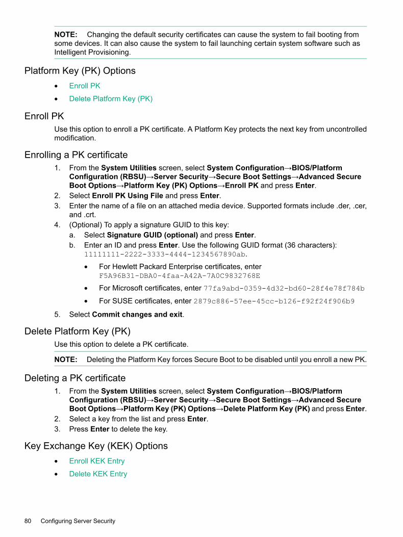
NOTE: Changing the default security certificates can cause the system to fail booting fromsome devices. It can also cause the system to fail launching certain system software such asIntelligent Provisioning.
Platform Key (PK) Options• Enroll PK
• Delete Platform Key (PK)
Enroll PKUse this option to enroll a PK certificate. A Platform Key protects the next key from uncontrolledmodification.
Enrolling a PK certificate1. From the System Utilities screen, select System Configuration→BIOS/Platform
Configuration (RBSU)→Server Security→Secure Boot Settings→Advanced SecureBoot Options→Platform Key (PK) Options→Enroll PK and press Enter.
2. Select Enroll PK Using File and press Enter.3. Enter the name of a file on an attached media device. Supported formats include .der, .cer,
and .crt.4. (Optional) To apply a signature GUID to this key:
a. Select Signature GUID (optional) and press Enter.b. Enter an ID and press Enter. Use the following GUID format (36 characters):
11111111-2222-3333-4444-1234567890ab.
• For Hewlett Packard Enterprise certificates, enterF5A96B31-DBA0-4faa-A42A-7A0C9832768E
• For Microsoft certificates, enter 77fa9abd-0359-4d32-bd60-28f4e78f784b
• For SUSE certificates, enter 2879c886-57ee-45cc-b126-f92f24f906b9
5. Select Commit changes and exit.
Delete Platform Key (PK)Use this option to delete a PK certificate.
NOTE: Deleting the Platform Key forces Secure Boot to be disabled until you enroll a new PK.
Deleting a PK certificate1. From the System Utilities screen, select System Configuration→BIOS/Platform
Configuration (RBSU)→Server Security→Secure Boot Settings→Advanced SecureBoot Options→Platform Key (PK) Options→Delete Platform Key (PK) and press Enter.
2. Select a key from the list and press Enter.3. Press Enter to delete the key.
Key Exchange Key (KEK) Options• Enroll KEK Entry
• Delete KEK Entry
80 Configuring Server Security

Enroll KEK EntryUse this option to enroll a Key Exchange Key certificate. The Key Exchange Key protects thesignature database from unauthorized modifications. No changes can be made to the signaturedatabase without the private portion of this key.
Enrolling a KEK certificate1. From the System Utilities screen, select System Configuration→BIOS/Platform
Configuration (RBSU)→Server Security→Secure Boot Settings→Advanced SecureBoot Options→Key Exchange Key (KEK) Options→Enroll KEK Entry and press Enter.
2. Select Enroll KEK using File and press Enter.3. Enter the name of a file on an attached media device. Supported formats include .der, .cer,
and .crt.4. (Optional) To apply a signature GUID to this key:
a. Select Signature GUID (optional) and press Enter.b. Enter an ID and press Enter. Use the following GUID format (36 characters):
11111111-2222-3333-4444-1234567890ab.
• For Hewlett Packard Enterprise certificates, enterF5A96B31-DBA0-4faa-A42A-7A0C9832768E
• For Microsoft certificates, enter 77fa9abd-0359-4d32-bd60-28f4e78f784b
• For SUSE certificates, enter 2879c886-57ee-45cc-b126-f92f24f906b9
5. Select Commit changes and exit.
Delete KEK EntryUse this option to delete a Key Exchange Key.
Deleting a KEK entry1. From the System Utilities screen, select System Configuration→BIOS/Platform
Configuration (RBSU)→Server Security→Secure Boot Settings→Advanced SecureBoot Options→Platform Key (PK) Options→Delete KEK Entry and press Enter.
2. Select a key from the list and press Enter.3. Press Enter to delete the key.
Allowed Signatures Database (DB) OptionsThe Allowed Signatures Database maintains signatures of codes that are authorized to run onthe platform. This menu displays the following options:
• Enroll Signature (Allowed DB)
• Delete Signature (Allowed DB)
Enroll Signature (Allowed DB)Use this option to enroll a signature in the Allowed Signatures Database. This database maintainssignatures of codes that are authorized to run on the platform.1. From the System Utilities screen, select System Configuration→BIOS/Platform
Configuration (RBSU)→Server Security→Secure Boot Settings→Advanced SecureBoot Options→Allowed Signatures Database (DB) Options→Enroll Signature andpress Enter.
2. Select Enroll Signature Using File and press Enter.3. Enter the name of a file on an attached media device. Supported formats include .der, .cer,
and .crt.
Advanced Secure Boot Options 81

4. (Optional) To apply a signature GUID to this signature:a. Select Signature GUID (optional) and press Enter.b. Enter an ID and press Enter. Use the following GUID format (36 characters):
11111111-2222-3333-4444-1234567890ab.
• For Hewlett Packard Enterprise certificates, enterF5A96B31-DBA0-4faa-A42A-7A0C9832768E
• For Microsoft certificates, enter 77fa9abd-0359-4d32-bd60-28f4e78f784b
• For SUSE certificates, enter 2879c886-57ee-45cc-b126-f92f24f906b9
5. Select Commit changes and exit.
Enrolling a signature in the Allowed Signatures Database1. From the System Utilities screen, select System Configuration→BIOS/Platform
Configuration (RBSU)→Server Security→Secure Boot Settings→Advanced SecureBoot Options→Allowed Signatures Database (DB) Options→Enroll Signature andpress Enter.
2. Select Enroll Signature Using File and press Enter.3. Enter the name of a file on an attached media device. Supported formats include .der, .cer,
and .crt.4. (Optional) To apply a signature GUID to this signature:
a. Select Signature GUID (optional) and press Enter.b. Enter an ID and press Enter. Use the following GUID format (36 characters):
11111111-2222-3333-4444-1234567890ab.
• For Hewlett Packard Enterprise certificates, enterF5A96B31-DBA0-4faa-A42A-7A0C9832768E
• For Microsoft certificates, enter 77fa9abd-0359-4d32-bd60-28f4e78f784b
• For SUSE certificates, enter 2879c886-57ee-45cc-b126-f92f24f906b9
5. Select Commit changes and exit.
Delete Signature (Allowed DB)Use this option to delete a signature from the Allowed Signatures Database.
Deleting a signature from the Allowed Signatures Database1. From the System Utilities screen, select System Configuration→BIOS/Platform
Configuration (RBSU)→Server Security→Secure Boot Settings→Advanced SecureBoot Options→Allowed Signatures Database (DB) Options→Delete Signature andpress Enter.
2. Select a signature from the list and press Enter.3. Press Enter to delete the signature.
Forbidden Signatures Database (DBX) Options• Enroll Signature (Forbidden DB)
• Delete Signature (Forbidden DB)
Enroll Signature (Forbidden DB)Use this option to enroll a signature in the Forbidden Signatures Database. The ForbiddenSignatures Database maintains signatures of codes that are not authorized to run on the platform.
82 Configuring Server Security

Enrolling a signature in the Forbidden Signatures Database1. From the System Utilities screen, select System Configuration→BIOS/Platform
Configuration (RBSU)→Server Security→Secure Boot Settings→Advanced SecureBoot Options→Forbidden Signatures Database (DBX) Options→Enroll Signature andpress Enter.
2. Select Enroll Signature Using File and press Enter.3. Enter the name of a file on an attached media device. Supported formats include .der, .cer,
and .crt.4. (Optional) To apply a signature GUID to this signature:
a. Select Signature GUID (optional) and press Enter.b. Enter an ID and press Enter. Use the following GUID format (36 characters):
11111111-2222-3333-4444-1234567890ab.
• For Hewlett Packard Enterprise certificates, enterF5A96B31-DBA0-4faa-A42A-7A0C9832768E
• For Microsoft certificates, enter 77fa9abd-0359-4d32-bd60-28f4e78f784b
• For SUSE certificates, enter 2879c886-57ee-45cc-b126-f92f24f906b9
5. Select Commit changes and exit.
Delete Signature (Forbidden DB)Use this option to delete a signature from the Forbidden Signatures Database.
Deleting a signature from the Forbidden Signatures Database1. From the System Utilities screen, select System Configuration→BIOS/Platform
Configuration (RBSU)→Server Security→Secure Boot Settings→Advanced SecureBoot Options→Forbidden Signatures Database (DBX) Options→Delete Signature andpress Enter.
2. Select a signature from the list and press Enter.3. Press Enter to delete the signature.
Delete all keys (PK, KEK, DB, DBX)Use this option to delete all keys in the system, including the Platform Key.
NOTE: Changing the default security certificates can cause the system to fail booting fromsome devices, or to fail launching certain software such as Intelligent Provisioning.
Deleting all keys1. From the System Utilities screen, select System Configuration→BIOS/Platform
Configuration (RBSU)→Server Security→Secure Boot Settings→Advanced SecureBoot Options→Delete all keys (PK, KEK, DB, DBX) and press Enter.
2. Press Enter to delete all keys.
Reset all keys to platform defaultsUse this option to reset all keys to platform defaults.
Resetting all keys to platform defaults1. From the System Utilities screen, select System Configuration→BIOS/Platform
Configuration (RBSU)→Server Security→Secure Boot Settings→Advanced SecureBoot Options→Reset all keys to platform defaults and press Enter.
2. Press Enter to reset all keys.
Advanced Secure Boot Options 83

Trusted Platform Module optionsUse this menu to access Trusted Platform Module (TPM) options for servers configured with aTPM. TPM enables the firmware and operating system to take measurements of all phases ofthe booting process. For information on installing and enabling the TPM module option, see theuser documentation for your server model.
CAUTION: A TPM locks all data access if you do not follow proper procedures for modifyingthe server, including updating system or option firmware, replacing hardware such as the systemboard and hard drive, and modifying TPM OS settings.
Configuring Trusted Platform Module options1. From the System Utilities screen, select System Configuration→BIOS/Platform
Configuration (RBSU)→Server Security→Trusted Platform Module options and pressEnter.
2. Select an option and press Enter, then select a setting for that option and press Enter again.On servers configured with an optional TPM, you can set the following:• TPM 2.0 Operation—Sets the operational state of TPM 2.0. Options are:
No Action (default)—There is no TPM configured.◦◦ Enabled—TPM and Secure Boot (when enabled) are fully functional.
◦ Disabled—TPM is visible but functionality is limited. This option also resets TPMto factory settings, clearing assigned passwords, keys, or ownership data.
NOTE: Disabling TPM can prevent the server from booting to the TPM-awareoperating system if the OS uses TPM measurements.
• TPM 2.0 Visibility (default)—Sets whether TPM is hidden form the operating system.Options are:
◦ Visible (default)
◦ Hidden—Hides TPM from the operating system. Secure Boot is disabled and TPMdoes not respond to any commands. Use this setting to remove TPM options fromthe system without having to remove the actual hardware.
• TPMBinding—Sets whether data is encrypted using a TPM bind key, which is a uniqueRSA key. Options are:
◦ Enabled
◦ Disabled (default)
• TPM UEFI Option ROM Measurement—Enables or disables (skips) measuring UEFIPCI operation ROMs. Options are:
◦ Enabled (default)
◦ Disabled
3. Verify that your new Current TPM Type and Current TPM State settings appear at the topof the screen.
4. Press F10.
84 Configuring Server Security

16 Configuring PCI devicesPCI Device Enable/Disable
Use this option to enable or disable embedded and added-in PCI devices. Disabling devicesre-allocates the resources (memory, I/O, and ROM space and power) that are normally allocatedto the device. By default, all devices are enabled.
Enabling or disabling a PCI device1. From the System Utilities screen, select System Configuration→BIOS/Platform
Configuration (RBSU)→PCI Device Enabled/Disable and press Enter.2. Select a device on the system from the list and press Enter.3. Select Enable or Disable and press Enter.4. Press F10.
PCI Device Enable/Disable 85

17 Configuring Server AvailabilityServer Availability options
• ASR Status
• ASR Timeout
• Wake-On LAN
• POST F1 Prompt
• Power Button Mode
• Automatic Power-On
• Power-On Delay
ASR StatusUse the option to enable or disable ASR (Automatic Server Recovery). When enabled, the systemautomatically reboots if the server locks up. ASR is enabled by default.
Enabling or disabling ASRPrerequisiteThe System Management driver is loaded.
To enable or disable ASR1. From the System Utilities screen, select System Configuration→BIOS/Platform
Configuration (RBSU)→Server Availability→ASR Status and press Enter.2. Select a setting and press Enter.
• Enabled (default)
• Disabled—Disables all ASR functionality.3. Press F10.
ASR TimeoutWhen ASR Status is enabled, use this option to set the time to wait before rebooting the serverin the event of an operating system crash or server lockup. When the server has not respondedin the selected amount of time, the server automatically reboots.
Setting the ASR timeoutPrerequisiteASR Status is enabled.
To set the ASR timeout:1. From the System Utilities screen, select System Configuration→BIOS/Platform
Configuration (RBSU)→Server Availability→ASR Timeout and press Enter.2. Select a setting and press Enter.
• 5 Minutes• 10 Minutes (default)
• 15 Minutes
86 Configuring Server Availability
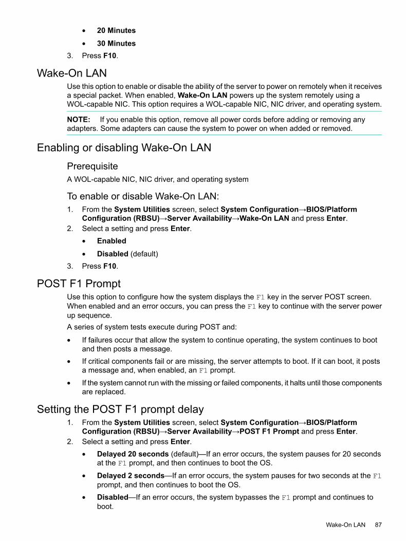
• 20 Minutes• 30 Minutes
3. Press F10.
Wake-On LANUse this option to enable or disable the ability of the server to power on remotely when it receivesa special packet. When enabled, Wake-On LAN powers up the system remotely using aWOL-capable NIC. This option requires a WOL-capable NIC, NIC driver, and operating system.
NOTE: If you enable this option, remove all power cords before adding or removing anyadapters. Some adapters can cause the system to power on when added or removed.
Enabling or disabling Wake-On LANPrerequisiteA WOL-capable NIC, NIC driver, and operating system
To enable or disable Wake-On LAN:1. From the System Utilities screen, select System Configuration→BIOS/Platform
Configuration (RBSU)→Server Availability→Wake-On LAN and press Enter.2. Select a setting and press Enter.
• Enabled• Disabled (default)
3. Press F10.
POST F1 PromptUse this option to configure how the system displays the F1 key in the server POST screen.When enabled and an error occurs, you can press the F1 key to continue with the server powerup sequence.A series of system tests execute during POST and:
• If failures occur that allow the system to continue operating, the system continues to bootand then posts a message.
• If critical components fail or are missing, the server attempts to boot. If it can boot, it postsa message and, when enabled, an F1 prompt.
• If the system cannot run with the missing or failed components, it halts until those componentsare replaced.
Setting the POST F1 prompt delay1. From the System Utilities screen, select System Configuration→BIOS/Platform
Configuration (RBSU)→Server Availability→POST F1 Prompt and press Enter.2. Select a setting and press Enter.
• Delayed 20 seconds (default)—If an error occurs, the system pauses for 20 secondsat the F1 prompt, and then continues to boot the OS.
• Delayed 2 seconds—If an error occurs, the system pauses for two seconds at the F1prompt, and then continues to boot the OS.
• Disabled—If an error occurs, the system bypasses the F1 prompt and continues toboot.
Wake-On LAN 87

3. Press F10.
Power Button ModeUse this option to enable or disable momentary power button functionality. Power Button Modedoes not affect the four-second power button override or the remote power control functionality.
Enabling or disabling momentary power button functionality1. From the System Utilities screen, select System Configuration→BIOS/Platform
Configuration (RBSU)→Server Availability→Power Button Mode and press Enter.2. Select a setting and press Enter.
• Enabled (default)—Enables the momentary power button functionality.
• Disabled—Disables the momentary power button functionality.3. Press F10.
Automatic Power-OnUse this option to configure how the server automatically powers on when AC power is appliedto the system. By default, the system returns to its previous power state when AC power isrestored after an AC power loss. The Always Power On option sets the system to always returnto the “on” state, even if it was in the “off” state when power was lost.
Setting the automatic power-on state1. From the System Utilities screen, select System Configuration→BIOS/Platform
Configuration (RBSU)→Server Availability→Automatic Power-On and press Enter.2. Select a setting and press Enter.
• Always Power On—The system automatically returns to a power on state.
• Always Power Off—The system automatically returns to a power off state.
• Restore Last Power State (default)—The system automatically returns to its previouspower off state.
3. Press F10.
Power-On DelayUse this option to set whether or not to delay the server from turning on for a specified time. Thisenables staggering when servers power up after a power loss, which can prevent power usagespikes.
NOTE: These events override the Power-On Delay setting and immediately power on theserver:• Pressing the power button using the iLO Virtual Power Button
• Wake-ON LAN events
• RTC (Real-Time Clock) wake-up events
Setting the power-on delay1. From the System Utilities screen, select System Configuration→BIOS/Platform
Configuration (RBSU)→Server Availability→Power-On Delay and press Enter.
88 Configuring Server Availability

2. Select a setting and press Enter.• No Delay (default)
• Random Delay• 15 Second Delay• 30 Second Delay• 45 Second Delay• 60 Second Delay
3. Press F10.
Setting the power-on delay 89

18 Configuring BIOS serial console and EMS optionsBIOS Serial Console and EMS options
BIOS serial console and EMS console redirection enable you to view POST error messages andrun RBSU remotely through a serial connection to the server COM port or iLO Virtual Serial port.To do so, you do not need a keyboard or mouse. This menu includes:
• BIOS Serial Console Port
• BIOS Serial Console Emulation Mode
• BIOS Serial Console Baud Rate
• EMS Console
NOTE: Some languages or characters might require that you use a specific emulation mode.
BIOS Serial Console PortUse this option to configure how to redirect video and keystrokes through the serial port. Whenset, this option can interfere with non-terminal devices attached to the serial port. If this occurs,set it to disabled.
IMPORTANT: This option is not supported on Japanese or Simplified Chinese systems.
Configuring the BIOS serial console portPrerequisitesTo set (enable) the option, you must use:
• Terminal software with a Unicode character set (for example: UTF-8)
• A supported language other than Japanese or Simplified Chinese
To configure the BIOS serial console port:1. From the System Utilities screen, select System Configuration→BIOS/Platform
Configuration (RBSU)→BIOS Serial Console and EMS→BIOS Serial Console Port andpress Enter.
2. Select a setting and press Enter.• Auto (default)
• Disabled• Physical Serial Port• Virtual Serial Port
3. Press F10.4. If you enabled a BIOS serial console port, connect a null modem cable to the serial port/COM
port on which it is enabled.
BIOS Serial Console Emulation ModeUse this option to select a serial console emulation mode type. Your selection depends on theemulation you want to use in your serial terminal program (for example, Hyper Terminal orPuTTY). The BIOS emulation mode must match the selected mode in the terminal program.When you select ANSI mode, some special characters are displayed in the serial console (forexample, a degree symbol °).
90 Configuring BIOS serial console and EMS options

BIOS Serial Console Emulation Mode1. From the System Utilities screen, select System Configuration→BIOS/Platform
Configuration (RBSU)→BIOSSerial Console and EMS→BIOSSerial Console EmulationMode and press Enter.
2. Select a setting and press Enter.• VT100 (default)
• ANSI• VT100+
3. Press F10.
BIOS Serial Console Baud RateUse this option to set the transfer rate at which data is transmitted through the serial port.
Setting the BIOS serial console baud rate1. From the System Utilities screen, select System Configuration→BIOS/Platform
Configuration (RBSU)→BIOS Serial Console and EMS→BIOS Serial Console BaudRate and press Enter.
2. Select a setting and press Enter.• 9600• 19200• 38400• 57600• 115200 (default)
3. Press F10.
EMS ConsoleUse this option to configure the ACPI serial port settings for redirecting the Windows ServerEmergency Management (EMS) console.When setting this option for redirecting EMS through a network connection, do the following:
• If you are using iLO 4, select the value (COM1 or COM2) that corresponds to the resourcesassigned to the Virtual Serial Port in the System Options→Serial Port Options menu.
• If you are redirecting EMS through a physical serial port, select the value (COM1 or COM2)that corresponds to the resources assigned to the Embedded Serial Port in the SystemOptions→Serial Port Options menu.
EMS Console in Windows Server 2008 and 2012EMS provides input and output support for all Microsoft Windows kernel components, includingthe loader, setup, recovery console, OS kernel, blue screens, and the Special AdministrationConsole. The Special Administration Console is a text mode management console that is availableafter Windows Server 2008 or 2012 OS is initialized.Microsoft enables EMS in the OS, and you must also enable EMS in the ROM. When enabled,EMS assumes the serial port for redirection and can cause interference with other devicesattached to the serial port. To avoid interference, EMS is disabled in the system ROM by defaulton ProLiant ML and DL servers. If EMS is disabled in Windows Server 2008 or 2012, configurethe EMS console on a COM port, and reboot the server to update the boot.ini file.
BIOS Serial Console Emulation Mode 91

Configuring the EMS console1. From the System Utilities screen, select System Configuration→BIOS/Platform
Configuration (RBSU)→BIOSSerial Console and EMS→EMSConsole and pressEnter.2. Select a setting and press Enter.
• Disabled (default)
• COM1—Enables the EMS console on the COM1 port.
• COM2—Enables the EMS console on the COM2 port.3. Press F10.
92 Configuring BIOS serial console and EMS options

19 Configuring Server Asset InformationServer Asset Information options
• Server Information
• Administrator Information
• Service Contact Information
• Custom POST Message
Selecting Server Asset Information options1. From the System Utilities screen, select System Configuration→BIOS/Platform
Configuration (RBSU)→Server Asset Information and press Enter.2. Select an option and press Enter.
Server InformationUse this option to enter reference information for the server administrator. For text settings, entera maximum of 14 characters. By default, all values are blank.
Entering server information1. From the System Utilities screen, select System Configuration→BIOS/Platform
Configuration (RBSU)→Server Asset Information→Server Information and press Enter.2. Select a setting and press Enter, then complete or select an entry and press Enter again.
• Server Name—Enter a server name.
• Server Asset Tag—Enter a server asset number.
• Asset Tag Protection—Select a setting:
Unlocked(default)◦◦ Locked—Locks asset tag information. The asset tag is not erased if you restore
default system settings.
• Server Primary OS—Enter a description of the primary OS of the server.
• Server Other Information—Enter additional text describing the server.
• Power-On Logo—Select a setting:
◦ Enabled (default)—Displays the logo during system boot.
◦ Disabled—Does not display the logo during system boot. This setting does notaffect system boot times.
3. Press F10.
Administrator InformationUse this option to enter contact information for the server administrator. The number of charactersallowed for each entry varies by server model. By default, all values are blank.
Entering administrator information1. From the System Utilities screen, select System Configuration→BIOS/Platform
Configuration (RBSU)→Server Asset Information→Administrator Information andpress Enter.
Server Asset Information options 93
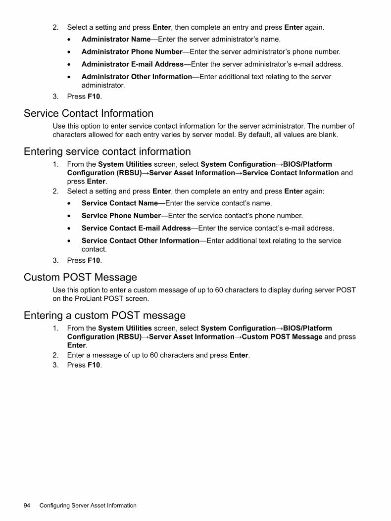
2. Select a setting and press Enter, then complete an entry and press Enter again.• Administrator Name—Enter the server administrator’s name.
• Administrator Phone Number—Enter the server administrator’s phone number.
• Administrator E-mail Address—Enter the server administrator’s e-mail address.
• Administrator Other Information—Enter additional text relating to the serveradministrator.
3. Press F10.
Service Contact InformationUse this option to enter service contact information for the server administrator. The number ofcharacters allowed for each entry varies by server model. By default, all values are blank.
Entering service contact information1. From the System Utilities screen, select System Configuration→BIOS/Platform
Configuration (RBSU)→Server Asset Information→Service Contact Information andpress Enter.
2. Select a setting and press Enter, then complete an entry and press Enter again:• Service Contact Name—Enter the service contact’s name.
• Service Phone Number—Enter the service contact’s phone number.
• Service Contact E-mail Address—Enter the service contact’s e-mail address.
• Service Contact Other Information—Enter additional text relating to the servicecontact.
3. Press F10.
Custom POST MessageUse this option to enter a custom message of up to 60 characters to display during server POSTon the ProLiant POST screen.
Entering a custom POST message1. From the System Utilities screen, select System Configuration→BIOS/Platform
Configuration (RBSU)→Server Asset Information→Custom POST Message and pressEnter.
2. Enter a message of up to 60 characters and press Enter.3. Press F10.
94 Configuring Server Asset Information

20 Configuring advanced platform configuration optionsAdvanced Options
• ROM Selection
• Video Options
• Embedded Video Connection
• Fan and Thermal Options
• Advanced System ROM Options
ROM SelectionOn a server with redundant ROMs, use this option to revert the server to a previous BIOS ROMimage.
Selecting a ROM image1. From the System Utilities screen, select System Configuration→BIOS/Platform
Configuration (RBSU)→Advanced Options→ROM Selection and press Enter.2. Select a setting and press Enter.
• Use Current ROM (default)
• Switch to Backup ROM—Reverts to the image in use before the last flash event.3. Press F10.
Video OptionsUse this option to configure the video display. By default, the system BIOS disables the embeddedvideo controller when an optional video controller is installed in the system. You can use thisoption to leave the embedded video controller enabled so that the iLO remote video functionsproperly and also provides dual-head video support. Early system startup video is always displayedto the embedded video controller.
NOTE:• The ability to support dual-head video between the embedded and a stand-up device depends
on support from the operating system. For more information, see your operating systemdocumentation.
• When multiple optional video cards are installed, the card that is selected as primary is basedon PCI enumeration, which varies by platform. You might have to remove and reinstall thecards in a different order to control which card is the primary controller.
Configuring the video display1. From the System Utilities screen, select System Configuration→BIOS/Platform
Configuration (RBSU)→Advanced Options→Video Options and press Enter.2. Select a setting and press Enter.
• Add-in Video Enabled, EmbeddedVideoDisabled (default)—The system only displaysvideo to the first discovered add-in video controller.
• Both Add-in and Embedded Video Enabled—The system displays video to theembedded and the first discovered add-in video controller.
3. Press F10.
Advanced Options 95

Embedded Video ConnectionUse this option to configure an external video connection to the embedded video connection. Bydefault, the external video connection to the embedded video controller is automatically disabledto save power when a monitor is not attached. It is enabled automatically when a monitor isattached (including when the server is operating).
Configuring an embedded video connection1. From the System Utilities screen, select System Configuration→BIOS/Platform
Configuration (RBSU)→Advanced Options→Embedded Video Connection and pressEnter.
2. Select a setting and press Enter.• Auto (default)—The external video connection to the embedded video controller is
automatically disabled to save power when a monitor is not attached. It is enabledautomatically when a monitor is attached (including when the server is operating).
• Always Disabled—The external video connection to the embedded video controller isdisabled and a monitor connected to this port does not display except during systemboot.
• Always Enabled—The external video connection to the embedded video controller isalways enabled. This option is only required if a monitor is attached with a monitordetection that does not function, causing Auto mode to not work properly.
3. Press F10.
Fan and Thermal Options• Thermal Configuration
• Thermal Shutdown
• Fan Installation Requirements
• Fan Failure Policy
• Extended Ambient Temperature Support
Thermal ConfigurationUse this option to select the fan cooling method for the system. Modifying this option is onlyadvised for configurations that differ from typical Hewlett Packard Enterprise-supportedconfigurations that cannot be cooled adequately via Optimal Cooling, the default setting.
Setting the thermal configuration1. From the System Utilities screen, select System Configuration→BIOS/Platform
Configuration (RBSU)→Advanced Options→Fan and Thermal Options→ThermalConfiguration and press Enter.
2. Select a setting and press Enter.• Optimal Cooling (default)—Provides the most efficient solution by configuring fan
speeds to the minimum required to provide adequate cooling.• Increased Cooling—Operates fans at a higher speed.
• Maximum Cooling—Provides the maximum cooling available for the system.3. Press F10.
96 Configuring advanced platform configuration options
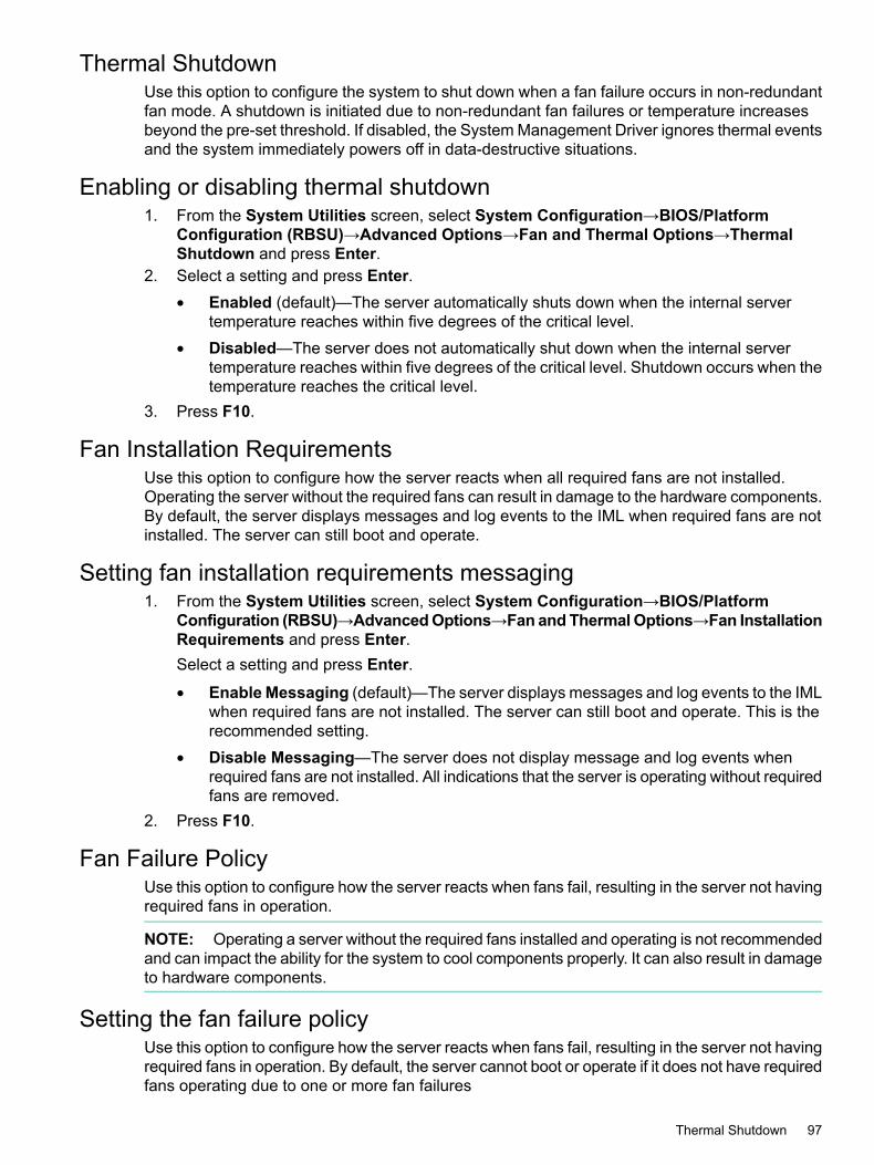
Thermal ShutdownUse this option to configure the system to shut down when a fan failure occurs in non-redundantfan mode. A shutdown is initiated due to non-redundant fan failures or temperature increasesbeyond the pre-set threshold. If disabled, the System Management Driver ignores thermal eventsand the system immediately powers off in data-destructive situations.
Enabling or disabling thermal shutdown1. From the System Utilities screen, select System Configuration→BIOS/Platform
Configuration (RBSU)→Advanced Options→Fan and Thermal Options→ThermalShutdown and press Enter.
2. Select a setting and press Enter.• Enabled (default)—The server automatically shuts down when the internal server
temperature reaches within five degrees of the critical level.• Disabled—The server does not automatically shut down when the internal server
temperature reaches within five degrees of the critical level. Shutdown occurs when thetemperature reaches the critical level.
3. Press F10.
Fan Installation RequirementsUse this option to configure how the server reacts when all required fans are not installed.Operating the server without the required fans can result in damage to the hardware components.By default, the server displays messages and log events to the IML when required fans are notinstalled. The server can still boot and operate.
Setting fan installation requirements messaging1. From the System Utilities screen, select System Configuration→BIOS/Platform
Configuration (RBSU)→AdvancedOptions→Fan andThermalOptions→Fan InstallationRequirements and press Enter.Select a setting and press Enter.
• Enable Messaging (default)—The server displays messages and log events to the IMLwhen required fans are not installed. The server can still boot and operate. This is therecommended setting.
• Disable Messaging—The server does not display message and log events whenrequired fans are not installed. All indications that the server is operating without requiredfans are removed.
2. Press F10.
Fan Failure PolicyUse this option to configure how the server reacts when fans fail, resulting in the server not havingrequired fans in operation.
NOTE: Operating a server without the required fans installed and operating is not recommendedand can impact the ability for the system to cool components properly. It can also result in damageto hardware components.
Setting the fan failure policyUse this option to configure how the server reacts when fans fail, resulting in the server not havingrequired fans in operation. By default, the server cannot boot or operate if it does not have requiredfans operating due to one or more fan failures
Thermal Shutdown 97

NOTE: Operating a server without the required fans installed and operating is not recommendedand can impact the ability for the system to cool components properly. It can also result in damageto hardware components.
To set the Fan Failure Policy:1. From the System Utilities screen, select System Configuration→BIOS/Platform
Configuration (RBSU)→Advanced Options→Fan and Thermal Options→Fan FailurePolicy and press Enter.
2. Select a setting and press Enter.• Shutdown/Halt on Critical Fan Failures (default)—The server cannot boot or operate
if it does not have required fans operating due to one or more fan failures. This is therecommended setting.
• Allow Operation with Critical Fan Failures—The server can boot and operate if itdoes not have required fans operating due to one or more fan failures.
Press F10.
Extended Ambient Temperature SupportUse this option to enable the server to operate at higher ambient temperatures than are normallysupported.
NOTE: This option is only supported by specific hardware configurations. See your HPE serverdocumentation before enabling extended ambient temperature support. Improper system operationor damage to hardware components can result from enabling these features in unsupportedconfigurations.
Enabling or disabling higher ambient temperature support1. From the System Utilities screen, select System Configuration→BIOS/Platform
Configuration (RBSU)→Advanced Options→Fan and Thermal Options→ExtendedAmbient Temperature Support and press Enter.
2. Select a setting and press Enter.• Disabled (default)
• Enabled for 40c Ambient (ASHRAE 3)—Enables the server to operate in environmentswith ambient temperatures up to 40 degrees Celsius.
• Enabled for 45c Ambient (ASHRAE 4)—Enables the server to operate in environmentswith ambient temperatures up to 45 degrees Celsius.
NOTE: Not all Gen9 servers support both 40c Ambient (ASHRAE 3) and 45c Ambient(ASHRAE 4).
3. Press F10.
Advanced System ROM Options• NMI Debug Button
• PCI Bus Padding Options
• Consistent Device Naming
• Mixed Power Supply Reporting
• Serial Number
• Product ID
98 Configuring advanced platform configuration options

NMI Debug ButtonUse this function to enable or disable debug functionality when the system experiences a softwarelock-up. The button generates a Non-Maskable Interrupt to enable the use of the operating systemdebugger. When enabled (the default setting), pressing the NMI Debug Button on the systemboard during normal operation halts the system.
Enabling or disabling the NMI debug button1. From the System Utilities screen, select System Configuration→BIOS/Platform
Configuration (RBSU)→Advanced Options→Advanced System ROM Options→NMIDebug Button and press Enter.
2. Select a setting and press Enter.• Enabled (default)
• Disabled3. Press F10.
PCI Bus Padding OptionsUse this option to enable or disable the default PCI Bus padding, which provides each expansionslot with an extra PCI Bus number. By default, the System BIOS pads one PCI bus for eachexpansion slot to allow expansion cards with PCI-PCI bridges to not affect current bus numberingschemes. Do not disable this option unless you encounter a specific problem with your expansioncard.
Enabling or disabling PCI Bus padding1. From the System Utilities screen, select System Configuration→BIOS/Platform
Configuration (RBSU)→Advanced Options→Advanced System ROM Options→PCIBus Padding Options and press Enter.
2. Select a setting and press Enter.• Enabled (default)
• Disabled3. Press F10.
Consistent Device NamingUse this option to set the level of Consistent Device Naming. On supported operating systems,device naming controls how NIC ports are named based on their locations in the system.
NOTE: Existing NIC connections retain their names until reinstalled under the OS environment.
Enabling Consistent Device Naming1. From the System Utilities screen, select System Configuration→BIOS/Platform
Configuration (RBSU)→Advanced Options→Advanced System ROMOptions→Consistent Device Naming and press Enter.
2. Select a setting and press Enter.• CDN Support for LOMs only—Embedded NICs and FlexibleLOM (not NICs installed
in expansion slots) are named based on their locations in the system.• Disabled (default)—All NIC ports are named based on their locations in the system.
3. Press F10.
Advanced System ROM Options 99

Mixed Power Supply ReportingUse this option to set whether the server logs messages when a mixed supply configuration ispresent. This is enabled by default.
Enabling or disabling mixed power supply reporting1. From the System Utilities screen, select System Configuration→BIOS/Platform
Configuration (RBSU)→AdvancedOptions→Advanced SystemROMOptions→MixedPower Supply Reporting and press Enter.
2. Select a setting and press Enter.• Enabled (default)
• Disabled3. Press F10.
Serial NumberUse this option to re-enter the server serial number after replacing the system board. Consult aqualified IT service specialist for assistance in modifying this value. This ID must match the IDlocated on the chassis.
Re-entering a chassis serial number1. From the System Utilities screen, select System Configuration→BIOS/Platform
Configuration (RBSU)→Advanced Options→Advanced System ROMOptions→SerialNumber and press Enter.
2. Enter the serial number and press Enter.3. Press F10.4. Press Enter.
Product IDUse this option to re-enter the server product ID after replacing the system board. This ID mustmatch the ID located on the chassis.
Re-entering a product ID1. From the System Utilities screen, select System Configuration→BIOS/Platform
Configuration (RBSU)→AdvancedOptions→AdvancedSystemROMOptions→ProductID and press Enter.
2. Enter the product ID and press Enter.3. Press F10.4. Press Enter.
100 Configuring advanced platform configuration options

21 Configuring the date and time and system defaultsDate and TimeDate and Time
1. From the System Utilities screen, select System Configuration→BIOS/PlatformConfiguration (RBSU)→Date and Time and press Enter.
2. Select a setting and press Enter, then complete your entry and press Enter again.• Date (mm-dd-yyyy)—Enter the date in a month-day-year (mm-dd-yyyy) format.
• Time (hh:mm:ss)—Enter the time in a 24–hour format (hh:mm:ss) format.
• Time Zone—Use the up and down arrow keys to select your current time zone for thesystem
• Daylight Savings Time:
Enabled—Adjusts the local time displayed by one hour for Daylight Savings Time.◦◦ Disabled (default)—Does not adjust the local time displayed for Daylight Savings
Time.
• Time Format:
◦ Coordinated Universal Time (UTC) (default)—Calculates the time stored in thehardware Real Time Clock (RTC) from the associated Time Zone setting.
◦ Local Time—Removes the use of the Time Zone setting. This option is useful foraddressing interaction issues between Windows operating systems set in LegacyBIOS boot mode.
3. Press F10.
Resetting system defaultsSystem Default Options
• Restore Default System Settings
• Restore Default Manufacturing Settings
• Default UEFI Device Priority
• User Default Options
Restore Default System SettingsUse this option to reset all BIOS configuration settings to their default values and immediatelyand automatically restart the server.Selecting this option resets all platform settings except:• Secure Boot BIOS settings
• Date and Time settings
• Primary and redundant ROM Selection (if supported)You can save a custom default configuration to use during a system restore. Doing so savessettings you might otherwise lose. See “User Default Options” (page 103).
CAUTION: When you select use this option to reset configuration settings, any modificationsthat you have made might be lost.
Date and Time 101

1. From the System Utilities screen, select System Configuration→BIOS/PlatformConfiguration (RBSU)→System Default Options→Restore Default System Settingsand press Enter.
2. Select a setting and press Enter.• No, cancel the restore procedure.• Yes, restore the default settings.
3. Press Enter to reboot the server for changes to take effect.
Restoring default system settings1. From the System Utilities screen, select System Configuration→BIOS/Platform
Configuration (RBSU)→System Default Options→Restore Default System Settingsand press Enter.
2. Select a setting and press Enter.• No, cancel the restore procedure.• Yes, restore the default settings.
3. Press Enter to reboot the server for changes to take effect.
Restore Default Manufacturing SettingsUse this option to reset all BIOS configuration settings to their default manufacturing values anddelete all UEFI non-volatile variables, such as boot configuration and Secure Boot security keys(if Secure Boot is enabled). Previous changes that you have made might be lost.The difference between this action and the Restore Default System Settings option is thatRestore Default Manufacturing Settings erases all UEFI variables. An OS can write UEFIvariables that store such things as entries in the boot order and key database information forSecure Boot. When you Restore Default Manufacturing Settings, this information is cleared,whereas it is retained when you Restore Default System Settings.You can save a custom default configuration to use during a system restore. Doing so savessettings you might otherwise lose. See “User Default Options” (page 103).
Restoring default manufacturing settings1. From the System Utilities screen, select System Configuration→BIOS/Platform
Configuration (RBSU)→System Default Options→Restore Default ManufacturingSettings and press Enter.
2. Select a setting and press Enter.• No, cancel the restore procedure.• Yes, restore the default settings.
3. Press Enter.
Default UEFI Device PriorityUse this option to change the UEFI device priority that is used when default system settings arerestored. The initial UEFI Boot Order list is created based on the priorities defined here. Beforeyou change the priority list, you must configure and save user defaults as described in the nextsection, User Default Options. When the default configuration settings are loaded, the settingsfrom the saved Default UEFI Device Priority list are used instead of the system or factorydefaults.
102 Configuring the date and time and system defaults

Changing the default UEFI device priority1. From the System Utilities screen, select System Configuration→BIOS/Platform
Configuration (RBSU)→System Default Options→Default UEFI Device Priority andpress Enter.
2. Select an entry and press Enter.3. Use the + key to move the entry higher in the list. Use the - key to move it lower in the list.
Use the arrow keys to navigate through the list.4. Press F10.
User Default OptionsUse this option to save or erase a configuration as the custom default configuration. Configurethe system as necessary and then enable this option to save the configuration as the defaultconfiguration. When the system loads the default settings, the custom default settings are usedinstead of the manufacturing defaults.
Saving or erasing user default options1. From the System Utilities screen, select System Configuration→BIOS/Platform
Configuration (RBSU)→System Default Options→User Default Options and pressEnter.
2. Select an option and press Enter, then select a setting for the option and press Enter again.• Save User Defaults
Yes, Save—Saves the current settings as the system default settings.◦◦ No, Cancel (default)—Does not save the current settings as the system default
settings.
• Erase User Defaults
◦ Yes, erase the current settings—Erases (deletes) the current user-defined defaultsettings. Once deleted, you can only restore these setting manually.
◦ No, Cancel (default)—Does not erase the current user-defined default settings
3. Press F10.
Resetting system defaults 103

22 Using scripted configuration flowsScripted configuration flow
You can use BIOS/Platform Configuration (RBSU) with the Scripting Toolkit (STK) to createstandard server configuration scripts to automate many of the manual steps in the serverconfiguration process. You can find the STK on the Hewlett Packard Enterprise website (http://www.hpe.com/servers/stk).The following utilities are provided in the toolkit:
• Configuration Replication Utility (CONREP)
• HPE Smart Storage Administrator (HPE SSA)
Configuration Replication Utility (CONREP)CONREP with ProLiant Gen9 and other UEFI enabled servers is shipped in the STK and is autility that operates with the BIOS/Platform Configuration (RBSU) to replicate hardwareconfiguration on ProLiant Gen8 and later servers. This utility is run during State 0, Run HardwareConfiguration Utility when performing a scripted server deployment. CONREP reads the stateof the system environment variables to determine the configuration and then writes the resultsto an editable script file. This file can then be deployed across multiple servers with similarhardware and software components. For more information, see the Scripting Toolkit User Guidefor your operating system environment on the Hewlett Packard Enterprise website (http://www.hpe.com/info/stk/docs).
RESTful API support for UEFIProLiant Gen9 servers include support for configuring UEFI BIOS settings using the RESTfulAPI, a management interface that server management tools can use to perform configuration,inventory, and monitoring of ProLiant server. A REST client uses HTTPS operations to configuresupported server settings, such as iLO 4 and UEFI BIOS settings. For more information aboutthe RESTful API and the RESTful Interface Tool, see the Hewlett Packard Enterprise website(http://www.hpe.com/info/restfulinterface/docs).
HPE Smart Storage Administrator (HPE SSA)ProLiant Gen9 servers support Smart Storage Administrator (HPE SSA). HPE SSA Scripting isa standalone application that is distributed with the HPE SSA CLI application. For more informationSee the Scripting Toolkit for Windows User Guide (http://www.hpe.com/support/STK_Windows_UG_en), and the HPE SSA guides at: http://www.hpe.com/info/smartstorage/docs.
104 Using scripted configuration flows

23 Troubleshooting• Basic troubleshooting techniques
• Cannot boot devices in UEFI Mode
• Cannot restore system defaults
• Cannot download the file in the network boot URL
• Cannot network boot with the downloaded image file
• Cannot deploy from the UEFI Shell script
Basic troubleshooting techniquesThe UEFI System Utilities provides basic troubleshooting tools you can use to resolve issues,including:
• Viewing the Integrated Management Log (IML) to see system events time stamped withone-minute granularity.
• Downloading an Active Health System Log (AHS).By default, the system downloads logs from the previous seven days if you do not use theRange Start Date and Range End Date fields to specify a different time period. Whenrequested by Hewlett Packard Enterprise, you can copy your stored .ahs file, and email itto your customer support representative.
Cannot boot devices in UEFI ModeSymptomYou see a message that the option or device you want to boot cannot be found, or it is listed inthe system configuration as an unknown device.
Solution 1
CauseYou are attempting to boot to an option that does not have a UEFI Option ROM driver.
ActionVerify that your option card has a UEFI option driver (Option ROM) that supports either x64 orEFI Byte Code for boot functionality.
NOTE:• UEFI drivers do not display messages on the System Utilities screen or provide function key
prompts.• If you replace the motherboard, UEFI variables are lost.
• You must configure PXE servers with a boot image. For x64 EFI machines, you must alsoconfigure the DHCP server to support x64 EFI DHCP boot requests. For more information,see the UEFI Information Library: http://www.hpe.com/info/ProLiantUEFI/docs.
Solution 2
CauseYou are attempting to boot to an option that is not supported or is not running the latest firmware.
Basic troubleshooting techniques 105

Action1. Refer to the Quick Specs or Read This First card for your server to make sure your card is
supported before you install it. Although third-party UEFI cards might work, they are notoptimized for ProLiant Gen9 servers running UEFI System Utilities.
2. Verify that the correct information is listed in the System Health settings for the option.3. If necessary, use the latest SPP in offline mode to upgrade the firmware to the latest version.
Solution 3
CauseYou are booting Microsoft Windows 2008 R2, and UEFI Optimized Boot is enabled.
ActionDisable UEFI Optimized Boot.
Solution 4
CauseYou are booting VMware ESXi, and UEFI Optimized Boot is disabled.
ActionEnable UEFI Optimized Boot.
Solution 5
CauseYour default boot mode settings are different than your user-defined settings.
ActionSave a custom default configuration to use during a system restore. See User Default Options.
Cannot restore system defaultsSymptoms
• After moving a drive from one server to another in Windows, you see an error message thatcertain settings cannot be found.
• After replacing a motherboard, you lose your configuration settings, such as Secure Boot.
CauseMoving drives and replacing system hardware can disrupt pointers to previously-configuredsettings.
ActionTry the following options:
• Restore Default System Settings
• Restore Default Manufacturing SettingsIt is a good practice to save a custom default configuration to use during a system restore. Doingso saves settings you might otherwise lose. See User Default Options.
106 Troubleshooting

Cannot download the file in the network boot URLSymptomYou see an error message when you try to download the file in the URL you specified for anetwork boot.
Solution 1
CauseThe network connection settings you specified during static configuration are incorrect.
Action1. Use the Embedded UEFI Shell ping command to check the network connection. See “Ping”
in the HPE UEFI Shell User Guide for HPE ProLiant Gen9 Servers.2. Change your static networking connection settings and try to download the file in URL again.
Solution 2
CauseThe DHCP server did not respond.
Action1. Ensure there is a DHCP server available and it is operational.2. Try to download the file in the URL again.
Solution 3
CauseNo cable is connected to the selected NIC port.
Action1. Ensure there is a cable connection.2. Try to download the URL again.
Solution 4
CauseThe file is incorrect or not present on the server, or it cannot be downloaded due to insufficientprivileges. Check the file name and that it exists on the server. Make sure you have adminprivileges on the server.
Action1. Ensure the file is present, that you are using the correct file name and have sufficient
privileges to download it.2. Try to download the file in the URL again.
Solution 5
CauseThe HTTP or FTP server is down or did not respond.
Cannot download the file in the network boot URL 107

Action1. Ensure that the HTTP or FTP server you specified is available and that it is operational.2. Try to download the file in the URL again.
Cannot network boot with the downloaded image fileSymptomBooting from the image specified in the URL fails.
Solution 1
CauseThe image is not signed and Secure Boot is enabled.
Action1. Ensure that the image is signed and that its Secure Boot settings are correct. See “Secure
Boot” in the HPE UEFI System Utilities User Guide for HPE ProLiant Gen9 Servers.2. Try to download the file in the URL again.
Solution 2
CauseThe downloaded file is corrupt.
Action1. Select a new file.2. Repeat the URL configuration, specifying the new file.3. Try to download the new file in the URL.
Cannot deploy from the UEFI Shell scriptSymptomYou attempted to deploy an OS using the UEFI Shell script and you see an error message thatthe deployment failed.
CauseConfiguration settings are not correct.
108 Troubleshooting

Action1. Verify the following.
• The Embedded UEFI Shell interface is added to the UEFI Boot Order list or One-TimeBoot Menu.
• When added to the UEFI Boot Order list, the Embedded UEFI Shell interface is thefirst boot option in UEFI Boot Order list so that it overrides other boot options to load.
• UEFI Shell Script Auto-Start is enabled.
• The correct startup.nsh script file location in attached media or a network locationis specified. If it is in attached media, the startup.nsh script must be either insidethe fsX:\ or the fsX:\efi\boot\ directory.
• The .nsh script only contains supported commands.
• Your system has enough RAM memory to create RAM disks during automated scriptexecution.
• Any OS boot loader or diagnostics application launched using the .nsh script issupported to run in UEFI the environment.
2. Try the deployment again.
Cannot deploy from the UEFI Shell script 109

24 Support and other resourcesAccessing Hewlett Packard Enterprise Support
• For live assistance, go to the Contact Hewlett Packard Enterprise Worldwide website:http://www.hpe.com/assistance
• To access documentation and support services, go to the Hewlett Packard Enterprise SupportCenter website:http://www.hpe.com/support/hpesc
Information to collect• Technical support registration number (if applicable)
• Product name, model or version, and serial number
• Operating system name and version
• Firmware version
• Error messages
• Product-specific reports and logs
• Add-on products or components
• Third-party products or components
Accessing updates• Some software products provide a mechanism for accessing software updates through the
product interface. Review your product documentation to identify the recommended softwareupdate method.
• To download product updates, go to either of the following:
Hewlett Packard Enterprise Support Center Get connected with updates page:http://www.hpe.com/support/e-updates
◦
◦ Software Depot website:http://www.hpe.com/support/softwaredepot
• To view and update your entitlements, and to link your contracts and warranties with yourprofile, go to the Hewlett Packard Enterprise Support Center More Information on Accessto Support Materials page:http://www.hpe.com/support/AccessToSupportMaterials
IMPORTANT: Access to some updates might require product entitlement when accessedthrough the Hewlett Packard Enterprise Support Center. You must have an HP Passportset up with relevant entitlements.
Related informationThe latest documentation for the UEFI System Utilities and Embedded Shell is available at: http://www.hpe.com/info/ProLiantUEFI/docs. Available documents include:
• HPE UEFI Shell User Guide for HPE ProLiant Gen9 Servers
• HPE UEFI Shell Quick Reference Card for HPE ProLiant Gen9 Servers
110 Support and other resources

• HPE UEFI System Utilities and Shell Release Notes for HPE ProLiant Gen9 Servers
• HPE UEFI Deployment Guide for HPE ProLiant Gen9 ServersHPE UEFI System Utilities and Shell Command Mobile Help for HPE ProLiant Gen9 Servers isavailable by scanning the QR code located at the bottom of the System Utilities screen, or athttp://www.hpe.com/qref/ProLiantUEFI/Help.
Websites
LinkWebsite
http://www.uefi.org/specificationsUEFI Specification
http://www.uefi.org/learning_centerUEFI Learning Resources
http://sourceforge.net/apps/mediawiki/tianocoreUEFI EDK2 project on SourceForge (downloadspecifications and code)
http://www.hpe.com/info/enterprise/docsHewlett Packard Enterprise Information Library
http://www.hpe.com/support/hpescHewlett Packard Enterprise Support Center
http://www.hpe.com/assistanceContact Hewlett Packard Enterprise Worldwide
http://www.hpe.com/support/e-updatesSubscription Service/Support Alerts
http://www.hpe.com/support/softwaredepotSoftware Depot
http://www.hpe.com/support/selfrepairCustomer Self Repair
http://www.hpe.com/info/insightremotesupport/docsInsight Remote Support
Customer self repairHewlett Packard Enterprise customer self repair (CSR) programs allow you to repair your product.If a CSR part needs to be replaced, it will be shipped directly to you so that you can install it atyour convenience. Some parts do not qualify for CSR. Your Hewlett Packard Enterprise authorizedservice provider will determine whether a repair can be accomplished by CSR.For more information about CSR, contact your local service provider or go to the CSR website:www.hpe.com/support/selfrepair
Remote supportRemote support is available with supported devices as part of your warranty or contractual supportagreement. It provides intelligent event diagnosis, and automatic, secure submission of hardwareevent notifications to Hewlett Packard Enterprise, which will initiate a fast and accurate resolutionbased on your product’s service level. Hewlett Packard Enterprise strongly recommends thatyou register your device for remote support.For more information and device support details, go to the following website:www.hpe.com/info/insightremotesupport/docs
Documentation feedbackHewlett Packard Enterprise is committed to providing documentation that meets your needs. Tohelp us improve the documentation, send any errors, suggestions, or comments to DocumentationFeedback ([email protected]). When submitting your feedback, include the documenttitle, part number, edition, and publication date located on the front cover of the document. Foronline help content, include the product name, product version, help edition, and publication datelocated on the legal notices page.
Websites 111

GlossaryACHI Advanced Host Controller InterfaceACR Array Configuration Replication UtilityASR Automatic Server RecoveryCHAP Challenge-Handshake Authentication ProtocolCNA Converged Network AdapterCONREP Configuration Replication utilityCPLD Complex Programmable Logic Device. Controls the write access to the secure NVRAM using
a write-once register that BIOS programs with a password during boot.ECP Extended Capabilities Port ModeEFI Extensible Firmware InterfaceEMS Emergency Management ServicesEPP Enhanced Parallel Port ModeEUI Extended Unique IdentifierIDE Integrated Device ElectronicsiLO Integrated Lights-OutIMD Integrated Management DisplayIML Integrated Management LogIOMMU I/O Memory Management UnitIPL Initial Program LoadIRQ Interrupt RequestiSCSI Internet Small Computer System InterfaceLPT Local PortMEMBIST Memory Built-in Self TestMPS Multi-Processor SpecificationNMI Non-Maskable InterruptNUMA Non-Uniform Memory ArchitectureNVRAM Non-Volatile MemoryORCA Option ROM Configuration for ArraysPCC Processor Clocking ControlPCI Peripheral Component InterfacePCI-X Peripheral Component Interconnect ExtendedPCIe Peripheral Component Interconnect ExpressPOST Power-On Self-TestPXE Pre-Boot Execution EnvironmentQPI Intel’s QuickPath InterconnectRBSU ROM-Based Setup UtilityROM Read-Only MemoryRTC Real-Time ClockSATA Serial Advanced Technology AttachmentSPP Standard Parallel Port ModeTPM Trusted Platform ModuleUEFI Unified Extensible Firmware InterfaceVSP Virtual Serial Port
112 Glossary

Index
Aaccessing
updates, 110accessing the Embedded UEFI Shell, 27, 28ACPI SLIT, 69adding a boot option, 47adjacent sector prefetch, 71administrator information, 93administrator password, 75Advanced ECC Support, 43Advanced Memory Protection, 43Advanced Options menu, 95Advanced Power Options, 63Advanced UEFI boot maintenance options, 47AES-NI Support, 77Allowed Signatures Database (DB), 81ASR Status, 86ASR timeout, 86Automatic Power-On, 88automatic server recovery, 86
BBIOS serial console baud rate, 91BIOS serial console emulation mode, 90BIOS serial console port, 90boot maintenance options, 47Boot Mode, 45boot options, 45
adding, 47deleting, 47UEFI Optimized Boot, 45
boot order list, 46, 58Boot Order Policy, 46boot retry, 50
CC-state, 62changing the UEFI boot order list, 46Channel Interleaving, 65chassis serial number, 100Collaborative Power Control, 66Configuration Replication Utility, 104configuring NICs, 50CONREP, 104consistent device naming, 99contacting Hewlett Packard Enterprise, 110custom HPE power profile, 61custom POST message, 94customer self repair, 111
Ddate set, 101DCU IP prefetcher, 72DCU prefetcher, 71default manufacturing settings, 102default system settings, 101
Default UEFI Device Priority, 102deleting a boot option, 47device information for Smart Array Controllers, 25DIMM, 64disabling Intelligent Provisioning (F10 Prompt), 76disabling power management options, 61document
related information, 110documentation
providing feedback on, 111drive keys, 37Dynamic Power Capping Functionality, 42Dynamic Power Savings Mode Response, 66
EEFI application, 47Embedded Applications, 28embedded devices, 36Embedded Diagnostics, 30
setting, 76Embedded Diagnostics Mode, 77Embedded Diagnostics, setting, 76Embedded FCoEs, 26Embedded NICs, 26Embedded SATA Configuration, 40Embedded Serial Port option, 35Embedded Storage Boot Policy, 56Embedded UEFI Shell, 27, 28
adding to boot order list, 58enabling, 58
Embedded UEFI Shell options, 58Embedded User Partition, 37Embedded Video Connection, 96EMS console, 91Energy/Performance Bias, 64exit and resume boot, 33Extended Ambient Temperature Support, 98external drive keys, 37external USB port, 36
FF11 boot menu prompt
disabling, 76FAT16, 59, 60FAT32, 59, 60Fibre Channel/FCoE scan policy, 56Firmware Update, 16, 29Forbidden Signatures Database (DBX), 82
HHPE Power Profile, 61HPE Smart Storage Administrator (HPE SSA), 104HPE SSA, 104HW prefetcher, 70
II/O Non-posted Prefetching, 73
113

iLO access settingsconfiguring, 23
iLO advanced network optionsconfiguring, 21
iLO factory default settingsresetting, 24
iLO informationviewing, 25
iLO network options, 20configuring, 20
iLO reset, 24iLO user accounts
adding, 21, 22deleting, 22editing, 22managing, 21
INT10 Legacy video expansion ROM, 45Integrated Management Log, 28Intel Core Multi-Processing (CMP) Technology, 39Intel DMI Link Frequency, 67Intel Hyperthreading option, 39Intel Performance Monitoring Support, 74Intel QPI Link Frequency, 64Intel QPI Link Power Management, 63Intel Turbo Boost Technology, 69Intel TXT support, 78Intel Virtualization Technology, 41Intelligent Provisioning
disabling the F10 prompt, 76interleaving, 65internal drive keys, 37Internal SD Card Slot, 38IPv4, 49IPv6, 49, 50IPv6 DHCP Unique Identifier, 50iPXE, 50
KKey Exchange Key (KEK), 80
Llanguage selection, 33Legacy BIOS Boot Mode order, 47Legacy BIOS boot options, 45Legacy BIOS Mode, 45Legacy BIOS One-Time Boot menu, 27
MMaximum Memory Bus Frequency, 64Maximum PCI Express Speed, 65Memory Proximity Reporting for I/O, 73memory speed, 64Minimum Processor Idle Power Core C-State, 62Minimum Processor Idle Power Package C-State, 62Mixed Power Supply Reporting, 100
NNetwork Boot Retry Support, 50Network Interface Card (NIC), 50
Network Location for UEFI Shell Script Auto-StartLocation, 60
NIC DMA channels, 70NMI Debug button, 99No-Execute Protection, 77Node Interleaving, 70NPAR, 26NUMA Group Size Optimization, 73
OOne-Time Boot menu, 27, 76Online Spare Memory with Advanced ECC Support, 43Overview, 12overview of the System Utilities, 13
Ppackage C6 states, 62password
administrator, 75PCI Bus Padding Options, 99PCI devices, 85PCI-Express device, 65PCIe Slot Network Boot, 51PCIe Storage Boot Policy, 57Platform Key (PK), 80POST F1 Prompt, 87POST message, 94Power Button mode, 88Power Management, 61power on password, 75Power Regulator, 61Power-On Delay, 88Pre-Boot Network Settings, 51Processor Clocking Control (PCC), 66Processor Core Disable, 39Processor Hyperthreading, 39processor idle power, 62processor idle power state, 62processor performance, 66processor power usage, 64processor rate speed, 69Processor x2APIC Support, 39product ID, 100ProLiant POST screen, 13protecting system from viruses, 77
QQPI Bandwidth Optimization (RTID), 72QPI link frequency , 64QPI link power management, 63QPI Snoop Configuration, 72Quick Path Interconnect links, 63
RRedundant Power Supply Mode, 67related documentation, 110remote access, 13remote support, 111remotely power on server, 87
114 Index

Removable Flash Media Boot Sequence option, 37reset boot order, 46RESTful API, 104restoring, 101, 102
default manufacturing settings, 102restoring default RBSU default settings, 101, 102retry boot, 50retry boot order, 46ROM options, 98ROM selection, 95
SSATA Controller options, 40SATA Secure Erase, 41saving default settings, 103Scripted configuration flow, 104SD Card devices, 37Secure Boot Enforcement, 79serial console port, 90serial number, 100Server Asset Information menu, 93Server Availability menu, 86server information, 93server recovery status, 86service contact, 94setting PCI Devices, 85setting the power-on password, 75Shell see UEFI Embedded ShellShell script auto start, 59, 60Smart Array Controllers, 25SR-IOV support, 42startup.nsh, 59, 60static power modes, 61support
Hewlett Packard Enterprise, 110system date and time, 101system default options, 101System Health, 32system information, 31System Locality Information Table, 69system ROM, 66system ROM options, 98System Utilities
accessing, 13overview, 13
Tthermal shutdown, 97time set, 101time zone, 101Troubleshooting, 105Trusted Platform Module (TPM), 84turbo mode, 69
UUEFI, 46
boot options, 47UEFI application, 47UEFI boot order list, 46
UEFI defined, 12UEFI Embedded Shell see Embedded UEFI ShellUEFI graphic drivers, 45UEFI Mode, 45UEFI Optimized Boot, 45UEFI PXE Boot Policy option, 49UEFI Shell Script Auto-Start, 59UEFI Shell Script Auto-Start Location, 59updates
accessing, 110USB 3.0 Mode, 38USB Boot Support option, 36USB Control option, 36USB options, 36USB ports, 36user default settings, 103
Vvideo options, 95Virtual Install Disk, 37Virtual Machine Manager, 41Virtual Serial Port option, 35Virtualization Technology, 41virus protection, 77VLAN Configuration, 54
WWake On LAN, 87websites, 111
customer self repair, 111WOL see Wake On LAN
115