HP Compaq Business PC Maintenance and Service Guide
356
HP Compaq Business PC Maintenance and Service Guide Elite 8300 Series Convertible Minitower Elite 8300 Series Microtower Elite 8300 Series Small Form Factor Elite 8300 Series Ultra-Slim Desktop
-
Upload
khangminh22 -
Category
Documents
-
view
2 -
download
0
Transcript of HP Compaq Business PC Maintenance and Service Guide

HP Compaq Business PC Maintenanceand Service Guide
Elite 8300 Series Convertible MinitowerElite 8300 Series MicrotowerElite 8300 Series Small Form FactorElite 8300 Series Ultra-Slim Desktop

© Copyright 2012 Hewlett-PackardDevelopment Company, L.P. Theinformation contained herein is subject tochange without notice.
Microsoft, Windows, and Windows Vista areeither trademarks or registered trademarksof Microsoft Corporation in the UnitedStates and/or other countries.
The only warranties for HP products andservices are set forth in the expresswarranty statements accompanying suchproducts and services. Nothing hereinshould be construed as constituting anadditional warranty. HP shall not be liablefor technical or editorial errors or omissionscontained herein.
This document contains proprietaryinformation that is protected by copyright.No part of this document may bephotocopied, reproduced, or translated toanother language without the prior writtenconsent of Hewlett-Packard Company.
Second Edition (December 2012)
First Edition (May 2012)
Document Part Number: 690355-002

About This Book
WARNING! Text set off in this manner indicates that failure to follow directions could result in bodilyharm or loss of life.
CAUTION: Text set off in this manner indicates that failure to follow directions could result indamage to equipment or loss of information.
NOTE: Text set off in this manner provides important supplemental information.
iii

iv About This Book
Table of contents
1 Product Features ............................................................................................................................................ 1
Standard Configuration Features ......................................................................................................... 1
Convertible Minitower (CMT) Front Panel Components ....................................................................... 3
Microtower (MT) Front Panel Components .......................................................................................... 4
Small Form Factor (SFF) Front Panel Components ............................................................................. 5
Ultra-Slim Desktop (USDT) Front Panel Components ......................................................................... 6
Convertible Minitower (CMT) Rear Panel Components ....................................................................... 7
Microtower (MT) Rear Panel Components ........................................................................................... 8
Small Form Factor (SFF) Rear Panel Components ............................................................................. 9
Ultra-Slim Desktop (USDT) Rear Panel Components ........................................................................ 10
Serial Number Location ...................................................................................................................... 11
2 Activating and Customizing the Software .................................................................................................. 13
Activating and customizing the software in Windows 7 ...................................................................... 13
Activating the Windows operating system ......................................................................... 13
Downloading Windows 7 updates ...................................................................................... 14
Installing or upgrading device drivers ................................................................................ 14
Customizing the monitor display ........................................................................................ 14
Activating and customizing the software in Windows 8 ...................................................................... 14
Activating the Windows Operating System ........................................................................ 14
Downloading Windows 8 updates ...................................................................................... 15
Customizing the monitor display ........................................................................................ 15
3 Computer Setup (F10) Utility ....................................................................................................................... 16
Computer Setup (F10) Utilities ........................................................................................................... 16
Using Computer Setup (F10) Utilities ................................................................................ 17
Computer Setup—File ....................................................................................................... 18
Computer Setup—Storage ................................................................................................ 19
Computer Setup—Security ................................................................................................ 22
Computer Setup—Power ................................................................................................... 27
Computer Setup—Advanced ............................................................................................. 28
v
Recovering the Configuration Settings ............................................................................................... 30
4 Illustrated parts catalog ............................................................................................................................... 31
Convertible minitower (CMT) chassis spare parts .............................................................................. 31
Computer system components .......................................................................................... 31
Cables ................................................................................................................................ 33
Misc parts .......................................................................................................................... 34
Drives ................................................................................................................................. 35
Misc boards ....................................................................................................................... 36
Sequential part number listing ........................................................................................... 36
Microtower (MT) chassis spare parts ................................................................................................. 40
Computer major components ............................................................................................ 40
Cables ................................................................................................................................ 42
Misc parts .......................................................................................................................... 43
Drives ................................................................................................................................. 44
Misc boards ....................................................................................................................... 45
Sequential part number listing ........................................................................................... 45
Small Form Factor (SFF) chassis spare parts .................................................................................... 49
Computer major components ............................................................................................ 49
Cables ................................................................................................................................ 51
Misc parts .......................................................................................................................... 52
Drives ................................................................................................................................. 54
Misc boards ....................................................................................................................... 54
Sequential part number listing ........................................................................................... 55
Ultra-Slim Desktop (USDT) chassis spare parts ................................................................................ 58
Computer major components ............................................................................................ 58
Cables ................................................................................................................................ 59
Misc parts .......................................................................................................................... 60
Drives ................................................................................................................................. 62
Misc boards ....................................................................................................................... 62
Sequential part number listing ........................................................................................... 62
5 Routine Care, SATA Drive Guidelines, and Disassembly Preparation .................................................... 66
Electrostatic Discharge Information .................................................................................................... 66
Generating Static ............................................................................................................... 66
Preventing Electrostatic Damage to Equipment ................................................................ 67
Personal Grounding Methods and Equipment ................................................................... 67
Grounding the Work Area .................................................................................................. 68
Recommended Materials and Equipment .......................................................................... 68
Operating Guidelines .......................................................................................................................... 69
Routine Care ...................................................................................................................................... 69
vi
General Cleaning Safety Precautions ................................................................................ 69
Cleaning the Computer Case ............................................................................................ 69
Cleaning the Keyboard ...................................................................................................... 70
Cleaning the Monitor .......................................................................................................... 70
Cleaning the Mouse ........................................................................................................... 71
Service Considerations ...................................................................................................................... 71
Power Supply Fan ............................................................................................................. 71
Tools and Software Requirements .................................................................................... 71
Screws ............................................................................................................................... 71
Cables and Connectors ..................................................................................................... 72
Hard Drives ........................................................................................................................ 72
Lithium Coin Cell Battery ................................................................................................... 72
SATA Hard Drives .............................................................................................................................. 73
SATA Hard Drive Cables .................................................................................................................... 73
SATA Data Cable .............................................................................................................. 73
SMART ATA Drives ............................................................................................................................ 73
Cable Management ............................................................................................................................ 73
6 Removal and Replacement Procedures Convertible Minitower (CMT) Chassis ..................................... 75
Preparation for Disassembly .............................................................................................................. 75
Access Panel ...................................................................................................................................... 76
Front Bezel ......................................................................................................................................... 77
Front Bezel Security ........................................................................................................................... 78
Bezel Blanks ....................................................................................................................................... 80
System Board Connections ................................................................................................................ 81
Memory .............................................................................................................................................. 82
DIMMs ............................................................................................................................... 82
DDR3-SDRAM DIMMs ...................................................................................................... 82
Populating DIMM Sockets ................................................................................................. 83
Installing DIMMs ................................................................................................................ 84
Expansion Card .................................................................................................................................. 85
Drives ................................................................................................................................................. 89
Drive Positions ................................................................................................................... 90
Removing a Drive from a Drive Bay .................................................................................. 91
Installing Drives ................................................................................................................. 95
Installing a 5.25-inch Drive into a Drive Bay ..................................................... 97
Installing a Hard Drive into an Internal Drive Bay ............................................. 99
Hood Sensor .................................................................................................................................... 104
Front I/O, USB Assembly ................................................................................................................. 105
Power Switch Assembly ................................................................................................................... 107
Speaker ............................................................................................................................................ 108
vii
Rear Chassis Fan ............................................................................................................................. 109
Fan sink ............................................................................................................................................ 110
Processor ......................................................................................................................................... 112
Power Supply ................................................................................................................................... 115
System Board ................................................................................................................................... 116
Changing from a Minitower to a Desktop Configuration ................................................................... 117
Changing from a Desktop to a Minitower Configuration ................................................................... 119
7 Removal and Replacement Procedures Microtower (MT) Chassis ........................................................ 122
Preparation for Disassembly ............................................................................................................ 122
Computer Access Panel ................................................................................................................... 123
Front Bezel ....................................................................................................................................... 124
Front Bezel Security ......................................................................................................................... 125
Bezel Blanks ..................................................................................................................................... 127
Memory ............................................................................................................................................ 128
DIMMs ............................................................................................................................. 128
DDR3-SDRAM DIMMs .................................................................................................... 128
Populating DIMM Sockets ............................................................................................... 128
Installing DIMMs .............................................................................................................. 129
Expansion Cards .............................................................................................................................. 130
System Board Connections .............................................................................................................. 136
Drives ............................................................................................................................................... 138
Drive Positions ................................................................................................................. 140
Removing a 5.25-inch or 3.5-inch Drive from a Drive Bay ............................................... 140
Installing a 5.25-inch or 3.5-inch Drive into a Drive Bay .................................................. 142
Removing a Hard Drive from a Drive Bay ........................................................................ 144
Installing a Hard Drive into an Internal Drive Bay ............................................................ 144
Front Fan Assembly ......................................................................................................................... 147
Front I/O Assembly ........................................................................................................................... 149
Power Switch/LED Assembly ........................................................................................................... 150
Heat sink .......................................................................................................................................... 151
Processor ......................................................................................................................................... 153
Speaker ............................................................................................................................................ 156
Rear Chassis Fan ............................................................................................................................. 157
Power Supply ................................................................................................................................... 159
System Board ................................................................................................................................... 161
8 Removal and Replacement Procedures Small Form Factor (SFF) Chassis .......................................... 163
Preparation for Disassembly ............................................................................................................ 163
Access Panel .................................................................................................................................... 164
Front Bezel ....................................................................................................................................... 165
viii
Front Bezel Security ......................................................................................................................... 166
Bezel Blanks ..................................................................................................................................... 168
Memory ............................................................................................................................................ 169
DIMMs ............................................................................................................................. 169
DDR3-SDRAM DIMMs .................................................................................................... 169
Populating DIMM Sockets ............................................................................................... 169
Installing DIMMs .............................................................................................................. 170
Expansion Card ................................................................................................................................ 172
System Board Connections .............................................................................................................. 177
Drives ............................................................................................................................................... 178
Drive Positions ................................................................................................................. 178
Installing and Removing Drives ....................................................................................... 179
Removing a 5.25-inch Drive from a Drive Bay ................................................ 180
Installing a 5.25-inch Drive into a Drive Bay ................................................... 181
Removing a 3.5-inch Drive from a Drive Bay .................................................. 184
Installing a 3.5-inch Drive into a Drive Bay ..................................................... 185
Removing and Replacing the Primary 3.5-inch Internal Hard Drive ................ 187
Fan duct ........................................................................................................................................... 190
Front Fan Assembly ......................................................................................................................... 191
Hood Sensor .................................................................................................................................... 193
Front I/O, Power Switch Assembly ................................................................................................... 194
Speaker ............................................................................................................................................ 196
Heat sink .......................................................................................................................................... 197
Processor ......................................................................................................................................... 198
Power Supply ................................................................................................................................... 202
System Board ................................................................................................................................... 204
Using the Small Form Factor Computer in a Tower Orientation ...................................................... 206
9 Removal and Replacement Procedures Ultra-Slim Desktop (USDT) Chassis ...................................... 207
Preparation for Disassembly ............................................................................................................ 207
Access Panel .................................................................................................................................... 208
Front Bezel ....................................................................................................................................... 209
Front Bezel Security ......................................................................................................................... 210
Bezel Blank ...................................................................................................................................... 212
System Board Connections .............................................................................................................. 213
Memory ............................................................................................................................................ 214
SODIMMs ........................................................................................................................ 214
DDR3-SDRAM SODIMMs ............................................................................................... 214
Populating SODIMM Sockets .......................................................................................... 215
Installing SODIMMs ......................................................................................................... 216
Front Fan .......................................................................................................................................... 218
ix
Optical Drive ..................................................................................................................................... 219
Removing the Optical Drive ............................................................................................. 219
Preparing the New Optical Drive ..................................................................................... 220
Installing the New Optical Drive ....................................................................................... 221
Hard Drive ........................................................................................................................................ 222
Optical Drive Rail .............................................................................................................................. 227
Card Reader ..................................................................................................................................... 228
Speaker ............................................................................................................................................ 230
Heat sink .......................................................................................................................................... 231
Processor ......................................................................................................................................... 233
WLAN Module .................................................................................................................................. 236
Hood Sensor .................................................................................................................................... 238
Graphics Board ................................................................................................................................ 239
System Board ................................................................................................................................... 241
Rear Fan .......................................................................................................................................... 243
Antennas .......................................................................................................................................... 244
Changing from Desktop to Tower Configuration .............................................................................. 248
Port Cover ........................................................................................................................................ 249
Power Supply, External .................................................................................................................... 250
10 Troubleshooting Without Diagnostics .................................................................................................... 251
Safety and Comfort .......................................................................................................................... 251
Before You Call for Technical Support ............................................................................................. 251
Helpful Hints ..................................................................................................................................... 252
Solving General Problems ................................................................................................................ 254
Solving Power Problems .................................................................................................................. 258
Solving Hard Drive Problems ........................................................................................................... 260
Solving Media Card Reader Problems ............................................................................................. 263
Solving Display Problems ................................................................................................................. 265
Solving Audio Problems ................................................................................................................... 270
Solving Printer Problems .................................................................................................................. 272
Solving Keyboard and Mouse Problems .......................................................................................... 274
Solving Hardware Installation Problems ........................................................................................... 276
Solving Network Problems ............................................................................................................... 278
Solving Memory Problems ............................................................................................................... 281
Solving Processor Problems ............................................................................................................ 283
Solving CD-ROM and DVD Problems .............................................................................................. 283
Solving USB Flash Drive Problems .................................................................................................. 285
Solving Front Panel Component Problems ...................................................................................... 287
Solving Internet Access Problems .................................................................................................... 287
Solving Software Problems .............................................................................................................. 289
x
Contacting Customer Support .......................................................................................................... 291
11 POST Error Messages .............................................................................................................................. 292
POST Numeric Codes and Text Messages ..................................................................................... 293
Interpreting POST Diagnostic Front Panel LEDs and Audible Codes .............................................. 301
12 Password Security and Resetting CMOS ............................................................................................... 305
Resetting the Password Jumper ...................................................................................................... 306
Clearing and Resetting the CMOS ................................................................................................... 307
13 HP PC Hardware Diagnostics .................................................................................................................. 309
Why run HP PC Hardware Diagnostics – UEFI ................................................................................ 309
How to access and run HP PC Hardware Diagnostics - UEFI ......................................................... 309
Downloading HP PC Hardware Diagnostics to a USB device .......................................................... 310
14 Backup and Recovery .............................................................................................................................. 311
Restoring and recovering in Windows 7 ........................................................................................... 311
System Restore ............................................................................................................... 311
System Recovery ............................................................................................................. 311
System Recovery when Windows is responding ............................................ 312
System Recovery when Windows is not responding ...................................... 313
System recovery using recovery media .......................................................... 313
Creating recovery media ................................................................ 314
Using recovery media ..................................................................... 315
Backup and recovery in Windows 8 ................................................................................................. 316
Backing up your information ............................................................................................ 316
Performing a system recovery ......................................................................................... 317
Using the Windows recovery tools .................................................................. 317
Using f11 recovery tools .................................................................................. 318
Using Windows 8 operating system media (purchased separately) ............... 318
Appendix A Battery Replacement ................................................................................................................ 319
Appendix B Removing and Replacing a Removable 3.5-inch SATA Hard Drive ..................................... 322
Appendix C Unlocking the Smart Cover Lock ............................................................................................ 327
Smart Cover FailSafe Key ................................................................................................................ 327
Using the Smart Cover FailSafe Key to Remove the Smart Cover Lock ......................................... 328
xi

Appendix D Power Cord Set Requirements ................................................................................................ 330
General Requirements ..................................................................................................................... 330
Japanese Power Cord Requirements .............................................................................................. 330
Country-Specific Requirements ........................................................................................................ 331
Appendix E Specifications ............................................................................................................................ 332
CMT Specifications .......................................................................................................................... 332
MT Specifications ............................................................................................................................. 333
SFF Specifications ........................................................................................................................... 335
USDT Specifications ........................................................................................................................ 336
Index ................................................................................................................................................................. 337
xii
1 Product Features
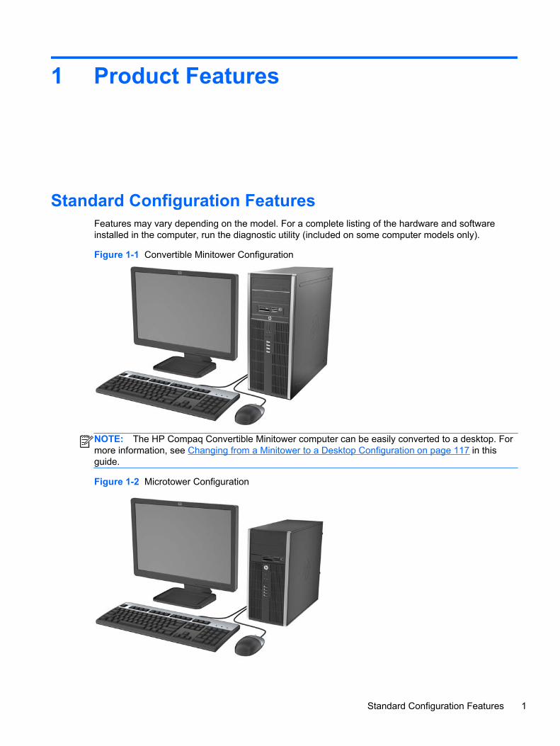
Standard Configuration FeaturesFeatures may vary depending on the model. For a complete listing of the hardware and softwareinstalled in the computer, run the diagnostic utility (included on some computer models only).
Figure 1-1 Convertible Minitower Configuration
NOTE: The HP Compaq Convertible Minitower computer can be easily converted to a desktop. Formore information, see Changing from a Minitower to a Desktop Configuration on page 117 in thisguide.
Figure 1-2 Microtower Configuration
Standard Configuration Features 1
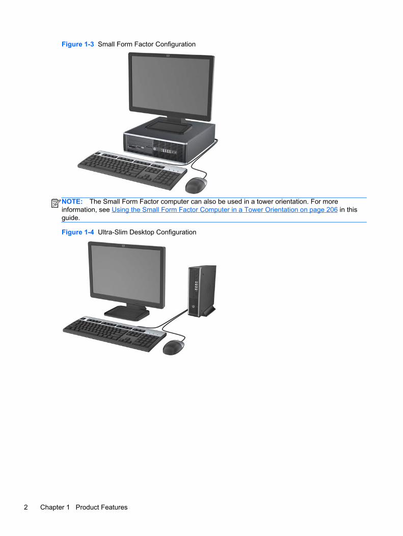
Figure 1-3 Small Form Factor Configuration
NOTE: The Small Form Factor computer can also be used in a tower orientation. For moreinformation, see Using the Small Form Factor Computer in a Tower Orientation on page 206 in thisguide.
Figure 1-4 Ultra-Slim Desktop Configuration
2 Chapter 1 Product Features
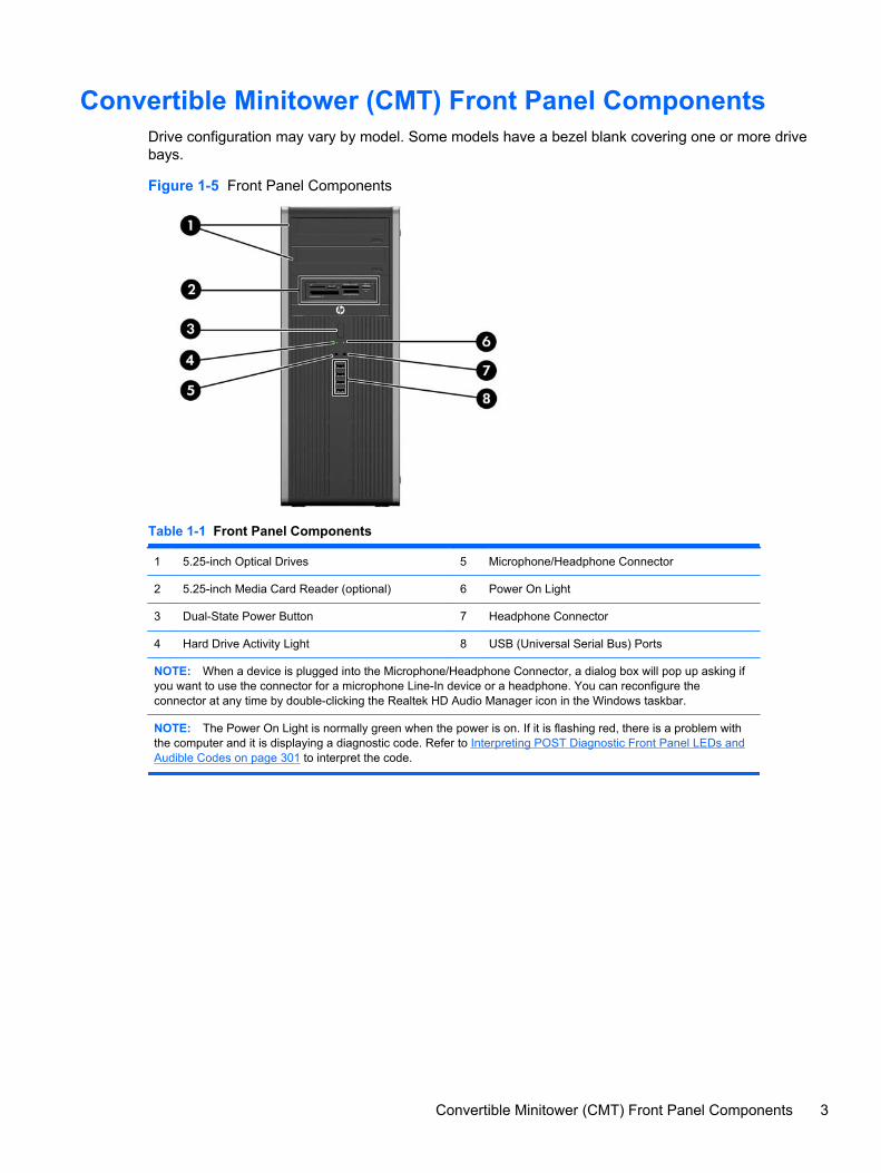
Convertible Minitower (CMT) Front Panel ComponentsDrive configuration may vary by model. Some models have a bezel blank covering one or more drivebays.
Figure 1-5 Front Panel Components
Table 1-1 Front Panel Components
1 5.25-inch Optical Drives 5 Microphone/Headphone Connector
2 5.25-inch Media Card Reader (optional) 6 Power On Light
3 Dual-State Power Button 7 Headphone Connector
4 Hard Drive Activity Light 8 USB (Universal Serial Bus) Ports
NOTE: When a device is plugged into the Microphone/Headphone Connector, a dialog box will pop up asking ifyou want to use the connector for a microphone Line-In device or a headphone. You can reconfigure theconnector at any time by double-clicking the Realtek HD Audio Manager icon in the Windows taskbar.
NOTE: The Power On Light is normally green when the power is on. If it is flashing red, there is a problem withthe computer and it is displaying a diagnostic code. Refer to Interpreting POST Diagnostic Front Panel LEDs andAudible Codes on page 301 to interpret the code.
Convertible Minitower (CMT) Front Panel Components 3
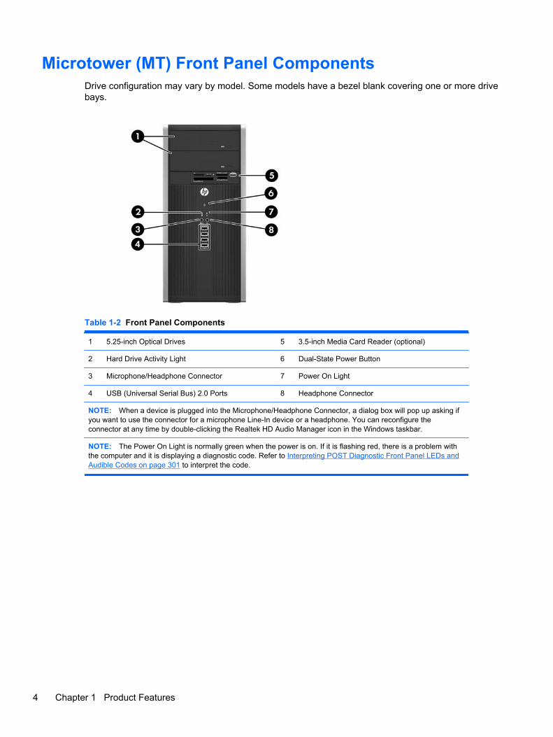
Microtower (MT) Front Panel ComponentsDrive configuration may vary by model. Some models have a bezel blank covering one or more drivebays.
Table 1-2 Front Panel Components
1 5.25-inch Optical Drives 5 3.5-inch Media Card Reader (optional)
2 Hard Drive Activity Light 6 Dual-State Power Button
3 Microphone/Headphone Connector 7 Power On Light
4 USB (Universal Serial Bus) 2.0 Ports 8 Headphone Connector
NOTE: When a device is plugged into the Microphone/Headphone Connector, a dialog box will pop up asking ifyou want to use the connector for a microphone Line-In device or a headphone. You can reconfigure theconnector at any time by double-clicking the Realtek HD Audio Manager icon in the Windows taskbar.
NOTE: The Power On Light is normally green when the power is on. If it is flashing red, there is a problem withthe computer and it is displaying a diagnostic code. Refer to Interpreting POST Diagnostic Front Panel LEDs andAudible Codes on page 301 to interpret the code.
4 Chapter 1 Product Features
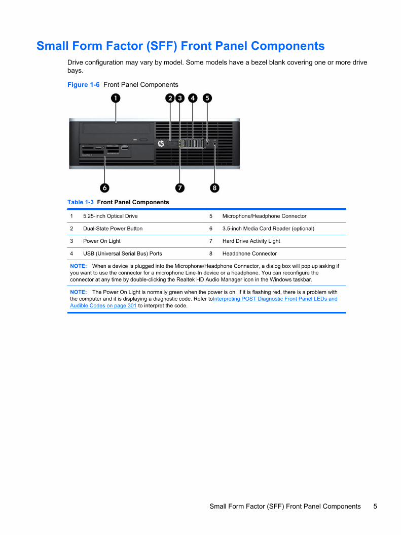
Small Form Factor (SFF) Front Panel ComponentsDrive configuration may vary by model. Some models have a bezel blank covering one or more drivebays.
Figure 1-6 Front Panel Components
Table 1-3 Front Panel Components
1 5.25-inch Optical Drive 5 Microphone/Headphone Connector
2 Dual-State Power Button 6 3.5-inch Media Card Reader (optional)
3 Power On Light 7 Hard Drive Activity Light
4 USB (Universal Serial Bus) Ports 8 Headphone Connector
NOTE: When a device is plugged into the Microphone/Headphone Connector, a dialog box will pop up asking ifyou want to use the connector for a microphone Line-In device or a headphone. You can reconfigure theconnector at any time by double-clicking the Realtek HD Audio Manager icon in the Windows taskbar.
NOTE: The Power On Light is normally green when the power is on. If it is flashing red, there is a problem withthe computer and it is displaying a diagnostic code. Refer toInterpreting POST Diagnostic Front Panel LEDs andAudible Codes on page 301 to interpret the code.
Small Form Factor (SFF) Front Panel Components 5
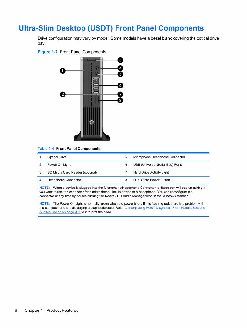
Ultra-Slim Desktop (USDT) Front Panel ComponentsDrive configuration may vary by model. Some models have a bezel blank covering the optical drivebay.
Figure 1-7 Front Panel Components
Table 1-4 Front Panel Components
1 Optical Drive 5 Microphone/Headphone Connector
2 Power On Light 6 USB (Universal Serial Bus) Ports
3 SD Media Card Reader (optional) 7 Hard Drive Activity Light
4 Headphone Connector 8 Dual-State Power Button
NOTE: When a device is plugged into the Microphone/Headphone Connector, a dialog box will pop up asking ifyou want to use the connector for a microphone Line-In device or a headphone. You can reconfigure theconnector at any time by double-clicking the Realtek HD Audio Manager icon in the Windows taskbar.
NOTE: The Power On Light is normally green when the power is on. If it is flashing red, there is a problem withthe computer and it is displaying a diagnostic code. Refer to Interpreting POST Diagnostic Front Panel LEDs andAudible Codes on page 301 to interpret the code.
6 Chapter 1 Product Features
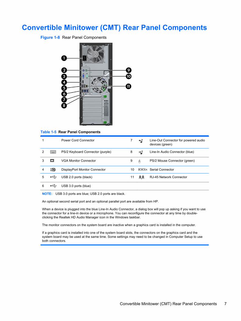
Convertible Minitower (CMT) Rear Panel ComponentsFigure 1-8 Rear Panel Components
Table 1-5 Rear Panel Components
1 Power Cord Connector 7 Line-Out Connector for powered audiodevices (green)
2 PS/2 Keyboard Connector (purple) 8 Line-In Audio Connector (blue)
3 VGA Monitor Connector 9 PS/2 Mouse Connector (green)
4 DisplayPort Monitor Connector 10 Serial Connector
5 USB 2.0 ports (black) 11 RJ-45 Network Connector
6 USB 3.0 ports (blue)
NOTE: USB 3.0 ports are blue; USB 2.0 ports are black.
An optional second serial port and an optional parallel port are available from HP.
When a device is plugged into the blue Line-In Audio Connector, a dialog box will pop up asking if you want to usethe connector for a line-in device or a microphone. You can reconfigure the connector at any time by double-clicking the Realtek HD Audio Manager icon in the Windows taskbar.
The monitor connectors on the system board are inactive when a graphics card is installed in the computer.
If a graphics card is installed into one of the system board slots, the connectors on the graphics card and thesystem board may be used at the same time. Some settings may need to be changed in Computer Setup to useboth connectors.
Convertible Minitower (CMT) Rear Panel Components 7
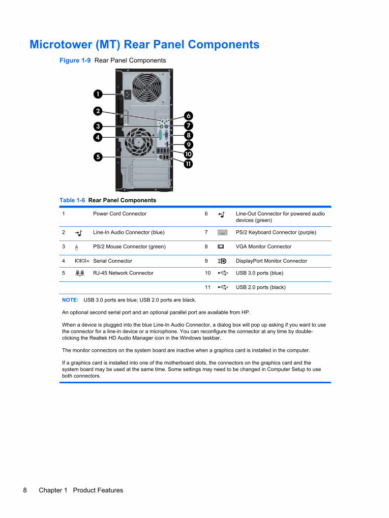
Microtower (MT) Rear Panel ComponentsFigure 1-9 Rear Panel Components
Table 1-6 Rear Panel Components
1 Power Cord Connector 6 Line-Out Connector for powered audiodevices (green)
2 Line-In Audio Connector (blue) 7 PS/2 Keyboard Connector (purple)
3 PS/2 Mouse Connector (green) 8 VGA Monitor Connector
4 Serial Connector 9 DisplayPort Monitor Connector
5 RJ-45 Network Connector 10 USB 3.0 ports (blue)
11 USB 2.0 ports (black)
NOTE: USB 3.0 ports are blue; USB 2.0 ports are black.
An optional second serial port and an optional parallel port are available from HP.
When a device is plugged into the blue Line-In Audio Connector, a dialog box will pop up asking if you want to usethe connector for a line-in device or a microphone. You can reconfigure the connector at any time by double-clicking the Realtek HD Audio Manager icon in the Windows taskbar.
The monitor connectors on the system board are inactive when a graphics card is installed in the computer.
If a graphics card is installed into one of the motherboard slots, the connectors on the graphics card and thesystem board may be used at the same time. Some settings may need to be changed in Computer Setup to useboth connectors.
8 Chapter 1 Product Features
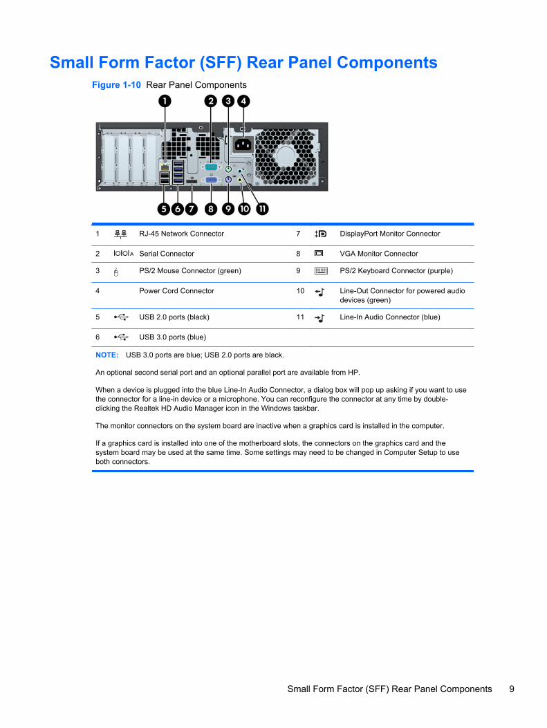
Small Form Factor (SFF) Rear Panel ComponentsFigure 1-10 Rear Panel Components
1 RJ-45 Network Connector 7 DisplayPort Monitor Connector
2 Serial Connector 8 VGA Monitor Connector
3 PS/2 Mouse Connector (green) 9 PS/2 Keyboard Connector (purple)
4 Power Cord Connector 10 Line-Out Connector for powered audiodevices (green)
5 USB 2.0 ports (black) 11 Line-In Audio Connector (blue)
6 USB 3.0 ports (blue)
NOTE: USB 3.0 ports are blue; USB 2.0 ports are black.
An optional second serial port and an optional parallel port are available from HP.
When a device is plugged into the blue Line-In Audio Connector, a dialog box will pop up asking if you want to usethe connector for a line-in device or a microphone. You can reconfigure the connector at any time by double-clicking the Realtek HD Audio Manager icon in the Windows taskbar.
The monitor connectors on the system board are inactive when a graphics card is installed in the computer.
If a graphics card is installed into one of the motherboard slots, the connectors on the graphics card and thesystem board may be used at the same time. Some settings may need to be changed in Computer Setup to useboth connectors.
Small Form Factor (SFF) Rear Panel Components 9
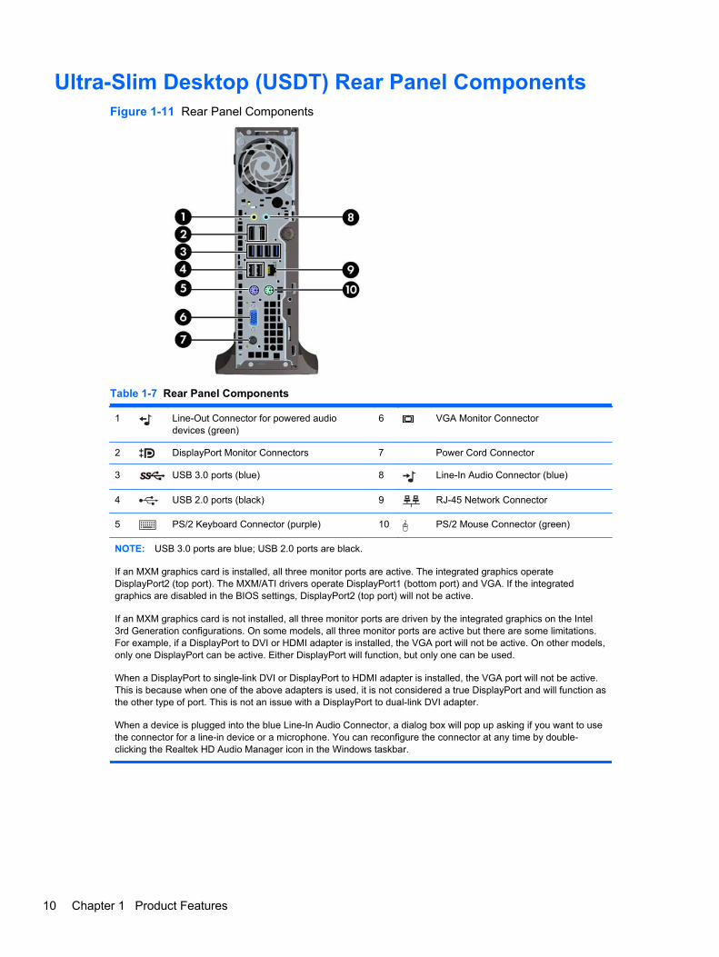
Ultra-Slim Desktop (USDT) Rear Panel ComponentsFigure 1-11 Rear Panel Components
Table 1-7 Rear Panel Components
1 Line-Out Connector for powered audiodevices (green)
6 VGA Monitor Connector
2 DisplayPort Monitor Connectors 7 Power Cord Connector
3 USB 3.0 ports (blue) 8 Line-In Audio Connector (blue)
4 USB 2.0 ports (black) 9 RJ-45 Network Connector
5 PS/2 Keyboard Connector (purple) 10 PS/2 Mouse Connector (green)
NOTE: USB 3.0 ports are blue; USB 2.0 ports are black.
If an MXM graphics card is installed, all three monitor ports are active. The integrated graphics operateDisplayPort2 (top port). The MXM/ATI drivers operate DisplayPort1 (bottom port) and VGA. If the integratedgraphics are disabled in the BIOS settings, DisplayPort2 (top port) will not be active.
If an MXM graphics card is not installed, all three monitor ports are driven by the integrated graphics on the Intel3rd Generation configurations. On some models, all three monitor ports are active but there are some limitations.For example, if a DisplayPort to DVI or HDMI adapter is installed, the VGA port will not be active. On other models,only one DisplayPort can be active. Either DisplayPort will function, but only one can be used.
When a DisplayPort to single-link DVI or DisplayPort to HDMI adapter is installed, the VGA port will not be active.This is because when one of the above adapters is used, it is not considered a true DisplayPort and will function asthe other type of port. This is not an issue with a DisplayPort to dual-link DVI adapter.
When a device is plugged into the blue Line-In Audio Connector, a dialog box will pop up asking if you want to usethe connector for a line-in device or a microphone. You can reconfigure the connector at any time by double-clicking the Realtek HD Audio Manager icon in the Windows taskbar.
10 Chapter 1 Product Features
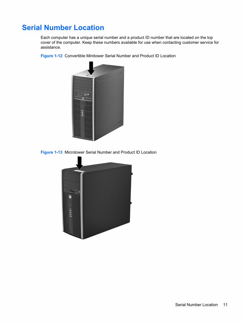
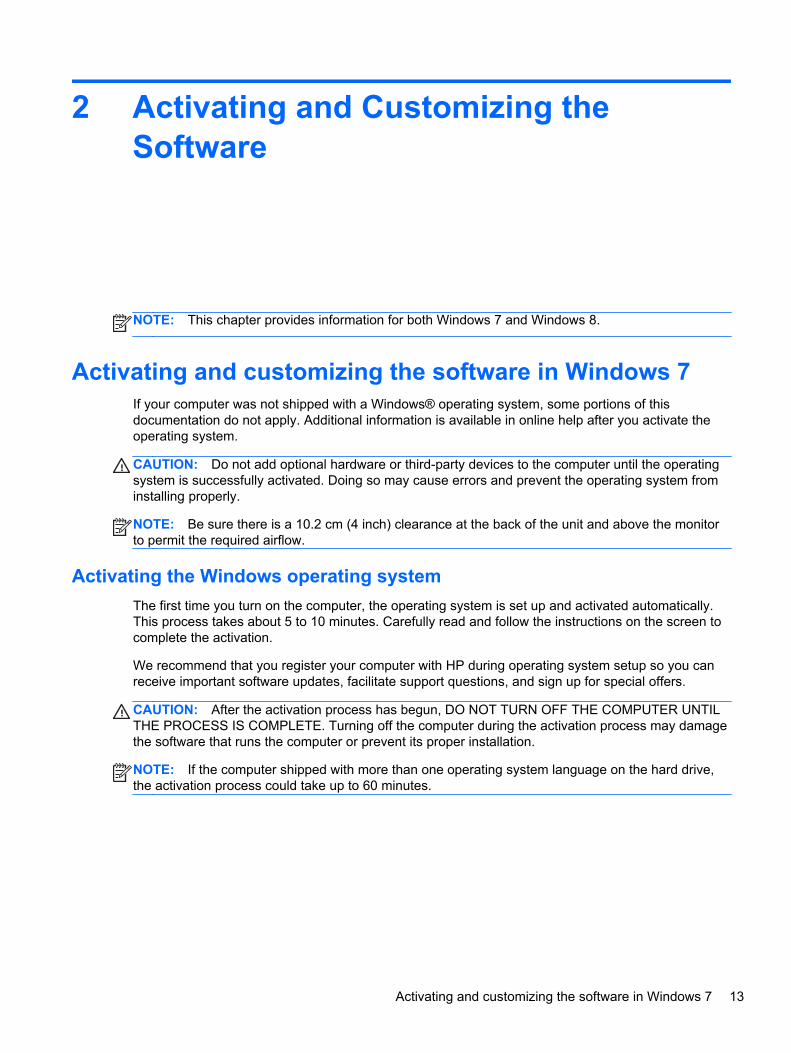
Serial Number LocationEach computer has a unique serial number and a product ID number that are located on the topcover of the computer. Keep these numbers available for use when contacting customer service forassistance.
Figure 1-12 Convertible Minitower Serial Number and Product ID Location
Figure 1-13 Microtower Serial Number and Product ID Location
Serial Number Location 11
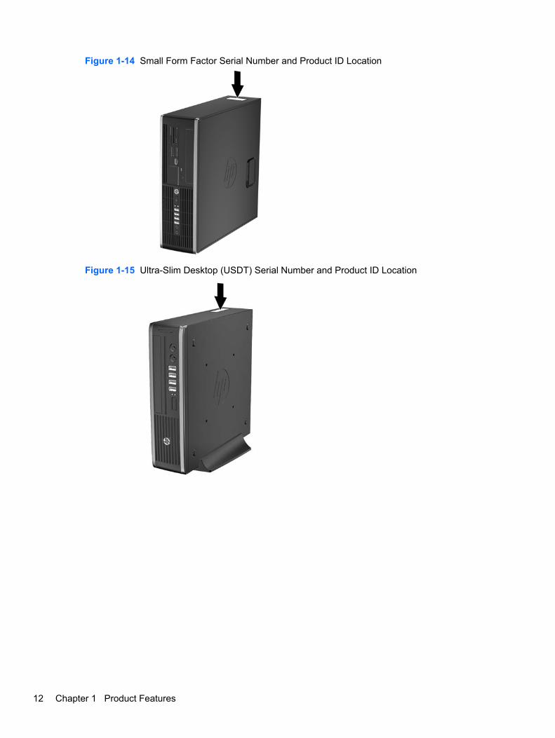
Figure 1-14 Small Form Factor Serial Number and Product ID Location
Figure 1-15 Ultra-Slim Desktop (USDT) Serial Number and Product ID Location
12 Chapter 1 Product Features
2 Activating and Customizing theSoftware
NOTE: This chapter provides information for both Windows 7 and Windows 8.
Activating and customizing the software in Windows 7If your computer was not shipped with a Windows® operating system, some portions of thisdocumentation do not apply. Additional information is available in online help after you activate theoperating system.
CAUTION: Do not add optional hardware or third-party devices to the computer until the operatingsystem is successfully activated. Doing so may cause errors and prevent the operating system frominstalling properly.
NOTE: Be sure there is a 10.2 cm (4 inch) clearance at the back of the unit and above the monitorto permit the required airflow.
Activating the Windows operating system
The first time you turn on the computer, the operating system is set up and activated automatically.This process takes about 5 to 10 minutes. Carefully read and follow the instructions on the screen tocomplete the activation.
We recommend that you register your computer with HP during operating system setup so you canreceive important software updates, facilitate support questions, and sign up for special offers.
CAUTION: After the activation process has begun, DO NOT TURN OFF THE COMPUTER UNTILTHE PROCESS IS COMPLETE. Turning off the computer during the activation process may damagethe software that runs the computer or prevent its proper installation.
NOTE: If the computer shipped with more than one operating system language on the hard drive,the activation process could take up to 60 minutes.
Activating and customizing the software in Windows 7 13
Downloading Windows 7 updates
Microsoft may release updates to the operating system. To help keep the computer running optimally,HP recommends checking for the latest updates during the initial installation and periodicallythroughout the life of the computer.
1. To set up your Internet connection, click Start > Internet Explorer and follow the instructions onthe screen.
2. After an Internet connection has been established, click the Start > All Programs > WindowsUpdate.
3. Run Windows Update monthly thereafter.
Installing or upgrading device drivers
When installing optional hardware devices after the operating system installation is complete, youmust also install the drivers for each of the devices.
In Windows 7, if prompted for the i386 directory, replace the path specification with C:\i386, or usethe Browse button in the dialog box to locate the i386 folder. This action points the operating systemto the appropriate drivers.
Obtain the latest support software, including support software for the operating system, fromhttp://www.hp.com/support. Select your country and language, select Download drivers andsoftware (and firmware), enter the model number of the computer, and press Enter.
Customizing the monitor display
If you wish, you can select or change the monitor refresh rates, screen resolution, color settings, fontsizes, and power management settings.
For more information, refer to the online documentation provided with the graphics controller utility orthe documentation that came with your monitor.
Right-click on the Windows desktop, then click Personalize to change display settings.
Activating and customizing the software in Windows 8Additional information is available in online help after you activate the operating system.
NOTE: Be sure there is a 10.2 cm (4 inch) clearance at the back of the unit and above the monitorto permit the required airflow.
Activating the Windows Operating System
The first time you turn on the computer, the operating system is set up and activated automatically.This process takes about 5 to 10 minutes. Carefully read and follow the instructions on the screen tocomplete the activation.
We recommend that you register your computer with HP during operating system set up so you canreceive important software updates, facilitate support questions, and sign up for special offers. Youcan also register your computer with HP using the Register with HP app on the Start screen.
14 Chapter 2 Activating and Customizing the Software
CAUTION: After the activation process has begun, DO NOT TURN OFF THE COMPUTER UNTILTHE PROCESS IS COMPLETE. Turning off the computer during the activation process may damagethe software that runs the computer or prevent its proper installation.
Downloading Windows 8 updates
Microsoft may release updates to the operating system. To help keep the computer running optimally,HP recommends checking for the latest updates during the initial installation and periodicallythroughout the life of the computer.
Run Windows Update as soon as possible after you set up your computer.
1. Point to the upper-right or lower-right corner of the Start screen to display the charms.
2. Click Settings > Change PC Settings > Windows Update.
3. Run Windows Update monthly thereafter.
Customizing the monitor display
You can customize display settings for Windows 8 separately for the Start screen and the Desktop.
To customize the Start screen:
1. Point to the upper-right or lower-right corner of the Start screen to display the charms.
2. Click Settings > Change PC Settings.
3. Click Personalize to change the display settings.
To customize the Desktop:
1. Click the Desktop app on the Start screen.
2. Right-click on the desktop, and then click Personalize to change display settings.
Activating and customizing the software in Windows 8 15
3 Computer Setup (F10) Utility
Computer Setup (F10) UtilitiesUse Computer Setup (F10) Utility to do the following:
● Change factory default settings.
● Set the system date and time.
● Set, view, change, or verify the system configuration, including settings for processor, graphics,memory, audio, storage, communications, and input devices.
● Modify the boot order of bootable devices such as hard drives, optical drives, or USB flashmedia devices.
● Enable Quick Boot, which is faster than Full Boot but does not run all of the diagnostic tests runduring a Full Boot. You can set the system to:
❑ always Quick Boot (default);
❑ periodically Full Boot (from every 1 to 30 days); or
❑ always Full Boot.
● Select Post Messages Enabled or Disabled to change the display status of Power-On Self-Test(POST) messages. Post Messages Disabled suppresses most POST messages, such asmemory count, product name, and other non-error text messages. If a POST error occurs, theerror is displayed regardless of the mode selected. To manually switch to Post MessagesEnabled during POST, press any key (except F1 through F12).
● Establish an Ownership Tag, the text of which is displayed each time the system is turned on orrestarted.
● Enter the Asset Tag or property identification number assigned by the company to this computer.
● Enable the power-on password prompt during system restarts (warm boots) as well as duringpower-on.
● Establish a setup password that controls access to the Computer Setup (F10) Utility and thesettings described in this section.
● Secure integrated I/O functionality, including the serial, USB, or parallel ports, audio, orembedded NIC, so that they cannot be used until they are unsecured.
● Enable or disable removable media boot ability.
16 Chapter 3 Computer Setup (F10) Utility
● Solve system configuration errors detected but not automatically fixed during the Power-On Self-Test (POST).
● Replicate the system setup by saving system configuration information on a USB device andrestoring it on one or more computers.
● Execute self-tests on a specified ATA hard drive (when supported by drive).
● Enable or disable DriveLock security (when supported by drive).
Using Computer Setup (F10) Utilities
Computer Setup can be accessed only by turning the computer on or restarting the system.To access the Computer Setup Utilities menu, complete the following steps:
1. Turn on or restart the computer.
2. Repeatedly press F10 when the monitor light turns green to access the utility.
You can also press Esc to a menu that allows you to access different options available atstartup, including the Computer Setup utility.
NOTE: If you do not press F10 at the appropriate time, you must restart the computer andagain repeatedly press F10 when the monitor light turns green to access the utility.
3. A choice of five headings appears in the Computer Setup Utilities menu: File, Storage, Security,Power, and Advanced.
4. Use the arrow (left and right) keys to select the appropriate heading. Use the arrow (up anddown) keys to select the option you want, then press Enter. To return to the Computer SetupUtilities menu, press Esc.
5. To apply and save changes, select File > Save Changes and Exit.
● If you have made changes that you do not want applied, select Ignore Changes and Exit.
● To reset to factory settings or previously saved default settings (some models), selectApply Defaults and Exit. This option will restore the original factory system defaults.
NOTE: Not all settings shown in the following sections are available for all models
CAUTION: Do NOT turn the computer power OFF while the BIOS is saving the Computer Setup(F10) changes because the CMOS could become corrupted. It is safe to turn off the computer onlyafter exiting the F10 Setup screen.
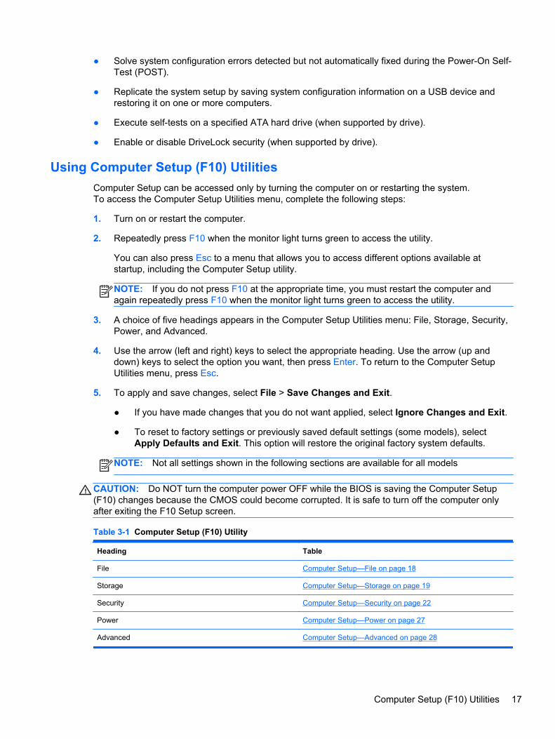
Table 3-1 Computer Setup (F10) Utility
Heading Table
File Computer Setup—File on page 18
Storage Computer Setup—Storage on page 19
Security Computer Setup—Security on page 22
Power Computer Setup—Power on page 27
Advanced Computer Setup—Advanced on page 28
Computer Setup (F10) Utilities 17
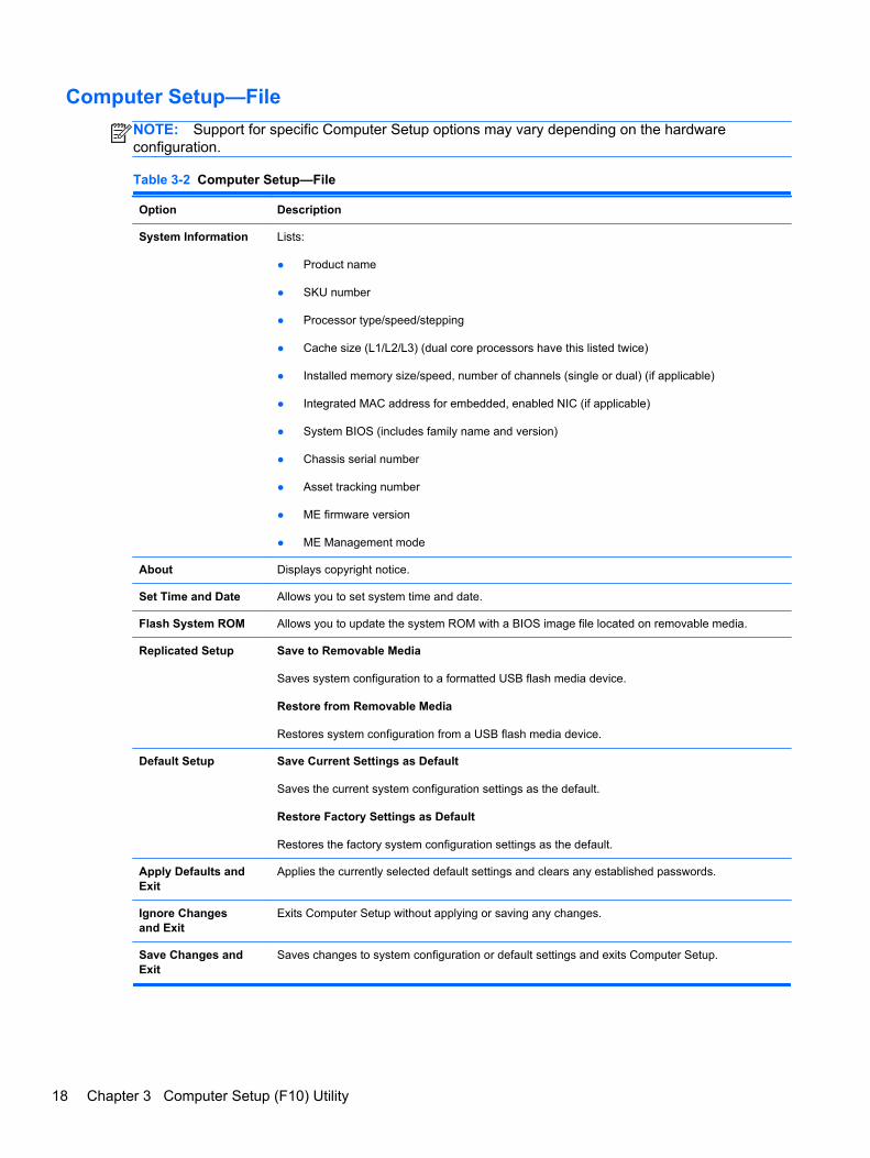
Computer Setup—File
NOTE: Support for specific Computer Setup options may vary depending on the hardwareconfiguration.
Table 3-2 Computer Setup—File
Option Description
System Information Lists:
● Product name
● SKU number
● Processor type/speed/stepping
● Cache size (L1/L2/L3) (dual core processors have this listed twice)
● Installed memory size/speed, number of channels (single or dual) (if applicable)
● Integrated MAC address for embedded, enabled NIC (if applicable)
● System BIOS (includes family name and version)
● Chassis serial number
● Asset tracking number
● ME firmware version
● ME Management mode
About Displays copyright notice.
Set Time and Date Allows you to set system time and date.
Flash System ROM Allows you to update the system ROM with a BIOS image file located on removable media.
Replicated Setup Save to Removable Media
Saves system configuration to a formatted USB flash media device.
Restore from Removable Media
Restores system configuration from a USB flash media device.
Default Setup Save Current Settings as Default
Saves the current system configuration settings as the default.
Restore Factory Settings as Default
Restores the factory system configuration settings as the default.
Apply Defaults andExit
Applies the currently selected default settings and clears any established passwords.
Ignore Changesand Exit
Exits Computer Setup without applying or saving any changes.
Save Changes andExit
Saves changes to system configuration or default settings and exits Computer Setup.
18 Chapter 3 Computer Setup (F10) Utility
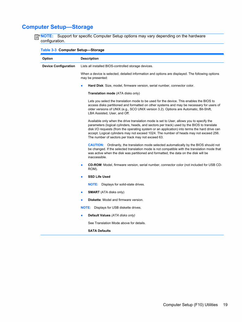
Computer Setup—Storage
NOTE: Support for specific Computer Setup options may vary depending on the hardwareconfiguration.
Table 3-3 Computer Setup—Storage
Option Description
Device Configuration Lists all installed BIOS-controlled storage devices.
When a device is selected, detailed information and options are displayed. The following optionsmay be presented:
● Hard Disk: Size, model, firmware version, serial number, connector color.
Translation mode (ATA disks only)
Lets you select the translation mode to be used for the device. This enables the BIOS toaccess disks partitioned and formatted on other systems and may be necessary for users ofolder versions of UNIX (e.g., SCO UNIX version 3.2). Options are Automatic, Bit-Shift,LBA Assisted, User, and Off.
Available only when the drive translation mode is set to User, allows you to specify theparameters (logical cylinders, heads, and sectors per track) used by the BIOS to translatedisk I/O requests (from the operating system or an application) into terms the hard drive canaccept. Logical cylinders may not exceed 1024. The number of heads may not exceed 256.The number of sectors per track may not exceed 63.
CAUTION: Ordinarily, the translation mode selected automatically by the BIOS should notbe changed. If the selected translation mode is not compatible with the translation mode thatwas active when the disk was partitioned and formatted, the data on the disk will beinaccessible.
● CD-ROM: Model, firmware version, serial number, connector color (not included for USB CD-ROM).
● SSD Life Used
NOTE: Displays for solid-state drives.
● SMART (ATA disks only)
● Diskette: Model and firmware version.
NOTE: Displays for USB diskette drives.
● Default Values (ATA disks only)
See Translation Mode above for details.
SATA Defaults
Computer Setup (F10) Utilities 19
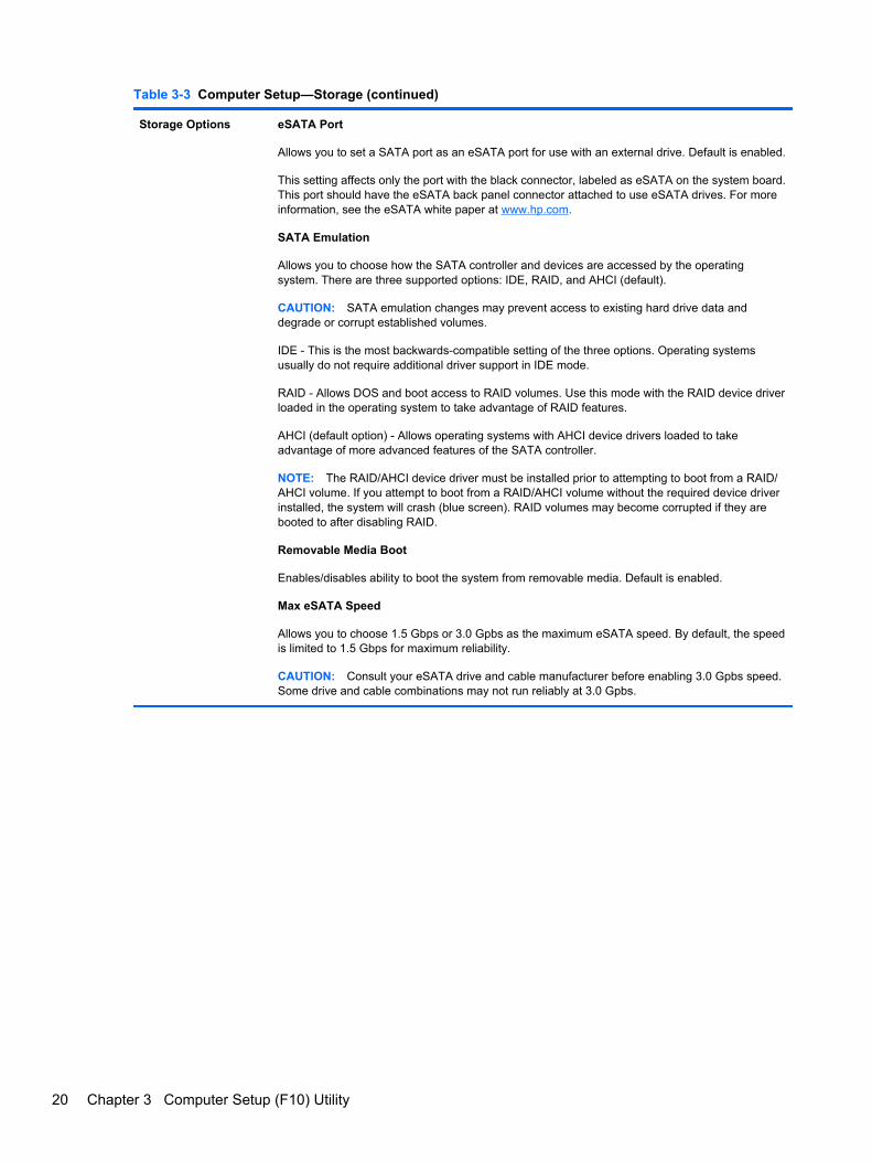
Table 3-3 Computer Setup—Storage (continued)
Storage Options eSATA Port
Allows you to set a SATA port as an eSATA port for use with an external drive. Default is enabled.
This setting affects only the port with the black connector, labeled as eSATA on the system board.This port should have the eSATA back panel connector attached to use eSATA drives. For moreinformation, see the eSATA white paper at www.hp.com.
SATA Emulation
Allows you to choose how the SATA controller and devices are accessed by the operatingsystem. There are three supported options: IDE, RAID, and AHCI (default).
CAUTION: SATA emulation changes may prevent access to existing hard drive data anddegrade or corrupt established volumes.
IDE - This is the most backwards-compatible setting of the three options. Operating systemsusually do not require additional driver support in IDE mode.
RAID - Allows DOS and boot access to RAID volumes. Use this mode with the RAID device driverloaded in the operating system to take advantage of RAID features.
AHCI (default option) - Allows operating systems with AHCI device drivers loaded to takeadvantage of more advanced features of the SATA controller.
NOTE: The RAID/AHCI device driver must be installed prior to attempting to boot from a RAID/AHCI volume. If you attempt to boot from a RAID/AHCI volume without the required device driverinstalled, the system will crash (blue screen). RAID volumes may become corrupted if they arebooted to after disabling RAID.
Removable Media Boot
Enables/disables ability to boot the system from removable media. Default is enabled.
Max eSATA Speed
Allows you to choose 1.5 Gbps or 3.0 Gpbs as the maximum eSATA speed. By default, the speedis limited to 1.5 Gbps for maximum reliability.
CAUTION: Consult your eSATA drive and cable manufacturer before enabling 3.0 Gpbs speed.Some drive and cable combinations may not run reliably at 3.0 Gpbs.
20 Chapter 3 Computer Setup (F10) Utility

Table 3-3 Computer Setup—Storage (continued)
DPS Self-Test Allows you to execute self-tests on ATA hard drives capable of performing the Drive ProtectionSystem (DPS) self-tests.
NOTE: This selection will only appear when at least one drive capable of performing the DPSself-tests is attached to the system.
Boot Order Allows you to:
● EFI Boot Sources: Specify the order in which EFI boot sources (such as a internal harddrive, USB hard drive, USB optical drive, or internal optical drive) are checked for a bootableoperating system image. Each device on the list may be individually excluded from orincluded for consideration as a bootable operating system source.
EFI boot sources always have precedence over legacy boot sources.
● Legacy Boot Sources: Specify the order in which legacy boot sources (such as a networkinterface card, internal hard drive, USB optical drive, or internal optical drive) are checked fora bootable operating system image. Each device on the list may be individually excludedfrom or included for consideration as a bootable operating system source.
Specify the order of attached hard drives. The first hard drive in the order will have priority inthe boot sequence and will be recognized as drive C (if any devices are attached).
NOTE: To drag a device to a preferred place, press Enter. To remove the device fromconsideration as a bootable device, press F5.
You can use F5 to disable individual boot items, as well as disable EFI boot and/or legacy boot.
NOTE: MS-DOS drive lettering assignments may not apply after a non-MS-DOS operatingsystem has started.
Shortcut to Temporarily Override Boot Order
To boot one time from a device other than the default device specified in Boot Order, restart thecomputer and press Esc (to access the boot menu) and then F9 (Boot Order), or only F9 (skippingthe boot menu) when the monitor light turns green. After POST is completed, a list of bootabledevices is displayed. Use the arrow keys to select the preferred bootable device and press Enter.The computer then boots from the selected non-default device for this one time.
Computer Setup (F10) Utilities 21
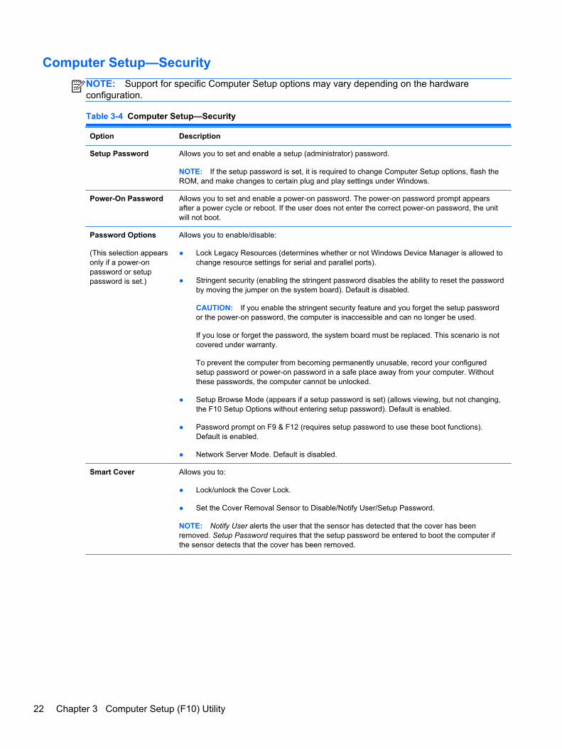
Computer Setup—Security
NOTE: Support for specific Computer Setup options may vary depending on the hardwareconfiguration.
Table 3-4 Computer Setup—Security
Option Description
Setup Password Allows you to set and enable a setup (administrator) password.
NOTE: If the setup password is set, it is required to change Computer Setup options, flash theROM, and make changes to certain plug and play settings under Windows.
Power-On Password Allows you to set and enable a power-on password. The power-on password prompt appearsafter a power cycle or reboot. If the user does not enter the correct power-on password, the unitwill not boot.
Password Options
(This selection appearsonly if a power-onpassword or setuppassword is set.)
Allows you to enable/disable:
● Lock Legacy Resources (determines whether or not Windows Device Manager is allowed tochange resource settings for serial and parallel ports).
● Stringent security (enabling the stringent password disables the ability to reset the passwordby moving the jumper on the system board). Default is disabled.
CAUTION: If you enable the stringent security feature and you forget the setup passwordor the power-on password, the computer is inaccessible and can no longer be used.
If you lose or forget the password, the system board must be replaced. This scenario is notcovered under warranty.
To prevent the computer from becoming permanently unusable, record your configuredsetup password or power-on password in a safe place away from your computer. Withoutthese passwords, the computer cannot be unlocked.
● Setup Browse Mode (appears if a setup password is set) (allows viewing, but not changing,the F10 Setup Options without entering setup password). Default is enabled.
● Password prompt on F9 & F12 (requires setup password to use these boot functions).Default is enabled.
● Network Server Mode. Default is disabled.
Smart Cover Allows you to:
● Lock/unlock the Cover Lock.
● Set the Cover Removal Sensor to Disable/Notify User/Setup Password.
NOTE: Notify User alerts the user that the sensor has detected that the cover has beenremoved. Setup Password requires that the setup password be entered to boot the computer ifthe sensor detects that the cover has been removed.
22 Chapter 3 Computer Setup (F10) Utility
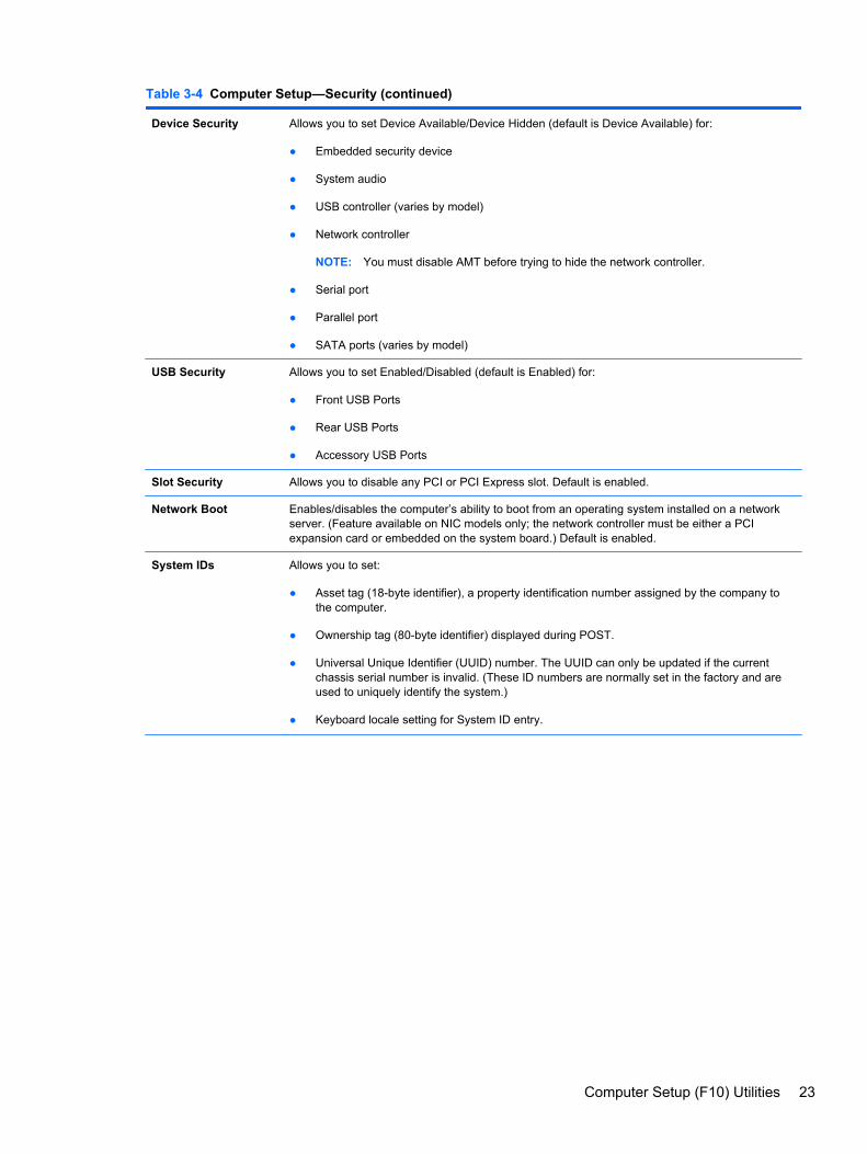
Table 3-4 Computer Setup—Security (continued)
Device Security Allows you to set Device Available/Device Hidden (default is Device Available) for:
● Embedded security device
● System audio
● USB controller (varies by model)
● Network controller
NOTE: You must disable AMT before trying to hide the network controller.
● Serial port
● Parallel port
● SATA ports (varies by model)
USB Security Allows you to set Enabled/Disabled (default is Enabled) for:
● Front USB Ports
● Rear USB Ports
● Accessory USB Ports
Slot Security Allows you to disable any PCI or PCI Express slot. Default is enabled.
Network Boot Enables/disables the computer’s ability to boot from an operating system installed on a networkserver. (Feature available on NIC models only; the network controller must be either a PCIexpansion card or embedded on the system board.) Default is enabled.
System IDs Allows you to set:
● Asset tag (18-byte identifier), a property identification number assigned by the company tothe computer.
● Ownership tag (80-byte identifier) displayed during POST.
● Universal Unique Identifier (UUID) number. The UUID can only be updated if the currentchassis serial number is invalid. (These ID numbers are normally set in the factory and areused to uniquely identify the system.)
● Keyboard locale setting for System ID entry.
Computer Setup (F10) Utilities 23
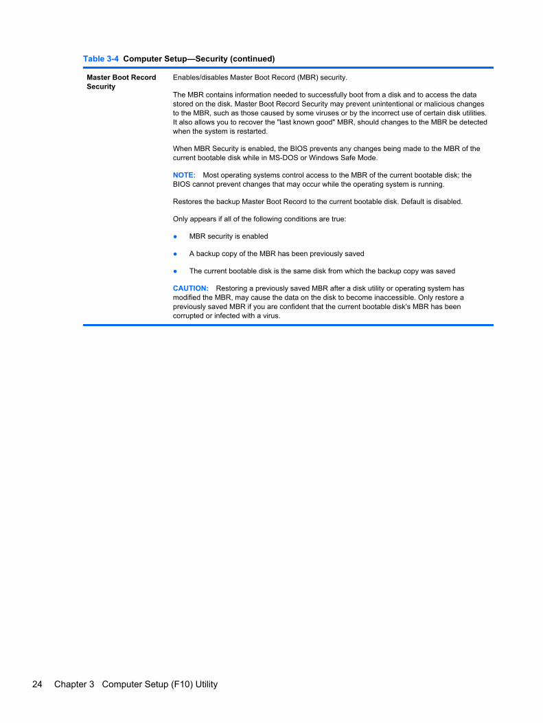
Table 3-4 Computer Setup—Security (continued)
Master Boot RecordSecurity
Enables/disables Master Boot Record (MBR) security.
The MBR contains information needed to successfully boot from a disk and to access the datastored on the disk. Master Boot Record Security may prevent unintentional or malicious changesto the MBR, such as those caused by some viruses or by the incorrect use of certain disk utilities.It also allows you to recover the "last known good" MBR, should changes to the MBR be detectedwhen the system is restarted.
When MBR Security is enabled, the BIOS prevents any changes being made to the MBR of thecurrent bootable disk while in MS-DOS or Windows Safe Mode.
NOTE: Most operating systems control access to the MBR of the current bootable disk; theBIOS cannot prevent changes that may occur while the operating system is running.
Restores the backup Master Boot Record to the current bootable disk. Default is disabled.
Only appears if all of the following conditions are true:
● MBR security is enabled
● A backup copy of the MBR has been previously saved
● The current bootable disk is the same disk from which the backup copy was saved
CAUTION: Restoring a previously saved MBR after a disk utility or operating system hasmodified the MBR, may cause the data on the disk to become inaccessible. Only restore apreviously saved MBR if you are confident that the current bootable disk's MBR has beencorrupted or infected with a virus.
24 Chapter 3 Computer Setup (F10) Utility
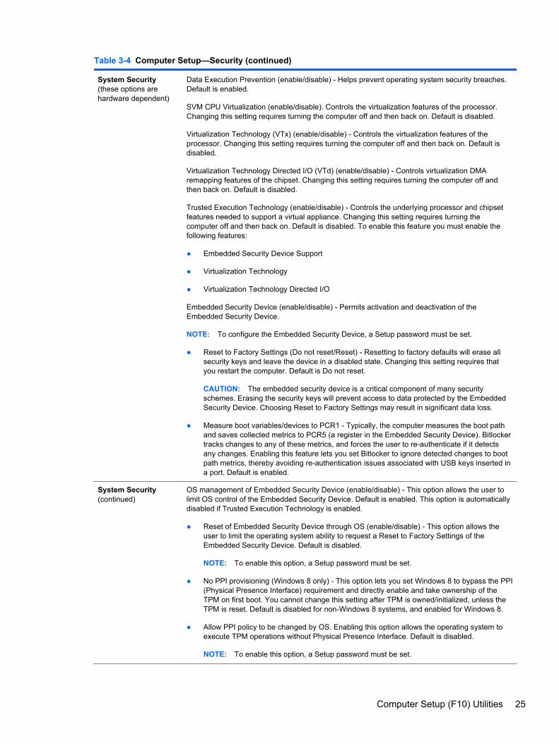
Table 3-4 Computer Setup—Security (continued)
System Security(these options arehardware dependent)
Data Execution Prevention (enable/disable) - Helps prevent operating system security breaches.Default is enabled.
SVM CPU Virtualization (enable/disable). Controls the virtualization features of the processor.Changing this setting requires turning the computer off and then back on. Default is disabled.
Virtualization Technology (VTx) (enable/disable) - Controls the virtualization features of theprocessor. Changing this setting requires turning the computer off and then back on. Default isdisabled.
Virtualization Technology Directed I/O (VTd) (enable/disable) - Controls virtualization DMAremapping features of the chipset. Changing this setting requires turning the computer off andthen back on. Default is disabled.
Trusted Execution Technology (enable/disable) - Controls the underlying processor and chipsetfeatures needed to support a virtual appliance. Changing this setting requires turning thecomputer off and then back on. Default is disabled. To enable this feature you must enable thefollowing features:
● Embedded Security Device Support
● Virtualization Technology
● Virtualization Technology Directed I/O
Embedded Security Device (enable/disable) - Permits activation and deactivation of theEmbedded Security Device.
NOTE: To configure the Embedded Security Device, a Setup password must be set.
● Reset to Factory Settings (Do not reset/Reset) - Resetting to factory defaults will erase allsecurity keys and leave the device in a disabled state. Changing this setting requires thatyou restart the computer. Default is Do not reset.
CAUTION: The embedded security device is a critical component of many securityschemes. Erasing the security keys will prevent access to data protected by the EmbeddedSecurity Device. Choosing Reset to Factory Settings may result in significant data loss.
● Measure boot variables/devices to PCR1 - Typically, the computer measures the boot pathand saves collected metrics to PCR5 (a register in the Embedded Security Device). Bitlockertracks changes to any of these metrics, and forces the user to re-authenticate if it detectsany changes. Enabling this feature lets you set Bitlocker to ignore detected changes to bootpath metrics, thereby avoiding re-authentication issues associated with USB keys inserted ina port. Default is enabled.
System Security(continued)
OS management of Embedded Security Device (enable/disable) - This option allows the user tolimit OS control of the Embedded Security Device. Default is enabled. This option is automaticallydisabled if Trusted Execution Technology is enabled.
● Reset of Embedded Security Device through OS (enable/disable) - This option allows theuser to limit the operating system ability to request a Reset to Factory Settings of theEmbedded Security Device. Default is disabled.
NOTE: To enable this option, a Setup password must be set.
● No PPI provisioning (Windows 8 only) - This option lets you set Windows 8 to bypass the PPI(Physical Presence Interface) requirement and directly enable and take ownership of theTPM on first boot. You cannot change this setting after TPM is owned/initialized, unless theTPM is reset. Default is disabled for non-Windows 8 systems, and enabled for Windows 8.
● Allow PPI policy to be changed by OS. Enabling this option allows the operating system toexecute TPM operations without Physical Presence Interface. Default is disabled.
NOTE: To enable this option, a Setup password must be set.
Computer Setup (F10) Utilities 25
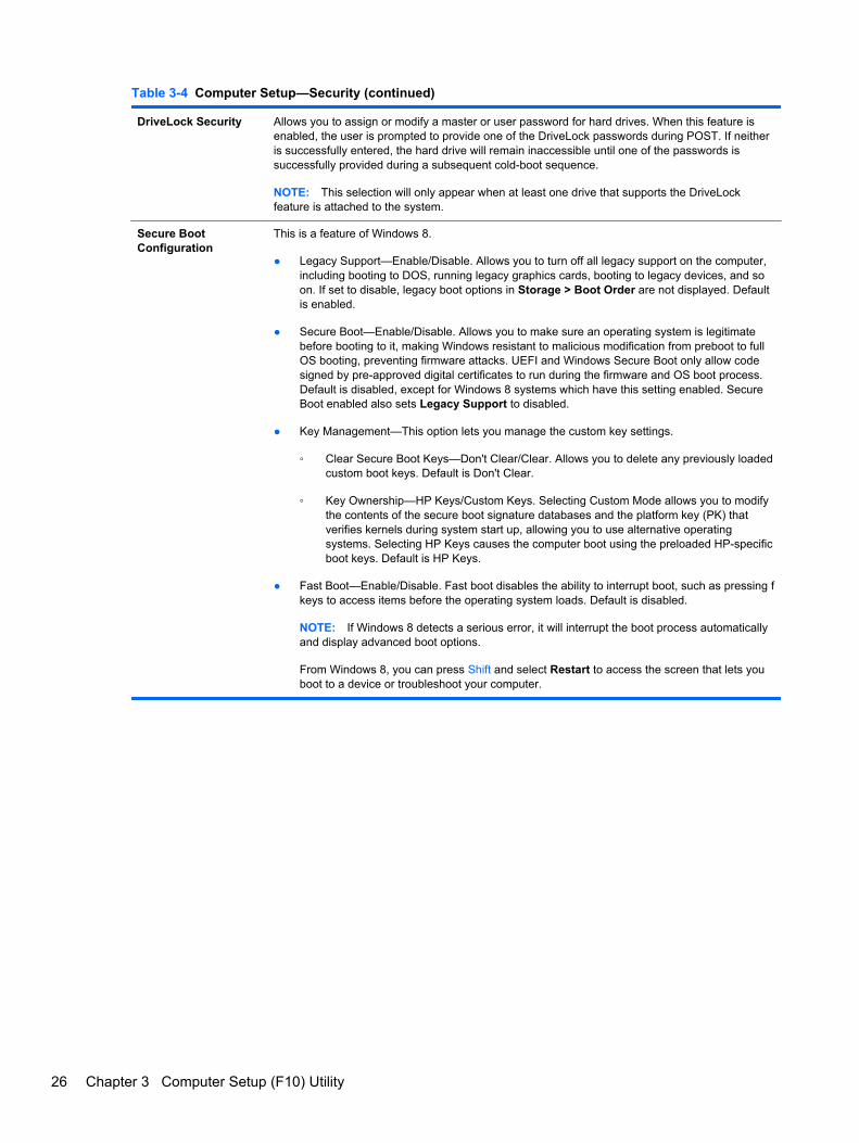
Table 3-4 Computer Setup—Security (continued)
DriveLock Security Allows you to assign or modify a master or user password for hard drives. When this feature isenabled, the user is prompted to provide one of the DriveLock passwords during POST. If neitheris successfully entered, the hard drive will remain inaccessible until one of the passwords issuccessfully provided during a subsequent cold-boot sequence.
NOTE: This selection will only appear when at least one drive that supports the DriveLockfeature is attached to the system.
Secure BootConfiguration
This is a feature of Windows 8.
● Legacy Support—Enable/Disable. Allows you to turn off all legacy support on the computer,including booting to DOS, running legacy graphics cards, booting to legacy devices, and soon. If set to disable, legacy boot options in Storage > Boot Order are not displayed. Defaultis enabled.
● Secure Boot—Enable/Disable. Allows you to make sure an operating system is legitimatebefore booting to it, making Windows resistant to malicious modification from preboot to fullOS booting, preventing firmware attacks. UEFI and Windows Secure Boot only allow codesigned by pre-approved digital certificates to run during the firmware and OS boot process.Default is disabled, except for Windows 8 systems which have this setting enabled. SecureBoot enabled also sets Legacy Support to disabled.
● Key Management—This option lets you manage the custom key settings.
◦ Clear Secure Boot Keys—Don't Clear/Clear. Allows you to delete any previously loadedcustom boot keys. Default is Don't Clear.
◦ Key Ownership—HP Keys/Custom Keys. Selecting Custom Mode allows you to modifythe contents of the secure boot signature databases and the platform key (PK) thatverifies kernels during system start up, allowing you to use alternative operatingsystems. Selecting HP Keys causes the computer boot using the preloaded HP-specificboot keys. Default is HP Keys.
● Fast Boot—Enable/Disable. Fast boot disables the ability to interrupt boot, such as pressing fkeys to access items before the operating system loads. Default is disabled.
NOTE: If Windows 8 detects a serious error, it will interrupt the boot process automaticallyand display advanced boot options.
From Windows 8, you can press Shift and select Restart to access the screen that lets youboot to a device or troubleshoot your computer.
26 Chapter 3 Computer Setup (F10) Utility
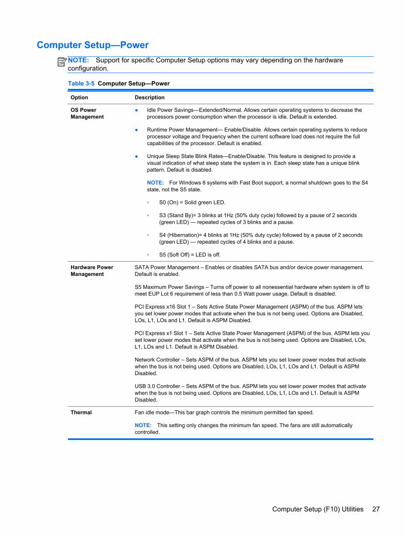
Computer Setup—Power
NOTE: Support for specific Computer Setup options may vary depending on the hardwareconfiguration.
Table 3-5 Computer Setup—Power
Option Description
OS PowerManagement
● Idle Power Savings—Extended/Normal. Allows certain operating systems to decrease theprocessors power consumption when the processor is idle. Default is extended.
● Runtime Power Management— Enable/Disable. Allows certain operating systems to reduceprocessor voltage and frequency when the current software load does not require the fullcapabilities of the processor. Default is enabled.
● Unique Sleep State Blink Rates—Enable/Disable. This feature is designed to provide avisual indication of what sleep state the system is in. Each sleep state has a unique blinkpattern. Default is disabled.
NOTE: For Windows 8 systems with Fast Boot support, a normal shutdown goes to the S4state, not the S5 state.
◦ S0 (On) = Solid green LED.
◦ S3 (Stand By)= 3 blinks at 1Hz (50% duty cycle) followed by a pause of 2 seconds(green LED) — repeated cycles of 3 blinks and a pause.
◦ S4 (Hibernation)= 4 blinks at 1Hz (50% duty cycle) followed by a pause of 2 seconds(green LED) — repeated cycles of 4 blinks and a pause.
◦ S5 (Soft Off) = LED is off.
Hardware PowerManagement
SATA Power Management – Enables or disables SATA bus and/or device power management.Default is enabled.
S5 Maximum Power Savings – Turns off power to all nonessential hardware when system is off tomeet EUP Lot 6 requirement of less than 0.5 Watt power usage. Default is disabled.
PCI Express x16 Slot 1 – Sets Active State Power Management (ASPM) of the bus. ASPM letsyou set lower power modes that activate when the bus is not being used. Options are Disabled,LOs, L1, LOs and L1. Default is ASPM Disabled.
PCI Express x1 Slot 1 – Sets Active State Power Management (ASPM) of the bus. ASPM lets youset lower power modes that activate when the bus is not being used. Options are Disabled, LOs,L1, LOs and L1. Default is ASPM Disabled.
Network Controller – Sets ASPM of the bus. ASPM lets you set lower power modes that activatewhen the bus is not being used. Options are Disabled, LOs, L1, LOs and L1. Default is ASPMDisabled.
USB 3.0 Controller – Sets ASPM of the bus. ASPM lets you set lower power modes that activatewhen the bus is not being used. Options are Disabled, LOs, L1, LOs and L1. Default is ASPMDisabled.
Thermal Fan idle mode—This bar graph controls the minimum permitted fan speed.
NOTE: This setting only changes the minimum fan speed. The fans are still automaticallycontrolled.
Computer Setup (F10) Utilities 27
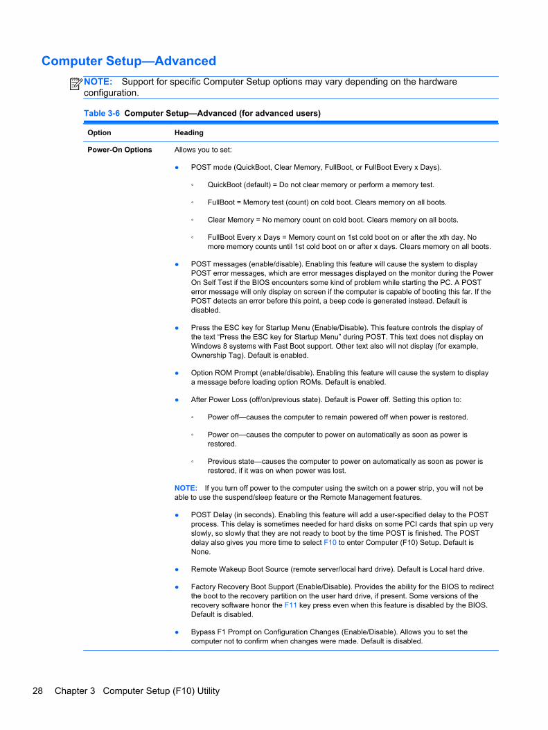
Computer Setup—Advanced
NOTE: Support for specific Computer Setup options may vary depending on the hardwareconfiguration.
Table 3-6 Computer Setup—Advanced (for advanced users)
Option Heading
Power-On Options Allows you to set:
● POST mode (QuickBoot, Clear Memory, FullBoot, or FullBoot Every x Days).
◦ QuickBoot (default) = Do not clear memory or perform a memory test.
◦ FullBoot = Memory test (count) on cold boot. Clears memory on all boots.
◦ Clear Memory = No memory count on cold boot. Clears memory on all boots.
◦ FullBoot Every x Days = Memory count on 1st cold boot on or after the xth day. Nomore memory counts until 1st cold boot on or after x days. Clears memory on all boots.
● POST messages (enable/disable). Enabling this feature will cause the system to displayPOST error messages, which are error messages displayed on the monitor during the PowerOn Self Test if the BIOS encounters some kind of problem while starting the PC. A POSTerror message will only display on screen if the computer is capable of booting this far. If thePOST detects an error before this point, a beep code is generated instead. Default isdisabled.
● Press the ESC key for Startup Menu (Enable/Disable). This feature controls the display ofthe text “Press the ESC key for Startup Menu” during POST. This text does not display onWindows 8 systems with Fast Boot support. Other text also will not display (for example,Ownership Tag). Default is enabled.
● Option ROM Prompt (enable/disable). Enabling this feature will cause the system to displaya message before loading option ROMs. Default is enabled.
● After Power Loss (off/on/previous state). Default is Power off. Setting this option to:
◦ Power off—causes the computer to remain powered off when power is restored.
◦ Power on—causes the computer to power on automatically as soon as power isrestored.
◦ Previous state—causes the computer to power on automatically as soon as power isrestored, if it was on when power was lost.
NOTE: If you turn off power to the computer using the switch on a power strip, you will not beable to use the suspend/sleep feature or the Remote Management features.
● POST Delay (in seconds). Enabling this feature will add a user-specified delay to the POSTprocess. This delay is sometimes needed for hard disks on some PCI cards that spin up veryslowly, so slowly that they are not ready to boot by the time POST is finished. The POSTdelay also gives you more time to select F10 to enter Computer (F10) Setup. Default isNone.
● Remote Wakeup Boot Source (remote server/local hard drive). Default is Local hard drive.
● Factory Recovery Boot Support (Enable/Disable). Provides the ability for the BIOS to redirectthe boot to the recovery partition on the user hard drive, if present. Some versions of therecovery software honor the F11 key press even when this feature is disabled by the BIOS.Default is disabled.
● Bypass F1 Prompt on Configuration Changes (Enable/Disable). Allows you to set thecomputer not to confirm when changes were made. Default is disabled.
28 Chapter 3 Computer Setup (F10) Utility
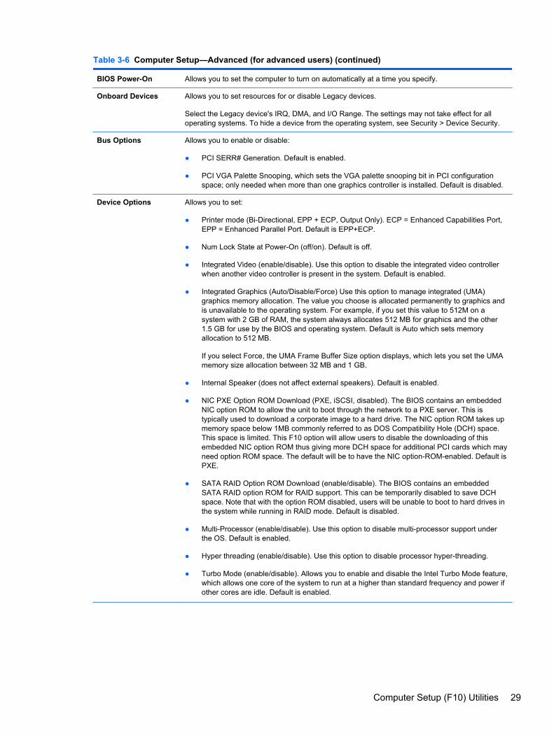
Table 3-6 Computer Setup—Advanced (for advanced users) (continued)
BIOS Power-On Allows you to set the computer to turn on automatically at a time you specify.
Onboard Devices Allows you to set resources for or disable Legacy devices.
Select the Legacy device's IRQ, DMA, and I/O Range. The settings may not take effect for alloperating systems. To hide a device from the operating system, see Security > Device Security.
Bus Options Allows you to enable or disable:
● PCI SERR# Generation. Default is enabled.
● PCI VGA Palette Snooping, which sets the VGA palette snooping bit in PCI configurationspace; only needed when more than one graphics controller is installed. Default is disabled.
Device Options Allows you to set:
● Printer mode (Bi-Directional, EPP + ECP, Output Only). ECP = Enhanced Capabilities Port,EPP = Enhanced Parallel Port. Default is EPP+ECP.
● Num Lock State at Power-On (off/on). Default is off.
● Integrated Video (enable/disable). Use this option to disable the integrated video controllerwhen another video controller is present in the system. Default is enabled.
● Integrated Graphics (Auto/Disable/Force) Use this option to manage integrated (UMA)graphics memory allocation. The value you choose is allocated permanently to graphics andis unavailable to the operating system. For example, if you set this value to 512M on asystem with 2 GB of RAM, the system always allocates 512 MB for graphics and the other1.5 GB for use by the BIOS and operating system. Default is Auto which sets memoryallocation to 512 MB.
If you select Force, the UMA Frame Buffer Size option displays, which lets you set the UMAmemory size allocation between 32 MB and 1 GB.
● Internal Speaker (does not affect external speakers). Default is enabled.
● NIC PXE Option ROM Download (PXE, iSCSI, disabled). The BIOS contains an embeddedNIC option ROM to allow the unit to boot through the network to a PXE server. This istypically used to download a corporate image to a hard drive. The NIC option ROM takes upmemory space below 1MB commonly referred to as DOS Compatibility Hole (DCH) space.This space is limited. This F10 option will allow users to disable the downloading of thisembedded NIC option ROM thus giving more DCH space for additional PCI cards which mayneed option ROM space. The default will be to have the NIC option-ROM-enabled. Default isPXE.
● SATA RAID Option ROM Download (enable/disable). The BIOS contains an embeddedSATA RAID option ROM for RAID support. This can be temporarily disabled to save DCHspace. Note that with the option ROM disabled, users will be unable to boot to hard drives inthe system while running in RAID mode. Default is disabled.
● Multi-Processor (enable/disable). Use this option to disable multi-processor support underthe OS. Default is enabled.
● Hyper threading (enable/disable). Use this option to disable processor hyper-threading.
● Turbo Mode (enable/disable). Allows you to enable and disable the Intel Turbo Mode feature,which allows one core of the system to run at a higher than standard frequency and power ifother cores are idle. Default is enabled.
Computer Setup (F10) Utilities 29
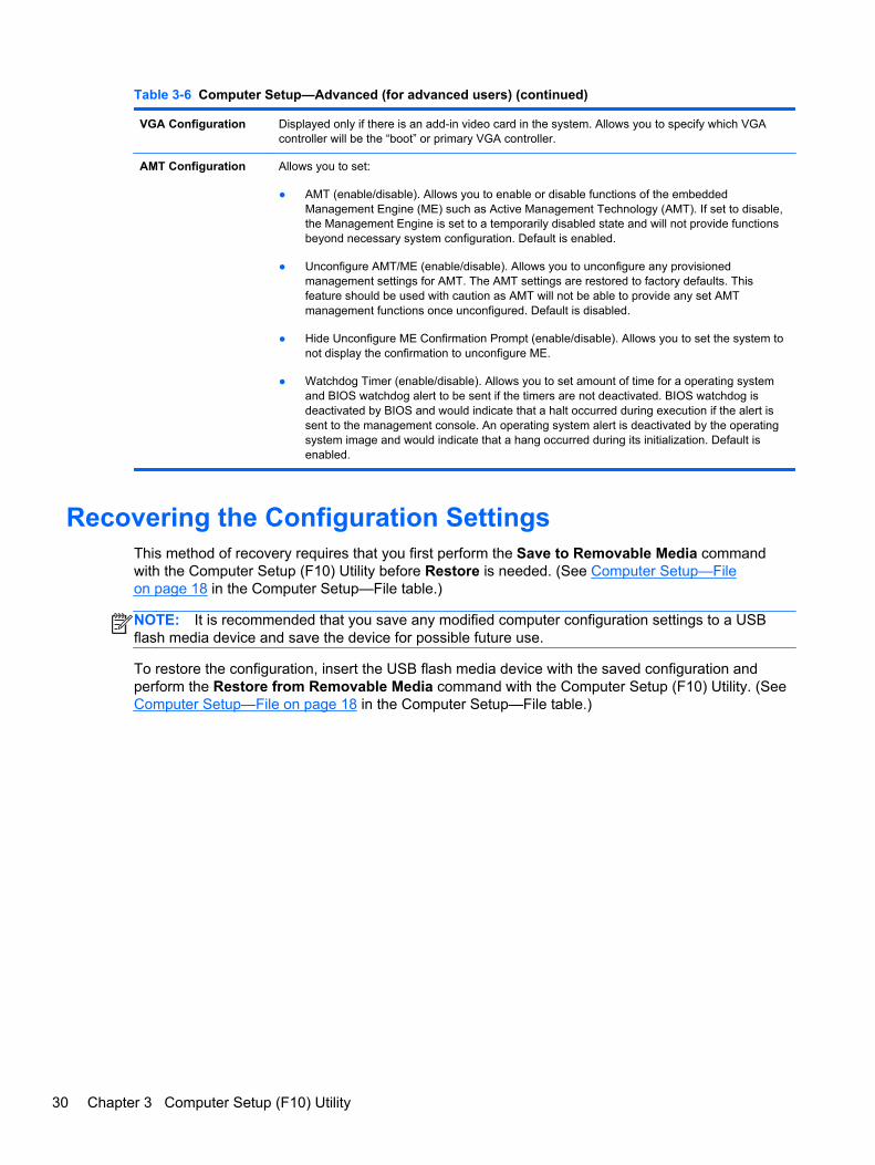
Table 3-6 Computer Setup—Advanced (for advanced users) (continued)
VGA Configuration Displayed only if there is an add-in video card in the system. Allows you to specify which VGAcontroller will be the “boot” or primary VGA controller.
AMT Configuration Allows you to set:
● AMT (enable/disable). Allows you to enable or disable functions of the embeddedManagement Engine (ME) such as Active Management Technology (AMT). If set to disable,the Management Engine is set to a temporarily disabled state and will not provide functionsbeyond necessary system configuration. Default is enabled.
● Unconfigure AMT/ME (enable/disable). Allows you to unconfigure any provisionedmanagement settings for AMT. The AMT settings are restored to factory defaults. Thisfeature should be used with caution as AMT will not be able to provide any set AMTmanagement functions once unconfigured. Default is disabled.
● Hide Unconfigure ME Confirmation Prompt (enable/disable). Allows you to set the system tonot display the confirmation to unconfigure ME.
● Watchdog Timer (enable/disable). Allows you to set amount of time for a operating systemand BIOS watchdog alert to be sent if the timers are not deactivated. BIOS watchdog isdeactivated by BIOS and would indicate that a halt occurred during execution if the alert issent to the management console. An operating system alert is deactivated by the operatingsystem image and would indicate that a hang occurred during its initialization. Default isenabled.
Recovering the Configuration SettingsThis method of recovery requires that you first perform the Save to Removable Media commandwith the Computer Setup (F10) Utility before Restore is needed. (See Computer Setup—Fileon page 18 in the Computer Setup—File table.)
NOTE: It is recommended that you save any modified computer configuration settings to a USBflash media device and save the device for possible future use.
To restore the configuration, insert the USB flash media device with the saved configuration andperform the Restore from Removable Media command with the Computer Setup (F10) Utility. (SeeComputer Setup—File on page 18 in the Computer Setup—File table.)
30 Chapter 3 Computer Setup (F10) Utility
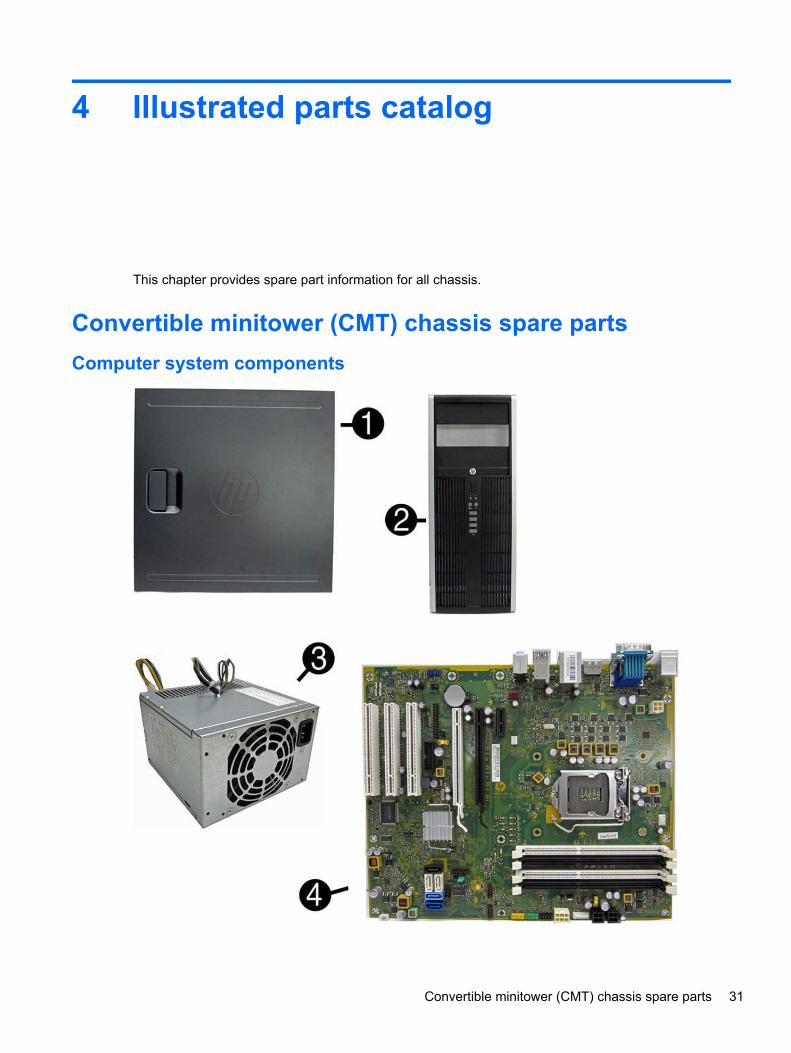
4 Illustrated parts catalog
This chapter provides spare part information for all chassis.
Convertible minitower (CMT) chassis spare parts
Computer system components
Convertible minitower (CMT) chassis spare parts 31
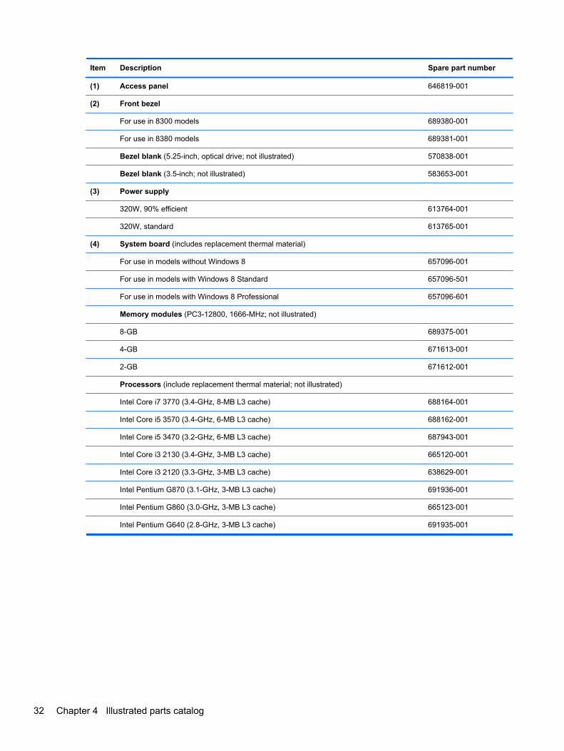
Item Description Spare part number
(1) Access panel 646819-001
(2) Front bezel
For use in 8300 models 689380-001
For use in 8380 models 689381-001
Bezel blank (5.25-inch, optical drive; not illustrated) 570838-001
Bezel blank (3.5-inch; not illustrated) 583653-001
(3) Power supply
320W, 90% efficient 613764-001
320W, standard 613765-001
(4) System board (includes replacement thermal material)
For use in models without Windows 8 657096-001
For use in models with Windows 8 Standard 657096-501
For use in models with Windows 8 Professional 657096-601
Memory modules (PC3-12800, 1666-MHz; not illustrated)
8-GB 689375-001
4-GB 671613-001
2-GB 671612-001
Processors (include replacement thermal material; not illustrated)
Intel Core i7 3770 (3.4-GHz, 8-MB L3 cache) 688164-001
Intel Core i5 3570 (3.4-GHz, 6-MB L3 cache) 688162-001
Intel Core i5 3470 (3.2-GHz, 6-MB L3 cache) 687943-001
Intel Core i3 2130 (3.4-GHz, 3-MB L3 cache) 665120-001
Intel Core i3 2120 (3.3-GHz, 3-MB L3 cache) 638629-001
Intel Pentium G870 (3.1-GHz, 3-MB L3 cache) 691936-001
Intel Pentium G860 (3.0-GHz, 3-MB L3 cache) 665123-001
Intel Pentium G640 (2.8-GHz, 3-MB L3 cache) 691935-001
32 Chapter 4 Illustrated parts catalog
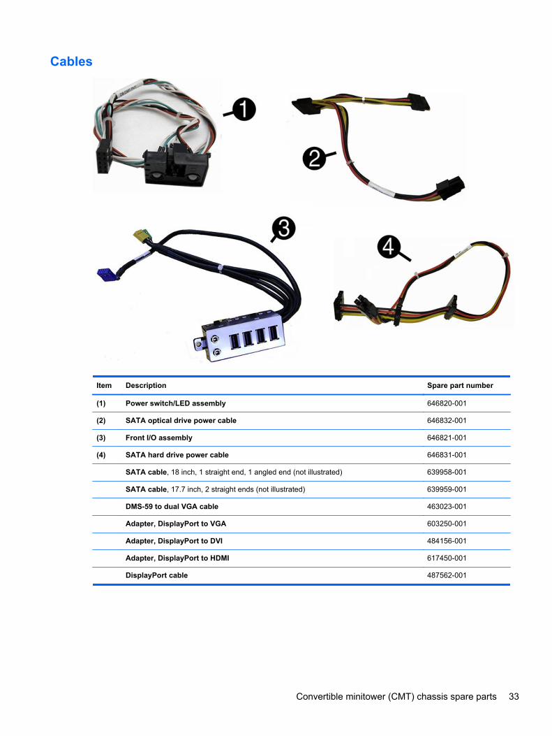
Cables
Item Description Spare part number
(1) Power switch/LED assembly 646820-001
(2) SATA optical drive power cable 646832-001
(3) Front I/O assembly 646821-001
(4) SATA hard drive power cable 646831-001
SATA cable, 18 inch, 1 straight end, 1 angled end (not illustrated) 639958-001
SATA cable, 17.7 inch, 2 straight ends (not illustrated) 639959-001
DMS-59 to dual VGA cable 463023-001
Adapter, DisplayPort to VGA 603250-001
Adapter, DisplayPort to DVI 484156-001
Adapter, DisplayPort to HDMI 617450-001
DisplayPort cable 487562-001
Convertible minitower (CMT) chassis spare parts 33
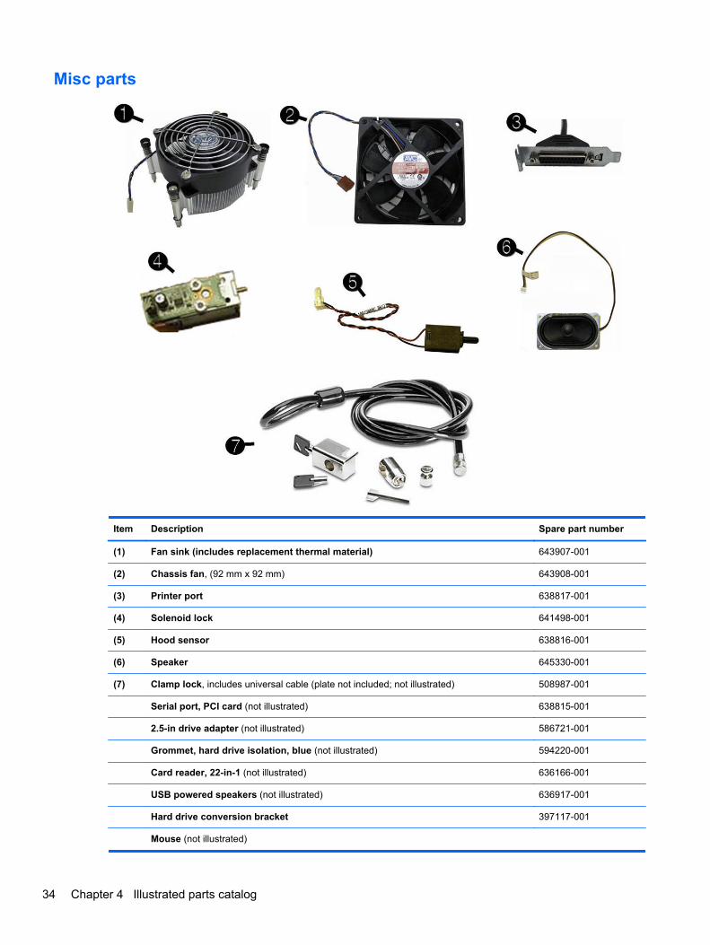
Misc parts
Item Description Spare part number
(1) Fan sink (includes replacement thermal material) 643907-001
(2) Chassis fan, (92 mm x 92 mm) 643908-001
(3) Printer port 638817-001
(4) Solenoid lock 641498-001
(5) Hood sensor 638816-001
(6) Speaker 645330-001
(7) Clamp lock, includes universal cable (plate not included; not illustrated) 508987-001
Serial port, PCI card (not illustrated) 638815-001
2.5-in drive adapter (not illustrated) 586721-001
Grommet, hard drive isolation, blue (not illustrated) 594220-001
Card reader, 22-in-1 (not illustrated) 636166-001
USB powered speakers (not illustrated) 636917-001
Hard drive conversion bracket 397117-001
Mouse (not illustrated)
34 Chapter 4 Illustrated parts catalog
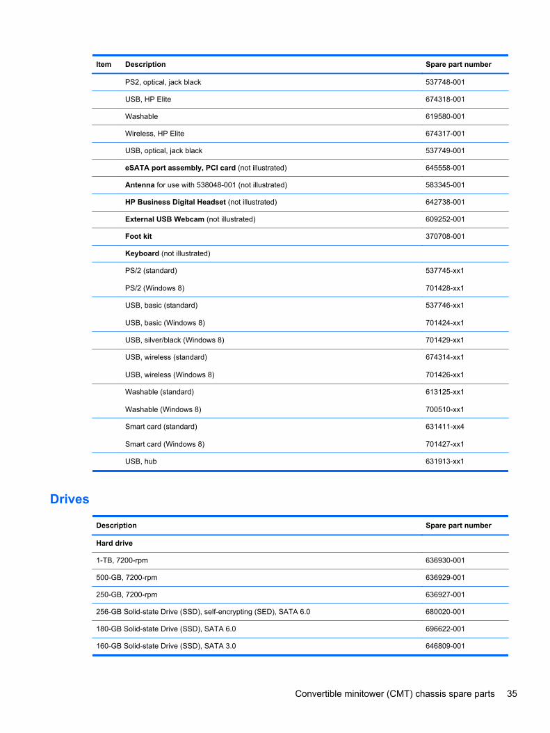
Item Description Spare part number
PS2, optical, jack black 537748-001
USB, HP Elite 674318-001
Washable 619580-001
Wireless, HP Elite 674317-001
USB, optical, jack black 537749-001
eSATA port assembly, PCI card (not illustrated) 645558-001
Antenna for use with 538048-001 (not illustrated) 583345-001
HP Business Digital Headset (not illustrated) 642738-001
External USB Webcam (not illustrated) 609252-001
Foot kit 370708-001
Keyboard (not illustrated)
PS/2 (standard)
PS/2 (Windows 8)
537745-xx1
701428-xx1
USB, basic (standard)
USB, basic (Windows 8)
537746-xx1
701424-xx1
USB, silver/black (Windows 8) 701429-xx1
USB, wireless (standard)
USB, wireless (Windows 8)
674314-xx1
701426-xx1
Washable (standard)
Washable (Windows 8)
613125-xx1
700510-xx1
Smart card (standard)
Smart card (Windows 8)
631411-xx4
701427-xx1
USB, hub 631913-xx1
Drives
Description Spare part number
Hard drive
1-TB, 7200-rpm 636930-001
500-GB, 7200-rpm 636929-001
250-GB, 7200-rpm 636927-001
256-GB Solid-state Drive (SSD), self-encrypting (SED), SATA 6.0 680020-001
180-GB Solid-state Drive (SSD), SATA 6.0 696622-001
160-GB Solid-state Drive (SSD), SATA 3.0 646809-001
Convertible minitower (CMT) chassis spare parts 35
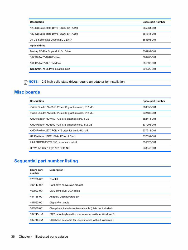
Description Spare part number
128-GB Solid-state Drive (SSD), SATA 2.0 665961-001
120-GB Solid-state Drive (SSD), SATA 2.0 661841-001
20-GB Solid-state Drive (SSD), SATA 683305-001
Optical drive
Blu-ray BD-RW SuperMulti DL Drive 656792-001
16X SATA DVD±RW drive 660408-001
16X SATA DVD-ROM drive 581599-001
Grommet, hard drive isolation, blue 594220-001
NOTE: 2.5-inch solid-state drives require an adapter for installation.
Misc boards
Description Spare part number
nVidia Quadro NVS310 PCIe x16 graphics card, 512 MB 680653-001
nVidia Quadro NVS300 PCIe x16 graphics card, 512 MB 632486-001
AMD Radeon HD7450 PCIe x16 graphics card, 1 GB 682411-001
AMD Radeon HD6350 PCIe x16 graphics card, 512 MB 637995-001
AMD FirePro 2270 PCIe x16 graphics card, 512-MB 637213-001
HP FireWire / IEEE 1394a PCIe x1 Card 637591-001
Intel PRO/1000CT2 NIC, includes bracket 635523-001
HP WLAN 802.11 g/n 1x2 PCIe NIC 538048-001
Sequential part number listing
Spare partnumber
Description
370708-001 Foot kit
397117-001 Hard drive conversion bracket
463023-001 DMS-59 to dual VGA cable
484156-001 Adapter, DisplayPort to DVI
487562-001 DisplayPort cable
508987-001 Clamp lock, includes universal cable (plate not included)
537745-xx1 PS/2 basic keyboard for use in models without Windows 8
537746-xx1 USB basic keyboard for use in models without Windows 8
36 Chapter 4 Illustrated parts catalog
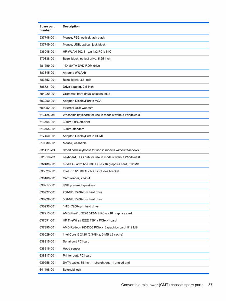
Spare partnumber
Description
537748-001 Mouse, PS2, optical, jack black
537749-001 Mouse, USB, optical, jack black
538048-001 HP WLAN 802.11 g/n 1x2 PCIe NIC
570838-001 Bezel black, optical drive, 5.25-inch
581599-001 16X SATA DVD-ROM drive
583345-001 Antenna (WLAN)
583653-001 Bezel blank, 3.5-inch
586721-001 Drive adapter, 2.5-inch
594220-001 Grommet, hard drive isolation, blue
603250-001 Adapter, DisplayPort to VGA
609252-001 External USB webcam
613125-xx1 Washable keyboard for use in models without Windows 8
613764-001 320W, 90% efficient
613765-001 320W, standard
617450-001 Adapter, DisplayPort to HDMI
619580-001 Mouse, washable
631411-xx4 Smart card keyboard for use in models without Windows 8
631913-xx1 Keyboard, USB hub for use in models without Windows 8
632486-001 nVidia Quadro NVS300 PCIe x16 graphics card, 512 MB
635523-001 Intel PRO/1000CT2 NIC, includes bracket
636166-001 Card reader, 22-in-1
636917-001 USB powered speakers
636927-001 250-GB, 7200-rpm hard drive
636929-001 500-GB, 7200-rpm hard drive
636930-001 1-TB, 7200-rpm hard drive
637213-001 AMD FirePro 2270 512-MB PCIe x16 graphics card
637591-001 HP FireWire / IEEE 1394a PCIe x1 card
637995-001 AMD Radeon HD6350 PCIe x16 graphics card, 512 MB
638629-001 Intel Core i3 2120 (3.3-GHz, 3-MB L3 cache)
638815-001 Serial port PCI card
638816-001 Hood sensor
638817-001 Printer port, PCI card
639958-001 SATA cable, 18 inch, 1 straight end, 1 angled end
641498-001 Solenoid lock
Convertible minitower (CMT) chassis spare parts 37
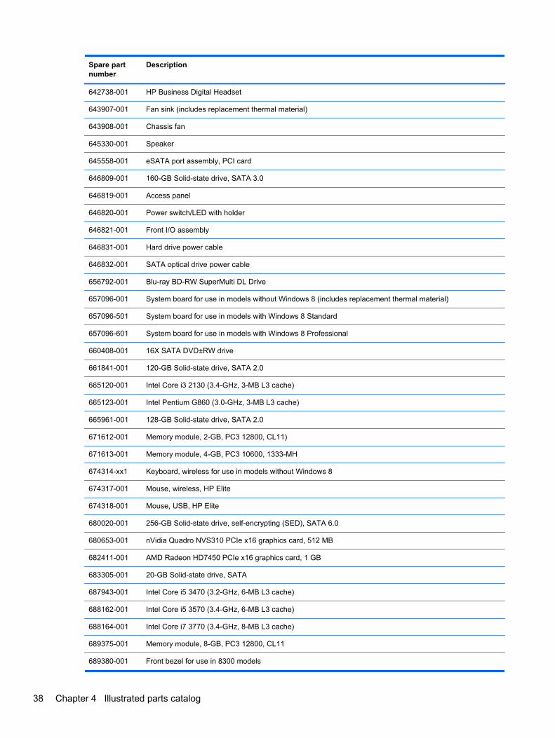
Spare partnumber
Description
642738-001 HP Business Digital Headset
643907-001 Fan sink (includes replacement thermal material)
643908-001 Chassis fan
645330-001 Speaker
645558-001 eSATA port assembly, PCI card
646809-001 160-GB Solid-state drive, SATA 3.0
646819-001 Access panel
646820-001 Power switch/LED with holder
646821-001 Front I/O assembly
646831-001 Hard drive power cable
646832-001 SATA optical drive power cable
656792-001 Blu-ray BD-RW SuperMulti DL Drive
657096-001 System board for use in models without Windows 8 (includes replacement thermal material)
657096-501 System board for use in models with Windows 8 Standard
657096-601 System board for use in models with Windows 8 Professional
660408-001 16X SATA DVD±RW drive
661841-001 120-GB Solid-state drive, SATA 2.0
665120-001 Intel Core i3 2130 (3.4-GHz, 3-MB L3 cache)
665123-001 Intel Pentium G860 (3.0-GHz, 3-MB L3 cache)
665961-001 128-GB Solid-state drive, SATA 2.0
671612-001 Memory module, 2-GB, PC3 12800, CL11)
671613-001 Memory module, 4-GB, PC3 10600, 1333-MH
674314-xx1 Keyboard, wireless for use in models without Windows 8
674317-001 Mouse, wireless, HP Elite
674318-001 Mouse, USB, HP Elite
680020-001 256-GB Solid-state drive, self-encrypting (SED), SATA 6.0
680653-001 nVidia Quadro NVS310 PCIe x16 graphics card, 512 MB
682411-001 AMD Radeon HD7450 PCIe x16 graphics card, 1 GB
683305-001 20-GB Solid-state drive, SATA
687943-001 Intel Core i5 3470 (3.2-GHz, 6-MB L3 cache)
688162-001 Intel Core i5 3570 (3.4-GHz, 6-MB L3 cache)
688164-001 Intel Core i7 3770 (3.4-GHz, 8-MB L3 cache)
689375-001 Memory module, 8-GB, PC3 12800, CL11
689380-001 Front bezel for use in 8300 models
38 Chapter 4 Illustrated parts catalog
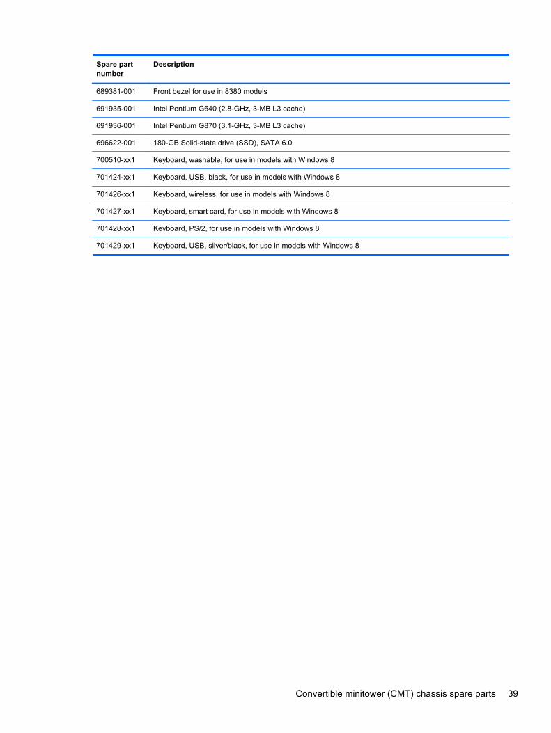
Spare partnumber
Description
689381-001 Front bezel for use in 8380 models
691935-001 Intel Pentium G640 (2.8-GHz, 3-MB L3 cache)
691936-001 Intel Pentium G870 (3.1-GHz, 3-MB L3 cache)
696622-001 180-GB Solid-state drive (SSD), SATA 6.0
700510-xx1 Keyboard, washable, for use in models with Windows 8
701424-xx1 Keyboard, USB, black, for use in models with Windows 8
701426-xx1 Keyboard, wireless, for use in models with Windows 8
701427-xx1 Keyboard, smart card, for use in models with Windows 8
701428-xx1 Keyboard, PS/2, for use in models with Windows 8
701429-xx1 Keyboard, USB, silver/black, for use in models with Windows 8
Convertible minitower (CMT) chassis spare parts 39
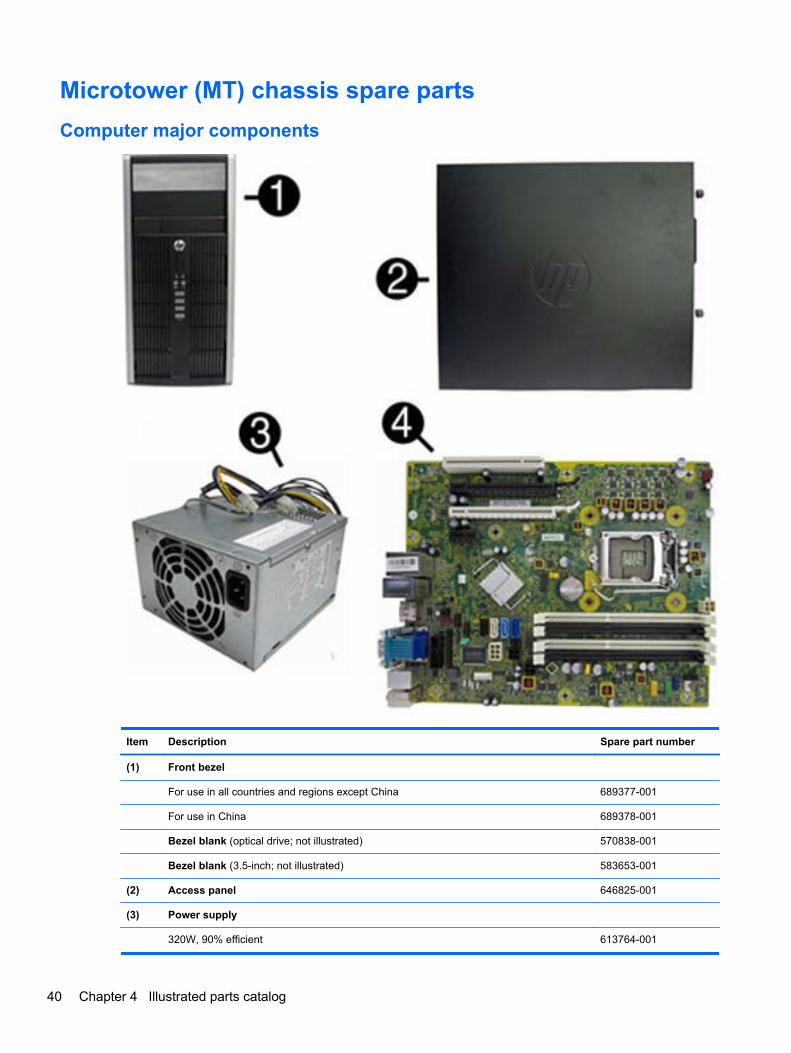
Microtower (MT) chassis spare parts
Computer major components
Item Description Spare part number
(1) Front bezel
For use in all countries and regions except China 689377-001
For use in China 689378-001
Bezel blank (optical drive; not illustrated) 570838-001
Bezel blank (3.5-inch; not illustrated) 583653-001
(2) Access panel 646825-001
(3) Power supply
320W, 90% efficient 613764-001
40 Chapter 4 Illustrated parts catalog
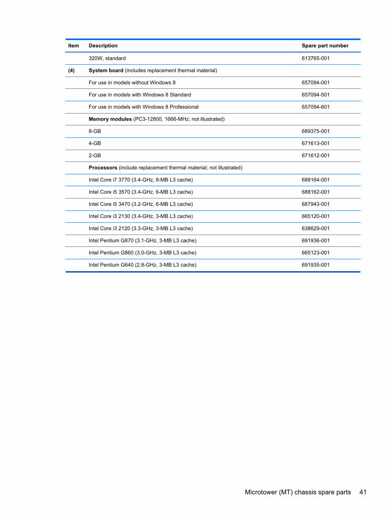
Item Description Spare part number
320W, standard 613765-001
(4) System board (includes replacement thermal material)
For use in models without Windows 8 657094-001
For use in models with Windows 8 Standard 657094-501
For use in models with Windows 8 Professional 657094-601
Memory modules (PC3-12800, 1666-MHz; not illustrated)
8-GB 689375-001
4-GB 671613-001
2-GB 671612-001
Processors (include replacement thermal material; not illustrated)
Intel Core i7 3770 (3.4-GHz, 8-MB L3 cache) 688164-001
Intel Core i5 3570 (3.4-GHz, 6-MB L3 cache) 688162-001
Intel Core i5 3470 (3.2-GHz, 6-MB L3 cache) 687943-001
Intel Core i3 2130 (3.4-GHz, 3-MB L3 cache) 665120-001
Intel Core i3 2120 (3.3-GHz, 3-MB L3 cache) 638629-001
Intel Pentium G870 (3.1-GHz, 3-MB L3 cache) 691936-001
Intel Pentium G860 (3.0-GHz, 3-MB L3 cache) 665123-001
Intel Pentium G640 (2.8-GHz, 3-MB L3 cache) 691935-001
Microtower (MT) chassis spare parts 41
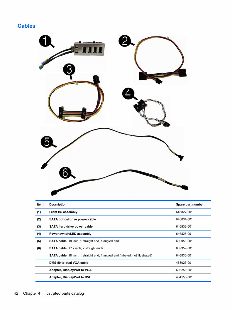
Cables
Item Description Spare part number
(1) Front I/O assembly 646827-001
(2) SATA optical drive power cable 646834-001
(3) SATA hard drive power cable 646833-001
(4) Power switch/LED assembly 646828-001
(5) SATA cable, 18 inch, 1 straight end, 1 angled end 639958-001
(6) SATA cable, 17.7 inch, 2 straight ends 639959-001
SATA cable, 18 inch, 1 straight end, 1 angled end (labeled; not illustrated) 646830-001
DMS-59 to dual VGA cable 463023-001
Adapter, DisplayPort to VGA 603250-001
Adapter, DisplayPort to DVI 484156-001
42 Chapter 4 Illustrated parts catalog
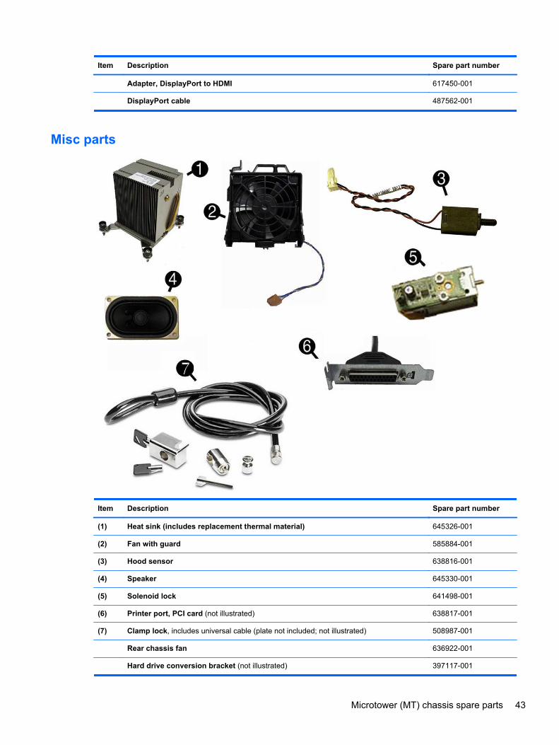
Item Description Spare part number
Adapter, DisplayPort to HDMI 617450-001
DisplayPort cable 487562-001
Misc parts
Item Description Spare part number
(1) Heat sink (includes replacement thermal material) 645326-001
(2) Fan with guard 585884-001
(3) Hood sensor 638816-001
(4) Speaker 645330-001
(5) Solenoid lock 641498-001
(6) Printer port, PCI card (not illustrated) 638817-001
(7) Clamp lock, includes universal cable (plate not included; not illustrated) 508987-001
Rear chassis fan 636922-001
Hard drive conversion bracket (not illustrated) 397117-001
Microtower (MT) chassis spare parts 43
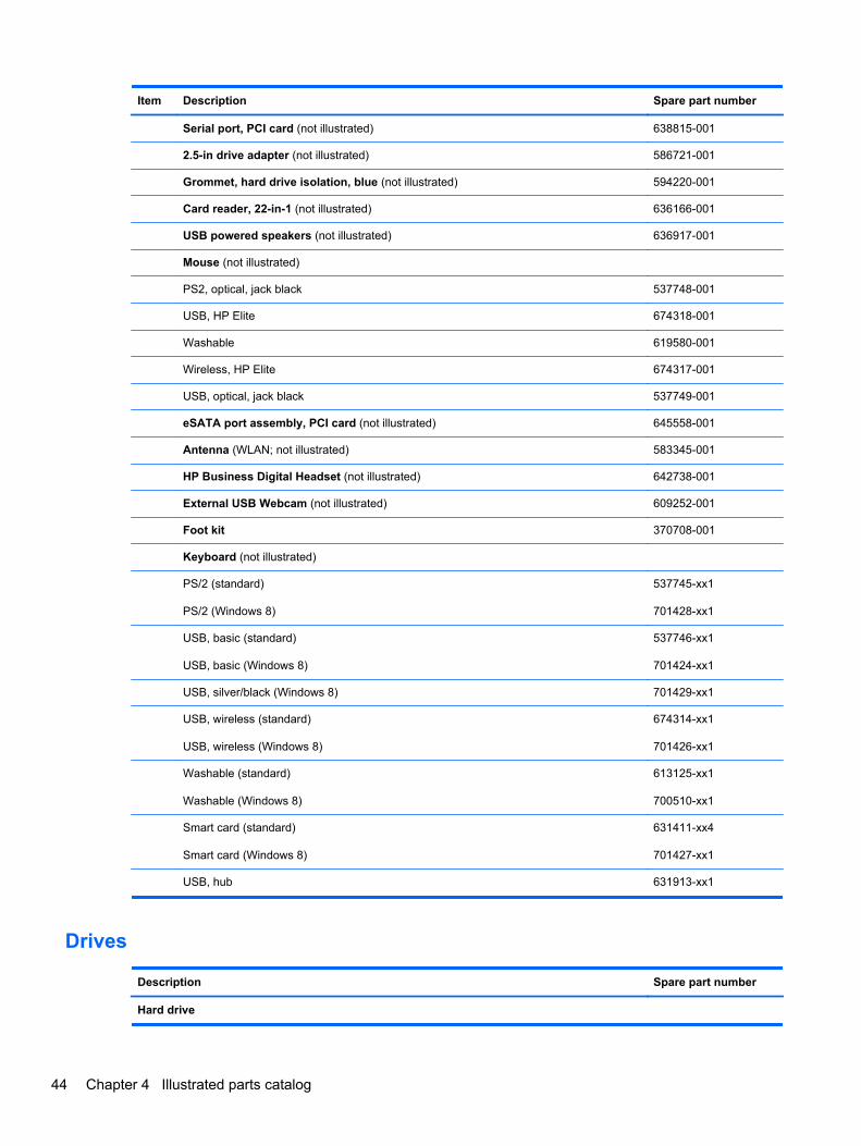
Item Description Spare part number
Serial port, PCI card (not illustrated) 638815-001
2.5-in drive adapter (not illustrated) 586721-001
Grommet, hard drive isolation, blue (not illustrated) 594220-001
Card reader, 22-in-1 (not illustrated) 636166-001
USB powered speakers (not illustrated) 636917-001
Mouse (not illustrated)
PS2, optical, jack black 537748-001
USB, HP Elite 674318-001
Washable 619580-001
Wireless, HP Elite 674317-001
USB, optical, jack black 537749-001
eSATA port assembly, PCI card (not illustrated) 645558-001
Antenna (WLAN; not illustrated) 583345-001
HP Business Digital Headset (not illustrated) 642738-001
External USB Webcam (not illustrated) 609252-001
Foot kit 370708-001
Keyboard (not illustrated)
PS/2 (standard)
PS/2 (Windows 8)
537745-xx1
701428-xx1
USB, basic (standard)
USB, basic (Windows 8)
537746-xx1
701424-xx1
USB, silver/black (Windows 8) 701429-xx1
USB, wireless (standard)
USB, wireless (Windows 8)
674314-xx1
701426-xx1
Washable (standard)
Washable (Windows 8)
613125-xx1
700510-xx1
Smart card (standard)
Smart card (Windows 8)
631411-xx4
701427-xx1
USB, hub 631913-xx1
Drives
Description Spare part number
Hard drive
44 Chapter 4 Illustrated parts catalog
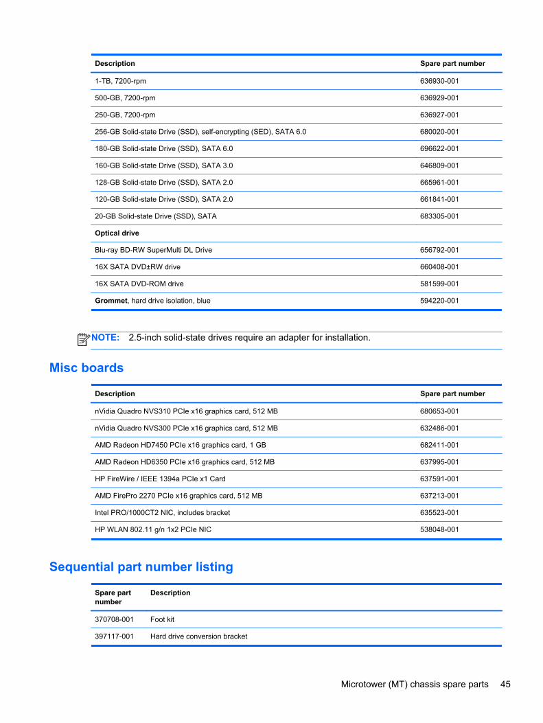
Description Spare part number
1-TB, 7200-rpm 636930-001
500-GB, 7200-rpm 636929-001
250-GB, 7200-rpm 636927-001
256-GB Solid-state Drive (SSD), self-encrypting (SED), SATA 6.0 680020-001
180-GB Solid-state Drive (SSD), SATA 6.0 696622-001
160-GB Solid-state Drive (SSD), SATA 3.0 646809-001
128-GB Solid-state Drive (SSD), SATA 2.0 665961-001
120-GB Solid-state Drive (SSD), SATA 2.0 661841-001
20-GB Solid-state Drive (SSD), SATA 683305-001
Optical drive
Blu-ray BD-RW SuperMulti DL Drive 656792-001
16X SATA DVD±RW drive 660408-001
16X SATA DVD-ROM drive 581599-001
Grommet, hard drive isolation, blue 594220-001
NOTE: 2.5-inch solid-state drives require an adapter for installation.
Misc boards
Description Spare part number
nVidia Quadro NVS310 PCIe x16 graphics card, 512 MB 680653-001
nVidia Quadro NVS300 PCIe x16 graphics card, 512 MB 632486-001
AMD Radeon HD7450 PCIe x16 graphics card, 1 GB 682411-001
AMD Radeon HD6350 PCIe x16 graphics card, 512 MB 637995-001
HP FireWire / IEEE 1394a PCIe x1 Card 637591-001
AMD FirePro 2270 PCIe x16 graphics card, 512 MB 637213-001
Intel PRO/1000CT2 NIC, includes bracket 635523-001
HP WLAN 802.11 g/n 1x2 PCIe NIC 538048-001
Sequential part number listing
Spare partnumber
Description
370708-001 Foot kit
397117-001 Hard drive conversion bracket
Microtower (MT) chassis spare parts 45
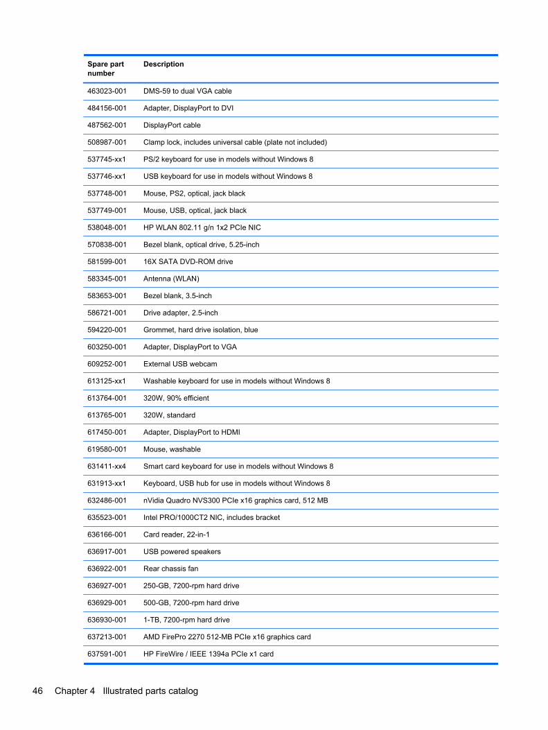
Spare partnumber
Description
463023-001 DMS-59 to dual VGA cable
484156-001 Adapter, DisplayPort to DVI
487562-001 DisplayPort cable
508987-001 Clamp lock, includes universal cable (plate not included)
537745-xx1 PS/2 keyboard for use in models without Windows 8
537746-xx1 USB keyboard for use in models without Windows 8
537748-001 Mouse, PS2, optical, jack black
537749-001 Mouse, USB, optical, jack black
538048-001 HP WLAN 802.11 g/n 1x2 PCIe NIC
570838-001 Bezel blank, optical drive, 5.25-inch
581599-001 16X SATA DVD-ROM drive
583345-001 Antenna (WLAN)
583653-001 Bezel blank, 3.5-inch
586721-001 Drive adapter, 2.5-inch
594220-001 Grommet, hard drive isolation, blue
603250-001 Adapter, DisplayPort to VGA
609252-001 External USB webcam
613125-xx1 Washable keyboard for use in models without Windows 8
613764-001 320W, 90% efficient
613765-001 320W, standard
617450-001 Adapter, DisplayPort to HDMI
619580-001 Mouse, washable
631411-xx4 Smart card keyboard for use in models without Windows 8
631913-xx1 Keyboard, USB hub for use in models without Windows 8
632486-001 nVidia Quadro NVS300 PCIe x16 graphics card, 512 MB
635523-001 Intel PRO/1000CT2 NIC, includes bracket
636166-001 Card reader, 22-in-1
636917-001 USB powered speakers
636922-001 Rear chassis fan
636927-001 250-GB, 7200-rpm hard drive
636929-001 500-GB, 7200-rpm hard drive
636930-001 1-TB, 7200-rpm hard drive
637213-001 AMD FirePro 2270 512-MB PCIe x16 graphics card
637591-001 HP FireWire / IEEE 1394a PCIe x1 card
46 Chapter 4 Illustrated parts catalog
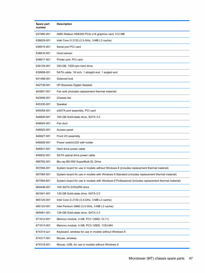
Spare partnumber
Description
637995-001 AMD Radeon HD6350 PCIe x16 graphics card, 512 MB
638629-001 Intel Core i3 2120 (3.3-GHz, 3-MB L3 cache)
638815-001 Serial port PCI card
638816-001 Hood sensor
638817-001 Printer port, PCI card
639135-001 320-GB, 7200-rpm hard drive
639958-001 SATA cable, 18 inch, 1 straight end, 1 angled end
641498-001 Solenoid lock
642738-001 HP Business Digital Headset
643907-001 Fan sink (includes replacement thermal material)
643908-001 Chassis fan
645330-001 Speaker
645558-001 eSATA port assembly, PCI card
646809-001 160-GB Solid-state drive, SATA 3.0
646824-001 Fan duct
646825-001 Access panel
646827-001 Front I/O assembly
646828-001 Power switch/LED with holder
646831-001 Hard drive power cable
646832-001 SATA optical drive power cable
656792-001 Blu-ray BD-RW SuperMulti DL Drive
657094-001 System board for use in models without Windows 8 (includes replacement thermal material)
657094-501 System board for use in models with Windows 8 Standard (includes replacement thermal material)
657094-601 System board for use in models with Windows 8 Professional (includes replacement thermal material)
660408-001 16X SATA DVD±RW drive
661841-001 120-GB Solid-state drive, SATA 2.0
665120-001 Intel Core i3 2130 (3.4-GHz, 3-MB L3 cache)
665123-001 Intel Pentium G860 (3.0-GHz, 3-MB L3 cache)
665961-001 128-GB Solid-state drive, SATA 2.0
671612-001 Memory module, 2-GB, PC3 12800, CL11)
671613-001 Memory module, 4-GB, PC3-12800, 1333-MH
674314-xx1 Keyboard, wireless for use in models without Windows 8
674317-001 Mouse, wireless
674318-001 Mouse, USB, for use in models without Windows 8
Microtower (MT) chassis spare parts 47
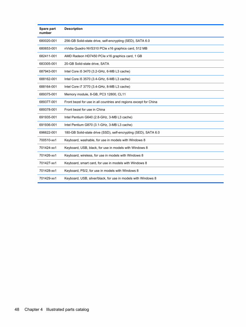
Spare partnumber
Description
680020-001 256-GB Solid-state drive, self-encrypting (SED), SATA 6.0
680653-001 nVidia Quadro NVS310 PCIe x16 graphics card, 512 MB
682411-001 AMD Radeon HD7450 PCIe x16 graphics card, 1 GB
683305-001 20-GB Solid-state drive, SATA
687943-001 Intel Core i5 3470 (3.2-GHz, 6-MB L3 cache)
688162-001 Intel Core i5 3570 (3.4-GHz, 6-MB L3 cache)
688164-001 Intel Core i7 3770 (3.4-GHz, 8-MB L3 cache)
689375-001 Memory module, 8-GB, PC3 12800, CL11
689377-001 Front bezel for use in all countries and regions except for China
689378-001 Front bezel for use in China
691935-001 Intel Pentium G640 (2.8-GHz, 3-MB L3 cache)
691936-001 Intel Pentium G870 (3.1-GHz, 3-MB L3 cache)
696622-001 180-GB Solid-state drive (SSD), self-encrypting (SED), SATA 6.0
700510-xx1 Keyboard, washable, for use in models with Windows 8
701424-xx1 Keyboard, USB, black, for use in models with Windows 8
701426-xx1 Keyboard, wireless, for use in models with Windows 8
701427-xx1 Keyboard, smart card, for use in models with Windows 8
701428-xx1 Keyboard, PS/2, for use in models with Windows 8
701429-xx1 Keyboard, USB, silver/black, for use in models with Windows 8
48 Chapter 4 Illustrated parts catalog
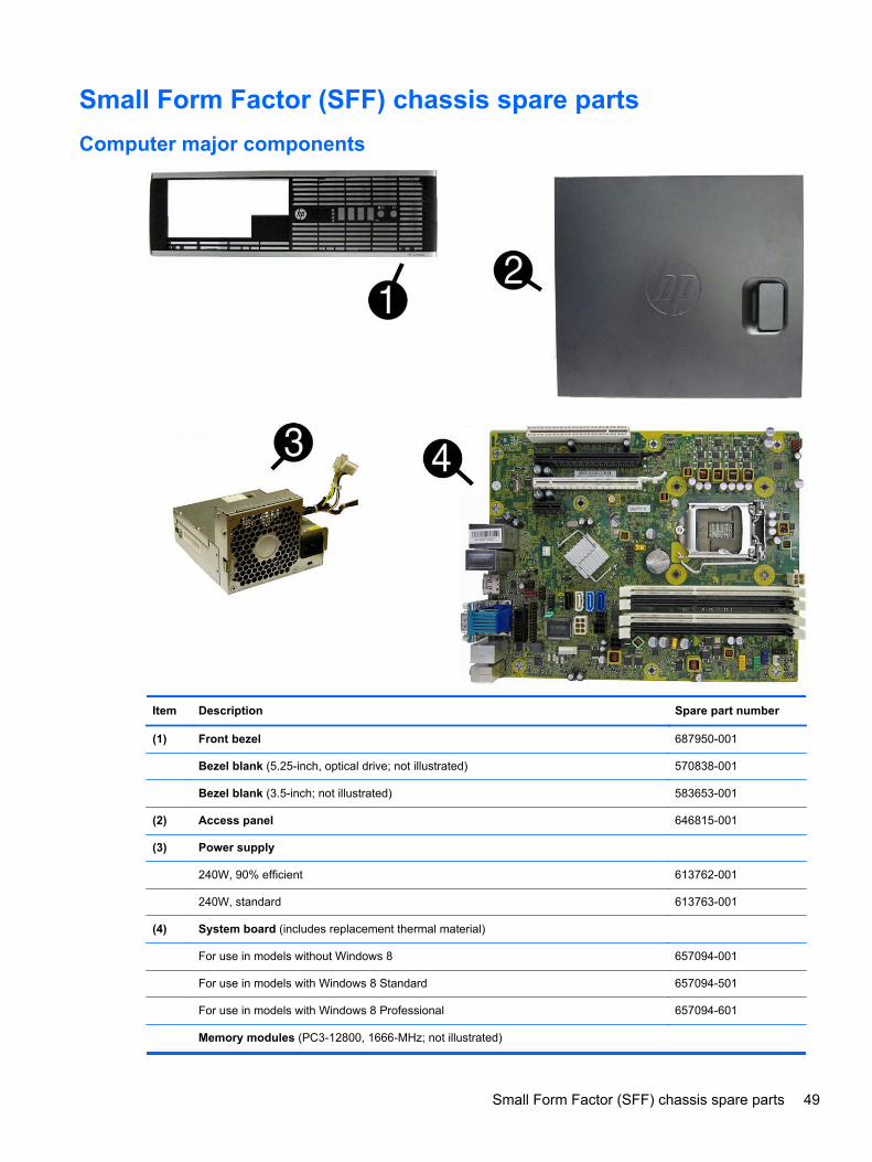
Small Form Factor (SFF) chassis spare parts
Computer major components
Item Description Spare part number
(1) Front bezel 687950-001
Bezel blank (5.25-inch, optical drive; not illustrated) 570838-001
Bezel blank (3.5-inch; not illustrated) 583653-001
(2) Access panel 646815-001
(3) Power supply
240W, 90% efficient 613762-001
240W, standard 613763-001
(4) System board (includes replacement thermal material)
For use in models without Windows 8 657094-001
For use in models with Windows 8 Standard 657094-501
For use in models with Windows 8 Professional 657094-601
Memory modules (PC3-12800, 1666-MHz; not illustrated)
Small Form Factor (SFF) chassis spare parts 49
Item Description Spare part number
8-GB 689375-001
4-GB 671613-001
2-GB 671612-001
Processors (include replacement thermal material; not illustrated)
Intel Core i7 3770 (3.4-GHz, 8-MB L3 cache) 688164-001
Intel Core i5 3570 (3.4-GHz, 6-MB L3 cache) 688162-001
Intel Core i5 3470 (3.2-GHz, 6-MB L3 cache) 687943-001
Intel Core i3 2130 (3.4-GHz, 3-MB L3 cache) 665120-001
Intel Core i3 2120 (3.3-GHz, 3-MB L3 cache) 638629-001
Intel Pentium G870 (3.1-GHz, 3-MB L3 cache) 691936-001
Intel Pentium G860 (3.0-GHz, 3-MB L3 cache) 665123-001
Intel Pentium G640 (2.8-GHz, 3-MB L3 cache) 691935-001
50 Chapter 4 Illustrated parts catalog
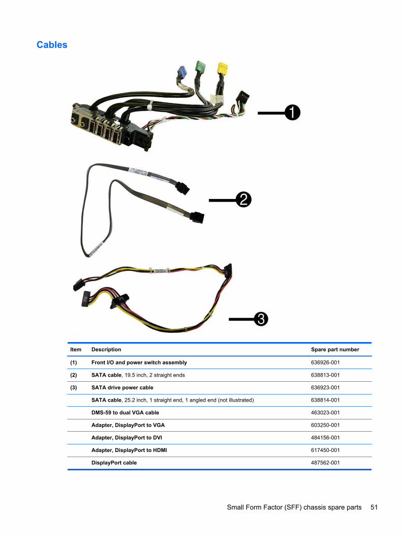
Cables
Item Description Spare part number
(1) Front I/O and power switch assembly 636926-001
(2) SATA cable, 19.5 inch, 2 straight ends 638813-001
(3) SATA drive power cable 636923-001
SATA cable, 25.2 inch, 1 straight end, 1 angled end (not illustrated) 638814-001
DMS-59 to dual VGA cable 463023-001
Adapter, DisplayPort to VGA 603250-001
Adapter, DisplayPort to DVI 484156-001
Adapter, DisplayPort to HDMI 617450-001
DisplayPort cable 487562-001
Small Form Factor (SFF) chassis spare parts 51
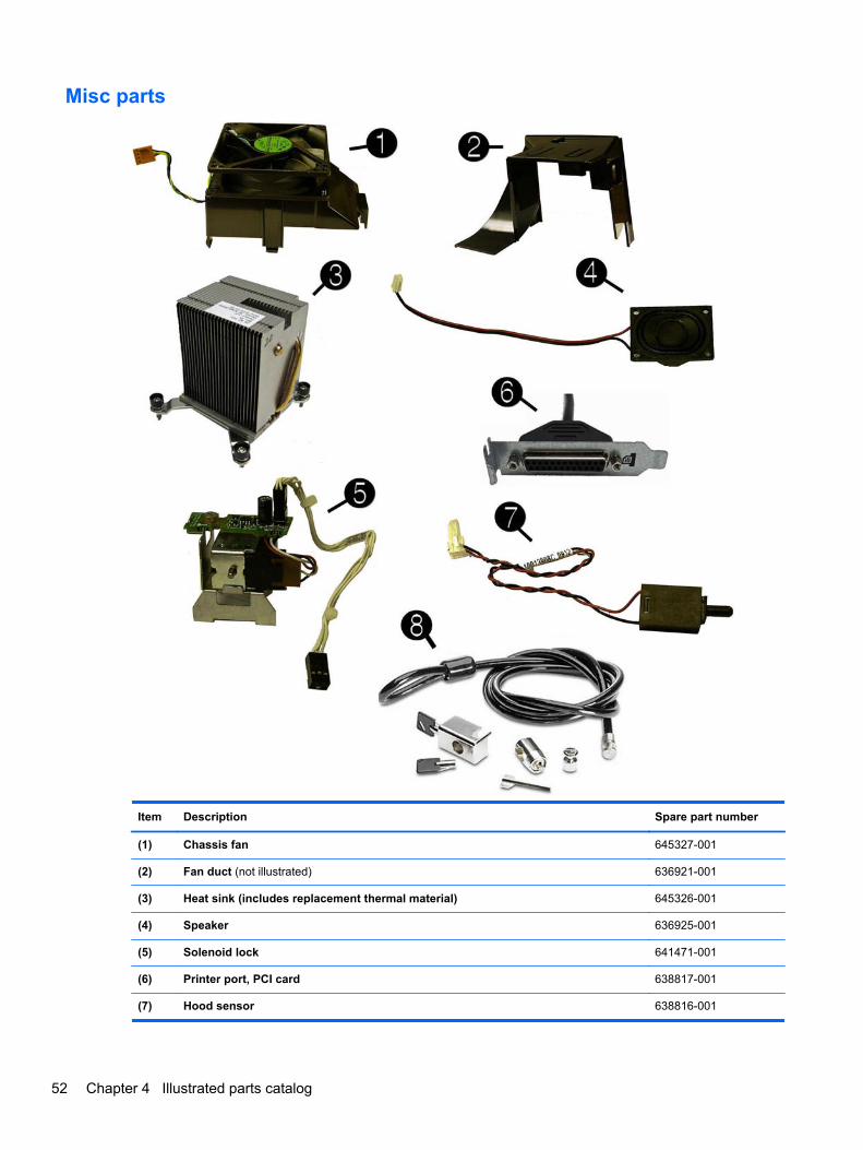
Misc parts
Item Description Spare part number
(1) Chassis fan 645327-001
(2) Fan duct (not illustrated) 636921-001
(3) Heat sink (includes replacement thermal material) 645326-001
(4) Speaker 636925-001
(5) Solenoid lock 641471-001
(6) Printer port, PCI card 638817-001
(7) Hood sensor 638816-001
52 Chapter 4 Illustrated parts catalog
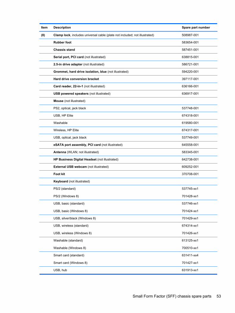
Item Description Spare part number
(8) Clamp lock, includes universal cable (plate not included; not illustrated) 508987-001
Rubber foot 583654-001
Chassis stand 587451-001
Serial port, PCI card (not illustrated) 638815-001
2.5-in drive adapter (not illustrated) 586721-001
Grommet, hard drive isolation, blue (not illustrated) 594220-001
Hard drive conversion bracket 397117-001
Card reader, 22-in-1 (not illustrated) 636166-001
USB powered speakers (not illustrated) 636917-001
Mouse (not illustrated)
PS2, optical, jack black 537748-001
USB, HP Elite 674318-001
Washable 619580-001
Wireless, HP Elite 674317-001
USB, optical, jack black 537749-001
eSATA port assembly, PCI card (not illustrated) 645558-001
Antenna (WLAN; not illustrated) 583345-001
HP Business Digital Headset (not illustrated) 642738-001
External USB webcam (not illustrated) 609252-001
Foot kit 370708-001
Keyboard (not illustrated)
PS/2 (standard)
PS/2 (Windows 8)
537745-xx1
701428-xx1
USB, basic (standard)
USB, basic (Windows 8)
537746-xx1
701424-xx1
USB, silver/black (Windows 8) 701429-xx1
USB, wireless (standard)
USB, wireless (Windows 8)
674314-xx1
701426-xx1
Washable (standard)
Washable (Windows 8)
613125-xx1
700510-xx1
Smart card (standard)
Smart card (Windows 8)
631411-xx4
701427-xx1
USB, hub 631913-xx1
Small Form Factor (SFF) chassis spare parts 53
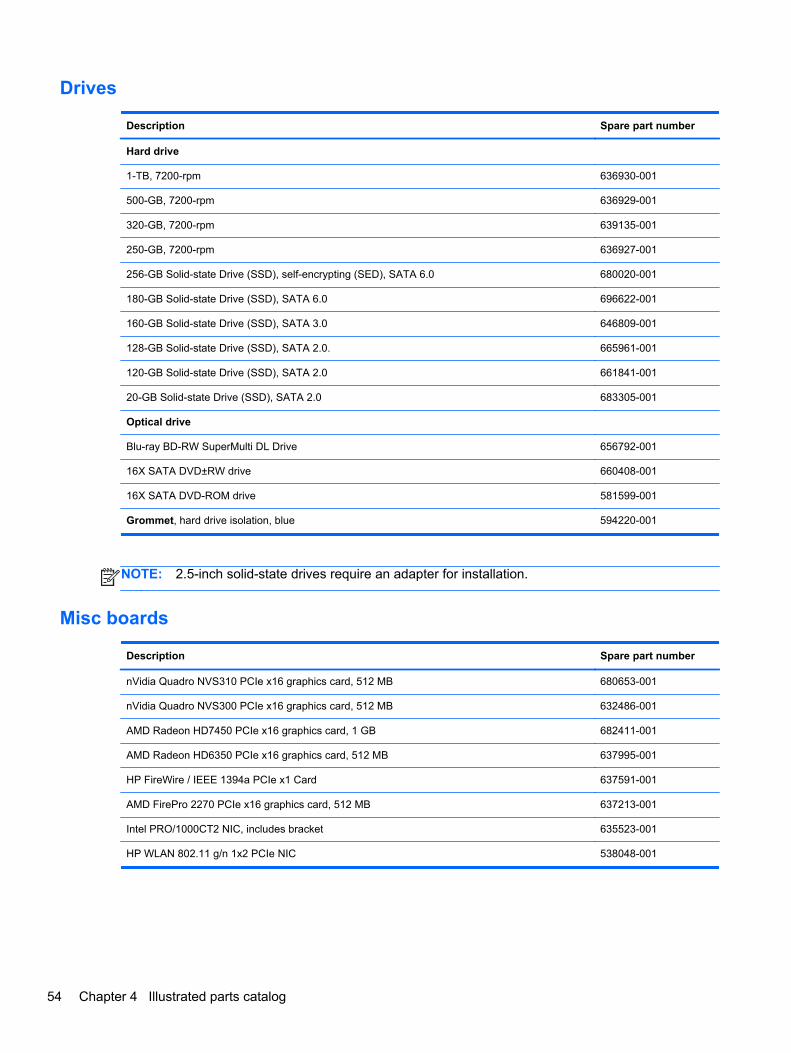
Drives
Description Spare part number
Hard drive
1-TB, 7200-rpm 636930-001
500-GB, 7200-rpm 636929-001
320-GB, 7200-rpm 639135-001
250-GB, 7200-rpm 636927-001
256-GB Solid-state Drive (SSD), self-encrypting (SED), SATA 6.0 680020-001
180-GB Solid-state Drive (SSD), SATA 6.0 696622-001
160-GB Solid-state Drive (SSD), SATA 3.0 646809-001
128-GB Solid-state Drive (SSD), SATA 2.0. 665961-001
120-GB Solid-state Drive (SSD), SATA 2.0 661841-001
20-GB Solid-state Drive (SSD), SATA 2.0 683305-001
Optical drive
Blu-ray BD-RW SuperMulti DL Drive 656792-001
16X SATA DVD±RW drive 660408-001
16X SATA DVD-ROM drive 581599-001
Grommet, hard drive isolation, blue 594220-001
NOTE: 2.5-inch solid-state drives require an adapter for installation.
Misc boards
Description Spare part number
nVidia Quadro NVS310 PCIe x16 graphics card, 512 MB 680653-001
nVidia Quadro NVS300 PCIe x16 graphics card, 512 MB 632486-001
AMD Radeon HD7450 PCIe x16 graphics card, 1 GB 682411-001
AMD Radeon HD6350 PCIe x16 graphics card, 512 MB 637995-001
HP FireWire / IEEE 1394a PCIe x1 Card 637591-001
AMD FirePro 2270 PCIe x16 graphics card, 512 MB 637213-001
Intel PRO/1000CT2 NIC, includes bracket 635523-001
HP WLAN 802.11 g/n 1x2 PCIe NIC 538048-001
54 Chapter 4 Illustrated parts catalog
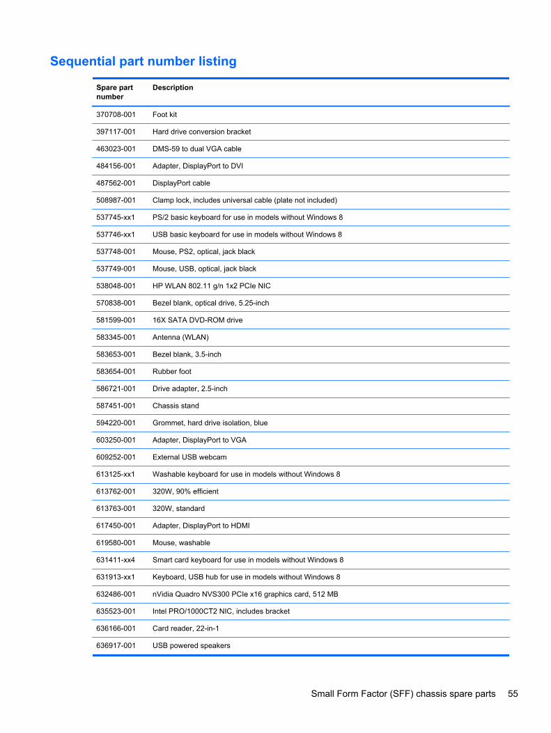
Sequential part number listing
Spare partnumber
Description
370708-001 Foot kit
397117-001 Hard drive conversion bracket
463023-001 DMS-59 to dual VGA cable
484156-001 Adapter, DisplayPort to DVI
487562-001 DisplayPort cable
508987-001 Clamp lock, includes universal cable (plate not included)
537745-xx1 PS/2 basic keyboard for use in models without Windows 8
537746-xx1 USB basic keyboard for use in models without Windows 8
537748-001 Mouse, PS2, optical, jack black
537749-001 Mouse, USB, optical, jack black
538048-001 HP WLAN 802.11 g/n 1x2 PCIe NIC
570838-001 Bezel blank, optical drive, 5.25-inch
581599-001 16X SATA DVD-ROM drive
583345-001 Antenna (WLAN)
583653-001 Bezel blank, 3.5-inch
583654-001 Rubber foot
586721-001 Drive adapter, 2.5-inch
587451-001 Chassis stand
594220-001 Grommet, hard drive isolation, blue
603250-001 Adapter, DisplayPort to VGA
609252-001 External USB webcam
613125-xx1 Washable keyboard for use in models without Windows 8
613762-001 320W, 90% efficient
613763-001 320W, standard
617450-001 Adapter, DisplayPort to HDMI
619580-001 Mouse, washable
631411-xx4 Smart card keyboard for use in models without Windows 8
631913-xx1 Keyboard, USB hub for use in models without Windows 8
632486-001 nVidia Quadro NVS300 PCIe x16 graphics card, 512 MB
635523-001 Intel PRO/1000CT2 NIC, includes bracket
636166-001 Card reader, 22-in-1
636917-001 USB powered speakers
Small Form Factor (SFF) chassis spare parts 55
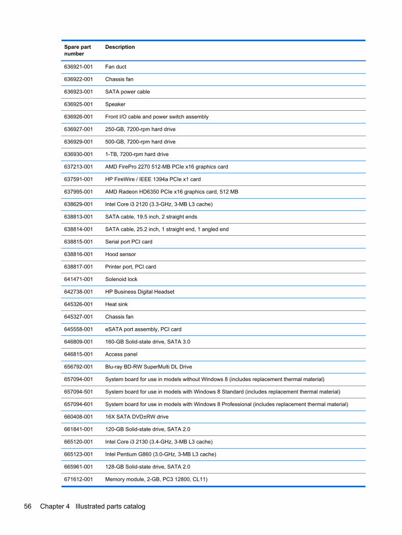
Spare partnumber
Description
636921-001 Fan duct
636922-001 Chassis fan
636923-001 SATA power cable
636925-001 Speaker
636926-001 Front I/O cable and power switch assembly
636927-001 250-GB, 7200-rpm hard drive
636929-001 500-GB, 7200-rpm hard drive
636930-001 1-TB, 7200-rpm hard drive
637213-001 AMD FirePro 2270 512-MB PCIe x16 graphics card
637591-001 HP FireWire / IEEE 1394a PCIe x1 card
637995-001 AMD Radeon HD6350 PCIe x16 graphics card, 512 MB
638629-001 Intel Core i3 2120 (3.3-GHz, 3-MB L3 cache)
638813-001 SATA cable, 19.5 inch, 2 straight ends
638814-001 SATA cable, 25.2 inch, 1 straight end, 1 angled end
638815-001 Serial port PCI card
638816-001 Hood sensor
638817-001 Printer port, PCI card
641471-001 Solenoid lock
642738-001 HP Business Digital Headset
645326-001 Heat sink
645327-001 Chassis fan
645558-001 eSATA port assembly, PCI card
646809-001 160-GB Solid-state drive, SATA 3.0
646815-001 Access panel
656792-001 Blu-ray BD-RW SuperMulti DL Drive
657094-001 System board for use in models without Windows 8 (includes replacement thermal material)
657094-501 System board for use in models with Windows 8 Standard (includes replacement thermal material)
657094-601 System board for use in models with Windows 8 Professional (includes replacement thermal material)
660408-001 16X SATA DVD±RW drive
661841-001 120-GB Solid-state drive, SATA 2.0
665120-001 Intel Core i3 2130 (3.4-GHz, 3-MB L3 cache)
665123-001 Intel Pentium G860 (3.0-GHz, 3-MB L3 cache)
665961-001 128-GB Solid-state drive, SATA 2.0
671612-001 Memory module, 2-GB, PC3 12800, CL11)
56 Chapter 4 Illustrated parts catalog
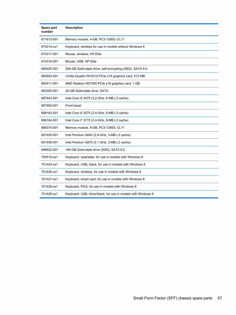
Spare partnumber
Description
671613-001 Memory module, 4-GB, PC3-12800,-CL11
674314-xx1 Keyboard, wireless for use in models without Windows 8
674317-001 Mouse, wireless, HP Elite
674318-001 Mouse, USB, HP Elite
680020-001 256-GB Solid-state drive, self-encrypting (SED), SATA 6.0
680653-001 nVidia Quadro NVS310 PCIe x16 graphics card, 512 MB
682411-001 AMD Radeon HD7450 PCIe x16 graphics card, 1 GB
683305-001 20-GB Solid-state drive, SATA
687943-001 Intel Core i5 3470 (3.2-GHz, 6-MB L3 cache)
687950-001 Front bezel
688162-001 Intel Core i5 3570 (3.4-GHz, 6-MB L3 cache)
688164-001 Intel Core i7 3770 (3.4-GHz, 8-MB L3 cache)
689375-001 Memory module, 8-GB, PC3-12800, CL11
691935-001 Intel Pentium G640 (2.8-GHz, 3-MB L3 cache)
691936-001 Intel Pentium G870 (3.1-GHz, 3-MB L3 cache)
696622-001 180-GB Solid-state drive (SSD), SATA 6.0
700510-xx1 Keyboard, washable, for use in models with Windows 8
701424-xx1 Keyboard, USB, black, for use in models with Windows 8
701426-xx1 Keyboard, wireless, for use in models with Windows 8
701427-xx1 Keyboard, smart card, for use in models with Windows 8
701428-xx1 Keyboard, PS/2, for use in models with Windows 8
701429-xx1 Keyboard, USB, silver/black, for use in models with Windows 8
Small Form Factor (SFF) chassis spare parts 57
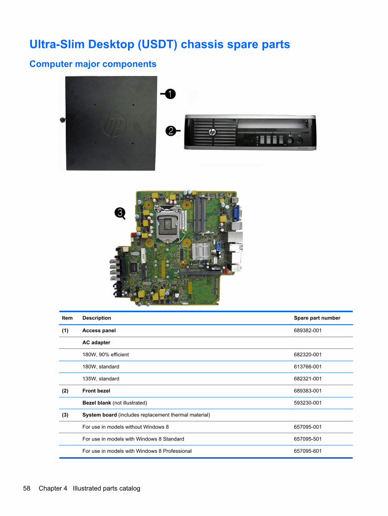
Ultra-Slim Desktop (USDT) chassis spare parts
Computer major components
Item Description Spare part number
(1) Access panel 689382-001
AC adapter
180W, 90% efficient 682320-001
180W, standard 613766-001
135W, standard 682321-001
(2) Front bezel 689383-001
Bezel blank (not illustrated) 593230-001
(3) System board (includes replacement thermal material)
For use in models without Windows 8 657095-001
For use in models with Windows 8 Standard 657095-501
For use in models with Windows 8 Professional 657095-601
58 Chapter 4 Illustrated parts catalog
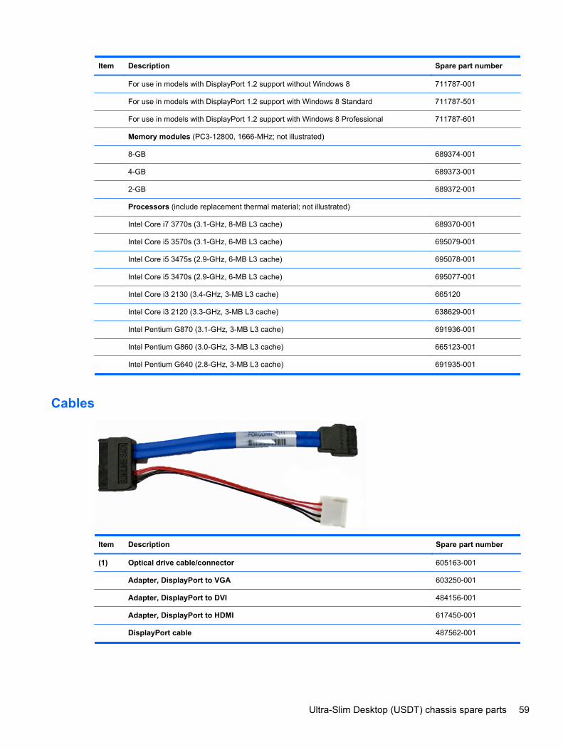
Item Description Spare part number
For use in models with DisplayPort 1.2 support without Windows 8 711787-001
For use in models with DisplayPort 1.2 support with Windows 8 Standard 711787-501
For use in models with DisplayPort 1.2 support with Windows 8 Professional 711787-601
Memory modules (PC3-12800, 1666-MHz; not illustrated)
8-GB 689374-001
4-GB 689373-001
2-GB 689372-001
Processors (include replacement thermal material; not illustrated)
Intel Core i7 3770s (3.1-GHz, 8-MB L3 cache) 689370-001
Intel Core i5 3570s (3.1-GHz, 6-MB L3 cache) 695079-001
Intel Core i5 3475s (2.9-GHz, 6-MB L3 cache) 695078-001
Intel Core i5 3470s (2.9-GHz, 6-MB L3 cache) 695077-001
Intel Core i3 2130 (3.4-GHz, 3-MB L3 cache) 665120
Intel Core i3 2120 (3.3-GHz, 3-MB L3 cache) 638629-001
Intel Pentium G870 (3.1-GHz, 3-MB L3 cache) 691936-001
Intel Pentium G860 (3.0-GHz, 3-MB L3 cache) 665123-001
Intel Pentium G640 (2.8-GHz, 3-MB L3 cache) 691935-001
Cables
Item Description Spare part number
(1) Optical drive cable/connector 605163-001
Adapter, DisplayPort to VGA 603250-001
Adapter, DisplayPort to DVI 484156-001
Adapter, DisplayPort to HDMI 617450-001
DisplayPort cable 487562-001
Ultra-Slim Desktop (USDT) chassis spare parts 59
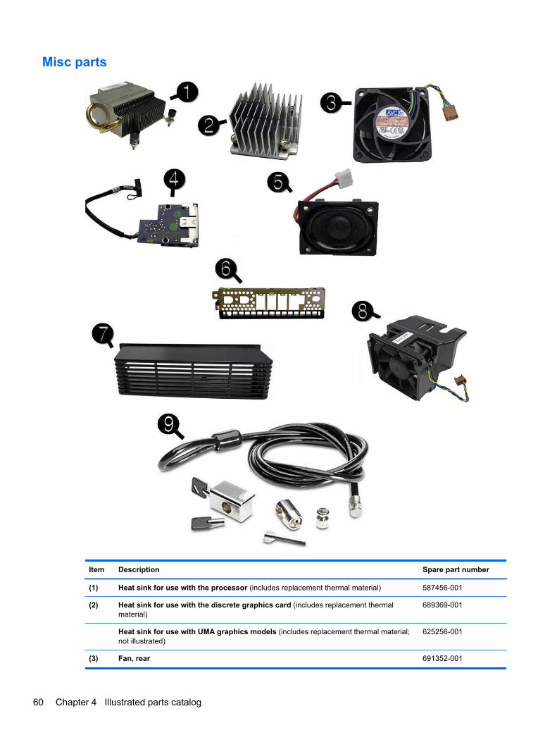
Misc parts
Item Description Spare part number
(1) Heat sink for use with the processor (includes replacement thermal material) 587456-001
(2) Heat sink for use with the discrete graphics card (includes replacement thermalmaterial)
689369-001
Heat sink for use with UMA graphics models (includes replacement thermal material;not illustrated)
625256-001
(3) Fan, rear 691352-001
60 Chapter 4 Illustrated parts catalog
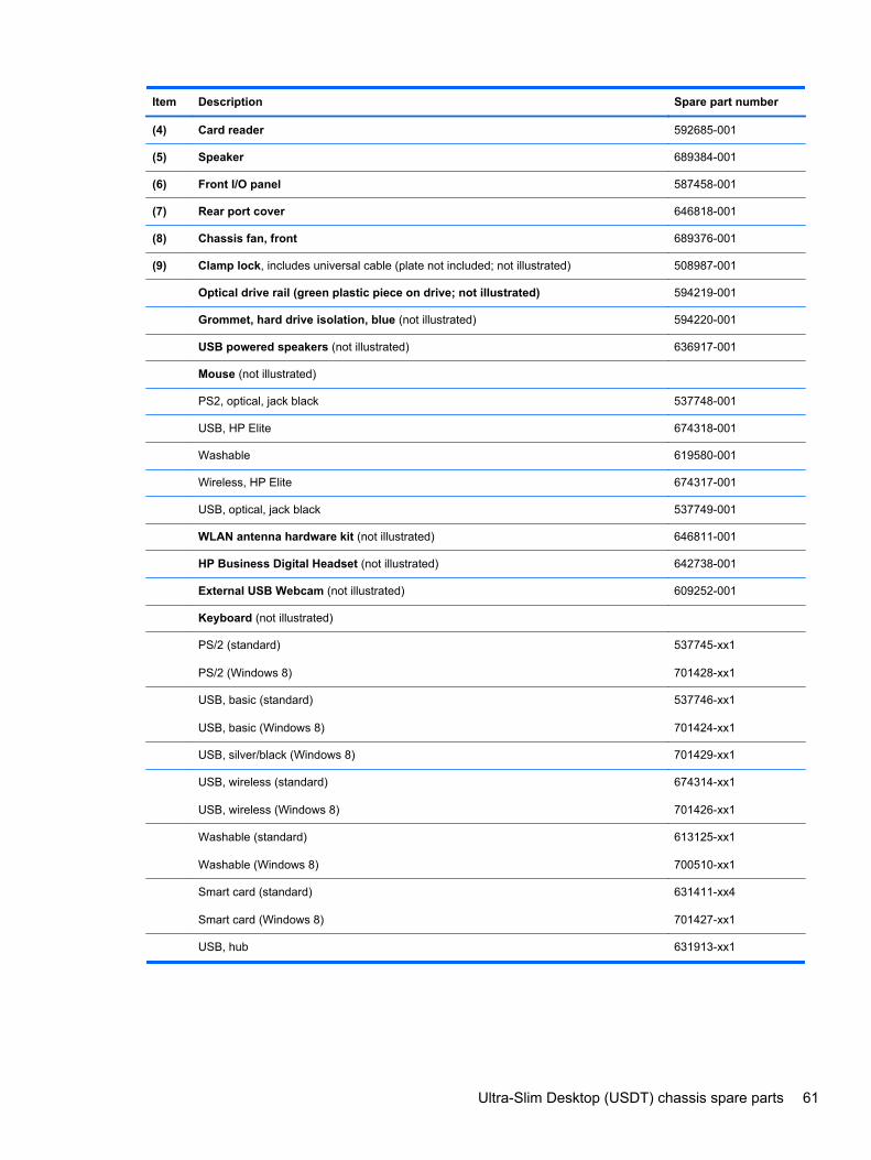
Item Description Spare part number
(4) Card reader 592685-001
(5) Speaker 689384-001
(6) Front I/O panel 587458-001
(7) Rear port cover 646818-001
(8) Chassis fan, front 689376-001
(9) Clamp lock, includes universal cable (plate not included; not illustrated) 508987-001
Optical drive rail (green plastic piece on drive; not illustrated) 594219-001
Grommet, hard drive isolation, blue (not illustrated) 594220-001
USB powered speakers (not illustrated) 636917-001
Mouse (not illustrated)
PS2, optical, jack black 537748-001
USB, HP Elite 674318-001
Washable 619580-001
Wireless, HP Elite 674317-001
USB, optical, jack black 537749-001
WLAN antenna hardware kit (not illustrated) 646811-001
HP Business Digital Headset (not illustrated) 642738-001
External USB Webcam (not illustrated) 609252-001
Keyboard (not illustrated)
PS/2 (standard)
PS/2 (Windows 8)
537745-xx1
701428-xx1
USB, basic (standard)
USB, basic (Windows 8)
537746-xx1
701424-xx1
USB, silver/black (Windows 8) 701429-xx1
USB, wireless (standard)
USB, wireless (Windows 8)
674314-xx1
701426-xx1
Washable (standard)
Washable (Windows 8)
613125-xx1
700510-xx1
Smart card (standard)
Smart card (Windows 8)
631411-xx4
701427-xx1
USB, hub 631913-xx1
Ultra-Slim Desktop (USDT) chassis spare parts 61
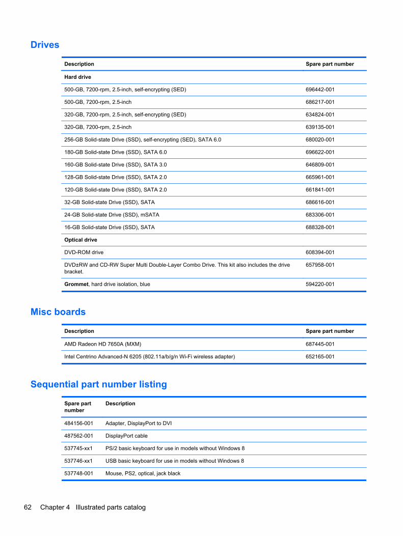
Drives
Description Spare part number
Hard drive
500-GB, 7200-rpm, 2.5-inch, self-encrypting (SED) 696442-001
500-GB, 7200-rpm, 2.5-inch 686217-001
320-GB, 7200-rpm, 2.5-inch, self-encrypting (SED) 634824-001
320-GB, 7200-rpm, 2.5-inch 639135-001
256-GB Solid-state Drive (SSD), self-encrypting (SED), SATA 6.0 680020-001
180-GB Solid-state Drive (SSD), SATA 6.0 696622-001
160-GB Solid-state Drive (SSD), SATA 3.0 646809-001
128-GB Solid-state Drive (SSD), SATA 2.0 665961-001
120-GB Solid-state Drive (SSD), SATA 2.0 661841-001
32-GB Solid-state Drive (SSD), SATA 686616-001
24-GB Solid-state Drive (SSD), mSATA 683306-001
16-GB Solid-state Drive (SSD), SATA 688328-001
Optical drive
DVD-ROM drive 608394-001
DVD±RW and CD-RW Super Multi Double-Layer Combo Drive. This kit also includes the drivebracket.
657958-001
Grommet, hard drive isolation, blue 594220-001
Misc boards
Description Spare part number
AMD Radeon HD 7650A (MXM) 687445-001
Intel Centrino Advanced-N 6205 (802.11a/b/g/n Wi-Fi wireless adapter) 652165-001
Sequential part number listing
Spare partnumber
Description
484156-001 Adapter, DisplayPort to DVI
487562-001 DisplayPort cable
537745-xx1 PS/2 basic keyboard for use in models without Windows 8
537746-xx1 USB basic keyboard for use in models without Windows 8
537748-001 Mouse, PS2, optical, jack black
62 Chapter 4 Illustrated parts catalog
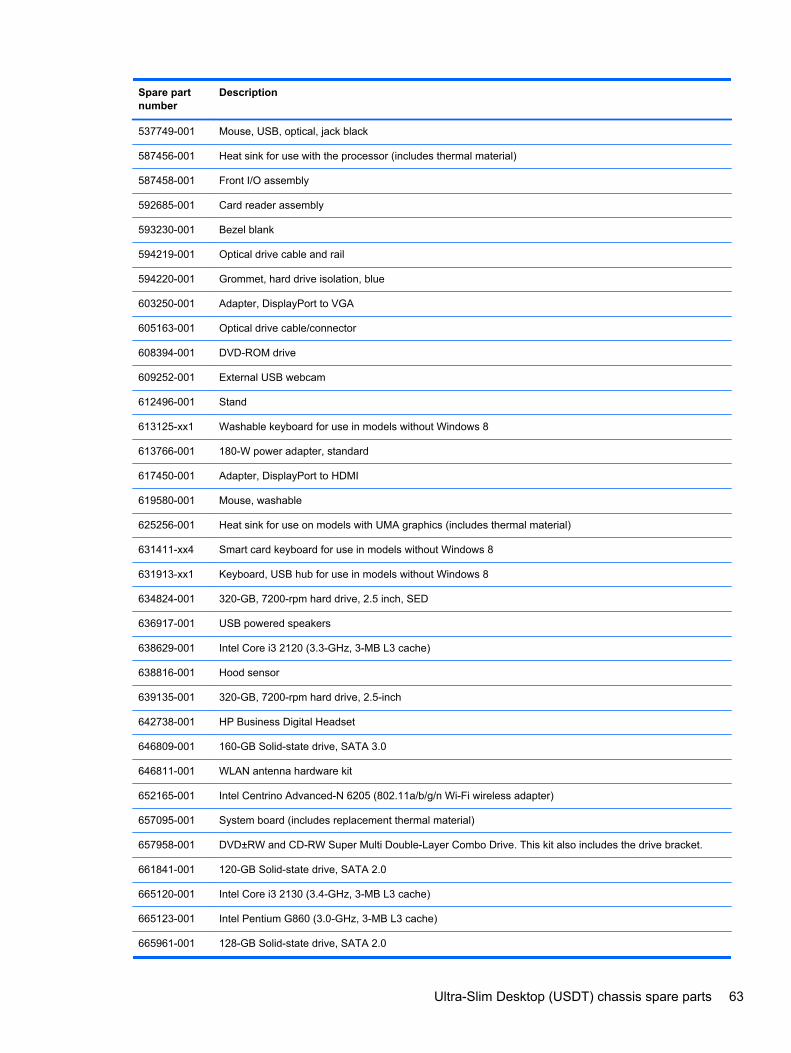
Spare partnumber
Description
537749-001 Mouse, USB, optical, jack black
587456-001 Heat sink for use with the processor (includes thermal material)
587458-001 Front I/O assembly
592685-001 Card reader assembly
593230-001 Bezel blank
594219-001 Optical drive cable and rail
594220-001 Grommet, hard drive isolation, blue
603250-001 Adapter, DisplayPort to VGA
605163-001 Optical drive cable/connector
608394-001 DVD-ROM drive
609252-001 External USB webcam
612496-001 Stand
613125-xx1 Washable keyboard for use in models without Windows 8
613766-001 180-W power adapter, standard
617450-001 Adapter, DisplayPort to HDMI
619580-001 Mouse, washable
625256-001 Heat sink for use on models with UMA graphics (includes thermal material)
631411-xx4 Smart card keyboard for use in models without Windows 8
631913-xx1 Keyboard, USB hub for use in models without Windows 8
634824-001 320-GB, 7200-rpm hard drive, 2.5 inch, SED
636917-001 USB powered speakers
638629-001 Intel Core i3 2120 (3.3-GHz, 3-MB L3 cache)
638816-001 Hood sensor
639135-001 320-GB, 7200-rpm hard drive, 2.5-inch
642738-001 HP Business Digital Headset
646809-001 160-GB Solid-state drive, SATA 3.0
646811-001 WLAN antenna hardware kit
652165-001 Intel Centrino Advanced-N 6205 (802.11a/b/g/n Wi-Fi wireless adapter)
657095-001 System board (includes replacement thermal material)
657958-001 DVD±RW and CD-RW Super Multi Double-Layer Combo Drive. This kit also includes the drive bracket.
661841-001 120-GB Solid-state drive, SATA 2.0
665120-001 Intel Core i3 2130 (3.4-GHz, 3-MB L3 cache)
665123-001 Intel Pentium G860 (3.0-GHz, 3-MB L3 cache)
665961-001 128-GB Solid-state drive, SATA 2.0
Ultra-Slim Desktop (USDT) chassis spare parts 63
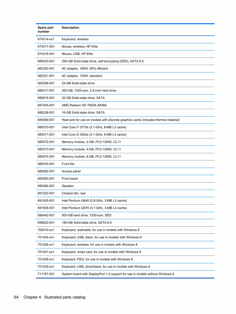
Spare partnumber
Description
674314-xx1 Keyboard, wireless
674317-001 Mouse, wireless, HP Elite
674318-001 Mouse, USB, HP Elite
680020-001 256-GB Solid-state drive, self-encrypting (SED), SATA 6.0
682320-001 AC adapter, 180W, 90% efficient
682321-001 AC adapter, 135W, standard
683306-001 24-GB Solid-state drive
686217-001 500-GB, 7200-rpm, 2.5-inch hard drive
686616-001 32-GB Solid-state drive, SATA
687445-001 AMD Radeon HD 7650A (MXM)
688328-001 16-GB Solid-state drive, SATA
689369-001 Heat sink for use on models with discrete graphics cards (includes thermal material)
689370-001 Intel Core i7 3770s (3.1-GHz, 8-MB L3 cache)
689371-001 Intel Core i5 3550s (3.1-GHz, 6-MB L3 cache)
689372-001 Memory module, 2-GB, PC3-12800, CL11
689373-001 Memory module, 4-GB, PC3-12800, CL11
689374-001 Memory module, 8-GB, PC3-12800, CL11
689376-001 Front fan
689382-001 Access panel
689383-001 Front bezel
689384-001 Speaker
691352-001 Chassis fan, rear
691935-001 Intel Pentium G640 (2.8-GHz, 3-MB L3 cache)
691936-001 Intel Pentium G870 (3.1-GHz, 3-MB L3 cache)
696442-001 500-GB hard drive, 7200-rpm, SED
696622-001 180-GB Solid-state drive, SATA 6.0
700510-xx1 Keyboard, washable, for use in models with Windows 8
701424-xx1 Keyboard, USB, black, for use in models with Windows 8
701426-xx1 Keyboard, wireless, for use in models with Windows 8
701427-xx1 Keyboard, smart card, for use in models with Windows 8
701428-xx1 Keyboard, PS/2, for use in models with Windows 8
701429-xx1 Keyboard, USB, silver/black, for use in models with Windows 8
711787-001 System board with DisplayPort 1.2 support for use in models without Windows 8
64 Chapter 4 Illustrated parts catalog

Spare partnumber
Description
711787-501 System board with DisplayPort 1.2 support for use in models with Windows 8 Standard
711787-601 System board with DisplayPort 1.2 support for use in models with Windows 8 Professional
Ultra-Slim Desktop (USDT) chassis spare parts 65
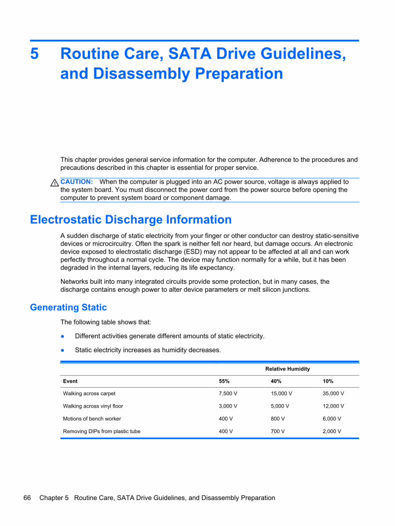
5 Routine Care, SATA Drive Guidelines,and Disassembly Preparation
This chapter provides general service information for the computer. Adherence to the procedures andprecautions described in this chapter is essential for proper service.
CAUTION: When the computer is plugged into an AC power source, voltage is always applied tothe system board. You must disconnect the power cord from the power source before opening thecomputer to prevent system board or component damage.
Electrostatic Discharge InformationA sudden discharge of static electricity from your finger or other conductor can destroy static-sensitivedevices or microcircuitry. Often the spark is neither felt nor heard, but damage occurs. An electronicdevice exposed to electrostatic discharge (ESD) may not appear to be affected at all and can workperfectly throughout a normal cycle. The device may function normally for a while, but it has beendegraded in the internal layers, reducing its life expectancy.
Networks built into many integrated circuits provide some protection, but in many cases, thedischarge contains enough power to alter device parameters or melt silicon junctions.
Generating Static
The following table shows that:
● Different activities generate different amounts of static electricity.
● Static electricity increases as humidity decreases.
Relative Humidity
Event 55% 40% 10%
Walking across carpet
Walking across vinyl floor
Motions of bench worker
Removing DIPs from plastic tube
7,500 V
3,000 V
400 V
400 V
15,000 V
5,000 V
800 V
700 V
35,000 V
12,000 V
6,000 V
2,000 V
66 Chapter 5 Routine Care, SATA Drive Guidelines, and Disassembly Preparation
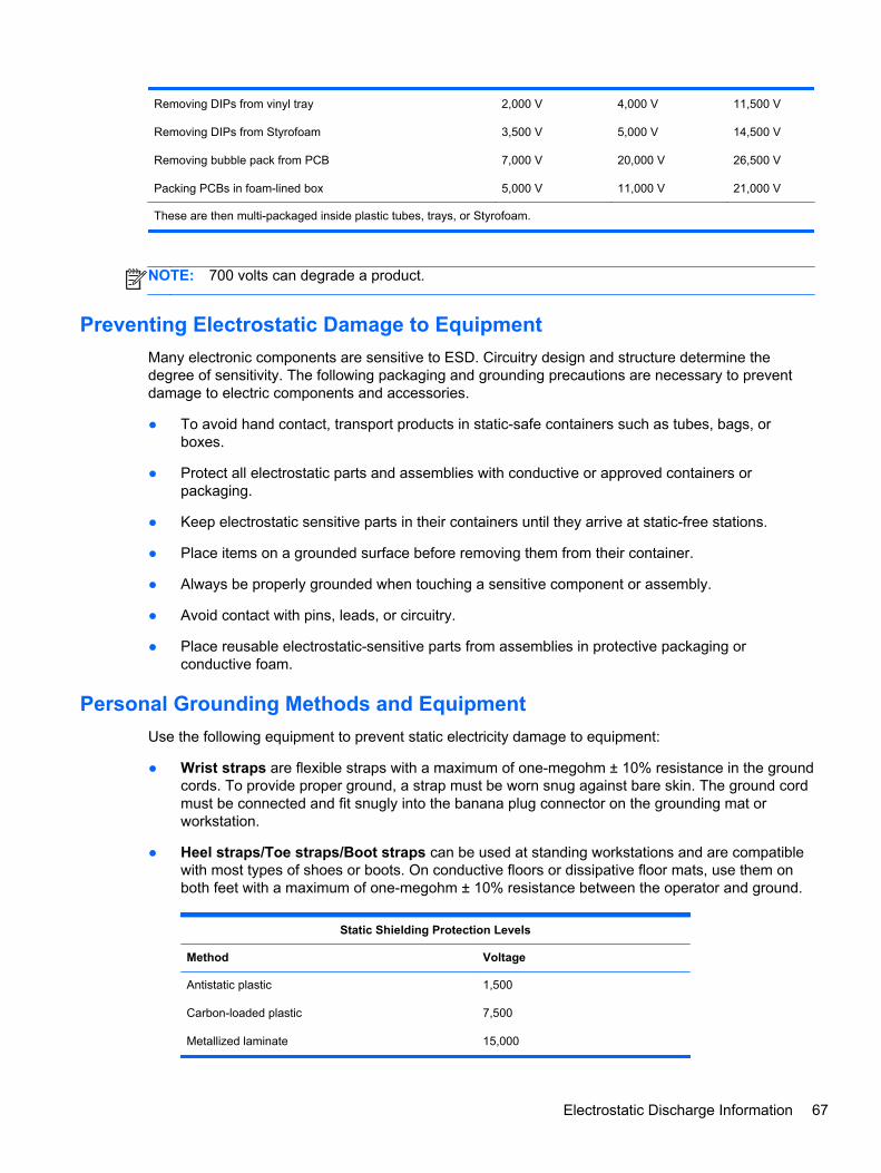
Removing DIPs from vinyl tray
Removing DIPs from Styrofoam
Removing bubble pack from PCB
Packing PCBs in foam-lined box
2,000 V
3,500 V
7,000 V
5,000 V
4,000 V
5,000 V
20,000 V
11,000 V
11,500 V
14,500 V
26,500 V
21,000 V
These are then multi-packaged inside plastic tubes, trays, or Styrofoam.
NOTE: 700 volts can degrade a product.
Preventing Electrostatic Damage to Equipment
Many electronic components are sensitive to ESD. Circuitry design and structure determine thedegree of sensitivity. The following packaging and grounding precautions are necessary to preventdamage to electric components and accessories.
● To avoid hand contact, transport products in static-safe containers such as tubes, bags, orboxes.
● Protect all electrostatic parts and assemblies with conductive or approved containers orpackaging.
● Keep electrostatic sensitive parts in their containers until they arrive at static-free stations.
● Place items on a grounded surface before removing them from their container.
● Always be properly grounded when touching a sensitive component or assembly.
● Avoid contact with pins, leads, or circuitry.
● Place reusable electrostatic-sensitive parts from assemblies in protective packaging orconductive foam.
Personal Grounding Methods and Equipment
Use the following equipment to prevent static electricity damage to equipment:
● Wrist straps are flexible straps with a maximum of one-megohm ± 10% resistance in the groundcords. To provide proper ground, a strap must be worn snug against bare skin. The ground cordmust be connected and fit snugly into the banana plug connector on the grounding mat orworkstation.
● Heel straps/Toe straps/Boot straps can be used at standing workstations and are compatiblewith most types of shoes or boots. On conductive floors or dissipative floor mats, use them onboth feet with a maximum of one-megohm ± 10% resistance between the operator and ground.
Static Shielding Protection Levels
Method Voltage
Antistatic plastic
Carbon-loaded plastic
Metallized laminate
1,500
7,500
15,000
Electrostatic Discharge Information 67
Grounding the Work Area
To prevent static damage at the work area, use the following precautions:
● Cover the work surface with approved static-dissipative material. Provide a wrist strap connectedto the work surface and properly grounded tools and equipment.
● Use static-dissipative mats, foot straps, or air ionizers to give added protection.
● Handle electrostatic sensitive components, parts, and assemblies by the case or PCB laminate.Handle them only at static-free work areas.
● Turn off power and input signals before inserting and removing connectors or test equipment.
● Use fixtures made of static-safe materials when fixtures must directly contact dissipativesurfaces.
● Keep work area free of nonconductive materials such as ordinary plastic assembly aids andStyrofoam.
● Use field service tools, such as cutters, screwdrivers, and vacuums, that are conductive.
Recommended Materials and Equipment
Materials and equipment that are recommended for use in preventing static electricity include:
● Antistatic tape
● Antistatic smocks, aprons, or sleeve protectors
● Conductive bins and other assembly or soldering aids
● Conductive foam
● Conductive tabletop workstations with ground cord of one-megohm +/- 10% resistance
● Static-dissipative table or floor mats with hard tie to ground
● Field service kits
● Static awareness labels
● Wrist straps and footwear straps providing one-megohm +/- 10% resistance
● Material handling packages
● Conductive plastic bags
● Conductive plastic tubes
● Conductive tote boxes
● Opaque shielding bags
● Transparent metallized shielding bags
● Transparent shielding tubes
68 Chapter 5 Routine Care, SATA Drive Guidelines, and Disassembly Preparation

Operating GuidelinesTo prevent overheating and to help prolong the life of the computer:
● Keep the computer away from excessive moisture, direct sunlight, and extremes of heat andcold.
● Operate the computer on a sturdy, level surface. Leave a 10.2-cm (4-inch) clearance on allvented sides of the computer and above the monitor to permit the required airflow.
● Never restrict the airflow into the computer by blocking any vents or air intakes. Do not place thekeyboard, with the keyboard feet down, directly against the front of the desktop unit as this alsorestricts airflow.
● Occasionally clean the air vents on all vented sides of the computer. Lint, dust, and other foreignmatter can block the vents and limit the airflow. Be sure to unplug the computer before cleaningthe air vents.
● Never operate the computer with the cover or side panel removed.
● Do not stack computers on top of each other or place computers so near each other that theyare subject to each other’s re-circulated or preheated air.
● If the computer is to be operated within a separate enclosure, intake and exhaust ventilationmust be provided on the enclosure, and the same operating guidelines listed above will stillapply.
● Keep liquids away from the computer and keyboard.
● Never cover the ventilation slots on the monitor with any type of material.
● Install or enable power management functions of the operating system or other software,including sleep states.
Routine Care
General Cleaning Safety Precautions
1. Never use solvents or flammable solutions to clean the computer.
2. Never immerse any parts in water or cleaning solutions; apply any liquids to a clean cloth andthen use the cloth on the component.
3. Always unplug the computer when cleaning with liquids or damp cloths.
4. Always unplug the computer before cleaning the keyboard, mouse, or air vents.
5. Disconnect the keyboard before cleaning it.
6. Wear safety glasses equipped with side shields when cleaning the keyboard.
Cleaning the Computer Case
Follow all safety precautions in General Cleaning Safety Precautions on page 69 before cleaning thecomputer.
Operating Guidelines 69
To clean the computer case, follow the procedures described below:
● To remove light stains or dirt, use plain water with a clean, lint-free cloth or swab.
● For stronger stains, use a mild dishwashing liquid diluted with water. Rinse well by wiping it witha cloth or swab dampened with clear water.
● For stubborn stains, use isopropyl (rubbing) alcohol. No rinsing is needed as the alcohol willevaporate quickly and not leave a residue.
● After cleaning, always wipe the unit with a clean, lint-free cloth.
● Occasionally clean the air vents on the computer. Lint and other foreign matter can block thevents and limit the airflow.
Cleaning the Keyboard
Follow all safety precautions in General Cleaning Safety Precautions on page 69 before cleaning thekeyboard.
To clean the tops of the keys or the keyboard body, follow the procedures described in Cleaning theComputer Case on page 69.
When cleaning debris from under the keys, review all rules in General Cleaning Safety Precautionson page 69 before following these procedures:
CAUTION: Use safety glasses equipped with side shields before attempting to clean debris fromunder the keys.
● Visible debris underneath or between the keys may be removed by vacuuming or shaking.
● Canned, pressurized air may be used to clean debris from under the keys. Caution should beused as too much air pressure can dislodge lubricants applied under the wide keys.
● If you remove a key, use a specially designed key puller to prevent damage to the keys. Thistool is available through many electronic supply outlets.
CAUTION: Never remove a wide leveled key (like the space bar) from the keyboard. If thesekeys are improperly removed or installed, the keyboard may not function properly.
● Cleaning under a key may be done with a swab moistened with isopropyl alcohol and squeezedout. Be careful not to wipe away lubricants necessary for proper key functions. Use tweezers toremove any fibers or dirt in confined areas. Allow the parts to air dry before reassembly.
Cleaning the Monitor
● Wipe the monitor screen with a clean cloth moistened with water or with a towelette designed forcleaning monitors. Do not use sprays or aerosols directly on the screen; the liquid may seep intothe housing and damage a component. Never use solvents or flammable liquids on the monitor.
● To clean the monitor body follow the procedures in Cleaning the Computer Case on page 69.
70 Chapter 5 Routine Care, SATA Drive Guidelines, and Disassembly Preparation
Cleaning the Mouse
Before cleaning the mouse, ensure that the power to the computer is turned off.
● Clean the mouse ball by first removing the retaining plate and the ball from the housing. Pull outany debris from the ball socket and wipe the ball with a clean, dry cloth before reassembly.
● To clean the mouse body, follow the procedures in Cleaning the Computer Case on page 69.
Service ConsiderationsListed below are some of the considerations that you should keep in mind during the disassembly andassembly of the computer.
Power Supply Fan
The power supply fan is a variable-speed fan based on the temperature in the power supply.
CAUTION: The cooling fan is always on when the computer is in the “On” mode. The cooling fan isoff when the computer is in “Standby,” “Suspend,” or “Off” modes.
You must disconnect the power cord from the power source before opening the computer to preventsystem board or component damage.
Tools and Software Requirements
To service the computer, you need the following:
● Torx T-15 screwdriver (HP screwdriver with bits, PN 161946-001)
● Torx T-15 screwdriver with small diameter shank (for certain front bezel removal)
● Flat-bladed screwdriver (may sometimes be used in place of the Torx screwdriver)
● Phillips #2 screwdriver
● Diagnostics software
● HP tamper-resistant T-15 wrench (Smart Cover FailSafe Key, PN 166527-001) or HP tamper-resistant bits (Smart Cover FailSafe Key, PN 166527-002)
Screws
The screws used in the computer are not interchangeable. They may have standard or metric threadsand may be of different lengths. If an incorrect screw is used during the reassembly process, it candamage the unit. HP strongly recommends that all screws removed during disassembly be kept withthe part that was removed, then returned to their proper locations.
CAUTION: Metric screws have a black finish. U.S. screws have a silver finish and are used on harddrives only.
CAUTION: As each subassembly is removed from the computer, it should be placed away from thework area to prevent damage.
Service Considerations 71
Cables and Connectors
Most cables used throughout the unit are flat, flexible cables. These cables must be handled withcare to avoid damage. Apply only the tension required to seat or unseat the cables during insertion orremoval from the connector. Handle cables by the connector whenever possible. In all cases, avoidbending or twisting the cables, and ensure that the cables are routed in such a way that they cannotbe caught or snagged by parts being removed or replaced.
CAUTION: When servicing this computer, ensure that cables are placed in their proper locationduring the reassembly process. Improper cable placement can damage the computer.
Hard Drives
Handle hard drives as delicate, precision components, avoiding all physical shock and vibration. Thisapplies to failed drives as well as replacement spares.
● If a drive must be mailed, place the drive in a bubble-pack mailer or other suitable protectivepackaging and label the package “Fragile: Handle With Care.”
● Do not remove hard drives from the shipping package for storage. Keep hard drives in theirprotective packaging until they are actually mounted in the CPU.
● Avoid dropping drives from any height onto any surface.
● If you are inserting or removing a hard drive, turn off the computer. Do not remove a hard drivewhile the computer is on or in standby mode.
● Before handling a drive, ensure that you are discharged of static electricity. While handling adrive, avoid touching the connector. For more information about preventing electrostaticdamage, refer to Electrostatic Discharge Information on page 66
● Do not use excessive force when inserting a drive.
● Avoid exposing a hard drive to liquids, temperature extremes, or products that have magneticfields such as monitors or speakers.
Lithium Coin Cell Battery
The battery that comes with the computer provides power to the real-time clock and has a minimumlifetime of about three years.
See the appropriate removal and replacement chapter for the chassis you are working on in thisguide for instructions on the replacement procedures.
WARNING! This computer contains a lithium battery. There is a risk of fire and chemical burn if thebattery is handled improperly. Do not disassemble, crush, puncture, short external contacts, disposein water or fire, or expose it to temperatures higher than 140ºF (60ºC). Do not attempt to recharge thebattery.
NOTE: Batteries, battery packs, and accumulators should not be disposed of together with thegeneral household waste. In order to forward them to recycling or proper disposal, please use thepublic collection system or return them to HP, their authorized partners, or their agents.
72 Chapter 5 Routine Care, SATA Drive Guidelines, and Disassembly Preparation

SATA Hard Drives
Serial ATA Hard Drive Characteristics
Number of pins/conductors in data cable 7/7
Number of pins in power cable 15
Maximum data cable length 39.37 in (100 cm)
Data interface voltage differential 400-700 mV
Drive voltages 3.3 V, 5 V, 12 V
Jumpers for configuring drive N/A
Data transfer rate 3.0 Gb/s
SATA Hard Drive Cables
SATA Data Cable
Always use an HP approved SATA 3.0 Gb/s cable as it is fully backwards compatible with the SATA1.5 Gb/s drives.
Current HP desktop products ship with SATA 3.0 Gb/s hard drives.
SATA data cables are susceptible to damage if overflexed. Never crease a SATA data cable andnever bend it tighter than a 30 mm (1.18 in) radius.
The SATA data cable is a thin, 7-pin cable designed to transmit data for only a single drive.
SMART ATA DrivesThe Self Monitoring Analysis and Recording Technology (SMART) ATA drives for the HP PersonalComputers have built-in drive failure prediction that warns the user or network administrator of animpending failure or crash of the hard drive. The SMART drive tracks fault prediction and failureindication parameters such as reallocated sector count, spin retry count, and calibration retry count. Ifthe drive determines that a failure is imminent, it generates a fault alert.
Cable ManagementAlways follow good cable management practices when working inside the computer.
● Keep cables away from major heat sources like the heat sink.
● Do not jam cables on top of expansion cards or memory modules. Printed circuit cards like theseare not designed to take excessive pressure on them.
● Keep cables clear of sliding or moveable parts to prevent them from being cut or crimped whenthe parts are moved.
● When folding a flat ribbon cable, never fold to a sharp crease. Sharp creases may damage thewires.
SATA Hard Drives 73
● Some flat ribbon cables come prefolded. Never change the folds on these cables.
● Do not bend any cable sharply. A sharp bend can break the internal wires.
● Never bend a SATA data cable tighter than a 30 mm (1.18 in) radius.
● Never crease a SATA data cable.
● Do not rely on components like the drive cage, power supply, or computer cover to push cablesdown into the chassis. Always position the cables to lay properly by themselves.
74 Chapter 5 Routine Care, SATA Drive Guidelines, and Disassembly Preparation
6 Removal and Replacement ProceduresConvertible Minitower (CMT) Chassis
Adherence to the procedures and precautions described in this chapter is essential for proper service.After completing all necessary removal and replacement procedures, run the Diagnostics utility toverify that all components operate properly.
NOTE: Not all features listed in this guide are available on all computers.
Preparation for DisassemblySee Routine Care, SATA Drive Guidelines, and Disassembly Preparation on page 66 for initial safetyprocedures.
1. Remove/disengage any security devices that prohibit opening the computer.
2. Close any open software applications.
3. Exit the operating system.
4. Remove any diskette, compact disc, or media card from the computer.
5. Turn off the computer and any peripheral devices that are connected to it.
CAUTION: Turn off the computer before disconnecting any cables.
Regardless of the power-on state, voltage is always present on the system board as long as thesystem is plugged into an active AC outlet. In some systems the cooling fan is on even when thecomputer is in the “Standby,” or “Suspend” modes. The power cord should always bedisconnected before servicing a unit.
6. Disconnect the power cord from the electrical outlet and then from the computer.
7. Disconnect all peripheral device cables from the computer.
8. As applicable, lay the computer down on its side to achieve a safe working position.
NOTE: During disassembly, label each cable as you remove it, noting its position and routing.Keep all screws with the units removed.
CAUTION: The screws used in the computer are of different thread sizes and lengths; using thewrong screw in an application may damage the unit.
Preparation for Disassembly 75
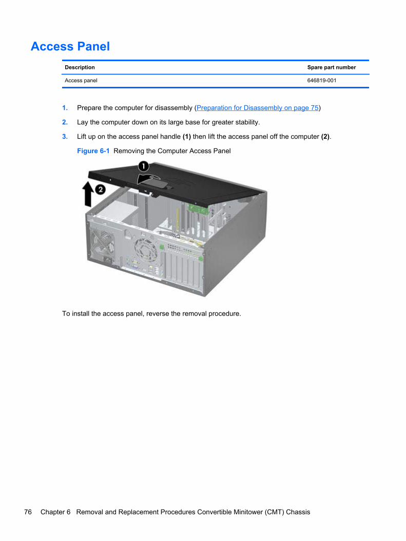
Access Panel
Description Spare part number
Access panel 646819-001
1. Prepare the computer for disassembly (Preparation for Disassembly on page 75)
2. Lay the computer down on its large base for greater stability.
3. Lift up on the access panel handle (1) then lift the access panel off the computer (2).
Figure 6-1 Removing the Computer Access Panel
To install the access panel, reverse the removal procedure.
76 Chapter 6 Removal and Replacement Procedures Convertible Minitower (CMT) Chassis
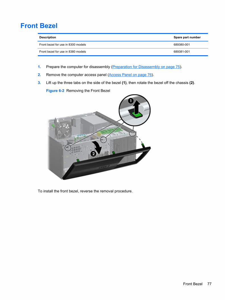
Front Bezel
Description Spare part number
Front bezel for use in 8300 models 689380-001
Front bezel for use in 8380 models 689381-001
1. Prepare the computer for disassembly (Preparation for Disassembly on page 75).
2. Remove the computer access panel (Access Panel on page 76).
3. Lift up the three tabs on the side of the bezel (1), then rotate the bezel off the chassis (2).
Figure 6-2 Removing the Front Bezel
To install the front bezel, reverse the removal procedure.
Front Bezel 77
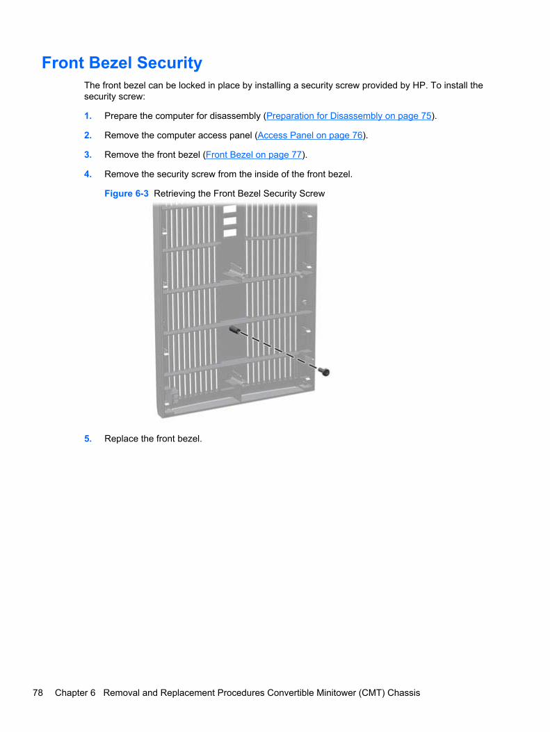
Front Bezel SecurityThe front bezel can be locked in place by installing a security screw provided by HP. To install thesecurity screw:
1. Prepare the computer for disassembly (Preparation for Disassembly on page 75).
2. Remove the computer access panel (Access Panel on page 76).
3. Remove the front bezel (Front Bezel on page 77).
4. Remove the security screw from the inside of the front bezel.
Figure 6-3 Retrieving the Front Bezel Security Screw
5. Replace the front bezel.
78 Chapter 6 Removal and Replacement Procedures Convertible Minitower (CMT) Chassis
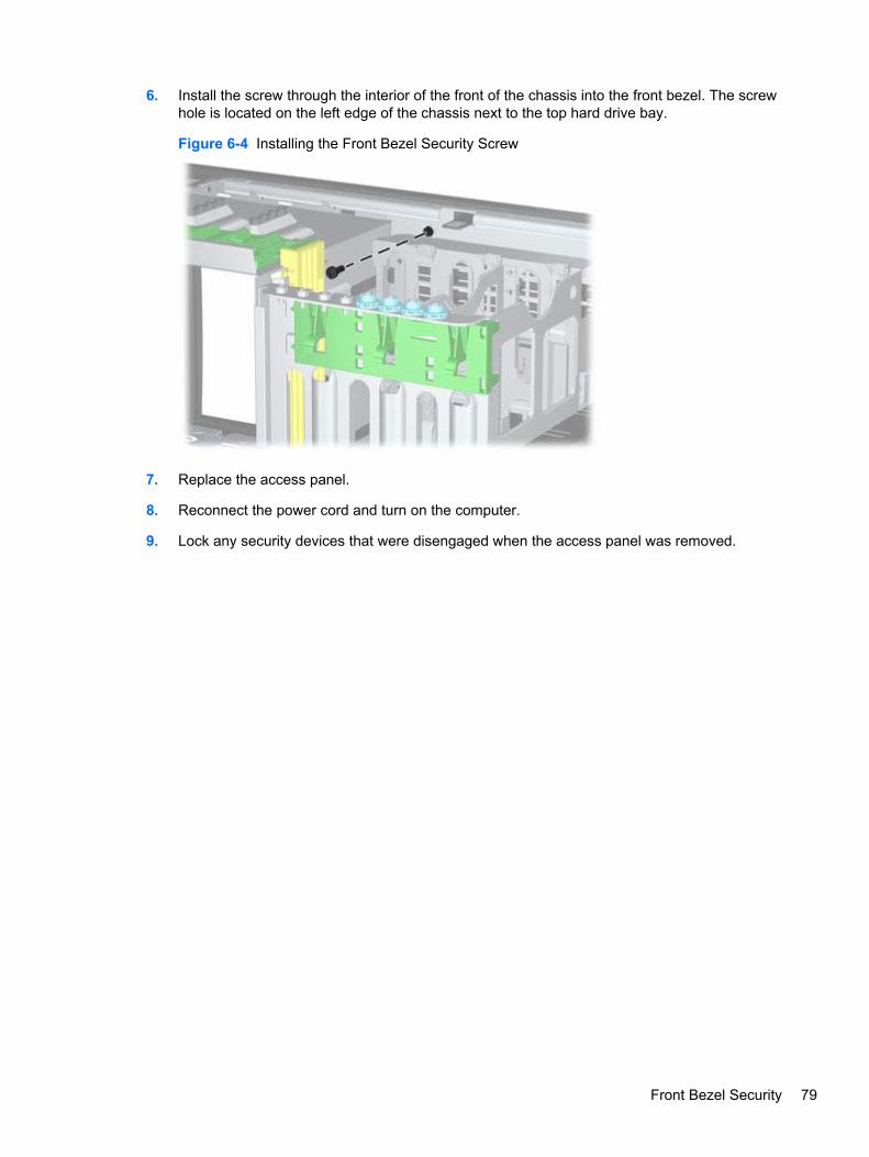
6. Install the screw through the interior of the front of the chassis into the front bezel. The screwhole is located on the left edge of the chassis next to the top hard drive bay.
Figure 6-4 Installing the Front Bezel Security Screw
7. Replace the access panel.
8. Reconnect the power cord and turn on the computer.
9. Lock any security devices that were disengaged when the access panel was removed.
Front Bezel Security 79
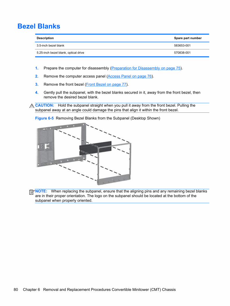
Bezel Blanks
Description Spare part number
3.5-inch bezel blank 583653-001
5.25-inch bezel blank, optical drive 570838-001
1. Prepare the computer for disassembly (Preparation for Disassembly on page 75).
2. Remove the computer access panel (Access Panel on page 76).
3. Remove the front bezel (Front Bezel on page 77).
4. Gently pull the subpanel, with the bezel blanks secured in it, away from the front bezel, thenremove the desired bezel blank.
CAUTION: Hold the subpanel straight when you pull it away from the front bezel. Pulling thesubpanel away at an angle could damage the pins that align it within the front bezel.
Figure 6-5 Removing Bezel Blanks from the Subpanel (Desktop Shown)
NOTE: When replacing the subpanel, ensure that the aligning pins and any remaining bezel blanksare in their proper orientation. The logo on the subpanel should be located at the bottom of thesubpanel when properly oriented.
80 Chapter 6 Removal and Replacement Procedures Convertible Minitower (CMT) Chassis
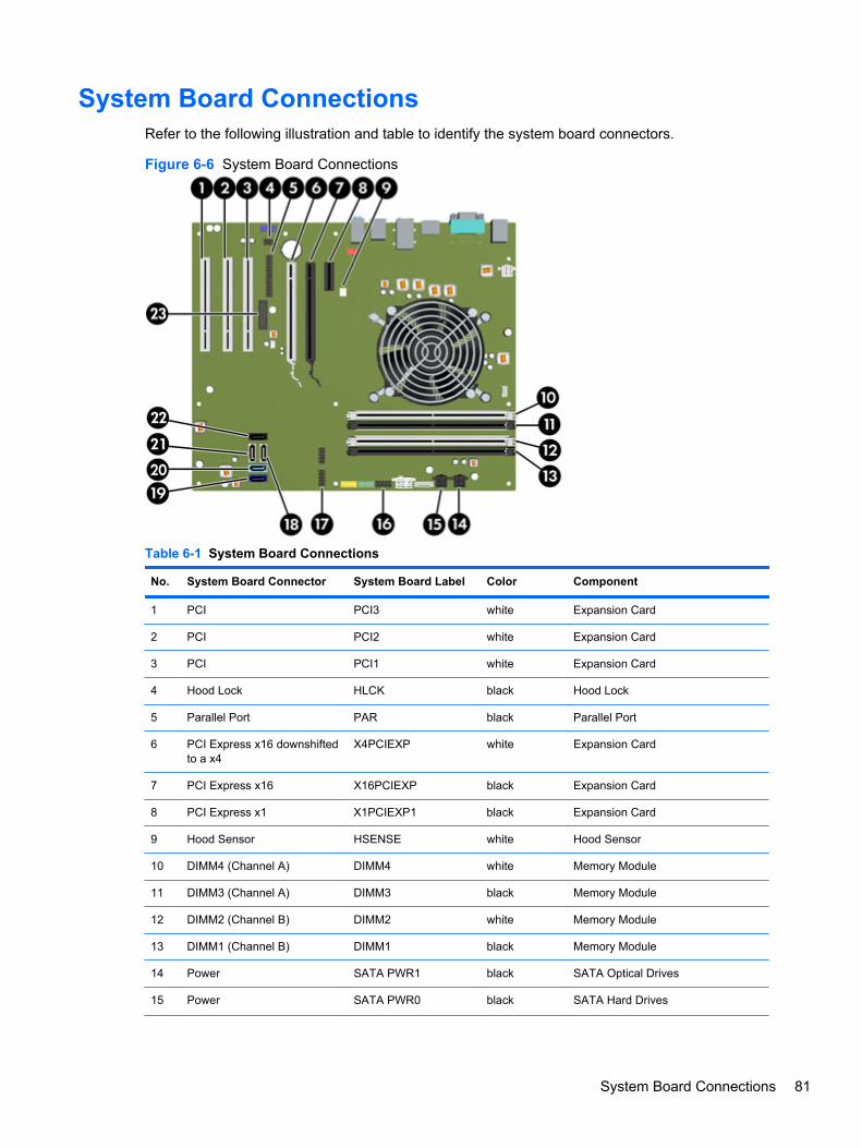
System Board ConnectionsRefer to the following illustration and table to identify the system board connectors.
Figure 6-6 System Board Connections
Table 6-1 System Board Connections
No. System Board Connector System Board Label Color Component
1 PCI PCI3 white Expansion Card
2 PCI PCI2 white Expansion Card
3 PCI PCI1 white Expansion Card
4 Hood Lock HLCK black Hood Lock
5 Parallel Port PAR black Parallel Port
6 PCI Express x16 downshiftedto a x4
X4PCIEXP white Expansion Card
7 PCI Express x16 X16PCIEXP black Expansion Card
8 PCI Express x1 X1PCIEXP1 black Expansion Card
9 Hood Sensor HSENSE white Hood Sensor
10 DIMM4 (Channel A) DIMM4 white Memory Module
11 DIMM3 (Channel A) DIMM3 black Memory Module
12 DIMM2 (Channel B) DIMM2 white Memory Module
13 DIMM1 (Channel B) DIMM1 black Memory Module
14 Power SATA PWR1 black SATA Optical Drives
15 Power SATA PWR0 black SATA Hard Drives
System Board Connections 81
Table 6-1 System Board Connections (continued)
No. System Board Connector System Board Label Color Component
16 USB MEDIA black USB Device, such as a Media CardReader
17 USB MEDIA2 black USB Device, such as a Media CardReader
18 SATA 2.0 SATA2 white 3rd Hard Drive, or 1st Optical Drive ifno 3rd Hard Drive
19 SATA 3.0 SATA0 dark blue 1st Hard Drive
20 SATA 3.0 SATA1 light blue 2nd Hard Drive
21 SATA 2.0 SATA3 white 2nd Optical Drive, or 1st OpticalDrive if a 3rd Hard Drive exists
22 eSATA ESATA black eSATA Adapter Cable, or 2ndOptical Drive if a 3rd Hard Driveexists
23 Serial Port COMB black Serial Port
Memory
Description Spare part number
8-GB, PC3-12800 689375-001
4-GB, PC3-12800 671613-001
2-GB, PC3-12800 671612-001
The computer comes with double data rate 3 synchronous dynamic random access memory (DDR3-SDRAM) dual inline memory modules (DIMMs).
DIMMs
The memory sockets on the system board can be populated with up to four industry-standard DIMMs.These memory sockets are populated with at least one preinstalled DIMM. To achieve the maximummemory support, you can populate the system board with up to 16-GB of memory configured in ahigh-performing dual channel mode.
DDR3-SDRAM DIMMs
CAUTION: This product DOES NOT support DDR3 Ultra Low Voltage (DDR3U) memory. Theprocessor is not compatible with DDR3U memory and if you plug DDR3U memory into the systemboard, it can cause the physical damage to the DIMM or invoke system malfunction.
82 Chapter 6 Removal and Replacement Procedures Convertible Minitower (CMT) Chassis
For proper system operation, the DDR3-SDRAM DIMMs must be:
● industry-standard 240-pin
● unbuffered non-ECC PC3-12800 DDR3-1600 MHz-compliant
● 1.5 volt DDR3-SDRAM DIMMs
The DDR3-SDRAM DIMMs must also:
● support CAS latency 11 DDR3 1600 MHz (11-11-11 timing)
● contain the mandatory JEDEC SPD information
In addition, the computer supports:
● 512-Mbit, 1-Gbit, and 2-Gbit non-ECC memory technologies
● single-sided and double-sided DIMMs
● DIMMs constructed with x8 and x16 DDR devices; DIMMs constructed with x4 SDRAM are notsupported
NOTE: The system will not operate properly if you install unsupported DIMMs.
Populating DIMM Sockets
There are four DIMM sockets on the system board, with two sockets per channel. The sockets arelabeled DIMM1, DIMM2, DIMM3, and DIMM4. Sockets DIMM1 and DIMM2 operate in memorychannel B. Sockets DIMM3 and DIMM4 operate in memory channel A.
The system will automatically operate in single channel mode, dual channel mode, or flex mode,depending on how the DIMMs are installed.
● The system will operate in single channel mode if the DIMM sockets are populated in onechannel only.
● The system will operate in a higher-performing dual channel mode if the total memory capacityof the DIMMs in Channel A is equal to the total memory capacity of the DIMMs in Channel B.The technology and device width can vary between the channels. For example, if Channel A ispopulated with two 1-GB DIMMs and Channel B is populated with one 2-GB DIMM, the systemwill operate in dual channel mode.
● The system will operate in flex mode if the total memory capacity of the DIMMs in Channel A isnot equal to the total memory capacity of the DIMMs in Channel B. In flex mode, the channelpopulated with the least amount of memory describes the total amount of memory assigned todual channel and the remainder is assigned to single channel. For optimal speed, the channelsshould be balanced so that the largest amount of memory is spread between the two channels.If one channel will have more memory than the other, the larger amount should be assigned toChannel A. For example, if you are populating the sockets with one 2-GB DIMM, and three 1-GBDIMMs, Channel A should be populated with the 2-GB DIMM and one 1-GB DIMM, and ChannelB should be populated with the other two 1-GB DIMMs. With this configuration, 4-GB will run asdual channel and 1-GB will run as single channel.
● In any mode, the maximum operational speed is determined by the slowest DIMM in the system.
Memory 83
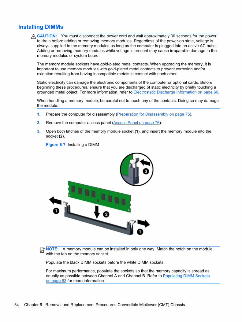
Installing DIMMs
CAUTION: You must disconnect the power cord and wait approximately 30 seconds for the powerto drain before adding or removing memory modules. Regardless of the power-on state, voltage isalways supplied to the memory modules as long as the computer is plugged into an active AC outlet.Adding or removing memory modules while voltage is present may cause irreparable damage to thememory modules or system board.
The memory module sockets have gold-plated metal contacts. When upgrading the memory, it isimportant to use memory modules with gold-plated metal contacts to prevent corrosion and/oroxidation resulting from having incompatible metals in contact with each other.
Static electricity can damage the electronic components of the computer or optional cards. Beforebeginning these procedures, ensure that you are discharged of static electricity by briefly touching agrounded metal object. For more information, refer to Electrostatic Discharge Information on page 66.
When handling a memory module, be careful not to touch any of the contacts. Doing so may damagethe module.
1. Prepare the computer for disassembly (Preparation for Disassembly on page 75).
2. Remove the computer access panel (Access Panel on page 76).
3. Open both latches of the memory module socket (1), and insert the memory module into thesocket (2).
Figure 6-7 Installing a DIMM
NOTE: A memory module can be installed in only one way. Match the notch on the modulewith the tab on the memory socket.
Populate the black DIMM sockets before the white DIMM sockets.
For maximum performance, populate the sockets so that the memory capacity is spread asequally as possible between Channel A and Channel B. Refer to Populating DIMM Socketson page 83 for more information.
84 Chapter 6 Removal and Replacement Procedures Convertible Minitower (CMT) Chassis
4. Push the module down into the socket, ensuring that the module is fully inserted and properlyseated. Make sure the latches are in the closed position (3).
5. Repeat steps 3 and 4 to install any additional modules.
6. Replace the computer access panel.
7. Reconnect the power cord and turn on the computer.
8. Lock any security devices that were disengaged when the access panel was removed.
The computer should automatically recognize the additional memory the next time you turn on thecomputer.
Expansion Card
Description Spare part number
nVidia Quadro NVS310 PCIe x16 graphics card, 512 MB 680653-001
nVidia Quadro NVS300 PCIe x16 graphics card, 512 MB 632486-001
AMD Radeon HD7450 PCIe x16 graphics card, 1 GB 682411-001
AMD Radeon HD6350 PCIe x16 graphics card, 512 MB 637995-001
AMD FirePro 2270 PCIe x16 graphics card, 512 MB 637213-001
Intel PRO/1000CT2 NIC, includes bracket 635523-001
HP FireWire / IEEE 1394a PCIe x1 Card 637591-001
The computer has three standard full-height PCI expansion slots, one PCI Express x1 expansion slot,one PCI Express x16 expansion slot, and one PCI Express x16 expansion slot that is downshifted toa x4 slot.
NOTE: You can install a PCI Express x1, x8, or x16 expansion card in the PCI Express x16 slots.
For dual graphics card configurations, the first (primary) card must be installed in the PCI Expressx16 slot that is NOT downshifted to a x4 slot.
To remove, replace, or add an expansion card:
1. Prepare the computer for disassembly (Preparation for Disassembly on page 75).
2. Remove the computer access panel (Access Panel on page 76).
3. Locate the correct vacant expansion socket on the system board and the correspondingexpansion slot on the back of the computer chassis.
Expansion Card 85
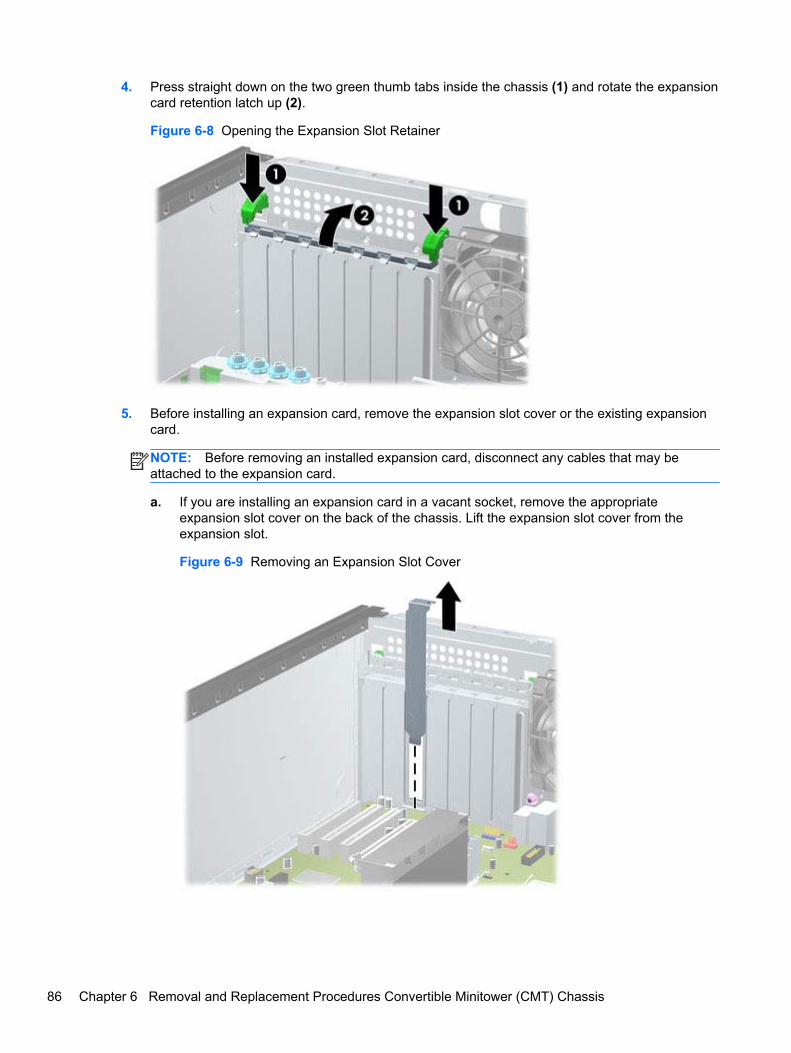
4. Press straight down on the two green thumb tabs inside the chassis (1) and rotate the expansioncard retention latch up (2).
Figure 6-8 Opening the Expansion Slot Retainer
5. Before installing an expansion card, remove the expansion slot cover or the existing expansioncard.
NOTE: Before removing an installed expansion card, disconnect any cables that may beattached to the expansion card.
a. If you are installing an expansion card in a vacant socket, remove the appropriateexpansion slot cover on the back of the chassis. Lift the expansion slot cover from theexpansion slot.
Figure 6-9 Removing an Expansion Slot Cover
86 Chapter 6 Removal and Replacement Procedures Convertible Minitower (CMT) Chassis
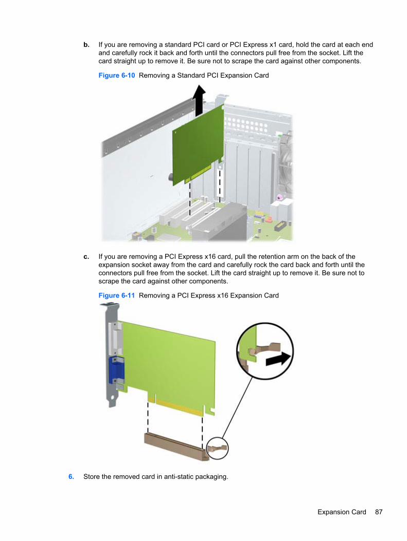
b. If you are removing a standard PCI card or PCI Express x1 card, hold the card at each endand carefully rock it back and forth until the connectors pull free from the socket. Lift thecard straight up to remove it. Be sure not to scrape the card against other components.
Figure 6-10 Removing a Standard PCI Expansion Card
c. If you are removing a PCI Express x16 card, pull the retention arm on the back of theexpansion socket away from the card and carefully rock the card back and forth until theconnectors pull free from the socket. Lift the card straight up to remove it. Be sure not toscrape the card against other components.
Figure 6-11 Removing a PCI Express x16 Expansion Card
6. Store the removed card in anti-static packaging.
Expansion Card 87
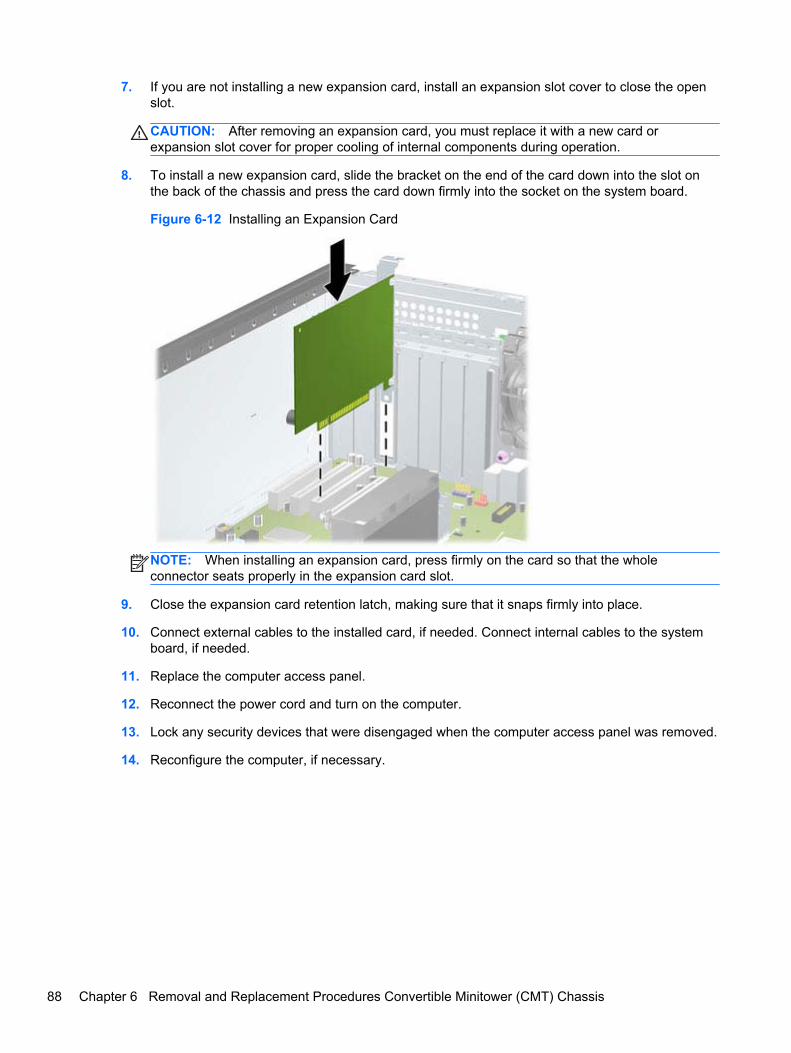
7. If you are not installing a new expansion card, install an expansion slot cover to close the openslot.
CAUTION: After removing an expansion card, you must replace it with a new card orexpansion slot cover for proper cooling of internal components during operation.
8. To install a new expansion card, slide the bracket on the end of the card down into the slot onthe back of the chassis and press the card down firmly into the socket on the system board.
Figure 6-12 Installing an Expansion Card
NOTE: When installing an expansion card, press firmly on the card so that the wholeconnector seats properly in the expansion card slot.
9. Close the expansion card retention latch, making sure that it snaps firmly into place.
10. Connect external cables to the installed card, if needed. Connect internal cables to the systemboard, if needed.
11. Replace the computer access panel.
12. Reconnect the power cord and turn on the computer.
13. Lock any security devices that were disengaged when the computer access panel was removed.
14. Reconfigure the computer, if necessary.
88 Chapter 6 Removal and Replacement Procedures Convertible Minitower (CMT) Chassis
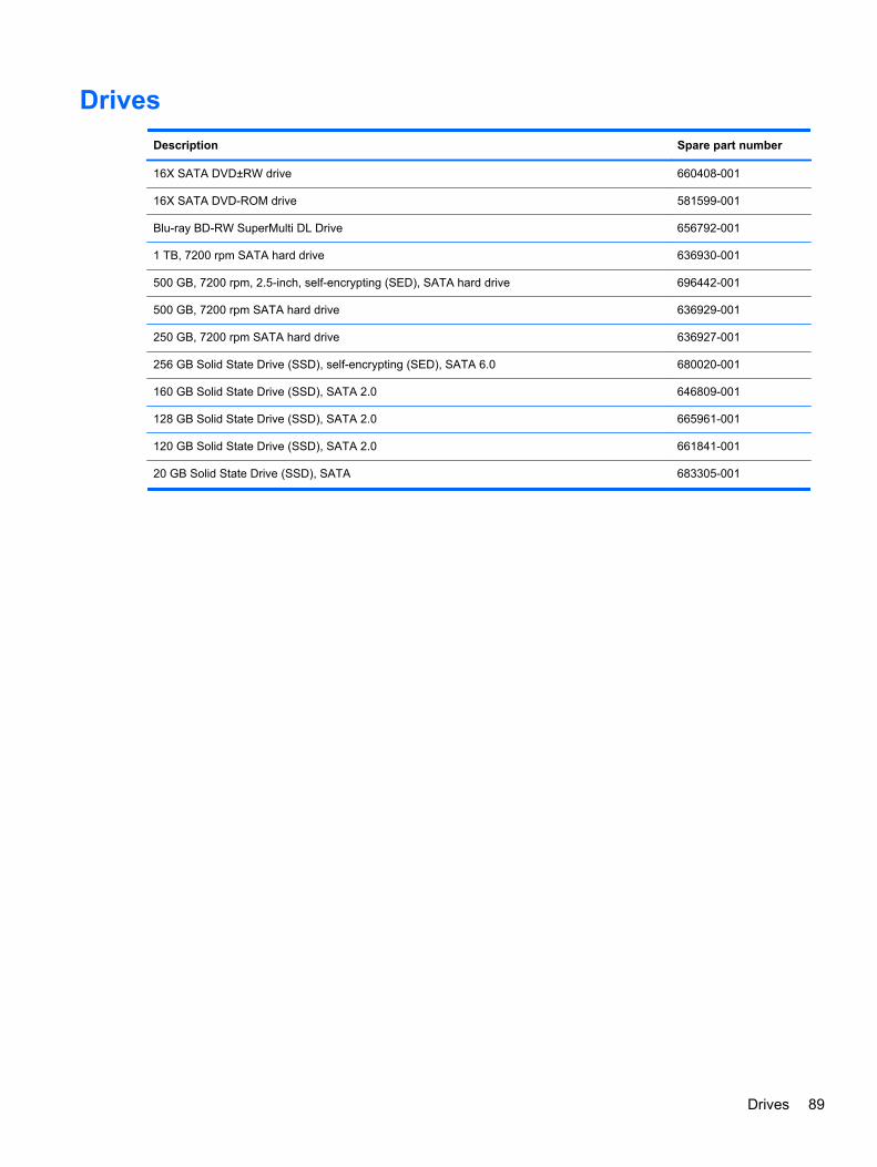
Drives
Description Spare part number
16X SATA DVD±RW drive 660408-001
16X SATA DVD-ROM drive 581599-001
Blu-ray BD-RW SuperMulti DL Drive 656792-001
1 TB, 7200 rpm SATA hard drive 636930-001
500 GB, 7200 rpm, 2.5-inch, self-encrypting (SED), SATA hard drive 696442-001
500 GB, 7200 rpm SATA hard drive 636929-001
250 GB, 7200 rpm SATA hard drive 636927-001
256 GB Solid State Drive (SSD), self-encrypting (SED), SATA 6.0 680020-001
160 GB Solid State Drive (SSD), SATA 2.0 646809-001
128 GB Solid State Drive (SSD), SATA 2.0 665961-001
120 GB Solid State Drive (SSD), SATA 2.0 661841-001
20 GB Solid State Drive (SSD), SATA 683305-001
Drives 89
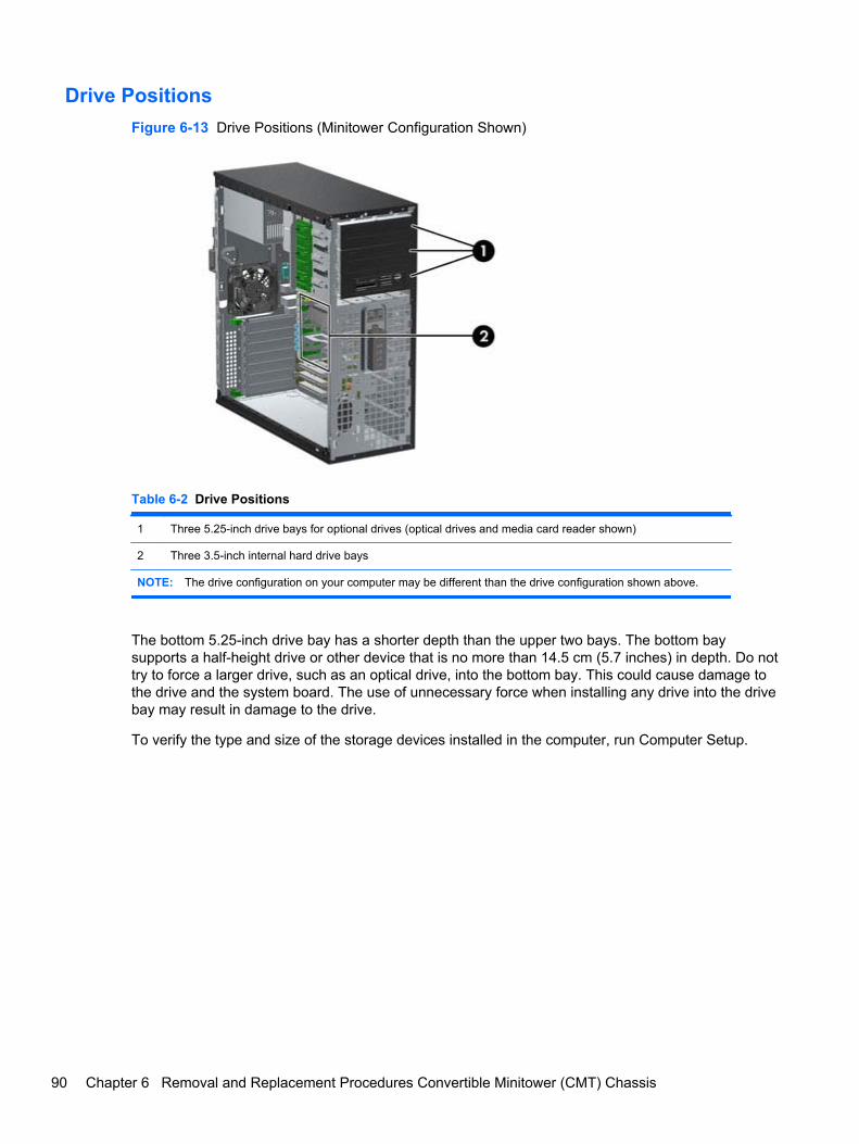
Drive Positions
Figure 6-13 Drive Positions (Minitower Configuration Shown)
Table 6-2 Drive Positions
1 Three 5.25-inch drive bays for optional drives (optical drives and media card reader shown)
2 Three 3.5-inch internal hard drive bays
NOTE: The drive configuration on your computer may be different than the drive configuration shown above.
The bottom 5.25-inch drive bay has a shorter depth than the upper two bays. The bottom baysupports a half-height drive or other device that is no more than 14.5 cm (5.7 inches) in depth. Do nottry to force a larger drive, such as an optical drive, into the bottom bay. This could cause damage tothe drive and the system board. The use of unnecessary force when installing any drive into the drivebay may result in damage to the drive.
To verify the type and size of the storage devices installed in the computer, run Computer Setup.
90 Chapter 6 Removal and Replacement Procedures Convertible Minitower (CMT) Chassis
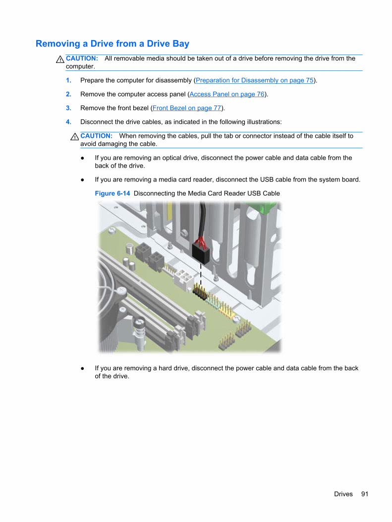
Removing a Drive from a Drive Bay
CAUTION: All removable media should be taken out of a drive before removing the drive from thecomputer.
1. Prepare the computer for disassembly (Preparation for Disassembly on page 75).
2. Remove the computer access panel (Access Panel on page 76).
3. Remove the front bezel (Front Bezel on page 77).
4. Disconnect the drive cables, as indicated in the following illustrations:
CAUTION: When removing the cables, pull the tab or connector instead of the cable itself toavoid damaging the cable.
● If you are removing an optical drive, disconnect the power cable and data cable from theback of the drive.
● If you are removing a media card reader, disconnect the USB cable from the system board.
Figure 6-14 Disconnecting the Media Card Reader USB Cable
● If you are removing a hard drive, disconnect the power cable and data cable from the backof the drive.
Drives 91
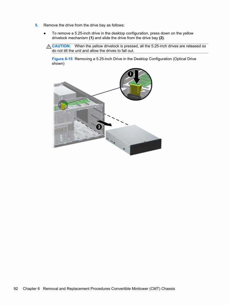
5. Remove the drive from the drive bay as follows:
● To remove a 5.25-inch drive in the desktop configuration, press down on the yellowdrivelock mechanism (1) and slide the drive from the drive bay (2).
CAUTION: When the yellow drivelock is pressed, all the 5.25-inch drives are released sodo not tilt the unit and allow the drives to fall out.
Figure 6-15 Removing a 5.25-inch Drive in the Desktop Configuration (Optical Driveshown)
92 Chapter 6 Removal and Replacement Procedures Convertible Minitower (CMT) Chassis
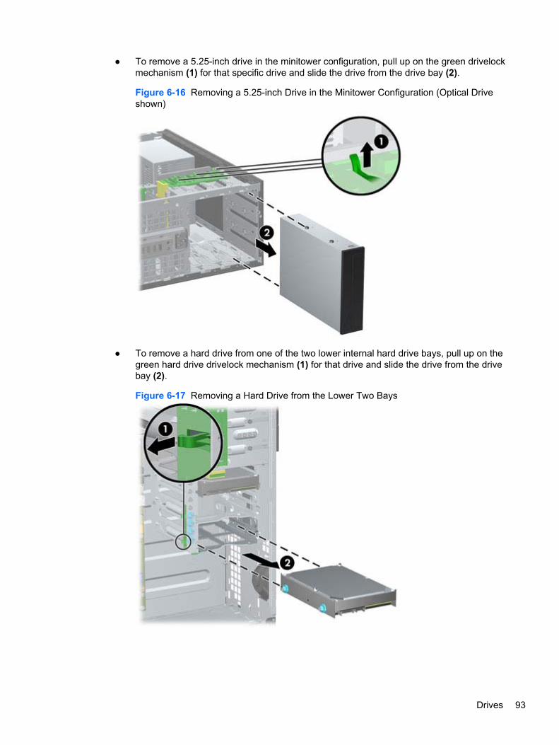
● To remove a 5.25-inch drive in the minitower configuration, pull up on the green drivelockmechanism (1) for that specific drive and slide the drive from the drive bay (2).
Figure 6-16 Removing a 5.25-inch Drive in the Minitower Configuration (Optical Driveshown)
● To remove a hard drive from one of the two lower internal hard drive bays, pull up on thegreen hard drive drivelock mechanism (1) for that drive and slide the drive from the drivebay (2).
Figure 6-17 Removing a Hard Drive from the Lower Two Bays
Drives 93
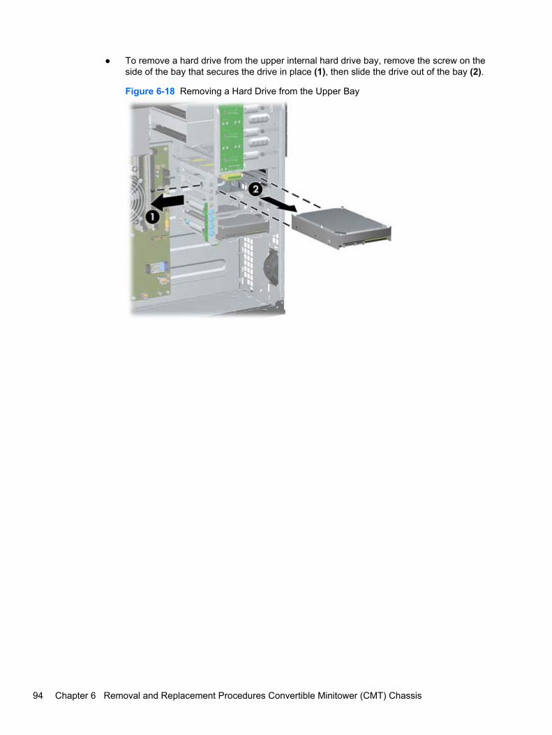
● To remove a hard drive from the upper internal hard drive bay, remove the screw on theside of the bay that secures the drive in place (1), then slide the drive out of the bay (2).
Figure 6-18 Removing a Hard Drive from the Upper Bay
94 Chapter 6 Removal and Replacement Procedures Convertible Minitower (CMT) Chassis
Installing Drives
When installing drives, follow these guidelines:
● The primary Serial ATA (SATA) hard drive must be connected to the dark blue SATA connectoron the system board labeled SATA0. If you are adding a second hard drive, connect it to thelight blue SATA1 connector.
● Connect the first SATA optical drive to the white SATA connector on the system board labeledSATA2. If you are adding a second optical drive, connect it to the white SATA3 connector.
● Connect an optional eSATA adapter cable to the black SATA connector on the system boardlabeled ESATA.
● Connect a media card reader USB cable to the USB connector on the system board labeledMEDIA.
● The power cable for the SATA optical drives is a two-headed cable this is plugged into thesystem board with the first connector routed to the middle 5.25-inch bay and the secondconnector routed to the top 5.25-inch bay.
● The power cable for the SATA hard drives is a three-headed cable this is plugged into thesystem board with the first connector routed to the bottom 3.5-inch bay, the second connectorrouted to the middle 3.5-inch bay, and the third connector routed to the top 3.5-inch bay.
● The system does not support Parallel ATA (PATA) optical drives or PATA hard drives.
● You must install guide screws to ensure the drive will line up correctly in the drive cage and lockin place. HP has provided extra guide screws installed on the chassis. The hard drive uses 6-32isolation mounting guide screws in the lower two bays and standard 6-32 screws in the upperbay. Four of each are installed on the hard drive bracket under the access panel. All other drivesuse M3 metric screws, eight of which are installed on the optical drive bracket under the accesspanel. The HP-supplied metric guide screws are black. The HP-supplied 6-32 isolation mountingguide screws are silver and blue. The HP-supplied standard 6-32 screws are silver. If you are
Drives 95
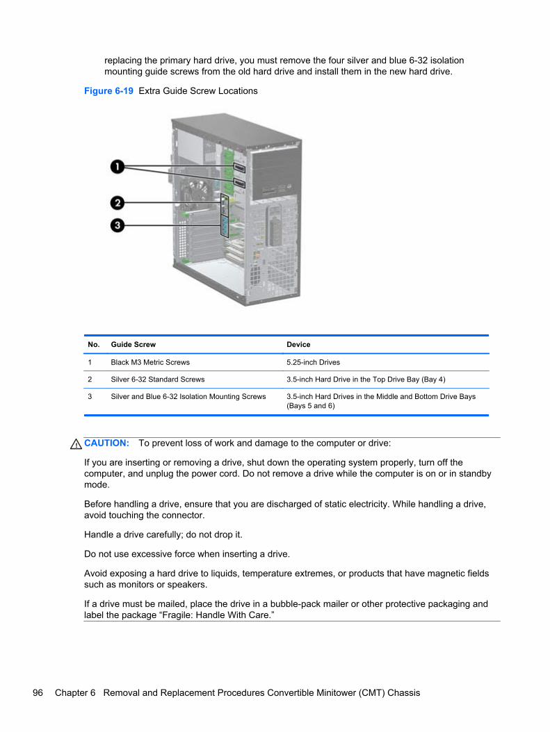
replacing the primary hard drive, you must remove the four silver and blue 6-32 isolationmounting guide screws from the old hard drive and install them in the new hard drive.
Figure 6-19 Extra Guide Screw Locations
No. Guide Screw Device
1 Black M3 Metric Screws 5.25-inch Drives
2 Silver 6-32 Standard Screws 3.5-inch Hard Drive in the Top Drive Bay (Bay 4)
3 Silver and Blue 6-32 Isolation Mounting Screws 3.5-inch Hard Drives in the Middle and Bottom Drive Bays(Bays 5 and 6)
CAUTION: To prevent loss of work and damage to the computer or drive:
If you are inserting or removing a drive, shut down the operating system properly, turn off thecomputer, and unplug the power cord. Do not remove a drive while the computer is on or in standbymode.
Before handling a drive, ensure that you are discharged of static electricity. While handling a drive,avoid touching the connector.
Handle a drive carefully; do not drop it.
Do not use excessive force when inserting a drive.
Avoid exposing a hard drive to liquids, temperature extremes, or products that have magnetic fieldssuch as monitors or speakers.
If a drive must be mailed, place the drive in a bubble-pack mailer or other protective packaging andlabel the package “Fragile: Handle With Care.”
96 Chapter 6 Removal and Replacement Procedures Convertible Minitower (CMT) Chassis
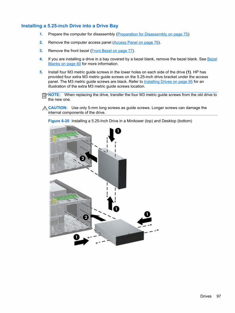
Installing a 5.25-inch Drive into a Drive Bay
1. Prepare the computer for disassembly (Preparation for Disassembly on page 75).
2. Remove the computer access panel (Access Panel on page 76).
3. Remove the front bezel (Front Bezel on page 77).
4. If you are installing a drive in a bay covered by a bezel blank, remove the bezel blank. See BezelBlanks on page 80 for more information.
5. Install four M3 metric guide screws in the lower holes on each side of the drive (1). HP hasprovided four extra M3 metric guide screws on the 5.25-inch drive bracket under the accesspanel. The M3 metric guide screws are black. Refer to Installing Drives on page 95 for anillustration of the extra M3 metric guide screws location.
NOTE: When replacing the drive, transfer the four M3 metric guide screws from the old drive tothe new one.
CAUTION: Use only 5-mm long screws as guide screws. Longer screws can damage theinternal components of the drive.
Figure 6-20 Installing a 5.25-Inch Drive in a Minitower (top) and Desktop (bottom)
Drives 97
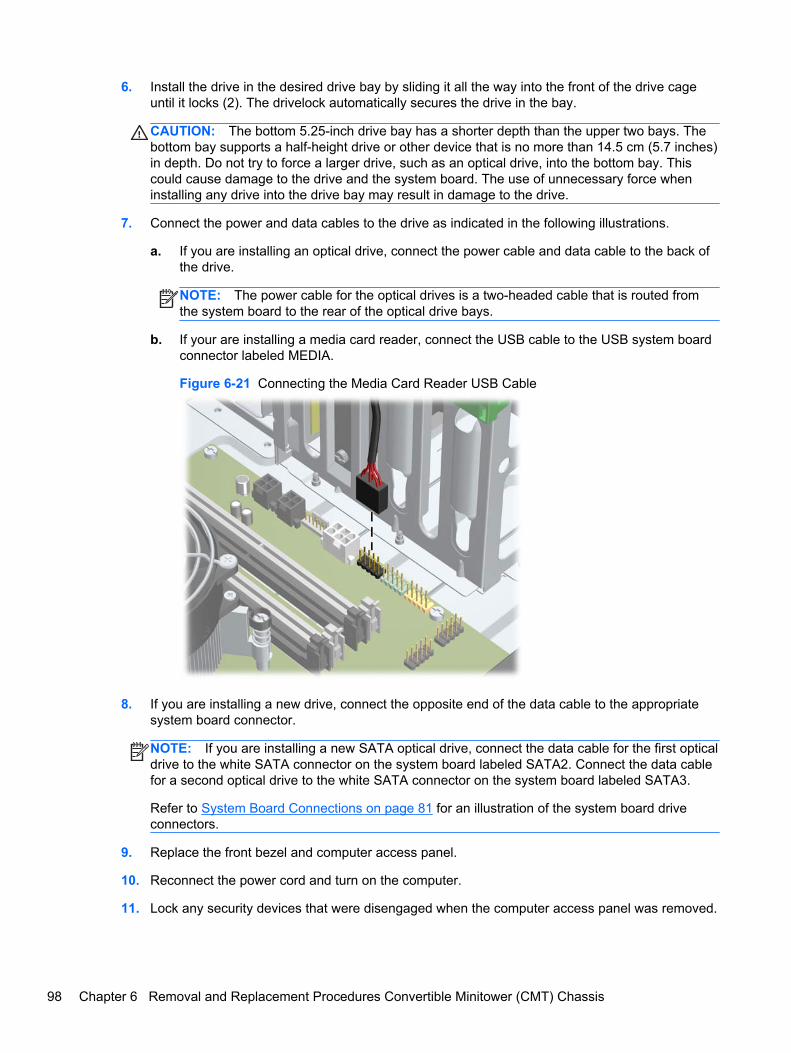
6. Install the drive in the desired drive bay by sliding it all the way into the front of the drive cageuntil it locks (2). The drivelock automatically secures the drive in the bay.
CAUTION: The bottom 5.25-inch drive bay has a shorter depth than the upper two bays. Thebottom bay supports a half-height drive or other device that is no more than 14.5 cm (5.7 inches)in depth. Do not try to force a larger drive, such as an optical drive, into the bottom bay. Thiscould cause damage to the drive and the system board. The use of unnecessary force wheninstalling any drive into the drive bay may result in damage to the drive.
7. Connect the power and data cables to the drive as indicated in the following illustrations.
a. If you are installing an optical drive, connect the power cable and data cable to the back ofthe drive.
NOTE: The power cable for the optical drives is a two-headed cable that is routed fromthe system board to the rear of the optical drive bays.
b. If your are installing a media card reader, connect the USB cable to the USB system boardconnector labeled MEDIA.
Figure 6-21 Connecting the Media Card Reader USB Cable
8. If you are installing a new drive, connect the opposite end of the data cable to the appropriatesystem board connector.
NOTE: If you are installing a new SATA optical drive, connect the data cable for the first opticaldrive to the white SATA connector on the system board labeled SATA2. Connect the data cablefor a second optical drive to the white SATA connector on the system board labeled SATA3.
Refer to System Board Connections on page 81 for an illustration of the system board driveconnectors.
9. Replace the front bezel and computer access panel.
10. Reconnect the power cord and turn on the computer.
11. Lock any security devices that were disengaged when the computer access panel was removed.
98 Chapter 6 Removal and Replacement Procedures Convertible Minitower (CMT) Chassis
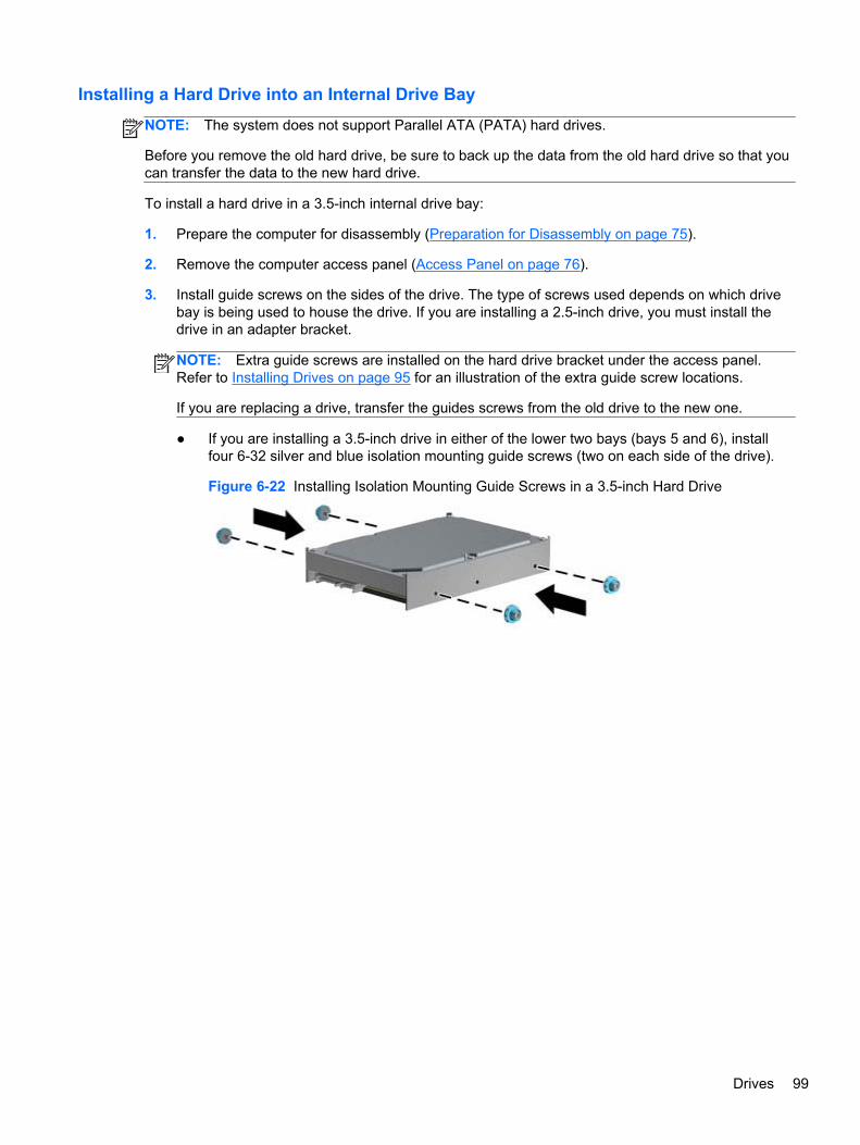
Installing a Hard Drive into an Internal Drive Bay
NOTE: The system does not support Parallel ATA (PATA) hard drives.
Before you remove the old hard drive, be sure to back up the data from the old hard drive so that youcan transfer the data to the new hard drive.
To install a hard drive in a 3.5-inch internal drive bay:
1. Prepare the computer for disassembly (Preparation for Disassembly on page 75).
2. Remove the computer access panel (Access Panel on page 76).
3. Install guide screws on the sides of the drive. The type of screws used depends on which drivebay is being used to house the drive. If you are installing a 2.5-inch drive, you must install thedrive in an adapter bracket.
NOTE: Extra guide screws are installed on the hard drive bracket under the access panel.Refer to Installing Drives on page 95 for an illustration of the extra guide screw locations.
If you are replacing a drive, transfer the guides screws from the old drive to the new one.
● If you are installing a 3.5-inch drive in either of the lower two bays (bays 5 and 6), installfour 6-32 silver and blue isolation mounting guide screws (two on each side of the drive).
Figure 6-22 Installing Isolation Mounting Guide Screws in a 3.5-inch Hard Drive
Drives 99
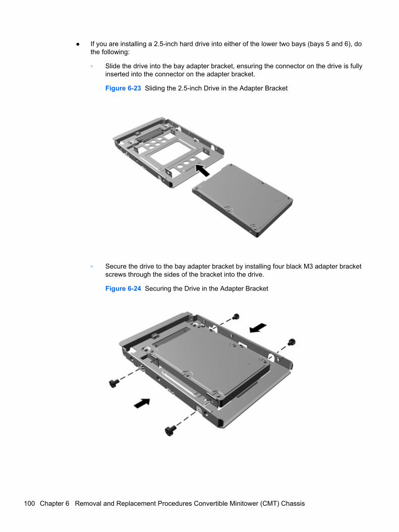
● If you are installing a 2.5-inch hard drive into either of the lower two bays (bays 5 and 6), dothe following:
◦ Slide the drive into the bay adapter bracket, ensuring the connector on the drive is fullyinserted into the connector on the adapter bracket.
Figure 6-23 Sliding the 2.5-inch Drive in the Adapter Bracket
◦ Secure the drive to the bay adapter bracket by installing four black M3 adapter bracketscrews through the sides of the bracket into the drive.
Figure 6-24 Securing the Drive in the Adapter Bracket
100 Chapter 6 Removal and Replacement Procedures Convertible Minitower (CMT) Chassis
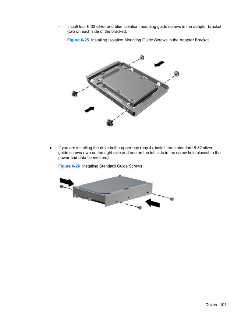
◦ Install four 6-32 silver and blue isolation mounting guide screws in the adapter bracket(two on each side of the bracket).
Figure 6-25 Installing Isolation Mounting Guide Screws in the Adapter Bracket
● If you are installing the drive in the upper bay (bay 4), install three standard 6-32 silverguide screws (two on the right side and one on the left side in the screw hole closest to thepower and data connectors).
Figure 6-26 Installing Standard Guide Screws
Drives 101
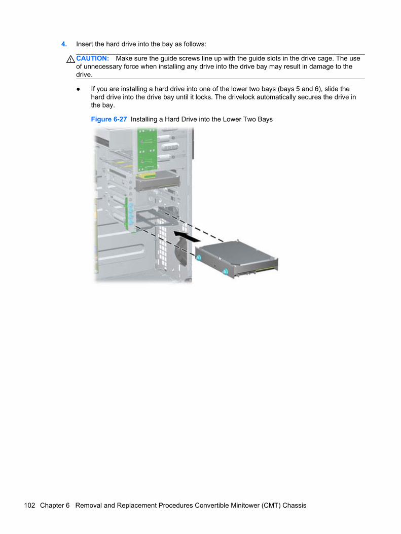
4. Insert the hard drive into the bay as follows:
CAUTION: Make sure the guide screws line up with the guide slots in the drive cage. The useof unnecessary force when installing any drive into the drive bay may result in damage to thedrive.
● If you are installing a hard drive into one of the lower two bays (bays 5 and 6), slide thehard drive into the drive bay until it locks. The drivelock automatically secures the drive inthe bay.
Figure 6-27 Installing a Hard Drive into the Lower Two Bays
102 Chapter 6 Removal and Replacement Procedures Convertible Minitower (CMT) Chassis
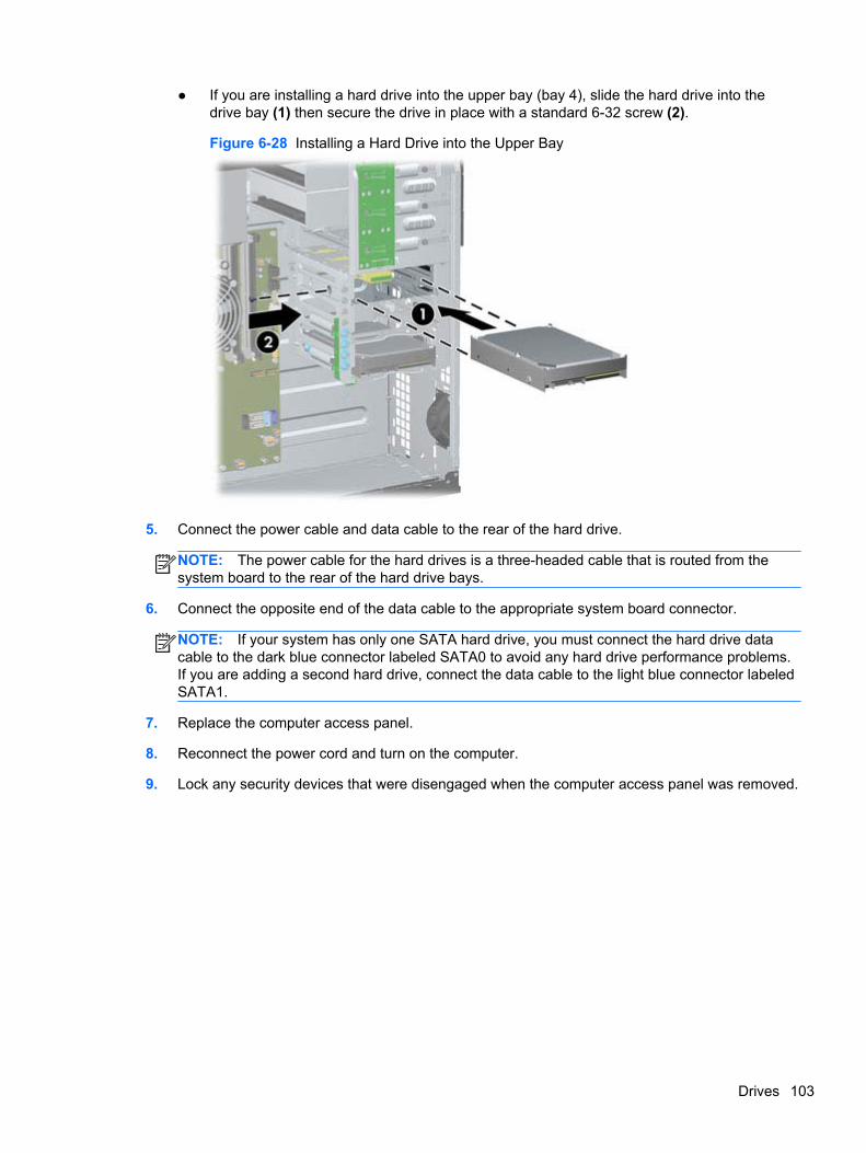
● If you are installing a hard drive into the upper bay (bay 4), slide the hard drive into thedrive bay (1) then secure the drive in place with a standard 6-32 screw (2).
Figure 6-28 Installing a Hard Drive into the Upper Bay
5. Connect the power cable and data cable to the rear of the hard drive.
NOTE: The power cable for the hard drives is a three-headed cable that is routed from thesystem board to the rear of the hard drive bays.
6. Connect the opposite end of the data cable to the appropriate system board connector.
NOTE: If your system has only one SATA hard drive, you must connect the hard drive datacable to the dark blue connector labeled SATA0 to avoid any hard drive performance problems.If you are adding a second hard drive, connect the data cable to the light blue connector labeledSATA1.
7. Replace the computer access panel.
8. Reconnect the power cord and turn on the computer.
9. Lock any security devices that were disengaged when the computer access panel was removed.
Drives 103
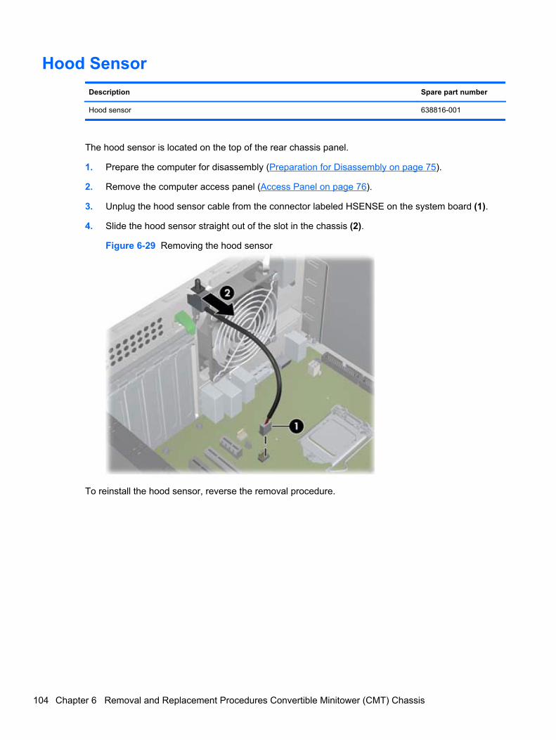
Hood Sensor
Description Spare part number
Hood sensor 638816-001
The hood sensor is located on the top of the rear chassis panel.
1. Prepare the computer for disassembly (Preparation for Disassembly on page 75).
2. Remove the computer access panel (Access Panel on page 76).
3. Unplug the hood sensor cable from the connector labeled HSENSE on the system board (1).
4. Slide the hood sensor straight out of the slot in the chassis (2).
Figure 6-29 Removing the hood sensor
To reinstall the hood sensor, reverse the removal procedure.
104 Chapter 6 Removal and Replacement Procedures Convertible Minitower (CMT) Chassis
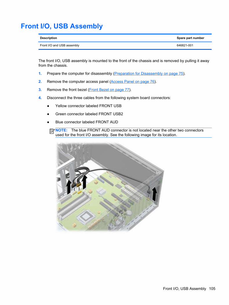
Front I/O, USB Assembly
Description Spare part number
Front I/O and USB assembly 646821-001
The front I/O, USB assembly is mounted to the front of the chassis and is removed by pulling it awayfrom the chassis.
1. Prepare the computer for disassembly (Preparation for Disassembly on page 75).
2. Remove the computer access panel (Access Panel on page 76).
3. Remove the front bezel (Front Bezel on page 77).
4. Disconnect the three cables from the following system board connectors:
● Yellow connector labeled FRONT USB
● Green connector labeled FRONT USB2
● Blue connector labeled FRONT AUD
NOTE: The blue FRONT AUD connector is not located near the other two connectorsused for the front I/O assembly. See the following image for its location.
Front I/O, USB Assembly 105
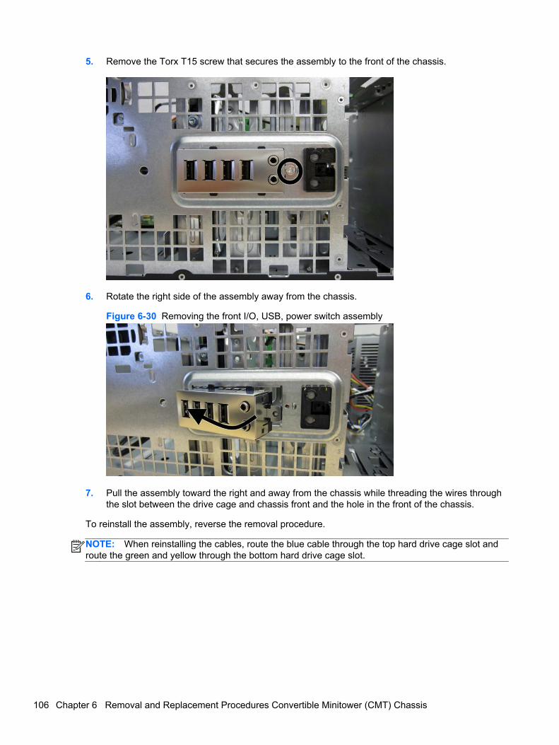
5. Remove the Torx T15 screw that secures the assembly to the front of the chassis.
6. Rotate the right side of the assembly away from the chassis.
Figure 6-30 Removing the front I/O, USB, power switch assembly
7. Pull the assembly toward the right and away from the chassis while threading the wires throughthe slot between the drive cage and chassis front and the hole in the front of the chassis.
To reinstall the assembly, reverse the removal procedure.
NOTE: When reinstalling the cables, route the blue cable through the top hard drive cage slot androute the green and yellow through the bottom hard drive cage slot.
106 Chapter 6 Removal and Replacement Procedures Convertible Minitower (CMT) Chassis
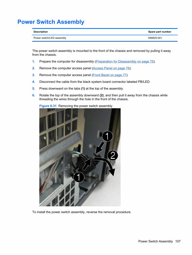
Power Switch Assembly
Description Spare part number
Power switch/LED assembly 646820-001
The power switch assembly is mounted to the front of the chassis and removed by pulling it awayfrom the chassis.
1. Prepare the computer for disassembly (Preparation for Disassembly on page 75).
2. Remove the computer access panel (Access Panel on page 76).
3. Remove the computer access panel (Front Bezel on page 77).
4. Disconnect the cable from the black system board connector labeled PB/LED.
5. Press downward on the tabs (1) at the top of the assembly.
6. Rotate the top of the assembly downward (2), and then pull it away from the chassis whilethreading the wires through the hole in the front of the chassis.
Figure 6-31 Removing the power switch assembly
To install the power switch assembly, reverse the removal procedure.
Power Switch Assembly 107
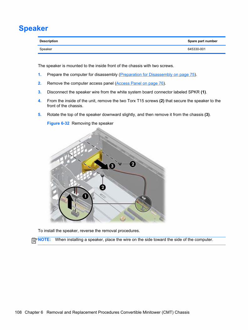
Speaker
Description Spare part number
Speaker 645330-001
The speaker is mounted to the inside front of the chassis with two screws.
1. Prepare the computer for disassembly (Preparation for Disassembly on page 75).
2. Remove the computer access panel (Access Panel on page 76).
3. Disconnect the speaker wire from the white system board connector labeled SPKR (1).
4. From the inside of the unit, remove the two Torx T15 screws (2) that secure the speaker to thefront of the chassis.
5. Rotate the top of the speaker downward slightly, and then remove it from the chassis (3).
Figure 6-32 Removing the speaker
To install the speaker, reverse the removal procedures.
NOTE: When installing a speaker, place the wire on the side toward the side of the computer.
108 Chapter 6 Removal and Replacement Procedures Convertible Minitower (CMT) Chassis
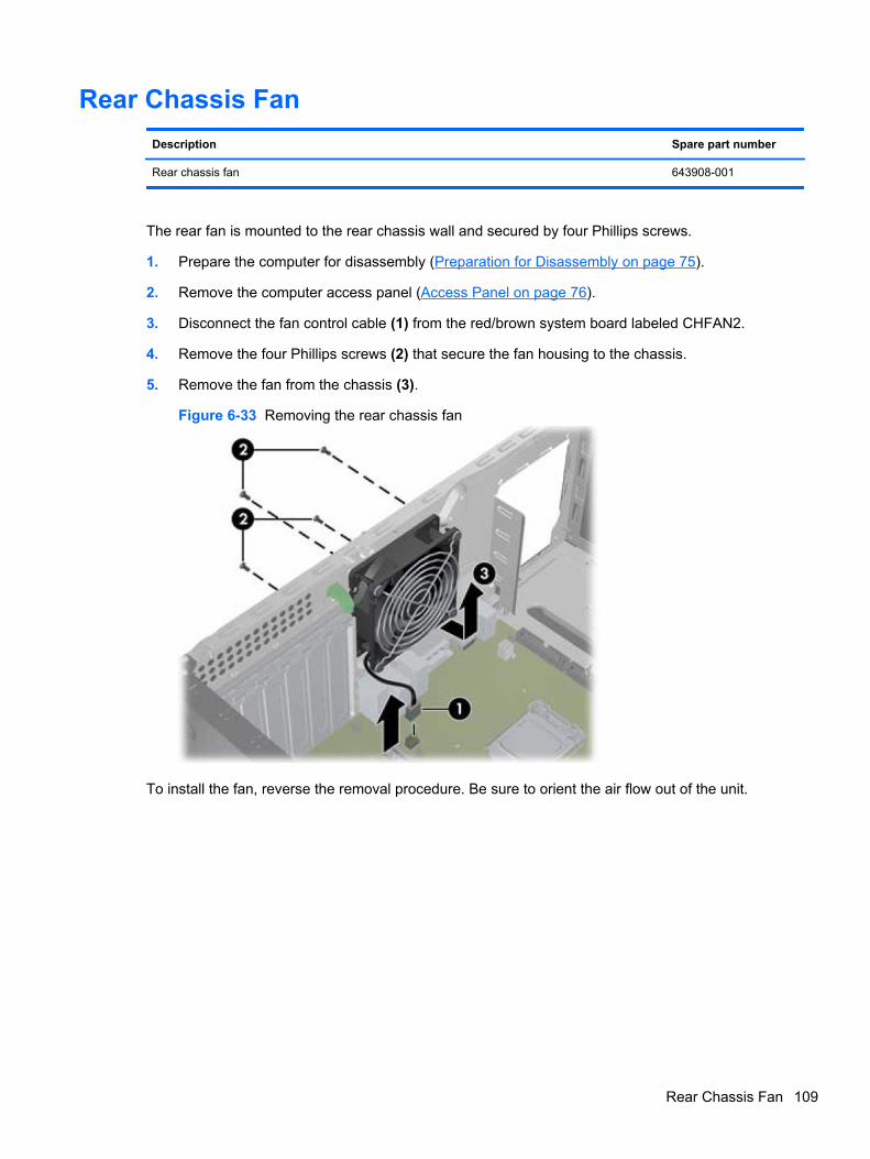
Rear Chassis Fan
Description Spare part number
Rear chassis fan 643908-001
The rear fan is mounted to the rear chassis wall and secured by four Phillips screws.
1. Prepare the computer for disassembly (Preparation for Disassembly on page 75).
2. Remove the computer access panel (Access Panel on page 76).
3. Disconnect the fan control cable (1) from the red/brown system board labeled CHFAN2.
4. Remove the four Phillips screws (2) that secure the fan housing to the chassis.
5. Remove the fan from the chassis (3).
Figure 6-33 Removing the rear chassis fan
To install the fan, reverse the removal procedure. Be sure to orient the air flow out of the unit.
Rear Chassis Fan 109
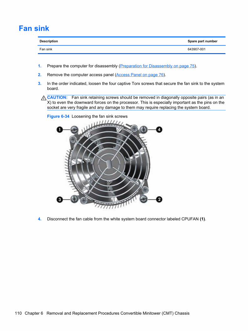
Fan sink
Description Spare part number
Fan sink 643907-001
1. Prepare the computer for disassembly (Preparation for Disassembly on page 75).
2. Remove the computer access panel (Access Panel on page 76).
3. In the order indicated, loosen the four captive Torx screws that secure the fan sink to the systemboard.
CAUTION: Fan sink retaining screws should be removed in diagonally opposite pairs (as in anX) to even the downward forces on the processor. This is especially important as the pins on thesocket are very fragile and any damage to them may require replacing the system board.
Figure 6-34 Loosening the fan sink screws
4. Disconnect the fan cable from the white system board connector labeled CPUFAN (1).
110 Chapter 6 Removal and Replacement Procedures Convertible Minitower (CMT) Chassis
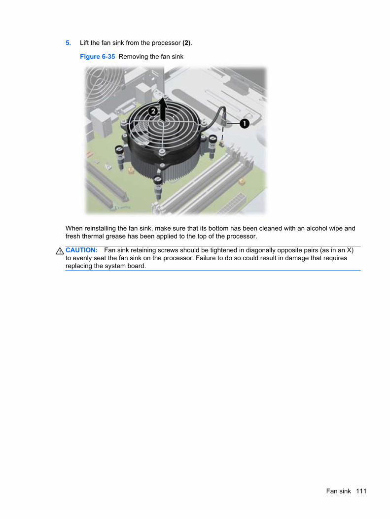
5. Lift the fan sink from the processor (2).
Figure 6-35 Removing the fan sink
When reinstalling the fan sink, make sure that its bottom has been cleaned with an alcohol wipe andfresh thermal grease has been applied to the top of the processor.
CAUTION: Fan sink retaining screws should be tightened in diagonally opposite pairs (as in an X)to evenly seat the fan sink on the processor. Failure to do so could result in damage that requiresreplacing the system board.
Fan sink 111
Processor
Description Spare part number
Intel Core i7 processor
3770, 3.4 GHz, 8-MB L3 cache, 95W 688164-001
Intel Core i5 processors
3570, 3.4 GHz, 6-MB L3 cache, 95W 688162-001
3470, 3.2 GHz, 6-MB L3 cache, 95W 687943-001
Intel Core i3 processors
2130, 3.4 GHz, 3-MB L3 cache, 65W 665120-001
2120, 3.3 GHz, 3-MB L3 cache, 65W 638629-001
Intel Pentium processors
G870, 3.0 GHz, 3-MB L3 cache 691936-001
G860, 3.0 GHz, 3-MB L3 cache 665123-001
G640, 2.8 GHz, 3-MB L3 cache 691935-001
1. Prepare the computer for disassembly (Preparation for Disassembly on page 75).
2. Remove the computer access panel (Access Panel on page 76).
3. Remove the heat sink (Fan sink on page 110).
4. Rotate the locking lever to its full open position (1).
5. Raise and rotate the microprocessor retainer to its fully open position (2).
112 Chapter 6 Removal and Replacement Procedures Convertible Minitower (CMT) Chassis
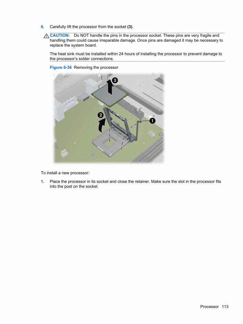
6. Carefully lift the processor from the socket (3).
CAUTION: Do NOT handle the pins in the processor socket. These pins are very fragile andhandling them could cause irreparable damage. Once pins are damaged it may be necessary toreplace the system board.
The heat sink must be installed within 24 hours of installing the processor to prevent damage tothe processor’s solder connections.
Figure 6-36 Removing the processor
To install a new processor:
1. Place the processor in its socket and close the retainer. Make sure the slot in the processor fitsinto the post on the socket.
Processor 113
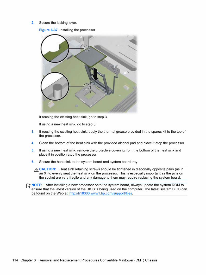
2. Secure the locking lever.
Figure 6-37 Installing the processor
If reusing the existing heat sink, go to step 3.
If using a new heat sink, go to step 5.
3. If reusing the existing heat sink, apply the thermal grease provided in the spares kit to the top ofthe processor.
4. Clean the bottom of the heat sink with the provided alcohol pad and place it atop the processor.
5. If using a new heat sink, remove the protective covering from the bottom of the heat sink andplace it in position atop the processor.
6. Secure the heat sink to the system board and system board tray.
CAUTION: Heat sink retaining screws should be tightened in diagonally opposite pairs (as inan X) to evenly seat the heat sink on the processor. This is especially important as the pins onthe socket are very fragile and any damage to them may require replacing the system board.
NOTE: After installing a new processor onto the system board, always update the system ROM toensure that the latest version of the BIOS is being used on the computer. The latest system BIOS canbe found on the Web at: http://h18000.www1.hp.com/support/files.
114 Chapter 6 Removal and Replacement Procedures Convertible Minitower (CMT) Chassis
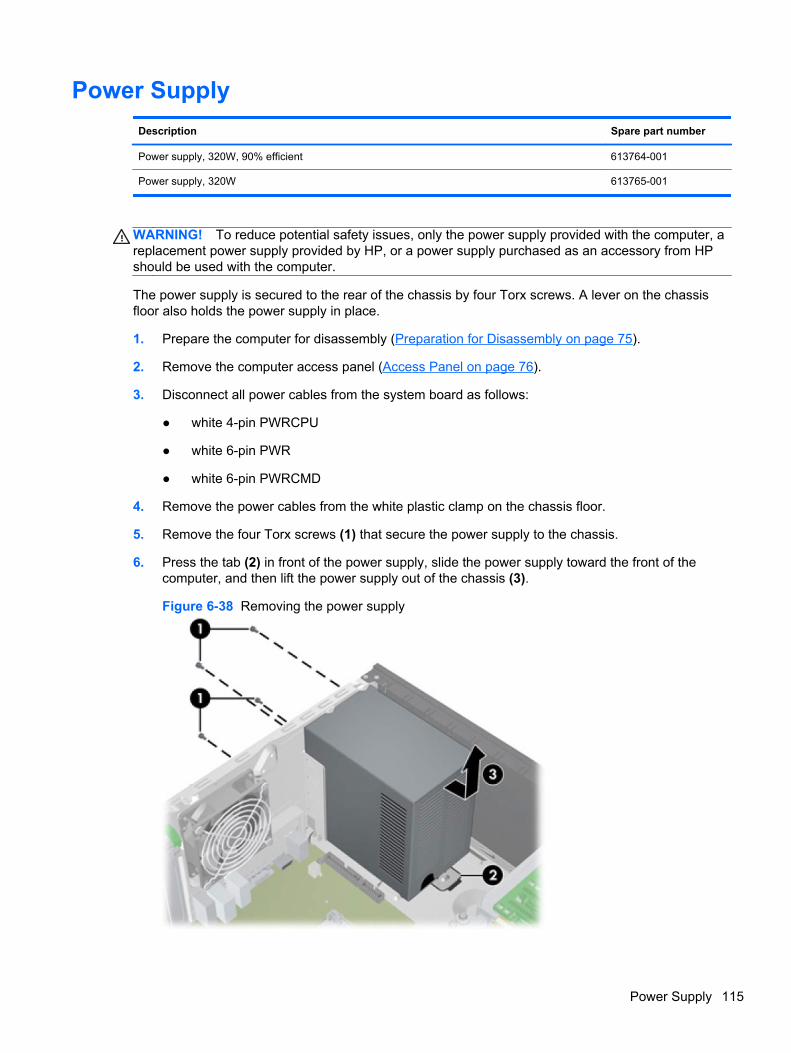
Power Supply
Description Spare part number
Power supply, 320W, 90% efficient 613764-001
Power supply, 320W 613765-001
WARNING! To reduce potential safety issues, only the power supply provided with the computer, areplacement power supply provided by HP, or a power supply purchased as an accessory from HPshould be used with the computer.
The power supply is secured to the rear of the chassis by four Torx screws. A lever on the chassisfloor also holds the power supply in place.
1. Prepare the computer for disassembly (Preparation for Disassembly on page 75).
2. Remove the computer access panel (Access Panel on page 76).
3. Disconnect all power cables from the system board as follows:
● white 4-pin PWRCPU
● white 6-pin PWR
● white 6-pin PWRCMD
4. Remove the power cables from the white plastic clamp on the chassis floor.
5. Remove the four Torx screws (1) that secure the power supply to the chassis.
6. Press the tab (2) in front of the power supply, slide the power supply toward the front of thecomputer, and then lift the power supply out of the chassis (3).
Figure 6-38 Removing the power supply
Power Supply 115
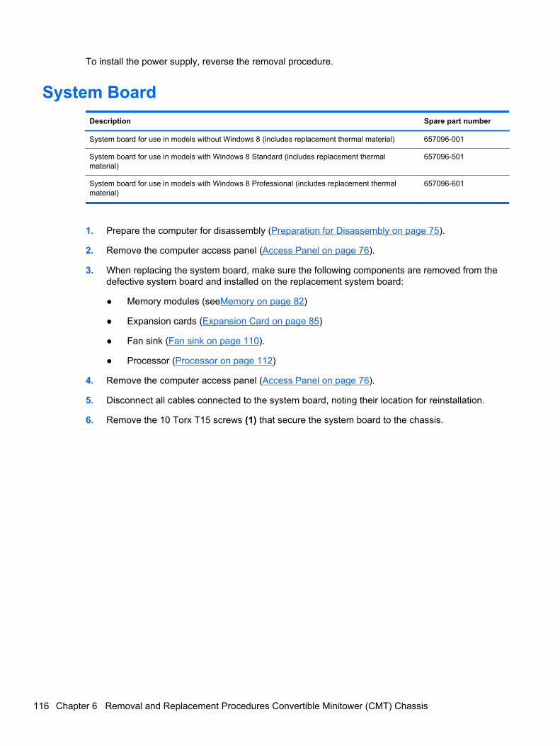
To install the power supply, reverse the removal procedure.
System Board
Description Spare part number
System board for use in models without Windows 8 (includes replacement thermal material) 657096-001
System board for use in models with Windows 8 Standard (includes replacement thermalmaterial)
657096-501
System board for use in models with Windows 8 Professional (includes replacement thermalmaterial)
657096-601
1. Prepare the computer for disassembly (Preparation for Disassembly on page 75).
2. Remove the computer access panel (Access Panel on page 76).
3. When replacing the system board, make sure the following components are removed from thedefective system board and installed on the replacement system board:
● Memory modules (seeMemory on page 82)
● Expansion cards (Expansion Card on page 85)
● Fan sink (Fan sink on page 110).
● Processor (Processor on page 112)
4. Remove the computer access panel (Access Panel on page 76).
5. Disconnect all cables connected to the system board, noting their location for reinstallation.
6. Remove the 10 Torx T15 screws (1) that secure the system board to the chassis.
116 Chapter 6 Removal and Replacement Procedures Convertible Minitower (CMT) Chassis
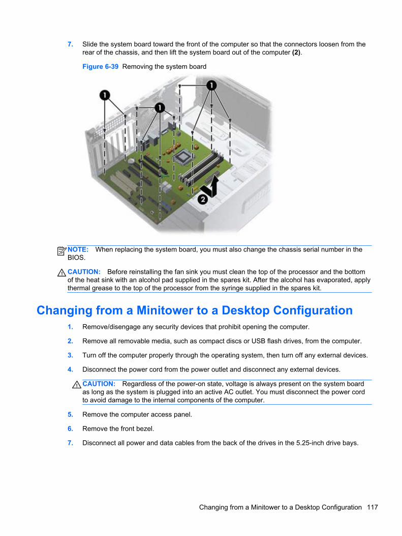
7. Slide the system board toward the front of the computer so that the connectors loosen from therear of the chassis, and then lift the system board out of the computer (2).
Figure 6-39 Removing the system board
NOTE: When replacing the system board, you must also change the chassis serial number in theBIOS.
CAUTION: Before reinstalling the fan sink you must clean the top of the processor and the bottomof the heat sink with an alcohol pad supplied in the spares kit. After the alcohol has evaporated, applythermal grease to the top of the processor from the syringe supplied in the spares kit.
Changing from a Minitower to a Desktop Configuration1. Remove/disengage any security devices that prohibit opening the computer.
2. Remove all removable media, such as compact discs or USB flash drives, from the computer.
3. Turn off the computer properly through the operating system, then turn off any external devices.
4. Disconnect the power cord from the power outlet and disconnect any external devices.
CAUTION: Regardless of the power-on state, voltage is always present on the system boardas long as the system is plugged into an active AC outlet. You must disconnect the power cordto avoid damage to the internal components of the computer.
5. Remove the computer access panel.
6. Remove the front bezel.
7. Disconnect all power and data cables from the back of the drives in the 5.25-inch drive bays.
Changing from a Minitower to a Desktop Configuration 117
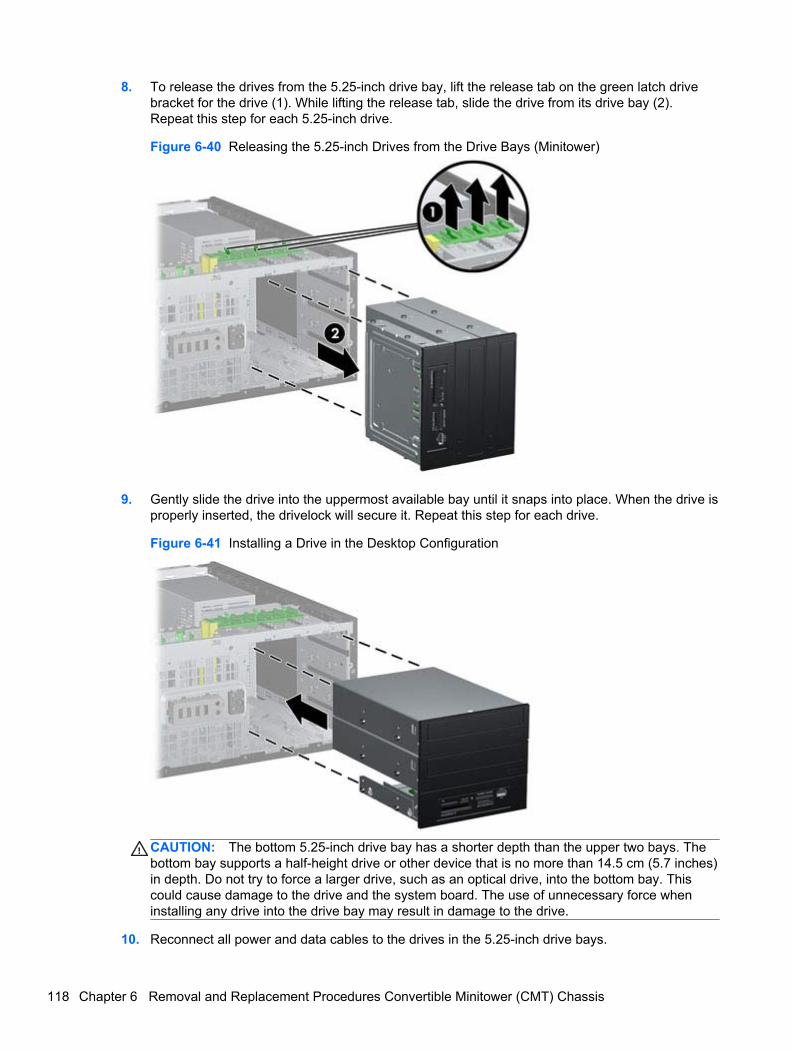
8. To release the drives from the 5.25-inch drive bay, lift the release tab on the green latch drivebracket for the drive (1). While lifting the release tab, slide the drive from its drive bay (2).Repeat this step for each 5.25-inch drive.
Figure 6-40 Releasing the 5.25-inch Drives from the Drive Bays (Minitower)
9. Gently slide the drive into the uppermost available bay until it snaps into place. When the drive isproperly inserted, the drivelock will secure it. Repeat this step for each drive.
Figure 6-41 Installing a Drive in the Desktop Configuration
CAUTION: The bottom 5.25-inch drive bay has a shorter depth than the upper two bays. Thebottom bay supports a half-height drive or other device that is no more than 14.5 cm (5.7 inches)in depth. Do not try to force a larger drive, such as an optical drive, into the bottom bay. Thiscould cause damage to the drive and the system board. The use of unnecessary force wheninstalling any drive into the drive bay may result in damage to the drive.
10. Reconnect all power and data cables to the drives in the 5.25-inch drive bays.
118 Chapter 6 Removal and Replacement Procedures Convertible Minitower (CMT) Chassis
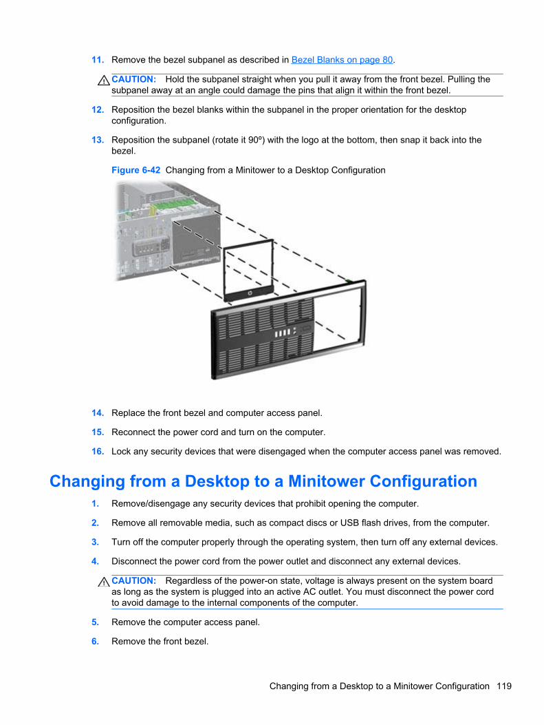
11. Remove the bezel subpanel as described in Bezel Blanks on page 80.
CAUTION: Hold the subpanel straight when you pull it away from the front bezel. Pulling thesubpanel away at an angle could damage the pins that align it within the front bezel.
12. Reposition the bezel blanks within the subpanel in the proper orientation for the desktopconfiguration.
13. Reposition the subpanel (rotate it 90º) with the logo at the bottom, then snap it back into thebezel.
Figure 6-42 Changing from a Minitower to a Desktop Configuration
14. Replace the front bezel and computer access panel.
15. Reconnect the power cord and turn on the computer.
16. Lock any security devices that were disengaged when the computer access panel was removed.
Changing from a Desktop to a Minitower Configuration1. Remove/disengage any security devices that prohibit opening the computer.
2. Remove all removable media, such as compact discs or USB flash drives, from the computer.
3. Turn off the computer properly through the operating system, then turn off any external devices.
4. Disconnect the power cord from the power outlet and disconnect any external devices.
CAUTION: Regardless of the power-on state, voltage is always present on the system boardas long as the system is plugged into an active AC outlet. You must disconnect the power cordto avoid damage to the internal components of the computer.
5. Remove the computer access panel.
6. Remove the front bezel.
Changing from a Desktop to a Minitower Configuration 119
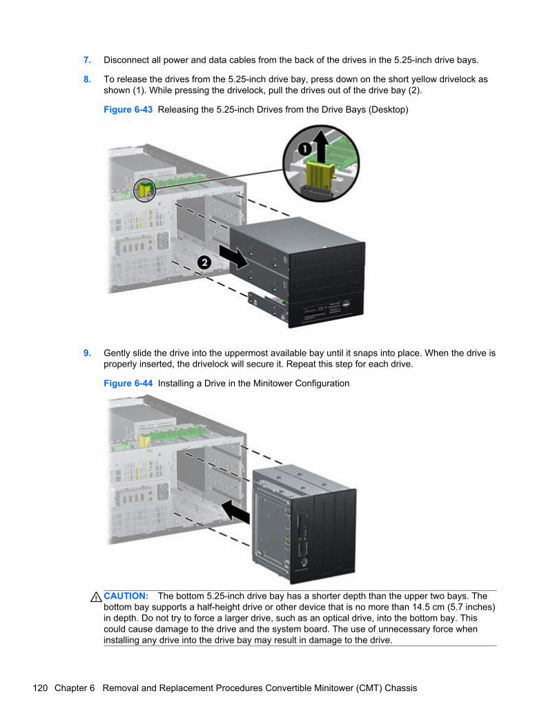
7. Disconnect all power and data cables from the back of the drives in the 5.25-inch drive bays.
8. To release the drives from the 5.25-inch drive bay, press down on the short yellow drivelock asshown (1). While pressing the drivelock, pull the drives out of the drive bay (2).
Figure 6-43 Releasing the 5.25-inch Drives from the Drive Bays (Desktop)
9. Gently slide the drive into the uppermost available bay until it snaps into place. When the drive isproperly inserted, the drivelock will secure it. Repeat this step for each drive.
Figure 6-44 Installing a Drive in the Minitower Configuration
CAUTION: The bottom 5.25-inch drive bay has a shorter depth than the upper two bays. Thebottom bay supports a half-height drive or other device that is no more than 14.5 cm (5.7 inches)in depth. Do not try to force a larger drive, such as an optical drive, into the bottom bay. Thiscould cause damage to the drive and the system board. The use of unnecessary force wheninstalling any drive into the drive bay may result in damage to the drive.
120 Chapter 6 Removal and Replacement Procedures Convertible Minitower (CMT) Chassis
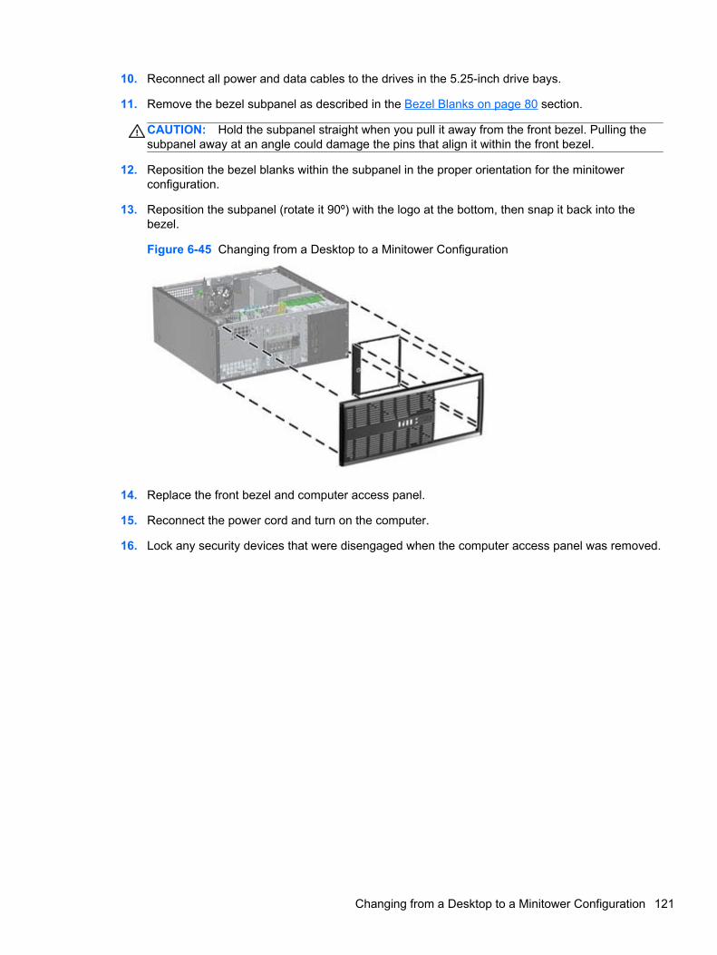
10. Reconnect all power and data cables to the drives in the 5.25-inch drive bays.
11. Remove the bezel subpanel as described in the Bezel Blanks on page 80 section.
CAUTION: Hold the subpanel straight when you pull it away from the front bezel. Pulling thesubpanel away at an angle could damage the pins that align it within the front bezel.
12. Reposition the bezel blanks within the subpanel in the proper orientation for the minitowerconfiguration.
13. Reposition the subpanel (rotate it 90º) with the logo at the bottom, then snap it back into thebezel.
Figure 6-45 Changing from a Desktop to a Minitower Configuration
14. Replace the front bezel and computer access panel.
15. Reconnect the power cord and turn on the computer.
16. Lock any security devices that were disengaged when the computer access panel was removed.
Changing from a Desktop to a Minitower Configuration 121
7 Removal and Replacement ProceduresMicrotower (MT) Chassis
Adherence to the procedures and precautions described in this chapter is essential for proper service.After completing all necessary removal and replacement procedures, run the Diagnostics utility toverify that all components operate properly.
NOTE: Not all features listed in this guide are available on all computers.
Preparation for DisassemblySee Routine Care, SATA Drive Guidelines, and Disassembly Preparation on page 66 for initial safetyprocedures.
1. Remove/disengage any security devices that prohibit opening the computer.
2. Close any open software applications.
3. Exit the operating system.
4. Remove any diskette, compact disc, or media card from the computer.
5. Turn off the computer and any peripheral devices that are connected to it.
CAUTION: Turn off the computer before disconnecting any cables.
Regardless of the power-on state, voltage is always present on the system board as long as thesystem is plugged into an active AC outlet. In some systems the cooling fan is on even when thecomputer is in the “Standby,” or “Suspend” modes. The power cord should always bedisconnected before servicing a unit.
6. Disconnect the power cord from the electrical outlet and then from the computer.
7. Disconnect all peripheral device cables from the computer.
8. As applicable, lay the computer down on its side to achieve a safe working position.
NOTE: During disassembly, label each cable as you remove it, noting its position and routing.Keep all screws with the units removed.
CAUTION: The screws used in the computer are of different thread sizes and lengths; using thewrong screw in an application may damage the unit.
122 Chapter 7 Removal and Replacement Procedures Microtower (MT) Chassis
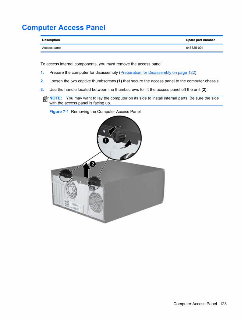
Computer Access Panel
Description Spare part number
Access panel 646825-001
To access internal components, you must remove the access panel:
1. Prepare the computer for disassembly (Preparation for Disassembly on page 122)
2. Loosen the two captive thumbscrews (1) that secure the access panel to the computer chassis.
3. Use the handle located between the thumbscrews to lift the access panel off the unit (2).
NOTE: You may want to lay the computer on its side to install internal parts. Be sure the sidewith the access panel is facing up.
Figure 7-1 Removing the Computer Access Panel
Computer Access Panel 123
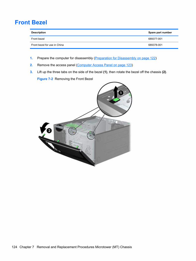
Front Bezel
Description Spare part number
Front bezel 689377-001
Front bezel for use in China 689378-001
1. Prepare the computer for disassembly (Preparation for Disassembly on page 122)
2. Remove the access panel (Computer Access Panel on page 123)
3. Lift up the three tabs on the side of the bezel (1), then rotate the bezel off the chassis (2).
Figure 7-2 Removing the Front Bezel
124 Chapter 7 Removal and Replacement Procedures Microtower (MT) Chassis
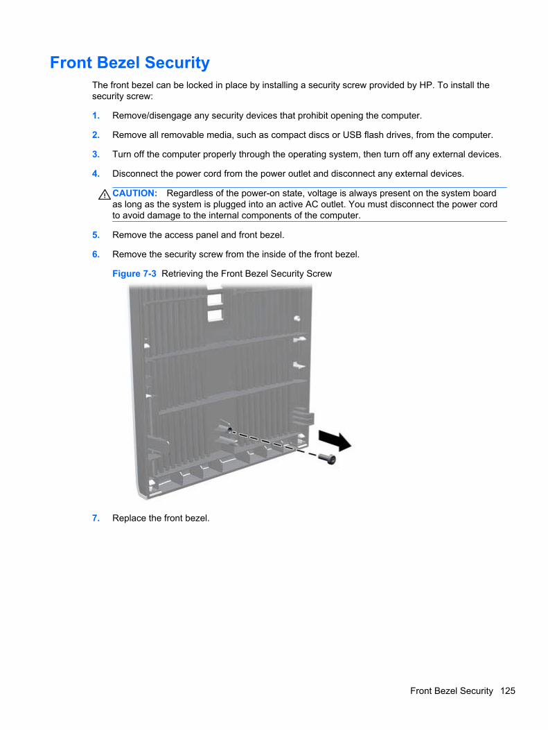
Front Bezel SecurityThe front bezel can be locked in place by installing a security screw provided by HP. To install thesecurity screw:
1. Remove/disengage any security devices that prohibit opening the computer.
2. Remove all removable media, such as compact discs or USB flash drives, from the computer.
3. Turn off the computer properly through the operating system, then turn off any external devices.
4. Disconnect the power cord from the power outlet and disconnect any external devices.
CAUTION: Regardless of the power-on state, voltage is always present on the system boardas long as the system is plugged into an active AC outlet. You must disconnect the power cordto avoid damage to the internal components of the computer.
5. Remove the access panel and front bezel.
6. Remove the security screw from the inside of the front bezel.
Figure 7-3 Retrieving the Front Bezel Security Screw
7. Replace the front bezel.
Front Bezel Security 125
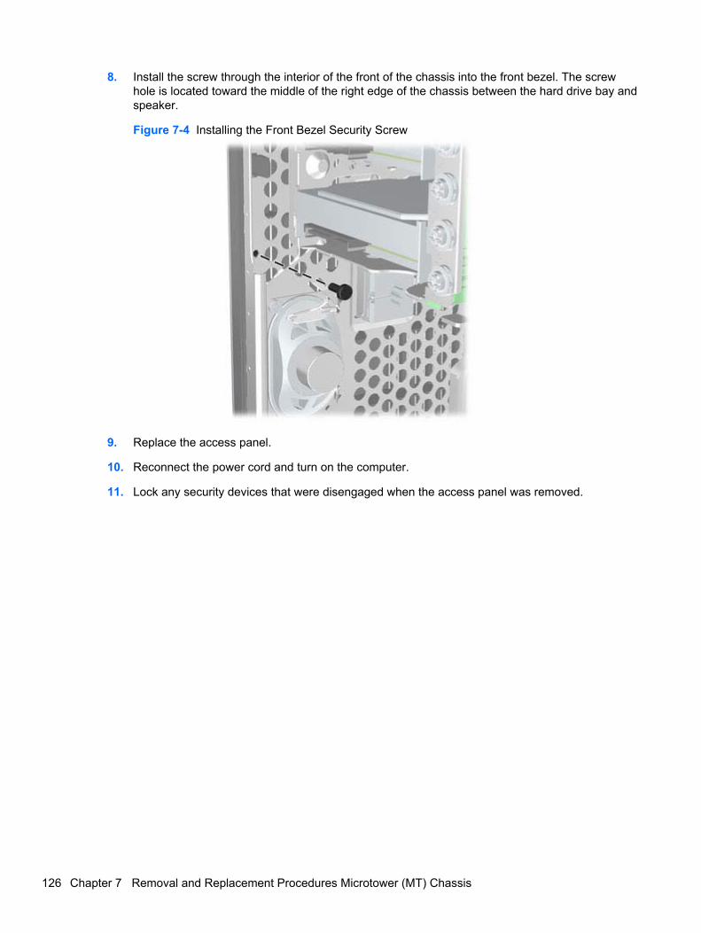
8. Install the screw through the interior of the front of the chassis into the front bezel. The screwhole is located toward the middle of the right edge of the chassis between the hard drive bay andspeaker.
Figure 7-4 Installing the Front Bezel Security Screw
9. Replace the access panel.
10. Reconnect the power cord and turn on the computer.
11. Lock any security devices that were disengaged when the access panel was removed.
126 Chapter 7 Removal and Replacement Procedures Microtower (MT) Chassis
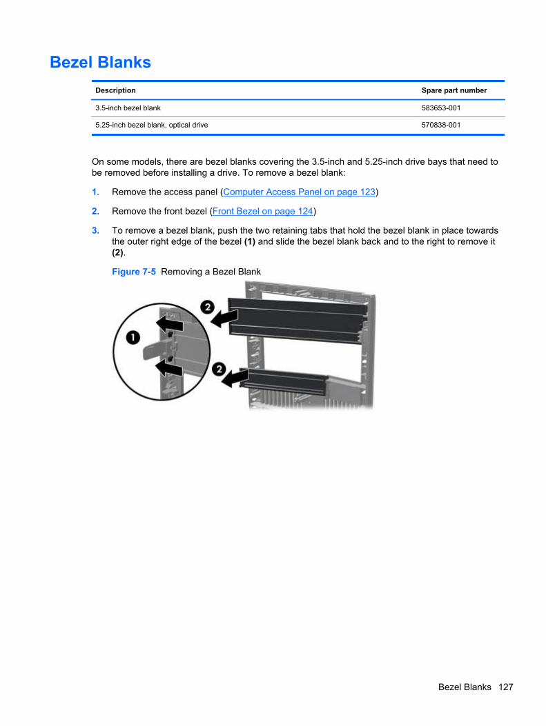
Bezel Blanks
Description Spare part number
3.5-inch bezel blank 583653-001
5.25-inch bezel blank, optical drive 570838-001
On some models, there are bezel blanks covering the 3.5-inch and 5.25-inch drive bays that need tobe removed before installing a drive. To remove a bezel blank:
1. Remove the access panel (Computer Access Panel on page 123)
2. Remove the front bezel (Front Bezel on page 124)
3. To remove a bezel blank, push the two retaining tabs that hold the bezel blank in place towardsthe outer right edge of the bezel (1) and slide the bezel blank back and to the right to remove it(2).
Figure 7-5 Removing a Bezel Blank
Bezel Blanks 127
Memory
Description Spare part number
8-GB, PC3-12800 689375-001
4-GB, PC3-12800 671613-001
2-GB, PC3-12800 671612-001
The computer comes with double data rate 3 synchronous dynamic random access memory (DDR3-SDRAM) dual inline memory modules (DIMMs).
DIMMs
The memory sockets on the system board can be populated with up to four industry-standard DIMMs.These memory sockets are populated with at least one preinstalled DIMM. To achieve the maximummemory support, you can populate the system board with up to 16-GB of memory configured in ahigh-performing dual channel mode.
DDR3-SDRAM DIMMs
CAUTION: This product DOES NOT support DDR3 Ultra Low Voltage (DDR3U) memory. Theprocessor is not compatible with DDR3U memory and if you plug DDR3U memory into the systemboard, it can cause the physical damage to the DIMM or invoke system malfunction.
For proper system operation, the DDR3-SDRAM DIMMs must be:
● industry-standard 240-pin
● unbuffered non-ECC PC3-12800 DDR3-1600 MHz-compliant
● 1.5 volt DDR3-SDRAM DIMMs
The DDR3-SDRAM DIMMs must also:
● support CAS latency 11 DDR3 1600 MHz (11-11-11 timing)
● contain the mandatory JEDEC SPD information
In addition, the computer supports:
● 512-Mbit, 1-Gbit, and 2-Gbit non-ECC memory technologies
● single-sided and double-sided DIMMs
● DIMMs constructed with x8 and x16 DDR devices; DIMMs constructed with x4 SDRAM are notsupported
NOTE: The system will not operate properly if you install unsupported DIMMs.
Populating DIMM Sockets
There are four DIMM sockets on the system board, with two sockets per channel. The sockets arelabeled DIMM1, DIMM2, DIMM3, and DIMM4. Sockets DIMM1 and DIMM2 operate in memorychannel B. Sockets DIMM3 and DIMM4 operate in memory channel A.
128 Chapter 7 Removal and Replacement Procedures Microtower (MT) Chassis
The system will automatically operate in single channel mode, dual channel mode, or flex mode,depending on how the DIMMs are installed.
● The system will operate in single channel mode if the DIMM sockets are populated in onechannel only.
● The system will operate in a higher-performing dual channel mode if the total memory capacityof the DIMMs in Channel A is equal to the total memory capacity of the DIMMs in Channel B.The technology and device width can vary between the channels. For example, if Channel A ispopulated with two 1-GB DIMMs and Channel B is populated with one 2-GB DIMM, the systemwill operate in dual channel mode.
● The system will operate in flex mode if the total memory capacity of the DIMMs in Channel A isnot equal to the total memory capacity of the DIMMs in Channel B. In flex mode, the channelpopulated with the least amount of memory describes the total amount of memory assigned todual channel and the remainder is assigned to single channel. For optimal speed, the channelsshould be balanced so that the largest amount of memory is spread between the two channels.If one channel will have more memory than the other, the larger amount should be assigned toChannel A. For example, if you are populating the sockets with one 2-GB DIMM, and three 1-GBDIMMs, Channel A should be populated with the 2-GB DIMM and one 1-GB DIMM, and ChannelB should be populated with the other two 1-GB DIMMs. With this configuration, 4-GB will run asdual channel and 1-GB will run as single channel.
● In any mode, the maximum operational speed is determined by the slowest DIMM in the system.
Installing DIMMs
CAUTION: You must disconnect the power cord and wait approximately 30 seconds for the powerto drain before adding or removing memory modules. Regardless of the power-on state, voltage isalways supplied to the memory modules as long as the computer is plugged into an active AC outlet.Adding or removing memory modules while voltage is present may cause irreparable damage to thememory modules or system board.
The memory module sockets have gold-plated metal contacts. When upgrading the memory, it isimportant to use memory modules with gold-plated metal contacts to prevent corrosion and/oroxidation resulting from having incompatible metals in contact with each other.
Static electricity can damage the electronic components of the computer or optional cards. Beforebeginning these procedures, ensure that you are discharged of static electricity by briefly touching agrounded metal object. For more information, refer to Electrostatic Discharge Information on page 66.
When handling a memory module, be careful not to touch any of the contacts. Doing so may damagethe module.
1. Prepare the computer for disassembly (Preparation for Disassembly on page 122)
2. Remove the access panel (Computer Access Panel on page 123)
Memory 129
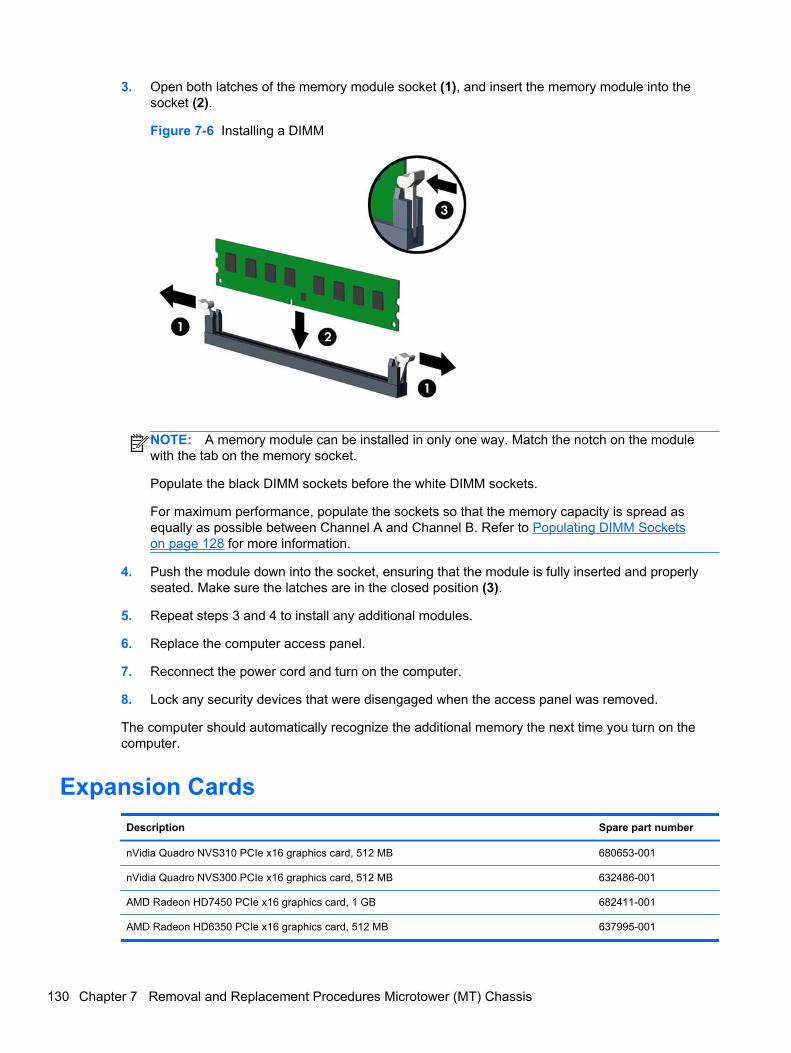
3. Open both latches of the memory module socket (1), and insert the memory module into thesocket (2).
Figure 7-6 Installing a DIMM
NOTE: A memory module can be installed in only one way. Match the notch on the modulewith the tab on the memory socket.
Populate the black DIMM sockets before the white DIMM sockets.
For maximum performance, populate the sockets so that the memory capacity is spread asequally as possible between Channel A and Channel B. Refer to Populating DIMM Socketson page 128 for more information.
4. Push the module down into the socket, ensuring that the module is fully inserted and properlyseated. Make sure the latches are in the closed position (3).
5. Repeat steps 3 and 4 to install any additional modules.
6. Replace the computer access panel.
7. Reconnect the power cord and turn on the computer.
8. Lock any security devices that were disengaged when the access panel was removed.
The computer should automatically recognize the additional memory the next time you turn on thecomputer.
Expansion Cards
Description Spare part number
nVidia Quadro NVS310 PCIe x16 graphics card, 512 MB 680653-001
nVidia Quadro NVS300 PCIe x16 graphics card, 512 MB 632486-001
AMD Radeon HD7450 PCIe x16 graphics card, 1 GB 682411-001
AMD Radeon HD6350 PCIe x16 graphics card, 512 MB 637995-001
130 Chapter 7 Removal and Replacement Procedures Microtower (MT) Chassis
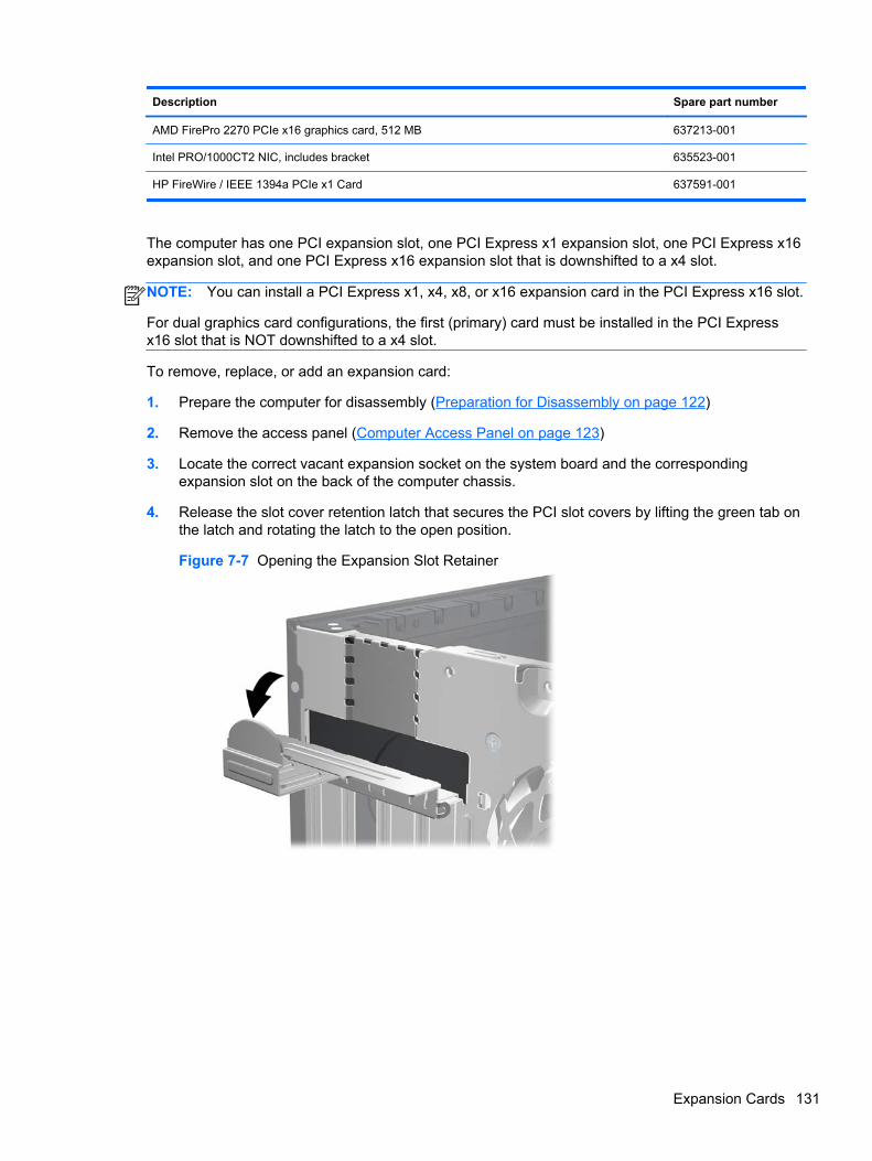
Description Spare part number
AMD FirePro 2270 PCIe x16 graphics card, 512 MB 637213-001
Intel PRO/1000CT2 NIC, includes bracket 635523-001
HP FireWire / IEEE 1394a PCIe x1 Card 637591-001
The computer has one PCI expansion slot, one PCI Express x1 expansion slot, one PCI Express x16expansion slot, and one PCI Express x16 expansion slot that is downshifted to a x4 slot.
NOTE: You can install a PCI Express x1, x4, x8, or x16 expansion card in the PCI Express x16 slot.
For dual graphics card configurations, the first (primary) card must be installed in the PCI Expressx16 slot that is NOT downshifted to a x4 slot.
To remove, replace, or add an expansion card:
1. Prepare the computer for disassembly (Preparation for Disassembly on page 122)
2. Remove the access panel (Computer Access Panel on page 123)
3. Locate the correct vacant expansion socket on the system board and the correspondingexpansion slot on the back of the computer chassis.
4. Release the slot cover retention latch that secures the PCI slot covers by lifting the green tab onthe latch and rotating the latch to the open position.
Figure 7-7 Opening the Expansion Slot Retainer
Expansion Cards 131
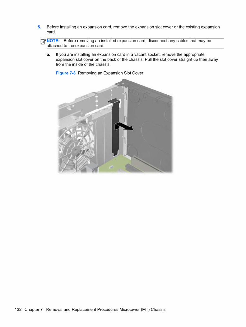
5. Before installing an expansion card, remove the expansion slot cover or the existing expansioncard.
NOTE: Before removing an installed expansion card, disconnect any cables that may beattached to the expansion card.
a. If you are installing an expansion card in a vacant socket, remove the appropriateexpansion slot cover on the back of the chassis. Pull the slot cover straight up then awayfrom the inside of the chassis.
Figure 7-8 Removing an Expansion Slot Cover
132 Chapter 7 Removal and Replacement Procedures Microtower (MT) Chassis
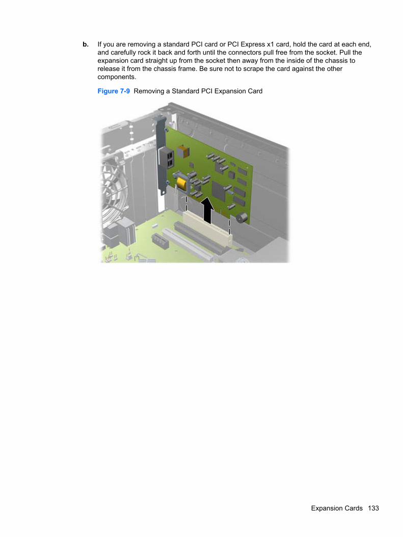
b. If you are removing a standard PCI card or PCI Express x1 card, hold the card at each end,and carefully rock it back and forth until the connectors pull free from the socket. Pull theexpansion card straight up from the socket then away from the inside of the chassis torelease it from the chassis frame. Be sure not to scrape the card against the othercomponents.
Figure 7-9 Removing a Standard PCI Expansion Card
Expansion Cards 133
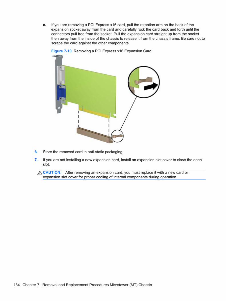
c. If you are removing a PCI Express x16 card, pull the retention arm on the back of theexpansion socket away from the card and carefully rock the card back and forth until theconnectors pull free from the socket. Pull the expansion card straight up from the socketthen away from the inside of the chassis to release it from the chassis frame. Be sure not toscrape the card against the other components.
Figure 7-10 Removing a PCI Express x16 Expansion Card
6. Store the removed card in anti-static packaging.
7. If you are not installing a new expansion card, install an expansion slot cover to close the openslot.
CAUTION: After removing an expansion card, you must replace it with a new card orexpansion slot cover for proper cooling of internal components during operation.
134 Chapter 7 Removal and Replacement Procedures Microtower (MT) Chassis
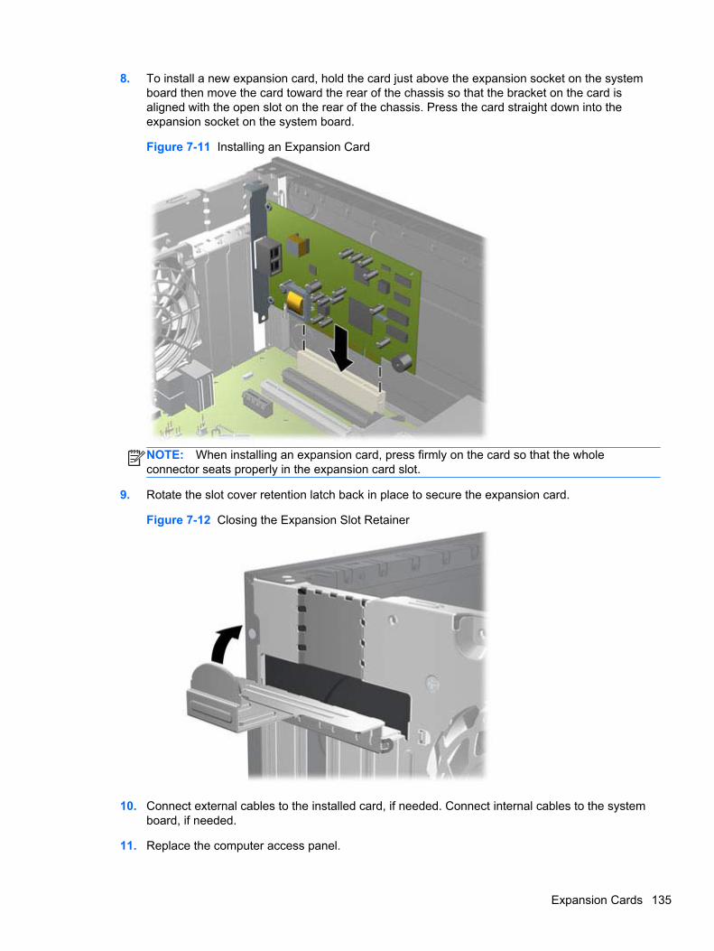
8. To install a new expansion card, hold the card just above the expansion socket on the systemboard then move the card toward the rear of the chassis so that the bracket on the card isaligned with the open slot on the rear of the chassis. Press the card straight down into theexpansion socket on the system board.
Figure 7-11 Installing an Expansion Card
NOTE: When installing an expansion card, press firmly on the card so that the wholeconnector seats properly in the expansion card slot.
9. Rotate the slot cover retention latch back in place to secure the expansion card.
Figure 7-12 Closing the Expansion Slot Retainer
10. Connect external cables to the installed card, if needed. Connect internal cables to the systemboard, if needed.
11. Replace the computer access panel.
Expansion Cards 135
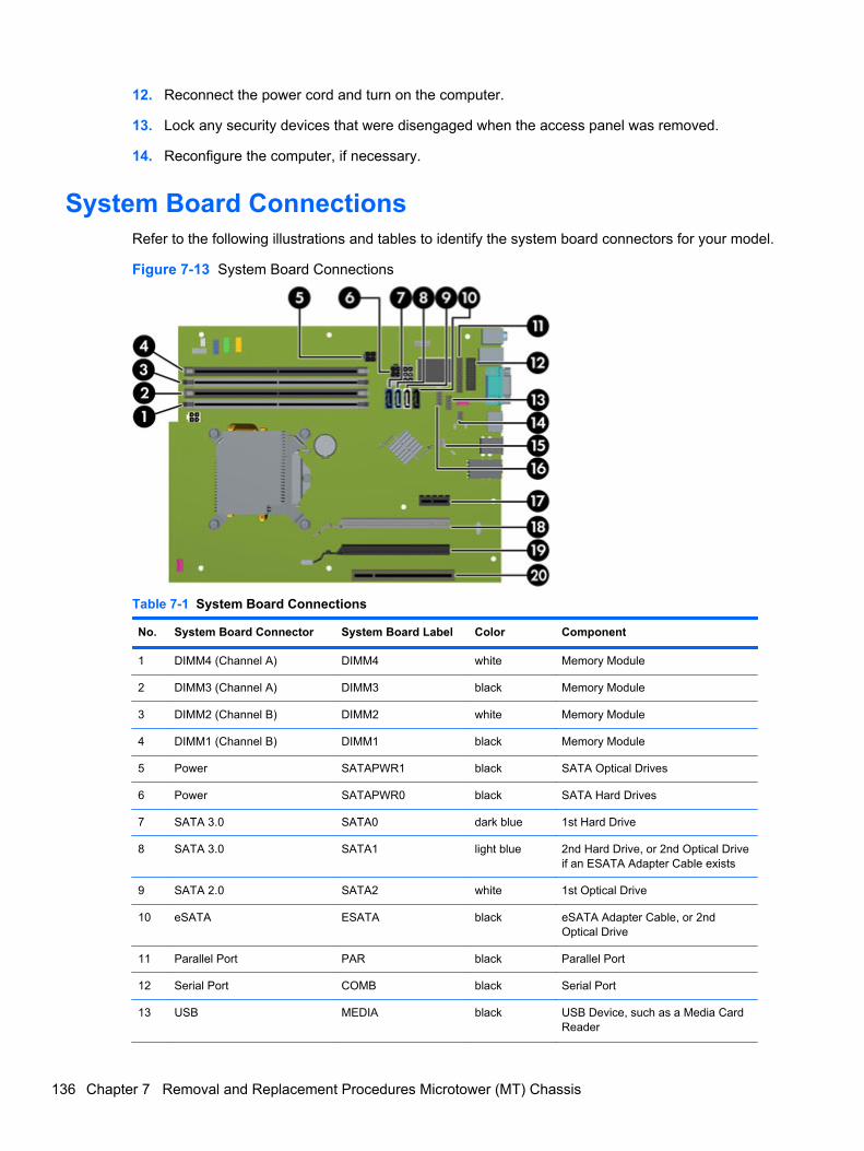
12. Reconnect the power cord and turn on the computer.
13. Lock any security devices that were disengaged when the access panel was removed.
14. Reconfigure the computer, if necessary.
System Board ConnectionsRefer to the following illustrations and tables to identify the system board connectors for your model.
Figure 7-13 System Board Connections
Table 7-1 System Board Connections
No. System Board Connector System Board Label Color Component
1 DIMM4 (Channel A) DIMM4 white Memory Module
2 DIMM3 (Channel A) DIMM3 black Memory Module
3 DIMM2 (Channel B) DIMM2 white Memory Module
4 DIMM1 (Channel B) DIMM1 black Memory Module
5 Power SATAPWR1 black SATA Optical Drives
6 Power SATAPWR0 black SATA Hard Drives
7 SATA 3.0 SATA0 dark blue 1st Hard Drive
8 SATA 3.0 SATA1 light blue 2nd Hard Drive, or 2nd Optical Driveif an ESATA Adapter Cable exists
9 SATA 2.0 SATA2 white 1st Optical Drive
10 eSATA ESATA black eSATA Adapter Cable, or 2ndOptical Drive
11 Parallel Port PAR black Parallel Port
12 Serial Port COMB black Serial Port
13 USB MEDIA black USB Device, such as a Media CardReader
136 Chapter 7 Removal and Replacement Procedures Microtower (MT) Chassis
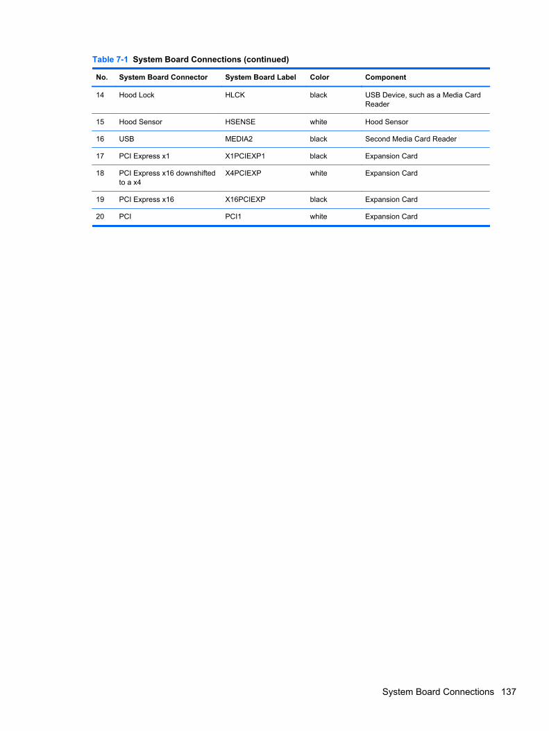
Table 7-1 System Board Connections (continued)
No. System Board Connector System Board Label Color Component
14 Hood Lock HLCK black USB Device, such as a Media CardReader
15 Hood Sensor HSENSE white Hood Sensor
16 USB MEDIA2 black Second Media Card Reader
17 PCI Express x1 X1PCIEXP1 black Expansion Card
18 PCI Express x16 downshiftedto a x4
X4PCIEXP white Expansion Card
19 PCI Express x16 X16PCIEXP black Expansion Card
20 PCI PCI1 white Expansion Card
System Board Connections 137
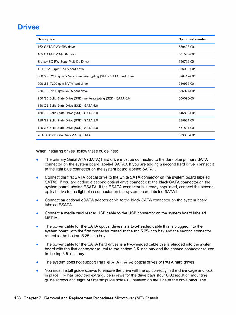
Drives
Description Spare part number
16X SATA DVD±RW drive 660408-001
16X SATA DVD-ROM drive 581599-001
Blu-ray BD-RW SuperMulti DL Drive 656792-001
1 TB, 7200 rpm SATA hard drive 636930-001
500 GB, 7200 rpm, 2.5-inch, self-encrypting (SED), SATA hard drive 696442-001
500 GB, 7200 rpm SATA hard drive 636929-001
250 GB, 7200 rpm SATA hard drive 636927-001
256 GB Solid State Drive (SSD), self-encrypting (SED), SATA 6.0 680020-001
180 GB Solid State Drive (SSD), SATA 6.0
160 GB Solid State Drive (SSD), SATA 3.0 646809-001
128 GB Solid State Drive (SSD), SATA 2.0 665961-001
120 GB Solid State Drive (SSD), SATA 2.0 661841-001
20 GB Solid State Drive (SSD), SATA 683305-001
When installing drives, follow these guidelines:
● The primary Serial ATA (SATA) hard drive must be connected to the dark blue primary SATAconnector on the system board labeled SATA0. If you are adding a second hard drive, connect itto the light blue connector on the system board labeled SATA1.
● Connect the first SATA optical drive to the white SATA connector on the system board labeledSATA2. If you are adding a second optical drive connect it to the black SATA connector on thesystem board labeled ESATA. If the ESATA connector is already populated, connect the secondoptical drive to the light blue connector on the system board labeled SATA1.
● Connect an optional eSATA adapter cable to the black SATA connector on the system boardlabeled ESATA.
● Connect a media card reader USB cable to the USB connector on the system board labeledMEDIA.
● The power cable for the SATA optical drives is a two-headed cable this is plugged into thesystem board with the first connector routed to the top 5.25-inch bay and the second connectorrouted to the bottom 5.25-inch bay.
● The power cable for the SATA hard drives is a two-headed cable this is plugged into the systemboard with the first connector routed to the bottom 3.5-inch bay and the second connector routedto the top 3.5-inch bay.
● The system does not support Parallel ATA (PATA) optical drives or PATA hard drives.
● You must install guide screws to ensure the drive will line up correctly in the drive cage and lockin place. HP has provided extra guide screws for the drive bays (four 6-32 isolation mountingguide screws and eight M3 metric guide screws), installed on the side of the drive bays. The
138 Chapter 7 Removal and Replacement Procedures Microtower (MT) Chassis
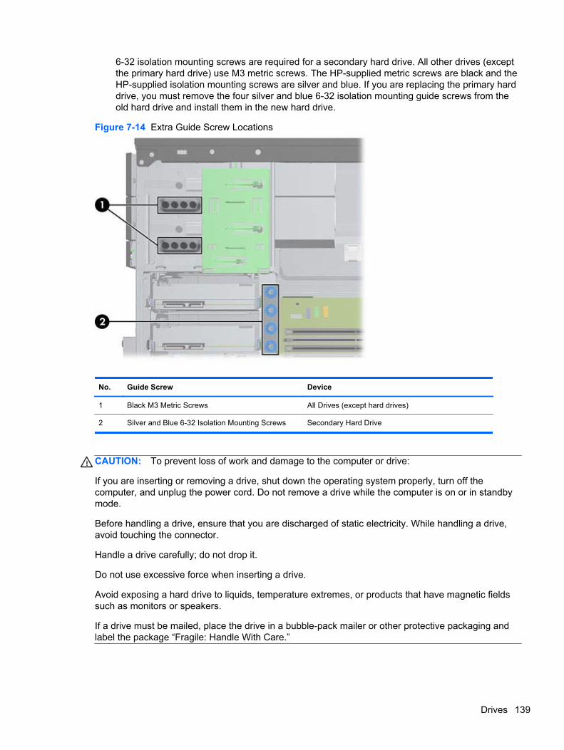
6-32 isolation mounting screws are required for a secondary hard drive. All other drives (exceptthe primary hard drive) use M3 metric screws. The HP-supplied metric screws are black and theHP-supplied isolation mounting screws are silver and blue. If you are replacing the primary harddrive, you must remove the four silver and blue 6-32 isolation mounting guide screws from theold hard drive and install them in the new hard drive.
Figure 7-14 Extra Guide Screw Locations
No. Guide Screw Device
1 Black M3 Metric Screws All Drives (except hard drives)
2 Silver and Blue 6-32 Isolation Mounting Screws Secondary Hard Drive
CAUTION: To prevent loss of work and damage to the computer or drive:
If you are inserting or removing a drive, shut down the operating system properly, turn off thecomputer, and unplug the power cord. Do not remove a drive while the computer is on or in standbymode.
Before handling a drive, ensure that you are discharged of static electricity. While handling a drive,avoid touching the connector.
Handle a drive carefully; do not drop it.
Do not use excessive force when inserting a drive.
Avoid exposing a hard drive to liquids, temperature extremes, or products that have magnetic fieldssuch as monitors or speakers.
If a drive must be mailed, place the drive in a bubble-pack mailer or other protective packaging andlabel the package “Fragile: Handle With Care.”
Drives 139
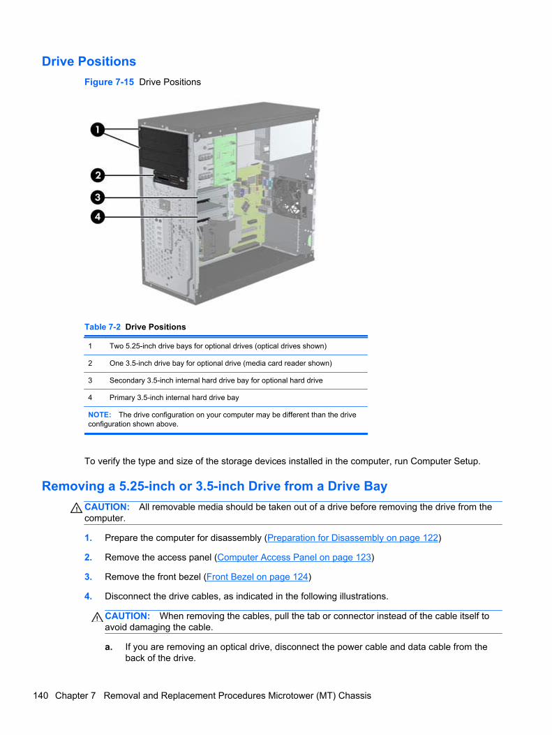
Drive Positions
Figure 7-15 Drive Positions
Table 7-2 Drive Positions
1 Two 5.25-inch drive bays for optional drives (optical drives shown)
2 One 3.5-inch drive bay for optional drive (media card reader shown)
3 Secondary 3.5-inch internal hard drive bay for optional hard drive
4 Primary 3.5-inch internal hard drive bay
NOTE: The drive configuration on your computer may be different than the driveconfiguration shown above.
To verify the type and size of the storage devices installed in the computer, run Computer Setup.
Removing a 5.25-inch or 3.5-inch Drive from a Drive Bay
CAUTION: All removable media should be taken out of a drive before removing the drive from thecomputer.
1. Prepare the computer for disassembly (Preparation for Disassembly on page 122)
2. Remove the access panel (Computer Access Panel on page 123)
3. Remove the front bezel (Front Bezel on page 124)
4. Disconnect the drive cables, as indicated in the following illustrations.
CAUTION: When removing the cables, pull the tab or connector instead of the cable itself toavoid damaging the cable.
a. If you are removing an optical drive, disconnect the power cable and data cable from theback of the drive.
140 Chapter 7 Removal and Replacement Procedures Microtower (MT) Chassis
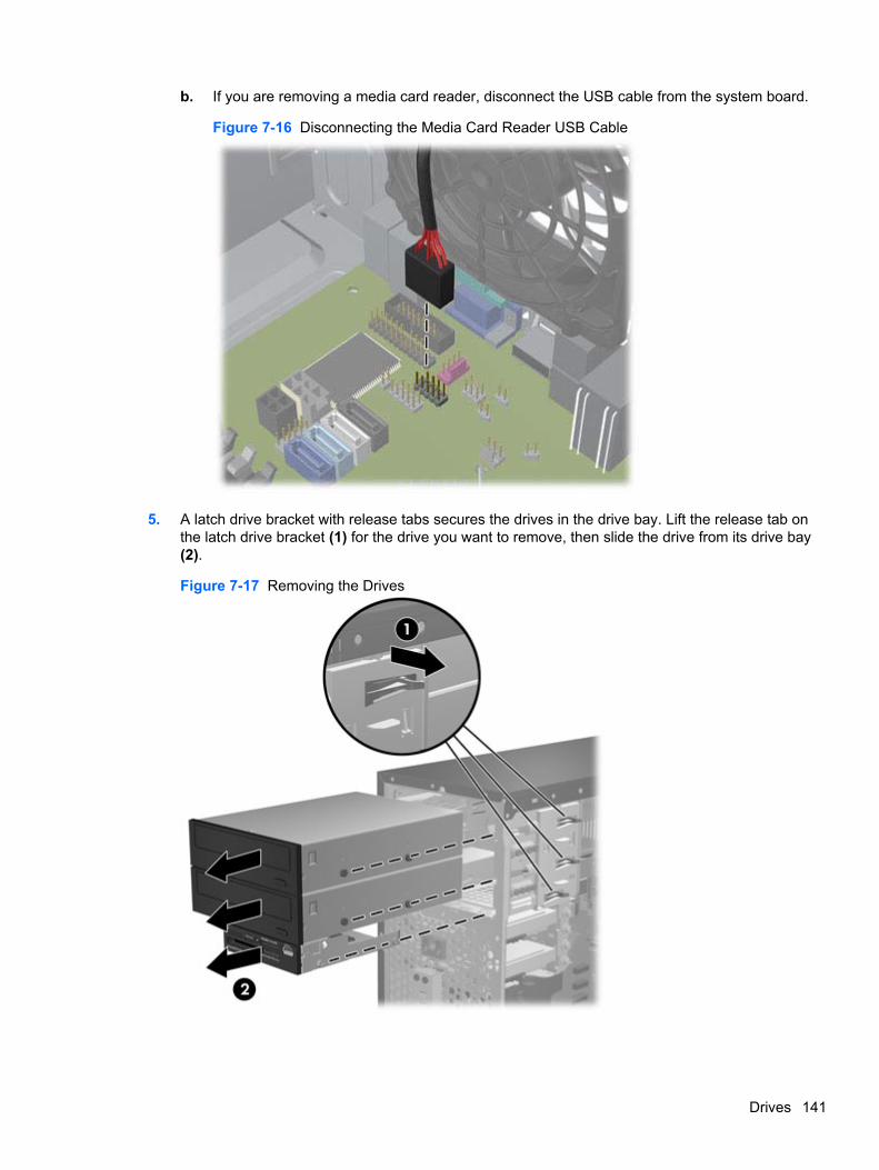
b. If you are removing a media card reader, disconnect the USB cable from the system board.
Figure 7-16 Disconnecting the Media Card Reader USB Cable
5. A latch drive bracket with release tabs secures the drives in the drive bay. Lift the release tab onthe latch drive bracket (1) for the drive you want to remove, then slide the drive from its drive bay(2).
Figure 7-17 Removing the Drives
Drives 141
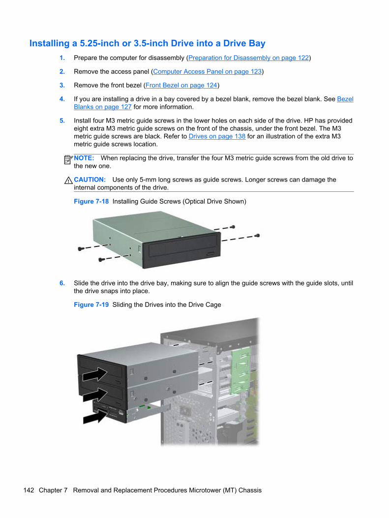
Installing a 5.25-inch or 3.5-inch Drive into a Drive Bay
1. Prepare the computer for disassembly (Preparation for Disassembly on page 122)
2. Remove the access panel (Computer Access Panel on page 123)
3. Remove the front bezel (Front Bezel on page 124)
4. If you are installing a drive in a bay covered by a bezel blank, remove the bezel blank. See BezelBlanks on page 127 for more information.
5. Install four M3 metric guide screws in the lower holes on each side of the drive. HP has providedeight extra M3 metric guide screws on the front of the chassis, under the front bezel. The M3metric guide screws are black. Refer to Drives on page 138 for an illustration of the extra M3metric guide screws location.
NOTE: When replacing the drive, transfer the four M3 metric guide screws from the old drive tothe new one.
CAUTION: Use only 5-mm long screws as guide screws. Longer screws can damage theinternal components of the drive.
Figure 7-18 Installing Guide Screws (Optical Drive Shown)
6. Slide the drive into the drive bay, making sure to align the guide screws with the guide slots, untilthe drive snaps into place.
Figure 7-19 Sliding the Drives into the Drive Cage
142 Chapter 7 Removal and Replacement Procedures Microtower (MT) Chassis
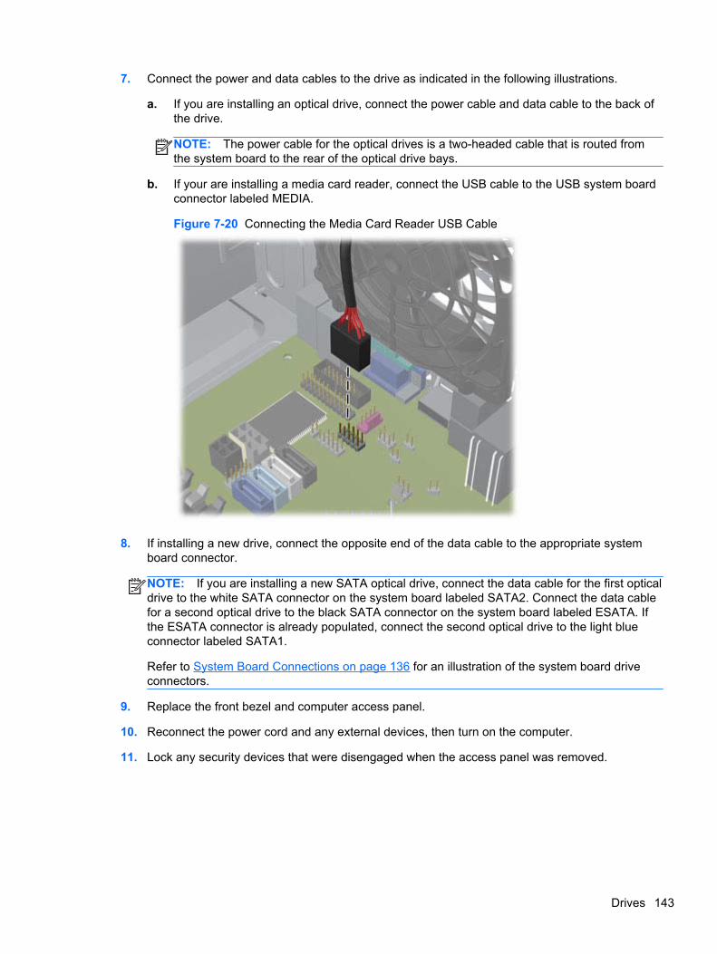
7. Connect the power and data cables to the drive as indicated in the following illustrations.
a. If you are installing an optical drive, connect the power cable and data cable to the back ofthe drive.
NOTE: The power cable for the optical drives is a two-headed cable that is routed fromthe system board to the rear of the optical drive bays.
b. If your are installing a media card reader, connect the USB cable to the USB system boardconnector labeled MEDIA.
Figure 7-20 Connecting the Media Card Reader USB Cable
8. If installing a new drive, connect the opposite end of the data cable to the appropriate systemboard connector.
NOTE: If you are installing a new SATA optical drive, connect the data cable for the first opticaldrive to the white SATA connector on the system board labeled SATA2. Connect the data cablefor a second optical drive to the black SATA connector on the system board labeled ESATA. Ifthe ESATA connector is already populated, connect the second optical drive to the light blueconnector labeled SATA1.
Refer to System Board Connections on page 136 for an illustration of the system board driveconnectors.
9. Replace the front bezel and computer access panel.
10. Reconnect the power cord and any external devices, then turn on the computer.
11. Lock any security devices that were disengaged when the access panel was removed.
Drives 143
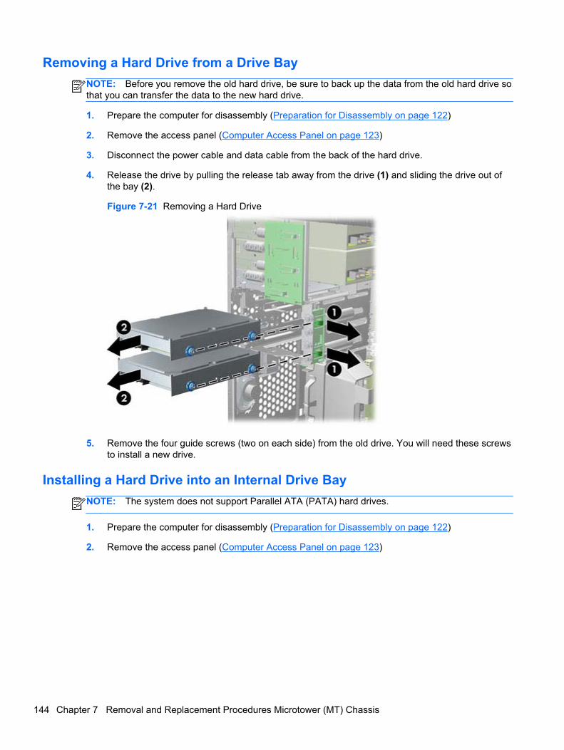
Removing a Hard Drive from a Drive Bay
NOTE: Before you remove the old hard drive, be sure to back up the data from the old hard drive sothat you can transfer the data to the new hard drive.
1. Prepare the computer for disassembly (Preparation for Disassembly on page 122)
2. Remove the access panel (Computer Access Panel on page 123)
3. Disconnect the power cable and data cable from the back of the hard drive.
4. Release the drive by pulling the release tab away from the drive (1) and sliding the drive out ofthe bay (2).
Figure 7-21 Removing a Hard Drive
5. Remove the four guide screws (two on each side) from the old drive. You will need these screwsto install a new drive.
Installing a Hard Drive into an Internal Drive Bay
NOTE: The system does not support Parallel ATA (PATA) hard drives.
1. Prepare the computer for disassembly (Preparation for Disassembly on page 122)
2. Remove the access panel (Computer Access Panel on page 123)
144 Chapter 7 Removal and Replacement Procedures Microtower (MT) Chassis
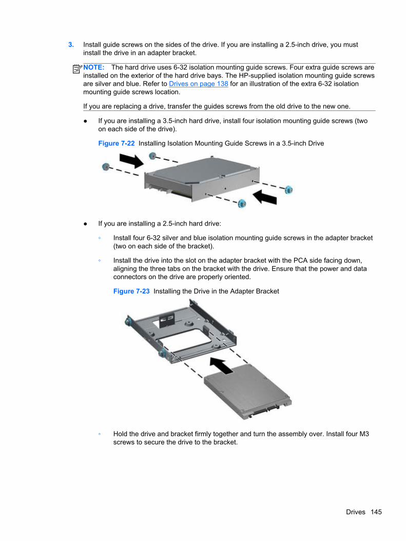
3. Install guide screws on the sides of the drive. If you are installing a 2.5-inch drive, you mustinstall the drive in an adapter bracket.
NOTE: The hard drive uses 6-32 isolation mounting guide screws. Four extra guide screws areinstalled on the exterior of the hard drive bays. The HP-supplied isolation mounting guide screwsare silver and blue. Refer to Drives on page 138 for an illustration of the extra 6-32 isolationmounting guide screws location.
If you are replacing a drive, transfer the guides screws from the old drive to the new one.
● If you are installing a 3.5-inch hard drive, install four isolation mounting guide screws (twoon each side of the drive).
Figure 7-22 Installing Isolation Mounting Guide Screws in a 3.5-inch Drive
● If you are installing a 2.5-inch hard drive:
◦ Install four 6-32 silver and blue isolation mounting guide screws in the adapter bracket(two on each side of the bracket).
◦ Install the drive into the slot on the adapter bracket with the PCA side facing down,aligning the three tabs on the bracket with the drive. Ensure that the power and dataconnectors on the drive are properly oriented.
Figure 7-23 Installing the Drive in the Adapter Bracket
◦ Hold the drive and bracket firmly together and turn the assembly over. Install four M3screws to secure the drive to the bracket.
Drives 145
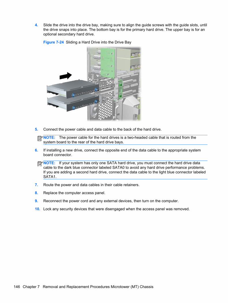
4. Slide the drive into the drive bay, making sure to align the guide screws with the guide slots, untilthe drive snaps into place. The bottom bay is for the primary hard drive. The upper bay is for anoptional secondary hard drive.
Figure 7-24 Sliding a Hard Drive into the Drive Bay
5. Connect the power cable and data cable to the back of the hard drive.
NOTE: The power cable for the hard drives is a two-headed cable that is routed from thesystem board to the rear of the hard drive bays.
6. If installing a new drive, connect the opposite end of the data cable to the appropriate systemboard connector.
NOTE: If your system has only one SATA hard drive, you must connect the hard drive datacable to the dark blue connector labeled SATA0 to avoid any hard drive performance problems.If you are adding a second hard drive, connect the data cable to the light blue connector labeledSATA1.
7. Route the power and data cables in their cable retainers.
8. Replace the computer access panel.
9. Reconnect the power cord and any external devices, then turn on the computer.
10. Lock any security devices that were disengaged when the access panel was removed.
146 Chapter 7 Removal and Replacement Procedures Microtower (MT) Chassis

Front Fan Assembly
Description Spare part number
Front fan assembly 585884-001
1. Prepare the computer for disassembly (Preparation for Disassembly on page 75).
2. Remove the access panel (Computer Access Panel on page 123).
3. Remove the cables from the clip on the top of the fan assembly.
Figure 7-25 Removing the cables from atop the front fan assembly
4. Unplug the fan cable from the system board connector labeled CHFAN.
Front Fan Assembly 147
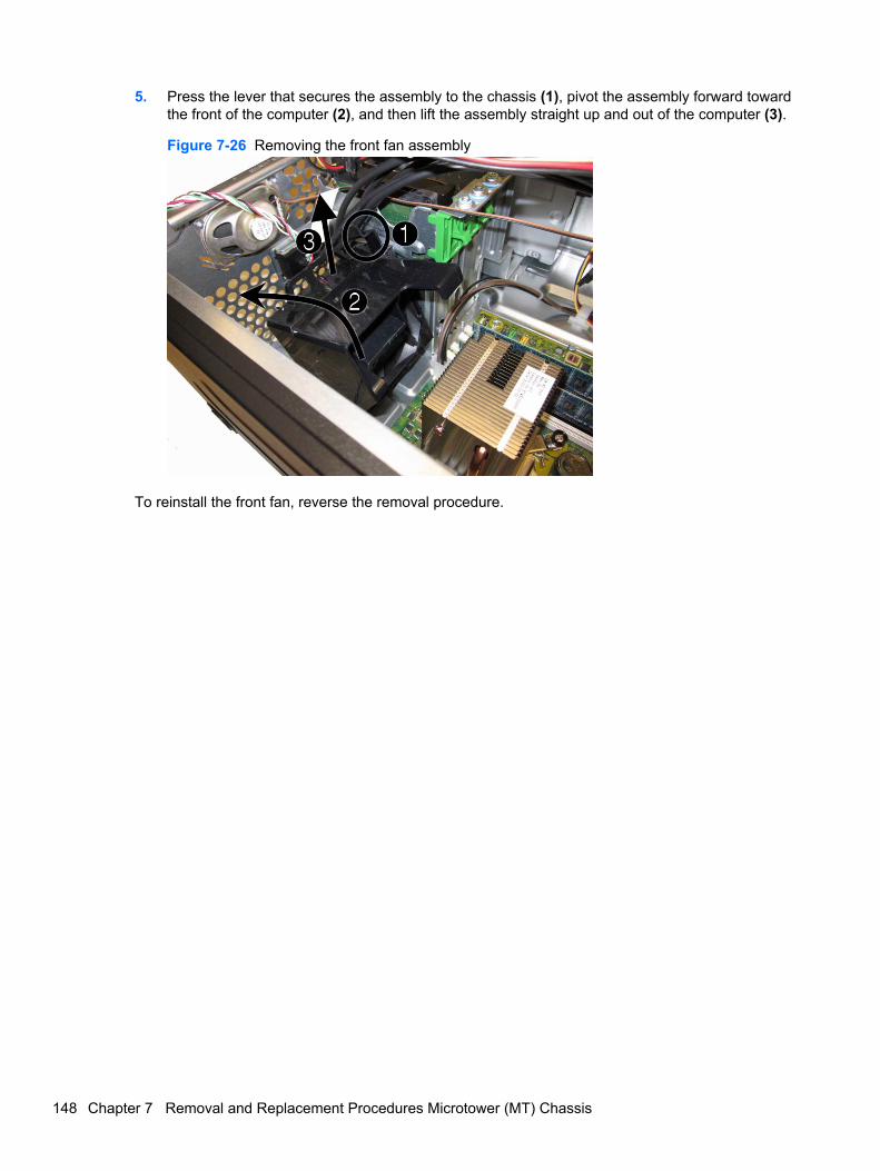
5. Press the lever that secures the assembly to the chassis (1), pivot the assembly forward towardthe front of the computer (2), and then lift the assembly straight up and out of the computer (3).
Figure 7-26 Removing the front fan assembly
To reinstall the front fan, reverse the removal procedure.
148 Chapter 7 Removal and Replacement Procedures Microtower (MT) Chassis
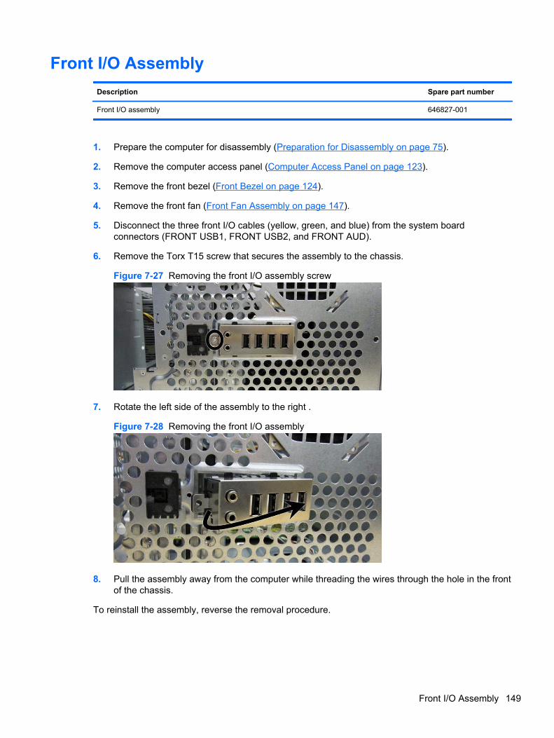
Front I/O Assembly
Description Spare part number
Front I/O assembly 646827-001
1. Prepare the computer for disassembly (Preparation for Disassembly on page 75).
2. Remove the computer access panel (Computer Access Panel on page 123).
3. Remove the front bezel (Front Bezel on page 124).
4. Remove the front fan (Front Fan Assembly on page 147).
5. Disconnect the three front I/O cables (yellow, green, and blue) from the system boardconnectors (FRONT USB1, FRONT USB2, and FRONT AUD).
6. Remove the Torx T15 screw that secures the assembly to the chassis.
Figure 7-27 Removing the front I/O assembly screw
7. Rotate the left side of the assembly to the right .
Figure 7-28 Removing the front I/O assembly
8. Pull the assembly away from the computer while threading the wires through the hole in the frontof the chassis.
To reinstall the assembly, reverse the removal procedure.
Front I/O Assembly 149
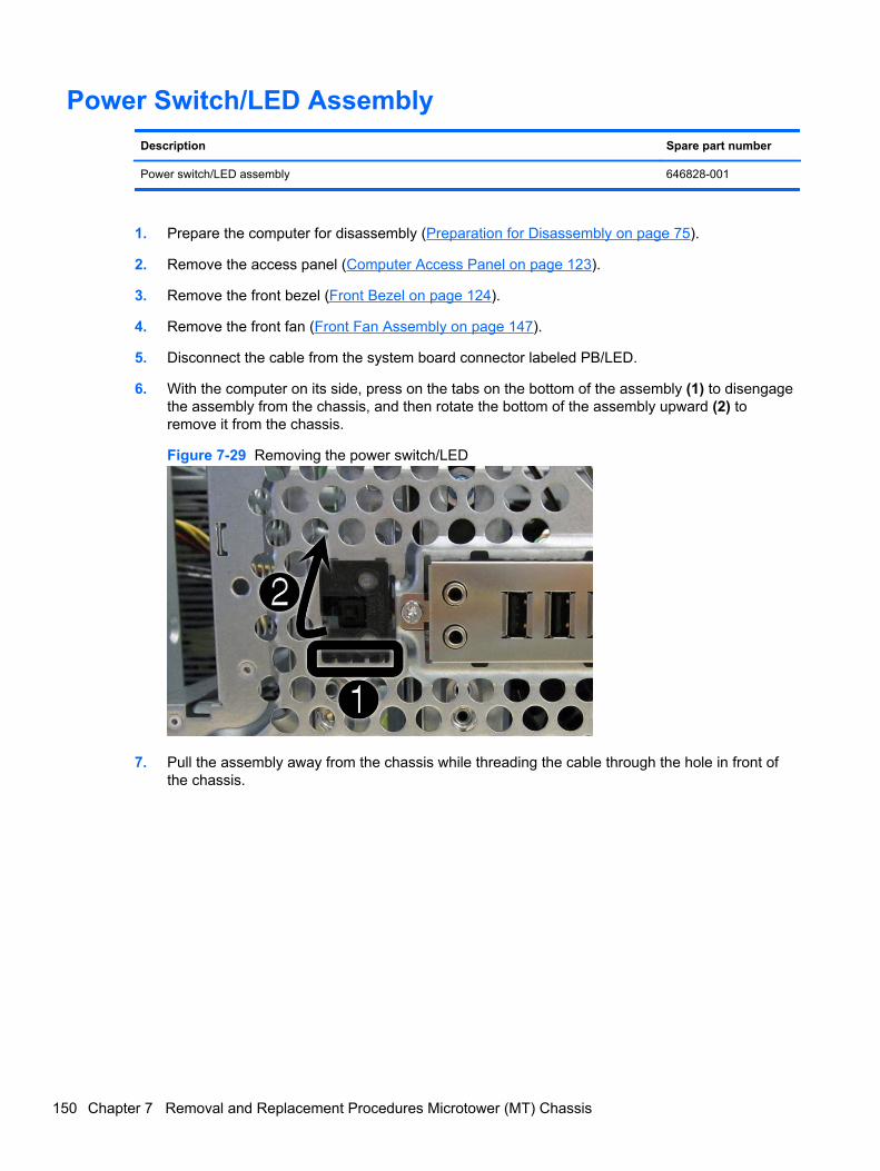
Power Switch/LED Assembly
Description Spare part number
Power switch/LED assembly 646828-001
1. Prepare the computer for disassembly (Preparation for Disassembly on page 75).
2. Remove the access panel (Computer Access Panel on page 123).
3. Remove the front bezel (Front Bezel on page 124).
4. Remove the front fan (Front Fan Assembly on page 147).
5. Disconnect the cable from the system board connector labeled PB/LED.
6. With the computer on its side, press on the tabs on the bottom of the assembly (1) to disengagethe assembly from the chassis, and then rotate the bottom of the assembly upward (2) toremove it from the chassis.
Figure 7-29 Removing the power switch/LED
7. Pull the assembly away from the chassis while threading the cable through the hole in front ofthe chassis.
150 Chapter 7 Removal and Replacement Procedures Microtower (MT) Chassis
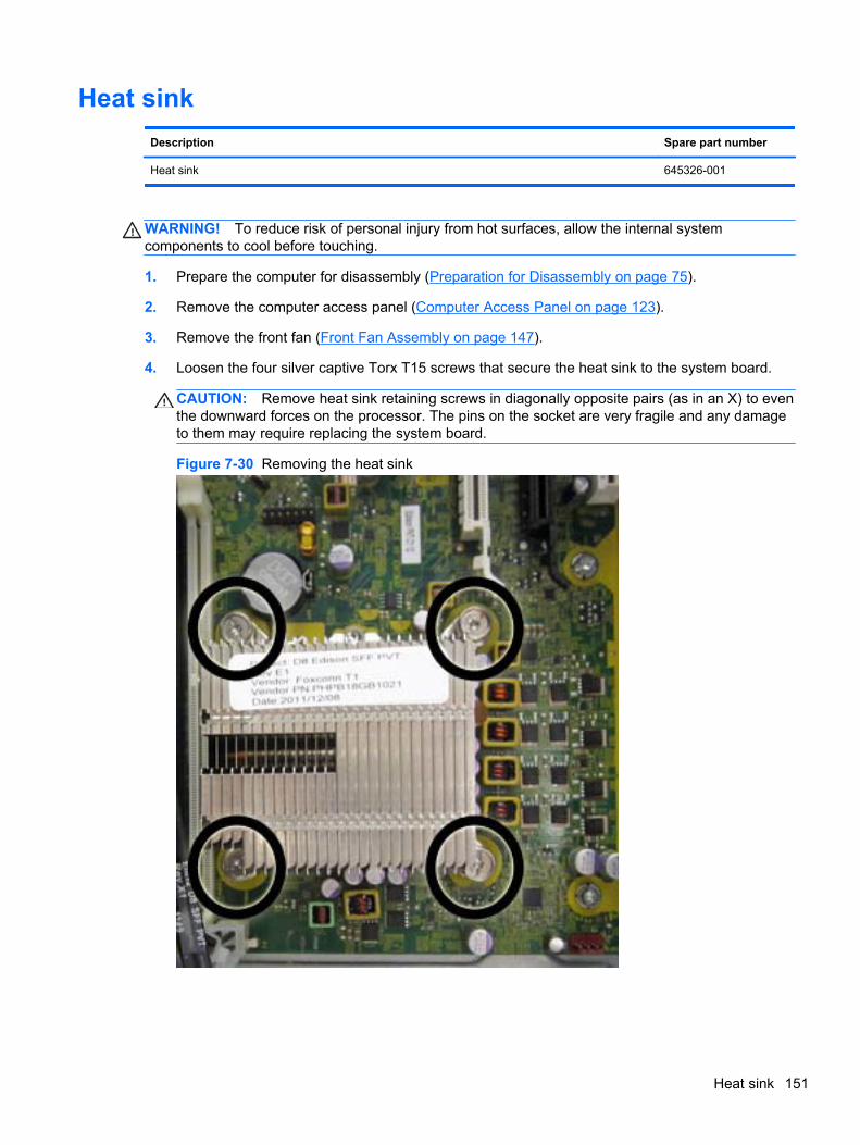
Heat sink
Description Spare part number
Heat sink 645326-001
WARNING! To reduce risk of personal injury from hot surfaces, allow the internal systemcomponents to cool before touching.
1. Prepare the computer for disassembly (Preparation for Disassembly on page 75).
2. Remove the computer access panel (Computer Access Panel on page 123).
3. Remove the front fan (Front Fan Assembly on page 147).
4. Loosen the four silver captive Torx T15 screws that secure the heat sink to the system board.
CAUTION: Remove heat sink retaining screws in diagonally opposite pairs (as in an X) to eventhe downward forces on the processor. The pins on the socket are very fragile and any damageto them may require replacing the system board.
Figure 7-30 Removing the heat sink
Heat sink 151
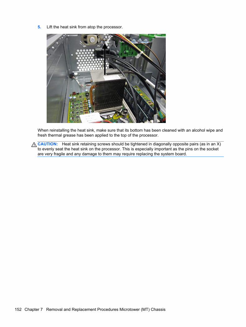
5. Lift the heat sink from atop the processor.
When reinstalling the heat sink, make sure that its bottom has been cleaned with an alcohol wipe andfresh thermal grease has been applied to the top of the processor.
CAUTION: Heat sink retaining screws should be tightened in diagonally opposite pairs (as in an X)to evenly seat the heat sink on the processor. This is especially important as the pins on the socketare very fragile and any damage to them may require replacing the system board.
152 Chapter 7 Removal and Replacement Procedures Microtower (MT) Chassis
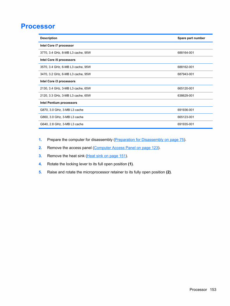
Processor
Description Spare part number
Intel Core i7 processor
3770, 3.4 GHz, 8-MB L3 cache, 95W 688164-001
Intel Core i5 processors
3570, 3.4 GHz, 6-MB L3 cache, 95W 688162-001
3470, 3.2 GHz, 6-MB L3 cache, 95W 687943-001
Intel Core i3 processors
2130, 3.4 GHz, 3-MB L3 cache, 65W 665120-001
2120, 3.3 GHz, 3-MB L3 cache, 65W 638629-001
Intel Pentium processors
G870, 3.0 GHz, 3-MB L3 cache 691936-001
G860, 3.0 GHz, 3-MB L3 cache 665123-001
G640, 2.8 GHz, 3-MB L3 cache 691935-001
1. Prepare the computer for disassembly (Preparation for Disassembly on page 75).
2. Remove the access panel (Computer Access Panel on page 123).
3. Remove the heat sink (Heat sink on page 151).
4. Rotate the locking lever to its full open position (1).
5. Raise and rotate the microprocessor retainer to its fully open position (2).
Processor 153
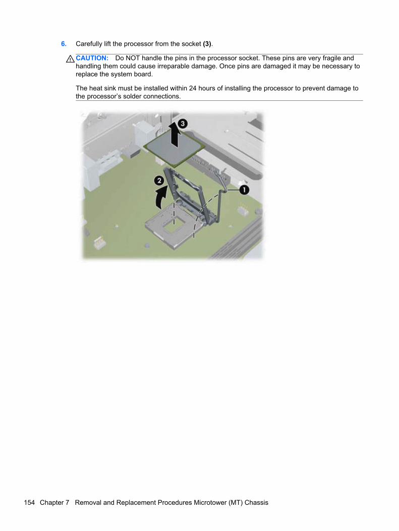
6. Carefully lift the processor from the socket (3).
CAUTION: Do NOT handle the pins in the processor socket. These pins are very fragile andhandling them could cause irreparable damage. Once pins are damaged it may be necessary toreplace the system board.
The heat sink must be installed within 24 hours of installing the processor to prevent damage tothe processor’s solder connections.
154 Chapter 7 Removal and Replacement Procedures Microtower (MT) Chassis
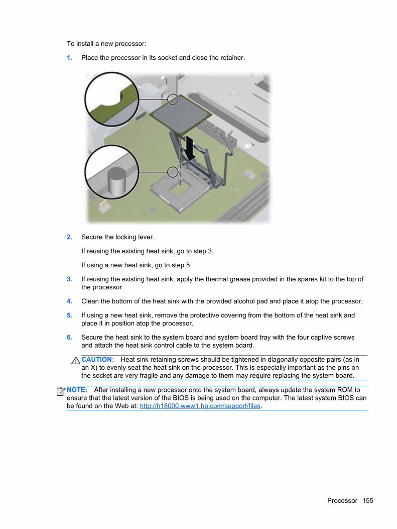
To install a new processor:
1. Place the processor in its socket and close the retainer.
2. Secure the locking lever.
If reusing the existing heat sink, go to step 3.
If using a new heat sink, go to step 5.
3. If reusing the existing heat sink, apply the thermal grease provided in the spares kit to the top ofthe processor.
4. Clean the bottom of the heat sink with the provided alcohol pad and place it atop the processor.
5. If using a new heat sink, remove the protective covering from the bottom of the heat sink andplace it in position atop the processor.
6. Secure the heat sink to the system board and system board tray with the four captive screwsand attach the heat sink control cable to the system board.
CAUTION: Heat sink retaining screws should be tightened in diagonally opposite pairs (as inan X) to evenly seat the heat sink on the processor. This is especially important as the pins onthe socket are very fragile and any damage to them may require replacing the system board.
NOTE: After installing a new processor onto the system board, always update the system ROM toensure that the latest version of the BIOS is being used on the computer. The latest system BIOS canbe found on the Web at: http://h18000.www1.hp.com/support/files.
Processor 155
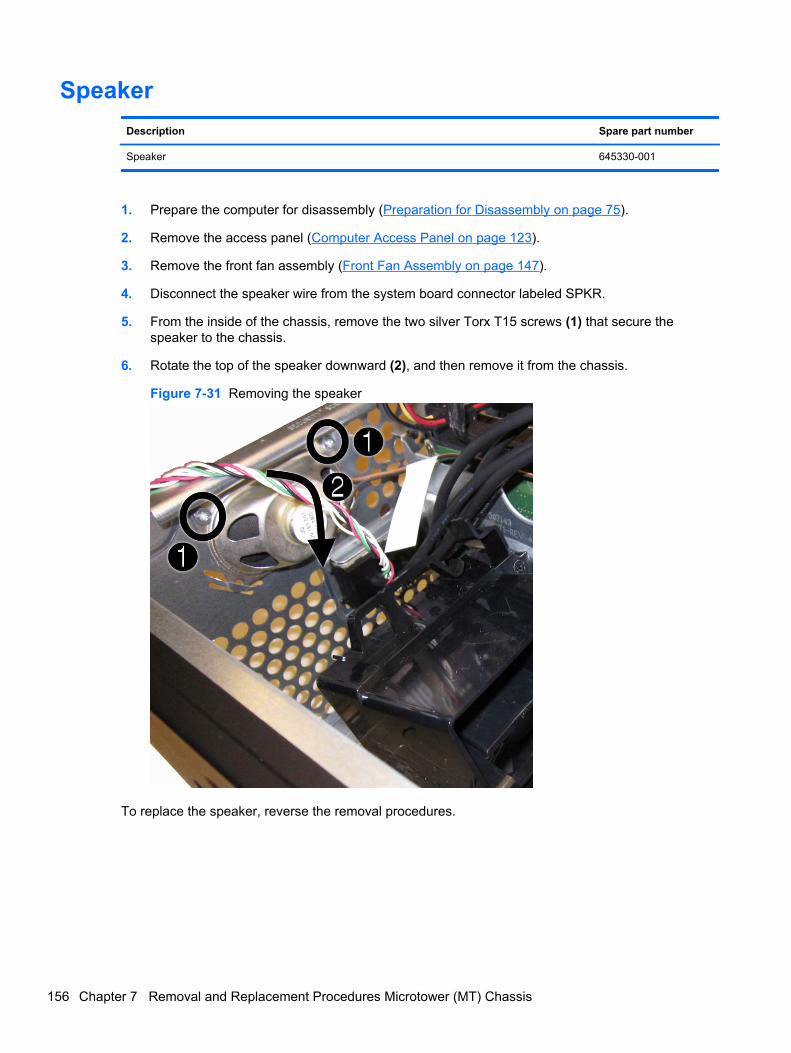
Speaker
Description Spare part number
Speaker 645330-001
1. Prepare the computer for disassembly (Preparation for Disassembly on page 75).
2. Remove the access panel (Computer Access Panel on page 123).
3. Remove the front fan assembly (Front Fan Assembly on page 147).
4. Disconnect the speaker wire from the system board connector labeled SPKR.
5. From the inside of the chassis, remove the two silver Torx T15 screws (1) that secure thespeaker to the chassis.
6. Rotate the top of the speaker downward (2), and then remove it from the chassis.
Figure 7-31 Removing the speaker
To replace the speaker, reverse the removal procedures.
156 Chapter 7 Removal and Replacement Procedures Microtower (MT) Chassis
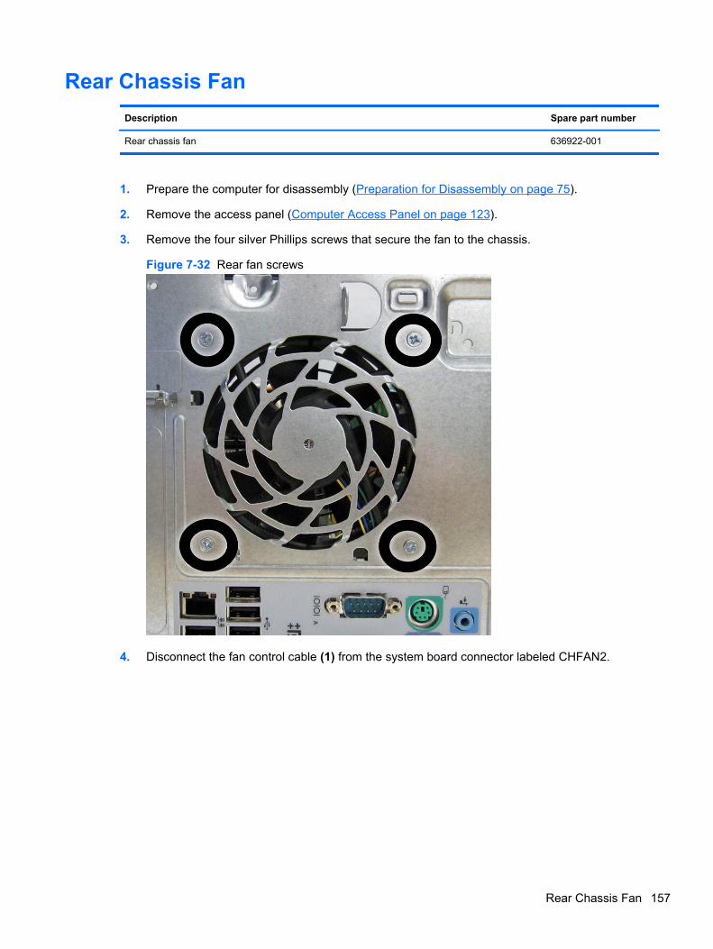
Rear Chassis Fan
Description Spare part number
Rear chassis fan 636922-001
1. Prepare the computer for disassembly (Preparation for Disassembly on page 75).
2. Remove the access panel (Computer Access Panel on page 123).
3. Remove the four silver Phillips screws that secure the fan to the chassis.
Figure 7-32 Rear fan screws
4. Disconnect the fan control cable (1) from the system board connector labeled CHFAN2.
Rear Chassis Fan 157
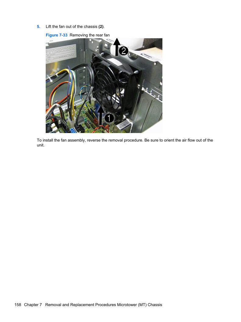
5. Lift the fan out of the chassis (2).
Figure 7-33 Removing the rear fan
To install the fan assembly, reverse the removal procedure. Be sure to orient the air flow out of theunit.
158 Chapter 7 Removal and Replacement Procedures Microtower (MT) Chassis
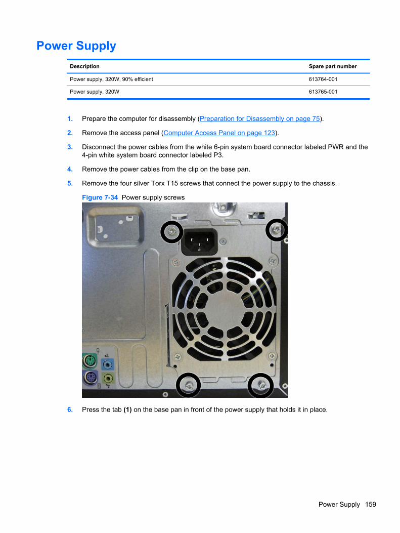
Power Supply
Description Spare part number
Power supply, 320W, 90% efficient 613764-001
Power supply, 320W 613765-001
1. Prepare the computer for disassembly (Preparation for Disassembly on page 75).
2. Remove the access panel (Computer Access Panel on page 123).
3. Disconnect the power cables from the white 6-pin system board connector labeled PWR and the4-pin white system board connector labeled P3.
4. Remove the power cables from the clip on the base pan.
5. Remove the four silver Torx T15 screws that connect the power supply to the chassis.
Figure 7-34 Power supply screws
6. Press the tab (1) on the base pan in front of the power supply that holds it in place.
Power Supply 159
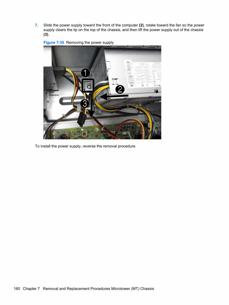
7. Slide the power supply toward the front of the computer (2), rotate toward the fan so the powersupply clears the lip on the top of the chassis, and then lift the power supply out of the chassis(3).
Figure 7-35 Removing the power supply
To install the power supply, reverse the removal procedure.
160 Chapter 7 Removal and Replacement Procedures Microtower (MT) Chassis
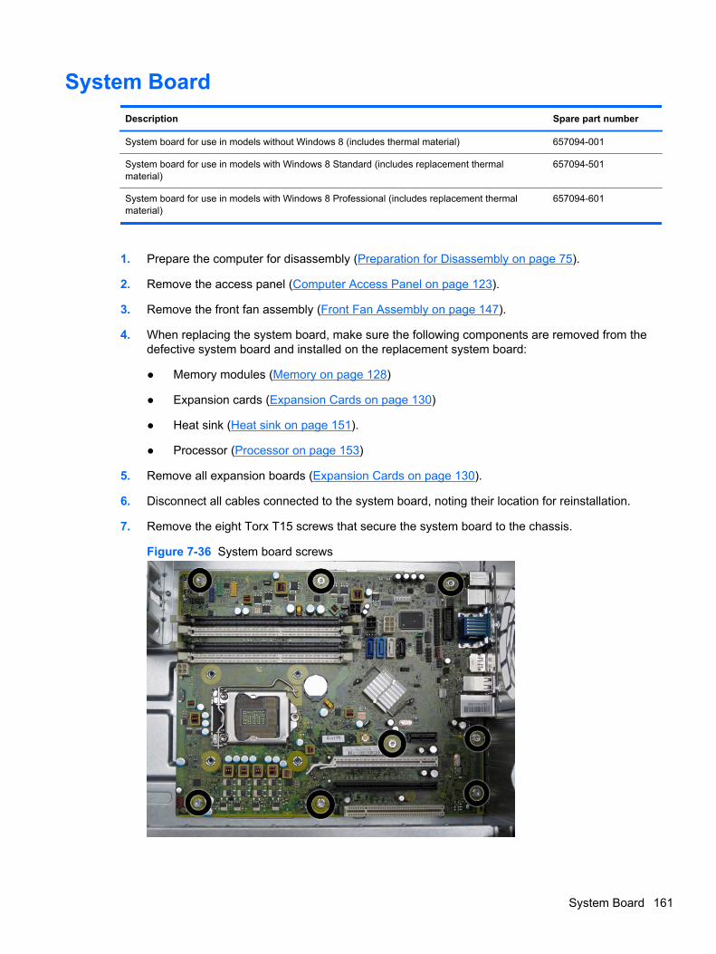
System Board
Description Spare part number
System board for use in models without Windows 8 (includes thermal material) 657094-001
System board for use in models with Windows 8 Standard (includes replacement thermalmaterial)
657094-501
System board for use in models with Windows 8 Professional (includes replacement thermalmaterial)
657094-601
1. Prepare the computer for disassembly (Preparation for Disassembly on page 75).
2. Remove the access panel (Computer Access Panel on page 123).
3. Remove the front fan assembly (Front Fan Assembly on page 147).
4. When replacing the system board, make sure the following components are removed from thedefective system board and installed on the replacement system board:
● Memory modules (Memory on page 128)
● Expansion cards (Expansion Cards on page 130)
● Heat sink (Heat sink on page 151).
● Processor (Processor on page 153)
5. Remove all expansion boards (Expansion Cards on page 130).
6. Disconnect all cables connected to the system board, noting their location for reinstallation.
7. Remove the eight Torx T15 screws that secure the system board to the chassis.
Figure 7-36 System board screws
System Board 161
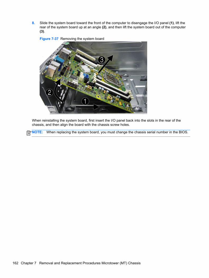
8. Slide the system board toward the front of the computer to disengage the I/O panel (1), lift therear of the system board up at an angle (2), and then lift the system board out of the computer(3).
Figure 7-37 Removing the system board
When reinstalling the system board, first insert the I/O panel back into the slots in the rear of thechassis, and then align the board with the chassis screw holes.
NOTE: When replacing the system board, you must change the chassis serial number in the BIOS.
162 Chapter 7 Removal and Replacement Procedures Microtower (MT) Chassis
8 Removal and Replacement ProceduresSmall Form Factor (SFF) Chassis
Adherence to the procedures and precautions described in this chapter is essential for proper service.After completing all necessary removal and replacement procedures, run the Diagnostics utility toverify that all components operate properly.
NOTE: Not all features listed in this guide are available on all computers.
Preparation for DisassemblySee Routine Care, SATA Drive Guidelines, and Disassembly Preparation on page 66 for initial safetyprocedures.
1. Remove/disengage any security devices that prohibit opening the computer.
2. Close any open software applications.
3. Exit the operating system.
4. Remove any compact disc or media card from the computer.
5. Turn off the computer and any peripheral devices that are connected to it.
CAUTION: Turn off the computer before disconnecting any cables.
Regardless of the power-on state, voltage is always present on the system board as long as thesystem is plugged into an active AC outlet. In some systems the cooling fan is on even when thecomputer is in the “Standby,” or “Suspend” modes. The power cord should always bedisconnected before servicing a unit.
6. Disconnect the power cord from the electrical outlet and then from the computer.
7. Disconnect all peripheral device cables from the computer.
NOTE: During disassembly, label each cable as you remove it, noting its position and routing.Keep all screws with the units removed.
CAUTION: The screws used in the computer are of different thread sizes and lengths; usingthe wrong screw in an application may damage the unit.
Preparation for Disassembly 163
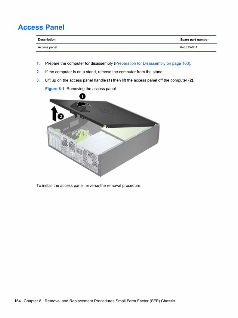
Access Panel
Description Spare part number
Access panel 646815-001
1. Prepare the computer for disassembly (Preparation for Disassembly on page 163).
2. If the computer is on a stand, remove the computer from the stand.
3. Lift up on the access panel handle (1) then lift the access panel off the computer (2).
Figure 8-1 Removing the access panel
To install the access panel, reverse the removal procedure.
164 Chapter 8 Removal and Replacement Procedures Small Form Factor (SFF) Chassis
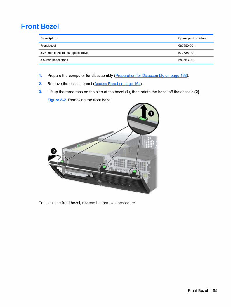
Front Bezel
Description Spare part number
Front bezel 687950-001
5.25-inch bezel blank, optical drive 570838-001
3.5-inch bezel blank 583653-001
1. Prepare the computer for disassembly (Preparation for Disassembly on page 163).
2. Remove the access panel (Access Panel on page 164).
3. Lift up the three tabs on the side of the bezel (1), then rotate the bezel off the chassis (2).
Figure 8-2 Removing the front bezel
To install the front bezel, reverse the removal procedure.
Front Bezel 165
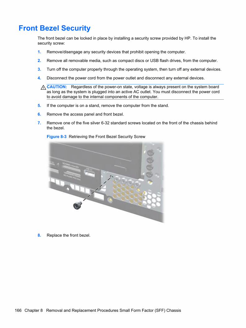
Front Bezel SecurityThe front bezel can be locked in place by installing a security screw provided by HP. To install thesecurity screw:
1. Remove/disengage any security devices that prohibit opening the computer.
2. Remove all removable media, such as compact discs or USB flash drives, from the computer.
3. Turn off the computer properly through the operating system, then turn off any external devices.
4. Disconnect the power cord from the power outlet and disconnect any external devices.
CAUTION: Regardless of the power-on state, voltage is always present on the system boardas long as the system is plugged into an active AC outlet. You must disconnect the power cordto avoid damage to the internal components of the computer.
5. If the computer is on a stand, remove the computer from the stand.
6. Remove the access panel and front bezel.
7. Remove one of the five silver 6-32 standard screws located on the front of the chassis behindthe bezel.
Figure 8-3 Retrieving the Front Bezel Security Screw
8. Replace the front bezel.
166 Chapter 8 Removal and Replacement Procedures Small Form Factor (SFF) Chassis
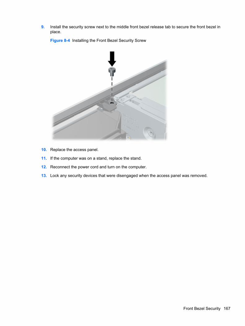
9. Install the security screw next to the middle front bezel release tab to secure the front bezel inplace.
Figure 8-4 Installing the Front Bezel Security Screw
10. Replace the access panel.
11. If the computer was on a stand, replace the stand.
12. Reconnect the power cord and turn on the computer.
13. Lock any security devices that were disengaged when the access panel was removed.
Front Bezel Security 167
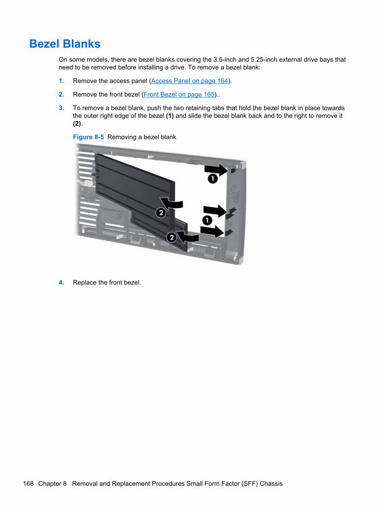
Bezel BlanksOn some models, there are bezel blanks covering the 3.5-inch and 5.25-inch external drive bays thatneed to be removed before installing a drive. To remove a bezel blank:
1. Remove the access panel (Access Panel on page 164).
2. Remove the front bezel (Front Bezel on page 165)..
3. To remove a bezel blank, push the two retaining tabs that hold the bezel blank in place towardsthe outer right edge of the bezel (1) and slide the bezel blank back and to the right to remove it(2).
Figure 8-5 Removing a bezel blank
4. Replace the front bezel.
168 Chapter 8 Removal and Replacement Procedures Small Form Factor (SFF) Chassis
Memory
Description Spare part number
8-GB, PC3-12800 689375-001
4-GB, PC3-12800 671613-001
2-GB, PC3-12800 671612-001
The computer comes with double data rate 3 synchronous dynamic random access memory (DDR3-SDRAM) dual inline memory modules (DIMMs).
DIMMs
The memory sockets on the system board can be populated with up to four industry-standard DIMMs.These memory sockets are populated with at least one preinstalled DIMM. To achieve the maximummemory support, you can populate the system board with up to 16-GB of memory configured in ahigh-performing dual channel mode.
DDR3-SDRAM DIMMs
CAUTION: This product DOES NOT support DDR3 Ultra Low Voltage (DDR3U) memory. Theprocessor is not compatible with DDR3U memory and if you plug DDR3U memory into the systemboard, it can cause the physical damage to the DIMM or invoke system malfunction.
For proper system operation, the DDR3-SDRAM DIMMs must be:
● industry-standard 240-pin
● unbuffered non-ECC PC3-12800 DDR3-1600 MHz-compliant
● 1.5 volt DDR3-SDRAM DIMMs
The DDR3-SDRAM DIMMs must also:
● support CAS latency 11 DDR3 1600 MHz (11-11-11 timing)
● contain the mandatory JEDEC SPD information
In addition, the computer supports:
● 512-Mbit, 1-Gbit, and 2-Gbit non-ECC memory technologies
● single-sided and double-sided DIMMs
● DIMMs constructed with x8 and x16 DDR devices; DIMMs constructed with x4 SDRAM are notsupported
NOTE: The system will not operate properly if you install unsupported DIMMs.
Populating DIMM Sockets
There are four DIMM sockets on the system board, with two sockets per channel. The sockets arelabeled DIMM1, DIMM2, DIMM3, and DIMM4. Sockets DIMM1 and DIMM2 operate in memorychannel B. Sockets DIMM3 and DIMM4 operate in memory channel A.
Memory 169
The system will automatically operate in single channel mode, dual channel mode, or flex mode,depending on how the DIMMs are installed.
● The system will operate in single channel mode if the DIMM sockets are populated in onechannel only.
● The system will operate in a higher-performing dual channel mode if the total memory capacityof the DIMMs in Channel A is equal to the total memory capacity of the DIMMs in Channel B.The technology and device width can vary between the channels. For example, if Channel A ispopulated with two 1-GB DIMMs and Channel B is populated with one 2-GB DIMM, the systemwill operate in dual channel mode.
● The system will operate in flex mode if the total memory capacity of the DIMMs in Channel A isnot equal to the total memory capacity of the DIMMs in Channel B. In flex mode, the channelpopulated with the least amount of memory describes the total amount of memory assigned todual channel and the remainder is assigned to single channel. For optimal speed, the channelsshould be balanced so that the largest amount of memory is spread between the two channels.If one channel will have more memory than the other, the larger amount should be assigned toChannel A. For example, if you are populating the sockets with one 2-GB DIMM, and three 1-GBDIMMs, Channel A should be populated with the 2-GB DIMM and one 1-GB DIMM, and ChannelB should be populated with the other two 1-GB DIMMs. With this configuration, 4-GB will run asdual channel and 1-GB will run as single channel.
● In any mode, the maximum operational speed is determined by the slowest DIMM in the system.
Installing DIMMs
CAUTION: You must disconnect the power cord and wait approximately 30 seconds for the powerto drain before adding or removing memory modules. Regardless of the power-on state, voltage isalways supplied to the memory modules as long as the computer is plugged into an active AC outlet.Adding or removing memory modules while voltage is present may cause irreparable damage to thememory modules or system board.
The memory module sockets have gold-plated metal contacts. When upgrading the memory, it isimportant to use memory modules with gold-plated metal contacts to prevent corrosion and/oroxidation resulting from having incompatible metals in contact with each other.
Static electricity can damage the electronic components of the computer or optional cards. Beforebeginning these procedures, ensure that you are discharged of static electricity by briefly touching agrounded metal object. For more information, refer to Electrostatic Discharge Information on page 66.
When handling a memory module, be careful not to touch any of the contacts. Doing so may damagethe module.
1. Prepare the computer for disassembly (Preparation for Disassembly on page 163).
2. Remove the access panel (Access Panel on page 164).
3. Rotate up the internal drive bay housing to access the memory module sockets on the systemboard.
170 Chapter 8 Removal and Replacement Procedures Small Form Factor (SFF) Chassis
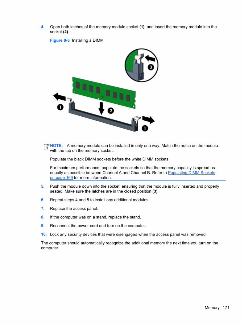
4. Open both latches of the memory module socket (1), and insert the memory module into thesocket (2).
Figure 8-6 Installing a DIMM
NOTE: A memory module can be installed in only one way. Match the notch on the modulewith the tab on the memory socket.
Populate the black DIMM sockets before the white DIMM sockets.
For maximum performance, populate the sockets so that the memory capacity is spread asequally as possible between Channel A and Channel B. Refer to Populating DIMM Socketson page 169 for more information.
5. Push the module down into the socket, ensuring that the module is fully inserted and properlyseated. Make sure the latches are in the closed position (3).
6. Repeat steps 4 and 5 to install any additional modules.
7. Replace the access panel.
8. If the computer was on a stand, replace the stand.
9. Reconnect the power cord and turn on the computer.
10. Lock any security devices that were disengaged when the access panel was removed.
The computer should automatically recognize the additional memory the next time you turn on thecomputer.
Memory 171
Expansion Card
Description Spare part number
nVidia Quadro NVS310 PCIe x16 graphics card, 512 MB 680653-001
nVidia Quadro NVS300 PCIe x16 graphics card, 512 MB 632486-001
AMD Radeon HD7450 PCIe x16 graphics card, 1 GB 682411-001
AMD Radeon HD6350 PCIe x16 graphics card, 512 MB 637995-001
AMD FirePro 2270 PCIe x16 graphics card, 512 MB 637213-001
Intel PRO/1000CT2 NIC, includes bracket 635523-001
HP FireWire / IEEE 1394a PCIe x1 Card 637591-001
The computer has one PCI expansion slot, one PCI Express x1 expansion slot, one PCI Express x16expansion slot, and one PCI Express x16 expansion slot that is downshifted to a x4 slot.
NOTE: The PCI and PCI Express slots support only low profile cards.
You can install a PCI Express x1, x4, x8, or x16 expansion card in the PCI Express x16 slot.
For dual graphics card configurations, the first (primary) card must be installed in the PCI Expressx16 slot that is NOT downshifted to a x4 slot (8300 models).
To remove, replace, or add an expansion card:
1. Prepare the computer for disassembly (Preparation for Disassembly on page 163).
2. Remove the access panel (Access Panel on page 164).
3. Locate the correct vacant expansion socket on the system board and the correspondingexpansion slot on the back of the computer chassis.
172 Chapter 8 Removal and Replacement Procedures Small Form Factor (SFF) Chassis
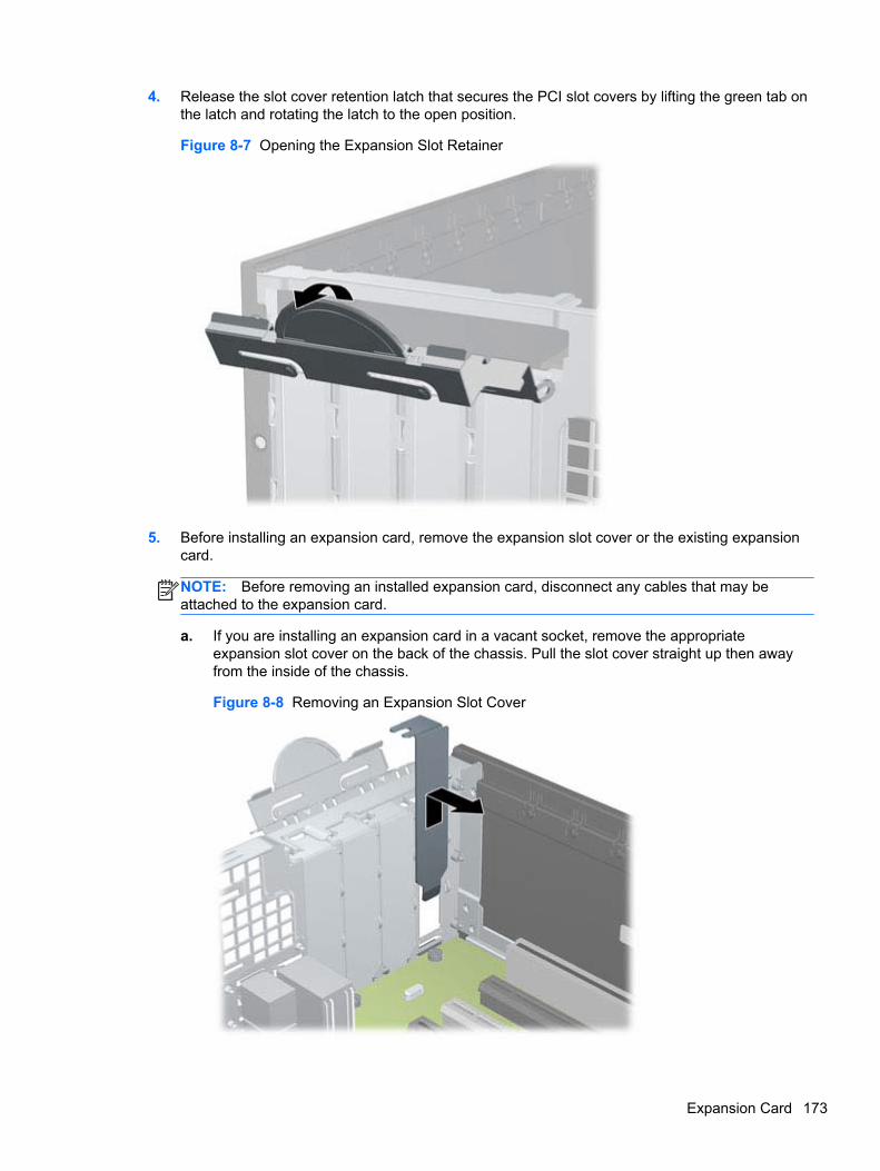
4. Release the slot cover retention latch that secures the PCI slot covers by lifting the green tab onthe latch and rotating the latch to the open position.
Figure 8-7 Opening the Expansion Slot Retainer
5. Before installing an expansion card, remove the expansion slot cover or the existing expansioncard.
NOTE: Before removing an installed expansion card, disconnect any cables that may beattached to the expansion card.
a. If you are installing an expansion card in a vacant socket, remove the appropriateexpansion slot cover on the back of the chassis. Pull the slot cover straight up then awayfrom the inside of the chassis.
Figure 8-8 Removing an Expansion Slot Cover
Expansion Card 173
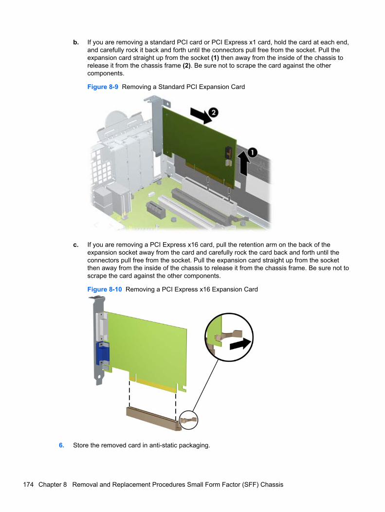
b. If you are removing a standard PCI card or PCI Express x1 card, hold the card at each end,and carefully rock it back and forth until the connectors pull free from the socket. Pull theexpansion card straight up from the socket (1) then away from the inside of the chassis torelease it from the chassis frame (2). Be sure not to scrape the card against the othercomponents.
Figure 8-9 Removing a Standard PCI Expansion Card
c. If you are removing a PCI Express x16 card, pull the retention arm on the back of theexpansion socket away from the card and carefully rock the card back and forth until theconnectors pull free from the socket. Pull the expansion card straight up from the socketthen away from the inside of the chassis to release it from the chassis frame. Be sure not toscrape the card against the other components.
Figure 8-10 Removing a PCI Express x16 Expansion Card
6. Store the removed card in anti-static packaging.
174 Chapter 8 Removal and Replacement Procedures Small Form Factor (SFF) Chassis
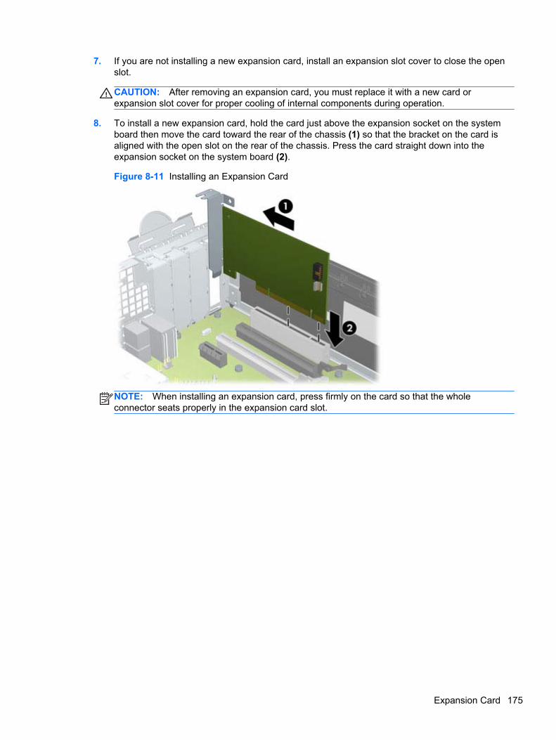
7. If you are not installing a new expansion card, install an expansion slot cover to close the openslot.
CAUTION: After removing an expansion card, you must replace it with a new card orexpansion slot cover for proper cooling of internal components during operation.
8. To install a new expansion card, hold the card just above the expansion socket on the systemboard then move the card toward the rear of the chassis (1) so that the bracket on the card isaligned with the open slot on the rear of the chassis. Press the card straight down into theexpansion socket on the system board (2).
Figure 8-11 Installing an Expansion Card
NOTE: When installing an expansion card, press firmly on the card so that the wholeconnector seats properly in the expansion card slot.
Expansion Card 175
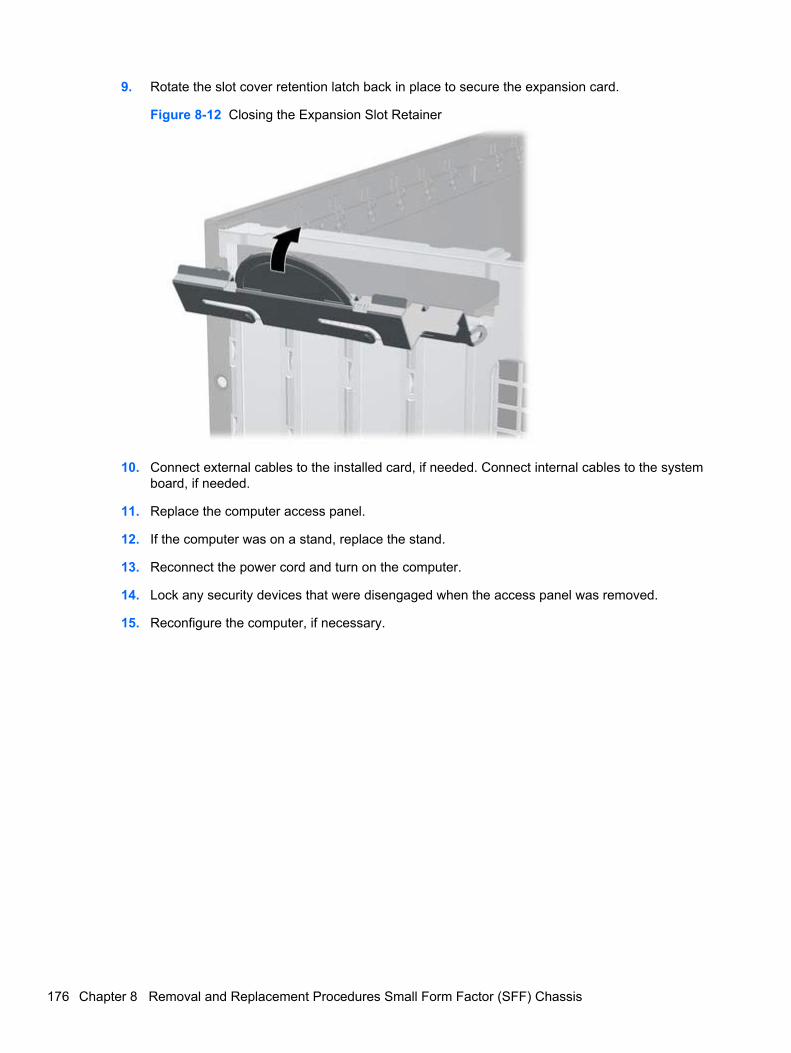
9. Rotate the slot cover retention latch back in place to secure the expansion card.
Figure 8-12 Closing the Expansion Slot Retainer
10. Connect external cables to the installed card, if needed. Connect internal cables to the systemboard, if needed.
11. Replace the computer access panel.
12. If the computer was on a stand, replace the stand.
13. Reconnect the power cord and turn on the computer.
14. Lock any security devices that were disengaged when the access panel was removed.
15. Reconfigure the computer, if necessary.
176 Chapter 8 Removal and Replacement Procedures Small Form Factor (SFF) Chassis
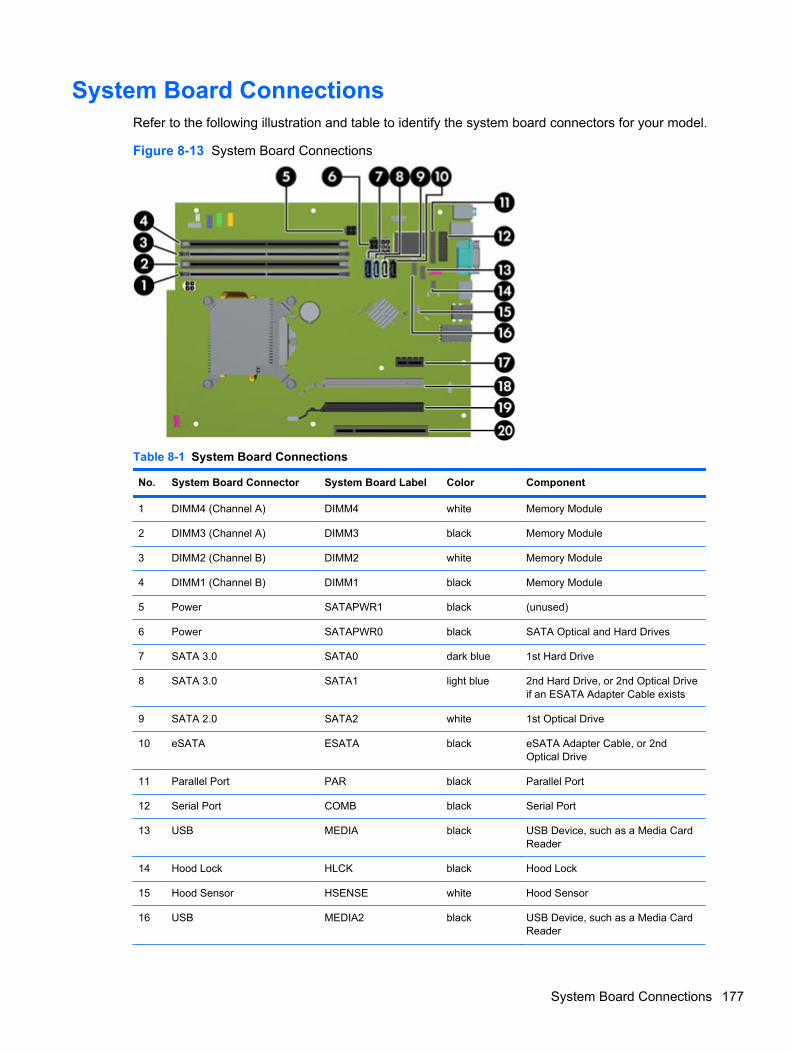
System Board ConnectionsRefer to the following illustration and table to identify the system board connectors for your model.
Figure 8-13 System Board Connections
Table 8-1 System Board Connections
No. System Board Connector System Board Label Color Component
1 DIMM4 (Channel A) DIMM4 white Memory Module
2 DIMM3 (Channel A) DIMM3 black Memory Module
3 DIMM2 (Channel B) DIMM2 white Memory Module
4 DIMM1 (Channel B) DIMM1 black Memory Module
5 Power SATAPWR1 black (unused)
6 Power SATAPWR0 black SATA Optical and Hard Drives
7 SATA 3.0 SATA0 dark blue 1st Hard Drive
8 SATA 3.0 SATA1 light blue 2nd Hard Drive, or 2nd Optical Driveif an ESATA Adapter Cable exists
9 SATA 2.0 SATA2 white 1st Optical Drive
10 eSATA ESATA black eSATA Adapter Cable, or 2ndOptical Drive
11 Parallel Port PAR black Parallel Port
12 Serial Port COMB black Serial Port
13 USB MEDIA black USB Device, such as a Media CardReader
14 Hood Lock HLCK black Hood Lock
15 Hood Sensor HSENSE white Hood Sensor
16 USB MEDIA2 black USB Device, such as a Media CardReader
System Board Connections 177
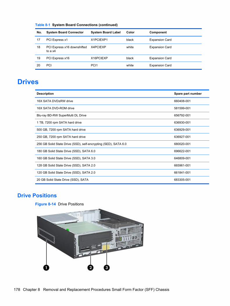
Table 8-1 System Board Connections (continued)
No. System Board Connector System Board Label Color Component
17 PCI Express x1 X1PCIEXP1 black Expansion Card
18 PCI Express x16 downshiftedto a x4
X4PCIEXP white Expansion Card
19 PCI Express x16 X16PCIEXP black Expansion Card
20 PCI PCI1 white Expansion Card
Drives
Description Spare part number
16X SATA DVD±RW drive 660408-001
16X SATA DVD-ROM drive 581599-001
Blu-ray BD-RW SuperMulti DL Drive 656792-001
1 TB, 7200 rpm SATA hard drive 636930-001
500 GB, 7200 rpm SATA hard drive 636929-001
250 GB, 7200 rpm SATA hard drive 636927-001
256 GB Solid State Drive (SSD), self-encrypting (SED), SATA 6.0 680020-001
180 GB Solid State Drive (SSD), SATA 6.0 696622-001
160 GB Solid State Drive (SSD), SATA 3.0 646809-001
128 GB Solid State Drive (SSD), SATA 2.0 665961-001
120 GB Solid State Drive (SSD), SATA 2.0 661841-001
20 GB Solid State Drive (SSD), SATA 683305-001
Drive Positions
Figure 8-14 Drive Positions
178 Chapter 8 Removal and Replacement Procedures Small Form Factor (SFF) Chassis
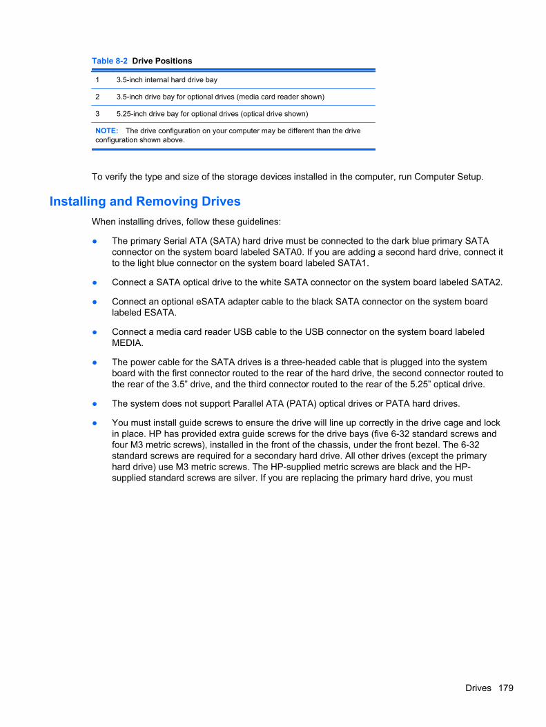
Table 8-2 Drive Positions
1 3.5-inch internal hard drive bay
2 3.5-inch drive bay for optional drives (media card reader shown)
3 5.25-inch drive bay for optional drives (optical drive shown)
NOTE: The drive configuration on your computer may be different than the driveconfiguration shown above.
To verify the type and size of the storage devices installed in the computer, run Computer Setup.
Installing and Removing Drives
When installing drives, follow these guidelines:
● The primary Serial ATA (SATA) hard drive must be connected to the dark blue primary SATAconnector on the system board labeled SATA0. If you are adding a second hard drive, connect itto the light blue connector on the system board labeled SATA1.
● Connect a SATA optical drive to the white SATA connector on the system board labeled SATA2.
● Connect an optional eSATA adapter cable to the black SATA connector on the system boardlabeled ESATA.
● Connect a media card reader USB cable to the USB connector on the system board labeledMEDIA.
● The power cable for the SATA drives is a three-headed cable that is plugged into the systemboard with the first connector routed to the rear of the hard drive, the second connector routed tothe rear of the 3.5” drive, and the third connector routed to the rear of the 5.25” optical drive.
● The system does not support Parallel ATA (PATA) optical drives or PATA hard drives.
● You must install guide screws to ensure the drive will line up correctly in the drive cage and lockin place. HP has provided extra guide screws for the drive bays (five 6-32 standard screws andfour M3 metric screws), installed in the front of the chassis, under the front bezel. The 6-32standard screws are required for a secondary hard drive. All other drives (except the primaryhard drive) use M3 metric screws. The HP-supplied metric screws are black and the HP-supplied standard screws are silver. If you are replacing the primary hard drive, you must
Drives 179
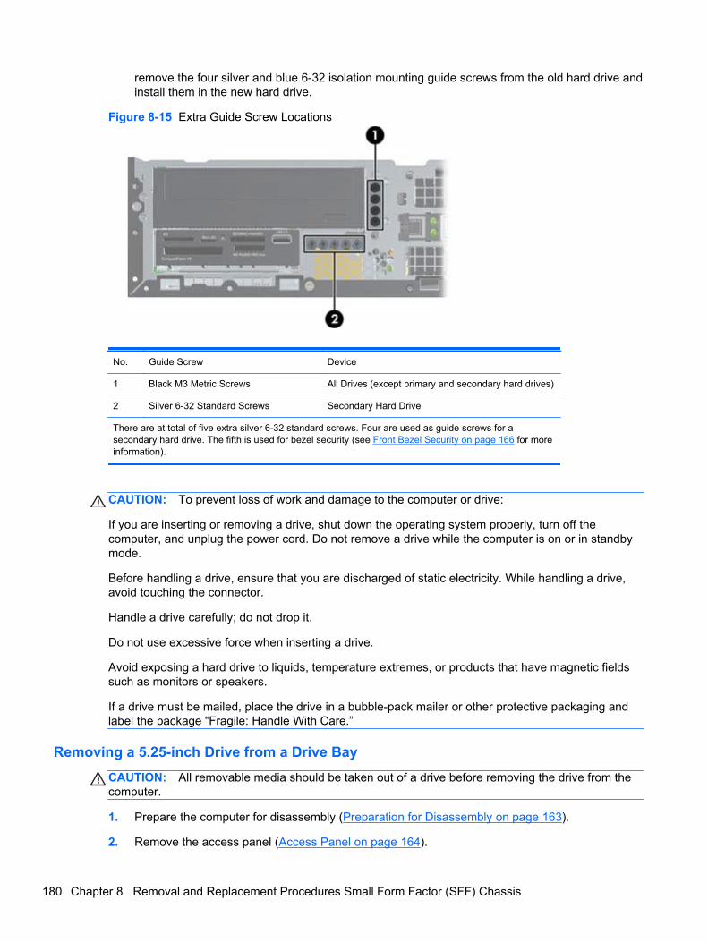
remove the four silver and blue 6-32 isolation mounting guide screws from the old hard drive andinstall them in the new hard drive.
Figure 8-15 Extra Guide Screw Locations
No. Guide Screw Device
1 Black M3 Metric Screws All Drives (except primary and secondary hard drives)
2 Silver 6-32 Standard Screws Secondary Hard Drive
There are at total of five extra silver 6-32 standard screws. Four are used as guide screws for asecondary hard drive. The fifth is used for bezel security (see Front Bezel Security on page 166 for moreinformation).
CAUTION: To prevent loss of work and damage to the computer or drive:
If you are inserting or removing a drive, shut down the operating system properly, turn off thecomputer, and unplug the power cord. Do not remove a drive while the computer is on or in standbymode.
Before handling a drive, ensure that you are discharged of static electricity. While handling a drive,avoid touching the connector.
Handle a drive carefully; do not drop it.
Do not use excessive force when inserting a drive.
Avoid exposing a hard drive to liquids, temperature extremes, or products that have magnetic fieldssuch as monitors or speakers.
If a drive must be mailed, place the drive in a bubble-pack mailer or other protective packaging andlabel the package “Fragile: Handle With Care.”
Removing a 5.25-inch Drive from a Drive Bay
CAUTION: All removable media should be taken out of a drive before removing the drive from thecomputer.
1. Prepare the computer for disassembly (Preparation for Disassembly on page 163).
2. Remove the access panel (Access Panel on page 164).
180 Chapter 8 Removal and Replacement Procedures Small Form Factor (SFF) Chassis
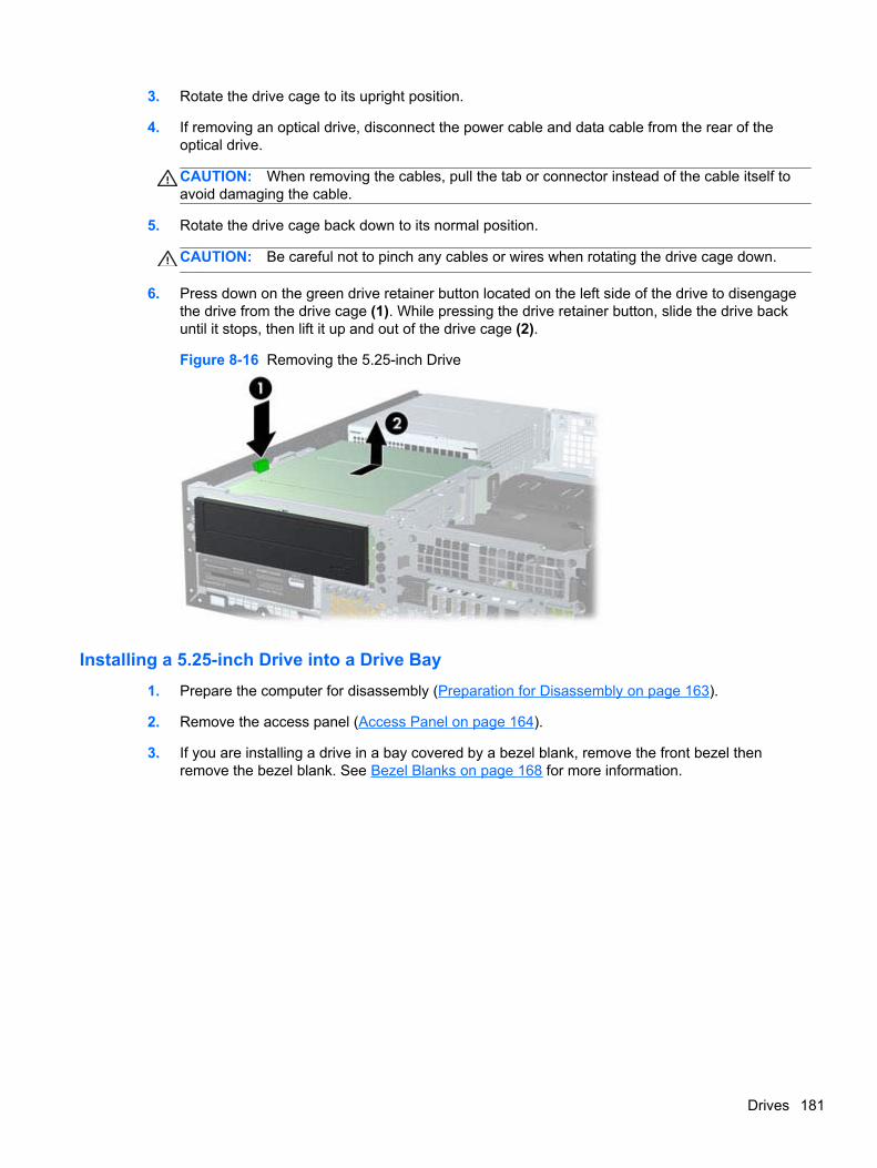
3. Rotate the drive cage to its upright position.
4. If removing an optical drive, disconnect the power cable and data cable from the rear of theoptical drive.
CAUTION: When removing the cables, pull the tab or connector instead of the cable itself toavoid damaging the cable.
5. Rotate the drive cage back down to its normal position.
CAUTION: Be careful not to pinch any cables or wires when rotating the drive cage down.
6. Press down on the green drive retainer button located on the left side of the drive to disengagethe drive from the drive cage (1). While pressing the drive retainer button, slide the drive backuntil it stops, then lift it up and out of the drive cage (2).
Figure 8-16 Removing the 5.25-inch Drive
Installing a 5.25-inch Drive into a Drive Bay
1. Prepare the computer for disassembly (Preparation for Disassembly on page 163).
2. Remove the access panel (Access Panel on page 164).
3. If you are installing a drive in a bay covered by a bezel blank, remove the front bezel thenremove the bezel blank. See Bezel Blanks on page 168 for more information.
Drives 181
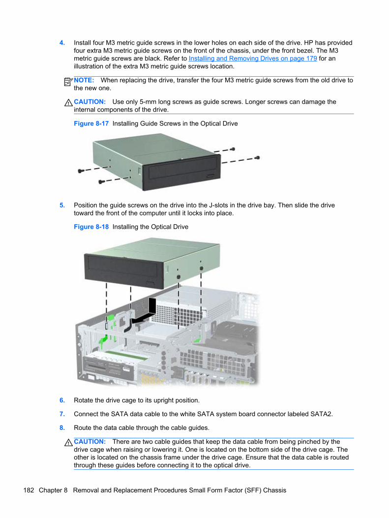
4. Install four M3 metric guide screws in the lower holes on each side of the drive. HP has providedfour extra M3 metric guide screws on the front of the chassis, under the front bezel. The M3metric guide screws are black. Refer to Installing and Removing Drives on page 179 for anillustration of the extra M3 metric guide screws location.
NOTE: When replacing the drive, transfer the four M3 metric guide screws from the old drive tothe new one.
CAUTION: Use only 5-mm long screws as guide screws. Longer screws can damage theinternal components of the drive.
Figure 8-17 Installing Guide Screws in the Optical Drive
5. Position the guide screws on the drive into the J-slots in the drive bay. Then slide the drivetoward the front of the computer until it locks into place.
Figure 8-18 Installing the Optical Drive
6. Rotate the drive cage to its upright position.
7. Connect the SATA data cable to the white SATA system board connector labeled SATA2.
8. Route the data cable through the cable guides.
CAUTION: There are two cable guides that keep the data cable from being pinched by thedrive cage when raising or lowering it. One is located on the bottom side of the drive cage. Theother is located on the chassis frame under the drive cage. Ensure that the data cable is routedthrough these guides before connecting it to the optical drive.
182 Chapter 8 Removal and Replacement Procedures Small Form Factor (SFF) Chassis
9. Connect the power cable and data cable to the rear of the optical drive.
NOTE: The power cable for the optical drive is a three-headed cable that is routed from thesystem board to the hard drive, then to the rear of the optical drive.
10. Rotate the drive cage back down to its normal position.
CAUTION: Be careful not to pinch any cables or wires when rotating the drive cage down.
11. Replace the front bezel (if removed) and access panel.
12. If the computer was on a stand, replace the stand.
13. Reconnect the power cord and turn on the computer.
14. Lock any security devices that were disengaged when the access panel was removed.
Drives 183
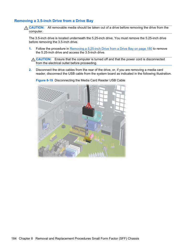
Removing a 3.5-inch Drive from a Drive Bay
CAUTION: All removable media should be taken out of a drive before removing the drive from thecomputer.
The 3.5-inch drive is located underneath the 5.25-inch drive. You must remove the 5.25-inch drivebefore removing the 3.5-inch drive.
1. Follow the procedure in Removing a 5.25-inch Drive from a Drive Bay on page 180 to removethe 5.25-inch drive and access the 3.5-inch drive.
CAUTION: Ensure that the computer is turned off and that the power cord is disconnectedfrom the electrical outlet before proceeding.
2. Disconnect the drive cables from the rear of the drive, or, if you are removing a media cardreader, disconnect the USB cable from the system board as indicated in the following illustration.
Figure 8-19 Disconnecting the Media Card Reader USB Cable
184 Chapter 8 Removal and Replacement Procedures Small Form Factor (SFF) Chassis
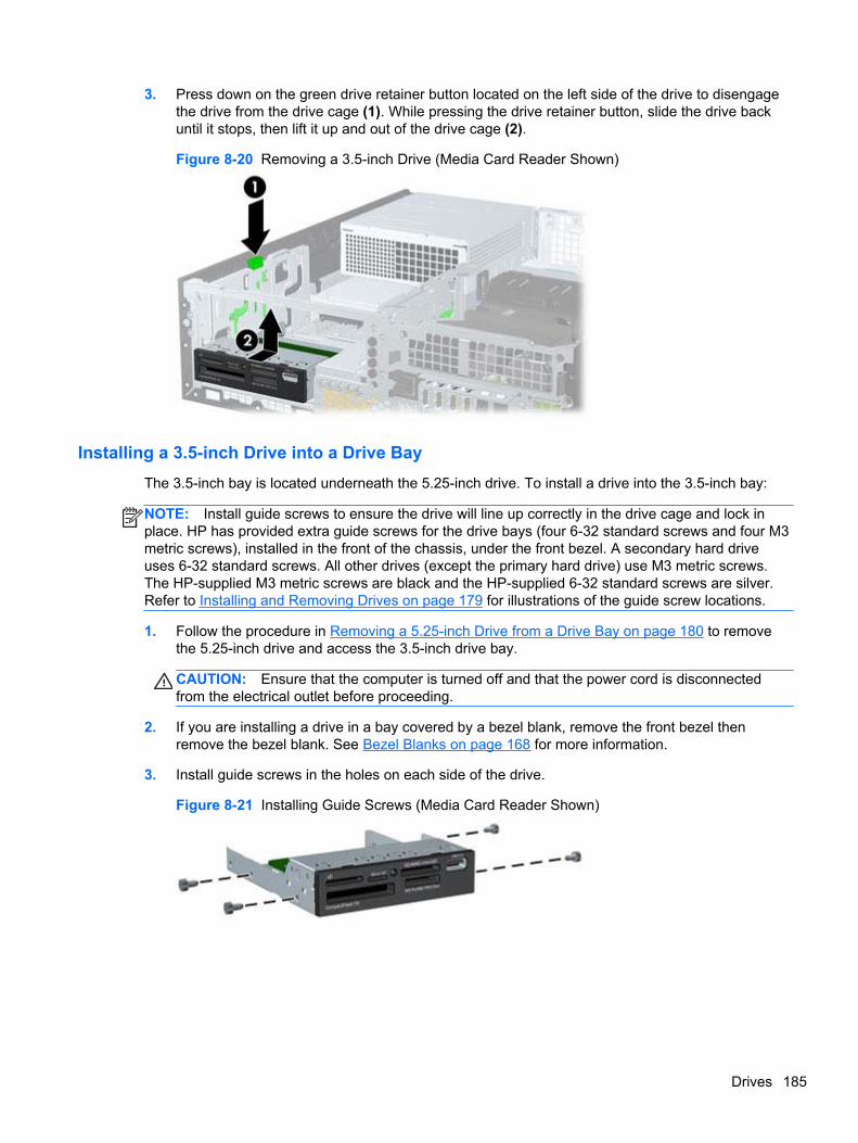
3. Press down on the green drive retainer button located on the left side of the drive to disengagethe drive from the drive cage (1). While pressing the drive retainer button, slide the drive backuntil it stops, then lift it up and out of the drive cage (2).
Figure 8-20 Removing a 3.5-inch Drive (Media Card Reader Shown)
Installing a 3.5-inch Drive into a Drive Bay
The 3.5-inch bay is located underneath the 5.25-inch drive. To install a drive into the 3.5-inch bay:
NOTE: Install guide screws to ensure the drive will line up correctly in the drive cage and lock inplace. HP has provided extra guide screws for the drive bays (four 6-32 standard screws and four M3metric screws), installed in the front of the chassis, under the front bezel. A secondary hard driveuses 6-32 standard screws. All other drives (except the primary hard drive) use M3 metric screws.The HP-supplied M3 metric screws are black and the HP-supplied 6-32 standard screws are silver.Refer to Installing and Removing Drives on page 179 for illustrations of the guide screw locations.
1. Follow the procedure in Removing a 5.25-inch Drive from a Drive Bay on page 180 to removethe 5.25-inch drive and access the 3.5-inch drive bay.
CAUTION: Ensure that the computer is turned off and that the power cord is disconnectedfrom the electrical outlet before proceeding.
2. If you are installing a drive in a bay covered by a bezel blank, remove the front bezel thenremove the bezel blank. See Bezel Blanks on page 168 for more information.
3. Install guide screws in the holes on each side of the drive.
Figure 8-21 Installing Guide Screws (Media Card Reader Shown)
Drives 185
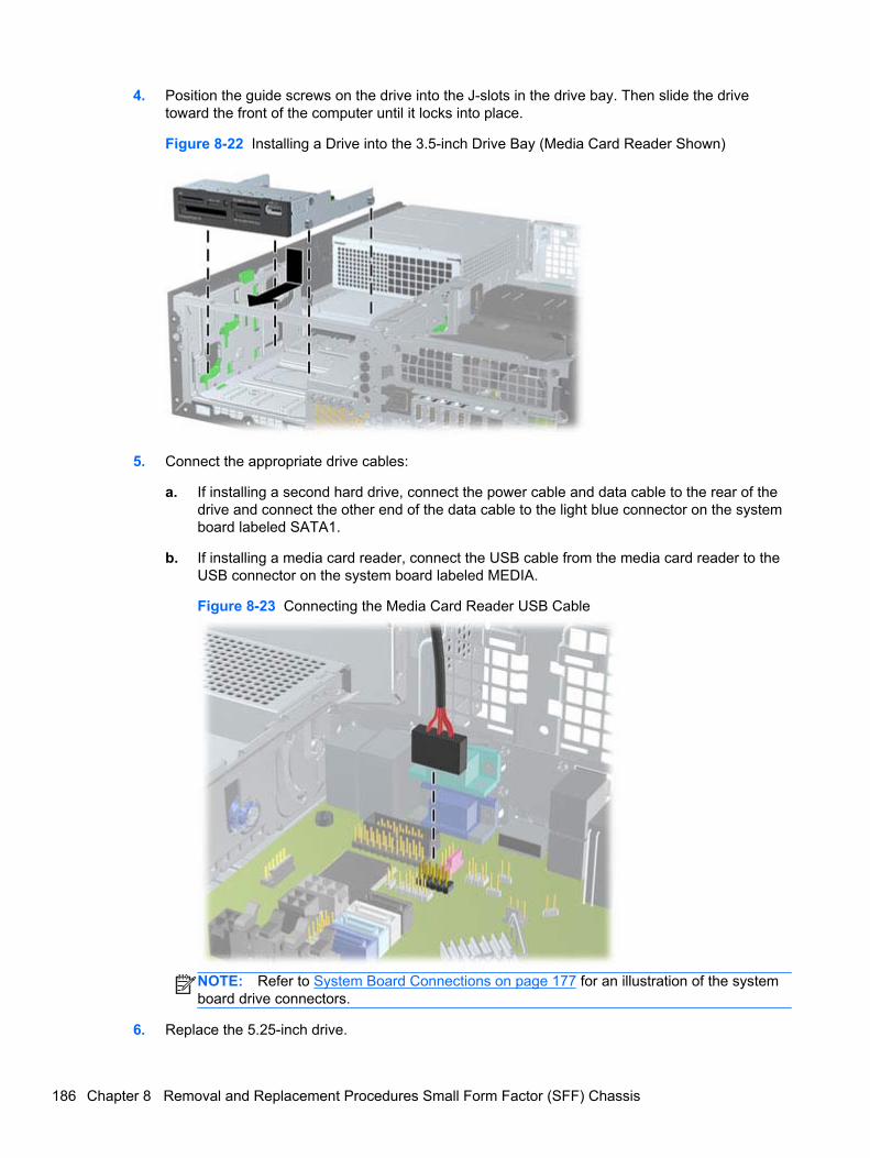
4. Position the guide screws on the drive into the J-slots in the drive bay. Then slide the drivetoward the front of the computer until it locks into place.
Figure 8-22 Installing a Drive into the 3.5-inch Drive Bay (Media Card Reader Shown)
5. Connect the appropriate drive cables:
a. If installing a second hard drive, connect the power cable and data cable to the rear of thedrive and connect the other end of the data cable to the light blue connector on the systemboard labeled SATA1.
b. If installing a media card reader, connect the USB cable from the media card reader to theUSB connector on the system board labeled MEDIA.
Figure 8-23 Connecting the Media Card Reader USB Cable
NOTE: Refer to System Board Connections on page 177 for an illustration of the systemboard drive connectors.
6. Replace the 5.25-inch drive.
186 Chapter 8 Removal and Replacement Procedures Small Form Factor (SFF) Chassis
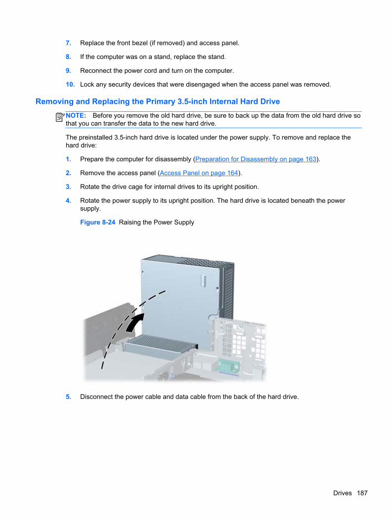
7. Replace the front bezel (if removed) and access panel.
8. If the computer was on a stand, replace the stand.
9. Reconnect the power cord and turn on the computer.
10. Lock any security devices that were disengaged when the access panel was removed.
Removing and Replacing the Primary 3.5-inch Internal Hard Drive
NOTE: Before you remove the old hard drive, be sure to back up the data from the old hard drive sothat you can transfer the data to the new hard drive.
The preinstalled 3.5-inch hard drive is located under the power supply. To remove and replace thehard drive:
1. Prepare the computer for disassembly (Preparation for Disassembly on page 163).
2. Remove the access panel (Access Panel on page 164).
3. Rotate the drive cage for internal drives to its upright position.
4. Rotate the power supply to its upright position. The hard drive is located beneath the powersupply.
Figure 8-24 Raising the Power Supply
5. Disconnect the power cable and data cable from the back of the hard drive.
Drives 187
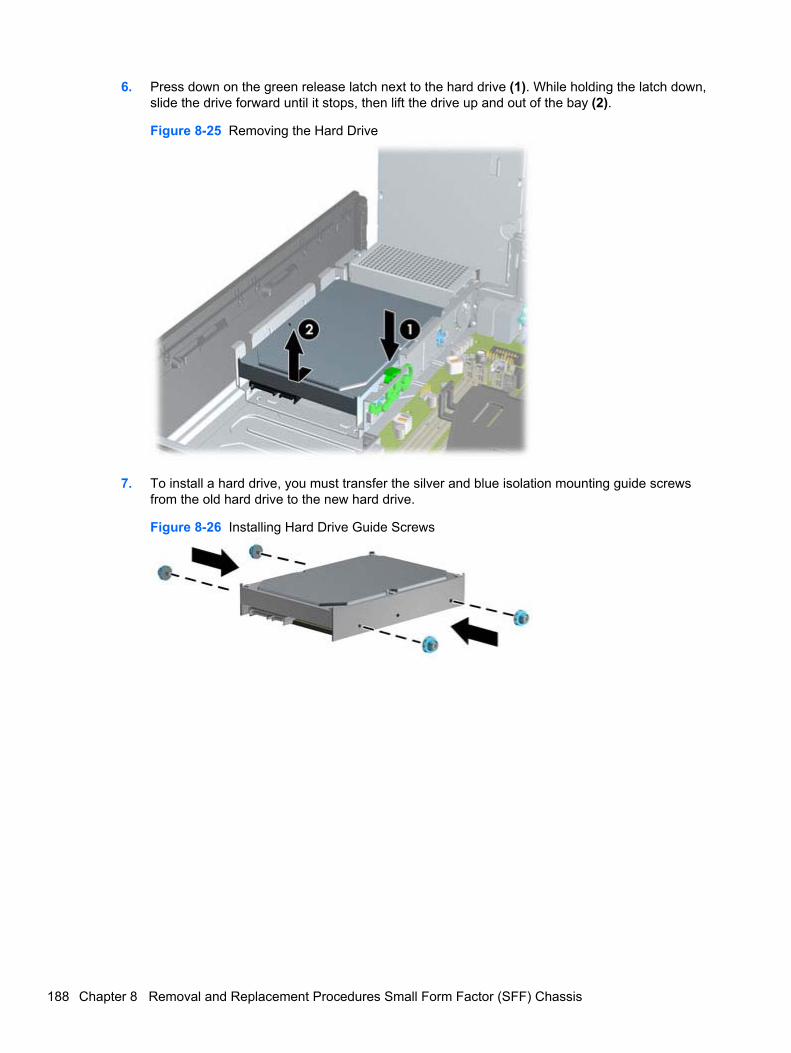
6. Press down on the green release latch next to the hard drive (1). While holding the latch down,slide the drive forward until it stops, then lift the drive up and out of the bay (2).
Figure 8-25 Removing the Hard Drive
7. To install a hard drive, you must transfer the silver and blue isolation mounting guide screwsfrom the old hard drive to the new hard drive.
Figure 8-26 Installing Hard Drive Guide Screws
188 Chapter 8 Removal and Replacement Procedures Small Form Factor (SFF) Chassis
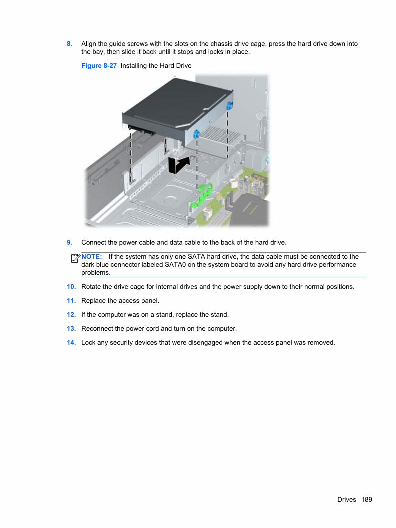
8. Align the guide screws with the slots on the chassis drive cage, press the hard drive down intothe bay, then slide it back until it stops and locks in place.
Figure 8-27 Installing the Hard Drive
9. Connect the power cable and data cable to the back of the hard drive.
NOTE: If the system has only one SATA hard drive, the data cable must be connected to thedark blue connector labeled SATA0 on the system board to avoid any hard drive performanceproblems.
10. Rotate the drive cage for internal drives and the power supply down to their normal positions.
11. Replace the access panel.
12. If the computer was on a stand, replace the stand.
13. Reconnect the power cord and turn on the computer.
14. Lock any security devices that were disengaged when the access panel was removed.
Drives 189
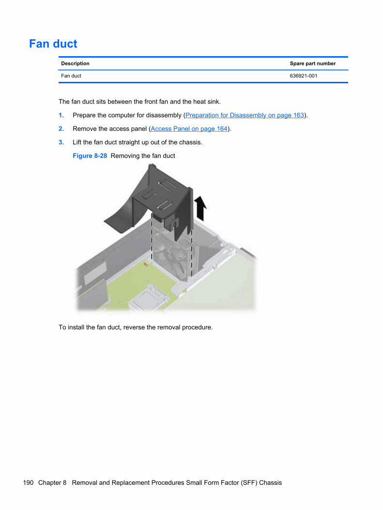
Fan duct
Description Spare part number
Fan duct 636921-001
The fan duct sits between the front fan and the heat sink.
1. Prepare the computer for disassembly (Preparation for Disassembly on page 163).
2. Remove the access panel (Access Panel on page 164).
3. Lift the fan duct straight up out of the chassis.
Figure 8-28 Removing the fan duct
To install the fan duct, reverse the removal procedure.
190 Chapter 8 Removal and Replacement Procedures Small Form Factor (SFF) Chassis
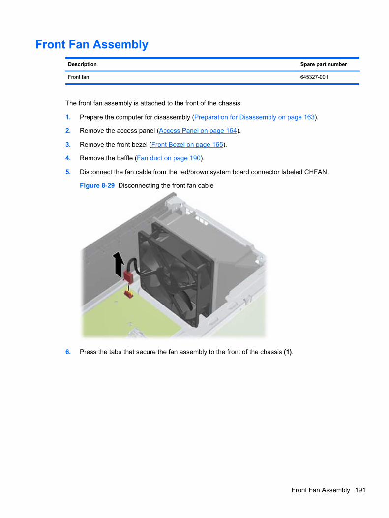
Front Fan Assembly
Description Spare part number
Front fan 645327-001
The front fan assembly is attached to the front of the chassis.
1. Prepare the computer for disassembly (Preparation for Disassembly on page 163).
2. Remove the access panel (Access Panel on page 164).
3. Remove the front bezel (Front Bezel on page 165).
4. Remove the baffle (Fan duct on page 190).
5. Disconnect the fan cable from the red/brown system board connector labeled CHFAN.
Figure 8-29 Disconnecting the front fan cable
6. Press the tabs that secure the fan assembly to the front of the chassis (1).
Front Fan Assembly 191
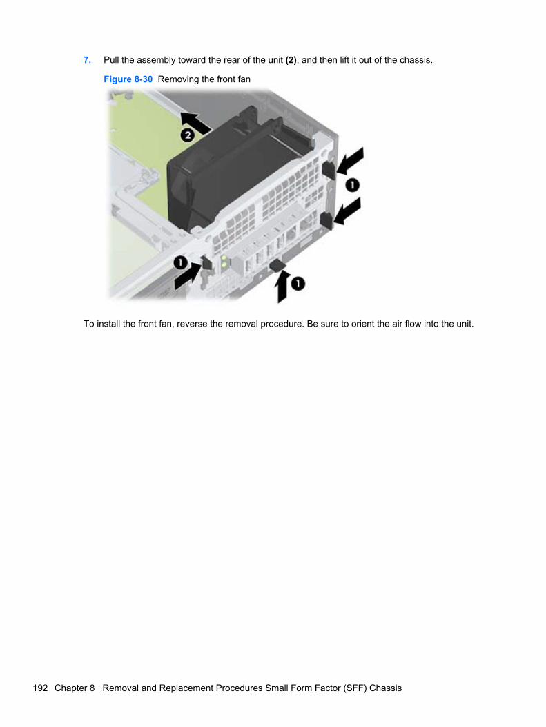
7. Pull the assembly toward the rear of the unit (2), and then lift it out of the chassis.
Figure 8-30 Removing the front fan
To install the front fan, reverse the removal procedure. Be sure to orient the air flow into the unit.
192 Chapter 8 Removal and Replacement Procedures Small Form Factor (SFF) Chassis
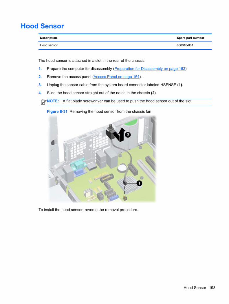
Hood Sensor
Description Spare part number
Hood sensor 638816-001
The hood sensor is attached in a slot in the rear of the chassis.
1. Prepare the computer for disassembly (Preparation for Disassembly on page 163).
2. Remove the access panel (Access Panel on page 164).
3. Unplug the sensor cable from the system board connector labeled HSENSE (1).
4. Slide the hood sensor straight out of the notch in the chassis (2).
NOTE: A flat blade screwdriver can be used to push the hood sensor out of the slot.
Figure 8-31 Removing the hood sensor from the chassis fan
To install the hood sensor, reverse the removal procedure.
Hood Sensor 193
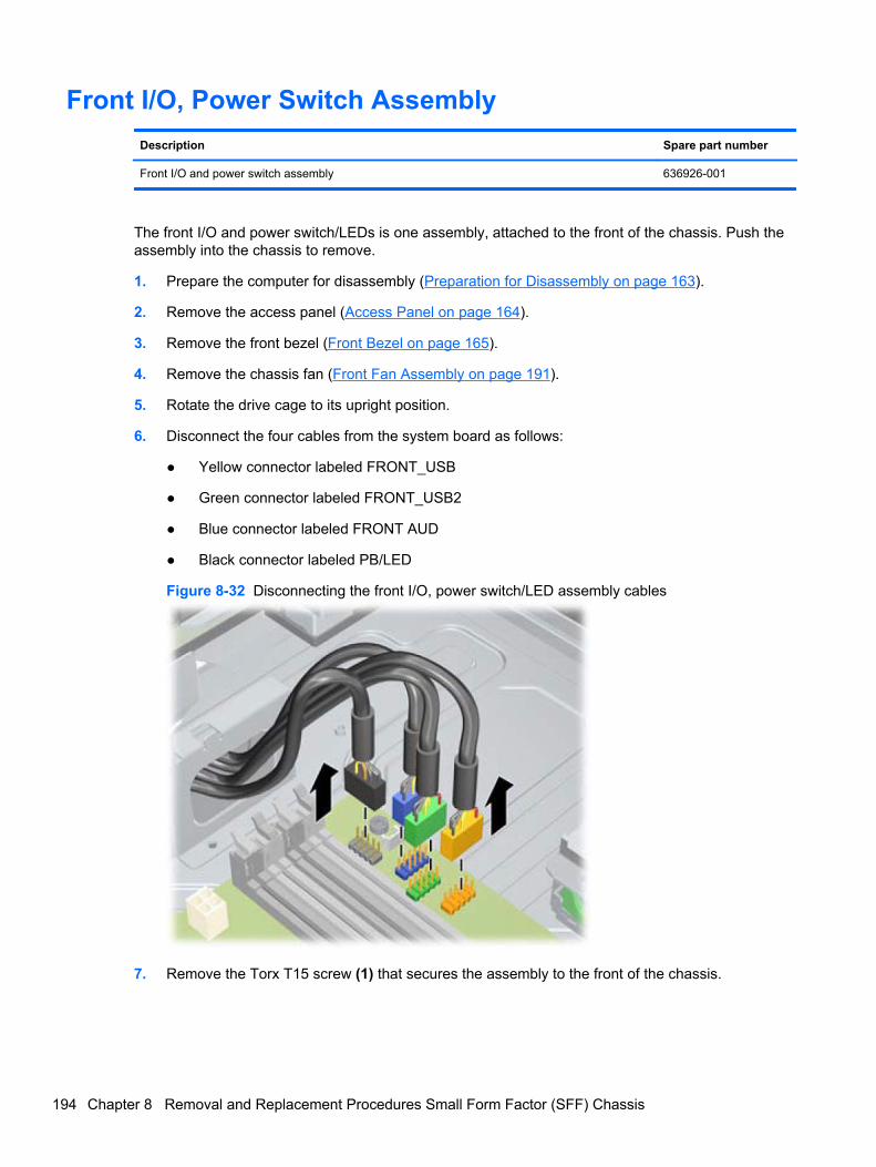
Front I/O, Power Switch Assembly
Description Spare part number
Front I/O and power switch assembly 636926-001
The front I/O and power switch/LEDs is one assembly, attached to the front of the chassis. Push theassembly into the chassis to remove.
1. Prepare the computer for disassembly (Preparation for Disassembly on page 163).
2. Remove the access panel (Access Panel on page 164).
3. Remove the front bezel (Front Bezel on page 165).
4. Remove the chassis fan (Front Fan Assembly on page 191).
5. Rotate the drive cage to its upright position.
6. Disconnect the four cables from the system board as follows:
● Yellow connector labeled FRONT_USB
● Green connector labeled FRONT_USB2
● Blue connector labeled FRONT AUD
● Black connector labeled PB/LED
Figure 8-32 Disconnecting the front I/O, power switch/LED assembly cables
7. Remove the Torx T15 screw (1) that secures the assembly to the front of the chassis.
194 Chapter 8 Removal and Replacement Procedures Small Form Factor (SFF) Chassis
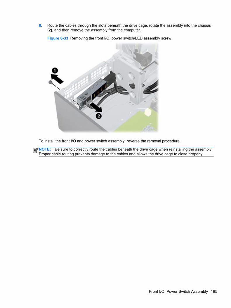
8. Route the cables through the slots beneath the drive cage, rotate the assembly into the chassis(2), and then remove the assembly from the computer.
Figure 8-33 Removing the front I/O, power switch/LED assembly screw
To install the front I/O and power switch assembly, reverse the removal procedure.
NOTE: Be sure to correctly route the cables beneath the drive cage when reinstalling the assembly.Proper cable routing prevents damage to the cables and allows the drive cage to close properly.
Front I/O, Power Switch Assembly 195
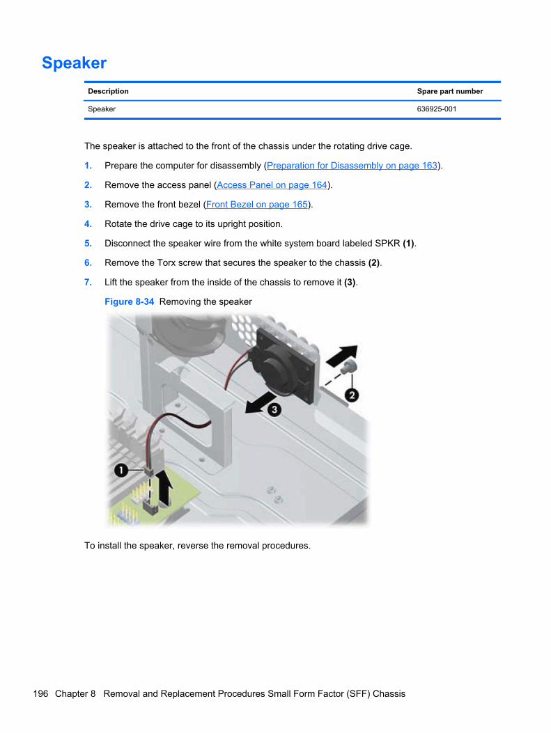
Speaker
Description Spare part number
Speaker 636925-001
The speaker is attached to the front of the chassis under the rotating drive cage.
1. Prepare the computer for disassembly (Preparation for Disassembly on page 163).
2. Remove the access panel (Access Panel on page 164).
3. Remove the front bezel (Front Bezel on page 165).
4. Rotate the drive cage to its upright position.
5. Disconnect the speaker wire from the white system board labeled SPKR (1).
6. Remove the Torx screw that secures the speaker to the chassis (2).
7. Lift the speaker from the inside of the chassis to remove it (3).
Figure 8-34 Removing the speaker
To install the speaker, reverse the removal procedures.
196 Chapter 8 Removal and Replacement Procedures Small Form Factor (SFF) Chassis
Heat sink
Description Spare part number
Heat sink 645326-001
The heat sink is secured atop the processor with four captive Torx screws. The heat sink does notinclude a fan.
1. Prepare the computer for disassembly (Preparation for Disassembly on page 163).
2. Remove the access panel (Access Panel on page 164).
3. Remove the fan duct (Fan duct on page 190).
4. Remove the front fan (Front Fan Assembly on page 191).
Heat sink 197
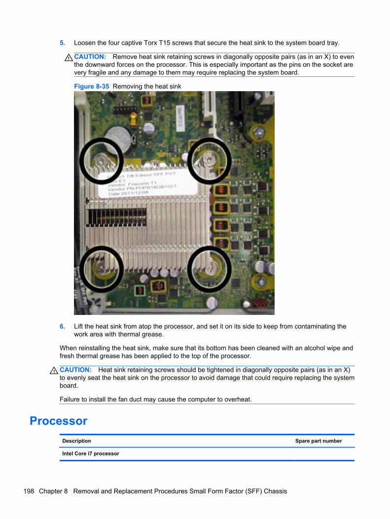
5. Loosen the four captive Torx T15 screws that secure the heat sink to the system board tray.
CAUTION: Remove heat sink retaining screws in diagonally opposite pairs (as in an X) to eventhe downward forces on the processor. This is especially important as the pins on the socket arevery fragile and any damage to them may require replacing the system board.
Figure 8-35 Removing the heat sink
6. Lift the heat sink from atop the processor, and set it on its side to keep from contaminating thework area with thermal grease.
When reinstalling the heat sink, make sure that its bottom has been cleaned with an alcohol wipe andfresh thermal grease has been applied to the top of the processor.
CAUTION: Heat sink retaining screws should be tightened in diagonally opposite pairs (as in an X)to evenly seat the heat sink on the processor to avoid damage that could require replacing the systemboard.
Failure to install the fan duct may cause the computer to overheat.
Processor
Description Spare part number
Intel Core i7 processor
198 Chapter 8 Removal and Replacement Procedures Small Form Factor (SFF) Chassis
Description Spare part number
3770, 3.4 GHz, 8-MB L3 cache, 95W 688164-001
Intel Core i5 processors
3570, 3.4 GHz, 6-MB L3 cache, 95W 688162-001
3470, 3.2 GHz, 6-MB L3 cache, 95W 687943-001
Intel Core i3 processors
2130, 3.4 GHz, 3-MB L3 cache, 65W 665120-001
2120, 3.3 GHz, 3-MB L3 cache, 65W 638629-001
Intel Pentium processors
G870, 3.0 GHz, 3-MB L3 cache 691936-001
G860, 3.0 GHz, 3-MB L3 cache 665123-001
G640, 2.8 GHz, 3-MB L3 cache 691935-001
1. Prepare the computer for disassembly (Preparation for Disassembly on page 163).
2. Remove the access panel (Access Panel on page 164).
3. Remove the fan duct (Fan duct on page 190).
4. Remove the front fan assembly (Front Fan Assembly on page 191).
5. Remove the heat sink (Heat sink on page 197).
6. Rotate the locking lever to its full open position (1).
7. Raise and rotate the microprocessor retainer to its fully open position (2).
Processor 199
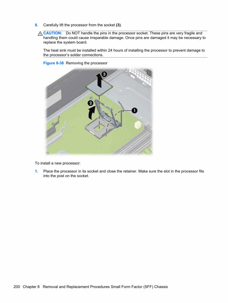
8. Carefully lift the processor from the socket (3).
CAUTION: Do NOT handle the pins in the processor socket. These pins are very fragile andhandling them could cause irreparable damage. Once pins are damaged it may be necessary toreplace the system board.
The heat sink must be installed within 24 hours of installing the processor to prevent damage tothe processor’s solder connections.
Figure 8-36 Removing the processor
To install a new processor:
1. Place the processor in its socket and close the retainer. Make sure the slot in the processor fitsinto the post on the socket.
200 Chapter 8 Removal and Replacement Procedures Small Form Factor (SFF) Chassis
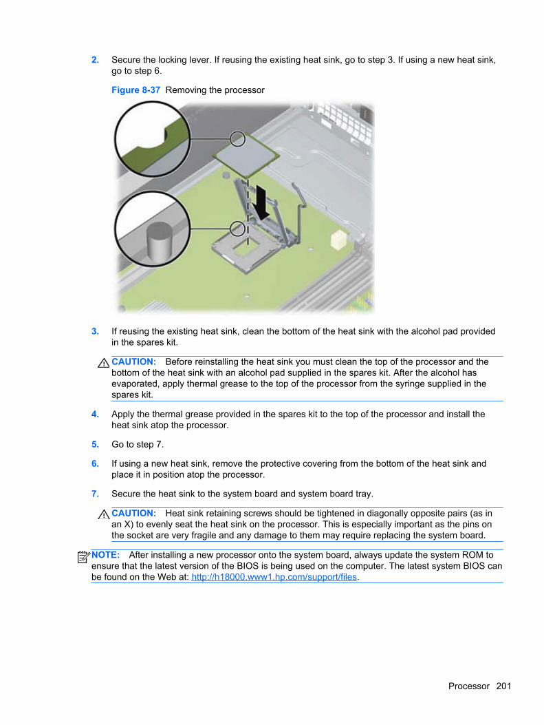
2. Secure the locking lever. If reusing the existing heat sink, go to step 3. If using a new heat sink,go to step 6.
Figure 8-37 Removing the processor
3. If reusing the existing heat sink, clean the bottom of the heat sink with the alcohol pad providedin the spares kit.
CAUTION: Before reinstalling the heat sink you must clean the top of the processor and thebottom of the heat sink with an alcohol pad supplied in the spares kit. After the alcohol hasevaporated, apply thermal grease to the top of the processor from the syringe supplied in thespares kit.
4. Apply the thermal grease provided in the spares kit to the top of the processor and install theheat sink atop the processor.
5. Go to step 7.
6. If using a new heat sink, remove the protective covering from the bottom of the heat sink andplace it in position atop the processor.
7. Secure the heat sink to the system board and system board tray.
CAUTION: Heat sink retaining screws should be tightened in diagonally opposite pairs (as inan X) to evenly seat the heat sink on the processor. This is especially important as the pins onthe socket are very fragile and any damage to them may require replacing the system board.
NOTE: After installing a new processor onto the system board, always update the system ROM toensure that the latest version of the BIOS is being used on the computer. The latest system BIOS canbe found on the Web at: http://h18000.www1.hp.com/support/files.
Processor 201

Power Supply
Description Spare part number
Power supply, 90% efficient 613762-001
Power supply, standard 613763-001
WARNING! To reduce potential safety issues, only the power supply provided with the computer, areplacement power supply provided by HP, or a power supply purchased as an accessory from HPshould be used with the computer.
The rotating power supply is located at the rear of the chassis. It is held in place by a bracket – noscrews are used.
WARNING! Voltage is always present on the system board when the computer is plugged into anactive AC outlet. To avoid possible personal injury and damage to the equipment the power cordshould be disconnected from the computer and/or the AC outlet before opening the computer.
1. Prepare the computer for disassembly (Preparation for Disassembly on page 163).
2. Remove the access panel (Access Panel on page 164).
3. Rotate the drive cage up and disconnect the power cables from all of the drives.
4. Disconnect all power cables from the system board as follows:
● clear 4-pin PWRCPU
● clear 6-pin PWR
● white 6-pin PWRCMD
5. Rotate the power supply to its full upright position.
6. Release the power supply cables from the cable retaining clip under the drive cage.
202 Chapter 8 Removal and Replacement Procedures Small Form Factor (SFF) Chassis
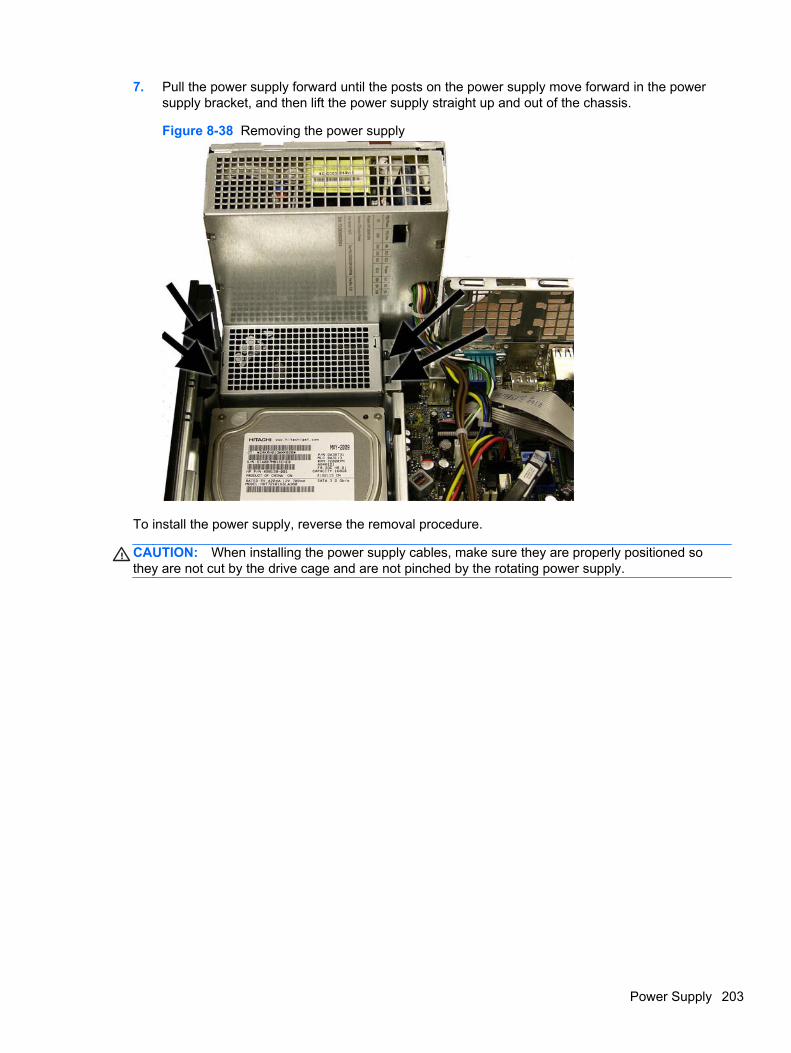
7. Pull the power supply forward until the posts on the power supply move forward in the powersupply bracket, and then lift the power supply straight up and out of the chassis.
Figure 8-38 Removing the power supply
To install the power supply, reverse the removal procedure.
CAUTION: When installing the power supply cables, make sure they are properly positioned sothey are not cut by the drive cage and are not pinched by the rotating power supply.
Power Supply 203
System Board
Description Spare part number
System board (includes thermal material) 657094-001
1. Prepare the computer for disassembly (Preparation for Disassembly on page 163).
2. Remove the access panel (Access Panel on page 164).
3. When replacing the system board, make sure the following components are removed from thedefective system board and installed on the replacement system board:
● Memory modules (Memory on page 169)
● Expansion cards (Expansion Card on page 172)
● Heat sink (Heat sink on page 197)
● Processor (Processor on page 198)
4. Remove the baffle from the chassis (Fan duct on page 190).
5. Remove the fan from the chassis (Front Fan Assembly on page 191).
6. Rotate the drive cage to its upright position.
7. Rotate the power supply to its full upright position.
8. Disconnect all data and power cables from the system board.
9. Disconnect the balance of the cables from the system board.
10. Remove the eight Torx T15 screws (1) that secure the system board to the chassis.
204 Chapter 8 Removal and Replacement Procedures Small Form Factor (SFF) Chassis
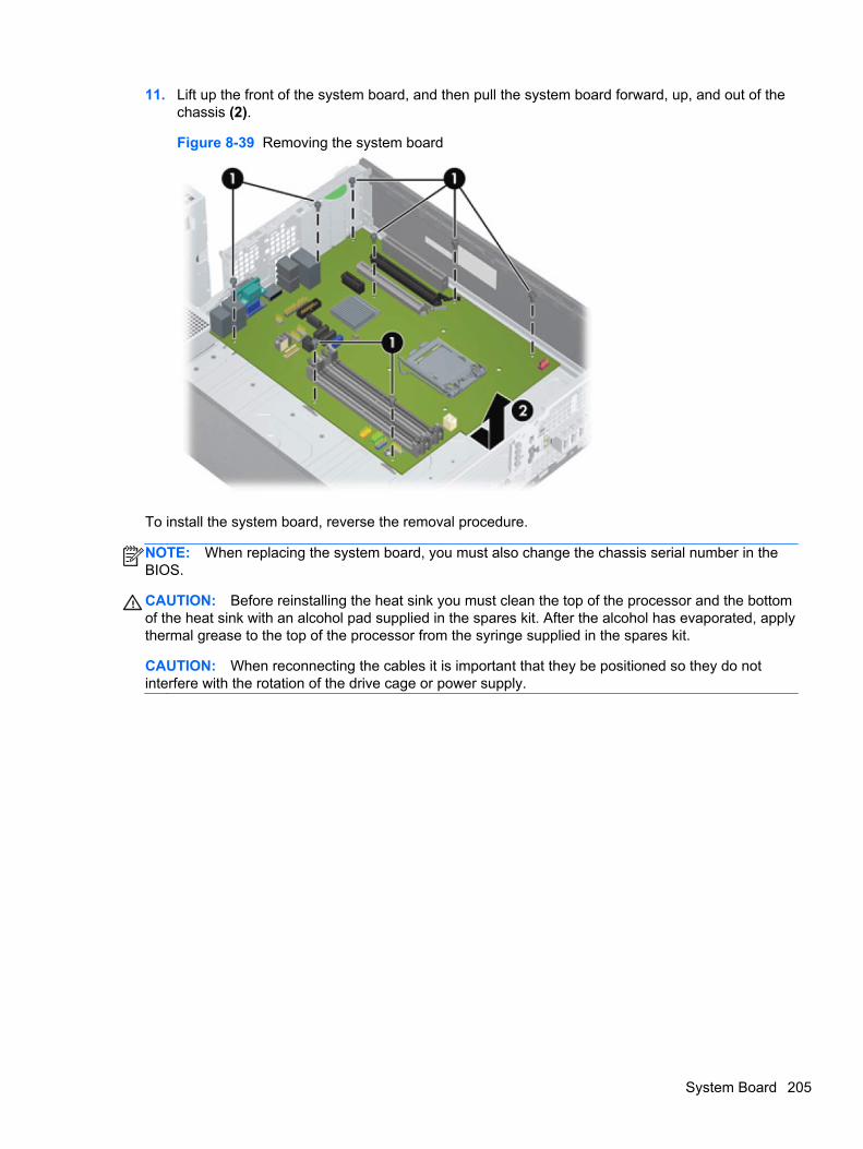
11. Lift up the front of the system board, and then pull the system board forward, up, and out of thechassis (2).
Figure 8-39 Removing the system board
To install the system board, reverse the removal procedure.
NOTE: When replacing the system board, you must also change the chassis serial number in theBIOS.
CAUTION: Before reinstalling the heat sink you must clean the top of the processor and the bottomof the heat sink with an alcohol pad supplied in the spares kit. After the alcohol has evaporated, applythermal grease to the top of the processor from the syringe supplied in the spares kit.
CAUTION: When reconnecting the cables it is important that they be positioned so they do notinterfere with the rotation of the drive cage or power supply.
System Board 205
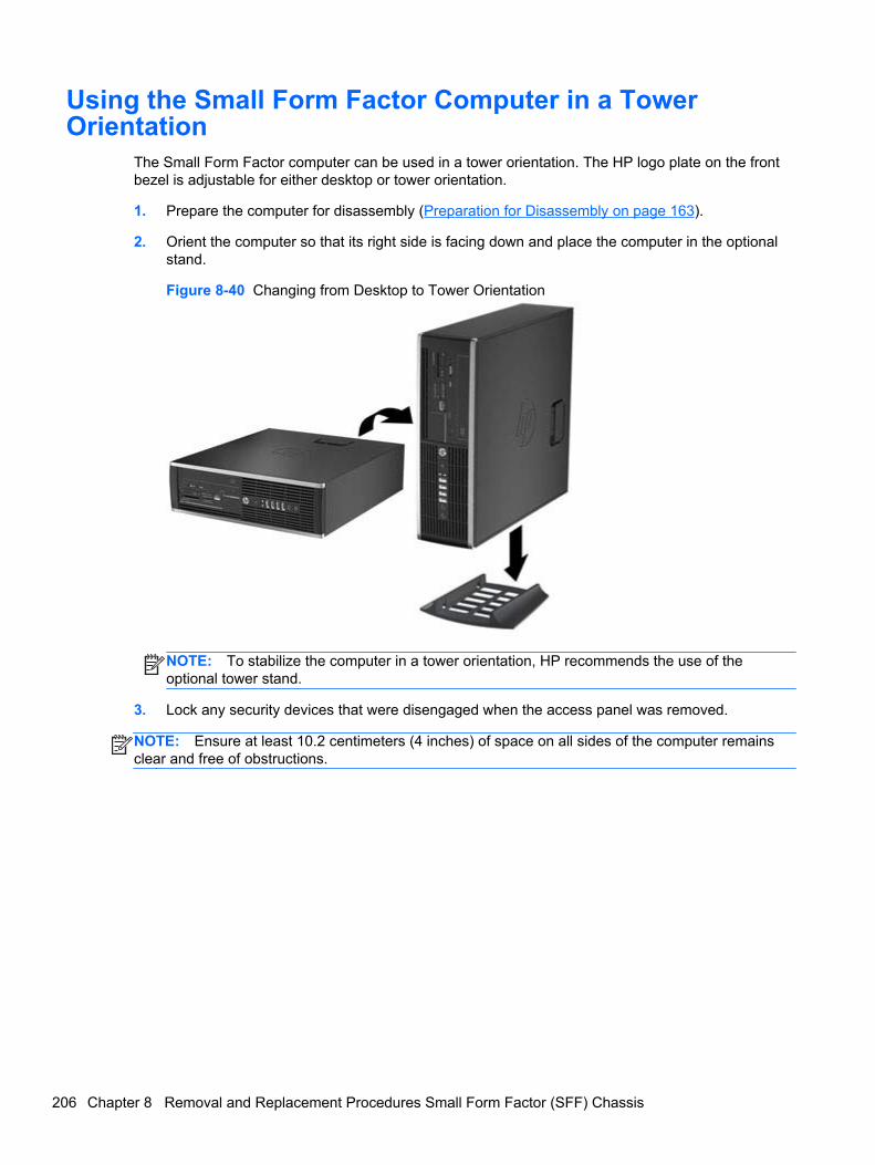
Using the Small Form Factor Computer in a TowerOrientation
The Small Form Factor computer can be used in a tower orientation. The HP logo plate on the frontbezel is adjustable for either desktop or tower orientation.
1. Prepare the computer for disassembly (Preparation for Disassembly on page 163).
2. Orient the computer so that its right side is facing down and place the computer in the optionalstand.
Figure 8-40 Changing from Desktop to Tower Orientation
NOTE: To stabilize the computer in a tower orientation, HP recommends the use of theoptional tower stand.
3. Lock any security devices that were disengaged when the access panel was removed.
NOTE: Ensure at least 10.2 centimeters (4 inches) of space on all sides of the computer remainsclear and free of obstructions.
206 Chapter 8 Removal and Replacement Procedures Small Form Factor (SFF) Chassis
9 Removal and Replacement ProceduresUltra-Slim Desktop (USDT) Chassis
Adherence to the procedures and precautions described in this chapter is essential for proper service.After completing all necessary removal and replacement procedures, run the Diagnostics utility toverify that all components operate properly.
NOTE: Not all features listed in this guide are available on all computers.
Preparation for DisassemblySee Routine Care, SATA Drive Guidelines, and Disassembly Preparation on page 66 for initial safetyprocedures.
1. Remove/disengage any security devices that prohibit opening the computer.
2. Close any open software applications.
3. Exit the operating system.
4. Remove any compact disc from the computer.
5. Turn off the computer and any peripheral devices that are connected to it.
CAUTION: Turn off the computer before disconnecting any cables.
Regardless of the power-on state, voltage is always present on the system board as long as thesystem is plugged into an active AC outlet. In some systems the cooling fan is on even when thecomputer is in the “Standby,” or “Suspend” modes. The power cord should always bedisconnected before servicing a unit.
6. Disconnect the power cord from the electrical outlet and then from the computer.
7. Disconnect all peripheral device cables from the computer.
NOTE: During disassembly, label each cable as you remove it, noting its position and routing.Keep all screws with the units removed.
CAUTION: The screws used in the computer are of different thread sizes and lengths; usingthe wrong screw in an application may damage the unit.
8. If the PC is mounted in the accessory mounting stand, remove it from the stand.
Preparation for Disassembly 207
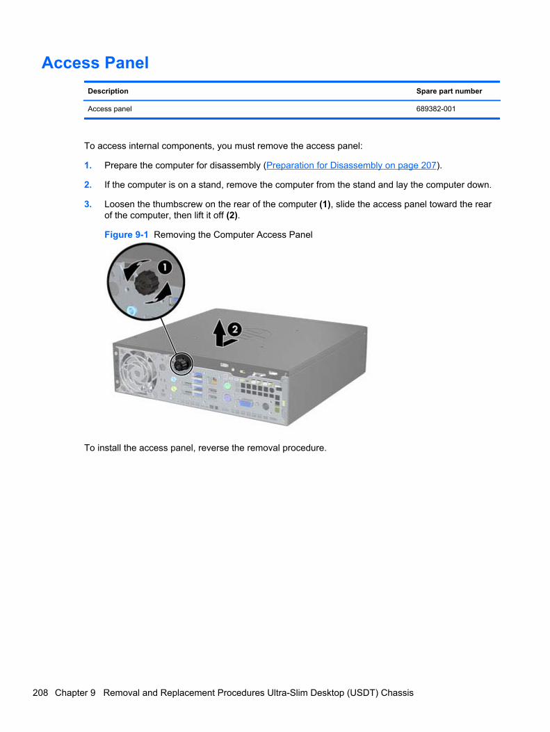
Access Panel
Description Spare part number
Access panel 689382-001
To access internal components, you must remove the access panel:
1. Prepare the computer for disassembly (Preparation for Disassembly on page 207).
2. If the computer is on a stand, remove the computer from the stand and lay the computer down.
3. Loosen the thumbscrew on the rear of the computer (1), slide the access panel toward the rearof the computer, then lift it off (2).
Figure 9-1 Removing the Computer Access Panel
To install the access panel, reverse the removal procedure.
208 Chapter 9 Removal and Replacement Procedures Ultra-Slim Desktop (USDT) Chassis
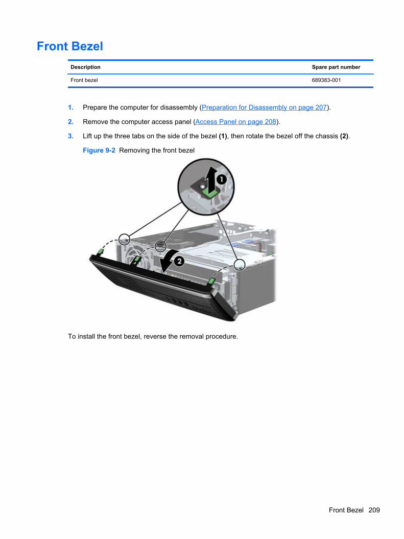
Front Bezel
Description Spare part number
Front bezel 689383-001
1. Prepare the computer for disassembly (Preparation for Disassembly on page 207).
2. Remove the computer access panel (Access Panel on page 208).
3. Lift up the three tabs on the side of the bezel (1), then rotate the bezel off the chassis (2).
Figure 9-2 Removing the front bezel
To install the front bezel, reverse the removal procedure.
Front Bezel 209
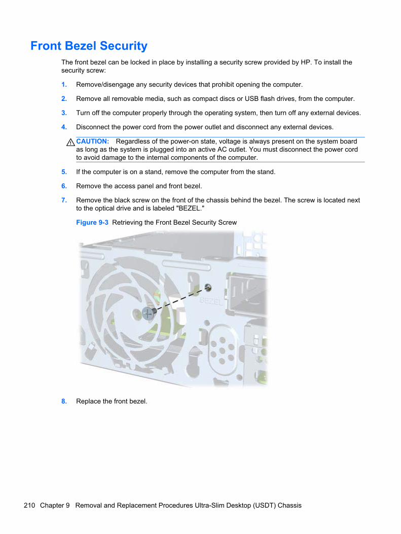
Front Bezel SecurityThe front bezel can be locked in place by installing a security screw provided by HP. To install thesecurity screw:
1. Remove/disengage any security devices that prohibit opening the computer.
2. Remove all removable media, such as compact discs or USB flash drives, from the computer.
3. Turn off the computer properly through the operating system, then turn off any external devices.
4. Disconnect the power cord from the power outlet and disconnect any external devices.
CAUTION: Regardless of the power-on state, voltage is always present on the system boardas long as the system is plugged into an active AC outlet. You must disconnect the power cordto avoid damage to the internal components of the computer.
5. If the computer is on a stand, remove the computer from the stand.
6. Remove the access panel and front bezel.
7. Remove the black screw on the front of the chassis behind the bezel. The screw is located nextto the optical drive and is labeled "BEZEL."
Figure 9-3 Retrieving the Front Bezel Security Screw
8. Replace the front bezel.
210 Chapter 9 Removal and Replacement Procedures Ultra-Slim Desktop (USDT) Chassis
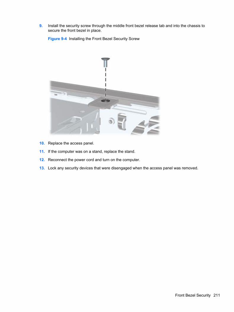
9. Install the security screw through the middle front bezel release tab and into the chassis tosecure the front bezel in place.
Figure 9-4 Installing the Front Bezel Security Screw
10. Replace the access panel.
11. If the computer was on a stand, replace the stand.
12. Reconnect the power cord and turn on the computer.
13. Lock any security devices that were disengaged when the access panel was removed.
Front Bezel Security 211
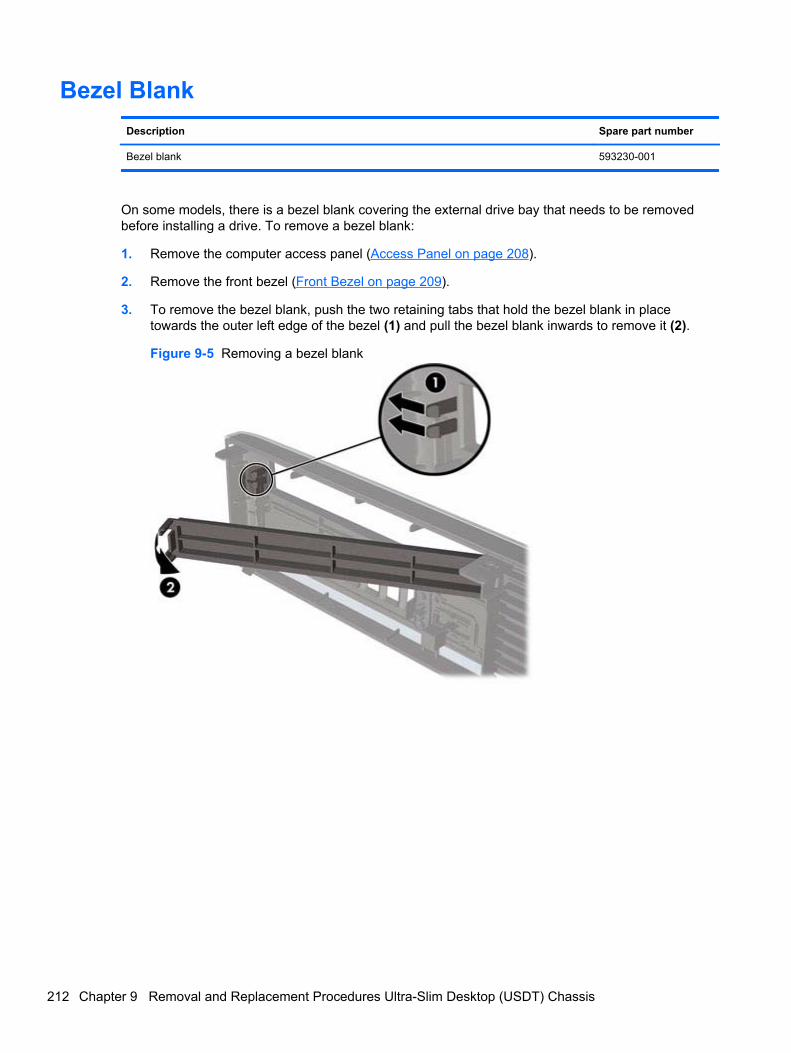
Bezel Blank
Description Spare part number
Bezel blank 593230-001
On some models, there is a bezel blank covering the external drive bay that needs to be removedbefore installing a drive. To remove a bezel blank:
1. Remove the computer access panel (Access Panel on page 208).
2. Remove the front bezel (Front Bezel on page 209).
3. To remove the bezel blank, push the two retaining tabs that hold the bezel blank in placetowards the outer left edge of the bezel (1) and pull the bezel blank inwards to remove it (2).
Figure 9-5 Removing a bezel blank
212 Chapter 9 Removal and Replacement Procedures Ultra-Slim Desktop (USDT) Chassis
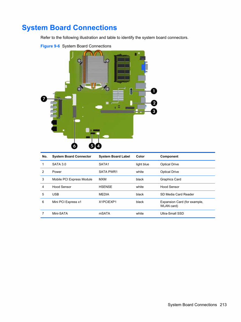
System Board ConnectionsRefer to the following illustration and table to identify the system board connectors.
Figure 9-6 System Board Connections
No. System Board Connector System Board Label Color Component
1 SATA 3.0 SATA1 light blue Optical Drive
2 Power SATA PWR1 white Optical Drive
3 Mobile PCI Express Module MXM black Graphics Card
4 Hood Sensor HSENSE white Hood Sensor
5 USB MEDIA black SD Media Card Reader
6 Mini PCI Express x1 X1PCIEXP1 black Expansion Card (for example,WLAN card)
7 Mini-SATA mSATA white Ultra-Small SSD
System Board Connections 213
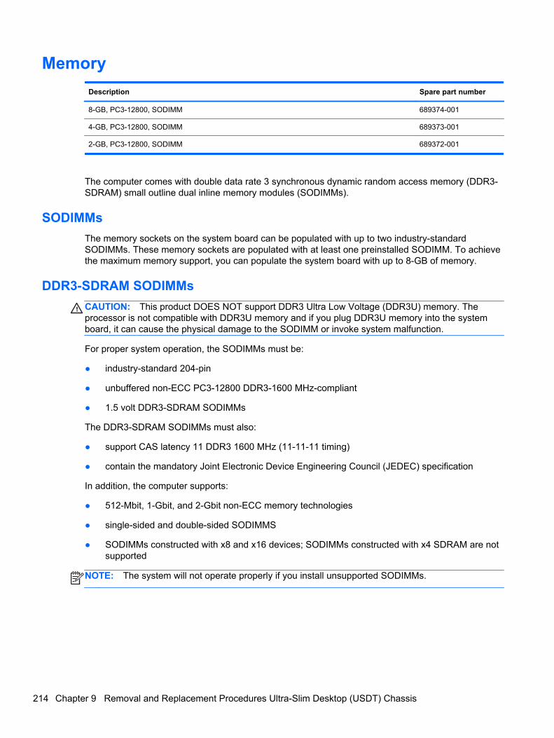
Memory
Description Spare part number
8-GB, PC3-12800, SODIMM 689374-001
4-GB, PC3-12800, SODIMM 689373-001
2-GB, PC3-12800, SODIMM 689372-001
The computer comes with double data rate 3 synchronous dynamic random access memory (DDR3-SDRAM) small outline dual inline memory modules (SODIMMs).
SODIMMs
The memory sockets on the system board can be populated with up to two industry-standardSODIMMs. These memory sockets are populated with at least one preinstalled SODIMM. To achievethe maximum memory support, you can populate the system board with up to 8-GB of memory.
DDR3-SDRAM SODIMMs
CAUTION: This product DOES NOT support DDR3 Ultra Low Voltage (DDR3U) memory. Theprocessor is not compatible with DDR3U memory and if you plug DDR3U memory into the systemboard, it can cause the physical damage to the SODIMM or invoke system malfunction.
For proper system operation, the SODIMMs must be:
● industry-standard 204-pin
● unbuffered non-ECC PC3-12800 DDR3-1600 MHz-compliant
● 1.5 volt DDR3-SDRAM SODIMMs
The DDR3-SDRAM SODIMMs must also:
● support CAS latency 11 DDR3 1600 MHz (11-11-11 timing)
● contain the mandatory Joint Electronic Device Engineering Council (JEDEC) specification
In addition, the computer supports:
● 512-Mbit, 1-Gbit, and 2-Gbit non-ECC memory technologies
● single-sided and double-sided SODIMMS
● SODIMMs constructed with x8 and x16 devices; SODIMMs constructed with x4 SDRAM are notsupported
NOTE: The system will not operate properly if you install unsupported SODIMMs.
214 Chapter 9 Removal and Replacement Procedures Ultra-Slim Desktop (USDT) Chassis
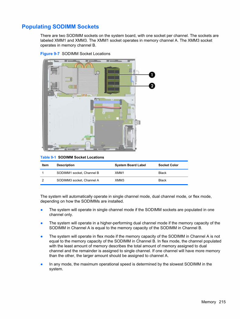
Populating SODIMM Sockets
There are two SODIMM sockets on the system board, with one socket per channel. The sockets arelabeled XMM1 and XMM3. The XMM1 socket operates in memory channel A. The XMM3 socketoperates in memory channel B.
Figure 9-7 SODIMM Socket Locations
Table 9-1 SODIMM Socket Locations
Item Description System Board Label Socket Color
1 SODIMM1 socket, Channel B XMM1 Black
2 SODIMM3 socket, Channel A XMM3 Black
The system will automatically operate in single channel mode, dual channel mode, or flex mode,depending on how the SODIMMs are installed.
● The system will operate in single channel mode if the SODIMM sockets are populated in onechannel only.
● The system will operate in a higher-performing dual channel mode if the memory capacity of theSODIMM in Channel A is equal to the memory capacity of the SODIMM in Channel B.
● The system will operate in flex mode if the memory capacity of the SODIMM in Channel A is notequal to the memory capacity of the SODIMM in Channel B. In flex mode, the channel populatedwith the least amount of memory describes the total amount of memory assigned to dualchannel and the remainder is assigned to single channel. If one channel will have more memorythan the other, the larger amount should be assigned to channel A.
● In any mode, the maximum operational speed is determined by the slowest SODIMM in thesystem.
Memory 215
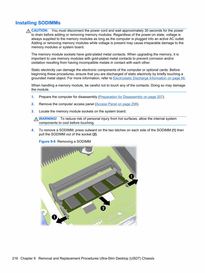
Installing SODIMMs
CAUTION: You must disconnect the power cord and wait approximately 30 seconds for the powerto drain before adding or removing memory modules. Regardless of the power-on state, voltage isalways supplied to the memory modules as long as the computer is plugged into an active AC outlet.Adding or removing memory modules while voltage is present may cause irreparable damage to thememory modules or system board.
The memory module sockets have gold-plated metal contacts. When upgrading the memory, it isimportant to use memory modules with gold-plated metal contacts to prevent corrosion and/oroxidation resulting from having incompatible metals in contact with each other.
Static electricity can damage the electronic components of the computer or optional cards. Beforebeginning these procedures, ensure that you are discharged of static electricity by briefly touching agrounded metal object. For more information, refer to Electrostatic Discharge Information on page 66.
When handling a memory module, be careful not to touch any of the contacts. Doing so may damagethe module.
1. Prepare the computer for disassembly (Preparation for Disassembly on page 207).
2. Remove the computer access panel (Access Panel on page 208).
3. Locate the memory module sockets on the system board.
WARNING! To reduce risk of personal injury from hot surfaces, allow the internal systemcomponents to cool before touching.
4. To remove a SODIMM, press outward on the two latches on each side of the SODIMM (1) thenpull the SODIMM out of the socket (2).
Figure 9-8 Removing a SODIMM
216 Chapter 9 Removal and Replacement Procedures Ultra-Slim Desktop (USDT) Chassis
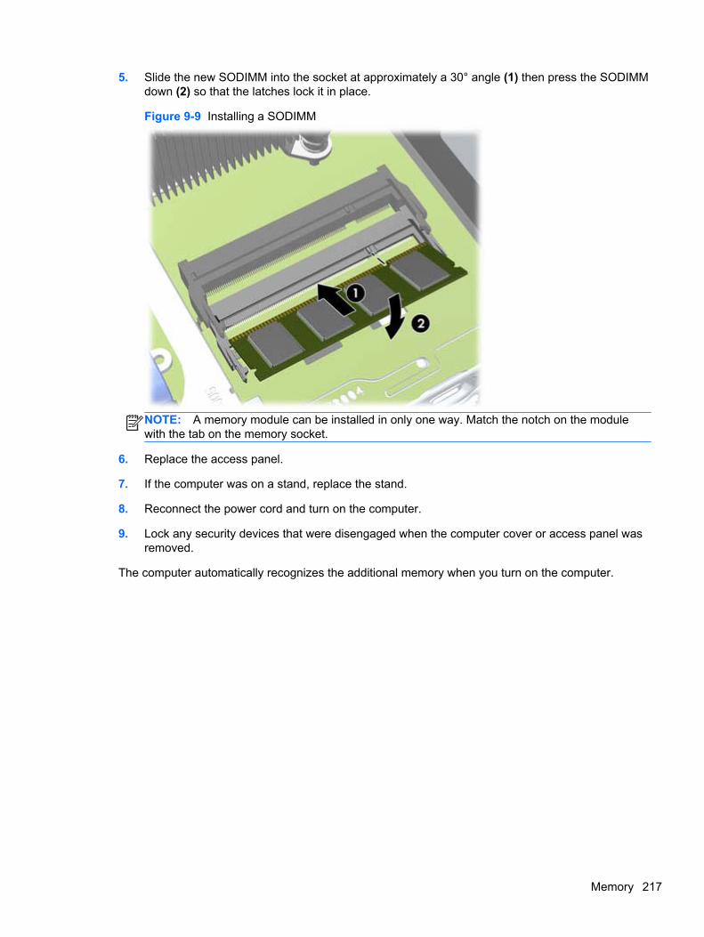
5. Slide the new SODIMM into the socket at approximately a 30° angle (1) then press the SODIMMdown (2) so that the latches lock it in place.
Figure 9-9 Installing a SODIMM
NOTE: A memory module can be installed in only one way. Match the notch on the modulewith the tab on the memory socket.
6. Replace the access panel.
7. If the computer was on a stand, replace the stand.
8. Reconnect the power cord and turn on the computer.
9. Lock any security devices that were disengaged when the computer cover or access panel wasremoved.
The computer automatically recognizes the additional memory when you turn on the computer.
Memory 217
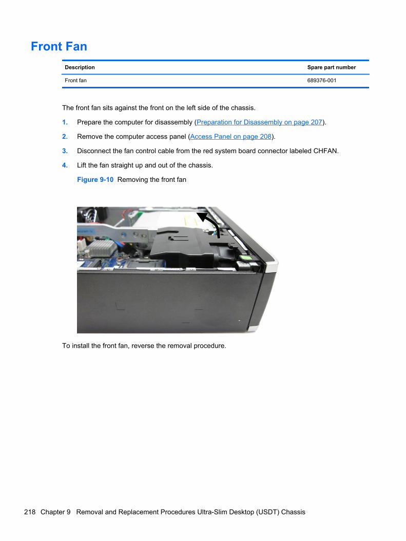
Front Fan
Description Spare part number
Front fan 689376-001
The front fan sits against the front on the left side of the chassis.
1. Prepare the computer for disassembly (Preparation for Disassembly on page 207).
2. Remove the computer access panel (Access Panel on page 208).
3. Disconnect the fan control cable from the red system board connector labeled CHFAN.
4. Lift the fan straight up and out of the chassis.
Figure 9-10 Removing the front fan
To install the front fan, reverse the removal procedure.
218 Chapter 9 Removal and Replacement Procedures Ultra-Slim Desktop (USDT) Chassis
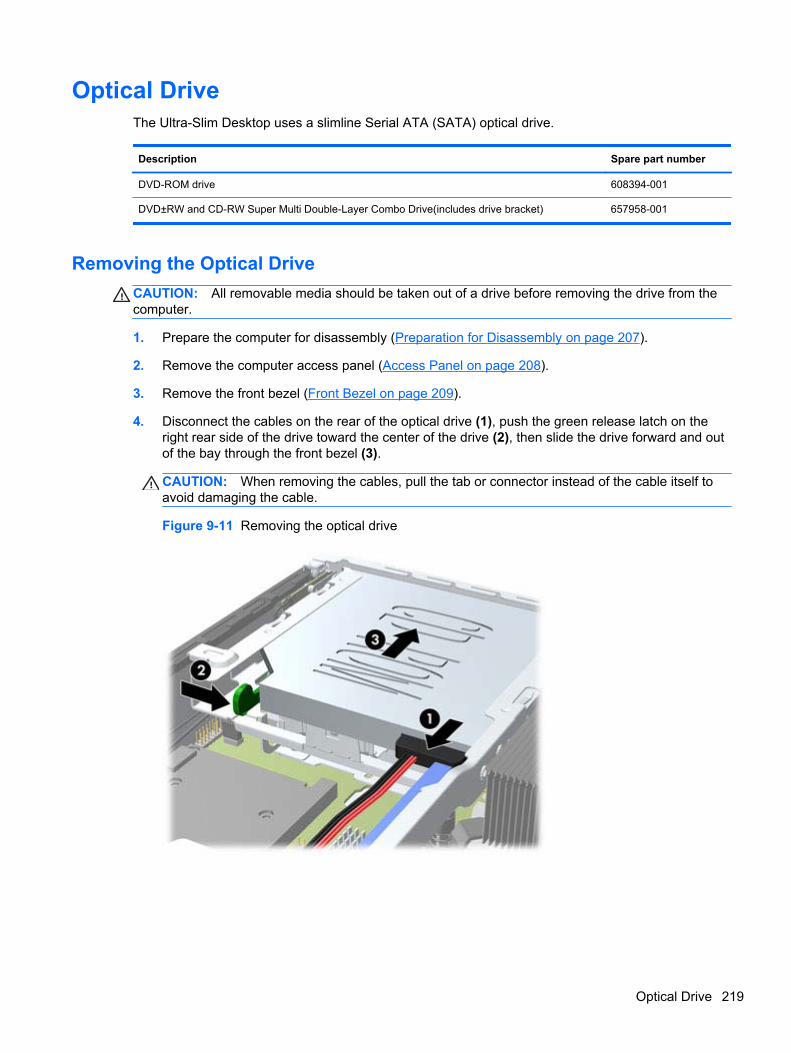
Optical DriveThe Ultra-Slim Desktop uses a slimline Serial ATA (SATA) optical drive.
Description Spare part number
DVD-ROM drive 608394-001
DVD±RW and CD-RW Super Multi Double-Layer Combo Drive(includes drive bracket) 657958-001
Removing the Optical Drive
CAUTION: All removable media should be taken out of a drive before removing the drive from thecomputer.
1. Prepare the computer for disassembly (Preparation for Disassembly on page 207).
2. Remove the computer access panel (Access Panel on page 208).
3. Remove the front bezel (Front Bezel on page 209).
4. Disconnect the cables on the rear of the optical drive (1), push the green release latch on theright rear side of the drive toward the center of the drive (2), then slide the drive forward and outof the bay through the front bezel (3).
CAUTION: When removing the cables, pull the tab or connector instead of the cable itself toavoid damaging the cable.
Figure 9-11 Removing the optical drive
Optical Drive 219
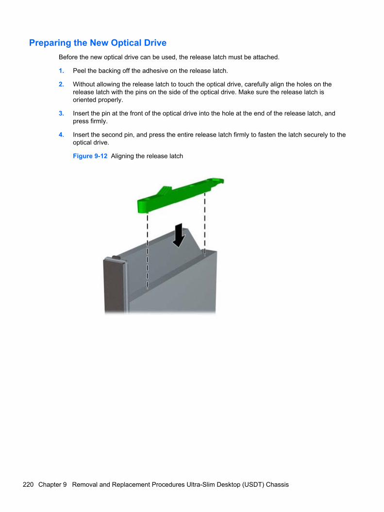
Preparing the New Optical Drive
Before the new optical drive can be used, the release latch must be attached.
1. Peel the backing off the adhesive on the release latch.
2. Without allowing the release latch to touch the optical drive, carefully align the holes on therelease latch with the pins on the side of the optical drive. Make sure the release latch isoriented properly.
3. Insert the pin at the front of the optical drive into the hole at the end of the release latch, andpress firmly.
4. Insert the second pin, and press the entire release latch firmly to fasten the latch securely to theoptical drive.
Figure 9-12 Aligning the release latch
220 Chapter 9 Removal and Replacement Procedures Ultra-Slim Desktop (USDT) Chassis
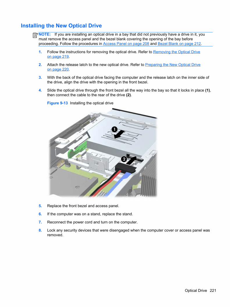
Installing the New Optical Drive
NOTE: If you are installing an optical drive in a bay that did not previously have a drive in it, youmust remove the access panel and the bezel blank covering the opening of the bay beforeproceeding. Follow the procedures in Access Panel on page 208 and Bezel Blank on page 212.
1. Follow the instructions for removing the optical drive. Refer to Removing the Optical Driveon page 219.
2. Attach the release latch to the new optical drive. Refer to Preparing the New Optical Driveon page 220.
3. With the back of the optical drive facing the computer and the release latch on the inner side ofthe drive, align the drive with the opening in the front bezel.
4. Slide the optical drive through the front bezel all the way into the bay so that it locks in place (1),then connect the cable to the rear of the drive (2).
Figure 9-13 Installing the optical drive
5. Replace the front bezel and access panel.
6. If the computer was on a stand, replace the stand.
7. Reconnect the power cord and turn on the computer.
8. Lock any security devices that were disengaged when the computer cover or access panel wasremoved.
Optical Drive 221
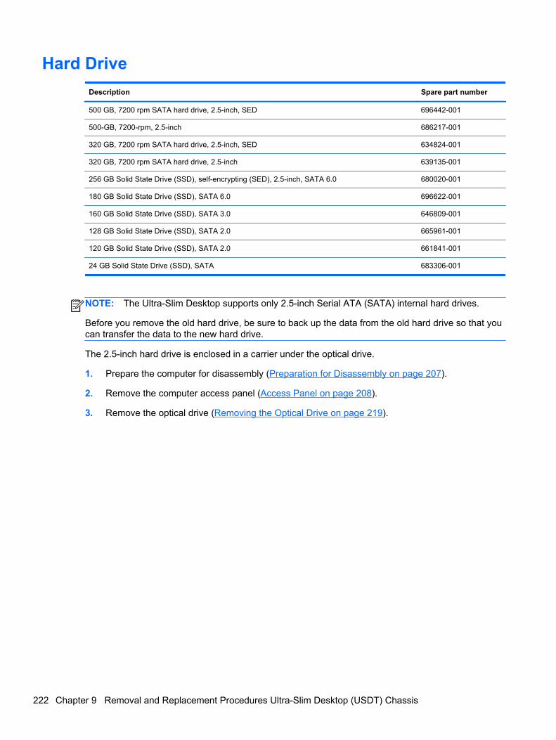
Hard Drive
Description Spare part number
500 GB, 7200 rpm SATA hard drive, 2.5-inch, SED 696442-001
500-GB, 7200-rpm, 2.5-inch 686217-001
320 GB, 7200 rpm SATA hard drive, 2.5-inch, SED 634824-001
320 GB, 7200 rpm SATA hard drive, 2.5-inch 639135-001
256 GB Solid State Drive (SSD), self-encrypting (SED), 2.5-inch, SATA 6.0 680020-001
180 GB Solid State Drive (SSD), SATA 6.0 696622-001
160 GB Solid State Drive (SSD), SATA 3.0 646809-001
128 GB Solid State Drive (SSD), SATA 2.0 665961-001
120 GB Solid State Drive (SSD), SATA 2.0 661841-001
24 GB Solid State Drive (SSD), SATA 683306-001
NOTE: The Ultra-Slim Desktop supports only 2.5-inch Serial ATA (SATA) internal hard drives.
Before you remove the old hard drive, be sure to back up the data from the old hard drive so that youcan transfer the data to the new hard drive.
The 2.5-inch hard drive is enclosed in a carrier under the optical drive.
1. Prepare the computer for disassembly (Preparation for Disassembly on page 207).
2. Remove the computer access panel (Access Panel on page 208).
3. Remove the optical drive (Removing the Optical Drive on page 219).
222 Chapter 9 Removal and Replacement Procedures Ultra-Slim Desktop (USDT) Chassis
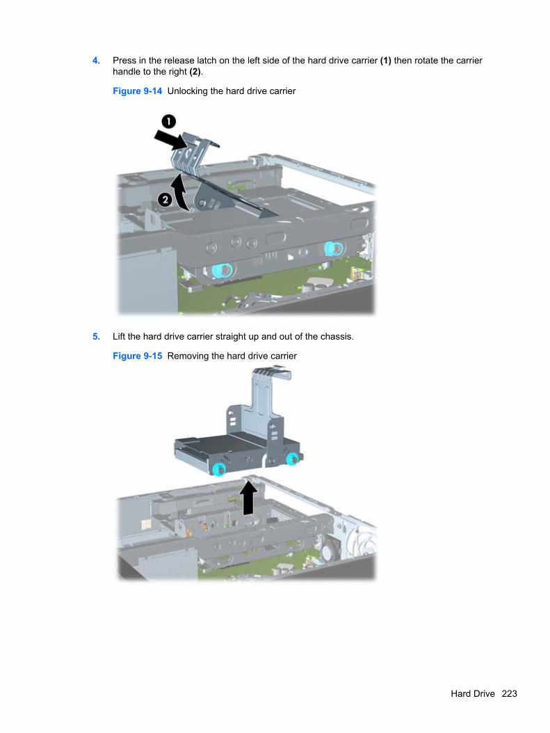
4. Press in the release latch on the left side of the hard drive carrier (1) then rotate the carrierhandle to the right (2).
Figure 9-14 Unlocking the hard drive carrier
5. Lift the hard drive carrier straight up and out of the chassis.
Figure 9-15 Removing the hard drive carrier
Hard Drive 223
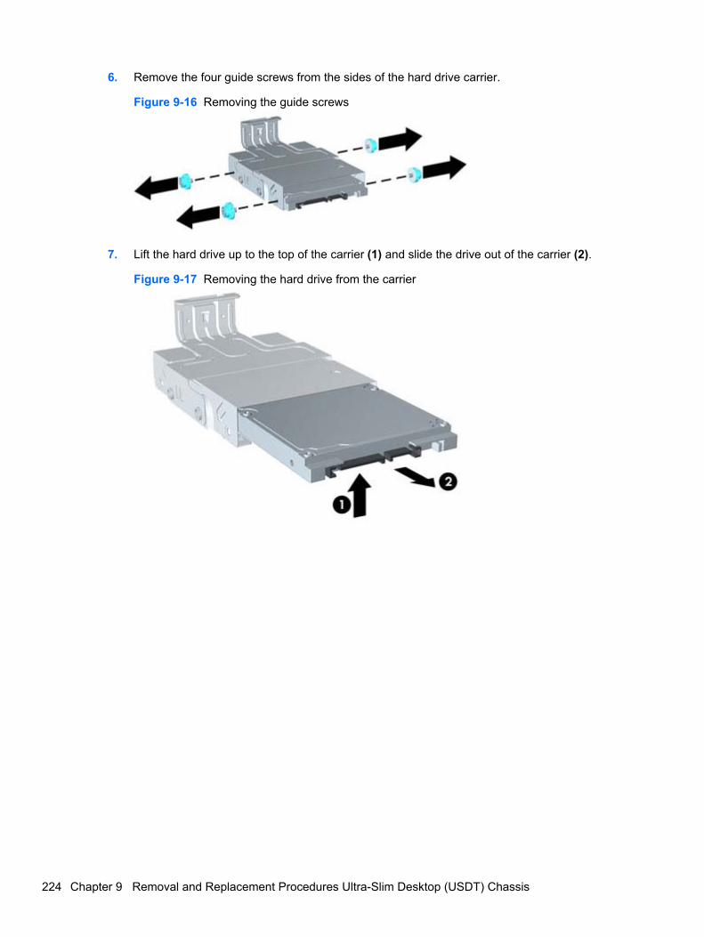
6. Remove the four guide screws from the sides of the hard drive carrier.
Figure 9-16 Removing the guide screws
7. Lift the hard drive up to the top of the carrier (1) and slide the drive out of the carrier (2).
Figure 9-17 Removing the hard drive from the carrier
224 Chapter 9 Removal and Replacement Procedures Ultra-Slim Desktop (USDT) Chassis
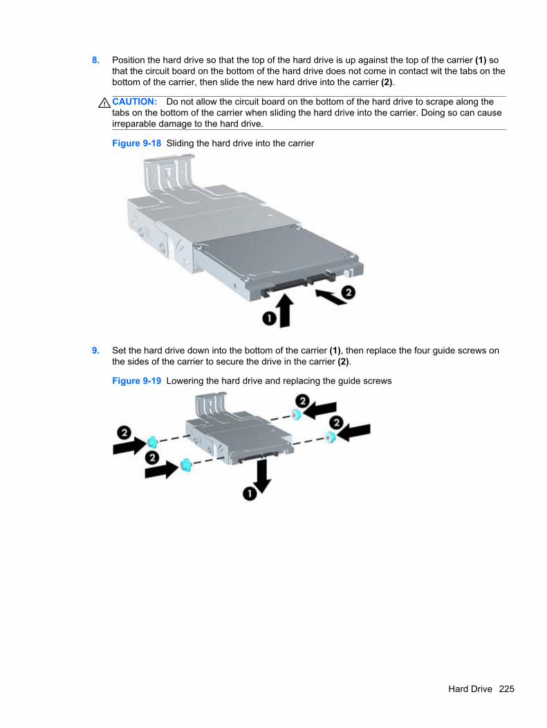
8. Position the hard drive so that the top of the hard drive is up against the top of the carrier (1) sothat the circuit board on the bottom of the hard drive does not come in contact wit the tabs on thebottom of the carrier, then slide the new hard drive into the carrier (2).
CAUTION: Do not allow the circuit board on the bottom of the hard drive to scrape along thetabs on the bottom of the carrier when sliding the hard drive into the carrier. Doing so can causeirreparable damage to the hard drive.
Figure 9-18 Sliding the hard drive into the carrier
9. Set the hard drive down into the bottom of the carrier (1), then replace the four guide screws onthe sides of the carrier to secure the drive in the carrier (2).
Figure 9-19 Lowering the hard drive and replacing the guide screws
Hard Drive 225
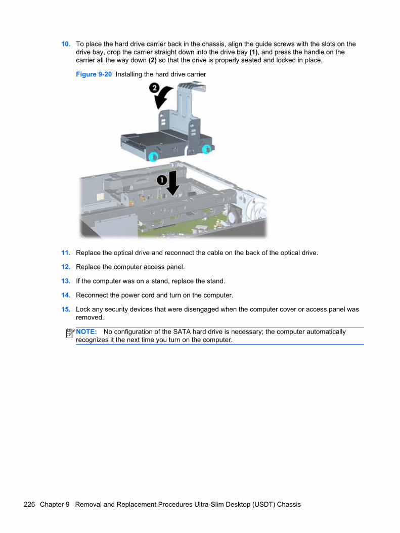
10. To place the hard drive carrier back in the chassis, align the guide screws with the slots on thedrive bay, drop the carrier straight down into the drive bay (1), and press the handle on thecarrier all the way down (2) so that the drive is properly seated and locked in place.
Figure 9-20 Installing the hard drive carrier
11. Replace the optical drive and reconnect the cable on the back of the optical drive.
12. Replace the computer access panel.
13. If the computer was on a stand, replace the stand.
14. Reconnect the power cord and turn on the computer.
15. Lock any security devices that were disengaged when the computer cover or access panel wasremoved.
NOTE: No configuration of the SATA hard drive is necessary; the computer automaticallyrecognizes it the next time you turn on the computer.
226 Chapter 9 Removal and Replacement Procedures Ultra-Slim Desktop (USDT) Chassis
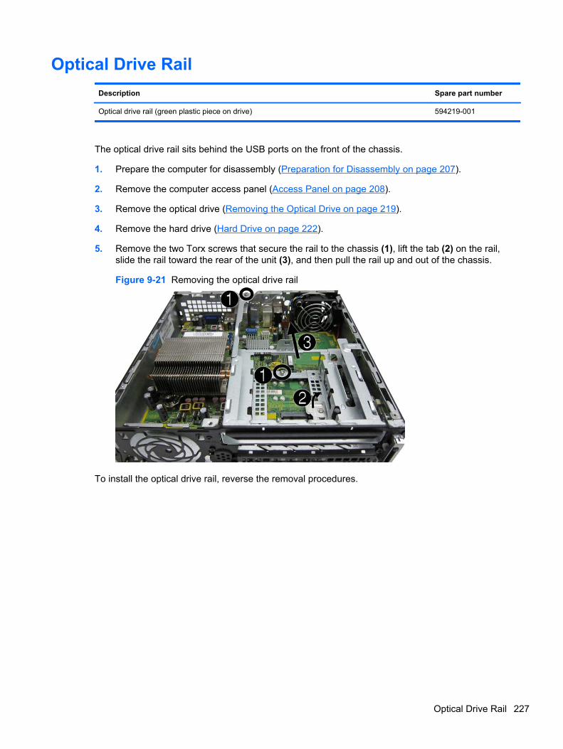
Optical Drive Rail
Description Spare part number
Optical drive rail (green plastic piece on drive) 594219-001
The optical drive rail sits behind the USB ports on the front of the chassis.
1. Prepare the computer for disassembly (Preparation for Disassembly on page 207).
2. Remove the computer access panel (Access Panel on page 208).
3. Remove the optical drive (Removing the Optical Drive on page 219).
4. Remove the hard drive (Hard Drive on page 222).
5. Remove the two Torx screws that secure the rail to the chassis (1), lift the tab (2) on the rail,slide the rail toward the rear of the unit (3), and then pull the rail up and out of the chassis.
Figure 9-21 Removing the optical drive rail
To install the optical drive rail, reverse the removal procedures.
Optical Drive Rail 227
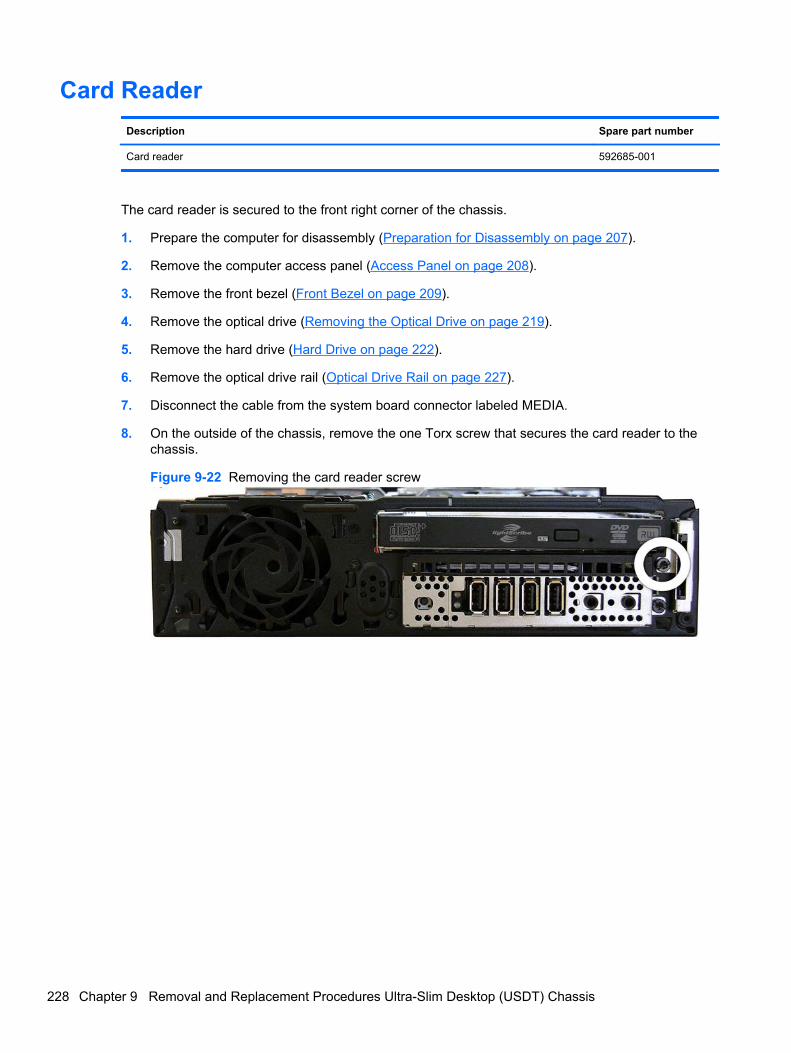
Card Reader
Description Spare part number
Card reader 592685-001
The card reader is secured to the front right corner of the chassis.
1. Prepare the computer for disassembly (Preparation for Disassembly on page 207).
2. Remove the computer access panel (Access Panel on page 208).
3. Remove the front bezel (Front Bezel on page 209).
4. Remove the optical drive (Removing the Optical Drive on page 219).
5. Remove the hard drive (Hard Drive on page 222).
6. Remove the optical drive rail (Optical Drive Rail on page 227).
7. Disconnect the cable from the system board connector labeled MEDIA.
8. On the outside of the chassis, remove the one Torx screw that secures the card reader to thechassis.
Figure 9-22 Removing the card reader screw
228 Chapter 9 Removal and Replacement Procedures Ultra-Slim Desktop (USDT) Chassis
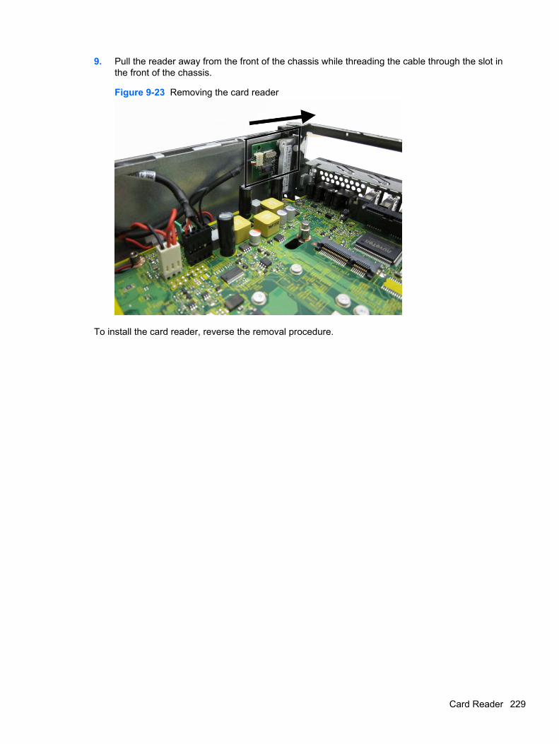
9. Pull the reader away from the front of the chassis while threading the cable through the slot inthe front of the chassis.
Figure 9-23 Removing the card reader
To install the card reader, reverse the removal procedure.
Card Reader 229
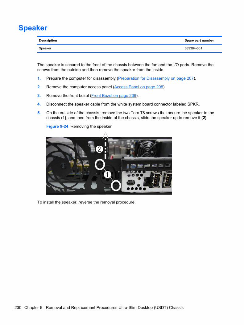
Speaker
Description Spare part number
Speaker 689384-001
The speaker is secured to the front of the chassis between the fan and the I/O ports. Remove thescrews from the outside and then remove the speaker from the inside.
1. Prepare the computer for disassembly (Preparation for Disassembly on page 207).
2. Remove the computer access panel (Access Panel on page 208).
3. Remove the front bezel (Front Bezel on page 209).
4. Disconnect the speaker cable from the white system board connector labeled SPKR.
5. On the outside of the chassis, remove the two Torx T8 screws that secure the speaker to thechassis (1), and then from the inside of the chassis, slide the speaker up to remove it (2).
Figure 9-24 Removing the speaker
To install the speaker, reverse the removal procedure.
230 Chapter 9 Removal and Replacement Procedures Ultra-Slim Desktop (USDT) Chassis
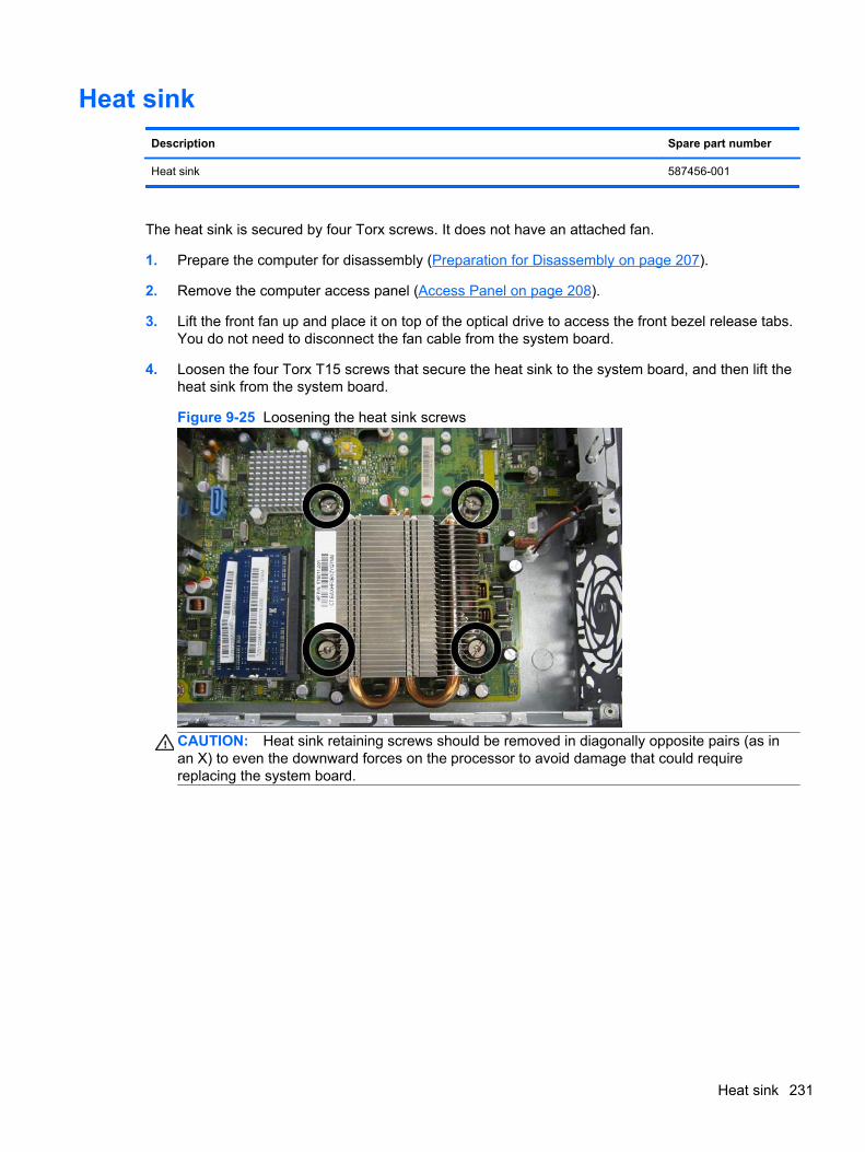
Heat sink
Description Spare part number
Heat sink 587456-001
The heat sink is secured by four Torx screws. It does not have an attached fan.
1. Prepare the computer for disassembly (Preparation for Disassembly on page 207).
2. Remove the computer access panel (Access Panel on page 208).
3. Lift the front fan up and place it on top of the optical drive to access the front bezel release tabs.You do not need to disconnect the fan cable from the system board.
4. Loosen the four Torx T15 screws that secure the heat sink to the system board, and then lift theheat sink from the system board.
Figure 9-25 Loosening the heat sink screws
CAUTION: Heat sink retaining screws should be removed in diagonally opposite pairs (as inan X) to even the downward forces on the processor to avoid damage that could requirereplacing the system board.
Heat sink 231
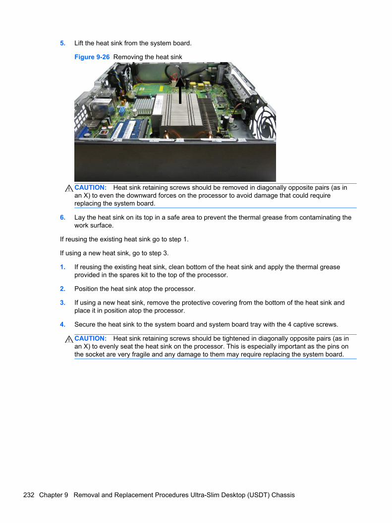
5. Lift the heat sink from the system board.
Figure 9-26 Removing the heat sink
CAUTION: Heat sink retaining screws should be removed in diagonally opposite pairs (as inan X) to even the downward forces on the processor to avoid damage that could requirereplacing the system board.
6. Lay the heat sink on its top in a safe area to prevent the thermal grease from contaminating thework surface.
If reusing the existing heat sink go to step 1.
If using a new heat sink, go to step 3.
1. If reusing the existing heat sink, clean bottom of the heat sink and apply the thermal greaseprovided in the spares kit to the top of the processor.
2. Position the heat sink atop the processor.
3. If using a new heat sink, remove the protective covering from the bottom of the heat sink andplace it in position atop the processor.
4. Secure the heat sink to the system board and system board tray with the 4 captive screws.
CAUTION: Heat sink retaining screws should be tightened in diagonally opposite pairs (as inan X) to evenly seat the heat sink on the processor. This is especially important as the pins onthe socket are very fragile and any damage to them may require replacing the system board.
232 Chapter 9 Removal and Replacement Procedures Ultra-Slim Desktop (USDT) Chassis
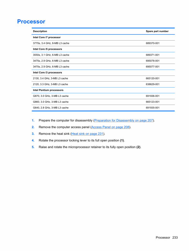
Processor
Description Spare part number
Intel Core i7 processor
3770s, 3.4 GHz, 8-MB L3 cache 689370-001
Intel Core i5 processors
3550s, 3.1 GHz, 6-MB L3 cache 689371-001
3475s, 2.9 GHz, 6-MB L3 cache 695078-001
3470s, 2.9 GHz, 6-MB L3 cache 695077-001
Intel Core i3 processors
2130, 3.4 GHz, 3-MB L3 cache 665120-001
2120, 3.3 GHz, 3-MB L3 cache 638629-001
Intel Pentium processors
G870, 3.0 GHz, 3-MB L3 cache 691936-001
G860, 3.0 GHz, 3-MB L3 cache 665123-001
G640, 2.8 GHz, 3-MB L3 cache 691935-001
1. Prepare the computer for disassembly (Preparation for Disassembly on page 207).
2. Remove the computer access panel (Access Panel on page 208).
3. Remove the heat sink (Heat sink on page 231).
4. Rotate the processor locking lever to its full open position (1).
5. Raise and rotate the microprocessor retainer to its fully open position (2).
Processor 233
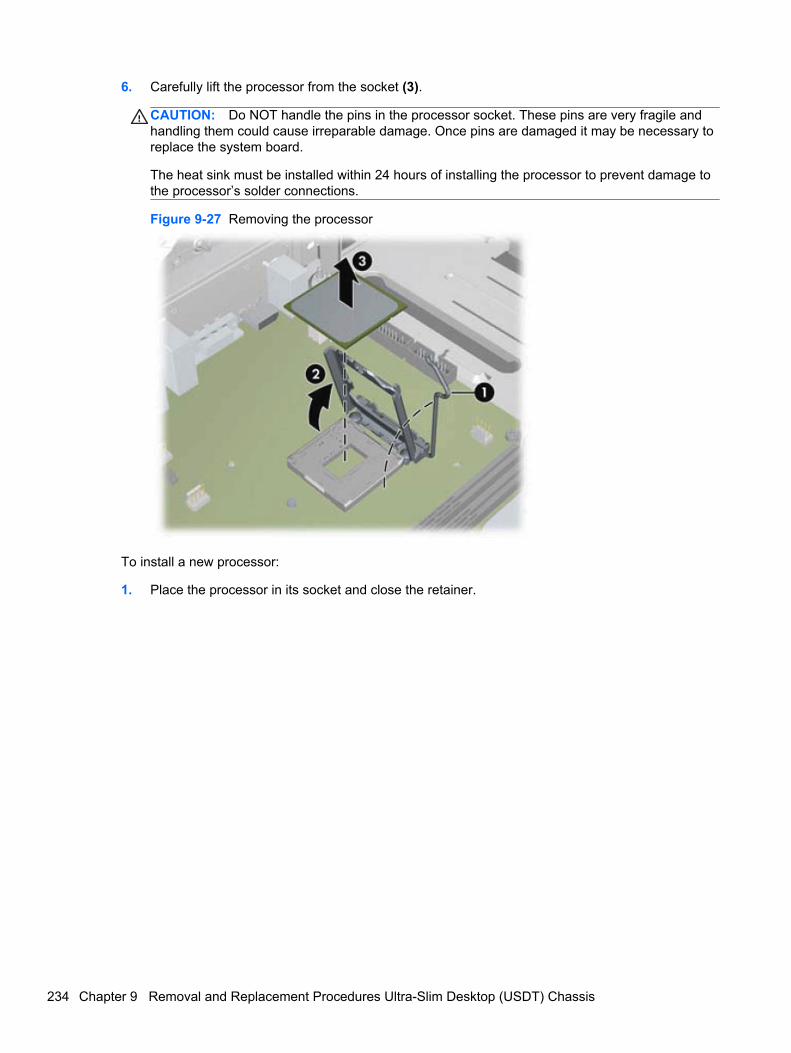
6. Carefully lift the processor from the socket (3).
CAUTION: Do NOT handle the pins in the processor socket. These pins are very fragile andhandling them could cause irreparable damage. Once pins are damaged it may be necessary toreplace the system board.
The heat sink must be installed within 24 hours of installing the processor to prevent damage tothe processor’s solder connections.
Figure 9-27 Removing the processor
To install a new processor:
1. Place the processor in its socket and close the retainer.
234 Chapter 9 Removal and Replacement Procedures Ultra-Slim Desktop (USDT) Chassis
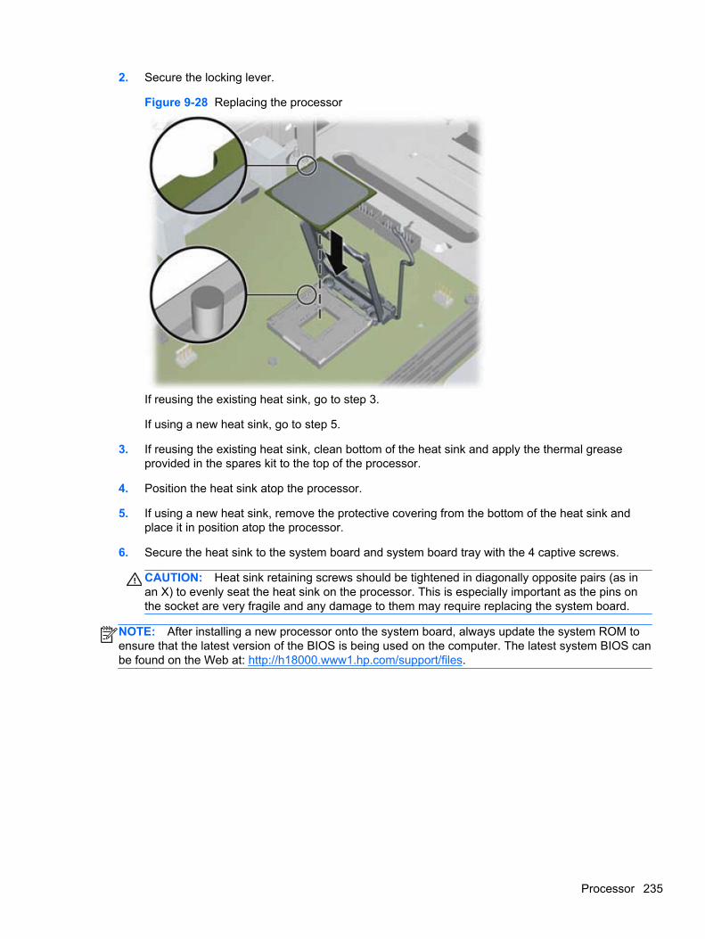
2. Secure the locking lever.
Figure 9-28 Replacing the processor
If reusing the existing heat sink, go to step 3.
If using a new heat sink, go to step 5.
3. If reusing the existing heat sink, clean bottom of the heat sink and apply the thermal greaseprovided in the spares kit to the top of the processor.
4. Position the heat sink atop the processor.
5. If using a new heat sink, remove the protective covering from the bottom of the heat sink andplace it in position atop the processor.
6. Secure the heat sink to the system board and system board tray with the 4 captive screws.
CAUTION: Heat sink retaining screws should be tightened in diagonally opposite pairs (as inan X) to evenly seat the heat sink on the processor. This is especially important as the pins onthe socket are very fragile and any damage to them may require replacing the system board.
NOTE: After installing a new processor onto the system board, always update the system ROM toensure that the latest version of the BIOS is being used on the computer. The latest system BIOS canbe found on the Web at: http://h18000.www1.hp.com/support/files.
Processor 235
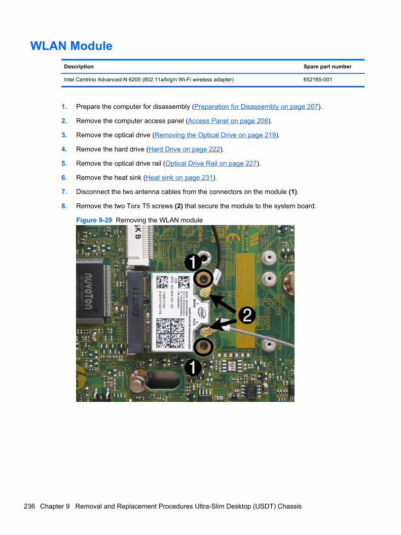
WLAN Module
Description Spare part number
Intel Centrino Advanced-N 6205 (802.11a/b/g/n Wi-Fi wireless adapter) 652165-001
1. Prepare the computer for disassembly (Preparation for Disassembly on page 207).
2. Remove the computer access panel (Access Panel on page 208).
3. Remove the optical drive (Removing the Optical Drive on page 219).
4. Remove the hard drive (Hard Drive on page 222).
5. Remove the optical drive rail (Optical Drive Rail on page 227).
6. Remove the heat sink (Heat sink on page 231).
7. Disconnect the two antenna cables from the connectors on the module (1).
8. Remove the two Torx T5 screws (2) that secure the module to the system board.
Figure 9-29 Removing the WLAN module
236 Chapter 9 Removal and Replacement Procedures Ultra-Slim Desktop (USDT) Chassis
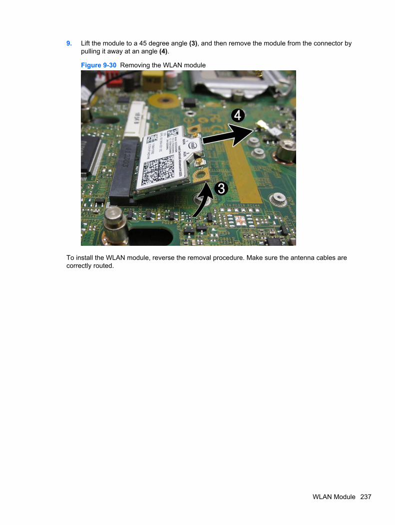
9. Lift the module to a 45 degree angle (3), and then remove the module from the connector bypulling it away at an angle (4).
Figure 9-30 Removing the WLAN module
To install the WLAN module, reverse the removal procedure. Make sure the antenna cables arecorrectly routed.
WLAN Module 237
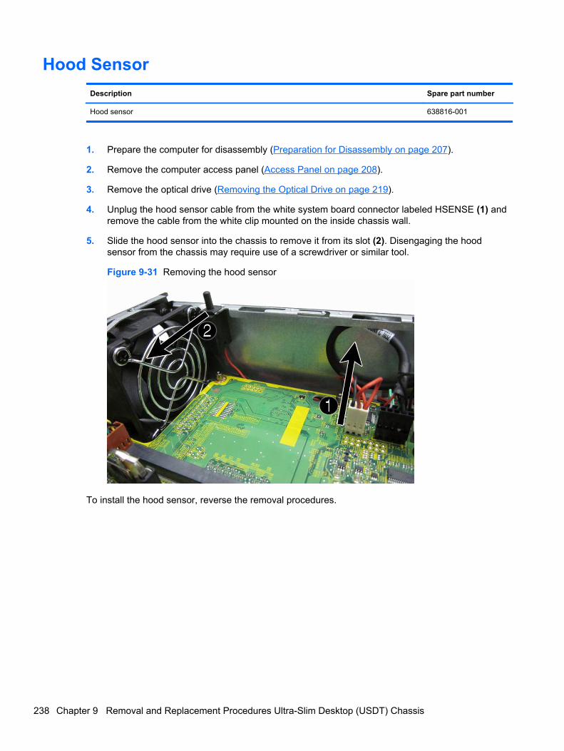
Hood Sensor
Description Spare part number
Hood sensor 638816-001
1. Prepare the computer for disassembly (Preparation for Disassembly on page 207).
2. Remove the computer access panel (Access Panel on page 208).
3. Remove the optical drive (Removing the Optical Drive on page 219).
4. Unplug the hood sensor cable from the white system board connector labeled HSENSE (1) andremove the cable from the white clip mounted on the inside chassis wall.
5. Slide the hood sensor into the chassis to remove it from its slot (2). Disengaging the hoodsensor from the chassis may require use of a screwdriver or similar tool.
Figure 9-31 Removing the hood sensor
To install the hood sensor, reverse the removal procedures.
238 Chapter 9 Removal and Replacement Procedures Ultra-Slim Desktop (USDT) Chassis
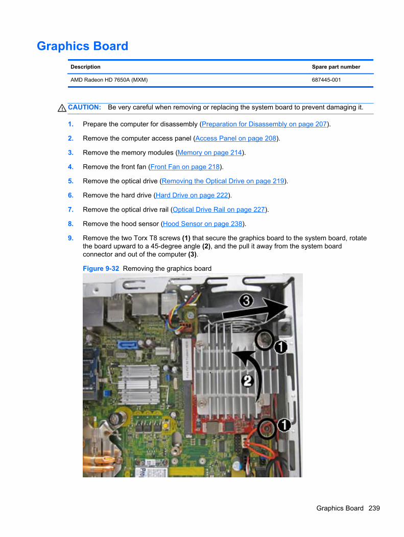
Graphics Board
Description Spare part number
AMD Radeon HD 7650A (MXM) 687445-001
CAUTION: Be very careful when removing or replacing the system board to prevent damaging it.
1. Prepare the computer for disassembly (Preparation for Disassembly on page 207).
2. Remove the computer access panel (Access Panel on page 208).
3. Remove the memory modules (Memory on page 214).
4. Remove the front fan (Front Fan on page 218).
5. Remove the optical drive (Removing the Optical Drive on page 219).
6. Remove the hard drive (Hard Drive on page 222).
7. Remove the optical drive rail (Optical Drive Rail on page 227).
8. Remove the hood sensor (Hood Sensor on page 238).
9. Remove the two Torx T8 screws (1) that secure the graphics board to the system board, rotatethe board upward to a 45-degree angle (2), and the pull it away from the system boardconnector and out of the computer (3).
Figure 9-32 Removing the graphics board
Graphics Board 239
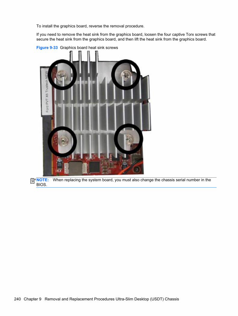
To install the graphics board, reverse the removal procedure.
If you need to remove the heat sink from the graphics board, loosen the four captive Torx screws thatsecure the heat sink from the graphics board, and then lift the heat sink from the graphics board.
Figure 9-33 Graphics board heat sink screws
NOTE: When replacing the system board, you must also change the chassis serial number in theBIOS.
240 Chapter 9 Removal and Replacement Procedures Ultra-Slim Desktop (USDT) Chassis
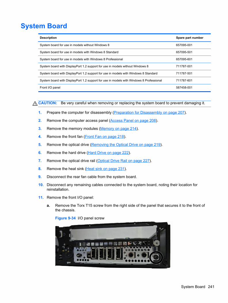
System Board
Description Spare part number
System board for use in models without Windows 8 657095-001
System board for use in models with Windows 8 Standard 657095-501
System board for use in models with Windows 8 Professional 657095-601
System board with DisplayPort 1.2 support for use in models without Windows 8 711787-001
System board with DisplayPort 1.2 support for use in models with Windows 8 Standard 711787-501
System board with DisplayPort 1.2 support for use in models with Windows 8 Professional 711787-601
Front I/O panel 587458-001
CAUTION: Be very careful when removing or replacing the system board to prevent damaging it.
1. Prepare the computer for disassembly (Preparation for Disassembly on page 207).
2. Remove the computer access panel (Access Panel on page 208).
3. Remove the memory modules (Memory on page 214).
4. Remove the front fan (Front Fan on page 218).
5. Remove the optical drive (Removing the Optical Drive on page 219).
6. Remove the hard drive (Hard Drive on page 222).
7. Remove the optical drive rail (Optical Drive Rail on page 227).
8. Remove the heat sink (Heat sink on page 231).
9. Disconnect the rear fan cable from the system board.
10. Disconnect any remaining cables connected to the system board, noting their location forreinstallation.
11. Remove the front I/O panel:
a. Remove the Torx T15 screw from the right side of the panel that secures it to the front ofthe chassis.
Figure 9-34 I/O panel screw
System Board 241
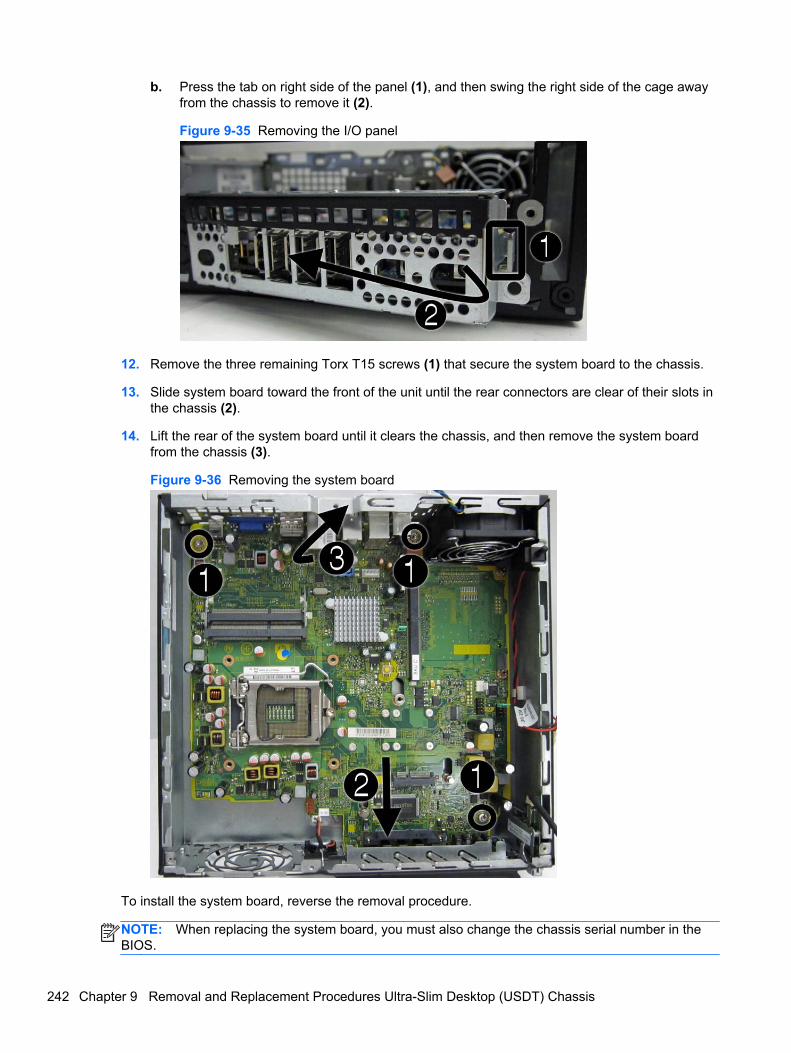
b. Press the tab on right side of the panel (1), and then swing the right side of the cage awayfrom the chassis to remove it (2).
Figure 9-35 Removing the I/O panel
12. Remove the three remaining Torx T15 screws (1) that secure the system board to the chassis.
13. Slide system board toward the front of the unit until the rear connectors are clear of their slots inthe chassis (2).
14. Lift the rear of the system board until it clears the chassis, and then remove the system boardfrom the chassis (3).
Figure 9-36 Removing the system board
To install the system board, reverse the removal procedure.
NOTE: When replacing the system board, you must also change the chassis serial number in theBIOS.
242 Chapter 9 Removal and Replacement Procedures Ultra-Slim Desktop (USDT) Chassis
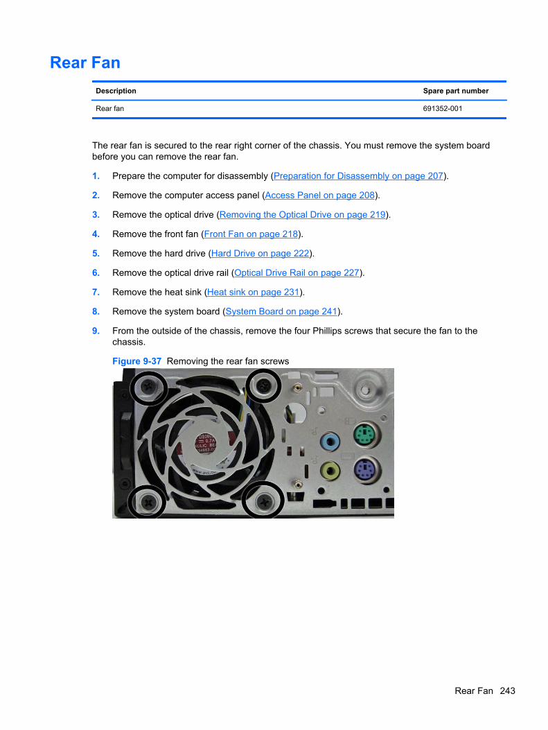
Rear Fan
Description Spare part number
Rear fan 691352-001
The rear fan is secured to the rear right corner of the chassis. You must remove the system boardbefore you can remove the rear fan.
1. Prepare the computer for disassembly (Preparation for Disassembly on page 207).
2. Remove the computer access panel (Access Panel on page 208).
3. Remove the optical drive (Removing the Optical Drive on page 219).
4. Remove the front fan (Front Fan on page 218).
5. Remove the hard drive (Hard Drive on page 222).
6. Remove the optical drive rail (Optical Drive Rail on page 227).
7. Remove the heat sink (Heat sink on page 231).
8. Remove the system board (System Board on page 241).
9. From the outside of the chassis, remove the four Phillips screws that secure the fan to thechassis.
Figure 9-37 Removing the rear fan screws
Rear Fan 243
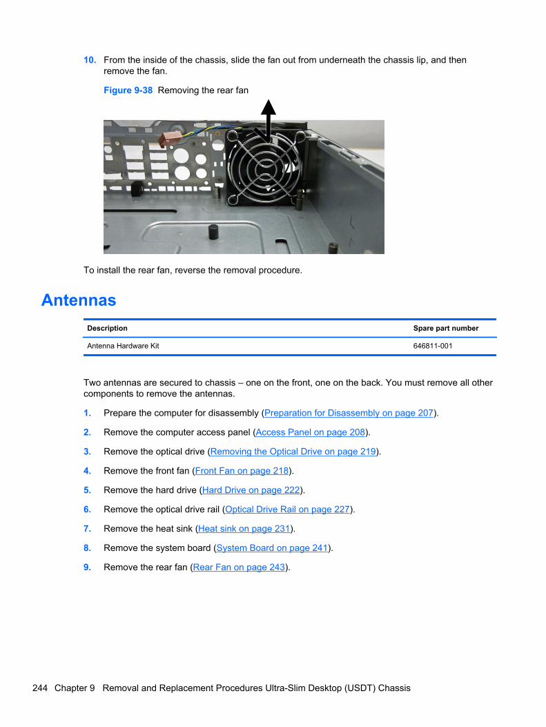
10. From the inside of the chassis, slide the fan out from underneath the chassis lip, and thenremove the fan.
Figure 9-38 Removing the rear fan
To install the rear fan, reverse the removal procedure.
Antennas
Description Spare part number
Antenna Hardware Kit 646811-001
Two antennas are secured to chassis – one on the front, one on the back. You must remove all othercomponents to remove the antennas.
1. Prepare the computer for disassembly (Preparation for Disassembly on page 207).
2. Remove the computer access panel (Access Panel on page 208).
3. Remove the optical drive (Removing the Optical Drive on page 219).
4. Remove the front fan (Front Fan on page 218).
5. Remove the hard drive (Hard Drive on page 222).
6. Remove the optical drive rail (Optical Drive Rail on page 227).
7. Remove the heat sink (Heat sink on page 231).
8. Remove the system board (System Board on page 241).
9. Remove the rear fan (Rear Fan on page 243).
244 Chapter 9 Removal and Replacement Procedures Ultra-Slim Desktop (USDT) Chassis
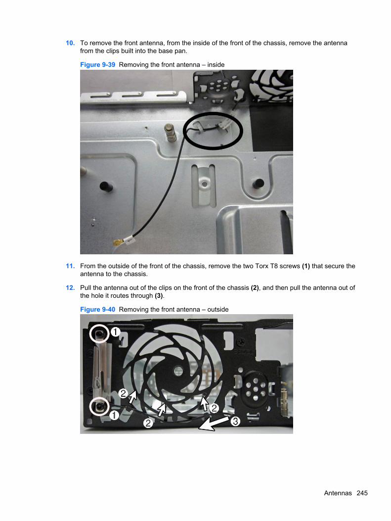
10. To remove the front antenna, from the inside of the front of the chassis, remove the antennafrom the clips built into the base pan.
Figure 9-39 Removing the front antenna – inside
11. From the outside of the front of the chassis, remove the two Torx T8 screws (1) that secure theantenna to the chassis.
12. Pull the antenna out of the clips on the front of the chassis (2), and then pull the antenna out ofthe hole it routes through (3).
Figure 9-40 Removing the front antenna – outside
Antennas 245
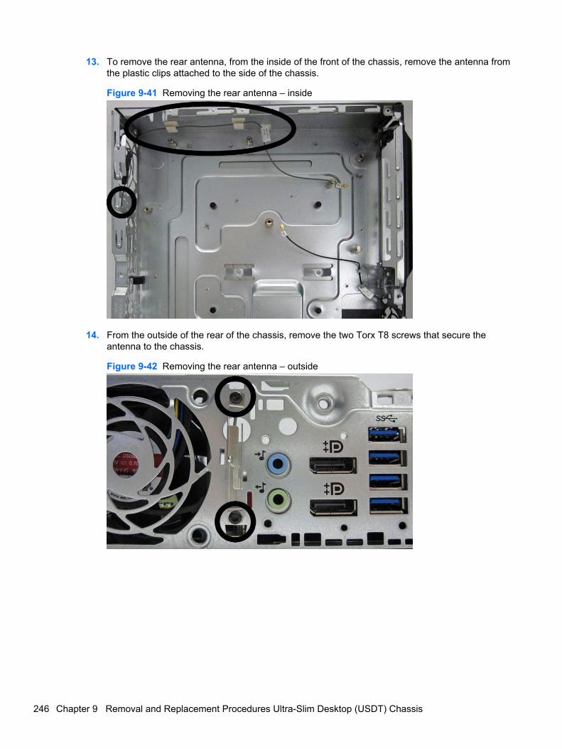
13. To remove the rear antenna, from the inside of the front of the chassis, remove the antenna fromthe plastic clips attached to the side of the chassis.
Figure 9-41 Removing the rear antenna – inside
14. From the outside of the rear of the chassis, remove the two Torx T8 screws that secure theantenna to the chassis.
Figure 9-42 Removing the rear antenna – outside
246 Chapter 9 Removal and Replacement Procedures Ultra-Slim Desktop (USDT) Chassis
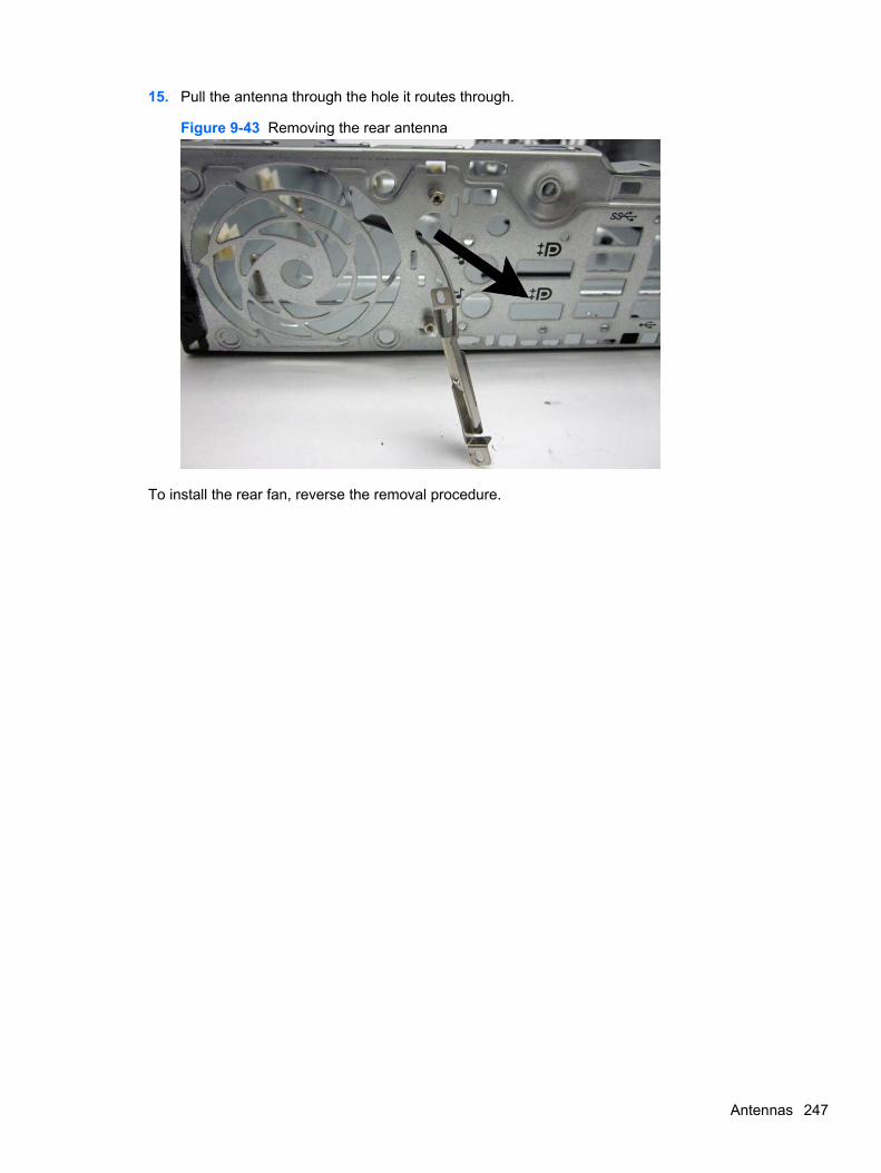
15. Pull the antenna through the hole it routes through.
Figure 9-43 Removing the rear antenna
To install the rear fan, reverse the removal procedure.
Antennas 247
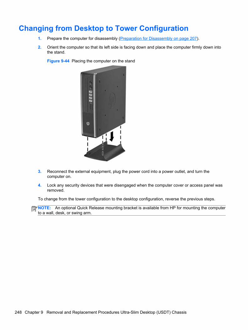
Changing from Desktop to Tower Configuration1. Prepare the computer for disassembly (Preparation for Disassembly on page 207).
2. Orient the computer so that its left side is facing down and place the computer firmly down intothe stand.
Figure 9-44 Placing the computer on the stand
3. Reconnect the external equipment, plug the power cord into a power outlet, and turn thecomputer on.
4. Lock any security devices that were disengaged when the computer cover or access panel wasremoved.
To change from the tower configuration to the desktop configuration, reverse the previous steps.
NOTE: An optional Quick Release mounting bracket is available from HP for mounting the computerto a wall, desk, or swing arm.
248 Chapter 9 Removal and Replacement Procedures Ultra-Slim Desktop (USDT) Chassis
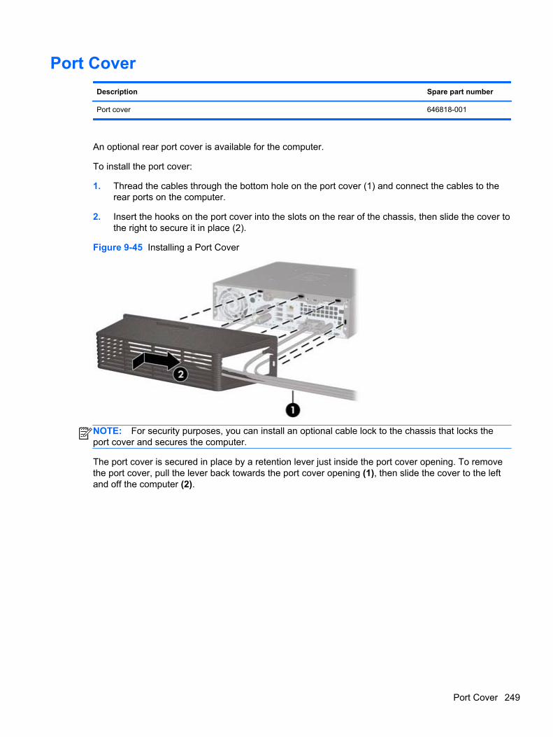
Port Cover
Description Spare part number
Port cover 646818-001
An optional rear port cover is available for the computer.
To install the port cover:
1. Thread the cables through the bottom hole on the port cover (1) and connect the cables to therear ports on the computer.
2. Insert the hooks on the port cover into the slots on the rear of the chassis, then slide the cover tothe right to secure it in place (2).
Figure 9-45 Installing a Port Cover
NOTE: For security purposes, you can install an optional cable lock to the chassis that locks theport cover and secures the computer.
The port cover is secured in place by a retention lever just inside the port cover opening. To removethe port cover, pull the lever back towards the port cover opening (1), then slide the cover to the leftand off the computer (2).
Port Cover 249
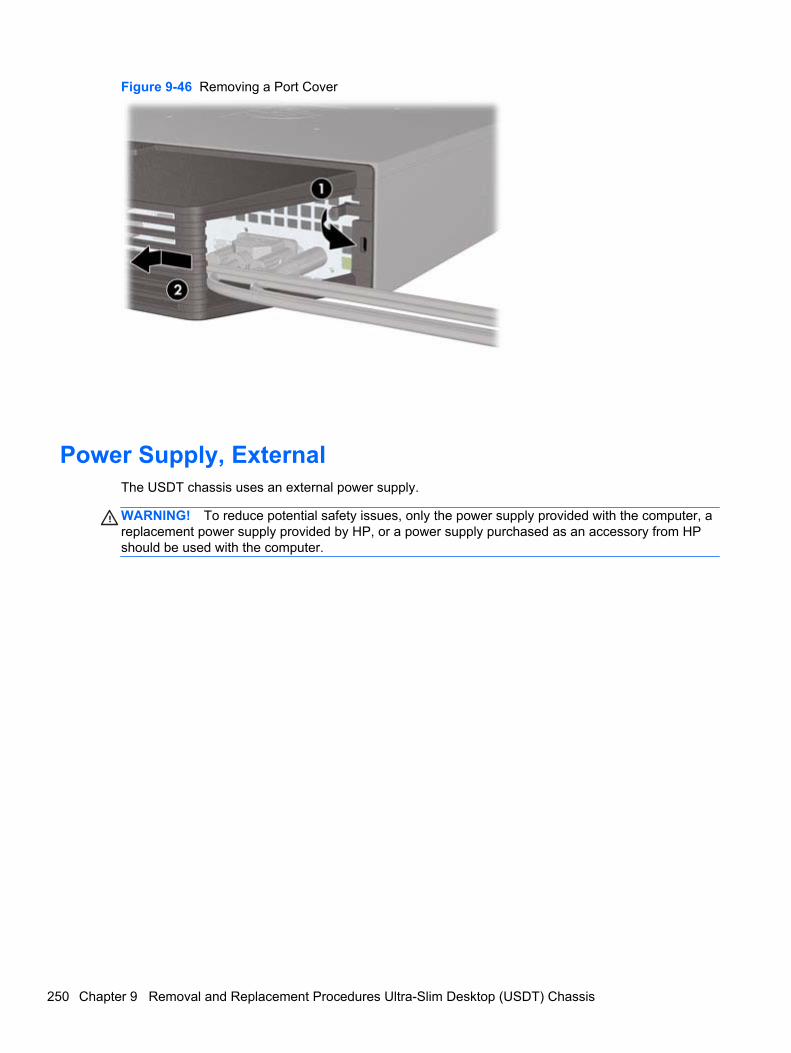
Figure 9-46 Removing a Port Cover
Power Supply, ExternalThe USDT chassis uses an external power supply.
WARNING! To reduce potential safety issues, only the power supply provided with the computer, areplacement power supply provided by HP, or a power supply purchased as an accessory from HPshould be used with the computer.
250 Chapter 9 Removal and Replacement Procedures Ultra-Slim Desktop (USDT) Chassis

10 Troubleshooting Without Diagnostics
This chapter provides information on how to identify and correct minor problems, such as USBdevices, hard drive, optical drive, graphics, audio, memory, and software problems. If you encounterproblems with the computer, refer to the tables in this chapter for probable causes and recommendedsolutions.
NOTE: For information on specific error messages that may appear on the screen during Power-OnSelf-Test (POST) at startup, refer to Appendix A, POST Error Messages on page 292.
Safety and ComfortWARNING! Misuse of the computer or failure to establish a safe and comfortable work environmentmay result in discomfort or serious injury. Refer to the Safety & Comfort Guide at http://www.hp.com/ergo for more information on choosing a workspace and creating a safe and comfortable workenvironment. For more information, refer to the Safety & Regulatory Information guide.
Before You Call for Technical SupportIf you are having problems with the computer, try the appropriate solutions below to try to isolate theexact problem before calling for technical support.
● Run the HP diagnostic tool.
● Run the hard drive self-test in Computer Setup. Refer to Computer Setup (F10) Utilityon page 16 for more information.
● Check the Power LED on the front of the computer to see if it is flashing red. The flashing lightsare error codes that will help you diagnose the problem. Refer to Appendix A, POST ErrorMessages on page 292 for more information.
● If the screen is blank, plug the monitor into a different video port on the computer if one isavailable. Or, replace the monitor with a monitor that you know is functioning properly.
● If you are working on a network, plug another computer with a different cable into the networkconnection. There may be a problem with the network plug or cable.
● If you recently added new hardware, remove the hardware and see if the computer functionsproperly.
● If you recently installed new software, uninstall the software and see if the computer functionsproperly.
● Boot the computer to the Safe Mode to see if it will boot without all of the drivers loaded. Whenbooting the operating system, use “Last Known Configuration.”
Safety and Comfort 251

● Refer to the comprehensive online technical support at http://www.hp.com/support.
● Refer to Helpful Hints on page 252 in this guide.
To assist you in resolving problems online, HP Instant Support Professional Edition provides you withself-solve diagnostics. If you need to contact HP support, use HP Instant Support ProfessionalEdition's online chat feature. Access HP Instant Support Professional Edition at: http://www.hp.com/go/ispe.
Access the Business Support Center (BSC) at http://www.hp.com/go/bizsupport for the latest onlinesupport information, software and drivers, proactive notification, and worldwide community of peersand HP experts.
If it becomes necessary to call for technical assistance, be prepared to do the following to ensure thatyour service call is handled properly:
● Be in front of your computer when you call.
● Write down the computer serial number, product ID number, and monitor serial number beforecalling.
● Spend time troubleshooting the problem with the service technician.
● Remove any hardware that was recently added to your system.
● Remove any software that was recently installed.
● Restore the system from the Recovery Disc Set that you created or restore the system to itsoriginal factory condition in System Software Requirement Disks (SSRD).
CAUTION: Restoring the system will erase all data on the hard drive. Be sure to back up all datafiles before running the restore process.
NOTE: For sales information and warranty upgrades (Care Packs), call your local authorizedservice provider or dealer.
Helpful HintsIf you encounter problems with the computer, monitor, or software, see the following list of generalsuggestions before taking further action:
● Check that the computer and monitor are plugged into a working electrical outlet.
● Check that the voltage select switch (some models) is set to the appropriate voltage for yourregion (115V or 230V).
● Check that the computer is turned on and the green power light is on.
● Check that the monitor is turned on and the green monitor light is on.
● Check the Power LED on the front of the computer to see if it is flashing red. The flashing lightsare error codes that will help you diagnose the problem. Refer to Appendix A, POST ErrorMessages on page 292 for more information.
● Turn up the brightness and contrast controls of the monitor if the monitor is dim.
● Press and hold any key. If the system beeps, then the keyboard should be operating correctly.
● Check all cable connections for loose connections or incorrect connections.
252 Chapter 10 Troubleshooting Without Diagnostics
● Wake the computer by pressing any key on the keyboard or pressing the power button. If thesystem remains in suspend mode, shut down the computer by pressing and holding the powerbutton for at least four seconds then press the power button again to restart the computer. If thesystem will not shut down, unplug the power cord, wait a few seconds, then plug it in again. Thecomputer will restart if it is set to power on automatically as soon as power is restored inComputer Setup. If it does not restart, press the power button to start the computer.
● Reconfigure the computer after installing a non-plug and play expansion board or other option.See Solving Hardware Installation Problems on page 276 for instructions.
● Be sure that all the needed device drivers have been installed. For example, if you are using aprinter, you need a driver for that model printer.
● Remove all bootable media (CD/DVD or USB device) from the system before turning it on.
● If you have installed an operating system other than the factory-installed operating system,check to be sure that it is supported on the system.
● If the system has multiple video sources (embedded, PCI, or PCI-Express adapters) installed(embedded video on some models only) and a single monitor, the monitor must be plugged intothe monitor connector on the source selected as the primary VGA adapter. During boot, theother monitor connectors are disabled and if the monitor is connected into these ports, themonitor will not function. You can select which source will be the default VGA source inComputer Setup.
CAUTION: When the computer is plugged into an AC power source, there is always voltage appliedto the system board. You must disconnect the power cord from the power source before opening thecomputer to prevent system board or component damage.
Helpful Hints 253
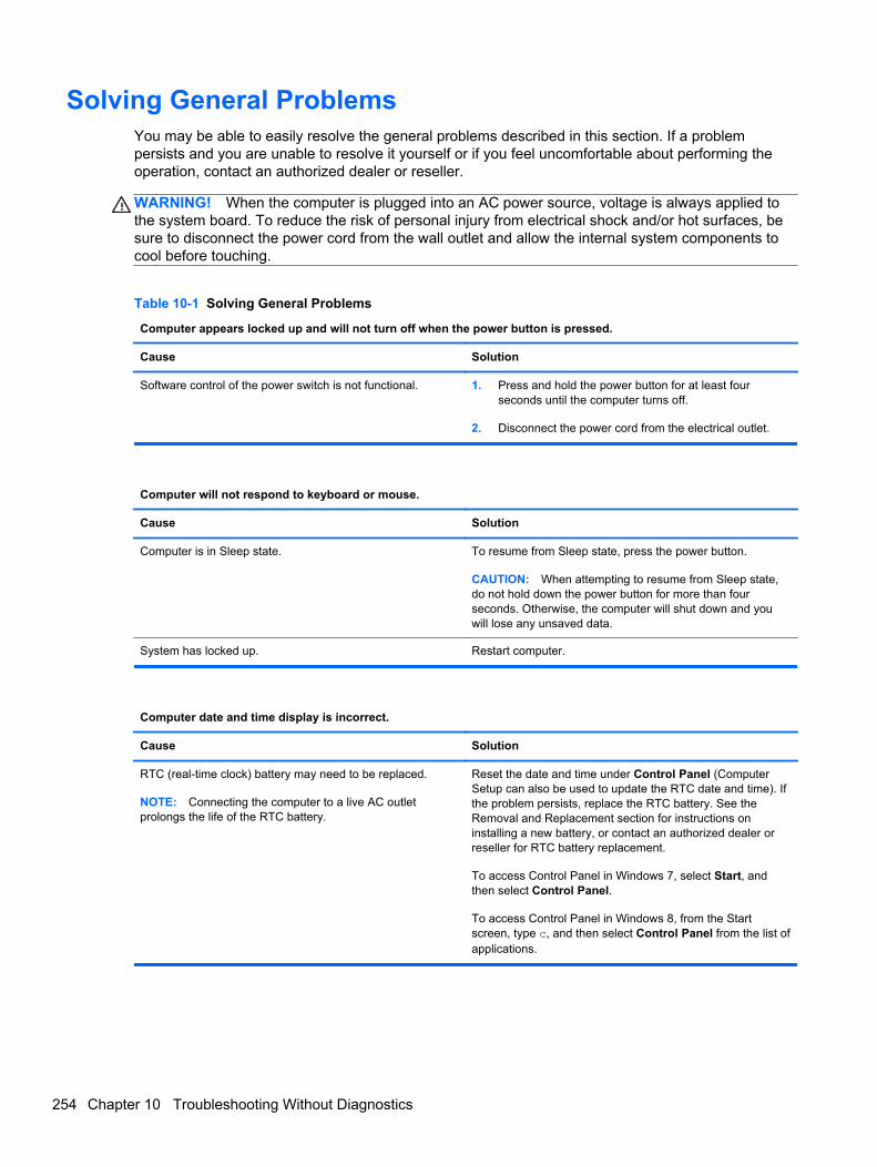
Solving General ProblemsYou may be able to easily resolve the general problems described in this section. If a problempersists and you are unable to resolve it yourself or if you feel uncomfortable about performing theoperation, contact an authorized dealer or reseller.
WARNING! When the computer is plugged into an AC power source, voltage is always applied tothe system board. To reduce the risk of personal injury from electrical shock and/or hot surfaces, besure to disconnect the power cord from the wall outlet and allow the internal system components tocool before touching.
Table 10-1 Solving General Problems
Computer appears locked up and will not turn off when the power button is pressed.
Cause Solution
Software control of the power switch is not functional. 1. Press and hold the power button for at least fourseconds until the computer turns off.
2. Disconnect the power cord from the electrical outlet.
Computer will not respond to keyboard or mouse.
Cause Solution
Computer is in Sleep state. To resume from Sleep state, press the power button.
CAUTION: When attempting to resume from Sleep state,do not hold down the power button for more than fourseconds. Otherwise, the computer will shut down and youwill lose any unsaved data.
System has locked up. Restart computer.
Computer date and time display is incorrect.
Cause Solution
RTC (real-time clock) battery may need to be replaced.
NOTE: Connecting the computer to a live AC outletprolongs the life of the RTC battery.
Reset the date and time under Control Panel (ComputerSetup can also be used to update the RTC date and time). Ifthe problem persists, replace the RTC battery. See theRemoval and Replacement section for instructions oninstalling a new battery, or contact an authorized dealer orreseller for RTC battery replacement.
To access Control Panel in Windows 7, select Start, andthen select Control Panel.
To access Control Panel in Windows 8, from the Startscreen, type c, and then select Control Panel from the list ofapplications.
254 Chapter 10 Troubleshooting Without Diagnostics
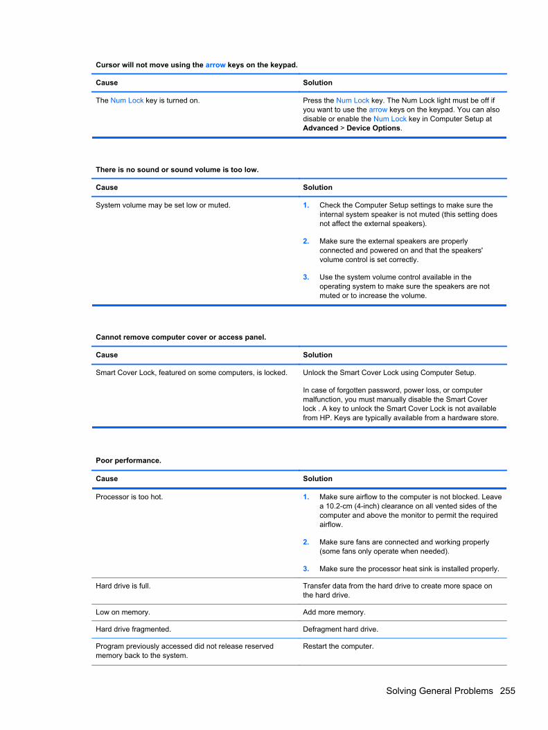
Cursor will not move using the arrow keys on the keypad.
Cause Solution
The Num Lock key is turned on. Press the Num Lock key. The Num Lock light must be off ifyou want to use the arrow keys on the keypad. You can alsodisable or enable the Num Lock key in Computer Setup atAdvanced > Device Options.
There is no sound or sound volume is too low.
Cause Solution
System volume may be set low or muted. 1. Check the Computer Setup settings to make sure theinternal system speaker is not muted (this setting doesnot affect the external speakers).
2. Make sure the external speakers are properlyconnected and powered on and that the speakers'volume control is set correctly.
3. Use the system volume control available in theoperating system to make sure the speakers are notmuted or to increase the volume.
Cannot remove computer cover or access panel.
Cause Solution
Smart Cover Lock, featured on some computers, is locked. Unlock the Smart Cover Lock using Computer Setup.
In case of forgotten password, power loss, or computermalfunction, you must manually disable the Smart Coverlock . A key to unlock the Smart Cover Lock is not availablefrom HP. Keys are typically available from a hardware store.
Poor performance.
Cause Solution
Processor is too hot. 1. Make sure airflow to the computer is not blocked. Leavea 10.2-cm (4-inch) clearance on all vented sides of thecomputer and above the monitor to permit the requiredairflow.
2. Make sure fans are connected and working properly(some fans only operate when needed).
3. Make sure the processor heat sink is installed properly.
Hard drive is full. Transfer data from the hard drive to create more space onthe hard drive.
Low on memory. Add more memory.
Hard drive fragmented. Defragment hard drive.
Program previously accessed did not release reservedmemory back to the system.
Restart the computer.
Solving General Problems 255
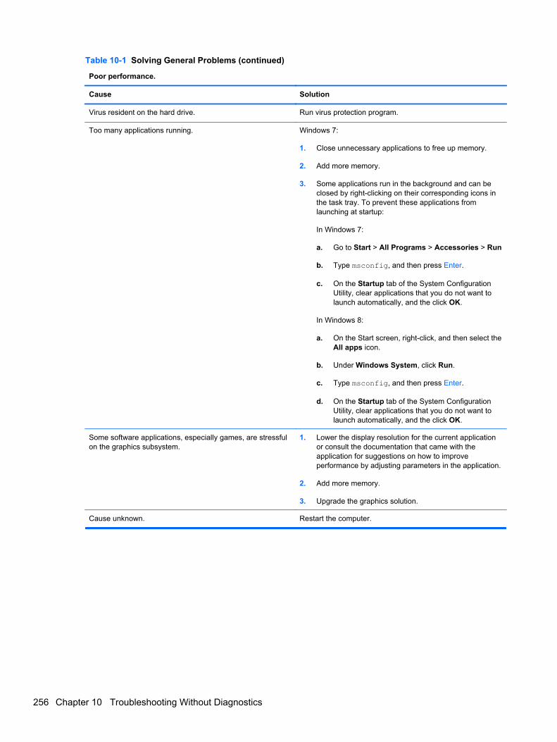
Table 10-1 Solving General Problems (continued)
Poor performance.
Cause Solution
Virus resident on the hard drive. Run virus protection program.
Too many applications running. Windows 7:
1. Close unnecessary applications to free up memory.
2. Add more memory.
3. Some applications run in the background and can beclosed by right-clicking on their corresponding icons inthe task tray. To prevent these applications fromlaunching at startup:
In Windows 7:
a. Go to Start > All Programs > Accessories > Run
b. Type msconfig, and then press Enter.
c. On the Startup tab of the System ConfigurationUtility, clear applications that you do not want tolaunch automatically, and the click OK.
In Windows 8:
a. On the Start screen, right-click, and then select theAll apps icon.
b. Under Windows System, click Run.
c. Type msconfig, and then press Enter.
d. On the Startup tab of the System ConfigurationUtility, clear applications that you do not want tolaunch automatically, and the click OK.
Some software applications, especially games, are stressfulon the graphics subsystem.
1. Lower the display resolution for the current applicationor consult the documentation that came with theapplication for suggestions on how to improveperformance by adjusting parameters in the application.
2. Add more memory.
3. Upgrade the graphics solution.
Cause unknown. Restart the computer.
256 Chapter 10 Troubleshooting Without Diagnostics
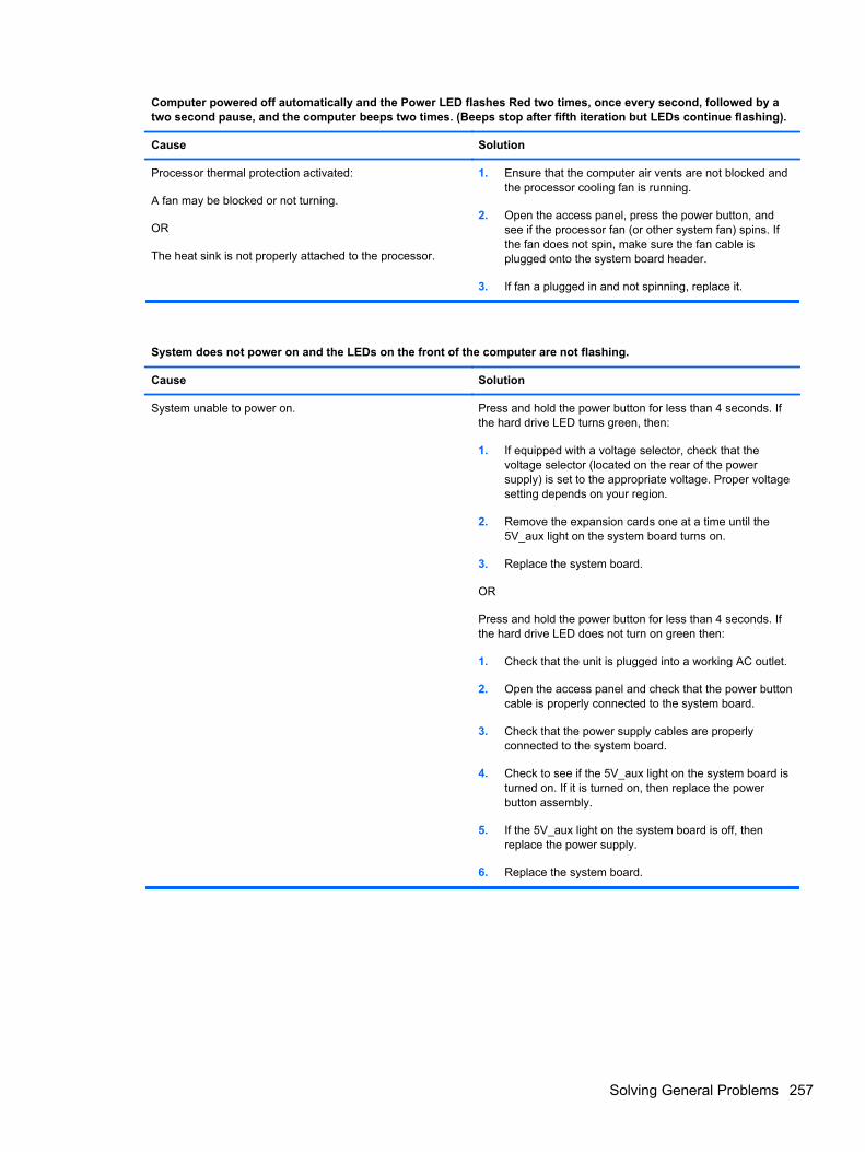
Computer powered off automatically and the Power LED flashes Red two times, once every second, followed by atwo second pause, and the computer beeps two times. (Beeps stop after fifth iteration but LEDs continue flashing).
Cause Solution
Processor thermal protection activated:
A fan may be blocked or not turning.
OR
The heat sink is not properly attached to the processor.
1. Ensure that the computer air vents are not blocked andthe processor cooling fan is running.
2. Open the access panel, press the power button, andsee if the processor fan (or other system fan) spins. Ifthe fan does not spin, make sure the fan cable isplugged onto the system board header.
3. If fan a plugged in and not spinning, replace it.
System does not power on and the LEDs on the front of the computer are not flashing.
Cause Solution
System unable to power on. Press and hold the power button for less than 4 seconds. Ifthe hard drive LED turns green, then:
1. If equipped with a voltage selector, check that thevoltage selector (located on the rear of the powersupply) is set to the appropriate voltage. Proper voltagesetting depends on your region.
2. Remove the expansion cards one at a time until the5V_aux light on the system board turns on.
3. Replace the system board.
OR
Press and hold the power button for less than 4 seconds. Ifthe hard drive LED does not turn on green then:
1. Check that the unit is plugged into a working AC outlet.
2. Open the access panel and check that the power buttoncable is properly connected to the system board.
3. Check that the power supply cables are properlyconnected to the system board.
4. Check to see if the 5V_aux light on the system board isturned on. If it is turned on, then replace the powerbutton assembly.
5. If the 5V_aux light on the system board is off, thenreplace the power supply.
6. Replace the system board.
Solving General Problems 257
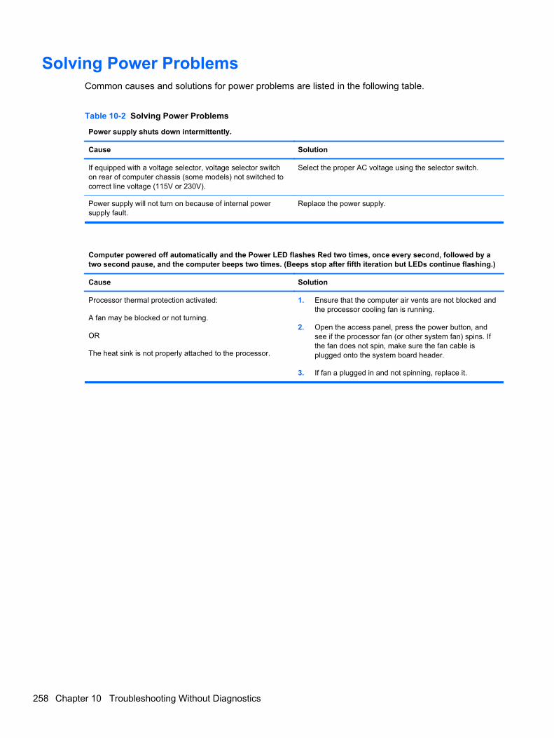
Solving Power ProblemsCommon causes and solutions for power problems are listed in the following table.
Table 10-2 Solving Power Problems
Power supply shuts down intermittently.
Cause Solution
If equipped with a voltage selector, voltage selector switchon rear of computer chassis (some models) not switched tocorrect line voltage (115V or 230V).
Select the proper AC voltage using the selector switch.
Power supply will not turn on because of internal powersupply fault.
Replace the power supply.
Computer powered off automatically and the Power LED flashes Red two times, once every second, followed by atwo second pause, and the computer beeps two times. (Beeps stop after fifth iteration but LEDs continue flashing.)
Cause Solution
Processor thermal protection activated:
A fan may be blocked or not turning.
OR
The heat sink is not properly attached to the processor.
1. Ensure that the computer air vents are not blocked andthe processor cooling fan is running.
2. Open the access panel, press the power button, andsee if the processor fan (or other system fan) spins. Ifthe fan does not spin, make sure the fan cable isplugged onto the system board header.
3. If fan a plugged in and not spinning, replace it.
258 Chapter 10 Troubleshooting Without Diagnostics
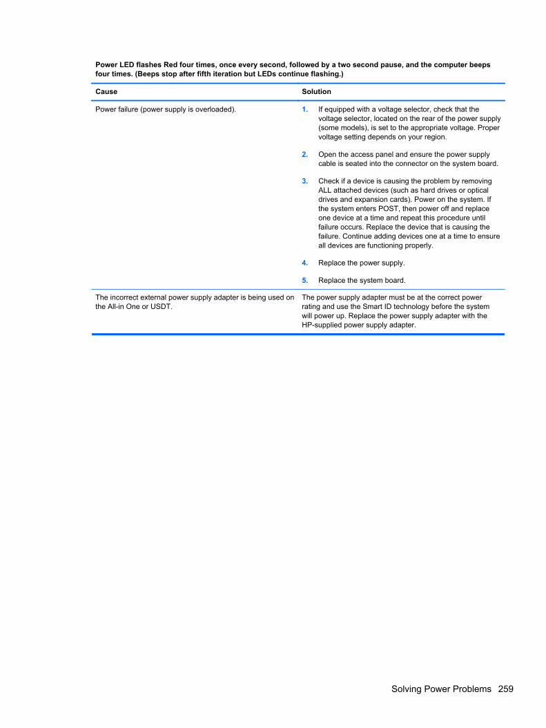
Power LED flashes Red four times, once every second, followed by a two second pause, and the computer beepsfour times. (Beeps stop after fifth iteration but LEDs continue flashing.)
Cause Solution
Power failure (power supply is overloaded). 1. If equipped with a voltage selector, check that thevoltage selector, located on the rear of the power supply(some models), is set to the appropriate voltage. Propervoltage setting depends on your region.
2. Open the access panel and ensure the power supplycable is seated into the connector on the system board.
3. Check if a device is causing the problem by removingALL attached devices (such as hard drives or opticaldrives and expansion cards). Power on the system. Ifthe system enters POST, then power off and replaceone device at a time and repeat this procedure untilfailure occurs. Replace the device that is causing thefailure. Continue adding devices one at a time to ensureall devices are functioning properly.
4. Replace the power supply.
5. Replace the system board.
The incorrect external power supply adapter is being used onthe All-in One or USDT.
The power supply adapter must be at the correct powerrating and use the Smart ID technology before the systemwill power up. Replace the power supply adapter with theHP-supplied power supply adapter.
Solving Power Problems 259
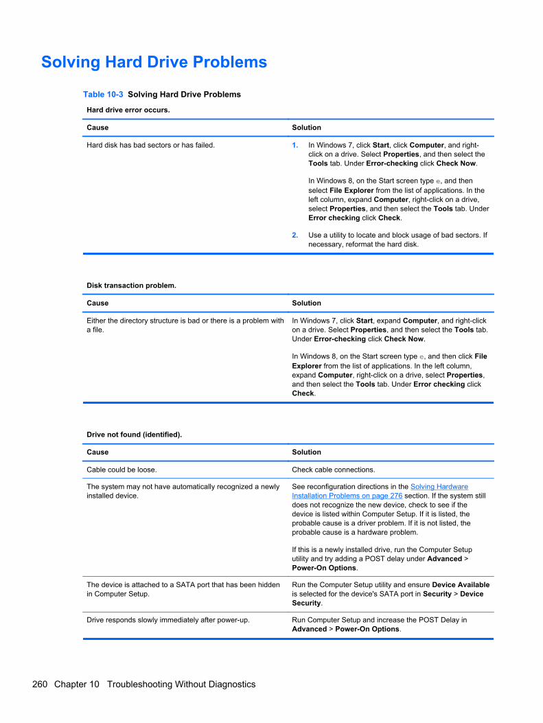
Solving Hard Drive Problems
Table 10-3 Solving Hard Drive Problems
Hard drive error occurs.
Cause Solution
Hard disk has bad sectors or has failed. 1. In Windows 7, click Start, click Computer, and right-click on a drive. Select Properties, and then select theTools tab. Under Error-checking click Check Now.
In Windows 8, on the Start screen type e, and thenselect File Explorer from the list of applications. In theleft column, expand Computer, right-click on a drive,select Properties, and then select the Tools tab. UnderError checking click Check.
2. Use a utility to locate and block usage of bad sectors. Ifnecessary, reformat the hard disk.
Disk transaction problem.
Cause Solution
Either the directory structure is bad or there is a problem witha file.
In Windows 7, click Start, expand Computer, and right-clickon a drive. Select Properties, and then select the Tools tab.Under Error-checking click Check Now.
In Windows 8, on the Start screen type e, and then click FileExplorer from the list of applications. In the left column,expand Computer, right-click on a drive, select Properties,and then select the Tools tab. Under Error checking clickCheck.
Drive not found (identified).
Cause Solution
Cable could be loose. Check cable connections.
The system may not have automatically recognized a newlyinstalled device.
See reconfiguration directions in the Solving HardwareInstallation Problems on page 276 section. If the system stilldoes not recognize the new device, check to see if thedevice is listed within Computer Setup. If it is listed, theprobable cause is a driver problem. If it is not listed, theprobable cause is a hardware problem.
If this is a newly installed drive, run the Computer Setuputility and try adding a POST delay under Advanced >Power-On Options.
The device is attached to a SATA port that has been hiddenin Computer Setup.
Run the Computer Setup utility and ensure Device Availableis selected for the device's SATA port in Security > DeviceSecurity.
Drive responds slowly immediately after power-up. Run Computer Setup and increase the POST Delay inAdvanced > Power-On Options.
260 Chapter 10 Troubleshooting Without Diagnostics
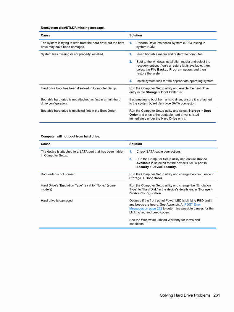
Nonsystem disk/NTLDR missing message.
Cause Solution
The system is trying to start from the hard drive but the harddrive may have been damaged.
1. Perform Drive Protection System (DPS) testing insystem ROM.
System files missing or not properly installed. 1. Insert bootable media and restart the computer.
2. Boot to the windows installation media and select therecovery option. If only a restore kit is available, thenselect the File Backup Program option, and thenrestore the system.
3. Install system files for the appropriate operating system.
Hard drive boot has been disabled in Computer Setup. Run the Computer Setup utility and enable the hard driveentry in the Storage > Boot Order list.
Bootable hard drive is not attached as first in a multi-harddrive configuration.
If attempting to boot from a hard drive, ensure it is attachedto the system board dark blue SATA connector.
Bootable hard drive is not listed first in the Boot Order. Run the Computer Setup utility and select Storage > BootOrder and ensure the bootable hard drive is listedimmediately under the Hard Drive entry.
Computer will not boot from hard drive.
Cause Solution
The device is attached to a SATA port that has been hiddenin Computer Setup.
1. Check SATA cable connections.
2. Run the Computer Setup utility and ensure DeviceAvailable is selected for the device's SATA port inSecurity > Device Security.
Boot order is not correct. Run the Computer Setup utility and change boot sequence inStorage > Boot Order.
Hard Drive's “Emulation Type” is set to “None.” (somemodels)
Run the Computer Setup utility and change the “EmulationType” to “Hard Disk” in the device's details under Storage >Device Configuration.
Hard drive is damaged. Observe if the front panel Power LED is blinking RED and ifany beeps are heard. See Appendix A, POST ErrorMessages on page 292 to determine possible causes for theblinking red and beep codes.
See the Worldwide Limited Warranty for terms andconditions.
Solving Hard Drive Problems 261
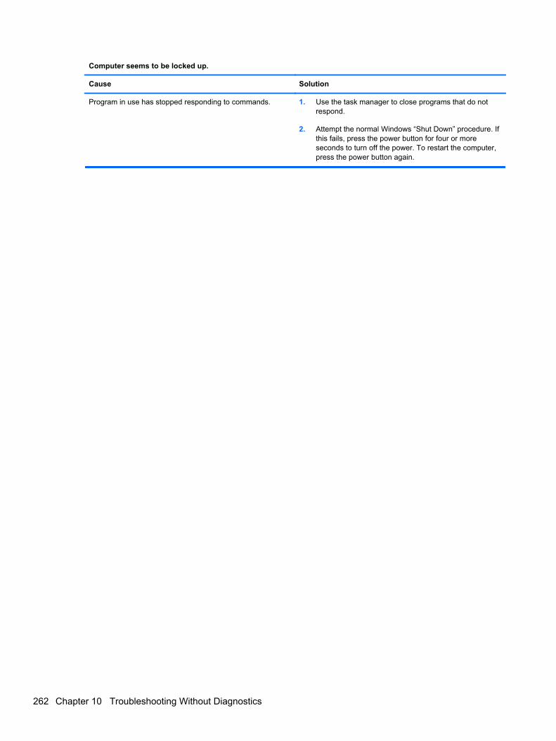
Computer seems to be locked up.
Cause Solution
Program in use has stopped responding to commands. 1. Use the task manager to close programs that do notrespond.
2. Attempt the normal Windows “Shut Down” procedure. Ifthis fails, press the power button for four or moreseconds to turn off the power. To restart the computer,press the power button again.
262 Chapter 10 Troubleshooting Without Diagnostics
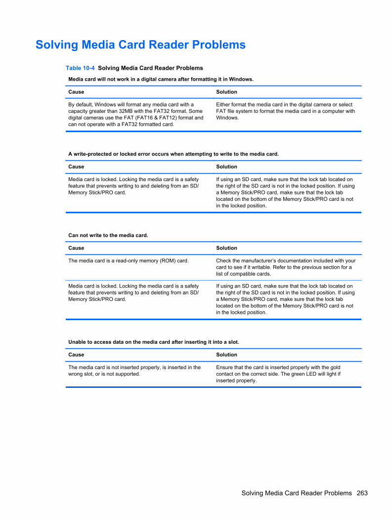
Solving Media Card Reader Problems
Table 10-4 Solving Media Card Reader Problems
Media card will not work in a digital camera after formatting it in Windows.
Cause Solution
By default, Windows will format any media card with acapacity greater than 32MB with the FAT32 format. Somedigital cameras use the FAT (FAT16 & FAT12) format andcan not operate with a FAT32 formatted card.
Either format the media card in the digital camera or selectFAT file system to format the media card in a computer withWindows.
A write-protected or locked error occurs when attempting to write to the media card.
Cause Solution
Media card is locked. Locking the media card is a safetyfeature that prevents writing to and deleting from an SD/Memory Stick/PRO card.
If using an SD card, make sure that the lock tab located onthe right of the SD card is not in the locked position. If usinga Memory Stick/PRO card, make sure that the lock tablocated on the bottom of the Memory Stick/PRO card is notin the locked position.
Can not write to the media card.
Cause Solution
The media card is a read-only memory (ROM) card. Check the manufacturer’s documentation included with yourcard to see if it writable. Refer to the previous section for alist of compatible cards.
Media card is locked. Locking the media card is a safetyfeature that prevents writing to and deleting from an SD/Memory Stick/PRO card.
If using an SD card, make sure that the lock tab located onthe right of the SD card is not in the locked position. If usinga Memory Stick/PRO card, make sure that the lock tablocated on the bottom of the Memory Stick/PRO card is notin the locked position.
Unable to access data on the media card after inserting it into a slot.
Cause Solution
The media card is not inserted properly, is inserted in thewrong slot, or is not supported.
Ensure that the card is inserted properly with the goldcontact on the correct side. The green LED will light ifinserted properly.
Solving Media Card Reader Problems 263
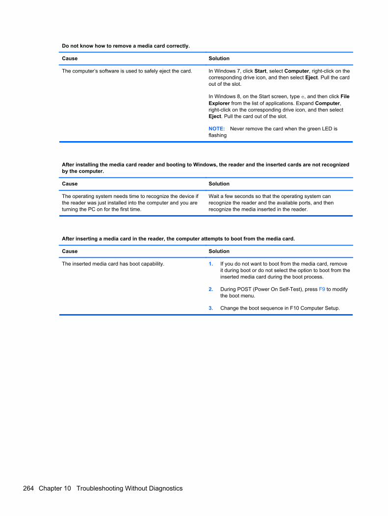
Do not know how to remove a media card correctly.
Cause Solution
The computer’s software is used to safely eject the card. In Windows 7, click Start, select Computer, right-click on thecorresponding drive icon, and then select Eject. Pull the cardout of the slot.
In Windows 8, on the Start screen, type e, and then click FileExplorer from the list of applications. Expand Computer,right-click on the corresponding drive icon, and then selectEject. Pull the card out of the slot.
NOTE: Never remove the card when the green LED isflashing
After installing the media card reader and booting to Windows, the reader and the inserted cards are not recognizedby the computer.
Cause Solution
The operating system needs time to recognize the device ifthe reader was just installed into the computer and you areturning the PC on for the first time.
Wait a few seconds so that the operating system canrecognize the reader and the available ports, and thenrecognize the media inserted in the reader.
After inserting a media card in the reader, the computer attempts to boot from the media card.
Cause Solution
The inserted media card has boot capability. 1. If you do not want to boot from the media card, removeit during boot or do not select the option to boot from theinserted media card during the boot process.
2. During POST (Power On Self-Test), press F9 to modifythe boot menu.
3. Change the boot sequence in F10 Computer Setup.
264 Chapter 10 Troubleshooting Without Diagnostics
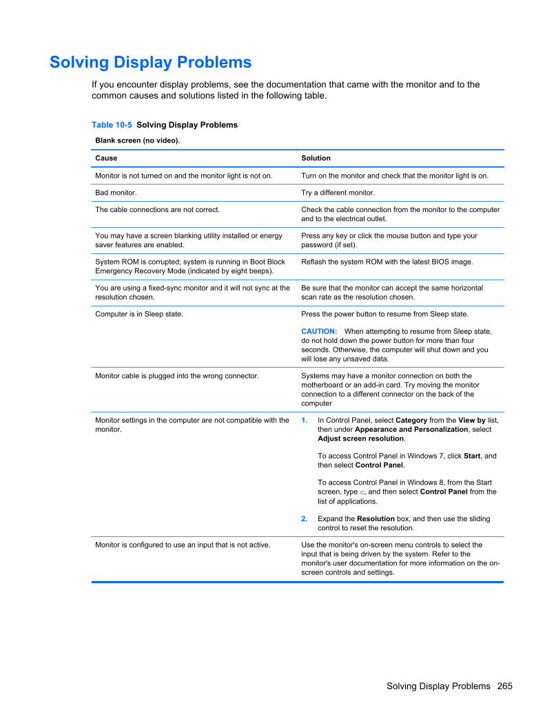
Solving Display ProblemsIf you encounter display problems, see the documentation that came with the monitor and to thecommon causes and solutions listed in the following table.
Table 10-5 Solving Display Problems
Blank screen (no video).
Cause Solution
Monitor is not turned on and the monitor light is not on. Turn on the monitor and check that the monitor light is on.
Bad monitor. Try a different monitor.
The cable connections are not correct. Check the cable connection from the monitor to the computerand to the electrical outlet.
You may have a screen blanking utility installed or energysaver features are enabled.
Press any key or click the mouse button and type yourpassword (if set).
System ROM is corrupted; system is running in Boot BlockEmergency Recovery Mode (indicated by eight beeps).
Reflash the system ROM with the latest BIOS image.
You are using a fixed-sync monitor and it will not sync at theresolution chosen.
Be sure that the monitor can accept the same horizontalscan rate as the resolution chosen.
Computer is in Sleep state. Press the power button to resume from Sleep state.
CAUTION: When attempting to resume from Sleep state,do not hold down the power button for more than fourseconds. Otherwise, the computer will shut down and youwill lose any unsaved data.
Monitor cable is plugged into the wrong connector. Systems may have a monitor connection on both themotherboard or an add-in card. Try moving the monitorconnection to a different connector on the back of thecomputer
Monitor settings in the computer are not compatible with themonitor.
1. In Control Panel, select Category from the View by list,then under Appearance and Personalization, selectAdjust screen resolution.
To access Control Panel in Windows 7, click Start, andthen select Control Panel.
To access Control Panel in Windows 8, from the Startscreen, type c, and then select Control Panel from thelist of applications.
2. Expand the Resolution box, and then use the slidingcontrol to reset the resolution.
Monitor is configured to use an input that is not active. Use the monitor's on-screen menu controls to select theinput that is being driven by the system. Refer to themonitor's user documentation for more information on the on-screen controls and settings.
Solving Display Problems 265
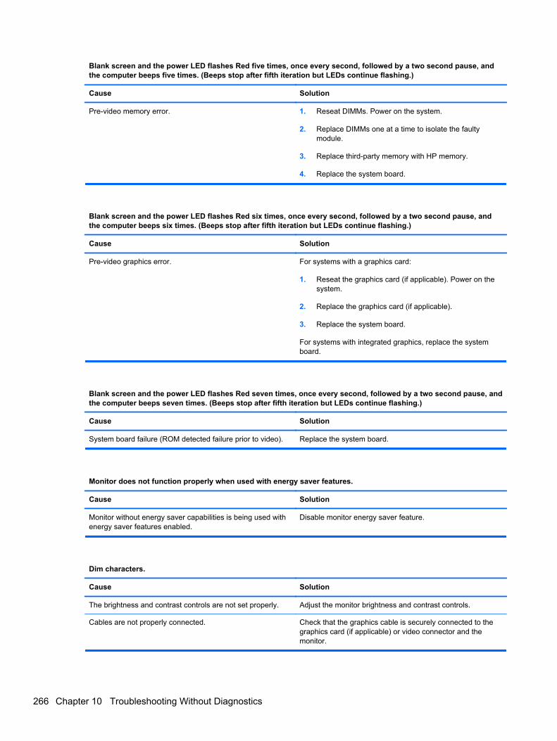
Blank screen and the power LED flashes Red five times, once every second, followed by a two second pause, andthe computer beeps five times. (Beeps stop after fifth iteration but LEDs continue flashing.)
Cause Solution
Pre-video memory error. 1. Reseat DIMMs. Power on the system.
2. Replace DIMMs one at a time to isolate the faultymodule.
3. Replace third-party memory with HP memory.
4. Replace the system board.
Blank screen and the power LED flashes Red six times, once every second, followed by a two second pause, andthe computer beeps six times. (Beeps stop after fifth iteration but LEDs continue flashing.)
Cause Solution
Pre-video graphics error. For systems with a graphics card:
1. Reseat the graphics card (if applicable). Power on thesystem.
2. Replace the graphics card (if applicable).
3. Replace the system board.
For systems with integrated graphics, replace the systemboard.
Blank screen and the power LED flashes Red seven times, once every second, followed by a two second pause, andthe computer beeps seven times. (Beeps stop after fifth iteration but LEDs continue flashing.)
Cause Solution
System board failure (ROM detected failure prior to video). Replace the system board.
Monitor does not function properly when used with energy saver features.
Cause Solution
Monitor without energy saver capabilities is being used withenergy saver features enabled.
Disable monitor energy saver feature.
Dim characters.
Cause Solution
The brightness and contrast controls are not set properly. Adjust the monitor brightness and contrast controls.
Cables are not properly connected. Check that the graphics cable is securely connected to thegraphics card (if applicable) or video connector and themonitor.
266 Chapter 10 Troubleshooting Without Diagnostics
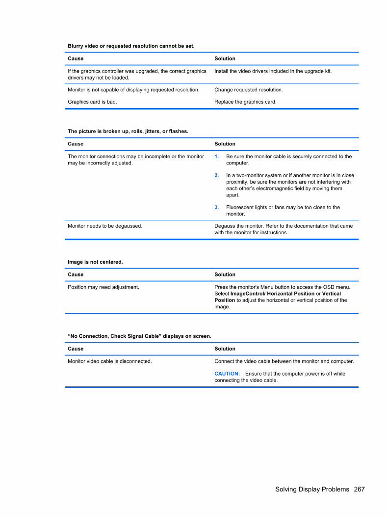
Blurry video or requested resolution cannot be set.
Cause Solution
If the graphics controller was upgraded, the correct graphicsdrivers may not be loaded.
Install the video drivers included in the upgrade kit.
Monitor is not capable of displaying requested resolution. Change requested resolution.
Graphics card is bad. Replace the graphics card.
The picture is broken up, rolls, jitters, or flashes.
Cause Solution
The monitor connections may be incomplete or the monitormay be incorrectly adjusted.
1. Be sure the monitor cable is securely connected to thecomputer.
2. In a two-monitor system or if another monitor is in closeproximity, be sure the monitors are not interfering witheach other’s electromagnetic field by moving themapart.
3. Fluorescent lights or fans may be too close to themonitor.
Monitor needs to be degaussed. Degauss the monitor. Refer to the documentation that camewith the monitor for instructions.
Image is not centered.
Cause Solution
Position may need adjustment. Press the monitor's Menu button to access the OSD menu.Select ImageControl/ Horizontal Position or VerticalPosition to adjust the horizontal or vertical position of theimage.
“No Connection, Check Signal Cable” displays on screen.
Cause Solution
Monitor video cable is disconnected. Connect the video cable between the monitor and computer.
CAUTION: Ensure that the computer power is off whileconnecting the video cable.
Solving Display Problems 267
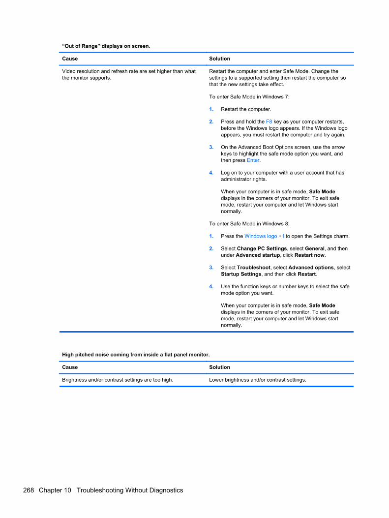
“Out of Range” displays on screen.
Cause Solution
Video resolution and refresh rate are set higher than whatthe monitor supports.
Restart the computer and enter Safe Mode. Change thesettings to a supported setting then restart the computer sothat the new settings take effect.
To enter Safe Mode in Windows 7:
1. Restart the computer.
2. Press and hold the F8 key as your computer restarts,before the Windows logo appears. If the Windows logoappears, you must restart the computer and try again.
3. On the Advanced Boot Options screen, use the arrowkeys to highlight the safe mode option you want, andthen press Enter.
4. Log on to your computer with a user account that hasadministrator rights.
When your computer is in safe mode, Safe Modedisplays in the corners of your monitor. To exit safemode, restart your computer and let Windows startnormally.
To enter Safe Mode in Windows 8:
1. Press the Windows logo + l to open the Settings charm.
2. Select Change PC Settings, select General, and thenunder Advanced startup, click Restart now.
3. Select Troubleshoot, select Advanced options, selectStartup Settings, and then click Restart.
4. Use the function keys or number keys to select the safemode option you want.
When your computer is in safe mode, Safe Modedisplays in the corners of your monitor. To exit safemode, restart your computer and let Windows startnormally.
High pitched noise coming from inside a flat panel monitor.
Cause Solution
Brightness and/or contrast settings are too high. Lower brightness and/or contrast settings.
268 Chapter 10 Troubleshooting Without Diagnostics
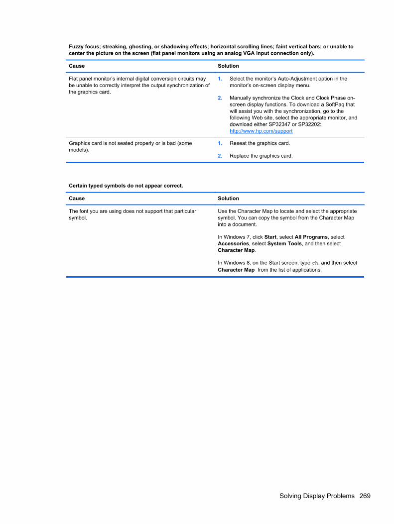
Fuzzy focus; streaking, ghosting, or shadowing effects; horizontal scrolling lines; faint vertical bars; or unable tocenter the picture on the screen (flat panel monitors using an analog VGA input connection only).
Cause Solution
Flat panel monitor’s internal digital conversion circuits maybe unable to correctly interpret the output synchronization ofthe graphics card.
1. Select the monitor’s Auto-Adjustment option in themonitor’s on-screen display menu.
2. Manually synchronize the Clock and Clock Phase on-screen display functions. To download a SoftPaq thatwill assist you with the synchronization, go to thefollowing Web site, select the appropriate monitor, anddownload either SP32347 or SP32202:http://www.hp.com/support
Graphics card is not seated properly or is bad (somemodels).
1. Reseat the graphics card.
2. Replace the graphics card.
Certain typed symbols do not appear correct.
Cause Solution
The font you are using does not support that particularsymbol.
Use the Character Map to locate and select the appropriatesymbol. You can copy the symbol from the Character Mapinto a document.
In Windows 7, click Start, select All Programs, selectAccessories, select System Tools, and then selectCharacter Map.
In Windows 8, on the Start screen, type ch, and then selectCharacter Map from the list of applications.
Solving Display Problems 269
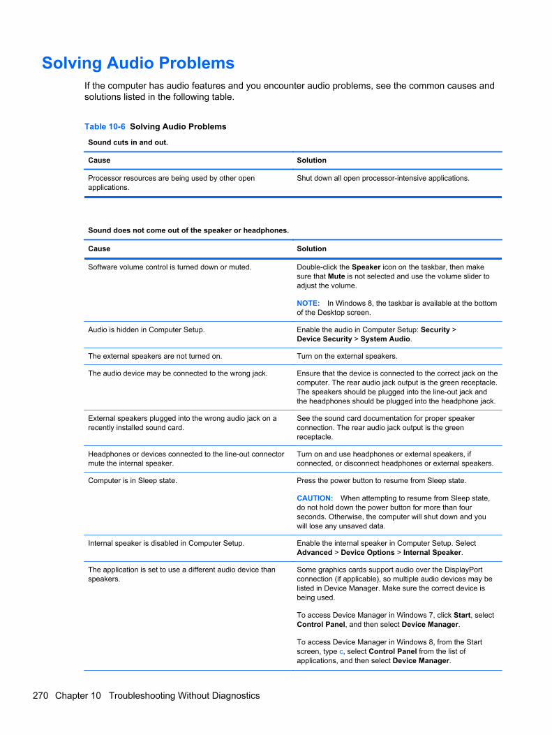
Solving Audio ProblemsIf the computer has audio features and you encounter audio problems, see the common causes andsolutions listed in the following table.
Table 10-6 Solving Audio Problems
Sound cuts in and out.
Cause Solution
Processor resources are being used by other openapplications.
Shut down all open processor-intensive applications.
Sound does not come out of the speaker or headphones.
Cause Solution
Software volume control is turned down or muted. Double-click the Speaker icon on the taskbar, then makesure that Mute is not selected and use the volume slider toadjust the volume.
NOTE: In Windows 8, the taskbar is available at the bottomof the Desktop screen.
Audio is hidden in Computer Setup. Enable the audio in Computer Setup: Security >Device Security > System Audio.
The external speakers are not turned on. Turn on the external speakers.
The audio device may be connected to the wrong jack. Ensure that the device is connected to the correct jack on thecomputer. The rear audio jack output is the green receptacle.The speakers should be plugged into the line-out jack andthe headphones should be plugged into the headphone jack.
External speakers plugged into the wrong audio jack on arecently installed sound card.
See the sound card documentation for proper speakerconnection. The rear audio jack output is the greenreceptacle.
Headphones or devices connected to the line-out connectormute the internal speaker.
Turn on and use headphones or external speakers, ifconnected, or disconnect headphones or external speakers.
Computer is in Sleep state. Press the power button to resume from Sleep state.
CAUTION: When attempting to resume from Sleep state,do not hold down the power button for more than fourseconds. Otherwise, the computer will shut down and youwill lose any unsaved data.
Internal speaker is disabled in Computer Setup. Enable the internal speaker in Computer Setup. SelectAdvanced > Device Options > Internal Speaker.
The application is set to use a different audio device thanspeakers.
Some graphics cards support audio over the DisplayPortconnection (if applicable), so multiple audio devices may belisted in Device Manager. Make sure the correct device isbeing used.
To access Device Manager in Windows 7, click Start, selectControl Panel, and then select Device Manager.
To access Device Manager in Windows 8, from the Startscreen, type c, select Control Panel from the list ofapplications, and then select Device Manager.
270 Chapter 10 Troubleshooting Without Diagnostics
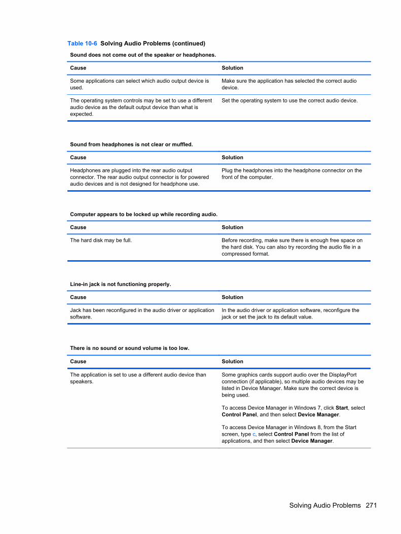
Table 10-6 Solving Audio Problems (continued)
Sound does not come out of the speaker or headphones.
Cause Solution
Some applications can select which audio output device isused.
Make sure the application has selected the correct audiodevice.
The operating system controls may be set to use a differentaudio device as the default output device than what isexpected.
Set the operating system to use the correct audio device.
Sound from headphones is not clear or muffled.
Cause Solution
Headphones are plugged into the rear audio outputconnector. The rear audio output connector is for poweredaudio devices and is not designed for headphone use.
Plug the headphones into the headphone connector on thefront of the computer.
Computer appears to be locked up while recording audio.
Cause Solution
The hard disk may be full. Before recording, make sure there is enough free space onthe hard disk. You can also try recording the audio file in acompressed format.
Line-in jack is not functioning properly.
Cause Solution
Jack has been reconfigured in the audio driver or applicationsoftware.
In the audio driver or application software, reconfigure thejack or set the jack to its default value.
There is no sound or sound volume is too low.
Cause Solution
The application is set to use a different audio device thanspeakers.
Some graphics cards support audio over the DisplayPortconnection (if applicable), so multiple audio devices may belisted in Device Manager. Make sure the correct device isbeing used.
To access Device Manager in Windows 7, click Start, selectControl Panel, and then select Device Manager.
To access Device Manager in Windows 8, from the Startscreen, type c, select Control Panel from the list ofapplications, and then select Device Manager.
Solving Audio Problems 271
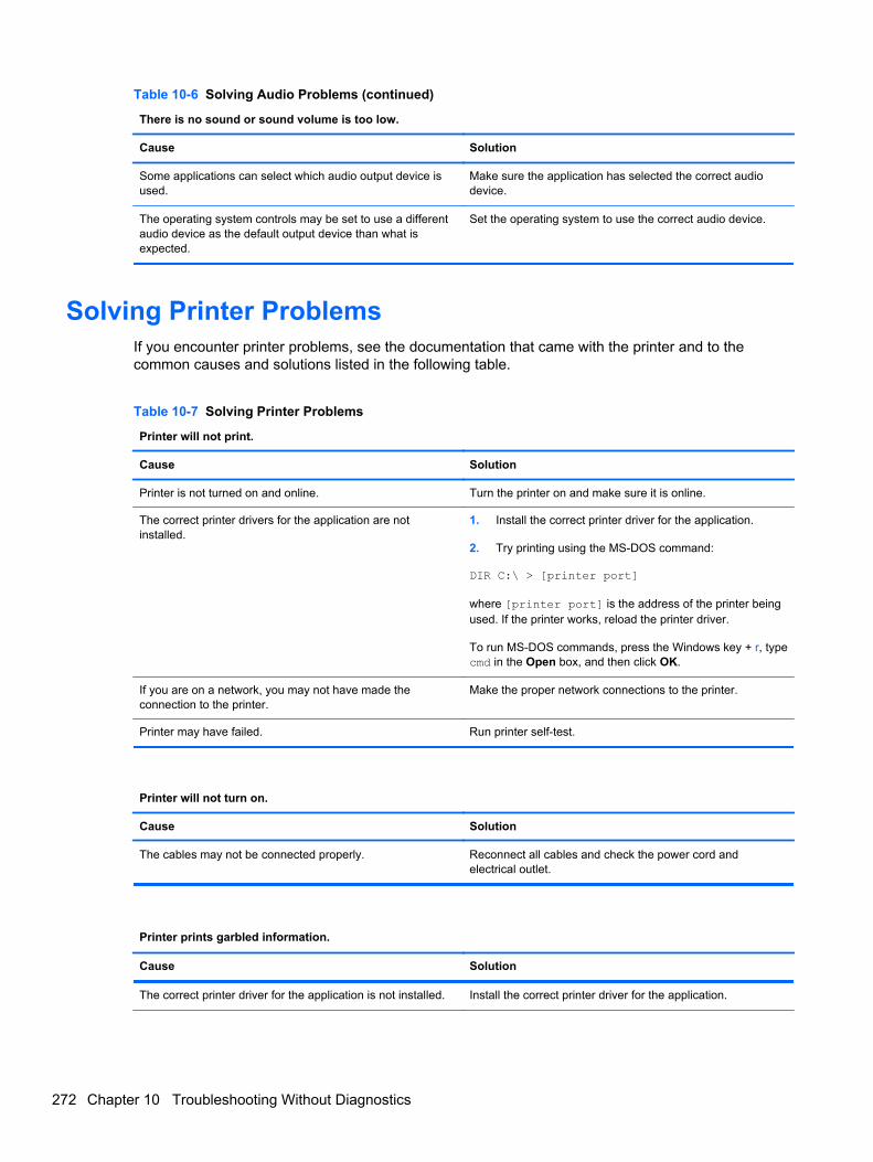
Table 10-6 Solving Audio Problems (continued)
There is no sound or sound volume is too low.
Cause Solution
Some applications can select which audio output device isused.
Make sure the application has selected the correct audiodevice.
The operating system controls may be set to use a differentaudio device as the default output device than what isexpected.
Set the operating system to use the correct audio device.
Solving Printer ProblemsIf you encounter printer problems, see the documentation that came with the printer and to thecommon causes and solutions listed in the following table.
Table 10-7 Solving Printer Problems
Printer will not print.
Cause Solution
Printer is not turned on and online. Turn the printer on and make sure it is online.
The correct printer drivers for the application are notinstalled.
1. Install the correct printer driver for the application.
2. Try printing using the MS-DOS command:
DIR C:\ > [printer port]
where [printer port] is the address of the printer beingused. If the printer works, reload the printer driver.
To run MS-DOS commands, press the Windows key + r, typecmd in the Open box, and then click OK.
If you are on a network, you may not have made theconnection to the printer.
Make the proper network connections to the printer.
Printer may have failed. Run printer self-test.
Printer will not turn on.
Cause Solution
The cables may not be connected properly. Reconnect all cables and check the power cord andelectrical outlet.
Printer prints garbled information.
Cause Solution
The correct printer driver for the application is not installed. Install the correct printer driver for the application.
272 Chapter 10 Troubleshooting Without Diagnostics
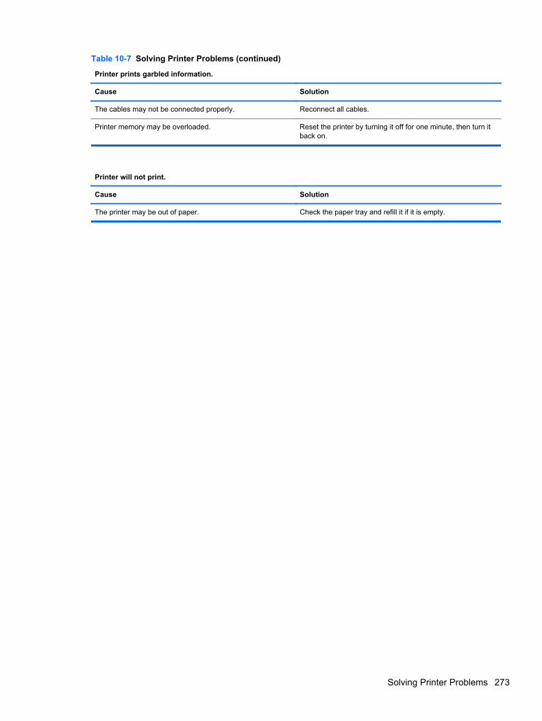
Table 10-7 Solving Printer Problems (continued)
Printer prints garbled information.
Cause Solution
The cables may not be connected properly. Reconnect all cables.
Printer memory may be overloaded. Reset the printer by turning it off for one minute, then turn itback on.
Printer will not print.
Cause Solution
The printer may be out of paper. Check the paper tray and refill it if it is empty.
Solving Printer Problems 273
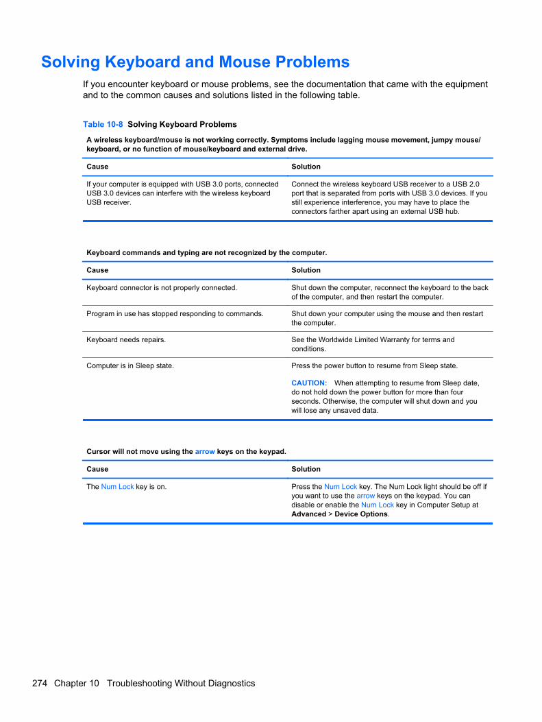
Solving Keyboard and Mouse ProblemsIf you encounter keyboard or mouse problems, see the documentation that came with the equipmentand to the common causes and solutions listed in the following table.
Table 10-8 Solving Keyboard Problems
A wireless keyboard/mouse is not working correctly. Symptoms include lagging mouse movement, jumpy mouse/keyboard, or no function of mouse/keyboard and external drive.
Cause Solution
If your computer is equipped with USB 3.0 ports, connectedUSB 3.0 devices can interfere with the wireless keyboardUSB receiver.
Connect the wireless keyboard USB receiver to a USB 2.0port that is separated from ports with USB 3.0 devices. If youstill experience interference, you may have to place theconnectors farther apart using an external USB hub.
Keyboard commands and typing are not recognized by the computer.
Cause Solution
Keyboard connector is not properly connected. Shut down the computer, reconnect the keyboard to the backof the computer, and then restart the computer.
Program in use has stopped responding to commands. Shut down your computer using the mouse and then restartthe computer.
Keyboard needs repairs. See the Worldwide Limited Warranty for terms andconditions.
Computer is in Sleep state. Press the power button to resume from Sleep state.
CAUTION: When attempting to resume from Sleep date,do not hold down the power button for more than fourseconds. Otherwise, the computer will shut down and youwill lose any unsaved data.
Cursor will not move using the arrow keys on the keypad.
Cause Solution
The Num Lock key is on. Press the Num Lock key. The Num Lock light should be off ifyou want to use the arrow keys on the keypad. You candisable or enable the Num Lock key in Computer Setup atAdvanced > Device Options.
274 Chapter 10 Troubleshooting Without Diagnostics
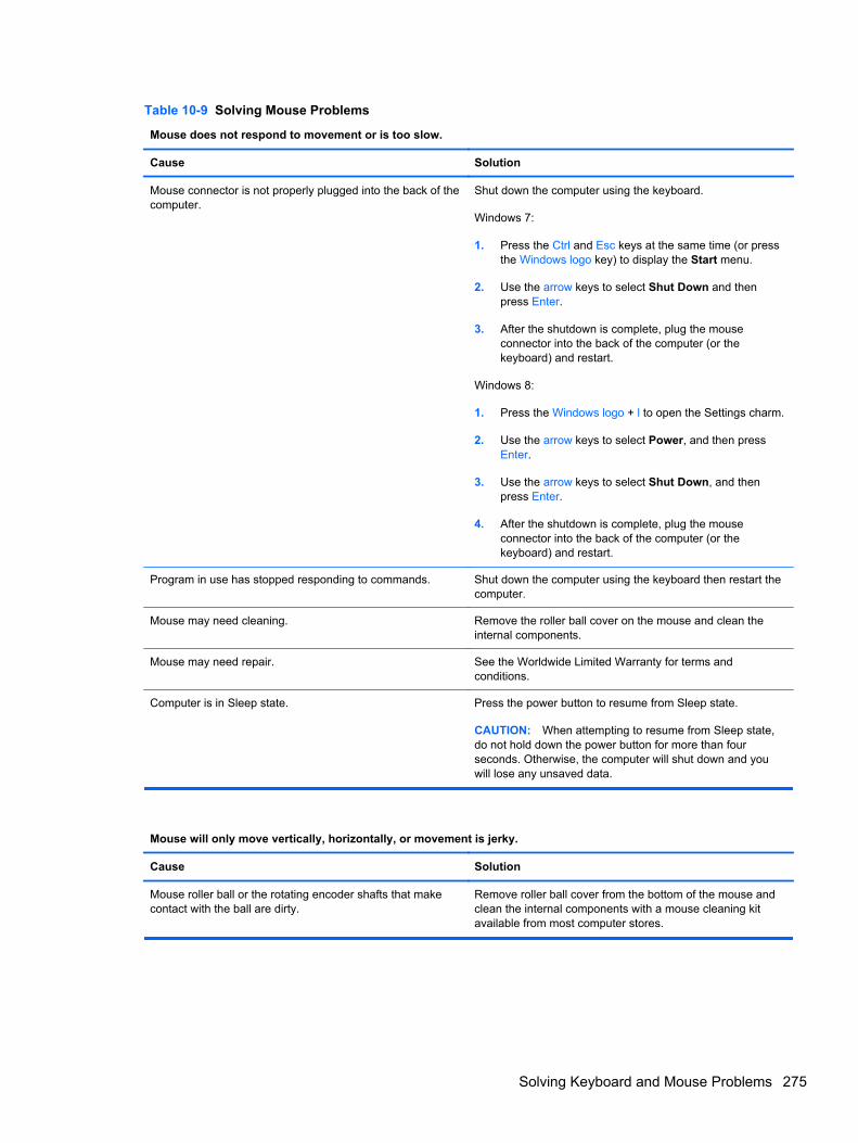
Table 10-9 Solving Mouse Problems
Mouse does not respond to movement or is too slow.
Cause Solution
Mouse connector is not properly plugged into the back of thecomputer.
Shut down the computer using the keyboard.
Windows 7:
1. Press the Ctrl and Esc keys at the same time (or pressthe Windows logo key) to display the Start menu.
2. Use the arrow keys to select Shut Down and thenpress Enter.
3. After the shutdown is complete, plug the mouseconnector into the back of the computer (or thekeyboard) and restart.
Windows 8:
1. Press the Windows logo + l to open the Settings charm.
2. Use the arrow keys to select Power, and then pressEnter.
3. Use the arrow keys to select Shut Down, and thenpress Enter.
4. After the shutdown is complete, plug the mouseconnector into the back of the computer (or thekeyboard) and restart.
Program in use has stopped responding to commands. Shut down the computer using the keyboard then restart thecomputer.
Mouse may need cleaning. Remove the roller ball cover on the mouse and clean theinternal components.
Mouse may need repair. See the Worldwide Limited Warranty for terms andconditions.
Computer is in Sleep state. Press the power button to resume from Sleep state.
CAUTION: When attempting to resume from Sleep state,do not hold down the power button for more than fourseconds. Otherwise, the computer will shut down and youwill lose any unsaved data.
Mouse will only move vertically, horizontally, or movement is jerky.
Cause Solution
Mouse roller ball or the rotating encoder shafts that makecontact with the ball are dirty.
Remove roller ball cover from the bottom of the mouse andclean the internal components with a mouse cleaning kitavailable from most computer stores.
Solving Keyboard and Mouse Problems 275
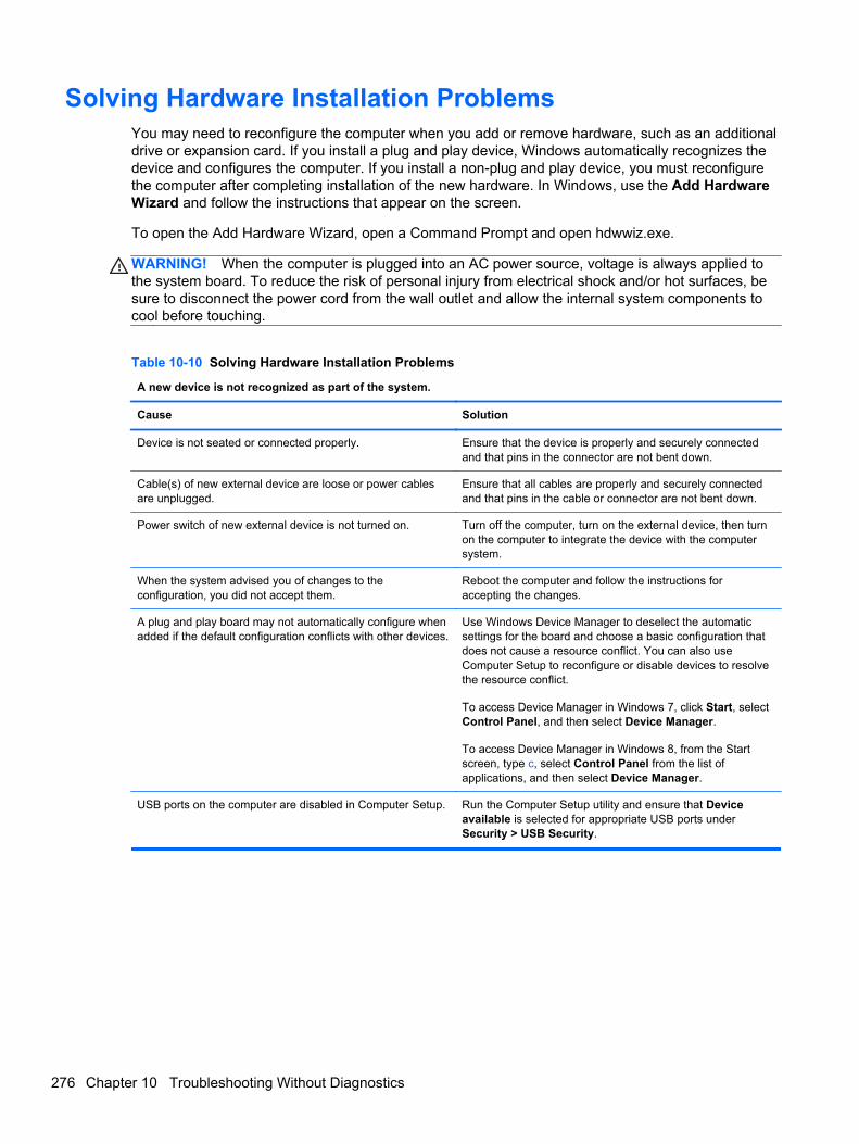
Solving Hardware Installation ProblemsYou may need to reconfigure the computer when you add or remove hardware, such as an additionaldrive or expansion card. If you install a plug and play device, Windows automatically recognizes thedevice and configures the computer. If you install a non-plug and play device, you must reconfigurethe computer after completing installation of the new hardware. In Windows, use the Add HardwareWizard and follow the instructions that appear on the screen.
To open the Add Hardware Wizard, open a Command Prompt and open hdwwiz.exe.
WARNING! When the computer is plugged into an AC power source, voltage is always applied tothe system board. To reduce the risk of personal injury from electrical shock and/or hot surfaces, besure to disconnect the power cord from the wall outlet and allow the internal system components tocool before touching.
Table 10-10 Solving Hardware Installation Problems
A new device is not recognized as part of the system.
Cause Solution
Device is not seated or connected properly. Ensure that the device is properly and securely connectedand that pins in the connector are not bent down.
Cable(s) of new external device are loose or power cablesare unplugged.
Ensure that all cables are properly and securely connectedand that pins in the cable or connector are not bent down.
Power switch of new external device is not turned on. Turn off the computer, turn on the external device, then turnon the computer to integrate the device with the computersystem.
When the system advised you of changes to theconfiguration, you did not accept them.
Reboot the computer and follow the instructions foraccepting the changes.
A plug and play board may not automatically configure whenadded if the default configuration conflicts with other devices.
Use Windows Device Manager to deselect the automaticsettings for the board and choose a basic configuration thatdoes not cause a resource conflict. You can also useComputer Setup to reconfigure or disable devices to resolvethe resource conflict.
To access Device Manager in Windows 7, click Start, selectControl Panel, and then select Device Manager.
To access Device Manager in Windows 8, from the Startscreen, type c, select Control Panel from the list ofapplications, and then select Device Manager.
USB ports on the computer are disabled in Computer Setup. Run the Computer Setup utility and ensure that Deviceavailable is selected for appropriate USB ports underSecurity > USB Security.
276 Chapter 10 Troubleshooting Without Diagnostics
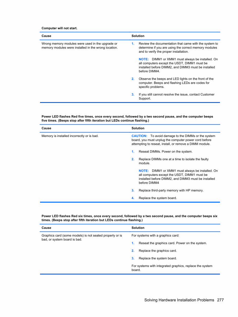
Computer will not start.
Cause Solution
Wrong memory modules were used in the upgrade ormemory modules were installed in the wrong location.
1. Review the documentation that came with the system todetermine if you are using the correct memory modulesand to verify the proper installation.
NOTE: DIMM1 or XMM1 must always be installed. Onall computers except the USDT, DIMM1 must beinstalled before DIMM2, and DIMM3 must be installedbefore DIMM4.
2. Observe the beeps and LED lights on the front of thecomputer. Beeps and flashing LEDs are codes forspecific problems.
3. If you still cannot resolve the issue, contact CustomerSupport.
Power LED flashes Red five times, once every second, followed by a two second pause, and the computer beepsfive times. (Beeps stop after fifth iteration but LEDs continue flashing.)
Cause Solution
Memory is installed incorrectly or is bad. CAUTION: To avoid damage to the DIMMs or the systemboard, you must unplug the computer power cord beforeattempting to reseat, install, or remove a DIMM module.
1. Reseat DIMMs. Power on the system.
2. Replace DIMMs one at a time to isolate the faultymodule.
NOTE: DIMM1 or XMM1 must always be installed. Onall computers except the USDT, DIMM1 must beinstalled before DIMM2, and DIMM3 must be installedbefore DIMM4
3. Replace third-party memory with HP memory.
4. Replace the system board.
Power LED flashes Red six times, once every second, followed by a two second pause, and the computer beeps sixtimes. (Beeps stop after fifth iteration but LEDs continue flashing.)
Cause Solution
Graphics card (some models) is not seated properly or isbad, or system board is bad.
For systems with a graphics card:
1. Reseat the graphics card. Power on the system.
2. Replace the graphics card.
3. Replace the system board.
For systems with integrated graphics, replace the systemboard.
Solving Hardware Installation Problems 277
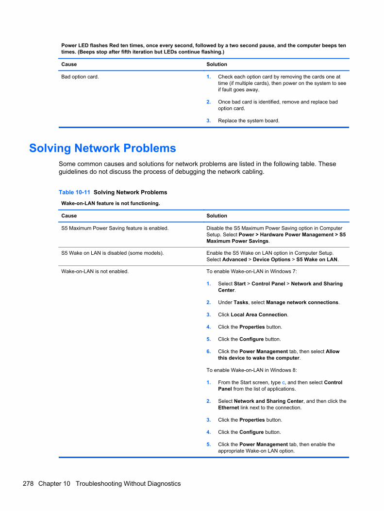
Power LED flashes Red ten times, once every second, followed by a two second pause, and the computer beeps tentimes. (Beeps stop after fifth iteration but LEDs continue flashing.)
Cause Solution
Bad option card. 1. Check each option card by removing the cards one attime (if multiple cards), then power on the system to seeif fault goes away.
2. Once bad card is identified, remove and replace badoption card.
3. Replace the system board.
Solving Network ProblemsSome common causes and solutions for network problems are listed in the following table. Theseguidelines do not discuss the process of debugging the network cabling.
Table 10-11 Solving Network Problems
Wake-on-LAN feature is not functioning.
Cause Solution
S5 Maximum Power Saving feature is enabled. Disable the S5 Maximum Power Saving option in ComputerSetup. Select Power > Hardware Power Management > S5Maximum Power Savings.
S5 Wake on LAN is disabled (some models). Enable the S5 Wake on LAN option in Computer Setup.Select Advanced > Device Options > S5 Wake on LAN.
Wake-on-LAN is not enabled. To enable Wake-on-LAN in Windows 7:
1. Select Start > Control Panel > Network and SharingCenter.
2. Under Tasks, select Manage network connections.
3. Click Local Area Connection.
4. Click the Properties button.
5. Click the Configure button.
6. Click the Power Management tab, then select Allowthis device to wake the computer.
To enable Wake-on-LAN in Windows 8:
1. From the Start screen, type c, and then select ControlPanel from the list of applications.
2. Select Network and Sharing Center, and then click theEthernet link next to the connection.
3. Click the Properties button.
4. Click the Configure button.
5. Click the Power Management tab, then enable theappropriate Wake-on LAN option.
278 Chapter 10 Troubleshooting Without Diagnostics
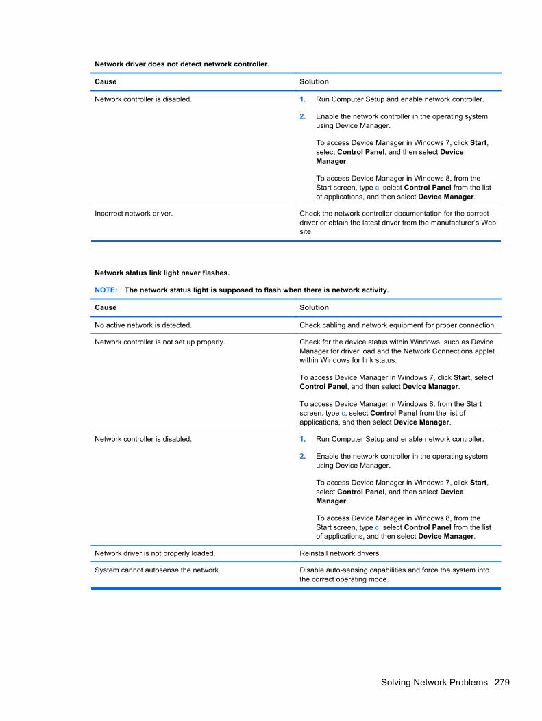
Network driver does not detect network controller.
Cause Solution
Network controller is disabled. 1. Run Computer Setup and enable network controller.
2. Enable the network controller in the operating systemusing Device Manager.
To access Device Manager in Windows 7, click Start,select Control Panel, and then select DeviceManager.
To access Device Manager in Windows 8, from theStart screen, type c, select Control Panel from the listof applications, and then select Device Manager.
Incorrect network driver. Check the network controller documentation for the correctdriver or obtain the latest driver from the manufacturer’s Website.
Network status link light never flashes.
NOTE: The network status light is supposed to flash when there is network activity.
Cause Solution
No active network is detected. Check cabling and network equipment for proper connection.
Network controller is not set up properly. Check for the device status within Windows, such as DeviceManager for driver load and the Network Connections appletwithin Windows for link status.
To access Device Manager in Windows 7, click Start, selectControl Panel, and then select Device Manager.
To access Device Manager in Windows 8, from the Startscreen, type c, select Control Panel from the list ofapplications, and then select Device Manager.
Network controller is disabled. 1. Run Computer Setup and enable network controller.
2. Enable the network controller in the operating systemusing Device Manager.
To access Device Manager in Windows 7, click Start,select Control Panel, and then select DeviceManager.
To access Device Manager in Windows 8, from theStart screen, type c, select Control Panel from the listof applications, and then select Device Manager.
Network driver is not properly loaded. Reinstall network drivers.
System cannot autosense the network. Disable auto-sensing capabilities and force the system intothe correct operating mode.
Solving Network Problems 279
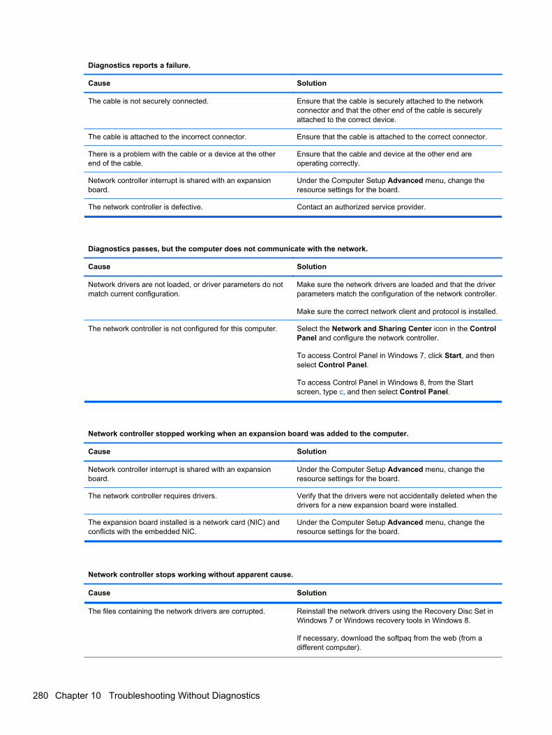
Diagnostics reports a failure.
Cause Solution
The cable is not securely connected. Ensure that the cable is securely attached to the networkconnector and that the other end of the cable is securelyattached to the correct device.
The cable is attached to the incorrect connector. Ensure that the cable is attached to the correct connector.
There is a problem with the cable or a device at the otherend of the cable.
Ensure that the cable and device at the other end areoperating correctly.
Network controller interrupt is shared with an expansionboard.
Under the Computer Setup Advanced menu, change theresource settings for the board.
The network controller is defective. Contact an authorized service provider.
Diagnostics passes, but the computer does not communicate with the network.
Cause Solution
Network drivers are not loaded, or driver parameters do notmatch current configuration.
Make sure the network drivers are loaded and that the driverparameters match the configuration of the network controller.
Make sure the correct network client and protocol is installed.
The network controller is not configured for this computer. Select the Network and Sharing Center icon in the ControlPanel and configure the network controller.
To access Control Panel in Windows 7, click Start, and thenselect Control Panel.
To access Control Panel in Windows 8, from the Startscreen, type c, and then select Control Panel.
Network controller stopped working when an expansion board was added to the computer.
Cause Solution
Network controller interrupt is shared with an expansionboard.
Under the Computer Setup Advanced menu, change theresource settings for the board.
The network controller requires drivers. Verify that the drivers were not accidentally deleted when thedrivers for a new expansion board were installed.
The expansion board installed is a network card (NIC) andconflicts with the embedded NIC.
Under the Computer Setup Advanced menu, change theresource settings for the board.
Network controller stops working without apparent cause.
Cause Solution
The files containing the network drivers are corrupted. Reinstall the network drivers using the Recovery Disc Set inWindows 7 or Windows recovery tools in Windows 8.
If necessary, download the softpaq from the web (from adifferent computer).
280 Chapter 10 Troubleshooting Without Diagnostics
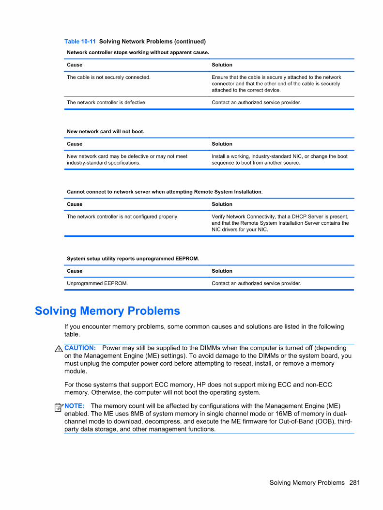
Table 10-11 Solving Network Problems (continued)
Network controller stops working without apparent cause.
Cause Solution
The cable is not securely connected. Ensure that the cable is securely attached to the networkconnector and that the other end of the cable is securelyattached to the correct device.
The network controller is defective. Contact an authorized service provider.
New network card will not boot.
Cause Solution
New network card may be defective or may not meetindustry-standard specifications.
Install a working, industry-standard NIC, or change the bootsequence to boot from another source.
Cannot connect to network server when attempting Remote System Installation.
Cause Solution
The network controller is not configured properly. Verify Network Connectivity, that a DHCP Server is present,and that the Remote System Installation Server contains theNIC drivers for your NIC.
System setup utility reports unprogrammed EEPROM.
Cause Solution
Unprogrammed EEPROM. Contact an authorized service provider.
Solving Memory ProblemsIf you encounter memory problems, some common causes and solutions are listed in the followingtable.
CAUTION: Power may still be supplied to the DIMMs when the computer is turned off (dependingon the Management Engine (ME) settings). To avoid damage to the DIMMs or the system board, youmust unplug the computer power cord before attempting to reseat, install, or remove a memorymodule.
For those systems that support ECC memory, HP does not support mixing ECC and non-ECCmemory. Otherwise, the computer will not boot the operating system.
NOTE: The memory count will be affected by configurations with the Management Engine (ME)enabled. The ME uses 8MB of system memory in single channel mode or 16MB of memory in dual-channel mode to download, decompress, and execute the ME firmware for Out-of-Band (OOB), third-party data storage, and other management functions.
Solving Memory Problems 281
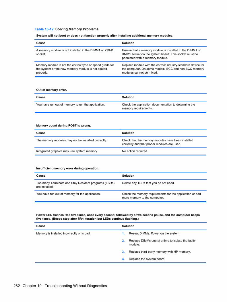
Table 10-12 Solving Memory Problems
System will not boot or does not function properly after installing additional memory modules.
Cause Solution
A memory module is not installed in the DIMM1 or XMM1socket.
Ensure that a memory module is installed in the DIMM1 orXMM1 socket on the system board. This socket must bepopulated with a memory module.
Memory module is not the correct type or speed grade forthe system or the new memory module is not seatedproperly.
Replace module with the correct industry-standard device forthe computer. On some models, ECC and non-ECC memorymodules cannot be mixed.
Out of memory error.
Cause Solution
You have run out of memory to run the application. Check the application documentation to determine thememory requirements.
Memory count during POST is wrong.
Cause Solution
The memory modules may not be installed correctly. Check that the memory modules have been installedcorrectly and that proper modules are used.
Integrated graphics may use system memory. No action required.
Insufficient memory error during operation.
Cause Solution
Too many Terminate and Stay Resident programs (TSRs)are installed.
Delete any TSRs that you do not need.
You have run out of memory for the application. Check the memory requirements for the application or addmore memory to the computer.
Power LED flashes Red five times, once every second, followed by a two second pause, and the computer beepsfive times. (Beeps stop after fifth iteration but LEDs continue flashing.)
Cause Solution
Memory is installed incorrectly or is bad. 1. Reseat DIMMs. Power on the system.
2. Replace DIMMs one at a time to isolate the faultymodule.
3. Replace third-party memory with HP memory.
4. Replace the system board.
282 Chapter 10 Troubleshooting Without Diagnostics
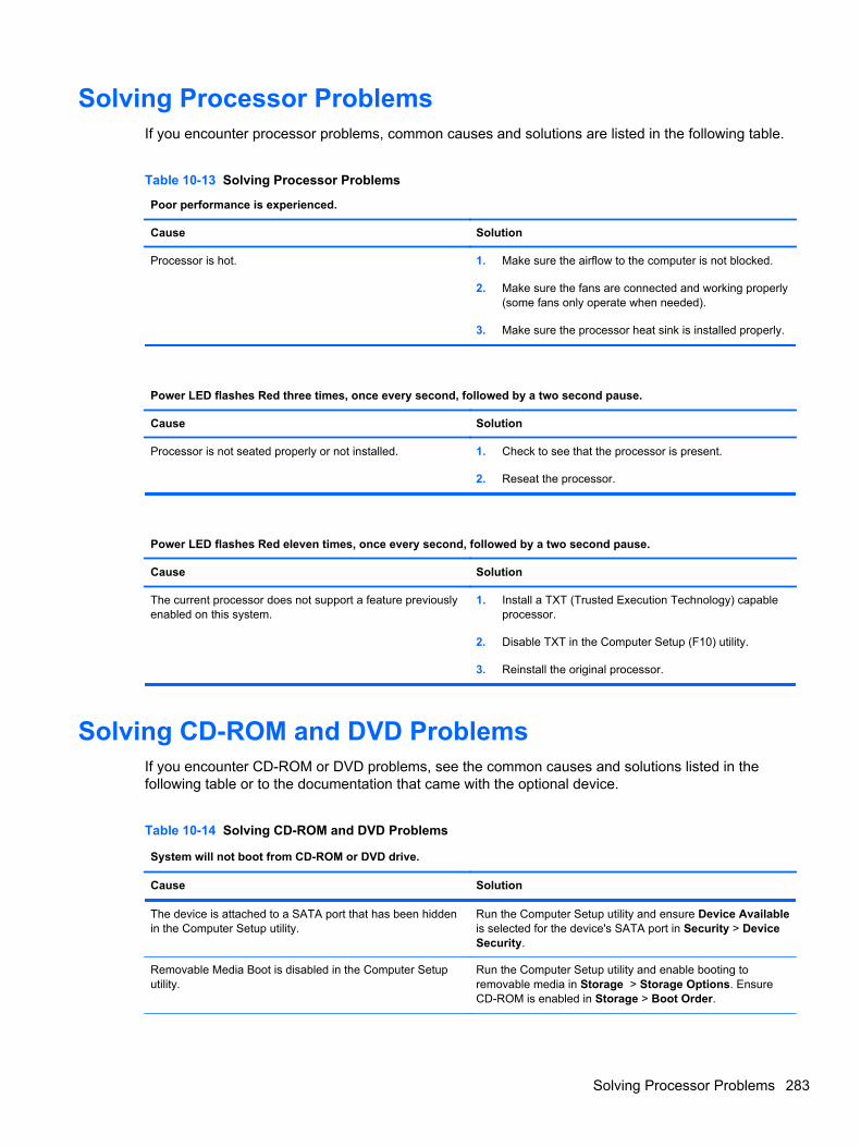
Solving Processor ProblemsIf you encounter processor problems, common causes and solutions are listed in the following table.
Table 10-13 Solving Processor Problems
Poor performance is experienced.
Cause Solution
Processor is hot. 1. Make sure the airflow to the computer is not blocked.
2. Make sure the fans are connected and working properly(some fans only operate when needed).
3. Make sure the processor heat sink is installed properly.
Power LED flashes Red three times, once every second, followed by a two second pause.
Cause Solution
Processor is not seated properly or not installed. 1. Check to see that the processor is present.
2. Reseat the processor.
Power LED flashes Red eleven times, once every second, followed by a two second pause.
Cause Solution
The current processor does not support a feature previouslyenabled on this system.
1. Install a TXT (Trusted Execution Technology) capableprocessor.
2. Disable TXT in the Computer Setup (F10) utility.
3. Reinstall the original processor.
Solving CD-ROM and DVD ProblemsIf you encounter CD-ROM or DVD problems, see the common causes and solutions listed in thefollowing table or to the documentation that came with the optional device.
Table 10-14 Solving CD-ROM and DVD Problems
System will not boot from CD-ROM or DVD drive.
Cause Solution
The device is attached to a SATA port that has been hiddenin the Computer Setup utility.
Run the Computer Setup utility and ensure Device Availableis selected for the device's SATA port in Security > DeviceSecurity.
Removable Media Boot is disabled in the Computer Setuputility.
Run the Computer Setup utility and enable booting toremovable media in Storage > Storage Options. EnsureCD-ROM is enabled in Storage > Boot Order.
Solving Processor Problems 283
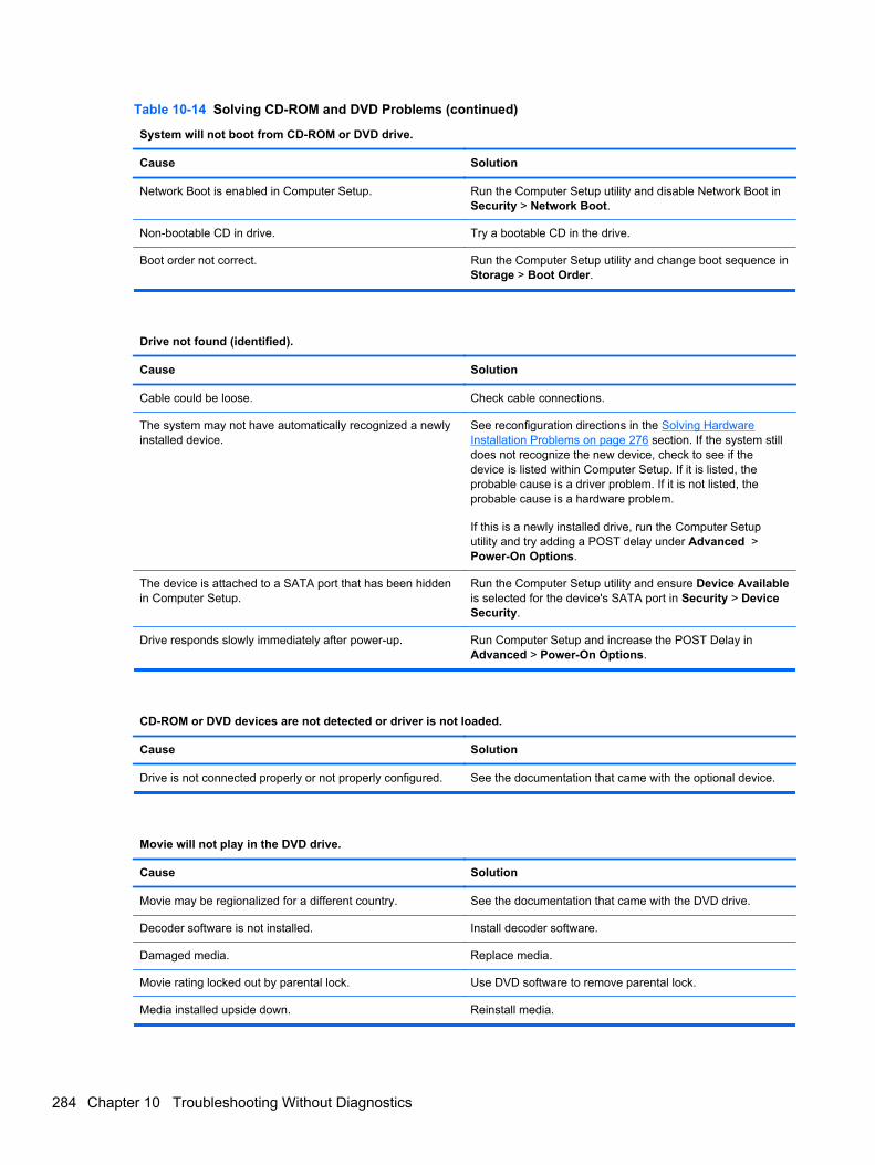
Table 10-14 Solving CD-ROM and DVD Problems (continued)
System will not boot from CD-ROM or DVD drive.
Cause Solution
Network Boot is enabled in Computer Setup. Run the Computer Setup utility and disable Network Boot inSecurity > Network Boot.
Non-bootable CD in drive. Try a bootable CD in the drive.
Boot order not correct. Run the Computer Setup utility and change boot sequence inStorage > Boot Order.
Drive not found (identified).
Cause Solution
Cable could be loose. Check cable connections.
The system may not have automatically recognized a newlyinstalled device.
See reconfiguration directions in the Solving HardwareInstallation Problems on page 276 section. If the system stilldoes not recognize the new device, check to see if thedevice is listed within Computer Setup. If it is listed, theprobable cause is a driver problem. If it is not listed, theprobable cause is a hardware problem.
If this is a newly installed drive, run the Computer Setuputility and try adding a POST delay under Advanced >Power-On Options.
The device is attached to a SATA port that has been hiddenin Computer Setup.
Run the Computer Setup utility and ensure Device Availableis selected for the device's SATA port in Security > DeviceSecurity.
Drive responds slowly immediately after power-up. Run Computer Setup and increase the POST Delay inAdvanced > Power-On Options.
CD-ROM or DVD devices are not detected or driver is not loaded.
Cause Solution
Drive is not connected properly or not properly configured. See the documentation that came with the optional device.
Movie will not play in the DVD drive.
Cause Solution
Movie may be regionalized for a different country. See the documentation that came with the DVD drive.
Decoder software is not installed. Install decoder software.
Damaged media. Replace media.
Movie rating locked out by parental lock. Use DVD software to remove parental lock.
Media installed upside down. Reinstall media.
284 Chapter 10 Troubleshooting Without Diagnostics
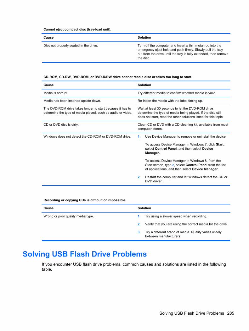
Cannot eject compact disc (tray-load unit).
Cause Solution
Disc not properly seated in the drive. Turn off the computer and insert a thin metal rod into theemergency eject hole and push firmly. Slowly pull the trayout from the drive until the tray is fully extended, then removethe disc.
CD-ROM, CD-RW, DVD-ROM, or DVD-R/RW drive cannot read a disc or takes too long to start.
Cause Solution
Media is corrupt. Try different media to confirm whether media is valid.
Media has been inserted upside down. Re-insert the media with the label facing up.
The DVD-ROM drive takes longer to start because it has todetermine the type of media played, such as audio or video.
Wait at least 30 seconds to let the DVD-ROM drivedetermine the type of media being played. If the disc stilldoes not start, read the other solutions listed for this topic.
CD or DVD disc is dirty. Clean CD or DVD with a CD cleaning kit, available from mostcomputer stores.
Windows does not detect the CD-ROM or DVD-ROM drive. 1. Use Device Manager to remove or uninstall the device.
To access Device Manager in Windows 7, click Start,select Control Panel, and then select DeviceManager.
To access Device Manager in Windows 8, from theStart screen, type c, select Control Panel from the listof applications, and then select Device Manager.
2. Restart the computer and let Windows detect the CD orDVD driver.
Recording or copying CDs is difficult or impossible.
Cause Solution
Wrong or poor quality media type. 1. Try using a slower speed when recording.
2. Verify that you are using the correct media for the drive.
3. Try a different brand of media. Quality varies widelybetween manufacturers.
Solving USB Flash Drive ProblemsIf you encounter USB flash drive problems, common causes and solutions are listed in the followingtable.
Solving USB Flash Drive Problems 285
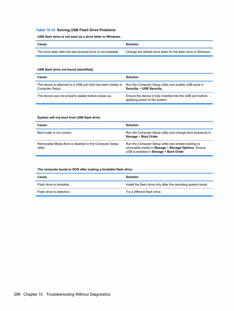
Table 10-15 Solving USB Flash Drive Problems
USB flash drive is not seen as a drive letter in Windows.
Cause Solution
The drive letter after the last physical drive is not available. Change the default drive letter for the flash drive in Windows.
USB flash drive not found (identified).
Cause Solution
The device is attached to a USB port that has been hidden inComputer Setup.
Run the Computer Setup utility and enable USB ports inSecurity > USB Security.
The device was not properly seated before power-up. Ensure the device is fully inserted into the USB port beforeapplying power to the system
System will not boot from USB flash drive.
Cause Solution
Boot order is not correct. Run the Computer Setup utility and change boot sequence inStorage > Boot Order.
Removable Media Boot is disabled in the Computer Setuputility.
Run the Computer Setup utility and enable booting toremovable media in Storage > Storage Options. EnsureUSB is enabled in Storage > Boot Order.
The computer boots to DOS after making a bootable flash drive.
Cause Solution
Flash drive is bootable. Install the flash drive only after the operating system boots.
Flash drive is defective. Try a different flash drive.
286 Chapter 10 Troubleshooting Without Diagnostics
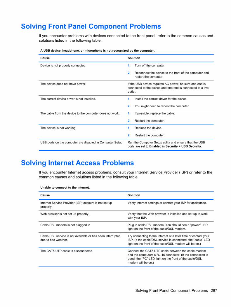
Solving Front Panel Component ProblemsIf you encounter problems with devices connected to the front panel, refer to the common causes andsolutions listed in the following table.
A USB device, headphone, or microphone is not recognized by the computer.
Cause Solution
Device is not properly connected. 1. Turn off the computer.
2. Reconnect the device to the front of the computer andrestart the computer.
The device does not have power. If the USB device requires AC power, be sure one end isconnected to the device and one end is connected to a liveoutlet.
The correct device driver is not installed. 1. Install the correct driver for the device.
2. You might need to reboot the computer.
The cable from the device to the computer does not work. 1. If possible, replace the cable.
2. Restart the computer.
The device is not working. 1. Replace the device.
2. Restart the computer.
USB ports on the computer are disabled in Computer Setup. Run the Computer Setup utility and ensure that the USBports are set to Enabled in Security > USB Security.
Solving Internet Access ProblemsIf you encounter Internet access problems, consult your Internet Service Provider (ISP) or refer to thecommon causes and solutions listed in the following table.
Unable to connect to the Internet.
Cause Solution
Internet Service Provider (ISP) account is not set upproperly.
Verify Internet settings or contact your ISP for assistance.
Web browser is not set up properly. Verify that the Web browser is installed and set up to workwith your ISP.
Cable/DSL modem is not plugged in. Plug in cable/DSL modem. You should see a “power” LEDlight on the front of the cable/DSL modem.
Cable/DSL service is not available or has been interrupteddue to bad weather.
Try connecting to the Internet at a later time or contact yourISP. (If the cable/DSL service is connected, the “cable” LEDlight on the front of the cable/DSL modem will be on.)
The CAT5 UTP cable is disconnected. Connect the CAT5 UTP cable between the cable modemand the computers’s RJ-45 connector. (If the connection isgood, the “PC” LED light on the front of the cable/DSLmodem will be on.)
Solving Front Panel Component Problems 287
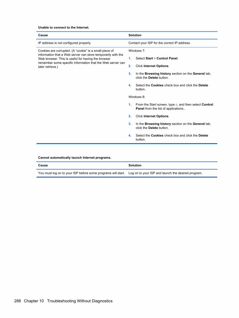
Unable to connect to the Internet.
Cause Solution
IP address is not configured properly. Contact your ISP for the correct IP address.
Cookies are corrupted. (A “cookie” is a small piece ofinformation that a Web server can store temporarily with theWeb browser. This is useful for having the browserremember some specific information that the Web server canlater retrieve.)
Windows 7:
1. Select Start > Control Panel.
2. Click Internet Options.
3. In the Browsing history section on the General tab,click the Delete button.
4. Select the Cookies check box and click the Deletebutton.
Windows 8:
1. From the Start screen, type c, and then select ControlPanel from the list of applications..
2. Click Internet Options.
3. In the Browsing history section on the General tab,click the Delete button.
4. Select the Cookies check box and click the Deletebutton.
Cannot automatically launch Internet programs.
Cause Solution
You must log on to your ISP before some programs will start. Log on to your ISP and launch the desired program.
288 Chapter 10 Troubleshooting Without Diagnostics

Solving Software ProblemsMost software problems occur as a result of the following:
● The application was not installed or configured correctly.
● There is insufficient memory available to run the application.
● There is a conflict between applications.
● Be sure that all the needed device drivers have been installed.
● If you have installed an operating system other than the factory-installed operating system,check to be sure it is supported on the system.
If you encounter software problems, see the applicable solutions listed in the following table.
Computer will not continue and the HP logo does not display.
Cause Solution
ROM issue - POST error has occurred. Observe the beeps and LED lights on the front of thecomputer. See Appendix A, POST Error Messageson page 292 to determine possible causes.
See the Worldwide Limited Warranty for terms andconditions.
Solving Software Problems 289
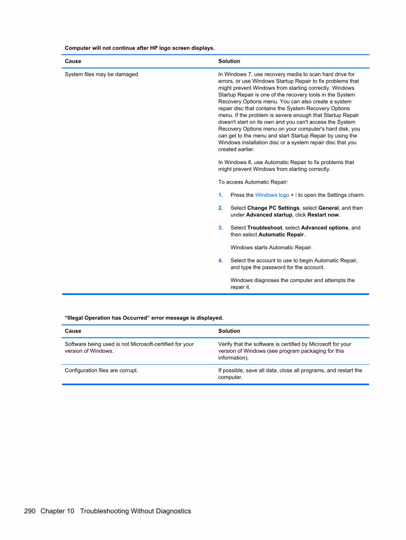
Computer will not continue after HP logo screen displays.
Cause Solution
System files may be damaged. In Windows 7, use recovery media to scan hard drive forerrors, or use Windows Startup Repair to fix problems thatmight prevent Windows from starting correctly. WindowsStartup Repair is one of the recovery tools in the SystemRecovery Options menu. You can also create a systemrepair disc that contains the System Recovery Optionsmenu. If the problem is severe enough that Startup Repairdoesn't start on its own and you can't access the SystemRecovery Options menu on your computer's hard disk, youcan get to the menu and start Startup Repair by using theWindows installation disc or a system repair disc that youcreated earlier.
In Windows 8, use Automatic Repair to fix problems thatmight prevent Windows from starting correctly.
To access Automatic Repair:
1. Press the Windows logo + l to open the Settings charm.
2. Select Change PC Settings, select General, and thenunder Advanced startup, click Restart now.
3. Select Troubleshoot, select Advanced options, andthen select Automatic Repair.
Windows starts Automatic Repair.
4. Select the account to use to begin Automatic Repair,and type the password for the account.
Windows diagnoses the computer and attempts therepair it.
“Illegal Operation has Occurred” error message is displayed.
Cause Solution
Software being used is not Microsoft-certified for yourversion of Windows.
Verify that the software is certified by Microsoft for yourversion of Windows (see program packaging for thisinformation).
Configuration files are corrupt. If possible, save all data, close all programs, and restart thecomputer.
290 Chapter 10 Troubleshooting Without Diagnostics

Contacting Customer SupportFor help and service, contact an authorized reseller or dealer. To locate a reseller or dealer near you,visit http://www.hp.com.
NOTE: If you take the computer to an authorized reseller, dealer, or service provider for service,remember to provide the setup and power-on passwords if they are set.
Refer to the number listed in the warranty or in the Support Telephone Numbers guide for technicalassistance.
Contacting Customer Support 291

11 POST Error Messages
This appendix lists the error codes, error messages, and the various indicator light and audiblesequences that you may encounter during Power-On Self-Test (POST) or computer restart, theprobable source of the problem, and steps you can take to resolve the error condition.
POST Message Disabled suppresses most system messages during POST, such as memory countand non-error text messages. If a POST error occurs, the screen will display the error message. Tomanually switch to the POST Messages Enabled mode during POST, press any key (except F10,F11, or F12). The default mode is POST Message Disabled.
The speed at which the computer loads the operating system and the extent to which it is tested aredetermined by the POST mode selection.
Quick Boot is a fast startup process that does not run all of the system level tests, such as thememory test. Full Boot runs all of the ROM-based system tests and takes longer to complete.
Full Boot may also be enabled to run every 1 to 30 days on a regularly scheduled basis. To establishthe schedule, reconfigure the computer to the Full Boot Every x Days mode, using Computer Setup.
NOTE: For more information on Computer Setup, see Computer Setup (F10) Utility on page 16.
292 Chapter 11 POST Error Messages
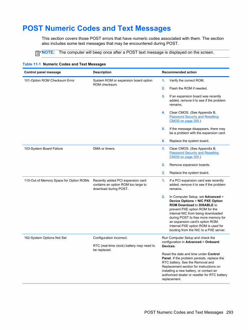
POST Numeric Codes and Text MessagesThis section covers those POST errors that have numeric codes associated with them. The sectionalso includes some text messages that may be encountered during POST.
NOTE: The computer will beep once after a POST text message is displayed on the screen.
Table 11-1 Numeric Codes and Text Messages
Control panel message Description Recommended action
101-Option ROM Checksum Error System ROM or expansion board optionROM checksum.
1. Verify the correct ROM.
2. Flash the ROM if needed.
3. If an expansion board was recentlyadded, remove it to see if the problemremains.
4. Clear CMOS. (See Appendix B,Password Security and ResettingCMOS on page 305.)
5. If the message disappears, there maybe a problem with the expansion card.
6. Replace the system board.
103-System Board Failure DMA or timers. 1. Clear CMOS. (See Appendix B,Password Security and ResettingCMOS on page 305.)
2. Remove expansion boards.
3. Replace the system board.
110-Out of Memory Space for Option ROMs Recently added PCI expansion cardcontains an option ROM too large todownload during POST.
1. If a PCI expansion card was recentlyadded, remove it to see if the problemremains.
2. In Computer Setup, set Advanced >Device Options > NIC PXE OptionROM Download to DISABLE toprevent PXE option ROM for theinternal NIC from being downloadedduring POST to free more memory foran expansion card's option ROM.Internal PXE option ROM is used forbooting from the NIC to a PXE server.
162-System Options Not Set Configuration incorrect.
RTC (real-time clock) battery may need tobe replaced.
Run Computer Setup and check theconfiguration in Advanced > OnboardDevices.
Reset the date and time under ControlPanel. If the problem persists, replace theRTC battery. See the Removal andReplacement section for instructions oninstalling a new battery, or contact anauthorized dealer or reseller for RTC batteryreplacement.
POST Numeric Codes and Text Messages 293
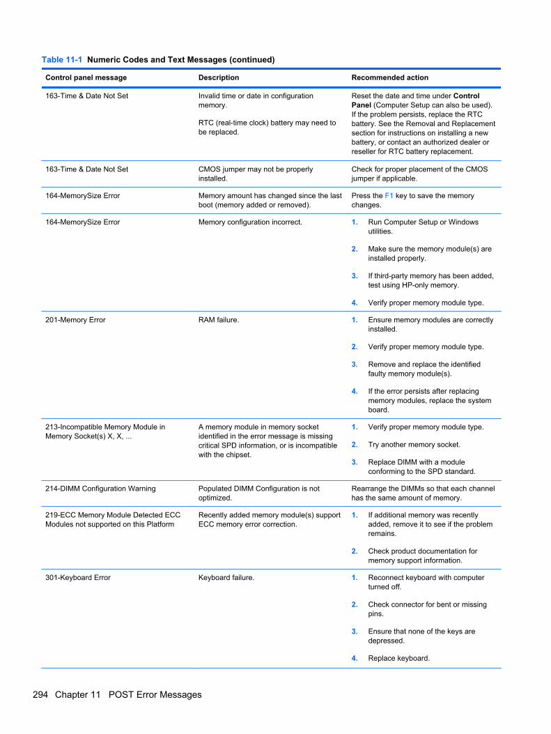
Table 11-1 Numeric Codes and Text Messages (continued)
Control panel message Description Recommended action
163-Time & Date Not Set Invalid time or date in configurationmemory.
RTC (real-time clock) battery may need tobe replaced.
Reset the date and time under ControlPanel (Computer Setup can also be used).If the problem persists, replace the RTCbattery. See the Removal and Replacementsection for instructions on installing a newbattery, or contact an authorized dealer orreseller for RTC battery replacement.
163-Time & Date Not Set CMOS jumper may not be properlyinstalled.
Check for proper placement of the CMOSjumper if applicable.
164-MemorySize Error Memory amount has changed since the lastboot (memory added or removed).
Press the F1 key to save the memorychanges.
164-MemorySize Error Memory configuration incorrect. 1. Run Computer Setup or Windowsutilities.
2. Make sure the memory module(s) areinstalled properly.
3. If third-party memory has been added,test using HP-only memory.
4. Verify proper memory module type.
201-Memory Error RAM failure. 1. Ensure memory modules are correctlyinstalled.
2. Verify proper memory module type.
3. Remove and replace the identifiedfaulty memory module(s).
4. If the error persists after replacingmemory modules, replace the systemboard.
213-Incompatible Memory Module inMemory Socket(s) X, X, ...
A memory module in memory socketidentified in the error message is missingcritical SPD information, or is incompatiblewith the chipset.
1. Verify proper memory module type.
2. Try another memory socket.
3. Replace DIMM with a moduleconforming to the SPD standard.
214-DIMM Configuration Warning Populated DIMM Configuration is notoptimized.
Rearrange the DIMMs so that each channelhas the same amount of memory.
219-ECC Memory Module Detected ECCModules not supported on this Platform
Recently added memory module(s) supportECC memory error correction.
1. If additional memory was recentlyadded, remove it to see if the problemremains.
2. Check product documentation formemory support information.
301-Keyboard Error Keyboard failure. 1. Reconnect keyboard with computerturned off.
2. Check connector for bent or missingpins.
3. Ensure that none of the keys aredepressed.
4. Replace keyboard.
294 Chapter 11 POST Error Messages
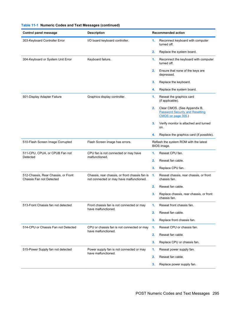
Table 11-1 Numeric Codes and Text Messages (continued)
Control panel message Description Recommended action
303-Keyboard Controller Error I/O board keyboard controller. 1. Reconnect keyboard with computerturned off.
2. Replace the system board.
304-Keyboard or System Unit Error Keyboard failure. 1. Reconnect the keyboard with computerturned off.
2. Ensure that none of the keys aredepressed.
3. Replace the keyboard.
4. Replace the system board.
501-Display Adapter Failure Graphics display controller. 1. Reseat the graphics card(if applicable).
2. Clear CMOS. (See Appendix B,Password Security and ResettingCMOS on page 305.)
3. Verify monitor is attached and turnedon.
4. Replace the graphics card (if possible).
510-Flash Screen Image Corrupted Flash Screen image has errors. Reflash the system ROM with the latestBIOS image.
511-CPU, CPUA, or CPUB Fan notDetected
CPU fan is not connected or may havemalfunctioned.
1. Reseat CPU fan.
2. Reseat fan cable.
3. Replace CPU fan.
512-Chassis, Rear Chassis, or FrontChassis Fan not Detected
Chassis, rear chassis, or front chassis fan isnot connected or may have malfunctioned.
1. Reseat chassis, rear chassis, or frontchassis fan.
2. Reseat fan cable.
3. Replace chassis, rear chassis, or frontchassis fan.
513-Front Chassis fan not detected Front chassis fan is not connected or mayhave malfunctioned.
1. Reseat front chassis fan.
2. Reseat fan cable.
3. Replace front chassis fan.
514-CPU or Chassis Fan not Detected CPU or chassis fan is not connected or mayhave malfunctioned.
1. Reseat CPU or chassis fan.
2. Reseat fan cable.
3. Replace CPU or chassis fan.
515-Power Supply fan not detected Power supply fan is not connected or mayhave malfunctioned.
1. Reseat power supply fan.
2. Reseat fan cable.
3. Replace power supply fan.
POST Numeric Codes and Text Messages 295
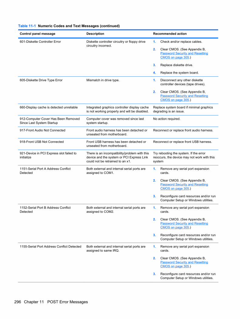
Table 11-1 Numeric Codes and Text Messages (continued)
Control panel message Description Recommended action
601-Diskette Controller Error Diskette controller circuitry or floppy drivecircuitry incorrect.
1. Check and/or replace cables.
2. Clear CMOS. (See Appendix B,Password Security and ResettingCMOS on page 305.)
3. Replace diskette drive.
4. Replace the system board.
605-Diskette Drive Type Error Mismatch in drive type. 1. Disconnect any other diskettecontroller devices (tape drives).
2. Clear CMOS. (See Appendix B,Password Security and ResettingCMOS on page 305.)
660-Display cache is detected unreliable Integrated graphics controller display cacheis not working properly and will be disabled.
Replace system board if minimal graphicsdegrading is an issue.
912-Computer Cover Has Been RemovedSince Last System Startup
Computer cover was removed since lastsystem startup.
No action required.
917-Front Audio Not Connected Front audio harness has been detached orunseated from motherboard.
Reconnect or replace front audio harness.
918-Front USB Not Connected Front USB harness has been detached orunseated from motherboard.
Reconnect or replace front USB harness.
921-Device in PCI Express slot failed toinitialize
There is an incompatibility/problem with thisdevice and the system or PCI Express Linkcould not be retrained to an x1.
Try rebooting the system. If the errorreoccurs, the device may not work with thissystem
1151-Serial Port A Address ConflictDetected
Both external and internal serial ports areassigned to COM1.
1. Remove any serial port expansioncards.
2. Clear CMOS. (See Appendix B,Password Security and ResettingCMOS on page 305.)
3. Reconfigure card resources and/or runComputer Setup or Windows utilities.
1152-Serial Port B Address ConflictDetected
Both external and internal serial ports areassigned to COM2.
1. Remove any serial port expansioncards.
2. Clear CMOS. (See Appendix B,Password Security and ResettingCMOS on page 305.)
3. Reconfigure card resources and/or runComputer Setup or Windows utilities.
1155-Serial Port Address Conflict Detected Both external and internal serial ports areassigned to same IRQ.
1. Remove any serial port expansioncards.
2. Clear CMOS. (See Appendix B,Password Security and ResettingCMOS on page 305.)
3. Reconfigure card resources and/or runComputer Setup or Windows utilities.
296 Chapter 11 POST Error Messages
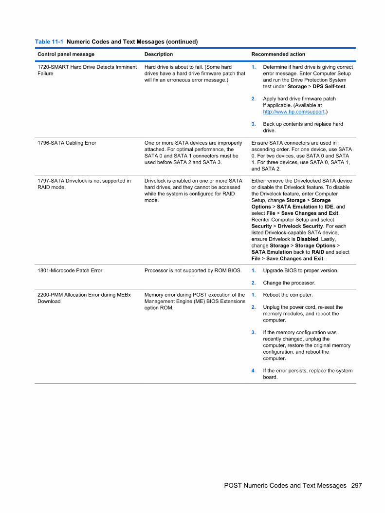
Table 11-1 Numeric Codes and Text Messages (continued)
Control panel message Description Recommended action
1720-SMART Hard Drive Detects ImminentFailure
Hard drive is about to fail. (Some harddrives have a hard drive firmware patch thatwill fix an erroneous error message.)
1. Determine if hard drive is giving correcterror message. Enter Computer Setupand run the Drive Protection Systemtest under Storage > DPS Self-test.
2. Apply hard drive firmware patchif applicable. (Available athttp://www.hp.com/support.)
3. Back up contents and replace harddrive.
1796-SATA Cabling Error One or more SATA devices are improperlyattached. For optimal performance, theSATA 0 and SATA 1 connectors must beused before SATA 2 and SATA 3.
Ensure SATA connectors are used inascending order. For one device, use SATA0. For two devices, use SATA 0 and SATA1. For three devices, use SATA 0, SATA 1,and SATA 2.
1797-SATA Drivelock is not supported inRAID mode.
Drivelock is enabled on one or more SATAhard drives, and they cannot be accessedwhile the system is configured for RAIDmode.
Either remove the Drivelocked SATA deviceor disable the Drivelock feature. To disablethe Drivelock feature, enter ComputerSetup, change Storage > StorageOptions > SATA Emulation to IDE, andselect File > Save Changes and Exit.Reenter Computer Setup and selectSecurity > Drivelock Security. For eachlisted Drivelock-capable SATA device,ensure Drivelock is Disabled. Lastly,change Storage > Storage Options >SATA Emulation back to RAID and selectFile > Save Changes and Exit.
1801-Microcode Patch Error Processor is not supported by ROM BIOS. 1. Upgrade BIOS to proper version.
2. Change the processor.
2200-PMM Allocation Error during MEBxDownload
Memory error during POST execution of theManagement Engine (ME) BIOS Extensionsoption ROM.
1. Reboot the computer.
2. Unplug the power cord, re-seat thememory modules, and reboot thecomputer.
3. If the memory configuration wasrecently changed, unplug thecomputer, restore the original memoryconfiguration, and reboot thecomputer.
4. If the error persists, replace the systemboard.
POST Numeric Codes and Text Messages 297
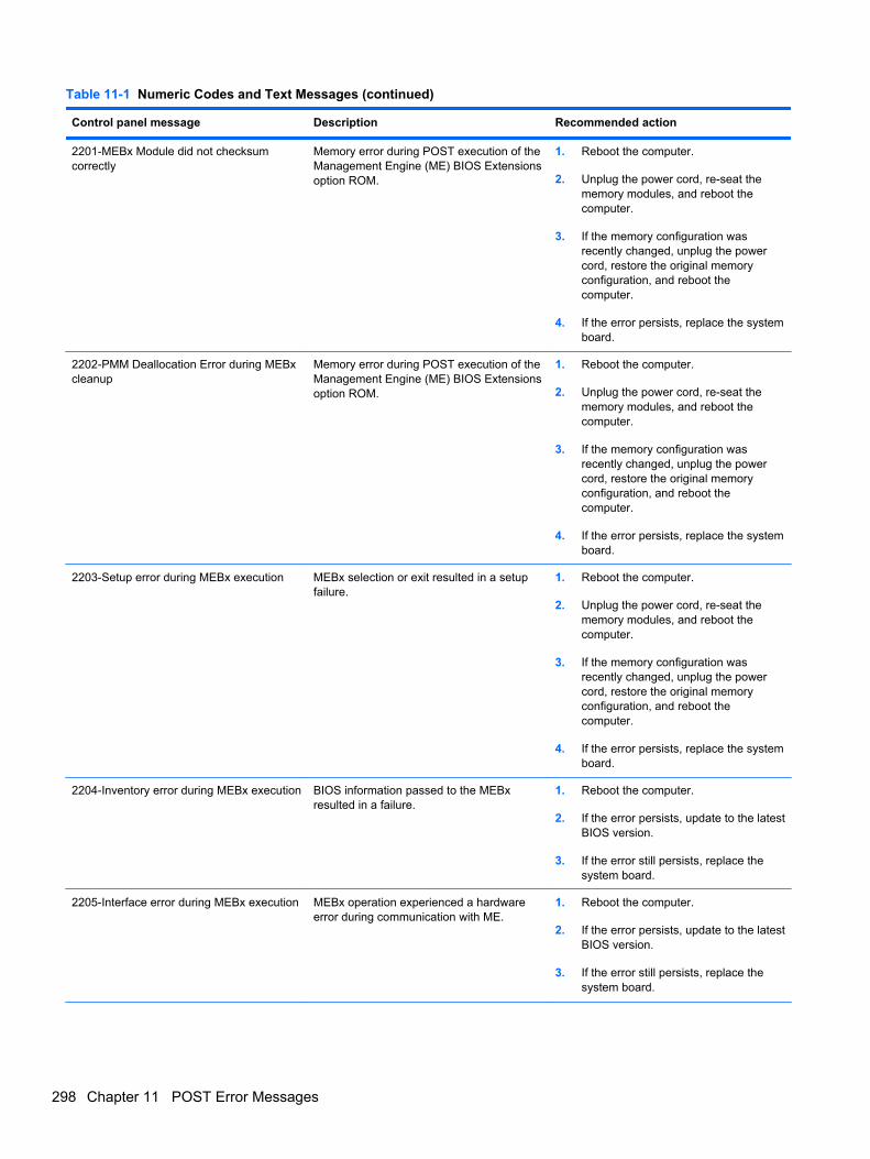
Table 11-1 Numeric Codes and Text Messages (continued)
Control panel message Description Recommended action
2201-MEBx Module did not checksumcorrectly
Memory error during POST execution of theManagement Engine (ME) BIOS Extensionsoption ROM.
1. Reboot the computer.
2. Unplug the power cord, re-seat thememory modules, and reboot thecomputer.
3. If the memory configuration wasrecently changed, unplug the powercord, restore the original memoryconfiguration, and reboot thecomputer.
4. If the error persists, replace the systemboard.
2202-PMM Deallocation Error during MEBxcleanup
Memory error during POST execution of theManagement Engine (ME) BIOS Extensionsoption ROM.
1. Reboot the computer.
2. Unplug the power cord, re-seat thememory modules, and reboot thecomputer.
3. If the memory configuration wasrecently changed, unplug the powercord, restore the original memoryconfiguration, and reboot thecomputer.
4. If the error persists, replace the systemboard.
2203-Setup error during MEBx execution MEBx selection or exit resulted in a setupfailure.
1. Reboot the computer.
2. Unplug the power cord, re-seat thememory modules, and reboot thecomputer.
3. If the memory configuration wasrecently changed, unplug the powercord, restore the original memoryconfiguration, and reboot thecomputer.
4. If the error persists, replace the systemboard.
2204-Inventory error during MEBx execution BIOS information passed to the MEBxresulted in a failure.
1. Reboot the computer.
2. If the error persists, update to the latestBIOS version.
3. If the error still persists, replace thesystem board.
2205-Interface error during MEBx execution MEBx operation experienced a hardwareerror during communication with ME.
1. Reboot the computer.
2. If the error persists, update to the latestBIOS version.
3. If the error still persists, replace thesystem board.
298 Chapter 11 POST Error Messages
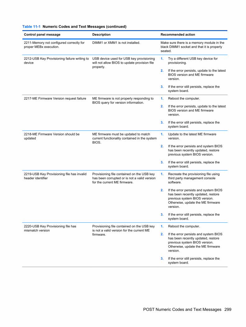
Table 11-1 Numeric Codes and Text Messages (continued)
Control panel message Description Recommended action
2211-Memory not configured correctly forproper MEBx execution.
DIMM1 or XMM1 is not installed. Make sure there is a memory module in theblack DIMM1 socket and that it is properlyseated.
2212-USB Key Provisioning failure writing todevice
USB device used for USB key provisioningwill not allow BIOS to update provision fileproperly.
1. Try a different USB key device forprovisioning.
2. If the error persists, update to the latestBIOS version and ME firmwareversion.
3. If the error still persists, replace thesystem board.
2217-ME Firmware Version request failure ME firmware is not properly responding toBIOS query for version information.
1. Reboot the computer.
2. If the error persists, update to the latestBIOS version and ME firmwareversion.
3. If the error still persists, replace thesystem board.
2218-ME Firmware Version should beupdated
ME firmware must be updated to matchcurrent functionality contained in the systemBIOS.
1. Update to the latest ME firmwareversion.
2. If the error persists and system BIOShas been recently updated, restoreprevious system BIOS version.
3. If the error still persists, replace thesystem board.
2219-USB Key Provisioning file has invalidheader identifier
Provisioning file contained on the USB keyhas been corrupted or is not a valid versionfor the current ME firmware.
1. Recreate the provisioning file usingthird party management consolesoftware.
2. If the error persists and system BIOShas been recently updated, restoreprevious system BIOS version.Otherwise, update the ME firmwareversion.
3. If the error still persists, replace thesystem board.
2220-USB Key Provisioning file hasmismatch version
Provisioning file contained on the USB keyis not a valid version for the current MEfirmware.
1. Reboot the computer.
2. If the error persists and system BIOShas been recently updated, restoreprevious system BIOS version.Otherwise, update the ME firmwareversion.
3. If the error still persists, replace thesystem board.
POST Numeric Codes and Text Messages 299
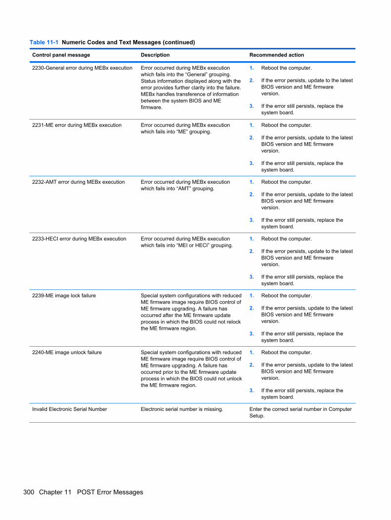
Table 11-1 Numeric Codes and Text Messages (continued)
Control panel message Description Recommended action
2230-General error during MEBx execution Error occurred during MEBx executionwhich fails into the “General” grouping.Status information displayed along with theerror provides further clarity into the failure.MEBx handles transference of informationbetween the system BIOS and MEfirmware.
1. Reboot the computer.
2. If the error persists, update to the latestBIOS version and ME firmwareversion.
3. If the error still persists, replace thesystem board.
2231-ME error during MEBx execution Error occurred during MEBx executionwhich fails into “ME” grouping.
1. Reboot the computer.
2. If the error persists, update to the latestBIOS version and ME firmwareversion.
3. If the error still persists, replace thesystem board.
2232-AMT error during MEBx execution Error occurred during MEBx executionwhich fails into “AMT” grouping.
1. Reboot the computer.
2. If the error persists, update to the latestBIOS version and ME firmwareversion.
3. If the error still persists, replace thesystem board.
2233-HECI error during MEBx execution Error occurred during MEBx executionwhich fails into “MEI or HECI” grouping.
1. Reboot the computer.
2. If the error persists, update to the latestBIOS version and ME firmwareversion.
3. If the error still persists, replace thesystem board.
2239-ME image lock failure Special system configurations with reducedME firmware image require BIOS control ofME firmware upgrading. A failure hasoccurred after the ME firmware updateprocess in which the BIOS could not relockthe ME firmware region.
1. Reboot the computer.
2. If the error persists, update to the latestBIOS version and ME firmwareversion.
3. If the error still persists, replace thesystem board.
2240-ME image unlock failure Special system configurations with reducedME firmware image require BIOS control ofME firmware upgrading. A failure hasoccurred prior to the ME firmware updateprocess in which the BIOS could not unlockthe ME firmware region.
1. Reboot the computer.
2. If the error persists, update to the latestBIOS version and ME firmwareversion.
3. If the error still persists, replace thesystem board.
Invalid Electronic Serial Number Electronic serial number is missing. Enter the correct serial number in ComputerSetup.
300 Chapter 11 POST Error Messages

Table 11-1 Numeric Codes and Text Messages (continued)
Control panel message Description Recommended action
Network Server Mode Active and NoKeyboard Attached
Keyboard failure while Network ServerMode enabled.
1. Reconnect keyboard with computerturned off.
2. Check connector for bent or missingpins.
3. Ensure that none of the keys aredepressed.
4. Replace keyboard.
Parity Check 2 Parity RAM failure. Run Computer Setup and Diagnosticutilities.
Interpreting POST Diagnostic Front Panel LEDs andAudible Codes
This section covers the front panel LED codes as well as the audible codes that may occur before orduring POST that do not necessarily have an error code or text message associated with them.
WARNING! When the computer is plugged into an AC power source, voltage is always applied tothe system board. To reduce the risk of personal injury from electrical shock and/or hot surfaces, besure to disconnect the power cord from the wall outlet and allow the internal system components tocool before touching.
NOTE: If you see flashing LEDs on a PS/2 keyboard, look for flashing LEDs on the front panel ofthe computer and refer to the following table to determine the front panel LED codes.
Recommended actions in the following table are listed in the order in which they should beperformed.
Not all diagnostic lights and audible codes are available on all models.
Table 11-2 Diagnostic Front Panel LEDs and Audible Codes
Activity Beeps Possible Cause Recommended Action
Green Power LED On. None Computer on. None
Green Power LED flashesevery two seconds.
None Computer in Suspend toRAM mode (some modelsonly) or normal Suspendmode.
None required. Press any key or move themouse to wake the computer.
Interpreting POST Diagnostic Front Panel LEDs and Audible Codes 301
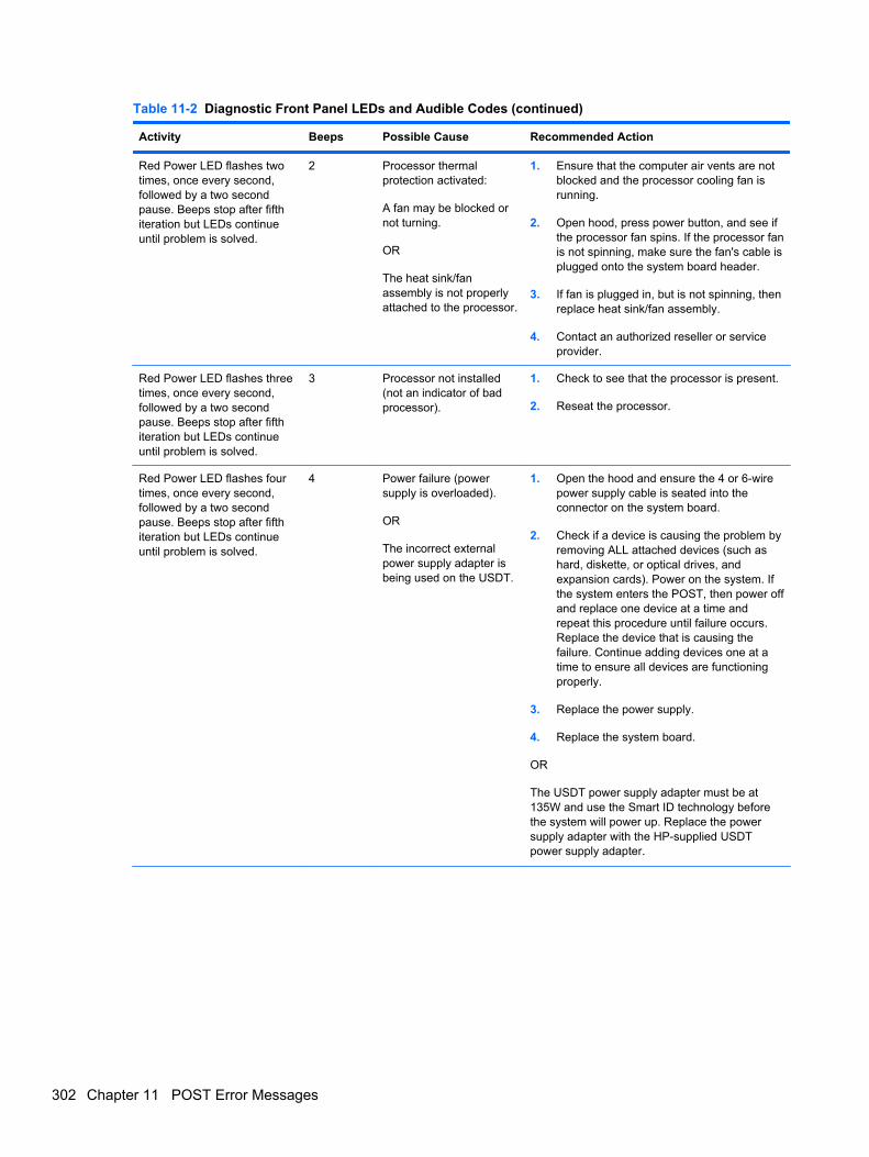
Table 11-2 Diagnostic Front Panel LEDs and Audible Codes (continued)
Activity Beeps Possible Cause Recommended Action
Red Power LED flashes twotimes, once every second,followed by a two secondpause. Beeps stop after fifthiteration but LEDs continueuntil problem is solved.
2 Processor thermalprotection activated:
A fan may be blocked ornot turning.
OR
The heat sink/fanassembly is not properlyattached to the processor.
1. Ensure that the computer air vents are notblocked and the processor cooling fan isrunning.
2. Open hood, press power button, and see ifthe processor fan spins. If the processor fanis not spinning, make sure the fan's cable isplugged onto the system board header.
3. If fan is plugged in, but is not spinning, thenreplace heat sink/fan assembly.
4. Contact an authorized reseller or serviceprovider.
Red Power LED flashes threetimes, once every second,followed by a two secondpause. Beeps stop after fifthiteration but LEDs continueuntil problem is solved.
3 Processor not installed(not an indicator of badprocessor).
1. Check to see that the processor is present.
2. Reseat the processor.
Red Power LED flashes fourtimes, once every second,followed by a two secondpause. Beeps stop after fifthiteration but LEDs continueuntil problem is solved.
4 Power failure (powersupply is overloaded).
OR
The incorrect externalpower supply adapter isbeing used on the USDT.
1. Open the hood and ensure the 4 or 6-wirepower supply cable is seated into theconnector on the system board.
2. Check if a device is causing the problem byremoving ALL attached devices (such ashard, diskette, or optical drives, andexpansion cards). Power on the system. Ifthe system enters the POST, then power offand replace one device at a time andrepeat this procedure until failure occurs.Replace the device that is causing thefailure. Continue adding devices one at atime to ensure all devices are functioningproperly.
3. Replace the power supply.
4. Replace the system board.
OR
The USDT power supply adapter must be at135W and use the Smart ID technology beforethe system will power up. Replace the powersupply adapter with the HP-supplied USDTpower supply adapter.
302 Chapter 11 POST Error Messages
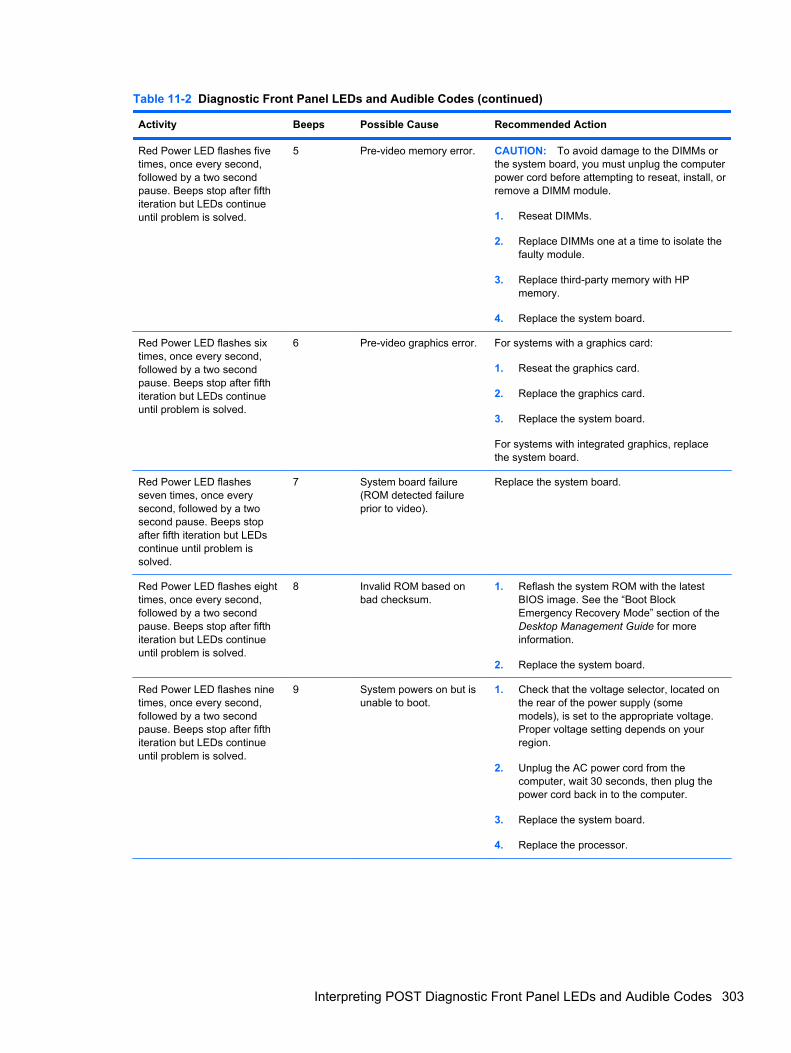
Table 11-2 Diagnostic Front Panel LEDs and Audible Codes (continued)
Activity Beeps Possible Cause Recommended Action
Red Power LED flashes fivetimes, once every second,followed by a two secondpause. Beeps stop after fifthiteration but LEDs continueuntil problem is solved.
5 Pre-video memory error. CAUTION: To avoid damage to the DIMMs orthe system board, you must unplug the computerpower cord before attempting to reseat, install, orremove a DIMM module.
1. Reseat DIMMs.
2. Replace DIMMs one at a time to isolate thefaulty module.
3. Replace third-party memory with HPmemory.
4. Replace the system board.
Red Power LED flashes sixtimes, once every second,followed by a two secondpause. Beeps stop after fifthiteration but LEDs continueuntil problem is solved.
6 Pre-video graphics error. For systems with a graphics card:
1. Reseat the graphics card.
2. Replace the graphics card.
3. Replace the system board.
For systems with integrated graphics, replacethe system board.
Red Power LED flashesseven times, once everysecond, followed by a twosecond pause. Beeps stopafter fifth iteration but LEDscontinue until problem issolved.
7 System board failure(ROM detected failureprior to video).
Replace the system board.
Red Power LED flashes eighttimes, once every second,followed by a two secondpause. Beeps stop after fifthiteration but LEDs continueuntil problem is solved.
8 Invalid ROM based onbad checksum.
1. Reflash the system ROM with the latestBIOS image. See the “Boot BlockEmergency Recovery Mode” section of theDesktop Management Guide for moreinformation.
2. Replace the system board.
Red Power LED flashes ninetimes, once every second,followed by a two secondpause. Beeps stop after fifthiteration but LEDs continueuntil problem is solved.
9 System powers on but isunable to boot.
1. Check that the voltage selector, located onthe rear of the power supply (somemodels), is set to the appropriate voltage.Proper voltage setting depends on yourregion.
2. Unplug the AC power cord from thecomputer, wait 30 seconds, then plug thepower cord back in to the computer.
3. Replace the system board.
4. Replace the processor.
Interpreting POST Diagnostic Front Panel LEDs and Audible Codes 303
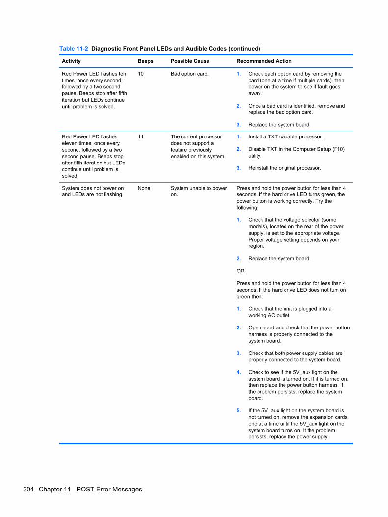
Table 11-2 Diagnostic Front Panel LEDs and Audible Codes (continued)
Activity Beeps Possible Cause Recommended Action
Red Power LED flashes tentimes, once every second,followed by a two secondpause. Beeps stop after fifthiteration but LEDs continueuntil problem is solved.
10 Bad option card. 1. Check each option card by removing thecard (one at a time if multiple cards), thenpower on the system to see if fault goesaway.
2. Once a bad card is identified, remove andreplace the bad option card.
3. Replace the system board.
Red Power LED flasheseleven times, once everysecond, followed by a twosecond pause. Beeps stopafter fifth iteration but LEDscontinue until problem issolved.
11 The current processordoes not support afeature previouslyenabled on this system.
1. Install a TXT capable processor.
2. Disable TXT in the Computer Setup (F10)utility.
3. Reinstall the original processor.
System does not power onand LEDs are not flashing.
None System unable to poweron.
Press and hold the power button for less than 4seconds. If the hard drive LED turns green, thepower button is working correctly. Try thefollowing:
1. Check that the voltage selector (somemodels), located on the rear of the powersupply, is set to the appropriate voltage.Proper voltage setting depends on yourregion.
2. Replace the system board.
OR
Press and hold the power button for less than 4seconds. If the hard drive LED does not turn ongreen then:
1. Check that the unit is plugged into aworking AC outlet.
2. Open hood and check that the power buttonharness is properly connected to thesystem board.
3. Check that both power supply cables areproperly connected to the system board.
4. Check to see if the 5V_aux light on thesystem board is turned on. If it is turned on,then replace the power button harness. Ifthe problem persists, replace the systemboard.
5. If the 5V_aux light on the system board isnot turned on, remove the expansion cardsone at a time until the 5V_aux light on thesystem board turns on. It the problempersists, replace the power supply.
304 Chapter 11 POST Error Messages
12 Password Security and ResettingCMOS
This computer supports security password features, which can be established through the ComputerSetup Utilities menu.
This computer supports two security password features that are established through the ComputerSetup Utilities menu: setup password and power-on password. When you establish only a setuppassword, any user can access all the information on the computer except Computer Setup. Whenyou establish only a power-on password, the power-on password is required to access ComputerSetup and any other information on the computer. When you establish both passwords, only thesetup password will give you access to Computer Setup.
When both passwords are set, the setup password can also be used in place of the power-onpassword as an override to log in to the computer. This is a useful feature for a network administrator.
If you forget the password for the computer, you can clear that password so you can gain access tothe information on the computer by resetting the password jumper.
CAUTION: Pushing the CMOS button will reset CMOS values to factory defaults. It is important toback up the computer CMOS settings before resetting them in case they are needed later. Back up iseasily done through Computer Setup. See Computer Setup (F10) Utility on page 16 for information onbacking up the CMOS settings.
305
Resetting the Password JumperCAUTION: If you enable the stringent security feature in Computer Setup and you forget the setuppassword or the power-on password, the computer is inaccessible and can no longer be used.
Enabling the stringent password disables the ability to reset the password by moving the jumper onthe system board.
If you lose or forget the password, the system board must be replaced. This scenario is not coveredunder warranty.
To prevent the computer from becoming permanently unusable, record your configured setuppassword or power-on password in a safe place away from your computer. Without these passwords,the computer cannot be unlocked.
To disable the power-on or setup password features, or to clear the power-on or setup passwords,complete the following steps:
1. Shut down the operating system properly, then turn off the computer and any external devices,and disconnect the power cord from the power outlet.
2. With the power cord disconnected, press the power button again to drain the system of anyresidual power.
WARNING! To reduce the risk of personal injury from electrical shock and/or hot surfaces, besure to disconnect the power cord from the wall outlet, and allow the internal systemcomponents to cool before touching.
CAUTION: When the computer is plugged in, the power supply always has voltage applied tothe system board even when the unit is turned off. Failure to disconnect the power cord canresult in damage to the system.
Static electricity can damage the electronic components of the computer or optional equipment.Before beginning these procedures, ensure that you are discharged of static electricity by brieflytouching a grounded metal object. See the Safety & Regulatory Information guide for moreinformation.
3. Remove the computer cover or access panel.
4. Locate the header and jumper.
NOTE: The password jumper is green so that it can be easily identified. For assistancelocating the password jumper and other system board components, see the Illustrated Parts &Service Map (IPSM). The IPSM can be downloaded from http://www.hp.com/support.
5. Remove the jumper from pins 1 and 2. Place the jumper on either pin 1 or 2, but not both, sothat it does not get lost.
6. Replace the computer cover or access panel.
7. Reconnect the external equipment.
8. Plug in the computer and turn on power. Allow the operating system to start. This clears thecurrent passwords and disables the password features.
9. To establish new passwords, repeat steps 1 through 4, replace the password jumper on pins 1and 2, then repeat steps 6 through 8. Establish the new passwords in Computer Setup.
306 Chapter 12 Password Security and Resetting CMOS
Clearing and Resetting the CMOSThe computer’s configuration memory (CMOS) stores information about the computer’s configuration.
The CMOS button resets CMOS but does not clear the power-on and setup passwords.
Clearing CMOS will clear the Active Management Technology (AMT) settings in the ManagementEngine BIOS Extension (MEBx), including the password. The password will default to “admin” and willneed to be reset. The AMT settings will also need to be reset. To access the MEBx, press Ctrl+Pduring POST.
1. Turn off the computer and any external devices, and disconnect the power cord from the poweroutlet.
2. Disconnect the keyboard, monitor, and any other external equipment connected to the computer.
WARNING! To reduce the risk of personal injury from electrical shock and/or hot surfaces, besure to disconnect the power cord from the wall outlet, and allow the internal systemcomponents to cool before touching.
CAUTION: When the computer is plugged in, the power supply always has voltage applied tothe system board even when the unit is turned off. Failure to disconnect the power cord canresult in damage to the system.
Static electricity can damage the electronic components of the computer or optional equipment.Before beginning these procedures, ensure that you are discharged of static electricity by brieflytouching a grounded metal object. See the Safety & Regulatory Information guide for moreinformation.
3. Remove the computer cover or access panel.
CAUTION: Pushing the CMOS button will reset CMOS values to factory defaults. It isimportant to back up the computer CMOS settings before resetting them in case they areneeded later. Back up is easily done through Computer Setup. See Computer Setup (F10) Utilityon page 16 for information on backing up the CMOS settings.
Clearing and Resetting the CMOS 307
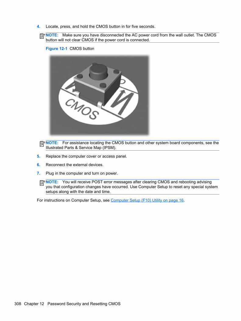
4. Locate, press, and hold the CMOS button in for five seconds.
NOTE: Make sure you have disconnected the AC power cord from the wall outlet. The CMOSbutton will not clear CMOS if the power cord is connected.
Figure 12-1 CMOS button
NOTE: For assistance locating the CMOS button and other system board components, see theIllustrated Parts & Service Map (IPSM).
5. Replace the computer cover or access panel.
6. Reconnect the external devices.
7. Plug in the computer and turn on power.
NOTE: You will receive POST error messages after clearing CMOS and rebooting advisingyou that configuration changes have occurred. Use Computer Setup to reset any special systemsetups along with the date and time.
For instructions on Computer Setup, see Computer Setup (F10) Utility on page 16.
308 Chapter 12 Password Security and Resetting CMOS

13 HP PC Hardware Diagnostics
To help troubleshoot and diagnose failures, use the UEFI-based hardware diagnostic solution that HPincludes on all products. This tool can even be used if the computer will not boot to the operatingsystem.
Why run HP PC Hardware Diagnostics – UEFIThe HP PC Hardware Diagnostic tools simplify the process of diagnosing hardware issues andexpedite the support process when issues are found. The tools save time by pinpointing thecomponent that needs to be replaced.
● Isolate true hardware failures: The diagnostics run outside of the operating system so theyeffectively isolate hardware failures from issues that may be caused by the operating system orother software components.
● Failure ID: When a failure is detected that requires hardware replacement, a 24-digit Failure IDis generated. This ID can then be provided to the call agent, who will either schedule support orprovide replacement parts.
How to access and run HP PC Hardware Diagnostics -UEFI
To access the UEFI diagnostics:
1. Restart or turn on the computer and press Esc repeatedly until the BIOS boot menu appears.
2. Press F2 or select Diagnostics (F2).
Why run HP PC Hardware Diagnostics – UEFI 309
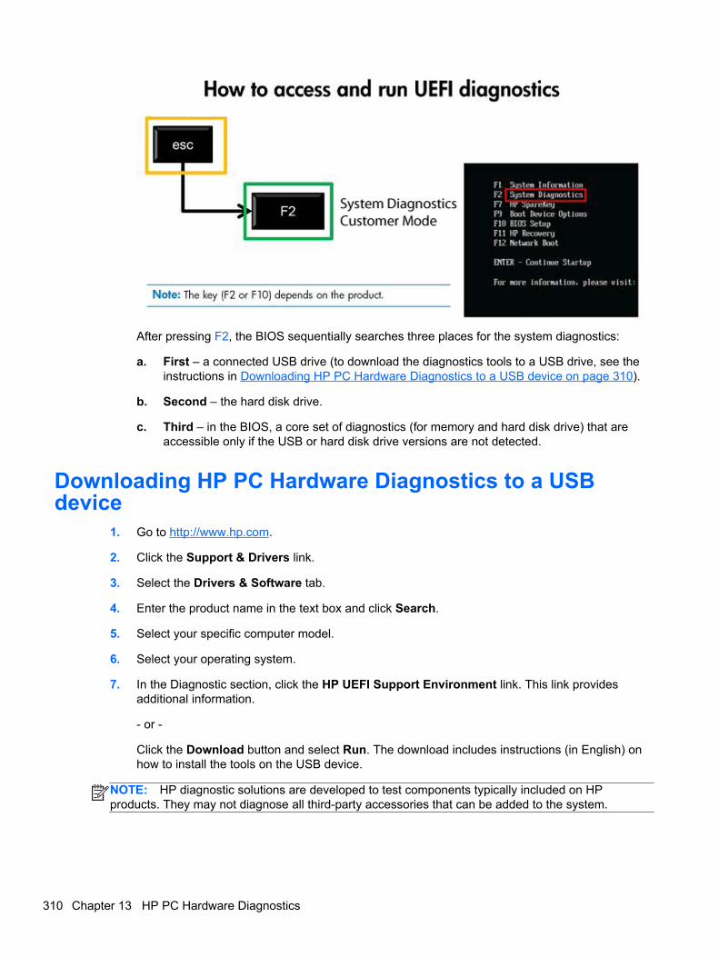
After pressing F2, the BIOS sequentially searches three places for the system diagnostics:
a. First – a connected USB drive (to download the diagnostics tools to a USB drive, see theinstructions in Downloading HP PC Hardware Diagnostics to a USB device on page 310).
b. Second – the hard disk drive.
c. Third – in the BIOS, a core set of diagnostics (for memory and hard disk drive) that areaccessible only if the USB or hard disk drive versions are not detected.
Downloading HP PC Hardware Diagnostics to a USBdevice
1. Go to http://www.hp.com.
2. Click the Support & Drivers link.
3. Select the Drivers & Software tab.
4. Enter the product name in the text box and click Search.
5. Select your specific computer model.
6. Select your operating system.
7. In the Diagnostic section, click the HP UEFI Support Environment link. This link providesadditional information.
- or -
Click the Download button and select Run. The download includes instructions (in English) onhow to install the tools on the USB device.
NOTE: HP diagnostic solutions are developed to test components typically included on HPproducts. They may not diagnose all third-party accessories that can be added to the system.
310 Chapter 13 HP PC Hardware Diagnostics
14 Backup and Recovery
Restoring and recovering in Windows 7To protect from loss or damage, back up your personal data files. Refer to the operating system orbackup utility documentation for instructions on making backup copies of your data files.
To protect the software from loss or damage, keep a backup copy of all system software,applications, and related files stored on the hard drive.
If you cannot create system recovery CDs or DVDs, you can order a recovery disk set from support.To obtain the support telephone number for your region, see http://www.hp.com/support/contactHP.
System Restore
If you have a problem that might be due to software that you installed on your computer, use SystemRestore to return the computer to a previous restore point. You can also set restore points manually.
NOTE: Always use this System Restore procedure before you use the System Recovery feature.
NOTE: Some features might not be available on systems that are shipped without a Windowsoperating system.
To start System Restore:
1. Close all open programs.
2. Click the Start button, right-click Computer, and then click Properties.
3. Click System protection, System Restore, click Next, and then follow the on-screeninstructions.
To add restore points manually:
1. Close all open programs.
2. Click the Start button, right-click Computer, click Properties, and then click Systemprotection.
3. Under Protection Settings, select the disk for which you want to create a restore point.
4. Click Create, and then follow the on-screen instructions.
System Recovery
WARNING! This procedure will delete all user information. To prevent loss of information, be sureto back up all user information so you can restore it after recovery.
Restoring and recovering in Windows 7 311
System Recovery completely erases and reformats the hard disk drive, deleting all data files that youhave created, and then reinstalls the operating system, programs, and drivers. However, you mustreinstall any software that was not installed on the computer at the factory. This includes software thatcame on media included in the computer accessory box, and any software programs you installedafter purchase.
NOTE: Always use the System Restore procedure before you use the System Recovery program.See System Restore on page 311.
NOTE: Some features might not be available on systems that are shipped without a Windowsoperating system.
You must choose one of the following methods to perform a System Recovery:
● Recovery image — Run System Recovery from a recovery image stored on your hard disk drive.The recovery image is a file that contains a copy of the original factory-shipped software. Toperform a System Recovery from a recovery image, see System Recovery when Windows isresponding on page 312 or System Recovery when Windows is not responding on page 313.
● Recovery media — Run System Recovery from recovery media that you have created from filesstored on your hard disk drive or purchased separately. To create recovery media, see Systemrecovery using recovery media on page 313.
System Recovery when Windows is responding
CAUTION: System Recovery deletes all data and programs you created or installed. Before youbegin, back up any important data to a CD or DVD or to a USB flash drive.
NOTE: In some cases, you must use recovery media for this procedure. To create this media, followthe instructions in Creating recovery media on page 314.
If the computer is working and Windows 7 is responding, use these steps to perform a SystemRecovery.
1. Turn off the computer.
2. Disconnect all peripheral devices from the computer except the monitor, keyboard, and mouse.
3. Turn on the computer.
4. When Windows has loaded, click the Start button, click All Programs, click Security andProtection, click Recovery Manager, and then click Recovery Manager. If prompted, click Yesto allow the program to continue.
5. Under I need help immediately, click System Recovery.
6. Select Yes, and then click Next. Your computer restarts.
NOTE: If your system does not detect a recovery partition, it prompts you to insert recoverymedia that you have created. Insert the first disc or the USB flash drive, select Yes, and thenclick Next to restart the computer. If you are using discs, insert the next disc when prompted.
7. When the computer restarts, you will see the Recovery Manager welcome screen again. Under Ineed help immediately, click System Recovery. If you are prompted to back up your files, andyou have not done so, select Back up your files first (recommended), and then click Next.Otherwise, select Recover without backing up your files, and then click Next.
312 Chapter 14 Backup and Recovery
8. System Recovery begins. After System Recovery is complete, click Finish to restart thecomputer.
9. When Windows has loaded, shut down the computer, reconnect all peripheral devices, and thenturn the computer back on.
System Recovery when Windows is not responding
CAUTION: System Recovery deletes all data and programs you created or installed.
If Windows is not responding, but the computer is working, follow these steps to perform a SystemRecovery.
1. Turn off the computer. If necessary, press and hold the power button until the computer turns off.
2. Disconnect all peripheral devices from the computer, except the monitor, keyboard, and mouse.
3. Press the power button to turn on the computer.
4. As soon as you see the HP logo screen, repeatedly press the F11 key on your keyboard until theWindows is Loading Files… message appears on the screen.
5. Under I need help immediately, click System Recovery.
6. If you are prompted to back up your files, and you have not done so, select Back up your filesfirst (recommended), and then click Next. Otherwise, select Recover without backing upyour files, and then click Next.
7. System Recovery begins. After System Recovery is complete, click Finish to restart thecomputer.
8. When Windows has loaded, shut down the computer, reconnect all peripheral devices, and thenturn the computer back on.
System recovery using recovery media
You should create a set of recovery media, either a set of DVDs or a USB flash drive, from therecovery image stored on your hard disk drive. This image contains the operating system andsoftware program files that were originally installed on your computer at the factory. You can createonly one set of recovery media for your computer, and the media can be used only with thiscomputer. Store the recovery media in a safe place.
NOTE: Some features might not be available on systems that are shipped without a Windowsoperating system.
● To create recovery discs, your computer must have a DVD writer, and you must use only high-quality blank DVD+R or DVD-R discs.
NOTE: You cannot use DVD+RW, DVD-RW, DVD+RW DL, DVD-RW DL, DVD+R DL, or DVD-R DL discs to create recovery discs.
● You have the option of creating a recovery USB flash drive instead, using a high-quality USBdrive.
Restoring and recovering in Windows 7 313
● If you are creating recovery discs, be sure to use high-quality discs. It is normal for the system toreject defective discs. You will be prompted to insert a new blank disc to try again.
● The number of discs in the recovery-disc set depends on your computer model (typically 3 to 6DVDs). The Recovery Media Creation program tells you the specific number of blank discsneeded to make the set. If you are using a USB flash drive, the program will tell you the size ofthe drive required to store all the data (minimum of 8 GB).
NOTE: The process of creating recovery media is lengthy. You can quit the process at anytime. The next time you initiate the process, it resumes where it left off.
Creating recovery media
To create recovery discs:
1. Close all open programs.
2. Click the Start button, click All Programs, click Security and Protection, and then click HPRecovery Media Creation. If prompted, click Yes to allow the program to continue.
3. Click Create recovery media using blank DVD(s), and then click Next.
4. Follow the on-screen instructions. Label each disc as you make it (for example, Recovery 1,Recovery 2), and then store the discs in a secure place.
To create a recovery USB flash drive:
NOTE: You must use a flash drive with a capacity of at least 8 GB.
1. Close all open programs.
2. Insert the USB flash drive into a USB port on the computer.
3. Click the Start button, click All Programs, click Security and Protection, and then clickRecovery Media Creation.
4. Click Create recovery media with a USB flash drive, and then click Next.
5. Select the USB flash drive from the list of media. The program will let you know how muchstorage is required to create the recovery drive. If the USB flash drive does not have enoughstorage capacity, it will appear grayed out, and you must replace it with a larger USB flash drive.Click Next.
NOTE: Recovery Media Creation formats the flash drive, deleting any files on it.
6. Follow the on-screen instructions. When the process is complete, label the USB flash drive andstore it in a secure place.
NOTE: Do not use media cards for creating recovery media. The system may not be able to boot upfrom a media card and you may not be able to run system recovery.
314 Chapter 14 Backup and Recovery

Using recovery media
CAUTION: System Recovery deletes all data and programs you have created or installed. Back upany important data to a CD or DVD or to a USB flash drive.
To create recovery media, see System recovery using recovery media on page 313.
To perform a System Recovery using recovery media:
1. If using a set of DVDs, insert the first recovery disc into the DVD drive tray, and close the tray. Ifyou are using a recovery USB flash drive, insert it into a USB port.
2. If the computer is not responding, press and hold the power button for approximately 5 secondsor until the computer turns off.
or
Click the Start button, and then click Shut Down.
3. Disconnect all peripheral devices from the computer except the monitor, keyboard, and mouse.
4. Press the power button to turn on the computer.
5. Press Esc as the computer is powering on to see the startup menu. Use the arrow keys to selectthe boot menu and press Enter. Use the arrow keys to select the location where the recoverymedia is inserted (USB or DVD). Press Enter to boot from that device.
6. If Recovery Manager asks if you want to run System Recovery from Media or Hard Drive, selectMedia. On the Welcome screen, under I need help immediately, click Factory Reset.
7. If you are prompted to back up your files, and you have not done so, select Back up your filesfirst (recommended), and then click Next. Otherwise, select Recover without backing upyour files, and then click Next.
8. If you are prompted to insert the next recovery disc, do so.
9. When Recovery Manager is finished, remove the recovery disc or the recovery USB flash drivefrom the system.
10. Click Finish to restart the computer.
Restoring and recovering in Windows 7 315
Backup and recovery in Windows 8To protect your information, use Windows Backup and Restore to back up individual files and folders,back up your entire hard drive, create system repair media, or create system restore points. In caseof system failure, you can use the backup files to restore the contents of your computer.
From the Start screen, type restore, click Settings, and then select from the list of displayedoptions.
NOTE: For detailed instructions on various backup and restore options, perform a search for thesetopics in Help and Support. From the Start screen, type h, and then select Help and Support.
In case of system instability, HP recommends that you print the recovery procedures and save themfor later use.
NOTE: Windows includes the User Account Control feature to improve the security of yourcomputer. You may be prompted for your permission or password for tasks such as installingsoftware, running utilities, or changing Windows settings. Refer to Help and Support for moreinformation. From the Start screen, type h, and then select Help and Support.
Backing up your information
Recovery after a system failure is as good as your most recent backup. You should create systemrepair media and your initial backup immediately after initial system setup. As you add new softwareand data files, you should continue to back up your system on a regular basis to maintain areasonably current backup. The system repair media is used to start up (boot) the computer andrepair the operating system in case of system instability or failure. Your initial and subsequentbackups allow you to restore your data and settings if a failure occurs.
Type backup on the Start screen, click Settings, and then select Save backup copies of your fileswith File History.
You can back up your information to an optional external hard drive, or a network drive.
Note the following when backing up:
● Store personal files in the Documents library, and back it up regularly.
● Back up templates that are stored in their associated programs.
● Save customized settings that appear in a window, toolbar, or menu bar by taking a screen shotof your settings. The screen shot can be a time-saver if you have to reset your preferences.
To create a backup using Backup and Restore:
NOTE: Be sure that the computer is connected to AC power before you start the backup process.
NOTE: The backup process may take over an hour, depending on file size and the speed of thecomputer.
1. From the Start screen, type backup, click Settings, and then select from the list of displayedoptions.
2. Follow the on-screen instructions to set up your backup, create a system image, or createsystem repair media.
316 Chapter 14 Backup and Recovery
Performing a system recovery
In case of system failure or instability, the computer provides the following tools to recover your files:
● Windows recovery tools: You can use Windows Backup and Restore to recover information youhave previously backed up. You can also use Windows Automatic Repair to fix problems thatmight prevent Windows from starting correctly.
● f11 recovery tools: You can use the f11 recovery tools to recover your original hard drive image.The image includes the Windows operating system and software programs installed at thefactory.
NOTE: If you are unable to boot (start up) your computer and you cannot use the system repairmedia you previously created, you must purchase Windows 8 operating system media to reboot thecomputer and repair the operating system. For additional information, see Using Windows 8 operatingsystem media (purchased separately) on page 318.
Using the Windows recovery tools
To recover information you previously backed up:
▲ From the Start screen, type h, and then select Help and Support.
To recover your information using Automatic Repair, follow these steps:
CAUTION: Some Automatic Repair options will completely erase and reformat the hard drive. Foradditional information go to Help and Support. From the Start screen, type h, and then select Helpand Support.
1. If possible, back up all personal files.
2. If possible, check for the presence of the HP Recovery partition and the Windows partition:
From the Start screen, type e, and then click Windows Explorer.
– or –
From the Start screen, type c, and then select Computer.
NOTE: If the Windows partition and the HP Recovery partition are not listed, you must recoveryour operating system and programs using the Windows 8 operating system media and theDriver Recovery media (both purchased separately). For additional information, see UsingWindows 8 operating system media (purchased separately) on page 318.
3. If the Windows partition and the HP Recovery partition are listed, restart the computer afterWindows has loaded, and then press and hold Shift while clicking Restart.
NOTE: If the computer fails to boot to Windows after several attempts, the system will boot tothe Windows Recovery Environment by default.
4. Select Troubleshoot, select Advanced Options, and then select Automatic Repair.
5. Follow the on-screen instructions.
NOTE: For additional information on recovering information using the Windows tools, perform asearch for these topics in Help and Support. From the Start screen, type h, and then select Help andSupport.
Backup and recovery in Windows 8 317
Using f11 recovery tools
CAUTION: Using f11 completely erases hard drive contents and reformats the hard drive. All filesthat you have created and any software that you have installed on the computer are permanentlyremoved. The f11 recovery tool reinstalls the operating system and HP programs and drivers thatwere installed at the factory. Software not installed at the factory must be reinstalled.
To recover the original hard drive image using f11:
1. If possible, back up all personal files.
2. If possible, check for the presence of the HP Recovery partition: From the Start screen, type C,and then select Computer.
NOTE: If the HP Recovery partition is not listed, you must recover your operating system andprograms using the Windows 8 operating system media, and the Driver Recovery media (bothpurchased separately). For additional information, see Using Windows 8 operating systemmedia (purchased separately) on page 318.
3. If the HP Recovery partition is listed, restart the computer, and then press esc while thecompany logo is displayed. The computer Startup Menu displays.
4. Press f11 to select the System Recovery option.
5. Follow the on-screen instructions.
Using Windows 8 operating system media (purchased separately)
To order Windows 8 operating system media, go to http://www.hp.com/support, select your country orregion, and follow the on-screen instructions. You can also order the media by calling support.
CAUTION: Using Windows 8 operating system media completely erases hard drive contents andreformats the hard drive. All files that you have created and any software that you have installed onthe computer are permanently removed. When reformatting is complete, the recovery process helpsyou restore the operating system, as well as drivers, software, and utilities.
To initiate recovery using Windows 8 operating system media:
NOTE: This process takes several minutes.
1. If possible, back up all personal files.
2. Restart the computer, and then follow the instructions provided with the Windows 8 operatingsystem media to install the operating system.
3. When prompted, press any keyboard key.
4. Follow the on-screen instructions.
After the repair is completed:
1. Remove the Windows 8 operating system media, and then insert the Driver Recovery media.
2. Install the Hardware Enabling Drivers first, and then install Recommended Applications.
318 Chapter 14 Backup and Recovery
A Battery Replacement
The battery that comes with the computer provides power to the real-time clock. When replacing thebattery, use a battery equivalent to the battery originally installed in the computer. The computercomes with a 3-volt lithium coin cell battery.
WARNING! The computer contains an internal lithium manganese dioxide battery. There is a risk offire and burns if the battery is not handled properly. To reduce the risk of personal injury:
Do not attempt to recharge the battery.
Do not expose to temperatures higher than 60°C (140ºF).
Do not disassemble, crush, puncture, short external contacts, or dispose of in fire or water.
Replace the battery only with the HP spare designated for this product.
CAUTION: Before replacing the battery, it is important to back up the computer CMOS settings.When the battery is removed or replaced, the CMOS settings will be cleared.
Static electricity can damage the electronic components of the computer or optional equipment.Before beginning these procedures, ensure that you are discharged of static electricity by brieflytouching a grounded metal object.
NOTE: The lifetime of the lithium battery can be extended by plugging the computer into a live ACwall socket. The lithium battery is only used when the computer is NOT connected to AC power.
HP encourages customers to recycle used electronic hardware, HP original print cartridges, andrechargeable batteries. For more information about recycling programs, go to http://www.hp.com/recycle.
1. Remove/disengage any security devices that prohibit opening the computer.
2. Remove all removable media, such as compact discs or USB flash drives, from the computer.
3. Turn off the computer properly through the operating system, then turn off any external devices.
4. Disconnect the power cord from the power outlet and disconnect any external devices.
CAUTION: Regardless of the power-on state, voltage is always present on the system boardas long as the system is plugged into an active AC outlet. You must disconnect the power cordto avoid damage to the internal components of the computer.
5. Remove the computer access panel.
6. Locate the battery and battery holder on the system board.
NOTE: On some computer models, it may be necessary to remove an internal component togain access to the battery.
319
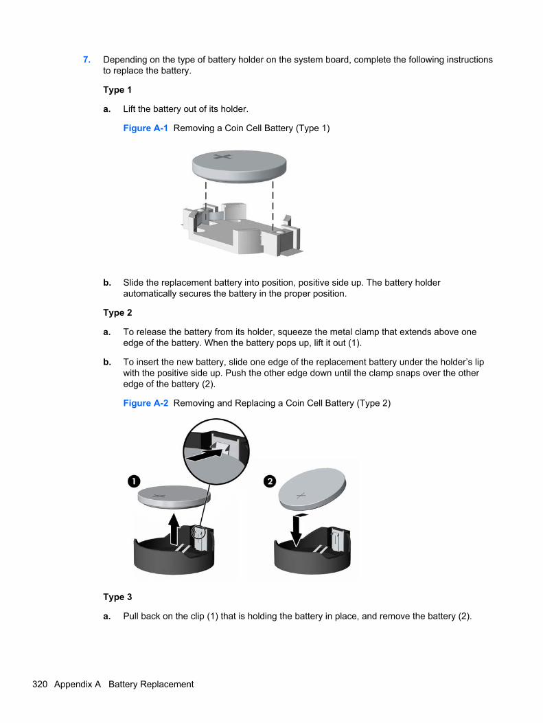
7. Depending on the type of battery holder on the system board, complete the following instructionsto replace the battery.
Type 1
a. Lift the battery out of its holder.
Figure A-1 Removing a Coin Cell Battery (Type 1)
b. Slide the replacement battery into position, positive side up. The battery holderautomatically secures the battery in the proper position.
Type 2
a. To release the battery from its holder, squeeze the metal clamp that extends above oneedge of the battery. When the battery pops up, lift it out (1).
b. To insert the new battery, slide one edge of the replacement battery under the holder’s lipwith the positive side up. Push the other edge down until the clamp snaps over the otheredge of the battery (2).
Figure A-2 Removing and Replacing a Coin Cell Battery (Type 2)
Type 3
a. Pull back on the clip (1) that is holding the battery in place, and remove the battery (2).
320 Appendix A Battery Replacement
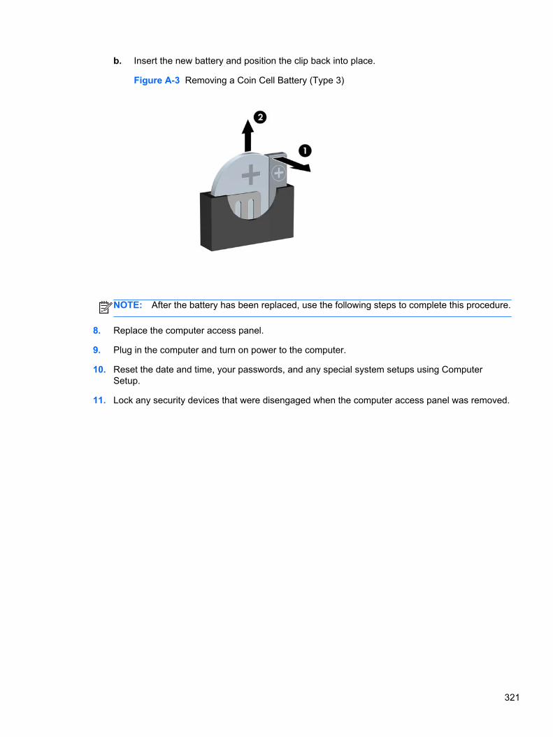
b. Insert the new battery and position the clip back into place.
Figure A-3 Removing a Coin Cell Battery (Type 3)
NOTE: After the battery has been replaced, use the following steps to complete this procedure.
8. Replace the computer access panel.
9. Plug in the computer and turn on power to the computer.
10. Reset the date and time, your passwords, and any special system setups using ComputerSetup.
11. Lock any security devices that were disengaged when the computer access panel was removed.
321
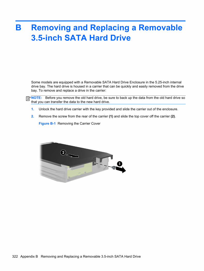
B Removing and Replacing a Removable3.5-inch SATA Hard Drive
Some models are equipped with a Removable SATA Hard Drive Enclosure in the 5.25-inch internaldrive bay. The hard drive is housed in a carrier that can be quickly and easily removed from the drivebay. To remove and replace a drive in the carrier:
NOTE: Before you remove the old hard drive, be sure to back up the data from the old hard drive sothat you can transfer the data to the new hard drive.
1. Unlock the hard drive carrier with the key provided and slide the carrier out of the enclosure.
2. Remove the screw from the rear of the carrier (1) and slide the top cover off the carrier (2).
Figure B-1 Removing the Carrier Cover
322 Appendix B Removing and Replacing a Removable 3.5-inch SATA Hard Drive
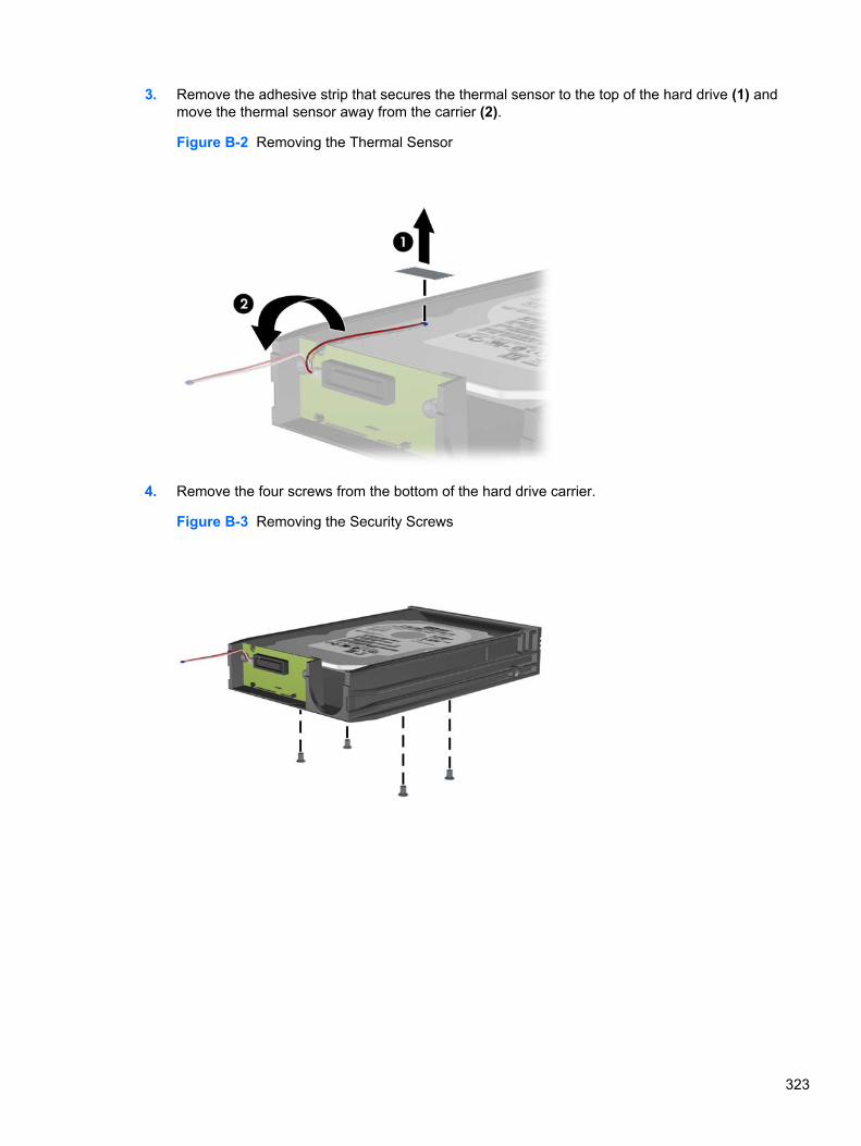
3. Remove the adhesive strip that secures the thermal sensor to the top of the hard drive (1) andmove the thermal sensor away from the carrier (2).
Figure B-2 Removing the Thermal Sensor
4. Remove the four screws from the bottom of the hard drive carrier.
Figure B-3 Removing the Security Screws
323
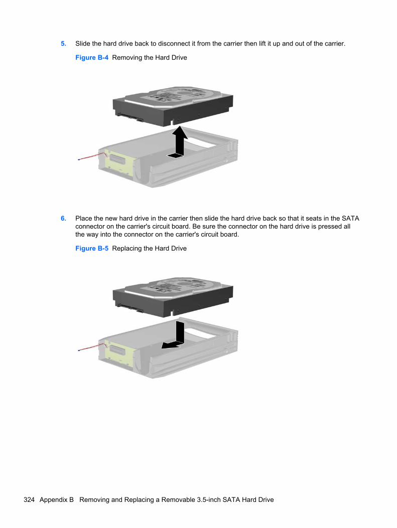
5. Slide the hard drive back to disconnect it from the carrier then lift it up and out of the carrier.
Figure B-4 Removing the Hard Drive
6. Place the new hard drive in the carrier then slide the hard drive back so that it seats in the SATAconnector on the carrier's circuit board. Be sure the connector on the hard drive is pressed allthe way into the connector on the carrier's circuit board.
Figure B-5 Replacing the Hard Drive
324 Appendix B Removing and Replacing a Removable 3.5-inch SATA Hard Drive
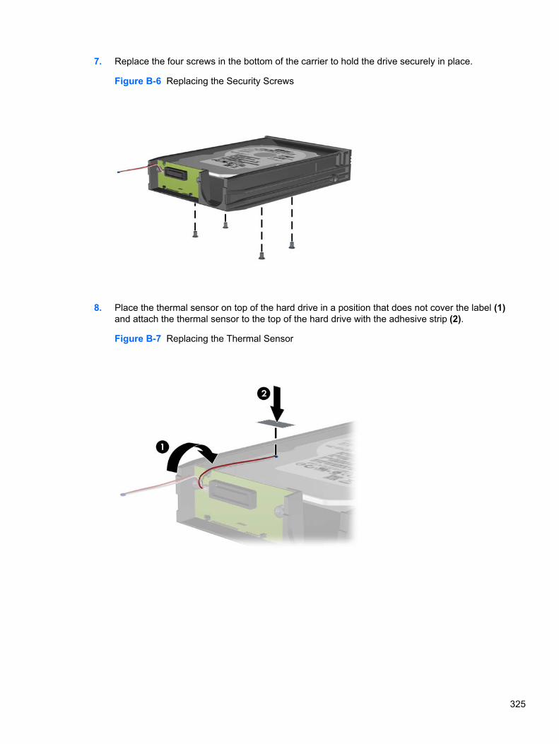
7. Replace the four screws in the bottom of the carrier to hold the drive securely in place.
Figure B-6 Replacing the Security Screws
8. Place the thermal sensor on top of the hard drive in a position that does not cover the label (1)and attach the thermal sensor to the top of the hard drive with the adhesive strip (2).
Figure B-7 Replacing the Thermal Sensor
325
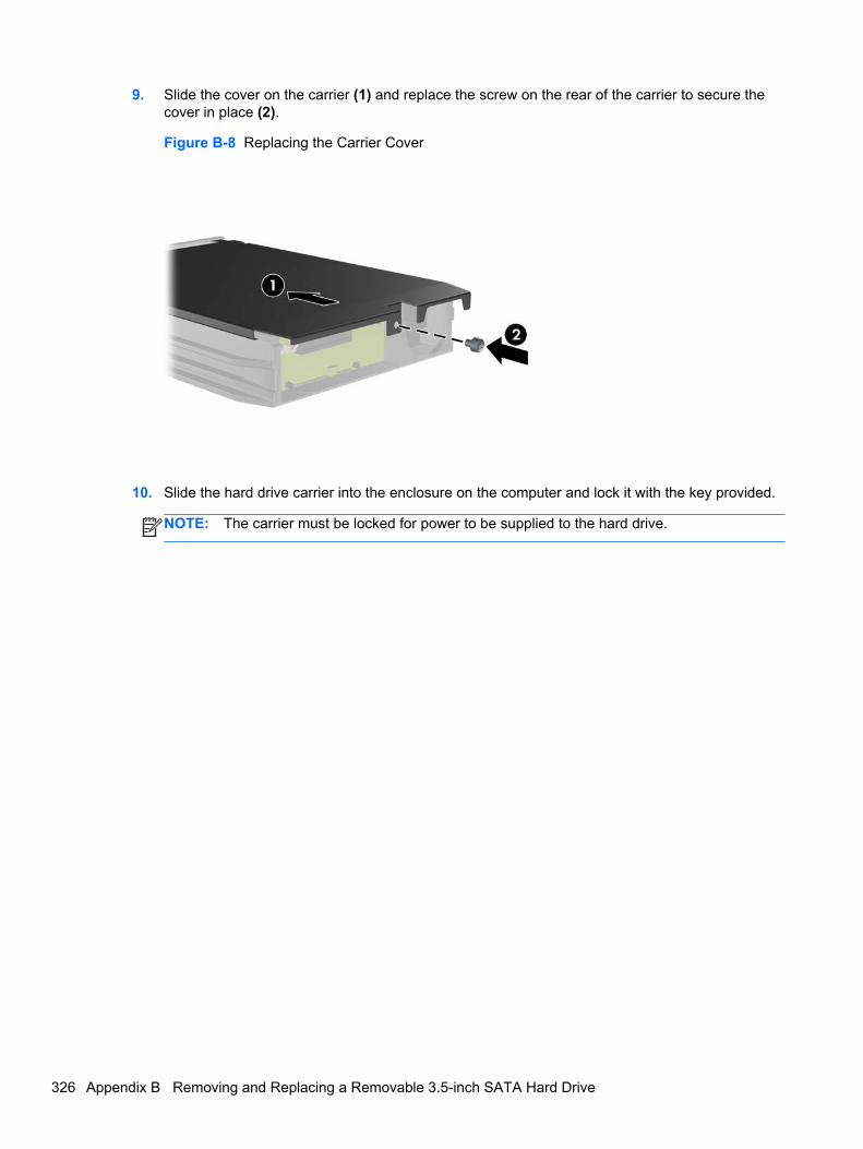
9. Slide the cover on the carrier (1) and replace the screw on the rear of the carrier to secure thecover in place (2).
Figure B-8 Replacing the Carrier Cover
10. Slide the hard drive carrier into the enclosure on the computer and lock it with the key provided.
NOTE: The carrier must be locked for power to be supplied to the hard drive.
326 Appendix B Removing and Replacing a Removable 3.5-inch SATA Hard Drive

C Unlocking the Smart Cover Lock
NOTE: The Smart Cover Lock is an optional feature included on some models only.
The Smart Cover Lock is a software-controllable cover lock, controlled by the setup password. Thislock prevents unauthorized access to the internal components. The computer ships with theSmart Cover Lock in the unlocked position. For more information about locking the Smart Cover Lock,refer to the Desktop Management Guide.
Smart Cover FailSafe KeyIf you enable the Smart Cover Lock and cannot enter your password to disable the lock, you will needa Smart Cover FailSafe Key to open the computer cover. You will need the key to access the internalcomputer components in any of the following circumstances:
● Power outage
● Startup failure
● PC component (for example, processor or power supply) failure
● Forgotten password
NOTE: The Smart Cover FailSafe Key is a specialized tool available from HP. Be prepared; orderthis key before you need it.
To obtain a FailSafe Key:
● Contact an authorized HP reseller or service provider. Order PN 166527-001 for the wrench-style key or PN 166527-002 for the screwdriver bit key.
● Refer to the HP Web site (http://www.hp.com) for ordering information.
● Call the appropriate number listed in the warranty or in the Support Telephone Numbers guide.
Smart Cover FailSafe Key 327
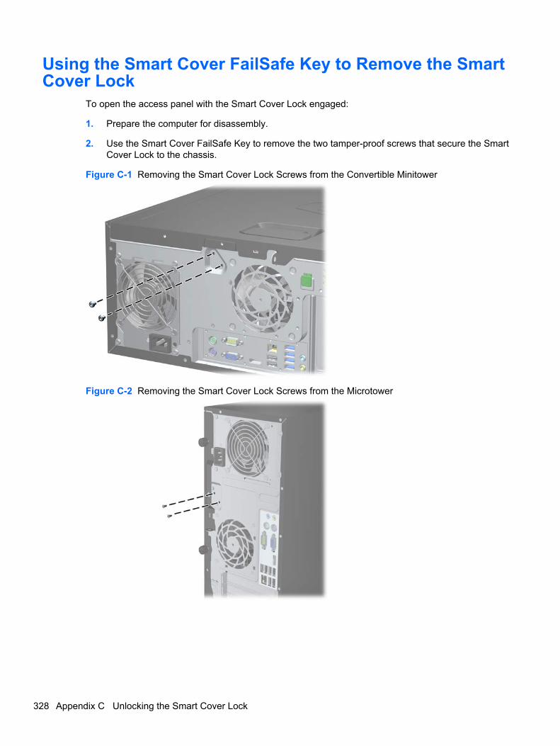
Using the Smart Cover FailSafe Key to Remove the SmartCover Lock
To open the access panel with the Smart Cover Lock engaged:
1. Prepare the computer for disassembly.
2. Use the Smart Cover FailSafe Key to remove the two tamper-proof screws that secure the SmartCover Lock to the chassis.
Figure C-1 Removing the Smart Cover Lock Screws from the Convertible Minitower
Figure C-2 Removing the Smart Cover Lock Screws from the Microtower
328 Appendix C Unlocking the Smart Cover Lock
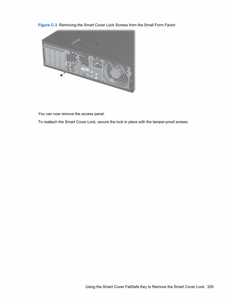
Figure C-3 Removing the Smart Cover Lock Screws from the Small Form Factor
You can now remove the access panel.
To reattach the Smart Cover Lock, secure the lock in place with the tamper-proof screws.
Using the Smart Cover FailSafe Key to Remove the Smart Cover Lock 329
D Power Cord Set Requirements
The power supplies on some computers have external power switches. The voltage select switchfeature on the computer permits it to operate from any line voltage between 100-120 or 220-240 voltsAC. Power supplies on those computers that do not have external power switches are equipped withinternal switches that sense the incoming voltage and automatically switch to the proper voltage.
The power cord set received with the computer meets the requirements for use in the country whereyou purchased the equipment.
Power cord sets for use in other countries must meet the requirements of the country where you usethe computer.
General RequirementsThe requirements listed below are applicable to all countries:
1. The power cord must be approved by an acceptable accredited agency responsible forevaluation in the country where the power cord set will be installed.
2. The power cord set must have a minimum current capacity of 10A (7A Japan only) and anominal voltage rating of 125 or 250 volts AC, as required by each country’s power system.
3. The diameter of the wire must be a minimum of 0.75 mm2 or 18AWG, and the length of the cordmust be between 1.8 m (6 feet) and 3.6 m (12 feet).
The power cord should be routed so that it is not likely to be walked on or pinched by items placedupon it or against it. Particular attention should be paid to the plug, electrical outlet, and the pointwhere the cord exits from the product.
WARNING! Do not operate this product with a damaged power cord set. If the power cord set isdamaged in any manner, replace it immediately.
Japanese Power Cord RequirementsFor use in Japan, use only the power cord received with this product.
CAUTION: Do not use the power cord received with this product on any other products.
330 Appendix D Power Cord Set Requirements
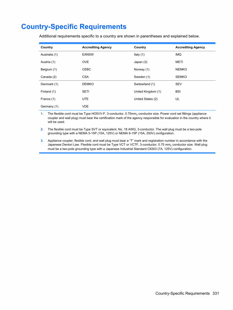
Country-Specific RequirementsAdditional requirements specific to a country are shown in parentheses and explained below.
Country Accrediting Agency Country Accrediting Agency
Australia (1)
Austria (1)
Belgium (1)
Canada (2)
EANSW
OVE
CEBC
CSA
Italy (1)
Japan (3)
Norway (1)
Sweden (1)
IMQ
METI
NEMKO
SEMKO
Denmark (1)
Finland (1)
France (1)
Germany (1)
DEMKO
SETI
UTE
VDE
Switzerland (1)
United Kingdom (1)
United States (2)
SEV
BSI
UL
1. The flexible cord must be Type HO5VV-F, 3-conductor, 0.75mm2 conductor size. Power cord set fittings (appliancecoupler and wall plug) must bear the certification mark of the agency responsible for evaluation in the country where itwill be used.
2. The flexible cord must be Type SVT or equivalent, No. 18 AWG, 3-conductor. The wall plug must be a two-polegrounding type with a NEMA 5-15P (15A, 125V) or NEMA 6-15P (15A, 250V) configuration.
3. Appliance coupler, flexible cord, and wall plug must bear a “T” mark and registration number in accordance with theJapanese Dentori Law. Flexible cord must be Type VCT or VCTF, 3-conductor, 0.75 mm2 conductor size. Wall plugmust be a two-pole grounding type with a Japanese Industrial Standard C8303 (7A, 125V) configuration.
Country-Specific Requirements 331
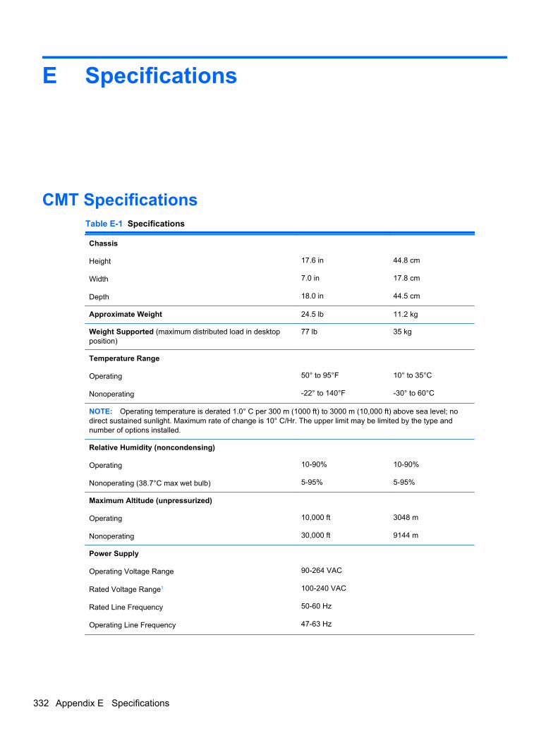
E Specifications
CMT SpecificationsTable E-1 Specifications
Chassis
Height
Width
Depth
17.6 in
7.0 in
18.0 in
44.8 cm
17.8 cm
44.5 cm
Approximate Weight 24.5 lb 11.2 kg
Weight Supported (maximum distributed load in desktopposition)
77 lb 35 kg
Temperature Range
Operating
Nonoperating
50° to 95°F
-22° to 140°F
10° to 35°C
-30° to 60°C
NOTE: Operating temperature is derated 1.0° C per 300 m (1000 ft) to 3000 m (10,000 ft) above sea level; nodirect sustained sunlight. Maximum rate of change is 10° C/Hr. The upper limit may be limited by the type andnumber of options installed.
Relative Humidity (noncondensing)
Operating
Nonoperating (38.7°C max wet bulb)
10-90%
5-95%
10-90%
5-95%
Maximum Altitude (unpressurized)
Operating
Nonoperating
10,000 ft
30,000 ft
3048 m
9144 m
Power Supply
Operating Voltage Range
Rated Voltage Range1
Rated Line Frequency
Operating Line Frequency
90-264 VAC
100-240 VAC
50-60 Hz
47-63 Hz
332 Appendix E Specifications

Table E-1 Specifications (continued)
Standard Efficiency
High Efficiency
320W
320W active PFC; 87/90/87% efficient at20/50/100% load
Rated Input Current 5.5A
1 This system utilizes an active power factor corrected power supply. This allows the system to pass the CE markrequirements for use in the countries of the European Union. The active power factor corrected power supply also has theadded benefit of not requiring an input voltage range select switch.
MT SpecificationsTable E-2 Specifications
Chassis
Height
Width
Depth
14.9 in
7.0 in
17.0 in
37.7 cm
17.7 cm
43.1 cm
Approximate Weight 20.5 lb 9.3 kg
Weight Supported (maximum distributed load in desktopposition)
77 lb 35 kg
Temperature Range
Operating
Nonoperating
50° to 95°F
-22° to 140°F
10° to 35°C
-30° to 60°C
NOTE: Operating temperature is derated 1.0° C per 300 m (1000 ft) to 3000 m (10,000 ft) above sea level; nodirect sustained sunlight. Maximum rate of change is 10° C/Hr. The upper limit may be limited by the type andnumber of options installed.
Relative Humidity (noncondensing)
Operating
Nonoperating (38.7°C max wet bulb)
10-90%
5-95%
10-90%
5-95%
Maximum Altitude (unpressurized)
Operating
Nonoperating
10,000 ft
30,000 ft
3048 m
9144 m
Power Supply
Operating Voltage Range
Rated Voltage Range1
Rated Line Frequency
Operating Line Frequency
90-264 VAC
100-240 VAC
50-60 Hz
47-63 Hz
Standard Efficiency
High Efficiency
320W
320W active PFC; 87/90/87% efficient at20/50/100% load
MT Specifications 333

Table E-2 Specifications (continued)
Rated Input Current 5.5A
1 This system utilizes an active power factor corrected power supply. This allows the system to pass the CE markrequirements for use in the countries of the European Union. The active power factor corrected power supply also has theadded benefit of not requiring an input voltage range select switch.
334 Appendix E Specifications
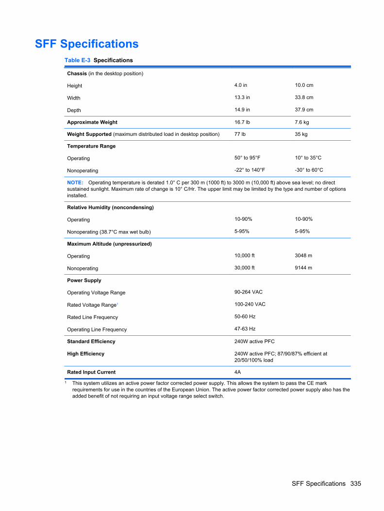
SFF SpecificationsTable E-3 Specifications
Chassis (in the desktop position)
Height
Width
Depth
4.0 in
13.3 in
14.9 in
10.0 cm
33.8 cm
37.9 cm
Approximate Weight 16.7 lb 7.6 kg
Weight Supported (maximum distributed load in desktop position) 77 lb 35 kg
Temperature Range
Operating
Nonoperating
50° to 95°F
-22° to 140°F
10° to 35°C
-30° to 60°C
NOTE: Operating temperature is derated 1.0° C per 300 m (1000 ft) to 3000 m (10,000 ft) above sea level; no directsustained sunlight. Maximum rate of change is 10° C/Hr. The upper limit may be limited by the type and number of optionsinstalled.
Relative Humidity (noncondensing)
Operating
Nonoperating (38.7°C max wet bulb)
10-90%
5-95%
10-90%
5-95%
Maximum Altitude (unpressurized)
Operating
Nonoperating
10,000 ft
30,000 ft
3048 m
9144 m
Power Supply
Operating Voltage Range
Rated Voltage Range1
Rated Line Frequency
Operating Line Frequency
90-264 VAC
100-240 VAC
50-60 Hz
47-63 Hz
Standard Efficiency
High Efficiency
240W active PFC
240W active PFC; 87/90/87% efficient at20/50/100% load
Rated Input Current 4A
1 This system utilizes an active power factor corrected power supply. This allows the system to pass the CE markrequirements for use in the countries of the European Union. The active power factor corrected power supply also has theadded benefit of not requiring an input voltage range select switch.
SFF Specifications 335
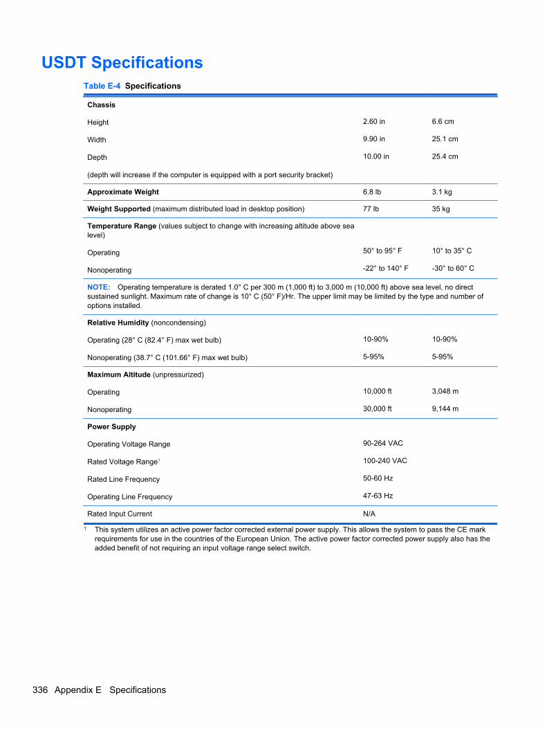
USDT SpecificationsTable E-4 Specifications
Chassis
Height
Width
Depth
(depth will increase if the computer is equipped with a port security bracket)
2.60 in
9.90 in
10.00 in
6.6 cm
25.1 cm
25.4 cm
Approximate Weight 6.8 lb 3.1 kg
Weight Supported (maximum distributed load in desktop position) 77 lb 35 kg
Temperature Range (values subject to change with increasing altitude above sealevel)
Operating
Nonoperating
50° to 95° F
-22° to 140° F
10° to 35° C
-30° to 60° C
NOTE: Operating temperature is derated 1.0° C per 300 m (1,000 ft) to 3,000 m (10,000 ft) above sea level, no directsustained sunlight. Maximum rate of change is 10° C (50° F)/Hr. The upper limit may be limited by the type and number ofoptions installed.
Relative Humidity (noncondensing)
Operating (28° C (82.4° F) max wet bulb)
Nonoperating (38.7° C (101.66° F) max wet bulb)
10-90%
5-95%
10-90%
5-95%
Maximum Altitude (unpressurized)
Operating
Nonoperating
10,000 ft
30,000 ft
3,048 m
9,144 m
Power Supply
Operating Voltage Range
Rated Voltage Range1
Rated Line Frequency
Operating Line Frequency
90-264 VAC
100-240 VAC
50-60 Hz
47-63 Hz
Rated Input Current N/A
1 This system utilizes an active power factor corrected external power supply. This allows the system to pass the CE markrequirements for use in the countries of the European Union. The active power factor corrected power supply also has theadded benefit of not requiring an input voltage range select switch.
336 Appendix E Specifications
Index
Symbols/Numerics2.5-in drive adapter, spare part
number 34, 44, 53
AAC adapter, USDT
spare part number 58, 64access panel
CMT removal andreplacement 76
CMT spare part number 76locking and unlocking 327MT removal 123MT spare part number 123SFF removal and
replacement 164SFF spare part number 164USDT removal and
replacement 208USDT spare part number 208
access panel, CMTspare part number 32, 38
access panel, locked 255access panel, MT
spare part number 40, 47access panel, SFF
spare part number 49, 56access panel, USDT
spare part number 58, 64adapter, DisplayPort to DVI
spare part number 36, 46, 55adapter, DisplayPort to DVI (not
illustrated)spare part number 33, 42, 51,
59adapter, DisplayPort to HDMI
spare part number 37, 46, 55
adapter, DisplayPort to HDMI (notillustrated)
spare part number 33, 43, 51,59
adapter, DisplayPort to VGAspare part number 37, 46, 55
adapter, DisplayPort to VGA (notillustrated)
spare part number 33, 42, 51,59
antenna, spare part number 35,44, 53, 61
antennasUSDT spare part number 244
audible codes 301audio problems 270
BBackup and Restore 316battery
disposal 72battery replacement 319beep codes 301bezel blank
spare part number 80, 127bezel blank (USDT), spare part
number 58spare part numbers 63
booting optionsFull Boot 292Quick Boot 292
Ccable management 73cable pinouts
SATA data 73
card readerUSDT removal and
replacement 228USDT spare part number 228
card reader, spare part number34, 44, 53
card reader, USDTspare part number 61
cautionsAC power 66cables 72cooling fan 71electrostatic discharge 66keyboard cleaning 70keyboard keys 70
CD-ROM or DVD problems 283chasis types, illustrated 66chassis fan, CMT
spare part number 34, 38chassis fan, MT
spare part number 47chassis fan, SFF
spare part number 56chassis fan, USDT
spare part number 64chassis stand
spare part number 53clamp lock, spare part number
34, 36, 43, 46, 53, 55, 61cleaning
computer 69mouse 71safety precautions 69
CMOSbacking up 305clearing and resetting 307
CMTaccess panel removal and
replacement 76
Index 337
access panel, spare partnumber 32, 38
chassis fan, spare partnumber 34, 38
disassembly preparation 75fan shroud removal and
replacement 104fan sink, spare part number
38fan, spare part number 34, 38front bezel removal and
replacement 77front bezel, spare part
number 32, 38front I/O assembly, spare part
number 33, 38front I/O device removal and
replacement 105heat sink removal and
replacement 110heat sink, spare part number
34power supply removal and
replacement 115power supply, spare part
number 32, 37power switch removal and
replacement 107power switch/LED assembly,
spare part number 33, 38preparation for disassembly
75processor removal and
replacement 112rear chassis fan removal and
replacement 109SATA hard drive cable, spare
part number 33, 38SATA optical drive cable, spare
part number 33, 38speaker removal and
replacement 108speaker, spare part number
34, 38system board removal and
replacement 116system board, spare part
number 32, 38
computerchanging from desktop to
tower 248specifications 335, 336
computer cleaning 69connecting drive cables 89country power cord set
requirements 331Customer Support 251, 291
Ddesktop conversion
CMT 117DIMMs. See memorydisassembly preparation
CMT 75MT 122SFF 163USDT 207
DisplayPort cablespare part number 36, 46, 55
DisplayPort cable (not illustrated)spare part number 33, 43, 51,
59DMS-59 to dual VGA cable
spare part number 36, 46, 55DMS-59 to dual VGA cable (not
illustrated)spare part number 33, 42, 51
drivesCMT cable connections 95CMT installation 95CMT locations 90connecting cables 89installing 89MT cable connections 138MT installation 138MT locations 140SFF cable connections 179SFF installation 179SFF locations 178
Eelectrostatic discharge (ESD) 66
preventing damage 67error
codes 292, 301messages 293
eSATA port (expansion), sparepart number 38, 47, 56
eSATA port assembly, spare partnumber 35, 44, 53
expansion cardCMT installation 85CMT removal 85MT installation 130MT removal 130SFF installation 172SFF removal 172
expansion slot coverCMT removal 86MT removal 132SFF removal 173
external USB webcam, spare partnumber 35, 44, 53, 61
Ff11 recovery 318FailSafe Key 327fan
CMT spare part number 109MT spare part number 43, 46,
157fan (front), USDT
spare part number 61fan (rear), USDT
spare part number 60fan duct
SFF removal andreplacement 190
SFF spare part number 190fan duct, SFF
spare part number 52, 56fan sink
CMT removal andreplacement 110
CMT spare part number 110fan sink, CMT
spare part number 38fan sink, MT
spare part number 47fan with guard, MT
spare part number 43fan, CMT
spare part number 34, 38fan, MT
spare part number 47fan, power supply 71fan, SFF
spare part number 52, 56
338 Index
fan, USDTspare part number 64
fan/baffle assemblyMT removal and replacement
147FireWire card, spare part
number 37, 46, 56flash drive problems 285flashing LEDs 301front bezel
CMT removal andreplacement 77
CMT security 78CMT spare part number 77MT blank removal 127MT removal 124MT security 125MT spare part number 124removing blanks 80, 168, 212SFF removal and
replacement 165SFF security 166SFF spare part number 165USDT removal and
replacement 209USDT security 210USDT spare part number 209
front bezel, CMTspare part number 32, 38
front bezel, MTspare part number 40, 48
front bezel, SFFspare part number 49, 57
front bezel, USDTspare part number 58, 64
front fanSFF removal and
replacement 191SFF spare part number 191USDT removal and
replacement 218USDT spare part number 218
front fan assemblyMT spare part number 147
front I/O and power switchassembly
SFF spare part number 194front I/O and USB assembly
CMT spare part number 105
front I/O assemblyMT spare part number 149
front I/O assembly, CMTspare part number 33, 38
front I/O assembly, MTspare part number 42, 47
front I/O assembly, SFFspare part number 51
Front I/O cable and power switchassembly, SFF
spare part number 56front I/O device
CMT removal andreplacement 105
front I/O panel, USDTspare part number 61
front I/O, power switch assemblySFF removal and
replacement 194front panel components
CMT 3MT 4SFF 5USDT 6
front panel problems 287front USB panel
MT removal and replacement149
Ggeneral problems 254graphics board
USDT removal andreplacement 239
graphics card, spare partnumber 36, 45, 54
grommet (hard drive isolation),spare part number 34, 44, 53,61
grounding methods 67guide screws 89
CMT location 96MT location 139SFF location 180
Hhard drive
CMT installation 99CMT removal 91MT installation 144
MT removal 144proper handling 72SATA characteristics 73SFF installation 187SFF removal 187spare part numbers 35, 44,
54, 62USDT installation 222USDT removal 222
hard drive problems 260hard drive recovery 318hardware installation problems
276heat sink
MT removal and replacement151
MT spare part number 151SFF removal and
replacement 197SFF spare part number 197USDT removal and
replacement 231USDT spare part number 231
heat sink, CMTspare part number 34
heat sink, MTspare part number 43
heat sink, SFFspare part number 52, 56
heat sink, USDTspare part number 60
helpful hints 252hood sensor
CMT removal andreplacement 104
SFF removal andreplacement 193
SFF spare part number 193spare part number 34, 37, 43,
47, 52, 56, 63, 104USDT removal and
replacement 238USDT spare part number 238
HP Business Digital Headset,spare part number 35, 44, 53,61
Iinstalling
battery 319
Index 339
CMT drive cables 95CMT expansion card 85CMT hard drive 99CMT media card reader 97CMT memory 82CMT optical drive 97drive cables 89guide screws 89MT drive cables 138MT expansion card 130MT hard drive 144MT media card reader 142MT memory 128MT optical drive 142SFF drive cables 179SFF expansion card 172SFF hard drive 187SFF media card reader 185SFF memory 169SFF optical drive 181USDT hard drive 222USDT memory 214USDT optical drive 221
Internet access problems 287
Kkeyboard
cleaning 70spare part numbers 35, 36,
37, 44, 46, 53, 55, 61, 62, 63keyboard problems 274
LLEDs
blinking power 301blinking PS/2 keyboard 301
locksCMT front bezel 78MT front bezel 125SFF front bezel 166Smart Cover Lock 327USDT front bezel 210
Mmedia card reader
CMT installation 97CMT removal 91MT installation 142MT removal 140SFF installation 185SFF removal 184
Media Card Reader problems263
memoryCMT installation 82CMT socket population 83CMT specifications 82MT installation 128MT socket population 128MT specifications 128SFF installation 169SFF socket population 169SFF specifications 169USDT installation 214USDT socket population 215USDT specifications 214
memory modulespare part number 82, 128,
169memory module, USDT
spare part number 214memory modules
spare part number 32, 38, 41,47, 48, 49, 57, 59, 64
memory problems 281monitor problems 265mouse
cleaning 71mouse problems 274mouse, spare part number 34,
35, 44, 53, 61MT
access panel, spare partnumber 40, 47
disassembly preparation 122fan sink, spare part number
47fan with guard, spare part
number 43fan, spare part number 47fan/baffle assembly removal
and replacement 147front bezel, spare part
number 40, 48front I/O assembly, spare part
number 42, 47front USB panel removal and
replacement 149heat sink removal and
replacement 151
heat sink, spare part number43
power supply removal andreplacement 159
power supply, spare partnumber 40, 46
power switch/LED assemblyremoval and replacement150
power switch/LED assembly,spare part number 42, 47
preparation for disassembly122
processor removal andreplacement 153
rear chassis fan removal andreplacement 157
SATA cable, spare partnumber 42
SATA hard drive cable, sparepart number 42, 47
SATA optical drive cable, sparepart number 42, 47
speaker removal andreplacement 156
speaker, spare part number43, 47
system board removal andreplacement 161
system board, spare partnumber 41, 47
Nnetwork problems 278NIC, spare part number 37, 46,
55numeric error codes 293
Ooperating guidelines 69optical drive
CMT installation 97CMT removal 91MT installation 142MT removal 140SFF installation 181SFF removal 180spare part numbers 36, 38,
45, 47, 54, 56, 62, 63USDT installation 221
340 Index
USDT release latchattachment 220
USDT removal 219optical drive cable/connector,
USDTspare part number 59
optical drive problems 283optical drive rail
USDT removal andreplacement 227
optical drive rail kitUSDT spare part number 227
optical drive rail, USDTspare part number 61
optical drive, USDTspare part number 219
overheating, prevention 69
Ppassword
clearing 305power-on 305setup 305
port coverUSDT spare part number 249
POST error messages 292power cord set requirements
country specific 331power problems 258power supply
CMT removal andreplacement 115
CMT spare part number 115fan 71MT removal and replacement
159MT spare part number 159operating voltage range 332,
333, 335, 336SFF removal and
replacement 202power supply, CMT
spare part number 32, 37power supply, MT
spare part number 40, 46power supply, SFF
spare part number 49, 55power switch
CMT removal andreplacement 107
power switch/LED assemblyCMT spare part number 107MT removal and replacement
150MT spare part number 150
power switch/LED assembly, CMTspare part number 33, 38
power switch/LED assembly, MTspare part number 42, 47
power-on password 305printer port
spare part number 34printer port (expansion), spare part
number 37, 47, 56printer port, PCI card
spare part number 52printer port, spare part number
43printer problems 272problems
audio 270CD-ROM or DVD 283flash drive 285front panel 287general 254hard drive 260hardware installation 276Internet access 287keyboard 274Media Card Reader 263memory 281monitor 265mouse 274network 278power 258printer 272processor 283software 289
processorCMT removal and
replacement 112MT removal and replacement
153SFF removal and
replacement 199spare part number 32, 38, 41,
48, 50, 57, 59USDT removal and
replacement 233processor problems 283
product ID locations 11
Rrear chassis fan
CMT removal andreplacement 109
CMT spare part number 109MT removal and replacement
157MT spare part number 43, 46,
157rear fan
USDT removal andreplacement 243, 244
USDT spare part number 243rear panel components
CMT 7MT 8SFF 9USDT 10
rear port cover, USDTspare part number 61
recovery partition 318removal and replacement
CMT access panel 76CMT fan sink 110CMT front bezel 77CMT front I/O device 105CMT hood sensor 104CMT power supply 115CMT power switch 107CMT processor 112CMT rear chassis fan 109CMT speaker 108CMT system board 116MT fan/baffle assembly 147MT front USB panel 149MT heat sink 151MT power supply 159MT power switch/LED
assembly 150MT processor 153MT rear chassis fan 157MT speaker 156MT system board 161SFF fan duct 190SFF front bezel 164, 165SFF front fan 191SFF front I/O, power switch
assembly 194
Index 341
SFF heat sink 197SFF hood sensor 193SFF power supply 202SFF processor 199SFF speaker 196SFF system board 204USDT access panel 208USDT card reader 228USDT front bezel 209USDT front fan 218USDT graphics board 239USDT heat sink 231USDT hood sensor 238USDT optical drive rail 227USDT processor 233USDT rear fan 243, 244USDT speaker 230USDT system board 241USDT WLAN tuner module
236removing
battery 319bezel blanks 168, 212CMT bezel blanks 80CMT drives 91CMT expansion card 85CMT expansion slot cover 86CMT media card reader 91MT bezel blanks 127MT computer access panel
123MT expansion card 130MT expansion slot cover 132MT front bezel 124MT hard drive 144MT media card reader 140MT optical drive 140SFF expansion card 172SFF expansion slot cover 173SFF hard drive 187SFF media card reader 184SFF optical drive 180Smart Cover Lock 327USDT hard drive 222USDT optical drive 219
resettingCMOS 305password jumper 305
restoring the hard drive 318
rubber footspare part number 53
Ssafety and comfort 251safety precautions
cleaning 69SATA
connectors on system board73
data cable pinouts 73hard drive characteristics 73
SATA cablespare part number 33
SATA cable, MTspare part number 42
SATA cable, SFFspare part number 51
SATA drive cable, SFFspare part number 51
SATA hard drive cable, CMTspare part number 33, 38
SATA hard drive cable, MTspare part number 42, 47
SATA optical drive cable, CMTspare part number 33, 38
SATA optical drive cable, MTspare part number 42, 47
screws, correct size 71security
CMT front bezel 78MT front bezel 125SFF front bezel 166Smart Cover Lock 327USDT front bezel 210
serial number locations 11serial port (expansion), spare part
number 37, 47, 56serial port, spare part number 34,
44, 53service considerations 71setup password 305SFF
access panel, spare partnumber 49, 56
chassis fan, spare partnumber 56
disassembly preparation 163fan duct removal and
replacement 190
fan duct, spare part number52, 56
fan, spare part number 52front bezel removal and
replacement 164, 165front bezel, spare part
number 49, 57front fan removal and
replacement 191front I/O assembly, spare part
number 51Front I/O cable and power
switch assembly, spare partnumber 56
front I/O, power switchassembly removal andreplacement 194
heat sink removal andreplacement 197
heat sink, spare part number52, 56
hood sensor removal andreplacement 193
power supply removal andreplacement 202
power supply, spare partnumber 49, 55
preparation for disassembly163
processor removal andreplacement 199
SATA cable, spare partnumber 51
SATA drive cable, spare partnumber 51
solenoid lock, spare partnumber 52
speaker removal andreplacement 196
speaker, spare part number52, 56
system board removal andreplacement 204
system board, spare partnumber 49, 56
Smart Cover Lock 327software
problems 289servicing computer 71
342 Index
solenoid lockspare part number 34, 37, 43,
47, 56solenoid lock, SFF
spare part number 52solid-state drive, spare part
number 36, 38, 45, 48, 54, 57,62
spare part numbertamper-resistant wrench 71Torx T-15 screwdriver 71
speakerCMT removal and
replacement 108CMT spare part number 108MT removal and replacement
156MT spare part number 156SFF removal and
replacement 196SFF spare part number 196USDT removal and
replacement 230USDT spare part number 230
speaker, CMTspare part number 34, 38
speaker, MTspare part number 43, 47
speaker, SFFspare part number 52, 56
speaker, USDTspare part number 61, 64
specificationsCMT memory 82computer 332, 335, 336MT memory 128SFF memory 169USDT memory 214
stand (USDT) spare part number63
static electricity 66system board
CMT removal andreplacement 116
CMT spare part number 116MT removal and replacement
161MT spare part number 161SATA connectors 73
SFF removal andreplacement 204
SFF spare part number 204USDT removal and
replacement 241system board connections
CMT 81MT 136SFF 177USDT 213
system board, CMTspare part number 32, 38
system board, MTspare part number 41, 47
system board, SFFspare part number 49, 56
system board, USDTspare part number 58, 63
Ttamper-proof screws
tool 71temperature control 69tools, servicing 71Torx T15 screwdriver 71tower configuration 248tower conversion
CMT 119tower orientation 206
Uunlocking access panel 327USB powered speakers, spare part
number 34, 37, 44, 46, 53, 55,61, 63
USDTAC adapter, spare part
number 58, 64access panel removal and
replacement 208access panel, spare part
number 58, 64card reader removal and
replacement 228card reader, spare part
number 61chassis fan, spare part
number 64disassembly preparation 207
fan (front), spare part number61
fan (rear), spare part number60
front bezel removal andreplacement 209
front bezel, spare partnumber 58, 64
front fan removal andreplacement 218
front I/O panel, spare partnumber 61
graphics board removal andreplacement 239
heat sink removal andreplacement 231
heat sink, spare part number60
hood sensor removal andreplacement 238
optical drive cable/connector,spare part number 59
optical drive rail removal andreplacement 227
optical drive rail, spare partnumber 61
preparation for disassembly207
processor removal andreplacement 233
rear fan removal andreplacement 243, 244
rear port cover, spare partnumber 61
speaker removal andreplacement 230
speaker, spare part number61, 64
system board removal andreplacement 241
system board, spare partnumber 58, 63
WLAN module removal andreplacement 236
Vventilation, proper 69
WWake-on-LAN feature 278
Index 343

Windows 8 operating systemDVD 318
WLAN moduleUSDT removal and
replacement 236USDT spare part number 236
344 Index