Historical Development and Current Effectiveness of Rear ...
88
UMTRI-99-31 HISTORICAL DEVELOPMENT AND CURRENT EFFECTIVENESS OF REAR LIGHTING SYSTEMS David W. Moore Kåre Rumar October 1999
-
Upload
khangminh22 -
Category
Documents
-
view
1 -
download
0
Transcript of Historical Development and Current Effectiveness of Rear ...

UMTRI-99-31
HISTORICAL DEVELOPMENT AND CURRENT EFFECTIVENESS OF REAR LIGHTING SYSTEMS
David W. Moore Kåre Rumar
October 1999

HISTORICAL DEVELOPMENT AND CURRENT EFFECTIVENESS OF REAR LIGHTING SYSTEMS
David W. Moore Kåre Rumar
The University of Michigan Transportation Research Institute
Ann Arbor, Michigan 48109-2150 U.S.A.
Report No. UMTRI-99-31 October 1999

i
Technical Report Documentation Page
1. Report No.
UMTRI-99-31 2. Government Accession No.
3. Recipient’s Catalog No.
5. Report Date
October 1999 4. Title and Subtitle
Historical Development and Current Effectiveness of Rear Lighting Systems 6. Performing Organization Code
302753 7. Author(s)
Moore, D.W. and Rumar, K. 8. Performing Organization Report No.
UMTRI-99-31 10. Work Unit no. (TRAIS)
9. Performing Organization Name and Address
The University of Michigan Transportation Research Institute 2901 Baxter Road Ann Arbor, Michigan 48109-2150 U.S.A.
11. Contract or Grant No.
13. Type of Report and Period Covered
12. Sponsoring Agency Name and Address
The University of Michigan Industry Affiliation Program for Human Factors in Transportation Safety
14. Sponsoring Agency Code
15. Supplementary Notes
The Affiliation Program currently includes Adac Plastics, AGC America, AutomotiveLighting, BMW, Britax International, Corning, DaimlerChrysler, Denso, Federal-MogulLighting Products, Ford, GE, GM NAO Safety Center, Guide Corporation, Hella, Hewlett-Packard, Ichikoh Industries, Koito Manufacturing, Libbey-Owens-Ford, North AmericanLighting, Osram Sylvania, Philips Lighting, PPG Industries, Reflexite, Reitter &Schefenacker, Stanley Electric, Stimsonite, TEXTRON Automotive, Valeo, Visteon, Yorka,3M Personal Safety Products, and 3M Traffic Control Materials. Information about the Affiliation Program is available at: http://www.umich.edu/~industry/ 16. Abstract
This report presents a historical account of the development of rear lighting systems.The account is based partly on a comprehensive review of the available documented sources.Various details of both technical developments and lighting standards are covered. Then therear end crash situation is discussed. It is noted that rear end crashes constitute a large andincreasing problem in present road traffic. This is followed by an analysis of the variousfunctions of rear signaling systems and the extent to which the present rear lampsaccomplish those functions. In the final section, the tasks of the driver in car-followingsituations are discussed, followed by a listing of possible changes to rear signaling systemsthat could enhance the safety of road transportation. (The report contains 191 references.)
17. Key Words
rear lighting, rear signaling, tail lamps, brake lamps, turn signal lamps, history, effectiveness
18. Distribution Statement
Unlimited
19. Security Classification (of this report)
None 20. Security Classification (of this page)
None 21. No. of Pages
85 22. Price

ii
Acknowledgments
Appreciation is extended to the members of the University of Michigan Industry Affiliation
Program for Human Factors in Transportation Safety for support of this research. The current
members of the Program are:
Adac Plastics AGC America Automotive Lighting
BMW Britax International Corning DaimlerChrysler Denso Federal-Mogul Lighting Products Ford GE GM NAO Safety Center Guide Corporation Hella Hewlett-Packard Ichikoh Industries Koito Manufacturing Libbey-Owens-Ford North American Lighting Osram Sylvania Philips Lighting PPG Industries Reflexite Reitter & Schefenacker Stanley Electric Stimsonite TEXTRON Automotive Valeo Visteon Yorka 3M Personal Safety Products 3M Traffic Control Materials
Additional thanks go to Wolfgang Hendrischk from Hella and Tilman Spingler from Bosch
for sending us relevant old documents; to Bob Sweet and Eric Traube for retrieving documents
from various library sources; and to Michael Flannagan, Michael Sivak, and John Sullivan for
helpful comments on earlier drafts of this report.

iii
Executive Summary
Rear end crashes are one of the largest crash and injury problems in road traffic. In the
U.S., they constitute close to 30% of all crashes, and account for about 25% of injuries in road
traffic that lead to permanent impairment. Could improvements in rear lighting systems reduce this
serious problem and facilitate the driver’s task of interacting with other road users? We will be
better able to answer this question by understanding how the present rear lighting systems have
developed and how they currently function. In this report, we review the history and current status
of rear lighting systems, limiting ourselves to the North American and European situations
primarily because information from other parts of the world was not readily accessible.
Humans, as well as other species, have always used signals to facilitate interaction. When
motorized vehicles were introduced, we started to move at higher speeds and also at night. It
became important to communicate at longer distances, as well as in darkness. The first automobiles
were equipped with the same lamps used on horse drawn carriages at the end of the 1890s.
Candles and kerosene lamps were located in the front of the vehicle, and were primarily intended to
make the vehicle visible to other road users. In the rear, there were no lamps. In the beginning of
the 1900s, the front lamps became first acetylene and later electric. The first rear lighting (normally
one kerosene lamp) was introduced just before the turn of the century to provide license plate
illumination. It was common to equip the license plate lamp with a red opening towards the rear,
thereby creating the first tail lamps. Not until about 1920 did most cars have electric lamps in both
the front and rear.
During the 1920s, the first national and international regulations and standards on rear
lighting appeared. Presently there exists a well developed national and international organizational
structure for standards and regulations. On the international level, the most active organizations are
UN/ECE, ISO, CIE, and GTB. In the U.S., SAE and NHTSA are the most prominent
organizations. Corresponding organizations exist in other countries as well. Presently, the two
largest comprehensive regulatory systems are published by ECE in Europe and NHTSA in the U.S.
In both cases, the first regulations on rear lamps were established in the 1960s.
In 1926, the predecessor of the UN, the League of Nations, agreed on the first conventions
related to automobile lighting. It was then agreed that during the night every motor vehicle must
have a red lamp in the rear, and that the rear registration plate must be illuminated. Specific
photometric requirements for tail lamps appeared first in the 1920s. They successively developed
from a minimum of 0.1 cd and a maximum of 5 cd in 1928, to a minimum of 2.0 cd, and a
maximum of 15 cd in 1955, along with a detailed specification of the light distribution. The 1955
requirements are essentially still valid in 1999. Two tail lamps became common in the 1930s in the
U.S. and became a requirement in Europe in the 1950s.

iv
The first brake lamps appeared as early as 1905. By 1928, requirements for brake lamps
were introduced in eleven states in the U.S. More general requirements for brake lamps did not
come until the 1960s. The photometrics of brake lamps have gone through a development similar
to tail lamps: from the requirement that there should be one lamp, to a photometric requirement, to a
light distribution, and eventually to a requirement for two lamps. The latest major development in
brake lamps came in the 1980s—the center high mounted stop lamp (CHMSL).
The first turn signals appeared in the 1920s. In the 1930s, the first requirements were
established both in Europe and in the U.S. However, the development was slightly different in that
Europe favored the semaphore arm while the U.S. favored flashing turn signals. The flashing turn
signals did not become common in Europe until the late 1960s. The photometric requirements for
turn signals have gone through the same pattern of development as those for the other rear lamps.
Rear fog lamps were introduced in Europe in the 1960s. The first ECE regulation came in
1974 and rear fog lamps were made compulsory in Europe in 1991. However, in the U.S., they are
still not mandatory. The first back-up lamp appeared as early as the 1920s. It was first standardized
in the U.S. in 1947 but did not become mandatory until the late 1960s.
Following the historical review of rear lighting systems, the rear end crash situation is
analyzed. It is concluded that the existence and design of rear lamps have a considerable influence
on rear end crashes, especially at night. Then the tasks of the rear lighting system are analyzed and
an evaluation is made of the extent to which the current systems meet the demands of these tasks.
Seventeen specific tasks are listed. It is concluded that in respect to several of these tasks the
present rear lamps do not meet optimum requirements.
In the final section, the task of the driver in car-following situations and the implications for
rear lighting design are discussed. That is followed by a discussion of possible changes to rear
lighting systems that have the potential to enhance the safety of road transportation.

v
Contents
Acknowlegments................................................................................................................ ..............ii
Executive Summary ........................................................................................................... .............iii
1. Why Do We Have Rear Lamps and How Have They Developed? ............................... ..............1
1.1. Natural signals..............................................................................................................1 1.2. The early generations of motor vehicles........................................................................2 1.3. The purpose of rear signals...........................................................................................3
2. Common Rear Lamps: Historical Development of Standards and Regulations............ ..............9
2.1. Organizations................................................................................................................9 2.2. Government lighting regulations.................................................................................10 2.3. General development...................................................................................................12 2.4. Tail, rear position, and parking lamps..........................................................................18 2.5. License plate lamps.....................................................................................................24 2.6. Brake/stop lamps ........................................................................................................26 2.7. Center high mounted stop lamps.................................................................................31 2.8. Turn signal lamps .......................................................................................................32 2.9. Rear fog lamps............................................................................................................38 2.10. Back up (reversing) lamps .........................................................................................38 2.11. Harmonization ...........................................................................................................40
3. Do Current Rear Signals Fulfil Their Tasks?................................................................ ............41
3.1. Accident statistics of rear end crashes.........................................................................41 3.2. General problems with present rear signal lamps........................................................43 3.3. Special problems with specific rear signal functions...................................................49
4. Discussion: Main Problems and Potential Countermeasures....................................... ............57
4.1. General considerations................................................................................................57 4.2. Driver tasks.................................................................................................................58 4.3. Proposals for improved rear lighting signals...............................................................61 4.4. Ideal and real world situations.....................................................................................65 4.5. Concluding comments ................................................................................................65
5. References .................................................................................................................... ............67

vi

1
1. Why Do We Have Signals and How Have They Developed?
1.1. Natural signals
When several animals move in a common environment, they have to interact in order to
avoid conflicts. Their interactions may be based on numerous explicit and implicit signals: rank,
size, speed, body language, visual contact, and sound. Most of the signals are inherited while some
are developed by experience. When people walk in the same area, they interact very much by the
same means. This was the situation for our ancestors, and this is the situation for us. The two main
requirements of signals are that they should be easy to detect and easy to interpret.
In the early stages of human development, the signals that were employed were probably
mainly inherited. They did not require any intellectual effort. A given signal was immediately and
unconsciously followed by a certain behavior. This process is what Schneider and Shiffrin call
automatic processing (Schneider and Shiffrin, 1977; Shiffrin and Schneider, 1977). Gradually,
along with the development of artificial physical tools, people developed the abstract tools of
artificial signals for communication. The first artificial signals that were developed by humans to
communicate at long distances probably included light or smoke signals. In nighttime, fires were
used to lead (or mislead) ships and to warn other villages about approaching enemies.
When people started moving by means of horse, carriage, or bicycle, the same basic
interaction signals were used. Since the speeds and energy levels when using such modes were
much higher than when moving by foot, interaction had to take place at longer distances in order to
avoid conflicts. Therefore, hand signals and sound signals (e.g., bells) were introduced to make
possible simple interaction at a distance. When people became involved with the first generations
of motor vehicles, interactions were very much the same as when they were moving on horses and
bicycles. The main difference was that the speeds and energy levels involved were even greater, so
that signals needed to be perceived at even longer distances. This led to the introduction of special
motor vehicle signals, (e.g., the horn). Detecting and understanding such signals was more abstract
and less natural. Schneider and Shiffrin call this conscious process controlled processing. Signals
that require controlled processing are often processed more slowly. However, after extensive
learning periods, signals originally requiring controlled processing may be processed automatically.
Automobile signal lamps are such an example. The existence of automatic reactions to vehicle
signal lamps is also one of the stronger arguments against changing an established signaling
system.

2
1.2. The early generations of motor vehicles
A human generation is now about twenty-five years. A passenger-car generation is probably
not longer than ten years (trucks and buses have longer generations). Let us say the automobile
was born about 1890. This means that by now we are in about the eleventh generation. Not every
system in the car changes with each generation. Rear lighting is probably one of the systems that
have changed the least over these generations.
One reason for the development of special motor-vehicle signals was the fact that people
started moving not only during the day, as was originally the case, but also at night. In darkness the
original signals, whether they were natural or artificial, were not visible. Thus, there was a need for
self-luminous signals, which, if strong enough, could also be used during daylight hours. However,
during daylight hand signals and other man-made signals were still used to a very large extent. In
Britain and in the U.S., for instance, driver hand signals were common even during the 1950s.
Some of the early light signals copied the original artificial signals (e.g., turn signals were
luminous arms that unfolded from the body of the car, similar to driver and bicyclist arm signals).
Because the meanings of abstract signals have to be learned and, after some time, are overlearned
and generally understood, engineers hesitate to radically change signals. Changing signals leads to
transition problems, with vehicles having different signals for the same message. It also leads to a
so-called negative transfer in which one learned reaction has to be extinguished and replaced by
another one.
Interestingly, the same signals sometimes have different informal meaning in different
countries. Flashing the high beams, for instance, means in some countries, “Here I come, give
way,” but in other countries it means “Please go ahead, I am waiting.” In Sweden, after an
overtaking, if the overtaken car has assisted, the overtaking driver expresses appreciation by flashing
turn signals right-left. The light-signaling system is used for a number of such local and informal
messages. This is one of the consequences of the fact that artificial signals do not have natural,
universal meanings. Another reason for the development of such informal signals is that the
standard signal system lacks provision for many important messages. For instance, you cannot
signal “excuse me,” which is a message that solves many problems for walking persons!
Light signals were originally meant for lower levels of ambient illumination, because it was
believed that under daylight conditions most vehicle motions and driver manual signals were
sufficiently visible. However, gradually it became evident that better signals were also needed under
daylight conditions.
Two good illustrations of the importance of light signals during the day are daytime running
lamps (DRLs) and center high mounted stop lamps (CHMSLs). DRLs have been shown to result
in a significant reduction of certain daylight vehicle collisions (Koornstra et al., 1997), while

3
CHMSLs have been shown to reduce daytime rear end collisions (Kahane and Hertz, 1998).
Although the ratio between ambient illumination at night and in daytime can exceed 1:10,000, in
practice all signal lights have only single fixed intensities, which are supposed to work in both
daylight and night conditions.
Another reason for the development of special motor vehicle signals was the fact that
automobiles became covered with roofs and windows. It was no longer possible for other road
users to clearly see the driver, or gestures the driver might make. The final reason for the
development of new and improved rear lamps was that motor traffic on high speed roads introduced
a series of new maneuvers that did not exist earlier, including lane changes, overtakings, and left
turns in potential conflict with oncoming traffic.
Originally, the main types of information that needed to be given to the road users behind
the vehicle were presence, braking, and intention to turn. In addition, police officers needed to be
able to read the rear license plate at night. Consequently, the new rear signals that were developed
during the early generations of automobiles were mainly license-plate lamps and tail/position lamps.
Later came brake/stop lamps and rear turn signals. It is uncertain to what extent any systematic
studies were made in the early phase of rear lighting development. However, efforts were probably
made to develop simple, automatically processed rear signals as opposed to more arbitrary signals
that required controlled processing.
1.3. The purpose of rear signals
In modern road traffic some of the basic, biological signals listed above (e.g., size and
speed) are still valid. For example, most drivers probably understand that trucks will not speed up
or slow down as quickly as smaller vehicles. However, a set of new signals was developed to
increase safety by reducing the uncertainty of other road users about what would happen in the
traffic scene in front of them. There are indications that there is room for improvement in the level
of safety provided by present vehicle rear lighting. Rear end crashes have increased steadily. For
example, in the U.S. in 1997 there were about 1.9 million rear end crashes, constituting 28% of all
crashes (NHTSA, 1998). In comparison, in 1992 there were about 1.5 million rear end crashes,
constituting 25% of all crashes (NHTSA, 1993). Furthermore, rear end crashes cause about one
third of the crashes responsible for traffic delays. A majority of the rear end crashes occur in
daytime, and about two thirds of all rear end crashes involve a lead vehicle that was stopped at the
time of impact.

4
1.3.1. The design of rear signal lamps
There are two main questions to be asked about the design of new signals:
(1) What information is needed by road users behind a vehicle in order to reduce their
uncertainty?
(2) How should this information be presented?
To answer the first question fully requires an understanding of many basic problems
concerning the driver’s task. Although driving an automobile is similar in many ways to walking, a
major difference is that driving involves higher speed and energy. Furthermore, the environment
being traversed contains fewer natural conditions and signals. The development of a theory of the
driver’s task in car-following situations is not very far advanced. There are, however, some models
that may contribute to the development of more comprehensive theory (e.g., Lee, 1978; van der
Horst, 1990).
The second question raises a broad range of issues, from how well signals are detected, to
how natural and easy they are to understand. Here, knowledge of basic psychophysical relations
concerning suitable stimulus conditions for detection and discrimination is useful. Knowledge of
more cognitive processes (e.g., interpretation of symbols) is useful here as well.
The broad outline of the design of rear signals has been influenced by historical
circumstances, as we describe in some detail in Section 2 of this report. When nighttime motor
traffic increased, the necessity of automobile signal lamps became obvious. The first lamps were
adapted from horse-drawn carriages. They were candle and kerosene lamps used more to mark the
vehicle than to illuminate the road scene in front of the driver. After marking the front of the vehicle
came the issue of marking the rear, which was first accomplished with one license plate lamp
combined with a tail lamp. Later, electricity became available in vehicles, but at first it was used only
for headlights, and it often was provided only by an add-on device. At first, no lamps were
compulsory and various manufacturers developed their own lighting systems, resulting in a large
variation of lighting equipment. The first lighting requirements concerned lamps that were not
compulsory. However, if a car was equipped with them, they needed to fulfil some rudimentary
requirements (e.g., color and area).
In the next phase of development, some basic rear lamps (e.g., tail lamps, license plate
lamps, and brake lamps) became compulsory and their characteristics were specified. That was
followed by signals that informed and warned other road users about drivers’ intentions at long
distances. Furthermore, efforts were made to make the signals obvious enough so that they could
be also effective in daylight conditions. Successively, brake lamps, turn signals, back up lamps, rear
fog lamps, and CHMSLs were introduced.

5
In this report, we use the term “lamp” when referring to a device and the term “light”
when referring to the light emitted by the device. Similarly, we use the following terms, with
alternative terms that we consider equivalent in parentheses: tail (presence), brake (stop), and turn
(direction indicator). Finally, we use the term yellow for yellow or amber.
Table 1 summarizes the major steps in the development of rear lighting systems. It should
be noted that the variations among continents and car makes is considerable.

6
Table 1. The major steps in the development of rear lighting systems.
Year(s) Developments
1890-1899 Most cars had no rear lamps.
1900-1911 Many cars did not have any rear lamps. Some cars had one or two kerosene or acetylene lamps with red to the rear and awhite lens to the inboard side for license plate lighting. Few cars had electric lamps, dynamo, or accumulators.
1912-1913 Electrical wire harnesses for the total vehicle and vacuum bulbs became available.
1912-1919 Kerosene and acetylene started decreasing and electric lamps started increasing. Headlamps became electric first, and the rear lamps followed. Most cars had one rear lamp (a combined tail and license lamp).
1920-1929 Many cars still had one electric rear lamp (combined tail and license lamp). Some cars had two electric rear lamps (combined tail and license lamps).
1930-1939 Signal lamps started to appear which could indicate stops, turns, or slowing down;they were usually red but sometimes green or yellow.
1939 In the U.S., self-canceling flashing turn signals on each side of the rear wereintroduced.
1940-1949 In the U.S., most cars on the rear had two tail lamps, two brake lamps, and alicense plate lamp. In the U.S., flashing turn signal lamps and a back up lamp were on many cars. In Europe, many cars had one rear position lamp, one brake lamp, semaphore turnsignals, and a rear registration plate lamp.
1950-1959 Most cars had two tail lamps, two brake lamps, two turn signals, one or two backup lamps, and one or two license plate lamps. In Europe, many cars still had yellow semaphore turn signals, while in the U.S.,most cars had red rear flashing turn signals.
1960-1969 Larger lamps started appearing. One-, two-, and three-compartment lamps. Rear fog lamps were introduced in Europe. ECE regulations started in Europe. FMVSS 108 became the U.S. national regulation.
1970-1979 Zonal values appeared in FMVSS 108. Some harmonization efforts were made regarding signal lamp intensities. Some cars had rear lamps across the total width.
1985 CHMSLs required by FMVSS 108 in the U.S.
1990-1999 CHMSLs and rear fog lamps required by ECE regulations in Europe. Harmonization efforts continued regarding installations and geometric visibility. LED and neon rear lamps introduced in the U.S. and Europe.

7
1.3.2. Functions of rear signaling systems
Many functions have been added to the rear signaling system during its history, and other
functions have been considered but have not yet been implemented. Rear lighting currently offers,
or could offer, potentially valuable information such as:
• to attract attention by indicating the presence of the vehicle
• to indicate the width of the vehicle
• to indicate the class or type of vehicle (e.g., heavy truck, passenger car, or motorcycle)
• to indicate the distance between vehicles
• to indicate the rate of closure between vehicles
• to indicate driver intention to brake
• to indicate that the driver has applied the brakes
• to indicate braking force or how rapidly the vehicle is decelerating
• to indicate that the driver intends to bring the vehicle to a full stop
• to indicate that the vehicle has come to a full stop
• to indicate that the driver intends to turn (left or right)
• to indicate that the vehicle is turning (left or right)
• to indicate that the driver has changed the main direction of the movement of the vehicle (from
forwards to backing)
• to indicate that the vehicle is parked
• to indicate that the vehicle is in an emergency situation (hazard warning)
• to identify the vehicle (make it possible to read the rear license plate at night)
Rear lighting issues that deserve additional attention include differences between:
day and night conditions
clear weather and reduced visibility conditions (e.g., fog, snow)
single vehicle and vehicle platoon
new signals and signals in actual traffic
drivers with normal vision and those with degraded vision
Turn signals and, to some extent brake lamps, indicate the intention of the driver to make a
maneuver. Are there other driver intentions that, if signaled, would reduce the uncertainty of the
road users behind the vehicle? In general, information that is predictive concerning driver intentions
may be useful to following drivers.

8
1.3.3. Presentation of rear signals
There are a large number of ways in which the types of information listed above can be
presented. They all have their advantages and disadvantages. The possibilities include light signals
(using intensity, luminance, color, size, form, and temporal pattern), other visual signals, sound
signals, or remote activation of in-vehicle displays.
Another important aspect of the rear lighting system is that various signals interact with each
other. An optimal system therefore requires that the relationships among the signals be studied.
For instance, a higher intensity of one signal will influence optimal intensity of other signals. A
larger separation or difference in appearance between signals may reduce such interactions.

9
2. Common Rear Lamps: Historical Development of Standards and Regulations
Most of the historical documentation of standards and regulations for rear lamps has been
in the U.S. and Europe. This is not to say that there have not been important developments in other
countries. This report has used information available in the literature, and more has been written
about the U.S. and Europe than other parts of the world.
2.1. Organizations
Several different organizations have been involved in developing lighting standards.
Comments and explanations are given about some of the more important organizations.
Since the late 1910s, there has been a committee within the Society of Automotive Engineers
(SAE) with responsibility for vehicle lighting. At first, this committee jointly worked with an
Illuminating Engineering Society (IES) group. Later this became the SAE Lighting Committee.
This committee worked with other committees and organizations to develop lighting and signaling
standards for automobiles and trucks. As technology changed and improvements were needed,
various revisions were made in the original lighting standards which were created in 1918. Many of
the SAE lighting standards have been incorporated in whole or in part into U.S. and Canadian
regulations.
In the U.S., the SAE Lighting Committee has had a leading role in the development of
lighting standards. The SAE Lighting Committee has always been of the opinion that proposed
values of intensities, colors, positions, areas, etc. (often based on research results) must be observed
and evaluated by a group of experts in real life situations before values become part of a standard.
Therefore, the committee has had sessions at its meetings where various lighting proposals are
observed in real situations and evaluated by the committee members, normally 80-100 professionals
in lighting and safety representing industry, governments, academia, and users. A criterion of 80%
acceptance (e.g., minimum intensity to reach an acceptable visibility, of maximum intensity not to
cause too much glare) has over the years proven to be a good level for requirements that have
entered the standards (Meese, 1983).
The IES was founded in 1906, one year after SAE. A joint committee of the two societies
was responsible for publishing the first automobile lighting standard in 1918, revised in 1922. At
that time, this standard focused exclusively on headlamps with only one beam (Meese, 1983). The
first SAE-IES standard for rear lamps was adopted in 1922 for a tail lamp, but it specified light for
the license plate and stated that the red light to the rear should be visible for 500 ft [152 m] (SAE,
1925). Gradually the functions (e.g., introduction of brake lamps) and the requirements (e.g.,
intensities) were upgraded as new materials and technologies permitted.

10
The International Organization for Standardization (ISO) consists of the national standards
organizations in many countries around the world, for example, the American National Standards
Institute (ANSI) in the U.S., the Canadian Standards Association (CSA) in Canada, and the British
Standards Institute (BSI) in England. ISO establishes voluntary industrial standards to be used for
manufactured products in many different fields, including automotive lighting.
The Commission Internationale de l’Eclairage (International Commission on Illumination;
CIE) is oriented towards basic lighting research. It covers all types of illumination including stage,
photographic, building, airport, naval, fixed roadway, and automotive. CIE had a special committee
on vehicle lighting (TC 4.7) that had regular meetings for several years.
The Groupe de Travail-Bruxelles 1952 (GTB) is an international lighting group of experts
from light-source, lighting-device, and vehicle manufacturers. GTB was established jointly by ISO
and CIE in 1952. GTB serves as a technical advisory group to the Groupe de Rapporteurs
Eclairage (Group of Experts-Lighting; GRE). GTB, in which industry is well represented, has done
the technical work and technical preparation for most of the Economic Commission for Europe
(ECE) lighting regulations that were adopted by GRE and WP29 (Working Party 29 on
Construction of Vehicles). WP29, has a number of expert groups specialized in various vehicle
areas preparing issues for them. GRE (Groupe de Rapporteurs Eclairage) is the special group on
lighting.
Finished regulations are published by the ECE, which is a subsidiary to the United Nations.
The European Community or European Union (EU) became a party to the 1958 agreement of the
ECE in March 1998. The European Union publishes directives on vehicle regulations. These
directives are normally based on the ECE regulations. However, contrary to the ECE regulations
the EU directives are compulsory.
Another European lighting group that is involved in developing standards is CEN
(Commission European Normalisation). CEN is the standardization organization within the EU.
As far as we know, they have not yet worked with any vehicle lighting questions.
2.2. Government lighting regulations
Lighting started on vehicles before there were any national or international government
regulations and industry standards in either the U.S. or Europe. After a few years, in the mid 1910s
in the U.S., there were some state lighting regulations and SAE/IES industry lighting standards.
The number of states adopting lighting regulations increased, and so did the number of industry
lighting standards. In the early 1920s, in Europe, there were some national lighting regulations.
This situation existed in Europe until after World War II when, under the UN organization, ECE
regulations were established. They created some uniform international lighting regulations
(adopted by most European countries, but not by the U.S.).

11
The U.S. continued with state lighting regulations until the U.S. federal government passed
the Motor Vehicle Safety Act in 1966. The U.S. National Highway Traffic Safety Administration
(NHTSA) was created in 1968. Within a few years, U.S. federal government regulations were
established for lighting, which were originally, in most cases, the existing SAE lighting standards.
The U.S. government has a self-certification approval process, meaning that the
manufacturer does what is necessary to meet the requirements. The manufacturer must test and
satisfy the requirements and show continuing “due care” that the manufactured products will also
meet the requirements.
The ECE regulations have a type-approval certification process. A manufacturer must
submit products to a designated national testing laboratory. If the submitted product meets the
requirements in the regulation, then the product is type approved. Approval numbers are granted
and the manufacturer can make the product with the approval number legibly included on the
product.
These two very different systems still exist in 1999. They both have their advantages and
disadvantages. The type-approval process requires the manufacturer to submit parts to a national
laboratory for testing. The manufactured products only have to meet the COP (conformity of
production) requirements, which are considerably less stringent than the type-approval
requirements.
Europe, soon after the UN established the ECE system, started adopting lighting
regulations. A summary of those relevant to this report is included in Table 2. NHTSA
incorporated into FMVSS 108 (Federal Motor Vehicle Safety Standard) several SAE lighting
standards, including several relevant to rear lighting (see Table 3). There was not an SAE standard
for rear fog lamps until SAE J1319 (August 1987). There is not an SAE standard for installation
of lighting devices. Some of the installation information is included in each individual SAE
standard, and some is included in parts of FMVSS 108.

12
Table 2. ECE regulations relevant to rear lighting.
ECE Regulation number Subject Date established
R4 License plate lamps 1964
R6 Turn signal lamps 1967
R7 Brake/tail lamps 1967
R23 Back up lamps 1971
R38 Rear fog lamps 1978
R48 Installation of lighting devices on a vehicle 1981
Table 3. SAE standards relevant to rear lighting that were incorporated in 1970 into FMVSS 108.
SAE standard number, date Subject
J585c, June 1966 Tail lamps
J586b, June 1966 Brake lamps
J588d, June 1966 Turn signal lamps
J593c, February 1968 Back up lamps
J587d, March 1969 License plate lamps
2.3. General development
The first motor vehicles did not have any lighting. Several vehicles in museums and in
photographs up to 1910 show various new car models without any lighting.
Drach (1993) describes the development of automobile lighting primarily in Europe and
especially in Germany. Because the automobiles from 1886 up until about 1900 were very similar
to horse carriages with engines, they were equipped with lamps designed for use on horse carriages.
The speeds of the first cars were not more than 20 km/h, and they did not really need any
illumination, just markings to make them visible to other road users. Consequently, those first
lamps were candle lamps, which were just moved from the horse carriage to the car. There were
normally no lamps in the rear. Some early vehicles, 1895-1899, had original equipment lighting
installations that could be purchased with the vehicle when it was ordered.
The devices often had openings to the side to mark the vehicle and a small red opening to
the rear, more to make it possible for the driver to see that the lamp was lighted than to mark the rear

13
of the vehicle. At the end of the century, the speeds of motor vehicles increased and the candle
lamps were no longer acceptable. Lamps especially made for motorized vehicles started to be
available. Oil (kerosene) lamps and the first acetylene lamps were introduced. During the first
years of the century, the front lamps were often acetylene and the rear lamps were kerosene, which
were often transformed bicycle lamps intended for license plate illumination.
The first lamp device was installed on the front of the vehicle. However, it could not be
considered a real headlamp. It was more of a position lamp or a presence lamp. Next, one or two
kerosene side lamps (really front position or front parking lamps) were installed near the
windshield or the dash. Card (1987) mentions an electric side lamp in 1901, which had its own
accumulator (battery). There was not a vehicle recharging system so the life of the light was not
very long.
Headlamps went through a transition using acetylene. Most headlamps were acetylene by
1906 (Horseless Carriage Gazette, 1961). Retrofit burners were made available to change over the
headlamps and side lamps to acetylene. During this time, the first complete acetylene automobile
lighting systems appeared. That is to say, a central acetylene container provided gas to the front as
well as the rear lamps. Electric headlamps started in limited usage in 1908. By 1912, most
headlamps were electric. However, acetylene headlamps continued to be used on some vehicles into
the 1920s.
The first rear lamp, a red presence lamp, was kerosene because there was no vehicle wire
harness or electrical system. At this time, the early lighting on the rear of the vehicle was primarily
to illuminate the license plate, and only secondarily to provide an indication of the presence of a
vehicle ahead (tail lamp). One lamp supplier made a square tail lamp assembly, in which a red lens
emitted light toward the rear, a white lens emitted light (in an inboard direction) toward the right to
illuminate the license plate, and a green lens emitted light (in an outboard direction) toward the left
(Horseless Carriage Gazette, 1961). This followed the marine boating convention for having
different colored lights on each side of a ship. Now two rear lamps showed up for the first time.
The main reason was probably that the license plate needed illumination from two sides. Since the
same lamps were used on each side, this resulted in two instead of one tail lamp.
Figure 1 illustrates a typical rear lamp of the first generation. It is a kerosene burner with
one white light opening to the inside illuminating the license plate, one red light opening to the rear
for the tail light, and (in this specific case) one green light opening to the outside indicating the left
side of the vehicle.

14
red tail lamp
green light�to the outside
white licenseplate lamp
Figure 1. A schematic representation of a 1911 Hupmobile kerosene rear lamp with red, green, andwhite lenses (Henry Ford Museum, Dearborn, Michigan).
Another method used for the license/rear lamp was to make an opening to the rear in the
white license plate lamp housing and cover the opening with a red or red/yellow glass. One method
in the 1910s used to illuminate the license plate was by means of a transparent display, illuminated
from the rear by means of a paraffin lamp (Hella, 1999). However, most rear signal lamps
continued with kerosene until electric bulbs were used. By 1920, the majority of vehicles had
electric powered rear lamps.
Between 1905 and 1915, several lighting suppliers made hybrid installations of kerosene
and electric to obtain a stop lamp function (Frye, 1964). An electric socket was put into the
kerosene rear lamp assembly with a wire harness. This was before two-filament bulbs were
invented. When the vehicle wire harness became available, most cars used all electric lighting
(Horseless Carriage Gazette, 1961).
In Europe, the first electrified automobile lamps were introduced after 1906, when a filament
bulb was produced that could withstand the jolts caused by driving on the still unpaved streets.
These bulbs were used mainly in side lamps and rear lamps and were powered by batteries. The
first vehicle dynamo or generator was patented in Germany in 1912 (Hella, 1999).
Lighting regulations and standards were minimal, if they existed at all. According to Abbott
(1909) (as cited in Lewerenz, 1965), California Automobile Law placed more emphasis on
illumination for the license plate than light for a following driver:

15
Every motor vehicle, while in use on a public highway, shall be…so constructed as toexhibit, during the period from one hour after sunset to one hour before sunrise, twolamps showing white lights visible within a reasonable distance in the directiontowards which such vehicle is proceeding, showing the registered number of thevehicle in separate Arabic numerals, not less than one inch in height and each stroketo be not less than one quarter of an inch in width, and also a red light visible in thereverse direction (Lewerenz, 1965).
The transition phase from kerosene, to acetylene, to electric lamps occurred over several
years. The following interesting comment about this transition was made in 1912:
Electric lighting today [1912] is past the experimental stage. Manufacturers of everyaccessory pertaining to electric lighting such as batteries, lamps, reflectors, bulbs, eventhe wiring and switches, have perfected their construction to such an extent that thereis hardly any improvement to be had that is not embodied in the different electriclighting accessories that we offer on the following pages (American Auto Supply Co.;New York and Chicago) (Post, 1970).
The first vehicle-wide harness was used in the industry in 1912 (Johnston, 1996). Along
with the introduction of vacuum bulbs, this allowed increasing numbers of electric rear lamps to be
installed on vehicles. Finch (1970) describes an add-on electrical rear lighting device, which was
available in the U.S. in 1912. It must have been far ahead of its time, because it provided a red tail
lamp, a green brake lamp (actuated by the application of the car’s brakes), a white license plate
lamp, and a pair of white turn signal lamps. These types of lamps did not come into regular use
until more than twenty years later. This seems to be the birth of a rear lighting system.
After World War I, most cars were equipped with a vehicle-wide electrical system, which
was also used for the lighting system. After that, the side lamps, the front position, and the parking
lamps were placed in the vicinity of the headlights. The first electrical side lamps (1912) had a 10
W filament bulb with a strong lens. The electrical development was initially hampered by the
fragility of the old carbon filament lamp. The new vacuum bulbs did not appear until 1913. Then
production of electrically powered vehicle lamps started (Finch, 1970).
The economic development after World War I was quicker in the U.S. than in Europe.
Automobile lighting also developed to a larger extent and more quickly in the U.S. than in Europe
(Maurer, 1980).
Because of concern about the increasing number of accidents, the British Parliament in the
late 1920s enacted laws to require vehicles to have two headlamps, two side lamps (front position
lamps), and one license lamp (which also was a combined brake/tail lamp) (Card, 1987).
Germany regulated lighting equipment for automobiles for the first time in 1923. In 1930,
the regulation was revised and improved for new vehicles (Licht und Lampe, 1930). One problem
at that time was that some vehicles still had acetylene or even oil as the energy source for vehicle
lighting. That is one of the reasons why rear position lamps were still only optional. Also, it was

16
felt there was enough marking of the vehicle with retroreflectors on the rear. However, rear license
plate illumination seems to have been compulsory.
The first electric tail lamp in Europe, with a built-in red or orange brake light, appeared in
the mid 1920s. It was one lamp placed on the left side of the rear of the vehicle (right-hand traffic).
In 1926, a combined tail/brake/license plate lamp was produced. The tail lamp (bottom part) could
have a text (e.g., Opel) or a sign (4—indicating that the car was equipped with four-wheel brakes).
The brake lamp (top part) had the text STOP. The same type of rear lamps continued to be
produced also during the 1930s (Hella, 1999).
Internationally, the League of Nations had a meeting in 1926 in Paris and agreed on two
relevant conventions, one on Road Traffic (No. 2220) and one on Motor Traffic (No. 2505)
(League of Nations, 1926). These two conventions were ratified a few years later by a large
number of countries. These conventions include the following concerning rear lighting:
• From sunset and during the night every motor vehicle must be equipped with a red light at the
rear.
• Every motor vehicle must carry a registration plate that at the rear must be illuminated when it
cannot be read in daylight illumination.
However, initially in 1923 and again in 1930, Germany was of another opinion concerning
the color, and specified that the tail lamps should be orange. The reason for this choice of color
was that Germany reserved the red light for railway signals! The color orange was not specified in
any other way, so we do not know exactly what mixture of red and yellow was intended.
In 1932, brake lamps and turn signals were still optional in Germany, while the tail lamp
was mandatory. However, if a brake lamp was used it had to be red. If turn signals were used, they
had to be in the form of an arm unfolding from the body of the car visible both from the front and
rear, and the light had to be orange (illuminated from the inside of the arm). White or slightly
yellow reversing lamps were allowed. Their light had to be angled down so that it reached the
ground not more than 10 m from the vehicle. It was required that reversing lamps could be turned
on only when the transmission was in reverse gear.
In 1935, Germany prescribed that tail lamps and brake lamps must be red. In Germany in
the late 1930s, the first plastics were introduced as lens materials (Hella, 1999). Before 1940, all
lenses for lighting devices in the U.S. were made from glass. The first use of yellow and red
acrylic was in 1940 for truck clearance, marker, and identification lamp lenses (Fisher and Bostick,
1968). Rapidly over the next several years, the use of plastic for lenses, increased greatly both in
the U.S. and in Europe.
Initially, the brake lamp used the same 21 cp single-filament bulb that was being used in
headlamps. In the late 1930s and early 1940s, two instead of one rear tail/brake lamps were

17
introduced in the U.S. together with the streamlined all-metal bodies. When the turn signals were
integrated into the same housing by means of a two-filament bulb, the turn signal was also red
because it used the same lens as the tail lamps (Hitzemeyer et al., 1977).
In 1935, British regulations were introduced for turn signals and brake lamps (Minister of
Transport, 1935). From that year it was allowed to fit vehicles with an internally illuminated
semaphore arm indicator. The arm had to be illuminated with a steady yellow light, and it had to be
visible from the front and the rear. When in operation, it had to alter the outline of the vehicle by 6
in (15 cm) measured horizontally. This regulation was valid until 1954.
After World War II, there was a boom of motor traffic, both in the U.S. and in Europe. The
second convention on road traffic was held in 1949 in Geneva (now under the auspices of the
United Nations) (UN, 1950). Here started many of the present automobile lighting requirements,
including the following:
• at least one red position lamp on the rear
• license plate lamp(s)
• at least one brake lamp on the rear (red or yellow)
• when there are turn signal lamps (not mandated but allowed), any of the following were allowed:
• semaphore arm (yellow) on each side• flashing turn signal (yellow) on each side• flashing turn signal
• on the front on each side (yellow or white)• on the rear on each side (yellow or red).
In 1949, the British car manufacturers adopted, with some modification, a 1947 SAE tail
lamp standard. This stated that, within 15° left and 15° right and 15° up from the optical axis, the
red light shall have an intensity of at least 0.25 cd. In a horizontal direction, 30° left to 30° right,
there shall be an intensity of at least 0.10 cd (Moore, 1952).
In 1951, ten years before any statutory requirements, the first flashing turn signals were
introduced in Europe. In 1957, there was a combined tail lamp, retroreflector, and a signal lamp in
which the light was focused and distributed by the lens only, without any reflector (Hella, 1999).
In 1952, the British legislation required vehicles to have a red light to the rear visible from
“a reasonable distance.” The red light had to be placed on the rear of the vehicle, either on the
vehicle centerline or on the right side of the vehicle (for left-hand traffic). The red light could not be
more than 42 in (107 cm) from the ground (unless a red reflector or a white surface was carried at
or below that height). There was no official specification of the size, shape, or power of rear lamps
(Moore, 1952).
In the 1950s came the requirement in Europe that there should be two tail lamps. From
1954, all new cars had to have type-approved brake lamps. From 1956, all new cars had to be
equipped with flashing turn signals instead of the previous semaphore arm. Old cars had to be

18
retrofitted with flashing turn signals after 1961. From the beginning of the 1960s, the rear lamps
started to be more multifunctional and more integrated with the car bodywork. The flashing turn
signals, the reversing lamps, and the rear fog lamps were integrated into one combined rear lamp
housing (Hella, 1999). Rather than having one rear lamp model that could be used on many
vehicles, there was a rear lamp model for every vehicle model.
Road traffic increased and lighting technology improved in the 1950s and 1960s. A third
major convention on road traffic was held in Vienna in 1968 (UN, 1969). There most of the
remaining vehicle lighting requirements were agreed on and several changes were made regarding
the number of lighting devices that were required on motor vehicles, including the following:
• even number (not one) red position lamps on the rear
• license plate lamp(s)
• two red brake lamps (yellow not allowed any longer)
• flashing yellow turn signals required (could be on the side, or on the front and the rear)
• reversing lamp allowed but not required.
There have been a number of amendments and revisions to the 1968 UN agreements.
2.4. Tail, rear position, and parking lamps
The first indications of one license/tail lamps and one tail lamp in pictures and from
observations of old collector cars are in about 1900-1905. These were observed on European cars
at the Heritage Car Museum in Warwick, England; on U.S. cars at the Henry Ford Museum in
Greenfield Village in Dearborn, Michigan; and in several photographs in the Horseless Carriage
Gazette (a collector magazine of mostly U.S. manufactured vehicles). These first lamps were
kerosene lamps. After 1912, most tail lamp installations were electric, and used a 2 cp bulb (Kebler,
1912).
By 1916, the SAE/IES committee with responsibility for lighting had determined a
vocabulary listing of lighting including head lamp, side lamp, and tail lamp (SAE, 1916).
The first SAE standardization activity for tail lamps was in 1919 to specify a common
dimensional size of 3 in (7.6 cm) in diameter with tolerances of plus 1/32 in (0.8 mm) and minus
1/64 in (0.4 mm) (SAE, 1920). The second activity was in 1920 (SAE, 1925) when the tolerances
were revised to plus 0 and minus 1/32 in (0.8 mm).
A photometric standard was adopted in 1923 (SAE, 1925) for a 2 cp electric tail lamp. The
requirements were as follows:
The illumination as measured shall not be less than 0.5 foot-candles [5.4 lux] at anypoint on the registration number-plate (white light). The ratio of maximum tominimum illumination shall not exceed 30. No lamp shall be considered acceptable

19
unless it conforms with the requirements for measured illumination and the ruby(red) light is visible for at least 500 ft [152 m].
These same requirements were in IES (1923). Therefore, for at least a few years there was
good cooperation between the SAE and the IES regarding automotive lighting.
In 1927, the SAE Lighting Committee adopted a revised standard for tail lamps (SAE,
1928). This maintained the 500 ft (152 m) visibility distance but also stated that tail lamps shall
emit a ruby (red) light with a minimum of 0.10 cd at the H-V point; a minimum of 0.05 cd within a
30° conical angle of the H-V point; and a maximum of 5 cd anywhere in the pattern. This was with
a 2 cp bulb. Figure 2 illustrates the photometric requirements for the tail lamp in 1928; before then
the requirement was only that the signal had to be visible at 500 ft (152 m). These photometric
requirements for the tail lamp did not change from 1927 through 1946.
Magdsick (1928) provided a good summary of the lighting laws in the U.S. (These laws
did not yet reflect the SAE standard of one year earlier, including some lighting intensities.) Ten
states required rear lamps (tail and license plate lamps); seventeen states required the tail lamp to be
visible at 500 ft (152 m); one state required visibility at 300 ft (91 m); three states required visibility
at 200 ft (61 m); and five states required visibility at 100 ft (30 m). In forty states the light from the
rear lamp had to be red, in four states it had to be either red or yellow, and in one state, it had to be
either red or green. The states also had requirements for the license lamps (see Section 2.5 below).
Requirements in Germany in 1930 for parking at night or in thick fog prescribed the front
parking lamps or the low beam headlights on the front, and license plate lamp in the rear (Licht und
Lampe, 1930). These lamps had to be turned on if the street lighting where the car was parked did
not provide enough illumination for visibility. The allowed light sources for parking lamps were as
follows:
• electrical filament bulb of 2-10 W
• electrical filament bulb of 10-35 W, if it is only using half of the original voltage
• acetylene lamps burning 5-10 liters per hour
• lamps burning on oil or candles.
The German regulation was amended in 1932 (Licht und Lampe, 1932). Now the German
requirements were harmonized with the international agreement on road traffic from 1926. This
meant that beginning in 1933 a rear position lamp was mandatory, and had to be red and not larger
than 20 cm2. Lenses, reflectors, and other means to make the lamp more intense were not allowed.
The reason for limiting the surface and intensity of the rear lamp was, again, the priority given to the
railways. The automobile rear lights must not cause any confusion with the railway signals.
In 1947, SAE revised the tail lamp photometric requirements (SAE, 1949). The intensity at
H-V was increased 150% (from 0.10 cd to 0.25 cd). The 0.25 cd was also required at all points

20
within 15° left to 15° right and 15° up. From 30° left to 30° right, along the horizontal line, the
required intensity was 0.10 cd. The maximum above the horizontal line was still 5 cd. Figure 3
illustrates the photometric requirements for a tail lamp in 1947.
In 1953, the SAE increased the allowed maximum intensity for the tail lamps from 5 cd to
10 cd (SAE, 1953). The minimum was still 0.25 cd.
5 5
5
5
10
10
10
10
15
15
15
15
20 2025 2530 30
H and above�≤ 5 cd
≤ 0.10 cd
V
V
H H
Within 30° conical�angle ≥ 0.05 cd
Figure 2. SAE tail lamp photometric requirements in 1928. There were three requirements:minimum 0.10 cd at H-V, minimum 0.05 cd within 30° conical angle, and maximum 5 cd at H andabove.

21
5 5
5
5
10
10
10
10
15
15
15
15
20 2025 2530 30
H and above�≤ 5 cd
V
V
H H
≥ 0.25 cd�within this area
from 30° left to 30° right�≥ 0.10 cd
Figure 3. SAE tail lamp photometric requirements in 1947.
5 5
5
5
10
10
10
10
15
15
15
15
20 2025 2530 30
H and above�≤ 15 cd
V
V
H H
0.2
0.2
0.2
0.2
0.2
0.2
0.2
0.2
0.5 0.5
0.50.5 1.0 1.0
2.0 2.0 2.0 0.70.70.3 0.3
1.5
1.5
0.5
0.5
Almost the same �in the U.S. in 1999.
Ratio 3:1 if stop or turn signal �are combined with the tail lamp. �
5:1 ratio in 5° zone.
Intensity numbers are in cd
Figure 4. SAE tail lamp photometric requirements in 1955. Current requirements are virtually thesame.

22
In 1954, the changes regarding photometric intensity requirements for the other signal
lamps were also applied to the tail lamp (SAE, 1954). Intensities were increased and the
photometric grid was established (20° left to 20° right, and 10° down to 10° up). The minimum at
H-V was 1.5 cd and the maximum for the tail lamp, above the horizontal line, was 15 cd. Also, there
was a requirement that when the tail lamp was combined with some other signal (brake or red rear
turn signal) the intensity for the test points above the horizontal must be at least three times greater
for the brake or red rear turn lamp than for the tail lamp.
In Britain, the Road Vehicles Lighting regulations of 1954 and 1958 provided the legal
requirements for rear lighting in Britain. It was now compulsory to fit two rear lamps to all cars.
Every obligatory rear lamp, if circular, had to have an illuminated area of not less than 2 in (5 cm) in
diameter, and of such a shape that a circle of 1 in (2.5 cm) diameter might be inscribed therein.
From 1959, the intensities in the center of the rear light were a minimum of 0.25 cd (preferably 1.5
cd), and had a specified light distribution (Minister of Transport and Civil Aviation, 1954 and
1958). The higher intensity level was similar to the 1954 SAE standard.
In 1955, the tail lamp photometric requirements in the U.S. were revised to 2 cd minimum at
H-V (SAE, 1955). (This minimum requirement has existed to the present.) The ratio requirement
was revised slightly; the three times ratio (see above) still existed for all test points above the
horizontal, but now for the 5° zone the ratio of brake lamp or red rear turn signal lamp had to be at
least five times the tail lamp. Figure 4 illustrates these photometric requirements, which are almost
the same as in the current FMVSS 108 (Office of the Federal Register, 1998).
For tail lamps in 1960, neither multi-compartment nor multiple-lamp arrangements had yet
been considered (SAE, 1961).
The SAE in 1967 created the photometric requirements for multicompartments (see Table 4)
that have existed, essentially unchanged, to the present (SAE, 1968). The reasons for introducing
compartments were probably mainly to achieve a larger area without having to make the lamp very
deep. As a fringe benefit of multi-compartment lamps, redundancy was also obtained.
Table 4. SAE (1968) tail lamp photometric requirements for multicompartments (cd).
Aspect Number of compartments
1 2 3
H-V minimum 2.0 3.5 5.0
Maximum 15 20 25

23
Because in 1967 all signal lamps used incandescent tungsten filament bulbs, the multi-
compartment designation was based solely on the number of separately lighted areas (bulbs) in a
lighting device. There was an increase in the intensity required or permitted at H-V as the number
of compartments increased. However, this increase was not proportional to the expected increase in
area, and thus the intensity increase did not keep the luminance constant. The requirements for
compartment lamps have continued to cause problems for new technology lamps (LEDs) in the
1990s. Even now there is an SAE task force working on this situation, and NHTSA has recently
issued a notice of proposed rulemaking to change the compartment designations for signal lamps.
Under UN organization, several ECE regulations were prepared. The ECE R7 for brake
and position lamps was adopted and put into practice in 1967 (Cole et al., 1977). The ECE R7
photometric requirements for a rear position lamp in 1967 at H-V were 2 cd minimum and 12 cd
maximum. The photometric distribution extended from 20° left to 20° right and from 10° down to
10° up. There also was a geometric visibility requirement of 0.05 cd from 45° left to 45° right and
from 15° down to 15° up. (Geometric visibility means the angular field in which all or a portion of
the lamp surface is visible.) Except for the geometric visibility requirement, this is similar to the
photometric requirements for a tail lamp in the U.S.
In 1968, NHTSA was formed in the U.S. Department of Transportation. NHTSA
established the Federal Motor Vehicle Safety Standard FMVSS 108 for lighting. FMVSS 108
incorporated SAE J585c, June 1966, for tail lamps. From this time on, the regulatory requirements
for tail lamps in the U.S. were FMVSS 108 and not state and SAE standards. The photometric
requirements introduced into FMVSS 108 were similar to those shown in Figure 4.
FMVSS 108 in 1973 created the zonal photometric requirements (Office of the Federal
Register, 1973). This meant the lamp did not have to meet each individual test point requirement if
the sum of the test points in a zone met the zonal total photometric requirement. For example, for a
one-compartment tail lamp the requirements within 5° of H-V are those listed in Table 5. Later a
note was added that the individual test points could be 60% of the individual test point requirement,
as long as the zonal total was met.
The next change in FMVSS 108 for tail lamp requirements was in 1980, when the
maximum value for a single-compartment lamp was increased to 18 cd. No change was made in the
maximum values for two or three-compartment tail lamps (Office of the Federal Register, 1980).
This revision was made because many one-compartment rear lamps were direct optics lamps (tail,
brake, and turn signal combined and not employing a reflector). In such a lamp assembly, the
optical design was determined by the photometric requirements for the brake and turn signal.
When making a good brake or turn signal, it resulted in a tail lamp that was very close to the
existing maximum of 15 cd. The U.S. government and industry agreed it was better to raise the tail
lamp maximum rather than decrease the brake/turn signal minimum.

24
Table 5. Zonal photometric requirements for a one-compartment tail lamp in FMVSS 108, 1973.
Test point location Test point minimum intensityrequirement (cd)
Zonal total minimumrequirement (cd)
5U-V 1.8
H-5L 2.0
H-V 2.0 9.6
H-5R 2.0
5D-V 1.8
SAE in 1986 made a change that was not incorporated into FMVSS 108 (SAE J585, March
1986). Two different tables—photometric design guidelines and photometric requirements—were
created. This was similar to the ECE type-approval and COP requirements (see Section 2.2.)
SAE J585, December 1991, contains the tail lamp requirements for passenger cars. A new
standard (SAE J2040, June 1991) was created for tail lamps on heavy-duty vehicles which only has
photometric requirements for one-compartment lamps because most heavy-duty vehicles only have
one-compartment lamps. Several of the SAE standards have been divided into one version for
passenger vehicles and one version for heavy-duty vehicles.
The existing U.S. FMVSS 108 tail lamp requirements in 1999 (Office of the Federal
Register, 1998) are almost the same as those originally adopted in 1968. The only significant
change has been an increase in the allowed maximum for a one-compartment lamp. The existing
European ECE R7 rear position lamp requirements in 1999 (ECE R7; 1998) are also almost the
same as those originally enforced in 1967 except the minimum requirement is now 4 cd at H-V (the
maximum is still 12 cd), and some changes have occurred in the geometric visibility requirements to
make the field of view larger, but the 0.05 cd intensity value, for geometric visibility, is the same.
2.5. License plate lamps
License plate lamps were the first compulsory rear lamps. The first photometric
requirements in 1923 were intermixed with those for a tail lamp described above in Section 2.4,
because the tail lamp and license plate lamp lighting functions were combined in one assembly
(SAE, 1925).
In 1927, the SAE revised the license plate lamp requirements (SAE, 1928). The previously
mentioned requirements still existed (0.5 ft-c [5.4 lx] and the maximum ratio of 30), but now for the

25
first time the 8° incident angle requirement was specified and the light cutoff of illumination was
extended for 1.5 in (3.8 cm) beyond the farthest edge of the plate from the lamp.
Magdsick (1928) summarized the existing state laws. Legibility or visibility of the license
plate was specified at a distance of 50 ft (15 m) in twenty states, 100 ft (30 m) in two states, 60 ft
(18 m) in five states, and 25 ft (7.6 m) in three states. In eight other states, the only requirement
was illumination of the plate (nothing else specified).
SAE (1939) included the first separate standard for license plate lamps. It contained the
illumination levels and the ratio requirement previously mentioned.
By the time NHTSA incorporated license plate lamps into FMVSS 108 in 1968 (SAE
J587d, March 1969) the lighting and mounting requirements were as follows:
• Angle between the plane of the license plate and the plane on which the vehicle stands will not
exceed 90° ± 15°.
• Light rays shall reach all portions of a plane at least 1 in (2.5 cm) ahead of the actual license
plate measured perpendicular to the plane of the plate.
• License plate lamps shall be mounted so as to illuminate the license plate from the top or sides.
• When a single license plate lamp is used, the incident light shall not make an angle of less than
8° to the plane of the license plate.
• When two or more license plate lamps are used, the minimum 8° incident light angle shall apply
only to that portion of the license plate that each particular lamp is to illuminate.
• Illumination on each of the eight designated test locations shall be at least 0.75 ft-c [8.1 lx].
• Ratio of maximum to minimum illumination shall not exceed 20:1 for the 6 in by 12 in (15 cm
by 30 cm) plate for passenger cars and 15:1 for the 4 in by 7 in (10 cm by 18 cm) plate for
motorcycles. Average of the two highest and the two lowest illumination values at the eight test
locations shall be taken as the maximum and minimum, respectively.
Out of all the above requirements for license plate lamps, the only one that does not exist in
1999 is the one requiring the license plate lamp to be mounted on the top or sides (Office of the
Federal Register, 1998). This allows a license plate lamp to be below the license plate, which had
been prohibited for a few years.
The sizes of European license plates are different from those in the U.S. There are
illumination requirements in the ECE Regulation 4 (1977) that differ from those in the U.S. (These
same requirements existed when ECE R4 was first introduced in 1964.) The European
requirements are as follows:
• There are twelve designated test point locations.
• Luminance at the test points shall be at least 2.5 cd/m2.
• Difference in illumination values between two test locations shall not exceed twice the value of
the minimum reading at any test location.

26
2.6. Brake/stop lamps
The first mention of a “STOP” sign, exposed when the brakes were applied and
illuminated at night, was made in 1905 by the French and British for an aftermarket vehicle
installation (Fisher and Bostick, 1968). (Nothing is said to indicate this was an electric lamp; it is
earlier than most other references for electric lamps.) This was made available to “diminish street
accidents.”
Brake lamps first appeared as a combined assembly with a tail lamp. While kerosene tail
lamps were still being used, lamp manufacturers installed an electric light source to give additional
illumination (Frye, 1964). This extra electric light source was connected to the brake pedal to give
an indication that the vehicle was slowing down or stopping.
Brake lamps offered as original equipment by a vehicle manufacturer appeared about 1916
(General Motors, 1965). There is a 1916 Apperson at the Henry Ford Museum with a brake lamp
with the word STOP in the lens. Figure 5 shows a rear lamp from a 1930 Auburn.
Falge and Johnson (1923) provide a good review article of brake and other signal lamps in
use in the U.S. at that time. They indicated that fourteen automobile companies installed signal
lamps as initial equipment and a number of states passed laws making the use of some form of
mechanical or electrical signal compulsory. The early installation of a brake lamp was only one per
vehicle, and it was mounted on the left rear fender. Several signal lamp applications were described:
STOP lamps with the text letters actually included in the lens; brake-tail combined lamps; SLOW
and STOP combined lamps, where SLOW indicated that the clutch or brake was depressed and
STOP replaced SLOW when both pedals were depressed; a lamp based on the accelerator position
(when the accelerator was being pressed a green light would be lighted and when the accelerator
was not pressed a red light would appear); and a combined brake/turn signal lamp with pointed
arrows indicating the direction of a turn.
The first mention of a telltale for a signal lamp appears in Falge and Johnson (1923).
Because of the newness of signal lamps, it was felt the driver needed to be assured every time that
the signal lamps were working correctly. “In recognition of the importance of an indicator, the
Connecticut law now [1923] requires that a device of this kind be provided with electrically lighted
rear signals” (Falge and Johnson, 1923, p. 476).

27
1 9 3 0M I C H I G A N
red tail lamp
red brake lamp
white license�plate lamp
Figure 5. A schematic representation of a 1930 Auburn rear lamp with the text STOP in the lens ofthe brake lamp (Henry Ford Museum, Dearborn, Michigan).
A telltale was not required for acetylene or kerosene rear lamps, only with this new
“unreliable” electric technology. This telltale indicator still exists for turn signals in 1999, to let
the driver know if one of the turn signal bulbs has burned out the flash rate is different. Falge and
Johnson also described some of the problems experienced by engineers in the early 1920s in
developing signal lamps: reflector efficiency, painted reflectors, polished reflectors, prisms and
pillows, uniformity of the pattern, spread of the pattern, dust and moisture in the assembly, and vent
or drain holes. (Some things never change.)
In 1928, brake lamps were required to be approved in eleven states (Magdsick, 1928).
Visibility of the signal at 100 ft (30 m), in normal sunlight, was required in six states. Three states
specified a red color; two states specified red or yellow; and one state specified red, yellow, or
green.
The first SAE work on signal lamps was all-inclusive, including everything on the rear of
the vehicle except tail and license lamps. Signal lamps were defined as lamps indicating the driver’s
intention to diminish speed (deceleration lamp), to stop (stop lamp) or to change direction (turn
signal lamp), by displaying a yellow light attracting attention in normal sunlight at a distance of 100
ft (30 m) to the rear and 45° to the left and 45° to the right of the vehicle (first geometric visibility
requirement) (SAE, 1928). The minimum H-V luminance was specified to be at least 2 cd/in2 (0.31
cd/cm2) over the minimum illuminated area of 3.5 in2 (22.6 cm2). The reasons for a required

28
minimum area were probably mainly practical. That was what was needed to make a good lamp. At
all points within a 30° conical angle, the minimum luminance was specified to be at least 0.15 cd/in2
(0.023 cd/cm2) over the area of 3.5 in2 (22.6 cm2). The maximum intensity was specified as 25 cd
in any direction. (Thus, these requirements included both luminance and intensity for the same
lamp.)
The above SAE standard did not last long. In the 1930 SAE Handbook (SAE, 1930), it is
indicated that the above standard was found unsatisfactory and had been canceled. Probably, it was
found to be an unnecessary restriction.
At this time, IES and SAE were still jointly working on and publishing automotive lighting
standards. IES (1930) and SAE (1933) contain revisions to the above SAE standard. First, red and
yellow were allowed for rear signal lamps. The luminance requirement at H-V was 2 cd/in2 (0.31
cd/cm2), and the entire area of the lighting device was specified to be at least 3.5 in2 (22.6 cm2), with
the minimum luminous area of the lamp of 2 in2 (5 cm2). In addition, the minimum intensity was 7
cd at H-V, and at all angles between 30° left to 30° right and 15° up, the minimum intensity was 0.5
cd.
In 1937, SAE established separate requirements for brake and turn signal lamps. (See
Section 2.8. for the turn signal discussion and requirements after 1937.) The color for brake lamps
(SAE, 1937) was red or yellow, but preferably red. The minimum area of the entire brake lamp was
3.5 in2 (22.6 cm2), with the minimum luminous area of 2 in2 (12.9 cm2). The photometric
requirements called for a minimum of 7 cd at all points between 5° left to 5° right and 5° up. The
minimum intensity from the entire signal lamp was 7 cd, and the minimum average luminance from
any 2 in2 (12.9 cm2) of the luminous area of the lamp was 2 cd/in2 (0.31 cd/cm2). Finally, at all
angles between 30° left to 30° right and 15° up, the minimum intensity was 0.5 cd.
Significant changes were made in the photometric requirements for brake lamps in 1953
(SAE, 1953). Red had an intensity requirement of 15 cd at the H-V test point, with no maximum
specified. This was approximately the same as the photometric intensity requirements for the red
and yellow rear turn signals for passenger (Class B) vehicles. (Class A mainly referred to trucks
and heavy-duty vehicles, but Class A signals could be used on any vehicles.) Although yellow was
still allowed for a brake lamp, this was not used by vehicle manufacturers. The distribution was
over the same test point grid as today: 20° left to 20° right, and 10° down to 10° up.
The brake photometric intensity requirements were changed in 1955 (SAE, 1955). The red
minimum intensity at H-V was now 30 cd. The ratio requirements still existed above the horizontal
(at least three times the tail lamp intensity) and within 5° of H-V (at least five times the tail lamp
intensity).
Breckenridge (1957), in the process of doing a pictorial review of signal lighting in
connection with the celebration of the fiftieth anniversary of the founding of IES, to his surprise

29
notes that although brake lights “have been in use for more than three decades, it is still common
practice to depend upon a difference in intensity to distinguish them from tail lights.”
The brake lamp photometric requirements in 1960 were changed to a minimum of 60 cd
with a maximum of 300 cd at the H-V test point (SAE, 1961). Although both red and yellow were
allowed, red was preferred, and all vehicle manufacturers used red.
Although in 1966 brake lamps were still not mandated in England, most new cars had brake
lamps installed (Moore and Smith, 1966). In 1966, SAE revised the red photometric intensity
requirements for brake lamps to 40 cd minimum and 300 cd maximum at H-V (SAE, 1967). In
1967, the requirements for multi-compartment lamps were created (SAE, 1968). Some of the
requirements are shown in Table 6.
Table 6. Some of the 1967 SAE photometric requirements for multi-compartment brake lamps (cd).
Number of compartments Aspect
1 2 3
H-V minimum 40 70 100
Maximum 180 240 300
The other test points in the pattern also were increased as the number of compartments
increased. Even though multi-compartment requirements were created for tail lamps, brake lamps,
and Class B (passenger vehicle) red rear turn signals, multi-compartment requirements were not yet
established for yellow turn signals nor for Class A (mainly truck and heavy-duty vehicle) red
signals.
The ECE Regulation 7 was adopted and enforced in 1967 for brake lamps (Cole et al.
1977). The photometric requirements for a single level brake lamp at H-V were 40 cd minimum
and 100 cd maximum. Requirements were established for dual level (day/night) lamps, but these
have not been used. The photometric grid extended from 20° left to 20° right, and from 10° down
to 10° up. The geometric visibility requirement was 0.3 cd from 45° left to 45° right, and from 15°
down to 15° up. There also was a ratio requirement of 5:1 in the area between 10° left to 10° right,
and from 5° down to 5° up for the brake lamp when it was combined with the rear position lamp.
The original FMVSS 108 incorporated the SAE J586b, June 1966, for brake lamps. From
this time on, the regulatory requirements for brake lamps in the U.S. were FMVSS 108 and not
state and SAE standards. The photometric requirements initially incorporated into FMVSS 108
were the red brake values shown above (40 cd minimum to 180 cd maximum for one compartment).

30
However, NHTSA stated that after January 1, 1973, the photometric requirements would be the
(more demanding) red turn signal requirements for trucks and heavy vehicles, which for one
compartment were 80 cd minimum and 300 cd maximum. These basic values have existed until the
present (Office of the Federal Register, 1998).
It was not until 1970 that yellow was removed from the SAE standard as an allowed color
for brake lamps, although red had been the common practice for many years (SAE, 1974). Red was
the only color allowed by FMVSS 108 when it was created in 1968. Also at this time, the intensity
values in the SAE standard were increased to match those required in FMVSS 108. The new SAE
candela values are presented in Table 7.
Table 7. The 1970 SAE intensities for multicompartment brake lamps (cd).
Number of compartments Aspect
1 2 3
H-V minimum 80 95 110
Maximum 300 360 420
FMVSS 108 in 1973 created the zonal photometric requirements (Office of the Federal
Register, 1973). This meant the lamp did not have to meet each individual test point requirement if
the sum of the test points in a zone met the zonal total photometric requirements. For a one-
compartment brake lamp, as an example, the requirements in the 5° zone were those listed in
Table 8. Later a note was added that the individual test points could be 60% of the individual test
point requirement as long as the zonal total was met, but this note did not exist in 1973.
Table 8. Zonal photometric requirements (cd) in 1973 FMVSS 108 for a one-compartment brake lamp.
Test point location Test point minimum intensityrequirement
Zonal total minimumrequirement
5U-V 70
H-5L 80
H-V 80 380
H-5R 80
5D-V 70

31
Lighting harmonization efforts between the U.S. and Europe started again in the late 1970s.
(There had been previous harmonization activities in the 1920s and 1950s.) The minimum and
maximum brake lamp requirements at that time were 40/100 cd in Europe (ECE) and 80/300 cd in
the U.S. (NHTSA). After the harmonization efforts, the requirements were revised to be 60/185 cd
in Europe and 80/300 in the U.S. This increased the overlapping window from 80-100 cd to 80-
185 cd—sufficiently large to allow a lamp to meet both requirements. The GTB Harmonization
Working Group activities continued through the 1980s and 1990s on different lighting subjects.
The SAE standard in 1984 (SAE J586, February 1984) included the following changes:
• Zonal requirements, incorporated by NHTSA in FMVSS 108, were added.
• Separate brake lamp standards were created for passenger cars and heavy-duty vehicles.
• Photometric design guidelines were separated from photometric requirements (analogous to
ECE type approval and COP values). (This was never incorporated by NHTSA into FMVSS
108.)
The SAE standard for heavy-duty vehicles (SAE J1398, May 1985) was incorporated into
FMVSS 108 in 1991 (Office of the Federal Register, 1991).
2.7. Center high mounted stop lamps
Some cars in the early 1970s in the U.S. had two supplemental high mounted brake/turn
signal lamps mounted on the rear of the vehicle near the outboard edges. The photometric
requirements (SAE J186a) for these lamps were as follows:
• red for supplemental brake or turn signal; 15 cd minimum at H-V to 60 cd maximum
• yellow for supplemental turn signal; 24 cd minimum at H-V to 120 cd maximum
Several studies were performed on high mounted stop lamps, both in the U.S. and Europe
(see Section 3.3.7.). These studies led NHTSA to mandate the installation of a CHMSL on all
passenger cars manufactured after September 1, 1985 (Office of the Federal Register, 1985). The
photometric requirements for the red CHMSL (one lamp per vehicle) when it was introduced into
FMVSS 108, were 25 cd minimum at H-V and 160 cd maximum. Transport Canada adopted
almost the same requirement as NHTSA, except they only allowed a maximum of 130 cd. The
NHTSA photometric requirements have not significantly changed from 1985 to 1999 (Office of the
Federal Register, 1998).
Effective in 1993, NHTSA extended the requirement for the installation of a CHMSL to
multipurpose passenger vehicles, large trucks, and buses (Office of the Federal Register, 1993). On
some trucks, the rear door has a structural member on the vehicle centerline, so two CHMSLs were
allowed if they were located near the vehicle centerline.

32
Two high-level brake lamps were approved in Germany in 1980 and sold as add-on devices.
Later they were made obsolete by the introduction of the factory-mounted CHMSL which was
allowed in Europe after 1993 (Hella, 1999). In the early 1990s, European requirements for a high
mounted stop lamp were added to ECE R7 (ECE R7, 1998). The photometric requirements were
25 cd minimum at H-V and 80 cd maximum.
2.8. Turn signal lamps
The first turn signals were developed in the early 1920s in the U.S. as aftermarket devices.
Because the rear lamp at that time was normally only a single device, the turn signal was given by
illuminated arrows. It was difficult to see these arrows in daylight, and efforts were made to
improve them by using different colors (Hitzemeyer et al., 1977). However, the arrow idea only
lasted in production for a few years.
Falge and Johnson (1923) indicate that green, yellow, or red arrows were initially used
before any standards existed. These arrows were steady burning until canceled manually by the
driver. An example of this type of turn signal is shown in Figure 6. Much later, self-canceling and
flashing turn signals came into existence.
orange turn signals
red brake lamp
red tail lamp
white license�plate lamp
Figure 6. A schematic representation of a 1926 Rolls-Royce with yellow turn signal arrows, andbrake, tail, and license plate lamp in the assembly (Henry Ford Museum, Dearborn, Michigan).

33
Much of the discussion for the early turn signals is covered in the brake lamp section above
because there was only one standard to cover everything. In 1937, SAE finally established separate
requirements for brake lamps and turn signal lamps (SAE, 1937). However, there was not any
provision for turn signals on the front of the vehicle. One noticeable change in 1937 was that red
and yellow were allowed for the rear turn signal, but if the brake lamp and the turn signal lamp were
separate, then red was for brake and yellow was for the turn signal. Prior to this, all turn signal
lamps had been specified as steady burning (not flashing). Now the SAE acknowledged that
flashing greatly increased the conspicuity of the turn signal. Therefore flashing was proposed (60
to 150 flashes per minute) with the on period at least 1/3 of the flashing cycle. All of the area and
photometric requirements were the same as those mentioned in Section 2.6 for brake lamps in
1937. The minimum area of the entire brake lamp was 3.5 in2 (22.6 cm2) and the minimum
luminous area was 2 in2 (12.9 cm2). The photometric requirements included a minimum of 7 cd at
all points between 5° left to 5° right and 5° up, and the minimum average brightness of 2 cd/in2
(0.31 cd/cm2) from any 2 in2 (12.9 cm2) of the luminous area of the lamp. Also, at all angles
between 30° left and 30° right and 15° up, the minimum intensity was 0.5 cd. Note that in 1937
there was no difference in the required intensity if the color for the turn signal was red or yellow.
Finally, the SAE standard introduced the requirement for a telltale (turn signal indicator) to give a
clear and unmistakable indication to the driver that the turn signal was flashing, if the turn signal
was not readily visible to the operator of the vehicle.
In the 1930s, turn signals were developed as standard equipment in Europe, probably
influenced by the large number of bicycles. The European turn signals were of the semaphore type
(with or without motion). They were illuminated from inside with an intensity of about 1 cd. These
semaphore turn indicators dominated the European scene into the 1950s. The first U.S. flashing
turn signals were introduced in 1939 (General Motors, 1965). These turn signals were flashing red
lamps in the rear and flashing white lamps in the front.
The first SAE recognition of front turn signals is in SAE (1939). Front turn signals were
proposed as white or yellow, and this lasted for many years. The rear turn signals were still allowed
to be red or yellow. Some rear turn signals continued to be steady burning pointed arrows rather
than a flashing turn signal lamp. The standard listed different visibility distance requirements,
based on the implementation of the signal. For example, if a signal was not located on each side or
was not flashing, the required visibility distance was 100 ft (30 m); no visibility distance was
required if a signal was on each side and was flashing.
In 1949, SAE began to make some modern day technical revisions to the signal lamp
standards (SAE, 1949). Class A and Class B turn signal requirements were established. The idea
was to step up the requirements gradually starting with the signal lamps for trucks and heavy-duty
vehicles. For these vehicles, Class A was required. Class B was, for the moment, enough for

34
passenger cars. Gradually and voluntarily, most manufacturers of passenger cars started using
Class A. Class B maintained the existing minimal photometric values of previous years. The new
Class A minimum requirements were 100 cd for red rear lamps and 400 cd for yellow or white
front lamps.
Significant changes were made in the photometric requirements for turn signal lamps in
1953 (SAE, 1953). Class A turn signals, which could be used on any vehicle, were divided into two
types. Type I indicated a change in direction by giving flashing signals on the side toward which
the turn would be made. Class A, type I had an area requirement of at least 12 in2 (77.4 cm2). Type
II indicated a change in direction by flashing arrowheads on the side toward which the turn would
be made. This type II turn signal was a carry over from previous standards in which the
requirement was visibility of the turn signal at some distance. The type II turn signal was not
required to meet the photometric requirements of the type I signal. Class B turn signals had an area
requirement of at least 3.5 in2 (22.6 cm2) and had lower photometric intensity requirements than
Class A, and could be used on passenger cars and on other smaller vehicles. No maximums were
specified. Red and yellow were allowed on the rear. White and yellow were allowed on the front.
The period in the 1950s and early 1960s was a transition period. Turn signal requirements
previously included visibility at some distance. Now turn signal photometric intensity requirements
were being phased in.
The changes in the SAE requirements from 1953 to 1967 are illustrated in Table 9. Starting
in 1953, the test point angles were the same as today: 20° left to 20° right, and 10° down to 10° up.
Table 9. Illustration of how the Class A and Class B SAE photometric minimum and maximumrequirements (cd) for turn signals changed from 1953 to 1967.
Class A, type I 1953 1956 1957 1960 1966 1967
Red 100/- 100/- 100/- 100/300 80/300 80/300
Yellow 300/- 300/- 250/- 200/- 200/900 200/900
White 600/- 600/- 400/- 400/- 300/- -
Class B 1953 1956 1957 1960 1966 1967
Red 15/- 30/- 30/- 60/300 60/300 40/300
Yellow 50/- 90/- 75/- 180/- 180/- 120/900
White 100/- 180/- 120/- 300/- 300/- -

35
Starting with 1956, ratios existed between the tail lamp and the red rear turn signal. In
addition, a new requirement was established that the red rear turn signal should override the brake
lamp on the side with the flashing turn signal, if these two lamps were optically combined.
Most cars in England in 1954 used the semaphore arm as the turn signal indicator (Moore
and Smith, 1966). By 1965, the flashing turn signal was used almost universally.
Interestingly, the change of the turn signal colors from white (front) and red (rear) to yellow
was first taken up in the U.S. in the late 1950s by the members of the Vehicle Lighting Committee
of the Automobile Manufacturers Association (AMA). They convinced the GTB about the
advantages of yellow turn signals at a meeting in 1960. GTB in turn convinced the Europeans, and
the ECE in 1967 required yellow turn signals in the rear and yellow or white turn signals in the
front. The U.S., on the other hand, decided to require yellow turn signals in the front and red or
yellow in the rear. The original reasons were that yellow in the front separated the turn signals from
reflections in the chrome, and yellow signals in the rear were not shown to be cost effective
(Maurer, 1980).
Under UN organization, several ECE regulations were prepared and adopted. The ECE
Regulation 6 for turn signal lamps was approved and put into practice in 1967 (Cole et al. 1977).
The photometric requirements for a yellow rear turn signal in 1967 were for a single level 60 to 200
cd, and for a double level 175 to 700 cd during the day and 40 to 120 cd during the night.
The photometric grid extended from 20° left to 20° right, and from 10° down to 10° up.
Geometric visibility requirements were established over the same field of view as other rear lamps.
The photometric grid was approximately the same as in the U.S., but the intensity values were
different.
In 1968, NHTSA was formed in the U.S. Department of Transportation. NHTSA
established the FMVSS 108 for lighting. FMVSS 108 incorporated the SAE J588d, June 1966, for
turn signal lamps. From this time on, the regulatory requirements for turn signal lamps in the U.S.
were FMVSS 108 and not state regulations and SAE standards. The photometric requirements
incorporated by NHTSA into FMVSS 108 were the 1967 SAE Class A intensity values mentioned
in Table 9.
In 1970, multicompartment requirements were created for turn signal lamps (SAE, 1974);
see Table 10. The numerical values for Class B turn signal lamps were finally removed. These had
not been used by any manufacturers for several years prior to 1970.

36
Table 10. 1970 SAE requirements (cd) for multicompartment turn signals.
Number of compartmentsColor
1 2 3
Red 80/300 95/360 110/420
Yellow 200/750 240/900 275/1050
FMVSS 108 in 1973 created the zonal photometric requirements (Office of the Federal
Register, 1973). This meant the lamp did not have to meet each individual test point requirement if
the sum of the test points in a zone met the zonal total photometric requirements. For a one-
compartment red turn signal, the zonal values were the same as for a one-compartment red brake
lamp. As an example, Table 11 lists the requirements in the 5° zone for a one-compartment yellow
turn signal lamp. Later a note was added that the individual test points could be 60% of the
individual test point requirement as long as the zonal total was met.
Table 11. Zonal requirements (cd) in the 1973 FMVSS for a one-compartment yellow turn signal.
Test point location Test point minimum intensityrequirement
Zonal total minimumrequirement
5U-V 175
H-5L 200
H-V 200 950
H-5R 200
5D-V 175
SAE J588f, November 1978, made a revision for yellow rear turn signals, which was
incorporated into FMVSS 108 in 1985 (Office of the Federal Register, 1985). The immediately
previous red and yellow signals had a ratio of red to yellow of 2.5. Now that ratio was changed to
1.6. This was achieved by reducing the requirements for the rear yellow turn signal. No change
was made in the requirements for the front yellow turn signals. First, this reduced many complaints
from drivers that felt the rear yellow turn signals in the U.S. were too bright (glaring), and second,
this harmonized closer with ECE rear turn signal lamps to create a “window of opportunity.” The
changes for the compartments for yellow rear turn signals are listed in Table 12. The zonal
requirements in the 5° zone for a one-compartment yellow rear turn signal lamp are shown in Table
13.

37
Table 12. Photometric requirements (cd) for yellow rear turn multicompartmentsignals in the 1978 FMVSS.
Number of compartmentsAspect
1 2 3
H-V minimum 130 150 175
Maximum 750 900 1050
Table 13. Zonal requirements (cd) for a one-compartment yellow rear turn signal inthe 1978 FMVSS.
Test point location Test point minimum intensityrequirement
Zonal total minimumrequirement
5U-V 110
H-5L 130
H-V 130 610
H-5R 130
5D-V 110
Turn signals were harmonized in the same way as brake lamps. When the U.S. reduced the
yellow intensities because of the red to yellow ratio and Europe increased the maximum intensity
allowed for yellow rear turn signals and red brake lamps, there became a “window of opportunity”
for lighting harmonization. The minimum and maximum turn signal requirements at that time were
50/200 cd in Europe (ECE) and 200/900 cd in the U.S. (NHTSA). After the harmonization efforts,
the requirements were revised to be 50/350 cd in Europe and 130/750 in the U.S. This created a
previously nonexistent overlapping 130/350 cd window—sufficiently large to make a lamp meet
both requirements.
In 1984, separate turn signal standards were created for passenger cars and heavy-duty
vehicles (SAE J588, November 1984, and SAE J1395, April 1985). While passenger cars still had
multicompartment requirements, for heavy-duty vehicles there were only photometric requirements
for one-compartment lamps. This change for heavy-duty vehicles was incorporated into FMVSS
108 in 1991 (Office of the Federal Register, 1991).
The ECE R6 in 1999 (ECE, 1998) is only slightly changed from the regulation adopted in
1967. The only photometric change is that the maximum allowed intensity is now 350 cd. (See

38
paragraphs above for original values and harmonization changes to increase the maximum.) The
geometric visibility field of view was increased to 80° outboard instead of 45° outboard.
2.9. Rear fog lamps
The first rear fog lamp was introduced in Germany in 1966 (Hella, 1999). ECE approval
for European-wide use of rear fog lamps did not occur until 1978 when ECE R38 was issued. R38
specified a minimum intensity of 150 cd between 10° left to 10° right and 5° down to 5° up, and a
maximum of 300 cd in any direction. The apparent surface was limited to a maximum of 140 cm2.
These requirements have existed in R38 until the present (ECE R38, 1996).
There has not been any significant usage of rear fog lamps in the U.S. An SAE standard
was not created until 1987 (SAE J1319, August 1987). The SAE J1319 photometric requirements
for a rear fog lamp were the same as for a one-compartment brake lamp (80 cd minimum and 300
cd maximum), with the same test point grid (20° left to 20° right, and from 10° down to 10° up).
There has not been any change in the SAE requirements for rear fog lamps since 1987.
In Europe, it is allowed to have one rear fog lamp mounted on the rear on the driver side of
the vehicle, or two rear fog lamps mounted symmetrically about the vehicle centerline. In the U.S.,
it is allowed to have one rear fog lamp mounted on or to the left of the vehicle centerline, or two rear
fog lamps mounted symmetrically about the vehicle centerline. There is a 100 mm spacing
requirement for the distance between the rear fog lamp and the brake lamp in Europe and the U.S.
Rear fog lamps became mandatory in Europe in 1991 (ECE R48; 1998). Rear fog lamps
are not required in the U.S. and are not included in FMVSS 108. They are controlled by SAE
standards and state regulations.
2.10. Back up (reversing) lamps
Back up lamps were used in some installations before any standard was developed. Figure 7
shows such an integrated back up lamp from 1927. The first SAE standard for back up lamps was
adopted in 1947 (SAE, 1948). This first standard had a downward oriented beam pattern that was to
provide rearward illumination for the driver. At this time, the purpose of a back up lamp did not
include alerting a pedestrian to motion of the vehicle. The first photometric requirements included a
maximum of 800 cd between the horizontal and 1.5° down, and a maximum of 300 cd at and above
the horizontal.

39
red tail lampwhite backup lamp red brake lamp
white license�plate lamp
Figure 7. A schematic representation of a 1927 Chrysler multifunction rear lamp: back up, tail, brake,and license plate lamps (Henry Ford Museum, Dearborn, Michigan).
By the time back up lamps were incorporated into FMVSS 108 in 1968, the photometric
requirements were considerably different. The maximum was still 300 cd at H and above (SAE,
1970). The minimum at H-V was 80 cd. The test point grid ranged from 45° left to 45° right and
from 10° up to 5° down. One or two back up lamps were allowed on a vehicle. However, if only
one back up lamp was installed on the vehicle, it had to meet twice the candlepower requirements. It
was also allowed to have two unsymmetrical back up lamps. This meant that each back up lamp
could be tested individually and the values added to determine whether the combined units met twice
the candlepower requirements. These same photometric requirements still exist in FMVSS 108 in
1999.
The ECE R23 for reversing lamps was created and enforced in 1971 (Cole et al. 1977). The
photometric requirements were 80 cd minimum at H-V, and 300 cd maximum above the horizontal
line. There was a maximum of 600 cd below the horizontal line. The test point grid extended from
45° left to 45° right and from 10° up to 5° down.
The ECE R23 photometric requirements in 1999 (ECE R23, 1996) are very similar to those
adopted in 1971. However, now for an installation where two reversing lamps are on the vehicle, the
inboard photometric angle need only be tested to 30° with a minimum of 25 cd.

40
2.11. Harmonization
Lighting regulations proceeded pretty much independently in the U.S. and Europe. The
regulations for many years, although somewhat similar, did not allow, in most cases, a “window of
opportunity.” When serious harmonization efforts occurred, then some successes were achieved.
Back up lamps and tail lamps are essentially harmonized. License plate lamps, when adjusted to
take into account the different plate sizes, are close to harmonization. Rear fog lamps and
CHMSLs are close to harmonization, when they are properly mounted.
For many years, brake and turn signal lamps were difficult to harmonize. When the
maximums and minimums were changed in the U.S. and Europe in the late 1970s then a “window
of opportunity” was created for brake and turn signal lamps. Another success in harmonization
activities occurred in the middle 1990s. The GTB Harmonization Working Group had been
working on the subject of geometric visibility for signal lamps. Proposals were made by the
Working Group to GTB and then to GRE for revisions to existing ECE regulations. In addition,
GTB submitted a petition to NHTSA to revise FMVSS 108. These geometric visibility
recommendations would allow either the European photometric method of a specified candela value
requirement over a stated angular field or the U.S. area method over an angular field. These two
methods would be considered acceptable in both FMVSS 108 (U.S.) and the ECE regulations
(Europe). The ECE regulation changes have been accepted by GRE and WP29, and NHTSA has
issued a NPRM (notice of proposed rulemaking) to make the changes in FMVSS 108. When
these geometric visibility changes are final in both the U.S. and ECE regulations, it will increase the
harmonization of rear signal lighting.

41
3. Do Current Rear Signals Fulfil Their Tasks?
When we evaluate the extent to which the present rear lighting systems fulfil their purposes
we must base this on available empirical evidence. There is a vast literature relevant to rear lighting
and rear end collisions. Although only a limited number of these studies are discussed in Sections
3 and 4, we think they are consistent with general trends and results reported in other studies.
When it comes to the evaluation of rear signal lamp design, a basic issue is the choice of
evaluation criteria. Roszbach (1972) analyzed this problem and concluded that none of the three
most common evaluation approaches (accident studies, indirect field studies, and indirect laboratory
studies) are fully satisfactory. They suffer from low reliability, low validity, or both. Furthermore,
they all are based on an analysis of the problem that determines which alternatives to test. Instead
of recommendations for specific configurations, he proposes guidelines and restrictions. A
problem associated with proposed new designs that has not received enough attention is the
confusion that may be produced during the transition period when vehicles are equipped with both
old and new designs. Often positive and negative effects, and long-term and short-term effects,
must be weighed against each other.
3.1. Accident statistics of rear end crashes
Moore (1952) noted that the risk of a rear end collision in Britain was four times greater at
night than during daytime. He suggested that the rear lamps then in use were often inadequate. In
another study, he compared the risk of a rear end collision for cars before and after the war. After
the war, vehicles had more intense rear lights. The results showed that, for every postwar car hit
during the day, 0.4 were hit at night; and for every prewar car hit in the day, 2.3 were hit at night.
Thus, rear lamp intensity is obviously an important safety factor at night.
In 1972, the strict British legislation for nighttime parking of vehicles was eased. Certain
classes of vehicles were allowed to park at night under certain circumstances (e.g., speed limit 48
km/h or less) without showing previously compulsory parking lights. Johnson (1974) studied the
effect of this regulatory change on collisions with vehicles parked at night (presumably mainly rear
end crashes). His conclusion from this analysis was that the reduction in vehicle markings at night
resulted in a 36 % increase of parked vehicle involvement in nighttime crashes. These results
illustrate the importance of rear vehicle marking at night.
Mortimer (1989) noticed that while most rear end crashes are approximately equally
distributed over the day and night, this is not the case for parked vehicles. The number of parked
cars hit from the rear at night is twice the number of parked cars hit during the day.

42
Mortimer and Post (1972) divided the crashes according to the action taken by the struck
car. Their conclusion was that the differences in proportion between day and night crashes were
small. However, on limited-access roads, a majority of the crashes occurred on straight stretches
without slowing, while on non-limited-access roads a majority of the crashes occurred when the
lead car was braking or stopping.
As already mentioned, rear end crashes constitute a high proportion and a steadily
increasing part of all crashes. It has been noted (Mortimer, 1979) that in over 50% of rear end
crashes that did not involve parked vehicles, the struck vehicle was stationary. Almost 30% of the
hit vehicles were moving very slowly (< 32 km/h). In another study, Mortimer (1981) reported that
from the analysis of a study of CHMSLs, it could be inferred that 50-80% of the struck vehicles
were either stopped or moving very slowly. In a more recent study, Knipling et al. (1992) reported
that an even larger proportion of the vehicles hit from the rear (about 70%) were stopped at the
moment of collision and had been stopped for 2-6 s. (However, it is not clear how this time of 2-6
s was obtained). A critical question is whether a large proportion of stopped vehicles consists of
cars that stopped after the rear driver began interacting with them, or if they were stopped during the
entire interaction.
Rear end crashes are one of the most frequent crash types. For example, in the U.S. there
are currently about 1.9 million rear end accidents every year (NHTSA, 1998), and they are
responsible for about 21% of the total crash costs (Wang et al., 1996). (The real figure may be
even larger as argued below.)
According to U.S. national accident statistics (NHTSA, 1998) the rear end accidents
constitute 28% of all motor-vehicle collisions (5% of the fatal collisions, 29% of the injury
collisions, and about 28% of the property damage collisions). The fatality rate per 1,000 crashes is
lower for rear end crashes than for any other vehicle collision type. Rear end collisions are the third
most serious collision after head on and angular collisions in terms of injury rate per 1,000 crashes.
From these figures, it looks as if rear end collisions, even if they are frequent, are usually less
serious than both frontal and angular collisions.
Rear end crashes often cause injuries that are very difficult to diagnose at the scene of the
crash. Often there is no visible injury or trauma. Recent Swedish experience (Krafft et al., 1997)
indicates that a large proportion of road crash victims treated at hospitals are treated for injuries
received in rear end collisions. As many as 50% of all permanent impairments in road traffic
crashes are related to neck injuries, half of which are sustained in rear end crashes.
Many neck injuries are not detected at the crash site because of the lack of evident injury.
The neck injuries are often not discovered until weeks, months, or even years after the collision, with
a delayed onset of neck and head pain. Neck injuries from rear end collisions are a substantial
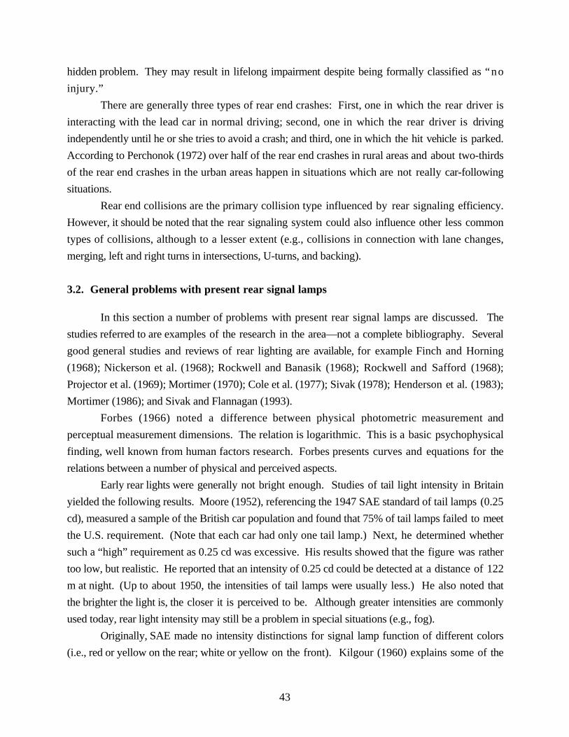
43
hidden problem. They may result in lifelong impairment despite being formally classified as “no
injury.”
There are generally three types of rear end crashes: First, one in which the rear driver is
interacting with the lead car in normal driving; second, one in which the rear driver is driving
independently until he or she tries to avoid a crash; and third, one in which the hit vehicle is parked.
According to Perchonok (1972) over half of the rear end crashes in rural areas and about two-thirds
of the rear end crashes in the urban areas happen in situations which are not really car-following
situations.
Rear end collisions are the primary collision type influenced by rear signaling efficiency.
However, it should be noted that the rear signaling system could also influence other less common
types of collisions, although to a lesser extent (e.g., collisions in connection with lane changes,
merging, left and right turns in intersections, U-turns, and backing).
3.2. General problems with present rear signal lamps
In this section a number of problems with present rear signal lamps are discussed. The
studies referred to are examples of the research in the area—not a complete bibliography. Several
good general studies and reviews of rear lighting are available, for example Finch and Horning
(1968); Nickerson et al. (1968); Rockwell and Banasik (1968); Rockwell and Safford (1968);
Projector et al. (1969); Mortimer (1970); Cole et al. (1977); Sivak (1978); Henderson et al. (1983);
Mortimer (1986); and Sivak and Flannagan (1993).
Forbes (1966) noted a difference between physical photometric measurement and
perceptual measurement dimensions. The relation is logarithmic. This is a basic psychophysical
finding, well known from human factors research. Forbes presents curves and equations for the
relations between a number of physical and perceived aspects.
Early rear lights were generally not bright enough. Studies of tail light intensity in Britain
yielded the following results. Moore (1952), referencing the 1947 SAE standard of tail lamps (0.25
cd), measured a sample of the British car population and found that 75% of tail lamps failed to meet
the U.S. requirement. (Note that each car had only one tail lamp.) Next, he determined whether
such a “high” requirement as 0.25 cd was excessive. His results showed that the figure was rather
too low, but realistic. He reported that an intensity of 0.25 cd could be detected at a distance of 122
m at night. (Up to about 1950, the intensities of tail lamps were usually less.) He also noted that
the brighter the light is, the closer it is perceived to be. Although greater intensities are commonly
used today, rear light intensity may still be a problem in special situations (e.g., fog).
Originally, SAE made no intensity distinctions for signal lamp function of different colors
(i.e., red or yellow on the rear; white or yellow on the front). Kilgour (1960) explains some of the

44
changes made from the early SAE standards. Tests in normal sunlight conditions of Michigan and
bright sunlight conditions of Arizona determined the intensity ratios for equal effectiveness of red,
yellow, and white. The candela intensity ratios for these colors were determined to be 1:3:5.
Some researchers believe that signal lighting luminances are at least as important as signal
light intensities (e.g., Cole et al., 1977, Schmidt-Clausen, 1985). Consequently, they argue that
luminance should be part of the regulations. Cole et al., for instance, proposed regulations
specifying minimum and maximum intensities, maximum luminances (e.g., 1,000 cd/m2 for tail
lamps and 30,000 cd/m2 for brake lamps), and minimum and maximum areas. However, the
majority of the experts seem to share the opinion that signal light intensity is dominant and that
signal light luminance, although of some importance, is secondary.
Flannagan et al. (1998) have explicitly studied this question. The concept of
multicompartment lamps is based on traditional lamp construction with a filament bulb in each
compartment. When the lamp area is increased by increasing the number of compartments, one
way not to lower luminance too much is to prescribe higher intensities for multicompartment lamps.
However, with new light sources (e.g., LED), the situation changes. Can the luminance or area
controls in the requirements now be completely eliminated, regulating lamps only in terms of
intensity? Flannagan et al. found that luminance has some influence and suggest that a standard
area of 225 cm2 be chosen as the basis for an area-dependent intensity requirement, in which
intensity values increased with area in the multiple of 225 cm2.
In the following paragraphs, the performance of rear lighting is examined in a general way.
Some negative aspects of the rear lighting functions are pointed out and commented on.
Rear lights have the same intensities during day and night, in good weather and
bad (a compromise intensity). The ECE Regulations 6 and 7 in fact allow one intensity or two
intensities (day and night) for brake and turn signals. Since ECE also has a rear fog lamp
regulation 38, all three functions have some provision for different intensities depending on ambient
conditions. However, as far as we know, no car manufacturer is using the two-level alternative for
brake and turn signals.
Several researchers and organizations have proposed intensities for two or even three-level
rear lighting systems. Because the various rear lighting functions interact in a complicated way,
such proposals have to consider at least all of the three main functions (tail, brake, and turn).
Several such proposals are presented in Table 14.

45
Table 14 Proposed photometric values for multilevel lamps (minimum/maximum, all values in cd).
Night Day Fog
(day and night)
Tail lamps
ECE R7 (1998)* 4/12 -- 150/300
AMA (1967) 3/12 --
Bol and Decker (1977) 8/18 -- 30/240
Mortimer (1977) 4/15 --
Brake lamps
ECE R7 (1998) 30/80 130/520
AMA (1967) 50/150 250/750
Bol and Decker (1977) 80/185 300/2400 300/2400
Mortimer (1977) 80/190 300/-
Fowkes & Storey (1993) 32 66 66
Turn Signals
ECE R6 (1998) 40/120 175/700
AMA (1967) 60/180 300/900
Bol and Decker (1977) 100/235 400/5800 460/5800
Mortimer (1977) 80/320 425/-
Lucas (RRL, 1963) 100 500
*The values for fog are from ECE R38 (1996) for rear fog lamps. Rear fog lampsare meant to provide the marking function of tail lamps in fog.
Pasta and Soardo (1979) suggested that low placement of a brake lamp with a vertical-
gradient light distribution produces good visibility at long distances even in daylight without the
problem of glare at short distances at night. They propose a specific light distribution and suggest
that two intensity levels are not necessary.
Rear light functions rely on an intensity difference that is often perceptually difficult
to detect. Researchers do not agree what constitutes an adequate intensity difference. For
instance, Rockwell and Safford (1966) found that when the ratio of brake light to tail light intensity
increased to 5.3:1, both reaction time and confusion risk were reduced. Above this ratio, little added
benefit was noted. Forbes (1966), however, received positive effects of ratios even up to 22.

46
Fisher and Cole (1974), studying intensity of traffic signals, found that red signals need not
be as bright as green and yellow signals. They recommended that the intensity ratios should be
1.33 for green to red signals, and 3 for yellow to red signals.
Rear light functions might not be sufficiently separated in space. However, the
suggested remedies differ. For example, Case et al. (1969) studied the effects of physical
separation of function (in space) and redundancy of mode—that is, more than one mode (e.g.,
intensity and pattern). They found that redundancy of mode resulted in a 30% improvement of
correct responses. Physical separation resulted in a 75% improvement of correct responses. On
the other hand, there was no effect of the specific pattern used as long as the two principles were
followed.
Mortimer (1969) studied the distance at which a separation between two red lights could be
detected. He found that lamp area was not a significant variable. The results show that the larger
the separation, the better the performance. He compared separations of 102, 152 and 204 mm in
nighttime situations. A separation of 152 mm was detected at a distance of 122 m. At a distance of
300 m, none of the separations were visible.
Helliar-Symons and Irving (1981) investigated how rear fog lamps influenced the visibility
of brake lamps in fog. They found that even a fairly small separation distance of 50 mm between
the fog and brake lamps improved the visibility of the brake lamps considerably. Akerboom et al.
(1993) reported that rear fog lamps introduced an ambiguity that led to false alarms and slow
reaction to brake lamps. A CHMSL reduced, but did not eliminate, these disadvantages. Fowkes
and Storey (1993) studied the effect of separation distance between tail lamps and brake lamps.
They proposed a minimum separation distance of 100 mm. They argued that with such a
separation, rear fog lamps, together with the tail lamps, do not seriously mask the brake signal.
Differences in color between the rear light functions might not be large enough.
The color of rear lights is a recurring theme. Opinions differ on the use of colors. In the 1920s
and 1930s, different colors (green, yellow, and red) were evaluated for use as signal lamps. After
various rounds, the choice of red dominated, save for the occasional use of yellow for rear turn
signals.
Rear lights are often seen in the visual periphery. Consequently, peripheral discrimination
of colors is relevant. In the periphery, color recognition declines (Lythgoe, 1931; Hunt, 1952;
Moreland and Cruz, 1959). Thus, color recognition is not a good basis for discrimination even for
persons with normal color vision. Sivak et al. (1999) found that color differences are insufficient to
discriminate between signals outside of center vision. They suggest that other coding parameters,
such as intensity difference or steady versus flashing signal, are more salient.

47
On the other hand, Mortimer (1970, 1977) suggested that a total color separation of
functions should be applied to all three major rear signal lamps. Tail or presence lamps should be
greenish-blue, turn signal lamps yellow, and brake lamps red. Nickerson et al. (1968) shared the
same opinion as Mortimer. Many U.S. passenger cars only have red rear signal lamps; European
vehicles must have yellow turn signals.
Rockwell and Safford (1968) made comparison tests between red and yellow tail lamps with
red brake lamps. The results indicate that a yellow tail lamp with a red brake lamp of equal intensity
is equivalent to a red tail lamp with a red brake lamp, with an intensity ratio of 1:5.
Safford et al. (1970) found that red is perceived to be further away than its objective
position, and blue is perceived to be closer. They suggested exploiting this difference by using
different colors in the rear signaling system. The effect, however, is comparatively small. Its use
must be weighed against the fact that the colors of the present system are well established.
Chandra et al. (1992) studied the effects of making brake lamps appear in the off state the
same color as the car body. They distinguished the effect of luminance contrast from chromaticity
contrast. Their results suggested that there is a small but significant increase in the effectiveness of
body colored brake lamps that provide chromaticity contrast as well.
For persons with defective color vision, such as so-called red-blind persons (protanopes)
and green-blind persons (deuteranopes), color cues are problematic. It is well known that in
artificial situations, where color is the only clue, color defective persons are error prone. However,
in real traffic situations, where there are redundant cues (e.g., lamp position), color defective persons
make few mistakes. Shirley et al. (1966) investigated the effect of color defective vision on
identification of flashing signals corresponding to turn signals. The colors used were red, yellow,
green, blue, and white. Their results show that color defective persons make more mistakes at lower
levels of signal intensity. They also make more mistakes in daylight compared to night (yellow is
confused with red, and white is confused with green). The most confused color is yellow followed
by white, green, red, and blue. From this specific point of view, blue is the preferred signal color!
Taylor and Ng (1981) studied accident data from insurance claim files to determine the
relative effectiveness of red and yellow rear turn signals. The background was that Europe and UN
ECE require yellow rear turn signals, while the U.S. and Canada allow both yellow and red. They
found no significant differences in rear end collisions, and consequently recommended no change
to the U.S. and Canadian regulations.
Rear lights frequently might produce an ambiguous outline of the vehicle at night.
Two red points could be a car, a truck, two motorcycles, or two cars partially obstructing each other.
Fisher and Hall (1978) investigated the effect of tail lights on the estimation of change of vehicle

48
headway. They found that when the rear surfaces of a vehicle are visible, as they are in daylight and
in most street lighting situations, tail lights have no influence on the estimation of headway.
Rear lights have a relatively short life time, and little redundancy. For instance, the
failure of one lamp may cause a false signal. Mortimer et al. (1974) surveyed the malfunctions of
rear lamps and conducted studies in a simulator to estimate the effects of such malfunctions. Their
conclusions were that about 4% of vehicles with single-compartment lamps had failure of a tail,
brake, or turn signal lamp on one side. This was less common on vehicles with multi-compartment
lamps. The results show that lamp failures lead to interpretation errors and elevated reaction times.
Furthermore, they found that many drivers did not use their turn signals. Huhn et al. (1997)
suggested using a redundancy pattern so that when one lamp fails, one of the other lamps
automatically substitutes.
Rear lights are exposed to heavy degradation. Rosig (1970) reported a survey
conducted in Germany between 1966 and 1969. In it, about 2.5% of the vehicles inspected had
some lighting deficiency. The report, however, did not distinguish between deficiencies in
headlamps and rear signal lamps. Cole et al. (1977) showed that signal malfunctioning in Australia
is 5.7% for tail lamps and 11.3% for brake lamps. However, there was no difference in malfunction
rate between areas with and without annual vehicle inspection.
A U.S. survey of the operation of rear lamps between 1979 and 1984 (Olson, 1985),
determined that about 2% of signal lamps were not working. Note that Rosig, as well as Cole and
Olson et al. merely checked whether the lamps were working, not how well they worked (e.g.,
photometric values were not measured).
Schmidt-Clausen (1985) performed static and dynamic tests to rate the luminances of brake
lamps and rear position lamps. He observed new lamps and also measured the intensity values of
rear lamps on cars in use. His results show that the older the car, the lower the intensity of the rear
lamps. The intensities of rear lamps in use were, on the average, half of the values required by the
regulations. Many of the rear lamps on cars older than five years did not meet the minimum values
prescribed in the appropriate ECE regulation (tail lamps: 4 cd; brake lamps: 40 cd, turn signals:
50 cd).
Cobb (1990) performed roadside surveys of vehicle lighting in Britain in 1989, including
rear signal lamps. He determined whether the lights worked, and recorded their intensities. He
found that a large proportion of the vehicles in traffic did not achieve the intensity values required in
the applicable ECE regulations. The worst situation was observed for rear fog lamps on heavy
vehicles. For passenger cars, the situation was as follows:

49
• 16% of rear position lamps did not reach the minimum required intensity of 4 cd
• 24% of rear turn signals did not reach the minimum required intensity of 50 cd
• 46% of brake lamps did not reach the minimum required intensity of 40 cd
• 54% of rear fog lamps did not reach the minimum required intensity of 150 cd
The main causes of the low values were dirt, cracked lenses, poor reflector condition,
condensation, and blown bulbs. There is no reason to think that the situation in Britain is any
different than the rest of Europe. No corresponding surveys appear to have been conducted in the
U.S.
Sivak et al. (1997) studied the effects of realistic levels of dirt on the light output of rear
lamps. A route of almost 500 km was driven in three conditions (dry, wet, and snowy/salty),
equivalent to approximately ten days of normal driving for a typical U.S. driver. The results show a
decrease in light output throughout the beam pattern. Driver-side lamps collected slightly more dirt
than the passenger side. In dry conditions, the reductions were all lower than 8%; in wet and
snowy/salty conditions some values were reduced by more than 25%. Greatest reductions occurred
in the central area of the light distribution (near the optical axis).
Rockwell and Safford (1968) studied the intensity ratio of brake lamps to tail lamps of cars
in traffic in Ohio. They found that about 15% of the cars tested had ratios below the legal
minimum 5:1. This leads to significantly reduced response times. The proportion of cars having
this defect increased with the age of the car.
Regulatory requirements on rear lamps are not internationally harmonized (see
Section 2.11). This adds cost for producers and consumers and likely adds to road user confusion
in international traffic.
When drivers have a choice, they often do not use signal lamps properly. Drivers
often fail to use turn signals and rear fog lamps, and when used, they often forget to turn them off.
3.3. Special problems with specific rear signal functions
In the following paragraphs the performance of rear lighting systems is evaluated using the
list of rear lighting functions presented in Section 1.3.2.
3.3.1. Vehicle presence (conspicuity)
There is little difficulty detecting vehicle presence except in reduced visibility conditions
(such as fog, heavy snow, smoke, or dust). Finch and Horning (1968) and Mortimer (1977)
addressed the issue of the optimal color for rear fog lamps. They concluded that in day fog, red is
most visible, while in night fog, greenish-blue and red are most visible. The degree of fog

50
penetration is determined primarily by intensity. Rear fog lamps should have a considerably higher
intensity because lamp visibility is exponentially related to lamp intensity. Finch and Horning
(1968) suggested that rear fog lamps should be at least 100 times more intense than normal rear
lamps (about 500 cd). Moore and Smith (1966) found improvements in fog visibility increased
with substantially increased lamp intensity. For example, visibility from 30 m at 2 cd, to 73 m at
5000 cd.
Lythgoe’s (1973) research suggested that visibility of rear lights in fog is determined not
only by intensity, but also by area. However, he apparently did not vary intensity and area
independently, making interpretation unclear.
Lancashire (1978) analyzed rear end crashes in Australia, and the use of rear fog lamps as a
countermeasure. His analyses showed that rear end crashes in fog are rare and that rear fog lamps
are expensive. He suggested that rear fog lamps are not cost effective, and consequently should not
be compulsory.
3.3.2. Indication of vehicle width
When vehicles were equipped with only one tail lamp, they provided no cue to their width.
Currently, this is mainly a concern for heavy-duty vehicles and cycles, but passenger cars with
only one functional tail lamp, or a single rear fog lamp in fog, are also subject to this problem.
3.3.3. Indication of class of vehicle
At night, the rear lighting system can be an ambiguous source of information about a
vehicle’s class. If the rear lighting system is fully functional, these problems mainly concern
vehicles other than passenger cars. Typical problems of early identification occur with very long,
slow moving, or very wide vehicles, and in discriminating two-wheelers from “one-eyed” cars, and
mopeds from motorcycles.
3.3.4. Indication of distance to the vehicle
At night, one cue to a vehicle’s distance is the separation between the tail lamps. Many
researchers have suggested standardization of this separation. In daylight, drivers are reasonably
skilled in detecting and estimating forward headway. There, the angular size of the rear of the
vehicle and the road area between the lead and following vehicles provide the main distance cues.
Mortimer estimated the Weber fraction for distance estimation between cars to be 0.12. This means
that if the headway is 100 m, a change of less than 12 m cannot be detected.

51
3.3.5. Indication of rate of closure to the vehicle
Many researchers consider this variable to be critical in a driver’s ability to avoid rear end
crashes. The relative velocity or rate of closure is difficult to estimate at long distances. The rate of
change of the visual angle of an automobile does not change substantially until the distance is less
than about 100 m. For shorter distances, the estimation of rate of closure improves (Mortimer
1997).
In an extensive field test, Parker et al. (1964) evaluated how drivers used three visual cues
for estimating approach speed to a lead car ahead at night. The three cues were visual angle
between the tail lamps, change in brightness of rear lamps, and change in perceived area of rear
lamps. Tests were run at speeds of 32, 48, and 64 km/h. The results show that the three tested
factors together give much more accurate results than any factor alone. Visual angle proved to be
slightly superior to brightness, and both were superior to area. The approach speed had no
influence on the effectiveness of any of the cues.
Reilly et al. (1965) similarly studied the relative importance of these three visual cues, as a
driver approaches a lead vehicle at night. Their results showed that a driver uses the angular velocity
information from the lead vehicle’s two rear lamps, and weighs this information together with his
own speed. If the angular separation is distorted (e.g., because of an unusually small distance
between rear lights), the driver relies more on change of brightness or apparent size. If the
distortion is great, the driver may be incapable of compensating for this, making a closure
estimation that is worse than if there were only one rear lamp.
Janssen et al. (1976) investigated the effect of various factors on the movement threshold of
a lead car in a series of laboratory and field experiments at night. They found that the relative
horizontal angular separation of the lead vehicle’s tail lamps is the primary cue for estimating
relative vehicle speed. They recommended that the separation between tail lamps be standardized
and set as large as possible.
Mortimer (1990) took the analysis one step further. He found that on large distances
drivers make judgements of closure to the vehicle ahead of them based on changes in the visual
angle. They can detect distance changes as small as 0.12 (Weber ratio) (see Section 3.3.4).
However, from vehicle distances of about 130 m or less (dependent on the relative velocity) the
importance of rate of change of visual angle gradually increases, and drivers can also give an
accurate estimation of the rate of closure. In other words, the driver can detect a closure at large
distances, but does not get good information on the rate of closure until the vehicle ahead is fairly
close.

52
3.3.6. Indication of driver intention to brake
The present system provides no prior warning that the brakes will be applied. Several
proposals have been presented that offer such information (see Section 4.3).
3.3.7. Indication of the fact that the vehicle is braking (slowing down)
The first problem is to detect brake initiation. In very bright sunlight or extreme glare
conditions, the signal is often difficult to detect.
The effect of intensity, area, and aspect ratio on reaction times to brake lamps was studied
by Sayer et al. (1996). There is heightened interest in this, as new light sources (e.g., LED) are
integrated into the body design (e.g., CHMSLs). Some designs result in very long and narrow
signal lights. How does intensity and aspect ratio affect reaction time? The results show that both
intensity, and aspect ratio, and their interaction influence reaction time. A combination of a low
intensity and a large aspect ratio produces the longest reaction times, and should be avoided.
Brake signals are sometimes masked by other signals. When the brake signal and turn
signal are the same color, detection of the brake lamp onset is more difficult. Luoma et al. (1995)
concluded that yellow turn signals produced shorter reaction times to the onset of brake lamps than
did red turn signals. The difference was in the order of 110 ms.
Brake signals are often confused with rear fog lamps. Helliar-Symons and Irving (1981)
found that increasing the separation between the brake and rear fog lamps to 50 mm improved
detection of the brake signal. Further improvement at larger separations was limited; nevertheless,
they recommended a separation of 100 mm.
The CHMSL was developed to improve detection of the brake signal by separating it from
the other rear signals, and positioning it centrally in the visual field of the following driver to make it
visible through other vehicles. Crosley and Allen (1966) conducted a study of reaction times with
cars equipped with normal and high-mounted brake/tail lamps. In their study, the drivers of the
third and fourth cars always reacted quicker when the higher mounted brake/tail lamps were used.
The authors recommended that the supplementary brake lamps be mounted high, but tail lamps and
regular brake lamps continue to be positioned at their normal mounting height.
Initial accident studies of the effect of CHMSLs in the beginning of the 1980s found an
amazing crash reduction effect of about 50%. However, these effects gradually diminished and a
recent long-term study (Kahane and Hertz, 1998) suggests a more modest rear end crash reduction
of 4.3% with CHMSLs. Nevertheless CHMSLs appear to remain a cost effective crash reduction
measure.

53
3.3.8. Indicating braking force or deceleration of the driver/vehicle
The following driver first needs to detect the brake signal, and then needs to decide which
level of deceleration to apply to avoid crashing into the lead car. To do this, the driver needs to
judge that car’s deceleration. Presently, the same rear light signal is produced whether the brakes
are lightly touched or heavily stomped on. Drivers are provided little assistance from the brake
lights, but several proposals have been made to convey this information (see Section 4.3.).
3.3.9. Indication that the driver has the intention to stop the vehicle
The number of rear end crashes occurring when the lead car is stationary suggests that it
may be important to know the lead driver’s intention to stop. Present rear signaling systems
provide no assistance with this, but several proposals have been suggested and evaluated (e.g.,
Olson, 1989; Shinar, 1995) (see Section 4.3.).
3.3.10. Indication that the vehicle is stopped
This is related to the previous problem. Present rear signaling systems offer little
assistance, and are sometimes even misleading. For example, vehicles equipped with manual
transmissions may be stopped without any brake lights on. Some proposals have been made (see
Section 4.3.).
3.3.11. Indication of driver intention to change forward directions
Here, failure to use turn signals is the main problem. Mortimer and Domas (1974) found
that in urban areas, drivers signaled their intention to turn right only about 50% of the time. Left
turns were signaled about 75% of the time. Failure to use turn signals is also frequently observed
when changing lanes on freeways.
Fricker and Larsen (1989) argue that, like the use of seat belts, the use of turn signals is a
personal choice of the driver and must be enforced to be effective. They suspect that a common
personality trait is shared by drivers who fail to use seat belts and who do not use turn signals, and
their studies support this hypothesis. Technical solutions are needed to prevent such negligence in
both cases.
In certain situations, masking of the turn signals may occur naturally. Sivak et al. (1998)
found that sun loading on clear-lens turn signals can reduce the effectiveness of turn signals.
Gibbs conducted two studies of turn signals. In the first one (Gibbs et al., 1952), he
compared the British semaphore arm with the U.S. flashing lights. The number of missed signals,

54
reaction time to the signal, and the ease with which the signal was comprehended were measured
both in day and night conditions. The possible interaction with brake lamps was also investigated.
The results showed that flashing lights were seen at larger distances than the semaphore
arm, especially in adverse weather conditions. On the other hand, the semaphore arm produced
shorter reaction times at night, and was less influenced by headlight glare. At shorter distances and
in good conditions, the two systems produced comparable results.
In the second study (Gibbs et al., 1955), the effects of flash frequency and flash duration
were measured. They found that higher frequencies and brief light durations produced shorter
reaction times. Probably as a consequence of the lamps used at that time, they recommended
frequencies of 60-120 flashes per minute and an on time to allow the lamp to reach full intensity
(about 170 ms). (Some incandescent lamps do not reach their full intensity until about 250 ms after
being energized [Flannagan and Sivak, 1988].)
Post (1976) studied the performance requirements for turn and hazard warning lights. His
conclusion was that the present standard of 1-2 Hz could be improved if it was increased to 1-3 Hz,
because the higher frequencies increase the salience of turn and hazard signals. However, medical
studies indicate that for small children, frequencies as low as 3 Hz may trigger epileptic reactions
(RRL, 1963). For adults, higher frequencies are needed to trigger epileptic reactions.
Luber and van Elslande (1991) studied the interpretation of turn signals. Their conclusion
was that all signals, including turn signals, are interpreted with respect to other circumstances, in
particular, the behavior of the other driver. For instance, a driver’s speed, changes in speed, position
on the road, or change in position independently signal something about the driver’s intention. The
signal light itself is only one of many cues used.
3.3.12. Indication that the vehicle is changing forward direction (left or right)
During the day, this is less important than the signaling of the intention because in daylight
direction is easy to detect. At night this information may be very important. The rear lighting
variables are the same as mentioned under Section 3.3.11.
3.3.13. Indication that the vehicle is changing main direction (rearwards)
A back up lamp is one of the vehicle lamps that has a double function. It both illuminates
the road for the backing driver, and it signals to other drivers that the car is backing up. Back up
lamps work as signals at night but do not offer sufficient illumination. In bright daylight, they are
inadequate as signals. No formal studies on back up lamps have been found.

55
3.3.14. Indication that the vehicle is parked
Prior to World War II, parking lamps were considered very important, but in more recent
times, they have become less so. Nevertheless, collisions with parked cars at night continue to be a
problem. Presently there are no differences between tail lamps and parking lamps. At night, there
is no difference between the rear of a parked car with lights on and a car that is just temporarily
stopped. Should there be a difference? The practice of illuminating parked vehicles may have been
discontinued because of the energy consumption of parking lights. Modern solutions can
substantially reduce energy consumption, eliminating this problem. No formal studies of this
problem have been found.
3.3.15. Indication of hazard and/or warning (stopped or moving vehicle)
This function is often misused. Hazard lights also interact with turn and brake lights.
Mortimer (1989) pointed out that the interactions between the hazard warning light on one hand,
and the turn and brake signals on the other hand have not been analyzed or regulated optimally.
This is an example of how new signals are added to the existing signals with not enough regard for
the consequences to the overall system. The possible interactions have not been sufficiently
analyzed.
3.3.16. Illumination of the license plate
In the early years of rear lighting development, this function was considered very important.
License plate illumination was developed at the same time as tail lamps, long before brake lamps
and turn signals. Today, it is difficult to understand why this lamp was considered so important.
The few studies of license plate legibility suggest that the illumination is less effective than required.
It is a difficult task for the lighting engineer to illuminate the whole license plate adequately at a very
large angle (almost parallel to the surface) and it causes large problems for lighting designers. At
night, when illuminated from a light source close to the observer (e.g., headlamps on another
vehicle), retroreflective license plates are normally more legible than when illuminated by a license
plate lamp. Exposure to dirt and other forms of degradation of the license plate lamp further
impairs its efficiency. Furthermore, it shows white light to the rear, thereby violating one of the
conventional rules of vehicle lighting. A radical solution might be to eliminate this lighting
requirement. Few would miss it!

56

57
4. Discussion: Main Problems and Potential Countermeasures
4.1. General considerations
The ultimate purpose of rear signal lamps is to prevent crashes, primarily rear end crashes
but also other relevant types of crashes. These types of crashes are a large and well-recognized
traffic safety problem. Consequently, this report focuses on how the rear lamps could mitigate such
crashes. To do this, we apply a human factors analysis of the driving task and ask how it may be
facilitated or supported by new technological developments and solutions. However, before we
discuss how the rear lighting system could be improved, let us look at the problem more generally.
When the interaction between an operator and a machine is not optimal, as is the case with
rear lighting, there are four complementary solutions that can be applied:
(1) Only permit expertly trained operators access to the equipment.
(2) Only use equipment that is easy to interact with.
(3) Modify the equipment design to match the competence of the operator (traditionally the task
of the human factors specialist).
(4) Train the operator to adapt to the constraints of the equipment.
Of these four alternatives, the first one (of using expert drivers only) is not practical or
politically acceptable. The driving population would be as small as the airplane pilot population.
Present society depends on the mobility of its population provided by the automobile.
The second alternative (only use equipment that is easy to interact with) is practiced to some
extent today. However, opinions vary about ease of use, and the present regulations and standards
were largely developed without sufficient regard for human factors. One of the reasons is that
regulations and standards are almost by definition obsolete by the time they come into effect.
Before we get regulations, research results must be accepted, implemented, and tested on a wide
scale. The technology must be accepted by almost all manufacturers. Then comes a lengthy
compromise discussion before an agreement is reached. Finally the administrative process and the
lead time is time consuming. The history of rear lighting cited earlier illustrates this. Problems are
also complex. Often conflicting motives or contradictory research results slow progress. Finally,
long-accepted practices are resistant to change.
The third alternative is the approach taken in this report. It is a direct and systematic way of
understanding how the human operator, the driver, functions with the car as a system, and it leads to
steady improvements in design.
The fourth alternative, use of training, has rarely been discussed. Summala (1998) studied
learning of peripheral detection of braking and closing headways. He found no learning effects in
the periphery, but left open the possibility of effects in central vision. Drivers appear to have limited

58
success estimating distance, closure rate, and speed change of the car ahead. The extent to which
these skills are trainable is unknown. Admittedly, training is not a practical solution for the entire
problem of rear end crashes, but it would be of some value to understand more about the limits of
acquiring such skills.
4.2. Driver tasks
Lee (1976; 1978) analyzed rear end crashes from a perceptual point of view. First he
asserted that driving is predictive. A driver plans what to do next. The driver is attuned to the
dynamics of the “optic array” as he drives. Responses are largely automatic. Lee divides the task
of approaching a slower moving, stopping, or stationary vehicle into three consecutive parts:
detection of closing in, initiation of braking, and regulation of braking force to avoid collision.
The temporal pattern of braking appears crucial. If the braking force is insufficient at the
beginning, difficulty escalates. A general recommendation would be to brake hard initially, and
adjust the braking force afterwards.
The task of detecting closing in on a forward vehicle, and the task of deciding to brake are
performed using visual closure information. Good rear signal lights can be of assistance here.
Present brake lamps help support the first task, but not the second one.
Time to collision (TTC) is likely used by drivers to assess the urgency of action. It
indicates both the degree of need to start braking and the magnitude of force necessary to avoid a
collision. The driver receives feedback about the adequacy of braking from the rate of change of
TTC. TTC is also a key measure in car-following behavior at near distances. At greater distances,
it appears to be more of a conscious process involving estimation of distance and speed. Thus,
behavioral processes in car following can be seen, in different circumstances, as automatic or
controlled (see Section 1.1.).
Fancher et al. (1998) found that on limited-access roads with small speed differences and
low probabilities of sudden stops, drivers tend to drive with fairly constant headways independent
of speed. They found that for speeds greater than 80 km/h, the typical headways on U.S. freeways
are just below 30 m, which is amazingly short. The variability increases and the probability for
longer headways increases with higher speeds.
Most official driver instructions and recommendations suggest drivers maintain a time gap
(time headway) of 2 to 3 s to the car ahead. However, a simple analysis shows that the minimum
time gap that a driver needs for reaction time and braking time varies both with his speed and the
speed of the car ahead. That is to say, if drivers tend to use a headway independent of speed (which
studies indicate that they do), they will have to brake very hard or they will be in trouble when
driving at higher speeds or when the car ahead is stationary or moving very slowly. Data from

59
Fancher et al. (1998) indicate that at speeds over about 90 km/h the range of time gaps is very
large—from about 0.3 s to more than 3 s. However, the most likely time gap at those speeds was
0.8 s.
A time gap of 5 s would be safe for driving at high speeds, encountering a stationary or very
slow moving vehicle ahead, or in bad visibility conditions. Studies show that in real traffic, few
drivers maintain such a gap. A British study (cited by Lee, 1978) found that 11% of drivers
traveled at headways less than 0.5 s! Fancher et al. (1998) found that more than 10% of time gaps
in the U.S. are less than 0.65 s.
The faster the closing velocity, the greater the risk, because the driver has less time to detect
and react to the threat of collision. At the same time, a longer braking distance is required (Lee,
1978). Collision risk is also greater the narrower the visible width of the forward vehicle (see also
Janssen et al. 1976), because of the difficulty to estimate closure rate. This has implications for the
lateral separation of tail and brake lamps.
Lee suggests that the rear of the car including the lamps should be designed so that drivers
following another car at night have a stimulus situation comparable to the daylight situation.
According to Lee, the brake signal system should include an imperative signal, which is initiated
when a following driver must brake— i.e., when the car ahead has stopped.
Liebermann et al. (1995) conducted field studies of braking responses to emergency
braking. Their conclusions are slightly different from those of Lee. They suggest that braking
responses are both automatic and controlled. The presence of brake lamps increases the speed of
the braking response. Subjects reacted to the onset of the brake lamps with a “ballistic” braking
response. On the other hand, they agree with Lee that the modulation of the braking response is
influenced by the optic expansion of the leading vehicle. Consequently, braking responses were
faster at short headways.
Ohta (1993) studied the car-following behavior and classified drivers into three groups:
(1) Drivers who attempt to maintain a constant time headway.
(2) Drivers who attempt to maintain a constant distance headway.
(3) Drivers who change their headway depending on the circumstances.
Perhaps, these driver traits can be influenced by changes in vehicle rear lighting. The three
groups would probably be influenced to a different degree by training.
Fancher et al. (1998) concluded that the drivers could be divided into five groups:
(1) Ultraconservative (tendency to drive unusually slow and/or with long headways);
older and female drivers are overrepresented in this category.
(2) Planner (unusual tendency to drive fast and/or with long headways); male and
younger drivers are overrepresented.

60
(3) Hunter/tailgater (unusual tendency to drive fast and/or with short headways);
younger drivers are overrepresented.
(4) Extremist (changes between two of the earlier strategies); the smallest group, fairly
equally distributed over age and sex.
(5) Flow conformist (drives as the other drivers in the traffic flow); the largest group,
middle aged drivers overrepresented.
Cavallo (1993) agrees with Liebermann et al. in that the improvement of the brake lamps has
been excessively driven by the concern to improve detection and reduce reaction time. This view
regards the driver as data driven, not a thinking, predictive operator. Cavallo suggests that even if
detection is improved and reaction times reduced, if the driver does not improve basic car-following
behavior (e.g., by increasing the following distances), there will be little change in safety. Safety
improvements can easily be erased by driver compensation or adaptation.
Cavallo argues that studies have shown (e.g., Sivak et al., 1981) that drivers do not brake in
slavish response to the brake lamps of the car in front of them. Rather, they regard brake lamps as
a warning signal. Drivers often assume that the lead vehicle’s braking is moderate and does not
require immediate action. While she agrees that early detection is important, she suggests that it is
neither the only variable, nor even the most important variable. Cavallo fears that introduction of an
advanced warning brake system, for example, that produces false alarms, could adversely affect
safety.
For Cavallo, the most important factor to improve safety is to alert the following driver to the
unexpected, namely, an extreme slow down or stop of the lead vehicle. As an example, Cavallo
mentions the fact that some drivers use hazard warning lights or pump their brakes to provide added
warning. Should this be recommended and taught? Cavallo’s main conclusion is that many
psychological considerations should significantly influence the design of rear lighting systems, and
that to date excessive emphasis has been placed on visual considerations.
Colbourne et al. (1978) found that British drivers tend to adopt a headway of approximately
2 s, regardless of speed, driving experience, and instruction. The headways are too short for high
speeds, and too long for low speeds.
Evans and Wasielewski (1982) have shown a significant correlation between driving with
very short headways (< 1 s) and involvement in crashes and violations. One interpretation is that
these drivers have a trait that makes them more vulnerable to crashes. Whether this trait difference
is central and cognitive, or peripheral and visual, or both, is unclear.
Van der Horst (1990) tested the hypothesis that TTC is directly used to estimate the degree
of risk in a traffic situation, as well as the hypothesis that estimated TTC is based on the optical
flow pattern predicted by Lee (1976; 1978). He found that TTC at the onset of braking increases

61
with speed but not as much as it should in order to keep safety constant. When Van der Horst
eliminated the optical flow, he found support for the optical flow being used for estimating TTC.
Cavallo et al. (1998) observed car-following behavior in situations with varying degrees of
stimulus richness. They found that the more degraded the stimulus situation, the greater the
probability of a driver estimation error. This is likely the reason why car following is more difficult
in fog and darkness.
4.3. Proposals for improved rear lighting signals
Five U.S. studies performed in the late 1960s (Nickerson et al., 1968; Rockwell and
Banasik, 1968; Finch and Horning, 1968; Case et al., 1968, Projector et al., 1969) proposed
improvements for rear lighting systems prevalent at that time. One proposal, called a V-bar,
involved the use of a large number of lamps to indicate the speed of the car. Another proposal,
called AC, used colored lights to indicate the acceleration of the car. A third one presented a
distinctive pattern in the rear to signify panic braking, a slow moving vehicle, and a stopped vehicle.
A fourth proposal used an array of lamps that changed in number and size to indicate speed
changes. None of these alternative designs have been sufficiently tested. However, many of these
ideas have been championed by later researchers.
Safford et al. (1970) describes several rear lighting studies. They attempt to determine how
to select alternative systems, but without success.
Bol and Decker (1971) suggested several rear lighting improvements to permit better
differentiation of the movements of the forward vehicle, including other colors for tail lamps,
progressive brake lamps, cleaning systems, and intensity adjustments based on ambient illumination
and atmospheric visibility conditions.
Horowitz (1994) characterizes possible improvements of rear signaling systems using five
different scenarios, based on accident statistics and human factors considerations. For each
scenario, he proposes the use of a particular signal. The scenarios and the proposed signals are
listed in Table 15.

62
Table 15 Suggested improvements by Horowitz (1994) to rear signaling in five scenarios.
Number Scenario Signal
1 Braking at low speeds or stopped. A red flashing signal for stopped or stoppingvehicle located in or near the current CHMSL.
2 Deceleration with no braking. A yellow or red signal for one second.
3 Sudden accelerator release. A standard brake signal for one second.
4 Antilock braking system activation. Flashing CHMSL.
5 Braking at any speed. Improved signal rise time (LED, neon, or fastincandescent) or increased lamp intensity/area.
Jolliffe et al. (1971) argued that the speed of the lead car affects the estimation of closure
rate. They noted that drivers infer speed of the lead car using several cues. They suggest the use of
a special speed indicator rear light that would simplify the task. To test this hypotheses, they
constructed an indicator containing 14 yellow rear lamps in a row. The number of illuminated
lamps was directly related to speed. Drivers were asked to estimate closure rate and lead vehicle
speed. They report that the speed indicator produces significant overestimation of speed. An
important question here is whether speed of the lead car is really an important variable in estimation
of closure rate.
Irving and Rutley (1972) tested two driver aids in car following. One was a multilevel brake
light, in which a ramp of lamps becomes progressively illuminated as deceleration increases. The
second one was a simple head-up display using two vertical lines to indicate the suitable width of a
standard car ahead. The separation between the lines varied with the speed of the car so time
headway gap was constant. (If the car ahead was wider than the lines, one was following too
closely.) Rutley and Mace (1969) found no significant improvement in following behavior with the
first aid.
Several researchers have suggested the use of a signal to indicate sharp decelerations (e.g., a
variable flashing CHMSL). Although one study supported this concept (Voevodsky, 1974), most
studies have concluded that such a device has no or little value (Mortimer and Sturgis, 1974; Rutley
and Mace, 1969; Rockwell and Treiterer, 1966; Mortimer, 1981). Goldberg (1997) proposed
CHMSL flashes if the deceleration exceeds a threshold, but no relevant empirical data is yet
available.
Mortimer and Sturgis (1976) studied the effect of a rear signal that is green when the
accelerator is depressed, yellow when it is released, and red when the brake pedal is depressed. The

63
system was added to a normal rear lighting system. The effects on the behavior of the following
driver were only minor, and thus this concept was abandoned.
Mortimer (1971) studied deceleration in the absence of braking signals, when the foot is
simply lifted off the accelerator. His results show that the deceleration levels were moderate (0.3-1
m/s2). He further showed that in most coasting cases, the brakes were never applied. Coasting is
usually of a very short duration, and if signaled, should be limited to coasting that exceeds 5 s.
Additionally, signaling might be restricted to situations in which the foot is abruptly released from
the accelerator.
In a field study of an advanced brake light device (ABLD) triggered by rapid accelerator
release, Olson (1989) found that the system produced a highly reliable brake signal following the
quick release of the accelerator with few false triggerings of the brake signal. With this device,
brake signals can appear 0.2-0.3 s sooner than they do with conventional systems. Olson also
estimated the potential crash reduction benefits of an ABLD system. Unfortunately he based this
estimation on the comparison with early estimates of the CHMSL effect. Now, with more accurate
measures of the crash reduction effect of CHMSL (4.3%), the corresponding estimate of the effect
of ABLD is about a 2% reduction in rear end crashes.
Shinar et al. (1997) also studied similar early warning braking systems in which the brake
lamps are illuminated for 1 s upon release of the accelerator faster than 0.3 m/s. This reduced the
lag in the onset of the brake lights by the movement time of the driver’s foot. Like Olson, Shinar
(1995) found few false triggerings of the brake signal. In a second study, a simulator was used to
mimic the basic characteristics of U.S. highway driving (speeds, headways, road conditions, etc.), so
that performance of the system could be evaluated. This specific warning system was found to be
most efficient on dry roads when headways were 1 s or less (which is quite common). No
differences were found as a function of speed.
In the mid-1970s, LEDs produced only about 1% of the intensity of current units.
Nevertheless, lighting engineers hoped to use LEDs in the future because of their long life, fast rise
time, low energy consumption, and low thermal properties. LEDs provide uniform luminance and
permit flat lamp designs. LED brake lamps first appeared in 1992 in Europe. From the mid-1990s,
neon tubes were also introduced in brake lamp applications.
Decker (1999) compared the various light sources now available for rear signaling lamps
along several dimensions. LEDs and neon light sources now bid to supercede conventional bulbs
in the signal lighting arena. In the future, electroluminescent foils and polymer LEDs may also
enter the competition. The market competition has also resulted in many improvements in the
performance of conventional bulbs.

64
Presently, the conventional bulbs are superior in terms of light output for all colors. LEDs
are superior in service life and in light efficacy, except for white. Neon light sources, lacking the
capability to produce white light, provide illumination uniformity and design versatility.
Masuelli (1995) described present trends in rear lighting. She identified new possibilities
afforded by the new light sources, from a design viewpoint.
Sivak et al. (1993) studied reaction time for different types of brake lamps. They found that
the reaction time to LED and neon brake lamps averaged 166 ms faster than to conventional brake
lamps. A special fast rise incandescent lamp (Flannagan and Sivak, 1988) produced reaction time
135 ms shorter than a conventional incandescent brake lamp. A reduction of the luminous intensity
of the conventional lamp from 42 cd to 5 cd resulted in an 84 ms increase in reaction time.
Morrison et al. (1986) found that changing the height of the brake pedal, relative to the
accelerator pedal, can reduce the foot movement time by 0.25 s. Gustafsson (1993) proposed to
combine the accelerator and brake into one pedal. Toe motion controls the gas, while movements of
the foot control the brake. This uses a natural startle response (withdrawing the foot, thereby
raising it) for the brake reaction. Furthermore, the foot is always on the pedal. Gustafsson argues
that this design can avoid many unintended depressions of the accelerator.
Muth (1999) has designed a supplementary turn signal that is mounted in the side rearview
mirrors and visible to the drivers behind.
Finsterer (1995) showed that the hazard warning lights are more readily recognizable if a
double pulse system is used instead of the present single pulse. He proposed two pulses of about
170 ms, each separated by an interval of 60 ms. The flashing frequency could vary between 60 and
90 double flashes per minute. Huhn et al. (1997) share this opinion. They note the ambiguity
between turn signals and the hazard warning lights because they share the same flash frequency. If
one of the two hazard warning lamps is obstructed, it is not possible to distinguish a turn signal
from a hazard warning light. Like Finsterer, Huhn et al. suggests that the hazard flashing pattern
should be changed to a double flash with a short break.
In the late 1990s, a new concept to increase heavy-truck visibility and identification was
introduced: contour marking by means of glass fibers with a central light source (Hella, 1999).
Contour marking of heavy trucks by means of retroreflective material has proven effective to reduce
night time collisions (Schmidt-Clausen and Finsterer, 1989). It is possible that contour marking of
passenger cars would assist in driver estimation of vehicle nighttime distance and motion.

65
4.4. Ideal and real world situations
At the conclusion of Section 1.3.2., an effort was made to introduce a number of rear
lighting issues which deserve additional attention. These issues represent normal road traffic
situations that are often not covered by regulations and standards. But normal traffic situations are
the situations in which crashes occur. Let us examine how well the present rear lighting system
handles these issues.
The balance between adequate daylight visibility and excessive nighttime glare has been
largely ignored in present day rear lighting. The ECE regulations permit two intensity levels: one
for daylight and one for nighttime. To our knowledge, however, no car manufacturers utilize this
option. In the U.S., only one level is specified.
Rear light visibility under reduced visibility conditions, like thick fog or heavy snowfall, is
of serious concern. Rear fog lamps, first introduced in the 1960s, attempted to meet this demand.
However, we often see cases of one rear fog lamp, reminiscent of the 1940s in U.S., and the 1950s
in Europe, when one tail lamp was considered sufficient. No other signal lights (brake, turn, or
license) have separate performance requirements for situations with seriously reduced visibility.
Simple car-following situations are rare, because on most roads cars follow each other in
long rows. Only CHMSLs attempt to deal with this issue.
Automobile lighting systems have become sensitive optical systems. Rear lamps are
exposed to conditions that severely reduce their optical performance. Many rear lamps in actual
traffic do not meet the lighting requirements prescribed for them.
Not all road users have perfect vision. Of the male population about 8% suffer from
deficient color vision. Furthermore, a significant number of drivers do not have the same vision on
the road as when they passed their driver license test. Additionally, the proportion of older drivers
with reduced visual capabilities continues to increase (Rumar, 1998). Finally, road users who are
not motorists but do participate in traffic, have no visual requirements. There is little evidence that
rear signaling development addresses these and related issues.
4.5. Concluding comments
Today’s signal lamps are less than optimal, and several design characteristics could be
modified to improve driver detection and understanding of their messages. Despite this, it is
difficult to satisfy all constraints with a single solution. The research examples and analyses
provided characterize both the potential for improvement and the problems that arise in
implementation. Rear lamps interact with driving in a complicated way. Proposed changes have to
be well justified and supported, because there is much resistance to change in an established
system.

66
During development, a number of factors and limitations have moved the development of
rear signaling in specific directions. At times the best solutions were not acceptable or available.
Limits on energy availability, light output, optical characteristics, technical factors, or cost precluded
their use.
Once a specific system is introduced and widely available, it is difficult and perhaps even
dangerous to change it substantially. Often a stable solution is preferred to a technically superior
solution.
What should be done? Within the constraints of present technology the following
modifications have been proposed by others, and they should be included in discussions of future
improvements:
(1) Use of two (or more) levels of intensity of rear lamps: one each for daytime,
nighttime, and possibly for low visibility conditions (e.g., fog).
(2) Use of redundancy in encoding messages.
(3) Differentiation between lamps signaling braking and being stopped.
(4) International harmonization of regulations.
(5) Elimination of license plate lamps.
(6) Signaling vehicle type.
(7) Reducing failure rates of lamps.
(8) Redesigning the lamps to reduce the exposure to dirt, corrosion, and damage.
(9) Eliminating driver misuse of rear lamps, especially of turn signals and hazard
warning lamps.
Proper car-following behavior should be taught in driver training. Some problems with rear
end crashes might be reduced by training.
Modern information technology applications in road traffic—intelligent transportation
systems (ITS)—offer new and yet unexplored possibilities to enhance communication between
drivers following each other. Those possibilities were not explored here.
Rear end and other relevant crashes constitute a substantial part of vehicle collisions today.
They often cause neck injuries. Such injuries often fail to be reported in official crash statistics, but
nevertheless cause lifelong impairment and suffering. (It has been estimated that about 25% of all
the road crash permanent injuries are caused by rear end crashes.) Improved rear lighting systems
would likely reduce rear end crashes and these injuries.

67
5. References
Akerboom, S.P., Kruysse, H.W., and La Heij, W. (1993). Rear light configurations: The removal
of ambiguity by a third brake light. In Gale, A.G. (Ed.), Vision in Vehicles IV (pp. 129-
138). Amsterdam, The Netherlands: North Holland.
Automobile Manufacturers Association (1967). Status report on Vehicle Lighting Committee
program to evaluate various rear lighting systems and signalling color. Detroit:
Author.
Bol, J. and Decker, H-J. (1971). Verbesserung der Heckbeleuchtung von Kraftfahrzeugen.
Deutsche Kraftfahrtforschung und Strassenverkehrstechnik (Heft 216). Dusseldorf,
Germany: VDI.
Breckenridge, F.C. (1958). Fifty years of signal lighting. Illuminating Engineering, June, 311-
317.
Breckenridge, F.C. (1957). A configuration of taillight and brakelights. Highway Research
Board Bulletin, 146, 56-57.
Card, P.W. (1987). Early vehicle lighting. Aylesbury, England: Shire Publications.
Case, H.W., Hulbert, S.F., Lyman, J.H., O’Brian, P., and Patterson, O.E. (1969). Selection of
vehicle rear lighting systems (Report No. 70-9). Los Angeles, CA: Institute of
Transportation and Traffic Engineering, University of California.
Cavallo, V. (1993). The improvement of brake light systems: psychological considerations. In
Proceedings of the Dedicated Conference on Road and Vehicle Safety (pp. 381-387).
Croydon, United Kingdom: Automotive Automation.
Cavallo, V., Berthelon, C., Mestre, D., and Pottier, A. (1998). Visual information and perceptual
style in time-to-collision estimation. In Gale, A.G. (Ed.) Vision in Vehicles VI (pp. 81-
89). Amsterdam, The Netherlands: North Holland.
Chandra, D., Sivak, M., Flannagan, M.J., Sato, T., and Traube, E.C. (1992). Reaction times to
body-color brake lamps (Report No. UMTRI-92-15). Ann Arbor, MI: The University of
Michigan Transportation Research Institute.
Cobb, J. (1990). Roadside survey of vehicle lighting 1989 (Research Report No. 290).
Crowthorne, England: Transport and Road Research Laboratory.
Colbourne, C.J., Brown, I.D., and Copeman, A.K. (1978). Drivers’ judgement of safe distances in
vehicle following. Human Factors, 20, 1-11.
Cole, B.L., Dain, S.J., and Fisher, A.J. (1977). Study of motor vehicle signal systems (Project
No. 73/844, Final Report). Commonwealth of Australia: The Department of Transport.

68
Crosley, J. and Allen, M.J. (1966). Automobile brake light effectiveness: An evaluation of high
placement and accelerator switching. American Journal of Optometry and Archives of
American Academy of Optometry, 43, 299-304.
Decker, D. (1999). Performance perspectives of light sources for signal lamps (SAE
Technical Paper Series No. 1999-01-0703). Warrendale, PA: Society of Automotive
Engineers.
Drach, J. (1993). Automobilia (pp. 6-29). Mainz, Germany: Verlagsgesellschaft.
ECE (Economic Commission for Europe) R4 (1997). Uniform provisions for the approval of
devices for the illumination of rear registration plates of motor vehicles (except motorcycles)
and their trailers. Brussels: InterEurope Regulations, 1997.
ECE (Economic Commission for Europe) R6 (1998). Uniform provisions concerning the approval
of direction indicators for motor vehicles and their trailers. Brussels: InterEurope
Regulations, 1998.
ECE (Economic Commission for Europe) R7 (1998). Uniform provision concerning the approval
of front and rear position (side) lamps, stop-lamps and end-outline marker lamps for motor
vehicles (except motor cycles) and their trailers. Brussels: InterEurope Regulations, 1998.
ECE (Economic Commission for Europe) R23 (1996). Uniform provision concerning the approval
of reversing lamps for power-driven vehicles and their trailers. Brussels: InterEurope
Regulations, 1996.
ECE (Economic Commission for Europe) R38 (1996). Uniform provision concerning the approval
of rear fog lamps for power-driven vehicles and their trailers. Brussels: InterEurope
Regulations, 1996.
ECE (Economic Commission for Europe) R48 (1998). Uniform provision concerning the approval
of vehicles with regard to the installation of lighting and light-signalling devices. Brussels:
InterEurope Regulations, 1998.
Evans, L. and Wasielewski, P. (1982). Do accident-involved drivers exhibit riskier everyday driving
behavior? Accident Analysis and Prevention, 14, 57-64.
Falge, R.N. and Johnson, W.M. (1923). Stop and direction signals for motor vehicles. The
Journal of the Society of Automotive Engineers, 12 (5), 475-479.
Fancher, P., Ervin, R., Sayer, J., Hagan, M., Bogard, S., Bareket, Z., Mefford, M., and Haugen, J.
(1998). Intelligent cruise control field operation test (Report No. DOT HS 808 849).
Springfield, Virginia: National Technical Information Service.
Finch, D.M. (1970). State-of-the-art automotive signaling and lighting (SAE Technical Paper
Series No. 700385). New York, NY: Society of Automotive Engineers.
Finch, D.M. and Horning, D.O. (1968). Motor vehicle rear lighting and signalling. Los
Angeles, CA: Institute of Transportation and Traffic Engineering, University of California.

69
Finsterer, H. (1995). Erhohte Warnwirkung durch die Verwendung eines Doppelblinkimpulses fur
das Warnblinksignal. In Proceedings of First Conference Progress in Automobile
Lighting (pp. 39-42). Darmstadt, Germany.
Fisher, A.J. and Cole, B.L. (1974). Photometric requirements of traffic signal lanterns. In
Proceedings of the 7th Conference of the Australian Road Research Board (pp. 246-
265). Canberra: Australian Road Research Board.
Fisher, A.J. and Hall, R.R. (1978). The effect of presence lights on the detection of change of
vehicle headway. Australian Road Research, 8 (2), 13-16.
Fisher, P.M. and Bostick, R.E. (1968). Colored signal lights their history, development and
speculation. Color Engineering, 6 (1), 28-33.
Flannagan, M.J. and Sivak, M. (1988). Vehicle stop light system (U.S. Patent No. 4,791,399).
Washington D.C.: U.S. Patent Office.
Flannagan, M.J., Sivak, M., and Traube, E.C. (1998). Photometric requirements for signal
lamps using innovative light sources: Updating requirements based on lighted
sections (Report No. UMTRI-98-19). Ann Arbor, MI: University of Michigan
Transportation Research Institute.
Forbes, L.M. (1966). The brightness of signal lights (Report T.R. No. S-66-24). Dearborn,
MI: Human Factors Research Department, Ford Motor Company.
Fowkes, M. and Storey, H.S. (1993). An evaluation of rear lighting equipment for vehicles. In
Gale, A.G. (Ed.), Vision in Vehicles IV (pp. 119-128). Amsterdam, The Netherlands:
North Holland.
Fricker, J.D. and Larsen, R.J. (1989). Safety belts and turn signals: Driver disposition and the law.
Transportation Research Record, 210, 47-52.
Frye, C. (1964). Stop lights in kerosene lamps. Horseless Carriage Gazette, 26 (1), 38-39.
General Motors (1965). Design for safety. Detroit, MI: General Motors, Public Relations Staff.
Gibbs, C.B., Brown, I.D., and Bilney, J.M. (1955). Reaction times to the flashing signals of
cars. The effects of varying the frequency and the duration of flash (Report No.
APU245/55). Cambridge, United Kingdom: Medical Research Council.
Gibbs, C.B., Davidson, A., and Shackel, B. (1952). Car turning signals and delays in
responding to visual information (Report No. A.P.U. 176/52). Cambridge, United
Kingdom: Medical Research Council.
Goldberg, F. (1997). Personal communication.
Gustafsson, S. (1993). Personal communication.
Hella (1999). 100 Years of Hella: From a lamp workshop to global supplier to the
automobile industry. Lippstadt, Germany: Hella KG Hueck & Co.

70
Helliar-Symons, R.D. and Irving, A. (1981). Masking of brake lights by high-intensity rear
lights in fog (TRRL Report No. 998). Crowthorne, United Kingdom: Transportation and
Road Research Laboratory.
Henderson, R.L., Sivak, M., Olson, P.L., and Elliott, W.M. (1983). Motor vehicle rear lighting
and signaling (SAE Technical Paper Series No. 830565). Warrendale, PA: Society of
Automotive Engineers.
Hitzemeyer, E.G. and Schmidt, C. (1989). Update: Lighting devices and their
installation—compatibility and harmonization of international requirements (SAE
Technical Paper Series No. 890691). Warrendale, PA: Society of Automotive Engineers.
Hitzemeyer, E.G., Wilde, H., and Ellenberger, D. (1977). What color should rear turn signals
be? (SAE Technical Paper Series No. 770812). Warrendale, PA: Society of Automotive
Engineers.
Horowitz, A.D. (1994). Human factors issues in advanced rear signaling systems. In Proceedings
of the Fourteenth International Technical Conference on Enhanced Safety of Vehicles
(pp. 1511-1516). Washington, D.C.: U.S. Department of Transportation.
Horseless Carriage Gazette. (1961). Vol. 23 (January-February), 17.
Huhn, W., Ripperger, J., and Befelein, C. (1997). Rear light redundancy and optimized hazard
warning signal—new safety functions for vehicles (SAE Technical Paper Series No.
970656). Warrendale, PA: Society of Automotive Engineers.
Hunt, R.W. (1952). Light and dark adaptation and the perception of color. Journal of the
Optical Society of America , 42, 190-199.
IES (Illuminating Engineering Society) (1923). Transactions of the Illuminating Engineering
Society, 18, 208-210.
IES (Illuminating Engineering Society) (1930). Transactions of the Illuminating Engineering
Society, 25 (11), 841-842.
Irving, A. and Rutley, K.S. (1972). Some driving aids and their assessment. Presented at the
Conference of Psychological Aspects of Driving Behaviour. Leidschendam, The
Netherlands: SWOV.
Janssen, W.H., Michon, J.A., and Lewis, O.H. (1976). The perception of lead vehicle movement in
darkness. Accident Analysis and Prevention, 8, 151-166.
Johnson, H.D. (1974). Parking without lights: the effect on accidents (Supplementary Report
No. 77). Crowthorne, England: Transport and Road Research Laboratory.
Johnston, R.H. (1996). A history of automobile electrical systems. Automotive Engineering, 104
(9), 53-66.
Jolliffe, C., Graf, C., and Alden, D. (1971). An evaluation of a rear mounted vehicle speed indicator.
Highway Research Record, 366, 130-132.

71
Kahane, C.J. and Hertz, E. (1998). The long term effectiveness of center high mounted stop
lamps in passenger cars and trucks (Report No. DOT HS 808 696). Washington
D.C.: National Highway Traffic Safety Administration.
Kebler, L. (1912). The requirements of automobile electric lighting systems. Transactions of The
Society of Automobile Engineers, VII (Part II), 284-289.
Kilgour, T.R. (1960). Some results of cooperative vehicle lighting research. Highway Research
Board Bulletin, 255, 92-100.
Knipling, R.R., Hendricks, D.L., Koziol, J.S., Allen, J.C., Tijerina, L., and Wilson, C. (1992). A
front-end analysis of rear end crashes. In Proceedings of the IVHS America 1992
Annual Meeting (Vol. 2, pp. 733-745). Santa Monica, CA: Human Factors Society.
Koornstra, M., Bijleveld, F., and Hagenzieker, M. (1997). The safety effects of daytime
running lights (SWOV Report No. R-97-36). Leidschendam, The Netherlands: SWOV.
Krafft, M., Kullgren, A., Lie, A., Nygren A., and Tingvall, C. (1997). Soft tissue injury of the
cervical spine in rear-end car collisions. Journal of Traffic Medicine, 25 (3-4), 89-96.
Lancashire, B.R. (1978). Road traffic accidents involving fog—a review of literature on rear
fog lights (Working Document No. 6). Canberra, Australia: Department of Transport,
Office of Road Safety.
League of Nations (1926). International Convention on Road Traffic, 2220, 85-93.
League of Nations (1926). International Convention on Motor Traffic, 2505, 125-145.
Lee, D. (1976). A theory of visual control of braking based on information about time-to-collision.
Perception, 5, 437-459.
Lee, D. (1978). Struck from the rear. New Scientist, 78 (1105), 598-600.
Lewerenz, A.S. (1965). Facts of sidelamps. Horseless Carriage Gazette, 27 (1), 52.
Licht und Lampe (1930). Neue Forschriften fur Kraftfahrzeugbeleuchtung, pp. 915-916 and
1042-1046.
Licht und Lampe (1932). Die Regelung der Kraftfahrzeugbeleuchtung, pp. 247-250.
Liebermann, D.G., Ben-David, G., Schweitzer, N., Apter, Y., and Parush, A. (1995). A field study
on braking responses during driving. Ergonomics, 38 (9), 1894-1910.
Luber, F. and van Elslande, P. (1991). Visual indication, cognitive schema and interpretation: the
role of indicators when driving a motor vehicle. In Gale, A.G. (Ed.), Vision in Vehicles
III (pp. 47-52). Amsterdam, The Netherlands: North Holland.
Luoma, J., Flannagan, M.J., Sivak, M., Aoki, M., and Traube, E.C. (1995). Effects of turn-signal
color on reaction times to brake signals (Report No. UMTRI 95-5). Ann Arbor, MI:
University of Michigan Transportation Research Institute.
Lythgoe, J.N. (1973). Visibility of vehicle rear lights in fog. Nature, 243, 243-244.

72
Lythgoe, R., (1931). Dark-adaptation and the peripheral colour sensation of normal subjects.
British Journal of Ophtalmology, 15, 193-210.
Magdsick, H.H. (1928). Motor vehicle lighting laws in the United States. Transactions of the
Illuminating Engineering Society, 23 (1), 46-50.
Masuelli, S. (1995). Design trends in rear lighting. In Proceedings of the First Conference
Progress in Automobile Lighting (pp. 122-126). Darmstadt, Germany: Darmstadt
University of Technology.
Maurer, P.W. (1980). History of automotive lighting in Europe (SAE Technical Paper Series
No. 800339). Warrendale, PA: Society of Automotive Engineers.
McLean, R.F., Wakeley, H., and Viergutz, O.J. (1980). Cost analysis for upgraded passenger
car rear signal lighting requirements (Report No. DOT HS-805-489). Chicago,
Illinois: IIT Research Institute.
Meese, G.E. (1983). History of lighting test development (SAE Technical Paper Series No.
830638). Warrendale, PA: Society of Automotive Engineers.
Minister of Transport (1935). Motor vehicles regulations, Statutory Instruments No. 897.
London, England: H.M. Stationary Office.
Minister of Transport and Civil Aviation (1954). The road vehicles lighting regulations,
Statutory Instruments No. 1105. London, England: H.M. Stationary Office.
Minister of Transport and Civil Aviation (1958). The road vehicles lighting regulations,
Statutory Instruments No. 819. London, England: H.M. Stationary Office.
Moore, R.L. (1952). Rear lights of motor vehicles and pedal cycles (Technical Paper No. 25).
Crowthorne, England: Transport and Road Research Laboratory.
Moore, R.L., Crawford, A., and Odescalchi, P. (1963). Turn signals for motor vehicles. In
Research on Road Safety (pp. 272-286). London, England: H.M. Stationary Office.
Moore, R.L. and Smith, H.P.R. (1966). Visibility from the driver’s seat: The conspicuousness of
vehicles, lights and signals. In Proceedings of the Symposium on Ergonomics and
Safety in Motor Car Design (pp. 48-60). Westminster, London: Institution of
Mechanical Engineers.
Moreland, J.D. and Cruz, A. (1959). Colour perception with the peripheral retina. Acta Optica, 6,
117-151.
Morrison, R.W., Swope, J.G., and Halcomb, C.G. (1986). Movement time and brake pedal
placement. Human Factors, 28, 241-246.
Mortimer, R.G. (1969). Automobile rear lighting and signaling research (GM Engineering
Publication 3303). Detroit, Michigan: General Motors Corporation.
Mortimer, R.G. (1970). Psychological research in automobile rear lighting (SAE Technical
Paper Series No. 700388). Warrendale, PA: Society of Automotive Engineers.

73
Mortimer, R.G. (1971). The value of an accelerator release signal. Human Factors, 13, 481-486.
Mortimer, R.G. (1977). A decade of research in rear lighting: what have we learned? In
Proceedings of the 21st Conference of the American Association for Automotive
Medicine (pp. 101-112). Morton Grove, IL: AAAM.
Mortimer, R.G. (1979). Field test evaluation of rear lighting deceleration signal: I-Analytical
and experimental studies (Interim Report No. DOT HS 805 061). Urbana, IL:
University of Illinois.
Mortimer, R.G. (1981). Field test evaluation of rear lighting deceleration signals (Safety
Research Report No. 81-1). Champaign, IL: University of Illinois.
Mortimer, R.G. (1981). Field test evaluation of rear lighting deceleration signals: II-Field
test (Report No. DOT HS 806 125). Washington, D.C.: U.S. Department of
Transportation.
Mortimer, R.G. (1986). Rear-end crashes. In Peters, G.A. and Peters, B.J. (Eds.) 1986
Supplement to Automotive Engineering and Litigation Volume 1 (pp. 27-59). New
York, NY: Garland Law Publishing.
Mortimer, R.G. (1989). The interaction of turn, hazard and stop signals—an examination of
the SAE standards (SAE Technical Paper Series No. 890688). Warrendale, PA: Society
of Automotive Engineers.
Mortimer, R.G. (1990). Perceptual factors in rear-end crashes. In Proceedings of the Human
Factors Society 34th Annual Meeting (pp. 591-594). Santa Monica, CA: Human
Factors and Ergonomics Society.
Mortimer R.G. (1997). Vehicle-driver communications to reduce rear-end collisions: What makes
sense and why? In Proceedings of the Human Factors and Ergonomics Society 41st
Annual Meeting (pp. 849-853). Santa Monica, CA: Human Factors and Ergonomics
Society.
Mortimer, R.G. and Domas, P.A. (1974). Effects on driver’s response times and errors of
some malfunctions in automobile rear lighting systems (SAE Technical Paper Series
No. 741000). Warrendale, PA: Society of Automotive Engineers.
Mortimer, R.G., Domas, P.A. and Moore C.D. (1974). Automobile rear lighting system
malfunctions: Surveys of their extent and driving simulator studies of some of
their effects (Report No. UM-HSRI-HF-74-19). Ann Arbor MI: University of Michigan
Highway Safety Research Institute.
Mortimer, R.G. and Post, D.(1972). Evaluation of rear-end collision data for determining vehicle
rear-lighting and signaling priorities. HIT Lab Reports, 3 (4), 1-3.

74
Mortimer, R.G. and Sturgis, S.P. (1974). Evaluation of automobile rear lighting and signaling
systems in driving simulations and road tests (Report No. UM-HSRI-HF-74-24).
Ann Arbor MI: University of Michigan Highway Safety Research Institute.
Mortimer, R.G. and Sturgis, S.P. (1976). Evaluation of an accelerator position signal.
Presented at TRB Annual Meeting. Washington, D.C.: Transportation Research Board.
Muth (1999). Signal mirrors (http://www.kwmuth.com). Product information.
NHTSA (National Highway Traffic Safety Administration) (1993). Traffic safety facts 1992.
Washington, D.C.: Author.
NHTSA (National Highway Traffic Safety Administration) (1998). Traffic safety facts 1997.
Washington, D.C.: Author.
Nickerson, R.S., Baron, S., Collins, A.M., and Crothers, C.G. (1968). Investigation of some of
the problems of vehicle rear lighting (Report No. 1586). Van Nuys, CA: Bolt,
Beranek and Newman Inc.
Office of the Federal Register. (1973). FMVSS (Federal Motor Vehicle Safety Standard) 108
(Lamps, reflective devices, and associated equipment). In 49 Code of Federal Regulations
(Part 571.108). Washington, D.C.: U.S. Government Printing Office.
Office of the Federal Register. (1980). FMVSS (Federal Motor Vehicle Safety Standard) 108
(Lamps, reflective devices, and associated equipment). In 49 Code of Federal Regulations
(Part 571.108). Washington, D.C.: U.S. Government Printing Office.
Office of the Federal Register. (1985). FMVSS (Federal Motor Vehicle Safety Standard) 108
(Lamps, reflective devices, and associated equipment). In 49 Code of Federal Regulations
(Part 571.108). Washington, D.C.: U.S. Government Printing Office.
Office of the Federal Register. (1991). FMVSS (Federal Motor Vehicle Safety Standard) 108
(Lamps, reflective devices, and associated equipment). In 49 Code of Federal Regulations
(Part 571.108). Washington, D.C.: U.S. Government Printing Office.
Office of the Federal Register. (1993). FMVSS (Federal Motor Vehicle Safety Standard) 108
(Lamps, reflective devices, and associated equipment). In 49 Code of Federal Regulations
(Part 571.108). Washington, D.C.: U.S. Government Printing Office.
Office of the Federal Register. (1998). FMVSS (Federal Motor Vehicle Safety Standard) 108
(Lamps, reflective devices, and associated equipment). In 49 Code of Federal Regulations
(Part 571.108). Washington, D.C.: U.S. Government Printing Office.
Ohta, H. (1993). Individual differences in driving distance headway. In Gale, A.G. (Ed.), Vision in
Vehicles IV (pp. 91-100). Amsterdam, The Netherlands: North Holland.
Olson, P.L. (1985). A survey of the conditions of lighting equipment on vehicles in the
United States (SAE Technical Report Series No. 850229). Warrendale, PA: Society of
Automotive Engineers.

75
Olson, P. L. (1989). An evaluation of the advance brake lights device (SAE Technical Paper
Series No. 890190). Warrendale, PA: Society of Automotive Engineers.
Owen, L.C. (1970). The controversy over rear lighting and signaling on motor vehicles
(SAE Technical Paper Series No. 700387). New York, NY: Society of Automotive
Engineers.
Parker, J.F., Gilbert, R.R., and Dillon, R.F. (1964). Effectiveness of three visual cues in the
detection of rate of closure at night (Report No. 64-1). Arlington, VA: BioTechnology
Inc.
Pasta, M. and Soardo, P. (1979). An optimum design for the stop lamp. In Proceedings of the
Seventh International Technical Conference on Experimental Safety Vehicles,
Washington, D.C.: U.S. Department of Transportation.
Perchonok, K. (1972), Accident cause analysis (Report No. CAL ZM-5010-V-3/DOT/HS 800
716). Buffalo, N.Y.: Cornell Aeronautical Laboratory.
Post, D. (1976). Performance requirements for turn and hazard warning signals (Report
No. DOT HS 801 371). Ann Arbor, MI: University of Michigan Highway Safety
Research Institute.
Post, D.R. (1970). Antique Auto Body for the Restorer, Brass Work. Arcadia, CA: Post
Motor Books.
Projector, T.H., Cook, K.G., and Peterson, L.O. (1969). Analytical assessment of motor vehicle
rear signal systems. Century Research Corporation (Contract No. F-11-6602).
Washington, D.C.: U.S. Department of Transportation.
Reilly, R.E., Gilbert, R.R., Dillon, R.F., and Parker, J.F. (1965). The translation of visual
information into vehicular control actions (BTI Report No. 65-2). Arlington, VA:
BioTechnology, Inc.
Road Research Laboratory (1963). Research on road safety (pp. 258-264, 272-286). London,
England: H.M. Stationary Office.
Rockwell, T.H. and Banasik, R.C. (1968). Experimental highway testing of alternative vehicle
rear lighting systems (RF Project 2475). Columbus, OH: The Ohio State University.
Rockwell, T.H. and Safford, R.R. (1966). Comparative evaluation of an amber-red tail light
system and the conventional system under night driving conditions (Report No. EES
272-1). Columbus, OH: The Ohio State University.
Rockwell, T.H. and Safford, R.R. (1968). An evaluation of automotive rear signal system
characteristics in night driving (Report No. EES-272 B). Columbus, OH: The Ohio
State University.
Rockwell, T.H. and Treiterer, J. (1966). Sensing and communication between vehicles (Report
No. 2475). Columbus, OH: The Ohio State University.

76
Rosig, W. (1970). Inspection of motor vehicles for accident-causing defects (SAE Technical
Paper Series No. 700382). New York, NY: Society of Automotive Engineers.
Roszbach, R. (1972). Some problems in the design of improved vehicle rearlighting
configurations. Presented at The Symposium on Psychological Aspects of Driver
Behaviour, Voorburg, The Netherlands.
Rumar, K. (1998). Vehicle lighting and the aging population (Report No. UMTRI-98-9). Ann
Arbor, MI: University of Michigan Transportation Research Institute.
Rutley, K.S. and Mace, D.G.W. (1969). An evaluation of a brakelight display which indicates
the severity of braking (Report No. LR-287). Crowthorne, England: Transport and Road
Research Laboratory.
SAE (Society of Automotive Engineers). (1916). Transactions of The Society of Automobile
Engineers, XI (Part II), 38.
SAE (Society of Automotive Engineers). (1920). Transactions of The Society of Automobile
Engineers, XV (Part I), 19.
SAE (Society of Automotive Engineers). (1925). SAE handbook (Vol. I, pp. 38ba and B8e-f).
New York: Society of Automotive Engineers.
SAE (Society of Automotive Engineers). (1928). SAE handbook (Vol. I, pp. 84-85). New York:
Society of Automotive Engineers.
SAE (Society of Automotive Engineers). (1930). SAE handbook (p. 143). New York: Society of
Automotive Engineers.
SAE (Society of Automotive Engineers). (1933). SAE handbook (p. 618). New York: Society of
Automotive Engineers.
SAE (Society of Automotive Engineers). (1937). SAE handbook (pp. 608-610). New York:
Society of Automotive Engineers.
SAE (Society of Automotive Engineers). (1939). SAE handbook (pp. 609-617). New York:
Society of Automotive Engineers.
SAE (Society of Automotive Engineers). (1948). SAE handbook (p. 764). New York: Society of
Automotive Engineers.
SAE (Society of Automotive Engineers). (1949). SAE handbook (pp. 809-811). New York:
Society of Automotive Engineers.
SAE (Society of Automotive Engineers). (1953). SAE handbook (p. 792). New York: Society of
Automotive Engineers.
SAE (Society of Automotive Engineers). (1954). SAE handbook (p. 841). New York: Society of
Automotive Engineers.
SAE (Society of Automotive Engineers). (1955). SAE handbook (p. 846). New York: Society of
Automotive Engineers.

77
SAE (Society of Automotive Engineers). (1956). SAE handbook (p. 890). New York: Society of
Automotive Engineers.
SAE (Society of Automotive Engineers). (1957). SAE handbook (pp. 846-80). New York: Society
of Automotive Engineers.
SAE (Society of Automotive Engineers). (1961). SAE handbook, New York: Society of
Automotive Engineers, (pp. 668 and 676).
SAE (Society of Automotive Engineers). (1966). SAE handbook (p. 706). New York: Society of
Automotive Engineers.
SAE (Society of Automotive Engineers). (1967). SAE handbook (pp.719 and 728). New York:
Society of Automotive Engineers.
SAE (Society of Automotive Engineers). (1968). SAE handbook (p.739). New York: Society of
Automotive Engineers.
SAE (Society of Automotive Engineers). (1970). SAE handbook (p. 741). New York: Society of
Automotive Engineers.
SAE (Society of Automotive Engineers). (1974). SAE handbook (pp.836 and 839). New York:
Society of Automotive Engineers.
SAE J186a September 1977. Supplemental high mounted stop and rear turn signal lamps. In
Lighting equipment and photometric tests, p. 23.47. Warrendale, PA: Society of
Automotive Engineers.
SAE J585 March 1986. Tail lamps (rear position lamps). In 1991 SAE ground vehicle lighting
manual (HS-34), p. 318. Warrendale, PA: Society of Automotive Engineers.
SAE J585 December 1991. Tail lamps (rear position lamps) for use on vehicles less than 2032 mm
in overall width. In 1994 SAE Ground Vehicle Lighting Manual (HS-34), p. 117.
Warrendale, PA: Society of Automotive Engineers.
SAE J586 February 1984. Stop lamps for use on motor vehicles less than 2032 mm in overall
width. In 1985 SAE Ground Vehicle Lighting Manual (HS-34), p. 52. Warrendale, PA:
Society of Automotive Engineers.
SAE J587d, March 1969. License plate lamps. In lighting equipment and photometric tests
(1970 HS-34), p. 735. New York, NY: Society of Automotive Engineers.
SAE J588f, November 1978. Turn signal lamps. In lighting equipment and photometric tests,
(1981 HS-34), p. 23, 44. Warrendale, PA: Society of Automotive Engineers.
SAE J588 November 1984. Turn signal lamps for use on motor vehicles less than 2032 mm in
overall width. In 1987 SAE Ground Vehicle Lighting Manual (HS-34), p. 72.
Warrendale, PA: Society of Automotive Engineers.
SAE J1319 August 1987. Fog tail lamp (rear fog light). In 1991 SAE ground vehicle lighting
Manual (HS-34), p. 311. Warrendale, PA: Society of Automotive Engineers.

78
SAE J1395 April 1985. Turn signal lamp for use on motor vehicles 2032 mm or more in overall
width. In 1987 Ground Vehicle Lighting Manual (HS-34), p. 81. Warrendale, PA:
Society of Automotive Engineers.
SAE J1398 May 1985. Stop lamps for use on motor vehicles 2032 mm or more in overall width.
In 1987 Ground Vehicle Lighting Manual (HS-34), p. 67. Warrendale, PA: Society of
Automotive Engineers.
SAE J2040 June 1991. Tail lamps (rear position lamps) for use on vehicles 2032 mm or more in
overall width. In 1994 SAE Ground Vehicle Lighting Manual (HS-34), p. 150.
Warrendale, PA: Society of Automotive Engineers.
Safford, R.R., Rockwell, T.H., and Banasik, R.C. (1970). The effects of automotive rear-signaling
system characteristics on driving performance. Highway Research Record, 336, 1-20.
Sayer, J.R., Mefford, M.L., Flannagan, M.J., and Sivak, M. (1996). Reaction time to center high-
mounted stop lamps: effects of context, aspect ratio, intensity, and ambient
illumination (Report No. UMTRI-96-3). Ann Arbor, MI: University of Michigan
Transportation Research Institute.
Schmidt-Clausen, H.J. (1985). Optimum luminances and areas of rear-position lamps and stop
lamps. In Proceedings of the Tenth International Technical Conference on
Experimental Safety Vehicles, (pp. 220-224) Washington, DC.: National Highway Traffic
Safety Administration.
Schmidt-Clausen, H.J. and Finsterer, H. (1989). Large scale experiment about improving the
night-time conspicuity of trucks. In Proceedings of the Twelfth International Technical
Conference on Experimental Safety Vehicles, Volume II (pp. 791-793). Washington,
D.C.: National Highway Traffic and Safety Administration.
Schneider, W. and Shiffrin, R.M. (1977). Controlled and automatic human information
processing: I. Detection, search and attention. Psychological Review, 84, 1-66.
Shiffrin, R.M. and Schneider, W. (1977). Controlled and automatic information processing: II.
Perceptual learning, automatic attending and a general theory. Psychological Review, 84,
127-190.
Shinar, D. (1995). Field evaluation of an advance brake warning system. Human Factors, 37,
746-751.
Shinar, D., Rotenberg, E., and Cohen, T. (1997). Crash reduction with an advance brake warning
system: a digital simulation. Human Factors, 39, 296-302.
Shirley, S.Y. and Gauthier, R.J. (1966). Recognition of coloured lights by colour defective
individuals (SASI 66-2593). Paper presented at the Annual Meeting of American
Association for Automotive Medicine, Holloman Air Force Base.

79
Sivak, M. (1978). Motor vehicle rear lighting and signaling: Effects of spacing position,
intensity, and color (Report No. UM-HSRI-78-8). Ann Arbor, MI: The University of
Michigan Highway Safety Research Institute.
Sivak, M. and Flannagan, M. (1993). Human factors considerations in the design of vehicle
headlamps and signal lamps. In Peacock, B. and Karwowski, W. (Eds.), Automotive
Ergonomics (pp. 185-204). Washington, D.C.: Taylor & Francis.
Sivak, M., Flannagan, M.J., Kojima, S., and Traube, E.C. (1998). The influence of sun loading
on the visibility of clear-lens turn signals (Report No. UMTRI-98-2). Ann Arbor, MI:
University of Michigan Transportation Research Institute.
Sivak, M., Flannagan, M.J., Miyokawa, T., and Traube, E.C. (1999). Color identification in the
visual periphery: Consequences for color coding of vehicle signals (Report No.
UMTRI-99-20). Ann Arbor, MI: University of Michigan Transportation Research
Institute.
Sivak, M., Flannagan, M.J., Sato, T., Traube, E.C., and Aoki, M. (1993). Reaction times to neon,
LED, and fast incandescent brake lamps (Report No. UMTRI-93-37). Ann Arbor, MI:
University of Michigan Transportation Research Institute.
Sivak, M., Flannagan, M.J., Traube, E.C., and Kojima, S. (1997). Effects of realistic levels of
dirt on light output of rear signal lamps (Report No. UMTRI-97-27). Ann Arbor, MI:
University of Michigan Transportation Research Institute.
Sivak, M., Post, D., Olson, P.L., and Donohue, R.J. (1981). Driver response to high-mounted
brake lights in actual traffic. Human Factors, 23, 231-235.
Summala, H., Lamble, D., and Laakso, M. (1998). Driving experience and perception of the lead
car’s braking when looking at in-car targets. Accident Analysis & Prevention, 30, 401-407.
Taylor, G.W. and Ng, W.K. (1981). Measurement of effectiveness of rear-turn-signal systems
in reducing vehicle accidents from a n analysis of actual accident data (SAE
Technical Paper Series No. 810192). Warrendale, PA: Society of Automotive Engineers.
U.N. (United Nations). (1950). Final Act, Convention on Road Traffic. United Nations
Conference on Road and Motor Transport, Geneva, August 23-September 19, 1949. Lake
Success, New York: United Nations Publications.
U.N. (United Nations). (1969). Final Act, Convention on Road Traffic. United Nations
Conference on Road and Motor Transport, Geneva, October 7-November 8, 1968. Lake
Success, New York: United Nations Publications.
Van der Horst, A.R.A. (1990). A time-based analysis of road user behaviour in normal and
critical encounters (Doctoral dissertation). Soesterberg, The Netherlands: TNO Institute
for Perception.

80
Voevodsky, J. (1974). Evaluation of a deceleration warning light in reducing rear end collisions.
Journal of Applied Psychology, 59, 270-273.
Wang, J.S., Knipling, R.R., and Blincoe, L.J. (1996). Motor vehicle crash involvements: A
multidimensional problem size assessment. Paper presented at ITS Sixth Annual
Meeting, Houston, TX.