A Novel Approach on Electricity Billing and fault Notification
Upload
khangminh22Category
view
0download
0
1
HIMACHAL PRADESH ELECTRICITY REGULATORY
COMMISSION
NOTIFICATION
Shimla 1st January 2009
No. HPERC/ Reg/ No. 392.- In exercise of the powers conferred by section 181, read with
sub-section (1) of section 42 and clauses (c), (e) and (i) of sub-section (1) of section 86 of
the Electricity Act, 2003 (36 of 2003) and all other powers enabling it in this behalf, the
Himachal Pradesh Electricity Regulatory Commission hereby makes the following Code
namely :-
THE HIMACHAL PRADESH ELECTRICITY DISTRIBUTION CODE, 2009.
CHAPTER- 1
GENERAL
1.1 Short title, applicability extent and commencement.-
(1) This Code may be called the Himachal Pradesh Electricity Distribution Code,
2009.
(2) This Code shall be applicable to all distribution system participants, including-
(a) the distribution licensees, including deemed distribution licensee
under section 14 ;
(b) all other persons who are exempted, under section 13 to hold a
distribution licence under section 12;
(c) embedded/captive generators;
(d) large consumers, having connected load of more than 500 kW; and
(e) Open Access customers connected to the distribution system.
(3) This Code extends to the whole of the State of Himachal Pradesh.
(4) This Code shall come into force from the date of its publication in the
Rajpatra, Himachal Pradesh.
1.2 Definitions .-
In this Code, unless it is repugnant to the context, -
1.2.1 ―Act‖ means the Electricity Act 2003 (Central Act No. 36 of 2003);
1.2.2 ―agreement‖ means, with its grammatical variations and cognate expressions, an
agreement entered into by the licensee and the User;
1.2.3 ―annexure‖ means annexure annexed to this Code;

2
1.2.4 ―apparatus‖ means electrical equipment and includes all machines, fittings,
accessories and appliances in which electrical conductors are used;
1.2.5 ―area of supply‖ means the geographical area within which a distribution licensee is
authorised by his licence to supply electricity;
1.2.6 ―bare conductor‖ means the conductor not covered with insulation;
1.2.7 ―captive generating plant‖ means a power plant set up by any person to generate
electricity for his use and includes a power plant set up by any co-operative society
or association of persons for generating electricity primarily for use of members of
such co-operative society or association;
1.2.8 ―circuit‖ means any arrangement of conductor(s) for the purpose of conveying
electrical energy and forming a system or a branch of system;
1.2.9 ―Code‖ or ―Distribution Code‖ means the Himachal Pradesh Electricity Distribution
Code, as in force from time to time;
1.2.10 ―Commission‖ means the Himachal Pradesh Electricity Regulatory Commission;
1.2.11 ―conductor‖ means any wire, cable, bar, tube, rail or plate used for conducting
electrical energy and so arranged as to be electrically connected to the system;
1.2.12 ―connected load‖, expressed in kW, means aggregate of the manufacturer’s rated
capacities of all energy consuming devices or apparatus, connected with the
distribution licensee’s service line, on the consumer’s premises, which can be
simultaneously used;
1.2.13 ―connection point / interface point/ inter connection point‖ means a point at which
the User’s plant or apparatus or the User’s installation is connected to the licensee’s
distribution system;
1.2.14 ―consumer‖ means any person who is supplied with electricity for his own use by a
licensee or by the Government or by any other person engaged in the business of
supplying electricity to the public under the Act or any other law for the time being
in force and includes bulk supply consumer and any person whose premises are for
the time being connected for the purpose of receiving electricity with the works of a
licensee, the Government or such other person, as the case may be and shall also
include-
(a) the consumer whose installation has been temporarily disconnected,
(b) prospective consumer i.e. any person who has applied for an electricity
connection and whose supply has not commenced, and
(c) in case of death of a consumer, his legal heirs or representatives;
1.2.15 ―contract demand‖ means maximum demand in kVA contracted by the consumer in
the agreement with the licensee and in absence of such contract, the contract
demand shall be determined in accordance with the Tariff Order;
1.2.15 ―control person‖ means a person identified by the concerned party and having
technical capability and responsibility for cross boundary safety;
1.2.16 “distribution Code review panel‖ or ―review panel‖ means the Electricity
Distribution Code Review Panel constituted by the Commission under this Code;
1.2.17 ―distribution system‖ means the system of wires and associated facilities between
the delivery points on the transmission lines or the generating station connection
and the point of connection to the installation of the consumers;
1.2.18 ―electricity rules‖ means the Indian Electricity Rules, 1956 to the extent saved by
the Act and the rules made under the Act thereafter;
1.2.19 ―embedded‖ means having a direct electrical connection to a distribution system or
the system of other Users to which consumers and/ or power stations are connected
but with no other connection to the Grid;
1.2.20 ―embedded generator‖ means a person or entity who generates electricity and whose
generating units are directly connected to a distribution system;

3
1.2.21 ―extra high voltage‖ or ―EHV‖ means a voltage which exceeds 33,000 volts under
normal conditions;
1.2.22 ―generating company‖ means any company or body corporate or associations or
body of individuals, whether incorporated or not or artificial juridical person, which
owns or operates or maintains a generating station;
1.2.23 ―Grid Code‖ means the Himachal Pradesh Electricity Grid Code;
1.2.24 ―high voltage‖ or ―HV‖ means a voltage which is higher than 400 volts but does not
exceed 33,000 volts under normal conditions;
1.2.25 ―Indian Standards‖ (IS) means the standards and specifications approved by the
Bureau of Indian Standards;
1.2.26 ―licensee‖ means any person who has been granted a distribution licence or is
exempted under section 13 or is a deemed licensee under the First or Fifth proviso
of section 14 of the Act;
1.2.27 ―low tension or (LT)‖ means a voltage, not exceeding 230 volts between phase and
neutral and 400 volts between phases under normal conditions;
1.2.28 ―operational metering‖ means monitoring of energy and power supplied to the
distribution licensee from a transmission sub-station 1.2.29 ―power factor‖ means the ratio of Active Power (kW) to Apparent Power (kVA) for
a period as may be relevant ;
1.2.30 ―transmission licensee‖ means any person who has been granted transmission
licence or is a deemed licensee under section 14 of the Act;
1.2.31 ―transmission system‖ means the system consisting of extra high voltage electric
lines being operated at EHV (excluding generating stations interconnection
facilities) owned and/or operated by the transmission licensee for the purposes of
the transmission of electricity from one power station to a sub-station or to another
power station or between sub-stations or to or from any external interconnection
equipment upto the interconnection with the distribution system; any plant and
apparatus and meters owned or used by the transmission licensee in connection
with the transmission of electricity, but shall not include any part of the licensee’s
distribution system;
1.2.32 ―User‖ means any person having electrical interface with, or using the distribution
system of the distribution licensee to whom this Code is applicable and includes any
other distribution licensee, transmission licensee, generating units, large consumers
with connected load of more than 500 kW, connected to the distribution system and
the person availing Open Access in transmission or distribution system are also
included in this term.
1.3 Interpretation .-
1.3.1 Unless the context otherwise requires, the words or expressions used and not defined
in this Code but defined in the Act shall have the meanings as assigned to them in
the Act. Other expressions used in this Code, but not specifically defined in the Act
shall have the meanings as are generally understood in the electricity supply
industry.
1.3.2 The words used in the singular shall also be deemed to include the plural and vice-
versa.
1.3.3 The General Clauses Act, 1897 (10 of 1897) shall apply to the interpretation of this
Code.
1.3 Abbreviations.-

4
Abbreviations used in this Code, are listed and explained in the list of abbreviations
annexed to this Code
1.5 Objectives.-
The main objectives of this Distribution Code are -
(a) to ensure the development and maintenance of an efficient, co-ordinated
and economical distribution system and the distribution licensee and all
distribution system participants comply with respective obligations as
provided in the Act, and
(b) to bring together a set of rules, for using the distribution network and to
provide-
(i) the technical aspects of working relationship between the
licensee’s distribution system and to those connected and seeking
connection to it,
(ii) the facilitation of operation, maintenance, development and
planning of economical and reliable power distribution network.
1.6 Requirement of the Distribution Code.-
1.6.1 Sub-section(1) of section 42 of the Act provides that it shall be the duty of a
licensee to develop and maintain an efficient coordinated and economical
distribution system in his area of supply and to supply electricity in accordance
with the provisions contained in the Act and the Distribution Licensee’s Standards
of Performance specified by the Commission.
1.6.2 This Distribution Code is specified by the Commission to ensure that the licensee
complies with the requirement of sub-section(1) of section 42, read with clauses
(c),(e), and (i) of sub-section (1) of section 86 of the Act.
1.7 Scope of the Distribution Code.-
1.7.1 This Distribution Code deals with technical aspects of the supply of electricity,
which have impact on the quality, continuity and reliability of service by licensees
and the use of the licensee’s distribution system for the distribution of electricity. It
specifies the rights and obligations of the licensee and the users in system planning
and operation.
1.7.2. This Distribution Code is not exhaustive as to the requirements to be complied with
by the licensee and the users connected to or seeking connection to the licensee’s
distribution system. The distribution licensee and all users/consumers must also
comply with the requirements as laid down in various Codes, standards and
regulations under relevant laws in force.
1.7.3 This Distribution Code also deals in terms of distribution management in the event
of outages and shortages of electricity supply and distribution thereof amongst all
the categories of consumers as per the system network requirement. However,
consumers having captive generating plants shall come to the rescue of the licensee

5
as first priority in the event of outages and shortages and they shall resort to load
shedding immediately in the event of his drawing power from the distribution
system, on instructions from the licensee in contingency or emergent conditions.
1.8 Implementation and operation of the Distribution Code.-
1.8.1 The licensees shall be responsible for the implementation of the provisions
contained in this Code within their respective area of supply and the Users shall
comply with the provisions of this Code.
1.8.2 If any User has any difficulty in complying with any of the provisions of this
Distribution Code, he shall immediately, without delay, inform the licensee and/ or
the Commission, as the case may be.
1.8.3 Non-compliance with any provisions of the Distribution Code by the licensee shall
attract the consequences as provided in the Act or in the licence. However, in the
event of non-compliance with this Distribution Code, the licensee shall prepare and
submit to the Commission a plan of action for compliance with this Distribution
Code. The Commission may, considering the resources available and the
circumstances prevailing, exempt the licensee from compliance of any provisions,
for a particular period, if it is found that the compliance is not feasible for such
period.
1.8.4 Any continued non-compliance, without reasonable grounds, shall constitute a
deviation under the Act, and may lead to disconnection of the User’s plant or
apparatus, in line with the provisions of the Act, from the licensee’s distribution
system. The responsibility for the consequences of disconnection, including
payment of damages, rests with the User who consistently violates the Distribution
Code.
1.9 Limitations of the Distribution Code.-
1.9.1 Nothing contained in this Code will abridge or prejudice the rights of the licensee
and the consumer under the Act or any Rules or Regulations made there under.
1.9.2. This Distribution Code contains procedures for the management of day-to-day
technical situations in the distribution system, taking into account a wide range of
operational conditions likely to be encountered under both normal and abnormal
conditions. This Distribution Code cannot force all the possible operating
conditions. The users must, therefore, understand and accept that the licensee, in
such unforeseen circumstances, may be required to act decisively and with due
expedition to discharge his obligations under the licence. The users shall provide
such reasonable co-operation and assistance as the distribution licensee may require
in such circumstances. The concerned licensee shall however refer all such cases for
ratification to the review panel.
1.6 Confidentiality.-
Under the terms of this Distribution Code, the licensee will receive information
from users relating to their business. The licensee shall not, other than as required
by the Distribution Code, disclose such information to any other person without the
prior written consent of such informant, unless required by the Central/State

6
Government Department or any other authority or under any provisions of the Right
to Information Act, 2005 (22 of 2005).
1.7 Procedures to settle disputes.-
In the event of any dispute regarding interpretation of any provisions provided in
this Distribution Code between any User and the licensee, the matter shall be
referred to the review panel, which after due examination, will make its
recommendations to the Commission. The decision of the Commission thereon shall
be final and binding on both the parties.

7
CHAPTER-2
MECHANISM FOR REVIEW OF THE DISTRIBUTION CODE
2. Objective.-
This Chapter defines the method of managing the Distribution Code, pursuing of
any changes/ modifications required in the Code and facilitates revisions taking into
account the views of all parties in an equitable manner.
2.2 Distribution Code Review Panel.-
2.2.1 A standing body ―Distribution Code Review Panel‖ shall be constituted by the
Commission comprising of the representatives of the Commission, licensees as well
as the Users of the distribution system in line with the provisions of this Code.
2.2.2. No change in this Distribution Code, however, small or big, shall be made without
being deliberated upon and recommended by the Distribution Code Review Panel
and thereafter approved by the Commission. The Distribution Code Review Panel
shall submit its recommendations to the Commission within a period of 45 days
from the date the case is referred for review. However, in an unusual situation
where normal day-to-day operation is not possible without revision of some clauses
of the Distribution Code, a provisional revision may be implemented before the
approval of the Commission is received, but only after discussion at a Special
Review Panel meeting convened on an emergency basis. The Commission should
promptly be intimated about the provisional revision. The Commission may issue
directions required to revise the Distribution Code accordingly as may be provided
in those directions and the distribution licensee shall promptly comply with such
directions.
2.2.3 The Distribution Code Review Panel shall comprise of the following: -
(a) one member, who shall be a senior technical officer, not below the
rank of the Chief Engineer or its equivalent, from each of the
distribution licensee in the State;
(b) one member, who shall not be below the rank of the Chief Engineer
or its equivalent, from the State Transmission Utility (STU);
(c) one member nominated by the Commission, who shall also be the
convener of the review panel;
(d) one member representing embedded generators connected to the
distribution system;
(e) one member representing open access consumers;
(f) one member representing industrial consumers;
(g) one member representing commercial consumers;
(h) one member representing domestic consumer groups;
(i) one member representing bulk consumer groups; and

8
(j) such other members as the Commission may direct and find
appropriate.
2.2.4. The Chairperson of the Review Panel shall be from amongst the Technical
Members/Directors of the distribution licensee and shall be nominated by the
Commission for two years term on rotation basis. The quorum of the meeting of the
Review Panel shall not be less than 50 percent of its total members and wherever it
is expedient to do so the Commission may by an order, permit the review panel
members to draw such remunerations, as it deems fit, for attending the meetings of
the review panel.
2.2.5 Term of Office .-
The Distribution Code Review Panel shall be perpetual under the Distribution Code.
All Members of the Distribution Code Review Panel shall hold office by virtue of
the position held by them in their respective organisation until changed/replaced by
the respective organization/consumer group.
2.3 Functions of the Review Panel.-
2.3.1 The functions of the review panel shall be-
(a) maintenance of the Distribution Code and its working, under continuous
scrutiny and review;
(b) consideration of all requests for review made by any user and publication
of their recommendations for changes in the Distribution Code together
with reasons for such changes;
(c) rendering guidance on interpretation and implementation of the
Distribution Code;
(d) examination of the problems put forth by any User as well as resolution of
the said problems;
(e) ensuring that the changes/modifications proposed in the Distribution Code
are consistent and compatible with standard technical manual or guidelines,
Codes, laws, Acts, rules and regulations in force at that point of time;
(f) constitution of a sub-committee for detailed study of various matters
pertaining to the Distribution Code and circulation of the findings and
recommendations to the Review Panel Members and the entities
concerned; and
(f) making arrangements for deliberation of the issues (regarding sub-
committee findings and recommendations) in the review panel meetings in
the time frame, as provided by the sub-committee.
2.3.2 The review panel shall, for transaction of its business, meet once in every six
months or at such intervals as may be decided by the Chairperson of the review
panel.
2.4 Review and revisions .-
2.4.1. The Users seeking any amendment to the Distribution Code shall send written
requests to the Convener of the Review Panel, with a copy to the Commission. If the
request is sent to the Commission directly, the same shall be forwarded to the
Convener of the Review Panel, who shall forward/circulate the request requiring
changes/modifications in the Code to all the review panel members for their written

9
comments within a reasonable time frame or the Convener may call for the review
panel meeting in consultation with the Chairperson. Based on this interaction/
discussion, the necessary amendments/ revisions may be incorporated in the
Distribution Code after the approval of the Commission and be published by the
Secretary of the Commission.
2.4.2 Any change from the previous version shall be clearly marked in the margin. In
addition, a revision sheet shall be placed at the front of the revised version, noting
the number of every changed provision, together with reasons for such change.
2.4.3 The Convener shall maintain copies of the Code incorporating the latest
amendments and shall be posted at the website of licensees as well as of the
Commission. The licensee shall also make available the copies of the same at a
reasonable cost to any person requiring it.
2.4.4 The Commission, may, on the application of the licensee or otherwise, call the
emergent meeting of the review panel as and when the situation so dictates and
based on its recommendations make such alterations and amendments in the
Distribution Code as it thinks fit.
10
CHAPTER-3
DISTRIBUTION SYSTEM PLANNING AND STANDARDS
3.1 Objectives .-
3.1.1 The main objectives of the Distribution System Planning are-
(a) to enable the planning, design and construction of the Distribution System for
a safe, reliable and economical operation confirming to the statutory Acts,
rules, regulations and Codes, which are in force,
(b) to facilitate the use of the Distribution System by any User connected to or
seeking connection with it,
(c) to specify technical conditions to be followed by the respective distribution
licensees and Users in meeting the standards for an efficient operation of the
common electrical interface,
(d) to prescribe the procedure for the exchange of the system planning data
between the licensee and the Users,
(e) to provide the required information to the Users for connection, planning and
development of their own systems and to make them compatible with the
distribution system,
(f) to enable the licensee in furnishing the required data as per the provisions of
in the Grid Code.
3.1.2 These planning provisions cover the individual sub-stations, system planning,
analysis and the techno-economical aspects in the field of distribution systems.
These provisions will apply to all the consumers, already connected or awaiting or
seeking connection to the distribution system, the licensees and the State
Transmission Utility (STU), wherever it is applicable.
3.2. Distribution Planning Framework.-
The Distribution Planning Framework relating to network extension planning,
network component design and solutions for operational problems, shall be as
detailed in Annexure-1.
3.3. Distribution System Planning Standards.-
The Distribution System Planning Standards specify the guidelines for planning of
the distribution system. The scope of these standards covers-
(a) Quality of power supply,
(b) Load forecast,

11
(c) Planning procedure,
(d) Service area of a distribution network,
(e) Planning standards,
(f) Reliability analysis,
(g) Standardisation of design of distribution transformer,
(h) Standardisation of sub-station layouts,
(i) Reactive compensation,
(j) Service mains,
(k) Metering cubicles,
(l) Security standards.
3.4 Development of Distribution Planning Procedures (DPP).-
3.4.1 The distribution system shall be planned and developed in such a way that the
system should be capable of catering the requirement of all categories of consumers
with a safe, reliable, economical and quality supply of electricity. The consumers
shall extend full support to the licensee to enable the licensee to ensure quality
supply of electricity. The distribution system shall conform to the statutory
requirements of all the relevant laws, Acts, Codes, Standards, rules and regulations,
in force.
3.4.2 Well-documented procedures are essential for adopting orderly and consistent
approach in planning and development of the distribution system on a long-term
basis. Adherence to these procedures will enable the licensee to produce a long-term
plan of five years to develop and maintain an efficient co-ordinated and economical
distribution system to satisfy requirements of future demand.
3.4.3 The licensee shall develop and maintain the Distribution Planning Procedures in
respect of following:-
(a) Database Management,
(b) Load Data Research,
(c) Load Forecast,
(d) Opportunity Statement.
3.4.4 The licensee shall furnish the copy of the Distribution Planning Procedures for the
approval to the Commission.
3.5 Database Management.-
12
3.5.1 The availability of accurate and reliable data is essential for planning and
development of the distribution system on long-term basis. The database
management system facilitates storage, retrieval and updating of data for complying
with the requirements of the Distribution Code and for other purposes like power
system studies.
3.5.2 (a) The large consumers connected to HV or EHV having connected load of 500
kW and above shall furnish annually to the licensee, planning data in the
format specified at Annexure-2.
(b) The embedded generators connected with distribution system or seeking new
connections shall furnish planning data in the format specified at Annexure-
3.
(c) The licensee, shall supply annually the system data, to the Users, wherever
required for their planning purpose as per format at Annexure-4.
(d) The licensee shall supply whole system data including the information
detailed in Annexure-5, to the transmission licensee and other distribution
system participants on the formats as devised by the STU under the Grid
Code.
3.5.3 A well-maintained database management system would facilitate exchange of data
between the Users and the licensee required for long-term planning and distribution
operation in an accurate and reliable manner. This will also help the Users, to have
access to data, which they may require for their planning purpose.
3.6 Load Data Research.-
3.6.1. From the metering data collected at each connection point with the transmission
system, the licensee shall develop load curves for the area fed and also the system
load curve for the area of supply by applying a suitable diversity factor. By
reconciling the figure for actual energy sales with the drawal based on the metering
data compiled, approximate voltage wise losses in the system may be arrived at for
any period.
3.6.2. The Users with connected load of 500 kW and above seeking connection shall
furnish their load data/characteristic of the load and other relevant details to the
licensee as detailed in Annexure-2. The licensee shall exercise special care to
monitor the actual development of loads in respect of consumers desiring to avail
loads of 500 kW and above at a single point.
3.6.3 The licensee shall implement the load research programme as detailed in
Annexure-6.
3.7 Load Forecast.-
3.7.1 The licensee shall formulate a short-term demand forecast (to enable the STU in
drawing up the annual planning process corresponding to a 5 years forward annual
plan for transmission system).
3.7.2. Energy sales in each tariff class shall be projected in the forecast period over the
corresponding figures relating to the base year by adopting an appropriate statistical
method.
3.7.3. This shall be formulated after considering the previous financial year as base and
projecting the over all demand for the succeeding 5 years – by adopting suitable

13
methodology, such as considering the trend for previous five years and considering
the expected economic and social development of various sectors in his area of
supply in succeeding five years.
3.7.4. During this process the licensee shall also review the status of loads materialising as
per the previous load forecast. Further these forecasts shall be in line with the plan
to be developed at national level by the CEA. The licensee shall incorporate the
variation to the forecast, as and when licensee revises the forecast annually.
3.7.5. The projections shall take into account the assumed normal growth for non-specific
loads, specific and identified loads of 500 kW and above, and the effects of demand
side management, if any, and energy conservation.
3.7.6. The peak load requirements at each Connection Point/ Interface Point shall be
estimated by the distribution licensee. The peak load requirement at each
Connection Point / Interface Point will essentially ensure that the STU/SLDC may
determine the corrective measures to be taken to maintain the capacity adequacy in
the transmission system upto the Connection Point /Interface Point. This will
facilitate the transmission licensee to develop the compatible transmission system.
However, if the licensee receives power at a number of Connection Points /
Interface Points in a compact area, which are interconnected in a ring, then such
licensee shall forward the overall short term demand forecast at each Connection
Point / Interface Point with the variation or tolerance as mutually discussed and
agreed upon with the STU/SLDC.
3.7.7. The aggregate energy and peak load requirements for the area of supply shall be
estimated by the licensee and the licensee shall forward the short term demand
forecast for each Connection Point/ Interface Point for peak load requirement as
well as aggregate energy and peak load demand for the area of supply on annual
basis in the month of December of every year, to the STU/SLDC, transmission
licensee and Commission, alongwith the details on the basis of which the forecast is
made.
3.7.8. It shall be the responsibility of all the licensees to fully co-operate with the STU in
preparation of demand forecasts for the entire State. The licensee shall furnish the
necessary peak load and energy forecasts to the STU for a period of 5 years in order
to enable the STU in formulating the perspective plan.
3.7.9. The licensee shall create a database of loads for each consumer category and for
each distribution sub-station and update it annually.
3.7.10. The licensee shall prepare a rolling short - term load forecast annually for a period
of five years in his area of supply duly estimating the probable load growth and the
consumption pattern of the consumers. The forecast thus made shall be updated
every year depending on the actual load that has come in that year and the changes
in assumption, if any, required for the next year.
3.7.11. The methodology of the load estimation/ assessment shall be as mentioned in
Annexure-7.
3.7.12. The licensee shall workout the diversity factor of each category of consumers fed
with in the area of supply. A record of such data shall be maintained and
continuously updated.

14
3.8. Opportunity Statement.-
3.8.1. This statement provides the potential users with future power scenario for five years
in distribution system. Opportunity statement helps in deciding potential for
connection to the system, creation of new generation capacities and load on system.
This statement serves as the basis for the selection of the best place to connect new
load or a new generator. The licensee shall prepare an opportunity statement as a
part of its Annual Report and the same shall be submitted to the Commission and
the STU.
3.9 Security Standards.-
The distribution system shall be planned and maintained so as to fulfil the
following security standards except under Force Majeure conditions, beyond
the reasonable control of the licensee -
(a) The feeders, either HT or LT, feeding important loads such as hospitals,
airports, railway stations, Telecommunication Exchanges, TV/AIR Stations,
water pumping and the like shall be planned to have a selective switching
system, so that selective switching can be operated to transfer the load on to
an alternate healthy feeder. Appropriate safety precautions shall invariably
be taken in this regard. In case of failure of the feeder, these switches shall
be operated immediately either manually or automatically depending on the
importance of the load.
(b) The feeders connected to important continuous process industries which are
very sensitive to interruption of even short duration shall be planned to have
automatic switchover to an alternate healthy feeder in case of failure of
supply. As far as possible the Industrial feeders will be independent.
(c) Loading in any current carrying component of the distribution system (e.g.
conductors, transformers, switchgear, cables and other apparatus) shall not
exceed the limits specified in the respective ISS, BIS, IEEE standard.
(d) The rupturing capacity of the switchgear employed in the system shall be as
per the relevant ISS, BIS or IEEE standard considering the anticipated future
development of the system.
(e) In case outages for every H.T. feeder efforts shall be made to manually
switch over immediately to a healthy feeder of the same voltage class
available in the vicinity for a short duration. Provision shall be made in the
design itself for any HT feeder to share at least 50% of the loads in the
adjacent feeder during emergencies.
(f) In case of single contingency, failure of any sub-station equipment
controlling any outgoing 11 kV or 22 kV or 33 kV feeders, the load
interrupted shall not generally exceed 50% of the total demand on the sub-
station..
(g) In case of breakdown of any distribution transformer, failure of 11 kV or 22
kV or 33 kV feeders including terminal equipment, the design of the
distribution system shall, accommodate the arrangements in such a way that
the electricity supply need not be interrupted for more than the specified
duration in Standards of Performance of the licensee .

15
3.10 System Adequacy and Redundancy.-
3.10.1 The licensee, shall, while planning distribution system, take into consideration the
adequacy and redundancy of system capacity and capability to allow for long term
load growth based on perspective plan, open access and maintaining supply to
consumers in the event of forced or planned outage of lines and transformers. The
system shall have built in redundancy (through alternative circuit arrangements) so
that consumers face no interruption in power supply to the extent possible.
3.10.2 The Distribution Sub-Station design should allow taking out any transformer for
maintenance without affecting supply to any area even during peak hours. More
than one transformer with smaller capacity may be employed rather than employing
one transformer of large capacity to meet n-1 planning criteria. Alternative circuits
should be planned for important loads. As far as possible, redundancy should be
kept in the system to meet the emergencies and system adequacies shall be taken
care of at planning stage of new sub-station(s).
3.10.3 For the old distribution network, the distribution licensee, to the extent possible,
shall carry out necessary works to create requisite system adequacy and redundancy
in a phased manner.
3.11 Power System Studies and Network Expansion Plan.-
3.11.1 The licensee shall carry out the power system studies before undertaking major
distribution expansion plan on long term time scale. The system studies include the
following:-
(a) Load Flow Analysis
(b) Short circuit studies
(c) Stability studies
3.11.2 The licensee shall employ the software tools for distribution network analysis for-
(a) Optimum 33kV and 11 kV distribution transformer location;
(b) Optimum network of sub-transmission system, primary distribution, LT feeders
and sub-station location and feeder development;
(c) Optimum distribution feeder voltages and conductor sizes; and
(c) Optimum reactive compensation.
3.12 Energy Audit.-
3.12.1 The licensee shall establish and maintain a system for segregation of voltage wise
technical and commercial losses through energy audits within six months from the
commencement of this Code. Interface meters capable of data retaining capacity of
at least 70 days shall be installed for all the incoming/outgoing feeders. Cent
percent energy audit at four monthly interval and declaration of its results at each

16
sub-division, division and circle levels shall be mandatory for the licensee not later
than 6 months from the commencement of this Code.
3.12.2 The energy audit for total system shall be carried out by compiling the data and
analysis carried out in each responsibility centre as specified in HPERC
(Distribution Licensee Standards of Performance) Regulations, 2005. The energy
received from each sub-station shall be measured at the 11 kV / 22kV/ 33kV
terminal switchgear of all the outgoing feeders installed with appropriate energy
meters so that the energy supplied to the each feeder is accurately available. It shall
be compared with the corresponding figures of monthly energy sales and the
distribution loss for each feeder shall be worked out. In case the licensee has
adopted ring main system at 11kV/22 kV/33 kV and there is difficulty in
determining the distribution losses for each feeder, then the licensee shall work out
distribution losses for the overall area of supply.
3.12.3 An action plan for reduction of the losses with adequate investments and suitable
improvements in governance should be drawn up and shall be submitted to the
Commission annually, alongwith Annual Revenue Requirement Filing.
3.13 Service area of a distribution network.-
3.13.1 The service area of a distribution network is an area in which the load is supplied
from a sub-station by one or more number of feeders, as required. The distribution
network fed from the distribution transformers and the sub-stations from which the
11 kV/ 22 kV/33kV feeders emanate shall be initially planned as independent
networks within their respective service area. Further, wherever possible, provision
shall be made for interconnection with adjacent networks and/or sub-stations for an
alternate supply in case of failure. The design of distribution lines shall incorporate
features to enable their augmentation in future, with minimum interruption to power
supply. The existing right of way shall be fully exploited.
3.13.2 The licensee shall take suitable measures, sufficiently in advance, to augment the
capacity of the feeders in the event the voltage regulation limit is exceeded.
3.13.3 Appropriate software to compute the design of the distribution network shall be
used to obtain the lowest possible energy losses for different loading conditions for-
(i) location and the capacity of the distribution transformers;
(ii) routing of LV and HV networks;
(iii) sizes of conductors; and
(iv) voltage regulation limits for all loading conditions.
3.13.4 The ratio of the lengths of HT and LT distribution lines for the new lines planned
shall be 1:1 by adopting measures such as High Voltage Distribution System and the
existing distribution system shall be modified in a phased manner to reduce the
distribution losses.

17
3.14 Standing Committee for Design, Construction and Maintenance
Practices.-
3.14.1 Standing Committee for design, construction and maintenance practices shall under
the chairmanship of the technical Member/Director of the licensee be constituted by
the licensee, within one month w.e.f. the commencement of this Code and shall
comprise of -
(a) the senior most Engineer (Planning) of the licensee
(b) the senior most Engineer (Materials Management) of the licensee
(c) the senior most Engineer (Design and Planning) of the STU ; and
(d) any other person as the licensee may deem appropriate.
3.14.2 The Standing Committee shall be an advisory body having perpetual term and shall
hold its meeting at least once in each quarter. The Standing Committee shall suggest
and make recommendations to the licensee on matters amongst others in the
following areas:-
(a) to review and suggest the latest practices on design and technical
specifications of line materials, meters and metering equipment, service line
materials, sub-station equipments like transformers, circuit breakers, CT/PT
sets etc;
(b) to suggest vendor selection and short listing procedures for various
equipments and materials being used in bulk;
(c) to suggest best industry practices and innovative techniques for
construction, operation, maintenance of 33kV, 11 kV and LT Lines, 33/ 11
kV Sub-stations, 11 kV Pole mounted and other plinth mounted sub-stations
etc;
(d) to recommend and suggest the latest technology upgradation and process
such as IT tools and SCADA and other Control System;
(e) to recommend embargo and restrictions on dangerous, unhygienic practices
and material from point of view of safety, environmental up-keep and
pollution norms.
3.15 Design Criteria for Distribution Lines.-
3.15.1 Radial system of distribution can be adopted in rural areas and as far as possible
loop system with provision for feeding from at least one alternate source shall be
adopted in urban areas. The HT and LT distribution lines shall according to the
necessity in the required area, be of the following types: -
(a) over-head line with bare conductors;
(b) over-head line with aerial bunched cables;
(c) under-ground cables.
3.15.2 All H.V. and L.V lines should be provided with an earth wire and no H.V/L.V line
shall be energised without an earth wire.

18
3.15.3 In thickly populated cities/towns and in areas having heavy traffic densities, under
ground cable installation shall be considered to the extent possible. Wherever a
number of trees are encountered, either in residential locations or in gardens and
forests, over-head lines with aerial bunched cables shall be adopted. In other places
over-head lines with bare conductors shall be adopted.
3.15.4 The following standards shall be adopted for planning and design purposes:-
(a) the design and construction of over-head lines with bare conductors shall be
generally in accordance with IS 5613 Part I, sections 1 and 2 and the
technical standards specified by the Authority under section 73 of the Act;
(b) to prevent accidental short circuit due to galloping of conductors, vertical
configuration of conductors for LT distribution lines, shall preferably be
adopted in rural areas since the spans are large in such areas;
(c) the maximum length of LT and HT lines shall be maintained within the
prescribed limit so that a safe and quality power may be delivered;
(d) the design and construction of over-head lines with aerial bunched cables
shall be generally in accordance with REC Specifications 32 and IS 14255
and the technical standards specified by the Authority under section 73 of
the Act;
(e) the design and construction of under-ground cables shall be generally in
accordance with IS 1255 and the technical standards specified by the
Authority under section 73 of the Act;
(f) in towns and industrial areas Conductor of size not less than 0.1 sq. inch
shall be used on main LT lines. The licensee shall endeavour to gradually
replace the existing AAC Conductor with All Aluminium Alloy Conductor
or ACSR Conductor in time bound manner. All line fittings of Conductor
shall be of Aluminium Alloy Metal;
(g) length of LT feeder in towns shall normally be restricted to 150 metres. In
villages the distribution licensee shall ensure that the length of LT lines do
not exceed 500 metres in atleast 80% villages;
(h) the line supports can be of steel or PCC. The PCC poles are preferred over
the steel pole considering their cost. The choice of the size of conductor for a
line shall be based on-
(1) the power to be transmitted and the techno-economic studies
conducted for selecting the size of conductor according to the cost
of loss of power and the interest and depreciation charges on the
cost of the conductor thus selected;
(2) length of Line;
(3) line Voltage;

19
(4) permissible Voltage regulation; and
(5) mechanical strength.
(i) to address corridor constraints, including right of way problem, multiple
voltage and multiple circuit lines shall be laid.
3.16 Standardization of Sizes and Ratings.-
3.16.1 Adequate provision for future load development shall be made while selecting the
sizes of power conductors and rating of distribution transformers. The sizes of
power conductors, insulators, lightning arresters, transformers, switchgear, etc. used
in the distribution system shall be standardized with the objective of reducing
inventory and standard specifications shall be prepared.
3.16.2 In case of distribution transformers, as an initial step, the various technical
parameters required for the design shall be incorporated in the specifications based
on the experience on performance gained among the various designs so far adopted.
Later, standard designs of the transformers shall be evolved based on the
performance of these transformers. These shall be adopted for future procurement.
This will also ensure the inter-changeability of components of similar transformers
manufactured by any manufacturer.
3.16.3 A good quality assurance plan shall be adopted for-
(a) the best quality of raw materials;
(b) quality control during manufacturing and routine tests;
(c) acceptance tests at the time of taking delivery; and
(d) ISO/IST certification,
3.16.4 Best quality of material shall be used for conductors and distribution transformers to
reduce losses and all necessary tests shall be conducted as per the relevant standards
at the time of procurement.
3.17 Standardization of sub-station layouts.-
3.17.1.The licensee shall develop standard layouts following in accordance with the
relevant standards, manuals and provisions of the Act. The licensee shall also adopt
the latest technology based on the feedback from the experience gained.
3.17.2 The licensee shall, wherever possible, plan its new 33 kV sub-stations to be in the
un-manned mode.
3.17.3 The licensee should make endeavour for conversion of manned sub-stations to
unmanned sub-stations in a time bound manner and shall prepare a time bound
program regarding this initiative and seek approval of the Commission in its Capital
Investment Plans.

20
3.17.4 Normally not more than 2 outgoing LT feeders from 25 kVA transformer and 3
outgoing LT feeders from 63 kVA transformer shall be taken out. In case of 100
kVA and above transformer 4 outgoing feeders shall be permitted.
3.18 Standardisation of Nomenclature and Identification Coding.-
The licensee shall prepare nomenclature and identification of equipment for
uniquely identifying various equipments in distribution system. The nomenclature
scheme shall be consistent with the provisions in the Grid Code for the intra -State
transmission system.
3.19 Reactive compensation.-
3.19.1 Shunt capacitors un-switched/switched type, shall be installed at the appropriate
places in the distribution system for power factor improvement, maintaining
satisfactory voltage profile and reduction of sub-transmission and distribution
losses. The size and location of the capacitor installations shall be determined using
an appropriate software, with reliable field data. Suitable precautionary measures,
such as automatic switching etc., shall be considered to avoid over voltages during
the light load periods.
3.19.2 Optimisation studies of shunt compensation shall be conducted by the licensee to
determine the most appropriate sizes and locations for shunt capacitor installations.
3.20 Service mains.-
3.20.1 The service mains to consumers shall be laid in accordance with relevant REC/
other Standards for 230 V single phase and 415 V three phase supply and shall
conform to the provisions of relevant rules under the Act. Preferably each LT
connection shall be provided with direct service main from L.T line pole. In case it
is not possible to provide connection from service main emanating from LT Line
Pole, the service main may be extended by maximum 2 sub-mains. PVC cable of
not less than 10 sq.mm size shall be used for service main and sub-main may be of
size 6 sq. mm PVC wire.
3.20.2 The length of L.T service main shall, normally, not exceed 30 metres from the L.T.
line pole.
3.21 Metering Cubicles.-
3.21.1 The H.V. consumers should be provided with a tamper-proof meter box in the safe
location to avoid any chance of pilferage. The tamper-proof box shall be of
sufficient strength and design with locking and sealing devices and shall have
adequate provision for heat dissipation with the required electrical clearances. The
design shall permit readings to be taken without access to the meter or its
connections.
3.21.2 The meters, maximum demand indicators, and secondary connections, shall be
housed in a separate compartment and other secondary apparatus such as instrument
transformers and connections required shall be housed in a separate metering
compartment, which shall be locked / sealed to prevent tampering.
4.21.3 The HT metering cubicle shall be suitable for cable entry on both sides or at least on
one side. No fuses are permitted in the secondary circuits of the instrument

21
transformers. The metering cubicle shall be painted with suitable epoxy paint for
installation in snow bound areas and other areas experiencing heavy rainfall. The
instrument transformers shall be of fixed ratio and shall not have any taps. The
primary current rating of the current transformers shall match with the normal full
load current and the saturation point of the core shall be higher than the maximum
current that may occur due to simultaneous full load operation of all the connected
equipment and machinery.
3.21.4 For EHT Consumers, the secondary terminals of the instrument transformers shall
be locked and sealed and the secondary wires brought out in a suitable GI conduit
pipe up to the metering panel. There shall be no joints in the conduit pipes. The
meters shall be as close to the instrument transformer, as far as possible and in no
case shall exceed Thirty (30) metres. The metering panel shall be housed in a
weatherproof and tamperproof box duly sealed.

22
CHAPTER-4
CONNECTIVITY CONDITIONS
4.1 Connectivity conditions .-
4.1.1 The connectivity conditions lay down the minimum technical and design criteria,
which shall be complied by any User connected to, or seeking connection to the
distribution system. The licensee shall ensure compliance of the such criteria by any
User as a pre-requisite for the establishment of an agreed connection. The
connectivity conditions shall fulfil the requirements stipulated in sections 50, 53 and
73 of the Act
4.1.2 The connectivity conditions are provided to ensure that -
(a) the basic rules for connections are complied with by all Users This will help
to treat all Users in a non-discriminatory manner;
(b) any new or modified connection, when established, shall not suffer
unacceptable effects due to its connection to the distribution system nor
produce unacceptable effects on the system of any other connected User;
(c) the ownership and responsibility for all the equipments shall be clearly
specified in a Site Responsibility Schedule as per Format specified in
Annexure-8 indicating following for each item of equipment installed at the
connection .-
(i) the ownership of equipment;
(ii) the responsibility for control of equipment;
(iii) the responsibility for maintenance of equipment;
(iv) the responsibility for operation of equipment;
(v) the co-ordinator at the site;
(vi) the responsibility for all matters relating to safety of persons at site.
4.2 4.2 Operational Labelling .-
4.2.1 The licensee and the User shall be responsible for the provision and maintenance of
clear, unambiguous signs and labels indicating the numbering and/ or name of the
equipment / apparatus and circuit at the sub-stations and connection sites.
4.2.2 The equipment installed shall conform to its relevant I.S specifications and the
ratings and salient specifications shall be maintained on the equipment’s nameplate.
No electrical equipment shall be used without its manufacturers nameplate
permanently affixed to it.

23
4.3 System Performance.-
4.3.1 The design and construction of all the equipment connected to the distribution
system shall satisfy the relevant Indian Standard Specifications. In case of
equipment for which the Indian Standard Specifications do not exist, the appropriate
IEC, or IEEE or other International Standards shall apply.
4.3.2 Installation of all electrical equipment shall comply with the rules and the Code of
Practices in force.
4.3.3 For every new connection sought, the licensee shall specify the Connection Point/
Interface Point and the supply voltage, alongwith the metering and protection
requirements as specified in this Code.
4.3.4 The operation of the distribution system shall be in accordance with the
"Distribution System Operating Standard" under Power System Management and
Operation Standard to be developed by the licensee. The Users shall however be
subject to the distribution discipline laid down by the SLDC/ Sub-SLDC and
licensee.
4.3.5 The insulation co-ordination of the Users' equipment shall conform to the applicable
Indian Standards/Code of Practices.
4.4 Connection point/ Interface Point.-
4.4.1 Connection to transmission system shall be governed by the relevant clauses of the
Grid Code.
4.4.2 The inter connection point of all generating plants shall be as per the relevant
agreements.
4.4.3 EHV/HV open Access Consumers.- The supply voltage may be 220kV/ 132kV/
66kV/33kV/ 22 kV or 11 kV as per the standard voltage laid down in the Supply
Code notified under section 50 of the Act. In respect of the sub-stations owned by
the Users, the boundary shall be the licensee’s cut off point/isolators. When any
existing or new EHV/HV/open access consumer is fed from a dedicated feeder the
boundary point shall be the line isolator at the sub-station of the licensee.
4.4.4 Low Tension Consumers.- The incoming terminal of the cut out/ MCB/ circuit
breaker installed by the consumer is the boundary of low tension consumers. The
metering shall be provided before a fuse unit / MCB/circuit breaker of the
consumer. The metering equipment shall be provided at the entry point of consumer
premises in a safe location, preferably at the entry of the boundary of the premises
or in a common passage on ground floor or near by safe location for easy access for
the purpose of meter reading, maintenance, repairs, inspection, etc. The metering
equipment shall be sealed by the licensee and the User/consumer shall not disturb
the seal of the metering equipment and shall take reasonable care for protecting the
meter and equipment.
4.5 Procedure for application for connection to the System .-
Any User seeking use of the distribution system is required to submit application for
connection to the licensee as per the procedures and on the formats as may be
evolved by the licensee indicating interalia technical data, purpose of the proposed
connection, connection point, description of the apparatus to be connected ,
construction schedule and target completion date.

24
4.6 Connection Agreement .-
4.6.1 The connection agreement between licensee and user, except transmission licensee,
shall be in accordance with this Code, and shall contain the terms and conditions for
connection to and use of the distribution system. The connection agreement between
the distribution licensee and transmission licensee shall be as per terms and
conditions mutually agreed to.
4.6.2 The connection agreement shall include, as appropriate, the following terms and
conditions:-
(a) a condition requiring both the parties to comply with this Code and other
relevant Codes, rules and regulations framed under the Act;
(b) details of connection, technical requirements and commercial arrangements;
(c) details of any capital expenditure arising from necessary reinforcement or
extension of the system and demarcation of the same between the concerned
parties;
(d) site operational procedures and break down rectification obligations;
(e) minimum requirement on protection ; and
(f) any other requirements identified by the licensee.

25
CHAPTER-5
DISTRIBUTION OPERATION CODE
5.1 Introduction .-
This Chapter contains the procedures and practices to be followed for safe and
efficient operation of the distribution system by the licensee and the Users, and shall
include the following aspects of operation : -
(a) demand and availability estimation;
(b) outage planning;
(c) crisis management and contingency planning;
(d) demand management and load shedding;
(e) interface with generating plant, including CPPs/IPP/ embedded
generator;
(f) monitoring and control of voltage, frequency, power factor and
harmonics; (g) safety Co-ordination;
(h) operational communication;
(i) consumer call centers;
(h) unmanned sub-stations;
(i) packaged sub-stations;
(j) mobile break down vans;
(k) reserve and standby;
(l) construction practices;
(m) preventive maintenance schedule and inspection manual;
(p) maintenance records;
(q) energy conservation;
(r) tools and spares;
(s) human resource development and training; and
(t) GIS/GPS based information system
5.2 Demand and Availability Estimation .-
5.2.1 The licensee shall estimate and prepare hourly and daily demand and availaibility for
his area of supply on the basis of relevant load curves and availability schedules
drawn on day ahead basis subject to modifications depending upon the availability
schedules/ communications received from any specific User or caused by any
contingency.
5.2.2 For the purpose of demand estimation, the concerned major Users, identified by the
licensee shall furnish the required data pertaining to the demands of the installation
to the licensee.
5.3 Outage Planning .-
5.3.1 The licensee and user shall furnish his proposed outage plan to the transmission
licensee and the SLDC on a month ahead basis. The outage plan shall contain

26
identification of lines and equipment of the distribution system proposed by the
licensee.
5.3.2. The outage plan proposed by the licensee shall come into effect only after the
transmission licensee releases the finally agreed transmission outage plan.
5.3.3 At the time the line or equipment is taken out of service, the licensee shall intimate
the transmission licensee to facilitate in accommodating their maintenance work, if
possible, even though the same is already included in the approved plan.
5.3.4 In case of lines and equipment of 66 kV and above, the specific concurrence of the
SLDC shall also be obtained.
5.4 Crisis Management and Contingency Planning .-
5.4.1 A contingency situation may arise in the event of a total or partial blackout in the
transmission system. A contingency may also arise in part of the distribution system
due to local breakdowns in the distribution system itself. It may also arise due to a
breakdown in the apparatus of the transmission licensee at or before the point of
interconnection.
5.4.2 Contingency and crisis management procedure shall be prepared by the licensee in
consultation with the STU unambiguously to achieve the restoration of the total
system and associated demand, and re-synchronization of parts of the total system,
which have become out of synchronism with each other, at the shortest possible
time.
5.4.3 Transmission system failure .-
(1) In case of a total blackout at any point of inter-connection, the licensee shall
follow the step-by-step instructions of the SLDC on system restoration,
prioritizing essential and non-essential loads and black start procedures of
embedded generators, as required in the Grid Code.
(2) The licensee shall sectionalize the distribution system into discrete blocks of
demand and shall inform the SLDC/STU the extent of load in MW likely to
be picked up on switching each demand block.
(3) The licensee shall prepare a schedule of essential and non-essential load in
the order of priority, as per format at Annexure-9, at each interconnection to
be picked up during the restoration process and the same shall be intimated
to the SLDC/STU.
(4) The licensee shall in accordance with the Grid Code, ensure and maintain
load generation balance under the direction of the SLDC.
(5) The licensee shall in accordance with the Grid Code maintain direct
communication links with the SLDC.
(6) The licensee shall in accordance with the Grid Code furnish the names,
designations of the person(s) and their telephone numbers and stations,
authorized to deal with contingency operations, to the SLDC/STU.
5.4.4 Distribution System Failure .-
(1) Interruption of power supply in any part of the distribution system, lasting
for the period, as specified in the HPERC (Distribution licensees Standards
of Performance) Regulations, 2005, due to breakdown in any part of the
distribution system may be termed as a distribution system failure.

27
(2) The licensee shall, in accordance with the Grid Code, co-ordinate with the
SLDC/STU / transmission licensee for restoration process.
(3) the licensee shall, designate nodal officers to co-ordinate with the
SLDC/STU/Transmission Licensee for transmission system restoration
process.
5.4.5 Failure of the apparatus of the transmission licensee .-
The licensee shall immediately contact the authorized person at the Grid
Sub-station of the transmission licensee and assess the probable period of
restoration and the probable restriction of load drawl from the affected Sub-
station. The licensee shall implement the demand management plan
accordingly.
5.5 Demand Management and Load Shedding .-
5.5.5 Temporary load shedding may be resorted to for maintaining the load generation
balance as instructed by the SLDC/Licensee. This may also be necessary due to loss
of any circuit or equipment or any other operational contingency.
5.5.6 The licensee shall, as may be necessary, estimate loads that may be shed in discrete
blocks at each Connection Point / Interface Point or in overall area of supply in
consultation with the Users supplied through independent circuits. Such Users shall
co-operate with the licensee in this regard. The licensee shall work out the sequence
of load shedding operations and the detailed procedure shall be furnished to the
persons in-charge of sub-station concerned where such load shedding has to be
carried out. In case of automatic load shedding through under frequency relays, the
circuits and the amount of load to be interrupted with corresponding relay settings
shall as may be necessary, be co-ordinated with the SLDC and persons in charge of
the sub-station of the licensee.
5.5.7 If the duration of unplanned load shedding to any part of the distribution system
likely to exceed 60 minutes, the affected consumers having contract demand of
5MVA and above may be suitably intimated. The essential services such as public
hospital, public water works, AIR/T.V Centres, Communication Centres, Telephone
Exchanges etc. shall be intimated over the telephone wherever possible.
5.5.8 The licensee shall submit quarterly report on load shedding to the Commission.
5.6 Interface with generating plant including CPP/IPP/ embedded
generator .-
5.6.1 If the licensee has an interface with any generating plant including CPP/ IPP/
embedded generator and an agreement for this purpose exists, the licensee and the
concerned owner of the generating plant shall abide by the following provisions in
addition to the provisions contained in this Code, as applicable to all the Users, and
power purchase agreement: -
(a) the owner shall provide suitable protection at the interface to protect his
system from any damage due to normal and abnormal conditions in the
distribution system,

28
(b) if the generating unit is an induction generator, the owner shall take
adequate precautions to limit the system disturbances, when the induction
generator is synchronised with the consent of the licensee. The generating
plants having induction generators shall be installed with adequate
capacitors to compensate the reactive power drawl. Also, whenever the
power factor is found very low during starting period and causes voltage dip
in the licensee’s system the licensee may advise the owner to install
capacitors and the CPP/IPP/embedded generator shall comply accordingly.
Non-compliance shall entail penalties/ as leviable under the law and/or
disconnection from the system by the licensee.
5.7 Monitoring and Control of Voltage, Frequency, Power Factor and
Harmonics .-
5.7.1 The licensee shall monitor the voltage, frequency, harmonics and power factors in
the distribution system at different grid points at peak and off-peak hours and take
reasonable measures for improvement of the same in co-ordination with the Users
and the transmission licensee.
5.7.2 The licensee shall take power factor improvement measures at strategic points in the
distribution system by carrying out system studies and installing the required
reactive compensation equipment.
5.7.3 The voltage in the distribution system may vary depending upon the available
generation, system demand, and the configuration of transmission and distribution
systems at any time. Under normal operating conditions, the licensee shall exercise
proper voltage management in the distribution system beyond the point of
connection with the transmission system, to maintain voltage at all levels according
to the quality mentioned in the relevant Distribution System Planning Standards and
Security Standards. The capacitors, wherever available in the 33/22/11 kV system,
shall be operated to maintain reactive compensation to be within acceptable limits
of power factor of at least 0.95.
5.7.4 Users having loads with high harmonic content, low power factor and fluctuations
shall install appropriate correction equipment and failing which they shall be liable
for disconnection.
5.7.5 The licensee shall abide by the instructions issued by the SLDC from time to time
on load management for maintaining the frequency of supply within the specified
limits.
5.8 Safety co-ordination .-
5.8.1 The licensee and the Users (comprising Generating Companies, Transmission
Licensee and Consumers having connected load above 1 MW or dedicated lines)
and any other licensee having common electrical interface with the licensee shall
designate suitable persons to be responsible for safety co-ordination. These persons
shall be referred to as Safety Officers. Their designations and telephone numbers
shall be exchanged between all the concerned persons. Any change in the list shall
be notified promptly to all the concerned.
5.8.2 The licensee and Users shall prepare safety manuals incorporating all the safety
precautions to be taken for each component of the distribution system. All the safety
rules and precautions issued by the authority shall be observed when work is to be
29
carried out on any line or apparatus, switchgear or circuits in any part of the
distribution system or in any part of the User system. The safety manual thus
prepared shall be issued to all the Safety Officers and such Users for compliance.
5.8.3 There shall be co-ordination between persons of the licensee and the Users and
between persons of two licensees having electrical interfaces, for carrying out the
work on any apparatus or lines etc., belonging to either party, at the point of
interconnection.
5.8.4 The provisions of the Grid Code shall be followed at Connection Points/ Interface
Points in co-ordination with the transmission licensee.
5.8.5 The disconnecting device(s) at each electrical interface, which shall be capable of
effectively disconnecting the system of the licensee and the other Users, and the
grounding devices of the respective systems at the control boundary shall be
identified and marked by the licensee and the respective Users. These shall be
maintained in good condition at all times. To prevent inadvertent switching
operations by unauthorised persons, such disconnecting devices shall be provided
with interlocks.
5.8.6 Wherever any consumer has installed an emergency power supply system, either an
electronic system with storage batteries or with own generating units, the
arrangement shall be such that the same cannot be operated without clearly isolating
the system from the supply mains. The responsibility of making the required
arrangement for isolation from supply mains shall be of the User and this shall be
part of the electrical layout submitted to the Electrical Inspector for his approval. A
copy of the approved layout shall be provided to the licensee. The possibility of a
feed back from these devices to the distribution system from any of the conductors,
including the neutral conductor shall be clearly ruled out.
5.8.7 The appropriate Control Person at the electrical interface shall issue written
permission to his counterpart for carrying out the work on any apparatus, switchgear
or lines beyond the electrical interface. Such permissions shall be termed as Permit
to Work (PTW). The format for PTW shall be standardised by the licensee and shall
be used by all concerned.
5.8.8 All maintenance work upto the interface point shall be duly authorised by the
designated officer of the licensee The system of PTW shall be observed for carrying
out any maintenance work. The line should not be energised back without the
cancellation of PTW after completion of maintenance work.
5.8.9 The licensee, in consultation with the concerned User, shall frame checklist of
operations to be carried out and the procedures for safety coordination for each
electrical interface, before issue and cancellation of PTW. Such procedures and
check-lists shall be issued to all concerned by the licensee for implementation.
5.8.10 The licensee and the Users shall also comply with the ―safety requirement for
construction, operation and maintenance of electric plants and lines‖ regulations
issued by the Authority under sections 53 and 73 of the Act and also the electricity
rules in force.
5.9 Operational Communication .-
5.9.1 Reliable communication links such as fax, telephones, wireless, e-mails etc. shall be
established for exchange of data, information and operating instructions between the
SLDC and the licensee, and the Users.

30
5.9.2 The licensee and the Users shall designate officers and agree on communication
channels for the exchange of information. The communication shall, as much as
possible, be direct between the User and the operator of the distribution system to
which that User is connected.
5.9.3 List of telephone numbers, call signs and e-mail I.D.s shall be exchanged by the
licensee and the Users to enable control activities to be efficiently coordinated.
5.10 Consumer Call Centres .-
5.10.1 The licensee shall set up Consumer Call Centres across its area of supply to address
the consumer complaints and grievances in accordance with the HPERC
(Distribution Licensee Standards of Performance) Regulations, 2005.
5.10.2 The functions of Consumer Call Centres shall include, but not limited to the
following:-
(a) Receiving and registering complaints. – The complaints may range from
supply related, new service requests, meter related, billing related,
disconnection related, or even general queries;
(b) Despatch of the complaints to relevant licensee offices. – The complaints
should be despatched through emails, telephone, SMS or even through
wireless to Mobile Breakdown Vans, Section Offices or Field Personnel;
(c) Tracking and Monitoring of the Complaints. – The call centre should keep a
track of the registered complaints and ensure closure of the same within the
stipulated time lines set by the specified standards;
5.11 Unmanned sub-stations .-
The licensee shall explore the possibility to fully automate the operation of 33 kV
sub-stations. The operation of such auto-controlled sub-stations shall be unmanned.
All circuit breakers at auto controlled sub-station shall be auto-reclose type on
temporary faults with pre-set time delay as per the IEC and will give alarm on
sustained faults at control centre. The auto-control sub-station shall be fully
equipped with the SCADA and preferably put on auto-control mode. The load
management shall be preferably SCADA driven by central control centre.
5.12 Packaged sub-stations .-
The licensee shall provide Packaged Sub-Station at such location where the space
for conventional standard sub-stations is inadequate or approach for operation and
maintenance is difficult. The Congested areas and multi-storied commercial
complexes are required to be provided with Packaged Sub-Stations. The licensee
shall prepare the design and standard layout of compact sub-stations. Multi-storied
buildings may have their sub-station located in basement or underground. All
Packaged Sub-Stations shall be designed and provided with adequate and safe
clearances for all live parts. Exit and fire protection way shall be universally
provided on such sub-stations

31
5.13 Mobile Breakdown Vans .-
The licensee shall provide Mobile Breakdown Vans for attending line and
transformer faults and consumers’ complaints. The Mobile Breakdown Vans will be
equipped with required tools and plants and consumable at all times on duty. The
Breakdown Vans shall be fitted with wireless phone, telescoping ladder etc. The
Mobile Breakdown Vans shall be provided with cable jointing kits and tools and
plants. All spares necessary for maintenance work shall be provided in such
breakdown van and inventory of spares shall be replenished from time to time.
5.14 Reserves and standbys .-
5.14.1 The licensee at all times must have adequate spare transformers, isolators, circuit
breakers, CTs, PTs , insulators, hardwares, cable and cable boxes etc. for attending
emergency.
5.14.2 The licensee shall have minimum maintenance and live wire maintenance gangs
available at important locations which can be called and deployed on maintenance
work of emergent nature.
5.15 Construction Practices .-
5.15.1 All electric supply lines and apparatus shall be of sufficient ratings for power,
insulation and estimated fault current and of sufficient mechanical strength, for the
duty, which may be required to be performed under the environmental conditions of
installation, and shall be constructed, installed, protected, worked and maintained in
such a manner as to ensure safety of human beings, animals and property.
5.15.2 The relevant Code of Practices of the Bureau of Indian Standards, REC Standard,
including National Electrical Code, if any, may be followed. The material and
apparatus used shall conform to the relevant specification of the Bureau of Indian
Standards where such specifications have been already laid.
5.15.3 The licensee and the User shall prepare and observe the Construction and
Maintenance Manuals for various equipment/works like 33 kV Lines, 22 kV Lines,
11 kV Lines, LT Lines, 33 kV sub-stations, 22 kV sub-stations and 11 kV sub-
stations. The Construction and Maintenance Manual shall be prepared taking into
consideration the following:-
(a) Technical Standards for construction of electrical plants, electric lines and
connectivity to the grid specified by the Central Electricity Authority under
Clause (b) of section 73 of the Act;
(b) Safety requirements for construction, operation and maintenance of
electrical plants and electric lines specified by the Central Electricity
Authority under Clause (c) of section 73 of the Act ;
(c) REC Construction Standards and Standard Design Layouts;
(d) CBIP Publications on Code of Practices;
(e) Code of Practices issued by the Bureau of Indian Standards for various
equipment and maintenance practices; and

32
(f) Instruction Manuals for installation, operation and maintenance issued by
standard equipments manufacturer concerned.
5.15.4 The standard tables for conductor size, fuse size, wire gauge, electrical clearance,
ground wire size, insulation resistance and earth resistively etc. shall be included in
the Construction and Maintenance Manuals. The licensee shall ensure that its
construction and maintenance staff strictly observe these Manuals. The copy of
Construction and Maintenance Manuals shall be furnished to the Commission.
5.16 Preventive Maintenance Schedule and Inspection Manual . -
5.16.1 The licensee and the User shall prepare a Preventative Maintenance Schedule and
Inspection Manual for various line and sub-station equipment installed in
distribution system. The Preventive Maintenance Schedule and Inspection Manual
shall include the following important equipment :-
(a) Power Transformers and Distribution Transformers installed indoor;
(b) Power Transformers and Distribution Transformers installed outdoor;
(c) 11 kV, 22kV and 33 kV Circuit Breakers and control panels;
(d) 11 kV, 22 kV and 33 kV overhead lines including G.O. Switches and
Drop Out Fuses;
(e) 11 kV, 22 kV and 33 kV Cable and Cable Boxes/ CTs/PTs/ lightening
arresters, battery and battery charger connection equipment, fire fighting
equipment.
(f) LT Lines; and
(g) Service Connection.
5.16.2 The Preventive Maintenance Schedule and Inspection Manual shall cover the
following:-
(a) Recommended Schedule for inspection;
(b) Recommended Schedule for preventive maintenance; and
(c) Recommended Schedule for overhauling.
5.16.3 The inspection schedule and preventive maintenance schedule shall have daily,
weekly, monthly, quarterly and annual periodic activity, to be carried out for various
equipment.
5.17 Maintenance Records .-
5.17.1 The licensee as User shall maintain records of periodic inspections carried out in the
standard formats prescribed in the Preventive Maintenance Schedule and Inspection
Manual. Records shall be maintained in respect of following amongst others:-
a) (a) Power Transformers and Distribution Transformers;
33
b) (b) 11 kV, 22 kV and 33 kV Circuit Breakers;
(c) 11 kV, 22 kV and 33 kV Lines;
(d) Protection and metering equipment; and
(e) Any other component of the distribution system.
5.17.2 Periodic testing of all the equipments such as transformers, switchgear, protective
relays, etc., should be carried out as recommended by the manufacturer and the
relevant Code of Practices issued by the Bureau of Indian Standards and the CBIP.
These shall be carried out at the fixed intervals and the test results shall be recorded
in the maintenance registers. Wherever the test results indicate a decline in the
insulation resistance and/or deterioration of the equipment, preventive maintenance
shall be carried out to ensure serviceability, safety and efficiency.
5.17.3 The licensee shall maintain well trained hot-line maintenance personnel with all the
required tools in good condition and conduct maintenance work by using hot-line
technique, wherever possible, to reduce period of interruption.
6.18.3 5.17.4 The consumers shall maintain their apparatus and power lines at all times
conforming to the Electricity Rules, and these shall be suitable for connection to
distribution system in a safe and reliable manner.
5.18 Energy Conservation .-
5.18.1 The licensee, in order to minimize the overall requirement, energy conservation and
Demand Side Management (DSM), shall accord high priority to ensure compliance
of the Energy Conservation Act, 2001 and shall adhere to the guidelines of the
Bureau of Energy Efficiency.
5.18.2 The licensee shall ensure that the periodic energy audits, wherever made
compulsory for power intensive industries under the Energy Conservation Act, 2001
are complied with by its consumers. Other industrial consumers may also be
encouraged to adopt energy audits and energy conservation measures.
5.18.3 In the agriculture sector the licensee shall promote the pump sets and the water
delivery system engineered for high efficiency. In the industrial sector, the licensee
shall take action for promoting energy efficient technologies as energy conservation
measures. Motors and drive system are the major source of high consumption in
agricultural and industrial sector. The licensee shall encourage that the consumers
use high efficiency motors in agricultural and industrial sector. The licensee shall
take effective steps so that energy efficient lighting technologies are adopted in
industries, commercial and domestic establishments.
6.20 5.19 Tools and Spares.-
5.19.1 The licensee shall maintain adequate reserves and standby emergency equipment for
attending forced outage conditions of lines and transformers. These include oil
filtration sets, cable jointing and maintenance kits, mobile cranes, for chain-pulley,
lifter and tools and plants. The tools and tackles shall be checked/inspected once in
a quarter of the year by an officer not below the rank of Assistant Engineer and their
serviceability shall be ensured.
5.19.2 The licensee shall maintain an inventory of spares required for maintenance and
replacement purposes at suitable locations according to a clear policy to be laid
down by the licensee.

34
5.20 HR Development and Training .-
5.20.1 The licensee and the User shall impart necessary training to its officers/staff at each
level in distribution system operation and maintenance practices as well as
knowledge of manuals, codes and procedures so as to implement the provisions of
this Code. The licensee shall make appropriate arrangements for imparting training
in both cold line and hot-line work to workmen and supervisory staff, incorporating
up-to-date techniques and safety measures of the distribution system design,
construction and maintenance. Suitable syllabus shall be framed for this purpose.
For the upkeep of the distribution system staff with adequate minimum qualification
shall be recruited to incorporate and deal with advance technology.
5.21 GIS/ GPS based information system .-
The licensee shall employ GIS/GPS based Geographical Facilities Information
System for planning operation and maintenance of the distribution system. The
Geographical Information System shall be utilized for mapping all important
elements of the distribution system which include lines, transformers, sub-stations,
generating stations, unit locations and shall eventually cover all consumers. The GIS
shall be linked to active Relational Database Management System (RDBMS) and
Global Positioning System shall be utilized for time synchronization.

35
CHAPTER-6
DISTRIBUTION PROTECTION REQUIREMENT
6.1 Objectives .-
In order to safeguard the distribution system and prevent faults travelling into the
transmission system, it is essential that certain minimum standards for protection be
specified for the distribution licensee and the Users connected to the distribution
system. This Chapter describes these minimum standards, so that faulty distribution
section can be isolated from rest of power system and thereby minimum disruption,
is caused due to faults.
6.2 General Principles .-
6.2.1 No item of electrical equipment shall be allowed to remain connected to the
distribution system, unless it is covered by appropriate protection aimed at
reliability, selectivity, speed and sensitivity of protective relays/devices. The
licensee and the Users shall co-operate with the transmission licensee /STU to
ensure correct and appropriate settings of protection to achieve effective,
discriminatory removal of faulty equipment within the target clearance time
specified in the Grid Code.
6.2.2 Protective relay settings shall not be altered or protection bypassed and/or
disconnected without consultation with the concerned distribution licensee. In case
the protection has been bypassed and/or disconnected by mutual consent, the same
shall be rectified and protection restored to normal condition as quickly as possible.
If no consensus is reached, all the electrical equipments shall be isolated forthwith.
6.3 Protection Manual .-
Licensee shall, within six months from the commencement of this Code, prepare
and enforce standard manual of protection indicating minimum protection
requirement within the distribution system and connected Users’ system. The
Protection Manual shall cover protection of supply lines and power and distribution
transformers through which supply is provided to the consumers. The Protection
Manual shall be prepared taking into consideration the Grid Code Protection
requirement on Distribution /User System and shall contain relevant data on fault
levels at various places, guidelines for setting standard relays for over current and
earth faults, fuse rating selection criteria etc. A copy of the Protection Manual
prepared by the licensee shall be furnished to the Commission.
36
6.4 Protection at inter-connection point of EHV/ Sub- Stations .-
All 33 kV, 22 kV and 11 kV lines emanating from EHV Sub-Station shall be
provided with a minimum of over current and earth fault protection with or without
directional features alongwith high set element. Co-ordination with the originating
EHV sub-station should be ensured to avoid major sub-station equipment / EHV
transmission lines from tripping through faults due to delayed fault clearance in the
distribution feeders. Protection on 33 kV, 22 kV and 11 kV transformers and lines
(or their sectionalising points) of HV System of the Distribution licensee shall be
co-ordinated with settings of protection provided on 33 kV, 22 kV and 11 kV
feeders at EHV sub-stations.
6.5 33 kV, 22kV and 11 kV line protection .-
6.5.1 The settings of protective relays for 33 kV, 22 kV and 11 kV lines from the
feeding sub-stations shall be such that a fault in any section does not affect the
upstream section under all conditions. 33 kV radial lines shall have two over
current and one earth fault non-directional IDMT relay protection at feeding
station. The relays shall also have instantaneous over current element. Where 33
kV line is an interconnection between two sub-stations or a generatimg plant and
the sub-station, these relays shall have directional feature. The protection scheme
of 33 kV, 22 kV and 11 KV lines shall have the provision of auto reclosure.
6.5.2 All 33 kV, 22kV and 11 kV lines at connection points shall be provided with a
minimum of over current and earth fault relays as follows:-
1 Radial feeders Non-directional time lag over current and
earth fault relays with suitable settings to
obtain discrimination between adjacent
relays settings.
2 Parallel/ring feeders and
inter-connected feeders
Directional time lag over current and earth
fault relays.
3 Long feeders/transformer
feeders
These feeders shall incorporate a high set
instantaneous element.
6.6 Transformer Protection .-
6.6.1 Subject to the provisions in the Electricity Rules, the minimum protection
requirements of transformers installed in distribution system shall be as under.-

37
On primary side of transformers:
(a) A gang operated link switch of such capacity as to carry the full load current
and to break only the magnetising current of transformer provided the
capacity of the transformer does not exceed 1000 kVA;
(b) Circuit breaker of adequate capacity for transformers having capacity above
1000 kVA.
On secondary side of transformers:
(a) All the transformers of capacity 630 kVA and above transforming HV
to LV a circuit breaker of adequate rating shall be provided;
(b) In respect of transformers of capacity upto 630 kVA a link switch with
fuse or circuit breaker of adequate rating shall be provided.
6.6.2 All Users having connected load above 500 k.W. shall install appropriate circuit
breaker on its transformers to avoid unnecessary interruptions to other consumers
on the feeder.
6.6.3 In addition to protection provided in para 6.6.1, the transformers having High or
Extra High Voltage on any side shall be provided with following protection:-
(a) Gas pressure type Boucholz relay and winding and oil temperature
protection to give alarm and tripping on all transformers of rating 1000 kVA
and above;
(b) Transformers of capacity 5 MVA and above shall be protected against
incipient faults by differential protection or restricted earth fault protection.
(c) The provisions of CBIP manual for transformer shall be complied with for
protection etc.
6.7 Generator Protection .-
All generators with rating of 100 kVA and above shall be protected against earth
fault/leakage. All generators of rating 1000 kVA and above shall be protected
against faults within the generator winding using restricted earth fault protection or
differential protection or both as per provisions under the Electricity Rules. The
protection at inter-connection point with the State Transmission/Power Grid and the
licensee shall be in accordance with the Grid Code requirements and connectivity
criteria.

38
6.8 Protection Co-ordination .-
6.8.1 The transmission licensee shall notify the initial relay settings and any subsequent
changes to the licensee and the Users from time to time. Routine checks on the
performance of protective relays shall be conducted and any malfunction shall be
noted and corrected as soon as possible. The routine checks shall be conducted by
the protection unit of the licensee and no changes in PSM/TMS security be allowed
without the approval of protection unit. The licensee shall decide the relay settings
with the data collected from the transmission licensee and the Users on Fault Levels
at various EHV Sub-Stations. Representatives of the generating companies,
transmission licensees and distribution licensees shall meet periodically to discuss
such malfunctions, changes in the system configuration, if any, and possible revised
settings of relays.
6.8.2 The transmission licensee shall be responsible for arranging periodical meetings
between the generating companies, transmission licensee and the distribution
licensees to discuss co-ordination of protection as per the Grid Code requirement.
The transmission licensee shall investigate any malfunction of protection or other
unsatisfactory protection issues. The distribution licensees shall take prompt action
to correct any protection malfunction or activity in the distribution system as
discussed and agreed to in the periodical meetings.
39
CHAPTER-7
CROSS BOUNDARY SAFETY CODE
7.1. Objective .-
To achieve an agreement on the principles of safety when working across a control
boundary between the licensee and the Users; this Chapter specifies the
requirements for safe working practices for maintenance of equipment associated
with cross boundary operations and lays down the procedure to be followed when
the work is carried out on electrical equipment connected to another User's System.
7.2 Control Persons and their responsibility .-
7.2.1 The licensee and all the Users shall nominate suitably authorised and technically
qualified persons to be responsible for the co-ordination of safety across their
boundary. These persons shall be referred to as "Control Persons".
7.2.2 The licensee shall issue a list of Control Persons with their names, designations,
addresses and telephone numbers, to all the Users having direct control boundary
with him. This list shall be updated promptly, whenever there is any change of
name, designation or telephone number of any Control Person named in the list.
7.2.3 All the Users having a direct control boundary with the licensee shall issue a similar
list of their Control Persons to the licensee. This list shall be updated promptly
whenever there is any change of name, designation or telephone number of any
Control Person named in the list.
7.2.4 Whenever any work across boundary is to be carried out by the User or the licensee,
the Control Person of the User or the licensee, as the case may be, who has to
carryout the work, shall directly contact his counter part. Code words shall be
agreed to at the time of work to ensure correct identification of both the parties.
Contact between Control Persons shall normally be made by direct telephone.
7.2.5 If the work extends beyond one shift, the Control Person shall hand over charge to
the relief Control Person and fully brief him on the nature of work and the code
words in the operation.
7.2.6 The Control Persons shall co-operate to establish and maintain the precautions
necessary to be taken for carrying out the required work in a safe manner. Both the
established isolation and the established earth shall be kept in the locked positions
wherever such facilities exist, and these shall be clearly identified.
7.2.7 The Control Person-in-charge of the work shall satisfy himself that all the safety
precautions to be taken are established before commencing the work and shall issue
the safety documentation to the working party to allow the work to commence.
7.2.8 After the completion of the work, the Control Person-in-charge of the work being
carried out should satisfy himself that the safety precautions taken are no longer
required, and shall make a direct contact with his counterpart Control Person and
request removal of the safety precautions. The equipment shall be declared as
suitable for return to service only after confirmation of removal of all the safety
precautions, by direct communication, using the code word contact between the two
40
Control Persons, and the return of agreed safety documentation from the working
party.
7.2.9 The licensee shall develop an agreed written procedure for cross boundary safety
and shall continuously update the same.
7.3 Special Considerations .-
7.3.1 All the equipment on cross boundary circuits, which may be used for the purpose of
safety co-ordination and establishment of isolation and earthing, shall be
permanently and clearly marked with an identification number or name being
unique to the particular sub-station. These equipments shall be regularly inspected
and maintained in accordance with the manufacturer's specifications.
7.3.2 Each Control Person shall maintain a legibly written safety log, in chronological
order, of all operations and messages relating to the safety co-ordination sent and
received by him. All these safety logs shall be retained for a period of not less than
ten years.
7.3.3 As far as possible each of the licensees shall maintain an updated map of his system
pertaining to the area fed by each sub-station. Otherwise the schematic diagram of
the system for 11kV/22kV/33kV and above shall be maintained and exhibited in the
concerned area offices/feeding sub-stations of the distribution licensee.

41
CHAPTER- 8
INCIDENT/ACCIDENT REPORTING
8.1 Objective .-
8.1 This Chapter covers procedure of major incident / accident reporting (which occur
in distribution system) by the Users to the licensee and the licensee to the Chief Electrical
Inspector.
8.2 Major Incident or Accident Reporting .-
8.2.1 Any of the following events that could affect the distribution system requires
reporting:-
(a) Major blackout in power supply;
(b) Failure of Power Transformer affecting power supply in large area;
(c) Accidents-fatal and non-fatal;
(d) Major fire incidents;
(e) Major failure of protection;
(f) Major breakdowns in the distribution system;
(g) Loss of major generating unit;
(h) Major break down in sub-transmission line;
(i) Serious equipment problem i.e. major circuit breaker, transformer or bus bar
etc.;
(j) any other incident which the licensee or the User may consider worth
reporting in view of its repercussions on the safe and reliable operation of
the distribution system;
(k) Major breakdowns of the equipment supplying power to the User’s System.
8.2.2 The licensee shall report to the Chief Electrical Inspector the occurrence of any of
the above incident on the prescribed time and on the specified format, under
intimation to the Commission.
8.2.3. The distribution licensee and the Users shall establish a format and procedures for
exchange of information with respect to any of the above incidents.
8.2.4 The Users may furnish information to the Chief Electrical Inspector directly with
intimation to distribution licensee regarding any major reportable incidents
occurring in their system promptly.
8.3 Reporting Procedure .-
All reportable incidents occurring in lines and equipment of 11 kV and above at the
33 kV sub-stations shall be reported within 15 minutes of the incident telephonically
by the licensee whose equipment has experienced the incident, to all other
significantly affected Users identified by the licensee and the SLDC/transmission
licensee. The reporting licensee shall submit a report in writing to the
SLDC/transmission licensee within one hour of such telephonic report. This report
shall be duly followed by a comprehensive report within 48 hours of the incident. In

42
other cases, the reporting licensee shall submit a report within five working days to
the SLDC/transmission licensee. The SLDC/ transmission licensee shall call for a
report from any licensee on any reportable incident affecting other consumers in
case a consumer whose equipment might have been a source of the reportable
incident does not report the same. However, this shall not absolve any User from
obligation to report events in accordance with the rules.
8.4 Reporting Form .-
8.4.1 All reportable incidents, except the accident cases, shall be reported in standard
format attached at Annexure-10.
8.4.2 The Distribution Review Panel Committee shall review any new requirement of
reporting an incident and shall review the format as the need arises.
8.5 Accident Reporting .-
Reporting of accident shall be in accordance with section 161 of the Act read, with
rule 44A of the Indian Electricity Rules, 1956 as reproduced at Annexure-12. If an
accident occurs in the distribution system resulting in or likely to have resulted in
loss or injury to human or animal life, the distribution licensee shall send a
telegraphic report to the Electrical Inspector within 24 hours of the knowledge of
such occurrence. This shall be followed by a report in writing in the form set out in
Annexure XIII to the Indian Electricity Rules, 1956, within 48 hours of the
knowledge of occurrence of fatal and other accidents. However, incidents shall be
reported to the Commission by the respective Chief Engineer or equivalent under
whose jurisdiction the incident has occurred.
By order of the Commission
Secretary.

43
Annexure-1
(see para 3.2)
Distribution Planning Framework
1. The main areas, which require a careful network planning, and
analysis are :-
(a) Network extension planning – newly built networks or extension of
already existing network or configuration of the existing network to
meet the changed load or feeder situation or operational exigency;
(b) Network component design; and
(c) Providing solutions for operational problems like low voltage and
short circuit withstand capability, power swings and protection
selectivity errors.
2. Networks are generally extended over several stages. The
operational conditions are then simulated for this future load forecast. This step
will facilitate the fulfilling of all the operational conditions after Commissioning of
the new extension stage. A careful network analysis provides the decision aids for
selecting the most reliable and cost effective solution from among several
configurations. To dimension the individual components like transformer, cables
and switchgear and to provide an optimal solution for the total system, an
extensive analysis of the network is often necessary.
3. The System Planning Wing,-
(a) examines the operational behaviour of electrical systems both in
normal operation and under fault condition,
(b) proposes remedial measures, if the operational conditions do not
conform to the requirements for quality supply,
(c) promotes the development of components by examining operational
conditions and equipment requirements,
(d) advises in system configuration, system structuring and component
design questions, and
(e) plans the extension of already existing systems as well as the new
construction of supply systems within the framework of the total
system.
4. Intensive sessions are required to be held to clarify the task situation and it
may be processed in direct contact with the customer also the distribution
network are cost intensive and hence they require long term planning. The
location and nature of the connected loads on the quality and reliability of
the power requirement determine the structure of the distribution network.
5. The system planning is also necessary in the cases that include
(a) network modernization and upgrading;

44
(b) changes in operational and protection philosophy or neutral
grounding.
6. The tasks, problems and activities related to network expansion planning,
component design and operational problems are brought out as follows.
Sl.
No.
Description Tasks and problems Activities
1 Expansion
planning
Load increase
New transformer, sub-stations
Integration of peripheral networks
Cable relaying
Modernization of sub-stations
Network coupling
Power station extension
High voltage level
Network documentation
Geographic Information
System/ Global Positioning
System/Network
calculations for load flow
and short-circuit.
Dynamic network
Calculations.
2 Component
design
Circuit-breaker stress
Cable cross section
Transformer size
Neutral earthing resistor
Stability
Fault analysis
Relay coordination studies
3 Operational
problems
Sub-station faults
Voltage quality
Harmonics
Earthing problems
Motor starting
Power swings
Frequency of occurrence of faults
Fault tripping
Overloads
Over voltages
Under Voltage
Harmonics analysis
Harmonics filter design
Earthing measurement
Network configuration
Sub-station design
Economic analysis
Relay selection
Handling of neutral point
Insulation coordination
7. Stages involved in network expansion planning:-
(a) Defining the task
(b) Commencement the planning task which consists of:-
(i) recording of the status of the existing distribution network and
analysis of its operational situation,
(ii) load forecast and analysis – Compilation of data on the
characteristic features of the loads that will be incident in the near
future and that of the existing loads,
(iii) estimation of load development,
(iv) examination of the alternative options,
(v) checking the issues involved in the above options and also
the feasibility of introducing a new transformer, enhancement
of existing transformer capacity etc.
(vi) establishment of site location and new sub-station design,

45
(vii) modification /Redesign of sub-transmission and distribution
networks and its protective arrangement including protective
relay setting and coordination.
(viii) study on alternatives for least cost investment and also on
environmental impact,
(ix) assessment of operational advantages and disadvantages and
anticipated supply reliability levels of various options.
(x) investment planning, and
(xi) procurement of the required network components.

46
Annexure-2
(See para 3.5.2(a) and 3.6.2)
LOAD DATA FOR DEMANDS OF 500 KW AND ABOVE TO BE FURNISHED BY THE
USER/CONSUMER
Name and Address of User/Consumer:
S No Description Details
1 Type of Load (State whether: - steel melting furnace loads,
rolling mills, traction loads, other industrial
loads, pumping loads, etc.)
2 Maximum Demand (kVA) and Annual
Energy Requirement in kWh
3 Year/Years by which full/part Supply
is required
4 Location of Load (Furnish location map to scale, indicate details
of Consumer category/capacity, nearest
Railway Station, and nearest EHV sub-station)
5 Rated Voltage at which supply is
required. Whether Single phase or
Three-phase supply required
6 Type of supply Normal/Alternate/Dedicated (specify details)
7 Description of Equipment
A Motors
State purpose and number of
installations, voltage and kW rating,
starting current, type of motors, types
of drives and control arrangements
B Heating
Type and kW Rating
C Furnace
Type of Furnace, Furnace Transformer
details
Capacity and Voltage Ratio
D Electrolysis
Purpose, kVA capacity
E Lighting
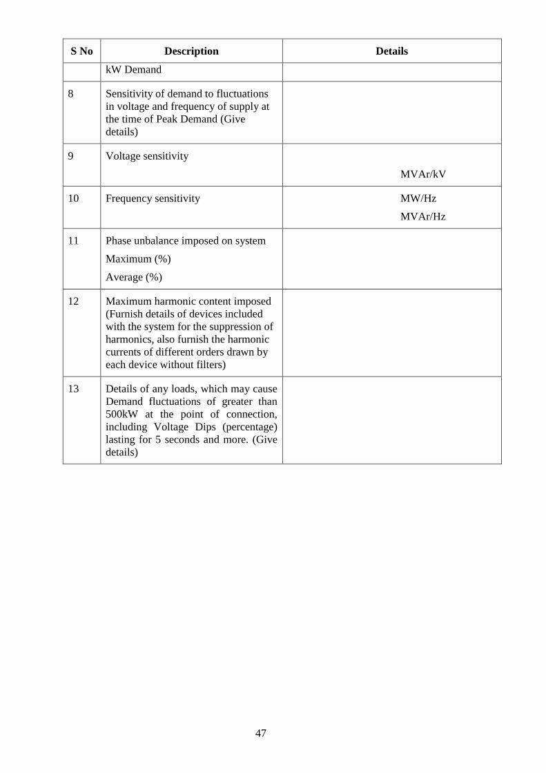
47
S No Description Details
kW Demand
8 Sensitivity of demand to fluctuations
in voltage and frequency of supply at
the time of Peak Demand (Give
details)
9 Voltage sensitivity
MVAr/kV
10 Frequency sensitivity MW/Hz
MVAr/Hz
11 Phase unbalance imposed on system
Maximum (%)
Average (%)
12 Maximum harmonic content imposed
(Furnish details of devices included
with the system for the suppression of
harmonics, also furnish the harmonic
currents of different orders drawn by
each device without filters)
13 Details of any loads, which may cause
Demand fluctuations of greater than
500kW at the point of connection,
including Voltage Dips (percentage)
lasting for 5 seconds and more. (Give
details)

48
Annexure 3
(See para 3.5.2.(b) )
EMBEDDED GENERATOR UNIT-WISE DATA
Name and address of Generating Company:
Location of Generating Plants (s):
Generation Volts (kV);
Rated kVA/kW
Maximum and minimum Active Power sent out
(kW) Reactive Power capability (kVAr), if any;
Type of Generating Plant—synchronous,
asynchronous, etc.;
Method of voltage control;
Generator transformer details, if applicable;
Requirements for Top-up supplies and/or
standby supplies;
Generator kW/kVAr capability chart (at lower
voltage terminals);
Type of excitation system;
Inertia constant kW secs/kVA;
Stator Resistance;
Direct-Axis Reactance (Sub-transient, Transient
and Synchronous);
Quadrature-Axis Reactance (Sub-transient and
Synchronous);
Zero Sequence (Resistance and Reactance);
Negative Sequence (Resistance and Reactance);
Generator Transformer (Resistance, Reactance,
kVA Rating, Tap Arrangement, Vector Group,
Grounding, Connection and % Impedance);
Automatic Voltage Regulator block diagram,
including the data on the gains (forward and
feedback), time constants, and voltage control
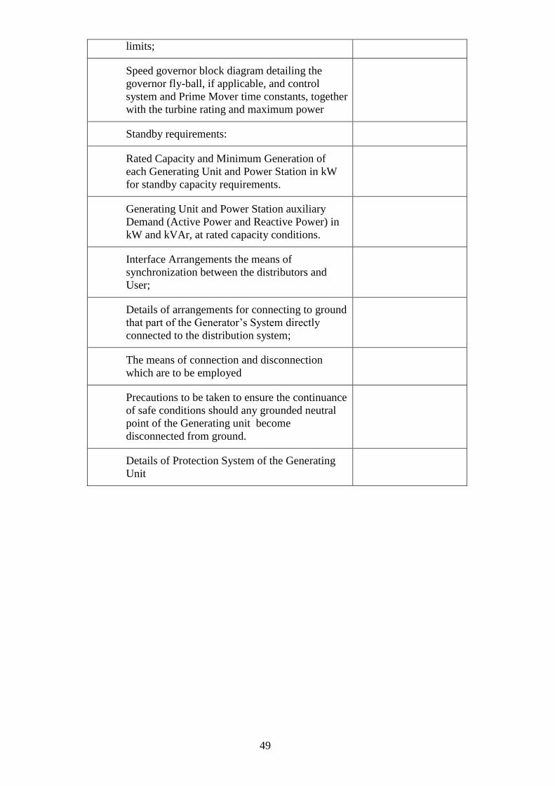
49
limits;
Speed governor block diagram detailing the
governor fly-ball, if applicable, and control
system and Prime Mover time constants, together
with the turbine rating and maximum power
Standby requirements:
Rated Capacity and Minimum Generation of
each Generating Unit and Power Station in kW
for standby capacity requirements.
Generating Unit and Power Station auxiliary
Demand (Active Power and Reactive Power) in
kW and kVAr, at rated capacity conditions.
Interface Arrangements the means of
synchronization between the distributors and
User;
Details of arrangements for connecting to ground
that part of the Generator’s System directly
connected to the distribution system;
The means of connection and disconnection
which are to be employed
Precautions to be taken to ensure the continuance
of safe conditions should any grounded neutral
point of the Generating unit become
disconnected from ground.
Details of Protection System of the Generating
Unit

50
Annexure-4
(See para 3.5.2(c))
SYSTEM DATA TO BE PROVIDED BY LICENSEES TO THE INTENDING USERS
1) 33 kV and above distribution line data relevant to the location where connection has
been applied/feasible to provide.
2) Details of metering system and protection system proposed .
3) Fault levels at which the consumer should design his equipment.
4) Fault clearance time for consumer's switch gear and
5) Sub-station fault level.

51
Annexure- 5
(See para 3.5.2(d))
SYSTEM DATA OF WHOLE LICENSEE SYSTEM
1. Topological map of Himachal Pradesh marking boundaries of area of supply of the
licensee.
2. Distribution map of the licensee drawn to scale of not less than 1 Cm to 2.5 Km
showing the existing 11 kV and 33 kV lines and sub-stations within the area of
supply. Lines and sub-stations under construction or planned for the next five years
shall be shown in dotted lines.
3. Single line diagram of the distribution system showing line length, conductor sizes,
sub-station capacity, capacitor sizes with locations of auto-
reclosures/Kiosks/Breakers etc.
4. Details of Metering and relaying at 33/11, 22/0.4,11/0.4 kV sub-stations.
5. Details of Grid sub-stations at the point of interconnections as follows:
i) MVA Capacity and voltage.
ii) Number of transformers, capacity of each
transformer, voltage ranges of taps.
iii) Fault level at sub-station bus bars,
iv) Bus impendence
v) Sub-station layout diagram.
6. Drawl at interconnection points: Maximum and Minimum MW drawn during last six months from each interconnection with the transmission system or with other distribution licensees.

52
Annexure-6
(see para 3.6.3)
LOAD RESEARCH PROGRAM
1. The licensee shall implement an appropriate load research program
for the systematic collection of data describing consumers' energy usage
patterns and analysis of the data for energy and demand forecast.
2. The pattern of energy consumed by each sector and the load
demand, the period of peak demand etc., shall be determined on the basis of
sample surveys taking representative samples from each sector for its
different seasonal requirements. A suitable questionnaire shall be prepared
for the sample surveys and the data obtained shall be analysed using suitable
statistical models. Based on this, load profiles shall be drawn implementing
demand side management techniques to match the availability from time to
time.
3. The load research program shall assess the following:-
(a) demand at the time of system peak, daily, monthly, seasonal or
annual,
(b) hourly demand for the day of the system peak, monthly, seasonally
or annually,
(c ) hourly end use demand for the average day of the system peak,
monthly, seasonal or annually;
(d) total energy consumption for each category by month, season or
year.
(e) category wise diverse or coincidence factors and load factors
(f) category wise non-coincident peak demands.
4. Based on the results of the above analysis, the load forecast shall be made
using the appropriate modern forecasting tools wherever applicable.
5. The optimum circuit loading and the maximum number of circuits at any
electrical interface between the Distribution and Transmission Systems shall
conform to the Distribution System Planning and Security Standards.
6. The loads shall be arranged as far as possible in discrete load blocks to
facilitate load management during emergency operations.
7. Load flow and other system studies shall be conducted to locate the
position of outlets from sub-stations, capacitor installations, distribution
transformers, and to contain voltage variation and energy losses within
reasonable limits.

53
8. The following parameters of equipments and system designs shall be
standardised to facilitate easy replacement and reduction of inventories of
spares in stores:
(a) Capacities of power
transformers,
(b) Capacities and designs of
distribution transformers,
(c) 33kV/22kV/ 11kV sub-
station layout.
(d) Pole mounted sub-stations,
(e) Sizes of bus bars, (f) Capacities and ratings of
circuit breakers and
instrument transformers,
(g) Earthing, (h) Lightning arresters,
(i) Control panels, (j) Station batteries,
(k) Fire extinguishers. (l) Maintenance tools
(m) Safety equipments (n) Energy meters
(o) Wires and cables (p) Clamps and connectors
9. The planning of the Distribution System shall always keep in view the cost
effectiveness and reduction in energy losses without sacrificing the
requirements of Security Standards and Safety Standards for the Distribution
System.
10. The distribution licensee shall plan the distribution system expansion and
reinforcement keeping the following in view alongwith all other measures to
accommodate the advancement in technology prevailing at the time:-
(a) Optimising the ratio of single, two and three phase LT Lines.
(b) Optimising the ratio of single to three phase transformers;
(c ) Economic ratio of HT and LT line lengths,
(d) Use of aerial bunched conductors,
(e) Underground cables,
(f) Optimizing the number of distribution transformers and their
location at the electrical load centres,
(g) Replacement of long PVC lines wiith conductors/ 3 phase service
line.

54
Annexure-7
(see para 3.7.11)
METHODOLOGY OF LOAD ESTIMATION/ASSESSMENT:
1 Domestic and Commercial Loads:- The consumption in domestic and commercial
sectors shall be estimated on the basis of the number of consumers and their
specific consumption. The past growth rate in the number of consumers in the area
shall be studied. In cases where power shortages have been experienced in the
recent past, the growth rate to be adopted shall take into consideration the
appropriate demand making due allowance in the growth rate to account for
increased tempo of household electrification envisaged in the future. The higher
level of electrification planned in the area should be kept in view. Energy
consumption per consumer shall be estimated after studying the past trends and
taking into account the anticipated improvements in the standard of living.
2 Public Lighting and Water Works: The estimates of electricity consumption in
public lighting and water works shall be based on the average consumption per
kilowatt of connected load, projected on the basis of trends, keeping in mind the
likely increase in public lighting and water supply facilities. The number of hours
of operation shall be estimated taking into account the past trends and the power
cuts if any effected in the area.
3 Agricultural Loads: The power requirement for irrigation pump sets shall be based
on the program of energisation of pump sets in the plan period, available resources
and the ultimate ground water potential. The average capacity of pump sets shall be
worked out considering the mid-year figures for connected load and the numbers of
pump sets.
4 Industrial Loads: The power requirements for industrial sector shall be estimated
under following three categories, namely:-
(a) L.T. Industries ;
(b) H.T. Industries with a demand of less than 5 MW;
(c) H.T. Industries with a demand of 5 MW and above.
(d) EHT Industries
The consumption in category (a) and (b) shall be on the basis of historical data duly
considering the developments in future. In case of category (c), projection shall be
made separately for each industrial unit on the basis of the information furnished by
the industrialists and the Department of Industries of the State Government.
5. Non-industrial Bulk Supply: The available data regarding the consumption of bulk
supply to non-industrial consumers such as research establishments, military
engineering services, supply to power projects etc., and the probable future
developments in these areas, shall be considered for the forecast.
6. Other Loads: For other loads, the projections shall be based on the best judgement.

55
Annexure- 8 (See para 4.1.2(c) )
SITE RESPONSIBILITY SCHEDULE
Name of Sub-station/Location
Site Owner
Name of co-ordination officer of site
Telephone No.
Fax No.:
Item of Plant/
Apparatus
Plant
Owner
Safety
Responsibility
Control
Responsibility
Operation
Responsibility
Maintenance
Responsibility
Remarks
……kV Switchyard
All equipment
including bus-bars
Feeders
Generating Units
Other (to be specified)
Signatures
Plant Owner
Safety Responsibility
Officer
Control
Responsibility Officer
Operation
Responsibility Officer
Maintenance
Responsibility Officer
Annexure-9
(See para 5.4.3.(3) )

56
ESSENTIAL LOADS AND PRIORITY OF RESTORATION
Priority Type of Load Name of the Sub-station
feeding such loads
1. Hospitals, Water Works,
2. Defence Establishments
3. Radio, Television Stations and
telecommunication Exchanges/Stations
4. Air Port
5. Important cities
6. Police Stations
7. Fire Stations
8. Process Industries and Mining

57
Annexure –10
(See para 8.4)
OPERATIONAL EVENT REPORTING
Name of the reporting Organization
Date and Time of reporting the /event incident
1 Date and time of incident
2 Location of incident (Name of Sub-station/Line etc.)
3 Description of incident
4 System parameters before the incident (voltage,
frequency, flows, generation, etc.)
5 Failure of protection at EHV GSS if any and relay
indications.
6 Damage to equipment
7 Supplies interrupted and duration, if applicable
8 Amount of generation lost, if applicable
9 Possibility of alternate supply arrangement
10 Estimate of time to return service
11 Cause of incident
12 Any other relevant information and remedial action taken
13 Recommendations for future improvement/repeat incident

58
Annexure-11
(See para 8.5)
RULE NO. 44 A OF THE INDIAN ELECTRICITY RULES, 1956
Rule no. 44 A – Intimation of Accident
If any accident occurs in connection with the generation, transmission, supply or use
of energy in or in connection with any part of electric supply lines or other works of
any person and the accident results in or is likely to have resulted in loss of human
or animal life or in any injury to a human being or an animal, such person or any
authorized person of the distribution licensee not below the rank of Junior Engineer
or equivalent shall send to the Inspector a telegraphic report within 24 hours of the
knowledge of the occurrence of the fatal accident and a written report in a form set
out in Annexure XIII within 48 hours of the knowledge of the occurrence of the
fatal accident and all other accidents. Where practicable a telephonic message
should also be given to the Inspector immediately the accident comes to the
knowledge of authorized officer of distribution licensee or other person concerned.
The Indian Electricity Rules, 1956
[ANNEXURE XIII]
FORM FOR REPORTING ELECTRICAL ACCIDENTS
(See Rule 44-A)
1 Date and Time of accident
2 Place of accident
(Village/Town, Tehsil /Thana, District and State)
3 System and voltage of supply
(Whether EHV/HV/LV line, sub-station/generating
station/consumer’s installations/service lines/other
installations)
4 Designation of the Officer-in-charge (in whose
jurisdiction the accident occurred)
5 Name of owner/user of energy in whose premises the
accident occurred.
6 Details of victim(s)
(a) Human
S.No. Name Father’s
Name
Sex of
victim
Full Postal
Address
Approx.
Age
Fatal /
Non-Fatal

59
(b) Animal
S.No. Description of
Animals
Number(s) Name(s) of
Owner(s)
Address
(es) of
owner(s)
Fatal /
Non-Fatal
7 In case the victim(s) is /are employee(s):
(a)designation of such person(s)
(b) brief description of the job undertaken, if any.
( c) Whether such person/persons was/were allowed to work on
the job.
8 In case the victim(s) is/are employee(s) of a licensed contractor
(a) Did the victim(s) possess any electric workman’s permits(s),
supervisor’s certificate of competency issued under Rule 45? If
yes give number and date of issue and the name of issuing
authority.
(b) Name and designation of the person who assigned the duties of
the victim(s)
9 In case of accident in the Distribution licensee system, was the
Permit To Work (PTW) taken?
10 Describe fully the nature and extent of injuries, e.g. fatal
/disablement (permanent or temporary) of any portion of the body
or burns or other injuries.
In case of fatal accident, was the post mortem performed?
11 Detailed causes leading to the accident
(To be given in a separate sheet annexed to this form)
12 Action taken regarding first-aid, medical attendance etc.
immediately after the occurrence of the accident (give details)
13 Whether the District Magistrate and Police Station concerned have
been notified of the accident (if so, give details)
14 Steps taken to preserve the evidence in connection with accident to

60
the extent possible.
15 Names and designation(s) of the person(s) assisting, supervising
the person(s) killed or injured.
16 What safety equipments were given to and used by the person(s)
who met with this accident (e.g. rubber gloves, rubber mats, safety
belts and ladders etc.)?
17 Whether isolating switches and other sectionalizing devices were
employed to deaden the section for working on the same? Whether
working section was earthed at the site of work?
18 Whether the work on live lines was undertaken by authorized
person(s)?
If so, the name and the designation of such person(s) may be
given.
19 Whether the artificial resuscitation treatment work on live lines
was undertaken by authorised person(s)?
If yes, how long was it continued before its abandonment?
20 Names and designations of persons present at and witnessed the
accident.
21 Any other information / remarks.
Place
Time
Date
Signature
Name
Designation
Address of the person reporting
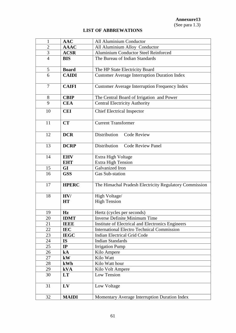
61
Annexure13
(See para 1.3)
LIST OF ABBREWATIONS
1 AAC All Aluminium Conductor
2 AAAC All Aluminium Alloy Conductor
3 ACSR Aluminium Conductor Steel Reinforced
4 BIS The Bureau of Indian Standards
5 Board The HP State Electricity Board
6 CAIDI Customer Average Interruption Duration Index
7 CAIFI Customer Average Interruption Frequency Index
8 CBIP The Central Board of Irrigation and Power
9 CEA Central Electricity Authority
10 CEI Chief Electrical Inspector
11 CT
Current Transformer
12 DCR Distribution Code Review
13 DCRP Distribution Code Review Panel
14 EHV
EHT
Extra High Voltage
Extra High Tension
15 GI Galvanized Iron
16 GSS Gas Sub-station
17 HPERC The Himachal Pradesh Electricity Regulatory Commission
18 HV/
HT
High Voltage/
High Tension
19 Hz Hertz (cycles per seconds)
20 IDMT Inverse Definite Minimum Time
21 IEEE Institute of Electrical and Electronics Engineers
22 IEC International Electro Technical Commission
23 IEGC Indian Electrical Grid Code
24 IS Indian Standards
25 IP Irrigation Pump
26 kA Kilo Ampere
27 kW Kilo Watt
28 kWh Kilo Watt hour
29 kVA Kilo Volt Ampere
30 LT Low Tension
31 LV Low Voltage
32 MAIDI Momentary Average Interruption Duration Index

62
33 MAIFI Momentary Average Interruption Frequency Index
34 MCB Miniature Circuit Breaker
35 MVA Mega Volt Ampere
36 MW Megawatt
37 PAP Project affected person
38 PCC Prestressed Cement Concrete
39 PT Potential transformer
40 PTW Permit to work
41 RCC Reinforced Cement Concrete
42 REC Rural Electrification Corporation
43 R&R Rehabilitation and Resettlement
44 SAIDI System Average Interruption Duration Index
45 SAIFI System Average Interruption Frequency Index
46 SCADA Supervisory Control and Data Acquisition
47 SLDC State Load Despatch Centre
48 STU State Transmission Utility
Copyright © 2022 FDOKUMEN