GY-HC900CHU/GY-HC900CHE GY-HC900STU/GY ...
236
. HD MEMORY CARD CAMERA RECORDER GY-HC900CHU/GY-HC900CHE GY-HC900STU/GY-HC900RCHE INSTRUCTIONS . . In this illustration, the supplied viewfinder is attached to the GY-HC900CHU/GY-HC900CHE. Wireless LAN antenna and viewfinder are not included in GY-HC900STU and GY-HC900RCHE. The specifications and appearance of this product are subject to changes for further improvement without prior notice. Please check the latest version of the INSTRUCTIONS from the following Mobile User Guide. You can also download the PDF from the Mobile User Guide. Mobile User Guide When you are outside, you can refer to the instructions from your Android phone or iPhone. http://manual3.jvckenwood.com/pro/mobile/global/ You can view the Mobile User Guide using the browser on your Android phone or iPhone. Thank you for purchasing this product. Before operating this unit, please read the instructions carefully to ensure the best possible performance. In this manual, each model number is described without the last letter (U/E) which means the shipping destination. (U: for USA and Canada, E: for Europe) Only “U” models (GY-HC900CHU/ GY-HC900STU) have been evaluated by UL. Please read the following before getting started: For Customer Use: Model No. Serial No. Enter below the Serial No. which is located on the body. Retain this information for future reference. GY-HC900CHU/GY-HC900STU IM 2.04 B5A-2755-00
-
Upload
khangminh22 -
Category
Documents
-
view
3 -
download
0
Transcript of GY-HC900CHU/GY-HC900CHE GY-HC900STU/GY ...

.
HD MEMORY CARD CAMERA RECORDERGY-HC900CHU/GY-HC900CHEGY-HC900STU/GY-HC900RCHEINSTRUCTIONS
.
.
In this illustration, the supplied viewfinder is attached to the GY-HC900CHU/GY-HC900CHE.Wireless LAN antenna and viewfinder are not included in GY-HC900STU and GY-HC900RCHE.The specifications and appearance of this product are subject to changes for further improvementwithout prior notice.Please check the latest version of the INSTRUCTIONS from the following Mobile User Guide. You canalso download the PDF from the Mobile User Guide.
Mobile User GuideWhen you are outside, you can refer to the instructions from your Android phone or iPhone.http://manual3.jvckenwood.com/pro/mobile/global/You can view the Mobile User Guide using the browser on your Android phone or iPhone.
Thank you for purchasing this product.Before operating this unit, please read the instructions carefully to ensure the best possible performance.In this manual, each model number is described without the last letter (U/E) which means the shipping destination. (U: for USA and Canada, E: for Europe)Only “U” models (GY-HC900CHU/GY-HC900STU) have been evaluated by UL.
Please read the following before getting started:
For Customer Use:
Model No. Serial No.
Enter below the Serial No. which is located on the body.Retain this information for future reference.
GY-HC900CHU/GY-HC900STU
IM 2.04 B5A-2755-00

2

.
1. Read these instructions.2. Keep these instructions.
Important Safety Instructions
4.5.6.7.
8.
These are general Important Safety Instructions and certain items may not apply to all appliances.
3.
FOR USA
9.
10.11.
12.
13.
For USA-California OnlyThis product contains a CR Coin Cell Lithium Battery which contains Perchlorate Material – special handling may apply.See www.dtsc.ca.gov/hazardouswaste/perchlorate
Heed all warnings.Follow all instructions.Do not use this apparatus near water.Clean only with dry cloth.Do not block any ventilation openings. Install in accordance with the manufacturer’s instructions.Do not install near any heat sources such as radiators, heat registers, stoves, or other apparatus (including amplifiers) that produce heat.Protect the power cord from being walked on or pinched particularly at plugs, convenience receptacles, and the point where they exit from the apparatus.Only use attachments/accessories specified by the manufacturer.Use only with the cart, stand, tripod, bracket, or table specified by the manufacturer, or sold with the apparatus. When a cart is used, use caution when moving the cart/apparatus combination to avoid injury from tip-over.Unplug this apparatus during lightning storms or when unused for long periods of time.Refer all servicing to qualified service personnel. Servicing is required when the apparatus has been damaged in any way, such as power-supply cord or plug is damaged, liquid has been spilled or objects have fallen into the apparatus, the apparatus has been exposed to rain or moisture, does not operate normally, or has been dropped.
Important Safety Instructions 3
Introduction

.
4.5.6.7.
8.
9.
10.11.
12.
13.
Pour Californie des États-Unis seulementCet appareil contient une pile-bouton CR au lithium qui contient du perchlorate – une manipulation spéciale peut être requise.Voir www.dtsc.ca.gov/hazardouswaste/perchlorate
Respecter toutes les instructions.Ne pas utiliser cet appareil à proximité de l’eau.Ne nettoyer qu’avec un chiffon sec.Ne pas boucher les ouvertures de ventilation. Installer selon les instructions du fabricant.Ne pas installer à proximité de sources de chaleur telles que des radiateurs, des accumulateurs de chaleur, des poêles, ou d’autres appareils (comprenant les amplificateurs) qui produisent de la chaleur.Protéger le cordon d’alimentation pour éviter qu’il ne soit piétiné ou ne se coince, tout particulièrement au niveau de la fiche, de la prise de courant et du point où il sort de l’appareil.Utiliser uniquement des équipements/accessoires spécifiés par le fabricant.N’utiliser qu’avec le chariot, le stand, le trépied, le support ou la table spécifié par le fabricant, ou vendu avec l’appareil. Lorsqu’un chariot est utilisé, faire attention pour déplacer la combinaison chariot/appareil pour éviter des blessures causées par un basculement.Débrancher cet appareil pendant un orage ou quand il n’est pas utilisé pendant une longue durée.L’entretien ou la réparation de l’appareil doit être effectué par du personnel qualifié uniquement. Un dépannage est nécessaire lorsque l’appareil a été endommagé d’une façon ou d’une autre, telle que lorsque le cordon d’alimentation ou la fiche est endommagé, si du liquide a été renversé ou si des objets sont tombés à l’intérieur de l’appareil, si l’appareil a été exposé à la pluie ou à l’humidité, ne fonctionne pas normalement ou a fait une chute.
1. Lire ces instructions.2. Conserver ces instructions.
CONSIGNES DE SÉCURITÉ IMPORTANTES
Ces informations sont des CONSIGNES DE SÉCURITÉ IMPORTANTES etcertains points peuvent ne pas s’appliquer à tous les appareils.
3.
POUR LES ÉTATS-UNIS
Tenir compte de tous les avertissements.
4 Important Safety Instructions
Introduction
Safety Precautions
.
CAUTION
FOR USA AND CANADA
CAUTION:TO REDUCE THE RISK OF ELECTRIC SHOCK. DO NOT REMOVE COVER (OR BACK).NO USER-SERVICEABLE PARTS INSIDE. REFER SERVICING TO QUALIFIED SERVICE PERSONNEL.
The lightning flash with arrowhead symbol, within an equilateral triangle is intended to alert the user to the presence of uninsulated “dangerous voltage” within the product’s enclosure that may be of sufficient magnitude to constitute a risk of electric shock to persons.
The exclamation point within an equilateral triangle is intended to alert the user to the presence of important operating and maintenance (servicing) instructions in the literature accompanying the appliance.
RISK OF ELECTRIC SHOCK
DO NOT OPEN
.
POUR CANADA
RISQUE D’ELECTROCUTION
NE PAS OUVRIR
ATTENTION: POUR EVITER TOUT RISQUE D’ELECTROCUTION NE PAS OUVRIR LE BOITER. AUCUNE PIECE INTERIEURE N’EST A REGLER PAR L’UTILISATEUR. SE REFERER A UN AGENT QUALIFIE EN CAS DE PROBLEME.
ATTENTION
Le symbole de l’éclair à l’intérieur d’un triangle équilatéral est destiné à alerter l’utilisateur sur la présence d’une “tension dangereuse” non isolée dans le boîtier du produit. Cette tension est suffisante pour provoquer l’électrocution de personnes.Le point d’exclamation à l’intérieur d’un triangle équilatéral est destiné à alerter l’utilisateur sur la présence d’opérations d’entretien importantes au sujet desquelles des renseignements se trouvent dans le manuel d’instructions.
Ces symboles ne sont utilisés qu’aux Etats-Unis.
Safety Precautions 5
Introduction

.
Supplier's Declaration of ConformityModel Number: GY-HC900CHU GY-HC900STUTrade Name: JVCResponsible JVCKENWOOD USAparty: CorporationAddress: 500 Valley Road, Suite 203 Wayne, NJ 07470Telephone 973-317-5000Number:
This device complies with Part 15 of FCC Rules. Operation is subject to the following two conditions: (1) This device may not cause harmful interference, and (2) this device must accept any interference received, including interference that may cause undesired operation.
.
Changes or modifications not approved by JVC could void the user’s authority to operate the equipment. This equipment has been tested and found to comply with the limits for a Class A digital device, pursuant to Part 15 of the FCC Rules. These limits are designed to provide reasonable protection against harmful interference when the equipment is operated in a commercial environment. This equipment generates, uses, and can radiate radio frequency energy and, if not installed and used in accordance with the instructions, may cause harmful interference to radio communications. Operation of this equipment in a residential area is likely to cause harmful interference in which case the user will be required to correct the interference at his own expense.
.
Numéro de modèle :Nom de marque :Personne responsable :Adresse :
Numéro de téléphone :
Déclaration de conformité du fournisseurGY-HC900CHUGY-HC900STUJVCJVCKENWOOD USA Corporation500 Valley Road, Suite 203 Wayne, NJ 07470973-317-5000
Cet ensemble se conforme à la partie 15 des règles de la FCC (Federal Communications Commission). Le fonctionnement est sujet aux deux conditions suivantes : (1) Cet appareil ne peut pas causer d’interférences nuisibles, et (2) cet appareil doit accepter toute interférence reçue, comprenant des interférences qui peuvent causer un mauvais fonctionnement.
.
Des changements ou modifications non approuvés par JVC peuvent annuler le droit de l’utilisateur de faire fonctionner l’appareil. Cet appareil a été testé et il a été reconnu qu’il se conforme aux limites concernant l’appareillage informatique de classe A correspondant à la partie 15 des règles de la FCC. Ces limites sont conçues pour fournir une protection raisonnable contre les interférences dangereuses lorsque l’équipement est utilisé dans un environnement commercial. Cet appareil génère, utilise et peut émettre de l’énergie des fréquences radio et, s’il n’est pas installé et utilisé selon les instructions du fabricant, peut causer des interférences nuisibles en communications radio. L’utilisation de cet équipement dans une zone résidentielle est susceptible de causer des interférences néfastes, auquel cas l’utilisateur devra prendre des mesures à ses propres frais.
6 Safety Precautions
Introduction
.
CAUTION:The mains plug shall remain readily operable.� Remove the mains plug immediately if
the camera functions abnormally.
.
WARNING:The battery pack, the camera with battery installed, and the remote control with battery installed should not be exposed to excessive heat such as direct sunlight, fire or the like.
.
WARNING: TO PREVENT FIRE OR SHOCK HAZARD, DO NOT EXPOSE THIS UNIT TO RAIN OR MOISTURE.
.
NOTES:� The rating plate and safety caution are
on the bottom and/or the back of the main unit.
� The serial number plate is on the bottom of the unit.
.
Caution on Replaceable lithium batteryThe battery used in this device may present a fire or chemical burn hazard if mistreated.Do not recharge, disassemble, heat above 100°C (212°F) or incinerate.Replace battery with Panasonic, Sanyo, Sony or Maxell CR2025.Danger of explosion or risk of fire if the battery is incorrectly replaced.� Dispose of used battery promptly.� Keep away from children.� Do not disassemble and do not dispose
of in fire.
.
Attention:La prise secteur doit être opérationnelle.� Débranchez immédiatement la fiche
secteur si le caméscope ne fonctionne pas normalement.
.
Avertissement:Évitez d’exposer la batterie, le caméscope avec la batterie insérée ou la télécommande avec la batterie insérée à une chaleur excessive, telle que celle des rayons directs du soleil, d’un feu ou de tout autre source de chaleur.
.
AVERTISSEMENT : POUR EVITER LES RISQUES D’INCENDIE OU D’ELECTROCUTION, NE PAS EXPOSER L’APPAREIL A LA PLUIE NI A L’HUMIDITE.
.
REMARQUES :� La plaque d’identification et
l’avertissement de sécurité se trouvent sous l’appareil et/ou au dos.
� La plaque du numéro de série est située sur la partie inférieure de l’appareil.
.
Avertissement sur la pile au lithium remplaçableLa pile utilisée dans cet appareil peut présenter des risques d’incendie ou de brûlure chimique si elle est mal traitée.Ne pas recharger, démonter, chauffer à plus de 100°C (212°F) ni mettre au feu.Remplacez la pile avec Panasonic, Sanyo, Sony ou Maxell CR2025.Danger d’explosion ou risque d’incendie si la pile n’est pas changée correctement.� Jeter immédiatement les piles usées.� Placer hors de la portée des enfants.� Ne pas démonter ni jeter au feu.
Safety Precautions 7
Introduction
.
When the equipment is installed in a cabinet or on a shelf, make sure that it has sufficient space on all sides to allow for ventilation (10 cm (3-15/16") or more on both sides, on top and at the rear).Do not block the ventilation holes.(If the ventilation holes are blocked by a newspaper, or cloth etc. the heat may not be able to get out.)No naked flame sources, such as lighted candles, should be placed on the apparatus.When discarding batteries, environmental problems must be considered and the local rules or laws governing the disposal of these batteries must be followed strictly.
.
The apparatus shall not be exposed to dripping or splashing and that no objects filled with liquids, such as vases, shall be placed on the apparatus.
.
Do not point the lens directly into the sun. This can cause eye injuries, as well as lead to the malfunctioning of internal circuitry. There is also a risk of fire or electric shock. CAUTION!The following notes concern possible physical damage to this unit and to the user.Carrying or holding this unit by the LCD monitor can result in dropping the unit, or in a malfunction.Do not use a tripod on unsteady or unlevel surfaces. It could tip over, causing serious damage to the unit. CAUTION!Connecting cables (Audio/Video, etc.) to this unit and leaving it on top of the TV is not recommended, as tripping on the cables will cause the unit to fall, resulting in damage.
.
Si le matériel est installé dans un coffret ou sur une étagère, s’assurer qu’il y a un espace suffisant sur tous les côtés pour permettre la ventilation (10 cm (3-15/16") ou plus sur les deux côtés, au dessus et à l’arrière).Ne pas boucher les orifices de ventilation.(Si les orifices de ventilation sont bouchés par un journal, un tissu, etc., la chaleur peut ne pas s’éliminer.)Aucune source à flamme nue, telle que des bougies allumées, ne doit être placée sur l’appareil.En jetant des batteries aux ordures, les problèmes d’environnement doivent être pris en considération et les réglementations locales ou la législation concernant le rebut de ces batteries doivent être strictement respectées.
.
L’appareil ne doit pas être exposé à de l’eau ou à des éclaboussures et les objets remplis de liquide, tels que des vases, ne doivent pas être placés sur l’appareil.
.
Ne dirigez pas l’objectif directement vers le soleil. Vous pourriez vous abîmer la vue et l’appareil pourrait être endommagé. Il y a aussi risque d’incendie ou d’électrocution.Attention!Les remarques suivantes sont destinées à protéger l’utilisateur et le caméscope contre des dommages éventuels.Ne pas transporter ou saisir le caméscope par l’écran LCD, car il pourrait tomber ou s’endommager.Ne pas utiliser de trépied photographique sur des surfaces irrégulières et inclinées. Il pourrait tomber et le caméscope pourrait être sérieusement endommagé.Attention!Avec des câbles (Audio/Vidéo, etc.) raccordés, il est recommandé de ne pas laisser le caméscope sur le dessus du téléviseur, car tirer sur les câbles pourrait faire tomber le caméscope, causant des dommages.
8 Safety Precautions
Introduction

.
IMPORTANT (for owners in the U.K.)Connection to the mains supply in the United Kingdom.DO NOT cut off the mains plug from this equipment.If the plug fitted is not suitable for the power points in your home or the cable is too short to reach a power point, then obtain an appropriate safety approved extension lead or contact the local dealers in your area.BE SURE to replace the fuse only with an identical approved type, as originally fitted, and to replace the fuse cover.If nonetheless the mains plug is cut off be sure to remove the fuse and dispose of the plug immediately, to avoid possible shock hazard by inadvertent connection to the mains supply.If this product is not supplied fitted with a mains plug then follow the instructions given below:DO NOT make any connection to the Larger Terminal coded E or Green.The wires in the mains lead are coloured in accordance with the following code:
If these colours do not correspond with the terminal identifications of your plug, connect as follows:Blue wire to terminal coded N (Neutral) or coloured black.Brown wire to terminal coded L (Live) or coloured Red.If in doubt — consult a competent electrician.
CAUTIONS:To prevent shock, do not open the cabinet. No user serviceable parts inside.Refer servicing to qualified personnel.
Blue to N (Neutral) or BlackBrown to L (Live) or Red
.
WARNINGOperation of this equipment in a residential environment could cause radio interference.
.
CAUTION:Where there are strong electromagnetic waves or magnetism, for example near a radio or TV transmitter, transformer, motor, etc., the picture and the sound may be disturbed. In such case, please keep the apparatus away from the sources of the disturbance.
.
The plastics packaging bags may cause suffocation when they are covered over the head. Tear them open, and keep them away from the reach of infants and children by ensuring that they are disposed of properly.
v
.
Wireless LAN� This device is a 2.4 GHz wideband
transmission system (transceiver), intended for use in all EU member states and EFTA countries, except in France and Italy where restrictive use applies.
� In Italy the end-user should apply for a license at the national spectrum authorities in order to obtain authorization to use the device for setting up outdoor radio links and/or for supplying public access to telecommunications and/or network services.
� This device may not be used for setting up outdoor radio links in France and in some areas the RF output power may be limited to 10 mW EIRP in the frequency range of 2454 - 2483.5 MHz. For detailed information the end-user should contact the national spectrum authority in France.
.
Frequency Range Output Power
2.4GHz Band : 1 - 13ch11 b/g/n : 14 dBm (max)
.
Frequency Range Output Power
5GHz Band : W52/W53/W5611 n/a/ac : 11 dBm (max)
Safety Precautions 9
Introduction

v x
.
The European representative of JVC KENWOOD Corporation is:
Die europäische Vertretung für die JVC KENWOOD Corporation ist:
JVCKENWOOD Deutschland GmbHKonrad-Adenauer-Allee 1-1161118 Bad VilbelGERMANY
x
.
Dear customer, this apparatus is in compliance with the valid European Directive and the relevant standards regarding electromagnetic compatibility.
Sehr geehrter Kunde, sehr geehrte Kundin, dieses Gerät stimmt mit der gültigen europäischen Richtlinie und den relevanten Normen bezüglich elektromagnetischer Verträglichkeit überein.
v
.
Hereby, JVC KENWOOD Corporation declares that the radio equipment type GY-HC900CHE is in compliance with Directive 2014/53/EU. The full text of the EU declaration of conformity is available at the following internet address:
Hiermit erklärt die , JVC KENWOOD Corporation, dass der Funkanlagentyp GY-HC900CHE der Richtlinie 2014/53/EU entspricht. Der vollständige Text der EU-Konformitätserklärung ist unter der folgenden Internetadresse verfügbar:
http://www3.jvckenwood.com/ecdoc/
.
Para BrasilInformação sobre eliminação de bateriasEste produto não deverá ser eliminado como lixo doméstico em geral.Devolva a bateria velha ao comerciante ou para a rede autorizada, para que seja devolvida ao fabricante ou importador.A reciclagem e eliminação de lixo em uma maneira adequada, ajudarão para preservar recursos, prevenindo, ao mesmo tempo, contra efeitos prejudiciais sobre a nossa saúde e o meio ambiente.
o
10 Safety Precautions
Introduction

ContentsIntroductionSafety Precautions ............................................ 5Contents .......................................................... 11Main Features ................................................. 14Precautions for Proper Use ............................. 16Operation Modes ............................................. 20Names of Parts ................................................ 22
Side Control Panel ....................................... 24Side Terminal Section .................................. 26Rear Terminal .............................................. 27Electronic Viewfinder u v .................. 28
Basic System Diagram .................................... 29PreparationsSettings and Adjustments Before Use ............. 30
Attaching the Lens (Sold Separately) ........... 30Attaching the Viewfinder (Supplied) u v..................................................................... 30Attaching the Microphone (Sold Separately)..................................................................... 31Attaching the Video Light (Sold Separately) 31Attaching the Wireless LAN Antennas(Supplied) u v ................................... 32Attaching the Tripod (Sold Separately) ........ 32Adjusting the Position of the Shoulder Pad .. 32
Power Supply .................................................. 33Using AC Power (DC IN Power) ................... 33Using a Battery Pack .................................... 34Battery Warning Settings ............................. 35
Power Status Display ...................................... 36Turning On/Off the Power ................................ 37Initial Settings .................................................. 38Displays on the LCD Monitor and Viewfinder .. 40
Display Screen ............................................. 40Status Screen .............................................. 41Remote Edit Mode Screen ........................... 41Warning Display ........................................... 41
Adjusting the LCD Monitor and Viewfinder ...... 42Adjusting the LCD Monitor ........................... 42Adjusting the Viewfinder .............................. 42
Adjusting the Back Focus ................................ 44Assignment of Functions to User Buttons ........ 45Tally Lamp ....................................................... 46
SD Card ........................................................... 47Usable Cards ............................................... 47Estimated Recordable Time of SD Cards .... 47Inserting an SD Card .................................... 48Removing the SD Card ................................ 49Switching the SD cards ................................ 49Formatting (Initializing) SD Cards ................ 50Restoring the SD Card ................................. 51Clips Recorded to SD Cards ........................ 52
Operation Lock Feature ................................... 53ShootingBasic Shooting Procedures ............................. 54Selecting System Definition, File Format and VideoFormat ............................................................. 55Zoom Operation .............................................. 57Focus Operation .............................................. 58Adjusting the Brightness .................................. 59Adjusting the Iris .............................................. 60Setting the Gain ............................................... 61Setting the Electronic Shutter .......................... 62Adjusting the White Balance ............................ 63Adjusting the Camera Image ........................... 69Audio Recording .............................................. 69Audio Output during Recording ....................... 73Time Code and User’s Bit ................................ 73Setting Time Code Generator .......................... 74Setting the User’s Bit ....................................... 77Synchronizing the Time Code with an ExternalTime Code Generator ...................................... 78Setting Zebra Pattern ...................................... 80Setting Spot Meter ........................................... 81Acquiring Positioning Information by GPS vu ................................................................. 83Viewing Recorded Videos Immediately (ClipReview) ........................................................... 84Displaying the Video Signal Monitor ................ 85Recording Simultaneously at Two DifferentDefinitions 2 ............................................ 86Series Rec ....................................................... 86Dual Rec .......................................................... 86Backup Rec 0 ......................................... 88Special Recording 0 ................................ 90
Pre Rec 0 ............................................ 90Clip Continuous Rec 0 ......................... 91Frame Rec 1 ........................................ 92Interval Rec 1 ...................................... 93
Splitting the Clips Freely (Clip Cutter Trig) 0......................................................................... 94
Contents 11
Introduction

PlaybackPlaying Recorded Clips ................................... 95
Thumbnail Screen ........................................ 95Actions ......................................................... 97Playing back ................................................ 98
Deleting Clips ................................................ 100Appending/Deleting OK Mark ........................ 101Selecting and Performing Operations on MultipleClips .............................................................. 102
Selecting Multiple Clips Randomly ............. 102Selecting Multiple Clips Consecutively ...... 103
Trimming Recorded Clips .............................. 104Menu Display and Detailed SettingsBasic Operations in Menu Screen ................. 105
Display and Description of the Menu Screen................................................................... 106Text Input with Software Keyboard ............ 107
Menu Screen Hierarchical Chart ................... 108Camera Function Menu ................................. 109
User Switch Set Item .................................. 111Full Auto Item ............................................. 115
Camera Process Menu .................................. 116Detail/Adjust Item ....................................... 121White Balance Item .................................... 122
TC/UB Menu ................................................. 124LCD/VF Menu ................................................ 125
Shooting Assist Item .................................. 126Marker Settings Item .................................. 128Display Type Item ...................................... 129Display On/Off Item .................................... 130
A/V Set Menu ................................................ 131Video Set Item ........................................... 131Audio Set Item ........................................... 135
Network Menu ............................................... 139Connection Setup Item .............................. 140Live Streaming Item ................................... 141Return over IP Item 0 ......................... 143Web Item ................................................... 145Metadata Server Item ................................ 145Upload Item 0 .................................... 146
System Menu ................................................ 148Record Set Item ......................................... 151
Adding/Editing Frequently Used Menu Items(Favorites Menu) ........................................... 157
Adding Menu Items to Favorites Menu ...... 157Editing Favorites Menu .............................. 158
Display/Status ScreenDisplay Screen in Camera Mode ................... 161Display Screen in Media Mode ...................... 167Status Screen ................................................ 170Camera FeaturesMarker and Safety Zone Displays (Camera ModeOnly) .............................................................. 172Color Bar Output ........................................... 172Adjusting the Gamma .................................... 173Adjusting Color Matrix ................................... 174Configuring Setup Files ................................. 176
Saving Setup Files ..................................... 176Loading a Setup File .................................. 177Deleting Setup Files ................................... 178
Connecting External DevicesConnecting External Monitor ......................... 179Connecting a Remote Control Unit ................ 180Connecting the Headphone ........................... 181Inputting External Synchronizing Signals(Genlock) ....................................................... 182Displaying Return Videos from an ExternalDevice ........................................................... 184Connecting to the NetworkFunctions of Network Connection .................. 185Preparing Network Connection ...................... 186
Operating Environment .............................. 186Camera Setup for Network Connection ..... 186Connecting to Network via [LAN] Terminal0 ........................................................ 186Connecting to Network via [HOST] Terminal(USB) 0 ............................................. 187Connecting to Network via Built-in Wireless LANu v 0 ....................................... 188
Importing Metadata ....................................... 189Preparing Metadata ................................... 189Configuring the Server for Downloading .... 189Importing Metadata .................................... 190
Uploading a Recorded Video Clip ................. 191Configuring the FTP Server for Uploading . 191Uploading Clips Automatically (AutoFTP)0 ................................................ 191Uploading Clips Manually (Manual FTP) .... 192
FTP Resume Feature .................................... 194
12 Contents
Introduction

Connecting from a Web Browser ................... 195Editing Metadata ........................................... 195
Planning Metadata ..................................... 195Clip Metadata ............................................ 196
Uploading a Recording Clip via a Web Browser....................................................................... 199View Remote Control and Camera ControlFunctions ....................................................... 202Changing the Settings via a Web Browser .... 204
Changing View Remote Function Settings . 205Changing Connection Setup ...................... 205Changing Metadata Server Settings .......... 206Changing Clip Server Settings ................... 206Changing Streaming Settings .................... 206
Managing the Network Connection Settings File....................................................................... 207
Saving the Connection Settings File .......... 207Reading the Connection Settings File ........ 208Deleting Connection Settings .................... 209
Performing Live Streaming ............................ 210Setting Distribution ..................................... 212Starting Distribution ................................... 214Setting the FEC Matrix 0 ................... 215
Return Video/Audio from the Network (Return overIP)0 ....................................................... 216IFB (Return Audio)0 .............................. 217OthersError Messages and Actions ......................... 218
List of FTP Transfer Errors ......................... 219List of Live Streaming Error Displays ......... 221Blinking of the Tally Lamp .......................... 222Warning Tone ............................................ 222
Troubleshooting ............................................ 223Specifications ................................................ 226Appendix ....................................................... 231Index ............................................................. 232Software License Agreement ........................ 234Important Notice concerning the Software ..... 235.
Contents 13
Introduction

Main FeaturesA variety of wired and wirelessinterfaces to support various networkconnections
In addition to the USB host terminal for wirelessLAN and LTE USB adapter connections, thiscamera recorder is equipped with a variety ofinterfaces such as wired LAN terminal and built-inwireless LAN with 2.4GHz/5GHz MIMO dual bandantennas u v to support various networkconnections.
Three full HD 2/3-inch CMOS imagesensors for high sensitivity of F12, lownoise high quality recording
This camera recorder is equipped with three 2/3-inch 2.20M pixels full HD CMOS image sensors.It delivers high sensitivity of F12, low noise highquality recordings.
2/3-inch B4 lens mount systemequipped with B4 lens mount and 4-position optical ND filter
This camera recorder comes with a 2/3-inch B4lens mount system equipped with B4 lens mountand 4-position optical ND filter.A wide range of B4 mount lenses can be used.Furthermore, when a B4 lens with chromaticaberration compensation data is installed,chromatic aberration can be corrected on thecamera recorder.By switching the 4-position ND filter (CLEAR, 1/4,1/16, 1/64), the amount of light can be adjustedaccording to the brightness during shooting.
High quality signal processing by 10-bit,4:2:2 sampling
High quality signal processing that delivers richgradation expression and color reproduction ofvideo signals is possible by means of 10-bit, 4:2:2sampling.
Various usage-based recording formatsThe recording codec supports two types of formatsthat are compatible with the 4:2:2 10-bit formatswidely used by broadcasting stations, namelyMPEG-4 AVC/H.264 and MPEG-2. All file formatsare compatible with QuickTime (MOV).
Newly developed user multi-matrix for16-axis color correction
In addition to the conventional 6-axis user linearmatrix adjustment, this camera recorder isequipped with user multi-matrix that enablesaccurate adjustment of hue and saturation in thesmaller 16-axis color region.
HDR and log gamma for high dynamicrange and high color gamut
This camera recorder is equipped with HLG(Hybrid Log-Gamma) that conforms to ITU-BT.2100 and our in-house J-Log1 Gamma with 800%dynamic range to cope with HDR (High DynamicRange). Capable of recording in 10-bit for highdynamic range and high color gamut.
Double SD card slots for series/dualrecordings
The most common SDHC/SDXC card recordingsystem is used for the memory card. This ensureshigh reliability and operation at low running cost.Various user friendly recording options areavailable. These include series recording whichenables seamless long hour continuousrecordings over the slots and dual recording of thesame file to two slots.
3.26-inch OLED electronic viewfinderand 3.5-inch LCD monitor (with focusassist function)
This camera recorder supports focusing throughthe 3.26-inch OLED electronic viewfinder and 3.5-inch LCD monitor. Other assist functions are alsoavailable, including magnified focus on a manuallyselected point.
Time code input/output and genlockterminals for shooting using multiplecameras
This camera recorder supports the use of multiplecameras as well as studio use.
Professional-style switch layout anddiverse video parameters
Switches for Gain and White Balance are availableon the side panel to enable quick switchingaccording to the shooting scene. Image qualityparameters such as gamma and color matrix arealso available in the menu for adjustment to thepreferred tones.
14 Main Features
Introduction

Built-in GPS u v
This camera recorder is built in with GPS function,which enables the positional information obtainedfrom the GPS satellite during a shoot to berecorded as metadata.* Note that acquisition of the positional
information may fail depending on the weathercondition.
User buttons/switches assignable withdifferent functions for greater ease ofuse
Menu items corresponding to each user button areavailable to assign the buttons with differentfunctions.
“IPX2” standard equivalent waterprooffunction for shooting in the rainSDI pool feed for simultaneousrecording and streaming of videos
Symbols usedCaution : Describes precautions concerning the
operation of this product.Memo : Describes reference information, such
as functions and usage restrictions ofthis product.
A : Indicates the reference page numbersand reference items.
u : Feature available on GY-HC900CHUonly.
v : Feature available on GY-HC900CHEonly.
w : Feature available on GY-HC900STUonly.
x : Feature available on GY-HC900RCHEonly.
0 : Feature available with firmware versionV0200-xxxx
1 : Feature available with firmware versionV0201-xxxx
2 : Feature available with firmware versionV0210-xxxx
o : Feature that will be supported afterfuture firmware upgrade.
Content of this manual0 All rights reserved by JVC KENWOOD
Corporation. Unauthorized duplication orreprinting of this manual, in whole or in part, isstrictly prohibited.
0 Illustrated designs, specifications and othercontents of this manual are subject to change forimprovement without prior notice.
0 SDXC and SDHC logos are trademarks ofSD-3C, LLC.
0 The terms HDMI and HDMI High-DefinitionMultimedia Interface, and the HDMI Logo aretrademarks or registered trademarks of HDMILicensing Administrator, Inc. in the United Statesand other countries.
0 QuickTime, Final Cut Pro, iPhone, iPad, iPodtouch, macOS and Safari are trademarks ofApple Inc., registered in the U.S. and othercountries.
0 iOS is a trademark or registered trademark ofCisco in the U.S. and other countries and is usedunder license.
0 Android and Google Chrome are trademarksand/or registered trademarks of Google LLC.
0 QR Code is a registered trademark of DensoWave Incorporated.
0 Microsoft, Windows, and Internet Explorer areeither registered trademarks or trademarks ofMicrosoft Corporation in the United Statesand/or other countries.
0 The company name of Fontworks, Fontworks,and the name of the fonts are registeredtrademarks of Fontworks Inc.
0 Zixi and the Zixi logo are trademarks of Zixi LLC.0 UniSlot is a registered trademark of Ikegami
Tsushinki Co., Ltd.0 Other product and company names included in
this instruction manual are trademarks and/orregistered trademarks of their respectivecompanies. Marks such as ™ and ® have beenomitted in this manual.
Main Features 15
Introduction

Precautions for ProperUseStorage and Usage Locations
o Allowable ambient temperature and humidityBe sure to use this unit within the allowabletemperature range of 0 °C to 40 °C (32 °F to104°F) and a relative humidity of 30 % to 80 %.Using this unit at a temperature or humidityoutside the allowable ranges could result notonly in malfunction but also serious impact onthe CMOS elements as small white spots maybe generated. Please exercise care during use.
o Strong electromagnetic waves or magnetismNoise may appear in the picture or audio and/orthe colors may be incorrect if this unit is usednear a radio or television transmitting antenna,in places where strong magnetic fields aregenerated by transformers, motors, etc., or neardevices emitting radio waves, such astransceivers or cellular phones.
o Use of wireless microphone near this unitWhen a wireless microphone or wirelessmicrophone tuner is used near this unit duringrecording, the tuner could pick up noise.
o Avoid using or placing this unit in the followingplaces.0 Places subject to extreme heat or cold0 Places with excessive dirt or dust0 Places with high humidity or moisture0 Places subject to smoke or vapor such as near
a cooking stove0 Places subject to strong vibrations or unstable
surfaces0 In a parked car under direct sunlight or near a
heater for long hourso Do not place this unit at places that are subject
to radiation or X-rays, or where corrosive gasesoccur.
o Protect this unit from getting wet when shootingon a beach. In addition, salt and sand mayadhere to the body. Be sure to clean the unit afteruse.
o Protect this unit against penetration of dustwhen using it in a place subject to sandy dust.
Drip-proofo This camera recorder has a drip-proof structure
equivalent to IPX2 according to our testingmethod. It is not completely waterproof. And thedrip-proof performance under all conditions isnot guaranteed.0 IPX2 (protection rating against dripping water)
ensures that when a device is tilted at an angleof 15 degrees to the front, back, right and leftwith water dripping vertically on it at a rate of3 mm/min for a total of 10 minutes at 2 minutes30 seconds for each position, the device willfunction properly when operated.
o To ensure the drip-proof performance, close thecaps and covers fully.
o Avoid heavy rain and heavy water splashes.o If this camera recorder gets wet and there are
water droplets, wipe off with a dry clothimmediately. If the camera recorder is turnedupside down or tilted at 15 ° or more while it iswet, water may enter the camera recorder andcause malfunction.
o If this camera recorder gets wet, water maycome out from the gaps. Do not carry it while itis wet. Place it on a dry cloth for a while and letit dry.
Carrying the Camerao Do not drop or hit this unit against a hard object
when transporting.
Power Savingo When this unit is not in use, be sure to set the
[POWER ON/OFF] switch to “OFF” in order toreduce power consumption.
Maintenanceo Turn off the power before performing any
maintenance.o Wipe the external cabinet of the unit with a soft
cloth. Do not wipe the body with benzene orthinner. Doing so may cause the surface to meltor turn cloudy. When it is extremely dirty, soakthe cloth in a solution of neutral detergent, wipethe body with it, and then use a clean cloth toremove the detergent.
16 Precautions for Proper Use
Introduction

Rechargeable Batteryo The batteries recommended for use with this
camera recorder are as follows.U model : Digital 150 (Anton/Bauer)E model : DUO-150 (IDX)
o Please make use of one of the recommendedbatteries.Heavy batteries may fall off if they are not usedcorrectly.
Regular Inspection (Maintenance)o Under normal environment, dust will
accumulate on the camera recorder when it isused over a long period. Dust may enter thecamera recorder especially if it is used outdoors.This may affect the image and sound quality ofthe camera recorder. Check and replace the fanafter every 9000 hours (suggested guideline).You can check the usage time of the fan in[System] B [System Information] B [Fan Hour].(A P150 [ Fan Hour ] )If the fan is used for more than 9000 hourswithout replacement, “Fan MaintenanceRequired” will be displayed every time you turnon the power.
LCD Monitor and Viewfinder u v
o The LCD monitor and viewfinder screen aremanufactured using high-precision technology.Black or bright spots may appear on the LCDmonitor and viewfinder screen. This is not amalfunction. These spots will not be recorded.
o If you use this unit continuously for a long periodof time, the characters displayed in theviewfinder may temporarily remain on thescreen. This phenomenon will not be recordedto the recording media. They will not appearafter you turn the power off and then on again.
o If you use this unit in a cold place, the imagesmay appear to lag on the screen, but this is nota malfunction. Retained images are notrecorded on the SD card.
o Do not press against the surface with force orsubject it to strong impact. Doing so maydamage or break the screens.
o Noise may appear in the viewfinder whenswitching between the live video and playbackimages.
o Due to the characteristic of the viewfinderdisplay device, colors may appear on theimages when you blink your eyes. It does notaffect the recorded images, SDI output, or HDMIoutput.
Lenso This camera recorder is an interchangeable lens
camera. Please have the interchangeable lensready before use.
o Read the “INSTRUCTIONS” of theinterchangeable lens to be attached to get a fullunderstanding before use.
o Optical performance of lensDue to the optical performance of the lens, colordivergence phenomena (magnificationchromatic aberration) may occur at theperiphery of the image. This is not a cameramalfunction.
o Depending on the lens attached, there arefunction limitations on the lens with this camerarecorder or the lens may not function properly.
o The lens operation sound may be recorded.o Depending on the lens used, the approximate
distance to the subject may not be displayed.o There can be a large variation in the light
intensity during Auto Iris mode, Manual Irismode and zoom mode.
GPS u v
o The GPS (Global Positioning System) satellitesare managed by the Department of State of theU.S., and its precision may be alteredintentionally.
o Perform positioning at an unobstructed locationwith a clear view that is not indoors or blockedby trees.
o The time needed for obtaining the positioninformation may be longer and variation mayalso be larger depending on the surroundingenvironment and time of day.
o This camera recorder uses the WGS 84 WorldGeodetic System.
o Signal from GPS satellites may be interrupted bycommunication signal from electronic devicessuch as mobile phones.
o Make use of it in accordance with the regulationsof the country, region or location of use.
Encryption in Network Connectiono Wireless LAN connections make use of an
encryption function.This encryption is designed for commercially-sold equipment, and it cannot be altered.
Precautions for Proper Use 17
Introduction

SDHC/SDXC Cardso SDHC/SDXC card is referred to as “SD card” or
“recording media” in this manual.o This camera recorder saves the recorded
images and audio sound on the SD card (soldseparately) in the card slot.
o If the SD card contains files recorded by devicesother than this camera recorder or files that aresaved from a PC, the recordable time may beshorter or data may not be properly recorded. Inaddition, the remaining space on the card maynot increase even when files are deleted usinga PC.
o For details on the combinations of usable SDcard and format setting, refer to the following.(A P47 [Format Setting and Usable SD CardCombinations] )
* Using cards other than those from Panasonic,TOSHIBA or SanDisk may result in recordingfailure or data loss.
Handling of SD Cardso The status indicator lights up in red when data
on the SD card is being accessed.Do not remove the SD card during data access(such as recording, playback, or formatting). Donot turn off the power or remove the battery andAC adapter during access either.
o Do not use or store the SD card in a place thatis subject to static electricity or electrical noise.
o Do not place the SD card near locations that areexposed to strong magnetic fields or radiowaves.
o Inserting the SD card incorrectly may result indamage of this unit or the SD card.
o We are not liable for any accidental loss of datastored on the SD card. Please back up anyimportant data.
o Make use of the SD card within the prescribedconditions of use.Do not use it at the following locations.Places that are subject to direct sunlight, highhumidity or corrosion, places near thermalequipment, sandy or dusty places, or in a carunder the sun with the doors and windowsclosed.
o Do not bend or drop the SD card, or subject it tostrong impact or vibration.
o Do not splash the SD card with water.o Do not dismantle or modify the SD card.o Do not touch the terminals with your hands or
with a metal object.o Do not allow dust, dirt, water, or foreign objects
to adhere to the terminals.o Do not remove the labels or stick other labels or
stickers on the SD cards.
o Do not use pencils or ballpoint pens to write onthe SD cards. Always use oil-based pens.
o If you format (initialize) the SD card, all datarecorded on the card, including video data andsetup files, will be deleted.
o You are recommended to use cards that areformatted (initialized) on this camera recorder.0 The SD card may be damaged if the camera
recorder is not operated correctly. Formatting(Initializing) the SD card may allow it tooperate correctly.
0 SD cards that have been formatted(initialized) on other cameras, computers orperipheral equipment may not operatecorrectly. In this case, format (initialize) the SDcard on this camera recorder.
o If you want to wipe out all information bycompletely erasing the data, we recommendeither using commercially available softwarethat is specially designed for that purpose, or byphysically destroying the SD card with ahammer, etc. When formatting or erasing datausing the camera recorder, only the fileadministration information is changed. The datais not completely erased from the SD card.
o Some commercially available SD cards may beharder to be removed from this unit. Removethem by hooking onto the groove on the cards.0 It will be easier to remove the cards after
several times.0 Do not stick any stickers on the cards.
.Groove
o The SD card may pop out when it is beingremoved. Be careful not to lose the card.
Copyrighto Any recordings made on this camera recorder
that are played back for profit or public previewmay infringe on the rights of the owner of therecordings.Do not use the recordings for purpose other thanpersonal enjoyment without prior consent fromthe owner. And even for personal enjoyment,you may not be able to record withoutpermission from the owner.
18 Precautions for Proper Use
Introduction

License Noticeso MPEG LA AVC
THIS PRODUCT IS LICENSED UNDER THEAVC PATENT PORTFOLIO LICENSE FORTHE PERSONAL USE OF A CONSUMER OROTHER USES IN WHICH IT DOES NOTRECEIVE REMUNERATION TO(i) ENCODE VIDEO IN COMPLIANCE WITHTHE AVC STANDARD (“AVC VIDEO”) AND/OR(ii) DECODE AVC VIDEO THAT WASENCODED BY A CONSUMER ENGAGED IN APERSONAL ACTIVITY AND/OR WASOBTAINED FROM A VIDEO PROVIDERLICENSED TO PROVIDE AVC VIDEO.NO LICENSE IS GRANTED OR SHALL BEIMPLIED FOR ANY OTHER USE. ADDITIONALINFORMATION MAY BE OBTAINED FROMMPEG LA, L.L.C. SEEHTTP://WWW.MPEGLA.COM
o MPEG LA MPEG-2 PatentANY USE OF THIS UNIT IN ANY MANNEROTHER THAN PERSONAL USE THATCOMPLIES WITH THE MPEG-2 STANDARDFOR ENCODING VIDEO INFORMATION FORPACKAGED MEDIA IS EXPRESSLYPROHIBITED WITHOUT A LICENSE UNDERAPPLICABLE PATENTS IN THE MPEG-2PATENT PORTFOLIO, WHICH LICENSE ISAVAILABLE FROM MPEG LA, LLC, 6312 S.WHICH LICENSE IS AVAILABLE FROM MPEGLA, LLC, 6312 S. Fiddlers Green circle, Suite400E, Greenwood Village, Colorado 80111U.S.A.
Otherso Do not insert objects other than the memory card
into the card slot.o Do not block the vent on the unit.
Blocking of the vent causes internal heating andmay lead to burns and fires.
o Do not turn off the [POWER ON/OFF] switch orremove the power cable during recording orplayback.
o The camera recorder may not show stablepictures for a few seconds immediately after thepower is turned on, but this is not a malfunction.
o When the video signal output terminals are notin use, put on the covers to prevent damage tothe terminals.
o Do not drop this unit or subject it to strong impactor vibration as it is a precision equipment.
o Noise may appear in the image when switchingmodes.
o If placed on its side, heat release efficiency willdeteriorate.
o When the connectors that come with connectorcovers are not in use, put on the covers toprevent damage to the connectors.
o This camera recorder makes use of fonts byFontworks Inc.
o This camera recorder makes use of M+FONTS.o Use the built-in wireless LAN only in the country
and region where it was purchased.And there are legal restrictions on the use andoutdoor use depending on the country andregion. Please be careful not to violate the law.u v
Precautions for Proper Use 19
Introduction

Operation ModesThis camera recorder has three operation modes - Camera mode, Media mode, and Remote Edit mode.
.
Trimming Playback
Normal PlaybackCamera Input
(Actions)Execute [Delete Clips]
File Deletion in Progress
Exit Trimming Operation (Successful/Failed/Stopped)
Execute [Trim This Clip]
Thumbnail DisplayPlayback
Camera Mode Media Mode
Press and hold [CAM/MEDIA]
[CAM/MEDIA] Button
[CANCEL/RESET]/[MENU/THUMB] Button
* Selecting a mode other than the Metadata Edit mode via the web browser, or selecting [Exit] on the [Remote Edit Mode] screen
Upon access via a web browser and selecting [Change] on the [Change to Remote Edit Mode?] screen on the camera or the web browser
*
Press and hold [CAM/MEDIA]
[CAM/MEDIA] Button
Exit FTP Operation (Successful)
[SET] Button (R)
Remote Edit Mode
FTP in Progress FTP in Progress
[USER4] Button
Trimming in Progress
Exit/Cancel File Delete Operation (Successful/Failed/Stopped)
Exit/Cancel FTP Operation (Successful/Failed/Stopped)Execute [FTP Upload]
20 Operation Modes
Introduction

Operation Mode DescriptionCamera Mode 0 This is the camera shooting mode. The camera recorder starts up in Camera mode
when the power is turned on.0 Camera images are output to the viewfinder and LCD monitor. When a recordable
media is inserted, the camera recorder enters the recording standby mode. “STBY”appears on the operation mode display area of the LCD monitor and viewfinder.
0 Press the [REC] trigger button to start recording.0 When [Record Set] B [Record Format] B [System] is set to “HD(SDI In)” or “SD(SDI
In)”2, and the device is connected to the [HD/SD SDI IN] terminal, the SDIinput video is displayed on the LCD monitor or viewfinder.
Memo : 0 Playback of recording media is not possible in the Camera mode. However, you
can check the most recently recorded video clip.(A P84 [Viewing Recorded Videos Immediately (Clip Review)] )
Media Mode 0 This mode allows you to play back or delete clips recorded on the recording media.0 When a playable recording media is inserted, the thumbnail or playback screen is
displayed on the viewfinder and LCD monitor.0 Press and hold the [CAM/MEDIA] button to enter the Media mode when you are
not shooting in the Camera mode. Once the camera recorder is in Media mode,thumbnails of the selected media slot are displayed.
Remote EditMode
0 This mode enables the list display and editing of the recorded clip data throughaccess to the clip list display page via a web browser on a smartphone, tabletterminal, or PC.
0 When you access via a web browser on a smartphone, tablet terminal, or PC, “Itis necessary to change the camera mode to "Remote Edit Mode". Change themode.” appears on the web browser. Also, “Change to Remote Edit Mode?” isdisplayed on the display screen of the camera unit.Selecting [Change] on the camera recorder and pressing the Set button switchesto the Remote Edit mode, and enables display of the clip list and editing of the clipmetadata.
(A P196 [ Clip Metadata ] )(A P199 [Uploading a Recording Clip via a Web Browser] )
Memo : 0 If you access via a web browser on devices such as a smartphone, tablet terminal,
or PC while recording is in progress, the message appears after recording stops.0 If playback is in progress, the message appears once the files are closed
automatically, such as when playback stops.
Operation Modes 21
Introduction
Names of Parts
.
A
C
G K
B
D
E F H I J
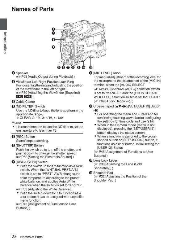
A Speaker(A P98 [Audio Output during Playback] )
B Viewfinder Left-Right Position Lock RingFor loosening the ring and adjusting the positionof the viewfinder to the left or right.(A P30 [Attaching the Viewfinder (Supplied)u v] )
C Cable ClampD [ND FILTER] Switch
Use the ND filter to keep the lens aperture in theappropriate range.1: CLEAR, 2: 1/4, 3: 1/16, 4: 1/64
Memo : 0 It is recommended to use the ND filter to set the
lens aperture to less than F8.E [REC] Button
Starts/stops recording.F [SHUTTER] Switch
Push the switch up to turn off the shutter, andpush it down to change the shutter speed.(A P62 [Setting the Electronic Shutter] )
G [AWB/USER8] Switch0 Push the switch up for it to function as a AWB
switch. When the [WHT.BAL PRST/A/B]switch is set to “PRST”, AWB changes thecolor temperature according to the presetwhite balance, and applies Auto WhiteBalance when the switch is set to “A” or “B”.
(A P63 [Adjusting the White Balance] )0 Push the switch down for it to function as a
user button. It can be assigned with a specificmenu function.
(A P45 [Assignment of Functions to UserButtons] )
H [MIC LEVEL] KnobFor manual adjustment of the recording level forthe microphone that is attached to the [MIC IN]terminal when the [AUDIO SELECTCH1/2/3/4]-[MANUAL/AUTO] selection switchis set to “MANUAL” and the [FRONT/REAR/WIRELESS] selection switch is set to “FRONT”.(A P69 [Audio Recording] )
I Cross-shaped (JKHI)/[SET/USER13] Button(R)0 For operating the menu and cursor and for
confirming a setting, as well as for configuringthe settings for time code and user’s bit.
0 When in the Camera mode (menu is notdisplayed), pressing the [SET/USER13]button displays the status screen.
0 When a function is assigned to the cross-shaped button or [SET/USER13] button, itfunctions as a user button. Initial setting for[USER13]: Status
(A P45 [Assignment of Functions to UserButtons] )
J Lens Lock Lever(A P30 [Attaching the Lens (SoldSeparately)] )
K Shoulder Pad(A P32 [Adjusting the Position of theShoulder Pad] )
22 Names of Parts
Introduction

.
L
S
W
VMNOPQ T
R
U
L Slide Cover (For [USER6]/[USER7] Button)Sliding the cover over the buttons helps toprevent accidental operation.
M [USER6] ButtonIt can be assigned with a specific menu function.(A P45 [Assignment of Functions to UserButtons] )
N [USER7] ButtonIt can be assigned with a specific menu function.(A P45 [Assignment of Functions to UserButtons] )
O Back Tally Lamp (Handle)(A P46 [Tally Lamp] )
P [TALLY] Switch(A P46 [Tally Lamp] )(A P222 [Blinking of the Tally Lamp] )
Q Wireless LAN Antenna Terminal u v(A P32 [Attaching the Wireless LANAntennas (Supplied) u v] )
R SD Card Cover Knob(A P48 [Inserting an SD Card] )
S SD Card CoverT Expansion slotU Wireless Audio Receiver Mounting Slot
(“UniSlot”)A “UniSlot” wireless receiver can be attached tothis slot.
Memo : 0 When removing the cover, avoid losing the
screws, etc.0 Check the “INSTRUCTIONS” of the wireless
receiver.
V Shoulder Belt Mount (x2)For mounting a shoulder belt (sold separately).
Caution : 0 Be sure to use a shoulder belt with the strength
to withstand the weight of this camera recorder.0 If the shoulder belt is not properly attached, the
camera recorder may fall and cause injuries.0 Check the [INSTRUCTIONS] provided with the
shoulder belt before using.W Shoe
For mounting separately sold video lights andaccessories.(A P31 [Attaching the Video Light (SoldSeparately)] )
Names of Parts 23
Introduction

Side Control Panel
.
PRESETAUDIO INPUT
TC
F-RUNR-RUNREGEN
UB
GEN
DISPLAY
J K MLI N O
ABCDE
F
G
H
S TU
a Zb
X
Y
VW
P Q R
A [ONLINE/5] Button0 Switches live streaming between ON/OFF.(A P214 [Starting Distribution] )0 You can also use it as a user button by
assigning a specific feature in the menusetting to this button. Initial setting: Livestreaming
(A P45 [Assignment of Functions to UserButtons] )
B [USER4] ButtonIt can be assigned with a specific menu function.(A P45 [Assignment of Functions to UserButtons] )
C [LIGHT] SwitchFor selecting the operation mode of the videolight connected to the [LIGHT] terminal.AUTO : The video light lights up only during
recording when the video light isturned on.
MANUAL: The video light lights up or goes outwhen the video light is turned on oroff.
D [MONI SELECT] Switch/[CH SELECT] SwitchFor configuring the audio monitor (speaker/headphone) output with the combined use oftwo switches.(A P181 [Connecting the Headphone] )
E [USER1] ButtonIt can be assigned with a specific menu function.(A P45 [Assignment of Functions to UserButtons] )
F [USER2] SwitchIt can be assigned with a specific menu function.(A P45 [Assignment of Functions to UserButtons] )
Memo : 0 Even when the function assigned to the
[USER2] switch is assigned to another userbutton at the same time, only the [USER2] switchis enabled.
G [USER3] ButtonIt can be assigned with a specific menu function.(A P45 [Assignment of Functions to UserButtons] )
H [USER0] SwitchIt can be assigned with a specific menu function.(A P45 [Assignment of Functions to UserButtons] )
I [GAIN H/M/L] SwitchFor selecting the gain sensitivity level.(A P61 [Setting the Gain] )
J [MENU/THUMB] Button0 Displays the menu screen during Camera
mode.0 Switches between [Main Menu] and
[Favorites Menu] when the [MENU/THUMB]button is pressed and held down while themenu screen is displayed.
(A P105 [Basic Operations in Menu Screen] )0 Displays the menu screen when the button is
pressed during thumbnail display in theMedia mode.
0 Stops playback and displays the thumbnailscreen when the button is pressed duringplayback screen display in the Media mode.
K [POWER ON/OFF] SwitchTurns ON/OFF the power.0 When the power is turning OFF, “P.OFF”
appears on the LCD monitor and viewfinder.0 Wait for 5 seconds or more to turn on the
power again.L [OUTPUT] Switch
For configuring the output signal when in theCamera mode.0 CAM/AUTO KNEE ON: Turns “ON” Auto
Knee.0 CAM/AUTO KNEE OFF: Turns “OFF” Auto
Knee.0 BARS/AUTO KNEE OFF: Outputs a color
bar.M [WHT.BAL PRST/A/B] Switch
For switching the white balance.(A P63 [Adjusting the White Balance] )
N [MONITOR] Volume Adjustment KnobFor adjusting the volume of the audio monitor(speaker/headphone).
O [ALARM] Volume Adjustment KnobFor adjusting the warning alarm volume of theaudio monitor (speaker/headphone).
Memo : 0 Whether the sound is to be muted or output
when it is at the minimum level can be configuredin [Min. ALARM Level].
24 Names of Parts
Introduction

P [AUDIO INPUT CH1/2/3/4] Recording LevelAdjustment KnobFor adjusting the recording level manually whenthe [MANUAL/AUTO] selection switch is set to“MANUAL”.(A P69 [Audio Recording] )
Q [AUDIO CH1/2/3/4]-[MANUAL/AUTO]Selection SwitchFor configuring the recording level of eachchannel to [MANUAL/AUTO].(A P69 [Audio Recording] )
R [AUDIO CH1/2/3/4]-[FRONT/REAR/WIRELESS] Selection SwitchFor selecting the recording input path [FRONT/REAR/WIRELESS] for each channel.(A P69 [Audio Recording] )
S [TC DISPLAY] TC/UB Display SwitchSwitches the display between time code anduser’s bit.(A P73 [Time Code and User’s Bit] )(A P74 [Setting Time Code Generator] )
T [TC GEN] Time Code Generator SwitchFor configuring the run mode of the time code.F-RUN : The time code operates in the run
mode at all times. Synchronizeswith the external time code when anexternal time code generator isconnected.
R-RUN : The time code operates in the runmode while recording is inprogress. When the SD card isreplaced, recording continues fromwhere it last stopped using theprevious card.
REGEN : The time code operates in the runmode while recording is inprogress. When the SD card isreplaced, recording starts from thelast time code recorded on thecurrent SD card.
(A P73 [Time Code and User’s Bit] )(A P74 [Setting Time Code Generator] )(A P78 [Synchronizing the Time Code with anExternal Time Code Generator] )
U [TC PRESET] ButtonWhen the [TC GEN] switch is set to “F-RUN” or“R-RUN”, this camera recorder enters or exitsPreset mode when this button is pressed.Upon entering Preset mode, an enlargeddisplay appears on the LCD monitor. Use thecross-shaped button to move the cursor andselect a value. Next, press the [STATUS/SET]button to preset the time code and the screenreturns to the original display.
Memo : 0 The UB mode is enabled only when [TC/UB] B
[UB Mode] is set to “Preset”.V [B.LIGHT] Button
Sets the LCD monitor backlight.Pressing the button each time switches themode as follows:Dark B Normal B Bright B Off B Dark
W [CAM/MEDIA] ButtonSwitches between the Camera mode andMedia mode.(A P20 [Operation Modes] )
X Cross-shaped (JKHI)/[STATUS/SET] Button(R)0 For operating the menu and cursor and for
confirming a setting, as well as for configuringthe settings for time code and user’s bit.
0 When in the Camera mode (menu is notdisplayed), pressing the [STATUS/SET]button displays the status screen.
0 When a function is assigned to the cross-shaped button, it functions as a user button.
(A P45 [Assignment of Functions to UserButtons] )
Y [ACCESS] LampThe indicator lights up in green when the SDcard is being accessed.
Memo : 0 Regardless of whether a recording media has
been inserted, the access lamp will light up forabout 5 seconds when the power is turned on.0
Z [CANCEL/RESET] Button0 Cancels various settings and stops playback.0 Performs reset when the TC mode or UB
mode is being configured during enlargeddisplay on the LCD monitor.
Names of Parts 25
Introduction

a [MENU/THUMB] Button0 Displays the menu screen during Camera
mode.0 Switches between [Main Menu] and
[Favorites Menu] when the [MENU/THUMB]button is pressed and held down while themenu screen is displayed.
(A P105 [Basic Operations in Menu Screen] )0 Displays the menu screen when the button is
pressed during thumbnail display in theMedia mode.
0 Stops playback and displays the thumbnailscreen when the button is pressed duringplayback screen display in the Media mode.
b [DISPLAY] Button0 Press the [DISPLAY] button to switch to the
display screen during normal screen display(when the menu screen is not displayed).
(A P40 [Display Screen] )0 Switches between [Main Menu] and
[Favorites Menu] when the [DISPLAY] buttonis pressed while the menu screen isdisplayed.
(A P105 [Basic Operations in Menu Screen] )
Side Terminal Section
.A B HC D E F I JG
F
K
A [VIDEO OUT] Terminal(A P78 [Synchronizing the Time Code with anExternal Time Code Generator] )
B [GENLOCK] Terminal(A P182 [Inputting External SynchronizingSignals (Genlock)] )
C [TC OUT] Terminal(A P78 [Synchronizing the Time Code with anExternal Time Code Generator] )
D [TC IN] Terminal(A P78 [Synchronizing the Time Code with anExternal Time Code Generator] )
E [SLOT SELECT] ButtonSwitches the active card slot during shootingand playback.
F Card Slot A/BG Access Lamp A/BH [VF] Terminal
(A P30 [Attaching the Viewfinder (Supplied)u v] )
I [LENS] Lens Connection Terminal(A P30 [Attaching the Lens (SoldSeparately)] )
J [MIC IN] Terminal (XLR 5-pin)(A P31 [Attaching the Microphone (SoldSeparately)] )
K [LIGHT] Terminal(A P31 [Attaching the Video Light] )
26 Names of Parts
Introduction

Rear Terminal
.
M
L
N
P
J
I
K
D
E
BA
C
O
Q
G HF
R
A Back Tally Lamp (Rear)(A P46 [Tally Lamp] )(A P222 [Blinking of the Tally Lamp] )
B [AUDIO INPUT1/2] Switch(A P69 [Audio Recording] )
C [DC OUT] Terminal (Rear)Supplies power to an externally-connectedwireless receiver.
.
1423
1234
UNREG GNDNCNCUNREG +12V
Signal NamePin Number
Memo : 0 The pin configurations for C and K are the
same.Caution : 0 Do not connect it to any device other than an
external wireless receiver.D [PHONE] Terminal (Φ3.5 mm)
(A P181 [Connecting the Headphone] )E [DC INPUT] Terminal
Input terminal for DC 12 V power supply. Forconnecting a separately sold AC adapter.(A P33 [Using AC Power (DC IN Power)] )
F [AUDIO INPUT1/2] Terminal (XLR 3-pin)G [AUDIO OUT] Terminal (XLR 5-pin)
Outputs audio signals of AUDIO CH1/CH2 orCH3/CH4.Audio signals are output according to thesetting in [A/V Set] B [Audio Set] B [AUDIOOUT Ch.].
H [HD/SD SDI OUT1/2] Terminal(A P179 [Connecting External Monitor] )
I [HD/SD SDI IN] Terminal(A P182 [Inputting External SynchronizingSignals (Genlock)] )
J [REMOTE] Terminal(A P180 [Connecting a Remote Control Unit] )
K [DC OUT] (LAN) TerminalSupplies power to devices such as a mobilerouter that is connected to the [LAN] terminal.
Memo : 0 The pin configurations for C and K are the
same.L [HDMI] Output Terminal
(A P179 [Connecting External Monitor] )M [LAN] Terminal
For connecting the LAN cable.N [HOST] USB Host Terminal
For connecting a USB adapter according to theintended purpose when you are connecting theunit to a network.
Caution : 0 When [System] B [Record Set] B [Record
Format] B [System] is configured to “High-Speed”2, network cannot be used viawireless LAN u v or the [HOST] terminal(USB). Configure as follows in this case.0 Set [Network] B [Connection Setup] B [USB/
Int. WLAN] to “Off”. u v0 Unplug the USB network adapterNote that camera operation will come to anemergency stop and the power will turn off if theabove steps are not performed.File data may be damaged if this happens whilerecording is in progress.
O Battery Loading FolderThe shape varies across the U and E models.* The E model is used in the illustration here.(A P34 [Using a Battery Pack] )
P Expansion Unit TerminalTerminal for connecting a FS-790 (soldseparately) or other units.
Memo : 0 Remove the battery loading folder when using
this terminal.Q D-TAP terminal (IDX)v xR D-TAP terminal (Anton/Bauer)u w
Names of Parts 27
Introduction

Electronic Viewfinder u v
(A P42 [Adjusting the Viewfinder] )
.
A
D
B
C
F
E
L MJ K
O NQ P
G
H
I
A Microphone Holder Lock KnobB Microphone HolderC Front Tally Lamp
(A P46 [Tally Lamp] )(A P222 [Blinking of the Tally Lamp] )
D Eyepiece Focus RingFor adjusting the visibility.
E Electronic ViewfinderF Eyepiece
Prevents external light from entering theviewfinder screen and cameraman’s vision.
G [USER1] Button (VF)It can be assigned with a specific menu function.Initial setting: VF Display(A P45 [Assignment of Functions to UserButtons] )
H [USER2] Button (VF)It can be assigned with a specific menu function.Initial setting: Expanded Focus(A P45 [Assignment of Functions to UserButtons] )
I Slide StopperUse it when mounting or unmounting theviewfinder.
J [MIRROR] SwitchFlips the image.L/R: Flips horizontally; OFF: Normal display; B/T: Flips vertically
K [B.LIGHT] SwitchFor configuring the brightness of the viewfinder.H: Bright; N: Normal; L: Dark
L [ZEBRA] SwitchDisplays the zebra pattern.ON: Turns on zebra pattern; OFF: Turns offzebra pattern; MOMENT: “Turns on zebrapattern” for a specific time interval while theswitch is being pressed.
M [TALLY] Front Tally SwitchFor configuring the front tally lamp.HIGH: Bright; OFF: Light off; LOW: Dark(A P46 [Tally Lamp] )(A P222 [Blinking of the Tally Lamp] )
N [BRIGHT] KnobFor adjusting the brightness of the viewfinder.
O [CONTRAST] KnobFor adjusting the contrast of the viewfinder.
P [CHROMA] KnobFor adjusting the color of the viewfinder.
Q [PEAKING] KnobFor adjusting the outline of the viewfinder.
28 Names of Parts
Introduction
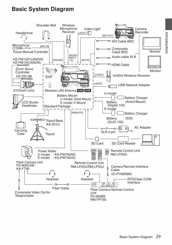
Basic System Diagram.
OPERATE LOCK
OFF FULL
MODE
RM-LP20REMOTE CONTROL UNIT
GAINSHUTTER
NORMAL
1/1201/100
1/250 1/500 1/10001/2000
EEI 0dB
+3dB+6dB +9dB +12dB
+18dB
ALC
LEVEL GAMMA LEVEL GAMMA KNEE POINT AUTOKNEE
WHITE BALANCEMANUAL PRESET FAW AW A AW B
WHITE PAINTR B
PAINT AUTO WHITE
TALLYCALL PREVIEW
MASTER BLACK
IRIS
AUTO MANUAL
CLOSE OPEN
XLR 4-pin
(DUO-150)
FS-900BSRM-FP790
VC-P790RMG
RM-LP20G
RM-LP25U/RM-LP55UFS-900CAMKA-F790
: KA-PW790AG: KA-PW790VG
[AUDIO INPUT 1/2]
[REMOTE]
[UniSlot]
[MIC IN]
[PHONE] [SDI IN]
[SDI OUT]
HZ-FM13(FUJINON)HZ-FM15(CANON)
HZ-ZS13B EVF
2/3
KA-551U
[HOST]
(Digital 150)
[LIGHT]
(IDX)
Carrying Case Tripod
AC Adapter
U model
E model
U modelE model
Focus Manual Controller
Zoom Lens
Shoulder Belt Wireless Microphone
ReceiverVideo Light Camera
RecorderHeadphone
SDI Cable BNC
Composite Cable BNC
Microphone
Monitor
Monitor
HeadsetHeadset
Zoom Servo Controller
LCD Studio Viewfinder
Tripod Base
Fiber Camera Unit
Power Wafer
Remote Control UnitCamera Remote Interface Cable
Fiber Camera Remote Control Unit
Fiber CableComposite Video Out for Teleprompter
RTS/Clear-COM Interface
Audio cable XLR
HDMI Cable
UniSlot Wireless Receiver
USB Network Adapter
Battery Charger
Battery Charger
Battery
Battery
Remote Control Unit
Battery MountWireless LAN Antenna u v
E model: V MountU model: Gold Mount
Standard Package
SD Card SD Card Reader
(Anton/Bauer)
Basic System Diagram 29
Introduction
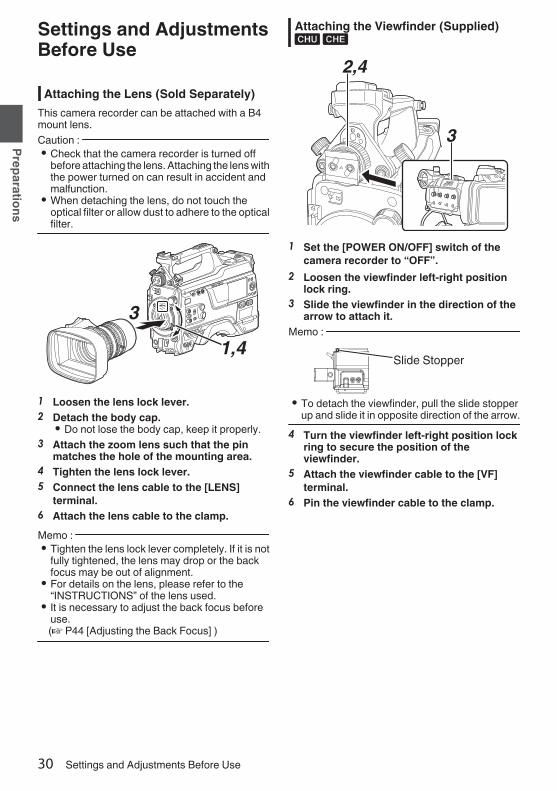
Settings and AdjustmentsBefore Use.
Attaching the Lens (Sold Separately)This camera recorder can be attached with a B4mount lens.Caution : 0 Check that the camera recorder is turned off
before attaching the lens. Attaching the lens withthe power turned on can result in accident andmalfunction.
0 When detaching the lens, do not touch theoptical filter or allow dust to adhere to the opticalfilter.
.
1,4
3
1 Loosen the lens lock lever.2 Detach the body cap.
0 Do not lose the body cap, keep it properly.3 Attach the zoom lens such that the pin
matches the hole of the mounting area.4 Tighten the lens lock lever.5 Connect the lens cable to the [LENS]
terminal.6 Attach the lens cable to the clamp.Memo : 0 Tighten the lens lock lever completely. If it is not
fully tightened, the lens may drop or the backfocus may be out of alignment.
0 For details on the lens, please refer to the“INSTRUCTIONS” of the lens used.
0 It is necessary to adjust the back focus beforeuse.(A P44 [Adjusting the Back Focus] )
Attaching the Viewfinder (Supplied)u v
.
2,4
3
1 Set the [POWER ON/OFF] switch of thecamera recorder to “OFF”.
2 Loosen the viewfinder left-right positionlock ring.
3 Slide the viewfinder in the direction of thearrow to attach it.
Memo :
.
Slide Stopper
0 To detach the viewfinder, pull the slide stopperup and slide it in opposite direction of the arrow.
4 Turn the viewfinder left-right position lockring to secure the position of theviewfinder.
5 Attach the viewfinder cable to the [VF]terminal.
6 Pin the viewfinder cable to the clamp.
30 Settings and Adjustments Before Use
Preparations

Attaching the Microphone (SoldSeparately)
You can attach a separately sold microphone to themicrophone holder.The microphone that is sold separately uses aphantom power supply.
.
4
1, 32
1 Turn the knob on the microphone holdercounterclockwise to loosen and open themicrophone holder.
2 Place the microphone in the microphoneholder.
3 Turn the knob on the microphone holderclockwise to secure the microphone.
4 Connect the microphone cable to the [MICIN] terminal.
5 Pin the microphone cable to the clamp.6 Perform the settings for the phantom mic
correctly.(A P69 [Audio Recording] )
Attaching the Video Light (SoldSeparately)
Video lights or accessories can be attached to theaccessory shoe of this camera recorder.The accessory shoe is of the 1/4-inch screw type.To make use of a slide shoe, attach the suppliedcold shoe unit.Attaching the Cold Shoe Unit1 Remove the plate from the cold shoe unit.
While lifting the catch, slide the plate out.
.
Catch
Plate
2 Attach the cold shoe unit to the shoe of thiscamera recorder using the four screwssupplied.
3 Attach the plate to the cold shoe unit.Push the catch up from the bottom and slot theplate into the guide in the direction of the arrow.
.
Guide
Plate
Attaching the Video LightThe [LIGHT] terminal (D-tap) of this camerarecorder can be connected with a video light (DC12 V, maximum power consumption 50 W uw x and DC 12V, 2A v).Connect the [LIGHT] terminal after attaching theaccessory shoe.When the [LIGHT] switch is set to “AUTO”, the lightgoes on only during recording in tandem with thecamera. When it is set to “MANUAL”, the light goeson or turns off respectively when the video lightpower is turned on or off.
Settings and Adjustments Before Use 31
Preparations

Attaching the Wireless LAN Antennas(Supplied) u v
Attach the wireless LAN antenna by turning it in theclockwise direction. Hold the base while attachingthe antenna.
.
Caution : 0 Applying force to the wireless LAN antenna or
yanking it may damage the antenna so pleaseuse caution when using the antenna.If it is damaged, replacement is chargeable evenduring the warranty period.(Part number: T9A-0095-00)
0 Use the antenna holders without removingthem.
Attaching the Tripod (Sold Separately)Mount this camera recorder after attaching theKA-551U tripod base unit (sold separately) to thetripod.To prevent the camera recorder from falling off,which may result in injuries or damages, read the“INSTRUCTIONS” of KA-551U as well as that ofthe tripod to be used to attach the camera recordersecurely.Caution : 0 If the camera recorder exceeds the weight limit
of the tripod, do not mount it on the tripod.0 Use the tripod on a stable surface.
Adjusting the Position of the ShoulderPad
Adjust the position of the shoulder pad back andforth.1 Release the lock of the lock lever and adjust
the position of the shoulder pad back andforth.
2 Lock the lock lever and check that theshoulder pad is fixed.
.
Lock Lever
32 Settings and Adjustments Before Use
Preparations

Power SupplyTo use this camera recorder, you can attach abattery pack or connect an AC adapter to it.
(A P34 [Using a Battery Pack] )(A P33 [Using AC Power (DC IN Power)] )
Caution : 0 Set the [POWER ON/OFF] switch to “OFF”
before changing the power supply that operatesthis camera recorder.
0 Use the camera recorder and peripheralequipments within the rated output of the ACadapter.
0 To connect other peripheral equipment, do sounder the following conditions.0 Keep the total power consumption of the
peripheral equipments under 35 W whenusing the recommended battery.
0 Keep the total power consumption of theperipheral equipments under 65 W whenusing Tandem 150 (recommended ACadapter). u w
0 Keep the total power consumption of theperipheral equipments under 50 W whenusing AC-100 (recommended AC adapter).x
0 The power consumption of the [LIGHT] terminalis below 50 W. Keep the total powerconsumption of the peripheral equipmentsexcluding the [LIGHT] terminal under 35 Wwhen using the terminal. If the total powerconsumption of the peripheral equipmentsexceeds the rating, the power to the [LIGHT],[DC OUT] (rear) and [DC OUT] (LAN) terminalsis automatically cut off. This is not a malfunction.Use peripheral equipments with lower powerconsumption then turn on the power of thiscamera recorder again. u w x
0 To check the power consumption, refer to thePower screen of the Status screen.(A P171 [Power Screen] )0 If the voltage of the [DC INPUT] becomes 12 V
or less, the USB adapter connected to the[HOST] terminal cannot be used. Check thepower supply and the peripheral equipments,and turn on the power of this camera recorderagain.
0 Use a power supply of 12 V/ 2A or below for the[LIGHT] terminal.The [LIGHT] terminal, DC OUT terminal(rear)/DC OUT (LAN) terminal and the D-tapterminal of the battery loading folder cannot beused at the same time. v
Using AC Power (DC IN Power)Use the AC adapter (sold separately) to operatethe camera recorder with AC power.Recommended AC Adapteru w : Tandem 150 (Anton/Bauer)v : IA-300a (IDX)x : AC-100 (IDX)Memo : 0 For the type of AC adapter to be attached on a
battery mount, check the method of attachmentin [Using a Battery Pack] (A P 34).
o Attaching Core Filter Beforehand vAttach the core filter (large) to the DC cable of theAC adapter before using the AC adapter.
.
Release the stopper.
To be connected to the AC Adapter.
5 cm Wind twice
1 Connect the DC cable of the AC adapter tothe [DC INPUT] terminal of the camerarecorder.Check that the power of this unit and that of theAC adapter are both set to “OFF”, followed byconnecting according to the diagram.
.
2 Turn on the power of the AC adapter,followed by setting the [POWER ON/OFF]switch of this unit to “ON”.Power will be supplied to the camera recorder.
Caution : 0 Do not insert or remove the DC cable during
recording.0 Do not use power supply of high voltage
fluctuation, containing noise such as ripple, orwith insufficient capacity.
Power Supply 33
Preparations

Using a Battery PackRecommended BatteriesU model : Digital 150 (Anton/Bauer)E model : DUO-150 (IDX)* Models with an E suffix are for the European
market and the UL Listing mark is not applicable.Caution : 0 Make use of the recommended batteries. Heavy
batteries may fall off if not used correctly.0 For details on how to charge the battery, please
refer to the “INSTRUCTIONS” of the battery inuse.
Battery Operating TimeThe following are the approximate times forcontinuous operation on fully-charged batteries.
BatteryContinuous
Recording Time (At25 °C)
Digital 150 (U model) Approx. 3.1 hrsDUO-150 (E model) Approx. 3.1 hrsMemo : 0 Actual operating times may differ depending on
the age of the battery, charging condition, andoperating environment.
0 Operating time is shortened in coldenvironment.
0 The operating time may shorten when powerzoom is used, accessories are connected, orwhen the LCD monitor is frequently used.
Precautions for the Battery Operation0 Do not remove the battery when the [POWER
ON/OFF] switch is “ON”.0 Do not insert or remove the DC cable when the
battery is in use.0 Leaving the camera recorder unused with the
battery attached will deplete the battery powereven when you set the [POWER ON/OFF]switch to “OFF”. Remove the battery if you arenot using the camera recorder.
Attaching/Detaching the Battery (U Model)Use the following battery type.0 Gold Mount1 Align the battery guide pins (x3) with the
battery adapter guide hole, and insert themdirectly.
.
Guide PinsGuide Hole (x3)
2 Slide the battery in the direction indicatedby the arrow until a “click” sound is heard.
Memo : 0 If the guide pins are not inserted straight, the
battery will not be attached correctly.3 Detaching the Battery
Press down the release lever and slide thebattery toward you to detach it from the camerarecorder.
.
Battery
Release Lever
34 Power Supply
Preparations

Attaching/Detaching the Battery (E Model)Use the following battery type.0 V Mount1 Attach the battery.
Face the terminal downward and attach the Vmount of the battery onto the V mountattachment bracket of the camera recorder.
2 Press down the battery until it snaps intoplace.
.
V MountV Mount Attachment Bracket
3 Detaching the BatteryPress down the release lever and slide thebattery upward to detach it from the camerarecorder.
.
Battery
Release Button
Precautions for Batteries0 Store the battery in a cool and dry place when
not in use. Do not expose the battery to hightemperatures (such as in a car under directsunlight). This will cause battery leakage andshorten the battery life.
0 Operating time is shortened if the batteryterminal is dirty.
0 If the operating time shortens drastically evenafter charging, the battery may be reaching theend of its life. Replace the battery with a newone.
Battery Warning SettingsFollow the steps below to configure the warningvoltage or warning level when the remainingbattery level is running low.1 Select “Voltage” or “Capacity%” in
[System] B [Battery] B [Type]0 “Near End (V)” and “End (V)” are enabled
when “Voltage” is selected.0 “Near End (%)” and “End (%)” are enabled
when “Capacity%” is selected.2 Configure “Near End” and “End”
0 Configures the setting at which the power isshut down automatically after the warning isactivated.
(A P149 [ Near End (V) 0 ] )(A P149 [ End (V) 0 ] )(A P149 [ Near End (%) 2 ] )(A P149 [ End (%) 2 ] )
3 Check in advance to ensure that theconnected battery is in order and thesettings are appropriate0 If the time is different from what has been
anticipated, repeat the steps in 2 and 3.Memo : 0 When the battery that is connected does not
support communication, “Near End (V)” and“End (%)” are enabled even when “Capacity%”is selected.
Power Supply 35
Preparations
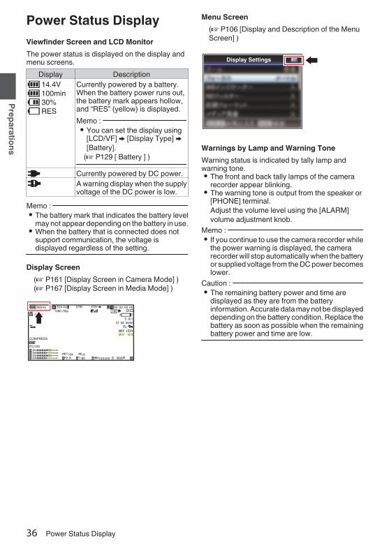
Power Status DisplayViewfinder Screen and LCD MonitorThe power status is displayed on the display andmenu screens.
Display DescriptionB 14.4VB 100minC 30%4 RES
Currently powered by a battery.When the battery power runs out,the battery mark appears hollow,and “RES” (yellow) is displayed.Memo : 0 You can set the display using
[LCD/VF] B [Display Type] B[Battery].
(A P129 [ Battery ] )
G Currently powered by DC power.H A warning display when the supply
voltage of the DC power is low.Memo : 0 The battery mark that indicates the battery level
may not appear depending on the battery in use.0 When the battery that is connected does not
support communication, the voltage isdisplayed regardless of the setting.
Display Screen(A P161 [Display Screen in Camera Mode] )(A P167 [Display Screen in Media Mode] )
.
100min50min
282min
1/ 60F2.8AE±0ND1 /64
12 :34 :56
ISO102400
00:00:00.001080 /30p
SDI IN
ITU709
COMPRESS
5 . 6f t
B 5600K
Menu Screen(A P106 [Display and Description of the MenuScreen] )
.
Display Settings
Warnings by Lamp and Warning ToneWarning status is indicated by tally lamp andwarning tone.0 The front and back tally lamps of the camera
recorder appear blinking.0 The warning tone is output from the speaker or
[PHONE] terminal.Adjust the volume level using the [ALARM]volume adjustment knob.
Memo : 0 If you continue to use the camera recorder while
the power warning is displayed, the camerarecorder will stop automatically when the batteryor supplied voltage from the DC power becomeslower.
Caution : 0 The remaining battery power and time are
displayed as they are from the batteryinformation. Accurate data may not be displayeddepending on the battery condition. Replace thebattery as soon as possible when the remainingbattery power and time are low.
36 Power Status Display
Preparations

Turning On/Off the PowerTurning On the Power
.
1 Set the [POWER ON/OFF] switch to “ON”.The camera recorder starts up in Camera modeand is ready for shooting.
Memo : 0 The camera recorder always start up in Camera
mode when the [POWER ON/OFF] switch is set to“ON”. Use the [CAM/MEDIA] button at the side ofthe camera recorder to switch mode.(A P20 [Operation Modes] )
Turning Off the PowerSets the camera recorder to the recording standby orstop mode.1 Set the [POWER ON/OFF] switch to “OFF”.2 Remove the battery and the power to the [DC
INPUT] terminal (when not in use for a longtime).
Caution : 0 Do not set the [POWER ON/OFF] switch to “OFF”
during recording. Check that the operation modedisplay is “STBY” or “STOP” before you turn off thepower.
0 If you have mistakenly set the [POWER ON/OFF]switch to “OFF” during recording, wait for 5seconds or more before you turn on the poweragain.
0 When turning off the power, first set the [POWERON/OFF] switch of the camera recorder to “OFF”.Do not remove the battery or turn off the AC powerwhile the [POWER ON/OFF] switch is set to “ON”.
Turning On/Off the Power 37
Preparations

Initial SettingsWhen the power is first turned on, the Initial Settingscreen for performing the initial settings in thecamera recorder appears.Set the date/time of the built-in clock in the [Date/Time] screen.All operations are disabled until initial settings arecomplete.
.
Memo : 0 It is recommended to use the AC adapter as the
power supply.0 Attach the lens cap.1 Set the [POWER ON/OFF] switch to “ON”.
A language selection screen appears.0 For U models
.
0 For E models
.
Memo : 0 The menus and messages on the screen of the
LCD monitor or viewfinder are displayed in theselected language.
2 Select a language using the cross-shapedbutton (JK), and press the [STATUS/SET]button (R).A self-diagnosis screen appears.
.
3 Ensure the lens cap is attached, and pressthe [STATUS/SET] button (R).0 Self-diagnosis starts.0 A progress bar appears, and “Complete
Diagnosis” appears when the diagnosis iscomplete.
.
Memo : 0 It takes about 6 minutes to complete the
diagnosis. During the diagnosis, do not operateor turn off the camera recorder.
38 Initial Settings
Preparations

4 Press the [STATUS/SET] button (R) afterconfirming the exit screen.The [Date/Time] screen appears.0 For U models
.
0 For E models
.
5 Set the time zone and date/time.A Move the cursor with the cross-shaped button
(HI) and select the setting item.B Change the values with the cross-shaped
button (JK).6 Press the [STATUS/SET] button (R) after
setting is complete.The clock is set to 0 seconds of the input date/time.
Memo : 0 The configured date/time data can be displayed
on the LCD monitor and viewfinder screen andbe recorded to a recording media.
0 The value of the year can be set in the range of“2000” to “2099”.
0 The configured date/time data is saved in thebuilt-in battery even if the power is turned off.
0 If the date/time data is no longer retained, thebuilt-in battery is dead. For replacement of thebuilt-in battery, please contact the local dealersin your area.
Changing the Time after Initial SettingSetting the Date/Time
(A P149 [ Date/Time ] )1 Select [System] B [Date/Time].
The [Date/Time] screen appears.2 Set the date and time.A Move the cursor with the cross-shaped button
(HI) and select the setting item.B Change the values with the cross-shaped
button (JK).3 Press the Set button (R) after setting is
complete.The clock is set to 0 seconds of the input date/time.
Changing the Display StyleYou can change the display style of the date/timeon the menu.Setting the Date Display (Date Style)
(A P150 [ Date Style ] )The date display can be changed in [System] B[Date Style].
Setting the Time Display (Time Style)(A P150 [ Time Style ] )
The time display can be changed in [System] B[Time Style].
Date/Time Display in Each OperationMode
During Camera mode:Time of the built-in clock is displayed.During Media mode:Shooting date/time of the clip being played back isdisplayed.
Initial Settings 39
Preparations

Displays on the LCDMonitor and ViewfinderYou can display the camera status, recordingmedia information, zebra pattern, and variousmarkers in the video image on the LCD monitor andviewfinder screen during shooting.Memo : 0 When [A/V Set] B [Video Set] B [SDI OUT2
Char.]/[HDMI Char.]/[Video OUT Char.] is set to“On”, the display screen and menu screen arealso displayed in the video image of the videosignal output terminal.(A P131 [ SDI OUT2 Char. ] )(A P131 [ HDMI Char. ] )(A P131 [ Video OUT Char. ] )
Display ScreenDisplay Screen (VF/LCD) in Camera Mode
(A P161 [Display Screen in Camera Mode] )0 Use the [DISPLAY] button to switch the display
mode of the LCD monitor.(Display off B Display on B Enlarged display BDisplay off)
0 Use the user button that is assigned with “VFDisplay” to switch the viewfinder screen.(Display off B Display on B Display off)
0 Press the [STATUS/SET] button to switch to thestatus screen.
.
100min50min
282min
1/ 60F2.8AE±0ND1 /64
12 :34 :56
ISO102400
00:00:00.001080 /30p
SDI IN
ITU709
COMPRESS
5 . 6f t
B 5600K
Display OffElectronic Viewfinder
Display On
Enlarged Display
LCD Monitor
Display Screen (VF/LCD) in Media Mode(A P167 [Display Screen in Media Mode] )0 This is the screen display during clip playback in
Media Mode.0 The display switches with every press of the
[DISPLAY] button.(Display off B Display on B Display off)
.
Jan 24,2018
1920x108030p 50M
282min
12 :34 :56
00:00:00.001000/2000
Display Off
Display On
40 Displays on the LCD Monitor and Viewfinder
Preparations

Status Screen0 This screen allows you to check the current
settings.0 To display the status screen, press the
[STATUS/SET] button in the normal screen.0 Press the [STATUS/SET] button to switch to the
status screen.0 Press the [MENU/THUMB] button at each status
screen (other than the [Camera] and [Power]screen) to enter the setting screen.
0 Use the cross-shaped button (HI) to switchbetween the screens.
.
USER Switch Set
CameraLCD/VFRecord FormatAudio InputAudio OutputVideoPowerPlanning MetadataNetworkLANUSB/Int. WLAN u vUSB w x
Streaming
* These are screen examples. The contentsdisplayed are different depending on the modeland settings.
Remote Edit Mode ScreenThis is a mode for accessing the page for editingthe metadata that is recorded in a clip via a webbrowser on devices such as a smartphone, tabletterminal, or PC.
(A P196 [ Clip Metadata ] )
.
Exit
Remote Edit Mode
Warning DisplayWarning display is displayed in the display screen(Camera mode, Media mode).
(A P218 [Error Messages and Actions] )
.
100min50min
282min
1/ 60F2.8AE±0ND1 /64
12 :34 :56
ISO102400
00:00:00.001080 /30p
SDI IN
ITU709
COMPRESS
5 . 6f t
B 5600K
Warning Display Area
Displays on the LCD Monitor and Viewfinder 41
Preparations

Adjusting the LCD Monitorand ViewfinderYou can monitor video images on this camerarecorder using the viewfinder, LCD monitor, orboth.
Adjusting the LCD MonitorYou can change the brightness of the LCD monitoraccording to your usage condition.Changing the brightness of the screen will notaffect the recorded images.Adjusting the BrightnessUse [LCD/VF] B [LCD Bright] to adjust thebrightness of the LCD monitor.
(A P125 [ LCD Bright ] )
Adjusting the OutlineUse [LCD/VF] B [LCD Peaking] to adjust theoutline of the LCD monitor.
(A P125 [ LCD Peaking ] )
Adjusting the ContrastUse [LCD/VF] B [LCD Contrast] to adjust thecontrast of the LCD monitor.
(A P125 [ LCD Contrast ] )
Adjusting the LCD RGB GainUse [LCD/VF] B [LCD RGB Gain] to adjust theR/G/B gain of the LCD monitor.
(A P126 [ LCD RGB Gain ] )
Configuring the BacklightConfigure the backlight using the [B.LIGHT] buttonlocated on the side operation panel.Dark B Normal B Bright B Off B Dark
Adjusting the ViewfinderYou can change the brightness and peaking of theviewfinder screen according to your usageconditions.Changing the brightness of the screen will notaffect the recorded images.
.
3
12 2
4
1 Loosen the fastening rings on the left andright sides of the viewfinder to adjust thehorizontal position, followed by tighteningthe rings.
2 Loosen the viewfinder front-back positionlock ring. Adjust the front and backpositions then tighten the ring.
3 Adjust the angle of the viewfinder to aposition that enables easy viewing.
4 Adjust the visibility using the eyepiecefocus ring.Adjust until the viewfinder image appearssharp.
42 Adjusting the LCD Monitor and Viewfinder
Preparations

5 Adjust the brightness, outline and contrastof the viewfinder screen.Adjusting the BrightnessUse the [BRIGHT] knob to adjust the brightnessof the viewfinder.Adjusting the OutlineUse the [PEAKING] knob to adjust the outline ofthe viewfinder.Adjusting the ContrastUse the [CONTRAST] knob to adjust thecontrast of the viewfinder.Adjusting the ColorUse the [CHROMA] knob to adjust the color ofthe viewfinder.Configuring the LuminanceUse the [B.LIGHT] switch to configure theluminance level.H: Bright; N: Normal; L: DarkAdjusting the VF RGB gainUse [LCD/VF] B [VF RGB Gain] to adjust the R/G/B gain level of the viewfinder.
(A P126 [ VF RGB Gain ] )
Displaying in Black and WhiteThe display can be switched to black-and-whiteby configuring [LCD/VF] B [VF Color] to “Off”.
(A P125 [ VF Color ] )
o Flipping up the EyepieceFlipping up the eyepiece provides a better viewof the entire image.Push the lock upward to flip up the eyepiece.
.
Lock
o Flipping up the VF BarrelFlipping up the viewfinder barrel enablesviewing of the image directly. The image will beinverted in this case. Press the [MIRROR]switch to display the image correctly.Push the lock upward to flip up the viewfinderbarrel.
.
Lock
Adjusting the LCD Monitor and Viewfinder 43
Preparations

Adjusting the Back FocusWhen the lens is attached for the first time, adjustthe back focus of the lens if the focus is not clearwhen it is zoomed to the telephoto or wide-angleend.0 The Siemens Star Chart is most suitable as the
subject.
.
Siemens Star Chart
1 Place an object at approximately 3 m awayfrom the camera recorder.
2 Open up the iris.3 Set the lens to the telephoto end.4 Turn the focusing ring to adjust the focus.5 Set the lens to the wide-angle end.6 Loosen the F.B. locking screw of the lens
and turn the back focus adjustment ring toadjust the focus.
7 Repeat the steps from 3 to 6 to adjust thefocus at both ends of the zoom.
8 After determining the position of the backfocus adjustment ring, tighten the F.B.locking screw.
Memo : 0 For details, please refer to the
“INSTRUCTIONS” of the lens.
44 Adjusting the Back Focus
Preparations
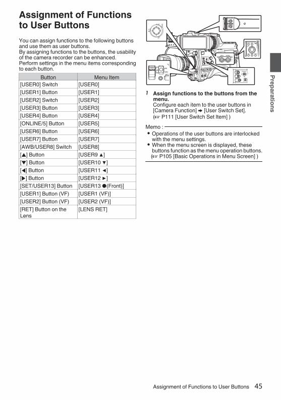
Assignment of Functionsto User ButtonsYou can assign functions to the following buttonsand use them as user buttons.By assigning functions to the buttons, the usabilityof the camera recorder can be enhanced.Perform settings in the menu items correspondingto each button.
Button Menu Item[USER0] Switch [USER0][USER1] Button [USER1][USER2] Switch [USER2][USER3] Button [USER3][USER4] Button [USER4][ONLINE/5] Button [USER5][USER6] Button [USER6][USER7] Button [USER7][AWB/USER8] Switch [USER8][J] Button [USER9 ▲][K] Button [USER10 ▼][H] Button [USER11 ◀][I] Button [USER12 ▶][SET/USER13] Button [USER13 ●(Front)][USER1] Button (VF) [USER1 (VF)][USER2] Button (VF) [USER2 (VF)][RET] Button on theLens
[LENS RET]
.1 Assign functions to the buttons from the
menu.Configure each item to the user buttons in[Camera Function] B [User Switch Set].(A P111 [User Switch Set Item] )
Memo : 0 Operations of the user buttons are interlocked
with the menu settings.0 When the menu screen is displayed, these
buttons function as the menu operation buttons.(A P105 [Basic Operations in Menu Screen] )
Assignment of Functions to User Buttons 45
Preparations

Tally LampThis is the indicator lamp for recording andwarning.The operation changes according to the menusettings.The lamp blinks when the battery or remainingspace on the recording media is low. (Cameramode only)* Configure in [System] B [Front Tally]/[Back
Tally].(A P148 [ Tally System ] )(A P148 [Front Tally/Back Tally] )
.
Front Tally Lamp
Back Tally Lamp (Handle)
Back Tally Lamp (Rear)
0 When [Tally System] is set to “Internal”
Menu SettingFront Tally/Back Tally
Rec LiveStreaming
Rec/LiveStreaming
Informationon CameraRecorderFunctions
Warning JAlarm
o
CameraRecorderRecordingStatus
Recording R - RSpecialRecordinginProgress*1
R - R
LiveStreamingStatus
LiveStreaminginProgress
- R R
0 When [Tally System] is set to “Studio”
[TALLY] Switch
FrontTally/BackTally
FrontTally
BackTally
OFF HIGH orLOW ON
Informationon CameraRecorderFunctions
Warning - JAlarm
- o
Input fromRemoteControlUnit
CALL - o*2PROGRAM - RPREVIEW - R
R : Lights upJ : Blinks four times in 1 secondo : Blinks once in 1 second*1 Paused state during special recording ([Clip
Continuous]0).(A P91 [Clip Continuous Rec 0] )
*2 Back tally onlyMemo : 0 Blinking takes priority over lighting up.
46 Tally Lamp
Preparations

SD CardThis camera recorder saves the recorded imagesand audio sound on the SD card (sold separately)in the card slot.
Usable CardsFormat Setting and Usable SD CardCombinations
System Format Bit Rate Usable SDCard
High-Speed2
QuickTime(H.264)
70M (XHQ),
50M (XHQ),50M (XHQ),35M (UHQ)
UHS-I U3 orhigher
HD70M (XHQ)0,
50M (XHQ),50M (XHQ)
UHS-I U1 orhigher, orClass 10 orhigher
35M (UHQ)
UHS-I U1 orhigher, orClass 6 orhigher
QuickTime(MPEG2),MXF(MPEG2)0
35M (HQ),25M (SP)
Exchange(U model)0
12M (LP),8M (LP)
MP4(H.264)(E model)0
12M (LP),8M (LP)
SD2
- - UHS-I U1 orhigher, orClass 4 orhigher
Web2
- -Caution : 0 Using cards other than those from Panasonic,
TOSHIBA or SanDisk may result in recordingfailure or data loss.
Estimated Recordable Time of SD CardsThe estimated recordable time is only a guide.Differences may occur depending on the SD cardin use and the battery condition.0 The recordable time varies according to the
settings in [System], [WFormat], [WResolution],[WBit Rate] and [YResolution].
0 The following is the recording time during audio4ch recording. The recording time is longer for2ch recording.(A P151 [ System ] )(A P151 [ W Format ] )(A P152 [ W Resolution ] )(A P153 [ W Bit Rate ] )(A P153 [ Y Resolution ] )
System HD,HD + Web (HD)
SD,HD + Web
(Web)HD + Web
(Web)Format QuickTime (H.264)
Resolution 1920x1080 1920x1080,1280x720
720x480,720x576 960x540 480x270
Bit Rate XHQ(70M)
XHQ(50M) UHQ HQ HQ LP
8GB 12 17 24 80 240 48016GB 24 35 48 160 480 96032GB 48 70 96 320 960 192064GB* 96 140 192 640 1920 3840
128GB* 192 280 384 1280 3840 7680256GB* 384 560 768 2560 7680 15360
(Unit: minute)System HDFormat QuickTime (MPEG2),
MXF (MPEG2)Exchange,
MP4 (H.264)
Resolution1920x1080,1440x1080,1280x720
1440x1080 1920x1080 1280x720
Bit Rate HQ SP LP (12M) LP (8M)8GB 24 32 80 120
16GB 48 64 160 24032GB 96 130 320 48064GB* 192 260 640 960
128GB* 384 520 1280 1920256GB* 768 1040 2560 3840
(Unit: minute)* SDXC
SD Card 47
Preparations

Memo : 0 If the SD card contains files recorded by devices
other than this camera recorder or files that aresaved from a PC, the recordable time may beshorter or data may not be properly recorded.
0 For each file format, up to 600 clips can berecorded to one SD card on this camerarecorder. When 600 clips are recorded to onecard, the remaining space is displayed as 0 minregardless of the estimated recordable time,and no further recording can be performed.
0 When [System] is configured to “High-Speed”,the remaining time display for recording to theSD card will run out faster than usual. 2
Write-Protect Switch on the SD CardA Slide the write-protect switch upward to enable
writing or deleting.B Slide the write-protect switch downward to
prevent writing or deleting. (Images in the cardare protected.)
.
A B
Write/Delete Enabled Write/Delete Disabled
Write-Protect Switch
Inserting an SD CardThis camera recorder comes with two card slots(Slot A and B) for video/audio recording andplayback.1 Press the SD card cover knob to open the
cover.2 Insert an SD card with the notched corner
pointing up.The status indicator of the card slot to which thecard was inserted lights up in red.
3 Close the SD card cover.
Card Slot Status IndicatorThe following table shows the respective states ofslot A and B.
Lamp Slot StatusLights up inred
The inserted SD card is beingaccessed. (writing/reading data)Do not turn off the power of thecamera recorder or remove the SDcard.
Lights up ingreen
On standby. The inserted SD cardcan be used for recording orplayback.
Light goes out 0 SD card is not inserted.0 An unusable card is inserted.0 An SD card is inserted but a
different slot is selected.
48 SD Card
Preparations

Removing the SD Card1 Check that the SD card to be removed is not
being accessed (status indicator of thecard slot lights up in red).
2 Press the SD card cover knob to open thecover.
3 Push the SD card and remove it from theslot.
4 Close the SD card cover.Memo : 0 When both slots are inserted with usable SD
cards, the previously selected slot is used.Caution : 0 Data may be lost if you turn off the power of the
camera recorder or remove the SD card when itis being accessed. All data recorded on thecard, including the file that is being accessed,may be corrupted. Be sure to check whether thestatus indicator is lit in green or turned off beforeyou turn off the power or remove the SD card.
0 If you mistakenly remove the card when it isbeing accessed, reinsert the card only after thestatus indicator goes off.
0 The SD card may not be recognized if you insertand remove the card within a short time. Whenthis happens, remove the card and wait for a fewseconds before you reinsert.
Switching the SD cardsWhen both card slots are inserted with SD cards,you can use the [SLOT SELECT] button to switchthe card to use.When the memory on an SD card is full duringrecording, data recording automatically switches tothe other card.Memo : 0 The [SLOT SELECT] button is disabled during
recording or playback. Cards will not beswitched even if you press the button.
SD Card 49
Preparations

Formatting (Initializing) SD CardsWhen the following cards are inserted, [!FORMAT]appears at the remaining media display area.Format the card using the camera recorder menu.0 Unformatted SD cards0 SD cards formatted under different
specifications* For details of the menu operation, refer to
“[Basic Operations in Menu Screen] (A P 105)”.
Caution : 0 Be sure to format the SD card on this camera
recorder. SD cards formatted on a PC and otherperipheral equipment cannot be used on thiscamera recorder.
0 [!RESTORE] appears at the remaining mediadisplay area when an SD card that requiresrestoring is inserted.
1 Select [System] B [Media] B [FormatMedia].(A P148 [ Format Media ] )
2 Select the slot of the SD card to beformatted and press the [STATUS/SET]button (R).
.
2
Set
Format MediaFormat Slot AFormat Slot B
3 The status of the selected SD card appears.4 Select [Format] and press the
[STATUS/SET] button (R).
.
4
Set
Cancel
Format
Format Media
5 Formatting starts.
.
Formatting...
6 Formatting is complete.When formatting is complete, “Complete” appearsand the camera recorder returns to the [FormatMedia] screen.Memo : 0 During formatting, menu operation is
unavailable but you can start recording.However, this is only available when arecordable SD card is inserted in the other slot.
0 Formatting cannot be performed in the followingcases.0 Recording is in progress on the SD card to be
formatted.0 SD card is not inserted.0 Write-protect switch of the SD card is set (z
is displayed).Caution : 0 If you format the SD card, all data recorded on
the card, including video data and setup files,will be deleted.
50 SD Card
Preparations

Restoring the SD CardIt is necessary to restore the SD card if anabnormality occurs to the data in the card due tosome reasons.Memo : 0 [!RESTORE] appears at the remaining media
display area when an SD card that requiresrestoring is inserted.
1 Select [System] B [Media] B [RestoreMedia].(A P148 [ Restore Media ] )
2 Select the SD card to be restored and pressthe [STATUS/SET] button (R).
.
2
Set
Restore MediaRestore Slot ARestore Slot B
3 Restoring starts.
.
Restoring...
4 Restoring is complete.0 When restoring is complete, “Complete”
appears and the camera recorder returns to the[Restore Media] screen.
0 When no media that requires restoring isinserted, the camera recorder returns to the[Media] menu screen.
Caution : 0 [Restore Media] can only be selected in Camera
mode. However, it cannot be selected while thecamera recorder is recording. Select [RestoreMedia] in Camera mode when the camerarecorder is not recording.
0 [Restore Media] does not restore the SD card toits original states completely. If restoring fails,replace or format the SD card. Take note thatformatting erases all the information inside theSD card.
0 Restoring cannot be performed in the followingcases.0 Camera recorder is recording in progress.0 SD card is not inserted.0 Write-protect switch of the SD card is set (z
is displayed).
SD Card 51
Preparations

Clips Recorded to SD CardsFolders in the SD CardThe captured image is recorded into differentfolders according to the [Format] settings.0 Other than MXF (MPEG2): [DCIM]0 MXF (MPEG2): [PRIVATE]
Memo : 0 By formatting (initializing) the SD card from the
[Format Media] menu on the camera recorder,folders required for recording in the current[System] settings will be generated.
0 When the [System] settings and [WFormat]/[YFormat] settings are changed, foldersrequired for recording in those settings will beautomatically generated.
Caution : 0 When a clip inside the folder is moved or deleted
using the Explorer (Windows) or Finder (Mac),recording to the SD card may fail if formatting(initializing) of the card is not performed.
Clip (Recorded Data) and Clip Name0 When recording is stopped, the images, audio
and accompanying data which are recordedfrom start to stop are recorded as one “clip” onthe SD card.
0 An 8-character clip name is automaticallygenerated for the recorded clip.(“Clip Name Prefix” + “Clip Number”)
Example: QuickTime
.
ABCG0001
This is set to “xxxG” (“xxx” denotes the last 3 digits of the serial number) by default.
Clip Name Prefix (any four alphanumeric characters)
The Clip Number can be reset in the menu.*
A number in automatic ascending order is assigned in the recording order.
Clip Number
* [Clip Set] B [Reset Clip Number](A P156 [ Reset Clip Number ] )
Memo : 0 Before recording starts, you can set any
characters for the clip name prefix by using[System] B [Record Set] B [Clip Set] B [ClipName Prefix].(A P156 [ Clip Name Prefix ] )0 Changes cannot be made after recording.
Recorded Clips0 The recorded materials may be split into several
files but they can be played back continuouslyon the camera recorder.
0 Clips may be recorded across the two SD cardsin card slots A and B depending on the recordingtime of the clip.
Caution : 0 A clip recorded across several cards cannot be
played back continuously. Continuous playbackis only possible when the recording is made onone card.
52 SD Card
Preparations
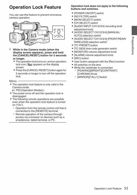
Operation Lock FeatureYou can use this feature to prevent erroneouscamera operation.
.
1 While in the Camera mode (when thedisplay screen appears), press and holdthe [CANCEL/RESET] button for 5 secondsor longer.0 The operation lock turns on, and an operation
lock icon (r) appears on the displayscreen.
0 Press the [CANCEL/RESET] button again for5 seconds or longer to turn off the operationlock.
Memo : 0 The operation lock feature is only valid in the
Camera mode.(A P20 [Operation Modes] )0 The power turns off and the operation lock is
disengaged.0 The following remote operations are possible
even when the operation lock feature is turnedon (“On”).0 Operation from the remote control unit that is
connected to the [REMOTE] terminal.0 Remote operation of the camera through
access via a browser on devices such as asmartphone, tablet terminal, or PC.
Operation lock does not apply to the followingbuttons and switches.0 [POWER ON/OFF] switch0 [ND FILTER] switch0 [MONI SELECT] switch0 [CH SELECT] switch0 [AUDIO INPUT CH1/2/3/4] recording level
adjustment knob0 [AUDIO SELECT CH1/2/3/4]-[MANUAL/
AUTO] selection switch0 [AUDIO SELECT CH1/2/3/4]-[FRONT/REAR/
WIRELESS] selection switch0 [TC PRESET] button0 [TC GEN] time code generator switch0 [MONITOR] volume adjustment knob0 [ALARM] volume adjustment knob0 [REC] button0 User button assigned with the [Rec] function0 All switches on the lens0 While the viewfinder is connected
0 [PEAKING][BRIGHT][CONTRAST][CHROMA] Knob
0 [MIRROR][TALLY] Switch
Operation Lock Feature 53
Preparations

Basic ShootingProceduresPreparations
.
2
4
1
3
1 Supply battery or AC adapter power to thecamera recorder.(A P33 [Power Supply] )
2 Insert the recording media(A P47 [SD Card] )
3 Turn on the power of the camera recorder.Setting the [POWER ON/OFF] switch to “ON”starts up the camera recorder in the Cameramode to enable shooting.
4 Adjust the angle of the viewfinder.(A P42 [Adjusting the LCD Monitor andViewfinder] )
5 Set [System], [Format], [Resolution],[Frame Rate], [Bit Rate] and [Audio] in[System] B [Record Set] B [RecordFormat].0 You can select the definition of the recorded
videos, file format for recording/playback,and the video recording format on thiscamera recorder.
0 Press the [MENU/THUMB] button to displaythe menu screen on the LCD monitor andviewfinder.
Shooting1 Configure the video and audio input
settings.You have to configure video settings such asbrightness adjustment (iris, gain, shutter) andwhite balance adjustment in order to startshooting. You also have to adjust the audioinput settings and audio recording level foraudio recording.0 Adjusting the Brightness0 Adjusting the White Balance0 Adjusting Audio Input Settings and
Recording Level2 Press the [REC] button to start recording to
the recording mediaThe tally lamp lights up in red during recording.0 Zoom Operation(A P57 [Zoom Operation] )0 Adjusting the Focus(A P58 [Focus Operation] )
Memo : 0 If both the slots are loaded with recordable cards
in the factory default, pressing the [REC] buttonstarts recording only to the media in the selectedslot.When [System] B [Record Set] B [Slot Mode] isset to “Dual”, recording can be performedsimultaneously to the cards in both the slots.(A P86 [Dual Rec] )0 The tally lamp can be turned off by setting the
[TALLY] switch to “OFF”.
3 Check the most recently captured images.0 Press the user button that is assigned with
the Clip Review function. Doing so activatesthe function and plays back the most recentlycaptured images on the LCD monitor andviewfinder screen.
0 After playback, the camera recorder returnsto standby mode (STBY).
(A P84 [Viewing Recorded VideosImmediately (Clip Review)] )
54 Basic Shooting Procedures
Shooting
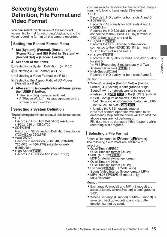
Selecting SystemDefinition, File Format andVideo FormatYou can select the definition of the recordedvideos, file format for recording/playback, and thevideo recording format on this camera recorder.
Setting the Record Format Menu1 Set [System], [Format], [Resolution],
[Frame Rate] and [Bit Rate] in [System] B[Record Set] B [Record Format].
2 Set each of the items.A [Selecting a System Definition] (A P 55)B [Selecting a File Format] (A P 55)C [Selecting a Video Format] (A P 56)D [Selecting the Aspect Ratio of SD Videos2] (A P 57)
3 After setting is complete for all items, pressthe [USER1] button.0 The recording format is switched.0 A “Please Wait...” message appears on the
screen during switching.
Selecting a System DefinitionThe following definitions are available for selection.0 HD:
Records in HD (High Definition) resolution(1920x1080 or 1280x720)
0 SD 2:Records in SD (Standard Definition) resolution(720x480 or 720x576)
0 Web2:Records in resolution (960x540, 720x480,720x576, or 480x270) suitable for webdistribution
0 High-Speed2:Records in HD resolution (1920×1080)
You can select a definition for the recorded imagesfrom the following items under [System].0 HD:
Records in HD quality for both slots A and B.0 SD 2:
Records in SD quality for both slots A and B.0 HD(SDI In):
Records the HD SDI video of the deviceconnected to the [HD/SD SDI IN] terminal in“HD” to both slot A and slot B.
0 SD(SDI In)2:Records the SD SDI video of the deviceconnected to the [HD/SD SDI IN] terminal in“SD” to both slot A and slot B.
0 HD+Web2:Records in HD quality for slot A, and Web qualityfor slot B.(A P86 [Recording Simultaneously at TwoDifferent Definitions 2] )0 High-Speed2:
Records in HD quality for both slots A and B.Caution : 0 When [System] B [Record Set] B [Record
Format] B [System] is configured to “High-Speed”2, network cannot be used viawireless LAN u v or the [HOST] terminal(USB). Configure as follows in this case.0 Set [Network] B [Connection Setup] B [USB/
Int. WLAN] to “Off”. u v0 Unplug the USB network adapterNote that camera operation will come to anemergency stop and the power will turn off if theabove steps are not performed.File data may be damaged if this happens whilerecording is in progress.
Selecting a File FormatSelect a file format in [WFormat]/[YFormat].The following file formats are available forselection.0 QuickTime (MPEG2):
QuickTime file format (.MOV)0 MXF (MPEG2)0:
MXF (material exchange format)0 QuickTime (H.264):
QuickTime file format (.MOV)0 Exchange0: (U model only)
Sports Video Interop Group format (.MP4)0 MP4 (H.264)0: (E model only)
MP4 file formatMemo : 0 Exchange (U model) and MP4 (E model) are
selectable only when [System] is configured to“HD”.
0 When Exchange (U model) or MP4 (E model) isselected, backup recording and clip cutterfunction cannot be used.
Selecting System Definition, File Format and Video Format 55
Shooting

Selecting a Video Format0 The selectable [Frame Rate]/[Bit Rate] changes
according to the settings of [System]/[Format]/[Resolution].
List of FormatsThe following is a list of file formats and videoformats that can be selected on this camerarecorder. o When [System] is configured to “HD”, “HD
+Web”, 2 or “HD(SDI In)”, the options forslot A are:
Record FormatW Format W
ResolutionW Frame
RateW Bit Rate W Audio
QuickTime(MPEG2),MXF(MPEG2)
1920x1080 60i, 50i,30p*,25p*
35M (HQ) 4CH 16 bit/2CH 16 bit
1440x1080 60i, 50i 35M (HQ),25M (SP)
1280x720 60p, 50p 35M (HQ)QuickTime(H.264)
1920x1080 60p, 50p70M (XHQ),
50M (XHQ)
4CH 24 bit/2CH 24 bit
50M (XHQ) 4CH 16 bit/2CH 16 bit
60i, 50i,30p*,25p*,24p*
50M (XHQ)4CH 24 bit/2CH 24 bit
50M (XHQ),35M (UHQ)
4CH 16 bit/2CH 16 bit
1280x720 60p, 50p50M (XHQ)
4CH 24 bit/2CH 24 bit
35M (UHQ) 4CH 16 bit/2CH 16 bit
Exchange(U model)
1920x1080 60p 12M (LP) 2CH1280x720 8M (LP)
MP4(H.264)(E model)
1920x1080 50p 12M (LP) 2CH1280x720 8M (LP)
* Not selectable when configuring “HD(SDI In)”.Memo : 0 When [System] is set to “HD” or “HD(SDI In)”,
each item for slot B is fixed at the same settingas slot A.
0 When “HD+Web”[System] is set to 2,[Format] is fixed at “QuickTime(H.264)”.
0 When [WFormat] is configured to “Exchange” or“MP4(H.264)”, selection is possible only when[System] is configured to “HD” or “HD(SDI In)”.
0 The following functions cannot be used whenHD+Web is selected.View Remote, Live Streaming, Return over IP
o When [System] is set to “High-Speed”2Record Format
W Format WResolution
W FrameRate
W Bit Rate W Audio
QuickTime(H.264)
1920x1080 120/60p,100/50p 70M (XHQ),
50M (XHQ)
2CH 24 bit
50M (XHQ) 2CH 16 bit120/30p,100/25p,120/24p 50M (XHQ)
2CH 24 bit
50M (XHQ),35M (UHQ)
2CH 16 bit
Caution : 0 When [System] B [Record Set] B [Record
Format] B [System] is configured to “High-Speed”2, network cannot be used viawireless LAN u v or the [HOST] terminal(USB). Configure as follows in this case.0 Set [Network] B [Connection Setup] B [USB/
Int. WLAN] to “Off”. u v0 Unplug the USB network adapterNote that camera operation will come to anemergency stop and the power will turn off if theabove steps are not performed.File data may be damaged if this happens whilerecording is in progress.
Memo : 0 The [Rec Mode] is fixed at “Normal”.0 The following functions cannot be used when
High-Speed is selected.View Remote, Live Streaming, Return over IP,Upload of recorded clip, time stamp recordingand Pixel Mapping
0 The settings for slot B are fixed at the same asslot A.
0 When the [TC GEN]] selection switch is set to“F-RUN”, the time code will be recorded in “R-RUN”.
0 [TC/UB...] B [TC Mode] is fixed at “SW Set”.0 It is not possible to set a shutter speed that is
slower than the frame rate.(Example: When 120/60p is selected, 1/120 to1/9873 can be set.)
0 The sensitivity of high speed shooting is lowerthan normal shooting. In order to capture morebeautiful images, it is recommended to performshooting in a lighted environment.
0 The remaining space on the media (recordabletime to the recording media) runs out faster thanusual.(Example: For 120/60p, as the recording speedis twice as fast as usual, the remaining space onthe media is reduced by approximately doublethe speed.)
56 Selecting System Definition, File Format and Video Format
Shooting

o When [System] is set to “SD” or “SD(SDI In)”:2
Record FormatW Format W
ResolutionW Frame
RateW Bit Rate W Audio
QuickTime(H.264)
720x480 60i(U model)
8M (HQ) 4CH 16 bit/2CH 16 bit
720x576 50i(E model)
Memo : 0 Each item for slot B is fixed at the same setting
as slot A.o When [System] is set to “HD+Web”, the options
for slot B are 2:Record Format
Y Format YResolution
Y FrameRate
Y Bit Rate Y Audio
QuickTime(H.264)
960x540 30p, 25p,24p
3M (HQ) 4CH/2CH
720x480 60i 8M (HQ) 4CH 16 bit/2CH 16 bit720x576 50i 8M (HQ)
480x270 30p, 25p,24p
1.2M (LP) 4CH/2CH
Memo : 0 The following functions cannot be used when
HD+Web is selected.View Remote, Live Streaming, Return over IP
Selecting the Aspect Ratio of SD Videos2
For setting the aspect ratio of the recorded imagewhen [System] is set to “SD” or “SD(SDI In)”.You can select “16:9” or “4:3”.Memo : 0 For conditions other than those above, this item
is fixed at “16:9”.
Zoom OperationAdjusts the angle of view.Zooming can be operated using the following.0 Zoom ring/zoom lever on the commercially
available lens0 User buttons assigned with “Zoom Tele” and
“Zoom Wide”During the zoom operation, the zoom bar ornumber will appear on the upper right corner of thescreen.
(A P164 [Zoom Display] )Caution : 0 Depending on the zoom speed, the zoom drive
noise of the power zoom may be recorded.
Using Zoom Ring/Zoom Lever onCommercially Available Lens
You can adjust the preferred angle of view byturning the zoom ring or operating the zoom lever.Memo : 0 For details on the lens, please refer to the
“INSTRUCTIONS” of the lens used.
Using User Buttons Assigned with“Zoom Tele” and “Zoom Wide”
1 Assign “Zoom Tele” and “Zoom Wide” tothe user buttons.(A P45 [Assignment of Functions to UserButtons] )(A P111 [User Switch Set Item] )0 Configure the zoom speed of the user
buttons in [Camera Function] B [User SwitchSet] B [Zoom Speed].Increasing the value increases the zoomspeed.
2 Press the user button assigned with “ZoomTele”/“Zoom Wide” to zoom.0 The zoom operation is performed in the
speed that has been set.Memo : 0 This function may not work depending on the
lens attached.
Selecting System Definition, File Format and Video Format 57
Shooting
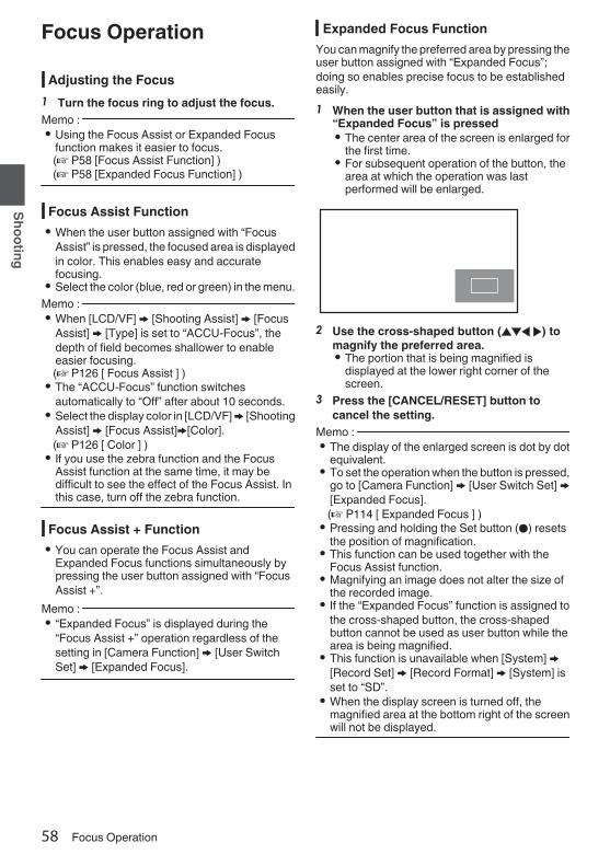
Focus OperationAdjusting the Focus
1 Turn the focus ring to adjust the focus.Memo : 0 Using the Focus Assist or Expanded Focus
function makes it easier to focus.(A P58 [Focus Assist Function] )(A P58 [Expanded Focus Function] )
Focus Assist Function0 When the user button assigned with “Focus
Assist” is pressed, the focused area is displayedin color. This enables easy and accuratefocusing.
0 Select the color (blue, red or green) in the menu.Memo : 0 When [LCD/VF] B [Shooting Assist] B [Focus
Assist] B [Type] is set to “ACCU-Focus”, thedepth of field becomes shallower to enableeasier focusing.(A P126 [ Focus Assist ] )0 The “ACCU-Focus” function switches
automatically to “Off” after about 10 seconds.0 Select the display color in [LCD/VF] B [Shooting
Assist] B [Focus Assist]B[Color].(A P126 [ Color ] )0 If you use the zebra function and the Focus
Assist function at the same time, it may bedifficult to see the effect of the Focus Assist. Inthis case, turn off the zebra function.
Focus Assist + Function0 You can operate the Focus Assist and
Expanded Focus functions simultaneously bypressing the user button assigned with “FocusAssist +”.
Memo : 0 “Expanded Focus” is displayed during the
“Focus Assist +” operation regardless of thesetting in [Camera Function] B [User SwitchSet] B [Expanded Focus].
Expanded Focus FunctionYou can magnify the preferred area by pressing theuser button assigned with “Expanded Focus”;doing so enables precise focus to be establishedeasily.1 When the user button that is assigned with
“Expanded Focus” is pressed0 The center area of the screen is enlarged for
the first time.0 For subsequent operation of the button, the
area at which the operation was lastperformed will be enlarged.
.
2 Use the cross-shaped button (JKH I) tomagnify the preferred area.0 The portion that is being magnified is
displayed at the lower right corner of thescreen.
3 Press the [CANCEL/RESET] button tocancel the setting.
Memo : 0 The display of the enlarged screen is dot by dot
equivalent.0 To set the operation when the button is pressed,
go to [Camera Function] B [User Switch Set] B[Expanded Focus].(A P114 [ Expanded Focus ] )0 Pressing and holding the Set button (R) resets
the position of magnification.0 This function can be used together with the
Focus Assist function.0 Magnifying an image does not alter the size of
the recorded image.0 If the “Expanded Focus” function is assigned to
the cross-shaped button, the cross-shapedbutton cannot be used as user button while thearea is being magnified.
0 This function is unavailable when [System] B[Record Set] B [Record Format] B [System] isset to “SD”.
0 When the display screen is turned off, themagnified area at the bottom right of the screenwill not be displayed.
58 Focus Operation
Shooting

Adjusting the BrightnessAdjust the brightness using Iris, Gain, Shutterspeed and ND filter according to the brightness ofthe object.
Adjusting the Brightness Automatically:Automatic Brightness Adjustment (AE)Mode
Iris, Gain, Shutter speed and ND filter areautomatically adjusted according to the brightnessof the object to maintain optimum brightness.To set only the Gain, Iris and Shutter to Auto mode,set the Full Auto mode to off before setting eachitem to the automatic adjustment mode using theuser button assigned with “Full Auto”.1 Set Gain, Iris and Shutter to Auto mode.
0 [Adjusting the Iris] (A P 60)0 [Setting the Gain] (A P 61)0 [Setting the Electronic Shutter] (A P 62)
2 Set the target level (brighter/darker) tomaintain optimum brightness duringautomatic adjustment.0 Press the user button assigned with “AE
Level” and when the “AE±” indication turnswhite operate the cross-shaped button (JK)to set the target level.
0 This can be configured in [CameraFunction] B [AE Level].
.
100min50min
282min
1/ 60F2.8AE±0ND1 /64
12 :34 :56
ISO102400
00:00:00.001080 /30p
SDI IN
ITU709
COMPRESS
5 . 6f t
B 5600K
Memo : 0 Using the user button assigned with “Full Auto”
to enter the Full Auto mode also activates theautomatic brightness adjustment (AE) mode. Inthis case, the White Balance also enters intoAuto mode forcibly.
0 The convergence speed of the automaticadjustment for automatic brightness adjustment(AE) can be set in the menu.(A P109 [ AE Speed ] )0 If one or more of the items (Gain, Iris and
Shutter) have been set to Auto mode, the valueof the corresponding items when the user buttonthat is assigned “AE Lock” is pressed can befixed.(A P113 [ AE Lock ] )0 If one or more of the items (Gain, Iris and
Shutter) have been set to Auto mode, theautomatic brightness adjustment (AE) mode isenabled.
Adjusting the Brightness ManuallyUse the user button assigned with “Full Auto” to setFull Auto mode to off, some or all of the items (Iris,Gain and Shutter Speed) can be manuallyadjusted.1 Set Full Auto mode to off using the user
button assigned with “Full Auto”.2 Adjust the Iris, Gain and Shutter speed.
0 [Adjusting the Iris] (A P 60)0 [Setting the Gain] (A P 61)0 [Setting the Electronic Shutter] (A P 62)
Memo : 0 The brightness cannot be manually adjusted in
the Full Auto mode.0 If Iris, Gain and Shutter Speed are manually
adjusted, the [AE Level] setting is temporarilydisabled.
Adjusting the Brightness 59
Shooting

Adjusting the IrisAdjust the aperture of the lens iris according to thebrightness of the subject.
Manual Iris (Manual Adjustment) ModeThe aperture value (F-number) of the lens can beset manually.1 Set Full Auto mode to off using the user
button assigned with “Full Auto”.2 Set to Manual Iris mode using the [IRIS
A/M] switch on the lens.The lens aperture value (F-number) isdisplayed.
.
100min50min
282min
1/ 60F2.8AE±0ND1 /64
12 :34 :56
ISO102400
00:00:00.001080 /30p
SDI IN
ITU709
COMPRESS
5 . 6f t
B 5600K
3 Turn the iris ring on the lens to adjust theiris manually.
The open F-number of the aperture variesaccording to the zoom position.
F-number DescriptionDecrease The subject appears brighter.
The focused range becomessharper, while the background isblurred to produce a soft image.
Increase The subject appears darker.Background of image becomesfocused as well.
Memo : 0 Even while in the Manual Iris mode, pressing
and holding the [IRIS] button on the lensswitches the camera recorder to the Push AutoIris mode.
Push Auto IrisWhen the camera recorder is in the Manual Irismode, press and hold the [IRIS] button on the lensto change to the Auto Iris mode temporarily. Theiris will be automatically adjusted according to thebrightness of the subject.
Auto Iris (Automatic Adjustment) Mode1 Set Full Auto mode to off using the user
button assigned with “Full Auto”.2 Set to Auto Iris mode using the [IRIS A/M]
switch on the lens.The iris is automatically adjusted according tothe brightness of the object.A v icon appears on the left side of the lensaperture value (F-number) in the Auto Iris mode.
Memo : 0 Use the user button assigned with “Full Auto” to
enter the Full Auto mode also activates the AutoIris mode. In this case, the Gain, Shutter andWhite Balance also enter into Auto modeforcibly.The iris operation during Full Auto mode can beconfigured in [Camera Function] B [Full Auto] B[Iris Control].
0 The iris open/close limit can be set in [CameraFunction] B [Auto Iris Limit (OPEN)]/[Auto IrisLimit (CLOSE)] during Auto Iris.(A P110 [ Auto Iris Limit (OPEN) ] )(A P110 [ Auto Iris Limit (CLOSE) ] )0 You can press the user button assigned with “AE
Level” and use the cross-shaped button (JK) toconfigured the target level (brighter/darker) ofthe auto iris in [Camera Function] B [AE Level].
0 The convergence speed of the auto iris can beset in the menu.(A P109 [ AE Speed ] )0 While in the Auto Iris mode, and [AE Lock] is set
to “AE” or “AE/FAW”, a icon appears on theleft side of the lens aperture value (F-number)during lock operation.
60 Adjusting the Iris
Shooting
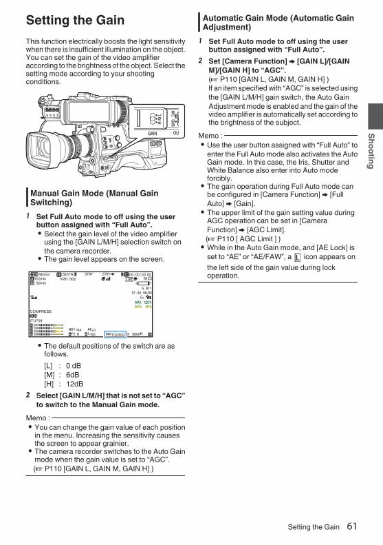
Setting the GainThis function electrically boosts the light sensitivitywhen there is insufficient illumination on the object.You can set the gain of the video amplifieraccording to the brightness of the object. Select thesetting mode according to your shootingconditions.
.
Manual Gain Mode (Manual GainSwitching)
1 Set Full Auto mode to off using the userbutton assigned with “Full Auto”.0 Select the gain level of the video amplifier
using the [GAIN L/M/H] selection switch onthe camera recorder.
0 The gain level appears on the screen.
.
100min50min
282min
1/ 60F2.8AE±0ND1 /64
12 :34 :56
ISO102400
00:00:00.001080 /30p
SDI IN
ITU709
COMPRESS
5 . 6f t
B 5600K
0 The default positions of the switch are asfollows.[L] : 0 dB[M] : 6dB[H] : 12dB
2 Select [GAIN L/M/H] that is not set to “AGC”to switch to the Manual Gain mode.
Memo : 0 You can change the gain value of each position
in the menu. Increasing the sensitivity causesthe screen to appear grainier.
0 The camera recorder switches to the Auto Gainmode when the gain value is set to “AGC”.(A P110 [GAIN L, GAIN M, GAIN H] )
Automatic Gain Mode (Automatic GainAdjustment)
1 Set Full Auto mode to off using the userbutton assigned with “Full Auto”.
2 Set [Camera Function] B [GAIN L]/[GAINM]/[GAIN H] to “AGC”.(A P110 [GAIN L, GAIN M, GAIN H] )If an item specified with “AGC” is selected usingthe [GAIN L/M/H] gain switch, the Auto GainAdjustment mode is enabled and the gain of thevideo amplifier is automatically set according tothe brightness of the subject.
Memo : 0 Use the user button assigned with “Full Auto” to
enter the Full Auto mode also activates the AutoGain mode. In this case, the Iris, Shutter andWhite Balance also enter into Auto modeforcibly.
0 The gain operation during Full Auto mode canbe configured in [Camera Function] B [FullAuto] B [Gain].
0 The upper limit of the gain setting value duringAGC operation can be set in [CameraFunction] B [AGC Limit].(A P110 [ AGC Limit ] )0 While in the Auto Gain mode, and [AE Lock] is
set to “AE” or “AE/FAW”, a icon appears onthe left side of the gain value during lockoperation.
Setting the Gain 61
Shooting

Setting the ElectronicShutterYou can change the shutter speed (time for eachshooting frame) using the electronic shutterfunction. Electronic shutter can be adjustedmanually or automatically.
Manual Shutter Mode (Manual ShutterSwitching)
1 Set Full Auto mode to off using the userbutton assigned with “Full Auto”.
2 Set [Camera Function] B [Shutter] to“Slow” or “Step/Variable”.0 The shutter speed appears on the screen.
.
100min50min
282min
1/ 60F2.8AE±0ND1 /64
12 :34 :56
ISO102400
00:00:00.001080 /30p
SDI IN
ITU709
COMPRESS
5 . 6f t
B 5600K
Memo : 0 To display Shutter in angle (DEG), set [WFrame
Rate] to “25p” and set [LCD/VF] B [DisplayType] B [Shutter] to “DEG”.(A P152 [ W Frame Rate ] )(A P109 [ Shutter ] )
Switching Shutter Speedo Manual shutter mode (step/variable)Press down the [SHUTTER] switch toward the“SEL” end. When the shutter speed indication turnswhite, press down the [SHUTTER] switchrepeatedly to change the setting.Example:
.
1/60 1/100 1/20001/60.00
1/1000
Variable
Step
After the shutter speed indication turns white, thesetting value can be changed using the cross-shaped button (JK).You can use the cross-shaped button I to switchto variable mode and the cross-shaped button H toswitch to step mode.
ShutterMode
FrameRate
SettingValue
Setting Value(Shutter
OFF)Step 60p, 60i,
30p1/60,1/100,1/120,1/250,1/500,1/1000,1/2000
1/60
Variable 1/30.00 -1/9873
Step 50p, 50i,25p
1/50,1/60,1/100,1/120,1/250,1/500,1/1000,1/2000
1/50
Variable 1/25.00 -1/9873
o Manual shutter mode (low speed)Press down the [SHUTTER] switch toward the“SEL” end. When the shutter speed indication turnswhite, press down the [SHUTTER] switchrepeatedly to change the setting.After the shutter speed indication turns white, thesetting value can also be changed using the cross-shaped button (JK).
ShutterMode
FrameRate
SettingValue
Setting Value(Shutter
OFF)Slow 60p, 60i,
30p1/30,1/15,1/7.5,1/3.75
1/60
50p, 50i,25p
1/25,1/12.5,1/6.25,1/3.125
1/50
62 Setting the Electronic Shutter
Shooting

Automatic Shutter Mode (AutomaticShutter Adjustment)
1 Set Full Auto mode to off using the userbutton assigned with “Full Auto”.
2 Set [Camera Function] B [Shutter] to “EEI”.0 Automatic Shutter mode adjusts the shutter
speed automatically according to thebrightness of the object.
3 Set the controllable range for the AutomaticShutter in [Camera Function] B [EEI Limit].(A P110 [ EEI Limit ] )
Memo : 0 Use the user button assigned with “Full Auto” to
enter the Full Auto mode also activates theAutomatic Shutter mode. In this case, the Iris,Gain and White Balance also enter into Automode forcibly.
0 The shutter operation during Full Auto mode canbe configured in [Camera Function] B [FullAuto] B [Shutter].
0 While in the Automatic Shutter mode, and [AELock] is set to “AE” or “AE/FAW”, a iconappears on the left side of the shutter speedduring lock operation.
Adjusting the WhiteBalanceAdjust the white balance according to the colortemperature of the lighting. You can select theadjustment mode according to the shootingconditions.As the color of the light (color temperature) variesaccording to the light source, it is necessary toreadjust the white balance when the main lightsource illuminating the subject changes.
.
Automatic White Balance Mode (FAW:Fulltime Auto White balance)
1 Set Full Auto mode to off using the userbutton assigned with “Full Auto”.
2 Assign “FAW” (Full Auto White Balance) toone of the three [WHT.BAL] switches.0 You can set the Full Auto White Balance
feature to either “A”, “B”, or “PRST” in[Camera Function] B [FAW].
(A P110 [ FAW ] )0 If the position assigned with “FAW” is
selected using the [WHT BAL B/A/PRST]switch, the Automatic White Balance mode isenabled and an appropriate white balance isautomatically adjusted according to the colortemperature of the lighting on the subject.
Caution : 0 The accuracy of [FAW] is inferior to that of [AWB]
(Auto White Balance).0 When the power of the camera recorder is
turned on with the [FAW] mode selected, it takesabout 15 seconds for the colors to stabilize.
Setting the Electronic Shutter 63
Shooting

Memo : 0 Use the user button assigned with “Full Auto” to
enter the Full Auto mode also activates theAutomatic White Balance mode. In this case, theIris, Gain and Shutter also enter into Auto modeforcibly.
0 The white balance operation during Full Automode can be configured in [Camera Function]B [Full Auto] B [White Balance].
0 When [Camera Function] B [User Switch Set] B[AE Lock] is set to “AE/FAW” or “FAW”, the whitebalance when the user button that is assignedwith [AE Lock] is pressed can be fixed while inthe Automatic White Balance mode.(A P113 [ AE Lock ] )0 If [White Balance] is assigned to the user button,
pressing the assigned user button will displaythe FAW Paint Adjustment screen.(A P45 [Assignment of Functions to UserButtons] )
FAW Paint AdjustmentYou can fine-adjust the white balance that wasautomatically adjusted.1 Select [Camera Process] B [White
Balance] B [FAW Paint] and press the Setbutton (R).The FAW Paint Adjustment screen appears.
.
1FAW Paint
White Balance
2 Adjust the R and B values.Use the cross-shaped button (JK) to adjust Rvalue and (HI) to adjust B value.
.
BR
3 Press the Set button (R).Returns to the [White Balance] screen.
.
B Value
R Value
FAW Paint
White Balance
Manual White Balance Mode (ManualSwitching)
1 Set Full Auto mode to off using the userbutton assigned with “Full Auto”.0 Use the [WHT.BAL] switch to select “PRST”
(preset mode), “A” (memory A mode), or “B”(memory B mode).
Memo : 0 You can set the Full Auto White Balance feature
to either [A], [B], or [PRST] in [CameraFunction] B [FAW].(A P110 [ FAW ] )0 The FAW (Full Time Auto White Balance) mode
makes automatic adjustments by sampling thecolor temperature of the video to obtain the mostappropriate white balance level.
Preset Mode (PRST)0 Two different color temperature settings are
registered on this camera recorder. You canswitch between them by pushing the [AWB/USER8] switch upward or using the user buttonassigned with “AWB”.
Default setting:[Preset Temp.] : 3200K[Alternative Temp.] : 5600K1 Set the [WHT.BAL] switch to “PRST”.2 Push the [AWB/USER8] switch upward or
press the user button assigned with the“AWB” function.0 The color temperature switches.
(“Preset Temp.”1“Alternative Temp.”)
64 Adjusting the White Balance
Shooting
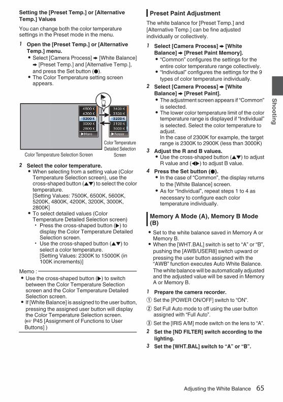
Setting the [Preset Temp.] or [AlternativeTemp.] ValuesYou can change both the color temperaturesettings in the Preset mode in the menu.1 Open the [Preset Temp.] or [Alternative
Temp.] menu.0 Select [Camera Process] B [White Balance]B [Preset Temp.] and [Alternative Temp.],and press the Set button (R).
0 The Color Temperature setting screenappears.
.
Color Temperature Detailed Selection
ScreenColor Temperature Selection Screen
2 Select the color temperature.0 When selecting from a setting value (Color
Temperature Selection screen), use thecross-shaped button (JK) to select the colortemperature.[Setting Values: 7500K, 6500K, 5600K,5200K, 4800K, 4200K, 3200K, 3000K,2800K]
0 To select detailed values (ColorTemperature Detailed Selection screen)0 Press the cross-shaped button (I) to
display the Color Temperature DetailedSelection screen.
0 Use the cross-shaped button (JK) toselect a color temperature.[Setting Values: 2300K to 15000K (in100K increments)]
Memo : 0 Use the cross-shaped button (I) to switch
between the Color Temperature Selectionscreen and the Color Temperature DetailedSelection screen.
0 If [White Balance] is assigned to the user button,pressing the assigned user button will displaythe Color Temperature Selection screen.(A P45 [Assignment of Functions to UserButtons] )
Preset Paint AdjustmentThe white balance for [Preset Temp.] and[Alternative Temp.] can be fine adjustedindividually or collectively.1 Select [Camera Process] B [White
Balance] B [Preset Paint Memory].0 “Common” configures the settings for the
entire color temperature range collectively.0 “Individual” configures the settings for the 9
types of color temperature individually.2 Select [Camera Process] B [White
Balance] B [Preset Paint].0 The adjustment screen appears if “Common”
is selected.0 The lower color temperature limit of the color
temperature range is displayed if “Individual”is selected. Select the color temperature toadjust.In the case of 2300K for example, the targetrange is 2300K to 2900K (less than 3000K)
3 Adjust the R and B values.0 Use the cross-shaped button (JK) to adjust
R value and (HI) to adjust B value.4 Press the Set button (R).
0 In the case of “Common”, the display returnsto the [White Balance] screen.
0 As for “Individual”, repeat steps 1 to 4 asnecessary to configure each colortemperature individually.
Memory A Mode (A), Memory B Mode(B)0 Set to the white balance saved in Memory A or
Memory B.0 When the [WHT.BAL] switch is set to “A” or “B”,
pushing the [AWB/USER8] switch upward orpressing the user button assigned with the“AWB” function executes Auto White Balance.The white balance will be automatically adjustedand the adjusted value will be saved in MemoryA or Memory B.
1 Prepare the camera recorder.A Set the [POWER ON/OFF] switch to “ON”.B Set Full Auto mode to off using the user button
assigned with “Full Auto”.C Set the [IRIS A/M] mode switch on the lens to “A”.2 Set the [ND FILTER] switch according to the
lighting.3 Set the [WHT.BAL] switch to “A” or “B”.
Adjusting the White Balance 65
Shooting

4 Locate a place with similar lighting conditionsas the object to be shot, place a white objectnear the center of the screen and zoom in tofill the screen with white.
5 Push the [AWB/USER8] switch upward orpress the user button assigned with the“AWB” function.0 The white detection frame appears when Auto
White Balance is activated. Fill the frame withwhite completely.
0 While Auto White Balance is starting up,“A y ” or “B y ” appears on the screen.(y mark appears blinking)
0 After the correct white balance is obtained, anestimated value of the current colortemperature is displayed.
.
100min50min
282min
1/ 60F2.8AE±0ND1 /64
12 :34 :56
ISO102400
00:00:00.001080 /30p
SDI IN
ITU709
COMPRESS
5 . 6f t
B
100min50min
282min
1/ 60F2.8AE±0ND1 /64
12 :34 :56
ISO102400
00:00:00.001080 /30p
SDI IN
ITU709
COMPRESS
5 . 6f t
B 5600K
Result Display
[AWB] Activating
White Detection Frame
Blinking
Caution : 0 Do not use highly reflective objects, such as
metals. Doing so may result in improper whitebalance adjustment.
0 The Auto White Balance function cannot provideoptimum white balance with an object outside theadjustment range, for example when it containsonly a single color or not enough white color.
Error MessageIf the Auto White Balance adjustment is notcorrectly completed, one of the followingmessages will appear for about 3 seconds.
Message StatusAuto White * NG:Object(*A or B)
Displayed when there is notenough white color on theobject, or when the colortemperature is not suitable.Use another white object andadjust the white balanceagain.
Auto White * Error:Low Light(*A or B)
Displayed when the lighting isdark. Increase the lightingand adjust the white balanceagain.
Auto White * Error:Over Light(*A or B)
Excessive illumination.Displayed when the lighting istoo bright. Decrease thelighting and adjust the whitebalance again.
White Paint AdjustmentYou can fine-tune the white balance saved inMemory A or Memory B.1 Select [Camera Process] B [White
Balance] B [AWB Paint] and press the Setbutton (R).The White Paint Adjustment screen appears.
.
1AWB Paint
White Balance
2 Adjust the R and B values.Use the cross-shaped button (JK) to adjust Rvalue and (HI) to adjust B value.
.
BR
66 Adjusting the White Balance
Shooting

3 Press the Set button (R).Returns to the [White Balance] screen.
.
B Value
R Value
AWB Paint
White Balance
Memo : 0 Executing Auto White Balance will usually clear
the White Paint Adjustment value. But when[Camera Process] B [White Balance] B [ClearPaint After AWB] is set to “Off”, values will notbe cleared even when Auto White Balance isexecuted.(A P123 [ Clear Paint After AWB ] )0 If [White Balance] is assigned to the user button,
pressing the assigned user button will displaythe AWB Paint Adjustment screen.(A P45 [Assignment of Functions to UserButtons] )
Vertical Shading Adjustment0 Adjustment of white shading is needed when
you have changed the lens.0 Although white balance may be appropriate at
the center of the image, this may not be the caseat the top and bottom areas.If this is the case, the image will appear greenishor yellowish. This phenomenon is due to thecharacteristics of the lens. The process ofcorrecting this phenomenon is referred to asvertical shading adjustment.
0 Perform this process after adjusting the whitebalance.
Setup Prior Adjustment1 Obtain the white balance on the camera.
(A P65 [Memory A Mode (A), Memory B Mode(B)] )
2 Set the control of the camera lens asfollows.
A Set the iris to F4.0 or narrower to obtain theappropriate brightness.If the brightness is insufficient at F4.0, obtain theappropriate brightness such as by adjusting thelighting.
B When using a zoom lens, set to the center of thezoom adjustment range.
3 Fill the monitor screen with a pattern box ofa uniform light source, or a piece of white(plain) paper that is uniformly illuminated.
4 Set the chroma level of the monitor to themaximum.
5 Check the monitor screen.0 There is no need for adjustment if there is no
color at the top and bottom of the screen.0 If the top of the screen is greenish and the
bottom is reddish or vice versa, continue thisadjustment.
Adjusting the White Balance 67
Shooting

Adjusting the Vertical Shading1 Set [Camera Process] B [White Balance] B
[V. Shading] to “On”.2 Select [Adjust...] in [V. Shading] and press
the Set button (R).The Vertical Shading Adjustment screenappears.
.
Setting Value
Evaluated Value Detection Frames
Sliding Bar for SettingEvaluated Level Meter
3 Press the [USER1] button to set to performautomatic adjustment.You can use the R, G, B channels individuallyto adjust the value of the evaluated level meterup to a margin error of ±1 from the median value.
4 Adjust manually.0 If you want to adjust manually after automatic
adjustment is performed, follow the stepsbelow.
0 You are recommended to adjust the G(green) level only.
0 If manual adjustment in not necessary,adjustment is complete at step 7.
5 Use the cross-shaped buttons (HI) toselect the item to adjust from [R]/[G]/[B].
6 Adjust the setting value using the cross-shaped buttons (JK).0 Adjust the sliding bar for setting while
referring to the evaluated level meter.0 Adjust the values such that the evaluated
value falls almost at the center of the meterusing the K cross-shaped button if theevaluated value of the channel to be adjustedis larger than the median value, and the Jcross-shaped button if the evaluated value issmaller than the median value.
7 Press the Set button (R) to save the setting.0 Make sure to press the Set button (R) to save
the setting.0 Pressing the [CANCEL/RESET] button
discards the setting and returns to the menuscreen at the next higher level.
Memo : 0 There may be some delay in the changes of the
evaluated value after pressing the cross-shapedbutton (JK).
0 Increasing the setting value suppresses thecolors at the bottom and enhances the colors ontop.
0 Adjustment is not possible in the followingcases. An error message will appear.0 When the top and bottom ends of the frame
are overexposed0 When the top and bottom ends of the frame
are underexposed0 When there is significant difference in the
level between the top and bottom ends of theframe
What is evaluated value?This is a relative value (difference between thetop and bottom ends) with respect to the averagevalue of the R, G, B channels within the evaluatedvalue detection frames at the top and bottom ofthe LCD monitor or viewfinder.The evaluated value is positioned higher than thecenter of the evaluated level meter when the levelat the top is higher than that at the bottom end.Similarly, the evaluated value is positioned lowerthan the center of the evaluated level meter whenthe level at the top is lower than that at the bottomend.Adjust the evaluated value such that it fallsalmost at the center of the meter.
68 Adjusting the White Balance
Shooting

Adjusting the CameraImageThe picture quality of the camera can be set usingthe [Camera Process] menu.As the adjustments are shown on the screen, youcan adjust the values while checking the picturequality on the camera.0 [Color Space]0 [Gamma]0 [Detail]0 [Master Black]0 [Black Paint]0 [Flare]0 [V. Shading]0 [Black Toe]0 [Knee Level]0 [Auto Knee Sensitivity]0 [Auto Knee Peak Filter]0 [White Clip]0 [Chroma Clip]0 [White Balance]0 [Color Matrix]0 [Color Gain]0 [Reverse Picture]0 [DNR]
Memo : 0 For details of the respective items, see the
[Camera Process] menu.(A P116 [Camera Process Menu] )
Audio RecordingYou can record audio from the four channels (CH1/CH2/CH3/CH4) in synchronization with the videoimages on this camera recorder.Select from the options below to record the audio.0 Microphone connected to [MIC IN] terminal
(XLR 5-pin)0 Microphone or line input connected to the
[AUDIO INPUT1] terminal (XLR 3pin)0 Microphone or line input connected to the
[AUDIO INPUT2] terminal (XLR 3pin)
.
PRAUDIO INPUT
DIS
Setting the Number of RecordingChannels0 Set the number of recording channels in
[System] B [Record Set] B [Record Format] B[Audio].
Selecting Audio to Be Recorded in EachChannel
Select the audio to be recorded in CH1/CH2/CH3/CH4.
- SwitchSetting Connected Devices
CH1CH3
FRONT 0 Audio input ofmicrophone 1 from[MIC IN] terminal
REAR 0 Audio input from[AUDIO INPUT1]terminal
WIRELESS 0 Audio input of CH1from the “UniSlot”wireless receiver
CH2CH4
FRONT 0 Audio input ofmicrophone 2 from[MIC IN] terminal
REAR 0 Audio input from[AUDIO INPUT2]terminal
WIRELESS 0 Audio input of CH2 (orCH1) from the “UniSlot”wireless receiver
Adjusting the Camera Image 69
Shooting

When the switch setting is set to “FRONT”Audio recording is performed according to thesetting in [A/V Set] B [Audio Set] B [Front MicSelect]/[Front Mic Power]/[Front Mic 1 Ref.]/[FrontMic 2 Ref.].Caution : 0 Set [Front Mic Select] to “Stereo M/S” to convert
the audio signal to stereo (L/R) signal forrecording when a Mid/Side direct outputmicrophone is connected.Do not set to “Stereo L/R” or “Mono” when an L/R out stereo microphone or a monophonicmicrophone is connected.
When the switch setting is set to “REAR”Select the audio input to the [AUDIO INPUT 1/2]terminal using the [AUDIO INPUT 1/2] switch.
Setting Description[LINE] Use this setting when connecting to
an audio device or other equipment.[MIC] Use this setting when connecting to
a dynamic microphone.[MIC+48V] Use this setting when connecting to
a microphone (phantommicrophone) that requires a +48 Vpower supply.
Memo : 0 When “LINE” is selected, configure the
reference input level in [A/V Set] B [Audio Set]B [Rear Line Ref.].(A P135 [ Rear Line Ref. ] )0 When “MIC” or “MIC+48V” is selected, set the
reference input level in [A/V Set] B [Audio Set]B [Rear Mic 1 Ref.]/[Rear Mic 2 Ref.].(A P135 [ Front Mic 1 Ref. ] )(A P135 [ Front Mic 2 Ref. ] )
Caution : 0 When connecting a device that does not require
a +48 V power supply, make sure that it is notset to the “MIC+48V” position.
0 When the [AUDIO INPUT 1/2] switch is set to“MIC”, make sure that a microphone isconnected to the [AUDIO INPUT 1/2] terminal. Ifyou increase the recording level when amicrophone is not connected, noise from theinput terminal may be recorded.
0 When a microphone is not connected to the[AUDIO INPUT 1/2] terminal, set the [AUDIOINPUT 1/2] switch to “LINE”.
When the switch setting is set to “WIRELESS”Recording is performed as follows according to thesetting in [A/V Set] B [Audio Set] B [WirelessChannel].
“UniSlot”WirelessReceiver
Camera
Single: CH1 B CH1/CH2Dual: CH1 B CH1
CH2 B CH2Caution : 0 Power is supplied to the “UniSlot” wireless
receiver when any of the CH1/CH2/CH3/CH4switches is set to “WIRELESS”.
Adjusting the Audio Recording LevelYou can select to adjust the audio recording levelsfor each of the four channels (CH1/CH2/CH3/CH4)manually or automatically.
.
PRAUDIO INPUT
DIS
70 Audio Recording
Shooting

Manual Adjustment Mode (ManualAdjustment)0 The manual adjustment mode is enabled by
setting the [AUDIO SELECT CH1/2/3/4]-[MANUAL/AUTO] selection switch on thiscamera recorder to “MANUAL”. The audio levelfor each channel can be configured in [A/VSet] B [Audio Set] B [CH1 Audio Level](/2/3/4)B [Front]/[Rear/Wireless].
0 You can adjust the level manually during therecording, recording standby, and stop modes.
Memo : 0 The audio setting in Full Auto mode can be
configured in [Camera Function] B [Full Auto] B[Audio Set].
1 Set the [AUDIO SELECT CH1/2/3/4]-[MANUAL/AUTO] selection switch to“MANUAL” for the channel to be adjustedmanually.
2 Turn the adjustment knob correspondingto the channel to adjust the level.When [A/V Set] B [Audio Set] B [CH1/2 DRC]/[CH3/4 DRC] B [Threshold Level] is set to “Off”,adjust such that the audio level meter -2 dBdoes not light up even for loud sounds.(A P136 [ Threshold Level ] )
.
100min50min
282min
1/ 60F2.8AE±0ND1 /64
12 :34 :56
ISO102400
00:00:00.001080 /30p
SDI IN
ITU709
COMPRESS
5 . 6f t
B 5600K
-2dB
Memo : 0 The [Threshold Level], [Attack Time], [Decay
Time], [Mode], etc. of the compressor can beconfigured in [A/V Set] B [Audio Set] B [CH1/2DRC]/[CH3/4 DRC] for the audio to be recorded.* DRC (Dynamic Range Compressor)0 The limiter operates according to the setting in
[A/V Set] B [Audio Set] B [Limitter] B [CH1](/2/3/4).When [Limitter] is set to “Off”, the limiter functionis disabled even when the [MANUAL/AUTO]switch is set to “AUTO”. This may cause theOVER indication of the level meter to light up.
0 The reference audio level is configured in [A/VSet] B [Audio Set] B [CH1/2 Audio Ref. Lv.](common for CH1/2)/[CH3/4 Audio Ref. Lv.](common for CH3/4).
Automatic Adjustment Mode0 Set the [AUDIO SELECT CH1/2/3/4]-[MANUAL/
AUTO] selection switch to “AUTO” or press theuser button assigned with “Full Auto” to set FullAuto mode to off. This activates the AutomaticAdjustment mode and the audio recording levelis configured automatically according to theinput level.
0 The audio setting in Full Auto mode can beconfigured in [Camera Function] B [Full Auto] B[Audio Set].
Memo : 0 If [A/V Set] B [Audio Set] B [CH1/2 DRC]/
[CH3/4 DRC] B [Threshold Level] is set to avalue other than “Off”, the compressor operatesaccording to the value set.
Audio Recording 71
Shooting

References on DRC (Dynamic RangeCompressor) and LimiterDRC and Limiter Configuration Block Diagram
.
CH2 (CH4) In
CH1 (CH3) OutCH2 (CH4) Out
Limiter
Limiter
On/Off
On/Off
DRC
ThresholdAttack TimeDecay TimeMode (Link/Separate)
CH1 (CH3) In
.
0dBFS
Figure 1 Operating Level of DRC and Limiter
Threshold Limiter On
Limiter Off
CHx In
CHx Out
.
Figure 2 DRC Response Characteristics
Decay TimeAttack Time
0 DRC OperationThis operation helps to prevent the recordinglevel from reaching saturation (0 dBFS) byslowing down the gain changes when theexcessive sound input exceeds the thresholdlevel.
0 [CH1/2 DRC] and [CH3/4 DRC] settingsThresholdLevel
: This is the point when the gainchanges slowly. (See Figure 1)Lowering the threshold level willmake it difficult for the recordinglevel to become saturated but thiswill decrease the sound volume.
AttackTime
: This is the response time fromwhen the sound exceeds thethreshold level until the level iscompressed. (See Figure 2)“Fast” will result in fast responsetime and “Slow” will result in slowresponse time.
DecayTime
: This is the response time fromwhen the excessive sound inputfalls below the threshold level untilthe level compression operation iscanceled. (See Figure 2)“Fast” will result in fast responsetime and “Slow” will result in slowresponse time.
Mode : CH1 (CH3)/CH2 (CH4) operateindependently (mono) when“Separate” is selected.CH1 (CH3)/CH2 (CH4) operate intandem (stereo) when “Linked” isselected. The level differencebetween CH1 (CH3)/CH2 (CH4)remains constant.
0 “Fast” and “Middle” in the Attack setting aresuitable for speech. “Middle” and “Slow” aresuitable for music.
0 “Fast” and “Middle” in the Decay setting aresuitable for speech. “Middle” and “Slow” aresuitable for music.
0 When using a stereo microphone with CH1(CH3)/CH2 (CH4), configure the Modesetting to “Linked”.To record different audio with CH1(CH3)/CH2 (CH4), configure the Modesetting to “Separate”.
0 Limiter OperationA high speed response limiter that does notexceed the saturation level (0 dBFS) for sharpincrease in the sound input not trackable byDRC.
0 [Limitter] settingsOn : Enables the limiter separately for
CH1/CH2/CH3/CH4.Off : Disables the limiter separately for
CH1/CH2/CH3/CH4.AUTO/MANUALSW Set
: The limiter is enabled when the[MANUAL/AUTO] selectionswitch is set to “AUTO” anddisabled when “MANUAL” isselected.
72 Audio Recording
Shooting
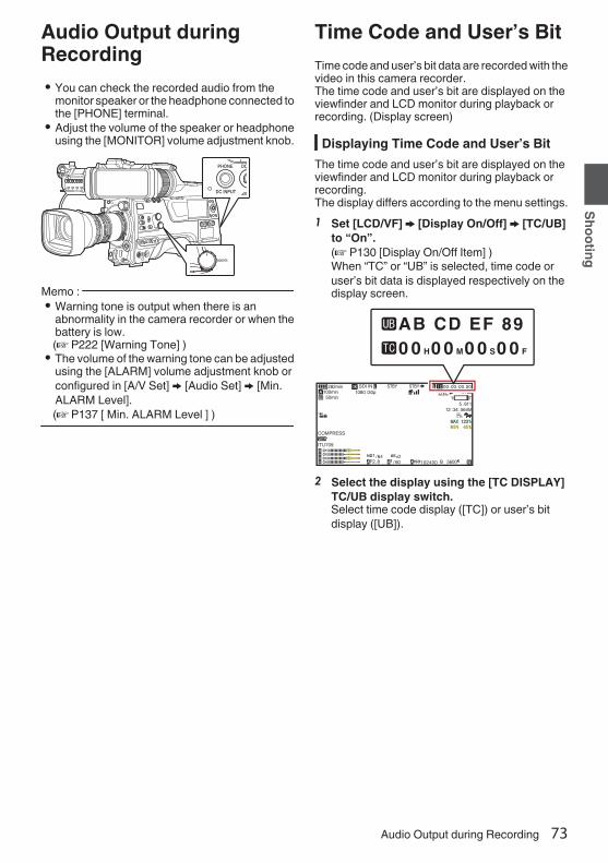
Audio Output duringRecording0 You can check the recorded audio from the
monitor speaker or the headphone connected tothe [PHONE] terminal.
0 Adjust the volume of the speaker or headphoneusing the [MONITOR] volume adjustment knob.
.
Memo : 0 Warning tone is output when there is an
abnormality in the camera recorder or when thebattery is low.(A P222 [Warning Tone] )0 The volume of the warning tone can be adjusted
using the [ALARM] volume adjustment knob orconfigured in [A/V Set] B [Audio Set] B [Min.ALARM Level].(A P137 [ Min. ALARM Level ] )
Time Code and User’s BitTime code and user’s bit data are recorded with thevideo in this camera recorder.The time code and user’s bit are displayed on theviewfinder and LCD monitor during playback orrecording. (Display screen)
Displaying Time Code and User’s BitThe time code and user’s bit are displayed on theviewfinder and LCD monitor during playback orrecording.The display differs according to the menu settings.1 Set [LCD/VF] B [Display On/Off] B [TC/UB]
to “On”.(A P130 [Display On/Off Item] )When “TC” or “UB” is selected, time code oruser’s bit data is displayed respectively on thedisplay screen.
.
100min50min
282min
1/ 60F2.8AE±0ND1 /64
12 :34 :56
ISO102400
00:00:00.001080 /30p
SDI IN
ITU709
COMPRESS
5 . 6f t
B 5600K
0 0 H0 0 M0 0 S0 0 F
AB CD EF 89
2 Select the display using the [TC DISPLAY]TC/UB display switch.Select time code display ([TC]) or user’s bitdisplay ([UB]).
Audio Output during Recording 73
Shooting

Time Code Operation ModeSelect the time code operation using the [TCGEN] switch.
Setting DescriptionF-RUN The time code operates in the run
mode at all times regardless of therecording status.It continues to run even when thepower of the camera recorder isturned off.Synchronizes with the externaltime code when an external timecode generator is connected.
(A P78 [Synchronizing theTime Code with an ExternalTime Code Generator] )
R-RUN The time code operates in the runmode during recording. Itcontinues to run in the order of therecorded clips as long as the SDcard is not replaced. If the SD cardis removed and recording is madeon another card, time code will berecorded on the new card fromwhere it was left off in the previouscard.
REGEN The time code operates in the runmode during recording. When theSD card is replaced, the last timecode recorded on the card is readand recorded on a new card so thatthe time code continues in runningorder.
(A P75 [Setting Time Code] )Memo : 0 When [System] B [Record Set] B [Rec Mode] is
set to “Interval Rec”1 or “FrameRec”1, and the [TC GEN] switch is set to“F-RUN”, R-RUN mode is activated.
0 When [System] B [Record Set] B [RecordFormat] B [System] is set to “High-Speed”2, and the [TC GEN] switch is setto “F-RUN”, R-RUN mode is activated.
Setting Time CodeGeneratorPresetting the Time Code
Time code and user’s bit data generated from theinternal time code generator are recorded.This section describes how to set [TC/UB] B [TCPreset].
(A P124 [ TC Preset ] )Memo : 0 When [System] B [Record Set] B [Record
Format] B [WFrame Rate] is set to “50p”, “50i”or “25p”, setting for “Drop” will be disabled.(A P152 [ W Frame Rate ] )0 You can configure the setting without accessing
the [TC/UB] menu screen.(A P76 [Setting Time Code without Openingthe Menu] )
Required Settings Before Preset
.
PRESET
TC
F-RUNR-RUNREGEN
UB
GEN
DISPLAY
1 Set the [TC GEN] switch to “R-RUN” or “F-RUN”.0 [R-RUN]
Preset data in the time code generatoroperates in run mode during recording mode.Set this when recording continuous timecode in connecting frames.
0 [F-RUN]Time code starts to operate in run mode fromthe preset time in the time code generator.
74 Time Code and User’s Bit
Shooting

2 Select the framing mode for the time codegenerator (only when the frame rate settingis “60” or “30”).To configure the setting, go to [TC/UB] B [DropFrame].(A P124 [ Drop Frame ] )0 [Drop]:
Sets the run mode of the time code generatorto drop frame mode. Use this setting whenplacing emphasis on the recording time.
0 [Non Drop]:Sets the run mode of the time code generatorto non-drop frame mode. Use this settingwhen placing emphasis on the number offrames.
Memo : Drop frame/non-drop frame mode0 When [System] B [Record Set] B [Record
Format] B [Frame Rate] is set to “60p”, “60i”, or“30p”, the actual number of frames per secondis approximately 59.94 (29.97). However, thetime code processing standard is “60p”, “60i”, or“30p” frames. To make up for the frame numberdiscrepancy, the drop frame mode (Drop) dropsthe 00 frame and 01 frame every minute exceptfor minutes that are multiples of 10. However, inthe case of “60p”, the 00, 01, 02 and 03 frameare dropped.
0 The non-drop frame mode (Non Drop) does notdrop frames and ignores the discrepancy withthe actual time.
Setting Time Code
1 Select [TC/UB] B [TC Preset] and press theSet button (R).(A P124 [ TC Preset ] )The [TC Preset] screen appears.
.
1TC Preset 00:00:00:00
TC/UB
Memo : 0 When the [TC GEN] switch is set to “REGEN”,
the parameter is displayed as “REGEN” andselection is disabled.
2 Set the time code (hour, minute, second,frame).Use the cross-shaped button (HI) to place thecursor at the item to set, then use the cross-shaped button (JK) to change the values.
.
During drop frameDuring non-drop frame
CursorTC Preset 00:00:00:00
TC/UB
Memo : 0 Press the [USER3] button to reset each digit to
“0”. The cursor moves to the time digit (left).
3 Check the values and press the Set button(R).0 The time code is set and the screen returns
to [TC/UB].0 To cancel the setting, press the [CANCEL/
RESET] button.4 Press the [MENU/THUMB] button.
Returns to the normal screen.
Setting Time Code Generator 75
Shooting

Setting Time Code without Opening theMenu
.
PRESET
TC
F-RUNR-RUNREGEN
UB
GEN
DISPLAY
Memo : 0 Settings cannot be made in the following cases.
0 When the [TC GEN] switch is set to“REGEN”.
0 Menu screen is displayed.0 The camera recorder is not in the Camera
mode.
Setting Time Code1 Set the [TC DISPLAY] switch to “TC”.2 Set the [TC GEN] switch to a setting other
than “REGEN”.3 Press the [TC PRESET] button.
.
4 Set the time code (hour, minute, second,frame).Use the cross-shaped button (HI) to place thecursor at the item to set, then use the cross-shaped button (JK) to change the values.
Memo : 0 Press the [CANCEL/RESET] button to reset
each digit to “0”. The cursor moves to the left.
5 Check the values and press the Set button(R).0 The time code is set and the screen returns
to the normal screen.0 To cancel the setting, press the [TC
PRESET] button.Caution : 0 When the camera recorder is switched to Media
mode during editing, editing will be canceledand the screen will close.
0 When editing the time code, operations of thebuttons configured in [Camera Function] B[User Switch Set] are disabled.
Recording Time Code in Continuation ofthe Recorded Time Code on SD Card
This camera recorder is equipped with the timecode reader.1 Set the [TC GEN] switch to “REGEN”.
0 When the camera recorder enters fromrecording standby mode to recording mode,it reads the time code already recorded onthe SD card and records the new time codein continuation of that value.
0 The same data as the user’s bit alreadyrecorded on the SD card is recorded.
Memo : 0 When the [TC GEN] switch is set to “REGEN”,
the framing mode of the time code follows thesettings in [TC/UB] B [Drop Frame] instead ofthe clip settings.(A P124 [ Drop Frame ] )
76 Setting Time Code Generator
Shooting

Setting the User’s BitYou can add the date, time or an 8-digithexadecimal number as the user’s bit to therecorded image.
Selecting a Recording ModeRecording date/time information to the user’sbit1 Set [TC/UB] B [UB Mode] to “Date” or
“Time”, and press the Set button (R).(A P124 [ UB Mode ] )The date or time information is recorded to theuser’s bit.
Memo : 0 When “Date” or “Time” is set, [Preset] appears
as “-” and cannot be set.0 “Time” is displayed in the 24-hour format.
Presetting the User’s BitRecording arbitrary information (8-digithexadecimal) to the user’s bit1 Set [TC/UB] B [UB Mode] to “Preset”, and
press the Set button (R).(A P124 [ UB Mode ] )
.
1
TC/UB
UB ModePreset Time
Preset
Date
Memo : 0 When the [TC GEN] switch is set to “REGEN”,
the parameter is displayed as “REGEN” andselection is disabled.
2 Select [TC/UB] B “Preset” and press the Setbutton (R).The [Preset] setting screen appears.
3 Use the cross-shaped button (HI) to placethe cursor at the item to set, then use thecross-shaped button (JK) to change thevalues.Numbers between 0 and 9 or alphabetsbetween A and F can be specified for the user’sbit.
.
TC/UB
Cursor
Memo : 0 Press the [CANCEL/RESET] button to reset each
digit to “0”. The cursor moves to the left.
4 Check the values and press the Set button(R).0 The user’s bit is set and the screen returns to
[TC/UB].0 To cancel the setting, press the [CANCEL/
RESET] button.5 Press the [MENU/THUMB] button.
Returns to the normal screen.
Setting the User’s Bit 77
Shooting

Setting User’s Bit without Opening theMenu
.
PRESET
TC
F-RUNR-RUNREGEN
UB
GEN
DISPLAY
Memo : 0 Settings cannot be made in the following cases.
0 When the [TC GEN] switch is set to“REGEN”.
0 Menu screen is displayed.0 The camera recorder is not in the Camera
mode.
Setting the user’s bit1 Set the [TC DISPLAY] switch to “UB”.2 Set the [TC GEN] switch to a setting other
than “REGEN”.3 Press the [TC PRESET] button.4 Set the user’s bit (numbers between 0 and
9, or alphabets between A and F).Use the cross-shaped button (HI) to place thecursor at the item to set, then use the cross-shaped button (JK) to change the values.
Memo : 0 Press the [CANCEL/RESET] button to reset
each digit to “0”. The cursor moves to the left.5 Check the values and press the Set button
(R).0 The user’s bit is set and the screen returns to
the normal screen.0 To cancel the setting, press the [TC
PRESET] button.Caution : 0 When the camera recorder is switched to Media
mode during editing, editing will be canceledand the screen will close.
0 When editing the user’s bit, operations of thebuttons configured in [Camera Function] B[User Switch Set] are disabled.
Synchronizing the TimeCode with an ExternalTime Code GeneratorThis camera recorder comes with a [TC IN]terminal.Connect a time code signal generator to the [TCIN] terminal to synchronize with the SMPTE/EBULTC time code.Memo : 0 After synchronization (slave lock), the internal
time code generator continues to run even ifthere is no input from the external time codegenerator.
ConnectionSetting up the external time code generator asa master device
.
GENLOCK
TC OUT
TC IN
To [TC IN] Terminal of Another Camera
LTC Time Code
External Synchronizing Signal
External Synchronizing Signal
Master Device
External Time Code Generator
Sync Signal Generator
Slave Device
78 Setting the User’s Bit
Shooting

1 Input the external synchronizing signal tothe external time code generator and the[GENLOCK] terminal of this camerarecorder.
Memo : 0 BB signals or HDTV tri-level synchronizing
signals are used as the external synchronizingsignal.
0 If the power of the camera recorder is turned on/off during input of external synchronizingsignals, the screen may appear disrupted for afew seconds. This is not a malfunction.
2 Input the SMPTE/EBU LTC time code fromthe external time code generator to the [TCIN] terminal of this camera recorder.
Connecting multiple devices, with one as themaster unit and the others as slave units
.
TC OUT TC IN
GENLOCKVIDEO OUT
Master Device Slave Device
1 Connect the [TC OUT] terminal of themaster device with the [TC IN] terminal ofthe slave device.
2 Connect the [VIDEO OUT] terminal of themaster device with the [GENLOCK]terminal of the slave device.
Settings and Operation of the CameraRecorder
1 Set to Camera mode.(A P20 [Operation Modes] )
2 Set [A/V Set] B [Video Set] B [GenlockInput] to “GENLOCK”.(A P134 [ Genlock Input ] )
3 Set the [TC GEN] switch to “F-RUN”.4 Set LCD monitor or viewfinder to Display
screen.5 Set the external time code generator or the
master device, and run the time code.0 When the built-in time code generator is
synchronized with the external time codedata input, the Z icon on Display screen lightsup.
0 When time code is not synchronized or timecode input is not available, the Z icon goesout.
.
100min50min
282min
1/ 60F2.8AE±0ND1 /64
12 :34 :56
ISO102400
00:00:00.001080 /30p
SDI IN
ITU709
COMPRESS
5 . 6f t
B 5600K
Memo : 0 The built-in time code generator will continue
operation even when the master device isdisconnected after synchronization.
0 User’s bit will become data in the master device.
Synchronizing the Time Code with an External Time Code Generator 79
Shooting

Setting Zebra PatternWhen the luminance level range for displayingzebra patterns is specified, diagonal lines (zebrapattern) are displayed at areas with the specifiedluminance levels during shooting.1 Set the zebra display pattern.
Select the display pattern in [LCD/VF] B[Shooting Assist] B [Zebra].(A P126 [ Zebra ] )
.
Zebra 2 Display Example
Zebra 1 Display Example
2 Specify the brightness (luminance) levelrange for displaying zebra pattern.Set the maximum brightness limit in [LCD/VF]B [Shooting Assist] B [Zebra] B [Top 1]/[Top2], and the minimum brightness limit in [Bottom1]/[Bottom 2].Item Settings Options
Top 1 Maximumbrightness limit fordisplaying Zebra 1
5%, 10% to 95%,98%, 100%, Over
Bottom 1 Minimumbrightness limit fordisplaying Zebra 1
0%, 5% to 95%,98%, 100%
Top 2 Maximumbrightness limit fordisplaying Zebra 2
5%, 10% to 95%,98%, 100%, Over
Bottom 2 Minimumbrightness limit fordisplaying Zebra 2
0%, 5% to 95%,98%, 100%
Memo : 0 When [Zebra] is set to “1 Pattern”, “Top 2” and
“Bottom 2” cannot be selected.0 If the area specified by two zebra patterns
overlaps, Zebra1 pattern will be displayed.0 The timing to detect the zebra pattern display
can be configured only when “J-Log1” or “HLG”is selected in [Color Space] and “Cam” or “Cam+ Return” is selected in [Convert to ITU709].(A P116 [ Color Space ] )(A P126 [ Detect ] )
3 Display the zebra pattern.0 When the viewfinder is connected, the zebra
pattern is displayed when the [ZEBRA]switch is set to “ON” or push down to“MOMENT”.
0 When the viewfinder is not connected, thezebra pattern is displayed using the userbutton assigned with “Zebra”.
.
During zebra pattern display, (zebra icon)is displayed on the display screen in Cameramode.
Memo : 0 When the viewfinder is connected, priority is
given to the [ZEBRA] switch on the viewfinderso the user button assigned with “Zebra” will notfunction.
80 Setting Zebra Pattern
Shooting

Setting Spot MeterThe brightness of the object during shooting isdisplayed.This function is useful when setting video or stagelighting or when specifying camera exposure.A cursor indicating the location and the brightness(%) of that location are displayed in the imagesshown on the LCD monitor and viewfinder screen.0 Zebra patterns display the brightness of output
video signals.(A P80 [Setting Zebra Pattern] )0 This function allows you to check the brightness
of input images from the lens without dependingon image processing such as gamma curve.
0 When [Color Space] is set to a value other than“HLG” and “J-Log1”, the dynamic range of thecamera recorder is max. 600% and a brightnessrange of 0% to 600% is displayed.
0 The value of the spot meter changes accordingto the setting of [LCD/VF] B [Convert toITU709]/[White Level] when [Color Space] is setto “HLG”.When [Color Space] is set to “HLG” and[LCD/VF] B [Convert to ITU709]/[White Level] isset to “72.5%”, the dynamic range of the camerarecorder is max. 687% and a brightness rangeof 0% to 687% is displayed.
0 When [Color Space] is set to “J-Log1”, thedynamic range of the camera recorder is max.800% and a brightness range of 0% to 800% isdisplayed.
Memo : 0 Spot meter may not be consistent with the zebra
display range.1 Select one of the following from [Camera
Function] B [User Switch Set] B [SpotMeter].(A P113 [ Spot Meter ] )
Item SettingsColor of FrameIndicating the
PositionMax & Min Displays the
brightness (%)and positions ofthe brightest anddarkest areas inthe screen.Frames may alsobe stopped at thecurrent positions.
0 Max: Green0 Min: Yellow
Max Displays thebrightness (%)and position of thebrightest area inthe screen.Frames may alsobe stopped at thecurrent positions.
Green
Min Displays thebrightness (%)and position of thedarkest area in thescreen. Framemay also bestopped at thecurrent positions.
Yellow
Manual Displays thebrightness (%) ofthe specifiedposition.
Green(Blinks in greenwhen specifyingthe position)
2 Assign the “Spot Meter” function to any ofthe user buttons.(A P45 [Assignment of Functions to UserButtons] )
3 Press the user button that is assigned with“Spot Meter”.The operation switches as below when thebutton is pressed.
Setting Spot Meter 81
Shooting

When [Max & Min]/[Max]/[Min] is selectedA The cursors appear according to the setting
when the button is pressed.Green and yellow frames appear, and thebrightness levels of these areas are displayed.
.
Cursor
Cursor
Brightness Indication
(Yellow)
(Green)
B Hold down the button in the state in A, thepositions of the brightest (Max) and darkest(Min) areas in the screen are automaticallydetected with regard to the changes of theobject, and the brightness level of these areasare displayed.
.
(Min: Yellow)Cursor
(Max: Green)Cursor
Brightness Indication
C Pressing the button in the state in B stops theautomatic position detection. The frames arefixed at the stopped positions and thebrightness levels are displayed.
D By pressing the button, the cursors andbrightness indication disappear.
.
When [Manual] is selectedA The brightness of the cursor position is
displayed when the button is pressed.
.
Cursor (Green)
Brightness Indication
B By pressing the button, the cursors andbrightness indication disappear.
.
C Hold down the button in the state in A or B, thecursor blinks in green.Move the cursor with the cross-shaped button(JKHI) to specify the position to display thebrightness.When you decide on the position, press the Setbutton (R) to confirm.
.
(Blinks in green)
Cursor
Brightness Indication
D Frames are fixed at the stopped positions andthe brightness is displayed.
Memo : 0 When moving the cursor position, [Shutter]/[AE
Level] control is disabled.0 When the brightness is 0 % in the entire screen,
the frame is fixed in the center.
82 Setting Spot Meter
Shooting

Acquiring PositioningInformation by GPS vu
This camera recorder comes with a built-in GPSfunction. The GPS function is able to record thepositioning information.During playback, you can also display the recordedinformation on the playback screen.
(A P99 [Playing back] )1 Set [System] B [GPS] to “On”.
0 Positioning starts when the H icon on thedisplay screen starts blinking.
0 After positioning is complete, the H iconswitches to a solid light and records thepositioning information during shooting.
0 The icon that appears on the screen changesaccording to the condition of signal receptionfrom the GPS satellite.
.
100min50min
282min
1/ 60F2.8AE±0ND1 /64
12 :34 :56
ISO102400
00:00:00.001080 /30p
SDI IN
ITU709
COMPRESS
5 . 6f t
B 5600K
Display ReceptionStatus Positioning Status
.
(Yellow)
[GPS] is set to“On”, but signalcannot bereceived
GPS signal cannotbe received. UTCand positioninginformation cannotbe obtained.
.
(Blink)
GPS search inprogress
UTC informationcan be obtained,but not positioninginformation.
.
GPS receptionin progress(signal strength:weak)
Receiving weakGPS signal. UTCand positioninginformation can beobtained andrecorded.
.
GPS receptionin progress(signal strength:medium)
Receiving GPSsignal. UTC andpositioninginformation can beobtained andrecorded.
Display ReceptionStatus Positioning Status
.
GPS receptionin progress(signal strength:strong)
Receiving strongGPS signal. UTCand positioninginformation can beobtained andrecorded.
(Nodisplay)
GPS function isturned off
The [GPS] item isset to “Off”.
Memo : 0 If positioning cannot be performed after waiting
for several minutes, this means GPS receptionis poor, and there is difficulty in receiving data.Move to an open place with no obstructions.Otherwise, GPS information will not be recordedwhen shooting is performed.
0 Signal may not be received depending oncircumstances such as locations that areindoors or surrounded by tall buildings, or thegeographical conditions.Precision error may occur in the positioninformation depending on the conditions ofreception.
0 Even when positioning is in progress,information may be disrupted depending on thecondition of signal reception.
0 When [A/V Set] B [Video Set] B [SDI OUT1Res.] is set to “1080p”, configuring [System] B[GPS] to “On” changes the setting to “1080i”.
Acquiring Positioning Information by GPS v u 83
Shooting

Viewing Recorded VideosImmediately (Clip Review)You can check (review) the last recorded video clipon the screen.However, the video clip cannot be played back ifthe settings of the camera recorder are differentfrom the video format (Resolution/Frame Rate/BitRate/SD Aspect) of the clip.
(A P152 [ W Resolution ] )(A P152 [ W Frame Rate ] )(A P153 [ W Bit Rate ] )(A P154 [ SD Aspect 2 ] )
Memo : 0 To use this function, assign “Clip Review” to any
of the user buttons.1 Press the user button assigned with the
“Clip Review” function during standby(“STBY” is displayed).Playback of the configured section starts.
Memo : 0 The video clip is played back according to the
setting in [Camera Function] B [User SwitchSet] B [Clip Review]. By default setting (Last5sec), the last 5 seconds of the clip is playedback.(A P113 [ Clip Review ] )0 When playback is complete, the camera
recorder exits Clip Review and returns to“STBY” (recording standby) mode.
Caution : 0 During Clip Review, only the [CANCEL/
RESET] and [REC] buttons are enabled.Press the [CANCEL/RESET] button to cancelclip review and return to “STBY” (recordingstandby) mode.Press the [REC] button to cancel clip review andenter recording mode. It will take some time tostart recording after the button is pressed.
0 When the last clip is less than 5 seconds, thewhole clip is played back.
0 Only video clips in the currently selected slot canbe reviewed.
0 When there are no clips in the selected slot, ClipReview function is disabled.
0 Clip Review is unavailable when ClipContinuous Rec is paused (“STBYC”, yellowtext). To operate Clip Review, use the[CANCEL/RESET] button to set to “STBYC”(white text) first.(A P91 [Clip Continuous Rec 0] )0 Clip Review is unavailable when the camera
recorder is connected to an external equipmentand the equipment is in recording state.
0 Clip Review is unavailable when operating ViewRemote via network connection.(A P202 [View Remote Control and CameraControl Functions] )0 Clip Review does not function during live
streaming.0 Clip Review does not function while the record
trigger is in the REC state.
84 Viewing Recorded Videos Immediately (Clip Review)
Shooting
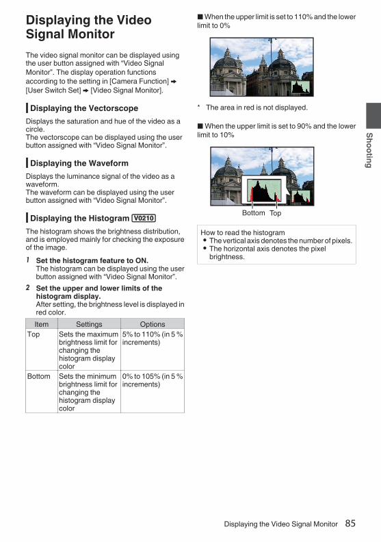
Displaying the VideoSignal MonitorThe video signal monitor can be displayed usingthe user button assigned with “Video SignalMonitor”. The display operation functionsaccording to the setting in [Camera Function] B[User Switch Set] B [Video Signal Monitor].
Displaying the VectorscopeDisplays the saturation and hue of the video as acircle.The vectorscope can be displayed using the userbutton assigned with “Video Signal Monitor”.
Displaying the WaveformDisplays the luminance signal of the video as awaveform.The waveform can be displayed using the userbutton assigned with “Video Signal Monitor”.
Displaying the Histogram 2The histogram shows the brightness distribution,and is employed mainly for checking the exposureof the image.1 Set the histogram feature to ON.
The histogram can be displayed using the userbutton assigned with “Video Signal Monitor”.
2 Set the upper and lower limits of thehistogram display.After setting, the brightness level is displayed inred color.Item Settings Options
Top Sets the maximumbrightness limit forchanging thehistogram displaycolor
5% to 110% (in 5 %increments)
Bottom Sets the minimumbrightness limit forchanging thehistogram displaycolor
0% to 105% (in 5 %increments)
o When the upper limit is set to 110% and the lowerlimit to 0%
.
* The area in red is not displayed.
o When the upper limit is set to 90% and the lowerlimit to 10%
.
TopBottom
How to read the histogram0 The vertical axis denotes the number of pixels.0 The horizontal axis denotes the pixel
brightness.
Displaying the Video Signal Monitor 85
Shooting

RecordingSimultaneously at TwoDifferent Definitions2
By setting [System] to “HD+Web”, you can recordsimultaneously at two different definitions.0 When HD+Web is selected:
Records a high-definition (HD) file to slot A anda web file to slot B at the same time.Web files can be used as a proxy file for the HDfile.
Memo : 0 If a recordable SD card is inserted into only one
of the slots, files will only be recorded to that slot.0 The [Rec Mode] is fixed at “Normal”.0 Clip Cutter Trig is disabled.0 [Slot Mode] cannot be selected.0 Clip Review can only be performed for slot A.
(“No Media” appears if there is no card in slot Awhile a card is inserted into slot B.)
0 Playback of web files is only possible from slotB when “HD+Web” is selected.
Series Rec0 Series Rec mode is specified in the factory
default.([System] B [Record Set] B [Slot Mode] is set to“Series”.)(A P155 [ Slot Mode ] )0 If both the slots are loaded with recordable
cards, pressing the [REC] button startsrecording only to the media in the selected slot.When the remaining space in the selectedmedia runs out, recording continues byautomatically activating the media in the otherslot.
0 There is no indication on the display screenwhen the Series Rec mode is set.
Dual Rec0 If both the slots are loaded with recordable cards
in the Dual Rec mode ([Slot Mode] is set to“Dual”), pressing the [REC] button startsrecording simultaneously to the media in boththe slots.
0 The clips recorded to the media in both the slotsare identical, and two clips of the same contentcan be created only on this camera recorder.(A P155 [ Slot Mode ] )
.
Setting to Dual Rec Mode1 Set [System] B [Record Set] B [Slot Mode]
to “Dual”.(A P155 [ Slot Mode ] )“DUAL” appears on the enlarged displayscreen.
.
DUAL
86 Recording Simultaneously at Two Different Definitions 2
Shooting

2 Start recording.0 Insert recordable media in both slots, and
press the [REC] button.0 In the Dual Rec mode, recording to the media
in both slots starts at the same time.0 Both the card slot marks turn red, and the
status indicators of both the card slots alsolight up in red.
.
100min50min
282min
1/ 60F2.8AE±0ND1 /64
12 :34 :56
ISO102400
00:00:00.001080 /30p
SDI IN
ITU709
COMPRESS
5 . 6f t
B 5600K
Lit in red
3 Stop recording.0 Press the [REC] button again.0 Recording to both slots stops, and both the
card slot marks turn white.0 The same clips are recorded to both cards.
.
100min50min
282min
1/ 60F2.8AE±0ND1 /64
12 :34 :56
ISO102400
00:00:00.001080 /30p
SDI IN
ITU709
COMPRESS
5 . 6f t
B 5600K
White
Memo : 0 During recording in the Dual Rec mode, both the
card slot marks light up in red.0 During recording in the Dual Rec mode to two
cards with a different amount of remainingspace, if the space of one card runs out,recording to both slots will stop automatically.After recording stops, recording automaticallyresumes for the card with remaining space.Although the clips are separated in this case, theclips can be seamlessly joined by arrangingthem on the timeline of the editing software sincethey are recorded seamlessly.
0 If the last clip on the cards that are inserted inthe two slots are different from each other, andthe time code operating mode is set to“REGEN”, the REGEN mode for the selectedcard slot will be enabled in the next recording.
Caution : 0 To perform recording in the Dual Rec mode, it is
recommended that you start recording bymaking use of two cards with the same capacityand from the formatted state.
0 You can combine the use of the Dual Rec modewith a special recording mode. While in the DualRec mode, you can also set [Rec Mode] to“Normal”, “Pre Rec”, “Clip Continuous”, “IntervalRec”, or “Frame Rec”.(A P90 [Special Recording 0] )(A P154 [ Rec Mode 0 1 ] )0 When both slots are inserted with recordable
cards, the Dual Rec (simultaneous recording)operation can be performed. If a recordablemedia is only inserted in one of the slots, you canalso start recording with one card.
0 In the Dual Rec mode, continuous recording byswitching from one slot to another cannot beperformed. Continuous recording will not beperformed if a recordable media is inserted in aslot after recording to the other slot has started.
0 When recording to one slot is in progress withthe recorder set to the Dual Rec mode, insertinga recordable media to the other slot does notenable the Dual Rec operation. To perform theDual Rec operation, stop recording temporarily(excluding pausing recording in the ClipContinuous Rec mode), and start again.
0 When one of the cards is accidentally removedwhile recording is in progress in the Dual Recmode, recording to the card in the other slot willcontinue. However, repair of the accidentallyremoved card by the recovery function may fail.
0 If an error occurs on one of the cards whilerecording is in progress in the Dual Rec mode,recording of the erroneous card stops, while thatof the other card continues.
0 Operations on clips recorded in the Dual Recmode, such as clip deletion in the Media modeor appending of OK marks, can only beperformed on the card in the selected slot.
Dual Rec 87
Shooting

Backup Rec 00 The Backup Rec mode allows you to make use
of the media in slot B for backup recording bycontrolling the starting and stopping of recordingin slot B without using the [REC] button.
0 Start or stop the recording using [System] B[Record Set] B [Slot Mode] B [Backup Rec] orpress the user button that is assigned with“Backup Trig”.(A P155 [ Slot Mode ] )(A P111 [User Switch Set Item] )
.
Slot B
Slot A
Clip 3Clip 2Clip 1
Clip 2
Slot B stops recording
Slot A stops recording
Slot A starts recording
Slot B starts recording
Memo : 0 During the Backup Rec mode (when [Slot
Mode] is set to “Backup”), you can controlrecording to the 2 slots at different timings, andbackup recording can only be performed on thiscamera recorder.(A P155 [ Slot Mode ] )0 You can record without worrying about missing
the important scenes by setting slot B to bealways recording (backup recording) and usingthe [REC] button to start/stop recording of onlythe required scenes in slot A.
0 It is recommended to use a media with highcapacity in slot B.
0 Backup cannot be selected when [WFormat] isconfigured to “Exchange” (U model) or “MP4” (Emodel).
1 Set [System] B [Record Set] B [Slot Mode]to “Backup”.(A P155 [ Slot Mode ] )“BACKUP” appears on the enlarged displayscreen.
.
BACKUP
2 Start backup recording. (Backup recordinginto slot B)0 Select “REC” in [System] B [Record Set] B
[Slot Mode] B [Backup Rec] and press theSet button (R).
(A P155 [ Slot Mode ] )0 You can also press the user button that is
assigned with “Backup Trig”.(A P111 [User Switch Set Item] )0 Backup recording into slot B starts.0 The card slot mark of slot B turns red
(selected state), and the status indicator ofslot B also blinks in red.
.
100min50min
282min
1/ 60F2.8AE±0ND1 /64
12 :34 :56
ISO102400
00:00:00.001080 /30p
SDI IN
ITU709
COMPRESS
5 . 6f t
B 5600K
50min100min
Red (selected)
88 Backup Rec 0
Shooting

3 Start normal recording (normal recordinginto slot A)0 Press any of the [REC] buttons.0 Recording into the media in slot A starts.
(The characters “RREC” appear in red.)0 The card icon of slot A turns red (unselected
state), and the status indicator of slot A blinksin red.
.
100min50min
282min
1/ 60F2.8AE±0ND1 /64
12 :34 :56
ISO102400
00:00:00.001080 /30p
SDI IN
ITU709
COMPRESS
5 . 6f t
B 5600K
50min100min
Red (not selected)
4 Stop normal recording.0 Press any of the [REC] buttons again.0 Recording to slot A stops, and the card slot
mark of slot A turns white (unselected state).0 The characters “RREC” (red) changes back
to “STBY” (white).0 The status indicator of slot A goes out.
.
100min50min
282min
1/ 60F2.8AE±0ND1 /64
12 :34 :56
ISO102400
00:00:00.001080 /30p
SDI IN
ITU709
COMPRESS
5 . 6f t
B 5600K
50min100min
White (not selected)
5 Stop backup recording.0 Select [STBY] in [System] B [Record Set] B
[Slot Mode] B [Backup Rec] and press theSet button (R).
(A P155 [ Slot Mode ] )0 You can also press the user button that is
assigned with “Backup Trig”.(A P111 [User Switch Set Item] )0 Recording to slot B stops, and the card slot
mark of slot B turns white (unselected state).0 The status indicator of slot B lights up in
green.
.
100min50min
282min
1/ 60F2.8AE±0ND1 /64
12 :34 :56
ISO102400
00:00:00.001080 /30p
SDI IN
ITU709
COMPRESS
5 . 6f t
B 5600K
50min100min
White
Memo : 0 During backup recording, if the space of one
card runs out, recording stops only for the cardthat is full.
0 When recording to both slots is stopped,recording in the REGEN mode will be enabledfor the card slot in which recording started.
0 When recording is started in the other slot whilerecording to one slot, the clip being recorded issplit and simultaneous recording to the othercard starts.
0 When recording is stopped for either slot A or Bwhile recording to both slots, the clip on the slotwhich is still recording is split.
0 Although the clips are separated duringrecording the clips can be seamlessly joined byarranging them on the timeline of the editingsoftware since they are recorded seamlessly.
0 Clip Cutter Trig cannot be performed duringbackup recording.(A P94 [Splitting the Clips Freely (Clip CutterTrig) 0] )0 When [Slot Mode] is set to “Backup”, [Rec
Mode] can only be set to “Normal”.(A P154 [ Rec Mode 0 1 ] )
Backup Rec 0 89
Shooting

Special Recording 0Besides the normal recording mode, four specialrecording methods are available in this camerarecorder. They are Pre Rec, Clip Continuous,Frame Rec and Interval Rec.Select a mode from [System] B [Record Set] B[Rec Mode].
(A P154 [ Rec Mode 0 1 ] )Memo : 0 Special recording cannot be selected when
[System] B [Record Set] B [Record Format] B[System] is set to “HD+Web”2 or “High-Speed”2.
Pre Rec 00 By setting the number of seconds in the [Pre Rec
Time], you can start recording video and audiobefore actual recording starts based on the [PreRec Time] setting.
0 When starting actual recording while the camerarecorder is in Recording Standby (STBYP)mode, you can start recording a few secondsearlier based on the [Pre Rec Time] setting.
0 Using Pre Rec allows you to record a completeevent without missing the initial scenes even ifyou start the recording late.
Memo : 0 Pre Rec Time can be set in [System] B [Record
Set] B [Rec Mode] B [Pre Rec Time].
.(Recording stops)
Press [REC](Recording starts)
Press [REC]
Recording starts a number of seconds earlier based on the
[Pre Rec Time] setting
(Recorded video and audio)Completed Clip
1 Set [Rec Mode] to “Pre Rec”.(A P154 [ Rec Mode 0 1 ] )0 Set [System] B [Record Set] B [Rec Mode]
to “Pre Rec”.0 The display changes (“STBY” B “STBYP”).
2 Press the [REC] button to start recording inPre Rec mode.0 The display changes (“STBYP” B
“RRECP”) and the card slot status indicatorlights up in red.
0 Press the [REC] button again to pauserecording. The display changes (“RRECP”B “STBYP”) and the card slot statusindicator lights up in green.
Caution : 0 When the interval between start and stop
recording is short, “STBYP” may not bedisplayed immediately after recording iscomplete.“RRECP” B “STBYP” (“STBY” blinks in red) B“STBYP” is displayed.
0 When the SD card becomes full duringrecording, recording stops and “STOP” isdisplayed.
0 In the following cases, video and audio beforethe specified Pre Rec time may not be recordedeven if recording starts.0 Immediately after power on0 Immediately after recording stops0 Immediately after switching from Media
mode to Camera mode0 Immediately after setting [Rec Mode]0 Immediately after the end of Clip Review0 Immediately after changing file format0 Immediately after changing video format
90 Special Recording 0
Shooting

Clip Continuous Rec 00 In normal recording, when the recording stops,
the image, audio, and accompanying data fromthe start till the end of the recording are recordedas one “clip” on the SD card.
0 This mode allows you to consolidate severalrounds of “startstop recording” into one clip.
Example:In normal recording, three clips are generated asRecording 1, Recording 2, and Recording 3.However, recording in this mode generates onlyone clip.
.
(Recorded video and audio)Completed Clip
Recording 3Recording 2Recording 1
Recording 3Recording 2Recording 1
(Recording stops)Press and hold [REC]
(Recording pauses)Press [REC]
(Recording pauses)Press [REC]
(Recording resumes)Press [REC]
(Recording resumes)Press [REC]
(Recording starts)Press [REC]
1 Set “Rec Mode” to “Clip Continuous”.(A P154 [ Rec Mode 0 1 ] )0 Set [System] B [Record Set] B [Rec Mode]
to “Clip Continuous”.0 The display changes (“STBY” B “STBYC”).
2 Start recording. (Recording 1)0 Press the [REC] button to start recording in
Clip Continuous mode.0 The display changes (“STBYC” B
“RRECC”) and the card slot status indicatorlights up in red.
3 Pause recording.0 Press the [REC] button again to pause
recording. The display changes (“RRECC”B “STBYC” (yellow text)).
0 The card slot status indicator remains lightedin red.
Memo : 0 When the [CANCEL/RESET] button is pressed
while the camera recorder is paused (STBYC),the display changes (“STBYC” (yellow text) B“STBYC” (blinking yellow text) B “STBYC”(white text)), and a “clip” is generated. The cardslot status indicator lights up in green.
4 Resume recording. (Recording 2)0 Press the [REC] button again to resume
recording. The display changes (“STBYC”(yellow text) B “RRECC”).
0 The card slot status indicator remains lightedin red.
5 Pause recording.0 Press the [REC] button again to pause
recording. The display changes (“RRECC”B “STBYC” (yellow text)).
0 The card slot status indicator remains lightedin red.
6 Resume recording. (Recording 3)0 Press the [REC] button again to resume
recording. The display changes (“STBYC”(yellow text) B “RRECC”).
0 The card slot status indicator remains lightedin red.
7 Press and hold the [REC] button.0 Recording stops and the display changes
(“RRECC” B “STBYC”). A “clip” isgenerated.
0 The card slot status indicator lights up ingreen.
8 Press the [REC] button again.0 The display changes (“STBYC” B
“RRECC”) and the card slot status indicatorlights up in red.
0 A new “clip” is generated from here.
Special Recording 0 91
Shooting

Memo : 0 The following operations cannot be performed
while recording is paused (STBYC, yellow text).0 Clip Review operation
(A P84 [Viewing Recorded VideosImmediately (Clip Review)] )
0 Switching SD card slots0 Switching operation mode
(A P20 [Operation Modes] )0 Files are split into sizes of 4 GB (or 30 minutes)
regardless of the menu settings.Caution : 0 Do not remove the SD card during recording
(RRECC, red text) or recording pause(STBYC, yellow text).
0 To remove the SD card in the “ClipContinuous” mode, press the [CANCEL/RESET] button, check that “STBYC” (whitetext) is displayed and the card slot statusindicator lights up in green before you removethe card.
0 When the SD card becomes full duringrecording, recording stops and “STOP” isdisplayed.
0 When the [POWER ON/OFF] switch is turned offduring recording or recording pause, recordingstops and power is cut off after a clip isgenerated.
0 If the power is cut off due to low battery power,a proper clip may not be generated.
Frame Rec 1In normal recording, when the recording stops, theimage and accompanying data from the start till theend of the recording are recorded as one “clip” onthe SD card.In this mode, recording starts with every press ofthe [REC] button, and only the specified number offrames is recorded.The recording can be written to the media as asingle clip until it is stopped.Memo : 0 Audio will not be recorded.0 Until a specified amount of recordings is
accumulated, the file cannot be written to themedia.
0 If the specified amount is not reached whenrecording is stopped, normal recording isperformed and frames are added to the endingof the clip until the amount is reached. (Padding)
0 After the specified number of frames is recordedand written to the media, recording will beperformed until the same number isaccumulated again.
. Specific amount of data
Actual clips recorded to the media
Records number of frames specified in [Rec Frames](Padding data)
Normal recordingPausePausePause
Recording resumesRecording resumesPress [REC]Press [REC]
(Frame Rec stops)(Frame Rec starts)Press and hold [REC]Press [REC]
1 Set [Rec Mode] to “Frame Rec”.0 Set [System] B [Record Set] B [Rec Mode]
to “Frame Rec”.(A P154 [ Rec Mode 0 1 ] )0 The display changes (“STBY” B “STBYM”).
92 Special Recording 0
Shooting

2 Set the number of frames to record in [RecFrames].0 To configure the setting, go to [System] B
[Record Set] B [Rec Mode] B [Rec Frames].(A P154 [ Rec Frames 1 ] )
3 Start recording.0 Press the [REC] button to record only the
number of frames specified in [Rec Frames]and pause.
0 The display changes (“STBYM” B “RRECM”B “STBYM” (yellow text)).
0 The card slot status indicator lights up ingreen.
4 Repeat Frame Rec.0 Press the [REC] button again to record only
the number of frames specified in [RecFrames] and pause.
0 The display changes (“STBYM” B “RRECM”B “STBYM” (yellow text)).
0 Frame Rec continues until the recording isstopped (step 5).
5 Press and hold the [REC] button.0 The card slot status indicator lights up in
green.Caution : 0 Do not remove the SD card during recording
(“RRECM”, red text) or recording pause(“STBYM”, yellow text).
0 To remove the SD card during Frame Rec, pressthe [CANCEL/RESET] button, check that“STBYM” (white text) is displayed and the cardslot status indicator lights up in green before youremove the card.
0 When the [TC GEN] selection switch is set to “F-RUN”, the time code will be recorded in “R-RUN”.
0 Audio cannot be recorded. The audio levelmeter is grayed out.(A P162 [Audio Level Meter] )
Interval Rec 1In normal recording, when the recording stops, theimage and accompanying data from the start till theend of the recording are recorded as one “clip” onthe SD card.In this mode, recording and pause are performedrepeatedly at the specified time interval. Only thespecified number of frames is recorded.The recording can be written to the media as asingle clip until it is stopped.Memo : 0 Audio will not be recorded.0 Until a specified amount of recordings is
accumulated, the file will not be written to themedia.
0 After the specified number of frames is recordedand written to the media, recording will beperformed until the same number isaccumulated again.
0 If the specified amount is not reached whenrecording is stopped, normal recording isperformed and frames are added to the endingof the clip until the amount is reached. (Padding)
. Specific amount of data
Actual clips recorded to the media
Records number of frames specified in [Rec Frames](Padding data)
Normal recordingPausePausePause
[Rec Interval][Rec Interval]
Recording resumesRecording resumes
(Interval Rec stops)(Interval Rec starts)Press [REC]Press [REC]
1 Set [Rec Mode] to “Interval Rec”.0 Set [System] B [Record Set] B [Rec Mode]
to “Interval Rec”.(A P154 [ Rec Interval 1 ] )0 The display changes (“STBY” B “STBYN”).
2 Set the number of frames to record in [RecFrames].To configure the setting, go to [System] B[Record Set] B [Rec Mode] B [Rec Frames].(A P154 [ Rec Frames 1 ] )
Special Recording 0 93
Shooting

3 Set the time interval to start recording in[Interval Rec].To configure the setting, go to [System] B[Record Set] B [Rec Mode] B [Rec Interval].(A P154 [ Rec Interval 1 ] )
4 Start recording.0 Press the [REC] button to record only the
number of frames specified in [Rec Frames]and pause.
0 After the specified time in [Rec Interval] haspassed, recording starts again to record onlythe number of frames specified in [RecFrames] and pause.
0 Interval Rec continues until the recording isstopped.The display changes (“STBYN” B “RRECN”B “STBYN” (red text) B “RRECN” B“STBYN” (red text)).
0 The card slot status indicator lights up in red.5 Press the [REC] button.
0 The card slot status indicator lights up ingreen.
0 The display becomes “STBYN”.Caution : 0 Do not remove the SD card during recording
(RRECN, red text) or recording pause (STBYN,yellow text).
0 To remove the SD card during Interval Rec,press the [CANCEL/RESET] button, check that“STBYN” (white text) is displayed and the cardslot status indicator lights up in green before youremove the card.
0 When the [TC GEN] selection switch is set to “F-RUN”, the time code will be recorded in “R-RUN”.
0 Audio cannot be recorded. The audio levelmeter is grayed out.(A P162 [Audio Level Meter] )
Splitting the Clips Freely(Clip Cutter Trig) 0You can split the clips freely without having to stoprecording during shooting.1 Assign the “Clip Cutter Trig” function to
any of the user buttons.(A P45 [Assignment of Functions to UserButtons] )
2 Press the user button that is assigned with“Clip Cutter Trig” during shooting.A clip cut icon (Q) appears on the displayscreen for 3 seconds, and the clip is split.
.
100min50min
282min
1/ 60F2.8AE±0ND1 /64
12 :34 :56
ISO102400
00:00:00.001080 /30p
SDI IN
ITU709
COMPRESS
5 . 6f t
B 5600K
Memo : 0 Clips cannot be split again for a few seconds
after the operation is performed.0 This item cannot be used when [Slot Mode] is
set to “Backup”.0 This item cannot be used when [Rec Mode] is
set to a value other than “Normal” or “Pre Rec”.(A P154 [ Rec Mode 0 1 ] )0 The split clips are recorded seamlessly without
interruptions in the video.0 When Exchange (U model) or MP4 (E model) is
selected, the clip cutter function cannot be used.
94 Special Recording 0
Shooting

Playing Recorded ClipsTo play back clips recorded on SD cards, switch tothe Media mode.Press and hold the [CAM/MEDIA] selection buttonin the Camera mode to enter the Media mode. Athumbnail screen of the clips recorded on the SDcard is displayed.You can play back the selected clip on thethumbnail screen.Memo : 0 When an SD card without any clips is inserted,
“No Clips” is displayed.
Operation ButtonsUse the operation buttons on the side control panelor front side of the camera recorder to operate thethumbnail screen.
.
DA
B
H
CB
C
E
G
F
A [MENU/THUMB] Button0 Displays the menu.0 Press this button to close the menu screen
during menu display and return to thethumbnail screen.
B Cross-Shaped Button (JKHI)Moves the cursor.
C [STATUS/SET] (Play) Button0 Sets the values and items. (Confirm)0 Plays back the selected clip.
D [CANCEL/RESET] (Stop) ButtonCancels settings and returns to the previousscreen.
E [USER1] Button0 Switches the OK mark of the clip selected by
the cursor.0 If an OK mark has been appended, it will be
deleted. Otherwise, an OK mark will beappended.
F [USER3] Button0 Switches the selection status of the clip
selected by the cursor.0 Clips being selected are displayed with
check mark.G [USER4] Button
Enters the action selection screen.H [DISPLAY] Button
Switches to “Standard Screen”, “DetailedScreen” or “Media Information Screen”.
Thumbnail Screen0 “Standard Screen” and “Detailed Screen” are
available.Use the [DISPLAY] button to switch between thescreens.
0 Thumbnails are displayed in order of recordingfrom the oldest to most recent.
Standard screen
.
AJ
HC
B
GE
D
F
I
K
A SD Card Information0 Displays the status of the inserted SD card,
selected SD card, write-protect switch, andthe need for restoring.
0 Use the [SLOT A/B] switch to switch slots.Clips in slot A and B cannot be displayed atthe same time.W z : Write-protect switch of the SD card
in slot A is set.S : SD card in slot B needs to be
restored or formatted, or is anunsupported SD card.
B Clip MarkDisplays the clip information (properties).
.
A
B D
E
C
A OK MarkClip is appended with OK mark.
Playing Recorded Clips 95
Playback

Memo : 0 Clips appended with OK marks cannot be
deleted on the camera recorder.B Continued From Mark
This mark indicates that the current clip iscontinued from another SD card whenrecording is divided and made on several SDcards.
C Uneditable Mark0 This mark indicates that an OK mark cannot
be appended to or deleted from the clip, andthe clip cannot be deleted.
D Continue MarkThis mark indicates that recording of the currentclip is continued to another SD card whenrecording is divided and made on several SDcards.
E Check Mark0 A green check mark is displayed when the
clip is selected.0 Magenta and gray check marks are
displayed in multiple selection mode.(A P102 [Selecting and PerformingOperations on Multiple Clips] )
C CursorClip to be worked on. Use the cross-shapedbutton (JKHI) to move the cursor.
D Thumbnail Substitution Display
.
A B
A A clip with corrupted management information.It cannot be played back even if you press theSet (Play) button.
B A clip that cannot be played back nor displayedin thumbnail with the current video formatsettings.It cannot be played back even if you press theSet (Play) button.
Memo : 0 Dependent on the settings for [System] B
[Record Set] B [Record Format] B [System]/[WResolution]/[YResolution]/[WFrame Rate]/[YFrame Rate]/[WBit Rate], and [YBit Rate].(A P151 [ System ] )(A P152 [ W Resolution ] )(A P152 [ W Frame Rate ] )(A P153 [ W Bit Rate ] )
E Clip NameThe file name (clip number) of the selected clipis displayed.
F Operation Guide0 Displays a guide for the current operation
buttons.0 The action selection screen is displayed
when the [USER4] button is pressed.(A P97 [Actions] )
G Recording Start TimeDisplays the recording start time of the clip.
Memo : 0 The date/time display is dependent on the
settings in [System] B [Date Style]/[Time Style].(A P150 [ Date Style ] )(A P150 [ Time Style ] )H Scroll Bar
0 Indicates the scroll position.0 Black space below the scroll bar (white)
indicates that there are more pages.0 When the scroll bar (white) is at the bottom,
this indicates the last page.I Remaining Battery Power
(A P36 [Power Status Display] )J Number of Clips
0 If none of the clips are selected, the “runningnumber/total number of clips” of the clip to bedisplayed appears.
0 Even if only one clip is selected, the numberof selected clips in the current slot isdisplayed.
K Network Connection Icon0 The network connection status is displayed.
96 Playing Recorded Clips
Playback

Detailed screen* Items that are common with the Standard screen
will not be described. Refer to “[Standardscreen] (A P 95)”.
.
C
B
A
A ThumbnailThumbnail of the clip selected by the cursor.Use the cross-shaped button (HI) to move thecursor.
B Scroll Mark (DE)0 If there are previous clips, D appears on the
left.0 If there are more clips, E appears on the right.0 The marks will not be displayed if there are
no clips before and after the current clip.C Metadata
Metadata of the clip pointed by the cursor.You can use the cross-shaped button (JK) toscroll.
ActionsThe action selection screen is displayed when the[USER4] button is pressed.The following operations can be performed.
Item DescriptionSelect All Clips Selects all clips.Select OKMarked
Selects all clips appended withOK mark.
Select Range Specifies the range whenselecting multiple clips.
(A P102 [Selecting MultipleClips Randomly] )
Deselect All Clears all clip selections.Add OK Mark Appends an OK mark.
0 This Clip:Appends an OK mark to theclip pointed by the cursor.
0 Selected Clips:Appends an OK mark to theclips selected (appendedwith check mark).
0 All Clips:Appends an OK mark to allclips.
Delete OK Mark Deletes the OK mark.0 This Clip:
Deletes the OK mark of theclip pointed by the cursor.
0 Selected Clips:Deletes the OK mark of theclips selected (appendedwith check mark).
0 All Clips:Deletes the OK mark of allclips.
Playing Recorded Clips 97
Playback

Item DescriptionFTP Upload Uploads a clip to the FTP server.
0 This Clip:Uploads the clip pointed bythe cursor.
0 Selected Clips:Uploads the clips selected(appended with checkmark).
0 All Clips:Uploads all clips.
Delete Clips Deletes clip. However, clips withOK mark cannot be deleted.0 This Clip:
Deletes the clip pointed bythe cursor.
0 Selected Clips:Deletes the clips selected(appended with checkmark).
0 All Clips:Deletes all clips.
Trim This Clip Trims the clip pointed by thecursor.
Memo : 0 The object of action is the clip of the current slot
being displayed.0 [Selected Clips] cannot be performed if there are
no selected (appended with check mark) clips.0 [This Clip] cannot be performed if there are more
than one selected (appended with check mark)clips.
0 If the write-protect switch of an SD card is set,OK mark cannot be appended or deleted, andthe clips cannot be deleted and trimmed.
Playing backUse the operation buttons on the side control panelof the camera recorder to play back.
.
C
B
A
A [STATUS/SET] Button (R)0 Plays back/pauses the clip pointed by the
cursor.0 You can press the cross-shaped button (HI)
to perform frame-by-frame forward playbackduring pause mode.
B Cross-shaped Button (JKH I)0 [J/K] Button:
Skips in the reverse or forward direction.0 [H/I] Button:
0 During Playback:Fast forwards in the reverse or forwarddirection.
0 While paused:Frame-by-frame playback in the reverseor forward direction.
C [CANCEL/RESET] ButtonStops playback.
1 In the thumbnail screen, move the cursor tothe clip to be played back.Move the cursor to the clip to be played backusing the cross-shaped button (JKH I).
2 Press the [STATUS/SET] button (R).Playback of the selected clip starts.
Audio Output during Playback0 You can confirm the playback sound from the
monitor speaker, or the headphone connectedto the [PHONE] terminal. When a headphone isconnected to the [PHONE] terminal, soundcannot be output from the monitor speaker.(A P181 [Connecting the Headphone] )0 Adjust the volume of the monitor speaker or
headphone using the [MONITOR] volumeadjustment knob.
98 Playing Recorded Clips
Playback

Time Code PlaybackTime code or user’s bit recorded on an SD card canbe displayed on the LCD monitor and viewfinder.Memo : 0 The time code is also superimposed on the
video signal output from the [HD/SD SDI OUT1/2] terminal.
0 If a section without time code is played back, thetime code will stop. However, playback willcontinue.
Displaying Information during ShootingPressing the [DISPLAY] button during playbackdisplays the display screen.Pressing the [USER4] button during shootingswitches the display information between camerainformation display, GPS display and turning off thedisplay.0 The GPS display displays information on the
recording location of the video being playedback only when GPS information has beenrecorded.
0 Camera information display displays onlyinformation of Gain, Iris, Shutter and WhiteBalance that have been recorded.
.
5600K1/ 100
F1.60dB
+35.483197+139.652172
USER4
USER4
USER4
GPS Display
Camera Information DisplayDisplay Off
Memo : 0 Trimming information is displayed while
trimming is in progress. In this case, pressing the[USER4] button does not switch the display.
Playing Recorded Clips 99
Playback

Deleting ClipsDelete clip.Memo : 0 Clips appended with OK marks cannot be
deleted on the camera recorder.0 Read-only clips can be deleted on a PC.
Deleting One ClipDelete the clip (one clip) pointed by the cursor in[Delete Clips] B [This Clip] in the menu.Memo : 0 Clips with OK mark cannot be deleted.
During Thumbnail Screen1 Move the cursor to the clip to be deleted.
Move the cursor to the clip to be deleted usingthe cross-shaped button (JKH I).
.
1
2 Press the [USER4] button.The action selection screen is displayed.
3 Select [Delete Clips] B [This Clip] and pressthe Set button (R).A screen to confirm deletion appears.
.
3All ClipsSelected ClipsThis Clip
4 Select [Delete] using the cross-shapedbutton (JK), and press the Set button (R).Deleting starts.
.
4
Stop
Deleting...
Cancel
Delete
Delete This Clip?
Selecting and Deleting Multiple ClipsTo select and delete multiple clips, refer to“[Selecting and Performing Operations on MultipleClips] (A P 102)”.
Deleting All ClipsDelete all clips that are displayed.1 Press the [USER4] button.
The action selection screen is displayed.2 Select [Delete Clips] B [All Clips].
A screen to confirm deletion appears.3 Select [Delete] and press the Set button
(R).Deleting starts.
Memo : 0 The time taken to delete clips depends on the
number of clips to be deleted.
100 Deleting Clips
Playback

Appending/Deleting OKMark0 You can append OK marks to the clips for
important scenes.0 Clips appended with OK marks cannot be
deleted, thus protecting the important clips.0 When the camera recorder is in Media mode,
you can delete the OK marks appended duringrecording, or append/delete OK marks aftershooting.
During Thumbnail Screen1 Press the [USER1] button.
0 If the clip does not have an OK mark, an OKmark will be appended.
0 If the clip is appended with an OK mark, theOK mark will be deleted.
.
OK Mark
During Playback or Pause Screen1 Press [USER1] button during clip playback.
0 If the clip does not have an OK mark, an OKmark will be appended.
0 If the clip is appended with an OK mark, theOK mark will be deleted.
.
OK Mark
Memo : 0 The clip pauses when an OK mark is appended
or deleted during playback.
Appending/Deleting OK Mark ofMultiple Clips
To select and append/delete OK mark for multipleclips, refer to “[Selecting and PerformingOperations on Multiple Clips] (A P 102)”.
Appending/Deleting OK Mark 101
Playback

Selecting and PerformingOperations on MultipleClips0 Multiple clips can be selected during thumbnail
screen or playback screen display.0 After selecting multiple clips, perform
appending/deleting of OK mark, deleting of clipsusing the action selection screen.
0 After selecting multiple clips, the selections willbe canceled by the following operations.0 When [Deselect All] in the action menu is
selected0 When exiting Media mode from the thumbnail
screen0 When removing the SD card0 When switching the slot in use
Selecting Multiple Clips Randomly1 Move the cursor to a clip without a check
mark, and press the [USER3] button.A green check mark appears on the clip.
.
1
2 Repeat Step 1 to select multiple clips.0 Multiple clips can be selected.0 Press the [USER4] button while the multiple
clips are selected.0 Appends OK mark together:
[Add OK Mark] B [Selected Clips]0 Deletes OK mark together:
[Delete OK Mark] B [Selected Clips]0 Uploading selected clips to the FTP server
together:[FTP Upload] B [Selected Clips]
0 Deletes selected clips together:[Delete Clips] B [Selected Clips]
Memo : 0 Selecting clips appended with check mark and
pressing the [USER3] button will cancel theselection.
0 If the operation is performed on multiple clips atthe same time, a progress bar appears. You canstop the operation by pressing the Set button (R)while the operation is in progress. However, it isnot possible to undo operations that arecompleted.
102 Selecting and Performing Operations on Multiple Clips
Playback

Selecting Multiple Clips Consecutively1 Press the [USER4] button.2 Select “Select Range” in the action
selection screen, and press the Set button(R).
.
FTP Upload...Delete OK Mark...Add OK Mark...Deselect AllSelect RangeSelect OK MarkedSelect All Clips
2
3 Move the cursor to the beginning (or end)of the range for multiple selection, andpress the Set button (R).
4 Move the cursor to the other end of therange.0 Magenta check marks appear on the clips
within the range. (Including clips that werealready selected.)
0 Gray check marks appear on selected clipsthat are outside the range.
.
3
4
Selected Range:
Selected Range:
End Position
Start Position
5 Press the Set button (R) to confirm therange.0 The check marks change from magenta to
green.0 Pressing the [USER4] button while the
multiple clips are selected displays the actionselection screen. The following operationscan be performed.0 Appends OK mark together:
[Add OK Mark] B [Selected Clips]0 Deletes OK mark together:
[Delete OK Mark] B [Selected Clips]0 Uploading selected clips to the FTP server
together:[FTP Upload] B [Selected Clips]0 Deletes selected clips together:
[Delete Clips] B [Selected Clips]Memo : 0 Selecting clips appended with check mark and
pressing the [USER3] button will cancel theselection.
0 If the operation is performed on multiple clips atthe same time, a progress bar appears. You canstop the operation by pressing the Set button (R)while the operation is in progress. However, it isnot possible to undo operations that arecompleted.
Selecting and Performing Operations on Multiple Clips 103
Playback

Trimming Recorded ClipsYou can extract (trim) the necessary parts of a cliprecorded in the SD card.The trimmed clip is saved as a new file on the sameSD card as the original clip. No changes are madeto the original clip.1 Switch to Media mode.
Switch the mode using the [CAM/MEDIA]selection button on the side control panel.
2 Move the cursor to the clip to be trimmed.Move the cursor to the clip to be trimmed usingthe cross-shaped button (JKH I).
.
2
3 Press the [USER4] button.The action selection screen is displayed.
4 Select [Trim This Clip], and press the Setbutton (R).Playback of the selected clip starts.
.
0 30min11:22:33.0011:23:44.0000:08:22
282min
12 :34 :56Jan 24,2018
00:00:00.001920x108030p 50M
1000/2000
TRIMOUTIN
Trim This ClipDelete Clips...FTP Upload...Delete OK Mark...Add OK Mark...Deselect AllSelect Range
A
B
C
4
A GuideOperation guide
B Position bar6 : Current position of the video7 : Position to start trimming (in point)8 : Position to end trimming (out point)
C Trimming informationW or Y : Indicates the available space in
the storage media (W or Y)7 : Indicates the time code of the in
point8 : Indicates the time code of the out
point9 : Indicates the duration from the in
point to the out pointMemo : 0 The trimmed clip will be saved to the same card
slot as that of the original clip.0 [Duration] appears in yellow if the duration is 10
minutes or longer. Trimming cannot beperformed in this case.0 When [System] B [Record Set] B [Record
Format] B [WFrame Rate] is set to “70M (XHQ)”2, [Duration] appears inyellow if the duration is 6 minutes or longer.Trimming cannot be performed in this case.
0 [Duration] appears in yellow if the duration islonger than the recordable time on the storagemedia. Trimming cannot be performed in thiscase.
0 When trimming starts, the display switches tothe Media Display screen.
5 Specify the in point.0 Operate buttons such as H/I or J/K to move
the video to the in point.(A P98 [Playing back] )0 Specify the in point by pressing the [USER1]
button at the point you want to start trimming.6 Specify the out point.
0 Operate buttons such as H/I or J/K to movethe video to the out point.
(A P98 [Playing back] )0 Specify the out point by pressing the
[USER3] button at the point you want to endtrimming.
7 Perform trimming.Press the [USER4] button to perform trimming.
Memo : 0 While trimming is in progress, you can press the
[CANCEL/RESET] button to return to thethumbnail screen.
0 When trimming the in and out point, the in pointtrimmed may be up to one second before thespecified in point and the out point trimmed maybe up to one second behind the specified outpoint.
104 Trimming Recorded Clips
Playback

Basic Operations in MenuScreen0 Pressing the [MENU/THUMB] button displays
the menu screen on the LCD monitor andviewfinder.
0 Various settings for shooting and playback canbe configured on the menu screen.
0 There are two types of menu screens - [MainMenu] and [Favorites Menu].
0 [Main Menu] contains all the setting items of thecamera recorder, classified according tofunctions and uses, while [Favorites Menu]allows users to customize the menu items freely.(A P157 [Adding/Editing Frequently UsedMenu Items (Favorites Menu)] )0 The operating procedures and main screen
displays are the same for both menus.0 The menu screen can also be displayed on
external monitors connected to the video signaloutput terminal.(A P131 [ SDI OUT2 Char. ] )(A P131 [ HDMI Char. ] )(A P131 [ Video OUT Char. ] )
Operation ButtonsTo operate the menu, use the cross-shapedbuttons on the side operation panel of the camerarecorder or the cross-shaped buttons at the front ofthe camera or at the bottom of the lens.
.
DC
E
G
F
A
B
A [USER1] ButtonAdds the selected menu or submenu item to the[Favorites Menu].
B [USER3] ButtonResets settings in the [TC Preset] or [UBPreset] setting screen.
C [MENU/THUMB] Button0 Displays the menu screen. The [Main
Menu] screen is displayed by default.0 During normal usage, [Main Menu] is
displayed if the previous menu operationended at [Main Menu], and [FavoritesMenu] if the previous menu operation endedat [Favorites Menu].
0 Press this button to close the menu screenduring menu display and return to the normalscreen.
0 Pressing and holding down the button whilethe menu is displayed switches the [MainMenu] screen to the [Favorites Menu] or viceversa.
(A P157 [Adding/Editing Frequently UsedMenu Items (Favorites Menu)] )
D [CANCEL/RESET] ButtonCancels settings and returns to the previousscreen.
E Cross-shaped Button (JKH I)J : Moves the cursor upward.K : Moves the cursor downward.H : Moves back to the previous item.I : Moves forward to the next item.
F [STATUS/SET] Button (R)Sets the values and items.
G [DISPLAY] ButtonSwitches between the [Main Menu] and[Favorites Menu] screens.
Basic Operations in Menu Screen 105
Menu Display and Detailed Settings

Display and Description of the MenuScreen
Selecting Menu Items
.
AddFavoritesSECShutter
24hourTime StyleYMDDate Style
OnDate/TimeTimeBattery
OffAudio MeterDisplay Settings H
I
F
E
B
D
GA
C
A CursorIndicates the selected item. Use the cross-shaped button (JK) to move the cursor
B Menu Item0 Displays the names of the menu item and
sub-menu.0 Menu items with [...] after them indicates that
there is a sub-menu to access.C Fixed Item
Items that cannot be changed are displayed ingray and cannot be selected.
D Operation GuideGuide for the current operation buttons.
E Setting ValueSetting values for the menu items.For menus with sub-menus, values are notdisplayed.
F Scroll BarIndicates the scroll position.
G HeaderIndicates the current menu type with the linecolor.Blue : [Main Menu] ScreenGreen : [Favorites Menu] (Operation
screen)Magenta : [Favorites Menu] (Editing screen)
H Remaining Battery Power(A P36 [Power Status Display] )
Memo : 0 The battery mark that indicates the battery level
may not appear depending on the battery in use.
I Menu TitleTitle of the currently displayed menu.
Changing Setting Values
.
CancelSet
Off
SECShutter24hourTime Style
YMDDate StyleDate/TimeBatteryAudio Meter
Display SettingsOn
D
F
A
C
B
E
A Menu Item to ChangeMenu item to be changed.A list of setting values F appears in a pop-up.
B Operation GuideGuide for the current operation buttons.
C Setting Values Before ChangeSetting values before changing. Thebackground of the item is displayed in blue.
D Scroll BarIndicates the scroll position.
E CursorIndicates the selected item. Use the cross-shaped button (JK) to move the cursor
F List of Setting Values0 A pop-up displaying a list of setting values for
selection.0 The height of the pop-up depends on the
number of settings available. Use the scrollbar D to confirm the current display status.
106 Basic Operations in Menu Screen
Menu Display and Detailed Settings

Text Input with Software KeyboardUse the software keyboard to enter the [SetupFile] subname, [Clip Name Prefix], and the settingsunder [Network].
Entering a subname(A P176 [Configuring Setup Files] )
.
G
A
E
H
C
B
D
F
Entering the [Clip Name Prefix](A P156 [ Clip Name Prefix ] )
.
CancelSet
A
E
H
C
B
D
Settings under [Network]The keyboard displayed varies according to thesettings.
(A P139 [Network Menu] )
.
A
H
CG
D
B
E
F
I
A Character Entry Field0 Field for entering the title.0 You can enter up to 8 characters for the
[Setup File] subname or up to 4 charactersfor the [Clip Name Prefix].
B Character CursorSelect a character using the key cursor D, andpress the Set button (R) to input the selectedcharacter at the position of the character cursor.The character cursor moves to the next positionon the right each time a character is input.The cursor can be moved using the arrow keysH.
C Character KeysUse the cross-shaped button (JKHI) to movethe key cursor D to the character you want toenter.
D Key CursorIndicates the currently selected character oritem. Use the cross-shaped button (JKHI) tomove the cursor.
E Confirmation Buttons0 Select [Set]/[Store] and press the Set button
(R) to confirm the title.0 Select [Cancel] and press the Set button (R)
on the side control panel of the camerarecorder to abort character input and returnto the previous screen.
F [SP] Space KeySelect [SP] and press the Set button (R) on theside control panel of the camera recorder toenter a space at the current position of thecharacter cursor B.
G [3 ] Backspace KeySelect [3 ] and press the Set button (R) on theside control panel of the camera recorder todelete the character on the left of the charactercursor B.
H Arrow KeysMoves the position of the character cursor B.
I Character Switch ButtonSwitches the character buttons C to the uppercase, lower case, and symbols.
Basic Operations in Menu Screen 107
Menu Display and Detailed Settings

Menu Screen HierarchicalChart[Main Menu...] ..................................... (A P 108)
- [Camera Function...] ....................... (A P 109)- [Chroma Aberration] ................... (A P 109)- [Pixel Mapping] ........................... (A P 109)- [Shutter] ...................................... (A P 109)- [AE Level] ................................... (A P 109)- [AE Speed] ................................. (A P 109)- [AE Area] .................................... (A P 109)- [AGC Limit] ................................. (A P 110)- [Auto Iris Limit (OPEN)] .............. (A P 110)- [Auto Iris Limit (CLOSE)] ............ (A P 110)- [EEI Limit] ................................... (A P 110)- [Smooth Trans] ........................... (A P 110)- [FAW] ......................................... (A P 110)- [FAW Speed] .............................. (A P 110)- [GAIN L] ...................................... (A P 110)- [GAIN M] ..................................... (A P 110)- [GAIN H] ..................................... (A P 110)- [Lens REC] ................................. (A P 111)- [User Switch Set...] ..................... (A P 111)- [Full Auto...] ................................ (A P 111)
- [Camera Process...] ........................ (A P 116)- [Color Space] ............................. (A P 116)- [Gamma] .................................... (A P 116)- [Detail] ........................................ (A P 117)- [Master Black] ............................ (A P 117)- [Black Paint] ............................... (A P 117)- [Flare] ......................................... (A P 117)- [V. Shading] ................................ (A P 117)- [Black Toe] ................................. (A P 118)- [Knee Level] ............................... (A P 118)- [Auto Knee Sensitivity] ................ (A P 118)- [Auto Knee Peak Filter] ............... (A P 118)- [White Clip] ................................. (A P 119)- [Chroma Clip] ............................. (A P 119)- [White Balance...] ....................... (A P 119)- [Color Matrix] .............................. (A P 119)- [Color Gain] ................................ (A P 120)- [Reverse Picture] ........................ (A P 120)- [DNR] ......................................... (A P 120)- [Reset Process] .......................... (A P 120)
- [TC/UB...] ........................................ (A P 124)- [TC Mode] .................................. (A P 124)- [TC Preset] ................................. (A P 124)- [UB Mode] .................................. (A P 124)- [Drop Frame] .............................. (A P 124)
- [LCD/VF...] ...................................... (A P 125)- [Shooting Assist...] ...................... (A P 125)- [Marker Settings...] ..................... (A P 125)- [Display Type...] .......................... (A P 125)- [Display On/Off...] ....................... (A P 125)- [VF Color] ................................... (A P 125)- [LCD Contrast] ............................ (A P 125)- [LCD Bright] ................................ (A P 125)- [LCD Peaking] ............................ (A P 125)- [Convert to ITU709] .................... (A P 125)- [LCD RGB Gain] ......................... (A P 126)- [VF RGB Gain] ............................ (A P 126)
- [A/V Set...] ....................................... (A P 131)- [Video Set...] ............................... (A P 131)- [Audio Set...] ............................... (A P 135)
- [Network] ........................................ (A P 139)- [Connection Setup...] .................. (A P 139)- [Live Streaming...] ...................... (A P 139)- [Return over IP...] 0 ............ (A P 139)- [Web...] ....................................... (A P 139)- [Metadata Server...] .................... (A P 139)- [Upload Settings] 0 ............ (A P 139)- [Import Metadata] ....................... (A P 139)- [Zero Config] .............................. (A P 140)- [Reset Network] .......................... (A P 140)
- [System...] ....................................... (A P 148)- [Record Set...] ............................ (A P 148)- [Media] ....................................... (A P 148)- [Setup File] ................................. (A P 148)- [Tally System] ............................. (A P 148)- [Front Tally] ................................ (A P 148)- [Back Tally] ................................. (A P 148)- [GPS] u v ......................... (A P 148)- [Battery] 0 .......................... (A P 149)- [Language] ................................. (A P 149)- [Reset All] ................................... (A P 149)- [Date/Time] ................................. (A P 149)- [Date Style] ................................. (A P 150)- [Time Style] ................................ (A P 150)- [Time Zone] ................................ (A P 150)- [Reserved] .................................. (A P 150)- [System Information] ................... (A P 150)
Memo : 0 Some menus cannot be set depending on the operating mode or status of the camera recorder. These
items are displayed in gray, and they cannot be selected.0 Setting value with the R mark is the factory default.
108 Menu Screen Hierarchical Chart
Menu Display and Detailed Settings
Camera Function MenuMenu screen for specifying operation settingsduring shooting.This item can only be selected in the Cameramode.Chroma Aberration
For configuring whether to apply ALAC (Auto LensAberration Compensation) to reduce chromaticaberration of magnification which appears ascolored outlines.0 Auto:
Configures to ALAC automatically when anALAC-compatible lens is used.
0 Off:Disables the ALAC function.
[Setting Values: RAuto, Off]Memo : 0 This function does not support CAC lenses,
which adopts a different method ofcompensation from ALAC lenses.
0 This function does not correct axial chromaticaberration.
0 When in the “Auto” mode, chromatic aberrationcorrection is functioning if chromatic aberrationcorrection on the status screen (camera) isconfigured to “On”.
Pixel MappingDetects white spots in the sensor and performscorrection to reduce the defect. To perform pixelmapping, do so in the Camera mode after attachingthe lens cap.[Setting Values: Execute, RCancel]Memo : 0 It is recommended to use the AC adapter as the
power supply.0 Selection for this item is disabled when [System]
is configured to “High-Speed”2.
ShutterFor specifying shutter-related settings.When “Slow” or “Step/Variable” is selected,configure the shutter speed by pressing “SEL” ofthe [SHUTTER] switch and using the cross-shapedbutton (J K).The cross-shaped button (H I) can also be usedto switch between step and variable.0 Slow:
Configures the shutter speed to low speed.0 EEI:
Select this to perform automatic control of theshutter.
0 Step/Variable:Step mode switches the shutter speed in fixedvalues. Selecting Variable configures the settingto variable scan. Use this setting when shootinga PC monitor.
[Setting Values: Slow, EEI, RStep/Variable]Memo : 0 When “J-Log1” or “HLG” is selected for [Camera
Process] B [Color Space], “EEI” cannot beselected.
AE LevelFor setting the convergence level during AE (AutoExposure).[Setting Values: -6 to +6 (R0)]Memo : 0 When “J-Log1” or “HLG” is selected for [Camera
Process] B [Color Space], [AE Level] cannot beconfigured.
0 AE level can also be configured using the cross-shaped button (J K) after operating the userbutton that is assigned with the AE Levelfunction.
AE SpeedFor setting the convergence speed during AE (AutoExposure).[Setting Values: RFast, Middle, Slow]AE Area
For configuring the AE detection area.[Setting Values: Center, Bottom, RNormal]
Camera Function Menu 109
Menu Display and Detailed Settings

AGC LimitFor setting the maximum gain value of “AGC”,which electrically boosts the sensitivity levelaccording to the brightness automatically.0 When [LCD/VF] B [Display Type] B [Gain] is set
to “dB”:[Setting Values: 30 dB, 24 dB, R18 dB, 12 dB,6 dB]
0 When [LCD/VF] B [Display Type] B [Gain] is setto “ISO”:[Setting Values: ISO 25600, ISO 12800, RISO6400, ISO 3200, ISO 1600]
Auto Iris Limit (OPEN)For setting the limit value of the OPEN end whenauto iris is enabled.[Setting Values: F5.6, F4, F2.8, RF2, Open]Auto Iris Limit (CLOSE)
For setting the limit value of the CLOSE end whenauto iris is enabled.[Setting Values: F16, RF11, F8, F5.6]EEI Limit
For setting the shutter speed control range whenthe Automatic Shutter mode (EEI) is enabled.[Setting Values: 4F-stop, R3F-stop, 2F-stop]Smooth Trans
For setting the shock reduction function, whichslows down the sudden change when switchingwith the [GAIN] or [WHT.BAL] switch.[Setting Values: On, ROff]Memo : 0 This function is disabled when AGC is operating.9 Gain
For configuring the speed at which gain changeswhen [Smooth Trans] is set to “On”.[Setting Values: Fast, R, Middle, Slow, Off]9 Shutter
For configuring the speed at which the shutterchanges when [Smooth Trans] is set to “On”.[Setting Values: Fast, R, Middle, Slow, Off]9 White Balance
For configuring the speed at which white balancechanges when [Smooth Trans] is set to “On”.[Setting Values: Fast, R, Middle, Slow, Off]
FAWFor setting the position in the white balance switch[WHT.BAL] to assign the FAW (Full Auto WhiteBalance) function.[Setting Values: B, A, PRST, RNone]FAW Speed
For configuring the operation speed of FAW (Full-time Auto White Balance)[Setting Values: RFast, Middle, Slow]GAIN L, GAIN M, GAIN H
For setting the gain value of each position on the[GAIN] selection switch.The setting is fixed at “AGC” in the Full Auto mode.In addition, the sensitivity setting in [Lolux] is used.
(A P113 [ Lolux ] )0 When [LCD/VF] B [Display Type] B [Gain] is set
to “dB”:[Setting Values: AGC, 30 dB, 27 dB, 24 dB, 21dB, 18 dB, 15 dB, 12 dB, 9 dB, 6 dB, 3 dB, 0 dB,-3 dB, -6 dB](Default values for GAIN L: 0dB, GAIN M: 6dB,GAIN H: 12dB)
0 When [LCD/VF] B [Display Type] B [Gain] is setto “ISO” and [Camera Process] B [ColorSpace] is set to a value other than “HLG”:[Setting Values: AGC, ISO25600, ISO20000,ISO16000, ISO12800, ISO10000, ISO8000,ISO6400, ISO5000, ISO4000, ISO3200,ISO2500, ISO2000, ISO1600, ISO1250,ISO1000, ISO800, ISO640, ISO500, ISO400](Default values for GAIN L: ISO800, GAIN M:ISO1600, GAIN H: ISO3200)
Memo : 0 “AGC” cannot be selected when “J-Log1” or
“HLG” is selected for [Camera Process] B [ColorSpace].
0 When “J-Log1” is selected for [CameraProcess] B [Color Space], the base ISO speedfor achieving the 800% dynamic range of [J-Log1] is “[ISO1000]”. The square bracketsappear only in the case of the base ISO.
110 Camera Function Menu
Menu Display and Detailed Settings

Lens RECFor selecting a function to be assigned to theRecord button (VTR button, etc.) on the lens.A menu is displayed only when the FS-790 orFS-900 is connected.0 Intercom2:
Turns on/off the Intercom 2 connection.0 Intercom1:
Turns on/off the Intercom 1 (intercom)connection.
0 Rec:Starts/stops recording.
[Setting Values: Intercom2, Intercom1, RRec]Memo : 0 This function is available when it can be
assigned to the Record button (VTR button, etc.)on the lens in use.
0 Configure to “Intercom1” when configuring theintercom with the FS-790 connected.
0 When the FS-900 or FS-790 is connected, thefunctions of “Intercom1” and “Intercom2” canalso be assigned to a user button.
User Switch Set...For specifying user button related settings.
(A P111 [User Switch Set Item] )Full Auto...
For configuring the Full Auto settings.(A P115 [Full Auto Item] )
User Switch Set Item
USER0 to USER8, USER9J, USER10K,USER11H, USER12I, USER13R (front),USER1 (VF), USER2 (VF), LENS RET
The preconfigured function can be operated (on/off, start, switch) by assigning one of the functionsin the following menu table to [USER0], [USER1],[USER2], [USER3], [USER4], [ONLINE/5],[USER6], [USER7], [USER8], [J/9], [K/10], [H/11],[I/12], front [SET/USER13] button, [RET] buttonon the lens and the [USER1(VF)] and [USER2(VF)]buttons on the viewfinder.Set according to the shooting conditions. Usable inthe Camera mode.
(A P45 [Assignment of Functions to UserButtons] )
Memo : 0 When a viewfinder is connected, priority is given
to the [ZEBRA] switch of the viewfinder and theuser button that is assigned with the “Zebra”function will not function.
0 “Focus Assist +” is a combination of the “FocusAssist” and “Expanded Focus” functions.
0 “Skin Detail +” is a combination of the “SkinDetail” and “Skin Area” functions.
0 The [SET/USER13] button at the front functionsas the [STATUS/SET] button in the factorysetting, but it can also be assigned with the[USER13] function.
0 If “VF Display” is assigned to the [USER1(VF)]or [USER2(VF)] button of the viewfinder, thebutton can also be used in the Media mode.
Camera Function Menu 111
Menu Display and Detailed Settings
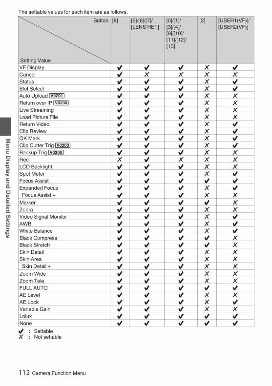
The settable values for each item are as follows.Button
Setting Value
[8] [5]/[6]/[7]/[LENS RET]
[0]/[1]/[3]/[4]/[9]/[10]/[11]/[12]/[13]
[2] [USER1(VF)]/[USER2(VF)]
VF Display c c c b cCancel c b b b bStatus c c c b cSlot Select c c c b cAuto Upload 1 c c c b bReturn over IP 0 c c c b bLive Streaming c c c b bLoad Picture File c c c b bReturn Video c c c b cClip Review c c c b cOK Mark c c c b cClip Cutter Trig 0 c c c b cBackup Trig 0 c c c b bRec b c b b bLCD Backlight c c c b bSpot Meter c c c b cFocus Assist c c c c cExpanded Focus c c c b c Focus Assist + c c c b bMarker c c c c bZebra c c c b bVideo Signal Monitor c c c b cAWB c c c b cWhite Balance c c c b cBlack Compress c c c c bBlack Stretch c c c c bSkin Detail c c c b bSkin Area c c c b b Skin Detail + c c c b bZoom Wide c c c b bZoom Tele c c c b bFULL AUTO c c c c cAE Level c c c b bAE Lock c c c b cVariable Gain c c c b bLolux c c c c cNone c c c c cc : Settableb : Not settable
112 Camera Function Menu
Menu Display and Detailed Settings

LoluxTo increase the sensitivity when in dimsurroundings, set a value in the Lolux mode.0 When [LCD/VF] B [Display Type] B [Gain] is set
to “dB”:[Setting Values: 42 dB, R36 dB, 30 dB, 24 dB]
0 When [LCD/VF] B [Display Type] B [Gain] is setto “ISO”:[Setting Values: ISO 102400, RISO 51200, ISO25600, ISO 12800]
Clip ReviewFor configuring the behavior when operating theuser button that is assigned with the “ClipReview” function.0 Last 5sec:
Views about 5 seconds of the clip from theending.
0 Top 5sec:Views about 5 seconds of the clip from thebeginning.
0 Clip:Views the entire clip.
[Setting Values: RLast 5sec, Top 5sec, Clip]Spot Meter
For configuring the behavior when operating theuser button that is assigned with the “Spot Meter”function.0 Max & Min:
Displays the brightest and darkest areas of theimage.
0 Max:Displays the brightest area of the image.
0 Min:Displays the darkest area of the image.
0 Manual:Displays the image brightness at a specifiedposition.
[Setting Values: RMax & Min, Max, Min, Manual]Memo : 0 When “HLG” is selected in [Camera Process] B
[Color Space], the value of the spot meterchanges according to the setting of [LCD/VF] B[Convert to ITU709]/[White Level].
AE LockFor configuring the behavior when operating theuser button that is assigned with the “AE Lock”function.0 FAW:
Use this to fix the FAW (Full-time Auto WhiteBalance) function to the value when the userbutton assigned with “AE Lock” is pressed.
0 AE:Use this to fix the Auto function of Gain, Iris, orShutter to the value when the user buttonassigned with “AE Lock” is pressed.
0 AE/FAW:Use this to fix the FAW (Full-time Auto WhiteBalance) function and the Auto function of Gain,Iris, or Shutter to the value when the user buttonassigned with “AE Lock” is pressed.
[Setting Values: FAW, RAE, AE/FAW]Memo : 0 This feature only works when Iris, Shutter, Gain
or White Balance is set to Auto mode.0 “AE Lock” is canceled when the user button
assigned with “AE Lock” is pressed, or when anyof the functions that can be locked is operatedregardless of the mode (Manual or Auto).
0 “AE Lock” is canceled when the lens extender isoperated and when the iris is adjusted by 2/3(two-third) stop or more.
0 “AE Lock” is canceled in the following cases.0 When the user button that is assigned with
“AE Lock” is pressed0 When changes are made to the iris (including
operation of the lens extender), gain andshutter settings
0 When changes are made to the AE level0 When there is a switch between the Camera
and Media modes
Zoom SpeedFor configuring the zoom speed when operatingthe user button that is assigned with “Zoom Tele”or “Zoom Wide”.Increasing the value increases the speed.[Setting Values: 8 to R 5 to 1]
Camera Function Menu 113
Menu Display and Detailed Settings

Expanded FocusFor configuring the behavior when operating theuser button that is assigned with the “ExpandedFocus” function.0 Limited Time:
Activates the timer.Turns off the “Expanded Focus” function about3 seconds after the user button assigned with“Expanded Focus” is pressed.
0 Momentary:The “Expanded Focus” function is enabledduring the interval while the user buttonassigned with “Expanded Focus” is pressed.
0 Toggle:Pressing the user button assigned with“Expanded Focus” each time switches the“Expanded Focus” function to on or off.
[Setting Values: Limited Time, Momentary,RToggle]Memo : 0 When “Toggle” is selected after assigning the
expanded focus to any of the [J/9], [K/10], [H/11], [I/12] buttons, press the [CANCEL/RESET] button if you want to disable thefunction.
Video Signal MonitorFor configuring the behavior when operating theuser button that is assigned with the “Video SignalMonitor” function.0 Switch in Order:
Pressing the button each time switches themode in the following sequence: Vectorscope,Waveform, Histogram 2, Off.
0 On/Off:Switches the function configured in [LCD/VF] B[Shooting Assist] B [Video Signal Monitor] to onor off.
[Setting Values: RSwitch in Order, On/Off]
Return VideoFor configuring the behavior when operating theuser button that is assigned with the “ReturnVideo” function.0 CameraGPiP:
Pressing the user button assigned with the“Return Video” function each time togglesbetween the captured video and picture-in-picture return video.
0 CameraRPiP:The picture-in-picture return video is displayedwhen the user button assigned with the “ReturnVideo” function is pressed and held down, andthe captured video is displayed when the buttonis released.
0 PiPRCamera:The captured video is displayed when the userbutton assigned with the “Return Video” functionis pressed and held down, and the picture-in-picture return video is displayed when the buttonis released.
0 PiPRReturn:The return video is displayed when the userbutton assigned with the “Return Video” functionis pressed and held down, and the picture-in-picture return video is displayed when the buttonis released.
0 CameraRReturn:The return video is displayed when the userbutton assigned with the “Return Video” functionis pressed and held down, and the capturedvideo is displayed when the button is released.
[Setting Values: CameraGPiP, CameraRPiP,PiPRCamera, PiPRReturn, RCameraRReturn]
114 Camera Function Menu
Menu Display and Detailed Settings

Full Auto ItemFor configuring the operation of each item in theFull Auto mode.Full Auto can be turned on/off using the user buttonassigned with the “Full Auto” function.Gain
For specifying the Gain operation.0 AGC:
Sets the gain to Auto.0 SW Set:
Follows the setting of the [GAIN] switch.[Setting Values: RAGC, SW Set]Iris Control
For specifying the Iris control operation.0 Auto:
Sets the iris to Auto.0 SW Set:
Follows the setting of the [IRIS A/M] switch onthe lens.
[Setting Values: RAuto, SW Set]Memo : 0 This item can be specified even if the lens used
does not have iris function.
ShutterFor specifying the Shutter operation.0 EEI:
Sets the shutter to Auto.0 SW Set:
Follows the setting of the [SHUTTER] switch.[Setting Values: REEI, SW Set]
White BalanceFor specifying the White Balance operation.0 FAW:
Sets the white balance to Auto.0 SW Set:
Follows the setting of the [WHT BAL] switch.[Setting Values: RFAW, SW Set]Audio
For configuring the audio operation.0 Auto:
Sets the audio sound to Auto.0 SW Set:
Follows the settings of the [AUDIO CH1/2/3/4]-[MANUAL/AUTO] switches.
[Setting Values: RAuto, SW Set]
Camera Function Menu 115
Menu Display and Detailed Settings

Camera Process MenuMenu screen for adjusting the quality of cameraimages.This item cannot be selected in the Media mode.Color Space
For configuring the color space that is used insidethe camera.The gamma and color gamut change automaticallyaccording to the selected color space.When [System] is configured to a setting other than“SD” and “SD(SDI In)”0 J-Log1:
Color space that supports 800% dynamic rangeand log gamma
0 HLG:Color space that supports the ITU2100 HLGHDR
0 ITU2020:Color space that supports the ITU2020 widecolor gamut
0 ITU709:ITU709 color space
[Setting Values: J-Log1, HLG, ITU2020, RITU709]When [System] is set to “SD” or “SD(SDI In)” 20 ITU601 (EBU):
Color space that supports the EBU color gamut0 ITU601 (170M):
Color space that supports the SMPTE170Mcolor gamut
0 ITU709:ITU709 color space
[Setting Values: ITU601 (EBU), ITU601 (170M),RITU709]Memo : 0 When [System] is set to “HD” and when “J-
Log1” or “HLG” is selected, some menu itemsunder [Camera Process] cannot be configured.
0 The AE function does not function when “J-Log1” or “HLG” is selected. When the [AUTOIRIS] switch on the lens is set to “AUTO”, the irisis fixed at “F4”.
9 ColorimetryFor configuring the standard for converting R, G, Bsignals to Y, Cb, Cr signals when [Color Space] isconfigured to “HLG” or “ITU2020”.0 ITU2020:
Records and outputs ITU2020 RGB signalsusing the Y-Cb-Cr signal conversion coefficient.
0 ITU709:Records and outputs ITU709 RGB signals usingthe Y-Cb-Cr signal conversion coefficient.
[Setting Values: RITU2020, ITU709]Memo : 0 This item is available when [Color Space] is set
to “HLG” or “ITU2020”.0 This is fixed at “ITU709” when [Color Space] is
set to “J-Log1” or “ITU709”.0 This is fixed at “ITU601” when [System] is set to
“SD” 2.
GammaFor adjusting the gamma curve that determines thegradation expression.
(A P173 [Adjusting the Gamma] )0 Cinema 2:
Sets to a gamma curve with soft expressiongiving priority to high luminance gradation.
0 Cinema 1:Sets to a gamma curve with similar gradation tothe screen characteristics of movies.
0 Standard:Sets to a standard gamma curve.
0 Off:Does not perform adjustment.
[Setting Values: Cinema 2, Cinema 1, RStandard,Off]Memo : 0 [Gamma] cannot be configured when [Color
Space] is set to “HLG” or “J-Log1”. “HLGGamma” is used during “HLG” and “J-Log1Gamma” is used during “J-Log1”.
116 Camera Process Menu
Menu Display and Detailed Settings

9 LevelThe amount of correction can be specifiedseparately when [Gamma] is set to “Standard”,“Cinema 1” or “Cinema 2”.When [Gamma] is set to “Standard”[Setting Values: 0.35 to R 0.45 to 0.55 (in steps of0.01)]0 Increase the number:
Finer gradation at bright areas and coarsergradation at dark areas.
0 Decrease the number:Finer gradation at dark areas and coarsergradation at bright areas.
When [Gamma] is set to “Cinema 1” or “Cinema 2”[Setting Values: +10 to R 0 to -10]0 Increase the number:
Finer gradation at dark areas and coarsergradation at bright areas.
0 Decrease the number:Finer gradation at bright areas and coarsergradation at dark areas.
Memo : 0 When [Gamma] is set to “Standard” with the
value set at [0.45], the gamma adjustedconforms to ITU709 or ITU2020.
0 If [Gamma] is set to “Cinema 2”, the maximumpeak signal decreases from 109% as thenumber becomes smaller in the setting valuesfrom 0 to -10. When the level is at -10, the videoinput with a dynamic range of 600% will be keptwithin a 100% output.
0 The level cannot be configured when [Gamma]is set to “Off” or [Color Space] is set to “HLG” or“J-Log1”.
DetailFor adjusting the contour (detail) enhancementlevel.Increasing the value increases the sharpness ofthe contour.[Setting Values: +20 to -20, Off] (Default Value: -6for “J-Log1” and “HLG” of Color Space; 0 for allother settings)Memo : 0 The setting values of this item and [Adjust...] are
stored separately when [Color Space] is set to“HLG” or “J-Log1”.
9 Adjust...For specifying the detailed settings of the contour(detail).
(A P121 [Detail/Adjust Item] )Memo : 0 This item cannot be selected when [Detail] is set
to “Off”.
Master BlackFor adjusting the pedestal level (master black) thatserves as the reference black.Increasing the value increases the pedestal.[Setting Values: +50 to +1, R0, -1 to -50]Memo : 0 This item cannot be configured when [Color
Space] is set to “J-Log1”.0 The setting value of this item is stored separately
when [Color Space] is set to “HLG”.
Black PaintFor adjusting the R (red) and B (blue) componentsof black.[Setting Values: +50 to +1, R0, -1 to -50]Memo : 0 This item cannot be configured when [Color
Space] is set to “J-Log1” or “HLG”.
FlarePerforms flare correction.[Setting Values: ROn, Off]9 Master Flare
Performs correction to prevent the entire imagefrom turning white due to light that enters the lens.The image appears blacker with a larger value, andwhiter with a smaller value.[Setting Values: +20 to +1, (R0), -1 to -20]Memo : 0 This item cannot be configured when [Color
Space] is set to “J-Log1” or “HLG”.9 Flare Balance
For adjusting the balance between R (red) and B(blue).[Setting Values: +10 to +1, (R0), -1 to -10] (R/B)V. Shading
For adjusting shading (color shift) in the verticaldirection which occurs due to the lenscharacteristics.0 On:
For adjusting shading.0 Off:
Fixes shading adjustment. Manual adjustmentis not allowed.
[Setting Values: On, ROff]9 Adjust
Performs vertical shading adjustment when [V.Shading] is set to “On”.[Setting Values: -128 to R 0 to +127]
(A P67 [Vertical Shading Adjustment] )
Camera Process Menu 117
Menu Display and Detailed Settings
Black ToeProcess the dark areas according to the balance ofbright and dark areas in the image to adjust theoverall balance of contrast.For altering the gain of dark areas. Adjust this itemaccording to the condition of the captured videosignals.0 Stretch:
Increases the gain of dark areas in an image tostretch the signals of these areas only, therebyshowing the contrast between bright and darkareas more clearly.Specify the amount of stretch with [StretchLevel].
0 Normal:Normal condition.
0 Compress:Compresses the gain of dark areas to increasethe contrast when the entire image appearsbright and contrast is weak. Specify thecompression amount with [Compress Level].
[Setting Values: Stretch, RNormal, Compress]Memo : 0 This item cannot be configured when [Color
Space] is set to “J-Log1” or “HLG”.0 When “Black Stretch” or “Black Compress” is
assigned to the [USER2] switch, priority is givento the user button setting and configurationusing the menu is disabled.
9 Stretch LevelStretch amount increases when a larger value isspecified.[Setting Values: 5 to 1 (R 3)]Memo : 0 This item is displayed only when [Black Toe] is
set to “Stretch”. Otherwise, this item appears as“---” and cannot be selected.
0 This item cannot be configured when [ColorSpace] is set to “J-Log1” or “HLG”.
9 Compress LevelCompression amount increases when a largervalue is specified.[Setting Values: 5 to 1 (R 3)]Memo : 0 This item is displayed only when [Black Toe] is
set to “Compress”. Otherwise, this item appearsas “---” and cannot be selected.
0 This item cannot be configured when [ColorSpace] is set to “J-Log1” or “HLG”.
Knee LevelFor specifying the start point (knee point) forcompressing the video signal to show the gradationof the highlighted portion. Set the [OUTPUT] switchto “AUTO KNEE OFF”.[Setting Values: 109.0%, 107.5%, 105.0%,102.5%, 100.0%, 97.5%, R 95.0%, 92.5%, 90.0%,87.5%, 85.0%, 82.5%, 80.0%, 77.5%, 75.0%,72.5%, 70.0%]Memo : 0 This item cannot be configured when [Color
Space] is set to “J-Log1” or “HLG” and when[Gamma] is set to “Cinema 2”.
Auto Knee SensitivityFor configuring the response speed of the kneeoperation when the [OUTPUT] switch is set to“AUTO KNEE ON”. Set to “Slow” when shooting anobject under a condition where there is drasticchange in the light intensity.[Setting Values: RFast, Middle, Slow]Memo : 0 This item cannot be configured when [Color
Space] is set to “J-Log1” or “HLG” and when[Gamma] is set to “Cinema 2”.
Auto Knee Peak FilterFor configuring the response speed of the kneeoperation with respect to a high-luminance pointlight source and the like when the [OUTPUT] switchis set to “AUTO KNEE ON”.[Setting Values: RHigh, Middle, Low]Memo : 0 This item cannot be configured when [Color
Space] is set to “J-Log1” or “HLG” and when[Gamma] is set to “Cinema 2”.
118 Camera Process Menu
Menu Display and Detailed Settings

White ClipFor setting the point to apply white clip for videosignals with a high luminance level.[Setting Values: 109% to 90% (R109%)]Memo : 0 Set this item to 100% if the screen becomes too
white with a setting value above 100% or whenthe system in use limits Y signals within 100%.
0 The setting value of this item is stored separatelywhen [Color Space] is set to “HLG” or “J-Log1”.
9 RGB Gamut Clip 2For configuring whether to the clip the RGB signalsat the same time when clipping the luminancesignal using the settings in [White Clip].0 On: Performs gamut clipping using the settings
in [White Clip] for video signals with a high RGBsignal level. Performs gamut clipping accordingto the settings in [White Clip] for negative signallevels.
[Setting Values: On, ROff]Memo : 0 The area that is subject to gamut clipping when
“On” is configured is as follows.Example:0 [White Clip] 103 %・RGB signal: 103 % or above・Negative level: -3 % or below
0 [White Clip]100 % or below・RGB signal: Equivalent to or higher than thepreset value in [White Clip]・Negative level: 0 % or below
0 When RGB gamut clipping for EBU-R103 issupported, this feature can be configured to“On” and the value of [White Clip] can beadjusted to a desired level that is 104 % or lower.
0 The setting value of this item is stored separatelywhen [Color Space] is set to “HLG” or “J-Log1”.
Chroma ClipFor configuring the point to apply chroma clippingfor video signals with a high color difference level.[Setting Values: 113% to 90% (R113%)]Memo : 0 When this is set to 100%, the Cb-Cr signal will
be clipped so that it falls within the 64-960 rangeof the ITU 10-bit video standard.
0 When [Color Space] is set to “HLG” or “J-Log1”,the settings will be saved separately.
White Balance...Menu for adjusting white balance.
(A P122 [White Balance Item] )* For details, refer to “[Adjusting the White
Balance] (A P 63)”.Color Matrix
For setting the color matrix.0 Natural:
Sets to a brighter and more natural color matrixthan the standard. Effective for shooting undera strong single color light source such as stagelightings.
0 Cinema Subdued:Sets to a subdued color matrix that is similar tothe screen characteristics of movies.
0 Cinema Vivid:Sets to a vivid color matrix that is similar to thescreen characteristics of movies.
0 Standard:Sets to a standard color matrix.
0 Off:Sets the color matrix function to Off.
[Setting Values: Natural, Cinema Subdued,Cinema Vivid, RStandard, Off]Memo : 0 This item cannot be configured when [Color
Space] is set to “J-Log1”.0 This is fixed at “Standard” when [Color Space]
is set to “HLG”.
Camera Process Menu 119
Menu Display and Detailed Settings

9 AdjustThis item is used to adjust [Color Matrix] to a coloraccording to the user’s preference.The adjusted values of “Natural”, “Standard”,“Cinema Vivid”, and “Cinema Subdued” in [ColorMatrix] can be stored individually.o Linear Adjust:
The saturation, hue and brightness of theprimary and complementary colors (6 colors intotal) can be set individually when “On” isconfigured.
o Multi Adjust:The saturation and hue of the 16 hue axes (R/R+/Mg-/Mg/B-/B/B+/Cy-/Cy/Cy+/G-/G/G+/Yl/Yl+/R-) can be set when “On” is configured.When the USER1 button is pressed while themulti adjustment screen is displayed, only thecolors of the hue under adjustment remain in thefollowing cases. The other colors become blackand white.0 LCD monitor and viewfinder video images0 [HD/SD SDI OUT2] terminal output when [A/V
Set]→[SDI OUT2] is set to “VF”0 [HDMI] terminal output when [A/V Set]→[HDMI
OUT] is set to “VF”(A P174 [Adjusting Color Matrix] )
Memo : 0 This item cannot be configured when [Color
Space] is set to “J-Log1”.0 The setting value of this item is stored separately
when [Color Space] is set to “HLG”.
Color GainFor adjusting the video signal color level.Increasing the value deepens the color.[Setting Values: +15 to -50, Off (R0)]Memo : 0 Images are displayed in black-and-white when
this is set to “Off”.0 This item cannot be configured when [Color
Space] is set to “J-Log1”.0 The setting value of this item is stored separately
when [Color Space] is set to “HLG”.
Reverse PictureFor recording images correctly by setting this itemto “Rotate” when the lens image appears upsidedown or laterally inverted.0 Rotate:
Enables horizontal/vertical inversion of theimage.
0 Off:Disables horizontal/vertical inversion of theimage.
[Setting Values: Rotate, ROff]DNR
Decreases noise in the image.[Setting Values: High, RMiddle, Low]Reset Process
Restores all items in the [Camera Process] menuto their default settings.
120 Camera Process Menu
Menu Display and Detailed Settings

Detail/Adjust ItemV/H Balance
For setting the H/V balance to enhance contour(detail) in the horizontal (H) or vertical (V) direction.0 H+1 to H+20:
Increasing the value enhances contour in thehorizontal direction.
0 V+1 to V+20:Increasing the value enhances contour in thevertical direction.
[Setting Values: H+20 to H+1, RNormal, V+1 to V+20]H Frequency
For specifying the correction frequency of thehorizontal contour. Set this according to the object.0 High:
Emphasizes the high frequency range. Use thiswhen shooting objects with fine patterns.
0 Middle:Emphasizes the intermediate frequency range.
0 Low:Emphasizes the low frequency range. Use thiswhen shooting objects with large patterns.
[Setting Values: High, RMiddle, Low]V Frequency
For specifying the correction frequency of thevertical contour. Set this according to the object.0 High:
Emphasizes the high frequency range.0 Middle:
Emphasizes the intermediate frequency range.0 Low:
Emphasizes the low frequency range.[Setting Values: High, RMiddle, Low]Coring
For configuring the degree of enhancement withrespect to low-level signals (noise, etc.) with subtle“outline” enhancement.Applies outline enhancement to even low-levelsignals when the setting is closer to -20, and outlineenhancement of low-level signals becomes lessnoticeable with noise suppressed when the settingis closer to +20.[Setting Values: +20 to +1, R0, -1 to -20]
Level DependConfigure this item when areas such as the darkerportions of the video image appear coarse whenthe Detail function is applied.+1 reduces the outline enhancement of dark areasand suppresses the noise, while -1 enhances theoutline of dark areas.[Setting Values: +1, R0, -1]Posi Gain
For configuring the amount of detail in the whitedirection of the outline enhancement signals.[Setting Values: +20 to +1, R0, -1 to -20]Nega Gain
For configuring the amount of detail in the blackdirection of the outline enhancement signals.[Setting Values: +20 to +1, R0, -1 to -20]Knee Gain
For configuring the amount of detail at the highlightareas of the video image. A larger value furtherenhances the outline of the signals at the highlightareas. While a smaller value reduces the outline ofthe highlight areas, moire (aliasing) due to whiteclipping at the highlight areas is also less likely tooccur.[Setting Values: 32 to R16 to 0]Memo : 0 This item cannot be configured when [Color
Space] is set to “J-Log1” or “HLG”.
Skin DetailDetects the skin tone and smooths the outline.[Setting Values: On, ROff]9 Level
For configuring the outline correction level when[Skin Detail] is set to “On”.The smaller the number, the smoother the video.[Setting Values: -1 to R -5 to -10]
Camera Process Menu 121
Menu Display and Detailed Settings

Skin AreaFor configuring whether to display only the colorcorrection area in color and areas that are notcorrected in black-and-white.0 On:
When “Detect” of [Skin Color Adjust] isfunctioning, only the detected color is displayedin color and the other areas are displayed inblack-and-white in the following cases.0 LCD monitor and viewfinder video images0 [HD/SD SDI OUT2] terminal output when
[A/V Set] B [SDI OUT2] is set to “VF”0 [HDMI] terminal output when [A/V Set] B
[HDMI OUT] is set to “VF”0 Off:
Displays all the colors.[Setting Values: On, ROff]Skin Color Adjust
For configuring details of the skin color.0 Detect
For detecting the skin tone.[USER1]Stop appears when detection is inprogress and [USER1]Execute appears whiledetection is stopped.[Setting Values: Execute, Stop]
0 SaturationSelecting a larger value widens the saturationrange of the color to be corrected, while asmaller value reduces the color saturationrange.[Setting Values: +10 to R0 to -10]
0 WidthAlthough selecting a larger value widens the huerange of the color to be corrected and easesidentification, it also increases the likelihood oferroneous correction. Selecting a smaller valuenarrows down the hue range, but helps toreduce erroneous correction at the same time.[Setting Values: +10 to R0 to -10]
White Balance ItemPreset Temp.
For setting the color temperature when the[WHT.BAL] switch is set to “PRST”.For details, refer to “[Adjusting the White Balance] (A P 63)”.Alternative Temp.
For setting the alternative color temperature in thePreset mode.When the [WHT.BAL] switch is set to “PRST”,pressing the user button assigned with the “AWB”function each time switches the color temperaturesetting in the Preset mode. ([PresetTemp.]1[Alternative Temp.])For details, refer to “[Adjusting the White Balance] (A P 63)”.Preset Paint Memory
For configuring whether to configure the colortemperature individually or collectively in thePreset mode. Adjustment is performed in [PresetPaint].0 Individual:
Each of the 9 types of color temperatures(2300K, 3000K, 3200K, 4200K, 4800K, 5200K,5600K, 6500K, 7500K) are configuredindividually.
0 Common:The entire color temperature range is configuredcollectively.
[Setting Values: Individual, RCommon]Preset Paint
For adjusting the R (red) and (B) blue componentsin the Preset mode.0 Increase the number:
Strengthens the red/blue.0 Decrease the number:
Weakens the red/blue.[Setting Values: +32 to -32 (R 0)]
122 Camera Process Menu
Menu Display and Detailed Settings

AWB PaintFor adjusting the R (red)/B (blue) component in theAWB (Auto White Balance) mode.For details, refer to “[Adjusting the White Balance] (A P 63)”.0 Increase the number:
Strengthens the red/blue.0 Decrease the number:
Weakens the red/blue.[Setting Values: -32 to +32 (R 0)]Memo : 0 This item is selectable when the [WHT.BAL]
switch is set to “A” or “B”. When “PRST” is set,this item appears as “---” and cannot beselected.
0 Different values can be specified for “A” and “B”.0 When [Clear Paint After AWB] is set to “On”,
pressing the user button that is assigned with the“AWB” function to readjust the white balanceswitches the R and B values automatically to“0”.
Clear Paint After AWBFor specifying whether to clear the [AWB Paint] (Rvalue and B value) settings after executing AWB(Auto White Balance).0 On:
Sets the [AWB Paint] (R value and B value)settings to “0” after executing AWB (Auto WhiteBalance).
0 Off:Does not change the [AWB Paint] (R value andB value) settings after executing AWB (AutoWhite Balance).
[Setting Values: ROn, Off]FAW Paint
For adjusting the R (red)/B (blue) componentduring FAW (Full Auto White Balance) mode.0 Increase the number:
Strengthens the red/blue.0 Decrease the number:
Weakens the red/blue.[Setting Values: -32 to +32 (R 0)]
Camera Process Menu 123
Menu Display and Detailed Settings

TC/UB MenuMenu screen for setting time code and user’s bit.This item cannot be selected in the Media mode,or during recording.TC Mode
For configuring the TC mode settings.0 SW Set:
Follows the settings of the [TC GEN] switch.0 Clock:
This is set to “Clock” when the [TC GEN] switchis set to “F-RUN”.
[Setting Values: RSW Set, Clock]Memo : 0 When the [TC GEN] selection switch is set to “R-
RUN” or “REGEN”, or during “IntervalRec”1, “Frame Rec”1 and “High-Speed”2, the setting is fixed at “SW Set”.
TC PresetFor setting the time code (hour, minute, second,frame).Display : Drop setting 02:02:25.20
: Non Drop setting 02:02:25:20(A P74 [Setting Time Code Generator] )
Memo : 0 When the [TC GEN] switch is set to “REGEN”,
“<Regen>” is displayed and preset is disabled.0 When [TC Mode] is set to “Clock”, “<Clock>” is
displayed and preset is disabled.
UB ModeFor setting the recording mode of the user’s bit.0 Date:
Records the date.0 Time:
Records the time.0 Preset:
Records according to the preset setting.(A P77 [Setting the User’s Bit] )
[Setting Values: Date, Time, RPreset]Memo : 0 If [UB Mode] is set to “Time”, the user’s bit
operates in the 24-hour format even if the LCDdisplay is in the 12-hour format.
9 PresetFor setting the user’s bit. (Digit by digit)Display : AB CD EF 01
(A P77 [Presetting the User’s Bit] )Memo : 0 When [UB Mode] is set to “Date” or “Time”, this
item appears as “---” and preset is disabled.0 When the [TC GEN] switch is set to “REGEN”,
“<Regen>” is displayed and preset is disabled.
Drop FrameFor setting the framing mode of the time codegenerator.0 Non Drop:
Internal time code generator works in the non-drop-frame mode. Use this setting when placingemphasis on the number of frames.
0 Drop:Internal time code generator works in the drop-frame mode. Use this setting when placingemphasis on the recording time.
[Setting Values: Non Drop, RDrop]Memo : 0 This item can be set only when [System] B
[Record Set] B [Record Format] B [WFrameRate] is set to “60p”, “30p”, or “60i”. When[Frame Rate] is “24p”2, “Non Drop”becomes fixed and cannot be selected. When[Frame Rate] is “50p”, “25p”, or “50i”, this itemappears as “---” and cannot be selected.(A P152 [ W Frame Rate ] )
124 TC/UB Menu
Menu Display and Detailed Settings

LCD/VF MenuItem for specifying settings related to the LCDmonitor or viewfinder screen.This menu screen can be used to specify settingsrelated to the Focus Assist mode, zebra patterndisplay, screen size, marker, and safety zone. Inaddition, it is also used for selecting whether todisplay characters on the LCD monitor orviewfinder screen, as well as for adjusting thepicture quality of the LCD monitor.Shooting Assist...
Menu for setting the Shooting Assist function.(A P126 [Shooting Assist Item] )
Marker Settings...For setting items such as the safety zone andcenter mark.
(A P128 [Marker Settings Item] )Display Type...
For specifying display-related settings.(A P129 [Display Type Item] )
Display On/Off...For configuring the on/off setting of the screendisplay.
(A P130 [Display On/Off Item] )VF Color
For selecting whether to display the image on theviewfinder screen in color or black-and-white.Select “On” to display in color, and “Off” to displayin black-and-white.[Setting Values: ROn, Off]LCD Contrast
For setting the difference in luminance between thedarkest and brightness areas in the LCD monitor.Increasing the value increases the contrast.[Setting Values: +10 to +1, R0, -1 to -10]
LCD BrightFor configuring the brightness of the LCD monitor.Increasing the value increases the brightness.[Setting Values: +10 to +1, R0, -1 to -10]LCD Peaking
For adjusting the outline of the image displayed onthe LCD monitor.[Setting Values: +10 to +1, R0, -1 to -10]Convert to ITU709
When [Color Space] is set to “ITU2020”, “J-Log1”or “HLG”, the video images on the LCD monitor andviewfinder are converted to the ITU709 color spacefor display.
0 When [A/V Set] B [Video Set] B [SDI OUT2]is set to “VF”, the [HD/SD SDI OUT2] terminaloutput is also converted.
0 When [A/V Set] B[Video Set] B [HDMIOUT] is set to “VF”, the [HDMI] terminaloutput is also converted.
0 Cam + Return:The camera and return videos are convertedfrom the color space configured in [ColorSpace] to the ITU709 color space.
0 Cam:Only the camera video is converted to theITU709 color space.
0 Off:Not converted.
[Setting Values: Cam + Return, Cam, ROff]Memo : 0 This item can be configured only when [Color
Space] is set to “ITU2020”, “J-Log1” or “HLG”.
LCD/VF Menu 125
Menu Display and Detailed Settings

9 White LevelFor configuring the white level during adjustment ofthe dynamic range that is visible in the LCD monitoror viewfinder when [Color Space] is set to “HLG”.When [Color Space] is set to “HLG” and [Convertto ITU709] is set to a value other than “Off”, this itemcan be used to configure the output luminance level(%) of HLG videos that corresponds to 100% onthe ITU709 gamma curve during the conversion.[Setting Values: 80.0%, 77.5%, 75.0%, R 72.5%,70.0%, 67.5%,65.0%, 62.5%, 60.0%, 57.5%,55.0%, 52.5%, 50.0%]Memo : 0 This item can be configured only when [Color
Space] is set to “HLG”.0 The value on the spot meter changes in tandem
with this setting.Example: When [White Level] is set to “75.0%”,the point at which the HLG output is 75% isdisplayed as 100% on the spot meter.
0 Refer to [Tone Mapping Characteristics forConverting HLG to ITU709 for LCD/VF] (A P 231) for each characteristic. Conversionto the ITU709 color space is performed withgamma and knee adjusted such that themaximum HDR dynamic range is visible duringthe conversion.
LCD RGB GainFor adjusting the R (red), G (green) and B (blue)gain level of the LCD monitor.[Setting Values: +127 to R 0 to -128]9 Reset
Restores [LCD RGB Gain] to the default settings.VF RGB Gain
For adjusting the R (red), G (green) and B (blue)gain level of the viewfinder.[Setting Values: +127 to R 0 to -128]9 Reset
Restores [VF RGB Gain] to the default settings.
Shooting Assist ItemFocus Assist
For setting whether to add color to the contour ofthe focused image upon switching the image toblack-and-white.[Setting Values: On, ROff]9 Type
For configuring the behavior when operating theuser button that is assigned with the [FocusAssist] function.
(A P58 [Focus Assist Function] )0 ACCU-Focus:
Enables the Focus Assist and ACCU-Focus(forced focus) functions. The depth of field of theobject becomes shallower to enable easierfocusing. The ACCU-Focus function switchesautomatically to “Off” after about 10 seconds.
0 Normal:Enables only the Focus Assist function. Thefocused area is displayed in color to enableeasier focusing. Display color can be specifiedwith [Color].
[Setting Values: ACCU-Focus, RNormal]9 Color
For setting the display color of the focused areawhen Focus Assist is activated.[Setting Values: RBlue, Green, Red]Zebra
For selecting whether the number of zebra patternsto display at the bright areas of the subject.
(A P80 [Setting Zebra Pattern] )0 2 Patterns:
Displays two types of zebra patterns (Zebra1and Zebra2).
0 1 Pattern:Displays one type of zebra pattern (Zebra1).
[Setting Values: 2 Patterns, R1 Pattern]9 Detect
For configuring the timing to detect the zebrapattern display.0 Converted ITU709:
Performs detection after converting to theITU709 color space.
0 HLG/J-Log1:Performs detection before converting to theITU709 color space.
[Setting Values: Converted ITU709, RHLG/J-Log1]Memo : 0 This item is selectable only when [Color
Space] is set to “J-Log1” or “HLG” and [Convertto ITU709] is set to “Cam” or “Cam + Return”.
126 LCD/VF Menu
Menu Display and Detailed Settings

9 Top 1For setting the maximum luminance level to displayZebra1.[Setting Values: Over, 100%, 98%, 95% to 5% (in5% increments)] (R80%)9 Bottom 1
For setting the minimum luminance level to displayZebra1.[Setting Values: 100%, 98%, 95% to 0% (in 5%increments)] (R70%)9 Top 2
For setting the maximum luminance level to displayZebra2.[Setting Values: Over, 100%, 98%, 95% to 5% (in5% increments)] (ROver)Memo : 0 This item cannot be selected when [Zebra] is set
to “1 Pattern”.9 Bottom 2
For setting the minimum luminance level to displayZebra2.[Setting Values: 100%, 98%, 95% to 0% (in 5%increments)] (R80%)Memo : 0 This item cannot be selected when [Zebra] is set
to “1 Pattern”.
Peaking FrequencyFor configuring the frequency band for applyingoutline enhancement using [LCD Peaking] and the[PEAKING] adjustment knob on the viewfinder.[Setting Values: High, RMiddle, Low]Video Signal Monitor
For configuring whether to display or hide the videosignal monitor.[Setting Values: On, ROff]Memo : 0 This may not be selectable depending on the
operating mode and status.
9 TypeFor configuring the video signal monitor to bedisplayed.0 Histogram2:
Displays the distribution of points in the imagebased on the degree of brightness and thecorresponding number of points.
0 Vector Scope:Displays the saturation and hue of the video asa circle.
0 Waveform:Displays the luminance signal of the video as awaveform.
[Setting Values: Histogram2, Vector Scope,RWaveform]9 Histogram Top 2
For selecting the maximum brightness limit forchanging the histogram display color.[Setting Values: 5% to 110% (in 5% increments)](R 80%)0 When [Color Space] is set to “J-Log1”
[Setting Values: -5F-stop, -4F-stop, -3F-stop(2%),-2F-stop, -1F-stop, 0F-stop(18%), ⅓F-stop, ⅔F-stop, 1F-stop, 1⅓F-stop, 1⅔F-stop, 2F-stop, 2 ⅓F-stop(90%), 2 ⅔ F-stop, R3F-stop, 3 ⅓ F-stop, 3⅔ F-stop, 4F-stop, 4 ⅓ F-stop, 4 ⅔ F-stop, 5F-stop, 5 ⅓ F-stop, 5½F-stop]Memo : 0 When [Color Space] is set to “J-Log1”, a green
line appears which corresponds to the 0F-stop(18%) portion of the subject with 18%reflectance.
9 Histogram Bottom 2For selecting the minimum brightness limit forchanging the histogram display color.[Setting Values: 0% to 105% (in 5% increments)](R 20%)0 When [Color Space] is set to “J-Log1”
[Setting Values: -6F-stop, -5F-stop, -4F-stop,R-3F-stop(2%), -2F-stop, -1F-stop, 0F-stop(18%),⅓ F-stop, ⅔ F-stop, 1F-stop, 1 ⅓ F-stop, 1 ⅔ F-stop, 2F-stop, 2 ⅓ F-stop(90%), 2 ⅔ F-stop, 3F-stop, 3 ⅓ F-stop, 3 ⅔ F-stop, 4F-stop, 4 ⅓ F-stop,4 ⅔ F-stop, 5F-stop, 5 ⅓ F-stop]Memo : 0 When [Color Space] is set to “J-Log1”, a green
line appears which corresponds to the 0F-stop(18%) portion of the subject with 18%reflectance.
LCD/VF Menu 127
Menu Display and Detailed Settings

Marker Settings ItemFor setting the marker and safety zone, which areuseful in helping you determine the angle of viewfor the image according to the shooting purpose.
(A P172 [Marker and Safety Zone Displays(Camera Mode Only)] )
Memo : 0 During Clip Review or when in the Media mode,
the markers do not appear regardless of thesetting.
MarkerFor setting whether to display marker, safety zone,and center marks on the screen.[Setting Values: On, ROff]9 Grid Marker
For setting whether to display a 3x3 grid on thescreen.[Setting Values: On, ROff]Memo : 0 When [Grid Marker] is set to “On”, [Aspect
Ratio], [Aspect Marker], and [Safety Zone] donot function.
9 Aspect RatioFor selecting the final image aspect ratio to be usedfrom the overall angle of view.[Setting Values: 16:9(+4:3), 2.35:1 Top, 2.35:1Center, 1.85:1 Top, 1.85:1 Center, R16:9, 1.75:1,1.66:1, 14:9, 13:9, 4:3]Memo : 0 When [System] B [Record Set] B [Record
Format] B [SD Aspect] is set to “4:3”, this itemis fixed at “4:3” and selection is disabled. 2(A P154 [ SD Aspect 2 ] )
9 Aspect MarkerFor specifying how boundary markers are to beused to indicate the parts of an image that arebeyond the range of the aspect ratio selected in[Aspect Ratio].0 Line+Halftone:
Displays the boundary using lines, and areasoutside the boundary in halftone.
0 Halftone:Displays areas outside the boundary in halftone.
0 Line:Displays the boundary using lines.
0 Off:Hides the boundary markers.
[Setting Values: Line+Halftone, Halftone, Line,ROff]Memo : 0 When [Aspect Ratio] is set to “16:9” or
“16:9(+4:3)”, this item is fixed at “Off” and cannotbe selected.
9 Safety ZoneFor setting the percentage of area that is to bedeemed as valid area (Safety Zone) within theboundary of the aspect ratio selected in [AspectRatio].[Setting Values: 95%, 93%, 90%, 88%, 80%, ROff]9 Center Mark
For specifying whether to display a mark to indicatethe screen center within the aspect ratio selectedin [Aspect Ratio].[Setting Values: ROn, Off]
128 LCD/VF Menu
Menu Display and Detailed Settings

Display Type ItemThis menu is used to set the displays on the LCDmonitor and viewfinder screen.Battery
For setting the display of the remaining batterypower on the LCD monitor and viewfinder screen.0 Time:
Displays the remaining battery power inminutes. (min)
0 Capacity%:Displays the remaining battery power inpercentage. (%)
0 Voltage:Displays the current battery voltage in units of0.1 V. (V)
[Setting Values: RTime, Capacity%, Voltage]Memo : 0 The battery mark that appears before the “Time”,
“Capacity%” or “Voltage” value changes according tothe remaining battery power.I : Battery which the capacity could not be
acquired4 : Below 13%D : 13% or higherC : 30% or higherB : 60% or higherF : Battery communication errorJ : Calibration required
0 While “Time” or “Capacity%” is displayed, “E”appears when the level falls below the setting in[System] B [Battery] B [Near End (%)]. Replace thebattery as soon as possible.
0 The remaining battery power and remaining time areintended as reference values for the shootingduration.
0 When the battery that is connected does not supportcommunication, the voltage is displayed regardlessof the setting.
ZoomFor setting the display method of the zoomposition.0 Number:
Displays the zoom position in numbers (Z00 to99).
0 Bar:Displays the zoom position in a bar.
[Setting Values: Number, RBar]Memo : 0 This item will not be displayed if the lens
attached does not support zoom positioninformation.
FocusFor setting the display method of the approximatedistance to the subject in focus during manualfocus.0 Feet:
Displays the distance in feet.0 Meter:
Displays the distance in meters.[Setting Values: Feet, RMeter]Memo : 0 This item will not be displayed if the lens
attached does not support focus positioninformation.
ShutterFor setting the shutter display to be displayed onthe LCD monitor and viewfinder screen.0 DEG:
Displays the shutter speed in degrees in thesame way as film cameras.
0 SEC:Displays the shutter speed in seconds.
[Setting Values: DEG, RSEC]Memo : 0 “DEG” is selectable only when [WFrame Rate]
is set to “24p”2 or “25p”. When [WFrameRate] is set to other values, the shutter displaysetting is fixed at “SEC” and cannot be selected.(A P152 [ W Frame Rate ] )0 When a remote control unit is connected to the
[REMOTE] terminal, “SEC” is displayed andselection is disabled.
LCD/VF Menu 129
Menu Display and Detailed Settings

GainFor setting the gain display to be displayed on theLCD monitor and viewfinder screen.0 ISO:
Displays the gain as ISO sensitivity.0 dB:
Displays the gain in dB (decibel).[Setting Values: ISO, RdB]Memo : 0 This item cannot be configured when [Color
Space] is set to “HLG”.
Audio MeterFor specifying whether to display the audio levelmeter on the LCD monitor and viewfinder screen.0 Auto:
Displays the audio meter for 4 channels when[System] B [Record Set] B [Record Format] B[WAudio] is set to “4CH” and for 2 channels([CH1]/[CH2]) in all other cases. Whether 4channels or 2 channels ([CH1]/[CH2]) aredisplayed during playback is dependent on therecorded clip.
0 CH1/2:Displays the audio level meter for [CH1] and[CH2].
[Setting Values: RAuto, CH1/2]
Display On/Off ItemFor setting whether to turn on or off the display ofan item on the LCD monitor and viewfinder screen.Battery, Clip Info, OK Mark, High-Speed2, SDI IN, Check Mark, Media Status,Rec Trigger, TC/UB, Media Remain, RecordFormat, Video Format, Guide, GPS uv, Return over IP 0, Live Streaming,Network, Date, Time, Operation Lock, Zoom,Focus, Zebra, Focus Assist, Color Space,Black Toe, Skin Detail, ND Filter, AE Level,Iris, Shutter, Gain, White Balance, AudioMeter, Position Bar
For configuring whether to display or hide an item.[Setting Values: ROn, Off]Memo : 0 This may not be selectable depending on the
operating mode and status.
130 LCD/VF Menu
Menu Display and Detailed Settings

A/V Set MenuMenu screen for video output and audio.Video Set...
For specifying video output-related settings.(A P131 [Video Set Item] )
Audio Set...For specifying audio-related settings.
(A P135 [Audio Set Item] )
Video Set ItemSDI OUT2 Char.
For configuring whether to show the display andmenu on the [HD/SD SDI OUT2] terminal.[Setting Values: On, ROff]Memo : 0 When “VF” is selected for [SDI OUT2], the
setting is fixed at “On”.
HDMI Char.For configuring whether to show the display andmenu on the [HDMI] terminal.[Setting Values: On, ROff]Memo : 0 When “VF” is selected for [HDMI OUT], the
setting is fixed at “On”.
Video OUT Char.For configuring whether to show the display andmenu on the [VIDEO OUT] terminal.[Setting Values: On, ROff]
SDI OUT1 Res.For selecting the resolution of video output from the[HD/SD SDI OUT1] terminal according to themonitor to be connected.[Setting Values: 1080psF, 1080p, R1080i, 720p,576i, 480i]Memo : 0 The selectable options vary according to the
setting in [System]/[WResolution] and [WFrameRate] of [System] B[Record Set] B [RecordFormat].
0 Cross conversion output is not possible.0 When [A/V Set] B [Video Set] B [SDI OUT1
Res.] is set to “1080p”, configuring [System] B[GPS] to “On” changes the setting to “1080i”.u v
SDI OUT2/HDMI Res.For configuring the resolution of the video outputfrom the [HD/SD SDI OUT2] and [HDMI] terminalsaccording to the monitor to be connected.[Setting Values: 1080psF/i, 1080p, R1080i, 720p,576p(HDMI only), 576i, 480p(HDMI only), 480i]Memo : 0 The selectable options vary according to the
setting in [System]/[WResolution] and [WFrameRate] of [System] B [Record Set] B [RecordFormat].
0 Cross conversion output is not possible.0 When “VF” is selected for [SDI OUT2], signal is
output from the [HD/SD SDI OUT 2] terminal at1080p.
0 When “VF” is selected for [HDMI OUT], signal isoutput from the [HDMI] terminal at 1080p.
SDI OUT1For configuring video output from the [HD/SD SDIOUT1] terminal.[Setting Values: On, ROff]Memo : 0 When a resolution with no SDI output is
selected, the setting is fixed at “Off”.0 This item needs to be configured to “On” even
during SDI OUT1 output from the expansion unitterminal (68-pin) at the back.
A/V Set Menu 131
Menu Display and Detailed Settings

SDI OUT2For configuring video output from the [HD/SD SDIOUT2] terminal.0 VF:
Outputs the same display as that of theviewfinder at 1080p.
0 Camera:Outputs from the terminal. The screen and menudisplays can be configured in [SDI OUT2 Char.].
0 Off:Does not output from the terminal.
[Setting Values: VF, Camera, ROff]Memo : 0 When a resolution with no SDI output is
selected, “Camera” cannot be selected.0 When “576p(HDMI only)” or “480p(HDMI
only)” is selected for [SDI OUT2/HDMI Res.]while “Camera” is being selected, the settingswitches from “Camera” to “Off”.
HDMI OUTFor configuring video output from the [HDMI]terminal.0 VF:
Outputs the same display as that of theviewfinder at 1080p.
0 Camera:Outputs from the terminal. The screen and menudisplays can be configured in [HDMI Char.].
0 Off:Does not output from the terminal.
[Setting Values: VF, Camera, ROff]Memo : 0 When a resolution with no HDMI output is
selected, “Camera” cannot be selected.
VIDEO OUTFor configuring video output from the [VIDEOOUT] terminal.[Setting Values: On, ROff]HDMI Color
For setting the color format of HDMI signals.[Setting Values: RGB, RAuto]Memo : 0 This item can be configured when [HDMI OUT]
is set to a setting other than “Off”.
HDMI ColorimetryFor configuring the colorimetry of the HDMI signalwhen [Camera Process] B [Color Space] B[Colorimetry] is set to “ITU2020”.0 ITU2020:
Outputs using the colorimetry of ITU2020regardless of the device that is connected viaHDMI.
0 ITU709:Outputs using the colorimetry of ITU709regardless of the device that is connected viaHDMI.
0 Auto:Switches the colorimetry automaticallyaccording to the device that is connected viaHDMI.
[Setting Values: ITU2020, ITU709, RAuto]Memo : 0 This item can be configured when [HDMI OUT]
is set to a setting other than “Off”.0 This item can be configured when [HDMI
Color] is set to “Auto”.0 This item cannot be configured when [Camera
Process] B [Color Space] B [Colorimetry] is setto a setting other than “ITU2020”.
132 A/V Set Menu
Menu Display and Detailed Settings
HDMI EnhanceFor setting the color range of HDMI signals. Whenconnecting to a PC monitor, set this to “On”.[Setting Values: On, ROff]Memo : 0 This item can be configured when [HDMI OUT]
is set to a setting other than “Off”.
SDI Rec TriggerFor configuring whether to superimpose triggersignals on the [HD/SD SDI OUT] terminal in tandemwith the [REC] button.If “Type-A” or “Type-B” is specified, it is possible torecord on a device equipped with SDI record triggerin tandem with the operation of the [REC] button.When a compatible device is connected,recording/stop control signals are output in tandemwith the operation of the [REC] button.The SDI record trigger output status to theconnected device is indicated by REC B/STBY Bon the display screen.[Setting Values: Type-A, Type-B, ROff]Memo : 0 If “Type-A” does not work, it may operate in the
“Type-B” setting, but the user’s bit to theconnected device will not be correctly output.
0 Even if REC B/STBY B is displayed on thedisplay screen, the compatible device may notnecessarily be recording.
0 This item can be configured when [SDI OUT1]is set to “On” or [SDI OUT2] is set to a settingother than “Off”, and [Rec Mode] is set to“Normal”, “Pre Rec”0 or “ClipContinuous”0.
0 Set to “Off” if connecting to a device that doesnot support record trigger.
HDMI Rec TriggerFor configuring whether to superimpose triggersignals on the [HDMI] out terminal in tandem withthe [REC] button.If “On” is specified, it is possible to record on adevice equipped with HDMI record trigger intandem with the operation of the [REC] button.When a compatible device is connected,recording/stop control signals are output in tandemwith the operation of the [REC] button.The HDMI record trigger output status to theconnected device is indicated by REC B/STBY Bon the display screen.[Setting Values: On, ROff]Memo : 0 Even if REC B/STBY B is displayed on the
display screen, the compatible device may notnecessarily be recording.
0 This item can be configured when [HDMI OUT]is set to a value other than “Off”, and [RecMode] is set to “Normal”, “Pre Rec”0 or“Clip Continuous”0.
0 Set to “Off” if connecting to a device that doesnot support record trigger.
HDMI TCFor setting whether to superimpose time code tothe [HDMI] terminal.[Setting Values: On, ROff]Memo : 0 This item can be configured when [HDMI OUT]
is set to a setting other than “Off”.0 Set to “Off” if connecting to a device that does
not support HDMI TC.
A/V Set Menu 133
Menu Display and Detailed Settings

SD AspectFor setting the style of displaying images with a16:9 aspect ratio on a 4:3 aspect ratio screen.0 Side Cut:
Displays image with the left and right sides cutoff.
0 Letter:Displays as a wide image with the top andbottom blackened.
0 Squeeze:Displays image that is squeezed horizontally.
[Setting Values: Side Cut, Letter, RSqueeze]Memo : 0 When [Record Format] B [System] is set to
“SD”, and [Record Format] B [SD Aspect] is setto “4:3”, “---” is displayed and selection isdisabled. 2(A P151 [ System ] )0 [System] B [Record Set] B [Record Format] B
[System] is set to “SD”, “Squeeze” and “Letter”can be selected. 2
SD Set UpFor selecting whether to add a setup signal to thevideo signal output from the [VIDEO OUT] terminal.Setup signals are added when “7.5%” is selected.[Setting Values: 7.5%, R0.0%]Memo : 0 Depending on the menu settings of the camera
recorder and the condition of the cableconnected to it, the setup signal setting may befixed at “0.0%”. “0.0%” is displayed in gray in thiscase.
0 When [System] B [Record Set] B [RecordFormat]B[Frame Rate] is set to “50p” or “50i”,“---” is displayed and selection is disabled.
Genlock InputFor selecting the input destination of videosynchronizing signals.0 SDI IN:
Inputs video synchronizing signals from the [HD/SD SDI IN] terminal.
0 Adapter:Inputs video synchronizing signals from theadapter connected to the accessory connectionterminal (68 pins) on the rear of the camerarecorder.
0 GENLOCK:Inputs video synchronizing signals from the[GENLOCK] terminal.
[Setting Values: SDI IN, Adapter, RGENLOCK]Memo : 0 When “HD(SDI In)” or “SD(SDI In)” 2 is
selected in [System], “SDI IN” is displayed andselection is disabled.
Genlock Adjust...Adjusts the H Phase of the camera recorder’s videosignals with respect to the input synchronizingsignals.9 SD-SDI H Phase
Adjusts the H Phase of the camera recorder’s SD-SDI signal with respect to the externalsynchronizing signal input to the terminal set in the[Genlock Input] item.[Setting Values: -373 to +373] (R 0)Memo : 0 When there is no SD video output from the [SDI
OUT] terminal, “---” is displayed and selection isdisabled.
9 HD-SDI H PhaseAdjusts the H Phase of the camera recorder’s HD-SDI signal with respect to the externalsynchronizing signal input to the terminal set in the[Genlock Input] item.[Setting Values: -1024 to +1023] (R 0)Memo : 0 When there is no HD video output from the [SDI
OUT] terminal, “---” is displayed and selection isdisabled.
134 A/V Set Menu
Menu Display and Detailed Settings

Return Input 0For selecting the input destination of the returnvideo.0 Network:
For inputting the return video from thepreconfigured network.
0 SDI:Inputs return video from the [HD/SD SDI IN]terminal.
[Setting Values: Network, RSDI]Return Aspect
For selecting the aspect ratio of the return video.0 16:9:
Select this option if the return video is a squeezesignal.
0 4:3:Select this option if the return video is a 4:3aspect signal (including Letter Box).
[Setting Values: R16:9, 4:3]
Audio Set Item
Front Mic SelectFor selecting the microphone to be connected tothe [MIC IN] terminal.0 Stereo M/S:
Selects the stereo M/S (Mid/Side) direct outputmicrophone.
0 Stereo L/R:Selects the stereo L/R type microphone.
0 Mono:Selects the monophonic microphone.
[Setting Values: Stereo M/S, RStereo L/R, Mono]Memo : 0 When “Stereo M/S” is configured, use only
stereo M/S (Mid/Side) direct outputmicrophone.
Front Mic PowerConfigure this setting when it is necessary tosupply +48 V power to the microphone that isconnected to the [MIC IN] terminal.[Setting Values: ROn, Off]Memo : 0 When using a microphone that does not require
a +48V power supply, make sure that it is set tothe “Off” position before connecting themicrophone.
Front Mic 1 Ref.For setting the reference input level when the[AUDIO INPUT CH1] or [AUDIO INPUT CH3]selection switch is set to “FRONT”.[Setting Values: -30dB, -40dB, R -50dB, -60dB]Front Mic 2 Ref.
For setting the reference input level when the[AUDIO INPUT CH2] or [AUDIO INPUT CH4]selection switch is set to “FRONT”.[Setting Values: -30dB, -40dB, R -50dB, -60dB]Rear Mic 1 Ref.
For configuring the reference input level when the[AUDIO INPUT CH1] or [AUDIO INPUT CH3]selection switch is set to “REAR”, and the [AUDIOINPUT1] selection switch to “MIC” or “MIC+48V”.[Setting Values: -30dB, -40dB, -50dB, R -60dB]Rear Mic 2 Ref.
For configuring the reference input level when the[AUDIO INPUT CH2] or [AUDIO INPUT CH4]selection switch is set to “REAR”, and the [AUDIOINPUT2] selection switch to “MIC” or “MIC+48V”.[Setting Values: -30dB, -40dB, -50dB, R -60dB]Rear Line Ref.
For configuring the reference input level when oneof the [AUDIO INPUT CH1/CH2/CH3/CH4]selection switches is set to “REAR”, and thecorresponding [AUDIO INPUT1/2] selection switchis set to “LINE”.[Setting Values: R+4dB, 0dB, -3dB]
A/V Set Menu 135
Menu Display and Detailed Settings

CH1 Audio Level/CH2 Audio Level/CH3Audio Level/CH4 Audio Level9 Front, Rear/Wireless
For configuring the method for adjusting volumelevel when the [MANUAL/AUTO] selection switchof [AUDIO INPUT CH1 (/2/3/4)] is set to“MANUAL”.0 Front + CH1(/2/3/4):
Adjust using the [MIC LEVEL] knob on the frontand the [AUDIO INPUT CH1(/2/3/4)] recordinglevel adjustment knob.
0 CH1(/2/3/4) Knob:Adjust using the [AUDIO INPUT CH1(/2/3/4)]recording level adjustment knob.
0 Front Knob:Adjust using the [MIC LEVEL] knob on the front.
[Setting Values: Front + CH1(/2/3/4), CH1(/2/3/4)Knob, Front Knob](Default setting: “Front Knob” for Front, “CH1(/2/3/4) Knob” for Rear/Wireless)CH1/2 Audio Ref. Lv.
For setting the reference recording level of [CH1]and [CH2].(Applies to both [CH1] and [CH2].)[Setting Values: -12dB, -18dB, R-20dB]CH3/4 Audio Ref. Lv.
For setting the reference recording level of [CH3]and [CH4].(Applies to both [CH3] and [CH4].)0 Ch1/2 -6 dB:
Sets to a value that is 6dB lower than that of[CH1] and [CH2].
0 Ch1/2 -12 dB:Sets to a value that is 12dB lower than that of[CH1] and [CH2].
0 Ch1/2 Linked:Sets to the same value as [CH1] and [CH2].
[Setting Values: Ch1/2 -6 dB, Ch1/2 -12 dB,RCh1/2 Linked]
CH1/2 DRC..., CH3/4 DRC...For configuring the individual parameters of DRC(Dynamic Range Compression).
(A P72 [References on DRC (Dynamic RangeCompressor) and Limiter] )9 Threshold Level
For configuring the threshold of DRC for CH1/2 andCH3/4.[Setting Values: R -6dBFS, -9dBFS, -12dBFS,-15dBFS, -17dBFS, Off]9 Attack Time
For configuring the time before DRC for CH1/2 andCH3/4 operates.[Setting Values: Fast, RMiddle, Slow]9 Decay Time
For configuring the time before the DRC operationfor CH1/2 and CH3/4 is canceled.[Setting Values: Fast, RMiddle, Slow]9 Mode
For configuring whether DRC for each channeloperates independently or in tandem with eachother.([CH1] and [CH2], [CH3] and [CH4])Select “Linked” to link or “Separate” to separate.[Setting Values: Linked, RSeparate]Limitter...9 CH1(/2/3/4)
For configuring whether to enable limiter operationfor each channel.0 On:
Enables limiter operation.0 Off:
Disables limiter operation.0 AUTO/MANUAL SW Set:
Operates according to the [AUDIO INPUTMANUAL/AUTO] selection switch.Operation is “On” in the AUTO mode and “Off”in the MANUAL mode.
[Setting Values: On, Off, RAUTO/MANUAL SWSet]
136 A/V Set Menu
Menu Display and Detailed Settings

Mic Wind Cut...9 CH1(/2/3/4)
For configuring whether to cut the low-frequencyrange of the audio signal when “FRONT” or “REAR”is selected for [AUDIO INPUT] of each channel and“MIC” or “MIC+48V” is selected for [AUDIO INPUT1/2] at the back of the camera.Set this item to reduce wind noise from themicrophone.[Setting Values: On, ROff]Memo : 0 When [Mic Wind Cut] is set to “On”, a icon
is displayed on the status screen (audio input)while the function is operating.
Test ToneFor specifying whether to output the audio testsignals (1 kHz) during color bar output.[Setting Values: On, ROff]AUDIO OUT Ch.
For setting the channel to output to the [AUDIOOUT] terminal.0 CH3/4:
Outputs the audio of [CH3] and [CH4].0 CH1/2:
Outputs the audio of [CH1] and [CH2].0 MONI SEL SW Set:
Outputs according to the [MONI SELECT]switch setting.
[Setting Values: CH3/4, CH1/2, RMONI SEL SWSet]AUDIO OUT Ref.
For configuring the reference output level of the[AUDIO OUT] terminal.[Setting Values: +4dB, R 0dB, -3dB]
AUDIO OUT LimiterFor configuring whether to enable limiter operationfor the output of the [AUDIO OUT] terminal.0 On:
Enables limiter operation.0 Off:
Disables limiter operation.[Setting Values: On, ROff]Memo : 0 When [AUDIO OUT Limiter] is set to “On”, a
icon is displayed on the status screen (audiooutput).
PHONE OutputFor selecting whether to output audio from the[PHONE] terminal as stereo sound or mixed soundwhen the [MONI SELECT] switch is set to “BOTH”.0 Stereo:
Outputs stereo sound (outputs audio sound ofCH1(CH3) to L, and CH2(CH4) to R).
0 Mix:Outputs mixed sound (mixed sound ofCH1(CH3) and CH2(CH4)) to both L and R.
[Setting Values: Stereo, RMix]Min. ALARM Level
For configuring whether to output or mute the alarmsound when the [ALARM] volume adjustment knobis turned to the minimum level.[Setting Values: Audible, ROff]Speaker Gain
For configuring the speaker gain.[Setting Values: +6dB, +3dB, R0dB, -3dB, -6dB]Wireless Channel
For configuring the wireless channels.0 Dual:
Inputs the wireless Ch1 output to Ch1(Ch3)Audio In and the wireless Ch2 output toCh2(Ch4) Audio In.
0 Single:Inputs the wireless Ch1 output to both ofCh1(Ch3)/Ch2(Ch4) Audio In.
[Setting Values: Dual, RSingle]
A/V Set Menu 137
Menu Display and Detailed Settings

IFB/RET Monitor... 09 CH1(/2)
For configuring the output from the [PHONE]terminal during IFB Return over IP of each channel.0 Auto:
Outputs upon mixing the IFB/Return over IPaudio with the microphone audio when IFB/Return over IP audio input is detected. Outputsonly the microphone audio when IFB/Returnover IP audio input is not detected.
0 IFB/RET Only:Outputs only the IFB/Return over IP audio at alltimes.
0 Off:IFB/Return over IP audio is not output.
[Setting Values: Auto, IFB/RET Only, ROff]Memo : 0 To enable different settings for CH1 and CH2 of
[IFB/RET Monitor], configure [PHONE] output to“Stereo”.
9 IFB/RET Audio ALCFor configuring the audio ALC operation duringIFB/Return over IP.[Setting Values: ROn, Off]Memo : 0 [IFB/RET Audio ALC] is an automatic level
adjustment function that enables clear IFB/Return over IP audio.
9 ALC LevelFor setting the IFB/Return over IP audio levelduring ALC operation.0 High:
Automatically adjusts the IFB/Return over IPaudio to maximum sound level.
0 Middle:Automatically adjusts the IFB/Return over IPaudio to middle sound level.
0 Low:Automatically adjusts the IFB/Return over IPaudio to low sound level.
[Setting Values: High, RMiddle, Low]
Memo : 0 If the IFB/Return over IP audio is too loud, set
this item to “Low”. If the sound is still loud evenafter setting to “Low”, set [IFB/RET Audio ALC]to “Off”.
Caution : The IFB/Return over IP audio may not be audible ifall the following conditions are true, please readjusteach setting accordingly.0 [IFB/RET Audio ALC] is set to “Off”0 [IFB/RET Monitor]/[CH1][CH2] is set to “Auto”0 The audio input of IFB/Return over IP is low
138 A/V Set Menu
Menu Display and Detailed Settings

Network MenuFor specifying network-related settings.The display of the software keyboard for inputvaries according to the item you are setting.Connection Setup...
For configuring the network connection settings.A [Wizard] screen will appear according to themode of connection. Follow the instructions toperform the setting.The preconfigured settings can be loaded, savedor deleted.
(A P140 [Connection Setup Item] )Memo : 0 Configure the [LAN] terminal and the USB
terminal/built-in wireless LAN u v or USBterminal w x such that each has adifferent network address (network segment).
0 Users cannot access this menu in the followingcases.0 During manual FTP transfer0 During live streaming0 Return over IP in Progress
Live Streaming...For configuring settings for distributing live videoimages and audio.
(A P141 [Live Streaming Item] )Memo : 0 Users cannot access this menu in the following
cases.0 When [Record Format] B [System] is set to
“HD+Web”2 or “High-Speed”20 During FTP transfer0 When [Record Format] B [Frame Rate] is set
to “24p”2
Return over IP... 0For configuring settings related to Return over IP.This function allows video and audio to be receivedvia the network.
(A P143 [Return over IP Item 0] )Web...
For setting the functions that make use of the webbrowser.
(A P145 [Web Item] )Metadata Server
For registering the FTP server for importing themetadata and the path of the file to be imported.Up to 4 settings can be registered.
(A P145 [Metadata Server Item] )Upload Settings 0
For configuring the method for uploading to theFTP server as well as the server and directory foruploading the clip recorded in the media to the FTPserver.
(A P146 [Upload Item 0] )Import Metadata0 For importing metadata from the FTP server.0 Metadata loaded by the setup files (“User File”/
“All File”) will be deleted.(A P189 [Importing Metadata] )
Memo : 0 This option is not selectable if the network
connection is not established.0 This option is not selectable while using the
network.
Network Menu 139
Menu Display and Detailed Settings

Zero ConfigFor allowing this camera recorder to be detectedautomatically by external devices (such asswitchers) connected to the same LAN.Connection can be established via one link fromthe menu of the external device.Memo : 0 The Zero Config function is not equipped with
the function to change the settings of the camerarecorder.
9 AnnouncementFor configuring the method of connection from anexternal device during automatic detection of thiscamera recorder.[Setting Values: RAll, LAN, USB/Int. WLAN, Off]u v[Setting Values: RAll, LAN, USB, Off] w xOnly for cellular adapter connection (USB)[Setting Values: RLAN, Off]9 Hostname Prefix
Part of the host name can be changed.It will appear in the format of “XXXX-YYYY.local”on the Status screen (network).XXXX : Character string (maximum 8 characters)
configured in [Hostname Prefix]YYYY : Serial number of this camera recorderMemo : 0 When [Announcement] is set to “Off”, this item
does not appear on the Status screen (LAN,USB/Int. WLAN u v, USB w x).
Reset NetworkRestores all items in the [Network] menu to theirdefault settings.
Connection Setup ItemWizard
Displays a [Wizard] screen for connecting to thenetwork.Follow the instructions on the screen.USB/Int. WLAN u v
For configuring the USB/built-in wireless LANnetwork connection to On/Off.[Setting Values: On, ROff]
Setup Fileu v/USB Setup Filew x
9 LoadLoads the settings on the [Wizard] screen.
(A P208 [Reading the Connection SettingsFile] )9 Store
Saves the settings on the [Wizard] screen.(A P207 [Saving the Connection Settings File] )9 Delete
Deletes the saved settings.(A P209 [Deleting Connection Settings] )
Default GatewayFor configuring the gateway to be used. Select theterminal that is connected to the router for externalnetwork access.[Setting Values: RLAN, USB/Int. WLAN] u v[Setting Values: RLAN, USB] w x
FTP Proxy...For setting the FTP proxy.9 Type
Select the type of FTP proxy.[Setting Values: RNo Proxy, HTTP]9 Server
Set the FTP proxy server name.Memo : 0 Enter the name using the onscreen keyboard.0 You can enter characters not more than 127
bytes using single-byte alphanumericcharacters (a to z, 0 to 9), single-byte hyphen(“-”) or dot (“.”).
0 When [Type] is set to “No Proxy”, changescannot be made.
9 PortSet the FTP proxy port number.Memo : 0 Enter the name using the onscreen keyboard.0 Enter an integer between 1 and 65535.
140 Network Menu
Menu Display and Detailed Settings

APNFor specifying APN (Access Point Name).* This item is grayed out and cannot be selected
if APN cannot be set for the adapter attached.Caution : 0 The APN setting is written into the cellular
adapter, not this camera recorder.Setting a wrong APN may result incommunication failure or expensive bills fromthe telecommunications company. Set the APNcorrectly.
Live Streaming ItemLive Streaming
Starts live distribution when “On” is selected.[Setting Values: On, ROff]Memo : 0 “On” cannot be selected if streaming is not
possible with the selected resolution, frame rateand bitrate combination.
0 “On” cannot be selected if connection of theselected network in [Interface] is notestablished.
0 “On” cannot be selected when FTP is running.0 Live streaming switches to “Off” when the power
is turned off.9 Auto Restart
When the network is reconnected afterdisconnection, live streaming will resumeautomatically.0 On:
Once the network is reconnected, live streamingresumes automatically.
0 Off:Live streaming does not resume automaticallyeven when the network is reconnected.
[Setting Values: On, ROff]Memo : 0 When the power of the camera is turned off,
regardless of the settings in [Auto Restart], livestreaming does not begin automatically evenwhen power is turned on again and networkconnection is established.
0 The setting cannot be changed during livestreaming (when live streaming is configured to“On”).
InterfaceFor selecting the terminal for live streaming.[Setting Values: RLAN, USB/Int. WLAN] u v[Setting Values: RLAN, USB] w x
ServerFor selecting the server for live streaming.[Setting Values: RServer1, Server2, Server3,Server4]Memo : 0 The setting cannot be changed during live
streaming (when [Live Streaming] set to “On”).9 Streaming Server
For setting the server for live streaming.Memo : 0 The setting cannot be changed during live
streaming (when [Live Streaming] set to “On”).9 Server1, Server2, Server3, Server4
* The name that is set in [Alias] is displayedindividually.
o AliasFor setting a name to distinguish the settings of thiscamera.The name set in this item will be displayed in the[Server] options.*1 The default value is “Server1/Server2/
Server3/Server4”.*2 You can enter up to 31 characters and ASCII
characters.o TypeFor configuring the system for transferring videoand audio to be distributed.[Setting Values: RMPEG2-TS/UDP, MPEG2-TS/TCP, MPEG2-TS/RTP, RTSP/RTP, ZIXI, RTMP]Memo : 0 Use reception devices that are compatible with
the respective transfer systems.0 To use the “ZIXI” setting, a dedicated server is
needed separately.0 The following items that can be set vary
depending on the setting of this item.o Destination AddressFor setting details such as the host name and theIP address of the live distribution destination.* Enter not more than 127 characters using
single-byte alphanumeric characters (a to z, 0 to9), single-byte hyphen [-], or dot [.].
Network Menu 141
Menu Display and Detailed Settings

o Destination URLFor entering the URL of the live distributiondestination beginning with “rtmp://”.There is no default value (blank).* You can enter up to 191 characters and ASCII
characters.Memo : 0 This item is selectable only when [Type] is set to
“RTMP”.o Destination PortEnter the network port number of the livedistribution destination using an integer between 1and 65535.When [Type] is set to “MPEG2-TS/UDP”, “MPEG2-TS/TCP” or “MPEG2-TS/RTP”, the default value is“6504”. If “ZIXI” is set, the default value is “2088”.Memo : 0 When [Type] is set to “MPEG2-TS/RTP”, only
even numbers from 2 to 65530 can be specifiedfor the port number.
0 When [Type] is set to “MPEG2-TS/RTP” and[SMPTE 2022-1 FEC] is set to “On”, N+2 and N+4 port numbers are also used in addition to thespecified port number (N). 0
o Stream IDFor setting the registered stream ID of the livedistribution destination.The default value varies with the product model.* Enter not more than 63 characters.Memo : 0 This item is selectable only when [Type] is set to
“ZIXI”.o Stream KeyEnter the stream key specified at the livetransmission destination.There is no default value (blank).* Enter not more than 127 characters.Memo : 0 This item is selectable only when [Type] is set to
“RTMP”.
o UsernameFor setting the user name.The default value is “JVC”.* Enter not more than 31 characters.Memo : 0 This item is selectable only when [Type] is set to
“RTSP/RTP”.o PasswordFor setting the [Stream ID] password.For ZIXI, there is no default value (blank).For RTSP/RTP, a random alphanumeric value thatvaries with each model is assigned as the defaultvalue.* Enter not more than 127 characters. Enter not
more than 31 characters for RTSP/RTP setting.o LatencyFor setting the latency mode.[Setting Values: High, Medium, RLow, Min]Memo : 0 This item is selectable only when [Type] is set to
“ZIXI”.o Adaptive Bit Rate 0If “On” is selected, the bit rate setting value of livestreaming is set to maximum limit, and the bit rateis changed automatically according to changes inthe network bandwidth.[Setting Values: On, ROff]Memo : 0 [Adaptive Bit Rate] can be configured when
[Type] is configured to “ZIXI”.* The bit rate is displayed on the status screen
only when “On” is set.o SMPTE 2022-1 FEC 0Set to “On” to use FEC (Forward Error Correction).A transmission system that recovers the missingpackets in the decoding process without having toretransmit the missing packets.[Setting Values: On, ROff]* The decoder must be compatible with SMPTE
2022-1.Memo : 0 This item is selectable only when [Type] is set to
“MPEG2-TS/RTP”.
142 Network Menu
Menu Display and Detailed Settings

o FEC Matrix 0For setting the amount of FEC (Forward ErrorCorrection) overhead for configuringSMPTE2022-1.
(A P215 [Setting the FEC Matrix 0] )Memo : 0 This item is selectable only when [SMPTE
2022-1 FEC] is set to “On”.
ResolutionFor setting the resolution of the video image duringlive distribution.The available options vary according to the settingsfor [WResolution] and [WFrame Rate] under[Record Format].W Resolution Setting Value
1920x1080 1920x1080, 1280x720,640x360 2,720x480 2 (U model)720x576 2 (E model)
1280x720 1280x720,640x360 2
720x480 2 (Umodel)
720x480 2
720x576 2 (Emodel)
720x576 2
Memo : 0 The setting cannot be changed during live
streaming (when [Live Streaming] set to “On”).0 The Aspect Ratio for the live streaming image is
fixed to “16:9”.
Frame RateFor setting the frame rate of the video image duringlive distribution.The options vary according to the settings of [LiveStreaming Set] B [Resolution] and the [WFrameRate] settings under [Record Format].W Frame Rate Setting Value
60p, 60i 60p, 60i, 30p50p, 50i 50p, 50i, 25p30p 30p25p 25pMemo : 0 The setting cannot be changed during live
streaming (when live streaming is configured to“On”).
Bit RateFor setting the encode bitrate of the video imageduring live distribution.The selectable options vary according to thesettings in [Live Streaming Set] B [Resolution] and[Bit Rate].For details on the settings, please refer to[Distributable [Record Format] and [Live StreamingSet] Combinations] (A P 212).Memo : 0 The setting cannot be changed during live
streaming (when [Live Streaming] set to “On”).0 Depending on the type of network adapter used
and the connection, images and audio soundduring live streaming may be choppy.
Return over IP Item 0Return over IP
For configuring Return over IP to On/Off.[Setting Values: On, ROff]Server
For selecting the source server for sending outReturn over IP audio/video.[Setting Values: RServer1, Server2, Server3,Server4]Memo : 0 The setting cannot be changed while Return
over IP is operating (when [Return over IP] is setto “On”).
9 Return ServerFor configuring the source server for sending outReturn over IP audio/video.Memo : 0 The setting cannot be changed while Return
over IP is operating (when [Return over IP] is setto “On”).
9 Server1, Server2, Server3, Server4* The name that is set in [Alias] is displayed
individually.
Network Menu 143
Menu Display and Detailed Settings

o AliasFor setting a name to distinguish the settings of thiscamera.The name set in this item will be displayed in the[Server] options.*1 The default value is “Server1/Server2/
Server3/Server4”.*2 You can enter up to 31 characters and ASCII
characters.o TypeFor configuring the system for transferring videoand audio to be distributed.[Setting Values: RRTSP/RTP, ZIXI o, Icecast]Memo : 0 Operates as IFB when the setting is configured
to “Icecast”.0 Use transmission devices that are compatible
with the respective transfer systems.0 To use the “ZIXI” setting, a dedicated server is
needed separately.0 The following items that can be set vary
depending on the setting of this item.o ProtocolFor configuring the protocol of the video/audiosource server to be connected.[Setting Values: RUDP, TCP]Memo : 0 This item is selectable only when [Type] is set to
“RTSP/RTP”.o Source AddressFor configuring details such as the host name andIP address of the video/audio transmission source.There is no default value (blank).* You can enter up to 191 characters and ASCII
characters.o Source PortEnter the network port number of the video/audiotransmission source using an integer between 1and 65535.The default value is “554” when [Type] is set to“RTSP/RTP”, “2077” when it is set to “ZIXI”, and“5000” when it is set to Icecast.Memo : 0 When [Type] is set to “RTSP/RTP”, only even
numbers from 2 to 65530 can be specified forthe port number.
o Stream IDFor configuring the stream ID registered on thevideo/audio transmission source.There is no default value (blank).* Enter not more than 63 characters.Memo : 0 This item is available for setting when [Type] is
set to “RTSP/RTP” or “ZIXI”.o UsernameFor setting the user name.There is no default value (blank).* Enter not more than 63 characters.Memo : 0 This item is selectable only when [Type] is set to
“RTSP/RTP”.o PasswordFor setting the password.There is no default value (blank).* You can enter up to 31 characters when [Type]
is set to “RTSP/RTP”.* You can enter up to 127 characters when [Type]
is set to “ZIXI”.Memo : 0 This item is available for setting when [Type] is
set to “RTSP/RTP” or “ZIXI”.o NameFor configuring the name.The default value is “HC900”.* Enter not more than 31 characters.Memo : 0 This item is selectable only when [Type] is set to
“ZIXI”.o LatencyFor setting the latency mode.[Setting Values: Medium, RMinimum, Off]Memo : 0 This item is selectable only when [Type] is set to
“ZIXI”.o MountpointEnter the mountpoint (character string foridentifying a stream) for streaming servers thatsupport multiple streams.There is no default value (blank).* Enter not more than 63 characters.Memo : 0 This item is selectable only when [Type] is set to
“Icecast”.
144 Network Menu
Menu Display and Detailed Settings

Web ItemWeb Access
To access via a web browser, set to “On”.[Setting Values: ROn, Off]Camera Name
For setting the name to be displayed on the webbrowser. Enter not more than 8 characters usingthe software keyboard.(Default value: HC900)Username
For setting the user name. Enter not more than 31characters using the software keyboard.(Default value: jvc)Password
Changes the password for accessing via a webbrowser.The current password is displayed. Enter a newpassword directly.Enter not more than 31 characters using thesoftware keyboard.(Default value: random alphanumeric value thatvaries with each model)Port
For configuring the port number during access to aweb page from an external source.Memo : 0 Enter the name using the software keyboard.0 Enter an integer between 1 and 65535. (Default
value: 80)0 To configure the setting to a number other than
the default value, specify the number of anunused port.
0 For more details, please consult theadministrator of the network in use.
Metadata Server ItemMeta-FTP1, Meta-FTP2, Meta-FTP3, Meta-FTP4
* The name that is set in [Alias] is displayedindividually.
o AliasFor setting a name to distinguish the settings of thiscamera.The name set in this item will be displayed in the[Import Metadata] options.* Enter not more than 31 characters.o ProtocolFor setting the protocol of the FTP server to beconnected.0 FTP:
Protocol that does not encrypt the incoming andoutgoing data.
0 SFTP:Protocol that encrypts incoming and outgoingdata using SSH.
0 FTPS:Protocol that encrypts incoming and outgoingdata using SSL or TLS. It uses an implicit mode(starts encrypted communication onceconnection starts).
0 FTPES:Protocol that encrypts incoming and outgoingdata using SSL or TLS. It uses an explicit mode(starts encrypted communication afterpermission is granted).
[Setting Values: RFTP, SFTP, FTPS, FTPES]o ServerFor setting the server name (“mystation.com”, etc.)or the IP address (“192.168.0.1”, etc.) of the FTPserver.* Enter not more than 127 characters using
single-byte alphanumeric characters (a to z, 0 to9), single-byte hyphen [-], or dot [.].
o PortEnter the FTP server port number to use using aninteger between 1 and 65535.The default value varies with the protocol setting.(FTP: 21, SFTP: 22, FTPS: 990, FTPES: 21)o File PathEnter the path name for the metadata file (“/pub/meta.xml”, “/home/user/meta2.xml”, etc.)0 Enter not more than 127 characters.
Network Menu 145
Menu Display and Detailed Settings
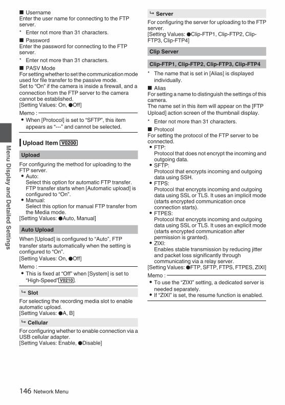
o UsernameEnter the user name for connecting to the FTPserver.* Enter not more than 31 characters.o PasswordEnter the password for connecting to the FTPserver.* Enter not more than 31 characters.o PASV ModeFor setting whether to set the communication modeused for file transfer to the passive mode.Set to “On” if the camera is inside a firewall, and aconnection from the FTP server to the cameracannot be established.[Setting Values: On, ROff]Memo : 0 When [Protocol] is set to “SFTP”, this item
appears as “---” and cannot be selected.
Upload Item 0Upload
For configuring the method for uploading to theFTP server.0 Auto:
Select this option for automatic FTP transfer.FTP transfer starts when [Automatic upload] isconfigured to “On”.
0 Manual:Select this option for manual FTP transfer fromthe Media mode.
[Setting Values: RAuto, Manual]Auto Upload
When [Upload] is configured to “Auto”, FTPtransfer starts automatically when the setting isconfigured to “On”.[Setting Values: On, ROff]Memo : 0 This is fixed at “Off” when [System] is set to
“High-Speed”2.9 Slot
For selecting the recording media slot to enableautomatic upload.[Setting Values: RA, B]9 Cellular
For configuring whether to enable connection via aUSB cellular adapter.[Setting Values: Enable, RDisable]
9 ServerFor configuring the server for uploading to the FTPserver.[Setting Values: RClip-FTP1, Clip-FTP2, Clip-FTP3, Clip-FTP4]Clip Server
Clip-FTP1, Clip-FTP2, Clip-FTP3, Clip-FTP4* The name that is set in [Alias] is displayed
individually.o AliasFor setting a name to distinguish the settings of thiscamera.The name set in this item will appear on the [FTPUpload] action screen of the thumbnail display.* Enter not more than 31 characters.o ProtocolFor setting the protocol of the FTP server to beconnected.0 FTP:
Protocol that does not encrypt the incoming andoutgoing data.
0 SFTP:Protocol that encrypts incoming and outgoingdata using SSH.
0 FTPS:Protocol that encrypts incoming and outgoingdata using SSL or TLS. It uses an implicit mode(starts encrypted communication onceconnection starts).
0 FTPES:Protocol that encrypts incoming and outgoingdata using SSL or TLS. It uses an explicit mode(starts encrypted communication afterpermission is granted).
0 ZIXI:Enables stable transmission by reducing jitterand packet loss significantly throughcommunicating via a relay server.
[Setting Values: RFTP, SFTP, FTPS, FTPES, ZIXI]Memo : 0 To use the “ZIXI” setting, a dedicated server is
needed separately.0 If “ZIXI” is set, the resume function is enabled.
146 Network Menu
Menu Display and Detailed Settings

o ServerFor setting the server name (“mystation.com”, etc.)or the IP address (“192.168.0.1”, etc.) of the FTPserver.* Enter not more than 127 characters using
single-byte alphanumeric characters (a to z, 0 to9), single-byte hyphen [-], or dot [.].
o PortEnter the FTP server port number to use using aninteger between 1 and 65535.The default value varies with the protocol setting.(FTP: 21, SFTP: 22, FTPS: 990, FTPES: 21, ZIXI:2088)o Dir. PathEnter the path name for the directory to upload to(“/pub”, “/home/user”, etc.)* Enter not more than 127 characters.o UsernameEnter the user name for connecting to the FTPserver.* Enter not more than 31 characters.o Stream IDFor configuring the stream ID that is registered atthe distribution destination.The default value varies with the product model.* Enter not more than 63 characters.Memo : 0 This item is selectable only when [Type] is set to
“ZIXI”.o PasswordEnter the password for connecting to the FTPserver.* Enter not more than 31 characters. Enter not
more than 127 characters for ZIXI setting.o PASV ModeFor setting whether to set the communication modeused for file transfer to the passive mode.Set to “On” if the camera is inside a firewall, and aconnection from the FTP server to the cameracannot be established.[Setting Values: On, ROff]Memo : 0 When [Protocol] is set to “SFTP”, this item
appears as “---” and cannot be selected.
Network Menu 147
Menu Display and Detailed Settings

System MenuThis menu screen allows system-related settings.For configuring recording settings, formatting andrestoration of a recording media, tally lamp setting,date/time, time zone and other settings.It can also be used to reset the menu settings totheir default values.Record Set...
For specifying recorded video-related settings.(A P151 [Record Set Item] )
Media9 Format Media
For formatting (initializing) a recording media.Select a card slot, select [Format] from [Cancel]/[Format], and press the [STATUS/SET] button (R)to format (initialize) the card.
(A P50 [Formatting (Initializing) SD Cards] )9 Restore Media
For restoring a recording media.Select a card slot, and press the [STATUS/SET]button (R) to restore the SD card.
(A P51 [Restoring the SD Card] )Memo : 0 This item appears only when the recording
media needs to be restored. However, it is notselectable when recording in Camera mode andduring Clip Review.
Setup FileThis allows you to save the menu settings as wellas the performance results of shutter speed andAWB.It is useful to save settings according to differentshooting conditions.9 Load File...
Loads the settings.(A P177 [Loading a Setup File] )9 Store File...
Saves the settings.(A P176 [Saving Setup Files] )9 Delete File...
Deletes the configured file.(A P178 [Deleting Setup Files] )
Tally SystemFor setting the display conditions of the tally lamp(front and back) on the camera recorder.0 Internal:
Displays mainly the status of the camerarecorder.
0 Studio:Displays the TALLY IN/PREVIEW IN signalsfrom an external device, such as a remotecontrol unit.
[Setting Values: RInternal, Studio]Front Tally/Back Tally
For configuring how the front and back tally lampson this camera recorder are illuminated when [TallySystem] is set to “Internal” and while recording is inprogress, when a remaining level warning isdisplayed or during live streaming.0 Rec/Live Streaming:
Lights up during recording or live streaming.0 Live Streaming:
Lights up during live streaming. Does not lightup during recording.
0 Rec:Lights up during recording.
[Setting Values: Rec/Live Streaming, LiveStreaming, RRec]Memo : 0 When [Tally System] is set to “Studio”, this item
appears as “---” and selection is disabled.
GPS u vFor setting the GPS function to On or Off (poweron/off).[Setting Values: On, ROff]Memo : 0 When [A/V Set] B [Video Set] B [SDI OUT1
Res.] is set to “1080p”, configuring [System] B[GPS] to “On” changes the setting to “1080i”.u v
148 System Menu
Menu Display and Detailed Settings

Battery 0For configuring the warning voltage or warninglevel (%) according to the battery specificationsand condition of use.9 Type 2
For configuring the battery warning using voltageor remaining level (%).[Setting Values: Capacity%, RVoltage]Memo : 0 For batteries where information on the
remaining level cannot be acquired, the statuswill be the same as when “Voltage” is selectedeven when “Capacity%” is selected. To find outwhether information on the remaining level canbe obtained for the battery, check the remainingbattery level icon on the display screen.
9 Near End (V) 0Outputs a warning sound when the voltage fallsbelow the preset level.[Setting value: 12.1 V to 14.0 V (R13.1 V)]Memo : 0 This cannot be configured to a value that is lower
than the setting of [End (V)].9 End (V) 0
Outputs a warning sound upon reaching the presetvoltage, and turns off the power automatically whenthe voltage falls below the preset level.[Setting value: 12.0 V to 13.9 V (R12.8 V)]Memo : 0 This cannot be configured to a value that is
higher than the setting of [Near End (V)].9 Near End (%) 2
Outputs a warning sound when the voltage fallsbelow the preset level (%).[Setting Values: 10 %, 15 %, R20 %, 25 %, 30 %]Memo : 0 This cannot be configured to a value that is lower
than the setting of [End (%)].0 A warning sound is also output when the voltage
reaches 12.5 V or lower.9 End (%) 2
Outputs a warning sound upon reaching the presetlevel (%), and turns off the power automaticallywhen the remaining level falls below the presetlevel.[Setting Values: 1 %, 5 %, R10 %, 15 %, 20 %]
Memo : 0 This cannot be configured to a value that is
higher than the setting of [Near End (%)].0 A warning sound is also output when the voltage
reaches 12.0 V, and the power will turn offautomatically when the voltage reaches 11.9 Vor lower.
LanguageSwitches between languages in the menu screen.[Setting Values: REnglish, Français, Español] (Umodel)[Setting Values: REnglish, Français, Deutsch,Italiano, Español, Türkçe] (E model)Reset All
Resets all menu settings.Memo : 0 [Date/Time] and [Time Zone] cannot be reset.
(A P149 [ Date/Time ] )(A P150 [ Time Zone ] )0 This item is not selectable when recording in
Camera mode, during Clip Review, during livestreaming and in Media mode.
Date/TimeFor setting the year, month, day, hour, and minute.Memo : 0 The display order of the date (year, month, day)
follows the setting in [Display Settings] B [DateStyle]. However, the 24-hour format is used forthe hour display regardless of the [Time Style]setting.(A P150 [ Time Style ] )0 If the signal reception for GPS satellites allows
date and time to be set based on the GPSinformation, you can set the time obtained fromthe GPS satellite by pressing the [USER1]button.The [USER1] button is grayed out if informationfor setting the date and time cannot be acquiredfrom the GPS satellite. u v
System Menu 149
Menu Display and Detailed Settings

Date StyleFor setting the date display sequence for displayon the LCD monitor and viewfinder screen as wellas for time stamp recording.Display examples of the setting values are asfollows.0 DMY2: 30 Jun 20180 DMY1: 30-06-20180 MDY2: Jun 30, 20180 MDY1: 06-30-20180 YMD: 2018-06-30
[Setting Values: DMY2, DMY1, MDY1, MDY2,YMD](Default values: MDY2 (U model), DMY1 (Emodel))Time Style
For setting the time display for display on the LCDmonitor and viewfinder screen as well as for timestamp recording.[Setting Values: R24hour, 12hour]Time Zone
For setting the UTC time difference in units of 30minutes.[Setting Values: UTC-12:00-UTC-00:30, UTC,UTC+00:30-UTC+14:00 (in 30 min increments)](Default values: UTC-05:00 (U model), UTC (Emodel))Memo : 0 If [Date/Time] is already set, the [Date/Time]
item is automatically adjusted when [TimeZone] is altered.
ReservedFor setting the additional function to “On” or “Off”.9 Reserved 1 to Reserved 16
Normally set to “Off”.[Setting Values: On, ROff]
System Information9 Version
Displays the version of the camera in the upper rowand the version of the dedicated viewfinder in thelower row.Display : 0000-0000
00-00-00Memo : 0 The lower row is displayed only when a
viewfinder (supplied u v or separatelysold w x) is connected .
9 Fan HourFor displaying the usage time of the internal fan.Memo : 0 Under normal environment, dust will
accumulate on the internal fan when the camerarecorder is used over a long period. Dust mayenter the camera recorder especially if it is usedoutdoors. This may affect the image and soundquality of the camera recorder. Check andreplace the fan after every 9000 hours(suggested guideline).
9 Open Source LicenseDisplays the license for the open source softwareused by this camera recorder.
150 System Menu
Menu Display and Detailed Settings

Record Set ItemRecord Format
After setting of all items in the [Record Format]menu is complete, select [Set] at the bottom of thescreen to apply the new settings on the camerarecorder and switch the recording format. A“Please Wait...” message appears duringswitching.9 System
For selecting a system definition.0 HD:
Records in “HD” (High Definition) quality for bothslots A and B.
0 SD2:Records in “SD” (Standard Definition) quality forboth slots A and B.
0 HD+Web2:Records in “HD” (high definition) for slot A, andin resolution suitable for web distribution for slotB.
0 HD(SDI In):Records the HD SDI video of the deviceconnected to the [HD/SD SDI IN] terminal in“HD” to both slot A and slot B.
0 SD(SDI In)2:Records the SD SDI video of the deviceconnected to the [HD/SD SDI IN] terminal in“SD” to both slot A and slot B.
0 High-Speed2:Records slow motion videos in “HD” (HighDefinition) for both slot A and slot B.
[Setting Values: RHD, SD2, HD+Web2,HD(SDI In), SD(SDI In)2, High-Speed2]Caution : 0 The selectable options for the [WFormat],
[WResolution], [WFrame Rate], [WBit Rate][WAudio], [YFormat], [YResolution], [YFrameRate], [YBit Rate] and [YAudio] settings varydepending on the setting of this item.
0 When [System] B [Record Set] B [RecordFormat] B [System] is configured to “High-Speed”2, network cannot be used viawireless LAN u v or the [HOST] terminal(USB). Configure as follows in this case.0 Set [Network] B [Connection Setup] B [USB/
Int. WLAN] to “Off”. u v0 Unplug the USB network adapterNote that camera operation will come to anemergency stop and the power will turn off if theabove steps are not performed.File data may be damaged if this happens whilerecording is in progress.
9 W FormatFor selecting the format of the file to be recorded tothe SD card in slot A.0 QuickTime(MPEG2):
QuickTime file format (.MOV)0 MXF(MPEG2)0:
MXF (material exchange format)0 QuickTime(H.264):
QuickTime file format (.MOV)0 Exchange0: (U model only)
Sports Video Interop Group format0 MP4 (H.264)0: (E model only)
MP4 file format[Setting Values: QuickTime(MPEG2),MXF(MPEG2), RQuickTime(H.264), Exchange](U model only)[Setting Values: QuickTime(MPEG2),MXF(MPEG2), RQuickTime(H.264), MP4 (H.264)](E model only)Memo : 0 When [System] is set to “SD”2 or “SD(SDI
In)”2, this item is fixed at “QuickTime(H.264)”.
0 When [System] is set to “HD+Web”, this item isfixed at “QuickTime(H.264)”. 2
0 When [System] is set to “High-Speed”, this itemis fixed at “QuickTime(H.264)”. 2
0 Exchange (U model) and MP4 (H.264) (Emodel) are selectable only when [System] isconfigured to “HD” or “HD(SDI In)”.
0 Exchange format is used under license fromSports Video Interoperability Group, Inc..
System Menu 151
Menu Display and Detailed Settings
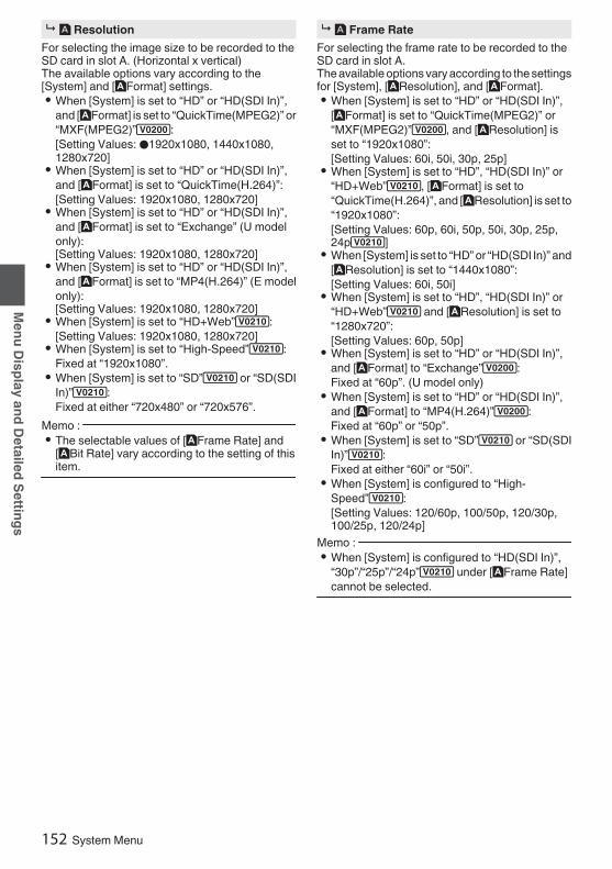
9 W ResolutionFor selecting the image size to be recorded to theSD card in slot A. (Horizontal x vertical)The available options vary according to the[System] and [WFormat] settings.0 When [System] is set to “HD” or “HD(SDI In)”,
and [WFormat] is set to “QuickTime(MPEG2)” or“MXF(MPEG2)”0:[Setting Values: R1920x1080, 1440x1080,1280x720]
0 When [System] is set to “HD” or “HD(SDI In)”,and [WFormat] is set to “QuickTime(H.264)”:[Setting Values: 1920x1080, 1280x720]
0 When [System] is set to “HD” or “HD(SDI In)”,and [WFormat] is set to “Exchange” (U modelonly):[Setting Values: 1920x1080, 1280x720]
0 When [System] is set to “HD” or “HD(SDI In)”,and [WFormat] is set to “MP4(H.264)” (E modelonly):[Setting Values: 1920x1080, 1280x720]
0 When [System] is set to “HD+Web”2:[Setting Values: 1920x1080, 1280x720]
0 When [System] is set to “High-Speed”2:Fixed at “1920x1080”.
0 When [System] is set to “SD”2 or “SD(SDIIn)”2:Fixed at either “720x480” or “720x576”.
Memo : 0 The selectable values of [WFrame Rate] and
[WBit Rate] vary according to the setting of thisitem.
9 W Frame RateFor selecting the frame rate to be recorded to theSD card in slot A.The available options vary according to the settingsfor [System], [WResolution], and [WFormat].0 When [System] is set to “HD” or “HD(SDI In)”,
[WFormat] is set to “QuickTime(MPEG2)” or“MXF(MPEG2)”0, and [WResolution] isset to “1920x1080”:[Setting Values: 60i, 50i, 30p, 25p]
0 When [System] is set to “HD”, “HD(SDI In)” or“HD+Web”2, [WFormat] is set to“QuickTime(H.264)”, and [WResolution] is set to“1920x1080”:[Setting Values: 60p, 60i, 50p, 50i, 30p, 25p,24p2]
0 When [System] is set to “HD” or “HD(SDI In)” and[WResolution] is set to “1440x1080”:[Setting Values: 60i, 50i]
0 When [System] is set to “HD”, “HD(SDI In)” or“HD+Web”2 and [WResolution] is set to“1280x720”:[Setting Values: 60p, 50p]
0 When [System] is set to “HD” or “HD(SDI In)”,and [WFormat] to “Exchange”0:Fixed at “60p”. (U model only)
0 When [System] is set to “HD” or “HD(SDI In)”,and [WFormat] to “MP4(H.264)”0:Fixed at “60p” or “50p”.
0 When [System] is set to “SD”2 or “SD(SDIIn)”2:Fixed at either “60i” or “50i”.
0 When [System] is configured to “High-Speed”2:[Setting Values: 120/60p, 100/50p, 120/30p,100/25p, 120/24p]
Memo : 0 When [System] is configured to “HD(SDI In)”,
“30p”/“25p”/“24p”2 under [WFrame Rate]cannot be selected.
152 System Menu
Menu Display and Detailed Settings

9 W Bit RateFor selecting the bit rate to be recorded to the SDcard in slot A.The available options vary according to the settingsfor [System], [WResolution], and [WFormat].0 When [System] is set to “HD” or “HD(SDI In)”,
[WFormat] is set to “QuickTime(MPEG2)” or“MXF(MPEG2)”0, and [WResolution] isset to “1440x1080”:[Setting Values: 35M (HQ), 25M (SP)]
* When [WResolution] is set to a setting other than“1440x1080”, it is fixed at “35M (HQ)”.
0 When [System] is set to “HD”, “HD(SDI In)” or“HD+Web”2 and [WFormat] is set to“QuickTime(H.264)”:0 When [WResolution] is set to “1920x1080”,
and [WFrame Rate] is set to “60p” or “50p”:[Setting Values: 70M (XHQ)0,
50M (XHQ), 35M (UHQ)]0 When [WResolution] is set to “1920x1080”,
and [WFrame Rate] to “60i”/“50i”/“30p”/“25p”/“24p”2:[Setting Values: 50M (XHQ), 50M(XHQ), 35M (UHQ)]
0 When [WResolution] is set to “1280x720”:[Setting Values: 50M (XHQ), 35M(UHQ)]
0 When [System] is set to “HD” or “HD(SDI In)” and[WFormat] is set to “Exchange”0 or“MP4(H.264)”0:0 When [WResolution] is set to “1920x1080”:
Fixed at “12M(LP)”.0 When [WResolution] is set to “1280x720”:
Fixed at “8M(LP)”.0 When [System] is set to “SD”2 or “SD(SDI
In)”2:Fixed at 8M (HQ).
0 When [System] is set to “High-Speed”2:0 When [WFrame Rate] is set to “120/60p” or
“100/50p”[Setting Values: 70M (XHQ),
50M (XHQ), 50M (UHQ)]0 When [WFrame Rate] is configured to a
setting other than “120/60p” and “100/50p”[Setting Values: 50M (XHQ), 50M(XHQ), 35M (UHQ)]
Memo : 0 When [System] is configured to “HD(SDI In)”,
“30p”/“25p”/“24p”2 under [WFrame Rate]cannot be selected.
9 W AudioFor selecting the audio to be recorded to slot A (2chor 4ch). The selectable options vary according tothe settings in [WFormat] or [WBit Rate].0 When [WBit Rate] is configured to a setting other
than “ 70M (XHQ)”0 and“ 50M (XHQ)”:[Setting Values: R4CH 16 bit, 2CH 16 bit]
0 When [WBit Rate] is set to “ 70M(XHQ)”0 or “ 50M (XHQ)”:[Setting Values: R4CH 24 bit, 2CH 24 bit]
Memo : 0 When [WFormat] is configured to
“Exchange”0 (U model) or“MP4(H.264)”0 (E model), the setting isfixed at “2CH”.
0 When [System] is configured to “High-Speed”2, the setting is fixed at “2CH”.
9 Y FormatFor selecting the format of the file to be recorded tothe SD card in slot B when [System] is configuredto “HD+Web”2.This is fixed at QuickTime (H.264).Memo : 0 When [System] is set to other than “HD
+Web”2, this item is fixed at the samesetting as [WFormat].
9 Y ResolutionFor selecting the size of the image to be recordedto the SD card in slot B when [System] is configuredto “HD+Web”2. (Horizontal x vertical)0 When [System] is set to “HD+Web”2:
0 When [WFrame Rate] is configured to “60p”/“60i”/“30p”[Setting Values: 960x540, 720x480,480x270]
0 When [WFrame Rate] is configured to “50p”/“50i”/“25p”[Setting Values: 960x540, 720x576,480x270]
0 When [WFrame Rate] is configured to “24p”[Setting Values: 960x540, 480x270]
Memo : 0 When [System] is set to other than “HD
+Web”2, this item is fixed at the samesetting as [WResolution].
System Menu 153
Menu Display and Detailed Settings

9 Y Frame RateThe frame rate of the image to be recorded to theSD card in slot B is fixed when [System] is set to“HD+Web”2.The value fixed varies according to the settings for[WFrame Rate].0 Fixed at “60i”, “50i”, “30p”, “25p” or “24p”2.
Memo : 0 When [System] is set to other than “HD
+Web”2, this item is fixed at the samesetting as [WFrame Rate].
9 Y Bit RateThe bit rate of the image to be recorded to the SDcard in slot B is fixed when [System] is set to “HD+Web”2.The value fixed varies according to the settings for[YResolution].
0 “3M(HQ)” when [YResolution] is configuredto “960x540”
0 “1.2M(LP)” when [YResolution] is configuredto “480x270”
0 “8M(HQ)” when [YResolution] is configuredto “720x480” or “720x576”
Memo : 0 When [System] is set to other than “HD
+Web”2, this item is fixed at the samesetting as [WBit Rate].
9 Y AudioThe audio (2ch/4ch) to be recorded to slot B is thesame as the audio to be recorded to slot A.9 SD Aspect 2
For setting the aspect ratio of the image when[System] is set to “SD” or “SD(SDI In)”.[Setting Values: R16:9, 4:3]Memo : 0 For conditions other than those above, this item
is fixed at “16:9”.
Rec Mode 0 10 For selecting the mode for recording to the
recording media.(A P90 [Special Recording 0] )
[Setting Values: RNormal, Pre Rec0, ClipContinuous0, Interval Rec1, FrameRec1]Memo : 0 When [Slot Mode] is set to “Backup”0, this
item is fixed at “Normal”.0 This is fixed at “Normal” when [System] B
[Record Format] B [System] is configured to anyof the following.0 HD(SDI In)0 SD(SDI In) 20 HD+Web 20 High-Speed 2
9 Pre Rec Time 0For setting the pre-recording time when [RecMode] is set to “Pre Rec”.[Setting Values: R5sec, 10sec, 15sec]9 Rec Frames 1
For setting the number of frames to record when[Rec Mode] is set to “Frame Rec” or “Interval Rec”.[Setting Values: R1frame, 3frames, 6frames]9 Rec Interval 1
For setting the recording time interval when [RecMode] is set to “Interval Rec”.[Setting Values: R1sec, 2sec, 5sec, 10sec, 30sec,1min, 2min, 5min, 10min, 30min, 1hour]
154 System Menu
Menu Display and Detailed Settings

Slot ModeFor setting the operation of the card slot.0 Series:
Mode that activates slots A and B sequentially.0 Dual:
Mode that activates slots A and Bsimultaneously.(A P86 [Dual Rec] )0 Backup0: Mode that enables recording to
slot B without using the [REC] button. This itemis selectable only when [Rec Mode] is set to“Normal”. Record, start and stop operations canbe controlled from the [Backup Rec] menu orusing the user button that is assigned with“Backup Trig”.(A P88 [Backup Rec 0] )
[Setting Values: RSeries, Dual, Backup0]Memo : 0 When this is configured to “Series” and
recordable media is inserted into slot A or slot Bor both the slots, pressing the [REC] buttonstarts recording only to the card in the selectedslot (active slot).
0 When this is configured to “Dual” and recordablemedia are inserted into both slots A and B,pressing the [REC] button starts simultaneousrecording to the cards in both slots.
0 When [System] is configured to “HD+Web”2, “---” is displayed.
9 Backup Rec 0For starting/stopping backup recording with [REC]/[STBY].This item is selectable only when [Slot Mode] is setto “Backup”.Memo : 0 When recording is stopped due to no remaining
space on the media, etc., this item is fixed at“STOP” and cannot be selected.
4GB File Spanning(SDXC)A recording file is automatically split when the sizeexceeds 4 GB, but if an SDXC card is used, youcan record clips larger than 4 GB by setting thisoption to “Off”. (Up to a maximum of 64 GB or 4hours)0 On:
Splits a file when it exceeds 4 GB or 30 minutes.0 Off:
Splits a file when it exceeds 64 GB or 4 hours.[Setting Values: ROn, Off]Memo : 0 This option is only valid if the SD card used for
recording is of the SDXC format.0 During simultaneous recording, such as Dual
Rec and backup recording0, this option isvalid only when the SD cards in slots A and Bare of the SDXC format.
LPCM (QuickTime)For setting the audio recording format ofQuickTime.[Setting Values: Dual Mono, RStereo]
System Menu 155
Menu Display and Detailed Settings

Time StampFor setting whether to display shooting date/timeinformation in the recorded video.[Setting Values: On, ROff]Memo : 0 The date/time display style can be changed in
[Date Style]/[Time Style].(A P150 [ Date Style ] )(A P150 [ Time Style ] )0 When [System] is set to “High-Speed”2,
this item is fixed at “Off”.
Clip Set9 Clip Name Prefix
For configuring the first four characters of the nameof the clip file to be recorded to the recording media.Enter any of the 36 characters including alphabets(upper case) and numbers (0 to 9) using thesoftware keyboard.
(A P107 [Text Input with Software Keyboard] )[Setting Values: xxxG] (The default value of xxx isthe last three digits of the serial number.)9 Reset Clip Number
For assigning a new number (Clip Number) byresetting it (0001).Select [Reset] and press the [STATUS/SET] button(R) to reset the number.If there are other clips on the recording media, it willbe assigned with the smallest available number.0 Example:
If the [Clip Name Prefix] is “ABCD” and“ABCD0001” already exists on the recordingmedia, “ABCD0002” will be assigned.
Clear Planning MetadataErases the planning metadata downloaded fromthe FTP server.This item also deletes the metadata loaded usingthe setup files (“User File”/“All File”).
156 System Menu
Menu Display and Detailed Settings

Adding/EditingFrequently Used MenuItems (Favorites Menu)You can select and add/edit frequently used menuitems freely to create a personal menu screen(Favorites Menu).Memo : 0 [Favorites Menu] is only enabled in the Camera
mode. [Favorites Menu] remains unchangedeven when the recording format changes.
0 Up to 20 menu items can be added.0 Added items in [Favorites Menu] will not be reset
even when [Main Menu] B [Reset All] isexecuted.
0 Long descriptive names may be displayed forthe menu items in [Favorites Menu] to enablebetter understanding.
Adding Menu Items to Favorites Menu1 Press the [MENU/THUMB] button to open
the [Main Menu] screen.2 Select the menu or submenu item to add.
.
Focus
Display Settings
Meter 2
Memo : 0 Adding items to [Favorites Menu] cannot be
performed in the following cases. [USER1Add] is displayed in gray in the operation guide.0 Selected item is already added to [Favorites
Menu].0 Number of menu items that can be added (20
items) is exceeded.3 Press the [USER1] button.
A screen to confirm the addition appears.4 Select [Add] and press the Set button (R).
The selected menu item is added to [FavoritesMenu].
.
4Cancel
AddFocus
Add to Favorites Menu?
Adding/Editing Frequently Used Menu Items (Favorites Menu) 157
Menu Display and Detailed Settings
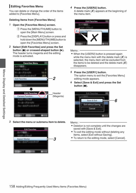
Editing Favorites MenuYou can delete or change the order of the itemsadded to [Favorites Menu].
Deleting Items from [Favorites Menu]1 Open the [Favorites Menu] screen.
A Press the [MENU/THUMB] button toopen the [Main Menu] screen.
B Press the [DISPLAY] button or press andhold down the [MENU/THUMB] button toopen the [Favorites Menu] screen.
2 Select [Edit Favorites] and press the Setbutton (R) or crossed-shaped button (I).The header turns magenta and the editingmode is activated.
.
2
Header (Magenta)Camera Function...
Edit Favorites
Edit Favorites
Favorites Menu
3 Select the menu or submenu item to delete.
.
3Aspect Marker
Edit Favorites
4 Press the [USER2] button.A delete mark (b) appears at the beginning ofthe menu item.
.
Aspect Marker
Edit Favorites
Memo : 0 When the [USER2] button is pressed again
while the menu item with the delete mark (b) isselected, the menu item will be excluded fromthe items to be deleted and the delete mark (b)disappears.
5 Press the [USER1] button.The option menu to exit the [Favorites Menu]editing mode appears.
6 Select [Save & Exit] and press the Setbutton (R).
.
6
Cancel
Exit without Saving
Save & Exit
Edit Favorites
Memo : 0 Deletion is not complete until the changes are
saved with [Save & Exit].0 To exit the editing mode without deleting any
items, select [Exit without Saving].0 To return to the editing mode, select [Cancel].
158 Adding/Editing Frequently Used Menu Items (Favorites Menu)
Menu Display and Detailed Settings

Changing the Order of Items in [FavoritesMenu]1 Open the [Favorites Menu] screen.
Press the [MENU/THUMB] button to open the[Favorites Menu] screen.
2 Select [Edit Favorites] and press the Setbutton (R) or crossed-shaped button (I).The header turns magenta and the editingmode is activated.
.
2
Header (Magenta)Camera Function...
Edit Favorites
Edit Favorites
Favorites Menu
3 Select the menu or submenu item to moveand press the Set button (R).The moving mode is activated and a positionselection bar for the move appears.
.
Edit Favorites
Edit Favorites
TC/UB
TC/UB
3
Position Selection Bar
4 Select the position to move to with thecross-shaped button (JK).Move the position selection bar with the cross-shaped button (JK) and select a position tomove to.
5 Press the Set button (R).The selected item moves to the new position.
.
5
4TC/UB
TC/UB
Edit Favorites
Edit Favorites
Adding/Editing Frequently Used Menu Items (Favorites Menu) 159
Menu Display and Detailed Settings

6 Press the [USER1] button.The option menu to exit the [Favorites Menu]editing mode appears.
7 Select [Save & Exit] and press the Setbutton (R).
.
7
Cancel
Exit without Saving
Save & Exit
Edit Favorites
Memo : 0 Moving is not complete until the changes are
saved with [Save & Exit].0 To exit the editing mode without saving any
changes, select [Exit without Saving].0 To return to the editing mode, select [Cancel].
160 Adding/Editing Frequently Used Menu Items (Favorites Menu)
Menu Display and Detailed Settings

Display Screen in CameraModeWhen the display setting for [LCD/VF] B [DisplayOn/Off] is set to “Off”, the corresponding display ishidden but it will appear for approximately 3seconds when changes are being made.Memo : 0 When the display screen is turned off, it will
appear only in the following cases.0 Approximately 3 seconds when changes are
being made0 During event display or warning display
Display Screen
.
100min50min
282min
1/ 60F2.8AE±0ND1 /64
12 :34 :56
ISO102400
00:00:00.001080 /30p
SDI IN
ITU709
COMPRESS
5 . 6f t
B 5600KG
LJ
B
M
N
P
T
C
DEF
A
IH K
Y Xc
Q
Wdf be Z
SR
Va
O
U
Enlarged DisplayEnlarged Display (LCD Monitor Only)
.
Be
V
G
C X b U a g AZ
Memo : 0 Only the display on the LCD monitor is enlarged.A Voltage/Battery Power
Displays the current status of the power supplyin use.(A P36 [Power Status Display] )
Memo : 0 Even when the display screen is turned off and
[LCD/VF] B [Display On/Off] B [Battery] is set to“Off”, this will be displayed when there is awarning.
B Remaining Space on MediaDisplays the remaining recording time for therecording media in slot A and slot B separately.W : Currently selected slot. (White card)W z : Write-protect switch of SD card is set.W!INVALID : SD card cannot be read or
written to, or restored.W!FORMAT : SD card requires
formatting.W!RESTORE : SD card requires restoring.W!INCORRECT :
0 When the SD card is not supported.0 When an SD card lower than Class 10 is
inserted while in the XHQ mode.W!REC INH :
0 When attempting to record more than 4GB while a media that does not supportrecording of more than 4 GB is inserted.(A P155 [ 4GB File Spanning(SDXC) ] )
The following icons are displayed during FTPupload.(A P191 [Uploading a Recorded Video Clip] )
Icon Status
.
[Auto Upload] is configured to“On” and in the standby state.“A” is displayed at the top leftcorner of the icon while in theAuto FTP mode.
.
Auto FTP transfer is in progress.Three images are alternatelydisplayed, and the arrowsbecome animated.
.
FTP transfer is in progress.Three images are alternatelydisplayed, and the arrowsbecome animated. In this case,instead of the recordable time ofthe SD card, an estimated valueof the remaining transfer time isdisplayed.
.
(Yellow)
Error has occurred during FTPtransfer.
Memo : 0 The displayed time is an estimate.0 Even when the display screen is hidden and
[LCD/VF] B [Display On/Off] B [MediaRemain] is set to “Off”, this will be displayedwhen there is a warning.
Display Screen in Camera Mode 161
Display/Status Screen

C Operation lockThe r icon appears during operation lock.(A P53 [Operation Lock Feature] )
Memo : 0 The s icon appears for 3 seconds after
operation lock is turned off.D Black Toe
Displays the Black Toe setting.Memo : 0 The “Normal” appears for 3 seconds after
changing to Normal.E Skin Detaile appears when Skin Detail is functioning.
Memo : 0f appears for 3 seconds after Skin Detail is
turned off.F Color Space Display
Displays the color space.Memo : 0 This can be configured in [Camera Process] B
[Color Space].(A P116 [ Color Space ] )
G Audio Level Meter0 Displays the audio levels for CH-1 to CH-4.0 a appears on the screen when in the Auto
mode.
.
0 This is grayed out when in a mode that doesnot support audio recording or when theaudio is not supported. The CH display isgrayed out in the enlarged display mode.
.
0 When in the enlarged display mode, thedisplay changes with the setting of the[AUDIO INPUT CH1/CH2/CH3/CH4]selection switch.
Example: During 1ch and 3ch display
FRONT1: When the selection switch is setto “FRONT” and [Front Mic Select] is set toa value other than “Mono”FR1+2: When the selection switch is set to“FRONT” and [Front Mic Select] is set to“Mono”REAR1: When the selection switch is set to“REAR”WL1: When the selection switch is set to“WIRELESS”
H Iris F-NumberDisplays F-number of the lens iris.(A P60 [Adjusting the Iris] )
Memo : 0 This item may not be displayed depending on
the lens used.0 A a icon appears on the left side of the lens
aperture value (F-number) during Auto Irismode.
0 While in the Auto Iris mode, and [AE Lock] is setto “AE” or “AE/FAW”, a icon appears on theleft side of the lens aperture value (F-number)during lock operation.(A P113 [ AE Lock ] )I ND Filter Position
Displays the current ND filter position.
162 Display Screen in Camera Mode
Display/Status Screen

J Shutter0 The current shutter speed appears on the
screen.(A P109 [ Shutter ] )
0 When the camera recorder is switched to theFull Auto shooting mode using the userbutton that is assigned with “Full Auto” orwhen it is switched to the Automatic Shuttermode with [Camera Function] B [Shutter] setto “EEI”, the a icon appears on the left side ofthe shutter speed.
Memo : 0 The variable range of the shutter speed varies
according to the video format settings.(A P62 [Setting the Electronic Shutter] )0 While in the Automatic Shutter mode, and [AE
Lock] is set to “AE” or “AE/FAW”, a iconappears on the left side of the shutter speedduring lock operation.
0 [OFF] is displayed when the shutter is turned offor when in the Low-light shooting mode.
K AE Level0 Displayed when the AE function is activated.0 When operated while manual operation is
disabled, “AE” blinks for about 5 seconds.L Gain
0 You can select to display the gain in “dB” or“ISO”.
(A P130 [ Gain ] )0 Displays the gain value when in the Manual
Gain mode.0 A a icon appears on the left side of the gain
value in the “AGC” mode.0 “LUX” is displayed to the left of the gain value
when in the Low-light shooting mode.Memo : 0 While in the “AGC” mode, and [AE Lock] is set
to “AE” or “AE/FAW”, a icon appears on theleft side of the gain value during lock operation.
M White Balance ModeDisplays the current white balance mode.(*****K indicates color temperature)A *****K : When the [WHT BAL B/A/PRST]
switch is set to “A” in the Manual WhiteBalance mode.
B *****K : When the [WHT BAL B/A/PRST]switch is set to “B” in the ManualWhite Balance mode.
P *****K : When the [WHT BAL B/A/PRST]switch is set to “PRST” in the ManualWhite Balance mode.
a FAW : During Full Auto White Balancemode.
FAW : While in the Full Auto White Balancemode, and [AE Lock] is set for “FAW”or “AE/FAW” during lock operation.
(A P64 [Preset Mode (PRST)] )(A P65 [Memory A Mode (A), Memory B Mode(B)] )
Memo : 0 When [Preset Paint], [AWB Paint] or [FAW
Paint] is set to a setting other than the defaultvalue, a q icon is displayed to the right of thecolor temperature.
N Expanded Focus/Video Signal Monitor/ReturnVideo (PiP)Displayed upon pressing the user button that isassigned with “Expanded Focus”, “Video SignalMonitor” and “Return Video” (PiP).
Memo : 0 The order of display is “Expanded Focus” >
“Video Signal Monitor” > “Return Video” (PiP).O Focus Assist
0 “ ” is displayed when auto focus isactivated.
0 When ACCU-Focus is enabled, “ACCU ”blinks for about 10 seconds while FocusAssist starts up, after which the “ ”indicator lights up.
0 If recording starts while [ACCU-Focus] isactive, [ACCU-Focus] will be forciblydeactivated.
(A P126 [ Focus Assist ] )
Display Screen in Camera Mode 163
Display/Status Screen

P Luminance InformationDisplayed when the Spot Meter function isactivated.MAX : Maximum luminanceMIN : Minimum luminance
Q Zebra patternDuring zebra pattern display, (zebra icon)is displayed on the display screen in Cameramode.(A P80 [Setting Zebra Pattern] )
R Time DisplayDisplays the current time.
Memo : 0 The date/time display style can be configured in
[System] B [Date/Time].0 When [System] B [Record Set] B [Time
Stamp] is set to “On”, this item is not displayed.S Focus Display
Displays the approximate distance to thesubject in focus during manual focus.
Memo : 0 The displayed unit of measurement (feet or
meter) can be configured in [LCD/VF] B [DisplayType] B [Focus].
0 This item may not be displayed depending onthe lens used.
T Zoom Display0 Displays the zoom position. (Zoom bar or
value)
.
0 The zoom bar will only be displayed for 3seconds after the zoom operation isactivated.
0 The value will always be displayed. (Z00 to99)
Memo : 0 The mode of display (value or bar) can be
configured in [LCD/VF] B [Display Type] B[Zoom].
0 This item may not be displayed depending onthe lens used.
U Network Connection Icon0 USB connection or built-in wireless LAN
connection u v0 Set [Network] B [Connection Setup] B
[USB/Int. WLAN] to “On”. u v(A P140 [ USB/Int. WLAN u v ] )0 In the case of connecting to an external
network, check the destination in[Network] B [Connection Setup] B[Default Gateway].
(A P140 [ Default Gateway ] )Icon Status
.
Wireless LAN connection from thehost terminal (USB) is established
.
Wired LAN connection from thehost terminal (USB) is established
.
Cellular adapter connection fromthe host terminal (USB) isestablished
.
When a USB adapter differentfrom the connection settings isdetected
.
Built-in wireless LAN connection isestablishedu v
(Nodisplay)
0 When [USB/Int. WLAN] is setto “Off”u v
0 When an unusable USBadapter is detected
Memo : 0 The icon appears blinking when the camera
recorder is starting up, and is displayed in yellowwhile getting ready to connect.0 LAN terminal connectionIn the case of connecting to an external network,check the destination in [Network] B[Connection Setup] B [Default Gateway].
Icon Status
.
LAN terminal connection isestablished
(Nodisplay)
When the LAN cable is notconnected
Memo : 0 The icon appears blinking when the camera
recorder is starting up, and is displayed in yellowwhile getting ready to connect.
164 Display Screen in Camera Mode
Display/Status Screen
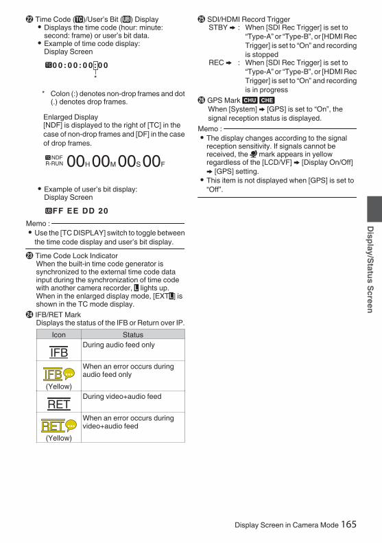
V Time Code (I)/User’s Bit (J) Display0 Displays the time code (hour: minute:
second: frame) or user’s bit data.0 Example of time code display:
Display Screen
.
0 0 : 0 0 : 0 0 : 0 0
*
* Colon (:) denotes non-drop frames and dot(.) denotes drop frames.
Enlarged Display[NDF] is displayed to the right of [TC] in thecase of non-drop frames and [DF] in the caseof drop frames.
.
00H 00M 00S 00FNDF
R-RUN
0 Example of user’s bit display:Display Screen
.FF EE DD 20
Memo : 0 Use the [TC DISPLAY] switch to toggle between
the time code display and user’s bit display.W Time Code Lock Indicator
When the built-in time code generator issynchronized to the external time code datainput during the synchronization of time codewith another camera recorder, Z lights up.When in the enlarged display mode, [EXTZ] isshown in the TC mode display.
X IFB/RET MarkDisplays the status of the IFB or Return over IP.
Icon Status
.
During audio feed only
.
(Yellow)
When an error occurs duringaudio feed only
.
During video+audio feed
.
(Yellow)
When an error occurs duringvideo+audio feed
Y SDI/HDMI Record TriggerSTBY B : When [SDI Rec Trigger] is set to
“Type-A” or “Type-B”, or [HDMI RecTrigger] is set to “On” and recordingis stopped
REC B : When [SDI Rec Trigger] is set to“Type-A” or “Type-B”, or [HDMI RecTrigger] is set to “On” and recordingis in progress
Z GPS Mark u vWhen [System] B [GPS] is set to “On”, thesignal reception status is displayed.
Memo : 0 The display changes according to the signal
reception sensitivity. If signals cannot bereceived, the H mark appears in yellowregardless of the [LCD/VF] B [Display On/Off]B [GPS] setting.
0 This item is not displayed when [GPS] is set to“Off”.
Display Screen in Camera Mode 165
Display/Status Screen

a Media Status---- : A card is not detected in the
selected slot, and [TallySystem] is also not set to“Studio”
STBY : Recording standbyRREC : RecordingREVIEW : Clip Review(A P84 [Viewing Recorded Videos Immediately(Clip Review)] )STBY P : Pre Rec recording standby(A P90 [Pre Rec 0] )RRECP : Pre Rec recording(A P90 [Pre Rec 0] )STBY C : Clip Continuous Rec recording
standby(A P91 [Clip Continuous Rec 0] )RRECC : Clip Continuous Rec recording(A P91 [Clip Continuous Rec 0] )STBYC(displayed inyellow)
: Clip Continuous Rec recordingpause
(A P91 [Clip Continuous Rec 0] )STBY N : Interval Rec recording standby(A P93 [Interval Rec 1] )STBYN(displayed inred)
: Interval recording pause
RRECN : Interval Rec recording(A P93 [Interval Rec 1] )STBY M : Frame Rec recording standby(A P92 [Frame Rec 1] )RRECM : Frame Rec recording(A P92 [Frame Rec 1] )STBYM(displayed inyellow)
: Frame Rec recording pause
(A P92 [Frame Rec 1] )STOP : Unable to record to the card in
the slotP.OFF : Power OFFQ : During clip cutter recording
(displayed for 3 seconds)(A P94 [Splitting the Clips Freely (Clip CutterTrig) 0] )CALL : Receiving call signals from an
external device, such as aremote control unit
PGM : Receiving program signalsfrom an external device, suchas a remote control unit
PVW : Receiving preview signalsfrom an external device, suchas a remote control unit
b Live streaming markWhen [Network] B [Live Streaming] B [LiveStreaming] is set to “On”, the distribution statusis displayed.(A P141 [Live Streaming Item] )
Icon Status
.
(Red)
Distribution in progress (goodconnection quality)
.
(Red)
Distribution in progress (poorconnection quality)
.
(Yellow)
Waiting for connection(RTSP/RTP only), connectionfailed
c SDI Input Mode/High-Speed Frame Rate0 “SDI INZ” is displayed when a device is
connected to the [HD/SD SDI IN] terminal,and [System] B [Record Set] B [RecordFormat] B [System] is set to “HD(SDI In)” or“SD(SDI In)”2.
0 When [System] B [Record Set] B [RecordFormat] B [System] is configured to “High-Speed”2, the setting value for [WFrameRate] is displayed.
d OK MarkDisplayed when OK mark has been appended.(A P101 [Appending/Deleting OK Mark] )
e Recording Format/Bit Rate (Enlarged DisplayMode Only)Displays the recording format and bit rate (onlywhen in the enlarged display mode).
Memo : 0 The resolution, frame rate and bit rate can be
viewed on the status screen.f Event/Warning Display Area
Displays error messages.(A P218 [Error Messages and Actions] )
g Dual Rec/ Backup Rec Display (EnlargedDisplay Mode Only)“DUAL” is displayed in the Dual Rec mode and“BACKUP” is displayed in the Backup Recmode.(A P155 [ Slot Mode ] )
Memo : 0 Displayed only when in the enlarged display
mode.
166 Display Screen in Camera Mode
Display/Status Screen

Display Screen in MediaModeWhen the display setting for [LCD/VF] B [DisplayOn/Off] is set to “Off”, the corresponding display ishidden.Memo : 0 Display on the information display area can be
toggled using the [USER4] button.0 When the display screen is turned off, it will
appear only in the following cases.0 During event display or warning display
0 If “VF Display” is assigned to the [USER1(VF)]button or [USER2(VF)] button of the viewfinder,the corresponding button can also be used in theMedia mode.
.
Jan 24,2018
1920x108030p 50M
282min
12 :34 :56
00:00:00.001000/2000
A JKNO LM
E
G
H
IB
D
C
F
P
A Voltage/Battery PowerDisplays the current status of the power supplyin use.(A P36 [Power Status Display] )
Memo : 0 Even when the display screen is turned off and
[LCD/VF] B [Display On/Off] B [Battery] is set to“Off”, this will be displayed when there is awarning.
B ResolutionDisplays the video image resolution.
C Frame Rate/Bit RateDisplays the frame rate and bit rate in pairs.
D Operation GuideDisplays a guide for the current operationbuttons.
E Audio Level Meter0 Displays the audio levels for CH-1 to CH-4.
.
F Position BarDisplays the current position in the video.During trimming, the position bar appears ingreen, and icons for the in and out points aredisplayed.6 : Current position of the video7 : Position to start trimming
(In point)8 : Position to end trimming
(Out point)
Display Screen in Media Mode 167
Display/Status Screen

G Information DisplayUse the [USER4] button to switch betweencamera information display, GPS display andturning off the display.0 The GPS display displays information on the
recording location of the video being playedback only when GPS information has beenrecorded.
0 Camera information display displays onlyinformation of Gain, Iris, Shutter and WhiteBalance that have been recorded.
.
5600K1/ 100
F1.60dB
+35.483197+139.652172
USER4
USER4
USER4
GPS Display
Camera Information DisplayDisplay Off
Memo : 0 Trimming information is displayed while
trimming is in progress. In this case, pressing the[USER4] button does not switch the display.
0 The information display area is not subject to thedisplay settings of the items in [LCD/VF] B[Display On/Off].
H Date/Time DisplayDisplays the date/time that is recorded on thecurrently played recording media.
Memo : 0 The date/time display style can be specified in
[System] B [Date Style]/[Time Style].(A P150 [ Date Style ] )(A P150 [ Time Style ] )
I Network Connection Icon0 USB connection or built-in wireless LAN
connection u v0 Set [Network] B [Connection Setup] B
[USB/Int. WLAN] to “On”. u v(A P140 [ USB/Int. WLAN u v ] )0 In the case of connecting to an external
network, check the destination in[Network] B [Connection Setup] B[Default Gateway].
(A P140 [ Default Gateway ] )Icon Status
.
Wireless LAN connection from thehost terminal (USB) is established
.
Wired LAN connection from thehost terminal (USB) is established
.
Cellular adapter connection fromthe host terminal (USB) isestablished
.
When a USB adapter differentfrom the connection settings isdetected
.
Built-in wireless LAN connection isestablishedu v
(Nodisplay)
0 When [USB/Int. WLAN] is setto “Off”u v
0 When an unusable USBadapter is detected
Memo : 0 The icon appears blinking when the camera
recorder is starting up, and is displayed in yellowwhile getting ready to connect.0 LAN terminal connectionIn the case of connecting to an external network,check the destination in [Network] B[Connection Setup] B [Default Gateway].
Icon Status
.
LAN terminal connection isestablished
(Nodisplay)
When the LAN cable is notconnected
Memo : 0 The icon appears blinking when the camera
recorder is starting up, and is displayed in yellowwhile getting ready to connect.
168 Display Screen in Media Mode
Display/Status Screen
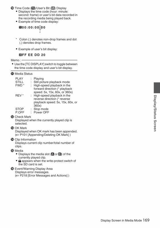
J Time Code (I)/User’s Bit (J) Display0 Displays the time code (hour: minute:
second: frame) or user’s bit data recorded inthe recording media being played back.
0 Example of time code display:
.
0 0 : 0 0 : 0 0 : 0 0
*
* Colon (:) denotes non-drop frames and dot(.) denotes drop frames.
0 Example of user’s bit display:.
FF EE DD 20
Memo : 0 Use the [TC DISPLAY] switch to toggle between
the time code display and user’s bit display.K Media Status
PLAY : PlayingSTILL : Still picture playback modeFWD * : High-speed playback in the
forward direction (* playbackspeed: 5x, 15x, 60x, or 360x)
REV * : High-speed playback in thereverse direction (* reverseplayback speed: 5x, 15x, 60x, or360x)
STOP : Stop modeP.OFF : Power OFF
L Check MarkDisplayed when the currently played clip isselected.
M OK MarkDisplayed when OK mark has been appended.(A P101 [Appending/Deleting OK Mark] )
N Clip InformationDisplays current clip number/total number ofclips.
O Media0 Displays the media slot (W or Y) of the
currently played clip.0 z appears when the write-protect switch of
the SD card is set.P Event/Warning Display Area
Displays error messages.(A P218 [Error Messages and Actions] )
Display Screen in Media Mode 169
Display/Status Screen

Status ScreenFor checking the settings of the camera recorder.
USER Switch Set ScreenFor checking the status (functions assigned) of theuser buttons.
(A P45 [Assignment of Functions to UserButtons] )
.
Camera ScreenFor checking information related to shooting usingthe camera recorder.
.
LCD/VF ScreenFor checking information related to the contentsdisplayed on the LCD monitor and viewfinderscreens.
.
Record Format ScreenFor checking settings related to the recordingformat.
.
Audio Input ScreenFor checking settings related to audio inputchannels and their input levels.
.
Audio Output ScreenFor checking settings related to audio outputchannels and their output levels.
.
Video ScreenFor checking the settings related to video output.
.
170 Status Screen
Display/Status Screen

Power ScreenFor checking the power consumption.
.
Memo : 0 [System] shows the power consumption of the
entire camera system (camera recorder +connecting devices) while [ConnectedDevices] shows the estimated powerconsumption of the peripheral equipments suchas lens and wireless slots.
0 When the bar on the bar graph enters the redzone, it indicates that the power consumptionhas exceeded its rating. As this may result inmalfunction, do keep the power consumptionwithin the rating.
0 If [System] shows a value that exceeds therating, the power to the [LIGHT], [DC OUT] (rear)and [DC OUT] (LAN) terminals is automaticallycut off. This is not a malfunction. Use peripheralequipments with lower power consumption thenturn on the power of this camera recorder again.
Planning Metadata ScreenFor checking the current planning metadatasetting.
(A P195 [ Planning Metadata ] )
.
Network ScreenFor checking the network login information.
.
LAN ScreenFor checking the network information for LANconnection.
.
USB/Int. WLAN Screen v vUSB Screen w x
For checking the network information for the USBadapter and built-in wireless LAN connections.
.
Streaming ScreenFor viewing information related to live streaming.
.
Status Screen 171
Display/Status Screen

Marker and Safety ZoneDisplays (Camera ModeOnly)The marker and safety zone displays are useful inhelping you determine the angle of view for theimage according to the shooting purpose.The marker is displayed only in the Camera mode.Displaying the Grid Marker1 Set [LCD/VF] B [Marker Settings] B [Grid
Marker] to “On”.(A P128 [ Grid Marker ] )A grid that divides the screen into 3x3 isdisplayed.
.
Memo : 0 When [Grid Marker] is set to “On”, [Aspect
Ratio], [Aspect Marker], and [Safety Zone] donot function.
0 Example of display when [Aspect Ratio] = “4:3”,[Aspect Marker] = “Line+Halftone”, and [CenterMark] = “On”
. Aspect Marker
Center MarkSafety Zone
Memo : 0 You can turn On/Off the safety zone and center
mark displays using [LCD/VF] B [MarkerSettings] B [Aspect Ratio], [Safety Zone], and[Center Mark].(A P128 [ Safety Zone ] )
Color Bar OutputColor bars can be output on this camera recorder.Memo : 0 The audio test signals (1 kHz) can be output
simultaneously with the color bar output.(A P137 [ Test Tone ] )
To output color bars, follow the setting procedurebelow.1 Set the [OUTPUT] switch to “BARS”.
Color bars are output.
172 Marker and Safety Zone Displays (Camera Mode Only)
Camera Features

Adjusting the GammaThe gamma curve can be adjusted to variouscharacteristics when Color Space is set to a valueother than “HLG” and “J-Log1”.
(A P116 [ Color Space ] )(A P116 [ Gamma ] )
Standard : Standard gamma curve based onvideo standard.The adjustable level is 0.35 to 0.45to 0.55 in steps of 0.01.When the level is at 0.45, thegamma curve becomes one thatconforms to the ITU709 standard.
Cinema 1 : Sets to a cinema-like gammacurve.The level can be adjustedextensively from -10 to 0 to +10.
Cinema 2 : Sets to a gamma curve with softexpression giving priority to highluminance gradation.The level can be adjustedextensively from -10 to 0 to +10.
Gamma VariationThe typical characteristics are shown in thefollowing figure. The figure shows thecharacteristics when “Standard”, “Cinema 1” or“Cinema 2” is configured and [Knee Level] is set to“95%” for the “Standard” or “Cinema 1” graph.
.
STANDARD 0.45Cinema2 NORMALCinema2 -5 Cinema2 -10 Cinema2 +10Cinema1 NORMALCinema1 -10 Cinema1 +10
Cinema1 +10
Cinema1 0
Cinema1 -10
Cinema2 +10
Cinema2 -5
Cinema2 0
Cinema2 -10
STANDARD 0.45
0
20
40
60
80
100
120
0 100 200 300 400 500 600SCEAN(%)
OUT
PUT
(IRE)
HLG and J-Log1 GammaThe gamma switches automatically to therespective “HLG Gamma” and “J-Log1 Gamma”when [Color Space] is set to “HLG” or “J-Log1”.The HLG Gamma becomes an ITU2100 HLG HDRgamma. Output signals above 100 IRE can beclipped by adjusting “White Clip”.The J-Log1 Gamma becomes a Log gamma withdynamic range of max 800%.
.
INPUT (%)
HLGJ-Log1ITU709+KNEE
J-Log1HLG
STANDARD0.45+KNEE 95%
OUT
PUT
(IRE)
0
20
40
60
80
100
120
0 100 200 300 400 500 600 700 800
Adjusting the Gamma 173
Camera Features

Adjusting Color Matrix0 The color matrix of the camera recorder can be
adjusted to a color of the user’s preference.0 When shooting is performed using multiple
cameras, the colors of the different cameras canbe adjusted, and a color of the user’s preferencecan be set on this camera recorder.
0 Adjust the color on the vector scope andwaveform monitor using the DSC color chart.
* The adjusted values of “Natural”, “Standard”,“Cinema Vivid”, and “Cinema Subdued” in[Color Matrix] can be stored individually.(A P119 [ Color Matrix ] )
Linear Matrix AdjustmentThe Saturation, Hue and Lightness of the primaryand complementary colors (6 colors in total) can beset individually.1 Set [Camera Process] B [Color Matrix]/
[Adjust] B [Linear Adjust] to “On” andselect [Adjust].(A P119 [ Color Matrix ] )
2 Adjust Hue.0 Select the color using the cross-shaped
button (JK) and confirm using the cross-shaped button (I). (The cursor moves toHue.)
0 Pressing the cross-shaped button (J)rotates the hue in the clockwise direction onthe vector scope.
0 Pressing the cross-shaped button (K)rotates the hue in the anti-clockwise directionon the vector scope.
.
R
Cy
B
G
Y
I Mg R
Cy
B
G
Y
I Mg
R
Cy
B
G
Y
I MgR
Cy
B
G
Y
I Mg
R
Cy
B
G
Y
I Mg R
Cy
B
G
Y
I MgMagentaGreen
BlueYellow
CyanRed
174 Adjusting Color Matrix
Camera Features

3 Adjust Saturation.0 Press the cross-shaped button (I) to move
the cursor to Saturation.0 Each of the colors changes in the direction
indicated by the arrow on the vector scope.0 Pressing the cross-shaped button (J) moves
the color outward from the center of the circleon the vector scope.
0 Pressing the cross-shaped button (K) movesthe color toward to the center of the circle onthe vector scope.
.
R
Cy
B
G
Y
I Mg R
Cy
B
G
Y
I Mg
R
Cy
B
G
Y
I MgR
Cy
B
G
Y
I Mg
R
Cy
B
G
Y
I Mg R
Cy
B
G
YI
I MgMagentaGreen
BlueYellow
CyanRed
4 Adjust Lightness.0 Pressing the cross-shaped button (J)
lightens; and pressing the cross-shapedbutton (K) darkens.
0 Press the cross-shaped button (I) to returnthe cursor to Hue.
Multi-Matrix AdjustmentMulti-matrix adjustment is capable of advancedconfiguration of the Saturation and Hue for 16colors than linear adjustment.1 Set [Camera Process] B [Color Matrix]/
[Adjust] B [Multi Adjust] to “On” and select[Adjust].(A P119 [ Color Matrix ] )
2 Adjust Hue.0 Select the color using the cross-shaped
button (J K) and confirm using the cross-shaped button (I). (The cursor moves toHue.)
0 Pressing the cross-shaped button (J)rotates the hue in the clockwise direction onthe vector scope.
0 Pressing the cross-shaped button (K)rotates the hue in the anti-clockwise directionon the vector scope.
3 Adjust Saturation.0 Press the cross-shaped button (I) to move
the cursor to Saturation.0 Pressing the cross-shaped button (J) moves
the color outward from the center of the circleon the vector scope.
0 Pressing the cross-shaped button (K) movesthe color toward to the center of the circle onthe vector scope.
.
Yl+
R-
R R+ Mg-
Mg
B-
B+
B
CY-
CYCy+G-
G+
Yl
G
Hue
Saturation
Adjusting Color Matrix 175
Camera Features
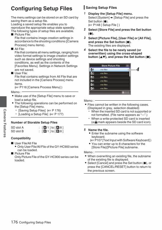
Configuring Setup FilesThe menu settings can be stored on an SD card bysaving them as a setup file.Loading a saved setup file enables you toreproduce the appropriate setup state speedily.The following types of setup files are available.o Picture File:
File that contains image creation settings inaccordance to the shooting conditions ([CameraProcess] menu items).
o All File:File that contains all menu settings, ranging fromvideo format settings to image creation settingssuch as device settings and shootingconditions, as well as the contents of the[Favorites Menu]. Settings in Network Settingsare not saved.
o User File:File that contains settings from All File that arenot included in the [Camera Process] menuitems.(A P116 [Camera Process Menu] )
Memo : 0 Make use of the [Setup File] menu to save or
load a setup file.0 The following operations can be performed on
the [Setup File] menu.0 [Saving Setup Files] (A P 176)0 [Loading a Setup File] (A P 177)
Number of Storable Setup FilesSD slot A : [ W 1 ] to [ W 8 ]SD slot B : [ Y 1 ] to [ Y 8 ]
Compatibilityo User File/All File0 Only User File/All File of the GY-HC900 series
can be loaded.o Picture File
Only Picture File of the GY-HC900 series can beloaded.
Saving Setup Files1 Display the [Setup File] menu.
Select [System] B [Setup File] and press theSet button (R).(A P148 [ Setup File ] )
2 Select [Store File] and press the Set button(R).
3 Select [Picture File], [User File] or [All File],and press the Set button (R).The existing files are displayed.
4 Select the file to be newly saved (oroverwritten) using the cross-shapedbutton (JK), and press the Set button (R).
.
4
<no file>
<no file>
<no file>
<no file>
<no file>
<no file>
Store Picture File
Memo : 0 Files cannot be written in the following cases.
(Displayed in gray, selection disabled)0 When the inserted SD card is not supported or
not formatted. (File name appears as “---”.)0 When a write-protected SD card is inserted
(a z mark appears beside the SD card icon).
5 Name the file.0 Enter the subname using the software
keyboard.(A P107 [Text Input with Software Keyboard] )0 You can enter up to 8 characters for the
[Store File]/[Picture File] subname.Memo : 0 When overwriting an existing file, the subname
of the existing file is displayed.0 Select [Cancel] and press the Set button (R), or
press the [CANCEL/RESET] button to return tothe previous screen.
176 Configuring Setup Files
Camera Features

6 Select [Store] and press the Set button (R).
.
6
5
7 Save the file.0 A confirmation screen appears when you
choose to overwrite.Select [Overwrite] on the confirmationscreen, and press the Set button (R). Savingstarts, and “Storing...” appears on the screen.
.
:SUNSET
7
Load Picture File
Cancel
Overwrite
Overwrite Picture File?
0 Saving starts, and “Storing...” appears on thescreen when the file is newly saved.
.
8 Saving is complete.After saving of the file is complete, “Complete”appears on the screen, and the menu screencloses automatically.
Loading a Setup File1 Display the [Setup File] menu.
Select [System] B [Setup File] and press theSet button (R).(A P148 [ Setup File ] )
2 Select [Load File] and press the Set button(R).
3 Select [Picture File], [User File] or [All File],and press the Set button (R).The existing files are displayed.
4 Select the file to load using the cross-shaped button (JK), and press the Setbutton (R).
.
4Load Picture File
Memo : 0 When the write-protect switch of the inserted SD
card is set, a z mark appears beside the SDcard icon. Setup files can be loaded from an SDcard even if the write-protect switch is set.
0 Setup files that are completely incompatible willnot be displayed.(A P176 [Configuring Setup Files] )
5 Select [Load] on the confirmation screen,and press the Set button (R).Loading starts, and “Loading...” appears on thescreen.
.
5Cancel
Load
Load Picture File?
6 Reading is complete.After reading of the file is complete, “Complete”appears on the screen, and the menu screencloses automatically.
Configuring Setup Files 177
Camera Features

Deleting Setup Files1 Display the [Setup File] menu.
Select [Main Menu] B [System] B [Setup File]and press the Set button (R).(A P148 [ Setup File ] )
2 Select [Delete File] and press the Set button(R).
3 Select [Picture File], [User File] or [All File],and press the Set button (R).The existing files are displayed.
4 Select the file to delete using the cross-shaped button (JK), and press the Setbutton (R).
.
4CAM2CAM1
Delete Picture File
Memo : 0 Setup File saved on the SD card cannot be
deleted.
5 Select [Delete] on the confirmation screen,and press the Set button (R).Deletion starts, and “Deleting...” appears on thescreen.
.
:SUNSET
5Cancel
Delete
CAM1
Delete Picture File?
6 Deletion is complete.After file deletion is complete, “Complete”appears on the screen.
178 Configuring Setup Files
Camera Features

Connecting ExternalMonitor0 To output live or playback video images and
audio sound to an external monitor, select theoutput signals from the camera recorder, andconnect using an appropriate cable according tothe monitor to be used.
0 Choose the most suitable terminal according tothe monitor in use.
0 [HD/SD SDI OUT] terminal:Outputs either the 3G-SDI/HD-SDI signal or SD-SDI signal.
0 [VIDEO OUT] terminal:Outputs composite video signals.
0 [HDMI] terminal:Outputs HDMI signals.
Memo : 0 If the [HD/SD SDI OUT] terminal or [HDMI]
terminal is connected, configure the settings inthe [A/V Set] menu according to the monitor tobe connected.(A P131 [ SDI OUT1 ] )(A P132 [ SDI OUT2 ] )(A P132 [ HDMI OUT ] )(A P132 [ VIDEO OUT ] )
.
SDI IN HDMIVIDEO IN
* Select the output signal in [A/V Set] B [SDIOUT1]/[SDI OUT2]/[HDMI OUT].(A P131 [ SDI OUT1 ] )(A P132 [ SDI OUT2 ] )(A P132 [ HDMI OUT ] )
* When [Record Format] B [System] is set to“SD”2, only SD-SDI signals are output.(A P151 [ System ] )
* To display the menu screen or display screen onthe external monitor, set [A/V Set] B [VideoSet] B[SDI OUT2 Char.]/[HDMI Char.]/[VideoOUT Char.] to “On”.(A P131 [ SDI OUT2 Char. ] )(A P131 [ HDMI Char. ] )(A P131 [ Video OUT Char. ] )
Connecting External Monitor 179
Connecting External Devices

Connecting via SDI0 Digital video signals, together with embedded
(superimposed) audio signals and time codesignals, are output for both the 3G-SDI/HD-SDIand SD-SDI signals.
Memo : 0 The sampling frequency for embedded
(superimposed) audio signals is 48 kHz. Timecode of the built-in time generator as well asplayback time code are also output.
Setting the Aspect0 For setting the mode to convert images with a
16:9 aspect ratio to display on a 4:3 aspect ratioscreen.
0 Set using [A/V Set] B [Video Set] B [SDAspect].
0 The available modes include “Side Cut”, “Letter”(blackened at the top and bottom), and“Squeeze” (full size, compressed at the left andright).(A P134 [ SD Aspect ] )
Memo : 0 When [Record Format] B [System] is set to “SD”,
and [SD Aspect] is set to “4:3”, this item cannot beselected.
0 When [Record Format] B [System] is set to“SD”2, and [SD Aspect] is set to “16:9”,“Side Cut” in [A/V Set] B [Video Set] B [SDAspect] cannot be selected.(A P151 [ System ] )(A P154 [ SD Aspect 2 ] )
Connecting a RemoteControl UnitThe switch functions of the camera recorder can beconfigured using the remote control unit.* Remote control units supported: RM-LP25U,
RM-LP55U, RM-LP20Go Attaching Core Filter Beforehand vBefore using the remote control unit, attach thecore filter (small) to the remote cable of theremote control unit.
.
Release the stopper. 5 cm Wind twice
To be connected to the camera recorder. [Core filter (small)]
1 Connect the remote control unit to thecamera recorder.Connect the remote cable of the remote controlunit to the [REMOTE] terminal.
.
REMOTE Connect to the Remote Control Unit
Caution : 0 Turn off the power of the camera recorder when
connecting a remote control unit.2 Turn on the power of the camera recorder.3 Set the operate switch of the remote control
unit to ON.Precautions on Using the Remote Control Unit0 When the switches of the camera recorder and
remote control unit are operated at the sametime, the switch operation of the remote controlunit takes priority over that of the camerarecorder.
0 Focus and zoom operations cannot beperformed using the remote control unit.
0 The shutter speed may vary slightly from thevalue displayed on the camera recorder.
0 While the camera recorder is in the Media mode,the Auto White Balance feature does notfunction even if you operate it from the remotecontrol unit.
180 Connecting External Monitor
Connecting External Devices

Connecting theHeadphone
.
0 Audio output from the [PHONE] terminal can beselected using [A/V Set] B [Audio Set] B[PHONE Output] and the combination of the[MONI SELECT] and [CH SELECT] switches.(A P137 [ PHONE Output ] )0 The outputs from the [PHONE] terminal and
monitor speaker are as follows according to thedifferent combinations of settings.[MONI
SELECT]SwitchSetting
[PHONEOutput]Setting
[PHONE]Terminal SpeakerL R
[CH1/CH3] - CH1 CH1
[BOTH] Mix CH1+CH2 CH1+CH2Stereo CH1 CH2[CH2/CH4] - CH2 CH2
1 Connect the headphone.2 Select the channels to monitor using the
different combinations of the [MONISELECT] and [MONI SELECT] switches.
Combinations of[MONI SELECT]
and [CHSELECT]Switches
Channelsto
MonitorDescription
.
CH1 The audio input to[CH1] is output.
.
CH2 The audio input to[CH2] is output.
.
CH1/CH2 The audio inputsto [CH1] and[CH2] are output.
.
CH3 The audio input to[CH3] is output.
.
CH4 The audio input to[CH4] is output.
.
CH3/CH4 The audio inputsto [CH3] and[CH4] are output.
3 Use the [MONITOR] adjustment knob toadjust the monitor volume.
Memo : 0 There is no sound output from the speaker when
the headphone is connected.
Connecting the Headphone 181
Connecting External Devices
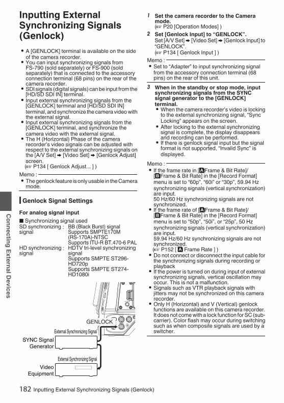
Inputting ExternalSynchronizing Signals(Genlock)0 A [GENLOCK] terminal is available on the side
of the camera recorder.0 You can input synchronizing signals from
FS-790 (sold separately) or FS-900 (soldseparately) that is connected to the accessoryconnection terminal (68 pins) on the rear of thecamera recorder.
0 SDI signals (digital signals) can be input from the[HD/SD SDI IN] terminal.
0 Input external synchronizing signals from the[GENLOCK] terminal and [HD/SD SDI IN]terminal, and synchronize the camera video withthe external signal.
0 Input external synchronizing signals from the[GENLOCK] terminal, and synchronize thecamera video with the external signal.
0 The H (Horizontal) Phase of the camerarecorder’s video signals can be adjusted withrespect to the external synchronizing signals onthe [A/V Set] B [Video Set] B [Genlock Adjust]screen.(A P134 [ Genlock Adjust... ] )
Memo : 0 The genlock feature is only usable in the Camera
mode.
Genlock Signal SettingsFor analog signal inputo Synchronizing signal usedSD synchronizingsignal
: BB (Black Burst) signalSupports SMPTE170M(RS-170A)-NTSCSupports ITU-R BT.470-6 PAL
HD synchronizingsignal
: HDTV tri-level synchronizingsignalSupports SMPTE ST296-HD720pSupports SMPTE ST274-HD1080i
.
GENLOCK
Video Equipment
External Synchronizing Signal
External Synchronizing SignalSYNC Signal
Generator
1 Set the camera recorder to the Cameramode.(A P20 [Operation Modes] )
2 Set [Genlock Input] to “GENLOCK”.Set [A/V Set] B [Video Set] B [Genlock Input] to“GENLOCK”.(A P134 [ Genlock Input ] )
Memo : 0 Set to “Adapter” to input synchronizing signal
from the accessory connection terminal (68pins) on the rear of this unit.
3 When in the standby or stop mode, inputsynchronizing signals from the SYNCsignal generator to the [GENLOCK]terminal.0 When the camera recorder’s video is locking
to the external synchronizing signal, “SyncLocking” appears on the screen.
0 After locking to the external synchronizingsignal is complete, the display disappearsand recording can be performed.
0 If there is genlock signal input but the signalformat is not supported, “Invalid Sync” isdisplayed.
Memo : 0 If the frame rate in [WFrame & Bit Rate]/
[YFrame & Bit Rate] in the [Record Format]menu is set to “60p”, “60i” or “30p”, 59.94 Hzsynchronizing signals (vertical synchronization)are input.50 Hz/60 Hz synchronizing signals are notsynchronized.
0 If the frame rate of [WFrame & Bit Rate]/[YFrame & Bit Rate] in the [Record Format]menu is set to “50p”, “50i”, or “25p”, 50 Hzsynchronizing signals (vertical synchronization)are input.59.94 Hz/60 Hz synchronizing signals are notsynchronized.(A P152 [ W Frame Rate ] )0 Do not connect or disconnect the input cable for
the synchronizing signals during recording orplayback
0 If the power is turned on during input of externalsynchronizing signals, vertical oscillation mayoccur. This is not a malfunction.
0 Signals such as VTR playback signals withjitters may not be synchronized on this camerarecorder.
0 Only H (Horizontal) and V (Vertical) genlockfunctions are available on this camera recorder.It does not come with a lock function for SC (sub-carrier). Color flash may occur during switchingsuch as when composite signals are used by aswitcher.
182 Inputting External Synchronizing Signals (Genlock)
Connecting External Devices
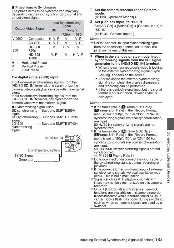
o Phase Items to SynchronizeThe phase items to be synchronized may varydepending on the input synchronizing signal andoutput video signal.
Output Video SignalInput Synchronizing
SignalBB Tri-sync
720p 1080iVIDEO Composite H, V, F V V, F
SDI
SD-SDI H, V, F V V, FHD-SDI720p
V H, V V
HD-SDI1080i
V, F V H, V, F
H : Horizontal PhaseV : Vertical PhaseF : Field PhaseFor digital signals (SDI) inputInput external synchronizing signals from the[HD/SD SDI IN] terminal, and synchronize thecamera video or playback image with the externalsignal.Input external synchronizing signals from the[HD/SD SDI IN] terminal, and synchronize thecamera video with the external signal.
o Synchronizing signal usedSD synchronizingsignal
: Supports SMPTE259MHD synchronizingsignal
: Supports SMPTE ST2963G-SDIsynchronizingsignal
: Supports SMPTE ST424
.
External Synchronizing SignalSYNC Signal
Generator
1 Set the camera recorder to the Cameramode.(A P20 [Operation Modes] )
2 Set [Genlock Input] to “SDI IN”.Set [A/V Set] B [Video Set] B [Genlock Input] to“SDI IN”.(A P134 [ Genlock Input ] )
Memo : 0 Set to “Adapter” to input synchronizing signal
from the accessory connection terminal (68pins) on the rear of this unit.
3 When in the standby or stop mode, inputsynchronizing signals from the SDI signalgenerator to the [HD/SD SDI IN] terminal.0 When the camera recorder’s video is locking
to the external synchronizing signal, “SyncLocking” appears on the screen.
0 After locking to the external synchronizingsignal is complete, the display disappearsand recording can be performed.
0 If there is genlock signal input but the signalformat is not supported, “Invalid Sync” isdisplayed.
Memo : 0 If the frame rate in [WFrame & Bit Rate]/
[YFrame & Bit Rate] in the [Record Format]menu is set to “60p”, “60i” or “30p”, 59.94 Hzsynchronizing signals (vertical synchronization)are input.50 Hz/60 Hz synchronizing signals are notsynchronized.
0 If the frame rate of [WFrame & Bit Rate]/[YFrame & Bit Rate] in the [Record Format]menu is set to “50p”, “50i”, or “25p”, 50 Hzsynchronizing signals (vertical synchronization)are input.59.94 Hz/60 Hz synchronizing signals are notsynchronized.(A P152 [ W Frame Rate ] )0 Do not connect or disconnect the input cable for
the synchronizing signals during recording orplayback
0 If the power is turned on during input of externalsynchronizing signals, vertical oscillation mayoccur. This is not a malfunction.
0 Signals such as VTR playback signals withjitters may not be synchronized on this camerarecorder.
0 Only H (Horizontal) and V (Vertical) genlockfunctions are available on this camera recorder.It does not come with a lock function for SC (sub-carrier). Color flash may occur during switchingsuch as when composite signals are used by aswitcher.
Inputting External Synchronizing Signals (Genlock) 183
Connecting External Devices

o Phase Items to SynchronizeThe phase items to be synchronized may varydepending on the input synchronizing signal andoutput video signal.
Output Video SignalInput Synchronizing
Signal3G-SDI
HD-SDI SD-SDI720p 1080i
VIDEO Composite V V V, F H, V,F
SDI SD-SDI V V V, F H, V,F
HD-SDI720p V H, V V VHD-SDI1080i V V H, V,
F V, F3G-SDI1080p H, V - - -
Adjusting H Phase1 Select [Genlock Adjust] in the [A/V Set]
menu.Adjust the [A/V Set] B [Video Set] B GenlockAdjust item as follows.(A P134 [ Genlock Adjust... ] )[SD-SDI H Phase] : Adjusts the H Phase
of the SD SDI signal.[HD-SDI H Phase] : Adjusts the H Phase
of the HD SDI signal.2 Select a value using the cross-shaped
buttons (JK).0 The H Phase of the camera recorder’s video
signal is adjusted with respect to the externalsynchronizing signal input from the[GENLOCK] terminal.
Memo : 0 Adjustment cannot be made while recording or
playback is in progress.0 The video image may be disrupted momentarily
during adjustment. This is not a malfunction.
Displaying Return Videosfrom an External DeviceReturn video from an external device (switcher,etc.) can be displayed on the viewfinder or LCDmonitor of the camera recorder.Memo : 0 This feature is only usable in the Camera mode.1 Set the camera recorder to the Camera
mode.(A P20 [Operation Modes] )
2 Assign the “Return Video” function to anyof the user buttons.(A P45 [Assignment of Functions to UserButtons] )
3 Configure the input destination of thereturn video to “SDI”0To specify the input destination of the returnvideo, configure [A/V Set] B [Video Set] B[Return Input] to “SDI”.(A P135 [ Return Input 0 ] )
Memo : 0 When [System] B [Record Set] B [Record
Format] B [System] is configured to “HD(SDIIn)” or “SD(SDI In)”2, “---” is displayed andthe setting cannot be configured.
4 Select the aspect ratio of the return video.Set using [A/V Set] B [Video Set] B [ReturnAspect].(A P135 [ Return Aspect ] )
5 Select the way the return video is to bedisplayed.Select in [Camera Function] B [User SwitchSet] B [Return Video]. The camera will operateaccording to the setting.(A P114 [ Return Video ] )
6 Press the user button that is assigned withthe “Return Video” function.0 By pressing the user button assigned with the
“Return Video” function, the captured imageor return video is displayed according to themethod specified in step 5.
Memo : 0 Compatible input formats for the return video are
as follows.0 1920x1080/60p, 60i, 50p, 50i0 1280x720/60p, 50p0 720x480/60i 2 (U model)0 720x576/50i 2 (E model)
184 Inputting External Synchronizing Signals (Genlock)
Connecting External Devices

Functions of NetworkConnectionThe network feature comprises web-browser-based functions using devices such as asmartphone, tablet terminal, or PC, as well as FTPand live streaming functions that run via thumbnailscreens and menu operation.Memo : 0 When [System] B [Record Set] B [Record
Format] B [System] is set to “High-Speed”2, only “Planning Metadata” can beused for the [LAN] terminal connection.
Connecting to the Network0 [LAN] Terminal0 Built-in Wireless LAN u v0 Connect the following adapters to the [HOST]
terminal (USB)0 Wireless LAN adapter0 Ethernet adapter0 Cellular adapter
(A P186 [Camera Setup for NetworkConnection] )
List of FunctionsImporting MetadataYou can download a metadata settings file (XMLformat) from the FTP server and store metadata inthe camera recorder.
(A P189 [Importing Metadata] )
Uploading Recorded ClipsYou can upload clips recorded in the SD card to apreset FTP server.
(A P191 [Uploading a Recorded Video Clip] )Memo : 0 Uploading can also be performed via a web
browser.(A P199 [Uploading a Recording Clip via a WebBrowser] )
Editing Metadata0 Planning Metadata
You can access the page for editing the camerarecorder’s metadata via a web browser ondevices such as a smartphone, tablet terminal,or PC, and edit the metadata that is to be appliedto clips to be recorded.(A P195 [ Planning Metadata ] )0 Clip Metadata
You can access the page for editing themetadata via a web browser on devices such asa smartphone, tablet terminal, or PC, anddisplay or rewrite the metadata that is recordedto a clip.(A P196 [ Clip Metadata ] )
View RemoteYou can access via a web browser on devices suchas a smartphone, tablet terminal, or PC to checkthe live image or remotely control the camera.
(A P202 [View Remote Control and CameraControl Functions] )
Camera ControlYou can access via a web browser on devices suchas a smartphone, tablet terminal, or PC to remotelycontrol the camera.
(A P202 [View Remote Control and CameraControl Functions] )
Live streamingBy combining with the decoder or PC applicationthat supports live streaming, you can perform audioand video streaming via the network.
(A P210 [Performing Live Streaming] )
Functions of Network Connection 185
Connecting to the Network

Preparing NetworkConnectionOperating Environment
Operation has been verified for the followingenvironments.Computer0 OS: Windows 7
Web browser: Internet Explorer 110 OS: Windows 10
Web browser: Chrome0 OS: macOS 10.13
Web browser: Safari 10Smartphone/Tablet Terminal0 OS: iOS11 (iPhone X/iPad Pro)
Web browser: Safari 110 OS: Android 6 (Smartphone)
Web browser: Chrome0 OS: Android 7 (Tablet)
Web browser: Chrome
Camera Setup for Network Connection1 Connect using the corresponding method
of connection0 [LAN] Terminal
Connect a PC to this camera recorder directlyusing a cross-over cable or via devices suchas an Ethernet hub using a LAN cable.
(A P186 [Connecting to Network via [LAN]Terminal 0] )0 Built-in Wireless LAN u v
Attach the wireless LAN antenna if it is notmounted.
(A P32 [Attaching the Wireless LAN Antennas(Supplied) u v] )(A P188 [Connecting to Network via Built-inWireless LAN u v 0] )0 Connect the following adapters to the
[HOST] terminal (USB)0 Wireless LAN adapter0 Ethernet adapter0 Cellular adapter(A P187 [Connecting to Network via[HOST] Terminal (USB) 0] )
Memo : 0 Only a network connection adapter can be
connected to the [HOST] terminal (USB).0 Connect or disconnect an adapter only after you
have turned off the power of the camerarecorder.
0 You can find the latest information on thecompatible adapters at the product page of ourwebsite.
0 Two types of network coverage (WAN and LAN)are available for each application.
Caution : 0 When [System] B [Record Set] B [Record
Format] B [System] is configured to “High-Speed”2, network cannot be used viawireless LAN u v or the [HOST] terminal(USB). Configure as follows in this case.0 Set [Network] B [Connection Setup] B [USB/
Int. WLAN] to “Off”. u v0 Unplug the USB network adapterNote that camera operation will come to anemergency stop and the power will turn off if theabove steps are not performed.File data may be damaged if this happens whilerecording is in progress.
Connecting to Network via [LAN]Terminal 0
You can connect a device such as a smartphone,tablet terminal, or PC directly to the camerarecorder using a cross cable to access the camerarecorder’s web functions. Alternatively, you canalso connect using an Ethernet hub.1 Configure the connection settings with
[Wizard].0 Select “LAN” in [Network] B [Connection
Setup] B [Wizard], and configure the settingsaccording to the instructions on the screen.Perform setting for the following.0 IP address setting (DHCP or manual)0 IP Address0 Subnet mask0 Default gateway0 DNS Server
Memo : 0 When an address is manually assigned in a NAT
environment, it is also necessary to set thedefault gateway correctly besides conversion ofthe address at the router’s end in order toperform operations such as access to theInternet from an external network via the router.
2 Setting is complete.After setting is complete, you can access thecamera recorder via a web browser.
Memo : 0 After setting is complete, the following items will
be automatically configured.0 The [Network] B [Connection Setup] B
[Default Gateway] setting changes to “LAN”.0 The [Network] B [Live Streaming] B
[Interface] setting changes to “LAN”.
186 Preparing Network Connection
Connecting to the Network
Connecting to Network via [HOST]Terminal (USB) 0
1 Configure the connection settings with[Wizard].0 Select “USB” in [Network] B [Connection
Setup] B [Wizard], and configure the settingsaccording to the instructions on the screen.
Configure the settings for the followingaccording to the type of connection.o USB wireless LAN connection
0 Mode of connection0 Configuration method
* For P2P connections, it is necessary toconfigure the [Default Gateway] and[Passphrase] according to the steps belowafter the above settings are configured.A Configure [Network] B [Connection
Setup] B [Default Gateway] to “USB/Int.WLAN” u v or “USB” w x
B Set the camera recorder to the Cameramode, and display the status screen([USB/Int. WLAN] screen u v or[USB] screen w x).0 Press the [STATUS/SET] button on the
camera recorder to display the statusscreen.Press the cross-shaped button (H I) todisplay the [USB/Int. WLAN] screen uv or [USB] screen w x.
0 Check to ensure that the [SSID] and[Passphrase] that you have set in thewizard are displayed.
C Select an SSID from the list of accesspoints (smartphone, tablet terminal, PC,etc.) and enter a passphrase.0 Display the list of access points in the
wireless connection settings of thesmartphone, tablet terminal, or PC, andselect “HC900-****”. (**** are numbersthat vary with the device used.)
0 After the password confirmation screenappears, enter the [Passphrase]displayed on the [USB/Int. WLAN] screenu v or [USB] screen w x.
o USB wired LAN connection0 IP address setting (DHCP or manual)0 IP Address0 Subnet mask0 Default gateway0 DNS Server
Memo : 0 When an address is manually assigned in a NAT
environment, it is also necessary to set thedefault gateway correctly besides conversion ofthe address at the router’s end in order toperform operations such as access to theInternet from an external network via the router.o USB cellular adapter connection
0 Connection phone number0 Username0 Password
Caution : 0 You can access the web functions via a web
browser on devices such as a smartphone,tablet terminal, or PC only in a LAN environment.
0 Note that you may have to pay very high bills inthe case of pay-per-use contracts. Fixed pricecontract is recommended if you are using thenetwork function.
0 Note that the use of improper settings may resultin expensive bills from the phone serviceprovider. Make sure that the setting is correct.
0 To avoid expensive bills due to the roamingconnection, you are recommended to use thisfunction by disabling the roaming contract.
0 There may be communication even when youare not using the network function. Remove thecellular adapter when the function is not in use.
2 Setting is complete.After setting is complete, you can access thecamera recorder via a web browser.
Memo : 0 After setting is complete, the following items will
be automatically configured.0 The [Network] B [Connection Setup] B [USB/
Int. WLAN] setting changes to “On”. uv
0 The setting of [Network] B [ConnectionSetup] B [Default Gateway] changes to“USB/Int. WLAN” u v or “USB” wx. However, this does not apply to theP2P connection.
0 The setting of [Network] B [Live Streaming]B [Interface] changes to “USB/Int. WLAN”u v or “USB” w x.
Preparing Network Connection 187
Connecting to the Network

Connecting to Network via Built-inWireless LAN u v 0
1 Configure the connection settings with[Wizard].0 Select “USB/Int. WLAN” in [Network] B
[Connection Setup] B [Wizard], andconfigure the settings according to theinstructions on the screen.Perform setting for the following.0 Mode of connection0 Configuration method
* For P2P connections, it is necessary toconfigure the [Default Gateway] and[Passphrase] according to the steps belowafter the above settings are configured.A Set [Network] B [Connection Setup] B
[Default Gateway] to “USB/Int. WLAN”.B Set the camera recorder to the Camera
mode, and display the [USB/Int. WLAN](status) screen.0 Press the [STATUS/SET] button on the
camera recorder to display the statusscreen. Press the cross-shaped button(H I) to display the [USB/Int. WLAN]screen.
0 Check to ensure that the [SSID] and[Passphrase] that you have set in thewizard are displayed.
C Select an SSID from the list of accesspoints (smartphone, tablet terminal, PC,etc.) and enter a passphrase.0 Display the list of access points in the
wireless connection settings of thesmartphone, tablet terminal, or PC, andselect “HC900-****”. (**** are numbersthat vary with the device used.)
0 After the password confirmation screenappears, enter the [Passphrase]displayed on the [USB/Int. WLAN]screen.
2 Setting is complete.After setting is complete, you can access thecamera recorder via a web browser.
Memo : 0 After setting is complete, the following items will
be automatically configured.0 The [Network] B [Connection Setup] B [USB/
Int. WLAN] setting changes to “On”.0 The [Network] B [Connection Setup] B
[Default Gateway] setting changes to “USB/Int. WLAN”. However, this does not apply tothe P2P connection.
0 The [Network] B [Live Streaming] B[Interface] setting changes to “USB/Int.WLAN”.
188 Preparing Network Connection
Connecting to the Network

Importing MetadataYou can download a metadata settings file (XMLformat) from the FTP server and store metadata inthe camera recorder.The imported metadata is applied to clips to berecorded.
Preparing Metadata0 You can record the four metadata types below.
Title1 : ASCII only, max. 63 characters(bytes)
Title2 : UNICODE, max. 127 bytesCreator : UNICODE, max. 127 bytesDescription : UNICODE, max. 2047 bytes
0 Metadata makes use of the XML descriptionformat.
0 Edit the<Title1><Title2><Description><Creator> tagelement using the XML editor. (Indicated by theframes below)
.
<?xml version="1.0" encoding="UTF-8"?><NRT-MetaInterface lastUpdate="2015-01-29T18:06:21+09:00" xmlns="urn:schemas-proHD:nonRealTimeMetaInterface:ver.1.00" xmlns:xsi="http://www.w3.org/2001/XMLSchema-instance"> <MetaData> <Title1>Title1 sample</Title1> <!-- only "en",max63bytes --> <Title2>Title2 sample</Title2> <!-- ,max127bytes --> <Description>Description sample</Description> <!-- ,max2047bytes --> <Creator>Creator sample</Creator> <!-- ,max127bytes --> </MetaData></NRT-MetaInterface>
Configuring the Server for DownloadingFor specifying the settings for connecting to theFTP server for downloading the metadata (domainname, user name, password, etc.) as well as thepath of the file to download.1 Open the [Metadata Server] screen.
Open the [Network] B [Metadata Server]screen.
.
Meta-FTP4...Meta-FTP3...Meta-FTP2...Meta-FTP1...
Metadata Server
2 Register the [Metadata Server].0 Select a server using the cross-shaped
button (JK), and press the Set button (R).The server settings screen appears. Performsetting for each item.
0 Up to 4 settings can be registered.(A P139 [ Metadata Server ] )
.
UsernameFile PathPortServerProtocolAlias
Metadata Server Set
Memo : 0 For details on the registered information, please
consult the network administrator for the server.
Importing Metadata 189
Connecting to the Network
Importing MetadataDownload the metadata settings file (XML format)from the FTP server.1 Select [Network] B [Import Metadata] and
press the Set button (R).The [Import Metadata] screen appears.
.
Import Metadata
2 Select the server for importing themetadata.0 The name that is registered in [Metadata
Server] B [Alias] is displayed.0 Select a server using the cross-shaped
button (JK), and press the Set button (R).
.
2
Import Metadata
3 Select [Import] on the confirmation screen,and press the Set button (R).Import starts.After import is complete, the display is restoredto the screen before the [Import Metadata]screen appears.
.
3
Importing...
Cancel
Import
Import Metadata?
Memo : 0 You cannot exit the menu or perform recording
while import is in progress.0 If import of the metadata failed, “Import Error!” is
displayed, and a message indicating the causeof the error appears.Press the Set button (R) to return to the [ImportMetadata] screen in step 1.(A P219 [List of FTP Transfer Errors] )0 When “HTTP” is selected in the [Select FTP
Proxy] screen of the network connection setting,connections to the servers other than “FTP”protocol cannot be made.
0 If a setting other than “FTP” is specified for[Protocol], to ensure the safety of thecommunication path, a screen appearsprompting you to validate the fingerprint of thepublic key and certificate received from theserver.Check to ensure that the displayed valuecoincides with the known value.
190 Importing Metadata
Connecting to the Network

Uploading a RecordedVideo ClipThe following are steps to upload clips recorded ina recording media to a preset FTP server.
Configuring the FTP Server forUploading
For specifying the settings for connecting to theFTP server to upload recorded clips to (domainname, user name, password, etc.) as well as thedirectory of the upload destination.1 Open the [Clip Server] screen.
Open the [Network] B [Upload Settings] B [ClipServer] screen.
.
Clip Server
2 Register the [Clip Server].Register the server to upload recorded clips inthe recording media to.Up to 4 servers can be registered.(A P146 [ Clip Server ] )
Memo : 0 For details on the registered information, please
consult the network administrator for the server.
Uploading Clips Automatically (AutoFTP)0
The following are steps to automatically uploadclips recorded in a recording media to a preset FTPserver.1 Configure the settings for automatic
uploadConfigure [Network] B [Upload Settings] B[Upload] to “Auto” and configure the settings foreach of [Slot], [Cellular] and [Server].(A P146 [ Upload ] )
.
2 Start uploading0 Configuring [Network] B [Upload Settings] B
[Auto Upload] to “On” starts uploading.0 You can also press the user button that is
assigned with “Auto Upload”.Memo : 0 FTP transfer is performed for the slot configured
in [Slot].0 If recording is started for the same slot as the
one configured in [Slot] while FTP transfer is inprogress, FTP transfer will be interrupted.
0 FTP transfer is not performed while livestreaming or Return over IP is in progress.
0 FTP transfer is disabled when [System] B[Record Set] B [Record Format] B [System] isconfigured to “High-Speed”2. To performFTP transfer, select a setting other than “High-Speed”.
Uploading a Recorded Video Clip 191
Connecting to the Network

Uploading Clips Manually (Manual FTP)The following are steps to upload clips recorded ina recording media to a preset FTP server.All playable clips on the thumbnail screen can beuploaded.1 Configure the FTP server for manual
uploadingSet [Network] B [Upload Settings] B [Upload]to “Manual”.(A P146 [ Upload ] )
2 Register the [Clip Server].0 Open the [Network] B [Upload Settings] B
[Clip Server] screen.0 Register the server to upload recorded clips
in the recording media to.Up to 4 servers can be registered.
(A P146 [ Clip Server ] )Memo : 0 For details on the registered information, please
consult the network administrator for the server.0 When [Network] B [Upload Settings] B [Upload]
is configured to “Auto”, manual uploading is alsodisabled for slots other than the selected “Slot”.To perform manual uploading, select “Manual”.
0 FTP transfer is disabled when [System] B[Record Set] B [Record Format] B [System] isconfigured to “High-Speed”2. To performFTP transfer, select a setting other than “High-Speed”.
Uploading a Video Clip1 Set the camera recorder to the Media mode.
0 Press and hold the [CAM/MEDIA] selectionbutton in the Camera mode to enter theMedia mode. A thumbnail screen of the clipsrecorded on the SD card is displayed.
0 You can upload the selected clips on thethumbnail screen to the FTP server.
(A P95 [Thumbnail Screen] )
2 Move the cursor to the clip to be uploaded.Move the cursor to the clip to be uploaded usingthe cross-shaped button (JKH I).
.
2
3 Press the [USER4] button.The action selection screen is displayed.
.
All ClipsSelected ClipsThis Clip 3
4 Select [FTP Upload] B [This Clip] B serverto upload to, and press the Set button (R).The status of the transfer process is indicatedby a progress bar.
.
Upload in Background
Stop
FTP Upload
Memo : 0 The name for the server to upload files to are
indicated using the preset names in [ClipServer] B [Alias].
0 To stop uploading, press the Set button (R).Select [Yes] on the confirmation screen, andpress the Set button (R) to stop uploading andreturn to the thumbnail screen.
192 Uploading a Recorded Video Clip
Connecting to the Network

5 Upload is complete.0 After upload is complete, “Successfully
Completed.” appears on the screen.0 Press the Set button (R) to return to the
thumbnail screen.
.
5Exit
Successfully Completed.
FTP Upload
Selecting and Uploading Multiple ClipsTo select and upload multiple clips, refer to“[Selecting and Performing Operations on MultipleClips] (A P 102)”.
Uploading All Video Clips1 Press the [USER4] button.
The action selection screen is displayed.2 Upload the clips.
Select [FTP Upload...] B [All Clips] B server toupload to, and press the Set button (R).
.
All ClipsSelected ClipsThis Clip
2
3 Upload starts.The status of the transfer process is indicatedby a progress bar.
.
Upload in Background
Stop
FTP Upload
Memo : 0 To stop uploading, press the Set button (R).
Select [Yes] on the confirmation screen, andpress the Set button (R) to stop uploading andreturn to the thumbnail screen.
0 If the file to be uploaded has the same name asan existing file in the FTP server, an overwriteconfirmation window appears.
0 When “HTTP” is selected in the [Select FTPProxy] screen of the network connection setting,the overwrite confirmation window will not bedisplayed and the existing file is overwritten.
0 Even after upload has started (FTP transfer inprogress) in step 3, pressing the [CAM/MEDIA] button switches the camera recorder tothe Camera mode, allowing you to startshooting.
0 If a setting other than “FTP” is specified for[Protocol], to ensure the safety of thecommunication path, a screen appearsprompting you to validate the fingerprint of thepublic key and certificate received from theserver.Check to ensure that the displayed valuecoincides with the known value.0 Fingerprint is a unique value that varies with
each public key and certificate.0 For details of the fingerprint, please consult
the administrator of the server to beconnected.
(A P146 [ Clip Server ] )0 When “HTTP” is selected in the [Select FTP
Proxy] screen of the network connection setting,connections to the servers other than “FTP”protocol cannot be made.
Uploading a Recorded Video Clip 193
Connecting to the Network

4 Upload is complete.0 After all clips are uploaded successfully,
“Successfully Completed.” is displayed.Press the Set button (R) to return to thethumbnail screen.
0 When clips are not uploaded successfully,the following errors are displayed.
.
Cause of Error
Exit
Internal Error.
Failed.
FTP Upload
(A P219 [List of FTP Transfer Errors] )Memo : 0 If there is an error message or other notifications
when you switched to the Camera mode whileFTP upload is in progress, a 5 icon (yellow) willappear in the remaining media space displayarea in the Camera mode.You can press the [CAM/MEDIA] button toswitch to the Media mode and display the aboveerror screen.Follow “[List of FTP Transfer Errors] (A P 219)”to clear the error message.
FTP Resume FeatureWhen FTP transfer starts and there is a file of thesame name on the server with a file size smallerthan the file to be transferred, the file on the serverwill be regarded as an interrupted file during a FTPtransfer. A confirmation screen to resume transfer(append writing) appears.
.
If “Resume” is selected, FTP transfer is carried outsuch that it appends from the position where it wasinterrupted.When FTP transfer ends normally, “Complete”appears on the screen.Memo : 0 FTP server equipped with resume function is
required.0 If [Network] B [Upload Settings] B [Clip
Server] B [Clip-FTP1/2/3/4] B [Protocol] is setto “SFTP”, the resume function is disabled.
0 If “HTTP” is selected in the [Select FTP Proxy]screen of the network connection setting, theresume function is disabled.
194 Uploading a Recorded Video Clip
Connecting to the Network
Connecting from a WebBrowserYou can access the web functions of this camerarecorder via a web browser on devices such as asmartphone, tablet terminal, or PC.Make the necessary preparations for connection inadvance.
(A P186 [Camera Setup for NetworkConnection] )
1 Set the camera recorder to the Cameramode, and display the status screen([LAN] or [USB/Int. WLAN] screen u vor [USB] screen w x).0 Press the [STATUS/SET] button on the
camera recorder to display the status screen.Press the cross-shaped button (HI) todisplay the [LAN] or [USB/Int. WLAN] screenu v, or [USB] screen w x.
0 Check the displayed [IP Address].2 Start up the web browser on the terminal
you wish to connect to the camerarecorder, and enter the [IP Address] in theaddress field.(Example: 192.168.0.10)If “192.168.0.10” is displayed in [IP Address],enter “http://192.168.0.10”.
.
http://192.168.0.10
3 Enter the user name and password.Enter the user name and the password on thelogin screen to display the main page of thecamera.0 Check the [Web Username] and [Web
Password] in the [Network] screen (statusscreen).
Memo : 0 The user name and password can be changed
in [Network] B [Web] B [Username] and[Password].(A P145 [ Username ] )(A P145 [ Password ] )
Editing MetadataYou can create the metadata to be inserted into arecorded file, or rewrite the metadata of a recordedclip.
Planning MetadataYou can access the page for editing the camerarecorder’s metadata via a web browser on devicessuch as a smartphone, tablet terminal, or PC, andedit the metadata that is to be applied to clips to berecorded.1 Access the main page of the camera.
Access the page via a web browser on devicessuch as a smartphone, tablet terminal, or PC.(A P195 [Connecting from a Web Browser] )
2 Tap (click) the [Planning Metadata] tab toopen the [Planning Metadata] screen.
.
2
Connecting from a Web Browser 195
Connecting to the Network

3 Edit the metadata.A Enter information for the necessary fields.B After input is complete, tap (click) [Save] to
overwrite the metadata.
.
A
B
4 Tap (click) [OK] on the confirmation screen.0 Update of the [Planning Metadata] starts.0 After update is complete, “Renewal of
planning metadata is succeeded.” isdisplayed. Tap (click) [OK].
0 Returns to the screen in step 3.
.
4
OK
Renewal of planning metadata is succeeded.
Memo : 0 If update failed, “Renewal of planning metadata
is failed.” is displayed.Tap (click) [Close] to return to the screen of step3.
Clip MetadataYou can access the page for editing the metadatavia a web browser on devices such as asmartphone, tablet terminal, or PC, and display orrewrite the metadata that is recorded to a clip.1 Access the main page of the camera.
Access the page via a web browser on devicessuch as a smartphone, tablet terminal, or PC.(A P195 [Connecting from a Web Browser] )
2 Display the clip list.Tap (click) the [Clip List] tab to display the cliplist.
.
2
3 Set the camera recorder to the “RemoteEdit Mode”.You can switch to “Remote Edit Mode” from aweb browser or through operation of thecamera.
196 Editing Metadata
Connecting to the Network

o Switching from a web browserA You will see a message indicating “It is
necessary to change the camera mode to"Remote Edit Mode". Change the mode.”on the web browser.
.
A
BChangeCancel
It is necessary to change the camera mode to "Remote Edit Mode".
Change the mode.
B Tap (click) [Change] to switch the camerato the Remote Edit mode.
.
Exit
Remote Edit Mode
o Switching from the cameraA “Change to Remote Edit Mode?” is
displayed on the display screen of thecamera unit.
B Select [Change] and press the Set button(R) to switch to the Remote Edit mode.
.
B
A
Exit
Remote Edit Mode
Cancel
Change
Remote Edit Mode?Change to
Memo : 0 When the menu or status is displayed, display
of the confirmation screen will be put on hold.0 If the menu is displayed on the camera recorder,
close the menu.0 If the status is displayed on the camera recorder,
close the status display.0 Pressing the Set button (R) on the camera
recorder while in the Remote Edit Mode endsthe Remote Edit Mode forcibly and switches tothe Camera mode.
0 When FTP upload via the camera unit iscurrently in progress, switching to the RemoteEdit mode is disabled.
4 Select the Metadata Edit mode.Select the [Metadata] tab.
5 Select the clip to rewrite the metadata.0 A list of the recorded clips appears on the
[Clip List] screen.0 Tap (click) the clip for which you want to
rewrite the metadata.
.
45
Memo : 0 You can switch the displayed slot using the [Slot
A] and [Slot B] tabs.0 You can use the [J-30] or [K+30] tab to jump to
the previous or next 30 clips on the list.
Editing Metadata 197
Connecting to the Network

6 Edit the metadata of the selected clips.A Edit the information for the necessary fields.
0 If you are using a PC, input using the mouseand keyboard.
0 If you are using a smartphone or tabletterminal, tap the text input area to display astandard software keyboard on the screen.Enter the information using the displayedkeyboard.
B You can tap (click) [OK Mark] to add an OK markto or delete it from selected clips.
C After editing is complete, tap (click) [Save] tooverwrite the metadata.
.
BA
C
7 Tap (click) [OK] on the confirmation screen.0 Update of the metadata starts.0 After update is complete, “Renewal of clip
metadata is succeeded.” is displayed. Tap(click) [OK].
0 Returns to the screen in step 4.
.
7
OK
Renewal of clip metadata is succeeded.
Memo : 0 If update failed, “Renewal of clip metadata is
failed.” is displayed.Tap (click) [Close] to return to the screen of step4.
198 Editing Metadata
Connecting to the Network

Uploading a RecordingClip via a Web Browser0 Upload clips recorded in the SD card to a preset
FTP server.0 You can upload selected clips, all clips, or those
appended with an OK mark.
Configuring the FTP Server forUploading(A P191 [Configuring the FTP Server forUploading] )
Uploading Video Clips1 Access the main page of the camera.
Access the page via a web browser on devicessuch as a smartphone, tablet terminal, or PC.(A P195 [Connecting from a Web Browser] )
2 Display the clip list.Tap (click) the [Clip List] tab to display the cliplist.
.
2
3 Set the camera recorder to the “RemoteEdit Mode”.You can switch to “Remote Edit Mode” from aweb browser or through operation of thecamera.
o Switching from a web browserA You will see a message indicating “It is
necessary to change the camera modeto "Remote Edit Mode". Change themode.” on the web browser.
.
A
BChangeCancel
It is necessary to change the camera mode to "Remote Edit Mode".
Change the mode.
B Tap (click) [Change] to switch thecamera to the Remote Edit mode.
.
Exit
Remote Edit Mode
o Switching from the cameraA “Change to Remote Edit Mode?” is
displayed on the display screen of thecamera unit.
B Select [Change] and press the Set button(R) to switch to the Remote Edit mode.
.
B
A
Exit
Remote Edit Mode
Cancel
Change
Remote Edit Mode?Change to
Uploading a Recording Clip via a Web Browser 199
Connecting to the Network

Memo : 0 When the menu or status is displayed,
display of the confirmation screen willbe put on hold.
0 If the menu is displayed on the camerarecorder, close the menu.
0 If the status is displayed on the camerarecorder, close the status display.
0 Pressing the Set button (R) on thecamera recorder while in the RemoteEdit Mode ends the Remote Edit Modeforcibly and switches to the Cameramode.
0 When FTP upload via the camera unitis currently in progress, switching to theRemote Edit mode is disabled.
4 Select the Upload mode.Select the [Upload] tab.
5 Select the clip you want to upload.0 A list of the recorded clips appears on the
[Clip List] screen.0 Tap (click) the clip you want to upload to
select it.0 Clips being selected are indicated by a check
mark.Memo : 0 You can switch the displayed slot using the [Slot
A] and [Slot B] tabs.0 You can use the [J-30] or [K+30] tab to jump to
the previous or next 30 clips on the list.6 Select the upload operation.
Tap (click) the [Actions] button.
.
46
5
7 Select a method to upload the clips.
.
A
B
C
D
A Upload all clipsUploads all the clips in the displayed slots.Tap (click) to move to the [Clip Server]screen.
B Upload OK clipsUploads all clips in the displayed slots thatare appended with an OK mark.Tap (click) to move to the [Clip Server]screen.
C Upload selected clipsUploads the clips you have selected.Tap (click) to move to the [Clip Server]screen.
D Clear all selectionClears all clip selection and returns to the[Clip List] screen.
200 Uploading a Recording Clip via a Web Browser
Connecting to the Network

8 Select the clip server and start uploading.0 Upon selecting the server to upoload clips to,
an upload screen appears.
.
8
0 The status of the transfer process is indicatedby a progress bar.
.
Memo : 0 To stop transfer, tap (click) the [Stop] button.
Tapping (clicking) [Yes] on the confirmationscreen stops the transfer halfway and brings youback to the main page.
0 If there already exists a file on the FTP serverwith a name identical to the file to be transferred,a confirmation screen asking to overwrite the filewill appear.However, if “HTTP” is selected in the [SelectFTP Proxy] screen of the network connectionsettings, an overwrite confirmation screen doesnot appear, and the existing file will beoverwritten directly.
0 After uploading in step 8 has started, other webbrowser operations are disabled until uploadingis complete.
0 After uploading in step 8 has started and uponshifting to the Media mode by pressing the[CAM/MEDIA] selection button, operation fromthe web browser will be disabled.To enable web browser operation, press the[CAM/MEDIA] selection button again to switchto the Camera mode.
0 If a setting other than “FTP” is specified for[Protocol], to ensure the safety of thecommunication path, a screen appearsprompting you to validate the fingerprint of thepublic key and certificate received from theserver.Check to ensure that the displayed valuecoincides with the known value.0 Fingerprint is a unique value that varies with
each public key and certificate.0 For details of the fingerprint, please consult
the administrator of the server to beconnected.
(A P146 [ Clip Server ] )0 When “HTTP” is selected in the [Select FTP
Proxy] screen of the network connection setting,connections to the servers other than “FTP”protocol cannot be made.
Uploading a Recording Clip via a Web Browser 201
Connecting to the Network

9 Upload is complete.0 After upload is complete, “Successfully
Completed.” appears on the screen.
.
9Exit
Successfully Completed.
FTP Upload
0 When clips are not uploaded successfully,the following errors are displayed.
.
Cause of Error
Exit
Internal Error.
Failed.
FTP Upload
(A P219 [List of FTP Transfer Errors] )Memo : 0 Follow “[List of FTP Transfer Errors] (A P 219)”
to clear the error message.
View Remote Control andCamera Control FunctionsYou can control the camera by accessing via a webbrowser on devices such as a smartphone, tabletterminal, or PC.You can perform the following operations for eachof the items.The image is displayed on the View remote.
.
A
BC
D
E
F
G
A RECFor performing recording start or recordingpause operation.
.
B STREAMINGTurns on or off live streaming.
.
202 Uploading a Recording Clip via a Web Browser
Connecting to the Network
C CAMERAEnables operations related to the camerafunctions.
.
.
D ZOOMEnables zooming operations.
.
E FOCUSEnables focusing operations.
.
F USER SWITCHYou can enable or disable the user buttons thatare assigned with a function.
.
G MENUYou can show or hide the display and menucharacters on an external monitor as well asoperation of menus, switching the displayscreen and status display.
.
View Remote Control and Camera Control Functions 203
Connecting to the Network

Changing the Settings viaa Web BrowserYou can change the network-related settings byaccessing via a web browser on devices such as asmartphone, tablet terminal, or PC.1 Access the main page of the camera.
Access the page via a web browser on devicessuch as a smartphone, tablet terminal, or PC.(A P195 [Connecting from a Web Browser] )
2 Tap (click) the [Settings] tab.
.
2
3 The [Settings] screen appears.Set each of the items as follows.
.
A
B
CD
E
F
A View RemoteSettings for operations on the View Remote.
B Connection SetupSettings related to the network.You can change the settings for each of thepreset items on the [Wizard] screen of thecamera recorder.
C Metadata ServerSettings on the server for importing themetadata.Setting can be performed in the same way asthe Metadata Server menu on the camerarecorder.The latest settings are reflected, regardless ofwhether they are specified via the camerarecorder or web operation.
D Clip ServerSettings for the server to upload recorded clipsto.Setting can be performed in the same way asthe [Clip Server] menu on the camera recorder.The latest settings are reflected, regardless ofwhether they are specified via the camerarecorder or web operation.
E Live StreamingSetting for streaming audio and video via thenetwork.The latest settings are reflected, regardless ofwhether they are specified via the camerarecorder or web operation.
F Return over IPFor specifying settings related to Return over IP.For configuring settings for receiving video andaudio via the network.The latest settings are reflected, regardless ofwhether they are specified via the camerarecorder or web operation.
Memo : 0 Priority is given to menu operation on the
camera recorder.0 When the menu on the camera recorder is
opened while the [Settings] screen is openedusing a web browser, a warning appears, afterwhich the display returns to the main screen.
0 While the menu is displayed on the camerarecorder, the [Settings] screen cannot beopened via the web browser.
204 Changing the Settings via a Web Browser
Connecting to the Network

Changing View Remote FunctionSettings
For performing setting for using the View Remotefunction.
.
A
B
C
A [Camera Name]0 For setting the name that appears at the top
left of the view screen.0 Tapping the text input area displays a
software keyboard.If you are using a PC, enter using the PCkeyboard.
0 By tapping the Go key after input is complete,the software keyboard disappears.
B [Restrictions]For setting the buttons to be disabled on theView screen while in the locked mode.0 [REC]:
For setting whether to disable the StopRecord button, zoom operation, and cameracontrol during recording.Tap (click) each item to switch between[Unlock] and [Lock].
0 [Except REC]:For setting whether to disable the recordbutton, zoom operation, and camera controlin any mode other than the recording mode.Tap (click) each item to switch between[Unlock] and [Lock].
C [Save]/[Cancel]Tap (click) [Save] to save the settings.Tap (click) [Cancel] to stop setting and return tothe main [Settings] screen.
Changing Connection SetupYou can change the settings for each of the presetitems on the [Wizard] screen of the camerarecorder.0 If all the items cannot be displayed in a single
page, scroll down to display the remainingitems.
0 Items that cannot be changed are grayed outaccording to the type of adapter connected andthe mode of connection.
.
HC900
A
D
C
B
A Type of Adapter ConnectedB Mode of Wireless LAN ConnectionC [Search Access Point] Button
Tap (click) to display a list of the detectedaccess points.The currently selected access point is indicatedby a dot mark ( 0 ).
.
Cancel
Search Access Point
HC900
Changing the Settings via a Web Browser 205
Connecting to the Network

D Settings on the [Select Setup Type] Screen
.
E Settings on the [IP Address Configuration]ScreenWhen “DHCP” is selected, all items will begrayed out.
.
F
G
H
F Settings when using cellular adapterG Settings on the [Select FTP Proxy] ScreenH [OK]/[Cancel] Button
After changing of settings is complete, tap(click) the [OK] button.On the confirmation screen, tap (click)[Execute] to change the settings on the camerarecorder and restart the network.
Changing Metadata Server SettingsYou can make direct changes to the FTP server forimporting the metadata set in [Network] B[Metadata Server], as well as the path of the file toimport.
(A P145 [Metadata Server Item] )
Changing Clip Server SettingsYou can make direct changes to the server anddirectory settings that are specified in [Network] B[Clip Server] for uploading recorded clips in therecording media to the FTP server.
(A P146 [ Clip Server ] )
Changing Streaming SettingsYou can make direct changes to settings that arespecified in [Network] B [Live Streaming], such asinformation on the destination of distribution.
(A P141 [Live Streaming Item] )
206 Changing the Settings via a Web Browser
Connecting to the Network

Managing the NetworkConnection Settings FileThis camera recorder allows you to save thenetwork connection settings on the Wizard screento the camera recorder unit.Loading a saved connecting settings file enablesyou to reproduce the appropriate networkconnection state speedily.Memo : 0 To save or retrieve the connection settings, go
to [Network] B [Connection Setup].0 The following operations can be performed on
the [Connection Setup] menu.0 [Saving the Connection Settings File]
(A P 207)0 [Reading the Connection Settings File]
(A P 208)0 [Deleting Connection Settings] (A P 209)
Number of Storable Setup FilesCamera recorder : [CAM1] to [CAM4]
Saving the Connection Settings File1 Select [Network] B [Connection Setup] B
[Setup File]u v / [USB SetupFile]w x and press the Set button(R).
2 Select [Store] and press the Set button (R).
.
2
3 Select the file to be newly saved (oroverwritten) using the cross-shapedbutton (JK), and press the Set button (R).
.
3
4 Name the file.Enter the subname using the softwarekeyboard.(A P107 [Text Input with Software Keyboard] )
Memo : 0 When overwriting an existing file, the subname
of the existing file is displayed.0 Select [Cancel] and press the Set button (R), or
press the [CANCEL/RESET] button to return tothe previous screen.
Managing the Network Connection Settings File 207
Connecting to the Network

5 Select [Store] and press the Set button (R).
.
5
4
6 Save the file.0 A confirmation screen appears when you
choose to overwrite.Select [Overwrite] on the confirmationscreen, and press the Set button (R). Savingstarts, and “Storing...” appears on the screen.
.
:KAMAKURA
6Cancel
OverwriteCAM3
Setup?Overwrite Connection
0 Saving starts, and “Storing...” appears on thescreen when the file is newly saved.
.
Storing...
7 Saving is complete.After saving of the file is complete, “Complete”appears on the screen, and the menu screencloses automatically.
Reading the Connection Settings File1 Select [Network] B [Connection Setup] B
[Setup File]u v / [USB SetupFile]w x and press the Set button(R).
2 Select [Load] and press the Set button (R).
.
2
3 Select the file to read using the cross-shaped button (JK), and press the Setbutton (R).
.
3
4 Select [Load] on the confirmation screen,and press the Set button (R).Loading starts, and “Loading...” appears on thescreen.
.
:YOKOHAMA
4Cancel
LoadCAM2
Setup?Load Connection
5 Reading is complete.After reading of the file is complete, “Complete”appears on the screen, and the menu screencloses automatically.
208 Managing the Network Connection Settings File
Connecting to the Network

Deleting Connection Settings1 Select [Network] B [Connection Setup] B
[Setup File]u v / [USB SetupFile]w x and press the Set button(R).
2 Select [Delete] and press the Set button(R).
.
2
3 Select the file to delete using the cross-shaped button (JK), and press the Setbutton (R).
.
3
4 Select [Delete] on the confirmation screen,and press the Set button (R).Deletion starts, and “Deleting...” appears on thescreen.
.
:TOKYO
4Cancel
Delete
CAM1Setup?
Delete Connection
5 Deletion is complete.After file deletion is complete, “Complete”appears on the screen.
Managing the Network Connection Settings File 209
Connecting to the Network

Performing Live StreamingBy combining with the decoder or PC application that supports live streaming, you can perform audio andvideo streaming via the network. Supported Formats0
.
Record Format Usable Formats for Live StreamingSystem Format Resolution Frame
Rate1920x1080,60p
1920x1080,
60i
1920x1080,30p
1280x720,60p
1280x720,30p
720x480,60i
2
640x360,60p
2
640x360,30p
2
HDHD(SDI In)
QuickTime(H.264) 1920x
1080
60p c c c c c c c c
60i - c c* c* c* c c* c*30p - - c* - c* - - c*
1280x720 60p - - - c c c c c
Exchange(U model)
1920x1080 60p c c c c c c c c
1280x720 60p - - - c c c c c
QuickTime(MPEG2)MXF(MPEG2)
1920x1080
60i - c c* c* c* c c* c*30p - - c* - c* - - c*
1440x1080 60i - c c* c* c* c c* c*1280x720 60p - - - c c c c c
SDSD(SDI In)2
(U model)
QuickTime(H.264) 720x480 60i - - - - - c - -
.
1920x1080,50p
1920x1080,
50i
1920x1080,25p
1280x720,50p
1280x720,25p
720x576,50i
2
640x360,50p
2
640x360,25p
2
1920x1080
50p c c c c c c c c
50i - c c* c* c* c c* c*25p - - c* - c* - - c*
1280x720 50p - - - c c c c c
1920x1080 50p c c c c c c c c
1280x720 50p - - - c c c c c
1920x1080
50i - c c* c* c* c c* c*25p - - c* - c* - - c*
1440x1080 50i - c c* c* c* c c* c*1280x720 50p - - - c c c c c
720x576 50i - - - - - c - -
Record Format Usable Formats for Live StreamingSystem Format Resolution Frame
Rate
HDHD(SDI In)
QuickTime(H.264)
MP4(E model)QuickTime(MPEG2)MXF(MPEG2)
SDSD(SDI In)2
(E model)
QuickTime(H.264)
* Not selectable when the setting is configured to HD(SDI In) or SD(SDI In).
210 Performing Live Streaming
Connecting to the Network
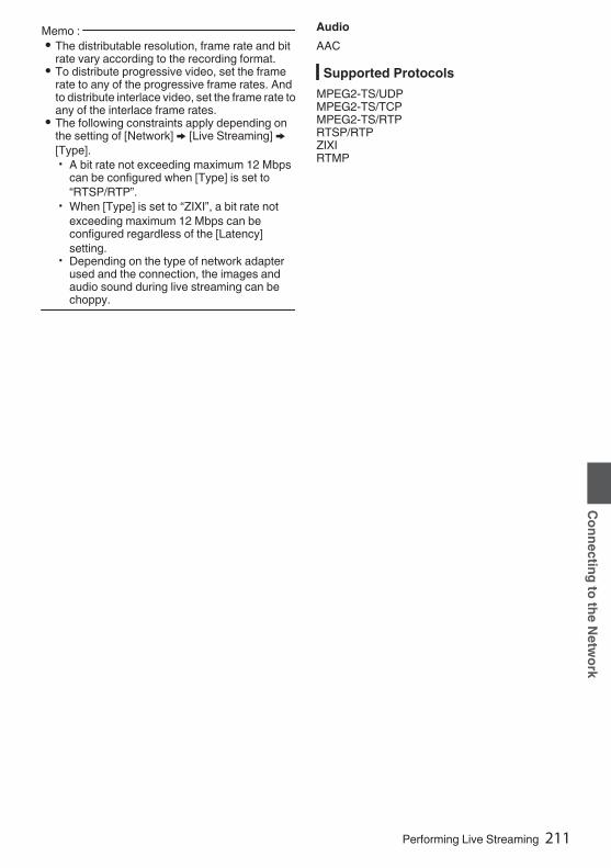
Memo : 0 The distributable resolution, frame rate and bit
rate vary according to the recording format.0 To distribute progressive video, set the frame
rate to any of the progressive frame rates. Andto distribute interlace video, set the frame rate toany of the interlace frame rates.
0 The following constraints apply depending onthe setting of [Network] B [Live Streaming] B[Type].0 A bit rate not exceeding maximum 12 Mbps
can be configured when [Type] is set to“RTSP/RTP”.
0 When [Type] is set to “ZIXI”, a bit rate notexceeding maximum 12 Mbps can beconfigured regardless of the [Latency]setting.
0 Depending on the type of network adapterused and the connection, the images andaudio sound during live streaming can bechoppy.
AudioAAC
Supported ProtocolsMPEG2-TS/UDPMPEG2-TS/TCPMPEG2-TS/RTPRTSP/RTPZIXIRTMP
Performing Live Streaming 211
Connecting to the Network
Setting Distribution1 Set the [Record Format] according to the
resolution and frame rate of the video to bedistributed.For details on the [Record Format] settings,please refer to [Distributable [Record Format]and [Live Streaming Set] Combinations] (A P 212).
Memo : 0 Live streaming cannot be performed in the
following cases.0 [System] B [Record Set] B [Record Format]B [System] set to “HD+Web”2 or “High-Speed”2.
0 When [System] B [Record Set] B [RecordFormat] B[WFrame Rate] is set to“24p”2
2 Set the Resolution and Frame & Bit Rate forthe video to be distributed.Specify the settings in [Network] B [LiveStreaming].(A P141 [Live Streaming Item] )
3 Specify the distribution protocol andrelated items.Specify the distribution protocol and relateditems in [Network] B [Live Streaming] B[Streaming Server].(A P141 [ Streaming Server ] )
4 Select the server for live streaming.Select the distribution server in [Network] B[Live Streaming] B [Server].
Distributable [Record Format] and [Live Streaming Set] Combinations
.
R R
R R
R
R
R
R
R
R
R
R
R
R
R
R
R
R
R
R
R
R
R
R
R
R
R R R R R R
R
R
R
R
R
R
R
R
R
RR
R
R
R
24 Mbps
60p, 50p1920 x 1080
60i, 50i, 30p, 25p 60p, 50p1280 x 720
30p, 25p
MPE
G2-
TS/U
DP
MPE
G2-
TS/T
CP
MPE
G2-
TS/R
TP
RTSP
ZIXI
RTM
P
MPE
G2-
TS/U
DP
MPE
G2-
TS/T
CP
MPE
G2-
TS/R
TP
RTSP
ZIXI
RTM
P
MPE
G2-
TS/U
DP
MPE
G2-
TS/T
CP
MPE
G2-
TS/R
TP
RTSP
ZIXI
RTM
P
MPE
G2-
TS/U
DP
MPE
G2-
TS/T
CP
MPE
G2-
TS/R
TP
RTSP
ZIXI
RTM
P
20 Mbps16 Mbps12 Mbps8 Mbps5 Mbps3 Mbps1.5 Mbps0.8 Mbps0.3 Mbps
Frame RateResolution
Type
Bitrate
* R: Distributable
212 Performing Live Streaming
Connecting to the Network

2
.
R
R
R
R
R
R
R
R
R
R
R
R
R
R
R
R
R
24 Mbps
60i or 50i720 x 480 or 720 x 576
60p, 50p 30p, 25p640 x 360
MPE
G2-
TS/U
DP
MPE
G2-
TS/T
CP
MPE
G2-
TS/R
TP
RTSP
ZIXI
RTM
P
MPE
G2-
TS/U
DP
MPE
G2-
TS/T
CP
MPE
G2-
TS/R
TP
RTSP
ZIXI
RTM
P
MPE
G2-
TS/U
DP
MPE
G2-
TS/T
CP
MPE
G2-
TS/R
TP
RTSP
ZIXI
RTM
P
20 Mbps16 Mbps12 Mbps8 Mbps5 Mbps3 Mbps1.5 Mbps0.8 Mbps0.3 Mbps
Frame RateResolution
Type
Bitrate
* R: Distributable
Performing Live Streaming 213
Connecting to the Network

Starting Distribution1 Perform the necessary setting for the
decoder and PC application.For details on the settings, please refer to the“INSTRUCTIONS” of the respective devicesand applications.
Memo : 0 If there is an NAT router within the
communication path between the camera andthe decoder, port forwarding setup is required.For details on the settings, please refer to the“INSTRUCTIONS” of the router in use.
0 The following parameters are required whenconnecting to this camera recorder using theRTSP/RTP.Port number: 554Stream ID: stream
0 Use the following to access via URL.rtsp://<IP address of the camera recorder>:554/stream
2 With the network connection established,set [Live Streaming] to “On”.(A P186 [Preparing Network Connection] )0 Set [Network] B [Live Streaming] B [Live
Streaming] to “On”.0 The network connection mark appears on the
display screen when a network connection isestablished.
(A P164 [Network Connection Icon] )
Memo : 0 You can also assign “Live Streaming” to a user
button.(A P45 [Assignment of Functions to UserButtons] )0 You can view the status of distribution on the
LCD monitor.(A P166 [Live streaming mark] )
Icon Status
.
(Red)
Distribution in progress (goodconnection quality)Blinks when distribution starts orstops
.
(Red)
Distribution in progress (poorconnection quality)
.
(Yellow)
Waiting for connection (duringRTSP/RTP) or connection failed
0 When the 5 icon is displayed, you can view thedetails of the error on the [Streaming] screen ofthe status screen.
.
Cause of Error
(A P221 [List of Live Streaming Error Displays] )Caution : 0 Streaming may be interrupted temporarily 24
hours after the process started.
214 Performing Live Streaming
Connecting to the Network

Setting the FEC Matrix 0Set the amount of FEC (Forward Error Correction)overhead for configuring SMPTE2022-1.1 Select [Network] B [Live Streaming] B
[Streaming Server] B [Server1] to [Server4]B [FEC Matrix] and press the Set button.The FEC adjustment screen appears.
.
2 Adjust the L and D values.Use the H/I buttons to adjust the L value, andthe J/K buttons to adjust the D value.The amount of FEC overhead changes whenthe L and D values are changed.To restore the L and D values to their defaultvalues, press the [USER3] button.
Memo : 0 Setting range
0 4 ≦ L ≦ 20 (Default value: L = 10)0 4 ≦ D ≦ 20 (Default value: D = 10)0 L × D ≦ 100 (Default value: L×D = 10×10)
3 Press the Set button (R).The screen returns to the streaming serversetting screen.
.
Memo : 0 Increasing the amount of FEC overhead
increases the packet loss resilience but morenetwork bandwidth is used.
0 Even with the same amount of overhead,increasing the L value will increase the packetloss (continuous packet loss) resilience.
Performing Live Streaming 215
Connecting to the Network

Return Video/Audio fromthe Network (Return overIP)0Return video/audio from the network can bedisplayed on the viewfinder or LCD monitor of thecamera or listened through a headphone.Memo : 0 This feature is only usable in the Camera mode.0 Start the encoder before activating Return over
IP. To end, turn off Return over IP before shuttingdown the encoder.
0 This feature is available when [System] B[Record Set] B [Record Format] B [System] isset to “HD” or “SD”2. When [WFrame Rate]is set to “24p”, this feature is not available.
Configuring the Return over IP ServerConfigure the Return over IP settings and establishthe connection before displaying the return video.1 Register the [Return Server].
Configure [Network] B [Return over IP] B[Server] to “Server”.Configure the individual settings in the [ReturnServer] item.
Memo : 0 For details on the registered information, please
consult the network administrator for the server.0 Configure “Icecast” to a setting other than
[Type].Operates as IFB when the setting is configuredto “Icecast”.
Return Video and Audio from theNetwork
1 Set the camera recorder to the Cameramode.(A P20 [Operation Modes] )
2 Assign the “Return Video” and “Returnover IP” features to any of the user buttons(A P45 [Assignment of Functions to UserButtons] )
Memo : 0 The “Return over IP” feature can also be
operated using “On”/“Off” under [Network] B[Return over IP] B [Return over IP].
3 Configure the input destination of thereturn video to “Network”To specify the input destination of the returnvideo, configure [A/V Set] B [Video Set] B[Return Input] to “Network”.(A P135 [ Return Input 0 ] )
Memo : 0 When [System] B [Record Set] B [Record
Format] B [System] is configured to “HD(SDIIn)” or “SD(SDI In)”2, “---” is displayed andthe setting cannot be configured.
4 Select the aspect ratio of the return video.Set using [A/V Set] B [Video Set] B [ReturnAspect].(A P135 [ Return Aspect ] )
5 Press the user button that is assigned withthe “Return over IP” function.When Return over IP is activated, the settingsin [A/V Set] B [Audio Set] B [IFB/RET Monitor]will be applied to the audio.(A P138 [ IFB/RET Monitor... 0 ] )
6 Select the way the return video is to bedisplayed.Select in [Camera Function] B [User SwitchSet] B [Return Video]. The camera will operateaccording to the setting.(A P114 [ Return Video ] )
7 Press the user button that is assigned withthe “Return Video” function.By pressing the user button assigned with the“Return Video” function, the captured image orreturn video is displayed according to themethod specified in step 6.
216 Return Video/Audio from the Network (Return over IP)0
Connecting to the Network

IFB (Return Audio)0Return audio from the network can be playedthrough a headphone.Memo : 0 This feature is only usable in the Camera mode.0 Start the encoder before activating Return over
IP. To end, turn off Return over IP before shuttingdown the encoder.
0 This feature is available when [System] B[Record Set] B [Record Format] B [System] isset to “HD” or “SD”2. When [WFrame Rate]is set to “24p”, this feature is not available.
Configuring the Return over IP ServerConfigure the Return over IP settings and establishthe connection before displaying the return video.1 Register the [Return Server].
Configure [Network] B [Return over IP] B[Server] to “Server”.Configure the individual settings in the [ReturnServer] item.
Memo : 0 For details on the registered information, please
consult the network administrator for the server.0 Configure “Icecast” to [Type].
Operates as IFB when the setting is configuredto “Icecast”.
Return Audio from the Network (IFB)1 Set the camera recorder to the Camera
mode.(A P20 [Operation Modes] )
2 Assign the “Return over IP” function to anyof the user buttons.(A P45 [Assignment of Functions to UserButtons] )
Memo : 0 The “Return over IP” feature can also be
operated using “On”/“Off” under [Network] B[Return over IP] B [Return over IP].
3 Configure the input destination of thereturn video to “Network”To specify the input destination of the returnvideo, configure [A/V Set] B [Video Set] B[Return Input] to “Network”.(A P135 [ Return Input 0 ] )
Memo : 0 When [System] B [Record Set] B [Record
Format] B [System] is configured to “HD(SDIIn)” or “SD(SDI In)”2, “---” is displayed andthe setting cannot be configured.
4 Press the user button that is assigned withthe “Return over IP” function.When Return over IP is activated, the settingsin [A/V Set] B [Audio Set] B [IFB/RET Monitor]will be applied to the audio.(A P138 [ IFB/RET Monitor... 0 ] )
IFB (Return Audio)0 217
Connecting to the Network

Error Messages and ActionsWarning display on the LCD monitor and viewfinder screen, tally lamp indication and warning tone are asfollows according to the error status.Memo : 0 This camera recorder makes use of a microcomputer. Noise interference from external sources may
prevent it from functioning properly. When this occurs, turn off and on the power of the camera recorderagain.
Error Message Status ActionTurn Power Off Turn Back OnLater
System error.* The warning tone sounds and the
tally lamp blinks twice everysecond.
Turn off the power, and turn it onagain.If the error persists, please contactthe local dealers in your area.
Fan Stop Detected PleaseTurn P.Off
0 The fan stopped running. Please contact the local dealers inyour area.
Fan Maintenance Required Usage time of the fan has exceeded9000 hours.
Check the fan and replaceaccordingly. For more details,please contact the local dealers inyour area.Memo : 0 You can check the usage time of
the fan in [System] B [SystemInformation] B [Fan Hour].
(A P150 [ Fan Hour ] )
Getting Overheated. PleaseTurn Power Off.
0 The battery has exceeded thespecified temperature.
0 The power turns offautomatically after about 15second.
0 Wait until the temperature dropsor replace the battery.
0 If the error persists, pleasecontact the local dealers in yourarea.
Rec Inhibited [REC] button is pressed when thewrite-protect switch of the SD cardis set.
Turn off the write-protect switch ofthe SD card, or insert a recordableSD card.
(A P47 [SD Card] )Lost Media Info * 0 Card is removed while recording
is in progress.0 Card is removed while
formatting is in progress.0 Card is removed while restoring
is in progress.0 Card is removed while adding
the OK mark.0 Card is removed while writing a
setup file.0 Card is removed while deleting a
clip.(*: A, B)
Restore the card using this camerarecorder.
(A P51 [Restoring the SD Card] )
218 Error Messages and Actions
Others

Error Message Status ActionRecord Format Incorrect 0 The video format of the file for
Clip Review is different from thecurrent [WResolution],[WFrame Rate], or [WBit Rate]setting.
Set [WResolution], [WFrame Rate]and [WBit Rate] correctly.
(A P152 [ W Resolution ] )(A P152 [ W Frame Rate ] )(A P153 [ W Bit Rate ] )
Media Full 0 [REC] button is pressed whenthe media in use has noremaining space.
0 Remaining space ran out duringrecording.
Replace the recording media with anew one.
No Clips No viewable clips are found on thecard for Clip Review.
Insert an SD card that contains clipsthat can be reviewed.
(A P47 [SD Card] )(A P84 [Viewing RecordedVideos Immediately (ClipReview)] )
No Media When the [REC] button is pressedwhile a recording media is notinserted.
Insert a recording media.(A P47 [SD Card] )
No Media No recording media is inserted whilein Media mode or when thethumbnail screen is displayed.
Insert a recording media.(A P47 [SD Card] )
No Clips No clips are found in the insertedrecording media while in Mediamode or when the thumbnail screenis displayed.
Insert a recording media thatcontains playable clips.
(A P47 [SD Card] )(A P95 [Playing RecordedClips] )
List of FTP Transfer ErrorsIf the upload of a recorded clip or download of the metadata setup file (XML format) is not successfullycompleted, the following errors are displayed.
Error message Status ActionTimeout. Transfer was discontinued due to
timeout caused by networktransmission or server failure.
0 Execute again.0 Use a different server.
Media Was Removed. Recording media is removed whileFTP transfer is in progress.
Insert the recording media andexecute FTP transfer again.
Adapter Was Removed. The USB network device isremoved while FTP transfer is inprogress.
Connect the USB network device.
Cannot Connect to Server. Unable to connect to the FTP server. Adjust the Server and Port settingsfor [Metadata Server] or [ClipServer].
(A P139 [ Metadata Server ] )(A P146 [ Clip Server ] )
Error Messages and Actions 219
Others

Error message Status ActionAccess Denied. Access is denied. Adjust the Server and Port settings
for [Metadata Server] or [ClipServer].
(A P139 [ Metadata Server ] )(A P146 [ Clip Server ] )
Invalid Username orPassword.
Authentication for login to the FTPserver failed.
Adjust the Username and Passwordsettings for [Metadata Server] or[Clip Server].
(A P139 [ Metadata Server ] )(A P146 [ Clip Server ] )
Invalid Path Was Requested. The path specified for the FTPserver is incorrect.
Adjust the [Clip Server] and [Dir.Path] settings for [MetadataServer] or [File Path].
(A P139 [ Metadata Server ] )(A P146 [ Clip Server ] )
Server Error. There was an unintended operationof the FTP server.
Execute again.Use a different server.
Invalid Request. A bad request is executed for theFTP server.
Execute again.
Invalid Data Size. Invalid data size, such as a planningmetadata size that exceeds 4 KB.
Adjust the planning metadata savedin the [Metadata Server].
(A P195 [ Planning Metadata ] )Invalid Data Format. The XML format of the planning
metadata is invalid.Adjust the planning metadata savedin the [Metadata Server].
(A P195 [ Planning Metadata ] )Transfer Error. Transfer failed due to
communication failure.Execute again.
Invalid URL. The path was deemed invalid by theFTP server.
Adjust the Server and Port settingsfor [Metadata Server] or [ClipServer].
(A P139 [ Metadata Server ] )(A P146 [ Clip Server ] )
Media Access Error. Reading/writing of the recordingmedia failed while FTP transfer is inprogress.
Use a different recording media.
Internal Error. An internal error has occurred whileFTP transfer is in progress.
Adjust the settings and executeagain.
Other Error. An unknown error or other errorshave occurred while FTP transfer isin progress.
Adjust the settings and executeagain.
Media Read Error. Reading of the recording mediafailed while FTP transfer is inprogress.
Use a different recording media.
220 Error Messages and Actions
Others

List of Live Streaming Error DisplaysThe following error messages are displayed when the live streaming setting is incorrect, or when theconnection is lost during live streaming.
Error message Status ActionInvalid Address 0 The IP address format is
incorrect.0 The domain name cannot be
converted into the IP address.
0 Enter the IP address, host nameor URL of the destinationcorrectly.
(A P212 [Setting Distribution] )Multicast Is Not Supported An IP multicast address was set. Use an IP address that is not a
multicast address.Cannot Connect to Receiver Establishment of connection with
TCP failed.0 Ensure that the recipient’s
device is set to TCP.0 Set Type to “MPEG2-TS/UDP”.
(A P212 [Setting Distribution] )TCP Disconnected TCP connection is lost. Check to ensure that there is no
abnormality in the decoder, ornetwork connection device andcables, followed by establishing theconnection again.
Not Enough Bandwidth 0 The communication bandwidthis narrower than the average bitrate.
0 The network bandwidth isinsufficient, and packets arediscarded.
0 Lower the resolution/picturequality of the video to bedistributed.
0 Consider switching to the use ofa stable network, such as wiredLAN.
Connection Timeout Timeout for connection via ZIXI. Set [Destination Address] and[Destination Port] correctly.
(A P212 [Setting Distribution] )Authorization Failed Authentication of connection via
ZIXI failed.Set [Stream ID] and [Password]correctly.
(A P212 [Setting Distribution] )Connection Error Connection via “ZIXI” or “RTMP”
failed.0 Check whether a different
camera with an identical streamID is connected.
0 Set [Destination URL] and[Stream Key] correctly.
(A P142 [ Destination URL ] )(A P142 [ Stream Key ] )
Disconnected “ZIXI” or “RTMP” connection is lost. Check whether there is abnormalitywith the network connection device,cables, etc., and try to re-establishthe connection.
Error Messages and Actions 221
Others

Blinking of the Tally LampThe tally lamp starts blinking when the remaining space on the recording media is running out duringrecording or when the battery power is running low.
Blinking Mode Remaining Battery Power/SD Card SpaceBlinks slowly
(once every second)0 Battery power is low0 Remaining recording time on recording media is less than 3 minutes
(during recording)0 When a malfunction occurred during live streaming
Blinks quickly(2 times per second)
0 Remaining battery power is almost zero0 Remaining recording time on recording media has reached 0 minutes
(during recording)0 Error on the camera recorder
Warning Tone0 Warning tone is output from the speaker and [PHONE] terminal when the battery level is low.
Warning tone is also output when an error occurs in the camera recorder.Memo : 0 Whether the sound is to be muted or output when it is at the minimum level can be configured in [Min.
ALARM Level].(A P137 [ Min. ALARM Level ] )
222 Error Messages and Actions
Others

TroubleshootingSymptom Action
Power does not turn on. 0 Is the AC adapter properly connected?0 Is the battery charged?0 Is the power turned on immediately after it is turned off?
Make sure to wait for an interval of at least 5 seconds before turningon the power again.
Unable to start recording. 0 Is the write-protect switch of the SD card turned on?Make sure that the write-protect switch is turned off.
(A P48 [Write-Protect Switch on the SD Card] )0 Is the camera recorder set to the Camera mode?
Use the [CAM/MEDIA] selection button to switch to the Camera mode.(A P20 [Operation Modes] )0 Is the SD card inserted compatible with the recording format?
(A P56 [Selecting a Video Format] )(A P155 [ 4GB File Spanning(SDXC) ] )
Camera image is not output onthe LCD monitor andviewfinder screen.
0 Is the camera recorder set to the Camera mode?Use the [CAM/MEDIA] selection button to switch to the Camera mode.
(A P20 [Operation Modes] )Camera image is not output onthe LCD monitor.
0 Is the LCD backlight set to “Off”?Press the [B.LIGHT] button to switch the mode.
(A P42 [Adjusting the LCD Monitor] )Camera image is not output onthe viewfinder screen.
0 Is the CONTRAST knob on the viewfinder set to the minimum?Adjust the [CONTRAST] knob on the viewfinder.
(A P42 [Adjusting the Viewfinder] )Playback does not start afterselecting a clip thumbnail andpressing the [STATUS/SET]button (R).
0 Is the selected clip a playable clip?Playback is not possible if the clip has a different video format setting.
Images on the LCD monitorand viewfinder screen appeardark or blurred.
0 Readjust the brightness of the LCD monitor and viewfinder.0 Is the [ND FILTER] switch set to “1/64”?0 Is the iris closed?0 Is the shutter speed setting too high?0 Is the peaking level too low?
For the LCD monitor, adjust the outline with [LCD/VF] B [LCDPeaking].For the viewfinder, adjust the outline with the [PEAKING] knob on theviewfinder. u v
(A P42 [Adjusting the LCD Monitor] )(A P42 [Adjusting the Viewfinder] )
Troubleshooting 223
Others

Symptom ActionThe [CH-1/CH-2] recordinglevel adjustment knob doesnot work.
0 Is the [AUDIO SELECT CH1/2]-[MANUAL/AUTO] selection switch setto “AUTO”?
0 Is Full Auto enabled?Is [Camera Function] B [Full Auto] B [Audio] set to “Auto” in Full Automode?
(A P115 [Full Auto Item] )[CH-3/CH-4] audio is notrecorded.
0 Is the number of recording channels set to “4ch”?Set [System] B [Record Set] B [WAudio]/[YAudio] to “4ch”.
(A P153 [ W Audio ] )Microphone audio cannot beheard through the headphone.
0 Is the audio setting configured to “IFB/RET Only”?Set [A/V Set] B [Audio Set] B [IFB/RET Monitor] to “Off”.
(A P138 [ IFB/RET Monitor... 0 ] )SD card cannot be initialized(formatted).
0 Is the write-protect switch of the SD card turned on?Make sure that the write-protect switch is turned off.
(A P48 [Write-Protect Switch on the SD Card] )Battery alarm appears evenafter loading a chargedbattery.
0 Is the battery too old?
The time code and user’s bitare not displayed.
0 Even in Camera mode or Media mode, the time code and user’s bitmay not be displayed depending to the type of display.
0 Is [LCD/VF] B [Display On/Off] B [TC/UB] set to “Off”? To display thedate and time, set it to “On”.
(A P130 [Display On/Off Item] )The time is not displayed. 0 The time is only displayed on the display screen in the Camera mode
(during shooting).(A P161 [Display Screen in Camera Mode] )0 Is [System] B [Record Set] B [Time Stamp] set to “On”? To display
the date and time, set it to “Off”.(A P156 [ Time Stamp ] )
The actual recording time isshorter than the estimatedtime.
0 The recordable time may be shorter depending on the shootingconditions or the subject.
The two camera recorders arenot synchronized even thoughthe time codes have beensynchronized. (Z on the Slavedevice is not displayed.)
0 Is the [TC GEN] switch set to “F-RUN”?(A P78 [Synchronizing the Time Code with an External Time CodeGenerator] )0 Set [System] B [Record Set] B [Record Format] B [WFrame Rate]
such that the two camera recorders have the same frame rate.(A P152 [ W Frame Rate ] )
Cannot connect to wirelessLAN.
0 Check the mode of connection and method of setting ([SSID] and[Passphrase] in cases other than WPS).
(A P187 [Connecting to Network via [HOST] Terminal (USB) 0] )(A P188 [Connecting to Network via Built-in Wireless LAN u v0] )0 Even if the Passphrase is wrong, “Completed the Setup Wizard.
Please Input the Passphrase into Your Device.” may appear at thebrowser setting depending on the type of encryption.Adjust [Passphrase] again.
0 Set [Network] B [Connection Setup] B [Default Gateway] to a valueother than “LAN”.
(A P140 [ Default Gateway ] )
224 Troubleshooting
Others
Symptom ActionThe View Remote screen turnsblack.The screen flickers.The screen freezes.Cannot perform remoteoperation.
0 The network path is congested.Wait a while before refreshing (reloading) the web browser.
0 Clear the cache in your Web browser.
The clips cannot be uploadedto the FTP server.
0 Adjust the [Clip Server] settings.(A P146 [ Clip Server ] )0 If a file size limit is set in the FTP server, set the size limit such that it
is larger than the maximum size of the recorded clip.0 Take necessary action as described in “[List of FTP Transfer Errors]
(A P 219)”.The wireless LAN isdisconnected.
0 The wireless LAN may be disconnected depending on theenvironment. Change the usage environment.
0 Connect via wired LAN.(A P186 [Connecting to Network via [LAN] Terminal 0] )
The images and audio soundduring live streaming arechoppy.
0 Depending on the connection method to the network and connectionenvironment, streaming may not be possible with the encoding bit ratespecified. Please reduce the encoding bit rate.
GPS signal cannot bereceived. u v
0 Signal reception from GPS satellites may be affected by buildings ortrees.Perform positioning preferably at an unobstructed location with a clearview.
0 Radio wave reception may be affected by weather conditions such ason a cloudy or rainy day.
The position is not accurate.u v
0 The precision error may be up to hundreds of meters if the GPS signalis weak or reflected off surrounding buildings.
Troubleshooting 225
Others

SpecificationsGeneral
Item DescriptionPower When using an external power source:
DC 11.0 V to 17.0 VWhen using a battery:DC 14.4 V (Anton/Bauer, IDX)
Powerconsumption
Approx. 38 W(during single recording atfactory default settings whileusing the viewfinder)Approx. 33 W(When using only the camerabody during single recording atfactory default settings)
Mass u : Approx. 5.1 kg (*1)v : Approx. 5.2 kg (*1)w : Approx. 4.3 kg (*2)x : Approx. 4.4 kg (*2)
Allowable operatingtemperature
0 ℃ to 40 ℃ (32 °F to 104 °F)
Allowable operatinghumidity
30 %RH to 80 %RH
Allowable storagetemperature
-20 ℃ to 50 ℃ (-4 °F to 122 °F)
Drip-proofperformance
Equivalent to IPX2
Built-in wirelessLANu v
IEEE802.11a/b/g/n/ac(2.4 GHz/5 GHz band)Encryption method: WPA2
u 2.4 GHz Ch1, 2, 3, 4, 5, 6, 7, 8, 9, 10, 115 GHzUSA
Ch36, 40, 44, 48, 52, 56, 60, 64,100, 104, 108, 112, 116, 120,124, 128, 132, 136, 140, 149,153, 157, 161, 165
5 GHzCANADA
Ch36, 40, 44, 48, 52, 56, 60, 64,100, 104, 108, 112, 116, 132,136, 140, 149, 153, 157, 161,165
v 2.4 GHz Ch1, 2, 3, 4, 5, 6, 7, 8, 9, 10, 11,12, 13
5 GHzOutsideRussia
Ch36, 40, 44, 48, 52, 56, 60, 64,100, 104, 108, 112, 116, 120,124, 128, 132, 136, 140
5 GHzRussia
Ch36, 40, 44, 48, 52, 56, 60, 64,132, 136, 140, 149, 153, 157,161, 165
*1 Camera body and Viewfinder*2 Camera body only
Terminal SectionVideo/Audio
Item Description[HD/SD SDI IN] terminal 3G-SDI,
HD-SDICompliant with SMPTE ST424,Compliant with SMPTE ST292
3G-SDI,HD-SDIEmbeddedaudiostandard
Compliant with SMPTE ST299,Compliant with SMPTE ST299
[HD/SD SDI OUT 1/2] terminal (480i or 576i: Downconverted720p/1080i/1080p: embedded audio), BNC (unbalanced) 3G-SDI,
HD-SDI,SD-SDI
Compliant with SMPTE ST424,Compliant with SMPTE ST292,Compliant with SMPTE ST259
3G-SDI,HD-SDI,SD-SDIEmbeddedaudiostandard
Compliant with SMPTE ST299,Compliant with SMPTE ST299,Compliant with SMPTE ST272
[HDMI] outputterminal
Type A
[VIDEO OUT]terminal (BNC)
Composite Video1.0 V (p-p), 75 K (unbalanced)
[VF] terminal 26-pin[MIC IN] terminal(XLR 5-pin)
-50 dBu, 4 kK, XLR (balanced),+48 V output (phantom powersupply)
[AUDIO INPUT1/INPUT2] terminal (XLR 3-pin) [MIC] -60 dBu, 4 kK, XLR (balanced),
+48 V output (phantom powersupply)
[LINE] +4 dBu, 10 kK, XLR (balanced)[AUDIO OUT]terminal(XLR 5-pin)
0 dBu, 100 K, XLR (balanced)
[PHONE]terminal
Φ3.5 mm stereo mini jack
226 Specifications
Others

OthersItem Description
[LAN] terminal(RJ-45)
100BASE-TX/1000BASE-T
[HOST] terminal USB-A type, networkconnection function only
[REMOTE]terminal
miniDin 6-pin
[TC IN] terminal 1.0 V(p-p) to 4.0 V(p-p) highimpedance
[TC OUT]terminal
2.0 ± 1.0 V (p-p) low impedance
[LENS] terminal 12pin[DC INPUT]terminal
XLR 4-pin
[DC OUT]terminal (rear)
4-pin, DC 11.0 V to 17.0 V, 1.8 Au w x4-pin, DC 11.0 V to 17.0 V, 1.5 Av
[DC OUT] (LAN)terminal
4-pin, DC 11.0 V to 17.0 V, 0.5 Au w x4-pin, DC 11.0 V to 17.0 V, 0.2 Av
[LIGHT] terminal D-tap (DC 12 V, max. 50 W uw x)(DC 12 V, 2 A v)
[GENLOCK]terminal
1.0 V (p-p), 75 K
Wireless audioslot
UniSlot2ch, -40 dBu (balanced)
Expansion slot For future expansion
Camera SectionItem Description
Image pickupdevice
2/3-inch, 2.2 megapixels,progressive CMOS x 3
Lens Mount 2/3-inch B4 Bayonet mountsystem
Color separationprism
F1.4, 3-color separation prism
Sensitivity F12, 2000 lx (standard value: 60Hz)
Sync system External/InternalSynchronization (Built-in SSG)
ND filter CLEAR, 1/4, 1/16, 1/64Gain -6 dB, -3 dB, 0 dB, 3 dB, 6 dB, 9
dB, 12 dB, 15 dB, 18 dB, 21 dB,24 dB, 27 dB, 30 dB, Lolux (24dB, 30 dB, 36 dB,42 dB), AGC
Electronicshutter
1/3 to 1/10000, EEI
LCD Monitor 3.5-inch LCD QHD (960 × 540)Viewfinder uv
3.26-inch OLED WVGA (854 ×480)
Storage SectionItem Description
Supportedmedia
SDHC/SDXC
Slots x 2
Specifications 227
Others
Video/AudioItem DescriptionHD mode (MOV/MXF: MPEG-2) Recording file
formatQuickTime File Format (MOV),MXF File Format (MXF)0
Video HQ mode MPEG-2 Long GOP VBR, 35
Mbps (Max) MP@HL,1920x1080/59.94i, 29.97p, 50i,25p1440x1080/59.94i, 50i1280x720/59.94p, 50p
SP mode MPEG-2 Long GOP CBR, 25Mbps (Max) MP@H141440×1080/59.94i, 50i
Audio LPCM 2ch/4ch, 48 kHz/16 BitHD mode (MOV: H.264) Recording file
formatQuickTime File Format
Video
XHQ ModeMPEG-4 AVC/H.264, 70 Mbps(Max) 01920×1080/59.94p, 50pMPEG-4 AVC/H.264, 50 Mbps(Max) 1920×1080/59.94p,59.94i,29.97p, 23.98p2,50p, 50i, 25p1280×720/59.94p, 50p
XHQ Mode MPEG-4 AVC/H.264, 50 Mbps(Max)1920×1080/59.94p, 59.94i,29.97p, 23.98p2, 50p, 50i,25p
UHQ Mode MPEG-4 AVC/H.264, 35 Mbps(Max)1920×1080/59.94i, 29.97p,23.98p2, 50i, 25p1280×720/59.94p, 50p
Audio LPCM 2ch/4ch, 48 kHz/16 Bit,24 Bit (422 10 bit only)
Item DescriptionHD mode (Exchange (U model) / MP4 (E model):H.264) 0 Recording file
formatMP4 File Format
Video LP mode MPEG-4 AVC/H.264, 12 Mbps
(Max)1920x1080/59.94p (U model),1920x1080/50p (E model),MPEG-4 AVC/H.264, 8 Mbps(Max)1280x720/59.94p (U model)1280x720/50p (E model)
Audio AAC 2ch, 48 kHz/16 Bit 128kbps
HD mode (High-Speed) 2 Recording file
formatQuickTime File Format
Video
XHQ ModeMPEG-4 AVC/H.264, 70 Mbps(Max), 1920×1080119.88/59.94p, 100/50pMPEG-4 AVC/H.264, 50 Mbps(Max), 1920×1080119.88/59.94p, 100/50p,119.88/29.97p, 100/25p,119.88/23.98p
XHQ Mode MPEG-4 AVC/H.264, 50 Mbps(Max), 1920×1080119.88/59.94p, 100/50p,119.88/29.97p, 100/25p,119.88/23.98p
UHQ Mode MPEG-4 AVC/H.264, 35 Mbps(Max), 1920×1080119.88/29.97p, 100/25p,119.88/23.98p
Audio LPCM 2ch, 48 kHz/16 Bit, 24 Bit(422 10 bit only)
228 Specifications
Others

Item DescriptionSD mode (MOV: H.264) 2 Recording file
formatQuickTime File Format
Video MPEG-4 AVC/H.264, 8 Mbps(Max)720×480/59.94i (U model)720×576/50i (E model)
Audio LPCM 2ch, 48 kHz/16bitWeb mode (MOV: H.264) 2 Recording file
formatQuickTime File Format
Video HQ mode MPEG-4 AVC/H.264, 8 Mbps
(Max)720x480/59.94i, 720x576/50iMPEG-4 AVC/H.264, 3 Mbps(Max)960x540/29.97p, 25p, 23.98p
LP mode MPEG-4 AVC/H.264, 1.2 Mbps(Max)480x270/29.97p, 25p, 23.98p
Audio LPCM 2ch/4ch, 48 kHz/16 Bit(720x480, 720x576)μ-law 2ch/4ch, 16 kHz(960x540, 480x270)
Streaming ModeVideo MPEG-4 AVC/H.264
1920x1080/59.94p, 50p24/20/16/12/8 Mbps (Max)1920x1080/59.94i, 50i, 29.97p,25p20/16/12/8/5/3 Mbps (Max)1280x720/59.94p, 50p20/16/12/8/5/3 Mbps (Max)1280x720/29.97p, 25p8/5/3/1.5 Mbps (Max)2720x480/59.94i (U model)720x576/50i (E model)8/5/3/1.5/0.8/0.3 Mbps (Max)640x360/59.94p, 50p3/1.5 Mbps (Max)640x360/29.97p, 25p3/1.5/0.8/0.3 Mbps (Max)
Audio AAC 2ch, 128/64 kbps
AccessoriesAccessories
Warranty Card u w 1INSTRUCTIONS (BASIC) 1Electronic Viewfinder u v 1Cold Shoe Unit 1Screw (M2) 4Wireless LAN Antenna u v 2Core filter (large x 1, small x 1)v 2* Eyepiece and body cap are attached to the
camera recorder.
Specifications 229
Others

Dimensional Outline Drawing (Unit: mm)Wireless LAN antenna and viewfinder are not included in GY-HC900STU and GY-HC900RCHE.For U Model
.
10440
137.5(137.5)
96
20(VF MOVE)
(S.PAD MOVE)
(VF
MOVE
)
265244
359
319
69
137
50
93.5
251276
207
102.
4
For E Model
.
10440
137.5(137.5)
96
20(VF MOVE)
(S.PAD MOVE)
(VF
MOVE
)
265244
371
319
69
137
50
93.5
251276
207
102.
4
* The specifications and appearance of this product are subject to changes for further improvementwithout prior notice.
230 Specifications
Others

AppendixTone Mapping Characteristics for Converting HLG to ITU709 for LCD/VF
.
*1*2
*3
*5
*6
*4
0
10
20
30
40
50
60
70
80
90
100
110
0 0.1 0.2 0.3 0.4 0.5 0.6 0.7 0.8 0.9 1INPUT
OUT
PUT
(IRE)
hlg50%white + KNEE60%white +_KNEE72.5%_white + knee75%_white + knee80%_white + kneeITU709_50%ITU709_60%ITU709_72.5%ITU709_75%ITU709_80%WHITE POINT
50%
60%
72.5%75%
80%
50%ITU709
60%ITU709
72.5%ITU709
75%ITU709
80%ITU709
*1 HLG*2 White Level
80% converted*3 White Level
75% converted*4 White Level
72.5% converted*5 White Level
60% converted*6 White Level
50% converted
Appendix 231
Others

IndexA AC adapter .......................................... 33, 34
Action ........................................................ 97Aspect ratio ................................................ 57
B Backup rec ................................................ 88Battery ................................................. 17, 34Brightness adjustment ............................... 59
C Camera control function ........................... 202Camera mode .............................. 21, 40, 161Clip continuous rec .................................... 91Clip cutter trig (splitting clips) ..................... 94Clip name ............................................. 52, 96Clip review ................................................. 84Color bar .................................................. 172Color matrix ............................................. 174Connection settings file ............................ 207Continuous operating time ......................... 34
D Deleting clips ........................................... 100Display screen ........................... 40, 161, 167Dual rec ..................................................... 86
E Electronic shutter ....................................... 62Error message ................................... 66, 218Expanded focus ......................................... 58External monitor ....................................... 179
F Favorites menu ........................................ 157FAW (Full Auto White Balance) . 63, 110, 113FEC Matrix ............................................... 215File format .................................................. 55Focus ......................................................... 58Focus assist ............................................... 58Formatting (initializing) SD cards ............... 50Frame rec .................................................. 92FTP Resume ............................................ 194FTP server ................................. 98, 189, 191
G Gain adjustment ........................................ 61Genlock ................................................... 182GPS ................................................... 83, 148
H Headphone .............................................. 181Histogram .......................................... 85, 127
I Initial settings ............................................. 38Interval rec ................................................. 93Iris adjustment ........................................... 60
L LCD monitor ............................. 17, 36, 40, 42Live streaming ......................................... 210
M Marker display ......................................... 172Media mode ................................. 21, 40, 167Menu ........................................ 105, 106, 108Metadata .......................................... 189, 195
N ND filter ...................................................... 22Network ........................................... 139, 185Network operating environment ............... 186
O OK mark .................................................. 101Operation lock ........................................... 53
P Picture quality setting ................................. 69Power .................................................. 36, 37Pre rec ....................................................... 90
R Recordable time ........................................ 47Remote edit mode ............................... 21, 41Resolution .................................................. 55Restoring SD card ..................................... 51Return Audio ............................................ 217Return over IP .................................. 143, 216Return Videos .......... 114, 135, 135, 184, 217
S Safety zone display .................................. 172SD/SDHC/SDXC card ......................... 18, 47SDI ........................................................... 179Selecting multiple clips ............................ 102Series rec .................................................. 86Setting the date/time .................................. 39Setup file .................................................. 176Shooting .................................................... 54Software keyboard ................................... 107Spot meter ................................................. 81Status screen ..................................... 41, 170Switching shutter speed ............................ 62
T Tally lamp .......................................... 46, 222Thumbnail (detailed screen) ...................... 97Thumbnail (standard screen) ..................... 95Thumbnail screen ...................................... 95Time code ............................................ 73, 74Time code generator ................................. 74Time code playback ................................... 99Trimming .................................................. 104
U User button ................................................ 45User’s bit .................................................... 73
V Video format .............................................. 55View remote ............................................. 202Viewfinder ................................ 17, 36, 40, 42
232 Index
Others

W Warning ............................................. 41, 222Web browser ............................ 195, 199, 204White balance adjustment ......................... 63White paint ................................................. 66Wired LAN ............................................... 186Wireless LAN ............................. 32, 187, 188Wizard .............................. 140, 186, 187, 188
Z Zebra pattern ............................................. 80Zoom ......................................................... 57
Index 233
Others

Software LicenseAgreementThe software embedded in the Product (hereinafterthe “Licensed Software”) provided byJVC KENWOOD Corporation (hereinafter the“Licensor”) is copyrighted to or sublicensable by theLicensor, and this Agreement provides for the termsand conditions which Users shall follow in order touse the Licensed Software. The User shall use theLicensed Software by agreeing with the terms of thisSoftware License Agreement. This Agreement shallbe deemed completed at the time the User(hereinafter the “User”) initially used the Product inwhich the “Licensed Software” is embedded.The Licensed Software may include the softwarewhich has been licensed to the Licensor directly orindirectly from any third party. In such case, somethird parties require the Users to follow theirconditions for use separately from this SoftwareLicense Agreement. Such software shall not besubject to this Agreement, and the Users are urgedto read the “[Important Notice concerning theSoftware] (A P 235)” to be provided separately.Article 1 General ProvisionThe Licensor shall grant to the User a non-exclusiveand non-transferable (other than the exceptionalcase referred to in Article 3, Paragraph 1) licensedto use the Licensed Software within the country ofthe User (the country where the User bought theProduct (hereinafter the “Country”)).Article 2 License1. The license granted under this Agreement shall bethe right to use the Licensed Software in the Product.2. The User shall not duplicate, copy, modify, add,translate or otherwise alter, or lease the LicensedSoftware and any related documents, whether inwhole or in part.3. The use of the Licensed Software shall be limitedto personal purpose, and the Licensed Softwareshall not be distributed, licensed or sub-licensedwhether it is for commercial purpose or not.4. The User shall use the Licensed Softwareaccording to the directions described in theoperation manual or help file, and is prohibited to useor duplicate any data in a manner violating theCopyright Law or any other laws and regulations byapplying whole or a part of the Licensed Software.Article 3 Conditions for Grant of License1. When the User transfers the Product, it may alsotransfer the license to use the Licensed Softwareembedded in the Product (including any relatedmaterials, updates and upgrades) on condition thatno original, copies or related materials continue inthe possession of the User, and that the User shallcause the transferee to comply with this SoftwareLicense Agreement.2. The User shall not carry out reverse engineering,disassembling, decompiling or any other codeanalysis works in connection with the LicensedSoftware.
Article 4 Right pertaining to the LicensedSoftware1. Any and all copyrights and other rights pertainingto the Licensed Software and related documentsshall belong to the Licensor or the original holder ofthe right who granted to the Licensor the license orsublicense for the Licensed Software (hereinafterthe “Original Rightholder”), and the User shall not beentitled to any right other than the license grantedhereunder, in respect of the Licensed Software andany related documents.2. The User shall, whenever the User uses theLicensed Software, comply with any laws relating tothe copyright and other intellectual property rights.Article 5 Indemnification of Licensor1. Neither the Licensor nor the Original Rightholdershall be liable for any damage incurred by the Useror any third party due to the exercise of the licensegranted to the User under this Agreement, unlessotherwise restricted by law.2. The Licensor will offer no guarantee for themerchantability, convertibility and consistency withcertain objective of the Licensed Software.Article 6 Liability to Third PartyIf any dispute has arisen with any third party due toan infringement upon a copyright, patent or any otherintellectual property right that was caused by theUser’s use of the Licensed Software, the User shallsettle such dispute at the User’s own cost and holdthe Licensor and the Original Rightholder harmlessfrom any inconvenience it may cause.Article 7 ConfidentialityThe User shall keep the confidentiality of suchportion of the Licensed Software, related documentsthereof or any other information to be granted underthis Agreement, as well as the conditions of thisAgreement as has not yet entered the public domain,and shall not disclose or divulge the same to any thirdparty without approval of the Licensor.Article 8 TerminationIn case the User falls under any of the eventsdescribed in the following items, the Licensor mayimmediately terminate this Agreement or claim thatthe User compensates for the damage incurred bythe Licensor due to such event:(1) when the User violated any provision of thisAgreement; or(2) when a petition has been filed against the Userfor an attachment, provisional attachment,provisional disposition or any other compulsoryexecution.
234 Software License Agreement
Others

Article 9 Destruction of the Licensed SoftwareIf this Agreement is terminated pursuant to theprovision of Article 8, the User shall destroy theLicensed Software, any related documents andcopies thereof within two (2) weeks from such dateof termination.Article 10 Export Restriction1. The User shall understand that the LicensedSoftware shall be subject to the export restrictionsadopted by the country of User and any othercountries.2. The User shall agree that the software will besubject to any and all applicable international anddomestic laws including the export control regulationof the country of User and any other countries, andany restrictions concerning the end-users, the useby end-users and importing countries to be providedby the country of User and any other countries, andany other governmental authorities.3. If the User is an agency of the United States ofAmerica (the “Government”), the User acknowledgeLicensor’s representation that the LicensedSoftware is a “Commercial Item” as defined inFederal Acquisition Regulation (FAR) part 2.101(g)consisting unpublished “Commercial ComputerSoftware” as those items are used at FAR part12.212 and is only license the User with the sameuse right Licensor grants all commercial end userspursuant to the terms of this Agreement.Article 11 Miscellaneous1. In the event any part of this Agreement isinvalidated by operation of law, the residualprovisions shall continue in force.2. Matters not stipulated in this Agreement or anyambiguity or question raised in the construction ofthis Agreement shall be provided or settled upongood-faith consultation between the Licensor andthe User.3. The Licensor and the User hereby agree that thisAgreement is governed by the laws of Japan, andany dispute arising from, and relating to the rightsand obligations under, this Agreement shall besubmitted to the exclusive jurisdiction of the TokyoDistrict Court for its first instance.
Important Noticeconcerning the SoftwareSoftware License Attached to the Product :The Software embedded in the Product is composedof several independent software components, and ineach of such individual components (hereinafter the“Licensed Software”), a copyright of eitherJVC KENWOOD Corporation (hereinafter “JKC”) ora third party subsists.The Product uses the software componentdesignated in the End-User License Agreement thatwas executed between JKC and a third party(hereinafter “EULA”).
The Licensed Software covers those correspondingto free software, and, as a condition of distribution ofthe software component in executable format whichis based on the license granted under the GNUGeneral Public License or Lesser General PublicLicense (hereinafter “GPL/LGPL”), it requires anavailability of the source code for the relevantcomponent. Please refer to the following URLconcerning the distribution of the source code;
https://www3.jvckenwood.com/english/download/gpl/index.html
Please note that we are unable to answer any inquiryrelating to the contents, etc. of the source code. Inaddition, the Licensed Software includes thesoftware developed or created independently byJKC and there exists an ownership of JKC in suchsoftware and any accompanying documents, whichis protected by the Copyright Law, any internationaltreaties and other applicable laws. As to mattersconcerning the handling by JKC of the softwarecomponents, please refer to the “Software LicenseAgreement” attached hereto. Please note that anysoftware component licensed under “EULA” whichis not subject to “GPL/LGPL”, and those developedor created independently by JKC shall not be subjectto the requirement for provision of the source code.The software component distributed under “GPL/LGPL” shall be licensed to users without charge,and, therefore, no warranty is given for such softwarecomponent, either express or implied, within thescope of the applicable laws and regulations. Unlessotherwise permitted by applicable laws andregulations or agreed in written form, none of theowners of the copyright or persons entitled to alter orredistribute the software component under the saidlicense shall have any liability for any type of damageor loss resulting from the use of or inability to usesuch software component. For further details of theconditions of use of such software component ormatters required to be complied with, please refer tothe relevant “GPL/LGPL”.Users are urged to read the details for the relevantlicense carefully before using the softwarecomponent covered by “GPL/LGPL” and embeddedin the Product. Since the terms and conditions ofindividual licenses are provided by parties other thanJKC, the original English version will be displayed bythe Product. A Turn on the power.B Press the [MENU/THUMB] button.C Select [System] B [System Information] B [Open
Source License].
Software License Agreement 235
Others

.
GY-HC900CHU/GY-HC900CHE GY-HC900STU/GY-HC900RCHE HD MEMORY CARD CAMERA RECORDER
© 2019 JVC KENWOOD Corporation B5A-2755-00