GUIDELINES &CASE STUDIES | Europeana Pro
59
GUIDELINES & CASE STUDIES
-
Upload
khangminh22 -
Category
Documents
-
view
4 -
download
0
Transcript of GUIDELINES &CASE STUDIES | Europeana Pro
44
GUIDELINES & CASE STUDIESGUIDELINES & CASE STUDIES
44 44
GUIDELINES & CASE STUDIES
First published in 2014 by 3D-ICONS
3D-ICONS is a pilot project funded under the European Commission’s
ICT Policy Support Programme
©3D-ICONS
Design and layout by: Ian McCarthy
Printed in Ireland by: Paceprint, Shaws Lane, Sandymount, Dublin 4, Ireland
3D-ICONS is a project funded under the European Commission’s ICT Policy Support Programme,
project no. 297194. The views and opinions expressed in this presentation are the sole responsibility
of the authors and do not necessarily re�et the views of the European Commission.
44 44
Metadata 36
CARARE 2.0 Metadata Schema 37
Resources for CARARE Metadata Creation 40
Relating Metadata to Europeana 43
LICENSING & IPR Considerations 44
IPR & the 3D pipeline 45
Access Agreement 46
CREATIVE COMMONS 48
3D-ICOns Case studies 50
Introduction 50
Monuments 56
Architectural features 88
Artefacts 102
Appendix 1: Additional 3D-ICONS Publications 112
Appendix 2: Project Partners 114
Introduction 06
Guidelines 08
3D Data Capture Techniques 10
Short range techniques 11
Long & mid range techniques 13
Multi Scale Image Based Methods 14
Post Processing of 3D Content 18
Post-Process A - Geometric reconstruction 18
Post-Process B - Model structuring 23
Post Process C - Visual enrichment of 3D models 24
Post Process D - Hypothetical reconstruction 25
Creating complementary 2D media (derived from the 3D model) 26
3D Publishing Methodology 28
Online publication technologies 29
IPR Considerations 35
CONTENTS
44 44
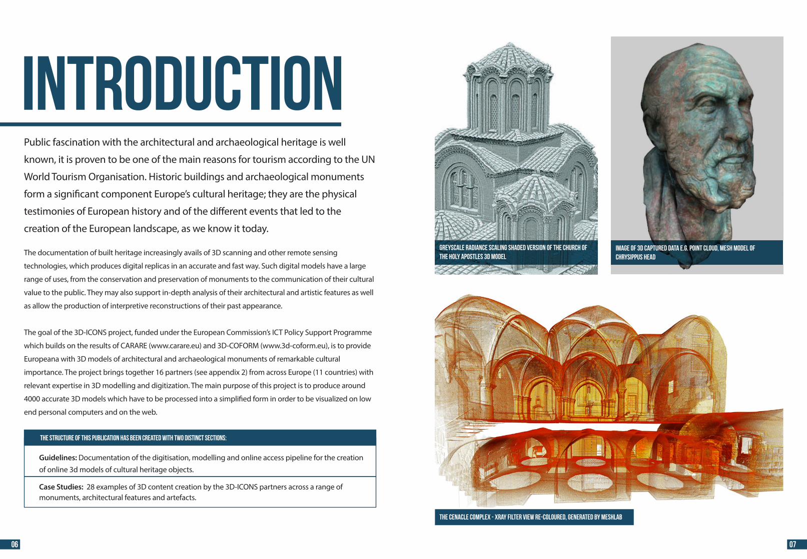
IntroductionPublic fascination with the architectural and archaeological heritage is well
known, it is proven to be one of the main reasons for tourism according to the UN
World Tourism Organisation. Historic buildings and archaeological monuments
form a signi�cant component Europe’s cultural heritage; they are the physical
testimonies of European history and of the di�erent events that led to the
creation of the European landscape, as we know it today.
The documentation of built heritage increasingly avails of 3D scanning and other remote sensing
technologies, which produces digital replicas in an accurate and fast way. Such digital models have a large
range of uses, from the conservation and preservation of monuments to the communication of their cultural
value to the public. They may also support in-depth analysis of their architectural and artistic features as well
as allow the production of interpretive reconstructions of their past appearance.
The goal of the 3D-ICONS project, funded under the European Commission’s ICT Policy Support Programme
which builds on the results of CARARE (www.carare.eu) and 3D-COFORM (www.3d-coform.eu), is to provide
Europeana with 3D models of architectural and archaeological monuments of remarkable cultural
importance. The project brings together 16 partners (see appendix 2) from across Europe (11 countries) with
relevant expertise in 3D modelling and digitization. The main purpose of this project is to produce around
4000 accurate 3D models which have to be processed into a simpli�ed form in order to be visualized on low
end personal computers and on the web.
The structure of this publication has been created with two distinct sections:
Guidelines: Documentation of the digitisation, modelling and online access pipeline for the creation of online 3d models of cultural heritage objects. Case Studies: 28 examples of 3D content creation by the 3D-ICONS partners across a range of monuments, architectural features and artefacts.
06 07
IMAGE OF 3D CAPTURED DATA E.G. POINT CLOUD, MESH model ofCHRYSIPPUS HEAD
Greyscale radiance scaling shaded version of the Church ofthe Holy Apostles 3D model
THE CENACLE COMPLEX - Xray filter view re-coloured, generated by meshlab
44 44
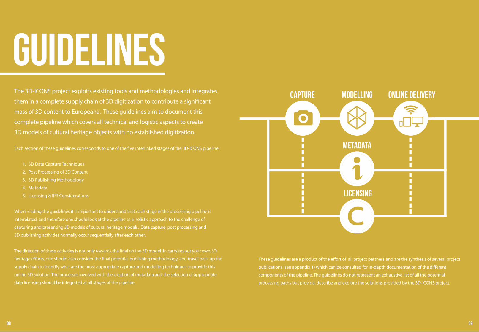
GuidelinesThe 3D-ICONS project exploits existing tools and methodologies and integrates
them in a complete supply chain of 3D digitization to contribute a signi�cant
mass of 3D content to Europeana. These guidelines aim to document this
complete pipeline which covers all technical and logistic aspects to create
3D models of cultural heritage objects with no established digitization.
These guidelines are a product of the e�ort of all project partners’ and are the synthesis of several project
publications (see appendix 1) which can be consulted for in-depth documentation of the di�erent
components of the pipeline. The guidelines do not represent an exhaustive list of all the potential
processing paths but provide, describe and explore the solutions provided by the 3D-ICONS project.
Each section of these guidelines corresponds to one of the �ve interlinked stages of the 3D-ICONS pipeline:
1. 3D Data Capture Techniques
2. Post Processing of 3D Content
3. 3D Publishing Methodology
4. Metadata
5. Licensing & IPR Considerations
When reading the guidelines it is important to understand that each stage in the processing pipeline is
interrelated, and therefore one should look at the pipeline as a holistic approach to the challenge of
capturing and presenting 3D models of cultural heritage models. Data capture, post processing and
3D publishing activities normally occur sequentially after each other.
The direction of these activities is not only towards the �nal online 3D model. In carrying out your own 3D
heritage e�orts, one should also consider the �nal potential publishing methodology, and travel back up the
supply chain to identify what are the most appropriate capture and modelling techniques to provide this
online 3D solution. The processes involved with the creation of metadata and the selection of appropriate
data licensing should be integrated at all stages of the pipeline.
Capture MODELLING ONLINE DELIVERY
LICENSING
METADATA
08 09
44 44
ACTIVE METHODS
LASER SCANNING STRUCTURED LIGHT RANGE SENSING
TIME OF FLIGHT PHASE SHIFT
PASSIVE METHODS
IMAGE BASEDMETHODS
3D Data CAPTURE
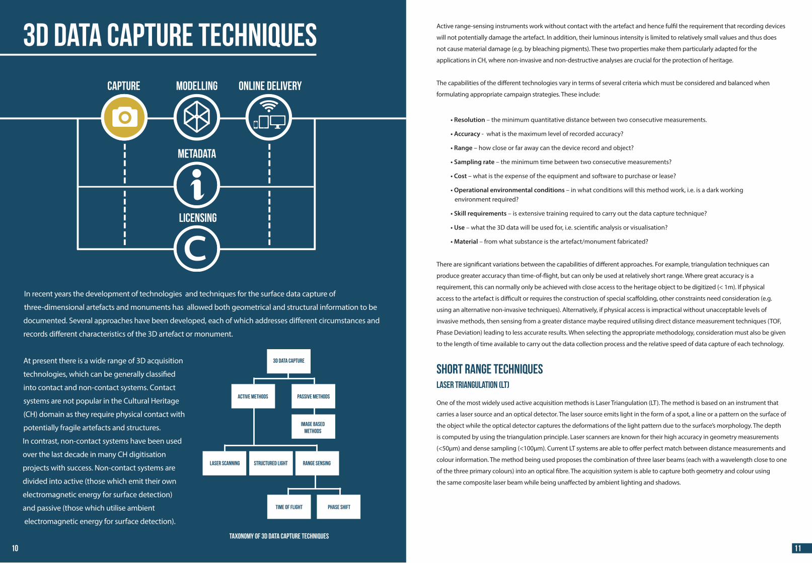
Active range-sensing instruments work without contact with the artefact and hence ful�l the requirement that recording devices
will not potentially damage the artefact. In addition, their luminous intensity is limited to relatively small values and thus does
not cause material damage (e.g. by bleaching pigments). These two properties make them particularly adapted for the
applications in CH, where non-invasive and non-destructive analyses are crucial for the protection of heritage.
The capabilities of the di�erent technologies vary in terms of several criteria which must be considered and balanced when
formulating appropriate campaign strategies. These include:
• Resolution – the minimum quantitative distance between two consecutive measurements.
• Accuracy - what is the maximum level of recorded accuracy?
• Range – how close or far away can the device record and object?
• Sampling rate – the minimum time between two consecutive measurements?
• Cost – what is the expense of the equipment and software to purchase or lease?
• Operational environmental conditions – in what conditions will this method work, i.e. is a dark working environment required?
• Skill requirements – is extensive training required to carry out the data capture technique?
• Use – what the 3D data will be used for, i.e. scienti�c analysis or visualisation?
• Material – from what substance is the artefact/monument fabricated?
There are signi�cant variations between the capabilities of di�erent approaches. For example, triangulation techniques can
produce greater accuracy than time-of-�ight, but can only be used at relatively short range. Where great accuracy is a
requirement, this can normally only be achieved with close access to the heritage object to be digitized (< 1m). If physical
access to the artefact is di�cult or requires the construction of special sca�olding, other constraints need consideration (e.g.
using an alternative non-invasive techniques). Alternatively, if physical access is impractical without unacceptable levels of
invasive methods, then sensing from a greater distance maybe required utilising direct distance measurement techniques (TOF,
Phase Deviation) leading to less accurate results. When selecting the appropriate methodology, consideration must also be given
to the length of time available to carry out the data collection process and the relative speed of data capture of each technology.
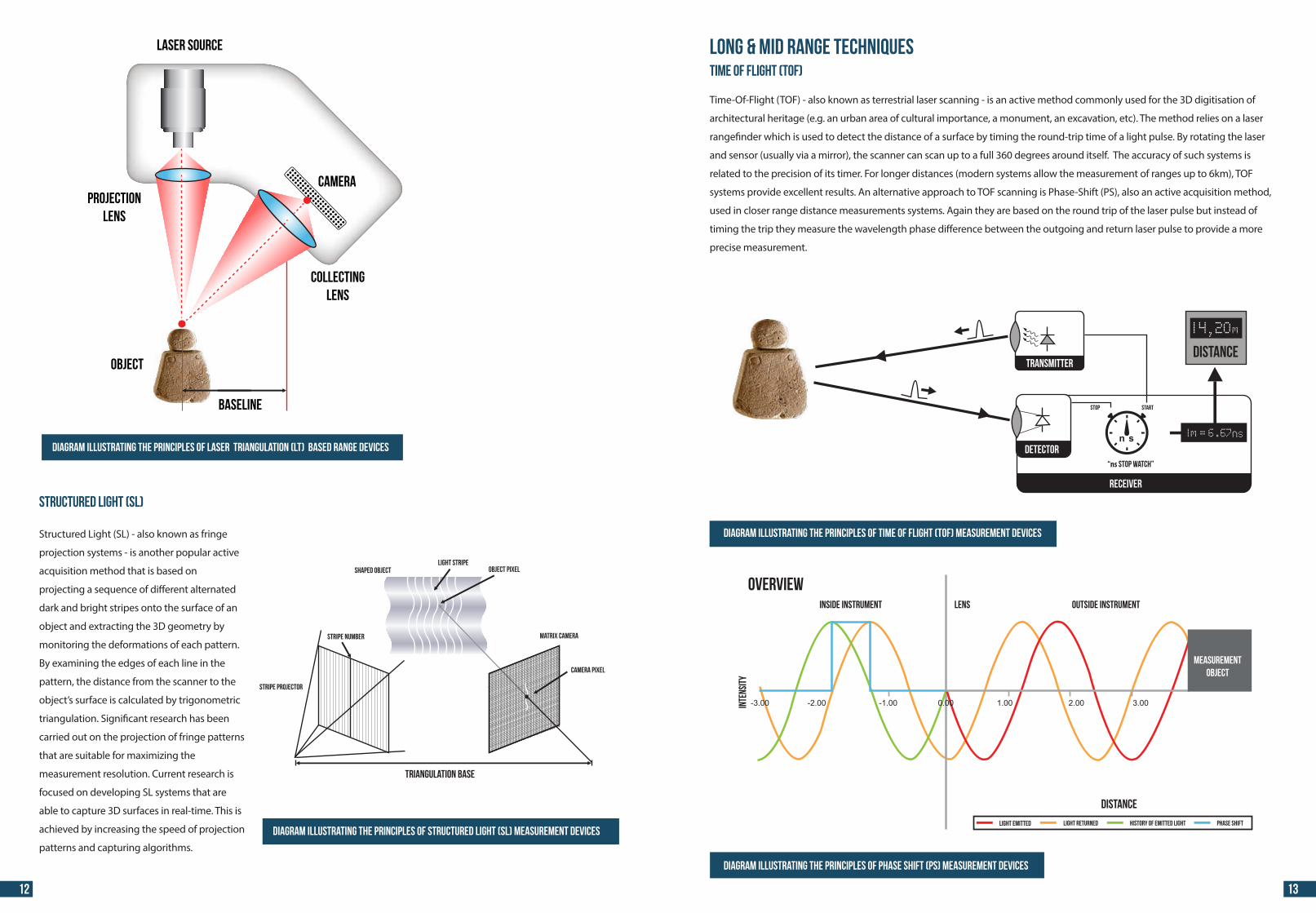
Short Range TechniquesLaser Triangulation (LT)
One of the most widely used active acquisition methods is Laser Triangulation (LT). The method is based on an instrument that
carries a laser source and an optical detector. The laser source emits light in the form of a spot, a line or a pattern on the surface of
the object while the optical detector captures the deformations of the light pattern due to the surface’s morphology. The depth
is computed by using the triangulation principle. Laser scanners are known for their high accuracy in geometry measurements
(<50μm) and dense sampling (<100μm). Current LT systems are able to o�er perfect match between distance measurements and
colour information. The method being used proposes the combination of three laser beams (each with a wavelength close to one
of the three primary colours) into an optical �bre. The acquisition system is able to capture both geometry and colour using
the same composite laser beam while being una�ected by ambient lighting and shadows.
In recent years the development of technologies and techniques for the surface data capture of
three-dimensional artefacts and monuments has allowed both geometrical and structural information to be
documented. Several approaches have been developed, each of which addresses di�erent circumstances and
records di�erent characteristics of the 3D artefact or monument.
At present there is a wide range of 3D acquisition
technologies, which can be generally classi�ed
into contact and non-contact systems. Contact
systems are not popular in the Cultural Heritage
(CH) domain as they require physical contact with
potentially fragile artefacts and structures.
In contrast, non-contact systems have been used
over the last decade in many CH digitisation
projects with success. Non-contact systems are
divided into active (those which emit their own
electromagnetic energy for surface detection)
and passive (those which utilise ambient
electromagnetic energy for surface detection).
Taxonomy of 3D data capture techniques
3D Data Capture Techniques
Capture MODELLING ONLINE DELIVERY
LICENSING
METADATA
10 11
44 44
-3.00Inte
nsit
y
-2.00 -1.00 1.00 2.00 3.00
Inside Instrument
OVERVIEWLens Outside Instrument
Distance
Light Emitted Light Returned History of Emitted Light Phase Shift
0.00
MeasurementObject
Collectinglens
CameraProjection
lens
Laser Source
Object
BasEline
Structured Light (SL)
Structured Light (SL) - also known as fringe
projection systems - is another popular active
acquisition method that is based on
projecting a sequence of di�erent alternated
dark and bright stripes onto the surface of an
object and extracting the 3D geometry by
monitoring the deformations of each pattern.
By examining the edges of each line in the
pattern, the distance from the scanner to the
object’s surface is calculated by trigonometric
triangulation. Signi�cant research has been
carried out on the projection of fringe patterns
that are suitable for maximizing the
measurement resolution. Current research is
focused on developing SL systems that are
able to capture 3D surfaces in real-time. This is
achieved by increasing the speed of projection
patterns and capturing algorithms.
DISTANCE
“ns stop watch”
STOP START
n s
transmitter
detector
receiver
S
SHAPED OBJECTLIGHT STRIPE
OBJECT PIXEL
MATRIX CAMERA
TRIANGULATION BASE
STRIPE NUMBER
STRIPE PROJECTOR
CAMERA PIXEL
Long & Mid Range TechniquesTime of Flight (TOF)
Time-Of-Flight (TOF) - also known as terrestrial laser scanning - is an active method commonly used for the 3D digitisation of
architectural heritage (e.g. an urban area of cultural importance, a monument, an excavation, etc). The method relies on a laser
range�nder which is used to detect the distance of a surface by timing the round-trip time of a light pulse. By rotating the laser
and sensor (usually via a mirror), the scanner can scan up to a full 360 degrees around itself. The accuracy of such systems is
related to the precision of its timer. For longer distances (modern systems allow the measurement of ranges up to 6km), TOF
systems provide excellent results. An alternative approach to TOF scanning is Phase-Shift (PS), also an active acquisition method,
used in closer range distance measurements systems. Again they are based on the round trip of the laser pulse but instead of
timing the trip they measure the wavelength phase di�erence between the outgoing and return laser pulse to provide a more
precise measurement.
Diagram illustrating the principles of laser triangulation (LT) based range devices
Diagram illustrating the principles of structured light (SL) measurement devices
Diagram illustrating the principles of time of flight (TOF) measurement devices
Diagram illustrating the principles of phase shift (PS) measurement devices
12 13
44 44
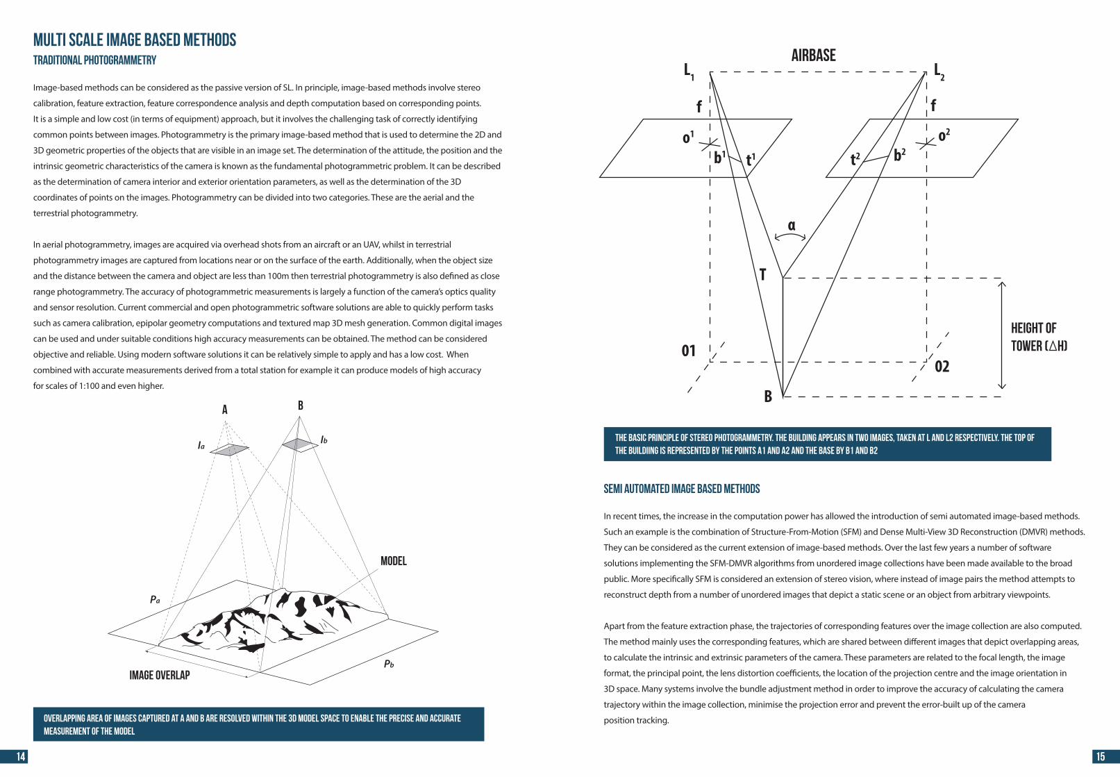
A B
Ia Ib
Image overlap
Pa
Pb
Model
Multi Scale Image based MethodsTraditional Photogrammetry
Image-based methods can be considered as the passive version of SL. In principle, image-based methods involve stereo
calibration, feature extraction, feature correspondence analysis and depth computation based on corresponding points.
It is a simple and low cost (in terms of equipment) approach, but it involves the challenging task of correctly identifying
common points between images. Photogrammetry is the primary image-based method that is used to determine the 2D and
3D geometric properties of the objects that are visible in an image set. The determination of the attitude, the position and the
intrinsic geometric characteristics of the camera is known as the fundamental photogrammetric problem. It can be described
as the determination of camera interior and exterior orientation parameters, as well as the determination of the 3D
coordinates of points on the images. Photogrammetry can be divided into two categories. These are the aerial and the
terrestrial photogrammetry.
In aerial photogrammetry, images are acquired via overhead shots from an aircraft or an UAV, whilst in terrestrial
photogrammetry images are captured from locations near or on the surface of the earth. Additionally, when the object size
and the distance between the camera and object are less than 100m then terrestrial photogrammetry is also de�ned as close
range photogrammetry. The accuracy of photogrammetric measurements is largely a function of the camera’s optics quality
and sensor resolution. Current commercial and open photogrammetric software solutions are able to quickly perform tasks
such as camera calibration, epipolar geometry computations and textured map 3D mesh generation. Common digital images
can be used and under suitable conditions high accuracy measurements can be obtained. The method can be considered
objective and reliable. Using modern software solutions it can be relatively simple to apply and has a low cost. When
combined with accurate measurements derived from a total station for example it can produce models of high accuracy
for scales of 1:100 and even higher.
L1 L2Airbase
Height oftower ( H)
ff
o1
α
o2
0201
B
T
b1 b2t1 t2
Overlapping area of images captured at A and B are resolved within the 3D model space to enable the precise and accurate measurement of the model
The basic principle of stereo photogrammetry. The building appears in two images, taken at L and L2 respectively. The top of the buildiing is represented by the points a1 and a2 and the base by b1 and b2
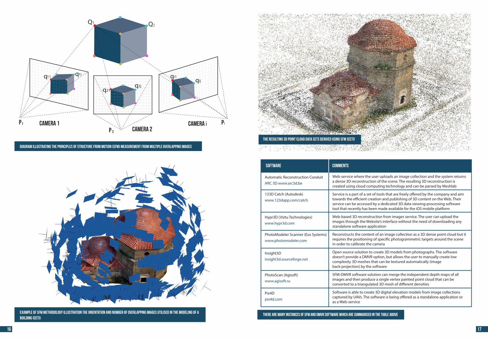
Semi Automated Image Based Methods
In recent times, the increase in the computation power has allowed the introduction of semi automated image-based methods.
Such an example is the combination of Structure-From-Motion (SFM) and Dense Multi-View 3D Reconstruction (DMVR) methods.
They can be considered as the current extension of image-based methods. Over the last few years a number of software
solutions implementing the SFM-DMVR algorithms from unordered image collections have been made available to the broad
public. More speci�cally SFM is considered an extension of stereo vision, where instead of image pairs the method attempts to
reconstruct depth from a number of unordered images that depict a static scene or an object from arbitrary viewpoints.
Apart from the feature extraction phase, the trajectories of corresponding features over the image collection are also computed.
The method mainly uses the corresponding features, which are shared between di�erent images that depict overlapping areas,
to calculate the intrinsic and extrinsic parameters of the camera. These parameters are related to the focal length, the image
format, the principal point, the lens distortion coe�cients, the location of the projection centre and the image orientation in
3D space. Many systems involve the bundle adjustment method in order to improve the accuracy of calculating the camera
trajectory within the image collection, minimise the projection error and prevent the error-built up of the camera
position tracking.
14 15
44 44
Web-service where the user uploads an image collection and the system returns a dense 3D reconstruction of the scene. The resulting 3D reconstruction is created using cloud computing technology and can be parsed by Meshlab Service is a part of a set of tools that are freely o�ered by the company and aim towards the e�cient creation and publishing of 3D content on the Web. Their service can be accessed by a dedicated 3D data viewing-processing software tool that recently has been made available for the iOS mobile platform Web-based 3D reconstruction from images service. The user can upload the images through the Website’s interface without the need of downloading any standalone software application Reconstructs the content of an image collection as a 3D dense point cloud but it requires the positioning of speci�c photogrammetric targets around the scene in order to calibrate the camera Open source solution to create 3D models from photographs. The software doesn’t provide a DMVR option, but allows the user to manually create low complexity 3D meshes that can be textured automatically (image back-projection) by the software SFM-DMVR software solution can merge the independent depth maps of all images and then produce a single vertex painted point cloud that can be converted to a triangulated 3D mesh of di�erent densities Software is able to create 3D digital elevation models from image collections captured by UAVs. The software is being o�ered as a standalone application or as a Web-service
Automatic Reconstruction ConduitARC 3D www.arc3d.be
123D Catch (Autodesk)www.123dapp.com/catch
Hypr3D (Viztu Technologies)www.hypr3d.com
PhotoModeler Scanner (Eos Systems)www.photomodeler.com
Insight3Dinsight3d.sourceforge.net
PhotoScan (Agisoft)www.agisoft.ru
Pix4Dpix4d.com
Software Comments
Diagram illustrating the principles of structure from motion (SFM) measurement from multiple overlapping images
Example of SFM methodology illustration the orientation and number of overlapping images utilised in the modeling of a building (CETI)
P Camera 1Camera 2
1
P 2
Camera i Pi
Q1 Q j
q11 q1i
q21q2j
qi1qij
The resulting 3D point cloud data sets derived using SFM (CETI)
16 17
There are many instances of SFM and DMVR software which are summarised in the table above
44 44
Automatic meshing from a dense 3D point cloud
The simple criteria for choosing and evaluating a relevant 3D geometric reconstruction technique is the degree of consistency
of the 3D model compared to the real object. These guidelines are primarily concerned with the creation of 3D models from
digitised data therefore this processing method will focus upon the automated meshing of 3D data from point-cloud data.
However, additional methods are available for the 3D reconstruction, including (in order of level of approximation
to reality):
•
•
•
•
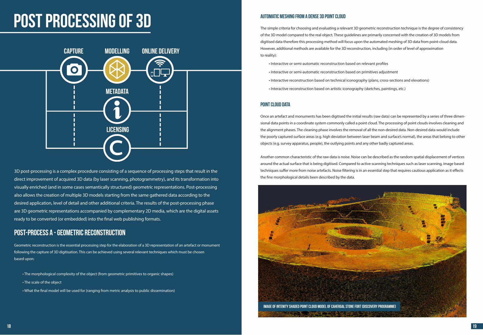
Point cloud data
Once an artefact and monuments has been digitised the initial results (raw data) can be represented by a series of three dimen-
sional data points in a coordinate system commonly called a point cloud. The processing of point clouds involves cleaning and
the alignment phases. The cleaning phase involves the removal of all the non-desired data. Non-desired data would include
the poorly captured surface areas (e.g. high deviation between laser beam and surface’s normal), the areas that belong to other
objects (e.g. survey apparatus, people), the outlying points and any other badly captured areas.
Another common characteristic of the raw data is noise. Noise can be described as the random spatial displacement of vertices
around the actual surface that is being digitised. Compared to active scanning techniques such as laser scanning, image based
techniques su�er more from noise artefacts. Noise �ltering is in an essential step that requires cautious application as it e�ects
the �ne morphological details been described by the data.3D post-processing is a complex procedure consisting of a sequence of processing steps that result in the
direct improvement of acquired 3D data (by laser scanning, photogrammetry), and its transformation into
visually enriched (and in some cases semantically structured) geometric representations. Post-processing
also allows the creation of multiple 3D models starting from the same gathered data according to the
desired application, level of detail and other additional criteria. The results of the post-processing phase
are 3D geometric representations accompanied by complementary 2D media, which are the digital assets
ready to be converted (or embedded) into the �nal web publishing formats.
Post-Process A - Geometric reconstruction
Geometric reconstruction is the essential processing step for the elaboration of a 3D representation of an artefact or monument
following the capture of 3D digitisation. This can be achieved using several relevant techniques which must be chosen
based upon:
•
•
•
Image of intenity shaded point cloud model of Cahergal stone fort (DiscoveRy Programme)
Post Processing of 3D
Capture MODELLING ONLINE DELIVERY
LICENSING
METADATA
18 19
44 44
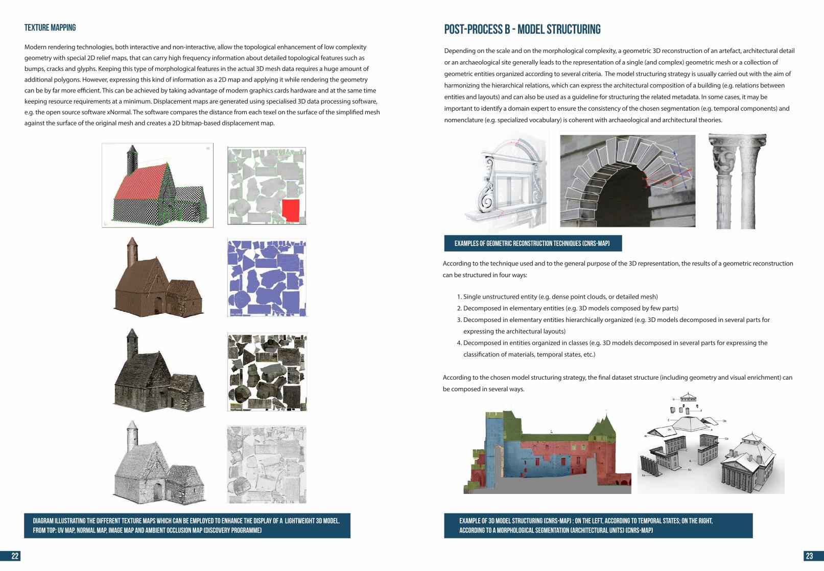
Mesh retopologisation
Extreme simpli�cation of complex meshes, such as for use
in computer games and simulations, usually cannot be
done automatically. Important features are dissolved and in
extreme conditions even topology is compromised.
Decimating a mesh at an extreme level can be achieved
by an empirical technique called retopology. This is a 3D
modelling technique, where special tools are used by the
operator to generate a simpler version of the original dense
model, by utilising the original topology as a supportive
underlying layer. This technique keeps the number of
polygons at an extreme minimum, while at the same time
allow the user to select which topological features should
be preserved from the original geometry. Retopology
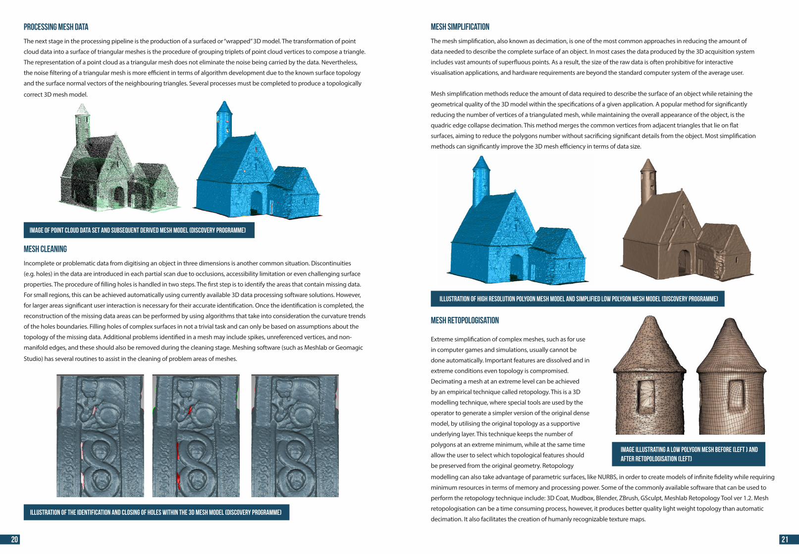
Processing mesh data
The next stage in the processing pipeline is the production of a surfaced or “wrapped” 3D model. The transformation of point
cloud data into a surface of triangular meshes is the procedure of grouping triplets of point cloud vertices to compose a triangle.
The representation of a point cloud as a triangular mesh does not eliminate the noise being carried by the data. Nevertheless,
the noise �ltering of a triangular mesh is more e�cient in terms of algorithm development due to the known surface topology
and the surface normal vectors of the neighbouring triangles. Several processes must be completed to produce a topologically
correct 3D mesh model.
Image of point cloud data set and subsequent derived mesh model (DiscoveRy Programme)
Illustration of the identification and closing of holes within the 3D mesh model (DiscoveRy Programme)
Mesh Cleaning
Incomplete or problematic data from digitising an object in three dimensions is another common situation. Discontinuities
(e.g. holes) in the data are introduced in each partial scan due to occlusions, accessibility limitation or even challenging surface
properties. The procedure of �lling holes is handled in two steps. The �rst step is to identify the areas that contain missing data.
For small regions, this can be achieved automatically using currently available 3D data processing software solutions. However,
for larger areas signi�cant user interaction is necessary for their accurate identi�cation. Once the identi�cation is completed, the
reconstruction of the missing data areas can be performed by using algorithms that take into consideration the curvature trends
of the holes boundaries. Filling holes of complex surfaces in not a trivial task and can only be based on assumptions about the
topology of the missing data. Additional problems identi�ed in a mesh may include spikes, unreferenced vertices, and non-
manifold edges, and these should also be removed during the cleaning stage. Meshing software (such as Meshlab or Geomagic
Studio) has several routines to assist in the cleaning of problem areas of meshes.
Mesh Simplification
The mesh simpli�cation, also known as decimation, is one of the most common approaches in reducing the amount of
data needed to describe the complete surface of an object. In most cases the data produced by the 3D acquisition system
includes vast amounts of super�uous points. As a result, the size of the raw data is often prohibitive for interactive
visualisation applications, and hardware requirements are beyond the standard computer system of the average user.
Mesh simpli�cation methods reduce the amount of data required to describe the surface of an object while retaining the
geometrical quality of the 3D model within the speci�cations of a given application. A popular method for signi�cantly
reducing the number of vertices of a triangulated mesh, while maintaining the overall appearance of the object, is the
quadric edge collapse decimation. This method merges the common vertices from adjacent triangles that lie on �at
surfaces, aiming to reduce the polygons number without sacri�cing signi�cant details from the object. Most simpli�cation
methods can signi�cantly improve the 3D mesh e�ciency in terms of data size.
Illustration of high resolution polygon mesh model and simplified low polygon mesh model (DiscoveRy Programme)
modelling can also take advantage of parametric surfaces, like NURBS, in order to create models of in�nite �delity while requiring
minimum resources in terms of memory and processing power. Some of the commonly available software that can be used to
perform the retopology technique include: 3D Coat, Mudbox, Blender, ZBrush, GSculpt, Meshlab Retopology Tool ver 1.2. Mesh
retopologisation can be a time consuming process, however, it produces better quality light weight topology than automatic
decimation. It also facilitates the creation of humanly recognizable texture maps.
Image illustrating a low polygon mesh before (left ) and after retopologisation (left)
20 21
44 44
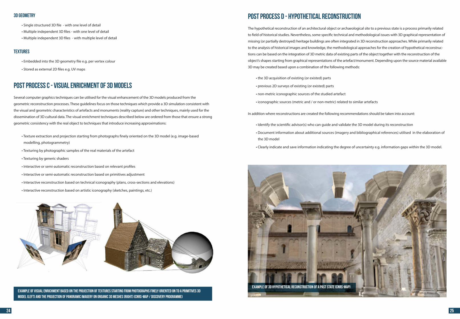
TEXTURE MAPPING
Modern rendering technologies, both interactive and non-interactive, allow the topological enhancement of low complexity
geometry with special 2D relief maps, that can carry high frequency information about detailed topological features such as
bumps, cracks and glyphs. Keeping this type of morphological features in the actual 3D mesh data requires a huge amount of
additional polygons. However, expressing this kind of information as a 2D map and applying it while rendering the geometry
can be by far more e�cient. This can be achieved by taking advantage of modern graphics cards hardware and at the same time
keeping resource requirements at a minimum. Displacement maps are generated using specialised 3D data processing software,
e.g. the open source software xNormal. The software compares the distance from each texel on the surface of the simpli�ed mesh
against the surface of the original mesh and creates a 2D bitmap-based displacement map.
Examples of geometric reconstruction techniques (CNRS-MAP)
Example of 3D model structuring (CNRS-MAP) : on the left, according to temporal states; on the right, according to a morphological segmentation (architectural units) (CNRS-MAP)
Post-Process B - Model structuring
Depending on the scale and on the morphological complexity, a geometric 3D reconstruction of an artefact, architectural detail
or an archaeological site generally leads to the representation of a single (and complex) geometric mesh or a collection of
geometric entities organized according to several criteria. The model structuring strategy is usually carried out with the aim of
harmonizing the hierarchical relations, which can express the architectural composition of a building (e.g. relations between
entities and layouts) and can also be used as a guideline for structuring the related metadata. In some cases, it may be
important to identify a domain expert to ensure the consistency of the chosen segmentation (e.g. temporal components) and
nomenclature (e.g. specialized vocabulary) is coherent with archaeological and architectural theories.
According to the technique used and to the general purpose of the 3D representation, the results of a geometric reconstruction
can be structured in four ways:
1. Single unstructured entity (e.g. dense point clouds, or detailed mesh)
2. Decomposed in elementary entities (e.g. 3D models composed by few parts)
3. Decomposed in elementary entities hierarchically organized (e.g. 3D models decomposed in several parts for
expressing the architectural layouts)
4. Decomposed in entities organized in classes (e.g. 3D models decomposed in several parts for expressing the
classi�cation of materials, temporal states, etc.)
According to the chosen model structuring strategy, the �nal dataset structure (including geometry and visual enrichment) can
be composed in several ways.
Diagram illustrating the different texture maps which can be employed to enhance the display of a lightweight 3D model. From top: UV map, normal map, image map and ambient occlusion map (DISCOVERY PROGRAMME)
22 23
44 44
3D Geometry
• of detail
•
•
Textures
•
•
Example of visual enrichment based on the projection of textures starting from photographs finely oriented on to a primitives 3D
model (left) and the projection of panoramic imagery on organic 3D meshes (right) (CNRS-MAP / Discovery Programme)
Post Process C - Visual enrichment of 3D models
Several computer graphics techniques can be utilised for the visual enhancement of the 3D models produced from the
geometric reconstruction processes. These guidelines focus on those techniques which provide a 3D simulation consistent with
the visual and geometric characteristics of artefacts and monuments (reality capture) and other techniques, mainly used for the
dissemination of 3D cultural data. The visual enrichment techniques described below are ordered from those that ensure a strong
geometric consistency with the real object to techniques that introduce increasing approximations:
• �nely oriented on the 3D model (e.g. image-based
modelling, photogrammetry)
• the artefact
•
• relevant pro�les
• primitives adjustment
• (plans, cross-sections and elevations)
• (sketches, paintings, etc.)
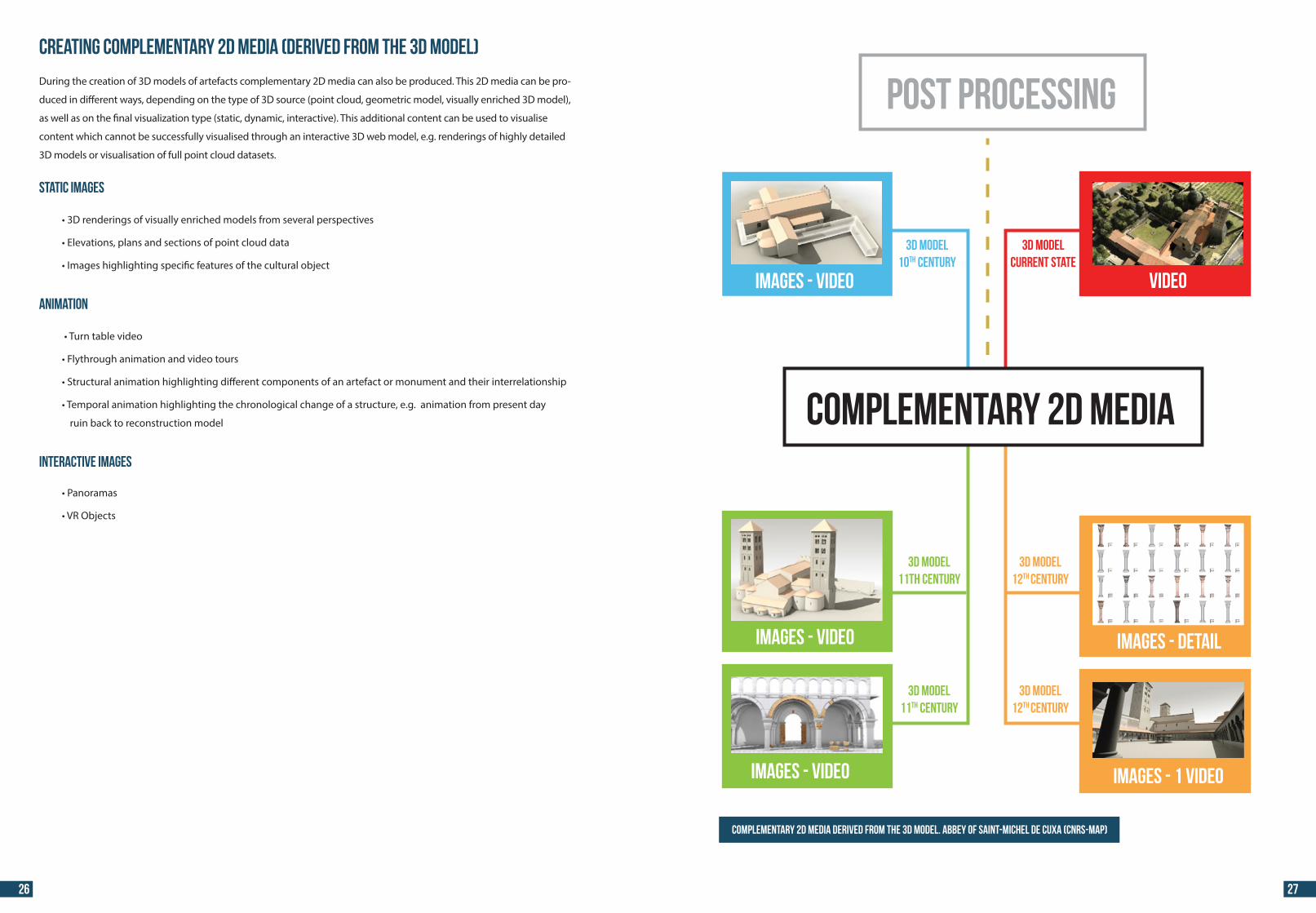
Example of 3D hypothetical reconstruction of a past state (CNRS-MAP)
Post Process D - Hypothetical reconstruction
The hypothetical reconstruction of an architectural object or archaeological site to a previous state is a process primarily related
to �eld of historical studies. Nevertheless, some speci�c technical and methodological issues with 3D graphical representation of
missing (or partially destroyed) heritage buildings are often integrated in 3D reconstruction approaches. While primarily related
to the analysis of historical images and knowledge, the methodological approaches for the creation of hypothetical reconstruc-
tions can be based on the integration of 3D metric data of existing parts of the object together with the reconstruction of the
object’s shapes starting from graphical representations of the artefact/monument. Depending upon the source material available
3D may be created based upon a combination of the following methods:
•
•
•
•
In addition where reconstructions are created the following recommendations should be taken into account:
•
• the elaboration of
the 3D model
• degree of uncertainty e.g. information gaps within the 3D model.
24 25
44 44
Creating complementary 2D media (derived from the 3D model)
During the creation of 3D models of artefacts complementary 2D media can also be produced. This 2D media can be pro-
duced in di�erent ways, depending on the type of 3D source (point cloud, geometric model, visually enriched 3D model),
as well as on the �nal visualization type (static, dynamic, interactive). This additional content can be used to visualise
content which cannot be successfully visualised through an interactive 3D web model, e.g. renderings of highly detailed
3D models or visualisation of full point cloud datasets.
Static images
•
• cloud data
• the cultural object
Animation
•
•
• di�erent components of an artefact or monument and their interrelationship
• chronological change of a structure, e.g. animation from present day
ruin back to reconstruction model
Interactive Images
•
•
Complementary 2D media derived from the 3D model. Abbey of Saint-Michel de Cuxa (CNRS-MAP)
3D modelCUrrent state
3D model12th CENTURY
3D model12th CENTURY
3D model11th CENTURY
3D model10th CENTURY
3D model11th CENTURY
IMAGeS - video video
IMAGeS - video
IMAGeS - video
images - detail
images - 1 video
POST PROCESSING
COMPLEMENTARY 2D MEDIA
26 27
44 44
•
•
•
•
(desktop and mobile)
•
to facilitate e�cient & sustainable production
•
•
Creators of 3D content will also need to consider if the online 3D models require �le format conversion
and optimisation procedures to enable their use online, to ensure a responsive and pleasant user
experience. It is important to evaluate which is the most optimal approach, taking into account the
potential e�ort required for �le format conversions and optimisation procedures.
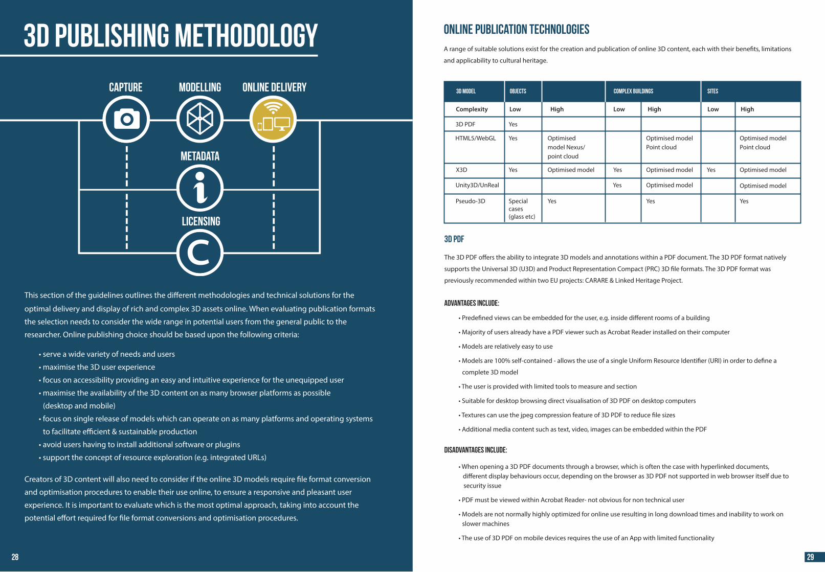
This section of the guidelines outlines the di�erent methodologies and technical solutions for the
optimal delivery and display of rich and complex 3D assets online. When evaluating publication formats
the selection needs to consider the wide range in potential users from the general public to the
researcher. Online publishing choice should be based upon the following criteria:
Online publication technologiesA range of suitable solutions exist for the creation and publication of online 3D content, each with their bene�ts, limitations
and applicability to cultural heritage.
3D PDF
The 3D PDF o�ers the ability to integrate 3D models and annotations within a PDF document. The 3D PDF format natively
supports the Universal 3D (U3D) and Product Representation Compact (PRC) 3D �le formats. The 3D PDF format was
previously recommended within two EU projects: CARARE & Linked Heritage Project.
Advantages include:
•
•
•
•
complete 3D model
•
•
•
•
Disadvantages include:
• When opening a 3D PDF documents through a browser, which is often the case with hyperlinked documents, di�erent display behaviours occur, depending on the browser as 3D PDF not supported in web browser itself due to security issue
•
• slower machines
•
3D model Objects Complex Buildings Sites
Complexity Low High Low High Low High
Yes
Yes
Yes
Yes Yes
YesYesYes
Yes
Special cases(glass etc)
Optimised model Nexus/point cloud
Optimised model Optimised model
Optimised model
Optimised model
Optimised model
Optimised modelPoint cloud
Optimised modelPoint cloud
HTML5/WebGL
X3D
Unity3D/UnReal
Pseudo-3D
3D PDF
3D Publishing Methodology
Capture MODELLING ONLINE DELIVERY
LICENSING
METADATA
28 29
44 44
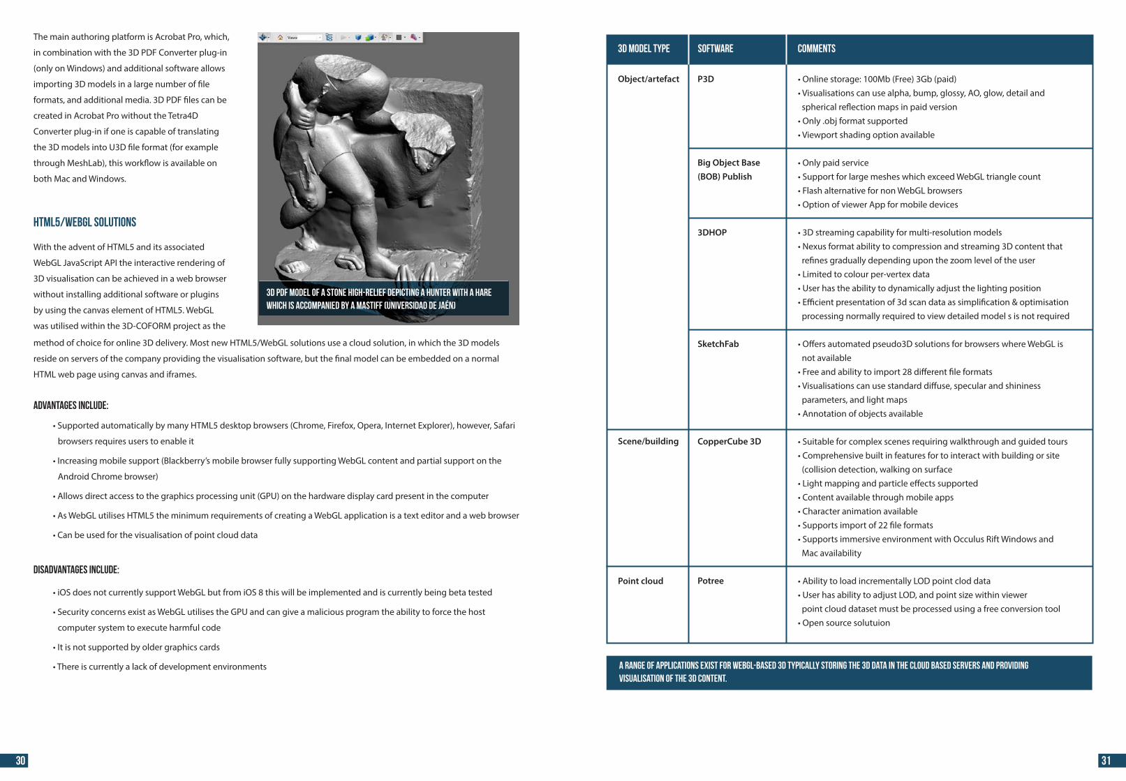
The main authoring platform is Acrobat Pro, which,
in combination with the 3D PDF Converter plug-in
(only on Windows) and additional software allows
importing 3D models in a large number of �le
formats, and additional media. 3D PDF �les can be
created in Acrobat Pro without the Tetra4D
Converter plug-in if one is capable of translating
the 3D models into U3D �le format (for example
through MeshLab), this work�ow is available on
both Mac and Windows.
HTML5/WebGL Solutions
With the advent of HTML5 and its associated
WebGL JavaScript API the interactive rendering of
3D visualisation can be achieved in a web browser
without installing additional software or plugins
by using the canvas element of HTML5. WebGL
was utilised within the 3D-COFORM project as the
3D PDF model of a stone high-relief depicting a hunter with a hare which is accompanied by a mastiff (Universidad de Jaén)
method of choice for online 3D delivery. Most new HTML5/WebGL solutions use a cloud solution, in which the 3D models
reside on servers of the company providing the visualisation software, but the �nal model can be embedded on a normal
HTML web page using canvas and iframes.
Advantages include:
• browsers (Chrome, Firefox, Opera, Internet Explorer), however, Safari
browsers requires users to enable it
• browser fully supporting WebGL content and partial support on the
Android Chrome browser)
• (GPU) on the hardware display card present in the computer
• requirements of creating a WebGL application is a text editor and a web browser
•
Disadvantages include:
• iOS 8 this will be implemented and is currently being beta tested
• can give a malicious program the ability to force the host
computer system to execute harmful code
•
• environments
Object/artefact
Scene/building
Point cloud
••
••
••••
••
•••
•
••
•
••
•••••
••
•
3D Model Type Software Comments
Big Object Base(BOB) Publish
3DHOP
SketchFab
CopperCube 3D
Potree
P3D
30 31
A range of applications exist for WebGL-based 3D typically storing the 3D data in the Cloud based servers and providing visualisation of the 3D content.
44 44
X3D
X3D is the technological successor and extension to VRML which is recognised by the International Organisation for
Standardization (ISO). Currently X3D provides native authoring and use of declarative XML-based X3D scenes which can be
viewed within a HTML5 web browser, and provides Extensible Markup Language (XML) capabilities within 3D to integrate with
other WWW technologies.
Advantages include:
•
re�ection, Non-uniform rational basis splines (NURBS)
•
•
•
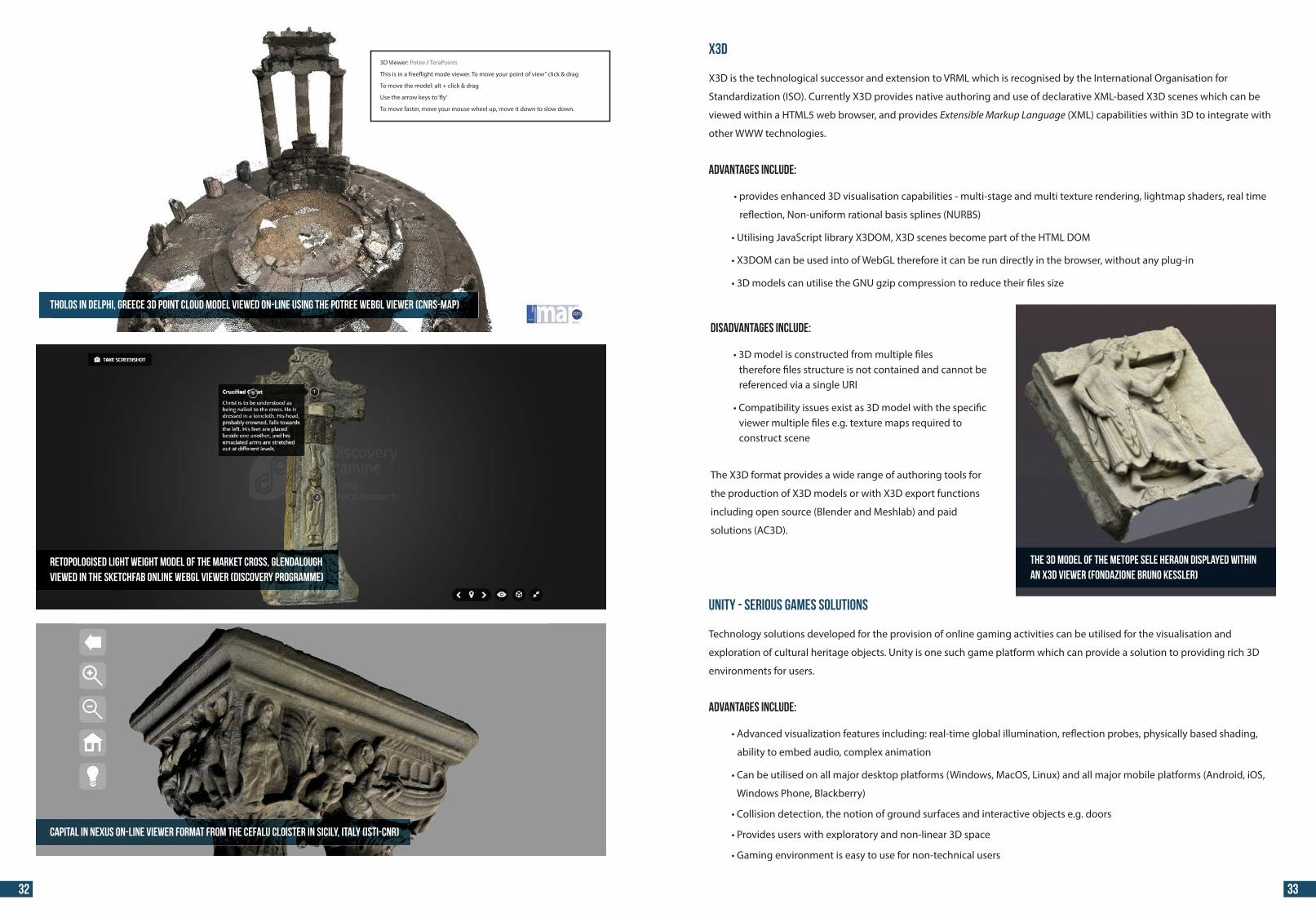
Tholos in Delphi, Greece 3D point cloud model viewed on-line using the Potree WebGL viewer (CNRS-MAP)
Capital in Nexus on-line viewer format from the Cefalu cloister in Sicily, Italy (ISTI-CNR)
Retopologised light weight model of the Market Cross, Glendalough viewed in the SketchFab online WebGL viewer (Discovery Programme)
3D Viewer: Potee / TeraPoints
This is in a free�ight mode viewer. To move your point of view” click & drag
To move the model: alt + click & drag
Use the arrow keys to ‘�y’
To move faster, move your mouse wheel up, move it down to slow down.
The 3D model of the Metope Sele heraon displayed within an X3D viewer (Fondazione Bruno Kessler)
Disadvantages include:
• therefore �les structure is not contained and cannot be referenced via a single URI
• viewer multiple �les e.g. texture maps required to construct scene
The X3D format provides a wide range of authoring tools for
the production of X3D models or with X3D export functions
including open source (Blender and Meshlab) and paid
solutions (AC3D).
Unity - Serious Games Solutions
Technology solutions developed for the provision of online gaming activities can be utilised for the visualisation and
exploration of cultural heritage objects. Unity is one such game platform which can provide a solution to providing rich 3D
environments for users.
Advantages include:
• illumination, re�ection probes, physically based shading,
ability to embed audio, complex animation
• Linux) and all major mobile platforms (Android, iOS,
Windows Phone, Blackberry)
•
•
•
32 33
44 44
•
•
•
Disadvantages include:
• plug-in to be installed on the user’s machine, however, from the release of Unity v.5 online
publishing within HTML5 capabilities will be available
• author 3D scenes if Pro functions required
Other game engine platforms adopted for serious gaming such as the Unreal Development Kit (UDK) are available; however,
most require the installation of an additional plug-in.
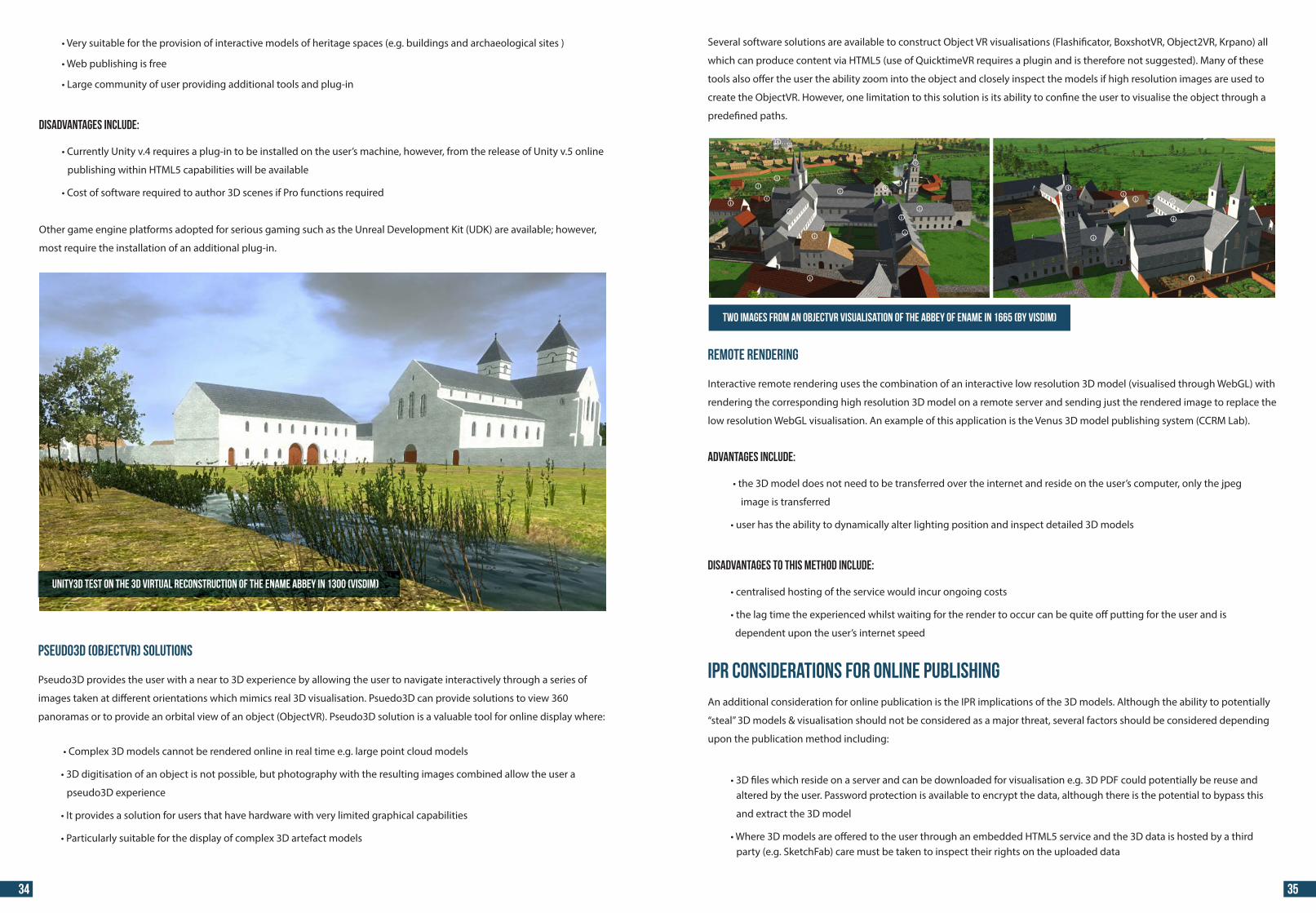
Several software solutions are available to construct Object VR visualisations (Flashi�cator, BoxshotVR, Object2VR, Krpano) all
which can produce content via HTML5 (use of QuicktimeVR requires a plugin and is therefore not suggested). Many of these
tools also o�er the user the ability zoom into the object and closely inspect the models if high resolution images are used to
create the ObjectVR. However, one limitation to this solution is its ability to con�ne the user to visualise the object through a
prede�ned paths.
Pseudo3D (ObjectVR) solutions
Pseudo3D provides the user with a near to 3D experience by allowing the user to navigate interactively through a series of
images taken at di�erent orientations which mimics real 3D visualisation. Psuedo3D can provide solutions to view 360
panoramas or to provide an orbital view of an object (ObjectVR). Pseudo3D solution is a valuable tool for online display where:
•
•
pseudo3D experience
•
•
Remote Rendering
Interactive remote rendering uses the combination of an interactive low resolution 3D model (visualised through WebGL) with
rendering the corresponding high resolution 3D model on a remote server and sending just the rendered image to replace the
low resolution WebGL visualisation. An example of this application is the Venus 3D model publishing system (CCRM Lab).
Advantages include:
•
image is transferred
•
Disadvantages to this method include:
•
•
dependent upon the user’s internet speed
IPR Considerations for online publishingAn additional consideration for online publication is the IPR implications of the 3D models. Although the ability to potentially
“steal” 3D models & visualisation should not be considered as a major threat, several factors should be considered depending
upon the publication method including:
• altered by the user. Password protection is available to encrypt the data, although there is the potential to bypass this
and extract the 3D model
• party (e.g. SketchFab) care must be taken to inspect their rights on the uploaded data
Unity3D test on the 3D virtual reconstruction of the Ename abbey in 1300 (VisDim)
Two images from an ObjectVR visualisation of the abbey of Ename in 1665 (by VisDim)
34 35
44 44
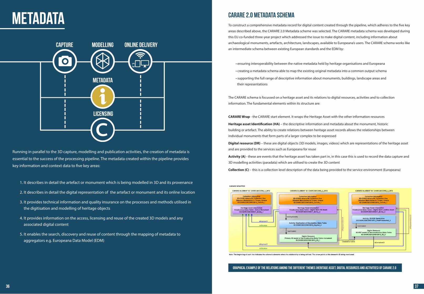
Running in parallel to the 3D capture, modelling and publication activities, the creation of metadata is
essential to the success of the processing pipeline. The metadata created within the pipeline provides
key information and context data to �ve key areas:
1. It describes in detail the artefact or monument which is being modelled in 3D and its provenance
2. It describes in detail the digital representation of the artefact or monument and its online location
3. It provides technical information and quality insurance on the processes and methods utilised in the digitisation and modelling of heritage objects
4. It provides information on the access, licensing and reuse of the created 3D models and any associated digital content
5. It enables the search, discovery and reuse of content through the mapping of metadata to aggregators e.g. Europeana Data Model (EDM)
CARARE 2.0 Metadata SchemaTo construct a comprehensive metadata record for digital content created through the pipeline, which adheres to the �ve key
areas described above, the CARARE 2.0 Metadata scheme was selected. The CARARE metadata schema was developed during
this EU co-funded three-year project which addressed the issue to make digital content, including information about
archaeological monuments, artefacts, architecture, landscapes, available to Europeana’s users. The CARARE schema works like
an intermediate schema between existing European standards and the EDM by:
•
•
•
their representations
The CARARE schema is focussed on a heritage asset and its relations to digital resources, activities and to collection
information. The fundamental elements within its structure are:
CARARE Wrap - the CARARE start element. It wraps the Heritage Asset with the other information resources
Heritage asset Identi�cation (HA) – the descriptive information and metadata about the monument, historic
building or artefact. The ability to create relations between heritage asset records allows the relationships between
individual monuments that form parts of a larger complex to be expressed
Digital resource (DR) – these are digital objects (3D models, images, videos) which are representations of the heritage asset
and are provided to the services such as Europeana for reuse
Activity (A) - these are events that the heritage asset has taken part in, in this case this is used to record the data capture and
3D modelling activities (paradata) which are utilised to create the 3D content
Collection (C) – this is a collection level description of the data being provided to the service environment (Europeana)
Graphical example of the relations among the different themes (Heritage Asset, Digital Resources and Activities) of CARARE 2.0
METADATA
Capture MODELLING ONLINE DELIVERY
LICENSING
METADATA
36 37
44 44
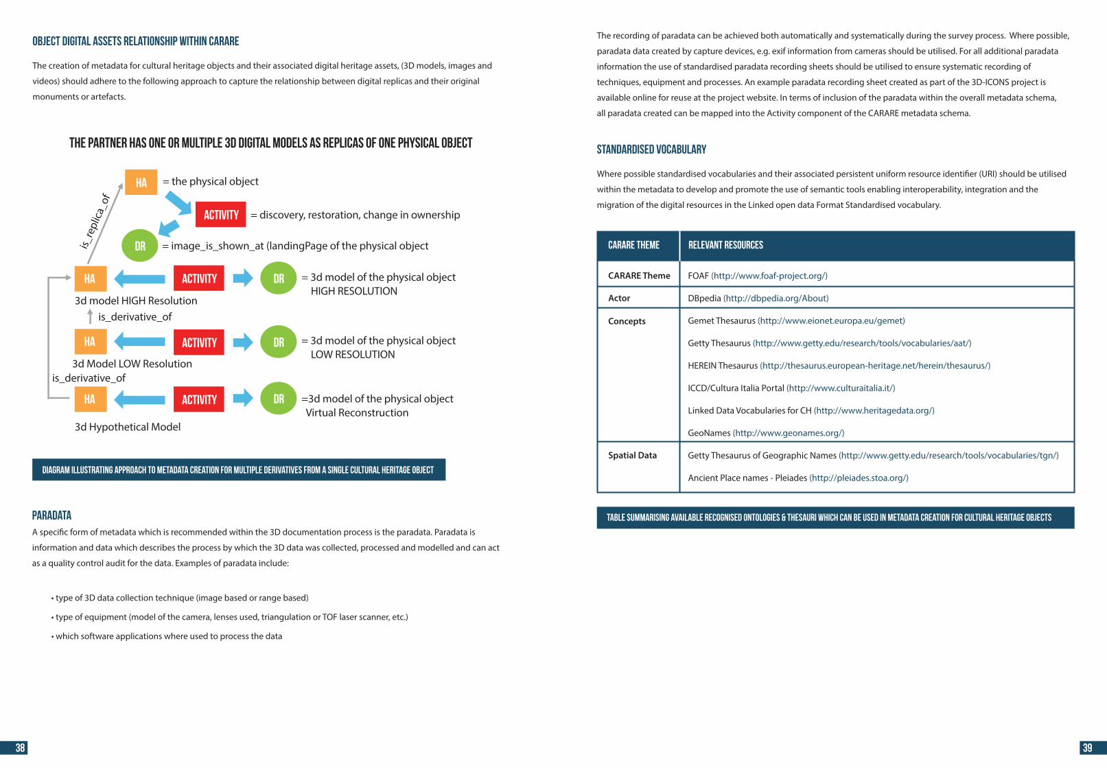
Object digital assets relationship within CARARE
The creation of metadata for cultural heritage objects and their associated digital heritage assets, (3D models, images and
videos) should adhere to the following approach to capture the relationship between digital replicas and their original
monuments or artefacts.
Diagram illustrating approach to metadata creation for multiple derivatives from a single cultural heritage object
ParadataA speci�c form of metadata which is recommended within the 3D documentation process is the paradata. Paradata is
information and data which describes the process by which the 3D data was collected, processed and modelled and can act
as a quality control audit for the data. Examples of paradata include:
•
•
•
The recording of paradata can be achieved both automatically and systematically during the survey process. Where possible,
paradata data created by capture devices, e.g. exif information from cameras should be utilised. For all additional paradata
information the use of standardised paradata recording sheets should be utilised to ensure systematic recording of
techniques, equipment and processes. An example paradata recording sheet created as part of the 3D-ICONS project is
available online for reuse at the project website. In terms of inclusion of the paradata within the overall metadata schema,
all paradata created can be mapped into the Activity component of the CARARE metadata schema.
Standardised vocabulary
Where possible standardised vocabularies and their associated persistent uniform resource identi�er (URI) should be utilised
within the metadata to develop and promote the use of semantic tools enabling interoperability, integration and the
migration of the digital resources in the Linked open data Format Standardised vocabulary.
CARARE Theme
Actor
Concepts
Spatial Data
FOAF (http://www.foaf-project.org/)
DBpedia (http://dbpedia.org/About)
Gemet Thesaurus (http://www.eionet.europa.eu/gemet)
Getty Thesaurus (http://www.getty.edu/research/tools/vocabularies/aat/)
HEREIN Thesaurus (http://thesaurus.european-heritage.net/herein/thesaurus/)
ICCD/Cultura Italia Portal (http://www.culturaitalia.it/)
Linked Data Vocabularies for CH (http://www.heritagedata.org/)
GeoNames (http://www.geonames.org/)
Getty Thesaurus of Geographic Names (http://www.getty.edu/research/tools/vocabularies/tgn/)
Ancient Place names - Pleiades (http://pleiades.stoa.org/)
CARARE Theme Relevant resources
Table summarising available recognised ontologies & thesauri which can be used in metadata creation for cultural heritage objects
38 39
THE PARTNER HAS ONE or multiple 3D digital models as replicas of one physical object
= the physical object
= discovery, restoration, change in ownership
= image_is_shown_at (landingPage of the physical object
HA
= 3d model of the physical object HIGH RESOLUTION
= 3d model of the physical object LOW RESOLUTION
=3d model of the physical object Virtual Reconstruction
3d Hypothetical Model
3d Model LOW Resolution
is_re
plic
a_of
3d model HIGH Resolution
HA
HA
ACTIVITY
ACTIVITY
ACTIVITY
ACTIVITY
DR
DR
DR
DR
HA
is_derivative_of
is_derivative_of
44 44
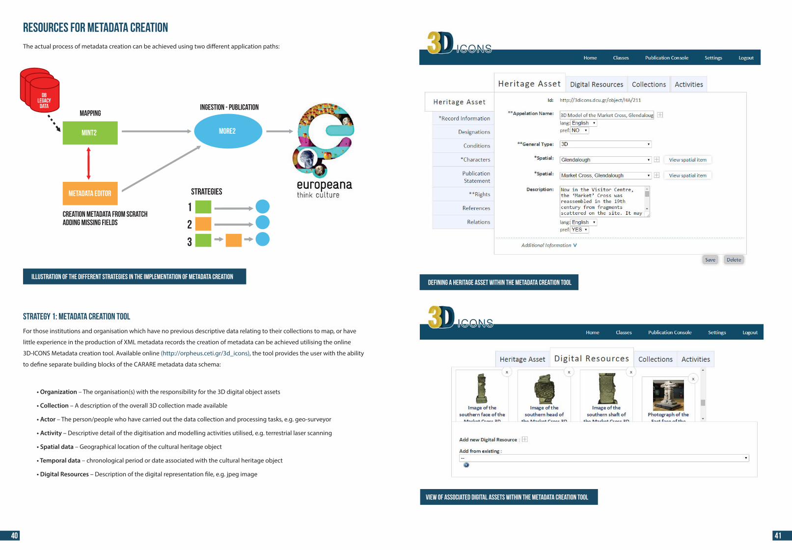
Resources for Metadata CreationThe actual process of metadata creation can be achieved using two di�erent application paths:
Strategy 1: Metadata Creation Tool
For those institutions and organisation which have no previous descriptive data relating to their collections to map, or have
little experience in the production of XML metadata records the creation of metadata can be achieved utilising the online
3D-ICONS Metadata creation tool. Available online (http://orpheus.ceti.gr/3d_icons), the tool provides the user with the ability
to de�ne separate building blocks of the CARARE metadata data schema:
• Organization – The organisation(s) with the responsibility for the 3D digital object assets
• Collection – A description of the overall 3D collection made available
• Actor – The person/people who have carried out the data collection and processing tasks, e.g. geo-surveyor
• Activity – Descriptive detail of the digitisation and modelling activities utilised, e.g. terrestrial laser scanning
• Spatial data – Geographical location of the cultural heritage object
• Temporal data – chronological period or date associated with the cultural heritage object
• Digital Resources – Description of the digital representation �le, e.g. jpeg image
Illustration of the different strategies in the implementation of metadata creation
View of associated digital assets within the metadata creation tool
Defining a Heritage Asset within the metadata creation tool
40 41
MAPPING
MINT2 MORe2
METADATA EDITOR
INGESTION - PUBLICATION
CREATION METADATA FROM SCRATCHADDING MISSING FIELDS
STRATEGIES
1
2
3
DBLEGACY
DATA
44 44
Strategy 2: MINT2 Mapping Tool
For those organisations which have their metadata already created and contained within their own formalised cataloguing
management software, e.g. museum collections databases, this can be reused to form the main component of the CARARE
metadata record. To achieve this, the MINT 2 metadata services tool can be employed.
MINT 2 services comprise of a web based platform that is designed and developed to facilitate aggregation initiatives for
cultural heritage content and metadata in Europe. The platform o�ers an organisation a management system that allows the
operation of di�erent aggregation schemes (thematic or cross-domain, international, national or regional) and corresponding
access rights. Registered organizations can upload (http, ftp, OAI-PMH) their metadata records in xml or csv format in order to
manage, aggregate and publish their collections.
The CARARE metadata model serves as the aggregation schema to which the ingested data is mapped. Users can de�ne their
metadata crosswalks from their own schema to CARARE with the help of a visual mappings editor utilising a simple drag-and-
drop function which creates the mappings. The MINT tool supports string manipulation functions for input elements in order
to perform 1-n and m- mappings between the two models. Additionally, structural element mappings are allowed, as well
as constant or controlled value (target schema enumerations) assignment, conditional mappings (with a complex condition
editor) and value mappings between input and target value lists. Mappings can be applied to ingested records, edited,
downloaded and shared as templates between users of the platform.
Visualization of the mapped record metadata record in MINT 2
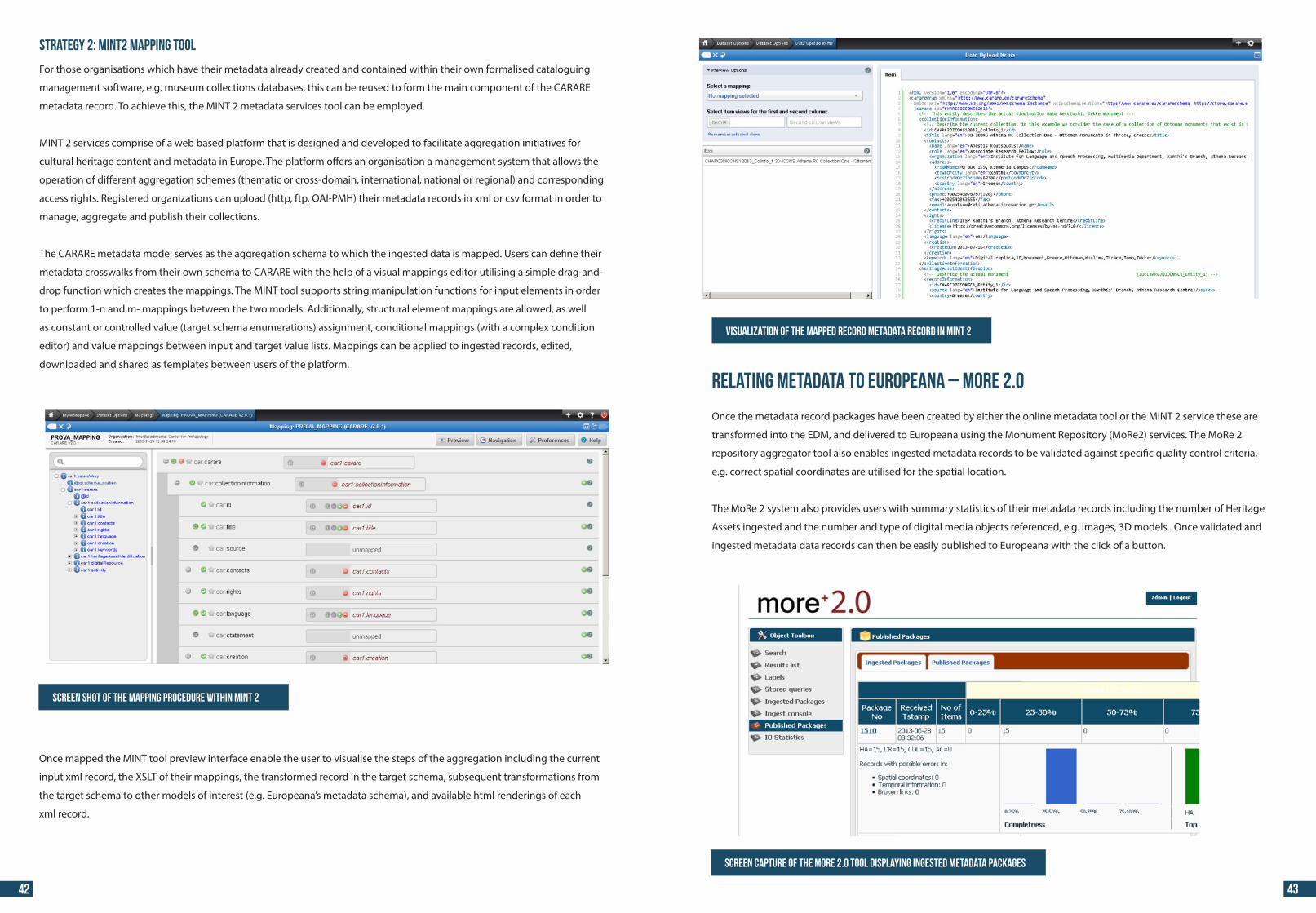
Relating Metadata to Europeana – MoRe 2.0
Once the metadata record packages have been created by either the online metadata tool or the MINT 2 service these are
transformed into the EDM, and delivered to Europeana using the Monument Repository (MoRe2) services. The MoRe 2
repository aggregator tool also enables ingested metadata records to be validated against speci�c quality control criteria,
e.g. correct spatial coordinates are utilised for the spatial location.
The MoRe 2 system also provides users with summary statistics of their metadata records including the number of Heritage
Assets ingested and the number and type of digital media objects referenced, e.g. images, 3D models. Once validated and
ingested metadata data records can then be easily published to Europeana with the click of a button.
Screen capture of the MORE 2.0 tool displaying ingested metadata packages
Screen shot of the mapping procedure within MINT 2
Once mapped the MINT tool preview interface enable the user to visualise the steps of the aggregation including the current
input xml record, the XSLT of their mappings, the transformed record in the target schema, subsequent transformations from
the target schema to other models of interest (e.g. Europeana’s metadata schema), and available html renderings of each
xml record.
42 43
44 44
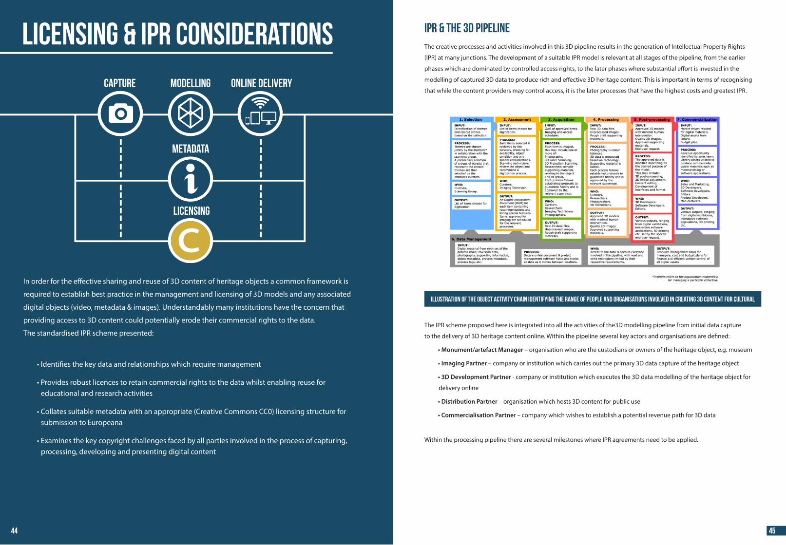
In order for the e�ective sharing and reuse of 3D content of heritage objects a common framework is
required to establish best practice in the management and licensing of 3D models and any associated
digital objects (video, metadata & images). Understandably many institutions have the concern that
providing access to 3D content could potentially erode their commercial rights to the data.
The standardised IPR scheme presented:
•
• educational and research activities
• submission to Europeana
• processing, developing and presenting digital content
IPR & the 3D pipelineThe creative processes and activities involved in this 3D pipeline results in the generation of Intellectual Property Rights
(IPR) at many junctions. The development of a suitable IPR model is relevant at all stages of the pipeline, from the earlier
phases which are dominated by controlled access rights, to the later phases where substantial e�ort is invested in the
modelling of captured 3D data to produce rich and e�ective 3D heritage content. This is important in terms of recognising
that while the content providers may control access, it is the later processes that have the highest costs and greatest IPR.
The IPR scheme proposed here is integrated into all the activities of the3D modelling pipeline from initial data capture
to the delivery of 3D heritage content online. Within the pipeline several key actors and organisations are de�ned:
• Monument/artefact Manager – organisation who are the custodians or owners of the heritage object, e.g. museum
• Imaging Partner – company or institution which carries out the primary 3D data capture of the heritage object
• 3D Development Partner - company or institution which executes the 3D data modelling of the heritage object for
delivery online
• Distribution Partner – organisation which hosts 3D content for public use
• Commercialisation Partner – company which wishes to establish a potential revenue path for 3D data
Within the processing pipeline there are several milestones where IPR agreements need to be applied.
Illustration of the Object activity chain identifying the range of people and organisations involved in creating 3D content for cultural
heritage
LICENSING & IPR Considerations
Capture MODELLING ONLINE DELIVERY
LICENSING
METADATA
44 45
44 44
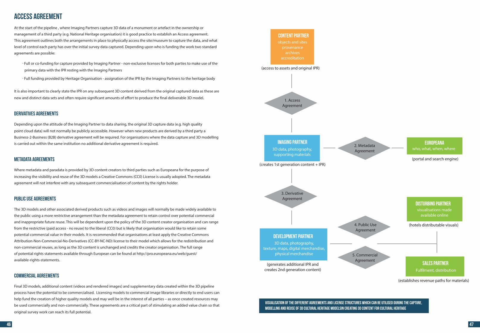
Access AgreementAt the start of the pipeline , where Imaging Partners capture 3D data of a monument or artefact in the ownership or
management of a third party (e.g. National Heritage organisation) it is good practice to establish an Access agreement.
This agreement outlines both the arrangements in place to physically access the site/museum to capture the data, and what
level of control each party has over the initial survey data captured. Depending upon who is funding the work two standard
agreements are possible:
· Full or co-funding for capture provided by Imaging Partner - non-exclusive licenses for both parties to make use of the
primary data with the IPR resting with the Imaging Partners
· Full funding provided by Heritage Organisation - assignation of the IPR by the Imaging Partners to the heritage body
It is also important to clearly state the IPR on any subsequent 3D content derived from the original captured data as these are
new and distinct data sets and often require signi�cant amounts of e�ort to produce the �nal deliverable 3D model.
Derivatives Agreements
Depending upon the attitude of the Imaging Partner to data sharing, the original 3D capture data (e.g. high quality
point cloud data) will not normally be publicly accessible. However when new products are derived by a third party a
Business-2-Business (B2B) derivative agreement will be required. For organisations where the data capture and 3D modelling
is carried out within the same institution no additional derivative agreement is required.
Metadata Agreements
Where metadata and paradata is provided by 3D content creators to third parties such as Europeana for the purpose of
increasing the visibility and reuse of the 3D models a Creative Commons (CC0) License is usually adopted. The metadata
agreement will not interfere with any subsequent commercialisation of content by the rights holder.
Public Use Agreements
The 3D models and other associated derived products such as videos and images will normally be made widely available to
the public using a more restrictive arrangement than the metadata agreement to retain control over potential commercial
and inappropriate future reuse. This will be dependent upon the policy of the 3D content creator organisation and can range
from the restrictive (paid access - no reuse) to the liberal (CC0) but is likely that organisation would like to retain some
potential commercial value in their models. It is recommended that organisations at least apply the Creative Commons
Attribution-Non-Commercial-No-Derivatives (CC-BY-NC-ND) license to their model which allows for the redistribution and
non-commercial reuses, as long as the 3D content is unchanged and credits the creator organisation. The full range
of potential rights statements available through European can be found at http://pro.europeana.eu/web/guest/
available-rights-statements.
Commercial Agreements
Final 3D models, additional content (videos and rendered images) and supplementary data created within the 3D pipeline
process have the potential to be commercialised. Licensing models to commercial image libraries or directly to end users can
help fund the creation of higher quality models and may well be in the interest of all parties – as once created resources may
be used commercially and non-commercially. These agreements are a critical part of stimulating an added value chain so that
original survey work can reach its full potential.
Visualisation of the different agreements and license structures which can be utilised during the capture, modelling and reuse of 3d cultural heritage modelsin creating 3D content for cultural heritage
46 47
CONTENT PARTNER
IMaging partner EUROPEANA
DEVELOPMENT PArtner
DISTURBING PArtner
SALES PArtner
objects and sitesprovenance
archivesaccreditation
1. AccessAgreement
3D data, photography,supporting materials
3D data, photography,texture, maps, digital merchandise,
physical merchandise
(creates 1st generation content + IPR)
(generates additional IPR andcreates 2nd generation content)
3. DerivativeAgreement
4. Public UseAgreement
Ful�lment, distribution
(hotels distributable visuals)
visualisations madeavailable online
(establishes revenue paths for materials)
5. CommercialAgreement
2. MetadataAgreement who, what, when, where
(portal and search engine)
(access to assets and original IPR)
44 44
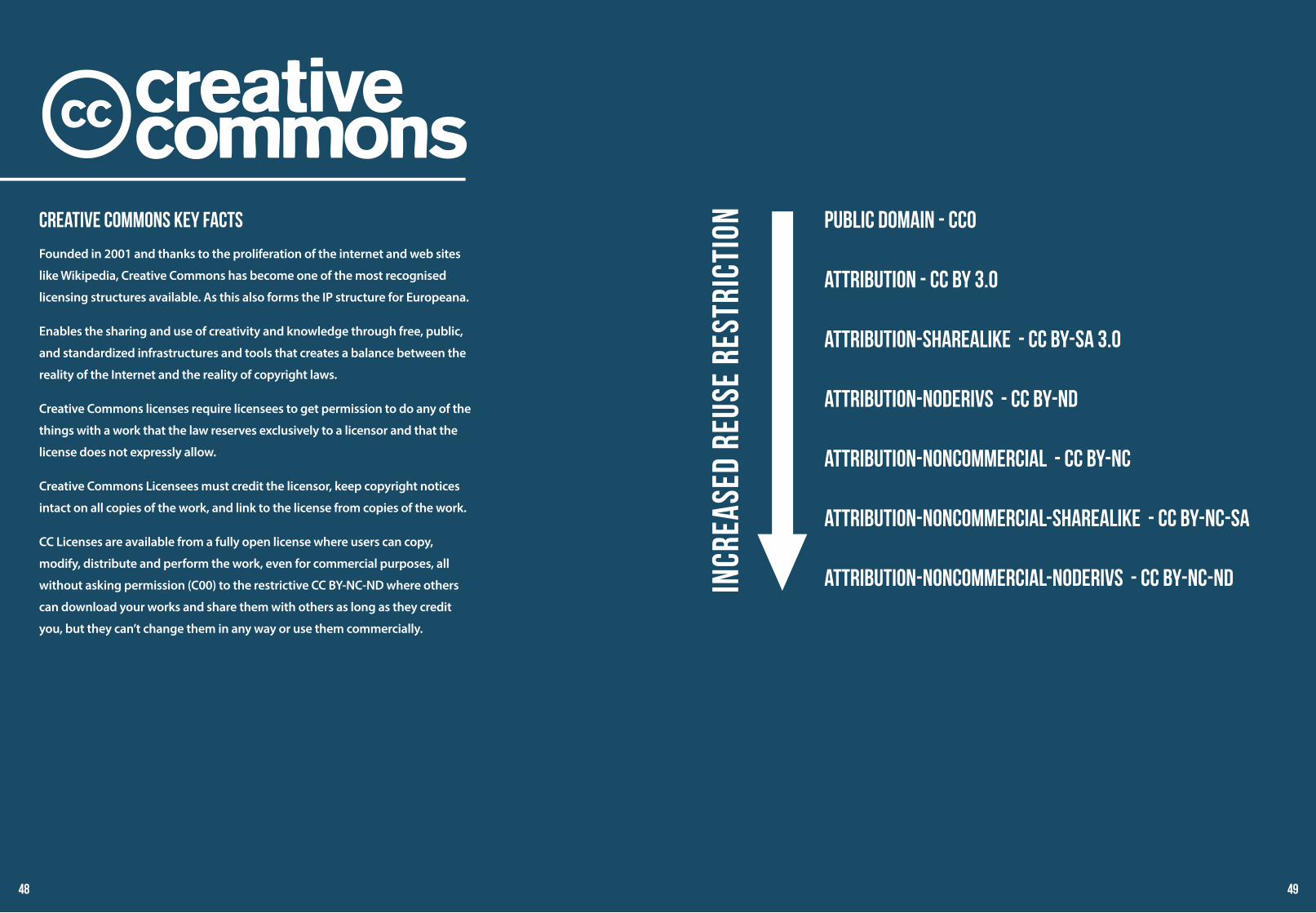
Creative Commons Key Facts
Founded in 2001 and thanks to the proliferation of the internet and web sites
like Wikipedia, Creative Commons has become one of the most recognised
licensing structures available. As this also forms the IP structure for Europeana.
Enables the sharing and use of creativity and knowledge through free, public,
and standardized infrastructures and tools that creates a balance between the
reality of the Internet and the reality of copyright laws.
Creative Commons licenses require licensees to get permission to do any of the
things with a work that the law reserves exclusively to a licensor and that the
license does not expressly allow.
Creative Commons Licensees must credit the licensor, keep copyright notices
intact on all copies of the work, and link to the license from copies of the work.
CC Licenses are available from a fully open license where users can copy,
modify, distribute and perform the work, even for commercial purposes, all
without asking permission (C00) to the restrictive CC BY-NC-ND where others
can download your works and share them with others as long as they credit
you, but they can’t change them in any way or use them commercially.
Incr
ease
d re
use
rest
rict
ion Public Domain - CC0
Attribution - CC BY 3.0
Attribution-ShareAlike - CC BY-SA 3.0
Attribution-NoDerivs - CC BY-ND
Attribution-NonCommercial - CC BY-NC
Attribution-NonCommercial-ShareAlike - CC BY-NC-SA
Attribution-NonCommercial-NoDerivs - CC BY-NC-ND
48 49
44 44
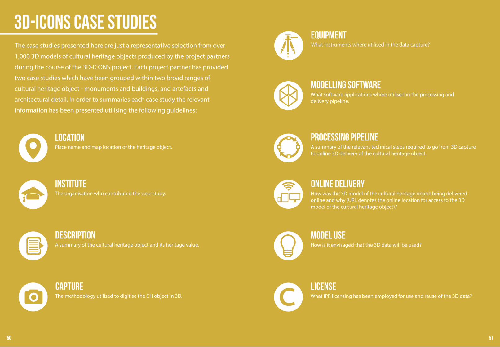
3D-ICONS Case StudiesThe case studies presented here are just a representative selection from over
1,000 3D models of cultural heritage objects produced by the project partners
during the course of the 3D-ICONS project. Each project partner has provided
two case studies which have been grouped within two broad ranges of
cultural heritage object - monuments and buildings, and artefacts and
architectural detail. In order to summaries each case study the relevant
information has been presented utilising the following guidelines:
LOCATIONPlace name and map location of the heritage object.
InstituteThe organisation who contributed the case study.
DescriptionA summary of the cultural heritage object and its heritage value.
CaptureThe methodology utilised to digitise the CH object in 3D.
EquipmentWhat instruments where utilised in the data capture?
Modelling SoftwareWhat software applications where utilised in the processing and delivery pipeline.
Processing PipelineA summary of the relevant technical steps required to go from 3D capture to online 3D delivery of the cultural heritage object.
Online deliveryHow was the 3D model of the cultural heritage object being delivered online and why (URL denotes the online location for access to the 3D model of the cultural heritage object)?
Model UseHow is it envisaged that the 3D data will be used?
LicenseWhat IPR licensing has been employed for use and reuse of the 3D data?
50 51
44 44
10
0503
06
13
13
14
15
09/14
01
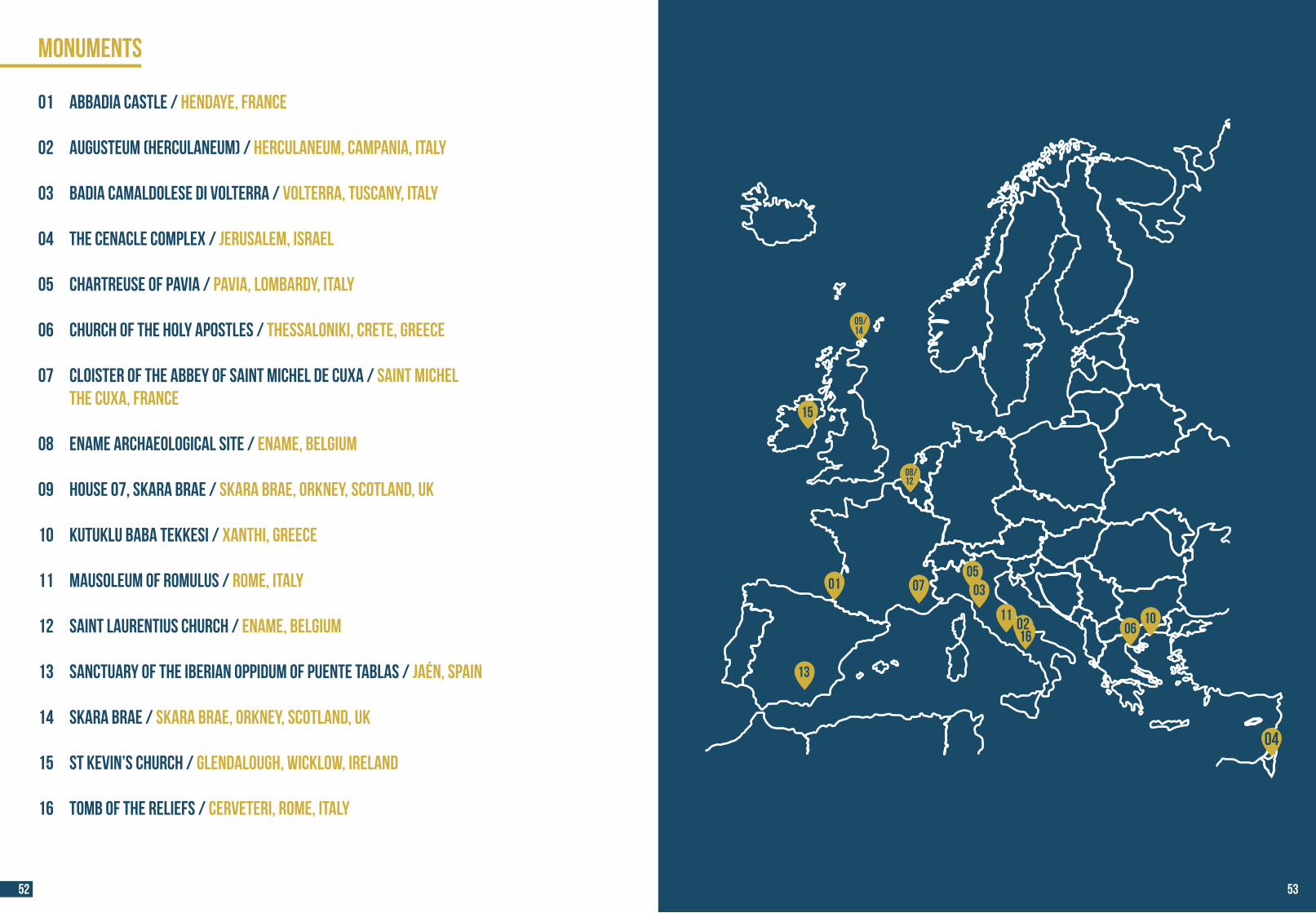
MONUMENTS
01 Abbadia Castle / Hendaye, France
02 Augusteum (Herculaneum) / Herculaneum, Campania, Italy
03 Badia Camaldolese di Volterra / Volterra, Tuscany, Italy
04 The Cenacle Complex / Jerusalem, Israel
05 Chartreuse of Pavia / Pavia, Lombardy, Italy
06 Church of the Holy Apostles / Thessaloniki, Crete, Greece
07 Cloister of the Abbey of Saint Michel de Cuxa / Saint Michel the Cuxa, France
08 Ename archaeological site / Ename, Belgium
09 House 07, Skara Brae / Skara Brae, Orkney, Scotland, UK
10 Kutuklu Baba Tekkesi / Xanthi, Greece
11 Mausoleum of Romulus / Rome, Italy
12 Saint Laurentius church / Ename, Belgium
13 Sanctuary of the Iberian oppidum of Puente Tablas / Jaén, Spain
14 Skara Brae / Skara Brae, Orkney, SCOTLAND, UK
15 St Kevin’s Church / Glendalough, Wicklow, Ireland
16 Tomb of the Reliefs / Cerveteri, Rome, Italy
07
11
04
02
08/12
16
52 53
44 44
01
11
02
06
05
03
07
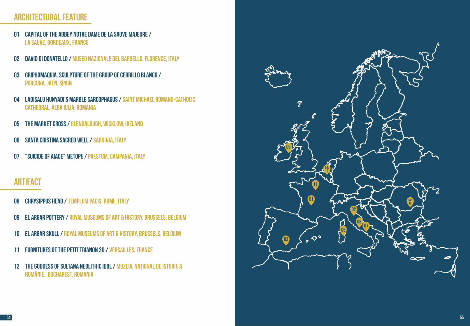
ARCHITECTURAL FEATURE
01 Capital of the Abbey Notre Dame de la Sauve Majeure / La Sauve, Bordeaux, France 02 David di Donatello / Museo Nazionale del Bargello, Florence, Italy
03 Griphomaquia. Sculpture of the group of Cerrillo Blanco / Porcuna, Jaén, Spain
04 Ladisalu Hunyadi's marble sarcophagus / Saint Michael Romano-Catholic Cathedral, Alba Iulia. ROMANIA
05 The Market Cross / Glendalough, Wicklow, Ireland 06 Santa Cristina Sacred Well / Sardinia, Italy 07 "Suicide of Aiace" metope / Paestum, Campania, Italy
ARTIFACT
08 Chrysippus Head / Templum Pacis, Rome, Italy
09 El Argar Pottery / Royal Museums of Art & History, Brussels, Belgium
10 El Argar SKULL / Royal Museums of Art & History, Brussels, Belgium
11 Furnitures of the Petit Trianon 3D / Versailles, France
12 The Goddess of Sultana Neolithic Idol / Muzeul Național de Istorie a Românie, Bucharest, Romania
08
04/12
09/10
54 55
44 44
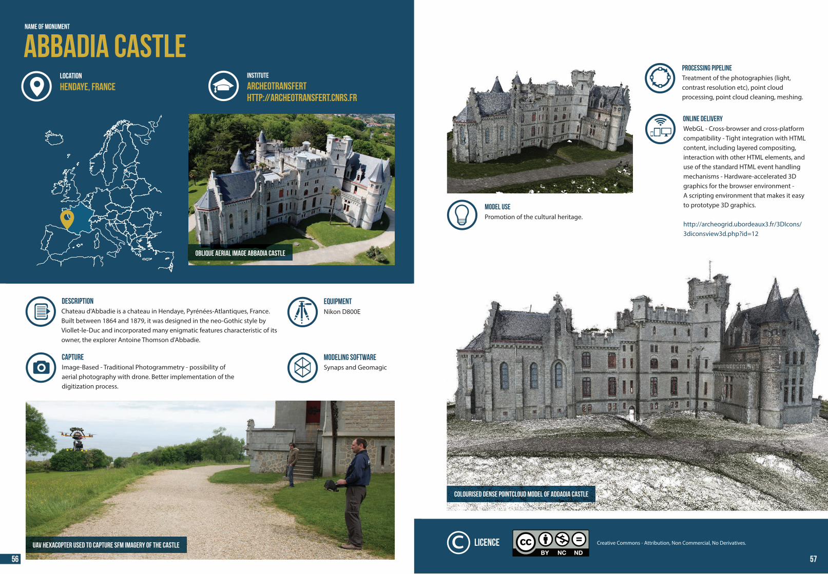
Oblique aerial image Abbadia Castle
LOCATION
NAME OF MONUMENT
Abbadia CastleINSTITUTE
Archeotransferthttp://archeotransfert.cnrs.fr
Hendaye, France
DESCRIPTION Chateau d'Abbadie is a chateau in Hendaye, Pyrénées-Atlantiques, France. Built between 1864 and 1879, it was designed in the neo-Gothic style by Viollet-le-Duc and incorporated many enigmatic features characteristic of its owner, the explorer Antoine Thomson d'Abbadie.
UAV hexacopter used to capture SfM imagery of the castle
MODELING SOFTWAREImage-Based - Traditional Photogrammetry - possibility ofaerial photography with drone. Better implementation of the digitization process.
CAPTURESynaps and Geomagic
EQUIPMENTNikon D800E
PROCESSING PIPELINETreatment of the photographies (light, contrast resolution etc), point cloud processing, point cloud cleaning, meshing.
ONLINE DELIVERYWebGL - Cross-browser and cross-platform compatibility - Tight integration with HTML content, including layered compositing, interaction with other HTML elements, anduse of the standard HTML event handling mechanisms - Hardware-accelerated 3D graphics for the browser environment -A scripting environment that makes it easyto prototype 3D graphics.
http://archeogrid.ubordeaux3.fr/3DIcons/3diconsview3d.php?id=12
Colourised DENSE pointcloud model of Addadia Castle
Promotion of the cultural heritage.
Creative Commons - Attribution, Non Commercial, No Derivatives.Licence
MODEL USE
56 57
44 44
Augusteum (Herculaneum)Name of Monument
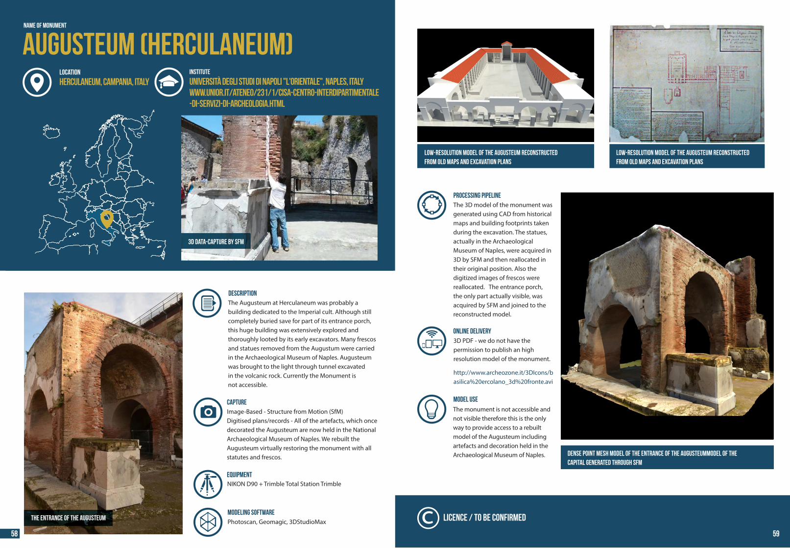
DESCRIPTION The Augusteum at Herculaneum was probably a building dedicated to the Imperial cult. Although still completely buried save for part of its entrance porch, this huge building was extensively explored and thoroughly looted by its early excavators. Many frescos and statues removed from the Augustum were carried in the Archaeological Museum of Naples. Augusteum was brought to the light through tunnel excavated in the volcanic rock. Currently the Monument is not accessible.
Image-Based - Structure from Motion (SfM) Digitised plans/records - All of the artefacts, which once decorated the Augusteum are now held in the National Archaeological Museum of Naples. We rebuilt the Augusteum virtually restoring the monument with all statutes and frescos.
CAPTURE
MODELING SOFTWAREPhotoscan, Geomagic, 3DStudioMaxThe entrance of the Augusteum
3D data-capture by SFM
INSTITUTE
Università degli Studi di Napoli "L'Orientale", Naples, Italywww.unior.it/ateneo/231/1/cisa-centro-interdipartimentale-di-servizi-di-archeologia.html
LOCATION
Herculaneum, Campania, Italy
NIKON D90 + Trimble Total Station TrimbleEquipment
Dense point Mesh model of the Entrance of the Augusteummodel of thecapital generated through SfM
Low-resolution model of the Augusteum RECONSTRUCTEDfrom old maps AND excavation PLANS
Low-resolution model of the Augusteum RECONSTRUCTEDfrom old maps AND excavation PLANS
Licence / TO BE CONFIRMED
PROCESSING PIPELINEThe 3D model of the monument was generated using CAD from historical maps and building footprints taken during the excavation. The statues, actually in the Archaeological Museum of Naples, were acquired in 3D by SFM and then reallocated in their original position. Also the digitized images of frescos were reallocated. The entrance porch, the only part actually visible, was acquired by SFM and joined to the reconstructed model.
ONLINE DELIVERY3D PDF - we do not have the permission to publish an high resolution model of the monument. http://www.archeozone.it/3DIcons/basilica%20ercolano_3d%20fronte.avi
MODEL USE The monument is not accessible and not visible therefore this is the only way to provide access to a rebuilt model of the Augusteum including artefacts and decoration held in the Archaeological Museum of Naples.
58 59
44 44
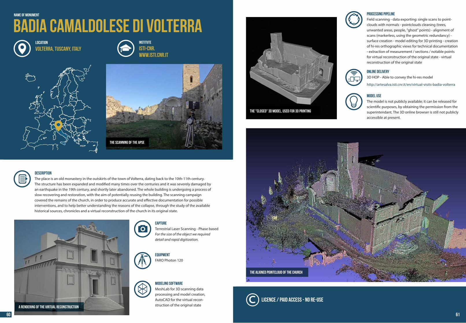
The scanning of the apse
DESCRIPTION The place is an old monastery in the outskirts of the town of Volterra, dating back to the 10th-11th century. The structure has been expanded and modi�ed many times over the centuries and it was severely damaged by an earthquake in the 19th century, and shortly later abandoned. The whole building is undergoing a process of slow recovering and restoration, with the aim of potentially reusing the building. The scanning campaign covered the remains of the church, in order to produce accurate and e�ective documentation for possible interventions, and to help better understanding the reasons of the collapse, through the study of the available historical sources, chronicles and a virtual reconstruction of the church in its original state.
Badia Camaldolese di VolterraISTI-CNR.www.isti.cnr.it
MODELING SOFTWARE
Terrestrial Laser Scanning - Phase based For the size of the object we required detail and rapid digitization.
CAPTURE
MeshLab for 3D scanning data processing and model creation, AutoCAD for the virtual recon-struction of the original stateA rendering of the virtual reconstruction
Name of MONUMENT
INSTITUTE
Volterra, Tuscany, ItalyLOCATION
FARO Photon 120 Equipment
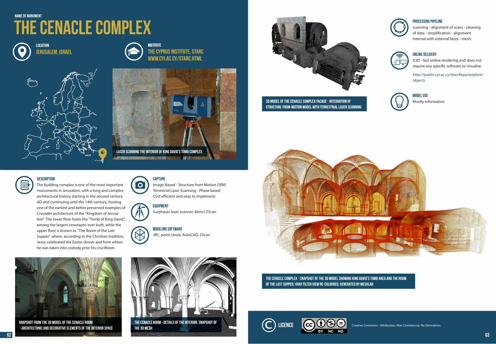
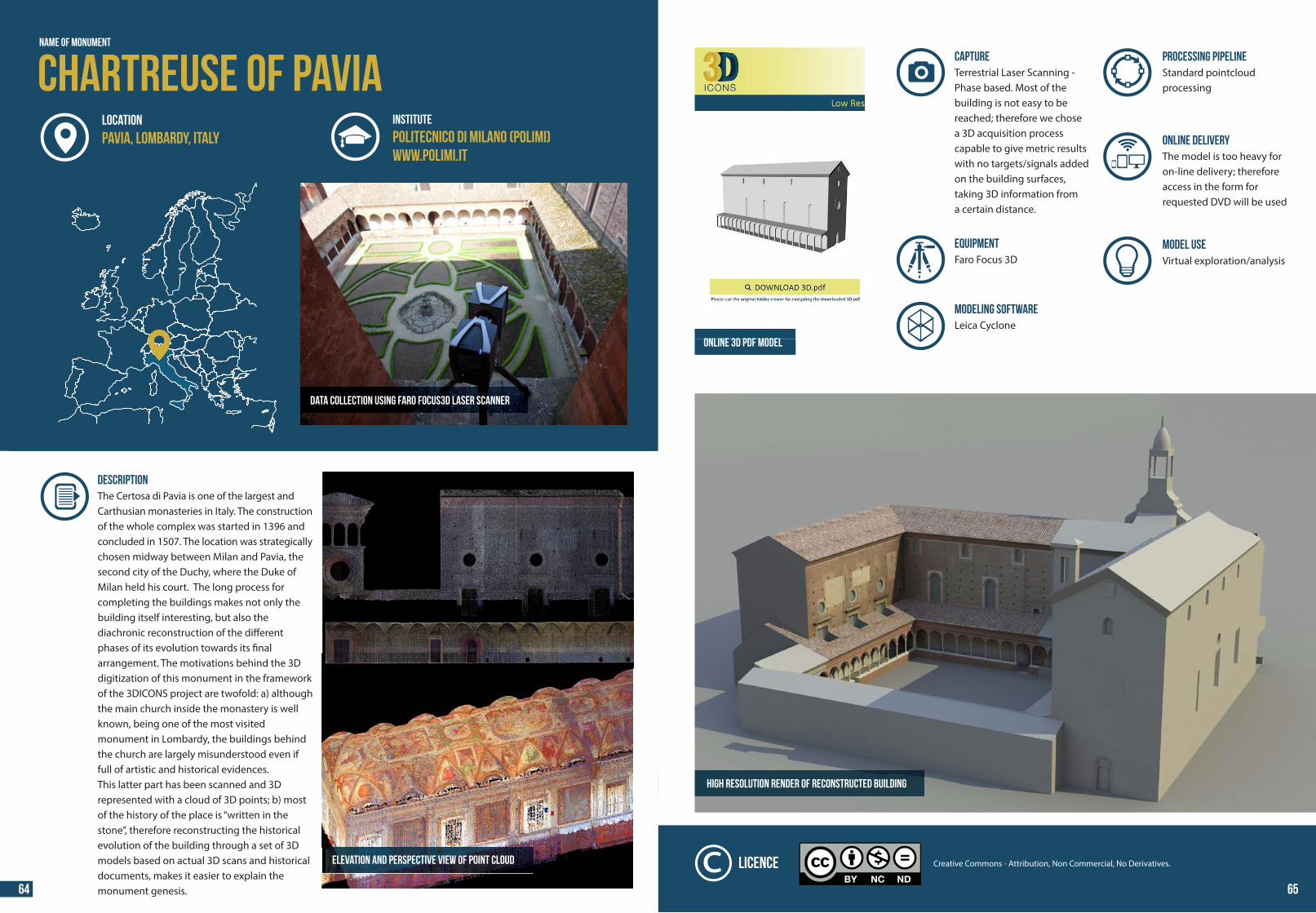
PROCESSING PIPELINEField scanning - data exporting: single scans to point-clouds with normals - pointclouds cleaning (trees, unwanted areas, people, "ghost" points) - alignment of scans (markerless, using the geometric redundancy) - surface creation - model editing for 3D printing - creation of hi-res orthographic views for technical documentation - extraction of measurement / sections / notable points for virtual reconstruction of the original state - virtual reconstruction of the original state
MODEL USE The model is not publicly available; it can be released for scienti�c purposes, by obtaining the permission from the superintendant. The 3D online browser is still not publicly accessible at present.
ONLINE DELIVERY3D HOP - Able to convey the hi-res model
http://artesalva.isti.cnr.it/en/virtual-visits-badia-volterra
Licence / Paid Access - No Re-use
The aligned pointcloud of the Church
The "closed" 3D model, used for 3D printing
60 61
44 44
Name of Monument
Laser scanning the interior of King David’s Tomb complex
LOCATION INSTITUTE
DESCRIPTION The building complex is one of the most important monuments in Jerusalem, with a long and complex architectural history starting in the second century AD and continuing until the 14th century, hosting one of the earliest and better preserved examples of Crusader architecture of the "Kingdom of Jerusa-lem". The lower �oor hosts the "Tomb of King David", among the largest cenotaphs ever built, while the upper �oor is known as "The Room of the Last Supper" where, according to the Christian tradition, Jesus celebrated the Easter dinner and from where he was taken into custody prior his cruci�xion.
The Cenacle Room - Details of the interior, snapshot ofthe 3D mesh
Image-Based - Structure from Motion (SfM)Terrestrial Laser Scanning - Phase basedCost e�cient and easy to implement.
MODELING SOFTWAREJRC, point cloud, AutoCAD, ZScan
CAPTURE
Surphaser laser scanner, Menci ZScanEquipment
The Cenacle ComplexINSTITUTE
The Cyprus Institute, STARCwww.cyi.ac.cy/starc.html
Jerusalem, Israel
Snapshot from the 3D model of the Cenacle room - architectonic and decorative elements of the interior space
PROCESSING PIPELINEscanning - alignment of scans - cleaning of data - simpli�cation - alignment internal with external faces - mesh.
ONLINE DELIVERYX3D - fast online rendering and does not require any speci�c software to visualise. http://public.cyi.ac.cy/starcRepo/explore/objects
The Cenacle complex - snapshot of the 3D model showing King David’s Tomb area and the Roomof the Last Supper; Xray filter view re-coloured, generated by MeshlaB
MODEL USE Mostly informative3D model of the Cenacle complex facade - integration of
structure-from-motion model with terrestrial laser scanning
Creative Commons - Attribution, Non Commercial, No Derivatives.Licence
62 63
44 44
Name of Monument
Chartreuse of PaviaINSTITUTE
Politecnico di Milano (POLIMI)www.polimi.it
LOCATIONPavia, Lombardy, Italy
DESCRIPTION The Certosa di Pavia is one of the largest and Carthusian monasteries in Italy. The construction of the whole complex was started in 1396 and concluded in 1507. The location was strategically chosen midway between Milan and Pavia, the second city of the Duchy, where the Duke of Milan held his court. The long process for completing the buildings makes not only the building itself interesting, but also the diachronic reconstruction of the di�erent phases of its evolution towards its �nalarrangement. The motivations behind the 3D digitization of this monument in the framework of the 3DICONS project are twofold: a) although the main church inside the monastery is well known, being one of the most visitedmonument in Lombardy, the buildings behind the church are largely misunderstood even if full of artistic and historical evidences.This latter part has been scanned and 3D represented with a cloud of 3D points; b) most of the history of the place is “written in the stone”, therefore reconstructing the historical evolution of the building through a set of 3D models based on actual 3D scans and historical documents, makes it easier to explain the monument genesis.
DATA COLLECTION USING FARO FOCUS3D LASER SCANNER
ELEVATION AND PERSPECTIVE VIEW OF POINT CLOUD
ONLINE 3D PDF MODEL
HIGH RESOLUTION RENDER OF RECONSTRUCTED BUILDING
PROCESSING PIPELINEStandard pointcloud processing
ONLINE DELIVERYThe model is too heavy for on-line delivery; therefore access in the form for requested DVD will be used
Terrestrial Laser Scanning - Phase based. Most of the building is not easy to be reached; therefore we chosea 3D acquisition process capable to give metric results with no targets/signals added on the building surfaces, taking 3D information froma certain distance.
CAPTURE
MODELING SOFTWARELeica Cyclone
EQUIPMENTFaro Focus 3D
MODEL USE Virtual exploration/analysis
Creative Commons - Attribution, Non Commercial, No Derivatives.Licence
64 65
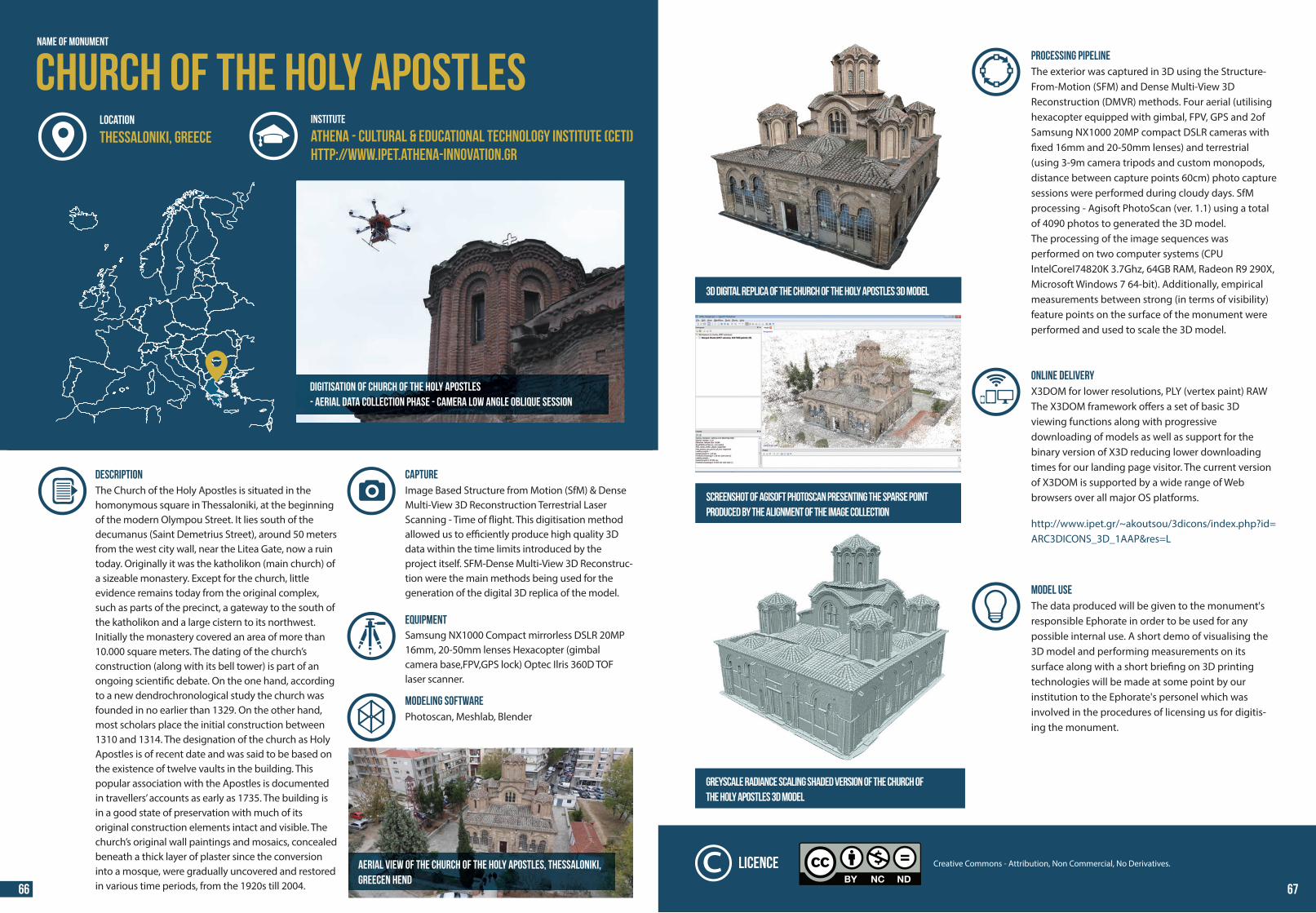
44 44
Digitisation of Church of the Holy Apostles- Aerial data collection phase - Camera low angle oblique session
Name of Monument
Church of the Holy ApostlesINSTITUTE
Athena - CULTURAL & EDUCATIONAL TECHNOLOGY INSTITUTE (CETI)http://www.ipet.athena-innovation.gr
LOCATION
Thessaloniki, Greece
DESCRIPTION The Church of the Holy Apostles is situated in the homonymous square in Thessaloniki, at the beginning of the modern Olympou Street. It lies south of the decumanus (Saint Demetrius Street), around 50 meters from the west city wall, near the Litea Gate, now a ruin today. Originally it was the katholikon (main church) of a sizeable monastery. Except for the church, little evidence remains today from the original complex, such as parts of the precinct, a gateway to the south of the katholikon and a large cistern to its northwest. Initially the monastery covered an area of more than 10.000 square meters. The dating of the church’s construction (along with its bell tower) is part of an ongoing scienti�c debate. On the one hand, according to a new dendrochronological study the church was founded in no earlier than 1329. On the other hand, most scholars place the initial construction between 1310 and 1314. The designation of the church as Holy Apostles is of recent date and was said to be based on the existence of twelve vaults in the building. This popular association with the Apostles is documented in travellers’ accounts as early as 1735. The building is in a good state of preservation with much of its original construction elements intact and visible. The church’s original wall paintings and mosaics, concealed beneath a thick layer of plaster since the conversion into a mosque, were gradually uncovered and restored in various time periods, from the 1920s till 2004.
Image Based Structure from Motion (SfM) & Dense Multi-View 3D Reconstruction Terrestrial Laser Scanning - Time of �ight. This digitisation method allowed us to e�ciently produce high quality 3D data within the time limits introduced by the project itself. SFM-Dense Multi-View 3D Reconstruc-tion were the main methods being used for the generation of the digital 3D replica of the model.
CAPTURE
MODELING SOFTWAREPhotoscan, Meshlab, Blender
!
Samsung NX1000 Compact mirrorless DSLR 20MP 16mm, 20-50mm lenses Hexacopter (gimbal camera base,FPV,GPS lock) Optec Ilris 360D TOF laser scanner.
Equipment
Aerial view of the Church of the Holy Apostles, Thessaloniki,Greecen Hend
PROCESSING PIPELINEThe exterior was captured in 3D using the Structure-From-Motion (SFM) and Dense Multi-View 3DReconstruction (DMVR) methods. Four aerial (utilising hexacopter equipped with gimbal, FPV, GPS and 2of Samsung NX1000 20MP compact DSLR cameras with �xed 16mm and 20-50mm lenses) and terrestrial (using 3-9m camera tripods and custom monopods, distance between capture points 60cm) photo capture sessions were performed during cloudy days. SfM processing - Agisoft PhotoScan (ver. 1.1) using a total of 4090 photos to generated the 3D model. The processing of the image sequences was performed on two computer systems (CPU IntelCoreI74820K 3.7Ghz, 64GB RAM, Radeon R9 290X, Microsoft Windows 7 64-bit). Additionally, empirical measurements between strong (in terms of visibility) feature points on the surface of the monument were performed and used to scale the 3D model.
ONLINE DELIVERYX3DOM for lower resolutions, PLY (vertex paint) RAWThe X3DOM framework o�ers a set of basic 3D viewing functions along with progressivedownloading of models as well as support for the binary version of X3D reducing lower downloading times for our landing page visitor. The current version of X3DOM is supported by a wide range of Web browsers over all major OS platforms. http://www.ipet.gr/~akoutsou/3dicons/index.php?id=ARC3DICONS_3D_1AAP&res=L
Greyscale radiance scaling shaded version of the Church ofthe Holy Apostles 3D model
3D Digital replica of the Church of the Holy Apostles 3D model
MODEL USE The data produced will be given to the monument's responsible Ephorate in order to be used for any possible internal use. A short demo of visualising the 3D model and performing measurements on its surface along with a short brie�ng on 3D printing technologies will be made at some point by our institution to the Ephorate's personel which was involved in the procedures of licensing us for digitis-ing the monument.
Screenshot of Agisoft Photoscan presenting the sparse pointproduced by the alignment of the image collection
Creative Commons - Attribution, Non Commercial, No Derivatives.Licence
66 67
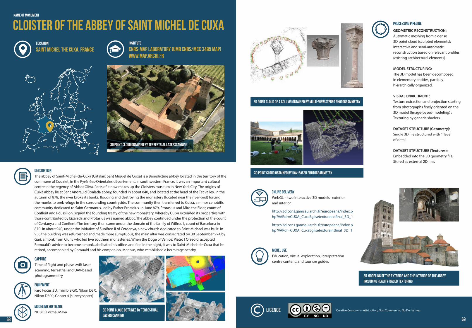
44 44
Name of Monument
3D point cloud obtained by terrestrial laserscanning
INSTITUTE
DESCRIPTION The abbey of Saint-Michel-de-Cuxa (Catalan: Sant Miquel de Cuixà) is a Benedictine abbey located in the territory of the commune of Codalet, in the Pyrénées-Orientales département, in southwestern France. It was an important cultural centre in the regency of Abbot Oliva. Parts of it now makes up the Cloisters museum in New York City. The origins of Cuixà abbey lie at Sant Andreu d'Eixalada abbey, founded in about 840, and located at the head of the Tet valley. In the autumn of 878, the river broke its banks, �ooding and destroying the monastery (located near the river-bed) forcing the monks to seek refuge in the surrounding countryside. The community then transferred to Cuixà, a minor cenobitic community dedicated to Saint Germanus, led by Father Protasius. In June 879, Protasius and Miro the Elder, count of Con�ent and Roussillon, signed the founding treaty of the new monastery, whereby Cuixà extended its properties with those contributed by Eixalada and Protasius was named abbot. The abbey continued under the protection of the count of Cerdanya and Con�ent. The territory then came under the domain of the family of Wilfred I, count of Barcelona in 870. In about 940, under the initiative of Sunifred II of Cerdanya, a new church dedicated to Saint Michael was built. In 956 the building was refurbished and made more sumptuous; the main altar was consecrated on 30 September 974 by Garí, a monk from Cluny who led �ve southern monasteries. When the Doge of Venice, Pietro I Orseolo, accepted Romuald's advice to become a monk, abdicated his o�ce, and �ed in the night, it was to Saint-Michel-de-Cuxa that he retired, accompanied by Romuald and his companion, Marinus, who established a hermitage nearby.
Time of �ight and phase swift laserscanning, terrestrial and UAV-basedphotogrammetry
MODELING SOFTWARENUBES Forma, Maya
CAPTURE
Faro Focus 3D, Trimble GX, Nikon D3X,Nikon D300, Copter 4 (surveycopter)
Equipment
Cloister of the Abbey of Saint Michel de CuxaINSTITUTE
CNRS-MAP laboratory (UMR CNRS/MCC 3495 MAP)WWW.map.archi.fr
LOCATION
Saint Michel the Cuxa, France
3D point cloud obtained by terrestriallaserscanning
68 69
PROCESSING PIPELINE
GEOMETRIC RECONSTRUCTION: Automatic meshing from a dense 3D point cloud (sculpted elements); Interactive and semi-automaticreconstruction based on relevant pro�les (existing architectural elements)
MODEL STRUCTURING: The 3D model has been decomposed in elementary entities, partially hierarchically organized.
VISUAL ENRICHMENT: Texture extraction and projection starting from photographs �nely oriented on the 3D model (Image-based-modeling) ; Texturing by generic shaders.
DATASET STRUCTURE (Geometry):Single 3D �le structured with 1 levelof detail
DATASET STRUCTURE (Textures):Embedded into the 3D geometry �le;Stored as external 2D �les
MODEL USE Education, virtual exploration, interpretation centre content, and tourism guides
3D point cloud of a column obtained by multi-view stereo photogrammetry
3D point cloud obtained by UAV-based photogrammetry
3D modeling of the exterior and the interior of the abbey including reality-based texturing
Creative Commons - Attribution, Non Commercial, No Derivatives.Licence
ONLINE DELIVERYWebGL – two interactive 3D models : exteriorand interior. http://3dicons.gamsau.archi.fr/europeana/index.php?VARdr=CUXA_CuxaEglisetextureext�nal_3D_1 http://3dicons.gamsau.archi.fr/europeana/index.php?VARdr=CUXA_CuxaEglisetextureint�nal_3D_1
69
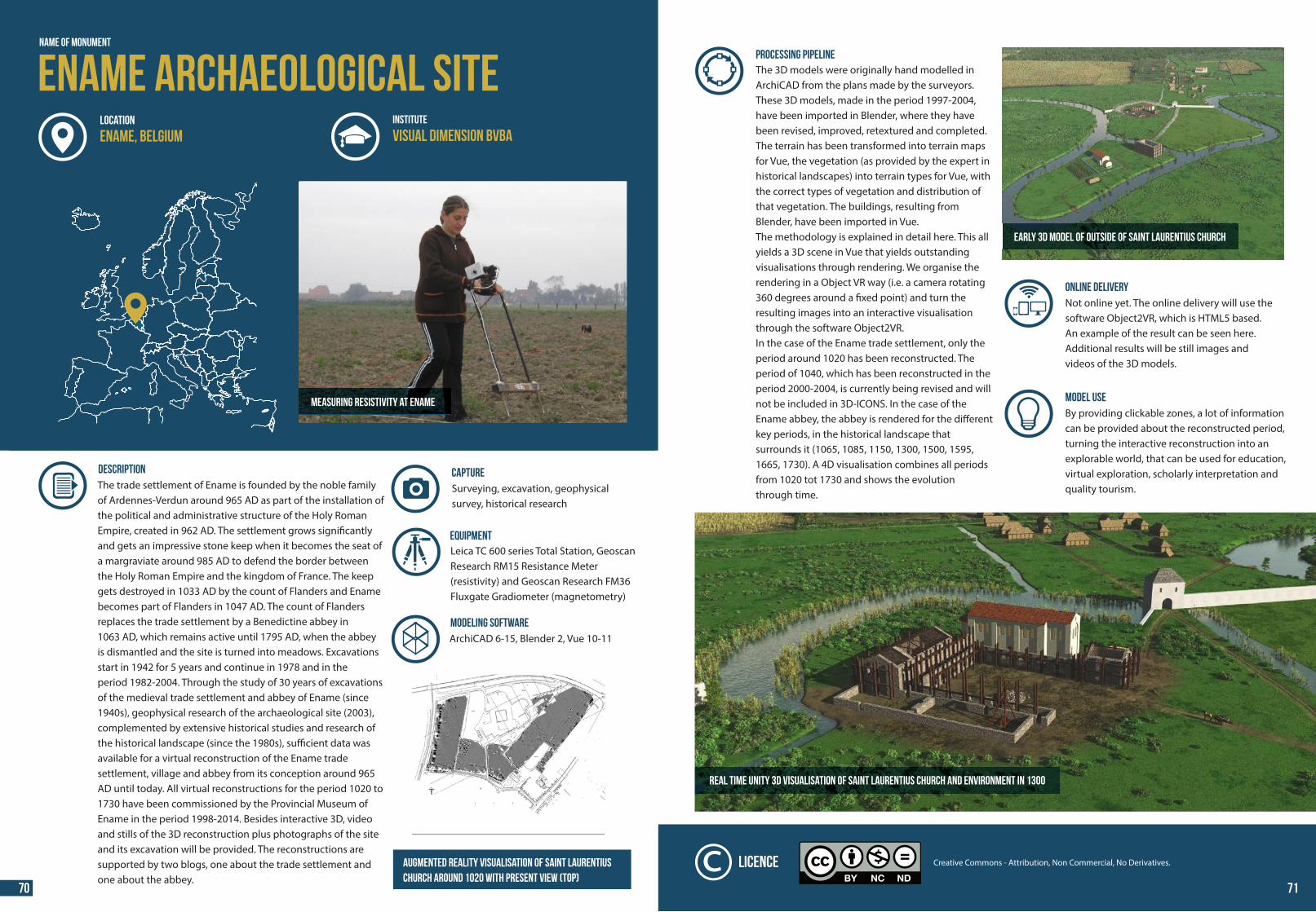
44 44
E
B
E
A
A
R
N
S
T
R
A
A
T
U
C
E
N
A
M
L
E
P
E
I
N
S
t
.
-
S
A
L
V
A
T
R
T
R
A
A
O
S
T
S
C
H
E
L
D
E
N
0
AKKER
BRAAK
AKKER
WEILAND
WEILAND
BRAAK
RIETVELD
BRAAK
10.0
00
12.2
99
12.0
58
9
12.1
6
12.21
2
10.8
50
9.42
0
.59 89
981
5.
9.64
8
10.
913
9.148
3659.
9.19
3
10.22
0
9.87
4
10.0
27
9.97
8
9.49
5
9.25
1
9.03
0
149.0
10.0
57
0710.7
9649.
7
9.92
9.86
9
9.068
9.75
5
9.69
6
9.62
9
569.
5
9.49
4
942
8.
936
7.
.2899
.1749
906
5.
9.21
6
9.41
4
9.56
8
9.67
2
7549.
9.877
9.81
8
9.85
0
9 83.8
99.21
9.97
4 10.00
5
10.1
11
01.17
0
1 1920.
7
10.1
8
10
4.1210.1
34
10.1
38
10.1
28
10.1
31
101
3 6.
9.90
7
994
2.
11.7
92
1
941.7
9011.8
119
6 5.
83311.
11
6.81
11.8
87
913.18
24.363
12.584
10.0
00
9.52
0
feno
pal pavilio
en k
ijken
ter
a
v
s
eno
palw
k
t
F
- a erfe
e
s
Dorpel e
lektr
icite
itca
b nei
pse
lunt
o
t p
p-ud
na
ar
v o
e
de
GIN
-t
k
este
vpsi
e -ijkv
n
r
e
vp-s
ite-k
et
mepu
nt
et
P
H
Hm
P
© Archaeological Prospection
Services of Southampton
Ename, Belgium
0 100m
N
Measuring resistivity at Ename
DESCRIPTION The trade settlement of Ename is founded by the noble family of Ardennes-Verdun around 965 AD as part of the installation of the political and administrative structure of the Holy Roman Empire, created in 962 AD. The settlement grows signi�cantly and gets an impressive stone keep when it becomes the seat of a margraviate around 985 AD to defend the border between the Holy Roman Empire and the kingdom of France. The keep gets destroyed in 1033 AD by the count of Flanders and Ename becomes part of Flanders in 1047 AD. The count of Flanders replaces the trade settlement by a Benedictine abbey in 1063 AD, which remains active until 1795 AD, when the abbey is dismantled and the site is turned into meadows. Excavations start in 1942 for 5 years and continue in 1978 and in the period 1982-2004. Through the study of 30 years of excavations of the medieval trade settlement and abbey of Ename (since 1940s), geophysical research of the archaeological site (2003), complemented by extensive historical studies and research of the historical landscape (since the 1980s), su�cient data was available for a virtual reconstruction of the Ename trade settlement, village and abbey from its conception around 965 AD until today. All virtual reconstructions for the period 1020 to 1730 have been commissioned by the Provincial Museum of Ename in the period 1998-2014. Besides interactive 3D, video and stills of the 3D reconstruction plus photographs of the site and its excavation will be provided. The reconstructions are supported by two blogs, one about the trade settlement and one about the abbey.
MODELING SOFTWARE
Surveying, excavation, geophysical survey, historical research
CAPTURE
ArchiCAD 6-15, Blender 2, Vue 10-11
Name of Monument
Ename archaeological siteINSTITUTE
Visual Dimension bvbaLOCATION
Ename, Belgium
Leica TC 600 series Total Station, Geoscan Research RM15 Resistance Meter (resistivity) and Geoscan Research FM36 Fluxgate Gradiometer (magnetometry)
Equipment
Augmented reality visualisation of Saint Laurentiuschurch around 1020 WITH PRESENT VIEW (TOP)
MODEL USE By providing clickable zones, a lot of information can be provided about the reconstructed period, turning the interactive reconstruction into an explorable world, that can be used for education, virtual exploration, scholarly interpretation and quality tourism.
ONLINE DELIVERYNot online yet. The online delivery will use the software Object2VR, which is HTML5 based.An example of the result can be seen here. Additional results will be still images andvideos of the 3D models.
Real time Unity 3D visualisation of Saint Laurentius church and environment in 1300
Early 3D model of OUTSIDE OF Saint Laurentius church
Creative Commons - Attribution, Non Commercial, No Derivatives.Licence
PROCESSING PIPELINEThe 3D models were originally hand modelled in ArchiCAD from the plans made by the surveyors. These 3D models, made in the period 1997-2004, have been imported in Blender, where they have been revised, improved, retextured and completed. The terrain has been transformed into terrain maps for Vue, the vegetation (as provided by the expert in historical landscapes) into terrain types for Vue, with the correct types of vegetation and distribution of that vegetation. The buildings, resulting from Blender, have been imported in Vue. The methodology is explained in detail here. This all yields a 3D scene in Vue that yields outstanding visualisations through rendering. We organise the rendering in a Object VR way (i.e. a camera rotating 360 degrees around a �xed point) and turn the resulting images into an interactive visualisation through the software Object2VR.In the case of the Ename trade settlement, only the period around 1020 has been reconstructed. The period of 1040, which has been reconstructed in the period 2000-2004, is currently being revised and will not be included in 3D-ICONS. In the case of the Ename abbey, the abbey is rendered for the di�erent key periods, in the historical landscape that surrounds it (1065, 1085, 1150, 1300, 1500, 1595, 1665, 1730). A 4D visualisation combines all periods from 1020 tot 1730 and shows the evolution through time.
70 71
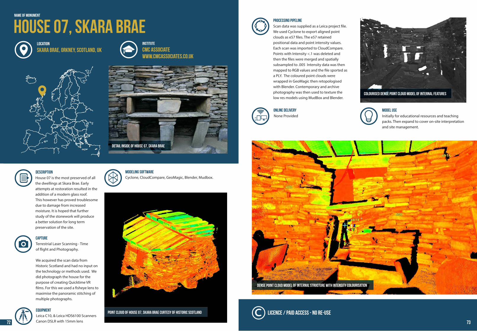
44 44
House 07, Skara Brae
Detail inside of House 07, Skara Brae
Name of Monument
INSTITUTE
CMC Associatewww.cmcassociates.co.uk
LOCATION
Skara Brae, Orkney, Scotland, UK
DESCRIPTION House 07 is the most preserved of all the dwellings at Skara Brae. Early attempts at restoration resulted in the addition of a modern glass roof. This however has proved troublesome due to damage from increasedmoisture. It is hoped that further study of the stonework will producea better solution for long term preservation of the site.
Point cloud of House 07, Skara Brae curtesy of Historic Scotland
MODELING SOFTWARE
Terrestrial Laser Scanning - Timeof �ight and Photography.
We acquired the scan data from Historic Scotland and had no input on the technology or methods used. We did photograph the house for the purpose of creating Quicktime VR �lms. For this we used a �sheye lens to maximise the panoramic stitching of multiple photographs.
Cyclone, CloudCompare, GeoMagic, Blender, Mudbox.
CAPTURE
Leica C10, & Leica HDS6100 ScannersCanon DSLR with 15mm lens
Equipment
Dense point cloud model of internal structure with intensity colourisation
MODEL USE Initially for educational resources and teachingpacks. Then expand to cover on-site interpretationand site management.
Colourised dense point cloud model of internal features
Licence / Paid Access - No Re-use
PROCESSING PIPELINEScan data was supplied as a Leica project �le. We used Cyclone to export aligned point clouds as e57 �les. The e57 retained positional data and point intensity values. Each scan was imported to CloudCompare. Points with Intensity <.1 was deleted and then the �les were merged and spatially subsampled to .005 Intensity data was then mapped to RGB values and the �le sported as a PLY. The coloured point clouds were wrapped in GeoMagic then retopologised with Blender. Contemporary and archive photography was then used to texture the low res models using MudBox and Blender.
ONLINE DELIVERYNone Provided
72 73
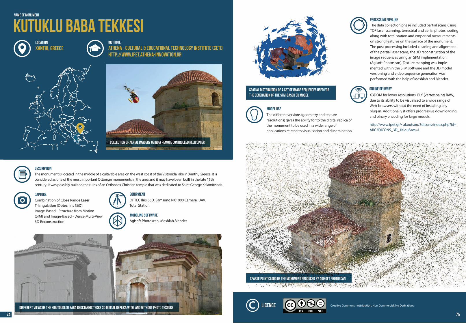
44 44
Collection of aerial imagery using a remote controlled helicopter
DESCRIPTION The monument is located in the middle of a cultivable area on the west coast of the Vistonida lake in Xanthi, Greece. It is considered as one of the most important Ottoman monuments in the area and it may have been built in the late 15th century. It was possibly built on the ruins of an Orthodox Christian temple that was dedicated to Saint George Kalamitziotis.
Combination of Close Range Laser Triangulation (Optec Ilris 36D),Image-Based - Structure from Motion (SfM) and Image-Based - Dense Multi-View 3D Reconstruction
CAPTURE:
MODELING SOFTWAREAgisoft Photoscan, Meshlab,Blender
Different views of the Kioutouklou Baba Bekctashic Tekke 3D digital replica with, and without photo texture
Name of Monument
Kutuklu Baba TekkesiINSTITUTE
Athena - CULTURAL & EDUCATIONAL TECHNOLOGY INSTITUTE (CETI)http://www.ipet.athena-innovation.gr
LOCATION
Xanthi, Greece
EQUIPMENTOPTEC Ilris 36D, Samsung ΝΧ1000 Camera, UAV,Total Station
PROCESSING PIPELINEThe data collection phase included partial scans using TOF laser scanning, terrestrial and aerial photoshooting along with total station and emperical measurements on strong features on the surface of the monument. The post processing included cleaning and alignment of the partial laser scans, the 3D reconstruction of the image sequences using an SFM implementation (Agisoft Photoscan). Texture mapping was imple-mented within the SFM software and the 3D model versioning and video sequence generation was performed with the help of Meshlab and Blender.
ONLINE DELIVERY
X3DOM for lower resolutions, PLY (vertex paint) RAW, due to its ability to be visualised to a wide range of Web-browsers without the need of installing any plug-in. Additionally it o�ers progressive downloading and binary encoding for large models. http://www.ipet.gr/~akoutsou/3dicons/index.php?id=ARC3DICONS_3D_1Kiou&res=L
Sparse point cloud of the monument produced by Agisoft Photoscan
Spatial distribution of a set of image sequences used forthe generation of the SFM-based 3D model
Creative Commons - Attribution, Non Commercial, No Derivatives.Licence
MODEL USE The di�erent versions (geometry and textureresolutions) gives the ability for to the digital replica of the monument to be used in a wide range ofapplications related to visualisation and dissemination.
74 75
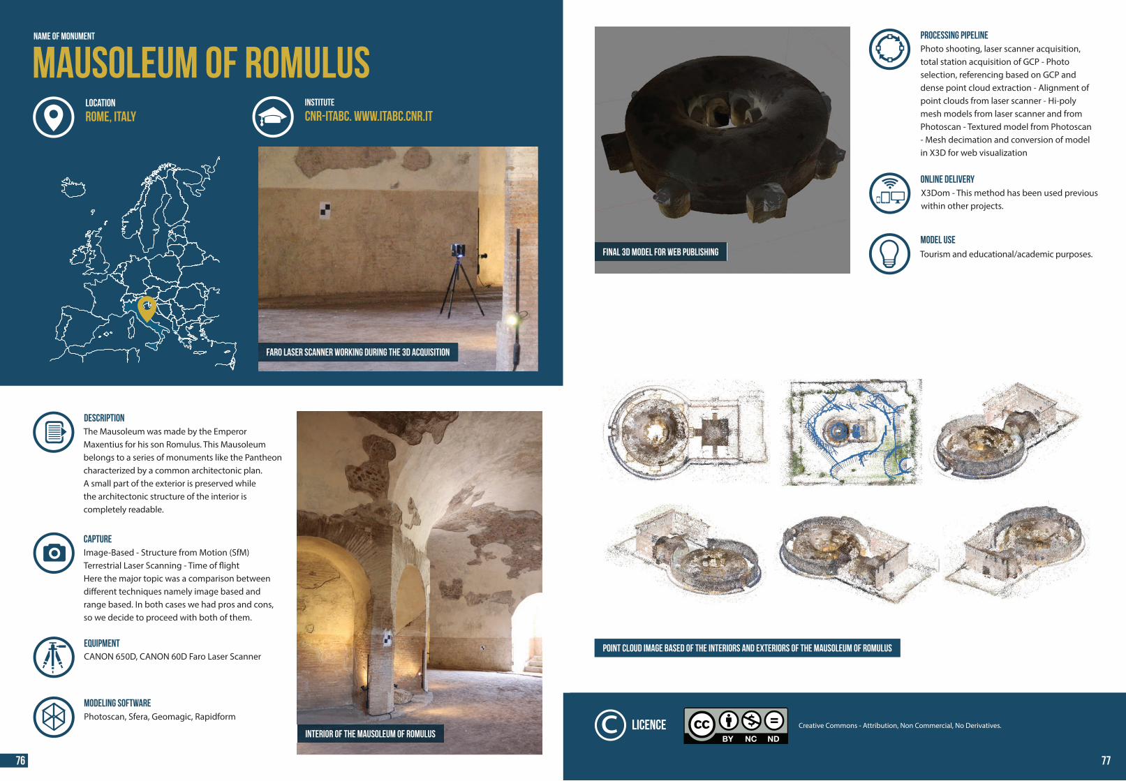
44 44
Mausoleum of RomulusName of Monument
DESCRIPTION The Mausoleum was made by the EmperorMaxentius for his son Romulus. This Mausoleumbelongs to a series of monuments like the Pantheon characterized by a common architectonic plan.A small part of the exterior is preserved whilethe architectonic structure of the interior is completely readable.
CANON 650D, CANON 60D Faro Laser Scanner
Image-Based - Structure from Motion (SfM) Terrestrial Laser Scanning - Time of �ightHere the major topic was a comparison between di�erent techniques namely image based and range based. In both cases we had pros and cons, so we decide to proceed with both of them.
CAPTURE
Equipment
MODELING SOFTWAREPhotoscan, Sfera, Geomagic, Rapidform
Interior of the Mausoleum of Romulus
Faro Laser Scanner working during the 3D acquisition
INSTITUTE
CNR-ITABC. www.itabc.cnr.itLOCATION
Rome, Italy
Final 3D model for web publishing
Point cloud image based of the interiors and exteriors of the Mausoleum of Romulus
PROCESSING PIPELINEPhoto shooting, laser scanner acquisition, total station acquisition of GCP - Photo selection, referencing based on GCP and dense point cloud extraction - Alignment of point clouds from laser scanner - Hi-poly mesh models from laser scanner and from Photoscan - Textured model from Photoscan- Mesh decimation and conversion of model in X3D for web visualization
ONLINE DELIVERYX3Dom - This method has been used previous within other projects.
MODEL USE Tourism and educational/academic purposes.
Creative Commons - Attribution, Non Commercial, No Derivatives.Licence
76 77
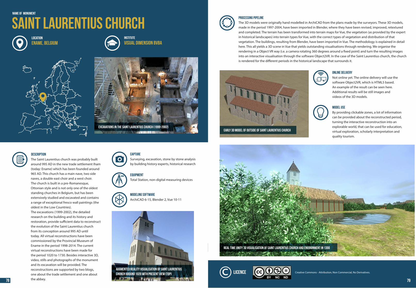
44 44
Excavations in the Saint Laurentius church (1999-2002)
DESCRIPTION The Saint Laurentius church was probably builtaround 995 AD in the new trade settlement Iham (today: Ename) which has been founded around 965 AD. This church has a main nave, two side naves, a double east choir and a west choir. The church is built in a pre-Romanesque, Ottonian style and is not only one of the oldest standing churches in Belgium, but has been extensively studied and excavated and contains a range of exceptional fresco wall paintings (the oldest in the Low Countries).The excavations (1999-2002), the detailed research on the building and its history and restoration, provide su�cient data to reconstruct the evolution of the Saint Laurentius churchfrom its conception around 995 AD untiltoday. All virtual reconstructions have been commissioned by the Provincial Museum of Ename in the period 1998-2014. The current virtual reconstructions have been made forthe period 1020 to 1730. Besides interactive 3D, video, stills and photographs of the monument and its excavation will be provided. Thereconstructions are supported by two blogs,one about the trade settlement and one about the abbey.
MODELING SOFTWARE
Surveying, excavation, stone by stone analysis by building history experts, historical research
CAPTURE
ArchiCAD 6-15, Blender 2, Vue 10-11
Augmented reality visualisation of Saint Laurentiuschurch around 1020 WITH PRESENT VIEW (TOP)
Name of Monument
Saint Laurentius churchINSTITUTE
Visual Dimension bvbaLOCATION
Ename, Belgium
Total Station, non-digital measuring devicesEquipment
PROCESSING PIPELINEThe 3D models were originally hand modelled in ArchiCAD from the plans made by the surveyors. These 3D models, made in the period 1997-2004, have been imported in Blender, where they have been revised, improved, retextured and completed. The terrain has been transformed into terrain maps for Vue, the vegetation (as provided by the expert in historical landscapes) into terrain types for Vue, with the correct types of vegetation and distribution of thatvegetation. The buildings, resulting from Blender, have been imported in Vue. The methodology is explained in detail here. This all yields a 3D scene in Vue that yields outstanding visualisations through rendering. We organise the rendering in a Object VR way (i.e. a camera rotating 360 degrees around a �xed point) and turn the resulting imagesinto an interactive visualisation through the software Object2VR. In the case of the Saint Laurentius church, the church is rendered for the di�erent periods in the historical landscape that surrounds it.
MODEL USE By providing clickable zones, a lot of information can be provided about the reconstructed period, turning the interactive reconstruction into an explorable world, that can be used for education, virtual exploration, scholarly interpretation and quality tourism.
ONLINE DELIVERYNot online yet. The online delivery will use the software Object2VR, which is HTML5 based.An example of the result can be seen here.Additional results will be still images andvideos of the 3D models.
Real time Unity 3D visualisation of Saint Laurentius church and environment in 1300
Early 3D model of OUTSIDE OF Saint Laurentius church
Creative Commons - Attribution, Non Commercial, No Derivatives.Licence
78 79
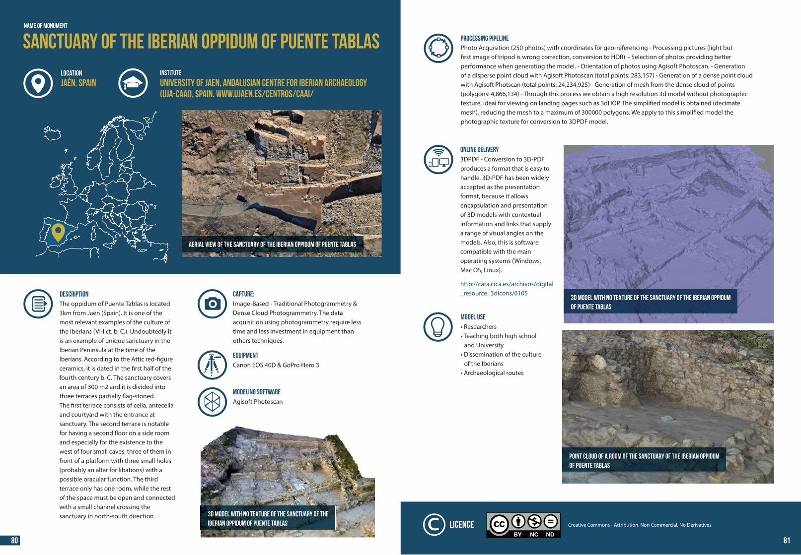
44 44
Aerial view of the Sanctuary of the Iberian oppidum of Puente Tablas
DESCRIPTION The oppidum of Puente Tablas is located 3km from Jaén (Spain). It is one of the most relevant examples of the culture of the Iberians (VI-I ct. b. C.). Undoubtedly it is an example of unique sanctuary in the Iberian Peninsula at the time of the Iberians. According to the Attic red-�gure ceramics, it is dated in the �rst half of the fourth century b. C. The sanctuary covers an area of 300 m2 and it is divided into three terraces partially �ag-stoned. The �rst terrace consists of cella, antecella and courtyard with the entrance at sanctuary. The second terrace is notable for having a second �oor on a side room and especially for the existence to the west of four small caves, three of them in front of a platform with three small holes (probably an altar for libations) with a possible oracular function. The third terrace only has one room, while the rest of the space must be open and connected with a small channel crossing thesanctuary in north-south direction. 3D model with no texture of the Sanctuary of the
Iberian oppidum of Puente Tablas
NAME OF MONUMENT
Sanctuary of the Iberian oppidum of Puente TablasINSTITUTELOCATION
Jaén, Spain University of Jaen, Andalusian Centre for Iberian Archaeology (UJA-CAAI), Spain. www.ujaen.es/centros/caai/
Image-Based - Traditional Photogrammetry & Dense Cloud Photogrammetry. The dataacquisition using photogrammetry require less time and less investment in equipment thanothers techniques.
CAPTURE:
MODELING SOFTWAREAgisoft Photoscan
EQUIPMENTCanon EOS 40D & GoPro Hero 3
PROCESSING PIPELINEPhoto Acquisition (250 photos) with coordinates for geo-referencing - Processing pictures (light but �rst image of tripod is wrong correction, conversion to HDR). - Selection of photos providing better performance when generating the model. - Orientation of photos using Agisoft Photoscan. - Generation of a disperse point cloud with Agisoft Photoscan (total points: 283,157) - Generation of a dense point cloud with Agisoft Photscan (total points: 24,234,925) - Generation of mesh from the dense cloud of points (polygons: 4,866,134) - Through this process we obtain a high resolution 3d model without photographic texture, ideal for viewing on landing pages such as 3dHOP. The simpli�ed model is obtained (decimate mesh), reducing the mesh to a maximum of 300000 polygons. We apply to this simpli�ed model the photographic texture for conversion to 3DPDF model.
MODEL USE • Researchers• Teaching both high school and University• Dissemination of the culture of the Iberians• Archaeological routes
ONLINE DELIVERY3DPDF - Conversion to 3D-PDF produces a format that is easy to handle. 3D-PDF has been widely accepted as the presentation format, because it allowsencapsulation and presentation of 3D models with contextual information and links that supply a range of visual angles on the models. Also, this is softwarecompatible with the main operating systems (Windows, Mac OS, Linux). http://cata.cica.es/archivos/digital_resource_3dicons/6105
Point cloud of a room of the Sanctuary of the Iberian oppidumof Puente Tablas
3D model with no texture of the Sanctuary of the Iberian oppidumof Puente Tablas
Creative Commons - Attribution, Non Commercial, No Derivatives.Licence
80 81
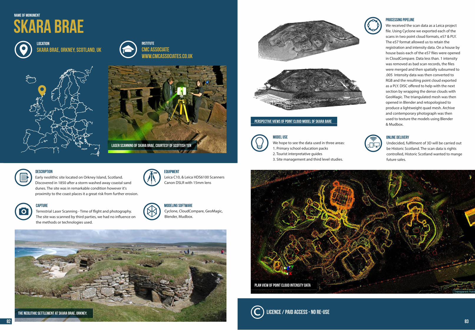
44 44
Skara Brae
Laser scanning of Skara Brae, courtesy of Scottish Ten
Name of Monument
INSTITUTE
CMC Associatewww.cmcassociates.co.uk
LOCATION
Skara Brae, Orkney, SCOTLAND, UK
DESCRIPTION Early neolithic site located on Orkney Island, Scotland.Discovered in 1850 after a storm washed away coastal sand dunes. The site was in remarkable condition however it's proximity to the coast places it a great risk from further erosion.
The Neolithic settlement at Skara Brae, Orkney.
MODELING SOFTWARECyclone, CloudCompare, GeoMagic,Blender, Mudbox.
Terrestrial Laser Scanning - Time of �ight and photography.The site was scanned by third parties, we had no in�uence on the methods or technologies used.
CAPTURE
Leica C10, & Leica HDS6100 ScannersCanon DSLR with 15mm lens
Equipment
Licence
PROCESSING PIPELINEWe received the scan data as a Leica project �le. Using Cyclone we exported each of the scans in two point cloud formats, e57 & PLY. The e57 format allowed us to retain the registration and intensity data. On a house by house basis each of the e57 �les were opened in CloudCompare. Data less than. 1 intensity was removed as bad scan records, the �les were merged and then spatially subsumed to .005 Intensity data was then converted to RGB and the resulting point cloud exported as a PLY. DISC o�ered to help with the next section by wrapping the dense clouds with GeoMagic. The triangulated mesh was then opened in Blender and retopologised to produce a lightweight quad mesh. Archive and contemporary photograph was then used to texture the models using Blender& Mudbox.
ONLINE DELIVERYUndecided, ful�lment of 3D will be carried out be Historic Scotland. The scan data is rights controlled, Historic Scotland wanted to mange future sales.
Licence / Paid Access - No Re-use
PLAN VIEW of POINT CLOUD INTENSITY DATA
MODEL USE We hope to see the data used in three areas:1. Primary school education packs2. Tourist interpretative guides3. Site management and third level studies.
PERSPECTIVE VIEWS OF POINT CLOUD MODEL OF Skara Bare
82 83
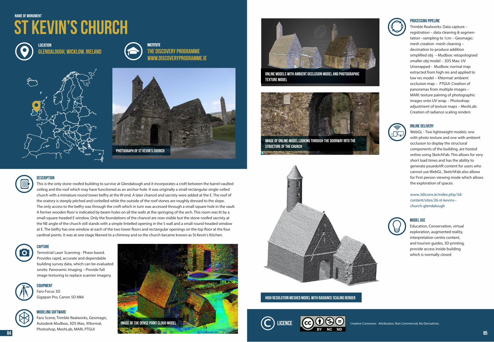
44 44
Name of Monument
Photograph of St Kevin’s Church
INSTITUTE
DESCRIPTION This is the only stone-roofed building to survive at Glendalough and it incorporates a croft between the barrel-vaulted ceiling and the roof which may have functioned as an anchor-hole. It was originally a small rectangular single-celled church with a miniature round tower belfry at the W end. A later chancel and sacristy were added at the E. The roof of the oratory is steeply pitched and corbelled while the outside of the roof stones are roughly dressed to the slope.The only access to the belfry was through the croft which in turn was accessed through a small square hole in the vault. A former wooden �oor is indicated by beam-holes on all the walls at the springing of the arch. This room was lit by a small square-headed E window. Only the foundations of the chancel are now visible but the stone-roofed sacristy at the NE angle of the church still stands with a simple lintelled opening in the S wall and a small round-headed window at E. The belfry has one window at each of the two lower �oors and rectangular openings on the top �oor at the four cardinal points. It was at one stage likened to a chimney and so the church became known as St Kevin's Kitchen.
Terrestrial Laser Scanning - Phase based. Provides rapid, accurate and dependable building survey data, which can be evaluated onsite. Panoramic Imaging – Provide full image texturing to replace scanner imagery.
MODELING SOFTWAREFaro Scene, Trimble Realworks, Geomagic, Autodesk Mudbox, 3DS Max, XNormal, Photoshop, MeshLab, MARI, PTGUI
CAPTURE
Faro Focus 3DGigapan Pro, Canon 5D MkII
Equipment
St Kevin’s ChurchINSTITUTE
The Discovery Programmewww.discoveryprogramme.ie
LOCATION
Glendalough, Wicklow, Ireland
Image of the dense point cloud model
PROCESSING PIPELINETrimble Realworks: Data capture – registration – data cleaning & segmen-tation –sampling to 1cm – Geomagic: mesh creation -mesh cleaning – decimation to produce addition simpli�ed obj – Mudbox: retopologised smaller obj model – 3DS Max: UV Unwrapped - Mudbox: normal map extracted from high res and applied to low res model – XNormal: ambient occlusion map – PTGUI: Creation of panoramas from multiple images – MARI: texture paining of photographic images onto UV wrap - Photoshop: adjustment of texture maps – MeshLab: Creation of radiance scaling renders
ONLINE DELIVERYWebGL - Two lightweight models: one with photo texture and one with ambient occlusion to display the structural components of the building, are hosted online using SketchFab. This allows for very short load times and has the ability to generate psuedoVR content for users who cannot use WebGL. SketchFab also allows for First person viewing mode which allows the exploration of spaces.
www.3dicons.ie/index.php/3d-content/sites/26-st-kevins--church-glendalough
High resolution meshed model with radiance scaling render
MODEL USE Education, Conservation, virtual exploration, augmented reality, interpretation centre content, and tourism guides, 3D printing, provide access inside building which is normally closed
Online models with ambient occlusion model and photographictexture model
Image of online model looking through the doorway into thestructure of the church
Creative Commons - Attribution, Non Commercial, No Derivatives.Licence
84 85
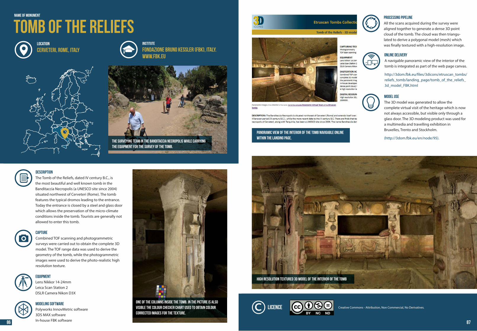
44 44
The surveying team in the Banditaccia Necropolis while carryingthe equipment for the survey of the tomb.
Name of Monument
INSTITUTE
Fondazione Bruno Kessler (FBK), Italy.www.fbk.eu
LOCATION
Cerveteri, Rome, Italy
DESCRIPTION The Tomb of the Reliefs, dated IV century B.C., isthe most beautiful and well known tomb in the Banditaccia Necropolis (a UNESCO site since 2004) situated northwest of Cerveteri (Rome). The tomb features the typical dromos leading to the entrance. Today the entrance is closed by a steel and glass door which allows the preservation of the micro-climate conditions inside the tomb. Tourists are generally not allowed to enter this tomb.
One of the columns inside the tomb. In the picture is alsovisible the colour checker chart used to obtain colourcorrected images for the texture.
Combined TOF scanning and photogrammetric surveys were carried out to obtain the complete 3D model. The TOF range data was used to derive the geometry of the tomb, while the photogrammetric images were used to derive the photo-realistic high resolution texture.
MODELING SOFTWAREPolyworks InnovMetric software3DS MAX softwareIn-house FBK software
CAPTURE
Lens Nikkor 14-24mmLeica Scan Station 2DSLR Camera Nikon D3X
Equipment
Tomb of the ReliefsPROCESSING PIPELINEAll the scans acquired during the survey were aligned together to generate a dense 3D point cloud of the tomb. The cloud was then triangu-lated to derive a polygonal model (mesh) which was �nally textured with a high-resolution image.
ONLINE DELIVERYA navigable panoramic view of the interior of the tomb is integrated as part of the web page canvas. http://3dom.fbk.eu/�les/3dicons/etruscan_tombs/reliefs_tomb/landing_page/tomb_of_the_reliefs_3d_model_FBK.html
High resolution textured 3D model of the interior of the tomb
MODEL USE The 3D model was generated to allow the complete virtual visit of the heritage which is now not always accessible, but visible only through a glass door. The 3D modeling product was used for a multimedia and travelling exhibition in Bruxelles, Trento and Stockholm. (http://3dom.fbk.eu/en/node/95).
Panoramic view of the interior of the tomb navigable onlinewithin the landing page.
Creative Commons - Attribution, Non Commercial, No Derivatives.Licence
86 87
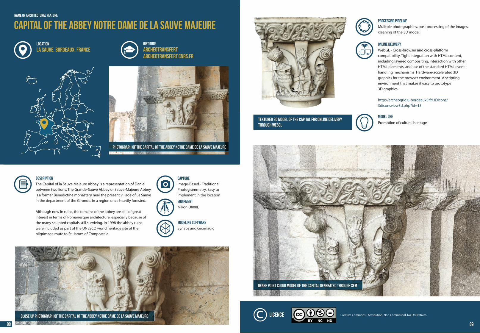
44 44
NAME OF Architectural FEATURE
Capital of the Abbey Notre Dame de la Sauve Majeure
DESCRIPTION The Capital of la Sauve Majeure Abbey is a representation of Daniel between two lions. The Grande-Sauve Abbey or Sauve-Majeure Abbey is a former Benedictine monastery near the present village of La Sauve in the department of the Gironde, in a region once heavily forested.
Although now in ruins, the remains of the abbey are still of great interest in terms of Romanesque architecture, especially because of the many sculpted capitals still surviving. In 1998 the abbey ruins were included as part of the UNESCO world heritage site of the pilgrimage route to St. James of Compostela.
CLOSE UP Photograph of the Capital of the Abbey Notre Dame de la Sauve Majeure
Photograph of the Capital of the Abbey Notre Dame de la Sauve Majeure
INSTITUTE
Archeotransfertarcheotransfert.cnrs.fr
LOCATION
La Sauve, Bordeaux, France
Image-Based - Traditional Photogrammetry. Easy to implement in the location
Nikon D800E
CAPTURE
Equipment
MODELING SOFTWARESynaps and Geomagic
Textured 3D model of the capital for online deliverythrough WebGL
Dense point cloud model of the capital generated through SfM
Creative Commons - Attribution, Non Commercial, No Derivatives.Licence
PROCESSING PIPELINEMulitple photographies, post processing of the images, cleaning of the 3D model.
ONLINE DELIVERYWebGL - Cross-browser and cross-platformcompatibility. Tight integration with HTML content, including layered compositing, interaction with other HTML elements, and use of the standard HTML event handling mechanisms Hardware-accelerated 3D graphics for the browser environment A scripting environment that makes it easy to prototype3D graphics.
http://archeogrid.u-bordeaux3.fr/3DIcons/3diconsview3d.php?id=15
MODEL USE Promotion of cultural heritage
88 89
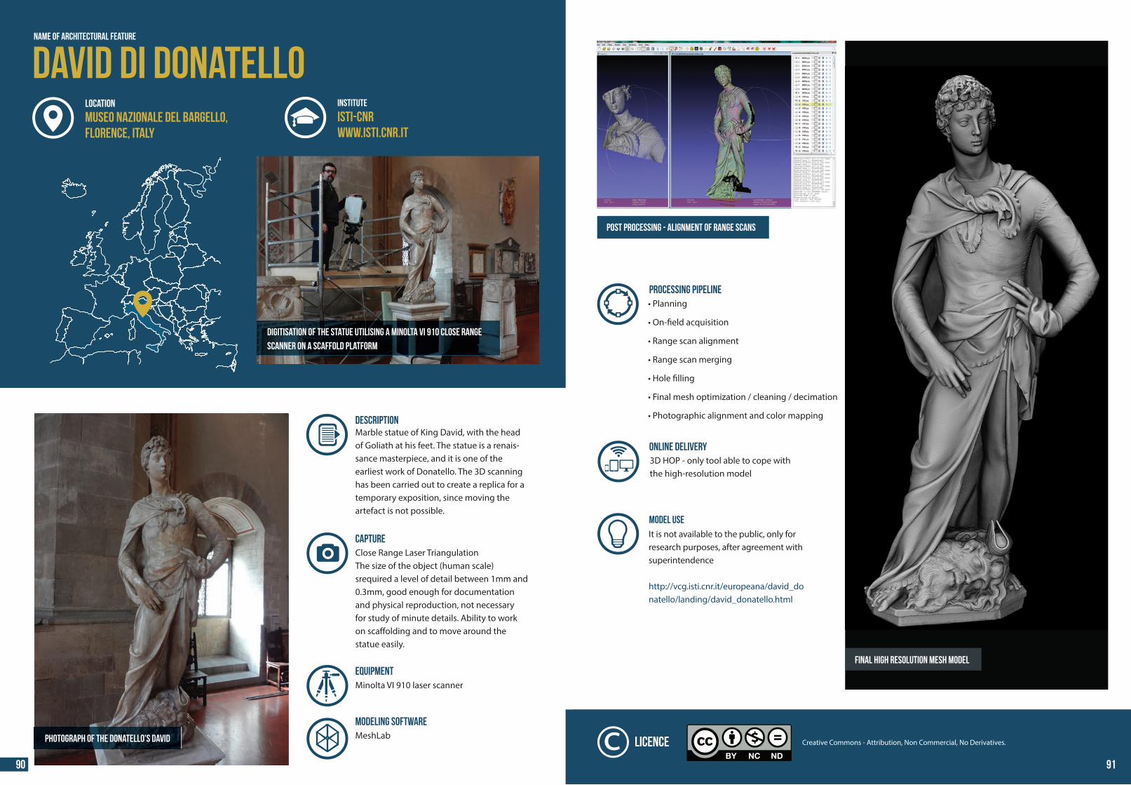
44 44
Name of Architectural Feature
David di DonatelloINSTITUTE
ISTI-CNRwww.isti.cnr.it
DESCRIPTION Marble statue of King David, with the head of Goliath at his feet. The statue is a renais-sance masterpiece, and it is one of the earliest work of Donatello. The 3D scanning has been carried out to create a replica for a temporary exposition, since moving the artefact is not possible.
Photograph of The Donatello's David
Digitisation of the statue utilising a Minolta VI 910 close range
scanner on a scaffold platform
Close Range Laser TriangulationThe size of the object (human scale) srequired a level of detail between 1mm and 0.3mm, good enough for documentation and physical reproduction, not necessaryfor study of minute details. Ability to workon sca�olding and to move around the statue easily.
CAPTURE
MODELING SOFTWAREMeshLab
EQUIPMENTMinolta VI 910 laser scanner
LOCATION
Museo Nazionale del Bargello,Florence, Italy
PROCESSING PIPELINE• Planning
• On-�eld acquisition
• Range scan alignment
• Range scan merging
• Hole �lling
• Final mesh optimization / cleaning / decimation
• Photographic alignment and color mapping
ONLINE DELIVERY3D HOP - only tool able to cope withthe high-resolution model
Post processing - alignment of range scans
Final high resolution mesh model
MODEL USE It is not available to the public, only for research purposes, after agreement with superintendence
http://vcg.isti.cnr.it/europeana/david_donatello/landing/david_donatello.html
Creative Commons - Attribution, Non Commercial, No Derivatives.Licence
90 91
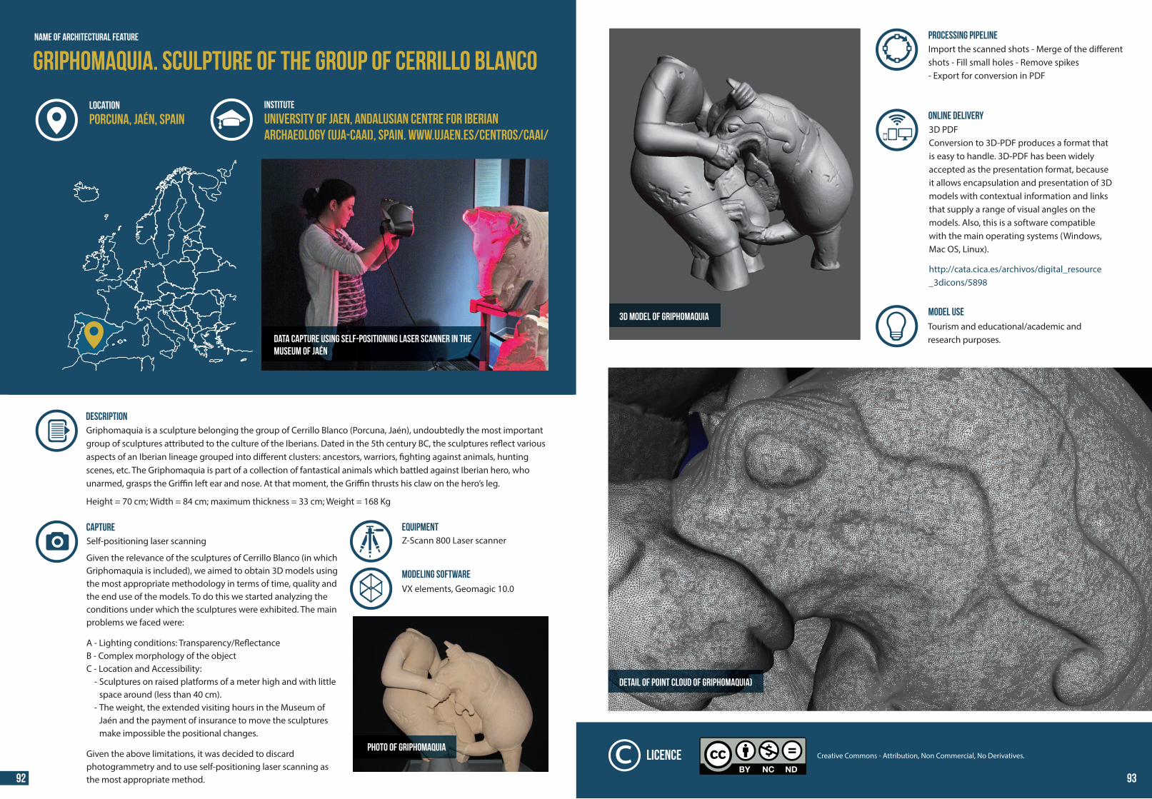
44 44
Data capture using self-positioning laser scanner in themuseum of Jaén
DESCRIPTION Griphomaquia is a sculpture belonging the group of Cerrillo Blanco (Porcuna, Jaén), undoubtedly the most important group of sculptures attributed to the culture of the Iberians. Dated in the 5th century BC, the sculptures re�ect various aspects of an Iberian lineage grouped into di�erent clusters: ancestors, warriors, �ghting against animals, hunting scenes, etc. The Griphomaquia is part of a collection of fantastical animals which battled against Iberian hero, who unarmed, grasps the Gri�n left ear and nose. At that moment, the Gri�n thrusts his claw on the hero’s leg. Height = 70 cm; Width = 84 cm; maximum thickness = 33 cm; Weight = 168 Kg
Self-positioning laser scanning Given the relevance of the sculptures of Cerrillo Blanco (in which Griphomaquia is included), we aimed to obtain 3D models using the most appropriate methodology in terms of time, quality and the end use of the models. To do this we started analyzing the conditions under which the sculptures were exhibited. The main problems we faced were: A - Lighting conditions: Transparency/Re�ectanceB - Complex morphology of the objectC - Location and Accessibility: - Sculptures on raised platforms of a meter high and with little space around (less than 40 cm). - The weight, the extended visiting hours in the Museum of Jaén and the payment of insurance to move the sculptures make impossible the positional changes. Given the above limitations, it was decided to discard photogrammetry and to use self-positioning laser scanning as the most appropriate method.
CAPTURE
Griphomaquia. Sculpture of the group of Cerrillo BlancoName of Architectural Feature
INSTITUTE
University of Jaen, Andalusian Centre for IberianArchaeology (UJA-CAAI), Spain. www.ujaen.es/centros/caai/
LOCATION
Porcuna, Jaén, Spain
VX elements, Geomagic 10.0MODELING SOFTWARE
Z-Scann 800 Laser scannerEquipment
Photo of Griphomaquia
Detail of point cloud of Griphomaquia)
3D model of Griphomaquia
PROCESSING PIPELINEImport the scanned shots - Merge of the di�erent shots - Fill small holes - Remove spikes - Export for conversion in PDF
ONLINE DELIVERY3D PDFConversion to 3D-PDF produces a format that is easy to handle. 3D-PDF has been widely accepted as the presentation format, because it allows encapsulation and presentation of 3D models with contextual information and links that supply a range of visual angles on the models. Also, this is a software compatible with the main operating systems (Windows, Mac OS, Linux). http://cata.cica.es/archivos/digital_resource_3dicons/5898
MODEL USE Tourism and educational/academic andresearch purposes.
Creative Commons - Attribution, Non Commercial, No Derivatives.Licence
92 93
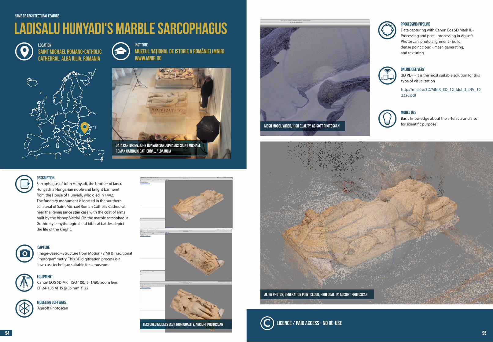
44 44
Ladisalu Hunyadi's marble sarcophagus
Data capturing, John Hunyadi sarcophagus, Saint MichaelRoman Catholic Cathedral, Alba Iulia
Name of Architectural Feature
INSTITUTE
Muzeul Național de Istorie a României (MNIR)www.mnir.ro
LOCATION
Saint Michael Romano-CatholicCathedral, Alba Iulia, ROMANIA
DESCRIPTION Sarcophagus of John Hunyadi, the brother of Iancu Hunyadi, a Hungarian noble and knight banneretfrom the House of Hunyadi, who died in 1442. The funerary monument is located in the southern collateral of Saint Michael Roman Catholic Cathedral, near the Renaissance stair case with the coat of arms built by the bishop Vardai. On the marble sarcophagus Gothic style mythological and biblical battles depict the life of the knight.
Image-Based - Structure from Motion (SfM) & Traditional Photogrammetry. This 3D digitisation process is a low-cost technique suitable for a museum.
MODELING SOFTWAREAgisoft Photoscan
CAPTURE
Canon EOS 5D Mk II ISO 100, t=1/60/ zoom lens EF 24-105 AF IS @ 35 mm f: 22
Equipment
Textured modelS (X3), high quality, Agisoft PhotoScan
PROCESSING PIPELINEData capturing with Canon Eos 5D Mark II, - Processing and post - processing in Agisoft Photoscan: photo alignment - builddense point cloud - mesh generating,and texturing.
ONLINE DELIVERY3D PDF - It is the most suitable solution for this type of visualization http://mnir.ro/3D/MNIR_3D_12_Idol_2_INV_102326.pdf
Align photos, generation point cloud, high quality, Agisoft PhotoScan
MODEL USE Basic knowledge about the artefacts and alsofor scienti�c purposeMesh model wired, high quality, Agisoft PhotoScan
Licence / Paid Access - No Re-use
94 95
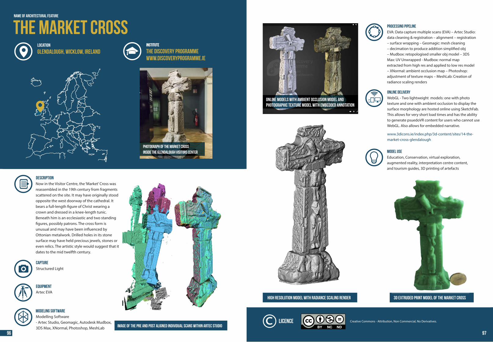
44 44
Name of Architectural Feature
Photograph of the Market Crossinside the Glendalough Visitors Center
INSTITUTE
DESCRIPTION Now in the Visitor Centre, the ‘Market’ Cross wasreassembled in the 19th century from fragments scattered on the site. It may have originally stood opposite the west doorway of the cathedral. It bears a full-length �gure of Christ wearing a crown and dressed in a knee-length tunic. Beneath him is an ecclesiastic and two standing �gures, possibly patrons. The cross form is unusual and may have been in�uenced by Ottonian metalwork. Drilled holes in its stone surface may have held precious jewels, stones or even relics. The artistic style would suggest that it dates to the mid twelfth century.
Image of the pre and post aligned individual scans within Artec Studio
Structured Light
MODELING SOFTWAREModelling Software- Artec Studio, Geomagic, Autodesk Mudbox, 3DS Max, XNormal, Photoshop, MeshLab
CAPTURE
Artec EVAEquipment
The Market CrossINSTITUTE
The Discovery Programmewww.discoveryprogramme.ie
LOCATION
Glendalough, Wicklow, Ireland
Online models with ambient occlusion model andphotographic texture model with embedded annotation
PROCESSING PIPELINEEVA: Data capture multiple scans (EVA) – Artec Studio: data cleaning & registration – alignment – registration – surface wrapping – Geomagic: mesh cleaning– decimation to produce addition simpli�ed obj – Mudbox: retopologised smaller obj model – 3DS Max: UV Unwrapped - Mudbox: normal map extracted from high res and applied to low res model – XNormal: ambient occlusion map – Photoshop: adjustment of texture maps – MeshLab: Creation of radiance scaling renders
ONLINE DELIVERYWebGL - Two lightweight models: one with photo texture and one with ambient occlusion to display the surface morphology are hosted online using SketchFab. This allows for very short load times and has the ability to generate psuedoVR content for users who cannot use WebGL. Also allows for embedded narrative. www.3dicons.ie/index.php/3d-content/sites/14-the-market-cross-glendalough
High resolution model with radiance scaling render 3D Extruded print model of the Market Cross
MODEL USE Education, Conservation, virtual exploration, augmented reality, interpretation centre content,and tourism guides, 3D printing of artefacts
Creative Commons - Attribution, Non Commercial, No Derivatives.Licence
96 97
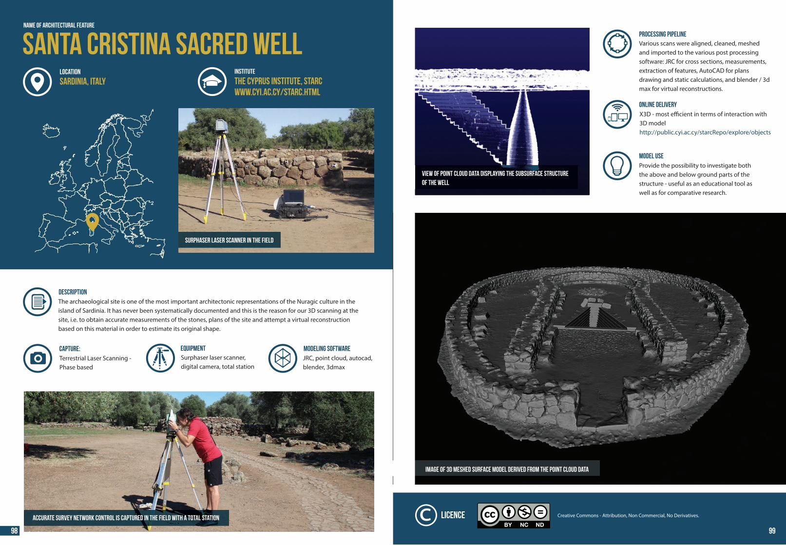
44 44
Surphaser laser scanner in the field
DESCRIPTION The archaeological site is one of the most important architectonic representations of the Nuragic culture in the island of Sardinia. It has never been systematically documented and this is the reason for our 3D scanning at the site, i.e. to obtain accurate measurements of the stones, plans of the site and attempt a virtual reconstruction based on this material in order to estimate its original shape.
MODELING SOFTWARETerrestrial Laser Scanning - Phase based
CAPTURE:JRC, point cloud, autocad, blender, 3dmax
Accurate survey network control is captured in the field with a total station
Name of Architectural Feature
Santa Cristina Sacred WellINSTITUTE
The Cyprus Institute, STARCwww.cyi.ac.cy/starc.html
LOCATION
Sardinia, Italy
Surphaser laser scanner, digital camera, total station
Equipment
PROCESSING PIPELINEVarious scans were aligned, cleaned, meshed and imported to the various post processing software: JRC for cross sections, measurements, extraction of features, AutoCAD for plans drawing and static calculations, and blender / 3d max for virtual reconstructions.
MODEL USE Provide the possibility to investigate both the above and below ground parts of the structure - useful as an educational tool as well as for comparative research.
ONLINE DELIVERYX3D - most e�cient in terms of interaction with 3D modelhttp://public.cyi.ac.cy/starcRepo/explore/objects
Image of 3D meshed surface model derived from the point cloud data
View of point cloud data displaying the subsurface structureof the well
Creative Commons - Attribution, Non Commercial, No Derivatives.Licence
98 99
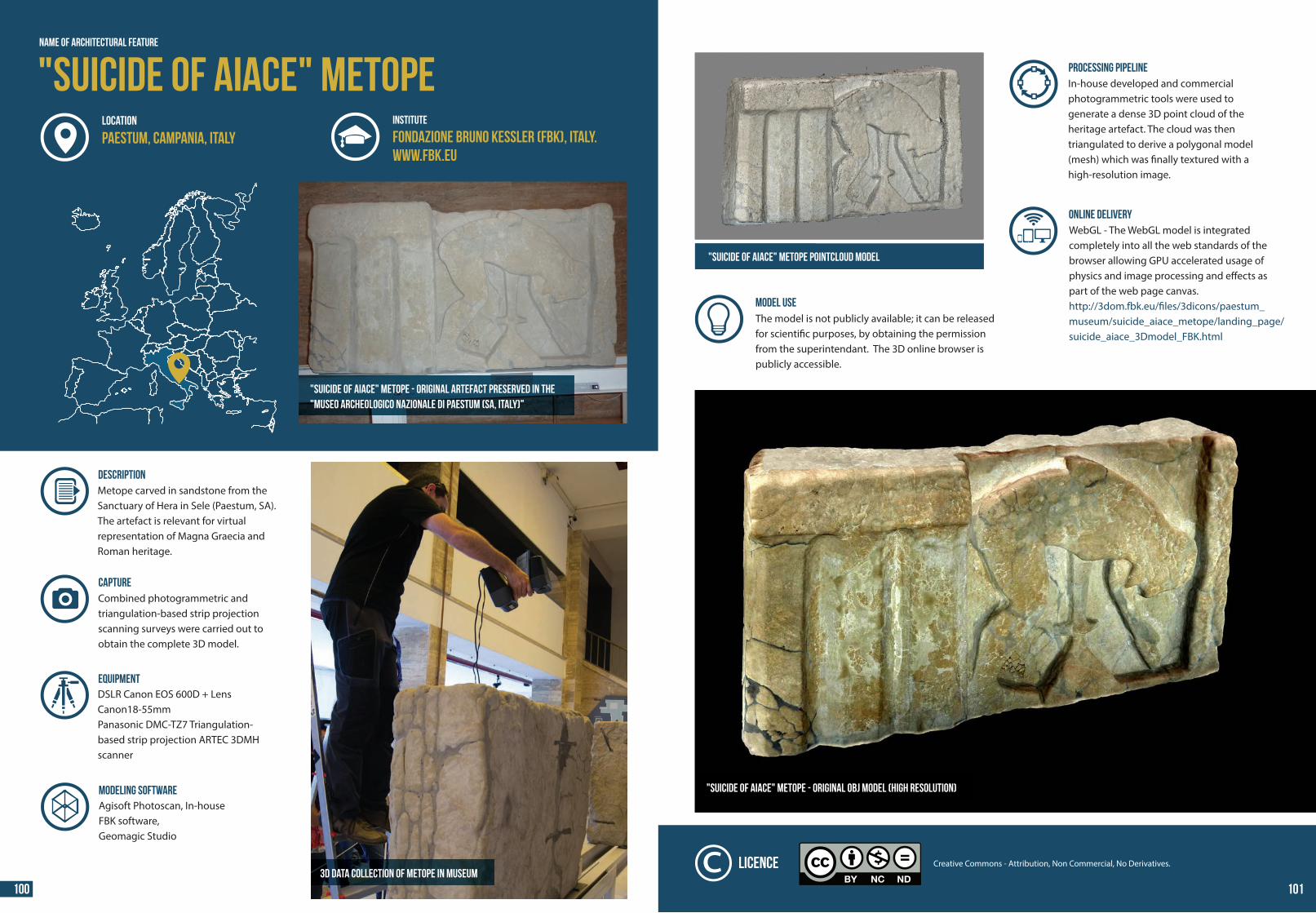
44 44
"Suicide of Aiace" metope
"Suicide of Aiace" metope - Original artefact preserved in the"Museo Archeologico Nazionale di Paestum (SA, Italy)"
Name of Architectural Feature
INSTITUTE
Fondazione Bruno Kessler (FBK), Italy.www.fbk.eu
LOCATION
Paestum, Campania, Italy
DESCRIPTION Metope carved in sandstone from the Sanctuary of Hera in Sele (Paestum, SA). The artefact is relevant for virtual representation of Magna Graecia and Roman heritage.
3D data collection of metope in museum
Combined photogrammetric and triangulation-based strip projection scanning surveys were carried out to obtain the complete 3D model.
CAPTURE
MODELING SOFTWAREAgisoft Photoscan, In-house FBK software,Geomagic Studio
DSLR Canon EOS 600D + Lens Canon18-55mmPanasonic DMC-TZ7 Triangulation-based strip projection ARTEC 3DMH scanner
Equipment
PROCESSING PIPELINEIn-house developed and commercialphotogrammetric tools were used togenerate a dense 3D point cloud of the heritage artefact. The cloud was thentriangulated to derive a polygonal model (mesh) which was �nally textured with a high-resolution image.
ONLINE DELIVERYWebGL - The WebGL model is integrated completely into all the web standards of the browser allowing GPU accelerated usage of physics and image processing and e�ects as part of the web page canvas.http://3dom.fbk.eu/�les/3dicons/paestum_museum/suicide_aiace_metope/landing_page/suicide_aiace_3Dmodel_FBK.html
"Suicide of Aiace" metope - Original OBJ model (high resolution)
MODEL USE The model is not publicly available; it can be released for scienti�c purposes, by obtaining the permission from the superintendant. The 3D online browser is publicly accessible.
"Suicide of Aiace" metope pointcloud model
Creative Commons - Attribution, Non Commercial, No Derivatives.Licence
100 101
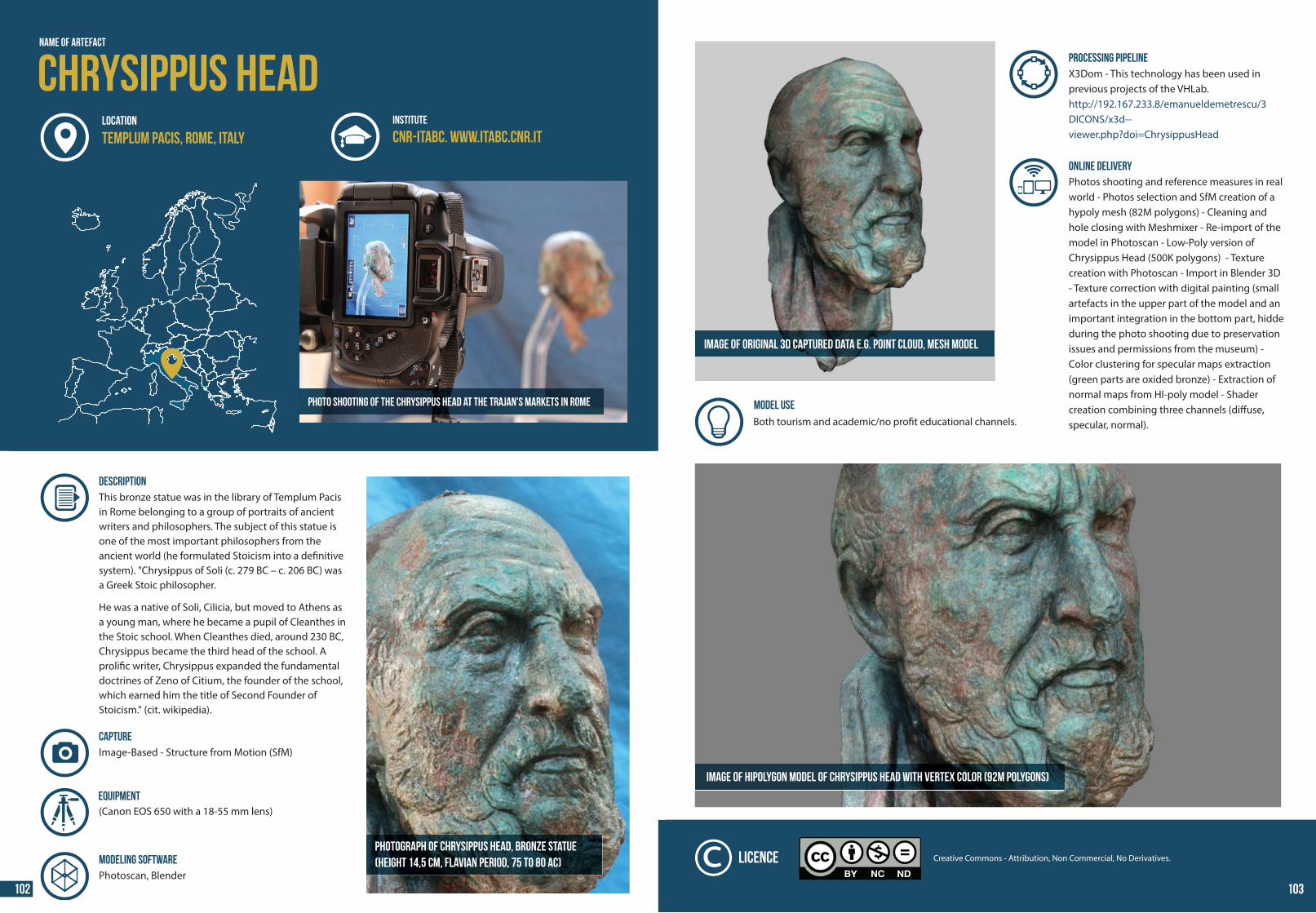
44 44
The scaffolding used for the digitization
Name of Artefact
Chrysippus HeadINSTITUTE
CNR-ITABC. www.itabc.cnr.itLOCATION
Templum Pacis, Rome, Italy
DESCRIPTION This bronze statue was in the library of Templum Pacis in Rome belonging to a group of portraits of ancient writers and philosophers. The subject of this statue is one of the most important philosophers from the ancient world (he formulated Stoicism into a de�nitive system). "Chrysippus of Soli (c. 279 BC – c. 206 BC) was a Greek Stoic philosopher. He was a native of Soli, Cilicia, but moved to Athens as a young man, where he became a pupil of Cleanthes in the Stoic school. When Cleanthes died, around 230 BC, Chrysippus became the third head of the school. A proli�c writer, Chrysippus expanded the fundamental doctrines of Zeno of Citium, the founder of the school, which earned him the title of Second Founder of Stoicism." (cit. wikipedia).
Photograph of Chrysippus Head, bronze statue(height 14,5 cm, Flavian Period, 75 to 80 AC)
Image-Based - Structure from Motion (SfM) CAPTURE
MODELING SOFTWAREPhotoscan, Blender
Photo shooting of the Chrysippus Head at the Trajan's Markets in Rome
(Canon EOS 650 with a 18-55 mm lens)Equipment
PROCESSING PIPELINEX3Dom - This technology has been used in previous projects of the VHLab.http://192.167.233.8/emanueldemetrescu/3DICONS/x3d--viewer.php?doi=ChrysippusHead
ONLINE DELIVERYPhotos shooting and reference measures in real world - Photos selection and SfM creation of a hypoly mesh (82M polygons) - Cleaning and hole closing with Meshmixer - Re-import of the model in Photoscan - Low-Poly version of Chrysippus Head (500K polygons) - Texture creation with Photoscan - Import in Blender 3D - Texture correction with digital painting (small artefacts in the upper part of the model and an important integration in the bottom part, hidde during the photo shooting due to preservation issues and permissions from the museum) - Color clustering for specular maps extraction (green parts are oxided bronze) - Extraction of normal maps from HI-poly model - Shader creation combining three channels (di�use, specular, normal).
Image of hipolygon model of Chrysippus Head with vertex color (92M Polygons)
Image of original 3D captured data e.g. point cloud, mesh model
Creative Commons - Attribution, Non Commercial, No Derivatives.Licence
MODEL USE Both tourism and academic/no pro�t educational channels.
102 103
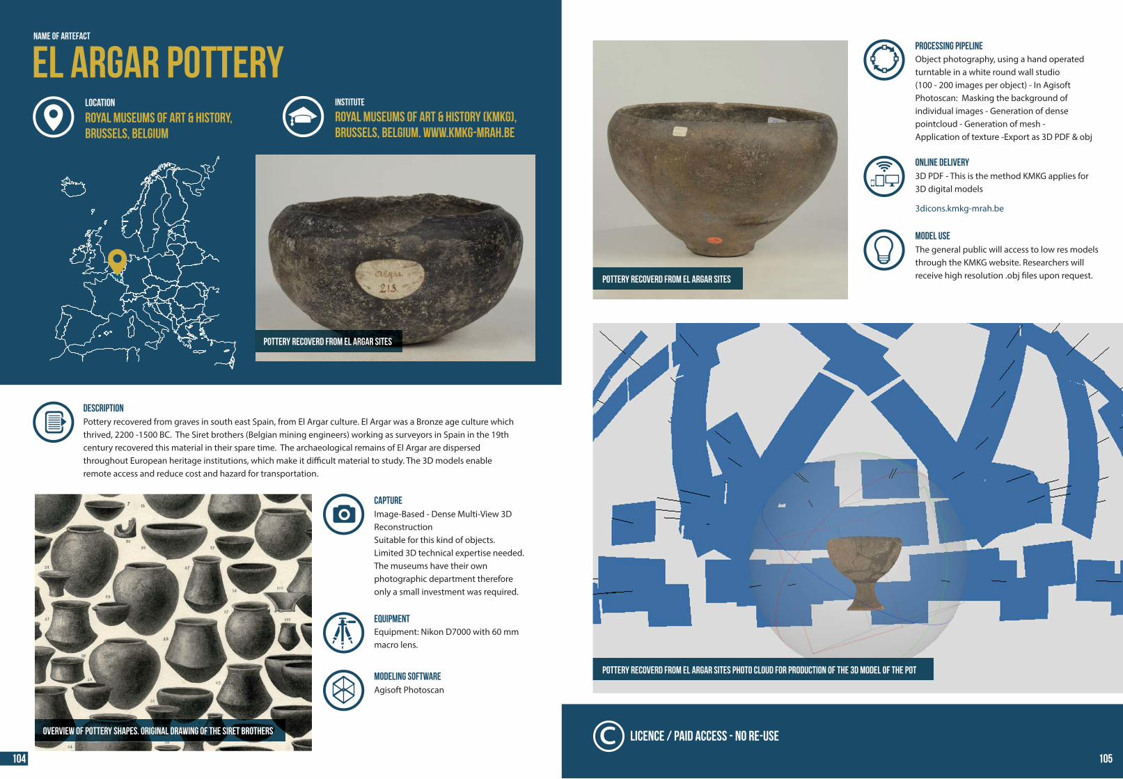
44 44
Pottery recoverd from El Argar sites
DESCRIPTION Pottery recovered from graves in south east Spain, from El Argar culture. El Argar was a Bronze age culture which thrived, 2200 -1500 BC. The Siret brothers (Belgian mining engineers) working as surveyors in Spain in the 19th century recovered this material in their spare time. The archaeological remains of El Argar are dispersed throughout European heritage institutions, which make it di�cult material to study. The 3D models enable remote access and reduce cost and hazard for transportation.
El Argar PotteryRoyal Museums of Art & History (KMKG),Brussels, Belgium. www.kmkg-mrah.be
MODELING SOFTWARE
Image-Based - Dense Multi-View 3D ReconstructionSuitable for this kind of objects.Limited 3D technical expertise needed.The museums have their ownphotographic department therefore only a small investment was required.
CAPTURE
Agisoft Photoscan
Overview of pottery shapes. Original drawing of the Siret brothers
Name of Artefact
INSTITUTE
Royal Museums of Art & History,Brussels, Belgium
LOCATION
Equipment: Nikon D7000 with 60 mm macro lens.
Equipment
PROCESSING PIPELINEObject photography, using a hand operated turntable in a white round wall studio(100 - 200 images per object) - In Agisoft Photoscan: Masking the background of individual images - Generation of dense pointcloud - Generation of mesh -Application of texture -Export as 3D PDF & obj
MODEL USE The general public will access to low res models through the KMKG website. Researchers will receive high resolution .obj �les upon request.
ONLINE DELIVERY3D PDF - This is the method KMKG applies for 3D digital models 3dicons.kmkg-mrah.be
Pottery recoverd from El Argar sites Photo cloud for production of the 3D model of the pot
Pottery recoverd from El Argar sites
Licence / Paid Access - No Re-use
104 105
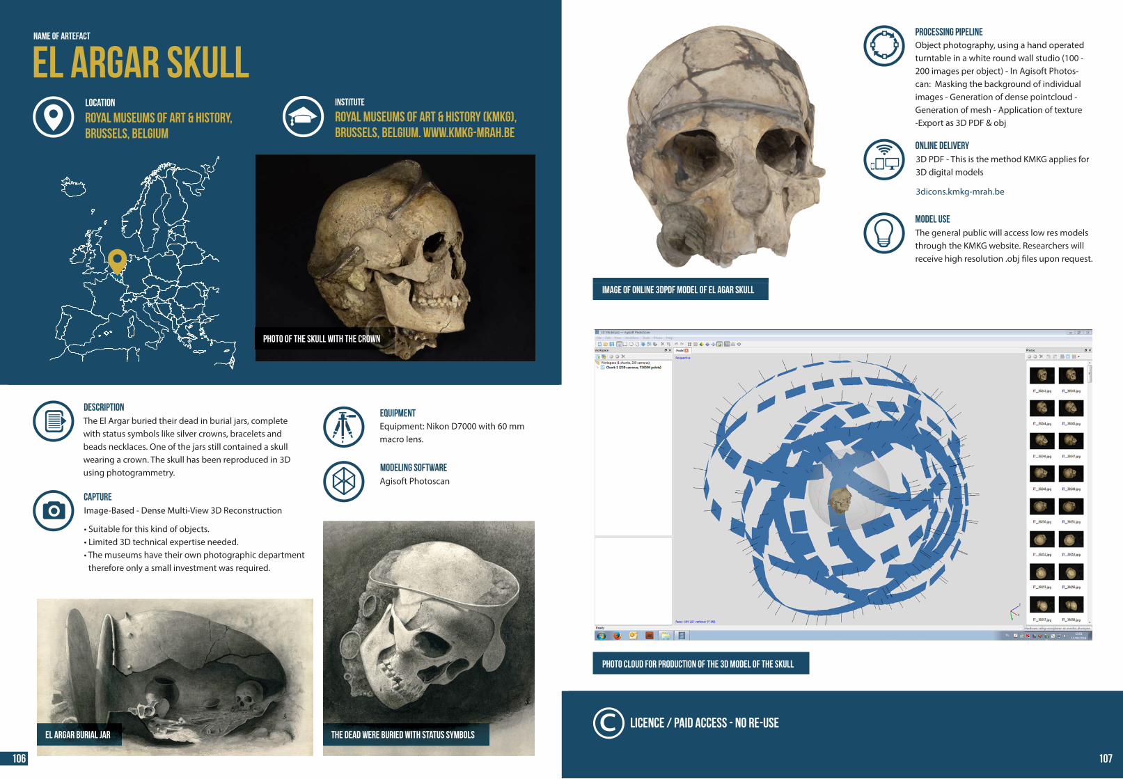
44 44
Photo of the skull with the crown
DESCRIPTION The El Argar buried their dead in burial jars, complete with status symbols like silver crowns, bracelets and beads necklaces. One of the jars still contained a skull wearing a crown. The skull has been reproduced in 3D using photogrammetry.
El Argar SKULLRoyal Museums of Art & History (KMKG),Brussels, Belgium. www.kmkg-mrah.be
Image-Based - Dense Multi-View 3D Reconstruction • Suitable for this kind of objects.• Limited 3D technical expertise needed.• The museums have their own photographic department therefore only a small investment was required.
CAPTURE
The dead were buried with status symbolsEl Argar burial jar
Name of Artefact
INSTITUTE
Royal Museums of Art & History,Brussels, Belgium
LOCATION
MODELING SOFTWAREAgisoft Photoscan
Equipment: Nikon D7000 with 60 mm macro lens.
Equipment
Photo cloud for production of the 3D model of the skull
PROCESSING PIPELINEObject photography, using a hand operated turntable in a white round wall studio (100 - 200 images per object) - In Agisoft Photos-can: Masking the background of individual images - Generation of dense pointcloud - Generation of mesh - Application of texture -Export as 3D PDF & obj
MODEL USE The general public will access low res models through the KMKG website. Researchers will receive high resolution .obj �les upon request.
ONLINE DELIVERY3D PDF - This is the method KMKG applies for 3D digital models 3dicons.kmkg-mrah.be
Image of online 3DPDF model of El Agar skull
Licence / Paid Access - No Re-use
106 107
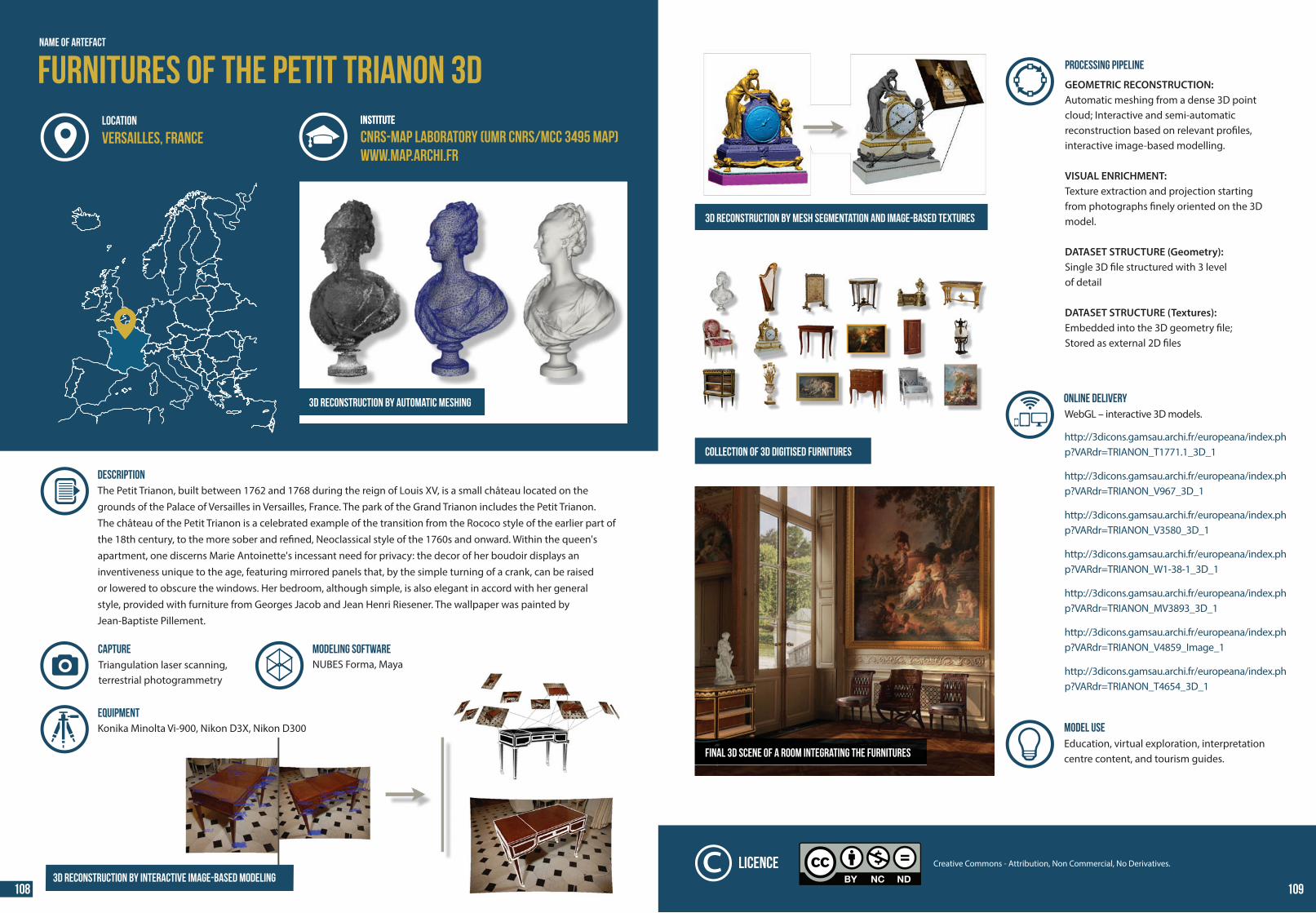
44 44
Name of ARTEFACT
3D reconstruction by automatic meshing
INSTITUTE
DESCRIPTION The Petit Trianon, built between 1762 and 1768 during the reign of Louis XV, is a small château located on the grounds of the Palace of Versailles in Versailles, France. The park of the Grand Trianon includes the Petit Trianon. The château of the Petit Trianon is a celebrated example of the transition from the Rococo style of the earlier part of the 18th century, to the more sober and re�ned, Neoclassical style of the 1760s and onward. Within the queen's apartment, one discerns Marie Antoinette's incessant need for privacy: the decor of her boudoir displays an inventiveness unique to the age, featuring mirrored panels that, by the simple turning of a crank, can be raised or lowered to obscure the windows. Her bedroom, although simple, is also elegant in accord with her general style, provided with furniture from Georges Jacob and Jean Henri Riesener. The wallpaper was painted by Jean-Baptiste Pillement.
Triangulation laser scanning, terrestrial photogrammetry
MODELING SOFTWARENUBES Forma, Maya
CAPTURE
Konika Minolta Vi-900, Nikon D3X, Nikon D300Equipment
Furnitures of the Petit Trianon 3D INSTITUTE
CNRS-MAP laboratory (UMR CNRS/MCC 3495 MAP)www.map.archi.fr
LOCATION
Versailles, France
3D reconstruction by interactive image-based modeling
PROCESSING PIPELINE
GEOMETRIC RECONSTRUCTION: Automatic meshing from a dense 3D point cloud; Interactive and semi-automatic reconstruction based on relevant pro�les, interactive image-based modelling.
VISUAL ENRICHMENT: Texture extraction and projection starting from photographs �nely oriented on the 3D model.
DATASET STRUCTURE (Geometry):Single 3D �le structured with 3 level of detail
DATASET STRUCTURE (Textures):Embedded into the 3D geometry �le; Stored as external 2D �les
ONLINE DELIVERYWebGL – interactive 3D models. http://3dicons.gamsau.archi.fr/europeana/index.php?VARdr=TRIANON_T1771.1_3D_1 http://3dicons.gamsau.archi.fr/europeana/index.php?VARdr=TRIANON_V967_3D_1 http://3dicons.gamsau.archi.fr/europeana/index.php?VARdr=TRIANON_V3580_3D_1 http://3dicons.gamsau.archi.fr/europeana/index.php?VARdr=TRIANON_W1-38-1_3D_1 http://3dicons.gamsau.archi.fr/europeana/index.php?VARdr=TRIANON_MV3893_3D_1 http://3dicons.gamsau.archi.fr/europeana/index.php?VARdr=TRIANON_V4859_Image_1 http://3dicons.gamsau.archi.fr/europeana/index.php?VARdr=TRIANON_T4654_3D_1
MODEL USE Education, virtual exploration, interpretation centre content, and tourism guides.
3D reconstruction by mesh segmentation and image-based textures
collection of 3D digitised furnitures
Final 3D scene of a room integrating the furnitures
Creative Commons - Attribution, Non Commercial, No Derivatives.Licence
108 109
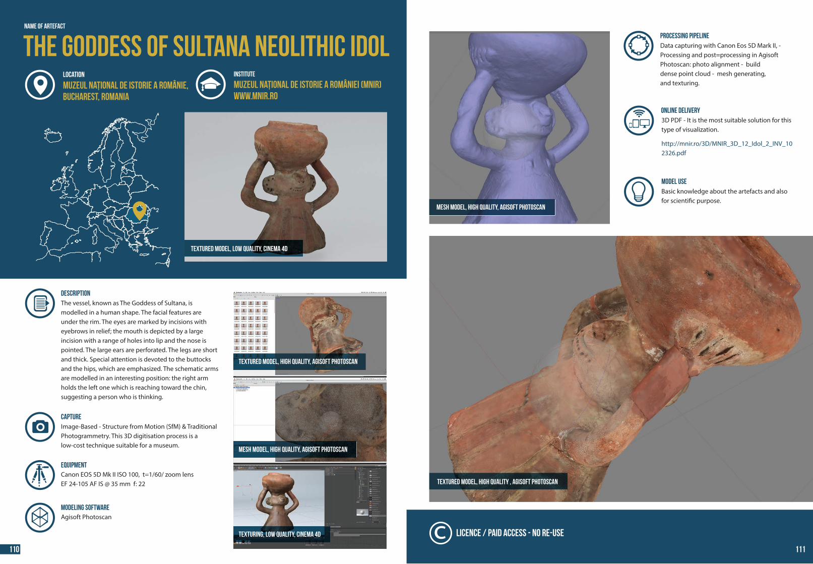
44 44
The Goddess of Sultana Neolithic Idol
Textured model, low quality, Cinema 4D
Name of Artefact
INSTITUTE
Muzeul Național de Istorie a României (MNIR)www.mnir.ro
LOCATION
Muzeul Național de Istorie a Românie, Bucharest, Romania
DESCRIPTION The vessel, known as The Goddess of Sultana, is modelled in a human shape. The facial features are under the rim. The eyes are marked by incisions with eyebrows in relief; the mouth is depicted by a large incision with a range of holes into lip and the nose is pointed. The large ears are perforated. The legs are short and thick. Special attention is devoted to the buttocks and the hips, which are emphasized. The schematic arms are modelled in an interesting position: the right arm holds the left one which is reaching toward the chin, suggesting a person who is thinking.
Texturing, low quality, Cinema 4D
Image-Based - Structure from Motion (SfM) & Traditional Photogrammetry. This 3D digitisation process is a low-cost technique suitable for a museum.
MODELING SOFTWAREAgisoft Photoscan
CAPTURE
Canon EOS 5D Mk II ISO 100, t=1/60/ zoom lens EF 24-105 AF IS @ 35 mm f: 22
Equipment
Textured model, high quality, Agisoft PhotoScan
Mesh model, high quality, Agisoft PhotoScan
PROCESSING PIPELINEData capturing with Canon Eos 5D Mark II, - Processing and post=processing in Agisoft Photoscan: photo alignment - builddense point cloud - mesh generating,and texturing.
ONLINE DELIVERY3D PDF - It is the most suitable solution for this type of visualization. http://mnir.ro/3D/MNIR_3D_12_Idol_2_INV_102326.pdf
Textured model, high quality , Agisoft PhotoScan
MODEL USE Basic knowledge about the artefacts and alsofor scienti�c purpose.
Mesh model, high quality, Agisoft PhotoScan
Licence / Paid Access - No Re-use
110 111
44 44
Appendix 1: Additional 3D-ICONS ResourcesProject Reports
D2.1 Digitisation Planning Report, Paolo Cignioni (CNR) and Andrea d’Andrea (CISA)
D2.3 Case Studies for the Testing the Digitisation Process, Anestis Koutsoudis, Blaz Vidmar and Fotis Arnaoutoglou (CETI) and Fabio Remondino (FBK)
D3.1 Interim Report on Data Acquisition, Gabriele Guidi (POLIMI)
D3.2 Final Report on Data Acquisition, Gabriele Guidi (POLIMI)
D4.1 Interim Report on Post-processing, Livio de Luca (CNRS-MAP)
D4.2 Interim Report on Metadata Creation , A. D’Andrea (CISA) with the collaboration of R. Fattovich and F. Pesando (CISA), A.
Tsaouselis and A. Koutsoudis (CETI)
D4.3 FinalReport on Post-processing, Livio de Luca (CNRS-MAP)
D5.1 3D Publication Formats Suitable for Europeana , Daniel Pletinckx and Dries Nollet (VisDim)
D5.2 Report on publication, Daniel Pletinckx and Dries Nollet (VisDim)
D6.1 Report on Metadata and Thesauri Andrea d’Andrea (CISA) and Kate Fernie (MDR)
D6.2 Report on Harvesting and Supply, Andrea d’Andrea (CISA) and Kate Fernie (B2C)
D7.1 Preliminary Report on IPR Scheme, Mike Spearman, Sharyn Emslie (CMC)
D7.2 IPR Scheme, Mike Spearman, Sharyn Emslie and Paul O’Sullivan (CMC)
D7.4 Report on Business Models, Mike Spearman, James Hemsley, Emma Inglis, Sharyn Emslie and Paul O’Sullivan (CMC)
All Project reports are available at fro the 3D-ICONS website at the following
URL: http://3dicons-project.eu/index.php/eng/Resources
Publications
D’Andrea, A., Niccolucci, F. and Fernie K., 2012. 3D-ICONS: European project providing 3D models and related digital content to Europeana, EVA Florence 2012.
D’Andrea, A., Niccolucci, F., Bassett, and Fernie, K., 2012. 3D-ICONS: World Heritage Sites for Europeana: Making Complex 3D Models Available to Everyone, VSMM 2012.
D’Andrea, A., Niccolucci, F. and Fernie K., 2013. CARARE 2.0: a metadata schema for 3D Cultural Objects. Digital Heritage 2013, International Congress, IEEE Proceedings.
D’Andrea, A., Niccolucci, F. and Fernie K., 2013. 3D ICONS metadata schema for 3D objects, Newsletter di Archeologia CISA, Volume 4, pp. 159-181,
Callieri, M., Leoni, C., Dellepiane, M. and Scopigno, R., 2013. Artworks narrating a story: a modular framework for the integrated presentation of three-dimensional and textual contents, ACM WEB3D - 18th International Conference on 3D Web Technology, page 167-175pdf: http://vcg.isti.cnr.it/Publications/2013/CLDS13/web3D_cross.pdf
Dell’Unto, N., Ferdani, D., Leander, A., Dellepiane, M. and Lindgren, S., 2013. Digital reconstruction and visualization in archaeology Case-study drawn from the work of the Swedish Pompeii Project, Digital Heritage 2013 International Conference, page 621-628 pdf: http://vcg.isti.cnr.it/Publications/2013/DFLDCL13/digitalheritage2013_Pompeii.pdf
Gonizzi Barsanti, S. and Guidi, G., 2013. 3D digitization of museum content within the 3D-ICONS project, ISPRS Ann. Photogramm. Remote Sens. Spatial Inf. Sci., II-5/W1, pp. 151-156.Online: www.isprs-ann-photogramm-remote-sens-spatial-inf-sci.net/II-5-W1/151/2013/
Gonizzi Barsanti, S., Micoli, L.L., Guidi, G., 2013. 3D Digitizing a whole museum: a metadata centered work�ow, 2013 Digital Heritage International Congress (DigitalHeritage), Vol. 2, pp. 307-310, IEEE, ISBN 978-1-4799-3169-9.
Guidi, G., Rodríguez Navarro, P., Gonizzi Barsanti, S., Loredana Micoli, L., Russo, M., 2013. Quick textured mesh generation in Cultural Heritage digitization, Built Heritage 2013, Milan, Italy, pp. 877-882, [Selected for printed publication].
Guidi, G., Rodríguez Navarro, P., Gonizzi Barsanti, S., Loredana Micoli, L., Russo, M., 2013. Quick textured mesh generation in Cultural Heritage digitization, Built Heritage 2013, Milan, Italy, pp. 877-882, [Selected for printed publication]. Online: http://www.bh2013.polimi.it/papers/bh2013_paper_324.pdf
Hermon, S., Bakirtzis, N., Kyriacou, P., 2013. 3D Documentation – Analysis - Interpretation, Digital libraries of 3D data – access and inter-operability, and The cycle of use and re-use of digital heritage assets., Scienti�c Support for Growth & Jobs (2013): Cultural and Creative Industries, Brussels, Belgium., Session: posters and presentation.
Hermon, S., Ben-Ami, D., Khalaily, H., Avni, G., Iannone, G., Faka, M., 2013. 3D documentation of large-scale, complex archaeological sites: The Givati Parking excavation in Jerusalem, Conference Proceedings, Digital Heritage 2013, Marseilles, France, vol 2, Session: Documentia. Digital Documentation of Archaeological Heritage, pp. 581
Hermon, S., Niccolucci, F.,Yiakoupi, K., Kolosova, A., Iannone, G., Faka, M., Kyriacou, P., Niccolucci, V., 2013. Documenting Architectonic Heritage in Con�ict Areas. The case of Agia Marina Church, Derynia, Cyprus, Conference Proceedings, Built Heritage 2013, Monitoring Conservation Management, Milan, Italy, 20 November, pp. 800 - 808. Available:http://www.bh2013.polimi.it/papers/bh2013_paper_216.pdf [20 Dec 2013].
Hermon, S., Khalaily, H., Avni, G., Reem, A., Iannone, G., Fakka, M., 2013. Digitizing the Holy – 3D Documentation and analysis of the architectural history of the “Room of the Last Supper” – the Cenacle in Jerusalem, Conference Proceedings, Digital Heritage 2013, Marseilles, France, vol 2, Session 3−Architecture, Landscape: Documentation & Visualization, pp. 359 - 362.
Jiménez Fernández-Palacios, B., Remondino, F., Lombardo, J., Stefani, C. and L. De Luca, 2013. Web visualization of complex reality-based 3D models with Nubes, Digital Heritage 2013 Int. Congress, IEEE Proceedings.
Leoni, C., Callieri, M., Dellepiane, M. Rosselli Del Turco, R. and O’Donnell, D., 2013. The Dream and the Cross: bringing 3D content in a digital edition, Digital Heritage 2013 International Conference, page 281-288 - October 2013 pdf:http://vcg.isti.cnr.it/Publications/2013/LCDRO13/DreamAndTheCross.pdf
Niccolucci, F., Felicetti, A., Amico, N. and D’Andrea, A., 2013. Quality control in the production of 3D documentation of monuments, Built Heritage 2013, proceedings http://www.bh2013.polimi.it/papers/bh2013_paper_314.pdf
Remondino, F., Menna, F., Koutsoudis, A., Chamzas, C. and El-Hakim, S., 2013. Design and implement a reality-based 3D digitisation and modelling project”. Digital Heritage 2013 Int. Congress, IEEE Proceedings.
Ronzino, P., Niccolucci, F. and D’Andrea, A., 2013. Built Heritage metadata schemas and the integration of architectural data-sets using CIDOC-CRM , Built Heritage 2013, proceedings http://www.bh2013.polimi.it/papers/bh2013_paper_318.pdf
Yiakoupi, K., Hermon, S., 2013. Israel Case Studies: The room of Last Supper and The Tomb of King David Hall, Presentation, Digital Heritage 2013, Marseilles, France, Session: “Exploring the 3D ICONS project: from capture to delivery”.
112 113
44 44
Appendix 2: Project Partners
Archeotransfert, France
Athena Research and Innovation Centre in Information Communication & Knowledge
Technologies (CETI), Greece
Centre National de la Recherche Scienti�que (CNRS-MAP) France
CMC Associates Ltd., UK Consiglio Nazionale delle Ricerche (CNR-ISTI), Italy
Consorzio Interdipartimentale Servizi Archeologici (CISA), Italy
The Cyprus Research and Educational Foundation (CYI-STARC), Cyprus
The Discovery Programme Ltd., Ireland Koninklijke Musea Voor Kunst en Geschiedenis (KMKG), Belgium
Muzeul Naţional de Istorie a României (MNIR), Romania
National Technical University of Athens (NTUA), Greece
Politecnico di Milano (POLIMI), Italy
Universidad de Jaen, Andalusian Centre for Iberian Archaeology (UJA-CAAI), Spain
Visual Dimension bvba (VisDim) Belgium
Fondazione Bruno Kessler (FBK), Italy
114 115

44
3D-ICONS CASE STUDIES