
Common Guidelines
145
-
Upload
khangminh22 -
Category
Documents
-
view
0 -
download
0
Transcript of Common Guidelines

Guidelines For The Safe Management of Offshore Supply And Anchor Handling Operations (NWEA) Version 1
- i -
TABLE OF CONTENTS
Signatories to the Guidelines......................................................v Document Control Sheet ............................................................vi Using the document ...................................................................vii Abbreviations / Definitions ......................................................... ix 1 Introduction .........................................................................1-1
1.1 Objectives.......................................................................................1-1 1.2 Ownership ......................................................................................1-1 1.3 Document Control, Revisions and Distribution ...............................1-1 1.4 Application ......................................................................................1-1 1.5 Applicable Legislation.....................................................................1-2
1.5.1 Overview ........................................................................................................... 1-2 1.5.2 Regulatory enforcement, best practice and safety ........................................... 1-2 1.5.3 Relationship between offshore and maritime regulations ................................ 1-2
2 Responsibilities...................................................................2-1 2.1 General Responsibilities .................................................................2-1
2.1.1 Management ..................................................................................................... 2-1 2.1.2 Workscope Responsibilities. Minimum safety requirements that shall be laid down are as follows: ...................................................................................................... 2-1
2.2 Responsibilities...............................................................................2-2 2.2.1 Masters of Vessels............................................................................................ 2-2 2.2.2 Installation OIM................................................................................................. 2-3 2.2.3 Ship Owner ....................................................................................................... 2-3 2.2.4 Base companies ............................................................................................... 2-4 2.2.5 Operating / Logistics company ........................................................................ 2-4
2.3 Meetings .........................................................................................2-5 2.3.1 General ............................................................................................................. 2-5 2.3.2 Onshore operations meetings........................................................................... 2-5
3 Operations ...........................................................................3-1 3.1 In Port .............................................................................................3-1
3.1.1 Information / Planning....................................................................................... 3-1 3.1.2 Berthing Moorings & Gangways ....................................................................... 3-1 3.1.3 Shipboard Lifting Operations In Port................................................................. 3-1
3.2 Voyage Planning ............................................................................3-1 3.2.1 Vessel Routeing................................................................................................ 3-1 3.2.2 Weather ............................................................................................................ 3-2 3.2.3 Outward Cargo Planning .................................................................................. 3-2 3.2.4 Deck Cargo Handling & Securing ..................................................................... 3-2 3.2.5 Sailing Instructions & Cargo Documentation .................................................... 3-4
3.3 Approaching and at the installation (safety zone) ...........................3-5 3.3.1 Pre-Arrival Information & Planning ................................................................... 3-5 3.3.2 Arrival at the Installation ................................................................................... 3-5 3.3.3 Communication ................................................................................................. 3-5 3.3.4 Vessel Approach and Manoeuvring.................................................................. 3-6 3.3.5 Overboard Discharges...................................................................................... 3-8 3.3.6 Deck Cargo Operations, Inter-Field Transfers and Cargo Securing ................ 3-9 3.3.7 Personnel transfers......................................................................................... 3-11 3.3.8 Installation Departure...................................................................................... 3-12
3.4 Vertical Seismic Profiling (VSP)....................................................3-13 4 Bulk Cargo Operations .......................................................4-1
4.1 General Requirements....................................................................4-1 4.2 Bulk Transfer Operations In Port ....................................................4-2

Guidelines For The Safe Management of Offshore Supply And Anchor Handling Operations (NWEA) Version 1
- ii -
4.3 Hazard Overview ............................................................................4-3 4.4 Bulk Transfers of Particular Concern..............................................4-3 4.5 Fuel ................................................................................................4-4 4.6 Potable Water.................................................................................4-5 4.7 Bulk transfer Operations - General .................................................4-5 4.8 Hose marking and usage................................................................4-5 4.9 Vessel responsibilities at the installation ........................................4-5 4.10 Installation responsibilities ..............................................................4-6 4.11 Bulk Transfer Operations At The Installation ..................................4-7
5 Contractor Management .....................................................5-1 5.1.1 Project (3rd Party) Mobilisation & De-Mobilisation ........................................... 5-1 5.1.2 Tank Cleaning................................................................................................... 5-2
6 Anchor Handling & Towing ................................................6-1 6.1 Agreed Procedures and Responsibilities ........................................6-1
6.1.1 Responsibilities of the Ship Owner ................................................................... 6-1 6.1.2 Responsibilities of the Operating Company ..................................................... 6-1 6.1.3 Responsibilities of the MOU Owner.................................................................. 6-2 6.1.4 Responsibilities of the OIM ............................................................................... 6-2 6.1.5 Responsibilities of the A/H vessel Master......................................................... 6-3
6.2 Rig move meeting...........................................................................6-3 6.3 Reporting ........................................................................................6-4 6.4 Risk Assessment ............................................................................6-4 6.5 Rig move procedures......................................................................6-4
6.5.1 Information required relating to MOU ............................................................... 6-4 6.5.2 Requirements related to A/H vessels ............................................................... 6-4 6.5.3 Other information required in rig move procedures .......................................... 6-5
6.6 Equipment ......................................................................................6-5 6.6.1 General ............................................................................................................. 6-5 6.6.2 Anchor Handling Equipment ............................................................................. 6-6
6.7 The Anchor Handling Operation .....................................................6-6 6.7.1 Anchor securing on deck .................................................................................. 6-6
6.8 The Towing Operation ....................................................................6-6 6.8.1 Operation Planning ........................................................................................... 6-6 6.8.2 Bollard Pull........................................................................................................ 6-7 6.8.3 General Towing Rules ...................................................................................... 6-7 6.8.4 Pendant Return to MOU ................................................................................... 6-8
6.9 Deep Water (300m +) Anchor Handling Operations .......................6-8 7 Risk Management................................................................7-9
7.1 Overview.........................................................................................7-9 7.2 Risk Assessment & Safe Job Analysis (RA & SJA) ........................7-9 7.3 Permit to Work (PTW)...................................................................7-10 7.4 Toolbox Talks ...............................................................................7-10 7.5 Personal Protective Equipment (PPE)..........................................7-10 7.6 Accident, Incident, Near Miss, Non-conformance Reporting ........7-11 7.7 Vessel Operational Limits .............................................................7-11
8 Collision Risk Avoidance ...................................................8-1 8.1 Collision Risk Avoidance ................................................................8-1
8.1.1 Overview ........................................................................................................... 8-1 8.1.2 Adverse Weather Working Guidelines.............................................................. 8-2 8.1.3 Adverse Weather Working................................................................................ 8-3
9 Training, Competency & Manning .....................................9-1 9.1.1 Vessels, general ............................................................................................... 9-1
9.2 Training & Competency ..................................................................9-1

Guidelines For The Safe Management of Offshore Supply And Anchor Handling Operations (NWEA) Version 1
- iii -
9.2.1 Role Specific Requirements ............................................................................. 9-1 9.2.2 Trainee Personnel............................................................................................. 9-1 9.2.3 Regional emergency preparedness.................................................................. 9-1 9.2.4 Anchor handling vessels................................................................................... 9-1 9.2.5 DP competence requirements: ......................................................................... 9-2 9.2.6 Enhanced joystick facility.................................................................................. 9-2
9.3 Manning..........................................................................................9-3 9.3.1 General ............................................................................................................. 9-3 9.3.2 Supply vessels within the Safety Zone ............................................................. 9-3 9.3.3 Anchor handling vessels................................................................................... 9-3
10 Emergencies...................................................................10-4 10.1 Emergency preparedness procedures..........................................10-4 10.2 Installation Emergency .................................................................10-4 10.3 Port Emergency............................................................................10-4 10.4 Operators Co-operative Emergency Service ................................10-4 10.5 Search & Rescue..........................................................................10-5
11 Security ...........................................................................11-1 11.1 In Port ...........................................................................................11-1 11.2 At the Installation ..........................................................................11-1 11.3 Ship – Ship Interface ....................................................................11-1
A Good practice for the carriage of oil contaminated cargoes for transportation by offshore supply vessel ........................ A-1 B Bulk Transfer Checklist ..................................................... B-1 C Offshore Support Vessel Bridge Procedures at Offshore Installations .............................................................................. C-1 D Checklist for Support Vessel and Installation Ops ......... D-1 E Tank Cleaning Checklist.................................................... E-1 F Cargo Segregation Table....................................................F-1 G Deck Cargo Plan.................................................................G-1 H Installation Data Card ........................................................ H-1 I FPSO-Specific Checklist......................................................I-1 J Communication with vessels .............................................J-1 K Bulk Loading Hoses – Guidance Notes ........................... K-1 L Example Operating Company Data Card ..........................L-1 M Example Port Data Card ....................................................M-1 N Anchor Handling Set Up Systems .................................... N-1 O Hazard Overview ................................................................O-1 P Hand Signals for Crane Operations.................................. P-1 Q References..........................................................................Q-1 R Contacts.............................................................................. R-1

Guidelines For The Safe Management of Offshore Supply And Anchor Handling Operations (NWEA) Version 1
- iv -
Table of National Addenda Reference Title Dutch NL1 Hoisting and Chain Gear NL2 Radioactive material including LSA NL3 Backloading checklist NL4 Potable water NL5 Personnel basket transfer Norwegian NO1 PSA responsibility NO2 Acceptance Criteria for Offshore Support Vessels NO3 Operational Limitations NO4 Operations within the safety zone using DP NO5 Competence requirements NO6 Technical redundancy NO7 Anchor securing NO8 Offshore Potable Water Supply United Kingdom
UK1 Role of the DfT, MCA and HSE on UK Continental Shelf (UKCS)
UK2 Weather limitations for operations UK3 Additional requirements for carriage of hazardous goods in
UKCS UK4 Waste and waste disposal UK5 Discharging waste cargo carrying units UK6 Cargo packing and handling UK7 Dangerous goods & pollutants stowage

Guidelines For The Safe Management of Offshore Supply And Anchor Handling Operations (NWEA) Version 1
- v -
Signatories to the Guidelines These Guidelines have been recognised and endorsed by the following Administrations, Regulators, Trade Associations and Trade Unions.
Chamber of Shipping Danish Ship Owners' Association Netherlands Oil and Gas Exploration and Production Association Norwegian Oil Industry Association (OLF) Norwegian Shipowners' Association United Kingdom Offshore Operators Association

Guidelines For The Safe Management of Offshore Supply And Anchor Handling Operations (NWEA) Version 1
- vi -
Document Control Sheet Date Issue No. Location(s) of changes)

Guidelines For The Safe Management of Offshore Supply And Anchor Handling Operations (NWEA) Version 1
- vii -
Using the document 1. Attention is drawn to specific sections of the text through the graphics shown below.
Attention!
Responsible organisations: Base
Vessel
Installation
Management
National addenda:
Danish
Dutch
Irish
Norwegian
UK 2. Links from one section of the document to another are shown as Introduction. Ctrl-click to go straight to the reference. 3. Links to References are shown as 30. Ctrl-click to go to the reference. 4. Links to Endnotes (additional information placed at the end of each section if applicable) are shown as i . Double-click to go straight to the reference. 5. Links to National Addenda are indicated by the flag of that nation; this is linked directly to the document, which can be opened by Ctrl-clicking the flag. Example is: UK1 The information in the national addenda is always in addition to the text used in these guidelines. 6. Ctrl-click on a section heading in the table of contents to go to that section.

Guidelines For The Safe Management of Offshore Supply And Anchor Handling Operations (NWEA) Version 1
- viii -
i This is an endnote for this section

Guidelines For The Safe Management of Offshore Supply And Anchor Handling Operations (NWEA) Version 1
Page ix
Abbreviations / Definitions Abbreviations 24/7 24 hours per day, 7 full days per week AB Able-bodied Seaman ABS American Bureau of Shipping A/H Anchor handling ACoP Approved Code of Practice AHTS Anchor Handling Tug Supply vessel AHV Anchor handling vessel CoS Chamber of Shipping – the trade association representing
owners and operators of UK-based shipping companies COSHH Control Of Substances Hazardous to Health CoSWP Code of Safe Working Practices for Merchant Seamen DGPS Differential Global Positioning System DNV Det Norske Veritas DP Dynamic Positioning DSV Diving Support Vessel ERRV Emergency Response & Rescue Vessel ETA Estimated/Expected Time of Arrival ETD Estimated Time of Departure FMEA Failure mode and effect analysis FPSO Floating production, storage and offloading unit FRC Fast Rescue Craft GPS Global Positioning System HAZOP Hazard & Operability HSE Health & Safety Executive HS&E Health, Safety and Environment IADC International Association of Drilling Contractors (North Sea
Chapter) ICS International Chamber of Shipping ILO International Labour Organisation ILP Integrated Logistics Provider IMCA International Marine Contractors Association IMDG International Maritime Dangerous Goods IMO International Maritime Organisation INLS International Noxious Liquid Substances ISM-Code IMO International Safety Management Code ISPS International Security code for Port facility & ships LR Lloyds Register LSA Low Specific Activity MARPOL IMO International Convention for the Prevention of Pollution
from ships MBL Minimum Breaking Load MCA Maritime and Coastguard Agency MGN Marine Guidance Note - issued by the MCA MIN Marine Information Note - issued by the MCA

Guidelines For The Safe Management of Offshore Supply And Anchor Handling Operations (NWEA) Version 1
Page x
MOB Man Overboard Boat MODU Mobile Offshore Drilling Unit MOU Mobile Operating Unit MS Merchant Shipping – mainly used in a legal context when
referring to UK Statutory Instruments MSC Maritime Safety Committee (of the IMO) MSDS Material Safety Data Sheet MSN Merchant Shipping Notice – issued by the MCA NLS Noxious liquid substances NSA Norwegian Shipowners’ Association NMD Norwegian Maritime Directorate NOGEPA Netherlands Oil and Gas Exploration and Production
Association NUMAST National Union of Marine, Aviation and Shipping Transport
Officers OBM Oil Based Mud OCES Operators Co-operative Emergency Services OIM Offshore Installation Manager OLF Oljeindustriens Landsforening (Norwegian Oil Industry
Association) ORQ Oil Rig Quality, chain quality designation OSV Offshore Support Vessel PAPA Platform Abandon Platform Alarm PCP Permanent Chaser Pendant PGA Platform General Alarm PPE Personal Protective Equipment PSA Petroleum Safety Authority PSV Platform Supply Vessel PTW Permit to Work RA Risk Assessment ROV Remotely operated vehicle SJA: Safe job analysis SMPEP Shipboard Marine Pollution Emergency Plan SOW: Scope of Work STCW: International Convention on Standards of Training,
Certification and Watchkeeping for Seafarers SWL: Safe Working Load UHF: Ultra high frequency UKCS United Kingdom Continental Shelf UKOOA UK Offshore Operators Association VHF: Very high frequency VSP Vertical Seismic Profile
Guidelines For The Safe Management of Offshore Supply And Anchor Handling Operations (NWEA) Version 1
Page xi
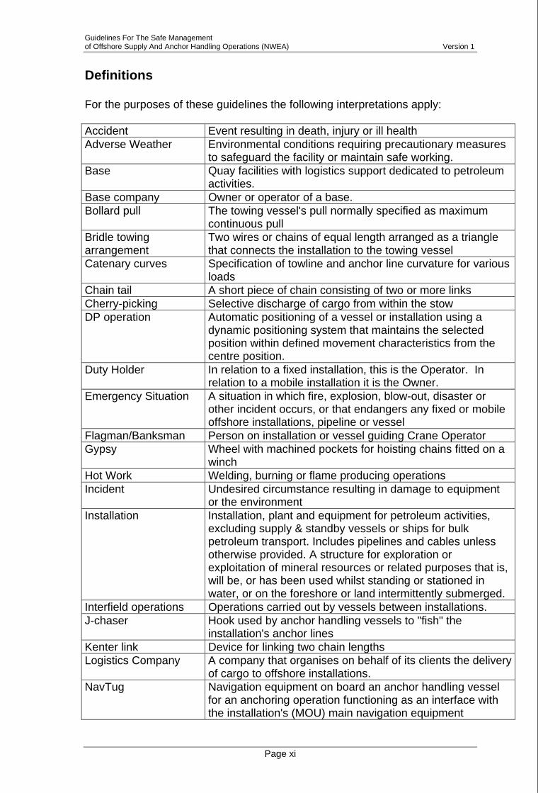
Definitions For the purposes of these guidelines the following interpretations apply: Accident Event resulting in death, injury or ill health Adverse Weather Environmental conditions requiring precautionary measures
to safeguard the facility or maintain safe working. Base
Quay facilities with logistics support dedicated to petroleum activities.
Base company Owner or operator of a base. Bollard pull The towing vessel's pull normally specified as maximum
continuous pull Bridle towing arrangement
Two wires or chains of equal length arranged as a triangle that connects the installation to the towing vessel
Catenary curves Specification of towline and anchor line curvature for various loads
Chain tail A short piece of chain consisting of two or more links Cherry-picking Selective discharge of cargo from within the stow DP operation Automatic positioning of a vessel or installation using a
dynamic positioning system that maintains the selected position within defined movement characteristics from the centre position.
Duty Holder In relation to a fixed installation, this is the Operator. In relation to a mobile installation it is the Owner.
Emergency Situation A situation in which fire, explosion, blow-out, disaster or other incident occurs, or that endangers any fixed or mobile offshore installations, pipeline or vessel
Flagman/Banksman Person on installation or vessel guiding Crane Operator Gypsy Wheel with machined pockets for hoisting chains fitted on a
winch Hot Work Welding, burning or flame producing operations Incident Undesired circumstance resulting in damage to equipment
or the environment Installation Installation, plant and equipment for petroleum activities,
excluding supply & standby vessels or ships for bulk petroleum transport. Includes pipelines and cables unless otherwise provided. A structure for exploration or exploitation of mineral resources or related purposes that is, will be, or has been used whilst standing or stationed in water, or on the foreshore or land intermittently submerged.
Interfield operations Operations carried out by vessels between installations. J-chaser Hook used by anchor handling vessels to "fish" the
installation's anchor lines Kenter link Device for linking two chain lengths Logistics Company A company that organises on behalf of its clients the delivery
of cargo to offshore installations. NavTug Navigation equipment on board an anchor handling vessel
for an anchoring operation functioning as an interface with the installation's (MOU) main navigation equipment

Guidelines For The Safe Management of Offshore Supply And Anchor Handling Operations (NWEA) Version 1
Page xii
Near-miss Undesired circumstance with the potential to cause death, injury, ill health, damage to equipment or the environment
Nominated Manager Nominated persons “in charge” of a specified area or task to be performed
Non-conformity / non-compliance
A circumstance where guidelines, regulation or legislation have not been followed.
North West European Area
Operations taking place throughout the North Sea but also encompassing those West of Shetland, in the Irish Sea and Liverpool Bay and those up into the Norwegian Sea
Offshore Installation All offshore platforms (manned and unmanned), including MODU’s used for mining activities.
Offshore Support vessel
Supply vessels, and other vessels involved in offshore supply and anchor handling activities.
Operating company Party that carries out the management of petroleum activities on behalf of licensees.
Pear link Device for linking two different chain dimensions Pendant Wire hanging permanently attached to the installation used
for chasing out anchors. PCP (Permanent Chain Pendant) Pennant wire Buoy wire; wire from the seabed up to a buoy on the surfacePermanent chaser Ring fitted over the anchor line connected to the pendant
wire. Used by anchor handling vessel when hoisting or setting the installation's anchors
Piggyback anchor Anchor connected to primary anchor with wire or chain in case of insufficient holding power
Pigtail Short chain or wire with open end links Radio silence Precautions to reduce potential induction of spurious current
in detonator circuits Recognised classification society
Classification society recognised by the International Association of Classification Societies (IACS) to supervise vessel design, construction, outfitting and operations.
Redundancy The ability or possibility of a component or system to maintain or re-establish its function following a failure.
Risk Assessment A process of assessing risk in any operation Safety Delegate Nominated representative for crew or part of crew or group
of workers with regard to HS&E matters Safety Zone Established within a radius extending to 500 metres beyond
the outline of any installation, excluding submarine pipelines.Shark jaw Device for connecting or disconnecting chains or wires. Ship Owner Those responsible for normal vessel management and
operation. Shipper A person who, as principal or agent for another, consigns
goods for carriage by sea Socket Cast anchoring termination on wire Spooling gear Arrangement to guide wire onto drum Stern roller Large stern roller for guiding chains, wires and anchors Supply chain Base or base company – vessel or Ship Owner – installation
or operating company Supply service Supply and/or receipt of goods to or from offshore
installations.

Guidelines For The Safe Management of Offshore Supply And Anchor Handling Operations (NWEA) Version 1
Page xiii
Swivel Connecting link or device used to prevent wire rotation Tension control May be set to pull in or pay out at a specified tension Toolbox Talk A meeting of the individuals due to be involved in an
imminent task to review the task, individual responsibilities, equipment required, competency of the individuals, hazards, any Safe Job Analysis or Risk Assessment and/or Permit to Work in place, simultaneous tasks ongoing which may affect the task and any other relevant subject.
Tow eye/towline guide Arrangement for keeping towline in centre line or midship area
Towing pins/guide pins Device for guiding towline or pennant wire. Towing winch Similar to a working winch, often geared differently. Newer
towing winches have drums smaller than working winches. Towline Wire on towing winch used for towing Transfer basket Equipment utilised for transferring personnel by crane Tugger winch For pulling equipment on deck during anchor handling. Have
remote control on newer vessels, or may be controlled from the bridge on some vessels
Tugger wire Steel or fibre wire used for tugger winch Weak link Weak link in a rigging arrangement. Weather criteria Specification of maximum allowed weather (wind, waves,
etc.) when performing the operation Weather window Specification of maximum allowed weather (wind, waves,
etc.) when performing an operation for a specific time periodWorking winch Winch for hoisting and setting anchors. Power, length, width
and diameter set the application area of the working winch Working wire Wire in working winch including termination, for example
socket

Guidelines For The Safe Management of Offshore Supply And Anchor Handling Operations (NWEA) Version 1
Page 1-1
1 Introduction
1.1 Objectives 1. To ensure and improve the safety of Supply and Anchor Handling
operations in the North West European Area (NWEA). 2. To provide guidance on eliminating or reducing hazards or risks
during Supply and Anchor Handling operations.
1.2 Ownership 1. Ownership of these Guidelines belongs to jointly and equally to the
following organisations: Chamber of Shipping Danish Shipowners Association Netherlands Oil and Gas Exploration and Production Association Norwegian Ship Owners Association Oljeindustriens Landsforening (OLF) United Kingdom Offshore Operators Association
2. To contact the Working Group On Guidelines For The Safe Management Of Offshore Supply And Anchor Handling Operations (North West European Area) please write to: Secretary To The Working Group On Guidelines For The Safe Management Of Offshore Supply And Anchor Handling Operations (North West European Area) C/O CoS OSV Section, Carthusian Court, 12 Carthusian Street, LONDON. EC1M 6EZ
1.3 Document Control, Revisions and Distribution 1. These Guidelines will be reviewed and amended as a result of changes in
operating practices, technology, and experience. 2. Comments on the Guidelines are welcomed and should either be
submitted directly to the NWEA Working Group or via safety officers, safety representatives, industry representative organisations or trade union representatives. Guidelines will be reviewed within two years from first issue and biennially thereafter.
3. Suggestions for areas for future consideration are also welcome.
1.4 Application 1. These Guidelines incorporate best practice and procedures from North
Sea operating companies, logistics companies, ship owners, shippers and

Guidelines For The Safe Management of Offshore Supply And Anchor Handling Operations (NWEA) Version 1
Page 1-2
lessons from the appropriate safety forums. These Guidelines do not supersede flag and other legal requirements
2. They apply to all those involved in interaction between offshore installations, bases and offshore support vessels related to offshore operations in the NWEA.
3. For these Guidelines references to Master or OIM include their nominated representatives, where appropriate
1.5 Applicable Legislation
1.5.1 Overview 1. In addition to the Guidelines, organisations involved in operating in the
NWEA shall adhere to relevant international and national legislation. NO1 UK1
1.5.2 Regulatory enforcement, best practice and safety
1. All relevant operations in the NWEA will be covered by these guidelines.
2. Adherence to these guidelines will provide strong indication to national administrations that health and safety legislation is being met and due diligence taken. Use them unless alternative solutions: equal or better these, and meet regulatory requirements
3. Deviation from NWEA Guidelines or National Addenda must include risk assessment or safe job analysis and be accepted by parties involved.
4. Necessary resources should be provided to relay interim Safety Alerts, or best practice examples promulgated from appropriate safety forums, to relevant base, offshore and ship’s staff.
5. All companies involved in relevant operations should audit their adherence to these Guidelines.
6. Relevant authorities must be advised of accidents and incidents.
1.5.3 Relationship between offshore and maritime regulations UK1
1. Design, outfitting and operation of offshore support vessels in the NWEA are regulated by both the vessel's flag state, classification society and the requirements laid down in these guidelines.
2. Flag states are responsible for maritime safety control and supervision of vessels, including construction, stability, watertight or weatherproof integrity, navigation safety, safe manning and associated certification.

Guidelines For The Safe Management of Offshore Supply And Anchor Handling Operations (NWEA) Version 1
Page 1-3
3. Flag state requirements stem from mandatory international requirements stipulated in the IMO & ILO, supplemented by any national requirements.
4. Operating companies are responsible for safety for their own offshore activities in the NWEA. Anchor handling, loading, offloading to or from installations and similar operations are subject to maritime authorities’ regulatory requirements. NO1

Guidelines For The Safe Management of Offshore Supply And Anchor Handling Operations (NWEA) Version 1
Page 2-1
2 Responsibilities
2.1 General Responsibilities 1. All personnel are responsible for both their own safety and the safety
of those they work with. They must always act to prevent accidents. 2. Personnel must participate in relevant safety and working environment
activities.
2.1.1 Management 1. Active involvement of management is key to safe and efficient
operations. Management comprises the relevant decision makers in the operating company, logistics company, base company and Ship Owner.
2. Management must make available necessary resources to ensure safe and efficient operations, including:
Facilitating safe working environment and operations Regular visits to workplaces (at least annually) as well as participating
in annual conferences on safe and efficient operations Following up to ensure measures adopted from incident and non-
conformance reports are implemented, and operate as intended.
2.1.2 Workscope Responsibilities. Minimum safety requirements that shall be laid down are as follows:
2.1.2.1 Operating / Logistics company 1. Clear work specification and scope of service 2. Take into account consequences of simultaneous vessel operations (e.g.
tank cleaning v deck cargo work) 3. Identified hazards and acceptance criteria. 4. Notification format for non-conformances, accidents, incidents, etc. 5. Operating company’s requirements for competence, training and
certificates for the workscope the vessel is to perform. 6. Plan for workscope follow-up. 7. Operational manning (see Section 9.3) 8. Lines of communication
2.1.2.2 Offshore installation. For interaction between installation and vessels:
1. Clear scope of work. 2. Risk Assessment of interaction between installation and vessels (e.g.
weather working conditions)

Guidelines For The Safe Management of Offshore Supply And Anchor Handling Operations (NWEA) Version 1
Page 2-2
3. Technical systems requirements needed to prevent fluid discharges from installation (including cooling water and/or solids) drifting towards vessels working within the safety zone.
4. Mechanisms and persons responsible for notifying or reporting non-conformances etc to operating company and authorities when vessels are within safety zone.
5. Training and competence requirements of personnel responsible for or participating in loading, offloading and other coordinated operations with vessels.
6. Plan for workscope follow-up. 7. Communication between ship and offshore installation
2.1.2.3 Base Companies. Co-ordinated activities between base and vessels:
1. Clear work specification and scope of service. 2. Risk assessment of interaction between base and vessels. 3. Competence requirements of personnel who plan, coordinate or perform
loading or offloading operations. 4. Mechanism and persons responsible for notifying or reporting to the
operating company, authorities, etc. for non-conformances etc. 5. Communication between ship and base
2.2 Individual Responsibilities
2.2.1 Masters of Vessels 1. Are at all times responsible for safety of their crews, vessels and cargo
and marine environment protection. The Master must stop operations that threaten the safety of the vessel, crew, or the installation’s integrity. Other pressures must not interfere with the Master’s professional judgement and must inform relevant parties of a serious conflict of interest arising from instructions or activities of other parties.
2. Approve loading plans before cargo (both bulk and Deck cargo) is loaded on board the vessel.
3. Review all dangerous goods declarations before dangerous goods are loaded
4. Report incidents and non-conformances. 5. Approve seafastening of cargo. 6. Must ensure all applicable field charts and relevant documentation are
on board. 7. Before entering the safety zone shall obtain permission from OIM or their
authorised representative for maritime operations.

Guidelines For The Safe Management of Offshore Supply And Anchor Handling Operations (NWEA) Version 1
Page 2-3
8. When alongside an installation, if extended interruption of operations occurs, shall decide whether to move to a safe position pending resumption. OIM must be informed before moving away.
2.2.2 Installation OIM 1. Is responsible for:
Installation safety, personnel on board, and any operation within the safety zone affecting installation safety and overviews of simultaneous operations.
2. Prepares required documentation before loading is initiated for cargo to be shipped ashore by the vessel, including declarations for transporting dangerous goods when required.
3. Before cargo (bulk and deck) is loaded on board the vessel: Submit documentation to the vessel Master. Grant the Master sufficient time to plan loading to ensure e.g. that
dangerous goods are stowed according to regulatory requirements. 4. Ensures optimal turn-around time for performance of planned operations
when vessels enter the safety zone. 5. Must ensure installation operations do not present a hazard to vessels
alongside.
This is especially critical where overside discharges may contact or fall on a vessel working alongside.
6. Approves commencement of an operation and has authority to stop any operation.
7. In case of an incident offshore must inform the relevant operating company and the Master of the vessel involved as soon as possible.
8. Must ensure there is a good level of communication between the vessel and the installation.
2.2.3 Ship Owner 1. Communicate the workscope to vessel 2. Manage vessel operations and manning ensuring:
A vessel is appropriately manned and equipped for the intended workscope.
An overall operational plan is prepared for all anticipated onboard operations and services provided by the vessel.
3. Prepare operational conditions for vessels (define requirements for safe operation of vessels under all conditions, and any vessel limitations due to e.g. lack of technical redundancy, etc NO3.).
4. Ensure non-conformances are recorded, assessed and handled in accordance with an established incident reporting system.

Guidelines For The Safe Management of Offshore Supply And Anchor Handling Operations (NWEA) Version 1
Page 2-4
5. Must ensure an up-to-date copy of these Guidelines is kept on board and ensure they and their crew are familiar with the contents.
2.2.4 Base companies 1. Load/offload vessels. Before any cargo is loaded they shall:
Prepare required documentation for cargo to be shipped. Grant the Master sufficient time to plan the loading operation, to ensure
e.g. that dangerous goods are stowed according to regulatory requirements.
Issue required cargo documentation to the Master for all cargo before the vessel leaves the harbour.
2. Conduct inspection of all load carriers to ensure they are in proper
working order before being lifted on board vessels.
3. Provide responsible person to fill-in Cargo checklist. NL3 4. Are responsible for safety on the base. 5. Must agree procedures to be used between Vessel Master, the Port
Authority and/or quay operator.
2.2.5 Operating / Logistics company 1. Performs overall supervision of base, vessel and installation activities. 2. Defines job performance requirements. 3. Ensures that everyone performing work on their behalf complies with
requirements of the health, safety and environment regulations. 4. Manages non-conformance resolution. 5. Must ensure time is allowed to perform health and safety requirements
including meetings. 6. Provides up to date documentation for the Master and Ship Owner
including necessary field charts and other relevant documentation. 7. Ensure the installation keeps an up-to-date copy of these Guidelines on
board and ensure all installation staff are familiar with the contents
8. Must not pressurise Masters to take or execute any decision which, in the Master’s professional judgement, compromises the safety of the vessel and/or crew.
9. Are responsible for planning and conducting safe and efficient rig moves, and distributing relevant marine information.

Guidelines For The Safe Management of Offshore Supply And Anchor Handling Operations (NWEA) Version 1
Page 2-5
2.3 Meetings
2.3.1 General 1. Appropriate cross-party cooperation and communication throughout the
contract is essential to safe and efficient operations. 2. For rapid resolution of significant issues, direct communication between
parties must be established through nominated individuals. The first line of offshore communication is between vessel Master and OIM.
3. Operating companies are responsible for establishing effective cooperation and communication between supply chain parties. All involved must participate and deliver resolutions or recommendations.
2.3.2 Onshore operations meetings Cooperation and communication with affected parties shall be regarded as a precondition for safe and efficient operations. Recommended cooperation and communication structure could be as follows: Responsible: Operating company / Logistics Company
Participants may include:
Representatives of: • Vessel; Master, Chief Officer, safety delegate • Ship Owner management • Installation; manager, crane operator, safety
delegate • Base; operation manager, shipping manager,
vessel coordinator, quay foreman. Operating company management
• Logistics Companies
Purpose: Teambuilding through contact and familiarity with each others' work location and tasks
Relevant topics may include:
• Communication • Experience transfer • Operational and safety issues • Incidents or near misses reporting • Deviations from safe efficient operations • Feedback on measures taken following
undesired incidents or non-conformances • Improvement projects
Frequency: Appropriate for the length of the workscope.

Guidelines For The Safe Management of Offshore Supply And Anchor Handling Operations (NWEA) Version 1
Page 3-1
3 Operations
3.1 In Port
3.1.1 Information / Planning
1. The Master should obtain weather restrictions from base operator or harbour authority. confirm berthing arrangements with the base operator and port
authority.
2. Base Operator and Port Authority should: plan vessel’s port movements in advance. provide water depth information in respect of their quays and bases
3.1.2 Berthing Moorings & Gangways
1. Port or base operators must provide linesmen to assist with all berth movements.
Vessel crew members or base personnel must not jump between vessel and quay to moor or unmoor the vessel.
2. A safe means of access must be provided: when alongside, vessel is to provide safe access to the quay; when alongside another vessel, outboard vessel is to provide safe
access to inboard vessel.
3.1.3 Shipboard Lifting Operations In Port 1. The Shipowner and vessel’s Master are responsible for ensuring adequate
procedures are in place to ensure compliance with relevant national or flag and operating company’s requirements with regard to lifting operations.
3.2 Voyage Planning
3.2.1 Vessel Routeing
Operating/Logistics Companies, Master and OIM (if necessary) should agree voyage plan before loading commences. This will consist of:
the sequence of calls at installations communication lines and reporting advice on ETA/ETD and sailing speed

Guidelines For The Safe Management of Offshore Supply And Anchor Handling Operations (NWEA) Version 1
Page 3-2
3.2.2 Weather
1. Operating/Logistics companies should provide latest weather forecast for intended destinations prior to sailing.
2. In all circumstances, the Master has ultimate discretion to decide whether to set sail.
3.2.3 Outward Cargo Planning
3.2.3.1 General
1. Base operator must provide a copy of the vessel load list a Dangerous Goods list for each installation to be visited.
in sufficient time to allow proper stowage of cargo prior to departure.
2. The Master is responsible for the safe stowage of cargo.
3.2.3.2 Cargo Plan 1. A cargo plan should be produced jointly by the Master and Base operator
from the load list. 2. Consideration must be given to backload space requirements. Vessels
should arrive at installations with 10% of useable deck space, or one bay equivalent, free for backloading. This can be reduced if all involved (Master, installation being visited and other installations on planned route) agree cargo can still be worked safely.
3. Free deck space must be a single empty block suitable for deck cargo stowage, not made up of walkways or dead spaces.
3.2.4 Deck Cargo Handling & Securing
3.2.4.1 Discharging Deck Cargo 1. Crew or stevedores must not release cargo sea fastenings until vessel is
alongside, or Master advises it is safe to do so. Check all lifts for loose items before commencing operations.
2. Vessel’s waste cargo carrying units should be checked by vessel’s crew prior to discharge to confirm:
they are correctly covered with appropriate netting or hard cover; there are no loose items on top; appropriate legislation with regards to waste segregation is complied
with. UK5
3.2.4.2 Restraining of Cargo
1. The Master must ensure cargo is secured in accordance with the vessel’s cargo securing manual. 15
Guidelines For The Safe Management of Offshore Supply And Anchor Handling Operations (NWEA) Version 1
Page 3-3
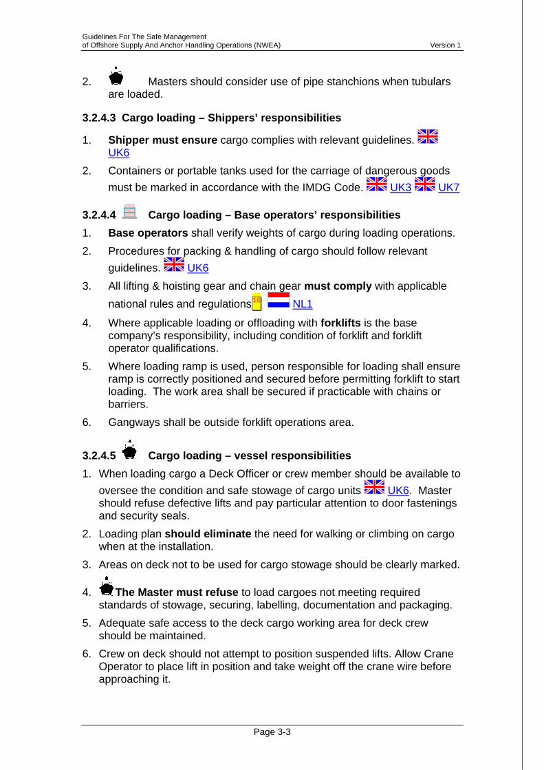
2. Masters should consider use of pipe stanchions when tubulars are loaded.
3.2.4.3 Cargo loading – Shippers’ responsibilities
1. Shipper must ensure cargo complies with relevant guidelines. UK6
2. Containers or portable tanks used for the carriage of dangerous goods must be marked in accordance with the IMDG Code. UK3 UK7
3.2.4.4 Cargo loading – Base operators’ responsibilities 1. Base operators shall verify weights of cargo during loading operations. 2. Procedures for packing & handling of cargo should follow relevant
guidelines. UK6 3. All lifting & hoisting gear and chain gear must comply with applicable
national rules and regulations 16 NL1
4. Where applicable loading or offloading with forklifts is the base company’s responsibility, including condition of forklift and forklift operator qualifications.
5. Where loading ramp is used, person responsible for loading shall ensure ramp is correctly positioned and secured before permitting forklift to start loading. The work area shall be secured if practicable with chains or barriers.
6. Gangways shall be outside forklift operations area.
3.2.4.5 Cargo loading – vessel responsibilities 1. When loading cargo a Deck Officer or crew member should be available to
oversee the condition and safe stowage of cargo units UK6. Master should refuse defective lifts and pay particular attention to door fastenings and security seals.
2. Loading plan should eliminate the need for walking or climbing on cargo when at the installation.
3. Areas on deck not to be used for cargo stowage should be clearly marked.
4. The Master must refuse to load cargoes not meeting required standards of stowage, securing, labelling, documentation and packaging.
5. Adequate safe access to the deck cargo working area for deck crew should be maintained.
6. Crew on deck should not attempt to position suspended lifts. Allow Crane Operator to place lift in position and take weight off the crane wire before approaching it.

Guidelines For The Safe Management of Offshore Supply And Anchor Handling Operations (NWEA) Version 1
Page 3-4
7. Entering gaps between cargo units can be extremely dangerous as unsecured cargo may move at any time.
8. Multiple stacking of units as one unit is not permitted 9. Tubular cargoes should be stowed in safe bundles or singles as required
by their weight. 10. Subject to above, generally stow:
heavier or larger lifts towards side rails where they can be secured smaller lifts towards the centre where they are protected and less likely
to snag in safe haven access points.
3.2.4.6 Cargo loading – joint responsibilities 1. Time should be allowed to complete cargo deck plans, check against
manifest and query any discrepancies prior to departure.
3.2.5 Sailing Instructions & Cargo Documentation
3.2.5.1 Sailing Instructions 1. Sailing instructions are issued by relevant organisation (usually
operating or logistics company). Sent to production platforms and drilling contractors as required by operating companies.
2. Sailing itinerary is issued to Master in writing before departure and copied to installations. This should include all voyage information including bulks allocated at each location, plus ETD and routing.
3. Sailing instructions will be issued in writing and signed for by the Master. Unless advised otherwise, vessels shall proceed at economical speed.
4. Requests to proceed at full or best speed are at Master’s discretion.
3.2.5.2 Prior to Departure
1. A copy of Deck Cargo Plan should be lodged at the base operator’s office.
3.2.5.3 Cargo Documentation 1. All cargo must be accompanied by cargo manifest providing:
clear identification contents destination weight MSDS COSHH (where applicable) IMDG declaration
Guidelines For The Safe Management of Offshore Supply And Anchor Handling Operations (NWEA) Version 1
Page 3-5
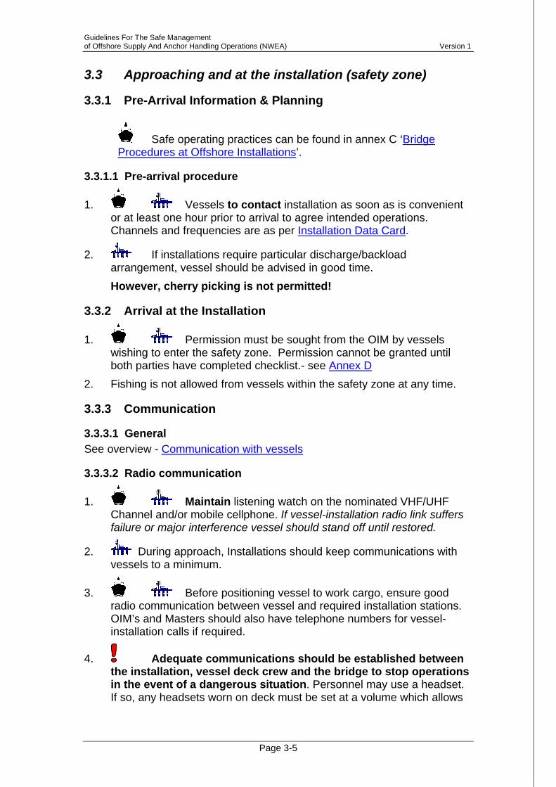
3.3 Approaching and at the installation (safety zone)
3.3.1 Pre-Arrival Information & Planning
Safe operating practices can be found in annex C ‘Bridge Procedures at Offshore Installations’.
3.3.1.1 Pre-arrival procedure
1. Vessels to contact installation as soon as is convenient or at least one hour prior to arrival to agree intended operations. Channels and frequencies are as per Installation Data Card.
2. If installations require particular discharge/backload arrangement, vessel should be advised in good time. However, cherry picking is not permitted!
3.3.2 Arrival at the Installation
1. Permission must be sought from the OIM by vessels wishing to enter the safety zone. Permission cannot be granted until both parties have completed checklist.- see Annex D
2. Fishing is not allowed from vessels within the safety zone at any time.
3.3.3 Communication
3.3.3.1 General See overview - Communication with vessels
3.3.3.2 Radio communication
1. Maintain listening watch on the nominated VHF/UHF Channel and/or mobile cellphone. If vessel-installation radio link suffers failure or major interference vessel should stand off until restored.
2. During approach, Installations should keep communications with vessels to a minimum.
3. Before positioning vessel to work cargo, ensure good radio communication between vessel and required installation stations. OIM’s and Masters should also have telephone numbers for vessel-installation calls if required.
4. Adequate communications should be established between the installation, vessel deck crew and the bridge to stop operations in the event of a dangerous situation. Personnel may use a headset. If so, any headsets worn on deck must be set at a volume which allows

Guidelines For The Safe Management of Offshore Supply And Anchor Handling Operations (NWEA) Version 1
Page 3-6
other sounds (waves, sea, cargo movements, warnings, etc.) to be heard.
5. The crew shall be able to communicate in the language of either the Continental shelf nation or English. Vessel’s crew interacting with base or installation must be able to communicate effectively.
6. Vessel MF or HF transmission is banned. If this is necessary, OIM’s permission is needed. If refused and the requirement is urgent enough, the Master must ask permission to leave the zone to transmit.
7. All VHF Radio’s should be used on low power. 8. Switch off unscreened mobile telephones.
3.3.3.3 Radio Silence
1. All vessels must have specific procedures for radio silence in place. Masters must ensure these, and any additional requirements operating companies may impose, are followed.
2. Immediately prior to imposition, OIM will instruct all vessels to withdraw to and remain outside 1000 meters from the installation, or as advised, and to maintain listening watch on both VHF channel 16 and other channels designated for working.
3. Any vessel that for any reason does not have exemption and cannot withdraw adequately from the installation must stop all radio, radar, position reference systems and beacon transmissions, shut down all non-essential rotating electrical equipment and stop any hot work. All portable radio handsets, bleepers and mobile phones must be recalled before start of silence and kept non-operational throughout.
4. Prior to the start of radio silence, the vessel's Master must confirm to OIM that all radio silence procedures are being correctly observed.
3.3.4 Vessel Approach and Manoeuvring
3.3.4.1 Approaching the installation 1. Manoeuvre to a safe position, adjacent to the work location, outside the
radius of installation’s cranes and at least 50 metres off the installation, such that the vessel would drift clear in the event of engine failure. Set-up vessel on proposed heading, and assess environmental conditions and vessel’s motion and behaviour over 10-15 minute period.
2. When the Master is satisfied vessel can safely be held in required mode and heading, ease towards the operating position. Speed on final approach should be less than 0.5 knots.
3. Changing vessel’s control mode (e.g. manual to joystick), and manoeuvring position (e.g. forward to aft) poses risks. After changeover, check all manoeuvring systems function properly.
Guidelines For The Safe Management of Offshore Supply And Anchor Handling Operations (NWEA) Version 1
Page 3-7
4. Surface current speed and direction may vary around an installation and differ from local current meter information. The Master must be familiar with local conditions.
5. Before coming alongside a power assisted installation or Vessel (e.g. FPSO, Crane Barge, Dive Support Vessel, MOU running thrusters) Masters should ascertain what propulsion units are running and if propulsion settings are liable to alter:
number of propellers or thrusters running type of thruster control i.e. automatic (DP/mooring assist) or manual; direction of thrust. The installation or Vessel should advise the OSV bridge team if it
intends to alter propulsion arrangements or settings whilst the OSV is alongside.
Installation movement presents a significant hazard when manoeuvring alongside. Prior to manoeuvring alongside an FPSO, the Master should review the FPSO-Specific Checklist.
3.3.4.2 Manoeuvring alongside 1. Note:
Deep water Installations with steep chain catenaries tend to move more laterally than those with shallow catenaries.
Installation thrusters may make movement unnatural or different to vessel.
Thruster wash may affect vessel’s manoeuvring. 2. If required to move away the Master must establish position at a safe
distance. 3. Moving between work faces must be properly planned, accounting for
prevailing conditions. Maintain safe distance. For major position changes move well clear and approach a new work face cleanly.
4. Make allowance for visibility of under deck structure and position and volume of overboard discharges and vents when positioning.
5. Vessel must liaise with OIM immediately in event of: equipment failure problem with machinery or control room systems contact being made with the installation structure
6. If required to leave the safety zone re-entry is not allowed until Master and OIM are satisfied action has been taken to prevent recurrence, and vessel is fully operational.
Guidelines For The Safe Management of Offshore Supply And Anchor Handling Operations (NWEA) Version 1
Page 3-8
3.3.4.3 Dynamic Positioning (DP) Guidance on the use of DP can be found in IMO MSC/Circ 645 and in the industry guidance ‘International guidelines for the safe operation of DP offshore supply vessels at offshore installations’ published by IMCA.
3.3.4.4 Vessel Technical Redundancy NO6
3.3.4.5 DP system testing 1. Before entering safety zone, test and prepare DP and backup systems
as per vessel’s checklist for DP operations. 2. Before moving alongside, ensure DP system has sufficient data. As a
minimum, at safe distance from installation position vessel in auto mode with reference data entered for at least 15 minutes to build up the model.
3. Norwegian requirements for DP use are at NO4
3.3.4.6 DP reference systems 1. If a reference system develops problems while the vessel is in DP mode,
Masters or DP operators shall ensure the vessel maintains position. They may stop operations and move vessel out to a safe position to avoid risk arising to personnel, vessel or installation.
2. For a dynamically positioned installation, or one anchored to allow limited movement (e.g. tension leg platforms) reference systems may be less reliable. The two units may also move differently due to “surging”. DP system operator must be familiar with these conditions and take the necessary precautions.
3. Installations may need to place reflectors, which require cleaning to ensure effectiveness.
3.3.5 Overboard Discharges
1. The law prohibits discharges that threaten workers’ health. All non-essential overboard discharges that may hamper safe vessel operations alongside must be shut down before commencing cargo operations.
2. If Masters feel an overboard discharge may cause distress or risk to personnel or vessel, they are authorised to cease operations after notifying OIM, and to stand off until discharge ceases or conditions keep it clear of vessel. Such discharges should be reported.
3. Offshore facilities should have systems preventing their discharges drifting towards vessels operating within safety zone. Otherwise, they must have established procedures preventing vessel exposure during operations within safety zone.
Guidelines For The Safe Management of Offshore Supply And Anchor Handling Operations (NWEA) Version 1
Page 3-9
3.3.6 Deck Cargo Operations, Inter-Field Transfers and Cargo Securing
3.3.6.1 Loading and Offloading, General
1. Installations will designate a person responsible for cargo operations.
2. PPE requirements apply as 7.5
3. Open stern anchor handling vessels require special care, especially with regards to freeboard. Consideration should be given to the open stern being physically barriered. Use RA or SJA to minimise crew or cargo exposure to elements, particularly working stern-to-weather.
4. All loads above crane whipline capacity should be regarded as a heavy lift. (refer to Installation Data Card)
5. All heavy lift operations require a RA or SJA.
3.3.6.2 Crane operations 1. Crane Operators should have adequate radio communication with vessel
bridge and deck crew, as per national requirements 2. All crane operations are carried out in joint consultation with Masters,
OIM and Crane Operators, any of whom can veto the operation. 3. Use of self-locking safety hooks is mandatory unless otherwise agreed
between Master and OIM. 4. Crane operators should swing the load away from the vessel deck
before lowering or hoisting to prevent risk in event of lift failure. 5. Crane Operators should have clear view of vessel’s deck. Where this is
impaired, a banksman should be provided; however Masters or OIM may then restrict operations. Vessel deck banksman shall wear distinctive high visibility clothing. Banking hand signals are below.
6. Banking hand signals: A diagram of hand signals for crane operations can be found at Annex ‘U’.
3.3.6.3 Offloading 1. Cherrypicking is a dangerous practice that needs to be eliminated from
the industry. Breaking of stow (“cherrypicking”) requiring deck crew to climb on top of lifts or entering unsafe deck area shall not be permitted. Report any attempt to pressure the Master immediately to Shipowner as well as operating or logistics company.
2. Visually check cargo carrying units for loose items (tools, debris, etc.) before commencing discharge or loading. If these are seen during

Guidelines For The Safe Management of Offshore Supply And Anchor Handling Operations (NWEA) Version 1
Page 3-10
lift, advise installation immediately. Note the unit ID number and report the incident.
3. The Master should ensure all lifts are inspected before being discharged to offshore installation to ensure they are properly slung, all doors, lids etc. are properly secured and open skips are fitted with nets or tarpaulins.
3.3.6.4 Backload – Installation responsibilities 1. All backloading should be pre-planned to ensure safe operation. OIM
must sanction any unforeseen or unscheduled backload. 2. OIM must provide load list and dangerous goods list for all installations
or ports the vessel is due to visit in time to permit proper stowage for planned route. For backload the OIM is the shipper.
3. A competent person on the installation should inspect all cargo for backloading. This includes: NL3
Lifting equipment correctly certificated lifting frames with diesel equipment have empty drip trays (to avoid
pollution risk). dangerous cargo labels on empty cleaned containers are removed cargo within open-topped or half-height cargo carrying units is secured
open topped waste cargo carrying units are covered UK4 lifts are inspected for potential “dropped objects” Skips should have safety nets to retain cargo. Do not overload,
particularly carrying scrap metal or shot blasting materials.
3.3.6.5 Backload – Vessel responsibilities 1. Master and OIM should liaise to ensure correct vessel backloading. 2. Vessel officers in charge of backloading should:
ensure safety of the crew, vessel and cargo, and ensure sufficient area for safety zones and escape routes for those on the cargo deck.
ensure no materials are loaded, especially dangerous goods, not covered by OIM’s provided load list and dangerous goods list.
always have full sight of all cargo operations and personnel on deck, crane wire and hook.
if necessary, refuse open hooks offered to vessels ensure all deck crew stand well clear of all lifts to or from vessel deck.
3. On receipt of an improperly secured lift, Masters should immediately inform OIM and request lift return to installation for rectification, unless doing so itself presents a safety hazard. In the latter case, cargo shall be returned to shore, the incident recorded in the

Guidelines For The Safe Management of Offshore Supply And Anchor Handling Operations (NWEA) Version 1
Page 3-11
vessel’s log and a report prepared for OIM and operating or Logistics Company as soon as possible.
4. Masters should also notify OIM of any lifting gear deficiencies or cargo carrying unit damage found during backloading.
5. Lifts without a fifth leg slinging arrangement may require hooking or unhooking from restricted accesses. Treat as special lifts and perform a RA or SJA.
3.3.6.6 LSA 1. Master must be informed by the installation before commencement of
backloading LSA. NL2
3.3.6.7 Inter-field transfers 1. Requests by installations for ad-hoc inter-field cargo transfers should be
routed via the operating or logistics company representative. 2. Interfield manifests, including Dangerous Goods declaration, should be
correctly prepared by the originating installation and key information given directly to the Master and receiving OIM.
3.3.6.8 Oil contaminated cargoes 1. See Annex A Good practice for the carriage of oil contaminated cargoes
for transportation by offshore supply vessel .
3.3.6.9 Cargo securing 1. See general requirements of 3.2.4.2 2. Use pipe stanchions if available to restrain movement of backloaded
tubulars.
3.3.7 Personnel transfers 1. If no helicopter transport is available, transport by vessel may be
considered. This is voluntary and subject to RA or SJA.
2. Personnel basket may be used provided it: NL5 40 is certified for transfer of personnel is maintained in good condition is inspected frequently for defects and before use has a control line attached. is inspected and load tested at least annually.
3. The crane must be: certified for transfer of personnel fitted with braking mechanism for controlled lowering in case of failure.
4. Basket use is strictly voluntary. Users must wear survival suit, life jacket, safety helmet and boots. Transfer maximum 4 persons at once.

Guidelines For The Safe Management of Offshore Supply And Anchor Handling Operations (NWEA) Version 1
Page 3-12
5. Masters, OIM, Crane Operators and passengers shall all agree to the operation.
6. Basket transfers should be done in daylight, and when Crane Operator can see vessel’s deck.
7. During the transfer, the person in charge, Crane Operator and vessel Master must be in radio contact.
8. While transferring personnel from installation to vessel, the basket must: be lifted just above installation railing swung out over the water lowered alongside the vessel just above the railing swung over the vessel and lowered onto it. Transfer of persons from vessel to installation is the reverse sequence.
9. Appropriate rescue vessel or craft must be prepared for immediate launch before using the personnel basket.
10. Vessel Masters must pay special attention to weather conditions, sea state, movement and condition of vessel, and available free deck space to ensure transfer takes place in a safe controllable manner.
11. Vessel Masters must also ensure: no passengers are on cargo deck during loading or discharging cargo; a competent crew member is in charge on cargo deck during
passenger transfer who shall instruct passengers and Crane Operator.
3.3.8 Installation Departure 1. If proceeding inbound provide the following details to the Operating or
Logistics Company’s nominated representative: ETA; heavy, non-conforming or wide loads and their position on the vessel; tank status and contents remaining on board; dangerous cargo; specific information requested by Operating Company or Logistics
Companies (see Example Operating Company Data Card). 2. In addition, vessels should comply with the specific requirements
detailed in the destination port data card – see Example Port Data Card. 3. Master should co-ordinate the best time for arrival with base operators in
order to minimise port movements. 4. If proceeding to another location contact the installation giving the
following information: ETA; inform the location of heavy or non-conforming lifts;

Guidelines For The Safe Management of Offshore Supply And Anchor Handling Operations (NWEA) Version 1
Page 3-13
confirm bulk discharge plan if applicable.
3.4 Vertical Seismic Profiling (VSP) 1. In the absence of cross-industry standards for VSP, shipowners should
follow their own internal procedures ensuring that all involved (including operating company, Master, OIM and VSP service provider) should co-operate in a risk assessment. This should consider as a minimum:
joint review of procedures affected by the VSP survey; safe deployment of the VSP array from the vessel; briefing of personnel including “tool box talks”; weather limitations on VSP operations, including limitations imposed by
weather side working. 2. If vessel is to carry a mobile crane for performing a VSP survey,
positioning and securing must be in accordance with the Merchant Shipping (Hatches and Lifting Plant) Regulations 1988 SI 1639 37.
3. Vessel stability must be verified under all conditions in which the crane is used.
Guidelines For The Safe Management of Offshore Supply And Anchor Handling Operations (NWEA) Version 1
Page 4-1
4 Bulk Cargo Operations
4.1 General Requirements
1. Bulk cargo transfer is potentially hazardous and must be done in a controlled manner.
2. During bulk cargo operations observe the following: communication between vessel, base, installation or roadside tanker of
pressure rating to avoid overpressure.
IMDG Code requirements shall be followed. Masters must be given a completed Dangerous Goods Declaration and MSDS prior to loading or backloading of dangerous goods.
the Master or delegate must ensure they can see bulk hose(s) at all times and not be distracted away from these. The Master must pay particular attention during hydrocarbons transfers and therefore give proper consideration to potential hazards when carrying out concurrent cargo operations.
shipper and receiver should confirm quantities discharged and received at regular intervals to ensure there are no leaks
relevant personnel must be readily available and nearby throughout transfer operations
each party shall give sufficient warning prior to changing over tanks do not close valves against a cargo pump if at any point vessel Master, shipper or OIM doubt operation’s
integrity it must be terminated do not use compressed air to clear wet bulk line as this may damage
tanks. do not transfer any other liquids using potable water hoses. pre-use, flush potable water lines through to clear any residues. during hours of darkness, hose and support vessel must be
adequately lit throughout the operation. Consideration should be given to use of retro-reflective material on the hoses.
hoses must remain afloat at all times through use of sufficient floating devices.
consider use of self-sealing weak link couplings in the hose string. avoid use of heavy sections of reducers or connections at hose ends.

Guidelines For The Safe Management of Offshore Supply And Anchor Handling Operations (NWEA) Version 1
Page 4-2
4.2 Bulk Transfer Operations In Port

Guidelines For The Safe Management of Offshore Supply And Anchor Handling Operations (NWEA) Version 1
Page 4-3
4.3 Hazard Overview 1. Bulk materials other than potable water can be extremely hazardous.
The most common groups are all types of oil-based muds, water based muds, base oils and brine. COSHH assessment and MSDS must be consulted prior to shipping.
4.4 Bulk Transfers of Particular Concern
1. Special care must be taken to follow correct procedures or marine operations instructions when loading and discharging 2 particular materials; methanol and zinc bromide. See also 25. These must include RA and Permit to Work.
2. An accredited MARPOL Surveyor must be in attendance at the unloading of all MARPOL Annex II Category A substances and when Category B and C substances cannot be carried out in accordance with the ship's P&A manual. Note that the categorisation of substances will change with the introduction of the IBC Code from 01/01/07.
3. Methanol: burns with no visible flame in daylight conditions readily or completely miscible with water is a class 3 substance with noticeable odour is highly flammable, with a flashpoint below 23°C can evaporate quickly. has heavier than air vapour that may be invisible, and disperses
over the ground. can form an explosive mixture with air, particularly in empty
unclean offshore containers. experiences pressure increase on heating, with the risk of bursting
followed by explosion. is very toxic, and possibly fatal, if swallowed. Symptoms may not
appear for several hours. can cause significant irritation of the eyes
Operating company and base operator responsibilities:
nominate berth after liaising with harbour authority, fire brigade and harbour police or security;
ensure sufficient cooling or drenching water is available; cordon-off area, with signs posted to indicate a hazardous area;
Vessel Master’s responsibilities: should complete a ship to shore safety check with shipper; must authorise loading; must ensure a permit to work is in place before any loading
operations can be conducted;

Guidelines For The Safe Management of Offshore Supply And Anchor Handling Operations (NWEA) Version 1
Page 4-4
must ensure vessel’s restricted zone is clear, fire hoses are rigged and SMPEP equipment are ready for action before commencing loading.
Logistics or Base Company responsibilities shipper’s staff to be on site throughout to advise on pumping,
handling, earthing and discharge of tanks. shipper to provide appropriate fire fighting equipment.
During bulk methanol transfer, smoking and the use of ignition sources are prohibited. During electrical storms (lightning) operations should be terminated.
4. Zinc Bromide is a highly corrosive brine subject to “Control of Pollution by Noxious Liquid Substances in Bulk” regulations 13.
Due to the brine’s very corrosive nature, protection against injury from spillage is essential. Additionally:
General responsibilities check loading/discharge hose for damage before use. Hose
should have self sealing coupling to minimise spillage during connection or disconnection;
provide and ensure the wearing of chemical suits for all personnel handling hoses.
Vessel responsibilities: possess International Pollution Prevention Certificate for the
Carriage of Noxious Liquid Substances in Bulk (INLS) certificate and manual detailing legal and safety requirements for handling the product.
perform RA or SJA before commencing operations;
Tanks for Zinc Bromide only use tanks specifically detailed for this in INLS certificate tanks cannot carry any other product until properly cleaned and
all washings disposed of as per regulations. If this has not been done, any cargo accidentally loaded is to be treated as special waste;
tanks for Zinc Bromide must be drained as far as possible before washing. If cargo pump cannot remove all the liquid, consider use of portable pumps to remove as much as possible;
tank washings are special waste. Cleaning or washings discharge must be monitored by an approved Surveyor.
4.5 Fuel 1. Establish a sampling procedure when loading fuel (bunkers). Sampling
taken in accordance with MARPOL Annex VI will suffice for these operations.

Guidelines For The Safe Management of Offshore Supply And Anchor Handling Operations (NWEA) Version 1
Page 4-5
2. Ships must have in place procedures covering the loading, discharging and transferring of fuel.
3. On some smaller installations fuel hoses have been removed. Transportable 2” fuel hoses with TODO to dry break couplings are used for these, stored in toolboxes at bases. Load this toolbox + hose when fuelling installations.
4.6 Potable Water
1. Specific National requirements may apply: see NL4 NO8
4.7 Bulk transfer Operations - General 1. See also 4.1, General Requirements, and 4.4, Bulk Transfers of
Particular Concern. 2. All coupling and connection areas should have containment facilities
where practicable. 3. Avoid hydrocarbon transfer (e.g. fuel, methanol, OBM) during darkness.
Exceptionally this may be done under closely controlled conditions and only with specific approval of OIM and Master.
4. Vessel’s crew must ensure that an external watch is maintained to prevent overboard discharges during all pumping operations.
4.8 Hose marking and usage 1. Hoses and hose terminations should be product-identified via high
visibility bands, tape or other means. Colour coding, sizes and couplings are detailed in Bulk Loading Hoses – Guidance Notes for details of a recommended NW European standard.
2. Note: Manufacturers’ identification or approval of hoses is often by spiral coloured bands. Do not confuse this with product colour markings.
4.9 Vessel responsibilities at the installation 1. Before offloading bulk cargo confirm the following with installation:
volume and weight of bulk to be offloaded hoses and connections, colour codes and dimensions rigged hose lengths are adequate procedures for venting and blowing through hoses installation is ready to receive cargo; all valves and vents are open and
correct tanks lined up emergency shut down procedures should be in place and crew familiar
with these. 2. Ensure that:
all pollution prevention equipment is in place, as per SMPEP; all manifold valves are in good condition; the person in charge should not be distracted from the operation.

Guidelines For The Safe Management of Offshore Supply And Anchor Handling Operations (NWEA) Version 1
Page 4-6
installation under-deck lighting is adequate; dry bulk vent line positions are identified.
3. Master shall submit to the: operating company’s logistic office all receipts, including meter-slips, for cargoes received; all meter-slips for cargoes discharged; records of tanks’ contents.
4.10 Installation responsibilities 1. Ensure that:
hoses are visually inspected and replaced as required; slings and lifting points are visually checked and replaced as required; hoses are lifted by a certified wire strop on a certified hook eye fitting; under-deck lighting adequately illuminates hose and vessel.
OIMs are responsible for ensuring the correct hoses, with appropriate flotation collars, are sent to the vessel (for details on flotation collars see Bulk Loading Hoses – Guidance Notes) 2. OIMs are responsible for ensuring installation bulk loading hoses
manifolds and pipelines are fit for purpose 3. Prior to start of operations, visually check hoses. If in doubt prevent their
use.

Guidelines For The Safe Management of Offshore Supply And Anchor Handling Operations (NWEA) Version 1
Page 4-7
4.11 Bulk Transfer Operations At The Installation Bulk Transfer Operations at Installation
Vessel NotesInstallation
Agree cargo transfer plan
- product(s) & quantities, and sequence of discharge;- estimated timings for each discharge;- tanks to be used & procedures for topping off;- load/discharge rates required/possible, & maximum safe working pressure- stoppage procedures – required advance warning, and time required to stop;- pump control and emergency stop facilities- confirmation lines can be drained back to vessel’s tank(s)
- loading/discharge line and tank valves correctly set- correct hose(s) is fitted to appropriate coupling(s)- loading/discharging hoses condition- position keeping effectively prevents strain on hose(s) from vessel movements;- sufficient hose deployment to handle worst-case ranging of the vessel;- communications routine between all parties is established;- vessel's tank level monitoring system is proven. - a watchman with suitable communication equipment is on duty at deck manifold;- any relevant company safety check list or dangerous goods safety checklist are
reviewed and signed-off- for fuel or oil based fluids ensure Avery Hardoll connections are fitted. Fuel should
not be loaded using Weco type screw couplings- pollution prevention equipment is in place as per SMPEP- drip trays, fire hoses, fire extinguishers, gas concentration test equipment and
explosimeter are provided at vessel hose/manifold/reception site- “No Smoking” conditions are imposed
Pre-commencement
checks
- Emergency shut-off valves manned throughout operation with permanent radio contact between installation and vessel
- Crane is manned whenever hose is attached to crane hook- During liquid loading manually check the level monitoring system,
especially loading to near capacity of individual tanks.- Pumping pressure of fuel and glycol may not exceed 7 bar. No more than
requested quantity of fuel oil / glycol should be discharged
Connect hoses and set lines
Start pumping at slow rate.
- Check all system manifold connections for leaks. - Check product entering correct tanks. - For dry bulk transfers, use air purge first to clear lines, prove connections
and ensure a good vent is obtained.
All lines & connections OK?
Full delivery rate
Cease pumping
Fix problems
Tank near full?
Reduce loading rate to top off tanks safely
Use vacuum breaker if fitted to aid draining. Where suitable use crane to raise hose to aid draining. Crane should be used in suitable conditions to elevate hose to aid draining. For dry bulk, use purge air to clear line.
Completed?
Set lines to drain back to vessel's tank (except for potable water)
When hose disconnected fit suitable cap / blank
Log all starting values for bulk volume recording
Log all finishing values for bulk volume recording. Compare records and resolve any discrepancies.
Guidelines For The Safe Management of Offshore Supply And Anchor Handling Operations (NWEA) Version 1
Page 5-1
5 Contractor Management 5.1.1 Project (3rd Party) Mobilisation & De-Mobilisation
5.1.1.1 General 1. Mobilisation: the installation of extra equipment to Operating
Company’s requirements by 3rd party contractors using ship’s services as necessary. Demobilisation: the removal of extra equipment after work completed.
2. This also applies to management of routine work by 3rd party contractors, e.g. tank cleaning, repairs, modifications. These can be complex or hazardous and performed by personnel unfamiliar with vessel.
3. Master may ( 2.2.1) forbid or stop any operation it is felt may affect the safety of vessel or personnel.
4. A single Safety Management System (SMS) must be in place; this will be the vessel’s SMS, modified or adapted to suit mobilisation work in hand.
5.1.1.2 Prior to Mobilisation or Demobilisation
1. Ensure a suitable berth is chosen for the work.
2. Operating Company must ensure clear procedures are provided to all involved responsible persons. These must as a minimum:
include plan and schedule of activities include for RA or SJA and Hazard Identification of activities identify Project Manager to liaise with Master on mobilisation matters. provide for continuity of personnel and effective information handover include for provision of 3rd party liaison
3. All involved must receive clear instructions including: reporting of Accidents, Near Misses and Unsafe Practices explanation of safety initiatives (e.g. Time out for Safety (TOFS),
STOP, Tool Box talks etc. identification of Ship’s Safety Officer identification of ship’s officer responsible for issuing of Permits to Work action to take on hearing ship’s Fire and General Alarms escape routes and Muster Points ship’s Smoking and Alcohol policy Raising safety concerns regarding the work
4. Meetings of key personnel should be held, preferably daily, to discuss progress, management of plan changes, problems and rescheduling.

Guidelines For The Safe Management of Offshore Supply And Anchor Handling Operations (NWEA) Version 1
Page 5-2
5. Responsible ship’s officer must confirm adequacy, isolation and safety before newly installed equipment is connected.
5.1.2 Tank Cleaning
1. Tank cleaning operations can be potentially hazardous, mainly due to the high levels of Enclosed Spaces Entry required, and associated hazards within. Careful planning must take place and tank cleaning operations only carried out when necessary and safe.
5.1.2.1 Preparation 1. The Base Operator/Operating Company is responsible for providing
approved tank cleaning contractors. 2. Shipboard Tank Cleaning Operations shall be carried out and controlled by
the Master using a single Permit to Work issued by the vessel. The permit shall: be signed by the Master or designated responsible person and tank
cleaning contractors’ supervisor; be in line with vessel’s operating procedures; be accompanied by a Tank Cleaning Checklist (example given at
annex E) and Risk Assessment; detail pre-entry tank atmospheric readings and record readings
throughout tank entry; detail required precautions and risk reduction measures including an
assessment of how the safety of personnel in tanks is to be monitored; detail safety equipment and protective clothing; detail machinery/appliance isolation and lock out requirements; detail rescue equipment and suitably trained personnel required in the
event of an emergency. 3. The Base Operator shall have procedures detailing the method of product
recovery, and the contingencies in place should an unplanned event occur such as a hydrocarbon discharge or major spillage
4. Personnel involved in tank cleaning must wear the appropriate PPE as identified in the risk assessment, COSHH or equivalent assessment, Material Safety Data Sheets (MSDS) and in accordance with Tank Cleaning Checklist (annex E)
5. The following must be in place before commencing operations: Emergency response procedures and rescue equipment, as per Permit
to Work Appropriately trained personnel to assist with rescue if necessary Risk assessments for the planned operation conducted by the tank
cleaning contractor in association with vessel personnel. Material Safety Data Sheets (MSDS) and the analysis sheet provided
in annex A for previous cargoes carried since last cleaning operations.

Guidelines For The Safe Management of Offshore Supply And Anchor Handling Operations (NWEA) Version 1
Page 5-3
This is to be made available to the tank cleaning contractor by the vessel Master.
Effective and tested communications system set up between all personnel, vessel tank cleaning, and shore.
Area around tank entrances is as clear as possible. Unrestricted, safe access to and from entrances is provided.
Tank entrances open for access are effectively cordoned off with physical barriers to prevent unauthorised access. Appropriate hazard signs are prominently displayed in the immediate vicinity and quayside. Tanks opened for ventilation are fitted with secure open grating.
For quayside equipment controls to be in place to prevent unauthorised entry.
Appliances in tanks to be entered are mechanically and/or electrically isolated / locked off by use of tag out system or similar. Status noted on permit to work.
Where tank access is via engine room, a specific risk assessment should be conducted to take account of the hazards associated with running machinery, ignition sources, routeing of hoses (N.B. Only continuous hoses should be used in machinery spaces) etc. All non-vital machinery should be switched off and isolated. The outcome of the risk assessment and the actions required to mitigate the risks should be covered on the Permit to Work and highlighted at the Toolbox Talk.
All actual/potential worksite ignition sources are isolated, particularly in the vicinity of tanks and hoses containing recovered product.
Tanks to be cleaned are isolated from any tanks that still contain bulk liquids.
Tank atmosphere is tested for oxygen content and free from toxic and/or explosive gases by competent vessel and tank cleaning contractor personnel with properly calibrated equipment. The result of the atmosphere test should be recorded on the permit or other agreed document.
Tank and worksite are adequately illuminated by intrinsically safe lighting.
6. A Toolbox Talk must be conducted in association with all relevant parties. As a minimum the Toolbox Talk must: Highlight conditions of Permit to Work Review the control measures and requirements of the Tank Cleaning
Checklist Highlight actions required to minimize risks identified on Risk
Assessment Identify all applicable hazards Highlight any other permits in place that could impact on operation i.e.
conflicting activities Identify ongoing quayside and shipboard operations Identify location of permit to work on board vessel

Guidelines For The Safe Management of Offshore Supply And Anchor Handling Operations (NWEA) Version 1
Page 5-4
Designate duties of all personnel Be recorded and signed by all parties present Promote ‘Stop the Job’/’halting unsafe operations’ culture Highlight all emergency actions and exits routes on the vessel
7. Under MARPOL, some substances mentioned on a vessel’s Noxious Liquid Substances certificate require approved surveyors in attendance during tank cleaning, e.g. zinc bromide, methanol.
5.1.2.2 Tank Cleaning Operations 1. Although the tank cleaning operation is conducted by a contractor under
control of the contractor’s supervisor the safety of the operation remains the responsibility of the Master. The operation should be continuously monitored by a designated responsible vessel person who should stop any operation that he considers unsafe.
2. The tank cleaning contractor must station a stand by person at each tank as per assessment in 5.1.2.1. The stand by person should be competent and trained to take the necessary action in the event of an emergency. Communication system between all personnel within tank and at access must be agreed and tested.
3. Personnel working in the tank shall wear the appropriate PPE as identified in the risk assessment, COSHH or equivalent assessment and MSDS.
4. Regular tank atmosphere testing by competent personnel from both the vessel and tank cleaning contractor must be conducted throughout the tank entry at the frequency identified at toolbox talk and/or Risk Assessment. The results of the atmosphere testing should be recorded on the permit or other agreed document.
5. Effective means of ship/ship and ship/shore communication shall be established and maintained throughout the tank cleaning operation.
6. Where simultaneous tank cleaning and other operations i.e. cargo operations, are undertaken then suitable safety precautions must be in place. Interfaces between vessel’s officers, tank cleaning and quay supervisors must be kept open and active during the tank cleaning operation.
7. Hand over between shifts of vessel’s and tank cleaning personnel must be carefully controlled to ensure continuity. Consideration must be given to holding a further tool box talk.
5.1.2.3 Completion of Tank Cleaning 1. On completion of tank cleaning operation the Master must carry out an
inspection together with the tank cleaning contractor supervisor to ensure that the tanks have been properly cleaned and lines and pumps are thoroughly flushed. If these parties disagree an independent surveyor will carry out an inspection.
2. The tank inspection should confirm that the tanks have been cleaned to the following appropriate standard:
Derek Latter
If this is correct amendment also to be made to section 4 [ME: is it correct, and if so what is required at section 4?]
Guidelines For The Safe Management of Offshore Supply And Anchor Handling Operations (NWEA) Version 1
Page 5-5
Brine Standard Cargo lines and pumps are flushed through with clean water and lines drained. Tank bottoms and internal structure (stringers, frames, etc.) are clear of mud solids, semi-solids and all evidence of previous cargo. The tank may require cleaning with detergent to achieve the highest standard of cleanliness possible. All traces of water and detergent removed from tank. Water Based Mud Standard Cargo lines and pumps are flushed through with clean water and lines drained. Tank bottoms and internal structure (stringers, frames, etc.) are clear of mud solids, semi-solids and all evidence of previous cargo. The tank may require cleaning with detergent to achieve the highest standard of cleanliness possible. All traces of water and detergent removed from tank. Oil Based Mud Standard Tank bottoms and internal structure (stringers, frames, etc.) are clear of mud solids and semi-solids. Cargo lines are flushed through with clean water and lines drained. Pump suctions are checked and clean. Tank must be empty and clear of all water / mud mixtures. Pump out Standard Pump out residues from tank and wipe tank floor using rubber mops or equivalent. Check suction pipes to ensure they are clear. No requirement for washing.
5.1.2.4 Dry Bulk Tanks 1. Tanks to be brushed down and residues removed by vacuum tanker,
eductor system or equivalent. Slides to be checked for dryness and condition and ‘elephant foot’ suction checked to be clear.
2. On successful completion of the tank inspection, the Master should: Ensure that a Clean Tank Certificate has been issued by Operating
Company/Independent surveyor when hazardous material has been cleaned.
Visually check the integrity of tank coating Record tank status in the deck log book Confirm the tank hatch covers are replaced and secured Ensure the work area has been left in a safe and tidy condition Close Permit to Work/Tank Entry Permit.

Guidelines For The Safe Management of Offshore Supply And Anchor Handling Operations (NWEA) Version 1
Page 6-1
6 Anchor Handling & Towing
6.1 Agreed Procedures and Responsibilities 3
1. Anchor handling operations and towing are potentially hazardous. Installation personnel should appreciate vessels’ operational limitations, including power and freeboard. Safety of vessel and crew is paramount.
6.1.1 Responsibilities of the Ship Owner 1. Shipowners are responsible for ensuring vessels and equipment used
in A/H operations are: in operational order and comply with relevant legislation. adequately manned by competent personnel taking into account hours
of rest requirements and scope of work including possibility of 24/7 working.
6.1.2 Responsibilities of the Operating Company 1. Arrange necessary A/H vessels, survey positioning equipment and
personnel, marine equipment as appropriate and brief all involved in the scope of the A/H operation.
2. Ensuring adequate planning and risk assessment of the entire anchor handling and towing operation for the contracted installation.
3. Ensuring installations are moored in accordance with the proposed anchor pattern.
4. Obtaining required information, including chart data and site survey to anchor installation in a field. Similar requirements, including soil specific data, will be required to locate jack up rigs.
5. Provision of: seabed infrastructure, conditions and any obstructions horizontal and vertical minimum distances to installations and pipelines
for anchors and anchor lines, including elevated catenary. HAZOP or RA. weather and wave data, also tidal stream data as appropriate information on simultaneous operations
6. Ensure that they: Organise rig move meeting with all relevant parties in good time Determine logistic requirements Brief their nominated marine representative Ensure A/H equipment is sourced, certified and shipped.
7. Agree with all relevant parties full clear written procedures for installation move. These should identify key roles and responsibilities.
Guidelines For The Safe Management of Offshore Supply And Anchor Handling Operations (NWEA) Version 1
Page 6-2
8. Brief A/H vessel Masters before leaving port or, in exceptional circumstances, on location before starting operations, including any particular installation’s detailed procedures, also any safety awareness issues.
6.1.3 Responsibilities of the MOU Owner 1. Prepare rig move procedures in English language unless otherwise
agreed, for the entire A/H or towing operation. Depending on local requirements rig move procedures may be prepared by the Operator.
2. Agree anchor patterns with the operating company, supported by satisfactory anchoring analyses.
3. Procure required extra personnel (OIM, winch operators, etc.) 4. Ensure rig move procedures are reviewed with participating vessel(s)
and key personnel, is understood, and that Risk Assessment has been performed.
5. Allocate frequency for helicopter beacon 6. Notify authorities of installation departure and arrival in accordance with
local requirements. 7. Ensure fully functional communication between all involved parties 8. Communicate any changes to SOW 9. Identify potential Anchor Handling equipment for backload 10. Ensure the MOU crew is rested
6.1.4 Responsibilities of the OIM 1. The OIM has overall responsibility for the safety of the installation and
personnel at all times as per statutory requirements and MOU owners' policy. May delegate some of the rig move duties to a suitably qualified person such as the Towmaster who should also consult with vessel Masters in the process.
2. Sole point of contact through which all rig move notifications and exterior communications will pass. Ensures that all relevant authorities are kept informed of the rig move status, as required.
3. Decides when it is safe and practicable to commence operations within the limitations of the installation’s operating manual, having consulted with the Operators representative.
4. Ensures correct placement of competent installation personnel to ensure the safe deployment of anchors and handling of towing gear.
5. Responsible for ensuring that a pre-rig move meeting is held on board and minuted accordingly, with an appropriate entry in the log book to that effect.
6. Responsible for the conduct and safety of the tow and will give instruction to the towing vessels with regard to tow wire deployment, passage

Guidelines For The Safe Management of Offshore Supply And Anchor Handling Operations (NWEA) Version 1
Page 6-3
planning, courses and speed, after consultation with the Marine Representative or Towmaster.
7. Informs the Operating Company representative of any significant deviation from the proposed rig move procedures as they occur.
8. Liaises with the Operating Company representative on all matters concerned with the rig move operations.
6.1.5 Responsibilities of the A/H vessel Master 1. Safety of crew and equipment on board the A/H or towing vessel at all
times. The Master may if necessary stop operations that may put vessel or crew at risk.
2. Pre-move briefing of crew to ensure A/H safety procedures are fully understood, and how these apply to specific rig procedures.
3. Define communication of power requirements, particularly instructions specifically relating to bollard pull.
4. The Master will be responsible for ensuring that anchor handling operations are conducted in a safe manner with due regard to safe working practices and the practices of good seamanship.
5. Will ensure that tensions applied avoid over-stressing any of the rig move equipment including MOU and vessel towing gear.
6. Lead towing vessel Master is responsible for navigation of the towing operation, compliance with prepared plans, shall issue appropriate navigational warnings at regular intervals and ensure other towing vessels follow the stipulated plans.
6.2 Rig move meeting
1. Operating company should arrange a rig move meeting before operation starts. Rig move procedures should be distributed before the meeting. Meeting should be attended by all relevant parties:
2. Meeting is intended to identify needs in connection with: A/H equipment Navigation and positioning Advance inspection of materials HAZOP or Risk Assessment input for vessels and installation Drawings and sketches of anchoring equipment Anchoring analysis, anchor pattern and rig move procedures Main towing and secondary towing arrangements to be agreed by all
parties. Vessel requirements; quantity and technical specifications Vessel and Installation manning Communication lines

Guidelines For The Safe Management of Offshore Supply And Anchor Handling Operations (NWEA) Version 1
Page 6-4
6.3 Reporting
1. Where required Installation Owner, in cooperation with vessels and Marine Representative or Towmaster, should report to the appropriate National Authorities as per the national requirements
6.4 Risk Assessment
1. Installation and vessel shall perform RA before operation starts.
2. If an operation has changed from the original plan for which RA was performed, personnel must review the hazards of the changed operation. This requires a time-out and review with personnel involved, performed at the workplace.
6.5 Rig move procedures 1. The rig move procedures shall have an introduction that describes their
purpose and define the roles and responsibilities of key personnel. It shall take a step-by-step approach to the rig move, making maximum use of diagrams and contain the following:
Positions, departure and arrival Water depths Sea bottom conditions (and site specific conditions for jack up rigs) Infrastructure (pipelines, templates etc.) Field-specific requirements Appendices should describe the anchor pattern with line lengths, and
operations manual for the running anchor issued by supplier.
6.5.1 Information required relating to MOU 1. Chain type and length (numbering of anchor lines and anchor pattern) 2. Anchor type, weight and quantity 3. Recommended PCP length, dimension, socket type and any chain tails
(both ends) 4. Fluke angle on anchor 5. Towing gear SWL 6. Propulsion systems (size and type thrusters, DP on installation) 7. Crane radius and lifting capacity
6.5.2 Requirements related to A/H vessels 1. Bollard pull 2. Winch capacity (pull, drum capacity, diameter and number of drums) 3. Gypsies, number and dimensions

Guidelines For The Safe Management of Offshore Supply And Anchor Handling Operations (NWEA) Version 1
Page 6-5
4. Chain lockers, number and capacity 5. Secondary winches, number and capacity 6. Guide pins / hydraulic stoppers (minimum 2) 7. Requirements for wire terminations 8. Stern roller: single or double 9. System for clay removal 10. Spooling gear 11. Minimum freeboard requirement for safety on deck 12. Requirements for crane on aft-deck for equipment handling
6.5.3 Other information required in rig move procedures 1. Prepare step-by-step illustrated descriptions for special operations 2. Where anchoring arrangement is more complex than chains with PCP, a
drawing should be available 3. Catenary curves for relevant water depths showing the various tensions 4. Installation draught during A/H (transit, operations, survival draughts) 5. List of back up equipment 6. Weather criteria and weather window 7. Time estimate.
6.6 Equipment
6.6.1 General 1. To maintain vessel’s and MOU’s safe working environment the following
should be in place: all equipment operation and maintenance should be according to
manufacturer’s instructions; a suitable system, with record keeping, for testing, inspection,
maintenance and recording of AH equipment retained on board vessels and MOUs.
readily available cutting gear. a safe and effective method of stoppering wire pennants, recognising
likely loads on the wire and the load-bearing capacity of wire termination employed. Note: soft eye pennants wear more quickly than hard eye pennants and require frequent inspection.
use of alloy ferrule terminations to be avoided. monitoring, with regular inspection and maintenance, of roller fairleads
on vessels’ deck or crash barrier to ensure that uplift by e.g. a tugger wire will not dislodge them
suitable lifesaving appliances must be available at the stern and immediately accessible

Guidelines For The Safe Management of Offshore Supply And Anchor Handling Operations (NWEA) Version 1
Page 6-6
2. Secure all AH equipment until required; see 3.2.4 3. Hired equipment must be labelled adequately to enable tracking. Original
certificates should be available if required.. 4. Take care opening wire coils, in particular pennant wires, as coils
springing open following securing bands release may cause injury.
6.6.2 Anchor Handling Equipment 1. An example of good practice for the following systems can be found in
Annex N: Permanent Chaser Pendant (PCP) Pennant Buoy System Vessel Working Wire Chaser Termination On Vessel Piggy Back Systems
6.7 The Anchor Handling Operation 1. Must be according to the rig move procedures, OIM may amend this as
required subject to review of the RA. Operating company must approve significant changes and the vessel Master’s agreement to amendments shall be sought.
6.7.1 Anchor securing on deck 1. When running or recovering anchors over pipelines, anchors must be
decked and double secured to prevent the anchor dropping uncontrollably off the stern. NO7
6.8 The Towing Operation
6.8.1 Operation Planning 1. See 6.1 for responsibilities. 2. The passage plan must be carefully developed with regard to water
depth, other offshore and subsea installations, and emergency anchorage.
3. Route must keep safe distance from any other installations, preferably five nautical miles. Pass on the side that best assures tow will drift away from the installation in case of black-out or towline failure.
4. The passage plan should avoid using installations as way points. Vessels apparently on collision course may result in installation crew having to go to muster stations.
5. Define weather criteria and necessary weather window for the tow. Obtain regular weather reports.
6. Specify communication lines: see 3.3.3.2

Guidelines For The Safe Management of Offshore Supply And Anchor Handling Operations (NWEA) Version 1
Page 6-7
7. Assess what support vessels are required. Support vessels’ tasks include, but are not limited to:
Monitoring and plotting ship traffic along the towing route. Intercepting vessels that approach tow too closely. Checking anchoring site is clear and unobstructed before installation
arrival. Functioning as back-up towing vessel, especially in winter months.
8. Establish safe procedure to pass main towing pennant from installation to towing vessel, and ensure this is clearly understood by all parties.
9. Identify the MOU’s secondary emergency towing system, establish a readily available retrieval method for main towing gear, and agree a safe procedure for passing the secondary towing system in all weather conditions.
10. Ensure installation personnel are aware of the time that may be required to rig spare towing wire. If an additional vessel is available as reserve towing vessel on passage, this should be rigged for towing.
6.8.2 Bollard Pull
1. Maximum bollard pull utilised must not exceed SWL for the installation’s equipment. Use vessel’s tension gauge to monitor.
6.8.3 General Towing Rules
1. Pay close attention to: towline, particularly prevention of any chafing or friction. Either use
fibre protection, or regularly adjust wire length. towing speed and heading. Make changes very slowly and in a
controlled way. heaving in or paying out towline. When doing so, reduce engine thrust
correspondingly to avoid damage to towline. 2. Vessels are normally equipped with a quick release. Any vessel without
this must have cutting equipment available for immediate use. 3. When towing MOU, anchor chains are often the best towline hook-up. A
good catenary is ensured if MOU pays out a little anchor chain. 4. Towing vessels should issue regular navigational warnings. 5. During towing, any other deck work should be risk assessed. 6. In adverse weather the Master to consider if a gog wire may be used to
control the towline.
7. Towing in adverse weather, dynamic forces are significant. Exercise great caution, particularly when waves come in astern.

Guidelines For The Safe Management of Offshore Supply And Anchor Handling Operations (NWEA) Version 1
Page 6-8
6.8.4 Pendant Return to MOU 1. Returning a chasing pendant to a MOU after chasing collar has been
stripped back will normally cause a snatch load on the MOU crane. To avoid this, crane fall must be vertically above vessel’s stern roller when the chasing pendant is released.
2. To achieve this safely and without endangering vessel personnel: Equip chasing pendant with a short, pre-measured pendant with hard
eye each end, of the same length as the distance between outboard end of stern roller and inboard end of mechanical stopper.
Insert the short pendant between pendant and work wire when pendant is in the stopper.
Attach crane hook to the chasing pendant. Take the weight on the work wire and release pendant from the stopper.
Ease back on the work wire to gently lower pendant, crane hook and short pendant to the roller, until the inboard eye of the short pendant can be secured in the stopper.
With short pendant stopped off, disconnect work wire and release the stopper.
MOU crane then makes a clean vertical lift on the chasing pendant.
6.9 Deep Water (300m +) Anchor Handling Operations
1. Deep water anchor handling operations carry significant additional hazards. Prior to commencing deep water A/H operations, consider the following in addition to normal anchor handling operations:
to minimise damage to work wire from joining shackles use longer continuous lengths of work wire;
all wires to be spooled under tension; use work wire swivels to avoid twisting damage from the inherent high
loads of deep water A/H; use chain connecting links in the shark jaws. buoys should be launched under controlled tension to avoid shock load
damage; method of deploying chain from a locker. Modern vessels can ensure
approximately 75% cable-gypsy engagement and adequate power availability. On other vessels, lead chain from the gypsy as normal, then pass it down the deck around one or more towing pins to give a lead back up the deck to the opposite gypsy. Then pass chain under and over gypsy to lead back down the deck and over the stern roller. This method provides a length of chain on deck that relieves tension on the first gypsy and eliminates risk of the chain jumping under tension.

Guidelines For The Safe Management of Offshore Supply And Anchor Handling Operations (NWEA) Version 1
Page 7-9
7 Risk Management
7.1 Overview 1. Good risk management is a key component to successful safety
management. All parties involved in an operation have a duty to ensure it is carried out properly. The key components are: risk assessment, safe-job analysis and Permit To Work (PTW). If the risks or hazards cannot be controlled the job should not be carried out.
2. Management of change is an important tool in preventing incidents and near misses. In the event an operation changes whilst it is ongoing consideration must be given to stopping it and reviewing the appropriateness of the RA or SJA.
7.2 Risk Assessment & Safe Job Analysis (RA & SJA) 1. The objective of RA and SJA is to eliminate or minimise to a controllable
level hazards and risks. 2. In some sectors of the NWEA the RA for a limited operation is known as
a SJA. SJA may replace a comprehensive RA where, for instance, there are no existing procedures that describe how the task is to be handled with defined safety precautions, or if someone on board has uncovered a hazard or potential hazard during the operation, or where there is no procedure describing how to tackle a task with defined safety precautions.
3. Each party involved in an operation must have in place a procedure for carrying out RAs. Personnel must receive appropriate RA training.
Ship owners, operating companies, logistics companies and base companies are responsible for ensuring: they have appropriate RA procedures in place, RAs are carried out with respect to operations within their organisations, there is good liaison between relevant parties where required and where necessary be involved in the RA process.
OIMs are responsible for ensuring that RAs are carried out for operations onboard their installation and liaising with vessels over RAs involving vessels.
Masters are responsible for ensuring that RAs are carried out for operations onboard their vessel and liaising with installations and bases over RA involving installations and bases.
Base managers are responsible for ensuring that RAs are carried out for operations on their bases and liaising with vessels over RAs involving vessels.
4. The relevance of a PTW must be considered during the RA or SJA process.

Guidelines For The Safe Management of Offshore Supply And Anchor Handling Operations (NWEA) Version 1
Page 7-10
7.3 Permit to Work (PTW)
1. PTWs are required in NWEA in accordance with the PTW system for the relevant vessel, installation or base.
2. A vessel's permit to work system must be used for 3rd party work on board.
3. In port, the base operator and port authority may need to authorise in advance work taking place on board that requires a PTW under the vessel, base or port safety management system and will ensure that a permit to work is issued and closed out when necessary.
The Master must ensure that the base operator or port authority is advised once the PTW is completed.
4. The Master must also ensure that: A toolbox talk is held, attended by appropriate personnel, prior to any
work being carried out on board requiring a PTW. all conditions applicable to an issued PTW are monitored and adhered
to. All HOT WORK must be carried out under a PTW. Due to the hazardous nature of HOT WORK, particular care must be taken. If relevant, base and port regulations are to be taken into account.
7.4 Toolbox Talks 1. Prior to the task being carried out crew members should carry out a
toolbox talk. This should include (but not limited to): Individual roles Tools, methods and procedures to be used Review of RA or SJA and PTW
7.5 Personal Protective Equipment (PPE)
1. All personnel must use PPE wherever it is required. 2. It is the individual’s responsibility to:
Use PPE correctly Look after PPE properly Get PPE checked, maintained or replaced as appropriate
3. Where personnel’s duties change, their PPE requirements must be reviewed and PPE updated as necessary.

Guidelines For The Safe Management of Offshore Supply And Anchor Handling Operations (NWEA) Version 1
Page 7-11
7.6 Accident, Incident, Near Miss, Non-conformance Reporting
1. All near misses, accidents and incidents are to be reported. Certain accidents or incidents must be reported under statutory legislation.
2. The objective of reporting is to establish whether further investigation should take place to determine immediate and root causes of the occurrence.
3. Investigations should seek to identify and implement actions to prevent recurrence. Findings should be communicated to the parties involved and industry.
4. All vessel accidents or incidents within the safety zone shall be reported as soon as possible to the OIM and operating company, in addition to statutory requirements.
5. All accidents or incidents on board a vessel outside the safety zone shall be reported in accordance with applicable regulations, Owner’s and Operating/Logistics company procedures, and statutory requirements.
6. All polluting incidents must be reported to appropriate regulatory bodies.
7.7 Vessel Operational Limits 1. Operating companies must be informed of any vessel operational
limitations.
2. The Master is responsible for continuously evaluating safety of any ongoing operation. The Master shall at all times operate the vessel within safe operational limits and if necessary stop the operation in good time ( 2.2.1) advising the OIM immediately.
Additional precautions should be taken during adverse weather conditions.

Guidelines For The Safe Management of Offshore Supply And Anchor Handling Operations (NWEA) Version 1
Page 8-1
8 Collision Risk Avoidance
8.1 Collision Risk Avoidance
8.1.1 Overview 1. 98% of collisions with installations involve visiting vessels. This section
addresses safe conduct of vessel operation in the vicinity of installations. 45, 46
2. To reduce the risk whenever vessel is alongside or near installation:
minimise number and duration of visits avoid working weather side where possible. do not undertake any operation without risk assessment
3. Vessel Master or officers must never be pressured to carry out operations where safety of vessel, installation or personnel is prejudiced.
4. Vessels should have adequate contingency plans for potential problems near offshore installations, particularly various mechanical or control systems failure modes. These should be regularly exercised.
5. Key points for consideration in voyage planning are: obtain confirmation of installation readiness for operations prior to
vessel approach and set-up to minimise time alongside perform risk assessment against Adverse Weather Working Guidelines communicate with installation and confirm agreement to commence
operations. Vessel Master or OIM or Crane Operator have right of veto during operations.
Vessel Master, Crane Operator and OIM continually review conditions and actual operation as an ongoing risk assessment.

Guidelines For The Safe Management of Offshore Supply And Anchor Handling Operations (NWEA) Version 1
Page 8-2
8.1.2 Adverse Weather Working Guidelines Leeside Working Trigger Precaution Wind Unfavourable Wind Direction 20 kts mean wind speed at 10m level 20 - 25 knots Mean Wind Speed at 10m level
No installation overboard venting or discharges whilst working supply vessels, unless previously agreed with vessel Master. Secure loose items and advise greater caution to prevent injury to personnel and damage to equipment. OIM, Crane Operator and Master should evaluate the weather conditions and forecast. If necessary, a risk assessment should be carried out before commencing / continuing the operation. Consider vessel motion and potential cargo damage when reviewing prevailing weather conditions and immediate forecast.
25-40 knots mean wind speed at 10m level
Any operations in this range must only be carried out with full agreement of OIM, Crane Operator and Master. Weather conditions should be continuously monitored.
Sea State 3m - 4m Significant Wave Height
OIM, Crane Operator and Master should assess the situation on positioning and cargo handling before arrival within safety zone. Account for vessel motion, any awkward lifts, potential cargo damage due to heave and potential effects of sea on hose work.
Tidal Streams Strong Currents or Tides
Consider delaying discharging until slack tides if vessel cannot hold station satisfactorily (propeller and/or thruster utilisation below 50%) against tide
Visibility Poor visibility Visibility <250m
Cease cargo operations if crane operator is unable to see vessel deck crew clearly. Remain outside safety zone of installation to avoid collision with installation or other vessels. Maintain radar watch.
Vessel and Equipment Vessel rolling heavily Vessel moving violently Forecast for vessel’s specific criteria to be exceeded
Master may cease operations at lower wave heights than those above if rolling starts to affect station keeping or crew safety. If vessel motion adversely affects vessel’s station-keeping equipment Master will cease operations and clear installation. Consider making for sheltered waters or port to avoid risk to personnel or equipment or cargo.
Hose Operations
Continue hose operations at Master's discretion. If station keeping requires 50% of propeller and/or thruster utilisation consider ceasing hose operations.

Guidelines For The Safe Management of Offshore Supply And Anchor Handling Operations (NWEA) Version 1
Page 8-3
Weather Side Working 20 - 25 knots Mean Wind Speed at 10m level. Above 25 knots at 10m level
Secure loose items and advise greater caution to prevent injury to personnel and damage to equipment.
Operations cease. When on Norwegian Continental Shelf see NO8.
Sea State 3m - 4m Significant Wave Height Above 4m
OIM, Crane Operator and Master should assess the situation on positioning and cargo handling before arrival within safety zone. Account for vessel motion, any awkward lifts, potential cargo damage due to heave and potential effects of sea on hose work.
Operations cease. When on Norwegian Continental Shelf see NO8.
Tidal Streams Strong Currents or Tides
Consider delaying discharging until slack tides if vessel cannot hold station satisfactorily (propeller and/or thruster utilisation below 50%) against tide
Visibility Poor visibility Visibility <250m
Cease cargo operations if crane operator is unable to see vessel deck crew clearly. Remain outside safety zone of installation to avoid collision with installation or other vessels. Maintain radar watch.
Vessel and Equipment Vessel rolling heavily Vessel moving violently Forecast for vessel’s specific criteria to be exceeded
Master may cease operations at lower wave heights than those above if rolling starts to affect station keeping or crew safety. If vessel motion adversely affects vessel’s station-keeping equipment Master will cease operations and clear installation. Consider making for sheltered waters or port to avoid risk to personnel or equipment or cargo.
Thruster and propeller Utilisation
If vessel thruster or propeller use exceeds 50% of propeller and/or thruster utilisation Master will cease operations.
8.1.3 Adverse Weather Working
8.1.3.1 Working Parameters 1. When alongside, prevailing and forecast weather conditions should be
continually compared to Adverse Weather Working Guidelines 8.1.2. 2. If weather requires change of position or heading, promptly inform
installation. If it becomes difficult to maintain position or see installation, inform installation and move vessel away.
3. Consider vessel motion in deteriorating weather. Safety of crew on deck is paramount; prevention of damage to cargo and vessel is important. Consider also the risk of lifts becoming snagged under the cargo rail.

Guidelines For The Safe Management of Offshore Supply And Anchor Handling Operations (NWEA) Version 1
Page 8-4
4. If necessary, advise Crane Operator of safe cargo landing position. Should conditions become unsafe for operations, inform installation and move away and wait until sea state and vessel motion improves.
5. Weather criteria must be discussed and agreed before starting heavy lift operations, and may cause other operations to be suspended. Use of tag lines for heavy or large lifts is subject to the Master’s agreement and risk assessment.
6. OIM and Masters must allow time for vessels to seek shelter in event of adverse forecast.
8.1.3.2 Weather Side Working – Risk Assessment 1. Weather side should be considered as that side at which the net
environmental forces (wind, waves and current) will cause the vessel to move toward the installation.
2. It is preferable for an OSV to work on the lee side (opposite side to the weather side) of any installation when working cargo.
3. When planning operations weather-side of an installation any vessel must analyse impact of failure in propulsion, manoeuvring or positioning systems within the safety zone. Situations that may lead to vessel starting to drift shall be identified and operational limitations defined in the operations manual. The Ship Owner shall inform operating/logistics company of such limitations.
4. When working weather side, Masters must use their judgement, experience and knowledge of the vessel, plus any specific weather policy of the operating/logistics company or installation, to set their own weather limits; i.e. they must perform risk assessment before agreeing to come alongside.
5. Risk assessment should include: Master’s and relevant officers’ experience; weather and sea state; adverse weather-induced fatigue; anticipated tidal effect; forecast weather and impact on wind speed, direction or sea state; vessel’s power management configuration, and station keeping ability
in event of loss of one main propulsion unit; peak loads on position-keeping power generation capacity; impact on vessel of deck cargo layout and cargo to be discharged and
associated hazards to deck crew; free surface effect of slack tanks; position or reach of installation crane(s), hose lengths, platform lighting time vessel is expected to remain alongside; continuous hours worked previously by Master and crew.
6. Masters have final decision on whether to work weather side.

Guidelines For The Safe Management of Offshore Supply And Anchor Handling Operations (NWEA) Version 1
Page 8-5
8.1.3.3 Weather Side Working – Practice 1. All requirements of 3.3.4.1 apply. If vessel power requirement to
maintain station exceeds 50 % of main propulsion or any thrusters, including shaft alternator power, the Master must cease operations. This critical limit also applies to diesel electric propelled vessels.

Guidelines For The Safe Management of Offshore Supply And Anchor Handling Operations (NWEA) Version 1
Page 9-1
9 Training, Competency & Manning 9.1.1 Vessels, general 1. Crews shall meet standards for training, certificates and watchkeeping
for maritime personnel (STCW Convention of 1995 as amended), including valid health certificates for maritime personnel.
9.2 Training & Competency
9.2.1 Role Specific Requirements 1. A matrix of role specific competency requirements for Norwegian
operations is appended. NO5
9.2.2 Trainee Personnel 1. Trainee personnel should always be accompanied by suitably
experienced qualified personnel.
9.2.3 Regional emergency preparedness
1. Special qualification requirements may apply in areas with regional emergency preparedness. These requirements must be contractually defined, and Ship Owners must ensure that crews always meet them.
9.2.4 Anchor handling vessels 1. Due to the nature of A/H operations participating personnel must
additionally be familiar with all aspects of such operations as follows: 2. Masters:
Require relevant expertise. Masters with no previous A/H experience should perform at least 5 rig moves accompanied by an A/H experienced Master, or a suitable combination of rig moves and simulator training, before they may command an A/H assignment. Ship Owner shall document Master’s compliance with this. A/H experience gained in a chief officer role is acceptable.
Masters having previous A/H experience as Master or chief officer, but where this is more than 5 years ago, should have an overlap period of at least 14 days with an A/H experienced Master. At least one A/H operation must be performed during this period.
3. Officers: Officers require relevant expertise. They shall be familiar with A/H
operational guidelines on safety, and with safe use and limitations of equipment.
Officers with no previous A/H operations experience should perform at least 5 rig moves or a suitable combination of rig moves and

Guidelines For The Safe Management of Offshore Supply And Anchor Handling Operations (NWEA) Version 1
Page 9-2
simulator training. Ship Owner shall document the officer’s compliance with this requirement.
If supervising A/H work on deck, the officer must have A/H experience and be competent in A/H procedures and guidelines, A/H equipment set-up and function, and be familiar with associated hazards and risks.
Officers working on the bridge during A/H and have tasks that may affect the safety of those working on deck shall be familiar with A/H deck work operations and the associated hazards and risks.
4. Winch operators:
Must be competent in the winch, safety systems, functions and limitations. Ship Owner shall be able to demonstrate necessary training has been given. A certificate should be issued.
5. Deck crew: Personnel assigned independent work on deck during A/H operations
shall be familiar with guidelines and procedures for this, and A/H safety. They should also be familiar with the use of UHF/VHF radio.
Able-bodied seamen with no previous A/H experience must be trained in guidelines, procedures and safe equipment use before assignment to independent A/H work on deck. Document training
9.2.5 DP competence requirements:
1. If DP operations are to be carried out within safety zone Masters and mates on board DP-equipped vessels shall possess necessary competence, experience and certificates for the vessel’s certified equipment class, as specified by its class notation. At all times at least one DP operator on the bridge shall have deck officer certificate of competence.
2. If a non-DP-certificated person is to operate the DP system they should be supervised by a competent DP operator. They should have completed the basic introduction course in system functions and DP system use at an approved training centre.
9.2.6 Enhanced joystick facility
1. Ship owners must provide training giving Deck Officers good working systems knowledge, as a minimum covering:
procedures for system operation, especially approaching and setting-up on location.
description of the manoeuvring systems (propulsion, joystick and reference systems).
engaging or disengaging enhanced joystick facility selecting appropriate settings for joystick and reference input according
to the conditions recovery in event of failure

Guidelines For The Safe Management of Offshore Supply And Anchor Handling Operations (NWEA) Version 1
Page 9-3
limitations of the facility (a capability footprint is a useful aid). 2. Records of training should be maintained.
9.3 Manning
9.3.1 General 1. The operating company must describe the framework and work scope
for the service. Vessel manning is determined from this. 2. Sailing periods for vessel crew members shall be agreed between
shipping organisations and crew's organisations. 3. Crew size must meet flag state's safety manning regulations. Ship
Owner shall also ensure manning levels comply with the requirements of the sovereign state of the continental shelf (coastal state) for rest and working hours throughout the assignment.
4. Vessels must be manned sufficiently to meet manning and rest requirements to ensure 24 hour operation, where necessary
5. Possession and use of alcohol and drugs on board OSVs is strictly prohibited.
9.3.2 Supply vessels within the Safety Zone 1. Crew size should always enable two people to be on the bridge during
loading or offloading operations within safety zone. One must be the duty Officer and the other a bridge watch duty-certified crew member. This must not lead to working hour regulations being exceeded.
2. A Cadet with a watchkeeping certificate may replace the number 2 person on bridge watch duty.
3. There should be at least 2 qualified seamen on deck during loading or offloading operations within safety zone.
9.3.3 Anchor handling vessels 1. Two people, of whom one is the Master or duty deck officer, shall be on
the bridge throughout anchor handling operations or any other operation within safety zone. NO5. There must be at least two qualified seamen on deck or in immediate vicinity.

Guidelines For The Safe Management of Offshore Supply And Anchor Handling Operations (NWEA) Version 1
Page 10-4
10 Emergencies
10.1 Emergency preparedness procedures
1. Operating company shall prepare emergency preparedness procedures and provide them to vessels and to Ship Owners before vessels begin assignments. This shall include:
Communication: Channel plan for radio, phone, fax, telex, e-mail Notification plans Interfaces between Ship Owner’s and operating company’s emergency
procedures Organisation chart with telephone, fax and pager numbers Area charts showing installations, etc. Overview of local resources in emergency: vessels, helicopters, etc.
10.2 Installation Emergency 1. Any emergency will be handled in accordance with the Emergency
Preparedness Procedures.
2. When installation emergency alarms sound OIM will issue instructions to all vessels:
3. On hearing the alarm the Master shall contact the installation and await instructions. If connected by hoses, cease pumping and await instructions.
4. All Work Permits are automatically withdrawn.
10.3 Port Emergency 1. Shipowner and vessel’s Master are responsible for ensuring provision of
adequate internal emergency procedure covering their own vessel as well as ensuring sufficient familiarization with relevant procedures from Port Authority and base company in this respect.
10.4 Operators Co-operative Emergency Service 1. In their respective sectors of the NWEA the operating companies have
formed National Associations to represent their member companies and promote co-operation. The Associations are:
UK Offshore Operators Association (UKOOA) Norwegian Oil Industry Association (OLF) North Sea Operators Committee Denmark (NSOC-D) Netherlands Oil and Gas Exploration and Production Association
(NOGEPA) Irish Offshore Operators Association (IOOA) Wirtschaftverband Erdoel- und Erdgasgewinnung eV (WEG-Germany)

Guidelines For The Safe Management of Offshore Supply And Anchor Handling Operations (NWEA) Version 1
Page 10-5
2. In its 1979 Joint Declaration, the Offshore Petroleum Industry agreed to provide mutual aid in an emergency situation, irrespective of national boundaries, within the scope of a "Code of Practice" issued by each National Association and ratified by its member companies. The Declaration and national Codes of Practice applied to both production and exploration or appraisal activities, and committed each member to:
Provide each installation with the capability to deal with an emergency Upon request, provide mutual aid to another operator in an emergency,
provided their own operational safety is not at risk Release resources (e.g. vessels, aircraft etc.) to assist Co-operate in establishing and maintaining arrangements to provide
mutual aid promptly. 3. The Emergency Assistance Code, agreed by the national associations,
sets out the principles and arrangements between members for provision and receipt of aid in an emergency.
4. The code is secondary to the statutory rights and duties of operating companies, OIM’s, Masters of vessels or others.
5. The code encourages operating companies to contractually provide for the necessary commercial arrangements to facilitate provision of assistance to another operator by a contacted unit. It does not replace such contractual arrangements between a member and its provider.
6. The code is embodied in six points: Joint declaration of the national associations regarding the provision of
mutual assistance Distress call situation Emergency situation Provision for the giving and receiving of assistance in emergency
situations Confidentiality Definitions
10.5 Search & Rescue In case of an emergency within the NWEA, the Coastguard or the Radio Station appointed as RCC (Rescue Coordination Centre) will co-ordinate all Search and Rescue activities. If requested by the Coastguard or RCC or as demanded by statutory obligation, Masters of OSVs will offer their assistance in rescue attempts.

Guidelines For The Safe Management of Offshore Supply And Anchor Handling Operations (NWEA) Version 1
Page 11-1
11 Security
11.1 In Port 1. The vessel is to be manned, and watches set, with sufficient staff able to
cope with all likely situations. Unless specific permission has been granted, the Master should ensure that his vessel is kept in a state of readiness to be able to sail within one hour of notification or as required by the Port Authority or Operating Company.
11.2 At the Installation 1. The owner and vessel’s Master are responsible for internal procedures
with regard to the safety of their own vessel and crew, as well operating in accordance with current ISPS code requirements if required by installation, vessel or state in whose territorial waters the installation is situated. Operating Company and OIM on offshore installations are responsible for providing any common area procedure for operations within safety zone.
11.3 Ship – Ship Interface 1. The Shipowner and vessel’s Master are responsible for adequate
procedures to ensure compliance with ISPS code requirements, flag or coastal state interpretations and any national and flag and operating company’s area requirements in this respect.

Guidelines For The Safe Management of Offshore Supply And Anchor Handling Operations (NWEA) Version 1
Annex A - 1
A Good practice for the carriage of oil contaminated cargoes for transportation by offshore supply vessel
1.0 OBJECTIVE To provide specific advice for the safe transportation, offshore handling, tank cleaning, onshore handling and onshore disposal or treatment of wet bulk back loads contaminated during drilling and other operations. 28 This guidance is aimed at offshore installations, Offshore Supply Vessels and appropriate onshore staff (e.g. Surveyors, Tank Cleaners, Base Operators, and Waste Processors). In particular, analytical tests should be carried out and made available to the Ship's Master prior to back loading, confirming that Flash point exceeds 60°C and that there is no trace of Hydrogen Sulphide in the product mass.
2.0 BACKGROUND Industry, in conjunction with the Chamber of Shipping and the Marine Safety Forum has produced this Good Practice document to assist operators in better describing the wet bulk back load cargoes they wish to transfer to shore for processing, using the bulk mud tanks on Offshore Supply Vessels (OSVs). In the course of well operations, water based fluids such as seawater, brine or water based mud may become contaminated, commonly with oil based mud or base oil from oil based mud, (herein after called wet bulk waste) which cannot be legally discharged to the marine environment. These contaminated fluids are returned to shore for treatment or disposal. Operations giving rise to such fluids include:
• Well bore cleanup operations where oil base mud is displaced from the wellbore to seawater or completion brine.
• Operations where water base mud becomes contaminated with oil base mud during displacements.
• Cementing operations with associated spacers. • Pit cleaning operations. • Drilling operations where wellbore fluids are contaminated with oil based mud, crude
oil, or condensate. • Other tank cleaning operations where fluid chemical components cannot be
discharged because of the Offshore Chemical Regulations. • Rig floor drains where the fluid is oil contaminated. • Any of the above fluids may also be contaminated with hydrogen sulphide (H2S),
typically from sulphate reducing bacteria (SRB) activity When fluids are severely contaminated and of small volume, then general industry practice is to transport to shore in Tote tanks or similar type carrying units. For fluids that are “lightly” contaminated, general industry practice has been to back load to the mud tanks on the OSVs. It is this latter practice in particular that has raised grave concerns for the following reasons.
a) It is difficult to accurately describe the chemical make up of the fluid and hence provide a Material Safety Data Sheet (MSDS) sheet that adequately describes the material.
b) Gas testing on OSVs returning to shore with this cargo has found on a significant number of occasions, high levels of H2S in the atmosphere above the cargo. Lower

Guidelines For The Safe Management of Offshore Supply And Anchor Handling Operations (NWEA) Version 1
Annex A - 2
Explosive Limit (LEL) tests also revealed an explosive atmosphere in excess of that which the which the OSV has the capability to safely transport.
c) The mud tanks on the OSVs are not designed or classified to contain and transport wet bulk cargo with a flash point of less than 60°C. The pump rooms and pumping systems for the discharge of the product tanks are not intrinsically safe. This classification is only found onboard specialist type OSVs.
The reason for the very high LEL % values that have been recorded is contamination with crude oil and condensate. The bulk mud tanks on OSVs are not designed for this purpose and under NO CIRCUMSTANCES should fluids contaminated with the mentioned products be back loaded to an OSV's mud tanks. Recognising the relatively complex nature of the cargo, this Good Practice document has addressed the issue by recognising that a series of tests should be undertaken on the material intended for back load to provide an indicative view of the constituent make up and reactive qualities of the material. It must be recognised that because of the segregation issues described in section 3.0 below, these tests can only be indicative. The tests can be performed either on the rig or onshore. The rate at which these fluids are generated during certain operations on the rig may preclude sending samples to shore for testing necessitating rig based testing. In either case, the results of the tests must be made available to the Master of the OSV prior to the back loading hose connection taking place. Once tests have been carried out no more fluid should be added to the intended cargo on the offshore installation. If any further additions are made a further test will be required. The results of these tests will allow the Master, through confirmation with the attached checklist, to establish if the back load is acceptable for carriage onboard the OSV. Acceptance is based on the reported analytical information and the measured physical properties, the known nature of the chemical make up and the previous cargo carried in the OSV’s tanks. A generic risk assessment will be available onboard the OSV and updated when new, improved or different information and circumstances become apparent. Offshore installation staff should be aware that in certain circumstances the Master of the OSV may require advice from the OSV’s onshore technical advisors and that a response from onshore may take time to progress. If there is any doubt regarding results repeat the tests and review. The back load hose should not be sent to the OSV and connected up unless there is agreement between the OSV Master and the Installation OIM that the back load is acceptable for transportation. 3.0 COMPOSITION OF THE WET BULK WASTE The final wet bulk waste may contain components and formulated mixtures including:
• Water (both seawater and potable water) • Oil base mud • Base oil • Water base mud • Well bore cleanup detergents • Completion brine (including corrosion inhibitors, biocide etc) • Cement spacers • Rig wash • Brines containing various salts.
The major component is normally seawater. The proportions of the other constituents are variable. The wet bulk waste is likely to be heterogeneous in that oil mud will separate to the bottom, base oil to the top, with seawater in between. OSV motion will not normally be sufficient to mix and stabilise the cargo to a homogeneous form.

Guidelines For The Safe Management of Offshore Supply And Anchor Handling Operations (NWEA) Version 1
Annex A - 3
The components and formulated mixtures may arise from different wellbore operations. The volumes of each component are normally known, although the degree of volumetric accuracy is variable depending on how and where this material is stored on the rig prior to back loading to the OSV. During discharge to onshore storage tanks and road tankers the make up of the initial discharge may be different in composition to that discharged later due to separation of components during transportation. This may result in higher concentrations of an individual component being transported in road tankers. Example Oil based mud or contaminated wet bulk waste containing:
Seawater 75% (volumes) Mineral oil base mud 10% Cement spacer with surfactants 10% Base oil 5%
The above mixture will separate, leaving the base oil on the surface, the seawater below this and the mineral oil mud on the bottom. The cement spacer will mix with the seawater although the surfactants will also mix with base oil and oil mud. During transfer operations from the OSV to road tankers the initial fluid comprises the heavy oil mud, followed by the lighter seawater and finally the base oil. In the event of a hose rupture or spillage, all component fluids should be treated as oil contaminated and should be contained, preventing discharge to the sea. 4.0 TESTING PRIOR TO BACK LOAD A wet bulk waste may contain a significant number of chemicals for which Material Safety Data Sheets (MSDS) are available offshore. It is not practicable, however, to develop a description of the wet bulk waste from such an array of documents. Although MSDS will be available for formulated mixtures, there may still be uncertainty in describing the properties of the wet bulk waste. As a precaution the following tests should be carried out, prior to back loading, in order to assist confirmation of the potential hazards:
• pH Numerical range 0 - 14 • Chlorides mg/l • Retort Oil content volume %
Water content volume % Solids content volume %
• Flash point (closed cup) °C • Noxious gases LEL Explosive gases, H2S, Oxygen • Bulk density Specific gravity
As described in section 2.0, tests may be carried out offshore on the installation by trained personnel or samples sent onshore for analysis by the Waste Processor or other competent laboratory The analysis should be carried out in a timely fashion on representative samples of each wet bulk waste intended for back loading to an OSV. If back loading is delayed for any reason, such as bad weather, it should be noted on the Appendix II analysis form. If there is any doubt regarding results repeat the tests and review.

Guidelines For The Safe Management of Offshore Supply And Anchor Handling Operations (NWEA) Version 1
Annex A - 4
Results of the tests should be entered on the Appendix II analysis form and attached to the appropriate Waste Consignment Note e.g. SEPA C note. 5.0 KEY TEST RESULTS RANKED Test Indicator Range of results Interpretation. Flash point Potential for
explosion > 60°C Should be > 60° C to back load,. If
the flash point is low (<70° C) then an explanation should be provided.
LEL Potential for explosion
Ideally zero. Meter alarm typically set to 10 - 20% LEL
Consistent with Flash point above - for transport only. If measurable LEL, repeat test and review explanation.
H2S Poisonous gas Ideally zero Indication of bacterial activity pH Measure of acidity or
alkalinity 4 - 11 COSHH Personnel Protection
Equipment and personnel exposure
Oil % volume The major component requiring back load
Agrees with components in Appendix II
Confirm retort agrees with Appendix II and Waste consignment note
Solids % content
Potential need for tank cleaning
Agrees with components in Appendix II
Confirm retort agrees with Appendix II components and Waste consignment note. Tank residue could form a source of SRB and H2S over time.
More detailed Procedures are provided in Appendix I (attached). Test results should be consistent with the information on the Appendix II analysis form. 6.0 FURTHER TESTING ON THE OFFSHORE OSV There is no onus on the OSV to carry out further tests. Tank hatches cannot be removed offshore because of safety. Tests on board OSV at the time of back loading are only possible if sampling ports are available. Consideration should be given to installing suitable sampling ports onboard OSV’s to allow the use of the LEL/ H2S meter. (Usually this can be dropped from the vent system using the extended sniffer hose). If testing has not been carried out the waste processor handling the back load in harbour should be advised and the material condition should be deemed fit for transportation onshore prior to that occurring. Where the back load is to a dirty tank (containing material from a previous oil contaminated back load for example) the previous documentation should be reviewed. The potential for biological activity resulting in H2S in the dead volume and sludge must be determined. Should the overall pH be reduced through mixing of the fluids H2S breakout could occur. Back loads should be discharged from the OSV as soon as possible. The need to clean the tanks should be reviewed on each trip to minimise the risk of biological activity and H2S build up from any solid residue.

Guidelines For The Safe Management of Offshore Supply And Anchor Handling Operations (NWEA) Version 1
Annex A - 5
7.0 TESTING IN THE HARBOUR PRIOR TO OFFLOAD A gas test for LEL and H2S must always be performed on the OSV tanks containing the back loaded material prior to offloading in port as a matter of standard procedure. Waste Processors should also check Appendix II analysis form parameters onshore. Prior to discharge, the ullage air space in the tank will be sampled by the Waste Processor, preferably in conjunction with the Surveyor, for LEL and H2S, to confirm that no change of condition has occurred. Undertaking these tests will confirm that the properties of the wet bulk waste are properly described in shipping documentation. In the event that there is a significant divergence between offshore analysis and onshore analysis, the Waste Processor should raise a non-conformance. If there is any doubt regarding results repeat the tests and review. The Offshore Operator, the Offshore location, the Ship’s Master, Base Operator, Surveyor, and Tank Cleaners should be advised accordingly. Note. If the wet bulk waste is back loaded into tanks already containing oil based mud residues as can be the case, then the onshore test results will be different to those measured on the rig. Test results should be also be provided to tank cleaning companies in the event tank cleaning is required. 8.0 DOCUMENTION AND REPORTING REQUIREMENTS Material Safety Data Sheets (MSDS) documentation of the components and mixtures must be made available to the OSV Master. IMDG manuals are carried on the OSV for all types of chemical materials shipped. A Waste consignment note EA or SEPA C is normally generated to accompany the wet bulk waste being back loaded. This should reference the attached Appendix II analysis form. The completed Appendix II analysis form is reviewed by the Installation OIM to confirm the back load is safe to transfer. The Waste Consignment note and Appendix II analysis form is to be made available to the Ship’s Master prior to back load operations for review and comment. Once it is agreed to back load, a copy is forwarded to the Waste Processor onshore by the offshore Installation. A dangerous goods certificate must be provided by the Offshore Installation based on the requirements of the individual component MSDS. The Waste Processor checks the samples drawn onshore, comparing the analytical results to those obtained from the per back load offshore samples. In the event of a discrepancy the Waste Processor advises the Operator, Offshore location and OSV Master. Test results should be also be provided to tank cleaning companies in the event tank cleaning is required Whilst every effort has been made to ensure the accuracy of the information contained in this document and Appendices, neither UKOOA, the Chamber of Shipping nor the Marine Safety Forum nor any of their member companies will assume liability for any use made thereof.

Guidelines For The Safe Management of Offshore Supply And Anchor Handling Operations (NWEA) Version 1
Annex A - 6
APPENDIX I Flash Point The minimum acceptable flash Point (Pensky Martin Closed Cup or equivalent) of 60°C is applicable to wet bulk wastes and will determine whether the material is safe for transportation via the OSV’s tanks. SOLAS regulations determine that materials with a flash point below 60°C cannot be back loaded to a OSVs mud tanks unless the OSV is certified for carriage where additional systems of inerting the environment onboard the OSV will be in place. Generally, OSVs do not have the intrinsically safe systems required for the carriage of produced or unrefined hydrocarbons. Sampling should be set up to detect the worst case situation, particularly where there is potential for crude oil or condensate contamination where the oil will rise to the surface of the tank. Drilling rigs will normally have robust ventilation in the area used to store oil contaminated fluids and this may mask the condition experienced onboard an OSV when carrying hydrocarbon contaminated product. OSV storage tanks are not normally vented. Air sampling from above the drilling rig mud pits may understate explosive gases. Sampling should reflect the conditions in the OSV tanks i.e. no agitation. Base oils typically have flash points in the range 70 - 100°C. If the only oil component in a bulk waste is base oil then the flash point cannot be lower than that of the base oil itself. If the flash point is relatively low (60 - 70°C) an explanation must be provided on the Appendix II before the form is presented to the OSV Master. Prior to sampling, the installation pit should be left without agitation for at least 30 minutes and then surface sampled. If there is any doubt regarding results repeat the tests and review.
This sample can then be split and one part used for Flash point testing and the other for Noxious gases. Flash point is tested as per Closed cup Flash Point equipment manufacturers instructions. Lower Explosive Limit (LEL) The LEL gas detector will confirm potential flash point problems. Note that the LEL meter (which also serves as an H2S meter) is used in harbour to check vapour condition in the ullage air space above the tank prior to discharge. The test carried out prior to back loading should reflect the conditions in the ships tanks i.e. there will be no agitation and no forced ventilation unless it is specifically required or requested (unlike rig mud pits). The Noxious gas test is modified to simulate the unvented ships tanks. The sample is placed in a closed container with a sampling port on top and left to equilibrate for 30 minutes. A tube is then connected from the port to the gas analyser and the sample analysed. This method simulates the unvented ships tank. The above Procedure has been agreed with gas analyser manufacturers and Service companies carrying out the test offshore. So far this adaptation has been available through BW Technologies - Gas Alert Max equipment. Other manufacturers are able to offer alternatives. The flash point and LEL results should be consistent with each other. LEL gas meters are normally set so that the alarm goes off in the range 10 - 20% LEL methane equivalent. Any number above 25% would be considered high. Other gases potentially present can have a different LEL range than methane. If there is any doubt regarding results repeat the tests and review.
Hydrogen Sulphide (H2S) Hydrogen sulphide may be detected. H2S can occur in wellbore fluids but this source would normally be identified by rig equipment, and appropriate measures taken to neutralise and remove the H2S.

Guidelines For The Safe Management of Offshore Supply And Anchor Handling Operations (NWEA) Version 1
Annex A - 7
In surface tanks and facilities H2S most commonly arises from the activity of sulphate reducing bacteria (SRB). SRB will become active provided there is a "food" source and low oxygen conditions. This would be typical of stagnant oil contaminated fluid stored for a long time (several weeks). This environment can arise on both installations and OSVs in tanks and manifolds. Disturbing stagnant fluids or mixing low pH fluid into a high pH fluid containing H2S could cause the release of H2S into the void space above the tank. Hydrogen Sulphide is a heavier than air and an extremely poisonous gas. Maximum exposure limit is 10 ppm over an 8 hour period. The LEL gas meters currently being used also tests for the presence of H2S. H2S is a known danger during drilling operations. Offshore sensors and routine offshore analysis methods will detect if H2S is a potential problem in bulk waste back loads. In the event of a positive test another sample should be collected to confirm the result. If this second result is positive further work may be required to determine the source of the H2S. A test using a Garrett Gas train will determine the levels of H2S dissolved in the liquid. As a precaution treatment of the material may be required. The SRB organisms thrive in a pH range of 5.5 - 8.0. The lower the pH the greater the breakout of H2S. The back load can be treated on the installation to prevent breakout of H2S in the OSV tanks. Biocides kill the bacteria but do not remove dissolved H2S. H2S scavengers will remove dissolved H2S but do not stop biological activity. Caustic soda will raise the pH and prevent H2S gas breakout In the event H2S is detected, tests should be carried out offshore to determine the best treatment prior to back loading. After treatment a final H2S test should be carried out to confirm zero H2S and noted on the Appendix II analysis form before the hose is connected to the OSV for back load. Example Procedure for LEL% and H2S meter only Collection of Sample The sample should be taken from below the surface of the unagitated tank to simulate the unagitated OSV tank. Most oil will be in the top layer and will give a worst case oil content. 1. Leave tank or pit unagitated for 30 minutes before taking a 2.5 litre sample. 2. Fill the sample into container provided, up to the marked line and replace screw cap lid 3. If a magnetic stirred is available, mix for 1 hour before proceeding to gas detection. Two large magnetic fleas included in kit. Gas Detection (% LEL value, combustible gases) 1. Ensure batteries have been fully charged. If not, place in charger and allow charging for 12 hours. 2. Switch instrument on in a clean air environment 3. The detector will beep and run a set of self checks once these are complete the screen will display 3 levels on the screen
H2S: 000 ppm O2 : 20.9 % LEL: 000 %
4. The pump automatically starts and continues to run until the unit is switched off. 5. Remove the plugs in the sample container lid and place the sampling hose into the head space 6. Any combustible gas will be registered on the LEL monitor. 7. After 5 minutes remove the hose and switch detector off by holding down the on/off button for 5 seconds; (the unit will beep 4 times before switching off) 8. Any gases detected should be reported on the Appendix II.

Guidelines For The Safe Management of Offshore Supply And Anchor Handling Operations (NWEA) Version 1
Annex A - 8
Calibration 1. O2 sensor is automatically calibrated each time the unit is switched on. 2. LEL sensor is factory calibrated to Methane and can be calibrated using a calibration gas supplied by BW Technologies. 3. H2S sensor is factory calibrated but subsequent calibrations can be done using a calibration gas supplied by BW Technologies. 4. It is recommended that the LEL and H2S sensors be calibrated every three months or when the unit is on shore using the appropriate mixed calibration gas from BW Technologies. pH Seawater pH is typically 8.3. Oil mud is alkaline and could raise the pH slightly. Cement contaminant is highly alkaline. In general alkaline pH (above 7) protects from corrosion. Highly alkaline materials can be caustic and require care in handling. Cement and sodium silicate can lead to high pH. Low pH (less than 4) is highly acidic and an explanation should be provided on the Appendix II analysis form. Acids such as citric acid or acidizing chemicals such as hydrochloric acid can lead to low pH.
Note that low pH means any H2S will already have broken out as a gas. Salinity - Chlorides Seawater is typically 20500 mg/l chlorides. Oil mud contains some calcium chloride increasing this level slightly. Sodium chloride brine can contain up to 189000 mg/l. Results should agree with the composition. Retort analysis (solids, water, oil volume %) This should match the estimated composition (volume %) on the Appendix II analysis form. Note; that it may be difficult to get representative samples if the liquid tends to separate. Some divergence is expected e g. if oil is noted as 5%, the range could be 3 - 10%. If separation is likely a range is preferred e.g. 5 - 10%. The solids component can form a residue in the OSV tank and a potential location for SRB activity and H2S. Specific Gravity - S.G. Common water based fluids cover the range 1.03 (seawater), sodium chloride (1.2), and calcium chloride (1.33). Rarely used brines such as caesium formate can reach 2.2. Oil mud is typically 1.1 - 1.5 but can exceed 2.0. Mixtures will have intermediate values, most tending to 1.03 as seawater is the major component. Note that if mixtures separate the top half can be a different density than the bottom half. Appearance General description confirming if cloudy, clear and colour. Should be consistent with Waste Consignment Note description. Odour Slight versus strong odour, consistent with description. Conclusions Should demonstrate the various parameters measured are in agreement with one another.

Guidelines For The Safe Management of Offshore Supply And Anchor Handling Operations (NWEA) Version 1
Annex A - 9
CHECK LIST REVIEW WET BULKS BACKLOADS
Operation Offshore
Installation Offshore Supply Vessel
Waste Processor
Tank Cleaner
1 Ensure MSDS of components and formulated mixtures are available
X X X X
2 If test to dispatch period is greater than 48 hours explanation is on Appendix II analysis form
X X
3 Check if Dangerous Goods note required X X
4 No back loading without completed Appendix II form
X X
5 Data provided in all boxes (no boxes marked N/A)
X X X X
6 No additions to the backload cargo after the analysis is carried out
X
7 No Crude oil contamination in back load. X
8 Flash point significantly higher than 60°C X X X X
9 Base oil flash point noted X X X X
10 Flash point of any other low flash chemical entered on Appendix II analysis form.
X
11 Lower explosive limits consistent with flash point
X X X X
12 Hydrogen sulphide (H2S) concentration zero X X X X
13 pH within range 4 - 11, if outwith explanation provided on Appendix II analysis form
X X X X
14 Salinity mg/l chlorides - consistent with description
X X X X
15 Retort oil/water/solids % volume - consistent with Waste Consignment Note description % or bbl of components
X X X X
16 Specific gravity - in expected range of description
X X X X
17 Note if any heterogeneity and separation expected.
X X X X
18 Waste Consignment Note and Appendix II analysis form consistent
X X X X
19 Appendix II analysis form signed X X X X
20 Information reviewed on Installation and results within limits for OSV transportation
X
21 Waste Consignment Note and Appendix II analysis form to ship's Master before back loading confirming that the material is safe for carriage onboard the OSV
X X

Guidelines For The Safe Management of Offshore Supply And Anchor Handling Operations (NWEA) Version 1
Annex A - 10
22 Master to check dirty tanks previous back load information prior to loading
X
23 Master to confirm to installation that cargo can be back loaded before operation commences
X
24 Onshore test before discharge or tank entry with Waste Consignment Note and Appendix II checked
X X X
25 Waste Processor onshore tests and where a significant difference in result is obtained a non conformance raised
X X
26 Non Conformance to the Operator, Offshore Installation, Ship’s Master, Base Operator Surveyor, and Tank Cleaner.
X X X X

Guidelines For The Safe Management of Offshore Supply And Anchor Handling Operations (NWEA) Version 1
Annex A - 11
Sample DescriptionSample Reference
Vessel DateOffshore Asset Producer
Total number of Barrels Waste Note
Component name Value Units Method MSDS Available% volume N/A% volume N/A% volume N/A% volume N/A% volume N/A% volume N/A% volume N/A% volume N/A
pH pH MeterSalinity (Chloride) (mg/l) mg/l Titration
Flash Point (Oil Fraction) °CClosed Cup Flash Point >60°C
Base Oil Flash Point °CClosed Cup Flash Point From MSDS
Other low Flash point chemical °C
Closed Cup Flash Point From MSDS
Gas Test (H2S) Mg/l Zero mg/lGas Test (LEL) % <25%
Gas Test (Oxygen) % Water % volume Retort
Oil Content % volume RetortSolids % volume Retort
Bulk Specific Gravity S. G. <2.5
AppearanceOdour
Conclusions
Analyst (print name) Issue 2
Analyst signatureMay 19 2004
Date
Good Practice - Oil Contaminated Cargoes for Transportation by OSV
TO BE COMPLETED AND PROVIDED TO OSV MASTER PRIOR TO BACK LOADING.
APPENDIX II ANALYSIS FORM
Gas Meter

Guidelines For The Safe Management of Offshore Supply And Anchor Handling Operations (NWEA) Version 1
Annex B - 1
B Bulk Transfer Checklist WET BULK TRANSFER CHECK LIST
Pre-Start Check List
PORT Pre-Start Check List
OFFSHORE 1. Type & quantity of product(s) to be transferred,
confirmed and MSDS available 1. Type & quantity of product(s) to be
transferred, confirmed and MSDS available
2. Allocate tanks to product 2. Order of discharge confirmed, if more than one
3. Confirm transfer rate and max. allowable rate per product
3. Confirm transfer rate and maximum allowable rate per product
4. Topping off procedure agreed 4. Emergency stop procedure agreed 5. Emergency stop procedure agreed
5. Tank changeover/topping off procedure agreed
6. Hose(s) confirmed as fit for purpose and of sufficient length
6. Confirm notice required to stop cargo
7. Hose(s) connected to correct coupling(s) 7. Confirm whether vessel or installation stop
8. Vessel springs tensioned to limit ranging 8. Slings and lifting arrangement satisfactory
9. Communications procedure established for transfer, including agreement on central control point, i.e. bridge
9. Hose(s) visually inspected and found suitable
10. Appropriate pollution prevention equipment deployed as SOPEP
10. Hose(s) connected to correct coupling(s)
11. Scuppers plugged if hydrocarbons to be transferred
11. Communications procedure established and agreed for transfer
12. All Hot Work Permits withdrawn if hydrocarbons to be transferred.
12. Appropriate pollution prevention equipment deployed as per SOPEP
13. Self sealing couplings to be used if fuel to be transferred
13. Underdeck lighting adequate for task in hand
14. Lines set ready for cargo transfer
14. One person appointed to sight hose(s) and advise Master of position
15. Tank monitoring system proven
15. Lines set ready for transfer
16. Watch established on manifold with suitable communications in place
16. Crane Operator and both installation and vessel deck crews close at hand
Transfer Check List
PORT Transfer Check List
OFFSHORE 1. All communications to be routed via control point
which should be vessel bridge 1. Start transfer slowly until cargo
confirmed as entering correct tank(s)
2. Start transfer slowly until cargo confirmed as entering correct tank(s)
2. If fuel to be transferred, line checked for leaks at start up
3. Volume checks conducted at regular intervals with receiver/provider
3. Volume checks conducted at regular intervals with receiver
4. All personnel involved in transfer in regular contact
4. Cargo Officer can see bulk hose(s) throughout
5. Adequate warning given of tank changeover 5. Adequate warning given of tank changeover etc.
6. Rate reduced for topping off

Guidelines For The Safe Management of Offshore Supply And Anchor Handling Operations (NWEA) Version 1
Annex B - 2
DRY BULK TRANSFER CHECK LIST
Pre-Start Check List
LOADING Pre-Start Check List
DISCHARGING 1. No residue remaining from previous cargo and
tank (s) dry 1. Vessel settled in position and ready to
receive hose(s)
2. Tank air distribution slides are in good condition 2. Type and quantity of product(s) to be transferred confirmed and MSDS available
3. Tank access seals are in good condition 3. Appropriate tankage on vessel lined up and ready for discharge
4. Type and quantity of product(s) to be loaded confirmed and MSDS available
4. Confirm transfer rate and max. allowable per product
5. Tank(s) allocated to product 5. Emergency stop procedure agreed 6. Order of loading confirmed, if more than one
product to be loaded 6. Notice required to stop agreed
7. Proper vent line connected to vessel
7. Confirm whether cargo will be stopped by vessel or receiver
8. Confirm loading rate and max. allowable rate per product
8. Hose Lifting arrangement satisfactory
9. Emergency stop procedure agreed
9. Hose(s) visually inspected and found fit for purpose
10. Notice required to stop, agreed
10. System de-pressurised, ready for hose(s)
11. Confirm whether cargo will be stopped by vessel or provider
11. Hose(s) connected to correct coupling(s)
12. Confirm tank(s) and lines are vented to atmospheric pressure
12. Communications procedure established and agreed for transfer
13. Confirm Lines set for cargo
13. Underdeck lighting adequate task in hand
14. Hose(s) connected to correct coupling(s) 14. Vent position(s) identified 15. Hose(s) inspected and fit for purpose.
15. Cargo Officer appointed to watch hose(s) relative to vessel’s stern
16. Moorings tensioned sufficiently, particularly springs, to limit ranging
16. Crane Operator and both installation and vessel deck crews close at hand
17. Communications procedure established for transfer, including agreement on central control point, i.e. Bridge
18. Watch established on manifold with suitable communications in place
LOADING Check List
DISCHARGING Check List
1. All communications to be routed via control point which should be vessel bridge
1. Good vent obtained from receiver before commencing discharge of cargo
2. Good vent obtained on start up 2. Good watch maintained on hose(s) in case of blockage
3. Bulk hose(s) and vent checked throughout operation for blockages
3. Contact with receiver’s personnel maintained throughout
4. Contact with loading personnel maintained throughout
4. Lines blown clear to receiver on completion of cargo
5. Lines cleared back to vessel 5. System de-pressurised before hose disconnection
6. System de-pressurised on completion, before disconnection
6. Blank cap(s) fitted to hose end(s) before passing back to receiver

Guidelines For The Safe Management of Offshore Supply And Anchor Handling Operations (NWEA) Version 1
Annex C - 1
C Offshore Support Vessel Bridge Procedures at Offshore Installations
Introduction and Purpose Safe operations alongside offshore installations are critical. Both vessels and installations, the staff onboard both and the environment are potentially at risk. Individuals at all levels must recognise this and act accordingly. The impact of failures can be serious. The purpose of this procedure is to ensure the safety of the vessel, installation, those onboard both and the environment during operations within the safety zone of the installation. It applies primarily to offshore support vessels intending to perform cargo and anchorhandling operations at the installation. This procedure deals primarily with the shiphandling aspects of the operation. Cargo and anchorhandling operations are dealt with elsewhere within these guidelines. Installation staff will not apply pressure on shiphandlers to come alongside or carry out operation which the shiphandler considers to be unsafe. Prior to safety zone entry See annex D ‘Checklist for Support Vessel and Installation Ops’ Prior to entry within the safety zone:
• The vessel will have assessed the appropriateness of the weather, tidal and sea conditions for the intended operations over the anticipated period alongside. This may require a Risk Assessment or at least a Safe Job Analysis according to the identified hazards.
• Contact will have been established with the installation and the following items discussed: the above assessment, the intended operations, concurrent operations (e.g. helicopter flights) and other relevant items (e.g. FPSO checklist).
• Request by the vessel to enter the safety zone, if appropriate, following the above communication of information.
• Functional test by the vessel of propulsion units and controls thereof. • Completion of the attached checklist • The role of the shiphandler and assistant will be agreed prior to coming
alongside In the event the vessel is required to wait outside of the safety zone the vessel should do so down-weather of the installation. Waiting time can be used to test the operation of joystick and if possible DP. If appropriate, training of trainee shiphandlers should also be considered.

Guidelines For The Safe Management of Offshore Supply And Anchor Handling Operations (NWEA) Version 1
Annex C - 2
Entry into the safety zone and installation approach
A safe and proper approach to an installation can be a complex task. It is amongst the most critical of the tasks demanded of the vessels. To minimise the risk of an incident it must be carefully planned. During the planning stages and during the approach all non-essential tasks should be stopped, delegated etc. Other crew-members should be reminded not to interfere during the planning or the approach unless it is essential. Planning of Installation Approach Good planning will assist greatly during the approach and during cargo operations. At least the following factors that should be taken into account:- - Machinery tests - Type of installation: Platform, jack-up rig, semi-submersible, FPSO, FPU
etc - Direction of approach to installation - Position of other vessels or installations in the vicinity i.e. standby or dive
vessels, rigs - Changeover from forward to aft console position. - Location of crane(s) on installation - Direction of and prevailing weather conditions - Tidal conditions - this is particularly important in the Southern North Sea
and how the tidal conditions will alter during the anticipated period that the vessel will be alongside.
- Orientation of installation i.e. if mobile unit, FPSO or FPU - Cateneries of anchor wires if mobile unit. - Planned cargo operations - i.e. deck or hose operations. Anticipated
changes in weather conditions should be taken into account and cargo operations planned accordingly.
- Location of cargo on deck. - Location of bulk discharges. - A contingency plan in the event the approach does not happen as
planned. Approaches are to be planned such that:- - the vessel does not have to steer forward directly for the installation - the vessel does not have to turn in towards the installation - if the changeover from forward to aft control does not occur as anticipated
there is space for the shiphandler to regain control of the vessel without risk of the vessel contacting the installation.
Approaches in the Southern North Sea can be particularly awkward due to the strength and direction of the tides. It is important to pay attention to this aspect of the approach plan. Use of a tide vector card or similar should be used to assist the planning process.

Guidelines For The Safe Management of Offshore Supply And Anchor Handling Operations (NWEA) Version 1
Annex C - 3
Check the plan prior to executing it The approach 1. Two persons should be on the bridge during the approach 2. Approach to the installation should be done at a safe speed. 3. Changeover of control from forward to aft console is to occur at a safe
position. Main engines are to be brought to idle all thrusters are to be brought to idle rudders and propulsion units are to be brought to midships position.
4. Vessel is to be backed up to and brought beam on to the installation at a safe speed into the “set-up position”, at least 50M from the installation.
5. Vessel to be settled in the “set-up position” to allow the vessel Master to ascertain and become attuned to the weather, tidal and sea conditions.
6. Once the Master is satisfied that the intended operations can be carried out safely the vessel should approach the installation.
Operations Alongside Once alongside the shiphandler and his assistant should continue to monitor:
1. the weather, tidal and sea conditions 2. visually, the position of the vessel in relation to the installation.
In the event of deteriorating conditions termination of operations must be considered and the installation advised accordingly. The shiphandler must be ready at all times to change modes of operation e.g. from DP to joystick, joystick to manual in the event of an equipment failure. The assistant should be ready to take over the shiphandling of the vessel in the event of the shiphandler having to be relieved (comfort breaks, illness etc). The assistant will normally: co-ordinate communications with installation and vessel deck, note load or discharge of deck cargo, documentation. Handover between the shiphandler and assistant should be carefully co-ordinated. In the event of an emergency the senior shiphandler should take over control of the vessel. Termination of operations must be considered and the installation advised. At watch changeover times the oncoming watch must allow themselves time to become accustomised with the operations in hand and the weather, tidal and sea conditions.

Guidelines For The Safe Management of Offshore Supply And Anchor Handling Operations (NWEA) Version 1
Annex C - 4
Moving from one position to another at the installation The vessel may be required to move from one position to another at the installation for a number of different reasons: location of cargo on deck, location of where cargo is to placed on installation, location of hoses on installation, changes in weather, tidal and sea conditions, …, etc When moving from one position to another, particularly if changing the aspect of the vessel to the installation or the weather, tidal and sea conditions, shiphandlers need to consider, at least, the following:
• the intended route and potential hazards (anchor wires, installation propulsion units, etc)
• whether to transfer from dp/joystick into manual and back again and the hazards associated thereto
• the tidal, weather and sea conditions at the new intended location and the affects this will have on the vessel
Change of management Near Misses and Incidents often occur where an agreed plan is deviated from. It is essential that the impacts of so doing are considered carefully before agreeing to the changes. This may necessitate reviewing the risk assessment or having a Safe Job Analysis. Pressure must not be applied on shiphandlers to deviate from agreed plans and time allowed for them to consider the requested deviations. See Annex D ‘Checklist for Support Vessel and Installation Ops’

Guidelines For The Safe Management of Offshore Supply And Anchor Handling Operations (NWEA) Version 1
Annex D - 1
D Checklist for Support Vessel and Installation Ops Vessel Field installation Date/time Date: Time: CHECKS TO BE CARRIED OUT BEFORE
ENTERING 500 M SAFETY ZONE Status Yes/No Comments
1 Sea/weather conditions acceptable for a safe operation
2 Limitations due to sea/weather condition 3 Safe direction of approach towards installation
evaluated
4 Bridge and Engine room manned in accordance with requirements
5 Communication established 6 No hot work/smoking on deck within 500 m zone 7 Auto Pilot off 8 All manoeuvring and steering gear systems tested
including changeover between control positions and manoeuvring modes.
9 Emergency manoeuvring system tested 10 Working side confirmed with installation 11 Load operations (cargo, bulk, fluid) confirmed with
installation
12 Installation to confirm readiness for vessel arrival and operation (inclusive no overboard discharge)
13 Manoeuvring mode during the operation to be agreed. If DP mode DP checklist to be used in addition.
14 On-going and/or planned activities within 500 m zone confirmed between installation, vessel and ERRV (if in attendance)
15 Permission for entering the safety zone obtained Date: Time:
CHECKS TO BE CARRIED OUT BEFORE
DEPARTING INSTALLATION Status Yes/No Comments
1 Vessel to be manoeuvred well clear of Installation before changing mode
2 All controls set to neutral position before changing mode

Guidelines For The Safe Management of Offshore Supply And Anchor Handling Operations (NWEA) Version 1
Annex E - 1
E Tank Cleaning Checklist
TANK CLEANING CHECKLIST Checklist No: Vessel Name:
Vessel Permit No: Reason for Entry
Tank No’s
Confined Space Contents
SAFETY CHECKS 1 Has enclosed space been thoroughly: Yes N/A Hazards: Yes N/A1.1 Depressurised 7.1 Noise 1.2 Ventilated (by natural/mechanical means) 7.2 Toxic 1.3 Drained 7.3 Chemical 1.4 Isolated by - Blanking 7.4 Corrosive - Disconnecting 7.5 Explosive - Valves 7.6 Flammable 1.5 Steamed 7.7 Electrical 1.6 Water Flushed 7.8 Static Electricity 1.7 Inert Gas Purged 7.9 Fall from Height 1.8 Tank Appliances Electrically Isolated and Locked 7.10 Overhead Hazards 1.9 Opened tank hatches guarded 7.11 Potential Dropped Objects 2 Tank Prime Mover has been: Yes N/A 7.12 Entrapment
2.1.1 Electrically isolated and locked (All stations, wheelhouse engine room etc.) 7.13 High Pressure Jetting
2.1.2 Mechanical motive power isolated and locked (All stations, wheelhouse engine room etc.) 7.14 Suction
7.15 Trip Hazards (Specify) 3 Vessel Machinery – Main Engines, Shafts Generators etc. Yes N/A 7.16 Hot Surfaces
7.17 Other 3.1 Agreed isolation of vessel machinery (All stations,
wheelhouse engine room etc.) 8 Protective Equipment: Yes N/A3.2 Agreed change of status, start-up procedure 8.1 Eye Protection (Specify) 4 Other Considerations: Yes N/A 8.2 Face Shields 4.1 Material Safety Data Sheets available 8.3 Respirator 4.2 Annex A Analysis Sheet 8.4 PVC Gloves 4.3 Suitable Access / Egress provided 8.5 Safety Boots 4.4 Standby Personnel detailed 8.6 High Pressure Jetting Boots 4.5 Lifeline / Safety Harnesses / Rescue Hoist 8.7 Wet Suit 4.6 Breathing Apparatus 8.8 Full Chemical Protective Clothing 4.7 Means of communications tested OK 8.9 Breathing Apparatus 4.8 Area free of flammable materials 8.10 Head Protection 4.9 Area free of Ignition sources 8.11 Ear Protection 4.10 Work time / Fatigue 8.12 Other 4.11 Clear working area 9 Emergency Procedures: Yes N/A4.12 Illuminations 9.1 Muster Points Identified 4.13 Visibility of Hoses 9.2 Escape Routes Identified 4.14 Other work that could cause hazard 9.3 Alarms Understood 5 Tool Box Talk: Yes N/A 9.4 Location of fire-fighting and first aid equipment 5.1 TBT conducted with ALL applicable personnel 5.2 Special Training / Briefing required 5.3 Other 9.5 Contact No’s.
6 Plant Required: Emergency Services 6.1 Compressor 6.2 Safety Barriers/Signs Vessel Bridge
6.3 Pressure Washers 6.4 Lighting Base Operator
6.5 Vacuum Tankers 6.6 Air Driven Pumps Tank Cleaning Contractor
6.7 Jetting Lance Baffles 6.8 Others (Specify):
10. Other Requirements / Limitations:
11.1 Ongoing Gas Monitoring Required: Yes No 11.3 Competent Analyst(s) required) Yes No 11.2 Frequency of Ongoing Monitoring 30 minutes 1 hour 2 hours Other - specify

Guidelines For The Safe Management of Offshore Supply And Anchor Handling Operations (NWEA) Version 1
Annex E - 2
Declaration I have personally checked the above conditions and consider it safe to enter provided that the conditions laid down are adhered to:
Tank Cleaning Contractor Signed Print Name Date
Client/Vessel Master (or Designate) Signed Print Name Date

Guidelines For The Safe Management of Offshore Supply And Anchor Handling Operations (NWEA) Version 1
Annex F - 1
F Cargo Segregation Table

Guidelines For The Safe Management of Offshore Supply And Anchor Handling Operations (NWEA) Version 1
Annex G - 1
G Deck Cargo Plan
Notes
1. Plans indicate general position of cargo on deck of vessel, but are not to scale. 2. Safety zones are required for vessel operations and should not be used for stowage of cargo. 3. Dashed lines are for ease of reference only and may not relate to physical features on vessels deck. Each sub-
division represents approximately 2.5% of useable deck space. 4. When supporting several installations where possible cargo for each to be stowed together. Boundaries of each
stow to be clearly marked. 5. Dangerous goods, cargo notified as “urgent”, items requiring special handling or heavy lifts (definition may be
location specific) to be clearly indicated. 6. Where relevant, separate cargo plan(s) for bulk commodities to be prepared. Copies of cargo plan(s) shall be forwarded to base operator prior to departure.

Guidelines For The Safe Management of Offshore Supply And Anchor Handling Operations (NWEA) Version 1
Annex H - 1
H Installation Data Card Example:

Guidelines For The Safe Management of Offshore Supply And Anchor Handling Operations (NWEA) Version 1
Annex H - 2

Guidelines For The Safe Management of Offshore Supply And Anchor Handling Operations (NWEA) Version 1
Annex I - 1
I FPSO-Specific Checklist This checklist details checks and exchange of information to be carried out by the Master of the supply vessel (OSV) and the OIM (or his representative) of the FPSO. The list is in addition to any other checklists completed prior to entry into the safety zone. No Check Completed
Yes / No 1 Risk Assessment of ALL operations is to be carried out prior to operations
commencing. To be completed by the Vessel Master, OIM and Crane Operator.
2 FPSO to confirm its heading and that the heading will not alter or be altered during supply vessel operations
3 OIM to confirm motion of the FPSO in current conditions, e.g.: FPSO Roll – Degrees FPSO Roll – Period FPSO Pitch – Degrees FPSO Heave – Metres
4 A general exchange of information regarding the disposition of cargo to be offloaded to the FPSO and back loaded cargo to be received by the vessel.
5 A general exchange of information regarding “hose work” to be conducted. This will include the method of lowering the hose to the vessel and available space for this to be carried out safely. Where practicable sufficient deck space must be available or be cleared so that the vessel crew have a safe area in which to handle the hose.
6 Confirmation from the Master to the crane operator of the location of the vessel’s “safe havens” and where the deck crew will be working.
7 Information from the OIM as to any particular limitations on crane operations or special conditions affecting normal operation of the crane.

Guidelines For The Safe Management of Offshore Supply And Anchor Handling Operations (NWEA) Version 1
Annex J - 1
J Communication with vessels
Voyage Phase Information Required
Parties InvolvedCommunications withVessels
Char
tere
rBa
se O
pera
tor
Vess
elM
aste
r
(or
seni
or w
atch
keep
er)
Start of Charter
Start of Outward Voyage(prior to departure)
Start of General Field Operations(prior to arrival in field)
OIM
(or n
omin
ated
dep
uty)
Area
Co-
Ord
inat
or
(may
be
on- o
r offs
hore
)
Start of Specific Operations(at each installation visited)
Start of Inward Voyage
Completion of Voyage(or charter if appropriate)
confirmation of operating standardscontact details - including telephone numbersdecision making processparticulars of all locations(including ports)any other relevant information
voyage planning and routinganticipated weather during voyage(including potential impact on operations)outbound / inbound cargo requirements(including dangerous goods, urgent or special items and in-field transfers)particular preparations at each installation(including initial back-load, etc.)potential delays and / or routing changes
any changes to routingparticular preparations at each installation(including any initial back-load, etc.)other activities in progress in fieldany expected delays in course of operationsanticipated weather during operations(including effect on workability at each site)
confirmation of readiness to work on arrival - and tocontinue to completion without undue delaysshift-patterns, meal breaks, etc.operational status of all cargo handling arrangementsinitial preparations necessary prior to discharge(particularly if necessary to clear deck space to receive outward cargo)particulars of inward cargo to be loaded onto vessel(especially any dangerous goods & / or heavy / unusual lifts)any items required urgentlyany potential hazards in vicinity(including discharges, local obstructions, etc.)any unusual operations during cargo operations(including fire drills, flushing, venting, etc.)
confirmation that information relating to inward cargoreceived by logistics service provider(including manifest, dangerous goods information, etc.)estimated time of arrivaloperations planned on arrivalvessel requirements on arrival
consumables remaining on boardoff-hire information / survey report(if applicable)
essential
recommended, particularly forunusual / dangerous items

Guidelines For The Safe Management of Offshore Supply And Anchor Handling Operations (NWEA) Version 1
Annex K - 1
K Bulk Loading Hoses – Guidance Notes These notes are intended to provide a quick reference guide to the supply, storage and use of Bulk Loading Hoses. They reflect the latest equipment specifications and, with ‘best practice’ input from various offshore areas, should be considered the minimum standard for offshore bulk loading hoses. GUIDELINES Mobile rigs and installations are recommended to order “Type Approved Bulk Loading Hoses to UKOOA Colour Coding”. This will assure use of a quality product to the recognised standard and colour coding. 1. Hose uses
Hoses are supplied for the bulk transfer of the following fluids: Potable Water Diesel Brine Oil Based Mud Base oil Baryte Drill Water Cement Specialist Chemicals Note: The potable water hoses are lined with synthetic rubber and have British Water Research Council Approval.
2. Hose sizes The majority of hoses are supplied in 4” diameter, with the exception of the cement and baryte hoses that tend to be supplied in 5” diameter.
3. Hose construction and length The standard hoses are of softwall construction, however hardwall and heavy duty hardwall hoses are also available for a number of fluids hoses. The hose assemblies are normally supplied in 18.3m lengths but can be manufactured to other lengths as required. The actual make-up of each ‘platform to vessel hose’ will consist of the most appropriate combination of section lengths, which is covered in Section 13 of this guideline.
4. Colour coding A colour chart giving details is shown at the end of this Appendix.
5. Hose quality and identification All hose assemblies should be supplied ‘Type Approved’. Each individual hose assembly should have a unique identifier number stamped on the end connection, giving the following information: manufacturer’s logo, hose type, month and year of assembly, working pressure in barg and unique serial number.
6. Hose lifters Hose Lifters are supplied as items of certified lifting equipment. There are various types on the market, however the lightest and easiest to handle are recommended.

Guidelines For The Safe Management of Offshore Supply And Anchor Handling Operations (NWEA) Version 1
Annex K - 2
7. Unions Hammer lug unions are generally used to join hose sections together. It is important that the union size and pressure rating is suitable for the hose service.
8. Flotation Flotation Collars can be of the ‘lace-on-jacket-type’ or made from polystyrene moulded section. The latter are banded onto the hose and all collars have a highly visible colour. The recommended number of floats per 18.3m hose section are given below:
Hose Service Hose Size Floats Per Hose Section
Diesel 3” 4”
4 4
Potable and Drill Water
3” 4”
4 4
Oil Based Mud 3” 4”
10 9
Dry Cement 4” 5”
7 8
Dry Baryte 4” 5”
10 13
Lace-on collars should be secured using manila rope rather than man made fibre to avoid slippage. The rope should be secured to the hose, threaded through the jacket eyelets and finally tied off on the hose at the other end.
9. Self-Sealing Quick Release, Self-Sealing Couplings are available for hydrocarbon based products. These couplings are either of Avery Hardoll or TODO manufacture and should be used on all hydrocarbon based product hoses, to avoid spillage during connection or disconnection. This type of coupling should also be used on brines where the product is corrosive and injurious to health.
10. Weak Link Weak Link, Self-Sealing Couplings (Breakaway Couplings) are also available for 4” hoses. The function of these items is to avoid over-tensioning or even breaking the hose and therefore having to discard the complete length of hose string. Spills from this type of assembly are avoided by the self-sealing action of the coupling.

Guidelines For The Safe Management of Offshore Supply And Anchor Handling Operations (NWEA) Version 1
Annex K - 3
11. Hose Testing and Dispatch All hose sections should be hydro-tested to at least 1.5 x Working Pressure on assembly, to ensure that hose assembly is tight and does not leak.
12. New and Unused Hose Storage On delivery, hoses are rolled up tightly with one end connection in the middle, then shrink wrapped and laid flat. Wherever possible, hoses should be stored flat, out of direct sunlight and minimising any contact with water. Ultra violet radiation and kinking during storage will shorten the projected life of a hose considerably.
13. Hose String Assembly New hose assemblies should be made up on deck rather than by hanging from a crane. When a section of hose is to be replaced, it should be inserted and couplings secured whilst free from tension. After couplings are fully tightened the assembly should be leak tested. If satisfactory, the couplings should then be marked with a paint line to indicate any subsequent movement during a visual inspection.
14. Bulk Operations Any bulk transfer operations should only take place after all personnel involved are clear on their roles and responsibilities, in particular those persons monitoring tank levels and setting lines. In any event, ALL bulk transfer operations should follow the procedures laid out in the checklists, contained in Appendix 9 of this manual.
15. In Service Inspection During operations, inspection of hoses is primarily by ‘close visual inspection’ of the entire hose length, paying particular attention to the end terminations.
Close visual inspection means a visual check of the entire external area of the flexible hose assembly paying particular attention to blisters, deep lacerations or abrasions exposing inner core or fabric, unravelling of the outer cover, surface cracking and misalignment of coupling paint marks. Flotation collars should be secure and in the correct position (see Table in Section 8 of this Appendix).
16. In Service Leak Testing Leak testing should be carried out whenever a component of the assembly is changed to confirm the integrity of the connections.
Potable water should be used to carry out leak tests wherever possible. Leak testing should be conducted on the complete hose assembly wherever possible and should consist of:
hose assembly hung off or laid on deck;

Guidelines For The Safe Management of Offshore Supply And Anchor Handling Operations (NWEA) Version 1
Annex K - 4
blank end cap fitted at one end; hose filled with water; pressurise to circa five (5) bar sufficient to indicate a leak; hold for five minutes and visually inspect complete length; if all okay, drain assembly to oily drains system; repair or replace as needed, re-test and return to service.
The use of compressed gas such as air or nitrogen for any form of leak or pressure test is not permissible because:
large volumes of pressurised gases are dangerous; hoses are not designed for pressurised gas; leaks in hydrocarbon hoses can produce a flammable mist; pinhole leaks are not always detected.
17. In Service Hose Hanging Arrangements and Deployment
To avoid hand injuries all hoses should be suspended in arrangements that avoid all sharp bends and protrusions wherever possible. Slings used for hanging off bulk hoses should be connected to hard couplings thus avoiding cutting into the body of the hose. Hose lifters are available for fitting at hose connection points. Hoses should be left hanging clear of the sea to avoid undue movement in stormy or poor weather conditions and immersion in seawater, which degrades the hose fabric. Potable water hoses must have an end cap fitted to prevent seawater contamination of the hose when stowed.
Before deploying hoses the end caps, where fitted, should be removed by the installation and retained there.
18. Supply Vessels etc. The supply vessel should position itself ready to receive the hose. The installation Crane Operator must then lower the hose to the vessel, holding the hose against the ship’s side and at a height that allows the crew to catch and secure the hose to the vessel’s side rail, keeping the hose end clear of the crews' heads. Once secure, the hose end is lowered inboard of the rail and the crew disconnects the crane hook. When clear, the crew will connect the hose to the appropriate connection on the ship's manifold. Uncoupling is the reverse of the above procedure.
Vessel crews should be reminded that hose couplings should, whenever possible, avoid contact with the ship’s structure and to monitor the integrity of the couplings by visual inspection of the painted line on the couplings, where applied. Note that in marginal weather greater care than normal is needed by the vessel to avoid over running the hose especially if deck cargo is also being worked. Consideration should be given to working bulk only at this time.
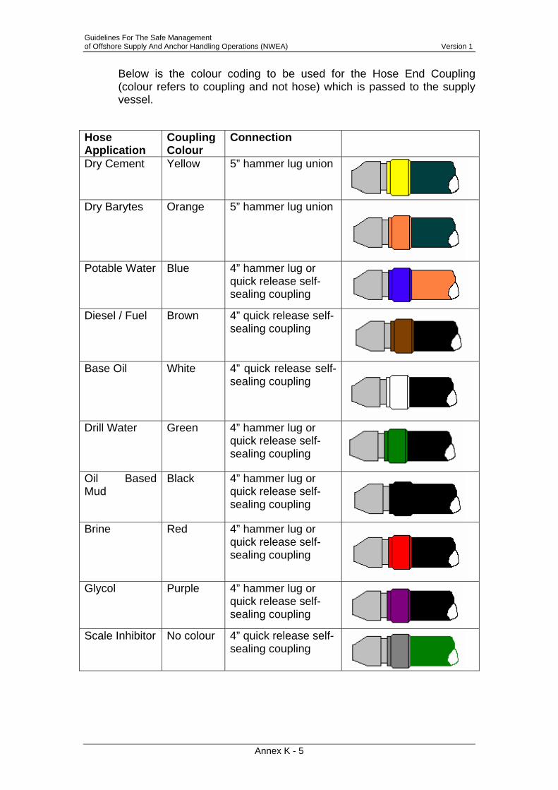
Guidelines For The Safe Management of Offshore Supply And Anchor Handling Operations (NWEA) Version 1
Annex K - 5
Below is the colour coding to be used for the Hose End Coupling (colour refers to coupling and not hose) which is passed to the supply vessel.
Hose Application
Coupling Colour
Connection
Dry Cement Yellow 5” hammer lug union
Dry Barytes Orange 5” hammer lug union
Potable Water Blue 4” hammer lug or
quick release self-sealing coupling
Diesel / Fuel Brown 4” quick release self-
sealing coupling
Base Oil White 4” quick release self-sealing coupling
Drill Water Green 4” hammer lug or quick release self-sealing coupling
Oil Based Mud
Black 4” hammer lug or quick release self-sealing coupling
Brine Red 4” hammer lug or
quick release self-sealing coupling
Glycol Purple 4” hammer lug or
quick release self-sealing coupling
Scale Inhibitor No colour 4” quick release self-
sealing coupling

Guidelines For The Safe Management of Offshore Supply And Anchor Handling Operations (NWEA) Version 1
Annex L - 1
L Example Operating Company Data Card

Guidelines For The Safe Management of Offshore Supply And Anchor Handling Operations (NWEA) Version 1
Annex M - 1
M Example Port Data Card

Guidelines For The Safe Management of Offshore Supply And Anchor Handling Operations (NWEA) Version 1
Annex N - 1
N Anchor Handling Set Up Systems 1. Permanent chaser pendant (PCP) requirements 1. The diagrams below apply to PCP components. In general a swivel
should not be used in the pendant system, only on the working wire. Illustrated below are PCP’s, alone and with anchor.
2. Requirements related to chaser: certification, recertification, repairs,
discarding: The original chaser certificate shall be on board and any repairs
documented Periodic inspection will be performed, focussed on dimensions and
wear. Requirements related to shackles between chain tail and chaser: Minimum of 110 tonnes (corresponds to super green pin).
3. Chain tail requirements:
Minimum ORQ and 400-tonne breaking load Chain shall be certified Minimum length 40’ / 12 metres Dimension 3” / 76 mm

Guidelines For The Safe Management of Offshore Supply And Anchor Handling Operations (NWEA) Version 1
Annex N - 2
Open common link at both ends. 4. Requirements related to shackles between chain tail and pendant wire:
Minimum of 120 tonnes. 5. Pendant wire requirements:
The wire to be minimum 3” / 76 mm The length of the pendant wire shall be a minimum of 200’ / 61 metres.
Some operations may require longer pendants. The wire shall be galvanized and quality certified with Flemish eye
terminations and steel sleeve. Gusseted thimbles to be heavy duty and galvanised.
Eye towards chaser shall be socket with an option for connecting a minimum 3" / 76mm connecting link
Eye towards vessel/shark jaw shall be socket with an option for connecting a minimum 3" / 76mm connecting link. It is recommended a 3" / 76mm chain tail is attached, to ensure the shark jaw on board grabs the chain tail to avoid damage to the pendant wire.
6. Connector requirements (connecting link or pear link) To be minimum of four links, for example: connecting link with a
minimum of four links with stud and one open common link To be to ORQ quality standard as a minimum Minimum dimension 3" / 76 mm Certified.
7. Recommended system length (from piggyback to pigtail) should be water depth plus 60 metres. Recommended maximum length is water depth plus 75 metres.
8. Buoy requirements: Able to withstand collision with a vessel Load bearing capacity based on water depth and equipment weight Shall have sufficient buoyancy related to weight Marked in accordance with applicable regulatory requirements Fixed pigtail Shackle rated to a minimum of 110 tonnes Pigtail length 20’ / 6 metres with minimum dimension 2 ¾" / 70mm An open common link is recommended for eyes at bottom end of pigtail Pigtail is connected to a connecting link at the bottom
9. Connecting link requirements:
Minimum ORQ quality 3" / 76mm 10. Shackle requirements:
Minimum 110 tonnes. 11. Buoy pennant wire:
Colour code markings (e.g. splice socket) based on length
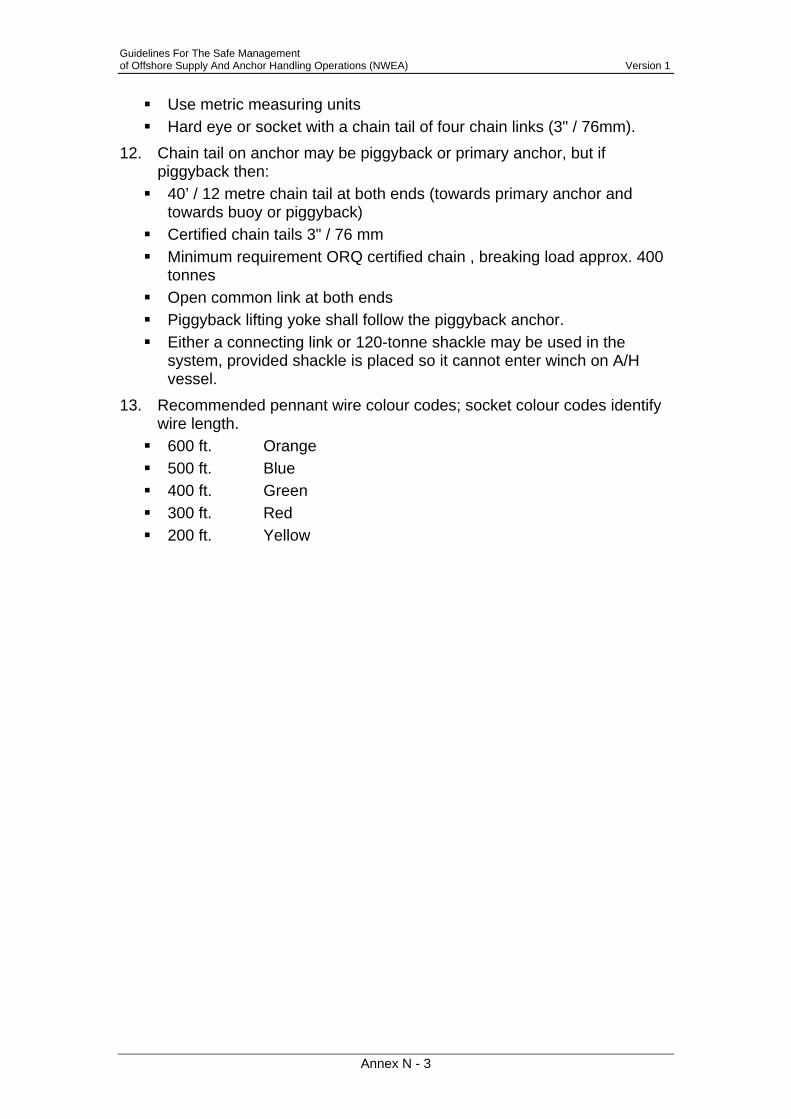
Guidelines For The Safe Management of Offshore Supply And Anchor Handling Operations (NWEA) Version 1
Annex N - 3
Use metric measuring units Hard eye or socket with a chain tail of four chain links (3" / 76mm).
12. Chain tail on anchor may be piggyback or primary anchor, but if piggyback then:
40’ / 12 metre chain tail at both ends (towards primary anchor and towards buoy or piggyback)
Certified chain tails 3" / 76 mm Minimum requirement ORQ certified chain , breaking load approx. 400
tonnes Open common link at both ends Piggyback lifting yoke shall follow the piggyback anchor. Either a connecting link or 120-tonne shackle may be used in the
system, provided shackle is placed so it cannot enter winch on A/H vessel.
13. Recommended pennant wire colour codes; socket colour codes identify wire length.
600 ft. Orange 500 ft. Blue 400 ft. Green 300 ft. Red 200 ft. Yellow
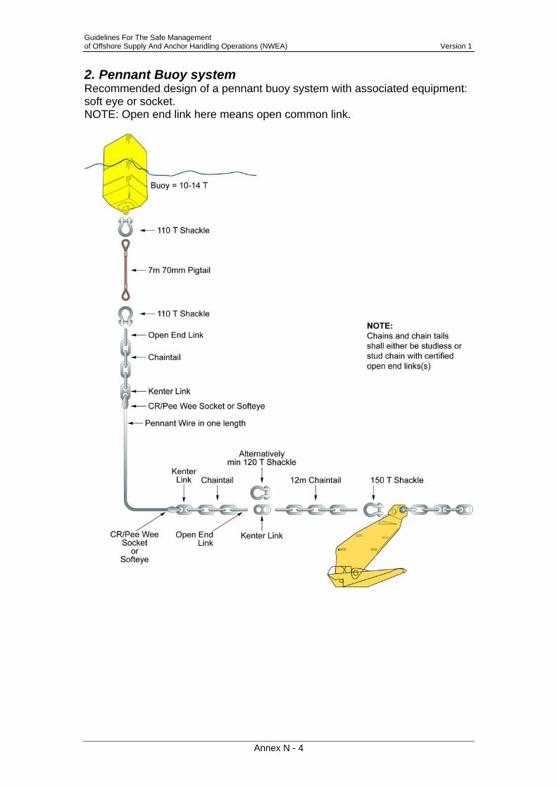
Guidelines For The Safe Management of Offshore Supply And Anchor Handling Operations (NWEA) Version 1
Annex N - 4
2. Pennant Buoy system Recommended design of a pennant buoy system with associated equipment: soft eye or socket. NOTE: Open end link here means open common link.

Guidelines For The Safe Management of Offshore Supply And Anchor Handling Operations (NWEA) Version 1
Annex O - 1
3. Working wire/chaser termination on vessel 1. Use an appropriate rated swivel in the working wire to prevent wire
spinning. 2. A closed socket termination is recommended for the working wire 3. Minimum thickness of the working wire should be sized to the winch. 4. Use a pear link of an approved make 5. Use correct wire length for the water depth, i.e. 1 ½ times water depth Recommended design is below.
PeeWee/CR socket
Pear link
Swivel 7000 kN Concave
Two chain links- with stud
Pear link
Open common link

Guidelines For The Safe Management of Offshore Supply And Anchor Handling Operations (NWEA) Version 1
Annex P - 1
4. Piggyback system Recommended design of piggyback system - with associated equipment. NOTE: Open end link here means open common link. The wire breaking load between piggyback anchor and primary anchor shall be a minimum of 70% of the holding tension of the primary anchor. The wire between the piggyback and primary anchor shall be fastened to pad eye or bridle. Piggyback anchor shall be appropriate to sea bottom conditions based on the site survey.

Guidelines For The Safe Management of Offshore Supply And Anchor Handling Operations (NWEA) Version 1
Annex Q - 1
5. Chasing Pendant 5.1 Connecting Chasing Pendant
5.2 ‘Releasing Chasing Pendant

Guidelines For The Safe Management of Offshore Supply And Anchor Handling Operations (NWEA) Version 1
Annex R - 1
O Hazard Overview Although a COSHH assessment and material Safety Data Sheet must be in place prior to any operations, the following summarises the hazards of the most frequently shipped products. Although there are many kinds of oil-based mud, water based mud, base oil and brine the summary covers the general hazards of all.
Base Oil
Base oil has a hazard category of Harmful. Contact with skin or eyes should be avoided and breathing vapour, fumes or spray is harmful and will cause lung and respiratory damage. Hand, eye and skin protection should be in place and an approved respirator worn when entering a confined space that has contained Base Oil. Base oil flash point ranges from >65ºC with an auto ignition range of >230ºC and should be shielded/protected from all ignition sources. If spillage occurs it must be prevented from entering sewers, watercourses and ground and should be absorbed in vermiculite, dry sand or earth. The COSHH assessment and Material Safety Data Sheet should always be consulted.
Oil Based Mud
Oil based mud does not have a hazard category as such but each individual component has a hazard category. Nausea and headaches can occur if excessive exposure occurs. Contact with skin or eyes should be avoided and do not breathe vapour, fumes or spray. Hand, eye and skin protection must be in place and an approved respirator utilised. The flash point of oil based mud is dependant on the base oil used but will be >65ºC and should be shielded/protected from all ignition sources. If spillage occurs it must be prevented from entering sewers, watercourses and ground and should be absorbed in vermiculite, dry sand or earth. The COSHH assessment and Material Safety Data Sheet should always be consulted.
Silicate Liquor
Silicate Liquor is considered to be of limited harm although proper PPE should be worn when in contact with the product. Contact with skin or eyes should be avoided and do not breathe vapours, fumes or spray. As the liquid is not flammable there is no danger from ignition sources,. The COSHH assessment and Material Safety Data Sheet should always be consulted.
Brine (NaCl, KCL, CaCl, CaBr)
Brine in general has a hazard category of Xi – irritant. It is advised to avoid contact with skin or eyes and do not breathe vapours, fumes or spray. NaCl, KCL, CaCl based Brines are considered to be of low/medium risk. Calcium Bromide (CaBr) and fluids containing Bromides are extremely harmful should they make contact with skin or eyes. Appropriate PPE should be worn at all times when working with Bromide based fluids. Brine is non-flammable with a non-determined flash point. If spillage occurs it must be prevented from entering sewers, watercourses and the ground and should be absorbed in dry sand or earth. The COSHH assessment and Material Safety Data Sheet should always be consulted.

Guidelines For The Safe Management of Offshore Supply And Anchor Handling Operations (NWEA) Version 1
Annex S - 1
P Hand Signals for Crane Operations

Guidelines For The Safe Management of Offshore Supply And Anchor Handling Operations (NWEA) Version 1
Annex T - 1
Q References General Anchor Handling & Towing
11.. OLF/NSA Guidelines for Safety and Emergency Preparedness Training 22.. OLF/NSA Acceptance Criteria for Offshore Service Vessels 33.. UKOOA Guidelines for Anchor Handling in the Vicinity of UKCS Installations,
Pipelines and Their Subsea Equipment 44.. Norwegian Maritime Directorate's rules for passenger and cargo vessels, etc. 55.. Norwegian Maritime Directorate's rules for mobile installations (most recent edition) 66.. Norwegian Maritime Directorate's Safety Notification No. 9 dated 3 April 2001 on
incorrect use of shark jaws 77.. OLF/NSA 061 Guidelines for Safe Operation of Offshore Service Vessels 88.. PSA’s regulations 99.. NORSOK Marine Operations (J-003 Marine Operations) 1100.. DNV Rules for Planning and Execution of Marine Operations
Accident Reporting 1111.. Merchant Shipping (Accident Reporting & Investigation) Regulations 1999 SI
1999/2567 1122.. Reporting of Injuries, Diseases and Dangerous Occurrences Regulations (RIDDOR)
SI 1995/3163 (plus associated HSE leaflet) Bulk Transfers
1133.. IMO Resolution A.673 (16) – “Guidelines for the Transport and Handling of Limited Amounts of Hazardous and Noxious Liquid Substances in Bulk in Offshore Support Vessels”
Cargoes 1144.. M1231 – “Safe Cargo Handling Operations on Offshore Supply Vessels” 1155.. MSC/Circ 745 – “Cargo Securing Manual” 1166.. Dutch Labour Act, leaflet A1-17
Cargo carrying units/Containers 1177.. IMO “Guidelines for the Approval of Containers Handled in Open Sea” 1998
MSC/Circ 860. 1188.. EN-12079 (for offshore containers built after 01-04-2000) 1199.. Nogepa Industry Guideline no. 2 (for offshore containers built before 01-04-2000)
Dangerous Goods 2200.. MSN 1705 – Portable Tanks, Road Tank Vehicles and Rail Tank Wagons for the
Carriage by Sea of Liquid Dangerous Goods and Liquefied Gases 2211.. Merchant Shipping (Dangerous Goods and Marine Pollutants) Regulations 1997 SI
1997/2367 2222.. MGN 159 - The Carriage of Dangerous Goods and Marine Pollutants in Packaged
Form on ships in accordance with Amendment 30-00 to the International Maritime Dangerous Goods (IMDG) Code
2233.. Dangerous Substances in Harbour Areas Regulations SI 1987/37 2244.. MGN 205 – Dangerous Goods – Guidance in the Carriage of Dangerous Goods on
Offshore Supply Vessels. 2255.. MSN 1458 - Offshore Support Vessels Carrying Hazardous or Noxious Liquid
Substances in Bulk 2266.. MSN 1741 – Reporting Requirements for Ships Carrying Dangerous or Polluting
Goods

Guidelines For The Safe Management of Offshore Supply And Anchor Handling Operations (NWEA) Version 1
Annex T - 2
2277.. MIN 183 – The Merchant Shipping (Dangerous or Noxious Liquid Substances in Bulk) Regulations 1996 – List of Current MARPOL Surveyors
2288.. Marine Guidance Note MGM 283(M), "Dangerous Goods - Guidance on the Back Loading of Contaminated Bulk Liquids from Offshore Installations to Offshore Supply/Support Vessels"
Gangways etc. 2299.. MS (Means of Access) Regulations 1988 (SI 1988/1637)
Health & Safety 3300.. The Health & Safety at Work etc. Act 1974 3311.. Management of Health and Safety at Work Regulations SI 1992/2051 3322.. The Merchant Shipping and Fishing Vessel (Health and Safety at Work) Regulations
1997 SI 1997/2962 3333.. MGN 20 – Health & Safety Merchant Shipping and Fishing Vessel (Manual Handling
Operations) Regulations 1998 SI 2857. 3344.. Docks Regulations SI 1988/1655 and ACoP 3355.. Code of Safe Working Practices for Merchant Seamen – MCA: 1998 edition
amendment 02. 3366.. Lifting Operations and Lifting Equipment Regulations 1998 (LOLER). The current
Merchant Shipping equivalent is: 3377.. Merchant Shipping (Hatches and Lifting Plant) Regulations 1988 SI 1639. These are
due for replacement in Q1 2003 with a merchant shipping version of LOLER. 3388.. OLF Guidelines for Safety and Emergency Preparedness Training 3399.. OLF Guidelines for Safety Requirements for Hired Equipment 4400.. HSE Safety Notice 10/80
Hours of Work/STCW 4411.. Merchant Shipping (Safe Manning, Hours of Work and Watchkeeping) Regulations SI
1320 as amended by 1997 SI 1911 and 2000 SI 484 and also by the Merchant Shipping (Hours of Work) Regulations 2002 SI 2125.
4422.. MSN 1767 Hours of Work, Safe Manning and Watchkeeping. 4433.. Offshore Installations and Pipeline Works (Management and Administration) (MAR)
Regulations 1995/738, reg 8: Co-operation Interface between Installation and Vessel
4444.. The Offshore Installations (Safety Case) Regulations 1992 (SI 1992 No. 2885) – Regulation 14: Duty of co-operation with the operator and owner of an installation.
4455.. UKOOA Guidance on Ship/Installation Collision Avoidance 4466.. HSE Offshore Technology Report (OTO 1999 052) “Effective Collision Risk
Management for Offshore Installations” International
4477.. IMO Resolution A.469 (12) – as amended – “Guidelines for the Design and Construction of Offshore Supply Vessels”
4488.. IMO Resolution A.741 (18) – ISM Guidelines & SOLAS Chapter IX (Management for the safe operation of ships)
4499.. IMO Resolution A.863 (20) – Code of Safe Practice for the carriage of cargoes and persons by Offshore Supply Vessels
Manning 5500.. MSN 1767 – Hours of Work, Safe Manning and Watchkeeping.
Masters Responsibility 5511.. SOLAS ch V Reg 10-1 invoked by reg 4 of Merchant Shipping (Safety of Navigation)
Regulations 2002 SI 1473. Merchant Shipping Legislation – General
5522.. Merchant Shipping Act 1995.

Guidelines For The Safe Management of Offshore Supply And Anchor Handling Operations (NWEA) Version 1
Annex T - 3
Pollution Prevention 5533.. MS (Oil Pollution Preparedness, Response and Co-operation Convention)
Regulations 1998 SI 1056 amended by 2001 SI 1639. 5544.. International Chamber of Shipping – “Shipping and the Environment: A Code of
Practice” 1999. 5555.. OLF Recommended Guidelines for Reporting of Emissions and Discharges
Regulatory Authorities – Demarcation 5566.. Maritime and Coastguard Agency/Health and Safety Executive Memorandum of
Understanding : April 1999 Stowage & Securing
5577.. IMO resolution A.714 (17) – Code of Safe Practice for Cargo Stowage and Securing (CSS Code) and IMO Guidelines for the preparation of the Cargo Securing manual to MSC/Circ. 745 and the IMO/ILO/ECE Guidelines for Packaging of Cargo Transport Units (CTUs) (MSC/Circ.787)
5588.. Merchant Shipping (Carriage of Cargoes) Regulations 1999 SI 336. Technical
5599.. NORSOK Marine Operations (J-003 Marine Operations, rev. 2 Aug. 1997). 6600.. NORSOK Mechanical Standard (R-003N Lifting Equipment Operations) OLF
Guidelines for Acceptance Criteria for Offshore Service Vessels (No. 072) Training
6611.. MS (Training and Certification) Regulation 1997 (SI 1997 NO 348 and subsequent correction, 1911)
Transfer & Towing
6622.. NMD Regulations of 17 December 1986 relating to transfer and towing of mobile installations as well as towing arrangement and mooring of supply vessels on such installations (w/associated guidelines and notices).

Guidelines For The Safe Management of Offshore Supply And Anchor Handling Operations (NWEA) Version 1
Annex U - 1
R Contacts MARITIME AND COASTGUARD AGENCY Bay 1/18 Spring Place 105 Commercial Road Southampton SO15 1EG Tel: 02380 329 122 Fax: 02380 329 161 Web: http://www.mcga.gov.uk NORWEGIAN SHIPOWNERS' ASSOCIATION Raadhusgt. 25 P.O.Box 1452 Vika NO-0116 Oslo Tel: +47 22401500 Fax: +47 22401515 Web: http://www.rederi.no HEALTH & SAFETY EXECUTIVE Offshore Safety Division & Safety Policy Directorate Rose Court 2 Southwark Bridge London SE1 9HS Tel: 020 7717 6000 Fax: 020 7717 6717 Web: http://www.hse.gov.uk CHAMBER OF SHIPPING Secretary, OSV Issues Committee Carthusian Court 12 Carthusian St London EC1M 6EZ Tel: 020 7417 2827 Fax: 020 7600 1534 Web: http://www.british-shipping.org UKOOA Director, Operational & Technical Affairs UK Offshore Operators Association 3rd Floor The Exchange 2 62 Market Street Aberdeen AB11 5PJ Tel: 01224 626652 Fax: 01224 626503 Web: http://www.oilandgas.org.uk BROA Manager British Rig Owner’s Association Carthusian Court 12 Carthusian St London EC1M 6EZ Tel: 020 7417 2827 Fax: 020 7600 1534 Web: http://www.broa.org

Guidelines For The Safe Management of Offshore Supply And Anchor Handling Operations (NWEA) Version 1
Annex U - 2
IADC Director - European Offshore Affairs International Association of Drilling Contractors Wood International Centre Craigshaw Drive West Tullos Aberdeen AB12 3AG Tel: 01224 874800 Fax: 01224 875600 Web: http://www.iadc.org NUMAST Senior National Secretary (Professional & Technical) NUMAST Oceanair House 750-760 High Road Leytonstone London E11 3BB Tel: 020 8989 6677 Fax: 020 8530 1015 Web: http://www.numast.org RMT General Secretary Unity House Euston Road London NW1 2BL Tel: 020 7387 4771 Fax: 020 7387 4123 Web: http://www.rmt.org.uk STEP CHANGE IN SAFETY C/o Shell UK Exploration & Production 1 Altens Farm Road Nigg Aberdeen AB12 3FY Tel: 01224 882000 Fax: 01224 882350 Web: http://www.stepchangeinsafety.net MARINE SAFETY FORUM c/o Maersk House Greenbank Road East Tullos Aberdeen AB12 3BR Tel: +44 (0) 7969 497580 Fax: +44 (0) 1224 862357 Web: http://www.marinesafetyforum.org OLF Oljeindustriens Landsforening Hovedkontor, Forus Postboks 8065, 4068 Stavanger Vassbotnen 1, 4313 Sandnes Norway NOGEPA Netherlands Oil and Gas Exploration and Production Association Koningin Julianaplein 30

Guidelines For The Safe Management of Offshore Supply And Anchor Handling Operations (NWEA) Version 1
Annex U - 3
Kantoren Babylon B 5th floor P.O. Box 11729, 2502 AS Den Haag Tel: +31 70 347 88 71 Fax: +31 70 385 12 31 Web: http://www.nogepa.nl/ DSA Danish Shipowners' Association Amaliegade 33 P.O. Box 3037 DK-1256 Copenhagen K Denmark

Guidelines For The Safe Management of Offshore Supply And Anchor Handling Operations (NWEA) Version 1
Page NA-1
National Addenda
Guidelines For The Safe Management of Offshore Supply And Anchor Handling Operations (NWEA) Version 1
Page NA-2
NL1 Title: Hoisting and Chain Gear
Issue: 1
Related documents: 1. Mining Law, translated into the Mining Regulations - special safety regulations SV-7 2. Dutch Labour Act, leaflet A1-17
All hoisting gear and chain gear must comply with above regulatory documents Authorised by:

Guidelines For The Safe Management of Offshore Supply And Anchor Handling Operations (NWEA) Version 1
Page NA-3
NL2 Title: Radioactive material including LSA
Issue: 1
Related documents: • Radioactive Handling Procedure • NORM procedure
1. Shipment of LSA materials shall always be conducted in
accordance with the Radioactive Handling Procedure and the Import permit, which limits the import of LSA material to the location only as stated in the permit of the relevant operating company
2. Further requirements are laid down in the NORM procedure. This procedure is available on the Southern North Sea Pool website: www.snspool.com.
Authorised by:

Guidelines For The Safe Management of Offshore Supply And Anchor Handling Operations (NWEA) Version 1
Page NA-4
NL3 Title: Backloading Checklist
Issue: 1
Related documents:
SNS POOL - Cargo Checklist
Platform :
Manifest Number :
Name Supplier :
1. Last date of inspection 8. Last date of inspection hoisting equipment2. Certificates available and checked 9. Hoisting equipment certificates available3. Dangerous goods labels placed and checked4. Doors properly closed and bolted 10. Colorcode of hoisting equipment5. Container free from loosely attached 11. Split pins attached
nameplate i.e. commercial text 12. Platform labels attached6. Condition of other materials attached 13. Maximum gross weight7. Check for loose items 14. Heavy lift label > 4500 kgs
No. Supplier Description 1 2 3 4 5 6 7 8 9 10 11 12 13 14
Remarks:
Note: V = Agreed
X = Not agreed
NVT = Not applicable
Date: Checked: Signature: Signature facility supervisor:
Authorised by:

Guidelines For The Safe Management of Offshore Supply And Anchor Handling Operations (NWEA) Version 1
Page NA-5
NL4 Title: Potable water
Issue: 1
Related documents: As per SNS Pool potable water protocol, SNS Pool Manager is responsible for sampling of the potable water tanks of every supply boat under contract to the SNS Pool. This procedure is available from the SNS Pool Manager. A spot-charter vessel may only supply potable water to an offshore installation after a full bacteriological analysis of its potable water tanks has been carried out, including for Legionnaire's disease bacteria. Inspection of potable water The Waterleidingswet en Drinkwaterbesluit (Water-works Decree and Drinking water decree) must be observed, due to past experiences regarding the quality of water. The following procedures, regarding the loading, transporting, discharging and quality control of potable water, also apply.

Guidelines For The Safe Management of Offshore Supply And Anchor Handling Operations (NWEA) Version 1
Page NA-6
Periodical potable water investigation Weekly • chloride counts
• taste • colour • smell
For each potable water tank, to be noted in the vessel’s water logbook
Monthly Take samples for bacteriological analysis
For each potable water tank
3 monthly Legionella samples For each potable water tank Annual • Physical-chemical
• Biological • Mineral oil (aromatic)
For each potable water tank
If an official laboratory establishes E-coli or Legionella to be present in tank samples, the water must be pumped out of those tanks which are then to be filled with fresh water and disinfected with Hadex (1 litre: 5m³ potable water). This liquid should be pumped out no less than 10 hours after application of the disinfectant. It may not be transferred to the drillwater tanks. New samples must be taken as soon as possible. Potable water may be used for consumption only after laboratory approval of analysis. Temperature measurements of potable watertanks Monitor and log temperature in each potable water tank:
• daily, or • before potable water bunkering.
Should be less than 20ºC and must not exceed 25 ºC. If over a period of 2 days 25 ºC is exceeded, pump this water to drillwater tanks or discharge it. Send a copy of the temperature logbook to Poolplanning once a month. Bunkering of water The master of the vessel is responsible for correct bunkering of water. Storage of potable water on board a vessel is to be in specified and suitable tanks.
Potable water may not be kept on board for more than 7 days. If possible, potable water is to be transferred to the drillwater tanks or pumped overboard. This action is also to be noted in the water logbook; Procedure for bunkering of water is shown below.
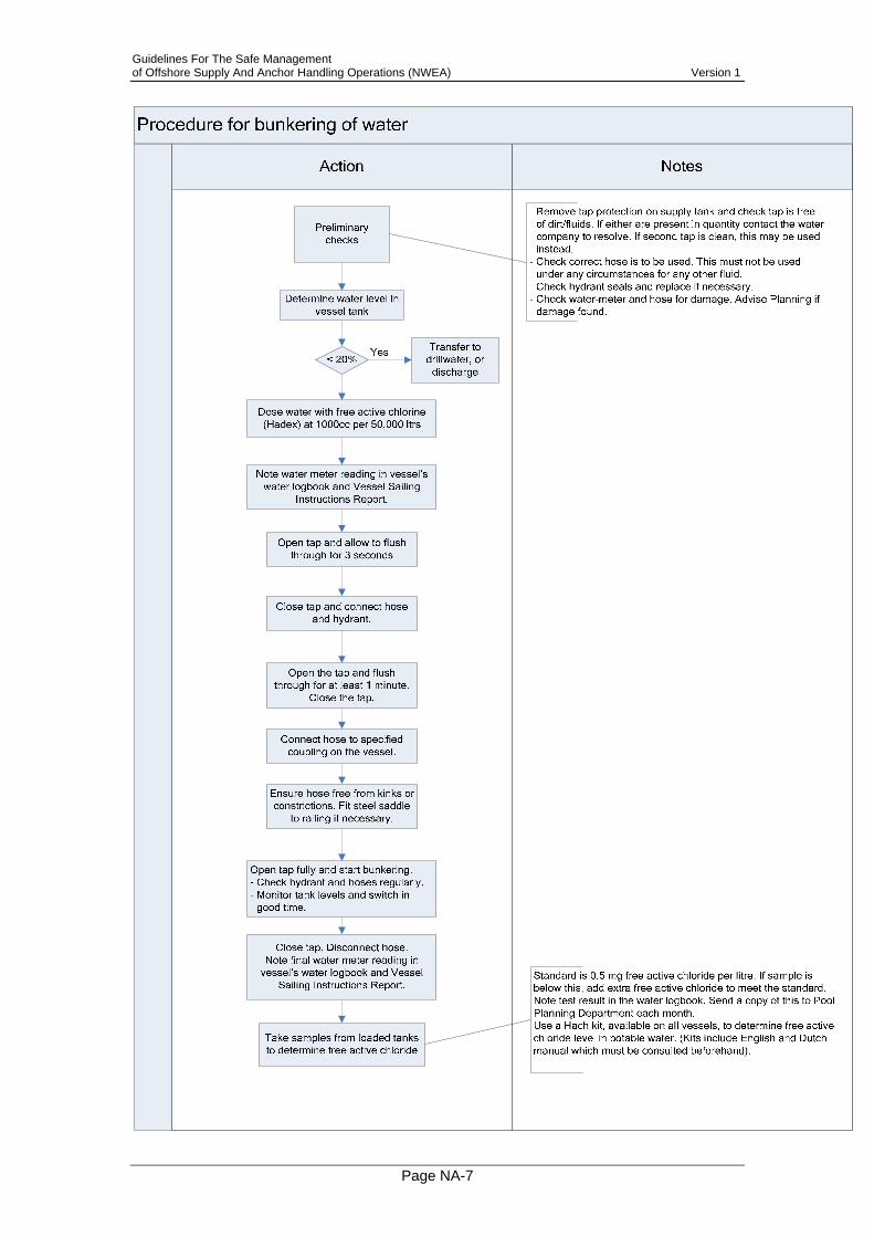
Guidelines For The Safe Management of Offshore Supply And Anchor Handling Operations (NWEA) Version 1
Page NA-7

Guidelines For The Safe Management of Offshore Supply And Anchor Handling Operations (NWEA) Version 1
Page NA-8
Procedure for discharge of potable water at offshore locations The master of the vessel is responsible for proper discharge of potable water at an offshore location. Procedure for discharge of potable water
NotesAction
Preliminary checks
- Check correct hose is to be used. This must not be used under any circumstances for any other fluid.
Dose water with free active chlorine (Hadex) at 1000cc per 50,000 ltrs
Note water meter reading in vessel’s water logbook
Open tap and allow to flush through for 3 seconds
Connect correct hose to coupling on vessel.
Open the tap and flush through for at least 1 minute.
Close the tap.
Ensure hose free from kinks or constrictions. Fit steel saddle
to railing if necessary.
Pump requested amount of water to
the recipient
Cease pumping. Close tap. Disconnect hose.
Standard is 0.5 mg free active chloride per litre. If sample is below this, add extra free active chloride to meet the standard.
Take samples from tanks to be used to determine free active
chloride
Note final water meter reading in vessel’s water logbook and
vessel voyage report.
Clear hose.- Lay on rear deck- Ensure deck crew aside at
safe distance- Drain by air. Drained water
flushes to sea.

Guidelines For The Safe Management of Offshore Supply And Anchor Handling Operations (NWEA) Version 1
Page NA-9
Separate potable and drillwater loading systems If demand for drill water exceeds the amount available on board during a supply trip, potable water may be discharged as drill water. The reverse is not allowed. Every vessel is equipped with standard materials - see 4.8 and Bulk Loading Hoses – Guidance Notes for Colour Coding. Authorised by:

Guidelines For The Safe Management of Offshore Supply And Anchor Handling Operations (NWEA) Version 1
Page NA-10
NL5 Title: Personnel basket transfer
Issue: 1
Related documents: Nadere Regelen, MR cp - 27 articles 2, 78 and 79 Refer to above documents for additional information. Authorised by:

Guidelines For The Safe Management of Offshore Supply And Anchor Handling Operations (NWEA) Version 1
Page NA-11
NO1 Title: PSA responsibility
Issue: 1
Related documents: OLF 61 The Petroleum Safety Authority (PSA) is responsible for safety control and supervision of offshore activities inside the safety zone on the Norwegian Continental Shelf, including operations (functions or tasks) performed by vessels, such as standby. This requires equipment, systems and procedures for performing the vessel's functions or tasks in the petroleum activities to comply with the PSA's requirements (see 1.5.3), in addition to any requirements stipulated by the flag state. Authorised by:

Guidelines For The Safe Management of Offshore Supply And Anchor Handling Operations (NWEA) Version 1
Page NA-12
NO2 Title: Acceptance Criteria for Offshore Support
Vessels
Issue: 1
Related documents: OLF 72 OLF Guidelines for Acceptance Criteria for Offshore Service Vessels (No. 072) shall accompany the contract. Authorised by:

Guidelines For The Safe Management of Offshore Supply And Anchor Handling Operations (NWEA) Version 1
Page NA-13
NO3 Title: Operational limitations
Issue:
Related documents: OLF 61 The Ship Owner is responsible for describing operational limitations for the various vessel operations for each single vessel. Operational limitations will vary according to the vessel's design, size, outfitting etc. The operating company shall be informed of any operational limitations before signing the contract, for example in the form of classification society approved DP capability plot and Environment Regularity Number (ERN). The Ship Owner shall draft operational limitations for any vessel with insufficient technical redundancy in its propulsion, manoeuvring and positioning systems (see Chapter 8.2). The operational limitations shall describe the restrictions placed on the individual operations to be carried out by the vessel, as well as describe any compensating measures that will be initiated to ensure the operations can be carried out. The operating company may stipulate weather limitations on a more general basis for operations on fields or facilities, such as loading or offloading operations involving a installation and vessel. This shall be communicated to the Master on board vessels arriving at the relevant installation before the vessels enter the safety zone. The Master is responsible for continuously evaluating the safety of any ongoing operation. If one approaches the limits for safe operation, the Master shall take the necessary precautions to ensure staying within the limits. If necessary, the Master shall stop the operation (cf. Section 1.3 Responsibilities). If an ongoing operation is stopped by the Master, this shall be communicated immediately to the offshore installation manager, and the operating company or shipping manager shall be notified. Special safety precautions shall be taken when lifting in unstable wave conditions, particularly involving heavy lifts. The crane operator is responsible for ensuring that the lifting operation is carried out in accordance with the crane's load diagram and other relevant operational limitations applicable to the installation in question. Authorised by:
Guidelines For The Safe Management of Offshore Supply And Anchor Handling Operations (NWEA) Version 1
Page NA-14
NO4 Title: Operations within the safety zone using DP
Issue: 1
Related documents: OLF 61 1. To be allowed to operate within the safety zone using dynamic
positioning (DP), vessels shall meet the requirements of equipment class 2 or 3 (cf. IMO / MSC Circular 645 of 6 June 1994) and with class notation DYN POS AUTR or DYN POS AUTRO issued by DNV or equivalent from another classification society.
2. Vessel with DP class 1 that in other respects comply with technical redundancy requirements corresponding to "Specification for redundancy in position keeping ability" with a "Declaration of Compliance", issued by a recognized classification society, will be required to obtain the operator’s permission before the vessel is allowed to carry out DP operations within the safety zone. Such acceptance will normally be tied to the operating company accepting the vessel on a contract, unless the contract stipulates special conditions for DP operations.
3. DP systems shall enable transition from DP to joystick/manual mode by operation of a single key touch.
Authorised by:

Guidelines For The Safe Management of Offshore Supply And Anchor Handling Operations (NWEA) Version 1
Page NA-15
NO5 Title: Competence requirements
Issue: 1
Related documents: OLF 61
Role Ade
quat
e E
nglis
h
IMD
G C
ode
Lifti
ng E
quip
men
t
Slin
ger c
ours
e
Car
go c
onta
iner
s
Car
go h
andl
ing
Bul
k m
ater
ials
han
dlin
g
Mat
eria
ls m
anag
emen
t
Notes & Additional Requirements
Operation managers
Shipping managers
Sailing managers
Vessel coordinators
Logistics coordinators
X X X
1. Shall preferably have a maritime background (nautical studies, mate, Master)
2. The defined operation manager, shipping manager, sailing manager, vessel coordinator or logistics coordinator is responsible for coordination and follow-up of all loading or offloading operations involving offshore service vessels at a base, quay or tank installation.
Quay foremen X X X X X
Personnel packing goods in cargo containers
x* X * IMDG required if handling goods classified as dangerous goods
Crane operators X X
Personnel involved in cargo loading or offloading
X X
Personnel involved in bulk cargo loading or offloading operations
X
1. Safe handling of bulk cargo is especially important for methanol, A and B liquids and hazardous chemicals.
2. Handling and containment of spills, and familiar with related external notification procedures
Installation Maritime operations co-ordinator
X
1. Training shall include vessel types, functioning of manoeuvring and/or positioning systems, vessels' characteristics and limitations (including weather restrictions and vessel load capacity) and maritime terminology.
Installation Loading/offloading
X

Guidelines For The Safe Management of Offshore Supply And Anchor Handling Operations (NWEA) Version 1
Page NA-16
Role Ade
quat
e E
nglis
h
IMD
G C
ode
Lifti
ng E
quip
men
t
Slin
ger c
ours
e
Car
go c
onta
iner
s
Car
go h
andl
ing
Bul
k m
ater
ials
han
dlin
g
Mat
eria
ls m
anag
emen
t
Notes & Additional Requirements responsible person
Storekeepers/deckhands X X X X
Person receiving drilling fluid/cementing products for drilling and production
X
1. In-depth knowledge of installation pipework and valves for bulk handling on the installation.
2. Familiar with procedures and guidelines for handling vessels alongside offshore facilities.
Flagmen/deckhands X X X Knowledgeable in offshore service vessels’ characteristics
Crane Operators X X X Possess an offshore crane operator certificate.
1. Foreign trainee contract personnel undergoing training to flag state
requirements on foreign flagged vessels may work on the cargo deck, provided they work with at least one qualified able-bodied seaman.
2. Able-bodied seamen on foreign flagged vessels shall be able to document knowledge on securing cargo, work with slings and lifting equipment. Such training shall be equivalent to a slinger course. The Ship Owner shall ensure personnel can provide documentation demonstrating such training.
Anchor handling All performing tasks on deck shall have completed a "slinger course"* at an approved training centre or equivalent. * Seamen on board foreign flagged vessels shall be able to document knowledge on securing cargo with slings, and lifting equipment. Of the two people on deck during AH operations, the number two shall as a minimum comply with bridge watch duty requirements. Authorised by:

Guidelines For The Safe Management of Offshore Supply And Anchor Handling Operations (NWEA) Version 1
Page NA-17
NO6 Title: Technical redundancy
Issue: 1
Related documents: A satisfactory technical redundancy level for an offshore service vessel is meeting the requirements in the "Specification for redundancy in position keeping ability". However, DNV or some other classification society shall verify that the vessel's technical systems comply with the requirements described in the document by issuing a Declaration of Compliance (DOC). The interval for renewal of the DOC is the same as for the vessel's main classification (i.e. every fifth year). Note: Vessels equipped with class 2 dynamic positioning equipment with class notation DYN POS AUTR or AUTRO issued by the DNV or equivalent or by another recognised classification society, comply with the technical redundancy requirements (cf. DNV Rules for Classification, Dynamic Positioning System, Pt 6, Ch. 7, Sec. 2 D. Redundancy and independence and E. System arrangement). Authorised by:

Guidelines For The Safe Management of Offshore Supply And Anchor Handling Operations (NWEA) Version 1
Page NA-18
NO7 Title: Anchor securing
Issue: 1
Related documents: Recommended safety measures:
• Anchor completely disconnected + wire connected to anchor chains • Use of separate safety wire (backup) • When running chains to the installation, secure the anchor using a
hydraulic stopper and work winch Authorised by:

Guidelines For The Safe Management of Offshore Supply And Anchor Handling Operations (NWEA) Version 1
Page NA-19
NO8 Title: Offshore Potable Water Supply
Issue: 1
Related documents: Offshore units such as platforms, drilling ships and pipeline-laying vessels operating under Norwegian jurisdiction are required to have a potable water system and potable water supply in accordance with Norwegian regulations. The same applies to offshore units requesting Norwegian certificates. The regulations concerning offshore potable water supply must be met to ensure good water quality and a system that is functioning properly regardless of how the water is supplied to the unit. The Norwegian regulations concerning potable water now include offshore units when it comes to issues not covered in special offshore regulations. One of 2 regulations are applied depending on whether the unit is defined as a mobile offshore unit or not. These regulations have the same basic requirement: "Potable water shall be available in sufficient quantities, be hygienically satisfactory and moreover be clear, without smell, flavour and colour", ref.:
• Regulations of 4. December 2001 concerning potable water (Norwegian text only)
• Regulations of 4 September 1987 No. 860 concerning potable water
system and potable water supply on mobile offshore units (Norwegian text only)
• Regulations relating to health, environment and safety in the petroleum
activities (HES - the framework regulations) Authorised by:

Guidelines For The Safe Management of Offshore Supply And Anchor Handling Operations (NWEA) Version 1
Page NA-20
UK1 Title: Role of the DfT, MCA and HSE on UK
Continental Shelf (UKCS)
Issue: 1
Related documents: 1. The MCA, an Executive Agency of the DETR, is responsible for marine
safety, including: seaworthiness of vessels matters concerning their construction and stability, equipment,
carriage of dangerous goods, navigational safety, safe manning and certification,
prevention of pollution the health, safety and welfare of seafarers.
2. Marine Surveyors of the MCA enforce Merchant Shipping legislation and administer international marine safety conventions, together with related Codes of Practice. They are responsible for:
the survey and certification of safety equipment in vessels; in some cases, the survey of vessels’ structures; inspecting crew accommodation and related matters; inspecting the arrangements on vessels for dealing with the
prevention of pollution; random general safety inspections of vessels, both UK and foreign; random inspections of the condition, loading, stowage and
securement on vessels of packaged dangerous goods, including tank containers and motor tank vehicles and includes goods offered for shipment on such vessels.
inspecting ship board operational arrangements for the loading and unloading of oil, chemical and gas tankers and offshore support vessels;
inspecting arrangements relating to the occupational health and safety of seafarers;
safe manning and the certification of crews; ISM accreditation and auditing (including non-UK vessels).
3. The Marine Accident Investigation Branch (MAIB) must be advised of accidents, major injuries and serious injuries. MAIB recommends that hazardous incidents are reported (see MGN 115).
With respect to those activities on vessels operating on the UKCS to which Merchant Shipping legislation applies, compliance with these Guidelines will provide strong indication that a vessel is meeting the standards required by Merchant Shipping Legislation.
Guidelines For The Safe Management of Offshore Supply And Anchor Handling Operations (NWEA) Version 1
Page NA-21
4. The Health and Safety Executive (HSE) Health and safety legislation is relevant to supply vessel operations
in a number of ways. Part 1 of the Health and Safety at Work etc. Act 1974 (HSWA)1, and certain health and safety legislation, applies to dock operations, including the loading and unloading of UK and foreign flagged ships in British ports and harbours, and to dangerous substances in ports and harbours, except for normal shipboard activities carried out solely by the Master and crew.
Offshore, health and safety legislation applies to: offshore installations and any activities on or near them; activities carried out by vessels in connection with offshore
installations (except the transport, towing or navigation of the installation; and any activity on a vessel being used as an ERRV). This applies regardless of the Flag State of the vessel from which an activity is carried out.
Activities in connection with an installation would be: • loading; • unloading; • fuelling; • diving operations; • provision of accommodation for persons who work on
or from an installation (where provision of accommodation is not the main use of the vessel)
• activities immediately preparatory to any of the above activities.
Such activities would not however include, for example, a supply vessel whilst on passage to or from an installation.
Regulations made under the HSWA – the Offshore Installations (Safety Case) Regulations 1992 – require safety cases to be prepared for all offshore installations. These safety cases should cover all the above listed activities carried out on the installation, or in connection with it. Guidance to the regulation states that the particulars to be included by operators and owners of installations in the safety case should address as fully as necessary activities carried out on, or connection with, a vessel.
With respect to those activities (primarily loading and unloading) to which health and safety legislation applies, adopting the guidance on good practice set out in these Guidelines will help meet legal duties under the HSWA, and regulations made under it where indicated. These Guidelines are not an Approved Code of Practice within the meaning of the HSWA.
1 30The Health & Safety at Work etc. Act 1974

Guidelines For The Safe Management of Offshore Supply And Anchor Handling Operations (NWEA) Version 1
Page NA-22
5. Safety cases (or equivalent risk and consequence analysis) must be prepared for offshore installations that cover all above activities performed on or in connection with the installation.
Authorised by:

Guidelines For The Safe Management of Offshore Supply And Anchor Handling Operations (NWEA) Version 1
Page NA-23
UK2 Title: Weather limitations for operations
Issue: 1
Related documents: 1. Operating companies may stipulate more general weather limitations
for operations on fields or facilities, such as installation or vessel loading or offloading operations. Masters of vessels arriving at relevant installations shall be advised of these before entering the safety zone.
Authorised by:
Guidelines For The Safe Management of Offshore Supply And Anchor Handling Operations (NWEA) Version 1
Page NA-24
UK3 Title: Additional requirements for carriage of
hazardous goods in UKCS
Issue: 1
Related documents: 6. MSN 1705 – Portable Tanks, Road Tank Vehicles and Rail Tank Wagons for the Carriage by Sea of Liquid Dangerous Goods and Liquefied Gases
7. Merchant Shipping (Dangerous Goods and Marine Pollutants) Regulations 1997 SI 1997/2367
8. MGN 159 - The Carriage of Dangerous Goods and Marine Pollutants in Packaged Form on ships in accordance with Amendment 30-00 to the International Maritime Dangerous Goods (IMDG) Code
9. Dangerous Substances in Harbour Areas Regulations SI 1987/37
10. MGN 282 – Dangerous Goods – Guidance in the Carriage of Dangerous Goods on Offshore Supply Vessels.
11. MSN 1458 - Offshore Support Vessels Carrying Hazardous or Noxious Liquid Substances in Bulk
12. MSN 1741 – Reporting Requirements for Ships Carrying Dangerous or Polluting Goods
13. MIN 93 – The Merchant Shipping (Dangerous or Noxious Liquid Substances in Bulk) Regulations 1996 – List of Current MARPOL Surveyors
14. MGN 283 – Guidance on the Back Loading of Contaminated Bulk Liquids from Offshore Installations to Offshore Supply and Support Vessels
The above list represents additional regulations applicable to UKCS. Note that for vessels operating in waters around the United Kingdom this also extends to the most recent version of the relevant guidance note. Authorised by:

Guidelines For The Safe Management of Offshore Supply And Anchor Handling Operations (NWEA) Version 1
Page NA-25
UK4 Title: Waste and waste disposal
Issue: 1
Related documents: UKOOA Guidelines for the Safe Packing and Handling of Cargo to and from offshore Locations
The management of waste generated by offshore installations located in UKCS is described in the UKOOA Guidelines for the Safe Packing and Handling of Cargo to and from offshore Locations. This should be referred to for further information. Authorised by:

Guidelines For The Safe Management of Offshore Supply And Anchor Handling Operations (NWEA) Version 1
Page NA-26
UK5 Title: Discharging waste cargo carrying units
Issue: 1
Related documents: 15. Environmental Protection Act, Section 36 16. Special Waste Regulations 1996
Check that appropriate legislation with regards to waste segregation is complied with. Authorised by:

Guidelines For The Safe Management of Offshore Supply And Anchor Handling Operations (NWEA) Version 1
Page NA-27
UK6 Title: Cargo packing and handling
Issue: 1
Related documents: UKOOA Guidelines for the Safe Packing and Handling of Cargo to and from Offshore Installations and the IMDG code
Refer to above guidelines. Authorised by:

Guidelines For The Safe Management of Offshore Supply And Anchor Handling Operations (NWEA) Version 1
Page NA-28
UK7 Title: Dangerous goods & pollutants stowage
Issue: 1
Related documents: Dangerous Substances in Harbour Areas Regulations Relevant ACoPs
Masters of vessels must ensure all dangerous goods and pollutants are stowed, secured and segregated in accordance with IMDG Code, as modified by Dangerous Substances in Harbour Areas Regulations and relevant AcoPs. Authorised by: