Guide to Contamination Standards - Hymatik
16
Guide to Contamination Standards ENGINEERING YOUR SUCCESS.
-
Upload
khangminh22 -
Category
Documents
-
view
1 -
download
0
Transcript of Guide to Contamination Standards - Hymatik

Guide to Contamination Standards
ENGINEERING YOUR SUCCESS.

Introduction .......................................................................3Contamination basics ........................................................4ISO 4406:1999 codes (hydraulic fluid contamination) .......6Suggested acceptable contamination levels .....................8ISO codes (fuel contamination) .........................................9Typical reporting: particle sizes ........................................9NAS 1638 table ................................................................10SAE AS4059 rev E table ...................................................11GOST 17216-2001 table ...................................................12NAV AIR 10-1A-17 table ...................................................13ISO/NAS/SAE code comparison table .............................14PPM Conversion table .....................................................14Fluid Condition Monitoring Product Solutions ................15
The unique HFDE Condition Monitoring app is available to download free onto your iPhone, iPad or iPod Touch and offers two valuable calculation tools to help reduce the risk of equipment downtime. The ISO Generator assesses the ISO cleanliness of a system and the Frequency Calculator gives a system monitoring frequency.
Download the free app by searching the appstore on Parker or ConMon or for more information contact your local Parker location or email: [email protected]
Also check out our unique online Hydraulic Filter Selector at www.filterselector.com
ContentsFluid Condition Monitoring App

Introduction .......................................................................3Contamination basics ........................................................4ISO 4406:1999 codes (hydraulic fluid contamination) .......6Suggested acceptable contamination levels .....................8ISO codes (fuel contamination) .........................................9Typical reporting: particle sizes ........................................9NAS 1638 table ................................................................10SAE AS4059 rev E table ...................................................11GOST 17216-2001 table ...................................................12NAV AIR 10-1A-17 table ...................................................13ISO/NAS/SAE code comparison table .............................14PPM Conversion table .....................................................14Fluid Condition Monitoring Product Solutions ................15
IntroductionThis guidebook is aimed at engineers, technicians and quality control personnel involved in contamination control. Its purpose is to make available accepted and widely-used cleanliness specification levels for liquid samples.
The tables in this guide allow users of automatic portable particle counters to see the relationship between raw particle counts at various sizes and the reporting code numbers of various contamination standards.
A NOTE ON THE FIGURES USEDNote that some of the table entries are defined as cumulative counts (e.g. “> 6µm”) and others are defined as differential counts (e.g. 6–14µm”).
Instances of particle sizes given as “µm” refer to ACFTD (i.e. Air Cleaner Fine Test Dust) distributions. Instances of particle sizes given as “µm(c)” refer to MTD (i.e. ISO Medium Test Dust) distributions.
All standards are in counts per volume, and provide easy methods for converting particle counts into limits that are simple to interpret. By noting the requirements of the standard, particle counts can be accurately converted to contamination levels.
3

Gra
in o
f
tabl
e sa
lt
100
μm
Dia
met
er
of h
uman
70
μm
hair
Mill
ed
flour
25
μm
Red
bloo
d
8 μm
cells
Bact
eria
2
μm
Cont
amin
atio
n ba
sics
Solid
con
tam
inan
ts in
flui
d sy
stem
s va
ry
in s
ize,
sha
pe, f
orm
and
qua
ntity
. The
m
ost d
amag
ing
cont
amin
ants
in h
ydra
ulic
sy
stem
s ar
e no
rmal
ly b
etw
een
6 an
d 14
m
icro
ns, a
nd th
eref
ore
cann
ot b
e se
en b
y th
e na
ked
eye.
The
tabl
e be
low
giv
es a
n in
dica
tion
of th
e re
lativ
e si
zes
of c
omm
on o
bjec
ts.
Obj
ect
Typi
cal
Imag
e
S
ize
4

Gra
in o
f
tabl
e sa
lt
100
μm
Dia
met
er
of h
uman
70
μm
hair
Mill
ed
flour
25
μm
Red
bloo
d
8 μm
cells
Bact
eria
2
μm
Lim
it of
hum
an v
isib
ility
(nak
ed e
ye)
40
μm
NO
TE: O
ne m
icro
n (μ
m) e
qual
s on
e th
ousa
ndth
of a
m
illim
etre
(1μm
= 0
.001
mm
).
5

ISO
4406
:199
9 co
des
(hyd
raul
ic
fluid
con
tam
inat
ion)
ISO
sta
ndar
d 44
06:1
999
prov
ides
a
way
of s
umm
aris
ing
the
dist
ribut
ion
of
cont
amin
ants
in a
flui
d by
cou
ntin
g th
e pa
rtic
les
per 1
00m
l sam
ple
of h
ydra
ulic
flu
id: t
he fi
gure
s ar
e cu
mul
ativ
e. To
mak
e th
e nu
mbe
rs le
ss c
umbe
rsom
e, th
ey a
re
conv
erte
d to
num
ber c
odes
, as
in th
e fo
llow
ing
tabl
e.
Each
cod
e m
easu
res
a “c
hann
el” o
f re
pres
enta
tive
part
icle
siz
es th
at a
re
part
icul
arly
ass
ocia
ted
with
wea
r and
da
mag
e in
hyd
raul
ic s
yste
ms:
thes
e ar
e 4µ
m(c
), 6µ
m(c
) and
14µ
m(c
).
For e
xam
ple,
700
000
par
ticle
s la
rger
th
an 4
µm(c
) cor
resp
onds
to IS
O 2
0 (a
s 70
0 00
0 is
mor
e th
an 5
00 0
00 b
ut
few
er th
an 1
000
000
). In
the
sam
e w
ay,
140
000
part
icle
s la
rger
than
6µm
(c)
corr
espo
nds
to IS
O 1
8; a
nd 7
000
pa
rtic
les
larg
er th
an 1
4µm
(c) c
orre
spon
ds
to IS
O 1
3. S
o th
is fl
uid
wou
ld b
e re
port
ed
as 2
0 / 1
8 / 1
3.
Whe
n th
e ra
w d
ata
in o
ne o
f the
siz
e ra
nges
resu
lts in
a p
artic
le c
ount
of f
ewer
th
an 2
0 pa
rtic
les,
the
scal
e nu
mbe
r for
th
at s
ize
rang
e is
labe
lled
with
the
sy
mbo
l ‘>’.
6

ISO
cod
e nu
mbe
r M
ore
than
Up
to a
nd in
clud
ing
24
8
000
000
16
000
000
23
4
000
000
8
000
000
22
2
000
000
4
000
000
21
1
000
000
2
000
000
20
50
0 00
0
1 00
0 00
0
19
25
0 00
0
500
000
18
13
0 00
0
250
000
17
64
000
13
0 00
0
16
32
000
64
000
15
16
000
32
000
14
8
000
16
000
13
4
000
8 0
00
12
2
000
4
000
11
1
000
2
000
10
50
0
1 00
0
9
25
0
500
8
13
0
250
7
64
13
0
6
32
64
5
16
32
4
8
16
3
4
8
2
2
4
1
1
2
Num
ber o
f par
ticle
s pe
r 10
0ml s
ampl
e
7
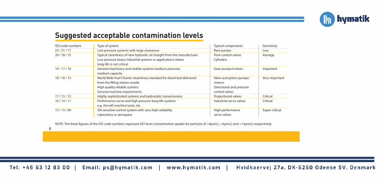
Suggested acceptable contamination levelsISO code numbers Type of system Typical components Sensitivity23 / 21 / 17 Low pressure systems with large clearances Ram pumps Low20 / 18 / 15 Typical cleanliness of new hydraulic oil straight from the manufacturer. Flow control valves Average Low pressure heavy industrial systems or applications where Cylinders long-life is not critical19 / 17 / 14 General machinery and mobile systems medium pressure, Gear pumps/motors Important medium capacity18 / 16 / 13 World Wide Fuel Charter cleanliness standard for diesel fuel delivered Valve and piston pumps/ Very important from the filling station nozzle. motors High quality reliable systems Directional and pressure General machine requirements control valves17 / 15 / 12 Highly sophisticated systems and hydrostatic transmissions Proportional valves Critical16 / 14 / 11 Performance servo and high pressure long-life systems Industrial servo valves Critical e.g. Aircraft machine tools, etc.15 / 13 / 09 Silt sensitive control system with very high reliability High performance Super critical Laboratory or aerospace servo valves
NOTE: The three figures of the ISO code numbers represent ISO level contamination grades for particles of >4μm(c), >6μm(c) and >14μm(c) respectively.8

ISO
code
s (f
uel
cont
amin
atio
n)
ISO
sta
ndar
d 44
06:1
999
is u
sed
to m
easu
re
cont
amin
atio
n in
fuel
, as
wel
l as
in h
ydra
ulic
sys
tem
s (s
ee
page
6).T
he o
nly
diffe
renc
e is
that
par
ticle
cou
nts
are
usua
lly e
xpre
ssed
as
per
mill
ilitr
e, ra
ther
than
per
10
0ml,
so th
e ra
w c
ount
s ar
e ge
nera
lly 1
00 ti
mes
low
er.
22
20
000
40
000
21
10
000
20
000
20
5
000
10
000
19
2
500
5
000
18
1
300
2
500
17
64
0
1300
16
32
0
640
15
16
0
320
14
80
16
0
13
40
80
12
20
40
11
10
20
10
5
10
09
2.
5
5
08
1.
3
2.5
07
0.
64
1.3
Typical reporting: particle sizes Hydraulic ISO MTD 4μ(c) 6μ(c) 14μ(c) 21μ(c) 38μ(c) 70μ(c)
Fluid ACFTD 2μ 5μ 1 5μ 25μ 50μ –
Fuel ISO MTD 4μ(c) 6μ(c) 14μ(c) 21μ(c) 25μ(c) 30μ(c)
Industry conventionally reports raw particle counts as per 100ml for hydraulic fluids, and per ml for fuel, though this is not part of any standard.
ISO
co
de
no.
Mor
e th
anU
p to
an
d in
clud
ing
Num
ber o
f par
ticle
s pe
r ml
9

NAS 1638 tableThe NAS 1638 cleanliness standard was developed for aerospace components in the US and is still widely used for industrial and aerospace fluid power applications and in the UK North Sea industries.
The figures are differential counts, and the NAS class is usually reported as a single figure representing the maximum allowed particle counts (i.e. worst case) for designated particle size ranges.
Size range 5–15 μm 15–25 μm 25–50 μm 50–100 μm >100 μm
00 125 22 4 1 0
0 250 44 8 2 0
1 500 89 16 3 1
2 1000 178 32 6 1
3 2000 356 63 11 2
4 4000 712 126 22 4
5 8000 1425 253 45 8
6 16 000 2850 506 90 16
7 32000 5700 1012 180 32
8 64000 11400 2025 360 64
9 128000 22800 4050 720 128
10 256000 45600 8100 1440 256
11 512000 91000 16200 2880 512
12 1024000 182400 32400 5760 1024N
AS
clas
ses
(bas
ed o
n m
axim
um
cont
amin
atio
n lim
its, p
artic
les
per 1
00m
l)
10
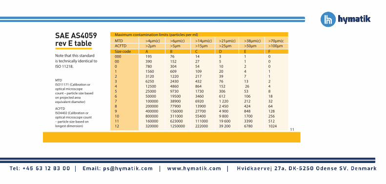
SAE AS4059 rev E table
Maximum contamination limits (particles per ml)MTD >4μm(c) >6μm(c) >14μm(c) >21μm(c) >38μm(c) >70μm(c ACFTD >2μm >5μm >15μm >25μm >50μm >100μm Size code A B C D E F 000 195 76 14 3 1 0 00 390 152 27 5 1 0 0 780 304 54 10 2 0 1 1560 609 109 20 4 1 2 3120 1220 217 39 7 1 3 6250 2430 432 76 13 2 4 12500 4860 864 152 26 4 5 25000 9730 1730 306 53 8 6 50000 19500 3460 612 106 18 7 100000 38900 6920 1 220 212 32 8 200000 77900 13900 2 450 424 64 9 400000 156000 27700 4 900 848 128 10 800000 311000 55400 9 800 1700 256 11 160000 623000 111000 19 600 3390 512 12 320000 1250000 222000 39 200 6780 1024
Note that this standard is technically identical to ISO 11218.
MTD ISO11171 (Calibration or optical microscope count – particle size based on projected area equivalent diameter)
ACFTD ISO4402 (Calibration or optical microscope count – particle size based on longest dimension)
11

GOST 17216-2001 table Size range 5–10μm 10–25μm 25–50μm 50–100μm 100–200μm 00 8 4 1 0 0 0 16 8 2 0 0 1 32 16 3 0 0 2 63 32 4 1 0 3 125 63 8 2 0 4 250 125 12 3 0 5 500 250 25 4 1 6 1000 500 50 6 2 7 2000 1000 100 12 4 8 4000 2000 200 5 6 9 8000 4000 400 50 12 10 16000 8000 800 100 25 11 31500 16000 1600 200 50 12 63000 31500 3150 400 100 13 – 63000 6300 800 200 14 – 125000 12500 1600 400 15 – – 25000 3150 800 16 – – 50000 6300 1600 17 – – – 125000 3150
Part
icle
con
tam
inat
ion
leve
l by
clas
s
(par
ticle
s pe
r 100
ml)
The GOST standard is developed by the Technical Committee of Standardization TK 184 “Ensuring Industrial Cleanliness” introduced by the Government of Russia.
Adopted by the Inter-governmental Committee of Standardization Metrology and Certification.
(Protocol No.19 dated 24 May 2001).
12
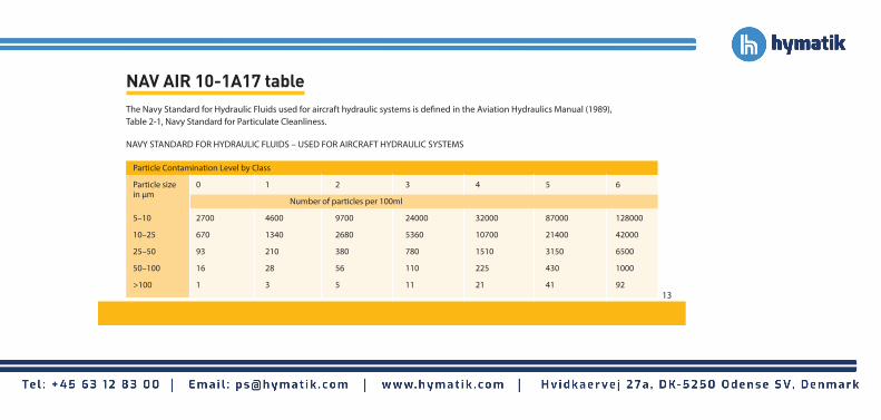
NAV AIR 10-1A17 tableThe Navy Standard for Hydraulic Fluids used for aircraft hydraulic systems is defined in the Aviation Hydraulics Manual (1989), Table 2-1, Navy Standard for Particulate Cleanliness.
Particle Contamination Level by Class
Particle size 0 1 2 3 4 5 6 in μm
Number of particles per 100ml
5–10 2700 4600 9700 24000 32000 87000 128000
10–25 670 1340 2680 5360 10700 21400 42000
25–50 93 210 380 780 1510 3150 6500
50–100 16 28 56 110 225 430 1000
>100 1 3 5 11 21 41 92
NAVY STANDARD FOR HYDRAULIC FLUIDS – USED FOR AIRCRAFT HYDRAULIC SYSTEMS
13

IS
O/D
IS 4
406
D
efen
ce S
td. 0
5/42
BS 5
540/
4 Ta
ble
Ta
ble
N
AS
SA
E
code
s
A
B
1638
74
9
13
/ 11
/ 08
2
14
/ 12
/ 09
3
0
15
/ 13
/ 10
4
1
16
/ 14
/ 09
400F
16 /
14 /
11
5
2
17 /
15 /
09
400
17
/ 15
/ 10
800F
17 /
15 /
12
6
3
18 /
16 /
10
800
18 /
16 /
11
13
00F
18
/ 16
/ 13
7
4
19
/ 17
/ 11
13
00
2000
19
/ 17
/ 14
8
5
20
/ 18
/ 12
20
00
20
/ 18
/ 13
4400
F
20 /
18 /
15
9
6
21 /
19 /
13
4400
63
00F
21
/ 19
/ 16
10
22 /
20 /
13
6300
22 /
20 /
17
11
23
/ 21
/ 14
1500
0
23 /
21 /
18
12
24
/ 22
/ 15
21
000
25
/ 23
/ 17
10
0000
ISO/
NAS
/SAE
cod
e co
mpa
riso
n ta
ble
PPM Conversion table Percent contamination vs. PPM (parts per million) Percent PPM 100% 1 000 000 10% 100 000 1% 10 000 0.1% 1 000 0.01% 100 0.001% 10 Volume 1 litre = 1 000 ml 1 PPM = 1 μl in 1 litre Example 1 400 PPM in 1 litre = 400 μl Example 2 A reading of 250 PPM equates to a quantity of absorbed water in a 400 ltr. capacity system of 0.1 litre.Th
e co
mpa
rison
s re
late
to p
artic
le c
ount
dat
a on
ly.
To c
onfo
rm to
any
par
ticul
ar s
tand
ard,
refe
renc
e
shou
ld b
e m
ade
to th
e re
com
men
ded
expe
rimen
tal
proc
edur
e.
14

icountLCM20 portable particle counter
icountOS Oil Sampler
• 2-minute test procedure. • Multi-standard ISO, NAS and AS4059 cleanliness reporting. • Data entry, data graphing and integral printer • Single Point Samplers (SPS’s) are fingertip operated control valves that connects icountLCM20 and H2Oil into a system.
• Cost effective, portable condition monitoring for hydraulic oil and fuel systems. • Compact, lightweight and reliable. • Proven laser detection technology. • A self contained, field-use oil sampler with on-board battery • Delivers precise, repeatable particulate results down to 4 microns (c).
Fluid Condition Monitoring Product Solutions icountBS2 bottle sampler• icountBS2 provides quick sample bottle analysis with variable test time options from 15 seconds and volume capacities from 10ml. • Repeatable and re-producible results performance, calibration carried out to ISO11171 via ISO11943 principles. • Design concept allows for portability with AC and rechargeable battery power options built-in. • Sample tube self-cleaning sleeve minimizing contamination crossover. • CE Marked.
icountPD particle detector• icountPD provides online and independent monitoring of system contamination trends. • Laser diode light obscuration technology for repeatable results. • Calibration to approved, on-line methods. • Early warning LED or digital display indicators for low, medium and high contamination levels. • Moisture RH% indicator option for real time water ingress awareness before saturation damage occurs. • Fully PC/PLC integration technology such as: – RS232, 0-5V, 4-20mA, CANBUS (J1939). 15

Hydraulic Filter DivisionEurope’s Filtration andCondition MonitoringProduct Catalogueis available today in multiple languages.
Over 460
full colour
pages
Parker Innovation in Manufacturing Parker’s Hydraulic Filter Division Europe provides a truly comprehensive product and service solution to many industries. Together, we can provide hydraulic and lube filtration solutions based on ecological and economic values and find powerful filtration solutions that generate effective savings for customers and end users alike. Together, we can ensure that system fluid contamination isn’t allowed to affect equipment maintenance programmes and with over 50,000 Par Fit Hydraulic Interchange Elements for customers to select from, once you know how contaminated your system is, Parker will help ensure it’s kept clean.
© 2
012
Park
er H
anni
fin C
orpo
ratio
n
FDCB
805U
K 0
2/20
12
Parker Hannifin Manufacturing (UK) Ltd. Hydraulic Filter Division Europe [email protected] www.parker.com/hfde Distributor
The HFDE Hydraulic and heavy duty filtration and fluid condition monitoring catalogue contains, over 460 full colour pages, extensive product technical information, clear specifications, installation drawings, dual scale flow curves and ordering information.