Grouting and freezing unconsolidated and water-bearing strata
110
Scholars' Mine Scholars' Mine Masters Theses Student Theses and Dissertations 1950 Grouting and freezing unconsolidated and water-bearing strata Grouting and freezing unconsolidated and water-bearing strata Robert Walter Heins Follow this and additional works at: https://scholarsmine.mst.edu/masters_theses Part of the Mining Engineering Commons Department: Department: Recommended Citation Recommended Citation Heins, Robert Walter, "Grouting and freezing unconsolidated and water-bearing strata" (1950). Masters Theses. 7128. https://scholarsmine.mst.edu/masters_theses/7128 This thesis is brought to you by Scholars' Mine, a service of the Missouri S&T Library and Learning Resources. This work is protected by U. S. Copyright Law. Unauthorized use including reproduction for redistribution requires the permission of the copyright holder. For more information, please contact [email protected].
-
Upload
khangminh22 -
Category
Documents
-
view
7 -
download
0
Transcript of Grouting and freezing unconsolidated and water-bearing strata

Scholars' Mine Scholars' Mine
Masters Theses Student Theses and Dissertations
1950
Grouting and freezing unconsolidated and water-bearing strata Grouting and freezing unconsolidated and water-bearing strata
Robert Walter Heins
Follow this and additional works at: https://scholarsmine.mst.edu/masters_theses
Part of the Mining Engineering Commons
Department: Department:
Recommended Citation Recommended Citation Heins, Robert Walter, "Grouting and freezing unconsolidated and water-bearing strata" (1950). Masters Theses. 7128. https://scholarsmine.mst.edu/masters_theses/7128
This thesis is brought to you by Scholars' Mine, a service of the Missouri S&T Library and Learning Resources. This work is protected by U. S. Copyright Law. Unauthorized use including reproduction for redistribution requires the permission of the copyright holder. For more information, please contact [email protected].

-1-
GROUTnm AND FREEZING UNCONSOLIDATED
.AND WATER-BEARING STRATA
BY
ROBERT WALTER HEINS
......--_......._-
A
THESIS
submi~~ed ~o ~he faculty of ~he
SCHOOL OF MINES AND METALLURGY OF THE UNIVERSITY OF MISSOURI
in par-tial f'ultillmen-t of the work required tor the
Degree ot
MASTER OF SCIENCE. MINING ENGItIEERING
Rolla. Missouri
1950
.....------
f2A.~~profes8or of Mining Engineering
Approved by~~.I.--------';;;;;'::;;";;-="""_-----

-i1-
ACRNOV'rr..EDGEMENT
This work was made possible by a graduate assistantship at the
University o£ Missouri School o£ Mines and Metallurgy. The writer is
grateful to the School o£ Mines for reoeiving this assistance. The
author wishes to express his sincerest thanks to -che staff of -che
Depa.rtmen-t of Mining Engineering at -che M'issouri School of lIinea and
Me-tallurgy, in par-cicular, Dr. J. D. Forres-cer, Professor of Mining
Engineering, for their invaluable aid and advioe in 'Writing this 'thesis.
-ii1-
PREFACE
The problem of controlling ground wa~er is becoming more important
to the mining engineer. In many cases, large amounts of time and money
are being spent to enable the mining industry to penetrate unconsolidated
and water-bearing rook and soils. The purpose of this thesis is to
oombine in a single volume all the available information concerning
grouting and freezing as me~ods of solving this problem. As far as
possible, this information has been brought up to date •
.An original research was conduoted by the author. The experiments
were made ~o determine if freeZing a water-saturated sand could be
accomplished in laborator.y experiment by using dry ioe and isopropyl
alcohol. The tests are.desoribed and the results are given in this
·paper.
-iv-
CONTENTS
Acknowledgemen~ •••••••••••• ~ ••••••••••••••••••••••••••••••••••
Prefaoe•••••••••••••••••••••••••••••••••••••••••••••••••••••••
Lis~ of illustrations•••••••••••••••••••••••••••••••••••••••••
List of tables ••••••••••••••••••••••••••••••••••••••••••••••••
Grouting••••••••••••••••••••••••••••••••••••••••••••••••••••••
Introduotion••••••••••••••••••••••••••••••••••••••••••• ••
Uses ot Grouting•••••••••••••••••••••••••••••••••••••••••
Page
11
iii
vii
viii
1
1
1
Construotion industry............................... 2
Oil industry•••••••••••••••••••••••••••••••••••••• ~. 2
Mining industry..................................... 3
Grouting materials and mixtures.......................... 4
Faotors influencing type of material used........... 4
Grouting m.a1#erials................... ..... ..... •.• • • • • •• 8
C8men~s........................................ 8
Chemioals...................................... 24
Asphalts ' '. 30
Clays.......................................... 31Injec~1an................................................ 33
Drilling patterns................................... 33
Number of holas required............................ 47
Ke~ods •••••••••••••••••••••••••••••••••• e.......... 47
Pressures •••••••••••••••••••••••••'. • • • • • .... • • • • • •• • • • • • • • • 48
Amounts required.................................... 48
Methods of applying pressure........................ 49
other equipment used in grouting......................... 51

Cemen~ grou~ing equipmen~•••••••••••••••••••••••••••
Chemioa1 grou~ing equipment•••••••••••••••••••••••••
Asphalt grouting equipment••••••••••••••••••••••••••
Clay grouting equipment•••••••••••••••••••••••••••••
Speoia1 grou~ing methods•••••••••••••••••••••••••••••••••
Carbon Diexide method•••••••••••••••••••••••••••••~.
Bentonite-petroleum grouting method•••••••••••••••••
s~••••••••••••••••••••••••••••••••••••••••••••••••••
Freezing••••••••••••••••••••••••••••••••••••••••••••••••••••••
Introduction•••••••••••••••••••••••••••••••••••••••••••••
Freezing me~hods•••••••••••••••••••••••••••••••••••••••••
Equipment used•••••••••••••• e ••••••••••••••••••••••••••••
Refrigeration unit••••••••••••••••••••••••••••••••••
Refrigeran~••••••••••••••••••••••••••••• ~ •••••••••••
Freezing tubes •••••••••••••••••••••••• e' •••••••••••••
Operation••••••••••••••••••••••••••••••••••••••••••••••••
Ini~ial prepara~ion•••••••••••••••••••••••••••••••••
Drilling the holes ••••••••••••••••••••••••••••••••••
Freezing the strata•••••••••••••••••••••••••••••••••
Tha."W'1ng••••••••••••••••••••••••••••••••••••••••.•••••
s~••••••••••••••••••••••••••••••••••••••••••••••••••
Dry ioe-isopropyl a1oohol freezing me~hod••••••••••••••• e •••••
Introduc~ion••••••••••••••••••••••••••••••••••••••••••• ••
Test I •••••••••••••••••••••••••••••••••••••••••••••••••••
Equipmen~••••••••••••••••••••••••••••••••••••• e •••••
Prooedure •••••••••••••••••••••••••••••••••••••••••••
Re8ul~8•••••••••••••••••••••••••••••••••••••••••••••
-v-
51
57
59
59
61
61
61
65
66
66
61
68
68
69
69
72
72
13
75
11
17
79
79
79
79
82
82
Test II••••••••••••••••••••••••••••••••••••••••••••••••••
Equipmeni;•••••••••••••••••••••••••••••••••••••••••••
Procedure•••••••••••••••••••• &••••••••••••••••••••••
Re8ul~s•••••••••••••••••••••••••••••••••••••••••••••
S'UII1lIl.8.ry•••••••••••••••••••••••••••••••••••••••••••••••'•••
Oonolusions••••••••••••••••••••••••••••••••••••••••••••••
Bibliography .
Vi'ta '••••••••• '•••••••.•
-vi-
83
83
86
86
9'1
97
98
101
-vii-
LIST OF ILLUSTRATIONS
Figure Page
1. Effect of water-oement on setting time of portland
oement............................................... 14
2. Eight cubio foot oapaoity grout mixer ••••••••••••••• 20
3. Twenty-on~ cubio foot capacity grout mixer........... 21
4. Grout Manifold for single line system ••••••••••••••• 25
5. Sohematio diagram o:f oirculating and single line
grouting systems •••••••••••••••••••••••••••••••••••• 26
6. -Diagram of drilling pattern for grouting circular
shaft................................................ 34
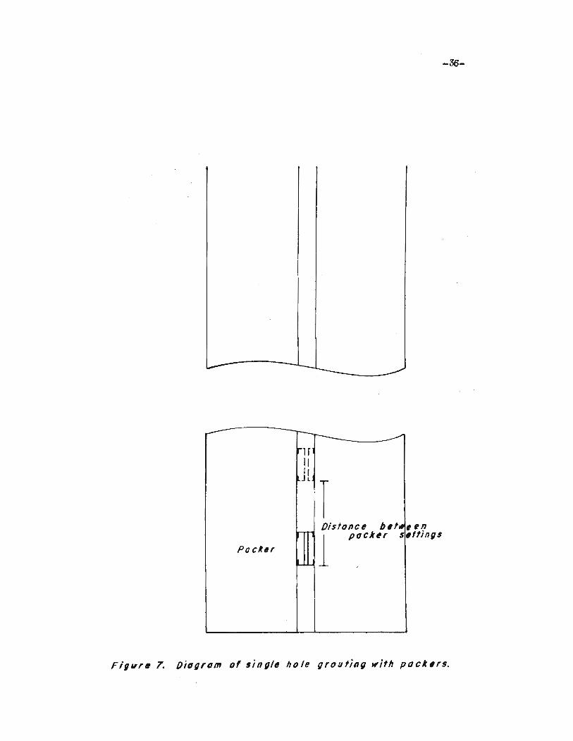
7. Diagram of single hole grouting with packers......... 36
8. Removable grout packer for "EXU drill hole........... 37
9. Air paoker for grouting holes of variable diameter... 38
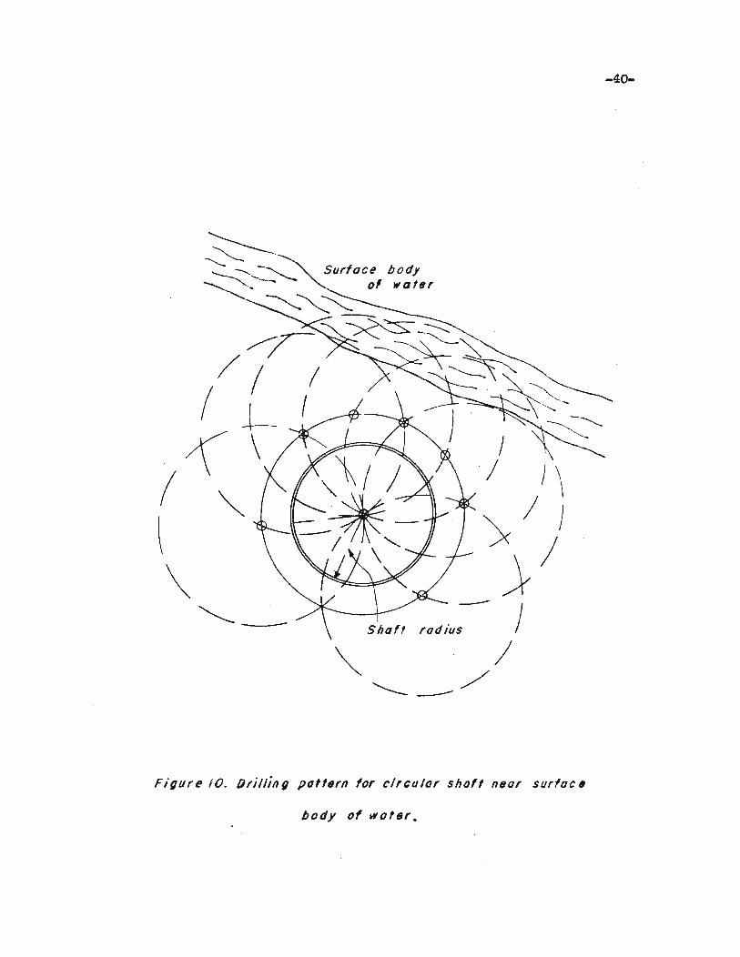
10. Drill pattern for ciroular shaft near surfaoe body
of water............................................. 40
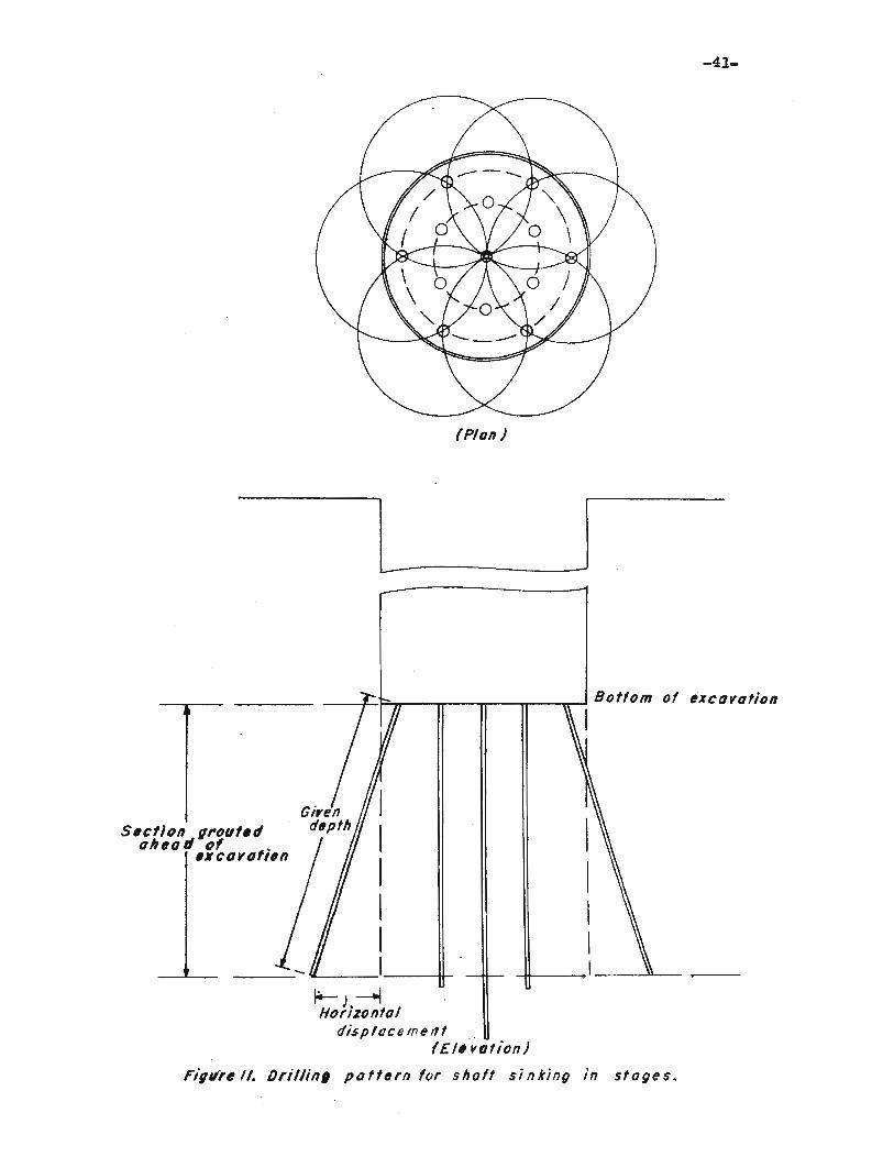
11. Drilling pattern for shaft Sinking in Stages......... 41
12. Drilling pattern for grouting square and reotangular
shafts............................................... 4213. Diagram of grouting in slope sinking................. 44
14. Grouting behind lining of a shaft.................... 45
15. Drilling pattern for grouting a water-bearing stratum
above a drift•••••••••••••••••••••••••••••••••••••••• f. 46
16. Seo1iional diagram. of line-type slush pump equipped for
cement grout service................................. 50
17. Grout agitator used in foundation grouting........... 55
18. Sohematio diagram. of equipment used in Joosten
prooess.............................................. 58
-viii-
19. Carbon dioxide pressure equipment................... 62
20. Schematic diagram of freezing tubes................. 70
21. Plan view of drilling pattern for freezing •••• .,.... 74
22. Diagram of heat exchanger........................... 81
23. Schematic diagram of freezing unit.................. 85
24. Temperature - depth - time curves lit from hea'ti
exBhanger........................................... 89
25. Temperature - depth - tiJ.,'le ourves 2ft from hea'ti
exchanger........................................... 90
26 • Temperature - dep't;h - -clme ourves 3" from hea-c
exohanger•••••••••••••••••••••••••••• & ••• &.......... 91
27. Temperature - dis-cance from heat exchanger - -cime
ourves 3" below surfa.ce of sand..................... 92
28. Temperature - distance from heat exchanger - time
curves 5.5- below surfaoe of sand................... 93
29. Temperature - distanoe :from heat exchanger - time
ourves 9" below surface of sand..................... 94
30. Tempera1iure
31. Temperature
depth - time curves a-c 105 minutes ••••
distanoe from heat exchanger - -cime
95
ourves at 106 minutes............................... 96
LISr OF TABLES
Table
1. Summary of normal oement and rook flour •••••••••••••
Page
13
2. Summary of tests using various admistures........... 18
3. Uni-c weight of various mixes........................ 52
4. Water-oement ra.tios of volumetrio grout mixes....... 64
5. Petrole~bentonitegrout tests..................... 64
6. Temperatures measured with thermooouples............ 88
-1-
GROUTING
In'troduotion
The process of grou'ting haa undergone many changes in reoen-t
years. A defini-tion lDUS-t. 'theref'ore. be inclusive. "Grouting" is
. the process of injecting. under pressure, into soil and rock 'through
boreholes or other openings. ~ solution or suspension containing
ma-terials that harden, stiffen, or swell in void spaces to produce a
solid or semi-solid impermeable mass. Various cements. chemioals.
asphal-ts and clays are the materials used in -the grouting process.
The use of tailings is also considered a type of grouting, since some
hardening or stiffening takes plaoe.
Cement grout relies on chemical reaotion to bring about setting
or 4ardening in place. Chemioal grouting consists ot injeoting solu-
tions ot two or more soluble sali:s. and i i: depends on the ohemioal
reaotion between the solutions to produce an insoluble salt ~ch is
precipi-ta1:ed in the voids. Asphalts are solidified by cooling. Clays
depend on swelling oaused by absorp-tion of water to produce an impenn-
eable mass.
The liquid in a grouting mixture serves as the transporting medium..
The pressure exer'ted on the liquid forces grout into the voids. Con-
tinued pressur~ holds -the grout in place un-til it hardens or swells.
Uses of' Grouting
Grouting can accomplish several purposes. St:urges (1) lists
(1)S~es. F. C.1 Inhroduction-grouting in mines. A.l.U.E. Teohnical Publicat on 2427. SympOS1.um on Grouting. February. 1948.p. 1.
. ,

~em as follows:
1. To atop the passage of fluids and gas•••·
2. To oement aaterials together to .ake thea .tronger.
3. !'o preTeDt oonsol.idation o~ aaterials by fillillg Toi.4
spaoe with something solid as a replacement tor ~e
alr and water that oould be toroed out under load.
Construotion Ind.uat!z
The oouatruotion tnduatry uaea grouting tor all three of' ~
abon parpos... Stabilising soils and rook under f'OUD<lati.ona. bridges.
dam si. tee • and roadbeds and repa.iring leaks 1n oonorete and JBa&ODr7
atruotures oonati.tute its greatest uses. · Grouti.Dg 1D f'CNDdation work
is uaed to till void spaces and to bind broken material to reduoe
settlement and i.Doreaae bear1Dg strength. Daa ai. te groutbg opeft
tions are undertaken to red.uoe !v'droatatio uplift 'b7 sealiDg under-
ground water oouraea. Water leakage ~rom reservoirs oan be stopped
by grouting. Briok ancl oonorete atruotu.res can be -.de impe~ble b7
grouting.
Oil Ia4u.at!z
'!he oil inclustry is pri111aril7 oonoerned wi 1:h sealing ·'boreholes ·:-to
preTent passage ot tlui.ds and gasses. Cement grout is usuallY used.
·' It is :m:ixed as a neat oement slurry. !'his slurry is injected into the
borehole tor the following purposeaa
1. !'o proteot oil abel gas beariDg sones tro.a undesirable
water.
2. !o proteot oaatDc••
I~ ·!o pre~··bl~.
·~ 4~'~,:~·: h8ip'·-~~'·''~ · -.bi·ia the Jaole.

-3-
The meth.od used in oil well cementing varies somewhat trom other
grouting methods. After the cement is pumped in1:;o 1:;he casing, a plug
is placed above the cement. This plug separates the cement slurry and
the D11d or wa:ter whioh is used to apply pressure on the grout. The
cemen1:; is pushed d01l11 through the casing and. back up through the annular
spaoe be'tiween the casing and rook. When the plug reaches the bottom
of the casing, pumping is stopped. This leaves the bottom of the casing
surrounded by oemen1:; to insure a tight seal.
Mining Industry
The mining industry JllJ.st; meet; the same basic problems as the 011
and construc"t1on industries "though mining as a whole has not made tne
extensive use of grouting 1:hat the other industries have. In those
mines where "the water problems are not too diffioul1; and expensi:v.o 1;0
solve, grouting is no't worth oonsidering. On the o1;her hand, water
met while sinking a shaft or driving cm;tries, slopes, drifts, and o'ther
openings presen'ts a Tery difficult problem and one 'that is expensive
to overcome.
Basioally, grouting as applied 'to the mining field 1s used tor
the control of groun.d wa:ter whether i1; is in sinking a ahatt or in the
extrao'tion of ore. If 'the problem warrants the use of grouting, the
following results can be obtained:
1. Provide stable ground tor the shatt 'to the orebody.
2. Provide add!tional support tor roofs and walls.
3. Improve safety conditions.
4. Lower pumping costs.
Whatever the purpose. only intelligent handling by experienoed personnel
can make grou1;ing effeo'tive e.nd eoonomical.

-4-
Two me'thods of grou'ting are used in tunnel and mine work. The
rirs't me'thod oonsis'ts of grou'ting 'through pipes in'to 'the s'trata whioh
are to be made impermeable before 'the exoavation has reaohed 'the wa'ter
bearing zone. In the seoond me'thod, water is 'temporarily drained away
through bleeder pipes until some 'type or lining is plaoed. Af''ter 'the
lining has been plaoed, grou't is injeoted through these bleeder pipes
or through speoial pipes let't tor 'this purpose. The lining must be
designed 'to withs'tand high pressure. A cylindrioal lining is oapable
ot resisting very high pressures and should be used it high pres~es
are antioipated.
In existing shat'ts in whioh 'the lining is not impervious, the
seoond me'thod oan be modified somewhat. Boles oan be drilled along
the lining and grou't toroed in1;o 'the holes. This method mus't be used
with oau'tion beoause 'the pressure might break 'the lining.
Grou'ting in slopes 13 usually a muoh more ditfioul't problem than
grouting in ver'tioal shafts. Sinoe the s'trata are usually horizon'tal,
'the grou't must travel over a greater radius to be effeotive. A test
hole which is drilled ahead ot, and downward at a grea'ter angle than
the slope, is used to determine 'the presenoe of a water-bearing stratum
or unoonsolidated material. If suoh a formation is reaohed, grouting
is oarried on in steps.
Grou'ting ahead of 'the exoavation is the method usually used 'to
seal underground workings. It loose material is enooun'tered or it wa'ter
breaks through af"ter advanoe, 'the seoond me'thod will be used.
Grou'ting llaterials and Mixtures
Fao'tors Influenoing Type of Ma'terial Used
Various tao'tors influenoe 'the seleo'tion ot the type or ma'terial 'to

-5-
be used in grouting. These faotors are listed as tollows:
1. Permeability and porosity of the strata.
2. Purpose for whioh grout is to be used.
3. Water pressure and tlow in the strata.
4. Availability of grouting material.
5. Chemioal considerations.
6. Temperatures of the water, rook, and soil.
7. Cost of the grouting materials.
8. TYPe of projeot.
The permeability of a formation is a measure of the resistanoe
offered to movement of fluids through its pore spaoes. The size ot
the pore spaoes between the grains and whether or not these spaces are
oonneoted will determine what fluids may enter and will have a marked
effeot upon the resistanoe offered to movement of fluids through the
rook. In addition "to "the pore openings between grains in a granular
rook, other openings, such as joint and oleavage planes, vesicular
openings, solution oavities, and orevioes formed by rraoturing may
also be oonsidered under permeability.
In grouting openings with a permeability greater than one-tenth
of 9. centimeter per second, cements, olays, and asphalts may be used.
In most oases oements are used if possible sinoe they provide the
strongest and best seal. Where the permeability is less than one
tenth or a centimeter per second, chemioals are applioable. orten,
oraoks and tissures permit the grout to esoape and penetrate a muoh
larger volume than is required to oomplete the grouting operation.
!hia is oited by Elgin (2) who says:
-6-
(2)Elgin, R. A., Bow Leadville Tunnel is driven through bad ground*Engineering and JaU.n1ng Journal, Vol. 146, No.3, March 1945. p. 99.
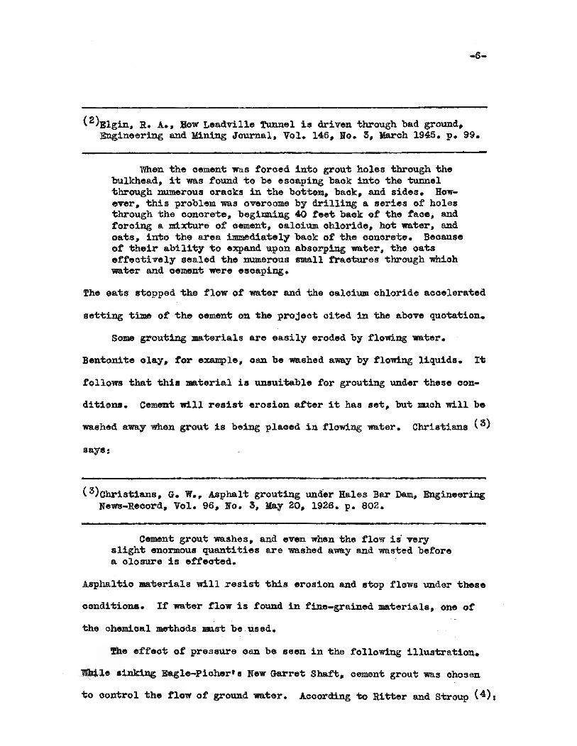
When the cement wa.s forced into grout holes through thebulkhead, it was found to be escaping back into the tunnelthrough numerous eraoks in the bottom, baok, and sides. However, this problem was overoome by drilling a series of holesthrough -che ooncrete, begim:d.ng 40 t'eet baok of the face, andforoing a mixture 01' oement, oalcium ohloride, hot water, andoats, into the area immediately back of -che conorete. Becauseof their ability 1;0 expand upon absorping water, the oatsetfeotively sealed the numerous small frao"tures through whiohwater and oement were escaping.
The eats stopped the flow of water and the oalcium ohloride accelerated
setting time of the cement on the projeot oited in the above quotation.
Some grouting materials are easily eroded by flowing water.
Bentonite olay, for eX81Ilple, oan be washed away by flowing liquids. 11:
follows that this material is unsui'table for grouting under these oon-
ditiona. Cement will resist erosion atter it has set, but lII.loh will be
washed away when grout is beiDg plaoed in flowing water. Christians (3)
says:
(3)Christians, G. W., Asphalt grouting under Hales Bar Dam, EngineeringNews-Reoord, Vol. 96, No.3, May 20, 1926. p. 802.
Cement grout washes, and even when the tloW' is· verysligh1; enormous quantities are washed away and wasted beforea olosure is efteo1;ed.
Asphaltic materials will resist this erosion and stop flows under these
oonditiona. It water flow is found in tine-grained materials, one of
the chemical me1:hods DUst be used.
!he ett801; of pressure oan be seen in the following illustration.
lIlai,le ain1d.ng Eagle-Picher'lS New Garret Shatt, cement grout was ohosen
to control the 1'1011'01' ground 1I9.ter. Acoording to Ritter and stroup (4),

-7-
(4)Ritter, N. E. and stroup, R. J., Sinking Eagle-Pioher's New Garretshaft, Mining Congress Journal, Vol. 24, No.9, September 1938. p. 14.
The quantity of water was immaterial i;o the method; bui;it was realized that grouting would have to withai;and 110pounds per square inoh of pressure at the 439 ft. level.
Cements increase the strength of a formation and oan be used where high
pressures are antioipated as oited above.
Grouting materials whioh are olose to the operation and whioh
posseS8 properties suitable tor i;he job are the materials used. For
example, if olay is olose to the projeot and if it has the properties
needed to oomplete the grouting operation, olay will be used. Freight
oharges raise the cost of grouting materials and thereby raise the oost
of placing the grout. The elimina:tion of these charges reduoes the ooat
of the whole operation.
The chemioal constituents of i;he rook or 80il to be grouted determines
'the type of grout to be used. For example, large quantitiea ot quartz
in strata to be grouted with ohemioals will produoe a better seal and
greater strength than if small quantities are present.
In an example cited by Stiefel (5) , ordinary oement gave a set
(5)8;;ie£el, F. W., OVerooming underground diftiouli;ies, CompressedAir Magazine, Vol. 46, No. 12, Deoember 1941. p. 6613.
volume of 50 per oent while high early strength oement gave a sei; volume
ot 90 per oent. It was this difference thai; enabled the contraotor to
seal ~d oonso1idate the water-bearing rook.
!he effeot ot temperature 1s indioated by Elgin (6) in his d1s-
-8-
( 6)Elgin, !. !..~ 2.£. ~. p. 97.
cuesion of the construction of the Leadville Tunnel. The underground
wa:ter temperature was found "to be 37 deg. F. Straight oemeut mixed wi"th
the oold mine wa"ters did not set tor several days. This difficulty was
overoome with the use of hot water and calcium. chloride. All grout used
was mixed with hot; water and one pound of oalcium ohloride was added tor
each 100 pounds of cement.
When the need for grouting has been established beyond a doubt,
cost has little effect on "the choioe at the material to be used in grout
ing. The choice will depend on the purpose for which the grout is
injeo"ted. When ma"terials have equal proper"ties to acoomplish the
~esfr.d results, the oheapest grouting material will be used.
Grou1:;ing Materials
There are various ma"terials and classifications of these materials
used for grou"ting. but for "this paper, the following olasses will be
oonsidered:
1. Cements
2. Chemicals
3. Asphalts
4. Clays
Cements
The mos"t oommon types of cements used in grouting operations are
listed as follows:
1. Portland cemen"t
2. Modified portland cement
3. High alumina or high early strength cement
-9-
4. Gypsum cement
The grouting properties 01' portland oement vary with different
manufacturers so that a definite statement oannot be made. The port-
land cement referred to here is oommonly used in the construction
industry. Occasionally. only minus 200 mesh portland cements are
used. These materials are obtained by rescreening the cement. This
is rather expensive and should be avoided if possible.
The modified portland cement contains an admixture 01' calcium
ohloride to accelerate setting. This ad.mixture is usually added by
the manuf'aoturer. The consumer may add it if shortening of setting
time ia desired. The affeot 01' this admixture will be discussed
later.
High alumina or high early strength cements are often used be-
cause tiner grind1D.g permits better penetre:tion, and -the high early
strength saves time.
Gypsum cement, made £rom calcium sulphate, sets and hardens at
nearly the same time. It takes approximately two hours tor gypsum
oement to develope full strength.
The two most important problems which confront the engineer in
planning a grouting program, are the de'termination 01' the grout mix
or consis'tency and the determination 01' the pressure at which the
grout will be injected. Since pressures will be discussed thoroughly
in a later section, this discussion will to liJni'ted to grout mixes.
Minear (7) statess
(7)Minear, V. L., '!he art 01' pressure grouting" The Reolamation Era,Vol. 27, Maroh 1937. p. 59.

-10-
The selection of a proper water cement ratio is themost importan't phase of high pressure grouting and undoubtedly more holes have been lost by inexperienced men attempting to use a thioker grout than the hole would accomodatethan from any other oause.
There is no standard oonsistenoy of cement mixtures that should be
used in initially starting the hole. On one operation. it may be
necessary to use a water-oement volume ratio ot one to 30J on another.
a ra'tio of one to 10 is the thinnest mixture that can be used. From
experienoes on Boulder Dam, Minear (8) suggests the following rule of
(8)Minear. v. L. , ~.
thumb:
The initial injections should be of grout having awater-oement ratio equal to O.OlP where P is the limiting pressure. Thus a 500 pound hole (9) would be started
(9)This term refers to 'the limiting pumping pressure at whioh grout maybe injec'ted.
with a grout 'Whose water-cement ratio by volume, was 5.
The water cement ratio depends on the permeability and porosity of
'the struo'ture 'to be grouted. A neat oement paste is ordinarily used for
grouting fine fissures or highly faulted rock zones. Large oavities
sometimes require tha't some type of filler be mixed with the cement
paste. oats, hay, straw, beans, sawdus't, wood shavings, and manure
have been used in plaoes where water is flowing. These materials plug
the oavity and retard the flow of water. They also provide a bulkhead
against which grout may be injected. This work requires a low pressure
until a partial set has been reached.
-11-
Sand has been used to fill cavities, seams, and some faulted
zones where water was not flo\~ng. When used, the sand should be fine.
All should pass 1/8 inch sieve and 50 per cent should pass 50 mesh
sieve. While mixing a sand..water..oement grout, oare should be taken
'to insure thorough mixing. otherwise, the sand may form lenses and
fail to make a good seal. Hays (10) states:
(lO)Hays" J. B." Improving foundation rock for dwns, Civil Engineering"Vol. 9" No.5, May 1939. p. 309.
~ grouting specifications have allowed the use ofmixtures ot sand and oement, especially where the requiredquantities ot grout are large. It it is intended merely totill large openings and to neglect small seamB" and it thereis no concern as to pe:nneabili'ty of' grout" the addition otsand is satisfao1iory.
In a grouting mixture of' sand and cement, the cementserves as a lubricant to convey the sand. Once in theoavi'ty" the sand settles to the bottom and the cement comesto the top" the rate and degree ot segregation depending onthe relative quantity ot water used in the grout and thepresence of water in the oavity.
If high strength of cement grout is not required" bentonite may
be added to the sand-cement grout. Hays (11) says:
(ll)Hays, J. B., Foundation experiences,T. V. A•• Ameriean Society otCivil Engineers Transaotions, Vol. 106, 1941. p. 791.
Bentonite has a dispersion action on the sand and cemen~p
thus keeping a.ll of "the ma"terials in suspension. Withoutbentoni"te, "the sand would have washed out of the mix and wouldno"t have been effective in stopping water.
Rook tlour ms.y be 8ubstitu"ted for part of' the cement used in grout-
ing. When large quanti"ties ot grouting materials are required. ~his
substitution may be made to save on the quantity of oement used. The
addition of rook tlour may have a ha.rmful effect on the oement in "tha~
-12-
i't can oause unsoundness. I't also re'tards 'the se't'ting 'time of 'the
oemen't. Le"'d.s (12) says:
(12)Lewis, J. S., Jr., Founda'tion experiences, T. V. A., AmericanSocie'ty of Civil Engineers Transac'tions, Vol. 106, 1941. p. 718.
It may safely be assumed 'tha't, in grou'ting extremelyseamed rock a't a fixed rate of pumping, 'the area 'tha't willbe oovered is dependent 'to a large exten't upon 'the settingtime of 'the cemen'ting ma'terial. By the use of a slow-set'ting material, the distance traveled by the fluid may beincreased so that areas oompletely outside of the regionthat it is desired to treat will be grouted and the quantityof material necessary to ef£ec't consolida'tion inoreased appreciably. Obviously, eTen if 'the uni't cost of grout was reducedby the use of a cheap, inert ma'terial to replace parl of "thecement the 'to'tal cost of trea"ting a given area might be increased if the quantity of material consumed was appreciablylarger.
To accelerate the se'tting time, oalcium chloride can be added to
the oemen't-rock flour mixture. It was found that 'the addi'tion ot
three per oen't calcium. ohloride by weight will otfse't the retarda'tion
ot the rock flour. Table 1 gives a condensed summary ot the results
ot rock flour-cement grout tests.
Many authors believe the best mixture and 'the proper consistency
oemen't grout oan be found by trial and error combined with judgemen't
and experience. It is usually best to use the thickes't mixture tha't
will flow since less me.'terial is wasted and the cemen't will attain its
highest s"trength. The strength of oement varies inversely as the
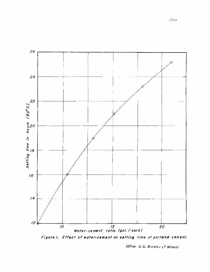
quaniiity ot waiier used during mixing. The time required for portland.
cement to se't increases as 'the water-cemen"t ratio increases as shown
in Figure 1. Consequently, that percentage ot water which will meet
the requirements must be used if satistactory results are to be obtained.
While grout is set"ting, iii undergoes considerable shrinkage. even
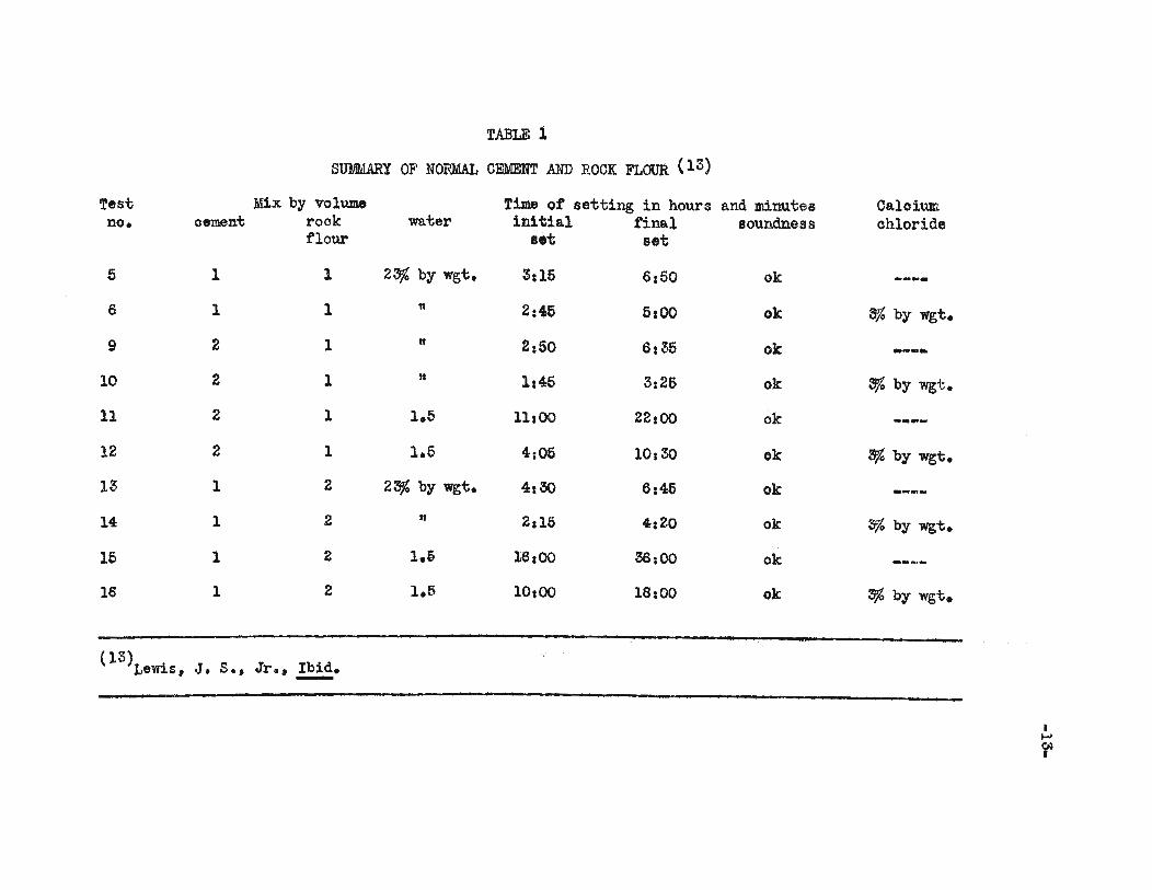
TABLE 1
SUMMARY OF NORMAL CEMENT AND ROCK FLOUR (13)
Test Mix by volume Time of setting in hours and minutes Caloium.no. oement rock water initial final soundness chloride
flour set set
5 1 1 2~ by wgt. 3:15 6:50 ok _.._-6 1 1 11 2:45 5:00 ok 3% by wgt.
9 2 1 n 2:50 6:35 ok .....
10 2 1 11 1:45 3:26 ok 3fo by wgt.
11 2 1 1.6 11:00 22:00 ok --...
12 2 1 1.5 4:05 10:30 ok 3% by wgt.
13 1 2 23% by wgt. 4:30 6:46 ok
14 1 2 n 2:15 4:20 ok 3% by wgt.
16 1 2 1.6 16:00 38;00 ok
16 1 2 1.5 10:00 18:00 ok s;& by wgt.
(13) . .Le~s, J. S., Jr., Ib1d•.........
,....r
-li:-
26
24
/--------1----------1--- - --------
V/
/
1------+---------+-----------
t--------II--'oe-------t---------j-------+-------- --------
22'"~II<::>~
"-
\I)
~20()
~
c::......
"t::~ /8~c::......,
"..'b
(I)
/6 /
/4 --- ------~-------------f-----------+--------1---------------------
/2 e----_.6-- ./o....- .6-- ....I.... .6-- ---'20/0 /5
Water- cem.nf ratio (gal. / 5a"k)
Figure /. Eff,ct of water-cement on $tJttln, time of portland cement.
(After U.S. B:.Jreau ,:f Mi'1es)

-15-
though the minimum amount of water was used in the mix. When a thin
mix is pwnped at low pressure, the surface of the grout will shrink
from the top of the hole up to one-third of the depth of the hole &£ter
grouting has been completed. This same condition exists underground
around fissures. cracks. and crevices when the grout is too thin or
when it is injeoted with too low a pressure. 'When thicker grouts are
used. less shrinkage takes place. Higher pressure displaoes more water
from the grout atter it has been injected.
I't should be noted that there 1s no greater tendency for grout to
settle out in tanks or pipes with 'thiok mixes than there is wi'th 'thin
mixes. Set'tling can be minimized or stopped by maintaining a £101'1 of
grou't of sufficient velocity. This can be mos't easily aooomplished by
using flow and re'turn pipes w1'th a small diame'ter.
!he 'time required for setiiing at cement grou't is dependenii on:
(1) quality or type of cement. (2) age of cement, (3) lmter-cemenii
ra:tio, (4) temperature, (5) curing conditions. and (6) quality of
water.
There are several cements having decidedly dissimilar properties.
For cementing water-bearing ground. a hydraulic cement is required.
Such cements are represen'ted by portland. moditied por'tland. oaloium
aluminate, and gypsum oements. The time required tor a hard set to
form may vary within wide liJDit8 in sim1.lar types of oements. Se'ttitig
time 1s no oritierion of quali1iy, but it is impor-bant in grou'ting be
oause 1't indica'tes "fthe'ther or not a given cemen't oan be used advan
'tageously•.
In tests oonduc'ted with tresh portland and oalcium-&lum1na'te
oements. i't was found 'that the se'tting 'time leng'thened as the age at
the oement inoreased. All hydraulic oements will absorb moisture from.

-16-
"the air, whioh mois'bure, in "time, will be suf'ficien"t "to re"tard se"t-
"ting "time. This property was particularly noticeable in "the caloiUJlPo
alumdna"te cement "tested in the field.
Cer"tain grouting jobs require a high water-cement ratio to insure
proper plaoing, workable mixtures, and penen'tration of the grout into
the ground 'to be 'trea'ted. As previously pointed ou't, tests on por't-
land oement show 'that the ra'te of se't'ting decreases as 'the 1Iater-cemen't
ra"tio inoreases. However, similar 'tests conduc'ted on oaloi~alumina'te
oements indicate 'that hardening is no't ma'terially affec'ted when wa:ter
is added in quan"ti'ties varying trom 7~ to 21 gallons per saok.
Na'tural oonditions in 'the borehole oontrol the temperature and
curing condi'tions of the cement grout. Some oontrol oan be exer'ted by
regulating 'the 'temperature ot the mixing water and oement. Calcium
chloride JDay be added "to lower the freezing point and insure 'the com-
ple"te chemioal reao'tion between oe1l18D.t aDd ..a:ter. Care should be 'taken
because "too mu.ch caloium chloride can cause unsoundness.
Abrams (14) when making oomprehensive tes'ts at impure mixing wa."ter
(l4)Abrams, D. A., Tes"t of impure wa"ters tor miring ooncre"te, AmericanConcrete Ins"ti'bute, Proceedings of "the Twen"tie"th Anniversary ConVention, Vol. 20, 1924.
did not tind an unsound sample ot cement. Tes"ts by "the Bureau ot
Jlines (15) on WB:ter trom the Ohris-tmas Mine indicated tha"t the setting
(l5)U. S. Bureau ot )lines, Repor't at Investiga"tions 4559. p. 7.
times of both porlland and calcium-aluminate oemen'ts were retarded by
-17-
'the impuri'ties in the wa'ter. The se'tting time of por'tland cement was
re'tarded as much as 10 per cen't.
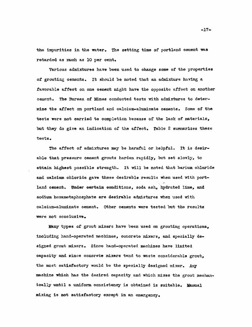
Various admixtures have been used to change some of 'the properties
of grouting cements. It should be noted that an admixture having a
favorable affect on one oement might have the opposite affect on another
cement. The Bureau of :Mines conducted 'tests with admixtures 'to deter-
mine the affec't on ponland and caloium-a.luminate cements. Some of the
tests were no't carried 'to completion beoause of the lack of ma'terials,
but they do give an indication of the affect. fable 2 summarizes -these
testa.
The affeot of' admixtures may be harmful or helpful. Ii; is desir-
able that pressure oement grouts harden rapidly, but set slowly, to
attain highest possible strength. It will be noted 'that barium chloride
and caloium. chloride gave these desirable results when used with port-,"
land cemen't. Under cerlain conditions, soda ash, h¥drated lime, and
sodi'Wll hexamei;aphosphate are desirable admis'tures when used with
caloium-aluminate cemen't. other cements were tes'ted bu't 'the resul-ts
were not oonclusive.
Many 'types of grou't mixers have been used on grouting operations,
inoluding hand-operated maohines, concrete mixers, and speoially de-
signed grou't mLxers. Since hand-operated machines have limited
capaci-t;y and since concre'te mixers tend to was'te oonsiderable grout,
'the most sai;istao'tory would be 'the specially designed mixer. Any
maohine which has the desired oapacity and which mixes the grout meohan-
ioally un'til a unifo~ oonsistency is obtained is sui'table. Manual
mixing is no't satisfaotory axcep't in an emergency.
PQRTLAlfl) CEMENTADMIn'URE
1. Caloium chloride
2. Barium Chloride
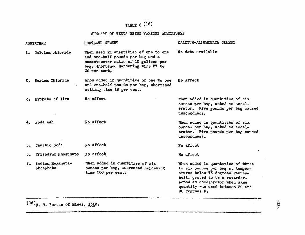
TABLE 2 (16)
SUMMARY OF TESTS usING VARIOUS ADMIXTURES
CALCIUJ4-Al.LUl4INATE CEMENT
When used in quantities of one to one No data availableand one-bAlf' pounds per bag and ..oement-water ratio of' 10 gallons perbag. shortened hardening. time 27 t.36 per oent.
When added in quantities of one to one No affectand one-half pounds per bag. shortened·setting time 18 per cent.
3. Hydrate of lime
4. soda Ash
5. Caustic Soda
6. Trisodium Phosphate
7. Sodium Hexametaphosphate
lio aff'eot
No affect
No affeot
No affeot
'When added in quantities of sixounoes per bag, increased hardeningtime 200 per cent.
When added in quantities of' sixounces per bag, aoted as aocelerator. Five pounds per bag causedunsoundness.
wnen added in quantities of sixounoes per bag, aoted as aooelerator. Five pounds per bag causedunsoundness.
No affect
No affect
When added in quantities of threeto six ounces per bag at temperatures below 75 degrees Fahrenheit, proved to be a retarder.Aoted as aocelerator when samequantity was used between 80 and90 degrees F.
(16~. S. Bureau ot lines, Ibid..........I....co•
-19-
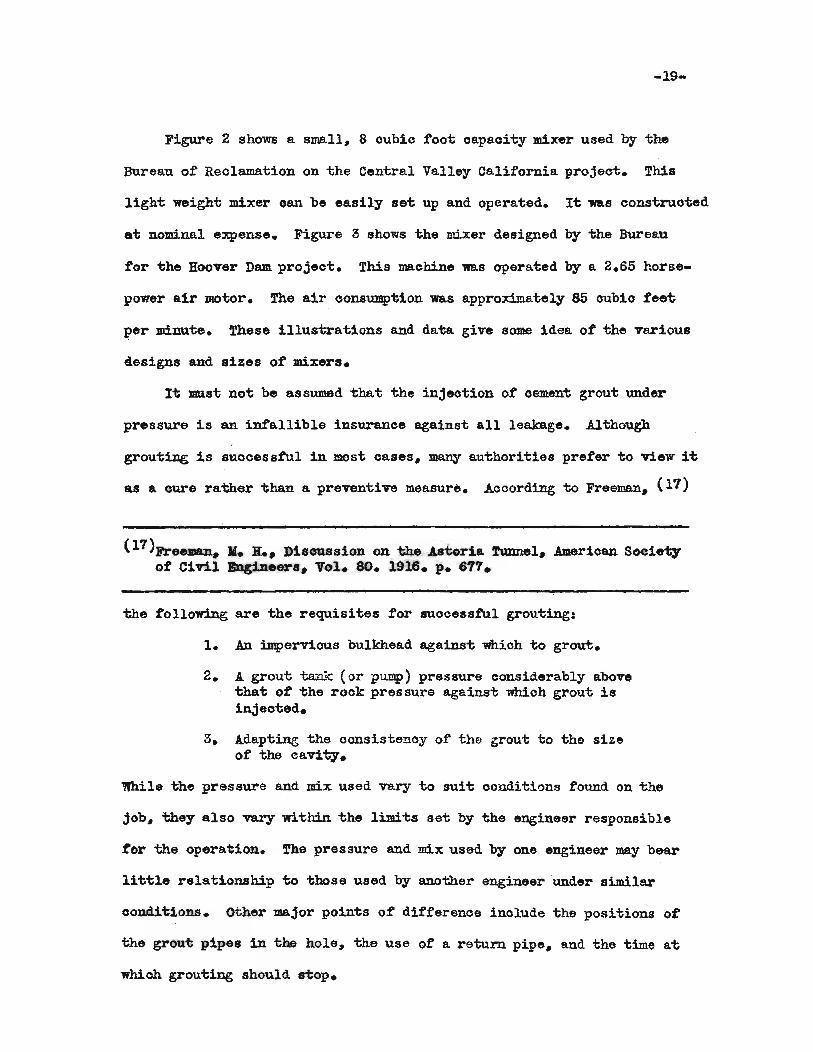
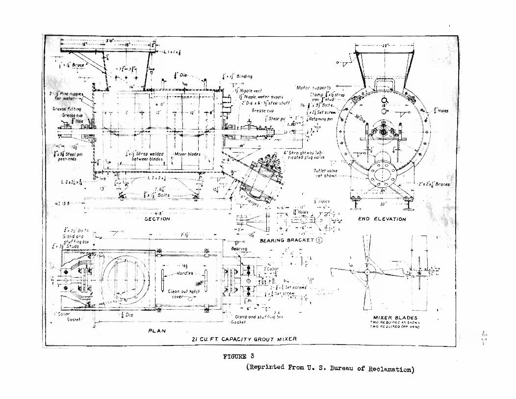
Figure 2 shows a small, 8 oubic toot oapaoity mixer used by the
Bureau ot Reolamation on the Central Valley California. project. This
ligh-t weight mixer oan be easily 86't up and operated. I't 'WaS oonstruoted
at nominal expense. Figure 3 shows the mixer designed by the Bureau
tor the Hoover Dam project. This maohine 1I8.S operated by a 2.65 horse-
power air motor. The air oonsumption 'W8.S approximately 85 oubio fee't
J?er minu'te. fhese illus'trations and data give some idea ot the various
designs and sizes of mixers.
1't ID1st not be assumed 'that the injeotion ot oement grout under
pressure is an infallible insuranoe against all leakage. Although
grouting is suooessful 1D. most oases. many au'thori-ties preter to view i't
as a oure rather than a preventive measure. Acoording to Freeman. (17)
(17)Freeman_ II. H._ Discussion on 'the As1:;oria. Tunnel• .Amerioan Soc1e1iyot CiTil Engineers. Vol. 80. 1916. p. 611.
the tollowing are the requisites tor suocessful grouting:
1. .An impervious bulkhead aga1ns't which to grout.
2. A grout ta:nk (or pump) pressure oonsiderably abovetha't ot the rook pressure against whiohgrout isinjeoted.
3. A.dapting the consistency of the grout to the sizeof the cavity.
While the pressure and mix used vary to sui't oonditions found on the
job. they also var,y wi-thin -the limi-ts set by the engineer responsible
tor the operation. The pressure and mix used by one engineer may bear
little relationship to those used by another engineer under similar
oonditions. other major points of differenoe inolude -the positions ot
the grout pipes in the hole, -the use ot a return. pipe, and the time at
whioh grouting should ROp.

0-
, '. • ~!.; ..:PIVOT BEARING
'--
BAFFLE
/'r
,L- _
....-!.. ...;
- ".-
I
i.r--:.
.---_..----
HUB
TOP COUPLING,Ole If(r,;:..
'-.:.f_ .,) •• -
2f, ~ .
PIN',' t t.. 7 JI(C-D
J'••.,::
BUSHING., ~ w"
l-- IO- -R~
:..-c:
MORSE TAPER~Pl(. .,;..
J' FRIANT DAM• CUIJIC !'OOT CA~ACITY GI'KXIT ItII)(C"
C~NT"AL VALL~Y TY~£
......... \· .... 1>:J6 ••• ~_t ....
~ .• .\lt"I..~ ,...t4{J:.';~
O""ww...'•• _~f~<iI.I(J>,._Y'~~
•"" ... co' '" ~
~-"'I -1::0
• oil .. ""'" ~ ,
~'/I'·"'l. ,.J
(;)80~LTS'O'iff "0
2
HOLDJN(i CLIP."t( f-'Ol)
d
I~;~D- I
-f-
FIGURE 2
I\'.)..
fHoItS
.2". f.rBraces
~_--J
BLADESMIXER~(C'~.s.C' ..~
TN() REQUI ro co;,. "44,,"401'NO ,l:tCQVIR..
- .••.. '··ZZ",·- ...~
END E.LEVATION
~j 11 r
\
:. + ..,.,~ ~-' I I'" I • •/........... • • ~ 1 ~~
"', .' ~';: --"I,. ~~- -1~-":::r----.,'~.... r ..~.~~~\. ". / "","",
D1,6 .
Gland and .tv f r,nq bot'Gasket
2/ CU. FT. CAPACITY GROUT MIXER
'" 11
~...... -
,Ii' Holesl.c.-4"·- 12 - ..-.. /.J."-
~ ~.l-.'." ..~ f[·Holes;. .r:;.<.{~ r, I ~"~""Y ~l'.- -- i ! :r l-=-~~-::~ -? 1~~<1
-i,.· .... I€I.II -"6·'-·""',J,!..z: IF ... ....... "fZr _ L:..: .11" . . t· t
------.-..- -'T'-'" -0 BE.ARING BRACKET CD"---, ._- .~ .. "II ~.g~- • 'z,-==C:F-=' . I', • 7·
~~--. 1"'. . 1 'J . I
~M'~~" i20:'or' ., .~~ ... ,~-
I" 0' ~~-:~b" p ';.:.~I.... !.Hl..". ~ . "
,- l J)) '''1 2' J ,;; Stf screws'( 1 l_ ~ J I 1 ,;iStl~sc~t~ f
J f PI r; I .••~ 'rh,.. -----. .. _ 1 t
- ," ~ 'TO
/2
.. 0
PL.AN
If·S·
seCTION
't
".If-.If." + .•~ .. ~ \ T
.='"- -.-.-.=-=-4, l3.e·
-1 '1/\)' i t,····~-a~';ft!.. ~I.J I . .. "1
... ,.., ..,' ,,JII ., ~ j..' I I CI I'!f'!" .
. I of:?,: .".•.•",.;ri//. "" ,.th./<,I "'~ : __ ~~.,caver .. ··
... .., I ; ,-~'~ .. ~.:.., (j'",~s;.f.." :. ! 0 ., '-- II., . 4 '0 . -'"- c.=4.:..F'~'_ . _ _-m-=-e-
;'.1 ~l' 50 J~ _ _--;,,_:
, .-'';;.ond c-(1 '-,L.
. p Itfvf f~n9 blj.r ,.t, 3J S/uosr=:! <::"
, -\<• •::'-il·
l'/'fJl,ftf t11~4 ~.
'01' ..t.rv ~~~...(",rfc:sc l,tI.~, :. .,
". ;".-G~~C.lIjl ~\I I.'__ I/folf "
..dt'i.. .....r~ .1--.........~.~
..,..::.:'.:':j'.::::' ··-':;'·J~:-~".-':i.; .. :... "'~;I--_• k< H ! tp;.·'Llalcf
L ZdL "~'"
.,~,
I
-:
FIGURE 3
(Reprinted From U. S. Bureau ot Reolamation)
-22-
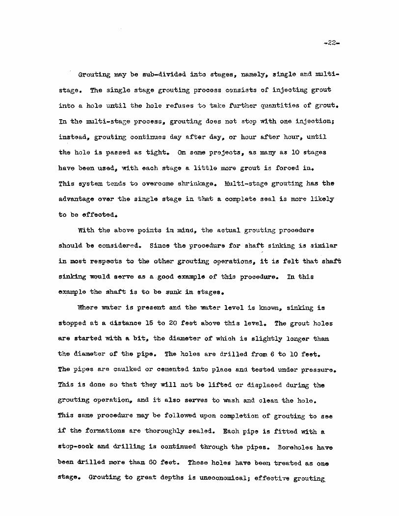
Grou-ting may be sub-divided into stages, namely, single and mul'ti
s'tage. The single stage grouting prooess oonsists of injeoting grou't
into a hole until the hole refuses to take further quantities of grout.
In the multi-stage process, grouting does not stop with one injeotion;
instead, grouting oontinues day after day, or hour a£ter hour, until
the hole is passed as tight. on some projeots. as ma~ as 10 stages
have been used. with each stage a little more grout is foroed in.
This system tends 1;0 overcome shrinkage. Multi-:rtage grouting has the
advantage over the single stage in tha'b a oomplete seal is more likely
to be effeoted.
With the above points in mind, the aotual grouting procedure
should be oonsidered. Sinoe the procedure for shaft sinking i6 similar
in most respeots -tio the other grouting operations. it is felt that shafii
sinking would serve as a good example ot this prooedure. In this
example the shaft is to be sunk in s-tages.
Where water is presen't and -the 'Water level is known. sinking is
stopped at a distance 15 to 20 feet above this level. The grout holes
are started lo:bh a bi-t. -the diam.e-ter of which is sligh-tly longer than
the diameter of -the pipe. The holes are drilled from 6 to 10 feet.
The pipes are caulked or cemented into place and tested under pressure.
This is done so that 'bhey will not be l1f'ted or displaced during the
grouting operation, and i1; also serves to wash and clean i;he hole.
This same prooedure may be followed upon oompletion of grouting i;o see
if the formations are i;horoughly sealed. Each pipe is fii;ted with a
stop-oook and drilling is com::inued 'through 'bhe pipes. Boreholes have
been drilled more than 60 feet. These holes have been treated as one
stage. Grouting "to great depths is uneconomioal; effective grouting.
-23-
oalls for shallow trea1:;ments.
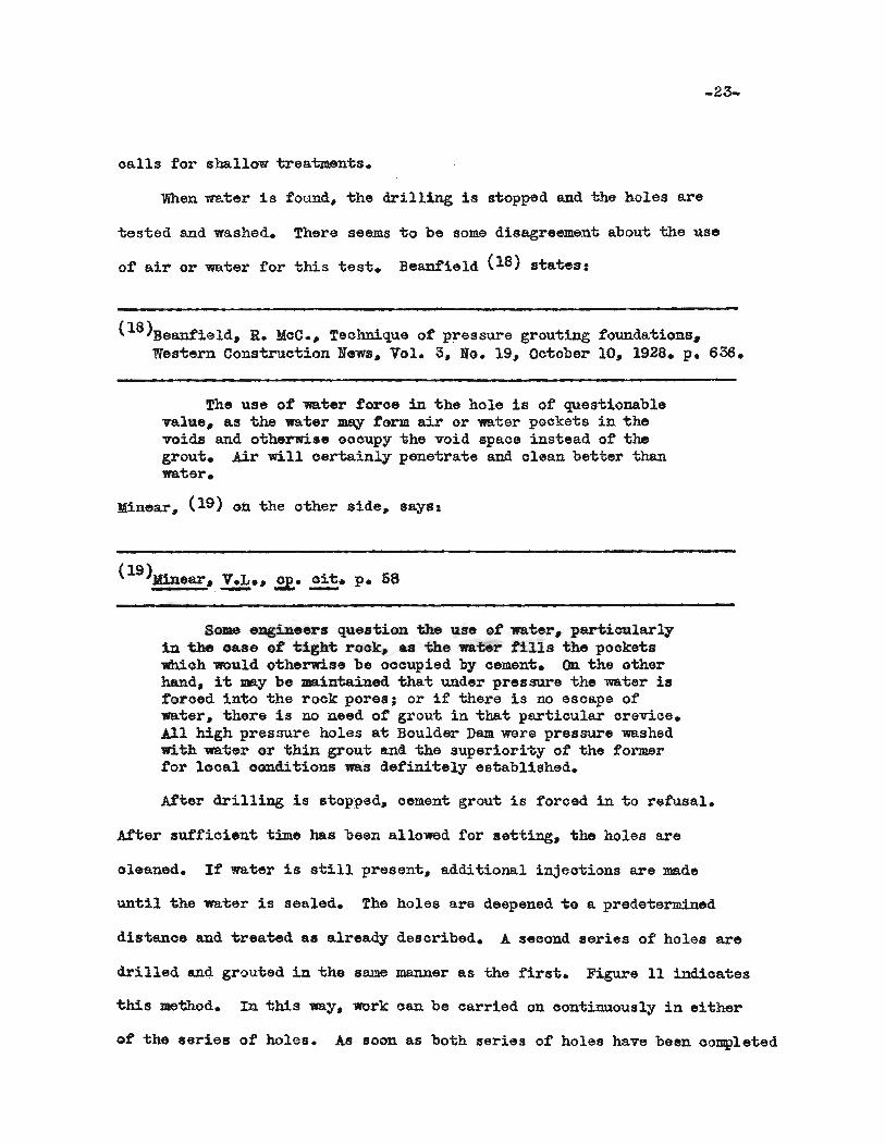
When water is found. the drilling is stopped and the holes are
tested and washed. There seems to be some disagreement about the use
of air or water for this test. Beanfield (18) states:
(18)Beanfield. R. MoC •• Teohnique of pressure grouting foundations,Western Construction News. Vol. 3. No. 19, October 10, 1928. p. 636.
The use of ~ter foroe in the hole is of questionablevalue. a.s the water ~ form air or water pockets in thevoids and otherwise oooupy 'the void spaoe instead of thegrout. Air will oertainly penetrate and olean better thanwater.
Minear. (19) on the other side. says:
Some engineers question 'the U2Je of water. particularlyin 'the case of 1;ight rook. as 'the wa'ter fills the pooketswhioh would otherwise be occupied by cement. On the otherhand, i1; may be maintained that under pressure the water isforced into the rock pores; or if there is no escape ofwater. there is no need of grout in i:;hat partioular orevioe.All high pressure holes at Boulder ])em were pressure washedwith water or thin grout and the superiority of the formerfor looal oGnditions was definitely established.
After drilling is stopped, oement grout is forced in to refusal.
A.fter sufficient time bas been allowed for setting, the holes are
oleaned. If water is still present, additional injeotions are made
until the water is sealed. The holes are deepened to a predetermined
distance and treated as already described. A seoond series of holes are
drilled and grouted in the same manner as the first. Figure 11 indicates
this me1mod. In 'this way. work can be oarried on oontinuously in either
of the series of holes. As soon as both series of holes have been oompleted

-24-
exoava1:ion is begun immedia1:ely and 1s oontinued to a dis"l;anoe of f:rom
15 to 20 feet above the bot1:om of "the "trea"ted seotion. Ano"ther seotion
is prepared for grouting following the prooedure outlined above. ~his
method desoribed is oommonly oalled the advanoing me1:hod.
It has been found that the penetration ot "the grout is in a hori
zontal direotion rather than vertically downward. Therefore, the
bottom ot the treated seotion is the bottom ot the hole. The 15 'to 20
feet allowed between the bottom of the exoavation and the treated
seo'tion is a faotor of sa1.'e'ty.
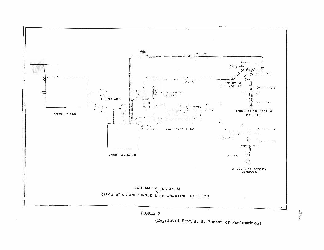
There are two general methods of oonneo"ting supply lines to grou"t
holes. The diree1; oonnec'tion 1NJ.y be made similar "bo Figure 4. In
this method, 'the supply line is oonneoted to the hole. There is no
provision tor a return line. The oiroulating system uses a return
line .from the manifold 'to "the agi'ta"tor, as illus'tra'ted in Figure 5.
The pump 1s opera"ted at a oons"tan"t speed and the pressure is regulated
by valves a't "the manifold conneo'tion. Thb arrangement is useful in
grouting holes where 'the rate of pene"tra"bion is low.
Chemioals
The ohoice of ma"terials used in "bhe chemioal grouting prooesses
is dependen"b on the method employed. There are four major me"bhods,
namely, Joos"ben, Franoois, K. L. M., and "bhe Jorgensen prooesses.
The Joosten method uses solutions of sodium silioate and oaloium
ohloride. The silioa"te solution is injeoted first and the ohloride
solution seoond. \~en these solutions come in oontaot, they reaot to
form insoluble oaloium s111oa1;e and soluble sodium ohlor1de~ The
s1lioa~e whioh forms is a sticky subs'tanc8 wh10h gradually hardens as
1't looses some of the liquid. Upon furlher hardening. 'the mass beoomes

r--------------------------- ..-----.,
5upply 117e;
Gage saver
"" IjSucply valve
" '. IT'-'. -/~ N·-'. .
/-jNipp/e .'<-':-----.
Bottom
L Q~~:L "'>A " -.- ---/-jUnlo
"/jGrout hole valve -
Startlnq hole,
Ca1kin9 or 9rouf.::.·.-.--'.--
,IjBlowoff valve "
Grout nI pple -.
Half couplin9 or endof pipe swaged out\.
Drill hole,,- '----'- - - . - , '--:-----..H-~ - - - J
" T;" ~/~
lLofho/e-_",_~
SECTION A-A
L', -E::J s:-..::-t-o -'':' R - ... c. " - F' '-1 to .• , .,' C"
BU.~ ~L ~,I..- F.ECL;' V...l r ~'\
STANDARD DESIGNS
GROUT MANIFOLD FORSINGLE LINE SYSTEM
FIGURE 4
LINE TYPE PUMP
~ c ~ e
"...,. ,
.~,' -, .c~-~, C' .. c··,f:~4 ~~..
D'CP"1q-" IPe.:~~Jqe saver ""--"',~ ...... , '"fl< .cr - - "- .e
,:
C ~:!,,-...,--
:;:r'':.f'1
CIRCULATING SYSTEM
MANIFOLD
-., .: .. e
, '
,I,
Rp.1vrn lont:
rt:'l.-...., , I .~., . "Ill
# '
~
"JVCoIy ·,':e
Ijp,:
-"~--7
J
'\
- -_.._,_.-_._----- -F" --,."-' ----"--.---
--£=.~._;-
'S,pt"IO:'
svver
-----1 ~'
,..,
rIiI
ii it- /.'[ ,1
1P P'9'a"
YI , ~
I 8)'" ;',~"; " goge
I ')'I .. l........i ... ~ t.' r-' ~ -4 II1 r., I; I ~ _____}i I i1" _ .
r, ii! -lilll't, l. 'I" I:~: r I!
.) ( I"' l ,: i
iI:·- -"-' "~~......L., .G'O!J' DuTp
hO':.tI..'~
,
I ILL1
:
AI R MOTORS
GROUT MIXER
,L--:l I~ l~:
iI
---~
~ ." .~~, I,. L;' \ \:::: y (
II
II'j
!!
GROUT AGITATOR c" "'o:e
to.:
-r~:;' .~~ ,,~, "
~:.: ~:...".~. '.'.~
..... &.:.....~, .
- \ ~
SINGLE LIN£: SYSTEMMANIFOLD
SCHEMATIC DIAGRAMOF
CIRCULATING AND SINGLE LINE GROUTING SYSTEMS
Ii .. IFIGURE 5
(Reprinted From u. S. Bureau ot Reclamation)
~to,)
-21-
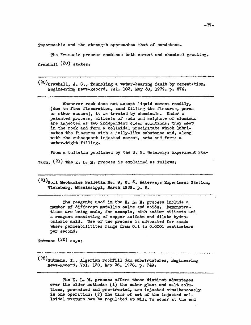
impermeable and 'the s'trength approaohes 'that of sands'tone.
The Francois prooess oombines booth oement and ohemical grouting.
Crawhall (20) 8'ta'te8:
( 20)Orawhall, J. S.. Tunneling a ws:ter-bearing rault by cemen1:;a'tion.Engineering News-Reoord. Vol. 102. May 30. 1929. p. 874.
'Whenever rock does not aocept liquid oement readily.(due to fine fissuration. sand filling the fissures. poresor other oauses). i't is 1:reated by ohemioals. Under apa'tented process. silioa1:e of soda and sulphate of aluminumare injeoted as 'two independent olear solutions; they meetin the rook and form a oolloidal preoipita'te whioh lubricates the fissures with a jelly-like substanoe and. alongwith the subsequent injeoted cement. se'ts and forms awater-tight tilling.
From a bulletin published by -the U. S. waterways Experiment sta
tion. (21) the K. L. M. process is explained as follows:
(21)80il Iteohanic. Bu11e'tin No.9. lJ. S. Wa1ierways Experiment Sta'tion.Vicksburg. lIiasi8sippi. Maroh 1939. p. S.
The reagents used in the K. L. M. prooess include aDUmber of different me'tallio sal'ts and aoids. Demonstra'tions are being made. for example. with sodium. silioate anda reagent oonsisting of copper sulta'te and dilute hydroohlorio aoid. Use ot the proces9 1s advooated tor sandswhere permeabilitii;es range from 0.1 to 0.0001 oentime'tersper seoond.
Gutmann (22) says &
(22)GtItimann. I •• Algerian rocktill dam. subs'true'tures. EngineeringNews-Reoord. Vol. 120. J!ay 26. 1938. p. 149.
The K. L. lI. process offers 'these d1s'tinot advan'tagesover the older me'thods: (l) 'the water glass and 8al't solu'tiona. pre-mixed and pre-treai;ed. are injeo'ted simultaneouslyin one operation; (2) The time of sei; ot 'the injeo-ced 001
loidal mixture oan be regulated at will to ooour a't 'the· end

-28-
of say~ one minute. 20 minutes or 2 hours atter it hasbeen prepared.
The Jorgensen ohemical process. as given by the U. S. Waterways
Experiment Station. (23) is as tollQwsc
(23)U. S. Wat;erways Experiment; 81;ation, ~. ~. p. 8.
The reagen1;s used in 'this prooedure are sodium si11oate,oalcium chlQride, end carbon dioxide gas. The use of thisprocess is recommended by the patentee for petrifying grannular materials and for strengthening weak rook formations.The chemioals are injeo'ted separa'tely 1n 'two or 'three stagesdepending upon whether the oarbon dioxide 1s in'troduoed withthe salt or separately. The gas 1s olaimed to be valuablein water-tigh't work, making the solidified mass denser.
It has been determined tha't the silicate of soda used in t;he chemi- ..
ca.l grou'ting processes should have a. density grea'ter than 41 deg. :Ba.ume t
and a ra'tio of one part sodium oxide to not les8 than 3.22 parts silica.
For best resuli;s, the soil or rock 'to be treated should contain 2Q per
cen1; or more quartz. This was brought out by tests ccnduc'tied by the
Corps ot Bng1neers~ u. S. Army. (24) In 'tihese tests, sand~ whioh
(24)fhe U. S. Engineer Sub-Oftice Hydraulic Laboratory, War Depart:men't.Corps of Engineers. u. s. .Arm3. November 1931.
contained a high quan'ti'tiy at si11oa, was trea'ted. A sample of river
sand. when treated the S8.lIl8 way~ did not show appreciable bonding.
small lumps of gel were tound soattered in 'l:;he speoimen~ but o'tiherwise
the ma:terial was jus't as plastio and sticky as it was before 'trea1;men'ti.
In general. 'the following materials are suitable tor chemioal
grOU'ting, (25)

-29-
(25)Riedel, C. M., Chemioal joint sealing and 80il solidification.Engineering News-Reoord, Vol. 127. August 14. 1941. p. 17.
1. Loose. not tOG fine sand, dr.1 or under water pressure.
2. Layers of' sand and gravel with a limit of clay content.
about 20 per cent, sinoe clay oannot be impregnated.
3. other alluvial 80ils shown suitable by laboratory tests.
4. ~uioksan.d. even under high water pressure.
6. Poor, pervious conorete or brickwork.
As already pointed cui;, the main difference in the various
ohemioal processes is in the type of materials used to effeot solidi-
f10ation. The method of applioation is muoh the same e:x:cep't that the
K. L. M. process permits simultaneous injeotion of the chemioals.
,According .... Jorgensen: (26)
(26)Jorgensen. L. R.. Solidifying gravel, sand. and weak roo:tc. WesternCens'truc1;ion News, Vol. 6, November 10, 1931. p. 591.
The general prooedure (Joosten Process) is to drivethe perforated pipe down into the material to be solidified,say 20 inohes; then pump the first solution (sodium. silioate)into this layer; then drive the pipe another 20 inohes andinjeot ohemioal I and so on again. When the full depth hasbeen reaohed and all the solution I desired has been forcedin. the salt solution (ohemioal II) is injeoted in 20 inohlit'ts, as the pipe is pulled out. The gel is formed immediately, but remains in suoh a Gondition tor sufficient timefor the salt solution to penetrate to the outer strata,"there to tind the atoms ot silioate. Bo-th liquids areheavier than water, and have a tendenoy to displaoe all thewater in ~he voids of the gravel and reach rock bot~ca,
eVen it the end of the pipe dees no't.
The solidified mass is water tight and in.olable. The distance
of pene'tration from 'the injeotion pipe depends on the size of the void

-30-
spaoes~ The dis~anoe ~hat ~he che~cal grouts penetra~e8 is directly
proportional to the pressure used.
Asphalts
Asphalt ma~erials used for grouting are obtainable in several
varieties. They range from a thiok fluid to a brittle or oxidized
grade~ As a general rule, ~he bes~ ~ype of material 1s one which
stiffens after cooling, but does not become hard and brittle.
Alphalts are used where water is flowing through cracks and
crevices at a high velocity and at a high pressure. This material
will solidify enough to resist moving water, but remains soft enough
80 that continued pressure will expand the asphalt against the sides
ot the cavity. The asphalt is injected h~i:; and when it comes in con
1;ao~ with wa:t:er, 'the ou'bside is oooled. Inside this oovering, the
asphal~ remains liquid. Oontimled applioation ot pressure tend.s to
till thAt cavity. .A:t'ter tilling ~ake8 place, 'tihe asphalt is forced
along -the long dj.mension of the opening. When the required section
haa been treated, the pressure is reduoed and theremaini.ng liquid
asphalt 1s allowed to cool. The distanoe traveled by 'tihe asphalt is
dependent on the size Gf i:heopening, type and shape .t the cavity,
the grade ot asphalt used, the amoun'b ot pressure applied, and the
length ot time over which the pressure is applied.
There are three general methods used for asphalt grouting. The
first or Ohristiana method uses an electrioal resistance wire suspend
ed in iihe injeotion pipe. "When electrioity is applied, the wire
becomes inoandescent, the heat generated keeps the asphalt hot. Grou1i
ing opera1;ions, "Whioh have been stopped tor a period ot time, may be
resumed by applying 8. current to the wire a few mimttes before s"tarting
-31-
"the pUlllps. Chr1s"tians (21) s"tate8:
(21)Christians, ~." 2,2,. ~. p. 802.
By al-tering the grade of asphalt" adjusting 'the rawof flow, con"trolling 'the "tempera"ture in the pipe line. opera"tiDg interm1t-tently and. 'to de'termined pressures, it ispossible 1;0 adapt the method 1;0 various looal oondi"tionsso as 'to ob"ta1n maximum resul"ts with minimum efforl andma"terial.
The seoond me1;hod uses a oirculating swam system to keep "the
asphal"t hot during injection. The s1;eam unit is lowered in1;o the hole
1;0 be grouted, asphalt is forced in. This m.e"thod. is particularly
applioable where i't is necessary to till large oavernous openings.
The Shell Oil Company, Incorpora'ted, reoen"tly announoed the use
of an asphalt-in-water emu.lsion in a method for oontrol ot subsurfaoe
seepage. '!his is beillg used under the 'brade name of "She1lperm"•
!he following method of use is quo'bed from. 1:;he Pe'tr'oleum. Refiner: (28)
( 2S >Underground. dam, Pet:roleum Refiner, Vol. 28 No.3, )laroh 1949.A Gulf Publishing Oomp~ Publioa"tion. p. 114.
Shellperm is a prooess employing an euulsion at asphaltin-water, whioh is pumped under low pressure through a metalpipe drivan into "the ground. Af'ter the emulsion emerges from1:;he pipe, i1:; spreads out roughly in the form of a ball. Thenohemi.oals mixed wi1:;h the emulsion cause "the asphal't to coal...esoe and the reSUlting mass 1s impermeable to water.
When "the firs1:; or bo1:;tom injeotion has been made, "thepipe is raised and addi"tional shellperm. pumped down. 1:;0 tarathe seoond impermeable DaSS. Repeated injeo1:;ions produoe averlical asphal't oolumn. The pipe is "then moved and. injeotions made "to for.a a seoond ver"tioal asphalt oolumn.By repeating 1;he process ot building the overlapping Qrabut"ti.Dg Ter'bioal oolWlll1s, an impermeable underground damis tormed.
Clays
The ..s1; oeDllllOn type ot: olay used in grou1;ing is ben"tonite. Most

-32-
bentonites have a strong affinity for water 6 absorbing trom eight to
15 times their volume. Beniionite forms a plastic gelaiiinous mass whioh
resembles sott soap. 1Vhen it is agi-taiied in waiier, i-t torms a more or
less permanent suspension. An electroly-te coagula-tes or flooculates the
suspension and bentonite setiiles out rapidly. These properties make
bentoni-te suitable tor use as a grouting material. From. experienoe, it
has been determined that the clay used in grouting should contain less
"than iive per cent plus 200 mesh sand.
other clays have been used tor grou-ting. These materials JID.1st be
"tested in a laboratory to determine it they are suitable. Tes"ts were
oonducted on olays to be used in grouting the Madden Reservoir (29) to
(29)JIadden Dam Project. Alhajuela, Canal Zone.
determine their properties for use on this operation. Kellog (SO) states:
(30)le110g, F. H•• Clay grouting at ltadden Reservoir. EngineeringNe~-Reoord, Vol. 109, Ho. 14. October 6. 1932. p. 396.
The objeots of this group of tests ~re: (1) to determinewhat type of clay mix would make the bes"t grout; (2) "to notethe dis'tance through whioh the grout would travel underground;(3) to note the sizes and types ot openings in the rock thatoould be grouted; and (4) to check the ef'f'ioienoy of' themethods used in stopping leakage.
The results of these experiments indioaiied that a pureolay-lmter mix would serve the best. The best results wereobtained with grouts oontaining about 65 per cent water (byweight). !he minimum distanoe underground through whichgrouts of 'this oonsistency were seen to flow was 13 1'ee"'.The maxiJmlm du"tanoe observed was 50 feet. Grouts oontaining abOU't 55 per oent water 1'rere found to penetrate seamswi:th widths as low as one-half inoh.
The olay u8ed on the Madden operation, acoording to Randolph: (31)
(3l)Randolph, E. S., Sealing reservoir lakes with clay grouting,The J411itary Engineer, Vol. 28. No. 159. :May-June 1936. p.209•
•••tested out 26 per cent clay. 33 per oent silt, 4lpercent tine sand, and between three and eight per oent was retained on a Number 200 sieve. This material was difficultto break down from its natural compact form into 'the ore~paste needed for grouting. but once this was done i't remainedin suspension ve~ well.
The injeotion of clay grou't closely resembles methods used for
cement grouting. In general. holes are drilled into the wa'ter-bearing
s'trata or stratum. The injeo'tion pipes are wedged and caulked into
place. The grout is then :rorced in at the required pressure until the
hole refuses 'to take more grout. Pressure is maintained un'bil 'the
grout stiffens. Pressure is released, and the hole is tested for leak-
age wi-th water or air. If leaks are present, the process is repeated
until 'the s'Crata are tightly sealed.
mJECTION
Drilling Patterns
In grouting operations, 'the first task 1s to drill 'the holes.
The patterns used in drilling will depend on the 'type of opening being
excava'ted, the type of material 'to be grouted, and the dep'th of the
rock cr soil below the surface. The number of holes required may vary
from one to forty.
There are various patterns, one of 'Which may fi't the needs of 'the
projec't. In most cases, 'these pa'tterns may be used in'terchangeably
tor cement, chemical, asphal't or clay grouting with only small modifi-
oa'tions.
Figure 6 illUS'Crates 'the drill hole pattern for grou'ting a proposed
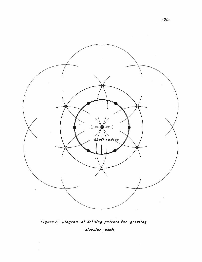
FJ,ur, G. OiQ(Jrom of drilling polfern for groutin,
efrcu/tJr shof!.
-35-
oiroular sha£1:;. The broken oircles indicate areas ot influence tor
each hole. The number ot holes and the spacing between eaoh hole will
be determined by the porosi"ty and "the permeabili"ty of "the formation•.
The wter ring of holes is drilled t'ir8"t. It more holes must be drilled
to completely s"top water seepage, it is reoommended "that holes be
drilled around "the periphery of 'the proposed shaft. This pattern is
used when gronting is completed before the sinking opera"tions are begun.
The holes are drilled 1;0 full depth. GroutUlg is then begun at the
bo't"bom of the hole and, wi'th."the aid ot paokers, each seo'tion is grouted
'to refusal •.
A modifioation of 'this method has been used as shown in Figure 7.
In this eJaUDple, a single, large diame'ter hole is drilled trom the
surface to 'the boi;tom ot 'the proposed shaft. Using packers for grout
ing various .aotions, 'the opera"tion is complete in a re"trea"ting manner.
Packers, or expanding plugs, are devioes which are inserted in'to
holes for the purpose of looalizing "the applied pressure "to cortain
. zones wi:thin 'the hole. Several packers have been developed. They
usually consis1; of a series of sott rubber oollars mounted on a pipe
wi"th a devioe tor expanding 'them against "bhe hole "to etteo"t a soal.
A simple and inexpensive packer whioh oan' be made in 'the tield is
shown in Figure 8. It oonsis"ts of lea"ther cup washers and pipe fi1;
'tiDgs as illus"trated in the diagram. Packers ot this "type are sati8- .
fao1;ory for hard rock 'Where "bhe hole has been drilled "true. The
air-expanded paoker, shown in Figure 9, is mos"b applioable tor holes
drilled un1;rue or in sof1; and/or broken rock. The rubber 'tube around
'the grouting pipe is expanded by oompressed air "to form "tightly in the
hole. "thereby holding the grout pipe in i1;s proper plaoe.
-36-
--- -r----r-------~
'''IfIIIIJL
Fi,,,r. 7. Oil/lrOm of $in,/~ hole ,rouling with pack,rs.

. .; End Nvt - I reqVlrtd JSt. dtlOl1 I8'0 10 , I 125.0 0.' t 8ross ",ashe,,' I rtqvlftdThrtod pipe; -'.IIF2, I"dtplh
..··F SId pipet
f {Hord leather cup 4 reQulfedlrcvtov l
"
Brass spOeer - J reqUired (See deJoJ! )
.stetl collar, (See dtlO,1 I
weld 10 f l!'f)
{Coupling ,~{"out lint tomanifold
_0-f-~;; ::::'!:~~=-'------:-'~~--I~~~!-=~-=':::~-=--- --~~:::~u~;:::<:::.:-;-:::::-::-----.--:---:--UJ~,::1~:::.-: -:----~] <! ;_ _, _ 1 _ ....._.. _ • ~__ _ _ _ _ __ __ .•.
__ 1... :__ ~ __ . ... __ _._ _ 1 ... ,
.-~::-~-; -- ..----- - --- - -- ~::'~j -~-.=~ ~-::."";- - "---_. -: .~-=: ~=. - ;-=--_-.: . _. -. -----=-=~~ ----------, , '
~ .. .~- Jj .~ Ji ,;... J{ >-< I.! >',
;< .- - IZ} .. .,.
PACKER ASSEM8)..Y
J{
.J--
'ij_m: u. . __IQ_- ----
-:::.- ." -- - - - -- -- - -- - _. --
l:l.~)... .~
85.7 . 010,).
~<r,
~.
;.
_ i )5\.) [i'o, i ("~"e I"d
c::.
~
DETAIL OF END NUTMo.e1rom rtofldo,d ,'·~Iel {iV I
DETAIL OF PACKER SPACER DETAIL OF COLLAR
REMOVABLE GROUT PACKER
FOff "EX" DRILL HOLE
i<.• .;J
~
I.J ... ,reo ~l ",r, S
r>c"""", r ... C"-.,. 0'" r"'l ·c "'e'''8l'''('''''' O • .... e ~ '0",,"
STAIYDAlW OES/6IYS
,",."". u..... iI. JtI~••e••••_ ..,v~~
4."""" .".....X./l.~_~._~. __II -
·f·
@!J,. .. ".. --,
I
-t
,->......~en
.Ii ..
c:,~
FIGURE 8

r----.--------------
i.~ • - • oi • i
h :1, ;:: ',"';.
.-
'1I
....... ;.;., 1
l.-L.. ... <-~ ~J'IC!-.",,' " .. ·~·)C ..... ~- ...
40-0-4708
{'.
~ '.L'
, ,.'" '1'
... -....... ..;
"~/I
\ .... .J .,JI~.
Alit "ACICEIt FOR GR.~LtTI1V6
HOL£$ OF VARIA8LE {)/AIIIETER
CROSS SECTION OFAIR-PACKER RUBBER TUBE
!~
> i
l~fV
TYPICAL VIEW OF LAYOUT
l"' • ..-,.\. ";, ••1 ... ,,'
:;'&'~~"'~.'" .... ::-: ,:,~
,~'~.'-·IlII·'· '"~'''
:~r:,~,', '/c .~ ~ .0'
f ~ ... ....
......... --
NOTEi.t'q\ithcdA,I"'·ro,",,,,~ .~:--~. :'t'.' ......
Gr(\\Jf,q'pl), "t> i ~~~t" ·· co·. ':l'.' :t".'''.:-~
fr'r'f f\" .. i 'tl' .~t'~'f'"' '·f
rlompt.r \,)f r":h·,,.r '-'''Q ~'.''''' ~f.·· : ... '.' ~ i'" t",,~
mln\mljm dlometflf ," rh'lil.'"
~. ~. - ·.'·c ...>
? ';,,': .... : ." -.or" :: ,. :::.;-11n 'I~ . "'1
.;
....:--
3 SJ~ culs-
IlCTION Al.-ONe t-
•....rap pipe undeeclamps Wllh rubberlope
{'Copper tuoeembedded In slotIn shell of ~- pipeand brOleo .'-
.1:1'1
!I
~I. ,
~I~
,~ h1
! I ~ ., Irj •
Lit; :1 'if: '•.1
'. : ~ I'I
, , ~l. ,"
.·'t 0 ',.1f 11 h'
., . ....... ....aL.-+-------+ ~
~1
~.~Alr·P~c~~r, ~rubopr fuOe I, ,e.ponded b)' , •compre~seJ...:.,J , H;oor l~ ~
. I ~'i
~ I',, .~
~ ~J.' ~
~ .l~~ ~~~~~l ~{,1. l' ., -" .. ..!Hftl1"'y *,r~ r
. y ~\
Til;"!. tlJ d, t ;" \~,
.. '." ('\,It'f \Ill'"
1 t,....
FIGURE 9

-39-
V'Vhen a. shafi; is being sunk near a surtaoe body ot water, the
pattern is al'tered sligh'tly. Figure 10 shows this pat'tern. In this
example, holes are oloser 'toge'ther on the side nearest the water to
prevent seepage into the exoavation. A second series ot holes may be
drilled as indicated on Figure 6.
When a shatt is being sunk in stages, the grouting pat'tern most
applicable is shown in Figure 11. It oonsists of drilling a ring .t
holes around 'the oiroumferenoe of the shaft at an angle giving a radial
pat"tern. A seoond ring of holes is drilled vertioa.lly downward. The
horizon-tal displaoement of -the radial pat-tern at the bot'tom ot the
hole may be as muoh as ten feet. Sinoe the water bearing strata may
be oharao-terized by vertioal, inolined, and horizontal fissures, drill-
. ing in "this manner makes it possible 1;0 in"tersect these openings. This
allows the grou't 1;0 enter "these" oavi"ties to insure a oomplete grouting
operation. This "type pat"tern may be applied to 'the square or reotangular
shafts as shown in Figure 12.
It should be no-ted -tha-t in "the above examples, a drill hole is
always plaoed in the oen1;er of 'the proposed exoava1;ion. This hole,
besides being a grout hole, serves a.s a guide during sinking operations
-to help keep the shaft vertioal. The areas ot influenoe shown on the
diagrams are ciroular when a honwgeneous mass is grouted. AJ3 1;his area
of influence for eaoh hole will be de-termined by -the types of :me:terial
being treated, i;he pattern should be drilled 80 that the entire shaft
area will be eomple-tely enoiroled by a ourtain of grout. Various
examples indioate that the area of influenoe may vary from a few inohes
up to several hundred feet. I"t beoomes necessary -to de-termine, by
boriDgs, "the 'types of s'trata beneath -the surface. The mos-t sui-table
-40-
surfac"hoff nsarfar c/r~ular s/)I'illing paffsrnFigure 10.
bady of wafsr.
-41-
(PIon)
L__J
of ,xcavot;on
jo.--1), IHOrJzontod;splocemel1' "
(£/#votionJ
F;'II'~ 1/. Odllin, poff~rn for shoff sinking in stoges.
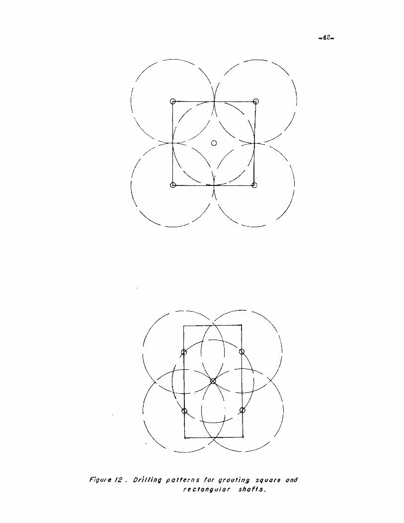
Figure /2. IJri/ling patterns for groufing square andrectangular shofts.
-42-
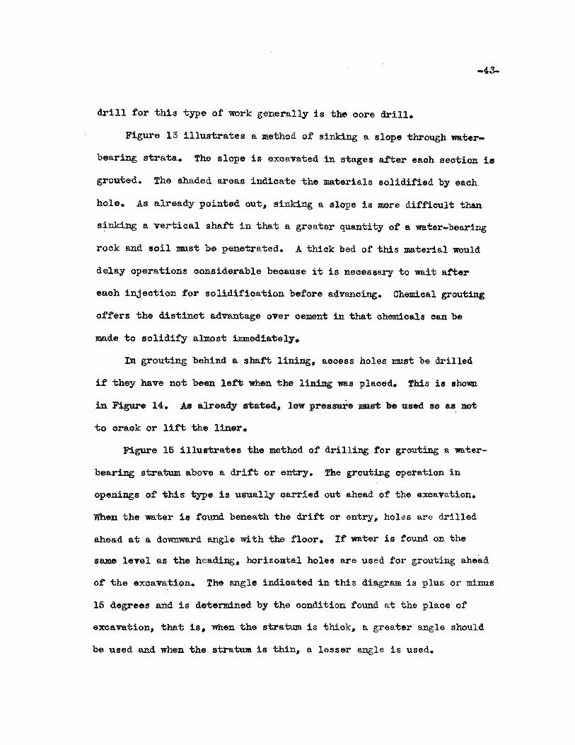
drill for "tihia type of work generally is -the oore drill.
Figure 13 illus~a-tes a me-thod of sinking a slope "tihrough wa'ter
bearing s-tra-ta. The slope is excava-ted in stages af-ter eaoh seo-tion is
grou-ted. The shaded areas indica-te -the materials solidified by each
hole. As already pointed out. sinking a slope is more difficult than
sinking a vertioal shaft in tha."ti a greater quantity of a water-bearing
rock and soil mus-t be penetrated. A thick bed of this material would
delay opera-tions oonsiderable because it is necessary to wait atter
eaoh injeo-tion for solidification before advancing. Chemioal grou-t1ng
offers the distinc-t advantage over cement in that ohemioals oan be
made to solidify almos-t immedia-tely.
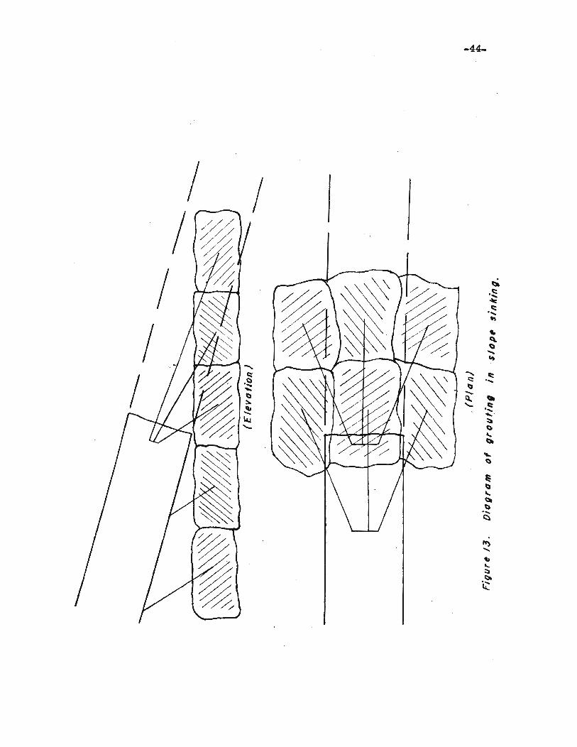
In grouting behind a shatt lining. aooess holes must be drilled
if -they have not been lett when the liniDg was plaoed. This is shown
in Figure 14. As already stated. low pressure must be used so as DDt
to orack or lift the liner.
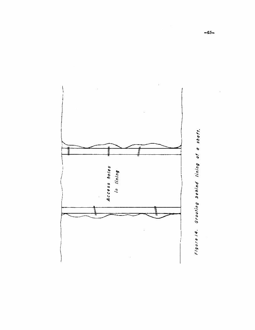
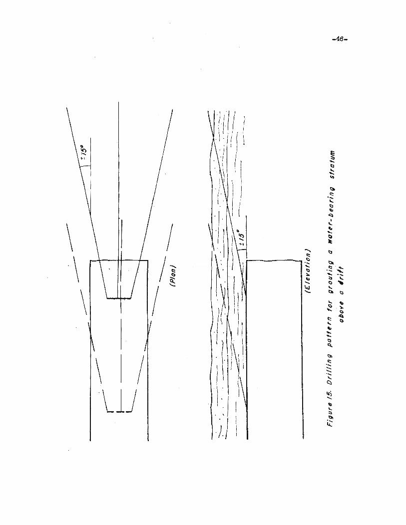
Figure 15 illustrates the method of drilling for grouting a lIater
bearing stratum above a drift or entry. The grouting operation in
openings of this type is usually carried out ahead of the excavation.
When the wa-ter is tound beneath the drift or entry. holes are drilled
ahead at a dovmward angle wi.th the floor. It water is found on the
seune level as -the heading. horizontal holes are used for grouting ahead
of the exoavation. The angle indioated in this diagram is plus or minus
15 degrees and is determined by the condition found at the plaoe of
excavation. tha-t is, when the stratum is thiok. a greater angle should
be used and when the stratum is -thin, a lesser angle 1s used.
-44-
-45-
II)q,
~......() I::::
.c:: ....,I::::
II) .::II)q, .1:::~
...v~
-46-
If.Ii (\ I
~ I.\ . I •
1 iIe) . J } §" I1-1 · ./ i I "-I tl· 1 I. I '-
I \' \ .....
II '".; . 1 ' ~
(.. I j c::....I .
'-I :. I tl
I ( q,
'I· ~I
I'-
\ 'J..
" .....
~~tl
I ~
)..... bc::
\ /1tl. \
.... til.......~.~. l:l
::0. ..... ....\) ~ '-.... tl ,.- Io4,J '-
\ I )I - til l:l
'- ..tl ~
I ...... tl
c:: ~
I'- b............tl
V~
Itil
\I \ i c::, 1 I ....
\
j j .................
i~\
~lJl I()
\'....
I \l
I...
· , ::)
tilI
~
.;. I1
-47-
Humber of Holes Required
As s'ta"ted previously. the spacing and number of bore holes needed
for an:y grou1;ing opera1;ion depends on the we or ms:terial being 1;reated.
Blandford (32) writes:
(32)Blandtord. T•• The prooess of oementation. The Iron and CoalTrades Review. Vol. 136. March 18. 1938. p. 471.
The numb.er of boreholes required to complete shaft cemen1;a-cion in advance of sinking varies oonsiderably. and is controlled entirely by "the nature and disposi"tion of the fissuresin the ground "together wi"th the diameter of 1;he shaft oonoerned.For example. in a five foot diame1;er shaft, certain non-porouss1::ra-tum 11JB.y be efficiently treated by means of six 1;0 eightholes. whereas for 1;he same shaft under different oondi"tionai"t may be neoessary 1;0 have 12 1;0 14 holes, and again, inporous rook it may be necessary to have 35 to 40 holes forefficien"t -creatmen"t in an 18 foo1; shaft.
Me-thods
Three meiilioda are used to injeot grout. These are listed as
follows:
1. Retreating method
2. Advanoing method
3. Entire hole me-thod
The retrea1;ing method was disoussed when considering Figures 6. 7,
and 10 on pages 34, 36, and 40. The advancing me1;hod was discussed
lIhen considering Figure 11 on page 41.
'When grou1;ing large openings. the entire hole is sometimes grouted,
and. in suoh prac"tioes. the hole is drilled 1::0 full depth and a s1;and
pipe i8 oaulked into place. Grout is injec1;ed through "the full dep1;h
ot the hole -to refusal. This method is not as effec1;ive as the otherdue
me-thods because of loss of pressure"to friction in the hole. As a

-48-
oonsequence. the reduoed pressure deeper in the hole results in lesser
penetration of the grout into the surrounding rook.
PRESSURES
Amounts Re~uired
The determination of the oorreet or efficient grouting pressure
i~ a diffioult problem.· Ordinarily. grouting pressures vary from 30 to
500 pounds per square inoh. but pressures of several thousand pounds
per square inoh have been used. The maximum pressure is dependent on
the 6haraoter of the material to be grouted. The pressure should not
be great enough to lift or disturb the natural formation. but greater
penetration oan be obtained by inoreasing pressure. Thus the deeper
the hole. the greater the pressure. The mininnun pressure should be
limited to that neoes8ary to maintain even flow of grout end prevent
plugging of holes. It should be great enough to overcome the ...tar
head against which grout :rJUst be injected. The hole should be filled
in the shortest possible time. Alternate drilling and grouting permit8
higher ultimate pressure than one injection at the tull depth of the
hole.
There are no definite rules whioh can be used to d.etermine the
effeotive grouting presaures. The highest possible pressure consistent
with safetw should be used. Low pressures are limited to thin beds.
In grouting thinner beds. high pressures will rupture and displace the
stra-tum.. High pressures oan be used in thicker beds. Denholm (33)
(33)Denholm.. E. W.Pressure grouting: Some notes on standard practiceThe Surveyer, Vol. 103, No. 2724, April 7, 1944. p. 165.

-49-
offers ~he following rule which may be used for pressure oement
grouting:
As a rough rule in normal rock, pressure in pounds persquare inch is equal to It to li times the depth in feetwould generally be considered safe, whioh in rook~in massive layers or at depths over 100 teet, this figurecould in most oases be inoreased by from 25 per oent 'te50 per oent.
This rule, 8.S stated, is approximate and may not always apply. It
may be used if there are no other oriteria for determining what
pressure to use.
Pressure is an import~t consideration of grouting. Experience
and judgement of the personnel on the job are two faotors whioh will
help make grouting a suooess.
Methods of' Applying Pressure
The pressures used in grouting are obtained by pumps, pneumatio
pressure injeotors, and gravity. The most oOllUD.On type ·of pUlllp employed
in grouting is the double-acting slush pump, which is shown in Figure
16. This pump is made in a number of sizes and with oapaoities whioh
vary from 20 to 100 gallons per minute and oa.pable of pumping against
pres sures from 200 to 500 pounds per square inch. rhe driving power
of these pumps may be supplied ~ ste~, air, gasoline, or electrioity.
Pumps ot this type are used for oement, chem.ioal, asphalt, and olay
grouting operations.
Pneumatio pressure injectors are essentially pressure chambers
ti~ted wi~h valves for admission of oompressed air and disoharge of
grou~. These maohines are usually designed to operate against at
pressures less than 100 pounds per squ.are inch. Where greater pressures
are needed, some other injector is u.sed.

r.I
't..l' Jr"""" •••• • • ,.,...
,F' lit ....
J
L , .., .. I:JC- 1:··.1If' 'f" :-po ....J
~ )~ .. , i'"
.: "t-· =, ° ..
to' t_'-f't<..1 5t.r· ';t: "'i ~'-'J.t!'
0' ,' .. n.r- ~',
• iliff" ,"t~' :"'('. It
". •.., 1""
I
I \I \... ~
IrJ· :-- .. iJ\
( • 1'1'(' eN",' ,,'''', unCflf>1"'. C" !"""fJo ror-vfL
, ".' , ..'
[;1\
.",~'~
'IU
" ,
, ~ 1
\ ,,\
I,'.•...
'1')
to'1
(\" ,I
~lt),lil'J, '\' ~
II
l
:""._ ,.,'1. ;
''\.' ~ ",,,, t r , 'j,.a ~, ,,," "f ",..,..,. M'.,,,
t _O~
.l''P' l ._f~ :v _~ (J,
°ar"'1 .. ~ s'OC""r;
~
-Foret ftflJ Ivb('~Qlor,
_''''''''Ca/I, ~'td
,-, -....... _...L_,f"-:" f· .. ·~ :!":x. '''!
~,
0" "J!J", ~)
, " "l.",~ .. ,
...J !t rJ 0 II' 0"
fhJt(J D':i I,... 5
LINE TYPE DUPLEX GROUT PUMPHellO" "'ROUGH ,~[AR crll"OERS
• "r,' ,~,. ',:,. ~ .. It- t'" .,,.J " Sit) .O","g
I. 'l' • lI' IJ I • ''It /I' ".' ,'l(" ~ ItS
" I 4 I " .,'Ch ,. I .. 'j) ..... '
I "}' ";/l ." n, J j I IJ 0 0'
.. 'h~ ""a~f
.. , "'L::- ~ ... - t"s;0•• " , ". ~"r , ..... .:••
..... 1' " .. r ..· .. "'\6."~"
STANOA"O OE.'lJN.
SECTIONAL OIAtJlfAMLlNE'TYPESLUSH PUMP
EQUIPPED /'0" CEMENT GffOUT SERVICE
.......: ~"'r ,1.1r<-<L,,<.-G<..
01t"J,.'" ....',,"':.' ••.• ••..• -'O~36e
• ~ •.~ ••• :."~,,, .1,,_1 .. L •
A N-~ •"""'.' ~K:.-'11'-:~~.............., .
.•,.,'.' !A.Jti
FlGUml 16
-51-
Graviiiy is so~"times used :to inject grout, particularly a oement
grou"t. This type of injeotion relies on the weight of a column ot grout
"to apply pressure to the grout. Table 3 shows "the weight of a oolumn
of oement grou"t one inch sqaare and one foot high. From this table "the
effeotive head oan be oomputed.
Pumps are the moat oommon means of applying pressure on grouts.
Lewis (35) says:
fhe value of a pump for handling grout, as compared wi:thoompressed air cshamber. 1s great. The p~s affords additionalmixing of the fluid and makes possible a flexibility of oontroland con"tinnity of flow that is not obtainable with the pneumaticmachine. llowever,"the pneumatio machine is superior for handling grout oontaining sand or sa~ust or othercoarss ma~erials
Which are 80me'ti.m.es injected into large openings.
Hayes (36) says:
Unless extreme care is used, 'the air-pressure :method 18apt to force air into the seams if the grout flo~ taster"than expeoted. Moreover. in some 'types of air-injection i:;e.nk.s~he cement in a thin mix 'Will settle to the bottom and plugthe out1e1;, the pipe line. or the hole, before the job isreally oomplete.
OTHER EQUIPMENT USED IN GROUTmG
Cement Grouting Bquip:ment
Pressure oement groui:;ing is used on large jobs taking many thousand
ot sacks of oement or on small jobs using only a few saoks. In the
above example, iohe equipment required would be quii:;e different.. The
followi.Dg list would be used on both large and small jobs:
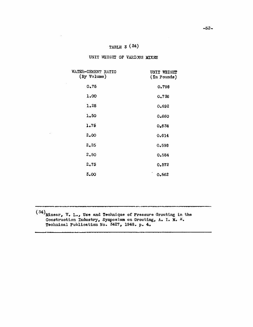
TABLE 3 (34)
UNIT WEIGHT OF VARIOUS MID!S
WATER-CEMENT RATIO UNIT WEIGHT(By Volume) (In Pounds)
0.75 0.798
1.00 0.736
1.25 0.692
1.50 0.860
1.75 0.634
2.00 0.614
2.25 0.598
2.50 0.584
2.15 0.512
3.00 0.562
(34)Minear. V. L... Use and Teolmique of Pressure Grouting in theCons-truotion Industry. SynposiWJI. on Grou-ting. A. I. :Y:• .Il:.Teohnioal Publioation No. 3427. 1948. p. 4.
-52-

-53-
1. Water met~r
2. Agi-tator sump
3. Air supplY'
4. Water supply
5. Pressure gages
6. Conduits or pipe and tittings
1. Valves
8. Hese
The oonsis'banoy of 'the grout used on any grouting job is very
important. By use 01' a water meter, olose control oan be Qbtained in
mixing the grout. A water meter that has proved highly satist'aotory.
is a 1 to Ii inoh single diso -type threaded for a pipe comeotion.
This type has a six inoh 'V"ertiea1 register with two hands, a long hand
which:makes one revolution per cubio foat and a short hand 'Whioh indi
oates 10 oubio feet per revollition. If sand and rock partioles are
present. it is neoessary to provide aome filtering devioe to remova
them before they enter the meter. A water meter reading may be 09l1
ver'bed using Table 4.
Atter 'lihe grou'li has been mixed. it should be agit8.'lied oontilw.ously
to prevent se'ttlement while it is being pumped. This is aooomplished
with the use 01' an agitator similar to that shown in Figure 11. For
smaller jobs. a simple arrangement of a barrel and a sump pump can be
used to provide this agitation. The sump pump 1s oonneoted in a olosed
circu1'b with the barrel. The grout 1s kept agitated bY' operating the
pump. In aQY oase. ~e agita~r should have a oapaoity at least as
large as the mixer.
An adequate air 8UPP~ is necessary 'bo complete a suooessful

TABLE 4 (37)
WATER-CEMENT RATIOS OF VOLUMETRICGROUT MIXE;;
WATER-CEMENT RATIO(WEIGHT)
0.210.330.360.440.450.490.500.510.530.620.660.710.830.890.991.111.161.~2
1.331.661.781.992.222.662.663.323.563.984.444.656.64
13.28
Gallons of water persack of oement
4.05.0
5.5
5.756.07.0
8.0
10.0
20.0
25.0
30.0
40.00
50.00
Cubio f'eet of' .a:tarper sack of cement
0.5
0.67
0.75
1.00
1.50
2.50
4.00
5.00
6.00
7.0010.0020.00
(37)U. S. Bureau ot Reola:ma.tion. Technioal Memorandum. 638. ttpressureGrouting Equipmeni;". by A. W. Simonds. Page 38.
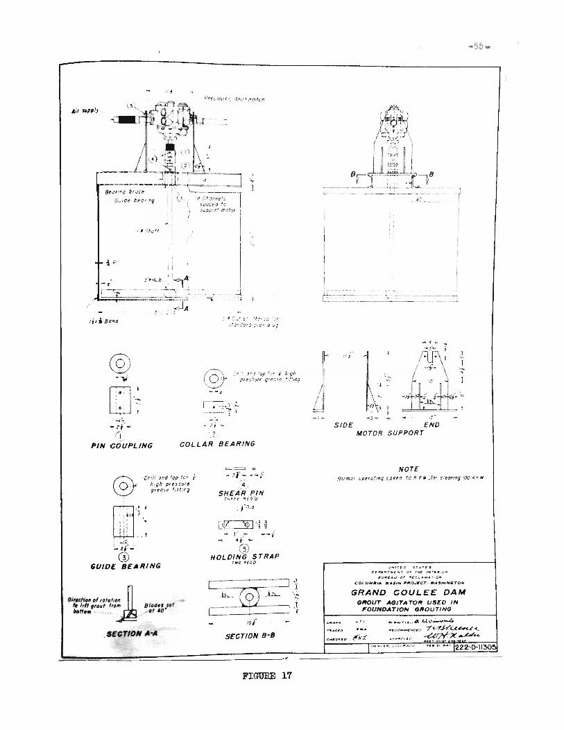
Air SlIpp.'".
~ ,-
_~~l~,~:......,.'.'~---BtJllfI; br.:ct 1\ \:::.>- _
G"let b~o' fig !I (} °l r."u(ln~!5~. spr: ~a ~:)
) ~l.Jp:o~ (f ,7'ator
'"
II!'
),t"w:U'~Y' .
. ~; d .J',_~ t , .•~
( -'c~~-;'~ \
1r ::;; i
Br- -0..
V ..------,
----~'-, '
: I .~~ _
I
III
-55-
,--I C J~ t' 'rr~(JJ ~~,
J'YI!:;1f1] p Cf 0 U(j
__ ...:.J
2,
COLLAR BEARING
@-y
rfl·--~~l
..,:- 2{-
'-'I I
PIN COUPLING
@--"
... ?; -
, : J"'!1' 'ap {'I' T h'9hpttssvre 9'eJ5e I.Hmq
~ 4 ~
111-I,
-"';'
" '",ci ! y
I-J"- ... I~·
SIDE ENDMOTOR SUPPORT
-Dnll and top for f!l;9h prts SUft
fJ,tast 'Jf: tr 9
'"
I -1=.:.. 2; .;G)
GUIDE BEARING
Oi,ICHOII of 'OIOI/O'j,. I", "0.' I,om Blod" 1ft.." •• ' _ .. ,~tlt 10·
- "
SEGTION A-A
4,SHEAR PIN
fHRtf. IlEC'O
, {DIO
Ld ''OJ'H... J-..... --;"4{ _
@HOLDING STRAP
r...o IUO'D
SECTION B-8
FIGURE 17
NOTE~o,mol operatmg speed 30 R Pit ,for c1eaftfng
1.J"'I~fD Sf.l"t:'" $
C1t~.. "rMl"tr o. r,.,c ,,,,,"rlf.V"lJt.)IItCAU OF "'<:4A.., .. -'0,,",
COlV1lJtSIA lJA$IN ~o..JEcr-W... ,,",NflTON
GRAND COULEE DAMGftOUT AGITA TOR USeD IN
FDUNDATION GROUTING
RP/i
grouting operation. The actual requiremeIIt will depend on the type
equipment 'CQ be used. The following quantities of air at 100 pounds
per square inoh should be oonsidered as maxima for ordinary grouting
when air-driven equipment is used: (38)
(38)Simonds, A. W., Pressure grouting equipment, U. S. Bureau ofReolamation Technioal Memorandum 638. p. 14.
1.
3..
One 6 x 2i x 6 inch pump, one 7 cubio foot mixer,one 1 cubic foot agitator will require 200 oubicfeet of air per minute.
One 10 x 3 x 10 inch pump. one 17 cubic foot mixer,one 11 cubio foot agitator will require 300 cubicteet of air per minute for an average hole. For ..fast hole at low pressure, the consumption may rea.oh600 'Co 800 cubic feet of air per minute.
One 10 x 3 x 10 inch pump, one 27 oubic foo1: mixer,one 27 cubic toei: agi'ta1:or will require 300 cubioteet per mimrte tor an average hole. A tast holeat low pressure may require 800 to 1000 cubic feetper minute.
An adequate water supply is neoessary in all grouting operations.
It the wa:ber oontains trash or sand, some tiltaring denoe should be
installed. Large amounts ot these materials have a harmtul affect on
the s'brength properties ot the oement af''ber harden,ing.
Reliable pressure gages are essential in pressure grouting. A
pressure gage is the best indicator to the case of penetration of the
grout and the streB ses which mAy be set up in the structure being
grouted.
For ordinary grouting, 1 to l~ inch pipe and f1tting are satis-
taotory. Grout oan be pumped long distanoes through supply lines of
this size. Larger sizes 'than 1* inch pipe alloW'IDOre grout to be pumped
but this advantage is offset by additional cost. Larger sizes ot pipe
-57-
are also proportionally harder "to handle.
Brass globe valves should be used for pump throttles. All other
valves should be quick-acting. lubricated plug "mlves. These valves are
made in different weights. They are designed to withs"tand the differen't
pressures at which 'they might be used.
fhe pump suo'tion hose should be between ~ and 4 inohes in diame'ter
and about five feet long. When grouting through a hose oare should be
taken not to exceed the safe working pressure. A hose may be rein
forced somewhat by wrapping wi.th telephone wire.
Chemioal Grouting Equipment
The equipment used in the ohemioal grouting processe. is dependent
aD. the method employed. Schematioally. Figure 18 illustra.tes the equip
ment used in the Joosten prooess. The pumps used in these prooesses
are -the same as those used in oement grouting. fhe Joosten. Jorgensen.
and Francois prooesses require two mixing tanks. sinoe the chemicals
are injeo'ted separately. The K. L. M. process requires only one tank
beoause the ohemioals are mixed' and injeoted at the same time. Barrels
of 50 gallons oapaoity have been used as mixing tanks. The valves and
holes used are 'the same as the type used in oemen't grouting. The
injeetion pipe. of'ten referred. to as a needle, is between 15 and 30
fee't long and made of s'trong one inch steel pipe. The lower 20 to 24
inehes of' 'the injection pipe is perforated with 0.08 inoh holes. When
chemieals are being used to treat loose. unconsolidated material, a
steel point is a"ached to the end of the injection pipe to facilitate
driving. The steel poin't is no't used on the grout pipe when solidifying
oraokl and cavi'ties in solid material.

~
c::()....,......
, ~
;; ~',' ...... ""
"'. Cl
o
-58-
....()
-59-
Asphalt Grouting Equipmen't
The equipment required in the Chris"tians process is relatively
simple and inexpensive. Christians (39) saysi
(39) G WChristians.~•• .2£. ill. p. 801.
A heating kettle for melting the asphalt. and a smalladjustable-si;roke piston~ driven by a one horsepower motorare all that is required for handling the asphalt to the pipeline. The pipe is usually Ii inoh. extra heavy throUghout theupper portion. 'While that in the crevioe bearing rock is liinch standard-weight pipe perforated by 3/4 inch holes. Itis heated by an iron resistanoe wire wbich enters through an1nsula-ted s'tu£fing bar a-t the top and is held in the oenterof the pipe by suii;able insulators at the pipe couplings andfastened eleotrically and mechanically to the pipe at thebottom. The electrio oircuit passes down the wire and baokup the pipe. The wire is kept taut by tension springs atthe bottom.
The nea.4ea-t1ng system equipment is muoh the same as that in
the above pro~e,ss. The differenoe is in the heating IDethod. In 'the
Shel1perm. prooess, equipmen1; siiil.i:1ar to that employed for chemical
grouting prooesses is used to plaoe the asphali;-in-water emulsion.
Clay Grouting Equipment
The equipment used in reservoir grouting is determined by the
soope of the projeoi;. The colloidal suspension must be pumped through
a pipe line 1;0 the area to be grouted and discharged to the bottom of
-the reservoir. The pipe line used on i;he Chenery Reservoir (40) was
(40)Lee. C. H. Sealing Chenery Reservoir. Western Construci;ion News.Vol. 5. Deoember 15. 1930. p. 624.
:four inches in diameter. In some instanoes Vihen only e. small area. is
to be i;reated. the clay is carried by boat to the area i;o be sealed and
dumped ini;o the water.
-60-
Aocording to Randolph, (41) the equipment used on Madden Dam projeot
(4l)Randolph, E. S., .2E,.~. p. 210-212.
oonsisted 0'£:
1. Mixer
2. Soreen
3. Pump
4. Air Compressor
5. Wa:ter Supply
6. Connections and fittings
The mixer used was built especially for this operation. 1-t oonsisted
of a s-tirring and ohopping loops rotating in opposite directions to mix
and stir the grou-t. This was done until the clay grout reaohed a uni-
form oonsistancy. The oapaoity was 'two cubic yards.
Attar mixing. i;he grout 'WaS discharged onto a i inch soreen to
remove the lumps vdli.eh might be present. These lumps were saved and
remixed with "the next batoh.
Three types or injectors were used on this operation. A oompressed
air chamber was used £or low pressure grouting. This was operated at. . '.
100 pounds per square inoh. Pressure up 1;0 150 pounds per square inch
was obtained with the use of an ordinary slush pump. For higher pressures
up "to 300 pounds per square inoh, a specially designed, single-acting
ram pump was used. This pump had a oapacity of l! cubic yard per hour.
The oompressor was a portable plant furnishing air at 100 pounds
per square ino11. It had a oapacity of 220 cubic feet per minute. The
water supply was obtained from a nearby stream. I"t was used both for

..61-
mixing ~he grou~ and general washing and cleaning purposes.
. The injeci:;ion pipes were ~he same as in pressure oemen't grou"bing.
The manifold hook-up was like "bha't shown in Figure 4.
SPEC!.JU, GROUTING METHODS
Carbon Dioxide Pressure Method
The Bureau of Mines used a new approaoh 'to pressure oemen't grouting
by u'tilizing oarbon dioxide gas under pressure to injeot grou't .(42)
(42)!ainter. S. L.. Grou"bing diamond drill holes at the ChriS'tman mine.Gila coun'ty. Arizona. U. S. Bureau of Mines Reports of Investigations 4559.
Figure 19 illustrates the equipment used.
A -thin mixture of oement was poured into the hole to be grouted.
A mixture of drilling mud, weighing nine pounds per gallon, was poured
on top of the oement. The carbon dioxide cylinder was oonnected to the
standpipe as shown in Figure 19. Pressure was gradually applied.
After the pressure reached a~. the valve was closed. The pressure
gradually reduoed to about 100 pounds. At this point. the remaining
gas was bled ot:f. The hole was immediately refilled with drilling mud.
The pressure "W8.S applied. This pressure was equal 'to the n1aximum from
the first run plus 20 pounds per square inch. This pressure was main-
'tained until the cemen't hardened.
Ben-tonite-.Pe"tro leum. Grouting Method
Investigation has pointed out that bentoni'te mixed wi'th gasoline
and other pe'trolwm produots does not swell. 'When a mixture of this
'type oomes in oontact nth 1ftl.ter the wa:ber displaces the pe'troleum and
the bentonite begins 'to ewell. The Bureau of Reclamation investigated
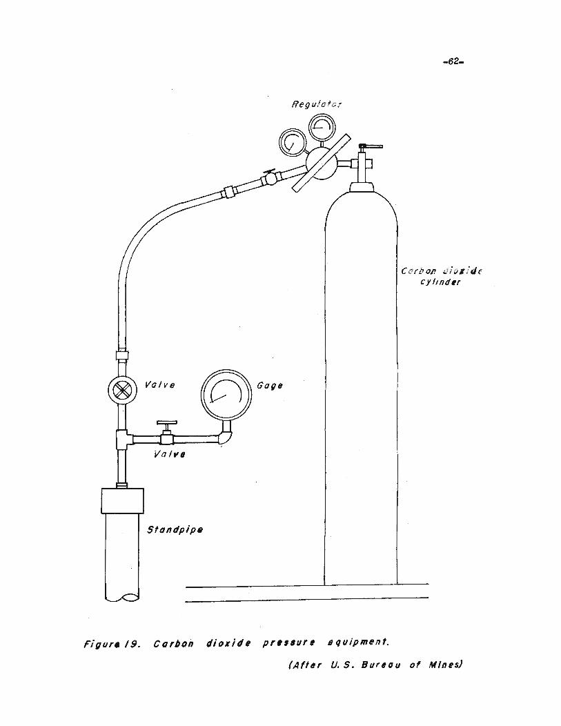
-62-
Regulater
Valve
Sfondpip.
C c'"rb Oft oJ i ()lidecyllndu
(Aff6r U. S. BUf60U of Mines)
-63-
'this subjeo1; and reported the following findings: (43)
(43)Grouting with bentoni'te mixed in produots of pe'troleum, U. S.Burea.u ot Reelsmations Labora.'tory Report 1'0. 0-229. January21. 1944. p. 4.
I.. A grou't can be made from ben1;onite and any one ota numberot petl"oleum oils. This grout will notswell un'til i't comes in oontaot with water. Uponoontaot wii::h water. the 'Water displaces the oil andswelling "takes plaoe. The rate at swelliDg dependsupon the thiclmess or viscosity ot the oil.
2. The flow of underground water in eertain porous formations oan be sealed by proper application ofbentonite-oil grout. "Whether the use of bentonite011 grout would be applicable to a:n:y given grou'tingproblem in the f'ield may only be aseer1;ained byaotual trial.
3. Bentomte-oil grou't will not pene'trate water-bearingsand for any appreciable dis'tance. Twelve incheswas the maximum dep1;h ob1;ained in laboratory test.
4. Oil in bentonite-oil grout attaoks rubber sealings.pis'tons and o'ther parts in a grout pump and willrender such parts useless 'With prolonged usage.
5. The beni::oni1;e-oil grou1; should be p'~~o_,ji as rapidlyas possible so thai:: the grout will. b(t9roed intothe cavi'ties bef4i)re the oil is washed awe:y from. theben'toni1;e. The equipment should be ot sutficieD:tcapaoity for rapid injection.
Table 5 summarizes the tes't oonduc'ted by the Bureau of Reclama'tion
and i't should be noted that oil-bentonite grou't was effective on aggre
gate of plus S/S of an inch. The penetra1;ion of the grout in sand 'WaS
ineffective. The void spaces in 1;his material were 1;00 small and
fil~ered the hentonite.
The proper propor'tions of oil to ben1;onite will depend upon the
grouting ~onditions. It w8.8 found that the ra.'tio of oil to ben1;onite
could be as low as 0.60 to 1.0 by volume before the grou1; beowme 'too

TABLE 6 (44)
PE'rROLEUM..BENTONITE GROUT TESTS
Test 1t\iii size or 011 Used «Yix Grou'Eing Grou'€£ng U'ead of I Re"suTtS---Number Aggregate Oil to Bentonite Method· Pressure H20 1n
(pounds ) Feet
1 3/8"-3/4" Fuel Oil 1 : 1 pump 20 115
2 3/8".3/4" Kerosene 1 : 1 pump 20 116
3 #4-3/6" Fuel 011 1 : 1 pump 20 7
4: 3/8tt.3/4" Kerosene 1 : 1 pump 20 7
6 4h.6-#4 Fuel Oil 1.5 : 1 pump 30 1
6
7
3/4"-1t'#16-1/4
Kerosene
No. 10 oil
0.7 : 1
0.8 : 1
Pressure tank 20
Pressure tank 30
7
7
Benton!te ta.ilsto stop flow ofwater.Flow of waterwas not stoppedFlow was almostoompletelys-coppedFlow oompletelystoppedGrout did notpenetrate sandapproximate penetration 8 inohesBentonite stoppedflowDid not stop flowPenetrationapproximately 12inohes
(44)Adapted trom U. S. Bureau ot Reclamation I,aborator Report No. 0-22$. p. 5.~t
thick to punq>. Swelling begins immedia'tely in 'the case of gasoline
and fuel oil and is proportionally slower as 'the oils become thicker.
This would indicate that gasoline or kerosene would be better in large
open formations and the heavier oils would be better in 'tighter forma
tions and Where it was desired to pump 'the grout for some distance
through water.
SUWi1ARY
Cement grou't is the most widely used material in grouting. This
grout 1s applicable to fissured or faulted rock or solid strata Where
"Void spaces are large enough 'Co permit the cement particale to enter.
cement grouted soils and structures offer high strength after hardening.
This 1::ype of grout is not as applicable as asphalt is in flowing water.
Considerable oement grou't is washed away before the voids can be plugged.
Chamical grouting is mest applicable in looee unconsolidated 80il.
with a perm.eabili1iy ot not more than 0.1 or less than 0.0001 centillle'ters
per second. The soil to be solidified by this method should not contain
more than 20 per cent olay.
Asphalt grouts are applicable to large openings espeoially where
wa:tar is flowing at a high ve10ci1iy. The smallest opening which can
be sealed effectively 1& i inch. The most 8uitable grout s1;if£ens
rather than hardens to brittleness.
Clay grouting is used lIhare a Jll8,terial 1s needed to till seams
in which water is not flowing. Clay offers little resiatance to erosion
by water•. It has been used in place of other materials, when clay was
close at hand and. thus considerably cheaper to plaoe.
-66-
FltEEZING
Introduotion
The freezing method is essentially a process used to solidif,y
h:ter-bearing soils and rock by sOlidifying 'the wa.'ter oontained in 'these
materials. The greatest use .0£ freezing is in hardening water-bearing
materials to permi.t the sinking of shafts. This method has been used
also for stabilizing landslide areas and loose earth around excavations.
The use of freezing in the oonstruo'tion industry has been small. but
its use appears to be increasing.
The freezing :method has been used inf'requently in the UJrlted
S'ta'tes" but has been widely used in England and on the Continent of
Europe. RecentlY', freezing was used in England to penetrate heavy
flows of ~:ter overlying ooal formations. Using this method, preTiousJ.,"
inaooessible ooal has been developed into m:nable ooal. (4S)
(4Q )RefrigeratioD permits mine she1't s1nk1J1g, Retriget'at1Dg Eng1n.er~•.April 1949. p. 335.
In writing about the Gilbertsville Dam. of 'the Tennessee Valley
Authority, Gough (46) states:
(46 )Gough, H. B. A wet sh.a£t frozen tight, Engineering NeV'ts-ReeordVol. 122. No. 19. May II, 1939. p. 74.
Seepage troubles, eon5idered impossible 'to meet byo'ther aethods 'tha't per.ai:tted the purposes of the shatt tobe served, Were oOllpletely overoome by freezing.
1'he freeziilg me'tbod generallylfconsists ot drilling holes through
the material tG be frozen. Into eaoh hole are lowered two concentrio
pipes. The internal pipe oarries the aooled liquid down. to the bottom
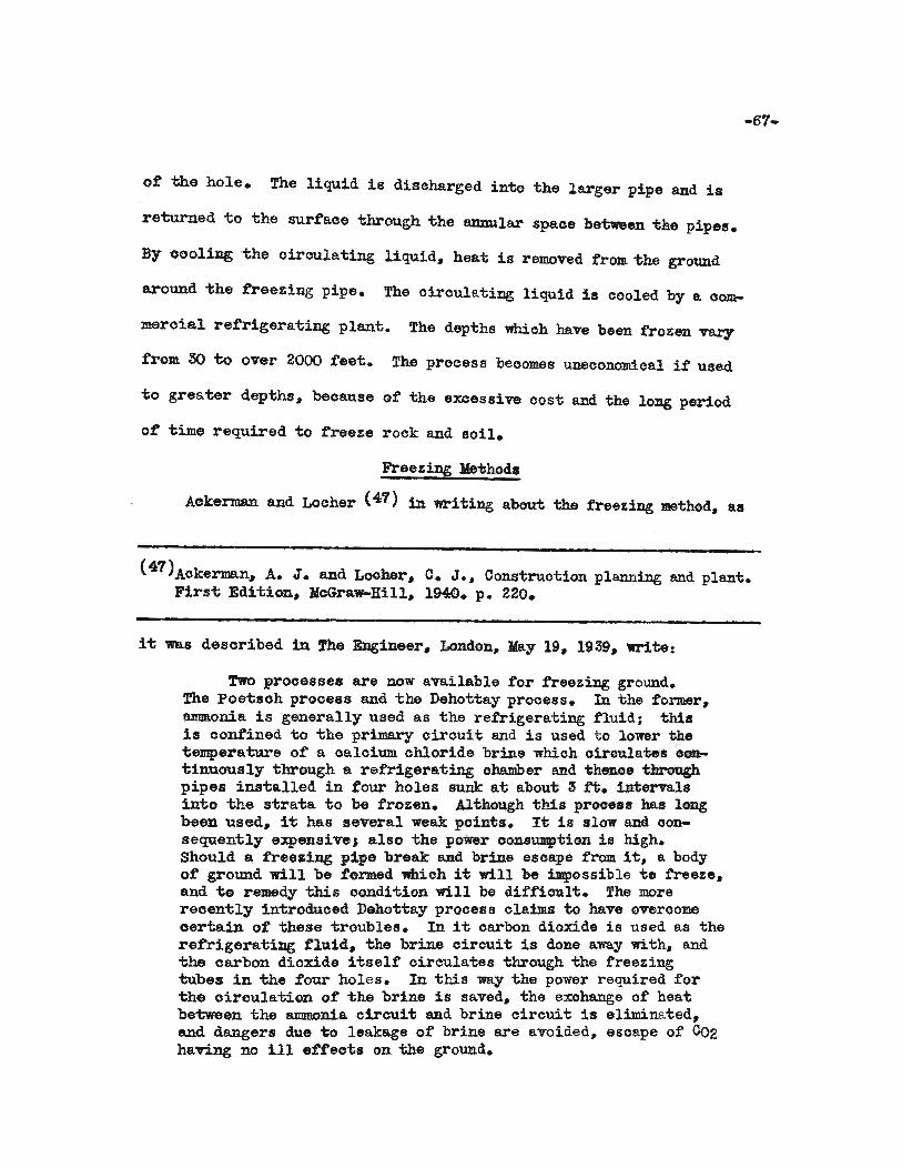
o~ the hole. The liquid is discharged into t:he larger pipe and is
returned to the sur~ace through the annular space between the pipes.
By cool~the oirculating liquid, heat is removed ~rom the ground
around "the freezing pipe. The circulating liquid 18 cooled by a oom.
meroial refrigerating plant. The depths which have been frozen vary
from SO 1:;0 over 2000 ~eet. The process beoomes uneconomieal if used
to greater depths, because of the excessive cost and the long period
of time required to ~reeze rock and 80il.
Freezing ~thod.
Aokerman and Locher (47) in wr1ting about the freezing method, as
(47)Aokerman, A. J. and Locher, C. J., Construotion planniDg and plant.First Edition, McGraw-Hill, 1940. p. 220.
it: was desoribed in The Engineer, London, ]{ay 19. 1939, 'Write:
rwo processes are now available for freezing ground.The Poetsch process and the Dehottay prooess. In the former,8JIDIl.onia is generally used as the refrigerating fluid; thisis oonfined to the primary circuit and is used to lower thetemperature of a oaloium ohloride brine whioh oiroulates C~tinuously through a refrigerating chamber and t:henoe throughpipes installed in four holes sunk at about 3 fi. intervalsinto the strata to be frozen. Although this process has longbeen used, 1't has several weak points. It 1s slow and oonsequently expens1ve J also the power oonsumption is high.Should a freezing pipe break and brine esoape from it, 8. bodyo~ ground will be formed which it will be ilIIpossible to free2:e.and to remedy this oondi-tion will be difficult. The morereoently introduced Dehottay proces s claims to have overcomeoertaiJl of these troubles. In it oarbon dioxide is used as therefrigerating fluid. the brine circuit is done away with. andthe carbon dioxide itself' circulates through the freeZing"tubes in the four holes. In 'this way the power required forthe oirculation of' the brine is saved, the exohange of' heatbe'tween the ammonia. oircuit and brine cirouit is eliminated,and dangers due 'to leakage of brine are avoided~ esoape of CO2having no ill effeots on the ground.
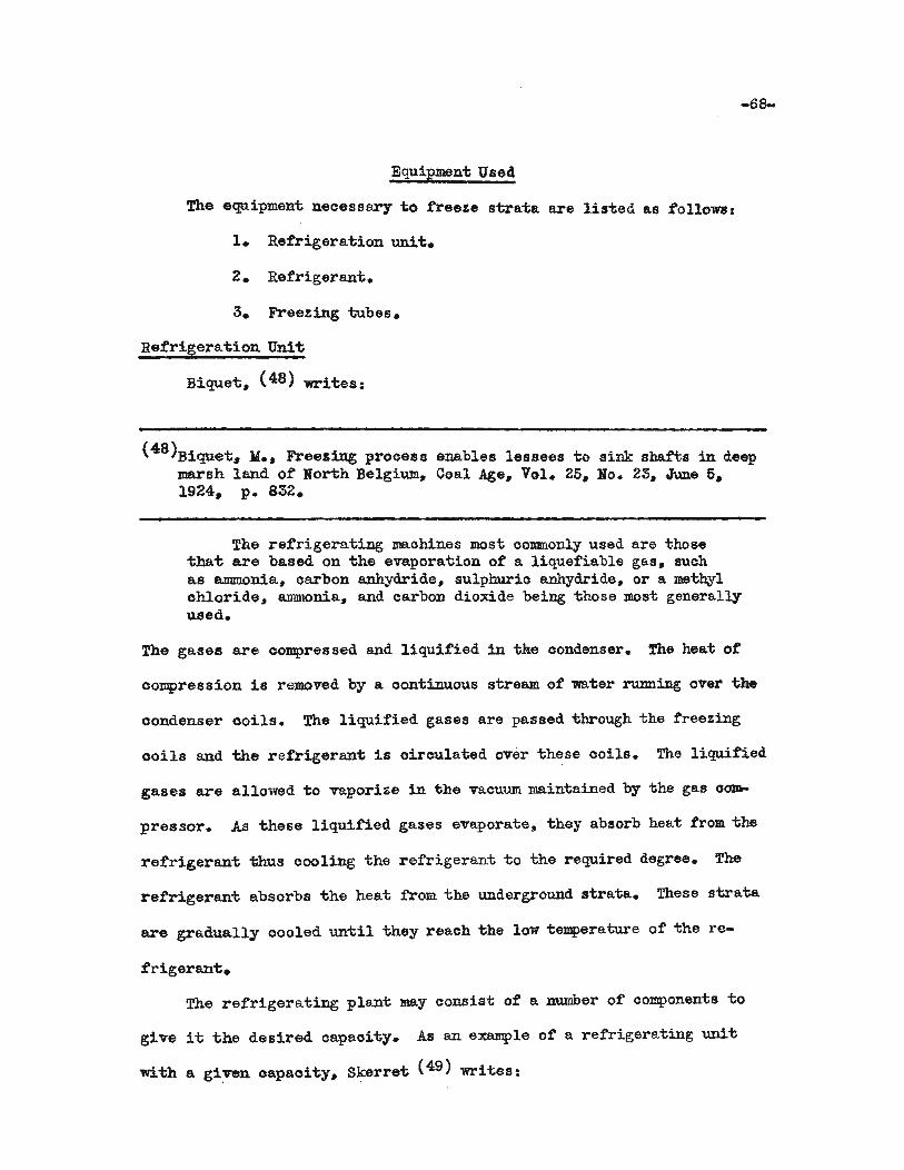
-66-
Equipmen't Used
The equipment; necessary to freeJ:e strata are listed as followsl
1. Refrigeration unit.
2. Refrigerant.
3. Free~ing tubes.
Refrigeration Unit
Biquet, (48) writes:
(48)Biquet, M., Freezing process enables lessees to sink shafts in deepmarsh land of North Belgium, Coal Age, Vol. 25, No. 23, June 5,1924, p. 832.
The refrigerating machines most commonly used are thosethat are based on the evaporation of a liquefiable gas, suchas ammonia, carbon anhydride, sulphuric anhydride, or a methylchloride, ammonia, and carbon dioxide being 'those most generallyused.
The gases are compres sed and liquified in 'the condenser. The heat ot
oompression is removed by a oontinuous stream of water rwming over the
oondenser ooils. The 1iquified gases are passed through the freezing
ooi1s and the refrigerant is oircu1ated over 'these ooils. The 1iquitied
gases are allowed to vaporize in the vacuum maintained by the gas oom-
pressor. As these 1iquified gases evaporate, they absorb heat from 'the
refrigerant "thus cooling the refrigerant to the required degree. The
refrigeran't absorbs 'the heat from the underground strata. These strata
are gradually cooled un-til they reach 'the low 'temperature of the re-
frigeran-c.
The refrigerating plant may consist of a number of components 1;0
give it 'the desired oapacity. Aa an example ot a refrigerating unit
with a gi:ven oapacity, Skerrei; (49) writea:

-69-
( 49 )Skerra'b. R. G•• How .Antwerp is building two tunnels under 'bhe Soheldt.compressed Air Magazine. Vol. 37. November 1932. p. 3965. .
The refrigera'bing plan'b tor 'bhe wes'bern ven'bilating shaftoonsisted ot two ammonia oompressors, eigh'b evaporators, oneoondenser, two brine pumps, and 'bwo oiroula'bing pumps. Itscapaci'by was equivalent to 90 tons of ice per hour at a temperature of 4 deg. below zero Fahrenheit.
Refrigeran-t
The retrigeran'b, or brine, most oommonly used is a 25 per cent
solution of caloium chloride Whioh solution freezes at approximately
30 degrees F. below zero. Magnesium ohloride is sometimes used in3tead
of oaloium ohloride, because it precipitates less at low temperature
and, therefore, does not clog 'bhe oiroulating pipes. One of the prime
requisites. of the refrigerant is that it does no'b freeze at the low
-temperatures produced by the refrigera'bion uni~.
The Dehottay process, as already indioated, oombines the refrigerant
and the refrigerating unit by circulating carbon dioxide 'bhrough "the
freezing pipes. This eliminates the brine circuit and reduoes the
amount of equipment needed and the power oonsumption ot the refriger-
ation unit.
Freezing Tubes
The :freezing tubes are made up of' two conoentric pipes. The outer
pipe is closed at the bottom. The inner pipe is open at the lower end
whioh is about 8 inohes above the olosed end of the outer pipe. The
dia.m.e"ters of the "two pipes vary with di£:ferent operations. '!he dia:meter
of "the outer pipe varies from two to eight inches. The smaller pipe is
one inch or more in diame'ber. Figure 20 illustrates this arrangement
in sohematic diagram.
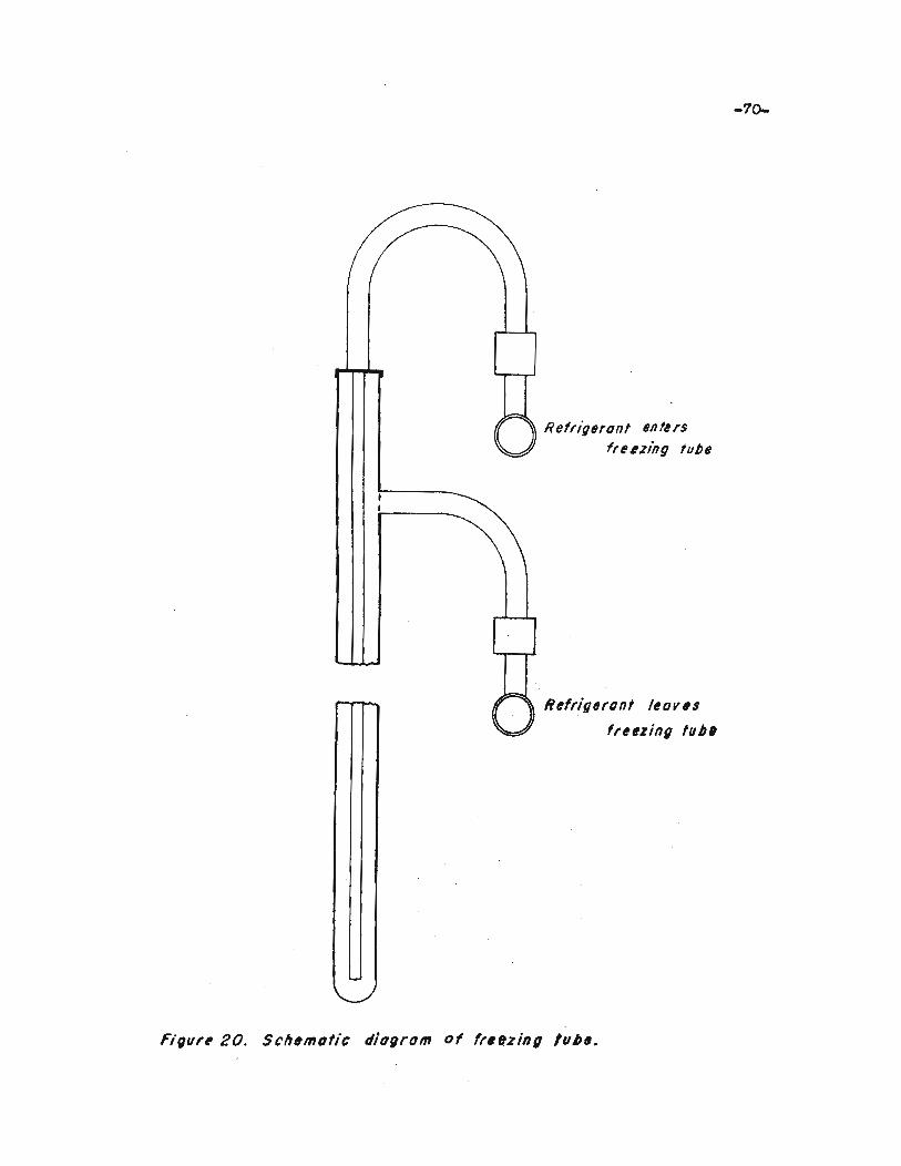
Refrigerant eAlersfrelzing tu/Je
Refrigerant I,ov#s
fr,#zing lub'
-70-
Figllre 20. SclJ#molic diagram of fr.ez;ng 'lIb_.

-71-
The ra.tio ot diameters of the pipes "that make up the freezing
"tubes must be such i;hat the eiroula"ting liquid flows down the oenter
pipe rapidly and up i;hrough the annular spaoe more slowly. There is
no exaoi; rule for determining the rate of flow in these pipes. The
velooity down the smaller pipe is two or more feet per second. The
re"turn flow is usually between 0.9 and 1.5 feet per second. Gough (50)
writes:
Another improvement would be to ohange the dimenaions ofthe vertioal freezing pipe a.ssemblies themselves, substitutinga smaller diameter pipe for the 1 in. intake and a largerdiame"ter for the 2 in. outlet casing. This rearrangemen"t wouldoause the incomiIlg cold brine "to travel with grea."ter velooityand reaoh the bo"ttom of i:;he freezing pipe more quiokly• with aconsequent reduction in heat transfer from the warmer outgoingbrine "to the inooming brine through 1ihe pipe. Thus "the inoomingbrine would be colder when i"t reaohed the bo"t;tom. and itseffeotiveness at the lower levels inoreased.
I1:; may be found that using 1Vhatever pipes are available may save
time and money. In discussing the construction of the Grand Coulee~
Froage (51) writes:
(51)Froage. L. V•• Frozen earth dam at Grand Coulee, lIechanioal Engin-. eering, Vol. 63, No.1, Januar,y 1941. p. 10.
Pipe sizes of 1~ and 3 inches were selected beoause "theywere used in large quantities throughout the projeot and wouldhave maximum salvage value.
The pipes used in the freezing process should be made of a metal
oapable of resisting the ohanges of -temperture to which they are sub-
jected. Ii> is necessar,y that all joints be tight. If brine leaks into
the soil to be frozen, this soil will be difficult to freeze.

Operation
Initial Preparation
The initial step in a freezing process, for shaft 8inking~ is the
investiga.tion of the stra'ta to be penetrated. Biquet (62) -writes:
Preliminary to the initiation of the freezing prooess, acareful study is made of the strata to be penetrated: (1) withregard to their nature because the freezing is transmitteddifferBIl-cly in different stl"ata, (2) in respaot to the wa:tarin the strata enoountered, whioh may be standing or gushing,and aither fresh or of varying degrees of sa.linity, and (3)with regard to the permeabili'ty of the surface layers.
From study (3) in the above quotation, it should be possible to determine
if the exoavation oan be started before the freezing prooess is begun.
Several advantages are realized if excavation of the shaft is oarried
out to the wa:ter-bearing strata before freezing 1s started. Biquet (53)
lists them as follo~:
1. A reduction in drilling.
2. A diminution of the cold necessary for that part ofthe shatt that is driven without freezing.
3. A saving resulting from the greater facility of workat the surface, the distributing equipment for thebrine being pla.ced in this foreshaft.
It it is not possible to sink a foreshaft, it becomes neoessary to
drill the holes to full depth and freeze this depth before beginning the
sha.tt exoavation.

-73-
Drilling the Holes
The number of holes required tor the process is dependent on
several taotors. The depth to be frozen will af£eot the size ot the
circle along the oircumferenoe on which the holes are to be drilled.
The spaoing ot the holes depends on the ease with whioh the ground is
frozen. All materials do not freeze at the same rate. Aooording to
Landgrauber (54):
(54)Landgrauber, F. W., Freezing s~ds, Refrigerating Engineering,Vol. 13, No. S. February 1927. p. 263.
Quioksand freezes most readily, olay soils less 80; brownooals set up a serious obstacle, being poor conductors. Soilscontaining sands also freezes into the most solid wall.
It the ground does not freeze readily, the distanoe between the holes
must be decreased.
Shafts sunk by the freezing process are usually circular in shape.
The radius of the oirole on which these holes are drilled is equal to
the radius of the shaft plUS from. 2 to 15 feet. Figure 21 shows a
plan view of the drilling pattern. for freezing.
It is very iDq;>ortant that all holes be drilled vertioal so that
the frozen area will be a predetermined thiokness; otherwise, there will
be places where the shaft protection "Will be inadequate. If some at the
holes are not vertical, it is the usual practioe to redrill them so that
the spacing underground will be the same as the surface spaoing.
In drilling the holes, it is usually necessary to case them as ~h8
drill penetrates to the required depth. The hole should be large enough
to permit the casing to be plaoed. The oasing should be large enough
to permdt ~he freeZing tubes to be placed. In other ~rds, the size of
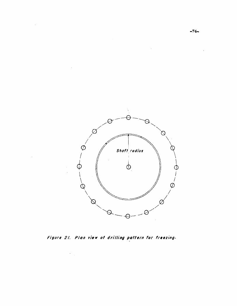
---e-/(J ---0."
/' '"/0 0/ \
(/) Shoff rod/lis ~I I \
~ <b ~~ I\ /Q (/)
\ /"& 0/
'"", /
"&-- -e- _0/
-75-
the bit used in drilling will be dependent on. the size of the free~ing
pipes used. In most oases, the holes are drilled 10 feet into the
solid rook which underlies the material to be frozen. This insures
freez~ to the tull depth of the hole.
FreeZing the strata
After the holes have been drilled and the freeZing tubes have been
plaoed, the refrigerating plant is connected to these tubes. As soon
as all connections are oompleted, the pl~t is put in operation.
When the plant is started, the temperatures of the rook and soil
tall rapidly. This is due to the large differential -temperature between
i;he refrigerant and the soil and rock whioh are being frozen. Months
are o:f"ten required to freeze i;his material. The freezing is not uniforla
along the freeZing tubes. Biquei; (55) states:
•
The theory of :M. Lebreton proves i;hai;, oi;her i;hingS" beingequal, the cross-aeoi;ion of the ioe 'Wall formed around the pipewill assume i;he shape of an ereot cone. of a oylinder, or ot aninveriied oone, according as the depth to be froz.en is equal to,less, or greater than the theoretioal depth, which depends onthe f'ollowiJag elements; The thiokness of the inner pipes,their diamei;er. i;he conduc-bivity of i;he metal, the quantity ofsali; solution in circulation at any time, and finally, thespecific heat Df the brine. Inversely, i;he depi;h being given,the form. of "the ice wall will depend on i;he elements that havejust bean enumerated.
Wii;h the aid of Lebreton's theory. i;he shape ot i;he ioewall may be oalculai;ed. Consequently. knowing t;he quantity .of wai;er contained in the ground (or assuming it approximately)the number of necessary unii;s of treezing for the fcrmationof this ice wall can be deduoed; but it is necessary to rememberthat all ~he cooling does not result in the formation of ioe.Ai; each level. the temperature decreases progressively fromi;hai; of i;he natural ground -to that ot "the brine returning ini;he freezing pipe.
Taking into accouni;. also. the losses due t;o radiation ini;he brine pipe, between the eentral refrigeration plant; and the

-76-
sha:N:; to be frozen. the total units of freezing that must beemployed can easily de deduced. On ascertaining the length oftime required to form the ice wall, we find the degree otrefrigeration per hour that is required.
Froage (56) suggests a method of estUnating the spaoing of freezing
(56)Froage, ! . .!.• ~.~. pp. 10..11.
tubes. He writes:
Since the oapacity of the refrigerating plant determinedthe time estimated for freeZing the arch at 20 days. the spaoingof the refrigerating points was calculated on this same basis.Although no data were available which applied direotly to thetime required for freeZing of earth. the following formula torfreezing of large sheets of plate ice was selected as beingapplioable because the thermal oonduotivity of the ice and ofa wide variety of mineral matter is almost identical.
21X tXt =£reezin~ time hr32-!r -c,.
where t equals thiokness of frozen material. in.T equals teDperature of brine, (57)deg. F.
(57)Motz, W. H., A leoture course on the prinoipals of refrigeration,Nickerson and Collins Comp~, Chicago. Illinois, 1922. LeotureII, p. 21.
By assuming the temperature of "the brine and estimating the freezing
time, it is possible to solve for the thickness of the frozen earth.
The distanoe between the tubes would be twice the value of this
thiokness.
During the freezing prooess. it is neoessary to de~erndne when
the area to be penetrated i8 enveloped by the ioe wall. A bore hole
is drilled in the oen~er of ~he shaft site into which no freezing pipe
is inserted. Variations in the ~emperature and level of the water in
this hole indica~e ~he progress of the freezing. When the ice wall
-77-
has completely enveloped the shaft area. exoavation is sta.r1ied or oon-
tinued. Either light blasting or hand exoavation should be used in
exoavating ground treated by the freezing prooess. Heavy blasts will
rup'ture the ice wall and permit water to drain into the exoavation..
Tha~
Atter the exoavation has been completed and lined. it is neoessary
to thaw the frozen zone. The lining must be caulked to stop any leaks
that show up as thawing progresses.
There are three general methods of thawing. They are:
1. Gradually inoreasing the temperature of the ciroulating
brine. This is the reverse prooess of freezing.
2. Filling the excavation with water.
3. Aerating the excavation.
Another method was suggested by haage (58) which was used on the Grand
Coulee Dwm. He writes:
steam. hoses were inserted in the It inoh inner pipes andpushed to the bottom. The hoses were securely tied in placeand steam at full boiler pressure was turned on. In the prooessof thawing. many of the pipes were fraotured at the coupling.but they usually held together so that the entire point couldbe reoovered. The breaking of pipes during thawing could beavoided by inserting the steam. hose in the l! inch pipe veryslowly and thawing the pipe loose progressively from the top,but as speed was imperative and the breaking of pipe was notimportant so long as it could be recovered, this thawingprooedure was not used.
SUlllIIla1"y
The freezing process is used mostly in shaft sinking operations.
The process is expensive and time consuming, but is applicable where
-78-
o-ther me-thods of stabilizing soils are not effective and oannot be
used.
The JDe-thod offers several advan-tages. I'b is noi; atfee'bed by
lIIGving wa'ber and i-t may be used in any water-bearing soil or rock re
gardless of physical composi-tion and size of void spaces.
The two ,:main disadvantages of the freezing process is the high
cost and the long period of time required to freeze iihe formaiiiens;.
some opera:tions have taken several years to complete. Saline w:tar
atfec-ts the efficienoy and applieability. Lower -temperatures over
longer periods of time are required iio complete the freezing .t ground
coni;aining salt water.
-79-
DRY ICE-ISOPROPYL ALCOHOL FREEZING METHOD
Introduction
.An original research was conduoted by the author to test the
applioability of freezing water-bearing sands with isopropyl alcohol
as the refrigerant and dry ice as the cooling medium. This problem was
suggested by Mr. M. P. :Nackowski. Instructor in Geology. Missouri Sohool
of Mines and Me-tallurgy, Rolla, Missouri.
In oonducting this experiment. it was the author's intention t.
find the rate at which sand saturated with water could be frozen and
the temperatures that could be ob'tained in so doing. These objectives
stemmed trom the hope that low temperatures could be developed with
this method. This would result in fast freezing.
Two tes"ts were conduoted. Each will be discussed separately,
giving the equipmen"t, procedure, and results.
Test I
Equipmen"t
The research was started af-ter the neoessary equipment had been
acquired and a.ssembled. The items for "the firs"t experiment are listed
as follows:
1. Insula"ted freezing chamber
2. Copper coil
3. Hea"t exchanger
4. Thermorn.e"ters
6. Reservoir
6. Centrifugal pump
7. Isopropyl alcohol
8. Dry ice
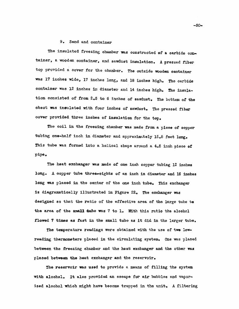
-80-
9. Sand and container
The insulated freezing chamber was oonstructed ~t a oarbide con
tainer. a wOoden container, and sawdust insulation. .A. pressed fiber
top provided a cover for the chamber. The outside wooden container
was 17 inches wide. 17 inches long, and 18 inohes high. fhe oarbide
oontainer was 12 inohes in diameter and 14 inches high. !he insula
tion consisted of from 2.5 to 6 inches of sawdust. The bottom ot the
ohest was insulated with four inohes of sawdust. The pressed tiber
cover provided three inohes of insulation tor the top.
The ooi1 in the freezing ohamber was madetrom a piece of copper
'tubing one-half' inoh in diameter and approxim8:tely 15.5 feet long.
This tube was t'ormed into a helical shape around a 4.5 inch piece of
pipe.
The heat exchanger was made of one ineh oopper tubing 12 inches
long. A oopper tube three-eighi>s of' an inch in diameter and 15 inches
long was pla.oed in the center of the one inoh tube. This exohanger
is diagrama:tically illustrated in Figure 22. The exchanger was
designed so that the ratio of the ef'f'eotive area of' the large tube t.
the area of the S1DI21 abe was 7 to 1. With this ratio the aloohol
flowed 1 times as fast in the small tube as it did in the larger tube.
The temperature readings were obtained with the \lse of two low
reading thermometers plaoed in the oiroulating SYlitem. One was plaoed
between the freezing ohamber and the heat exohanger and the other 198.8
plaoed between the heat exchanger and the reservoir.
The reservoir was used to provide a means of filling the system
with a.lcoho1. Ii; also provided an esoape for air bubbles and vapor
ized a.looho1 which might have beoome trapped in the unit. A filtering
3/8" COPPER= ?TUBE
3/8" COPPER
'----I" COPPER TUBE
SPA CER/
1r (TUBE[=:,.=====-----------T'--
FIGURE22. DIAGRAM OF HEAT EXCHANGER
IQ)....I
-82-
flask was used as a reservoir in the first test•
.A:JJ. Eastern model A-l oentrii'ugal pump was used in the initial test
to circulate the alcohol. This PUIllp was powered by a 1/100 horse
power motor. The motor was eonnected to the impeller by a drive shaft.
Isopropyl alcohol was ohosen because it is less toxic and also is
oheaper than other low-freezing liquids. Solid oarbon dioxide sublimes
at minus 78.5 deg. C. and isopropyl alcohol freezes at minus 88.5 deg.
C. The alcohol would, therefore, remain liquid a.t the subliming teD
perature of dry i08.
The sand used in this experimen't was ordinary river sand soreened
to minus 28 mesh Tyler standard scale to remove large pieces of dirt
and other impurities. The iron container which was used to hold the
water-saturated sand 1mS 10 inohes in diameter and 11 inohes deep.
·Prooedure
The equipment was assembled as follows: (1) A rubber hose with.
a low-reading thermometer plaoed near the he~t exohanger was attached
from the outlet or the rreezing chamber to the heat exchanger; (2)
another leng-th of hose 'Wi.th a lew-reading thermolll$ter near the heat
exchanger was used to 'connect the exoh8.liger and the reservoir; (3)
the reservoir was oonneoted to the oentrifugal pump with hose; and (4)
the pump was oonneoted wi-t:h hose to the freezing chamber.
Fifty pounds of dry ice and one-half gallon of isopropyl alcohol
were used in this test.
Results
Some freezing of the saturated sand and water mixture did occur
in the f'our hours during which 'the unit was. operated.
Several difficulties were met while oonducting this test. As the

-83-
dry iee 8ubl~ed it became necessary to tamp the remaining ice te
maintain contact with the coil. .An insufficient number of thermometers,
whioh were difficult to read.. were used during the test. No method was
used to determine the velocity ot the aloohol circulating in the unit.
Tes't II
Equipment
The second 'test was conducted ~th the following equipment:
1. Insulated freezing ohamber
.2. Kerosene
3. Copper ooil
4. Heat exchanger
5. Orifice
6. Pres sure gage
1. Globe valve
8. Chrome1-alumel thermocouples
9. potentiometer
10. Reservoir
11. Centrifugal pump
12. Sand and container
13. Isopropyl alooho1
14-. Dry ice
The insulated freeZing ohamber used in 1:;his 1:;est 'WaS the same
as "bhe one used in "bes1:; I. Beoause of the difficulty found in keeping
the dry ice in contact wi"bh 'the coil during 'test I. it was decided to
use some liquid to provide 'this contaot. Kersosene was chosen as this
liquid because i"b was relatively inexpensive and less volatile th~
some ot the other liquids tha't could have been used. In order to reduce
the 'Volume of the ch8Jllber, the oarbide oontainer ..s lined with two
inoh by four inoh pieces of wood. This lining reduced the diameter te
eight inches.
The copper coil and heat exchanger used in this test ...ere the same
as those used in test I. No changes were made in either of these pieces
ot equipment.
A globe valve and pressure gage were put into the circulating
sY8tem to de't;ermine the veloo1ty of the alcohol. The valve 1Il!l.8 used
as a throttle for the pump. By regulating the pressure built up by
the pump. the flow was kept a1; a constant velocity. As a check against
this method. a three-sixteens inch oritice was used in the systea. J.
1II8.1lometer capable of indioa:bing up to 30 inohes differential pressure.
was oonnected 'to the taps on e1ther side of the ori:fice.
Thirteen ohromel-alumel thermocouples were used :to determine the
temperatures of the water-satura'ted aan4 and of the circulating aloohol.
!he position of these thermocouples is indicated on Figure 23. In
series with the thermocouples 1I'8re a potentiUleter, a thirteen pole
switch which 1V8.8 numbered from zero to twelve, and a double-thrcnr sutoh
"Which was used to change 'the polarity of the potentiometer. When the
te~era'tures Were below zero degrees C., the double-throw switch enabled
the "pera:tor to change the polarity of" the potentiometer and read this
"temperature.
J. quart oil can, tapped at the "top and the bottcm. to provide en
eni;ranoe and eni:, respec"tively, 'WaS used as the reservoir in 'the second
test. t. provide insulation for the reservoir, it was placed in a box
and paoked 111th s8;wdus't.
The pump in 'test I proved 1;0 be too small tor this process. An
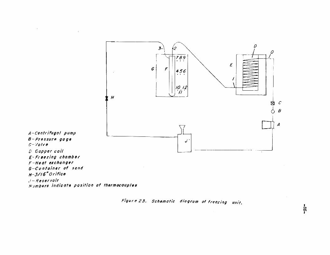
l
BI C
¢ 8
~A
0,
3- 2
/789...£
G F 456...I
10 12'Ii'
H
J'
A-centrifugal pump
8 - Pr~ssur" go gtlC- Valvtl
D-Copper coilE-Fr,ez;ng chamberF-Heot exchangtlr(;-Con/ainer of sand
H-3/16"Orifictl,i - l? esef voirN'Jm/)fJrs indicoftl position of thtlfmOCOllpltl6
Figure 23, Sch"motic diagram of freezing unit,
•())0'1
•

Eastern model E-7 centrifugal pump was obtained and used in test II.
This pUlIlp was oapable of developing 30 p.s.i. at zero flow and zero
p.s.i. at a flow of nine gallons per minute.
The sand, oontainer, and alcohol were the same as those used in
-tes-t I. A new supply o:f dry ioe was obtained.
Procedure
The equipment used in test II was as sembled as illustrated in
Figure 23, the -thermocouples numbered 0, 1, 2, and 3 in Figure 23 were
di:f:ficult "ho seal into the oircuit. After many attempts, this problem
was solved by using dental stone around the thermooouples and covering
this stone with a plastio which was dissolved in aoetone. Several
coats of plastic were applied and this effectively sealed the thermo-
couples.
Nine thermocouples were placed in the sud. ~e depth of thermo-
couples numbered 7, 8, and 9 shown in Figure 23 averaged three inches
below the surface. The depth of these numbered 4, 5, and 6 was 5.6
inohes and the depth of those numbered 10, 11, and 12 was nine inches.
The ciroulating system was filled with 0.62 gallons of alcohol,
the initial te~eratures were recorded, and then fifty pounds of dry
ice were plaoed in "hhe f'reeling chamber. !he pump was started and the
velooity was regulated to circulate a oonstant flow of 2.35 gallons .t
alcohol per minute. Ai; the end of five minutes, another reading ot
all -the thermooouples was reoorded and readings were ta.ken every 10
minutes 'to 1me end of the test.
Resu1'ts
The lIs:t:er-sa.-tura:t:ed sand was frozen. The -thickness of freezing.
ranged from one-quar'ter of an inch at the surface to more than one inoh
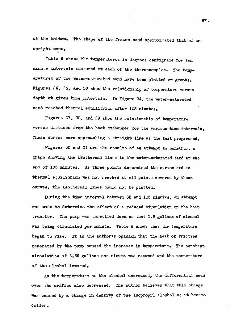
-87.
a"t the bo"t"tom. The shape of "the frozen sand approximated tha"t of an
uprigh"t eone.
Table 6 ehows "the "temperatures in degrees oen1:;igrade for ten
minute intervals measured at eaoh of the thermocouples. The temp
-eratures of 'the wa'ter-saturated sand have been plo"t1:;ed on graphs.
Figures 24, 25, and 26 show the relationship of temperature versus
dep"th a't given "time intervals. In Figure 24. the water-saturated
sand reached thermal equilibrium atter 105 minutes.
Figures 27, 28, and 29 show the rela"tionship of temperature
versus dis"tance from the heat exchanger for the various 'time intervals.
These ourves were approaohing a stra1gh"t line as the test progressed.
Figures 30 and 31 are 'the results of an a'ttempt 'to oonstruct a
graph showing 'the l'sothermal lines in the water-sa"turated sand at the
end of 105 minutes. As three poin'ts determined the ourves and as
'thermal equilibrium was not reaohed at all points covered by these
ourves, the isothermal lines could not be plotted.
During the 'time in'terval between 85 and 105 minutes, an attemp't
was made to determine the effect of a reduced circulation on the heat
'transfer. The pump was thro't"tled down so tha't 1.8 gallons of alcohol
was being circulated per minu'te. Table 6 sho~ that the temperature
began to rise. It is the author's opinion that 'the hea't of friction
generated by the pump oaused 'the inorease in 'tempera'ture. The constant
oircula'tion of 2.35 gallons per minute was resumed and the temperature
of the aloohol lowered.
As 'the temperature of the alcohol deoreased, the differential head
over the orifice also decreased. The author believes that this ohange
was caused by a. ohange in density of the isopropyl aloohol as it became
colder.

TABLE 6
TEMPERATURES MEASURED WITH THERMOCOUPLES
TIME (MIN.) ALCOHOL SAND
0 1 2 :3 4 6 6 7 8 9 10 11 120 32.75 33.5 33.8 33.25 29.0 28.76 28.9 28.4 28.4 28.0 29.5 29.5 29.45 23.5 18.8 18.0 17.6 29.6 29.6 29.1 28.4 29.1 28.8 29.4 29.4 29.4
16 3.0 0 -4.9 -4.26 23.6 29.6 29.3 22.4 27.4 28.2 22.4 27.6 28.225 -9.2 -14.9 -14.6 -13.6 18.5 26.3 29.6 16.3 23.8 26.6 16.0 25.0 27.7535 -9.0 -14.5 -16.2 -14.7 -16.8 23.8 27.3 14.0 21.6 25.0 13.3 22.75 26.2546 -10.25 -17.0 -15.75 ..11.75 13.6 21.6 25.0 12.5 19.2 23.6 11.0 20.8 24.065 -13.6 -18.9 -18.4 -15.8 12.0 20.0 23.8 10.5 17.8 22 ..6 9.0 18.6 22.566 -14.0 -19.6 -19.6 -17.0 10.2 18.6 22.75 9.25 16.0 21.4 7.2 17.0 22.075 -16.0 -19.0 -20.5 -16.0 8.15 17.0 21.3 7.5 14.8 20.9 5.16 15.6 18.986 -14.0 -21 ..0 -21.1 -24.4 7.25 16.3 19.4 6.76 14.0 19.0 4.4 13.86 17.395 -12.7 -20.3 -19.7 -21.0 6.75 14.2 18.7 5.8 13.1 17.8 3.5 12.6 16.5
106 -11.3 -17.2 -17.2 -14.0 6.2 13.2 17.3 6.2 12.5 17.2 3.0 11.6 16.2116 -14.0 -20.0 -19.1 -18.8 5.3 12.6 16.3 5.5 11.4 16.0 2.2 10.8 14.2125 -16.75 -19.8 -19.8 -18.8 4.2 11.4 16.4 4.4 11.0 14.9 1.3 9.6 13.6135 -17.0 -21.25 -21.75 -20.3 2.6 10.5 14.7 3.4 9.8 12.5 .26 B.8 12.8145 -17.6 -23.0 -22 •.3 -20.5 2.0 10.0 14.0 2.6 8.9 12.4 0 8.2 12.4165 -15.5 -19.5 -19.5 -19.0 1.5 8.7 13.3 2.0 7.6 11.0 -.75 7.4 11.5165 -15.9 -19.0 -19.0 -18.7 .5 7.8 12.6 .8 6.3 9.75 -1.3 7.1 lO.8175 -19.0 -21.0 ..21.0 -20.7 ... 3 7.0 10.0 0 5.8 10.0 -2.0 6.35 9.75
I0)
'f
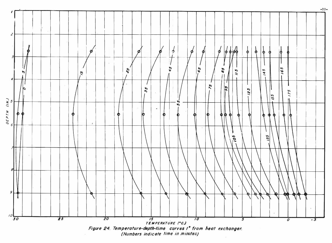
-89-
-3o20 /5 10 5TEMPERATURE (OC)
Figure 24. Temperofure-depth-lime cf{rv8s /" from heol exchanger.(Numbers indicote time In minutes)
15
. -I I
t I'v
I 1 I f f If cD~l,
II
i ,,) c~ ~ (~ ( ~ ~ P I
3 iti~II ! V I V / V r;/ I It) / : ~ \C'):) "I-
/' .. J
It) \C') '0It)~ / V
::::: "It' -'/ I - I4 / 1 I
I~v. / I
I 1 I,
~
I ~ ~It)
I~ I ~ \C')
c.\oi ....I " \C') -'Q
tc)Ie) ,
I4
~ , C~ C~ ~ cb I .C~ IC~ ~ l ~C C~ ~ ) l C 4
I I
6( \ \ \ \ \ 1\ \
\,1\\\ \
\ \I
\ ~ \ 1\\C')
~ \ \I \ \ 1\~-\ ,
I
\ \ . \ \ \ \ \ \ \\ \ \ \'1\ ~~ \:\ :\ ~ ~D 1\ \ 1\ 1\
\ \ \ \ \ \ \ \~~\ \ ,
~.1\ 1\1\ \ \ l\ 1\ \.\\' ~I\..
" 1\ " "'"" ~ "\ ~ '\ '\ 1\', ""\ \~ '"\ "\ ~"
2
9
1030
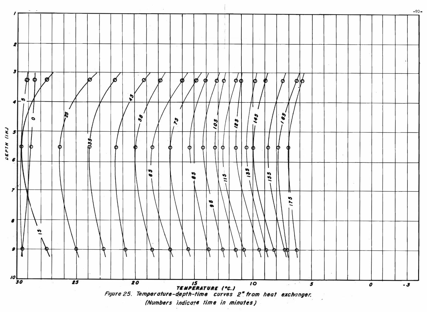
(J
11---+---+----+--+---+----I------l'----~+---+--+--+---+-------Ir---+--+--+---~--+-__+___I-+__+__+___t____+____+__1r__+___+___+_____+_____+____t
IO~J...-~~~~~-..L....-..L...-~~~---'--.L-""""--~ ..........----...........---'--.L-'--~.....a..- ...............-..L.-""-'--"""'------ ............-..L....o._.I~(J 6$ 10 IS 10 $
TIII"IIATIJII' -(-C.)Agure 25. 78mperolure-depfh-timlJ curves 2" from heal exchangsr.
(Numbers indico!. lime in milluf~$) .

-91-
3o20 IS 10 5TEMPERATURE (·C.}
FigurfJ 26. Temperafurs-dtJpfh-l;me curves 3- f,om heat e~chong(Jr.
(Numbers indicate time in minutes)
2530
2
3
7
I
-
-
~ ,tl ~ ./! v ,i 1 1 ~ !j It
L J. 1(1/h- I,.. lJ5"
V If If 1... rr
VI 8/\() l ~~~v.
I JI I
V JIt)
SIJ
J " ,J J",4
f,
/ I 1 /
VJI I~
I~
~.<:)
/II It). "~ ~ ~
J:
J IJ~
., J j..,I ,
I I I "I
I:
(~~ 0 (~ ~ I(~ ( ) 10 ) () 0 ( ~ ( ( ~ D ~lJ.. ,
It)
"6 \ \~ It")
l\Ii
1\ \-\ 1\ ' \ ~
;
\ ~ \ ~ i I~ \ i I\ '0, ,
\ -,i\\
1 - \ I
\ ~\I
\\()
~ \I) I
I
\ ""'" ~ \. I
\ ~-~\
I
~ \ II
\\
\,
1\ '\~ \~0\~1\ 1\, .~ \~ ~ ~ ~9 ~ j,
"'\ '\~ '\ ~ \ " \ " ~ '\ \\ .,
\ '\-
0., -
8
I

25 20 /5 0 _ 0, TEMPERA TUNE (Oc.)
Figure27. Tempera/urfJ-disfoPC6 from heat excnongtJr-liI"tJ ctlrves 3" below surface of sond.(Numbers indicate time in minutes)
~ -I .
,, \
vi.
L,..- v -",v_V ~~~~i
I~r ~ ~ L/ ,./ v~v~ -....>~-7 " ~/
~~~~/'7VYv- ~
/ // V V V V V:::~ ~ /Ie V V V ~~~.v: ~~~V ~V ~ ~f;) ;'
V" V t» ~~~\/ ')fJ " ./ ~ V./ ./ ~ /" .,
V .')/ V l.' V V
Vv
~~v ~V L7Vl/::V/
,.,/~V
~ ~~ VI
/1 / ~ ~\~
~~~II') ';) ~ ~'J 1*J
~[/VJ ,/ IJ ~. 1/ V V ,~ ,/-/ J
V - vV"' V V~·VV V ~/' r?~V..... V rV..
V ~iIII
~Vfit;,
~~ 'JfJ fV V/
Ii
Ii \
/ / / / / / IIr
/ ~
i ~
V/7~
'/ v V~
V Ij V V,
I
V V~J ~ V ./; Vv... J ,,/-/ V ..l\ r ) / /1'l l1li" / 7 / I "'" r I IfI I
., .".-.
I . 5 ..-
I
30
4
o
.......
~~~~
:t~
:tu 2~~
....~~
~()
~
""~(,,)
:t3~~
~~
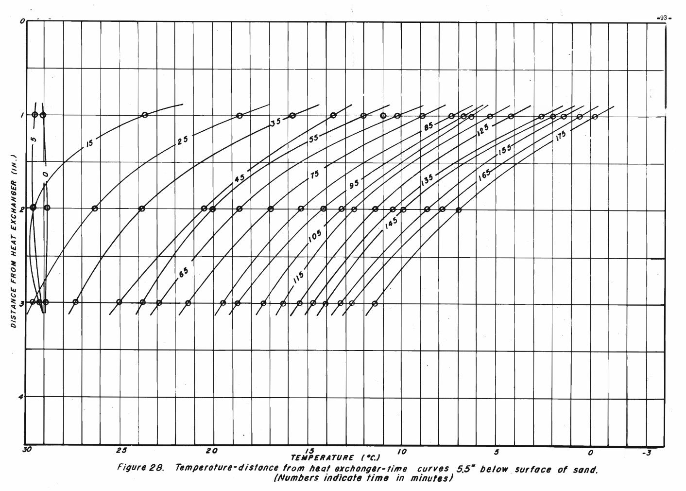
o - -
I-93-
41---+--+--+-----4-----+-1--+--4---4----+---+----+-1--+---+--+---+---+---+---.,1--+---+----+---;--+----+-+--+---+--+---+---+----+---1
24
Figure 28.
20 /4 10 4 0TEMPERATURE (-t'.J
Temperoture-dis/once from heal fJXChong8r-time curv,s 5.5M below surfoce of sand.(Numbers indicate lime in minutes)
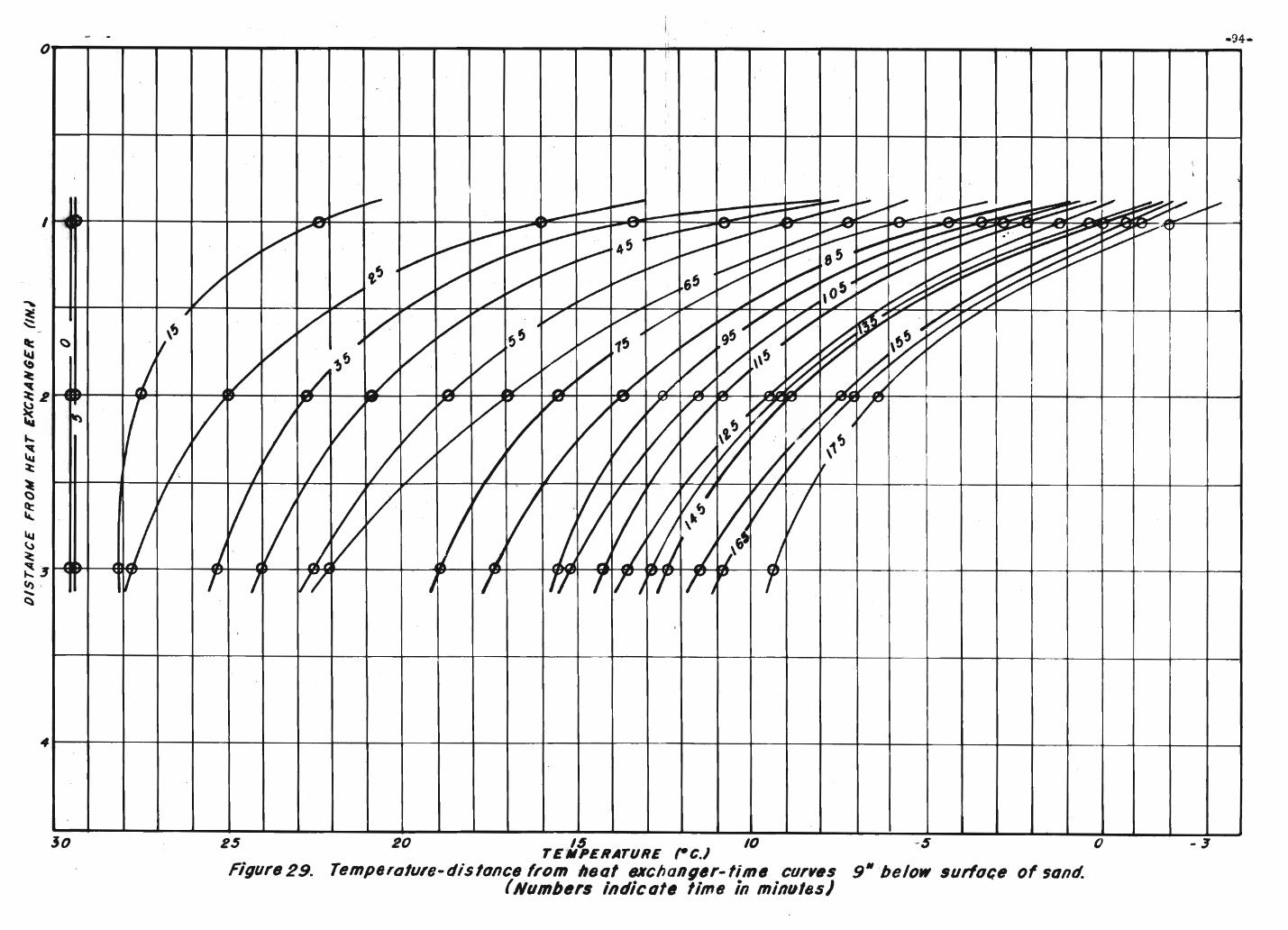
- .I .
I
1
.
I
I
,.,- ~ - ~ V ;--:::-~~ ~,., - V~ -~ - ~ t:---~V-- -- ~.~~~-..
11 ".- ~ ~ - ...- . ~....~.~~
~~~.......~
~~V'..
'/ ~~ ~
45 k--" ~ t::::::~b:::~~~ ~ ~
~ ~~~~V t.~
~V
V ~ V~
~ ~~~I ~l0 ~V V V 65~ ~/ ./ ./ V / ,0/ ~~V
-" ~ ~,VV V
10'" V V V V,V t/' l"Iii"
~V .
~V
~ . V~ ~
4,fj
V,
95
~l;) ·V . ' V !>
V 1~
V ~f) V V ~
\\!)
~ ~j / I/~ V ,/ ./ ,/ J J -/ J!. ~
V V " /" ~ /,
V ~
/ t/~
~ ~V'r)
/ V / V~ ~/ .. ~ 1~
I / / / / 1/ J /;,
j / ~IIt
V V 1/
~V V V ~I VjV:'
~VVV1/ V ~\.~LJ L J J Ij J ~fj J4 4 .,J Llr r I r/ J r rr TI,~r iJ
.,T
,
/
o
4
30 2 $ 20 16 10 -5 0TEMPERATURE ,-c.)
Figure 29. TemptJrolure-dislonce from hsol BKcIJang6r-fim6 curves 9" below surfoce of sand.(Numbtlrs indicot. time in minulas)
-3

I
7
8
9
- -
II 1.h
IfI R3,
() (~ ~
\ . 1\,
\~ ,\
R2 \\.
\ \~
1\R\\.....,1\ ...,
1\
-95-
20 m m 5 0Temperature (e)
Figure30. Tempera/ure -depth-limB curves 01 105 minutes.(R: distonce from heal exchanger in irc/JesJ

-96-
TemperolurtJ (oCfTemperoture-distonce from heat exchanger-time curves of /05
minultJs.(Osdepth in inch.s)
5
Figure 3/.
,
I
\.. \~ \ I- r'\ ""'\
1'\ 1\~1'\ I\.
""I'"~~O3,
09
" ~,"- "-
'"'"'""\
~~~~ ~ "-""
" ~ '"~ ,
"" 05.~
~~ ~~"- '--~ ~
..............i'-. ...
I
.I 10 020
I
4
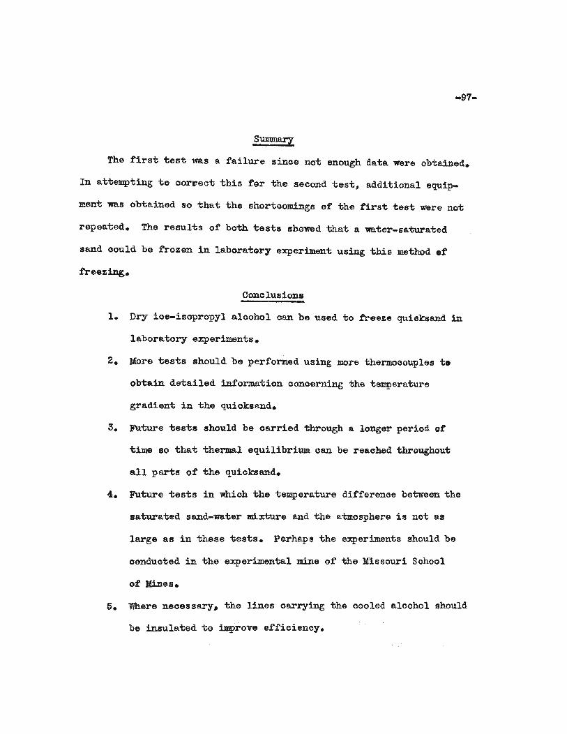
-97-
SUJJlIIla!l
The first ~est was a failure sinoe no~ enough data ~re obtained.
In attempting to oorrec~ this for the second test, additional equip
ment was obta.ined so that the shortoomings of the first 1iest were not
repeated. The results of both tests showed that a water-sa1;urated
sand could be frozen in laboratory experiment using this method of
freezing.
Conolusions
1. Dry ioe-isopropyl a.loohol oan be used to freeze quioksand in
laboratory experiments.
2. More tests should be performed using more thermooouples t.
obtain detailed information oonoerning the temperature
gradient in the quioksand.
3. Future 1iests should be carried through a longer period of
time so 1ihat thermal equilibrium oan be reached throughout
all parts of the qUicksand.
4. FUture tests in which the temperature differenoe between the
saturated sand-water mixture and the atmosphere is not as
large as in these tests. Perhap 8 the experiments should be
conducted in the experimenta.l mine ot the Missouri School
of Mines.
6. Where necessary. the lines carrying the cooled alcohol should
be insulated to improve efficiency.

-98-
BIBLIOGRAPHY
Grouting
Abrams, D. A., Test of impure waters for mixing ooncrete.American Concrete Institute. Proceedings of TwentiethAnniversary Convention. Vol. 20, 1924.
Beanfield, R. McC. Technique of grouting foundations. Western Construction News. Vol. 3, No. 19, October 10, 1928.pp. 634-638.
Blandford, T.Trades Review.
The process of cementation.Vol. 136, Karch 18, 1938.
The Iron and Cea1pp.. 477-479.
Christians, G. W.iDg News-Record.
Asphalt grouting under Hales Bar D~ EngineerVol. 96, No.3, May 20, 1926. pp. 798-802.
Cra:whall, J. S. Tunneling a water-bearing fault by oementation., Engineering News-Record. Vol. 102, May 30, 1929. p.874.
Denholm, E. W. Pressure grouting: some notes on standardpractice. The Surveyor. Vol. 103, No. 2724, April 7, 1944.pp. 165-166.
Elgin, R. A. HoW Leadville Tunnel is driven through bad ground.Engineering and Mining Journal, Vol. 146, No.3, March 1945,pp. 96-100.
, Freeman, M. H. Discussion on the Astoria Tunnel, .AmerioanSociety of Civil Engineers Transaotions. Vol. 80, 1916. p. 677.
Grouting with bentonite :mixed in produots of petroleum, u. S.Bureau of Reclamation. Laboratory report No. C-229, January 27,1944. p. 4.
Gutmann, I.News-Record.
Algerian rockf.'il1 dam substructures.Vol. 120, May 26, 1938. p. 749.
Engineering
Hays, J. B. lfoundation experienoes, T. V. A. Amerioan Society otCivil Engineers Transaotions. Vol. 106, 1941. p. 718.
_Hays, J. B. Improving foundation rook for dams. Civil Engineer";ing. Vol. 9, No.5, May 1939. p. 309•
.Jorgensen. L. R. SolidifYing gravel, sand, and weak rock.Western Cons~ruotionNews. Vol. 6, November 10, 1931. pp 591-593.
, Kellog~ F. H.Hews-Reoord.
Clay grouting a~ Madden Reservoir. EngineeringVol 109. No. 14, October 6. 1932. pp. 395-396.
-. Lee, C. H. Sealing Chenery Reservoir. Western ConstruotionNews. Vol. 5. December 25. 1930. p. 624.
-99-
Lewis, J. S., Jr. Foundation experiences. T. V. A. AmerioanSociety of Civil Engineers Transactions. Vol. 106. 1941. p. 718.
Minear. V. L. The art of pressure grouting. The ReolamationEra. Vol. 27. March 193'l. p. 69.
Randolph. E. s. Sealing reservoir lakes with olay grouting.The Military Engineer. Vol. 28. No. 159. May-June 1936. p. 209.
Riedel. C. M. Chemical joint sealing and soil solidification.Engineering NeWS-Record. Vol. 127. August 14, 1941. p. 77.
Ritter. N. E. and Stroup. R.. J. Sinking Eagle-Pioher's HewGarret shaft. Mining Congress Journal. Vol. 24. No.9.September 1938. p. 14.
Simonds. A. W. Pressure grouting equipment. U. S. Bureau ofReolamation. Teclmioal Memorandum. 638. p. 14.
Soil Mechanics Bulletin No.9. U. S. Waterways ExperimentStation. Vicksburg, Mississippi. March 1939. p. 8.
stiefel. F. W.Air Magazine.
Overcoming underground difficulties. CompressedVol. 46. No. 12, Deoember 1941. 1'. 6613.
Sturges. F. C. Introduction - grouting in mines. A. I. :M. E.Teohnioal publication 2427. Synposium on grouting. FebrtJ.ary1948. 1'1'. 1-3.
Syn1'osium on grouting. A. I. M. E. Technical Publication 2427.February 1948. 1'1'. 1-23.
Tainter. S. L. Grouting diamond-drill holes at the ChristmasMine, Gila Coun'ty. Arizona. U. S. Bureau of Mines. Report ofInvestigations 4559.
Underground dam. Petroleum Refiner. Vol. 28. No.3. Maroh 1949 0
A Gulf' Publishing Company Publioation. p. 114.
u. 8. Engineers. Final Laboratory Report. Tests for ohemicalconsolidation of' foundation materials at Lock and Dam No.3,Mississippi Rivero U. S. Engineers Sub-Offioe HydraulicsLaboratory, Iowa City, Iowa. November 1937. 30 1'1'.
FreeZing
Aokerman. A. J. and Locher. C. J. Construction planning andplant. First Edition. MoGraw-Hill. 1940. 1'1'. 219-22Q.
Biquet. M. FreeZing process enables lessees 'to sink shafts indeep marsh land of North Belgium. Coal Age. Vol. 25. No. 23.June 5. 1924. pp. 831-834.
-100-
Froage, L. V. Frozen eaI1:ih dam a t Grand Coulee. Meohanioa1Engineering, Vol. 63~ No.1, January 1941. pp. 9-15, 36.
Gough, H. B. A wet shaft :frozen tight.Record. Vol. 122, No. 19, May 11, 1939.
Engineering Newspp. 14-16.
Landgrauber, F. W. Freezing sands. Refrigera.ting EngineeringVol. 13, No.8, February 1921. p. 263.
Motz, W. H. A leoture course on the prinoipals of refrigeration.Nickerson and Collins Company. Chioago, Illinois, 1922.Lecture 11, p. 21.
Re:fr1geration permits shaft sinking. Refrigerating Engineering.April 1949. p. 335.
Shaft sinking at Calverton Colleriery. The Engineer. Vol. 188,Bo. 4887, September 23, 1949. pp. 355-356.
Skerret, R. G. How.AJ1twerp is building tow tunnels under thescheIdt. Compressed Air Magazine. Vol. 31, November 1932.pp. 3962-3966.

-101-
VITA
Robert Walter Heins was born June 10. 1924 a~ Edgerton,
Wisoonsin. Elemen~ary schooling 1vaS reoeived a~ Platteville,
Wisoonsin. He g~aduated from Platteville High School in May, 1942.
He attended Wisconsin Ins~i-tute of Teclmology from September 1942 ~o
March 1943, at which time he left school ~o en~er ~he.Arnry. 'While
in the Army he transferred to the Army Air Force. On May 20, 1944,
he gradua~ed fromNaviga~ionSchool a~ Ellington Field, Texas, and
received a oommission of Second Lieutenant. After his disoharge,
he re-entered the Wisoonsin Ins~itute of Technology in February,
1946, and was graduated in May 1948. He entered ~he Missouri
School of Mines in September 1948 and was gradua~ed with a degree
of Bachelor of Soienoe in Mining Engineering, May 1949.