Grid integration aspects of large solar PV installations: LVRT capability and reactive power/voltage...
8
1 Abstract--The current work focuses on two specific issues concerning grid-connected solar PV units, i.e. the fault ride- through capability, also called low voltage ride-through capability, and the voltage support function through reactive power injection during faults. With the first one the PV unit can actually provide some limited grid support, whereas with a defined reactive power characteristic it can give a complete dynamic grid support. These two requirements, already known for wind power generation but new for the PV, have been recently introduced in the German technical guidelines for connection to the MV grid. Scope of the paper is to implement these requirements in a large solar PV plant, modeled in DIgSILENT PowerFactory, in order to understand its operation, and to evaluate its behavior and impact on the grid, in terms of stability and voltage support during grid fault. Index Terms—Photovoltaic systems, reactive power control, solar power generation, voltage control. I. INTRODUCTION N the last decade a number of reasons have led the capacity of solar PV plants to a continuous increase. Some of them include significant cost reduction of PV modules, market incentives for electricity production from PV, greater social acceptance of solar PV parks, etc. At the same time there have been concerns about the connection to the grid of these upcoming large PV plants, sizing from a couple of MW up to hundreds of MW. The up to now connection of small PV plants, i.e. smaller than 1-2 MW, was very much dealt with using known practices regarding the distribution grid. However, the upcoming integration of large solar PV installations into the sub-transmission and even the transmission grid has different characteristics, which will highly affect the transmission and generation systems. Thus, a number of technical issues regarding the impact on the system operational security, stability, and power quality have to be taken into consideration before these plants can be connected to the electricity grid. This paper concentrates on two specific aspects concerning solar photovoltaic (PV) power generation units connected to A. Marinopoulos, M. Reza, and S. Norrga are with ABB AB, Corporate Research, Västerås, Sweden (e-mail: [email protected]). F. Papandrea is with ISOFOTÓN S.A., Milan, Italy (email: [email protected]). R. Napoli and F. Spertino are with Politecnico di Torino, Italy (email: [email protected], [email protected]) the utility network. The first issue is the Fault Ride-Through (FRT) or Low Voltage Ride-Through (LVRT) capability, defined as the PV inverters' capability of remaining connected to the grid in the event of grid failures, of not supplying any active power during a grid fault, and of delivering active power directly after clearing the fault, thus stabilizing the grid. The second aspect is also related to LVRT, but it refers to the additional capability of injecting reactive power in the grid in case of grid fault, with the purpose to give a voltage support during fault conditions. Initially, an investigation on new requirements for PV power plants is done. These requirements are quite similar to the current Grid Code (GC) requirements for wind power plants. However, the only existing legislation in effect, that refers to technical guidelines and requirements specifically for PV interconnection is the German GC [1]-[2]. An evaluation of a solar PV power plant with fault ride- through capability and reactive power support in dynamic conditions in case of grid faults is performed. The control system model of this solar PV power plant is studied and a number of simulations for various scenarios is done. The scenarios concern different size of the solar plant, different strengths of the grid connection, different faults and control strategies. The modeling of the solar PV plant and the necessary simulations have been performed in DIgSILENT Power Factory v14. II. GRID CODES The GC is a technical document containing the rules that govern the operation, maintenance & development of the system at the Point of Common Coupling (PCC). Grid codes usually make a distinction between traditional power plants, which have a synchronous generator directly connected to the grid, and other types, mostly including RES. A. Grid codes for Wind power plants Regarding wind power plants, GCs already exist for numerous countries worldwide, due to the maturity in wind power technology and the resulting high penetration of wind power generation. The international guidelines and standards require in general that wind plants achieve the same levels of reliability and performance as conventional generation plants. It is foreseen that in the near future this requirement will be also posed for large solar PV plants. According to the general trend among the various GCs, the main requirements for wind Grid Integration Aspects of Large Solar PV Installations: LVRT Capability and Reactive power/Voltage support Requirements Antonios Marinopoulos, Fabio Papandrea, Muhamad Reza, Staffan Norrga, Filippo Spertino, and Roberto Napoli I Paper accepted for presentation at the 2011 IEEE Trondheim PowerTech 978-1-4244-8417-1/11/$26.00 ©2011
-
Upload
independent -
Category
Documents
-
view
3 -
download
0
Transcript of Grid integration aspects of large solar PV installations: LVRT capability and reactive power/voltage...
1
Abstract--The current work focuses on two specific issues concerning grid-connected solar PV units, i.e. the fault ride-through capability, also called low voltage ride-through capability, and the voltage support function through reactive power injection during faults. With the first one the PV unit can actually provide some limited grid support, whereas with a defined reactive power characteristic it can give a complete dynamic grid support. These two requirements, already known for wind power generation but new for the PV, have been recently introduced in the German technical guidelines for connection to the MV grid. Scope of the paper is to implement these requirements in a large solar PV plant, modeled in DIgSILENT PowerFactory, in order to understand its operation, and to evaluate its behavior and impact on the grid, in terms of stability and voltage support during grid fault.
Index Terms—Photovoltaic systems, reactive power control, solar power generation, voltage control.
I. INTRODUCTION N the last decade a number of reasons have led the capacity of solar PV plants to a continuous increase. Some of them
include significant cost reduction of PV modules, market incentives for electricity production from PV, greater social acceptance of solar PV parks, etc. At the same time there have been concerns about the connection to the grid of these upcoming large PV plants, sizing from a couple of MW up to hundreds of MW. The up to now connection of small PV plants, i.e. smaller than 1-2 MW, was very much dealt with using known practices regarding the distribution grid. However, the upcoming integration of large solar PV installations into the sub-transmission and even the transmission grid has different characteristics, which will highly affect the transmission and generation systems. Thus, a number of technical issues regarding the impact on the system operational security, stability, and power quality have to be taken into consideration before these plants can be connected to the electricity grid.
This paper concentrates on two specific aspects concerning solar photovoltaic (PV) power generation units connected to
A. Marinopoulos, M. Reza, and S. Norrga are with ABB AB, Corporate
Research, Västerås, Sweden (e-mail: [email protected]). F. Papandrea is with ISOFOTÓN S.A., Milan, Italy (email:
[email protected]). R. Napoli and F. Spertino are with Politecnico di Torino, Italy (email:
[email protected], [email protected])
the utility network. The first issue is the Fault Ride-Through (FRT) or Low Voltage Ride-Through (LVRT) capability, defined as the PV inverters' capability of remaining connected to the grid in the event of grid failures, of not supplying any active power during a grid fault, and of delivering active power directly after clearing the fault, thus stabilizing the grid. The second aspect is also related to LVRT, but it refers to the additional capability of injecting reactive power in the grid in case of grid fault, with the purpose to give a voltage support during fault conditions.
Initially, an investigation on new requirements for PV power plants is done. These requirements are quite similar to the current Grid Code (GC) requirements for wind power plants. However, the only existing legislation in effect, that refers to technical guidelines and requirements specifically for PV interconnection is the German GC [1]-[2].
An evaluation of a solar PV power plant with fault ride-through capability and reactive power support in dynamic conditions in case of grid faults is performed. The control system model of this solar PV power plant is studied and a number of simulations for various scenarios is done. The scenarios concern different size of the solar plant, different strengths of the grid connection, different faults and control strategies. The modeling of the solar PV plant and the necessary simulations have been performed in DIgSILENT Power Factory v14.
II. GRID CODES The GC is a technical document containing the rules that
govern the operation, maintenance & development of the system at the Point of Common Coupling (PCC). Grid codes usually make a distinction between traditional power plants, which have a synchronous generator directly connected to the grid, and other types, mostly including RES.
A. Grid codes for Wind power plants Regarding wind power plants, GCs already exist for
numerous countries worldwide, due to the maturity in wind power technology and the resulting high penetration of wind power generation. The international guidelines and standards require in general that wind plants achieve the same levels of reliability and performance as conventional generation plants. It is foreseen that in the near future this requirement will be also posed for large solar PV plants. According to the general trend among the various GCs, the main requirements for wind
Grid Integration Aspects of Large Solar PV Installations: LVRT Capability and Reactive
power/Voltage support Requirements Antonios Marinopoulos, Fabio Papandrea, Muhamad Reza, Staffan Norrga, Filippo Spertino, and
Roberto Napoli
I
Paper accepted for presentation at the 2011 IEEE Trondheim PowerTech
978-1-4244-8417-1/11/$26.00 ©2011
2
plants are the following, although the detailed specifications may of course vary:
• All the wind generation plants should support grid disturbances and faults without being disconnected from the grid (LVRT). In that way, they will help to maintain the voltage stability of the grid.
• They should also support utility grid when necessary, mainly during a fault, by generating/absorbing reactive power.
Today, the main problems that could lead a grid inverter to trip under faulty grid operating conditions are under- and/or over- voltages and heavy imbalance on the ac side as the consequence of a fault. Some grid codes have a specific plan of reactive power to be injected during grid faults, as a support to avoid a grid collapse. For this purpose inverters need simple control strategies for managing the reactive power delivered under voltage dips (or under unbalanced operating conditions).
B. Grid requirements for PV power plants Regarding PV power plants, only the German grid code has
some specific requests for solar PV. This is due to the fact that currently there is a significant penetration of solar PV technology in Germany; according to the German Federal Network Agency the cumulative nominal PV power installed at the end of 2010 was a little more than 15 GW [3]. A draft copy for grid connection guidelines for PV is under investigation in Spain, where also many solar PV units are already installed and many more are under construction.
Until now, PV generators connected to the grid are usually not permitted to take over an active role during faults and thus have to be disconnected. However, the new guidelines, as already stated in the German GC, will require the units to actively support the grid during faults. These new requirements have two principal parts: first, in steady-state conditions, grid support should be provided by contributing to the voltage control through the injection of reactive power. Second, during transient conditions, grid support can be performed by staying connected (LVRT) and by injection of reactive power during grid faults.
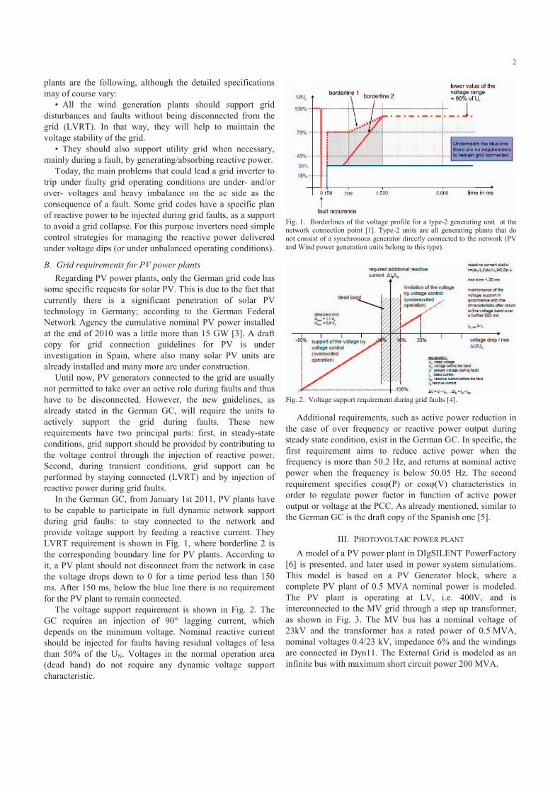
In the German GC, from January 1st 2011, PV plants have to be capable to participate in full dynamic network support during grid faults: to stay connected to the network and provide voltage support by feeding a reactive current. They LVRT requirement is shown in Fig. 1, where borderline 2 is the corresponding boundary line for PV plants. According to it, a PV plant should not disconnect from the network in case the voltage drops down to 0 for a time period less than 150 ms. After 150 ms, below the blue line there is no requirement for the PV plant to remain connected.
The voltage support requirement is shown in Fig. 2. The GC requires an injection of 90° lagging current, which depends on the minimum voltage. Nominal reactive current should be injected for faults having residual voltages of less than 50% of the UN. Voltages in the normal operation area (dead band) do not require any dynamic voltage support characteristic.
Fig. 1. Borderlines of the voltage profile for a type-2 generating unit at the network connection point [1]. Type-2 units are all generating plants that do not consist of a synchronous generator directly connected to the network (PV and Wind power generation units belong to this type).
Fig. 2. Voltage support requirement during grid faults [4].
Additional requirements, such as active power reduction in the case of over frequency or reactive power output during steady state condition, exist in the German GC. In specific, the first requirement aims to reduce active power when the frequency is more than 50.2 Hz, and returns at nominal active power when the frequency is below 50.05 Hz. The second requirement specifies cos (P) or cos (V) characteristics in order to regulate power factor in function of active power output or voltage at the PCC. As already mentioned, similar to the German GC is the draft copy of the Spanish one [5].
III. PHOTOVOLTAIC POWER PLANT A model of a PV power plant in DIgSILENT PowerFactory
[6] is presented, and later used in power system simulations. This model is based on a PV Generator block, where a complete PV plant of 0.5 MVA nominal power is modeled. The PV plant is operating at LV, i.e. 400V, and is interconnected to the MV grid through a step up transformer, as shown in Fig. 3. The MV bus has a nominal voltage of 23kV and the transformer has a rated power of 0.5 MVA, nominal voltages 0.4/23 kV, impedance 6% and the windings are connected in Dyn11. The External Grid is modeled as an infinite bus with maximum short circuit power 200 MVA.
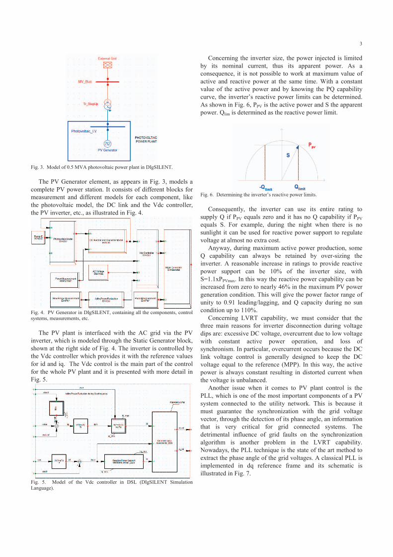
3
Fig. 3. Model of 0.5 MVA photovoltaic power plant in DIgSILENT.
The PV Generator element, as appears in Fig. 3, models a
complete PV power station. It consists of different blocks for measurement and different models for each component, like the photovoltaic model, the DC link and the Vdc controller, the PV inverter, etc., as illustrated in Fig. 4.
Fig. 4. PV Generator in DIgSILENT, containing all the components, control systems, measurements, etc.
The PV plant is interfaced with the AC grid via the PV
inverter, which is modeled through the Static Generator block, shown at the right side of Fig. 4. The inverter is controlled by the Vdc controller which provides it with the reference values for id and iq. The Vdc control is the main part of the control for the whole PV plant and it is presented with more detail in Fig. 5.
Fig. 5. Model of the Vdc controller in DSL (DIgSILENT Simulation Language).
Concerning the inverter size, the power injected is limited by its nominal current, thus its apparent power. As a consequence, it is not possible to work at maximum value of active and reactive power at the same time. With a constant value of the active power and by knowing the PQ capability curve, the inverter’s reactive power limits can be determined. As shown in Fig. 6, PPV is the active power and S the apparent power. Qlim is determined as the reactive power limit.
Fig. 6. Determining the inverter’s reactive power limits.
Consequently, the inverter can use its entire rating to
supply Q if PPV equals zero and it has no Q capability if PPV equals S. For example, during the night when there is no sunlight it can be used for reactive power support to regulate voltage at almost no extra cost.
Anyway, during maximum active power production, some Q capability can always be retained by over-sizing the inverter. A reasonable increase in ratings to provide reactive power support can be 10% of the inverter size, with S=1.1xPPVmax. In this way the reactive power capability can be increased from zero to nearly 46% in the maximum PV power generation condition. This will give the power factor range of unity to 0.91 leading/lagging, and Q capacity during no sun condition up to 110%.
Concerning LVRT capability, we must consider that the three main reasons for inverter disconnection during voltage dips are: excessive DC voltage, overcurrent due to low voltage with constant active power operation, and loss of synchronism. In particular, overcurrent occurs because the DC link voltage control is generally designed to keep the DC voltage equal to the reference (MPP). In this way, the active power is always constant resulting in distorted current when the voltage is unbalanced.
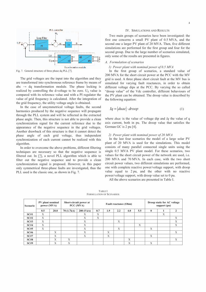
Another issue when it comes to PV plant control is the PLL, which is one of the most important components of a PV system connected to the utility network. This is because it must guarantee the synchronization with the grid voltage vector, through the detection of its phase angle, an information that is very critical for grid connected systems. The detrimental influence of grid faults on the synchronization algorithm is another problem in the LVRT capability. Nowadays, the PLL technique is the state of the art method to extract the phase angle of the grid voltages. A classical PLL is implemented in dq reference frame and its schematic is illustrated in Fig. 7.
4
Fig. 7. General structure of three phase dq PLL [7].
The grid voltages are the input into the algorithm and they
are transformed into synchronous reference frame by means of abc dq transformation module. The phase locking is realized by controlling the d-voltage to be zero. Ud value is compared with its reference value and with a PI regulator the value of grid frequency is calculated. After the integration of the grid frequency, the utility voltage angle is obtained.
In the case of unsymmetrical voltage faults, the second harmonics produced by the negative sequence will propagate through the PLL system and will be reflected in the extracted phase angle. Then, this structure is not able to provide a clean synchronization signal for the current reference due to the appearance of the negative sequence in the grid voltages. Another drawback of this structure is that it cannot detect the phase angle of each grid voltage, thus independent synchronization of each current cannot be realized with this algorithm.
In order to overcome the above problems, different filtering techniques are necessary so that the negative sequence is filtered out. In [7], a novel PLL algorithm which is able to filter out the negative sequence and to provide a clean synchronization signal is proposed. However, in this paper only symmetrical three-phase faults are investigated, thus the PLL used is the classic one, as shown in Fig. 7.
IV. SIMULATIONS AND RESULTS Two main groups of scenarios have been investigated: the
first one concerns a small PV plant of 0.5 MVA, and the second one a larger PV plant of 20 MVA. Then, five different simulations are performed for the first group and four for the second group. Due to the large number of scenarios simulated, only some of the results are presented in figures.
A. Formulation of scenarios 1) Power plant with nominal power of 0.5 MVA
In the first group of scenarios, a standard value of 200 MVA for the short circuit power at the PCC with the MV grid is used. A three phase short circuit fault at the MV bus is simulated for varying fault reactances, in order to obtain different voltage dips at the PCC. By varying the so called “droop value” of the Vdc controller, different behaviours of the PV plant can be obtained. The droop value is described by the following equation:
Iq duac droop= ⋅ (1)
where duac is the value of voltage dip and Iq the value of q axis current, both in pu. The droop value that satisfies the German GC is 2 pu [4]. 2) Power plant with nominal power of 20 MVA
In the last four scenarios the model of a large solar PV plant of 20 MVA is used for the simulations. This model consists of many parallel connected single units using the single 0.5 MVA PV plant model. For these scenarios, two values for the short circuit power of the network are used, i.e. 200 MVA and 70 MVA. In each case, with the two short circuit power values, two different simulations are performed, one with complete reactive power/voltage support, with droop value equal to 2 pu, and the other with no reactive power/voltage support, with droop value set to 0 pu.
All the above scenarios are presented in Table I.
TABLE I
FORMULATION OF SCENARIOS
Scenario PV plant nominal
power (MVA) Short-circuit power at
PCC (MVA) Fault reactance (Ohm) Droop static for AC voltage support (pu)
0.5 20.0 70 (1.7kA) 200 (5 kA) 0.7 1.9 2.2 4.0 5.5 0 1 2 SC#1 X X X X SC#2 X X X X SC#3 X X X X SC#4 X X X X SC#5 X X X X SC#6 X X X X SC#7 X X X X SC#8 X X X X SC#9 X X X X
5
B. Results of simulations and discussion In the following paragraphs the results from all simulated
scenarios are shortly presented and discussed. However, due to space limitations only four of the nine in total scenarios are illustrated in figures.
The PV plant operates in steady-state providing 448.8 kW of active power at MPP and almost zero reactive power. The voltage at the LV bus is 0.99 pu and at the MV bus is constant 1 pu. At time t=0s a three phase short circuit occurs at the MV bus and is cleared after 500ms. The behaviour of the PV power plant for the voltage dips in the MV and the LV buses caused by the short circuit is evaluated.
Varying the value of the fault reactance different voltage dips are created in order to study the behaviour of the PV plant for various voltage dip magnitudes. Different control strategies regarding the voltage support for the PV plant are also studied, by varying the droop value of the Vdc controller.
For all simulations the following variables are recorded during the fault (in parenthesis the colour of the line in the respective figure): voltage at the MV bus (red), voltage at the LV bus (green), AC voltage dip (magenta), active (red) and reactive (cyan) power injected from the PV plant, and active (green) and reactive (magenta) current reference. For the second group of scenarios for the large PV park, the plotted results for the active and reactive power regard only one single 0.5 MVA unit. The main parameters of the PV plant model, are given in the Appendix. 1) Scenario #1
In this case in the LV bus the voltage dip is around 0.76 pu, while it is a bit higher in the MV bus, around 0.8 pu (Fig.8). This is due to the presence of the transformer. In this case the reference value of active and reactive current, Idref and Iqref are respectively 0.241 pu and 0.759 pu. The injected values of active and reactive power are 28.6 kW and 91.789 kVar (Fig. 9). It is important to note that the values of power are influenced not only by the reference values of currents, but also by the voltage value on the LV bus.
This behaviour has to be improved to meet the GC requirements. In fact, this plant satisfies the German LVRT requirement, as it is shown in Fig. 1, but doesn’t satisfy the voltage support requirement through injection of reactive current. In case of voltage dip larger than 0.5 pu, the GC requires 1 pu of reactive current, and consequently 0 pu of active current. In this case this requirement is not satisfied. 2) Scenario #2
To change the above behavior of the PV plant the value of droop in the Vdc controller is increased from 1 to 2 pu. In this case the voltage dips are a bit lower than in the first simulation, around 0.745 pu, because more reactive power is injected (Fig. 10). The Vdc controller sets the reference value of active and reactive current respectively at 0 and 1 pu, according to the GC requirements. The reactive power injected is around 127 kVar, about 35% higher than the first case (Fig. 11). This increases by 0.015 pu the LV value, but does not influence the MV value.
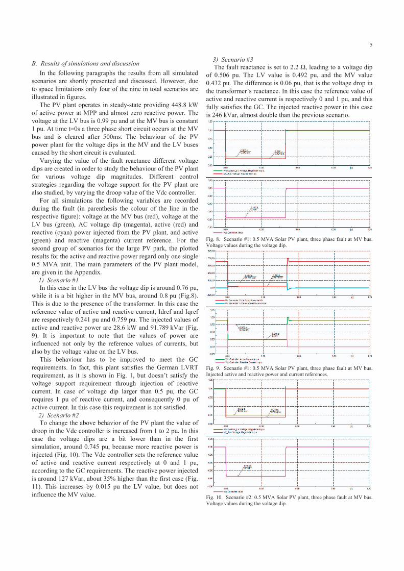
3) Scenario #3 The fault reactance is set to 2.2 , leading to a voltage dip
of 0.506 pu. The LV value is 0.492 pu, and the MV value 0.432 pu. The difference is 0.06 pu, that is the voltage drop in the transformer’s reactance. In this case the reference value of active and reactive current is respectively 0 and 1 pu, and this fully satisfies the GC. The injected reactive power in this case is 246 kVar, almost double than the previous scenario.
Fig. 8. Scenario #1: 0.5 MVA Solar PV plant, three phase fault at MV bus. Voltage values during the voltage dip.
Fig. 9. Scenario #1: 0.5 MVA Solar PV plant, three phase fault at MV bus. Injected active and reactive power and current references.
Fig. 10. Scenario #2: 0.5 MVA Solar PV plant, three phase fault at MV bus. Voltage values during the voltage dip.
6
Fig. 11. Scenario #2: 0.5 MVA Solar PV plant, three phase fault at MV bus. Injected active and reactive power and current references. 4) Scenario #4
The fault reactance value is further increased to 5.5 , causing a smaller value of voltage dip, around 0.3 pu, with a LV value of almost 0.7. In this case the reference values of active and reactive current are respectively 0.387 and 0.613 pu. The reference value of reactive current satisfies the requirement shown in Fig. 2. The injected values of active and reactive power are 133.9 kW and 212.2 kVar, respectively. 5) Scenario #5
In this scenario the parameters are the same with the third one, but with no AC voltage support, i.e. the droop value is set at 0. In this case the voltage dip is around 0.572 pu, and the LV value is 0.431 pu, while the MV value is 0.427 pu. Consequently at these values of voltages, the reference value of active and reactive current is respectively 1 and 0 pu. The injected values of active and reactive power are 213 kW and almost 0 kVar, respectively. It is clear that this situation does not satisfy any GC requirement.
In this case without voltage support the LV value is 0.431 pu and the MV value is 0.427 pu (comparing to 0.492 pu and 0.432 pu, respectively, in the third scenario). It is clear to see that the effect of the voltage support in the MV bus is very small, around 0.005 pu, almost negligible. This fact is due to the very large difference (400 times) between the values of the nominal power of the PV plant (0.5 MVA) and the short circuit power of the grid at the PCC (200 MVA). 6) Scenario #6
This scenario concerns a large solar PV park with 20 MVA nominal power. In this case the voltage dip is 0.501 pu, while the LV value is 0.498 pu and the MV value is 0.438 pu. In this case the reference value of active and reactive current respectively is 0 and 1 pu, fully satisfying the German GC. The total reactive power injected is 9.96 MVar. 7) Scenario #7
This scenario is the same as the above, however with deactivated voltage support, i.e. the droop value is set to 0. Without injection of reactive power during grid fault the voltage value at LV and MV bus is the same, equal to 0.388 pu. The reference value of active and reactive current is respectively 1 and 0 pu. Injected values of active and reactive power are 7.68 MW and almost 0 Var, respectively.
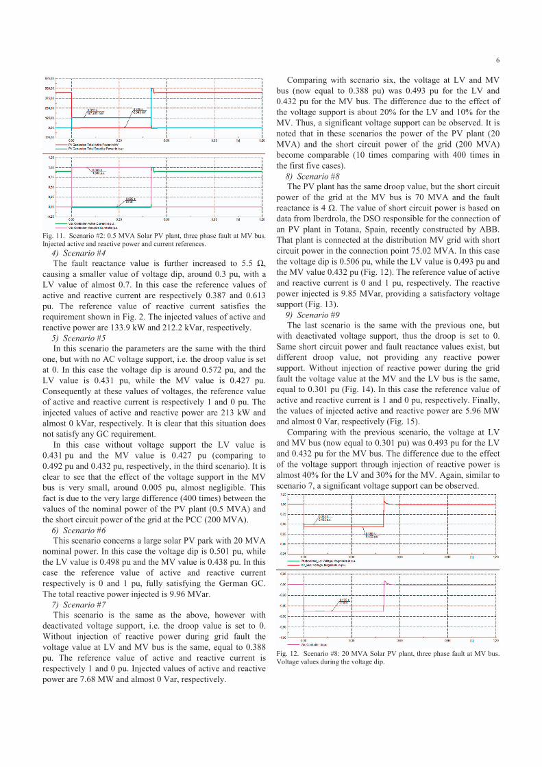
Comparing with scenario six, the voltage at LV and MV bus (now equal to 0.388 pu) was 0.493 pu for the LV and 0.432 pu for the MV bus. The difference due to the effect of the voltage support is about 20% for the LV and 10% for the MV. Thus, a significant voltage support can be observed. It is noted that in these scenarios the power of the PV plant (20 MVA) and the short circuit power of the grid (200 MVA) become comparable (10 times comparing with 400 times in the first five cases). 8) Scenario #8
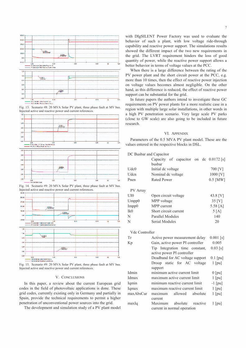
The PV plant has the same droop value, but the short circuit power of the grid at the MV bus is 70 MVA and the fault reactance is 4 . The value of short circuit power is based on data from Iberdrola, the DSO responsible for the connection of an PV plant in Totana, Spain, recently constructed by ABB. That plant is connected at the distribution MV grid with short circuit power in the connection point 75.02 MVA. In this case the voltage dip is 0.506 pu, while the LV value is 0.493 pu and the MV value 0.432 pu (Fig. 12). The reference value of active and reactive current is 0 and 1 pu, respectively. The reactive power injected is 9.85 MVar, providing a satisfactory voltage support (Fig. 13). 9) Scenario #9
The last scenario is the same with the previous one, but with deactivated voltage support, thus the droop is set to 0. Same short circuit power and fault reactance values exist, but different droop value, not providing any reactive power support. Without injection of reactive power during the grid fault the voltage value at the MV and the LV bus is the same, equal to 0.301 pu (Fig. 14). In this case the reference value of active and reactive current is 1 and 0 pu, respectively. Finally, the values of injected active and reactive power are 5.96 MW and almost 0 Var, respectively (Fig. 15).
Comparing with the previous scenario, the voltage at LV and MV bus (now equal to 0.301 pu) was 0.493 pu for the LV and 0.432 pu for the MV bus. The difference due to the effect of the voltage support through injection of reactive power is almost 40% for the LV and 30% for the MV. Again, similar to scenario 7, a significant voltage support can be observed.
Fig. 12. Scenario #8: 20 MVA Solar PV plant, three phase fault at MV bus. Voltage values during the voltage dip.
7
Fig. 13. Scenario #8: 20 MVA Solar PV plant, three phase fault at MV bus. Injected active and reactive power and current references.
Fig. 14. Scenario #9: 20 MVA Solar PV plant, three phase fault at MV bus. Injected active and reactive power and current references.
Fig. 15. Scenario #9: 20 MVA Solar PV plant, three phase fault at MV bus. Injected active and reactive power and current references.
V. CONCLUSIONS In this paper, a review about the current European grid
codes in the field of photovoltaic applications is done. These grid codes, currently existing only in Germany and partially in Spain, provide the technical requirements to permit a higher penetration of unconventional power sources into the grid.
The development and simulation study of a PV plant model
with DIgSILENT Power Factory was used to evaluate the behavior of such a plant, with low voltage ride-through capability and reactive power support. The simulations results showed the different impact of the two new requirements in the grid. The LVRT requirement hinders the loss of good quantity of power, while the reactive power support allows a better behavior in terms of voltage values at the PCC.
When there is a large difference between the rating of the PV power plant and the short circuit power at the PCC, e.g. more than 10 times, then the effect of reactive power injection on voltage values becomes almost negligible. On the other hand, as this difference is reduced, the effect of reactive power support can be substantial for the grid.
In future papers the authors intend to investigate these GC requirements on PV power plants for a more realistic case in a region with multiple large solar installations, in other words in a high PV penetration scenario. Very large scale PV parks (close to GW scale) are also going to be included in future research.
VI. APPENDIX Parameters of the 0.5 MVA PV plant model. These are the
values entered in the respective blocks in DSL.
DC Busbar and Capacitor Capacity of capacitor on dc
busbar 0.0172 [s]
Udc0 Initial dc voltage 700 [V] Udcn Nominal dc voltage 1000 [V] Pnen Rated Power 0.5 [MW]
PV Array
UI0 Open circuit voltage 43.8 [V] Umpp0 MPP voltage 35 [V] Impp0 MPP current 5.58 [A] Ik0 Short circuit current 5 [A] N Parallel Modules 140 N Serial Modules 20
Vdc Controller
Tr Active power measurement delay 0.001 [s] Kp Gain, active power PI controller 0.005 Tip Integration time constant,
active power PI controller 0.03 [s]
Deadband for AC voltage support 0.1 [pu] Droop static for AC voltage
support 1 [pu]
Idmin minimum active current limit 0 [pu] Idmax maximum active current limit 1 [pu] Iqmin minimum reactive current limit -1 [pu] Iqmax maximum reactive current limit 1 [pu] maxAbsCur maximum allowed absolute
current 1 [pu]
maxIq Maximum absolute reactive current in normal operation
1 [pu]

8
PLL
Controller Gain 1 Integration Gain 0.1 Upper frequency limit 1.2 Lower frequency limit 0.8
VII. REFERENCES [1] Technical Guideline: Generating Plants Connected to the Medium-
Voltage Network, Bundesverband der Energie- und Wasserwirtschaft e.V., BDEW, June 2008.
[2] Supplement to the Guideline on „Generating Plants Connected to the Medium-Voltage Network“ (June 2008 edition), BDEW, January 2009.
[3] Total PV installed capacity until 2010/11/30 from SMA website, based on data from the Database of the German Federal Energy Agency. Available online: http://www.sma.de/en/news-information/pv-electricity-produced-in-germany.html
[4] Grid Code: High and Extra High Voltage, E.ON Netz GmbH, Bayreuth, April 2006.
[5] Requisitos técnicos de las instalaciones eólicas, fotovoltaicas y todas aquellas instalaciones de producción cuya tecnología no emplee un generador síncrono conectado directamente a la red, Draft copy of PO 12.2, October 2008, Spain.
[6] DIgSILENT Power Factory, www.digsilent.de [7] A.V. Timbus, T. Teodorescu, F. Blaabjerg, M. Liserre, P. Rodriguez,
"PLL Algorithm for Power Generation Systems Robust to Grid Voltage Faults," 37th IEEE Power Electronics Specialists Conference, 2006. PESC '06, pp.1-7, 18-22 June 2006.