Part VIII – Electrical Installations and Control Systems - Polski ...
173
RULES FOR THE CLASSIFICATION AND CONSTRUCTION OF SEA-GOING SHIPS PART VIII ELECTRICAL INSTALLATIONS AND CONTROL SYSTEMS January 2022 GDAŃSK
-
Upload
khangminh22 -
Category
Documents
-
view
3 -
download
0
Transcript of Part VIII – Electrical Installations and Control Systems - Polski ...

RULES
FOR THE CLASSIFICATION AND CONSTRUCTION OF SEA-GOING SHIPS
PART VIII
ELECTRICAL INSTALLATIONS AND CONTROL SYSTEMS
January 2022
GDAŃSK

RULES FOR CLASSIFICATION AND CONSTRUCTION OF SEA-GOING SHIPS
developed and edited by Polski Rejestr Statków S.A., hereinafter referred to as PRS, consist of the following Parts:
Part I – Classification Regulations
Part II – Hull
Part III – Hull Equipment
Part IV – Stability and Subdivision
Part V – Fire Protection
Part VI – Machinery Installations and Refrigerating Plants
Part VII – Machinery, Boilers and Pressure Vessels
Part VIII – Electrical Installations and Control Systems
Part IX – Materials and Welding.
Part VIII – Electrical Installations and Control Systems – January 2022 was approved by the PRS Board on
14 December 2021 and enters into force on 1 January 2022.
From the entry into force, the requirements of Part VIII – Electrical Installations and Control Systems fully apply to
new ships.
With regard to existing ships, the requirements of Part VIII – Electrical Installations and Control Systems are
applicable within the scope specified in Part I – Classification Regulations.
The requirements of Part VIII – Electrical Installations and Control Systems are extended by the following
Publications:
Publication 9/P – Requirements for Computer Systems,
Publication 11/P – Environmental Tests on Marine Equipment,
Publication 15/P – Current Rating Tables for Cables, Wires and Busbars in Marine Installations,
Publication 35/P – One Man Bridge Operation (OMBO) Ships,
Publication 42/P – Testing of Electric Machines.
Publication 25/P – Technical Requirements for Shipboard Power Electronic Systems,
Publication 79/P – Type Testing Procedure for Crankcase Oil Mist Detection and Alarm Equipment,
Publication 90/P – Guidance for Safe Return to Port and Orderly Evacuation and Abandonment of Passenger Ship,
Publication 102/P – EU RO Mutual Recognition of Type Approval,
Publication 103/P – Guidelines for energy efficiency of ships,
Publication 106/P – ECO Class Rules,
Publication 117P – Using LNG or other Low-Flashpoint Fuels onboard Ships other than Gas Carriers,
Publication 120/P – Requirements for Vessels and Units with Dynamic Positioning Systems,
Publikacja 5/I – Wytyczne do przeprowadzania okresowych przeglądów klasyfikacyjnych elektrycznych urządzeń
przeciwwybuchowych na statkach w eksploatacji (available in Polish only),
Publikacja 9/I – Materiały elektroizolacyjne (available in Polish only).
© Copyright by Polski Rejestr Statków S.A., 2022
PRS/RP, 12/2021

CONTENTS Page
1 General .............................................................................................................................................................. 7 1.1 Application ................................................................................................................................................. 7 1.2 Definitions .................................................................................................................................................. 7 1.3 Scope of Survey ......................................................................................................................................... 9 1.4 Technical Documentation of a Ship ........................................................................................................... 11 1.5 Technical Documentation of Equipment ................................................................................................... 13
2 General Requirements ..................................................................................................................................... 14 2.1 Operating Conditions ................................................................................................................................. 14 2.2 Materials..................................................................................................................................................... 17 2.3 Design Requirements and Degrees of Enclosures Protection .................................................................... 18 2.4 Earthing of Non-current-carrying Metal Parts ........................................................................................... 20 2.5 Lightning Protection .................................................................................................................................. 22 2.6 Arrangement of Equipment ........................................................................................................................ 23 2.7 Special Electrical Spaces ........................................................................................................................... 24 2.8 Electrical Equipment in Hazardous Spaces ............................................................................................... 24 2.9 Additional Requirements for Ships Carrying Dangerous Goods ............................................................... 26
3 Main Source of Electric Power ........................................................................................................................ 27 3.1 General Requirements ................................................................................................................................ 27 3.2 Electric Generating Sets ............................................................................................................................. 28 3.3 Number and Power of Transformers .......................................................................................................... 30 3.4 Power Supply from an External Source of Electric Power ........................................................................ 30 3.5 Connection of Supply Sources ................................................................................................................... 30
4 Distribution of Electric Power ......................................................................................................................... 32 4.1 Distribution Systems .................................................................................................................................. 32 4.2 Permissible Voltages .................................................................................................................................. 32 4.3 Power Supply to Essential Services ........................................................................................................... 33 4.4 Power Supply to Ship Navigation Control and Monitoring Consoles ....................................................... 34 4.5 Distribution Switchboards.......................................................................................................................... 34
5 Electric Drives for Machinery and Equipment ............................................................................................. 41 5.1 General Requirements ................................................................................................................................ 41 5.2 Interlocking of Machinery Operation ........................................................................................................ 41 5.3 Safety Devices............................................................................................................................................ 41 5.4 Switchgear and Machine Control Gear ...................................................................................................... 41 5.5 Electric Drives for Steering Gear ............................................................................................................... 42 5.6 Electric Drives for Anchor and Mooring Machinery ................................................................................. 46 5.7 Electric Drives for Pumps .......................................................................................................................... 47 5.8 Electric Drives for Fans ............................................................................................................................. 47 5.9 Electric Drives for Boat Winches .............................................................................................................. 48 5.10 Electric Drives for Watertight and Fireproof Doors .................................................................................. 48
6 Lighting ............................................................................................................................................................. 49 6.1 General Requirements ................................................................................................................................ 49 6.2 Supply to the Lighting Circuits .................................................................................................................. 49 6.3 Emergency Lighting ................................................................................................................................... 50 6.4 Switches in Lighting Circuits ..................................................................................................................... 51 6.5 Fluorescent and Gas Discharge Lamps ...................................................................................................... 51 6.6 Socket Outlets and Plugs............................................................................................................................ 51 6.7 Illumination Intensity ................................................................................................................................. 52 6.8 Navigation Lights ....................................................................................................................................... 53

7 Internal Communication and Signalling ........................................................................................................ 54 7.1 General Requirements ................................................................................................................................ 54 7.2 Electric Engine-room Telegraphs............................................................................................................... 54 7.3 Internal Service Communication ................................................................................................................ 54 7.4 General Alarm System ............................................................................................................................... 56 7.5 Fire Detection System ................................................................................................................................ 58 7.6 Warning Signalisation of Fire-extinguishing Systems Operation .............................................................. 60 7.7 Indication of Closing Watertight and Fire Doors ....................................................................................... 61 7.8 Alarm System in the Accommodation Spaces for Engineering Personnel ................................................ 61 7.9 Single Hold Cargo Ships Water Detection System .................................................................................... 61 7.10 Alert Management System on Navigation Bridge ..................................................................................... 61
8 Protective Devices ............................................................................................................................................. 64 8.1 General Requirements ................................................................................................................................ 64 8.2 Protection of Generators............................................................................................................................. 64 8.3 Protection of Electric Motors ..................................................................................................................... 66 8.4 Protection of Steering Gear Motors ........................................................................................................... 66 8.5 Protection of Transformers......................................................................................................................... 67 8.6 Protection of Storage Batteries ................................................................................................................... 67 8.7 Protection of Pilot Lamps, Voltmeters, Capacitors and Voltage Coils of Apparatus ................................ 67 8.8 Protection of Power-electronic Equipment ................................................................................................ 67 8.9 Protection of Emergency Circuits .............................................................................................................. 68
9 Emergency Source of Electric Power and Distribution of Power from Emergency Sources .................... 69 9.1 General Requirements ................................................................................................................................ 69 9.2 Spaces of Emergency Sources of Electric Power....................................................................................... 69 9.3 Emergency Sources of Electric Power in Cargo Ships .............................................................................. 70 9.4 Distribution of Electric Power from Emergency Sources .......................................................................... 72 9.5 Starting Arrangements of Emergency Generating Sets.............................................................................. 73 9.6 Uninterruptible Power System (UPS) Units as Battery or Transitional Emergency Power Systems ........ 74
10 Electric Machines ............................................................................................................................................ 75 10.1 General Requirements ............................................................................................................................ 75 10.2 Rings, Commutators and Brushes .......................................................................................................... 75 10.3 Bearings .................................................................................................................................................. 75 10.4 Temperature Sensors .............................................................................................................................. 76 10.5 Overcurrent ............................................................................................................................................. 76 10.6 Alternating-current Generators ............................................................................................................... 76 10.7 Direct-current Generators ....................................................................................................................... 77 10.8 Electromagnetic Brakes .......................................................................................................................... 78
11 Transformers ................................................................................................................................................... 79 11.1 General Requirements ............................................................................................................................ 79 11.2 Overloads, Voltage Variations and Parallel Operation .......................................................................... 79
12 Power-electronic Equipment .......................................................................................................................... 80 12.1 General Requirements ............................................................................................................................ 80 12.2 Permissible Parameters of Voltage Distortion ....................................................................................... 80 12.3 Control and Signalling Systems ............................................................................................................. 81
13 Storage Batteries ............................................................................................................................................... 82 13.1 General Requirements ............................................................................................................................ 82 13.2 Arrangement of Accumulator Batteries.................................................................................................. 82 13.3 Heating ................................................................................................................................................... 83 13.4 Ventilation .............................................................................................................................................. 83 13.5 Charging the Accumulator Batteries ...................................................................................................... 83 13.6 Installation of Electrical Equipment in Battery Compartments ............................................................. 83

13.7 Electric Starters for Internal Combustion Engines ................................................................................. 83 13.8 Batteries for Essential and Emergency Services .................................................................................... 84
14 Electrical Apparatus and Accessories ........................................................................................................... 85 14.1 Electrical Apparatus ............................................................................................................................... 85 14.2 Installation Fittings ................................................................................................................................. 86
15 Heating Appliances ........................................................................................................................................... 88 15.1 General Requirements ............................................................................................................................ 88 15.2 Space Heating Appliances ...................................................................................................................... 88 15.3 Cooking Appliances ............................................................................................................................... 88 15.4 Oil and Fuel Heating Appliances ........................................................................................................... 89
16 Cables and Conductors ................................................................................................................................... 90 16.1 General Requirements ............................................................................................................................ 90 16.2 Conductors ............................................................................................................................................. 90 16.3 Insulating Materials ................................................................................................................................ 91 16.4 Cable Sheaths ......................................................................................................................................... 91 16.5 Protective Coverings .............................................................................................................................. 91 16.6 Marking .................................................................................................................................................. 92 16.7 Wiring..................................................................................................................................................... 92 16.8 Cabling ................................................................................................................................................... 92
17 Special Electrical Systems in Ships.............................................................................................................. 102 17.1 Electric Propulsion Plant ...................................................................................................................... 102 17.2 Dynamic Positioning (DP) Systems ..................................................................................................... 102
18 Additional Requirements for Equipment of above 1000 V ....................................................................... 103 18.1 General Requirements .......................................................................................................................... 103 18.2 Power Distribution ............................................................................................................................... 103 18.3 Protective Devices ................................................................................................................................ 104 18.4 Protective Earthing ............................................................................................................................... 105 18.5 Arrangement and Protection Degree of Electrical Equipment ............................................................. 106 18.6 Switchboards ........................................................................................................................................ 106 18.7 Electric Machines ................................................................................................................................. 107 18.8 Transformers ........................................................................................................................................ 108 18.9 Cabling ................................................................................................................................................. 108 18.10 Voltage Tests of Main Circuits ............................................................................................................ 109
19 Requirements for Electrical Equipment of Refrigerating Installations .................................................. 110 19.1 General Requirements .......................................................................................................................... 110 19.2 Power Supply ....................................................................................................................................... 110 19.3 Ventilation ............................................................................................................................................ 110 19.4 Lighting ................................................................................................................................................ 111
20 Automation and Remote Control Systems.................................................................................................. 112 20.1 Application ........................................................................................................................................... 112 20.2 Design Requirements ........................................................................................................................... 112 20.3 Power Supply of Automatic Systems ................................................................................................... 114 20.4 Monitoring Systems ............................................................................................................................. 115 20.5 Main Propulsion Control Systems........................................................................................................ 117 20.6 Electrical Power Supply and Distribution Control System .................................................................. 119 20.7 Control Systems of Steam Boilers ....................................................................................................... 120 20.8 Control Systems of Piping Installations ............................................................................................... 120
20.9 Monitoring of trunk piston internal combustion engines supplied with low pressure
natural gas as fuel - control, monitoring, alarm and safety system ………………………………… 120

21 Unattended Operation of Machinery Space and One Man Bridge Operation – marks: AUT, NAV1 123 21.1 Application .......................................................................................................................................... 123 21.2 General Requirements ......................................................................................................................... 123 21.3 Monitoring Systems ............................................................................................................................ 124 21.4 Control Systems .................................................................................................................................. 125 21.5 Personnel Alarm .................................................................................................................................. 126 21.6 Engineers’ Alarm................................................................................................................................. 126
22 Requirements for Assignment of Additional Mark in the Symbol of Class .......................................... 139 22.1 Passenger Ships – Mark: PASSENGER SHIP .................................................................................... 139 22.2 Roll on – Roll off Passenger Ships and Passenger Ferries – Marks: RO-RO/
PASSENGER SHIP, FERRY/ PASSENGER SHIP ........................................................................... 145 22.3 Roll on – Roll off Ships and Ferries – Marks: RO-RO SHIP, FERRY............................................... 147 22.4 Container Ships and Ships Intended for the Carriage of Containers – Marks: CONTAINER SHIP,
ACC (…) ............................................................................................................................................. 148 22.5 Crude Oil Tankers, Product Carriers, Gas Tankers, Chemical Tankers,
Ships Intended for Operation in Oil Spillage Area – Marks: CRUDE OIL TANKER,
PRODUCT CARRIER A, LIQUEFIED GAS TANKER, CHEMICAL TANKER,
OIL RECOVERY VESSEL ................................................................................................................ 150 22.6 Special Purpose Ships – Marks: RESEARCH SHIP, TRAINING SHIP .............................................. 156 22.7 Floating Cranes – Mark: FLOATING CRANE .................................................................................. 157 22.8 Bulk Carriers – Mark: BULK CARRIER ........................................................................................... 157 22.9 General Cargo Ships Occasionally Carrying Bulk Cargoes – mark: DRY CARGO SHIP ................ 158
22.10 Additional Requirements for Energy Efficient Ships
22.11 Ecological Ships – Mark: ECO AIR. .................................................................................................. 159 22.12 Chemical Spill Response Ships – mark: CHEMICAL RECOVERY VESSEL.................................. 159
22.13 Polar ships: marks: PC1, PC2, PC3, PC4, PC5, PC6 and PC7 ........................................................... 157
23 Spare Parts .................................................................................................................................................... 162 23.1 General Requirements ......................................................................................................................... 162 23.2 List of Spare Parts for Ship Electrical Equipment............................................................................... 162
Appendix 1 – Insulation Resistance of Cable Network ..................................................................................... 164
Appendix 2 – Values of Mechanical and Electrical Parameters to be Checked in Course of Testing Type
of Equipment and the Ship Electrical Installations ...................................................................... 165
Appendix 3 – Ship’s cyber security .................................................................................................................... 168
Supplement – Retroactive Requirements ............................................................................................................ 171

General
7
1 GENERAL
1.1 Application
1.1.1 Part VIII – Electrical Installations and Control Systems applies to electrical installations and
automatic systems in sea-going ships subject to PRS survey, as well as to particular types of equipment,
systems and their components in accordance with 1.3.
1.1.2 It is recommended that the relevant requirements of Part VIII should also cover electrical
equipment installed on ships, not specified in 1.3.2 and 1.3.3.
1.1.3 In addition to the requirements of the present Part of the Rules, the electrical equipment shall fulfil
the requirements of the national or international standards indicated by PRS.
1.1.4 In reasonably justified cases, the requirements of the present Part of the Rules may be waived
or extended by PRS, e.g.: in the case of innovatory solutions implementation.
1.2 Definitions
Definitions and explanations relating to the general terminology of the Rules for the Classification and
Construction of Sea-going Ships (hereinafter referred to as the Rules) are provided in Part I – Classification
Regulations. Wherever, in Part VIII, definitions contained in other Parts of the Rules are used, reference
to these Parts is made.
For the purpose of Part VIII, the following additional definitions have been adopted:
Additional source of electric power – a source of electric power intended to supply the electrical equipment
for domestic, living and technological applications only. Additional source of electric power with its
distribution system and consumers shall be totally separated from all other ship electric power systems.
Alarm system – the system intended to give warnings of conditions when deviations from the preset limits
on the selected parameters or changes in normal working conditions occur.
Automated machinery – an engine, machinery, installation or other devices equipped with automatic or
remote control systems.
Automatic control system – the system intended to control the machinery without human interference
according to the specified control function.
Automatic system – a defined number of components, units and their connections forming structural and
functional integrity, intended to perform control and monitoring functions.
Component of automatic system – the simplest and functionally self-dependent structural item used in
automatic systems (e.g. relay, resistor, logic element, sensor, final control element).
Dead ship condition – a condition under which the main propulsion plant, boilers and auxiliaries are not in
operation due to the absence of power. The absence of power means the starting battery discharge, the
absence of starting air needed for restoring the operation of the main propulsion plant, boilers and auxiliaries.
Earthing – metallic connection of equipment terminal with the ship metal hull.
Emergency condition – a condition under which any services needed for normal operational and habitable
conditions are not in working order due to failure of the main source of electric power.
Emergency lighting – lighting of the ship compartments and spaces by means of lighting fixtures fed from
the emergency source of power or from the transitional source of emergency electric power.
Emergency source of electric power – a source of electric power intended to supply emergency switchboard
for distribution of power to all the essential consumers on board the ship in the case of the loss of voltage
in the main switchboard busbars.

Electrical Installations and Control Systems
8
Emergency switchboard – a switchboard which, in the case of the loss of voltage in the main switchboard
busbars, is directly supplied from emergency source of electric power or from transitional source
of emergency electric power and is intended to distribute power to consumers which are necessary for
maintain safety of the ship during emergency.
Essential equipment – equipment which, under normal operation, ensures safe navigation, safety of cargo
and safety of human life on board the ship.
Fire-retardant insulating material – material satisfying the requirements specified in Publication 11/P –
Environmental Tests on Marine Equipment.
Hazardous area – an area in which an explosive gas atmosphere is present, or may be expected to be
present, in quantities such as to require special precautions for the construction, installation and use
of electrical apparatus.
Indicating system – the system intended to indicate values of given physical quantities or significant states.
Lightning conductor – conductor which ensures connection of spike with earthing.
Lightning protection zone – zone protected against direct lightning stroke.
Low-rated electrical installation – a shipboard electrical installation with the total output of sources
of electric power not exceeding 50 kW (kVA).
Machinery space – see sub-paragraph 1.2, Part V – Fire Protection.
Main generating station – a space where the main source of electrical power is situated.
Main source of electric power – a source intended to supply electric power to the main switchboard for
distribution to all services necessary for maintaining the ship in normal operational and habitable
conditions.
Main switchboard – a switchboard, which is directly supplied by the main source of electric power and is
intended to distribute electric energy to the ship services.
Monitoring systems – general term for alarm, safety and indicating systems.
Normal operational and habitable condition – a condition under which the ship as a whole, the machinery,
services, means and aids ensuring propulsion, ability to steer, safe navigation, fire and flooding safety,
internal and external communications and signals, means of escape, and emergency boat winches, as well as
the designed comfortable conditions of habitability are in working order and functioning normally.
Passive-EM equipment – electrical equipment which, when used as intended, does not create or produce
any switching or oscillation of current or voltage and is not affected by electromagnetic disturbances, e.g.
cables, cables accessories; equipment containing only resistive loads without any automatic switching
device; batteries and accumulators.
Remote control system – the system intended to affect remotely the machinery in order to achieve control
function given by the operator.
Safe voltage – any voltage not causing potential danger of electric shock or burn in normal conditions. This
condition is considered to be satisfied if the windings of transformers, converters and other devices
stepping down voltage are isolated electrically, and if the value of the stepped-down voltage across these
devices or sources of electric power does not exceed:
− 50 V between conductors for direct current,
− 50 V between conductors or between the hull and the phase for alternating current.
Safety system – the system intended to intervene in a specific way upon the machinery controlled in order
to prevent the failure of machinery or enlargement of its consequences.
Shaft generators – generators driven by the ship main propulsion plant supplying the ship power network
or individual consumers on board the ship.

General
9
Special electrical spaces – spaces or locations intended exclusively for electrical equipment and accessible
only for authorized personnel.
Spike – the upper part of the lightning conductor designed for the direct receiving of lightning strokes.
Steering gear control system (as defined in SOLAS II-1/A/3.1) – means the equipment required to control
the steering gear power actuating system.
Transitional source of emergency electric power – a source of electric power intended to supply all the
essential consumers from the moment the loss of voltage occurs in the main switchboard busbars until the
emergency generating set picks-up the load.
Unit of automatic system – part of the automatic system consisting of a certain number of components
forming structural and functional integrity.
Uninterruptible Power System (UPS) – combination of converters, switches and energy storage means,
e.g. batteries, constituting a power system for maintaining continuity of load power in case of input
power failure.
Zones – hazardous areas are classified into zones based upon frequency of the occurrence and duration
of an explosive atmosphere, as follows:
Zone 0 – a hazardous area in which an explosive gas atmosphere is present continuously or is present for
long periods. In Zone 0, only the following explosion-proof electrical equipment may be installed:
– intrinsically safe apparatus (Exia);
– simple electrical apparatus (thermocouples, photocells, strain gauges, junction boxes, switching
devices), not capable of storing or generating electrical power;
– electrical apparatus certified for use in Zone 0;
– submersible electrically-driven pumps, having at least two independent methods of shutting down
automatically in the event of low liquid level.
Zone 1 – an area, in which an explosive gas atmosphere is likely to occur in normal operation. In Zone 1,
the following explosion-proof electrical equipment may be installed:
– electrical equipment that may be considered for Zone 0;
– intrinsically safe apparatus (Exib), flameproof (Exd), pressurized (Exp), increased safety type (Exe),
encapsulated (Exm), sand filled (Exq), oil-immersed apparatus (Exo), certified specially (Exs);
– hull fittings containing the terminals for anodes or electrodes of an impressed current cathodic
protection or transducers (such as those for depth-sounding or log systems), provided that such fittings
are of gastight construction or are housed within a gas tight enclosure and are not located adjacent to
a cargo tank bulkhead;
– through runs of cables.
Zone 2 – an area in which an explosive gas atmosphere is not likely to occur in normal operation and if
it does occur, it is likely to do so infrequently and will exist for a short period of time. In Zone 2, the
following explosion-proof electrical equipment may be installed:
– any electrical equipment that may be considered for Zone 1;
– tested specially for Zone 2 (Exn);
– pressurized, accepted by PRS;
– having an enclosure filled with a liquid dielectric or encapsulated, accepted by PRS;
– the type which ensures the absence of sparks and arcs and of “hot spots” during its normal operation.
1.3 Scope of Survey
1.3.1 General
The general provisions relating to the classification procedure, survey during ship construction,
manufacture of equipment and to surveys are specified in Part I – Classification Regulations.

Electrical Installations and Control Systems
10
1.3.2 Survey of Electrical Installation in Ship
1.3.2.1 The following types of equipment and systems are subject to PRS survey during installation
on board:
.1 electrical propulsion plant;
.2 main and emergency, including transitional, sources of electric power;
.3 power and lighting transformers and electric power converters used in equipment listed in 1.3.2.1;
.4 distribution gear and control and monitoring panels;
.5 electric drives for:
− machinery essential for the operation of propulsion engines,
− steering gear and all devices for active steering of the ship,
− controllable pitch propellers,
− windlasses, mooring and towing winches,
− boat winches,
− starting air compressors and air compressors for sound signals,
− bilge and ballast pumps as well as cargo pumps on tankers;
− watertight doors and fire doors,
− pumps and compressors of the smothering system,
− ventilating fans in machinery spaces, cofferdams, cargo holds and hazardous rooms and spaces;
.6 main and emergency lighting of spaces and locations of essential machinery and means of escape;
.7 navigation lights and signalling lamps;
.8 electric engine-room telegraphs;
.9 internal service communication;
.10 general alarm system;
.11 fire detection signalling and warning system indicating the release of the fire extinguishing
medium;
.12 watertight door and fire door signals;
.13 electrical equipment in hazardous rooms and spaces;
.14 cabling;
.15 earthing devices on oil tankers;
.16 lightning conductors;
.17 electric drives of classified refrigerating machinery;
.18 electrical heaters of fuel and lubricating oil;
.19 heating appliances and space heaters;
.20 main propulsion control system;
.21 main propulsion safety system;
.22 generating sets automatic control system;
.23 safety system of engines driving generating sets;
.24 automatic system of pumps and air compressors;
.25 automatic system of oil and fuel separators;
.26 remote or automatic control system of bilge, ballast, and fuel transfer installations;
.27 machinery alarm system;
.28 control system of steam boilers;
.29 system regulating temperature, pressure and viscosity;
.30 other machinery and facilities not listed above, as required by PRS.
1.3.2.2 PRS classification survey on board the ship covers also all automatic systems which control
or monitor machinery, equipment or installations subject to PRS survey in accordance with the provisions
of the present Part of the Rules.
1.3.2.3 Electrical equipment intended for domestic, living and technological application shall be
surveyed by PRS within the following scope:
.1 influence of this equipment operation on the ship electric network parameters;
.2 choice of cable types, cable sections and the ways of running the cables;
.3 means of protection, insulation and earthing.

General
11
1.3.3 Survey of Electrical Equipment Manufacture
1.3.3.1 The following items of electrical equipment intended for systems and devices, specified
in 1.3.2.1, are subject to PRS survey during manufacture:
.1 generating sets;
.2 generators and electric motors of rating 50 kW (kVA) and above;
.3 transformers above 20 kVA rating;
.4 switchboards;
.5 control and monitoring panels;
.6 electric couplings and brakes;
.7 switchgear, protection and control devices;
.8 apparatus and devices of internal communication and signalling;
.9 rotary converters and power-electronic equipment;
.10 fuel and oil heaters;
.11 accumulators;
.12 cables;
.13 heating appliances and space heaters;
.14 photoluminescent materials and electrically powered lights of low-location lighting;
.15 lamps of additional emergency lighting;
.16 automatic pilots;
.17 public address system and general alarm systems;
.18 computers and programmable logic controllers;
.19 sensors and transducers;
.20 automation system controllers;
.21 power operated valves;
.22 servo-motors;
.23 electric, hydraulic and pneumatic relays;
.24 data loggers (if they perform functions covered by the Rules);
.25 uninterruptible power system (UPS) units of 3 kVA and above;
.26 other items of electrical equipment not listed above, as required by PRS.
1.3.3.2 Each explosion-proof electrical equipment shall be surveyed (with respect to its explosion
proofness) by a special body recognised by PRS for this purpose, irrespective of whether or not this
equipment is subject to survey according to the requirements specified in 1.3.3.1.
1.3.3.3 Test programme for electrical equipment will be specially considered by PRS in each particular
case and the values of the relevant test parameters are specified in Appendix 2.
1.3.4 Alternative/Innovatory Solutions Concerning Electrical Installations and Control Systems
Alternative/innovatory design or arrangements for electrical installations and control systems deviationg
from the prescriptive requirements of these Rules and SOLAS are permitted to be applied on board the ship
provided that the conditions specified in paragraph 1.1.3 of Part VI – Machinery Installations
and Refrigerating Plants are fulfilled.
1.4 Technical Documentation of a Ship
1.4.1 Classification Documentation of a Ship under Construction
1.4.1.1 Prior to the commencement of ship construction, documentation listed in 1.4.1.2 to 1.4.1.4,
shall be submitted to PRS Head Office for consideration and approval.
1.4.1.2 Classification documentation of electrical equipment:
.1 principle diagrams of power generation and distribution circuits of the main and emergency electric
power sources: power circuits, lighting circuits (up to branch circuit board) and navigation light
circuits;

Electrical Installations and Control Systems
12
.2 specification of data on the circuits with indication of current values, the applied protective devices,
as well as the types and cross-sectional areas of cables;
.3 principle diagrams and a general view of the main and emergency switchboards, ship navigation
control and monitoring console and other devices of non-standard design;
.4 calculation results of electric power plant output necessary to provide operation of the ship
in conditions specified in 3.1.6, as well as the basis for the choice of the number and output
of generators and the calculation of power of electric power emergency sources;
.5 principle or detailed diagrams of main, excitation, control, monitoring, signalization, protection
and interlocking circuits of the ship electric propulsion plant machines;
.6 calculation results of the ship electric propulsion plant generators output necessary to provide
operation in all conditions;
.7 calculation results of short-circuit currents on the main switchboard busbars and in the other points
of electric network – as the basis for the choice of switching and protecting apparatus of generators
and consumers, as well as for checking electrodynamic and thermal loads to which apparatus,
wiring and busbars of main switchboard and other distribution equipment shall correspond –
together with the selection of protective devices;
.8 results of calculation of illumination intensity for important compartments and open locations for
information;
.9 diagrams of internal communication and signalling;
.10 principle diagrams of essential electric drives according to 1.3.2.1.5;
.11 diagram of lubricating and air cooling systems of main propulsion el. motors;
.12 diagrams of protective earthing, drawings and if necessary, calculation of lightning conductors for
tankers, gas carriers and combined ships;
.13 principle diagram of cable passages with indication of compartments through which they pass;
.14 results of capacity calculations of accumulator batteries supplying emergency lighting, navigation
lights, general alarm and fire detection systems;
.15 data on electrical equipment in spaces where explosion hazard exists;
.16 diagrams of remote switching-off ventilation, fuel pumps and lubricating pumps;
.17 arrangement plans of main and emergency generators, main and emergency switchboards,
accumulator batteries, equipment of explosion-proof execution;
.18 maintenance schedule for accumulator batteries intended for the supply of essential and emergency
services (for details see paragraph 13.8.1); .19 detailed risk assessment document for steering gear (demonstrating that in the case of any single
failure in the steering gear, control system and power supply to the ship steering is maintained).
1.4.1.3 When classed refrigerating installation is foreseen, documentation listed in 1.4.1.2 shall include
data concerning electrical equipment of refrigerating installation.
1.4.1.4 Classification documentation of shipboard automated machinery:
.1 technical description including: specification of parameters covered by alarm, safety and automatic
control systems, information concerning continuity of lubrication of cylinders and machinery of main
engine, supply of fuel, steam, etc. and other means necessary for execution of unattended operation,
as well as accepted method of repair and maintenance of particular units or elements of automatic
systems, data concerning reliability of particular systems or their units;
.2 functional diagrams of particular automatic systems with regard to the respective equipment,
machinery and installations, giving information concerning: method of supply, functional features,
structure, eventual connections with other systems as well as the kind and limit values of parameters
covered by these systems;
.3 drawings of particular units of automatic systems such as desks, consoles, showing their elevation
and arrangement of internal components, as well as their location on board the ship;
.4 in the case of applying computer systems for control or checking the machinery and installations, the
above documentation shall be supplemented according to Publication 9/P – Requirements for
Computer Systems, paragraph 1.4.

General
13
1.4.2 Workshop Documentation of a Ship under Construction
In the case of approval of the classification documentation listed in 1.4.1, the following workshop
documentation shall be submitted to the relevant PRS Branch Office or Survey Station for agreement:
.1 drawings of cabling and cable fastening;
.2 diagrams of final circuits of emergency switchboard and emergency lighting;
.3 diagrams of final circuits of lighting switchboards;
.4 test programme for ship electrical equipment and automated machinery performed alongside the
quay and at sea.
1.4.3 Classification Documentation of a Ship under Alteration or Reconstruction
1.4.3.1 Prior to the commencement of alteration or reconstruction of a ship, documentation relating to
installations, systems and equipment subject to alteration or reconstruction shall be submitted to PRS Head
Office for consideration and approval.
1.4.3.2 Where new machinery or arrangements, covered by the requirements of the Rules, are installed,
or machinery installed differs substantially from those initially fitted, additional documentation, within the
scope required for a new ship, shall be submitted to the PRS Head Office (see 1.4.1).
1.5 Technical Documentation of Equipment
1.5.1 Prior to the commencement of supervising the manufacture of electrical equipment or control
systems, the following documentation shall be submitted to PRS for consideration:
.1 description of the principle of operation and the main characteristics;
.2 material specification which shall contain elements, instruments and materials used and their
technical characteristics;
.3 assembly drawing with sections;
.4 circuit diagram;
.5 technical specifications and the test programme;
.6 the rotor shaft mechanical strength calculations, drawings of poles and commutator fastenings for
machines of rating 50 kW (kVA) and above;
.7 for distribution switchboards – calculation of thermal and electrodynamic strength of busbars under
short-circuit conditions and the choice of apparatus to fit these conditions where the current rating
of a generator or generators running in parallel exceeds 1000 A;
.8 for generating sets – selection of output of internal combustion engine for generator, list
of sensors and their limit values, as well as calculation of torsional vibrations;
.9 data on static or dynamic interference resistance, or the means of testing the electro-magnetic
compatibility;
.10 definite means of interference damping;
.11 for engine control systems – a failure mode and effect analysis (FMEA) and (for reference)
PRS-issued Type Approval Certificate for the components used1.
Where necessary, PRS may require that additional documentation and data on reliability should be
submitted.
1 The requirement applies to engines submitted for certification on or after 1 July 2016.

Electrical Installations and Control Systems
14
2 GENERAL REQUIREMENTS
2.1 Operating Conditions
When designing, selecting and arranging electrical equipment, the operating conditions specified
in 2.1.1 to 2.1.4 shall be taken into account.
2.1.1 Climatic Hazards
2.1.1.1 The temperature values, specified in Table 2.1.1.1, shall be taken as the rated ambient air and
cooling water temperatures for electrical equipment. The use of electrical equipment for other temperature
ranges is subject to PRS consideration in each particular case.
Table 2.1.1.1
Item Location in the ship
Ambient air and cooling water temperature, [C]
Unrestricted service Service outside the tropic
Air Water Air Water
1 Machinery spaces, special
electrical spaces, galleys from 0 to 45 30 from 0 to 40 25
2 Open decks and spaces from –25 to 45 – from –25 to 40 –
3 Other spaces from 0 to 40 – from 0 to 40 –
Notes:
1) For electrical machines located in machinery space, maximum air temperature equal to +50C shall be taken.
2) Electronic equipment and components intended to be installed in switchboards, desks and enclosures shall be capable
of correct operation at the ambient air temperature of up to 55C. The temperature of up to 70C should not cause damage to
components, equipment and systems.
2.1.1.2 Electrical equipment shall be capable of correct operation at a relative air humidity of 75 3%
and a temperature of +45 2C or at a relative air humidity of 80 3% and a temperature of +40 2C or
at a relative air humidity of 95 3% and a temperature of +25 2C.
2.1.1.3 The structural parts of electrical equipment shall be made of materials resistant to sea air
or reliably protected against its effects.
2.1.2 Mechanical Hazards
2.1.2.1 Electrical equipment shall be capable of correct operation at vibrations with a frequency
of 2 Hz to 100 Hz, as follows:
– at a frequency from 2 Hz to 13.2 Hz with displacement amplitude 1.0 mm;
– at a frequency from 13.2 Hz to 100 Hz with acceleration amplitude 0.7 g.
Electrical equipment intended to be installed in locations in which specific severe vibration conditions
prevail (e.g. internal combustion engines, compressors) or to be installed in the steering gear compartment
shall be capable of correct operation at vibrations with a frequency of 2 Hz to 100 Hz, as follows:
– at a frequency from 2 Hz to 25 Hz with displacement amplitude 1.6 mm;
– at a frequency from 25 Hz to 100 Hz with acceleration amplitude 4.0 g.
2.1.2.2 Electrical equipment shall be capable of reliable operation with the ship continuously inclined
from the normal up to 15 transversely and up to 5 of trimming, as well as with the ship rolling up to 22.5
with the period of rolling of 10 sec. or pitching up to 10.
Emergency equipment shall also be capable of functioning reliably with the ship continuously inclined
up to 22.5 transversely or up to 10 of trimming, or within the same limits both transversely and
longitudinally.
2.1.2.3 Electrical safety equipment, switchgear, electrical and electronic appliances and remote control
systems are to operate properly in the following ambient conditions of angle of inclination:

General Requirements
15
Table 2.1.2.3
Installations, components
Angle of inclination [°]2
Athwartships Fore-and-aft
Static Dynamic Static Dynamic
Safety equipment, e.g. emergency power installations, emergency fire pump
and their devices
Switch gear, electrical and electronic appliances1 and remote control
systems
22.53 22.53 10 10
1 No undesired switching operations or operational changes are to occur. 2 Athwartships and fore-and-aft inclinations may occur simultaneously. 3 In ships for the carriage of liquefied gases and chemicals the emergency power supply must also remain operable with the ship
flooded to a final athwartships inclination up to maximum of 30°.
2.1.2.4 Electrical equipment shall have adequate mechanical strength and shall be so located that it is
not exposed to a risk of mechanical damage (see also 2.6.4).
2.1.3 Power Supply Parameters
2.1.3.1 Electrical equipment shall be so designed that it remains operative under steady conditions in
all cases, at all deviations from the rated values of voltage and frequency specified in the Tables: Table
2.1.3.1-1 – for a.c. distribution systems, Table 2.1.3.1-2 – for d.c. distribution systems, Table 2.1.3.1-3 –
for battery systems (see also 14.1.3.2 to 14.1.3.5 ).
Table 2.1.3.1-1
Voltage and frequency variations for a.c. distribution systems
Parameters
Deviations from rated values
Prolonged Transient
Value Time
Voltage +6%, –10% ±20% 1.5 sec
Frequency ±5% ±10% 5 sec
Table 2.1.3.1-2
Voltage variations for d.c. distribution systems
Parameters Variations
Voltage tolerance (continuous) ±10%
Voltage cyclic variation deviation 5%
Voltage ripple (a.c.r.m.s. over steady d.c. voltage) 10%
Table 2.1.3.1-3
Voltage variations for battery systems
Systems Variations
Components connected to the battery during charging (see Note) +30%, –25%
Components not connected to the battery during charging +20%, –25%
Note: Different voltage variations as determined by the charging/discharging characteristics,
including ripple voltage from the charging device, may be considered.
2.1.3.2 Where loads are supplied from a battery via an electronic converter or inverter, the maximum
permitted d.c. voltage variations shall be taken as those on the load side of the converter or inverter. Where
the d.c. is converted into a.c., the maximum variations shall not exceed those specified in Table 2.1.3.1-1.

Electrical Installations and Control Systems
16
2.1.4 Electromagnetic Interference
2.1.4.1 Electrical and electronic shipborne equipment shall be resistant to the following interference:
.1 electrostatic discharge;
.2 radiated electromagnetic field;
.3 fast transient interference;
.4 conducted radio frequency interference;
.5 surge voltage immunity;
.6 conducted audio frequency interference.
The test parameters are specified in Publication 11/P – Environmental Tests on Marine Equipment and in
IEC 60092-504.
2.1.4.2 Ship electrical and electronic equipment shall not emit excessive electromagnetic, radiated and
conducted interferences.
The test parameters are specified in Publication 11/P – Environmental Tests on Marine Equipment and in
IEC 60092-504.
2.1.4.3 For the purpose of protecting the radio receiving equipment from electrical interference,
the requirements specified in the SOLAS Convention shall be fulfilled (these requirements are also
specified in Chapter 4, Part IV – Radio Equipment of the Rules for Statutory Survey of Sea-going Ships).
2.1.4.4 Screens of power cables, metal coating and armouring of cables shall be earthed as often
as practicable at least at the points of their connections and at each end, connecting them to the metal
enclosures of electrical equipment and to the ship hull.
2.1.4.5 All signal, control and information cables shall be screened. Metallic screens of these cables
shall be earthed appropriately to the number of screens. In the case of using double-screened cables and
appearance of high frequency field interference, internal and external screens shall be earthed on both sides
and connected to equipment earthing. Internal cable screens may be earthed on one side if low frequency
interference occurs. The above-mentioned principles do not concern screened concentric cables.
2.1.4.6 In all cases, the electrical continuity of all cable sheaths shall be provided, i.e. in cable junction
and connecting boxes, as well as at the point of cable penetration of bulkheads.
2.1.4.7 Conductors which earth cable screens may be star connected to the earthing bus of switchboard,
if such bus exists, or directly to ship metallic hull.
2.1.4.8 To prevent contacts with the ship hull, screens of signal conductors shall be covered with
an insulated outer sheath.
2.1.4.9 The screens and enclosures of electrical equipment placed on the navigation bridge shall be
earthed.
The screens of cables and flexible cords shall be earthed in accordance with 2.4.3.5.
The screens and enclosures of passive-EM equipment which do not generate radio interference need
not be earthed, provided the electrical equipment itself does not require protective earthing.
2.1.4.10 It is recommended that screened cables with pair or multipair twisted wires be used to increase
their resistance to electromagnetic interference.
2.1.4.11 When installing electrical equipment and cables in the vicinity of magnetic compasses, the
requirements specified in the SOLAS Convention shall be satisfied (these requirements are also specified
in sub-chapter 4.2, Part V – Navigational Equipment of the Rules for Statutory Survey of Sea-going Ships).
2.1.4.12 Telephone cables and cables of other internal communication systems, except for the cables
connecting separate telephone sets, as well as cables of electrical medical equipment capable of generating
radio interference, shall be screened.

General Requirements
17
2.1.4.13 In ships constructed of non-current-carrying materials where radio equipment installation is
required, all cables installed within the radius of 9 m from antenna shall be screened or otherwise
effectively protected against interference.
2.2 Materials
2.2.1 Construction Materials
2.2.1.1 The structural parts of electrical equipment shall be made of metal or at least of hardly
combustible insulating materials, resistant to sea air and oil vapour effects, or they shall be reliably
protected against such effects.
2.2.1.2 Screws, nuts, hinges and similar items designed to fasten enclosures of the electrical
equipment to be installed on weather decks or in spaces with higher than normal humidity shall be made
of corrosion-resistant materials or shall have effective corrosion-resistant covering.
2.2.1.3 All current-carrying parts of electrical equipment shall be made of copper, copper alloys or other
materials of equivalent qualities, with the exception of:
.1 rheostat elements which shall be made of mechanically strong materials having high resistivity and
capable of withstanding high temperature;
.2 rotor cages windings of asynchronous and synchronous motors which can be made of aluminium
or its alloys resistant to sea conditions;
.3 carbon brushes and rings, cermet contacts and similar parts when the properties specified so
require;
.4 parts of electrical equipment connected directly to the hull used as return conductor in one-wire
system.
The use of other materials for current-carrying parts is subject to PRS consideration in each particular case.
2.2.2 Insulating Materials
2.2.2.1 Insulating materials of live parts shall have adequate dielectric and mechanical strength,
resistance to creepage currents, moisture and oil vapour or else they shall be effectively protected.
At the rated load, the temperature of the parts carrying current and the points of their connections shall
not be greater than the permissible temperature of the applied insulating material.
2.2.2.2 Uninsulated parts of electrical equipment shall be cooled by incombustible liquids only.
2.2.2.3 The insulating materials to be used for winding insulation in machines, apparatus and other
equipment for essential services shall be those specified in Table 3.1, Appendix 2. The use of insulating
materials of at least Class E is recommended.
2.2.2.4 Conductors used in electrical devices for internal connections shall have insulation made
of materials rated at least as hardly combustible. For apparatus with increased heating, as well as those
specified in Chapter 15 – of incombustible materials.
2.2.2.5 Insulating materials used for manufacturing cables shall fulfil the requirements specified in 16.3.
2.2.3 Usage of materials that contain asbestos in installations (e.g. thermal insulating materials, electrical
cable materials, cable penetration sealing, brake linings, circuit breakers arc chutes), including spare parts,
is prohibited for all ships according to SOLAS Regulation II-1/3-5, IACS UI SC 249 as well as
MSC.1/Circ.1374 and MSC.1/Circ.1379.

Electrical Installations and Control Systems
18
2.3 Design Requirements and Degrees of Enclosures Protection
2.3.1 General Requirements
2.3.1.1 Parts which may require replacement while in service shall be easily dismountable.
2.3.1.2 Where screw fastenings are applayed, measures shall be taken to exclude self-loosening
of screws and nuts or, where dismantling and opening are at frequent occurrence, loss of some.
2.3.1.3 Gaskets used in conjunction with electrical equipment components (such as doors, covers, sight
holes, packing glands, etc.) shall be appropriate to the degree of enclosure protection of the equipment in
question.
Gaskets shall be secured to the covers or casings.
2.3.1.4 Enclosures, shields and covers of electrical equipment installed in places accessible to unauthorised
persons, protecting against access to live parts, shall be opened only with the use of tools.
2.3.1.5 Water drainage arrangements shall be provided in electrical equipment where condensation is
likely to occur. Channels shall be fitted inside the equipment to ensure condensate drainage from all
equipment components. Windings and live parts shall be so arranged or protected that they are not exposed
to the effect of condensate which may accumulate inside the equipment.
2.3.1.6 When oil, steam or water are led to the measuring instruments used in the control desk or in the
switchboard, it is necessary to undertake the preventive measures in order not to allow oil, steam or water
to penetrate the live parts of the electrical equipment in case of damage of the measuring instruments
or pipes.
2.3.2 Insulation Clearances
2.3.2.1 Clearances between live parts of different potentials, or between live parts and earthed metal
parts or an outer enclosure, both in the air and across the insulant surface, shall be in accordance with the
operating voltage and operating conditions of the installation, the properties of the insulating materials
used being taken into account.
2.3.3 Internal Connections
2.3.3.1 Stranded conductors shall be used for all the internal wiring in electrical equipment. The use
of single-wire conductors is subject to PRS consideration in each particular case.
2.3.3.2 The conductors to be used for the internal wiring switchboards, control and monitoring desks
and other distribution and switching gear shall have the cross-sectional area of not less than 1 mm2. For
control, protection, measurement of parameters, signaling and internal communication circuits, conductors
with cross-sectional area of not less than 0.5 mm2 may be used.
For electric and electronic circuits transforming and transmitting low-current signals, conductors with
cross-sectional area of less than 0.5 mm2 may be used subject to PRS consent in each particular case.
2.3.3.3 Current-carrying parts shall be so attached as not to transmit any additional mechanical stresses;
such parts shall not be attached by means of screws fitted directly into insulating materials.
2.3.3.4 Stranded cores, cables and conductors shall have their ends fitted out to suit the type of terminal
used, or shall be provided with lugs.
2.3.3.5 Insulated conductors shall be laid out and secured in such a manner that the method used for
their attachment and arrangement does not lead to reduced insulation resistance and that they are not
exposed to damage due to short-circuit electrodynamic loads or dynamic loads caused by vibrations
or shocks.

General Requirements
19
2.3.3.6 The connection of insulated conductors to terminals and busbars shall be so effected that, under
rated operating conditions, the insulation of conductors is not exposed to overheating.
2.3.4 Degrees of Enclosures Protection
2.3.4.1 Electrical equipment shall be provided with appropriate protective enclosures depending on
their location or other suitable measures shall be taken to protect the equipment from a harmful effect of the
environment and to protect the personnel from electric shock hazards.
2.3.4.2 The minimum degree of protection of electrical equipment installed in rooms and spaces
of the ship shall be chosen in accordance with Table 2.3.4.2.
Table 2.3.4.2
Item Electrical equipment location (examples) Conditions in equipment location Design according to degree
of protection
1
2
3
4
5
6
7
Ammonia plant rooms (refrigerating machinery)
Accumulator battery rooms
Lamp rooms
Paint rooms
Stores for welding-gas bottles
Holds classified as explosion-hazardous
Tunnels for pipes containing oil with a flash-point
of 60C or below
Danger of explosion Certified safe-type (see 2.8)
8
9
Dry accommodation spaces
Dry control rooms
Danger of touching live parts only IP20
10
11
12
13
14
15
16
17
Rooms on the bridge
Engine and boiler rooms above floor
Steering gear rooms
Refrigerating machinery rooms (excluding
ammonia plant)
Emergency machinery rooms
General store-rooms
Pantries
Provision rooms
Danger of dripping liquid and/or
moderate mechanical damage
IP22
18 Bathrooms and showers Increased danger of liquid
occurrence and/or mechanical
damage
IP34
19
20
21
22
23
24
25
Engine and boiler rooms below floor
Closed fuel oil separator rooms
Closed lubricating oil separator rooms
Ballast pump-rooms
Refrigerated rooms
Galleys and laundries
Machinery space area protected by local water-
spraying fire-extinguishing system covering the
areas A and B according to Fig. 2.3.4.2.
Increased danger of liquid
occurrence and mechanical
damage
IP44
26
27
28
Rooms intended for fish processing
Shaft or pipe tunnels in double bottom
Holds
Danger of liquid spraying, cargo
dust presence, serious mechanical
damage, aggressive fumes
IP55
29 Open decks Danger of occurrence of liquids in
large quantities
IP56
30 Equipment intended to work under the conditions
of continuous submersion, (e.g.: sensors in forward
dry spaces of bulk carriers)
Submersion IPX8

Electrical Installations and Control Systems
20
Notes:
1) Where the protection is not achieved by the equipment enclosure itself, other means or the location where it is installed shall
ensure the degree of protection required in the Table.
2) For crude oil tankers, combined ships, ships intended or adapted for operation in the area of oil spillage – see 22.5.4.
3) The area protected by local water-spraying fire-extinguishing system is shown in Fig. 2.3.4.2.
A – a protected area – an area which is required to be protected by local water-spraying fire-extinguishing system
B – an area adjacent to a protected area, exposed to direct spray C – an adjacent area, other than A and B areas, where water may extend.
4) In area C, according to Fig. 2.3.4.2, the electrical and electronic equipment may have a lower protection degree than IP44,
provided evidence of suitability for use in these areas is submitted, taking into account the design and equipment layout, e.g.
the position of inlet ventilation openings. The cooling airflow for the equipment shall be ensured.
A
Fig. 2.3.4.2
2.4 Earthing of Non-current-carrying Metal Parts
Metal enclosures of electrical equipment designed for higher than the safety voltage, having no double
or reinforced insulation, shall be fitted with an earth terminal marked with the symbol .
Depending on the purpose of the electrical equipment, provision shall be made for its earthing from
inside or from outside.
2.4.1 Parts Subject to Earthing
2.4.1.1 The metal parts of electrical equipment which are likely to be touched under service conditions
and which may become live in the event of damage to the insulation (except those mentioned in 2.4.1.2)
shall have a reliable electric contact with a component fitted with an earth terminal (see also 2.4.3).
2.4.1.2 Protective earthing against electric shock hazard is not required for:
.1 electrical equipment supplied with current at safety voltage;
.2 electrical equipment provided with double or reinforced insulation;
.3 metal parts of electrical equipment fastened in an insulating material or passing through it and
isolated from the earthed and live parts in such a manner that under normal operating conditions
these parts cannot happen to be live or get in contact with the earthed parts;
.4 cages of specially insulated bearings;
.5 lamp bases, lamp holders and fasteners for luminescent lamps, lamp shades and reflectors, covers
fastened to lamp holders or to lighting fixtures made of an insulating material or screwed into such
a material;
.6 cable hangers and brackets;
.7 single sets of 250 V supplied by a separating transformer.
C
B
B

General Requirements
21
2.4.1.3 The screens and metal sheaths of cables shall be earthed.
2.4.1.4 The secondary windings of all measuring current and voltage transformers shall be earthed.
2.4.2 Earthing of Aluminium Superstructures in Steel Ships
Superstructures of aluminium alloys fastened to the ship steel hull, but insulated from it, shall be earthed
with a special conductor having a cross-section not less than 16 mm2 which shall be corrosion-resistant
and such that will not start electrolytic corrosion at the point of contact of the superstructure with the hull.
Such earthing connections shall be effected with at least two conductors provided at different locations
situated opposite each other, accessible for inspection and suitably protected from damage.
2.4.3 Earthing Terminals and Earthing Wires
2.4.3.1 Bolts for fastening the earthing wire to the ship structure shall not have a diameter less than
6 mm; only for fastening wires with a cross-section of up to 2.5 mm2 and wires with cross-section of up to
4 mm2, bolts of 4 mm and 5 mm in diameter, respectively, may be used. These bolts shall not be used for
other purposes than fastening the earthing wires. Bolts, which are screwed to a material (without nuts),
shall be made of brass or other corrosion-resistant material.
The surface of the ship structure to which the earthing wire is connected shall be metallically clean and
adequately protected against corrosion.
2.4.3.2 Fixed electrical equipment shall be earthed by means of external earthing wires or an earthing
conductor in the feeding cable. If earthing is made by means of one of the cores of the feeding cable, the
core shall be connected to the earthed part of the equipment inside its enclosure. Special earthing need not
be provided if the fastening of equipment ensures reliable electrical contact between the equipment
enclosure and the ship hull under all operating conditions.
For the purpose of earthing effected with an external earthing wire, copper wire shall be used. A wire
of another corrosion-resistant metal may also be used, provided the resistance of this wire does not exceed
that of the required copper wire.
The cross-section of copper earthing wire shall not be less than that specified in Table 2.4.3.2.
Table 2.4.3.2
Cross-section of cable connected
to appliance [mm2]
Minimum cross-section of external earthing
conductor of fixed equipment [mm2]
Single-wire conductor Multi-wire conductor
Up to 2.5 2.5 1.5
Over 2.5 to 120 Half the cross-section of a cable conductor connected, however not less than 4
Over 120 70
For the earthing effected with a special core in the feeding cable, the cross- section of this core shall be
equal to the nominal section of the feeding cable core for cables up to 16 mm2 and shall be equal to at least
half the cross-section of the feeding cable core, but not less than 16 mm2 for cables having a cross-section
over 16 mm2.
2.4.3.3 Earthing of the movable and portable appliances shall be effected through the earthed jack
of a socket outlet or other earthed connecting elements and through the earthed copper core of the
feeding cable. Cross-section of the earthing core shall not be less than the nominal cross-section of the
core in the flexible feeding cable for cables up to 16 mm2 and at least half the cross-section of the core
in the flexible feeding cable, but not less than 16 mm2 for cables over 16 mm2.
2.4.3.4 Earthing wires or earthing conductors of cables in fixed equipment shall not be disconnected.
2.4.3.5 Earthing of screens and metal sheaths of cables shall be effected by one of the following methods:
.1 by a copper earthing wire having a cross-section not less than 1.5 mm2 for cables with a cross-
section up to 25 mm2 and not less than 4 mm2 for cables with a cross-section over 25 mm2;

Electrical Installations and Control Systems
22
.2 by a suitable fastening of the metal sheath or armour of cables to the metal hull of the ship;
.3 by means of rings in the cable glands, provided they are corrosion-resistant, well conducting and
resilient.
The earthing shall be effected at both ends of a cable, except cables in final sub-circuits which are
permitted to be earthed on the supply end only. Where the methods specified above cause failures in the
equipment operation, the screens, metal sheaths and armour of cables may be earthed by other approved
means.
2.4.3.6 The external earthing wires shall be accessible for inspection and protected against getting
loose and against mechanical damage.
2.4.3.7 Cargo tanks and their process plant, including piping systems, shall have relevant connection
with the ship hull. Resistance between them and hull of the ship shall not exceed 1 MΩ. In the case
of lack of stable connection with the hull, bonding straps shall be used.
2.4.3.8 In the case of application of bonding straps, they shall be:
– clearly visible (in order to immediate verification of their failures);
– designed and installed in such way that they are protected against possible mechanical failures and
corrosive atmosphere/products;
– easy for installation and replacement.
2.5 Lightning Protection
2.5.1 General Requirements
2.5.1.1 The ship shall be fitted with a lightning protection, whose protection zone will comprise
all arrangements required for protection against lightning.
When a ship is exposed to the risk of fire or explosion due to after-effects of lightnings, the earthing
installation which would preclude secondary sparking shall be provided.
2.5.1.2 The lightning installation shall consist of a spike, lightning conductors and earthing. On metal
masts, the lightning conductors need not be fitted if provision is made for a reliable electrical connection
of the mast to the metal hull or to the earthing point.
2.5.2 Spike
2.5.2.1 In metal ships, such vertical structures as masts, superstructures, etc. shall be used as spikes
if provision is made for their electrical connection to the ship hull. Additional spikes may be used only
in such cases in which the structural elements do not form the required protection zone.
2.5.2.2 If electrical equipment is installed on top of a metal mast, a lightning spike having a reliable
connection with the mast shall be provided.
2.5.2.3 On each mast or topmast made of non-conducting material, a proper lightning installation shall
be fitted.
2.5.2.4 Spikes shall be made of a rod of at least 12 mm in diameter. The rod may be of copper, copper
alloys or steel suitably protected against corrosion; for aluminium masts, the spike may be made
of an aluminium rod.
2.5.2.5 The spike shall be fitted to the mast in such a way as to project at least 300 mm above the top
of the mast or above any equipment fitted on its top.
2.5.3 Lightning Conductor
2.5.3.1 The lightning conductor shall be made of a rod, flat bar or metal rope having a cross-section
not less than 70 mm2 for copper or its alloys and not less than 100 mm2 for steel, the steel lightning
conductors being suitably protected against corrosion.

General Requirements
23
2.5.3.2 Lightning conductors shall be led on the outer side of the mast and superstructures and as straight
as possible with a minimum number of bends which shall be smooth and have the largest possible radii.
2.5.3.3 Lightning conductors shall not pass through explosion-hazardous spaces.
2.5.4 Earthing
2.5.4.1 In composite ships, the metal stem or other metal structures immersed in water under all
conditions of sailing may be used as earthing.
2.5.4.2 Provision shall be made for earthing the lightning conductors or the ship steel hull to an efficient
earth on shore when the ship is in a dry dock or on a slipway.
2.5.5 Connections in the Lightning Installation
2.5.5.1 Connections in the lightning installation shall be welded, clamped, riveted or bolted with clamps.
2.5.5.2 The contact area of connections shall be at least 1000 mm2.
Clamps and bolts shall be made of copper, copper alloys or steel suitably protected against corrosion.
2.5.6 Earthing Installation
2.5.6.1 Separate metal structures, movable joints, pipelines, screens of the cable network, as well
as their inlets to the explosion-hazardous spaces shall be earthed.
2.5.6.2 Pipelines for crude oil products, as well as other pipelines related to the explosion-hazardous
spaces and located on open decks or in spaces without electromagnetic shielding shall be earthed to the hull
at distances not more than 10 m.
Pipelines located on the deck on which explosive gases may occur, but not related to the explosion
hazardous spaces, may be earthed to the ship hull at every 30 m.
2.5.6.3 Metal parts located near the lightning conductors shall be earthed if they are not fixed on the
earthed structures or if they are not metallically connected in any other way to the ship hull.
Devices or metal parts located at a distance not more than 200 mm from the earthing conductors shall
be connected to the latter in such a way as to preclude the possibility of secondary sparking.
2.5.6.4 All connections in the earthing installation shall be accessible for inspection and protected
against mechanical damage.
2.6 Arrangement of Equipment
2.6.1 Electrical and automation equipment shall be installed in such a manner as to provide convenient
access to control elements and to all parts that require maintenance, inspection and replacement.
2.6.2 The horizontal-shaft electric machines shall be so installed that the shaft is situated parallel
to the fore-and-aft plane of the ship. Placing of such machines with the shaft situated in another direction
is permitted only in those cases when the construction of the machine will ensure its normal operation
under conditions specified in 2.1.2.2.
2.6.3 The air-cooled electrical equipment shall be so located that cooling air is not drawn in from bilges
or other spaces in which the air may be contaminated with substances having a harmful effect on insulation.
2.6.4 The electrical equipment placed in locations subject to vibrations and shocks (heavier than those
specified in 2.1.2.1) which are impossible to eliminate shall be so designed as to be capable of normal
operation under such conditions or shall be installed on shock absorbers.
2.6.5 The electrical equipment shall be fixed in position in such a manner that the fastening method does
not reduce the strength or tightness of hull plating, deck or bulkhead.

Electrical Installations and Control Systems
24
2.6.6 Open live parts of electrical equipment shall not be situated closer than 300 mm horizontally
and 1200 mm vertically to non-protected combustible materials.
2.6.7 When installing electrical equipment having enclosures made of material other than that used for
the ship structures, suitable means to prevent electrolytic corrosion shall be provided, where necessary.
2.7 Special Electrical Spaces
2.7.1 The doors of special electrical spaces shall be locked with a key. These doors shall open outwards.
Doors leading to corridors and passageways may open inwards, provided that suitable stops are fitted.
A warning plate shall be placed on the doors. From the inside, the doors shall open without the use of a key.
2.7.2 Special electrical spaces shall not be adjacent to the tanks filled with flammable liquids.
If this requirement is impracticable from the structural point of view, no fittings or pipeline connectors
shall be fixed on the tanks within these spaces.
2.7.3 No exits, opening side-scuttles or other outlets are permissible from special electrical spaces into
rooms and spaces subject to explosion hazard.
2.7.4 Handrails made of insulation material shall be installed in special electrical spaces, in passageways
and servicing areas of open-type electrical equipment.
2.8 Electrical Equipment in Hazardous Spaces
2.8.1 The requirements of the present sub-chapter apply to electrical equipment installed on all ships
where in enclosed and semi-enclosed rooms and spaces explosive mixtures of vapour, gases and dust
with air may accumulate – specified in items 1 to 7 of Table 2.3.4.2.
Additional requirements for the installation of electrical equipment in crude oil tankers, combined ships,
ships intended or adapted for operation in the area of oil spillage are specified in 22.5, whereas
the requirements for the installation of electrical equipment in ships having holds and other spaces for
carrying vehicles with fuel in their tanks, as well as tank cars and tank trucks carrying cargoes subject
to explosion hazards are specified in 22.3.
2.8.2 The electrical installations in hazardous spaces and rooms shall be made in accordance with IEC
60092-506.
In hazardous spaces and rooms, only electrical equipment of explosion-proof construction according to
space category, temperature class and the ignition group of mixture, may be installed.
The installation of electrical equipment in paint stores and spaces leading to paint stores shall fulfil the
requirements specified in 2.8.3 to 2.8.5.
The installation of electrical equipment in accumulator battery rooms shall fulfil the requirements
specified in 13.6.
The installation of echo depth sounder oscillators and their cables shall fulfil the requirements specified
in SOLAS Convention (these requirements are also specified in 4.2.4, Part V – Navigational Equipment
of the Rules for Statutory Survey of Sea-going Ships).
2.8.3 Electrical equipment may be installed in paint stores and their ventilation ducts in such case only
when it is essential for operational services. Only the following explosion-proof electrical equipment is allowed to be installed: intrinsically safe type (Exi), with flameproof enclosure (Exd), with pressurized enclosure (Exp), increased safety type (Exe), with special enclosure (Exs). Cables (through-runs or terminating cables) of armoured type or installed in metallic conduits are to be used.
This equipment shall be intended for the ignition group of mixtures of at least II B and temperature
class of at least T3.
The a.m. paint stores and inlet and exhaust ventilation ducts are classified as Zone-1, as defined in IEC
standard 60092-502:1999, Electrical Installation in ships-part 502: Tankers-special features.
A watertight door may be considered as being gastight.

General Requirements
25
Switchgear, protective and control devices for electrical equipment installed in paint stores shall switch
off all poles and phases. It is recommended that such devices be installed in non-hazardous spaces.
2.8.4 In areas on open deck at the distance up to 1 m from input openings of paint stores ventilation
ducts or to 3 m from output openings of mechanical ventilation, the following electrical equipment is
permitted to be installed:
– electrical equipment of explosion-proof construction allowed for paint stores (see 2.8.3),
– equipment with enclosure Exn,
– equipment which does not generate arc during operation and whose surface does not reach unacceptably
high temperature,
– equipment with simplified pressurized enclosure or enclosure resistant to vapour (degree of enclosure
protection at least IP55) which surface does not reach unacceptably high temperature,
– cables of armoured type or installed in metallic conduits.
The a.m. areas on open deck are classified as Zone 2, as defined in IEC standard 60092-502:1999,
Electrical Installation in ships-part 502: Tankers-special features.
2.8.5 Adjacent spaces having exit to paint stores may be considered as non-hazardous spaces, provided
that:
– doors to the paint stores are gastight, self-closing type without holders,
– in the paint stores an independent, natural ventilation system from non-hazardous space is provided,
– at the entrance to the paint stores a warning inscription is placed indicating that there are flammable
liquids in the store.
2.8.6 In rooms where dust with air may produce explosive mixtures, electrical equipment is allowed
to be installed, provided it has an enclosure protection of at least IP65.
In spaces where dust with air may temporarily produce explosive mixtures only as a result of damage
to an enclosure or untightness of technological equipment under operation, as well as in the case
of interruptions in operation of a ventilation system, electrical equipment having an enclosure protection
of IP55 may be installed.
Electrical equipment installed in those rooms shall be so designed that the temperature of its upper
horizontal surfaces or of those inclined at an angle not exceeding 60 to the horizontal is at least 75C
below the smouldering point of the dust existing in these rooms under conditions of continuous operation
(the smouldering point shall be determined for a layer of dust 5 mm thick).
2.8.7 Lighting fixtures of explosion-proof construction shall be so installed that, except the fastening
points, free space of at least 100 mm is left around.
2.8.8 All devices, except fire detection devices, installed in hazardous rooms and spaces, shall be
fitted with switches, protection devices or starters capable of switching off all poles or phases located
outside hazardous rooms and spaces.
2.8.9 Fastening of electrical equipment to the walls of tanks intended for flammable liquids is not
permitted. In no case shall the distance between electrical equipment and the tank walls be less than
75 mm.
2.8.10 In enclosed and semi-enclosed rooms which do not contain vapours or gases that could cause an
explosion, but which have openings into hazardous rooms and spaces, electrical equipment of explosion-
proof construction shall be installed as a rule.
Electrical equipment of non-explosion-proof construction is permitted to be installed if the following
conditions are fulfilled:
.1 interruption in operation of a ventilation system gives an alarm signal (audible and visual) and
switches off the power supply to electrical equipment (with a time delay, if necessary);
.2 interlocking device is provided to ensure that electrical equipment cannot be switched on until
the room is ventilated enough (air in the room shall be changed at least 10 times).

Electrical Installations and Control Systems
26
2.8.11 In cargo holds for the carriage of cargoes in containers, subject to explosion hazard, electrical
equipment and cables shall not be installed. If the installation of electrical equipment is necessary, it shall
be of explosion-proof construction, i.e. of intrinsically safe type (Exi), ventilated type or with pressurized
enclosures (Exp), with flameproof enclosures (Exd) or of increased safety type (Exe).
In cargo holds intended for the occasional carriage of the above-mentioned cargoes, electrical
equipment of non-explosion-proof construction may be installed, provided it is possible to disconnect
completely the equipment by removal of special links, other than fuses, for the duration of the carriage
of cargoes subject to explosion hazard.
2.8.12 In hazardous spaces and rooms, only cables intended for electrical equipment located in these
spaces and rooms shall be installed.
Cables passing through the above-mentioned rooms and spaces may be installed, provided the
requirements specified in 2.8.13 to 2.8.17 are met.
2.8.13 Cables installed in hazardous rooms and spaces shall be sheathed with one of the following:
.1 metal armour or braid with non-metallic covering; or
.2 lead sheath plus further mechanical protection; or
.3 copper or stainless steel sheath (for mineral insulated cables only).
2.8.14 Cables passing through hazardous rooms and spaces shall be protected against mechanical
damage.
2.8.15 All metal sheaths and armour of the power supply cables of electric motors and lighting circuits
passing through hazardous rooms and spaces, or supplying electrical equipment located in these rooms and
spaces, shall be earthed at least at both ends.
2.8.16 Cables associated with intrinsically safe circuits shall be used for one device only and shall be
separated from other cables.
2.8.17 No cables of portable electrical equipment shall pass through hazardous rooms and spaces, except
cables associated with intrinsically safe circuits.
2.9 Additional Requirements for Ships Carrying Dangerous Goods
2.9.1 Where goods having a flash-point lower than 23C (Class 3, 6.1 or 8) are being carried in cargo
spaces, the electrical equipment in such spaces and in the spaces containing bilge water systems with such
components as flanges, valves and pumps shall fulfil the requirements specified in paragraph 2.10.4.2
of Part V – Fire Protection.

Main Source of Electric Power
27
3 MAIN SOURCE OF ELECTRIC POWER
3.1 General Requirements
3.1.1 Each ship shall be provided with main source of electric power of sufficient capacity to supply all
essential services of the ship in conditions specified in 3.1.6. The main source of electric power shall
consist of at least two generators with an independent prime mover.
In ships of 300 tons gross tonnage and downward (except passenger ships), accumulator battery may
be used as main source of power.
The main generating station shall be situated within the machinery space, i.e. within the extreme main
transverse watertight bulkheads. Any bulkhead between the extreme main transverse watertight bulkheads
is not regarded as separating the equipment in the main generating station, provided there is access between
the spaces.
3.1.2 The number and the capacity of the generating sets and power converters composing the main
source of electric power shall be such that in the event of any one generating set or power converter being
stopped, it will still be possible to:
.1 supply the essential services, (see par.4.3.1) under conditions mentioned in 3.1.6, maintaining
the minimum comfortable conditions of habitability;
.2 start the electric motor with maximum starting current under the most severe starting conditions,
with no such drop in voltage or frequency that might cause a fall out of synchronism or a stop of the
generator prime mover, or switching off the running machines and apparatus;
.3 supply the electrical services necessary to start the main propulsion plant.
3.1.3 The emergency source of electric power may be used for starting the engine-room machinery
operation from a dead ship condition if its capability either alone or combined with that of any other source
of electric power is sufficient to provide at the same time the services required in 9.3.1 to 9.3.3 or 22.1.2.1
to 22.1.2.3 (see also paragraph 1.8.4, Part VI – Machinery Installations and Refrigerating Plants).
3.1.4 If only electric power is used for starting the main propulsion plant operation from a dead ship
condition and if emergency source of electric power cannot be used for this purpose, then the generating
set used for starting the main propulsion plant from a dead ship condition shall be provided with starting
arrangements at least equivalent to those required for starting the emergency generating set.
3.1.5 Shaft generator may be used instead of one of the generating sets mentioned in 3.1.1, provided it
complies with the requirements of 3.2.3.1 and additionally:
.1 the shaft generator runs with a constant rotary speed at variable rotational speed of the main engine
or propeller shaft;
.2 there is a possibility of starting the ship main engine in the event of failure of any of the generating
sets;
.3 there is a possibility of the shaft generator operating under all weather conditions during sailing
and manoeuvring even when the vessel is stopped;
.4 their rated capacity is safeguarded during all operations given under .1 and .3, and is such that in
the event of any other one of the generators failing, the services given in paragraph 3.1.2.1 can be
maintained;
.5 the short circuit current of the generator/generator system is sufficient to trip the generator/
generator system circuit-breaker taking into account the selectivity of the protective devices for the
distribution system. Protection shall be arranged in order to safeguard the generator/generator
system in case of a short circuit in the main busbar. The generator/generator system shall be suitable
for further use after fault clearance;
.6 standby sets are started in compliance with paragraph 20.6.1.
The use of shaft generators, running with a variable rotary speed depending on the ship main engine
or propeller shaft, which constitute the main source of electric power, will be specially considered by PRS.
3.1.6 The number and the capacity of the main source of electric power shall be determined taking
account of the following operating conditions of the ship:

Electrical Installations and Control Systems
28
.1 running conditions;
.2 manoeuvring;
.3 in the event of fire, piercing of the hull or in other conditions having effect on the ship safety;
.4 other – according to the ship assignment.
3.1.7 Each hull of the catamaran shall be provided with at least one generating set.
3.1.8 If the main source of electric power are accumulator batteries, their capacity shall be sufficient
to satisfy the requirements specified in 3.1.2.1 for 8 hours without recharging.
3.1.9 In ships of restricted service III (except passenger ships) with a low-rated electrical installation,
one generating set or accumulator batteries may be used as the main source of electric power.
3.1.10 Relevant parameters of sources and consumers of electrical power shall be presented in order to
make necessary calculations for preparation of Ship Energy Efficiency Management Plan (SEEMP).
3.2 Electric Generating Sets
3.2.1 General Requirements
3.2.1.1 Engines designed for use as generator prime movers shall fulfil the requirements specified in
Chapter 2, Part VII – Machinery, Boilers and Pressure Vessels and additionally with the requirements
of the present sub-chapter.
3.2.1.2 Generating sets shall be designed for continuous duty, taking into account the power drop
of the prime movers during the operation of the ship under the conditions specified in 2.1.1.1.
3.2.1.3 In the event of short-circuit in the ship network, the generators shall be capable of maintaining
the design short-circuit current of the value sufficient for the operation of protective devices.
3.2.1.4 Generators of the generating sets shall be provided with voltage regulation within the limits
specified in 10.6 and 10.7, as well as with frequency regulation within the limits specified in 2.1.3.1.
3.2.1.5 For alternating current generators, the difference between the actual value of voltage curve and
the corresponding value of the 1st harmonic shall not exceed 5% of the 1st harmonic peak value.
3.2.2 Load Sharing between Generating Sets Running in Parallel
3.2.2.1 The regulator characteristics of prime movers used to drive alternating-current generators
intended to operate in parallel shall be such that within 20 to 100% of rated load the active loads of the
generators do not differ from the proportional outputs of the individual generators by more than 15% of
the active output of the largest generator operated in parallel or 25% of the active output of the given
generator, whichever is the smaller.
Alternating-current generating sets intended to operate in parallel shall be provided with a device for
precise regulation of the load change within the range not exceeding 5% of the rated power at the rated
frequency.
3.2.2.2 Alternating-current generating sets intended to be run in parallel shall be provided with such
a reactance drop compensating system that when the sets are run in parallel, the reactive load sharing
between the generators does not differ from a value proportional to their output by more than 10% of the
rated reactive load of the largest generator, or 25% of the smallest generator, whichever is the smaller.
3.2.2.3 Where alternating-current generators are run in parallel at 20 to 100% of rated load, the admissible
current variations shall be within 15% of the rated current value of the largest generator.
3.2.2.4 The speed governor characteristics of prime movers used to drive direct-current generators shall
be such that in parallel operation the load on individual generators is shared, as far as possible, in proportion
to the output of each generator.

Main Source of Electric Power
29
At loads within 20 to 100% of the rated value, the load on individual generators shall not differ from
the proportional output of a particular generator by more than 12% of the output of the largest, or by more
than 20% of the smallest of the generators run in parallel. For generators of equal size, the load on any
generator shall not vary from the value proportional to their output by more than 10% of rated output.
3.2.3 Shaft Generators
3.2.3.1 Shaft generators used as main source of electric power for shipboard electrical network shall
be provided with devices for voltage regulation within the limits specified in 10.6 and 10.7 and for
frequency regulation within the limits specified in 2.1.3.1.
In the event of the network frequency drop below the permissible value, provision shall be made for
automatic switching on one or more generators with an independent drive, or actuation of alarm system in
the engine room or central control platform.
3.2.3.2 The use of shaft generators designed to supply individual consumers with voltage and frequency
parameters different from those specified in 3.2.3.1 will be specially considered by PRS in each particular
case.
3.2.3.3 Shaft generators with semiconductor converters directly supplying the shipboard network
shall be so designed that they cannot be damaged in case of a short-circuit on the main switchboard
busbars. The determined value of the short-circuit current shall be sufficient for actuation of automatic
protective devices.
3.2.3.4 Shaft generators shall be designed for at least short-time operation in parallel with generating
sets with an independent drive for the purpose of manual or automatic picking-up of load.
3.2.3.5 For alternating-current shaft generators, automatic devices preventing current overloads
of elements of the generator excitation systems operating with a speed less than 95% of the rated speed
shall be provided. It is permitted that the voltage of the shaft generator terminals be suitably reduced.
3.2.3.6 The main switchboard shall be provided with de-exciters assigned for each shaft generator,
as well as with measuring instruments according to 4.5.4.3 or 4.5.4.4.
3.2.3.7 When shaft generators connect to the ship network, visual signalling shall automatically switch
on warning on the navigation bridge that a change of the rotational speed of the main propulsion may result
in a change of the ship network parameters exceeding the limits specified in 10.6, 10.7 and 2.1.3.1.
3.2.3.8 In systems with shaft generators with semiconductor converters, generators with an independent
drive may be used as reactive load compensators.
3.2.3.9 Generators and generator systems, having the ship propulsion machinery as their prime mover,
but not forming part of the ship main source of electrical power, may be used whilst the ship is at sea to
supply electrical services required for normal operational and habitable conditions, provided that:
.1 there are fitted sufficient and adequately rated additional generators which constitute the main
source of electrical power, meeting the requirements specified in 3.1.1;
.2 within the declared operating range of the generators and/or generator systems, voltage and
frequency variations meet the requirements of 10.6.2 and 2.1.3.1, respectively;
.3 arrangements are fitted to automatically start one or more of the generators, constituting the main
source of electrical power in the event of power drop and also upon the frequency variations
exceeding by ± 10% the limits specified in 2;
.4 the short-circuit current of the generator and/or generator system is sufficient to trip the generator
/generator system circuit-breaker taking into account the selectivity of the distribution system
protective devices;
.5 where considered appropriate, load shedding arrangements are fitted to meet the requirements
specified in 8.2.3;

Electrical Installations and Control Systems
30
.6 on ships having remote control of the ship propulsion machinery from the navigation bridge means
are provided, or procedures are in place, so as to ensure that supplies to the essential services are
maintained during manoeuvring conditions in order to avoid a blackout situation.
3.2.4 Requirements for AC Generating sets
Note: The requirements are applicable to AC generating sets driven by reciprocating internal combustion engines irrespective of
their types (i.e. diesel engine, dual fuel engine, gas-fuel engine), except for those sets consisting of a propulsion engine which also
drives power take off (PTO) generator(s).
3.2.4.1 The generating set shall show torsional vibration levels which are compatible with the
allowable limits for the alternator, shafts, coupling and damper.
3.2.4.2 The coupling selection for the generating set shall take into account the stresses and torques
imposed on it by the torsional vibration of the set. The torsional vibration calculations are to be submitted
to PRS for approval when the engine power is 110 kW or above.
3.2.4.3 The rated power shall be appropriate for the actual use of the generator set.
3.3 Number and Power of Transformers
In ships where lighting and other essential services are powered through transformers, provision shall
be made for not less than two transformers of such capacity that in case of failure of the largest unit,
the remaining transformers will be capable of satisfying the complete demand for electric power
under all operating conditions of the ship.
Where sectionalised busbars are used in the main switchboard, the transformers shall be connected
to different sections of the busbars.
In ships of restricted service III and in ships of restricted service II with a low-rated electrical
installation (other than passenger ships), only one transformer may be provided.
3.4 Power Supply from an External Source of Electric Power
3.4.1 If provision has been made for the ship network to be supplied from an external source of electric
power, a terminal for power supply from an external source of electric power shall be installed in the ship.
The circuit supplied by an external electric power source shall fulfil the requirements specified in 4.5.4.7.
The external supply terminal shall be connected to the main switchboard by permanently fixed cables.
In ships with a low-rated electrical installation, it is permitted to connect the cable supplying the ship
network from an external source of electric power directly to the main switchboard.
3.4.2 The terminal for power supply from an external source of electric power shall be provided with:
.1 suitable clamps to connect flexible cables;
.2 switchgear and protective devices for connection and protection of the cable supplying the main
switchboard; where the length of the cable between the main switchboard and the terminal is less
than 10 m, the terminal need not be provided with protection;
.3 a voltmeter or signal lamps to show the presence of voltage on terminals;
.4 a device or a possibility of connecting a device for checking the polarity and the phase sequence;
.5 clamps for earthing the neutral run from the external source;
.6 a plate indicating voltage level, kind of current and frequency;
.7 at the external supply terminal or nearby, a device for mechanical fastening of the flexible cable
led to the terminal and cable hangers shall be provided.
3.5 Connection of Supply Sources
3.5.1 Where the electric power supply sources are not adapted for a prolonged operation in parallel to
feed common busbars, the system of connections shall be so arranged as to provide possibility of their
parallel operation during the time necessary for load transfer from one generator to another.
3.5.2 Compound-wound generators designed for parallel operation shall have equalizing connections.

Main Source of Electric Power
31
3.5.3 Where alternating-current generators are intended to operate in parallel, a synchronizer shall be
installed in the main switchboard.
Where synchronizing is arranged to operate automatically, a stand-by manual synchronizer shall be
provided.
Lamps for manual synchronizing shall be provided, irrespective of whether or not synchronoscopes
have been fitted for manual or automatic synchronizing.
3.5.4 Where several direct-current generators are installed, a field initiating device shall be installed
in the main switchboard. Such a device shall also be used in the case of a.c. synchronous generators if it is
necessary for field initiation.
3.5.5 If provision has not been made for parallel operation between the shore electric power sources and
those fitted on board, the connection system shall be provided with interlocking to prevent the connection
of these sources for parallel operation.
3.5.6 Where the main source of electrical power is necessary for propulsion of the ship or where the
total output of generators running in parallel is over 1000 kW (kVA), the main switchboard busbars shall
be subdivided into at least two parts, which should normally be connected by circuit breakers, switches,
isolating switches or other means 1 approved by PRS.
As far as practicable, generators and electrical power consumers which are duplicated shall be equally
divided between the parts.
3.5.7 Sectionalisation of the main switchboard busbars for supplying the electrical equipment in each
hull of the catamaran shall be provided.
1 See interpretation in MSC.1/Circ.1572, Annex, Section 6.

Electrical Installations and Control Systems
32
4 DISTRIBUTION OF ELECTRIC POWER
4.1 Distribution Systems
The following systems of electric power distribution may be used in shipboard installations:
.1 for voltages up to 1000 V alternating current:
.1.1 three-phase three-wire insulated system;
.1.2 three-phase three-wire system with neutral earthed;
.2 in addition, for voltages up to 500 V alternating current:
.2.1 three-phase four-wire system with neutral earthed but without hull return;
.2.2 single-phase two-wire insulated system;
.2.3 single-phase two-wire system with one wire earthed;
.3 for direct current:
.3.1 two-wire insulated system;
.3.2 single-wire system with hull return, for voltages of up to 50 V only, under the following
conditions:
– in ships of gross tonnage less than 1600,
– in ships of gross tonnage 1600 and above in restricted and locally earthed systems (e.g.
in the starting system of internal combustion engines);
.3.3 two-wire system with one pole earthed;
.3.4 three-wire system with neutral earthed.
The use of other systems is subject to PRS consideration in each particular case.
4.2 Permissible Voltages
4.2.1 The voltages across the terminals of the sources of electric power, at the frequency of 50 Hz and 60
Hz, depending on the applied distribution systems, are specified in 4.1.1.
Additional requirements for electrical equipment with the rated voltage higher than 1000 V are specified
in Chapter 18.
4.2.2 The permissible rated voltages across the terminals of alternating current-consuming appliances
shall not exceed the values specified in Table 4.2.2.
4.2.3 The rated voltages across the terminals of direct current-consuming appliances shall not exceed
the values specified in Table 4.2.3.
Table 4.2.2
Item Type of consumers Permissible voltage [V]
1 Stationary power consumers, heating, cooking and space heating appliances permanently
installed in spaces other than those specified in item 2 1000
2 Portable socket-outlet supplying power consumers, fixed permanently when used; heating
and space heating appliances in cabins and passenger spaces (see 15.2.5) 500
3
Lighting, signalling and internal communication, control circuits, socket-outlets for supplying
portable equipment with reinforced or double insulation, or separated by means of selective
transformer
250
4 Socket-outlets installed in spaces with increased humidity or in extra humid spaces intended
for supplying equipment without reinforced or double insulation 50
Table 4.2.3
Item Type of consumers Permissible voltage [V]
1
2
3
4
Power consumers
Cooking, heating appliances, etc.
Lighting, socket-outlets*
Control circuits
500
250
250
250
* Inscriptions indicating the necessity of using the appliances only with double or reinforced insulation or appliances separated
from the voltage exceeding the safety voltage shall be provided near socket-outlets for a voltage exceeding the safety voltage,
installed in spaces with increased humidity or in extra humid spaces

Distribution of Electric Power
33
4.3 Power Supply to Essential Services
4.3.1 The following consumers shall be supplied with electric power by separate feeders from the main
switchboard busbars:
.1 steering gear electric drives (see also 5.5.2);
.2 electric drives of main propulsion plant excitation units;
.3 electric drives of machinery ensuring the operation of the main propulsion;
.4 electric drives of machinery ensuring the operation of the generating sets constituting the main
source of electric power;
.5 electric drives of machinery ensuring the operation of the controllable pitch propellers;
.6 switchboards of the ship control and monitoring desk (see also 4.4);
.7 windlass electric drives (see also 4.3.3);
.8 fire pump electric drives;
.9 bilge pump electric drives;
.10 gyrocompasses;
.11 electric drives of compressors and sprinkler system pumps;
.12 switchboard of cargo hold refrigerating installations;
.13 section switchboards of the main lighting;
.14 switchboards of radio communication equipment;
.15 navigational equipment switchboards;
.16 switchboards of navigation lights;
.17 section switchboards of other essential services concentrated in accordance with similar function
performed;
.18 switchboards of automatic gear of fire detection alarm system;
.19 switchboards for supplying the mooring equipment, cargo handling gear, boat winches, ventilation
and heating appliances;
.20 chargers of starting batteries and of batteries supplying essential services;
.21 switchboards supplying electric drives of watertight door closing appliances and of appliances
keeping the fire doors open, as well as switchboards of signals indicating the position and closing
of watertight and fire doors;
.22 switchboards of cargo refrigerating installation of low pressure carbon dioxide fire-extinguishing
system;
.23 switchboards for lighting the air-sheds and those of the signalling lights for helicopter landing
fields;
.24 other consumers3 which will be specially considered by PRS in each particular case.
The consumers specified in .3, .5, .9, .10, .14, .15, .16, .18, .21 may be supplied from switchboards
specified in .6 and .17 by separate circuits equipped with switchgear and protective devices.
4.3.2 When two or more devices of the same purpose as that of electric drives specified in 4.3.1 are
fitted, except those indicated in 4.3.1.1, 4.3.1.2 and 4.3.1.11, at least one of the drives of these devices shall
be supplied by a separate feeder from the main switchboard. The electric drives of other devices of this
kind may be supplied from section switchboards or special switchboards intended for supplying essential
services.
4.3.3 When the main switchboards busbars are sectionalized and provided with means for isolating the
sections, then the electric drives, section switchboards, special distribution boards or panels, if they are
doubled or supplied by two feeders, shall be connected to two different main switchboard busbar sections.
4.3.4 In cargo ships of restricted service II and III and in some cases, upon special agreement with PRS,
in cargo ships of other areas of navigation, the windlass may be supplied from the cargo winch switchboard
or any other switchboard, provided its power supply is taken directly from the main switchboard and
a suitable protection is fitted.
3 See interpretation in MSC.1/Circ.1572, Annex, Section 5 and 6.

Electrical Installations and Control Systems
34
4.3.5 Final sub-circuits having a current rating in excess of 16 A shall supply no more than one
consumer.
4.3.6 Power supply to automation systems shall fulfil the requirements specified in 20.3.
4.3.7 Where the main source of electrical power is necessary for propulsion and steering of the ship,
the system shall be so arranged that the electrical power supply to the equipment necessary for propulsion
and steering and to ensure safety of the ship will be maintained or immediately restored in the case of loss
of any one of the generators in service.
4.4 Power Supply to Ship Navigation Control and Monitoring Consoles
4.4.1 When locating the electrical equipment, navigational equipment, radio equipment, electrical
automatic and remote control equipment for the main and auxiliary machinery in the console, such
equipment shall be supplied by separate feeders.
4.4.2 It is permitted to supply the equipment specified in 4.3.1 from the switchboards built into ship
navigation control and monitoring console, provided the requirements of 4.4.3 to 4.4.7 are met (see also
9.4.3).
4.4.3 The switchboards of control and monitoring console shall be supplied from the main switchboard
directly or through a transformer by two independent feeders connected to different sections of the main
switchboard busbars (where sectionalized busbars are used) or shall be supplied by one feeder from the
main switchboard and by one feeder from the emergency switchboard if the generating set is the emergency
source of energy.
4.4.4 In addition, the switchboards of control and monitoring console shall be independently supplied
by a separate feeder from other source or sources of power, if necessary, basing on the requirements for
the equipment fed from these switchboards or on any other technical reasons.
4.4.5 The switchboard shall be provided with a change-over switch for feeders specified in 4.4.3. If an
automatic change-over switch is used, manual switching of feeders shall also be ensured. In that case,
provision shall be made for appropriate interlocking.
4.4.6 Each consumer specified in 4.3.1 supplied from the switchboard of control and monitoring console
shall be supplied by a separate feeder (see also 9.4.3).
4.4.7 In the control and monitoring console, a visual signalling device indicating the presence of voltage
shall be fitted.
4.4.8 The ship navigation control and monitoring consoles shall be provided with a means to check
the functioning of test lamps, e.g. “lamp test” button.
4.5 Distribution Switchboards
4.5.1 Switchboard Constructions
4.5.1.1 The frames, front panels and casings of switchboards shall be made of metal or some other
incombustible material. The generator panels of the main switchboards shall be separated by barriers made
of incombustible materials.
4.5.1.2 Switchboards shall be of rigid construction capable of withstanding the mechanical stresses
liable to occur under service conditions or as a result of short-circuits.
4.5.1.3 Switchboards shall be at least protected from drip. This protection is not required if the
switchboards shall be located in spaces where the conditions are such that no vertically falling drops
of liquid can get into the switchboard (see 4.5.6.2).

Distribution of Electric Power
35
4.5.1.4 Switchboards intended to be installed in places accessible to unauthorized persons shall be
provided with doors to be opened with the use of a special key, the same for all the switchboards in the
ship.
4.5.1.5 The design of the switchboard doors shall be such that with the doors opened access is assured
to all parts which require maintenance; live parts installed on the doors shall be protected against accidental
touch.
Opening panels and doors, on which electrical control devices and measuring instruments are located,
shall be securely earthed with at least one flexible connection.
4.5.1.6 Main, emergency and section switchboards and control desks shall be provided with handrails
fitted on their front side. Switchboards accessible from the rear shall be provided with horizontal handrails
fitted at the back.
The handrails may be made of insulating material, wood or earthed metal covered with a suitable
insulating material.
Near the main and emergency switchboards of rating 50 V and above, floors shall be covered with non-
conducting mats or gratings at the front and rear of the switchboards.
4.5.1.7 The generator panels of main switchboards shall be provided with lighting fittings supplied on
the side of the generator, but before its main circuit-breaker or from at least two different sections
of busbars through selector switch where sectionalised busbars are used in accordance with 3.5.6.
4.5.1.8 The lighting fittings on the front side of switchboard panels shall be so arranged as not to
interfere with instrument observation or produce a blinding effect.
4.5.1.9 The design of wall switchboards shall be such as to provide access to parts which require
attendance. The switchboard doors shall be locked in the open position.
It is recommended that withdrawable blocks and panels with apparatus were provided with mechanical
devices setting their position during operation, during testing (control circuit connected), as well as when
disconnected (main circuits and control circuits disconnected). Drawing-out or drawing-in of block
or panel from operating position shall be possible only when switching device is open.
4.5.2 Busbars and Bare Conductors
4.5.2.1 The permissible values of temperature rise due to rated loads and short-circuits for switchboard
busbars and bare conductors, or of permissible short-circuit load for copper busbars, shall be taken in
accordance with the relevant standards.
4.5.2.2 Equalizer busbars shall be designed for at least half the rated current of the largest-size
generator connected to the main switchboard.
4.5.2.3 Where the busbar is in contact with or close to insulated parts, its heat effects under operating
or short-circuit conditions shall not cause a temperature rise in excess of that allowable for a given
insulating material.
4.5.2.4 Busbars and bare conductors in switchboard shall have adequate electrodynamic and thermal
strength to withstand the passage of short-circuit currents occurring at relevant points in the circuit.
Such electrodynamic loads as occur in busbars and bare conductors due to short-circuit shall be
determined in accordance with the relevant standards.
4.5.2.5 Insulators and other insulating elements designed to support busbars and bare conductors shall
be capable of withstanding the loads caused by short-circuits.
4.5.2.6 The natural frequency of copper busbars shall be outside the ranges of 40 to 60 Hz and 90
to 110 Hz when the rated frequency is 50 Hz and outside the ranges of 50 to 70 Hz and 110 to 130 Hz
when the rated frequency is 60 Hz.
Electrical Installations and Control Systems
36
4.5.2.7 Busbars and bare conductors of different polarity shall be marked with the following distinguishing
colours:
.1 red for the positive pole;
.2 blue for the negative pole;
.3 black or yellow and green transverse bands for earth connections;
.4 light-blue for the middle wire.
The equalizer connection shall be marked with white transverse bands in addition to the appropriate
colour as given above.
4.5.2.8 Busbars and bare conductors of different phases shall be marked with the following distinguishing
colours:
.1 yellow for phase 1;
.2 green for phase 2;
.3 violet for phase 3;
.4 light-blue for neutral wire;
.5 green-yellow transverse bands for earth connections.
4.5.2.9 Busbar connections shall be so made as to preclude corrosion in places of connection.
4.5.3 Selection of Apparatus and Short-circuit Currents Calculation
4.5.3.1 Electrical apparatus shall be so selected that under normal service conditions their rated voltages,
load and temperature rise limits are not exceeded. The apparatus shall also be capable of withstanding,
without damage or reaching dangerous temperature, the prospective overloads and currents in transient
conditions.
Short-circuit protective equipment shall conform to specific conditions of the ship electrical network and
in particular:
– power factor at short-circuit in alternating current networks,
– sub-transient and transient components of short-circuit current.
The following cases of the short-circuits shall be taken into consideration:
– on the generator side,
– on the busbars of the main switchboard,
– on the busbars of the emergency switchboard,
– on the consumers and switchboards supplied directly from the main switchboard.
Calculation of the minimum short-circuit current shall be performed only if it is necessary for estimation
of the system.
4.5.3.2 The rated breaking capacity of an electrical apparatus designed to break short-circuit currents
shall not be less than the prospective short-circuit current at the point of its installation.
4.5.3.3 The rated making capacity of electrical apparatus designed to break short-circuit currents shall
not be less than the prospective peak value of short-circuit current at the point of its installation.
4.5.3.4 The rated electrodynamic strength of an electrical apparatus not intended for breaking the short-
circuit currents shall not be less than the prospective peak short-circuit current at the point of its installation.
4.5.3.5 The rated thermal strength of an apparatus shall be in accordance with the prospective short-
circuit current at the point of its installation, as well as with the prospective duration of short-circuits based
on the discriminative action of the protection.
4.5.3.6 Automatic circuit-breakers shall be used as overload protection in circuits with load currents
exceeding 320 A. In circuits with load currents in excess of 200 A, the use of automatic circuit-breakers is
recommended.

Distribution of Electric Power
37
4.5.3.7 Switches in the circuit of compound generators designed for parallel operation shall have a pole
in the equalizer connection so interlocked mechanically with the other circuit-breaker poles that it closes
and opens after the other poles are connected to or disconnected from the busbars.
4.5.3.8 Calculation of short-circuit currents shall be performed on the basis of standards or according
to the calculation method approved by PRS.
4.5.3.9 When calculating the anticipated short-circuit current, the equivalent impedance of the
arrangement on the damage side shall be taken into account. The source of current shall include all the
generators which may be connected in parallel and all the motors running simultaneously. Currents induced
by generators and motors shall be calculated according to IEC 61363-1 standard.
According to the above mentioned standard for alternating-current motors, the following effective
values shall be taken:
– big motors (power above 100 kW):
I”M = 6.25 IrM
IacM = 4IrM , t = T/2
IpM = 10IrM,
– small motors:
I”M = 5IrM
IacM = 3.2IrM , t = T/2
IpM = 8IrM
In the case of direct current, in order to determine the maximum value of the short-circuit current
induced by electric motors, the current equal to six times the total value of rated currents of the electric
motors running in parallel shall be taken.
Calculation shall be performed for all cases of short-circuit necessary for obtaining the system
characteristics.
4.5.4 Arrangement of Apparatuses and Measuring Instruments
4.5.4.1 Each circuit in a switchboard shall be provided with a non-manoeuvering switch capable
of switching off all poles or phases.
Switches may be not installed in each circuit in switchboards provided with central switches and
supplying the final lighting circuits, as well as in the circuits of instruments, interlocking devices, alarms
and local lighting of switchboards protected by fuses.
4.5.4.2 Apparatus, measuring and indicating instruments used in conjunction with generators and
essential services shall be fitted on the switchboard panels associated with the respective generator
or services.
The above-mentioned requirements do not refer to the case when switchgear and measuring instruments
for several generators are grouped in the central control console of main switchboard or in the central control
desk.
4.5.4.3 One ammeter and one voltmeter shall be provided for each direct-current generator on the main
and emergency switchboards.
4.5.4.4 The following instruments shall be installed on the main switchboard for each alternator and
on the emergency switchboard for the emergency set:
.1 an ammeter with a selector switch for current measurements in each phase;
.2 a voltmeter with a selector switch for measuring phase or line voltages;
.3 a frequency indicator (as regards generators operating in parallel, a twin frequency indicator with
a selector switch for each generator may be used);
.4 a wattmeter (for outputs in excess of 50 kVA).

Electrical Installations and Control Systems
38
4.5.4.5 In ships with a low-power electric installation, where provision has not been made for the parallel
operation of generators, only one set of the measuring instruments specified in 4.5.4.3 and 4.5.4.4 may be
installed on the main and emergency switchboards, provided the possibility of measurements on each
installed generator is ensured.
4.5.4.6 Ammeters shall be installed in the circuit of essential consumer services with rated current
of 20 A and more. These ammeters may be installed on the main switchboard or at the control stations.
It is permitted to install ammeters with switches but not more than one ammeter for six consumers.
4.5.4.7 On the main switchboard in the circuit supplied by an external electric power source, the following
shall be provided:
.1 a switchgear and a protective device;
.2 a voltmeter or indicating lamps.
4.5.4.8 A change-over arrangement or a separate device for each network of isolated systems shall
be installed on the main and emergency switchboards for measuring insulation resistance.
Earth current flowing to the ship hull, induced by insulation resistance measuring device shall not
exceed in any conditions 30 mA. Visual and audible alarms shall be provided to indicate an inadmissible
insulation resistance drop in the ship electrical network.
In ships with unattended machinery space, such signals shall be provided also in the central control
station.
4.5.4.9 Measuring instruments shall have scales with a margin exceeding the rated values of quantities
to be measured.
The upper scale limits of the instruments used shall not be less than:
.1 for voltmeters – 120% of the rated voltage;
.2 for ammeters associated with generators not operated in parallel and with current consumers –
130% of the rated current;
.3 for ammeters associated with parallel-operated generators – 130% of the rated current for load-
current scale and 15% of the rated current for reverse-current scale; (the last requirement applies
to d.c. generators only);
.4 for wattmeters associated with generators not operated in parallel – 130% of the rated output;
.5 for wattmeters associated with generators operated in parallel – 130% for power scale and 15% for
reverse power scale;
.6 for frequency indicators – 10% of the rated frequency.
The above given scale limits may be changed subject to PRS consent in each particular case.
4.5.4.10 The voltage, current and power ratings of electric propulsion plant and generator circuits shall
be clearly indicated on the instrument scales.
4.5.4.11 Where possible, switchgear shall be installed and connected to busbars in such a way that none
of the movable elements and the protection or control devices associated with the switchgear are energized
in the open position.
4.5.4.12 Where switchboard outgoing circuits are provided with switches and fuses, the fuses shall be
fitted between busbars and switches. Other pattern of fuse and switch installation is subject to PRS
consideration in each particular case.
4.5.4.13 Fuses provided in switchboards installed on a foundation at the floor level shall be located not
lower than 150 mm and not higher than 1800 mm from the floor level.
Open live parts of switchboards shall be located not lower than 150 mm from the floor level.
4.5.4.14 Fuses shall be so installed in switchboards as to be readily accessible and not to cause danger
to the attending personnel when renewing the fuse elements.
4.5.4.15 Screwed-in fuses shall be so installed that the supply leads are connected to the lower terminal.

Distribution of Electric Power
39
4.5.4.16 Fuses protecting the poles or phases of the same circuit shall be installed in a row, horizontally
or vertically, depending on the fuse design.
The fuses in an a.c. circuit shall be positioned to follow the sequence of phases from left to right or from
top to bottom. In a d.c. circuit, the positive-pole fuse shall be on the left side, on the top, or closer to be
reached.
4.5.4.17 The manual actuators of voltage regulators installed in the main or emergency switchboards
shall be positioned close to the measuring instruments associated with the respective generators.
4.5.4.18 The ammeters of compound-wound generators designed for operation in parallel shall be
installed in the pole circuit which is not connected to the equalizer.
4.5.4.19 Flexible stranded conductors shall be used for connection of instruments located on movable
or drawn-out parts.
4.5.4.20 Apparatus, instruments, panels and outgoing circuits shall have their designations marked on
the switchboards.
The position of switchgear shall also be indicated. Besides, marking shall be provided to indicate the
rated current of the fuses, as well as the setting of the circuits-breakers, thermal relays and other switches.
4.5.5 Visual Signals
4.5.5.1 For visual signals, colours specified in Table 4.5.5.1 shall be used.
Table 4.5.5.1
Item Colour Meaning Type
of signal Equipment usage
1 Red Danger Blinking Alarm in dangerous situations calling for immediate intervention
Permanent General alarm in dangerous situations, as well as in dangerous situations
detected but not yet eliminated
2 Yellow Attention Blinking Abnormal situations, but not requiring immediate intervention
Permanent Situations intermediate between abnormal and safe. Abnormal situations
detected, but not yet eliminated
3 Green Safety Blinking Indication that a stand-by unit is put into service
Permanent Normal operating conditions, normal functioning
4 Blue Instructions and
information
Permanent Units and devices ready to be started. Circuit energized. All in order
5 White General information Permanent Signals used when required. Notations relating to automatic action. Other
additional signals
4.5.5.2 The use of visual signals other than those specified in Table 4.5.5.1 (for example, letter codes)
will be specially considered by PRS in each particular case.
4.5.6 Arrangement of Switchboards
4.5.6.1 The main switchboards and section boards having open live parts on the rear side, installed along
the ship side below the load waterline, shall be protected from water with special metal shields or by means
of any other equivalent measures.
4.5.6.2 The switchboards shall be placed in locations where concentration of gases, steam, dust and
acid evaporations is not possible.
4.5.6.3 If switchboards with the degree of protection IP10 and lower are located in a special space,
cabinet or recess, such spaces shall be made of non-combustible material or shall have a lining of such
material. If the switchboards are located in a space having a deck area of less than 4 m2, such space is
treated as space of category (5) – see subchapter 2.2.2, Part V – Fire Protection.

Electrical Installations and Control Systems
40
4.5.6.4 The arrangement of pipelines and tanks near the electrical equipment shall conform to the
requirements specified in paragraphs 1.16.11.11, 1.16.11.14, 1.16.11.16 and 1.16.11.17, Part VI –
Machinery Installations and Refrigerating Plants.
4.5.6.5 The navigation light switchboard shall be located on the navigation bridge where it is readily
accessible and visible for the personnel on watch.
4.5.6.6 The main switchboard shall be located as close as practicable to the main generating station,
within the same machinery space and the same vertical and horizontal fire boundaries. Where essential
services for steering and propulsion are supplied from section boards, these and any transformers,
converters and similar appliances constituting an essential part of electrical supply system shall also fulfil
the above requirement.
4.5.6.7 In catamarans, the main switchboard shall be installed in each hull.
It is permitted to install one main switchboard provided that it is situated above bulkhead deck.
4.5.7 Access to Switchboards
4.5.7.1 In front of the switchboard, a passageway shall be provided not less than 800 mm wide for
switchboards up to 3 m long and not less than 1000 mm wide for longer switchboards.
In ships of less than 500 gross tonnage, the width of the passageway may be reduced to 600 mm.
4.5.7.2 Behind the free standing switchboards, it is necessary to provide a passageway not less than
600 mm wide for switchboards up to 3 m in length and not less than 800 mm wide – for longer
switchboards.
The width of passageways between the free standing switchboards with open live parts, located in
special electrical spaces shall not be less than 1000 mm.
4.5.7.3 The space behind the free standing switchboards with open live parts shall be enclosed and
fitted with doors in accordance with 2.7.1.
4.5.7.4 The space behind the free standing switchboards, specified in 4.5.7.3, of more than 3 m in
length shall have at least two exits located at the opposite ends of the switchboards and leading to the space
where the switchboard is installed. One of the doors may lead to the adjacent space provided with at least
one more exit.
4.5.7.5 The passageways, specified in 4.5.7.1 and 4.5.7.2, shall be measured from the most protruding
parts of the switchgear and the switchboard construction to the protruding parts of equipment or hull
structures.

Electric Drives for Machinery and Equipment
41
5 ELECTRIC DRIVES FOR MACHINERY AND EQUIPMENT
5.1 General Requirements
5.1.1 The control stations and automatic features of the drives shall fulfil the relevant requirements
specified in 20.1, while the power supply of electrical automation systems shall fulfil the requirements
specified in 20.3.
5.1.2 Electrically driven machinery shall be provided with visual signal indicating that the device is in
”on” position.
5.1.3 The equipment provided with automatic remote and manual control shall be so designed that the
automatic or remote control is switched off when changing over to the manual control. The manual control
shall be independent of automatic or remote control.
5.2 Interlocking of Machinery Operation
5.2.1 The machinery provided with electric and manual drives shall be fitted with interlocking devices
that will prevent the possible simultaneous operation of the drives.
5.2.2 If mutual dependence of machinery operation or machinery operation in a certain sequence is
required, the appropriate interlocking device shall be used.
5.2.3 A device may be installed that will switch off the interlocking on condition that this device is
protected from accidental switching off the interlocking. An informative inscription shall be placed in close
proximity to this device indicating its application and forbidding using it by unauthorized personnel. Such
a device shall not be used for machinery specified in 5.2.1.
5.2.4 Starting of the machinery whose electric motors or switchgear require additional ventilation in
normal operating conditions shall be possible only with ventilation in action.
5.3 Safety Devices
5.3.1 The control systems of electric drives, whose operation under certain conditions may endanger the
human safety, shall be provided with safety switches that will ensure the disconnecting of the power supply
from the electric drive.
The safety switches shall be painted red. An inscription indicating their purpose shall be placed near
the switch.
These safety switches shall be protected from accidental, unintended use.
5.3.2 Safety switches shall be located in the control stations or in other places to ensure safe operation
conditions.
5.3.3 Electric drives of the machinery and devices for which, in order to avoid damage or break-down,
movement limits are required, shall be provided with limit switches that would ensure effective disconnecting
of the electric motor.
5.4 Switchgear and Machine Control Gear
5.4.1 The switchgear which is not designed to break short-circuit currents shall withstand such
maximum prospective short-circuit current that may flow at the point of its installation during the time
required for operation of protection devices.
5.4.2 The machine control gear employed shall enable starting an electric motor only from the stop
position.

Electrical Installations and Control Systems
42
5.4.3 Machine control gear shall be provided with an appropriate discharge protection device that would
permit the disconnection of the shunt-field windings.
5.4.4 Only such alternating-current electric motors that meet the requirements of 3.1.2.2 and 16.8.3.3
may be directly connected to the network.
5.4.5 For each electric motor rated at 0.5 kW and more and its control gear, an appropriate device to
disconnect the power supply shall be provided. If the control gear is mounted on the main switchboard
or on any other switchboard in the same compartment and can be seen from the place of installation of the
electric motor, then for this purpose it is permitted to use non-manoeuvring switches mounted on the
switchboard.
If the requirements concerning the location of machine control gear stated above are not fulfilled, the
following shall be provided:
.1 a device interlocking the switch on the switchboard in the ”off” position; or
.2 an additional disconnecting switch near the electric motor; or
.3 fuses in each pole or phase arranged in such a manner that they can be readily removed or replaced
by the personnel.
5.5 Electric Drives for Steering Gear
5.5.1 In addition to the requirements specified in subchapter 6.2, Part VII – Machinery, Boilers and
Pressure Vessels and in subchapter 2.6, Part III – Hull Equipment, steering gear shall fulfil the requirements
of this sub-chapter.
5.5.2 Each electric or electro-hydraulic drive of the main steering gear comprising one or more power
units shall be supplied directly from the main switchboard by two separate circuits laid on separate routes
(see also 16.8.4.13).
Where sectionalised busbars are used in the main switchboard, each circuit shall be connected to
a different section of the busbars. It is recommended that one of the circuits be supplied through the
emergency switchboard.
An auxiliary electric or electrohydraulic steering gear associated with a main electric or electrohydraulic
steering gear may be connected to one of the circuits supplying this main steering gear. The circuits
supplying an electric or electro hydraulic steering gear shall have adequate rating for supplying all motors
which can be simultaneously connected to them and may be required to operate simultaneously.
5.5.3 For a ship fitted with multiple steering systems propulsion units, such as but not limited to
azimuthing propulsors or water jet propulsion systems, each of the steering-propulsion units shall be
provided with a main steering gear and an auxiliary steering gear or with two or more identical steering
actuating systems. The main steering gear and the auxiliary steering gear shall be so arranged that the
failure of one of them will not render the other one inoperative.
For a ship fitted with a single steering-propulsion unit, each of the steering gear is to be provided with
two or more steering actuating systems equipped with its own dedicated steering gear.
5.5.4 Each circuit shall have sufficient loads for supplying all the electric motors which are normally
connected to it and may run simultaneously.
5.5.5 If a change-over arrangement is provided to supply any electric motor or a combination of motors
from one or the other feeder, such feeders shall be designed for operation under the most severe loads and
the change-over arrangement shall be installed in the steering gear compartment.
5.5.6 In case of failure in the steering gear power unit operation, the other unit required in subchapter
2.6 of Part III – Hull Equipment shall be capable of being started automatically or by manual means located
on the navigation bridge.
5.5.7 In all ships provided with steering gears in accordance with subchapter 2.6, Part III – Hull
Equipment when the main source of power supplying the steering gear drive is out of service, the supply
from the emergency source of power or any other independent one located in the steering gear compartment
and designed only for this purpose, shall be switched on automatically within 45 seconds.

Electric Drives for Machinery and Equipment
43
For ships of 10 000 gross tonnage and upwards, this source of power shall have a capacity sufficient
for at least half an hour of continuous operation of the steering gear drive, as well as its associated control
system and the rudder angle indicator; for all other ships – for at least 10 minutes.
5.5.8 The operating conditions of the electric drive of active means of steering the ship shall conform to
the operating conditions of the whole system and the electric motors shall be calculated at least for a short-
time duty of 30 minutes.
5.5.9 The electric and electro-hydraulic drive for the steering gear shall ensure:
.1 putting the rudder over from one side to the other side within the time and angle specified in
subchapter 6.2.1, Part VII – Machinery, Boilers and Pressure Vessels;
.2 continuous putting the rudder over from one side to the other side during 30 minutes for each set
with the rudder fully immersed and at maximum ahead speed corresponding to such draught;
.3 continuous operation during one hour at the maximum service speed ahead with putting the rudder
over through an angle so as to ensure 350 puttings over per hour;
.4 possible stalling of the electric motor in ”on” position at the rated supply for one minute from hot
state (only for rudders fitted with the direct electric drive);
.5 sufficient strength of electric drive in the presence of mechanical forces arising at maximum speed
astern; it is recommended that a possibility of putting the rudder over at the average speed astern
be provided.
5.5.10 Starting and stopping of the steering gear electric motors other than the electric motors of rudders
with direct electric drive shall be effected from the steering gear room and from the navigation bridge.
5.5.11 The starting devices provided shall ensure automatic restarting of electric motor as soon as the
voltage is restored after interruption in power supply.
5.5.12 Visual and audible signals shall be provided on the navigation bridge and at the main engine
control station to indicate:
.1 the loss of voltage (power supply failure), the absence of phase and the overload in the supply
circuit of any energetic set;
.2 the loss of voltage (power supply failure) in the control system supply circuit;
.3 loop failures in closed loop systems, both command and feedback loops, due to short circuit, broken
connections, earth faults;
.4 if programmable electronic systems are used – data communication errors, computer hardware and
software failures;
.5 the low level of hydraulic oil in any service tank;
.6 hydraulic locking considering order given by steering wheel or lever;
.7 Earth fault on AC and DC circuits;
.8 Deviation between rudder order and feedback4.
Moreover, an indicator shall be provided to indicate that the electric motors of the steering gear power
units are running.
Alternatively to signals, required in .3 and .4, depending on rudder characteristic, critical deviations
between rudder order or response shall be indicated visually and audibly as steering failure alarm on the
navigation bridge. In the deviation analysis, the following parameters shall be considered: delay – the
rudder actual position reaches set position within acceptable time limits and accuracy – the end actual
position of the rudder shall correspond to the set value within the design offset tolerances.
The most probable failures, e.g. loss of power or loop failure shall result in the least critical of any new
possible conditions.
4 Deviation alarm shall be initiated if the rudder’s actual position does not reach the set point within acceptable time limits for the
closed loop control systems (e.g. follow-up control and autopilot). Deviation alarm may be caused by mechanical, hydraulic
or electrical failures.

Electrical Installations and Control Systems
44
5.5.13 The failures presented in item 5.5.12 likely to cause uncontrolled movements of rudder are to be
clearly identified. In the event of detection of such failure, the rudder is to stop in the current position
without manual intervention or, subject to PRS consideration in each particular case, is to return to the
midship/neutral position.
5.5.14 Where hydraulic locking, caused by a single failure, may lead to loss of steering, an audible and
visual alarm, which identifies the failed system, shall be provided on the navigating bridge.
5.5.15 For steering gears provided with two identical power units intended for simultaneous operation,
and normally provided with either their own control systems or two separate (partly or mutually) control
systems which are/may be operated simultaneously, the following signboard should be fitted at a suitable
place on steering control post on the bridge or incorporated into operating instruction on board:
CAUTION! IN SOME CIRCUMSTANCES WHEN TWO POWER UNITS ARE RUNNING
SIMULTANEOUSLY THE RUDDER MAY NOT RESPOND TO HELM. IF THIS HAPPENS STOP
EACH PUMP IN TURN UNTIL CONTROL IS REGAINED.
5.5.16 The control systems of the steering gear electric drive, required by subchapter 2.6, Part III – Hull
Equipment, shall be supplied from the steering gear power circuit in the steering gear compartment
or directly from the main switchboard busbars supplying the steering gear power circuits.
5.5.17 Wires, terminals and the components for duplicated steering gear control systems installed in
units, control boxes, switchboards or bridge consoles shall be separated as far as practicable. Where
physical separation is not practicable, separation may be achieved by means of fire retardant plate.
5.5.18 If a joint steering mode selector (uniaxial switch) is employed for both steering gear control
systems, the connections for the circuits of the control systems shall be divided accordingly and separated
from each other by an isolated plate or by air gap.
5.5.19 In the case of double follow-up control, the amplifiers shall be designed and fed so as to be
electrically and mechanically separated. In the case of non-follow-up control and follow-up control, it shall
be ensured that the follow-up amplifiers are protected selectively.
5.5.20 Control circuits for additional control systems, e.g. steering lever or autopilot shall be designed
for all – pole disconnection.
5.5.21 The feed-back units and limit switches, if any, for the steering gear control systems shall be
separated electrically and mechanically connected to the rudder stock or actuator separately.
5.5.22 Means shall be provided in the steering gear compartment for disconnecting from the steering
gear any control system operable from the navigation bridge.
5.5.23 Steering gear control shall be provided:
.1 for the main steering gear – on the navigation bridge and in the steering gear compartment;
.2 where the main steering gear is arranged in accordance with the requirements of paragraph 6.2.1.5,
Part VII – Machinery, Boilers and Pressure Vessels – by two independent control systems, both
operable from the navigation bridge. All electric components of the steering gear control systems
shall be duplicated. This does not require duplication of the steering wheel or steering lever. Where
the control system consists of a hydraulic telemotor, a second independent system need not be
fitted, except in a tanker, chemical tanker or gas carrier of 10,000 gross tonnage and upwards;
.3 for power-operated auxiliary steering gear – in the steering gear compartment and on the navigation
bridge; it shall be independent of the control system for the main steering gear.
5.5.24 If two independent steering gear control systems are provided they shall be so arranged that
a mechanical or electrical failure in one of them will not render the other one inoperative.5
5 Reference should be made to examples 1, 2 and 3 in the Annex to IACS UI SC94 which can be regarded as basic design.

Electric Drives for Machinery and Equipment
45
5.5.25 It is permitted to use a steering wheel, a handle or push-buttons as manual controlling means on
the control desk.
The direction of rotation of the rudder wheel or the direction of the movement of the control gear handle
shall correspond to the direction of putting the rudder over.
In the push-button control system, the push-buttons shall be arranged in such a manner that the push-
button located on the right side causes the rudder blade to move rightward, while the button on the left side
– leftward.
5.5.26 It is permitted to install in ships automatic pilots controlling the ship steering gear by means
of their own transmission gear or by means of the ordinary manual control system.
5.5.27 Under no-disturbance conditions, the heading control system shall keep the heading with accuracy
1% and with maximum single amplitude 1.5.
Heading control systems shall fulfil the requirements of ISO 11674 The use of other solutions is subject
to PRS consideration in each particular case.
5.5.28 If the heading control system is connected to two independent heading sources, an alarm, both
audible (with mute function) and visual, shall be provided to signal when the heading information deviates
from the second heading source beyond preset limit. The preset limit shall be set within a minimum range
of 5º to 15º. Clear indication of the heading source in use shall be provided, too. The heading data supplied
to the heading control system shall not deviate from the compass heading by more than 0.5º.
5.5.29 A device shall be provided for manual adjustment of the rudder putting-over sensitivity of the
automatic pilot depending on voyage conditions, as well as a possibility of automatic pilot adjustment
according to the ship characteristics determined during its construction.
5.5.30 Automatic pilot shall be fitted with a device capable of restricting the putting-over of the rudder
within the limits not exceeding 35 to each side.
5.5.31 Indicators shall be provided to inform of determining or obtaining maximum rudder putting
at automatic steering.
5.5.32 Adequate visual signalling system indicating both power supply “ON” mode and the control type
being used shall be provided. The control mode shall be situated near the control mode change-over switch.
The heading control system shall be provided with the alarm system giving the following visual and audible
alarms indicating:
.1 failure or impermissible reduction in the power supply to the heading control system or heading
monitor (alarm signalling facilities are not required to be integrated into the heading control
system);
.2 malfunction of the heading control system;
.3 off-heading – when the actual heading information deviates from the preset heading beyond the
preset limit. The preset limit shall be within a minimum range of 5º to 15º;
.4 signal absence or an error in the data received from the external sensors used for the ship control.
The alarm and signalling facilities shall be fitted near the conning position and easily accessible.
Audible signalling shall be provided with the mute function specified in 20.4.1.7. Visual signalling of the
heading control system shall fulfil the requirements specified in 20.4.1.6 and 20.4.1.13.
5.5.33 Automatic pilot control system shall be of a completely self-synchronized type and shall not
require any regulation during switching over from one kind of operation to another.
5.5.34 The control desk of the automatic pilot shall be provided with a device for manual control of the
steering gear.
5.5.35 Manual control of the steering gear shall be simple and reliable and capable of efficient operating,
without complex elements used in automatic control systems.

Electrical Installations and Control Systems
46
5.5.36 Change-over from automatic to manual control, and vice versa, shall be possible at any position
of the rudder, and it shall be activated by one manual control easily accessible to the officer of the watch
within 3 seconds.
5.5.37 The arrangement and construction of the automatic pilot shall ensure the possibility for manual
control of the rudder from any of the steering stations available on board the ship in the event of any
damage to the automatic control system.
5.5.38 The following instruments and devices shall be installed on the control desk of the automatic
pilot: repeater of gyrocompass or repeater of magnetic compass, true and intended rudder position display,
devices switching on the power supply to the whole system of control and electric motors of the steering
gear, change-over switches of sensitivity and various kinds of control, signal lamps as required in 5.5.18,
5.5.21 and 5.5.22 and other means of operational control and adjustment.
5.5.39 Repeater, true and intended rudder position display, switching and operation control means
of electric motors of the steering gear need not be installed on the control desk, provided the executive
mechanism of the automatic pilot is built in the control desk or is installed as a separate device directly
connected to the ordinary manual steering control station.
5.5.40 The control desk shall be provided with fuses or circuit-breakers capable of protecting all essential
circuits against short-circuit.
5.5.41 The control desk shall be provided with the light regulation of the repeater of the compass rose
and steering gear position indicator.
5.5.42 The automatic pilot shall be provided with a device capable of changing the predetermined ship
course to any other course by manual operation within the limits of at least 15 under automatic control
without switching over to manual control specified in 5.5.25.
5.5.43 It is recommended that the automatic pilot set be provided with two additional remote control
stations for manual control capable of ensuring rapid manual changing of the ship course when proceeding
under automatic steering control.
The value of the rapid change of the ship course shall be possible up to the complete circulation. The
remote control stations intended for manual control shall be so arranged as to ensure the return of the
ship to the predetermined course and further functioning of the automatic control system after the control
handle (push-button) of the station is set in neutral position.
5.5.44 Adaptive automatic pilot shall fulfil the following requirements:
.1 to ensure, without the services of a helmsman, optimum operation of the rudder in various ship
navigation conditions and under the change in the distribution of cargo, ship speed and trimming;
.2 to enable simultaneous and parallel operation of two steering gear motors in difficult navigation
and weather conditions.
5.5.45 Where remote control stations of the heading control system are provided, facilities for control
transfer to the remote station and unconditional return of control shall be incorporated in the master station.
5.6 Electric Drives for Anchor and Mooring Machinery
5.6.1 In addition to the requirements specified in sub-chapters 6.3 and 6.4, Part VII – Machinery, Boilers
and Pressure Vessels, the drives of windlasses, anchor and mooring capstans and mooring winches shall
fulfil the requirements of this sub-chapter.
5.6.2 The alternating-current squirrel-cage electric motors for driving the windlasses and mooring
winches shall withstand, after 30-minute operation at the rated load, the stalling in ”on” position at the
rated voltage for at least 30 seconds for windlasses and at least 15 seconds for mooring winches. For motors
with a change-over of the number of poles, this requirement shall be fulfilled for operating with winding
developing the largest starting torque.

Electric Drives for Machinery and Equipment
47
The direct-current electric motors and the alternating-current wound-rotor electric motors shall
withstand the above stalling conditions but at the torque twice that of the rated value; the voltage, in that
case, may be reduced below the rated value.
After stalling conditions, the temperature rise shall not exceed 130% of the permissible value for the
insulation used.
5.6.3 In anchor and mooring winch at the speed steps intended for mooring operations, not intended for
anchor lifting, provision shall be made for appropriate overload protection of electric motor.
5.6.4 The power supply of windlass electric drives shall fulfil the requirements of paragraphs 4.3.1
and 4.3.3.
5.7 Electric Drives for Pumps
5.7.1 The electric motors of fuel and lubricating oil transfer pumps, as well as of oil separators shall be
provided with remote switching devices located outside the spaces in which these pumps are located and
outside the machinery casing, but in direct vicinity of the exits from these spaces.
5.7.2 The electric motors of the pumps transferring the liquids outboard through the drain holes above the
lightest waterline at locations where lifeboats or liferafts are lowered, shall be provided with non-
manoeuvering switching devices located near the control stations of the driving machinery for lowering the
relevant boats or rafts.
5.7.3 The electric motors of submersible bilge pumps and emergency fire pumps shall be provided with
a remote starting device located above the bulkhead deck. The remote starting device shall be provided
with the visual signal to indicate that the electric drive is switched on.
5.7.4 The remote switching devices, referred to in 5.7.1 and 5.7.2, shall be located in conspicuous places
under glass covers and shall be provided with informative notices.
In catamarans, these devices shall be grouped separately for each hull.
5.7.5 The local starting of fire and bilge pumps shall be possible even in case of failure in their remote
control circuits.
5.8 Electric Drives for Fans
5.8.1 The electric motors for ventilation fans in machinery spaces shall be provided with at least two
remote switching devices, one of which shall be located outside these spaces and their casings but in direct
vicinity to the entries to these spaces.
It is recommended that such switching devices be installed in one place together with the switching
devices mentioned in 5.7.1.
5.8.2 The electric motors for ventilation fans serving cargo holds and galley fans shall be provided with
switching devices at locations readily accessible from the main deck, but outside the machinery casings.
Electric motors of exhaust fans from the space above galley ranges shall be provided with additional
switching devices located inside the galley room.
5.8.3 The electric motors for general shipboard ventilation shall have at least two devices for their
remote switching off from the navigation bridge and from the watchman special compartment (when the
ship is not underway). Where provision has not been made for a watchman compartment, a second
switching-off device shall be fitted in a place easily accessible from the main deck.
In ships with a low-rated electrical installation (other than passenger ships), only one remote
disconnecting switch may be used, located on the navigation bridge or in a place easily accessible from the
main deck.
5.8.4 The supply and exhaust ventilation in spaces protected by a smothering system shall stop
automatically when such a system is being put into operation.

Electrical Installations and Control Systems
48
5.8.5 The remote switching devices of electric motors for ventilation fans, specified in 5.8.1 5.8.3,
shall be grouped on board the ship so that all the electric motors may be remotely switched off from not
more than three places.
The local starting of fire and bilge pumps shall be possible even in case of failure in their remote control
circuits.
5.8.6 Positions of all the remote switching devices mentioned in paragraphs from 5.8.1 to 5.8.5 shall not
be readily cut off the access in the event of fire in the area/space being served.
5.9 Electric Drives for Boat Winches
5.9.1 The electric drives of boat winches shall fulfil the requirements specified in the SOLAS
Convention (these requirements are also specified in Part II – Life-Saving Appliances of the Rules for
Statutory Survey of Sea-going Ships, subchapter 2.9).
5.9.2 The controls of the boat winch electric drives shall be provided with self-return to the ”Stop”
position.
5.9.3 A switch in the main current of electric motors shall be installed near the boat winch control station.
5.10 Electric Drives for Watertight and Fireproof Doors
5.10.1 The electric drives of watertight doors shall fulfil the requirements of Chapter 21, Part III –
Hull Equipment and the requirements of the present sub-chapter.
5.10.2 Power supply of electric drives, alarm, control and indication circuits of the watertight doors shall
be separately distributed from the main switchboard through the emergency switchboard either directly
or by a dedicated distribution board situated above the bulkhead deck and be capable of being
automatically switched to the transitional source of electric power in the event of failure of either the main
or emergency source of electric power, in accordance with the requirements specified in 4.3.1.21, 22.1.2.4
and 22.1.2.8.
5.10.3 The electric drives of the devices keeping the fire doors in the open position shall:
.1 be supplied by main and emergency sources of electric power;
.2 be provided with remote control from the navigation bridge ensuring the release of each of the
doors separately, in groups or all of them at the same time;
.3 release automatically all the fire doors at the same time in the event of loss of voltage supply;
.4 be so designed that any failure of the release mechanism of a particular door does not stop
the operation and control of other doors.

Lighting
49
6 LIGHTING
6.1 General Requirements
6.1.1 In all rooms, spaces and locations of the ship where lighting is necessary to ensure the safety
of navigation, operating of machinery and equipment, as well as accommodation and evacuation
of passengers and crew, stationary fixtures of the main lighting supplied from the main source of electric
power shall be installed.
The list of rooms, spaces and locations in which, in addition to the main lighting, fixtures of emergency
lighting shall be installed, is contained in 9.3.1.1 and 22.1.2.1.1.
6.1.2 Lighting fixtures installed in rooms, locations and spaces where mechanical damage is possible
to the hoods shall be provided with protection gratings or hoods made of material resistant to mechanical
shocks.
6.1.3 Lighting fixtures shall be so installed as to prevent heating of cables and adjacent materials up
to a temperature exceeding the permissible level.
6.1.4 In rooms and places illuminated with luminescent lamps where visible rotating parts of machinery
are located, all measures shall be taken to prevent stroboscopic effect.
6.1.5 External lighting fixtures shall be installed in such a manner as not to dazzle the person running
the ship.
6.1.6 In rooms, locations and spaces lighted with discharge lamps which do not ensure the continuity
of lighting at the voltage variations specified in 2.1.3.1, lighting fixtures with incandescent lamps shall be
provided.
6.1.7 Battery compartments and other explosion-hazardous spaces shall be illuminated with lighting
fixtures located in adjacent safe spaces through gastight windows or with explosion-proof lighting fixtures
installed inside such spaces (see also 2.8).
6.1.8 Ergonomic Considerations
6.1.8.1 Lighting in all spaces and compartments shall be so designed and arranged and so operate as
to provide adequate illumination for the safety, well-being, capabilities and task performance as well as
means of access and egress and also their capability of detecting potential hazards to themselves.
6.1.8.2 Detailed recommendations in this respect are contained in IACS Rec 132 – Human Element
Recommendations for Structural Design of Lighting, Ventilation, Vibration, Noise, Access & Egress
Arrangements.
6.2 Supply to the Lighting Circuits
6.2.1 The main lighting switchboards shall be supplied by separate feeders solely intended for that
purpose.
In addition to the lighting final sub-circuits, the main lighting switchboards may supply the electric
drives of non-essential services rated up to 0.25 kW and individual space heaters rated up to 10 A.
6.2.2 The protections of the lighting final circuits of spaces shall be designed for the rated current not
exceeding 16 A and the total circuit current shall not exceed 80% of the rated current of the applied
protection.
The number of lighting fixtures supplied from the lighting final circuits shall not exceed that specified
in Table 6.2.2.

Electrical Installations and Control Systems
50
Table 6.2.2
Item Voltage [V] Maximum number of lighting fixtures
1 up to 50 10
2 from 51 to 120 14
3 from 121 to 250 24
The cabin fans and other minor consumers may be supplied from the lighting final circuits.
6.2.3 Lighting of corridors, stairways, machinery spaces, propeller shaft tunnels, boiler water-level
indicators shall be supplied by not less than two independent feeders. The lighting fixtures shall be arranged
in such a manner that in the event of failure of either feeder uniformity of lighting will be ensured. These
feeders shall be supplied from different distribution boards which, in the case of application of sectionalised
busbars in the main switchboard, shall be connected to different sections of the busbars.
In ships with a low-rated electrical installation, the lighting circuits in the above-mentioned spaces,
except machinery spaces, may be supplied by one feeder from the section switchboard or directly from the
main switchboard.
6.2.4 Local lighting fixtures in accommodation spaces, as well as socket-outlets shall take power from
the lighting switchboard by a separate feeder other than that intended for supplying the common lighting
fixtures.
6.2.5 If the ship is divided into main fire zones, lighting of each zone shall be supplied by two feeders
which are separated from the feeders supplying the lighting circuits in other fire zones.
As far as possible, the lighting feeders shall be so installed that a fire in one zone cannot damage the
feeders supplying the lighting circuits in other zones.
Where sectionalised busbars are used in the main switchboard, such feeders shall be connected
to different sections of the busbars.
6.2.6 The main lighting system shall be so designed that a fire or other failure in the spaces containing
the main source of electric power and/or the main lighting transformers does not cause the disconnection
of the emergency lighting.
6.2.7 Permanently-installed lighting fixtures in holds shall take their power supply from a special
switchboard. Apart from the fuses and switches, this switchboard shall be provided with visual signals to
indicate the presence of voltage in individual lighting circuits.
In ships with a low-rated electrical installation, lighting fixtures in holds may be supplied from the
switchboard located on the navigation bridge. The switchboard shall be provided with visual signals
indicating the presence of voltage in cargo hold lighting circuits.
6.3 Emergency Lighting
6.3.1 The intensity of emergency lighting in particular spaces, locations and areas mentioned in 9.3.1.1
and 22.1.2.1.1 shall be equal to at least 10% of the general lighting intensity (see 6.7).
Emergency lighting intensity in the engine room may be equal to only 5% of the general lighting intensity
if socket outlets, supplied from the emergency lighting system, are provided in such a space.
This lighting shall ensure easy identification of the escape routes (or ensure the intensity of light of
at least 0.5 lux).
6.3.2 For the purpose of achieving the intensity of lighting required by 6.3.1, incandescent lamps,
together with gas discharge lamps, may be applied (see also 6.1.6).
6.3.3 The main lighting lamps may be used as the lamps of the emergency lighting, provided that they
are supplied from the emergency source of electric power.

Lighting
51
6.3.4 The emergency lighting system shall be so designed that a fire or other casualty in the spaces
containing the emergency source of electric power and/or emergency lighting transformers will not
disconnect the main lighting system.
6.3.5 Permanently fixed, independent, automatically switched on lamps with built-in accumulator batteries
and automatically recharged from the main lighting circuits may be used for the emergency lighting.
6.3.6 Each emergency lighting fixture shall be painted red. This requirement concerns also lighting
fixtures mentioned in 6.3.3.
6.4 Switches in Lighting Circuits
6.4.1 Two-pole switches shall be used in lighting circuits. In dry accommodation and service spaces except
navigation bridge, single-pole switches may be used in circuits of individual and group lighting fixtures with
a total power consumption of not more than 6 A, as well as in safety-voltage lighting fixtures.
6.4.2 Permanently installed ship external lighting fixtures shall be provided with central switches located
on the navigation bridge or in any other permanently attended place situated on upper deck.
6.4.3 The switches of lighting circuits of fire-extinguishing stations shall be located outside these spaces.
6.4.4 The lighting switches behind free-standing switchboards shall be installed near each entry behind
the switchboard.
6.4.5 In the emergency lighting circuits, as a rule, no switches shall be fitted for the local disconnecting
of fixtures. These switches may be used only in such circuits of the emergency lighting lamps which, under
normal conditions, are the lamps of the main lighting.
Emergency lighting lamps of places near lifeboats and liferafts, as well as outboard spaces which in
normal conditions are main lighting lamps shall switch on automatically at the black-out.
It is permitted to switch them on by central switches located on the navigation bridge, provided that
these lamps switch on automatically after black-out.
The emergency lighting circuits of the navigation bridge shall be provided with switches.
6.5 Fluorescent and Gas Discharge Lamps
6.5.1 Reactors, capacitors and other ancillary gear of gas discharge lamps shall be protected by securely
earthed metal enclosures.
6.5.2 Capacitors of 0.5 F and above shall be fitted with discharging devices. The discharging device
shall be so designed that the voltage of the capacitor does not exceed 50 V 1 minute after disconnection
from the supply.
6.5.3 Reactors and transformers having a high reactance shall be installed as close as possible to the
lighting lamp they serve.
6.5.4 Gas discharge lamps supplied by a voltage exceeding 250 V shall be provided with warning notices
stating the voltage rating. All live parts of such lamps shall be suitably protected.
6.6 Socket Outlets and Plugs
6.6.1 Socket outlets for portable lighting fixtures shall be installed at least:
.1 on deck near the windlass;
.2 in the gyrocompass room;
.3 in the radio equipment converter room;
.4 in the steering gear compartment;
.5 in the emergency generator set compartment;
.6 in the machinery spaces;
.7 behind the main switchboard;

Electrical Installations and Control Systems
52
.8 in special enclosed electrical spaces;
.9 in the propeller shaft tunnel;
.10 on the navigation bridge;
.11 in the radio room;
.12 in the vicinity of cargo winches;
.13 in the vicinity of the log trunk and echo sounder;
.14 in spaces where centralized ventilation and air conditioning installations are located.
6.6.2 Socket outlets installed in circuits with different voltages shall be so designed as to prevent
insertion of a plug intended for one voltage into a socket intended for another voltage.
6.6.3 Socket outlets of portable lighting and other electric appliances, installed on weather decks, shall
be adapted for insertion of the plug from the underside.
6.6.4 Socket outlets cannot be installed in machinery spaces below the floor, in the enclosed spaces
of fuel or lubricating oil separators or in places where the explosion-proof type equipment is required.
6.7 Illumination Intensity
6.7.1 The intensity of illumination of rooms and spaces shall not be less than that specified in Table
6.7.1. These requirements are not applicable to ships provided with lighting circuits supplied at a voltage
below 30 V.
The general illumination standards, stated in Table 6.7.1, refer to the level of 800 mm above the compartment
floor, while the general illumination standards, plus local ones, refer to the level of the working areas.
Table 6.7.1
Item Spaces and surfaces
Illumination intensity [lux]
Lighting other than
incandescent
Incandescent
lighting
general
+ local
general General
+ local
general
1 Radio room At level of 0.8 m above floor – – – 100
Operation tables in radio room – – 200 –
2 Chart room At level of 0.8 m above floor – 100 – 50
Chart tables 150 – 150 –
3 Navigation bridge At level of 0.8 m above floor – 75 – 50
4 Engine rooms, spaces for switchboards,
manoeuvring and control stations, spaces
for automation facilities and
gyrocompasses
At level of 0.8 m above floor – 75 – 75
Surfaces of switchboards and
control and monitoring desks
200 100 150 75
Main engine controls stand 150 100 150 75
Passageways between boilers,
machinery, engines, stairs
– 75 – 30
In front of boilers 100 75 75 75
5 Battery compartments At level of 0.8 m above floor – 75 – 50
6 Propellers shaft tunnels, log and echo
sounder trunk or recess, chain lockers
At level of 0.8 m above floor – 50 – 20
Surfaces of shaft bearings and
connection flanges, etc.
75 – 50 –
7 Passageways on decks, gangway bridges
and lifeboat and liferaft positions
At level of 0.8 m above deck – 50 – 20
8 Overside spaces in way of lifeboat and
liferaft lowering
Near the load waterline – – – 5

Lighting
53
6.8 Navigation Lights
6.8.1 Navigation Light Controller (hereinafter referred to as NLC) shall be located on the bridge.
The NLC shall supply only navigation lights and special signal lights, such as lights required by canal
Authorities. Navigation lights defined in the COLREG Convention (specified also in the Rules for
Statutory Survey of Sea-going Ships, Part III – Signal Means, Table 2.4.1) shall be supplied by separate
circuits.
6.8.2 The NLC shall be supplied by two circuits:
.1 one circuit from the emergency switchboard, which is supplied in accordance with paragraph 9.4.1;
.2 the second circuit from the section switchboard, which is not supplied from the emergency
switchboard only.
The NLC installed in the ship navigation control and monitoring console may be supplied directly from
the console, provided it is supplied in compliance with paragraph 4.4.2.
In ships where the main source of electric power is an accumulator battery and the main switchboard is
located on the navigation bridge, the navigation lights may be supplied directly from the switchboard.
Automatic switch over to the alternative source of power is permitted.
6.8.3 Navigation lights shall be connected to the network by flexible cables and plug connectors.
6.8.4 Each feeding circuit of navigation lights shall be of two-wire type with a double-pole switch with visual
indication of ON/OFF status, installed in the NLC.
6.8.5 Each navigation light feeding circuit shall be provided with protection in both wires and with visual
signal of proper functioning of each navigation light.
The visual indicator shall be designed and installed in such a manner that its damage will not cause the
disconnection of the navigation light. A voltage drop on the NCL, including the signalling system
of functioning of the lights, shall not exceed 5% at the rated voltage up to 30 V and 3% at the rated voltage
over 30 V.
6.8.6 Irrespective of the signals, required in 6.8.5, provision shall be made for visual and audible signals
functioning in the case of failure of power supply to navigation lights and failure of any navigation light, with the
switch in the “on” position.
The power supply of signals shall be taken:
– from a circuit or a source other than used for the power supply of the NLC, or
– from an accumulator battery.
6.8.7 Provision shall be made for possibility of the NLC indicators’ illumination intensity adjustment
without the possibility of their switching off.
6.8.8 The NLC shall enable the use of a bi-directional communication interface in accordance with the
requirements of IEC 61162.
6.8.9 The lamp holders and lamps used in navigation lights shall fulfil the requirements of the COLREG
Convention (these requirements are also specified in Part III – Signal Means of the Rules for Statutory
Survey of Sea-going Ships, sub-chapter 3.1.7).

Electrical Installations and Control Systems
54
7 INTERNAL COMMUNICATION AND SIGNALLING
7.1 General Requirements
7.1.1 In addition to the compliance with the relevant requirements of this Chapter, signalling and internal
communication systems shall fulfil within the scope agreed with PRS the provisions of the Code on Alerts
and Indicators, 2009, adopted by Resolution A.1021(26).
7.1.2 With the exception of bells, audible signals shall have a signal frequency between 200 Hz and
2,500 Hz.
7.1.3 Alarm indicating devices shall be arranged such as to ensure attention of the responsible duty
officer, e.g. machinery alarm indicating devices, located in the normal working areas of the machinery
space. Several suitably placed low volume audible signal units should be used rather than a single unit for
the whole area. A combination of audible signals and blinking light signals may be of advantage.
7.2 Electric Engine-room Telegraphs
7.2.1 In addition to the compliance with the requirements of this sub-chapter, the electric engine-room
telegraphs shall fulfil the requirements specified in paragraph 1.14.1, Part VI – Machinery Installations
and Refrigerating Plants.
7.2.2 The engine-room telegraphs shall be provided with a visual signal of the presence of voltage in the
power supply circuit supplying the engine-room telegraphs and an audible signal of the supply voltage loss.
7.2.3 The engine-room telegraphs installed on the navigation bridge shall be provided with scale lighting
to allow for adjustment of the illumination intensity adjustment without the possibility of their switching off.
7.2.4 The engine-room telegraphs shall take their power supply from the main switchboard or from the
navigation equipment switchboard. If the ship is provided with a ship navigation control and monitoring
console, the engine-room telegraph may take its power supply from this control console.
7.2.5 The engine-room telegraph transmitter on the navigation bridge shall be so installed that in the
case of transmitting commands concerning the running of the ship, the handle of the transmitter is set in
accordance with the direction of the ship running. The vertical position of the handle shall correspond to
the command STOP.
7.2.6 When the engine-room telegraph, as well as remote controls of the main engines and controllable
pitch propellers are installed on an inclined panel of the control desk, the handle in the STOP position shall
be vertical to the desk and shall remain exactly in this position.
7.2.7 Where two and more engine-room telegraphs are located in close proximity to one another (on one
deck), they shall ensure the transmission of commands from any telegraph and the reception of reply by
all of them simultaneously, without any additional switching.
The change-over to telegraphs located on another deck or in another part of the ships shall be performed
by switches fitted on the navigation bridge.
7.2.8 Each engine-room telegraph shall be provided with an audible signal, on the navigation bridge and
in the machinery space, operating at communicating orders and switching off after receiving a correct
response. When the response is incorrect, the audible signal shall remain operating.
7.3 Internal Service Communication
7.3.1 Internal Telephone Communication
7.3.1.1 Where other types of communication facilities are not available, an independent telephone
communication shall be provided between the navigation bridge and control stands of machinery and main
engines, and engineer officers’ accommodation spaces. In the case of enclosed or not enclosed central

Internal Communication and Signalling
55
control stand, independent telephone communication shall be provided between this stand and the
navigation bridge and between the navigation bridge and a local main machinery and propellers control
stands.
These requirements are considered fulfilled if the apparatus located at local control stands are connected
in parallel to the apparatus of the independent telephone communication between the navigation bridge and
the enclosed central control stand.
7.3.1.2 In addition to the means of communication specified in 7.3.1.1, telephone communication shall
be provided between the navigation bridge and the following main service spaces and stands: forecastle,
poop, watch stand on the mast, steering gear compartment and each emergency steering position
(if provided), space of emergency switchboard, gyrocompass room, fire-extinguishing station, space
of electrical machinery for main propulsion, accommodation spaces of engineers or other spaces where the
equipment ensuring the safety of ship navigation has been installed.
Instead of telephones, loud master communicators may be used.
In the case of two-way communication between the navigation bridge and the above-mentioned spaces,
no additional means of communication are required.
7.3.1.3 Service communication systems shall enable calling the subscriber and the clear voice
communication in the conditions of specific noise in places where communication means are installed.
Where service telephone sets are located in spaces with a high noise level, noise suppressors shall be used
or the sets shall be provided with additional headphones.
7.3.1.4 The communication means specified in 7.3.1.1 and 7.3.1.2 shall be provided with suitable
sources of power, capable of ensuring the telephone operation even in the absence of power supply from
the main sources of power.
7.3.1.5 A damage or disconnection of any telephone set shall not affect the working ability of the other
sets.
7.3.1.6 The telephones prescribed by 7.3.1 for two-way telephone communication between the
navigation bridge and closed central control stand or between the navigation bridge and main engine and
machinery local control stand shall be provided with audible and visual calling signalisation both in the
closed central control stand and in the machinery space.
7.3.1.7 A loud master communicator may be independent or common with the public address system
described in 7.3.2.
7.3.2 Public Address System
7.3.2.1 Every passenger ship and every cargo ship of 300 gross tonnage and upwards shall be fitted
with public address system or other suitable means of communication between all accommodation and
service spaces, control stations and open decks.
7.3.2.2 Public address system shall be one complete system consisting of a loudspeaker installation which
enables simultaneous broadcast of messages from command microphone posts to all accommodation, service
and public spaces, as well as to open decks. The public address system may not be required in such spaces as
under-deck passageway, bosun’s locker, hospital, pump-room. The public address system may be used for
broadcasting radio programmes and sound recordings, provided they can be overridden by service orders and
information.
7.3.2.3 The public address system shall have one main command microphone post, installed on the
navigation bridge and at least one more command microphone post, e.g. installed in the compartment
intended for the watch when the ship is in port or provided at the accommodation ladder.
7.3.2.4 The main command microphone post shall be provided with means for control of the quality
of broadcasts in each broadcasting line, by e.g. audio control.

Electrical Installations and Control Systems
56
7.3.2.5 The public address system shall be capable of being connected to at least two broadcasting
lines:
.1 deck broadcasting line, intended for connecting loudspeakers installed on open decks;
.2 service broadcasting line, intended for connecting loudspeakers installed in service, accommodation
and public spaces (cabins, messrooms, smoking rooms, libraries, reading rooms, etc., including the
adjacent corridors and landings).
7.3.2.6 For the purpose of broadcasting commands and emergency messages, the control of the public
address system (switching on, changeover of broadcasting lines, disconnection of any broadcast and
switching on forced broadcasting system) shall be performed directly from the main command microphone
post, irrespective of the position of controls in all other command microphone posts and loudspeakers.
7.3.2.7 Loudspeakers installed in accommodation spaces shall be fitted with volume controllers
or switches. Plugs shall not be used.
7.3.2.8 Every command microphone post shall be fitted with signalling light which to operate after the
activation of the public address system.
7.3.2.9 The public address system, on full load and maximum amplification, shall ensure broadcasting
service orders and emergency messages from command microphone posts to all accommodation, service
and public spaces, at the following minimum sound pressure levels:
– 75 dB(A) and at least 20 dB(A) above the ambient noise level, in interior spaces;
– 80 dB(A) and at least 15 dB(A) above the ambient noise level, in exterior spaces.
7.3.2.10 The public address system shall be so arranged as to prevent feedback or other interference in
broadcasting lines, e.g. in the case of short-circuit in loudspeakers’ down-leads.
7.3.2.11 The public address system shall be supplied from the main source of electrical power, the
emergency source of electrical power and transitional source of electrical power, if required in Chapter 9
or 22.
7.3.2.12 Administration may accept the use of public address system for the general alarm and the fire
alarm, provided that:
.1 all requirements for those alerts specified in the LSA Code, FSS Code and the SOLAS Convention,
as amended, are fulfilled;
.2 all the relevant requirements for alerts, specified in the Code on Alerts and Indicators, 2009 are
fulfilled;
.3 the public address system automatically overrides: any other input system when an emergency
alarm is required and any volume controls provided to give the required output for the emergency
mode when an emergency alarm is required;
.4 the public address system is arranged to prevent feedback or other interference; and
.5 the public address system is arranged to minimize the effect of a single failure.
7.4 General Alarm System
7.4.1 Every cargo ship of 300 gross tonnage and upwards and every passenger ship shall be provided
with a general alarm system. The system shall be capable of sounding the general alarm signal consisting
of seven short blasts followed by one long blast on the ship whistle or siren and additionally on other
signalling devices.
The minimum sound pressure level for the alarm tone in open spaces shall be at least 80 dB(A) and at
least 15 dB(9A) above the ambient noise level. In closed spaces the sound pressure level for the alarm tone
shall be at least 80 dB(A) and at least 20 dB(A) above the ambient noise level. In no case shall the sound
pressure level exceed 120 dB(A). In cabins without a loudspeaker installation, a buzzer or a similar sound
device shall be installed.
In cargo ships of less than 300 gross tonnage, an alarm given by human voice or by any other means is
permitted, provided it is heard simultaneously in all locations where people may be present.

Internal Communication and Signalling
57
7.4.2 Signalling devices shall be installed in the following places:
.1 in machinery spaces;
.2 in public spaces if their floor area is more than 150 m2;
.3 in corridors of accommodation, service and public spaces;
.4 on open decks;
.5 in processing spaces;
.6 in vehicle spaces intended for the carriage of motor vehicles.
7.4.3 The general alarm system shall be supplied from the ship network and from the emergency
switchboard busbars in accordance with the requirements of paragraphs 9.3.1.3 or 22.1.2.1.4.
The general alarm system may be supplied from the ship network and from own accumulator battery,
provided that automatic switch-over of supply circuit to accumulator battery is ensured. In such case,
supply from emergency and transitional source of electric power is not required.
7.4.4 The general alarm system shall be power supplied continuously, irrespective of the accumulator
battery being set in position for charging or discharging.
7.4.5 When general alarm system is provided with its own accumulator battery, this battery may also be
used for supplying other internal communication appliances, provided the battery capacity is sufficient for
simultaneous supply of electric power to all appliances for at least 3 hours and these appliances are so
designed that a damage to any circuit does not interfere with operation of other circuits and the prospective
period of supplying the appliances is not long.
7.4.6 Power supply circuits of general alarm system shall be provided only with short-circuit
protection. Protection devices shall be fitted in both wires of supply circuit, as well as in circuits of each
signalling device, if the system is not of self-controlled type.
One common protection for several signalling devices may be fitted if, in the space in which signalling
devices are installed, good audibility of other signalling devices with independent protection is ensured.
7.4.7 Audible devices of general alarm system shall be so located that a signal is clearly heard against
the noise in the given space. Audible devices installed in spaces with high intensity of noise shall also be
fitted with visual signals.
The sound of the general alarm system shall be different from the sounds of all other signalling systems.
7.4.8 The general emergency alarm signal shall be activated from the navigation bridge and, except for
the ship whistle, also from the main fire control station or from the cargo central station, if provided,
or from the compartment intended for the watch when the ship is in port.
The alarm should continue to operate until it is manually turned off or overridden by the public address
system broadcast.
7.4.9 No switching devices shall be incorporated into the circuits of the general alarm system other than
the switch specified in 7.4.8. However, if it is necessary to install switches in the general alarm system
switchboards, they shall be interlocked in the closed position or shall be otherwise protected from access
thereto by unauthorized persons.
Intermediate contactors connected by means of a switch may be used; however, not more than one
contactor in each branch shall be fitted.
7.4.10 Signalling devices, switches and distribution boxes of the general alarm system shall be provided
with readily visible distinctive marking.
7.4.11 Audible devices of general alarm system shall be divided at least in two circuits connected by one
switch and so located that in large spaces (machinery spaces, boiler spaces, processing and other special
spaces) audible devices supplied from different circuits are installed.
7.4.12 Activation of general alarm system shall override all communication systems other than service
broadcasting systems.

Electrical Installations and Control Systems
58
7.5 Fire Detection System
7.5.1 General Requirements
7.5.1.1 In addition to the requirements of the present sub-chapter, fire detection system shall fulfil
the requirements specified in Chapter 4, Part V – Fire Protection.
7.5.1.2 Fire detection system may be used for fire detection and alarm, general alarm system and
control of:
.1 public address system;
.2 stopping fans;
.3 closing fire doors;
.4 closing fire dampers;
.5 sprinkler system;
.6 additional low-location lighting;
.7 smoke extraction system.
7.5.1.3 Fire detection control panels (see 7.5.2 and 7.5.3) shall be located on the navigation bridge, in
the main fire control station or another accessible place, where the fire detection alarm will result in
undertaking proper action by the crew.
7.5.1.4 Fire detection system shall be of self-controlled type and shall give visual and audible alarm
signal in an emergency, e.g. switching over to emergency power supply or power decay. Signalling of the
system emergency conditions shall be different from fire alarm signal.
7.5.1.5 Detection of high temperature, smoke or other combustion products shall actuate visual and
audible alarm in the fire detection control panels and on the navigation bridge.
7.5.1.6 Fire detection control panels shall be provided with informative plates identifying section
number and spaces or regions covered by the detection system.
7.5.1.7 Cables and conductors of fire detection system shall not be led through galleys, machinery
spaces of category A and other high fire risk spaces, except supply cables and fire detectors installed in
these spaces.
7.5.2 Fire Detection System in ship’s Compartments and Engine-rooms
7.5.2.1 Fixed fire detection system shall be installed in the spaces as specified by relevant requirements
contained in Part V – Fire Protection.
7.5.2.2 Fire detection and fire alarm system shall be supplied by separate feeders from two independent
sources of power supply.
If the main source of power supply is the main source of electrical power, then another source of power
supply shall be either the emergency power source or accumulator batteries having both the capacity and
location in accordance with the requirements specified in 9.3 or 22.1.2.
If the main source of power supply is a set of accumulator batteries, then additional accumulator
batteries shall be provided. Each of those batteries shall be in accordance with the requirements specified in 9.3 or 22.1.2.
Power supply changeover to the emergency source shall be automatic with simultaneous activation
of the indication mentioned in 7.5.1.4.
The feeders from the main and emergency power sources shall be led directly from the main
switchboard and from the emergency switchboard to the automatic changeover switch avoiding section
switchboards.
7.5.2.3 Detectors and manually operated call points shall be connected into loops corresponding to
sections specified in Chapter 4, Part V – Fire Protection. Activation of a detector or a manually operated
call point shall result in operation of audible and visual alarm in the fire detection control panel or in the
alarm indicating unit, giving the number of activated loop (section of detectors).

Internal Communication and Signalling
59
7.5.2.4 In the case of fire in machinery spaces the alarm shall be immediately audible within
accommodation spaces of the responsible engine-room crew.
7.5.2.5 If the alarm signals mentioned in 7.5.2.2 and 7.5.2.3 have not received attention at locations
specified in 7.5.1.3 within 2 minutes, audible alarm shall be automatically sounded at control stations, in
service spaces and crew accommodation as well as in machinery spaces of category A. This alarm sounder
system shall be an integral part of the fire detection and fire alarm system.
If such an alarm system is not an integral part of the fire detection and fire alarm system, it shall be
supplied from at least two independent sources of power supply one of which shall be an emergency source.
Additionally, the alarm sounder system shall also be supplied from a transitional source of electric power
ensuring continuous power supply, e.g. during the time necessary to start the emergency generating set.
7.5.2.6 Indicating units shall identify at least number of loop (section), where a detector or a manually
operated call point has been activated.
At least one indicating unit shall be continuously, easily accessible at sea and in port to responsible
crew members.
One indicating unit shall be located on the navigation bridge if fire detection control panel is located in
the main fire control station.
7.5.2.7 An informative plate, specified in 7.5.1.6, shall be provided near each indicating unit.
7.5.2.8 Fire detection system with a remote detector identification capability shall fulfil the following
requirements:
.1 configuration of the loop (electrical circuit linking detectors of various sections and connected to
the control panel) shall preclude its damage in more than one place, which means that data highway
shall not run through protected zone more than once, and where it is not possible, e.g. in large
general purpose compartments, the loop parts running through again shall installed as far as
practicable;
.2 any fault occurring in the loop, e.g. power decay, short-circuit, earth shall not cause the whole loop
ineffective, but only a part of it, of the size equal to the size of fire detection system loop without
capability of identifying detectors;
.3 arrangements shall be provided to ensure restoration of the initial configuration of the system after
repair/elimination of failure;
.4 the first indicated fire alarm shall not prevent any other detector from initiating further fire alarms.
7.5.2.9 Detectors shall be operated by heat, smoke or other combustion products, flame or any
combination of these factors. Flame detectors may only be used in addition to smoke or heat detectors.
Installation of other detectors is subject to PRS consideration in each particular case, provided that they
are as sensitive to the initial stage of fire as the detectors specified above.
7.5.2.10 Smoke detectors required in stairways, corridors and escape routes within accommodation
spaces shall be certified to operate before the smoke density exceeds 12,5% obscuration per metre, but not
until the smoke density exceeds 2% obscuration per metre. Sensitivity limits for smoke detectors intended
for other spaces are subject to PRS consideration in each particular case.
7.5.2.11 Heat detectors shall be certified to operate before the temperature exceeds 78°C, but not until
the temperature exceeds 54°C, when the temperature rises to these limits at a rate less than 1°C per minute.
Sensitivity limits of heat detectors for other temperature rises are subject to PRS consideration in each
particular case.
7.5.2.12 In spaces of a normal high ambient temperature, the permissible operation temperature of heat
detectors may be increased to 30°C above the maximum deckhead temperature. Operation temperature
of heat detectors in drying rooms and similar spaces may be up to 130°C, and up to 140°C in sauna.
7.5.2.13 All detectors shall be of such a type that they can be tested for correct operation and restored
to normal surveillance without the necessity of the renewal of any component.

Electrical Installations and Control Systems
60
7.5.2.14 Where fire detectors are provided with the means to adjust their sensitivity, necessary
arrangements shall be ensured to fix and identify the set point.
7.5.2.15 Where there is a possibility of temporary switching off a particular loop or detector, it shall be
clearly indicated at a fire detection control panel and reactivation shall be performed automatically after
the preset time.
7.5.2.16 It is recommended that each detector be provided with visual indicator to enable confirmation
of its operation.
7.5.2.17 The installation of detectors of the fire detection system in explosion- hazardous spaces
or located in the stream of air sucked from these spaces shall fulfil the requirements of 2.8 and 22.5.4.
7.5.3 Sample Extraction Smoke Detection System in Holds
7.5.3.1 Sample extraction smoke detection system in holds, operating on the principle of the analysis
of the air coming from the protected spaces to the analysing unit, shall be supplied, together with the fans,
from the main and other independent stand-by source of electric power. Change-over of power supply to
stand-by source of electric power shall be performed automatically with simultaneous activation of alarm
signal specified in 7.5.1.4.
7.5.3.2 The system shall be capable of continuous operation. Exception is the system operating on
sequential scanning principle, in which interval between scanning the same position twice shall depend on
number of sampling points and overall response time of the fans.
The interval shall be calculated from:
I = 1.2 T N [s] (7.5.3.2)
where:
T – response time of air sample extraction, [s];
N – number of air sampling points.
However, maximum permissible interval between two air sample extractions shall not exceed 120 s.
7.5.3.3 The system shall be so designed, constructed and installed as to prevent:
.1 penetration of hold atmosphere into accommodation, service spaces, machinery spaces and control
stations;
.2 ignition of flammable mixtures of gas and air.
7.5.3.4 The system shall ensure:
.1 testing correct operation and restoring to normal surveillance without the renewal of any component;
.2 observation of air in each sampling pipe;
.3 extracting, as far as practicable, equal quantity of air through each smoke accumulator.
7.5.3.5 Sample extraction fans shall be duplicated and have sufficient capacity to suck air from the
farthest spaces with the mechanical ventilation in these spaces switched on.
The complete time of air sample extraction, depending on fans capacity and pipes length shall be 15 s.
7.5.3.6 The sensing unit shall be certified to operate before the smoke density within the sensing
chamber exceeds 6.65% obscuration per metre.
7.6 Warning Signalisation of Fire-extinguishing Systems Operation
7.6.1 In addition to the requirements of the present sub-chapter, warning signalling system indicating
that a fire-extinguishing system is put into action, shall fulfil also the requirements specified in Chapter 4,
of Part V – Fire Protection.

Internal Communication and Signalling
61
7.6.2 Warning signalling system shall be supplied from the ship main source of electric power and from
accumulator battery of the capacity sufficient to provide power supply for 30 minutes. An automatic
change-over of its supply to an accumulator battery in case of voltage decay in the ship network shall be
provided.
7.6.3 Warning signal shall be:
.1 activated automatically, e.g. by opening doors of control boxes of manual and remote mechanism
activating fire-extinguishing system;
.2 activated ahead of activation of fire-extinguishing system operation – see paragraph 3.6.4.2.1, Part
V – Fire Protection;
.3 audible in spaces with fire-extinguishing system in usual noise conditions;
.4 different than any other audible signal;
.5 provided with additional visual signal in spaces of excessive noise.
7.7 Indication of Closing Watertight and Fire Doors
The indication of closing watertight doors shall fulfil the requirements of paragraphs 7.4.8 and 7.5.6,
Part III – Hull Equipment, and the indication of the fire doors position shall fulfil the requirements of
paragraph 6.1.8.3, Part V – Fire Protection.
7.8 Alarm System in the Accommodation Spaces for Engineering Personnel
An audible engineer’s alarm shall provided to be operated manually from the main engine control station
in the engine room or from the central control room, if provided.
7.9 Single Hold Cargo Ships Water Detection System
7.9.1 Ships having a length L < 80 m and a single cargo hold below the freeboard deck or cargo holds
below the freeboard deck which are not separated by at least one bulkhead made watertight up to that deck,
shall be fitted in such space or spaces with water level detectors in accordance with the requirements of
paragraphs from 7.9.2 to 7.9.5.
7.9.2 The water level detectors, required by 7.9.1, shall:
.1 give an audible and visual alarm at the navigation bridge when the water level above the inner
bottom in the cargo hold reaches a height of not less than 0.3 m (prealarm), and another when such
level reaches not more than 15% of the mean depth of the cargo hold (main alarm); audible alarms
shall clearly discriminate between the two different water levels detected in hold;
.2 be fitted at the aft end of the hold or above its lowest part where the inner bottom is not parallel to
the designed waterline. Where webs or partial watertight bulkheads are fitted above the inner
bottom, PRS may require the fitting of additional detectors.
7.9.3 Electrical equipment of single hold cargo ships water detection system shall fulfil the requirements
of paragraphs 22.8.1.4 to 22.8.1.11.
7.9.4 The water level detectors, required by 7.9.1, need not be fitted in ships complying with the
requirements of paragraph 22.8.1. The system need not be also fitted in ships having watertight side
compartments, each side of the cargo hold length extending vertically at least from inner bottom
to freeboard deck.
7.9.5 Ships of subdivision length Ls 80 m for which it will not be revealed that they fulfill regulations
regarding subdivision and damage stability (fulfillment of regulations of relevant requirements specified in
Part IV – Stability and Subdivision) shall fulfil requirements specified in subchapter 22.8.
7.10 Alert Management System on Navigation Bridge
7.10.1 It is recommended that navigation bridge be provided with an alert management system in accordance
with the requirements specified below. These requirements also apply to the existing systems (already installed
on board the ship).

Electrical Installations and Control Systems
62
7.10.2 Alert management system shall properly classify and deliver alerts so that the bridge crew have
full control over safe ship handling taking correct actions in emergencies.
7.10.3 Alert management system shall be divided into the following priorities:
– emergency alarms;
– alarms;
– warnings;
– cautions.
7.10.4 Prioritised groups mentioned in 7.10.3 shall be established according to the following criteria:
a) emergency alarm:
− alarm indicating immediate danger to human life or to the ship and its machinery exists and that
immediate action has to be taken, as specified in the Code on Alerts and Indicators, 2009.
b) alarm:
− condition requiring immediate attention and action to maintain the safe navigation and operation
of the ship;
c) warning:
− condition requiring no immediate attention or action; warnings are presented for precautionary
reasons to bring awareness of changed conditions which are not immediately hazardous, but may
become so if no action is taken;
d) caution:
− awareness of a condition which requires attention out of the ordinary consideration of the situation
or of given information.
7.10.5 Alerts shall be divided into the following three categories:
– category A – additional information related to the given alert is required to be displayed by the system,
i.e. detailed case description (serious hazard, e.g. collision, stranding);
– category B – additional information related to the given alert is not required to be displayed;
– category C – alerts which cannot be confirmed in the navigation bridge but they require information on
their status (e.g. cancellation), such as alerts related to the machinery installations.
7.10.6 The system shall also present alerts by their status:
– confirmed;
– unconfirmed.
7.10.7 Alert given (unconfirmed) shall:
– give audible signal along with visual indication;
– provide information on the alert reason;
Additionally, it is recommended that voice communication in English be given to describe the particular
alert.
7.10.8 Alert signals shall be in accordance with the requirements specified in paragraphs 20.4.1.5 and
20.4.1.6.
7.10.9 Unconfirmed warning shall gradually:
a) be repeated as a warning within 5 minutes;
b) convert into an alarm within further 5 minutes;
7.10.10 Alert management system shall be provided with human-machine interface (HMI).
7.10.11 Alerts of category A shall be indicated in the position directly corresponding to the particular
system.
7.10.12 Alerts of categories B and C shall be duplicated in the HMI.
7.10.13 In the HMI it shall be possible to confirm any alarm and warning only separately.

Internal Communication and Signalling
63
7.10.14 HMI shall provide for simultaneous communication of at least 20 of all recent alerts.
7.10.15 The possibility shall be provided for the screen to return to the display of essential alerts
by a single move of the operator.
7.10.16 Clear indication shall be provided on screen for each newly displayed alert in the case
of verification of the alerts in the history or in the case of screen selection for setting/analysis of other
functions.
7.10.17 Means shall be provided for all the alerts to be recorded in the history and kept for at least
24 hours. Easy access to the alerts for their immediate verification shall possible for the crew for 24 hours
a day.
7.10.18 The system including the HMI shall be duplicated and it shall be supplied by separate feeders from
two sources of electrical power one of which shall be an emergency source of power of the ship.
7.10.19 In case of failure of the main source of electrical power, the system shall retain all the
information and automatically restart on the resumption of power supply from the emergence source.

Electrical Installations and Control Systems
64
8 PROTECTIVE DEVICES
8.1 General Requirements
8.1.1 Except the cases, specified in 8.3.3, 8.4.1 and 8.9, outgoing circuits of switchboards shall be
protected against short-circuits and overloads by means of suitable devices installed at the beginning
of each circuit.
Where circuit overload is not likely to occur, the circuit may be protected against short-circuits only.
8.1.2 Protective devices shall be so matched with the characteristics of the equipment under protection
as to operate at all inadmissible overloads.
8.1.3 The protection system shall be discriminative both with regard to overload currents and to the
prospective short-circuit currents.
Protection devices shall be so adjusted that the damage of non-essential consumers or their circuits does
not affect harmfully the operation reliability of ship generating plant and the continuity of supplying
essential services.
Overload and short-circuits protection shall not operate under the effect of starting currents of the
protected devices.
8.1.4 Overload protection shall be provided in:
.1 not less than one phase or positive pole in a two-wire system;
.2 not less than two phases in an insulated three-wire three-phase alternating- current system;
.3 all phases in a three-phase four-wire alternating-current system.
8.1.5 Short-circuit protection shall be fitted in each insulated pole of a direct-current system and in each
phase of an alternating-current system.
Short-circuit current protective devices shall be set to operate at not less than 200% of the rated current.
Operation may be instantaneous or after a time-lag to allow for the proper discrimination.
To protect feeder cables and consumers against short-circuits, the same protective devices may be used.
8.1.6 Where, in any part of supply circuits, the cable cross-section is reduced, additional protection shall
be provided unless the previous protective device is capable of protecting the cable of the reduced cross-
section.
8.2 Protection of Generators
8.2.1 Generators not intended for parallel operation shall be provided with means of protection against
overload and short-circuits. Fuses may be used as protective devices for generators rated under 50 kW
(kVA), where installed with switches or contactors operating in all phases simultaneously.
8.2.2 Generators intended for parallel operation shall be provided with at least the following means
of protection:
.1 against overloads;
.2 against short-circuits;
.3 against reverse current or reverse power;
.4 against under-voltage.
Generator protection system against overload shall be provided with visual and audible signals of overload
operating with a time-lag of up to 15 minutes at overloads from 100 to 110% of the rated current and be
capable of disconnecting the generator after a time-lag corresponding to the generator thermal time constant
at overloads within 110 to 150% of the rated current of the generators.
For a setting of the protection to operate at 150% of the rated current of generator, the time-lag is not
to exceed 2 minutes for a.c. generator and 15 seconds for d.c. generator. At overloads exceeding 150% of
the rated current, the disconnection of the generator under such overload shall be instantaneous.

Protective Devices
65
Overload protection setting and time delay values shall be selected to correspond to the overload
characteristics of the generator prime mover so that the prime mover is capable of developing the necessary
output within the time delay period adopted.
The protective devices used for generator overload protection shall not preclude the possibility of re-
starting the generator immediately.
8.2.3 Means shall be provided to automatically and selectively disconnect the secondary essential
services in the event of the generator being overloaded. This load shedding may be performed in one
or several stages, depending on the generator overload capacity.6
The equipment for which the automatic load shedding is unconditionally allowed includes all services
for habitability, e.g.: cooking, heating, domestic refrigeration, mechanical ventilation, air-conditioning,
equipment of sanitary systems, etc.
The equipment for which the automatic load shedding is permissible includes the services specified in:
4.3.1.7, 4.3.1.12, 4.3.1.19 and 4.3.1.20. The automatic load shedding of other services is allowed unless their
disconnection causes immediate disruption or prevents the systems required for the ship safety from being
immediately available when the power supply is restored to normal operation conditions.
The equipment for which the automatic load shedding is not allowed includes all primary essential
services (examples specified in 4.3.1.1 to 4.3.1.6 and 4.3.1.8).
The scope of the shed equipment is subject to PRS consideration in each particular case.
The above-mentioned requirements may be considered not applicable to ships having low-power
electrical installation which requires PRS consent in each particular case.
8.2.4 Reverse-power protection for generators intended to operate in parallel shall be selected to
correspond to the prime mover characteristics. The respective protection settings shall be in accordance
with those specified in Table 8.2.4.
Table 8.2.4
Kind of current Limits of reverse-power protection settings related to generator prime mover
Turbine Internal combustion engine
Alternating current 2 - 6% of rated output of generator [kW] 8 - 15% of rated output of generator [kW]
Direct current 2 - 6% of rated current of generator [A] 8 - 15% of rated current of generator [A]
Reverse-power and reverse-current protection for direct-current generators shall be installed in the pole
opposite to that in which the equalizer is connected. Reverse power or reverse-current protection is still to
be capable of operation when the voltage applied is reduced by 50% although reverse current or reverse
power may have altered values.
Reverse-power and reverse-current protection shall permit transfer of power led from the ship network
(e.g. from cargo winches).
8.2.5 The under-voltage protection shall provide the possibility of connecting the generators to busbars
at a voltage equal to 85% or over of the rated value and to preclude their connecting to busbars at a voltage
lower than 35% of the rated value, as well as to disconnect generators when the voltage drops at their
terminals to a value from 70 to 35% of the rated voltage.
The under-voltage protection shall operate with a time-lag necessary for disconnecting the generators
from the busbars in the case of voltage drop and shall operate immediately during the attempt of connecting
to busbars a generator, whose voltage has not reached the above-mentioned value.
8.2.6 Protection against internal faults and damage to connections between the generator and the circuit-
breaker, causing de-energizing and immediate switching off the generator, is recommended for generators
of rating 1500 kVA and above.
6 See interpretation in MSC.1/Circ.1572, Annex, Section 5.

Electrical Installations and Control Systems
66
8.2.7 If a turbine-driven d.c. generator is intended for operation in parallel with other generator, a device
shall be provided to trip the automatic circuit-breaker of this generator when the emergency governor of the
turbine operates.
8.2.8 The short-circuit trips with a time-lag shall be so selected that in each case the expected short-
circuit current in a protected circuit, after the lapse of the time-lag, is greater than the minimum return
current of the trip.
8.2.9 Fuses may be applied as protection of semiconductors in the generator excitation circuits. Overload
protection shall be in accordance with thermal characteristics of semiconductors.
8.2.10 Electronic or computerised protection devices for generators and consumers with load current
higher than 30% of the rated current shall be provided with:
– arrangements to readily identify the final settings, if they are adjustable;
– facilities and instructions for testing on board the settings and functions.
8.3 Protection of Electric Motors
8.3.1 Outgoing feeders from switchboards supplying electric motors rated at over 0.5 kW shall be
provided with means of protection against short-circuit currents and overloads, as well as with no-voltage
protection if motors need not be automatically re-started.
It is admissible for overload and no-voltage protective devices to be installed in the motor starting
apparatus.
8.3.2 The overload protective devices for continuously-loaded motors shall be set to disconnect the
motor under protection in a range of 105 to 125% of the rated current.
Motor overload protective devices may be permitted to be replaced by audible and visual signals subject
to PRS consent in each particular case.
8.3.3 The feeders of the electric drives of fire pumps shall not be fitted with overload protection operating
on the thermal relay basis. Visual and audible signals may be substituted for overload protection.
8.4 Protection of Steering Gear Motors
8.4.1 Only short-circuit current protection shall be provided for electric motors and control systems
of electric and electro-hydraulic steering gear.
Visual and audible alarms warning of motor overload and voltage failure in any of the phases shall be
provided.
8.4.2 Short-circuit protection of the circuit-breakers of the d.c. motors of the electric and electro-
hydraulic steering gears shall be set for instantaneous release at current not lower than 300% and not higher
than 400% of the rated current of the motor under protection, while those used in conjunction with
alternating-current motors shall be set for instantaneous release at current exceeding by about 25% the
peak starting current of the motor under protection.
Where fuses are used for protection of steering gear motors, the rated current of the fuse elements shall
be chosen by one degree higher than that resulting from the choice made on the basis of the starting current
of the electric motor.
8.4.3 The electric motors of active means of steering the ship shall have short-circuit and overload
protection. Overload protection shall give audible and visual signals and shall cause the disconnection
of the electric motor within the range required by 8.3.2. Short-circuit protection shall fulfil the
requirements of 8.4.2.
8.4.4 Where the steering gear motor circuits are supplied via an electronic converter and are limited to
the converter’s full load current, the requirement of paragraph 8.4.2 need not be complied with. In such
case the required, in 8.4.1, an overload warning shall be set to a value not greater than the normal load
of the electronic converter (determined in accordance with the manufacturer’s operating instructions).

Protective Devices
67
8.5 Protection of Transformers
8.5.1 Short-circuit and overload protective devices shall be installed on the supply feeders of transformer
primaries.
Transformers rated up to 6.3 kVA may be protected with fuses only.
Overload protection of transformers may be replaced by appropriate visual and audible signals subject
to PRS consent.
Overload protection or alarms need not be provided for voltage transformers and transformers
supplying control circuits.
8.5.2 Transformers intended for parallel operation shall be provided with switches to disconnect their
primary and secondary windings, but not necessarily at the same time.
If these transformers are supplied from different sections of the main switchboard, which may be
disconnected during service , an interlocking device shall be provided to prevent their parallel operation
when one of the sections, from which they are supplied, is disconnected.
8.5.3 The connection of current transformers shall be so arranged as to prevent the possibility of their
secondary windings being opened during the switching of circuits.
8.6 Protection of Storage Batteries
8.6.1 Means of protection against short-circuit currents shall be provided for storage batteries other than
those which are designed to start up internal combustion engines.
8.6.2 Each battery charging system shall be provided with a suitable protection against battery discharge
due to a drop or loss of voltage at the outlet from the charger.
8.7 Protection of Pilot Lamps, Voltmeters, Capacitors and Voltage Coils of Apparatus
8.7.1 Pilot lamps, as well as measuring and recording instruments shall be provided with short-circuit
protection or elements limiting short-circuit current.
Pilot lamps need not have such protective devices or elements of their own, provided that:
.1 the lamps are supplied through circuits inside the enclosure of the device;
.2 the protection of the device circuit is not exceeding 25 A;
.3 a fault in the lamp circuit is not liable to cause an interruption in the operation of an essential
service.
Short-circuit protection and current limiting devices shall be located as close as practicable to the
terminals on the supply side.
8.7.2 Radio interference suppression capacitors installed in the circuits of main and emergency
switchboards, generators and essential electrical installations, shall be protected against short-circuit
currents.
8.7.3 The voltage coils of apparatus and control or protective devices shall be protected against short-
circuit current, but they need not have protection of their own, provided that:
.1 the coils are in the common enclosure of the device, they have common protective devices and
they refer to the control system of one device;
.2 the coils are supplied through circuit of the device with protection not exceeding 25 A.
8.8 Protection of Power-electronic Equipment
8.8.1 Power-electronic semiconductor equipment shall be protected against internal and external
overvoltage.
8.8.2 Blocks of semiconductor elements shall be protected against short-circuit. The protection of diodes
and thyristors shall be independent of the load circuits protection.

Electrical Installations and Control Systems
68
8.8.3 If only one consumer shall be supplied by power-electronic equipment, the blocks of diodes and
thyristors as well as load may have a common protection.
8.9 Protection of Emergency Circuits
8.9.1 The emergency sources of electric power shall be provided with a short-circuit protection only.
Where the emergency source is a generator with an independent drive, visual and audible signals indicating
the generator overload shall be fitted in the central control station.
8.9.2 Protection devices preventing immediate switching-on after operation of protection shall not be
used in supply circuits of the emergency switchboard and emergency consumers.

Emergency Source of Electric Power and Distribution of Power from Emergency Sources
69
9 EMERGENCY SOURCE OF ELECTRIC POWER AND DISTRIBUTION OF POWER
FROM EMERGENCY SOURCES 7
9.1 General Requirements
9.1.1 Each ship with self-propulsion shall be provided with the emergency source of electric power.
Such a source of power is not required in ships where the main source of electric power are accumulator
batteries, provided that at least one of the batteries installed meets the capacity and the location
requirements for the emergency source of electric power.
Installation of the emergency source of power in ships without self-propulsion is subject to PRS
consideration in each particular case.
9.1.2 Generators with an independent drive or accumulator batteries may be used as the emergency
source of electric power.
9.1.3 The capacity of the emergency source of electrical power shall be sufficient to supply power to all
consumers, whose simultaneous operation is necessary to ensure safety in case of emergency.
Where electrical power is necessary to restore propulsion from a dead ship condition, the emergency
source of electrical power shall have such capacity that the necessary propulsion starting energy is available
within 30 min of blackout. Emergency generator stored starting energy shall not be directly used for
starting the propulsion plant, the main source of electrical power and other essential auxiliaries (excluding
emergency generator).
The dead ship condition is understood to mean a condition under which the main propulsion plant,
together with generating sets are not in operation and devices intended for starting the main and auxiliary
engines such as starting air vessels or starting batteries are discharged. Emergency generating set is not in
operation but it is ready to use.
For steam ships, the 30 min. time limit shall be considered as time from blackout/dead ship condition
to light-off of the first boiler.
9.1.4 Means shall be provided to enable the inspection of all emergency electrical installations, including
the automatic starting arrangement.
9.1.5 The central control station or the main switchboard shall be provided with a device indicating the
discharge of an accumulator battery serving as the emergency or the transitional emergency source
of power.
9.2 Spaces of Emergency Sources of Electric Power
9.2.1 The spaces of emergency sources of electric power, associated transforming equipment (if any),
the transitional sources of electric power, the emergency switchboard and the emergency lighting
switchboard shall be situated above the highest continuous deck, outside machinery casings and aback the
collision bulkhead.
The exits from these spaces shall be easily accessible and shall lead directly to the open deck on which
the emergency source of electric power is located.
9.2.2 The location of the emergency sources of electric power, associated transforming equipment (if
any), the transitional sources of electric power, the emergency switchboard and the emergency lighting
switchboard in relation to the main source of electric power, associated transforming equipment, and the
main switchboard shall be such as to ensure that fire or other casualty in the space containing the main
source of electric power, associated transforming equipment, the main switchboard or in any machinery
space of Category A will not interfere with the supply, control and distribution of emergency electric
power.
7 See interpretation in MSC.1/Circ.1572, Annex, Section 7.

Electrical Installations and Control Systems
70
9.2.3 The spaces of emergency sources of electric power, associated transforming equipment, the
transitional sources of power, the emergency switchboard and the emergency lighting switchboard shall
not be adjoining, as far as practicable, to machinery and boiler compartments of Category A or spaces
containing the main source of electric power, associated transforming equipment and the main
switchboard.
Where such an arrangement is impracticable, decks and bulkheads separating the spaces shall fulfil the
requirements for control stations, set forth in Part V – Fire Protection.
9.2.4 The emergency switchboard shall be installed as near as practicable to the emergency source
of electric power.
9.2.5 Where the emergency source of electric power is a generator with an independent drive, the
emergency switchboard shall be located in the same space unless the operation of the emergency
switchboard would thereby be impaired.
This space shall also contain all the starting, charging and energy storing devices intended for starting
the emergency set.
9.2.6 The space of the emergency generating set shall be provided with heating arrangements to ensure
appropriate temperature for ready starting of the set. The space shall also be ventilated in accordance with
requirements of paragraph 11.3.3, Part VI – Machinery Installations and Refrigerating Plants.
9.2.7 An accumulator battery which constitutes the emergency or transitional source of electric power,
as well as the emergency switchboard shall be installed in separated spaces. The accumulator battery space
shall fulfil the requirements specified in 13.2.
9.3 Emergency Sources of Electric Power in Cargo Ships
9.3.1 The emergency sources of electric power in cargo ships of 300 tons gross tonnage and upwards
of unrestricted service and the restricted service I shall have adequate capacity to supply simultaneously,
for a period of 18 hours, electric power to the following consumers:
.1 emergency lighting of :
.1 all corridors, stairways and exits leading from accommodation and service spaces, personnel
lift cars and their trunks,
.2 the machinery and generating sets spaces,
.3 all control stations, the main and the emergency switchboards,
.4 emergency generating set space,
.5 the navigation bridge,
.6 chart room and radio room,
.7 the stowage positions for emergency and fire equipment, as well as the location of the manually
operated call points,
.8 the steering gear compartment,
.9 position at the fire pump, the emergency bilge pump, the sprinkler pump and at the starting
positions of their motors,
.10 air-sheds and landing fields for helicopters,
.11 gyrocompass rooms,
.12 medical rooms;
.13 in all cargo-pump rooms of tankers constructed on or after 1 July 2002;
.2 navigation lights, ”not under command” lights and other lights required by the International
Regulations for Preventing Collisions at Sea (the COLREG Convention);
.3 internal communication equipment, command broadcast apparatus and general alarm system;
.4 navigation and radio equipment in accordance with the requirements of the SOLAS Convention
(these requirements are also specified in Part IV and Part V of the Rules for Statutory Survey
of Sea-going Ships);
.5 fire detection system;

Emergency Source of Electric Power and Distribution of Power from Emergency Sources
71
.6 the daylight signalling lamp, audible devices (whistles, gongs, etc.), the manually operated calling
signalisation and all internal signalling systems required in an emergency2
.7 one of the fire pumps (if supplied by the emergency source of electric power) and the electric
installations ensuring the operation of the foam generators specified in paragraph 3.5.3.5, Part V
– Fire Protection;
.8 other consumers, whose operation will be regarded by PRS necessary to ensure the safety of the
ship and that of the people on board.
The consumers, specified in 9.3.1.3 to 9.3.1.6, may be supplied by their own accumulator batteries
installed in accordance with 9.2 and having sufficient capacity to supply the services during 18 hours.
For ships of 300 tons gross tonnage and upwards of restricted service II (only for ships engaged on
domestic voyages) and of restricted service III (for ships engaged on domestic voyages and for ships
engaged on international voyages) the required period of 18 hours may, upon the consent of the
Administration, be reduced to 12 hours.
For ships of less than 300 gross tonnage of unrestricted service and the restricted service I, the required
period of 18 hours may be reduced to 6 hours; for ships of less than 300 gross tonnage of restricted service
II and III – to 3 hours.
9.3.2 The emergency sources of electric power shall supply, for the period of 3 hours, the emergency
lighting of places at lifeboats and liferafts, as well as the out-board spaces where the lifeboats and liferafts
are brought down on water.
9.3.3 The emergency sources of electric power shall ensure supply to the steering gear.
9.3.4 Where the emergency source of electric power is a generator with an independent prime mover,
it shall be:
.1 driven by internal combustion engine (see paragraph 2.1.6, Part VII – Machinery, Boilers and
Pressure Vessels) fitted with an alarm and safety system required by 9.3.10;
.2 capable of automatically starting in case of the loss of voltage in the main network and
automatically connecting to the emergency switchboard busbars; the services required in 9.3.7
shall be automatically supplied from the emergency generator. The total time of starting and taking
over the required load by the generator cannot exceed 45 seconds;
.3 provided with a transitional source of electric power if the time of the generator automatic starting
and supplying the load, as required in .2, exceeds 45 seconds.
9.3.5 Where the emergency source of electric power is an accumulator battery, it is to:
.1 operate without recharging and with the voltage changes at its terminals within 12% of the rated
value throughout the discharge period;
.2 be capable of automatically connecting to the emergency switchboard busbars in the case of the
loss of voltage in the main network and capable of immediately supplying at least those services
specified in 9.3.7.
9.3.6 The emergency generator and its prime mover and any emergency accumulator battery shall be so
designed and arranged as to ensure that they will function at full rated power when the ship is upright and
when inclined at any angle of list up to 22.5° or when inclined up to 10° either in the fore or aft direction,
or is in any combination of angles within those limits. See also 2.1.2.3.
9.3.7 The accumulator battery shall be used as a transitional source of electric power required in 9.3.4.3.
The capacity of the battery shall be sufficient to provide power supply without recharging and at the voltage
changes at its terminals within 12% of the rated value throughout the discharge period.
9.3.8 The capacity of the battery used as a transitional source of electric power shall be such as to
ensure, for 30 minutes, power supply to the following consumers:
.1 lighting and navigation lights in accordance with 9.3.1.1, 9.3.1.2 and 9.3.2;
.2 all internal communication equipment and signals required in an emergency;
.3 fire detection and general alarm systems;

Electrical Installations and Control Systems
72
.4 the daylight signalling lamp, audible signals (whistles, gongs, etc.).
The consumers specified in .2, .3 and .4 are not required to be supplied by a transitional source
of electric power, provided they have their own accumulator batteries of sufficient capacity for the required
period of time.
9.3.9 During transition from the main to emergency power supply, services requiring continuous power
supply shall be supplied from uninterruptible power system (UPS) in accordance with the requirements
of subchapter 9.6.
9.3.10 Uninterruptible power systems used as battery or transitional emergency sources of power supply,
required in 9.3.5 and 9.3.4.3, shall additionally fulfil the requirements of sub-chapter 9.6.
9.3.11 Internal combustion engines driving emergency generators shall be fitted with an alarm and safety
system designed:
.1 so that their parameters fulfil the requirements of Chapter 2, Part VII – Machinery, Boilers and
Pressure Vessels;
.2 to “fail safe”. The characteristics of the “fail safe” operation shall be evaluated on the basis of the
system topology, its associated machinery, the complete installation and ship;
.3 such that regardless of the engine output, all shutdowns (except overspeed shutdown) are
automatically overridden when the engine is in automatic or remote control mode during navigation;
.4 in which the alarm system functions in accordance with the requirements of 20.4.1 and 21.3, with
an additional requirement that emergency diesel engine group alarms shall be arranged on the
bridge;
.5 with a local means of engine shutdown additional to the fuel oil control from outside the space;
.6 with a local indications of at least those parameters listed in .1 within the same space as the
emergency diesel engines and remaining operational in the event of failure of the alarm and safety
systems.
9.4 Distribution of Electric Power from Emergency Sources
9.4.1 The emergency switchboard shall be supplied during normal operation from the main switchboard
by an interconnector feeder which shall be protected at the main switchboard against overload and short-
circuit and which shall be disconnected automatically at the emergency switchboard in case of the loss of
voltage in the main source of electric power. Where the system is arranged for feedback operation, the
interconnector feeder shall also be protected at the emergency switchboard at least against short-circuit.
9.4.2 While the ship is at sea, the emergency generating set may be used for short periods only, to supply
consumers other than those specified in 9.3.1, 9.3.2, 9.3.3 in the following conditions:
.1 blackout condition;
.2 dead ship condition;
.3 routine use for testing;
.4 short-term parallel operation with the main source of electrical power for the purpose of load
transfer.
9.4.3 The emergency generating set may be used, exceptionally and for short periods, during the ship lay
time in port for the supply of the consumers not mentioned in 9.3.1, 9.3.2 and 9.3.3, provided the following
requirements are fulfilled:
.1 to prevent the generator or its prime mover from becoming overloaded when used in port,
arrangements shall be provided to shed sufficient non-emergency loads to ensure its continued safe
operation;
.2 the prime mover shall be fitted with fuel oil and lubrication oil filters, monitoring equipment and
protection devices as required for the prime mover for main power generation and for unattended
operation;
.3 the fuel oil supply tank shall be provided with a low level alarm, arranged at a level ensuring
sufficient fuel oil capacity for the emergency services for the period of time required in 9.3.1 and
22.1.2;

Emergency Source of Electric Power and Distribution of Power from Emergency Sources
73
.4 the prime mover shall be designed and built for continuous operation and shall be subject to
a planned maintenance scheme ensuring that it is always available and capable of fulfilling its role
in the event of an emergency at sea;
.5 fire detectors shall be installed in the locations containing emergency generating set and the emergency
switchboard;
.6 means shall be provided to readily change over to emergency operation;
.7 supply, control and monitoring circuits shall be so arranged and protected that any electrical fault
will not influence the operation of the main and emergency services.
When necessary for safe operation, the emergency switchboard shall be fitted with switches to isolate
the circuits.
9.4.4 Instructions shall be provided on board to ensure that when the ship is under way, all control
devices (e.g. valves, switches) are in a correct position for the independent emergency operation of the
emergency generating set and emergency switchboard.
These instructions shall also contain information on the required fuel oil tank level, position of harbour/
sea mode switch, if fitted, ventilation openings, etc.
9.4.5 The consumers, listed in 9.3.1.1 and 22.1.2.1, shall be supplied with electric power by separate
circuits directly from the busbars of the emergency switchboard fitted with suitable protection devices and
switches. The consumers, listed in 9.3.1.2 to 9.3.1.6 or in 22.1.2.1.2 to 22.1.2.1.6, may be supplied from
the ship navigation control and monitoring console located on the navigation bridge and supplied in
accordance with 4.4.2.
9.4.6 Where a transitional source of electric power is fitted, the consumers listed in 9.3.7 or 22.1.2.7
shall be supplied through a special switchboard. The circuits of the switchboard shall not be fitted with
switches.
9.4.7 Cables supplying the emergency consumers shall be so led as to ensure the electric power supply
to the remaining emergency consumers in case the emergency consumers located below the bulkhead deck
are flooded.
9.4.8 The switchboards of the emergency consumers shall be located above the bulkhead deck, behind
the collision bulkhead.
9.5 Starting Arrangements of Emergency Generating Sets
9.5.1 The following devices with a continuously stored energy may be used as the starting arrangements
of emergency generating sets:
.1 electrical starting system with its own accumulator battery and the charging system supplied from
the emergency switchboard;
.2 hydraulic starting system supplied from the emergency switchboard;
.3 compressed air starting system supplied from the main or auxiliary air receivers through a non-
return valve or by emergency air compressor supplied from the emergency switchboard.
9.5.2 Each emergency generating set arranged to be automatically started shall be equipped with
a starting device of an approved type having the energy reserve sufficient for performing at least three
consecutive starts. A source of the stored energy shall be protected against critical depletion by the
automatic starting system, unless a second independent means of starting is provided. Additionally, the
second source of energy for additional three starts within 30 minutes or a manual starting device shall be
provided.
9.5.3 Where automatic starting of the emergency generating set is not required, manual starting initiated
by manual cranking, inertial starter, manually charged hydraulic accumulators, powder charge cartridges
may be applied, provided it can be demonstrated as being effective.
Where manual starting is not practicable, the starting devices shall fulfil the requirements of 9.5.1 and
9.5.2, manual initiation of starting being permitted.

Electrical Installations and Control Systems
74
9.5.4 Where the emergency generating set is arranged to be started by means of electric starting system
with its own accumulator battery only, the second accumulator battery serving as a reserve source of power
with stored energy meeting the requirements of paragraph 9.5.2 shall be provided.
9.5.5 Emergency generating sets shall be capable of being readily started in their cold condition down to
the temperature of 0°C. If this is impracticable or if lower temperatures are likely to occur, heating
arrangements shall be provided so that ready starting of the generating sets is ensured.
9.6 Uninterruptible Power System (UPS) Units as Battery or Transitional Emergency Power
Systems
9.6.1 Uninterruptible Power System units (hereinafter referred to as UPS units) shall be constructed in
accordance with IEC 62040 or the relevant national or international standards agreed with PRS. For the
purpose of the present requirement, the following types of the UPS units can be distinguished:
.1 off-line UPS unit – an UPS unit where under normal operation the output load is powered from
the bypass line (raw mains) and only transferred to the inverter if the bypass supply fails or goes
outside, permitted by the Rules, preset limits. Permissible break in the load supply during transfer
shall not exceed 10 ms;
.2 line interactive UPS unit – an off-line UPS unit where the bypass line switches to the inverter when
the input power goes outside, required by the Rules, voltage and frequency limits;
.3 on-line UPS unit – an UPS unit where under normal operation the output load is powered from the
inverter, and will therefore continue to operate without break in the event of the supply input failing
or going outside, permitted by the Rules, preset limits.
9.6.2 The operation of the UPS unit shall not depend upon external services.
9.6.3 The type of the UPS unit shall be suitable to the power supply requirements of the connected load
equipment.
9.6.4 An external bypass shall be provided.
9.6.5 The UPS unit shall be monitored and audible and visual alarm shall be specified in a normally
attended location for:
.1 power supply failure (voltage and frequency) to the connected load;
.2 earth fault;
.3 operation of battery protective device;
.4 when the battery is being discharged;
.5 when the battery bypass is in operation (applies to on-line UPS units, see 9.6.1.3).
9.6.6 The UPS unit shall be properly located for use in an emergency. UPS units utilizing valve regulated
sealed batteries may be located in compartments with normal electrical equipment, provided the ventilation
arrangements are in accordance with the requirements of IEC 62040 or the relevant national or international
standards agreed with PRS.
9.6.7 Output power shall be maintained for at least the duration required for the connected equipment,
as specified in 9.3 or 22.1.2.
9.6.8 No additional services shall be connected to the UPS unit without verification that the UPS unit
has adequate capacity. The UPS battery capacity is, at all times, to be capable of supplying the designated
loads for the time specified in the requirements of this Part of the Rules.
9.6.9 The rating parameters of the UPS charge unit shall be sufficient to recharge the batteries while
maintaining the output supply to the UPS unit load equipment.

Electric Machines
75
10 ELECTRIC MACHINES
10.1 General Requirements
10.1.1 Electric propulsion generators and electric propulsion motors or, where justified, also machines
of other designation, shall have heating arrangements to maintain their temperature at least 3C above the
ambient air temperature.
10.1.2 Shaft generators shall have a possibility for the stator to be axially shifted in relation to the rotor
to ensure an access to the winding. If such shifting is impossible, a split stator and split bearing discs shall
be provided.
Such shaft generators shall have an air-gap precluding the possibility of mechanical contact of the stator
with the rotor in the most unfavourable service conditions.
10.1.3 Rotors of alternating and direct-current machines shall be capable of withstanding, for 2 minutes,
without damage and permanent deformations, the following increased speed of rotation:
.1 generators, converters, electric couplings and brakes: 120% of the rated speed;
.2 series-wound motors: 120% of the permissible speed as indicated on the rating plate, however not
less than 150% of the rated speed;
.3 all motors other than those mentioned above: 120% of the maximum no-load speed.
10.1.4 Where a machine is so designed that at the point of installation on board its lower part is situated
below the floor level, ventilating air intake shall not be effected through the bottom part of the machine.
10.1.5 The requirements concerning electric machines testing are specified in Publication 42/P – Testing
of Electric Machines.
10.2 Rings, Commutators and Brushes
10.2.1 Direct-current machines for driving the propulsion plants and direct-current machines rated at
200 kW and above shall be provided with sight holes to permit observation of the commutator and brushes
without removing the lids.
10.2.2 The permissible amount of wear of commutator segments or slip rings shall be indicated on their
face side. It shall be taken equal to at least 20% of the commutator segment or ship ring height.
10.2.3 For rotor of a mass of more than 1000 kg, possibility of reconditioning the commutator without
removing the rotor from the machine shall be provided.
10.2.4 A flexible copper shall be used for drawing current from brushes. Brush holder springs shall not
be used for this purpose.
10.2.5 The position of brushes in direct-current machines shall be clearly and indelibly marked.
Direct-current machines shall be so constructed as to be capable of working with fixed brush setting
under all conditions.
10.2.6 Commutator type machines shall be capable of operating practically without sparking at any load
from zero to the rated value.
No sparking shall be possible at the specified overloads, reversals or starts, to such an extent as to cause
damage to brushes or commutators.
10.3 Bearings
10.3.1 Bearings shall be so designed as to avoid the possibility of oil splashing or leaking along the shaft
and coming into contact with the machine windings or live parts.
10.3.2 Sliding bearings shall be fitted with overflow holes enabling outflow of oil excess and an oil level
inspection lid. Oil level indicators shall be provided on machines rated at 100 kW (kVA) or more.

Electrical Installations and Control Systems
76
10.3.3 Pressure lubrication systems shall incorporate pressure indicators for oil supplied to a bearing.
10.3.4 Where reasonable, measures shall be taken to prevent flow of shaft stray currents through
machinery bearings.
10.3.5 The bearings of generators driven by the main propulsion plant by means of belts or chains shall
be designed with the transverse pull taken into account.
10.4 Temperature Sensors
10.4.1 Stators of alternating-current machines rated at over 500 kVA or having an axial core length
of more than 1000 mm, shall be provided with temperature sensors installed in places where the highest
temperatures may be expected.
10.4.2 Embedded temperature sensors are recommended for short-time-rated and intermittent-rated
electric motors.
10.4.3 It is recommended that embedded temperature sensors be used for the windlass drive electric
motors. The sensors shall be so selected that the protection system disconnects the motor when the
temperature rise limit for the insulation employed is exceeded by more than 30%.
The terminals of sensors leads shall be so located as to be easily accessible.
10.5 Overcurrent
10.5.1 Generators shall be so designed that after reaching the steady-state temperature corresponding to
the rated load they are capable of sustaining overcurrent such as specified in Table 10.5.1
Table 10.5.1
Item Type of generator Overcurrent [%] Duration of overcurrent [s]
1 A.C. generator 50 120
2 D.C. generator 50 15
10.5.2 Electric motors shall be so designed as to be capable of developing, without stopping or sudden
speed changes, increased torque such as specified in Table 10.5.2.
Table 10.5.2
Item Type of motor
Overload
by torque
[%]
Duration
of overload
[s] Testing conditions
1 Polyphase synchronous motors, as well as
squirrel-cage motors with starting current less
than 4.5 times the rated current
50 15 Frequency, voltage and excitation to be
maintained at rated levels
2 Polyphase induction motors for continuous
and intermittent duties
60 15 Frequency and voltage to be
maintained at rated levels
3 Motors as specified in 2, but for short-time
and continuous duty with varying load
100 15 As above
4 Direct-current motors 50 15 Voltage to be maintained at rated level
10.6 Alternating-current Generators
10.6.1 General Requirements
10.6.1.1 Each alternating-current generator shall have a separate independent system for automatic
voltage regulation.
10.6.1.2 Damage to automatic voltage regulation of generators shall not result in inadmissible high
voltages at the generator terminals.

Electric Machines
77
10.6.1.3 Alternating-current generators shall have excitation margin sufficient to maintain for 2 minutes
the rated voltage with a tolerance up to 10%, with generator’s overload equal to 150% of the rated current
and power factor equal to 0.6.
10.6.1.4 Alternating-current generators rated at 50 kW (kVA) and above, together with their excitation
and voltage regulation systems shall be so designed as to be capable of withstanding, at short-circuits, the
effects of the three-fold rated current within 2 s.
10.6.1.5 Peak value of the three-phase short-circuit current of synchronous generators during operation
at rated value shall not exceed fifteen-fold peak value of rated current.
10.6.2 Voltage Regulation
10.6.2.1 Alternating-current generators shall have voltage regulation system so adjusted to the regulation
characteristics of the prime movers that the rated voltage is maintained within 2.5% (up to 3.5% for
emergency sets) at load changes from no-load to the rated load at rated power factor.
Main generators may have their voltage maintained within 3.5% of the rated value at all power factor
values from 0.6 to 0.9 except for the rated power factor.
The above requirement applies to a set operating at the rated speed and load of the generator.
10.6.2.2 A sudden change in the balanced load of a generator running at rated speed and rated voltage,
under given current and power factor conditions, shall not cause a fall of voltage below 85% of the rated
value or a rise above 120%.
Following such a change, the generator voltage shall be restored within not more than 1.5 seconds to
the rated value with a tolerance of 3%. For emergency sets, these values may be increased, respectively,
to 5 seconds and 4% of rated voltage.
Where no precise data are available on peak values of sudden load that may be connected additionally
to the existing generator load, this may be taken equal to a load of 60% of the rated current at a leading
power factor of 0.4 or less, which is connected at idle speed and then disconnected.
10.7 Direct-current Generators
10.7.1 General Requirements
Shunt-wound direct-current generators may be used only when equipped with automatic voltage
regulators.
10.7.2 Voltage Regulation
10.7.2.1 Voltage regulators of compound-wound generators shall provide for the reduction of no-load
voltage, with the generator cold, by not less than 10% of the rated generator voltage, with due account
taken of the increased revolutions of the prime mover running at no-load.
10.7.2.2 Manual voltage regulators shall be so designed that the voltage increases when their setting
knobs are rotated clockwise.
10.7.2.3 Voltage regulators of shunt-wound generators shall be so designed that when the field current
is switched off, field winding is shorted.
10.7.2.4 Compound-wound generators shall have independent devices for voltage regulation with
an accuracy of 1% for generators rated at up to 100 kW, or with an accuracy of 0.5% for generators
of rating exceeding 100 kW. The said regulation limits shall be maintained with both the generator cold
and hot and at any load within the operating load range of the generator.
10.7.2.5 Direct-current sets comprising compound-wound generators shall have such external
characteristics that voltage of a hot generator adjusted to the rated value with an accuracy of 1% at 20%
load does not vary, at full load, by more than 1.5% for generators rated at 50 kW or over, and by more
than 2.5% for generators of the lower output.

Electrical Installations and Control Systems
78
Voltage variations in a compound-wound generator running at 20 to 100% of the rated load shall not
exceed the following limits:
.1 3% for generators rated at 50 kW or more;
.2 4% for generators rated at over 15 kW but not higher than 50 kW;
.3 5% for generators rated at 15 kW or less.
10.7.2.6 Direct-current sets comprising shunt-wound generators shall have such external generator
characteristics and such automatic voltage regulators that voltage is maintained within 2.5% of the rated
value at all load variations from zero to the rated load.
10.8 Electromagnetic Brakes
10.8.1 The brake shall operate when the brake operating coil becomes de-energized.
10.8.2 A 30% voltage fall below the rated value shall not cause a hot brake to operate.
10.8.3 Electromagnetic brakes shall allow for manual release.
10.8.4 Electromagnetic brakes shall be fitted with at least two pressure springs.
10.8.5 The shunt windings of a compound-wound electromagnetic brake shall be capable of holding off
the brake even when no current flows through the series winding.
10.8.6 The shunt windings of electromagnetic brakes shall be so constructed or protected that they can
be safe from damage at overvoltages such as occur when they are disconnected.

Transformers
79
11 TRANSFORMERS
11.1 General Requirements
11.1.1 The requirements of the present sub-chapter apply to power and lighting transformers specified
in 3.3.
11.1.2 Dry transformers cooled by air shall be used in ships. The use of transformers of other design
(e.g. liquid-cooled) is subject to PRS consideration in each particular case.
11.1.3 Transformers shall have electrically separated windings for primary and secondary voltages.
11.2 Overloads, Voltage Variations and Parallel Operation
11.2.1 Transformers shall be capable of withstanding 10% overloads for 1 hour and 50% overloads for
5 minutes.
11.2.2 Voltage variations at an active load between zero and rated load shall not exceed 5% for
transformers rated at up to 6.3 kVA and 2.5% for transformers of higher rating.
11.2.3 Parallel-operating transformers shall have compatible vector groups, the same transformation
ratios and their short-circuit voltages shall be such that the load on any transformer, at full load, does not
depart from the corresponding proportional part of its power output by more than 10%.
11.2.4 Where transformers are arranged to operate in parallel, the rated power output of the smallest
transformer shall not be less than half the rated power output of the largest transformer.

Electrical Installations and Control Systems
80
12 POWER-ELECTRONIC EQUIPMENT
12.1 General Requirements
12.1.1 Power-electronic equipment shall be provided with silicon semi-conductor elements. The use
of other types of elements is subject to PRS consideration in each particular case.
12.1.2 Power-electronic equipment in which the power loss exceeds 500 W shall be provided with
heating appliances to maintain the temperature of at least 3C higher than the ambient temperature.
12.1.3 Power-electronic equipment shall be provided with air-cooling (natural or forced).
Application of liquid-cooling is subject to PRS consideration in each particular case.
12.1.4 In power-electronic equipment with forced ventilation, a protective device shall be provided to
ensure reducing or switching off the load when the ventilation is switched off, as well as the actuating
of the visual and audible signals when maximal permissible temperature inside equipment is exceeded.
12.1.5 Power-electronic equipment shall be provided with appropriate measuring instruments.
The maximum permissible values of parameters shall be marked on the scales of the measuring
instruments. On the scales of the cooling air thermometers, in the case of forced air cooling, the maximum
permissible temperature of the cooling air shall be clearly indicated.
12.2 Permissible Parameters of Voltage Distortion (harmonic distortion)
Note: These requirements apply to ships where harmonic filters are installed on main busbars of electrical distribution system, other than those installed for single application frequency drives such as pump motors.
12.2.1 The voltage distortion factor (K) of the ship network, also known as total harmonic distortion
(THD), caused by the operation of the power-electronic equipment shall not be greater than 8%. The
application of the power-electronic equipment causing the voltage distortions, exceeding the given
tolerance range, is subject to PRS consideration in each particular case.
The distortion factor shall be determined from the following formula:
=
=n
vv
n
UU
K2
21 100 [%] (12.2.1)
where:
Un – effective value of the network voltage;
Uv – effective value of voltage of v-number harmonic;
v – number of higher harmonic.
This limit may be exceeded where all installed equipment and systems have been designed for a higher
specified limit and this relaxation on limits shall be documented (harmonic distortion calculation report)
and made available on board as a reference for the surveyor at each periodical survey.
The ships shall be fitted with facilities to continuously monitor the levels of harmonic distortion
experienced on the main busbar as well as alerting the crew should the level of harmonic distortion exceed
the acceptable limits. Where the engine room is provided with automation systems, this reading shall be
logged electronically, otherwise it shall be recorded in the engine log book for future inspection by the
surveyor. Where the electrical distribution system on board a ship includes harmonic filters, the system
integrator of the distribution system (the ship design office) shall show, by calculation, the effect of a failure
of a harmonic filter on the level of harmonic distortion experienced. Arrangements shall be provided to alert
the crew in the event of activation of the protection of a harmonic filter circuit. A harmonic filter shall be
arranged as a three phase unit with individual protection of each phase. The activation of the protection
arrangement in a single phase shall result in automatic disconnection of the complete filter. Additionally,
there shall be installed a current unbalance detection system independent of the overcurrent protection
alerting the crew in case of current unbalance. Consideration shall be given to additional protection for the
individual capacitor element as e.g. relief valve or overpressure disconnector in order to protect against
damage from rupturing. This consideration shall take into account the type of capacitors used.

Power-Electronic Equipment
81
12.2.2 The factor uw, determining the maximum relative deviation of the voltage instantaneous value
from the first harmonic, shall not exceed 30%.
The factor shall be determined from the following formula:
1002 1
=U
Uu m
W
[%] (12.2.2)
where:
Um – the maximum value of the distorted voltage;
U1 – the first harmonic effective value of voltage.
12.3 Control and Signalling Systems
12.3.1 Power-electronic equipment shall be provided with visual signals indicating the ”on” and “off”
position of the power and control circuits.
12.3.2 The power circuits shall be electrically separated from the control circuit.
12.3.3 The prolonged difference between currents in parallel branches shall not be more than 10% of the
mean current value.
12.3.4 Failure of any of the rectifier valves shall not affect the operation of power-electronic equipment.
An automatic control of load shall be provided to avoid exceeding the permissible loads for each of the
rectifier valves. Failure of each of the rectifier valves shall be signalled by visual and audible alarms.
12.3.5 The asymmetry of control pulses of the converter control system () shall be determined by the
formula:
n
k
360−= (12.3.5)
where:
k – distance between pulses of the adjacent ducts, in electric degrees;
n – number of control channels.
shall not exceed 3 electric degrees at any point of the control range.

Electrical Installations and Control Systems
82
13 STORAGE BATTERIES
13.1 General Requirements
13.1.1 Storage batteries shall be so constructed that the loss of capacity of a fully charged battery due to
self-discharge after 28 days out of operation at a temperature of 25 5C does not exceed 30% of the rated
capacity for acid batteries and 25% for alkaline batteries.
13.1.2 Battery containers and closures for holes shall be so constructed and secured as to prevent spilling
or splashing of the electrolyte when the container is inclined on any side to an angle of 40 from the vertical.
Closures shall be made of a durable material resistant to electrolyte. The closure design shall be such
as to avoid the building up of excess gas pressure inside the battery.
13.1.3 The mastics used shall not change their properties or deteriorate at the ambient temperature
changes within –30C to +60C.
13.1.4 Materials used for fabrication of crates to house battery cells shall be resistant to electrolyte.
Individual cells arranged within the crates shall be so secured as to preclude their relative movement.
13.1.5 The use of non-service accumulators is subject to PRS consideration in each particular case.
13.1.6 Accumulator batteries connected in series (e.g. two 12 V batteries supplying 24 V installation)
shall be of the same type and the same capacity so that voltage drop occurring on each battery will be the
same.
13.2 Arrangement of Accumulator Batteries
13.2.1 Batteries having voltage exceeding the safety voltage, as well as batteries having a capacity
of over 2 kW (computed from the maximum charging current and the rated voltage) shall be located in
special battery compartments accessible from the deck or in appropriate boxes installed on the open deck.
These spaces shall be special electrical spaces.
Batteries having capacity of up to 2 kW may be installed in boxes or cabinets located inside the ship
hull.
In ships with the low-rated electrical installation (except passenger ships), the above-mentioned
batteries may be installed in the machinery space as high as possible, taking into account possibility
of servicing the battery.
Accumulator batteries intended for starting up internal combustion engines, except emergency sources
of power, may be located in the engine room in special boxes or cabinets with suitable ventilation.
Accumulator batteries having a capacity of less than 0.2 kW are permitted to be installed in any space
in accordance with the requirements of subchapter 11.8 in Part VI – Machinery Installations
and Refrigerating Plants, except accommodation spaces, provided that they are protected from the action
of water and mechanical damage and do not harmfully affect the surrounding equipment.
13.2.2 Acid and alkaline batteries shall not be placed in one compartment or in one box.
The vessels and instruments intended for the batteries with different electrolytes shall be placed
separately.
13.2.3 The inside part of battery compartment or box, as well as structural parts which may be subjected
to harmful effect of electrolyte or gas shall be effectively protected.
13.2.4 The accumulator batteries, as well as the individual accumulator cells shall be effectively secured
in position. When they are placed on a stillage, the distance between the deck and the plugs of the upper
tier of cells shall not exceed 1500 mm.
13.2.5 When installing the accumulator batteries or the individual accumulator cells, fitting linings
and distance pieces between them shall be provided to ensure a clearance for circulation of air of not less
than 15 mm.

Storage Batteries
83
13.2.6 Warning notices indicating the danger of explosion shall be provided on the doors leading to the
battery compartment or near thereto, as well as on the boxes containing accumulators.
13.2.7 Accumulator batteries shall not be located in accommodation spaces except where the batteries
are hermetically sealed. The location of hermetically sealed accumulator batteries in accommodation
spaces is subject to PRS consent in each particular case.
13.3 Heating
13.3.1 The battery compartments in which temperature during operation may fall down below +5C,
with the exception of battery boxes or cabinets installed on deck, shall be heated. The heating may be
effected by the heat produced in adjacent spaces, as well as with water or steam radiators located inside
the battery rooms.
13.3.2 The heating system valves shall be located outside the battery compartments.
13.3.3 The shipboard air conditioning system shall not be used for heating the battery compartments.
13.4 Ventilation
13.4.1 The battery compartments and boxes shall have sufficient ventilation that will prevent possible
formation and accumulation of explosive mixtures.
The ventilation system shall fulfil the requirements specified in subchapter 11.8, of Part VI –
Machinery Installations and Refrigerating Plants.
13.4.2 The battery compartments equipped with mechanical ventilation shall be provided with devices
that will prevent possible charging of accumulator batteries before ventilation has been switched on. The
charging cycle shall be automatically discontinued if the ventilators stop.
13.5 Charging the Accumulator Batteries
13.5.1 Charging facilities shall be provided for charging accumulator batteries supplying essential
services. These facilities shall be capable of charging a battery within a period of time not exceeding
8 hours.
If an additional battery, which replaces the battery being charged, is available, the charging time may
exceed 8 hours.
13.5.2 The charging facilities shall have means for measuring the voltage across battery terminals and
charging current, as well as discharging current for emergency sources of electric power.
13.5.3 In ships which are fitted with portable accumulator lanterns or which are fitted with spare
accumulator-fed navigation lights, facilities for charging the accumulators of these lights shall be provided.
13.6 Installation of Electrical Equipment in Battery Compartments
Except for explosion-proof lighting fixtures and cables led to accumulators and lighting fixtures, no
other electrical equipment shall be installed in battery compartments.
Cables leading to accumulators and lighting fixtures may be run without covers, provided that they have
a metal armour or braid covered by non-metallic sheath, and that the armour or the braid are effectively
earthed on both ends.
13.7 Electric Starters for Internal Combustion Engines
13.7.1 Number of Starter Batteries
13.7.1.1 In a ship equipped with electrically-started internal combustion engines, irrespective of the
number of such engines, not less than two starter batteries shall be installed for starting the main and the
auxiliary engines, or not less than two common batteries for starting all engines.

Electrical Installations and Control Systems
84
Permanent switching of the system shall be provided to ensure the possibility of using any battery for
starting any of the engines in the group serviced by this battery. The arrangement shall be such that the
batteries cannot be connected in parallel.
Where a single auxiliary engine is fitted, only one battery may be required.
13.7.1.2 The starting batteries shall be used for starting and the engine’s own monitoring purposes only.
Arrangements shall be provided to maintain continuously the stored energy at all times.
13.7.1.3 In ships of restricted service III and ships of restricted service II with the low-rated electrical
installation (other than passenger ships), only one starter battery may be allowed, provided it is capable of
starting any i.c. engine.
13.7.2 Battery Characteristics
13.7.2.1 Each starter battery shall be designed to withstand the discharging current during starting that
will correspond to the maximum current through the most powerful starting electric motor.
13.7.2.2 The capacity of each battery shall be sufficient for six starts of the engine in the ready-for-start
condition; in the case of two or more engines – for not less than three starts of each engine. For main engines,
such number of starts shall be ensured within 30 minutes as is required in the case of the starting compressed
air system (see subchapter 16.1, Part VI – Machinery Installations and Refrigerating Plants).
13.7.2.3 When calculating battery capacity, the duration of each start shall be considered to be at least 5
second.
13.7.3 Charging Facilities
13.7.3.1 A starter battery charging facility shall be supplied by a separate feeder from the main
switchboard even if battery charging is possible by a generator located on internal combustion engine.
13.7.3.2 In ships of restricted service III and in ships of restricted service II with the low-rated electrical
installation (other than passenger ships), the starting batteries may be charged only from the generator
mounted on the i.c. engine.
13.8 Batteries for Essential and Emergency Services
13.8.1 Where batteries are fitted to supply essential and emergency services, a schedule of such batteries
shall be complied and maintained. The schedule to be submitted to PRS Surveyor during the schedule
approval or the new building survey, shall include at least the following information regarding the batteries:
type and the manufacturer’s name; rating voltage and capacity; location; equipment and/or systems served;
maintenance/replacement cycle dates; dates of the latest maintenance and/or replacement; for replacement
batteries in storage, the date of manufacture and shelf life.
13.8.2 Replaced batteries shall be of an equivalent performance type. To ensure that, appropriate
procedures shall be provided.
13.8.3 Where vented batteries replace valve-regulated sealed ones, it shall be ensured that the existing
ventilation is adequate to the location and installation of the vented batteries (see Chapter 11 of Part VI –
Machinery Installations and Refrigerating Plants).

Electrical Apparatus and Accessories
85
14 ELECTRICAL APPARATUS AND ACCESSORIES
14.1 Electrical Apparatus
14.1.1 General Requirements
14.1.1.1 The design of switchgear with renewable contacts shall be such that renewal of contacts is
possible with the use of standard tools, without dismantling the switchgear or its basic components.
14.1.1.2 All non-manoeuvring switches, except for cabin switches, shall be provided with mechanical
or electrical contact position indicators.
14.1.1.3 Controllers and master controllers shall be provided with drums fixing the particular position
of controls; location in the zero position shall be more perceptible than elsewhere. Controller and master
controller drums shall be fitted with a scale and a position indicator.
14.1.1.4 Machine control gear, except that used for continuous regulation, shall be so constructed that
the end and intermediate fixed positions are easy to feel at various control stages, while movement beyond
the end positions is impossible.
14.1.2 Manually Operated Apparatus
14.1.2.1 The direction of movement of manual operating controls of switchgear or machine control gear
shall be such that clockwise rotation of a handle (handwheel) or upward/forward shifting of a handle (lever)
corresponds to closing of an apparatus, start-up of a motor, increased speed, increased voltage, and so
forth.
When controlling the lifting or lowering arrangements, clockwise rotation of a handle (handwheel)
or shifting of a handle (lever) towards the operator shall correspond to lifting movement, and counter-
clockwise rotation or shifting away from the operator – to lowering movement.
14.1.2.2 Switchgear push buttons shall be so designed that they cannot be actuated accidentally.
14.1.3 Motor-operated Apparatus
14.1.3.1 Actuators of motor-operated non-manoeuvring switches shall be so designed that in the event
of loss of supply to the actuating motor the switch contacts remain in closed or in open position only.
14.1.3.2 Electric motor actuators shall ensure correct closing of switchgear at control voltage varying
within 85 to 110% of the rated value and at rated frequency, in the case of alternating current.
14.1.3.3 Actuator operation at 110% of the rated control voltage shall not cause mechanical damage to the
switchgear or excessive rebounding of contact liable to affect the switching capacity (due to arcing or welding
of contacts). As regards electromagnetic contactors, the above requirement is applicable to contactor
operation at an ambient temperature of –10C and with the coil winding cold.
14.1.3.4 At 85% of the rated control voltage, the actuator shall be capable of correctly closing the
switchgear at rated making current, at an ambient temperature of +45C and with the actuator winding
heated to the rated temperature.
14.1.3.5 A fall of control voltage down to 70% of the rated value shall not cause opening or pressure
decrease of movable elements below the required minimum, at an ambient temperature of +45C and with
the actuator winding hot.
14.1.3.6 Motor-actuated non-manoeuvring switchgear shall be provided with a device for manual
operation.

Electrical Installations and Control Systems
86
14.1.4 Coils
14.1.4.1 A conductor or a damp shall be so attached to a coil winding as to avoid the weight or pressure
of the connection affecting the coil turns. The tappings of voltage coils shall be made of a flexible stranded
conductor, except the contact terminals secured directly to the coil frame.
14.1.4.2 The coils of electromagnetic apparatus shall bear notations giving particulars of their
characteristics.
14.1.5 Resistance Elements
14.1.5.1 Resistance elements shall be easily replaceable in sections or as a whole.
14.1.5.2 Resistors shall be so located and ventilated as not to heat other devices beyond the permissible
limits.
14.1.5.3 The joints between resistor elements or between the resistor elements and terminals shall be
made by welding or by mechanical press-fitting where there is no need to dismantle them. Soldering is
allowed where there is no risk of temperature rise at the point of junction above the specified limits for the
solder.
14.1.6 Fuses
14.1.6.1 Fuse elements shall be of a totally enclosed type and allow no arc ejection to the outside,
sparking, or any other harmful effect upon the adjacent parts in the case the fuse blows.
14.1.6.2 Fuse elements shall be made of incombustible and non-hygroscopic insulating material.
14.2 Installation Fittings
14.2.1 General Requirements
14.2.1.1 Enclosures of accessories and fittings shall be constructed of corrosion-resistant or suitably
protected from corrosion and at least low flame-spread materials of adequate mechanical strength. The
enclosures of accessories and fittings designed for installation on weather decks, in refrigerated cargo
spaces, fish processing shops, or other humid areas shall be made of brass, bronze or equivalent materials,
or of plastics of suitable quality.
If steel or aluminium alloys are used, adequate anticorrosive protection shall be provided.
Threaded and fitted joints shall not be made in aluminium alloys.
14.2.1.2 Insulating parts, to which current-carrying components are fixed, shall be made of materials
that do not evolve gases that would ignite from an electric spark at a temperature up to 500C inclusive.
14.2.1.3 The lighting fitting intended to be installed on or close to combustible materials shall be so
constructed as not to get heated over 90C.
14.2.2 Lampholders
14.2.2.1 The design of lampholders, fitted with screw caps, shall be such as to effectively prevent the
lamps from getting loose in service.
14.2.2.2 No switches are allowed to be fitted in lampholders.
14.2.2.3 Each lampholder shall be marked to indicate the rated voltage, as well as the permissible current
or the lamp power.

Electrical Apparatus and Accessories
87
14.2.3 Plug and Socket Connectors
14.2.3.1 The pin jacks of socket outlets shall be so constructed as to ensure permanent pressure in contact
with the plug pins.
14.2.3.2 Plugs with slotted pins are not allowed for use. The pins of plugs designed for currents in excess
of 10 A shall be cylindrically shaped, solid or hollow, as the case may be.
14.2.3.3 Socket outlets and plugs for voltage higher than the safety value shall have contacts for
connecting the earth conductors of enclosures of the connected consumers.
14.2.3.4 Socket outlets having enclosures shall be so constructed that the required degree of protection
is ensured, regardless of whether the plug is in or out of the socket outlet.
14.2.3.5 All the socket outlets rated at over 16 A shall be provided with built-in switches. Such socket
outlets shall be interlocked to prevent the possibility of inserting or withdrawing the plug when the socket
switch is in the ”closed” position.
14.2.3.6 Where socket outlets are not interlocked, the clearances between contacts in the air or across
the insulation surface shall be such that no short-circuit is possible due to arcing over when the plug is
withdrawn while carrying a load 50% above the rated current at rated voltage.
14.2.3.7 Socket outlets and plugs shall be so designed that it is not possible to insert only one live contact
pin into the socket outlet, or insert a live contact pin into the earthing contact. Besides, the design of the
outlets intended for connecting the motors (or gear), the direction of rotation (or operation) of which
depends on the change of the sequence of phases or poles connected, shall exclude the possibility of this
change. When the plug is inserted into the socket outlet, the earthing part of the plug shall make contact
with the earthing part of the socket outlet before connecting the live pins.
14.2.3.8 No fuses shall be fitted in socket outlets, plugs or tapping boxes.

Electrical Installations and Control Systems
88
15 HEATING APPLIANCES
15.1 General Requirements
15.1.1 Only heating appliances of stationary type shall be used.
15.1.2 Heating appliances shall be supplied from the main switchboard or section switchboard adopted
for this purpose, or from the lighting switchboard, with due regard paid to the requirements of paragraph
6.2.1.
15.1.3 The supporting structural parts of heating appliances, as well as the internal surfaces of
enclosures, shall be made entirely of non-combustible materials.
15.1.4 The permissible leakage current for hot heating appliances of stationary type shall not exceed
1 ma per 1 kW rated input of any separately connected heating element and not more than 10 mA for the
appliance taken as a whole.
15.1.5 Heating appliances shall be so designed that the temperature of their components which are to be
handled by the personnel or which can be touched accidentally does not exceed the values stated in Table
15.1.5.
Table 15.1.5
Item Specification Permissible temperature
[C]
1 Control handles and other parts to be handled during
substantial periods of time
metallic 55
non-metallic 65
2 The same, but where short-time contact is possible metallic 60
non-metallic 70
3 Enclosures of electric space heating appliances at 20C ambient temperature 80
4 Air coming out from space heaters 110
15.2 Space Heating Appliances
15.2.1 Electric heaters intended for space heating shall be of stationary type.
The electric heaters shall be provided with a suitable system to disconnect the supply source when
the temperature rise exceeds the permissible limits for the heater enclosures.
15.2.2 The space heaters shall be installed in compliance with the requirements of paragraph 7.5, Part V
– Fire Protection.
15.2.3 If built-in switches are not provided in the heating appliances, such switches shall be installed in
the rooms in which these appliances are located. Switches shall disconnect power supply at all poles
or phases.
15.2.4 The enclosures of electric heaters shall be so constructed as to prevent the possibility of placing
any objects on them.
15.2.5 Stationary space heating appliances rated at 380 V and admitted for use in accordance with Table
4.2.2 shall be protected against access to live parts except with the aid of special tools. The enclosures shall
have notices giving the voltage value.
15.3 Cooking Appliances
15.3.1 Heating appliances forming part of galley equipment shall be so constructed as to avoid the
possibility of bringing cooking utensils into contact with live parts, and to prevent short-circuits or damage
to insulation due to liquid spilling or leakage.

Heating Appliances
89
15.4 Oil and Fuel Heating Appliances
15.4.1 The electrical heating appliances may be used for heating oil and fuel having a flash point
of vapour above 60C, provided that the requirements specified in 15.4.2 and 15.4.3 are complied with.
15.4.2 The heating appliances of the oil and fuel pipelines shall be provided with temperature control
devices, visual signal of operation conditions, as well as visual and audible alarms indicating a failure in
the system or that the permissible temperature values have been exceeded.
15.4.3 As required in subchapter 12.3, Part VI – Machinery Installations and Refrigerating Plants, the
heating appliances for oil and fuel tanks shall be provided with temperature control devices for the heated
medium, temperature indicators for surfaces of heating elements, minimum level sensors, as well as with
means for the disconnection of power supply to the heating devices when the maximum permissible
parameters have been reached.
Such appliances shall be provided with visual signal on operation conditions and with audible and visual
signals indicating a failure in the system.
15.4.4 Where steam or electric heaters are provided in fuel or lubricating oil systems, they shall be fitted
with at least high temperature alarm or low flow alarm in addition to a temperature control system. These
alarms are not required where the temperature dangerous for ignition of the medium cannot be reached.
The safety switch with manual re-set shall be provided for disconnecting the supply voltage when
temperature above 220C can be reached by a surface of the heating element. The safety switch shall be
independent from the automatic control sensor.
Fuel and lubricating oil heaters shall be installed in accordance with the requirements specified in
subchapter 12.2, Part VI – Machinery Installations and Refrigerating Plants.

Electrical Installations and Control Systems
90
16 CABLES AND CONDUCTORS
16.1 General Requirements
16.1.1 Cables and conductors allowed for use in ships shall be at least fire retardant and tested in
accordance with IEC 60332-1 or equivalent test procedures, meeting the requirements of the present
Chapter or the relevant national and international standards agreed with PRS, including IEC: 60092-3,
60092-350, 60092-352, 60092-353, 60092-354, 60092-360, 60092-370 and 60092-376. Cables
manufactured and tested to standards other than mentioned above will be accepted provided that they are
in accordance with an acceptable and relevant international or national standard and are of an equivalent
or higher safety level than those listed above. However, cables such as flexible cable, fibre-optic cables,
etc. used for special purposes may be accepted provided they are manufactured and tested in accordance
with the relevant standards accepted by PRS.
16.1.2 The telecommunication, telephone and coaxial cables shall fulfil the requirements of IEC: 60092-
350, 60092-370, 60092-370, 60092-370, and 60331-23. Optical fibre cables shall fulfil the requirements
of IEC 60331-25.
16.1.3 Where the use of fire-resistant cables is required, the cables shall fulfil the requirements of IEC
60331-1 for cables of greater than 20 mm overall diameter otherwise IEC 60331-21 or IEC 60331-2 for
cables with an overall diameter not exceeding 20 mm. Fire resistant cables shall be easily distinguishable.
16.1.4 The possibility of the use of other types of cables and wires is subject to PRS consideration in each
particular case.
16.1.5 The requirements of the present Chapter do not apply to power cables for the voltage over 1000 V.
16.2 Conductors
16.2.1 Cable conductors intended for supplying essential services shall be of multi-wire type. Table
16.2.1 specifies the number of wires per conductor.
Table 16.2.1
Item
Nominal cross-sectional
area of conductor
[mm2]
Minimum number of wires per conductor
Circular non-compacted conductors Compacted circular and shaped conductors
1
2
3
4
5
6
7
0.5 – 6
10 – 16
25 – 35
50 – 70
95
120 – 185
240 – 300
7
7
19
19
37
37
61
–
6
6
15
15
30
30
Note: The ratio of nominal diameters of any two wires of mechanically compacted conductors shall not exceed the value of 1:1.3
and that of shaped non-compacted conductors – 1:1.8.
16.2.2 Separate wires in multi-wire conductors shall be spliced in a reliable manner so as not to impair
the mechanical or electrical properties of the wire and not to change the cross-section of the wire or that of
the whole conductor. Splice-to-splice distances in separate wires along the length of conductor shall not
be less than 500 mm.
16.2.3 Separate wires of rubber-insulated copper conductors shall be tinned or coated with a suitable alloy.
Tinning or other anticorrosive coating of external wiring or of all wires of a rubber-insulated
conductor may be dispensed with if the manufacturer takes measures to guarantee that the rubber insulation
does not affect adversely the metal of the conductor.
No tinning is required for conductors provided with other types of insulation.

Cables and Conductors
91
16.3 Insulating Materials
16.3.1 The types of insulation that may be used for insulating current-carrying conductors in cables are
listed in Table 16.3.1. The use of other types of insulation is subject to PRS consideration in each particular
case.
Table 16.3.1
Designation
of insulation Standard types of insulating materials
Permissible working
temperature1) [C]
PVC/A
V 75 PVC/D
EPR
XLPE
S 95
HF EPR
HF XLPE
HF S95
HF 85
Polyvinyl chloride compound – general purpose
Polyvinyl chloride compound – heat resistance quality
Ethylene-propylene rubber compound
Cross-linked polyethylene compound
Silicone rubber compound
Halogen free ethylene propylene rubber
Halogen free cross-linked polyethylene
Halogen free silicon rubber
Halogen free cross-linked polyolefin material
60
75
85
85
95
85
85
95
85
1) Temperature of the conductor assumed for the calculation of current rating in continuous serviceof cables.
16.4 Cable Sheaths
16.4.1 Cable and conductor sheaths may be made of materials specified in Table 16.4.1.
The use of other materials for cable sheaths is subject to PRS consideration in each particular case.
16.4.2 Sheaths shall be of uniform thickness, within permissible limits, throughout the manufacturing
length of cable, and shall envelope the cable cores concentrically.
The sheaths shall form an impervious cover adhering to the protected cores.
Table 16.4.1
Designation Type of tight non-metallic cable sheath
Maximum working
temperature of cable in sheath
[C]
ST1
ST2
SE1
SH
SHF1
SHF2
Polyvinyl chloride compound – general purpose
Polyvinyl chloride compound – heat resistance quality
Polychloroprene rubber compound
Chlorosulfonized polyethylene compound
Halogen free thermoplastics material
Halogen free thermosettings material
60
85
85
85
85
85
16.5 Protective Coverings
16.5.1 Metal screening braid shall be made of tinned copper wire. If plain copper wire is used, it shall
be protected by suitable sheaths. Non-screening braids may be of galvanized steel wires. The braid shall
be uniform and its density shall be such that its weight is at least equal to 90% of the weight of the tube of
an equal diameter, made of the same material, and with a wall thickness equal to the braiding wire diameter.
16.5.2 Metal armour shall be made of annealed steel wire or tape, galvanized and wound helically, with
a suitable pitch, over the cable sheath or an intermediate bedding over the sheath in such a way that
a continuous cylindrical layer is formed to assure adequate protection and flexibility of the finished cable.
On special demand, the armour may be made of non-magnetic metals, using the techniques described
above.
16.5.3 Cable armour or braid made of steel tape or wire shall be painted for corrosion prevention.

Electrical Installations and Control Systems
92
16.5.4 Armour bedding shall be made of moisture resistant materials.
16.6 Marking
16.6.1 Rubber- or polyvinyl-chloride-insulated cables having a limiting temperature at core over 60C
shall be so marked as to allow for their identification.
16.6.2 Cable conductors shall be marked in a way that would ensure the permanence of marking.
In multi-core cables, the cores of which are arranged in several concentric layers, at least two adjacent
cores in each layer shall be marked with different colours.
16.7 Wiring
16.7.1 Insulated single-core conductors shall be used for internal wiring of switchboards and electrical
devices (see also 2.3.3).
16.7.2 Non-insulated wires and busbars are permitted for use only for internal wiring of electrical
devices. The external wiring with non-insulated wires or busbars is not permitted unless they are reliably
guarded.
16.8 Cabling
16.8.1 General Requirements
16.8.1.1 There shall be used cables and conductors having multi-wire cores with the cross-sectional area
not less than:
.1 1.0 mm2 – for power, control and signalling circuits supplying the essential equipment and for
power circuits supplying other equipment;
.2 0.75 mm2 – for control and signalling circuits supplying non-essential equipment;
.3 0.5 mm2 – for monitoring and indicating circuits and the circuits serving internal communication,
with not less than 4 conductors in the cable.
In the case of circuits supplying non-essential equipment (see 1.2), it is permitted to use single-wire core
conductors with a cross-sectional area of 1.5 mm2 or less.
16.8.1.2 Maximum permissible temperature for the insulating material of the cable cores or conductors
shall be at least 10C higher than the maximum ambient temperature likely to exist in the space where the
cable is installed.
16.8.1.3 In locations affected by the action of crude oil products and other aggressive media, the cables
having a sheathing that will withstand the action of a particular medium shall be used. Cables of other
types may be installed in such locations, provided they are laid in metallic pipes (see 16.8.8).
16.8.1.4 In locations where cables may be subjected to mechanical damage, they shall have an
appropriate armour, while other types of cables in such locations shall be protected with special reliable
covers or shall be installed in metallic pipes (see 16.8.8).
16.8.1.5 Electrical services required to be operable under fire conditions are as follows:
− Control and power systems to power-operated fire doors and status indication for all fire doors
− Control and power systems to power-operated watertight doors and their status indication
− Emergency fire pump
− Emergency lighting
− Fire and general alarms
− Fire detection systems
− Fire-extinguishing systems and fire-extinguishing media release alarms
− Low location lighting
− Public address systems

Cables and Conductors
93
− Remote emergency stop/shutdown arrangements for systems which may support the propagation of fire
and/or explosion
− Other services required by PRS after individual consideration.
16.8.1.6 Where cables for a.m. services (including their power supplies) pass through high fire risk areas,
other than those which they serve, they are to be so arranged that a fire in any of these areas does not affect
the operation of the service in any other area. This may be achieved by either of the following measures:
.1 Cables being of a fire resistant type complying with IEC 60331-1:2018 for cables of greater than 20 mm
overall diameter, otherwise IEC 60331-21:1999+AMD1:2009 or IEC 60331-2:2018 for cables with an
overall diameter not exceeding 20 mm, are installed and run continuous to keep the fire integrity within
the high fire risk area, see Fig. 16.8.1.6.
Fig. 16.8.1.6
.2 At least two-loops/radial distributions run as widely apart as is practicable and so arranged that in the
event of damage by fire at least one of the loops/radial distributions remains operational.
.3 Systems that are self-monitoring, fail safe or duplicated with cable runs as widely separated as is
practicable may be exempted.
On the outer side of the a.m. compartments the cables shall be led at a distance of not less than that
specified in 16.8.4.2. In ships in which, due to their dimensions, the above requirement cannot be satisfied,
measures shall be taken to ensure effective protection of the cables running through fire-hazardous spaces.
16.8.1.7 The electrical cables to the emergency fire pump are not to pass through the machinery spaces
containing the main fire pumps and their source(s) of power and prime mover(s). They are to be of a fire
resistant type, in accordance with item 16.8.1.6.1, where they pass through other high fire risk areas.
Note: High fire risk areas shall be understood as machinery spaces as defined in SOLAS II-2/3.30, except spaces having little or
no fire risk as defined in SOLAS II-2/9.2.2.3.2.2, item (10). (See also the interpretations contained in MSC.1/Circ.1120 as amended
by MSC.1/Circ.1436 and MSC.1/Circ.1510).
16.8.1.8 Fire resistant type cables should be easily distinguishable.
16.8.1.9 For special cables requirements of the following standards may be used:
IEC 60331-23:1999: Procedures and requirements – Electric data cables
IEC 60331-25:1999: Procedures and requirements – Optical fibre cables
16.8.2 Selection of Cables and Conductors for Loads Required
16.8.2.1 Permissible continuous loads on single-core cables and on conductors insulated by various
materials shall be in accordance with the values specified in Table 16.8.2.1 (see also 16.8.2.6).
The values of loads specified in the Table apply to the following cases of cable installation:
.1 not more than 6 cables installed in one bunch or one layer, adhering to one another;

Electrical Installations and Control Systems
94
.2 in two layers, irrespective of the number of cables in the layer, provided that there exists clearance
for free circulation of the cooling air between the group or bunch of six cables.
The values of the permissible current ratings for the relevant cross-sectional areas specified in the Table shall
be reduced by 15% (factor 0.85) in the case where more than 6 cables installed in one bunch may be
simultaneously loaded by the rated current or where there is lack of clearance for the cooling air circulation.
Table 16.8.2.1
Permissible current ratings in continuous service of single-core cables
and conductors with various insulation at the ambient temperature of 45 C
Nominal cross-sectional
area of conductor [mm2]
Permissible current rating in continuous service [A]
Polyvinyl
chloride
Polyvinyl chloride
heat-resisting quality
Butyl
rubber
Ethylene-propylene rubber,
cross-linked polyethylene
Silicon rubber and
mineral insulation
+ 60* +75* +80* +85* +95*
1 8 13 15 16 20
1.5 12 17 19 20 24
2.5 17 24 26 28 32
4 22 32 35 38 42
6 29 41 45 48 55
10 40 57 63 67 75
16 54 76 84 90 100
25 71 100 110 120 135
35 87 125 140 145 165
50 105 150 165 180 200
70 135 190 215 225 255
95 165 230 260 275 310
120 190 270 300 320 360
150 220 310 340 365 410
185 250 350 390 415 470
240 290 415 460 490 –
300 335 475 530 560 –
* Maximum permissible temperature of conductor [C].
16.8.2.2 The values of permissible current ratings (I) for the cross-sectional areas specified in Table
16.8.2.1, as well as for any other cross-sectional areas shall be calculated from the formula:
I = S 0.625 A (16.8.2.2)
where:
– factor depending on the maximum permissible operating temperature of the conductor, determined
from Table 16.8.2.2;
S – nominal cross-section of conductor, [mm2].
Table 16.8.2.2
Maximum temperature of conductor [C] 60 65 70 75 80 85 90
Values of factor for the nominal
cross-sectional area of conductor (S)
2.5 mm2 9.5 11 12 13.5 15 18 18
2.5 mm2 8 10 11.5 13 15 18 20
16.8.2.3 Permissible current ratings for two-, three- or four-core cables shall be reduced in relation to
the values specified in Table 16.8.2.1, using the following correction factors:
0.85 – for two-core cables;
0.70 – for three- and four-core cables.

Cables and Conductors
95
16.8.2.4 Permissible current ratings for cables and conductors, installed in circuits with intermittent or
short-time service, shall be determined by multiplying the value of current rating in continuous service of
these cables, calculated in accordance with Table 16.8.2.1 or according to 16.8.2.3, by the correction factor
taken from Table 16.8.2.4.
Table 16.8.2.4
Values of correction factors in relation to load
Nominal cross-
sectional area
of conductor
[mm2]
Intermittent service,
40%
Short-time service,
30 min.
Short-time service,
60 min.
Cables and conductors
with metal
coverings without metal
coverings
with metal
coverings without metal
coverings
with metal
coverings without metal
coverings
1
1.5
2.5
4
6
10
16
25
35
50
70
95
120
150
185
240
300
1.24
1.26
1.27
1.30
1.33
1.36
1.40
1.42
1.44
1.46
1.47
1.49
1.50
1.51
–
–
–
1.09
1.09
1.10
1.14
1.17
1.21
1.26
1.30
1.33
1.37
1.40
1.42
1.44
1.45
–
–
–
1.06
1.06
1.06
1.06
1.06
1.08
1.09
1.12
1.14
1.17
1.21
1.25
1.28
1.32
1.36
1.41
1.46
1.06
1.06
1.06
1.06
1.06
1.06
1.06
1.07
1.07
1.08
1.09
1.12
1.14
1.17
1.20
1.24
1.28
1.06
1.06
1.06
1.06
1.06
1.06
1.06
1.06
1.07
1.08
1.09
1.11
1.12
1.14
1.16
1.18
1.20
1.06
1.06
1.06
1.06
1.06
1.06
1.06
1.06
1.06
1.06
1.06
1.07
1.07
1.08
1.09
1.10
1.12
16.8.2.5 Permissible current ratings specified in Table 16.8.2.1 refer to the ambient temperature
of + 45C. For other ambient temperatures, permissible current ratings of cables and conductors shall be
calculated using correction factors specified in Table 16.8.2.5.
Table 16.8.2.5
Values of correction factors in relation to the ambient temperature
Maximum
permissible
temperature
of conductor
[C]
Ambient temperature [C]
35 40 45 50 55 60 65 70 75 80 85
60 1.29 1.15 1.00 0.82 - - - - - - -
65 1.22 1.12 1.00 0.87 0.71 - - - - - -
70 1.18 1.10 1.00 0.89 0.77 0.63 - - - - -
75 1.15 1.08 1.00 0.91 0.82 0.71 0.58 - - - -
80 1.13 1.07 1.00 0.93 0.85 0.76 0.65 0.53 - - -
85 1.12 1.06 1.00 0.94 0.87 0.79 0.71 0.61 0.50 - -
90 1.10 1.05 1.00 0.94 0.88 0.82 0.74 0.67 0.58 0.47 -
95 1.10 1.05 1.00 0.95 0.89 0.84 0.77 0.71 0.63 0.55 0.45
16.8.2.6 Instead of making calculations resulting from 16.8.2.1 to 16.8.2.5, permissible current ratings
for cables and conductors in relation to different maximum insulation temperature and different ambient
temperatures in continuous, short-time and intermittent services may be selected according to Publication
15/P – Current Rating Tables for Cables, Wires and Busbars in Marine Installations.

Electrical Installations and Control Systems
96
16.8.2.7 When choosing cables for the final branch circuits of lighting or the heating appliances, neither
correction nor demand factors shall be used.
16.8.2.8 Cables shall be so selected as to withstand the maximum short-circuit current. When choosing
the cables, time-current characteristics of the applied protections, as well as the peak value of the
anticipated short-circuit current in the first alternation, shall also be taken into account.
16.8.2.9 Cables installed in parallel for the same polarity or phase shall be of the same type, shall be led
as close as possible to each other and shall have the same cross-sectional area of at least 10 mm2 and the
same length.
16.8.3 Selection of Cable Cross-sectional Areas for Permissible Voltage Drop
16.8.3.1 The voltage drop on the cables connecting the generators to the main switchboard or the
emergency switchboard shall not exceed 1%.
16.8.3.2 In normal operating conditions, the voltage drop on the cables between the busbars of the main
or emergency switchboard and any electric consumers shall not exceed 6% of the rated voltage. For the
consumers supplied from accumulator batteries of the voltage not exceeding 50 V, the value may be
increased to 10%.
For navigation light circuits, the permissible voltage drop may be limited to smaller values so as to
ensure the required lighting characteristics.
At short-time service, e.g. at starting the electric motors, a greater voltage drop is permissible, provided
it does not adversely affect the work of the remaining electric consumers.
16.8.3.3 Cables used for supplying the directly-started alternating-current electric motors shall be so
calculated that the total drop of voltage on motor terminals at starting does not exceed 25% of the rated
voltage.
The possibility of increasing the specified above voltage drop is subject to PRS consideration in each
particular case.
16.8.4 Installation of Cables
16.8.4.1 Cable runs shall be, as far as practicable, straight and accessible and shall pass through locations
where cables are not affected by any oil, fuel, water and excessive heating to which they are likely to be
exposed.
Cable runs shall not be installed closer than 100 mm to the sources of heat.
16.8.4.2 No cables shall be installed at a distance less than 50 mm from the double bottom and from the
liquid fuel and lubrication oil tanks. The distance of cables from the shell plating, as well as from fire-
resistant and watertight bulkheads and decks shall not be less than 20 mm.
16.8.4.3 Cables installed in bunches shall be in accordance with the requirements of IEC 332-3*)
regarding resistance of cable bunches to the spread of flame or the following means preventing the spread
of flame shall be provided:
.1 fire stops, at least of B-0 Class (see sub-chapter 1.2, Part V – Fire Protection) shall be fitted on the
cable bunches at the inlet to the main switchboard, emergency switchboard, switchboard supplying
essential auxiliaries, monitoring and control panels and desks for control of machinery and the
ship, as well as at each end of totally enclosed cable runs;
.2 in enclosed and semi-enclosed compartments and spaces, cable bunches installed in semi-enclosed
and open cable runs shall be provided with:
– fire protection coating applied to the entire length of vertical runs and to the length of 1 m at
every 14 m for horizontal runs, or
– fire stops of the B-0 Class, at least at every second deck or at every 6 m for vertical runs and at
every 14 m for horizontal runs;
*) Item 2.4 of PN-89/E-04160/55 is considered equivalent.

Cables and Conductors
97
.3 cable bunches installed in holds shall be protected using fire stops of B-0 Class at the boundaries
of the holds.
16.8.4.4 Cables having external metallic sheathing may be installed on structures of light alloys
or fastened in position with holders of such alloys only in cases where reliable anti-corrosive protection is
provided.
16.8.4.5 In holds of dry-cargo ships intended for the carriage of dangerous cargoes, as a rule, no through
runs of cables shall be installed.
Installation of cables and its methods in such holds are subject to PRS consent in each particular case.
16.8.4.6 Cables installed in fishing vessels and factory ships at locations exposed to the action of salt
shall be effectively protected with covers or shall be provided with salt-resistant sheathing.
16.8.4.7 It is recommended that no cables be installed under the flooring of machinery spaces. If such
an installation is required, cables shall be installed in metallic pipes or in closed ducts (see 16.8.8).
16.8.4.8 Cables installed across expansion joints in the hull structure shall be provided with expansion
loops having a radius adequate for such a joint. The inside diameter of a loop shall not be less than 12 times
the outside diameter of the cable.
16.8.4.9 Installation of cables having insulation intended to withstand different maximum permissible
temperatures in the common cable runs shall be so effected that the cables are not heated above their
permissible temperature.
16.8.4.10 Cables with different protective coverings the less resistant of which may be damaged shall
not be installed in one common pipe, one common duct or in other runs of unsupported common laying.
16.8.4.11 The current cables of the main electric propulsion machinery shall be installed separately from
the cables intended for other purposes.
16.8.4.12 Conductors in multi-core cables shall not be used for supplying power and control the circuits
of essential services not associated with one another.
Multi-core cable shall not be used for both the safe voltage circuits and working voltage circuits greater
than the safe voltage.
16.8.4.13 When equipment is supplied by two separate feeders, these feeders shall be installed
in different runs as far apart as possible from one another, both in horizontal and in vertical direction.
16.8.4.14 When installing cables in ducts and other structures of combustible material, the ways of cable
installation shall be protected from igniting by means of suitable fire protection, such as surface plating,
coating or impregnation.
16.8.4.15 Cables shall not be embedded in thermal or acoustic insulation if it is made of combustible
materials. From such an insulation, cables shall be separated with plating of incombustible material or shall
be located at a distance not less than 20 mm from it.
Where cables are installed in thermal or acoustic insulation made of incombustible materials, the cables
shall be calculated with a corresponding load reduction.
16.8.4.16 Cables installed in refrigerated spaces shall be provided with protective sheathing of neoprene
or of any other material resistant to the action of the refrigerant. If cables are provided with an armour, this
armour shall be effectively protected against corrosion.
16.8.4.17 Cables in refrigerating spaces shall be installed on perforated panels or bridges and so fastened
in position that free space is reserved between the cables and the walls of the room.
Panels, bridges and cable clips shall be protected against corrosion.
If cables are to pass through the thermal insulation of a refrigerated space, they shall be led
perpendicularly to the insulation surface in an appropriate gland packed on both ends.

Electrical Installations and Control Systems
98
16.8.4.18 The minimum internal bending radii of the cables shall not be less than those specified in Table
16.8.4.18.
Table 16.8.4.18
Item Kind of cable External diameter
of cable d [mm]
Minimum bending
radius Kind of insulation Kind of protective covering
1 Rubber or polyvinyl chloride Armoured
with metal tape or wire
Any 10 d
Protected with braid of metal
wires
Any 6 d
Lead alloy and armour Any 6 d
Other sheathing
Up to 9.5 3 d
9.5 to 25.4 4 d
Over 25.4 6 d
2 Varnished cambric Any Any 8 d
3 Mineral insulation Metal Up to 7 2 d
7 to 12.7 3 d
Over 12.7 4 d
4 Ethylene-propylene rubber
compound or cross-linked
polyethylene compound
Semiconducting or metallic 25 and over 10 d
16.8.4.19 Cables and earthing conductors of equipment mounted on shock absorbers shall be so
installed as not be damaged in service.
16.8.5 Fastening of Cables
16.8.5.1 Cables shall be properly fastened in position by means of clips, holders, hangers, etc. made
of metal or other incombustible or low flame spread material.
The fastener surface shall be wide enough and shall have no sharp edges.
The fasteners shall be selected in such a manner that the cables are fastened in position securely and
their protective coverings undamaged.
16.8.5.2 Distances between the cable fastening points in the case of horizontal installation shall not
exceed the values specified in Table 16.8.5.2. For vertical runs of cables, these distances may be
increased by 25%.
Table 16.8.5.2
External diameter of cable [mm] Distance between fastening points for cables [mm]
Over Up to Without armour With armour With mineral insulation
–
8
13
20
30
8
13
20
30
–
200
250
300
350
400
250
300
350
400
450
300
370
450
450
450
16.8.5.3 Cables shall be so fastened that mechanical strains in cables are not transmitted to their inlet
connections.
16.8.5.4 Cable runs and cables installed parallel to the shell plating shall be fastened to the hull structural
members but not to the shell plating.
On watertight bulkheads and masts, cables shall be fastened by means of suitable structures, such
as perforated tray plates or panels.

Cables and Conductors
99
16.8.5.5 Cables running parallel to bulkheads subject to sweating shall be installed on bridges or on
perforated panels in such a manner that a free space is reserved between cables and bulkheads.
16.8.5.6 Cable runs shall be installed with a minimum number of crossings. Bridges shall be used
at places where cables cross each other. An air gap of not less than 5 mm shall be left between a bridge
and the cable run crossing it over.
16.8.6 Cables Penetrating Decks, Bulkheads and Elements of Ship Structure
16.8.6.1 Penetration of watertight, gas-tight and fire-resisting bulkheads and decks shall be made tight.
Packing where cables penetrate the mentioned bulkheads and decks shall not reduce their tightness or
resistance; no force resulting from elastic deformations of the ship hull shall be transmitted to the cables.
16.8.6.2 When installing the cables through non-watertight bulkheads or elements of the ship structure
not exceeding 6 mm in thickness, lining or bushings that will prevent damage to cables shall be provided.
Where bulkheads or the ship structures are more than 6 mm thick, no lining or bushing is required, but the edges of the holes shall be rounded off.
16.8.6.3 Cables passing through decks shall be protected from mechanical damage up to a suitable height
above the deck, and in locations where mechanical damage is less probable, up to a height of at least
200 mm. Cable penetrations shall be filled with cable compound. For single cables, the use of glands is
permitted instead of filling with compound.
16.8.7 Cable Compounds and Packing
16.8.7.1 To fill the cable boxes in watertight bulkheads and decks, the use shall be made of packing
compounds having good adhesion to the inside surfaces of cable boxes and cable sheathing, that will
withstand the action of water and oil products, will not shrink and lose its tightness in continuous service
under conditions specified in 2.1.1 and 2.1.2.
16.8.7.2 Packing of cable penetrations through fire-resisting bulkheads shall be so made as to withstand
standard fire test required for the given type of bulkhead, specified in subchapter 1.2 of Part V – Fire
Protection.
16.8.8 Installation of Cables in Pipes and Conduits
16.8.8.1 Pipes and conduits in which cables are installed shall be metallic and protected from corrosion
on the inside and outside surface. The inside surface of pipes and conduits shall be even and smooth. Ends
of pipes shall be machined or protected in such a manner that no damage is caused to the cables when they
are being pulled in.
Cables with lead sheaths not having any additional protective coating shall not be drawn into pipes.
The application of cable trays and protective casings made of plastic materials is permitted, provided
they fulfil the requirements specified in sub-chapter 16.8.9.
16.8.8.2 Pipe and conduit bending radius shall not be smaller than the permissible radius for cable of the
largest diameter installed in this pipe (see 16.8.4.18).
16.8.8.3 The sum of the cross-sectional areas of all cables as measured on their outside diameters shall
not exceed 40% of the inside cross-sectional area of the pipe or conduit, in which the cables are put.
16.8.8.4 The pipes and conduits shall be mechanically and electrically continuous and shall be securely
earthed if the method of their installation does not present in itself a reliable earthing.
16.8.8.5 The pipes and conduits shall be installed in such a manner that no water can accumulate in them.
When required, ventilation holes shall be provided in the pipes, in the highest and lowest points possible,
to ensure circulation of air and to prevent steam condensation. Holes in pipes are permissible only in places
where they will not increase the danger of explosion or fire.

Electrical Installations and Control Systems
100
Pipes having open ends (e.g. ventilation and bilge pipes) in a hazardous area are regarded as hazardous
area. Enclosed spaces containing such pipes are regarded as extended hazardous area, unless provided with
overpressure ventilation, with air inlets located in non-hazardous areas.
16.8.8.6 Cable pipes and conduits installed alongside the ship hull, which can be damaged by
deformation of the ship hull, shall be provided with appropriate compensation devices.
16.8.8.7 Cables running in vertical pipes and conduits shall be so protected as not to be damaged due to
tension caused by their own mass.
16.8.9 Cable Trays and Protective Casings Made of Plastic Materials
16.8.9.1 Cable trays and protective casings made of plastic materials shall be supplemented by metallic
fixing and straps.
When used on open deck, cable trays and protective casings shall be additionally protected against UV
light.
16.8.9.2 The support spacing shall not be greater than that specified in the manufacturer’s
recommendations for the maximum safe working load and shall not exceed 2 meters.
16.8.9.3 The sum of the cross-sectional areas of all cables passing through the protective casing shall
not exceed the value specified in 16.8.8.3.
16.8.9.4 The selection and spacing of cable trays and protective casing supports shall take into account:
the dimensions of cable trays and casings; mechanical and physical properties of the material; the mass
of cable trays and protective casings, loads due to weight of cables, external forces, thrust forces and
vibrations; maximum accelerations to which the system may be subjected; combination of loads.
16.8.10 Special Requirements for Installation of Single-core Alternating-current Cables
16.8.10.1 Single-core cables are not recommended for alternating-current installation. If installation
of such cables is unavoidable, the cables rated in excess of 20 A shall fulfil the following requirements:
.1 cables shall not have coverings of magnetic material;
.2 cables which belong to one common circuit shall be installed in one run or in one pipe; installation
of such cables in different pipes is permitted only when pipes of non-magnetic materials are used;
.3 cable fasteners other than those made of non-magnetic materials shall embrace all single-core
cables in one circuit;
.4 distance between cables shall not be over one cable diameter.
16.8.10.2 When single-core cables are passed through bulkheads or decks, there shall be no magnetic
material between the cables which belong to one common circuit. Distance between such cables and
magnetic material shall not be less than 75 mm.
16.8.10.3 If single-core cables rated in excess of 250 A are installed parallel to steel structures, the
distance between cables and these structures shall not be less than 50 mm.
16.8.10.4 When installing single-core cables with cross-sectional areas of over 185 mm2, cables shall
inter-cross at intervals not less than 15 m. No cable inter-crossing is required in the case of cable length up
to 30 m.
16.8.10.5 Multi-core cables with parallel connected cores shall be installed in the same way as single-
core cables. For these cables, all requirements for single-core cables are applicable.
16.8.11 Connecting and Tapping of Cables
16.8.11.1 Ends of cables shall be packed in a manner that would prevent the entry of moisture inside the
cable.

Cables and Conductors
101
16.8.11.2 Protective covering of a cable led into a device from below shall enter inside the device to not
less than 10 mm from the inlet hole.
16.8.11.3 Connection of cables at places of tapping shall be effected in junction boxes by means
of clamps.
16.8.11.4 If it is found necessary to make additional connections during installation of cables, such
connections shall be effected in suitable junction boxes provided with clamps. The joint as a whole during
installation of cables be protected from the influence of environmental conditions. The use of cable jointing
and application of cable jointing method other than that mentioned above are subject to PRS consent
in each particular case.

Electrical Equipment and Control Systems – Special Electrical Systems in Ships
102
17 SPECIAL ELECTRICAL SYSTEMS IN SHIPS
17.1 Electric Propulsion Plant
17.1.1 General Requirements
17.1.1.1 In addition to compliance with the applicable requirements of particular Chapters of this Part
of the Rules, the electrical equipment forming part of the electric propulsion plant shall fulfil the
requirements specified in IEC 60092-501.
17.2 Dynamic Positioning (DP) Systems
17.2.1 General Requirements
17.2.1.1 In addition to compliance with the applicable requirements of particular Chapters of this Part,
dynamic positioning systems shall fulfil the requirements specified in Publication 120/P – Requirements
for Vessels and Units with Dynamic Positioning (DP) Systems 8.
8 For the requirements applicable to vessels and units constructed on or after 1 July 1994 but before 9 June 2017 refer to
MSC/Circ.645.

Additional Requirements for Equipment of above 1000 V
103
18 ADDITIONAL REQUIREMENTS FOR EQUIPMENT OF ABOVE 1000 V
18.1 General Requirements
18.1.1 The requirements of the present Chapter apply to electrical equipment with rated voltage above
1000 V up to 15 000 V alternating current and are supplementary to those specified in other Chapters of the
present Part of the Rules.
Distribution systems with rated voltages above 15 000 V are subject to PRS consideration in each
particular case.
18.1.2 Insulating materials used in electrical equipment of above 1000 V shall ensure, during the
continuous service of the ship, the insulation resistance of at least 2000 per V of rated voltage.
18.1.3 Warning notices indicating danger of high-voltage and the value of voltage shall be placed at the
entries to special electric spaces and on the enclosures of electric equipment located outside these spaces.
18.1.4 In junction boxes and sockets, as well as terminal boxes of electrical equipment with rated voltage
above 1000 V, no joints shall be installed or connection of conductors effected if such joints or conductors
are rated for lower voltages.
18.2 Power Distribution
18.2.1 Distribution Systems
18.2.1.1 The following systems of electric power distribution may be used in shipboard installations:
.1 a three-core insulated system;
.2 a three-core system with the neutral point earthed directly to the ship hull;
.3 a three-core system with the neutral point earthed to the hull through a low ohm resistance (value
of resistance shall be so selected that the short-circuit earth current is within limits 0.2 1.0 of the
rated load current of the largest generator);
.4 a three-core system with the neutral point earthed to the ship hull through a high ohm resistance
(value of resistance shall be equal to 1/3 value of the capacitive reactance between phase and
an earth).
18.2.1.2 The total resistance of the neutral earthing shall be so selected that the short-circuit current
passing through the hull is not greater than the rated current of the largest generator but not less than three
times the minimum current required to operate any device protecting against short-circuit with the ship
hull.
It is permitted to connect all earthing resistors to a common earth bar which has connection with the hull
at least in two places.
18.2.1.3 It shall be possible to split the main switchboard into at least two sections, each supplied by
at least one generator, by means of circuit breakers, switches or switch disconnectors. Alternatively, at least
two separate interconnected switchboards shall be provided. In that case, interconnecting cable shall be
provided with a circuit-breaker at each end of the cable.
Services which are duplicated shall be divided between the sections of the main switchboard or between
the interconnected switchboards. For the supply of auxiliary circuits, at least one independent source
of electrical power for each section shall be provided.
18.2.1.4 The neutrals of generators operating in parallel may be connected in common before the
common earthing resistor.
18.2.1.5 Generator neutrals shall be earthed through resistance in the main switchboard or directly on
the generator.

Electrical Installations and Control Systems
104
18.2.1.6 For the purpose of maintenance or for the resistance measurements, the neutral conductor
of each generator shall be provided with an isolating device so that the earthing connection of generator
neutral can be isolated.
18.2.1.7 When using system with neutral earthed, measures shall be taken to preclude passage of short-
circuit current from equipment or cable to the ship hull in the hazardous zones.
18.2.2 Permissible Voltages
Rated voltages shall not exceed the values specified in Table 18.2.2.
Table 18.2.2
Inter-phase rated voltage [kV] Rated frequency [Hz]
3/3.3 50 or 60
6/6.6 50 or 60
10/11 50 or 60
18.2.3 Power Supply from External Source of Electric Power
Where external source of supply is necessary for auxiliary circuits, at least two external sources
of supply shall be provided. Those external sources shall be so arranged that a failure or loss of one of them
will not cause the loss of more than one generator set and/or set of the essential services.
Where necessary, one source of supply shall be from the emergency source of electrical power for the
start-up from dead ship condition.
18.3 Protective Devices
18.3.1 General Requirements
18.3.1.1 When different voltages are used in one device, precautions shall be taken to prevent the lower
voltage systems from being charged by leakage from the higher voltage systems.
18.3.1.2 The overload protection shall be provided in all phases of the alternating-current system.
No fuses shall be used in the overload protection.
18.3.1.3 Installations with rated voltage above 1 000 V shall be provided with audible and visual alarm
giving a warning of short-circuit with the ship hull.
18.3.1.4 Any earth fault in the system is to be indicated by means of a visual and audible alarm. In low
impedance or direct earthed systems, provision is to be made to automatic disconnect the faulty circuits.
In high impedance earthed systems, where outgoing feeders will not be isolated, in case of an earth fault
the insulation of the equipment is to be designed for the phase to phase voltage.
Earthing factor is defined as the ratio between the phase to earth voltage of the health phase and the
phase to phase voltage. This factor may vary between 1/√3 and 1.
A system is defined effectively earthed (low impedance) when this factor is lower than 0.8. A system
is defined non-effectively earthed (high impedance) when this factor is higher than 0.8.
18.3.1.5 Switchgear and controlgear shall be made in accordance with IEC 62271-200 and IEC 62271-
201.
18.3.1.6 Enclosures for switchgear and controlgear shall be clearly marked for incoming and outgoing
circuits which may be achieved with the use of colours or labels.
18.3.1.7 Switchgear and controlgear assemblies shall be internal arc classified (IAC). Where switchgear
and controlgear are accessible by authorized personnel only Accessibility Type A is sufficient (IEC 62271-
200; Annex AA; AA 2.2). Accessibility Type B is required if accessible by non-authorised personnel.
Installation and location of switchgear and controlgear shall correspond with internal arc classification and
classified sides (F, L and R).

Additional Requirements for Equipment of above 1000 V
105
18.3.1.8 An adequate, unobstructed working space shall be left in the vicinity of high voltage equipment
for preventing potential severe injuries to personnel performing maintenance activities. In addition, the
clearance between the switchboard and the ceiling/deckhead above shall fulfil the requirements of the
Internal Arc Classification according to IEC 62271-200.
18.3.2 Protection of Generators
18.3.2.1 Generators shall be provided with protection against short-circuit with the ship hull and against
phase-to-phase faults in the cable connecting the generator with the main switchboard.
18.3.2.2 The excitation systems of generators shall cause de-energizing of generators when any of the
protective devices of the generator operates.
18.3.2.3 Generators shall be provided with protection against internal faults.
18.3.3 Protection of Transformers
18.3.3.1 Transformers shall be provided with overload and short-circuit protection.
18.3.3.2 The low voltage sides of the transformers shall be protected against overvoltages from higher
voltage sides, which may be achieved by:
– direct earthing of the lower voltage system,
– appropriate neutral voltage limiters,
– earthed screen between the primary and secondary windings of the transformers.
18.3.3.3 Where transformers are connected in parallel, tripping of the protective devices at the primary
side shall automatically trip the switch connected at the secondary side.
18.3.3.4 Voltage transformers shall be provided with overload and short-circuit protection on the secondary
side.
18.4 Protective Earthing
18.4.1 Metallic enclosure of switchboards shall be provided with copper conductor situated along its
total length, having at least two relevant terminals for connection with the ship hull. One-second short-
circuit earth current density in this conductor shall not exceed 150 A/mm2, and the cross-section
of conductor shall not be less than 30 mm2. Casings of compartments and fields shall be connected to
earthing conductor directly or by means of the metal parts of structure.
Welded and twisted connections assure proper continuity of earthing, but for twisted connections the
surface of connection shall be protected against corrosion by usage of adequate anti-corrosion surfaces.
Depending on the method of the network neutral earthing and the time necessary for activation of the
protection devices, maximum short-circuit current shall be taken into account for earthing connections.
18.4.2 Earthing of metal parts of withdrawable circuit-breakers or movable elements shall be effective
in each fixed and intermediate position.
18.4.3 Doors of the high voltage compartments shall be connected to the earthed structure by means
of copper conductor with a cross-section not less than 6 mm2.
18.4.4 Metal enclosures of other high voltage equipment shall be earthed by means of flexible copper
conductor of such cross-section that one-second short-circuit earth current density shall not exceed
150 A/mm2, however not less than 16 mm2.
18.4.5 The secondary windings of measuring current and voltage transformers shall be earthed by means
of copper conductor with cross-section of not less than 4 mm2.
18.4.6 The earthing conductors shall be properly marked.

Electrical Installations and Control Systems
106
18.5 Arrangement and Protection Degree of Electrical Equipment
18.5.1 The electrical equipment shall be located in special electric spaces; the degree of protection
of its enclosures shall be at least IP23 (see also 18.6).
The degree of protection of terminal boxes of electric rotating machines shall be at least IP44.
The degree of protection of metal enclosed switchgear, controlgear assemblies and static convertors shall
be at least IP32.
In justified cases, such equipment may be placed outside the special electric spaces, provided the
protection degree is at least IP4X and access to live parts is possible only when the voltage is off or with
the use of special tools.
18.5.2 A easy-to-read diagram of the arrangement and the connections of electrical equipment shall be
located in the special electric space.
18.5.3 Where equipment is not contained in an enclosure but a room forms the enclosure of the
equipment, the access doors shall be so interlocked that they cannot be opened until the supply is isolated
and the equipment earthed down.
18.6 Switchboards
18.6.1 The switchboards shall be provided with doors locked with a special key, other than those for
switchboards and electrical equipment operating at lower voltages.
Opening of the door shall be possible only when the part of main circuit located in compartment or field
of swichboard which becomes accessible is disconnected from supply.
18.6.2 Circuit-breakers used in switchboards shall be of a withdrawable type.
Circuit-breakers or movable elements with apparatus shall have mechanical devices fixing them in the
operating position, in the testing position (control circuits are connected), as well as in switching-off position
(main circuits are disconnected and furthermore, there is safe, insulating clearance in poles of main circuit).
Automatic shielding shall be provided, by means of insulating barriers, of fixed contacts of plug
connections in live condition when circuit-breaker or movable element is withdrawn to the testing position,
switched-off position or withdrawn totally from the switchboard.
Pulling out or pulling in of the circuit-breaker or movable element to the operating position shall be
possible only when switchgear is in open condition.
If electrical or other energy is required for the operation of circuit breakers and switches, a store supply
of such energy shall be provided for at least two operations of all the components.
However, the tripping due to overload, short-circuit or under-voltage shall be independent of any stored
electrical energy sources.
18.6.3 For the purpose of short-circuiting the busbars and the outgoing switchboard circuits with each
other and with the ship hull, a device rated for the maximum short-circuit current shall be provided in the
switchboard.
The possibility of using a portable short-circuiting device instead of a stationary one is subject to PRS
consideration in each particular case.
18.6.4 Along the free-standing switchboards a passageway shall be provided for inspection of the
switchboard and the switchgear. The width of the passageway between the switchboard and the wall shall
not be less than 800 mm and that between the parallel switchboard sections – not less than 1000 mm.
If such passageways are intended for maintenance of the switchboard, their width shall be increased to
1000 mm and 1200 mm, respectively.
Such passageway widths are required, irrespective of the type of the accidental touch protection applied.
18.6.5 The clearances between the live parts of electrical equipment and the protective barriers and
enclosures shall not be less than those specified in Table 18.6.5.

Additional Requirements for Equipment of above 1000 V
107
Table 18.6.5
Item Rated voltage [kV] Minimum height of
passageway [mm]
Minimum protective clearances of live parts from barriers and enclosures
consisting of:
tight doors and barriers [mm] insulating handrails [mm]
1 3/3.3 2500 70 600
2 6/6.6 2500 100 600
3 10/11 2500 140 700
4 15 2500 180 700
In the case of smaller distances, appropriate voltage impulse test must be applied.
18.6.6 Switchboards shall be provided with devices intended for reduction of overpressure to ensure the
mechanical strength of enclosure in case of internal short-circuit arcs.
Devices shall be so located that the influence of hot and ionized gases would not endanger personnel
and compartment, in which they are located.
18.6.7 Switchboards shall be provided with devices which respond to the internal overpressure
of compartments or radiation of electric arcs and which cause automatic switching-off of faulty circuit
during short-circuit arcs.
18.6.8 A power-frequency voltage test (high voltage test) is to be carried out on any switchgear
and controlgear assemblies. The test procedure and voltages are to be according to the IEC 62271-200
section 7 – Routine test.
18.7 Electric Machines
18.7.1 Electric generators and electric motors stator windings shall have all phase ends brought out to
a separate terminal box.
18.7.2 Electric machines shall be provided with temperature detectors in their stator windings to actuate
a visual and audible alarm in a normally attended position whenever temperature exceeds the permissible
limit. If embedded temperature detectors are used, means shall be provided to protect the circuit against
overvoltage.
18.7.3 Heating arrangements shall be provided to prevent the accumulation of moisture and condensation
within the machines when they are stopped. It is recommended that such means are automatically switched
on at stand-still and switched off at starting.
18.7.4 Heat exchangers of rotating machines shall be of the double tube type. In a normally attended
position, a visual and audible alarm shall be given to monitor water cooler leakage.
18.7.5 In addition to the tests normally required for rotating machinery, a high frequency high voltage
test shall be performed on the individual coils in order to demonstrate a satisfactory withstand level of the
inter-turn insulation to steep fronted switching surge. This test applies to coils for rotating machinery to be
used either in earthed or insulated system and shall be considered as acceptance test.
It is recommended that the test be performed as follows:
a sufficiently high frequency to develop the required voltage across the coil (e.g. by discharging
a capacitor across the coil leads) shall be applied to the coil preferably after inserting the coils into the stator
core and after bracing and wedging (if necessary with temporary wedges at the end of the core).
The peak value of the test voltage is given by the formula:
Up = 2.45U [V] (18.7.5)
where:
U – nominal voltage of the system, [V].
Each coil shall be subjected to five impulses. If any coil fails during testing, it shall be replaced and the
inter-turn test applied to the replaced coil and repeated on those coils disturbed during the replacement.
Alternative tests proposed by the manufacturer may be accepted subject to PRS consent in each
particular case.

Electrical Installations and Control Systems
108
18.8 Transformers
18.8.1 Dry transformers having earthed screens between the windings of the high and low voltages shall
be used.
The use of other types of transformers is subject to PRS consent in each particular.
18.8.2 The isolating of the transformer on the high voltage side shall cause the disconnection of the
switch on the low voltage side.
18.8.3 If the voltage on the low voltage side of the transformer does not exceed 1000 V and the windings
have the neutral insulated, a protective surge arrester shall be connected between the neutral of each
transformer and the ship hull. Such a surge arrester shall be designed for operation at a voltage not exceeding
80% of the minimum proof voltage of the equipment supplied by the transformer in question.
18.8.4 Parallel to the surge arrester, insulation monitoring instruments or an insulation fault indicator
in the lower voltage circuit supplied by the transformer in question may be connected. Such devices shall
not interfere with the proper operation of the arrester.
18.9 Cabling
18.9.1 Cables are to be constructed in accordance with the IEC 60092-353 and IEC 60092-354 or other
equivalent Standard.
18.9.2 For three-phase alternating-current cabling, three-core cables with multi-wire cores shall be used.
18.9.3 The cross-sectional area of power cable conductor shall not be less than 10 mm2.
18.9.4 Design, type and the permissible loads of the applied cables are subject to PRS consideration
in each particular case.
18.9.5 The cables of the network of over 1000 V shall be installed separately from the network cables
for voltages of up to 1000 V and shall be clearly marked.
18.9.6 When installing the cables, the following conditions shall be fulfilled:
.1 the cables intended for distribution of electric power with various voltage values in the network
may be installed in a common run, provided the insulation of all cables installed in the common
run is rated for the highest voltage occurring in the run in question;
.2 the cables passing through the accommodation spaces shall be led in enclosed cable protective
casings or pipes;
.3 the air clearances between high voltage cables of different voltage ratings shall be in accordance
with the values specified in column 4 of Table 18.6.5;
.4 cables installed outside the special electric spaces shall be contained in earthed metallic pipes
or ducts or shall be provided with earthed metallic sheaths.
Cables may be installed in the open on cable trays when they are provided with a continuous metallic
screens, sheaths or armour effectively bonded to earth.
18.9.7 Installation of connecting boxes or any similar means for clearing break or damage of cables
or for cable extension is not permitted.
18.9.8 Rated voltages of cables shall not be less than the rated voltages of circuits, in which they are
used.
Rated voltages of cables shall not be less than the rated voltage between phases of circuit. This applies to
systems with the neutral point earthed to the ship hull through high ohm resistance, without automatic
switching-off of the circuit with damaged insulation, as well as systems with insulated neutral point.
18.9.9 Creepage distances between live parts and between live parts and earthed metal parts shall be in
accordance with IEC 60092-503 for the nominal voltage of the system, the nature of the insulation material
and the transient overvoltage developed by switch and fault conditions.

Additional Requirements for Equipment of above 1000 V
109
18.10 Voltage Tests of Main Circuits
Before a new high voltage cable installation, or an addition to an existing installation, is put into service
a voltage withstand test shall be satisfactorily performed on each completed cable and its accessories.
The test shall be performed after an insulation resistance test.
18.10.1 For cables with rated voltage (Uo /U) above 1.8/3 kV (Um = 3.6 kV) an a.c. voltage withstand
test may be performed upon advice from high voltage cable manufacturer. One of the following test
methods to be used:
(a) test for 5 min with the phase-to-phase voltage of the system applied between the conductor and the
metallic screen/sheath;
(b) test for 24 h with the normal operating voltage of the system. Alternatively, a d.c. test voltage equal
to 4Uo may be applied for 15 minutes.
For cables with rated voltage (Uo /U) up to 1.8/3 kV (Um = 3.6 kV) a d.c. voltage equal to 4Uo shall be
applied for 15 minutes.
18.10.2 After completion of the test, the conductors shall be connected to earth for a sufficient period in
order to remove any trapped electric charge. Then an insulation resistance test shall be repeated.

Electrical Installations and Control Systems
110
19 REQUIREMENTS FOR ELECTRICAL EQUIPMENT OF REFRIGERATING
INSTALLATIONS
19.1 General Requirements
The requirements of the present Chapter apply to the electrical equipment of classed refrigerating
installations.
The requirements specified in 19.2.3, 19.2.4, 19.3.1 and 19.4 are also applicable to unclassed refrigerating
installations.
19.2 Power Supply
19.2.1 The electric drives of refrigerating installations shall be supplied by separate feeders from the
refrigerating plant switchboard. The motors of refrigerating compressors may be supplied directly from
the main switchboard. Refrigerating plant fans may be supplied from the refrigerating plant switchboard
or from other switchboard supplied directly from the main switchboard.
Irrespective of the kind of power supply, the drives of refrigerating installations shall be the last to be
disconnected in case of the generator overload.
The emergency ventilation shall be supplied by a separate feeder from the main switchboard or other
switchboard supplied directly from the main switchboard.
19.2.2 Power supply of the electric drives of isothermal container equipment shall fulfil the requirements
of sub-chapter 22.4.2.
19.2.3 If the refrigerant of Group II is applied (for the definition, see paragraph 21.2.1, Part VI –
Machinery Installations and Refrigerating Plants), a device shall be provided for emergency remote
disconnection of the refrigerating installation switchboard, operated from the below given places:
.1 from the permanent control post of the refrigerating installations in the refrigerating machinery
room;
.2 from a location situated outside the space that may be contaminated with refrigerants of Group II
in the case of a breakdown in the refrigerating machinery room;
.3 outside, near every exit from the refrigerating machinery room.
The apparatus for emergency remote disconnection shall be installed in such a manner that they cannot
be actuated accidentally.
19.2.4 The device for emergency remote-controlled disconnection of the refrigerating installation
switchboard employing the refrigerant of Group II shall disconnect simultaneously the electric drives
of refrigerating compressors if they are supplied directly from the main switchboard (see 19.2.1) and
simultaneously disconnect the main lighting of refrigerating machinery room, as well as to switch on the
emergency ventilation, water screens and emergency lighting.
Additionally, near the devices for emergency remote disconnection of switchboard of such
a refrigerating installation, at locations stated in 19.2.3.1 and 19.2.3.2, devices shall be installed for remote
starting, in any sequence, of emergency ventilation, water screens and emergency lighting without
disconnection of the refrigerating installation switchboard.
19.2.5 It is recommended that safe voltage power be supplied to electric heating appliances for hatches
and exits from refrigerating and freezing spaces.
19.3 Ventilation
19.3.1 If the refrigerant of Group II is used, exhaust fan electric motors of the emergency ventilation in
the refrigerating machinery rooms installed in the exhaust ducts shall be explosion-proof.
19.3.2 The fan electric motors located in the stream of air coming from the refrigerated cargo spaces
shall have an enclosure of at least IP55.

Requirements for Electrical Equipment of Refrigerating Installations
111
19.4 Lighting
19.4.1 If the refrigerant of Group II is used, explosion-proof emergency lighting fittings shall be installed
in the refrigerating machinery space in addition to the main lighting fittings. The emergency lighting
fittings shall be supplied separately from the electrical equipment and from the main lighting fittings
installed in the refrigerating machinery room.

Electrical Installations and Control Systems
112
20 AUTOMATION AND REMOTE CONTROL SYSTEMS
20.1 Application
The requirements of the present Chapter apply to all control systems covered by PRS survey, irrespective
of the extent of the ship automation.
20.2 Design Requirements
20.2.1 General Requirements
20.2.1.1 Computerised automatic systems shall fulfil the requirements specified in Publication 9/P –
Requirements for Computer Systems.
20.2.1.2 Automated machinery provided with automatic or remote control system, as well as, to the
necessary extent, with monitoring systems, is, in addition, to be provided with means of local manual
control.
In each case of failure in automatic or remote control system, the possibility of local control shall be
maintained.
20.2.1.3 Where machinery or installation is remotely controlled, it should be possible for the operator to
check, with sufficient reliance, from his control station whether his command has been performed by
remote control system.
20.2.1.4 Where remote control of the main propulsion from the navigation bridge has been applied and
the ship machinery space is continuously manned, local control in the event of remote control system
failure shall be provided.
Additionally, the possibility of controlling auxiliary machinery, essential for the operation of the main
propulsion and ship safety, from a local position shall be ensured.
20.2.1.5 Control systems with global asymptotical stability features are recommended.
20.2.1.6 Where machinery space of the ship shall be continuously attended by one person, the extent
of the necessary remote or automatic control is subject to PRS consideration in each particular case, having
regard to the location of the control station and surveillance procedure adopted for the machinery, as well
as their service requirements.
20.2.2 Requirements for Components and Units of Automatic Systems
20.2.2.1 Components and units used in automatic systems shall additionally fulfil the requirements of the
relevant Parts of the Rules.
20.2.2.2 Individual components and units of systems and their external connections shall be permanently
and clearly marked. The marking shall ensure an easy identification with the drawings and, in the case of
sensors, shall also indicate their purpose and the set point. Analog indicators shall be marked with rated
values using red colour.
20.2.2.3 Damping arrangements (shock absorbers), which are used to protect components and units
against the influence of shocks and vibration, shall be provided with stops to protect them against damage
in case of excessive rolling amplitudes.
20.2.2.4 Components and units to be installed in spaces or areas of explosion risk shall be of intrinsically
safe or flame-proof type.
20.2.2.5 Control elements intended for fixing the settings shall be secured against unintentional change
of the position. Their repeated securing in case of readjustment shall be possible.

Automation and Remote Control Systems
113
20.2.2.6 Conducting surfaces of plug-in connections shall be of such design as to prevent the increase of
contact resistance limiting the correct operation of the equipment.
20.2.2.7 At the terminals of cables and bunches of conductors to the components, as well as at the
connections to moving parts, means shall be provided to relieve components from the influence of tension
of cables and conductors.
20.2.2.8 Replaceable blocks (printed cards) with plug-in connections shall be so designed as to preclude
the possibility of erroneous replacement. They shall also be capable of being effectively and permanently
fixed in working position.
When it is necessary, due to design or functional features of the component or unit, the permanent
marking of correct mounting position shall be provided or the component or unit itself shall be so designed
that mounting in other than correct position is impossible.
20.2.2.9 Printed circuit cards shall be covered with electroinsulating varnish on the side on which current
lines are located.
20.2.2.10 Final control elements (servo-motors, controllers, etc.) shall be so designed that no uncontrollable
movement of their working parts is possible.
20.2.2.11 Pneumatic and hydraulic components and units shall withstand, without damage, short-time
overloads caused by an increase of the working medium pressure equal to 1.5 times the rated value.
20.2.2.12 Pressure sensors shall be connected to the piping installation by means of 3-way cocks in order
to supply the testing pressure, de-aeration of the piping and disconnecting of the damaged sensor.
20.2.2.13 Pneumatic and hydraulic components and units shall maintain their performance
characteristics under the deviation of supply pressure from the rated value within 20%.
20.2.2.14 Temperature sensors installed on the distribution piping for flammable liquids shall be fitted
in pockets.
20.2.3 Requirements for Automatic Systems
20.2.3.1 All control systems essential for the operation of the ship propulsion, machinery control and
safety shall operate independently or shall be so designed that a failure in one of those systems will not
interfere with the operation of the other systems.
20.2.3.2 Electric and electronic circuits of automatic systems shall be provided with means of protection
capable of selective disconnecting the damaged parts of the system.
20.2.3.3 Each automatic system shall be so designed that the failure in one circuit of lamps, sirens and
similar signalling devices does not interfere with the operation of other circuits.
20.2.3.4 Failure of power supply to automatic or remote control systems shall not result in dangerous
conditions.
20.2.3.5 Automatic systems shall be built of such components and units that their replacement with the
other ones of the same type does not affect the operation of the system. If readjustment is necessary, it
shall be possible by simple means.
20.2.3.6 Automatic systems shall be protected against malfunctions as a result of short time deviations
of parameters due to rolling and pitching, starting or stopping of the machinery or due to other similar,
normal fluctuation of parameters.
20.2.3.7 Automatic systems shall be so designed that typical failures of such systems do not result in
hazardous conditions and do not lead to the secondary failures in the system itself and in automated
machinery concerned.

Electrical Installations and Control Systems
114
20.2.3.8 Each automatic or remote control system shall prevent the automatic restart of controlled
machinery after its stopping by the safety system. Restart shall be possible after manual reset (e.g. by
control lever being brought to start position).
20.2.3.9 Replaceable and controllable components, as well as the test points shall be arranged with
permanent and easy access.
20.2.3.10 Components or units of automatic systems shall be so designed as to ensure the possibility
of their checking and calibration during operation.
20.2.3.11 Measuring range of analogue sensors should be at least 20% greater than the expected
deviation of the input signal value (measured parameter).
20.2.3.12 Pneumatic systems shall be fitted with effective means for ensuring the required degree
of purity and dryness of air supplied.
20.2.3.13 Drying and filtering equipment used in automatic systems of main propulsion and electric
generating sets are, as a rule, to be doubled and so arranged as to ensure the operation of one of them when
the other is out of action. Double drying and filtering equipment need not be used, provided it is of self-
cleaning type or of such design that quick replacement of contaminated inserts is possible without stopping
the air supply.
20.2.3.14 In supply piping of pneumatic systems, safety valves shall be provided to prevent an increase
of pressure by more than 10% of the working pressure.
20.2.3.15 Where hydraulic, pneumatic, electric and electronic components are situated in common
desks, consoles and other similar units, they shall be so separated from each other that possible leakage
of working medium does not affect the electric, electronic or pneumatic components.
The sections of desks, consoles and other units which incorporate the equipment containing liquid
medium, shall be provided with drip trays fitted with drain pipes.
20.2.3.16 Where components and units requiring forced cooling are used, effective means shall be
provided to prevent their damage in case of cooling failure.
Measures shall also be taken to enable components or units to operate in case of contamination by the
cooling air.
20.2.3.17 Elements intended for control shall be arranged with easy access, and shall be marked
appropriately to their assignment, as well as shall be secured against self-acting change of the position.
20.3 Power Supply of Automatic Systems
20.3.1 Where power supply to electrically driven essential machinery is required both from the main and
emergency sources, electric and electronic control systems of such machinery shall also be supplied from
two independent sources.
20.3.2 Control system of the main propulsion shall be supplied through two independent feeders. One
of these feeders shall be supplied from the main switchboard (directly or through a transformer) and the
second may be supplied from the nearest section switchboard supplying essential consumers. Switching
on of the second power source shall be effected automatically.
20.3.3 Where control systems of auxiliary machinery are supplied from the circuit supplying the prime
mover of the machinery, starting of the stand-by units shall be possible also in case of voltage failure in
the supply circuit of the machinery actually in operation.
20.3.4 Automatic systems or their hydraulic and pneumatic parts shall be supplied by means of two
compressors or two pumps.

Automation and Remote Control Systems
115
20.3.5 Power supply to control system of generating sets, their safety system and safety system of
the main engines shall be so arranged that the systems are capable of operating, irrespective of the voltage
on the main switchboard.
20.3.6 Alarm system shall always be supplied from two independent power sources. Switching on of the
stand-by power source shall be effected automatically.
Where the stand-by power source of the alarm system is an automatically started emergency generating
set, the alarm system circuits monitoring the conditions affecting the ship manoeuvrability and parameters
of generating sets prime movers ashall additionally be supplied from an accumulator battery of a capacity
sufficient for 30 minute operation of that part of the system.
20.3.7 Supply of automatic equipment essential for starting and operation of the emergency generating
set shall be taken from starting accumulator batteries or from separate battery located in the emergency
generating set compartment.
20.4 Monitoring Systems
20.4.1 Alarm System
20.4.1.1 In addition to compliance with the applicable requirements of the present Chapter, alarm
signalling shall fulfil, within the scope agreed with PRS, the requirements of the Code on Alerts and
Indicators, 2009.
20.4.1.2 Depending on the extent of machinery automation, the alarm system shall give the following
types of alarms:
.1 alarm to indicate that limit values of parameters have been exceeded;
.2 alarm to indicate that safety system has operated;
.3 alarm to indicate the failure of power supply to particular automatic system or that the stand-by
power supply has been switched on;
.4 alarm to indicate that other values or conditions resulting from the detailed requirements of the
present Part of the Rules have been changed.
Alarm conditions of machinery shall be indicated in the relevant control stations. The arrangement
of the alarm display shall assist in identifying the particular fault condition and its location within the
machinery space.
20.4.1.3 Alarm system shall function independently of control and safety systems so that a failure or
malfunction in these systems will not prevent the alarm system from operating. Possible interconnection
of these systems, restricted to the source of alarm only, is subject to PRS consideration in each particular
case.
20.4.1.4 Alarm system shall have such self-monitoring properties that alarm signal will be given in the
case of a broken circuit or other typical failures.
20.4.1.5 The alarm system shall operate simultaneously both visual and audible signals.
20.4.1.6 Visual signal shall be given by intermittent light and it shall indicate the alarm reasons.
Cancelling the visual signal shall be possible only after the reasons of its operation have been eliminated.
Acknowledgement of visual signal shall be clearly indicated by the change of its form (i.e. change from
intermittent light to steady light or change in flickering frequency).
20.4.1.7 Audible signal may be common for all types of alarms. If the possibility of switching off the
audible signal is provided, the readiness of actuating new alarms from other parameters shall be maintained
until the reason of previous signal has been eliminated.
In ships of 500 tons gross tonnage and upwards, switching off audible signals shall not switch off visual
signals.

Electrical Installations and Control Systems
116
Audible signals for machinery shall be clearly distinguished from surrounding sounds and other audible
signals, e.g. fire, CO2 releasing, etc. The local switching off the audible signal on the navigation bridge and
in the accommodation area, if provided, shall not stop the audible signal in the machinery space.
20.4.1.8 For easy identification of transitory alarm conditions which are automatically eliminated, the
alarm system shall have memory features, so that the transitory alarm conditions can be maintained until
they are acknowledged.
20.4.1.9 Disconnection or omission of any part of the alarm system shall be clearly indicated.
20.4.1.10 Alarm system shall be capable of being tested during normal machinery operation. Where
practicable, means shall be provided at convenient and accessible locations to permit the sensors to be
tested without affecting the operation of the machinery.
20.4.1.11 A short-time interruption of power supply to the alarm system shall not cause a loss
of information on alarm conditions prior to the interruption.
20.4.1.12 When visual signals are given by means of lamps, the colour of a visual signal shall be
adequate to the character of this signal and the size of the system in accordance with 4.5.5.
20.4.1.13 Where it is intended to provide a dimming arrangement for alarm system annunciators on the
navigation bridge, the arrangement shall be such that the total extinguishing of annunciators luminescence
is impossible.
20.4.2 Safety System
20.4.2.1 Safety system of particular units of automated machinery plant shall operate automatically after
exceeding limit values of the given parameters causing a failure and shall cover all foreseeable fault
conditions assumed with regard to operational properties and characteristics of the machinery concerned
so that:
.1 normal operating conditions are restored, or
.2 the machinery operation is temporarily adjusted to the prevailing conditions (by reducing the load
of machinery), or
.3 machinery and boilers are protected from failure by stopping (in the case of machinery) or by shutting
off the fuel (in the case of boilers).
20.4.2.2 Means shall be provided to trace the cause of the safety system action.
20.4.2.3 The safety system shall operate in the event of lack or wrong reaction of the crew which may
result in machinery failure.
20.4.2.4 The safety system intended for the functions specified in 20.4.2.1.3, shall be independent of all
other control and alarm systems so that failure or malfunction in these systems will not prevent the safety
system from operating.
For the safety system intended for functions listed in 20.4.2.1.1 and 20.4.2.1.2, complete independence
of other control and alarm systems is not required.
20.4.2.5 Safety system shall have such self-monitoring properties that, with the requirements
of paragraph 20.4.2.7 satisfied, alarm signal will be given at least in the case of short circuit, earth fault,
broken fuse or broken circuit.
20.4.2.6 Safety systems of different units of the machinery plant shall be independent. Failure in the
safety system of one part of the plant shall not interfere with the operation of the safety system in another
part of the plant.
20.4.2.7 Safety system shall intervene after operation of the alarm system in the relevant sequence
of functions.

Automation and Remote Control Systems
117
20.4.2.8 Safety system shall be so designed that the failure in the system does not cause hazardous
conditions. This feature shall be maintained, not only with regard to the safety of the system itself and
associated machinery, but also to the safety of the whole machinery installation and the ship.
20.4.2.9 When the safety system has stopped an unit, the unit shall not restart automatically, but only
after a manual reset has been performed (see also 20.2.3.8).
20.4.2.10 When the switching-off facilities in the safety system of the main propulsion are provided, the
switching-off device shall be of such design as to exclude the possibility of its unintentional use, and in
the case of the safety system being switched off, its position shall be indicated by means of a special signal.
20.4.3 Indicating and Recording Systems
20.4.3.1 Indicating and recording systems shall be independent of other systems and so designed that
their failures do not affect the other systems.
20.4.3.2 A failure in recording system shall be indicated by an audible and visual signal.
20.4.3.3 Means shall be provided to ensure accurate reading of indication on indicating instruments
taking into account lighting conditions at the point of their installation.
20.4.3.4 Indicating instruments shall be so designed that the operator will receive all necessary
information directly, without the necessity of calculations in the units normally used for the measured
variable.
20.5 Main Propulsion Control Systems
20.5.1 Main propulsion remote control system shall ensure the control within the whole scope under all
operation conditions, including manoeuvres, number of revolutions of the propulsion engine, direction
of the propeller thrust forces and controllable pitch propeller, if any.
20.5.2 The remote control from the bridge shall be limited to a single control element (lever, wheel, etc.)
separate for each propeller, and all the auxiliary control functions shall be performed automatically.
The protection against overloading of the propulsion and against the continuous operation of the propulsion
within the forbidden speed range shall be actuated by the remote control, where necessary. Where several
propellers constituting one propulsion system are provided to operate simultaneously, they may be
additionally controlled by one control element.
In ships of less than 500 gross tonnage, whose propulsion system consists of non-reversible engine
operating through a reversing gear or controllable pitch propeller, the arrangement with two control
elements may be used, provided that the control system is so designed that an erroneous manoeuvre does
not result in stopping the engine.
20.5.3 The remote control system shall be independent of engine room telegraph or any other means
of communication used for giving the manoeuvre commands. It is permitted to use one lever for both systems.
20.5.4 Auxiliary control operations performed by the remote control system after any setting of the
control system, including emergency reversing from ”full ahead”, shall proceed in the programmed
sequence with the time intervals required by the main engine being respected.
The programme shall not be time-dependent only, but it shall take account of the operational parameters
of the main engine auxiliary installations and signals acknowledging the performance of the sequence
of actions according to the programme.
Stoppage in the programme performance shall be alarmed. A simultaneous indication of the place
of interruption is recommended.
Where the main turbines are used, the control system shall be so designed that when maintaining
the necessary manoeuvrability of the propulsion system, the changes of controlled parameters of the
turbine set do not cause hazardous disturbances in the operation of auxiliary machinery and installations,
such as boilers, condenser installations, etc.

Electrical Installations and Control Systems
118
20.5.5 The remote control station on the navigation bridge shall be equipped with the device for stopping
the main engine in case of emergency independently of the remote control system.
Such device shall be so designed that the requirements specified in 20.4.2.9 and 20.2.3.8 are satisfied.
20.5.6 Automatic interlocking of the remote starting of the main engine shall be provided, e.g. when
the crankshaft turning gear is under operation or in case of lack of lubricating oil pressure.
20.5.7 In the case of the turbine main propulsion, a device for the slow turning of rotor shall be provided.
It shall start automatically when the turbine stops for a longer period of time than permitted by the
manufacturer. The possibility of switching off this device from the navigation bridge shall be provided.
In ships with permanently attended machinery spaces, automatic starting of the turning device need not be
applied.
20.5.8 The remote control system shall be so designed as to give alarm in case of failure, and the number
of revolutions, as well as the direction of power screw thrust be maintained till the local station takes over
the control. It especially refers to the power supply decay (electric, pneumatic and hydraulic). The decay
shall not cause a serious and abrupt change in the power of the main propulsion being developed and in
the direction of the propeller revolutions.
20.5.9 In the case of steering propeller (azimuth thruster, cycloidal propeller etc.) all requirements
applicable to steering control specified in Chapter 5.5 are to be fulfilled. For these types of propellers see
also interpretations in MSC.1/Circ.1416/Rev.1.
20.5.10 The number of the repeated starting (reversing) attempts in the case of faulty starts (reverses)
shall be limited in order to preserve enough starting energy to perform manual startings. The alarm shall
be given at the starting energy drop to the level indispensable to manual startings.
The minimum level of the starting energy at which the alarm starts to operate shall be such that:
.1 for starting by means of compressed air, six starts of reversible engine from the local control station
and three starts of non-reversible engine could be performed;
.2 for electrical starting – three starts of non-reversible engine could be performed.
20.5.11 Simultaneous control of the main propulsion from more than one station should be excluded.
The control from several conjugated control units is allowed from one control station.
20.5.12 The remote control system shall be so designed that the transfer of control from one station to
another will not cause any essential change in thrust of a screw or in rotations of the main engine.
20.5.13 Each control station shall be equipped with the indicator informing which station is in charge
of control.
Transfer of the control from one station to another shall be accompanied by audible and visual signals
at both stations. The control from a new control station shall be possible only after it has been
acknowledged in a suitable form that the control was taken over.
20.5.14 The number, type and arrangement of the main propulsion remote control stations shall be
adapted to the type of supervision over the machinery. One of such stations shall be superior with regard
to others. The superior control station shall be located in the machinery space. Only the superior control
station may overtake the control from the station on the navigation bridge or from other remote control
stations. The superior control station shall have monitoring facilities of all important parameters of the
propulsion system and associated installations, irrespective of which control station is actually in charge.
Instructions: The adequate hardware of the remote control stations shall be provided so that the operator will have a possibility
of supervising the performance of commands and controlling the parameters of the main engine operation within the range
appropriate for a given station. The control stations shall be equipped with:
– indicators of number of revolutions and direction of rotation of the propeller shaft;
– indicators of number of revolutions and direction of rotation of the main engine when clutch coupling is used;
– indicators of propeller speed and direction of rotation in the case of fixed pitch propellers, if such propeller has been installed;
– indicators of propeller speed and pitch position in the case of controllable pitch propeller, if such propeller has been installed;

Automation and Remote Control Systems
119
– alarm system annunciators and in particular, indicators informing about the conditions affecting the ship manoeuvrability (see
also 20.5.9);
– indicators informing which station is in charge of control;
– emergency shut-down device of the main engine;
– device for switching off the slow turning of the main turbine rotor (see 20.5.7);
– switching-off device of the main engine safety system (see 20.4.2.10).
Where several conjugated control units are used at one control station, only one of them may be provided with the above-
mentioned indicators of the alarm system. In the vicinity of the remaining control units, only an indicator informing about the
alarm signal may be used.
20.5.15 The remote control system shall be so designed that in the case of rapid commands following
each other, the last one is always performed. The of executing the commands shall not depend on the speed
with which the control element has been moved.
20.5.16 In multi-engine propulsion system, each propulsion engine (or a group of such engines) driving
one propeller shall be provided with an independent remote control system.
20.5.17 Remote control system of two or more main propulsion engines driving one propeller shall be
capable of automatic equalizing the load of operating engines.
20.5.18 Automation systems of the main propulsion remote control from the bridge shall be so designed
as to ensure that threshold warning of the impending or imminent slowdown or shutdown of the propulsion
system is given to the watch officer on the bridge, even when the machinery spaces are attended. The
warning shall be given in time to assess navigational circumstances in an emergency. In particular, the
systems shall control, monitor, report, alert and take safety action to slow down or stop the propulsion
while providing the officer in charge of the navigational watch with an opportunity to manually intervene,
except for those cases where manual intervention will result in total failure of the engine and/or propulsion
equipment within a short time, for example in the case of overspeed.
20.5.19 Propulsion engines electronic speed governors and overspeed protective devices are to comply
with requirements specified in Part VII – Machinery, Boilers and Pressure Vessels, items 2.10.5 – 2.10.9.
20.6 Electrical Power Supply and Distribution Control System
20.6.1 The arrangement of the ship electric generating plant shall ensure the continuity of electric power
supply in accordance with the following requirements:
.1 For ships having electric power demand normally supplied by one generator, there shall be
adequate provisions in case of its failure for automatic starting and connecting to the main
switchboard a stand-by generator of sufficient capacity to permit propulsion and steering and
to ensure the safety of the ship with automatic restarting of the essential auxiliaries, including,
where necessary, sequential operations. This stand-by electric power shall be available to take over
the load preferably within 30 seconds but in any case not more than 45 seconds, after loss of power.
The time of taking over the load by a stand-by generator shall be short enough to delay the starting
of the emergency source of electric power.
.2 For ships having electric power demand normally supplied by two or more generating sets
operating in parallel, arrangements shall be provided (e.g. load shedding of less essential
consumers for which the load shedding is unconditionally allowed and, where necessary, also the
consumers for which the load shedding is allowed – see 8.2.3) to ensure that in the case of failure
of one of these units, the remaining ones are kept in operation without overload, to permit
propulsion and steering and to ensure the safety of the ship.
When the arrangement, specified in .1, shall be applied in ships where the main generating set is driven
by a steam turbine, the prime mover of stand-by power supply unit shall be an internal combustion engine.
20.6.2 The control system of generating set prime movers should, in case of failure of first automatic
or remote starting, so limit the number of repeated automatic starting attempts of the same engine
or engines driving the remaining sets that the quantity of air left in air receivers or, in the case of electric
starting, the quantity of electric energy left in the battery is sufficient to perform, from the local control
station, at least three starts of one of the generating sets having the highest output.

Electrical Installations and Control Systems
120
20.6.3 Failure to start the set shall be signalled by the alarm system.
20.6.4 The automatic control system of generating sets shall be provided with interlocking arrangement
preventing the generating set from being automatically connected when a short-circuit occurs on the
busbars of the main switchboard.
20.6.5 The alarms specified in item 2.3, Table 21.3.1-1 shall be indicated in the engine control room as
individual alarms; where the alarm panel with individual alarms is installed on the engine or in the vicinity,
common alarm in the engine control room is required.
20.7 Control Systems of Steam Boilers
20.7.1 Control characteristics of different automatic control systems of operation of steam boilers shall
be so selected as to maintain the water level, steam pressure and other controlled parameters within the
predetermined limits over the entire load range of the boiler, and to ensure rapid changes of boiler load in
accordance with boiler characteristics.
20.7.2 The automatic control system of boiler firing installation shall be so designed that starting
of a cold boiler is only possible from the local control station.
20.7.3 The automatic control system of boiler firing installation shall be so designed that fuel supply is
only possible when, additionally to the conditions specified in paragraph 11.2.1, Part VII – Machinery,
Boilers and Pressure Vessels, the following conditions are fulfilled:
.1 water level is normal;
.2 viscosity and temperature of fuel oil are sufficient for its proper atomisation;
.3 prepurging of the combustion chamber has been effected during at least 30 sec., and the dampers
in the air ducts are fully opened;
.4 fuel supply to the burners is set for the minimum value.
20.7.4 The automatic control system of boiler firing installation shall be so designed that purging
of combustion chamber always takes place after the fuel supply has been cut off, whether manually
or automatically.
For the boiler fired by more than one burner, purging of the combustion chamber shall take place after
switching off of the last burner.
20.7.5 Where the boiler is fired by more than one burner, the control systems of burners shall be
independent of each other as far as practicable.
In any case, failure of pilot burner control system shall not disturb the operation of the main burners.
20.7.6 The automatic boiler firing installation shall be provided with safety system shutting off the fuel
oil supply as specified in paragraph 11.2.2, Part VII – Machinery, Boilers and Pressure Vessels, and also
when the following failures occur:
.1 the ignition of the fuel fails within 5 sec. from the beginning of fuel admission;
.2 the viscosity or the temperature of fuel oil is too low;
.3 the values of parameters of atomising steam or air intended for fuel atomising fall;
.4 the water level in the boiler is below the permissible value.
20.7.7 The restarting of firing installation after the elimination of defects shall be possible from the local
control station only.
The automatic control system of boiler firing installation shall be so designed that the ignition device is
switched on after a certain time of purging the combustion chamber in accordance with the manufacturer’s
requirements.
20.8 Control Systems of Piping Installations
20.8.1 Power operated valves of piping systems controlled automatically or remotely shall also be
provided with means for local manual control.

Automation and Remote Control Systems
121
20.8.2 The valves, specified in 20.8.1, shall be situated in places readily accessible for manual operation
under all normal service conditions.
20.8.3 All components of valve control system fitted inside the double bottom shall be so designed as to
be capable of normal operation when completely flooded under the water head resulting from the maximum
draught of the ship.
20.8.4 Where piping systems are intended to be alternately used for different purposes (e.g. for ballast
or fuel transfer), their control system shall be provided with such interlocking and protection arrangements
as to meet the relevant requirements for interconnection of such piping systems specified in Part VI –
Machinery Installations and Refrigerating Plants.
20.9 Monitoring of trunk piston internal combustion engines supplied with low pressure natural
gas as fuel - control, monitoring, alarm and safety system
20.9.1 The engine control system is to be independent and separate from the safety system.
20.9.2 The gas supply valves are to be controlled by the engine control system or by the engine gas
demand.
20.9.3 Combustion is to be monitored on an individual cylinder basis.
20.9.4 In the event that poor combustion is detected on an individual cylinder, gas operation may be
allowed in the conditions specified in IGF Code item 10.3.1.6.
20.9.5 If monitoring of combustion for each individual cylinder is not practicable due to engine size
and design, common combustion monitoring may be accepted.
20.9.6 Unless the risk analysis proves otherwise, the monitoring and safety system functions for DF9 or
GF engines are to be provided in accordance with Table 20.9.1 in addition to the general monitoring and
safety system functions required by PRS.
Table 20.9.1
Parameter Alarm
Automatic activation
of the double block
alnd bleed valves
Automatic
switching over to
oil fuel mode1)
Engine
shutdown
Abnormal pressures in the gas fuel supply line X X X X 5)
Gas fuel supply systems – malfunction X X X X 5)
Pilot fuel injection or spark ignition systems –
malfunction X X2) X X 2) 5)
Exhaust gas temperature after each cylinder – high X X2) X X 2) 5)
Exhaust gas temperature after each cylinder,
deviation from average-low3) X X2) X X 2) 5)
Cylinder pressure or ignition – failure, including
misfiring, knocking and unstable combustion X X 2) 4) X 4) X 2) 4) 5)
Oil mist cocncentration in crankcase or bearing
temperature 6) – high X X X
Pressure in the crankcase – high4) X X X
Engine stops – any cause X X
Failure of the control-actuating medium of the block
and bleed valves X X X
1) DF engine only, when running in gas mode.
9 For DF engines, Table 20.9.1 applies only to the gas mode.

Electrical Installations and Control Systems
122
2) For GF engines , the double block- and-bleed valves and the engine shutdown may not be activated in case of specific
failures affecting only one cylinder, provided that the concerned cylinder can be individually shutoff and the safe
operation of the engine in such conditions is demonstrated by the risk analysis. 3) Required only if necessary for the detection of misfiring. 4) In the case where the failure can be corrected by an automatic mitigation action, only the alarm may be activated. If the
failure persists after a given time, the safety actions are to be activated. 5) GF engine only. 6) Where required by UR M10.

Unattended Operation of Machinery Space and One Man Bridge Operation – Marks: AUT, NAVI
123
21 UNATTENDED OPERATION OF MACHINERY SPACE AND ONE MAN BRIDGE
OPERATION – MARKS: AUT, NAV1
21.1 Application
21.1.1 The requirements of the present Chapter apply to ships which shall be assigned additional
mark AUT or NAV1 in the symbol of class. Automation systems of these ships shall also fulfil the
requirements specified in other Chapters of this Part of the Rules.
21.1.2 To be assigned mark AUT, which means the ship ability for unattended operation of the
machinery space, the requirements specified in sub-chapter from 21.2 to 21.4 shall be fulfilled. These
requirements have been set out under the assumption that the number of engineering staff on board is
sufficient to maintain seaworthiness of the ship in case of failure of automatic systems, as well as to
perform routine adjustment and inspection of the operation of such systems.
21.1.3 To be assigned mark NAV1, which means that the ship is adapted for one man bridge operation,
the requirements specified in Publication 35/P – One Man Bridge Operated (OMBO) Ships shall be
fulfilled.
21.2 General Requirements
21.2.1 The extent of machinery automation shall be such that the operation of machinery periodically
unattended is possible during a period of 8 hours. This applies to the following machinery and equipment:
.1 the main propulsion, together with auxiliary machinery and controllable pitch propeller;
.2 electric power supply and distribution;
.3 steam boilers and exhaust gas boilers;
.4 air compressors;
.5 fuel and lubricating oil separators;
.6 inert gas generators;
.7 other machinery and equipment covered by the Rules.
The automatic control systems maintaining working parameters (temperature, pressure, viscosity, etc.)
shall be provided. These systems shall be capable of maintaining the working parameters under all normal
service conditions, including manoeuvring, within the limits appropriate for the considered machinery,
equipment and installations.
21.2.2 Subject to PRS consent in each particular case, the extent of automation of some simple and daily
irregular operations may be limited to remote control from the ship navigation bridge.
21.2.3 The local manual control may be applied as the only means of control to perform:
.1 operations performed at regular intervals, if, due to the character of these operations or the
arrangement of the plant, the intervals are greater than the assumed unmanned period;
.2 operations performed irregularly and not requiring quick response to alternations of the conditions
(e.g. blowing-off sea valves or chests with the exception of the case specified in 21.2.5, change-
over to filling, emptying, cleaning or heating the tanks, etc.);
.3 operations associated with starting the installations.
21.2.4 The power units developing the auxiliary energy (pneumatic or hydraulic) used in automatic
systems shall start automatically so that the continuity of power supply is maintained in all service
conditions.
21.2.5 In ships with ice strengthening L1A and L1, arrangements for cleaning sea valves and chests shall
be remotely controlled from the navigation bridge.
21.2.6 Where on board ship with the mark for unattended machinery space added to the class symbol,
refrigerating plant classed with PRS is fitted, the extent of automation of such plant, its monitoring systems
and the arrangement of indicators of such systems are subject to PRS consideration in each particular case.

Electrical Installations and Control Systems
124
21.2.7 Means shall be provided for detecting a rise of water in the machinery space bilges or bilge wells.
For this purpose, the following requirements shall be fulfilled:
.1 bilge wells shall be large enough to accommodate normal drainage during the unattended period.
The arrangement of these wells and level sensors shall be such that accumulation of liquids may
be detected at all normal angles of heel and trim as specified in sub-chapter 1.6, Part VI –
Machinery Installations and Refrigerating Plants;
.2 in the case where bilge pumps start automatically to drain machinery space, means shall be
provided to indicate that the influx of liquid is greater than the pump capacity or that the pump is
operating more frequently than would normally be expected.
Instructions: In order to meet the above requirements, the following measures may be taken:
– smaller bilge wells to cover a reasonable period of time for accommodating normal drainage,
– alarms of bilge pump operating for more than 15 minutes,
– alarm of high water level in bilge wells operating prior to automatic starting of the pump.
Where automatically controlled bilge pumps are provided, special attention shall be given to oil pollution prevention
requirements.
.3 alarms of high water level in bilges and those resulting from the requirements of sub-paragraph .2
shall be given in the space specified in 21.3.6, at the engineers’ accommodation area and on the
navigation bridge.
21.2.8 The requirements for fire detection systems in machinery space are specified in Chapter 4, Part V
– Fire Protection.
21.3 Monitoring Systems
21.3.1 The extent and operation principles of monitoring systems shall comply with:
– Table 21.3.1-1 for ships of 500 gross tonnage and above;
– Table 21.3.1-2 for ships above 24 m in length and of less than 500 gross tonnage.
Configurations where the extent of monitored parameters differs from that specified in the Table
or where it is proposed to install the systems based on different operation principles, are subject to PRS
consideration in each particular case.
Automatic change-over of stand-by machinery in auxiliary systems of the main internal combustion
engine, as required by Tables 21.3.1-1 and 21.3.1-2, need not be applied if at least two main engines are
provided for ship propulsion, each having independent auxiliary systems, as well as independent safety
system which will stop one of the engines, when necessary, and will simultaneously disconnect that engine
from the propulsion system.
21.3.2 The alarm system shall cover all automated machinery, as well as all types of alarms specified in
20.4.1.2.
21.3.3 Where the concentration of alarms is necessary in the engine room alarm panel, only such
individual alarms may be concentrated which are related to parameters which cannot be exceeded
simultaneously, as well as such which are associated with the same machinery, provided that individual
alarms are indicated at the location of this machinery.
Group alarms shall fulfil all requirements for alarm system specified in 20.4.1.
21.3.4 The alarm system annunciators shall be so located that during the unmanned period of machinery,
the engineering personnel on duty is made aware that a machinery fault has occurred.
If the bridge navigating officer of the watch is the sole watch-keeper, then, in the event a machinery
fault being monitored at the control location for machinery, the alarm system shall be such that this watch-
keeper is made aware when:
.1 a machinery fault has occurred;
.2 the machinery fault is being attended to;
.3 the machinery fault has been rectified.
For carrying out the function mentioned in sub-paragraph .3, means of communication between the
navigation bridge, accommodation spaces for engineering personnel and the machinery spaces may be
used.

Unattended Operation of Machinery Space and One Man Bridge Operation – Marks: AUT, NAVI
125
Instructions: The requirements of the present paragraph may be complied with, inter alia, through:
– arranging group alarms on the navigation bridge and accommodation spaces for the engineering personnel responsible for the
operation of the machinery and alarm annunciators giving detailed information in the space where the superior control station
is located, or
– arranging all alarm annunciators giving detailed information on the navigation bridge and group alarms in the accommodation
spaces of engineering personnel responsible for the operation of the machinery.
In any case, the acknowledgment of alarms in the machinery space and in the accommodation spaces
for engineering personnel shall be indicated on the navigation bridge.
21.3.5 When group alarms are used to indicate alarm conditions on the navigation bridge, the alarm
system on the bridge shall cover the following alarm groups, as applicable:
.1 alarm requesting to stop the main engine;
.2 alarm requesting the load reduction of the main engine;
.3 alarm to indicate that safety system stopping the main engine has operated;
.4 alarm to indicate that safety system reducing the main engine load has operated;
.5 alarm to indicate that starting (reversing) of the main engine has failed;
.6 alarm to indicate failure of the steering gear;
.7 alarm to indicate failure of the power supply to automatic systems;
.8 alarm to indicate the excessive bilge water level in machinery space;
.9 group covering all other alarms as specified in 21.3.1;
.10 alarm to indicate that alarm system of the internal combustion engine driving emergency generator
has operated;
.11 alarm to indicate that safety system of the internal combustion engine driving emergency generator
has operated.
Alarms indicating such states of machinery which have direct influence on ship manoeuvrability shall
operate on the navigation bridge, no matter which station is actually responsible for the control
of machinery.
Switching over of alarm system from the machinery space to the bridge or v.v. shall be accompanied
by visual and audible signal given in accordance with 20.4.1.5, 20.4.1.6 and 20.4.1.7.
21.3.6 All annunciators of alarm system, and to the necessary extent, the displaying instruments
of indicating system, shall be concentrated in the space in which the superior control station is situated.
Where in parallel to the control station on the navigation bridge which is equipped with group alarms,
only local control stations in the machinery space are provided, all indicators of indicating system shall be
situated on engines, turbines and machinery only, and all annunciators of alarm system giving detailed
information shall be concentrated in one place in the machinery space or in an adjacent space having door
communication with the machinery space.
21.3.7 Where the repeaters of alarm system annunciators are located within the accommodation spaces,
the switching off of the alarm signal (alarm acknowledgment) in the accommodation spaces shall also be
indicated on the navigation bridge.
Where the repeaters of alarm system annunciators are not provided within accommodation spaces, other
reliable and efficient means of communication between the bridge and the accommodation of the personnel
responsible for machinery operation shall be fitted. Such means of communication are also recommended
in the case where the repeaters of alarm system annunciators are provided.
21.4 Control Systems
21.4.1 Main Propulsion Control System
21.4.1.1 In addition to indicators and devices specified in 20.5.13, the main propulsion control station
on the bridge shall be equipped with an arrangement for immediate stopping of the main engine or turbine.
This arrangement shall be independent of the control system and shall be so designed that the
requirements, specified in 20.2.3.8 and 20.4.2.10, are complied with.

Electrical Installations and Control Systems
126
21.4.1.2 Means shall be provided to keep the starting air pressure at the required level where diesel
engines are used for the main propulsion.
21.4.2 Electric Power Supply and Distribution Control Systems
Automatic control of effective reserve output of actually running generating sets shall be provided and
the arrangement shall be such that automatic start of large power consuming machinery is only possible
when the reserve output of generating sets is sufficient to cover starting and operational power demand
of such machinery. In certain circumstances it may be necessary that stand-by generating set be started
prior to start of the machinery in question.
21.5 Personnel Alarm
21.5.1 The personnel alarm shall automatically set off an alarm on the navigation bridge or in the
officers’ quarters, as appropriate, if it is not reset from the machinery space, in a period not exceeding
30 minutes.
21.5.2 A pre-warning signal shall be provided in the machinery space which operates 3 min before the
alarm, referred to in 21.5.1, is given.
21.5.3 The alarm system shall be put into operation:
.1 automatically when the engineer on duty has to attend the machinery space in case of a machinery
alarm;
.2 manually by the engineer on duty when attending the machinery space on routine checks.
21.5.4 The alarm system shall be disconnected by the engineer on duty after leaving the machinery
space. When the system is brought into operation automatically in accordance with 21.5.3.1, its
disconnection should not be possible before the engineer acknowledged the alarm in the machinery space.
21.5.5 Personnel alarm shall automatically operate the engineers’ alarm, required in 21.6.
21.6 Engineers’ Alarm
In addition to manual operation from the machinery space, the engineers’ alarm on ships with periodically
unattended machinery spaces shall operate when the machinery alarm is not acknowledged in the machinery
space or ECR in a specified limited period of time, depending on the size of the ship but not exceeding 5 min.

Unattended Operation of Machinery Space and One Man Bridge Operation – Marks: AUT, NAVI
127
Table 21.3.1-1
Item Machinery, system
or equipment Parameters1)
Alarm system: alarm
condition / monitored value
of parameter
Safety system Remarks
1 Main propulsion
1.1 Main internal combustion
engine (cross-head)
1.1.1 Fuel system – pressure of fuel at outlet from filter (at inlet to
engine)
– minimum start of stand-by pump remote measurement
– viscosity or temperature of fuel before injection
pumps
– maximum and minimum –
– – fuel leakage from high pressure pipes – alarm signal –
– level in service tank – minimum – high level alarm signal is
required in case of lack of
overflow installation
– common rail fuel oil pressure – minimum
1.1.2 Lubricating oil system – pressure of lubricating oil at inlet to main and
thrust bearings
– minimum first stage: start of stand-by
pump;
second stage: load reduction2);
third stage: stop of engine
remote measurement
– pressure of lubricating oil at inlet to crosshead
bearings
– minimum first stage: start of stand-by
pump;
second stage: load reduction2);
third stage: stop of engine
remote measurement
when separate lubricating oil
systems are foreseen
– pressure of lubricating oil at inlet to camshaft – minimum first stage: start of stand-by
pump;
second stage: stop of engine
when separate lubricating oil
systems are foreseen
– temperature of lubricating oil at inlet to camshaft – maximum – when separate lubricating oil
systems are foreseen
– temperature of lubricating oil at inlet to ME – maximum –
– temperature of thrust bearing or temperature at
bearing outlet
– maximum first stage: load reduction;
second stage: stop of engine
– oil temperature at outlet from main, crank,
crosshead bearings or
– maximum load reduction for engines of > 2250 kW
output or diameter of cylinder
of > 300 mm

Electrical Installations and Control Systems
128
Item Machinery, system
or equipment Parameters1)
Alarm system: alarm
condition / monitored value
of parameter
Safety system Remarks
– activation of oil mist detection arrangements (or
activation of the temperature monitoring systems
or equivalent devices of:
- the engine main and crank bearing oil outlet; or
- the engine main and crank bearing) 8)
– dangerous load reduction 3) for engines of > 2250 kW
output or diameter of cylinder
of > 300 mm
– flow of oil lubrication of cylinders; on each cylinder – no flow load reduction
– level in lubricating oil tanks – minimum – for each tank separate alarm
signal is required, if separate
lubricating oil systems (e.g.
camshaft, valve arm etc.) are
provided
– common rail servo oil pressure – minimum
1.1.3 Turbochargers system – turbocharger lubricating oil inlet pressure – minimum – if independent lubricating oil
system, integrated with the
turbocharger, is not provided
– temperature of lubricating oil of each bearing at
outlet from turbocharger
– maximum –
– speed of turbocharger 9) – maximum – remote measurement
1.1.4 Piston cooling system – pressure of cooling medium at inlet – minimum first stage: start of stand-by
pump 4)
second stage: load reduction 2)
load reduction is not required
if the cooling oil is taken from
the main system of the engine
– temperature of cooling medium at outlet from each
cylinder
– maximum load reduction2)
– flow of piston cooling medium at outlet from each
cylinder 7)
– level in piston cooling medium expansion tank
– no flow
– minimum
load reduction 2)
–
1.1.5 Sea cooling water system – pressure of sea water – minimum start of stand-by pump
1.1.6 Cylinder fresh cooling
water system
– pressure of cylinder cooling water at inlet – minimum first stage: start of stand-by
pump 4)
second stage: load reduction 2)
Where, due to the turbocharger design, the alarm function “maximum lubricating oil temperature” of each bearing cannot be realized, alternative arrangements shall be provided, e.g. continuous
monitoring of inlet oil pressure and inlet temperature in combination with specific intervals for bearing inspection in accordance with the turbocharger manufacturer’s instructions.

Unattended Operation of Machinery Space and One Man Bridge Operation – Marks: AUT, NAVI
129
Item Machinery, system
or equipment Parameters1)
Alarm system: alarm
condition / monitored value
of parameter
Safety system Remarks
– temperature of cylinder cooling water (after each
cylinder) or
– maximum load reduction 2) where one common cooling
space without individual stop
valves is employed for all
cylinder jackets
– temperature of cylinder cooling water at outlet – maximum load reduction 2) where one common cooling
space without individual stop
valves is employed for all
cylinder jackets
– presence of oil in engine cooling installation – alarm signal – if engine cooling water is used
in fuel and lubricating oil heat
exchanger
– level in cylinder cooling water expansion tank – minimum –
1.1.7 Starting and control air
system
– pressure of starting air before main shut-off valve
– pressure of control air
– minimum
– minimum
–
–
remote measurement
– pressure of safety system air – minimum –
1.1.8 Scavenging air system – pressure in scavenging air collector – – remote measurement
– temperature of scavenging air in underpiston space
(fire)
– maximum load reduction3)
– level of water in scavenging air tank – maximum –
1.1.9 Exhaust system – temperature of exhaust gases after each cylinder
– temperature of exhaust gases after each cylinder.
– maximum
– maximum
load reduction2)
–
remote measurement
– Deviation from mean value
– temperature of exhaust gases before each
turbocharger
– temperature of exhaust gases after each
turbocharger
– maximum
– maximum
–
–
remote measurement
remote measurement
1.1.10 Fuel valves cooling medium
system
– pressure of fuel valves cooling medium
– temperature of fuel valves cooling medium
– minimum
– maximum
start of stand-by pump
–
– medium level in fuel valves cooling medium
expansion tank
– minimum –
1.1.11 Engine speed/direction of
rotation
– – – remote measurement
– wrong way – alarm signal –
1.1.12 Overspeed – alarm signal stop of engine
1.1.13 Supply failure of control,
safety and alarm systems
– alarm signal –

Electrical Installations and Control Systems
130
Item Machinery, system
or equipment Parameters1)
Alarm system: alarm
condition / monitored value
of parameter
Safety system Remarks
1.2 Main internal combustion
engine (trunk-piston)
1.2.1 Fuel system – pressure of fuel at outlet from filter (at inlet to
engine)
– minimum start of stand-by pump remote measurement
– viscosity or temperature of fuel before injection
pumps
– maximum and minimum – only in the case when engine
operates on heavy fuel oil
– fuel leakage from high pressure pipes – alarm signal –
– level in fuel service tank – minimum – high level alarm signal is
required in case of lack
of overflow installation
– common rail fuel oil pressure minimum
1.2.2 Lubricating oil system – pressure of lubricating oil at inlet to main and
thrust bearings
– minimum first stage: start of stand-by
pump;
second stage: stop of engine
remote measurement
– pressure difference on lubricating oil filter – maximum start of stand-by pump, if fitted remote measurement
– temperature of lubricating oil at inlet to ME – maximum – remote measurement
– activation of oil mist detection arrangements or
activation of the temperature monitoring systems
or equivalent devices of: - the engine main and crank bearing oil outlet; or - the engine main and crank bearing) 8) 11)
– dangerous
stop of engine
only for medium speed engines
of > 2250 kW output or
diameter of cylinder of
> 300 mm 5)
– flow of cylinder lubricating oil; on each cylinder – no flow load reduction
– common rail servo oil pressure minimum
1.2.3 Turbochargers system – pressure of lubricating oil at inlet to turbochargers – minimum – remote measurement
– temperature of lubricating oil of each bearing at
outlet from turbochargers
– maximum* if independent oil lubricating
system, integrated with the
turbocharger, is not provided.
– speed of turbocharger 9) – maximum –
1.2.4 Sea cooling water – pressure of sea water – minimum start of stand-by pump remote measurement
1.2.5 Cylinder fresh cooling
water system
– pressure or flow of cooling water at inlet to
cylinders
– minimum first stage: start of stand-by
pump;
second stage: load reduction
remote measurement
– temperature of cooling water at outlet from
cylinders
– maximum load reduction6) remote measurement

Unattended Operation of Machinery Space and One Man Bridge Operation – Marks: AUT, NAVI
131
Item Machinery, system
or equipment Parameters1)
Alarm system: alarm
condition / monitored value
of parameter
Safety system Remarks
– level in compensating tank of cylinders cooling
water
– minimum –
1.2.6 Starting and control air
system
– pressure of starting air before main shut-off valve – minimum – remote measurement
– pressure of control air – minimum – remote measurement
1.2.7 Scavenging air system – temperature of scavenging air in tank – maximum –
1.2.8 Exhaust system – temperature of exhaust gases after each cylinder – maximum load reduction remote measurement concerns
engines of output of
> 500 kW/cylinder
– temperature of exhaust gases after each cylinder,
deviation from mean value
– maximum – for engines of output of
> 500 kW/cylinder
1.2.9 Number of engine
revolutions
– – – remote measurement
1.2.10 Overspeed – – alarm signal stop of engine
1.2.11 Supply failure of control,
safety and alarm systems
– – alarm signal –
1.3 Main steam turbine
1.3.1 Lubricating oil system – oil pressure before turbine – minimum first stage: start of stand-by
pump; second stage: shutdown
of steam supply to turbine
– lubricating oil temperature – maximum –
– oil level in gravity tank – minimum –
1.3.2 Condensating and cooling
water system
– vacuum in condenser
– level in condenser
– minimum
– maximum
– minimum
stop of turbine
stop of turbine
stop of turbine
– level in hot-well – maximum –
– minimum
– level in de-aerator – maximum –
– minimum
– pressure in de-aerator – minimum –
– pressure or flow of condenser cooling water (after
the condenser)
– minimum start of stand-by pump
– pressure of condensate after pump – minimum start of stand-by pump

Electrical Installations and Control Systems
132
Item Machinery, system
or equipment Parameters1)
Alarm system: alarm
condition / monitored value
of parameter
Safety system Remarks
1.3.3 Steam system – pressure at inlet to turbine – maximum
– minimum –
– pressure of gland sealing steam – maximum
– minimum
– for each turbine casing
separately
1.3.4 Miscellaneous – turning gear – engaged –
– temperature of journal and thrust bearings – maximum –
– axial rotor displacement – maximum stop of turbine
– transverse rotor displacement – aximum stop of turbine
– vibration of turbine casing – dangerous stop of turbine
– excessive speed of turbine stop of turbine
1.4 Main gear – pressure of lubricating oil at inlet – minimum first stage: start of stand-by
pump 4);
second stage: stop of main
engine
– temperature of lubricating oil at inlet – maximum –
– pressure difference on lubricating oil filter – maximum –
– temperature of main bearings – maximum –
1.5 Shaft line – temperature of thrust, intermediate and stern tube
bearings
– maximum –
– oil pressure in hydraulic coupling – minimum – only in the case of separate oil
system
– level in gravity tank of stern tube lubrication – minimum –
– oil pressure in servo-system of c.p. propeller – minimum start of stand-by pump
– oil temperature in servo-system of c.p. propeller
at outlet
– maximum –
1.6 Compressors – pressure of compressor lubricating oil – minimum stop of compressor
– flow of compressor cooling water – no flow stop of compressor
– temperature of compressor cooling water at outlet – maximum –

Unattended Operation of Machinery Space and One Man Bridge Operation – Marks: AUT, NAVI
133
Item Machinery, system
or equipment Parameters1)
Alarm system: alarm
condition / monitored value
of parameter
Safety system Remarks
2 Electric installation
2.1 Main switchboards – insulation resistance
– voltage
– frequency
– minimum
– maximum
– minimum
– maximum
– minimum
functional features of safety
system with regard to item 2.1
and 2.2 will be separately
considered depending on the
arrangement
2.2 Main generators – load current – maximum
– short-circuit current
– reverse power
– minimum
– maximum
2.3 Internal combustion engines
driving main generators
(trunk-piston)
– pressure of lubricating oil at inlet
– flow or pressure of cooling water
– temperature of lubricating oil at inlet
– minimum
– no flow
– minimum
– maximum
stop of engine
– activation of oil mist detection arrangements or
activation of the temperature monitoring systems
or equivalent devices of: - the engine main and crank bearing oil outlet; or - the engine main and crank bearing) 8) 11)
– engine overspeed
– level in cooling medium expansion tank, if not
connected to the main system
– dangerous
– alarm signal
– minimum
stop of engine
stop of engine
for engines having power of
> 2250 kW or a cylinder bore of
> 300 mm
– temperature of cooling water or air at outlet – maximum –
– fuel leakage from high pressure pipes – physical value agreed
with PRS depending on
design
–
– level in fuel oil service tank – minimum –

Electrical Installations and Control Systems
134
Item Machinery, system
or equipment Parameters1)
Alarm system: alarm
condition / monitored value
of parameter
Safety system Remarks
– pressure of starting air before engine or in
receiver
– viscosity or temperature of fuel before injection
pumps
– temperature of exhaust gases after each cylinder
– minimum
– minimum
and maximum
– maximum
– before engine – only in the
case of remote starting of
stand-by generating set from
the bridge
for heavy fuel oil engines
for engines of output
> 500 kW/cylinder
– common rail fuel oil pressure – minimum
– common rail servo oil pressure – minimum
– speed of turbocharger9) – maximum –
2.4 Internal combustion engines
driving emergency
generators
– fuel oil leakage from pressure pipes – alarm signal
– lubricating oil temperature – maximum for engines having a power
output 220 kW
– lubricating oil pressure – minimum
– activation of oil mist detection arrangements or
activation of the temperature monitoring systems
or equivalent devices of: – engine main and crank bearing oil outlet or – engine main and crank bearing 8) 11)
– dangerous stop of engine for engines having a power
output > 2250 kW or having
a cylinder bore > 300 mm
– pressure or flow of cooling medium – minimum for engines having a power
output 220 kW
– temperature of cooling medium – maximum
– engine overspeed – alarm signal stop of engine for engines having a power
output 220 kW 2.5 Steam turbines driving
generators – pressure of lubricating oil at inlet – maximum stop of turbine
– temperature of lubricating oil at inlet – maximum –
– pressure in condenser – level in condenser – axial rotor displacement
– maximum
and minimum
– maximum
– maximum
stop of turbine
– stop of turbine
with regard to counter-pressure or vacuum

Unattended Operation of Machinery Space and One Man Bridge Operation – Marks: AUT, NAVI
135
Item Machinery, system
or equipment Parameters1)
Alarm system: alarm
condition / monitored value
of parameter
Safety system Remarks
2.6
Steering gear with electric or electrohydraulic propulsion
– supply voltage – load current – short-circuit current
– minimum
– maximum
– minimum
switching on of second feeder or second power supply unit depending on the arrangement disconnection of drive
2.7 Electrical drives of other essential machinery
– load current – short-circuit current
– maximum
– minimum
depending on the arrangement disconnection of drive
3 Piping system
3.1 Bilge system – vacuum on suction side of the pump
– level in bilge wells of machinery space
– minimum
– maximum
– –
separate alarm signal on the bridge (see also 21.2.8) is recommended
3.2
3.3
3.4 10)
3.5 10)
Fuel oil treatment system
Sludge systems
Boiler air supply casings and exhausts (uptakes) Scavenging air belts of propulsion machinery
– level in fuel settling tank
– water seal of fuel purifier
– fuel temperature at purifier inlet
– level in purifier wastes tank
– level in sludge tanks
– fire at an early stage
– fire at an early stage
– minimum
– loss of water
– maximum
– minimum
– maximum
– maximum
– alarm signal
– alarm signal
–
–
–
–
–
–
–
only in the case when purifier shall be in operation during unmanned period
4 Steam boilers and associated systems
4.1 Boiler – pressure of steam
– water level – maximum
– maximum
– minimum
–
shutdown of fuel oil supply at minimum level
– temperature of superheated steam – maximum – for main boilers only
– temperature of saturated steam – maximum – for main boilers only
4.2 Circulating pump – water flow through pump – no flow depending on arrangement of
system and type of boiler
4.3 Feed water system – pressure on delivery side of feed water pump – minimum start of stand-by pump
– pressure of lubricating oil at inlet to the turbine
driving feed water pump – minimum stop of turbine and start of
stand-by pump
for main boilers only
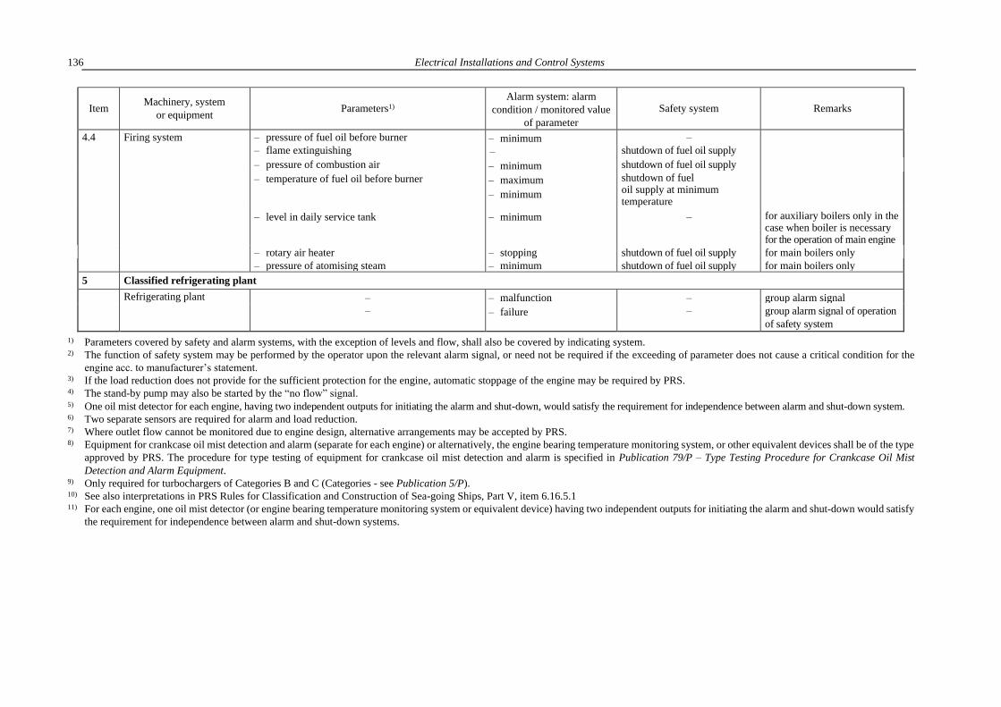
Electrical Installations and Control Systems
136
Item Machinery, system
or equipment Parameters1)
Alarm system: alarm
condition / monitored value
of parameter
Safety system Remarks
4.4 Firing system – pressure of fuel oil before burner
– flame extinguishing – minimum
–
–
shutdown of fuel oil supply
– pressure of combustion air – minimum shutdown of fuel oil supply
– temperature of fuel oil before burner – maximum
– minimum
shutdown of fuel oil supply at minimum temperature
– level in daily service tank – minimum – for auxiliary boilers only in the case when boiler is necessary for the operation of main engine
– rotary air heater – stopping shutdown of fuel oil supply for main boilers only
– pressure of atomising steam – minimum shutdown of fuel oil supply for main boilers only
5 Classified refrigerating plant
Refrigerating plant – – malfunction – group alarm signal
– – failure – group alarm signal of operation
of safety system
1) Parameters covered by safety and alarm systems, with the exception of levels and flow, shall also be covered by indicating system. 2) The function of safety system may be performed by the operator upon the relevant alarm signal, or need not be required if the exceeding of parameter does not cause a critical condition for the
engine acc. to manufacturer’s statement. 3) If the load reduction does not provide for the sufficient protection for the engine, automatic stoppage of the engine may be required by PRS. 4) The stand-by pump may also be started by the “no flow” signal. 5) One oil mist detector for each engine, having two independent outputs for initiating the alarm and shut-down, would satisfy the requirement for independence between alarm and shut-down system. 6) Two separate sensors are required for alarm and load reduction. 7) Where outlet flow cannot be monitored due to engine design, alternative arrangements may be accepted by PRS. 8) Equipment for crankcase oil mist detection and alarm (separate for each engine) or alternatively, the engine bearing temperature monitoring system, or other equivalent devices shall be of the type
approved by PRS. The procedure for type testing of equipment for crankcase oil mist detection and alarm is specified in Publication 79/P – Type Testing Procedure for Crankcase Oil Mist
Detection and Alarm Equipment. 9) Only required for turbochargers of Categories B and C (Categories - see Publication 5/P). 10) See also interpretations in PRS Rules for Classification and Construction of Sea-going Ships, Part V, item 6.16.5.1 11) For each engine, one oil mist detector (or engine bearing temperature monitoring system or equivalent device) having two independent outputs for initiating the alarm and shut-down would satisfy
the requirement for independence between alarm and shut-down systems.

Unattended Operation of Machinery Space and One Man Bridge Operation – Marks: AUT, NAVI
137
Table 21.3.1-2
Item Machinery, system
or equipment Parameters1)
Alarm system: alarm state
/monitored value
of parameter
Safety system Remarks
1 Main propulsion
1.1 Main internal combustion engine
1.1.1 Lubricating oil system – pressure at inlet to engine (after filter) – minimum first stage: start of stand-by pump3);
second stage: stop of engine
– temperature at inlet to engine – maximum load reduction2)
– level in circulating oil tank – minimum –
1.1.2. Cooling system – temperature of cooling water at outlet
from engine
– maximum – on outlet manifold after
cylinders
– pressure or cooling water flow at inlet – minimum first stage: start of stand-by pump3);
second stage: load reduction2)
for fresh and sea water
– level in compensating tanks – minimum –
1.1.3 Fuel system – level in service tanks – minimum –
1.1.4
1.1.5
Exhaust system
Engine overspeed
– temperature of exhaust gases
–
– maximum
alarm signal
load reduction2)
stop of engine
on exhaust manifold after
cylinders
1.2 Main gear – pressure of lubricating oil at inlet – minimum first stage: start of stand-by pump3);
second stage:
stop of main engine
– temperature of lubricating oil at inlet – maximum –
1.3 Shaft line – temperature of thrust bearing – maximum –
– oil pressure in hydraulic coupling – minimum – only in the case of separate
oil system
– level in gravity tank of stern tube
lubrication
– minimum –
– oil pressure in servo-system of c.p.
propeller
– minimum start of stand-by pump
2 Electrical installation
2.1 Main switchboards – insulation resistance – minimum – recommended
– voltage – maximum – recommended
– minimum
– frequency – maximum – recommended
– minimum

Electrical Installations and Control Systems
138
Item Machinery, system
or equipment Parameters1)
Alarm system: alarm state
/monitored value
of parameter
Safety system Remarks
2.2 Internal combustion engines
driving electrical generators
– pressure of lubricating oil at inlet
– minimum stop of engine
– temperature of lubricating oil at inlet
– temperature of cooling water or air at
outlet
– starting air pressure
– engine overspeed
– maximum
– maximum
– minimum
– alarm signal
–
–
stop of engine
3 Piping system
3.1
3.2 4)
3.3 4)
Bilge system
Boiler air supply casings and
exhausts (uptakes)
Air scavenging air belts of
propulsion machinery
– level in bilge wells of machinery space
– fire at an early stage
– fire at an early stage
– maximum
– alarm signal
– alarm signal
–
–
–
separate alarm signal on the
bridge (see also 21.2.7)
4 Steam boilers and associated systems
4.1 Boiler – steam pressure – maximum –
– water level – maximum
– minimum
shutdown of fuel oil supply at
minimum level
4.2 Circulating system – water flow through circulating installation – no flow depending on arrangement of system
and type of boiler
4.3 Feed water system – delivery pressure of feed water pump – minimum start of stand-by pump
4.4 Firing system – failure of burner – emergency shutdown of fuel oil
supply
1) Parameters covered by safety and alarm systems, with the exception of levels and flow, shall also be covered by indicating system. 2) The function of safety system may be performed by the operator according to the alarm signal, or need not be required if the exceeding of parameter does not cause critical condition for the engine
according to the engine manufacturer’s statement. 3) The stand-by pump may also be started by the “no flow” signal.
4) See also interpretations in PRS Rules for Classification and Construction of Sea-going Ships, Part V, item 6.16.5.1

Requirements for Assigning Additional Mark to the Symbol of Class
139
22 REQUIREMENTS FOR ASSIGNMENT OF ADDITIONAL MARK IN THE SYMBOL
OF CLASS )
22.1 Passenger Ships – Mark: PASSENGER SHIP
22.1.1 Power Supply and Signalling System
22.1.1.1 The power supply for pumps, air compressors and control and monitoring system of the
sprinkler system shall be taken directly from the main and emergency switchboards by separate feeders.
Such feeders shall run to an automatic change-over switch which in its normal position shall be connected
to the feeder from the main switchboard and in the event of voltage decay automatically will change over
to the feeder from the emergency switchboard. The switches of these feeders in the main and emergency
switchboard shall be clearly marked and provided with a notice that they must be permanently set in the
connected position. No other switches shall be installed in these feeders.
22.1.1.2 Cables supplying the sprinkler system machinery (pump, air compressor, control and
monitoring system) shall not be led through the machinery spaces, galleys and other enclosed fire-
hazardous spaces, except where the said machinery is installed in these spaces.
22.1.1.3 The lighting of saloons, ladders, stairs and passageways leading to the boat deck shall be
supplied by not less than two independent feeders.
The lighting fixtures shall so arranged that in the event of failure of either feeder uniformity of lighting
will be ensured. These feeders shall be supplied from different distribution boards which in the case of
application of sectionalised lighting busbars in the main switchboard shall be connected to different
sections of the busbars.
22.1.1.4 Feeders of essential services shall be so arranged that the fire in any main fire zone will not
damage such feeders in other fire zone. This requirement is considered to be satisfied when the cables of
the main and emergency supply passing through any main fire zone are run as far apart as possible from
one another both in horizontal and vertical direction.
22.1.1.5 The general alarm system shall be composed of two independent groups: one for the passengers
and one for the crew.
In passenger ships with low-rated electrical installations, only one group of the general alarm system
may be used.
22.1.1.6 In addition to the requirements, specified in 16.8.1.5 and 16.8.1.6, cables for services required
to be operable under fire conditions shall be fire-resistant where they pass through the main vertical fire
zones, other than those which they serve.
22.1.1.7 In addition to locations specified in paragraph 7.5.2.1, fire detection system be composed of be
installed on cabin balconies where fitted with furniture and furnishings other than the furniture and
furnishings of restricted fire risk defined in SOLAS II-2, regulation 3, paragraphs 40.1, 40.2, 40.3, 40.6
and 40.7.
22.1.2 Power Supply from the Emergency Source of Electric Power
22.1.2.1 Emergency sources of electric power in passenger ships, except those of restricted service II
and III, shall have adequate capacity to supply power simultaneously to the following consumers for 36
hours:
.1 emergency lighting of:
– places of embarkation and lowering of lifeboats and liferafts, as well as outboard spaces where
the lifeboats and liferafts are launched, in accordance with the requirements of the SOLAS
) The requirements of the present Chapter are supplementary to those given in other Chapters of the present Part of the Rules
for the purpose of assigning additional marks in the symbol of class. For the definition of particular marks – see Part I –
Classification Regulations.

Electrical Installations and Control Systems
140
Convention (these requirements are also given in Part II – Life-Saving Appliances of the Rules
for Statutory Survey of Sea-going Ships),
– indicators to exits to the boat deck, as well as informative plates near the life-saving appliances,
– exits from the spaces where a large number of passengers, crew or special personnel may gather
simultaneously,
– corridors and stairways leading to accommodation and service spaces, exits to open deck and
the passenger lift cars,
– machinery and generator spaces, together with their local control station,
– all control stations, as well as the main and emergency switchboards,
– emergency source of electric power space,
– the navigation bridge,
– chart room and radio room,
– the stowage positions for emergency and fire equipment, as well as the location of the manually
operated call points of fire signalisation,
– steering gear compartment,
– positions at the fire pumps, the emergency bilge pump, the sprinkler pump and at the starting
positions of their motors,
– air sheds and landing fields for helicopters,
– gyrocompass room,
– medical rooms;
.2 navigation lights, “no under command” lights, as well as other lights required by the International
Regulations for Preventing Collisions at Sea;
.3 navigation and radio equipment, in accordance with the requirements of the SOLAS Convention
(these requirements are also specified in Part IV – Radio Equipment and Part V – Navigation
Equipment of the Rules for Statutory Survey of Sea-Going Ships);
.4 internal communication equipment, command broadcast apparatus and general alarm system;
.5 fire detection system, the fire door holding and release system, specified in paragraph 6.1.8.3,
Part V – Fire Protection;
.6 audible signalling devices (whistles, gongs, etc.), daylight signalling lamp, manually operating
calling system and all other internal signalling systems required in an emergency;
.7 one of fire pumps, the automatic sprinkler pump and electrical equipment ensuring the operation of
foam generators specified in paragraph 3.5.3.5, Part V – Fire Protection;
.8 the emergency bilge pump and remote control system of bilge valve installation;
.9 other consumers, provided that their operation is considered by PRS necessary to ensure the safety
of the ship and that of the people on board.
The consumers, listed in sub-paragraphs .1 to .6 , may be supplied by their own accumulator batteries,
installed in accordance with 9.2, of sufficient capacity to supply the services during 36 hours.
For ships of restricted service, the required time of 36 hours may, subject to the consent of the
Administration, be shortened to 18 hours for ships of restricted service II, engaged on domestic voyages
only and to 12 hours – for ships of restricted service III, engaged on domestic and international voyages.
22.1.2.2 Emergency source of electric power shall supply power to additional low-location lighting
specified in 22.1.4 within at least 60 minutes from the moment of switching on the system in an emergency.
22.1.2.3 Emergency source of electric power shall supply power to the steering gear in accordance with
the requirements of 5.5.6.
22.1.2.4 Emergency source of electric power shall have adequate capacity to supply power to the below-
mentioned consumers for 30 minutes:
.1 electric drives of watertight doors, their indicators and warning signals; sequential operation of the
doors may be permitted, provided that all doors are closed in 60 seconds;
.2 emergency electric drive of passenger lifts; the passenger lifts may be brought to deck level
sequentially.

Requirements for Assigning Additional Mark to the Symbol of Class
141
.3 in ships constructed on or after 1 July 2010 – supplementary lighting shall be provided in all cabins
to clearly indicate the exit so that occupants will be able to find their way to the door. Such lighting
may have a self-contained source of electric power.
22.1.2.5 Where the emergency source of electric power is a generator with an independent drive, it shall
be:
.1 driven by diesel engine (see paragraph 2.1.7, Part VII – Machinery, Boilers and Pressure Vessels);
.2 capable of automatically starting in case of loss of voltage in the main network and automatically
connecting to the emergency switchboard busbars; the services required in 22.1.2.8 shall be
automatically supplied from the emergency generator. The total time of starting and taking over
the required load by the generator cannot exceed 45 seconds;
.3 provided with a transitional source of electric power connecting automatically at the loss of voltage.
22.1.2.6 Where the emergency source of electric power is an accumulator battery, it is to:
.1 operate without recharging and with the voltage change at its terminal within 12% of the rated
value throughout the discharge period;
.2 be capable of automatically connecting to the emergency switchboard busbars in case of the loss
of voltage in the main network and capable of supplying at least those services mentioned in
22.1.2.8.
22.1.2.7 The accumulator battery shall be used as a transitional source of electric power required in
22.1.2.5.3. The capacity of the battery shall be sufficient to provide power supply without recharging and
with the voltage change at its terminals within 12% of the rated value throughout the discharge period.
22.1.2.8 The capacity of the accumulator battery used as a transitional source of electric power shall be
sufficient to provide power supply for 30 minutes to the below-mentioned consumers:
.1 lighting and navigation lanterns in accordance with 22.1.2.1.1 and 22.1.2.1.2;
.2 all signalling and internal communication equipment required in an emergency;
.3 the general alarm and fire detection systems;
.4 daylight signalling lamp, audible signalling devices (whistles, gongs, etc.), the fire door holding
and release systems, as well as fire door position indicators, specified in paragraph 6.1.8.3, Part V
– Fire Protection;
.5 drives of watertight doors, their position indicators and warning signals. Sequential operation of
the doors may be permitted.
The consumers, specified in .2, .3 and .4, need not be supplied from a transitional source of electric power,
provided they are fitted with their own accumulator batteries of sufficient capacity to supply the services for
the required period of time.
22.1.3 Electrical Equipment of Watertight Doors
22.1.3.1 Electrical equipment of watertight doors as well as its associated elements shall be, as far as
practicable, located above the bulkhead deck, outside dangerous rooms and spaces.
22.1.3.2 Where the location of electrical equipment below the bulkhead deck cannot be avoided,
the following degrees of enclosure protection shall be ensured:
.1 electric motors, their associated circuits and control elements – IPX 7;
.2 watertight door position sensors and their associated circuit elements –IPX 8;
.3 elements of warning signals of the door movement – IPX 6.
22.1.3.3 Electric power, control, indication and alarm circuits shall be so protected against fault that
a failure in one door circuit will not cause a failure in any other door circuit.
Short circuits or other faults in the alarm or indication circuits of a door shall not result in a failure
of the supply and control circuits.
Arrangements shall be such that leakage of water into elements of electrical equipment located below
the bulkhead deck will not cause the door to open.

Electrical Installations and Control Systems
142
22.1.3.4 A single failure of the supply or control circuit of the watertight sliding doors shall not result in
the opening of the closed doors.
The power supply to electric motors mechanically driving doors of type 3 (specified in 21.2.1, Part III
– Hull Equipment) shall be continuously monitored in a direct vicinity of each of the electric motors.
The power supply decay in the supply and control circuits shall activate visual and audible signals on
the central stand on the navigation bridge.
A single failure in the electric or hydraulic power-operated systems of watertight doors, excluding the
hydraulic actuator shall not prevent the hand operation of any door.
22.1.3.5 Watertight doors which also serve as fire doors shall not be closed automatically in case of fire
detection by the fire detection system.
22.1.4 Additional Low-location Lighting
22.1.4.1 The means of escape including stairways and exits, in addition to the emergency lighting, shall
be marked by additional low-location lighting at all points of the escape route including angles and
intersections. In addition, all escape route signs and fire equipment location markings shall be made
according to paragraph 22.1.4.2.
22.1.4.2 Additional low-location lighting (required in paragraph 6.1.6.10.5, Part V – Fire Protection)
shall be made of:
– photoluminescent materials having properties of storing lighting energy when the ambient light source
is less effective; or
– light sources supplied by electric power such as incandescent bulbs, light emitting diodes,
electroluminescent lamps, electrofluorescent lamps, etc.
Additional low-location lighting products shall not contain radioactive or toxic materials.
22.1.4.3 Additional low-location lighting system shall operate for at least 60 minutes.
The system shall be capable of being activated directly from the continuously manned central control
station. It may, additionally, be continuously operating or be switched on automatically, e.g. by the presence
of smoke within the spaces served.
22.1.4.4 In all passageways, the additional low-location lighting shall be continuous except as
interrupted by corridors and cabin doors, however, the interruption shall not exceed 2 metres.
The additional low-location lighting shall be installed at least on one side of the corridor, either on the
bulkhead within 300 mm from the deck, or on the deck within 150 mm from the bulkhead.
In corridors of more than 2 metres wide, additional low-location lighting shall be installed on both sides.
In stairways the additional low-location lighting shall be installed within 300 mm above the steps such
that each step may be readily identified from either above or below that step.
The additional low-location lighting shall be installed on both sides if the width of the stairway is two
meters or more. The top and bottom of each set of stairs should be identified to show that there are no
further steps.
In dead-end corridors, additional low-location lighting shall have arrows placed at intervals not
exceeding 1 metre, or equivalent direction indicators, pointing away from the dead-end.
In all passenger cabins a placard explaining the additional low-location lighting system shall be installed
on the inside of the cabin door. It should also have a diagram showing the location of, and the way to, the
two closest exits with respect to the cabin.
22.1.4.5 Additional low-location lighting shall lead to the exit door handle. No other doors shall be
similarly marked. Sliding fire doors and watertight doors shall be marked with an additional low-location
lighting sign showing how the door opens.
22.1.4.6 Photoluminescent strips shall not be less than 75 mm wide. Photoluminescent strips having
a width less than that stated herein shall be used only if their luminance is properly increased.

Requirements for Assigning Additional Mark to the Symbol of Class
143
Photoluminescent materials shall ensure luminance equal at least 15 mcd/m2 measured 10 minutes after
the removal of all external lighting sources and greater than 2 mcd/m2 for 60 minutes. Photoluminescent
installation materials shall be provided with sufficient external light necessary to charge the photoluminescent
materials to meet luminance requirements.
22.1.4.7 Additional low-location lighting supplied by electric power shall be connected to the emergency
switchboard so as to be powered by the main source of electric power under normal service conditions and
by the emergency power source in emergency conditions (see also 22.1.2.2).
For existing ships, additional low-location lighting may be connected to the main lighting system,
provided that independent battery charged from the main lighting system, ensuring supply of low-location
lighting for at least 60 minutes, is fitted.
Additional low-location lighting supplied from battery shall fulfil the requirements specified in 22.1.4.7
22.1.4.10.
22.1.4.8 Additional low-location lighting supplied with electric power shall fulfil the following
requirements:
.1 the planar sources of light shall have minimum luminance of 10 cd/m2 from the active parts
in a continuous line of 15 mm minimum width;
.2 the point sources of miniature lamps shall provide not less than 150 mcd mean spherical intensity
with a spacing of not more than 100 mm between lamps;
.3 the point of source of light emitting diode systems shall have a minimum peak intensity of 35 mcd.
The angle of half intensity cone shall be appropriate to the likely track directions of approach and
viewing. Spacing between lamps shall not exceed 300 mm;
.4 electroluminescent lamps shall function for 60 minutes from the moment of removing the main
power supply specified in 22.1.4.6.
The typical track directions of approach and viewing shall be considered:
a) for sources which are required to be viewed from a horizontal position, within a 60° cone
having its centre located 30° from the horizontal mounting surface of the point source and in
line with the track direction,
b) for sources which are required to be viewed vertically, within a 60° cone having its centre
located perpendicular to the mounting service of the point source.
22.1.4.9 The power supply arrangements to the additional low-location lighting shall be so arranged that
a single fault does not result in the complete loss of the lighting in any fire zone and such that a fire in any
fire zone or on any deck does not result in loss of the lighting in any other fire zone or deck. This
requirement may be satisfied by the power supply circuit configuration, use of fire resistant cables
complying with IEC 60331 or the provision of suitably located power supply units having integral batteries
adequately rated to supply the lighting for a minimum period of 60 minutes.
22.1.4.10 Single lights and lighting assemblies of additional low-location lighting shall be so designed
or arranged that any single fault or failure in a light or lighting assembly, other than a short-circuit, will
not result in a break in visible delineation exceeding 1 metre.
22.1.4.11 Lighting fixtures and assemblies shall be flame retardant, have an ingress protection of at least
IP55 and shall fulfil the test requirements specified in Publication 11/P – Environmental Tests on Marine
Equipment.
22.1.4.12 Additional emergency lighting on passenger ferries, executed according to 22.2.2, may by
used partly or totally as low-location lighting, provided that conditions, specified in 22.1.4.1 – 22.1.4.10,
are fulfilled.
22.1.5 Additional Requirements for Public Address System
22.1.5.1 In passenger ship, the public address system shall be capable of being connected to three
broadcasting lines:
– deck broadcasting line, specified in 7.3.2.5.1;

Electrical Installations and Control Systems
144
– service broadcasting line, specified in 7.3.2.5.2;
– passenger broadcasting line, intended for connecting loudspeakers installed in passenger
accommodation and public spaces (cabins, messrooms, libraries, verandas, cafeterias, bars, etc.,
including the adjacent corridors and landings).
22.1.5.2 Provision shall be made for disconnecting passenger broadcasting line from service and deck
broadcasting lines when addressing crew accommodation and work spaces.
22.1.5.3 The public address system shall be protected against an unauthorized use. It shall be provided
with an override function controlled from the main command microphone post located on the navigation
bridge so that all emergency messages will be broadcast even if any loudspeaker has been switched off, its
volume has been turned down or the public address system is used for other purposes.
22.1.5.4 The public address system shall fulfil the following requirements:
.1 each of the broadcasting lines, specified in 22.1.5.1, shall have at least two loops of flame retardant
cable, which should be sufficiently separated throughout their length and have two separate and
independent amplifiers. Amplifiers cabling shall be run in segregated cable routes;
.2 each loudspeaker shall be individually protected against short-circuit;
.3 each command microphone post shall be provided with emergency function control, which should:
– be clearly indicated as the emergency function;
– be protected against unauthorized use;
– automatically disconnect any other input system or programme;
– automatically override all volume controls and on/off controls in the public address system so
that the required emergency mode volume specified in 7.3.2.9 is achieved in all spaces.
22.1.5.5 Cables and wiring serving internal communications or signals shall be, as far as practicable,
routed clear of galleys, laundries, machinery spaces of category A and their casings and other high fire risk
areas. Where practicable, all such cables shall be so led as to preclude their being rendered unserviceable
by heating of the bulkheads that may be caused by a fire in an adjacent space.
22.1.5.6 The sound pressure levels specified in paragraph 7.3.2.9 also apply to special category spaces,
ro-ro spaces and vehicle spaces intended for the carriage of motor vehicles.
22.1.6 Electric Drive of Ventilation Fans
22.1.6.1 In passenger ships carrying more than 36 passengers, power ventilation, except machinery space
and cargo space ventilation and any alternative system, shall be fitted with controls so grouped that all fans
may be stopped from either of two separate positions which shall be situated as far apart as practicable.
22.1.6.2 Passenger ships carrying more than 36 passengers shall have the fire detection alarms for the
systems centralized in a continuously manned central control station. In addition, controls for remote
closing of the fire doors and shutting down the ventilation fans shall be centralized in the same location.
The ventilation fans shall be capable of reactivation by the crew at the continuously manned control station.
The control panels in the central control station shall be capable of indicating open or closed positions of
fire doors and closed or off status of the detectors, alarms and fans. The control-and-indication circuits (i.e.
control panel and wires) shall be powered from the main source of power and shall have an automatic
change-over to standby power supply (emergency source of power) in case of loss of normal power supply.
Additionally, automatic changeover to batteries shall be provided to ensure power supply to the circuits
for the operation for at least 30 minutes (i.e. for the time necessary to start the standby generating set).
22.1.6.3 Cargo hold fans shall be provided with devices for remote shutting down situated outside the
space where the fans are located.
22.1.7 Passenger Ships Engaged on Domestic Voyages
The requirements for a ship to be assigned an additional mark Class A, Class B, Class C or Class D in
the symbol of class are specified separately by PRS in each particular case. PRS may also exempt a ship

Requirements for Assigning Additional Mark to the Symbol of Class
145
from certain requirements of the present Part or change the scope of these requirements.
Any exemptions/changes may be granted within the scope permitted by the Council Directive 98/18/EC
of 17 March 1998 on Safety Rules and Standards for Passenger Ships, as amended.
22.1.8 Safe Return to Port – additional Mark: SRTP
The requirements for a ship to be assigned an additional mark SRTP in the symbol of class are specified
separately in Publication 90/P – Guidance for Safe Return to Port and Orderly Evacuation and
Abandonment of Passenger Ship.
22.1.9 Cabling
22.1.9.1 Where cables for services specified in item 16.8.1.5 (including their power supplies) pass
through main vertical fire zones, other than those which they serve, they are to be so arranged that a fire in
any of these areas does not affect the operation of the service in any other area. This may be achieved by
either of the measures specified in item 16.8.1.6.
22.2 Roll on – Roll off Passenger Ships and Passenger Ferries – Marks: RO-RO/
PASSENGER SHIP, FERRY/ PASSENGER SHIP1
22.2.1 Installation of Electrical Equipment in Special Category Spaces
22.2.1.1 The requirements of sub-chapter 22.2.1 apply to special category spaces defined in Part V –
Fire Protection.
22.2.1.2 On the car deck or platform above the bulkhead deck in a zone over a height of 450 mm above
the deck or platform preventing the free passage of gas downwards, electrical equipment of an enclosure
protection of not less than IP55 is allowed to be installed, provided that the ventilation system ensures at
least 10 air changes per hour. Electrical equipment suitable for use in Zone 2 may be also installed in the
above locations.
22.2.1.3 In holds and compartments above the bulkhead deck in a zone below a height of 450 mm above
the deck or platform preventing the free passage of gas downwards, as well as in exhaust ventilation ducts,
electrical equipment of explosion-proof construction, suitable for Zone 1, shall be installed.
22.2.1.4 In the whole volume of holds and compartments below the bulkhead deck, electrical equipment
of explosion-proof construction – suitable for Zone 1, shall be installed.
22.2.1.5 Electrical and signalling installations of bow doors and inner doors leading to a complete
or long forward enclosed superstructures or to a long non-enclosed superstructure, where fitted to attain
minimum bow height equivalence shall fulfil following requirements:
.1 Separate indicator lights and audible alarms shall be provided on the navigation bridge and on the
operating panel to show that the bow door and inner door are closed and that their securing and
locking devices are properly positioned. The indication panel shall be provided with a lamp test
function. It shall not be possible to turn off the indicator light.
.2 The indicator system shall be designed on the fail-safe principle and shall show by visual alarms if
the door is not fully closed and not fully locked and by audible alarms if securing devices become
open or locking devices become unsecured. The power supply for the indicator system for
operating and closing doors shall be independent of the power supply for operating and closing the
doors and shall be provided with a back up power supply from the emergency source of power or
other power supply e.g. UPS. The sensors of the indicator system shall be protected from water,
ice formation and mechanical damage.
Note: the indicator system is considered designed on the fail-safe principle when:
.1 The indication panel is provided with:
1 See also guidelines in MSC.1/Circ.1615.

Electrical Installations and Control Systems
146
c) a power failure alarm,
d) an earth failure alarm,
e) a lamp test,
f) separate indication for door closed, door locked, door not closed and door not locked.
.2 Limit switches electrically closed when the door is closed (when no more limit switches are
provided, they may be connected in series).
.3 Limit switches electrically closed when securing arrangements are in place (when more limit
switches are provided, they may be connected in series).
.4 two electrical circuits (also in one multicore cable), one for the indication of door closed/not
closed and the other for door locked/not locked.
.5 In case of dislocation of limit switches, indication to show: not closed/not locked/ securing
arrangement not in place – as appropriate.
.3 The indication panel on the navigation bridge shall be equipped with a mode selection function
"harbour/sea voyage" so arranged that audible alarm is given on the navigation bridge if the vessel
leaves harbour with the bow door or inner door not closed and with any of the securing devices not
in the correct position.
.4 A water leakage detection system with audible alarm and television surveillance shall be arranged to
provide an indication to the navigation bridge and to engine control room of leakage through the
inner door.
Note: The indicator system shall be designed on fail-safe principle – see Note to para. 22.2.1.5.2.
.5 Between the bow door and the inner door, a television surveillance system shall be fitted with
a monitor on the navigation bridge and in engine control room. The system shall monitor the position
of doors and a sufficient number of their securing devices. Special consideration shall be given for
lighting and contrasting colour of objects under surveillance.
Note: The indicator system shall be designed on fail- safe principle – see Note to para. 22.2.1.5.2.
.6 A drainage system in the area between the bow door and ramp or where no ramp is fitted, between
the bow door and inner door shall be equipped with an audible alarm function to the navigation
bridge being set off when the water levels in these areas exceed 0.5 m or the high water level alarm,
whichever is lesser. See also Note to paragraph 22.2.1.5.2.
Note: The requirements for securing and locking devices of bow doors and inner doors are contained in relevant sections
of Part III – Hull Equipment.
22.2.1.6 Electrical and signalling installations of side shell doors (abaft the collision bulkhead) and stern
doors leading into enclosed spaces shall fulfil following requirements:
.1 Separate indicator lights and audible alarms shall be provided on the navigation bridge and on each
operating panel to indicate that the doors are closed and that their securing and locking devices are
properly positioned. The indication panel shall be provided with a lamp test function. It shall not be
possible to turn off the indicator light.
.2 The indicator system shall be designed on the fail-safe principle and shall indicate by visual alarms if
the door is not fully closed and not fully locked and by audible alarms if securing devices become open
or locking devices become unsecured. The power supply for the indicator system shall be independent
of the power supply for operating and closing the doors and shall be provided with a backup power
supply from the emergency source of power or secure power supply e.g. UPS. The sensors of the
indicator system shall be protected from water, ice formation and mechanical damage.
Note: The indicator system is considered designed on the fail-safe principle, provided it complies with the requirements
of Note to paragraph 22.2.1.5.2.
.3 The indication panel on the navigation bridge shall be equipped with a mode selection function
"harbour/voyage" so arranged that audible alarm is given if the ship leaves harbour with side shell
or stern doors not closed, or with any of securing devices not in the correct position.
.4 In passenger ships, a water leakage detection system with audible alarm and television surveillance
shall be arranged to provide an indication to the navigation bridge and to the engine control room

Requirements for Assigning Additional Mark to the Symbol of Class
147
of any leakage through the doors. In cargo ships, a water leakage detection system with audible alarm
shall be arranged to provide an indication to the navigation bridge.
Note: The requirements of par. 22.2.1.6 apply to doors in the boundary of special category spaces or ro-ro spaces, through
which such spaces may be flooded. The requirements do not apply to cargo ships, where no part of the door is below
the uppermost waterline and the area of the door opening is not greater than 6 m2. The requirements for securing and locking devices of side doors and shell doors are contained in relevant sections
of Part III – Hull Equipment.
22.2.1.7 In ro-ro passenger ships, cabling for general alarm and public address systems is subject to PRS
approval.
22.2.1.8 Where isolated power distribution system is applied, it is recommended to use the residual current
circuit breakers in socket outlet supply circuits intended for electrical energy supply of vehicles. Additionally,
it is recommended to use a separate transformer with earthed distributing system of secondary circuit,
intended for the above electrical system of the ship (for the socket outlet circuits considered).
22.2.1.9 It is recommended that the portable cables intended for the connection of ship electrical system
(plug sockets defined in 22.2.1.7) with vehicle electrical system should be located onboard and operated by
qualified personnel. Additionally it is recommended that the crew should have the possibility of verification
of continuity and electrical conductivity of the connection between ship’s hull and vehicle chassis/body.
The verification is recommended to be carried out using available onboard instruments measuring electrical
conductivity (provided e.g. with alarm indication of missing proper connection).
22.2.2 Supplementary Emergency Lighting
22.2.2.1 In addition to the emergency lighting required by 22.1.2.1.1, on passenger ships with ro-ro
cargo spaces or special category spaces, all passenger public spaces and alleyways shall be provided with
supplementary electric lighting that can operate for at least three hours when all other sources of electric
power have failed and under any condition of heel. The illumination provided shall be such that the
approach to the means of escape can be readily seen (or to ensure the lighting intensity of 0.5 lux).
The supplementary lighting shall be such that any failure of the lamp will be immediately apparent.
22.2.2.2 The source of power for the supplementary lighting shall be composed of accumulator batteries
located within the lighting units. Accumulator batteries provided shall be continuously charged from the
emergency switchboard and shall be replaced at intervals having regard to service life specified by the
manufacturer in the ambient conditions to which they are subject in service.
22.2.2.3 Portable rechargeable battery operated lamps shall be provided in every crew space alleyway,
crew recreational space and every working space which is normally occupied, unless supplementary
emergency lighting, as required by 22.2.2.1 and 22.2.2.2, is fitted.
22.2.3 General Alarm System
22.2.3.1 The minimum sound pressure level of the alarm system specified in paragraph 7.4.1 also applies
to special category spaces, ro-ro spaces and vehicle spaces intended for the carriage of motor vehicles.
22.3 Roll on – Roll off Ships and Ferries – Marks: RO-RO SHIP, FERRY
22.3.1 Installation of Electrical Equipment in Ro-Ro Cargo Spaces
22.3.1.1 Ro-ro cargo spaces (see the definition given Part V – Fire Protection) shall be considered
as hazardous areas.
22.3.1.2 The electrical equipment in ro-ro cargo spaces shall fulfil the requirements specified in sub-
chapter 22.2.1.
22.3.1.3 Cables shall be protected against mechanical damage. Cables installed horizontally shall be laid
at least 450 mm above the continuous deck or platform preventing the free passage of gas downwards.

Electrical Installations and Control Systems
148
Cable passages through decks and bulkheads shall be gastight.
22.3.1.4 Electrical devices installed in exhaust ventilation ducts, such as the fan motors shall be
of explosion-proof construction, i.e. of increased safety type (Exe) or with flameproof enclosures (Exd).
22.3.1.5 Lighting installed in ro-ro cargo spaces shall be divided into at least two groups; each of the
groups shall be supplied by a separate circuit.
22.3.2 Installation of Electrical Equipment in Holds and Compartments other than Ro-Ro Cargo
Spaces, Intended for the Carriage of Vehicles with Fuel in their Tanks
22.3.2.1 In holds and compartments in a zone above a height of 450 mm above the continuous deck
or platform preventing the free passage of gas downwards, electrical equipment of an enclosure protection
not less than IP55 may be installed, provided that the ventilation system ensures at least 10 air changes per
hour. Electrical equipment suitable for use in Zone 2 may also be installed in the above locations.
22.3.2.2 In holds and compartments in a zone below a height of 450 mm above the continuous deck
or platform preventing the free passage of gas downwards, as well as in exhaust ventilation ducts, electrical
equipment of explosion-proof construction, suitable for Zone 1, shall be installed.
22.4 Container Ships and Ships Intended for the Carriage of Containers – Marks: CONTAINER
SHIP, ACC (…)
22.4.1 Application
The requirements of sub-chapter 22.4 are applicable to electrical equipment of container ships and ships
intended for carrying isothermal containers.
22.4.2 Supply and Distribution of Electric Power
22.4.2.1 In addition to compliance with the requirements specified in 3.1.2, the output of the main
sources of electric power and of power converters shall provide the supply to all isothermal containers to
be carried.
In order to ensure the supply to isothermal containers during loading operations on board the ship, all
main sources of electric power and all power converters, including the reserve ones, may be used.
As the power value of electrical equipment of isothermal containers, their installed power shall be
assumed. The power consumption of electrical equipment of thermal containers under rated operating
conditions shall not exceed 15 kW (18.75 kVA).
The application of diversity and load factors is subject to PRS consideration in each particular case.
22.4.2.2 The means of overload protection of electric power sources, specified in 8.2.3, shall provide
for the feeder of the thermal container switchboard to be the last to be disconnected from the main
switchboard (see also 19.2.1).
22.4.2.3 Electrical network supplying the electrical equipment of isothermal container equipment shall
be separated from the ship network by means of separating transformers supplied from the main
switchboard.
22.4.2.4 The electrical equipment of isothermal containers shall be supplied from special switchboards
supplied by separate feeders.
22.4.2.5 The socket outlets installed in holds or on weather decks in places where isothermal containers
are located shall be supplied by separate feeders from special switchboards specified in 22.4.2.4 and 22.4.3.
22.4.2.6 Electrical network of socket outlets intended to supply electrical equipment of isothermal
containers shall have the rated voltage of 220 V or 380 V of 3-phase alternating current of a frequency
of 50 Hz or 240 V or 440 V of 3-phase alternating current of a frequency of 60 Hz.

Requirements for Assigning Additional Mark to the Symbol of Class
149
22.4.3 Distribution Switchboards and Transformers
22.4.3.1 The switchboards of isothermal containers, electric converters (if any) and separating
transformers shall be located in special electrical spaces.
22.4.3.2 The secondary windings of separating transformers shall have the neutral point insulated.
22.4.3.3 Each switchboard shall be fitted with apparatus providing for:
.1 visual signals to indicate that the switchboard is in live condition;
.2 switching on and off each feeder of socket outlets;
.3 protection of feeders supplying socket outlets against short-circuit;
.4 measuring of insulation resistance.
22.4.4 Socket Outlets
22.4.4.1 In holds intended for carrying isothermal containers, only the socket outlets to supply containers
may be installed. The socket outlets installed in the hold shall have a protection degree of at least IP55 and
those installed on the weather deck – at least IP56.
Where electrical system of remote monitoring of temperature, humidity, ventilation and other
parameters of isothermal containers in holds and on decks is employed, additional socket outlets may be
installed in holds and on decks to connect such a monitoring system.
22.4.4.2 Irrespective of the requirements specified in 14.2.3, socket outlets supplying electrical equipment
ofisothermal containers shall be fitted with a switch interlocked so that the plug cannot be inserted or withdrawn
while the switch is in the ”on” position. They shall also be provided with informative plates indicating their voltage
value.
22.4.4.3 The electrical equipment of isothermal containers shall be supplied from the ship network
through socket outlets with the direction of phase rotation in the sequence L1, L2, L3 as shown in the
diagram presented in Fig. 22.4.4.3.
The front view of plug The front view of socket outlet
Fig. 22.4.4.3. Sequence of phase connections of plug and socket outlet
22.4.4.4 Socket outlets intended to supply electrical equipment of isothermal containers shall be
designed for the following rated currents:
– 60 A for voltages 220 V, 50 Hz or 240 V, 60 Hz,
– 32 A for voltages 380 V, 50 Hz or 440 V, 60 Hz.
22.4.4.5 The design and dimensions of contacting parts of plugs shall be such as to exclude the
possibility of connecting the plugs rated for one voltage with the socket outlet rated for another voltage.
22.4.4.6 The design and dimensions of contacting parts of the socket outlets and plugs shall comply with
the international standards.

Electrical Installations and Control Systems
150
22.4.5 Protective Earthing
The socket outlet intended to connect the earthing conductor of the flexible cable of an isothermal
container shall be earthed by means of an earthing conductor in the supplying feeder. The earthing
conductor in the supply cable shall be earthed in the location of the switchboard supplying socket outlets
of isothermal containers.
22.5 Crude Oil Tankers, Product Carriers, Gas Tankers, Chemical Tankers, Ships Intended for
Operation in Oil Spillage Area – Marks: CRUDE OIL TANKER, PRODUCT CARRIER A,
LIQUEFIED GAS TANKER, CHEMICAL TANKER, OIL RECOVERY VESSEL
22.5.1 Application
22.5.1.1 The requirements of sub-chapter 22.5 apply to electrical equipment in ships intended for the
carriage of liquid cargoes having a flashpoint 60C and below, as well as to ships intended or adapted for
operation in the oil spillage area.
22.5.1.2 The equipment installed in hazardous spaces of the above-specified ships shall be suitable for
explosive mixtures specified in 2.8.4, with the exception of the following explosive mixtures:
– hydrogen and acetylene of explosion group IIC;
– acetaldehyde and ethylether of temperature class T4;
– carbon disulphide of temperature class T6 and explosion group IIC.
22.5.2 Power Distribution Systems
22.5.2.1 Only the following systems may be used for the distribution of electric power:
.1 two-wire insulated system for direct current;
.2 two-wire insulated system for single-phase alternating current;
.3 three-wire insulated system for three-phase alternating current (also for a voltage of 1000 V 11 000 V
alternating current);
.4 three-wire system with the earthed neutral point by a high ohm resistance for a voltage of 1000 V
11 000 V alternating current (see also 18.2.1).
22.5.2.2 The earthed systems of electric power distribution may be used only for the supply of the
following consumers, provided they are used outside the hazardous rooms and spaces:
.1 system of the outer hull cathode current protection against corrosion;
.2 system of monitoring and measuring the insulation resistance (see 4.5.4.8);
.3 electrical system for the starting of diesel engines.
22.5.3 Hazardous Rooms and Spaces
22.5.3.1 The following rooms and spaces are considered as hazardous:
.1 inner spaces of cargo compartments and cargo tanks, cargo pipelines and the cargo pumping systems;
.2 open spaces up to a height of 1 m above the water surface covered by oil (for ships operating
directly in the oil spillage area);
.3 cofferdams and other spaces adjoining cargo compartments and cargo tanks;
.4 enclosed or semi-enclosed spaces containing cargo pumps, enclosed or semi-enclosed spaces,
not completely welded, containing cargo pipelines;
.5 enclosed or semi-enclosed spaces situated above the cargo compartments and cargo tanks, as well
as spaces having bulkheads above or on the level of the cargo compartment bulkheads and the
cargo tank bulkheads;
.6 enclosed or semi-enclosed spaces situated directly above the pump rooms, as well as above the
vertical cofferdams adjacent to cargo compartments and cargo tanks, provided they are not divided
by the gas-tight decks and do not have power ventilation;
.7 spaces and rooms other than cofferdams, adjoining and situated below the upper part of cargo
compartments and cargo tanks;

Requirements for Assigning Additional Mark to the Symbol of Class
151
.8 spaces and semi-enclosed rooms on the open deck within a radius of 3 m from manholes, hatches
and other openings not intended for ventilation of cargo compartments and cargo tanks, as well as
the ends of cargo pipelines;
.9 spaces on the open deck above cargo compartments and cargo tanks (as well as above the ballast
tanks used as cargo tanks) over the full width of the ship and additionally 3 m fore and aft up to
a height 2.4 m above the deck. For ships operating directly in the oil spillage area, the space
specified above extends over the full length of the ship;
.10 compartments for oil hoses and oil recovery equipment;
.11 enclosed and semi-enclosed spaces having direct exits or other openings leading to one of the
above-mentioned rooms or spaces;
.12 rooms and spaces above cofferdams adjacent to the compartments of cargo tanks, not separated
by oil-tight and gas-tight bulkheads or decks, lacking proper ventilation and having entrances from
the deck above;
.13 rooms situated above the pump rooms, where the electric motors of cargo and stripping pumps are
installed.
22.5.3.2 Where the deck of a cargo tank extends to the bulkhead of accommodation spaces, the rooms
mentioned in 22.5.3.1.9 shall be defined assuming that the height of the wash barrier is at least equal to the
height of the side which restricts the flowing of the liquid cargoes from the ship deck. In that case, the
hazardous area extends 3 m beyond the wash barrier.
22.5.3.3 Spaces situated below the level of the main deck and having direct exits or other openings
leading to spaces on the main deck, specified in 22.5.3.1.9, are not considered as hazardous on condition
that suitable, double, self-closing gas-tight doors forming an air-lock, as well as the additional power
ventilation with an air inlet beyond the hazardous area are provided.
22.5.3.4 For ships adapted for operation in the oil spillage area, entrances, ventilating holes (inlets, outlets)
and other openings in non-hazardous spaces, such as accommodation, service and machinery spaces, not
provided with gastight closures, shall be situated 6 m above the highest load-line and, in each case, outside
the hazardous zone. Entrances to these spaces, situated 6 m below the highest load-line or in the hazardous
zone, shall be fitted with air-locks; the remaining openings shall be provided with gastight closures and shall
be closed during oil recovery operations.
22.5.3.5 Automatic isolation of non-certified equipment (not intended for application in explosive gas
atmosphere) on detection of a flammable gas is not permitted as an alternative to the use of certified
equipment (to be selected with respect to the risk of explosion).
22.5.3.6 Electrical generation and distribution systems, and associated control systems shall be so
designed that a single fault will not result in the loss of ability to maintain cargo tank pressures and hull
structure temperature.
22.5.3.7 Lighting system in hazardous areas shall be divided between at least two branch circuits.
All switches and protective devices shall interrupt all poles or phases and shall be located in a non-
hazardous area.
22.5.3.8 Electrical depth sounding or log devices and impressed current cathodic protection system
anodes or electrodes shall be housed in gastight enclosures.
22.5.3.9 Submerged cargo pump motors and their supply cables may be fitted in cargo containment
systems. Arrangements shall be made to automatically shut down the motors in the event of low-liquid
level. This may be accomplished by sensing low pump discharge pressure, low motor current or low liquid
level. This shutdown shall be alarmed at the cargo control station. Cargo pump motors shall be capable
of being isolated from their electrical supply during gas-freeing operations.

Electrical Installations and Control Systems
152
22.5.4 Electrical Equipment in Hazardous Rooms and Spaces
22.5.4.1 The electrical installations in hazardous spaces and rooms shall be made in accordance with
IEC 60092-502.
22.5.4.2 In hazardous rooms and spaces, the installation of electrical equipment is not permitted with
the exception of:
.1 lighting fixtures and signal lamps having pressurized enclosures (Exp) flameproof enclosures (Exd)
or enclosures of increased safety type (Exe);
.2 switches of increased safety type (Exe) or with flameproof enclosures (Exd);
.3 communication, remote control, monitoring and control equipment of intrinsically safe type (Exi);
.4 electric motors of increased safety type (Exe), with flameproof enclosures (Exd) or with pressurized
enclosures (Exp).
22.5.4.3 In inner spaces of cargo compartments and cargo tanks, cargo pipelines and cargo pumping
systems, electrical equipment and cables shall not be installed, with the exception of installation
of intrinsically safe type (Exi).
22.5.4.4 In open spaces up to a height of 1 m above the water surface covered with oil (for ships
operating directly in the oil spillage area), electrical equipment and cables shall not be installed with the
exception of installations of intrinsically safe type (Exi).
22.5.4.5 In cofferdams and other spaces adjacent to cargo compartments and cargo tanks, installation
of electrical equipment is not permitted except for:
.1 equipment of intrinsically safe type (Exi);
.2 echo depth sounder oscillators and their cables in accordance with the requirements of SOLAS
Convention (these requirements are also specified in Part V – Navigational Equipment of the
Rules for Statutory Survey of Sea-going Ships, sub-chapter 4.2.4);
.3 cables of the outer hull cathode current protection system installed in corrosion-proof steel pipes
with gastight joints up to the upper deck.
22.5.4.6 In enclosed and semi-enclosed spaces containing cargo pumps or cargo pipelines, only the
following equipment is permitted to be installed:
.1 electrical equipment specified in 22.5.4.5.1 to 22.5.4.5.3;
.2 lighting supplied by at least two circuits, with fuses and switches on all poles or phases, situated
outside the hazardous rooms and spaces, the following constructions are possible:
– illumination by means of lamps installed outside the hazardous rooms and spaces through side
scuttles of fixed type placed in gas-tight bulkheads or decks, provided they do not reduce the
strength, gastightness and flameproofness of those bulkheads and decks;
– lighting fixtures of explosion-proof construction with pressurized enclosures (Exp) or with
flameproof enclosures (Exd), whose cables shall be protected against mechanical damage by
means of metallic protective sheaths;
.3 through runs of cables.
Electric motors for driving the devices located in pump-rooms shall be installed in adjacent non-
hazardous rooms. Gas-tight stuffing boxes shall be used for the shaft penetrations through bulkheads
or decks. Electric motors shall have devices for remote switching off, located outside the rooms in which
electric motors are installed and above the tank deck.
22.5.4.7 In enclosed and semi-enclosed spaces above the deck of cargo compartments and cargo tanks,
as well as in spaces having bulkheads above or on the level of both the cargo compartment bulkhead and
the cargo tank bulkhead, in enclosed and semi-enclosed spaces situated directly above pump-rooms and
above vertical cofferdams adjacent to cargo compartments and cargo tanks which are not separated by gas-
tight decks and are not provided with power ventilation, in compartments for cargo hoses and oil recovery
equipment, only the following are allowed to be installed:
.1 electrical equipment of intrinsically safe type (Exi);

Requirements for Assigning Additional Mark to the Symbol of Class
153
.2 lighting fixtures of explosion-proof construction having pressurized enclosures (Exp), flameproof
enclosures (Exd); or of increased safety type (Exe); the switches of these fixtures shall be located
outside the hazardous rooms and spaces;
.3 through runs of cables.
22.5.4.8 In rooms and spaces other than cofferdams, adjacent to cargo compartments and cargo tanks or
situated below their upper parts, only the following equipment is allowed to be installed:
.1 electrical equipment specified in 22.5.4.5;
.2 lighting fixtures of explosion-proof construction having pressurized enclosures (Exp), flameproof
enclosures (Exd); this lighting shall be made by means of lamps supplied by at least two circuits,
with fuses and switches on all poles or phases, situated outside the hazardous rooms and spaces;
.3 through runs of cables.
22.5.4.9 In semi-enclosed spaces and rooms on the open deck within a radius of 3 m from manholes,
hatches and other non-ventilated openings of cargo compartments and cargo tanks, only the following
equipment is allowed to be installed:
.1 electrical equipment specified in 22.5.4.2;
.2 through runs of cables in ducts or pipes containing cables, except expansion loops.
22.5.4.10 In spaces on the open deck above cargo compartments and cargo tanks (also above the ballast
tanks used as cargo tanks) over the full width of the ship and 3 m fore and aft on the open deck up to
a height of 2.4 m above the deck, in enclosed or semi-enclosed spaces having direct exits or other openings
leading to one of the above rooms and spaces specified in 2.8.11, only the following equipment is allowed
to be installed:
.1 electrical equipment specified in 22.5.4.2;
.2 through runs of cables in ducts or pipes containing cables.
22.5.4.11 In rooms and spaces above cofferdams adjacent to cargo tanks which are not separated by oil-
tight and gastight bulkheads or decks and do not have suitable ventilation and have entrances from the
deck situated above, only the following equipment is allowed to be installed:
.1 lighting fixtures of explosion-proof construction having pressurized enclosures (Exp), flameproof
enclosures (Exd) or of increased safety type (Exe);
.2 other electrical devices which do not produce electric arcs during normal operation and whose
surfaces are not heated to a dangerous temperature;
.3 other electrical devices of increased safety type (Exe), ventilated and having an enclosure
protection of minimum IP55, whose surfaces are not heated to a dangerous temperature.
22.5.4.12 In rooms, where there are electric motors of cargo and stripping pumps, situated above pump-
rooms, the following equipment is allowed to be installed:
.1 lighting fixtures of explosion-proof construction having pressurized enclosures (Exp), flameproof
enclosures (Exd) or of increased safety type (Exe);
.2 other electrical devices which do not produce electric arcs during normal operation and whose
surfaces are not heated to a dangerous temperature; .3 other electrical devices of increased safety type (Exe), ventilated and having an enclosure
protection of minimum IP55 whose surfaces are not heated to dangerous temperature.
Where the room’s location and arrangement indicate that the explosive mixtures of gases, vapours or
dust with air may accumulate, suitable ventilation shall be ensured. Also interlocking between the starting
device for an electric motor of the cargo pump and the electric drive for the ventilation system of this
compartment shall be provided. This interlocking shall allow the pump electric motor to be started only
after the compartment has been sufficiently ventilated.
22.5.4.13 The possibility of occurrence of explosive mixtures of gas with air during cargo pumping,
ballasting and gas-freeing by mechanical means outside the spaces and rooms specified in 22.5.3.1 shall
be taken into account. Areas on open deck or semi-enclosed spaces on open deck, within a vertical cylinder
of unlimited height and 6 m radius centred upon the centre of the outlet, and within a hemisphere of 6 m
radius below the outlet which permits the flow of large volumes of vapour, gas mixtures during
loading/discharging/ballasting are defined as Zone 1, as specified by IEC 60092-502, paragraph 4.2.2.8.

Electrical Installations and Control Systems
154
Areas within 4 m beyond the zone specified above are defined as Zone 2, as specified by IEC 60092-
502, paragraph 4.2.3.2.
Electrical equipment or cables shall normally not be installed in the areas, referred to above. Where
essential for operational purposes, electrical equipment may be installed in these areas in accordance with
the requirements of IEC 60092-502.
22.5.4.14 Where the prescriptive requirements for the equipment in hazardous areas specified in
SOLAS and related Codes (IBC, IGC) and the standards published by the International Electrotechnical
Commission, such as but not limited to IEC 60092-502, are not aligned, the prescriptive requirements in
SOLAS and Codes take precedence and shall be applied.
22.5.4.15 Areas on open deck or semi-enclosed spaces on open deck, within 3 m of cargo tank
ventilation outlets are defined as Zone 1, as specified by IEC 60092-502, paragraph 4.2.2.7.
Areas within 2 m beyond the zone specified above shall be considered Zone 2 (as opposed to 1.5 m
specified by IEC 60092-502, paragraph 4.2.3.1).
Electrical equipment or cables shall normally not be installed in the areas, referred to above. Where
essential for operational purposes, electrical equipment may be installed in these areas in accordance with
the requirements of IEC 60092-502.
22.5.5 Portable Electrical Equipment Intended for Oil Recovery from Sea Surface
22.5.5.1 Portable electrical equipment shall be of explosion-proof construction.
22.5.5.2 Panels or sockets used for supplying portable electrical equipment shall be fitted with
interlocking preventing the connection of live portable electrical equipment, as well as with protective
devices against short-circuit and overload in any phase.
Such panels or sockets shall be so installed that a cable used for supplying portable electrical equipment
does not run through door openings or any other openings capable of being closed, enclosing hazardous
rooms and spaces.
22.5.5.3 Flexible cables used for supplying portable electrical equipment shall have a metal shield
covered with a tight non-metallic sheathing resistant to kerosine products.
22.5.6 Installation of Cables
22.5.6.1 In crude oil tankers and ships intended or adapted for operation in the oil spillage area, cables
installed on gangways shall be laid in appropriate conduits or pipes (see 16.8.8).
Where gangways are provided in the spaces mentioned in 22.5.3.1.9, the cables laid on them shall fulfil
the requirements of paragraph 2.8.15.
22.5.6.2 For systems operating at the voltage specified in 22.5.2.1.4, only cables having copper sheaths
plus additional isolating coating on those sheaths shall be used. The cross-sectional area of the sheaths shall
not be less than the cross-sectional area of the core. The design of such cables is subject to PRS consideration
in each particular case.
22.5.7 Additional Means for Prevention against Explosion in Cargo Pump Spaces
22.5.7.1 Cargo, ballast and stripping pumps installed in cargo pump spaces and driven through shafts
penetrating through bulkheads of those spaces shall be equipped with temperature measuring systems of
bulkhead shaft sealing, bearings and pump casings. The alarm signal shall be given in cargo central station
or on pump control stand and it shall be continuous, audible and visual.
22.5.7.2 To discourage personnel from entering the cargo pump-room when the ventilation system is not in
operation, one of the following means shall be applied:
.1 interlocking of lighting in the cargo pump-room with the ventilation system shall be provided such
that the ventilation shall be in operation to energize the lighting. Failure of the ventilation system
should not cause the lighting to go out. Emergency lighting shall not be interlocked;.
.2 warning alarms shall be provided at the door to the cargo pump- room:

Requirements for Assigning Additional Mark to the Symbol of Class
155
– visual alarm warning that the cargo pump-room ventilation system is not in operation, that the
pump-room atmosphere may therefore be hazardous, and that the pump-room shall not be entered
until verified safe;
– visual and audible alarms indicating that pump-room door was opened, although the pump-
room ventilation system is not in operation. The alarms shall also operate on the navigation
bridge. Reset of the alarm shall be provided from the navigation bridge only.
22.5.7.3 A system for continuous monitoring of the concentration of hydrocarbon gases shall be
provided. Sampling points or measuring detector heads shall be located in suitable positions in order that
potentially dangerous leakages are easily detected. Sequential sampling is acceptable as long as it is
dedicated for the pump-room only, including exhaust ducts, and the sampling time is reasonably short.
Suitable positions may be the exhaust ventilation duct, lower parts of the pump-room above floor plates
or other areas where air circulation is reduced. The system shall cause activation of alarm signal when gas
concentration exceeds 10% of the lower flammable limit.
Alarm signal (visual and audible) shall be given in the pump-room, engine control room, cargo central
station and on the navigation bridge. The requirements for gas analysing units are specified in 22.5.8.
22.5.7.4 All cargo pump-rooms shall be equipped with the bilge well monitoring system with properly
arranged signalling system.
22.5.8 Location of Units for Continuous Analysis of Flammable Vapours and Gas
22.5.8.1 Gas analysing units with non-explosion proof measuring equipment may be located in areas
outside the cargo spaces, e.g. in cargo central station, on the navigation bridge or in the engine room when
mounted on the forward bulkhead, provided that the requirements, specified in 22.5.8.2 to 22.5.8.6, are
fulfilled.
22.5.8.2 The gas sampling pipes shall not be led through hazardous spaces, except where permitted
in 22.5.8.6.
22.5.8.3 The gas sampling pipes shall be equipped with flame arresters. Sample gas shall be led to the
atmosphere through outlets arranged in a safe location.
22.5.8.4 Bulkhead penetrations of sample pipes between safe and hazardous areas shall be type-
approved and have the same fire integrity as the division penetrated. A manual isolating valve shall be
fitted in each of the sampling pipes at the bulkhead on the gas safe side.
22.5.8.5 The gas detection equipment, including sample piping, pumps, solenoids, analysing units, etc.
shall be located in a reasonably gastight steel cabinet (e.g. a fully enclosed steel cabinet with a gasketed door)
monitored by its own sampling point. At gas concentrations above 30% of the lower flammable limit inside
the steel cabinet, the entire gas analysing unit shall be automatically shut down.
22.5.8.6 Where the cabinet cannot be arranged directly on the bulkhead, sample pipes shall be of steel
or other equivalent material and without detachable connections, except for the connection points for
isolating valves at the bulkhead and analysing units, and they shall be routed on their shortest ways.
22.5.9 Integrated Cargo and Ballast Systems on Tankers
22.5.9.1 The requirements of the present sub-chapter apply to tankers contracted for construction on
or after 1 January 2004.
22.5.9.2 Integrated cargo and ballast system means any integrated hydraulic and/or electric system used
to drive both cargo and ballast pumps.
22.5.9.3 A single failure in the integrated cargo and ballast system – including its control and safety
systems – shall not make the integrated cargo and ballast pumps inoperable simultaneously.

Electrical Installations and Control Systems
156
22.5.9.4 The emergency stop circuits of the cargo and ballast systems shall be independent of the circuits
for the control systems and a single failure in the control system circuits or the emergency stop circuits
shall not cause disconnection of power supply and in consequence stopping the ballast pumps.
22.5.9.5 Manual emergency stops of the cargo pumps shall not make the ballast pumps inoperable.
22.5.9.6 The control systems shall be provided with backup power supply, which may be satisfied by
a duplicate power supply from the main switchboard. The failure of any power supply shall provide audible
and visible alarm activation at each location where the control panel is fitted.
22.5.9.7 In the event of failure of the automatic or remote control systems, secondary means of control
shall be made available for the operation of the integrated cargo and ballast system. This shall be achieved
by manual overriding and/or redundant arrangements within the control systems.
22.5.10 Ships Carrying Liquefied Gases in Bulk
22.5.10.1 Ships carrying liquefied gases in bulk built on or after 1 July 2016 shall fulfil the requirements
of the International Code for Construction and Equipment of Ships Carrying Liquefied Gases in Bulk (IGC
Code) – Res. MSC 370(93), as amended.1
22.5.10.2 Ships carrying liquefied gases in bulk built on or after 1 July 1986 but before 1 July 2016
shall fulfil the requirements of the International Code for Construction and Equipment of Ships Carrying
Liquefied Gases in Bulk (IGC Code) – Res. MSC.5(48), as amended until 2006.
22.5.11 Emergency source of electrical power
22.5.11.1 According to item 9.3.6 the additional requirement is to be met:
− At final equilibrium after flooding, the emergency source of power shall be capable of operating.
22.5.12 Location of fuel tanks in cargo area on oil and chemical tankers
22.5.12.1 For electrical equipment requirements in hazardous areas must be met.
22.6 Special Purpose Ships – Marks: RESEARCH SHIP, TRAINING SHIP
22.6.1 Power Supply of Essential Services
In special purpose ships carrying more than 50 special personnel, the circuits supplying the essential
services shall be made in accordance with 22.1.1.4.
22.6.2 Emergency Sources of Electric Power
22.6.2.1 In special purpose ships carrying not more than 50 special personnel, the emergency source
of electric power shall fulfil the requirements specified in 9.3.
Special purpose ships of more than 50 m in length shall additionally fulfil the requirements specified in
22.1.2.4.1.
22.6.2.2 In special purpose ships carrying more than 50 special personnel, the emergency source
of electric power shall fulfil the requirements specified in 22.1.2.
22.6.3 Electrical Equipment in Store-rooms for Explosives
22.6.3.1 In store-rooms for explosives electrical equipment shall not be installed, except lighting fixtures
with globes and guards. Cable runs passing through these store-rooms shall be installed in watertight pipes.
22.6.3.2 The switches of lighting circuits shall be installed outside these store-rooms. Visual signals
indicating the presence of voltage in the circuit shall be provided at the switch location.
1 See also IACS UI GC18, IACS UI GC27 and IMO Circulars, as applicable.

Requirements for Assigning Additional Mark to the Symbol of Class
157
22.6.3.3 Terminals for connecting portable magazines for explosives to the ship network shall have an
enclosure protection of at least IP56 and shall be fitted with supply rating plates.
22.7 Floating Cranes – Mark: FLOATING CRANE
22.7.1 For floating cranes and crane ships in which driving systems similar to those described in Chapter
17 are used for hoisting gears, the requirements of that Chapter may be applied to the electrical drives
of hoisting gears within the scope agreed with PRS in each particular case.
22.7.2 For floating cranes having their own propulsion, the output of the main sources of electric power
shall be sufficient for ensuring the operation of the crane under one of the conditions: when travelling
or during loading operations.
22.7.3 The rooms and lockers intended for the location of accumulator batteries, as well as the rooms
of emergency sources of electric power are allowed to be situated below the main deck, provided all other
requirements specified in Chapter 13 and sub-chapter 9.2 are complied with.
22.7.4 Floating cranes shall be provided with an audible signalling system operated from the operator
cabin to give audible signals during loading operations.
22.7.5 Telephone communication between the navigation bridge and the operator cabin shall be provided.
22.8 Bulk Carriers – Mark: BULK CARRIER
22.8.1 Detection system of water ingress into cargo holds, ballast tanks and dry spaces of bulk carriers1.
22.8.1.1 Bulk carriers shall be fitted with the below-mentioned water level detectors and indicators:
.1 in each cargo hold giving audible and visual alarms, one when the water level above the inner
bottom reaches the height of 0.5 m (the pre-alarm) and another at the height not less than 15%
of the depth of the cargo hold but not more than 2 m (the main alarm). The visual alarms shall
clearly discriminate between the two different water levels detected in each hold. On the existing
bulk carriers fitted with the pre-alarm system (0.5 m water level indication), detectors with only
the latter alarm (i.e. the main alarm) need be installed;
.2 in any ballast tank forward of the collision bulkhead giving an audible and visual alarm when the
liquid in the tank reaches the level not exceeding 10% of the tank capacity;
.3 in any dry or void space other than a chain cable locker any part of which extends forward of the
foremost cargo hold giving an audible and visual alarm at the water level of 0.1m above the deck.
Such alarms need not be provided in enclosed spaces, the volume of which does not exceed 0.1% of the
ship maximum displacement volume.
22.8.1.2 The visual and audible characteristics of the alarms, specified in 22.8.1.1.2 and 22.8.1.1.3, shall
be the same as those of the main alarm described in 22.8.1.1.1.
22.8.1.3 The alarm systems, described in 22.8.1.1.1 and 22.8.1.1.2, may be equipped with an alarm
overriding devices activated when the holds or tanks are used for the carriage of water ballast.
Hold/tank, where the override device is activated, shall be clearly identifiable on the signalling panel.
Cancellation of the override condition and reactivation of the water detection alarm system shall be
automatic, when the hold or tank has been de-ballasted to a level below the lowest alarm indicator level.
22.8.1.4 Electrical equipment of the water ingress detection system shall fulfil the following requirements:
.1 the water ingress detection system, including its essential equipment, shall be of a type approved
by PRS;
.2 the water level detectors in holds shall be fitted in aft part of each hold either as close to the centreline
as practicable or within a distance less or equal to B/6 from the centerline. Where not practicable,
they shall be located at both the port and starboard sides of the cargo hold. The sensors installed in
the spaces other than cargo holds shall be located in the lowest part of those spaces;
1 See interpretation in MSC.1/Circ.1572, Annex, Section 9.

Electrical Installations and Control Systems
158
.3 detection equipment shall be effectively corrosion resistant for all intended cargoes;
.4 the detector indicating the water level shall be capable of activating with the accuracy of 100 mm;
.5 the part of the system which has its circuitry in the cargo area shall be intrinsically safe;
.6 the degree of protection of electrical equipment installed in the cargo holds, ballast tanks and dry
spaces shall be at least IP68. Where necessary, the electrical equipment (including the cables) shall
be protected against mechanical damage by cargoes or mechanical handling equipment. The degree
of protection of electrical equipment installed above the cargo and ballast spaces shall be at least
IP56;
.7 the enclosures of electrical equipment for the dewatering system installed in any of the forward dry
spaces shall provide protection to IPX8 standard as defined in IEC 60529 for a water head equal to
the height of the space in which the electrical equipment is installed for a time at least 24 hours;
.8 time delays shall be incorporated into the alarm system to prevent spurious alarms.
22.8.1.5 The alarm system shall have such self-monitoring properties that audible and visual alarm
signal will be given in the case of broken circuit or other typical failure.
22.8.1.6 The water ingress detection system shall be supplied from two independent electrical power
supply sources – the primary electrical power supply and the emergency source of power supply.
A dedicated continuously charged accumulator battery may be used as the emergency source of power
supply, provided the capacity of the battery is equivalent to that of the emergency source, specified in 9.3.
Failure of the primary electrical power supply shall be indicated by visual and audible alarm. Where
batteries are used as the emergency source of power supply, failure alarms for both power supplies shall
be provided.
22.8.1.7 All the above-mentioned alarms shall be indicated at least on the navigation bridge.
22.8.1.8 The alarm panel shall be suitable for location on the navigation bridge. Dimmer shall be
provided for visual indication on the bridge. The audible indication shall be capable of being muted by the
operator.
Audible and visual signalling shall fulfil the requirements specified in 20.4.1.1, 20.4.1.6, 20.4.1.7 and
20.4.1.8.
22.8.1.9 The alarm panel shall be provided with a push-button for testing visual and audible indication
and returning to the off position when not operated.
22.8.1.10 The water ingress detection system shall be capable of continuous operation while the ship is
at sea.
22.8.1.11 The detector installation shall not inhibit the use of any sounding pipe or other level gauging
device for cargo holds or other spaces.
22.9 General Cargo Ships Occasionally Carrying Bulk Cargoes – mark: DRY CARGO SHIP
22.9.1 General cargo ships occasionally carrying bulk cargoes, shall fulfil the requirements specified in
sub-chapter 22.8 of this Part of the Rules.
22.10 Additional Requirements for Energy Efficient Ships
22.10.1 Application
The requirements specified in this Chapter apply to new ships or ships who have undergone substantial
modification of gross tonnage 400 and above engaged on international voyages specified in Regulation 21
of Annex VI to MARPOL, in accordance with definitions contained in Regulations 2.23 and 2.24 of Annex
VI to MARPOL.

Requirements for Assigning Additional Mark to the Symbol of Class
159
22.10.2 Documents to be Submitted
The documents to be submitted at each stage of design are specified in the Guidelines on Survey and
Certification of EEDI and the Industry Guidelines on Calculation and Verification of EEDI contained in
Publication 103/P – Guidelines for Energy Efficiency of Ships.
Prior to commencement and during the ship construction or modification the documentation required
at each stage of design, including the documentation prepared after the sea trials conducted shall be
submitted to PRS Head Office for consideration and approval.
22.10.3 Additional Mark ECO EF in the Symbol of Class
Ships whose attained energy efficiency design index (EEDI) does not exceed the required value
of EEDI (determined for the specific period) may be assigned additional mark ECO EF in the symbol
of class, according to Part I – Classification Regulations and Publication 106/P – Eco Class Rules.
22.11 Ecological Ships – Mark: ECO AIR
22.11.1 Technical requirements for shore power supply systems are specified in Publication 106/P – Eco
Class Rules.
22.12 Chemical Spill Response Ships – mark: CHEMICAL RECOVERY VESSEL
22.12.1 Chemical spill response ships shall fulfil the requirements specified in sub-chapter of 22.5 of this
Part of the Rules wherever reference is made to IEC 60092-502.
22.12.2 Chemical spill response ships shall fulfil the requirements specified in sub-chapters 6.24.12 and
6.24.14 of Part V – Fire Protection.
22.12.3 General
22.12.3.1 Electrical installations shall be such as to minimize the risk of fire and explosion from
flammable products.
22.12.3.2 Due consideration shall be given to the particular characteristics of the materials chosen for
conductors, insulation, metal parts, etc. As far as necessary, these components shall be protected to prevent
contact with gases or vapours liable to be encountered.
22.12.3.3 Electrical equipment, cables and wiring shall not be installed in the hazardous locations unless
it is necessary for operational reasons.
22.12.3.4 Where electrical equipment is installed in hazardous locations, as permitted in this sub-
chapter, it shall be certified by competent authorities for operation in the flammable atmosphere concerned.
22.12.3.5 The limitations provided in this sub-chapter do not preclude the application of intrinsically
safe systems and/or circuits in any in explosion hazardous location including cargo piping. It is particularly
recommended that intrinsically safe systems and circuits be used for measurement, monitoring, control and communications purposes.
22.12.3.6 For cargoes having a flashpoint not exceeding 60°C (closed-cup test):
.1 For the specific cargo or clearly defined range of cargoes, application of electric motors and
associated cables for the drive of immersed cargo pumps taking special care about chemical and
physical properties of such cargoes subject to PRS consent in each particular case. Means shall be
provided to preclude power supply to the motors and cables located n flammable atmosphere and
to enable the power supply to such motors and cables to be cut off where the hazard has been
detected. Alarm on such cut-off shall be indicated at the respective operating position.
.2 If electrical equipment is located in the cargo pump room, it shall be certified by competent
authorities as intrinsically safe.
.3 If the cargo is heated to a temperature lower, by 15ºC or less, than its flashpoint, the cargo pump room
and the areas within 3 m from tanks containing such a heated cargo as well as areas within 3 m from

Electrical Installations and Control Systems
160
access and ventilation openings are considered as explosion hazardous locations. Electrical
equipment installed in such areas shall be certified by competent authorities as intrinsically safe.
.4 If the cargo is heated to a temperature above its flashpoint, the requirements specified
in 22.12.3.7 apply.
22.12.3.7 Below are defined explosion hazardous areas for cargoes having a flashpoint not exceeding
60°C (closed-cup test) where in addition to the intrinsically safe systems and/or circuits, the following
electrical installations are permitted:
.1 Cargo tanks and piping: no additional electrical equipment is permitted;
.2 Void spaces adjacent to or locates above or under integral tanks:
.2.1 Cables passing through to be led in thick-walled steel pipes with gastitght connections and
without expansion joints.
.2.2 Electrical sounding arrangements or electrical ground logs as well as anodes and
electrodes for cathodic protection system to be gastight-sheathed shall be protected in
accordance with the requirements specified in 22.12.3.7.2.1.
.3 Cargo spaces containing independent cargo tanks:
.3.1 Cables passing through with no additional protection.
.3.2 Lighting fittings with pressure protection or enclosed in a flameproof enclosure. The
lighting system shall be divided into at least two branched off systems. All connections
and protecting devices shall isolate all the branched off poles or phases and shall be
installed outside explosion hazardous locations.
.3.3 Electrical sounding arrangements or electrical ground logs as well as anodes and
electrodes for cathodic protection system to be gastight-sheathed.
.4 Cargo pump rooms and pump rooms in cargo areas:
.4.1 Lighting fittings with pressure protection or enclosed in a flameproof enclosure. The
lighting system shall be divided into at least two branched off systems. All connections
and protecting devices shall isolate all the branched off poles or phases and shall not be
installed in explosion hazardous locations.
.4.2 Electrical motors driving cargo pumps and all the associated auxiliary pumps. Such motors
shall be isolated from explosion hazardous locations by means of gastight bulkhead or
deck and located in compartments provided with overpressure ventilation. On shafts
between the driven machinery and their motors, flexible couplings or other means of
alignment shall be installed. Bulkhead or deck penetrations shall be provided with glands
in accordance with the recognised standards.
.4.3 Flameproof general alarm sounder system.
.5 Areas on open deck, or semi-enclosed spaces on deck, within 3 m of any cargo tank outlet, gas or
vapour outlet, tank associated piping flange, access to or ventilation opening of cargo pump-rooms;
Cargo area on the open deck over all the cargo tanks and cargo holds for cargo tanks including
ballast tanks and cofferdams within the block of cargo tanks throughout the ship breadth plus
3 m fore and aft and up to the level of 2.4 m above the deck:
.5.1 Equipment of a certified safe type suitable to be used on open deck.
.5.2 Cables passing through.
.6 Enclosed or semi-enclosed spaces on deck containing cargo piping;
Enclosed or semi-enclosed spaces over cargo tanks (e.g between decks) or having bulkheads coplanar with cargo tank bulheads;
Enclosed or semi-enclosed spaces over cargo pump rooms or over vertical cofferdams adjacent
to cargo tanks unless they are bounded by gastight deck and properly ventilated;
Cargo hose lockers:
.6.1 Lighting fittings shall be certified by competent authorities as intrinsically safe. The
lighting system shall be divided into at least two branched off systems. All connections
and protecting devices shall isolate all the branched off poles or phases and shall be
installed outside explosion hazardous locations.
.6.2 Cables passing through

Requirements for Assigning Additional Mark to the Symbol of Class
161
.7 Enclosed or semi-enclosed spaces with direct openings to any of the above mentioned hazardous
areas shall be provided with electrical installations in accordance with the requirements for the
respective area.
22.12.3.8 Earthing
Independent cargo tanks shall have electrical connections to the hull. All pipe connections containing
gaskets and hose connections shall be earthed.
22.13 Polar ships: marks: PC1, PC2, PC3, PC4, PC5, PC6 and PC7
Ships intended to operate in polar waters, as defined in the International Code Ships Operating in Polar
Waters (Polar Code), with respect to electrical installations, should meet the requirements of the Polar
Code, Chapter 6.

Electrical Installations and Control Systems
162
23 SPARE PARTS
23.1 General Requirements
23.1.1 The number, kind and location of spare parts on board the ship are left to the shipowner’s
decision. The construction of electrical and automation equipment, the manufacturer’s recommendations,
intended service conditions, as well as the necessity of compliance with the requirements of the Flag
State Administration shall be taken into account.
Furthermore, for remote control systems and automation, the exchange of total elements or units
(blocks, cassettes, etc.) and not the exchange of their particular components is a rule.
23.1.2 Spare parts, together with the appropriate tools, materials and instruments shall be located in an
easily accessible position protected against corrosion.
23.2 List of Spare Parts for Ship Electrical Equipment
The number and kind of spare parts, specified in Table 23.2, are considered as general recommendations.
Table 23.2
Spare parts for ship electrical equipment
Item Equipment Spare parts Number of spare parts Remarks
1 2 3 4 5
1 Generators and
rotating exciters
Brushes 1 set Of each type per 3
identical machines Brush-holders 1 pc
Bearings 1 set
2 Static exciters Thyristors and diodes of the power circuits 1 pc of each type For 3 static exciters
of the same type Resistors and condensers of the power circuits
inductance 1 pc of each type
3 Electric motors Brushes 1 set Per 6 motors
of each type Brush-holders 1 pc
Bearings 1 set
4 Steering gear Brushes 1 set For each motor
Brush-holders 1 pc
Bearings 1 set
Rotors with shaft and the half
of coupling 1 unit
Additional spare parts
only for D.C. steering
gear with one motor Exciter coils of each type 1 pc
Complete electric motor 1 unit Only for A.C. steering
gear with one motor
5 V-belt drives V-belts 1 set For each drive
6 Main, emergency and auxiliary switchboards, control desks, etc. (quantity of spare parts for the whole ship)
Knife switches, rotary switches, etc.
Automatic circuit-breakers for current up to 63
A 2 pc
Of each type if there
are more than 10
switches, and 1 pc – if
there are less than 10
Automatic circuit
breakers for the current
over 63 A
Replaceable contacts 1 set Of each type
Voltage coils 1 pc
Arc chutes 1 pc
Fuses Complete fuses 2 pcs Of each type
7 Starting and control apparatus and contactors
Replaceable contacts 1 set Of each type per 6
identical devices Voltage coils 1 pc
8 Emergency lighting Incandescent lamps 1 set If lighting supply
voltage differs from
ship network voltage

Spare Parts
163
1 2 3 4 5
9 Navigation lanterns Incandescent lamps 2 pcs for each lantern
10 Switchboard of
navigation lanterns
Relay 2 pcs
Pilot lamps 1 set
11 Portable measuring
instruments
Insulation resistance measuring instrument 1 unit A multi-purpose multi-
range instrument
recommended Ammeter 1 unit
Voltmeter 1 unit
Ohmmeter 1 unit
12 Fans for refrigerated
spaces of classed
refrigerating
installations
Complete rotor 1 unit Per 6 D.C. motors of
the same type where no
spare motors are
available
Exciter winding coils 1 set
Complete stator 1 unit Per 6 A.C. motors of
the same type where no
spare motors are
available

Electrical Installations and Control Systems
164
Appendix 1
INSULATION RESISTANCE OF CABLE NETWORK
1 The insulation resistance to hull of electrical circuits of the cable network measured during trials on
completion of the ship construction or during surveys of ships in service shall not be less than that
specified in Table 1.
Table 1
Item Designation of circuit Minimum insulation resistance [M]
up to 125 V 125 to 500 V over 500 V
1 Supply to lighting installations 0.3 1.0 –
2 Supply to power consumers – 1.0 2000 per volt of the
rated voltage
3 Communication installation (unless
otherwise specified)
0.3 1.0 –
2 During the test, each circuit can be divided into any number of individual sections by means
of switches installed in it or by withdrawing the fuses, or by disconnecting the consumers.

Appendix 2
165
Appendix 2
VALUES OF MECHANICAL AND ELECTRICAL PARAMETERS
TO BE CHECKED IN COURSE OF TESTING TYPE OF EQUIPMENT AND THE SHIP
ELECTRICAL INSTALLATIONS
1 Insulation Resistance
1.1 The value of insulation resistance of the new electrical equipment measured at the manufacturer’s or
research laboratory shall fulfil the requirements of the relevant national standards, however it shall not be
less than:
– 10 M in cold condition, 1 M in hot condition – for equipment of rated voltage up to 65 V,
– 100 M in cold condition, 10 M in hot condition – for equipment of rated voltage over 65 V.
For electric machines, at the insulation resistance measurements after the electric strength test, the value
of insulation resistance in hot condition equal to 1 M is permitted (see also Publication 42/P – Testing
of Electric Machines).
1.2 The value of insulation resistance to hull, as well as between phases (poles) of electrical equipment
measured during testing after completion of the ship construction shall not be lesser than the values
indicated in Table 1.2.
The insulation resistance of the equipment measured during surveys of ships in service may be less than
the values indicated in Table 1.2, however not less than 2000 per volt of the rated consumer voltage.
The insulation resistance values indicated in Table 1.2 are applicable to electrical equipment having
a voltage up to 1000 V.
The minimum values of insulation resistance of electrical equipment having a voltage of over 1000 V
shall fulfil the requirements of 18.1.2 and for electric machines rated at over 1000 kW (kVA), irrespective
of the voltage value, will be specially considered by PRS in each particular case.
Insulation resistance readings shall be taken one minute after the application of the test voltage.
Table 1.2
Item Type of electrical equipment
Minimum insulation resistance at 20 5C ambient
temperature and normal humidity [M]
in cold condition in hot condition
1 Electric machines 1 1
2 Transformers 5 2
3 Switchboards 1 –
4 Machine control gear 5 –
2 Dielectric strength of insulation
2.1 General Requirements
The dielectric strength of insulation in electrical installations, with the exception of that pertaining to
individual types described under 2.2 of the present Appendix, shall be tested by applying, for 1 minute,
an alternating sinusoidal test voltage having a frequency of 50 Hz and the r.m.s. value as shown in Table 2.1.
Table 2.1
Rated voltage Un [V] Test voltage Up [V]
up to 65 2 Un + 500
66 to 250 1500
251 to 500 2000
501 to 1000 2 Un + 1000
over 1000 3Un

Electrical Installations and Control Systems
166
Table 2.1 is not applicable to communication appliances and electrical devices incorporating
semiconductor elements for which the test voltage value will be specially considered by PRS in each
particular case.
2.2 Machines, Transformers and Apparatus
2.2.1 The insulation of electric machine windings shall withstand for 1 minute, without breakdown and
sparking, an alternating practically sinusoidal test voltage having a frequency of 50 Hz and the r.m.s. value
as shown in Table 2.2.1.
Table 2.2.1
Test voltage at the test of dielectric strength of insulation
Item Electric machine or part thereof Test voltage r.m.s. value Up
[V]
1 Insulated parts of machines rated at less than 1 kW (kVA) 2 Un + 500
from 1 kW (kVA)
to 10 000 kW (kVA)
2 Un + 1000 but
not less than 1500
2 Field windings of direct-current machines supplied from external source 2 Uw + 1000 but
not less than 1500
3 Field windings of synchronous generators
10 Uw but not less than 1500
and not more than 3500
4 Field windings of synchronous
motors, when:
starting with the field winding short-circuited
or connected directly to the rotor, or starting
with the a.c. winding idle
2 Uw + 1000 but
not less than 1500
starting either with the field winding closed
through, connected in series, resistance,
or with the field winding open, regardless
of whether it is sectionalized or not
2 Um + 1000 but
not less than 1500
5 Rotor windings of slip-ring induction
motors or of synchronous induction
motors if not permanently short-
circuited (e.g. if intended for resistor
starting):
for non-reversing motors or motors reversible
from standstill only
2 Ur + 1000 but
not less than 1500
for reversible motors, as well as those braked
by counter-current
4 Ur + 1000 but
not less than 1500
6 Rotor windings of direct-current reversible crane motors 3 Un + 1000 but
not less than 1500
7 Exciters, except those mentioned in items 2 and 8 As for the field windings they
are intended to supply
8 Exciters of synchronous motors or synchronous induction motors if they are
disconnected from the motor during starting, or if one of the poles is connected to earth
2 Un + 1000 but
not less than 1500
Un – rated voltage [V];
Uw – maximum value of rated excitation voltage [V];
Um – maximum value of voltage which may occur under starting conditions between the terminals of
the field winding, or, in the case of a sectionalized field winding, between branch terminals [V];
Ur – voltage between the slip rings or terminals of the rotor at standstill, with rated voltage applied to
the stator terminals [V];
fn – rated frequency of the transformer [Hz];
fpr – frequency of the test voltage [Hz].
2.2.2 In addition to the tests specified in Table 2.2.1, the electric machines shall withstand for 3 minutes,
without damage, an elevated interturn test voltage equal to 1.3 times the rated voltage value. Machines
operating within a certain voltage range shall withstand an interturn insulation test voltage equal to 1.3
times the highest voltage level.

Appendix 2
167
2.2.3 While tested at the manufacturer’s works, the transformers shall withstand, for 1 minute, a test for
dielectric strength of insulation by application of test voltage equal to twice the rated voltage between
phases plus 1000 V, but not lower than 2500 V. An alternating current test voltage of the above value at
any frequency between 25 and 100 Hz shall be applied in turn between each winding and the remaining
windings connected to frame and earthed cores.
This test shall be performed after the temperature rise test, if any.
The interturn insulation shall withstand a test voltage equal to twice the voltage which occurs between
turns, coils and coil terminals when the rated voltage is applied to the transformer terminals. The duration
of the test shall not be less than that obtained from formula 2.2.3, but not less than 15 sec.
tf
f
n
pr
=2
(2.2.3)
t – duration of the test, min.
2.2.4 The insulation of electric apparatus shall withstand, for 1 minute, without breakdown or sparking,
a practically sinusoidal a.c. test voltage having a frequency of 50 Hz and r.m.s. value as indicated in Table
2.2.4.
Table 2.2.4
Rated voltage [V] Test voltage [V]
up to 65 1000
66 to 250 2000
251 to 660 2500
661 to 800 3000
801 to 1200 3500
1201 to 7500 3Un
2.2.5 The test voltage for fuses rated at up to 500 V shall be 3000 V.
2.2.6 The insulation of windings of electromagnetic tripping device shall withstand, for 1 minute,
without a breakdown or sparking, a practically sinusoidal test voltage having a frequency of 50 Hz and
r.m.s. value of 2000 V.
3 Temperature Rise Limits
3.1 The temperature rise limits for insulation material under continuous duty conditions are listed in
Table 3.1.
Where the insulation is composed of different materials, the temperature that each of the materials is
permitted to reach shall not be higher than the temperature rise limit for a given material.
Table 3.1
Class of insulation Temperature rise limit [C]
A 105
E 120
B 130
F 155
H 180
200, 220, 250 over 180
Where the insulation consists of several layers of different materials and it is not possible to measure
the temperature reached by particular materials, the temperature rise limit for the composite shall be
assumed to be that applicable to the lowest class of the material used.
A material used solely for mechanical protection or for separating shims may be of a lower class of
insulation.

Electrical Installations and Control Systems
168
3.2 The temperature rise limits for electric machines are specified in Table 3.2. They are based on the
cooling air temperature of 45C. Where the coolant temperature is lower than the said values, the
temperature rise limits may be increased accordingly, but not more than by 10C.
Where the coolant temperature is higher than the above values, the temperature rise limits shall be
reduced respectively.
Table 3.2
Temperature rise limits for electric machines at 45C cooling-air temperature
Item Electrical parts
Classes of insulating material
A E B F H
Method of measurement [C] T
her
mo
met
er
Res
ista
nce
Buil
t-in
sen
sors
Th
erm
om
eter
Res
ista
nce
Buil
t-in
sen
sors
Th
erm
om
eter
Res
ista
nce
Buil
t-in
sen
sors
Th
erm
om
eter
Res
ista
nce
Buil
t-in
sen
sors
Th
erm
om
eter
Res
ista
nce
Buil
t-in
sen
sors
1 2 3 4 5 6 7 8 9 10 11 12 13 14 15 16 17
1 A.C. windings of synchronous and
asynchronous machines rated at
5000 kVA and higher, or having
a core length of 1 m and over
– 55 55 – 65 65 – 75 75 – 95 95 – 120 120
2 Windings of A.C. machines rated
at under 5000 kVA and having
a core length of less than 1 m.
Field windings of D.C. and A.C.
machines, D.C. excited, except
such as are listed under 3, 4 and 5.
Windings of rotors connected with
commutator
45 55 – 60 70 – 65 75 – 80 95 – 100 120 –
3 Field windings of D.C. excited
non-salient-pole machines – 60 – – 75 – – 85 – – 105 – – 120 –
4 Single-layer field windings with
exposed surface 60 60 – 75 75 – 85 85 – 105 105 – 130 130 –
5 Low resistance field windings
with more than one layer, as
well as compensating windings
55 55 – 70 70 – 75 75 – 95 95 – 120 120 –
6 Permanently short-circuited
windings, insulated 55 – – 70 – – 75 – – 95 – – 120 – –
7 Permanently short-circuited
windings, uninsulated The temperature rise of such parts is not to be so high as to constitute risk of damage
to insulating and other adjacent materials 8 Steel cores and other parts out
of contact with windings
9 Steel cores and other parts in
contact with windings 55 – – 70 – – 75 – – 95 – – 120 – –
10 Commutators and ship rings
open and enclosed 55 – – 65 – – 75 – – 85 – – 95 – –
3.3 The temperature rise for transformers operating at the rated load and at an ambient temperature
of 45C shall not exceed the values specified in Table 3.3.

Appendix 2
169
Table 3.3
Item Transformer parts Method
of measurement
Temperature rise limits for insulation classes [C]
A E B F H
1 Windings Resistance 55 65 75 95 120
2 Cores and other parts Thermometer The temperature rise shall not be higher than that allowed for adjacent materials
3.4 The temperature rise limits for various parts of equipment (apparatus) at the ambient temperature of
+45C shall not exceed the values specified in Table 3.4.
Table 3.4
Item Equipment (apparatus) parts Temperature rise limits
[C]
1 Massive spring contacts Copper continuous duty 35
eight-hour continuous duty,
intermittent duty, short-time duty
55
silver or with silver inserts *
other metals or sintered cermets depending on quality
of metal or sintered
cermet
2 Brush contacts 25
3 Busbar connections no protection against oxidation at point of contact 45
protected against oxidation
at point contact by:
tin or cadmium plating,
silver plating
55
75
soldered or welded connections 75
4 Magnets, magnet cores, and similar parts the same as for
insulation in contact
with the said parts
5 Manual controls metallic 10
insulant 20
6 Enclosures, shields or parts accessible to accidental touch 35
7 Enclosures of rheostats suitably guarded against accidental touch 200
8 Cooling air from rheostats when taking measurements at a distance of 25 mm 175
* The temperature rise is admissible only up to a level at which a hot part does not cause heating of the adjacent parts above
their temperature rise limit.
4 Cyclic Irregularity of Electric Generating Sets
Cyclic irregularity, per revolution, of electric generating sets using piston engines as prime movers shall
not exceed the values specified in Table 4.
Cyclic irregularity, per revolution, for all loads, inclusive of rated load, at rated speed, is determined
from the formula:
Sav
=−
max min (4)
max – maximum angular velocity;
min – minimum angular velocity;
av – average angular velocity.

Electrical Installations and Control Systems
170
Table 4
Number of engine impulses
per second
Cyclic irregularity
one- or two-cylinder engines engines with more than two cylinders
under 10 1/75 1/150
10 to 20 1/75 number of impulses per second/1500
over 20 1/75 1/75
5 Vibration Resistance
The requirements are specified in Publication 11/P – Environmental Tests on Marine Equipment.
6 Climatic Tests
The requirements are specified in Publication 11/P – Environmental Tests on Marine Equipment.
7 Inflammability test of electro-insulating materials
The requirements are specified in Publication 11/P – Environmental Tests on Marine Equipment.

Supplement – Retroactive Requirements
171
Appendix 3
SHIP’S CYBER SECURITY
It is recommended to use IACS Recommendation 166.
SUPPLEMENT – RETROACTIVE REQUIREMENTS
1 GENERAL PROVISIONS
1.1 The requirements specified in this Supplement apply to existing ships.
1.2 The scope of retroactive requirements is specified separately for each of the requirements given
below.
1.3 The scope of technical documentation subject to PRS consideration and approval is specified in the
sub-chapters relevant to particular issues covered by retroactive requirements. The documentation shall be
submitted to PRS well in advance of the retroactive requirements implementation date.
1.4 It is the responsibility of the Owner to execute the applicable retroactive requirements in accordance
with the implementation schedule. Retroactive requirements execution is confirmed by PRS Surveyor in
the report on the nearest Periodical Survey.
2 REQUIREMENTS
2.1 Additional Low-Location Lighting
2.1.1 Application
The present requirements apply to existing passenger ships carrying more than 36 passengers,
constructed before 1 July 1998.
2.1.2 Required Technical Documentation
− LLL arrangement diagram,
− LLL power supply principal diagram (in the case of electrical power supply).
2.1.3 Detailed Requirements
The additional low-location lighting, referred to in sub-chapter 22.1.4, Part VIII, shall also be installed in
crew accommodation spaces.
2.2 Bow Doors and Inner Doors
2.2.1 Application
The present requirements apply to all existing ro-ro passenger ships constructed before 30 June 1996,
including, when not differently deliberated by the competent flag Administration, ships only engaged on
domestic sea voyages.
2.2.2 Required technical documentation – see 2.3.3
2.2.3 The electrical installations of securing and locking arrangements for bow doors and inner doors
which may lead to the flooding of a special category space or ro-ro space as defined in SOLAS II-2/3 shall
fulfil the following requirements:
– separate indicator lights and audible alarms shall be provided on the navigation bridge and on each
panel to indicate that the doors are closed and that their securing and locking devices are properly
positioned;

Electrical Installations and Control Systems
172
– the indication panel shall be provided with a lamp test function. It shall not be possible to turn off the
indicator light;
– the indication panel on the navigation bridge shall be equipped with a mode selection function
“harbour/sea voyage” so arranged that audible alarm is given if the vessel leaves harbour with the bow
door or inner door not closed or with any of the securing devices not in the correct position.
2.3 Side Shell Doors and Stern Doors
2.3.1 Application
The present requirements apply to existing passenger ferries and ro-ro passenger ships constructed
before 1 July 1997.
2.3.2 Required Technical Documentation
− signalling supply diagram,
− watertight doors closing signalling diagram,
− water leakage detection signalling diagram,
− assembly drawing of bridge indicators panel.
2.3.3 Detailed Requirements
The electrical installations of securing and locking arrangements for side shell doors and stern doors
which may lead to the flooding of a special category space or ro-ro cargo space, as defined in SOLAS II-2/3
shall fulfil the following requirements:
– separate indicator lights and audible alarms shall be provided on the navigation bridge and on each
operating panel to indicate that the doors are closed and that their securing and locking devices are
properly positioned. The indication panel shall be provided with a lamp test function. It shall not be
possible to turn off the indicator light;
– the indication panel on the navigation bridge shall be equipped with a mode selection function
"harbour/sea voyage" so arranged that audible alarm is given if the vessel leaves harbour with side shell
or stern doors not closed or with any of the securing devices not in the correct position;
– a water leakage detection system with audible alarm and television surveillance shall be arranged to
provide an indication to the navigation bridge and ECR of any leakage through the doors.
2.4 Signalling of Water Detection in Cargo Holds, Ballast Tanks and Dry Spaces on Bulk Carriers
2.4.1 Bulk carriers constructed before 1 July 2004 shall fulfil the requirements specified in 22.8.1 of this
Part of the Rules not later than the date of the Annual, Intermediate or Class Renewal Survey of the ship
to be performed after 1 July 2004, whichever comes first.
2.4.2 For bulk carriers constructed before 1 July 2004, water level detectors in cargo holds shall be
placed within a distance less than or equal to 1 corrugation space or 1 bulkhead vertical stiffener space
from the centreline. Where not practicable, the detectors shall be located at both the port and starboard
sides of the cargo hold.
2.4.3 Bulk carriers which have been constructed with an insufficient number of transverse watertight
bulkheads (and which do not fulfil the requirements of the SOLAS Convention XII/9) shall fulfil the
requirements specified in paragraph 2.3.2 of Supplement to Part II – Hull.
2.5 Water Detection in Cargo Holds, Ballast Tanks and Dry Spaces on General Cargo Ships
Occasionally Carrying Bulk Cargoes – mark: DRY CARGO SHIP
2.5.1 General cargo ships occasionally carrying bulk cargoes whose keel was laid or who were
at a similar stage of construction on or after 1 July 2010 shall fulfil the requirements specified in sub-
chapter 22.8.

Supplement – Retroactive Requirements 173
2.6 Signalling of Water Detection in Cargo Hold on Single Hold Cargo Ships other than Bulk
Carriers
2.6.1 Single hold cargo ships other than bulk carriers having a length L of less than 80 m constructed
before 1 January 2007 (or 100 m if constructed before 1 July 1998) shall fulfil the requirements of sub-
chapter 7.9 of the present Part not later than the date of the first Intermediate or Class Renewal Survey
of the ship to be performed after 1 January 2007, whichever comes first.
2.6.2 Existing ships fitted with the hold bilge high water level alarm system shall be upgraded to fulfil
the requirements of paragraph 7.9, on the date specified in 2.4.1.
2.6.3 Ships of subdivision length Ls 100 m constructed on or after 1 February 1992 and ships
of subdivision length Ls 80 m constructed on or after 1 July 1998 shall fulfil requirements specified
in subchapter 22.8.
2.6.4 General cargo ships occasionally carrying bulk cargoes whose keel was laid or who were
at a similar stage of construction on or after 1 July 2010 shall fulfil the requirements specified in sub-
chapter 22.8.
2.7 Retrofit of Harmonic Filters
The requirements specified in sub-chapter 12.2.1 apply to ships in which the retrofit of harmonic filters
has been performed on or after 1 July 2017. The compliance with these requirements shall be verified by
PRS Surveyor at any scheduled machinery periodical survey having a due date on or after 1 July 2017.
2.8 Dynamic Positioning (DP) Systems
2.8.1 For Ships constructed before 9 June 2017 (but after 1 July 1994) operational requirements
specified in section 3 of the Publication 120/P – Requirements for Vessels and Units with Dynamic
Positioning (DP) Systems shall be complied with.
List of amendments as of 1 January 2022
Item Title/Subject Source
2.8.3 2.8.4
Electrical equipment allowed in paint stores and in the enclosed spaces
leading to paint stores UR E12
16.8.1.5 –16.8.1.9 and
22.1.9
Electrical services required to be operable under fire conditions and fire
resistant cables UR E15
10.1.3 Audit note PRS