
Nostalgic Animation: Analogue Sensitivities in Pixar's Digital Animation
Upload
khangminh22Category
view
4download
0
Greta: A Simple Facial Animation Engine
Stefano Pasquariello1, Catherine Pelachaud2
1Kyneste S.p.A, Rome, Italy2Department of Computer and Information Science University of Rome “LaSapienza", Rome, Italy
Abstract. In this paper, we present a 3D facial model compliant with MPEG-4specifications; our aim was the realization of an animated model able to simulatein a rapid and believable manner the dynamics aspect of the human face.
We have realized a Simple Facial Animation Engine (SFAE) where the 3Dproprietary facial model has the look of a young woman: “Greta". Greta is the coreof an MPEG-4 decoder and is compliant with the “Simple Facial AnimationObject Profile" of the standard. Greta is able to generate the structure of aproprietary 3D model, to animate it, and, finally, to render it in real-time.
Our model uses a pseudo-muscular approach to emulate the behaviour of facetissues and also includes particular features such as wrinkles and furrow toenhance its realism. In particular, the wrinkles have been implemented usingbump mapping technique that allows to have a high quality 3D facial model with arelative small polygonal complexity.
1 Introduction
MPEG-4 is an ISO/IEC standard developed by MPEG (Moving Picture ExpertsGroup), the committee that also developed the well known standards MPEG-1 andMPEG-2.MPEG-4, whose formal ISO/IEC designation is ISO/IEC 14496, was finalized inOctober 1998 and became an International Standard in the first months of 1999.The fully backward compatible extensions under the title of MPEG-4 Version 2were frozen at the end of 1999, to acquire the formal International Standard Statusearly 2000. Some work, on extensions in specific domains, is still in progress.MPEG-4 provides the standardized technological elements enabling theintegration of the production, distribution and content access paradigms of: digitaltelevision, interactive graphics applications (synthetic content) and interactivemultimedia (World Wide Web, distribution of and access to content).
Among other items, MPEG-4 defines specifications for the animation of faceand body models within a MPEG-4 terminal [4, 9]. We realized a Simple FacialAnimation Engine (SFAE) that has the look of a young woman: “Greta”, it is thecore of a MPEG-4 decoder and it is compliant with the “Simple Facial AnimationObject Profile” defined by the standard.

2 Facial Animation Coding in MPEG-4 Standard
According to the MPEG-4 standard, the face is a node in a scene graph thatinclude face geometry ready for rendering. The shape, texture and expressions ofthe face are generally controlled by the bitstream containing instances of FacialDefinition Parameter (FDP) sets and Facial Animation Parameter (FAP) sets.Upon initial or baseline construction, the Face Object contains a generic face witha neutral expression: the “neutral face”. This face is already capable of beingrendered. It is also immediately capable of receiving the FAPs from the bitstream,which will produce animation of the face: expressions, speech etc. If FDPs arereceived, they are used to transform the generic face into a particular facedetermined by its shape and (optionally) texture. Optionally, a complete facemodel can be downloaded via the FDP set as a scene graph for insertion in theface node.
2.1 The Object Profiles
MPEG-4 defines three profiles for facial animation object that allow differentlevels of configuration of the decoder:
• Simple Facial Animation Object Profile: The decoder has its ownproprietary model that is animated by a coded FAP stream.
• Calibration Facial Animation Object Profile: This profile includes thesimple profile. The encoder transmits to the decoder calibration data forsome or all of the predefined feature points. The decoder adapts itsproprietary face model such that it aligns with the position of these featurepoints. This allows for customization of the model.
• Predictable Facial Animation Object Profile: This profile includes thecalibration profile. MPEG-4 also provides a mechanism for downloading amodel to the decoder according to Section 2.3 and animating this model.
Actually, Greta, presented in this paper, is fully compliant with MPEG-4specifications of the Simple Facial Animation Object Profile.
2.2 The Neutral Face
At the beginning of an animated sequence, by convention, the face is assumed tobe in a neutral position. All the animation parameters are expressed asdisplacements from the position defined in the “neutral face” (see Fig. 1).

Fig. 1. The “neutral face” of Greta.
2.3 The Features Points
In order to define face animation parameters for arbitrary face models, MPEG-4specifies 84 “feature points” located in relevant somatic places of the human face(see Fig. 2). They are subdivided in groups and labeled with a number, dependingon the particular region of the face to which they belong. Therefore, some of thefeature points (black labeled in the figure) are affected by the FAPs.

Fig. 2. The “feature points” (the black labeled ones are affected by FAPs).
2.4 The Facial Animation Parameters (FAPs)
The FAPs are based on the study of minimal perceptible actions and are closelyrelated to muscle action. The 68 parameters are categorized into 10 groups relatedto parts of the face (see Table 1).

Table 1. FAP groups.
Groups Number of FAPs in the GroupVisemes and expression 2Jaw, chin, inner lowerlip, cornerlips, midlip 16Eyeballs, pupils, eyelids 12Eyebrow 8Cheeks 4Tongue 5Head rotation 3Outer lip positions 10Nose 4Ears 4
FAPs represent a complete set of basic facial actions including head motion,tongue, eye, and mouth control. They allow the representation of natural facialexpressions. They can also be used to define facial action units [5].
Technically, the FAPs define the displacements of the feature points in relationto their positions in the neutral face. In particular, except that some parametersencode the rotation of the whole head or of the eyeballs, a FAP encodes themagnitude of the feature point displacement along one of the three Cartesian axes(see Table 2).
Table 2. FAP description table.
# FAP Name FAP Description Units Uni/Bidir
PosMotion
Grp FDPSubGrpNum
… … … … … … … …3 open_jaw Vertical jaw
displacement (does notaffect mouth opening)
MNS U down 2 1
4 lower_t_midlip Vertical top middleinner lip displacement
MNS B down 2 2
5 raise_b_midlip Vertical bottommiddle inner lipdisplacement
MNS B up 2 3
6 stretch_l_cornerlip Horizontaldisplacement of leftinner lip corner
MW B left 2 4
7 stretch_r_cornerlip Horizontaldisplacement of rightinner lip corner
MW B right 2 5
8 lower_t_lip_lm Vertical displacementof midpoint betweenleft corner and middleof top inner lip
MNS B down 2 6
… … … … … … … …

The magnitude of the displacement is expressed by means of specific measureunits, called FAPU (Facial Animation Parameter Unit). Except for FAPU used tomeasure rotations, each FAPU represents a fraction of a specific distance on thehuman face; so, is possible to express FAP in a general way by a normalized rangeof values that can be extracted or reproduced by any model.
2.5 The Facial Definition Parameters (FDPs)
The FDPs are responsible for defining the appearance of the 3D face model. Theseparameters can be used in two ways:
• To modify the shape and appearing of a face model already available atthe decoder.
• To encode the information necessary to transmit a complete model andthe rules that must be applied to animate it.
In both cases the animation of the model is described only by the FAPs. FDPs, onthe contrary, are typically used only at the beginning of a new session. However,in our work is not necessary to use the FDPs because, actually, Greta is compliantwith the Simple Facial Animation Object Profile.
3 The 3D Model of Greta
Greta is a Simple Facial Animation Engine (SFAE) compliant with the SimpleFacial Animation Object Profile of the MPEG-4 standard [7]; so, our decoder hasa proprietary model that has been directly animated by the FAPs.
3.1 The Polygonal Structure of the 3D Model
After a study of the best solution for the surface representation of the 3D facialmodel [10], we decided to use polygonal surfaces because modern graphicworkstation are adept at displaying them and can update complex facial polygonalmodels in near real time. In particular we used OpenGL technologies to develop,display and animate our original 3D model (see Fig. 3-5).

Fig. 3. Greta 3D model (front view).
Fig. 4. Greta 3D model (side view).
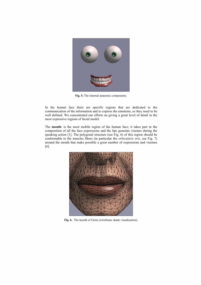
Fig. 5. The internal anatomic components.
In the human face there are specific regions that are dedicated to thecommunication of the information and to express the emotions, so they need to bewell defined. We concentrated our efforts on giving a great level of detail in themost expressive regions of facial model:
The mouth: is the most mobile region of the human face; it takes part in thecomposition of all the face expressions and the lips generate visemes during thespeaking action [1]. The polygonal structure (see Fig. 6) of this region should beconformable to the muscles fibers (in particular the orbicularis oris, see Fig. 7)around the mouth that make possible a great number of expressions and visemes[6].
Fig. 6. The mouth of Greta (wireframe shade visualization).

Fig. 7. The muscles that compose the lips.
The eyes: with brows are easily the most magnetic and compelling part of thehuman face. The polygonal structure (see Fig. 8) of this region should make easycoordinated linguistic and gaze communicative acts, blink, eyebrow and eyelid(upper and lower) moves.
Fig. 8.The eye of Greta (wireframe shade visualization).
3.2 Critical Regions of the 3D Model
In order to simulate the complex behaviour of the skin like the generation ofwrinkles and furrows during the muscular action, we dedicated particular attentionto the polygonal structure of two further regions of the facial model:

• The forehead: is a plane region of the face in the rest and neutral position,but, during communicative acts, the raising of the eyebrows generates on itregular horizontal wrinkles, that are perpendicular to the vertical pull of theforehead muscles. So we needed a regular horizontal structure for thepolygonal lattice of the forehead (see Fig. 9).
Fig. 9. The forehead of Greta with its polygonal structure.
• The nasolabial furrow: is typically of the contraction of the zygomaticmayor muscle. For example during a smile, there is a generation of a clearfurrow between the stretched skin near the mouth an the skin in the cheeksthat, pressed up from below, bulges out like a tiny balloon being squeezed.We needed, in this part of the model, a well defined line of separationbetween the two skin regions, with a considerable polygonal density (seeFig. 10-11).

Fig. 10. Example of nasolabial furrow.
Fig. 11. The polygonal structure in the nasolabial furrow in Greta.
3.3 Subdivision of the 3D Model in “Specific Areas”
In order to have more control on the polygonal lattice we subdivided the 3D modelsurface in “specific areas” that corresponds to the feature points affected by theFAPs. This subdivision was necessary to circumscribe and control the

displacements of polygonal vertexes induced by the FAPs applied in the variousfeature points. For example, in the nasolabial furrow, the two skin zones on theopposing sides of the furrow belong to distinct specific areas. All the specificareas are classified and can be seen in Fig. 12-13.
Fig. 12. Subdivision of Greta in “specific areas” (front view).
Fig. 13. Subdivision of Greta in “specific areas” (side view).

4 Simulation of the Skin Behaviour
Greta uses the FAPs to animate the skin of the 3D model in a realistic way, but itdoesn’t make a physical simulation of the muscles of the face and of the viscous-elastic behaviour of the skin, because the need of real-time calculation of theanimation is a great restriction for this approach. So the FAPs activate functionsthat deform the 3D polygonal lattice during the time and make an “emulation” ofthe real behaviour of the face tissues [12].
4.1 Definition of “Area of Influence”
We have to define the “area of influence” of the feature point. The deformation,due to the FAP for a single feature point, is performed in a zone of influence thathas an ellipsoid shape whose centroid is the feature point. The “area of influence”is the zone of the polygonal lattice that is within the ellipsoid; so we have a precisenumber of vertex that are affected by the displacement due to the FAP (see Fig.14). It must be noticed how the area of influence of each feature points canoverlap one another and, so, a vertex of the 3D model can be under the influenceof various feature points and their FAPs.
Fig. 14. The ellipsoid and the “area of influence”.
4.2 Definition of “Displacement Function”
The FAP is like a muscular action applied in the key point [5, 8, 13]; so, thedisplacement of the vertexes of the polygonal lattice into the area of influence hasto emulate the behaviour of skin under a traction applied just in the feature point.

The displacement ∆xj of a vertex Pj (xj, yj, zj) due to a FAP operating in the xdirection FAPx is computed (without considering now the “specific area”) as:
xjj FAPWx ∗=∆ (1)
The weight Wj is based on the distance of the vertex from the feature point and itis computed by a function that can be seen in Fig. 15, where d”j is a normalizeddistance. Therefore, in the sequence of Fig. 16-18 is possible to see effect of thedisplacement function centered in the white point on a plane polygonal lattice,with a growing intensity of displacement.
Fig. 15. The function of the weight Wj.
Fig. 16. Deformation within an area of influence (null intensity).

Fig. 17. Deformation within an area of influence (medium intensity)
Fig. 18. Deformation within an area of influence (maximum intensity)
4.3 Simulation of Furrows and Bulges
Greta has the possibility to emulate the complex behaviour of the skin like furrowand bulges (i.e. the nasolabial furrow in Fig. 10 that occurs during the contractionof the zygomatic mayor muscle) [11, 12, 13]. The mechanism that generates thefurrow in the skin is explained in Fig. 19; there is the traction of the mimic musclethat operates only onto a limited linear part of the skin and there are two distinctzones:
• The left zone, that is formed by the elastic skin stretched by the muscle.

• The right zone, that is formed by the accumulation of the skin due to thecompression.
Fig. 19. The mechanism that generates the skin furrow.
Fig. 20. The two zones of skin and the feature point.
If we have a simple situation like the Fig. 20 and we want a furrow along the zaxis, the emulation of this behaviour of the skin is obtained by the sum of thehorizontal displacement of the vertexes (∆xi of a vertex Pi (xi, yi, zi)) in the A andB zones (according to the laws previously explained and illustrated in Fig. 16-18)and the vertical displacement (∆yi of a vertex Pi (xi, yi, zi)) of the vertexes in the Bzone, according to the following law:

))/Kd'exp((1)))cos(d(1(0.5Kxy 2ii1ii −−∗+∗∗∗∆=∆ (2)
where di is the distance of the vertex Pi from the feature point, d’i is the distancebetween the vertex and the z axis, and K1 and K2 are constants. Therefore, in thesequence of Fig. 21-23 is possible to see the effect of the displacement functions(along x and y axis) on a plane polygonal lattice when a FAP is applied in thefeature point (green labeled), with a growing intensity.
Fig. 21. Generation of the furrow and the bulge (null intensity of the FAP).
Fig. 22. Generation of the furrow and the bulge (medium intensity of the FAP).

Fig. 23. Generation of the furrow and the bulge (maximum intensity of the FAP).
Finally, in the Fig. 24 is possible to see the effect of the displacement functionson the Greta face during the action of the zygomatic major.
Fig. 24. A “smile” of Greta.

4.4 Simulation of Wrinkles
Greta can also emulate the behaviour of the skin in the zone of the foreheadwhere, during the raising of the eyebrows, there is the generation of manyhorizontal wrinkles. The mechanism is similar to that seen in the previous section,in fact there is an accumulation of skin due to the compression of the raisingeyebrows but there is a series of little horizontal creases because the substrate ofthe forehead is different from the substrate of the cheeks.
Greta uses a bump mapping technique based on per-vertex shading of theOpenGl visualization; it is an innovative technique that let to have an high qualityof the animated facial model with a small polygonal complexity. In fact, inOpenGl based systems, the Gouraud algorithm, that makes possible the shadingrendering mode, uses the normals applied in the vertexes to compute a smoothlightning on the surfaces [2]. So, using the regular disposition of polygons in theforehead region of the 3D model, is possible to perform a perturbation of thenormals, without moving the vertexes, and have the bump mapping, that emulatesthe forehead wrinkles. This is possible, because the Gouraud algorithm performsan interpolation of colors between horizontal darkest and lightest zones,determined by the normal orientations that are controlled by our perturbationfunction. The function is rather complicated and, based on the regular dispositionof vertexes in the forehead region, uses many periodic functions; but moreexplicatory are the Fig. 25-27 that describe a bulge (created by the techniques ofthe previous section) with realistic wrinkles and the Fig. 28 that shows thewrinkles on the forehead of Greta during the raising of the eyebrows.
Fig. 25. Generation of a bulge with wrinkles (null intensity of the FAP).

Fig. 26. Generation of a bulge with wrinkles (medium intensity of the FAP).
Fig. 27. Generation of a bulge with wrinkles (maximum intensity of the FAP).

Fig. 28. Generation of the wrinkles on the Greta forehead.
5 FAPs in Action
The action of the FAPs on the whole 3D model is obtained by the application ofthe previous explained techniques; the extension from the plane polygonal latticeto a complex 3D polygonal face is not difficult. After computing the displacementthat all the FAPs produce for each vertex, is straightforward to calculate the newvertex coordinates and displaying the deformed Greta face using the OpenGlGouraud shading. This procedure is performed for each frame of the animation.
5.1 Application of FAPs on the 3D Model
Generally the displacements ∆xj (we have a similar situation for ∆yj and ∆zj) of avertex Pj (xj, yj, zj) due to a single FAP operating in the x direction is computedusing three kind of information:
• The intensity of the FAP in the related feature point.• The position of the vertex in the “area of influence” of the feature point.• The position within a “specific area”.
The displacement ∆xj of a vertex Pj (xj, yj, zj) in the k-th specific area due to aFAP operating in the x direction FAPx is computed as:
xkjj FAPWWx *′∗=∆ (3)

The weight Wj is based on the distance of the vertex from the feature point and itis computed by the function seen in Fig. 15, the weight W’k is defined by thedesigner after a calibration of the animation and describe how the intensity of theFAP influences the displacement of the vertexes of the k-th “specific area”. Forexample, if we want that the vertexes of the eyelids don’t be affected by the FAPsthat control eyebrows is possible to set Wk = 0 during the computation of the ∆xj
when the above mentioned FAPs operate; this is possible because the vertexes ofthe eyebrows and eyelids belong to distinct specific areas (see Fig. 12-13) and, so,the movements of the vertexes of the eyebrows don’t affect the vertexes of theeyelids. This approach gives a great control on the displacement of the vertexesand allows a natural animation of the 3D face without visual artifacts during therendering.
5.2 Application of auxiliary deformations
Greta uses auxiliary deformations to increase the realism of the animation inspecific parts of the model. These auxiliary deformations perform a displacementof vertexes in the same manner of the FAPs, the only difference is that theintensity of the displacement is not controlled by the FAP stream but is a functionof various weighted FAPs. These auxiliary deformations are used, during specificactions, to increase the realism of the behaviour of the face skin in two zones:
• The zone between the eyebrows during the act of frowning (see Fig. 29).• The zone of the cheeks that swells out during the act of smiling.
Fig. 29. The frown of Greta.

5.3 Example of multiple displacement
The zone of the eyebrow is a good example of multiple displacement of thevertexes due to the FAPs and to the auxiliary deformations combined with thewrinkles generation.
Setting increasing values on FAP 31 (raise_l_i_eyebrow), FAP 33(raise_l_m_eyebrow) and FAP 35 (raise_l_o_eyebrow) we can notice thegeneration of wrinkles on the forehead of Greta (see Fig. 30-32). This is asimulation of the action of the frontalis muscle.
Fig. 30. The action of the frontalis muscle (1).
Fig. 31. The action of the frontalis muscle (2).
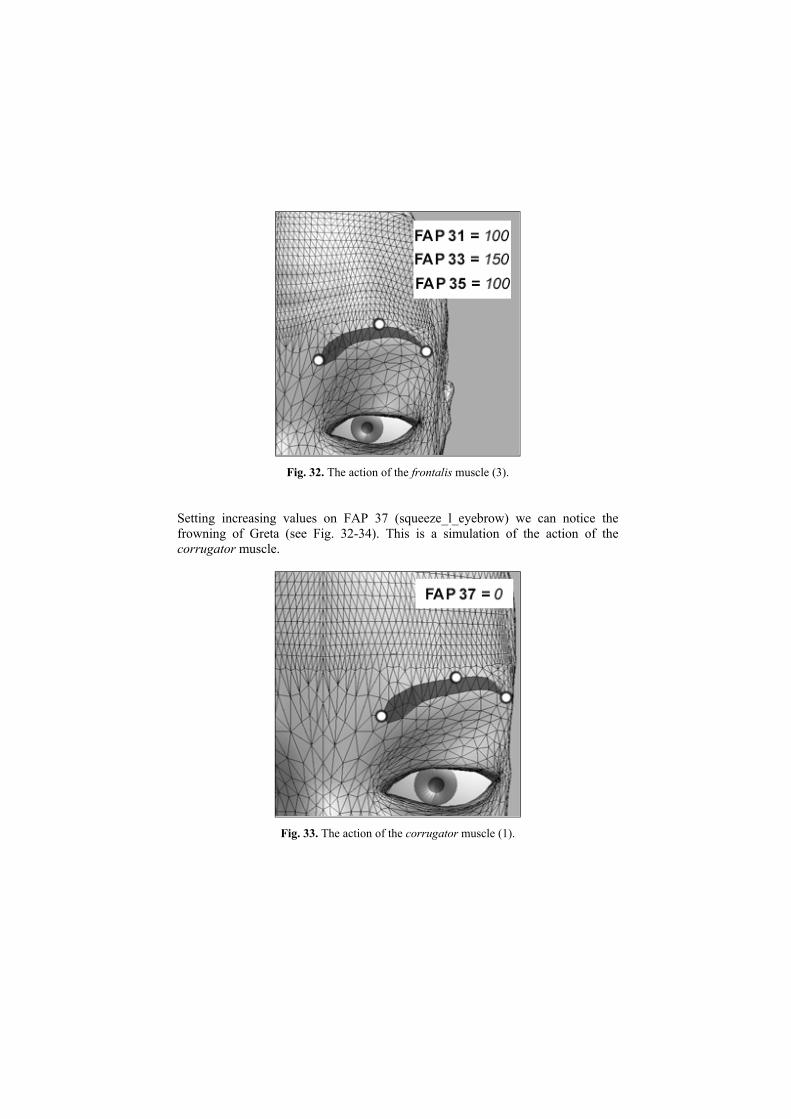
Fig. 32. The action of the frontalis muscle (3).
Setting increasing values on FAP 37 (squeeze_l_eyebrow) we can notice thefrowning of Greta (see Fig. 32-34). This is a simulation of the action of thecorrugator muscle.
Fig. 33. The action of the corrugator muscle (1).

Fig. 34. The action of the corrugator muscle (2).
Fig. 35. The action of the corrugator muscle (3).
6 Conclusions
The facial model of Greta is made of 15,000 triangles. The high number ofpolygons allows us to maintain a great level of detail in the most expressiveregions of human face: the eyes and the mouth. Indeed, these regions play animportant role in the communication process of human-human conversation and inexpressing emotions (see Fig 36-37).

The graphic engine of Greta has a conception similar to others MPEG basedprojects that were previously realized [7]. The novelty of Greta is the high qualityof the 3D model, and the generation in real-time of wrinkles, bulges and furrows,enhancing the realism and the expressive look to the animated face. This work ispart of an ongoing research on the creation of an embodied conversational agent,that is an agent able to communicate with other agent(s) or user(s) as well as toexpress its emotion [3].
Fig. 36. The fear of Greta.

Fig. 37. The joy of Greta.
References
1. Cohen MM, Massaro DW (1993) Modeling coarticulation in synthetic visual speech. InM. Magnenat-Thalmann and D. Thalmann, editors, Models and Techniques in ComputerAnimation, Tokyo, Springer-Verlag
2. Davis N, Davis J, Davis T, Woo M (1993) OpenGL Programming Guide: The OfficialGuide to Learning OpenGL, Release 1 (“Red Book”). Reading, MA: Addison-WesleyISBN 0-201-63274-8
3. De Carolis N, Pelachaud C, Poggi I, De Rosis F (2001) Behavior planning for areflexive agent. In IJCAI'01, Seattle, USA, August 2001
4. Doenges P, Lavagetto F, Ostermann J, Pandzic IS, Petajan E (1997) MPEG-4:Audio/video and synthetic graphics/audio for mixed media. Image CommunicationsJournal, 5(4), May 1997
5. Ekman P, Friesen WV (1978) Manual for the Facial Action Coding System. ConsultingPsychologists Press, Inc., Palo Alto
6. Faigin G (1990) The Artist’s Complete Guide to Facial Expression. Watson-Guptill,New York

7. Lavagetto F, Pockaj R (1999) The facial animation engine: towards a high-levelinterface for the design of MPEG-4 compliant animated faces. IEEE Trans. on Circuitsand Systems for Video Technology, 9(2):277-289, March 1999
8. Magnenat-Thalmann N, Primeau NE, Thalmann D (1988) Abstract muscle actionsprocedures for human face animation. Visual Computer, 3(5):290-297
9. Ostermann J (1998) Animation of synthetic faces in MPEG-4. In ComputerAnimation'98, pages 49-51, Philadelphia, USA, June 1998
10. Parke FI, Waters K (1996) Computer Facial Animation. A. K. Peters, Wellesley, MA11. Reeves B (1990) Simple and complex facial animation: Case studies. In Vol 26: State of
the Art in Facial Animation, pages 90-106. ACM Siggraph'90 Course Notes12. Sederberg TW, Parry SR (1986) Free-form deformation of solid geometry models.
Computer Graphics (SIGGRAPH ‘86), 20(4):151-16013. Waters K (1987) A muscle model for animating three-dimensional facial expressions.
Computer Graphics (SIGGRAPH ‘87), 21(4):17-24, July
Copyright © 2022 FDOKUMEN