
Xurography: rapid prototyping of microstructures using a cutting plotter
Dynamic Article LinksC<Journal ofMaterials Chemistry
Cite this: DOI: 10.1039/c2jm30512g
www.rsc.org/materials PAPER
Dow
nloa
ded
by D
ublin
City
Uni
vers
ity o
n 04
May
201
2Pu
blis
hed
on 0
3 A
pril
2012
on
http
://pu
bs.r
sc.o
rg |
doi:1
0.10
39/C
2JM
3051
2GView Online / Journal Homepage
Graphene-doped photo-patternable ionogels: tuning of conductivity andmechanical stability of 3D microstructures
Mohamed Oubaha,*a Andrew Kavanagh,b Arnaud Gorin,a Gabija Bickauskaite,c Robert Byrne,b Maria Farsari,c
Richard Winfield,d Dermot Diamond,b Colette McDonagha and Robert Copperwhitea
Received 26th January 2012, Accepted 3rd April 2012
DOI: 10.1039/c2jm30512g
This work reports for the first time the development of enhanced-conductivity, graphene-doped photo-
patternable hybrid organic-inorganic ionogels and the effect of the subsequent materials condensation
on the conductivity and mechanical stability of three-dimensional microstructures fabricated by multi-
photon polymerisation (MPP). Ionogels were based on photocurable silicon/zirconium hybrid sol–gel
materials and phosphonium (trihexyltetradecylphosphonium dicyanamide) [P6,6,6,14][DCA] ionic liquid
(IL). To optimise the dispersion of graphene within the ionogel matrices, aqueous solutions of graphene
were prepared, as opposed to the conventional graphene powder approach, and employed as catalysts
of hydrolysis and condensation reactions occurring in the sol–gel process. Ionogels were prepared via
a two step process by varying the hydrolysis degree from 25 to 50%, IL content between 0–50 w/w%,
and the inorganic modifier (zirconate complex) concentration from 30 to 60 mol.% against the
photocurable ormosil and they were characterised via Raman, Electrochemical Impedance
Spectroscopy and Transmission Electron Microscopy. MPP was performed on the hybrid ionogels,
resulting in three-dimensional microstructures that were characterised using scanning electron
microscopy. It is clearly demonstrated that the molecular formulation of the ionogels, including the
concentration of graphene and the zirconate network modifier, plays a critical role in the conductivity
of the ionogels and influences the resulting mechanical stability of the fabricated three-dimensional
microstructures. This work aims to establish for the first time the relationship between the molecular
design and condensation of materials in the physico-chemistry and dynamic of ionogels.
Introduction
Ionogels are currently the subject of a rapidly growing number of
both fundamental and applied studies in materials science. They
are a new type of hybrid material which consist of an ionic liquid
(IL) confined within the backbone of a gel-like structure.1–3 ILs
can be generally described as organic salts combining many
favourable physicochemical properties including low melting
points (typically <370 K), negligible vapour pressure, high ionic
conductivities and thermal stability.4,5 This has made ILs inter-
esting candidates for a number of applications including elec-
trolytes for solar-cells,6 fluorescent7 and optical devices.8
So far, two routes have been highlighted for the incorporation
of ILs in a gel; the organic route, which involves in situ poly-
merization or swelling of polymers with ILs,9,10 and the inorganic
route, which consists of impregnation of ILs within oxide
aOptical Sensors Laboratory, National Centre for Sensor Research, DublinCity University, Glasnevin, Dublin 9, IrelandbCLARITY: The Centre for SensorWeb Technologies, National Centre forSensor Research, Dublin City University, Glasnevin, Dublin 9, IrelandcInstitute of Electronic Structure and Laser, Foundation for Research andTechnology Hellas, N. Plastira 100, GR-70013 Heraklion, Crete, GreecedTyndall National Institute, Cork, Ireland
This journal is ª The Royal Society of Chemistry 2012
backbones.11 Of the inorganic routes, the polymeric sol–gel
process is probably the most popular synthetic route, as recently
summarized in an excellent review.2 It involves hydrolysis and
condensation reactions of inorganic or hybrid precursors in
order to develop inorganic backbones with morphologies
ranging from macroporous materials to dense bulk materials
depending on the hydrolysis conditions and the nature of the
precursors employed. The sol–gel chemistry is therefore well
known and is detailed in a number of reviews12–14 and books.15,16
The incorporation of ILs within sol–gel materials has been
reported mainly on silicate based materials, where confinement
and dynamics of ILs within mesoporous structures has been
demonstrated.17–19 However, one major disadvantage of these
materials is their limited mechanical resistance due to the low
connectivity of the inorganic network, because of the low drying
temperatures (to avoid degradation of the organic moieties in
ILs), and the characteristic liquid property of the ILs. This often
results in leaching and miniaturisation issues that are critical
parameters for all-solid-state devices. Furthermore, to our
knowledge, no study has so far investigated the effect of the
condensation of the inorganic backbone on the IL dynamic and
the subsequent conductivity.
J. Mater. Chem.
Dow
nloa
ded
by D
ublin
City
Uni
vers
ity o
n 04
May
201
2Pu
blis
hed
on 0
3 A
pril
2012
on
http
://pu
bs.r
sc.o
rg |
doi:1
0.10
39/C
2JM
3051
2G
View Online
An interesting approach to improve on the existing conduc-
tivity properties of solid-state electrolytes consists of the addition
of co-encapsulants that exhibit electronic conductivity.20 Argu-
ably the most popular avenue of choice is to use materials derived
from the carbon allotrope graphite, which is composed of
multiple stacked sheets of aromatic sp2-hybridised atoms that
exist in the third dimension.21 Graphite single two-dimensional
sheets (graphene) can be obtained by a chemical reduction
process of graphite in aqueous solutions22–25 and rolled up to
form one-dimensional nanotubes.26 When combined with ion-
ogels, so called ‘‘bucky gels’’ therefore unite the electron con-
ducting properties of graphite-based materials with the ionic
conducting ILs in the solid state.27 Composites based on ILs and
materials derived from graphite are easily prepared28 by simply
mixing and sonicating the two independent liquid phases,29 or by
mixing and grinding graphene powder with an IL in an agar
plate, to produce the gel-like material.30 Another important
aspect for the development of the next generation of solid-state
electrolytes and electro-optical systems is the shaping and mini-
aturisation on substrates of diverse forms.
A possible solution to these major issues has recently been
proposed by our group, which is to develop photocurable ion-
ogels that can be photo-structured to submicron resolution as
both planar and 3D patterns employing both single and multi-
photon polymerisation (MPP) techniques.31 The principle of
confining ILs within photopatternable silicon/zirconium hybrid
materials has been demonstrated and their conductivity and
electrochromic behaviour correlated to the IL concentrations. In
comparison to the relatively simple silicate-based sol–gel
matrices employed so far in the development of ionogels, our
materials contain an additional transition metal inorganic
network, which further increases the connectivity of the inor-
ganic network at ambient temperatures.32 Furthermore, the
occurrence of photopolymerisation reactions leads to the
formation of an organic network overlapping both inorganic
networks (silicate and zirconate). This additional double capa-
bility of polymerisation dramatically increases the condensation
of the sol–gel matrices and contributes to a better confinement of
the IL within the mesopores of the sol–gel matrices, thereby
minimizing IL leaching.
Herein we report the first study on the effect of the conden-
sation of hybrid sol–gel materials on the physical properties of
ILs, and the impact of the IL concentration on the photo-
reactivity and mechanical stability of 3D photopatterned
microstructures fabricated by MPP. In addition to this, a novel
sol–gel synthesis, employing aqueous solutions of graphene, is
proposed for the development of the materials. This original
strategy is proposed in order to ensure the highest possible
dispersion of graphene during the sol–gel synthesis and in the
subsequent ionogel materials as well as to investigate its effect on
the overall conductivity of the ionogels.
Experimental
Chemicals and materials
Trihexyltetradecylphosphonium dicyanamide [P6,6,6,14] [DCA]
was obtained as a complimentary sample from Cytec� Indus-
tries. Further purification was achieved by washing with both
J. Mater. Chem.
water and hexane, and by column chromatography. ILs were
then dried under vacuum at 40 �C for 48 h, and stored under
argon at 20 �C.33
Poly(3-octylthiophene-2,5-diyl) (POT), 3-methacryloxy-
propyltrimethoxysilane (MAPTMS, assay 99% in methanol),
zirconium(IV) n-propoxide (ZPO, assay �70% in propanol) and
methacrylic acid (MAAH, C4H6O2, assay �98%), were used as
purchased from Sigma-Aldrich� Ireland. Dieth-
ylaminobenzophenone (DEABPH) was purchased from Alpha
Aesar and used without any further purification.
Graphene solution preparation
Graphite powder was purchased from Sigma Aldrich and sieved
through a 0.5 mm mesh to remove large particles. Sodium
dodecylbenzene sulfonate (SDBS) was purchased from Sigma
and used as provided. A 0.5 mg ml�1 solution of SDBS in
deionised water was prepared. The graphene dispersion was
prepared by adding 1 mg ml�1 of sieved graphite to the SDBS
solution and sonicating in a low power sonic bath for 24 h. The
dispersion was then centrifuged for 90 min at 2000 rpm. The
concentration was calculated by filtering 10 ml of the dispersion
through a weighed filter paper, washing with 100 ml of deionised
water, drying in a vacuum oven overnight and measuring the
mass deposited.
Hybrid sol–gel synthesis
The sol–gel synthesis was based on the formation of stable and
homogeneous solutions obtained from the reaction between
photosensitive organically modified precursors MAPTMS, ZPO
andMAAHwhich were allowed to react in different molar ratios
leading to materials A to G, as shown in Table 1.
For the synthesis of material A, MAPTMS was pre-hydro-
lysed with an aqueous solution (HCl 0.005 N), employing
a 1.00:0.75 water to alkoxide molar ratio. For the synthesis of
materials B to G the pre-hydrolysis of the organosilane precursor
was performed employing an aqueous solution containing
0.22 mg ml�1 of graphene. Before use, this solution was acidified
with an aqueous solution of HCl (0.05 M) to obtain an aqueous
solution of pH 2.3
After 20 min of stirring, the solution became fully transparent
demonstrating the occurrence of hydrolysis and condensation
reactions leading to the production of alcohol that allows the
miscibility of all species present in solution. In parallel, to control
the hydrolysis–condensation of ZPO and avoid the formation of
any undesired ZrO2 precipitate, MAAH was used, in 1/1 stoi-
chiometric ratio against ZPO, as a chelating agent as it covalently
binds with the zirconium atom through two oxygen atoms. After
45 min of reaction, the pre-hydrolysed MAPTMS solution was
added drop-wise to the zirconium complex.
Following another 45 min of reaction, in order to improve the
homogeneity of both molecular systems, a second hydrolysis
employing water (pH 7) was performed leading to a hydrolysis of
50% mol. of the total alkoxide groups. To keep the quantity of
graphene constant in materials C–G, adjustment of the amount
of graphene was also performed by using the parent aqueous
graphene solution during the second hydrolysis. The final sols
were left stirring for 24 h before use.
This journal is ª The Royal Society of Chemistry 2012
Table 1 Ionogel formulations
Sol-gel Formulation MAPTMS (mol%) ZPO/MAAH (mol%)Graphene (mg/mlof sol-gel)
Hydrolysis Degree(mol%)
A 70 30 0 10B 70 30 0.0078 25C 70 30 0.0157 50D 60 40 0.0157 50E 55 45 0.0157 50F 50 50 0.0157 50G 40 60 0.0157 50
Dow
nloa
ded
by D
ublin
City
Uni
vers
ity o
n 04
May
201
2Pu
blis
hed
on 0
3 A
pril
2012
on
http
://pu
bs.r
sc.o
rg |
doi:1
0.10
39/C
2JM
3051
2G
View Online
Ionogel synthesis
e.g. sol–gel A: [P6,6,6,14][DCA] 50:50 w/w.
All ionogel formulations were photopolymerised using the
in situ technique. For the cited example the preparation was as
follows:
500 mg of sol–gel solution was mixed thoroughly with 500 mg
of [P6,6,6,14][DCA] and 10 mg of photoinitiator (DEABPH).
The ionogel solution was then sonicated for 5 min to ensure the
photoinitiator was dissolved fully. It was then transferred to
a 2 cm diameter circular mould and photopolymerized with a UV
BondWand (Electro-lite, Connecticut 20 W, 365 nm) for 10 min.
The ionogel was placed in a vacuum oven at 50 �C for 24 h. All
ionogel combinations were prepared in accordance with the
above procedure, with adjustments only to the hybrid organic
sol–gel composition.
3D structuring of ionogels
The experimental setup employed for the fabrication of three-
dimensional microstructures has been described extensively
previously.34–36 A Ti:sapphire femtosecond laser (Femtolasers
Fusion, 800 nm, 75 MHz, <20 fs) beam was focused into the
photopolymerisable composite using a high numerical aperture
focusing microscope objective lens (100x, N.A. ¼ 1.4, Zeiss, Plan
Apochromat). Sample movement was achieved using piezoelec-
tric and linear stages, for fine and step movement, respectively
(PI). The direct laser writing setup was computer-controlled
using 3DPoli software. Woodpile structures of dimensions 20 �20 mm � 10 mm height and of 1 mm period were fabricated. The
average power used for the fabrication of the high-resolution
structures was in the range 3 to 7 mW, measured before the
objective, while the average transmission was 20%. The scanning
speed was always set at 10 mm s�1.
Instrumentation
Refractive index values for the films were determined using the
prism coupling method at 632.8, 835, 1310 and 1550 nm (using
a Metricon 2010). Using this technique, a measurement accuracy
of 0.0005 is obtained and this value was taken as the measure-
ment uncertainty. Refractive index values were measured for
both TE and TM modes, but the modes rarely varied by more
than the measurement accuracy. Values reported in this paper
are averages of the TE and TM results.
Raman Spectroscopy was performed using a Perkin Elmer�Raman Station 400F (785 nm). UV/Vis spectra were recorded
This journal is ª The Royal Society of Chemistry 2012
using the Perkin Elmer� Lambda 900 UV/Vis/NIR
spectrometer.
Electrochemical Impedance Spectroscopy (EIS) was per-
formed using a CHI� Instruments 660A potentiostat. The
frequency range scanned ranged from 1 MHz to 1 Hz, and the
perturbation signal applied was 100 mV. Platinum and Ag/AgCl
were used as the reference and counter electrodes, respectively,
and a nF capacitance shunt bridge was used in order to reduce
high frequency noise. In house, screen-printed, carbon paste
silver electrodes were used as the working electrode, as described
in a previous report.37 The working electrodes were initially
covered in a layer of POT (10�2 M in chloroform) and allowed to
dry in order to aid the transfer of ionic to electronic conduction.
40 mL of the ionogel to be analysed was then dropcast and photo-
polymerised for 10 min onto the POT layer. Ionogel thickness
was estimated using a Mitutoyo� vernier calipers calibrated to
a resolution of 1 mm.
Results and discussion
Spectroscopic characterisation of encapsulated electroactive
components
Raman spectroscopy was performed to confirm the encapsula-
tion of the IL and the graphene dispersion within the sol–gel on
a molecular level. For comparative purposes, the spectra
obtained from the graphene free (material A) and graphene
doped material (material C) both containing 40 wt% IL, were
superimposed in Fig. 1. The baseline was corrected using the
1800–2000 cm�1 region where no spectral activity was seen, and
normalised according to the C–H contributions of both samples
at �2900 cm�1, as both materials should contain the same
concentration of organic groups. This approach allows the
spectral contributions of the graphene dispersion to be more
clearly analysed. The Raman spectroscopy of graphene and its
underlying physics are quite well understood and have been the
subject of previous reviews.38,39
The encapsulation of graphene within the ionogel matrix was
confirmed via the presence of the G0 band at 2590 cm�1 arising
from a two phonon inelastic scattering process; and the disorder
induced D0 band at 1572 cm�1. An increase in intensity of the
band at 1592 cm�1 can be attributed to the doubly degenerate G
phonon mode.
Spectral contributions from the sol–gel matrix prominent in
both spectra include the carbonyl band from MAPTMS present
at 1640 cm�1 the C–H polymeric backbone band at 1475 cm�1
plus the confirmation of the carboxylate bridged zirconium
J. Mater. Chem.
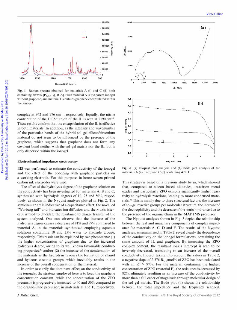
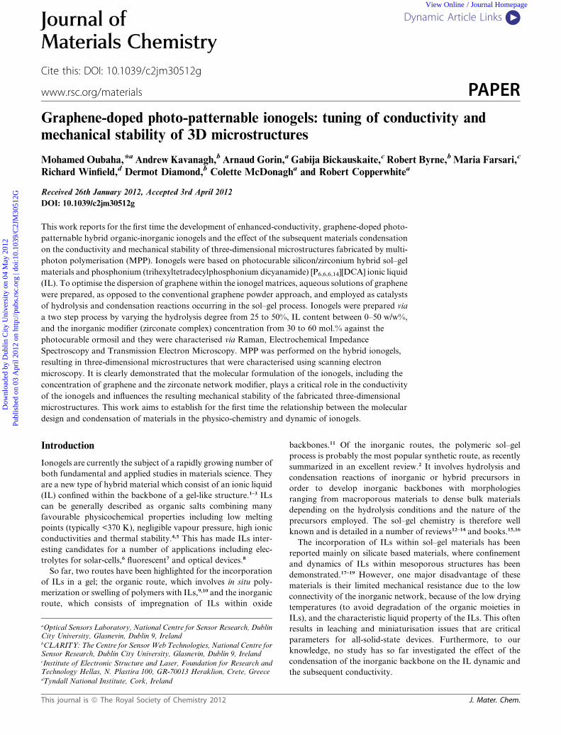
Fig. 1 Raman spectra obtained for materials A (i) and C (ii) both
containing 50 wt% [P6,6,6,14][DCA]. Here material A is the parent ionogel
without graphene, and material C contains graphene encapsulated within
the ionogel.
Dow
nloa
ded
by D
ublin
City
Uni
vers
ity o
n 04
May
201
2Pu
blis
hed
on 0
3 A
pril
2012
on
http
://pu
bs.r
sc.o
rg |
doi:1
0.10
39/C
2JM
3051
2G
View Online
complex at 942 and 976 cm�1, respectively. Equally, the nitrile
contribution of the DCA� anion of the IL is seen at 2190 cm�1.
These results confirm that the encapsulation of the IL is effective
in both materials. In addition, as the intensity and wavenumber
of the particular bands of the hybrid sol–gel silicon/zirconium
material do not seem to be influenced by the presence of the
graphene, which suggests that graphene does not form any
covalent bond neither with the sol–gel matrix nor the IL, but is
only dispersed within the ionogel.
Fig. 2 (a) Nyquist plot analysis and (b) Bode plot analysis of for
materials A (a), B (b) and C (c) containing 40% IL.
Electrochemical impedance spectroscopy
EIS was performed to estimate the conductivity of the ionogel
and the effect of the codoping with graphene particles on
a working electrode. For this purpose, in house screen-printed
carbon ink electrodes were used.
The effect of the hydrolysis degree of the graphene solution on
the conductivity has been investigated for materials A, B and C,
synthesised with hydrolysis degrees of 10, 25 and 50%, respec-
tively, as shown in the Nyquist analyses plotted in Fig. 2. The
semicircular arc is indicative of a capacitance effect, the so-called
‘‘Warburg tail’’ and indicates ion diffusion and the x-axis inter-
cept is used to elucidate the resistance to charge transfer of the
system analysed. One can observe that the increase of the
hydrolysis degree causes a decrease of 81% and 89% compared to
material A, in the materials synthesised employing aqueous
solutions containing 10 and 25% water to alkoxide groups,
respectively. This result can be explained by two phenomena: (1)
the higher concentration of graphene due to the increased
hydrolysis degree, owing to its well known favourable conduct-
ing properties;40 and/or (2) the increase of the condensation of
the materials as the hydrolysis favours the formation of silanol
and hydrous zirconia groups, which inevitably results in the
increase of the overall condensation of the material.
In order to clarify the dominant effect on the conductivity of
the ionogels, the strategy employed here is to keep the graphene
concentration constant, while the concentration of the ZPO
precursor is progressively increased to 40 and 50% compared to
the organosilane precursor, in materials D and F, respectively.
J. Mater. Chem.
This strategy is based on a previous study by us, which showed
that, compared to silicon based alkoxides, transition metal
oxides and particularly ZPO exhibits significantly higher reac-
tivity to hydrolysis reactions, leading to more condensed mate-
rials.32 This is mainly due to three structural factors: the increase
of sol–gel reactive groups per molecular structure, the increase of
the electrophilicity and the decrease of the steric hindrance due to
the presence of the organic chain in the MAPTMS precursor.
The Nyquist analyses shown in Fig. 3 depict the relationship
between the real and imaginary components of complex imped-
ance for materials A, C, D and F. The results of the Nyquist
analyses, as summarised in Table 2, reveal clearly the dependence
of the conductivity on the ionogel formulations, containing the
same amount of IL and graphene. By increasing the ZPO
complex content, the resultant x-axis intercept is seen to be
inversely decreased, translating to an increase of the overall
conductivity. Indeed, taking into account the values in Table 2,
a negative slope of 2.376 RCT/mol% of ZPO has been calculated
with an R2 > 97%. For the material containing the highest
concentration of ZPO (material F), the resistance is decreased by
82%, ultimately resulting in an increase of the conductivity by
more than a full order of magnitude through molecular design of
the sol–gel matrix. The Bode plot (ii) shows the relationship
between the total impedance and the frequency scanned.
This journal is ª The Royal Society of Chemistry 2012
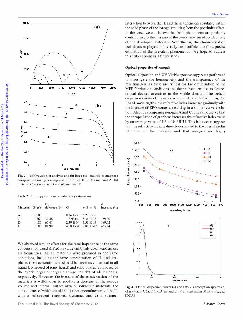
Fig. 3 (a) Nyquist plot analysis and (b) Bode plot analysis of graphene
encapsulated ionogels composed of 40% of IL in (a) material A, (b)
material C, (c) material D and (d) material F.
Table 2 EIS RCT and ionic conductivity estimation
Material Z0 (U)RCT
decrease (%) G s (S m�1)sincrease (%)
A 12100 8.26 E-05 5.21 E-06C 7567 37.46 1.32E-04 8.34 E-06 59.90D 4185 65.41 2.39 E-04 1.50 E-05 189.12F 2180 81.98 4.58 E-04 2.89 1E-05 455.04
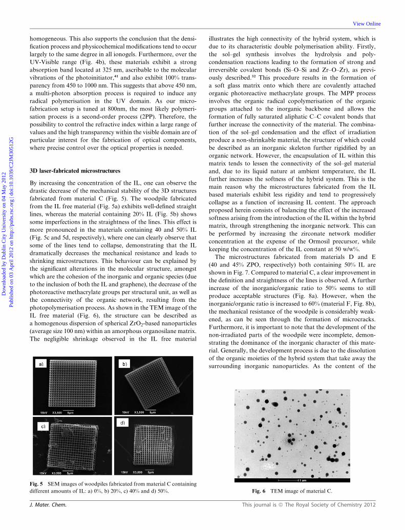
Fig. 4 Optical dispersion curves (a) and UV-Vis absorption spectra (b)
of materials A (i), C (ii), D (iii) and E (iv) all containing 50 wt% [P6,6,6,14]
[DCA].
Dow
nloa
ded
by D
ublin
City
Uni
vers
ity o
n 04
May
201
2Pu
blis
hed
on 0
3 A
pril
2012
on
http
://pu
bs.r
sc.o
rg |
doi:1
0.10
39/C
2JM
3051
2G
View Online
We observed similar effects for the total impedance as the same
condensation trend shifted its value uniformly downward across
all frequencies. As all materials were prepared in the same
conditions, including the same concentration of IL and gra-
phene, these concentrations should be rigorously identical in all
liquid (composed of ionic liquid) and solid phases (composed of
the hybrid organic-inorganic sol–gel matrix) of all materials,
respectively. However, the increase of the condensation of the
materials is well-known to produce a decrease of the porous
volume and internal surface area of solid-state materials, the
consequence of which should be 1) a better confinement of the IL
with a subsequent improved dynamic; and 2) a stronger
This journal is ª The Royal Society of Chemistry 2012
interaction between the IL and the graphene encapsulated within
the solid phase of the ionogel resulting from the proximity effect.
In this case, we can believe that both phenomena are probably
contributing to the increase of the overall measured conductivity
of the developed materials. Nevertheless, the characterisation
techniques employed in this study are insufficient to allow precise
estimation of the prevalent phenomenon. We hope to address
this critical point in a future study.
Optical properties of ionogels
Optical dispersion and UV-Visible spectroscopy were performed
to investigate the homogeneity and the transparency of the
resulting gels, as these are critical for the optimisation of the
MPP fabrication conditions and their subsequent use as electro-
optical devices operating in the visible domain. The optical
dispersion curves of materials A and C–E are plotted in Fig. 4a.
For all wavelengths, the refractive index increases gradually with
the increase of ZPO content, resulting in a similar curve evolu-
tion. Also, by comparing ionogels A and C, one can observe that
the encapsulation of graphene increases the refractive index value
by an average value of 1.6 � 10�3 RIU. This behaviour suggests
that the refractive index is directly correlated to the overall molar
refraction of the material, and that ionogels are highly
J. Mater. Chem.
Dow
nloa
ded
by D
ublin
City
Uni
vers
ity o
n 04
May
201
2Pu
blis
hed
on 0
3 A
pril
2012
on
http
://pu
bs.r
sc.o
rg |
doi:1
0.10
39/C
2JM
3051
2G
View Online
homogeneous. This also supports the conclusion that the densi-
fication process and physicochemical modifications tend to occur
largely to the same degree in all ionogels. Furthermore, over the
UV-Visible range (Fig. 4b), these materials exhibit a strong
absorption band located at 325 nm, ascribable to the molecular
vibrations of the photoinitiator,41 and also exhibit 100% trans-
parency from 450 to 1000 nm. This suggests that above 450 nm,
a multi-photon absorption process is required to induce any
radical polymerisation in the UV domain. As our micro-
fabrication setup is tuned at 800nm, the most likely polymeri-
sation process is a second-order process (2PP). Therefore, the
possibility to control the refractive index within a large range of
values and the high transparency within the visible domain are of
particular interest for the fabrication of optical components,
where precise control over the optical properties is needed.
3D laser-fabricated microstructures
By increasing the concentration of the IL, one can observe the
drastic decrease of the mechanical stability of the 3D structures
fabricated from material C (Fig. 5). The woodpile fabricated
from the IL free material (Fig. 5a) exhibits well-defined straight
lines, whereas the material containing 20% IL (Fig. 5b) shows
some imperfections in the straightness of the lines. This effect is
more pronounced in the materials containing 40 and 50% IL
(Fig. 5c and 5d, respectively), where one can clearly observe that
some of the lines tend to collapse, demonstrating that the IL
dramatically decreases the mechanical resistance and leads to
shrinking microstructures. This behaviour can be explained by
the significant alterations in the molecular structure, amongst
which are the cohesion of the inorganic and organic species (due
to the inclusion of both the IL and graphene), the decrease of the
photoreactive methacrylate groups per structural unit, as well as
the connectivity of the organic network, resulting from the
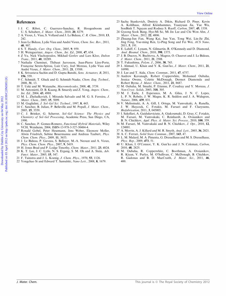
photopolymerisation process. As shown in the TEM image of the
IL free material (Fig. 6), the structure can be described as
a homogenous dispersion of spherical ZrO2-based nanoparticles
(average size 100 nm) within an amorphous organosilane matrix.
The negligible shrinkage observed in the IL free material
Fig. 5 SEM images of woodpiles fabricated from material C containing
different amounts of IL: a) 0%, b) 20%, c) 40% and d) 50%.
J. Mater. Chem.
illustrates the high connectivity of the hybrid system, which is
due to its characteristic double polymerisation ability. Firstly,
the sol–gel synthesis involves the hydrolysis and poly-
condensation reactions leading to the formation of strong and
irreversible covalent bonds (Si–O–Si and Zr–O–Zr), as previ-
ously described.32 This procedure results in the formation of
a soft glass matrix onto which there are covalently attached
organic photoreactive methacrylate groups. The MPP process
involves the organic radical copolymerisation of the organic
groups attached to the inorganic backbone and allows the
formation of fully saturated aliphatic C–C covalent bonds that
further increase the connectivity of the material. The combina-
tion of the sol–gel condensation and the effect of irradiation
produce a non-shrinkable material, the structure of which could
be described as an inorganic skeleton further rigidified by an
organic network. However, the encapsulation of IL within this
matrix tends to lessen the connectivity of the sol–gel material
and, due to its liquid nature at ambient temperature, the IL
further increases the softness of the hybrid system. This is the
main reason why the microstructures fabricated from the IL
based materials exhibit less rigidity and tend to progressively
collapse as a function of increasing IL content. The approach
proposed herein consists of balancing the effect of the increased
softness arising from the introduction of the IL within the hybrid
matrix, through strengthening the inorganic network. This can
be performed by increasing the zirconate network modifier
concentration at the expense of the Ormosil precursor, while
keeping the concentration of the IL constant at 50 w/w%.
The microstructures fabricated from materials D and E
(40 and 45% ZPO, respectively) both containing 50% IL are
shown in Fig. 7. Compared to material C, a clear improvement in
the definition and straightness of the lines is observed. A further
increase of the inorganic/organic ratio to 50% seems to still
produce acceptable structures (Fig. 8a). However, when the
inorganic/organic ratio is increased to 60% (material F, Fig. 8b),
the mechanical resistance of the woodpile is considerably weak-
ened, as can be seen through the formation of microcracks.
Furthermore, it is important to note that the development of the
non-irradiated parts of the woodpile were incomplete, demon-
strating the dominance of the inorganic character of this mate-
rial. Generally, the development process is due to the dissolution
of the organic moieties of the hybrid system that take away the
surrounding inorganic nanoparticles. As the content of the
Fig. 6 TEM image of material C.
This journal is ª The Royal Society of Chemistry 2012
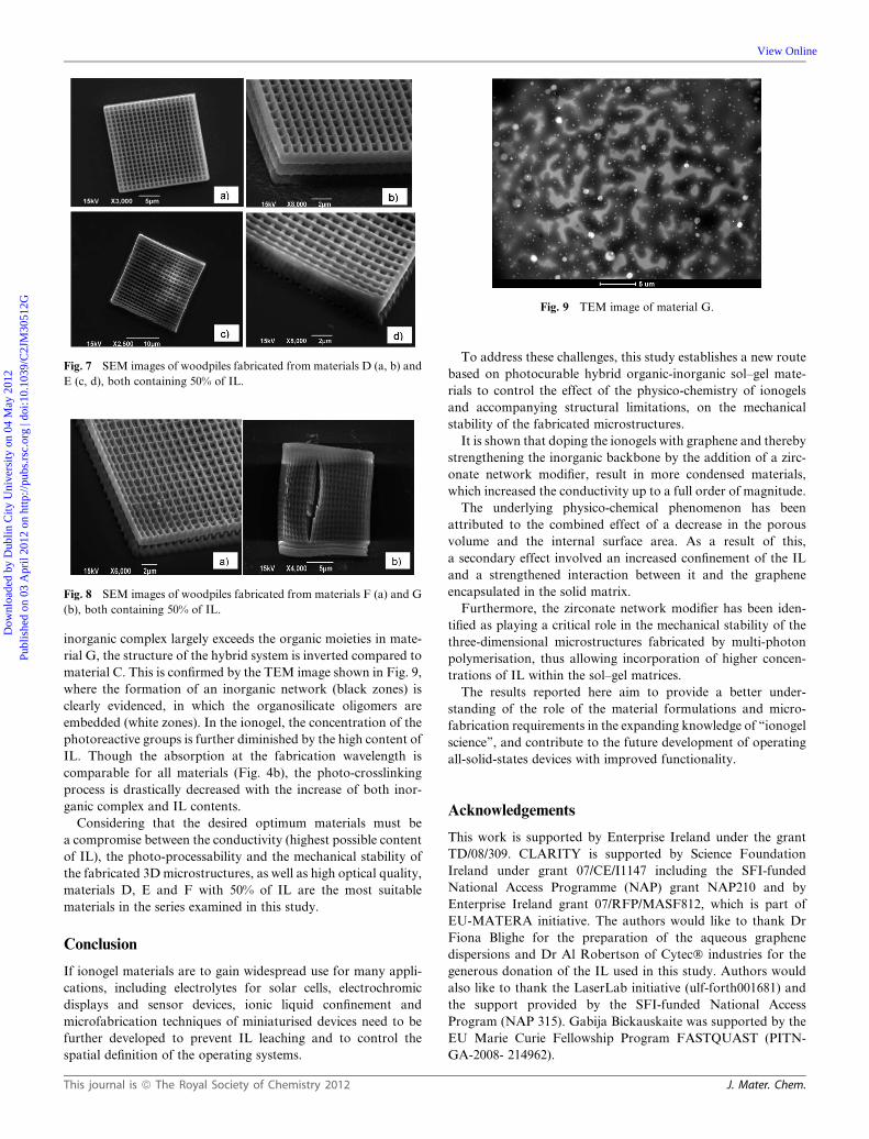
Fig. 7 SEM images of woodpiles fabricated from materials D (a, b) and
E (c, d), both containing 50% of IL.
Fig. 8 SEM images of woodpiles fabricated from materials F (a) and G
(b), both containing 50% of IL.
Fig. 9 TEM image of material G.
Dow
nloa
ded
by D
ublin
City
Uni
vers
ity o
n 04
May
201
2Pu
blis
hed
on 0
3 A
pril
2012
on
http
://pu
bs.r
sc.o
rg |
doi:1
0.10
39/C
2JM
3051
2G
View Online
inorganic complex largely exceeds the organic moieties in mate-
rial G, the structure of the hybrid system is inverted compared to
material C. This is confirmed by the TEM image shown in Fig. 9,
where the formation of an inorganic network (black zones) is
clearly evidenced, in which the organosilicate oligomers are
embedded (white zones). In the ionogel, the concentration of the
photoreactive groups is further diminished by the high content of
IL. Though the absorption at the fabrication wavelength is
comparable for all materials (Fig. 4b), the photo-crosslinking
process is drastically decreased with the increase of both inor-
ganic complex and IL contents.
Considering that the desired optimum materials must be
a compromise between the conductivity (highest possible content
of IL), the photo-processability and the mechanical stability of
the fabricated 3Dmicrostructures, as well as high optical quality,
materials D, E and F with 50% of IL are the most suitable
materials in the series examined in this study.
Conclusion
If ionogel materials are to gain widespread use for many appli-
cations, including electrolytes for solar cells, electrochromic
displays and sensor devices, ionic liquid confinement and
microfabrication techniques of miniaturised devices need to be
further developed to prevent IL leaching and to control the
spatial definition of the operating systems.
This journal is ª The Royal Society of Chemistry 2012
To address these challenges, this study establishes a new route
based on photocurable hybrid organic-inorganic sol–gel mate-
rials to control the effect of the physico-chemistry of ionogels
and accompanying structural limitations, on the mechanical
stability of the fabricated microstructures.
It is shown that doping the ionogels with graphene and thereby
strengthening the inorganic backbone by the addition of a zirc-
onate network modifier, result in more condensed materials,
which increased the conductivity up to a full order of magnitude.
The underlying physico-chemical phenomenon has been
attributed to the combined effect of a decrease in the porous
volume and the internal surface area. As a result of this,
a secondary effect involved an increased confinement of the IL
and a strengthened interaction between it and the graphene
encapsulated in the solid matrix.
Furthermore, the zirconate network modifier has been iden-
tified as playing a critical role in the mechanical stability of the
three-dimensional microstructures fabricated by multi-photon
polymerisation, thus allowing incorporation of higher concen-
trations of IL within the sol–gel matrices.
The results reported here aim to provide a better under-
standing of the role of the material formulations and micro-
fabrication requirements in the expanding knowledge of ‘‘ionogel
science’’, and contribute to the future development of operating
all-solid-states devices with improved functionality.
Acknowledgements
This work is supported by Enterprise Ireland under the grant
TD/08/309. CLARITY is supported by Science Foundation
Ireland under grant 07/CE/I1147 including the SFI-funded
National Access Programme (NAP) grant NAP210 and by
Enterprise Ireland grant 07/RFP/MASF812, which is part of
EU-MATERA initiative. The authors would like to thank Dr
Fiona Blighe for the preparation of the aqueous graphene
dispersions and Dr Al Robertson of Cytec� industries for the
generous donation of the IL used in this study. Authors would
also like to thank the LaserLab initiative (ulf-forth001681) and
the support provided by the SFI-funded National Access
Program (NAP 315). Gabija Bickauskaite was supported by the
EU Marie Curie Fellowship Program FASTQUAST (PITN-
GA-2008- 214962).
J. Mater. Chem.
Dow
nloa
ded
by D
ublin
City
Uni
vers
ity o
n 04
May
201
2Pu
blis
hed
on 0
3 A
pril
2012
on
http
://pu
bs.r
sc.o
rg |
doi:1
0.10
39/C
2JM
3051
2G
View Online
References
1 J. C. Ribot, C. Guerrero-Sanchez, R. Hoogenboom andU. S. Schubert, J. Mater. Chem., 2010, 20, 8279.
2 A. Vioux, L. Viau, S. Volland and J. Le Bideau,C. R. Chim., 2010, 13,242.
3 Jean Le Bideau, Lydie Viau and Andr�e Vioux, Chem. Soc. Rev., 2011,40, 907.
4 S. T. Handy, Curr. Org. Chem., 2005, 9, 959.5 H. Weingaertner, Angew. Chem., Int. Ed., 2008, 47, 654.6 Z Yu, Nick Vlachopoulos, Mikhail Gorlov and Lars Kloo, DaltonTrans., 2011, 40, 10289.
7 Nathalie Cheminet, Thibaut Jarrosson, Jean-Pierre L�ere-Porte,Francoise Serein-Spirau, Luiz Cury, Joel Moreau, Lydie Viau andAndr�e Vioux, J. Mater. Chem., 2011, 21, 13588.
8 K. Srivastava Sachin and D. Gupta Banshi, Sens. Actuators, B, 2011,156, 559.
9 C. Schmidt, T. Gluck and G. Schmidt-Naake, Chem. Eng. Technol.,2008, 31, 13.
10 T. Ueki and M. Watanabe, Macromolecules, 2008, 41, 3739.11 M. Antonietti, D. B. Kuang, B. Smarsly and Z. Yong, Angew. Chem.,
Int. Ed., 2004, 43, 4988.12 M. L. Zheludkevich, I. Miranda Salvado and M. G. S. Ferreira, J.
Mater. Chem., 2005, 15, 5099.13 M. Guglielmi, J. Sol–Gel Sci. Technol., 1997, 8, 443.14 C. Sanchez, B. Julian, P. Belleville and M. Popall, J. Mater. Chem.,
2005, 15, 3559.15 C. J. Brinker, G. Scherrer, Sol–Gel Science: The Physics and
Chemistry of Sol–Gel Processing, Academic Press, San Diego, CA,1990.
16 C. Sanchez, P. Gomez-Romero, Functional Hybrid Materials, WileyVCH, Weinheim, 2004, ISBN-13-978-3-527-30484-4.
17 Ronald Gobel, Peter Hesemann, Jens Weber, Eleonore Moller,Alwin Friedrich, Sabine Beuermanna and Andreas Taubert, Phys.Chem. Chem. Phys., 2009, 11, 3653.
18 J. Le Bideau, P. Gaveau, S. Bellayer, M.-A. Neouze and A. Vioux,Phys. Chem. Chem. Phys., 2007, 9, 5419.
19 H. Jones Brad and P. Lodge Timothy, Chem. Mater., 2011, 23, 4824.20 K. T. Lee, J. C. Lytle, N. S. Ergang, S. M. Oh and A. Stein, Adv.
Funct. Mater., 2005, 15, 547.21 F. Tuinstra and J. L. Koenig, J. Chem. Phys., 1970, 53, 1126.22 Yongchao Si and Edward T. Samulski, Nano Lett., 2008, 8, 1679.
J. Mater. Chem.
23 Sacha Stankovich, Dmitriy A. Dikin, Richard D. Piner, KevinA. Kohlhaas, Alfred Kleinhammes, Yuanyuan Jia, Yue Wu,SonBinh T. Nguyen and Rodney S. Ruoff, Carbon, 2007, 45, 1558.
24 Gyeong Sook Bang, Hye-Mi So, Mi Jin Lee and Chi Won Ahn, J.Mater. Chem., 2012, 22, 4806.
25 Zhuang-Jun Fan, Wang Kai, Jun Yan, Tong Wei, Lin-Jie Zhi,Jing Feng, Yue-ming Ren, Li-Ping Song and Fei Wei, ACS Nano,2011, 5, 191.
26 E. Lahiff, C. Lynam, N. Gilmartin, R. O’Kennedy and D. Diamond,Anal. Bioanal. Chem., 2010, 398, 1575.
27 J. B. Ducros, N. Buchtova, A. Magrez, O. Chauvet and J. Le Bideau,J. Mater. Chem., 2011, 21, 2508.
28 T. Fukushima, Polym. J., 2006, 38, 743.29 I. Ahmad, U. Khan and Y. K. Gun’ko, J. Mater. Chem., 2011, 21,
16990.30 J. Lee and T. Aida, Chem. Commun., 2011, 47, 6757.31 Andrew Kavanagh, Robert Copperwhite, Mohamed Oubaha,
Jessica Owens, Colette McDonagh, Dermot Diamonda andRobert Byrne, J. Mater. Chem., 2011, 21, 8687.
32 M. Oubaha, M. Smaihi, P. Etienne, P. Coudray and Y. Moreau, J.Non-Cryst. Solids, 2003, 318, 305.
33 M. J. Earle, J. Esperanca, M. A. Gilea, J. N. C. Lopes,L. P. N. Rebelo, J. W. Magee, K. R. Seddon and J. A. Widegren,Nature, 2006, 439, 831.
34 V. Melissinaki, A. A. Gill, I. Ortega, M. Vamvakaki, A. Ranella,J. W. Haycock, C. Fotakis, M. Farsari and F. Claeyssens,Biofabrication, 2011, 3, 045005.
35 I. Sakellari, A. Gaidukeviciute, A. Giakoumaki, D. Gray, C. Fotakis,M. Farsari, M. Vamvakaki, C. Reinhardt, A. Ovsianikov andB. N. Chichkov, Appl. Phys. A: Mater. Sci. Process., 2010, 100, 359.
36 M. Farsari, M. Vamvakaki and B. N. Chichkov, J. Opt., 2010, 12,124001.
37 A.Morrin, A. J. Killard andM. R. Smyth,Anal. Lett., 2003, 36, 2021.38 A. C. Ferrari, Solid State Commun., 2007, 143, 47.39 L.M.Malard,M. A. Pimenta, G. Dresselhaus andM. S. Dresselhaus,
Phys. Rep., 2009, 473, 51.40 U. Khan, I. O’Connor, Y. K. Gun’ko and J. N. Coleman, Carbon,
2010, 48, 2825.41 M. Oubaha, R. Copperwhite, C. Boothman, A. Ovsianikov,
R. Kiyan, V. Purlys, M. O’Sullivan, C. McDonagh, B. Chichkov,R. Gadonas and B. D. MacCraith, J. Mater. Sci., 2011, 46,400.
This journal is ª The Royal Society of Chemistry 2012
Copyright © 2022 FDOKUMEN