
GPS III Pilot B2 - the Monterey Navy Flying Club
112
Owner’s Manual & Reference ®
-
Upload
khangminh22 -
Category
Documents
-
view
0 -
download
0
Transcript of GPS III Pilot B2 - the Monterey Navy Flying Club

Owner’sManual &Reference
®
GPS III Pilot B2 4/1/99 2:01 PM Page 1

Software Version 2.05 or above
GARMIN International, Inc., 1200 E. 151st Street, Olathe, Kansas 66062 USATel: 913-397-8200 Fax: 913-397-8282
GARMIN (Europe) Ltd., Unit 5, The Quadrangle, Abbey Park Industrial Estate, Romsey SO51 9AQ UKTel: 011-44-1794-519944 Fax: 011-44-1794-519222
GARMIN (Asia) Corp., 3F, No.1, Lane 45, Pao-Hsing Road, Hsin Tien, Taipei, Taiwan R.O.C.Tel: 011-886-02-2917-3773 Fax: 011-886-02-2917-1758
Web Site Address: www.garmin.com
© 1997-1999 GARMIN Corporation All rights reserved. Except as expressly provided herin, no part of this manual maybe reproduced, copied, transmitted, disseminated or stored in any storage medium, for any purpose without the expresswritten permission of GARMIN. GARMIN Corporation hereby grants permission to download a single copy of this man-ual and of any revision to this manual onto a hard drive or other electronic storage medium to be viewed and to printone copy of this manual or of any revision hereto, provided that such electronic or printed copy of this manual or revi-sion must contain the complete text of this copyright notice and provided further that any unauthorized commercial distribution of this manual or any revision hereto is strictly prohibited.
Information in this document is subject to change without notice. GARMIN reserves the right to change or improve itsproducts and to make changes in the content without obligation to notify any person or organization of such changes.
March 1999 Part # 190-00127-00 Rev. B Printed in Taiwan.
GPS III Pilot B2 4/1/99 2:01 PM Page 2
Thank You!
Thank you for choosing the GARMIN GPS III Pilot —the smallest, easiest-to-use GPS navigator for today’ssophisticated aviator! The GPS III Pilot represents GARMIN’s continuing commitment to provide a quality air-borne navigation system in a versatile and user-friendly flexible design you’ll enjoy for years. To get the mostfrom your new GPS, take the time to read through this owner’s manual in order to understand the operatingfeatures of the GPS III Pilot. This manual is organized into three sections for your convenience:
Section One (Getting Started) introduces you to the basic features of the unit and provides a quick-start orientation to the GPS III Pilot.
Section Two (Simulator Tour) provides a step-by-step lesson in how your new GPS III Pilot would oper-ate in actual flight by utilizing the built-in simulator mode.
Section Three (Reference) provides details about the advanced features and operations of the GPS III Pilotby topic.
Before getting started with your GPS, check to see that your GARMIN GPS III Pilot package includes the following items. If you are missing any parts, please contact your dealer immediately.
Standard Package:• GPS III Pilot Unit with Detachable Antenna• Wrist Strap• GPS III Pilot Owner’s Manual• Quick Reference Card• Velcro™ Fasteners• Mounting Bracket
i
INTRODUCTIONAbout This Manual
GPS III Pilot B2 4/1/99 2:01 PM Page i

CAUTION: The Global Positioning System (GPS) is operated by the government of the United States,which is solely responsible for its accuracy and maintenance. The system is subject to changes which couldaffect the accuracy and performance of all GPS equipment. Although the GPS III Pilot is a precision electronicNAVigation AID (NAVAID), any NAVAID can be misused or misinterpreted and, therefore, become unsafe.
WARNING: For vehicular applications, it’s the sole responsibility of the owner/operator of the GPS III Pilotto secure the GPS unit so that it will not cause damage or personal injury in the event of an accident. For auto-motive use, do not mount the GPS III Pilot over airbag panels or in a place where the driver or passengers arelikely to have an impact with it in an accident or collision. The mounting hardware provided by GARMIN isnot warranted against collision damage or the consequences thereof.
WARNING: For vehicular operations, it is the sole responsibility of the operator of the vehicle to operatehis or her vehicle in a safe manner, maintain full surveillance of all conditions at all times, and never becomedistracted by the GPS III Pilot to the exclusion of safe operating practices. It is unsafe to operate the GPS IIIPilot while flying or driving. Failure by the operator of a vehicle equipped with a GPS III Pilot to pay full atten-tion to operating the vehicle while the vehicle is in motion could result in an accident.
INTRODUCTIONCautions
ii
#!
#!
#!
GPS III Pilot B2 4/1/99 2:01 PM Page ii

INTRODUCTIONFCC Compliance
iii
This device complies with Part 15 of the FCC limits for Class B digital devices. This equipment generates,uses, and can radiate radio frequency energy and, if not installed and used in accordance with the instructions,may cause harmful interference to radio communications. Furthermore, there is no guarantee that interferencewill not occur in a particular installation.
If this equipment does cause harmful interference to other equipment, which can be determined by turn-ing the affected equipment off and on, the user is encouraged to try and correct the interference by relocatingthe equipment or connecting the equipment to a different circuit than the affected equipment. Consult anauthorized dealer or other qualified service technician for additional help if these remedies do not correct theproblem.
Operation is subject to the following conditions: (1) This device may not cause harmful interference, and (2) this device must accept any interference received, including interference that may cause undesired operation.
The GPS III Pilot does not contain any user-serviceable parts. Repairs should only be made by an authorizedGARMIN service center. Unauthorized repairs or modifications could void your warranty and your authority tooperate this device under Part 15 regulations.
GPS III Pilot B2 4/1/99 2:01 PM Page iii

INTRODUCTIONLimited Warranty
iv
GARMIN Corporation warrants this product to be free from defects in materials and workmanship for oneyear from the date of purchase. GARMIN will, at its sole option, repair or replace any components which fail innormal use. Such repairs or replacement will be made at no charge to the customer for parts or labor. The cus-tomer is, however, responsible for any transportation costs. This warranty does not cover failures due to abuse,misuse, accident or unauthorized alteration or repairs.
THE WARRANTIES AND REMEDIES CONTAINED HEREIN ARE EXCLUSIVE AND IN LIEU OF ALLOTHER WARRANTIES EXPRESSED OR IMPLIED, INCLUDING ANY LIABILITY ARISING UNDER WARRAN-TY OF MERCHANTABILITY OR FITNESS FOR A PARTICULAR PURPOSE, STATUTORY OR OTHERWISE.THIS WARRANTY GIVES YOU SPECIFIC LEGAL RIGHTS, WHICH MAY VARY FROM STATE TO STATE.
IN NO EVENT SHALL GARMIN BE LIABLE FOR ANY INCIDENTAL, SPECIAL, INDIRECT OR CONSE-QUENTIAL DAMAGES, WHETHER RESULTING FROM THE USE, MISUSE OR INABILITY TO USE THISPRODUCT OR FROM DEFECTS IN THE PRODUCT. SOME STATES DO NOT ALLOW THE EXCLUSION OFINCIDENTAL OR CONSEQUENTIAL DAMAGES, SO THE ABOVE LIMITATIONS MAY NOT APPLY TO YOU.
To obtain warranty service, call the GARMIN Customer Service department (913-397-8200) for a returnedmerchandise tracking number. The unit should be securely packaged with the tracking number clearly marked onthe outside of the package, and sent freight prepaid and insured to a GARMIN warranty service station. A copy ofthe original sales receipt is required as the proof of purchase for warranty repairs. GARMIN retains the exclusiveright to repair or replace the unit or software or offer a full refund of the purchase price at its sole discretion. SUCHREMEDY SHALL BE YOUR SOLE AND EXCLUSIVE REMEDY FOR ANY BREACH OF WARRANTY.
GPS III Pilot B2 4/1/99 2:01 PM Page iv

INTRODUCTION
About This Manual . . . . . . . . . . . . . . . . . . . .i
Cautions . . . . . . . . . . . . . . . . . . . . . . . . . . .ii
FCC Compliance . . . . . . . . . . . . . . . . . . . . .iii
Limited Warranty . . . . . . . . . . . . . . . . . . . . .iv
GETTING STARTED
Unit Features . . . . . . . . . . . . . . . . . . . . . . . .1
Keypad Usage / Display . . . . . . . . . . . . . . . . .2
Battery Installation . . . . . . . . . . . . . . . . . . . .3
What is GPS? . . . . . . . . . . . . . . . . . . . . . . . .4
Initialization . . . . . . . . . . . . . . . . . . . . . . . . .5
Main Page Sequence . . . . . . . . . . . . . . . . . . .7
Satellite Status Page . . . . . . . . . . . . . . . . . . .8
Position Page . . . . . . . . . . . . . . . . . . . . . . . .9
Map Page . . . . . . . . . . . . . . . . . . . . . . . . . .10
HSI Page . . . . . . . . . . . . . . . . . . . . . . . . . .11
Highway Page . . . . . . . . . . . . . . . . . . . . . . .12
Main Menu . . . . . . . . . . . . . . . . . . . . . . . . .13
Viewing Database Info . . . . . . . . . . . . . . . .14
Going to a Waypoint . . . . . . . . . . . . . . . . . .15
Cancel GOTO / Active Route . . . . . . . . . . . .16
SIMULATOR TOUR . . . . . . . . . . . . . . . . . . .17
REFERENCE
Satellite Status Page . . . . . . . . . . . . . . . . . .27
Position Page . . . . . . . . . . . . . . . . . . . . . . .32
Map Page . . . . . . . . . . . . . . . . . . . . . . . . . .35
HSI Page . . . . . . . . . . . . . . . . . . . . . . . . . .40
Vertical Navigation . . . . . . . . . . . . . . . . . . .44
Highway Page . . . . . . . . . . . . . . . . . . . . . . .46
Waypoint Categories . . . . . . . . . . . . . . . . . .48
Nearest Page . . . . . . . . . . . . . . . . . . . . . . . .53
User Waypoints . . . . . . . . . . . . . . . . . . . . .55
GOTO . . . . . . . . . . . . . . . . . . . . . . . . . . . .61
TracBack . . . . . . . . . . . . . . . . . . . . . . . . . .64
Routes . . . . . . . . . . . . . . . . . . . . . . . . . . . .66
Active Route Page . . . . . . . . . . . . . . . . . . . .70 v
INTRODUCTIONTable of Contents
GPS III Pilot B2 4/1/99 2:01 PM Page v

vi
INTRODUCTIONTable of Contents
Main Menu . . . . . . . . . . . . . . . . . . . . . . . . .73
Setup Functions . . . . . . . . . . . . . . . . . . . . .76
APPENDIX A: Mounting Instructions . . . . . . . .88
APPENDIX B: Specifications . . . . . . . . . . . . . . .90
APPENDIX C: Wiring/Interfacing . . . . . . . . . . .91
APPENDIX D: Antenna/Remote Mounting . . . . .92
APPENDIX E: Messages . . . . . . . . . . . . . . . . . .93
APPENDIX F: Map Datums . . . . . . . . . . . . . . .95
APPENDIX G: Navigation Terms . . . . . . . . . . . .98
APPENDIX H: Index . . . . . . . . . . . . . . . . . . .100
GPS III Pilot B2 4/1/99 2:01 PM Page vi

1
GETTING STARTEDUnit Features
Antenna(detachable)
Function Keys
LCD Display
Battery Door
Rocker Keypad
Power/BacklightKey (red)
To change the screen orientation, press andhold the PAGE key.
GPS III Pilot B2 4/1/99 2:02 PM Page 1

2
GETTING STARTEDKeypad Usage/Display
(POWER)— Red key turns the unit on and off, andcontrols three levels of screen backlighting intensity.
(PAGE)— Scrolls main pages in sequence and returnsdisplay from a menu/options page to a main page.Press and hold this key to change screen orientation.
(MENU)— Displays a menu of available options forthe current page. Press twice to display the Main Menu.
(GOTO/NRST)— Displays the GOTO waypoint win-dow, allowing you to select the destination waypoint.Press and hold this key to display the nine nearest air-ports, airspaces, navaids, waypoints, etc.
(ENTER/MARK )— Activates highlighted fields andconfirms menu options and data entry. Press and holdthis key to mark present position as a waypoint.
(QUIT) — Returns the display to a previous page orrestores a data field’s previous value.
(IN and OUT)— Allows you to zoom in/out through23 scales on the Map Page. Also adjusts scale on theHighway and HSI pages.
(ROCKER KEYPAD) — Controls the movement ofthe cursor, is used to select options and positions, andto enter data.
CURSOR— A solid black bar which can be movedup, down, left, and right with the keypad to select indi-vidual fields on the display (see above).
DEFAULT — A system-selected format, built into theoperating software or the unit’s memory, that will befollowed unless the user chooses a different setting.
FIELD — The location on a page (see above) where agroup of characters or option is entered and displayed.
HIGHLIGHT— The act of using the cursor to select afield for the purpose of entering data.
SCROLL— The act of moving through characters oroptions from a selected field.
DATA ENTRY — Entering data, such as waypointnames, typically begins and ends with the ENTER/MARK key. Use the rocker keypad to enter the actualdata: UP/DOWN to change the highlighted character,RIGHT to move on to the next character.
Example ofCursor high-lighting the‘Mode’ Field
GPS III Pilot B2 4/1/99 2:02 PM Page 2

GETTING STARTEDBattery Installation
3
The GPS III Pilot operates on 4 AA batteries, which are installed at the base ofthe unit. These batteries provide up to 24 hours of continuous use. RechargeableNiCad or lithium batteries may also be used.
NOTE: The on-screen battery level indicator is calibrated for alkaline batteries,and will not be accurate when using NiCad or lithium batteries (see page 79).
To install the batteries:
1. Flip up the metal ring at the base of the unit, and turn the ring 90˚ counterclockwise.
2. Install the batteries and close the battery compartment door. When replacing theGPS III Pilot’s batteries, observe the polarity markings engraved in the plasticcase.
3. Lock the door in the closed position by rotating the metal ring 90˚ clockwise.
Battery life varies due to a variety of factors, including temperature andbacklighting. You may find that the battery life varies in different conditions andthat lithium batteries provide longer life in colder conditions. An internal 10-year lithium battery will retain your data while you’re changing batteries.
PolarityMarkings#?
GPS III Pilot B2 4/1/99 2:02 PM Page 3

What is GPS?
GETTING STARTEDThe Global Positioning System (GPS) is a system of 24 satellites which circle the
earth twice a day in a very precise orbit and transmit information to earth. The GPSIII Pilot must continuously “see” at least three of these satellites to calculate yourposition and track your movement. At times, additional satellites may be needed todetermine a position.
By using an almanac (a timetable of satellite numbers and their orbits) stored inthe receiver’s memory, the GPS III Pilot can determine the distance and position ofany GPS satellite and use this information to compute your position.
Your GPS receiver can only see satellites above the horizon, so it needs to knowwhat satellites to look for at any given time. To use this almanac data, your GPSneeds to either be told its general location (“initialized”) or given the opportunity tofind itself. Once you initialize the unit to a position, it will typically compute a fix with-in a few minutes. We’ll show you how to initialize your new GPS III Pilot on page 5.
Initialization is only necessary under the following conditions:
• The first time you use your receiver (new from the factory).
• After the receiver has been moved over 500 miles (with the power off) fromthe last time you used it.
• If the receiver’s memory has been cleared and all internally stored data hasbeen lost.
Because the GPS III Pilot relies on satellite signals to provide you with navigationguidance, the receiver needs to have an unobstructed, clear view of the sky for bestperformance. In a nutshell, the GPS receiver’s view of the sky will generally determinehow fast you get a position fix—or if you get a fix at all. GPS signals are relativelyweak and do not travel through rocks, buildings, people, metal, or heavy tree cover,so remember to keep a clear view of the sky at all times for best performance.
Hold the receiver at a comfortable height with theantenna pointing up.
When new (or if a positioncannot be determined after 10minutes), the GPS III Pilot willprompt you to initialize thereceiver. The unit needs astarting position to determinewhich satellites are in view. 4
GPS III Pilot B2 4/1/99 2:02 PM Page 4

Once the GPS III Pilot has calculated a position fix, you’ll usually have anywherefrom five to twelve satellites in view. The receiver will then continuously select the best satellites in view to update your position. If some of the satellites in view get blockedor “shaded,” the receiver can simply use an alternate satellite to maintain the positionfix. Although a GPS receiver needs four satellites to provide a three-dimensional (3D) fix, it can maintain a two-dimensional (2D) fix with only three satellites. A three-dimensional fix means the unit knows its latitude, longitude, and altitude, whilea two-dimensional fix means the unit knows only its latitude and longitude.
Initializing Your GPS III PilotTo initialize the GPS III Pilot, take the receiver outside and find an open area where
the antenna has a clear view of the sky. You may either hold the receiver at a comfort-able height with the antenna pointing up (see page 4), or mount the receiver on thedash of a vehicle, as described in Appendix A. (Likewise, when you use your GPS IIIPilot in a vehicle, make sure the antenna is pointing up.)
To turn the GPS III Pilot on, press and hold the red power key.The Welcome Page will be displayed while the unit conducts a self test. Once
testing is complete, the Welcome Page is replaced by the Database Page (which shows theeffective date for the Jeppesen database), followed by a warning page, then by the SatelliteStatus Page. A message will inform you to “select initialization method.” (If the initializa-tion prompt has not automatically appeared, press MENU and select ‘Initialize Position’.)
To initialize your unit:
1. Press ENTER to acknowledge the message. A window will appear prompting you toselect an initialization method.
2. Use the rocker keypad to highlight ‘Use Map’, and press ENTER.
3. Use the rocker keypad to point the map cursor to your approximate location (within atleast 250 miles). You may also wish to use the IN and OUT zoom keys to make it easier toidentify your approximate position.
4. Press ENTER to select the position and begin searching for satellites.
Check the Satellite StatusPage for ‘2D Navigation’ or‘3D Navigation’ to verify aposition fix.
The Welcome Page is displayed when the GPS IIIPilot is first turned on. Duringthis time the receiver is con-ducting a self-test.
5
GETTING STARTEDInitialization
GPS III Pilot B2 4/1/99 2:02 PM Page 5

This usually provides a position fix in one minute. You’ll know you have a fixwhen the unit automatically transitions from the Satellite Page to the Map Page(shown bottom left). Your receiver is now ready to use!
To turn the unit off:
1. Press and hold the red power key for one second.
Troubleshooting
If you have trouble initializing or getting a position fix, check the following:
• Does the receiver have a clear view of the sky?
If there are large buildings or mountains, or if there is heavy tree cover, the receiv-er may not be receiving enough satellite signals to calculate a fix. Also, if you’reusing the GPS III Pilot inside the cockpit, make sure the unit is placed so that ithas the clearest possible view of the sky. Your GPS will only be able to detect satel-lites that it can “see” through your vehicle’s windshield. Depending on the slopeof glass or the overall surface area, it may be necessary to remote mount an anten-na inside the cockpit or install an outside antenna. (Contact your local GARMINdealer and inquire about the GA 26 Remote Antenna, part number 010-10052-02, or the GA 56 Low Profile Antenna, part number 010-10040-01.)
• Have you selected the right area when initializing?
Check for the correct approximate position on the Map Page (press PAGE untilthe Map Page appears; see pages 7 and 10), or reselect your approximate location to restart the initialization.
• Have you moved more than 500 miles from the last calculated positionwith the receiver off?
Reinitialize the receiver by selecting your approximate position on the map, orselect ‘AutoLocate’ from the Satellite Status Page Options (see page 31).
To initialize the GPS III Pilot, designate your approximatelocation directly on the mapdisplay. Use the rocker keypadand IN/OUT zoom keys toposition the cursor on the map.
Once the GPS III Pilot has aposition fix, it will automati-cally transition from theSatellite Status Page to theMap Page.
6
GETTING STARTEDInitialization
GPS III Pilot B2 4/1/99 2:02 PM Page 6

To turn the GPS III Pilot back on, press and hold the red power key.
The GPS III Pilot features six main pages which are linked together in a chain. Youcan quickly scroll through the pages in either direction using the PAGE or QUIT keys.Let’s briefly tour each of these pages in order to give you some insight into how theyhelp you navigate. We’ll go over all of them in more detail in the reference section.
Press the PAGE key to movethrough each of the mainpages in normal fashion.
Press the QUIT key tosequence through the mainpages in reverse order.
7
GETTING STARTEDMain Page Sequence
Highway Page HSI Page
Map PageActive Route Page
Position PageSatellite Status Page
GPS III Pilot B2 4/1/99 2:02 PM Page 7

Let’s start with the Satellite Status Page, which is the page you’ll view while yourunit is getting a position fix. If you’re not already on this page, press PAGE or QUITuntil it appears. The Satellite Status Page shows you status information that helpsyou understand what the receiver is doing at any given time, and it’s a page thatyou’ll want to occasionally refer back to as you use your unit. It features a sky viewof available satellites, corresponding signal strength bars, the status of your currentposition fix (acquiring, 2D, 3D, etc.), and your estimated position error (EPE). Youcan also tell how much battery power is remaining, and you can adjust the screencontrast by pressing the rocker keypad.
Satellites are indicated on the sky view and the signal strength bars by their cor-responding number, from 01 through 32. The sky view shows where it is looking inthe sky for each satellite, by indicating the direction and elevation (angle above thehorizon). The signal strength bars depict the relative strength of the signal from eachsatellite being received. The taller the bar, the stronger the signal.
The signal strength bars giveyou an indication of whatsatellites are visible to thereceiver, whether or not they’rebeing used to calculate a posi-tion fix, and the signal quality.
If satellite reception is lost, oran insufficient number ofsatellites are available, youwill be alerted with a ‘PoorCoverage’ receiver status andmessage.
8
GETTING STARTEDSatellite Status Page
Satellite Status Page
Receiver Status
Battery LevelIndicator
Signal Strength Bar
Sky View
GPS III Pilot B2 4/1/99 2:02 PM Page 8

The Position Page shows you where you are, what direction you’re heading, andhow fast you’re going—and it’s a page you may want to use when you don’t have a destination selected.
A graphic compass display at the top of the page shows your direction of travel(track) while you’re moving, while six user-selectable data fields below display yourcurrent speed, average speed, trip odometer, trip timer, and sunrise/sunset times atyour current position. “User-selectable” means you can change them to display othernavigation information. We’ll cover these fields more in the reference section.
Below the user-selectable data fields are additional data fields to display your current position, along with current time and date. The current position readout canbe in latitude/longitude, UTM/UPS, Maidenhead or one of several regional grids.Current time and date can be in local time or UTC (Coordinated Universal Time, or“zulu” time).
Position Page showing currentposition in degrees, minutesand seconds.
The trip odometer, trip timerand average speed readingscan all be reset from the ‘TripComputer’ option on the MainMenu. See page 75.
9
GETTING STARTEDPosition Page
Position Page
Track CompassTrip Odometer
Current Timeand Date
Current PositionCoordinates
GPS III Pilot B2 4/1/99 2:02 PM Page 9

The Map Page shows your movement using a real-time track log (an electronicbreadcrumb trail that appears directly on the map as you’re traveling), and your present position as an airplane icon in the center of the map. The Map Page alsoshows any nearby airspace boundaries, lakes, rivers, highways and towns. The mapscale is shown in the lower left-hand corner of the map. Use the zoom keys (IN andOUT) to adjust the map to the desired scale.
To change the map scale:
1. Press the IN zoom key to select a smaller scale and more detail for a smaller area.
2. Press the OUT zoom key to select a larger scale and display a larger area.
The map can be oriented with the top of the page always pointing north, oriented along your desired course, or it can automatically rotate to keep your current direction of travel (track) at the top of the screen. ‘North Up’ is the defaultsetting.
Nearby airports, VORs, NDBs, intersections and user waypoints are depicted onthe map (each with its own unique symbol) with the identifier listed directly abovethe waypoint’s symbol. We’ll cover more about the GPS III Pilot’s waypoint featuresand the Map Page in the reference section of this manual.
With the map oriented to‘Track Up’, the pointer alwayspoints up and the map rotatesto your current direction oftravel (track). Note the northindicator on the map.
You can also select a full-screen map from the MapPage Options. See page 37.
10
GETTING STARTEDMap Page
Map Page
Nearby Navaid(Intersection)
Data Fields
Nearby AirportPresent Position
GPS III Pilot B2 4/1/99 2:02 PM Page 10

The GPS III Pilot features two different navigation pages: HSI (horizontal situationindicator) and Highway. The HSI Page is first. The HSI Page provides graphic steeringguidance to a destination waypoint and will likely become your primary navigationscreen. (The Highway page also provides graphic steering guidance by displaying athree-dimensional perspective of your course and the surrounding area.) The HSIgraphically depicts a mechanical HSI, showing the desired course using a ‘D-bar’(course deviation bar; which is part of the course deviation indicator, or ‘CDI’) andcourse pointer. If you move off course, the D-bar will indicate off course distance anddirection. To return to the desired course, simply steer in the direction of the D-baruntil it returns to the center of the CDI. The CDI scale is adjustable, with the currentscale indicated at the bottom of the page. The scale setting represents the distance fromthe center of the CDI to full left or right limits.
The HSI depicts your (ground) track heading using a rotating ‘compass card’.Don’t confuse this with the aircraft heading indicated on your panel. On a windy daythese two figures can differ significantly!
The HSI page also provides a TO/FROM indication and vertical guidance, whenusing the unit’s vertical navigation (VNAV) features. Four user-selectable data fieldsindicate current speed, distance to destination, time en route and time of day.
If you move off course, steerin the direction of the D-baruntil it returns to the center ofthe CDI.
The ‘Big Numbers’ option(available from the HSI PageOptions) shows a smallercompass-type display andlarger data field characters.See page 42.
11
GETTING STARTEDHSI Page
HSI Page
Compass Card(Track)
Current Speed and Distance to
Waypoint
Time to Waypoint
Pointer(Desired Course)
D-bar (part of CDI)
GPS III Pilot B2 4/1/99 2:02 PM Page 11

The GPS III Pilot’s Highway Page also provides graphic steering guidance to adestination waypoint. As you head toward your destination, the middle of the screenprovides visual guidance to your waypoint on a moving graphic “highway.” Your pre-sent position is at the bottom center of the highway display. The line down the mid-dle of the highway represents your desired course. As you navigate toward a way-point, the highway will actually move—indicating the direction you’re off course. Tostay on course, simply move toward the center of the highway.
The top of the page indicates speed and distance to your destination (or the nextwaypoint in a route), along with a track compass showing current direction of travel. Directly below the distance reading is the time required to reach your desti-nation (or the next waypoint in a route), in hours/minutes or minutes/seconds. Thepointer at the bottom of the page also shows the bearing to your destination, relativeto your current track. If the pointer points straight ahead, you’re heading directly toyour destination!
If you move off course, thehighway display will move,indicating the direction youare off course. To stay oncourse, simply move towardthe center of the highway.
As you approach your desti-nation, the graphic highwaywill stop at the destinationwaypoint. You have arrivedwhen the waypoint is at thebottom center of the display.12
GETTING STARTEDHighway Page
Highway Page
Highway Display
Distance toDestination (or Next
Route Waypoint)
Pointer(Bearing toDestination)
Track Compass
GPS III Pilot B2 4/1/99 2:02 PM Page 12

The GPS III Pilot’s Main Menu provides access to an additional set of pages thatare used to create or edit waypoints, create routes, review track log or trip information,configure the vertical navigation features, perform E6B calculations or make changesto system settings. These seven menu items are divided into categories by function.The waypoint and route management features of the Main Menu are described in moredetail in the Reference section of this manual. Let’s take a look at the Main Menu andone of its options.
To view the Main Menu:
1. Press the MENU key twice.
To select an item from the Main Menu:
1. Highlight the desired item using the rocker keypad, and press ENTER.
2. To return to the Main Menu, press QUIT.
The ‘Setup’ option provides a list of choices (presented as a series of ‘file tabs’) toperform various configuration settings including system settings, selection of positionformat and units of measure, time display, setting various alarms, enabling the built-insimulator feature and interface options with other equipment:
To change units of measure for distance and speed:
1. Select the ‘Setup’ option from the Main Menu (as described above), and press ENTER.
2. Highlight the ‘Units’ tab with the rocker keypad. The units settings are automatically displayed.
3. Highlight the ‘Distance & Speed’ field using the rocker keypad, and press ENTER. A pop-up menu appears showing the available options.
4. Select the desired option using the rocker keypad, and press ENTER.
The Main Menu providesaccess to additional pages,including database informa-tion, flight plans (routes), tripinformation and unit settings.
The ‘Setup’ option provides alist of menu choices to per-form various configurationsettings, such as changingunits of measure for distanceand speed.
13
GETTING STARTEDMain Menu
GPS III Pilot B2 4/1/99 2:02 PM Page 13

One of the most important features of the GPS III Pilot is the built-in Jeppesendatabase, which includes information on airports, runways, communication frequen-cies, VORs, NDBs, intersections and airspace boundaries. This information is readilyavailable directly from the map, or from the ‘Waypoints’ option on the Main Menu.
To view the database information from the Map Page:
1. With the Map Page displayed, use the rocker keypad to place the panning cursor over the desired facility on the map. When the cursor is directly over the desired item, the identifier for that item is highlighted. (For airspace information, place the cursor over any open area within the boundary of the desired airspace.)
2. Press ENTER to view the database information for the selected facility/airspace. Ifan airport was selected, use the rocker keypad to select the ‘Airport’, ‘Runway’ or‘Comm’ information pages for that airport.
To view the database information by entering the identifier, name or cityfor the desired facility:
1. Press MENU twice to display the Main Menu.
2. Highlight ‘Waypoints’ and press ENTER. A series of tabs appear for each category ofwaypoint information: airports, runways, comm frequencies, VORs, NDBs, intersec-tions, user-entered waypoints. Select the desired category using the rocker keypad.
3. To view information by identifier, highlight the identifier field and press ENTER. Enterthe identifier, using the rocker keypad, and press ENTER to display the information.
4. To view information by facility name or city (only applicable to the ‘Airport’, ‘VORs’, and‘NDBs’ information pages), highlight the appropriate field and press ENTER. Enter thename/city using the rocker keypad, and press ENTER to display the information.
To view database informationdirectly from the map, placethe panning cursor on thedesired item and pressENTER.
To view database informationby manually entering theidentifier, name or city, selectthe ‘Waypoints’ option fromthe Main Menu.
14
GETTING STARTEDViewing Database Info
GPS III Pilot B2 4/1/99 2:02 PM Page 14

The GPS III Pilot’s GOTO feature allows you to quickly and easily navigate to anyairport, navaid or user-entered waypoint stored in memory. A GOTO is really nothingmore than a straight-line course from your present position to the destination you’veselected. A GOTO can be performed several ways: by specifying the destination fromthe GOTO Page, graphically from the map display or by highlighting the waypointname on any page (such as the Nearest Page).
To select a GOTO destination from the GOTO Page:
1. Press GOTO/NRST. This captures your current position as the starting point for your trip.
2. Highlight the identifier field at the top of the page and press ENTER. This allows you toenter the identifier for any waypoint position stored in memory.
3. Use the rocker keypad to enter the identifier for the desired waypoint and press ENTER.
To select a GOTO destination from the Map Page:
1. With the Map Page displayed, use the rocker keypad to place the cursor over thedesired destination waypoint. (If no waypoint exists at the destination location, the GPSIII Pilot will automatically create one, named ‘MAP’ in the step below.)
2. Press GOTO/NRST, and then ENTER to navigate to the selected location.
To GOTO a listed waypoint on the Nearest Page:
1. Press and hold the GOTO/NRST key to display the Nearest Page.
2. Use the rocker keypad to select a tab for the desired waypoint category (e.g. ‘Airport’).
3. Use the rocker keypad to highlight the desired waypoint, press GOTO/NRST and ENTER.
Once the GOTO destination is selected, use the Map Page, HSI Page and/orHighway Page to keep track of your progress as you head toward your destination.
To select the GOTO destina-tion from a list of all userwaypoints or from a list ofrecently used waypoints, selectthe ‘User’ or ‘Recent’ tabs.
To GOTO one of the listed‘Nearest Waypoints’, highlightthe desired waypoint, pressGOTO/NRST and thenENTER.
15
GETTING STARTEDGoing to a Waypoint
GPS III Pilot B2 4/1/99 2:02 PM Page 15

To cancel the current GOTO destination, simply select another destination. If nodestination is currently desired, or you want to resume a previously selected route,the GOTO operation may be cancelled from the GOTO Options Page.
To cancel the current GOTO destination:
1. Press GOTO.
2. Press MENU.
3. Highlight ‘Cancel GOTO’ and press ENTER.
Active Route Page
The last of the six main pages is the Active Route Page. This page shows theGOTO waypoint or each waypoint of a route, with waypoint name and the coursealong each leg (segment) of the route. When using a route, the current destination ismarked with an arrow on the left-hand side of the screen. If no destination has beenspecified using the GOTO key or a route, no waypoints will be listed on the page.(For more information on using routes, see page 66 in the Reference section.)
To cancel the current GOTOdestination, select ‘CancelGOTO’ from the GOTOOptions Page.
Use the LEFT/RIGHT keys onthe rocker keypad to select thedesired data item. Availableitems include course, distance,fuel, and sunrise/sunset times.
16
GETTING STARTEDCancel GOTO/Active Route
Active Route PageWaypoint Name
Selectable Field,showing Course tothis Waypoint from Previous Waypoint(or start of GOTO)
Route NameField
Current Destination
GPS III Pilot B2 4/1/99 2:02 PM Page 16

The GPS III Pilot is a powerful navigation system providing detailed mappinginformation in a convenient, compact package. This simulator tour is designed to showyou the basic features of your new GPS III Pilot during a simulated trip. The simulatortour assumes that the receiver has been properly initialized as outlined in the GettingStarted section of this manual, and that you have not changed any of the factory defaultsettings. If you have changed any settings (position formats, units of measure, etc.), thedescriptions and pictures in the tour may not match your configuration.
Once you’re familiar with the primary functions of the GPS III Pilot, you’ll be readyto use your new receiver on a real trip to a destination of your choice. The Referencesection of this manual may be consulted for any additional questions you may have, orto learn about the more advanced features of the GPS III Pilot. For now, let’s get start-ed on the Simulator Tour!
If the GPS III Pilot is currently off, you’ll need to start by turning it on.
To turn the GPS III Pilot on, press and hold the red power key.
The Welcome Page will be displayed while the unit conducts a self test. Once test-ing is complete, the Welcome Page is replaced by the Database Page, then by a warn-ing page, and finally by the Satellite Status Page. Since we’ll be using the simulatormode, we don’t need to wait for the receiver to acquire satellites.
WARNING: Keep in mind that the GPS III Pilot does not track satellites in simulator mode and this mode should never be used for actual navigation. The GPS IIIPilot cannot be turned on in simulator mode. If you forget to change back to normaloperation before shutting the receiver off, it will automatically return to normal modethe next time you use the receiver.
The Welcome Page is displayedwhen the GPS III Pilot is turnedon. After a brief self-test, it isreplaced by database andwarning pages. To skip thesepages, press ENTER.
The Satellite Status Pageappears next. For simulatormode operations, there’s noneed to wait for the GPS IIIPilot to acquire satellites.
17
SIMULATOR TOURSelecting Simulator Mode
#!
GPS III Pilot B2 4/1/99 2:02 PM Page 17

To select the simulator mode:
1. Press MENU to list the options for the Satellite Status Page.
2. Highlight ‘Start Simulator’ with the rocker keypad, and press ENTER.
3. Press ENTER to acknowledge the warning message.
Let’s look at the sequence of pages again. The PAGE and QUIT keys are used tofind your way around on the GPS III Pilot.
To cycle through the main pages:
1. Press PAGE to move through each of the main pages in normal fashion.
2. Press QUIT to sequence through the main pages in reverse order.
In normal mode operation, the GPS III Pilot would automatically sequence fromSatellite Status Page to Map Page once enough satellites where received to determineyour position. At that point the receiver is ready to use for navigation. Since we’rein simulator mode we won’t see that automatic sequence of steps, but as you cyclethrough the main pages, notice that the simulator imitates satellite reception andshows that information on the Satellite Status Page.
The Position Page will show the last known position as a starting location. Ifyou’ve already initialized the receiver, as outlined in the Getting Started section, thestarting location should be very close to your current position! We’ll use this start-ing location from which to begin our simulated trip. Let’s move on to the Map Pageto see where we are, select a GOTO destination and explore the navigation featuresof the GPS III Pilot.
To select the Map Page, press PAGE repeatedly until it appears.
Select ‘Start Simulator’ fromthe Satellite Status PageOptions to enable the built-insimulator.
The simulator imitates satel-lite reception and shows thatinformation on the SatelliteStatus Page. Remember, inthis mode the GPS III is notactually tracking satellites.
18
SIMULATOR TOURSelecting Simulator Mode
GPS III Pilot B2 4/1/99 2:02 PM Page 18

The GPS III Pilot’s Map Page combines digital charts and Jeppesen data with anumber of user-selectable features. Before we select our destination and begin navi-gating toward it, let’s take a look at some of those features.
The map display shows your present position using an airplane icon in the centerof the screen. The Map Page also shows any nearby airports, navaids, airspace bound-aries, lakes, rivers, highways and towns. Use the zoom keys (IN and OUT) to adjustthe map to the desired scale. The current scale is indicated in the lower-left corner.
To change the map scale:
1. Press the IN zoom key to select a smaller scale and display a smaller geographic area.
2. Press the OUT zoom key to select a larger scale and display a larger geographic area.
The map can be oriented with the top of the page always pointing north (‘NorthUp’), oriented along your desired course (‘Course Up’), or it can automatically rotateto keep your current direction of travel at the top of the screen (‘Track Up’).
Let’s try panning around on the map display to see how that process works, andthen we’ll find a nearby airport, VOR, NDB or intersection and navigate to it. First wewill need to select an appropriate map scale to begin our search.
Select a five nautical mile scale by pressing zoom IN or OUT repeatedly.
In the ‘Track Up’ orientation,the map is automaticallyrotated to keep your currentdirection of travel at the topof the screen. Note the northindicator in upper-left corner.
Use the IN/OUT zoom keysto change the map scale. Thecurrent scale appears in thelower-left corner of the mapdisplay.
19
SIMULATOR TOURUsing the Map Page
Background Cities,Roads and Lakes
Present Position
Nearby AirportCurrent Scale
Setting
GPS III Pilot B2 4/1/99 2:02 PM Page 19

Working from the Map Page is a simple process that centers around the use ofthe cursor. Controlled by the rocker keypad, the cursor is an important tool allow-ing you to pan to other areas on the map display, view waypoint information, createwaypoints, specify a GOTO target and create routes. To get a feel for using the MapPage and the cursor, try the following exercise:
1. Using the rocker keypad to move the cursor, try following a highway (or other fea-ture) near your position. Simply press and hold one side of the rocker keypad tomove more quickly. Notice how a data field appears above the map, showing thebearing and distance from present position to the cursor, along with the latitude/longitude of the cursor.
2. Using the rocker keypad, continue moving the cursor in any direction until you findan airport or navaid. Once you find one, place the cursor over that waypoint so thatits identifier is highlighted.
3. Press ENTER to view the database information for the selected waypoint. If an air-port is selected, use the LEFT/RIGHT keys on the rocker keypad to select between‘Airport’, ‘Runway’ and ‘Comm’ information pages.
4. When finished reviewing the information press QUIT to return to the Map Page.(Pressing QUIT a second time will end the panning operation and return the map toyour present position. For now, we’ll stay in panning mode and leave the selectedwaypoint highlighted on the map.)
Use the rocker keypad to panto other areas on the map display. When panning, an on-screen cursor appears forreference.
Place the cursor over an on-screen airport or navaid tohighlight the item, then pressENTER to view databaseinformation for the selecteditem.
20
SIMULATOR TOURViewing Waypoint Info
WaypointIdentifier Field
Waypoint Symbol Field
Waypoint Position
‘File Tabs’ forother info types
GPS III Pilot B2 4/1/99 2:02 PM Page 20

Now that we’ve seen how to find waypoints on the map and view informationabout them, let’s see how the GPS III Pilot is used to navigate to the waypoint we justselected. (Keep in mind that the cursor can also be used to GOTO any point on themap–even without a waypoint already at that location–by simply panning to a locationand pressing GOTO/NRST. A waypoint named ‘MAP’ is automatically created. Wewon’t try that here, but you might want to experiment with this procedure at the endof the Simulator Tour.)
To select the highlighted waypoint as a GOTO destination, press GOTO/NRST and ENTER.
Notice that a course line appears on the map display showing the way to our destination, panning mode is automatically cancelled and the map re-centers itselfaround your present position. Now that we have our destination selected, it’s abouttime we get started—so let’s plug a speed into this simulator to animate the displays!
To enter a simulated speed and animate the displays:
1. Press PAGE repeatedly until the HSI Page appears (see page 22).
2. Enter a simulated speed of ‘100’ (knots) using the rocker keypad. (Press UP on the rock-er keypad repeatedly to select ‘100’. The speed readout is on the upper-right corner ofthe HSI Page.)
3. Press PAGE (or QUIT) repeatedly to return to the Map Page.
Notice the information on the map display is slowly moving? That’s how it wouldlook in actual use as well. The background map information, airports, navaids and air-space boundaries will move across the screen, while your current position remainsfixed in the center.
To select a GOTO destinationfrom the map, highlight thedesired waypoint, pressGOTO/NRST and thenENTER.
Once the GOTO destination isselected, a course line appearson the map display and themap re-centers itself aroundyour current position.
21
SIMULATOR TOURGoing to the Waypoint
GPS III Pilot B2 4/1/99 2:02 PM Page 21

The other primary navigation screens are the HSI and Highway pages, with theHSI Page appearing first in the sequence of main pages.
To view the HSI Page, press PAGE.
The HSI Page provides graphic steering guidance to your destination waypoint.The page features a graphic HSI (horizontal situation indicator), including a rotating‘compass card’ that shows your course over ground (track) while you’re moving, acourse pointer and CDI (course deviation indicator) which indicate the desiredcourse to your destination. The compass card, pointer arrow and CDI work inde-pendently to show—at a glance—the direction you’re travelling, the desired courseand whether or not you are off course.
At the center of the CDI is a ‘D-bar’, or course deviation bar. If you move offcourse, the D-bar will indicate how far off course you are and in what direction. Thescale for the CDI is indicated at the bottom of the page. The scale represents the distance from the center of the CDI to full left or right limits.
As you approach the waypoint, a TO/FROM indicator will signal waypoint cross-ing. The current speed, distance to the next waypoint, time to the next waypoint andvertical speed to target are all displayed to the right of the graphic HSI. To see how allthis works on our simulated trip, let’s head off course and watch the displays change.
To move off course/on course in simulator mode, use the LEFT/RIGHTkeys on the rocker keypad.
From the HSI Page, you canincrease/decrease the simulated speed using theUP/DOWN keys on the rocker keypad.
To move off course in simula-tor mode, use the LEFT/RIGHT rocker keypad keys.
22
SIMULATOR TOURHSI Page
Pointer (Desired Course)
Compass Card(Track)
D-bar and CDI Scale
Bug Indicator
TO/FROM Indicator
GPS III Pilot B2 4/1/99 2:02 PM Page 22

The GPS III Pilot’s Highway Page provides a graphic highway display that showsyour movement relative to the desired course. The line down the middle of the high-way represents your desired course. As you navigate toward your destination, the high-way will actually move, indicating the direction you’re off course. To stay on course,simply steer toward the center of the highway. As you approach the waypoint, thehighway will end at the final destination. When the waypoint marker is at the bottomcenter of the highway display, you’ve arrived at your destination.
The distance to the next waypoint, time to the next waypoint and current speedare displayed to the right of the highway display. A track compass also shows your current track directly above the highway display, making it easy to see at a glancewhich way you’re headed.
The pointer arrow at the bottom of the page indicates the direction to the destination waypoint (bearing) relative to the direction you are moving (track). If thepointer points straight ahead, you’re heading directly to the waypoint. If not, turn inthe direction of the pointer and the pointer will swing around, pointing straight aheadas you begin moving toward the destination waypoint. Let’s try changing the courseagain and see how the highway display changes.
To move off course/on course in simulator mode, use the LEFT/RIGHTkeys on the rocker keypad.
If you move off course, thehighway moves to indicate thedirection you’re off course. Toreturn to the course, steertoward the highway centerline.
As you approach your desti-nation, the highway will endat the destination waypoint.
23
SIMULATOR TOURHighway Page
Track Compass
HighwayDisplay
Pointer(Bearing toDestination)
Current Speed
GPS III Pilot B2 4/1/99 2:02 PM Page 23

Imagine you’ve just departed. Your home airport is thirty minutes behind you.You fly over a nice fishing lake or golf course you’ve never noticed before and decideyou would like to return to this place in your car. How would you mark this spot?The GPS III Pilot’s ENTER/MARK key provides a simple way to mark your presentposition and save it as a waypoint.
To mark your present position:
1. Press and hold the ENTER/MARK key. The mark position page will appear, with adefault three-digit name for the new waypoint in the upper-left portion of the page.
2. Let’s call this location ‘SIMUL8’. To change the name, highlight the waypoint namefield (at the top of the page) and press ENTER. Use the rocker keypad to enter thenew name — UP/DOWN to change the first character (‘S’), RIGHT to move to the nextcharacter (‘I’), and repeat. Press and hold UP or DOWN to cycle through the charac-ters more quickly. Once the new name is spelled out, press ENTER to accept it.
3. Now let’s use a special symbol to identify the location. Highlight the waypoint symbolfield (immediately right of the name field) and press ENTER. Use UP/DOWN on therocker keypad to select the ‘Information’ icon (‘?’) and press ENTER.
4. To save the new waypoint, highlight ‘DONE’ with the rocker keypad and press ENTER.
Press and hold the ENTER/MARK key to save your present position as a userwaypoint.
User waypoints can beassigned a custom symbol,making it easy to identify thewaypoint on the Map Page.
24
SIMULATOR TOURMarking Present Position
Waypoint NameField
PositionCoordinates
Waypoint Symbol Field
GPS III Pilot B2 4/1/99 2:02 PM Page 24

Suppose another thirty minutes into your flight you experience an emergency andneed to find a place to land. Or, you just want to stop for a break at a nearby airportor top off the tanks. A list of the nine nearest airports within 200 miles of your presentposition is just a keystroke away! Instantly, you can select an airport from the list anddesignate it as your destination waypoint. Or, you can review all the available Jeppesendata for that particular airport. Let’s take a look at the closest airports in your area.
To view the nine nearest airports:
1. Press and hold the GOTO/NRST key. The Nearest Page will appear.
2. Using the LEFT/RIGHT keys on the rocker keypad, select the ‘Airports’ tab to see up tonine nearest airports, along with bearing and distance to each.
To GOTO a nearest airport:
1. Using the UP/DOWN keys on the rocker keypad, highlight the desired airport.
2. Press GOTO/NRST, followed by ENTER, to designate the airport as your destination.
To view the Jeppesen data for a nearest airport:
1. Using the UP/DOWN keys on the rocker keypad, highlight the desired airport.
2. Press ENTER to view the waypoint information pages.
3. Use the LEFT/RIGHT keys on the rocker keypad to select the ‘Airport’, ‘Runway’ or‘Comm’ information pages.
Press and hold the GOTO/NRST key to view the NearestPage. Select the ‘Airports’ filetab to see the nine nearestairports.
To GOTO a nearest airport,highlight the desired airportusing the rocker keypad, pressGOTO/NRST, then ENTER.
25
SIMULATOR TOURNearest Waypoints
GPS III Pilot B2 4/1/99 2:02 PM Page 25

As you continue along your route, you may pass in close proximity to, or enter,an airspace. Whenever you are within 2 nm, projected to enter, or inside an airspace,the GPS III Pilot will notify you with a message and supply detailed informationabout each airspace you are being alerted to. Look closely at the map display. If yousee an airspace ahead of your present course, you may be alerted with a message asyou approach it.
NOTE: The airspace alert occurs when your current altitude places you withinthe floor and ceiling limits of the airspace. If you are several hundred feet, or more,below or above these limits, the GPS III Pilot will not bother you with an alert, butthe airspace boundary will still appear on the Map Page.
To view detailed information about an airspace alert:
1. Press and hold the GOTO/NRST key.
2. Use the LEFT/RIGHT keys on the rocker keypad to highlight the ‘Airspaces’ tab.
3. Use the UP/DOWN keys to highlight the desired airspace (if more than one is listed)and press ENTER.
That’s it! You’ve covered the basics and you’re ready to venture off on your own.Operating the GPS III Pilot is just as simple as you’ve seen here in the Simulator Tour,but in real applications you won’t need to change speed and track with the rockerkeypad. That’s all done automatically utilizing information from the GPS satellites asyou move about.
Before ending the tour, try a few experiments of your own, such as going to the‘SIMUL8’ waypoint or experimenting with the vertical navigation features (see page43). Use the Reference section of this manual for more ideas.
To end the Simulator Tour, turn the GPS III Pilot off with the power key.
When you are projected toenter an airspace, the firstalert is typically ‘AirspaceAhead Less Than 10 minutes’.
To view additional informa-tion about the airspace alert,press and hold the GOTO/NRST key and select the‘Airspaces’ file tab.
26
SIMULATOR TOURAirspace Warnings
#?
GPS III Pilot B2 4/1/99 2:02 PM Page 26

The GPS III Pilot’s Satellite Status Page provides a visual reference of variousreceiver functions, including current satellite coverage, receiver status, battery leveland position accuracy. As the receiver locks onto satellites, a signal strength bar willappear for each satellite in view, with the appropriate satellite number (01-32) under-neath each bar. The progress of satellite acquisition is shown in three stages:
• No signal strength bars— the receiver is looking for the satellites indicated.
• Hollow signal strength bars— the receiver has found the satellite(s) and iscollecting data.
• Solid signal strength bars— the receiver has collected the necessary data andthe satellite(s) is ready for use.
Each satellite has a 30-second data transmission that must be collected (hollow barstatus) before that satellite may be used for navigation (solid bar status). Once a fix hasbeen calculated, the GPS III Pilot will then update your position, track, and speed byselecting and using the best satellites in view. You can also access the GPS III Pilot’scontrast feature from this page.
To adjust the screen contrast:
1. Press LEFT or RIGHT on the rocker keypad to adjust the level of contrast, and pressENTER to save the new contrast setting.
Sky View and Signal Strength Bars
The sky view and signal strength bars give you an indication of what satellites arevisible to the receiver, whether or not they are being used to calculate a position fix,and the signal quality. The satellite sky view shows a bird’s-eye view of the position ofeach available satellite relative to the unit’s last known position. The outer circle rep-resents the horizon (north up); the inner circle 45º above the horizon; and the centerpoint directly overhead.
The Satellite Status Pageshows where the satellites areand how strong the signal isfrom each one. A solid signalbar means the satellite isready to use.
Use the LEFT/RIGHT keys onthe rocker keypad to adjustthe screen contrast. PressENTER to save the setting.
27
REFERENCESatellite Status Page
GPS III Pilot B2 4/1/99 2:02 PM Page 27

You can use the sky view to help determine if any satellites are being blocked,and whether you have a current position fix (indicated by ‘2D Navigation’ or ‘3DNavigation’ in the status field). You can also set the sky view to a ‘Track Up’ config-uration, causing the top of the sky view to align along your current track heading.
When the receiver is looking for a particular satellite, the corresponding signalstrength bar will be blank and the sky view indicator will not be highlighted. Oncethe receiver has found the satellite, a hollow signal strength bar will appear, indicat-ing that the satellite has been found and the receiver is collecting data from it. Thesatellite number on the sky view will appear highlighted. As soon as the GPS III Pilothas collected the necessary data to calculate a fix, the status field will indicate a 2Dor 3D status. (For ‘2D’, you may need to enter your altitude. See page 32.)
Receiver Status
Receiver status is indicated at the top left of the page. The status will be shownas one of the following conditions:
Searching— the GPS III Pilot is looking for any available satellites in view.
AutoLocate— the GPS III Pilot is initializing and collecting new almanac data. Thisprocess can take up to 5 minutes, depending on the satellites currently in view.
Acquiring— the receiver is collecting data from available satellites, but has notcollected enough data to calculate a position fix.
2D Navigation— at least three satellites with good geometry have been lockedonto and a 2-dimensional position fix (latitude and longitude) is being calculat-ed. ‘2D Diff’ will appear when you are receiving DGPS corrections in 2D mode.
3D Navigation— at least four satellites with good geometry have been lockedonto, and your position is now being calculated in latitude, longitude and alti-tude. ‘3D Diff’ will appear when you are receiving DGPS corrections in 3D mode.
‘2D Navigation’ means theGPS III Pilot has determined ahorizontal position (latitude/longitude), but is unable todetermine altitude. Additionalsatellites may be needed.
‘3D Navigation’ means theGPS III Pilot has determineda horizontal and vertical posi-tion (latitude, longitude andaltitude). The receiver isready for navigation.
28
REFERENCESatellite Status Page
GPS III Pilot B2 4/1/99 2:02 PM Page 28

Poor GPS Coverage— the receiver isn’t tracking enough satellites for a 2D or 3Dfix due to bad satellite geometry.
Not Usable— the receiver is unusable, possibly due to incorrect initialization orabnormal satellite conditions. Turn the unit off and back on to reset, and reinitial-ize the receiver if necessary.
Simulating Nav— the receiver is in simulator mode.
‘Need to Select Initialization’ Prompt
If no satellites are received for several minutes (or an insufficient number of satel-lites are received to determine a position fix) a message will appear, prompting you toinitialize the receiver (see page 5). This allows you to specify a starting location fromwhich to search for satellites, or to enable the AutoLocate feature, and is useful if youhave traveled over 500 miles with the receiver off. (This message will automaticallyappear when you first use your GPS III Pilot. The prompt may also appear during nor-mal use if the antenna is shaded or the unit is used indoors.)
Battery Level Indicator
The Satellite Status Page also features a battery level indicator, located to the left ofthe sky view, which displays the strength of the unit’s batteries. The battery indicatorwill not appear if the receiver is operating on external power.
NOTE: The battery level indicator is calibrated for alkaline batteries. NiCad andlithium batteries will display the battery level differently due to voltage differences. Todisplay battery level accurately select the appropriate type, as described on page 79.The GPS III Pilot features an internal 10-year lithium battery that will maintain theunit’s memory when the receiver is not running off batteries or external power.
‘Poor GPS Coverage’ meansthe receiver isn’t trackingenough satellites for a positionfix. Check for obstructions,including metal objects, trees,buildings, etc.
This message appears if aposition fix cannot be deter-mined after several minutes.After acknowledging the mes-sage, select ‘Use Map’ or‘AutoLocate’.
29
REFERENCESatellite Status Page
#?
GPS III Pilot B2 4/1/99 2:02 PM Page 29

EPE and DOP
The Satellite Status Page also indicates the accuracy of the position fix, usingEstimated Position Error (EPE) and Dilution of Precision (DOP) figures. DOP mea-sures satellite geometry quality (i.e., number of satellites received and where they arerelative to each other) on a scale from one to ten. The lowest numbers are the bestaccuracy and the highest numbers are the worst. EPE uses DOP and other factors tocalculate a horizontal position error, in feet or meters.
Screen Backlighting
The GPS III Pilot’s backlight feature illuminates the display and keypad for auser-defined interval (the default is 15 seconds) after the last key press. There arethree levels of backlighting. When backlighting is on, a bulb icon will appear at thebottom left of the sky view. To adjust the duration of the screen backlighting, referto the operation setup section (see p. 79).
To turn the screen backlighting on:
1. Cycle through the three levels of backlight by repeatedly pressing the red power key.
To turn the screen backlighting off:
1. Press the red power key. Whenever the GPS III Pilot’s backlighting is off, the bulbicon disappears from the Satellite Status Page.
Satellite Status Page Options
Many features of the GPS III Pilot are menu driven. Each of the main pages hasan options menu, allowing you to custom tailor the corresponding page to your pref-erences and/or select special features which specifically relate to that page.
To display the Satellite Status Page Options, press MENU (with theSatellite Status Page displayed).
When screen backlighting ison, a bulb icon will appear inthe lower-left corner of theSatellite Status Page.
The Satellite Status PageOptions allow you to enablethe built-in simulator, changethe sky view orientation orinitialize the receiver.
30
REFERENCESatellite Status Page
GPS III Pilot B2 4/1/99 2:02 PM Page 30

The following Satellite Status Page options are available:
Start Simulator— allows you to activate the GPS III Pilot’s built-in simulator mode. If ‘Start Simulator’ is selected, ‘Stop Simulator’ will appear as an option instead.
To activate (deactivate) simulator mode:
1. Highlight ‘Start Simulator’ (or ‘Stop Simulator’) and press ENTER.
2. Press ENTER again to confirm.
Track Up— changes the sky view display from ‘North Up’ orientation to align to current direction of travel (track). If ‘Track Up’ is selected, ‘North Up’ will appear as an option instead.
To change the sky view orientation:
1. Highlight ‘Track Up’ (or ‘North Up’) and press ENTER.
AutoLocate— forces the GPS III Pilot to search for any available satellite(s) to determine its position. This option may be used if you’ve relocated a long distance (>500 mi.) from the last location the GPS III Pilot was used.
To select AutoLocate, highlight ‘AutoLocate’ and press ENTER.
Initialize Position— allows you to designate your approximate position in order to speed up satellite acquisition. This option may be used in lieu of ‘AutoLocate’ (above) and typically provides a position fix quicker.
To initialize your starting position:
1. Highlight ‘Initialize Position’ and press ENTER.
2. Designate your approximate position on the map using the rocker keypad and press ENTER. (You may wish to use the IN/OUT zoom keys to adjust the level of detaildisplayed, as you determine your approximate position.)
‘AutoLocate’ forces the receiv-er to search for all satellites(twelve at a time) untilenough satellites are found todetermine a position.
‘Initialize Position’ is used todesignate your approximateposition directly on the mapdisplay. The receiver uses thisinformation to determinewhich satellites should be inview. 31
REFERENCESatellite Status Page Options
GPS III Pilot B2 4/1/99 2:02 PM Page 31

The Position Page shows youwhere you are, what directionyou’re heading and how fastyou’re going.
With 2D coverage, you willneed to enter your approxi-mate altitude. Without anapproximate altitude, yourposition error can be substan-tial.
32
REFERENCEThe second page in the GPS III Pilot’s main page sequence is the Position Page.
This page shows you where you are, what direction you’re heading, and how fastyou’re going, and it’s most useful when you are traveling without an active destina-tion waypoint. The graphic heading display at the top of the page indicates the direc-tion you’re heading, or track, only while you’re moving.
Directly below this display are the speed, average speed, trip timer, trip odome-ter and sunrise/sunset fields (default). The sunrise/sunset times indicated are foryour present position. These times, and the current time display in the lower right-hand corner, can be displayed in local time or UTC (zulu) time. The lower left-handcorner of the page shows your current latitude and longitude in degrees and minutes(default). Units of measure and the position readout are selectable from the MainMenu, as outlined on page 77. Average speed, max speed, trip odometer and timerscan each be reset from the Main Menu, as described on page 75.
2D Altitude EntryWhen the GPS III Pilot is acquiring satellites or navigating in the 2D mode, the
last known altitude will be used to compute your position. If the altitude shown isoff by several hundred feet, you can manually enter your altitude for greater accura-cy. In cases where the GPS III Pilot has only 2D coverage, entering your approximatealtitude will enable the receiver to more accurately determine a position fix.
To enter an altitude:
1. Press PAGE (or QUIT) until the Satellite Status Page appears, then press MENU toview the available options.
2. Highlight ‘Set 2D Altitude’ and press ENTER.
3. Enter your approximate altitude using the rocker keypad, and press ENTER.
Position Page
GPS III Pilot B2 4/1/99 2:02 PM Page 32

Many features of the GPS III Pilot are menu driven. Each of the main pages has anoptions menu, allowing you to custom tailor the corresponding page to your prefer-ences and/or select special features which specifically relate to that page.
To display the Position Page Options, press MENU (with the PositionPage displayed).
The following options are available:
Average Position— allows you to average position samples over time and save the averaged result as a waypoint. Averaging reduces the effects of selective availabili-ty on position error and results in a more accurate position reading.
To average position samples and save the result as a waypoint:
1. Highlight ‘Average Position’ and press ENTER. The Average Position Page will appear. Observe the ‘Estimated Accuracy’ and ‘Measurement Time’ fields.
2. When the ‘Estimated Accuracy’ and/or ‘Measurement Time’ figures reach the desired value(s), highlight ‘Save’ and press ENTER. (To cancel the averaging function, highlight‘Discard’ and press ENTER.)
3. The Waypoint Definition Page appears with a three-digit number assigned as a namefor the new waypoint. To save the waypoint with this name, highlight ‘Done’ and press ENTER. Or,
4. To change the waypoint name, highlight the waypoint name field and press ENTER. Use the rocker keypad to enter a new name for this waypoint and press ENTER whenfinished. Highlight ‘Done’ and press ENTER to save the waypoint.
The Position Page Optionsallow you to average positionsamples and save the result asa waypoint, change data fieldsor restore factory defaults.
When averaging positions tocreate a waypoint, observe the‘Estimated Accuracy’ and‘Measurement Time’ figures.When they reach the desiredvalue(s), highlight ‘Save’ andpress ENTER. 33
REFERENCEPosition Page Options
GPS III Pilot B2 4/1/99 2:02 PM Page 33

Change fields— allows you to choose the data displayed on the six user-selectable data fields. Available data types are: Altitude, Average (Avg) Speed, Battery (Bat) Timer, Max Speed, Odometer, Speed, Sunrise (at present position), Sunset (at present position), Track, Trip Odometer, Trip Timer, User Timer and Voltage. See page 98 for descriptions of navigation terms.
To change a data field:
1. Highlight ‘Change Fields’ and press ENTER.
2. Highlight the data field you wish to change (using the rocker keypad) and press ENTER.
3. Select the type of data you want to appear on this field and press ENTER.
Restore Defaults— resets all data fields to the factory default settings.
To restore the factory default settings, highlight ‘Restore Defaults’ andpress ENTER.
‘Change Fields’ allows you tocustom tailor the informationthat appears on the PositionPage. Select the desired datatype from the list.
‘Restore Defaults’ will over-ride any data field changesyou’ve made to the PositionPage, reverting back to thefactory default settings.
34
REFERENCEPosition Page Options
GPS III Pilot B2 4/1/99 2:02 PM Page 34

The GPS III Pilot features a powerful real-time moving map that can do much morethan just plot your course and route. The Map Page also displays a digital chart, includ-ing airspace boundaries, airports, navaids, lakes, rivers, coastlines and highways. An on-screen cursor lets you pan ahead to other map areas, determine the distance and bear-ing to any map position, and perform various waypoint and route functions. The GPS IIIPilot also features dedicated zoom keys for instant zooming (see p. 2). The map portionof the page displays your present position using an aircraft icon, with your track and/orroute displayed as small points on the screen (an electronic bread crumb trail, if youwill). You may select which features are shown via the Map Page Options (see pp. 37).
The data window beside (or above when display is vertical) the map displays thetime and distance to next waypoint, plus your current speed (all defaults). A bearingpointer lets you know if you’re heading toward your destination. If the pointer pointsstraight ahead, you’re heading directly to it. If the pointer points any direction otherthan up, turn toward the arrow until it points up—then continue in that direction.Each data field may be configured to display any one of twenty-eight data options.
Zooming and Panning
There are three main functions you can perform from the Map Page: zooming,panning, and pointing. The map display has 23 scales (from 120 feet to 500 miles, or30 meters to 800 km) which are selected by pressing the IN and OUT zoom keys. Thecurrent map scale is indicated in the bottom left corner of the map display.
To change the map scale:
1. Press zoom IN to see a smaller area with more detail.
2. Press zoom OUT to see a larger area with less detail.
The Map Page displays a dig-ital chart, including airspaceboundaries, airports, navaids,rivers, lakes and highways.
Zoom IN to see more detailfor a smaller area. ZoomOUT to see a larger area.
35
REFERENCEMap Page
GPS III Pilot B2 4/1/99 2:02 PM Page 35

Another function on the Map Page is the pan function, which allows you tomove the map with the keypad in order to view areas beyond the current map.
To activate the pan function:
1. Use the rocker keypad to move the map in any direction, including diagonally.
As you begin to pan on the map, a pointer appears. This map pointer will serveas a target marker for the map. When the pointer is placed on an object, the nameof that object will be highlighted. (If the name wasn’t originally displayed it willappear when the pointer is placed on the object.) This feature applies to airports,navaids, user-created waypoints, roads, lakes, rivers—pretty much everything dis-played except route lines and track log data.
When a waypoint name is highlighted, you can review information about thewaypoint, list waypoint options, or execute a GOTO right from the Map Page.
To select an on-screen airport or navaid with the panning pointer:
1. Use the rocker keypad to highlight the desired item.
2. To view additional database information about the selected item, press ENTER/MARK.
3. To exit the information pages, press QUIT.
To GOTO a highlighted waypoint:
1. With the waypoint highlighted, press GOTO/NRST, followed by ENTER.
The GOTO function can be used anywhere on the map. If nothing currentlyexists at the map pointer position, a new waypoint (called ‘MAP’) will be created atthe pointer’s location before the GOTO is initiated.
To cancel the pan function and re-center the map on your position:
1. Press the QUIT key.
Use the rocker keypad to panaway from your present position.Place the pointer over an airportor navaid and press ENTER tosee more information.
By placing the panning pointerover an on-screen waypointand pressing GOTO/ NRST,you won’t have to manuallyenter the identifier for thewaypoint.
36
REFERENCEMap Page
GPS III Pilot B2 4/1/99 2:02 PM Page 36

Many features of the GPS III Pilot are menu driven. Each of the main pages has anoptions menu, allowing you to custom tailor the corresponding page to your prefer-ences and/or select special features which specifically relate to that page.
To display the Map Page Options, press MENU (with the Map Page dis-played).
The following options are available:
Data Fields Off— allows you to select between a full-screen map display or the default map display with data window. If the data fields are off, ‘Data Fields On’ will appear as an option instead.
To turn the data fields off (or on), highlight ‘Data Fields Off’ (or ‘DataFields On’) and press ENTER.
Change fields— allows you to choose the data displayed on four user-selectable data fields. There are twenty-eight available data types, including Average (AVG) Speed, Bearing, Distance, ETA to Destination (DEST), Speed, Time to Destination,Track and a Trip Odometer. See page 98 for descriptions of navigation terms.
To change a data field:
1. Highlight ‘Change Fields’ and press ENTER.
2. Highlight the data field you wish to change and press ENTER.
3. Select the type of data you want to appear on this field and press ENTER.
Measure Dist— allows you to measure the bearing and distance between any two points on the map display.
To measure bearing and distance between two points:
1. Highlight ‘Measure Dist’ and press ENTER. An on-screen pointer will appear on themap display at your present position.
A full-screen map, without thedata fields, is available byselecting the ‘Data Fields Off’option.
When using the ‘MeasureDist’ option, an arrowappears with an ‘EnterReference’ prompt. Point tothe initial reference point andpress ENTER.
37
REFERENCEMap Page Options
GPS III Pilot B2 4/1/99 2:02 PM Page 37

2. Move the pointer to the desired reference point (the point you want to measure from)and press ENTER.
3. Move the pointer to the point you want to measure to. The bearing and distance fromthe reference point will be displayed at the bottom left of the data window.
Restore Defaults— resets all data fields to the factory default settings.
To restore the factory default settings, highlight ‘Restore Defaults’ andpress ENTER.
Setup Map— allows you to configure the map display to your preferences, including map orientation, land data enable/disable, Jeppesen data enable/dis-able, automatic zoom, airspace boundaries, and text size. The map setup optionuses a ‘file tab’ feature, making it easier to organize the various settings and eas-ier for you to use. The following table lists the file tabs and available settings:
Map Orientation, AutoZoom, Land Data, Aviation DataLine Track Log, Active Route Lines, Lat/Long Grid LinesWpt User Waypoints, Waypoint Text, Active Route WptsApt Large/Medium/Small Airports and TextNav VORs, NDBs, Intersections and TextCtrl Controlled Airspace: Class B/C/DSUA Special-Use Airspace: Restricted, MOA, OtherCity Large/Medium/Small Cities and TextRoad Freeway, Nat’l Highway, Local Highway, Local RoadOther States/Prov, Rivers/Lakes, Metro Areas, Railroads
NOTE: Large airports are those with a runway longer than 8000’. Medium airports are those witha runway longer than 5000’ or with a control tower. Large cities are those with approximate popu-lations greater than 100,000 and medium cities are those with approximate populations over 5,000.
‘Setup Map’ allows you tochange map orientation,background map detail, on-screen Jeppesen data, textsize, etc.
The map settings are orga-nized by a series of ‘file tabs’.Use the rocker keypad toselect the desired tab, and toselect the desired setting(s).
38
REFERENCEMap Page Options
GPS III Pilot B2 4/1/99 2:02 PM Page 38

To change a map setup feature:
1. Highlight ‘Map Setup’ and press ENTER.
2. To change map orientation, select the ‘Map’ tab (if not already selected) and press ENTER. Highlight the ‘Orientation’ field and press ENTER. Select ‘North Up’ to fix the top of the map display to a north heading. Select ‘Track Up’ to adjust the top of the map display to your current track heading. Select ‘DTK Up’ to fix the top of the map display to your desired course. Press ENTER to accept the selected option.
3. To enable/disable automatic zoom, select the ‘Map’ tab (if not already selected), high-light the ‘Auto Zoom’ field and press ENTER. Select ‘On’ or ‘Off to enable or disableautomatic zoom. Press ENTER to accept the selected option. The automatic zoom fea-ture will automatically adjust the map scale from 80 nm through each lower scale, stop-ping at 800 ft as you approach your destination waypoint.
4. To enable/disable all land data or aviation data, select the ‘Map’ tab (if not already selected) and press ENTER. Highlight the appropriate field and press ENTER. Select‘On’ or ‘Off’ to enable or disable all land data. Press ENTER to accept selected option.
5. For airports, navaids, active route waypoints, user waypoints, state/provincial bound-aries, rivers/lakes and cities: select the appropriate tab (per the chart on page 38) and press ENTER. Highlight the zoom field for the desired feature and press ENTER. Select the maximum scale at which the feature should appear on screen, or ‘Off’ to never dis-play, and press ENTER. Highlight the text field for the desired feature and press ENTER. Select the text size for the desired feature, or ‘None’ to disable text, and press ENTER.
6. For airspace boundaries, highways, roads, railroad lines, metro areas, track log data, active route lines and lat/long grid: select the appropriate tab (per the chart on page 38) and press ENTER. Highlight the zoom field for the desired feature and press ENTER. Select the maximum scale at which the feature should appear on screen, or select ‘Off’ to never display the feature. Press ENTER to accept the settings.
Select the ‘North Up’ optionto keep the top of the mapdisplay fixed on North. ‘TrackUp’ will cause the map torotate so the top of the map isthe direction you’re heading.
The ‘Zoom’ setting allows youto define the maximum scaleat which the feature willappear. Once selected, thatfeature will appear at theselected scale and all lowerscale settings. 39
REFERENCEMap Page Options
GPS III Pilot B2 4/1/99 2:02 PM Page 39

The primary navigation page, the HSI Page, also provides graphic steering guid-ance to your destination. The graphic HSI depicts the desired course to the destinationwaypoint (or the next waypoint in a route), current track, off course error and aTO/FROM indication. The rotating compass card indicates your current track, at thetop of the page. The desired course pointer and CDI indicate the desired course andwhether or not you’re on the desired course. A bug indicator provides course to steer(CTS) information, guiding you back to the desired course should you stray off course.
The CDI is indicated by a course deviation scale (across the center of the HSI) anda moving D-bar (course deviation bar). If you move off course, the D-bar will indicatehow far off course you are, based upon its placement along the course deviation scale.To get back on course and center the D-bar, simply steer toward the D-bar. The CDIscale setting is adjustable for 0.25, 1.25 or 5.0 (nautical mile/ statute mile/kilometer).The default setting is 1.25, which represents the distance from the center of the CDIto full left or right limits.
To change the CDI scale, use the IN/OUT zoom keys.
As you reach your destination, a TO/FROM indicator at the center of the HSI willindicate waypoint passage. Along the right-hand side of the page (top, when displayis vertical) are four user-selectable data fields that display current speed, distance andtime to next waypoint, and vertical speed to target (a vertical navigation function,described on page 43). These data fields may be configured to display different data.
This example shows the air-craft heading parallel to thedesired course, with the air-craft right of course morethan 0.5 nm.
When off course beyond thelimits of the CDI scale, the D-bar will appear in grayand stay at the edge of thescale (until your off courseerror is less than the limits ofthe scale).40
REFERENCEHSI Page
Desired CoursePointer
D-bar (part of CDI)
Compass Card(Track)TO/FROM
Indicator
CDI Scale Setting
Bug Indicator
GPS III Pilot B2 4/1/99 2:02 PM Page 40

Many features of the GPS III Pilot are menu driven. Each of the main pages has anoptions menu, allowing you to custom tailor the corresponding page to your prefer-ences and/or select special features which specifically relate to that page.
To display the HSI Page Options, press MENU (with the HSI Page displayed).
The following options are available:
Set OBS and Hold— allows you to manually define the course to your destina-tion waypoint. Once selected, the GPS III Pilot will use the OBS course setting forsteering guidance with the CDI and desired course pointer.
NOTE: When using the GPS III Pilot’s route features, ‘Set OBS and Hold’ will pre-vent the unit from automatically sequencing to the next route waypoint. To maintainthe OBS course and retain automatic sequencing, you must also select the ‘ReleaseHold’ option, described on the following page.
To manually set a course to the destination waypoint:
1. Highlight ‘Set OBS and Hold’ and press ENTER. An OBS data field will appear on theHSI display.
2. Select the desired OBS course using the LEFT/RIGHT keys on the rocker keypad andpress ENTER. The D-bar on the CDI and the desired course pointer will now providesteering guidance to the selected course.
To cancel the OBS course and reset a direct course to the waypoint, pressGOTO and ENTER (or re-activate the route).
The ‘Set OBS and Hold’option allows you to specifyan inbound heading to a destination waypoint.
Use the rocker keypad toselect the desired OBS heading. Note the heading atbottom center of HSI display(155° in this example).
41
REFERENCEHSI Page Options
#?
GPS III Pilot B2 4/1/99 2:02 PM Page 41

Release Hold— cancels the ‘hold’ feature enabled when the ‘Set OBS and Hold’ option was selected. This option returns the GPS III Pilot to automatic sequenc-ing of waypoints along the active route. However, if an OBS course has been selected, that course setting will be retained until cancelled (as described on page 41) or until waypoint passage.
To release a waypoint hold and return to automatic sequencing of routewaypoints, highlight ‘Release Hold’ and press ENTER.
Big Numbers— allows you to select a different page layout, with a smaller compass-type display and two user-selectable, large-character data fields. If ‘Big Numbers’ is selected, ‘HSI’ will appear as an option instead.
To toggle between HSI and Big Numbers page formats, highlight ‘BigNumbers’ (or ‘HSI’) and press ENTER.
Change Fields— allows you to choose the data displayed on four user-selectable data fields. There are twenty-nine available data types, including Average (AVG) Speed, Bearing, Distance, ETA at Destination (DEST), Speed, Time to Destination (DEST), Track, and a Trip Odometer. See page 98 for descriptions of data terms.
To change a data field:
1. Highlight ‘Change Fields’ and press ENTER.
2. Highlight the data field you wish to change and press ENTER.
3. Select the type of data you want to appear on this field and press ENTER.
Restore Defaults— resets all data fields to the factory default settings.
To restore the factory default settings, highlight ‘Restore Defaults’ andpress ENTER.
‘Big Numbers’ provides asmaller compass-type display,with a pointer indicating thebearing to your destination.
The ‘Change Fields’ optionallows you to select from a listof available data types. Fourdifferent items may be dis-played on the HSI Page’s user-selectable data fields.
42
REFERENCEHSI Page Options
GPS III Pilot B2 4/1/99 2:02 PM Page 42

Capture VNAV Profile— is used to center/re-center the VNAV indicator (see illus-tration to the right) on the HSI display. To utilize this feature, a GOTO or route mustbe in use and a valid vertical navigation profile must be entered on the vertical navi-gation setup page (see the following page and page 75).
Cancel Capture— is used to return the VNAV indicator to the settings originallyentered on the vertical navigation setup page (see the following page and page 75).
Vertical Navigation
The GPS III Pilot’s vertical navigation feature allows you to create a three-dimensional profile which guides you from your present position and altitude to a final (target) altitude at a specified location. Once the profile is defined, message alertsand additional data on the HSI Page will keep you informed of your progress.
NOTE: To use the vertical navigation feature, your speed must be greater than 35knots and you must be navigating to a GOTO destination or using a route.
When using the vertical navigation features, a VNAVindicator (moving horizontalbar) will guide you as youdescend to the target altitude.
The Main Menu’s ‘Vertical Nav’option allows you to define thetarget altitude and where itshould occur. The default set-tings are intended to guide youto pattern altitudes.
43
REFERENCEHSI Page Options
VNAV PROFILE
GLIDE RATIO TO TARGET
DISTANCE TO TARGET
DISTANCE TO PROFILE
TARGET ALTITUDE
AIRPORT
#?
GPS III Pilot B2 4/1/99 2:02 PM Page 43

To create a vertical navigation profile:
1. Select the Main Menu by pressing MENU twice.
2. Select ‘Vertical Nav’ using the rocker keypad and press ENTER.
3. With the ‘Target Altitude’ field highlighted, press ENTER. Enter the desired target alti-tude and press ENTER.
4. With the altitude reference field (immediately to the right of ‘Target Altitude’) high-lighted, press ENTER. Select ‘Above Wpt’ or ‘MSL’ (as desired) and press ENTER.‘Above Wpt’ will use the altitude of a destination airport as stored in the internalJeppesen database. ‘MSL’ lets you set a specific target altitude for any waypoint category: airport, VOR, NDB, intersection or user waypoint.
5. With the waypoint distance ‘By’ field highlighted, press ENTER. Enter an offset dist-ance from the destination waypoint where the target altitude should be reached. Ifthe target altitude occurs at the destination waypoint, enter a distance of zero. PressENTER when finished.
6. With the offset direction field (immediately to the right of ‘By’) highlighted, pressENTER. Select ‘Before’ or ‘After’ and press ENTER. This setting designates whetherthe offset distance defines a point before you reach the destination waypoint or afteryou reach the destination waypoint.
7. When using a route, the ‘VNav Waypoint’ field allows you to specify which routewaypoint will be used for the vertical navigation profile. By default, the GPS III Pilotwill select the last waypoint in the route. To select a different waypoint, highlight the‘VNAV Waypoint’ field, press ENTER, select the desired waypoint and press ENTER.
8. The default profile utilizes a 400 foot-per-minute descent rate. To change the rate,highlight the ‘Profile’ field, press ENTER, enter a new rate and press ENTER again.
9. To enable/disable all vertical navigation messages, highlight the ‘Message’ field andpress ENTER. Select ‘On’ or ‘Off’ (as desired) and press ENTER.
Your target altitude can bedefined as height ‘Above Wpt’or ‘MSL’. ‘Above Wpt’ onlyapplies to airports. Use ‘MSL’for all other waypoint types.
When using a route, verticalnavigation can apply to anywaypoint along the route byselecting it as the ‘VNAVWaypoint’.
44
REFERENCEVertical Navigation
GPS III Pilot B2 4/1/99 2:02 PM Page 44

With the profile set, the HSI Page will guide you through the maneuver. Data fieldson the HSI Page can be configured to indicate the time to beginning of maneuver, glideratio and vertical speed to target. A VNAV indicator on the HSI display will guide youalong the proper descent angle. Expect the following to occur when using the verticalnavigation feature:
• As you approach the initial descent point, the time to vertical navigation(‘Time to VNV’) field indicates the time to reach the initial descent point.
• At one minute prior to the initial descent point, a message ‘ApproachingVNAV Profile’ occurs. The time to vertical navigation (‘Time to VNV’) willsequence from indicating time to initial descent point to indicating time toreach target altitude. Finally, the descent angle will lock to prevent changesin speed from altering the profile.
• At 500 feet above the target altitude, an ‘Approaching Target Altitude’ mes-sage is provided. The time to vertical navigation (‘Time to VNV’) figure willgo blank and the VNAV indicator will disappear from the HSI Page.
WARNING: GPS accuracy may be degraded by the U.S. Department of Defense-imposed Selective Availability (SA) program. With ‘SA’ on, GPS altitude may be in errorby several hundred feet. Errors of this magnitude may result in fluctuations in theVNAV indicator on the HSI Page. The GPS III Pilot is a VFR navigation tool and shouldnot be used to perform instrument approaches.
Within one minute of the initial descent point, an‘Approaching VNAV Profile’message will appear.
Once you are within 500 feetof the target altitude, the‘Approaching Target Altitude’message will appear and theVNAV indicator will beremoved from the HSI display. 45
REFERENCEVertical Navigation
#!
GPS III Pilot B2 4/1/99 2:02 PM Page 45

Whenever a destination waypoint(s) has been selected, the GPS III Pilot’sHighway Page will guide you to your destination with digital readouts and a high-way display. Along the right side of the page (top, when display is vertical) are fouruser-selectable data fields that display current speed, distance and time to next way-point, and a bearing pointer (defaults). The bearing pointer always points to the des-tination waypoint (or the next waypoint when using a route) relative to the directionyou are moving (track). If the bearing pointer points straight ahead, you are headingdirectly to your destination. If the bearing pointer points any direction other thanup, turn toward the arrow until it points up—then continue in that direction.
The graphic heading compass at the top of the page indicates the direction you aremoving (track). Directly below the heading compass, the highway display providesvisual guidance to the destination waypoint and keeps you on your intended courseline. Your course is represented by the center line down the middle of the graphichighway. As you head toward your destination, the highway perspective will move toindicate your progress to the waypoint and which direction you should steer to stay oncourse. If you are navigating a route, the highway display will show each route way-point in sequence, with the route course indicated by a black highway. Nearby airportsnot in the route will also be displayed. Five available scale settings allow you to zoomin or out on the highway display for a smaller or larger view. The current scale setting,ranging from 1X to 16X, appears on the lower right corner of the highway display.
To zoom in or out on the highway display:
1. Press the IN zoom key to decrease the scale and show a smaller view area.
2. Press the OUT zoom key to increase the scale and show a larger view area.
Your course is represented bythe highway center line. Keepthe center line in the middleof the display to stay oncourse.
When using a route, theHighway Page will guide youto each waypoint along theroute.
46
REFERENCEHighway Page
GPS III Pilot B2 4/1/99 2:02 PM Page 46

Many features of the GPS III Pilot are menu driven. Each of the main pages has anoptions menu, allowing you to custom tailor the corresponding page to your prefer-ences and/or select special features which specifically relate to that page.
To display the Highway Page Options, press MENU (with the HighwayPage displayed).
The following options are available:
Sign Posts Off— removes the waypoint markers from the highway display. If ‘SignPosts Off’ is selected, ‘Sign Posts On’ will appear as an option instead.
To remove (or display) waypoint markers on the highway, highlight ‘SignPosts Off’ (or ‘Sign Posts On’) and press ENTER.
Change Fields— allows you to choose the data displayed on four user-selectable data fields. There are twenty-seven available data types, including Average (AVG) Speed, Bearing, Distance, ETA at Destination (DEST), Speed, Time to Destination (DEST), Track, a Trip Odometer and a bearing pointer. See page 98 for descrip-tions of navigation terms.
To change a data field:
1. Highlight ‘Change Fields’ and press ENTER.
2. Highlight the data field you wish to change and press ENTER.
3. Select the type of data you want to appear on this field and press ENTER.
Restore Defaults— resets all data fields to the factory default settings.
To restore the factory default settings, highlight ‘Restore Defaults’ andpress ENTER.
The Highway Page Optionslet you configure the HighwayPage to your preferences.
‘Change Fields’ allows you tochoose the type of data to dis-play on four user-selectabledata fields. Select the desiredtype from the ‘Change Fields’list.
47
REFERENCEHighway Page Options
GPS III Pilot B2 4/1/99 2:02 PM Page 47

Your GPS III Pilot uses a built-in Jeppesen database to provide position and facility information for thousands of airports, VORs, NDBs and intersections. Eachfacility in the database is stored as a waypoint, with its own latitude/longitude, iden-tifier (up to six letters and/or numbers) and other pertinent information. Waypointinformation is available from the ‘Waypoints’ selection under the Main Menu.Waypoint information is divided into categories (each represented by a ‘file tab’),with different types of information available for each. The following table lists the filetabs and information available under each tab:
Airport Identifier, city/state, name, position, elevation, fuel Runway Length, width, orientation, surface, lighting, diagramComm Frequencies for: ATIS, pre-taxi, clearance, ground,
tower, unicom, multicom, approach, departure,arrival, class B, class C, TMA, CTA, TRSA
VOR Identifier, city/state, facility name, position, freq., indication of co-located DME or TACAN
NDB Identifier, city/state, facility name, position, freq.Int Intersection name, region/country, nearest VORUser Wpt Name, position, user comments, reference waypointUser List Name, symbol, total number of user waypts created
To view waypoint information:
1. Press MENU twice to display the main menu.
2. Highlight ‘Waypoints’ using the rocker keypad and press ENTER. One of the waypointinformation pages listed above will be displayed.
3. A series of tabs across the top of the page will indicate the other available pages. Select the desired page using the rocker keypad.
The Main Menu’s ‘Waypoints’option allows you to viewdatabase information for air-ports, runways, comm fre-quencies, VORs, NDBs, etc.
Select the desired waypointcategory by selecting the corresponding ‘file tab’ at thetop of the page.
48
REFERENCEWaypoint Categories
GPS III Pilot B2 4/1/99 2:02 PM Page 48

To select the desired waypoint, by identifier:
1. Highlight the waypoint identifier field using the rocker keypad and press ENTER.
2. Use the rocker keypad to enter the desired identifier—UP/DOWN to change eachcharacter and RIGHT to move to the next character.
3. As the identifier is entered, the GPS III Pilot will scroll through the database, displayingany waypoints with the same identifier letters you have entered to that point. When the desired waypoint is displayed, press ENTER.
NOTE: The GPS III Pilot uses International Civil Aviation Organization (ICAO)identifiers to designate airports. In the United States, the prefix letter for airports is ‘K’.This applies to airport identifiers that are letters only. For example, ‘LAX’ becomes‘KLAX’ and ‘JFK’ becomes ‘KJFK’. Airport identifiers that use numbers, such as ‘H34’or ‘7M5’, do not use the ‘K’ prefix.
Some waypoints in the database may have the same identifier. When you haveentered a waypoint name that is not unique, a Duplicate Waypoint Page appears,prompting you to select the desired waypoint. A list showing each duplicate by way-point category and region/country makes it easy to identify the correct one.
To select the desired waypoint from a list of duplicates, highlight thedesired waypoint and press ENTER.
Waypoints are selected byidentifier (or name). Enter thedesired identifier in the way-point identifier field, using therocker keypad.
If more than one waypointuses the same identifier, theDuplicate Waypoint Pageallows you to choose the correct one.
49
REFERENCEWaypoint Information Pages
#?
Waypoint Category‘File Tabs’
WaypointSymbol FieldWaypoint
Identifier Field
GPS III Pilot B2 4/1/99 2:02 PM Page 49

The ‘Airport’, ‘VOR’ and ‘NDB’ information pages also allow you to retrieve thedesired waypoint by entering the facility name or the city name.
To select the desired waypoint, by facility or city name:
1. Use the rocker keypad to highlight the facility name or city name field. Press ENTER.
2. Use the rocker keypad to enter the desired name—UP/DOWN to change eachcharacter and RIGHT to move to the next character.
3. As the name is entered, the GPS III Pilot will scroll through the database, displayingany waypoints with the same letters you have entered to that point. In some instances there may be more than one waypoint with the desired name. (This often occurs when searching by city name.) To view all waypoints with the desired name, continuespelling the name with the rocker keypad. Once the name appears on-screen, continue to press UP/DOWN on the rocker keypad to view all entries for that name.
4. When the desired waypoint is displayed, press ENTER.
Airport Information Page
The Airport Information Page displays the identifier, facility name, city, position,elevation and available fuels for the selected airport. Position and elevation informa-tion will be in the format specified on the Setup pages (see page 77). Available fuelcan be any of the following types:
• AV — AVGAS: 80-87 octane, 100LL, 100-130 octane
• JET — Jet A, Jet A-1, Jet A+
• MO — MOGAS: 87 octane unleaded
Airports, VORs and NDBscan also be selected by thefacility’s name or the citywhere the facility is located.
The Airport Information Pageincludes airport position coor-dinates, field elevation andavailable fuels. This page willalso indicate if the facility ispublic use or military.
50
REFERENCEWaypoint Information Pages
GPS III Pilot B2 4/1/99 2:02 PM Page 50
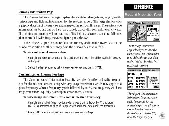
Runway Information Page
The Runway Information Page displays the identifier, designations, length, width,surface type and lighting information for the selected airport. This page also providesa graphic diagram of the runways and a map of the surrounding area. The surface typeinformation can be any one of: hard, turf, sealed, gravel, dirt, soft, unknown, or water.The lighting information will indicate one of five lighting schemes: part time, full time,pilot controlled (with frequency), no lighting or unknown.
If the selected airport has more than one runway, additional runway data can beviewed by selecting another runway from the runway designation field.
To view additional runway data:
1. Highlight the runway designation field and press ENTER. A list of the available runwayswill appear.
2. Select the desired runway using the rocker keypad and press ENTER.
Communication Information Page
The Communication Information Page displays the identifier and radio frequen-cies for the selected airport, along with any usage restrictions which may apply to agiven frequency. When a frequency type is followed by an ‘*’, that frequency will haveusage restrictions, typically based upon sector and/or altitude.
To view usage restrictions for a communication frequency:
1. Highlight the desired frequency (one with a type that’s followed by ‘*’) and press ENTER. An information page will appear with additional data about the frequency.
2. Press QUIT to return to the Communication Information Page.
The Runway InformationPage allows you to view therunways and the surroundingarea. Select the runway desig-nation field to view data foradditional runways.
The Airport CommunicationInformation Page shows theradio frequencies for theselected airport. Any frequen-cies with restrictions aredenoted by an asterisk (‘*’)after the frequency type. 51
REFERENCEWaypoint Information Pages
GPS III Pilot B2 4/1/99 2:02 PM Page 51

VOR Information Page
The VOR Information Page displays the identifier, facility name, city name,region/country, position and frequency for the selected VOR. The facility type (ter-minal, low altitude or high altitude) is also indicated. If DME or TACAN equipmentis co-located at the site, it will be indicated next to the transmitting frequency.Likewise, if the facility broadcasts weather information, ‘WX’ will appear next to thetransmitting frequency. Position information will be in the format specified on theSetup pages (see page 86).
NDB Information Page
The NDB Information Page displays the identifier, facility name, city name,region/country, position and frequency for the selected NDB. If the facility broadcastsweather information, it will be indicated by a ‘WX’ appearing next to the transmittingfrequency.
Intersection Information Page
The Intersection Information Page displays the identifier, position, region andcountry for the selected intersection. The page also shows the bearing and distance tothe nearest VOR facility.
NOTE: The VOR displayed is simply the nearest facility and may not be the facility used to define the intersection.
The VOR Information Pageprovides complete informationabout the selected VOR,including facility name, city,frequency and designation forco-located DME or TACAN.
Both the NDB and VORInformation Pages provide‘WX’ indications if the select-ed facility broadcasts weatherinformation.
52
REFERENCEWaypoint Information Pages
#?
GPS III Pilot B2 4/1/99 2:02 PM Page 52

In addition to being used to define a GOTO destination, the GPS III Pilot’sGOTO/NRST key can also be used to view detailed information on the nine nearestairports, VORs, NDBs, intersections and user waypoints within 200 miles of your pre-sent position. Information regarding the five nearest FSS (flight service station) andcenter (ARTCC) points of communication, along with associated frequency(s) is avail-able from the Nearest Page, as well. When an airspace alert is provided, the NearestPage will even provide additional detail about the airspace. Nearest information isselected by choosing the appropriate ‘file tab’, based upon the desired information. Thefollowing table lists the file tabs and information available under each tab:
Airports nine nearest with identifier, bearing to and distance VORs nine nearest with identifier, bearing to and distanceNDBs nine nearest with identifier, bearing to and distanceInts nine nearest with identifier, bearing to and distanceUser Wpts nine nearest with name, bearing to and distanceARTCC five nearest with bearing to, distance and frequency(s) FSS five nearest with bearing to, distance, freq(s) and VOR
(for duplex operations)Airspaces up to three (depending on number of alerts provided)
with type, controlling agency, frequency(s) and floor/ceiling altitude limits
To view the Nearest Page:
1. Press and hold the GOTO/NRST key.
2. Select the desired information by highlighting the appropriate tab from the chart above.
The Nearest Page organizes thenearest airports, navaids, FSS,center and airspace informa-tion by ‘file tab’ headings.Select the appropriate tab forthe desired information.
Nearest airspace informationis available on the NearestPage, once an airspace alerthas been provided.
53
REFERENCENearest Airports, etc.
GPS III Pilot B2 4/1/99 2:02 PM Page 53

To view the database infor-mation for a nearby airspace,highlight the airspace on theNearest Page and pressENTER.
To immediately set a GOTOcourse for a nearest airport,highlight the desired airporton the Nearest Page, pressGOTO/NRST and thenENTER.
54
REFERENCEAs mentioned earlier, additional information is stored in the GPS III Pilot’s
Jeppesen database. This information may be retrieved using the ‘Waypoints’ option onthe Main Menu, but it is also available from the Nearest Page.
To view additional information for a nearest airport, VOR, NDB, inter-section, user waypoint or airspace:
1. Highlight the desired item (from the Nearest Page) using the rocker keypad.
2. Press ENTER to view the database information for the selected item.
3. Press QUIT to return to the Nearest Page.
You can easily set a GOTO course directly to a nearest waypoint. In an emergency,a few simple keystrokes can guide you to the closest point to set down. (See page 61for more detail about the GPS III Pilot’s GOTO features.)
To GOTO a nearest waypoint, highlight the desired waypoint from theNearest Page, press GOTO/NRST and ENTER.
Airspace information also includes the frequency(s) of the controlling agency.
To view controlling agency frequency(s) for a nearby airspace:
1. With the information page displayed for the desired airspace, highlight the‘Frequencies’ field and press ENTER.
The Nearest Page displays one FSS or ARTCC at a time. Information for up to fiveremote communication outlets is available.
To view additional nearest FSS or ARTCC points of communication:
1. Highlight the ‘Station’ field and press ENTER.
2. Select the desired listing, numbered 1 through 5, and press ENTER.
Nearest Airports, etc.
GPS III Pilot B2 4/1/99 2:02 PM Page 54

The ENTER/MARK key allowsyou to mark your current posi-tion as a user waypoint. Youcan give this waypoint anyname you choose.
You can also choose from alist of symbols used to identifythe user waypoint on the mapdisplay.
55
REFERENCEIn addition to the built-in database, the GPS III Pilot also stores up to 500 user-
defined waypoints, with a selectable symbol and comment available for each waypoint.User-defined waypoints can be created using four methods:
Mark Present Position— your present position can be captured and saved as auser waypoint using the ENTER/MARK key (press & hold).
On Map— a new user waypoint position can be created directly on the map display using the panning pointer and ENTER/MARK key (press momentarily).
Text Entry— user waypoints can be created by entering position coordinates manually (from a chart, etc.) or by referencing bearing and distance from a previously stored waypoint (or present position).
Average Position— position samples can be averaged over time and the resultsaved as a user waypoint. Averaging reduces the effects of selective availability andimproves the accuracy of the position reading. (See page 33 for more info.)
Marking Present Position
The GPS III Pilot’s “mark” feature lets you quickly capture your present position inorder to create a new user waypoint. You must be locked onto satellites, with a validposition fix, to mark your present position.
To mark your present position:
1. Press and hold the ENTER/MARK key. The New Waypoint Page is automatically displayed.
2. To change the waypoint name (a three-digit number is automatically assigned), highlight the waypoint name field and press ENTER. Use the rocker keypad to enterthe new waypoint name and press ENTER when finished.
3. To save the waypoint in memory, highlight ‘Done’ and press ENTER.
Creating User Waypoints
GPS III Pilot B2 4/1/99 2:02 PM Page 55

Marking User Waypoints on the Map Page
User waypoints can also be quickly created from the Map Page, which allows youto “point and shoot” at any map position to create a new waypoint.
To create a new user waypoint on the map:
1. Press the PAGE key repeatedly to select the Map Page.
2. Use the rocker keypad to move the pointer to the desired map position. You may also need to use the IN and OUT zoom keys, in conjunction with the rocker keypad, to speed up this process.
3. Press ENTER (momentarily) to capture the pointer’s position and display the NewWaypoint Page.
4. To change the waypoint name (a three-digit number is automatically assigned), highlight the waypoint name field and press ENTER. Use the rocker keypad to enterthe new waypoint name and press ENTER when finished.
5. To save the waypoint in memory, highlight ‘Done’ and press ENTER.
Creating User Waypoints by Text Entry
User waypoints may be created by manually entering the position coordinates orby entering the bearing and distance from an existing waypoint (or present position).
To create a new user waypoint by manually entering its coordinates, orby bearing/distance from another position:
1. Press the MENU key twice to select the Main Menu.
2. Highlight ‘Waypoints’ and press ENTER.
3. Press MENU to display the Waypoint Options.
4. Highlight ‘New Waypoint’ and press ENTER. The Waypoint Definition Page appears.
User waypoints can be createddirectly from the Map Page,by placing the panning pointeron the desired position andpressing ENTER.
User waypoints can also becreated by entering the position coordinates for thewaypoint.
56
REFERENCECreating User Waypoints
GPS III Pilot B2 4/1/99 2:02 PM Page 56

5. To enter a name for the new waypoint, highlight the waypoint name field and pressENTER. Use the rocker keypad to enter the waypoint name and press ENTER whenfinished.
6. To enter position coordinates for the new waypoint, highlight the waypoint coordinatesfield and press ENTER. Use the rocker keypad to enter the position coordinates andpress ENTER when finished. (For lat/lon coordinates, enter both the latitude andlongitude information before pressing ENTER.) Or,
7. To create the new waypoint by referencing another position, highlight the referencewaypoint name field and press ENTER. Use the rocker keypad to enter the name ofthe reference waypoint and press ENTER. (If the reference waypoint name field is left blank, your present position will be used as the reference position.) Use the same procedure to enter the bearing (BRG) and distance (DST) from the reference way-point to the new waypoint. (Remember to press ENTER once each data item is selected with the rocker keypad.)
8. To save the new waypoint in memory, highlight ‘Done’ and press ENTER.
Waypoint OptionsThe Waypoint Options were displayed using the first three steps above.In addition
to ‘New Waypoint’, there are additional options which vary depending on whether youare viewing Jeppesen database waypoints or user-defined waypoints:
Show Map— allows you to view the map area around the selected waypoint.While viewing the map display, you can also use the IN and OUT zoom keys tosee additional detail.Edit Waypoint (‘User Wpt’ tab only)— allows you to modify name, symbol, com-ment or position information for the selected waypoint.Delete Waypoint (‘User Wpt’ and ‘User List’ tabs only)— allows you to delete theselected user waypoint from memory.
Select the ‘Show Map’ optionto display the map areaaround a selected waypoint.
Once ‘Show Map’ is selected,use the panning pointerand/or the IN/OUT zoomkeys to view the desired areaand detail.
57
REFERENCECreating User Waypoints
GPS III Pilot B2 4/1/99 2:02 PM Page 57

Delete by Symbol (‘User List’ tab only)— allows you to select a user waypointsymbol and all waypoints with this corresponding symbol will be deleted frommemory.Delete All (‘User List’ tab only)— deletes all user waypoints currently stored inmemory.To delete a user waypoint (or waypoints):
1. Select the desired delete option from the list above and press ENTER.
2. If ‘Delete by Symbol’ is selected, select the desired symbol and press ENTER.
Editing User WaypointsOnce you have created and stored a user waypoint, it may be modified, renamed
or deleted at any time through the Waypoint Edit Page. The Waypoint Edit Page forany stored user waypoint can be retrieved by selecting the desired waypoint on themap display, or from the waypoint information pages (‘User Wpt’ or ‘User List’ tabs).
To access the Waypoint Edit Page for a user waypoint:
1. Press the rocker keypad to highlight the desired user waypoint on the map displayand press ENTER. Or,
2. Highlight ‘Waypoints’ from the Main Menu and press ENTER. Select the desired filetab. If ‘User Wpt’ is selected, press MENU, select ‘Edit Waypoint’ and press ENTER. If‘User List’ is selected, highlight the desired waypoint and press ENTER.
From the Waypoint Edit Page, highlight the appropriate field to rename a way-point, change its symbol, edit the comment or edit the position.
To rename the user waypoint:
1. Highlight the waypoint name field and press ENTER.
2. Use the rocker keypad to enter the new waypoint name and press ENTER.
3. If finished, highlight ‘Done’ and press ENTER.
User waypoints can be delet-ed individually, by commonsymbol or all at once. Selectthe desired ‘Delete’ option andpress ENTER.
To rename a user waypoint,enter the new name directlyover the old name and pressENTER.
58
REFERENCEEditing User Waypoints
GPS III Pilot B2 4/1/99 2:02 PM Page 58

To change the user waypoint’s symbol:
1. Highlight the waypoint symbol field and press ENTER.
2. Use the rocker keypad to select the desired symbol and press ENTER. The selectedsymbol will be used to denote the waypoint position on the map display.
When a waypoint is created, the time and date of creation is automatically addedas a waypoint comment. You can edit this information or create an entirely new comment, as needed.
To edit the user waypoint comment:
1. Highlight the waypoint comment field and press ENTER.
2. Use the rocker keypad to enter the desired comment and press ENTER.
To edit the user waypoint position:
1. Highlight the waypoint coordinates field to change the position coordinates, orhighlight the reference waypoint name, bearing or distance fields to change thereference waypoint information. Press ENTER to begin editing.
2. Use the rocker keypad to enter the new information. Press ENTER to accept the newinformation.
A user waypoint’s position may also be edited, graphically, using the map display.
To move a waypoint’s position on the map display:
1. From the Waypoint Edit Page, press MENU to display the Waypoint Edit Options.
2. Use the rocker keypad to select ‘Show Map’ and press ENTER.
3. Press MENU to display an options window. Select ‘Move Wpt’ and press ENTER.
4. Use the rocker keypad to select the new location for the waypoint and press ENTER.
The default waypoint com-ment is the time and date thewaypoint was created. Youcan enter your own commentusing the rocker keypad.
Edit a user waypoint’s position by entering the newposition coordinates directlyover the old position.
59
REFERENCEEditing User Waypoints
GPS III Pilot B2 4/1/99 2:02 PM Page 59

The Waypoint Edit Page features additional options, besides the ‘Show Map’ optiondescribed in the previous steps. Waypoint Edit Options allow you to delete user way-points, define how a user waypoint will appear on the map display or average the way-point position to improve accuracy.
To display the Waypoint Edit Options, press MENU (with the WaypointEdit Page displayed).
The following options are available:
Show Map— allows you to view the area surrounding the selected waypoint’s position. While viewing the map display, you can also use the IN and OUT zoom keys to see additional detail.
Delete Waypoint— allows you to remove the selected user waypoint from memory.
To delete a waypoint:
1. Highlight ‘Delete Waypoint’ and press ENTER. A confirmation screen is displayed.
2. ENTER to delete (or QUIT to cancel).
Display Options— lets you select how the highlighted user waypoint will appear on the map display. Options are provided to show symbol & name, symbol & comment, or symbol only.
To change the display options for a user waypoint:
1. Highlight ‘Display Options’ and press ENTER.
2. Highlight the desired option and press ENTER.
Average Position— allows you to average position samples over time to improve the accuracy of the position reading and save the result as a user waypoint. (Seepage 33 for more information on averaging.)
‘Show Map’ allows you toview the area around the userwaypoint’s position.
‘Display Options’ lets youdetermine what user way-point information will appearon the map display.
60
REFERENCEWaypoint Options
GPS III Pilot B2 4/1/99 2:02 PM Page 60

The GPS III Pilot can navigate to a destination using any of three different methods:
GOTO— lets you select a waypoint as your destination and quickly plot a directcourse from present position to that waypoint.
TracBack— allows you to retrace your path using the track log automaticallystored in the receiver’s memory. This eliminates the need to store waypoints alongthe way. (See page 64 for more information about TracBack.)
Routes— allows you to manually create a sequence of intermediate waypointswhich lead you to your final destination. The GPS III Pilot will store up to 20reversible routes, with up to 30 waypoints in each route.
GOTO Navigation
The easiest way to select your destination is by using the GOTO key. The GOTOkey can be used by itself, after highlighting a waypoint name on a list, or after designating a position on the map display.
To GOTO a waypoint:
1. Press GOTO/NRST. The GOTO page shows a series of file tabs for ‘Recent’ waypoints, ‘User’ waypoints or ‘Spell n Find’.
2. To GOTO a recently used waypoint, select the ‘Recent’ tab, highlight the desired way-point and press ENTER.
3. To GOTO a user waypoint, select the ‘User’ tab, highlight the desired waypoint and press ENTER.
4. To enter the identifier of the destination waypoint, select the ‘Spell n Find’ tab and highlight the waypoint identifier (name) field. Press ENTER and use the rocker keypad to enter the identifier of the desired waypoint—UP/DOWN to change each characterand RIGHT to move to the next character. Press ENTER to confirm the selection.
To GOTO a waypoint, pressGOTO/NRST and highlightthe waypoint identifier field atthe top of the page.
Press ENTER and use therocker keypad to enter theidentifier of the destinationwaypoint. Press ENTER tobegin navigation.
61
REFERENCENavigation/GOTO
GPS III Pilot B2 4/1/99 2:02 PM Page 61

To designate a GOTO waypoint from a list of waypoints:
1. Highlight the desired waypoint on the list and press GOTO/NRST. A confirmation page shows the selected destination waypoint.
2. Press ENTER to confirm the selected waypoint and begin navigating.
To GOTO an existing waypoint on the map display:
1. Use the rocker keypad to place the crosshair on the desired target waypoint.
2. Press GOTO/NRST, followed by ENTER, to begin navigating.
To GOTO any position on the map display:
1. Use the rocker keypad to place the crosshair on any position you wish to navigate to.
2. Press GOTO/NRST to create a waypoint, called ‘MAP’, at the crosshair position. Each time you perform this step, it will overwrite any previously created ‘MAP’ waypoint.
3. Press ENTER to being navigating.
To select a GOTO waypoint by facility name or city (applicable to airports,VORs and NDBs only):
1. Press GOTO/NRST and select the ‘Spell n Find’ tab, as described on the previous page.
2. Highlight the facility name or city name field, as desired, and press ENTER.
3. Use the rocker keypad to enter the facility name/city. As you enter the first few char-acters, the GPS III Pilot’s Spell n Find feature will scroll through the database, display-ing any waypoints which match the letters you have entered. When searching by cityname, there may be mulitiple waypoints for the same city. Continue scrolling with theUP/DOWN portion of the rocker keypad to scroll through these entries.
4. When the desired waypoint appears, press ENTER.
By highlighting a waypointidentifier on a list and press-ing GOTO/NRST, you won’thave to manually enter theidentifier for the waypoint.
A GOTO can also be initiatedfrom the map display by plac-ing the panning pointer on thedesired target waypoint.
62
REFERENCEGOTO
GPS III Pilot B2 4/1/99 2:02 PM Page 62

GOTO Options are also provided to initiate a TracBack route or to cancel the current GOTO destination.
To display the GOTO Options, press MENU (immediately after pressingGOTO/NRST).
The following options are available:
TracBack— allows you to retrace your path using the track log automatically stored in the receiver’s memory. This eliminates the need to store waypoints along the way. (See page 64 for more information about TracBack.)
Cancel GOTO— cancels the current GOTO destination and resumes navigation of any previously selected route. If no route is currently in use; bearing, distance, etc. will remain blank until a destination waypoint is defined.
To cancel the current GOTO destination, highlight ‘Cancel GOTO’ andpress ENTER.
‘TracBack’ allows you toretrace your path based uponan automatic track logrecording.
To cancel a current GOTOdestination, select ‘CancelGOTO’ from the GOTOOptions.
63
REFERENCEGOTO Options
GPS III Pilot B2 4/1/99 2:02 PM Page 63

The TracBack navigation feature allows you to retrace your path using the tracklog automatically stored in the receiver’s memory. This eliminates the need to manual-ly store waypoints along the way. A track log is an electronic breadcrumb trail show-ing the path you have travelled. Your GPS III Pilot can be set to automatically recordtrack log points anytime the receiver is on and locked onto satellites (see page 74).
TracBack routes are created by reducing your track log into a route of up to 30waypoints and activating the new route in reverse order along those waypoints. Onceactivated, a TracBack route will lead you back to the oldest track log point stored inmemory, so it’s a good idea to clear the existing track log at the beginning of your cur-rent trip (e.g., at your home airport) before you get started.
To clear the track log and define the starting point for a TracBack route:
1. Press MENU twice to display the Main Menu.
2. Highlight ‘Track Log’ and press ENTER.
3. Highlight ‘Clear Log’ and press ENTER.
4. Press ENTER to delete the track log data (or press QUIT to cancel).
To create and activate a TracBack route:
1. Enable track log recording and leave the GPS III Pilot on to automatically record track log positions while under way. Refer to page 74 for information on track log settings.
2. Press MENU twice to display the Main Menu.
3. Highlight ‘Track Log’ and press ENTER.
4. Highlight ‘TracBack’ and press ENTER to create/activate the TracBack route. (Amessage box will appear while the unit analyzes the data and creates the route.)
Clear the old track log beforeyou depart. This defines thestarting point for a TracBackroute.
‘TracBack’ can also be initiat-ed from the Main Menu’s‘Track Log’ option.
64
REFERENCETracBack
GPS III Pilot B2 4/1/99 2:02 PM Page 64

Once a TracBack has been activated, the GPS III Pilot will take the track log cur-rently stored in memory and divide it into route segments, called ‘legs’. Up to 30 tracklog waypoints (labeled ‘T###’, e.g. ‘T001’) will be created to mark the most significantfeatures of the track log in order to duplicate your path as closely as possible. To gainthe most benefit from the TracBack feature, keep the following tips in mind:
• Always clear the track log at the point you want to return to (your home, yourhome airport, etc.)
• The ‘Record Mode’ on the Track Log Setup Page must be set to ‘Wrap’ or ‘Fill’.
• There must be at least two track log points stored in memory to create aTracBack route.
• If there is not enough available memory to add more waypoints and create aTracBack route, you will be alerted with a ‘waypoint memory full’ message. Thereceiver will use the available waypoints to create a route with an emphasis onthe track log closest to the destination. Also, existing track log waypoints that arenot contained in any route will be erased to free more memory. The GPS III Pilotwill create the new waypoints using the first available three-digit number.
• If the Track Log Setup Page’s ‘interval’ field is set to ‘Time’, the route may not fol-low your exact path. (Keep the ‘interval’ field set to ‘Resolution’ for best results.)
• If the receiver is turned off or satellite coverage is lost during your trip, TracBackwill draw a straight line between any point where coverage was lost and whereit resumed.
• If there are frequent changes in direction and distance in your track log, 30 way-points may not accurately depict your exact path. The receiver will then assignthe 30 waypoints to the most significant points of your track log, and simplifysegments with fewer changes in direction.
A TracBack route contains aseries of waypoints labeled‘T###’ that approximate yourprevious route of travel.
‘Wrap’ will overwrite the oldtrack log data in memory,once all memory has beenused.
65
REFERENCETracBack Tips
GPS III Pilot B2 4/1/99 2:02 PM Page 65

Route navigation allows you to manually create a sequence of intermediate way-points which lead you to your final destination. The GPS III Pilot will store up to 20reversible routes, with up to 30 waypoints in each route. Routes can be created andmodified by text entry—using the rocker keypad to enter waypoint names. All of theGPS III Pilot’s route functions are accessed through a ‘Routes’ option on the Main Menu.
To create a new route:
1. Press MENU twice to display the Main Menu.
2. Highlight ‘Routes’ and press ENTER. The Route List is displayed, showing all routesstored in memory.
3. Press MENU to display the Route Options.
4. Highlight ‘New Route’ and press ENTER. The GPS III Pilot creates a route called ‘Empty-XX’. (The name changes as you add waypoints to the route, so make note of the route name for future reference.)
5. Highlight the first waypoint name field and press ENTER to begin entering the name ofan existing waypoint in memory.
6. Use the rocker keypad to enter the name of the route waypoint and press ENTER.
7. Highlight the next waypoint name field, press ENTER and repeat step 6 until all routewaypoints have been added to the route.
Route List
The GPS III Pilot’s Route List displays all the routes currently stored in memory,along with a descriptive name for each route. Once a route has been created, it can beactivated and used for navigation from the Route List. A route may be followed in thesame sequence as it was originally created, or you can invert the route and navigatefrom the end waypoint back to the beginning waypoint.
To display the Route List,showing all routes stored inmemory, select ‘Routes’ fromthe Main Menu.
Select ‘New Route’ from theRoute Options and enter theidentifiers for the route way-points in the sequence youwish to follow them.
66
REFERENCERoutes
GPS III Pilot B2 4/1/99 2:02 PM Page 66

To activate a route:
1. Press MENU twice to display the Main Menu.
2. Highlight ‘Routes’ and press ENTER. The Route List is displayed, showing all routes stored in memory.
3. Highlight the desired route and press MENU to display the Route Options.
4. Highlight ‘Activate’ to navigate the route in sequence, and press ENTER.
The Route List also allows you to enter your own 13-character name for any list-ed route. By default the name includes the first and last waypoints in the route.
To enter a custom route name:
1. Follow steps 1 and 2 above to display the Route List.
2. Highlight the desired route and press ENTER to display the Route Edit Page.
3. Highlight the route name field (top line) and press ENTER to begin editing.
4. Use the rocker keypad to enter the desired name and press ENTER when finished.
When a route is highlighted on the Route List, additional functions are availablefrom the Route Options.
To display the Route Options, press MENU (with the Route List displayed).
The following Route Options are available:
New Route— allows you to create a new route, as described on page 66.
Activate— allows you to navigate the route in the same sequence it was original-ly created, as described above.
Activating a route tells theGPS III Pilot you wish to usethis route for navigation guidance.
Selecting a GOTO destinationalong the current route willtake you directly to that way-point, then continue with theremainder of the route.
67
REFERENCERoute List
GPS III Pilot B2 4/1/99 2:02 PM Page 67

Invert— allows you to reverse the order of waypoints in the route.
Copy— allows you to copy the selected route to a new route. The copy function can be used to save a TracBack route for future use. The copy function is also useful for duplicating an existing route before making changes.
To copy a route:
1. Highlight ‘Copy’ and press ENTER.
2. The Route Plan Page will appear for the duplicate route and the name for the newroute will be first and last waypoints in the route. If this name is identical to the origi-nal route name (or any other saved route), then a number will be added to the end ofthe name to create a unique name.
Delete Route— allows you to remove the selected route from memory. The waypoints contained in the route will still appear in memory, but not as part of the route.
To delete a route from memory:
1. Highlight ‘Delete Route’ and press ENTER. A confirmation page will appear.
2. Press ENTER to delete the route (or QUIT to cancel).
Delete All— allows you to remove all routes from memory. The waypoints con-tained in all stored routes will remain in memory, but not as part of any route.
To delete all routes from memory:
1. Highlight ‘Delete All’ and press ENTER. A confirmation page will appear.
2. Press ENTER to delete all routes (or QUIT to cancel).
‘Copy’ allows you to make aduplicate of a route beforemaking editing changes.
‘Delete’ will remove the routefrom memory, but not thewaypoints contained in theroute.
68
REFERENCERoute Options
GPS III Pilot B2 4/1/99 2:02 PM Page 68

Once a route is added to memory, you can review and/or edit the route from theRoute Edit Page. The Route Edit Page shows the sequence of waypoints for the select-ed route and provides additional options to insert waypoints, remove waypoints orperform trip/fuel planning functions.
To edit a route:
1. From the Route List, highlight the route you wish to edit and press ENTER. The RouteEdit Page appears for the selected route.
2. To change a route waypoint, highlight the waypoint you wish to change and pressENTER. Use the rocker keypad to enter the new waypoint and press ENTER.
3. To review the information for a route waypoint, highlight the desired waypoint andpress MENU. A pop-up menu appears with additional options. Highlight ‘Review Wpt’and press ENTER to display the Waypoint Definition Page for the selected waypoint.
4. To insert a waypoint in the route, highlight the waypoint that will immediately follow thenew route waypoint and press MENU. A pop-up menu appears with additional options. Highlight ‘Insert Wpt’ and press ENTER to display a blank line for the new waypoint. Enter the name of the new waypoint and press ENTER.
5. To delete a waypoint from the route, highlight the waypoint you wish to delete andpress MENU. Highlight ‘Remove Wpt’ on the pop-up menu and press ENTER.
To edit a route from the map display:
1. Follow step 1 above to select the Route Edit Page, press MENU and select ‘Show Map’.
2. To insert a new waypoint move the pointer to the route leg in which the new waypointwill be placed. press ENTER, move the pointer to the new waypoint location and pressENTER to insert the new waypoint.
3. To remove a waypoint, move the pointer to the waypoint, press MENU and select‘Remove Wpt’.
The Route Options allow foreasy editing of an existingroute.
To edit a route, highlight theroute waypoint which isaffected by the change. Ifinserting a waypoint, highlightthe existing waypoint whichfollows the new waypoint.
69
REFERENCERoute Editing
GPS III Pilot B2 4/1/99 2:02 PM Page 69

The Route Edit Page also displays trip planning information for each leg or theentire route. Available information includes desired course, time to waypoint, distanceto waypoint, required fuel and sunrise/sunset times at the waypoint location.
To use the trip planning features:
1. To select the desired planning figure, highlight the desired route from the Route List and press ENTER to display the Route Edit Page. One of ten available planning figuresappears to the right of each route waypoint. Use the LEFT/RIGHT keys on the rockerkeypad to select the desired item.
2. To enter planning information, Press MENU and select ‘Setup Plan’ from the options list. Enter the figures for speed, fuel flow and departure date/time.
Active Route Page
The last page appearing in the main sequence (using the PAGE or QUIT keys) isthe Active Route Page. Whenever you have activated a route, GOTO or TracBack, theActive Route Page will show each waypoint (by name) of the active route, along withthe desired course, distance to waypoint, time to each waypoint, fuel requirements orsunrise/sunset times at each route waypoint. As you navigate the route, the informa-tion on the Active Route Page will automatically update to indicate the destinationwaypoint and any remaining interim waypoints.
From the Active Route Page, you can change the name of the active route (see page67), review information on a route waypoint (see page 48) or bypass route waypointsand GOTO any waypoint in the route (see page 62). The user-selectable data field onthe right side of the page also keeps you informed of current conditions. There are tendifferent data items available. See page 98 for descriptions of navigation terms.
To change the Active Route Page data, press the LEFT/RIGHT keys on therocker keypad.
With a route displayed, usethe LEFT/RIGHT keys on therocker keypad to select thetrip planning features.
The Active Route Page showsthe route currently being usedfor navigation guidance.
70
REFERENCERoute Editing
GPS III Pilot B2 4/1/99 2:02 PM Page 70

Many features of the GPS III Pilot are menu driven. Each of the main pages has anoptions menu, allowing you to custom tailor the corresponding page to your prefer-ences and/or select special features which specifically relate to that page.
To display the Active Route Page Options, press MENU (with the ActiveRoute Page displayed).
The following options are available:
Setup Plan— displays a trip planning screen, allowing you to plan and reviewdistance, fuel and time en route information for the selected route.
To use the trip planning features:
1. Highlight ‘Setup Plan’ and press ENTER. A setup screen is provided for planned speed,fuel flow and departure time.
2. To enter a speed for your trip, highlight the speed field, press ENTER and use therocker keypad to select the desired speed. Press ENTER to confirm.
3. Enter an hourly fuel flow (if desired) in the fuel field, using the same steps above.
4. Enter the date and time of departure (the current date/time will be offered automatical-ly), using the same steps above.
5. Press QUIT to return to the Active Route Page, and use the LEFT/RIGHT portion of therocker keypad to select the planning figures (to the immediate right of each listed routewaypoint’s identifier).
Re-evaluate— reactivates the current route and selects the route leg closest to your current position as the active leg. The active leg defines the current ‘from’ and ‘to’ waypoints.
Deactivate— cancels navigation of the route you are currently using.
‘Setup Plan’ allows you todefine planned speed, fuelflow and departure time inorder to review trip planningfigures.
‘Re-evaluate’ will reactivatethe current route and selectthe closest leg. This feature ishandy if you stray well offcourse and later wish toreturn to the route.
71
REFERENCEActive Route Page Options
GPS III Pilot B2 4/1/99 2:02 PM Page 71

Invert— reactivates the current route in reverse order and navigates from the endwaypoint back to the beginning waypoint.
Insert Wpt— allows you to insert an additional waypoint into the route, directly in front of the currently highlighted waypoint in the route. If no route waypoint is highlighted, this option is not available. See page 69 for route editing info.
Remove Wpt— removes the currently highlighted waypoint from the route. If no waypoint is highlighted, this option is not available. See page 69 for route editing information.
Review Wpt— allows you to view the Waypoint Definition Page for the cur-rently highlighted waypoint in the route. If no route waypoint is highlighted, this option is not available. See page 48 for waypoint review information.
Delete Route— allows you to remove the current route from memory. The way-points contained in the route will still appear in memory, but not as part of theroute. See page 68.
To reverse the sequence ofwaypoints in the active route,select the ‘Invert’ option.
To delete the active route frommemory, select the ‘DeleteRoute’ option.
72
REFERENCEActive Route Page Options
GPS III Pilot B2 4/1/99 2:02 PM Page 72

The GPS III Pilot’s Main Menu provides access to the waypoint, route, track log,trip planning and setup features of the receiver. The Main Menu can be accessed at anytime using the MENU key.
To display the Main Menu, press the MENU key twice.
The 7 menu options are divided into categories by function: waypoints/routes/track log, trip computer, vertical navigation/E6B and system setups.
To select an option from the Main Menu, highlight the desired item andpress ENTER.
The following menu options are available:
Waypoints— allows you to review database information and create/edit/deleteuser waypoints. See pages 48-52 and pages 55-59.
Routes— allows you to create, edit, activate or delete routes. See pages 66-70.
Track Log— lets you specify whether or not to record a track log (an electronic ‘breadcrumb trail’ recording of your path) and defines how it is recorded. Thissubmenu page also provides an indicator of the percentage of track memory usedand options to clear the track memory or start a TracBack route. See pages 64-65for TracBack information.
Press MENU twice to displaythe Main Menu.
Select the desired menu optionby highlighting it with therocker keypad and pressingENTER.
73
REFERENCEMain Menu
GPS III Pilot B2 4/1/99 2:02 PM Page 73

Track Log Settings
Record Mode lets you select one of three track recording options:
‘Off’ – No track log will be recorded.
NOTE: Selecting ‘Off’ will prevent you from using the TracBack feature.
‘Fill’ – A track log will be recorded until the track memory is full.
‘Wrap’ (default) – A track log will be continuously recorded by wrapping throughavailable memory and replacing the oldest track data with new data.
Interval defines the frequency with which the track plot is recorded. Three intervalsettings are available:
‘Time’ – Records track log based on a user-defined time interval.
‘Resolution’ (default) – Records track log based upon a user-defined variance fromyour course over ground. The resolution option is recommended for the mostefficient use of memory and TracBack performance. The distance value (entered inthe ‘Interval Value’ field) is the maximum left/right deviation allowed from the lastdefined ground track before recording a new point.
‘Distance’ – Records track log based on a user-defined distance between points.
Interval Value defines the distance or time interval used to record the track log.
Clear Log allows you to clear the track log data currently stored in memory.
To delete the track log data, highlight ‘Delete Track’ and press ENTER.
TracBack converts the track log data in memory into an inverted route and beginsnavigation along the route. See pages 64-65.
‘Fill’ will record track log datauntil memory is full, then pro-vide a ‘Track Memory Full’message.
To utilize the TracBack fea-ture, you should clear thetrack log before leaving thedeparture airport.
74
REFERENCEMain Menu
#?
GPS III Pilot B2 4/1/99 2:02 PM Page 74

Trip Computer— provides readouts for average speed, maximum speed,odometer, trip odometer and trip timer. These readouts can be reset from the TripComputer Options.
To reset a trip computer readout(s):
1. Press MENU (with the Trip Computer Page displayed). An options list is displayed.
2. To reset all trip computer readouts, highlight ‘Reset All’ and press ENTER.
3. To reset a single readout item, highlight the desired option and press ENTER.
NOTE: The ‘Reset Trip’ option resets trip odometer, trip timer and average speed readouts.
Vertical Nav— allows you to define a vertical navigation profile used to descend(or climb) to a target altitude at a specified location. See pages 43-45.
E6B— provides calculation features for density altitude, true airspeed and windsaloft. The winds aloft function will calculate wind direction, speed and the head/tailwind component.
To calculate density altitude and true airspeed:
1. Select the ‘Density Altitude’ file tab using the rocker keypad.
2. Highlight the ‘Indicated Altitude’ field and press ENTER. Enter the altitude from youraltimeter and press ENTER.
3. Highlight the ‘Calibrated Airspeed’ field and press ENTER. Enter the airspeed fromyour airspeed indicator and press ENTER.
4. Highlight the ‘Pressure’ field and press ENTER. Enter the current altimeter setting(barometric pressure) and press ENTER.
‘Trip Computer’ providesreadouts for the trip odometer,trip timer, average speed andmaximum speed. Options areprovided to reset these figures.
Density altitude and true air-speed may be calculated byentering values for indicatedaltitude, calibrated airspeed,barometric pressure and totalair temperature.
75
REFERENCEMain Menu
#?
GPS III Pilot B2 4/1/99 2:02 PM Page 75
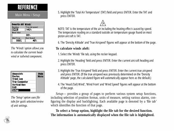
5. Highlight the ‘Total Air Temperature’ (TAT) field and press ENTER. Enter the TAT and press ENTER.
NOTE: TAT is the temperature of the air including the heating effect caused by speed.The temperature reading on a standard outside air temperature gauge found on most piston aircraft is TAT.
6. The ‘Density Altitude’ and ‘True Airspeed’ figures will appear at the bottom of the page.
To calculate winds aloft:
1. Select the ‘Winds’ file tab, using the rocker keypad.
2. Highlight the ‘Heading’ field and press ENTER. Enter the current aircraft heading andpress ENTER.
3. Highlight the ‘True Airspeed’ field and press ENTER. Enter the current true airspeed and press ENTER. (If the true airspeed was previously determined on the ‘DensityAltitude’ page, the calculated figure will automatically appear here as the default.)
4. The ‘Head (Tail) Wind’, ‘Wind From’ and ‘Wind Speed’ figures will appear at the bottomof the page.
Setup— provides a group of pages to perform various system setup functions,including selection of position format, units of measure, setting various alarms, con-figuring the display and backlighting. Each available page is denoted by a ‘file tab’which identifies the function of that page.
To select a Setup option, highlight the file tab for the desired function.The information is automatically displayed when the file tab is highlighted.
The ‘Winds’ option allows youto calculate the current head-wind or tailwind component.
The ‘Setup’ option uses filetabs for quick selection/reviewof unit settings.
76
REFERENCEMain Menu / Setup #?
GPS III Pilot B2 4/1/99 2:02 PM Page 76

The file tab headings and setup functions for these pages are:
Simulator Enable/Disable; Settings for simulated track, speed and altitude
System Backlight timeout, Battery type, Display Contrast andOrientation
Units Units of measure settings for—Distance & Speed, Heading, Altitude, Pressure and Temperature
Timers Count up/down User Timer, Battery Timer, andusage timers for current day and since new
Time Formats for local 24 hour, local 12 hour (AM/PM) orUTC; Difference setting from UTC to local time
Alarms Alarm Clock, Arrival Alarm, Off Course Alarm
Airspace Airspace alarms for: Class B, Class C, Class D,
Restricted Areas, MOAs, Other SUAs and Mode C
Veils; Altitude buffer above/below airspace limits
Nearest Runway surface type and Minimum Runway
Length for nearest airport search
Position Position Format (latitude/longitude, UTM/UPS,Maidenhead, regional grids); Map Datum selection
Interface Format (NMEA, RTCM, GARMIN proprietary); Mode setting for use with PC or a second unit
The following pages describe, in more detail, the available settings for each Setupfile tab item.
To display the desired infor-mation, highlight the appro-priate file tab.
Once the desired informationis selected, use the UP/DOWN keys on the rockerkeypad to select the desireditem on the page.
77
REFERENCESetup
GPS III Pilot B2 4/1/99 2:02 PM Page 77

Simulator Settings
Mode lets you turn the built-in simulator on or off.
To enable/disable the built-in simulator:
1. Highlight the ‘Mode’ field and press ENTER.
2. Select ‘Simulator Off’ or ‘Simulator On’ (as desired) and press ENTER.
Speed lets you select a simulated speed when the simulator is enabled.
Track Control allows the built-in simulator to automatically align track heading to thedesired course (when using a GOTO or route), or it allows you to manually adjust thetrack heading, as desired.
Track allows you to manually enter a track heading. This setting is only available whenTrack Control is set to ‘User Track’.
Altitude allows you to specify a user-defined altitude for your simulated position.
To select a simulator setting:
1. For track control, highlight the ‘Track Control’ field and press ENTER. Select ‘Auto Track’ or‘User Track’ and press ENTER.
2. For simulated speed, user track, or altitude, highlight the desired field and press ENTER. Enterthe desired value using the rocker keypad and press ENTER when finished.
‘Simulator’ allows you toenable/disable the built-insimulator feature—and setsimulated speed, track andaltitude.
The ‘Track Control’ settingallows the simulator to auto-matically “line up” on the cor-rect bearing to a destinationwaypoint.
78
REFERENCESetup: Simulator
GPS III Pilot B2 4/1/99 2:02 PM Page 78

System Settings
Backlight lets you keep the screen/keypad backlighting on continuously (‘always on’)when selected, or enables the automatic shutoff to preserve battery life. Automatic shutofftimes from 15 seconds to 4 minutes (since last key press) are available.
To set the backlight timeout:
1. Highlight the ‘Backlight’ field and press ENTER.
2. To keep backlighting on continuously, select ‘Always On’ and press ENTER. Or,
3. To set a timeout duration, select the desired time period and press ENTER.
NOTE: Backlighting timeout is automatically disabled when using external power.
Battery is used to designate the type of batteries currently being used to power your GPSIII Pilot: Alkaline, Lithium or NiCad. This setting ensures accurate readings from the battery gauge on the Satellite Status Page (see page 29).
Contrast lets you adjust the screen for optimum viewing in all lighting conditions. Screencontrast is set using an on-screen bar scale. Contrast can also be set from the SatelliteStatus Page, as described on page 27.
To set the screen contrast:
1. Highlight the ‘Contrast’ field and press ENTER.
2. Use the LEFT/RIGHT keys on the rocker keypad to select desired level and press ENTER.
Display allows you set the display orientation to horizontal (‘Landscape’) or vertical(‘Portrait’).
NOTE: Display orientation can also be changed by pressing and holding the PAGE key.
You can adjust the screen con-trast from the Satellite StatusPage or from the ‘System’ set-tings.
Display orientation isadjustable by pressing/holdingthe PAGE key or from the‘System’ settings.
79
REFERENCESetup: System
#?
#?
GPS III Pilot B2 4/1/99 2:02 PM Page 79

Units SettingsDistance & Speed lets you select the desired units of measure for distance and speedreadouts in ‘Nautical’, ‘Statute’ or ‘Metric’ terms.
Heading lets you select the reference used in calculating heading information. You canselect from ‘Auto Mag Var’, ‘True’, ‘Grid’ and ‘User Mag Var’. ‘Auto Mag Var’ providesmagnetic north heading references which are automatically determined from your currentposition. ‘True’ provides headings based upon a true north reference. ‘Grid’ providesheadings based on a grid north reference (and is used in conjunction with the grid posi-tion formats described on page 84). ‘User Mag Var’ allows you to specify the magneticvariation at your current position and provides magnetic north heading references basedupon the variation you enter.
Altitude lets you select altitude readouts in ‘Feet’ or ‘Meters’.
Vertical Speed lets you select a vertical speed in ‘Feet/Minute’ or ‘Meters/Minute’.
Pressure lets you select altimeter settings (barometric pressure) in ‘Inches’ or ‘Millibars’.
Temperature lets you select temperature readouts in degrees ‘Fahrenheit’ or ‘Celsius’.
To select a units setting:
1. Highlight the desired field and press ENTER to display the available options.
2. Select the desired option and press ENTER.
3. If ‘User Mag Var’ is selected in the ‘Heading’ field, highlight the heading reference field (immed-iately to the right) and press ENTER. Enter the magnetic variation at your current position using the rocker keypad and press ENTER.
WARNING: If ‘User Mag Var’ is selected, you must periodically update the magnetic varia-tion as your position changes. Using this setting, the GPS III Pilot will not automatically cal-culate and update the magnetic variation at your present position. Failure to update this set-ting may result in substantial differences between the information displayed on your GPS IIIPilot and external references, such as a magnetic compass.
Select nautical, statute ormetric units of measure fromthe ‘Units’ settings.
The ‘User Mag’ option allowsyou to define the magneticvariation for your area. ‘AutoMag Var’ is the preferred set-ting in most cases.
80
REFERENCESetup: Units
#!
GPS III Pilot B2 4/1/99 2:02 PM Page 80

Timers Settings
User Timer lets you select a count up or count down timer. For a count down timer, youmay also specify the count down duration.
To select a user timer setting:
1. For a count down timer, highlight the ‘User Timer’ field in the right-hand column, press ENTER andenter the count duration using the rocker keypad. Press ENTER to accept. Then (with the left-handcolumn highlighted) press ENTER to view the User Timer options. Select ‘Down’ and press ENTER.
2. For a count up timer, highlight the ‘User Timer’ field in the left-hand column, press ENTER andselect ‘Up’. Press ENTER to confirm.
3. To reset the timer or turn the timer off, highlight the ‘User Timer’ field in the left-hand column, press ENTER and select ‘Reset’ or ‘Off’ (as appropriate). Press ENTER to confirm.
Battery Timer provides a running count of how long the GPS III Pilot has been in operation with the current batteries. The timer automatically stops when using an externalpower source. The timer will automatically reset when depleted batteries are replaced, butcan also be manually reset.
To select a battery timer setting:
1. Highlight the ‘Battery Timer’ field in the right-hand column and press ENTER.
2. Select ‘Off’, ‘On’ or ‘Reset’ (as appropriate) and press ENTER.
Since Midnight provides a running count of how long the GPS III Pilot has been in operation since midnight of the current day.
Since Factory Reset provides a running count of total GPS III Pilot operating time sincethe receiver was shipped from the factory.
The ‘User Timer’ option pro-vides both count up and countdown timers.
The battery timer will auto-matically reset when depletedbatteries are replaced with afresh set.
81
REFERENCESetup: Timers
GPS III Pilot B2 4/1/99 2:02 PM Page 81

Time Settings
Time Format allows current time to be displayed using a 12- or 24- hour clock. Thisfield is also used to select between local and UTC time readouts.
To select a time format:
1. Highlight the ‘Time Format’ field and press ENTER to display the available options.
2. Select ‘Local 24hr’ or ‘Local 12hr’ to display local time references. ‘Local 12hr’ will show currenttime using a traditional AM/PM format. Or,
3. Select ‘UTC’ to display universal time references (also referred to as ‘Greenwich’ or ‘zulu’ time).
Local Time Zone is used to define the current local time. UTC date and time are calcu-lated directly from the satellites’ signals and cannot be edited. If you prefer to use localtime, you may designate an offset, either ‘Behind UTC’ or ‘Ahead of UTC’. The offset isthe difference, in hours and minutes, between local time and UTC time.
To enter the local time zone:
1. Highlight the ‘Local Time Zone’ field and press ENTER.
2. Select the desired offset amount (in hours and minutes) using the rocker keypad and press ENTER.
3. Highlight the offset direction field (immediately to the right) and press ENTER.
4. Select ‘Behind UTC’ or ‘Ahead of UTC’ (as appropriate) and press ENTER.
Time displays the current time based on the settings made above and information provided by the satellites received.
Date displays the current date based on the settings made above and information provided by the satellites received.
Enter an offset amount toadjust the time display toyour local area. In the UnitedStates, all offset amounts willbe ‘Behind UTC’.
If you’re unsure of the exactoffset select a ‘Local’ time for-mat, then enter offset valuesuntil you arrive at the correctlocal time.
82
REFERENCESetup: Time
GPS III Pilot B2 4/1/99 2:02 PM Page 82

Alarms Settings
Clock Alarm uses the internal clock to provide an ‘Alarm Clock’ message at the time you set.
To enable/disable the alarm clock:
1. Highlight the ‘Clock Alarm’ field and press ENTER.
2. Select ‘On’ or ‘Off’ (as desired) and press ENTER.
3. If enabling the alarm, highlight the time field (to the immediate right) and press ENTER. Enter thealarm time using the rocker keypad and press ENTER.
NOTE: The GPS III Pilot must be turned on when the alarm time is reached. Otherwise,the message will not occur.
Arrival Alarm provides an alarm message once you’ve come within a set distance fromyour destination waypoint. As you approach the destination waypoint, an ‘Arrival at ____’message occurs when you are within the alarm distance you entered.
Off Course Alarm provides an alarm message (‘Off Course Alarm’) when you deviate offcourse beyond the specified limits.
To set the arrival and/or off course alarms:
1. Highlight the ‘Arrival Alarm’ or ‘Off Course Alarm’ field and press ENTER.
2. Select ‘On’ or ‘Off’ (as desired) and press ENTER.
3. If enabling the alarm, highlight the alarm distance field (to the immediate right) and press ENTER.Enter the alarm distance using the rocker keypad and press ENTER.
An ‘Approaching’ messageautomatically appears oneminute before reaching thedestination waypoint. Thearrival alarm allows you to seta distance-defined message.
The ‘Off Course Alarm’ pro-vides an alert if you drift offcourse beyond the limits youhave set.
83
REFERENCESetup: Alarms
#?
GPS III Pilot B2 4/1/99 2:02 PM Page 83
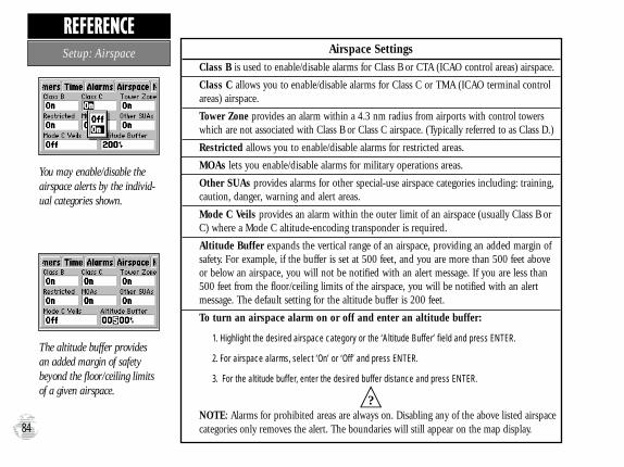
Airspace SettingsClass B is used to enable/disable alarms for Class B or CTA (ICAO control areas) airspace.
Class C allows you to enable/disable alarms for Class C or TMA (ICAO terminal controlareas) airspace.
Tower Zone provides an alarm within a 4.3 nm radius from airports with control towerswhich are not associated with Class B or Class C airspace. (Typically referred to as Class D.)
Restricted allows you to enable/disable alarms for restricted areas.
MOAs lets you enable/disable alarms for military operations areas.
Other SUAs provides alarms for other special-use airspace categories including: training,caution, danger, warning and alert areas.
Mode C Veils provides an alarm within the outer limit of an airspace (usually Class B orC) where a Mode C altitude-encoding transponder is required.
Altitude Buffer expands the vertical range of an airspace, providing an added margin ofsafety. For example, if the buffer is set at 500 feet, and you are more than 500 feet aboveor below an airspace, you will not be notified with an alert message. If you are less than500 feet from the floor/ceiling limits of the airspace, you will be notified with an alertmessage. The default setting for the altitude buffer is 200 feet.
To turn an airspace alarm on or off and enter an altitude buffer:
1. Highlight the desired airspace category or the ‘Altitude Buffer’ field and press ENTER.
2. For airspace alarms, select ‘On’ or ‘Off’ and press ENTER.
3. For the altitude buffer, enter the desired buffer distance and press ENTER.
NOTE: Alarms for prohibited areas are always on. Disabling any of the above listed airspacecategories only removes the alert. The boundaries will still appear on the map display.
You may enable/disable theairspace alerts by the individ-ual categories shown.
The altitude buffer providesan added margin of safetybeyond the floor/ceiling limitsof a given airspace.
84
REFERENCESetup: Airspace
#?
GPS III Pilot B2 4/1/99 2:02 PM Page 84

Airspace Settings (cont.)The airspace alarms are designed to provide message alerts in several stages, depending onwhether you are projected to enter the airspace or are just in close proximity. The alerts are:
• Airspace Ahead, Less Than 10 minutes — occurs if your projected course will take you inside an airspace within the next ten minutes.
• Airspace Near and Ahead — is displayed when you are within two nautical miles of an airspace and your current course will take you inside the airspace.
• Inside Airspace — occurs when you have entered the boundaries of the airspace.
• Near Airspace, Less Than 2 nm — appears when you are within two nautical miles of an airspace, but your current course will not take you inside the airspace.
NOTE: Some airspace altitude limits may be charted in terms of altitude above ground level(AGL). If the actual lower limit of an airspace is charted in AGL, the GPS III Pilot will alert youat any altitude below the upper limit. However, if the actual upper limit is also charted in AGL,the GPS III Pilot will provide the alert at all altitudes.
Nearest SettingsRunway Surface determines which surface type or types will be included when display-ing nearest airports on the Nearest Page. Available types include: ‘Any’ (includes waterlanding facilities), ‘Hard Only’ surface, ‘Hard or Soft’ surface and ‘Water Only’ facilities.
Min Runway Length determines the minimum allowable runway length when displayingnearest airports on the Nearest Page.
To select the nearest airport criteria:
1. Highlight the ‘Runway Surface’ or ‘Min Runway Length’ field and press ENTER.
2. For ‘Runway Surface’, select the desired surface type and press ENTER.
3. For ‘Min Runway Length’, enter the minimum allowable runway length and press ENTER.
Due to vertical airspace lim-its, if you fly above or belowan airspace then descend orclimb into the airspace, the‘Inside Airspace’ message maybe the only alert provided.
‘Hard Only’ includes onlyconcrete, asphalt, or similarsealed surface runways.
85
REFERENCESetup: Nearest
#?
GPS III Pilot B2 4/1/99 2:02 PM Page 85

Position Settings
Position Format is used to change the coordinate system in which a given positionreading is displayed. The default format is latitude and longitude in degrees and minutes(hddd°mm.mmm’). The following additional formats are available:
• hddd.ddddd° — latitude/longitude in decimal degrees only
• hddd°mm’ss.s” — latitude/longitude in degrees, minutes, seconds
• UTM/UPS — Universal Transverse Mercator / Universal Polar Stereographic grids
• British Grid • German Grid
• Irish Grid • Swedish Grid
• Swiss Grid • Taiwan Grid
• Maidenhead
Map Datum allows you to select the datum reference used to determine where a givenposition is. The default setting is ‘WGS 84’. Although over 100 datums are available (aslisted on page 95), you should only change the datum if you are using a map or chartthat specifies a different datum. If no datum is specified, you may select each datumapplicable to your region until you find the datum that provides the best positioning at aknown point.
WARNING: Selecting the wrong map datum can result in substantial position errors.When in doubt, use the default WGS 84 datum for best overall performance.
To change the position format and/or map datum:
1. Highlight the ‘Position Format’ or ‘Map Datum’ field and press ENTER.
2. Select the desired setting (using the rocker keypad) and press ENTER.
Only the latitude/longitude,UTM/UPS and Maidenheadsettings apply worldwide. Theadditional grid settings areonly valid for a specific region.
Over 100 different datumsare provided to allow the GPSIII Pilot to correspond to vari-ous paper charts. Use WGS84 unless your chart specifiesotherwise.
86
REFERENCESetup: Position
#!
GPS III Pilot B2 4/1/99 2:02 PM Page 86

Interface Settings
Format lets you control the input/output format used when connecting your GPS III Pilotto external NMEA devices, a DGPS beacon receiver, or a personal computer, etc. Five for-mat settings are available:
• Aviation In — allows the GPS III Pilot to communicate with a GARMIN panel-mounted GPS. Flight plans (or GOTO destinations) selected on the panel-mounted GPS will also appear on the GPS III Pilot.
• GARMIN — the proprietary format used to exchange waypoint, route, track logdata with a PC or with another GPS III Pilot.
• NMEA — supports the input/output of standard NMEA 0183 version 2.0 data.• None — provides no interfacing capabilities.• RTCM/NMEA — allows Differential GPS (DGPS) input using a standard RTCM
format and also provides NMEA 0183 version 2.0 output.• RTCM In — allows DGPS input using a standard RTCM format, without any
output capabilities.
To select an input/output format:
1. Highlight the ‘Format’ field and press ENTER.
2. Select the desired setting and press ENTER.
3. If the ‘GARMIN’ format is selected, highlight the ‘Transfer Mode’ field and press ENTER. Selectthe desired setting and press ENTER. The ‘Transfer Mode’ field allows you to specify what infor-mation to request or send to a second GPS III Pilot. The ‘Host’ setting lets you control all data transfer functions from the second GPS III Pilot or from a PC.
4. If an ‘RTCM’ format is selected, additional fields are provided to control a GARMIN differentialbeacon receiver (such as GARMIN’s GBR 21) directly from your GPS III Pilot. You can enter thebeacon frequency and bit rate on the GPS III Pilot and the information will be used to tune thebeacon receiver. For more information, refer to the owner’s manual for your beaon receiver.
The ‘GARMIN’ option allowsthe GPS III Pilot to exchangedata with a PC or anotherGPS III Pilot. Use this settingto perform database updates.
When transferring data to/from another unit, select thetype of data and whether to‘request’ it from or ‘send’ it tothe other unit.
87
REFERENCESetup: Interface
GPS III Pilot B2 4/1/99 2:02 PM Page 87

The GPS III Pilot can be mounted on any flat surface using the two Velcro™ stripsprovided in the standard package, or you can use the supplied mounting bracket.
To mount the GPS III Pilot using the Velcro strips:
1. Select a location for the unit that provides a clear and unobstructedview of the sky for the GPS antenna, but will not obstruct your fieldof view while flying.
2. Make sure the surface to which you’re adhering the Velcro is cleanand dry. Remove the paper liners from both Velcro pieces.
3. Place the adhesive side of the rough piece of Velcro on the desiredmounting surface, and press into place.
4. Place the adhesive side of the smooth piece of Velcro on the bottomof the unit (between the rubber anti-skid bumps), and press into place.
5. Mount the unit, placing one piece of Velcro on top of the other.
To mount the GPS III Pilot using the bracket:
1. Select a location for the unit that provides a clear and unobstructedview of the sky for the GPS antenna, but will not obstruct your fieldof view while flying.
2. Make sure the surface to which you’re adhering the Velcro is cleanand dry. Remove the paper liners from both Velcro pieces.
3. Place the adhesive side of the rough piece of Velcro on the desiredmounting surface, and press into place.
88
APPENDIX AMounting Instructions
GPS III Pilot B2 4/1/99 2:02 PM Page 88
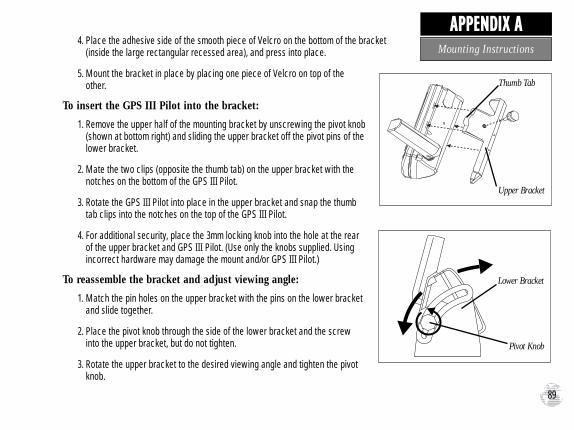
4. Place the adhesive side of the smooth piece of Velcro on the bottom of the bracket(inside the large rectangular recessed area), and press into place.
5. Mount the bracket in place by placing one piece of Velcro on top of theother.
To insert the GPS III Pilot into the bracket:
1. Remove the upper half of the mounting bracket by unscrewing the pivot knob(shown at bottom right) and sliding the upper bracket off the pivot pins of thelower bracket.
2. Mate the two clips (opposite the thumb tab) on the upper bracket with thenotches on the bottom of the GPS III Pilot.
3. Rotate the GPS III Pilot into place in the upper bracket and snap the thumbtab clips into the notches on the top of the GPS III Pilot.
4. For additional security, place the 3mm locking knob into the hole at the rearof the upper bracket and GPS III Pilot. (Use only the knobs supplied. Usingincorrect hardware may damage the mount and/or GPS III Pilot.)
To reassemble the bracket and adjust viewing angle:
1. Match the pin holes on the upper bracket with the pins on the lower bracketand slide together.
2. Place the pivot knob through the side of the lower bracket and the screwinto the upper bracket, but do not tighten.
3. Rotate the upper bracket to the desired viewing angle and tighten the pivotknob.
89
APPENDIX AMounting Instructions
Thumb Tab
Upper Bracket
Pivot Knob
Lower Bracket
GPS III Pilot B2 4/1/99 2:02 PM Page 89

Specifications subject to change without notice.
* With optional GARMIN Differential GPS (DGPS) Beacon Receiver Input.
** Subject to accuracy degradation to 100m 2DRMS under the U.S. DoD-imposed Selective Availability Program.
† Alkaline batteries lose a significant amount of their capacity as temperature decreases. Use lithium batteries when operating the GPS III Pilotin below freezing conditions. Extensive use of screen backlighting will significantly reduce battery life.
90
The GPS III Pilot is constructed of high-quality materials and should not requireuser maintenance. If your unit ever needs repair, please take it to an authorizedGARMIN service center. The GPS III Pilot has no user-serviceable parts. Never
attempt any repairs yourself. To protect your GPS III Pilot, keep it in its carrying case (optional accessory) when not inuse, and never allow gasoline or other solvents to come into contact with the case. To clean the case and lens, use a softcloth and a household window cleaner.
PHYSICAL
Case: Fully-gasketed, high-impact plastic alloy; waterproof to IPX7 standards
Size: 6.15”H x 2”W x 1.23”D (15.6 x 5.1 x 1.23 cm)
Weight: Approx. 9 ounces (255g) w/ batteries
Temperature Range: 5 to 158ºF (-15º to 70ºC)
Memory Back Up: Internal Lithium Battery
PERFORMANCE
Receiver: Differential-ready PhaseTrac12™
Acquisition Time: Approx. 15 seconds (warm start)
Approx. 45 seconds (EZinit/cold start)
Approx. 5 minutes (AutoLocate™)
Update Rate: 1/second, continuous
Position Accuracy: 1-5 meters (3-15 ft) with DGPScorrections*
15 meters (49 ft) RMS**
Velocity Accuracy: 0.1 knot RMS steady state
Dynamics: Performs to specification to 6g’s
Interfaces: NMEA 183, RTCM in (for DGPS corrections),Aviation in and RS-232 for PC interface
Antenna: Detachable with standard BNC connector
POWER
Input: Four 1.5-volt AA batteries or 10-32 VDC external
Power Consumption: 0.5 watts max.
Battery Life: Up to 24 hours †
Specifications
APPENDIX B
GPS III Pilot B2 4/1/99 2:02 PM Page 90

Interfacing formats are selected from the Setup options, described on page 87.The input/output lines on your GPS III Pilot are RS-232 compatible allowing easy interface to a wide range of external devices, including PCs, differentialbeacon receivers, marine autopilots and/or a second GPS receiver.
The NMEA 0183 version 2.0 interface format is supported by theGPS III Pilot and enables the unit to drive up to three NMEA devices:
NMEA 0183 version 2.0 Approved sentences:
GPGGA, GPGLL, GPGSA, GPGSV, GPRMB, GPRMC, GPRTE,GPWPL, GPBOD
Proprietary sentences:
PGRME (estimated error), PGRMM (map datum), PGRMZ(altitude), PSLIB (beacon receiver control)
DGPS (Differential GPS) corrections are accepted in RTCM SC-104 version 2.0 format through the Data In line. The GARMIN GBR 21 is therecommended beacon receiver for use with the GPS III Pilot. Other beaconreceivers with the correct RTCM format may be used, but may not correct-ly display status or allow tuning control from the GPS unit.
The GPS III Pilot may be hard-wired to a vehicle’s electrical system (10-32 VDC) using an optional power/data cable. Consult the wiring diagram tothe right for proper connections. (The male connector on the back of theGPS III Pilot is illustrated.) A cigarette lighter adapter is also available topower your GPS III Pilot without making permanent connections.
Additional cables are available to connect your GPS III Pilot to a PC-compatible computer’s serial port (PC Interface Cable) or to connect to asecond GPS III Pilot (Data Cross-Load Cable). Contact your GARMIN deal-er for any of these accessories. 91
GARMIN
GBR 21
(+) Power
(-) Ground
Data In Data Out
GPS III Pilot Connections (from back of unit)
GARMIN GBR 21 Beacon Receiver
APPENDIX CWiring / Interfacing
GPS III Pilot B2 4/1/99 2:02 PM Page 91

The GPS III Pilot’s antenna may be removed to allow attachment of an optionalremote-mounted antenna. In some applications, using a remote-mounted antennawill dramatically increase the number of satellites received. The GPS antenna should
be mounted in a location which provides an unobstructed view of much of the sky. A minimum of four satellites areneeded to determine a three-dimensional position. Satellite coverage will vary throughout the day, but may be checkedat any time using the Satellite Status Page (see page 27). If satellite reception is limited in your particular installation,you may want to consider one of the following options:
Remote Suction Cup Mount – allows you to mount the standard detachable antenna up to 6 feet away from the GPS III Pilot unit, using a suction cup mount. This mount should only be used inside a vehicle.
GA 26 Remote Antenna – allows you to mount an amplified antenna outside the vehicle, up to 8 feet away, using supplied magnetic or suction cup mounts. Trunk lip and permanent flange mounts are also available.
GA 56 Low Profile Antenna - allows you to permanently mount an amplified antenna outside the aircraft, with a feed cable up to 60 feet in length.
To remove the attached antenna:
1. Rotate the antenna toward the rear of the unit as shown. Note: The antenna can only be removed or installed in this position.
2. Pull the antenna gently away from the unit.
3. To install an optional external antenna, mate the BNC connector notcheswith the mounting posts and turn the knurled knob one-quarter turn clockwise.
92
Antenna / Remote Mounting
APPENDIX D
GPS III Pilot B2 4/1/99 2:02 PM Page 92

Airspace Ahead, Less Than 10 minutes—Your projected course andcurrent altitude will place you within an airspace in less than 10 minutes,based on your current track and speed.
Airspace Near and Ahead—Your present position is within 2 nm of anairspace, and you are projected to enter the airspace based on your cur-rent track, speed and altitude.
Alarm Clock—The alarm clock time that was set from the Alarms sub-menu has been reached.
Approaching—You are one minute away from reaching a destinationwaypoint.
Approaching Target Altitude—The current altitude is within 1000 feetof the final Vertical Nav target altitude.
Approaching VNav Profile—You are within one minute of reaching theinitial Vertical Nav descent point.
Arrival at—You have reached your destination waypoint.
Battery Power Low—The batteries are low and should be replaced.
Can’t Navigate Locked Route—You have attempted to navigate a routewith a locked waypoint. A waypoint can be ‘locked’ when the database isupdated if the waypoint does not exist in the new database.
Data Transfer Complete—The unit has finished uploading or down-loading information to the connected device.
Degraded Accuracy—The unit’s accuracy has been degraded beyond
500 meters due to poor satellite geometry or data quality. Check othernavigational sources to verify the position indicated.
Inside Airspace—Your aircraft has entered the boundaries of special-useor controlled airspace.
Leg not Smoothed—The upcoming route leg is too short for smoothwaypoint transitions.
Memory Battery Power Low—The battery that sustains user memory islow and should be replaced by an authorized service center as soon aspossible. Failure to do so may result in loss of stored data, including alluser waypoints and routes.
Near Airspace, Less Than 2 nm—Your position is within 2 nauticalmiles of an airspace and your current course will not take you inside.
Need Altitude for 2D Nav—The unit needs altitude input in order tostart and/or continue 2D navigation.
Need to Select Init Method—You must select an initialization methodso the unit can locate satellites and obtain a fix.
No Differential GPS Position—Not enough data is available to com-pute a DGPS position.
No RTCM Input—Beacon receiver is improperly connected or baudrates do not match.
Off Course Alarm—You are left or right of course, beyond the limits seton the Alarms submenu.
The GPS III Pilot uses an on-screen message indicator to alert you to importantinformation. Whenever the message appears, press ENTER to acknowledge the mes-sage and return to the previous page you were viewing. Messages are provided forsystem status, waypoint/route editing, battery condition, etc. For your safety, pay careful attention to all messages.
93
APPENDIX EMessages
GPS III Pilot B2 4/1/99 2:02 PM Page 93

Oscillator Needs Adjustment—The GPS III Pilot has detected excessivedrift in its internal crystal oscillator which may result in longer acquisitiontime. The unit should be taken to an authorized GARMIN service center.
Poor GPS Coverage—The unit cannot acquire the necessary number ofsatellites to compute a position. Try another location with a clearer viewof the sky.
Power Down and Re-init—The GPS III Pilot cannot calculate a positiondue to abnormal satellite conditions. Turn the unit off, and use othermeans to verify the last position shown. Try the unit again later, possiblyin a different location.
RAM Failed—The GPS III Pilot has detected a failure in its internalmemory. If the message persists, the GPS III Pilot is unusable and shouldbe taken to an authorized GARMIN service center.
Received Invalid Waypoint—A waypoint was received during uploadtransfer that has an invalid identifier and/or position.
Receiver Failed—A failure in receiver hardware has been detected. Ifthis message persists, do not use the unit and take it to an authorizeddealer for repair.
ROM Failed—The permanent memory has failed and the unit is notoperable. Take your unit to an authorized GARMIN dealer for repairs.
Route Already Exists—You have attempted to name a route with thesame name currently in use for an existing route. Enter a different namefor the route.
Route Full—You have attempted to add more than 30 waypoints to aroute.
Route Memory Full—Route memory is full and no additional routescan be added from another GPS III Pilot or uploaded from a PC.
Route Waypoint Deleted—A route waypoint entered does not exist inthe database and has been deleted from the route.
Route Waypoint Locked—A route waypoint was locked when the data-base was updated, since the waypoint does not exist in the new database.
Route Waypoint Moved—The waypoint was moved when waypointdata was added during a database update, from another GPS III Pilot oruploaded from a PC.
RTCM Input Failed—DGPS data being received has been lost. You areno longer receiving the beacon signal.
Searching the Sky—The GPS III Pilot is in searching the sky foralmanac data or the unit is in AutoLocate mode.
Steep Turn Ahead—This message appears approximately one minuteprior to a turn that requires a bank angle in excess of 25 degrees in orderto stay on course.
Stored Data Lost—All waypoints, routes, time, and almanac data havebeen lost due to battery failure, or the receiver’s memory has beencleared.
Timer Expired—The countdown timer has expired.
Track Memory Full—Track log memory, consisting of approximately1900 track points, is full. Delete the track log data to make room for newentries or select the ‘Wrap’ recording option.
Waypoint Memory Full—You have used all 500 waypoints in memory.Delete unwanted waypoints to make room for new entries.
Waypoint Already Exists—The name you are entering already exists inthe GPS III Pilot’s memory.94
APPENDIX EMessages
GPS III Pilot B2 4/1/99 2:02 PM Page 94

Adindan Adindan- Ethiopia, Mali, Senegal, Sudan
Afgooye Afgooye- Somalia
AIN EL ABD ‘70 AIN EL ANBD 1970- Bahrain Island, Saudi
Arabia
Anna 1 Ast ‘65 Anna 1 Astro ‘65- Cocos Isl.
ARC 1950 ARC 1950- Botswana, Lesotho, Malawi,
Swaziland, Zaire, Zambia, Zimbabwe
ARC 1960 ARC 1960- Kenya, Tanzania
Ascnsn Isld ‘58 Ascension Island ‘58- Ascension Island
Astro B4 Sorol Astro B4 Sorol Atoll- Tern Island
Astro Bcn “E” Astro Beacon “E”- Iwo Jima
Astro Dos 71/4 Astro Dos 71/4- St. Helena
Astr Stn ‘52 Astronomic Stn ‘52- Marcus Island
Astrln Geod ‘66 Australian Geod ‘66- Australia, Tasmania Island
Astrln Geod ‘84 Australian Geod ‘84- Australia, Tasmania Island
Bellevue (IGN) Efate and Erromango Islands
Bermuda 1957 Bermuda 1957- Bermuda Islands
Bogata Observ Bogata Obsrvatry- Colombia
Campo Inchspe Campo Inchauspe- Argentina
Canton Ast ‘66 Canton Astro 1966- Phoenix Islands
Cape Cape- South Africa
Cape Canavrl Cape Canaveral- Florida, Bahama Islands
Carthage Carthage- Tunisia
CH-1903 CH 1903- Switzerland
Chatham 1971 Chatham 1971- Chatham Island (New Zealand)
Chua Astro Chua Astro- Paraguay
Corrego Alegr Corrego Algre-Brazil
Djakarta Djakarta (Batavia)- Sumatra Island (Indonesia)
Dos 1968 Dos 1968- Gizo Island
(New Georgia Islands)
Easter Isld 67 Easter Island 1967
European 1950 European 1950- Austria, Belgium, Denmark,
Finland, France, Germany, Gibraltar, Greece,
Italy, Luxembourg, Netherlands, Norway,
Portugal, Spain, Sweden, Switzerland
European 1979 European 1979- Austria, Finland, Netherlands,
Norway, Spain, Sweden, Switzerland
Finland Hayfrd Finland Hayford- Finland
Gandajika Base Gandajika Base- Republic of Maldives
Geod Datm ‘49 Geodetic Datum ‘49- New Zealand
Guam 1963 Guam 1963- Guam Island
Gux 1 Astro Gux 1 Astro- Guadalcanal Island
Hjorsey 1955 Hjorsey 1955- Iceland
Hong Kong ‘63 Hong Kong ‘63- Hong Kong
Hu-Tzu-Shan Hu-Tzu-Shan- Taiwan
The following are the map datums available for the GPS III Pilot. Menu Pageabbreviations are listed first, followed by the corresponding map datum name andarea. The default map datum for the GPS III Pilot is WGS 84.
95
APPENDIX FMap Datums
GPS III Pilot B2 4/1/99 2:02 PM Page 95

Indian Bngldsh Indian- Bangladesh, India, Nepal
Indian Thailand Indian- Thailand, Vietnam
Indonesia ‘74 Indonesia 1974- Indonesia
Ireland 1965 Ireland 1965- Ireland
ISTS 073 Astro ISTS 073 ASTRO ‘69- Diego Garcia
Johnston Island Johnston Island Kandawala- Sri Lanka
Kerguelen Islnd Kerguelen Island
Kertau 1948 Kertau 1948- West Malaysia, Singapore
L. C. 5 Astro Cayman Brac Island
Liberia 1964 Liberia 1964- Liberia
Luzon Mindanao Luzon- Mindanao Island
Luzon Philippine Luzon- Philippines
(excluding Mindanao Island)
Mahe 1971 Mahe 1971- Mahe Island
Marco Astro Marco Astro- Salvage Island
Massawa Massawa- Eritrea (Ethiopia)
Merchich Merchich- Morocco
Midway Ast ‘61 Midway Astro ‘61- Midway
Minna Minna- Nigeria
NAD27 Alaska North American 1927- Alaska
NAD27 Bahamas North American 1927- Bahamas
(excluding San Salvador Island)
NAD27 Canada North American 1927- Canada and
Newfoundland
NAD27 Canal Zone North Am. 1927- Canal Zone
NAD27 Caribbn North American 1927- Caribbean (Barbados,
Caicos Islands, Cuba, Dom. Rep., Grand
Cayman,
Jamaica, Leeward and Turks Islands)
NAD27 Central North American 1927- Central America (Belize,
Costa Rica, El Salvador, Guatemala, Honduras,
Nicaragua)
NAD27 CONUS North Am. 1927- Mean Value
NAD27 Cuba North American 1927- Cuba
NAD27 Grnland North American 1927- Greenland
(Hayes Peninsula)
NAD27 Mexico N. American 1927- Mexico
NAD27 San Sal North American 1927- San Salvador Island
NAD83 North American 1983- Alaska, Canada, Central
America, CONUS, Mexico
Nhrwn Masirah Nahrwn- Masirah Island (Oman)
Nhrwn Saudi A Nahrwn- Saudi Arabia
Nhrwn United A Nahrwn- United Arab Emirates
Naparima BWI Naparima BWI- Trinidad and Tobago
Obsrvtorio ‘66 Observatorio 1966- Corvo and Flores Islands
(Azores)
Old Egyptian Old Egyptian- Egypt
Old Hawaiian Old Hawaiian- Mean Value96
APPENDIX FMap Datums
GPS III Pilot B2 4/1/99 2:02 PM Page 96

Oman Oman- Oman
Ord Srvy GB Old Survey Grt Britn- England, Isle of Man,
Scotland, Shetland Isl., Wales
Pico De Las Nv Canary Islands
Ptcairn Ast ‘67 Pitcairn Astro ‘67- Pitcairn Isl.
Prov S Am ‘56 Prov So Amricn ‘56- Bolivia, Chile,Colombia,
Ecuador, Guyana, Peru, Venezuela
Prov S Chln ‘63 Prov So Chilean ‘63- S. Chile
Puerto Rico Puerto Rico & Virgin Islands
Qatar National Qatar National- Qatar
Qornoq Qornoq- South Greenland
Reunion Reunion- Mascarene Island
Rome 1940 Rome 1940- Sardinia Island
RT 90 Sweden
Santo (Dos) Santo (Dos)- Espirito Santo Island
Sao Braz Sao Braz- Sao Miguel, Santa Maria Islands
(Azores)
Sapper Hill ‘43 Sapper Hill 1943- East Falkland Island
Schwarzeck Schwarzeck- Namibia
Sth Amrcn ‘69 South American ‘69- Argentina, Bolivia, Brazil,
Chile, Colombia, Ecuador, Guyana, Paraguay,
Peru, Venezuela, Trinidad and Tobago
South Asia South Asia- Singapore
SE Base Southeast Base- Porto Santo
and Madiera Islands
SW Base Southwest Base- Faial, Graciosa, Pico, Sao Jorge
and Terceira Islands (Azores)
Timbalai 1948 Timbalai 1948- Brunei and E. Malaysia (Sarawak
and Sabah)
Tokyo Tokyo- Japan, Korea, Okinawa
Tristan Ast ‘68 Tristan Astro 1968- Tristan da Cunha
Viti Levu 1916 Viti Levu 1916- Viti Levu/ Fiji Islands
Wake-Eniwetok Wake-Eniwetok- Marshall Isl.
WGS 72 World Geodetic System 1972
WGS 84 World Geodetic System 1984
Zanderij Zanderij-Surinam
97
APPENDIX FMap Datums
GPS III Pilot B2 4/1/99 2:02 PM Page 97

Altitude—Height above mean sea level (MSL).
Avg Speed—The average of all second-by-second speed readings since
last reset.
Bearing (BRG)—The compass direction from your present position to a
destination waypoint.
Course—The desired course between the active ‘from’ and ‘to’ waypoints.
Distance (Dist)—The ‘great circle’ distance from present position to a
destination waypoint.
Dist to Dest—The ‘great circle’ distance from present position to a
GOTO destination, or the final waypoint in a route.
Dist to Next—The ‘great circle’ distance from present position to a
GOTO destination, or the next waypoint in a route.
ETA—Estimate Time of Arrival. The estimated time you will reach your
destination waypoint, based on current speed and track.
ETA at Dest—The estimated time you will reach a GOTO destination,
or the final waypoint in a route.
ETA at Next—The estimated time you will reach a GOTO destination,
or the next waypoint in a route.
Fuel—The fuel required to travel from present position to the indicated
route waypoint.
Glide Ratio (GR)—The ratio of horizontal distance travelled to vertical
distance travelled.
GR to Target—The glide ratio required to descend from present position
and altitude to the target altitude at the location specified in the Vertical
Nav settings.
Leg Dist—The distance between two route waypoints.
Leg Fuel—The fuel required to travel from a route waypoint to the next
waypoint (in sequence) in the route.
Leg Time—The time required to travel from a route waypoint to the
next waypoint (in sequence) in the route.
Max Speed—The maximum second-by-second speed recorded since last
reset.
Odometer—A running tally of distance travelled, based upon the dis-
tance between second-by-second position readings. Both the ‘Odometer’
and ‘Trip Odometer’ are resettable, however the ‘Odometer’ is typically
used to keep track of total distance covered, where the ‘Trip Odometer’ is
used to keep track of shorter point-to-point distances.
Off Course—The distance you are off a desired course in either direc-
tion, left or right. Also referred to as ‘cross-track error’ or ‘course error’.
Ref—Reference Waypoint. Used to created a new waypoint, by specifying
a bearing and distance from an existing (reference) waypoint.
Speed—The current velocity at which you are travelling, relative to a
ground position. Also referred to as ‘ground speed’.
Time To—The estimated time required to reach a GOTO destination, or
the next waypoint in a route. Also referred to as ‘estimated time enroute’.98
APPENDIX GNavigation Terms
GPS III Pilot B2 4/1/99 2:02 PM Page 98
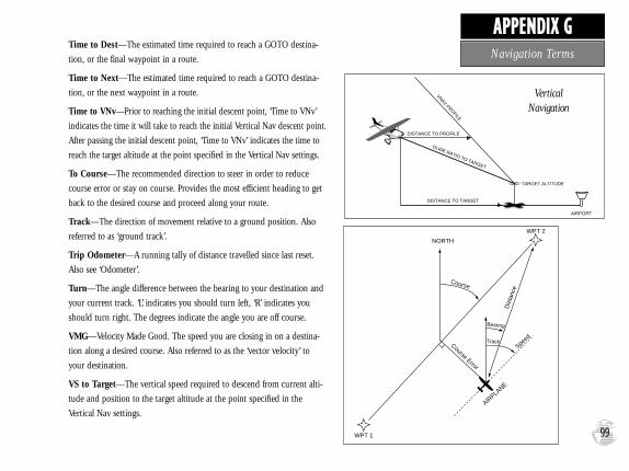
Time to Dest—The estimated time required to reach a GOTO destina-
tion, or the final waypoint in a route.
Time to Next—The estimated time required to reach a GOTO destina-
tion, or the next waypoint in a route.
Time to VNv—Prior to reaching the initial descent point, ‘Time to VNv’
indicates the time it will take to reach the initial Vertical Nav descent point.
After passing the initial descent point, ‘Time to VNv’ indicates the time to
reach the target altitude at the point specified in the Vertical Nav settings.
To Course—The recommended direction to steer in order to reduce
course error or stay on course. Provides the most efficient heading to get
back to the desired course and proceed along your route.
Track—The direction of movement relative to a ground position. Also
referred to as ‘ground track’.
Trip Odometer—A running tally of distance travelled since last reset.
Also see ‘Odometer’.
Turn—The angle difference between the bearing to your destination and
your current track. ‘L’ indicates you should turn left, ‘R’ indicates you
should turn right. The degrees indicate the angle you are off course.
VMG—Velocity Made Good. The speed you are closing in on a destina-
tion along a desired course. Also referred to as the ‘vector velocity’ to
your destination.
VS to Target—The vertical speed required to descend from current alti-
tude and position to the target altitude at the point specified in the
Vertical Nav settings.
99
APPENDIX GNavigation Terms
WPT 1
Course Error
NORTH
WPT 2
Bearing
Speed
Dis
tanc
e
AIRPLA
NE
Course
Track
VNAV PROFILE
GLIDE RATIO TO TARGET
DISTANCE TO TARGET
DISTANCE TO PROFILE
TARGET ALTITUDE
AIRPORT
VerticalNavigation
GPS III Pilot B2 4/1/99 2:02 PM Page 99

AActive Route Options . . . . . . . .68-72Active Route Page . . . . . . . . .16,70-72Active Waypoints . . . . . . . . . . . . . .48Airports
Nearest . . . . . . . . . . . . . . . . . . .25Warnings . . . . . . . . . . . . . . . . .26
Airspace . . . . . . . . . . . . . . . . . .26,84Alarms . . . . . . . . . . . . . . . . . . . . . .83Altitude Entry . . . . . . . . . . . . . . . .32Antenna, Removing . . . . . . . . . . . .92Arrival Alarm . . . . . . . . . . . . . . . . .83AutoLocateTM Mode . . . . . . . . . .6,28AutoZoom . . . . . . . . . . . . . . . . . . .38Averaging Positions . . . . . . . .33,55,60Averaging Speed . . . . . . . . . . . . . . .32
BBacklight Timer . . . . . . . . . . . . . . .79Backlighting On/Off . . . . . . . . . . . .30Battery Installation/Replacement . . . .3Battery Level Indicator . . . . . .8,29,69
Battery Type . . . . . . . . . . . . . . . . . . .3Beacon Receiver Setup . . . . . . . . . .87Bearing . . . . . . . . . . . . . . . . . . . . .98Bearing Pointer . . . . . . . . . . . . . . .46Big Numbers . . . . . . . . . . . . . . . . .11Bug Indicator . . . . . . . . . . . . . .22,40
CCancel GOTO . . . . . . . . . . . . . . . .16Cautions . . . . . . . . . . . . . . . . . . . . .iiCities on Map . . . . . . . . . . . . . . . .39Contrast . . . . . . . . . . . . . . . . . . .8,27Course . . . . . . . . . . . . . . . . . . . . . .98Course Error . . . . . . . . . . . . . . . . .98Cursor . . . . . . . . . . . . . . . . . . . . . . .2
DD-bar . . . . . . . . . . . . . . . . . . . . . . .11Data Entry . . . . . . . . . . . . . . . . . . . .2Database Info, viewing . . . . . . . . . .14Date and Time Setup . . . . . . . . . . .82Default . . . . . . . . . . . . . . . . . . . . . .2Dilution of Precision (DOP) . . . . . .30Distance . . . . . . . . . . . . . . . . . . . .98
EE6B . . . . . . . . . . . . . . . . . . . . . . . .75Enter/Mark Key . . . . . . . . . . . . . . . .2Estimated Position Error (EPE) . . . .30Estimated Time of Arrival (ETA) . . .98
FField . . . . . . . . . . . . . . . . . . . . . . . .2
GGOTO Function . . . . .15,21,36,61-62GOTO/Nrst Key . . . . . . . . . . . . . . . .2GOTO Options . . . . . . . . . . . . . . .63GPS Overview . . . . . . . . . . . . . . . . .4
HHeading Selection . . . . . . . . . . . . .80Highlight . . . . . . . . . . . . . . . . . . . . .2Highway Display . . . . . . . . . . . . . .12Highway Page . . . . . . . . . . . .12,23,46Highway Page Options . . . . . . . . . .47HSI Page . . . . . . . . . . . . . . .11,22,40HSI Page Options . . . . . . . . . . .41-43
IInitialization . . . . . . . . . . . . . . . . . .5Installation, antenna . . . . . . . . . . . .92100
APPENDIX HIndex
GPS III Pilot B2 4/1/99 2:02 PM Page 100

Installation, wiring . . . . . . . . . . . . .91Interface Formats . . . . . . . . . . . . . .77Interface Settings . . . . . . . . . . . . . .87
KKeypad Usage . . . . . . . . . . . . . . . . .2
LLakes on Map . . . . . . . . . . . . . . . .39Lat/Long Grid . . . . . . . . . . . . . . . .38
MMain Menu Page . . . . . . . . .13,73-76Map Datum List . . . . . . . . . . . .95-97Map Datum Selection . . . . . . . . . . .86Map Orientation . . . . . . . . . . . . . . .19Map Page . . . . . . . . . . . .10,19,35-36Map Page Options . . . . . . . . . . .37-39Map Scale . . . . . . . . . . . . . . . . . . .35Map Setup . . . . . . . . . . . . . . . . . . .38Mark Position Page . . . . . . . . . . . . .24Marking a Position . . . . . . . .14,24,55Maximum Speed . . . . . . . . . . . . . .98Measuring Between Waypoints . . . .37Menu Key . . . . . . . . . . . . . . . . . . . .2Messages . . . . . . . . . . . . . . . . . .93-94Mounting . . . . . . . . . . . . . . . . .88-89
NNavigation Terms . . . . . . . . . . .98-99Navigation Units . . . . . . . . . . . . . .80Nearest Airports . . . . . . . . . .25,53-54Nearest Waypoint List . . . . . . . . . .85NMEA Output Formats . . . . . . . . .87
OOff Course . . . . . . . . . . . . . . . .83,98Offset, local time . . . . . . . . . . . . . .82Odometer . . . . . . . . . . . . . . . . . . .72Output Setup . . . . . . . . . . . . . . . . .87
PPackage Contents . . . . . . . . . . . . . . .iPage Key . . . . . . . . . . . . . . . . . .1,2,7Page Sequence . . . . . . . . . . . . . . . . .7Panning . . . . . . . . . . . . . . . .20,35-36Pointer Arrow . . . . . . . . . . . . . . . .11Position Averaging . . . . . . . . . . . . .33Position Format . . . . . . . . . . . . . . .86Position Page . . . . . . . . . . . . . . . .9,32Position Page Options . . . . . . . .33-34Power Key . . . . . . . . . . . . . . . . . .1,2Power Off . . . . . . . . . . . . . . . . . . .2,6Power On . . . . . . . . . . . . . . . .2,5,17
QQuit Key . . . . . . . . . . . . . . . . . .1,2,7
RRailroads, on Map . . . . . . . . . . . . .30Receiver Status . . . . . . . . . . . .8,27-29Reference Waypoints . . . . . . . . . . .57Rivers, On Map . . . . . . . . . . . . . . .38Roads, on Map . . . . . . . . . . . . . . . .38Rocker Keypad . . . . . . . . . . . . . . .1,2Routes . . . . . . . . . . . . . . . . . . .66-72
Active Route Page . . . . . . . .71-72Activating . . . . . . . . . . . . . .67-67Copying . . . . . . . . . . . . . . . . . .68Creating . . . . . . . . . . . . . . . . .66Deactivating . . . . . . . . . . . . .67,71Deleting . . . . . . . . . . . . .68-69,72Deleting All . . . . . . . . . . . . . . .69Editing Routes . . . . . . . . . . .69-70Inverting . . . . . . . . . . . . . . .68,72List . . . . . . . . . . . . . . . . . . .66-67Naming . . . . . . . . . . . . . . . .66-67Options 66
101
APPENDIX HIndex
GPS III Pilot B2 4/1/99 2:02 PM Page 101

SSatellite Status Page . . . . . . . .8,27-29Satellite Status Page Options . . .30-31Screen Contrast . . . . . . . . . . . . .27,79Screen Orientation . . . . . . . . . . .1,79
Scrolling . . . . . . . . . . . . . . . . . . . . .2Setup Menu . . . . . . . . . . . . .13,76-87Signal Strength Bars . . . . . . . . . . .8,27Simulator Mode . . . . . . . .17-18,29,78Simulator Tour . . . . . . . . . . . . .17-26Sky View Display . . . . . . . . . .8,27-28Specifications . . . . . . . . . . . . . . . . .90Speed . . . . . . . . . . . . . . . . . . . . . .98Spell ‘n Find . . . . . . . . . . . . . . .57,61System Setup . . . . . . . . . . . . . . . . .79
TTime Format . . . . . . . . . . . . . . . . .82Time Settings . . . . . . . . . . . . . . . . .82Timers . . . . . . . . . . . . . . . . . . . . . .81
TracBack Navigation . . . . . . . . .64-65Track Compass . . . . . . . . . . . . . .9,12Track Log Setup . . . . . . . .38,64-65,74Track Recording . . . . . . . . . .64-65,74Trip Computer . . . . . . . . . . . . . . . .75Trip Odometer . . . . . . . . . . . . . .9,85Trip Planning . . . . . . . . . . . . . .70-71Troubleshooting . . . . . . . . . . . . . . . .6Turn . . . . . . . . . . . . . . . . . . . . . . .98
UUnit Features . . . . . . . . . . . . . . . . . .1Units of Measure . . . . . . . . . . . . . .80UTC time . . . . . . . . . . . . . . . . . . . .82UTM Coordinates . . . . . . . . . . . . . .86
VVelocity Made Good (VMG) . . . . . .98Vertical Navigation (VNAV) . .44-45.75WWarranty . . . . . . . . . . . . . . . . . . . . .ivWaypoints . . . . . . . . . . . . . . . .48-60
Categories . . . . . . . . . . . . . . . . .48Comments . . . . . . . . . . . . . . . .59Create By Text . . . . . . . . . . . . .56Create On Map . . . . . . . . . . . . .56
Deleting . . . . . . . . . . . . . . . .58,60Deleting All . . . . . . . . . . . . . . .58Deleting by Symbol . . . . . . . . . .58Editing . . . . . . . . . . . . . . . .58-59Editing Options . . . . . . . . . . . .60Going to . . . . . . . . . . . . . . . . . .21Information Pages . . . . . .20,49-52List Options . . . . . . . . . . . . .57-58Marking . . . . . . . . . . . . . . . .24,55Naming . . . . . . . . . . . . .24,55-58Nearest . . . . . . . . . . .25,48,51,64Options . . . . . . . . . . . . . . . . . .57Reference . . . . . . . . . . . . . . . . .57Renaming . . . . . . . . . . . . . . . . .58Reviewing . . . . . . . . . . . . . .48,73User-Defined . . . . . . . . . . . .55-57
Waypoint Definition Page . . . . .48,58Waypoint List Page . . . . . . . . . . . . .73Wiring Installation . . . . . . . . . . . . .91
ZZoom In/Out . . . . . . . . . .10,19,35,40Zoom Keys . . . . . . . . . . . . . . . . .2,35
102
APPENDIX HIndex
GPS III Pilot B2 4/1/99 2:02 PM Page 102

GPS III Pilot B2 4/1/99 2:02 PM Page 103

© 1997-1999 GARMIN Corporation
GARMIN International, Inc., 1200 E. 151st Street, Olathe, KS 66062 USA
GARMIN (Europe) Ltd., Unit 5, The Quadrangle, Abbey Park Industrial Estate, Romsey SO51 9AQ UK
GARMIN (Asia) Corp., 3F, No. 1, Lane 45, Pao-Hsing Road, Hsin Tien, Taipei, Taiwan R.O.C.Web Site Address: www.garmin.com
Part Number 190-00127-00 Rev. B
®
GPS III Pilot B2 4/1/99 2:02 PM Page 104