GP-PRO/PBIII for Windows Ver5.0 Parts List
198
i GP-PRO/PB III for Windows Ver. 5.0 Parts List PREFACE PREFACE Thank you for purchasing the GP Screen Editor Software, "GP-PRO/PB III for Windows Ver. 5.0" for use with Digitals GP series operators interfaces. Please read this manual carefully in order to use this software properly, and be sure to keep this manual handy for future reference. NOTES (1) The copyrights to all programs and manuals included in the GP-PRO/ PB III for Windows Ver. 5.0 (hereinafter referred to as "this product") are reserved by the Digital Electronics Corporation. Digital grants the use of this product to its users as described in the "Software Operating Conditions" documentation, included with this product’s CD-ROM. Any actions violating the above-mentioned conditions are prohibited by both Japanese and foreign regulations. (2) The contents of this manual have been thoroughly inspected. How- ever, if you should find any errors or omissions in this manual, please inform your local GP representative of your findings. (3) Regardless of article (2), the Digital Electronics Corporation shall not be held responsible for any damages or third party claims resulting from the use of this product. (4) Differences may occur between the descriptions found in this manual and the actual functioning of this product. Therefore, the latest infor- mation on this product is provided in data files (i.e. Readme.txt files, etc. ) and in separate documents. Please consult these sources as well as this manual prior to using the product. (5) Even though the information contained in and displayed by this prod- uct may be related to intangible or intellectual properties of the Digital Electronics Corporation or third parties, the Digital Electronics Corpo- ration shall not warrant or grant the use of said properties to any users and/or other third parties. (6) The specifications set out in this manual are for overseas products only. As a result, some differences may exist between the specifica- tions given here and for those of the identical Japanese product. ' Copyright 2000 Digital Electronics Corporation. All rights reserved. Digital Electronics Corporation, November 2000 For the rights to trademarks and trade names, see TRADEMARK RIGHTS.
-
Upload
khangminh22 -
Category
Documents
-
view
9 -
download
0
Transcript of GP-PRO/PBIII for Windows Ver5.0 Parts List
iGP-PRO/PB III for Windows Ver. 5.0 Parts List
PREFACE
PREFACEThank you for purchasing the GP Screen Editor Software, "GP-PRO/PB IIIfor Windows Ver. 5.0" for use with Digital�s GP series operators interfaces.
Please read this manual carefully in order to use this software properly, andbe sure to keep this manual handy for future reference.
NOTES(1) The copyrights to all programs and manuals included in the GP-PRO/
PB III for Windows Ver. 5.0 (hereinafter referred to as "this product")are reserved by the Digital Electronics Corporation. Digital grants theuse of this product to its users as described in the "Software OperatingConditions" documentation, included with this product's CD-ROM.Any actions violating the above-mentioned conditions are prohibitedby both Japanese and foreign regulations.
(2) The contents of this manual have been thoroughly inspected. How-ever, if you should find any errors or omissions in this manual, pleaseinform your local GP representative of your findings.
(3) Regardless of article (2), the Digital Electronics Corporation shall notbe held responsible for any damages or third party claims resultingfrom the use of this product.
(4) Differences may occur between the descriptions found in this manualand the actual functioning of this product. Therefore, the latest infor-mation on this product is provided in data files (i.e. Readme.txt files,etc. ) and in separate documents. Please consult these sources as wellas this manual prior to using the product.
(5) Even though the information contained in and displayed by this prod-uct may be related to intangible or intellectual properties of the DigitalElectronics Corporation or third parties, the Digital Electronics Corpo-ration shall not warrant or grant the use of said properties to any usersand/or other third parties.
(6) The specifications set out in this manual are for overseas productsonly. As a result, some differences may exist between the specifica-tions given here and for those of the identical Japanese product.
© Copyright 2000 Digital Electronics Corporation. All rights reserved.Digital Electronics Corporation, November 2000
For the rights to trademarks and trade names, see �TRADEMARK RIGHTS�.
ii GP-PRO/PB III for Windows Ver. 5.0 Parts List
PREFACETRADEMARK RIGHTS
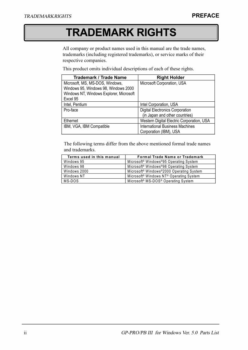
TRADEMARK RIGHTSAll company or product names used in this manual are the trade names,trademarks (including registered trademarks), or service marks of theirrespective companies.
This product omits individual descriptions of each of these rights.
The following terms differ from the above mentioned formal trade namesand trademarks.
Trademark / Trade Name Right Holder Microsoft, MS, MS-DOS, Windows, Windows 95, Windows 98, Windows 2000 Windows NT, Windows Explorer, Microsoft Excel 95
Microsoft Corporation, USA
Intel, Pentium Intel Corporation, USA Pro-face Digital Electronics Corporation
(in Japan and other countries) Ethernet Western Digital Electric Corporation, USA IBM, VGA, IBM Compatible International Business Machines
Corporation (IBM), USA
Terms used in this manual Formal Trade Name or Trademark Windows 95 M icrosoft® W indows®95 Operating System Windows 98 M icrosoft® W indows®98 Operating System Windows 2000 M icrosoft® W indows®2000 Operating System Windows NT Microsoft® W indows NT® Operating System MS-DOS Microsoft® MS-DOS® Operating System

iiiGP-PRO/PB III for Windows Ver. 5.0 Parts List
PREFACE HOW TO USE THIS MANUAL
HOW TO USE THIS MANUAL!!!!! Structure of this Manual Structure of this Manual Structure of this Manual Structure of this Manual Structure of this Manual
The "Parts List" is the fourth of five manuals for this product, and explainshow to use the "GP-PRO/PB III for Windows Ver. 5.0" software (hereinafterreferred to as "this product"). Please refer to all of these manuals when usingthis product.In addition to these manuals, data files containing supplemental informationon updated functions are also provided.To read these files, click on the [Start] button in your Windows OS mainscreen and select the [Programs]→[ProPB3Win] menu. Then click on the[Read Me] selection.For detailed information about GP series products, please refer to each GP's"User's Manual" . (Optionally available)
The PDF Manual CD-ROM also contains "Screen Data Layout Sheets" inExcel 95 format. To view this data, use your Excel program to open any ofthe files shown below.These sheets are useful for designing tag address settings, etc. and examplesheets are installed as part of the GP-PRO/PBIII for Windows standardinstallation.The following two layout sheets, "Device Allocation Table" and "Tag Lay-out Sheet", are in Microsoft Excel 95 format and are located in the PDFManual CD-ROM.The following file location and file names are used.
Vol. 1 Operation Manual Describes this product�s operation procedures and all standard functions.
Vol. 2 Tag Reference Manual
Describes the functions and detailed settings for all GP-PRO/PBIII Tags.
Vol. 3 Parts List (this manual)
Describes this product�s pre-made Parts and symbols.
Vol. 4 PLC Connection Manual
Describes the methods for connecting the GP to other, supported manufacturer PLCs.
For information on the use of Microsoft Excel, please refer to the Excelsoftware's Users manual.
Folder Name File Name ContentsDevice1E.xls Device Allocation Tablepropbwin/sheetTAG1E.xlsTAG2E.xlsTAG3E.xlsTAG4E.xls
Tag Layout Sheet

iv GP-PRO/PB III for Windows Ver. 5.0 Parts List
PREFACEHOW TO USE THIS MANUAL
!!!!! GP/GLC Series Product Names GP/GLC Series Product Names GP/GLC Series Product Names GP/GLC Series Product Names GP/GLC Series Product Names *1*1*1*1*1
The GP-PRO/PBIII functions and settings available will vary, depending onthe model of GP used. Use the following table to identify your GP/GLC�smodel number.
*1 For information about available models in your country, please contact your localdistributor.
Series Product Name ModelGP-H70 series GP-H70L GPH70-LG11-24V
GPH70-LG41-24VPGP-H70S GPH70-SC11-24V
GPH70-SC41-24VPGP-270 series GP-270L GP270-LG11-24V
GP270-LG21-24VPGP270-LG31-24V
GP-270S GP270-SC11-24VGP270-SC21-24VPGP270-SC31-24V
GP-370 series GP-370L GP370-LG11-24VGP370-LG21-24VPGP370-LG31-24VGP370-LG41-24VP
GP-370S GP370-SC11-24VGP370-SC21-24VPGP370-SC31-24VGP370-SC41-24VP
GP-470 series GP-470E GP470-EG11GP470-EG21-24VPGP470-EG31-24V
GP-570 series GP-570S GP570-SC11GP570-SC21-24VPGP570-SC31-24V
GP-570T GP570-TC11GP570-TC21-24VPGP570-TC31-24V
GP-570L GP570-LG21-24VGP-570VM GP570-TV11GP-571T GP571-TC11GP-57JS GP57J-SC11
GP-675 series GP-675T GP675-TC11GP675-TC41-24VP
GP-675S GP675-SC11GP-870 series GP-870VM GP870-PV11
GP77 series GP-377 series GP377-LG11-24VGP377-LG41-24V
GP-377S GP377-SC11-24VGP377-SC41-24V
GP-37W2 series GP-37W2B GP37W2-BG41-24VGP377R-TC11-24VGP377R-TC41-24V
GP-477RE GP477R-EG11GP477R-EG41-24VP
GP-577RT GP577R-TC11GP577R-TC41-24VP
GP-577RS GP577R-SC11GP-2400T GP2400-TC41-24VGP-2500T GP2500-TC11GP-2500T GP2500-TC11-24VGP-2600T GP2600-TC11GP-2600T GP2600-TC11-24V
GP 70 series
GP2000 series
GP-377L
GP77R series
GP-377R series GP-377RT
GP-477R series
GP-577R series
vGP-PRO/PB III for Windows Ver. 5.0 Parts List
PREFACE
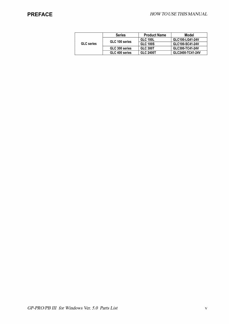
Series Product Name Model GLC 100L GLC100-LG41-24V GLC 100 series GLC 100S GLC100-SC41-24V
GLC 300 series GLC 300T GLC300-TC41-24V GLC series
GLC 400 series GLC 2400T GLC2400-TC41-24V
HOW TO USE THIS MANUAL
vi GP-PRO/PB III for Windows Ver. 5.0 Parts List
PREFACETABLE OF CONTENTS
TABLE OF CONTENTSPREFACE .........................................................................................iTRADEMARK RIGHTS ................................................................. iiHOW TO USE THIS MANUAL .................................................... iiiTABLE OF CONTENTS ............................................................... viMANUAL SYMBOLS AND TERMINOLOGY ............................ xiPRECAUTIONS ........................................................................... xii
Chapter 1 Parts List Manual
1.1 Description of the Parts List Manual .............................................. 1-11.2 Parts File Structure .......................................................................... 1-11.3 How to Read the Function Table ..................................................... 1-4
1.3.1 Items of the Function Table ......................................................................... 1-4
Chapter 2 Switch (Bit/Word/Function)
2.1 Switch 3D Parts01 .......................................................................... 2-12.2 Switch 3D Parts02 .......................................................................... 2-22.3 Switch Plain Parts01 ...................................................................... 2-42.4 Switch Plain Parts02 ...................................................................... 2-52.5 Switch Labeled Parts01 Color....................................................... 2-7
Switch Labeled Parts01 Monochrome ......................................... 2-92.6 Switch Standard Parts01 ..............................................................2-11
Chapter 3 Toggle Switches
3.1 Switch 3D Parts01 .......................................................................... 3-13.2 Switch 3D Parts02 .......................................................................... 3-23.3 Switch Plain Parts01 ...................................................................... 3-33.4 Switch Plain Parts02 ...................................................................... 3-53.5 Switch Standard Parts01 ............................................................... 3-6
Chapter 4 Lamps
4.1 Lamp 3D Parts01 ............................................................................ 4-14.2 Lamp 3D Parts02 ............................................................................ 4-34.3 Lamp Plain Parts01 ........................................................................ 4-4
viiGP-PRO/PB III for Windows Ver. 5.0 Parts List
PREFACE TABLE OF CONTENTS
4.4 Lamp Plain Parts02 ........................................................................ 4-64.5 Lamp Labeled Parts01 Color ......................................................... 4-7
Lamp Labeled Parts01 Monochrome............................................ 4-94.6 Lamp Conveyor Parts01 Color .....................................................4-11
Lamp Conveyor Parts01 Monochrome ....................................... 4-124.7 Lamp Ladder Parts01 Color ........................................................ 4-13
Lamp Ladder Parts01 Monochrome ........................................... 4-144.8 Lamp Water Pipe Parts01 Color .................................................. 4-15
Lamp Water Pipe Parts01 Monochrome..................................... 4-174.9 Lamp Standard Parts01 ............................................................... 4-19
Chapter 5 Bar Graphs
5.1 Bar Graph 3D Parts01 .................................................................... 5-15.2 Bar Graph Plain Parts01 ................................................................ 5-25.3 Bar Graph Water Pipe Parts01 Color ............................................ 5-3
Chapter 6 Pie Graphs
6.1 Pie Graph 3D Parts01..................................................................... 6-16.2 Pie Graph Plain Parts01................................................................. 6-2
Chapter 7 Half Pie Graphs
7.1 Half Pie Graph 3D Parts01 ............................................................. 7-17.2 Half Pie Graph Plain Parts01 ......................................................... 7-2
Chapter 8 Tank Graphs
8.1 Tank Graph 3D Parts01 .................................................................. 8-18.2 Tank Graph Plain Parts01 .............................................................. 8-3
Chapter 9 Meter Graphs
9.1 Meter Graph 3D Parts01 ................................................................ 9-19.2 Meter Graph Plain Parts01 ............................................................ 9-2
Chapter 10 Trend Graphs
10.1 Trend Graph 3D Parts01 .............................................................. 10-110.2 Trend Graph Plain Parts01 .......................................................... 10-2

viii GP-PRO/PB III for Windows Ver. 5.0 Parts List
PREFACETABLE OF CONTENTS
Chapter 11 Keypads
11.1 Keypad <Dec> 3D Parts01 ............................................................11-111.2 Keypad <Dec> Plain Parts01 ........................................................11-211.3 Keypad <Hex> 3D Parts01 ............................................................11-311.4 Keypad <Hex> Plain Parts01 ........................................................11-411.5 Keypad <Text> 3D Parts01 ...........................................................11-511.6 Keypad <Text> Plain Parts01 .......................................................11-6
Chapter 12 Keypad Input Display
12.1 Keypad Display 3D Parts01 ......................................................... 12-112.2 Keypad Display Plain Parts01 ..................................................... 12-2
Chapter 13 Numeric Displays
13.1 Numeric Display 3D Parts01 ....................................................... 13-113.2 Numeric Display Plain Parts01 ................................................... 13-2
Chapter 14 Message Displays
14.1 Message Display 3D Parts01 ....................................................... 14-114.2 Message Display Plain Parts01 ................................................... 14-2
Chapter 15 Date Displays
15.1 Date Display 3D Parts01 .............................................................. 15-115.2 Date Display Plain Parts01 .......................................................... 15-2
Chapter 16 Time Displays
16.1 Time Display 3D Parts01.............................................................. 16-116.2 Time Display Plain Parts01.......................................................... 16-2
Chapter 17 Libraries
17.1 Library File Contents ..................................................................... 17-117.2 Library Addresses .......................................................................... 17-217.3 Address Setup ................................................................................ 17-317.4 3-state Switches Data Input Equipment ................................... 17-417.5 Rotary Switches Data Input Equipment ....................................... 17-617.6 Slide Switches Data Input Equipment ......................................... 17-9
ixGP-PRO/PB III for Windows Ver. 5.0 Parts List
PREFACE
17.7 Selector Switches Data Input Equipment ................................. 17-1217.8 Digital Switches Data Input Equipment................................... 17-1517.9 Digital Switches2 Data Input Equipment2................................. 17-1717.10 Volume Switches Data Input Equipment ................................... 17-2117.11 Numeric Input Keypad Data Input Equipment ......................... 17-2317.12 LED Lamps Monitor Equipment Library Parts ......................... 17-2517.13 I/O Monitor Monitor Equipment Library Parts.......................... 17-2617.14 Device Monitor Monitor Equipment Library Parts ................... 17-2817.15 Timers Multifunction Equipment Library Parts ......................... 17-3017.16 Counter Multifunction Equipment Library Parts ..................... 17-3217.17 Heat Control Multifunction Equipment Library Parts .............. 17-3417.18 Add/Subtract Momentary Switch ................................................ 17-3717.19 Window Display Tool Application Library ................................ 17-3917.20 2 Button Safety Switch Application Library ............................... 17-4117.21 Alarm Display #1 Application Library ........................................ 17-4317.22 Alarm Display #2 Application Library ....................................... 17-4417.23 Alarm Display #3 Application Library ....................................... 17-4517.24 Active Image Display Tool Application Library ........................ 17-4617.25 Filing Data Edit Tool Application Library ................................. 17-4717.26 Logging Keypad-Decimal Application Library ......................... 17-4917.27 Logging Keypad-Hex Application Library ................................ 17-50
Chapter 18 Mark Libraries
18.1 What is the Mark Library ............................................................... 18-118.2 Configuration of the MRK File ....................................................... 18-118.3 Reading the Mark List .................................................................... 18-218.4 Symbol No.s 0001-0050 ............................................................... 18-318.5 Symbol No.s 0051-0100 ............................................................... 18-518.6 Symbol No.s 0101-0150 ............................................................... 18-718.7 Symbol No.s 0151-0200 ............................................................... 18-918.8 Symbol No.s 0201-0250 ..............................................................18-1118.9 Symbol No.s 0251-0300 ............................................................. 18-1318.10 Symbol No.s 0301-0350 ............................................................. 18-1518.11 Symbol No.s 0351-0400 ............................................................. 18-1718.12 Symbol No.s 0401-0450 ............................................................. 18-19
TABLE OF CONTENTS
x GP-PRO/PB III for Windows Ver. 5.0 Parts List
PREFACETABLE OF CONTENTS
18.13 Symbol No.s 0451-0500 ............................................................. 18-2118.14 Symbol No.s 0501-0550 ............................................................. 18-2318.15 Symbol No.s 0551-0600 ............................................................. 18-2518.16 Symbol No.s 0601-0650 ............................................................. 18-2718.17 Symbol No.s 0651-0700 ............................................................. 18-2918.18 Symbol No.s 0701-0750 ............................................................. 18-3118.19 Symbol No.s 0751-0800 ............................................................. 18-3318.20 Symbol No.s 0801-0850 ............................................................. 18-3518.21 Symbol No.s 0851-0900 .............................................................. 18-3718.22 Symbol No.s 0901-0950 .............................................................. 18-3918.23 Symbol No.s 0951-1000 ............................................................. 18-4118.24 Symbol No.s 1001-1050 ............................................................. 18-4318.25 Symbol No.s 1051-1100 ............................................................. 18-4518.26 Symbol No.s 1101-1140.............................................................. 18-47
Template Appendix
A.1 Switch 3D Template Switch Parts ................................... Appendix-1A.2 Switch Plain Template Switch Parts ............................... Appendix-3A.3 Lamp 3D Template Lamp Parts ....................................... Appendix-5A.4 Lamp Plain Template Lamp Parts ................................... Appendix-7A.5 Display Template Display Parts ...................................... Appendix-9A.6 Keypad 3D Template Keypad Parts .............................. Appendix-10A.7 Keypad Plain Template Keypad Parts .......................... Appendix-11A.8 Backgrounds Template Screen Background Parts ....... Appendix-12
xiGP-PRO/PB III for Windows Ver. 5.0 Parts List
PREFACE
Symbol Description Provides hints on correct product use, or supplementary
information.
Indicates an item's related information (manual name, page number).
IBM Compatible Indicates a PC that can run the Windows® operating system.
PLC Abbreviation for Programmable Logic Controller. Includes programmable logic controllers and sequencers.
GP Generic name for the "GP Series" of programmable operator interface made by the Digital Electronics Corporation.
GLC Generic name for the "GLC Series" of Graphic Logic Controller made by the Digital Electronics Corporation.
MANUAL SYMBOLS AND TERMINOLOGY
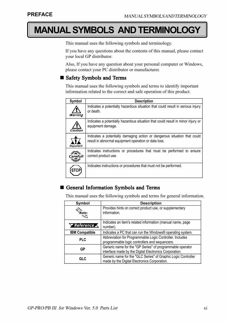
MANUAL SYMBOLS AND TERMINOLOGYThis manual uses the following symbols and terminology.
If you have any questions about the contents of this manual, please contactyour local GP distributor.
Also, If you have any question about your personal computer or Windows,please contact your PC distributor or manufacturer.
!!!!! Safety Symbols and T Safety Symbols and T Safety Symbols and T Safety Symbols and T Safety Symbols and TermsermsermsermsermsThis manual uses the following symbols and terms to identify importantinformation related to the correct and safe operation of this product.
!!!!! General Information Symbols and T General Information Symbols and T General Information Symbols and T General Information Symbols and T General Information Symbols and TermsermsermsermsermsThis manual uses the following symbols and terms for general information.
Symbol DescriptionIndicates a potentially hazardous situation that could result in serious injuryor death.
Indicates a potentially hazardous situation that could result in minor injury orequipment damage.
Indicates a potentially damaging action or dangerous situation that couldresult in abnormal equipment operation or data loss.
Indicates instructions or procedures that must be performed to ensurecorrect product use.
Indicates instructions or procedures that must not be performed.
xii GP-PRO/PB III for Windows Ver. 5.0 Parts List
PREFACE
!!!!! CD-ROM and Floppy Disk Usage Precautions CD-ROM and Floppy Disk Usage Precautions CD-ROM and Floppy Disk Usage Precautions CD-ROM and Floppy Disk Usage Precautions CD-ROM and Floppy Disk Usage PrecautionsTo prevent CD-ROM and floppy disk damage or failure, be sure to observe thefollowing guidelines:
� Turn your PC ON or OFF only after you remove CD-ROM disk orfloppy disk from it�s drive.
� Do not remove the CD-ROM from the CD-ROM drive while the CD-ROMdrive operation lamp is lit.
� Do not touch the CD-ROM recording surface or the floppy disk�s internalmagnetic disk.
� Do not place CD-ROMs or floppy disks where they may be exposed toextremely high or low temperatures, high levels of humidity or dust.
� Do not place the floppy disks near any type of magnetic device (stereospeaker, television, etc.)
!!!!! Product Usage Precautions Product Usage Precautions Product Usage Precautions Product Usage Precautions Product Usage PrecautionsFor safe and correct use of this product, be sure to observe the followingguidelines:
� Do not create touch panel switches that are used toeither control or to ensure the safety of equipment andpersonnel (such as an emergency stop switch, etc.)
� Please separate your safety/protection system fromthe GP operation system to prevent the danger ofpersonal injury or property damage in case the ma-chine malfunctions or operates incorrectly, or aninadequate system program is used.
� Be sure to quit this program before turning your PC's power switch OFF.� After transferring screen data created with this program to the GP unit, do
not then send the same screen data from the GP to a DOS version of thisscreen editor software (e.g. GP-PRO/PB III, GP-PRO III).
� Do not change the contents of this program's project files using the TextEditor software.
� Do not transfer screen data to a GP that does not support all the data'sfunctions (i.e. Logging, Filing, etc.).
MANUAL SYMBOLS AND TERMINOLOGY
PRECAUTIONS
1-1
Chapter 1 - Parts List Manual
GP-PRO/PB III for Windows Ver. 5.0 Parts List
1 Description of the Parts List Manual2 Parts File Structure3 How to Read the Function Table
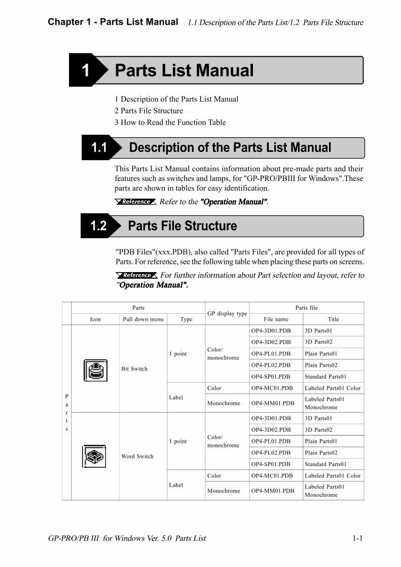
This Parts List Manual contains information about pre-made parts and theirfeatures such as switches and lamps, for "GP-PRO/PBIII for Windows".Theseparts are shown in tables for easy identification.
Refer to the "Operation Manual" "Operation Manual" "Operation Manual" "Operation Manual" "Operation Manual".
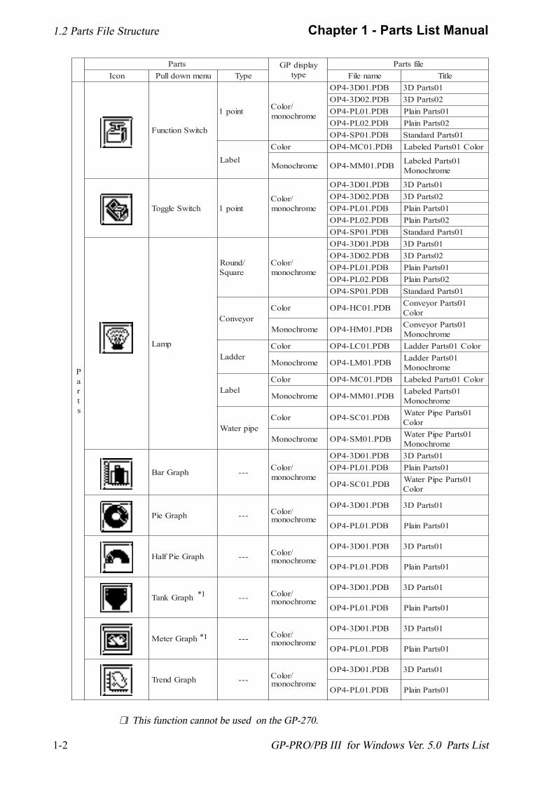
"PDB Files"(xxx.PDB), also called "Parts Files", are provided for all types ofParts. For reference, see the following table when placing these parts on screens.
For further information about Part selection and layout, refer to"Operation Manual".Operation Manual".Operation Manual".Operation Manual".Operation Manual".
PartsGP display type
Parts file
Icon Pull down menu Type File name Title
Parts
Bit Switch
1 pointColor/monochrome
OP4-3D01.PDB 3D Parts01
OP4-3D02.PDB 3D Parts02
OP4-PL01.PDB Plain Parts01
OP4-PL02.PDB Plain Parts02
OP4-SP01.PDB Standard Parts01
LabelColor OP4-MC01.PDB Labeled Parts01 Color
Monochrome OP4-MM01.PDBLabeled Parts01Monochrome
Word Switch
1 pointColor/monochrome
OP4-3D01.PDB 3D Parts01
OP4-3D02.PDB 3D Parts02
OP4-PL01.PDB Plain Parts01
OP4-PL02.PDB Plain Parts02
OP4-SP01.PDB Standard Parts01
LabelColor OP4-MC01.PDB Labeled Parts01 Color
Monochrome OP4-MM01.PDBLabeled Parts01Monochrome
1 Parts List Manual
1.1 Description of the Parts List Manual
1.1 Description of the Parts List/1.2 Parts File Structure
1.2 Parts File Structure
1-2
Chapter 1 - Parts List Manual
GP-PRO/PB III for Windows Ver. 5.0 Parts List
Parts GP displaytype
Parts fileIcon Pull down menu Type File name Title
Parts
Function Switch
1 point Color/monochrome
OP4-3D01.PDB 3D Parts01OP4-3D02.PDB 3D Parts02OP4-PL01.PDB Plain Parts01OP4-PL02.PDB Plain Parts02OP4-SP01.PDB Standard Parts01
LabelColor OP4-MC01.PDB Labeled Parts01 Color
Monochrome OP4-MM01.PDB Labeled Parts01Monochrome
Toggle Switch 1 pointColor/monochrome
OP4-3D01.PDB 3D Parts01OP4-3D02.PDB 3D Parts02OP4-PL01.PDB Plain Parts01OP4-PL02.PDB Plain Parts02OP4-SP01.PDB Standard Parts01
Lamp
Round/Square
Color/monochrome
OP4-3D01.PDB 3D Parts01OP4-3D02.PDB 3D Parts02OP4-PL01.PDB Plain Parts01OP4-PL02.PDB Plain Parts02OP4-SP01.PDB Standard Parts01
ConveyorColor OP4-HC01.PDB Conveyor Parts01
Color
Monochrome OP4-HM01.PDB Conveyor Parts01Monochrome
LadderColor OP4-LC01.PDB Ladder Parts01 Color
Monochrome OP4-LM01.PDB Ladder Parts01Monochrome
LabelColor OP4-MC01.PDB Labeled Parts01 Color
Monochrome OP4-MM01.PDB Labeled Parts01Monochrome
Water pipeColor OP4-SC01.PDB Water Pipe Parts01
Color
Monochrome OP4-SM01.PDB Water Pipe Parts01Monochrome
Bar Graph --- Color/monochrome
OP4-3D01.PDB 3D Parts01OP4-PL01.PDB Plain Parts01
OP4-SC01.PDB Water Pipe Parts01Color
Pie Graph --- Color/monochrome
OP4-3D01.PDB 3D Parts01
OP4-PL01.PDB Plain Parts01
Half Pie Graph --- Color/monochrome
OP4-3D01.PDB 3D Parts01
OP4-PL01.PDB Plain Parts01
Tank Graph --- Color/monochrome
OP4-3D01.PDB 3D Parts01
OP4-PL01.PDB Plain Parts01
Meter Graph --- Color/monochrome
OP4-3D01.PDB 3D Parts01
OP4-PL01.PDB Plain Parts01
Trend Graph --- Color/monochrome
OP4-3D01.PDB 3D Parts01
OP4-PL01.PDB Plain Parts01
1.2 Parts File Structure
∗ 1 This function cannot be used on the GP-270.
*1
*1

1-3
Chapter 1 - Parts List Manual
GP-PRO/PB III for Windows Ver. 5.0 Parts List
1.2 Parts File Structure
Parts GP displaytype
Parts file
Icon Pull down menu Type File name Title
Parts
Keypad --- Color/monochrome
OP4-3D01.PDB 3D Parts01
OP4-PL01.PDB Plain Parts01
Keypad InputDisplay
--- Color/monochrome
OP4-3D01.PDB 3D Parts01
OP4-PL01.PDB Plain Parts01
Alarm Display --- --- --- ---
Filing Data *2Display --- --- --- ---
Logging Display *2 --- --- --- ---
Numeric Display --- Color/monochrome
OP4-3D01.PDB 3D Parts01
OP4-PL01.PDB Plain Parts01
Message Display --- Color/monochrome
OP4-3D01.PDB 3D Parts01
OP4-PL01.PDB Plain Parts01
Date Display --- Color/monochrome
OP4-3D01.PDB 3D Parts01
OP4-PL01.PDB Plain Parts01
Time Display --- Color/monochrome
OP4-3D01.PDB 3D Parts01
OP4-PL01.PDB Plain Parts01
Library
Call up Library --- Color/monochrome
OP4-LIB1.CPW Data Input EquipmentLibrary Parts
OP4-LIB2.CPW Monitor EquipmentLibrary Parts
OP4-LIB3.CPWMultifunctionEquipment LibraryParts
OP4-LIB4.CPW Application LibraryParts
OP4-LIB5.CPW Data Input EquipmentPart 2 Library Parts
OP4-obja.CPW 3D Template SwitchParts
OP4-objb.CPW Plain Template SwitchParts
OP4-objc.CPW 3D Template LampParts
OP4-objd.CPW Plain Template LampParts
OP4-obje.CPW Template DisplayParts
OP4-objf.CPW 3D Template KeypadParts
OP4-objg.CPW Plain TemplateKeypad Parts
OP4-objh.CPW Template ScreenBackground Parts
∗ 2 Can only be used with GP2000, GP77R and GP-377 Series .
1-4
Chapter 1 - Parts List Manual
GP-PRO/PB III for Windows Ver. 5.0 Parts List
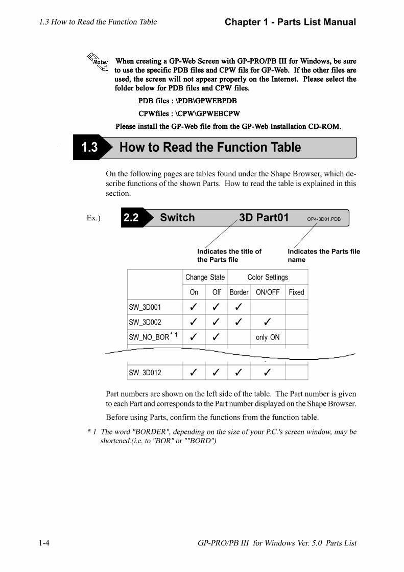
When creating a GP-W When creating a GP-W When creating a GP-W When creating a GP-W When creating a GP-Web Screen with GP-PRO/PB III for Web Screen with GP-PRO/PB III for Web Screen with GP-PRO/PB III for Web Screen with GP-PRO/PB III for Web Screen with GP-PRO/PB III for Windows, be sureindows, be sureindows, be sureindows, be sureindows, be sureto use the specific PDB files and CPW fils for GP-Wto use the specific PDB files and CPW fils for GP-Wto use the specific PDB files and CPW fils for GP-Wto use the specific PDB files and CPW fils for GP-Wto use the specific PDB files and CPW fils for GP-Web. If the other files areeb. If the other files areeb. If the other files areeb. If the other files areeb. If the other files areused, the screen will not appear properly on the Internet. Please select theused, the screen will not appear properly on the Internet. Please select theused, the screen will not appear properly on the Internet. Please select theused, the screen will not appear properly on the Internet. Please select theused, the screen will not appear properly on the Internet. Please select thefolder below for PDB files and CPW files.folder below for PDB files and CPW files.folder below for PDB files and CPW files.folder below for PDB files and CPW files.folder below for PDB files and CPW files.
PDB files : \PDB\GPWEBPDB PDB files : \PDB\GPWEBPDB PDB files : \PDB\GPWEBPDB PDB files : \PDB\GPWEBPDB PDB files : \PDB\GPWEBPDB
CPWfiles : \CPW\GPWEBCPW CPWfiles : \CPW\GPWEBCPW CPWfiles : \CPW\GPWEBCPW CPWfiles : \CPW\GPWEBCPW CPWfiles : \CPW\GPWEBCPW
Please install the GP-W Please install the GP-W Please install the GP-W Please install the GP-W Please install the GP-Web file from the GP-Web file from the GP-Web file from the GP-Web file from the GP-Web file from the GP-Web Installation CD-ROM.eb Installation CD-ROM.eb Installation CD-ROM.eb Installation CD-ROM.eb Installation CD-ROM.
On the following pages are tables found under the Shape Browser, which de-scribe functions of the shown Parts. How to read the table is explained in thissection.
Part numbers are shown on the left side of the table. The Part number is givento each Part and corresponds to the Part number displayed on the Shape Browser.
Before using Parts, confirm the functions from the function table.
Indicates the Parts filename
Indicates the title ofthe Parts file
Change State Color Settings
On Off Border ON/OFF Fixed
SW_3D001 ✓ ✓ ✓
SW_3D002 ✓ ✓ ✓ ✓
SW_NO_BOR ✓ ✓ only ON
y
SW_3D012 ✓ ✓ ✓ ✓
1.3 How to Read the Function Table
1.3 How to Read the Function Table
2.2 Switch 3D Part01 OP4-3D01.PDBEx.)
* 1
* 1 The word "BORDER", depending on the size of your P.C.'s screen window, may beshortened.(i.e. to "BOR" or ""BORD")
When creating
1-5
Chapter 1 - Parts List Manual
GP-PRO/PB III for Windows Ver. 5.0 Parts List
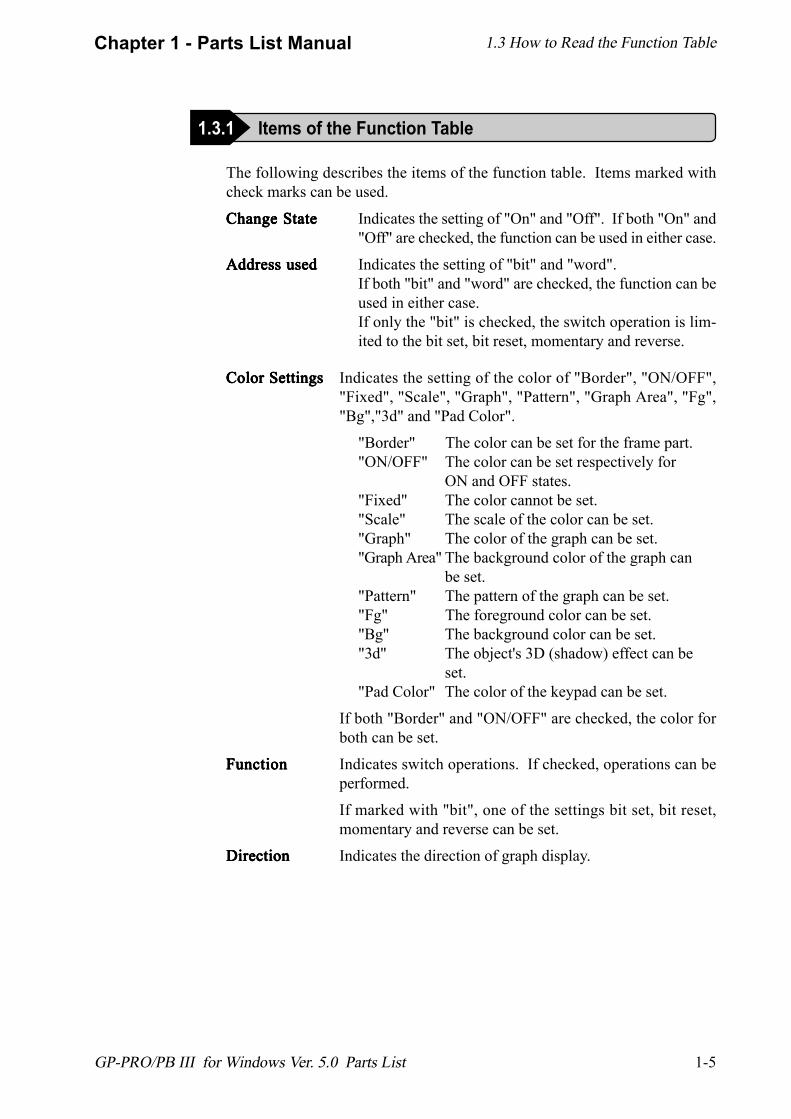
Color SettingsColor SettingsColor SettingsColor SettingsColor Settings Indicates the setting of the color of "Border", "ON/OFF","Fixed", "Scale", "Graph", "Pattern", "Graph Area", "Fg","Bg","3d" and "Pad Color".
"Border" The color can be set for the frame part."ON/OFF" The color can be set respectively for
ON and OFF states."Fixed" The color cannot be set."Scale" The scale of the color can be set."Graph" The color of the graph can be set."Graph Area" The background color of the graph can
be set."Pattern" The pattern of the graph can be set."Fg" The foreground color can be set."Bg" The background color can be set."3d" The object's 3D (shadow) effect can be
set."Pad Color" The color of the keypad can be set.
If both "Border" and "ON/OFF" are checked, the color forboth can be set.
FunctionFunctionFunctionFunctionFunction Indicates switch operations. If checked, operations can beperformed.
If marked with "bit", one of the settings bit set, bit reset,momentary and reverse can be set.
DirectionDirectionDirectionDirectionDirection Indicates the direction of graph display.
The following describes the items of the function table. Items marked withcheck marks can be used.
Change StateChange StateChange StateChange StateChange State Indicates the setting of "On" and "Off". If both "On" and"Off" are checked, the function can be used in either case.
Address usedAddress usedAddress usedAddress usedAddress used Indicates the setting of "bit" and "word".If both "bit" and "word" are checked, the function can beused in either case.If only the "bit" is checked, the switch operation is lim-ited to the bit set, bit reset, momentary and reverse.
1.3 How to Read the Function Table
1.3.1 Items of the Function Table
1-6
Chapter 1 - Parts List Manual
GP-PRO/PB III for Windows Ver. 5.0 Parts List
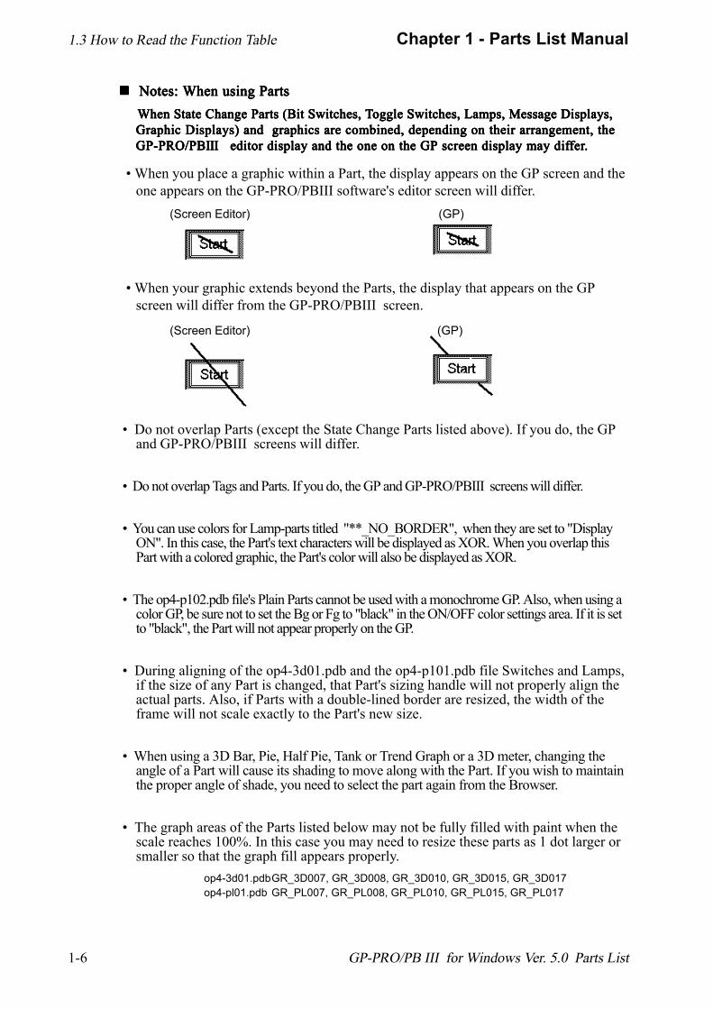
!!!!! Notes: When using Parts Notes: When using Parts Notes: When using Parts Notes: When using Parts Notes: When using Parts When State Change Parts (Bit Switches, T When State Change Parts (Bit Switches, T When State Change Parts (Bit Switches, T When State Change Parts (Bit Switches, T When State Change Parts (Bit Switches, Toggle Switches, Lamps, Message Displays,oggle Switches, Lamps, Message Displays,oggle Switches, Lamps, Message Displays,oggle Switches, Lamps, Message Displays,oggle Switches, Lamps, Message Displays,
Graphic Displays) and graphics are combined, depending on their arrangement, theGraphic Displays) and graphics are combined, depending on their arrangement, theGraphic Displays) and graphics are combined, depending on their arrangement, theGraphic Displays) and graphics are combined, depending on their arrangement, theGraphic Displays) and graphics are combined, depending on their arrangement, theGP-PRO/PBGP-PRO/PBGP-PRO/PBGP-PRO/PBGP-PRO/PBIIIIIIIIIIIIIII editor display and the one on the GP screen display may dif editor display and the one on the GP screen display may dif editor display and the one on the GP screen display may dif editor display and the one on the GP screen display may dif editor display and the one on the GP screen display may differferferferfer.....
� When you place a graphic within a Part, the display appears on the GP screen and theone appears on the GP-PRO/PBIII software's editor screen will differ.
� When your graphic extends beyond the Parts, the display that appears on the GPscreen will differ from the GP-PRO/PBIII screen.
� Do not overlap Parts (except the State Change Parts listed above). If you do, the GPand GP-PRO/PBIII screens will differ.
� Do not overlap Tags and Parts. If you do, the GP and GP-PRO/PBIII screens will differ.
� You can use colors for Lamp-parts titled "**_NO_BORDER", when they are set to "DisplayON". In this case, the Part's text characters will be displayed as XOR. When you overlap thisPart with a colored graphic, the Part's color will also be displayed as XOR.
� The op4-p102.pdb file's Plain Parts cannot be used with a monochrome GP. Also, when using acolor GP, be sure not to set the Bg or Fg to "black" in the ON/OFF color settings area. If it is setto "black", the Part will not appear properly on the GP.
� During aligning of the op4-3d01.pdb and the op4-p101.pdb file Switches and Lamps,if the size of any Part is changed, that Part's sizing handle will not properly align theactual parts. Also, if Parts with a double-lined border are resized, the width of theframe will not scale exactly to the Part's new size.
� When using a 3D Bar, Pie, Half Pie, Tank or Trend Graph or a 3D meter, changing theangle of a Part will cause its shading to move along with the Part. If you wish to maintainthe proper angle of shade, you need to select the part again from the Browser.
� The graph areas of the Parts listed below may not be fully filled with paint when thescale reaches 100%. In this case you may need to resize these parts as 1 dot larger orsmaller so that the graph fill appears properly.
op4-3d01.pdbGR_3D007, GR_3D008, GR_3D010, GR_3D015, GR_3D017op4-pl01.pdb GR_PL007, GR_PL008, GR_PL010, GR_PL015, GR_PL017
1.3 How to Read the Function Table
(Screen Editor)
(Screen Editor)
(GP)
(GP)
2-1
Chapter 2 - Switch (Bit/Word/Function)
GP-PRO/PB III for Windows Ver. 5.0 Parts List
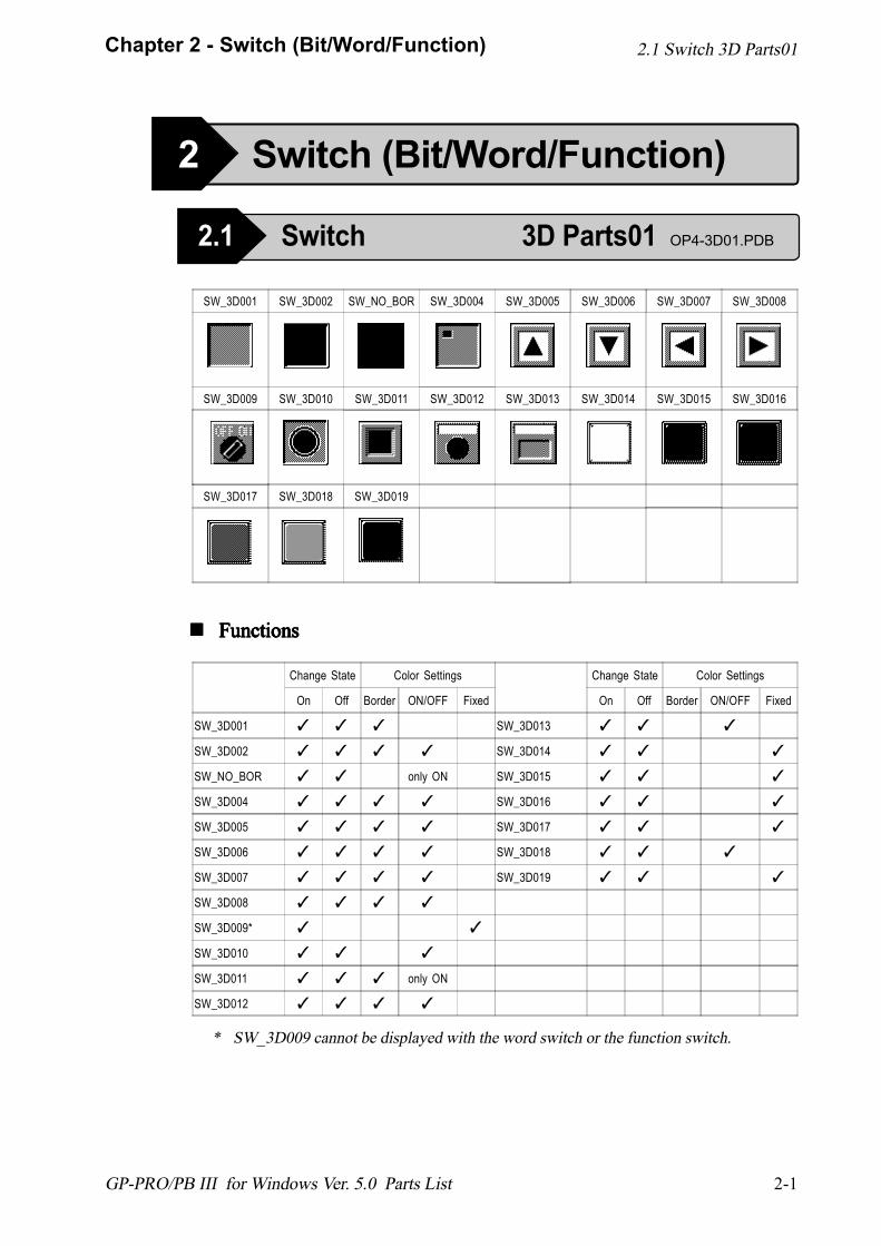
! ! ! ! ! FunctionsFunctionsFunctionsFunctionsFunctions
SW_3D001 SW_3D002 SW_NO_BOR SW_3D004 SW_3D005 SW_3D006 SW_3D007 SW_3D008
SW_3D009 SW_3D010 SW_3D011 SW_3D012 SW_3D013 SW_3D014 SW_3D015 SW_3D016
SW_3D017 SW_3D018 SW_3D019
Change State Color Settings
On Off Border ON/OFF Fixed
SW_3D001 ✓ ✓ ✓
SW_3D002 ✓ ✓ ✓ ✓
SW_NO_BOR ✓ ✓ only ON
SW_3D004 ✓ ✓ ✓ ✓
SW_3D005 ✓ ✓ ✓ ✓
SW_3D006 ✓ ✓ ✓ ✓
SW_3D007 ✓ ✓ ✓ ✓
SW_3D008 ✓ ✓ ✓ ✓
SW_3D009* ✓ ✓
SW_3D010 ✓ ✓ ✓
SW_3D011 ✓ ✓ ✓ only ON
SW_3D012 ✓ ✓ ✓ ✓
Change State Color Settings
On Off Border ON/OFF Fixed
SW_3D013 ✓ ✓ ✓
SW_3D014 ✓ ✓ ✓
SW_3D015 ✓ ✓ ✓
SW_3D016 ✓ ✓ ✓
SW_3D017 ✓ ✓ ✓
SW_3D018 ✓ ✓ ✓
SW_3D019 ✓ ✓ ✓
* SW_3D009 cannot be displayed with the word switch or the function switch.
2.1 Switch 3D Parts01
2 Switch (Bit/Word/Function)
2.1 Switch 3D Parts01 OP4-3D01.PDB
2-2
Chapter 2 - Switch (Bit/Word/Function)
GP-PRO/PB III for Windows Ver. 5.0 Parts List
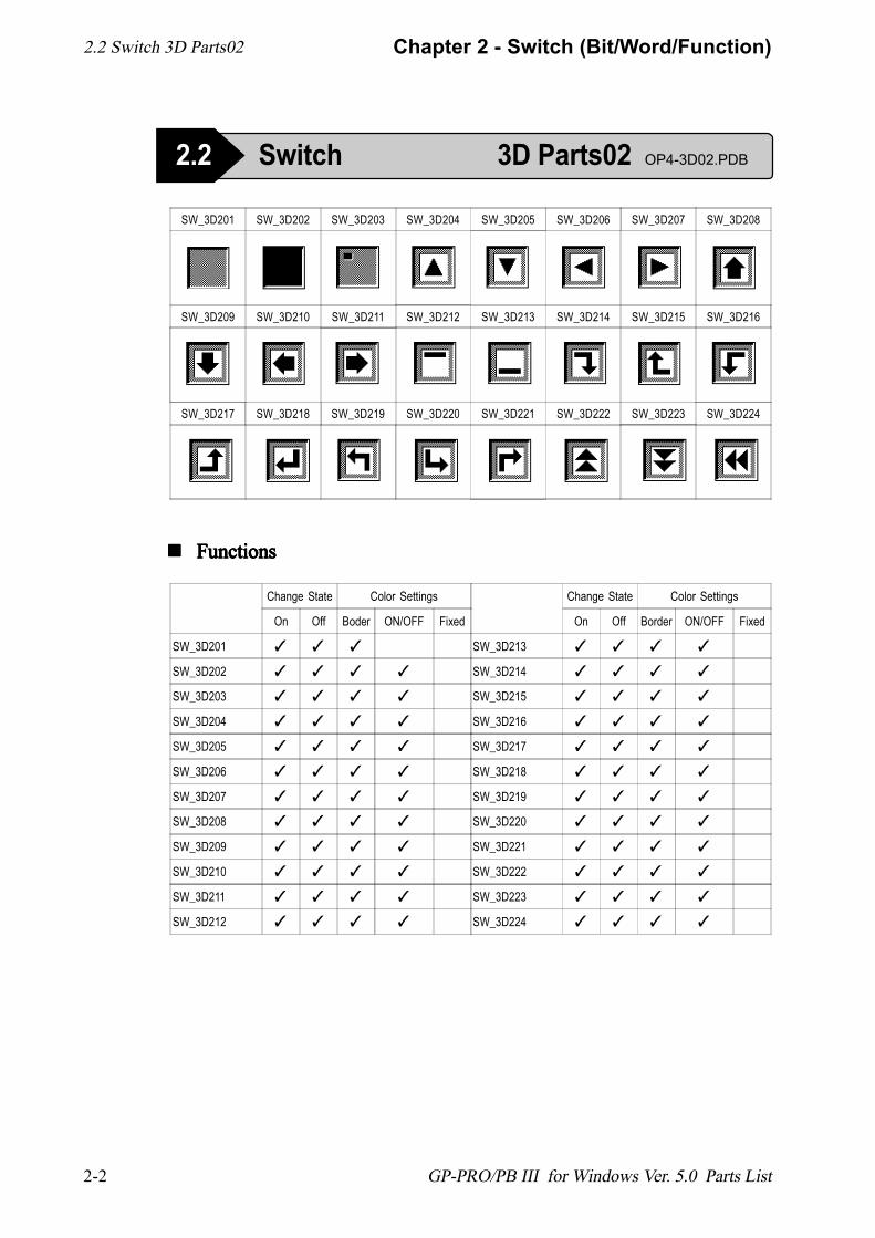
SW_3D201 SW_3D202 SW_3D203 SW_3D204 SW_3D205 SW_3D206 SW_3D207 SW_3D208
SW_3D209 SW_3D210 SW_3D211 SW_3D212 SW_3D213 SW_3D214 SW_3D215 SW_3D216
SW_3D217 SW_3D218 SW_3D219 SW_3D220 SW_3D221 SW_3D222 SW_3D223 SW_3D224
! ! ! ! ! FunctionsFunctionsFunctionsFunctionsFunctions
Change State Color Settings
On Off Boder ON/OFF Fixed
SW_3D201 ✓ ✓ ✓
SW_3D202 ✓ ✓ ✓ ✓
SW_3D203 ✓ ✓ ✓ ✓
SW_3D204 ✓ ✓ ✓ ✓
SW_3D205 ✓ ✓ ✓ ✓
SW_3D206 ✓ ✓ ✓ ✓
SW_3D207 ✓ ✓ ✓ ✓
SW_3D208 ✓ ✓ ✓ ✓
SW_3D209 ✓ ✓ ✓ ✓
SW_3D210 ✓ ✓ ✓ ✓
SW_3D211 ✓ ✓ ✓ ✓
SW_3D212 ✓ ✓ ✓ ✓
Change State Color Settings
On Off Border ON/OFF Fixed
SW_3D213 ✓ ✓ ✓ ✓
SW_3D214 ✓ ✓ ✓ ✓
SW_3D215 ✓ ✓ ✓ ✓
SW_3D216 ✓ ✓ ✓ ✓
SW_3D217 ✓ ✓ ✓ ✓
SW_3D218 ✓ ✓ ✓ ✓
SW_3D219 ✓ ✓ ✓ ✓
SW_3D220 ✓ ✓ ✓ ✓
SW_3D221 ✓ ✓ ✓ ✓
SW_3D222 ✓ ✓ ✓ ✓
SW_3D223 ✓ ✓ ✓ ✓
SW_3D224 ✓ ✓ ✓ ✓
2.2 Switch 3D Parts02
2.2 Switch 3D Parts02 OP4-3D02.PDB
2-3
Chapter 2 - Switch (Bit/Word/Function)
GP-PRO/PB III for Windows Ver. 5.0 Parts List
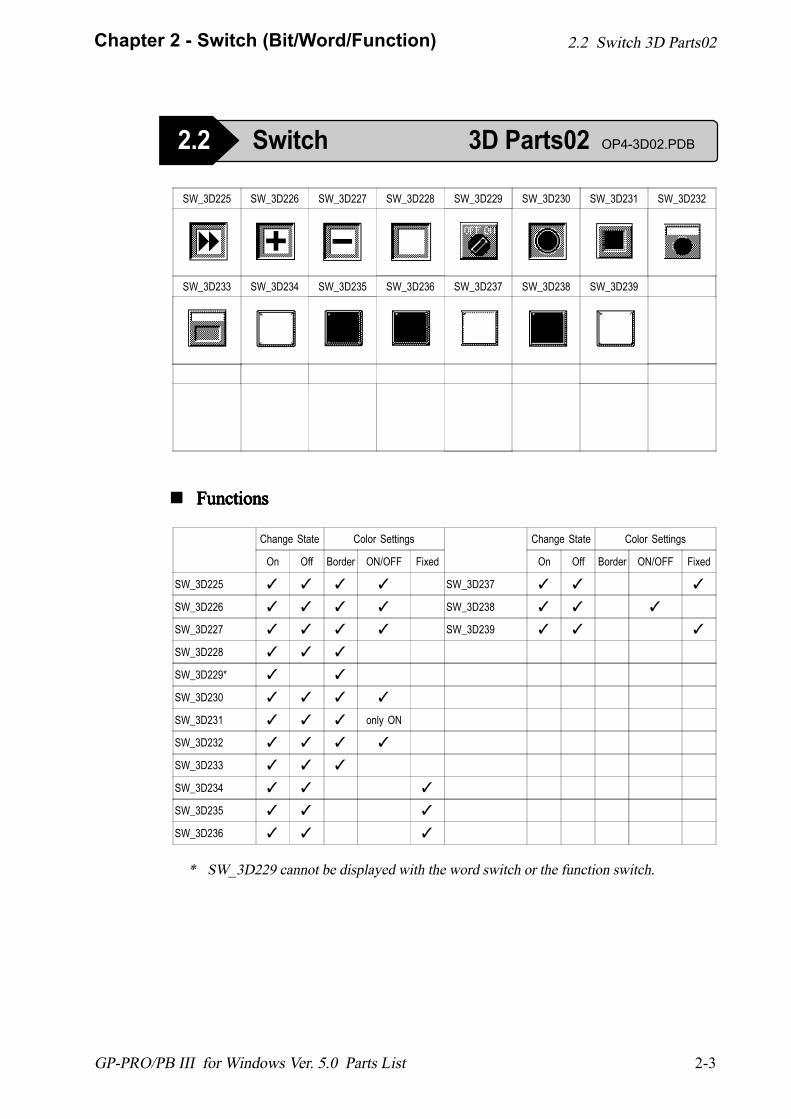
SW_3D225 SW_3D226 SW_3D227 SW_3D228 SW_3D229 SW_3D230 SW_3D231 SW_3D232
SW_3D233 SW_3D234 SW_3D235 SW_3D236 SW_3D237 SW_3D238 SW_3D239
! ! ! ! ! FunctionsFunctionsFunctionsFunctionsFunctions
Change State Color Settings
On Off Border ON/OFF Fixed
SW_3D225 ✓ ✓ ✓ ✓
SW_3D226 ✓ ✓ ✓ ✓
SW_3D227 ✓ ✓ ✓ ✓
SW_3D228 ✓ ✓ ✓
SW_3D229* ✓ ✓
SW_3D230 ✓ ✓ ✓ ✓
SW_3D231 ✓ ✓ ✓ only ON
SW_3D232 ✓ ✓ ✓ ✓
SW_3D233 ✓ ✓ ✓
SW_3D234 ✓ ✓ ✓
SW_3D235 ✓ ✓ ✓
SW_3D236 ✓ ✓ ✓
Change State Color Settings
On Off Border ON/OFF Fixed
SW_3D237 ✓ ✓ ✓
SW_3D238 ✓ ✓ ✓
SW_3D239 ✓ ✓ ✓
* SW_3D229 cannot be displayed with the word switch or the function switch.
2.2 Switch 3D Parts02
2.2 Switch 3D Parts02 OP4-3D02.PDB

2-4
Chapter 2 - Switch (Bit/Word/Function)
GP-PRO/PB III for Windows Ver. 5.0 Parts List
! ! ! ! ! FunctionsFunctionsFunctionsFunctionsFunctions
SW_PL001 SW_PL002 SW_NO_BORDER SW_PL004 SW_PL005 SW_PL006 SW_PL007 SW_PL008
SW_PL009 SW_PL010 SW_PL011 SW_PL012 SW_PL013 SW_PL014 SW_PL015 SW_PL016
SW_PL017 SW_PL018 SW_PL019 SW_PL020
Change State Color Settings
On Off Border ON/OFF Fixed
SW_PL001 ✓ ✓ ✓ ✓
SW_PL002 ✓ ✓ ✓ ✓
SW NO BORDER ✓ ✓ only ON
SW_PL004 ✓ ✓ ✓ ✓
SW_PL005 ✓ ✓ ✓ ✓
SW_PL006 ✓ ✓ ✓ ✓
SW_PL007 ✓ ✓ ✓ ✓
SW_PL008 ✓ ✓ ✓ ✓
SW_PL009* ✓ ✓
SW_PL010* ✓ ✓
SW_PL011* ✓ ✓ ✓
SW_PL012 ✓ ✓ ✓ ✓
Change State Color Settings
On Off Border ON/OFF Fixed
SW_PL013* ✓ ✓ ✓
SW_PL014 ✓ ✓ ✓ ✓
SW_PL015 ✓ ✓ ✓ ✓
SW_PL016 ✓ ✓ ✓ ✓
SW_PL017 ✓ ✓ ✓ ✓
SW_PL018* ✓ ✓
SW_PL019* ✓ ✓ ✓
SW_PL020* ✓ ✓ ✓
*1 SW_PL009, SW_PL010, SW_PL011, SW_PL013, SW_PL018, SW_PL019, andSW_PL020 cannot be displayed with the word switch or the function switch.
*2 Be sure not to set the Border color to "black", it will not appear properly on the GP.
2.3 Switch Plain Parts01 OP4-PL01.PDB
2.3 Switch Plain Parts01
*1 *2
*1 *2
*1 *2
*1
*1
*1
*1 *2
*2
*2
2-5
Chapter 2 - Switch (Bit/Word/Function)
GP-PRO/PB III for Windows Ver. 5.0 Parts List
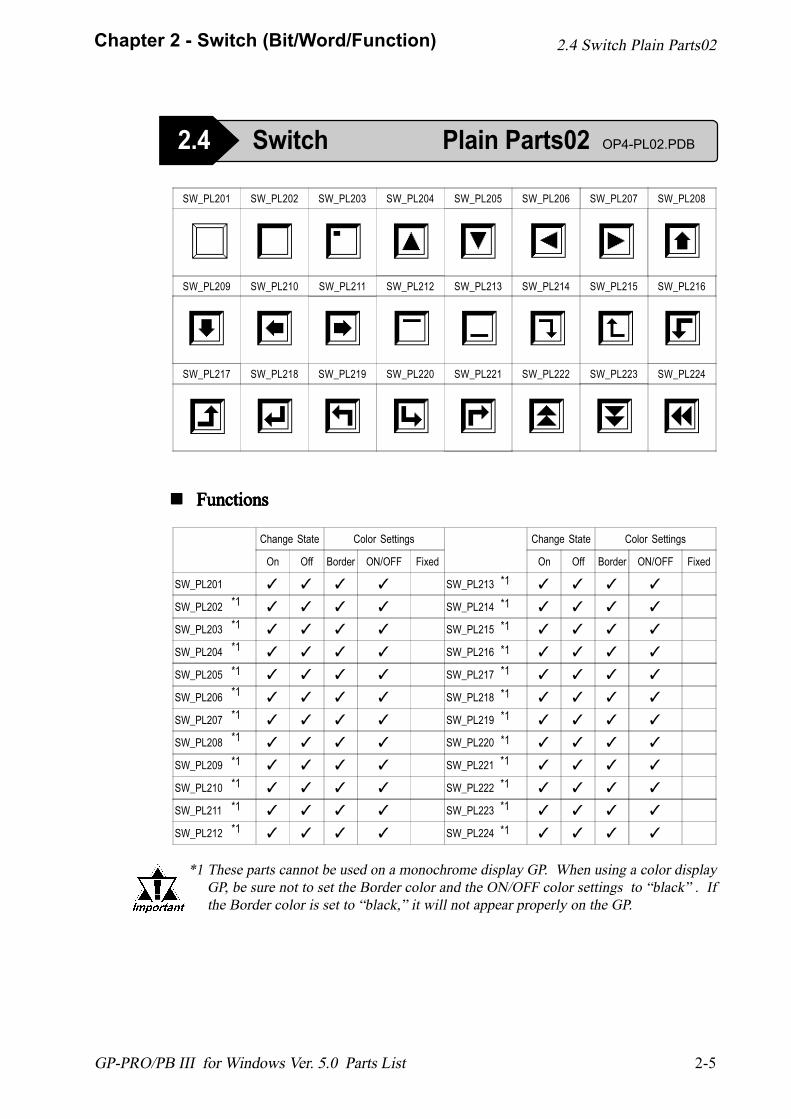
SW_PL201 SW_PL202 SW_PL203 SW_PL204 SW_PL205 SW_PL206 SW_PL207 SW_PL208
SW_PL209 SW_PL210 SW_PL211 SW_PL212 SW_PL213 SW_PL214 SW_PL215 SW_PL216
SW_PL217 SW_PL218 SW_PL219 SW_PL220 SW_PL221 SW_PL222 SW_PL223 SW_PL224
! ! ! ! ! FunctionsFunctionsFunctionsFunctionsFunctions
Change State Color Settings
On Off Border ON/OFF Fixed
SW_PL201 ✓ ✓ ✓ ✓
SW_PL202* ✓ ✓ ✓ ✓
SW_PL203 ✓ ✓ ✓ ✓
SW_PL204 ✓ ✓ ✓ ✓
SW_PL205 ✓ ✓ ✓ ✓
SW_PL206 ✓ ✓ ✓ ✓
SW_PL207 ✓ ✓ ✓ ✓
SW_PL208 ✓ ✓ ✓ ✓
SW_PL209 ✓ ✓ ✓ ✓
SW_PL210 ✓ ✓ ✓ ✓
SW_PL211 ✓ ✓ ✓ ✓
SW_PL212 ✓ ✓ ✓ ✓
Change State Color Settings
On Off Border ON/OFF Fixed
SW_PL213 ✓ ✓ ✓ ✓
SW_PL214 ✓ ✓ ✓ ✓
SW_PL215 ✓ ✓ ✓ ✓
SW_PL216 ✓ ✓ ✓ ✓
SW_PL217 ✓ ✓ ✓ ✓
SW_PL218 ✓ ✓ ✓ ✓
SW_PL219 ✓ ✓ ✓ ✓
SW_PL220 ✓ ✓ ✓ ✓
SW_PL221 ✓ ✓ ✓ ✓
SW_PL222 ✓ ✓ ✓ ✓
SW_PL223 ✓ ✓ ✓ ✓
SW_PL224 ✓ ✓ ✓ ✓
2.4 Switch Plain Parts02 OP4-PL02.PDB
2.4 Switch Plain Parts02
*1 These parts cannot be used on a monochrome display GP. When using a color displayGP, be sure not to set the Border color and the ON/OFF color settings to �black� . Ifthe Border color is set to �black,� it will not appear properly on the GP.
*1
*1
*1
*1*1
*1
*1
*1
*1
*1
*1
*1*1
*1
*1
*1*1
*1
*1
*1
*1
*1
*1
2-6
Chapter 2 - Switch (Bit/Word/Function)
GP-PRO/PB III for Windows Ver. 5.0 Parts List
! ! ! ! ! FunctionsFunctionsFunctionsFunctionsFunctions
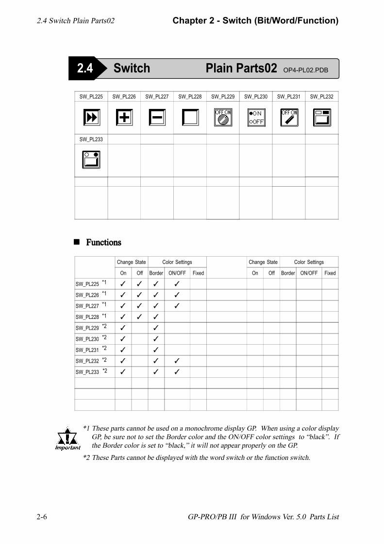
SW_PL225 SW_PL226 SW_PL227 SW_PL228 SW_PL229 SW_PL230 SW_PL231 SW_PL232
SW_PL233
Change State Color Settings
On Off Border ON/OFF Fixed
SW_PL225 ✓ ✓ ✓ ✓
SW_PL226 ✓ ✓ ✓ ✓
SW_PL227 ✓ ✓ ✓ ✓
SW_PL228 ✓ ✓ ✓
SW_PL229* ✓ ✓
SW_PL230* ✓ ✓
SW_PL231* ✓ ✓
SW_PL232* ✓ ✓ ✓
SW_PL233* ✓ ✓ ✓
Change State Color Settings
On Off Border ON/OFF Fixed
2.4 Switch Plain Parts02
2.4 Switch Plain Parts02 OP4-PL02.PDB
*1
*1
*1
*1
*2
*2
*2
*2
*2
*1 These parts cannot be used on a monochrome display GP. When using a color displayGP, be sure not to set the Border color and the ON/OFF color settings to �black�. Ifthe Border color is set to �black,� it will not appear properly on the GP.
*2 These Parts cannot be displayed with the word switch or the function switch.
2-7
Chapter 2 - Switch (Bit/Word/Function)
GP-PRO/PB III for Windows Ver. 5.0 Parts List
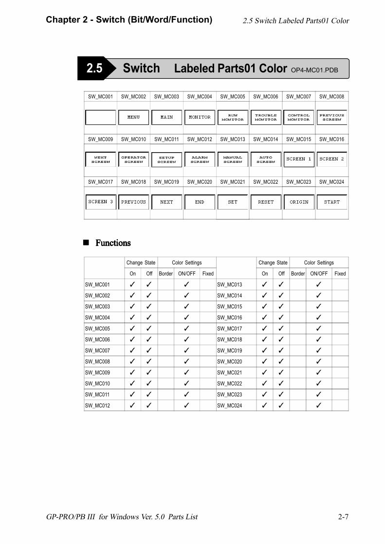
SW_MC001 SW_MC002 SW_MC003 SW_MC004 SW_MC005 SW_MC006 SW_MC007 SW_MC008
SW_MC009 SW_MC010 SW_MC011 SW_MC012 SW_MC013 SW_MC014 SW_MC015 SW_MC016
SW_MC017 SW_MC018 SW_MC019 SW_MC020 SW_MC021 SW_MC022 SW_MC023 SW_MC024
! ! ! ! ! FunctionsFunctionsFunctionsFunctionsFunctions
Change State Color Settings
On Off Border ON/OFF Fixed
SW_MC001 ✓ ✓ ✓
SW_MC002 ✓ ✓ ✓
SW_MC003 ✓ ✓ ✓
SW_MC004 ✓ ✓ ✓
SW_MC005 ✓ ✓ ✓
SW_MC006 ✓ ✓ ✓
SW_MC007 ✓ ✓ ✓
SW_MC008 ✓ ✓ ✓
SW_MC009 ✓ ✓ ✓
SW_MC010 ✓ ✓ ✓
SW_MC011 ✓ ✓ ✓
SW_MC012 ✓ ✓ ✓
Change State Color Settings
On Off Border ON/OFF Fixed
SW_MC013 ✓ ✓ ✓
SW_MC014 ✓ ✓ ✓
SW_MC015 ✓ ✓ ✓
SW_MC016 ✓ ✓ ✓
SW_MC017 ✓ ✓ ✓
SW_MC018 ✓ ✓ ✓
SW_MC019 ✓ ✓ ✓
SW_MC020 ✓ ✓ ✓
SW_MC021 ✓ ✓ ✓
SW_MC022 ✓ ✓ ✓
SW_MC023 ✓ ✓ ✓
SW_MC024 ✓ ✓ ✓
2.5 Switch Labeled Parts01 Color
2.5 Switch Labeled Parts01 Color OP4-MC01.PDB
2-8
Chapter 2 - Switch (Bit/Word/Function)
GP-PRO/PB III for Windows Ver. 5.0 Parts List
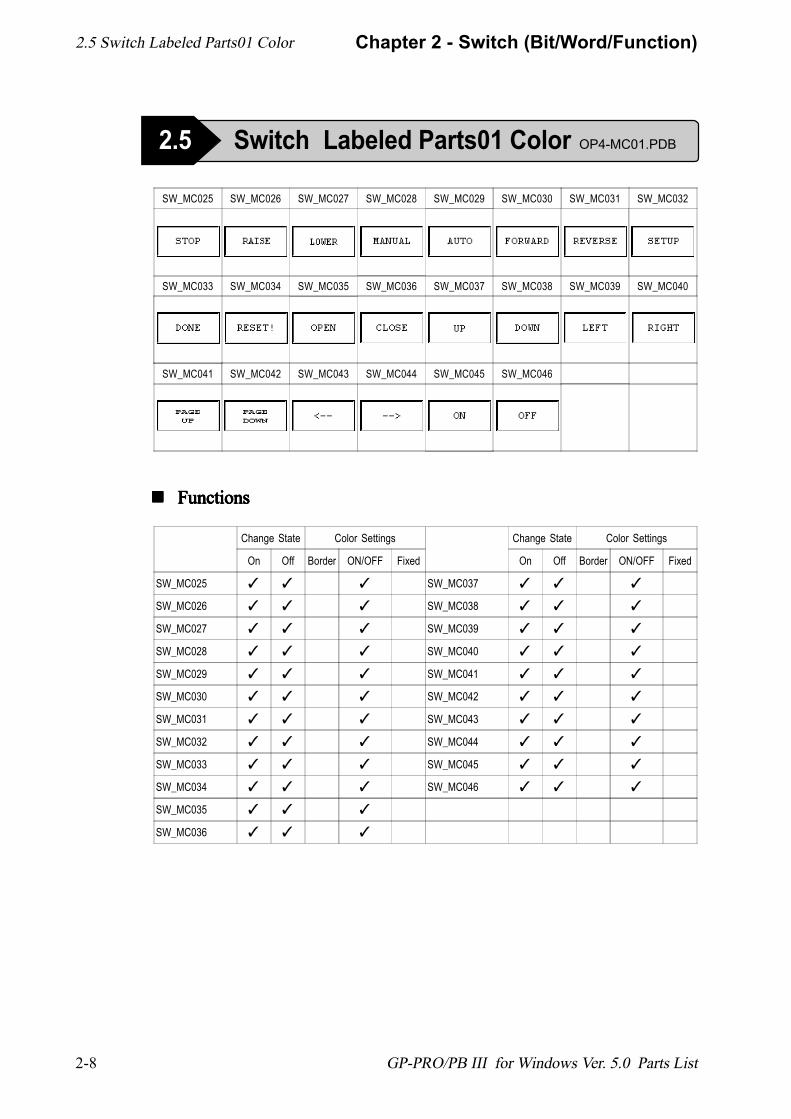
SW_MC025 SW_MC026 SW_MC027 SW_MC028 SW_MC029 SW_MC030 SW_MC031 SW_MC032
SW_MC033 SW_MC034 SW_MC035 SW_MC036 SW_MC037 SW_MC038 SW_MC039 SW_MC040
SW_MC041 SW_MC042 SW_MC043 SW_MC044 SW_MC045 SW_MC046
! ! ! ! ! FunctionsFunctionsFunctionsFunctionsFunctions
Change State Color Settings
On Off Border ON/OFF Fixed
SW_MC025 ✓ ✓ ✓
SW_MC026 ✓ ✓ ✓
SW_MC027 ✓ ✓ ✓
SW_MC028 ✓ ✓ ✓
SW_MC029 ✓ ✓ ✓
SW_MC030 ✓ ✓ ✓
SW_MC031 ✓ ✓ ✓
SW_MC032 ✓ ✓ ✓
SW_MC033 ✓ ✓ ✓
SW_MC034 ✓ ✓ ✓
SW_MC035 ✓ ✓ ✓
SW_MC036 ✓ ✓ ✓
Change State Color Settings
On Off Border ON/OFF Fixed
SW_MC037 ✓ ✓ ✓
SW_MC038 ✓ ✓ ✓
SW_MC039 ✓ ✓ ✓
SW_MC040 ✓ ✓ ✓
SW_MC041 ✓ ✓ ✓
SW_MC042 ✓ ✓ ✓
SW_MC043 ✓ ✓ ✓
SW_MC044 ✓ ✓ ✓
SW_MC045 ✓ ✓ ✓
SW_MC046 ✓ ✓ ✓
2.5 Switch Labeled Parts01 Color OP4-MC01.PDB
2.5 Switch Labeled Parts01 Color
2-9
Chapter 2 - Switch (Bit/Word/Function)
GP-PRO/PB III for Windows Ver. 5.0 Parts List
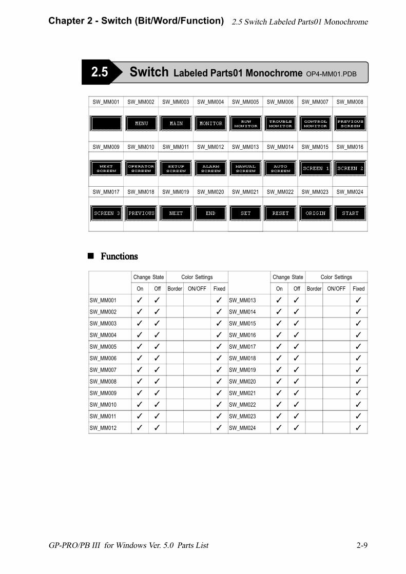
SW_MM001 SW_MM002 SW_MM003 SW_MM004 SW_MM005 SW_MM006 SW_MM007 SW_MM008
SW_MM009 SW_MM010 SW_MM011 SW_MM012 SW_MM013 SW_MM014 SW_MM015 SW_MM016
SW_MM017 SW_MM018 SW_MM019 SW_MM020 SW_MM021 SW_MM022 SW_MM023 SW_MM024
! ! ! ! ! FunctionsFunctionsFunctionsFunctionsFunctions
Change State Color Settings
On Off Border ON/OFF Fixed
SW_MM001 ✓ ✓ ✓
SW_MM002 ✓ ✓ ✓
SW_MM003 ✓ ✓ ✓
SW_MM004 ✓ ✓ ✓
SW_MM005 ✓ ✓ ✓
SW_MM006 ✓ ✓ ✓
SW_MM007 ✓ ✓ ✓
SW_MM008 ✓ ✓ ✓
SW_MM009 ✓ ✓ ✓
SW_MM010 ✓ ✓ ✓
SW_MM011 ✓ ✓ ✓
SW_MM012 ✓ ✓ ✓
Change State Color Settings
On Off Border ON/OFF Fixed
SW_MM013 ✓ ✓ ✓
SW_MM014 ✓ ✓ ✓
SW_MM015 ✓ ✓ ✓
SW_MM016 ✓ ✓ ✓
SW_MM017 ✓ ✓ ✓
SW_MM018 ✓ ✓ ✓
SW_MM019 ✓ ✓ ✓
SW_MM020 ✓ ✓ ✓
SW_MM021 ✓ ✓ ✓
SW_MM022 ✓ ✓ ✓
SW_MM023 ✓ ✓ ✓
SW_MM024 ✓ ✓ ✓
2.5 Switch Labeled Parts01 Monochrome
2.5 Switch Labeled Parts01 Monochrome OP4-MM01.PDB
2-10
Chapter 2 - Switch (Bit/Word/Function)
GP-PRO/PB III for Windows Ver. 5.0 Parts List
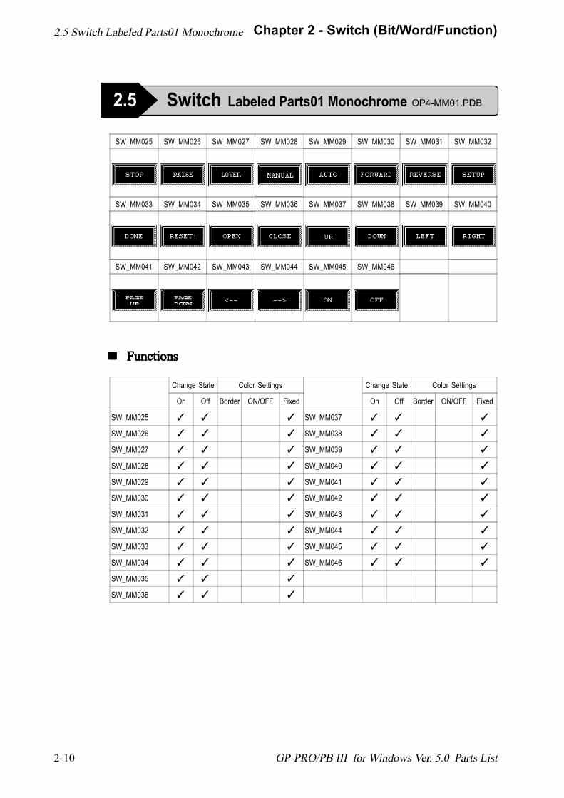
! ! ! ! ! FunctionsFunctionsFunctionsFunctionsFunctions
SW_MM025 SW_MM026 SW_MM027 SW_MM028 SW_MM029 SW_MM030 SW_MM031 SW_MM032
SW_MM033 SW_MM034 SW_MM035 SW_MM036 SW_MM037 SW_MM038 SW_MM039 SW_MM040
SW_MM041 SW_MM042 SW_MM043 SW_MM044 SW_MM045 SW_MM046
Change State Color Settings
On Off Border ON/OFF Fixed
SW_MM025 ✓ ✓ ✓
SW_MM026 ✓ ✓ ✓
SW_MM027 ✓ ✓ ✓
SW_MM028 ✓ ✓ ✓
SW_MM029 ✓ ✓ ✓
SW_MM030 ✓ ✓ ✓
SW_MM031 ✓ ✓ ✓
SW_MM032 ✓ ✓ ✓
SW_MM033 ✓ ✓ ✓
SW_MM034 ✓ ✓ ✓
SW_MM035 ✓ ✓ ✓
SW_MM036 ✓ ✓ ✓
Change State Color Settings
On Off Border ON/OFF Fixed
SW_MM037 ✓ ✓ ✓
SW_MM038 ✓ ✓ ✓
SW_MM039 ✓ ✓ ✓
SW_MM040 ✓ ✓ ✓
SW_MM041 ✓ ✓ ✓
SW_MM042 ✓ ✓ ✓
SW_MM043 ✓ ✓ ✓
SW_MM044 ✓ ✓ ✓
SW_MM045 ✓ ✓ ✓
SW_MM046 ✓ ✓ ✓
2.5 Switch Labeled Parts01 Monochrome
2.5 Switch Labeled Parts01 Monochrome OP4-MM01.PDB
2-11
Chapter 2 - Switch (Bit/Word/Function)
GP-PRO/PB III for Windows Ver. 5.0 Parts List
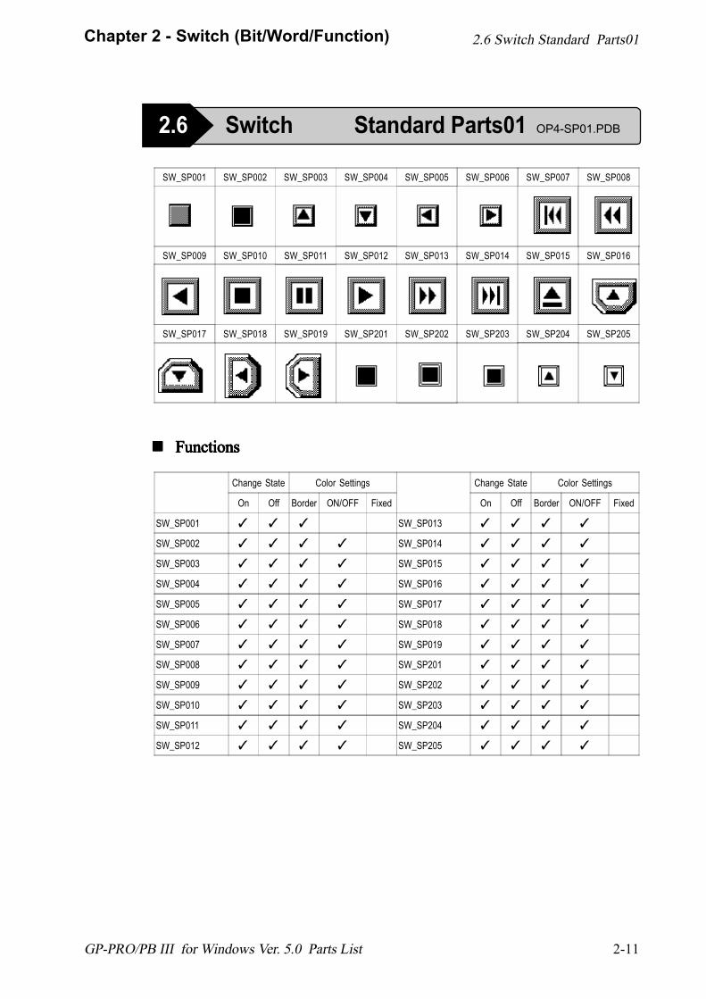
SW_SP001 SW_SP002 SW_SP003 SW_SP004 SW_SP005 SW_SP006 SW_SP007 SW_SP008
SW_SP009 SW_SP010 SW_SP011 SW_SP012 SW_SP013 SW_SP014 SW_SP015 SW_SP016
SW_SP017 SW_SP018 SW_SP019 SW_SP201 SW_SP202 SW_SP203 SW_SP204 SW_SP205
! ! ! ! ! FunctionsFunctionsFunctionsFunctionsFunctions
Change State Color Settings
On Off Border ON/OFF Fixed
SW_SP001 ✓ ✓ ✓
SW_SP002 ✓ ✓ ✓ ✓
SW_SP003 ✓ ✓ ✓ ✓
SW_SP004 ✓ ✓ ✓ ✓
SW_SP005 ✓ ✓ ✓ ✓
SW_SP006 ✓ ✓ ✓ ✓
SW_SP007 ✓ ✓ ✓ ✓
SW_SP008 ✓ ✓ ✓ ✓
SW_SP009 ✓ ✓ ✓ ✓
SW_SP010 ✓ ✓ ✓ ✓
SW_SP011 ✓ ✓ ✓ ✓
SW_SP012 ✓ ✓ ✓ ✓
Change State Color Settings
On Off Border ON/OFF Fixed
SW_SP013 ✓ ✓ ✓ ✓
SW_SP014 ✓ ✓ ✓ ✓
SW_SP015 ✓ ✓ ✓ ✓
SW_SP016 ✓ ✓ ✓ ✓
SW_SP017 ✓ ✓ ✓ ✓
SW_SP018 ✓ ✓ ✓ ✓
SW_SP019 ✓ ✓ ✓ ✓
SW_SP201 ✓ ✓ ✓ ✓
SW_SP202 ✓ ✓ ✓ ✓
SW_SP203 ✓ ✓ ✓ ✓
SW_SP204 ✓ ✓ ✓ ✓
SW_SP205 ✓ ✓ ✓ ✓
2.6 Switch Standard Parts01
2.6 Switch Standard Parts01 OP4-SP01.PDB
2-12
Chapter 2 - Switch (Bit/Word/Function)
GP-PRO/PB III for Windows Ver. 5.0 Parts List
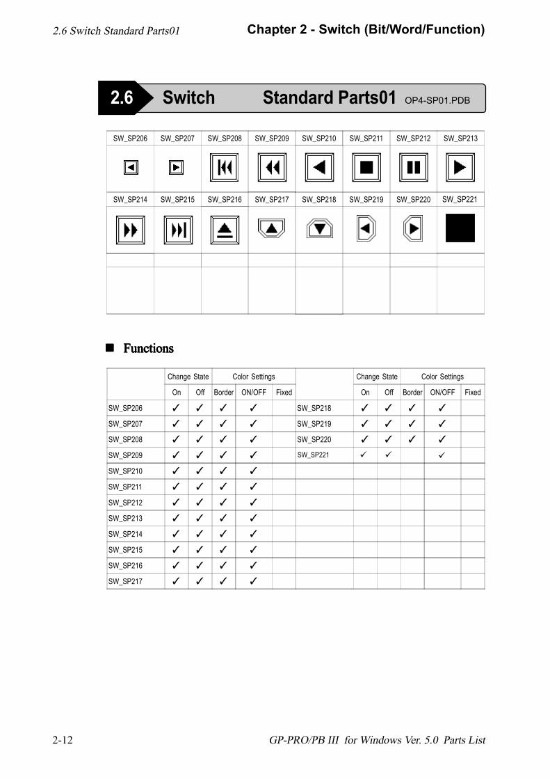
SW_SP206 SW_SP207 SW_SP208 SW_SP209 SW_SP210 SW_SP211 SW_SP212 SW_SP213
SW_SP214 SW_SP215 SW_SP216 SW_SP217 SW_SP218 SW_SP219 SW_SP220
! ! ! ! ! FunctionsFunctionsFunctionsFunctionsFunctions
Change State Color Settings
On Off Border ON/OFF Fixed
SW_SP206 ✓ ✓ ✓ ✓
SW_SP207 ✓ ✓ ✓ ✓
SW_SP208 ✓ ✓ ✓ ✓
SW_SP209 ✓ ✓ ✓ ✓
SW_SP210 ✓ ✓ ✓ ✓
SW_SP211 ✓ ✓ ✓ ✓
SW_SP212 ✓ ✓ ✓ ✓
SW_SP213 ✓ ✓ ✓ ✓
SW_SP214 ✓ ✓ ✓ ✓
SW_SP215 ✓ ✓ ✓ ✓
SW_SP216 ✓ ✓ ✓ ✓
SW_SP217 ✓ ✓ ✓ ✓
Change State Color Settings
On Off Border ON/OFF Fixed
SW_SP218 ✓ ✓ ✓ ✓
SW_SP219 ✓ ✓ ✓ ✓
SW_SP220 ✓ ✓ ✓ ✓
2.6 Switch Standard Parts01
2.6 Switch Standard Parts01 OP4-SP01.PDB
SW_SP221
SW_SP221 ###
3-1
Chapter 3 - Toggle Switches
GP-PRO/PB III for Windows Ver. 5.0 Parts List
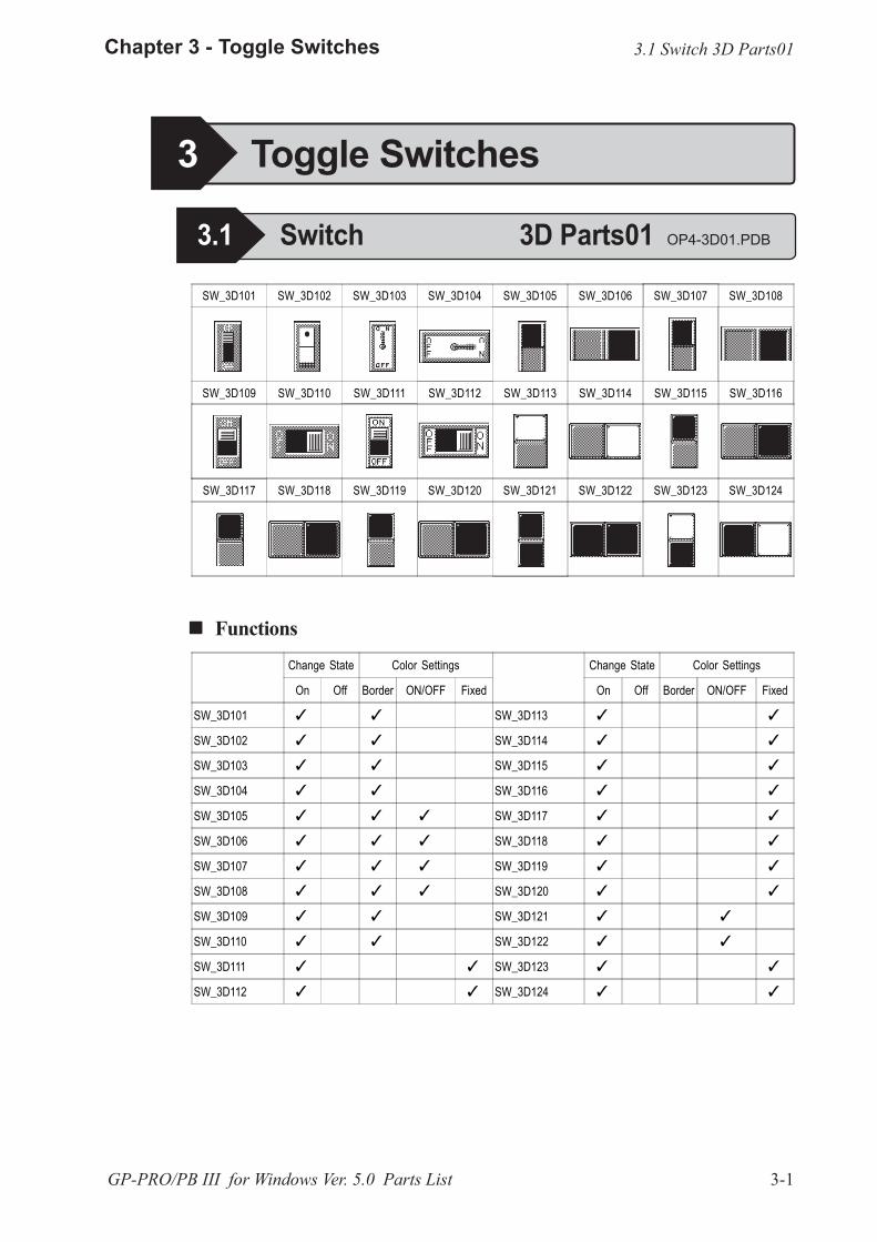
SW_3D101 SW_3D102 SW_3D103 SW_3D104 SW_3D105 SW_3D106 SW_3D107 SW_3D108
SW_3D109 SW_3D110 SW_3D111 SW_3D112 SW_3D113 SW_3D114 SW_3D115 SW_3D116
SW_3D117 SW_3D118 SW_3D119 SW_3D120 SW_3D121 SW_3D122 SW_3D123 SW_3D124
Change State Color Settings
On Off Border ON/OFF Fixed
SW_3D101 � �
SW_3D102 � �
SW_3D103 � �
SW_3D104 � �
SW_3D105 � � �
SW_3D106 � � �
SW_3D107 � � �
SW_3D108 � � �
SW_3D109 � �
SW_3D110 � �
SW_3D111 � �
SW_3D112 � �
Change State Color Settings
On Off Border ON/OFF Fixed
SW_3D113 � �
SW_3D114 � �
SW_3D115 � �
SW_3D116 � �
SW_3D117 � �
SW_3D118 � �
SW_3D119 � �
SW_3D120 � �
SW_3D121 � �
SW_3D122 � �
SW_3D123 � �
SW_3D124 � �
3 Toggle Switches
3.1 Switch 3D Parts01 OP4-3D01.PDB
3.1 Switch 3D Parts01
! ! ! ! ! Functions
3-2
Chapter 3 - Toggle Switches
GP-PRO/PB III for Windows Ver. 5.0 Parts List
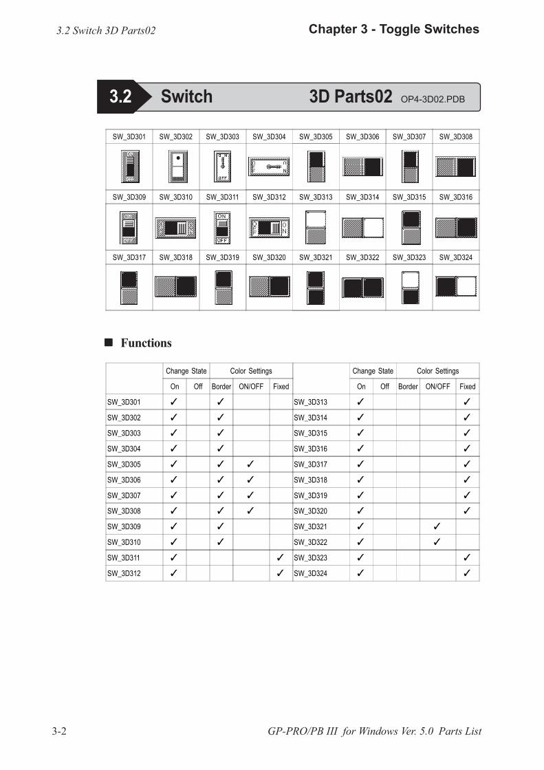
SW_3D301 SW_3D302 SW_3D303 SW_3D304 SW_3D305 SW_3D306 SW_3D307 SW_3D308
SW_3D309 SW_3D310 SW_3D311 SW_3D312 SW_3D313 SW_3D314 SW_3D315 SW_3D316
SW_3D317 SW_3D318 SW_3D319 SW_3D320 SW_3D321 SW_3D322 SW_3D323 SW_3D324
Change State Color Settings
On Off Border ON/OFF Fixed
SW_3D301 � �
SW_3D302 � �
SW_3D303 � �
SW_3D304 � �
SW_3D305 � � �
SW_3D306 � � �
SW_3D307 � � �
SW_3D308 � � �
SW_3D309 � �
SW_3D310 � �
SW_3D311 � �
SW_3D312 � �
Change State Color Settings
On Off Border ON/OFF Fixed
SW_3D313 � �
SW_3D314 � �
SW_3D315 � �
SW_3D316 � �
SW_3D317 � �
SW_3D318 � �
SW_3D319 � �
SW_3D320 � �
SW_3D321 � �
SW_3D322 � �
SW_3D323 � �
SW_3D324 � �
3.2 Switch 3D Parts02
3.2 Switch 3D Parts02 OP4-3D02.PDB
! ! ! ! ! Functions
3-3
Chapter 3 - Toggle Switches
GP-PRO/PB III for Windows Ver. 5.0 Parts List
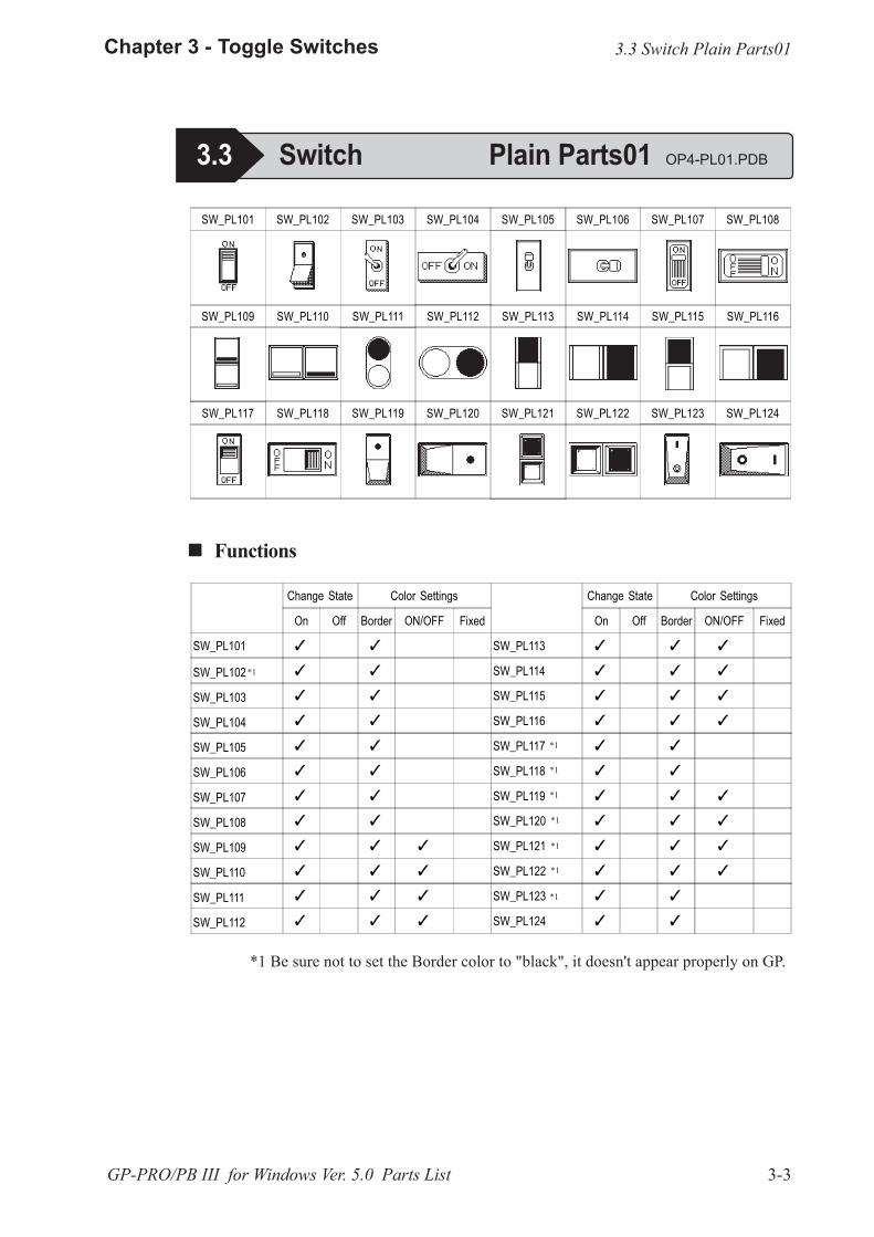
SW_PL101 SW_PL102 SW_PL103 SW_PL104 SW_PL105 SW_PL106 SW_PL107 SW_PL108
SW_PL109 SW_PL110 SW_PL111 SW_PL112 SW_PL113 SW_PL114 SW_PL115 SW_PL116
SW_PL117 SW_PL118 SW_PL119 SW_PL120 SW_PL121 SW_PL122 SW_PL123 SW_PL124
Change State Color Settings
On Off Border ON/OFF Fixed
SW_PL101 � �
SW_PL102 � �
SW_PL103 � �
SW_PL104 � �
SW_PL105 � �
SW_PL106 � �
SW_PL107 � �
SW_PL108 � �
SW_PL109 � � �
SW_PL110 � � �
SW_PL111 � � �
SW_PL112 � � �
Change State Color Settings
On Off Border ON/OFF Fixed
SW_PL113 � � �
SW_PL114 � � �
SW_PL115 � � �
SW_PL116 � � �
SW_PL117 � �
SW_PL118 � �
SW_PL119 � � �
SW_PL120 � � �
SW_PL121 � � �
SW_PL122 � � �
SW_PL123 � �
SW_PL124 � �
3.3 Switch Plain Parts01
! ! ! ! ! Functions
3.3 Switch Plain Parts01 OP4-PL01.PDB
*1
*1
*1
*1
*1
*1
*1
*1
*1 Be sure not to set the Border color to "black", it doesn't appear properly on GP.
3-4
Chapter 3 - Toggle Switches
GP-PRO/PB III for Windows Ver. 5.0 Parts List
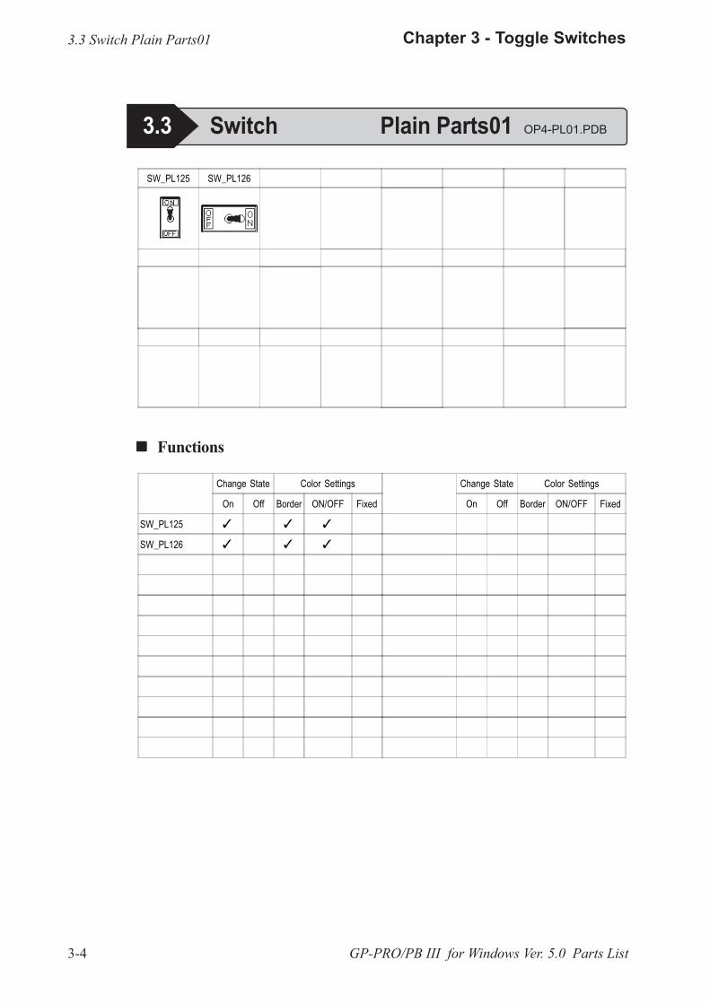
SW_PL125 SW_PL126
Change State Color Settings
On Off Border ON/OFF Fixed
SW_PL125 � � �
SW_PL126 � � �
Change State Color Settings
On Off Border ON/OFF Fixed
3.3 Switch Plain Parts01
! ! ! ! ! Functions
3.3 Switch Plain Parts01 OP4-PL01.PDB

3-5
Chapter 3 - Toggle Switches
GP-PRO/PB III for Windows Ver. 5.0 Parts List
SW_PL301 SW_PL302 SW_PL303 SW_PL304 SW_PL305 SW_PL306 SW_PL307 SW_PL308
SW_PL309 SW_PL310 SW_PL311 SW_PL312 SW_PL313 SW_PL314 SW_PL315 SW_PL316
SW_PL317 SW_PL318 SW_PL319 SW_PL320
Change State Color Settings
On Off Border ON/OFF Fixed
SW_PL301 � �
SW_PL302 � �
SW_PL303 � �
SW_PL304 � �
SW_PL305 � � �
SW_PL306 � � �
SW_PL307 � � �
SW_PL308 � � �
SW_PL309 � � �
SW_PL310 � � �
SW_PL311 � �
SW_PL312 � �
Change State Color Settings
On Off Border ON/OFF Fixed
SW_PL313 � � �
SW_PL314 � � �
SW_PL315 � � �
SW_PL316 � � �
SW_PL317 � �
SW_PL318 � �
SW_PL319 � � �
SW_PL320 � � �
! ! ! ! ! Functions
3.4 Switch Plain Parts02
3.4 Switch Plain Parts02 OP4-PL02.PDB
3-6
Chapter 3 - Toggle Switches
GP-PRO/PB III for Windows Ver. 5.0 Parts List
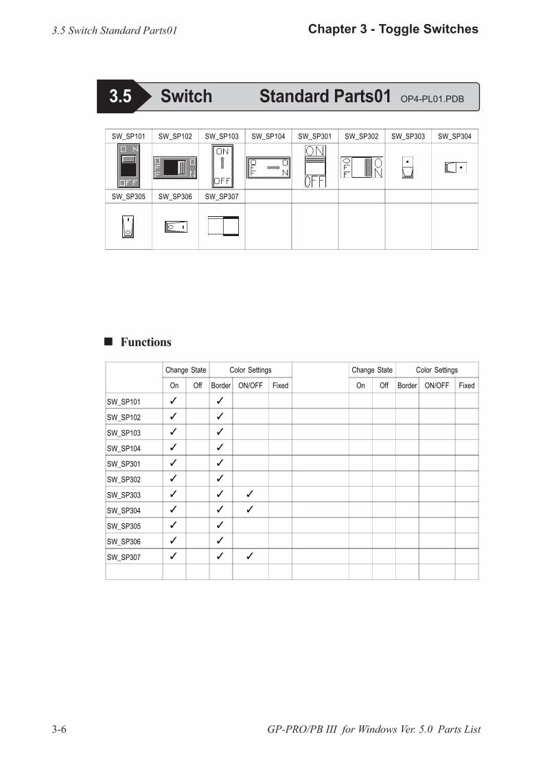
SW_SP101 SW_SP102 SW_SP103 SW_SP104 SW_SP301 SW_SP302 SW_SP303 SW_SP304
SW_SP305 SW_SP306 SW_SP307
Change State Color Settings
On Off Border ON/OFF Fixed
Change State Color Settings
On Off Border ON/OFF Fixed
SW_SP101 � �
SW_SP102 � �
SW_SP103 � �
SW_SP104 � �
SW_SP301 � �
SW_SP302 � �
SW_SP303 � � �
SW_SP304 � � �
SW_SP305 � �
SW_SP306 � �
SW_SP307 � � �
3.5 Switch Standard Parts01
! ! ! ! ! Functions
3.5 Switch Standard Parts01 OP4-PL01.PDB
4-1
Chapter 4 - Lamps
GP-PRO/PB III for Windows Ver. 5.0 Parts List
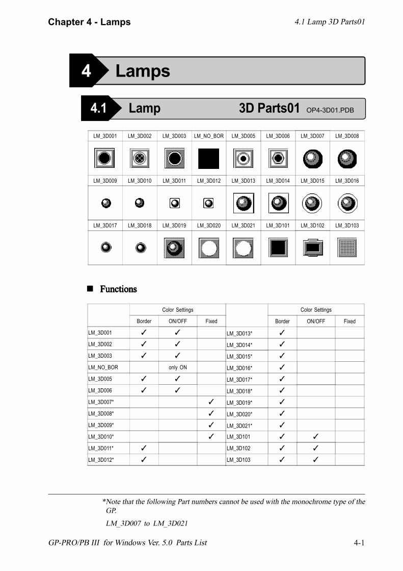
LM_3D001 LM_3D002 LM_3D003 LM_NO_BOR LM_3D005 LM_3D006 LM_3D007 LM_3D008
LM_3D009 LM_3D010 LM_3D011 LM_3D012 LM_3D013 LM_3D014 LM_3D015 LM_3D016
LM_3D017 LM_3D018 LM_3D019 LM_3D020 LM_3D021 LM_3D101 LM_3D102 LM_3D103
*Note that the following Part numbers cannot be used with the monochrome type of theGP.
LM_3D007 to LM_3D021
Color Settings
Border ON/OFF Fixed
LM_3D001 ✓ ✓
LM_3D002 ✓ ✓
LM_3D003 ✓ ✓
LM_NO_BOR only ON
LM_3D005 ✓ ✓
LM_3D006 ✓ ✓
LM_3D007* ✓
LM_3D008* ✓
LM_3D009* ✓
LM_3D010* ✓
LM_3D011* ✓
LM_3D012* ✓
Color Settings
Border ON/OFF Fixed
LM_3D013* ✓
LM_3D014* ✓
LM_3D015* ✓
LM_3D016* ✓
LM_3D017* ✓
LM_3D018* ✓
LM_3D019* ✓
LM_3D020* ✓
LM_3D021* ✓
LM_3D101 ✓ ✓
LM_3D102 ✓ ✓
LM_3D103 ✓ ✓
! ! ! ! ! FunctionsFunctionsFunctionsFunctionsFunctions
4.1 Lamp 3D Parts01
4 Lamps
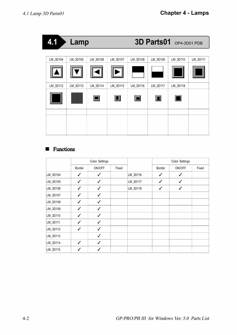
4.1 Lamp 3D Parts01 OP4-3D01.PDB
4-2
Chapter 4 - Lamps
GP-PRO/PB III for Windows Ver. 5.0 Parts List
Color Settings
Border ON/OFF Fixed
LM_3D104 ✓ ✓
LM_3D105 ✓ ✓
LM_3D106 ✓ ✓
LM_3D107 ✓ ✓
LM_3D108 ✓ ✓
LM_3D109 ✓ ✓
LM_3D110 ✓ ✓
LM_3D111 ✓ ✓
LM_3D112 ✓ ✓
LM_3D113 ✓
LM_3D114 ✓ ✓
LM_3D115 ✓ ✓
Color Settings
Border ON/OFF Fixed
LM_3D116 ✓ ✓
LM_3D117 ✓ ✓
LM_3D118 ✓ ✓
LM_3D104 LM_3D105 LM_3D106 LM_3D107 LM_3D108 LM_3D109 LM_3D110 LM_3D111
LM_3D112 LM_3D113 LM_3D114 LM_3D115 LM_3D116 LM_3D117 LM_3D118
4.1 Lamp 3D Parts01
! ! ! ! ! FunctionsFunctionsFunctionsFunctionsFunctions
4.1 Lamp 3D Parts01 OP4-3D01.PDB
4-3
Chapter 4 - Lamps
GP-PRO/PB III for Windows Ver. 5.0 Parts List
Color Settings
Border ON/OFF Fixed
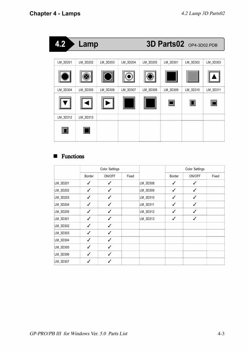
LM_3D201 ✓ ✓
LM_3D202 ✓ ✓
LM_3D203 ✓ ✓
LM_3D204 ✓ ✓
LM_3D205 ✓ ✓
LM_3D301 ✓ ✓
LM_3D302 ✓ ✓
LM_3D303 ✓ ✓
LM_3D304 ✓ ✓
LM_3D305 ✓ ✓
LM_3D306 ✓ ✓
LM_3D307 ✓ ✓
Color Settings
Border ON/OFF Fixed
LM_3D308 ✓ ✓
LM_3D309 ✓ ✓
LM_3D310 ✓ ✓
LM_3D311 ✓ ✓
LM_3D312 ✓ ✓
LM_3D313 ✓ ✓
LM_3D201 LM_3D202 LM_3D203 LM_3D204 LM_3D205 LM_3D301 LM_3D302 LM_3D303
LM_3D304 LM_3D305 LM_3D306 LM_3D307 LM_3D308 LM_3D309 LM_3D310 LM_3D311
LM_3D312 LM_3D313
4.2 Lamp 3D Parts02
! ! ! ! ! FunctionsFunctionsFunctionsFunctionsFunctions
4.2 Lamp 3D Parts02 OP4-3D02.PDB
4-4
Chapter 4 - Lamps
GP-PRO/PB III for Windows Ver. 5.0 Parts List
Color Settings
Border ON/OFF Fixed
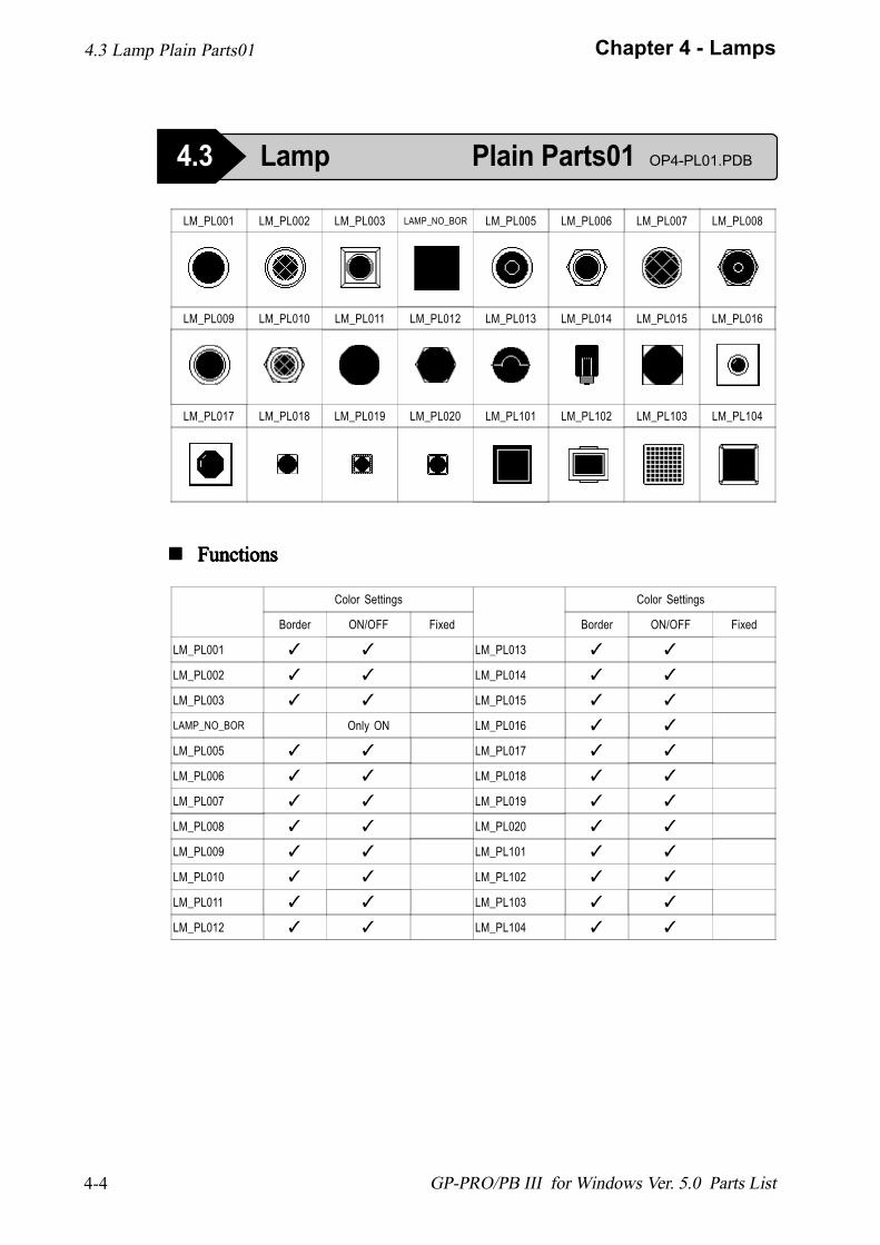
LM_PL001 ✓ ✓
LM_PL002 ✓ ✓
LM_PL003 ✓ ✓
LAMP_NO_BOR Only ON
LM_PL005 ✓ ✓
LM_PL006 ✓ ✓
LM_PL007 ✓ ✓
LM_PL008 ✓ ✓
LM_PL009 ✓ ✓
LM_PL010 ✓ ✓
LM_PL011 ✓ ✓
LM_PL012 ✓ ✓
Color Settings
Border ON/OFF Fixed
LM_PL013 ✓ ✓
LM_PL014 ✓ ✓
LM_PL015 ✓ ✓
LM_PL016 ✓ ✓
LM_PL017 ✓ ✓
LM_PL018 ✓ ✓
LM_PL019 ✓ ✓
LM_PL020 ✓ ✓
LM_PL101 ✓ ✓
LM_PL102 ✓ ✓
LM_PL103 ✓ ✓
LM_PL104 ✓ ✓
LM_PL001 LM_PL002 LM_PL003 LAMP_NO_BOR LM_PL005 LM_PL006 LM_PL007 LM_PL008
LM_PL009 LM_PL010 LM_PL011 LM_PL012 LM_PL013 LM_PL014 LM_PL015 LM_PL016
LM_PL017 LM_PL018 LM_PL019 LM_PL020 LM_PL101 LM_PL102 LM_PL103 LM_PL104
4.3 Lamp Plain Parts01
! ! ! ! ! FunctionsFunctionsFunctionsFunctionsFunctions
4.3 Lamp Plain Parts01 OP4-PL01.PDB
4-5
Chapter 4 - Lamps
GP-PRO/PB III for Windows Ver. 5.0 Parts List
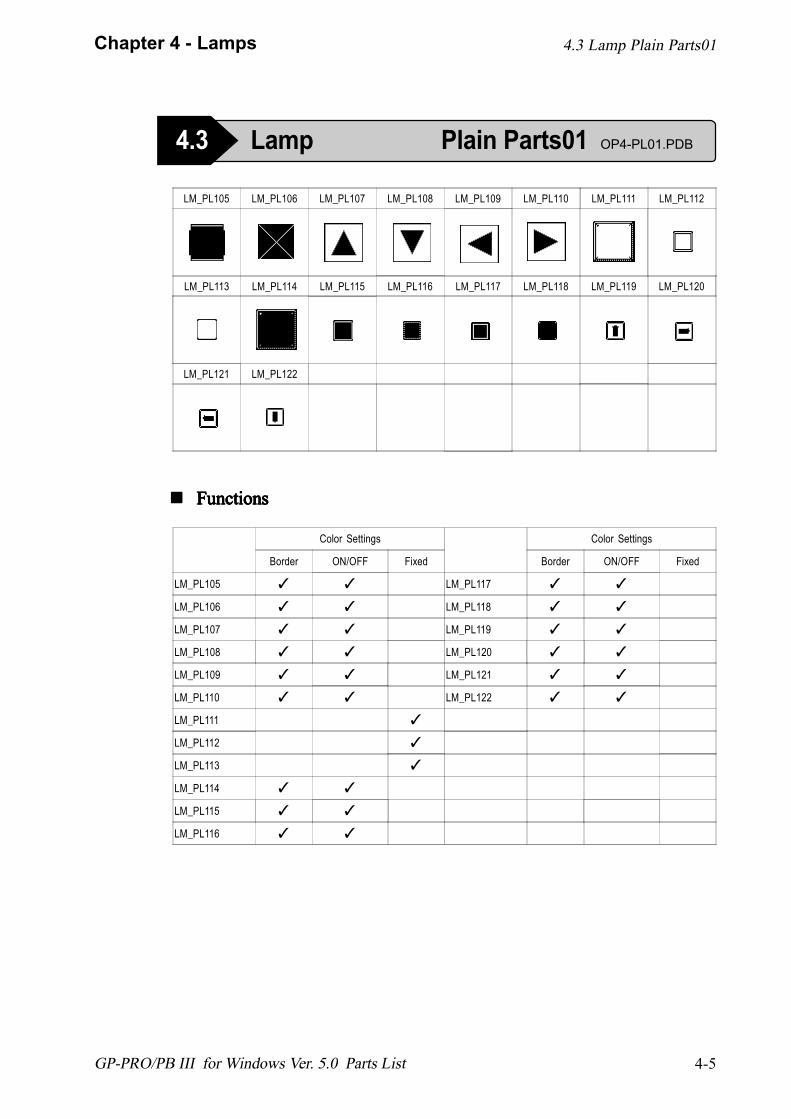
LM_PL105 LM_PL106 LM_PL107 LM_PL108 LM_PL109 LM_PL110 LM_PL111 LM_PL112
LM_PL113 LM_PL114 LM_PL115 LM_PL116 LM_PL117 LM_PL118 LM_PL119 LM_PL120
LM_PL121 LM_PL122
Color Settings
Border ON/OFF Fixed
LM_PL105 ✓ ✓
LM_PL106 ✓ ✓
LM_PL107 ✓ ✓
LM_PL108 ✓ ✓
LM_PL109 ✓ ✓
LM_PL110 ✓ ✓
LM_PL111 ✓
LM_PL112 ✓
LM_PL113 ✓
LM_PL114 ✓ ✓
LM_PL115 ✓ ✓
LM_PL116 ✓ ✓
Color Settings
Border ON/OFF Fixed
LM_PL117 ✓ ✓
LM_PL118 ✓ ✓
LM_PL119 ✓ ✓
LM_PL120 ✓ ✓
LM_PL121 ✓ ✓
LM_PL122 ✓ ✓
4.3 Lamp Plain Parts01
4.3 Lamp Plain Parts01 OP4-PL01.PDB
! ! ! ! ! FunctionsFunctionsFunctionsFunctionsFunctions
4-6
Chapter 4 - Lamps
GP-PRO/PB III for Windows Ver. 5.0 Parts List
Color Settings
Border ON/OFF Fixed
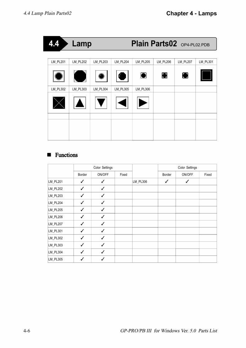
LM_PL201 ✓ ✓
LM_PL202 ✓ ✓
LM_PL203 ✓ ✓
LM_PL204 ✓ ✓
LM_PL205 ✓ ✓
LM_PL206 ✓ ✓
LM_PL207 ✓ ✓
LM_PL301 ✓ ✓
LM_PL302 ✓ ✓
LM_PL303 ✓ ✓
LM_PL304 ✓ ✓
LM_PL305 ✓ ✓
Color Settings
Border ON/OFF Fixed
LM_PL306 ✓ ✓
LM_PL201 LM_PL202 LM_PL203 LM_PL204 LM_PL205 LM_PL206 LM_PL207 LM_PL301
LM_PL302 LM_PL303 LM_PL304 LM_PL305 LM_PL306
4.4 Lamp Plain Parts02
4.4 Lamp Plain Parts02 OP4-PL02.PDB
! ! ! ! ! FunctionsFunctionsFunctionsFunctionsFunctions
4-7
Chapter 4 - Lamps
GP-PRO/PB III for Windows Ver. 5.0 Parts List
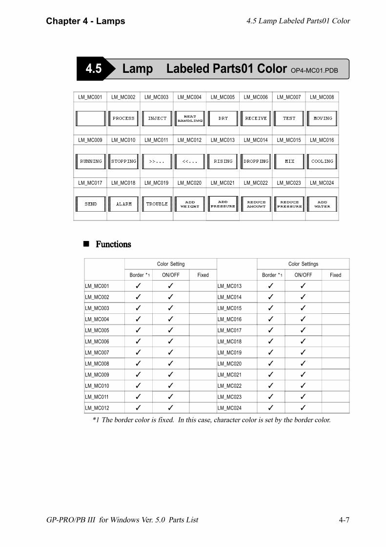
LM_MC001 LM_MC002 LM_MC003 LM_MC004 LM_MC005 LM_MC006 LM_MC007 LM_MC008
LM_MC009 LM_MC010 LM_MC011 LM_MC012 LM_MC013 LM_MC014 LM_MC015 LM_MC016
LM_MC017 LM_MC018 LM_MC019 LM_MC020 LM_MC021 LM_MC022 LM_MC023 LM_MC024
Color Setting
Border * ON/OFF Fixed
LM_MC001 ✓ ✓
LM_MC002 ✓ ✓
LM_MC003 ✓ ✓
LM_MC004 ✓ ✓
LM_MC005 ✓ ✓
LM_MC006 ✓ ✓
LM_MC007 ✓ ✓
LM_MC008 ✓ ✓
LM_MC009 ✓ ✓
LM_MC010 ✓ ✓
LM_MC011 ✓ ✓
LM_MC012 ✓ ✓
Color Settings
Border * ON/OFF Fixed
LM_MC013 ✓ ✓
LM_MC014 ✓ ✓
LM_MC015 ✓ ✓
LM_MC016 ✓ ✓
LM_MC017 ✓ ✓
LM_MC018 ✓ ✓
LM_MC019 ✓ ✓
LM_MC020 ✓ ✓
LM_MC021 ✓ ✓
LM_MC022 ✓ ✓
LM_MC023 ✓ ✓
LM_MC024 ✓ ✓
*1 The border color is fixed. In this case, character color is set by the border color.
4.5 Lamp Labeled Parts01 Color
4.5 Lamp Labeled Parts01 Color OP4-MC01.PDB
! ! ! ! ! FunctionsFunctionsFunctionsFunctionsFunctions
1 1
4-8
Chapter 4 - Lamps
GP-PRO/PB III for Windows Ver. 5.0 Parts List
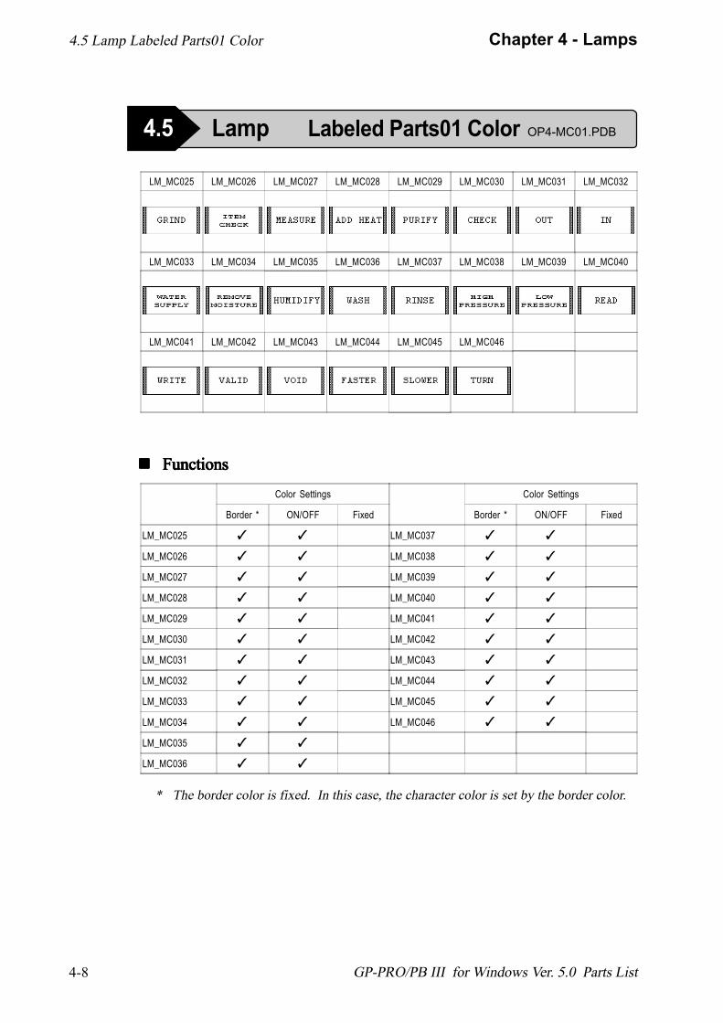
LM_MC025 LM_MC026 LM_MC027 LM_MC028 LM_MC029 LM_MC030 LM_MC031 LM_MC032
LM_MC033 LM_MC034 LM_MC035 LM_MC036 LM_MC037 LM_MC038 LM_MC039 LM_MC040
LM_MC041 LM_MC042 LM_MC043 LM_MC044 LM_MC045 LM_MC046
Color Settings
Border * ON/OFF Fixed
LM_MC025 ✓ ✓
LM_MC026 ✓ ✓
LM_MC027 ✓ ✓
LM_MC028 ✓ ✓
LM_MC029 ✓ ✓
LM_MC030 ✓ ✓
LM_MC031 ✓ ✓
LM_MC032 ✓ ✓
LM_MC033 ✓ ✓
LM_MC034 ✓ ✓
LM_MC035 ✓ ✓
LM_MC036 ✓ ✓
Color Settings
Border * ON/OFF Fixed
LM_MC037 ✓ ✓
LM_MC038 ✓ ✓
LM_MC039 ✓ ✓
LM_MC040 ✓ ✓
LM_MC041 ✓ ✓
LM_MC042 ✓ ✓
LM_MC043 ✓ ✓
LM_MC044 ✓ ✓
LM_MC045 ✓ ✓
LM_MC046 ✓ ✓
* The border color is fixed. In this case, the character color is set by the border color.
4.5 Lamp Labeled Parts01 Color
4.5 Lamp Labeled Parts01 Color OP4-MC01.PDB
! ! ! ! ! FunctionsFunctionsFunctionsFunctionsFunctions

4-9
Chapter 4 - Lamps
GP-PRO/PB III for Windows Ver. 5.0 Parts List
LM_MM001 LM_MM002 LM_MM003 LM_MM004 LM_MM005 LM_MM006 LM_MM007 LM_MM008
LM_MM009 LM_MM010 LM_MM011 LM_MM012 LM_MM013 LM_MM014 LM_MM015 LM_MM016
LM_MM017 LM_MM018 LM_MM019 LM_MM020 LM_MM021 LM_MM022 LM_MM023 LM_MM024
! ! ! ! ! FunctionsFunctionsFunctionsFunctionsFunctions
Color Settings
Border ON/OFF Fixed
LM_MM001 ✓
LM_MM002 ✓
LM_MM003 ✓
LM_MM004 ✓
LM_MM005 ✓
LM_MM006 ✓
LM_MM007 ✓
LM_MM008 ✓
LM_MM009 ✓
LM_MM010 ✓
LM_MM011 ✓
LM_MM012 ✓
Color Settings
Border ON/OFF Fixed
LM_MM013 ✓
LM_MM014 ✓
LM_MM015 ✓
LM_MM016 ✓
LM_MM017 ✓
LM_MM018 ✓
LM_MM019 ✓
LM_MM020 ✓
LM_MM021 ✓
LM_MM022 ✓
LM_MM023 ✓
LM_MM024 ✓
4.5 Lamp Labeled Parts01 Monochrome
4.5 Lamp Labeled Parts01 Monochrome OP4-MM01.PDB
4-10
Chapter 4 - Lamps
GP-PRO/PB III for Windows Ver. 5.0 Parts List
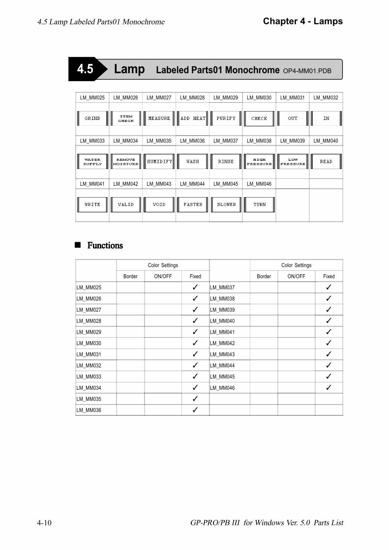
LM_MM025 LM_MM026 LM_MM027 LM_MM028 LM_MM029 LM_MM030 LM_MM031 LM_MM032
LM_MM033 LM_MM034 LM_MM035 LM_MM036 LM_MM037 LM_MM038 LM_MM039 LM_MM040
LM_MM041 LM_MM042 LM_MM043 LM_MM044 LM_MM045 LM_MM046
! ! ! ! ! FunctionsFunctionsFunctionsFunctionsFunctions
Color Settings
Border ON/OFF Fixed
LM_MM025 ✓
LM_MM026 ✓
LM_MM027 ✓
LM_MM028 ✓
LM_MM029 ✓
LM_MM030 ✓
LM_MM031 ✓
LM_MM032 ✓
LM_MM033 ✓
LM_MM034 ✓
LM_MM035 ✓
LM_MM036 ✓
Color Settings
Border ON/OFF Fixed
LM_MM037 ✓
LM_MM038 ✓
LM_MM039 ✓
LM_MM040 ✓
LM_MM041 ✓
LM_MM042 ✓
LM_MM043 ✓
LM_MM044 ✓
LM_MM045 ✓
LM_MM046 ✓
4.5 Lamp Labeled Parts01 Monochrome
4.5 Lamp Labeled Parts01 Monochrome OP4-MM01.PDB
4-11
Chapter 4 - Lamps
GP-PRO/PB III for Windows Ver. 5.0 Parts List
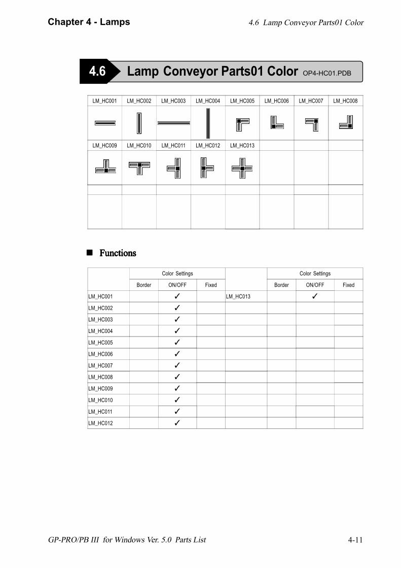
LM_HC001 LM_HC002 LM_HC003 LM_HC004 LM_HC005 LM_HC006 LM_HC007 LM_HC008
LM_HC009 LM_HC010 LM_HC011 LM_HC012 LM_HC013
! ! ! ! ! FunctionsFunctionsFunctionsFunctionsFunctions
Color Settings
Border ON/OFF Fixed
LM_HC001 ✓
LM_HC002 ✓
LM_HC003 ✓
LM_HC004 ✓
LM_HC005 ✓
LM_HC006 ✓
LM_HC007 ✓
LM_HC008 ✓
LM_HC009 ✓
LM_HC010 ✓
LM_HC011 ✓
LM_HC012 ✓
Color Settings
Border ON/OFF Fixed
LM_HC013 ✓
4.6 Lamp Conveyor Parts01 Color
4.6 Lamp Conveyor Parts01 Color OP4-HC01.PDB

4-12
Chapter 4 - Lamps
GP-PRO/PB III for Windows Ver. 5.0 Parts List
LM_HM001 LM_HM002 LM_HM003 LM_HM004 LM_HM005 LM_HM006 LM_HM007 LM_HM008
LM_HM009 LM_HM010 LM_HM011 LM_HM012 LM_HM013
! ! ! ! ! FunctionsFunctionsFunctionsFunctionsFunctions
Color Settings
Border ON/OFF Fixed
LM_HM001 ✓
LM_HM002 ✓
LM_HM003 ✓
LM_HM004 ✓
LM_HM005 ✓
LM_HM006 ✓
LM_HM007 ✓
LM_HM008 ✓
LM_HM009 ✓
LM_HM010 ✓
LM_HM011 ✓
LM_HM012 ✓
Color Settings
Border ON/OFF Fixed
LM_HM013 ✓
4.6 Lamp Conveyor Parts01 Monochrome
4.6 Lamp Conveyor Parts01 Monochrome OP4-HM01.PDB
4-13
Chapter 4 - Lamps
GP-PRO/PB III for Windows Ver. 5.0 Parts List
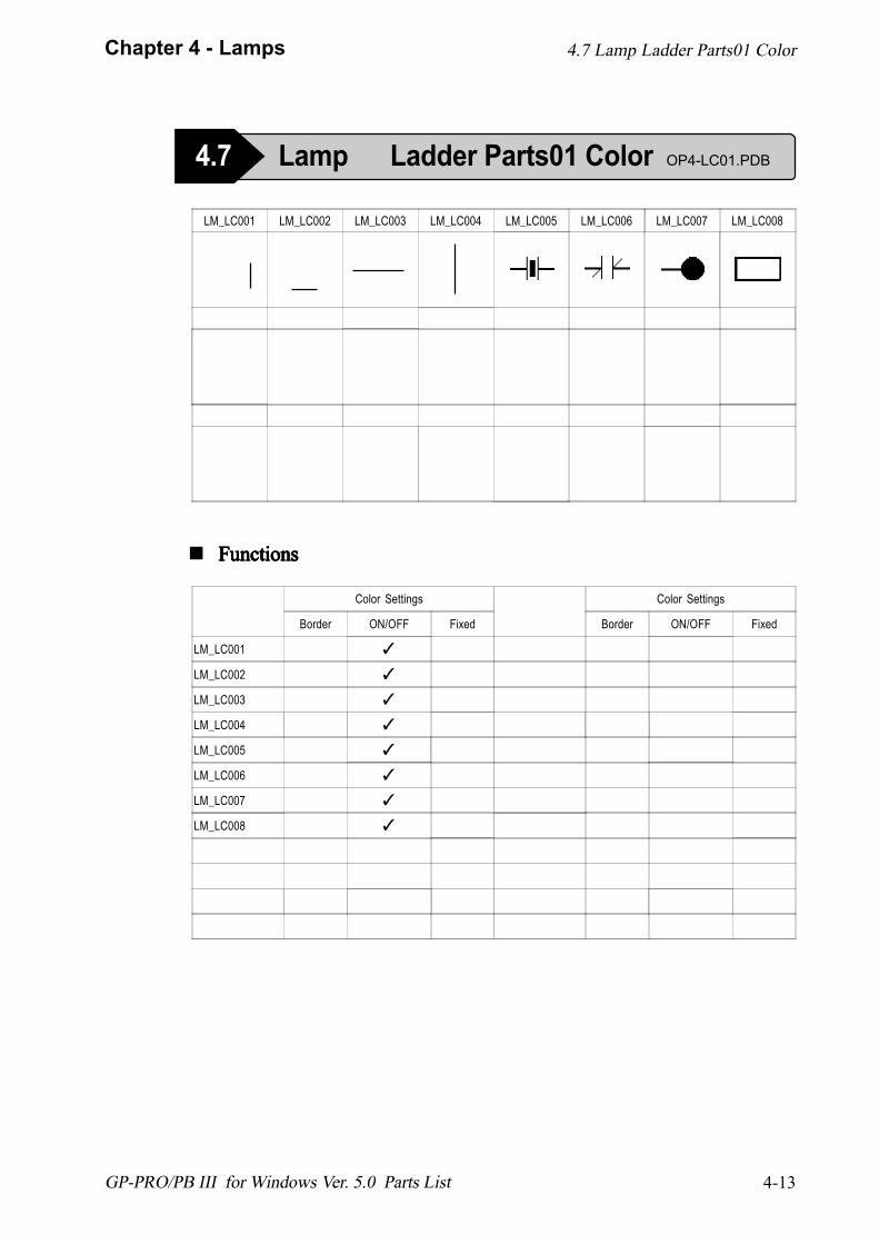
LM_LC001 LM_LC002 LM_LC003 LM_LC004 LM_LC005 LM_LC006 LM_LC007 LM_LC008
! ! ! ! ! FunctionsFunctionsFunctionsFunctionsFunctions
Color Settings
Border ON/OFF Fixed
LM_LC001 ✓
LM_LC002 ✓
LM_LC003 ✓
LM_LC004 ✓
LM_LC005 ✓
LM_LC006 ✓
LM_LC007 ✓
LM_LC008 ✓
Color Settings
Border ON/OFF Fixed
4.7 Lamp Ladder Parts01 Color
4.7 Lamp Ladder Parts01 Color OP4-LC01.PDB
4-14
Chapter 4 - Lamps
GP-PRO/PB III for Windows Ver. 5.0 Parts List
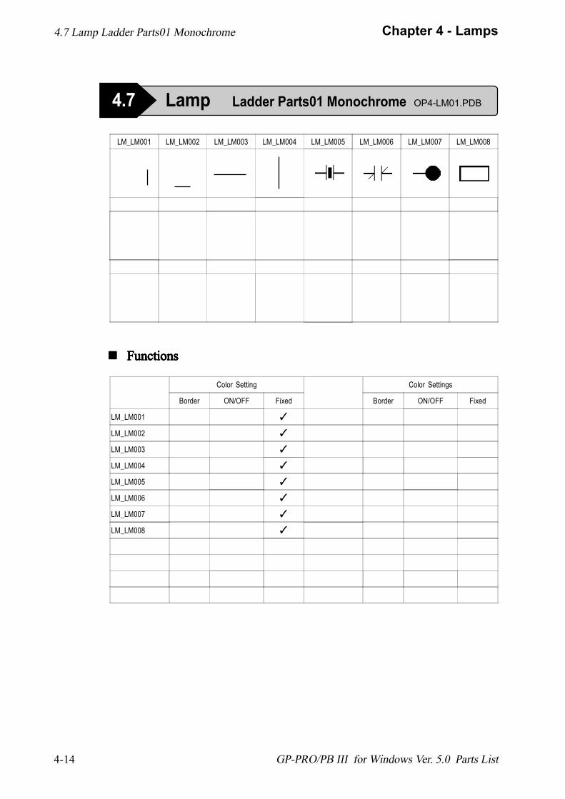
LM_LM001 LM_LM002 LM_LM003 LM_LM004 LM_LM005 LM_LM006 LM_LM007 LM_LM008
! ! ! ! ! FunctionsFunctionsFunctionsFunctionsFunctions
Color Setting
Border ON/OFF Fixed
LM_LM001 ✓
LM_LM002 ✓
LM_LM003 ✓
LM_LM004 ✓
LM_LM005 ✓
LM_LM006 ✓
LM_LM007 ✓
LM_LM008 ✓
Color Settings
Border ON/OFF Fixed
4.7 Lamp Ladder Parts01 Monochrome
4.7 Lamp Ladder Parts01 Monochrome OP4-LM01.PDB
4-15
Chapter 4 - Lamps
GP-PRO/PB III for Windows Ver. 5.0 Parts List
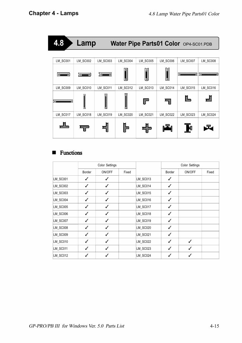
LM_SC001 LM_SC002 LM_SC003 LM_SC004 LM_SC005 LM_SC006 LM_SC007 LM_SC008
LM_SC009 LM_SC010 LM_SC011 LM_SC012 LM_SC013 LM_SC014 LM_SC015 LM_SC016
LM_SC017 LM_SC018 LM_SC019 LM_SC020 LM_SC021 LM_SC022 LM_SC023 LM_SC024
! ! ! ! ! FunctionsFunctionsFunctionsFunctionsFunctions
Color Settings
Border ON/OFF Fixed
LM_SC001 ✓ ✓
LM_SC002 ✓ ✓
LM_SC003 ✓ ✓
LM_SC004 ✓ ✓
LM_SC005 ✓ ✓
LM_SC006 ✓ ✓
LM_SC007 ✓ ✓
LM_SC008 ✓ ✓
LM_SC009 ✓ ✓
LM_SC010 ✓ ✓
LM_SC011 ✓ ✓
LM_SC012 ✓ ✓
Color Settings
Border ON/OFF Fixed
LM_SC013 ✓
LM_SC014 ✓
LM_SC015 ✓
LM_SC016 ✓
LM_SC017 ✓
LM_SC018 ✓
LM_SC019 ✓
LM_SC020 ✓
LM_SC021 ✓
LM_SC022 ✓ ✓
LM_SC023 ✓ ✓
LM_SC024 ✓ ✓
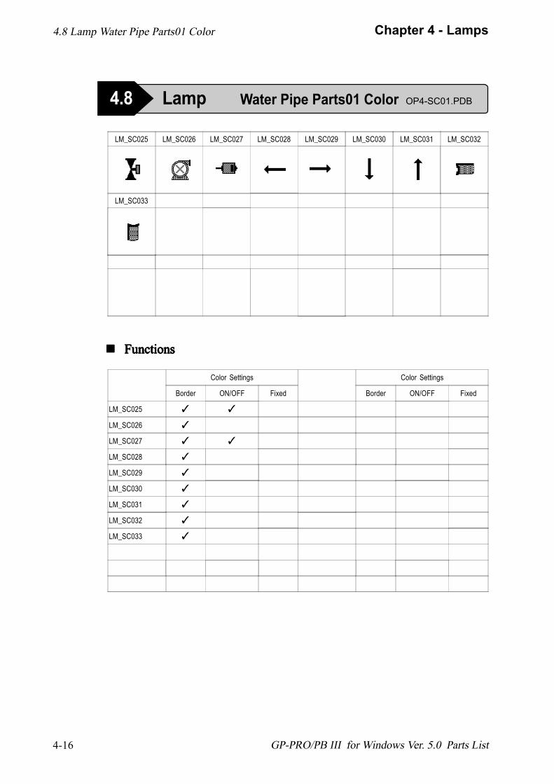
4.8 Lamp Water Pipe Parts01 Color
4.8 Lamp Water Pipe Parts01 Color OP4-SC01.PDB
4-16
Chapter 4 - Lamps
GP-PRO/PB III for Windows Ver. 5.0 Parts List
LM_SC025 LM_SC026 LM_SC027 LM_SC028 LM_SC029 LM_SC030 LM_SC031 LM_SC032
LM_SC033
! ! ! ! ! FunctionsFunctionsFunctionsFunctionsFunctions
Color Settings
Border ON/OFF Fixed
Color Settings
Border ON/OFF Fixed
LM_SC025 ✓ ✓
LM_SC026 ✓
LM_SC027 ✓ ✓
LM_SC028 ✓
LM_SC029 ✓
LM_SC030 ✓
LM_SC031 ✓
LM_SC032 ✓
LM_SC033 ✓
4.8 Lamp Water Pipe Parts01 Color
4.8 Lamp Water Pipe Parts01 Color OP4-SC01.PDB

4-17
Chapter 4 - Lamps
GP-PRO/PB III for Windows Ver. 5.0 Parts List
LM_SM001 LM_SM002 LM_SM003 LM_SM004 LM_SM005 LM_SM006 LM_SM007 LM_SM008
LM_SM009 LM_SM010 LM_SM011 LM_SM012 LM_SM013 LM_SM014 LM_SM015 LM_SM016
LM_SM017 LM_SM018 LM_SM019 LM_SM020 LM_SM021 LM_SM022 LM_SM023 LM_SM024
! ! ! ! ! FunctionsFunctionsFunctionsFunctionsFunctions
Color Settings
Border ON/OFF Fixed
LM_SM001 ✓
LM_SM002 ✓
LM_SM003 ✓
LM_SM004 ✓
LM_SM005 ✓
LM_SM006 ✓
LM_SM007 ✓
LM_SM008 ✓
LM_SM009 ✓
LM_SM010 ✓
LM_SM011 ✓
LM_SM012 ✓
Color Settings
Border ON/OFF Fixed
LM_SM013 ✓
LM_SM014 ✓
LM_SM015 ✓
LM_SM016 ✓
LM_SM017 ✓
LM_SM018 ✓
LM_SM019 ✓
LM_SM020 ✓
LM_SM021 ✓
LM_SM022 ✓
LM_SM023 ✓
LM_SM024 ✓
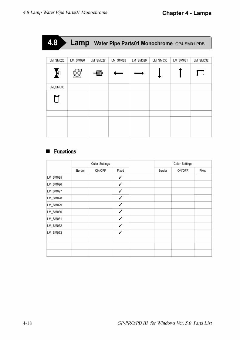
4.8 Lamp Water Pipe Parts01 Monochrome
4.8 Lamp Water Pipe Parts01 Monochrome OP4-SM01.PDB
4-18
Chapter 4 - Lamps
GP-PRO/PB III for Windows Ver. 5.0 Parts List
LM_SM025 LM_SM026 LM_SM027 LM_SM028 LM_SM029 LM_SM030 LM_SM031 LM_SM032
LM_SM033
! ! ! ! ! FunctionsFunctionsFunctionsFunctionsFunctions
Color Settings
Border ON/OFF Fixed
Color Settings
Border ON/OFF Fixed
LM_SM025 ✓
LM_SM026 ✓
LM_SM027 ✓
LM_SM028 ✓
LM_SM029 ✓
LM_SM030 ✓
LM_SM031 ✓
LM_SM032 ✓
LM_SM033 ✓
4.8 Lamp Water Pipe Parts01 Monochrome
4.8 Lamp Water Pipe Parts01 Monochrome OP4-SM01.PDB
4-19
Chapter 4 - Lamps
GP-PRO/PB III for Windows Ver. 5.0 Parts List
! ! ! ! ! FunctionsFunctionsFunctionsFunctionsFunctions
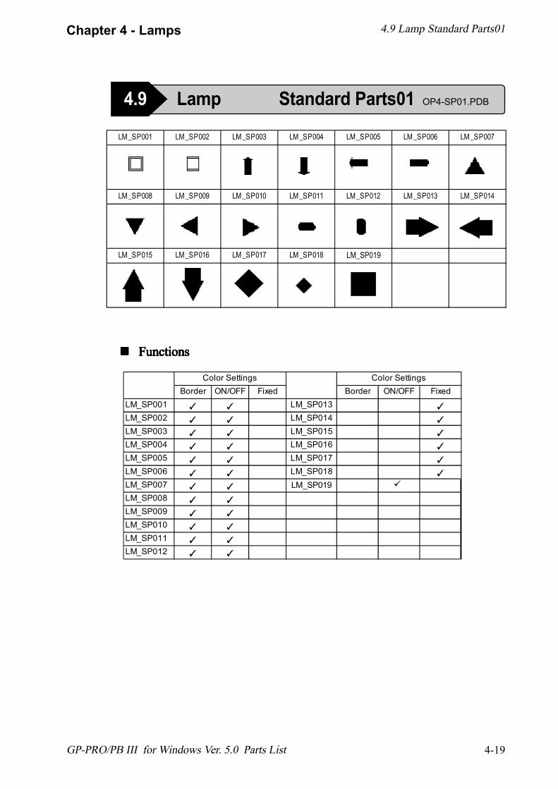
4.9 Lamp Standard Parts01
4.9 Lamp Standard Parts01 OP4-SP01.PDB
LM_SP001 LM_SP002 LM_SP003 LM_SP004 LM_SP005 LM_SP006 LM_SP007
LM_SP008 LM_SP009 LM_SP010 LM_SP011 LM_SP012 LM_SP013 LM_SP014
LM_SP015 LM_SP016 LM_SP017 LM_SP018
Border ON/OFF Fixed Border ON/OFF FixedLM_SP001 ✓ ✓ LM_SP013 ✓
LM_SP002 ✓ ✓ LM_SP014 ✓
LM_SP003 ✓ ✓ LM_SP015 ✓
LM_SP004 ✓ ✓ LM_SP016 ✓
LM_SP005 ✓ ✓ LM_SP017 ✓
LM_SP006 ✓ ✓ LM_SP018 ✓
LM_SP007 ✓ ✓
LM_SP008 ✓ ✓
LM_SP009 ✓ ✓
LM_SP010 ✓ ✓
LM_SP011 ✓ ✓
LM_SP012 ✓ ✓
Color Settings Color Settings
LM_SP019
LM_SP019 #

1234567890123456789012345678901212345678901123456789012345678901234567890121234567890112345678901234567890123456789012123456789011234567890123456789012345678901212345678901123456789012345678901234567890121234567890112345678901234567890123456789012123456789011234567890123456789012345678901212345678901123456789012345678901234567890121234567890112345678901234567890123456789012123456789011234567890123456789012345678901212345678901123456789012345678901234567890121234567890112345678901234567890123456789012123456789011234567890123456789012345678901212345678901123456789012345678901234567890121234567890112345678901234567890123456789012123456789011234567890123456789012345678901212345678901
MEMO
5-1
Chapter 5 - Bar Graphs
GP-PRO/PB III for Windows Ver. 5.0 Parts List
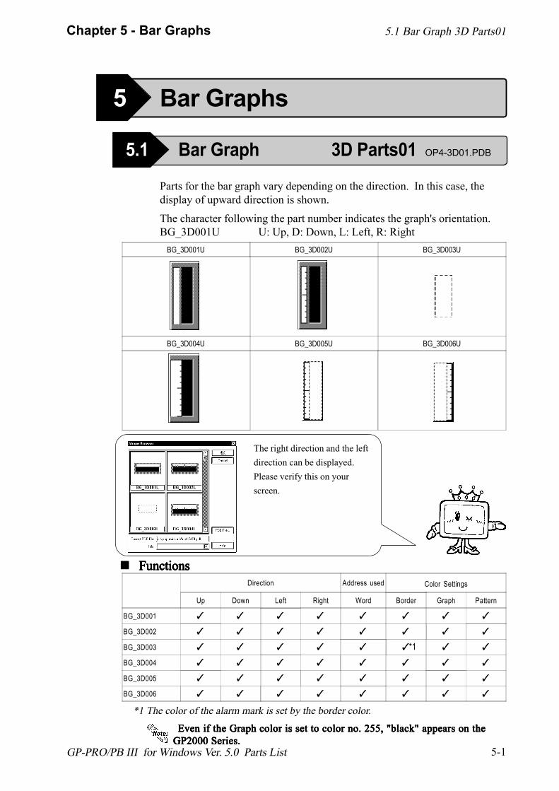
Parts for the bar graph vary depending on the direction. In this case, thedisplay of upward direction is shown.
The character following the part number indicates the graph's orientation.BG_3D001U U: Up, D: Down, L: Left, R: Right
BG_3D001U BG_3D002U BG_3D003U
BG_3D004U BG_3D005U BG_3D006U
The right direction and the leftdirection can be displayed.Please verify this on yourscreen.
! ! ! ! ! FunctionsFunctionsFunctionsFunctionsFunctionsDirection Address used Color Settings
Up Down Left Right Word Border Graph Pattern
BG_3D001 ✓ ✓ ✓ ✓ ✓ ✓ ✓ ✓
BG_3D002 ✓ ✓ ✓ ✓ ✓ ✓ ✓ ✓
BG_3D003 ✓ ✓ ✓ ✓ ✓ ✓ ✓ ✓
BG_3D004 ✓ ✓ ✓ ✓ ✓ ✓ ✓ ✓
BG_3D005 ✓ ✓ ✓ ✓ ✓ ✓ ✓ ✓
BG_3D006 ✓ ✓ ✓ ✓ ✓ ✓ ✓ ✓
*1 The color of the alarm mark is set by the border color.
Even if the Graph color is set to color no. 255, "black" appears on the Even if the Graph color is set to color no. 255, "black" appears on the Even if the Graph color is set to color no. 255, "black" appears on the Even if the Graph color is set to color no. 255, "black" appears on the Even if the Graph color is set to color no. 255, "black" appears on theGP2000 Series.GP2000 Series.GP2000 Series.GP2000 Series.GP2000 Series.
*1
5.1 Bar Graph 3D Parts01
5 Bar Graphs
5.1 Bar Graph 3D Parts01 OP4-3D01.PDB
5-2
Chapter 5 - Bar Graphs
GP-PRO/PB III for Windows Ver. 5.0 Parts List
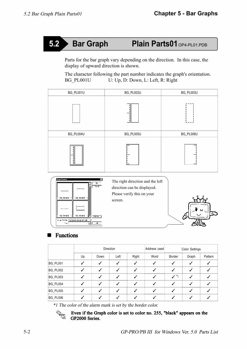
Parts for the bar graph vary depending on the direction. In this case, thedisplay of upward direction is shown.
The character following the part number indicates the graph's orientation.BG_PL001U U: Up, D: Down, L: Left, R: Right
BG_PL001U BG_PL002U BG_PL003U
BG_PL004U BG_PL005U BG_PL006U
! ! ! ! ! FunctionsFunctionsFunctionsFunctionsFunctions
Direction Address used Color Settings
Up Down Left Right Word Border Graph Pattern
BG_PL001 ✓ ✓ ✓ ✓ ✓ ✓ ✓ ✓
BG_PL002 ✓ ✓ ✓ ✓ ✓ ✓ ✓ ✓
BG_PL003 ✓ ✓ ✓ ✓ ✓ ✓ ✓ ✓
BG_PL004 ✓ ✓ ✓ ✓ ✓ ✓ ✓ ✓
BG_PL005 ✓ ✓ ✓ ✓ ✓ ✓ ✓ ✓
BG_PL006 ✓ ✓ ✓ ✓ ✓ ✓ ✓ ✓
The right direction and the leftdirection can be displayed.Please verify this on yourscreen.
*1 The color of the alarm mark is set by the border color.
Even if the Graph color is set to color no. 255, "black" appears on theEven if the Graph color is set to color no. 255, "black" appears on theEven if the Graph color is set to color no. 255, "black" appears on theEven if the Graph color is set to color no. 255, "black" appears on theEven if the Graph color is set to color no. 255, "black" appears on theGP2000 Series.GP2000 Series.GP2000 Series.GP2000 Series.GP2000 Series.
*
5.2 Bar Graph Plain Parts01
5.2 Bar Graph Plain Parts01OP4-PL01.PDB
1
5-3
Chapter 5 - Bar Graphs
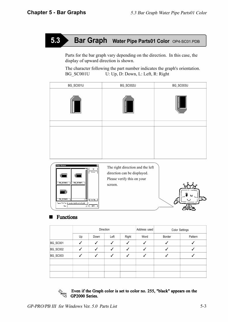
GP-PRO/PB III for Windows Ver. 5.0 Parts List
Parts for the bar graph vary depending on the direction. In this case, thedisplay of upward direction is shown.
The character following the part number indicates the graph's orientation.BG_SC001U U: Up, D: Down, L: Left, R: Right
BG_SC001U BG_SC002U BG_SC003U
! ! ! ! ! FunctionsFunctionsFunctionsFunctionsFunctions
The right direction and the leftdirection can be displayed.Please verify this on yourscreen.
Direction Address used Color Settings
Up Down Left Right Word Border Pattern
BG_SC001 ✓ ✓ ✓ ✓ ✓ ✓ ✓
BG_SC002 ✓ ✓ ✓ ✓ ✓ ✓ ✓
BG_SC003 ✓ ✓ ✓ ✓ ✓ ✓ ✓
5.3 Bar Graph Water Pipe Parts01 Color OP4-SC01.PDB
5.3 Bar Graph Water Pipe Parts01 Color
Even if the Graph color is set to color no. 255, "black" appears on the Even if the Graph color is set to color no. 255, "black" appears on the Even if the Graph color is set to color no. 255, "black" appears on the Even if the Graph color is set to color no. 255, "black" appears on the Even if the Graph color is set to color no. 255, "black" appears on theGP2000 Series.GP2000 Series.GP2000 Series.GP2000 Series.GP2000 Series.

1234567890123456789012345678901212345678901123456789012345678901234567890121234567890112345678901234567890123456789012123456789011234567890123456789012345678901212345678901123456789012345678901234567890121234567890112345678901234567890123456789012123456789011234567890123456789012345678901212345678901123456789012345678901234567890121234567890112345678901234567890123456789012123456789011234567890123456789012345678901212345678901123456789012345678901234567890121234567890112345678901234567890123456789012123456789011234567890123456789012345678901212345678901123456789012345678901234567890121234567890112345678901234567890123456789012123456789011234567890123456789012345678901212345678901
MEMO
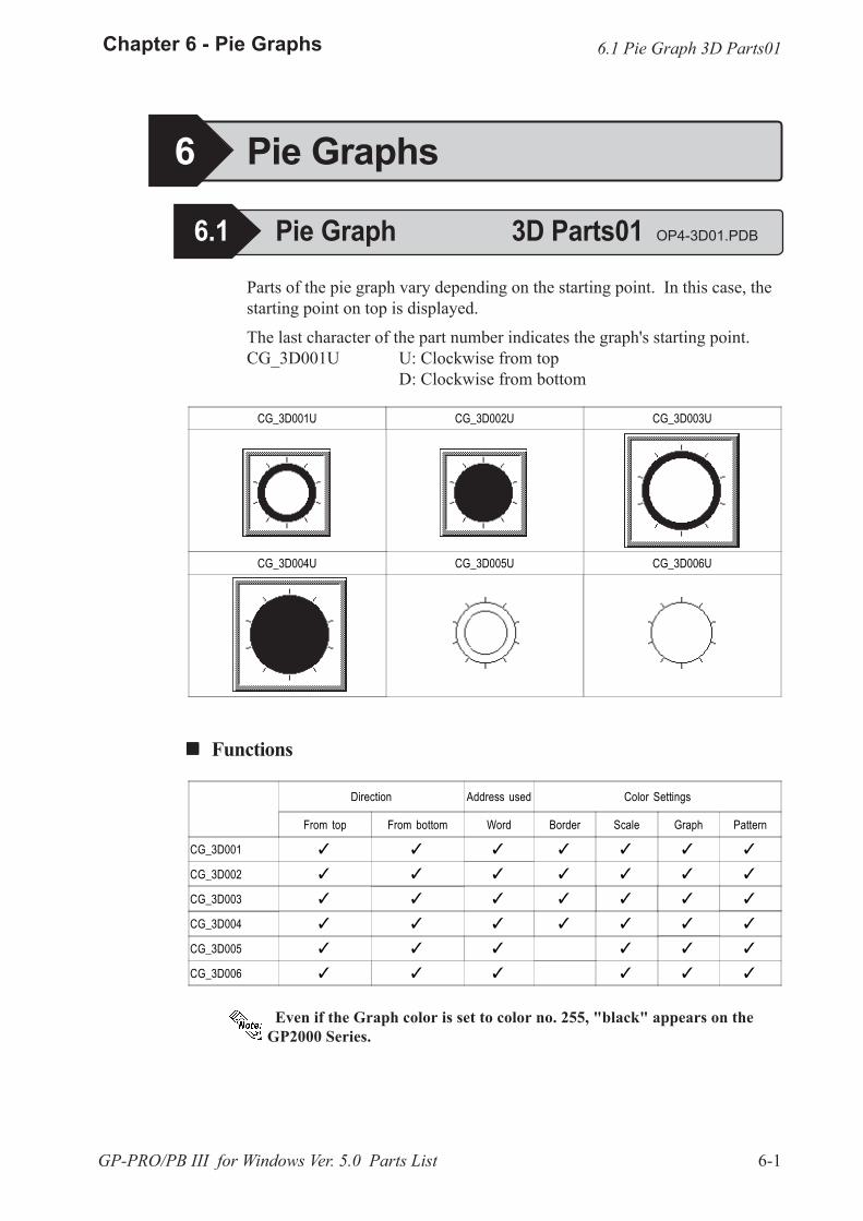
6-1
Chapter 6 - Pie Graphs
GP-PRO/PB III for Windows Ver. 5.0 Parts List
Parts of the pie graph vary depending on the starting point. In this case, thestarting point on top is displayed.
The last character of the part number indicates the graph's starting point.CG_3D001U U: Clockwise from top
D: Clockwise from bottom
CG_3D001U CG_3D002U CG_3D003U
CG_3D004U CG_3D005U CG_3D006U
! ! ! ! ! Functions
Direction Address used Color Settings
From top From bottom Word Border Scale Graph Pattern
CG_3D001 � � � � � � �
CG_3D002 � � � � � � �
CG_3D003 � � � � � � �
CG_3D004 � � � � � � �
CG_3D005 � � � � � �
CG_3D006 � � � � � �
6 Pie Graphs
6.1 Pie Graph 3D Parts01 OP4-3D01.PDB
6.1 Pie Graph 3D Parts01
Even if the Graph color is set to color no. 255, "black" appears on theGP2000 Series.
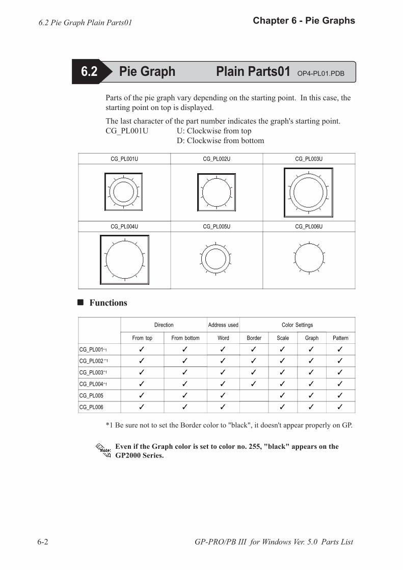
6-2
Chapter 6 - Pie Graphs
GP-PRO/PB III for Windows Ver. 5.0 Parts List
Parts of the pie graph vary depending on the starting point. In this case, thestarting point on top is displayed.
The last character of the part number indicates the graph's starting point.CG_PL001U U: Clockwise from top
D: Clockwise from bottom
CG_PL001U CG_PL002U CG_PL003U
CG_PL004U CG_PL005U CG_PL006U
! ! ! ! ! Functions
Direction Address used Color Settings
From top From bottom Word Border Scale Graph Pattern
CG_PL001 � � � � � � �
CG_PL002 � � � � � � �
CG_PL003 � � � � � � �
CG_PL004 � � � � � � �
CG_PL005 � � � � � �
CG_PL006 � � � � � �
6.2 Pie Graph Plain Parts01
6.2 Pie Graph Plain Parts01 OP4-PL01.PDB
*1
*1
*1
*1
*1 Be sure not to set the Border color to "black", it doesn't appear properly on GP.
Even if the Graph color is set to color no. 255, "black" appears on theGP2000 Series.
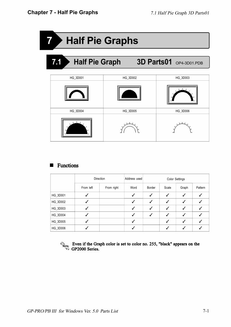
7-1
Chapter 7 - Half Pie Graphs
GP-PRO/PB III for Windows Ver. 5.0 Parts List
HG_3D001 HG_3D002 HG_3D003
HG_3D004 HG_3D005 HG_3D006
! ! ! ! ! FunctionsFunctionsFunctionsFunctionsFunctions
Direction Address used Color Settings
From left From right Word Border Scale Graph Pattern
HG_3D001 ✓ ✓ ✓ ✓ ✓ ✓
HG_3D002 ✓ ✓ ✓ ✓ ✓ ✓
HG_3D003 ✓ ✓ ✓ ✓ ✓ ✓
HG_3D004 ✓ ✓ ✓ ✓ ✓ ✓
HG_3D005 ✓ ✓ ✓ ✓ ✓
HG_3D006 ✓ ✓ ✓ ✓ ✓
7 Half Pie Graphs
7.1 Half Pie Graph 3D Parts01 OP4-3D01.PDB
7.1 Half Pie Graph 3D Parts01
Even if the Graph color is set to color no. 255, "black" appears on the Even if the Graph color is set to color no. 255, "black" appears on the Even if the Graph color is set to color no. 255, "black" appears on the Even if the Graph color is set to color no. 255, "black" appears on the Even if the Graph color is set to color no. 255, "black" appears on theGP2000 Series.GP2000 Series.GP2000 Series.GP2000 Series.GP2000 Series.
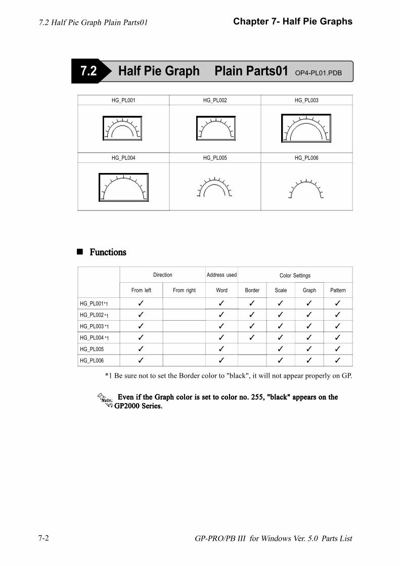
7-2
Chapter 7- Half Pie Graphs
GP-PRO/PB III for Windows Ver. 5.0 Parts List
HG_PL001 HG_PL002 HG_PL003
HG_PL004 HG_PL005 HG_PL006
! ! ! ! ! FunctionsFunctionsFunctionsFunctionsFunctions
Direction Address used Color Settings
From left From right Word Border Scale Graph Pattern
HG_PL001 ✓ ✓ ✓ ✓ ✓ ✓
HG_PL002 ✓ ✓ ✓ ✓ ✓ ✓
HG_PL003 ✓ ✓ ✓ ✓ ✓ ✓
HG_PL004 ✓ ✓ ✓ ✓ ✓ ✓
HG_PL005 ✓ ✓ ✓ ✓ ✓
HG_PL006 ✓ ✓ ✓ ✓ ✓
7.2 Half Pie Graph Plain Parts01 OP4-PL01.PDB
7.2 Half Pie Graph Plain Parts01
*1 Be sure not to set the Border color to "black", it will not appear properly on GP.
*1
*1
*1
*1
Even if the Graph color is set to color no. 255, "black" appears on the Even if the Graph color is set to color no. 255, "black" appears on the Even if the Graph color is set to color no. 255, "black" appears on the Even if the Graph color is set to color no. 255, "black" appears on the Even if the Graph color is set to color no. 255, "black" appears on theGP2000 Series.GP2000 Series.GP2000 Series.GP2000 Series.GP2000 Series.
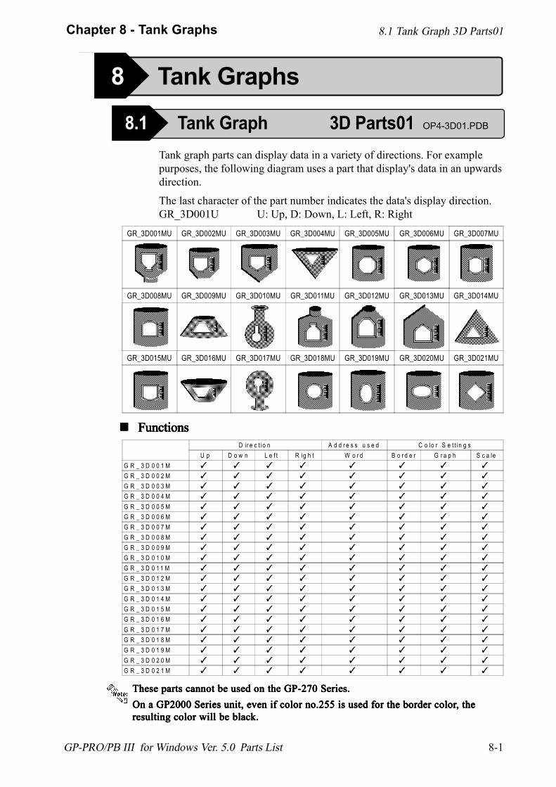
8-1
Chapter 8 - Tank Graphs
GP-PRO/PB III for Windows Ver. 5.0 Parts List
8.1 Tank Graph 3D Parts01
8 Tank Graphs
Tank graph parts can display data in a variety of directions. For examplepurposes, the following diagram uses a part that display's data in an upwardsdirection.
The last character of the part number indicates the data's display direction.GR_3D001U U: Up, D: Down, L: Left, R: Right
D ir e c t io n A d d r e s s u s e d C o lo r S e t t in g sU p D o w n L e f t R ig h t W o r d B o r d e r G r a p h S c a le
G R _ 3 D 0 0 1 M ✓ ✓ ✓ ✓ ✓ ✓ ✓ ✓
G R _ 3 D 0 0 2 M ✓ ✓ ✓ ✓ ✓ ✓ ✓ ✓
G R _ 3 D 0 0 3 M ✓ ✓ ✓ ✓ ✓ ✓ ✓ ✓
G R _ 3 D 0 0 4 M ✓ ✓ ✓ ✓ ✓ ✓ ✓ ✓
G R _ 3 D 0 0 5 M ✓ ✓ ✓ ✓ ✓ ✓ ✓ ✓
G R _ 3 D 0 0 6 M ✓ ✓ ✓ ✓ ✓ ✓ ✓ ✓
G R _ 3 D 0 0 7 M ✓ ✓ ✓ ✓ ✓ ✓ ✓ ✓
G R _ 3 D 0 0 8 M ✓ ✓ ✓ ✓ ✓ ✓ ✓ ✓
G R _ 3 D 0 0 9 M ✓ ✓ ✓ ✓ ✓ ✓ ✓ ✓
G R _ 3 D 0 1 0 M ✓ ✓ ✓ ✓ ✓ ✓ ✓ ✓
G R _ 3 D 0 1 1 M ✓ ✓ ✓ ✓ ✓ ✓ ✓ ✓
G R _ 3 D 0 1 2 M ✓ ✓ ✓ ✓ ✓ ✓ ✓ ✓
G R _ 3 D 0 1 3 M ✓ ✓ ✓ ✓ ✓ ✓ ✓ ✓
G R _ 3 D 0 1 4 M ✓ ✓ ✓ ✓ ✓ ✓ ✓ ✓
G R _ 3 D 0 1 5 M ✓ ✓ ✓ ✓ ✓ ✓ ✓ ✓
G R _ 3 D 0 1 6 M ✓ ✓ ✓ ✓ ✓ ✓ ✓ ✓
G R _ 3 D 0 1 7 M ✓ ✓ ✓ ✓ ✓ ✓ ✓ ✓
G R _ 3 D 0 1 8 M ✓ ✓ ✓ ✓ ✓ ✓ ✓ ✓
G R _ 3 D 0 1 9 M ✓ ✓ ✓ ✓ ✓ ✓ ✓ ✓
G R _ 3 D 0 2 0 M ✓ ✓ ✓ ✓ ✓ ✓ ✓ ✓
G R _ 3 D 0 2 1 M ✓ ✓ ✓ ✓ ✓ ✓ ✓ ✓
! ! ! ! ! FunctionsFunctionsFunctionsFunctionsFunctions
These parts cannot be used on the GP-270 Series.These parts cannot be used on the GP-270 Series.These parts cannot be used on the GP-270 Series.These parts cannot be used on the GP-270 Series.These parts cannot be used on the GP-270 Series.
GR_3D001MU GR_3D002MU GR_3D003MU GR_3D004MU GR_3D005MU GR_3D006MU GR_3D007MU
GR_3D008MU GR_3D009MU GR_3D010MU GR_3D011MU GR_3D012MU GR_3D013MU GR_3D014MU
GR_3D015MU GR_3D016MU GR_3D017MU GR_3D018MU GR_3D019MU GR_3D020MU GR_3D021MU
8.1 Tank Graph 3D Parts01 OP4-3D01.PDB
On a GP2000 Series unit, even if color no.255 is used for the border colorOn a GP2000 Series unit, even if color no.255 is used for the border colorOn a GP2000 Series unit, even if color no.255 is used for the border colorOn a GP2000 Series unit, even if color no.255 is used for the border colorOn a GP2000 Series unit, even if color no.255 is used for the border color, the, the, the, the, theresulting color will be black.resulting color will be black.resulting color will be black.resulting color will be black.resulting color will be black.
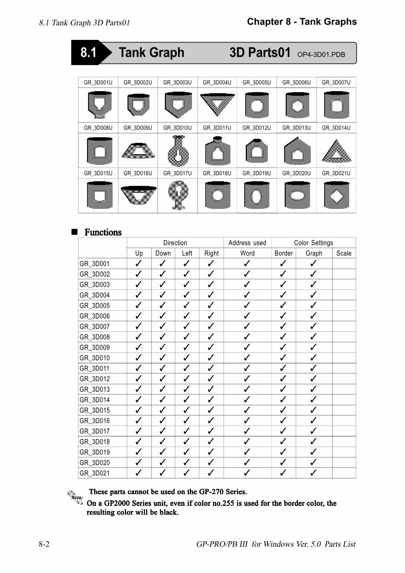
8-2
Chapter 8 - Tank Graphs
GP-PRO/PB III for Windows Ver. 5.0 Parts List
! ! ! ! ! FunctionsFunctionsFunctionsFunctionsFunctions
8.1 Tank Graph 3D Parts01
8.1 Tank Graph 3D Parts01 OP4-3D01.PDB
GR_3D001U GR_3D002U GR_3D003U GR_3D004U GR_3D005U GR_3D006U GR_3D007U
GR_3D008U GR_3D009U GR_3D010U GR_3D011U GR_3D012U GR_3D013U GR_3D014U
GR_3D015U GR_3D016U GR_3D017U GR_3D018U GR_3D019U GR_3D020U GR_3D021U
Direction Address used Color SettingsUp Down Left Right Word Border Graph Scale
GR_3D001 ✓ ✓ ✓ ✓ ✓ ✓ ✓
GR_3D002 ✓ ✓ ✓ ✓ ✓ ✓ ✓
GR_3D003 ✓ ✓ ✓ ✓ ✓ ✓ ✓
GR_3D004 ✓ ✓ ✓ ✓ ✓ ✓ ✓
GR_3D005 ✓ ✓ ✓ ✓ ✓ ✓ ✓
GR_3D006 ✓ ✓ ✓ ✓ ✓ ✓ ✓
GR_3D007 ✓ ✓ ✓ ✓ ✓ ✓ ✓
GR_3D008 ✓ ✓ ✓ ✓ ✓ ✓ ✓
GR_3D009 ✓ ✓ ✓ ✓ ✓ ✓ ✓
GR_3D010 ✓ ✓ ✓ ✓ ✓ ✓ ✓
GR_3D011 ✓ ✓ ✓ ✓ ✓ ✓ ✓
GR_3D012 ✓ ✓ ✓ ✓ ✓ ✓ ✓
GR_3D013 ✓ ✓ ✓ ✓ ✓ ✓ ✓
GR_3D014 ✓ ✓ ✓ ✓ ✓ ✓ ✓
GR_3D015 ✓ ✓ ✓ ✓ ✓ ✓ ✓
GR_3D016 ✓ ✓ ✓ ✓ ✓ ✓ ✓
GR_3D017 ✓ ✓ ✓ ✓ ✓ ✓ ✓
GR_3D018 ✓ ✓ ✓ ✓ ✓ ✓ ✓
GR_3D019 ✓ ✓ ✓ ✓ ✓ ✓ ✓
GR_3D020 ✓ ✓ ✓ ✓ ✓ ✓ ✓
GR_3D021 ✓ ✓ ✓ ✓ ✓ ✓ ✓
These parts cannot be used on the GP-270 Series. These parts cannot be used on the GP-270 Series. These parts cannot be used on the GP-270 Series. These parts cannot be used on the GP-270 Series. These parts cannot be used on the GP-270 Series.On a GP2000 Series unit, even if color no.255 is used for the border colorOn a GP2000 Series unit, even if color no.255 is used for the border colorOn a GP2000 Series unit, even if color no.255 is used for the border colorOn a GP2000 Series unit, even if color no.255 is used for the border colorOn a GP2000 Series unit, even if color no.255 is used for the border color, the, the, the, the, theresulting color will be black.resulting color will be black.resulting color will be black.resulting color will be black.resulting color will be black.
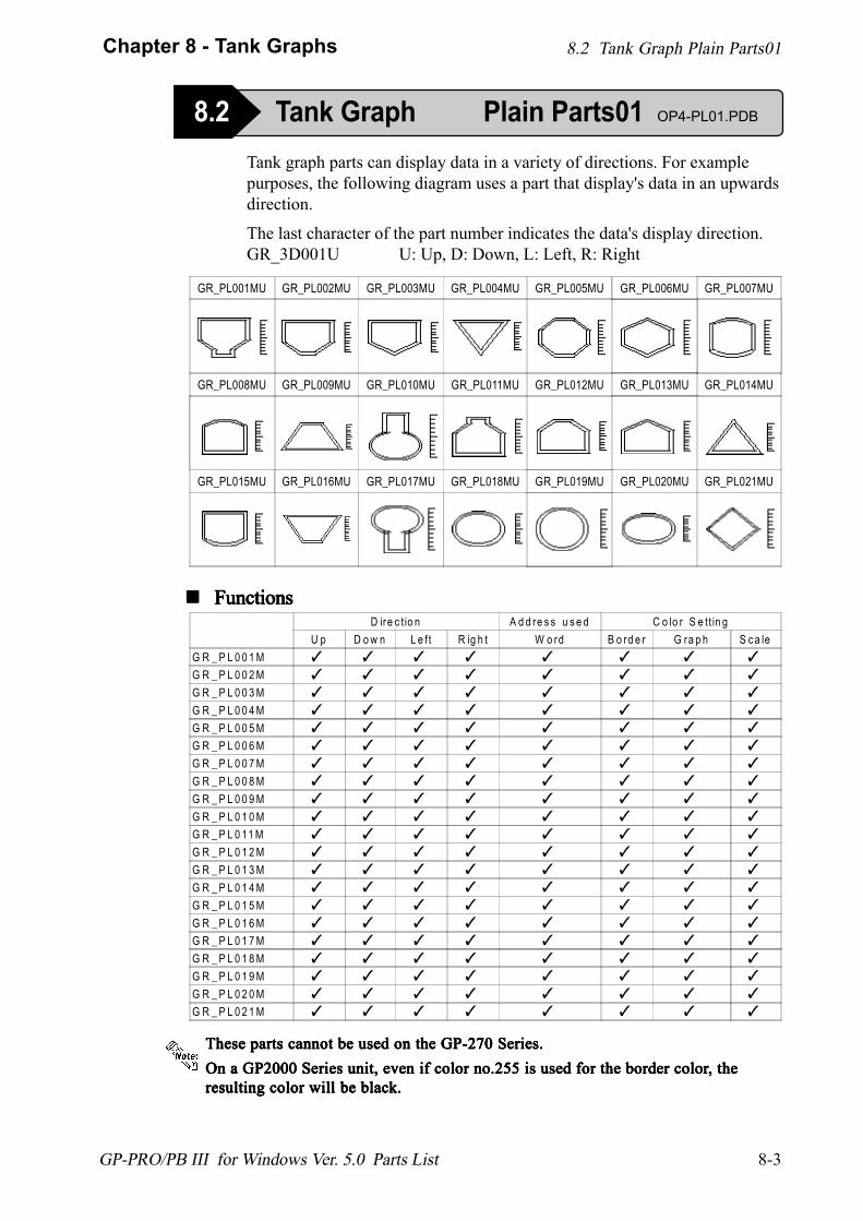
8-3
Chapter 8 - Tank Graphs
GP-PRO/PB III for Windows Ver. 5.0 Parts List
! ! ! ! ! FunctionsFunctionsFunctionsFunctionsFunctions
8.2 Tank Graph Plain Parts01
8.2 Tank Graph Plain Parts01 OP4-PL01.PDB
GR_PL001MU GR_PL002MU GR_PL003MU GR_PL004MU GR_PL005MU GR_PL006MU GR_PL007MU
GR_PL008MU GR_PL009MU GR_PL010MU GR_PL011MU GR_PL012MU GR_PL013MU GR_PL014MU
GR_PL015MU GR_PL016MU GR_PL017MU GR_PL018MU GR_PL019MU GR_PL020MU GR_PL021MU
D ire c t io n A d d re s s u s e d C o lo r S e tt in gU p D o w n L e ft R ig h t W o rd B o rd e r G ra p h S c a le
G R _ P L 0 0 1 M ✓ ✓ ✓ ✓ ✓ ✓ ✓ ✓
G R _ P L 0 0 2 M ✓ ✓ ✓ ✓ ✓ ✓ ✓ ✓
G R _ P L 0 0 3 M ✓ ✓ ✓ ✓ ✓ ✓ ✓ ✓
G R _ P L 0 0 4 M ✓ ✓ ✓ ✓ ✓ ✓ ✓ ✓
G R _ P L 0 0 5 M ✓ ✓ ✓ ✓ ✓ ✓ ✓ ✓
G R _ P L 0 0 6 M ✓ ✓ ✓ ✓ ✓ ✓ ✓ ✓
G R _ P L 0 0 7 M ✓ ✓ ✓ ✓ ✓ ✓ ✓ ✓
G R _ P L 0 0 8 M ✓ ✓ ✓ ✓ ✓ ✓ ✓ ✓
G R _ P L 0 0 9 M ✓ ✓ ✓ ✓ ✓ ✓ ✓ ✓
G R _ P L 0 1 0 M ✓ ✓ ✓ ✓ ✓ ✓ ✓ ✓
G R _ P L 0 11 M ✓ ✓ ✓ ✓ ✓ ✓ ✓ ✓
G R _ P L 0 1 2 M ✓ ✓ ✓ ✓ ✓ ✓ ✓ ✓
G R _ P L 0 1 3 M ✓ ✓ ✓ ✓ ✓ ✓ ✓ ✓
G R _ P L 0 1 4 M ✓ ✓ ✓ ✓ ✓ ✓ ✓ ✓
G R _ P L 0 1 5 M ✓ ✓ ✓ ✓ ✓ ✓ ✓ ✓
G R _ P L 0 1 6 M ✓ ✓ ✓ ✓ ✓ ✓ ✓ ✓
G R _ P L 0 1 7 M ✓ ✓ ✓ ✓ ✓ ✓ ✓ ✓
G R _ P L 0 1 8 M ✓ ✓ ✓ ✓ ✓ ✓ ✓ ✓
G R _ P L 0 1 9 M ✓ ✓ ✓ ✓ ✓ ✓ ✓ ✓
G R _ P L 0 2 0 M ✓ ✓ ✓ ✓ ✓ ✓ ✓ ✓
G R _ P L 0 2 1 M ✓ ✓ ✓ ✓ ✓ ✓ ✓ ✓
Tank graph parts can display data in a variety of directions. For examplepurposes, the following diagram uses a part that display's data in an upwardsdirection.
The last character of the part number indicates the data's display direction.GR_3D001U U: Up, D: Down, L: Left, R: Right
These parts cannot be used on the GP-270 Series.These parts cannot be used on the GP-270 Series.These parts cannot be used on the GP-270 Series.These parts cannot be used on the GP-270 Series.These parts cannot be used on the GP-270 Series.On a GP2000 Series unit, even if color no.255 is used for the border colorOn a GP2000 Series unit, even if color no.255 is used for the border colorOn a GP2000 Series unit, even if color no.255 is used for the border colorOn a GP2000 Series unit, even if color no.255 is used for the border colorOn a GP2000 Series unit, even if color no.255 is used for the border color, the, the, the, the, theresulting color will be black.resulting color will be black.resulting color will be black.resulting color will be black.resulting color will be black.
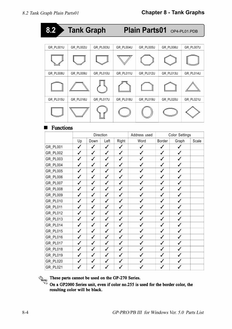
8-4
Chapter 8 - Tank Graphs
GP-PRO/PB III for Windows Ver. 5.0 Parts List
8.2 Tank Graph Plain Parts01 OP4-PL01.PDB
GR_PL001U GR_PL002U GR_PL003U GR_PL004U GR_PL005U GR_PL006U GR_PL007U
GR_PL008U GR_PL009U GR_PL010U GR_PL011U GR_PL012U GR_PL013U GR_PL014U
GR_PL015U GR_PL016U GR_PL017U GR_PL018U GR_PL019U GR_PL020U GR_PL021U
Direction Address used Color SettingsUp Down Left Right Word Border Graph Scale
GR_PL001 ✓ ✓ ✓ ✓ ✓ ✓ ✓
GR_PL002 ✓ ✓ ✓ ✓ ✓ ✓ ✓
GR_PL003 ✓ ✓ ✓ ✓ ✓ ✓ ✓
GR_PL004 ✓ ✓ ✓ ✓ ✓ ✓ ✓
GR_PL005 ✓ ✓ ✓ ✓ ✓ ✓ ✓
GR_PL006 ✓ ✓ ✓ ✓ ✓ ✓ ✓
GR_PL007 ✓ ✓ ✓ ✓ ✓ ✓ ✓
GR_PL008 ✓ ✓ ✓ ✓ ✓ ✓ ✓
GR_PL009 ✓ ✓ ✓ ✓ ✓ ✓ ✓
GR_PL010 ✓ ✓ ✓ ✓ ✓ ✓ ✓
GR_PL011 ✓ ✓ ✓ ✓ ✓ ✓ ✓
GR_PL012 ✓ ✓ ✓ ✓ ✓ ✓ ✓
GR_PL013 ✓ ✓ ✓ ✓ ✓ ✓ ✓
GR_PL014 ✓ ✓ ✓ ✓ ✓ ✓ ✓
GR_PL015 ✓ ✓ ✓ ✓ ✓ ✓ ✓
GR_PL016 ✓ ✓ ✓ ✓ ✓ ✓ ✓
GR_PL017 ✓ ✓ ✓ ✓ ✓ ✓ ✓
GR_PL018 ✓ ✓ ✓ ✓ ✓ ✓ ✓
GR_PL019 ✓ ✓ ✓ ✓ ✓ ✓ ✓
GR_PL020 ✓ ✓ ✓ ✓ ✓ ✓ ✓
GR_PL021 ✓ ✓ ✓ ✓ ✓ ✓ ✓
! ! ! ! ! FunctionsFunctionsFunctionsFunctionsFunctions
8.2 Tank Graph Plain Parts01
These parts cannot be used on the GP-270 Series.These parts cannot be used on the GP-270 Series.These parts cannot be used on the GP-270 Series.These parts cannot be used on the GP-270 Series.These parts cannot be used on the GP-270 Series.On a GP2000 Series unit, even if color no.255 is used for the border colorOn a GP2000 Series unit, even if color no.255 is used for the border colorOn a GP2000 Series unit, even if color no.255 is used for the border colorOn a GP2000 Series unit, even if color no.255 is used for the border colorOn a GP2000 Series unit, even if color no.255 is used for the border color, the, the, the, the, theresulting color will be black.resulting color will be black.resulting color will be black.resulting color will be black.resulting color will be black.

9-1
Chapter 9 - Meter Graphs
GP-PRO/PB III for Windows Ver. 5.0 Parts List
9.1 Meter Graph 3D Parts01
9 Meter Graphs
9.1 Meter Graph 3D Parts01 OP4-3D01.PDB
! ! ! ! ! Functions
MT_3D001 MT_3D002 MT_3D003 MT_3D004 MT_3D005 MT_3D006 MT_3D007
MT_3D008 MT_3D009 MT_3D010 MT_3D011 MT_3D012 MT_3D013 MT_3D014
MT_3D015 MT_3D016 MT_3D017 MT_3D018 MT_3D019 MT_3D020
D irec tion A ddress use d C o lo r S e ttingsLe ft R igh t W ord B order M ete r S ca le
M T _3D 001 � � � � � �
M T _3D 002 � � � � � �
M T _3D 003 � � � � � �
M T _3D 004 � � � � � �
M T _3D 005 � � � � � �
M T _3D 006 � � � � � �
M T _3D 007 � � � � � �
M T _3D 008 � � � � � �
M T _3D 009 � � � � � �
M T _3D 010 � � � � � �
M T _3D 011 � � � � � �
M T _3D 012 � � � � � �
M T _3D 013 � � � � � �
M T _3D 014 � � � � � �
M T _3D 015 � � � � � �
M T _3D 016 � � � � � �
M T _3D 017 � � � � � �
M T _3D 018 � � � � � �
M T _3D 019 � � � � � �
M T _3D 020 � � � � � �
These parts cannot be used on the GP-270 Series.
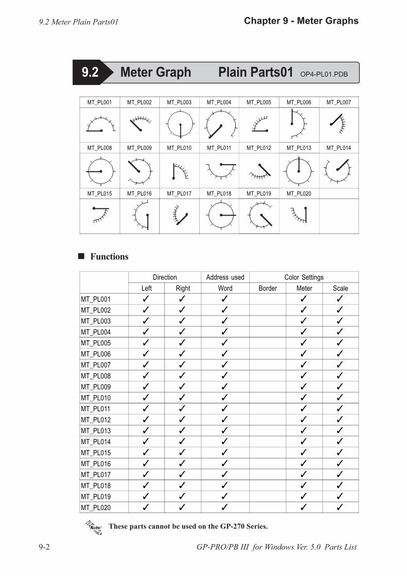
9-2
Chapter 9 - Meter Graphs
GP-PRO/PB III for Windows Ver. 5.0 Parts List
! ! ! ! ! Functions
9.2 Meter Plain Parts01
9.2 Meter Graph Plain Parts01 OP4-PL01.PDB
MT_PL001 MT_PL002 MT_PL003 MT_PL004 MT_PL005 MT_PL006 MT_PL007
MT_PL008 MT_PL009 MT_PL010 MT_PL011 MT_PL012 MT_PL013 MT_PL014
MT_PL015 MT_PL016 MT_PL017 MT_PL018 MT_PL019 MT_PL020
Direction Address used Color SettingsLeft Right Word Border Meter Scale
MT_PL001 � � � � �
MT_PL002 � � � � �
MT_PL003 � � � � �
MT_PL004 � � � � �
MT_PL005 � � � � �
MT_PL006 � � � � �
MT_PL007 � � � � �
MT_PL008 � � � � �
MT_PL009 � � � � �
MT_PL010 � � � � �
MT_PL011 � � � � �
MT_PL012 � � � � �
MT_PL013 � � � � �
MT_PL014 � � � � �
MT_PL015 � � � � �
MT_PL016 � � � � �
MT_PL017 � � � � �
MT_PL018 � � � � �
MT_PL019 � � � � �
MT_PL020 � � � � �
These parts cannot be used on the GP-270 Series.
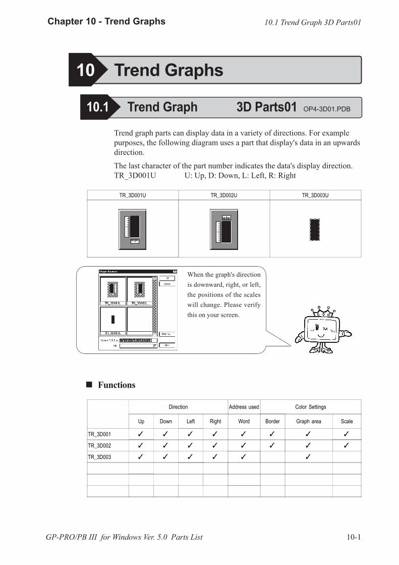
10-1
Chapter 10 - Trend Graphs
GP-PRO/PB III for Windows Ver. 5.0 Parts List
Trend graph parts can display data in a variety of directions. For examplepurposes, the following diagram uses a part that display's data in an upwardsdirection.
The last character of the part number indicates the data's display direction.TR_3D001U U: Up, D: Down, L: Left, R: Right
TR_3D001U TR_3D002U TR_3D003U
! ! ! ! ! Functions
Direction Address used Color Settings
Up Down Left Right Word Border Graph area Scale
TR_3D001 � � � � � � � �
TR_3D002 � � � � � � � �
TR_3D003 � � � � � �
When the graph's directionis downward, right, or left,the positions of the scaleswill change. Please verifythis on your screen.
10.1 Trend Graph 3D Parts01
10 Trend Graphs
10.1 Trend Graph 3D Parts01 OP4-3D01.PDB
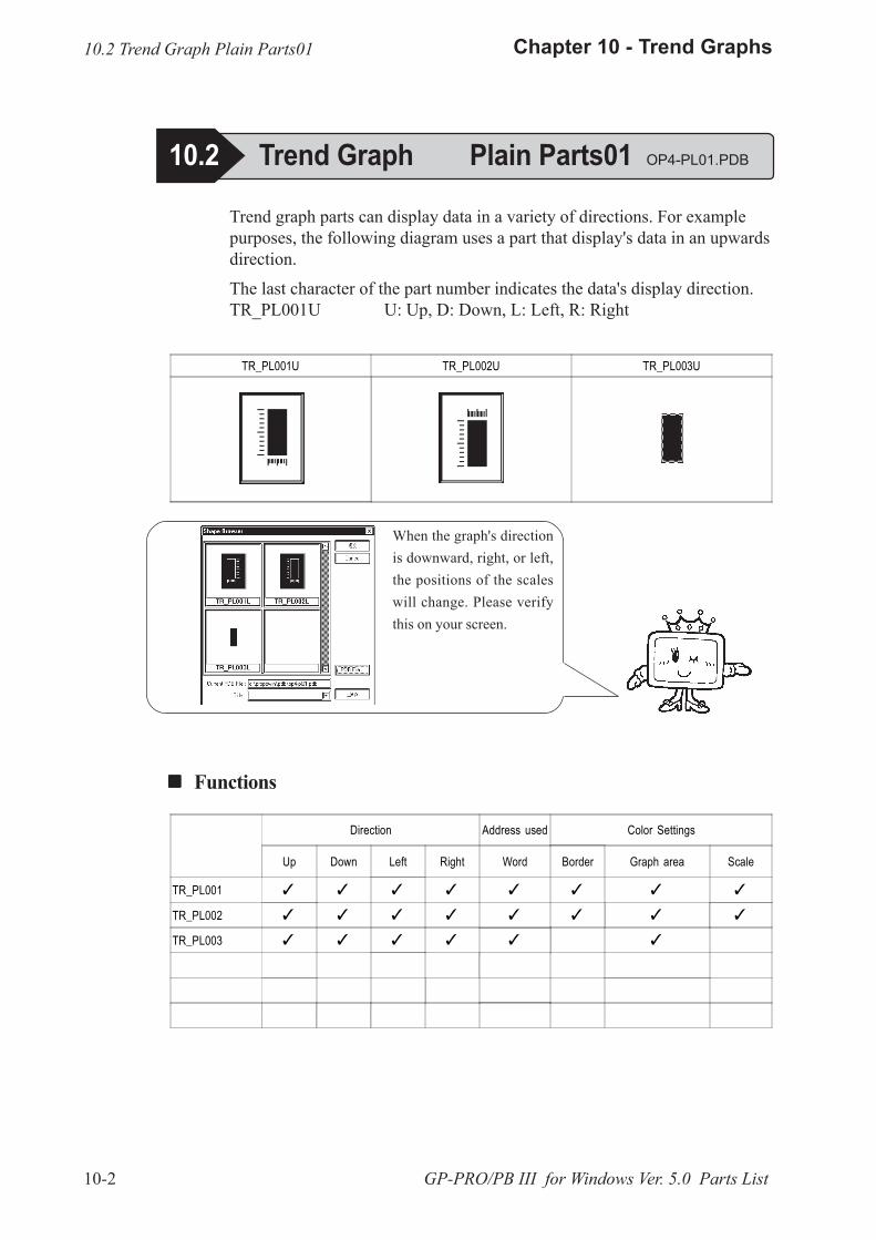
10-2
Chapter 10 - Trend Graphs
GP-PRO/PB III for Windows Ver. 5.0 Parts List
Trend graph parts can display data in a variety of directions. For examplepurposes, the following diagram uses a part that display's data in an upwardsdirection.
The last character of the part number indicates the data's display direction.TR_PL001U U: Up, D: Down, L: Left, R: Right
! ! ! ! ! Functions
TR_PL001U TR_PL002U TR_PL003U
Direction Address used Color Settings
Up Down Left Right Word Border Graph area Scale
TR_PL001 � � � � � � � �
TR_PL002 � � � � � � � �
TR_PL003 � � � � � �
When the graph's directionis downward, right, or left,the positions of the scaleswill change. Please verifythis on your screen.
10.2 Trend Graph Plain Parts01
10.2 Trend Graph Plain Parts01 OP4-PL01.PDB
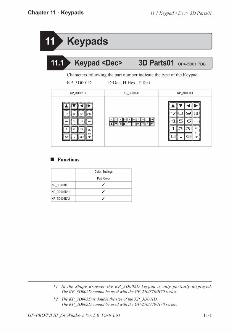
11-1
Chapter 11 - Keypads
GP-PRO/PB III for Windows Ver. 5.0 Parts List
KP_3D001D KP_3D002D KP_3D003D
Characters following the part number indicate the type of the Keypad.
KP_3D001D D:Dec, H:Hex, T:Text
! ! ! ! ! Functions
*1 In the Shape Browser the KP_3D002D keypad is only partially displayed.The KP_3D002D cannot be used with the GP-270/370/H70 series.
*2 The KP_3D003D is double the size of the KP_3D001D.The KP_3D003D cannot be used with the GP-270/370/H70 series.
Color Settings
Pad Color
KP_3D001D �
KP_3D002D*1 �
KP_3D003D*2 �
11 Keypads
11.1 Keypad <Dec> 3D Parts01 OP4-3D01.PDB
11.1 Keypad <Dec> 3D Parts01
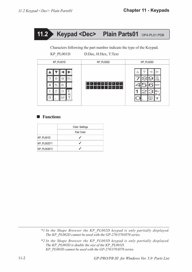
11-2
Chapter 11 - Keypads
GP-PRO/PB III for Windows Ver. 5.0 Parts List
KP_PL001D KP_PL002D KP_PL003D
*1 In the Shape Browser the KP_PL002D keypad is only partially displayed.The KP_PL002D cannot be used with the GP-270/370/H70 series.
*2 In the Shape Browser the KP_PL003D keypad is only partially displayed.The KP_PL003D is double the size of the KP_PL001D.KP_PL003D cannot be used with the GP-270/370/H70 series.
! ! ! ! ! Functions
Characters following the part number indicate the type of the Keypad.
KP_PL001D D:Dec, H:Hex, T:Text
Color Settings
Pad Color
KP_PL001D �
KP_PL002D*1 �
KP_PL003D*2 �
11.2 Keypad <Dec> Plain Parts01
11.2 Keypad <Dec> Plain Parts01 OP4-PL01.PDB
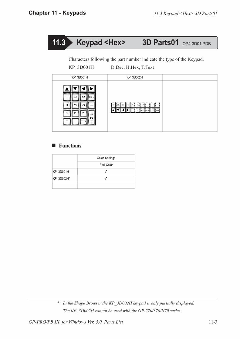
11-3
Chapter 11 - Keypads
GP-PRO/PB III for Windows Ver. 5.0 Parts List
KP_3D001H KP_3D002H
Characters following the part number indicate the type of the Keypad.
KP_3D001H D:Dec, H:Hex, T:Text
! ! ! ! ! Functions
* In the Shape Browser the KP_3D002H keypad is only partially displayed.
The KP_3D002H cannot be used with the GP-270/370/H70 series.
Color Settings
Pad Color
KP_3D001H �
KP_3D002H* �
11.3 Keypad <Hex> 3D Parts01 OP4-3D01.PDB
11.3 Keypad <Hex> 3D Parts01
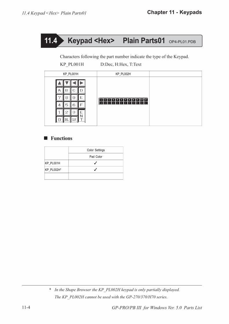
11-4
Chapter 11 - Keypads
GP-PRO/PB III for Windows Ver. 5.0 Parts List
KP_PL001H KP_PL002H
Characters following the part number indicate the type of the Keypad.
KP_PL001H D:Dec, H:Hex, T:Text
! ! ! ! ! Functions
* In the Shape Browser the KP_PL002H keypad is only partially displayed.
The KP_PL002H cannot be used with the GP-270/370/H70 series.
Color Settings
Pad Color
KP_PL001H �
KP_PL002H* �
11.4 Keypad <Hex> Plain Parts01
11.4 Keypad <Hex> Plain Parts01 OP4-PL01.PDB
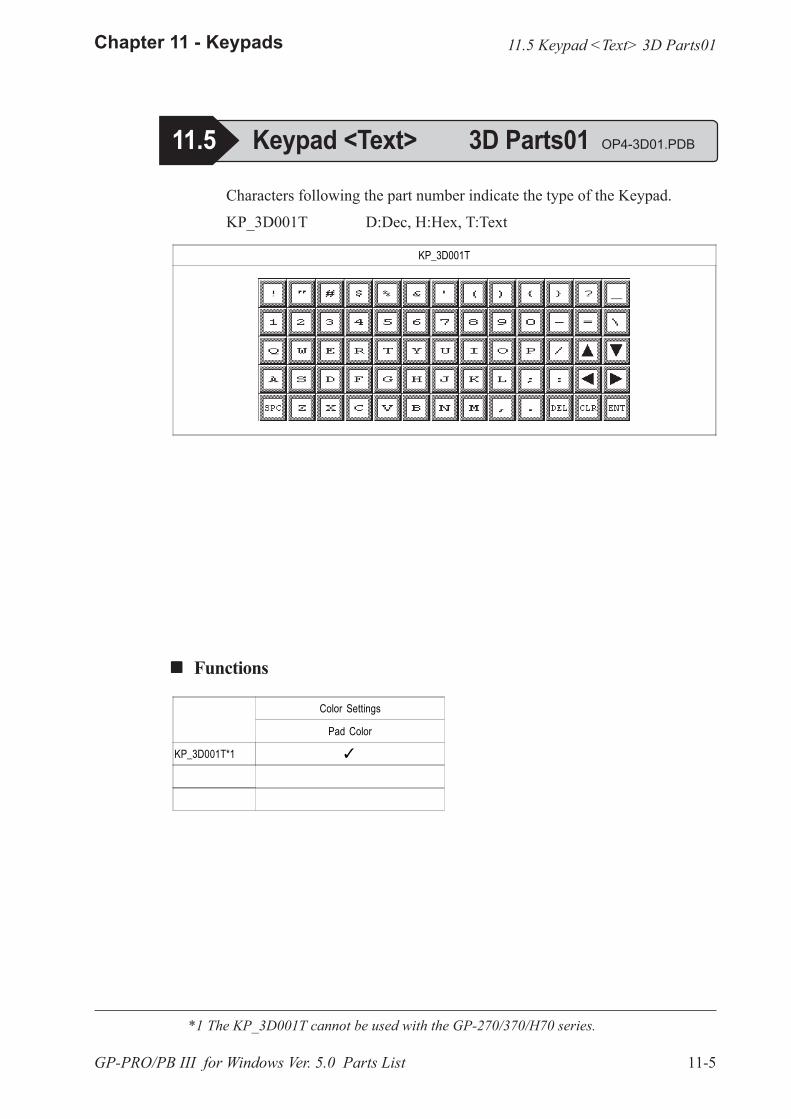
11-5
Chapter 11 - Keypads
GP-PRO/PB III for Windows Ver. 5.0 Parts List
Characters following the part number indicate the type of the Keypad.
KP_3D001T D:Dec, H:Hex, T:Text
! ! ! ! ! Functions
KP_3D001T
Color Settings
Pad Color
KP_3D001T*1 �
*1 The KP_3D001T cannot be used with the GP-270/370/H70 series.
11.5 Keypad <Text> 3D Parts01
11.5 Keypad <Text> 3D Parts01 OP4-3D01.PDB
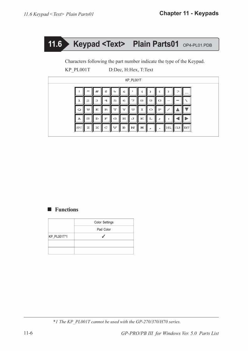
11-6
Chapter 11 - Keypads
GP-PRO/PB III for Windows Ver. 5.0 Parts List
Characters following the part number indicate the type of the Keypad.
KP_PL001T D:Dec, H:Hex, T:Text
! ! ! ! ! Functions
KP_PL001T
Color Settings
Pad Color
KP_PL001T*1 �
*1 The KP_PL001T cannot be used with the GP-270/370/H70 series.
11.6 Keypad <Text> Plain Parts01
11.6 Keypad <Text> Plain Parts01 OP4-PL01.PDB
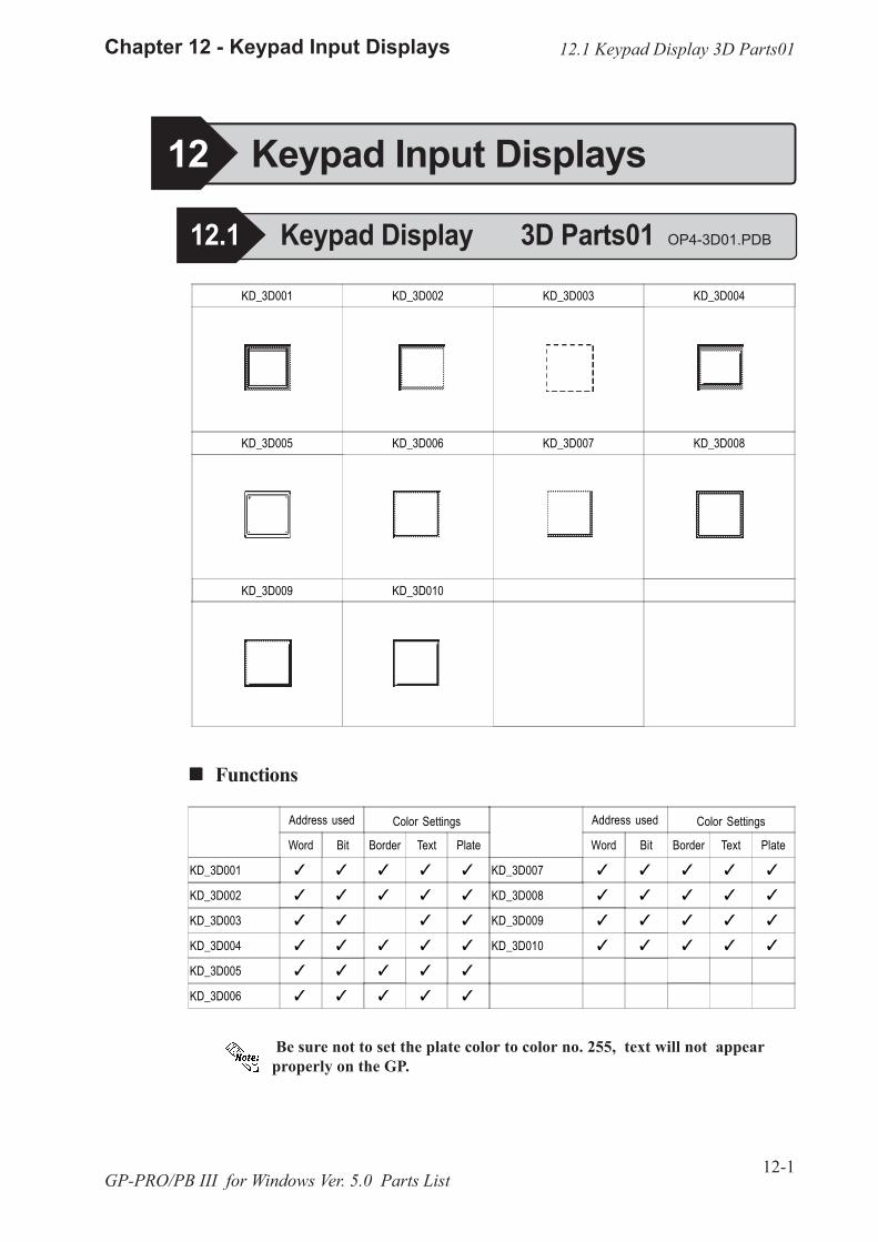
12-1
Chapter 12 - Keypad Input Displays
GP-PRO/PB III for Windows Ver. 5.0 Parts List
Address used Color Settings
Word Bit Border Text Plate
KD_3D001 � � � � �
KD_3D002 � � � � �
KD_3D003 � � � �
KD_3D004 � � � � �
KD_3D005 � � � � �
KD_3D006 � � � � �
Address used Color Settings
Word Bit Border Text Plate
KD_3D007 � � � � �
KD_3D008 � � � � �
KD_3D009 � � � � �
KD_3D010 � � � � �
KD_3D001 KD_3D002 KD_3D003 KD_3D004
KD_3D005 KD_3D006 KD_3D007 KD_3D008
KD_3D009 KD_3D010
! ! ! ! ! Functions
12.1 Keypad Display 3D Parts01
12 Keypad Input Displays
12.1 Keypad Display 3D Parts01 OP4-3D01.PDB
Be sure not to set the plate color to color no. 255, text will not appearproperly on the GP.
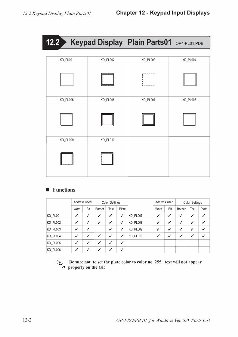
12-2
Chapter 12 - Keypad Input Displays
GP-PRO/PB III for Windows Ver. 5.0 Parts List
! ! ! ! ! Functions
KD_PL001 KD_PL002 KD_PL003 KD_PL004
KD_PL005 KD_PL006 KD_PL007 KD_PL008
KD_PL009 KD_PL010
Address used Color Settings
Word Bit Border Text Plate
KD_PL001 � � � � �
KD_PL002 � � � � �
KD_PL003 � � � �
KD_PL004 � � � � �
KD_PL005 � � � � �
KD_PL006 � � � � �
Address used Color Settings
Word Bit Border Text Plate
KD_PL007 � � � � �
KD_PL008 � � � � �
KD_PL009 � � � � �
KD_PL010 � � � � �
12.2 Keypad Display Plain Parts01
12.2 Keypad Display Plain Parts01 OP4-PL01.PDB
Be sure not to set the plate color to color no. 255, text will not appearproperly on the GP.
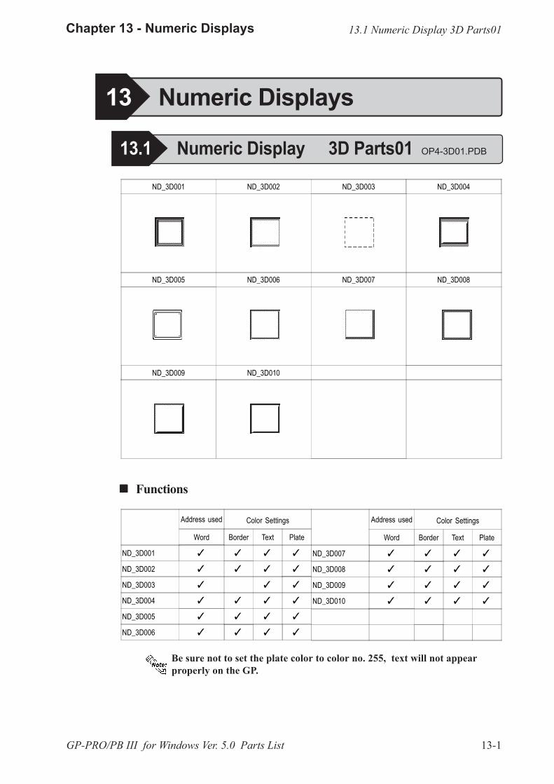
13-1
Chapter 13 - Numeric Displays
GP-PRO/PB III for Windows Ver. 5.0 Parts List
Address used Color Settings
Word Border Text Plate
ND_3D001 � � � �
ND_3D002 � � � �
ND_3D003 � � �
ND_3D004 � � � �
ND_3D005 � � � �
ND_3D006 � � � �
Address used Color Settings
Word Border Text Plate
ND_3D007 � � � �
ND_3D008 � � � �
ND_3D009 � � � �
ND_3D010 � � � �
ND_3D001 ND_3D002 ND_3D003 ND_3D004
ND_3D005 ND_3D006 ND_3D007 ND_3D008
ND_3D009 ND_3D010
! ! ! ! ! Functions
13 Numeric Displays
13.1 Numeric Display 3D Parts01 OP4-3D01.PDB
13.1 Numeric Display 3D Parts01
Be sure not to set the plate color to color no. 255, text will not appearproperly on the GP.

13-2
Chapter 13 - Numeric Displays
GP-PRO/PB III for Windows Ver. 5.0 Parts List
! ! ! ! ! Functions
Address used Color Settings
Word Border Text Plate
ND_PL001 � � � �
ND_PL002 � � � �
ND_PL003 � � �
ND_PL004 � � � �
ND_PL005 � � � �
ND_PL006 � � � �
Address used Color Settings
Word Border Text Plate
ND_PL007 � � � �
ND_PL008 � � � �
ND_PL009 � � � �
ND_PL010 � � � �
ND_PL001 ND_PL002 ND_PL003 ND_PL004
ND_PL005 ND_PL006 ND_PL007 ND_PL008
ND_PL009 ND_PL010
13.2 Numeric Display Plain Parts01 OP4-PL01.PDB
13.2 Numeric Display Plain Parts01
Be sure not to set the plate color to color no. 255, text will not appearproperly on the GP.

14-1
Chapter 14 - Message Displays
GP-PRO/PB III for Windows Ver. 5.0 Parts List
! ! ! ! ! Functions
MD_3D001 MD_3D002 MD_3D003 MD_3D004
MD_3D005 MD_3D006 MD_3D007 MD_3D008
MD_3D009 MD_3D010
14 Message Displays
14.1 Message Display 3D Parts01 OP4-3D01.PDB
Address used Color Settings
Word Bit Border Text Plate
MD_3D001 � � � � �
MD_3D002 � � � � �
MD_3D003 � � � �
MD_3D004 � � � � �
MD_3D005 � � � � �
MD_3D006 � � � � �
Address used Color Settings
Word Bit Border Text Plate
MD_3D007 � � � � �
MD_3D008 � � � � �
MD_3D009 � � � � �
MD_3D010 � � � � �
14.1 Message Display 3D Parts01
Be sure not to set the plate color to color no. 255, text will not appearproperly on the GP.
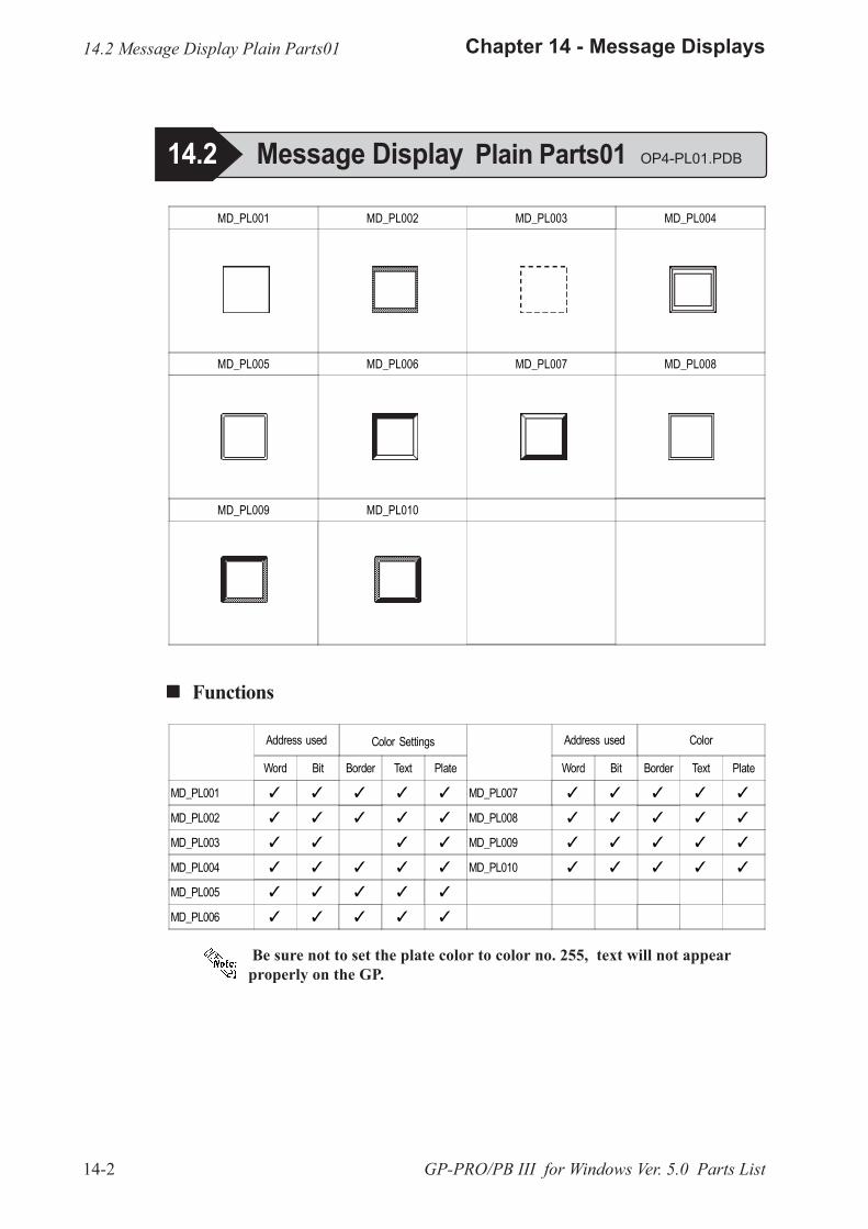
14-2
Chapter 14 - Message Displays
GP-PRO/PB III for Windows Ver. 5.0 Parts List
Be sure not to set the plate color to color no. 255, text will not appearproperly on the GP.
! ! ! ! ! Functions
Address used Color Settings
Word Bit Border Text Plate
MD_PL001 � � � � �
MD_PL002 � � � � �
MD_PL003 � � � �
MD_PL004 � � � � �
MD_PL005 � � � � �
MD_PL006 � � � � �
Address used Color
Word Bit Border Text Plate
MD_PL007 � � � � �
MD_PL008 � � � � �
MD_PL009 � � � � �
MD_PL010 � � � � �
MD_PL001 MD_PL002 MD_PL003 MD_PL004
MD_PL005 MD_PL006 MD_PL007 MD_PL008
MD_PL009 MD_PL010
14.2 Message Display Plain Parts01 OP4-PL01.PDB
14.2 Message Display Plain Parts01
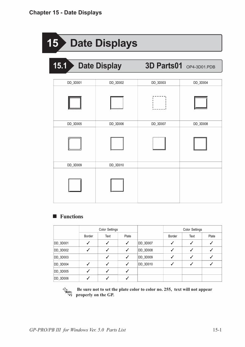
15-1
Chapter 15 - Date Displays
GP-PRO/PB III for Windows Ver. 5.0 Parts List
! ! ! ! ! Functions
Color Settings
Border Text Plate
DD_3D001 � � �
DD_3D002 � � �
DD_3D003 � �
DD_3D004 � � �
DD_3D005 � � �
DD_3D006 � � �
Color Settings
Border Text Plate
DD_3D007 � � �
DD_3D008 � � �
DD_3D009 � � �
DD_3D010 � � �
DD_3D001 DD_3D002 DD_3D003 DD_3D004
DD_3D005 DD_3D006 DD_3D007 DD_3D008
DD_3D009 DD_3D010
15 Date Displays
15.1 Date Display 3D Parts01 OP4-3D01.PDB
Be sure not to set the plate color to color no. 255, text will not appearproperly on the GP.
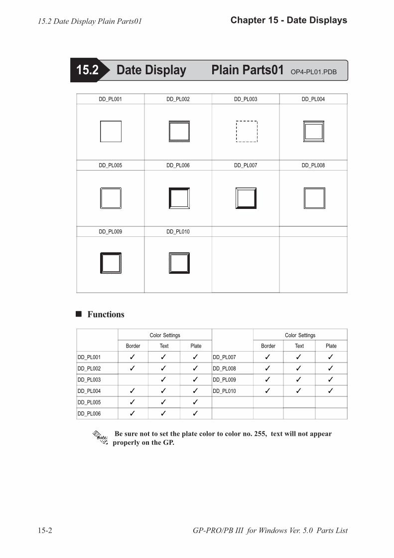
15-2
Chapter 15 - Date Displays
GP-PRO/PB III for Windows Ver. 5.0 Parts List
! ! ! ! ! Functions
Color Settings
Border Text Plate
DD_PL001 � � �
DD_PL002 � � �
DD_PL003 � �
DD_PL004 � � �
DD_PL005 � � �
DD_PL006 � � �
Color Settings
Border Text Plate
DD_PL007 � � �
DD_PL008 � � �
DD_PL009 � � �
DD_PL010 � � �
DD_PL001 DD_PL002 DD_PL003 DD_PL004
DD_PL005 DD_PL006 DD_PL007 DD_PL008
DD_PL009 DD_PL010
15.2 Date Display Plain Parts01
15.2 Date Display Plain Parts01 OP4-PL01.PDB
Be sure not to set the plate color to color no. 255, text will not appearproperly on the GP.

16-1
Chapter 16 - Time Displays
GP-PRO/PB III for Windows Ver. 5.0 Parts List
! ! ! ! ! Functions
Color Settings
Border Text Plate
TD_3D001 � � �
TD_3D002 � � �
TD_3D003 � �
TD_3D004 � � �
TD_3D005 � � �
TD_3D006 � � �
Color Settings
Border Text Plate
TD_3D007 � � �
TD_3D008 � � �
TD_3D009 � � �
TD_3D010 � � �
TD_3D001 TD_3D002 TD_3D003 TD_3D004
TD_3D005 TD_3D006 TD_3D007 TD_3D008
TD_3D009 TD_3D010
16 Time Displays
16.1 Time Display 3D Parts01 OP4-3D01.PDB
16.1 Time Display 3D Parts01
Be sure not to set the plate color to color no. 255, text will not appearproperly on the GP.

16-2
Chapter 16 - Time Displays
GP-PRO/PB III for Windows Ver. 5.0 Parts List
! ! ! ! ! Functions
Color Settings
Border Text Plate
TD_PL001 � � �
TD_PL002 � � �
TD_PL003 � �
TD_PL004 � � �
TD_PL005 � � �
TD_PL006 � � �
Color Settings
Border Text Plate
TD_PL007 � � �
TD_PL008 � � �
TD_PL009 � � �
TD_PL010 � � �
TD_PL001 TD_PL002 TD_PL003 TD_PL004
TD_PL005 TD_PL006 TD_PL007 TD_PL008
TD_PL009 TD_PL010
16.2 Time Display Plain Parts01
16.2 Time Display Plain Parts01 OP4PL01.PDB
Be sure not to set the plate color to color no. 255, text will not appearproperly on the GP.
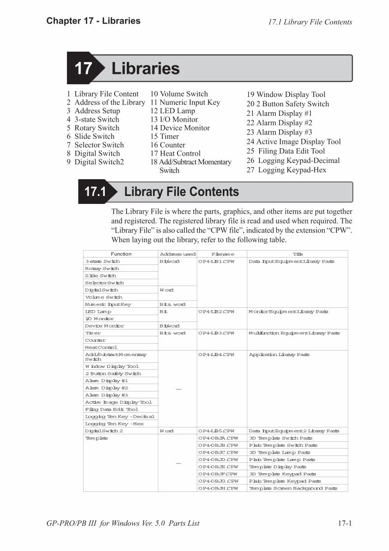
17-1
Chapter 17 - Libraries
GP-PRO/PB III for Windows Ver. 5.0 Parts List
15 Library
The Library File is where the parts, graphics, and other items are put togetherand registered. The registered library file is read and used when required. The�Library File� is also called the �CPW file�, indicated by the extension �CPW�.When laying out the library, refer to the following table.
17.1 Library File Contents
17 Libraries19 Window Display Tool20 2 Button Safety Switch21 Alarm Display #122 Alarm Display #223 Alarm Display #324 Active Image Display Tool25 Filing Data Edit Tool26 Logging Keypad-Decimal27 Logging Keypad-Hex
17.1 Library File Contents
1 Library File Content2 Address of the Library3 Address Setup4 3-state Switch5 Rotary Switch6 Slide Switch7 Selector Switch8 Digital Switch9 Digital Switch2
10 Volume Switch11 Numeric Input Key12 LED Lamp13 I/O Monitor14 Device Monitor15 Timer16 Counter17 Heat Control18 Add/Subtract Momentary
Switch
Function Addressused Filename Title
3-state Switch Bit/word OP4-LIB1.CPW DataInputEquipmentLibraryParts
RotarySwitch
Slide Switch
SelectorSwitch
DigitalSwitch Word
Volume Switch
NumericInputKey Bit& word
LED Lamp Bit OP4-LIB2.CPW MonitorEquipmentLibraryParts
I/O Monitor
Device Monitor Bit/word
Timer Bit& word OP4-LIB3.CPW MultifunctionEquipmentLibraryParts
Counter
HeatControl
Add/SubtractMomentarySwitch
---
OP4-LIB4.CPW ApplicationLibraryParts
Window DisplayTool
2ButtonSafetySwitch
Alarm Display#1
Alarm Display#2
Alarm Display#3
Active Image DisplayTool
Filing DataEdit Tool
Logging TenKey-Decimal
Logging TenKey-Hex
DigitalSwitch2 Word OP4-LIB5.CPW DataInputEquipment2LibraryParts
Template
---
OP4-OBJA.CPW 3D Template SwitchParts
OP4-OBJB.CPW PlainTemplate SwitchParts
OP4-OBJC.CPW 3D Template Lamp Parts
OP4-OBJD.CPW PlainTemplate Lamp Parts
OP4-OBJE.CPW Template DisplayParts
OP4-OBJF.CPW 3D Template Keypad Parts
OP4-OBJG.CPW PlainTemplate Keypad Parts
OP4-OBJH.CPW Template ScreenBackground Parts
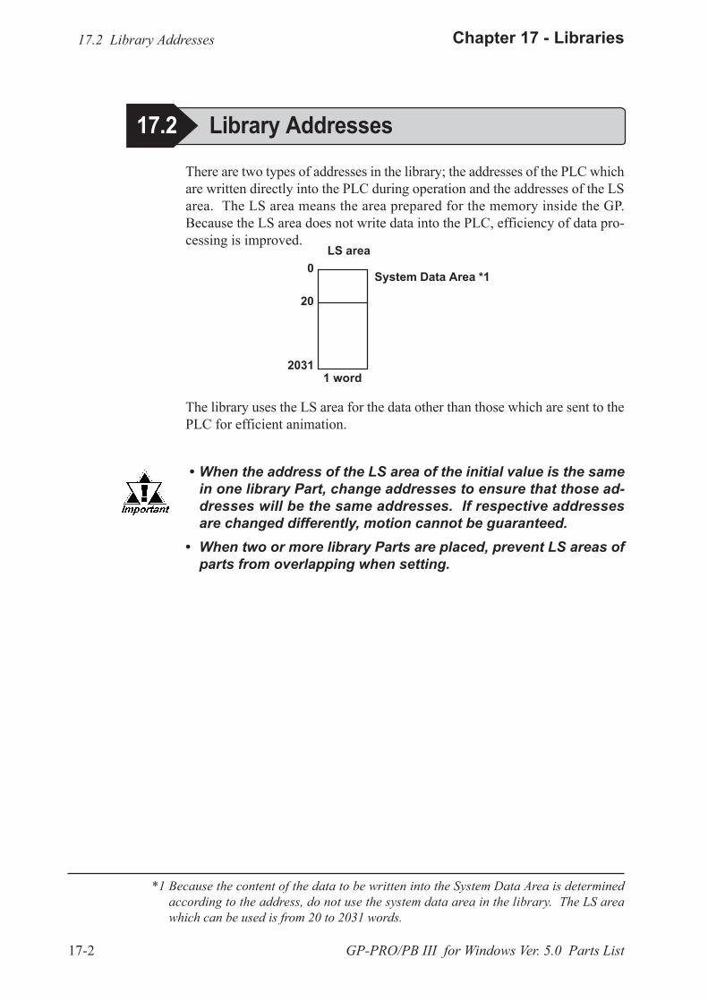
17-2
Chapter 17 - Libraries
GP-PRO/PB III for Windows Ver. 5.0 Parts List
There are two types of addresses in the library; the addresses of the PLC whichare written directly into the PLC during operation and the addresses of the LSarea. The LS area means the area prepared for the memory inside the GP.Because the LS area does not write data into the PLC, efficiency of data pro-cessing is improved.
*1 Because the content of the data to be written into the System Data Area is determinedaccording to the address, do not use the system data area in the library. The LS areawhich can be used is from 20 to 2031 words.
The library uses the LS area for the data other than those which are sent to thePLC for efficient animation.
� When the address of the LS area of the initial value is the samein one library Part, change addresses to ensure that those ad-dresses will be the same addresses. If respective addressesare changed differently, motion cannot be guaranteed.
� When two or more library Parts are placed, prevent LS areas ofparts from overlapping when setting.
17.2 Library Addresses
17.2 Library Addresses
System Data Area *1
20
0LS area
1 word2031
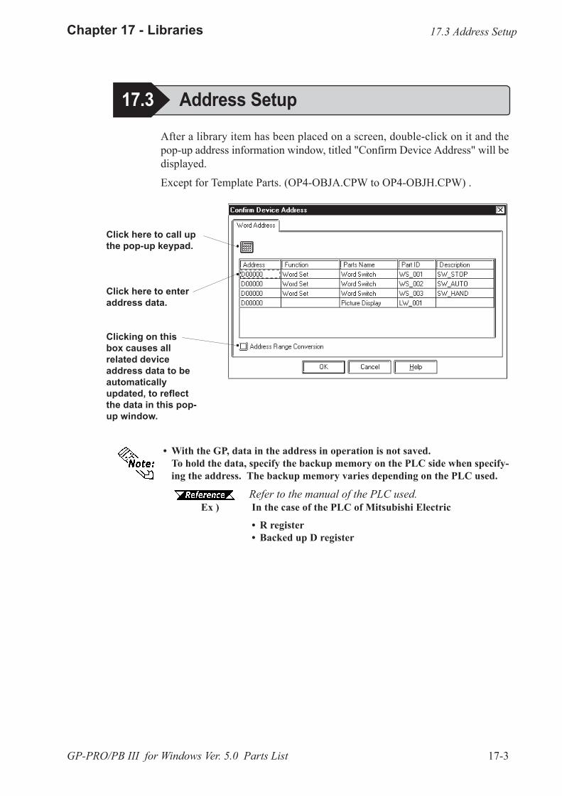
17-3
Chapter 17 - Libraries
GP-PRO/PB III for Windows Ver. 5.0 Parts List
After a library item has been placed on a screen, double-click on it and thepop-up address information window, titled "Confirm Device Address" will bedisplayed.
Except for Template Parts. (OP4-OBJA.CPW to OP4-OBJH.CPW) .
Click here to call upthe pop-up keypad.
Click here to enteraddress data.
Clicking on thisbox causes allrelated deviceaddress data to beautomaticallyupdated, to reflectthe data in this pop-up window.
� With the GP, data in the address in operation is not saved.To hold the data, specify the backup memory on the PLC side when specify-ing the address. The backup memory varies depending on the PLC used.
Refer to the manual of the PLC used.Ex ) In the case of the PLC of Mitsubishi Electric
� R register� Backed up D register
17.3 Address Setup
17.3 Address Setup
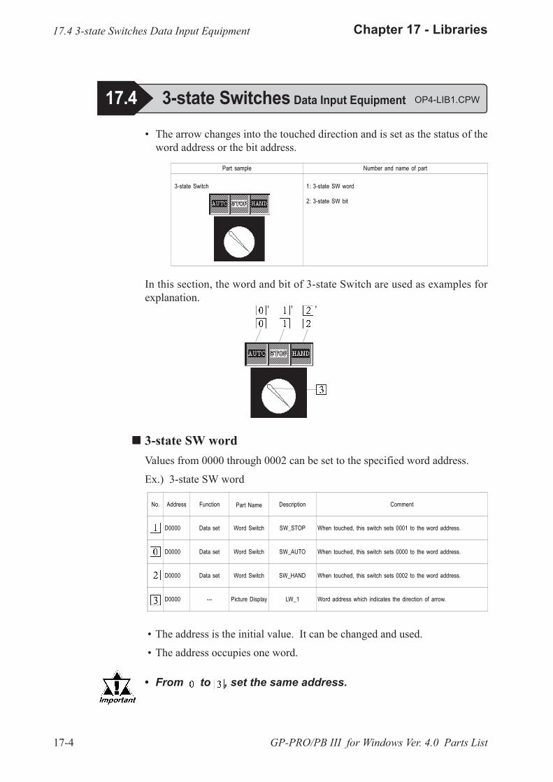
17-4
Chapter 17 - Libraries
GP-PRO/PB III for Windows Ver. 4.0 Parts List
� The arrow changes into the touched direction and is set as the status of theword address or the bit address.
Part sample Number and name of part
3-state Switch 1: 3-state SW word
2: 3-state SW bit
In this section, the word and bit of 3-state Switch are used as examples forexplanation.
'' '
!!!!! 3-state SW wordValues from 0000 through 0002 can be set to the specified word address.
Ex.) 3-state SW word
No. Address Function Part Name Description Comment
D0000 Data set Word Switch SW_STOP When touched, this switch sets 0001 to the word address.
D0000 Data set Word Switch SW_AUTO When touched, this switch sets 0000 to the word address.
D0000 Data set Word Switch SW_HAND When touched, this switch sets 0002 to the word address.
D0000 --- Picture Display LW_1 Word address which indicates the direction of arrow.
� The address is the initial value. It can be changed and used.
� The address occupies one word.
� From to , set the same address.
17.4 3-state Switches Data Input Equipment
17.4 3-state Switches Data Input Equipment OP4-LIB1.CPW
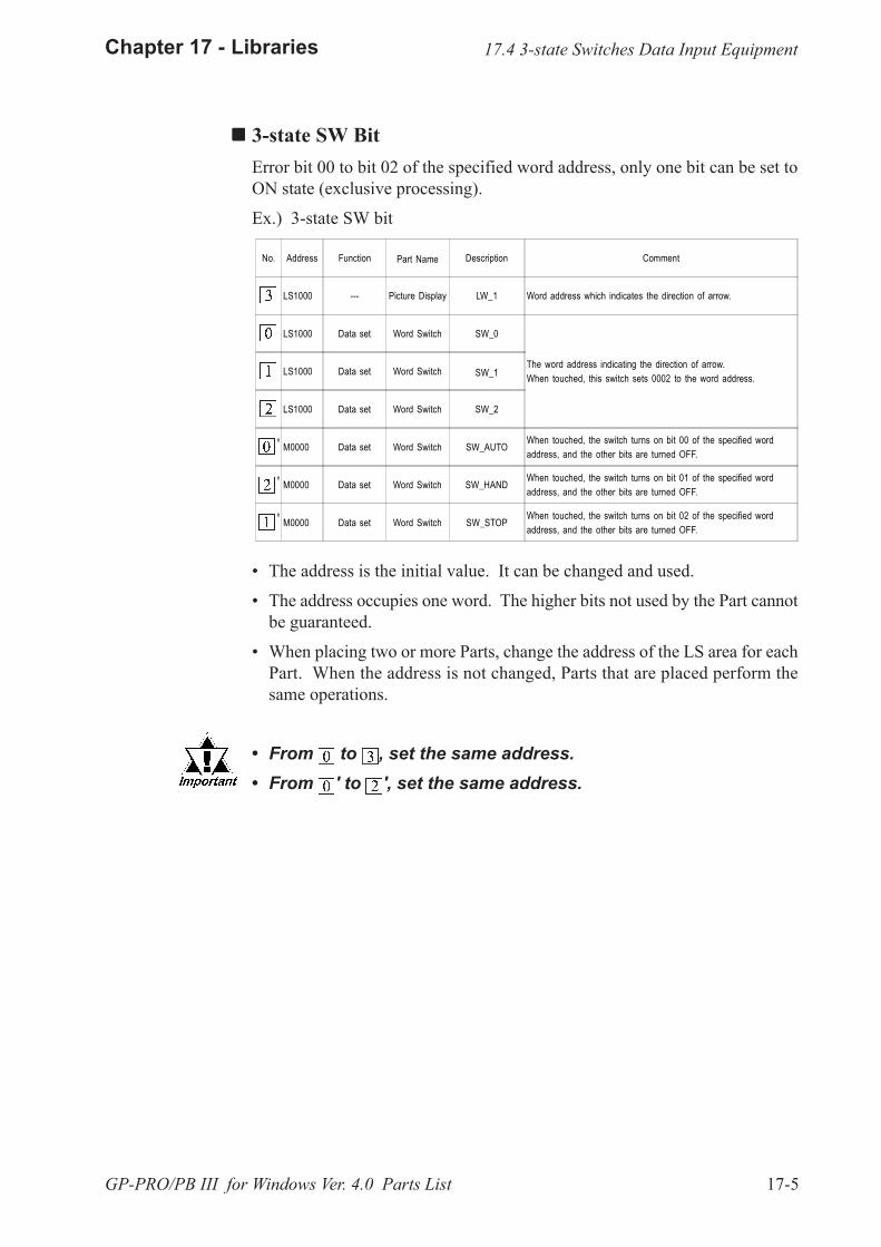
17-5
Chapter 17 - Libraries
GP-PRO/PB III for Windows Ver. 4.0 Parts List
!!!!! 3-state SW BitError bit 00 to bit 02 of the specified word address, only one bit can be set toON state (exclusive processing).
Ex.) 3-state SW bit
No. Address Function Part Name Description Comment
LS1000 --- Picture Display LW_1 Word address which indicates the direction of arrow.
LS1000 Data set Word Switch SW_0
The word address indicating the direction of arrow.When touched, this switch sets 0002 to the word address.
LS1000 Data set Word Switch SW_1
LS1000 Data set Word Switch SW_2
M0000 Data set Word Switch SW_AUTOWhen touched, the switch turns on bit 00 of the specified wordaddress, and the other bits are turned OFF.
M0000 Data set Word Switch SW_HANDWhen touched, the switch turns on bit 01 of the specified wordaddress, and the other bits are turned OFF.
M0000 Data set Word Switch SW_STOPWhen touched, the switch turns on bit 02 of the specified wordaddress, and the other bits are turned OFF.
� The address is the initial value. It can be changed and used.
� The address occupies one word. The higher bits not used by the Part cannotbe guaranteed.
� When placing two or more Parts, change the address of the LS area for eachPart. When the address is not changed, Parts that are placed perform thesame operations.
� From to , set the same address.� From ' to ', set the same address.
'
'
'
17.4 3-state Switches Data Input Equipment
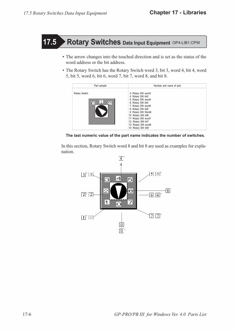
17-6
Chapter 17 - Libraries
GP-PRO/PB III for Windows Ver. 4.0 Parts List
� The arrow changes into the touched direction and is set as the status of theword address or the bit address.
� The Rotary Switch has the Rotary Switch word 3, bit 3, word 4, bit 4, word5, bit 5, word 6, bit 6, word 7, bit 7, word 8, and bit 8.
Part sample Number and name of part
Rotary Switch 3: Rotary SW word3 4: Rotary SW bit3 5: Rotary SW word4 6: Rotary SW bit4 7: Rotary SW word5 8: Rotary SW bit5 9: Rotary SW Word610: Rotary SW bit611: Rotary SW word712: Rotary SW bit713: Rotary SW word814: Rotary SW bit8
The last numeric value of the part name indicates the number of switches.
In this section, Rotary Switch word 8 and bit 8 are used as examples for expla-nation.
17.5 Rotary Switches Data Input Equipment OP4-LIB1.CPW
17.5 Rotary Switches Data Input Equipment
'
'
'
'
'
'
'
'

17-7
Chapter 17 - Libraries
GP-PRO/PB III for Windows Ver. 4.0 Parts List
! ! ! ! ! Rotary SW WordValues from 0000 through 0007 can be set to the specified word address.
Ex.) Rotary SW word8
No. Address Function Part Name Description Comment
D0000 Data Set Word Switch SW_0 When touched, the switch sets 0000 to the specified word address.
D0000 Data Set Word Switch SW_1 When touched, the switch sets 0001 to the specified word address.
D0000 Data Set Word Switch SW_2 When touched, the switch sets 0002 to the specified word address.
D0000 Data Set Word Switch SW_3 When touched, the switch sets 0003 to the specified word address.
D0000 Data Set Word Switch SW_4 When touched, the switch sets 0004 to the specified word address.
D0000 Data set Word Switch SW_5 When touched, the switch sets 0005 to the specified word address.
D0000 Data Set Word Switch SW_6 When touched, the switch sets 0006 to the specified word address.
D0000 Data Set Word Switch SW_7 When touched, the switch sets 0007 to the specified word address.
D0000 --- Picture Display LW_1 Word address which indicates the direction of arrow.
� The address is the initial value. It can be changed and used.
� The address occupies one word.
� From to , set the same address.
17.5 Rotary Switches Data Input Equipment

17-8
Chapter 17 - Libraries
GP-PRO/PB III for Windows Ver. 4.0 Parts List
! ! ! ! ! Rotary SW BitWithin bit 00 to bit 07 of the specified word address, only one bit can be set toON state (exclusive processing).
Ex.) Rotary SW bit8
No. Address Function Part Name Description Comment
LS1000 Data Set Word Switch SW_0
The word address indicating the direction of arrow.
LS1000 Data Set Word Switch SW_1
LS1000 Data Set Word Switch SW_2
LS1000 Data Set Word Switch SW_3
LS1000 Data Set Word Switch SW_4
LS1000 Data Set Word Switch SW_5
LS1000 Data Set Word Switch SW_6
LS1000 Data Set Word Switch SW_7
LS1000 --- Picture Display LW_1 Word address which indicates the direction of arrow.
M0000 Data Set Word Switch SW_0B When touched, the switch turns on bit 00 of the specified wordaddress.
M0000 Data Set Word Switch SW_1B When touched, the switch turns on bit 01 of the specified wordaddress.
M0000 Data Set Word Switch SW_2B When touched, the switch turns on bit 02 of the specified wordaddress.
M0000 Data Set Word Switch SW_3B When touched, the switch turns on bit 03 of the specified wordaddress.
M0000 Data Set Word Switch SW_4B When touched, the switch turns on bit 04 of the specified wordaddress.
M0000 Data Set Word Switch SW_5B When touched, the switch turns on bit 05 of the specified wordaddress.
M0000 Data Set Word Switch SW_6B When touched, the switch turns on bit 06 of the specified wordaddress.
M0000 Data Set Word Switch SW_7B When touched, the switch turns on bit 07 of the specified wordaddress.
'
� The address is the initial value. It can be changed and used.
� From to , set the same address.� From 'to ', set the same address.� The address occupies one word. The higher bits not used by
the Part cannot be guaranteed.� When placing two or more Parts, change the address of the LS
area. When the address is not changed, Parts that are placedmake the same operations.
'
'
'
'
'
'
'
17.5 Rotary Switches Data Input Equipment
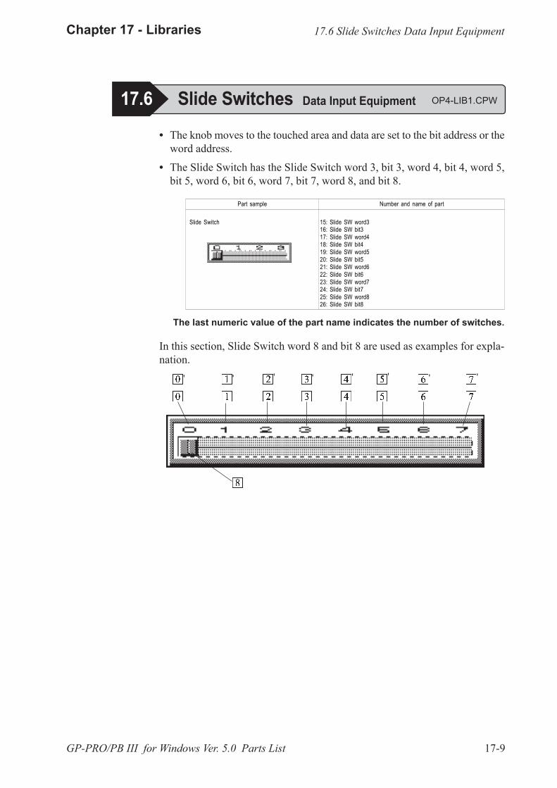
17-9
Chapter 17 - Libraries
GP-PRO/PB III for Windows Ver. 5.0 Parts List
� The knob moves to the touched area and data are set to the bit address or theword address.
� The Slide Switch has the Slide Switch word 3, bit 3, word 4, bit 4, word 5,bit 5, word 6, bit 6, word 7, bit 7, word 8, and bit 8.
Part sample Number and name of part
Slide Switch 15: Slide SW word316: Slide SW bit317: Slide SW word418: Slide SW bit419: Slide SW word520: Slide SW bit521: Slide SW word622: Slide SW bit623: Slide SW word724: Slide SW bit725: Slide SW word826: Slide SW bit8
The last numeric value of the part name indicates the number of switches.
In this section, Slide Switch word 8 and bit 8 are used as examples for expla-nation.
17.6 Slide Switches Data Input Equipment OP4-LIB1.CPW
17.6 Slide Switches Data Input Equipment
' ' ' ' ' ' ' '
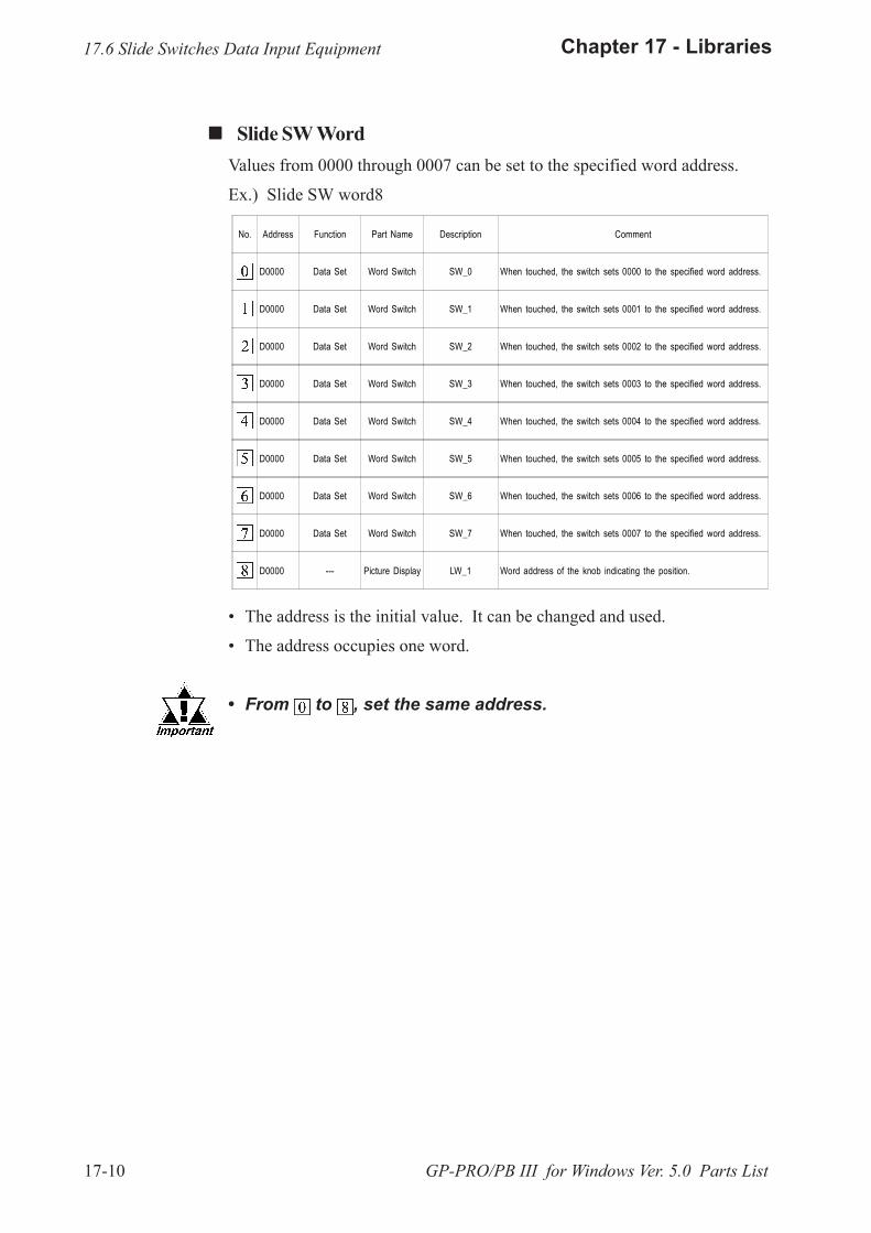
17-10
Chapter 17 - Libraries
GP-PRO/PB III for Windows Ver. 5.0 Parts List
! ! ! ! ! Slide SW WordValues from 0000 through 0007 can be set to the specified word address.
Ex.) Slide SW word8
No. Address Function Part Name Description Comment
D0000 Data Set Word Switch SW_0 When touched, the switch sets 0000 to the specified word address.
D0000 Data Set Word Switch SW_1 When touched, the switch sets 0001 to the specified word address.
D0000 Data Set Word Switch SW_2 When touched, the switch sets 0002 to the specified word address.
D0000 Data Set Word Switch SW_3 When touched, the switch sets 0003 to the specified word address.
D0000 Data Set Word Switch SW_4 When touched, the switch sets 0004 to the specified word address.
D0000 Data Set Word Switch SW_5 When touched, the switch sets 0005 to the specified word address.
D0000 Data Set Word Switch SW_6 When touched, the switch sets 0006 to the specified word address.
D0000 Data Set Word Switch SW_7 When touched, the switch sets 0007 to the specified word address.
D0000 --- Picture Display LW_1 Word address of the knob indicating the position.
� The address is the initial value. It can be changed and used.
� The address occupies one word.
� From to , set the same address.
17.6 Slide Switches Data Input Equipment
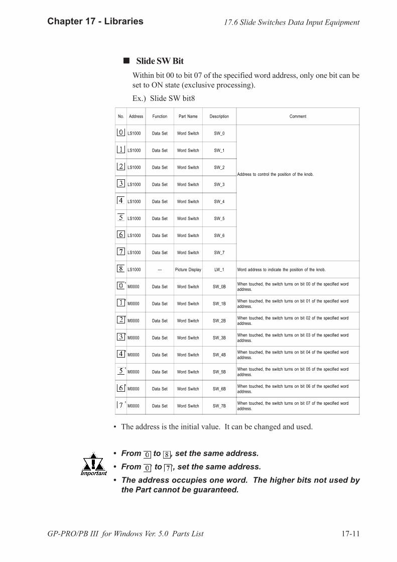
17-11
Chapter 17 - Libraries
GP-PRO/PB III for Windows Ver. 5.0 Parts List
! ! ! ! ! Slide SW BitWithin bit 00 to bit 07 of the specified word address, only one bit can beset to ON state (exclusive processing).
Ex.) Slide SW bit8
No. Address Function Part Name Description Comment
LS1000 Data Set Word Switch SW_0
Address to control the position of the knob.
LS1000 Data Set Word Switch SW_1
LS1000 Data Set Word Switch SW_2
LS1000 Data Set Word Switch SW_3
LS1000 Data Set Word Switch SW_4
LS1000 Data Set Word Switch SW_5
LS1000 Data Set Word Switch SW_6
LS1000 Data Set Word Switch SW_7
LS1000 --- Picture Display LW_1 Word address to indicate the position of the knob.
M0000 Data Set Word Switch SW_0B When touched, the switch turns on bit 00 of the specified wordaddress.
M0000 Data Set Word Switch SW_1B When touched, the switch turns on bit 01 of the specified wordaddress.
M0000 Data Set Word Switch SW_2B When touched, the switch turns on bit 02 of the specified wordaddress.
M0000 Data Set Word Switch SW_3B When touched, the switch turns on bit 03 of the specified wordaddress.
M0000 Data Set Word Switch SW_4B When touched, the switch turns on bit 04 of the specified wordaddress.
M0000 Data Set Word Switch SW_5B When touched, the switch turns on bit 05 of the specified wordaddress.
M0000 Data Set Word Switch SW_6B When touched, the switch turns on bit 06 of the specified wordaddress.
M0000 Data Set Word Switch SW_7B When touched, the switch turns on bit 07 of the specified wordaddress.
'
'
'
'
'
'
'
'
� The address is the initial value. It can be changed and used.
� From to , set the same address.� From ' to ', set the same address.� The address occupies one word. The higher bits not used by
the Part cannot be guaranteed.
17.6 Slide Switches Data Input Equipment

17-12
Chapter 17 - Libraries
GP-PRO/PB III for Windows Ver. 5.0 Parts List
� Sets only the one touched position to ON state (exclusive processing).
� Sets the data of ON state switch to the bit address or the word address.
� The Selector Switch has the Selector Switch word 3, bit 3, word 4, bit 4,word 5, bit 5, word 6, bit 6, word 7, bit 7, word 8, and bit 8.
Part sample Number and name of part
Selector Switch 27: Selector SW word328: Selector SW bit329: Selector SW word430: Selector SW bit431: Selector SW word532: Selector SW bit533: Selector SW word634: Selector SW bit635: Selector SW word736: Selector SW bit737: Selector SW word838: Selector SW bit8
The last numeric value of the part name indicates the number of switches.
In this section, Selector Switch word 8 and bit 8 are used as examples forexplanation.
17.7 Selector Switches Data Input Equipment
17.7 Selector Switches Data Input Equipment OP4-LIB1.CPW
' ' ' ' ' ' ' '
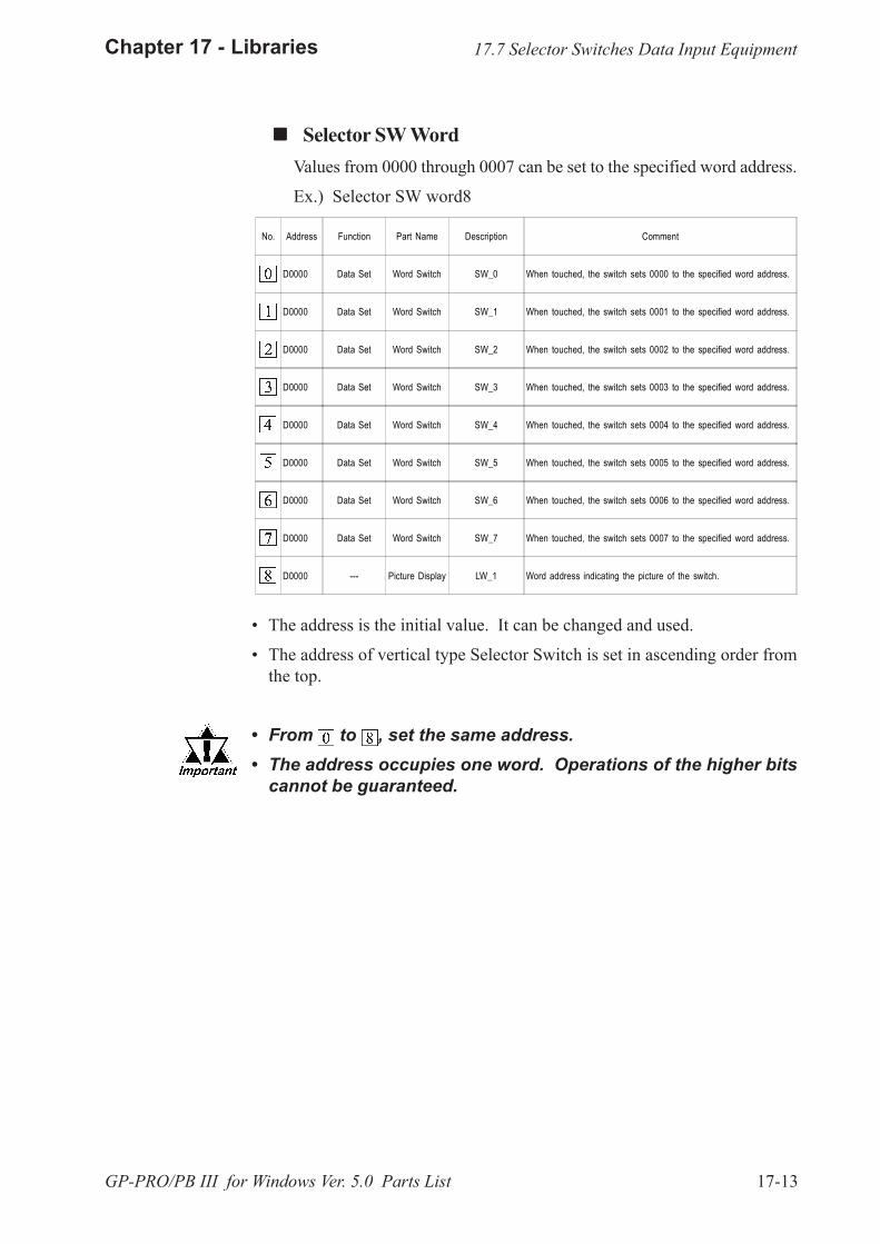
17-13
Chapter 17 - Libraries
GP-PRO/PB III for Windows Ver. 5.0 Parts List
! ! ! ! ! Selector SW WordValues from 0000 through 0007 can be set to the specified word address.
Ex.) Selector SW word8
No. Address Function Part Name Description Comment
D0000 Data Set Word Switch SW_0 When touched, the switch sets 0000 to the specified word address.
D0000 Data Set Word Switch SW_1 When touched, the switch sets 0001 to the specified word address.
D0000 Data Set Word Switch SW_2 When touched, the switch sets 0002 to the specified word address.
D0000 Data Set Word Switch SW_3 When touched, the switch sets 0003 to the specified word address.
D0000 Data Set Word Switch SW_4 When touched, the switch sets 0004 to the specified word address.
D0000 Data Set Word Switch SW_5 When touched, the switch sets 0005 to the specified word address.
D0000 Data Set Word Switch SW_6 When touched, the switch sets 0006 to the specified word address.
D0000 Data Set Word Switch SW_7 When touched, the switch sets 0007 to the specified word address.
D0000 --- Picture Display LW_1 Word address indicating the picture of the switch.
� The address is the initial value. It can be changed and used.
� The address of vertical type Selector Switch is set in ascending order fromthe top.
� From to , set the same address.� The address occupies one word. Operations of the higher bits
cannot be guaranteed.
17.7 Selector Switches Data Input Equipment
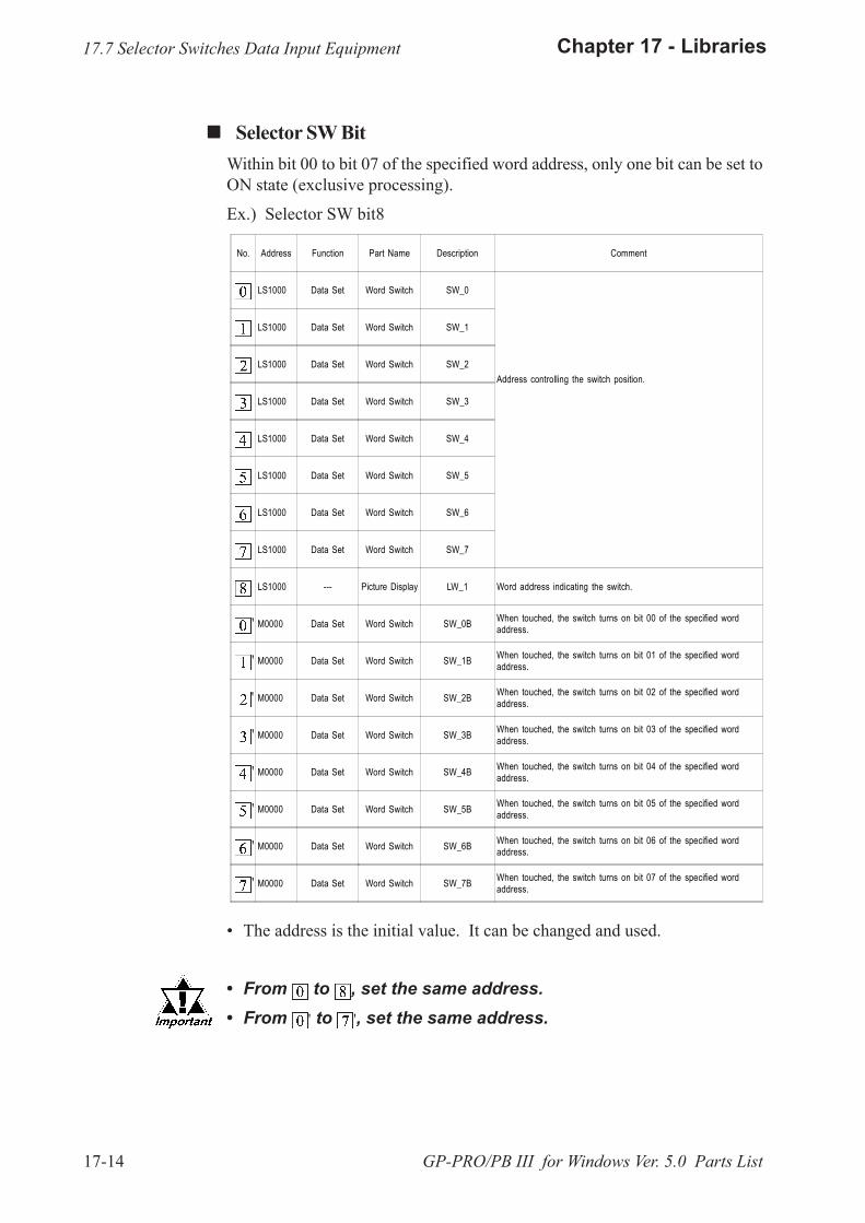
17-14
Chapter 17 - Libraries
GP-PRO/PB III for Windows Ver. 5.0 Parts List
! ! ! ! ! Selector SW BitWithin bit 00 to bit 07 of the specified word address, only one bit can be set toON state (exclusive processing).
Ex.) Selector SW bit8
No. Address Function Part Name Description Comment
LS1000 Data Set Word Switch SW_0
Address controlling the switch position.
LS1000 Data Set Word Switch SW_1
LS1000 Data Set Word Switch SW_2
LS1000 Data Set Word Switch SW_3
LS1000 Data Set Word Switch SW_4
LS1000 Data Set Word Switch SW_5
LS1000 Data Set Word Switch SW_6
LS1000 Data Set Word Switch SW_7
LS1000 --- Picture Display LW_1 Word address indicating the switch.
M0000 Data Set Word Switch SW_0B When touched, the switch turns on bit 00 of the specified wordaddress.
M0000 Data Set Word Switch SW_1B When touched, the switch turns on bit 01 of the specified wordaddress.
M0000 Data Set Word Switch SW_2B When touched, the switch turns on bit 02 of the specified wordaddress.
M0000 Data Set Word Switch SW_3B When touched, the switch turns on bit 03 of the specified wordaddress.
M0000 Data Set Word Switch SW_4B When touched, the switch turns on bit 04 of the specified wordaddress.
M0000 Data Set Word Switch SW_5B When touched, the switch turns on bit 05 of the specified wordaddress.
M0000 Data Set Word Switch SW_6B When touched, the switch turns on bit 06 of the specified wordaddress.
M0000 Data Set Word Switch SW_7B When touched, the switch turns on bit 07 of the specified wordaddress.
'
� The address is the initial value. It can be changed and used.
� From to , set the same address.� From ' to ', set the same address.
'
'
'
'
'
'
'
17.7 Selector Switches Data Input Equipment
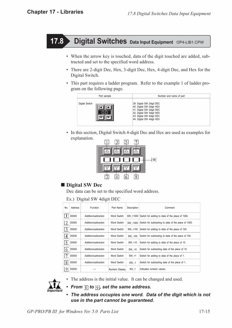
17-15
Chapter 17 - Libraries
GP-PRO/PB III for Windows Ver. 5.0 Parts List
No. Address Function Part Name Description Comment
D0000 Addition/subtraction Word Switch SW_+1000 Switch for adding to data of the place of 1000.
D0000 Addition/subtraction Word Switch SW_-1000 Switch for subtracting to data of the place of 1000.
D0000 Addition/subtraction Word Switch SW_+100 Switch for adding to data of the place of 100.
D0000 Addition/subtraction Word Switch SW_-100 Switch for subtracting to data of the place of 100.
D0000 Addition/subtraction Word Switch SW_+10 Switch for adding to data of the place of 10.
D0000 Addition/subtraction Word Switch SW_-10 Switch for subtracting data of the place of 10.
D0000 Addition/subtraction Word Switch SW_+1 Switch for adding to data of the place of 1.
D0000 Addition/subtraction Word Switch SW_-1 Switch for subtracting data of the place of 1.
D0000 --- Numeric Display NU_1 Indicates numeric values.
Part sample Number and name of part
Digital Switch 39: Digital SW 2digit DEC40: Digital SW 2digit HEX41: Digital SW 3digit DEC42: Digital SW 3digit HEX43: Digital SW 4digit DEC44: Digital SW 4digit HEX
� In this section, Digital Switch 4-digit Dec and Hex are used as examples forexplanation.
!!!!! Digital SW DecDec data can be set to the specified word address.
Ex.) Digital SW 4digit DEC
� The address is the initial value. It can be changed and used.
� From to , set the same address.� The address occupies one word. Data of the digit which is not
use in the part cannot be guaranteed.
� When the arrow key is touched, data of the digit touched are added, sub-tracted and set to the specified word address.
� There are 2-digit Dec, Hex, 3-digit Dec, Hex, 4-digit Dec, and Hex for theDigital Switch.
� This part requires a ladder program. Refer to the example 1 of ladder pro-gram on the following page.
17.8 Digital Switches Data Input Equipment OP4-LIB1.CPW
17.8 Digital Switches Data Input Equipment

17-16
Chapter 17 - Libraries
GP-PRO/PB III for Windows Ver. 5.0 Parts List
� The address is the initial value. It can be changed and used.
� From to , set the same address.� The address occupies one word. Data of the digit which is not
use in the part cannot be guaranteed.
!!!!! Ladder program Example #1In the case of 0000 to 9999 for 4-digit Dec.
The ladder program indicates the method for controlling the upper limit andthe lower limit.
D0: Specify the address of to .
!!!!! Digital SW Hex
No. Address Function Part Name Description Comment
D0000 Addition/subtraction Word Switch SW_+4096 Switch for adding to data of the place of 1000.
D0000 Addition/subtraction Word Switch SW_-4096 Switch for subtracting to data of the place of 1000.
D0000 Addition/subtraction Word Switch SW_+256 Switch for adding to data of the place of 100.
D0000 Addition/subtraction Word Switch SW_-256 Switch for subtracting to data of the place of 100.
D0000 Addition/subtraction Word Switch SW_+16 Switch for adding to data of the place of 10.
D0000 Addition/subtraction Word Switch SW_-16 Switch for subtracting data of the place of 10.
D0000 Addition/subtraction Word Switch SW_+1 Switch for adding to data of the place of 1.
D0000 Addition/subtraction Word Switch SW_-1 Switch for subtracting data of the place of 1.
D0000 --- Numeric Display NU_1 Indicates numeric values.
For Mitsubishi Electric MELSEC series
The following data which can be entered are given asthe reference.
Entry data format Hex
Displayed digit (Hexadecimal)
2 digits 00-FFh
3 digits 000-FFFh
4 digits 0000-FFFFh
The following data which can be entered are given asthe reference.
Entry data format Dec Hex
Displayed digit (Decimal) (Hexadecimal)
2 digits 0000-0099 0000-0063h
3 digits 0000-0099 0000-03E7h
4 digits 0000-0099 0000-270Fh
K 0 D 0 MOV K 0 D 0
D 0D 0K9999 K9999MOV
17.8 Digital Switches Data Input Equipment
Dec data can be set to the specified word address.
Ex.) Digital SW 4digit HEX
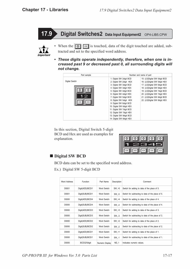
17-17
Chapter 17 - Libraries
GP-PRO/PB III for Windows Ver. 5.0 Parts List
Part sample Number and name of part
Digital Switch 1: Digital SW 2digit BCD 2: Digital SW 2digit HEX 3: Digital SW 3digit BCD 4: Digital SW 3digit HEX 5: Digital SW 4digit BCD 6: Digital SW 4digit HEX 7: Digital SW 5digit BCD 8: Digital SW 5digit HEX 9: Digital SW 6digit BCD10: Digital SW 6digit HEX11: Digital SW 7digit BCD12: Digital SW 7digit HEX13: Digital SW 8digit BCD14: Digital SW 8digit HEX
15: (LS)Digital SW 5digit BCD16: (LS)Digital SW 5digit HEX17: (LS)Digital SW 6digit BCD18: (LS)Digital SW 6digit HEX19: (LS)Digital SW 7digit BCD20: (LS)Digital SW 7digit HEX21: (LS)Digital SW 8digit BCD22: (LS)Digital SW 8digit HEX
In this section, Digital Switch 5-digitBCD and Hex are used as examples forexplanation.
!!!!! Digital SW BCDBCD data can be set to the specified word address.
Ex.) Digital SW 5-digit BCD
� When the is touched, data of the digit touched are added, sub-tracted and set to the specified word address.
Word Address Function Part Name Description Comment
D0001 Digit(ADD)/BCD/1 Word Switch SW_+5 Switch for adding to data of the place of 5.
D0001 Digit(SUB)/BCD/1 Word Switch SW_-5 Switch for subtracting to data of the place of 5.
D0000 Digit(ADD)/BCD/4 Word Switch SW_+4 Switch for adding to data of the place of 4.
D0000 Digit(SUB)/BCD/4 Word Switch SW_-4 Switch for subtracting to data of the place of 4.
D0000 Digit(ADD)/BCD/3 Word Switch SW_+3 Switch for adding to data of the place of 3.
D0000 Digit(SUB)/BCD/3 Word Switch SW_-3 Switch for subtracting to data of the place of 3.
D0000 Digit(ADD)/BCD/2 Word Switch SW_+2 Switch for adding to data of the place of 2.
D0000 Digit(SUB)/BCD/2 Word Switch SW_-2 Switch for subtracting to data of the place of 2.
D0000 Digit(ADD)/BCD/1 Word Switch SW_+1 Switch for adding to data of the place of 1.
D0000 Digit(SUB)/BCD/1 Word Switch SW_-1 Switch for subtracting to data of the place of 1.
D0000 BCD32/5digit Numeric Display ND_1 Indicates numeric values.
17.9 Digital Switches2 Data Input Equipment2 OP4-LIB5.CPW
17.9 Digital Switches2 Data Input Equipment2
� These digits operate independently, therefore, when one is in-creased past 9 or decreased past 0, all surrounding digits willnot change.
17-18
Chapter 17 - Libraries
GP-PRO/PB III for Windows Ver. 5.0 Parts List
!!!!! (LS) Digital SW BCDBCD data can be set to the specified word address.
Ex.) (LS) Digital SW 5-digit BCD
Word Address Function Part Name Description Comment
LS00000 Digit(ADD)/BCD/1 Word Switch SW_+5 Switch for adding to data of the place of 5.
LS00000 Digit(SUB)/BCD/1 Word Switch SW_-5 Switch for subtracting to data of the place of 5.
LS00001 Digit(ADD)/BCD/4 Word Switch SW_+4 Switch for adding to data of the place of 4.
LS00001 Digit(SUB)/BCD/4 Word Switch SW_-4 Switch for subtracting to data of the place of 4.
LS00001 Digit(ADD)/BCD/3 Word Switch SW_+3 Switch for adding to data of the place of 3.
LS00001 Digit(SUB)/BCD/3 Word Switch SW_-3 Switch for subtracting to data of the place of 3.
LS00001 Digit(ADD)/BCD/2 Word Switch SW_+2 Switch for adding to data of the place of 2.
LS00001 Digit(SUB)/BCD/2 Word Switch SW_-2 Switch for subtracting to data of the place of 2.
LS00001 Digit(ADD)/BCD/1 Word Switch SW_+1 Switch for adding to data of the place of 1.
LS00001 Digit(SUB)/BCD/1 Word Switch SW_-1 Switch for subtracting to data of the place of 1.
LS00000 BCD32/5digit Numeric Display ND_1 Indicates numeric values.
� The address is the initial value. It can be changed and used.
� Please select �(LS) digital SW ***� as the part name in the fol-lowing cases:1. When the memory link setting is used.2. When an LS device is used.3. When a device which processes two-word data as H/L *1 isused.
� A part�s address -up to four digits- will occupy one word. Partaddresses of five digits or more will occupy two words. Dataremaining in any unused digits cannot be assured.
� No overflow occurs with this digital switch. It only indicatesvalues from 0 to 9.
� This part can only be used for a 16-bit device.
<Changing addresses>Click on the check box for �Change all addresses in 1 group.�Then, in the address field, enter the first address for the part�snumeric display, and then change all the addresses.
*1 For each device�s two-word processing, please refer to the PLC Connection Manualremarks in chapters 2-*-3 and 5-*-3, �Supported Devices�.
17.9 Digital Switches2 Data Input Equipment2
17-19
Chapter 17 - Libraries
GP-PRO/PB III for Windows Ver. 5.0 Parts List
!!!!! Digital SW HexHex data can be set to the specified word address.
Ex.) Digital SW 5-digit Hex
Word Address Function Part Name Description Comment
D0001 Digit(ADD)/BIN/1 Word Switch SW_+5 Switch for adding to data of the place of 5.
D0001 Digit(SUB)/BIN/1 Word Switch SW_-5 Switch for subtracting to data of the place of 5.
D0000 Digit(ADD)/BIN/4 Word Switch SW_+4 Switch for adding to data of the place of 4.
D0000 Digit(SUB)/BIN/4 Word Switch SW_-4 Switch for subtracting to data of the place of 4.
D0000 Digit(ADD)/BIN/3 Word Switch SW_+3 Switch for adding to data of the place of 3.
D0000 Digit(SUB)/BIN/3 Word Switch SW_-3 Switch for subtracting to data of the place of 3.
D0000 Digit(ADD)/BIN/2 Word Switch SW_+2 Switch for adding to data of the place of 2.
D0000 Digit(SUB)/BIN/2 Word Switch SW_-2 Switch for subtracting to data of the place of 2.
D0000 Digit(ADD)/BIN/1 Word Switch SW_+1 Switch for adding to data of the place of 1.
D0000 Digit(SUB)/BIN/1 Word Switch SW_-1 Switch for subtracting to data of the place of 1.
D0000 HEX32/5digit Numeric Display ND_1 Indicates numeric values.
Word Address Function Part Name Description Comment
LS00000 Digit(ADD)/BIN/1 Word Switch SW_+5 Switch for adding to data of the place of 5.
LS00000 Digit(SUB)/BIN/1 Word Switch SW_-5 Switch for subtracting to data of the place of 5.
LS00001 Digit(ADD)/BIN/4 Word Switch SW_+4 Switch for adding to data of the place of 4.
LS00001 Digit(SUB)/BIN/4 Word Switch SW_-4 Switch for subtracting to data of the place of 4.
LS00001 Digit(ADD)/BIN/3 Word Switch SW_+3 Switch for adding to data of the place of 3.
LS00001 Digit(SUB)/BIN/3 Word Switch SW_-3 Switch for subtracting to data of the place of 3.
LS00001 Digit(ADD)/BIN/2 Word Switch SW_+2 Switch for adding to data of the place of 2.
LS00001 Digit(SUB)/BIN/2 Word Switch SW_-2 Switch for subtracting to data of the place of 2.
LS00001 Digit(ADD)/BIN/1 Word Switch SW_+1 Switch for adding to data of the place of 1.
LS00001 Digit(SUB)/BIN/1 Word Switch SW_-1 Switch for subtracting to data of the place of 1.
LS00000 HEX32/5digit Numeric Display ND_1 Indicates numeric values.
!!!!! (LS) Digital SW HexHex data can be set to the specified word address.
Ex.) (LS) Digital SW 5-digit Hex
� The address is the initial value. It can be changed and used.
17.9 Digital Switches2 Data Input Equipment2
17-20
Chapter 17 - Libraries
GP-PRO/PB III for Windows Ver. 5.0 Parts List
� Please select �(LS) digital SW ***� as the part name in the fol-lowing cases:1. When the memory link setting is used.2. When an LS device is used.3. When a device which processes two-word data as H/L *1 is used.
� A part�s address -up to four digits- will occupy one word. Partaddresses of five digits or more will occupy two words. Dataremaining in any unused digits cannot be assured.
� No overflow occurs with this digital switch. It only indicatesvalues from 0 to 9.
� This part can only be used for a 16-bit device.
<Changing addresses>Click on the check box for �Change all addresses in 1 group.�Then, in the address field, enter the start address for the part�snumeric display, and then change all the addresses.
*1 For each device�s two-word processing, please refer to the PLC Connection Manualremarks in chapters 2-*-3 and 5-*-3, �Supported Devices�.
17.9 Digital Switches2 Data Input Equipment2
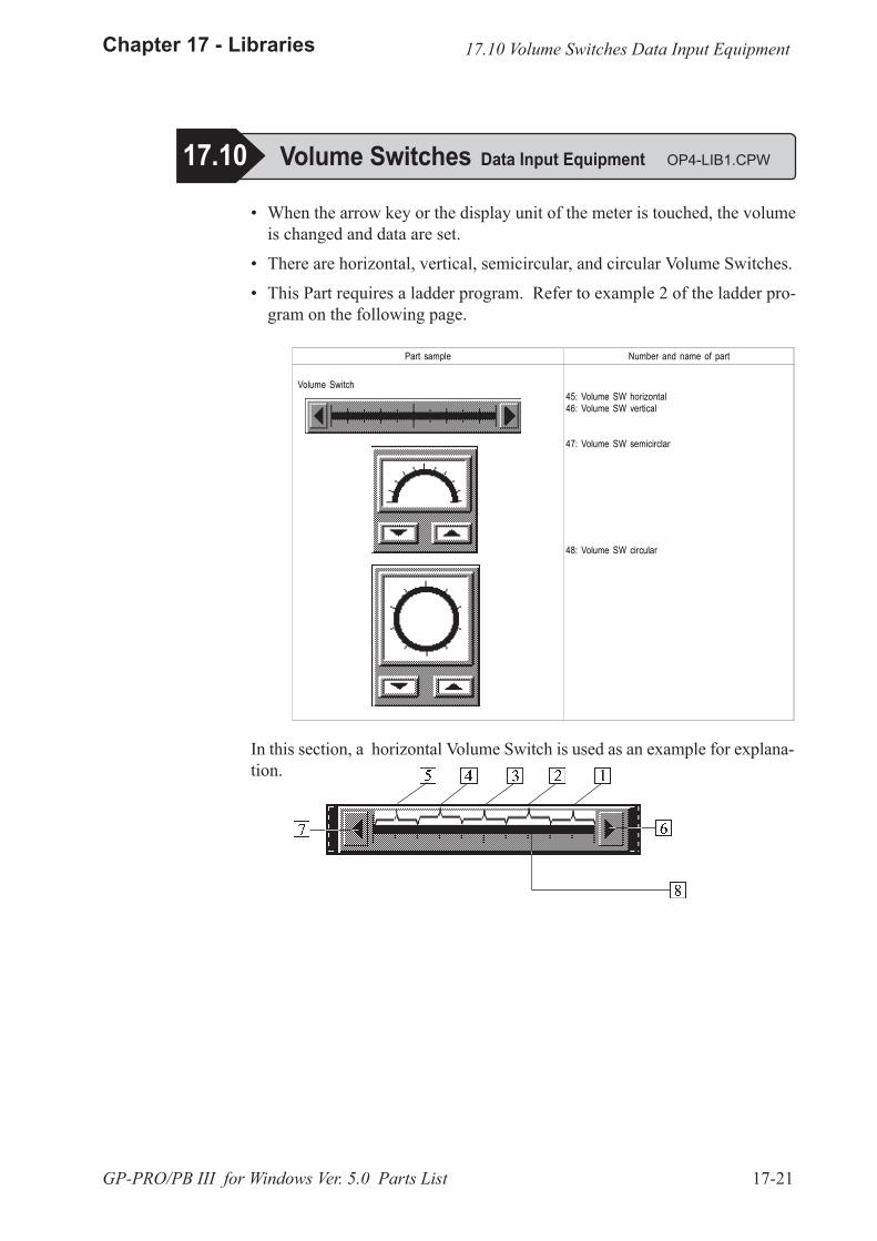
17-21
Chapter 17 - Libraries
GP-PRO/PB III for Windows Ver. 5.0 Parts List
In this section, a horizontal Volume Switch is used as an example for explana-tion.
� When the arrow key or the display unit of the meter is touched, the volumeis changed and data are set.
� There are horizontal, vertical, semicircular, and circular Volume Switches.
� This Part requires a ladder program. Refer to example 2 of the ladder pro-gram on the following page.
17.10 Volume Switches Data Input Equipment
17.10 Volume Switches Data Input Equipment OP4-LIB1.CPW
Part sample Number and name of part
Volume Switch45: Volume SW horizontal46: Volume SW vertical
47: Volume SW semicirclar
48: Volume SW circular
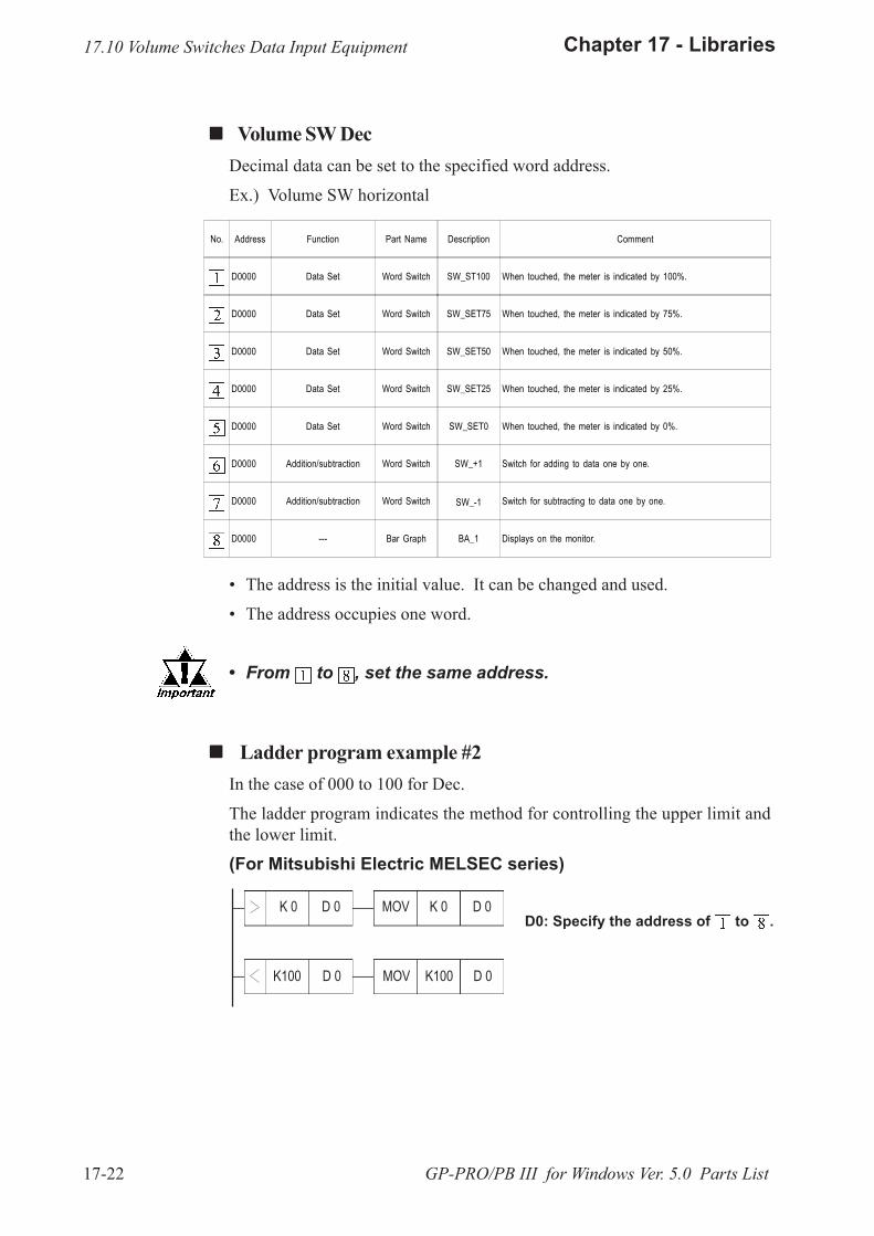
17-22
Chapter 17 - Libraries
GP-PRO/PB III for Windows Ver. 5.0 Parts List
� The address is the initial value. It can be changed and used.
� The address occupies one word.
� From to , set the same address.
! ! ! ! ! Volume SW DecDecimal data can be set to the specified word address.
Ex.) Volume SW horizontal
No. Address Function Part Name Description Comment
D0000 Data Set Word Switch SW_ST100 When touched, the meter is indicated by 100%.
D0000 Data Set Word Switch SW_SET75 When touched, the meter is indicated by 75%.
D0000 Data Set Word Switch SW_SET50 When touched, the meter is indicated by 50%.
D0000 Data Set Word Switch SW_SET25 When touched, the meter is indicated by 25%.
D0000 Data Set Word Switch SW_SET0 When touched, the meter is indicated by 0%.
D0000 Addition/subtraction Word Switch SW_+1 Switch for adding to data one by one.
D0000 Addition/subtraction Word Switch SW_-1 Switch for subtracting to data one by one.
D0000 --- Bar Graph BA_1 Displays on the monitor.
! ! ! ! ! Ladder program example #2In the case of 000 to 100 for Dec.
The ladder program indicates the method for controlling the upper limit andthe lower limit.
(For Mitsubishi Electric MELSEC series)
D0: Specify the address of to .K 0 D 0 MOV K 0 D 0
D 0D 0K100 K100MOV
17.10 Volume Switches Data Input Equipment
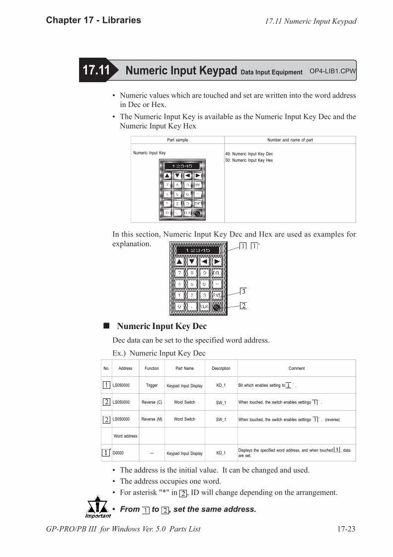
17-23
Chapter 17 - Libraries
GP-PRO/PB III for Windows Ver. 5.0 Parts List
No. Address Function Part Name Description Comment
LS050000 Trigger Keypad Input Display KD_1 Bit which enables setting to .
LS050000 Reverse (C) Word Switch SW_1 When touched, the switch enables settingo .
LS050000 Reverse (M) Word Switch SW_1 When touched, the switch enables settingo . (reverse)
Word address
D0000 --- Keypad Input Display KD_1 Displays the specified word address, and when touched , dataare set.
'
Part sample Number and name of part
Numeric Input Key 49: Numeric Input Key Dec50: Numeric Input Key Hex
� Numeric values which are touched and set are written into the word addressin Dec or Hex.
� The Numeric Input Key is available as the Numeric Input Key Dec and theNumeric Input Key Hex
In this section, Numeric Input Key Dec and Hex are used as examples forexplanation.
! ! ! ! ! Numeric Input Key DecDec data can be set to the specified word address.Ex.) Numeric Input Key Dec
� The address is the initial value. It can be changed and used.� The address occupies one word.� For asterisk "*" in , ID will change depending on the arrangement.
� From to , set the same address.
17.11 Numeric Input Keypad Data Input Equipment OP4-LIB1.CPW
17.11 Numeric Input Keypad
'
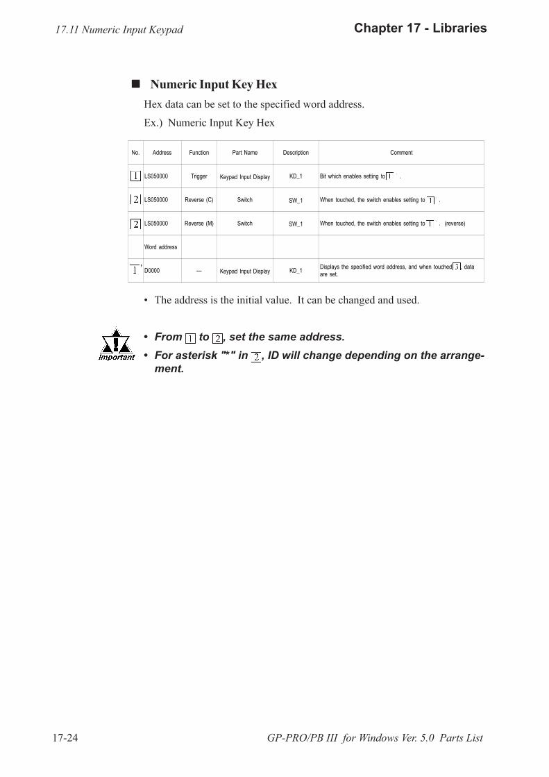
17-24
Chapter 17 - Libraries
GP-PRO/PB III for Windows Ver. 5.0 Parts List
No. Address Function Part Name Description Comment
LS050000 Trigger Keypad Input Display KD_1 Bit which enables setting to .
LS050000 Reverse (C) Switch SW_1 When touched, the switch enables setting to .
LS050000 Reverse (M) Switch SW_1 When touched, the switch enables setting to . (reverse)
Word address
D0000 --- Keypad Input Display KD_1 Displays the specified word address, and when touched , dataare set.
'
� The address is the initial value. It can be changed and used.
� From to , set the same address.� For asterisk "*" in , ID will change depending on the arrange-
ment.
! ! ! ! ! Numeric Input Key HexHex data can be set to the specified word address.
Ex.) Numeric Input Key Hex
17.11 Numeric Input Keypad
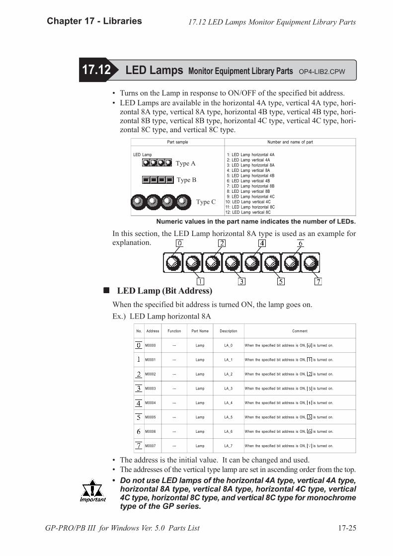
17-25
Chapter 17 - Libraries
GP-PRO/PB III for Windows Ver. 5.0 Parts List
17.12 LED Lamps Monitor Equipment Library Parts
� Turns on the Lamp in response to ON/OFF of the specified bit address.� LED Lamps are available in the horizontal 4A type, vertical 4A type, hori-
zontal 8A type, vertical 8A type, horizontal 4B type, vertical 4B type, hori-zontal 8B type, vertical 8B type, horizontal 4C type, vertical 4C type, hori-zontal 8C type, and vertical 8C type.
Numeric values in the part name indicates the number of LEDs.
In this section, the LED Lamp horizontal 8A type is used as an example forexplanation.
! ! ! ! ! LED Lamp (Bit Address)When the specified bit address is turned ON, the lamp goes on.Ex.) LED Lamp horizontal 8A
� Do not use LED lamps of the horizontal 4A type, vertical 4A type,horizontal 8A type, vertical 8A type, horizontal 4C type, vertical4C type, horizontal 8C type, and vertical 8C type for monochrometype of the GP series.
17.12 LED Lamps Monitor Equipment Library Parts OP4-LIB2.CPW
Part sample Number and name of part
LED Lamp 1: LED Lamp horizontal 4A 2: LED Lamp vertical 4A 3: LED Lamp horizontal 8A 4: LED Lamp vertical 8A 5: LED Lamp horizontal 4B 6: LED Lamp vertical 4B 7: LED Lamp horizontal 8B 8: LED Lamp vertical 8B 9: LED Lamp horizontal 4C10: LED Lamp vertical 4C11: LED Lamp horizontal 8C12: LED Lamp vertical 8C
Type A
Type C
Type B
No. Address Function Part Name Description Comment
M0000 --- Lamp LA_0 When the specified bit address is ON, is turned on.
M0001 --- Lamp LA_1 When the specified bit address is ON, is turned on.
M0002 --- Lamp LA_2 When the specified bit address is ON, is turned on.
M0003 --- Lamp LA_3 When the specified bit address is ON, is turned on.
M0004 --- Lamp LA_4 When the specified bit address is ON, is turned on.
M0005 --- Lamp LA_5 When the specified bit address is ON, is turned on.
M0006 --- Lamp LA_6 When the specified bit address is ON, is turned on.
M0007 --- Lamp LA_7 When the specified bit address is ON, is turned on.
� The address is the initial value. It can be changed and used.� The addresses of the vertical type lamp are set in ascending order from the top.
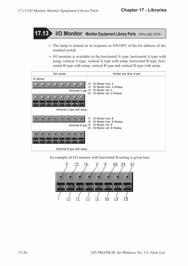
17-26
Chapter 17 - Libraries
GP-PRO/PB III for Windows Ver. 5.0 Parts List
Part sample Number and name of part
I/O Monitor
Horizontal A type
13: I/O Monitor horiz. A14: I/O Monitor horiz. A W/setup15: I/O Monitor vert. A16: I/O Monitor vert. A W/setup
Horizontal A type (with setup)
Horizontal B type
17: I/O Monitor horiz. B18: I/O Monitor horiz. B W/setup19: I/O Monitor vert. B20: I/O Monitor vert. B W/setup
Horizontal B type (with setup)
An example of I/O monitor with horizontal B setting is given here.
� The lamp is turned on in response to ON/OFF of the bit address of thetouched switch.
� I/O monitor is available in the horizontal A type, horizontal A type withsetup, vertical A type, vertical A type with setup, horizontal B type, hori-zontal B type with setup, vertical B type and vertical B type with setup.
17.13 I/O Monitor Monitor Equipment Library Parts OP4-LIB2.CPW
17.13 I/O Monitor Monitor Equipment Library Parts
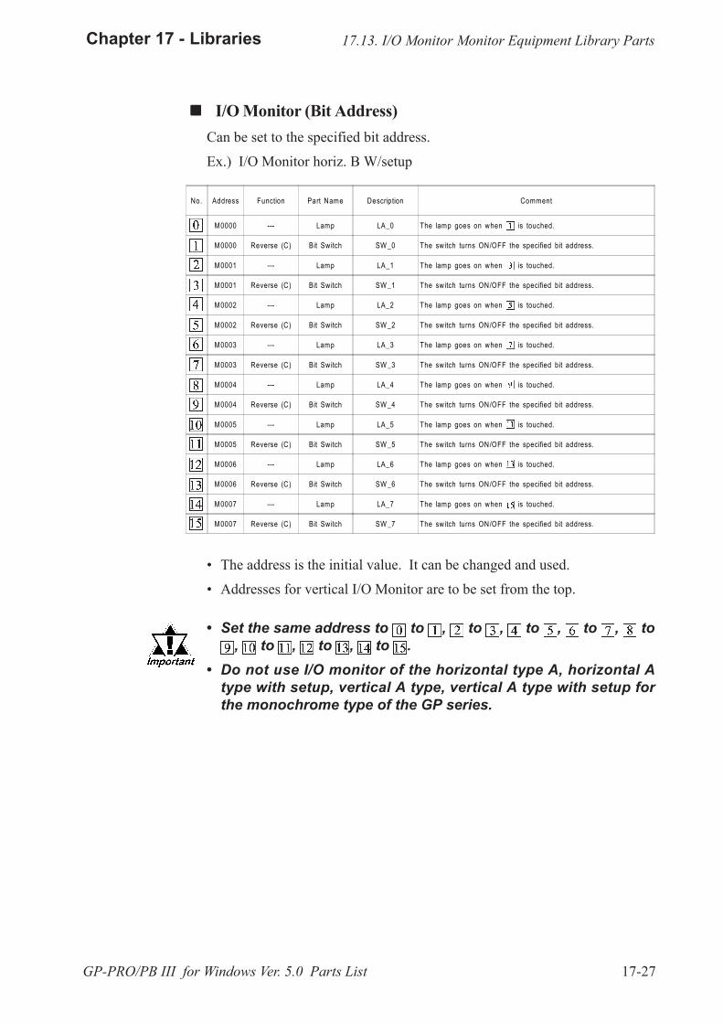
17-27
Chapter 17 - Libraries
GP-PRO/PB III for Windows Ver. 5.0 Parts List
! ! ! ! ! I/O Monitor (Bit Address)Can be set to the specified bit address.
Ex.) I/O Monitor horiz. B W/setup
No. Address Function Part Name Description Comment
M0000 --- Lamp LA_0 The lamp goes on when is touched.
M0000 Reverse (C) Bit Switch SW _0 The switch turns ON/OFF the specified bit address.
M0001 --- Lamp LA_1 The lamp goes on when is touched.
M0001 Reverse (C) Bit Switch SW _1 The switch turns ON/OFF the specified bit address.
M0002 --- Lamp LA_2 The lamp goes on when is touched.
M0002 Reverse (C) Bit Switch SW _2 The switch turns ON/OFF the specified bit address.
M0003 --- Lamp LA_3 The lamp goes on when is touched.
M0003 Reverse (C) Bit Switch SW _3 The switch turns ON/OFF the specified bit address.
M0004 --- Lamp LA_4 The lamp goes on when is touched.
M0004 Reverse (C) Bit Switch SW _4 The switch turns ON/OFF the specified bit address.
M0005 --- Lamp LA_5 The lamp goes on when is touched.
M0005 Reverse (C) Bit Switch SW _5 The switch turns ON/OFF the specified bit address.
M0006 --- Lamp LA_6 The lamp goes on when is touched.
M0006 Reverse (C) Bit Switch SW _6 The switch turns ON/OFF the specified bit address.
M0007 --- Lamp LA_7 The lamp goes on when is touched.
M0007 Reverse (C) Bit Switch SW _7 The switch turns ON/OFF the specified bit address.
� The address is the initial value. It can be changed and used.
� Addresses for vertical I/O Monitor are to be set from the top.
� Set the same address to to , to , to , to , to, to , to , to .
� Do not use I/O monitor of the horizontal type A, horizontal Atype with setup, vertical A type, vertical A type with setup forthe monochrome type of the GP series.
17.13. I/O Monitor Monitor Equipment Library Parts
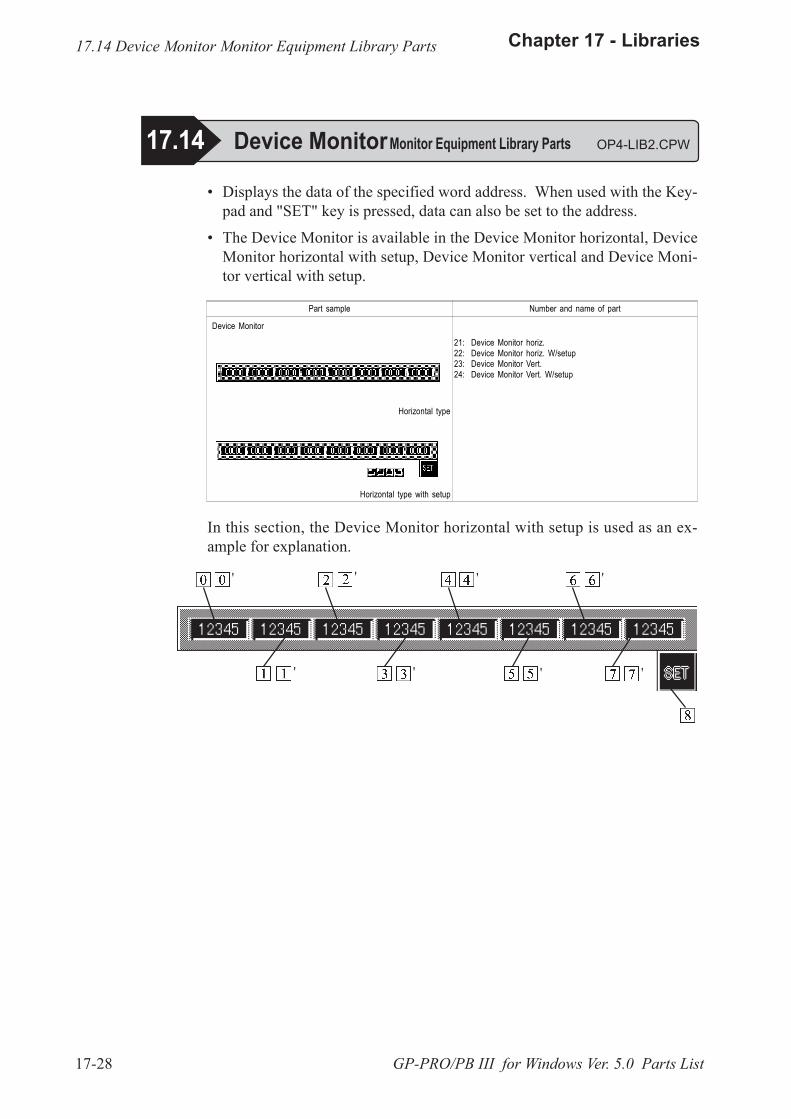
17-28
Chapter 17 - Libraries
GP-PRO/PB III for Windows Ver. 5.0 Parts List
� Displays the data of the specified word address. When used with the Key-pad and "SET" key is pressed, data can also be set to the address.
� The Device Monitor is available in the Device Monitor horizontal, DeviceMonitor horizontal with setup, Device Monitor vertical and Device Moni-tor vertical with setup.
In this section, the Device Monitor horizontal with setup is used as an ex-ample for explanation.
17.14 Device MonitorMonitor Equipment Library Parts OP4-LIB2.CPW
17.14 Device Monitor Monitor Equipment Library Parts
Part sample Number and name of part
Device Monitor
Horizontal type
21: Device Monitor horiz.22: Device Monitor horiz. W/setup23: Device Monitor Vert.24: Device Monitor Vert. W/setup
Horizontal type with setup
'
'
'
'
'
'
'
'
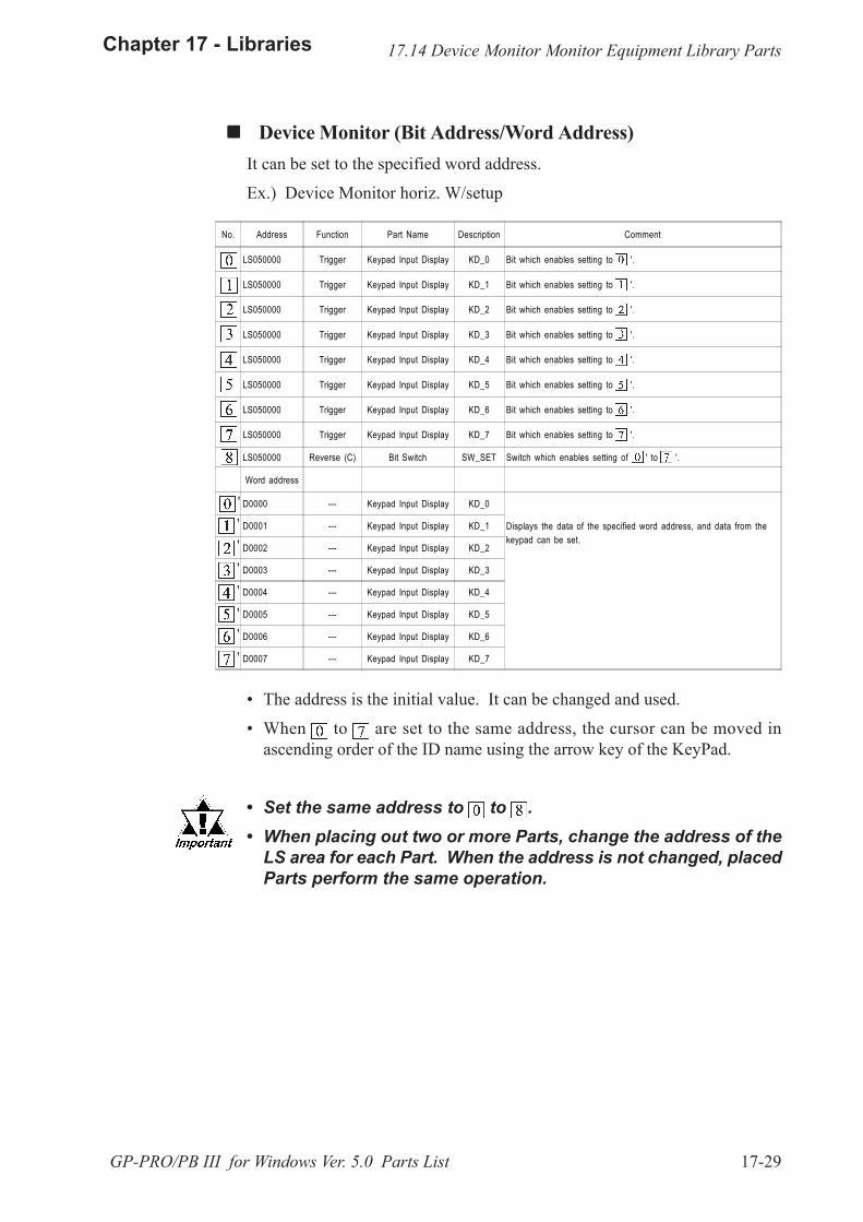
17-29
Chapter 17 - Libraries
GP-PRO/PB III for Windows Ver. 5.0 Parts List
! ! ! ! ! Device Monitor (Bit Address/Word Address)It can be set to the specified word address.
Ex.) Device Monitor horiz. W/setup
� The address is the initial value. It can be changed and used.
� When to are set to the same address, the cursor can be moved inascending order of the ID name using the arrow key of the KeyPad.
� Set the same address to to .� When placing out two or more Parts, change the address of the
LS area for each Part. When the address is not changed, placedParts perform the same operation.
17.14 Device Monitor Monitor Equipment Library Parts
No. Address Function Part Name Description Comment
LS050000 Trigger Keypad Input Display KD_0 Bit which enables setting to '.
LS050000 Trigger Keypad Input Display KD_1 Bit which enables setting to '.
LS050000 Trigger Keypad Input Display KD_2 Bit which enables setting to '.
LS050000 Trigger Keypad Input Display KD_3 Bit which enables setting to '.
LS050000 Trigger Keypad Input Display KD_4 Bit which enables setting to '.
LS050000 Trigger Keypad Input Display KD_5 Bit which enables setting to '.
LS050000 Trigger Keypad Input Display KD_6 Bit which enables setting to '.
LS050000 Trigger Keypad Input Display KD_7 Bit which enables setting to '.
LS050000 Reverse (C) Bit Switch SW_SET Switch which enables setting of ' to '.
Word address
D0000 --- Keypad Input Display KD_0
Displays the data of the specified word address, and data from thekeypad can be set.
D0001 --- Keypad Input Display KD_1
D0002 --- Keypad Input Display KD_2
D0003 --- Keypad Input Display KD_3
D0004 --- Keypad Input Display KD_4
D0005 --- Keypad Input Display KD_5
D0006 --- Keypad Input Display KD_6
D0007 --- Keypad Input Display KD_7
''''''''
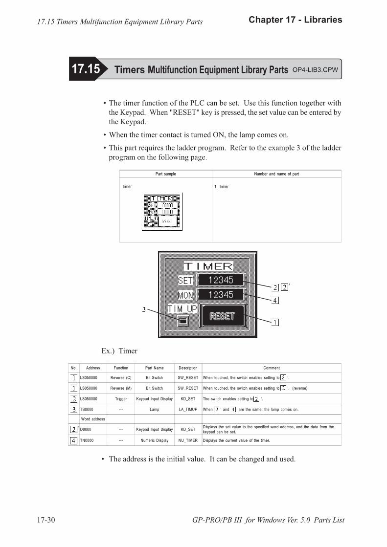
17-30
Chapter 17 - Libraries
GP-PRO/PB III for Windows Ver. 5.0 Parts List
� The timer function of the PLC can be set. Use this function together withthe Keypad. When "RESET" key is pressed, the set value can be entered bythe Keypad.
� When the timer contact is turned ON, the lamp comes on.
� This part requires the ladder program. Refer to the example 3 of the ladderprogram on the following page.
Ex.) Timer
No. Address Function Part Name Description Comment
LS050000 Reverse (C) Bit Switch SW_RESET When touched, the switch enables setting to '.
LS050000 Reverse (M) Bit Switch SW_RESET When touched, the switch enables setting to '. (reverse)
LS050000 Trigger Keypad Input Display KD_SET The switch enables setting to '.
TS0000 --- Lamp LA_TIMUP When ' and are the same, the lamp comes on.
Word address
D0000 --- Keypad Input Display KD_SET Displays the set value to the specified word address, and the data from thekeypad can be set.
TN0000 --- Numeric Display NU_TIMER Displays the current value of the timer.
'
� The address is the initial value. It can be changed and used.
17.15 Timers Multifunction Equipment Library Parts
17.15 Timers Multifunction Equipment Library Parts OP4-LIB3.CPW
Part sample Number and name of part
Timer 1: Timer
'
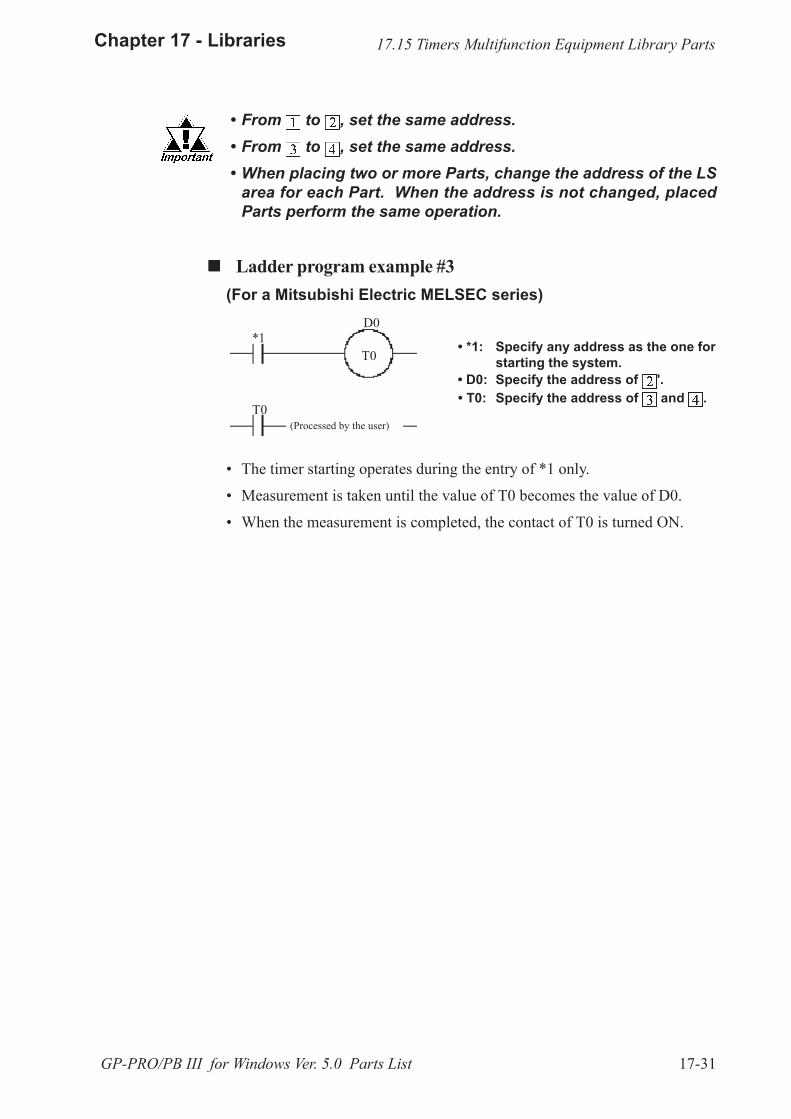
17-31
Chapter 17 - Libraries
GP-PRO/PB III for Windows Ver. 5.0 Parts List
� The timer starting operates during the entry of *1 only.
� Measurement is taken until the value of T0 becomes the value of D0.
� When the measurement is completed, the contact of T0 is turned ON.
� *1: Specify any address as the one forstarting the system.
� D0: Specify the address of '. � T0: Specify the address of and .
� From to , set the same address. � From to , set the same address. � When placing two or more Parts, change the address of the LS
area for each Part. When the address is not changed, placedParts perform the same operation.
! ! ! ! ! Ladder program example #3(For a Mitsubishi Electric MELSEC series)
17.15 Timers Multifunction Equipment Library Parts
D0*1
T0
T0
(Processed by the user)
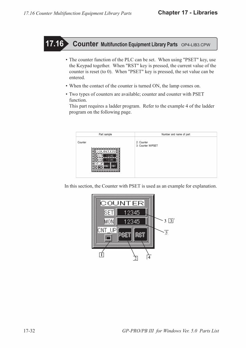
17-32
Chapter 17 - Libraries
GP-PRO/PB III for Windows Ver. 5.0 Parts List
� The counter function of the PLC can be set. When using "PSET" key, usethe Keypad together. When "RST" key is pressed, the current value of thecounter is reset (to 0). When "PSET" key is pressed, the set value can beentered.
� When the contact of the counter is turned ON, the lamp comes on.
� Two types of counters are available; counter and counter with PSETfunction.This part requires a ladder program. Refer to the example 4 of the ladderprogram on the following page.
17.16 Counter Multifunction Equipment Library Parts
17.16 Counter Multifunction Equipment Library Parts OP4-LIB3.CPW
Part sample Number and name of part
Counter 2: Counter 3: Counter W/PSET
In this section, the Counter with PSET is used as an example for explanation.
'
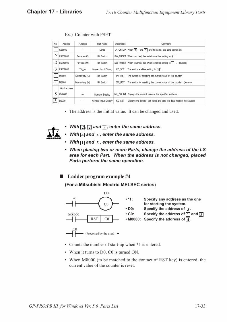
17-33
Chapter 17 - Libraries
GP-PRO/PB III for Windows Ver. 5.0 Parts List
� *1: Specify any address as the onefor starting the system.
� D0: Specify the address of .� C0: Specify the address of and .� M8000: Specify the address of .
� Counts the number of start-up when *1 is entered.
� When it turns to D0, C0 is turned ON.
� When M8000 (to be matched to the contact of RST key) is entered, thecurrent value of the counter is reset.
17.16 Counter Multifunction Equipment Library Parts
No. Address Function Part Name Description Comment
CS0000 --- Lamp LA_CNTUP When and are the same, the lamp comes on.
LS050000 Reverse (C) Bit Switch SW_PRSET When touched, the switch enables setting to .
LS050000 Reverse (M) Bit Switch SW_PRSET When touched, the switch enables setting to . (reverse)
LS050000 Trigger Keypad Input Display KD_SET The switch enables setting to .
M8000 Momentary (C) Bit Switch SW_RST The switch for resetting the current value of the counter.
M8000 Momentary (M) Bit Switch SW_RST The switch for resetting the current value of the counter. (reverse)
Word address
CN0000 --- Numeric Display NU_COUNT Displays the current value at the specified address.
D0000 --- Keypad Input Display KD_SET Displays the counter set value and sets the data through the Keypad.
Ex.) Counter with PSET
� The address is the initial value. It can be changed and used.
� With , and , enter the same address.� With and , enter the same address.� With and , enter the same address.� When placing two or more Parts, change the address of the LS
area for each Part. When the address is not changed, placedParts perform the same operation.
! ! ! ! ! Ladder program example #4(For a Mitsubishi Electric MELSEC series)
'
RST C0
C0
D0*1
C0(Processed by the user)
M8000
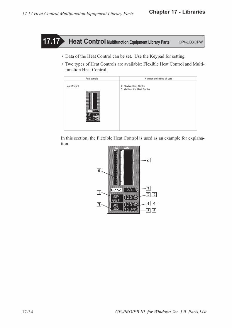
17-34
Chapter 17 - Libraries
GP-PRO/PB III for Windows Ver. 5.0 Parts List
� Data of the Heat Control can be set. Use the Keypad for setting.
� Two types of Heat Controls are available: Flexible Heat Control and Multi-function Heat Control.
In this section, the Flexible Heat Control is used as an example for explana-tion.
Part sample Number and name of part
Heat Control 4: Flexible Heat Control 5: Multifunction Heat Control
17.17 Heat Control Multifunction Equipment Library Parts
17.17 Heat Control Multifunction Equipment Library Parts OP4-LIB3.CPW
'
'
'
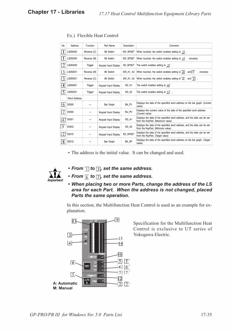
17-35
Chapter 17 - Libraries
GP-PRO/PB III for Windows Ver. 5.0 Parts List
In this section, the Multifunction Heat Control is used as an example for ex-planation.
Specification for the Multifunction HeatControl is exclusive to UT series ofYokogawa Electric.
A: AutomaticM: Manual
Ex.) Flexible Heat Control
'''
'
No. Address Function Part Name Description Comment
LS050000 Reverse (C) Bit Switch SW_SPSET When touched, the switch enables setting to .
LS050000 Reverse (M) Bit Switch SW_SPSET When touched, the switch enables setting to . (reverse)
LS050000 Trigger Keypad Input Display KD_SPSET The switch enables setting to .
LS050001 Reverse (M) Bit Switch SW_A1, A2 When touched, the switch enables setting to and . (reverse)
LS050001 Reverse (C) Bit Switch SW_A1, A2 When touched, the switch enables setting to and .
LS050001 Trigger Keypad Input Display KD_A1 The switch enables setting to .
LS050001 Trigger Keypad Input Display KD_A2 The switch enables setting to .
Word Address
D0000 --- Bar Graph BA_PV Displays the data of the specified word address on the bar graph. (Currentvalue)
D0000 --- Keypad Input Display NU_PV Displays the numeric value of the data of the specified word address.(Current value)
D0001 --- Keypad Input Display KD_A1 Displays the data of the specified word address, and the data can be setfrom the KeyPad. (Maximum value)
D0002 --- Keypad Input Display KD_A2 Displays the data of the specified word address, and the data can be setfrom the KeyPad. (Minimum value)
D0010 --- Keypad Input Display KD_SPSET Displays the data of the specified word address, and the data can be setfrom the KeyPad. (Target value)
D0010 --- Bar Graph BA_SP Displays the data of the specified word address on the bar graph. (Targetvalue)
� The address is the initial value. It can be changed and used.
� From to , set the same address. � From to , set the same address. � When placing two or more Parts, change the address of the LS
area for each Part. When the address is not changed, placedParts the same operation.
'
17.17 Heat Control Multifunction Equipment Library Parts
'
'
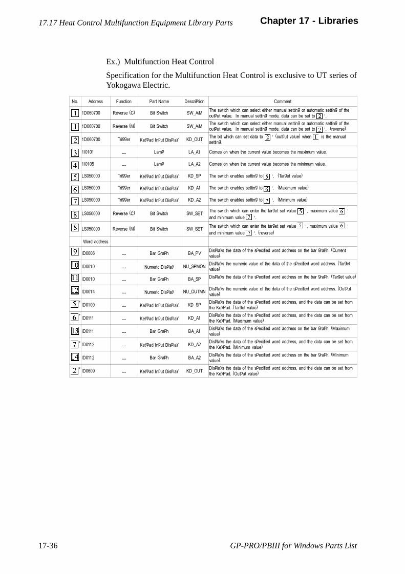
GP-PRO/PBIII for Windows Parts List17-36
Chapter 17 - Libraries
No. Address Function Part Name Description Comment
1D060700 Reverse (C) Bit Switch SW_A/MThe switch which can select either manual setting or automatic setting of theoutput value. In manual setting mode, data can be set to ' .
1D060700 Reverse (M) Bit Switch SW_A/MThe switch which can select either manual setting or automatic setting of theoutput value. In manual setting mode, data can be set to ' . (reverse)
1D060700 Trigger Keypad Input Display KD_OUTThe bit which can set data to ' (output value) when is the manualsetting.
1I0101 --- Lamp LA_A1 Comes on when the current value becomes the maximum value.
1I0105 --- Lamp LA_A2 Comes on when the current value becomes the minimum value.
LS050000 Trigger Keypad Input Display KD_SP The switch enables setting to ' . (Target value)
LS050000 Trigger Keypad Input Display KD_A1 The switch enables setting to ' . (Maximum value)
LS050000 Trigger Keypad Input Display KD_A2 The switch enables setting to ' . (Minimum value)
LS050000 Reverse (C) Bit Switch SW_SETThe switch which can enter the target set value ' , maximum value 'and minimum value ' .
LS050000 Reverse (M) Bit Switch SW_SETThe switch which can enter the target set value ' , maximum value 'and minimum value ' . (reverse)
Word address
ID0006 --- Bar Graph BA_PVDisplays the data of the specified word address on the bar graph. (Currentvalue)
ID0010 --- Numeric Display NU_SPMONDisplays the numeric value of the data of the specified word address. (Targetvalue)
ID0010 --- Bar Graph BA_SP Displays the data of the specified word address on the bar graph. (Target value)
ID0014 --- Numeric Display NU_OUTMNDisplays the numeric value of the data of the specified word address. (Outputvalue)
ID0100 --- Keypad Input Display KD_SPDisplays the data of the specified word address, and the data can be set fromthe KeyPad. (Target value)
ID0111 --- Keypad Input Display KD_A1Displays the data of the specified word address, and the data can be set fromthe KeyPad. (Maximum value)
ID0111 --- Bar Graph BA_A1Displays the data of the specified word address on the bar graph. (Maximumvalue)
ID0112 --- Keypad Input Display KD_A2Displays the data of the specified word address, and the data can be set fromthe KeyPad. (Minimum value)
ID0112 --- Bar Graph BA_A2Displays the data of the specified word address on the bar graph. (Minimumvalue)
ID0609 --- Keypad Input Display KD_OUTDisplays the data of the specified word address, and the data can be set fromthe KeyPad. (Output value)
Ex.) Multifunction Heat Control
Specification for the Multifunction Heat Control is exclusive to UT series ofYokogawa Electric.
'
'
'
'
17.17 Heat Control Multifunction Equipment Library Parts

17-37
Chapter 17 - Libraries
GP-PRO/PB III for Windows Ver. 5.0 Parts List
17.18 Add/Subtract Momentary Switch OP4-LIB4.CPW
The current value in the PLC's word address can be increased or decreasedusing these two touch keys. These touch keys are momentary switches.
Parts
Sample
17.18 Add/Subtract Momentary Switch
No. Address PartName Description Comment
LS0500NumericDisplay
ND_MONI Displaysthe current(numeric)datastored inaddressLS0500.
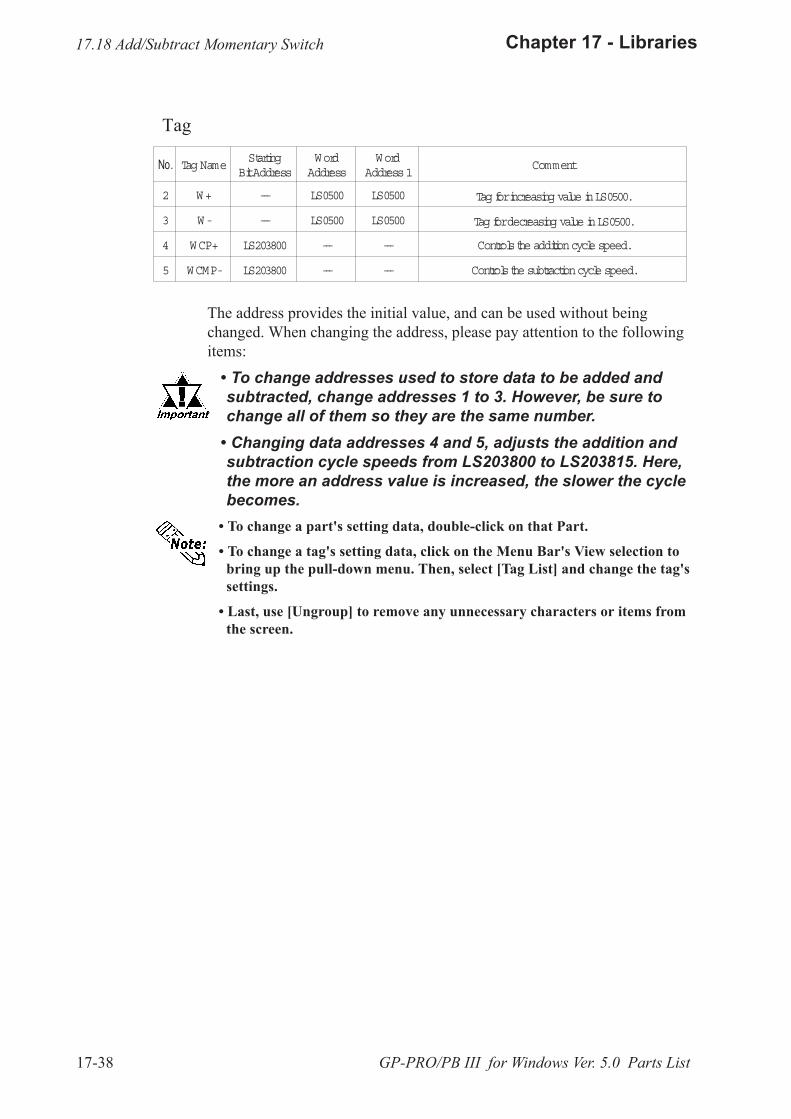
17-38
Chapter 17 - Libraries
GP-PRO/PB III for Windows Ver. 5.0 Parts List
Tag
The address provides the initial value, and can be used without beingchanged. When changing the address, please pay attention to the followingitems:
� To change addresses used to store data to be added andsubtracted, change addresses 1 to 3. However, be sure tochange all of them so they are the same number.
� Changing data addresses 4 and 5, adjusts the addition andsubtraction cycle speeds from LS203800 to LS203815. Here,the more an address value is increased, the slower the cyclebecomes.
� To change a part's setting data, double-click on that Part.
� To change a tag's setting data, click on the Menu Bar's View selection tobring up the pull-down menu. Then, select [Tag List] and change the tag'ssettings.
� Last, use [Ungroup] to remove any unnecessary characters or items fromthe screen.
17.18 Add/Subtract Momentary Switch
No. Tag NameStarting
BitAddressWordAddress
WordAddress1
Comment
2 W+ --- LS0500 LS0500 Tag forincreasing value inLS0500.
3 W- --- LS0500 LS0500 Tag fordecreasing value inLS0500.
4 WCP+ LS203800 --- --- Controlsthe additioncycle speed.
5 WCMP- LS203800 --- --- Controlsthe subtractioncycle speed.

17-39
Chapter 17 - Libraries
GP-PRO/PB III for Windows Ver. 5.0 Parts List
17.19 Window Display Tool Application Library
� The and keys are used to increase or decrease the window's registra-tion number, and the key is used to either display or hide the window.
� Also, the key is available for moving the window in any direction.
Sample
! ! ! ! ! PartsNo. Address Function Part Name Description Comment
LS501 --- Numeric Display ND_MONI Displays the window's registration number.
LS050000 Reverse (C) Bit Switch BS_001 Toggles between displaying or hiding the display.
LS0501 Addition/subtraction Word Switch WS_+ Increases the window registration number.
LS0501 Addition/subtraction Word Switch WS_- Decreases the window registration number.
17.19 Window Display ToolApplication Library OP4-LIB4.CPW
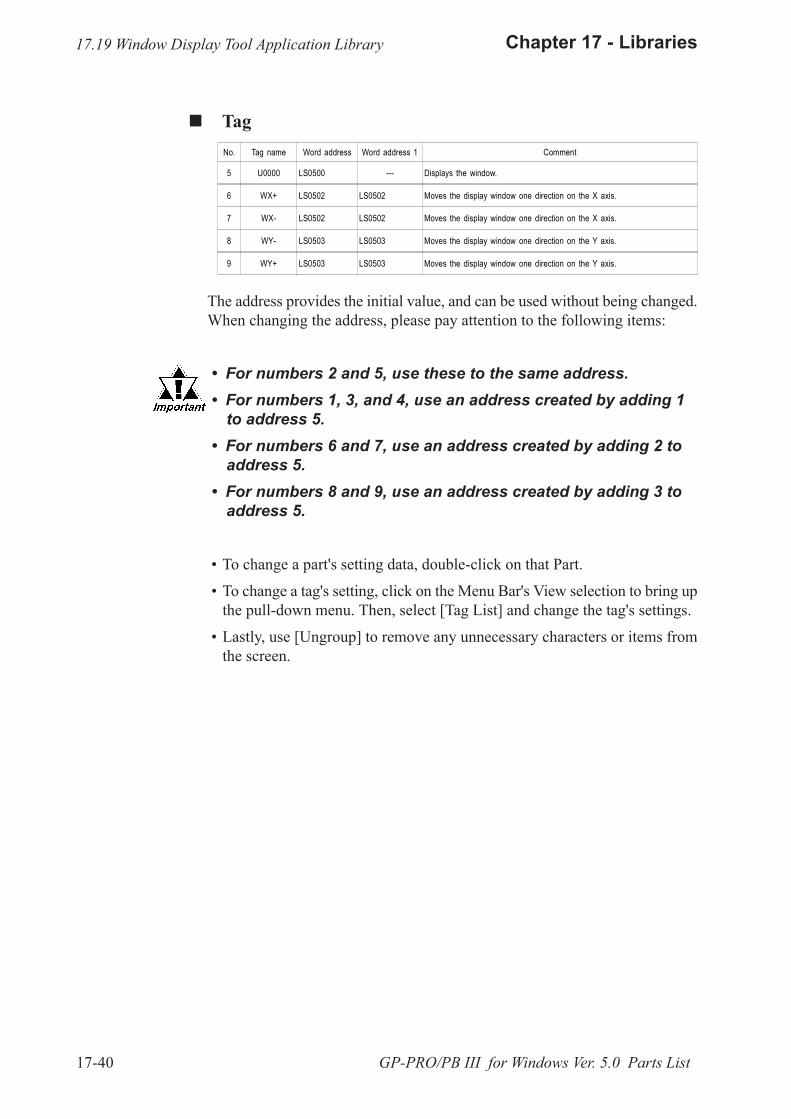
17-40
Chapter 17 - Libraries
GP-PRO/PB III for Windows Ver. 5.0 Parts List
! ! ! ! ! TagNo. Tag name Word address Word address 1 Comment
5 U0000 LS0500 --- Displays the window.
6 WX+ LS0502 LS0502 Moves the display window one direction on the X axis.
7 WX- LS0502 LS0502 Moves the display window one direction on the X axis.
8 WY- LS0503 LS0503 Moves the display window one direction on the Y axis.
9 WY+ LS0503 LS0503 Moves the display window one direction on the Y axis.
The address provides the initial value, and can be used without being changed.When changing the address, please pay attention to the following items:
� For numbers 2 and 5, use these to the same address. � For numbers 1, 3, and 4, use an address created by adding 1
to address 5. � For numbers 6 and 7, use an address created by adding 2 to
address 5. � For numbers 8 and 9, use an address created by adding 3 to
address 5.
� To change a part's setting data, double-click on that Part.
� To change a tag's setting, click on the Menu Bar's View selection to bring upthe pull-down menu. Then, select [Tag List] and change the tag's settings.
� Lastly, use [Ungroup] to remove any unnecessary characters or items fromthe screen.
17.19 Window Display Tool Application Library
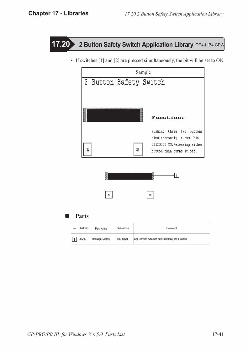
17-41
Chapter 17 - Libraries
GP-PRO/PB III for Windows Ver. 5.0 Parts List
Sample
17.20 2 Button Safety Switch Application Library
� If switches [1] and [2] are pressed simultaneously, the bit will be set to ON.
! ! ! ! ! Parts
No. Address Part Name Description Comment
LSI200 Message Display ME_MONI Can confirm whether both switches are pressed.
17.20 2 Button Safety Switch Application Library OP4-LIB4.CPW
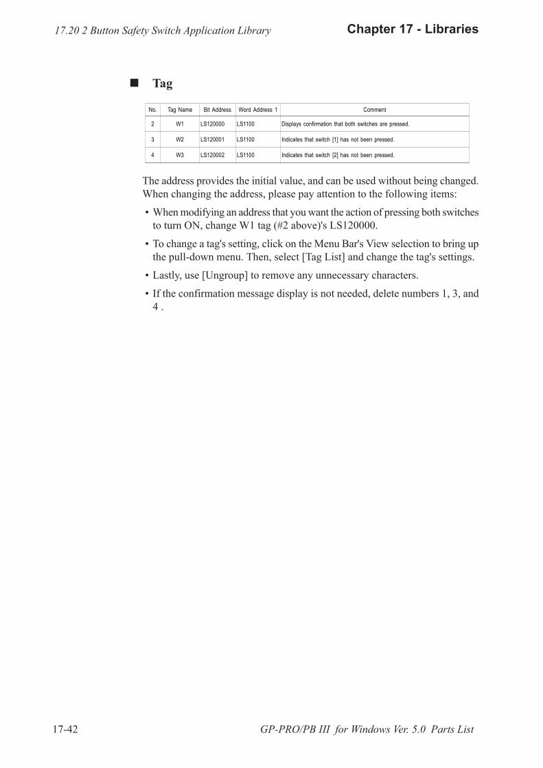
17-42
Chapter 17 - Libraries
GP-PRO/PB III for Windows Ver. 5.0 Parts List
! ! ! ! ! Tag
No. Tag Name Bit Address Word Address 1 Comment
2 W1 LS120000 LS1100 Displays confirmation that both switches are pressed.
3 W2 LS120001 LS1100 Indicates that switch [1] has not been pressed.
4 W3 LS120002 LS1100 Indicates that switch [2] has not been pressed.
The address provides the initial value, and can be used without being changed.When changing the address, please pay attention to the following items:
� When modifying an address that you want the action of pressing both switchesto turn ON, change W1 tag (#2 above)'s LS120000.
� To change a tag's setting, click on the Menu Bar's View selection to bring upthe pull-down menu. Then, select [Tag List] and change the tag's settings.
� Lastly, use [Ungroup] to remove any unnecessary characters.
� If the confirmation message display is not needed, delete numbers 1, 3, and4 .
17.20 2 Button Safety Switch Application Library

17-43
Chapter 17 - Libraries
GP-PRO/PB III for Windows Ver. 5.0 Parts List
17.21 Alarm Display #1 Application Library
� Messages are displayed by turning the monitor bit ON and OFF.
� You can display a detailed explanation of an alarm message (text screen) inthe sub-screen by first, using the or key to highlight aspecific message, and then pressing the key.
! ! ! ! ! TagNo. Tag Name Word Adress Word Adress 1 Comment
1 A LS1000 LS1100 Messages are displayed by turning the monitor bit ON.
The address provides the initial value, and can be used without being changed.When changing the address, please pay attention to the following items.
For details, refer to "A-tag" in the Tag Reference Manual. � When you want to change an alarm's monitor bit, change Tag #1's LS1000. � Create an alarm message on the X1 text screen that is 40 half-sized charac-
ters (20 full-sized) x 16 lines. (At any one time, a maximum of 12 lines canbe displayed.) Each line of text entered corresponds to a single bit in wordaddress LS1000. For example, LS1000's LS100000 address is used to con-trol the first line of X1's data, LS100001 controls the second line of data,and so on.
� Create detailed alarm data explanations on screen's X100 to X115 Thesetext screens are 20 half-sized characters (10 full-sized) x 12 lines. Thus,details about LS00000's alarm are explained on X100 screen, details ofLS100101's alarm are explained on X101 screen, etc.
� To change a tag's setting, click on the Menu Bar's View selection to bring upthe pull-down menu. Then, select [Tag List] and change the tag's settings.
� Lastly, use [Ungroup] to remove any unnecessary characters or items fromthe screen.
17.21 Alarm Display #1 Application Library OP4-LIB4.CPW
Sample
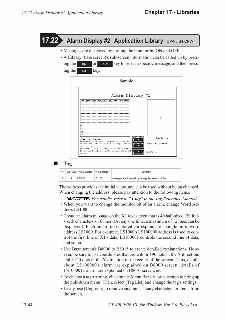
17-44
Chapter 17 - Libraries
GP-PRO/PB III for Windows Ver. 5.0 Parts List
� Messages are displayed by turning the monitor bit ON and OFF. � A Library (base screen)'s sub-screen information can be called up by press-
ing the or key to select a specific message, and then press-ing the key.
! ! ! ! ! TagNo. Tag Name Word Adress Word Adress 1 Comment
1 A LS1000 LS1100 Messages are displayed by turning the monitor bit ON.
The address provides the initial value, and can be used without being changed.When changing the address, please pay attention to the following items.
For details, refer to "A-tag" in the Tag Reference Manual. � When you want to change the monitor bit of an alarm, change Word Ad-
dress LS1000. � Create an alarm message on the X1 text screen that is 40 half-sized (20 full-
sized) characters x 16 lines. (At any one time, a maximum of 12 lines can bedisplayed). Each line of text entered corresponds to a single bit in wordaddress LS1000. For example, LS1000's LS100000 address is used to con-trol the first line of X1's data, LS100001 controls the second line of data,and so on.
� Use Base screen's B8000 to B8015 to create detailed explanations. How-ever, be sure to use coordinates that are within +90 dots in the X direction,and +120 dots in the Y direction of the center of the screen. Thus, detailsabout LS100000's alarm are explained on B8000 screen, details ofLS100001's alarm are explained on B8001 screen, etc.
� To change a tag's setting, click on the Menu Bar's View selection to bring upthe pull-down menu. Then, select [Tag List] and change the tag's settings.
� Lastly, use [Ungroup] to remove any unnecessary characters or items fromthe screen.
17.22 Alarm Display #2 Application Library OP4-LIB4.CPW
Sample
17.22 Alarm Display #2 Application Library
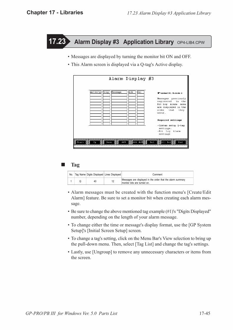
17-45
Chapter 17 - Libraries
GP-PRO/PB III for Windows Ver. 5.0 Parts List
17.23 Alarm Display #3 Application Library
� Messages are displayed by turning the monitor bit ON and OFF.
� This Alarm screen is displayed via a Q-tag's Active display.
! ! ! ! ! TagNo. Tag Name Digits Displayed Lines Displayed Comment
1 Q 40 12 Messages are displayed in the order that the alarm summarymonitor bits are turned on.
� Alarm messages must be created with the function menu's [Create/EditAlarm] feature. Be sure to set a monitor bit when creating each alarm mes-sage.
� Be sure to change the above mentioned tag example (#1)'s "Digits Displayed"number, depending on the length of your alarm message.
� To change either the time or message's display format, use the [GP SystemSetup]'s [Initial Screen Setup] screen.
� To change a tag's setting, click on the Menu Bar's View selection to bring upthe pull-down menu. Then, select [Tag List] and change the tag's settings.
� Lastly, use [Ungroup] to remove any unnecessary characters or items fromthe screen.
17.23 Alarm Display #3 Application Library OP4-LIB4.CPW

17-46
Chapter 17 - Libraries
GP-PRO/PB III for Windows Ver. 5.0 Parts List
� By displaying a series of related screens, an image screen becomes ani-mated.
! ! ! ! ! Tag
No. Tag NameWord
AddressBit Length
Starting ScreenNumber
Screen Type Comment
1 L LS2038 6 100 Image screen Displays image screens 100 to 163 in sequence.
The address provides the initial value, and can be used without being changed.The address is specified in the LS2038 tag scan counter. The image screensare changed to display screens in succession, giving the appearance of anima-tion, every time the tag is scanned. When changing the address, please payattention to the following items:
� To select a different screen change speed, change Word Address LS2038.
� Prepare the image screens (numbers 100 to 163) to be used for animation.
� When more than 64 image screens are used, be sure to increase the abovementioned example #1's bit length setting.
� When the first image screen used is either greater or less than 100, be sure tochange the starting screen number.
� When using animation on a base screen, be sure to change the designatedscreen type 1.
� To change a tag's setting, click on the Menu Bar's View selection to bring upthe pull-down menu. Then, select [Tag List] and change the tag's settings.
� Lastly, use [Ungroup] to remove any unnecessary characters or items fromthe screen.
17.24 Active Image Display Tool Application Library OP4-LIB4.CPW
Sample
17.24 Active Image Display Tool Application Library
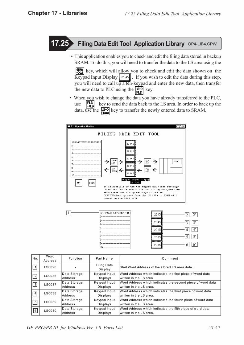
17-47
Chapter 17 - Libraries
GP-PRO/PB III for Windows Ver. 5.0 Parts List
17.25 Filing Data Edit Tool Application Library OP4-LIB4.CPW
� This application enables you to check and edit the filing data stored in backupSRAM. To do this, you will need to transfer the data to the LS area using the
key, which will allow you to check and edit the data shown on theKeypad Input Display . If you wish to edit the data during this step,you will need to call up a ten-keypad and enter the new data, then transferthe new data to PLC using the key.
� When you wish to change the data you have already transferred to the PLC,use key to send the data back to the LS area. In order to back up thedata, use the key to transfer the newly entered data to SRAM.
21
3
4
5
6
2'
3'
4'
5'
6'
17.25 Filing Data Edit Tool Application Library
No. WordAddres s Function Part Nam e Com m ent
1 LS0020 - Filing DataDis play Start Word Addres s of the s tored LS area data.
2 LS0036 Data StorageAddres s
Keypad InputDis plays
Word Addres s which indicates the firs t piece of word datawritten in the LS area.
3 LS0037 Data StorageAddres s
Keypad InputDis plays
Word Addres s which indicates the s econd piece of word datawritten in the LS area.
4 LS0038 Data StorageAddres s
Keypad InputDis plays
Word Addres s which indicates the third piece of word datawritten in the LS area.
5 LS0039 Data StorageAddres s
Keypad InputDis plays
Word Addres s which indicates the fourth piece of word datawritten in the LS area.
6 LS0040 Data StorageAddres s
Keypad InputDis plays
Word Addres s which indicates the fifth piece of word datawritten in the LS area.
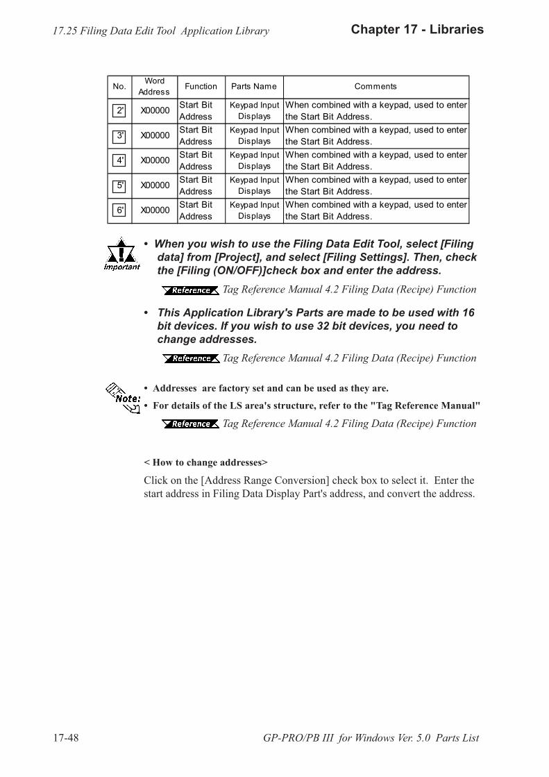
17-48
Chapter 17 - Libraries
GP-PRO/PB III for Windows Ver. 5.0 Parts List
17.25 Filing Data Edit Tool Application Library
� When you wish to use the Filing Data Edit Tool, select [Filingdata] from [Project], and select [Filing Settings]. Then, checkthe [Filing (ON/OFF)]check box and enter the address.
Tag Reference Manual 4.2 Filing Data (Recipe) Function
� This Application Library's Parts are made to be used with 16bit devices. If you wish to use 32 bit devices, you need tochange addresses.
Tag Reference Manual 4.2 Filing Data (Recipe) Function
� Addresses are factory set and can be used as they are.
� For details of the LS area's structure, refer to the "Tag Reference Manual"
Tag Reference Manual 4.2 Filing Data (Recipe) Function
< How to change addresses>
Click on the [Address Range Conversion] check box to select it. Enter thestart address in Filing Data Display Part's address, and convert the address.
No. WordAddress Function Parts Name Comments
2' X00000 Start BitAddress
Keypad InputDisplays
When combined with a keypad, used to enterthe Start Bit Address.
3' X00000 Start BitAddress
Keypad InputDisplays
When combined with a keypad, used to enterthe Start Bit Address.
4' X00000 Start BitAddress
Keypad InputDisplays
When combined with a keypad, used to enterthe Start Bit Address.
5' X00000 Start BitAddress
Keypad InputDisplays
When combined with a keypad, used to enterthe Start Bit Address.
6' X00000 Start BitAddress
Keypad InputDisplays
When combined with a keypad, used to enterthe Start Bit Address.
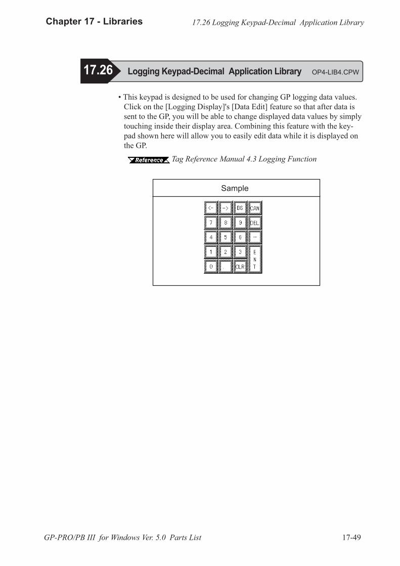
17-49
Chapter 17 - Libraries
GP-PRO/PB III for Windows Ver. 5.0 Parts List
17.26 Logging Keypad-Decimal Application Library OP4-LIB4.CPW
� This keypad is designed to be used for changing GP logging data values.Click on the [Logging Display]'s [Data Edit] feature so that after data issent to the GP, you will be able to change displayed data values by simplytouching inside their display area. Combining this feature with the key-pad shown here will allow you to easily edit data while it is displayed onthe GP.
Tag Reference Manual 4.3 Logging Function
Sample
17.26 Logging Keypad-Decimal Application Library
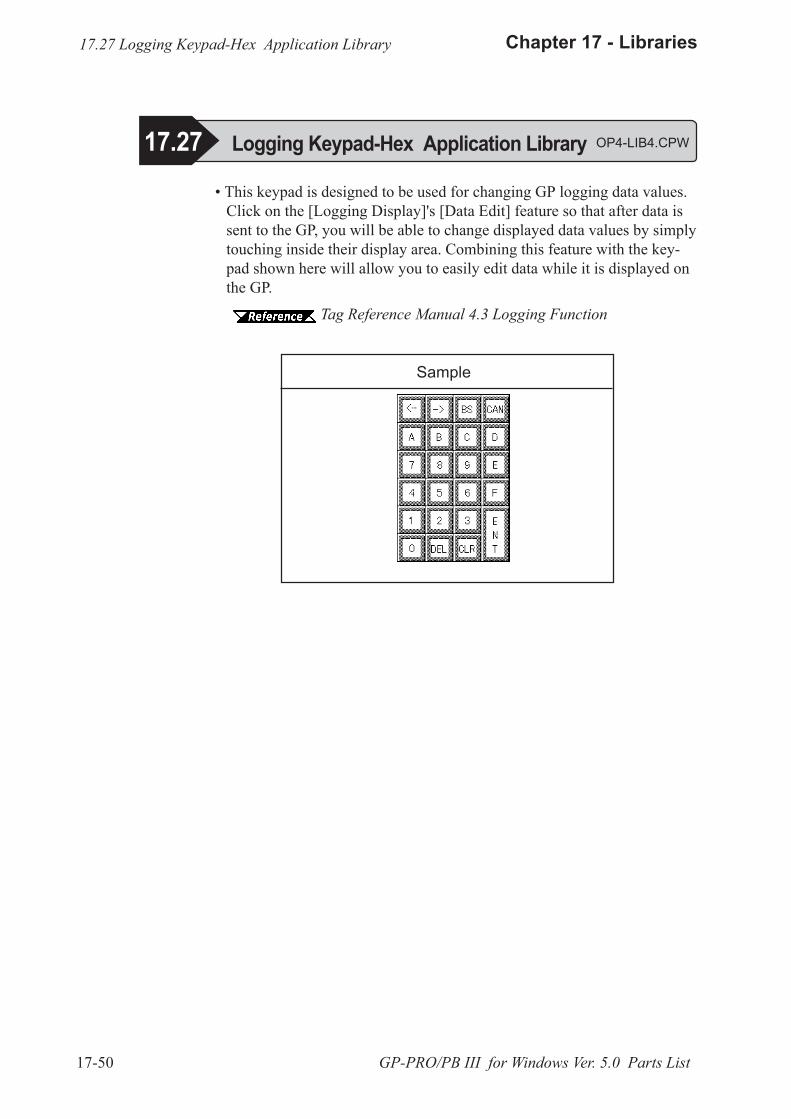
17-50
Chapter 17 - Libraries
GP-PRO/PB III for Windows Ver. 5.0 Parts List
17.27 Logging Keypad-Hex Application Library OP4-LIB4.CPW
Sample
� This keypad is designed to be used for changing GP logging data values.Click on the [Logging Display]'s [Data Edit] feature so that after data issent to the GP, you will be able to change displayed data values by simplytouching inside their display area. Combining this feature with the key-pad shown here will allow you to easily edit data while it is displayed onthe GP.
Tag Reference Manual 4.3 Logging Function
17.27 Logging Keypad-Hex Application Library
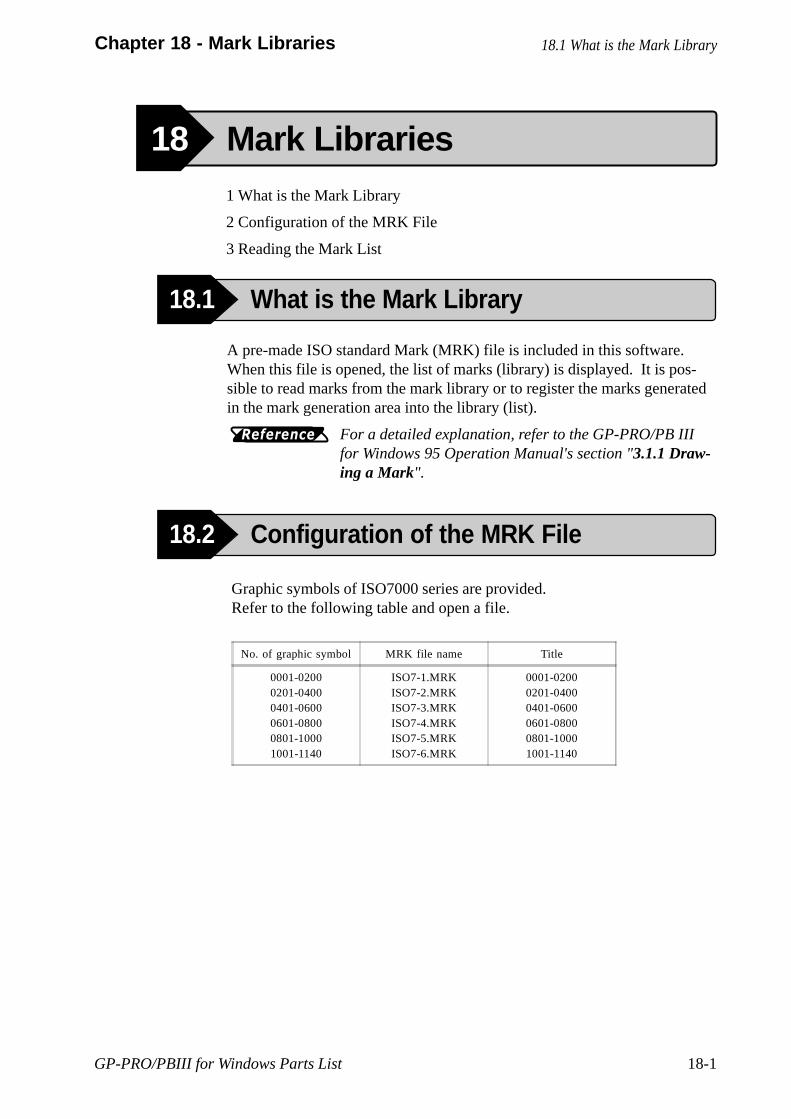
GP-PRO/PBIII for Windows Parts List 18-1
Chapter 18 - Mark Libraries
A pre-made ISO standard Mark (MRK) file is included in this software.When this file is opened, the list of marks (library) is displayed. It is pos-sible to read marks from the mark library or to register the marks generatedin the mark generation area into the library (list).
For a detailed explanation, refer to the GP-PRO/PB IIIfor Windows 95 Operation Manual's section "3.1.1 Draw-ing a Mark".
Graphic symbols of ISO7000 series are provided.Refer to the following table and open a file.
No. of graphic symbol MRK file name Title
0001-02000201-04000401-06000601-08000801-10001001-1140
ISO7-1.MRKISO7-2.MRKISO7-3.MRKISO7-4.MRKISO7-5.MRKISO7-6.MRK
0001-02000201-04000401-06000601-08000801-10001001-1140
18.1 What is the Mark Library
18 Mark Libraries1 What is the Mark Library
2 Configuration of the MRK File
3 Reading the Mark List
18.2 Configuration of the MRK File
18.1 What is the Mark Library
Reference
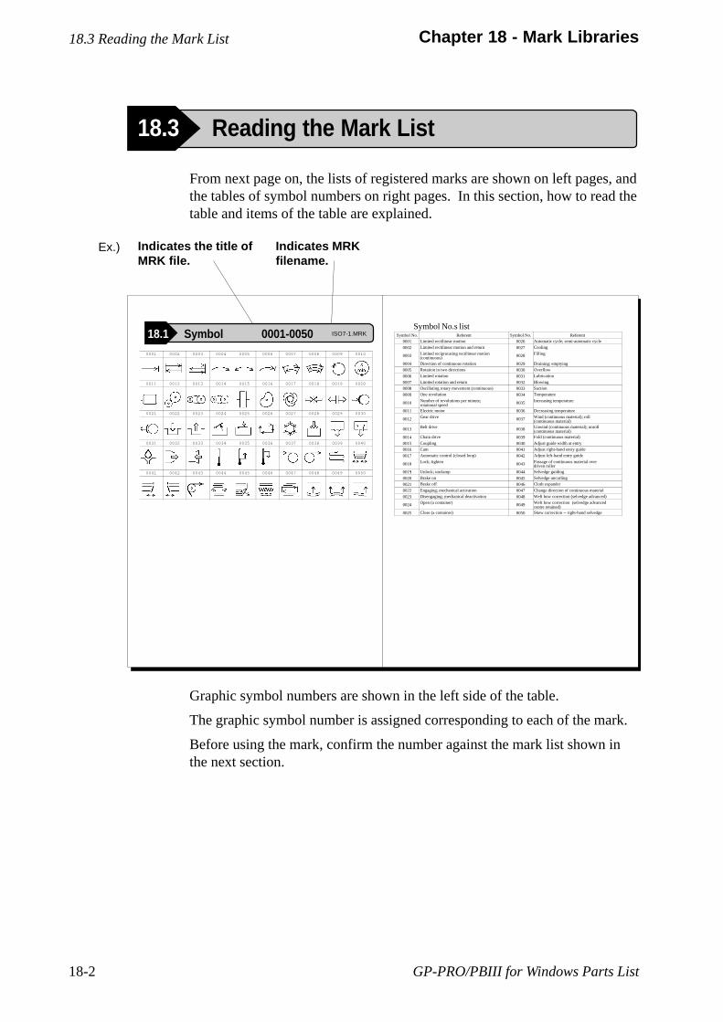
GP-PRO/PBIII for Windows Parts List18-2
Chapter 18 - Mark Libraries
From next page on, the lists of registered marks are shown on left pages, andthe tables of symbol numbers on right pages. In this section, how to read thetable and items of the table are explained.
Graphic symbol numbers are shown in the left side of the table.
The graphic symbol number is assigned corresponding to each of the mark.
Before using the mark, confirm the number against the mark list shown inthe next section.
Symbol No. Referent Symbol No. Referent
0001 Limited rectilinear motion 0026 Automatic cycle; semi-automatic cycle
0002 Limited rectilinear motion and return 0027 Cooling
0003 Limited reciprocating rectilinear motion(continuous) 0028 Filling
0004 Direction of continuous rotation 0029 Draining; emptying
0005 Rotation in two directions 0030 Overflow
0006 Limited rotation 0031 Lubrication
0007 Limited rotation and return 0032 Blowing
0008 Oscillating rotary movement (continuous) 0033 Suction
0009 One revolution 0034 Temperature
0010 Number of revolutions per minute;rotational speed 0035 Increasing temperature
0011 Electric motor 0036 Decreasing temperature
0012 Gear drive 0037 Wind (continuous material); roll(continuous material)
0013 Belt drive 0038 Unwind (continuous material); unroll(continuous material)
0014 Chain drive 0039 Fold (continuous material)
0015 Coupling 0040 Adjust guide width at entry
0016 Cam 0041 Adjust right-hand entry guide
0017 Automatic control (closed loop) 0042 Adjust left-hand entry guide
0018 Lock; tighten 0043 Passage of continuous material overdriven roller
0019 Unlock; unclamp 0044 Selvedge guiding
0020 Brake on 0045 Selvedge uncurling
0021 Brake off 0046 Cloth expander
0022 Engaging; mechanical activation 0047 Change direction of continuous material
0023 Disengaging; mechanical deactivation 0048 Weft bow correction (selvedge advanced)
0024 Open (a container) 0049 Weft bow correction (selvedge advancedcentre retained)
0025 Close (a container) 0050 Skew correction -- right-hand selvedge
Symbol No.s list
Indicates MRKfilename.
Indicates the title ofMRK file.
0001 0002 0003 0004 0005 0006 0007 0008 0009 0010
0011 0012 0013 0014 0015 0016 0017 0018 0019 0020
0021 0022 0023 0024 0025 0026 0027 0028 0029 0030
0031 0032 0033 0034 0035 0036 0037 0038 0039 0040
0041 0042 0043 0044 0045 0046 0047 0048 0049 0050
Ex.)
18.3 Reading the Mark List
18.3 Reading the Mark List
18.1 Symbol 0001-0050 ISO7-1.MRK
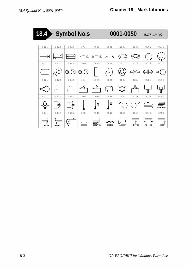
GP-PRO/PBIII for Windows Parts List18-3
Chapter 18 - Mark Libraries18.4 Symbol No.s 0001-0050
18.4 Symbol No.s 0001-0050 ISO7-1.MRK
0001 0002 0003 0004 0005 0006 0007 0008 0009 0010
0011 0012 0013 0014 0015 0016 0017 0018 0019 0020
0021 0022 0023 0024 0025 0026 0027 0028 0029 0030
0031 0032 0033 0034 0035 0036 0037 0038 0039 0040
0041 0042 0043 0044 0045 0046 0047 0048 0049 0050

GP-PRO/PBIII for Windows Parts List 18-4
Chapter 18 - Mark Libraries
Symbol No. Referent Symbol No. Referent
0001 Limited rectilinear motion 0026 Automatic cycle; semi-automatic cycle
0002 Limited rectilinear motion and return 0027 Cooling
0003 Limited reciprocating rectilinear motion(continuous) 0028 Filling
0004 Direction of continuous rotation 0029 Draining; emptying
0005 Rotation in two directions 0030 Overflow
0006 Limited rotation 0031 Lubrication
0007 Limited rotation and return 0032 Blowing
0008 Oscillating rotary movement (continuous) 0033 Suction
0009 One revolution 0034 Temperature
0010 Number of revolutions per minute;rotational speed 0035 Increasing temperature
0011 Electric motor 0036 Decreasing temperature
0012 Gear drive 0037 Wind (continuous material); roll(continuous material)
0013 Belt drive 0038 Unwind (continuous material); unroll(continuous material)
0014 Chain drive 0039 Fold (continuous material)
0015 Coupling 0040 Adjust guide width at entry
0016 Cam 0041 Adjust right-hand entry guide
0017 Automatic control (closed loop) 0042 Adjust left-hand entry guide
0018 Lock; tighten 0043 Passage of continuous material overdriven roller
0019 Unlock; unclamp 0044 Selvedge guiding
0020 Brake on 0045 Selvedge uncurling
0021 Brake off 0046 Cloth expander
0022 Engaging; mechanical activation 0047 Change direction of continuous material
0023 Disengaging; mechanical deactivation 0048 Weft bow correction (selvedge advanced)
0024 Open (a container) 0049 Weft bow correction (selvedge advancedcentre retained)
0025 Close (a container) 0050 Skew correction -- right-hand selvedge
18.4 Symbol No.s 0001-0050

GP-PRO/PBIII for Windows Parts List18-5
Chapter 18 - Mark Libraries
18.5 Symbol No.s 0051-0100 ISO7-1.MRK
18.5 Symbol No.s 0051-0100
0051 0052 0053 0054 0055 0056 0057 0058 0059 0060
0061 0062 0063 0064 0065 0066 0067 0068 0069 0070
0071 0072 0073 0074 0075 0076 0077 0078 0079 0080
0081 0082 0083 0084 0085 0086 0087 0088 0089 0090
0091 0092 0093 0094 0095 0096 0097 0098 0099 0100
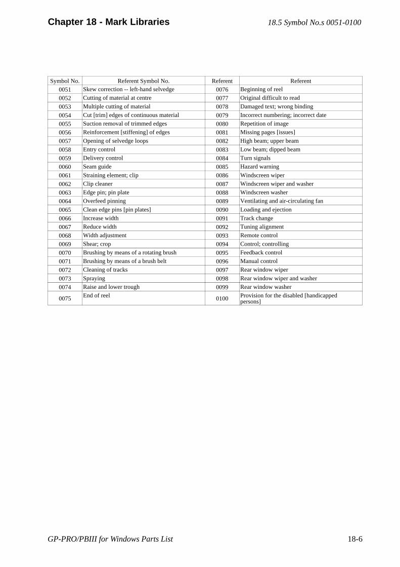
GP-PRO/PBIII for Windows Parts List 18-6
Chapter 18 - Mark Libraries
Symbol No. Referent Symbol No. Referent Referent
0051 Skew correction -- left-hand selvedge 0076 Beginning of reel
0052 Cutting of material at centre 0077 Original difficult to read
0053 Multiple cutting of material 0078 Damaged text; wrong binding
0054 Cut [trim] edges of continuous material 0079 Incorrect numbering; incorrect date
0055 Suction removal of trimmed edges 0080 Repetition of image
0056 Reinforcement [stiffening] of edges 0081 Missing pages [issues]
0057 Opening of selvedge loops 0082 High beam; upper beam
0058 Entry control 0083 Low beam; dipped beam
0059 Delivery control 0084 Turn signals
0060 Seam guide 0085 Hazard warning
0061 Straining element; clip 0086 Windscreen wiper
0062 Clip cleaner 0087 Windscreen wiper and washer
0063 Edge pin; pin plate 0088 Windscreen washer
0064 Overfeed pinning 0089 Ventilating and air-circulating fan
0065 Clean edge pins [pin plates] 0090 Loading and ejection
0066 Increase width 0091 Track change
0067 Reduce width 0092 Tuning alignment
0068 Width adjustment 0093 Remote control
0069 Shear; crop 0094 Control; controlling
0070 Brushing by means of a rotating brush 0095 Feedback control
0071 Brushing by means of a brush belt 0096 Manual control
0072 Cleaning of tracks 0097 Rear window wiper
0073 Spraying 0098 Rear window wiper and washer
0074 Raise and lower trough 0099 Rear window washer
0075 End of reel 0100 Provision for the disabled [handicappedpersons]
18.5 Symbol No.s 0051-0100
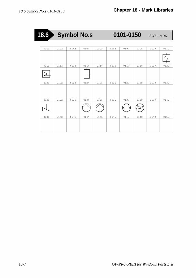
GP-PRO/PBIII for Windows Parts List18-7
Chapter 18 - Mark Libraries18.6 Symbol No.s 0101-0150
18.6 Symbol No.s 0101-0150 ISO7-1.MRK
0101 0102 0103 0104 0105 0106 0107 0108 0109 0110
0111 0112 0113 0114 0115 0116 0117 0118 0119 0120
0121 0122 0123 0124 0125 0126 0127 0128 0129 0130
0131 0132 0133 0134 0135 0136 0137 0138 0139 0140
0141 0142 0143 0144 0145 0146 0147 0148 0149 0150
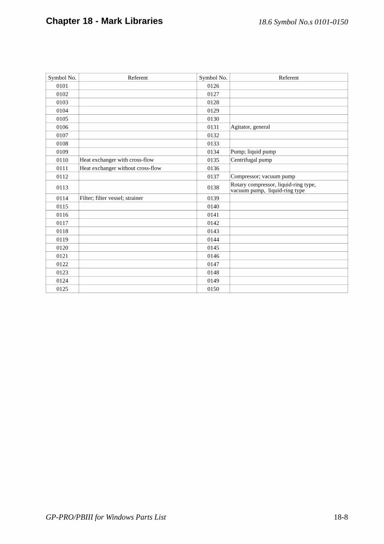
GP-PRO/PBIII for Windows Parts List 18-8
Chapter 18 - Mark Libraries
Symbol No. Referent Symbol No. Referent
0101 0126
0102 0127
0103 0128
0104 0129
0105 0130
0106 0131 Agitator, general
0107 0132
0108 0133
0109 0134 Pump; liquid pump
0110 Heat exchanger with cross-flow 0135 Centrifugal pump
0111 Heat exchanger without cross-flow 0136
0112 0137 Compressor; vacuum pump
0113 0138 Rotary compressor, liquid-ring type,vacuum pump, liquid-ring type
0114 Filter; filter vessel; strainer 0139
0115 0140
0116 0141
0117 0142
0118 0143
0119 0144
0120 0145
0121 0146
0122 0147
0123 0148
0124 0149
0125 0150
18.6 Symbol No.s 0101-0150
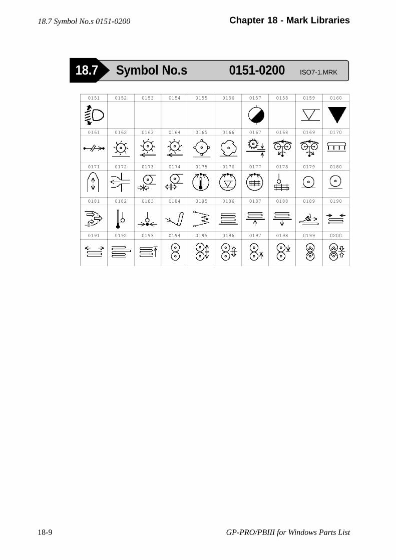
GP-PRO/PBIII for Windows Parts List18-9
Chapter 18 - Mark Libraries18.7 Symbol No.s 0151-0200
18.7 Symbol No.s 0151-0200 ISO7-1.MRK
0151 0152 0153 0154 0155 0156 0157 0158 0159 0160
0161 0162 0163 0164 0165 0166 0167 0168 0169 0170
0171 0172 0173 0174 0175 0176 0177 0178 0179 0180
0181 0182 0183 0184 0185 0186 0187 0188 0189 0190
0191 0192 0193 0194 0195 0196 0197 0198 0199 0200
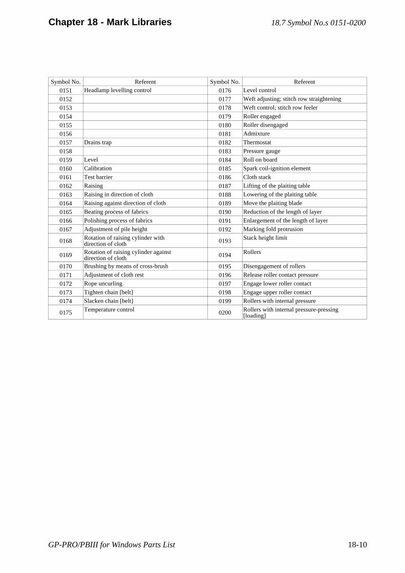
GP-PRO/PBIII for Windows Parts List 18-10
Chapter 18 - Mark Libraries
Symbol No. Referent Symbol No. Referent
0151 Headlamp levelling control 0176 Level control
0152 0177 Weft adjusting; stitch row straightening
0153 0178 Weft control; stitch row feeler
0154 0179 Roller engaged
0155 0180 Roller disengaged
0156 0181 Admixture
0157 Drains trap 0182 Thermostat
0158 0183 Pressure gauge
0159 Level 0184 Roll on board
0160 Calibration 0185 Spark coil-ignition element
0161 Test barrier 0186 Cloth stack
0162 Raising 0187 Lifting of the plaiting table
0163 Raising in direction of cloth 0188 Lowering of the plaiting table
0164 Raising against direction of cloth 0189 Move the plaiting blade
0165 Beating process of fabrics 0190 Reduction of the length of layer
0166 Polishing process of fabrics 0191 Enlargement of the length of layer
0167 Adjustment of pile height 0192 Marking fold protrusion
0168 Rotation of raising cylinder withdirection of cloth 0193 Stack height limit
0169 Rotation of raising cylinder againstdirection of cloth 0194 Rollers
0170 Brushing by means of cross-brush 0195 Disengagement of rollers
0171 Adjustment of cloth rest 0196 Release roller contact pressure
0172 Rope uncurling 0197 Engage lower roller contact
0173 Tighten chain [belt] 0198 Engage upper roller contact
0174 Slacken chain [belt] 0199 Rollers with internal pressure
0175 Temperature control 0200 Rollers with internal pressure-pressing[loading]
18.7 Symbol No.s 0151-0200
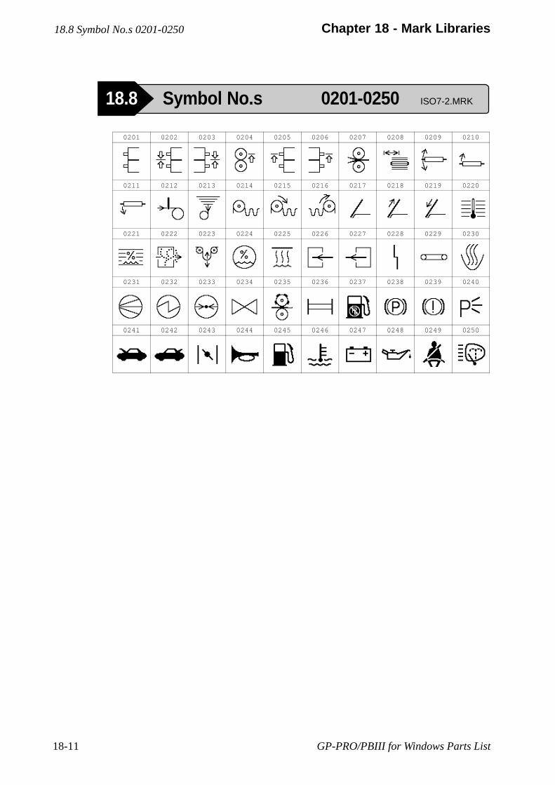
GP-PRO/PBIII for Windows Parts List18-11
Chapter 18 - Mark Libraries18.8 Symbol No.s 0201-0250
18.8 Symbol No.s 0201-0250 ISO7-2.MRK
0201 0202 0203 0204 0205 0206 0207 0208 0209 0210
0211 0212 0213 0214 0215 0216 0217 0218 0219 0220
0221 0222 0223 0224 0225 0226 0227 0228 0229 0230
0231 0232 0233 0234 0235 0236 0237 0238 0239 0240
0241 0242 0243 0244 0245 0246 0247 0248 0249 0250
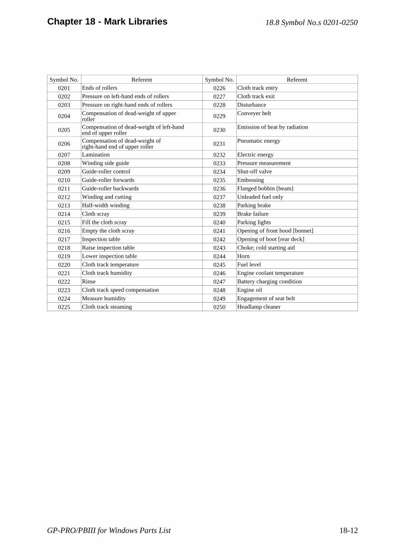
GP-PRO/PBIII for Windows Parts List 18-12
Chapter 18 - Mark Libraries
Symbol No. Referent Symbol No. Referent
0201 Ends of rollers 0226 Cloth track entry
0202 Pressure on left-hand ends of rollers 0227 Cloth track exit
0203 Pressure on right-hand ends of rollers 0228 Disturbance
0204 Compensation of dead-weight of upperroller 0229 Conveyer belt
0205 Compensation of dead-weight of left-handend of upper roller 0230 Emission of heat by radiation
0206 Compensation of dead-weight ofright-hand end of upper roller 0231 Pneumatic energy
0207 Lamination 0232 Electric energy
0208 Winding side guide 0233 Pressure measurement
0209 Guide-roller control 0234 Shut-off valve
0210 Guide-roller forwards 0235 Embossing
0211 Guide-roller backwards 0236 Flanged bobbin [beam]
0212 Winding and cutting 0237 Unleaded fuel only
0213 Half-width winding 0238 Parking brake
0214 Cloth scray 0239 Brake failure
0215 Fill the cloth scray 0240 Parking lights
0216 Empty the cloth scray 0241 Opening of front hood [bonnet]
0217 Inspection table 0242 Opening of boot [rear deck]
0218 Raise inspection table 0243 Choke; cold starting aid
0219 Lower inspection table 0244 Horn
0220 Cloth track temperature 0245 Fuel level
0221 Cloth track humidity 0246 Engine coolant temperature
0222 Rinse 0247 Battery charging condition
0223 Cloth track speed compensation 0248 Engine oil
0224 Measure humidity 0249 Engagement of seat belt
0225 Cloth track steaming 0250 Headlamp cleaner
18.8 Symbol No.s 0201-0250
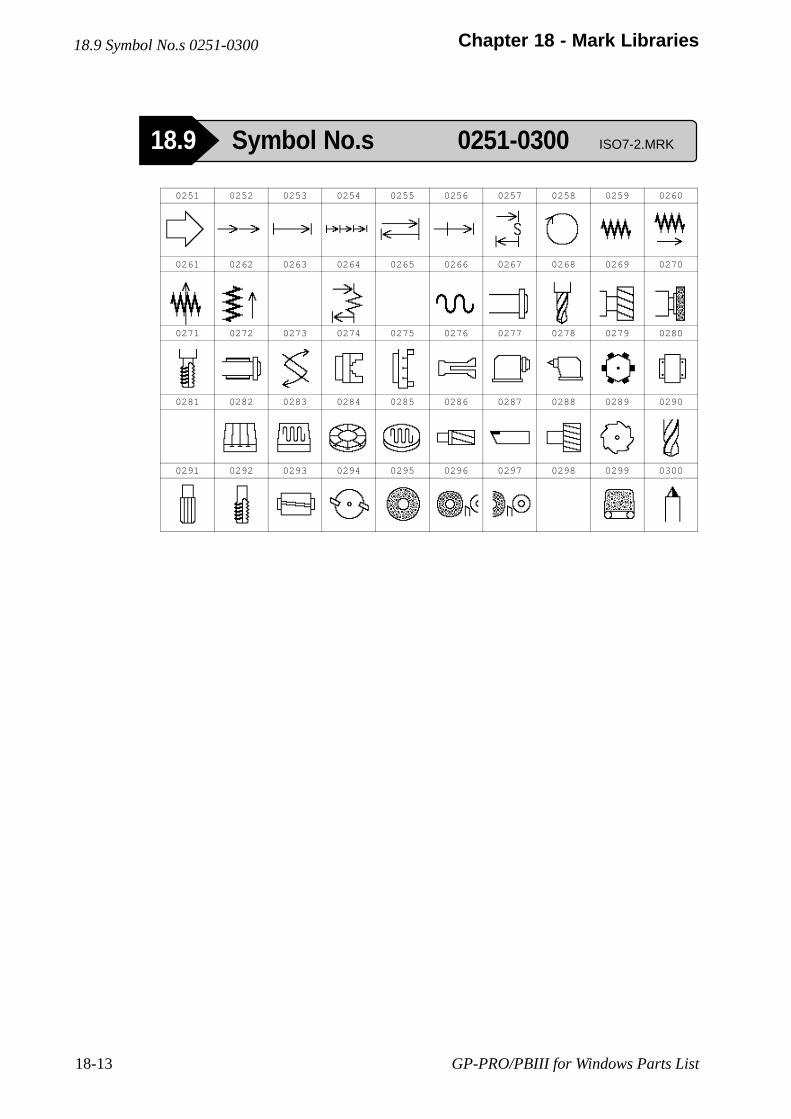
GP-PRO/PBIII for Windows Parts List18-13
Chapter 18 - Mark Libraries18.9 Symbol No.s 0251-0300
18.9 Symbol No.s 0251-0300 ISO7-2.MRK
0251 0252 0253 0254 0255 0256 0257 0258 0259 0260
0261 0262 0263 0264 0265 0266 0267 0268 0269 0270
0271 0272 0273 0274 0275 0276 0277 0278 0279 0280
0281 0282 0283 0284 0285 0286 0287 0288 0289 0290
0291 0292 0293 0294 0295 0296 0297 0298 0299 0300
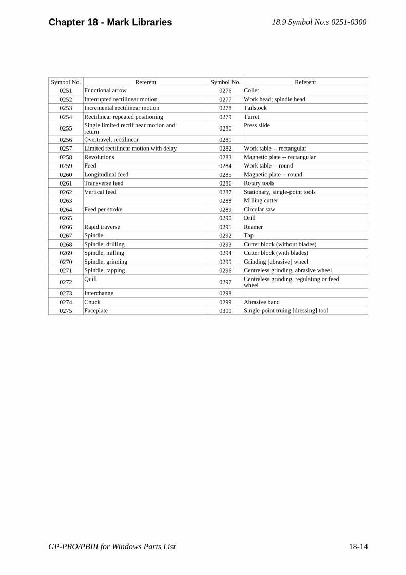
GP-PRO/PBIII for Windows Parts List 18-14
Chapter 18 - Mark Libraries
Symbol No. Referent Symbol No. Referent
0251 Functional arrow 0276 Collet
0252 Interrupted rectilinear motion 0277 Work head; spindle head
0253 Incremental rectilinear motion 0278 Tailstock
0254 Rectilinear repeated positioning 0279 Turret
0255 Single limited rectilinear motion andreturn 0280 Press slide
0256 Overtravel, rectilinear 0281
0257 Limited rectilinear motion with delay 0282 Work table -- rectangular
0258 Revolutions 0283 Magnetic plate -- rectangular
0259 Feed 0284 Work table -- round
0260 Longitudinal feed 0285 Magnetic plate -- round
0261 Transverse feed 0286 Rotary tools
0262 Vertical feed 0287 Stationary, single-point tools
0263 0288 Milling cutter
0264 Feed per stroke 0289 Circular saw
0265 0290 Drill
0266 Rapid traverse 0291 Reamer
0267 Spindle 0292 Tap
0268 Spindle, drilling 0293 Cutter block (without blades)
0269 Spindle, milling 0294 Cutter block (with blades)
0270 Spindle, grinding 0295 Grinding [abrasive] wheel
0271 Spindle, tapping 0296 Centreless grinding, abrasive wheel
0272 Quill 0297 Centreless grinding, regulating or feedwheel
0273 Interchange 0298
0274 Chuck 0299 Abrasive band
0275 Faceplate 0300 Single-point truing [dressing] tool
18.9 Symbol No.s 0251-0300
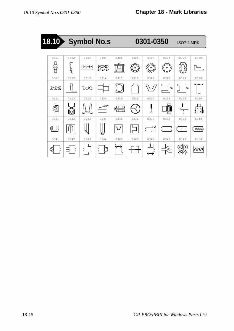
GP-PRO/PBIII for Windows Parts List18-15
Chapter 18 - Mark Libraries18.10 Symbol No.s 0301-0350
18.10 Symbol No.s 0301-0350 ISO7-2.MRK
0301 0302 0303 0304 0305 0306 0307 0308 0309 0310
0311 0312 0313 0314 0315 0316 0317 0318 0319 0320
0321 0322 0323 0324 0325 0326 0327 0328 0329 0330
0331 0332 0333 0334 0335 0336 0337 0338 0339 0340
0341 0342 0343 0344 0345 0346 0347 0348 0349 0350
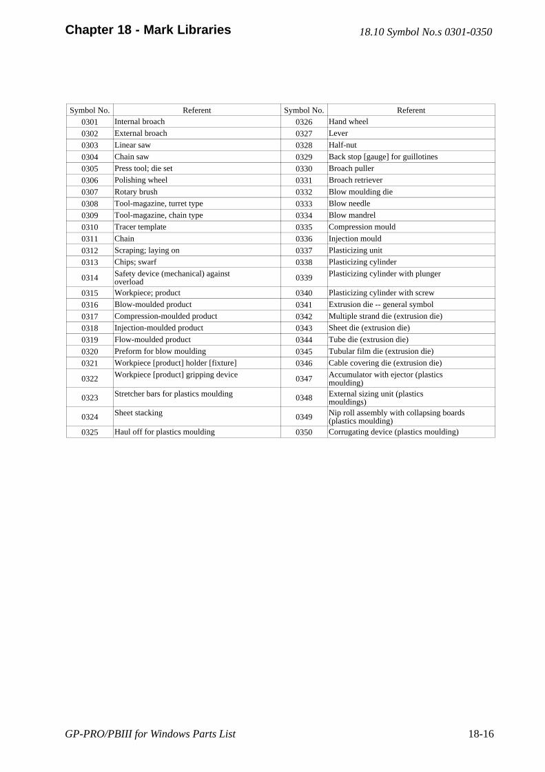
GP-PRO/PBIII for Windows Parts List 18-16
Chapter 18 - Mark Libraries
Symbol No. Referent Symbol No. Referent
0301 Internal broach 0326 Hand wheel
0302 External broach 0327 Lever
0303 Linear saw 0328 Half-nut
0304 Chain saw 0329 Back stop [gauge] for guillotines
0305 Press tool; die set 0330 Broach puller
0306 Polishing wheel 0331 Broach retriever
0307 Rotary brush 0332 Blow moulding die
0308 Tool-magazine, turret type 0333 Blow needle
0309 Tool-magazine, chain type 0334 Blow mandrel
0310 Tracer template 0335 Compression mould
0311 Chain 0336 Injection mould
0312 Scraping; laying on 0337 Plasticizing unit
0313 Chips; swarf 0338 Plasticizing cylinder
0314 Safety device (mechanical) againstoverload 0339 Plasticizing cylinder with plunger
0315 Workpiece; product 0340 Plasticizing cylinder with screw
0316 Blow-moulded product 0341 Extrusion die -- general symbol
0317 Compression-moulded product 0342 Multiple strand die (extrusion die)
0318 Injection-moulded product 0343 Sheet die (extrusion die)
0319 Flow-moulded product 0344 Tube die (extrusion die)
0320 Preform for blow moulding 0345 Tubular film die (extrusion die)
0321 Workpiece [product] holder [fixture] 0346 Cable covering die (extrusion die)
0322 Workpiece [product] gripping device 0347 Accumulator with ejector (plasticsmoulding)
0323 Stretcher bars for plastics moulding 0348 External sizing unit (plasticsmouldings)
0324 Sheet stacking 0349 Nip roll assembly with collapsing boards(plastics moulding)
0325 Haul off for plastics moulding 0350 Corrugating device (plastics moulding)
18.10 Symbol No.s 0301-0350
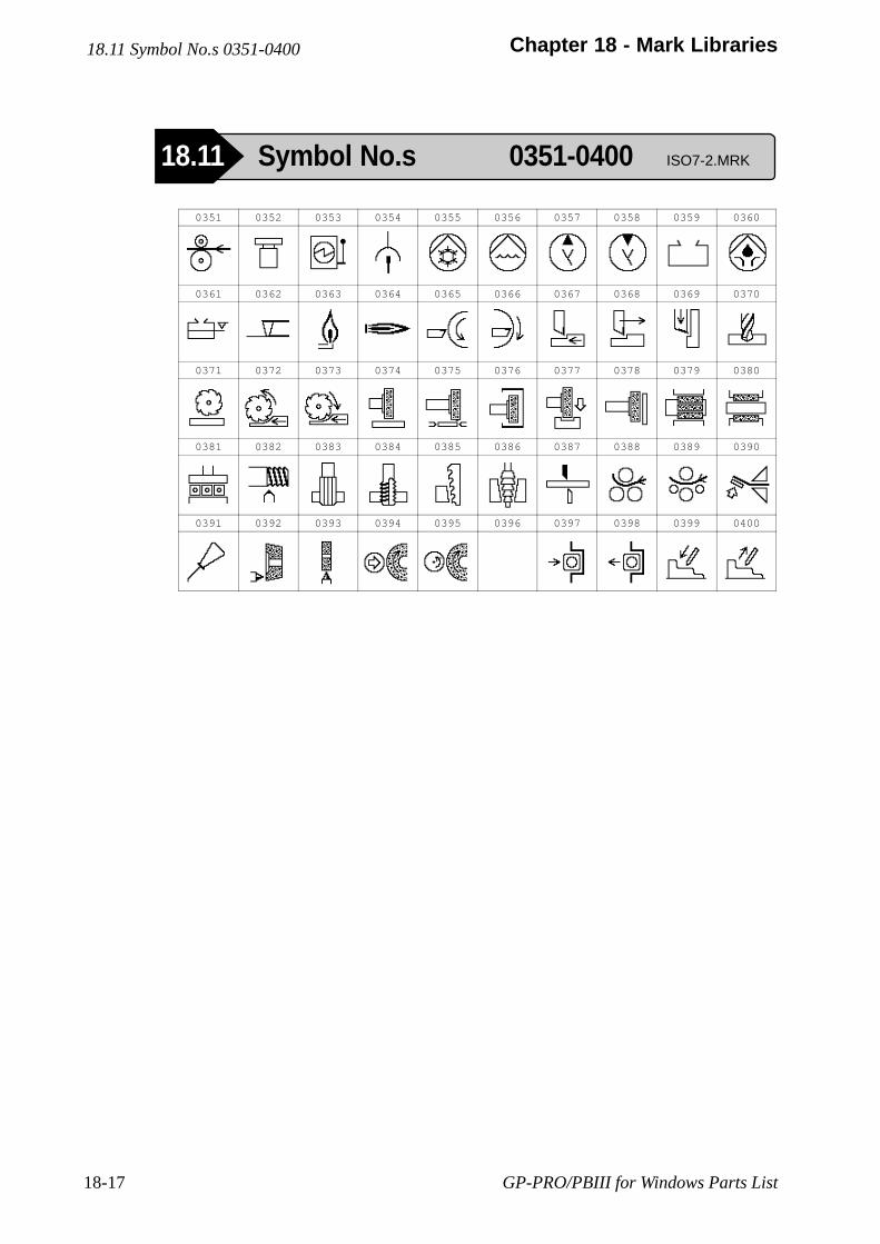
GP-PRO/PBIII for Windows Parts List18-17
Chapter 18 - Mark Libraries
0351 0352 0353 0354 0355 0356 0357 0358 0359 0360
0361 0362 0363 0364 0365 0366 0367 0368 0369 0370
0371 0372 0373 0374 0375 0376 0377 0378 0379 0380
0381 0382 0383 0384 0385 0386 0387 0388 0389 0390
0391 0392 0393 0394 0395 0396 0397 0398 0399 0400
18.11 Symbol No.s 0351-0400
18.11 Symbol No.s 0351-0400 ISO7-2.MRK
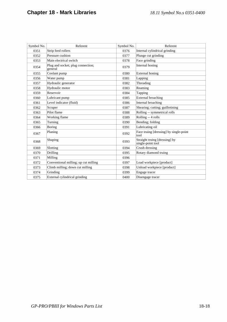
GP-PRO/PBIII for Windows Parts List 18-18
Chapter 18 - Mark Libraries
Symbol No. Referent Symbol No. Referent
0351 Strip feed rollers 0376 Internal cylindrical grinding
0352 Pressure cushion 0377 Plunge cut grinding
0353 Main electrical switch 0378 Face grinding
0354 Plug and socket; plug connection;general 0379 Internal honing
0355 Coolant pump 0380 External honing
0356 Water pump 0381 Lapping
0357 Hydraulic generator 0382 Threading
0358 Hydraulic motor 0383 Reaming
0359 Reservoir 0384 Tapping
0360 Lubricant pump 0385 External broaching
0361 Level indicator (fluid) 0386 Internal broaching
0362 Scraper 0387 Shearing; cutting; guillotining
0363 Pilot flame 0388 Rolling -- symmetrical rolls
0364 Working flame 0389 Rolling -- 4 rolls
0365 Turning 0390 Bending; folding
0366 Boring 0391 Lubricating oil
0367 Planing 0392 Face truing [dressing] by single-pointtool
0368 Shaping 0393 Straight truing [dressing] bysingle-point tool
0369 Slotting 0394 Crush dressing
0370 Drilling 0395 Rotary diamond truing
0371 Milling 0396
0372 Conventional milling; up cut milling 0397 Load workpiece [product]
0373 Climb milling; down cut milling 0398 Unload workpiece [product]
0374 Grinding 0399 Engage tracer
0375 External cylindrical grinding 0400 Disengage tracer
18.11 Symbol No.s 0351-0400

GP-PRO/PBIII for Windows Parts List18-19
Chapter 18 - Mark Libraries
0401 0402 0403 0404 0405 0406 0407 0408 0409 0410
0411 0412 0413 0414 0415 0416 0417 0418 0419 0420
0421 0422 0423 0424 0425 0426 0427 0428 0429 0430
0431 0432 0433 0434 0435 0436 0437 0438 0439 0440
0441 0442 0443 0444 0445 0446 0447 0448 0449 0450
18.12 Symbol No.s 0401-0450
18.12 Symbol No.s 0401-0450 ISO7-3.MRK
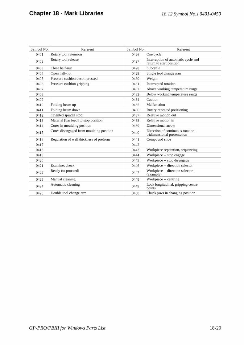
GP-PRO/PBIII for Windows Parts List 18-20
Chapter 18 - Mark Libraries
Symbol No. Referent Symbol No. Referent
0401 Rotary tool retension 0426 One cycle
0402 Rotary tool release 0427 Interruption of automatic cycle andreturn to start position
0403 Close half-nut 0428 Subcycle
0404 Open half-nut 0429 Single tool change arm
0405 Pressure cushion decompressed 0430 Weight
0406 Pressure cushion gripping 0431 Interrupted rotation
0407 0432 Above working temperature range
0408 0433 Below working temperature range
0409 0434 Caution
0410 Folding beam up 0435 Malfunction
0411 Folding beam down 0436 Rotary repeated positioning
0412 Oriented spindle stop 0437 Relative motion out
0413 Material [bar feed] to stop position 0438 Relative motion in
0414 Cores in moulding position 0439 Dimensional arrow
0415 Cores disengaged from moulding position 0440 Direction of continuous rotation;tridimensional presentation
0416 Regulation of wall thickness of preform 0441 Compound slide
0417 0442
0418 0443 Workpiece separation, sequencing
0419 0444 Workpiece -- stop engage
0420 0445 Workpiece -- stop disengage
0421 Examine; check 0446 Workpiece -- direction selector
0422 Ready (to proceed) 0447 Workpiece -- direction selector(example)
0423 Manual cleaning 0448 Workpiece -- centring
0424 Automatic cleaning 0449 Lock longitudinal, gripping centrepoints
0425 Double tool change arm 0450 Chuck jaws in changing position
18.12 Symbol No.s 0401-0450
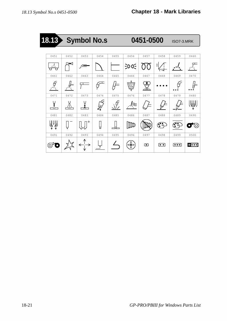
GP-PRO/PBIII for Windows Parts List18-21
Chapter 18 - Mark Libraries
0451 0452 0453 0454 0455 0456 0457 0458 0459 0460
0461 0462 0463 0464 0465 0466 0467 0468 0469 0470
0471 0472 0473 0474 0475 0476 0477 0478 0479 0480
0481 0482 0483 0484 0485 0486 0487 0488 0489 0490
0491 0492 0493 0494 0495 0496 0497 0498 0499 0500
18.13 Symbol No.s 0451-0500
18.13 Symbol No.s 0451-0500 ISO7-3.MRK
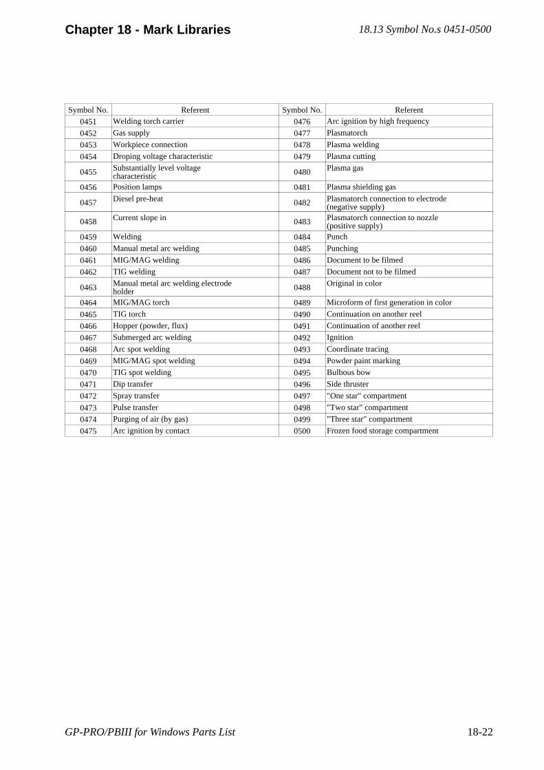
GP-PRO/PBIII for Windows Parts List 18-22
Chapter 18 - Mark Libraries
Symbol No. Referent Symbol No. Referent
0451 Welding torch carrier 0476 Arc ignition by high frequency
0452 Gas supply 0477 Plasmatorch
0453 Workpiece connection 0478 Plasma welding
0454 Droping voltage characteristic 0479 Plasma cutting
0455 Substantially level voltagecharacteristic 0480 Plasma gas
0456 Position lamps 0481 Plasma shielding gas
0457 Diesel pre-heat 0482 Plasmatorch connection to electrode(negative supply)
0458 Current slope in 0483 Plasmatorch connection to nozzle(positive supply)
0459 Welding 0484 Punch
0460 Manual metal arc welding 0485 Punching
0461 MIG/MAG welding 0486 Document to be filmed
0462 TIG welding 0487 Document not to be filmed
0463 Manual metal arc welding electrodeholder 0488 Original in color
0464 MIG/MAG torch 0489 Microform of first generation in color
0465 TIG torch 0490 Continuation on another reel
0466 Hopper (powder, flux) 0491 Continuation of another reel
0467 Submerged arc welding 0492 Ignition
0468 Arc spot welding 0493 Coordinate tracing
0469 MIG/MAG spot welding 0494 Powder paint marking
0470 TIG spot welding 0495 Bulbous bow
0471 Dip transfer 0496 Side thruster
0472 Spray transfer 0497 "One star" compartment
0473 Pulse transfer 0498 "Two star" compartment
0474 Purging of air (by gas) 0499 "Three star" compartment
0475 Arc ignition by contact 0500 Frozen food storage compartment
18.13 Symbol No.s 0451-0500
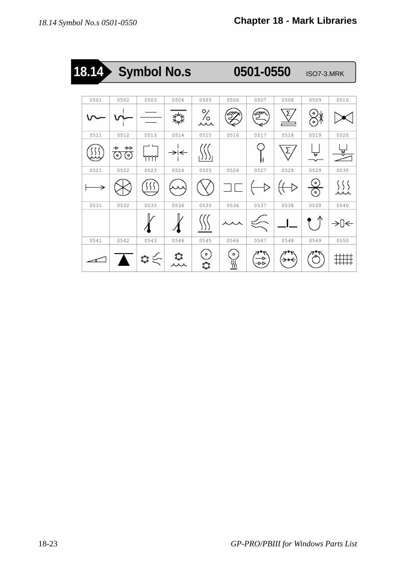
GP-PRO/PBIII for Windows Parts List18-23
Chapter 18 - Mark Libraries
0501 0502 0503 0504 0505 0506 0507 0508 0509 0510
0511 0512 0513 0514 0515 0516 0517 0518 0519 0520
0521 0522 0523 0524 0525 0526 0527 0528 0529 0530
0531 0532 0533 0534 0535 0536 0537 0538 0539 0540
0541 0542 0543 0544 0545 0546 0547 0548 0549 0550
18.14 Symbol No.s 0501-0550
18.14 Symbol No.s 0501-0550 ISO7-3.MRK
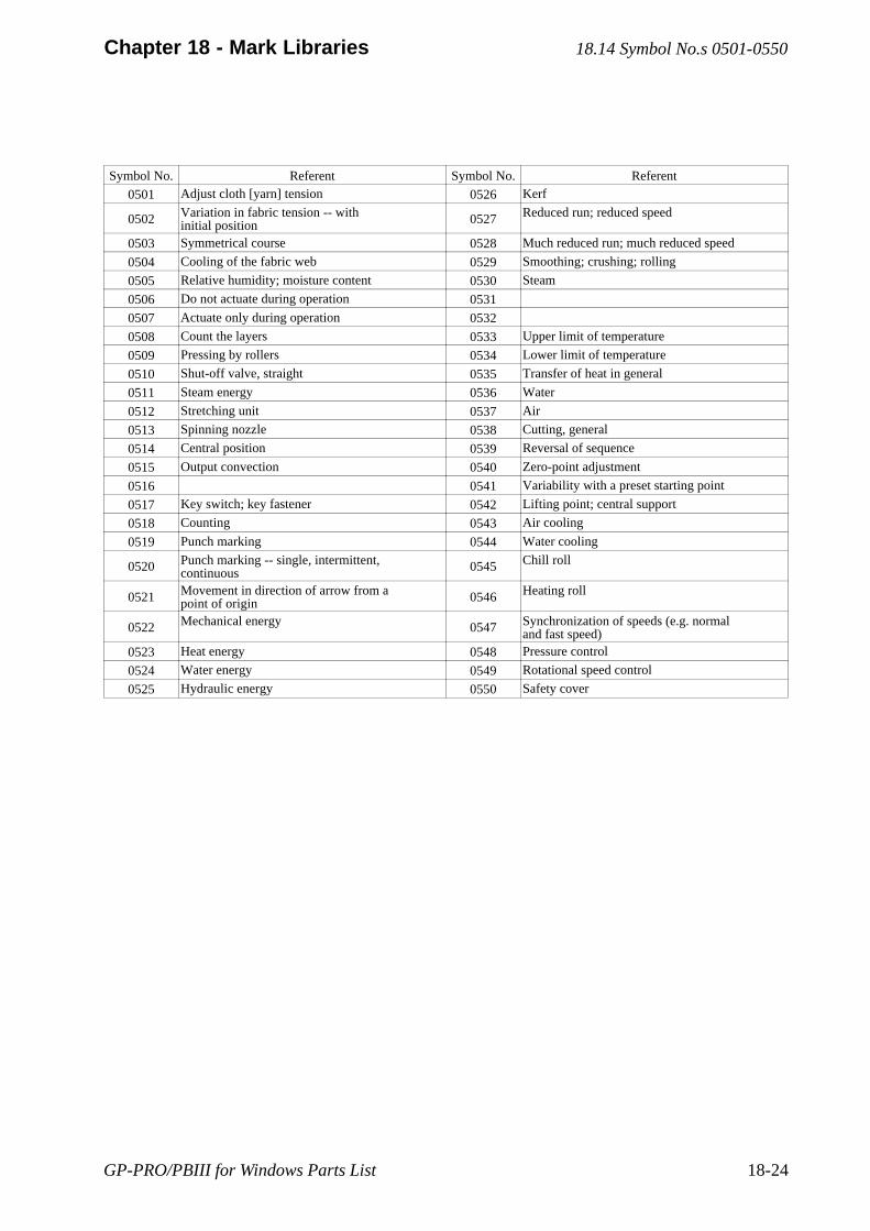
GP-PRO/PBIII for Windows Parts List 18-24
Chapter 18 - Mark Libraries
Symbol No. Referent Symbol No. Referent
0501 Adjust cloth [yarn] tension 0526 Kerf
0502 Variation in fabric tension -- withinitial position 0527 Reduced run; reduced speed
0503 Symmetrical course 0528 Much reduced run; much reduced speed
0504 Cooling of the fabric web 0529 Smoothing; crushing; rolling
0505 Relative humidity; moisture content 0530 Steam
0506 Do not actuate during operation 0531
0507 Actuate only during operation 0532
0508 Count the layers 0533 Upper limit of temperature
0509 Pressing by rollers 0534 Lower limit of temperature
0510 Shut-off valve, straight 0535 Transfer of heat in general
0511 Steam energy 0536 Water
0512 Stretching unit 0537 Air
0513 Spinning nozzle 0538 Cutting, general
0514 Central position 0539 Reversal of sequence
0515 Output convection 0540 Zero-point adjustment
0516 0541 Variability with a preset starting point
0517 Key switch; key fastener 0542 Lifting point; central support
0518 Counting 0543 Air cooling
0519 Punch marking 0544 Water cooling
0520 Punch marking -- single, intermittent,continuous 0545 Chill roll
0521 Movement in direction of arrow from apoint of origin 0546 Heating roll
0522 Mechanical energy 0547 Synchronization of speeds (e.g. normaland fast speed)
0523 Heat energy 0548 Pressure control
0524 Water energy 0549 Rotational speed control
0525 Hydraulic energy 0550 Safety cover
18.14 Symbol No.s 0501-0550
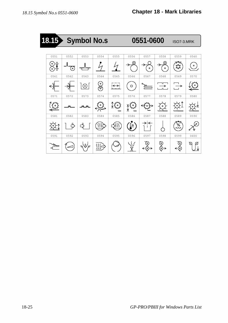
GP-PRO/PBIII for Windows Parts List18-25
Chapter 18 - Mark Libraries
0551 0552 0553 0554 0555 0556 0557 0558 0559 0560
0561 0562 0563 0564 0565 0566 0567 0568 0569 0570
0571 0572 0573 0574 0575 0576 0577 0578 0579 0580
0581 0582 0583 0584 0585 0586 0587 0588 0589 0590
0591 0592 0593 0594 0595 0596 0597 0598 0599 0600
18.15 Symbol No.s 0551-0600
18.15 Symbol No.s 0551-0600 ISO7-3.MRK
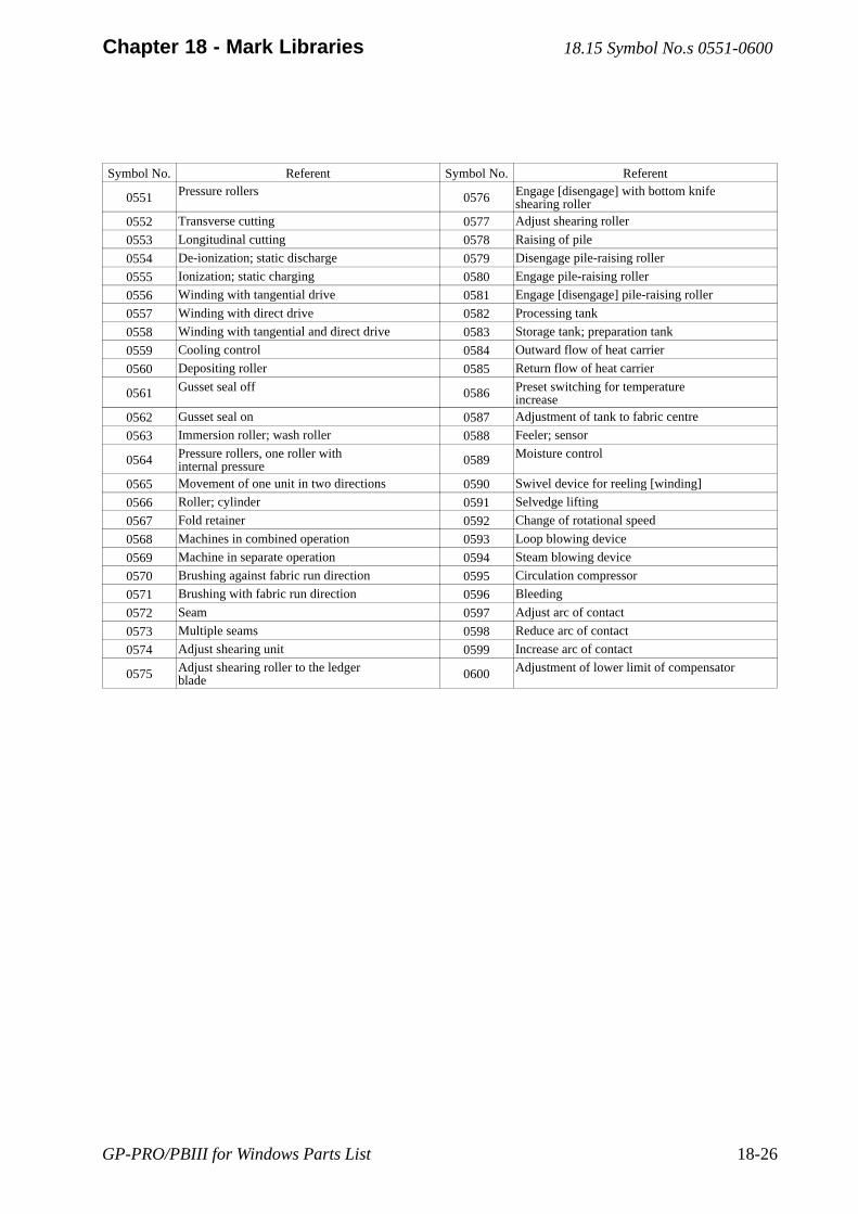
GP-PRO/PBIII for Windows Parts List 18-26
Chapter 18 - Mark Libraries
Symbol No. Referent Symbol No. Referent
0551 Pressure rollers 0576 Engage [disengage] with bottom knifeshearing roller
0552 Transverse cutting 0577 Adjust shearing roller
0553 Longitudinal cutting 0578 Raising of pile
0554 De-ionization; static discharge 0579 Disengage pile-raising roller
0555 Ionization; static charging 0580 Engage pile-raising roller
0556 Winding with tangential drive 0581 Engage [disengage] pile-raising roller
0557 Winding with direct drive 0582 Processing tank
0558 Winding with tangential and direct drive 0583 Storage tank; preparation tank
0559 Cooling control 0584 Outward flow of heat carrier
0560 Depositing roller 0585 Return flow of heat carrier
0561 Gusset seal off 0586 Preset switching for temperatureincrease
0562 Gusset seal on 0587 Adjustment of tank to fabric centre
0563 Immersion roller; wash roller 0588 Feeler; sensor
0564 Pressure rollers, one roller withinternal pressure 0589 Moisture control
0565 Movement of one unit in two directions 0590 Swivel device for reeling [winding]
0566 Roller; cylinder 0591 Selvedge lifting
0567 Fold retainer 0592 Change of rotational speed
0568 Machines in combined operation 0593 Loop blowing device
0569 Machine in separate operation 0594 Steam blowing device
0570 Brushing against fabric run direction 0595 Circulation compressor
0571 Brushing with fabric run direction 0596 Bleeding
0572 Seam 0597 Adjust arc of contact
0573 Multiple seams 0598 Reduce arc of contact
0574 Adjust shearing unit 0599 Increase arc of contact
0575 Adjust shearing roller to the ledgerblade 0600 Adjustment of lower limit of compensator
18.15 Symbol No.s 0551-0600
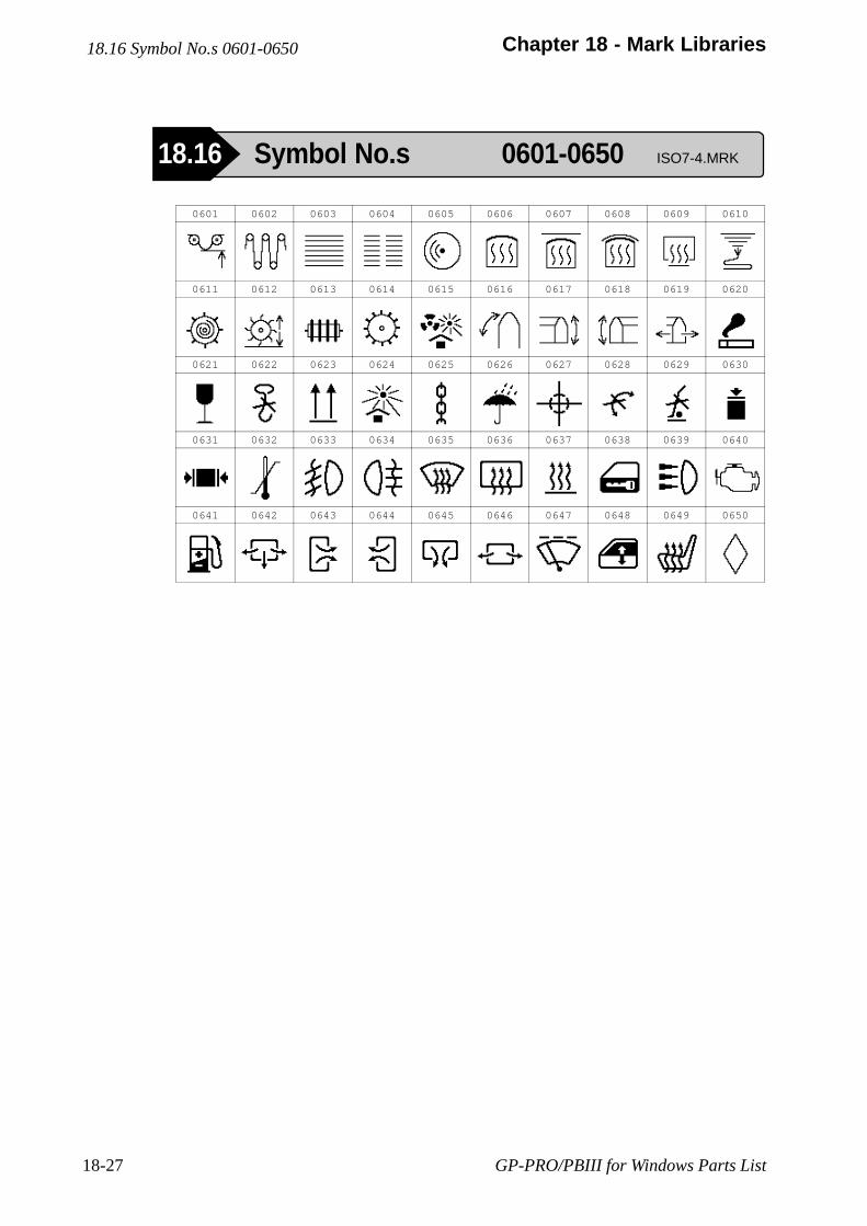
GP-PRO/PBIII for Windows Parts List18-27
Chapter 18 - Mark Libraries18.16 Symbol No.s 0601-0650
18.16 Symbol No.s 0601-0650 ISO7-4.MRK
0601 0602 0603 0604 0605 0606 0607 0608 0609 0610
0611 0612 0613 0614 0615 0616 0617 0618 0619 0620
0621 0622 0623 0624 0625 0626 0627 0628 0629 0630
0631 0632 0633 0634 0635 0636 0637 0638 0639 0640
0641 0642 0643 0644 0645 0646 0647 0648 0649 0650
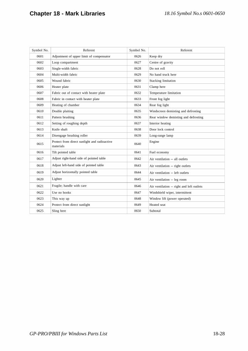
GP-PRO/PBIII for Windows Parts List 18-28
Chapter 18 - Mark Libraries
Symbol No. Referent Symbol No. Referent
0601 Adjustment of upper limit of compensator 0626 Keep dry
0602 Loop compartment 0627 Centre of gravity
0603 Single-width fabric 0628 Do not roll
0604 Multi-width fabric 0629 No hand truck here
0605 Wound fabric 0630 Stacking limitation
0606 Heater plate 0631 Clamp here
0607 Fabric out of contact with heater plate 0632 Temperature limitation
0608 Fabric in contact with heater plate 0633 Front fog light
0609 Heating of chamber 0634 Rear fog light
0610 Double plaiting 0635 Windscreen demisting and defrosting
0611 Pattern brushing 0636 Rear window demisting and defrosting
0612 Setting of roughing depth 0637 Interior heating
0613 Knife shaft 0638 Door lock control
0614 Disengage brushing roller 0639 Long-range lamp
0615Protect from direct sunlight and radioactivematerials
0640Engine
0616 Tilt pointed table 0641 Fuel economy
0617 Adjust right-hand side of pointed table 0642 Air ventilation -- all outlets
0618 Adjust left-hand side of pointed table 0643 Air ventilation -- right outlets
0619 Adjust horizontally pointed table 0644 Air ventilation -- left outlets
0620 Lighter 0645 Air ventilation -- leg room
0621 Fragile; handle with care 0646 Air ventilation -- right and left outlets
0622 Use no hooks 0647 Windshield wiper, intermittent
0623 This way up 0648 Window lift (power operated)
0624 Protect from direct sunlight 0649 Heated seat
0625 Sling here 0650 Subtotal
18.16 Symbol No.s 0601-0650
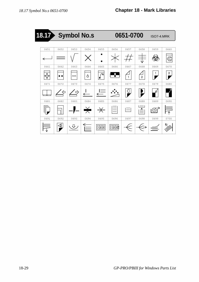
GP-PRO/PBIII for Windows Parts List18-29
Chapter 18 - Mark Libraries
0651 0652 0653 0654 0655 0656 0657 0658 0659 0660
0661 0662 0663 0664 0665 0666 0667 0668 0669 0670
0671 0672 0673 0674 0675 0676 0677 0678 0679 0680
0681 0682 0683 0684 0685 0686 0687 0688 0689 0690
0691 0692 0693 0694 0695 0696 0697 0698 0699 0700
18.17 Symbol No.s 0651-0700
18.17 Symbol No.s 0651-0700 ISO7-4.MRK
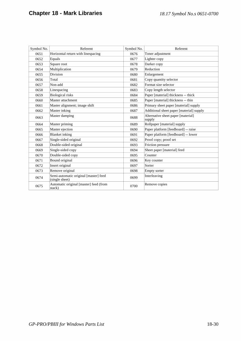
GP-PRO/PBIII for Windows Parts List 18-30
Chapter 18 - Mark Libraries
Symbol No. Referent Symbol No. Referent
0651 Horizontal return with linespacing 0676 Toner adjustment
0652 Equals 0677 Lighter copy
0653 Square root 0678 Darker copy
0654 Multiplication 0679 Reduction
0655 Division 0680 Enlargement
0656 Total 0681 Copy quantity selector
0657 Non-add 0682 Format size selector
0658 Linespacing 0683 Copy length selector
0659 Biological risks 0684 Paper [material] thickness -- thick
0660 Master attachment 0685 Paper [material] thickness -- thin
0661 Master alignment; image shift 0686 Primary sheet paper [material] supply
0662 Master inking 0687 Additional sheet paper [material] supply
0663 Master damping 0688 Alternative sheet paper [material]supply
0664 Master priming 0689 Rollpaper [material] supply
0665 Master ejection 0690 Paper platform [feedboard] -- raise
0666 Blanket inking 0691 Paper platform [feedboard] -- lower
0667 Single-sided original 0692 Proof copy; proof set
0668 Double-sided original 0693 Friction pressure
0669 Single-sided copy 0694 Sheet paper [material] feed
0670 Double-sided copy 0695 Counter
0671 Bound original 0696 Key counter
0672 Insert original 0697 Sorter
0673 Remove original 0698 Empty sorter
0674 Semi-automatic original [master] feed(single sheet) 0699 Interleaving
0675 Automatic original [master] feed (fromstack) 0700 Remove copies
18.17 Symbol No.s 0651-0700

GP-PRO/PBIII for Windows Parts List18-31
Chapter 18 - Mark Libraries
0701 0702 0703 0704 0705 0706 0707 0708 0709 0710
0711 0712 0713 0714 0715 0716 0717 0718 0719 0720
0721 0722 0723 0724 0725 0726 0727 0728 0729 0730
0731 0732 0733 0734 0735 0736 0737 0738 0739 0740
0741 0742 0743 0744 0745 0746 0747 0748 0749 0750
18.18 Symbol No.s 0701-0750
18.18 Symbol No.s 0701-0750 ISO7-4.MRK
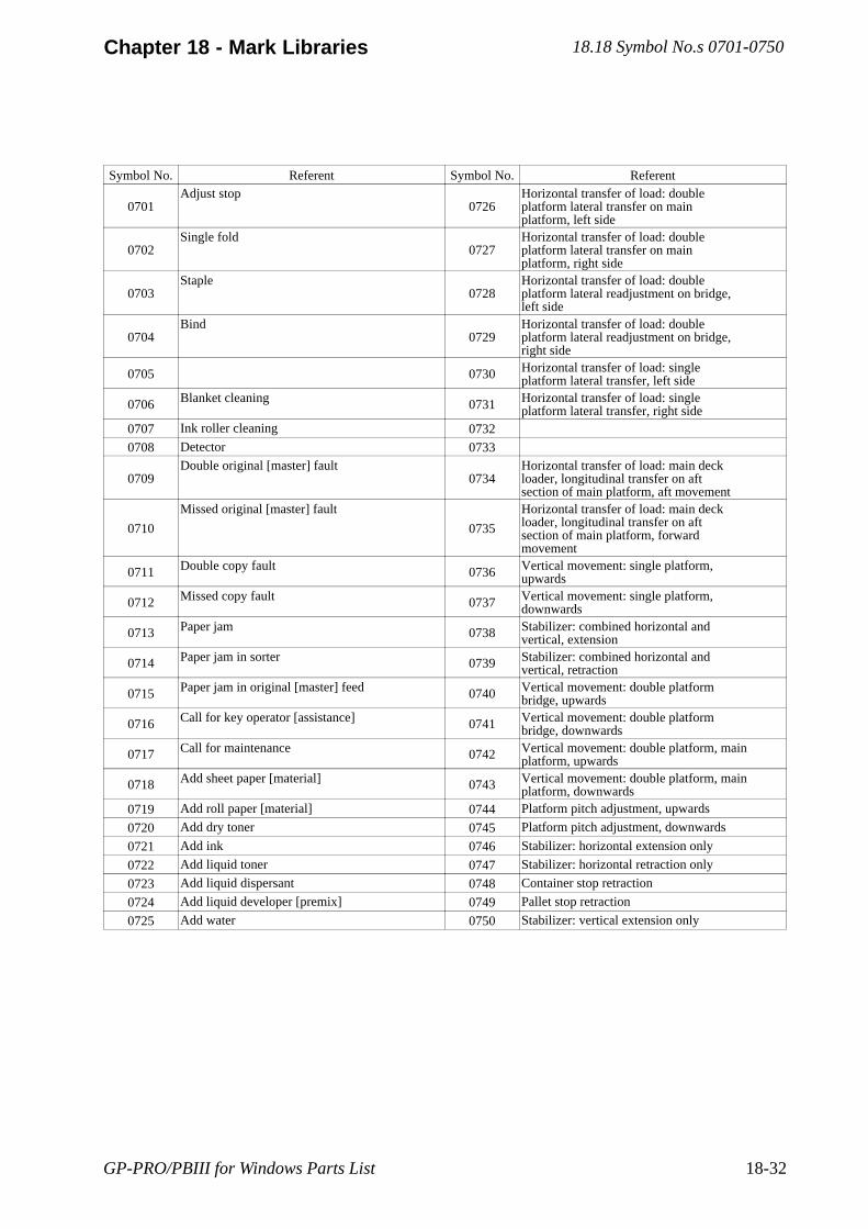
GP-PRO/PBIII for Windows Parts List 18-32
Chapter 18 - Mark Libraries
Symbol No. Referent Symbol No. Referent
0701Adjust stop
0726Horizontal transfer of load: doubleplatform lateral transfer on mainplatform, left side
0702Single fold
0727Horizontal transfer of load: doubleplatform lateral transfer on mainplatform, right side
0703Staple
0728Horizontal transfer of load: doubleplatform lateral readjustment on bridge,left side
0704Bind
0729Horizontal transfer of load: doubleplatform lateral readjustment on bridge,right side
0705 0730 Horizontal transfer of load: singleplatform lateral transfer, left side
0706 Blanket cleaning 0731 Horizontal transfer of load: singleplatform lateral transfer, right side
0707 Ink roller cleaning 0732
0708 Detector 0733
0709Double original [master] fault
0734Horizontal transfer of load: main deckloader, longitudinal transfer on aftsection of main platform, aft movement
0710
Missed original [master] fault
0735
Horizontal transfer of load: main deckloader, longitudinal transfer on aftsection of main platform, forwardmovement
0711 Double copy fault 0736 Vertical movement: single platform,upwards
0712 Missed copy fault 0737 Vertical movement: single platform,downwards
0713 Paper jam 0738 Stabilizer: combined horizontal andvertical, extension
0714 Paper jam in sorter 0739 Stabilizer: combined horizontal andvertical, retraction
0715 Paper jam in original [master] feed 0740 Vertical movement: double platformbridge, upwards
0716 Call for key operator [assistance] 0741 Vertical movement: double platformbridge, downwards
0717 Call for maintenance 0742 Vertical movement: double platform, mainplatform, upwards
0718 Add sheet paper [material] 0743 Vertical movement: double platform, mainplatform, downwards
0719 Add roll paper [material] 0744 Platform pitch adjustment, upwards
0720 Add dry toner 0745 Platform pitch adjustment, downwards
0721 Add ink 0746 Stabilizer: horizontal extension only
0722 Add liquid toner 0747 Stabilizer: horizontal retraction only
0723 Add liquid dispersant 0748 Container stop retraction
0724 Add liquid developer [premix] 0749 Pallet stop retraction
0725 Add water 0750 Stabilizer: vertical extension only
18.18 Symbol No.s 0701-0750
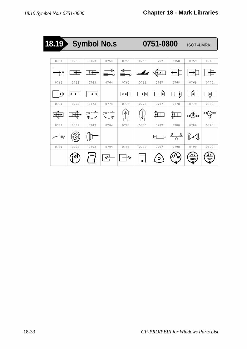
GP-PRO/PBIII for Windows Parts List18-33
Chapter 18 - Mark Libraries
0751 0752 0753 0754 0755 0756 0757 0758 0759 0760
0761 0762 0763 0764 0765 0766 0767 0768 0769 0770
0771 0772 0773 0774 0775 0776 0777 0778 0779 0780
0781 0782 0783 0784 0785 0786 0787 0788 0789 0790
0791 0792 0793 0794 0795 0796 0797 0798 0799 0800
18.19 Symbol No.s 0751-0800
18.19 Symbol No.s 0751-0800 ISO7-4.MRK
GP-PRO/PBIII for Windows Parts List 18-34
Chapter 18 - Mark Libraries
Symbol No. Referent Symbol No. Referent
0751 Stabilizer: vertical retraction only 0776 Backward (backward motion): vehicle aftmovement
0752Horizontal transfer of load: main deckloader, longitudinal transfer on bridge,aft movement
0777Horizontal transfer of load: main deckloader, lateral transfer on aft sectionof main platform, left side
0753Horizontal transfer of load: main deckloader, longitudinal transfer on bridge,forward movement
0778Horizontal transfer of load: main deckloader, lateral transfer of aft sectionof main platform, right side
0754 Platform telescopic adjustment,extension 0779 Drive unit(s) retraction, up
0755 Platform telescopic adjustment,retraction 0780 Drive unit(s) retraction, down
0756 Aircraft location 0781 Over-travel, rotary
0757Horizontal transfer of load: main deckloader, four directions transfer on aftsection of main platform
0782Flywheel
0758Horizontal transfer of load: doubleplatform, longitudinal transfer on mainplatform, aft
0783Knob; plunger
0759Horizontal transfer of load: doubleplatform, longitudinal transfer on mainplatform, forward
0784
0760Horizontal transfer of load: doubleplatform, longitudinal transfer onbridge, aft
0785
0761Horizontal transfer of load: doubleplatform, longitudinal transfer onbridge, forward
0786
0762 Horizontal transfer of load: singleplatform, longitudinal transfer, aft 0787 Lubricant grease
0763 Horizontal transfer of load: singleplatform, longitudinal transfer, forward 0788 Static balance
0764 0789 Dynamic balance
0765Horizontal transfer of load: main deckloader, longitudinal transfer on forwardsection of main platform, aft movement
0790
0766
Horizontal transfer of load: main deckloader, longitudinal transfer on forwardsection of main platform, forwardmovement
0791
0767Horizontal transfer of load: main deckloader, lateral readjustment on bridge,left side
0792Alignment
0768Horizontal transfer of load: main deckloader, lateral readjustment on bridge,right side
0793Print out
0769Horizontal transfer of load: main deckloader, lateral transfer on forwardsection of main platform, left side
0794Input; entrance
0770Horizontal transfer of load: main deckloader, lateral transfer on forwardsection of main platform, right side
0795Output; exit
0771Horizontal transfer of load: main deckloader, four directions transfer onforward section of main platform
0796Reciprocating internal combustion engine
0772Horizontal transfer of load: main deckloader, four directions/readjustment onbridge
0797Rotary piston engine
0773 Platform roll [twist] adjustment, leftside 0798 Rotational speed variation [fluctuation]
0774 Platform roll [twist] adjustment, rightside 0799 Speed range
0775 Forward (forward motion): vehicleforward movement 0800 Steady state speed differences
18.19 Symbol No.s 0751-0800
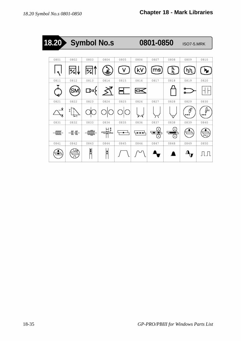
GP-PRO/PBIII for Windows Parts List18-35
Chapter 18 - Mark Libraries
0801 0802 0803 0804 0805 0806 0807 0808 0809 0810
0811 0812 0813 0814 0815 0816 0817 0818 0819 0820
0821 0822 0823 0824 0825 0826 0827 0828 0829 0830
0831 0832 0833 0834 0835 0836 0837 0838 0839 0840
0841 0842 0843 0844 0845 0846 0847 0848 0849 0850
18.20 Symbol No.s 0801-0850
18.20 Symbol No.s 0801-0850 ISO7-5.MRK
GP-PRO/PBIII for Windows Parts List 18-36
Chapter 18 - Mark Libraries
Symbol No. Referent Symbol No. Referent
0801 Cylinder 0826 Pilot arc
0802 Cylinder leakage 0827 Transferred arc
0803 Cylinder-to-cylinder compressioncomparison 0828 Non-transferred arc
0804 High voltage short circuit for differentcylinders 0829 MIG/MAG spot welding with time control
0805 Primary voltage 0830 TIG spot welding with time control
0806 Ignition voltage 0831 Continuous welding
0807 Calibrated time base 0832 Intermittent welding; tack welding
0808 Ignition voltage displayed in parade 0833 Weld with reduced initial and finalcurrent
0809 Ignition voltage displayed in raster 0834 Resistance spot welding, double stroke
0810 Ignition voltage displayed superimposed 0835 Spot welding, single spot welding
0811 TDC position sensor 0836 Spot welding, repeat spot welding
0812 Starter motor 0837 Seam welding with interrupted current
0813 Strobe light 0838 Continuous seam welding;continuous-current seam welding
0814 Ignition timing 0839 Squeeze time
0815 Switching element of the ignition system 0840 Weld current time
0816 Clip-on sensor 0841 Hold time
0817 0842 Off time
0818 Ignition coil 0843 Clamping without welding
0819 Measuring cables 0844 Approach with minimum force
0820 Capacitor 0845 Welding with constant force
0821 Peak voltage 0846 Welding with force variation
0822 Current slope out 0847 Full-wave welding current
0823 Wire feed drive 0848 Half-cycle welding current
0824 Wire feed drive, continuous 0849 Phase shift
0825 Wire feed drive, interrupted 0850 Number of thermal pulses
18.20 Symbol No.s 0801-0850
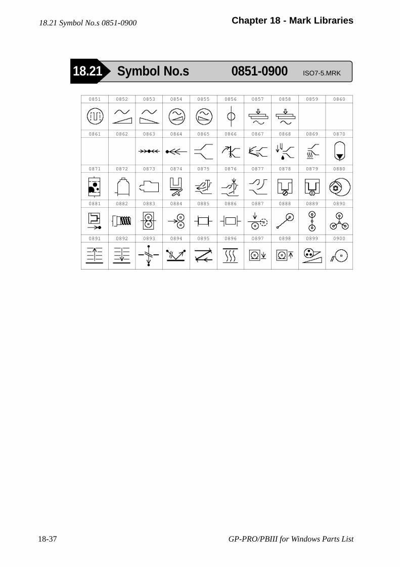
GP-PRO/PBIII for Windows Parts List18-37
Chapter 18 - Mark Libraries
0851 0852 0853 0854 0855 0856 0857 0858 0859 0860
0861 0862 0863 0864 0865 0866 0867 0868 0869 0870
0871 0872 0873 0874 0875 0876 0877 0878 0879 0880
0881 0882 0883 0884 0885 0886 0887 0888 0889 0890
0891 0892 0893 0894 0895 0896 0897 0898 0899 0900
18.21 Symbol No.s 0851-0900
18.21 Symbol No.s 0851-0900 ISO7-5.MRK
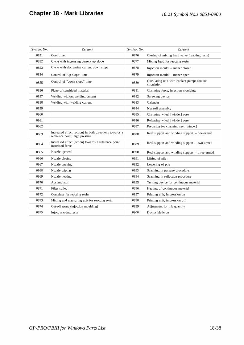
GP-PRO/PBIII for Windows Parts List 18-38
Chapter 18 - Mark Libraries
Symbol No. Referent Symbol No. Referent
0851 Cool time 0876 Closing of mixing head valve (reacting resin)
0852 Cycle with increasing current up slope 0877 Mixing head for reacting resin
0853 Cycle with decreasing current down slope 0878 Injection mould -- runner closed
0854 Control of "up slope" time 0879 Injection mould -- runner open
0855 Control of "down slope" time 0880 Circulating unit with coolant pump; coolantcirculation
0856 Plane of sensitized material 0881 Clamping force, injection moulding
0857 Welding without welding current 0882 Screwing device
0858 Welding with welding current 0883 Calender
0859 0884 Nip roll assembly
0860 0885 Clamping wheel [winder] core
0861 0886 Releasing wheel [winder] core
0862 0887 Preparing for changing reel [winder]
0863Increased effect [action] in both directions towards areference point; high pressure 0888 Reel support and winding support -- one-armed
0864Increased effect [action] towards a reference point;increased force 0889 Reel support and winding support -- two-armed
0865 Nozzle, general 0890 Reel support and winding support -- three-armed
0866 Nozzle closing 0891 Lifting of pile
0867 Nozzle opening 0892 Lowering of pile
0868 Nozzle wiping 0893 Scanning in passage procedure
0869 Nozzle heating 0894 Scanning in reflection procedure
0870 Accumulator 0895 Turning device for continuous material
0871 Filter soiled 0896 Heating of continuous material
0872 Container for reacting resin 0897 Printing unit, impression on
0873 Mixing and measuring unit for reacting resin 0898 Printing unit, impression off
0874 Cut-off sprue (injection moulding) 0899 Adjustment for ink quantity
0875 Inject reacting resin 0900 Doctor blade on
18.21 Symbol No.s 0851-0900
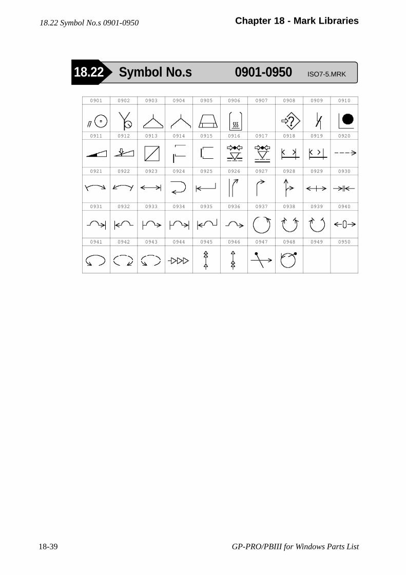
GP-PRO/PBIII for Windows Parts List18-39
Chapter 18 - Mark Libraries
0901 0902 0903 0904 0905 0906 0907 0908 0909 0910
0911 0912 0913 0914 0915 0916 0917 0918 0919 0920
0921 0922 0923 0924 0925 0926 0927 0928 0929 0930
0931 0932 0933 0934 0935 0936 0937 0938 0939 0940
0941 0942 0943 0944 0945 0946 0947 0948 0949 0950
18.22 Symbol No.s 0901-0950
18.22 Symbol No.s 0901-0950 ISO7-5.MRK
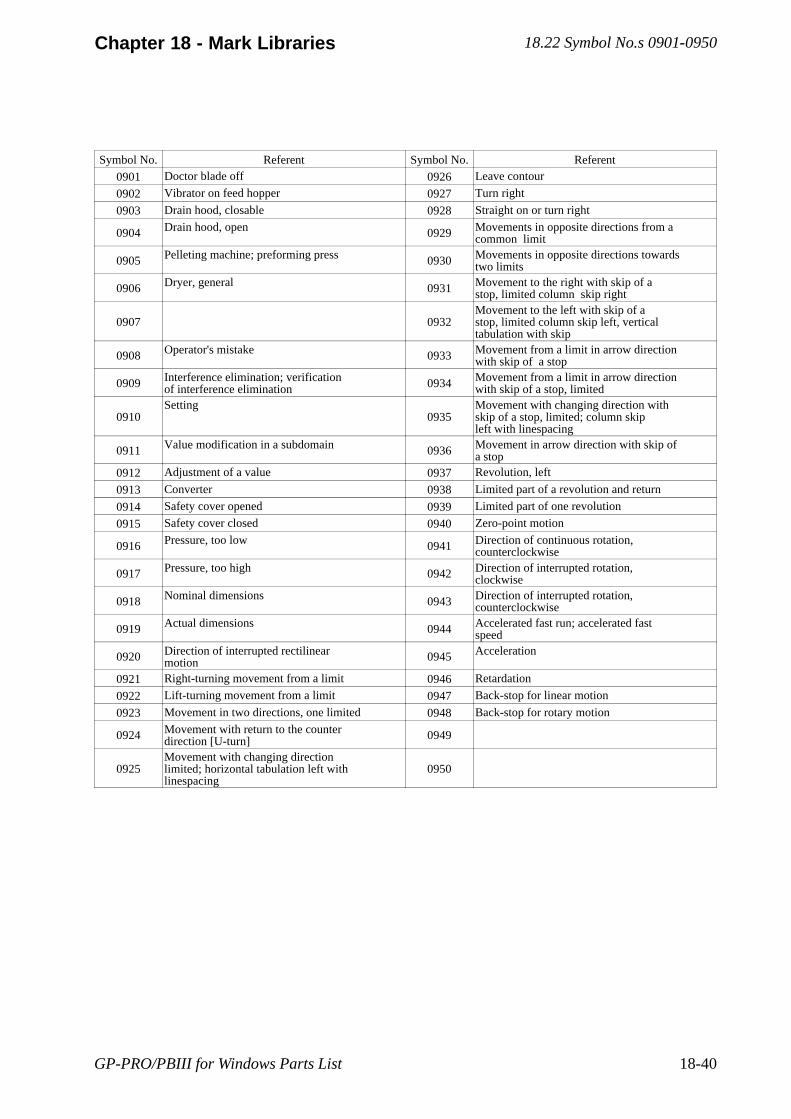
GP-PRO/PBIII for Windows Parts List 18-40
Chapter 18 - Mark Libraries
Symbol No. Referent Symbol No. Referent
0901 Doctor blade off 0926 Leave contour
0902 Vibrator on feed hopper 0927 Turn right
0903 Drain hood, closable 0928 Straight on or turn right
0904 Drain hood, open 0929 Movements in opposite directions from acommon limit
0905 Pelleting machine; preforming press 0930 Movements in opposite directions towardstwo limits
0906 Dryer, general 0931 Movement to the right with skip of astop, limited column skip right
0907 0932Movement to the left with skip of astop, limited column skip left, verticaltabulation with skip
0908 Operator's mistake 0933 Movement from a limit in arrow directionwith skip of a stop
0909 Interference elimination; verificationof interference elimination 0934 Movement from a limit in arrow direction
with skip of a stop, limited
0910Setting
0935Movement with changing direction withskip of a stop, limited; column skipleft with linespacing
0911 Value modification in a subdomain 0936 Movement in arrow direction with skip ofa stop
0912 Adjustment of a value 0937 Revolution, left
0913 Converter 0938 Limited part of a revolution and return
0914 Safety cover opened 0939 Limited part of one revolution
0915 Safety cover closed 0940 Zero-point motion
0916 Pressure, too low 0941 Direction of continuous rotation,counterclockwise
0917 Pressure, too high 0942 Direction of interrupted rotation,clockwise
0918 Nominal dimensions 0943 Direction of interrupted rotation,counterclockwise
0919 Actual dimensions 0944 Accelerated fast run; accelerated fastspeed
0920 Direction of interrupted rectilinearmotion 0945 Acceleration
0921 Right-turning movement from a limit 0946 Retardation
0922 Lift-turning movement from a limit 0947 Back-stop for linear motion
0923 Movement in two directions, one limited 0948 Back-stop for rotary motion
0924 Movement with return to the counterdirection [U-turn] 0949
0925Movement with changing directionlimited; horizontal tabulation left withlinespacing
0950
18.22 Symbol No.s 0901-0950
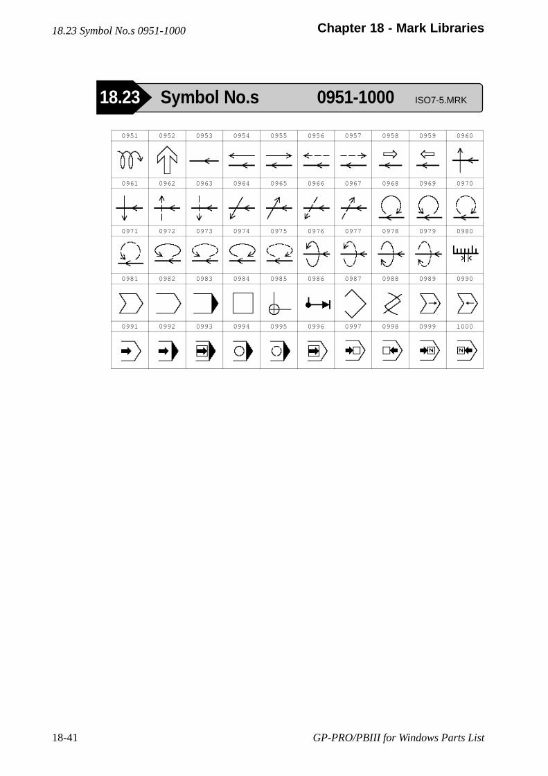
GP-PRO/PBIII for Windows Parts List18-41
Chapter 18 - Mark Libraries
0951 0952 0953 0954 0955 0956 0957 0958 0959 0960
0961 0962 0963 0964 0965 0966 0967 0968 0969 0970
0971 0972 0973 0974 0975 0976 0977 0978 0979 0980
0981 0982 0983 0984 0985 0986 0987 0988 0989 0990
0991 0992 0993 0994 0995 0996 0997 0998 0999 1000
18.23 Symbol No.s 0951-1000
18.23 Symbol No.s 0951-1000 ISO7-5.MRK
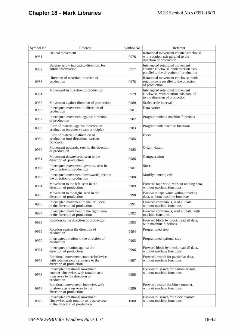
GP-PRO/PBIII for Windows Parts List 18-42
Chapter 18 - Mark Libraries
Symbol No. Referent Symbol No. Referent
0951Helical movement
0976Rotational movement counter-clockwise,with rotation axis parallel to thedirection of production
0952Belgian arrow indicating direction, forpublic information 0977
Interrupted rotational movementcounter-clockwise, with rotation axisparallel to the direction of production
0953Direction of material; direction ofproduction 0978
Rotational movement clockwise, withrotation axis parallel to the directionof production
0954Movement in direction of production
0979Interrupted rotational movementclockwise, with rotation axis parallelto the direction of production
0955 Movement against direction of production 0980 Scale; scale interval
0956Interrupted movement in direction ofproduction 0981
Data carrier
0957Interrupted movement against directionof production 0982
Program without machine functions
0958Flow of material against direction ofproduction (counter stream principle) 0983
Program with machine functions
0959Flow of material in direction ofproduction (uni-directional streamprinciple)
0984Block
0960Movement upwards, seen in the directionof production 0985
Origin; datum
0961Movement downwards, seen in thedirection of production 0986
Compensation
0962Interrupted movement upwards, seen inthe direction of production 0987
Store
0963Interrupted movement downwards, seen inthe direction of production 0988
Modify; amend; edit
0964Movement to the left, seen in thedirection of production 0989
Forward tape wind, without reading data,without machine functions
0965Movement to the right, seen in thedirection of production 0990
Backward tape wind, without readingdata, without machine functions
0966Interrupted movement to the left, seenin the direction of production 0991
Forward continuous, read all data,without machine functions
0967Interrupted movement to the right, seenin the direction of production 0992
Forward continuous, read all data, withmachine functions
0968Rotation in the direction of production
0993Forward block by block, read all data,with machine functions
0969Rotation against the direction ofproduction 0994
Programmed stop
0970Interrupted rotation in the direction ofproduction 0995
Programmed optional stop
0971Interrupted rotation against thedirection of production 0996
Forward block by block, read all data,without machine functions
0972Rotational movement counterclockwise,with rotation axis transverse to thedirection of production
0997Forward, search for particular data,without machine functions
0973
Interrupted rotational movementcounter-clockwise, with rotation axistransverse to the direction ofproduction
0998
Backward, search for particular data,without machine functions
0974Rotational movement clockwise, withrotation axis transverse to thedirection of production
0999Forward, search for block number,without machine functions
0975Interrupted rotational movementclockwise, with rotation axis transverseto the direction of production
1000Backward, search for block number,without machine functions
18.23 Symbol No.s 0951-1000
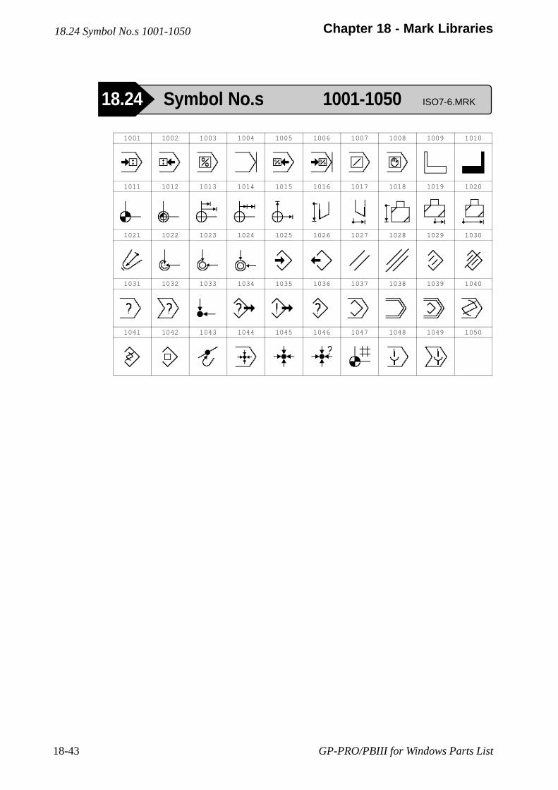
GP-PRO/PBIII for Windows Parts List18-43
Chapter 18 - Mark Libraries
1001 1002 1003 1004 1005 1006 1007 1008 1009 1010
1011 1012 1013 1014 1015 1016 1017 1018 1019 1020
1021 1022 1023 1024 1025 1026 1027 1028 1029 1030
1031 1032 1033 1034 1035 1036 1037 1038 1039 1040
1041 1042 1043 1044 1045 1046 1047 1048 1049 1050
18.24 Symbol No.s 1001-1050
18.24 Symbol No.s 1001-1050 ISO7-6.MRK
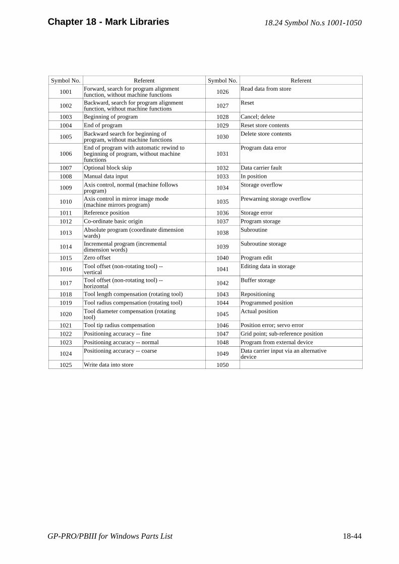
GP-PRO/PBIII for Windows Parts List 18-44
Chapter 18 - Mark Libraries
Symbol No. Referent Symbol No. Referent
1001 Forward, search for program alignmentfunction, without machine functions 1026 Read data from store
1002 Backward, search for program alignmentfunction, without machine functions 1027 Reset
1003 Beginning of program 1028 Cancel; delete
1004 End of program 1029 Reset store contents
1005 Backward search for beginning ofprogram, without machine functions 1030 Delete store contents
1006End of program with automatic rewind tobeginning of program, without machinefunctions
1031Program data error
1007 Optional block skip 1032 Data carrier fault
1008 Manual data input 1033 In position
1009 Axis control, normal (machine followsprogram) 1034 Storage overflow
1010 Axis control in mirror image mode(machine mirrors program) 1035 Prewarning storage overflow
1011 Reference position 1036 Storage error
1012 Co-ordinate basic origin 1037 Program storage
1013 Absolute program (coordinate dimensionwards) 1038 Subroutine
1014 Incremental program (incrementaldimension words) 1039 Subroutine storage
1015 Zero offset 1040 Program edit
1016 Tool offset (non-rotating tool) --vertical 1041 Editing data in storage
1017 Tool offset (non-rotating tool) --horizontal 1042 Buffer storage
1018 Tool length compensation (rotating tool) 1043 Repositioning
1019 Tool radius compensation (rotating tool) 1044 Programmed position
1020 Tool diameter compensation (rotatingtool) 1045 Actual position
1021 Tool tip radius compensation 1046 Position error; servo error
1022 Positioning accuracy -- fine 1047 Grid point; sub-reference position
1023 Positioning accuracy -- normal 1048 Program from external device
1024 Positioning accuracy -- coarse 1049 Data carrier input via an alternativedevice
1025 Write data into store 1050
18.24 Symbol No.s 1001-1050
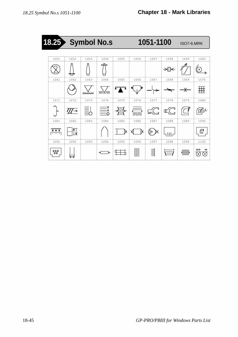
GP-PRO/PBIII for Windows Parts List18-45
Chapter 18 - Mark Libraries
1051 1052 1053 1054 1055 1056 1057 1058 1059 1060
1061 1062 1063 1064 1065 1066 1067 1068 1069 1070
1071 1072 1073 1074 1075 1076 1077 1078 1079 1080
1081 1082 1083 1084 1085 1086 1087 1088 1089 1090
1091 1092 1093 1094 1095 1096 1097 1098 1099 1100
18.25 Symbol No.s 1051-1100
18.25 Symbol No.s 1051-1100 ISO7-6.MRK
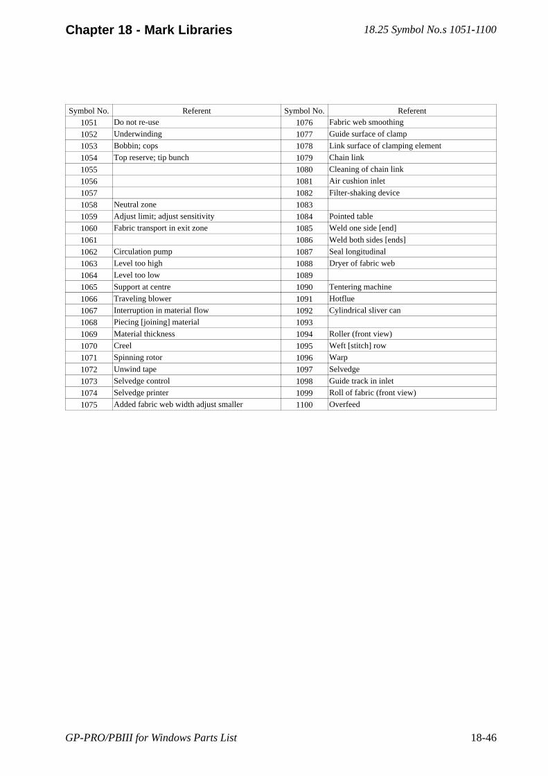
GP-PRO/PBIII for Windows Parts List 18-46
Chapter 18 - Mark Libraries
Symbol No. Referent Symbol No. Referent
1051 Do not re-use 1076 Fabric web smoothing
1052 Underwinding 1077 Guide surface of clamp
1053 Bobbin; cops 1078 Link surface of clamping element
1054 Top reserve; tip bunch 1079 Chain link
1055 1080 Cleaning of chain link
1056 1081 Air cushion inlet
1057 1082 Filter-shaking device
1058 Neutral zone 1083
1059 Adjust limit; adjust sensitivity 1084 Pointed table
1060 Fabric transport in exit zone 1085 Weld one side [end]
1061 1086 Weld both sides [ends]
1062 Circulation pump 1087 Seal longitudinal
1063 Level too high 1088 Dryer of fabric web
1064 Level too low 1089
1065 Support at centre 1090 Tentering machine
1066 Traveling blower 1091 Hotflue
1067 Interruption in material flow 1092 Cylindrical sliver can
1068 Piecing [joining] material 1093
1069 Material thickness 1094 Roller (front view)
1070 Creel 1095 Weft [stitch] row
1071 Spinning rotor 1096 Warp
1072 Unwind tape 1097 Selvedge
1073 Selvedge control 1098 Guide track in inlet
1074 Selvedge printer 1099 Roll of fabric (front view)
1075 Added fabric web width adjust smaller 1100 Overfeed
18.25 Symbol No.s 1051-1100

GP-PRO/PBIII for Windows Parts List18-47
Chapter 18 - Mark Libraries
1101 1102 1103 1104 1105 1106 1107 1108 1109 1110
1111 1112 1113 1114 1115 1116 1117 1118 1119 1120
1121 1122 1123 1124 1125 1126 1127 1128 1129 1130
1131 1132 1133 1134 1135 1136 1137 1138 1139 1140
18.26 Symbol No.s 1101-1140
18.26 Symbol No.s 1101-1140 ISO7-6.MRK
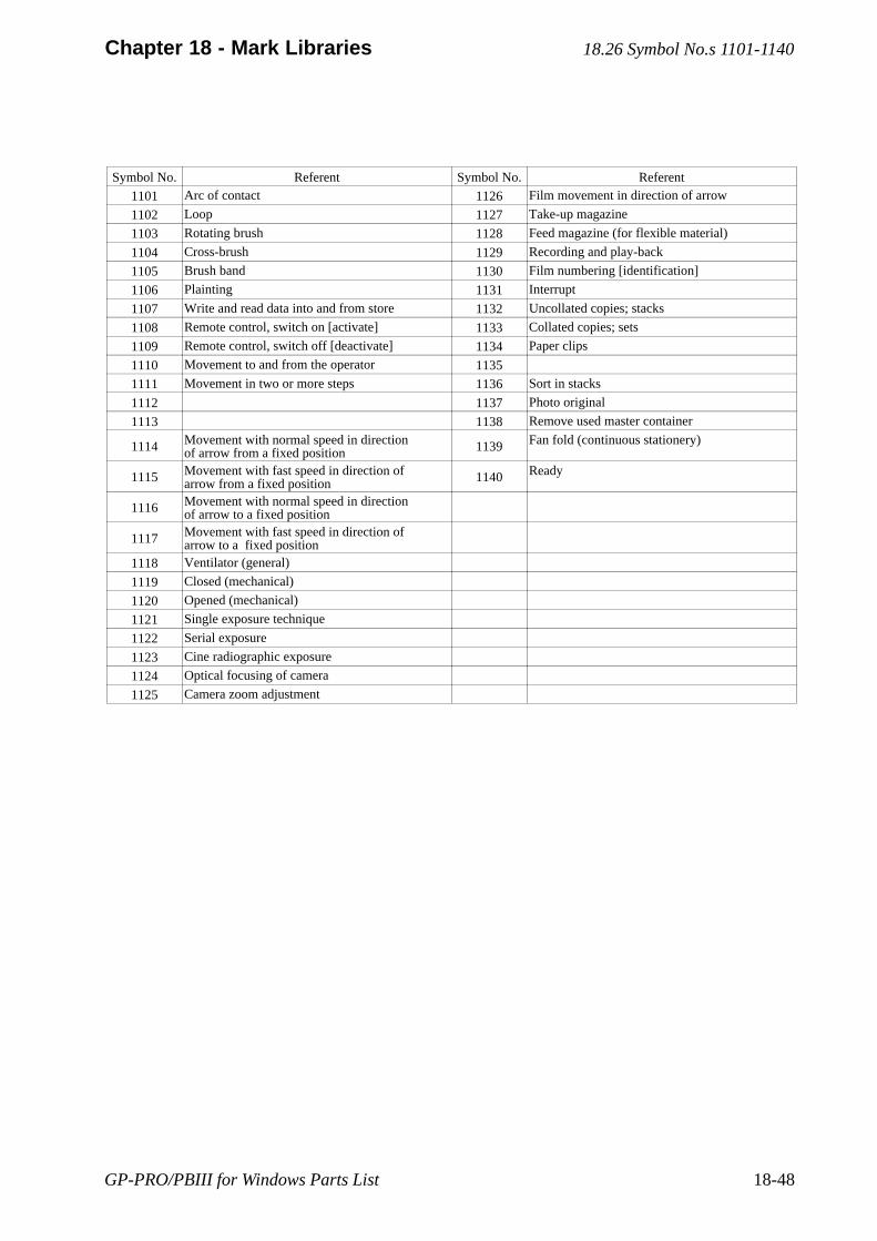
GP-PRO/PBIII for Windows Parts List 18-48
Chapter 18 - Mark Libraries
Symbol No. Referent Symbol No. Referent
1101 Arc of contact 1126 Film movement in direction of arrow
1102 Loop 1127 Take-up magazine
1103 Rotating brush 1128 Feed magazine (for flexible material)
1104 Cross-brush 1129 Recording and play-back
1105 Brush band 1130 Film numbering [identification]
1106 Plainting 1131 Interrupt
1107 Write and read data into and from store 1132 Uncollated copies; stacks
1108 Remote control, switch on [activate] 1133 Collated copies; sets
1109 Remote control, switch off [deactivate] 1134 Paper clips
1110 Movement to and from the operator 1135
1111 Movement in two or more steps 1136 Sort in stacks
1112 1137 Photo original
1113 1138 Remove used master container
1114 Movement with normal speed in directionof arrow from a fixed position 1139 Fan fold (continuous stationery)
1115 Movement with fast speed in direction ofarrow from a fixed position 1140 Ready
1116 Movement with normal speed in directionof arrow to a fixed position
1117 Movement with fast speed in direction ofarrow to a fixed position
1118 Ventilator (general)
1119 Closed (mechanical)
1120 Opened (mechanical)
1121 Single exposure technique
1122 Serial exposure
1123 Cine radiographic exposure
1124 Optical focusing of camera
1125 Camera zoom adjustment
18.26 Symbol No.s 1101-1140
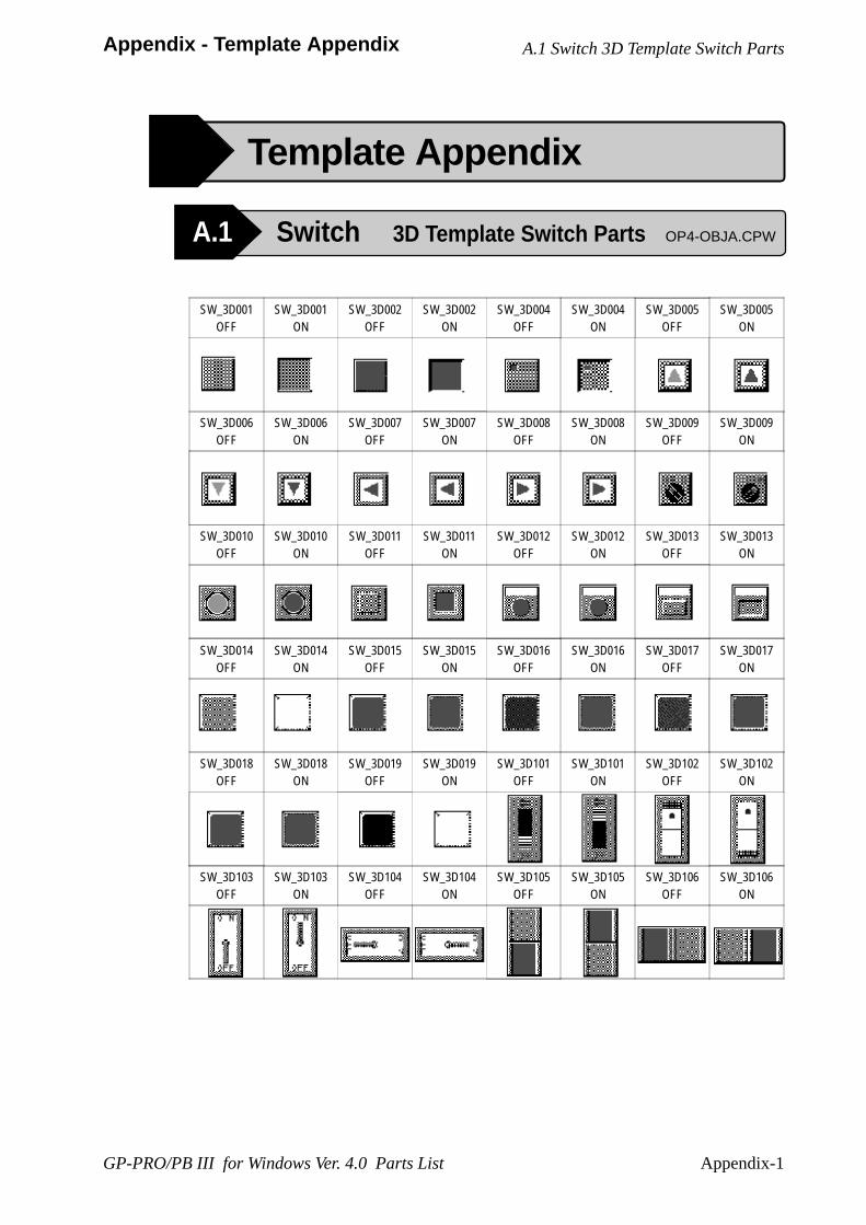
Appendix-1
Appendix - Template Appendix
GP-PRO/PB III for Windows Ver. 4.0 Parts List
A.1 Switch 3D Template Switch Parts
A.1 Switch 3D Template Switch Parts OP4-OBJA.CPW
Template Appendix
SW_3D001OFF
SW_3D001ON
SW_3D002OFF
SW_3D002ON
SW_3D004OFF
SW_3D004ON
SW_3D005OFF
SW_3D005ON
SW_3D006OFF
SW_3D006ON
SW_3D007OFF
SW_3D007ON
SW_3D008OFF
SW_3D008ON
SW_3D009OFF
SW_3D009ON
SW_3D010OFF
SW_3D010ON
SW_3D011OFF
SW_3D011ON
SW_3D012OFF
SW_3D012ON
SW_3D013OFF
SW_3D013ON
SW_3D014OFF
SW_3D014ON
SW_3D015OFF
SW_3D015ON
SW_3D016OFF
SW_3D016ON
SW_3D017OFF
SW_3D017ON
SW_3D018OFF
SW_3D018ON
SW_3D019OFF
SW_3D019ON
SW_3D101OFF
SW_3D101ON
SW_3D102OFF
SW_3D102ON
SW_3D103OFF
SW_3D103ON
SW_3D104OFF
SW_3D104ON
SW_3D105OFF
SW_3D105ON
SW_3D106OFF
SW_3D106ON
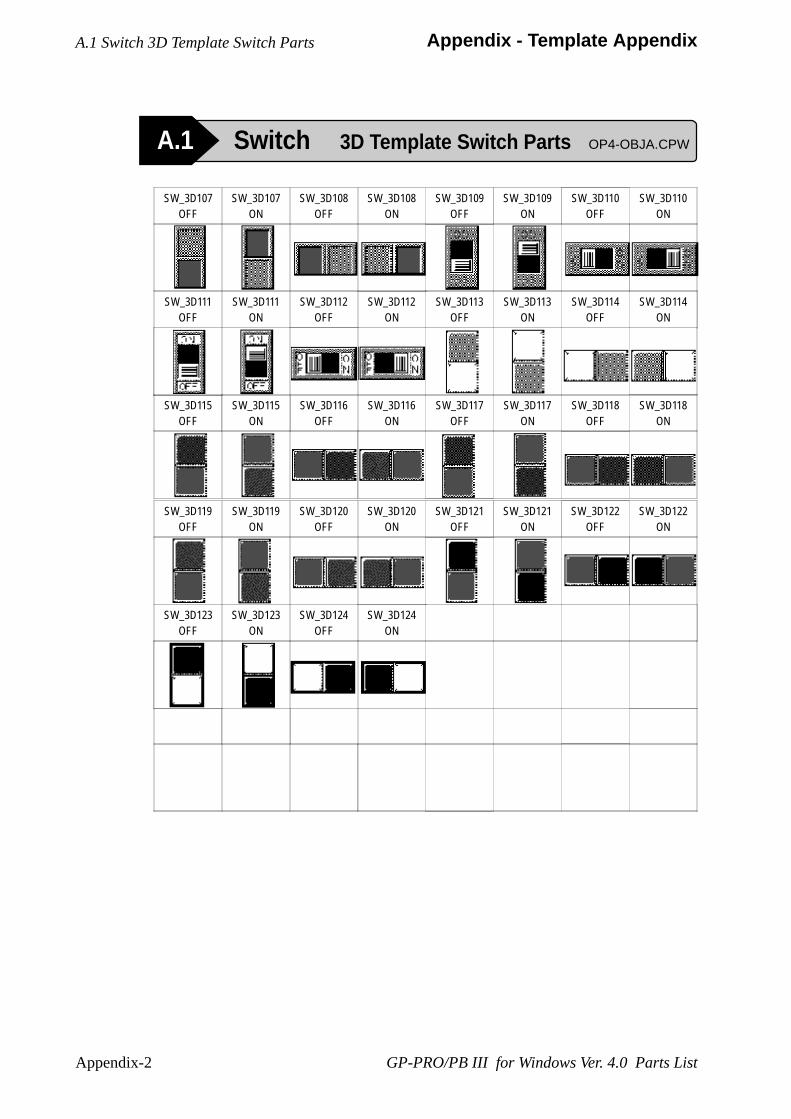
Appendix-2
Appendix - Template Appendix
GP-PRO/PB III for Windows Ver. 4.0 Parts List
A.1 Switch 3D Template Switch Parts
A.1 Switch 3D Template Switch Parts OP4-OBJA.CPW
SW_3D119OFF
SW_3D119ON
SW_3D120OFF
SW_3D120ON
SW_3D121OFF
SW_3D121ON
SW_3D122OFF
SW_3D122ON
SW_3D123OFF
SW_3D123ON
SW_3D124OFF
SW_3D124ON
SW_3D107OFF
SW_3D107ON
SW_3D108OFF
SW_3D108ON
SW_3D109OFF
SW_3D109ON
SW_3D110OFF
SW_3D110ON
SW_3D111OFF
SW_3D111ON
SW_3D112OFF
SW_3D112ON
SW_3D113OFF
SW_3D113ON
SW_3D114OFF
SW_3D114ON
SW_3D115OFF
SW_3D115ON
SW_3D116OFF
SW_3D116ON
SW_3D117OFF
SW_3D117ON
SW_3D118OFF
SW_3D118ON
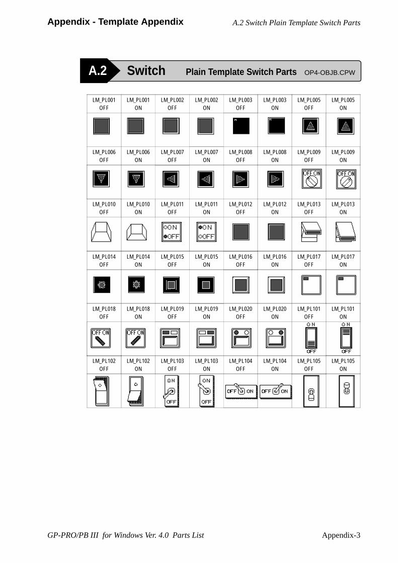
Appendix-3
Appendix - Template Appendix
GP-PRO/PB III for Windows Ver. 4.0 Parts List
A.2 Switch Plain Template Switch Parts OP4-OBJB.CPW
A.2 Switch Plain Template Switch Parts
LM_PL001OFF
LM_PL001ON
LM_PL002OFF
LM_PL002ON
LM_PL003OFF
LM_PL003ON
LM_PL005OFF
LM_PL005ON
LM_PL006OFF
LM_PL006ON
LM_PL007OFF
LM_PL007ON
LM_PL008OFF
LM_PL008ON
LM_PL009OFF
LM_PL009ON
LM_PL010OFF
LM_PL010ON
LM_PL011OFF
LM_PL011ON
LM_PL012OFF
LM_PL012ON
LM_PL013OFF
LM_PL013ON
LM_PL014OFF
LM_PL014ON
LM_PL015OFF
LM_PL015ON
LM_PL016OFF
LM_PL016ON
LM_PL017OFF
LM_PL017ON
LM_PL018OFF
LM_PL018ON
LM_PL019OFF
LM_PL019ON
LM_PL020OFF
LM_PL020ON
LM_PL101OFF
LM_PL101ON
LM_PL102OFF
LM_PL102ON
LM_PL103OFF
LM_PL103ON
LM_PL104OFF
LM_PL104ON
LM_PL105OFF
LM_PL105ON
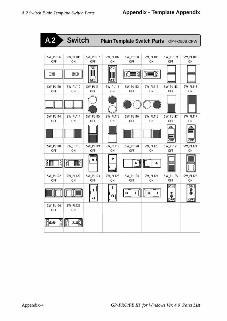
Appendix-4
Appendix - Template Appendix
GP-PRO/PB III for Windows Ver. 4.0 Parts List
A.2 Switch Plain Template Switch Parts OP4-OBJB.CPW
A.2 Switch Plain Template Switch Parts
SW_PL118OFF
SW_PL118ON
SW_PL119OFF
SW_PL119ON
SW_PL120OFF
SW_PL120ON
SW_PL121OFF
SW_PL121ON
SW_PL122OFF
SW_PL122ON
SW_PL123OFF
SW_PL123ON
SW_PL124OFF
SW_PL124ON
SW_PL125OFF
SW_PL125ON
SW_PL126OFF
SW_PL126ON
SW_PL106OFF
SW_PL106ON
SW_PL107OFF
SW_PL107ON
SW_PL108OFF
SW_PL108ON
SW_PL109OFF
SW_PL109ON
SW_PL110OFF
SW_PL110ON
SW_PL111OFF
SW_PL111ON
SW_PL112OFF
SW_PL112ON
SW_PL113OFF
SW_PL113ON
SW_PL114OFF
SW_PL114ON
SW_PL115OFF
SW_PL115ON
SW_PL116OFF
SW_PL116ON
SW_PL117OFF
SW_PL117ON
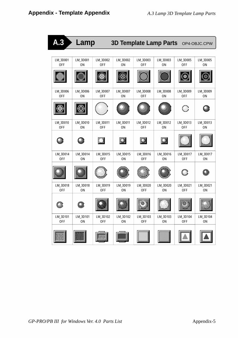
Appendix-5
Appendix - Template Appendix
GP-PRO/PB III for Windows Ver. 4.0 Parts List
A.3 Lamp 3D Template Lamp Parts OP4-OBJC.CPW
A.3 Lamp 3D Template Lamp Parts
LM_3D001OFF
LM_3D001ON
LM_3D002OFF
LM_3D002ON
LM_3D003OFF
LM_3D003ON
LM_3D005OFF
LM_3D005ON
LM_3D006OFF
LM_3D006ON
LM_3D007OFF
LM_3D007ON
LM_3D008OFF
LM_3D008ON
LM_3D009OFF
LM_3D009ON
LM_3D010OFF
LM_3D010ON
LM_3D011OFF
LM_3D011ON
LM_3D012OFF
LM_3D012ON
LM_3D013OFF
LM_3D013ON
LM_3D014OFF
LM_3D014ON
LM_3D015OFF
LM_3D015ON
LM_3D016OFF
LM_3D016ON
LM_3D017OFF
LM_3D017ON
LM_3D018OFF
LM_3D018ON
LM_3D019OFF
LM_3D019ON
LM_3D020OFF
LM_3D020ON
LM_3D021OFF
LM_3D021ON
LM_3D101OFF
LM_3D101ON
LM_3D102OFF
LM_3D102ON
LM_3D103OFF
LM_3D103ON
LM_3D104OFF
LM_3D104ON
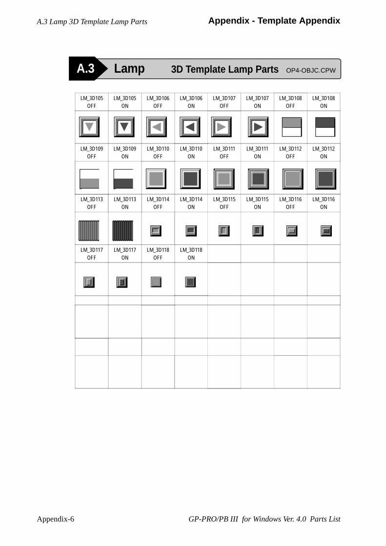
Appendix-6
Appendix - Template Appendix
GP-PRO/PB III for Windows Ver. 4.0 Parts List
A.3 Lamp 3D Template Lamp Parts OP4-OBJC.CPW
A.3 Lamp 3D Template Lamp Parts
LM_3D105OFF
LM_3D105ON
LM_3D106OFF
LM_3D106ON
LM_3D107OFF
LM_3D107ON
LM_3D108OFF
LM_3D108ON
LM_3D109OFF
LM_3D109ON
LM_3D110OFF
LM_3D110ON
LM_3D111OFF
LM_3D111ON
LM_3D112OFF
LM_3D112ON
LM_3D113OFF
LM_3D113ON
LM_3D114OFF
LM_3D114ON
LM_3D115OFF
LM_3D115ON
LM_3D116OFF
LM_3D116ON
LM_3D117OFF
LM_3D117ON
LM_3D118OFF
LM_3D118ON
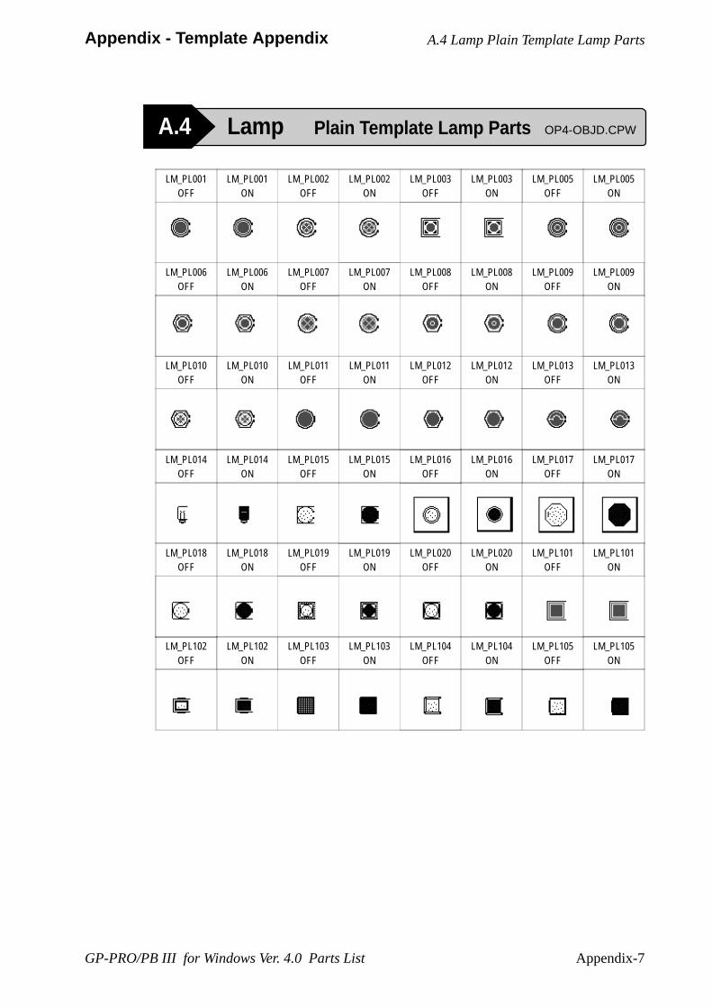
Appendix-7
Appendix - Template Appendix
GP-PRO/PB III for Windows Ver. 4.0 Parts List
A.4 Lamp Plain Template Lamp Parts OP4-OBJD.CPW
A.4 Lamp Plain Template Lamp Parts
LM_PL001OFF
LM_PL001ON
LM_PL002OFF
LM_PL002ON
LM_PL003OFF
LM_PL003ON
LM_PL005OFF
LM_PL005ON
LM_PL006OFF
LM_PL006ON
LM_PL007OFF
LM_PL007ON
LM_PL008OFF
LM_PL008ON
LM_PL009OFF
LM_PL009ON
LM_PL010OFF
LM_PL010ON
LM_PL011OFF
LM_PL011ON
LM_PL012OFF
LM_PL012ON
LM_PL013OFF
LM_PL013ON
LM_PL014OFF
LM_PL014ON
LM_PL015OFF
LM_PL015ON
LM_PL016OFF
LM_PL016ON
LM_PL017OFF
LM_PL017ON
LM_PL018OFF
LM_PL018ON
LM_PL019OFF
LM_PL019ON
LM_PL020OFF
LM_PL020ON
LM_PL101OFF
LM_PL101ON
LM_PL102OFF
LM_PL102ON
LM_PL103OFF
LM_PL103ON
LM_PL104OFF
LM_PL104ON
LM_PL105OFF
LM_PL105ON
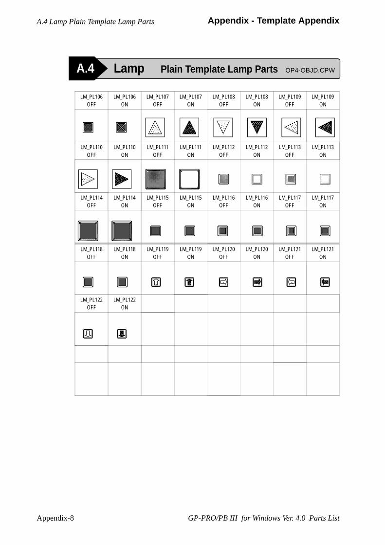
Appendix-8
Appendix - Template Appendix
GP-PRO/PB III for Windows Ver. 4.0 Parts List
A.4 Lamp Plain Template Lamp Parts OP4-OBJD.CPW
A.4 Lamp Plain Template Lamp Parts
LM_PL118OFF
LM_PL118ON
LM_PL119OFF
LM_PL119ON
LM_PL120OFF
LM_PL120ON
LM_PL121OFF
LM_PL121ON
LM_PL122OFF
LM_PL122ON
LM_PL106OFF
LM_PL106ON
LM_PL107OFF
LM_PL107ON
LM_PL108OFF
LM_PL108ON
LM_PL109OFF
LM_PL109ON
LM_PL110OFF
LM_PL110ON
LM_PL111OFF
LM_PL111ON
LM_PL112OFF
LM_PL112ON
LM_PL113OFF
LM_PL113ON
LM_PL114OFF
LM_PL114ON
LM_PL115OFF
LM_PL115ON
LM_PL116OFF
LM_PL116ON
LM_PL117OFF
LM_PL117ON
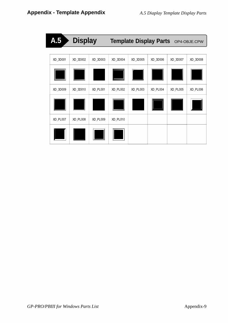
GP-PRO/PBIII for Windows Parts List Appendix-9
Appendix - Template Appendix
XD_3D001 XD_3D002 XD_3D003 XD_3D004 XD_3D005 XD_3D006 XD_3D007 XD_3D008
XD_3D009 XD_3D010 XD_PL001 XD_PL002 XD_PL003 XD_PL004 XD_PL005 XD_PL006
XD_PL007 XD_PL008 XD_PL009 XD_PL010
A.5 Display Template Display Parts OP4-OBJE.CPW
A.5 Diaplay Template Display Parts

GP-PRO/PBIII for Windows Parts ListAppendix-10
Appendix - Template Appendix
A.6 Keypad 3D Template Keypad Parts OP4-OBJF.CPW
A.6 Keypad 3D Template Keypad Parts
KP_3D001D KP_3D002D KP_3D003D
KP_3D001H KP_3D002H
KP_3D001T
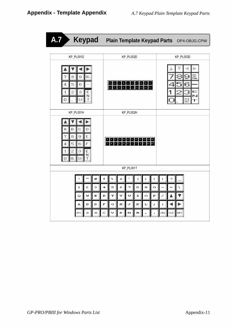
GP-PRO/PBIII for Windows Parts List Appendix-11
Appendix - Template Appendix
KP_PL001D KP_PL002D KP_PL003D
KP_PL001H KP_PL002H
KP_PL001T
A.7 Keypad Plain Template Keypad Parts OP4-OBJG.CPW
A.7 Keypad Plain Template Keypad Parts
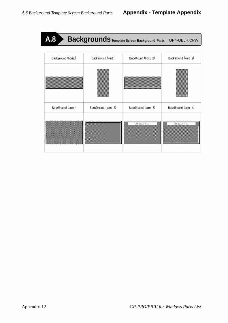
GP-PRO/PBIII for Windows Parts ListAppendix-12
Appendix - Template Appendix
Background (horiz.) Background (vert.) Background (horiz. 2) Background (vert. 2)
Background (scrn.) Background (scrn. 2) Background (scrn. 3) Background (scrn. 4)
A.8 Backgrounds Template Screen Background Parts OP4-OBJH.CPW
A.8 Background Template Screen Background Parts


![[GSW] Windows - Stata](https://static.fdokumen.com/doc/165x107/63274b65051fac18490e2cc7/gsw-windows-stata.jpg)