GP-PRO/PBIII for Windows Ver. 6.0 Operation Manual
676
1 GP-PRO/PB III for Windows Ver. 6.0 Operation Manual Thank you for purchasing the GP Screen Editor Software, "GP-PRO/PB III for Windows Ver. 6.0" for use with Pro-face’s GP series programmable operator interfaces. Please read this manual carefully in order to use this software properly, and be sure to keep this manual handy for future reference. NOTES (1) The copyrights to all programs and manuals included in the GP-PRO/PB III for Windows Ver. 6.0 (hereinafter referred to as "this product") are reserved by the Digital Electronics Corporation. Digital grants the use of this product to its users as described in the "Software Operating License Conditions" documentation, included with this product's CD-ROM. Any actions violating the above-mentioned conditions are prohibited by both Japanese and foreign regulations. (2) The contents of this manual have been thoroughly inspected. However, if you should find any errors or omissions in this manual, please inform your local GP representative of your findings. (3) Regardless of article (2), the Digital Electronics Corporation shall not be held responsible for any damages or third party claims resulting from the use of this product. (4) Differences may occur between the descriptions found in this manual and the actual functioning of this product. Therefore, the latest information on this product is provided in data files (i.e. Readme.txt files, etc. ) and in separate documents. Please consult these sources as well as this manual prior to using the product. (5) Even though the information contained in and displayed by this product may be related to intangible or intellectual properties of the Digital Electronics Corporation or third parties, the Digital Electronics Corporation shall not warrant or grant the use of said properties to any users and/or other third parties. (6) The specifications set out in this manual are for overseas products only. As a result, some differences may exist between the specifications given here and for those of the identical Japanese product. Digital Electronics Corpo- ration accepts no liability for issues related to the intellectual property rights of third parties or any issues related to the use of the information contained in or displayed by this product. PREFACE For the rights to trademarks and trade names, see “TRADEMARK RIGHTS”. © Copyright 2001 Digital Electronics Corporation. All rights reserved. Digital Electronics Corporation, November 2001 PREFACE
-
Upload
khangminh22 -
Category
Documents
-
view
1 -
download
0
Transcript of GP-PRO/PBIII for Windows Ver. 6.0 Operation Manual

1GP-PRO/PB III for Windows Ver. 6.0 Operation Manual
Thank you for purchasing the GP Screen Editor Software, "GP-PRO/PB III forWindows Ver. 6.0" for use with Pro-face’s GP series programmable operatorinterfaces.
Please read this manual carefully in order to use this software properly, and besure to keep this manual handy for future reference.
NOTES(1) The copyrights to all programs and manuals included in the GP-PRO/PB
III for Windows Ver. 6.0 (hereinafter referred to as "this product") arereserved by the Digital Electronics Corporation. Digital grants the use ofthis product to its users as described in the "Software Operating LicenseConditions" documentation, included with this product's CD-ROM. Anyactions violating the above-mentioned conditions are prohibited by bothJapanese and foreign regulations.
(2) The contents of this manual have been thoroughly inspected. However, ifyou should find any errors or omissions in this manual, please inform yourlocal GP representative of your findings.
(3) Regardless of article (2), the Digital Electronics Corporation shall not beheld responsible for any damages or third party claims resulting from theuse of this product.
(4) Differences may occur between the descriptions found in this manual andthe actual functioning of this product. Therefore, the latest information onthis product is provided in data files (i.e. Readme.txt files, etc. ) and inseparate documents. Please consult these sources as well as this manualprior to using the product.
(5) Even though the information contained in and displayed by this product maybe related to intangible or intellectual properties of the Digital ElectronicsCorporation or third parties, the Digital Electronics Corporation shall notwarrant or grant the use of said properties to any users and/or other thirdparties.
(6) The specifications set out in this manual are for overseas products only. Asa result, some differences may exist between the specifications given hereand for those of the identical Japanese product. Digital Electronics Corpo-ration accepts no liability for issues related to the intellectual property rightsof third parties or any issues related to the use of the information containedin or displayed by this product.
PREFACE
For the rights to trademarks and trade names, see “TRADEMARK RIGHTS”.
© Copyright 2001 Digital Electronics Corporation. All rights reserved.Digital Electronics Corporation, November 2001
PREFACE
2 GP-PRO/PB III for Windows Ver. 6.0 Operation Manual
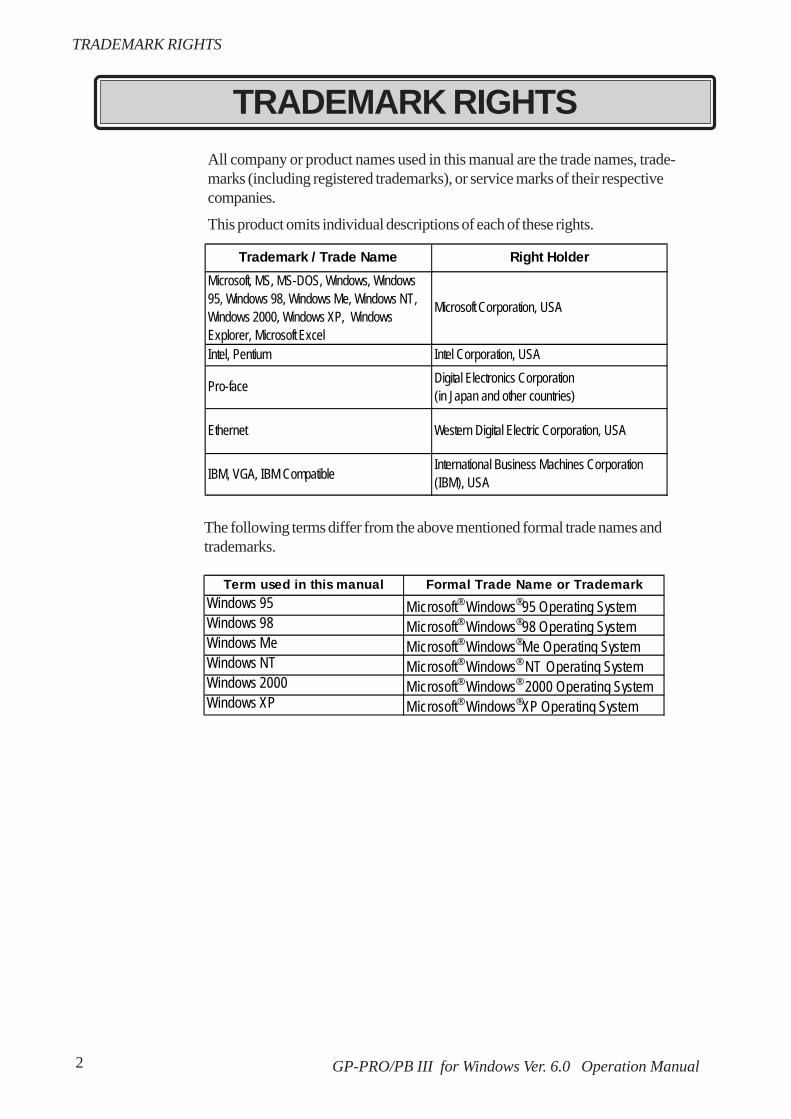
All company or product names used in this manual are the trade names, trade-marks (including registered trademarks), or service marks of their respectivecompanies.
This product omits individual descriptions of each of these rights.
The following terms differ from the above mentioned formal trade names andtrademarks.
TRADEMARK RIGHTS
Trademark / Trade Name Right HolderMicrosoft, MS, MS-DOS, Windows, Windows95, Windows 98, Windows Me, Windows NT,Windows 2000, Windows XP, WindowsExplorer, Microsoft Excel
Microsoft Corporation, USA
Intel, Pentium Intel Corporation, USA
Pro-face Digital Electronics Corporation(in Japan and other countries)
Ethernet Western Digital Electric Corporation, USA
IBM, VGA, IBM Compatible International Business Machines Corporation(IBM), USA
TRADEMARK RIGHTS
Term used in this manual Formal Trade Name or TrademarkWindows 95 Microsoft® Windows®95 Operating SystemWindows 98 Microsoft® Windows®98 Operating SystemWindows Me Microsoft® Windows®Me Operating SystemWindows NT Microsoft® Windows® NT Operating SystemWindows 2000 Microsoft® Windows® 2000 Operating SystemWindows XP Microsoft® Windows®XP Operating System

3GP-PRO/PB III for Windows Ver. 6.0 Operation Manual
LIST OF SUPPORTED MODELS
List of GP Series Product
The GP-PRO/PBIII functions and settings available will vary, depending on themodel of GP used. Use the following table to identify your GP.
LIST OF SUPPORTED MODELS
ProductName Model GP Type
GPH70-LG11-24VGPH70-LG41-24VPGPH70-SC11-24VGPH70-SC41-24VPGP270-LG11-24VGP270-LG21-24VPGP270-LG31-24VGP270-SC11-24VGP270-SC21-24VPGP270-SC31-24VGP370-LG11-24VGP370-LG21-24VPGP370-LG31-24VGP370-LG41-24VPGP370-SC11-24VGP370-SC21-24VPGP370-SC31-24VGP370-SC41-24VPGP470-EG11GP470-EG21-24VPGP470-EG31-24VGP570-SC11GP570-SC21-24VPGP570-SC31-24VGP570-TC11GP570-TC21-24VPGP570-TC31-24V
GP-57JS GP57J-SC11GP-570VM GP570-TV11 GP570VM
GP-571 series GP-571T GP571-TC11 GP571TGP-675S GP675-SC11
GP675-TC11GP675-TC41-24VP
GP-870 series GP-870VM GP870-PV11 GP870VMGP377-LG11-24VGP377-LG41-24VGP377-SC11-24VGP377-SC41-24V
GP-37W2 series GP-37W2B TP37W2-BG41-24V GP37W2GP377R-TC11-24VGP377R-TC41-24VGP477R-EG11GP477R-EG41-24VPGP577R-SC11GP577R-SC41-24VPGP577R-TC11GP577R-TC41-24VP
GP-570 series
GP477R
GPH70L
GPH70S
GP270L
GP270S
GP370L
GP-370S
GP470
GP570
GP577RGP-577R series
GP-477RE
GP-577RS
GP-577RT
GP377R
GP675
GP377L
GP377S
GP-675 series
GP77R seriesGP-477R series
GP-377S
GP-377LGP-377 series
GP-377R series GP-377RT
GP70 series
GP77 series
GP-270 seriesGP-270L
GP-270S
GP-H70L
GP-H70S
GP-570S
GP-570T
GP-675T
Series
GP-370L
GP-370S
GP-470 series GP-470E
GP-370 series
GP-H70 series

4 GP-PRO/PB III for Windows Ver. 6.0 Operation Manual
List of GLC Series Product
LIST OF SUPPORTED MODELS
ProductName Model GP Type
GLC100L GLC100-LG41-24V GLC100LGLC100S GLC100-SC41-24V GLC100S
GLC300 series GLC300 series GLC300T GLC300-TC41-24V GLC300TGLC2300L GLC2300-LG41-24V GLC2300LGLS2300T GLC2300-TC41-24V GLC2300
GLC2400 series GLC2400T GLC2400-TC41-24V GLC2400GLC2600 series GLC2600T GLC2600-TC41-24V GLC2600
GLC2000 seriesGLC2300 series
Series
GLC100 series GLC100 series
ProductName Model GP Type
GP-2301H series GP-2301HL GP2301H-LG41-24V GP2301HLGP-2301HS GP2301H-SC41-24V GP2301HS
GP-2401H series GP-2401HT GP2401H-TC41-24V GP2401HGP-2300L GP2300-LG41-24V GP2300LGP-2300T GP2300-TC41-24V GP2300GP-2301L GP2301-LG41-24V GP2301LGP-2301S GP2301-SC41-24V GP2301S
GP-2400 series GP-2400T GP2400-TC41-24V GP2400GP-2500L GP2500-LG41-24V GP2500LGP-2500S GP2500-SC41-24V GP2500S
GP2500-TC11GP2500-TC41-24V
GP-2501S GP2501-SC11 GP2501SGP-2501T GP2501-TC11 GP2501
GP2600-TC11GP2600-TC41-24VGP-2600T GP2600
GP-2500T GP2500
Series
GP2000series
GP-2501 series
GP-2600 series
GP2000Hseries
GP-2300 series
GP-2301 series
GP-2500 series

5GP-PRO/PB III for Windows Ver. 6.0 Operation Manual
NEW FEATURES
NEW FEATURES
GP-PRO/PBIII for Windows Ver. 6.0 features new functions such as Image Font,Image Parts and Multi Language Display. This section briefly describes eachfunction, listed with the GP Series supporting the respective functions.
<All GP Series>Registering windows and adding window parts to the Window Screen
The windows registered in the Window Screen (U) can be displayed on the BaseScreen (B). The window can be called up with the window parts.
3.7 Window Display: Window(U) Screen and Base(B)Screen
Image Conversion: More image files can be converted to the Image Screen.
Additional image files (bitmap files and JPEG files) can be converted into theImage Screen (I file). These image files (called "Image Data") can be registeredon the Image Screen as GP screens.
3.5 Creating an Image: the Image Screen
Word Log Alarm Message: The numbers of registered messageshave been extended.
The number of message lines displayed with the Alarm Summary (Q-tag) hasbeen extended from 256 to 768.
5.1.1 Alarm Editor Word Alarm Log
Keypad Input Display: New input styles are available.
Now you can select the input style through Extended feature settings of theKeypad Input Display.
2.1.14 Keypad Display Keypad Display [Extend]Attributes
<GP-377/GP77R/GP2000 Series>Multi Language Display Function
The index text registered with the Text Table Editor allows character strings(Index Text) used for displaying Drawings/Part Labels/Alarms to be switchedwhile the GP is in RUN mode. The language and items displayed on the screencan be changed easily.
4.6 Table Editor Character Strings
Pop-up Keypad Function
Touching the Keypad Input Display automatically displays a pop-up keypad forsetting numerical values.
2.1.14 Keypad Display

6 GP-PRO/PB III for Windows Ver. 6.0 Operation Manual
NEW FEATURES
<GP77R/GP2000 Series>Monitoring function for touch panel input timeTouching a specified position on the GP screen for a certain period of time (thetime to be monitored can be specified) displays an error message on the screen.
6.1 Menu Setting Items: GP Setup
<GP2000 Series>Image PartsImage Parts can be used for switches and lamps.Image files (bitmap files and JPEG files) can also be registered as Image Parts.
2.1 Parts Selecting a Part ShapeImage FontsWindows fonts are displayed in bitmap format.
2.2.9 Text Image FontScreen Capture FunctionThe screens being displayed on the GP can be saved on a CF Card in JPEG fileformat (as a hard copy of the GP screens).
Tag Reference Manual, 4.4.9 Screen CaptureScreen Snapshot Function for Simulation ScreensSimulation screens of the GP can be written to a CF Card in JPEG file format aseasily as taking a snapshot picture.
8.1.5 Snapshot FunctionExtended Video Window Display (v-tag)The video window set up on the Video Screen (V file) can be displayed on theBase Screen (B). This function is supported only by GP-2500T and GP-2600Tseries units.
3.6 Video Data Display (V Screen), Tag ReferenceManual, 2.28 v-tag (Extended Video Window Display)Extended LS AreaThe user area within the LS area is expanded to LS8191.
<GP2000H Series>VibrationRuns the internal motor and vibrates the Handy-type GP(available only forGP2000H series). (Vibration function)
2.9.3 Vibration Function
New PLC ProtocolToshiba TC200 SeriesKeyence KV SeriesMatsushita Electric Industrial MINAS-A/S Series
Device/PLC Connection Manual

7GP-PRO/PB III for Windows Ver. 6.0 Operation Manual
Structure of the Manual CD-ROMThe "Operation Manual" is the first of four manuals for this product and explainshow to use the "GP-PRO/PB III for Windows Ver. 6.0" software (hereinafterreferred to as "this product"). Please refer to all of the manuals named belowwhen using this product.These manuals can be found as PDF files in your“Manual CD-ROM” (CD #2).In addition to these manuals, data files containing supplemental information onupdated functions are also provided.To read these additional data files, click onthe [Start] button in your Windows OS main screen and select the[Programs]→[Pro-face]→[ProPB3Win] menu. Then, click on the [Read Me]selection.For detailed information about GP series products, please refer to each GP's"User Manual". (Optionally available)
Screen Data Layout Sheets are useful for designing tag address settings, etc. andexample sheets are installed as part of the GP-PRO/PBIII for Windows standardinstallation.The following two layout sheets, "Device Allocation Table" and "Tag LayoutSheet", are in Microsoft Excel format and are located in the PDF Manual CD-ROM.The following folder and file names are used.
HOW TO USE THIS MANUAL
For information on the use of Microsoft Excel, please refer to the Excelsoftware's User Manual. Designation of Supported ModelsThe functions and settings supported by each model may vary depending on thesupported models. In this manual, explanations given are based on the variation ofthe “Series” and “Product name” described in the “List of Supported Models”.
Vol. 1 Operation Manual(this manual)
Describes this product’s operation procedures and allstandard functions. (provided as PDF data)
Vol. 2 Tag ReferenceManual
Describes the function of and detailed settings for allGP-PRO/PBIII Tags. (provided as PDF data)
Vol. 3 Parts ListDescribes this product’s pre-made Parts and symbols.(provided as PDF data)
Vol. 4Device/PLCConnectionManual
Describes the methods for connecting the GP toother, supported manufacturer PLCs. (provided asPDF data)
Folder Name File Name ContentsPro-face\ Device1E.xls Device Allocation Tablepropbwin\sheet TAG1E.xls
TAG2E.xlsTAG3E.xlsTAG4E.xls
Tag Layout Sheet
HOW TO USE THIS MANUAL
* The GP-PRO/PB III Manual describes the procedures for developing GPscreens. When developing GLC, simply substitute "GLC" for "GP".
8 GP-PRO/PB III for Windows Ver. 6.0 Operation Manual
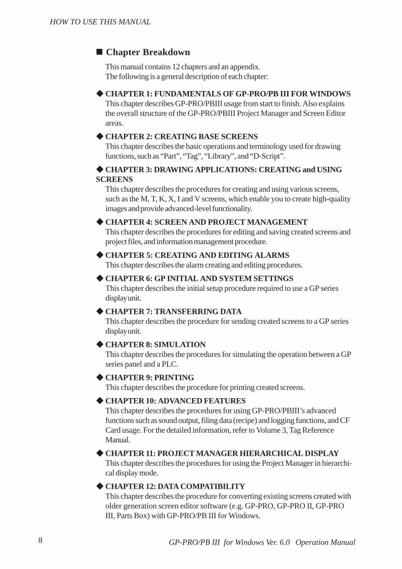
Chapter BreakdownThis manual contains 12 chapters and an appendix.The following is a general description of each chapter:
CHAPTER 1: FUNDAMENTALS OF GP-PRO/PB III FOR WINDOWSThis chapter describes GP-PRO/PBIII usage from start to finish. Also explainsthe overall structure of the GP-PRO/PBIII Project Manager and Screen Editorareas.
CHAPTER 2: CREATING BASE SCREENSThis chapter describes the basic operations and terminology used for drawingfunctions, such as “Part”, “Tag”, “Library”, and “D-Script”.
CHAPTER 3: DRAWING APPLICATIONS: CREATING and USINGSCREENS
This chapter describes the procedures for creating and using various screens,such as the M, T, K, X, I and V screens, which enable you to create high-qualityimages and provide advanced-level functionality.
CHAPTER 4: SCREEN AND PROJECT MANAGEMENTThis chapter describes the procedures for editing and saving created screens andproject files, and information management procedure.
CHAPTER 5: CREATING AND EDITING ALARMSThis chapter describes the alarm creating and editing procedures.
CHAPTER 6: GP INITIAL AND SYSTEM SETTINGSThis chapter describes the initial setup procedure required to use a GP seriesdisplay unit.
CHAPTER 7: TRANSFERRING DATAThis chapter describes the procedure for sending created screens to a GP seriesdisplay unit.
CHAPTER 8: SIMULATIONThis chapter describes the procedures for simulating the operation between a GPseries panel and a PLC.
CHAPTER 9: PRINTINGThis chapter describes the procedure for printing created screens.
CHAPTER 10: ADVANCED FEATURESThis chapter describes the procedures for using GP-PRO/PBIII’s advancedfunctions such as sound output, filing data (recipe) and logging functions, and CFCard usage. For the detailed information, refer to Volume 3, Tag ReferenceManual.
CHAPTER 11: PROJECT MANAGER HIERARCHICAL DISPLAYThis chapter describes the procedures for using the Project Manager in hierarchi-cal display mode.
CHAPTER 12: DATA COMPATIBILITYThis chapter describes the procedure for converting existing screens created witholder generation screen editor software (e.g. GP-PRO, GP-PRO II, GP-PROIII, Parts Box) with GP-PRO/PB III for Windows.
HOW TO USE THIS MANUAL

9GP-PRO/PB III for Windows Ver. 6.0 Operation Manual
APPENDIX• Error MessagesLists the error messages that will be displayed during operation of this product.
• TroubleshootingProvides problem diagnosis and suggests solutions for errors and softwareoperation problems.
• Address Conversion TablesLists the addresses available for each manufacturer’s supported models.
• Software Trouble ReportIf a software problem persists, even after using the Troubleshooting section, writedown information about the problem using this sheet and send it by fax to yourlocal Pro-face support center.
HOW TO USE THIS MANUAL
10 GP-PRO/PB III for Windows Ver. 6.0 Operation Manual
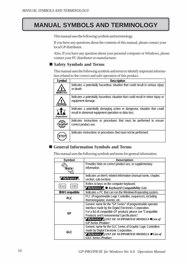
This manual uses the following symbols and terminology.
If you have any questions about the contents of this manual, please contact yourlocal GP distributor.
Also, If you have any question about your personal computer or Windows, pleasecontact your PC distributor or manufacturer.
Safety Symbols and TermsThis manual uses the following symbols and terms to identify important informa-tion related to the correct and safe operation of this product.
General Information Symbols and TermsThis manual uses the following symbols and terms for general information.
MANUAL SYMBOLS AND TERMINOLOGY
Symbol Description Indicates a potentially hazardous situation that could result in serious injury
or death.
Indicates a potentially hazardous situation that could result in minor injury or equipment damage.
Indicates a potentially damaging action or dangerous situation that could result in abnormal equipment operation or data loss.
Indicates instructions or procedures that must be performed to ensure correct product use.
Indicates instructions or procedures that must not be performed.
MANUAL SYMBOLS AND TERMINOLOGY
Symbol Description Provides hints on correct product use, or supplementary
information.
Indicates an item's related information (manual name, chapter, section, sub-section).
Refers to keys on the computer keyboard. Keyboard Compatibility List
IBM Compatible Indicates a PC that can run the Windows® operating system.
PLC PLC (Programmable Logic Controller, sequencer), including thermoregulator, inverter, etc.
GP
Generic name for the "GP Series" of programmable operator interface made by the Digital Electronics Corporation. For a list of compatible GP products please see "Compatible Products and Environmental Specifications".
LIST OF SUPPORTED MODELS List of GP Series Product
GLC Generic name for the GLC Series of Graphic Logic Controllers made by Digital Electronic Corporation.
LIST OF SUPPORTED MODELS List of GLC Series Product
Esc Ctrl
11GP-PRO/PB III for Windows Ver. 6.0 Operation Manual
Type Symbol
PS/2 Compatible101 Keyboard
Esc
Tab
Ctrl
-Shift
Alt
Delete
Backspace
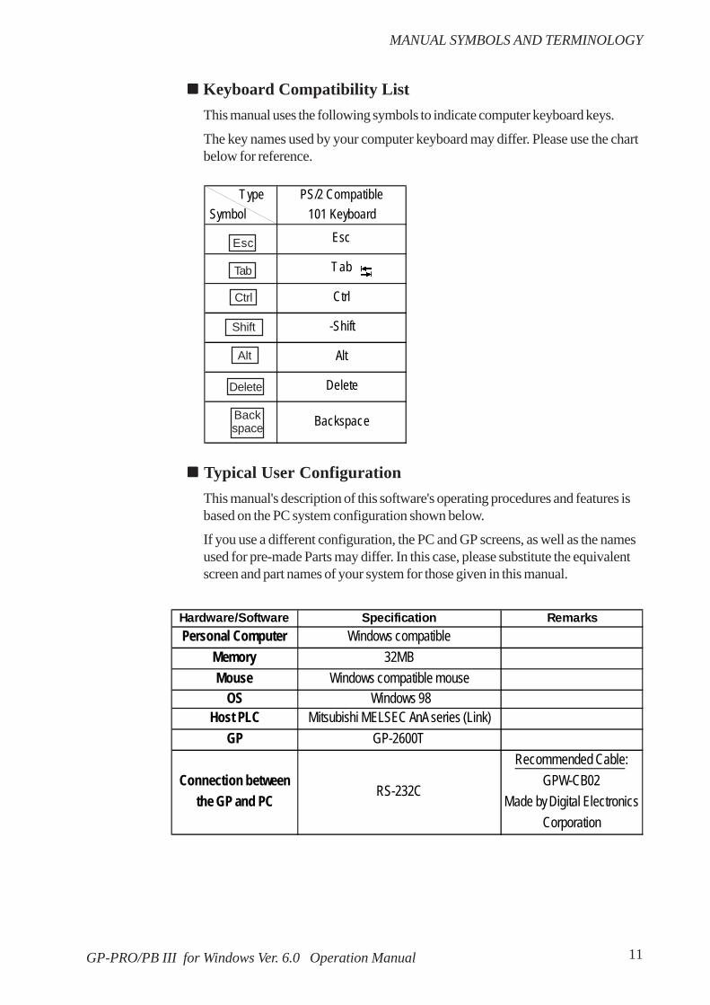
Keyboard Compatibility ListThis manual uses the following symbols to indicate computer keyboard keys.
The key names used by your computer keyboard may differ. Please use the chartbelow for reference.
Typical User ConfigurationThis manual's description of this software's operating procedures and features isbased on the PC system configuration shown below.
If you use a different configuration, the PC and GP screens, as well as the namesused for pre-made Parts may differ. In this case, please substitute the equivalentscreen and part names of your system for those given in this manual.
Esc
Tab
Ctrl
Shift
Alt
Delete
Backspace
Hardware/Software Specification RemarksPersonal Computer Windows compatible
Memory 32MBMouse Windows compatible mouse
OS Windows 98Host PLC Mitsubishi MELSEC AnA series (Link)
GP GP-2600T
Connection betweenthe GP and PC
RS-232C
Recommended Cable:GPW-CB02
Made by Digital ElectronicsCorporation
MANUAL SYMBOLS AND TERMINOLOGY

12 GP-PRO/PB III for Windows Ver. 6.0 Operation Manual
CD-ROM Usage PrecautionsTo prevent CD-ROM damage or malfunctions, please observe the followinginstructions:
• Do not remove the CD-ROM from the CD-ROM drive while the drive’s opera-tion lamp is lit.
• Do not touch the CD-ROM recording surface.• Do not place CD-ROMs in a place where they may be exposed to extremely
high or low temperatures, high humidity, or dust.
Product Usage PrecautionsTo prevent program malfunction or accidents, be sure to observe the followinginstructions:
• Touch panel switches should NOT be used fora device’s Emergency Stop Switch. Generallyspeaking, all industrial machinery/systemsmust be equipped with a mechanical, manuallyoperated emergency stop switch. Also, forother kinds of systems, similar mechanicalswitches must be provided to ensure safe op-eration of those systems.
• Do not turn off your personal computer’s power switch during the executionof a program.
• After you create a screen with this product and transfer it to the GP unit, donot send the same screen from the GP to a DOS version of this screeneditor software (e.g. GP-PRO/PB III, GP-PRO III).
• Do not change the contents of this product’s project files using the TextEditor software.
• Do not send a screen to a GP unit if that GP does not support the functionsprovided by your screen editor software.
PRECAUTIONS
!!!!!Warning
PRECAUTIONS

13GP-PRO/PB III for Windows Ver. 6.0 Operation Manual
GENERAL GP RESTRICTIONSThere are some restrictions written below in this product.• The GP-PRO/PB III for Windows software displays screen data using your
personal computer’s fonts and graphic functions. Therefore, there may be aslight difference between the data displayed on your personal computer andthe data displayed on the GP unit after that screen data is sent to the GP.
• When a GP unit is vertically installed, the panel’s coordinates will differ fromthose used on the screen editor software. Therefore, when you enter screencoordinates using tags or D-Script, please consider the GP’s orientation.
Software and GP Setting Controls
• Certain functions and setting supported by the GP unit are not supported bythe GP-PRO/PB III for Windows program, and vice versa.
• Full size characters in screen data drawn in a 2-byte version’s drawing envi-ronment may not display correctly when displayed in an English (1-byte)drawing environment. If you intend to use the screen data in an English versiondrawing environment, use only 1-byte alphanumeric characters for all yourscreen text.[Setting and functions items set via the GP unit (Not by GP-PRO/PB IIIfor Windows) ]
- Language Font selection- GP Date/Time- GP Self-Diagnosis Function- Functions for adjusting the Video Display
[Functions and setting items supported by GP-PRO/PB III for Windowsonly (Not by the GP unit)]
The following settings are included in the “GP System Settings” area:- “Checksum Verification”- “Buzzer Output”- Screen Change according to standby mode time- Screen Change Order in hierarchical display mode- Shift to OFFLINE mode- “K-tag” processing- GP unit’s internal memory (LS area) backup function- “Error Display Reset”- “Watchdog”- Control word address settings in “CF Card Data Save”- “Q-tag” settings (Display format, Print Settings, and Alarm Trigger
(0. 0) on the screen editor software
(0. 0) on the GP series’ panel
GENERAL GP RESTRICTIONS
GP-PRO/PB III for Windows Ver. 6.0 Operation Manual14
GENERAL GP RESTRICTIONS
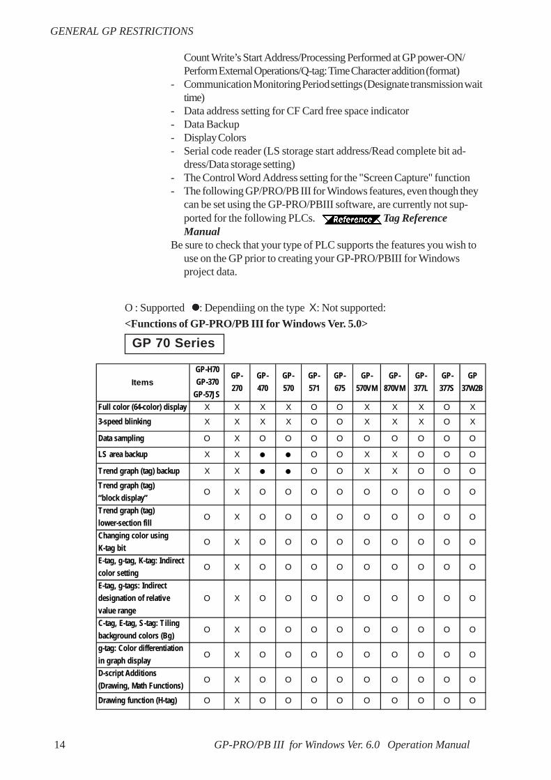
O : Supported : Dependiing on the type X: Not supported:<Functions of GP-PRO/PB III for Windows Ver. 5.0>
Count Write’s Start Address/Processing Performed at GP power-ON/Perform External Operations/Q-tag: Time Character addition (format)
- Communication Monitoring Period settings (Designate transmission waittime)
- Data address setting for CF Card free space indicator- Data Backup- Display Colors- Serial code reader (LS storage start address/Read complete bit ad-
dress/Data storage setting)- The Control Word Address setting for the "Screen Capture" function- The following GP/PRO/PB III for Windows features, even though they
can be set using the GP-PRO/PBIII software, are currently not sup-ported for the following PLCs. Tag ReferenceManual
Be sure to check that your type of PLC supports the features you wish touse on the GP prior to creating your GP-PRO/PBIII for Windowsproject data.
GP 70 Series
ItemsGP-H70GP-370
GP-57JS
GP-270
GP-470
GP-570
GP-571
GP-675
GP-570VM
GP-870VM
GP-377L
GP-377S
GP37W2B
Full color (64-color) display X X X X O O X X X O X
3-speed blinking X X X X O O X X X O X
Data sampling O X O O O O O O O O O
LS area backup X X O O X X O O O
Trend graph (tag) backup X X O O X X O O O
Trend graph (tag)“block display”
O X O O O O O O O O O
Trend graph (tag)lower-section fill
O X O O O O O O O O O
Changing color usingK-tag bit
O X O O O O O O O O O
E-tag, g-tag, K-tag: Indirectcolor setting
O X O O O O O O O O O
E-tag, g-tags: Indirectdesignation of relativevalue range
O X O O O O O O O O O
C-tag, E-tag, S-tag: Tilingbackground colors (Bg)
O X O O O O O O O O O
g-tag: Color differentiationin graph display
O X O O O O O O O O O
D-script Additions(Drawing, Math Functions)
O X O O O O O O O O O
Drawing function (H-tag) O X O O O O O O O O O

15GP-PRO/PB III for Windows Ver. 6.0 Operation Manual
GENERAL GP RESTRICTIONS
ItemsGP-H70GP-370
GP-57JS
GP-270
GP-470
GP-570
GP-571
GP-675
GP-570VM
GP-870VM
GP-377L
GP-377S
GP37W2B
T-tag: Radio switchfunction
O X O O O O O O O O O
Inching output switch(Tih-tag and Tiw-tag)
X X O O O O O O X X X
Q-tag: Backup X X O O X X O O OQ-tag: Setting displayformat
O X O O O O O O O O O
Q-tag: Display by second O X O O O O O O O O OQ-tag: Setting print color X X X O O O O O X X X
Tank graph (pre-made parts)
O X O O O O O O O O O
Meter graph(pre-made parts)
O X O O O O O O O O O
Video window display(V-tag) X X X X X X O O X X X
Setting Direction ofScreen Printout
X X X X X O X X X X X
Interrupt/cancel hard-copy printout
X X O O O O O O X X X
Set “OFFLINE” modeswitch feature off
O O O O O O O X O O O
Q-tag: Sub-display O X O O O O O O O O OQ-tag: Grouping ofalarms into a block
X X X X X X X X O O O
A-tag: Indirectdesignation of textscreen or sub-displayscreen
X X X X X X X X O O O
Filing data function X X X X X X X X O O OData logging function X X X X X X X X O O OSound output function X X X X X X X X X X XCF Card compatibility X X X X X X X X X X XGlobal D-script X X X X X X X X O O OCompatible withPro-Server
X X X X X X X X X X X
Compatible with LS areafor simulation
X X X X X X X X O O O
GP resetting due to writeerror
X X X X X X X X O O O
Compatible with transferspeed of 115.2Kbps
X X X X X X X X O O O
Creation of compositeparts for Filing Data
X X X X X X X X O O O
GP-PRO/PB III for Windows Ver. 6.0 Operation Manual16
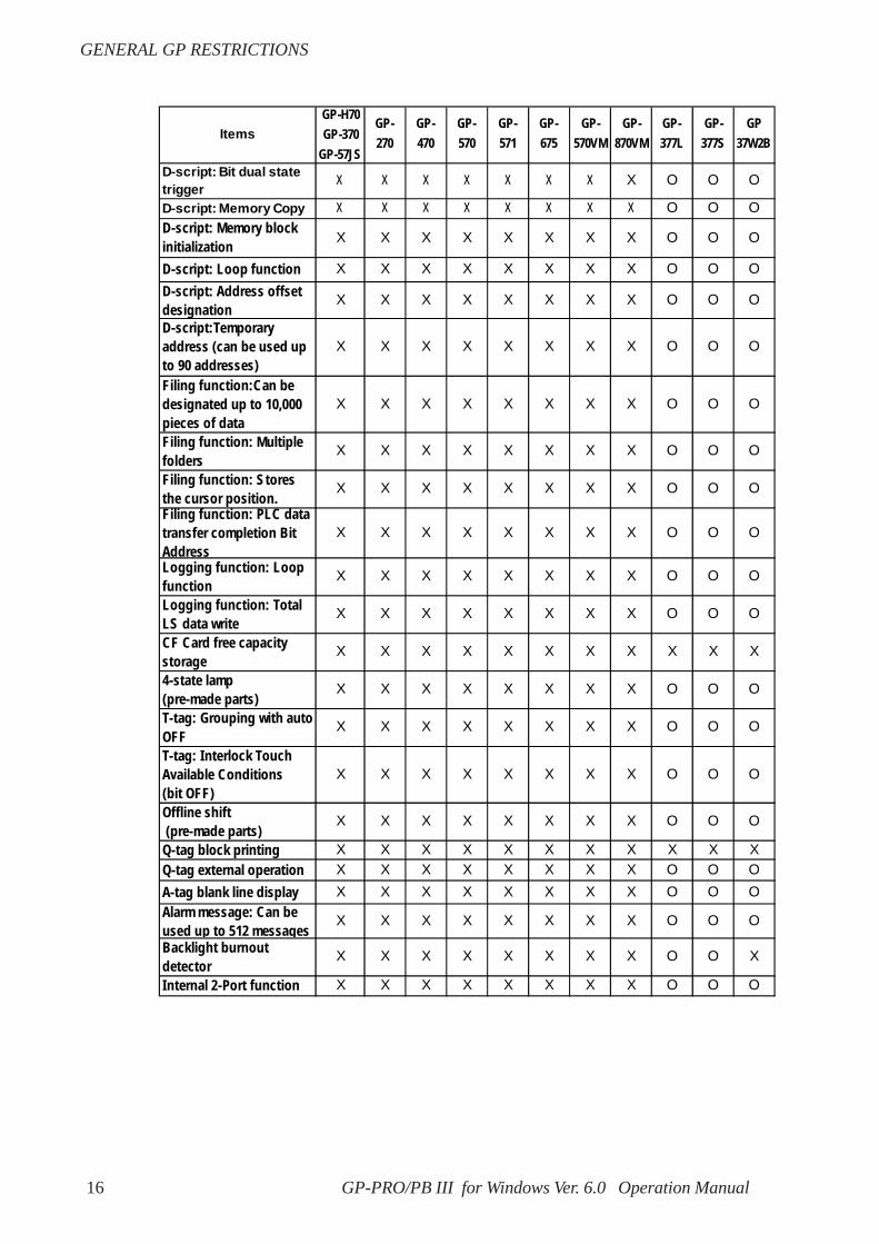
GENERAL GP RESTRICTIONS
ItemsGP-H70GP-370
GP-57JS
GP-270
GP-470
GP-570
GP-571
GP-675
GP-570VM
GP-870VM
GP-377L
GP-377S
GP37W2B
D-script: Bit dual statetrigger
X X X X X X X X O O O
D-script: Memory Copy X X X X X X X X O O OD-script: Memory blockinitialization X X X X X X X X O O O
D-script: Loop function X X X X X X X X O O OD-script: Address offsetdesignation
X X X X X X X X O O O
D-script:Temporaryaddress (can be used upto 90 addresses)
X X X X X X X X O O O
Filing function:Can bedesignated up to 10,000pieces of data
X X X X X X X X O O O
Filing function: Multiplefolders
X X X X X X X X O O O
Filing function: Storesthe cursor position.
X X X X X X X X O O O
Filing function: PLC datatransfer completion BitAddress
X X X X X X X X O O O
Logging function: Loopfunction
X X X X X X X X O O O
Logging function: TotalLS data write
X X X X X X X X O O O
CF Card free capacitystorage
X X X X X X X X X X X
4-state lamp(pre-made parts)
X X X X X X X X O O O
T-tag: Grouping with autoOFF
X X X X X X X X O O O
T-tag: Interlock TouchAvailable Conditions(bit OFF)
X X X X X X X X O O O
Offline shift (pre-made parts)
X X X X X X X X O O O
Q-tag block printing X X X X X X X X X X XQ-tag external operation X X X X X X X X O O OA-tag blank line display X X X X X X X X O O OAlarm message: Can beused up to 512 messages
X X X X X X X X O O O
Backlight burnoutdetector
X X X X X X X X O O X
Internal 2-Port function X X X X X X X X O O O

17GP-PRO/PB III for Windows Ver. 6.0 Operation Manual
GENERAL GP RESTRICTIONS
ItemsGP-H70GP-370
GP-57JS
GP-270
GP-470
GP-570
GP-571
GP-675
GP-570VM
GP-870VM
GP-377L
GP-377S
GP37W2B
GB-WEB compatibility X X X X X X X X X X X
PLC Simulation via Ethernet X X X X X X X X X X X
Factory-Set IP addresssettings for data transfer
X X X X X X X X X X X
D-Script I/O function X X X X X X X X X X XSerial 2-D readercompatibility
X X X X X X X X X X X
Serial bar-code readercompatibility
X X X X X X X X X X X
256-color display X X X X X X X X X X XQ-tag: up to 2048 messages X X X X X X X X X X XQ-tag: Expansion of timeformat digits
X X X X X X X X O O O
T-tag: momentary (one-shotbuzzer)
X X X X X X X X O O O
Number of logging words:255
X X X X X X X X X X X

GP-PRO/PB III for Windows Ver. 6.0 Operation Manual18
GENERAL GP RESTRICTIONS
GP77R/GP2000 Series
ItemsGP-
377RGP-
477RGP -577R
GP-2301H
GP-2401H
GP-2300
GP-2301
GP-2400
GP-2500
GP-2501
GP-2600
Full color (64-color) display O x O O O O*7 O O3-speed blinking O x O O O O*7 O OData sampling O O O O O O O O O O OLS area backup O O O O O O O O O O OTrend graph (tag) backup O O O O O O O O O O OTrend graph (tag) “blockdisplay” O O O O O O O O O O OTrend graph (tag) lower-section fill O O O O O O O O O O OChanging color using K-tagbit O O O O O O O O O O OE-tag, g-tag, K-tag: Indirectcolor setting O O O O O O O O O O OE-tag, g-tags: Indirectdesignation of relative valuerange
O O O O O O O O O O O
C-tag, E-tag, S-tag: Tilingbackground colors (Bg) O O O O O O O O O O Og-tag: Color differentiation ingraph display O O O O O O O O O O OD-script Additions (Drawing,Math Functions) O O O O O O O O O O ODrawing function (H-tag) O O O O O O O O O O OT-tag: Radio switch function O O O O O O O O O O OInching output switch (Tih-tag and Tiw-tag) x O O x x x x x x x xQ-tag: Backup O O O O O O O O O O OQ-tag: Setting display format O O O O O O O O O O O

19GP-PRO/PB III for Windows Ver. 6.0 Operation Manual
GENERAL GP RESTRICTIONS
*1 A large-size multi-unit is necessary to enable this function.
*2 A middle-size multi-unit E is necessary to enable this function.
*3 A large-size multi-unit E or GP Ethernet I/F unit is necessary to enable this func-tion.
*4 To utilize this feature, the optional VM unit is required.
*5 A bus conversion unit and a large-scale multi-unit are required to enable this func-tion.
*7 Not available with GP2500L unit.
ItemsGP-
377RGP-
477RGP-
577RGP-
2301HGP-
2401HGP-2300
GP-2301
GP-2400
GP-2500
GP-2501
GP-2600
Q-tag: Display by second O O O O O O O O O O OQ-tag: Setting print color O X O X X X O O*7 O OTank graph (pre-made parts) O O O O O O O O O O OMeter graph (pre-made parts) O O O O O O O O O O OVideo window display(V-tag) X X X X X X X X O*4 X O*4
Setting Direction of ScreenPrintout X X X X X X X X X X OInterrupt/cancel hard-copyprintout O*2 O O X X O X O O O OSet “OFFLINE” mode switchfeature off O O O O O O O O O O OQ-tag: Sub-display O O O O O O O O O O OQ-tag: Grouping of alarmsinto a block O O O O O O O O O O OA-tag: Indirect designation oftext screen or sub-displayscreen
O O O O O O O O O O O
Filing data function O O O O O O O O O O OData logging function O O O O O O O O O O OSound output function X O*1 O*1 X X X X O O O*5 OCF Card compatibility O*2 O*1 O*1 O O O O O O O OGlobal D-script O O O O O O O O O O OCompatible with Pro-Server O*2 O*3 O*3 X X O X O O O*3 OCompatible with LS area forsimulation O O O O O O O O O O OGP resetting due to writeerror O O O O O O O O O O OCompatible with transferspeed of 115.2Kbps O O O O O O O O O O OCreation of composite partsfor Filing Data O O O O O O O O O O O
GP-PRO/PB III for Windows Ver. 6.0 Operation Manual20
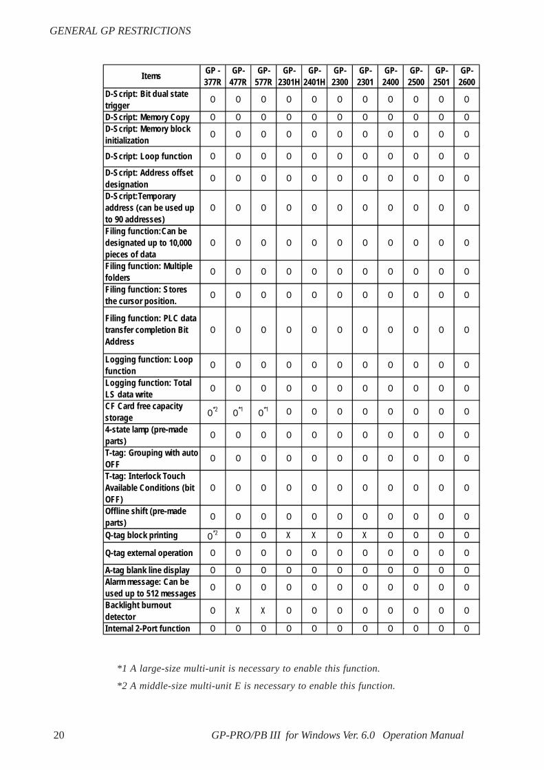
GENERAL GP RESTRICTIONS
*1 A large-size multi-unit is necessary to enable this function.
*2 A middle-size multi-unit E is necessary to enable this function.
I tems GP -377R
GP-477R
GP-577R
GP-2301H
GP-2401H
GP-2300
GP-2301
GP-2400
GP-2500
GP-2501
GP-2600
D-Script: Bit dual statetrigger O O O O O O O O O O O
D-Script: Memory Copy O O O O O O O O O O OD-Script: Memory blockinitialization O O O O O O O O O O O
D-Script: Loop function O O O O O O O O O O O
D-Script: Address offsetdesignation O O O O O O O O O O O
D-Script:Temporaryaddress (can be used upto 90 addresses)
O O O O O O O O O O O
Filing function:Can bedesignated up to 10,000pieces of data
O O O O O O O O O O O
Filing function: Multiplefolders O O O O O O O O O O O
Filing function: Storesthe cursor position. O O O O O O O O O O O
Filing function: PLC datatransfer completion BitAddress
O O O O O O O O O O O
Logging function: Loopfunction O O O O O O O O O O O
Logging function: TotalLS data write O O O O O O O O O O O
CF Card free capacitystorage O*2 O*1 O*1 O O O O O O O O
4-state lamp (pre-madeparts) O O O O O O O O O O O
T-tag: Grouping with autoOFF O O O O O O O O O O O
T-tag: Interlock TouchAvailable Conditions (bitOFF)
O O O O O O O O O O O
Offline shift (pre-madeparts) O O O O O O O O O O O
Q-tag block printing O*2 O O X X O X O O O O
Q-tag external operation O O O O O O O O O O O
A-tag blank line display O O O O O O O O O O OAlarm message: Can beused up to 512 messages O O O O O O O O O O O
Backlight burnoutdetector O X X O O O O O O O O
Internal 2-Port function O O O O O O O O O O O

21GP-PRO/PB III for Windows Ver. 6.0 Operation Manual
GENERAL GP RESTRICTIONS
*2 A middle-size multi-unit E is necessary to enable this function.
*3 A large-size multi-unit E or GP Ethernet I/F unit is necessary to enable this func-tion.
*6 A bus conversion unit and a large-scale multi-unit E or a GP Ethernet Interfaceunit are required to enable this function.
*8 Not available with GP2500L and GP2500S units.
ItemsGP -377R
GP-477R
GP-577R
GP-2301H
GP-2401H
GP-2300
GP-2301
GP -2400
GP-2500
GP-2501
GP-2600
GB-WEB compatibility O*2 O*3 O*3 X X O X O O O*6 O
PLC Simulation via Ethernet X X X X X O X O O O*6 OFactory-Set IP addresssettings for data transfer X X X X X O X O O X O
D-Script I/O function X X X X X O X O O X OSerial 2-D readercompatibility X X X X X O X O O X OSerial bar-code readercompatibility X X X X X O X O O X O
256-color display X X X X O X X O O*8 OQ-tag: up to 2048 messages X X X O O O O O O O OQ-tag: Expansion of timeformat digits O O O O O O O O O O OJapanese FEP X X X O O O O O O O OT-tag: momentary (one-shotbuzzer) O O O O O O O O O O ONumber of logging words:255 X X X O O O O O O O O
GP-PRO/PB III for Windows Ver. 6.0 Operation Manual22
GENERAL GP RESTRICTIONS
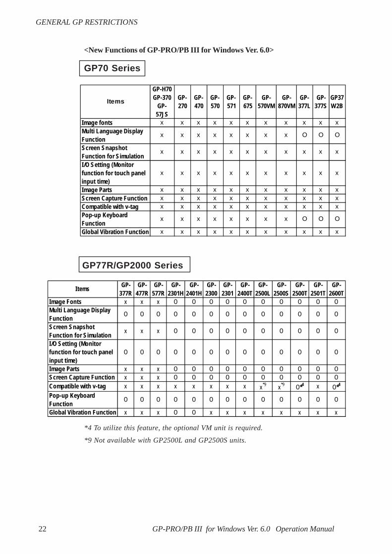
GP70 Series
<New Functions of GP-PRO/PB III for Windows Ver. 6.0>
GP77R/GP2000 Series
*4 To utilize this feature, the optional VM unit is required.
*9 Not available with GP2500L and GP2500S units.
Items
GP-H70GP-370
GP-57JS
GP-270
GP-470
GP-570
GP-571
GP-675
GP-570VM
GP-870VM
GP-377L
GP-377S
GP37W2B
Image fonts x x x x x x x x x x xMulti Language DisplayFunction
x x x x x x x x O O O
Screen SnapshotFunction for Simulation
x x x x x x x x x x x
I /O Setting (Monitorfunction for touch panelinput time)
x x x x x x x x x x x
Image Parts x x x x x x x x x x xScreen Capture Function x x x x x x x x x x xCompatible with v-tag x x x x x x x x x x xPop-up KeyboardFunction
x x x x x x x x O O O
Global Vibration Function x x x x x x x x x x x
I tems GP-377R
GP-477R
GP-577R
GP-2301H
GP-2401H
GP-2300
GP-2301
GP-2400T
GP-2500L
GP-2500S
GP-2500T
GP-2501T
GP-2600T
Image Fonts x x x O O O O O O O O O OMulti Language DisplayFunction O O O O O O O O O O O O O
Screen SnapshotFunction for Simulation x x x O O O O O O O O O O
I /O Setting (Monitorfunction for touch panelinput time)
O O O O O O O O O O O O O
Image Parts x x x O O O O O O O O O OScreen Capture Function x x x O O O O O O O O O OCompatible with v-tag x x x x x x x x x*9 x*9 O*4 x O*4
Pop-up KeyboardFunction O O O O O O O O O O O O O
Global Vibration Function x x x O O x x x x x x x x
23GP-PRO/PB III for Windows Ver. 6.0 Operation Manual
GP SERIES COMPATIBILITY
GP SERIES COMPATIBILITY
Converting Data from GP-PRO/PB III for WindowsA project file from GP-PRO/PB III for Windows can be easily opened with the GP-PRO/PB III for Windows Ver. 6.0 software.
1.1.2 Selecting an Existing Project
Converting Data from GP-PRO/PB III (DOS version)Screen data from GP-PRO/PB III (DOS version) can be opened with the GP-PRO/PB III for Windows Ver. 6.0 software. To do so, specify the "File Type" as a DOSproject file (*.PRO) in the [Files of type:] area, when selecting a project.
1.1.2 Selecting an Existing Project
Converting Data from GP-PRO, GP-PRO II, or GP-PRO/PB IIIGP-PRO II or GP-PRO III Screen data can be converted to 6.0 data for use onGP70/GP77R/GP2000 series units using the GP-PRO/PB III for Windows Ver.6.0 file converter utility. However, after the GP-PRO II or GP-PRO III SO(System) screen data is converted and sent to a GP70/GP77R/GP2000 seriesunit, you must then review all GP settings in OFFLINE mode.12.1 File ConverterCautions when converting GP-PRO II Data
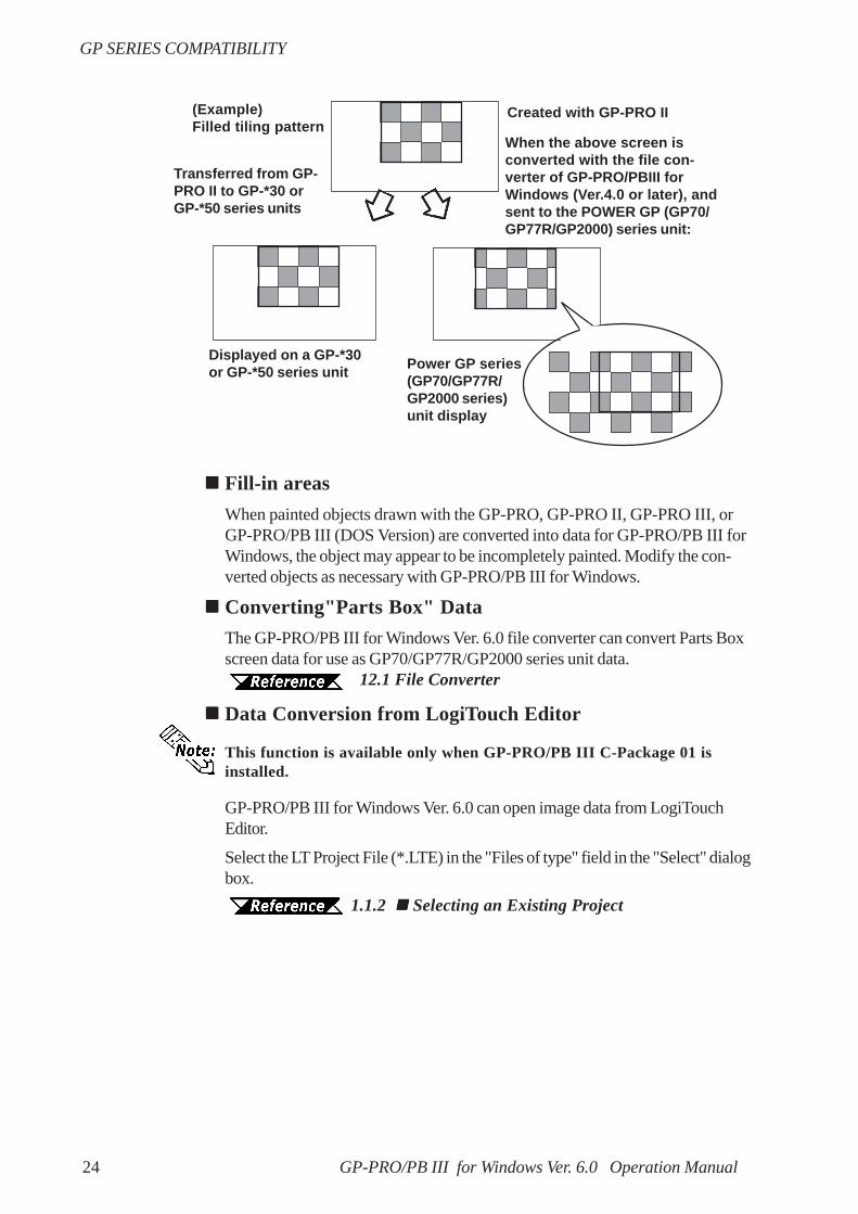
If a GP-PRO II screen contains "filled" data, filled tiling patterns may be shiftedwhen displayed on Power GP series (GP70/GP77R/GP2000 series) units. OnGP-*30 and GP-*50 series units, color is filled on the screen based on thedrawing's starting point. However, Power GP series (GP70/GP77R/GP2000series) units fill color from the upper-left corner (0,0) of the screen, and onlyshow the drawing area. Please be aware of this difference when you call up afilled drawing using L-tags, or when placing filled objects on top of one another.
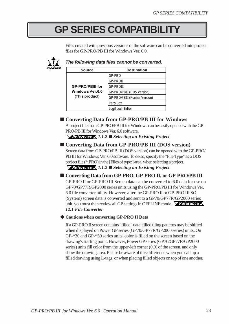
Files created with previous versions of the software can be converted into projectfiles for GP-PRO/PB III for Windows Ver. 6.0.
The following data files cannot be converted.Source Destination
GP-PROGP-PROIIGP-PROIIIGP-PRO/PBIII (DOS Version)GP-PRO/PBIII (Former Version)Parts BoxLogiTouch Editor
GP-PRO/PBIII forWindows Ver.6.0
(This product)
GP-PRO/PB III for Windows Ver. 6.0 Operation Manual24
GP SERIES COMPATIBILITY
Fill-in areasWhen painted objects drawn with the GP-PRO, GP-PRO II, GP-PRO III, orGP-PRO/PB III (DOS Version) are converted into data for GP-PRO/PB III forWindows, the object may appear to be incompletely painted. Modify the con-verted objects as necessary with GP-PRO/PB III for Windows.
Converting"Parts Box" DataThe GP-PRO/PB III for Windows Ver. 6.0 file converter can convert Parts Boxscreen data for use as GP70/GP77R/GP2000 series unit data.
12.1 File Converter
Data Conversion from LogiTouch Editor
This function is available only when GP-PRO/PB III C-Package 01 isinstalled.
GP-PRO/PB III for Windows Ver. 6.0 can open image data from LogiTouchEditor.
Select the LT Project File (*.LTE) in the "Files of type" field in the "Select" dialogbox.
1.1.2 Selecting an Existing Project
Created with GP-PRO II(Example)Filled tiling pattern
Power GP series(GP70/GP77R/GP2000 series)unit display
Displayed on a GP-*30or GP-*50 series unit
Transferred from GP-PRO II to GP-*30 orGP-*50 series units
When the above screen isconverted with the file con-verter of GP-PRO/PBIII forWindows (Ver.4.0 or later), andsent to the POWER GP (GP70/GP77R/GP2000) series unit:

25
TABLE OF CONTENTS
PREFACE ......................................................................................................................... 1
TRADEMARK RIGHTS .............................................................................................. 2
LIST OF SUPPORTED MODELS .............................................................................. 3
NEW FEATURES ........................................................................................................... 5
HOW TO USE THIS MANUAL .................................................................................. 7
MANUAL SYMBOLS AND TERMINOLOGY ..................................................... 10
PRECAUTIONS ........................................................................................................... 12
GENERAL GP RESTRICTIONS ............................................................................. 13
GP SERIES COMPATIBILITY ................................................................................. 23
TABLE OF CONTENTS ............................................................................................. 25
CHAPTER 1 FUNDAMENTALS OF GP-PRO/PB III for WINDOWS
1.1 From Start to Finish.......................................................................................... 1-21.1.1 Getting Started ........................................................................................................... 1-2
1.1.2 Creating/Selecting/Saving a Project .......................................................................... 1-3
1.1.3 Opening/Closing/Saving a Screen .............................................................................. 1-9
1.1.4 Quitting GP-PRO/PBIII for Windows ..................................................................... 1-14
1.2 Project Manager.............................................................................................. 1-151.2.1 Project Manager Areas and Functions .................................................................... 1-15
1.3 Screen Editor ................................................................................................... 1-171.3.1 Screen Editor Item Names and Functions .............................................................. 1-17
1.3.2 Display Area (50%, 100%, 200%) .......................................................................... 1-19
1.3.3 Tool/Icon Display ..................................................................................................... 1-19
1.4 GP-PRO/PB III Manuals and Help ............................................................. 1-201.4.1 Browsing Help Topics .............................................................................................. 1-21
1.4.2 Browsing Home Page .............................................................................................. 1-23
CHAPTER 2 CREATING BASE SCREENS
2.1 Parts ..................................................................................................................... 2-22.1.1 Bit Switches ............................................................................................................. 2-22
2.1.2 Word Switches ......................................................................................................... 2-27
2.1.3 Function Switches .................................................................................................... 2-31
2.1.4 Toggle Switches ....................................................................................................... 2-36
2.1.5 Lamps ...................................................................................................................... 2-40
2.1.6 4-State Lamp............................................................................................................ 2-43
TABLE OF CONTENTS

26
TABLE OF CONTENTS
2.1.7 Bar Graphs ............................................................................................................... 2-46
2.1.8 Pie Graphs ................................................................................................................ 2-51
2.1.9 Half Pie Graphs ....................................................................................................... 2-56
2.1.10 Tank Graphs ............................................................................................................ 2-61
2.1.11 Meters ..................................................................................................................... 2-66
2.1.12 Trend Graphs .......................................................................................................... 2-71
2.1.13 Keypads .................................................................................................................. 2-77
2.1.14 Keypad Display ...................................................................................................... 2-81
2.1.15 Alarm Display ......................................................................................................... 2-91
2.1.16 File Name Display .................................................................................................. 2-95
2.1.17 Data Logging Display ............................................................................................ 2-101
2.1.18 Numeric Displays ................................................................................................. 2-107
2.1.19 Message Display..................................................................................................... 2-111
2.1.20 Date Displays ........................................................................................................ 2-117
2.1.21 Time Displays ........................................................................................................ 2-120
2.1.22 Picture Displays ..................................................................................................... 2-122
2.1.23 Window Parts ......................................................................................................... 2-128
2.2 Drawing ........................................................................................................... 2-1302.2.1 Dot ..................................................................................................................... 2-131
2.2.2 Line/Poly-line ......................................................................................................... 2-133
2.2.3 Square/Rectangle ................................................................................................... 2-135
2.2.4 Circle/Oval ............................................................................................................. 2-137
2.2.5 Arc/Pie ................................................................................................................... 2-139
2.2.6 Fill ..................................................................................................................... 2-141
2.2.7 Line / Polygon ........................................................................................................ 2-143
2.2.8 Scale ..................................................................................................................... 2-145
2.2.9 Text ..................................................................................................................... 2-148
2.2.10 Load Screens ......................................................................................................... 2-154
2.2.11 Load Mark ............................................................................................................. 2-157
2.2.12 Convert (Import) Image ......................................................................................... 2-158
2.3 Tags .................................................................................................................. 2-1602.3.1 Designating Tags.................................................................................................... 2-163
2.4 Object Editing ................................................................................................ 2-1662.4.1 Selecting Objects ................................................................................................... 2-167
2.4.2 Moving Objects ...................................................................................................... 2-173
2.4.3 Scaling Up/Down ................................................................................................... 2-174
2.4.4 Cut ..................................................................................................................... 2-175
2.4.5 Copy ..................................................................................................................... 2-176
27
TABLE OF CONTENTS
2.4.6 Paste ..................................................................................................................... 2-177
2.4.7 Duplicate ................................................................................................................ 2-178
2.4.8 Delete ..................................................................................................................... 2-181
2.4.9 Align ..................................................................................................................... 2-182
2.4.10 Rotate Left/ Rotate Right ...................................................................................... 2-183
2.4.11 Mirror X/ Mirror Y ................................................................................................ 2-185
2.4.12 Group/Ungroup ...................................................................................................... 2-187
2.4.13 Bring to Front/ Send to Back ................................................................................. 2-189
2.4.14 Changing Attributes ............................................................................................... 2-190
2.4.15 Changing Coordinates ............................................................................................ 2-192
2.4.16 Editing the Node of a Multi-segment Line............................................................. 2-193
2.4.17 Transferring a Screen to the Clipboard ................................................................. 2-194
2.4.18 Converting a Screen to a Bitmap File .................................................................... 2-195
2.4.19 Redraw Screen ...................................................................................................... 2-197
2.4.20 Undo ..................................................................................................................... 2-198
2.4.21 Redo ..................................................................................................................... 2-198
2.5 Libraries.......................................................................................................... 2-1992.5.1 Registering Library Items ...................................................................................... 2-203
2.5.2 Placing Library Items ............................................................................................ 2-208
2.5.3 Editing Library Items ............................................................................................. 2-210
2.5.4 Saving Libraries and Quitting ................................................................................. 2-215
2.6 D-Script/Global D-Script ............................................................................. 2-217
2.7 Data Sampling................................................................................................ 2-224
2.8 Efficient Drawing Techniques ..................................................................... 2-2272.8.1 Grid/Snap................................................................................................................ 2-227
2.8.2 Screen Property Settings ....................................................................................... 2-230
2.8.3 Preview Screen ..................................................................................................... 2-235
2.8.4 Screen Data List .................................................................................................... 2-236
2.8.5 Part Reference List ............................................................................................... 2-238
2.8.6 Tag List .................................................................................................................. 2-241
2.8.7 Cross Reference List ............................................................................................. 2-243
2.8.8 Load Screen List .................................................................................................... 2-246
2.8.9 Display of Screen Level Change Structure ........................................................... 2-248
2.9 Creating Handy-type GP Screen................................................................ 2-2492.9.1 Function Keys ........................................................................................................ 2-250
2.9.2 Setting Up the Operation Switch ........................................................................... 2-254
2.9.3 Vibration Function .................................................................................................. 2-256

28
TABLE OF CONTENTS
2.10 DXF Conversion ............................................................................................ 2-2642.10.1 Conversion from DXF File to Base Screen (DXF → PRW) ................................ 2-264
2.10.2 Conversion from Base Screen to DXF File (PRW → DXF) ............................... 2-270
CHAPTER 3 DRAWING APPLICATIONS - CREATING and USING SCREENS
3.1 Creating a Mark: the Mark Screen .............................................................. 3-23.1.1 Drawing a Mark ........................................................................................................ 3-4
3.1.2 Special Mark Characters ......................................................................................... 3-12
3.1.3 Editing a Mark ......................................................................................................... 3-15
3.1.4 Registering and Placing a Mark Library Item ......................................................... 3-25
3.2 Creating a Trend Graph: the Trend Graph Screen .................................. 3-26
3.3 Creating a Keypad: the Keypad Screen..................................................... 3-32
3.4 Text Input: the Text Screen ......................................................................... 3-373.4.1 Editing Text .............................................................................................................. 3-39
3.5 Creating an Image: the Image Screen ........................................................ 3-453.5.1 Image Conversion .................................................................................................... 3-45
3.5.2 Compressing/Decompressing an Image Screen ...................................................... 3-51
3.6 Video Data Display (V Screen) .................................................................... 3-533.6.1 Video Settings ......................................................................................................... 3-59
3.6.2 Video Window Settings ............................................................................................ 3-60
3.7 Window Display: Window (U) Screen and Base (B) Screen................... 3-633.7.1 Overview of Window Display .................................................................................. 3-63
3.7.2 Window Registration on the U Screen .................................................................... 3-65
3.7.3 Window Registration on the B Screen..................................................................... 2-68
CHAPTER 4 SCREEN AND PROJECT MANAGEMENT
4.1 Screen Editing .................................................................................................... 4-24.1.1 Listing/Copying/Deleting Screen................................................................................ 4-2
4.1.2 Copying Screens from Other Projects....................................................................... 4-7
4.2 Project Editing ................................................................................................. 4-114.2.1 Deleting Project Files ............................................................................................... 4-11
4.2.2 Rebuilding A Project (Rebuild) ................................................................................ 4-12
4.2.3 Converting Addresses and Device Codes ............................................................... 4-15
4.2.4 Convert Load Screens ............................................................................................. 4-17
4.2.5 Changing a Project’s GP Type................................................................................. 4-19
4.2.6 Changing Your Project’s Device/PLC Type............................................................ 4-21
4.2.7 Changing Extend SIO Type ..................................................................................... 4-22
4.3 Project Compression/Decompression ......................................................... 4-23

29
TABLE OF CONTENTS
4.3.1 Compressing a Project File ...................................................................................... 4-24
4.3.2 Decompressing a Project File .................................................................................. 4-27
4.4 Comparing Projects......................................................................................... 4-29
4.5 Information Display ........................................................................................ 4-314.5.1 Project Information .................................................................................................. 4-31
4.5.2 Screen Information .................................................................................................. 4-33
4.5.3 Version Information ................................................................................................. 4-34
4.6 Table Editor Character Strings .................................................................... 4-354.6.1 Overview: Multi-language Display Feature ............................................................ 4-35
4.6.2 Table Editor Index Character Strings ..................................................................... 4-37
4.6.3 Entering Settings via the Screen Editor .................................................................. 4-43
4.7 Symbol Editor................................................................................................... 4-46
4.8 Device Monitor................................................................................................ 4-54
CHAPTER 5 CREATING AND EDITING ALARMS
5.1 Alarm Creation and Editing ............................................................................ 5-25.1.1 Alarm Editor ............................................................................................................... 5-3
5.1.2 Creating an Alarm ................................................................................................... 5-11
5.1.3 Editing Alarm Data .................................................................................................. 5-13
5.1.4 Alarm Import/Export................................................................................................ 5-22
CHAPTER 6 GP INITIAL AND SYSTEM SETTINGS
6.1 Menu Setting Items: GP Setup ...................................................................... 6-2
CHAPTER 7 TRANSFERRING DATA
7.1 Prior to Transferring Data .............................................................................. 7-27.1.1 GP Screen Transfer Cable......................................................................................... 7-2
7.2 Transferring Screens ........................................................................................ 7-37.2.1 Transfer Settings ........................................................................................................ 7-4
7.2.2 Passwords .................................................................................................................. 7-8
7.2.3 2-Way Driver ........................................................................................................... 7-10
7.2.4 Transfer Preparation ................................................................................................ 7-11
7.2.5 When Sending Screens To the GP........................................................................... 7-12
7.2.6 When Receiving Data From the GP ........................................................................ 7-14
7.2.7 Sending/Receiving Dictionary File ........................................................................... 7-16
7.2.8 Start GP-Web Compiler ........................................................................................... 7-17
7.3 Options .............................................................................................................. 7-18 7.3.1 GP Internal Screen Data Information ..................................................................... 7-18
30
TABLE OF CONTENTS
7.4 Setting Up Your GP via an Ethernet Network........................................... 7-21 7.4.1 Data Transfer Using the Factory-set IP Address ................................................... 7-25
CHAPTER 8 SIMULATION
8.1 Overview ............................................................................................................. 8-2 8.1.1 General Description of the Simulation Screen ........................................................... 8-4
8.1.2 Transferring Simulation Protocol .............................................................................. 8-10
8.1.3 Performing a Simulation ........................................................................................... 8-11
8.1.4 Simulation (Ethernet) ............................................................................................... 8-13
8.1.5 Snapshot Function .................................................................................................... 8-16
CHAPTER 9 PRINTING
9.1 Print Settings...................................................................................................... 9-2 9.1.1 Printing ....................................................................................................................... 9-2
9.1.2 Print Preview ............................................................................................................. 9-7
9.2 Sample Printer Output...................................................................................... 9-8
CHAPTER 10 ADVANCED FEATURES
10.1 Sound Output.................................................................................................... 10-2
10.2 Filing Data (Recipe) ....................................................................................... 10-2
10.3 Logging .............................................................................................................. 10-3
10.4 CF Card ............................................................................................................. 10-310.4.1 Using CF Card Tools ............................................................................................... 10-3
10.5 Creating/Transferring CF Memory Loader Tool ...................................... 10-910.5.1 CF Memory Loader Tool / Backup Data ................................................................ 10-9
10.5.2 CF Memory Loader Settings ................................................................................. 10-11
10.5.3 Creating System Boot Data for CF Card .............................................................. 10-12
10.5.4 Sending System Boot Data to CF Card ................................................................. 10-13
10.5.5 Creating Backup Data .......................................................................................... 10-13
10.5.6 Sending Backup Data ............................................................................................ 10-14
10.5.7 Receiving Backup Data ......................................................................................... 10-14
10.5.8 Transferring “CF Memory Loader Tool” data via CF Card Tool .......................... 10-15
10.6 CF Memory Loader Tool ............................................................................. 10-1610.6.1 About "CF Memory Loader Tool" ......................................................................... 10-16
10.6.2 Starting the "CF Memory Loader Tool" ................................................................. 10-16
10.6.3 MEMORY LOADER TOOL ............................................................................... 10-17
10.6.4 Menu Screen .......................................................................................................... 10-18

31
TABLE OF CONTENTS
10.6.5 Self Diagnosis ........................................................................................................ 10-25
CHAPTER 11 PROJECT MANAGER HIERARCHICAL DISPLAY
11.1 Project Manager - Hierarchical Display ................................................. 11-2
11.2 Using Hierarchical Display Mode ............................................................ 11-3
CHAPTER 12 DATA COMPATIBILITY
12.1 File Converter .................................................................................................. 12-212.1.1 Conversion from GP-PRO II or GP-PRO III ......................................................... 12-2
12.1.2 Conversion from Parts Box ..................................................................................... 12-8
12.1.3 GP-*10 (GPM) File Conversion ............................................................................ 12-11
12.1.4 Reading GP-*10 (GPM) Files ................................................................................ 12-16
APPENDICES
A.1 Error Messages .................................................................................. Appendix-2
A.2 Troubleshooting ................................................................................ Appendix-22 A.2.1 Troubleshooting List ................................................................................... Appendix-22
A.2.2 Buzzer will not Stop/No Display on the GP/Transfer Disabled ..................Appendix-24
A.3 Address Conversion Tables ........................................................... Appendix-28
A.4 Software Trouble Report ................................................................ Appendix-70

32 GP-PRO/PB III for Windows Ver. 6.0 Operation Manual
Memo

his chapter describes GP-PRO/PB III for Windows’ basic operationssuch as how to start and quit the software. It also explains the Project
Manager and Screen Editor areas, which are used for the majority of screencreation work. Also, a number of tools are introduced here, such as onlinehelp, which provide explanations of GP-PRO/PB III for Windows’ functionsand operations.
T
1 FUNDAMENTALS OF GP-PRO/PB III for WINDOWS
1.1 ...................................................... From Start to Finish
1.2 ............................................................ Project Manager
1.3 ................................................................. Screen Editor
1.4 ............................. GP-PRO/PB III Manuals and Help

GP-PRO/PB III for Windows Ver. 6.0 Operation Manual1-2
Chapter 1 - Fundamentals1.1 From Start to Finish
Starting GP-PRO/PB III for WindowsThe following explanation assumes your PC is turned on and the Windowsdesktop has appeared.
PROCEDURE R E M A R K S
1.1 From Start to Finish
Create/Select aproject file with theProject Manager.
1.1.1 Getting Started
Usage Pattern
StartSave the project,and quit theProject Manager.
Save the screen,and quit theScreen Editor.
Create/Edit ascreen with theScreen Editor.
→→→→→→→→→→ →→→→→ →→→→→
(2) The Project Manager screen appears.
This section describes the GP-PRO/PB III for Windows program’s operationflow from start to finish.
If you double-click directly on apreviously made project file(*.PRW file) via the Explorer soft-ware, GP-PRO/PB III for Windowswill automatically start.
(1) Click on the [Start] button, and point to the [Pro-grams] - [Pro-face] - [ProPB3Win] menu. Then,click on the [1. Project Manager] command.

GP-PRO/PB III for Windows Ver. 6.0 Operation Manual 1-3
1.1 From Start to FinishChapter 1 - Fundamentals
1.1.2 Creating/Selecting/Saving a Project
A project file (PRW file) normally contains multiple screens intended forthe operation of a certain system. GP-PRO/PB III for Windows creates oneproject file for the operation of one system, enabling system management byproject file units.You can send the screen data of one project file or individual screens of thesame project file to the GP unit. Screens of different project files cannot beused simultaneously on the GP unit.
Creating a New ProjectWhen you create a new project, you must designate the GP, Device/PLCand Extend SIO Type information, according to your current application.
GP Type
Select your Device/PLC Type accordinig to the series of the Device/PLType LIST OF SUPPORTED MODELS
Device/PLC TypeSelect the type of Device/PLC to be connected to your GP unit.
Device/PLC Connection Manual
Extend SIO Settings
Select the type of Extend SIO.This feature can be selected only when the GP-2000 series (except the GP-2301 and GP-2501) is selected as the GP Type.
• Serial Code Reader (LS)Select this option when connecting a Two-Dimensional Code Reader to theextended serial interface. Tag Reference Manual, 4.5.2 Compatible 2-D Codereaders
• General SIO Protocol
Select this option when using extended SIO functions with D-script. Tag Reference Manual, 3.1.11 D-Script Extended SIO
Function
• Serial Code Reader (K-tag)Select this option when connecting a One-Dimensional Code Reader to theextended serial interface.
Tag Reference Manual, 4.6 Bar Code Reader Compatibil-ity
GP-PRO/PB III for Windows Ver. 6.0 Operation Manual1-4
Chapter 1 - Fundamentals1.1 From Start to Finish
PROCEDURE R E M A R K S
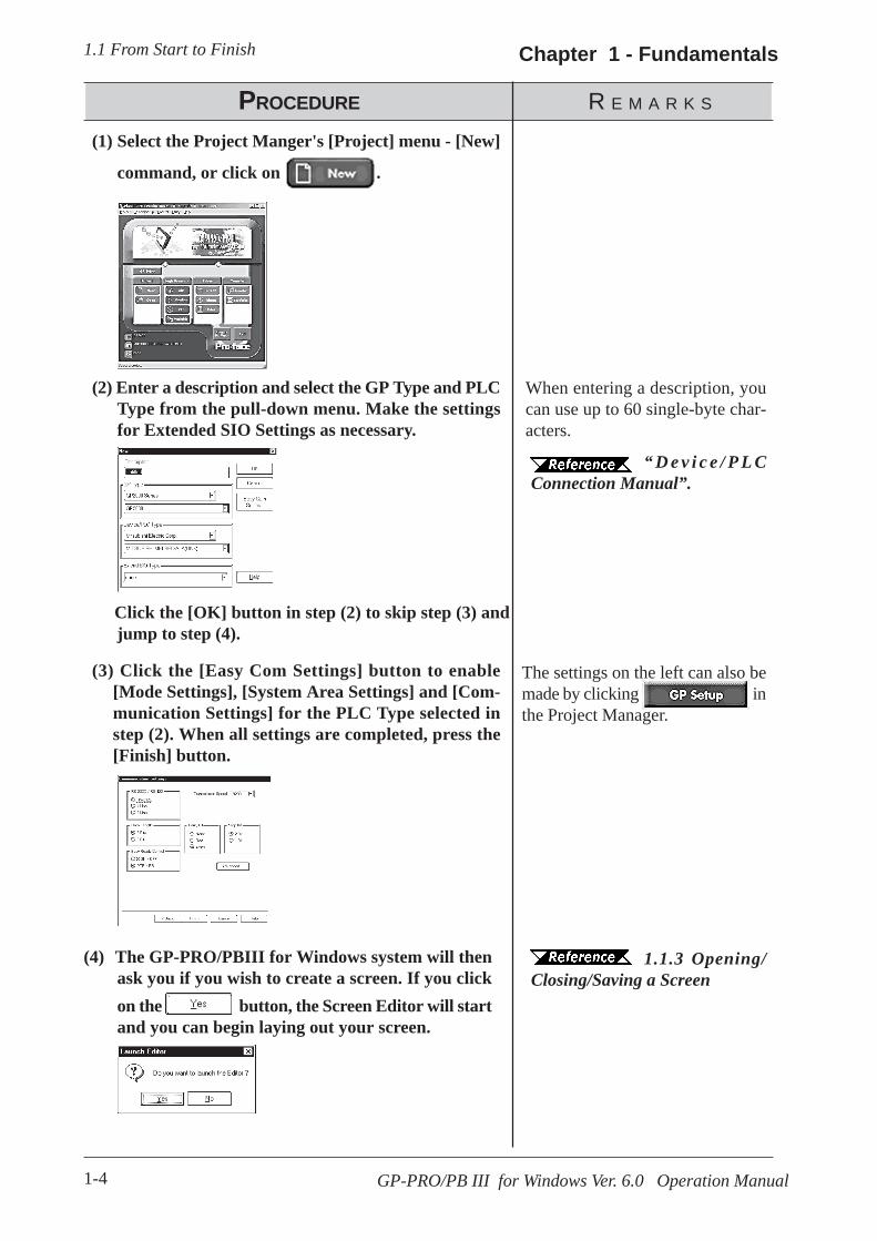
“ D e v i c e / P L CConnection Manual”.
When entering a description, youcan use up to 60 single-byte char-acters.
(3) Click the [Easy Com Settings] button to enable[Mode Settings], [System Area Settings] and [Com-munication Settings] for the PLC Type selected instep (2). When all settings are completed, press the[Finish] button.
(2) Enter a description and select the GP Type and PLCType from the pull-down menu. Make the settingsfor Extended SIO Settings as necessary.
(1) Select the Project Manger's [Project] menu - [New]
command, or click on .
(4) The GP-PRO/PBIII for Windows system will thenask you if you wish to create a screen. If you clickon the button, the Screen Editor will startand you can begin laying out your screen.
Click the [OK] button in step (2) to skip step (3) andjump to step (4).
The settings on the left can also bemade by clicking inthe Project Manager.
1.1.3 Opening/Closing/Saving a Screen
GP-PRO/PB III for Windows Ver. 6.0 Operation Manual 1-5
1.1 From Start to FinishChapter 1 - Fundamentals
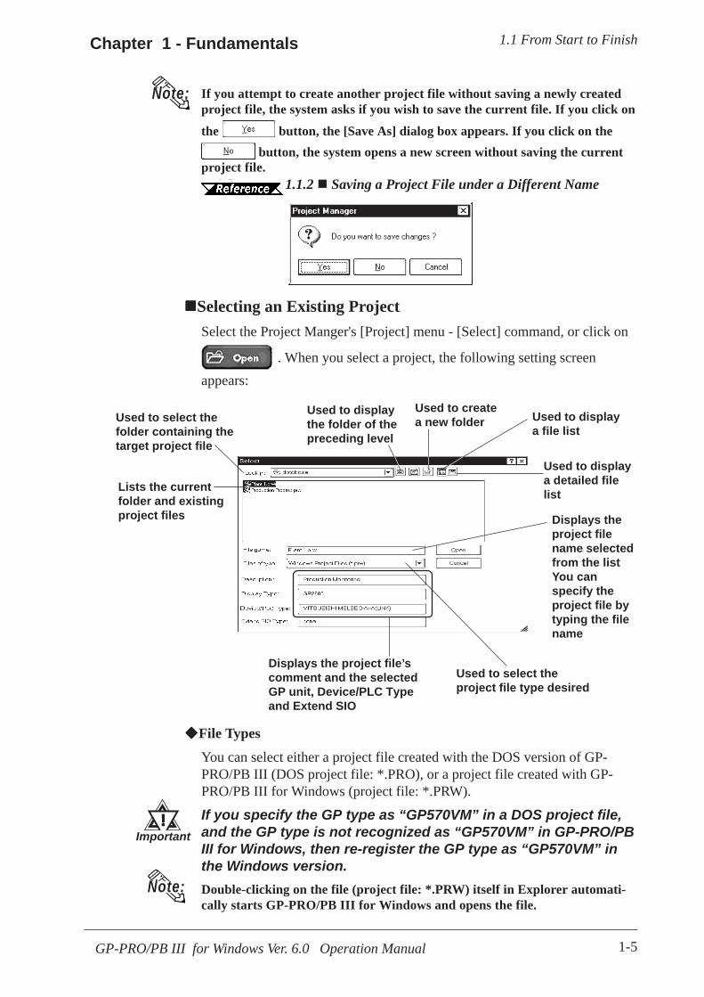
Used to select thefolder containing thetarget project file
Used to select theproject file type desired
Displays the project file’scomment and the selectedGP unit, Device/PLC Typeand Extend SIO
Displays theproject filename selectedfrom the listYou canspecify theproject file bytyping the filename
Used to displaya detailed filelist
Used to displaya file list
Used to createa new folder
Used to displaythe folder of thepreceding level
Lists the currentfolder and existingproject files
File Types
You can select either a project file created with the DOS version of GP-PRO/PB III (DOS project file: *.PRO), or a project file created with GP-PRO/PB III for Windows (project file: *.PRW).
If you specify the GP type as “GP570VM” in a DOS project file,and the GP type is not recognized as “GP570VM” in GP-PRO/PBIII for Windows, then re-register the GP type as “GP570VM” inthe Windows version.Double-clicking on the file (project file: *.PRW) itself in Explorer automati-cally starts GP-PRO/PB III for Windows and opens the file.
Selecting an Existing ProjectSelect the Project Manger's [Project] menu - [Select] command, or click on
. When you select a project, the following setting screenappears:
!!!!!Important
If you attempt to create another project file without saving a newly createdproject file, the system asks if you wish to save the current file. If you click on
the button, the [Save As] dialog box appears. If you click on the button, the system opens a new screen without saving the current
project file.
1.1.2 1.1.2 Saving a Project File under a Different Name
Note:
Note:
GP-PRO/PB III for Windows Ver. 6.0 Operation Manual1-6
Chapter 1 - Fundamentals1.1 From Start to Finish
PROCEDURE R E M A R K S
Select “Factory A”
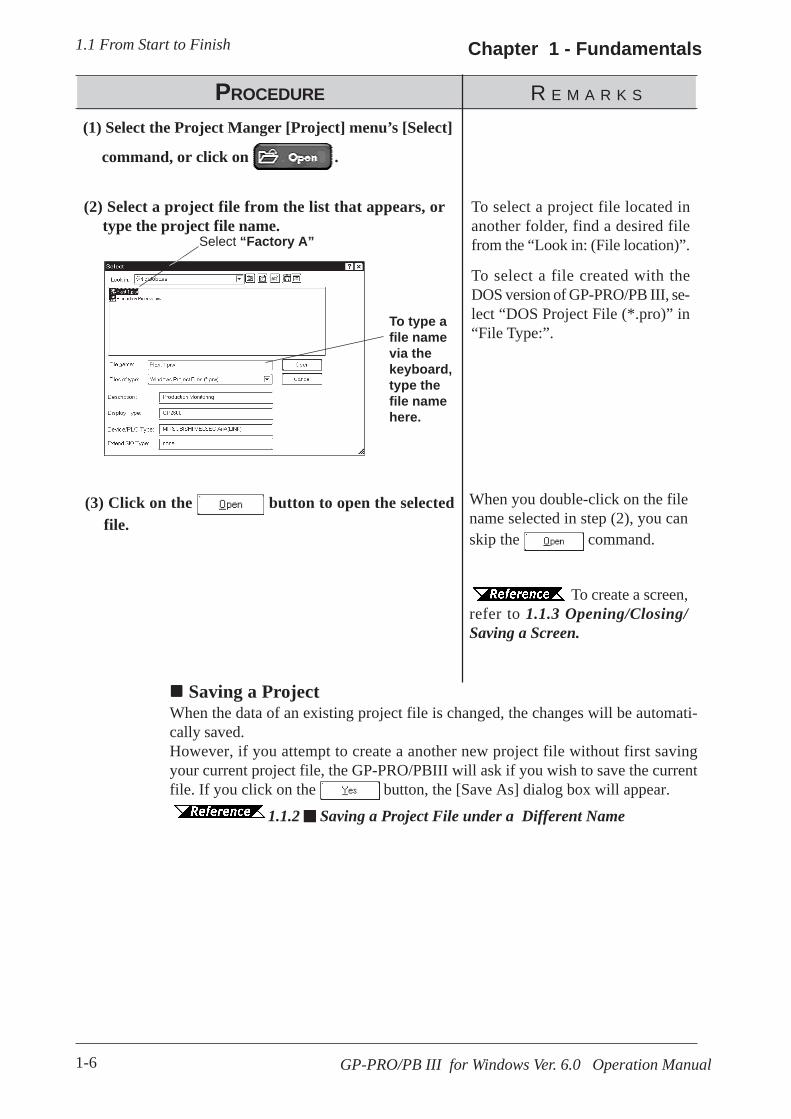
When you double-click on the filename selected in step (2), you canskip the command.
To create a screen,refer to 1.1.3 Opening/Closing/Saving a Screen.
To select a project file located inanother folder, find a desired filefrom the “Look in: (File location)”.
To select a file created with theDOS version of GP-PRO/PB III, se-lect “DOS Project File (*.pro)” in“File Type:”.
(3) Click on the button to open the selectedfile.
(2) Select a project file from the list that appears, ortype the project file name.
(1) Select the Project Manger [Project] menu’s [Select]
command, or click on .
To type afile namevia thekeyboard,type thefile namehere.
Saving a ProjectWhen the data of an existing project file is changed, the changes will be automati-cally saved.However, if you attempt to create a another new project file without first savingyour current project file, the GP-PRO/PBIII will ask if you wish to save the currentfile. If you click on the button, the [Save As] dialog box will appear.
1.1.2 Saving a Project File under a Different Name

GP-PRO/PB III for Windows Ver. 6.0 Operation Manual 1-7
1.1 From Start to FinishChapter 1 - Fundamentals
PROCEDURE R E M A R K S
The file name can contain up to 255characters (including the path-nameand extension.)
Before changing the GPtype, check the preset data,since the drawing area andfunctions vary depending onthe type of the GP unit.
4.2.5 Changing aProject’s GP Type
Once the Device/PLC type ischanged, you must changethe addresses of the Parts,Tags, D-Scripts and alarms,and perform the GP systemsetup again.
4.2.6 ChangingYour Project’s Device/PLC type
(2) The comment, GP type, Device/PLC type and Ex-tend SIO of the currently opened project file are dis-played.
Enter the desired file name, and enter the items to bechanged.
(1) Select the [Project ] menu - [Save As ] command inthe Project Manager.
To open anotherproject file, see “1.1.2 Creatinga New Project or Selecting anExisting Project”.
To c lose GP-PRO/PBIII for Windows, see“1.1.4 Quitting GP-PRO/PBIIIfor Windows”.
(3) Click on the button to save the file.
If a project file with the same name exists, GP-PRO/PBIII will ask if you want to replace (overwrite) the ex-isting project file with the project file you are attempt-ing to save.
If so, click on the button. If you do not wish tooverwrite the existing project file, click on the button.
Saving a Project File under a Different NameYou can save an existing project file under a different name or with different GPtype, Device/PLC type and Exend SIO settings.
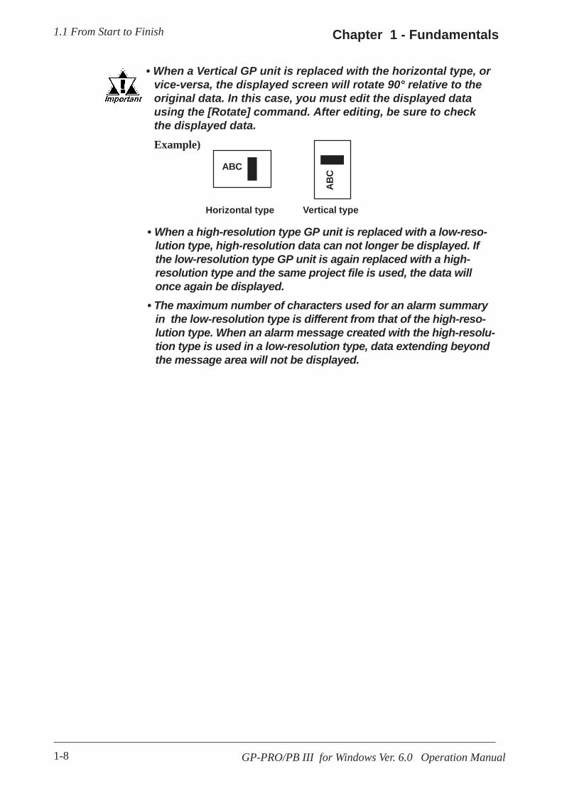
GP-PRO/PB III for Windows Ver. 6.0 Operation Manual1-8
Chapter 1 - Fundamentals1.1 From Start to Finish
Horizontal type
ABC
ABC
Vertical type
• When a high-resolution type GP unit is replaced with a low-reso-lution type, high-resolution data can not longer be displayed. Ifthe low-resolution type GP unit is again replaced with a high-resolution type and the same project file is used, the data willonce again be displayed.
• The maximum number of characters used for an alarm summaryin the low-resolution type is different from that of the high-reso-lution type. When an alarm message created with the high-resolu-tion type is used in a low-resolution type, data extending beyondthe message area will not be displayed.
• When a Vertical GP unit is replaced with the horizontal type, orvice-versa, the displayed screen will rotate 90° relative to theoriginal data. In this case, you must edit the displayed datausing the [Rotate] command. After editing, be sure to checkthe displayed data.Example)
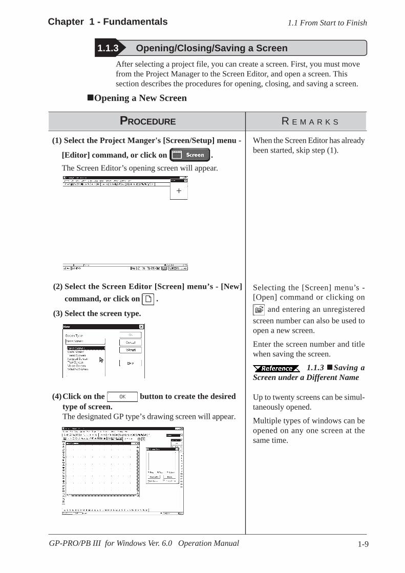
1-9GP-PRO/PB III for Windows Ver. 6.0 Operation Manual
Chapter 1 - Fundamentals 1.1 From Start to Finish
After selecting a project file, you can create a screen. First, you must movefrom the Project Manager to the Screen Editor, and open a screen. Thissection describes the procedures for opening, closing, and saving a screen.
Opening a New Screen
1.1.3 Opening/Closing/Saving a Screen
PROCEDURE R E M A R K S
Selecting the [Screen] menu’s -[Open] command or clicking on
and entering an unregisteredscreen number can also be used toopen a new screen.
When the Screen Editor has alreadybeen started, skip step (1).
(2) Select the Screen Editor [Screen] menu’s - [New]command, or click on .
(1) Select the Project Manger's [Screen/Setup] menu -
[Editor] command, or click on .The Screen Editor’s opening screen will appear.
Enter the screen number and titlewhen saving the screen.
1.1.3 Saving aScreen under a Different Name
(3) Select the screen type.
Up to twenty screens can be simul-taneously opened.
Multiple types of windows can beopened on any one screen at thesame time.
(4)Click on the button to create the desiredtype of screen.The designated GP type’s drawing screen will appear.

1-10
Chapter 1 - Fundamentals
GP-PRO/PB III for Windows Ver. 6.0 Operation Manual
1.1 From Start to Finish
Opening a Previously Saved Screen
PROCEDURE R E M A R K S
When you double-click on the de-sired screen number in step (3), youcan skip the operation of the
button.
If you enter a screen number thathas not been registered in the list, anew screen will be opened and thatnumber will be assigned to it.
When selecting multiple screens, ascreen with the smallest screennumber of them will be displayed.
When the Screen Editor has alreadybeen started, skip step (1).
(1) Select the [Screen/Setup] menu’s - [Editor] com-mand, or click on in the Project Man-ager.
The Screen Editor’s opening screen will appear.
(2) Select the [Screen] menu’s - [Open] command orclick on .
(3) Use this screen to select a screen name from the list,or select the screen type and enter the screen number.
When checking the [Preview] check box, the selectedscreen image can be viewed in the dialog box.
Preview Check Box
Place a check mark inthe [Preview] box.
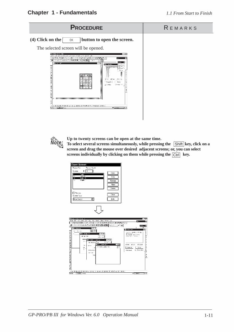
1-11GP-PRO/PB III for Windows Ver. 6.0 Operation Manual
Chapter 1 - Fundamentals 1.1 From Start to Finish
(4) Click on the button to open the screen.
The selected screen will be opened.
Up to twenty screens can be open at the same time.To select several screens simultaneously, while pressing the key, click on ascreen and drag the mouse over desired adjacent screens; or, you can selectscreens individually by clicking on them while pressing the key.
Note: Shift
Ctrl
PROCEDURE R E M A R K S
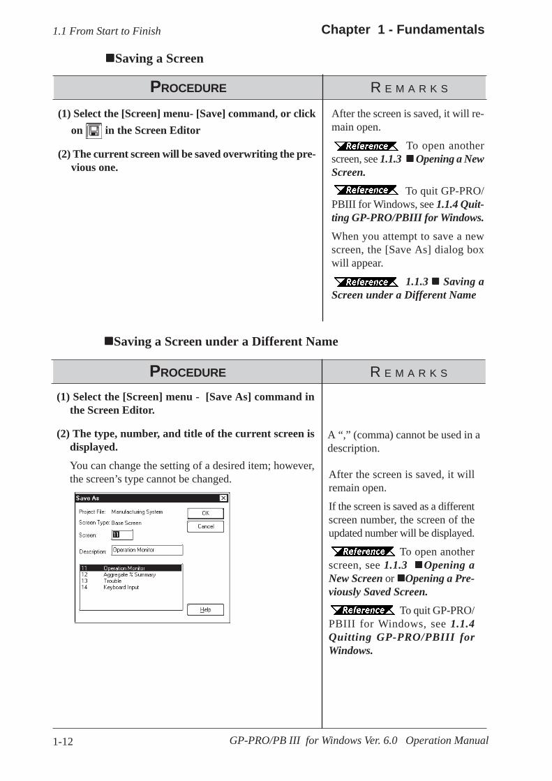
1-12
Chapter 1 - Fundamentals
GP-PRO/PB III for Windows Ver. 6.0 Operation Manual
1.1 From Start to Finish
Saving a Screen
PROCEDURE R E M A R K S
After the screen is saved, it will re-main open.
To open anotherscreen, see 1.1.3 Opening a NewScreen.
To quit GP-PRO/PBIII for Windows, see 1.1.4 Quit-ting GP-PRO/PBIII for Windows.When you attempt to save a newscreen, the [Save As] dialog boxwill appear.
1.1.3 Saving aScreen under a Different Name
(2) The current screen will be saved overwriting the pre-vious one.
(1) Select the [Screen] menu- [Save] command, or clickon in the Screen Editor
Saving a Screen under a Different Name
PROCEDURE R E M A R K S
A “,” (comma) cannot be used in adescription.
After the screen is saved, it willremain open.
If the screen is saved as a differentscreen number, the screen of theupdated number will be displayed.
To open anotherscreen, see 1.1.3 Opening aNew Screen or Opening a Pre-viously Saved Screen.
To quit GP-PRO/PBIII for Windows, see 1.1.4Quitting GP-PRO/PBIII forWindows.
(2) The type, number, and title of the current screen isdisplayed.
You can change the setting of a desired item; however,the screen’s type cannot be changed.
(1) Select the [Screen] menu - [Save As] command inthe Screen Editor.
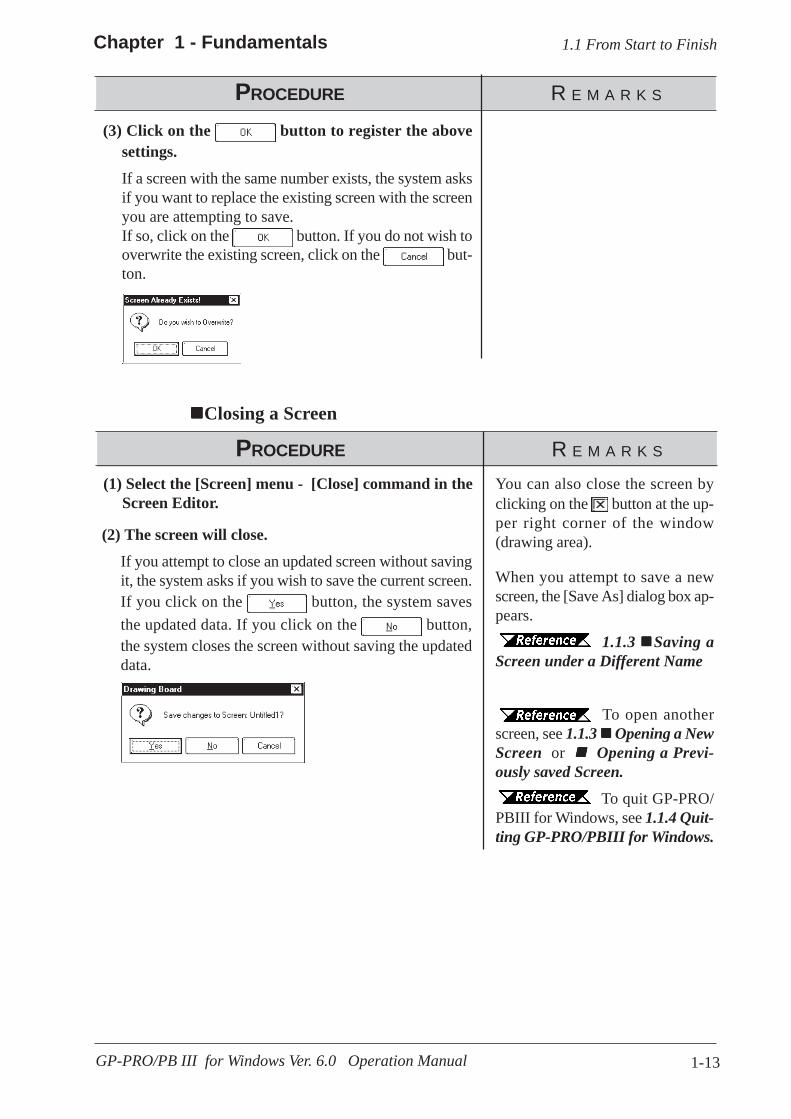
1-13GP-PRO/PB III for Windows Ver. 6.0 Operation Manual
Chapter 1 - Fundamentals 1.1 From Start to Finish
PROCEDURE R E M A R K S
(3) Click on the button to register the abovesettings.
If a screen with the same number exists, the system asksif you want to replace the existing screen with the screenyou are attempting to save.If so, click on the button. If you do not wish tooverwrite the existing screen, click on the but-ton.
Closing a Screen
PROCEDURE R E M A R K S
When you attempt to save a newscreen, the [Save As] dialog box ap-pears.
1.1.3 Saving aScreen under a Different Name
To open anotherscreen, see 1.1.3 Opening a NewScreen or Opening a Previ-ously saved Screen.
To quit GP-PRO/PBIII for Windows, see 1.1.4 Quit-ting GP-PRO/PBIII for Windows.
You can also close the screen byclicking on the button at the up-per right corner of the window(drawing area).(2) The screen will close.
If you attempt to close an updated screen without savingit, the system asks if you wish to save the current screen.If you click on the button, the system savesthe updated data. If you click on the button,the system closes the screen without saving the updateddata.
(1) Select the [Screen] menu - [Close] command in theScreen Editor.
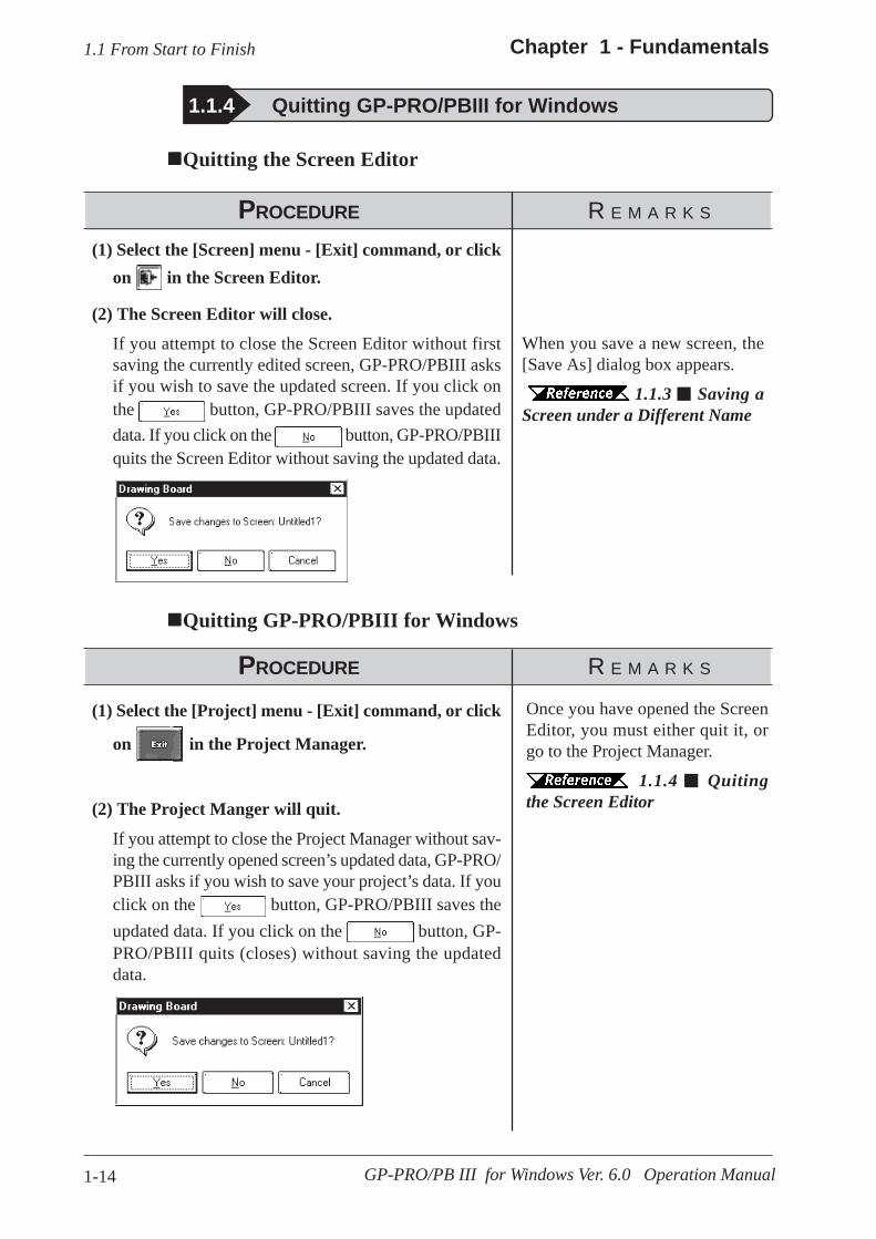
1-14
Chapter 1 - Fundamentals
GP-PRO/PB III for Windows Ver. 6.0 Operation Manual
1.1 From Start to Finish
Once you have opened the ScreenEditor, you must either quit it, orgo to the Project Manager.
1.1.4 Quitingthe Screen Editor
Quitting GP-PRO/PBIII for Windows
PROCEDURE R E M A R K S
(2) The Project Manger will quit.
If you attempt to close the Project Manager without sav-ing the currently opened screen’s updated data, GP-PRO/PBIII asks if you wish to save your project’s data. If youclick on the button, GP-PRO/PBIII saves theupdated data. If you click on the button, GP-PRO/PBIII quits (closes) without saving the updateddata.
(1) Select the [Project] menu - [Exit] command, or click
on in the Project Manager.
Quitting the Screen Editor
1.1.4 Quitting GP-PRO/PBIII for Windows
PROCEDURE R E M A R K S
When you save a new screen, the[Save As] dialog box appears.
1.1.3 Saving aScreen under a Different Name
(2) The Screen Editor will close.
If you attempt to close the Screen Editor without firstsaving the currently edited screen, GP-PRO/PBIII asksif you wish to save the updated screen. If you click onthe button, GP-PRO/PBIII saves the updateddata. If you click on the button, GP-PRO/PBIIIquits the Screen Editor without saving the updated data.
(1) Select the [Screen] menu - [Exit] command, or clickon in the Screen Editor.
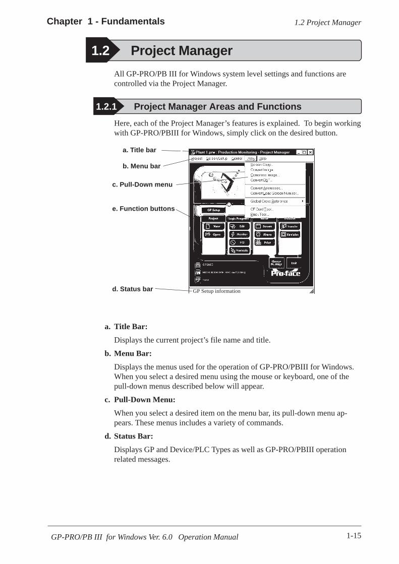
1-15GP-PRO/PB III for Windows Ver. 6.0 Operation Manual
1.2 Project ManagerChapter 1 - Fundamentals
All GP-PRO/PB III for Windows system level settings and functions arecontrolled via the Project Manager.
1.2 Project Manager
1.2.1 Project Manager Areas and Functions
c. Pull-Down menu
e. Function buttons
d. Status bar
a. Title bar
b. Menu bar
a. Title Bar:
Displays the current project’s file name and title.
b. Menu Bar:
Displays the menus used for the operation of GP-PRO/PBIII for Windows.When you select a desired menu using the mouse or keyboard, one of thepull-down menus described below will appear.
c. Pull-Down Menu:
When you select a desired item on the menu bar, its pull-down menu ap-pears. These menus includes a variety of commands.
d. Status Bar:
Displays GP and Device/PLC Types as well as GP-PRO/PBIII operationrelated messages.
Here, each of the Project Manager’s features is explained. To begin workingwith GP-PRO/PBIII for Windows, simply click on the desired button.
GP Setup information

1-16
Chapter 1 - Fundamentals
GP-PRO/PB III for Windows Ver. 6.0 Operation Manual
1.2 Project Manager
Selects an existingproject
Creates a new project
Creates AlarmEditor alarms
Switches the Project Managerto Hierarchical (Explorer-like)Display mode
Chapter 11 PROJECTMANAGER HIERARCHICALDISPLAY
Performs GP InitialSettings
Creates or modifies screendata via the Screen Editor
Quits the GP-PRO/PBIII for Windowsprogram
Prints out ScreenEditor screens
e. Function Buttons
These buttons indicate the GP-PRO/PB III for Windows program’s mainfunctions (e.g. Creating Screens/alarm, Printing). You can start each func-tion by simply clicking on that function’s button. You can also start thesefunctions by selecting the corresponding command from the ProjectManager’s pull-down menu.
Performs Simula-tion with the GPunit
Switches toPro-Control Editor(GP-PRO/PB III C-Package01 only)
Pro-Control EditorOperation Manual
Transmits screenand GP systemsetting data to theGP unit
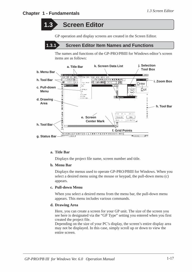
1-17GP-PRO/PB III for Windows Ver. 6.0 Operation Manual
1.3 Screen EditorChapter 1 - Fundamentals
1.3 Screen Editor
1.3.1 Screen Editor Item Names and Functions
g. Status Bar
a. Title Bar
c. Pull-downMenu
j. SelectionTool Box
i. Zoom Box
k. Screen Data List
d. DrawingArea
e. Screen Center Mark
f. Grid Points
a. Title Bar
Displays the project file name, screen number and title.
b. Menu Bar
Displays the menus used to operate GP-PRO/PBIII for Windows. When youselect a desired menu using the mouse or keypad, the pull-down menu (c)appears.
c. Pull-down Menu
When you select a desired menu from the menu bar, the pull-down menuappears. This menu includes various commands.
d. Drawing AreaHere, you can create a screen for your GP unit. The size of the screen yousee here is designated via the “GP Type” setting you entered when you firstcreated the project file.Depending on the size of your PC’s display, the screen’s entire display areamay not be displayed. In this case, simply scroll up or down to view theentire screen.
The names and functions of the GP-PRO/PBIII for Windows editor’s screenitems are as follows:
GP operation and display screens are created in the Screen Editor.
b. Menu Bar
h. Tool Bar
h. Tool Bar
h. Tool Bar

1-18
Chapter 1 - Fundamentals
GP-PRO/PB III for Windows Ver. 6.0 Operation Manual
1.3 Screen Editor
h. Tool Bar
The Tool Bar provides easy to use icons for drawing and editing. Clickingon one of these icons performs that command. The Tool Bar can either behidden or displayed, and individual Tool Bar areas can be moved freelyaround the Screen Editor screen, i.e. top, bottom, left, or right.
The following Tool Bar areas are available:
Main Tool BarEdit Tool BarDraw Tool BarOption Tool BarGrid/Snap Tool BarTag Tool BarParts Tool BarParts State Change Tool Bar
i. Zoom Box
Shows the cursor’s current position at three times magnification.
j. Selection Tool Box
Used to select objects to be edited (Parts, Tags and figures). Using thecommands included in this tool box, you can select objects using a varietyof methods.
k. Screen Data ListLists the settings and layout conditions of the objects (Parts, Tags andfigures) that have been arranged on the screen. You can select a desiredobject from the list.
2.8.4 Screen Data List
Amount of Screenmemory currentlyused (Ratio of usedscreen area to entirescreen)
Coordinatesof currentmouseposition
Description of thecurrently selectedcommand
Project’sDevice/PLC Type
Display area’smagnification/reduction ratio
e. Screen Center MarkIndicates the center of the screen. This mark is not displayed when the datais sent to the GP unit.
f. Grid PointsUsed as reference points when you draw or paste an object in the drawingmode. Grid points will not be displayed on the GP unit’s screen. The Optionarea’s “Snap” function allows you to position your screen objects using apre-made grid. You can also set the interval and display ON/OFF status ofthe grid points.
2.8.1 Grid/Snapg. Status Bar
Displays information related to the current screen and provides messagesexplaining the screen operation you are currently performing.

1-19GP-PRO/PB III for Windows Ver. 6.0 Operation Manual
1.3 Screen EditorChapter 1 - Fundamentals
Zoom out: Used to reduce the current display area to 50%.
Zoom in: Used to enlarge the current display area to 200%.In the [50%] display mode, the created screen data is reduced. In this case,the displayed screen data may be different from the actual data. We recom-mend you to use a [100%] or larger display area.
1.3.2 Display Area (50%, 100%, 200%)
Zoom out Zoom in
Note:
You can enlarge or reduce the drawing area by selecting a magnification/reduction ratio.To change the display area, select the or icon on the tool bar, orselect the [50%], [100%], or [200%] command from the [View] menu.
1.3.3 Tool/Icon DisplayThe Tag tool box, Parts tool box, tool bar, and status bar can be designatedas either shown (displayed) or not shown (not displayed). Each time youselect the [View] menu's [Screen Data Box], [Status Bar], or [Zoom Box],as well as the [Tool Bar] command's [Main], [Edit], [Draw], [Option],[Grid/Snap], [Tag], [Parts], [Parts State Change] or [String Table] sub-commands, these View/Hide settings will toggle ON or OFF.
1-20
Chapter 1 - Fundamentals
GP-PRO/PB III for Windows Ver. 6.0 Operation Manual
1.4 GP-PRO/PBIII Manuals and Help
1.4 GP-PRO/PB III Manuals and Help
Using the Help FeatureIf you have any problems or questions during GP-PRO/PB III for Windowsoperation, you can view the explanations for each feature and setting viaeach window’s Help button, or from the main menu’s Help feature.
Using the Home PageUsers can obtain the latest GP-PRO/PBIII for Windows information byaccessing the Digital Electronics Corporation Home Page at “GP-PRO/PBIIIfor Windows Members Club”.
CD JacketDescribes the system requirements, installation proceduresfor GP-PRO/PB III, and the method for reading the manualsin PDF format.
Operation Manual(This manual) Provides detailed program operation information.
Tag Reference Manual Provides detailed descriptions of this software's special andadvanced functions.
Parts List Lists all the pre-made Parts included in the GP-PRO/PB IIIfor Windows software.
Device/PLC ConnectionManual
Describes connection methods used between the GP andthe host (PLC), as well as the necessary operatingenvironment settings.
While you are learning how to use the GP-PRO/PBIII for Windows soft-ware, please refer to the following learning aids:
· Related User Manuals· On-line Help Topics· Digital’s Home Page· Power GP Q&A
For the help concerning the operation of the Windows operating system, seethe Windows software’s manuals and help screens.
Using GP-PRO/PBIII for Windows ManualsThe following manuals have been created for the GP-PRO/PB III for Win-dows software.

1-21GP-PRO/PB III for Windows Ver. 6.0 Operation Manual
1.4 GP-PRO/PBIII Manuals and HelpChapter 1 - Fundamentals
To display the help screen, select the [Help] menu or click on the button in the dialog box.
· When multiple screens are loaded or many Tags and Parts havebeen registered on the screens, the PC’s system memory maynot be sufficient to display the help screen.
· If you jump from one topic to another on the help screen, anerror message may be displayed. When this happens, simplyquit and then re-start help.
Searching for a Topic and then Display HelpSelect the [Help Topics] command from the [Help] menu, or press the [F1]key. A list of help topics will be displayed.
You can search for a topic by either trying to find it from the table of con-tents, or entering a keyword for that topic.
1.4.1 Browsing Help Topics
Searching for a Topic from the Contents Menu
To select a topic from the contents menu, double-click on the [Contents] tab.Follow the screen instructions to search for a desired topic.

1-22
Chapter 1 - Fundamentals
GP-PRO/PB III for Windows Ver. 6.0 Operation Manual
1.4 GP-PRO/PBIII Manuals and Help
Calling up Help from a Dialog BoxWhen you click on the button in the dialog box or press the [F1]key during execution of a command, a description of the currently-executedcommand will be displayed.
Searching for a Topic by a Keyword
To enter a keyword, click on the [Index] tab.Search for a desired topic according to the instruction indicated on thescreen.(When you enter initial characters of the keyword, the topics specified withthese initial characters are also automatically listed)
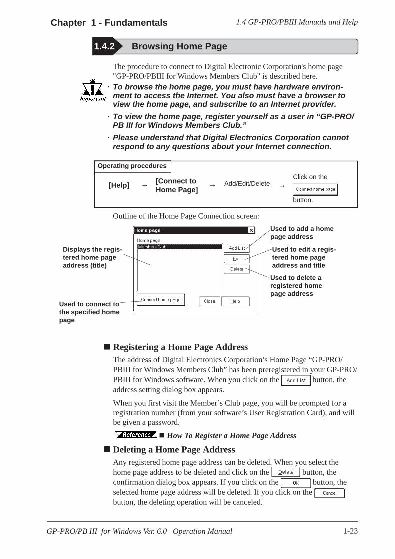
1-23GP-PRO/PB III for Windows Ver. 6.0 Operation Manual
1.4 GP-PRO/PBIII Manuals and HelpChapter 1 - Fundamentals
The procedure to connect to Digital Electronic Corporation's home page"GP-PRO/PBIII for Windows Members Club" is described here.
· To browse the home page, you must have hardware environ-ment to access the Internet. You also must have a browser toview the home page, and subscribe to an Internet provider.
· To view the home page, register yourself as a user in “GP-PRO/PB III for Windows Members Club.”
· Please understand that Digital Electronics Corporation cannotrespond to any questions about your Internet connection.
Registering a Home Page AddressThe address of Digital Electronics Corporation’s Home Page “GP-PRO/PBIII for Windows Members Club” has been preregistered in your GP-PRO/PBIII for Windows software. When you click on the button, theaddress setting dialog box appears.
When you first visit the Member’s Club page, you will be prompted for aregistration number (from your software’s User Registration Card), and willbe given a password.
How To Register a Home Page Address
Deleting a Home Page AddressAny registered home page address can be deleted. When you select thehome page address to be deleted and click on the button, theconfirmation dialog box appears. If you click on the button, theselected home page address will be deleted. If you click on the button, the deleting operation will be canceled.
1.4.2 Browsing Home Page
Used to delete aregistered homepage address
Used to edit a regis-tered home pageaddress and title
Used to add a homepage address
Used to connect tothe specified homepage
Displays the regis-tered home pageaddress (title)
[Help]
Operating proceduresClick on the
button.
Add/Edit/Delete[Connect toHome Page]
→ → →
Outline of the Home Page Connection screen:

1-24
Chapter 1 - Fundamentals
GP-PRO/PB III for Windows Ver. 6.0 Operation Manual
1.4 GP-PRO/PBIII Manuals and Help
Editing a Home Page AddressThe registered home page address or title can be changed. When you select the homepage address to be edited and click on the button, the address setting dialogbox appears (same as for the home page addition procedure), enabling you to changethe title and address of the home page. If Digital Electronics Corporation’s homepage address is changed in the future, please edit the currently registered address.
Connecting to the Home Page
PROCEDURE R E M A R K S
(1) Select the [Help] menu - [Connect to Home Page]command in the Project Manager.
(3) Click on the button to start connection.The browser is started, and you will be connected to thehome page.
(2) Select the target home page address.

1-25GP-PRO/PB III for Windows Ver. 6.0 Operation Manual
1.4 GP-PRO/PBIII Manuals and HelpChapter 1 - Fundamentals
(3) Enter a home page title and address to be registeredand click on .
The specified home page address will be registered.
How To Register a Home Page Address
(2) Click on the button.
(1) Select the [Help] menu - [Connect to Home Page]command in the Project Manager.
PROCEDURE R E M A R K S

1-26
Chapter 1 - Fundamentals
GP-PRO/PB III for Windows Ver. 6.0 Operation Manual
1.4 GP-PRO/PBIII Manuals and Help
Memo
2-1GP-PRO/PB III for Windows Ver. 6.0 Operation Manual
o create Base screens, the Editor area’s Part, Draw, Tag, and Menu Barcommands can all be used. Also, Edit commands can be used tomodify any Parts, objects or Tags that you have created. In addition to
editing these screen objects, the procedures for registering Library Items andWindows are also explained.
T
2 CREATING BASE SCREENS
2.1 ................................................................................ Parts
2.2 .......................................................................... Drawing
2.3 ................................................................................. Tags
2.4 ................................................................ Object Editing
2.5 ......................................................................... Libraries
2.6 .............................................. D-Script/Global D-Script
2.7 ............................................................... Data Sampling
2.8 ...................................... Efficient Drawing Techniques
2.9 .................................. Creating Handy-type GP Screen
2.10 ............................................................ DXF Conversion

2.1 Parts Chapter 2 - Base Screens
2-2 GP-PRO/PB III for Windows Ver. 6.0 Operation Manual
Icon Name Function Reference
Bit Switch Used to change a PLC’s Bit Address data. 2.1.1 Bit Switches
WordSwitch Changes a PLC’s Word Address data. 2.1.2 Word Switches
FunctionSwitch
Used to go back to the previous screen, toswitch screens, and to reset the GP.
2.1.3 Function
ToggleSwitch Turns the PLC’s Bit Address ON or OFF. 2.1.4 Toggle
LampTurns ON or OFF according to the PLC’sMonitor Bit.
2.1.5 Lamps
4-StateLamp
Switches the 4 states of the lamp,according to whether the PLC’s twoMonitor Bits are ON or OFF.
2.1.6 4-State Lamps
Bar GraphDisplays the PLC’s Word Address data in abar graph.
2.1.7 Bar Graphs
Pie GraphDisplays the PLC’s Word Address data in apie graph.
2.1.8 Pie Graphs
Half PieGraph
Displays the PLC’s Word Address data in aHalf-Pie graph.
2.1.9 Half Pie Graphs
TankGraph
Displays the PLC’s Word Address data asabsolute values in a Tank graph.
2.1.10 Tank Graphs
MeterDisplays the PLC’s Word Address data aMeter.
2.1.11 Meters
TrendGraph
Displays the PLC’s Word Address data asabsolute values in a trend graph.
2.1.12 T rend Graphs
Keypad Used to enter a PLC’s Word Address data. 2.1.13 Keypads
KeypadInput
DisplayDisplays data input via the keypad. 2.1.14 Keypad Display
2.1 Parts
GP-PRO/PBIII for Windows Part Type List
Each Part’s attributes such as setting Addresses and colors will be desig-nated via the dialog box. After designating all the necessary Part attributes,decide their position and size on the object drawing area.
The [Parts] menu’s commands are effective only on Base screens. Usage Pattern
Place iton theScreen
Specify itsAttributes
Select the specificPart from theBrowser
Decide ona type ofPart
[Parts] →→→→→ →→→→→ →→→→→ →→→→→
Select a desired icon from the Parts Tool Bar.or

2.1 PartsChapter 2 - Base Screens
2-3GP-PRO/PB III for Windows Ver. 6.0 Operation Manual
Up to 20alphanumeric(single-byte)characters or10 Chinese(double-byte)characters canbe entered
Entering a CommentIf desired, a comment can be entered for a Part.
Applies thedevicecomment
Icon Name Function Reference
Alarm Display When monitored Bits are turned ON, a list of “Basic” Alarm summary messages appear that have been previously registered in the Alarm Editor.
2.1.15 Alarm Display
Filing Data Display
Displays data registered in the Filing Data list by specifying the corresponding file number.
2.1.16 File Name Display
Logging Display
Displays PLC data loaded in the data logging settings by specifying the address for the corresponding block number.
2.1.17 Data Logging Display
Numeric Display
Displays the PLC’s Word Address numeric data as an absolute value.
2.1.18 Numeric Displays
Message Display
Displays a previously registered message, according to PLC Word Address data changes. A maximum of 16 messages can be displayed in a single Message Display.
2.1.19 Message Display
Date Display Displays the current date, using the GP’s internal calendar.
2.1.20 Date Displays
Time Display Displays the current time, using the GP’s internal clock.
2.1.21 Time Displays
Picture Display
Displays a single registered Library image (only graphic data), according to PLC Word Address data changes. A maximum of 16 different Library images can be displayed in a single Picture Display. (One at a time)
2.1.22 Picture Displays
Window Parts Windows created on the Window Screen (U) can be called up on the Base Screen (B).
2.1.23 Window Parts

2.1 Parts Chapter 2 - Base Screens
2-4 GP-PRO/PB III for Windows Ver. 6.0 Operation Manual
Enter the address datahere
Reflection of a Device Comment
If you click on the [Apply Device Comment] button after entering anaddress, the device comment entered using the Symbol Editor is automati-cally searched for, and the comment corresponding to the entered deviceappears in the Description field.
4.7 Symbol Editor
Entering AddressesHere, Addresses that are operated for Parts’ functions and that are monitoredare designated.
Entering from a keyboard
Click on the address entering field, and the cursor will appear there, whichindicates data entry is now effective. Then, enter device and address data viathe keyboard.
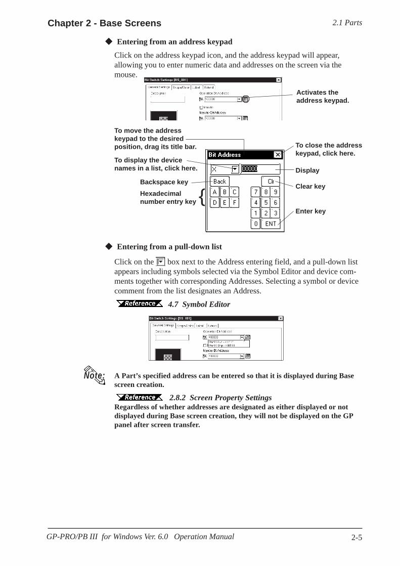
2.1 PartsChapter 2 - Base Screens
2-5GP-PRO/PB III for Windows Ver. 6.0 Operation Manual
Activates theaddress keypad.
Entering from an address keypad
Click on the address keypad icon, and the address keypad will appear,allowing you to enter numeric data and addresses on the screen via themouse.
Entering from a pull-down list
Click on the box next to the Address entering field, and a pull-down listappears including symbols selected via the Symbol Editor and device com-ments together with corresponding Addresses. Selecting a symbol or devicecomment from the list designates an Address.
4.7 Symbol Editor
A Part’s specified address can be entered so that it is displayed during Basescreen creation.
2.9.2 Screen 2.8.2 Screen Property SettingsRegardless of whether addresses are designated as either displayed or notdisplayed during Base screen creation, they will not be displayed on the GPpanel after screen transfer.
Note:
To move the addresskeypad to the desiredposition, drag its title bar.
To display the devicenames in a list, click here.
Backspace keyHexadecimalnumber entry key
Enter key
Clear key
Display
To close the addresskeypad, click here.
{
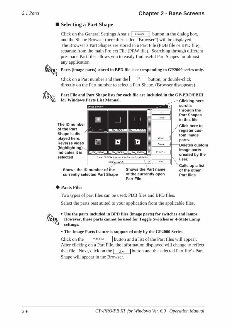
2.1 Parts Chapter 2 - Base Screens
2-6 GP-PRO/PB III for Windows Ver. 6.0 Operation Manual
Selecting a Part Shape
Click on the General Settings Area’s button in the dialog box,and the Shape Browser (hereafter called “Browser”) will be displayed.The Browser’s Part Shapes are stored in a Part File (PDB file or BPD file),separate from the main Project File (PRW file). Searching through differentpre-made Part files allows you to easily find useful Part Shapes for almostany application.Parts (image parts) stored in BPD file is corresponding to GP2000 series only.
Click on a Part number and then the button, or double-clickdirectly on the Part number to select a Part Shape. (Browser disappears)
Part File and Part Shape lists for each file are included in the GP-PRO/PBIIIfor Windows Parts List Manual.
Note:
Calls up a listof the otherPart files
Shows the Part nameof the currently openPart File
Note:
The ID numberof the PartShape is dis-played here.Reverse video(highlighting)indicates it isselected
Clicking herescrollsthrough thePart Shapesin this file
Shows the ID number of thecurrently selected Part Shape
Parts Files
Two types of part files can be used: PDB files and BPD files.
Select the parts best suited to your application from the applicable files.
Use the parts included in BPD files (image parts) for switches and lamps.However, these parts cannot be used for Toggle Switches or 4-State Lampsettings.
The Image Parts feature is supported only by the GP2000 Series.
Click on the button and a list of the Part files will appear.After clicking on a Part File, the information displayed will change to reflectthat file. Next, click on the button and the selected Part file’s PartShape will appear in the Browser.
Click here toregister cus-tom imageparts.Deletes customimage partscreated by theuser.
Note:

2.1 PartsChapter 2 - Base Screens
2-7GP-PRO/PB III for Windows Ver. 6.0 Operation Manual
Displays filenames and details
Displays filenames insummaryform
Shows thecurrentlyopen folder
Moves to the next higherfile directory level Creates a
new folder
Shows thecurrentlyselectedPart file’scomment
Lists thenames of allthe Partfiles in thisfolder
<Differences between the PDB File and BPD File>
The BPD file is located in the [imageparts] folder in the [PDB] folder.
Part files (PDB File/BPD File) are automatically installed in a folder named"PDB" when GP-PRO/PB III is first installed. If desired, these files can beinstalled in other folders instead. To display part shapes located in otherfolders, use the [Look in:] area to switch to the applicable folder.
Note:
PreprogrammedFile
Registration/Deletion by Users
Color S ettingAdjustment
PDB m X mBPD m m*1 X
*1: A preprogrammed BPD File cannot be registered or deleted.
Shows the name of the currentlyselected Part file. A name can alsobe entered here to select a file.
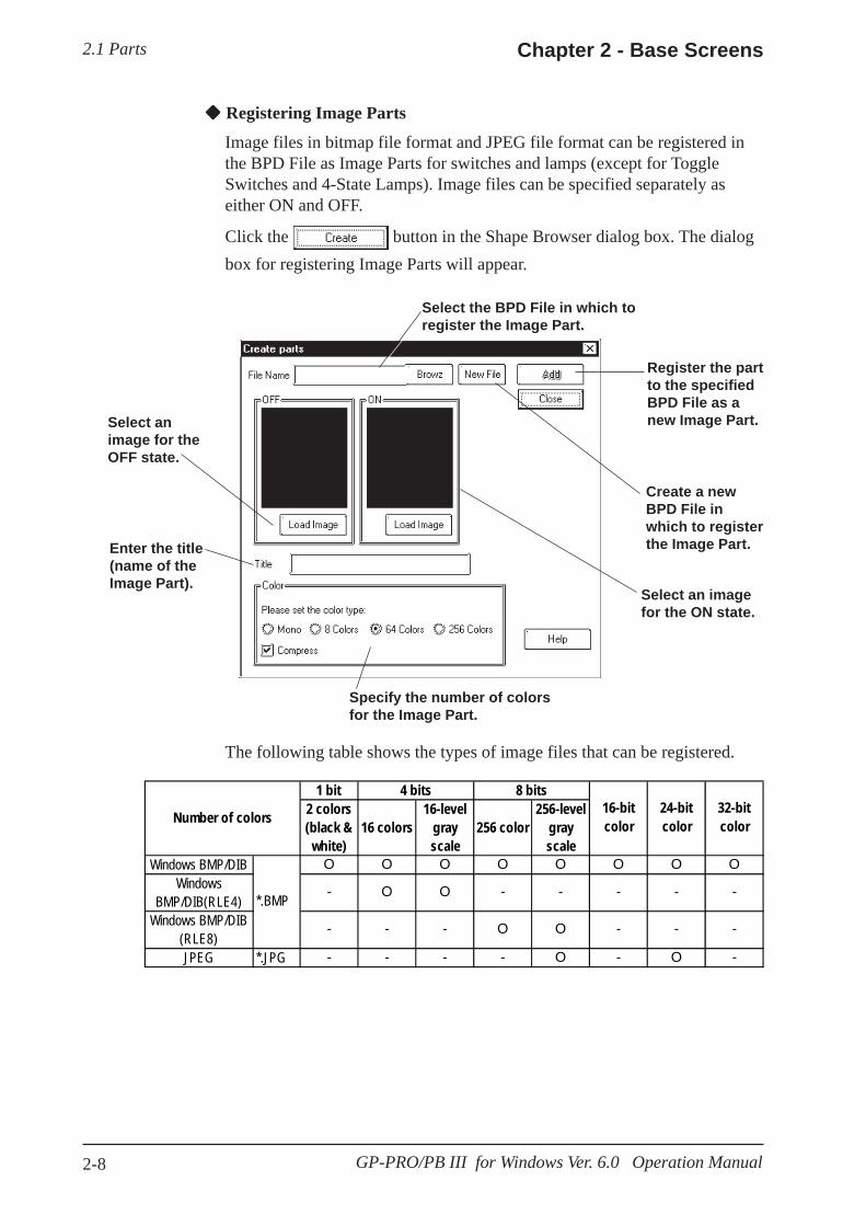
2.1 Parts Chapter 2 - Base Screens
2-8 GP-PRO/PB III for Windows Ver. 6.0 Operation Manual
Registering Image Parts
Image files in bitmap file format and JPEG file format can be registered inthe BPD File as Image Parts for switches and lamps (except for ToggleSwitches and 4-State Lamps). Image files can be specified separately aseither ON and OFF.
Click the button in the Shape Browser dialog box. The dialogbox for registering Image Parts will appear.
Select the BPD File in which toregister the Image Part.
Create a newBPD File inwhich to registerthe Image Part.
Select an imagefor the ON state.
Specify the number of colorsfor the Image Part.
Enter the title(name of theImage Part).
Select animage for theOFF state.
Register the partto the specifiedBPD File as anew Image Part.
The following table shows the types of image files that can be registered.
1 bit2 colors(black &
white)16 colors
16-levelgrayscale
256 color256-level
grayscale
Windows BMP/DIB O O O O O O O OWindows
BMP/DIB(RLE4)- O O - - - - -
Windows BMP/DIB(RLE8)
- - - O O - - -
JPEG *.JPG - - - - O - O -
*.BMP
16-bitcolor
24-bitcolor
32-bitcolor
4 bits 8 bits
Number of colors

2.1 PartsChapter 2 - Base Screens
2-9GP-PRO/PB III for Windows Ver. 6.0 Operation Manual
Image Parts can be registered to a maximum size of 160 x 160 (dots).
Image Parts will increase the size of the Project file. We recommendenabling the "Compress" setting in "Color" settings.
Up to 200 Image Parts can be registered in a single BPD File.
Before registering the Image Part, select image files for both ON and OFFstates.
When the sizes of the images for the ON and OFF states differ, the smaller image is magnified to equal the size of the larger image.
Image Parts that are zoomed in or zoomed out may appear slightly differ-ent on the GP screen than from the PC screen.
Note:
R E M A R K SPROCEDURE
This section describes the procedure for registeringImage Parts in the BPD File.
(1)Click the button in the ShapeBrowser dialog box.
(2)Specify the location for registering the Image Part.
[Register the Image Part in an existing BPD File.]
a) Click the [Browz] button and select the BPD File in which to register the Image Part.
b) Press the button to confirm the destination file for registering the Image Part.
[Register the Image Part to a new BPD File.]a) Click the button.
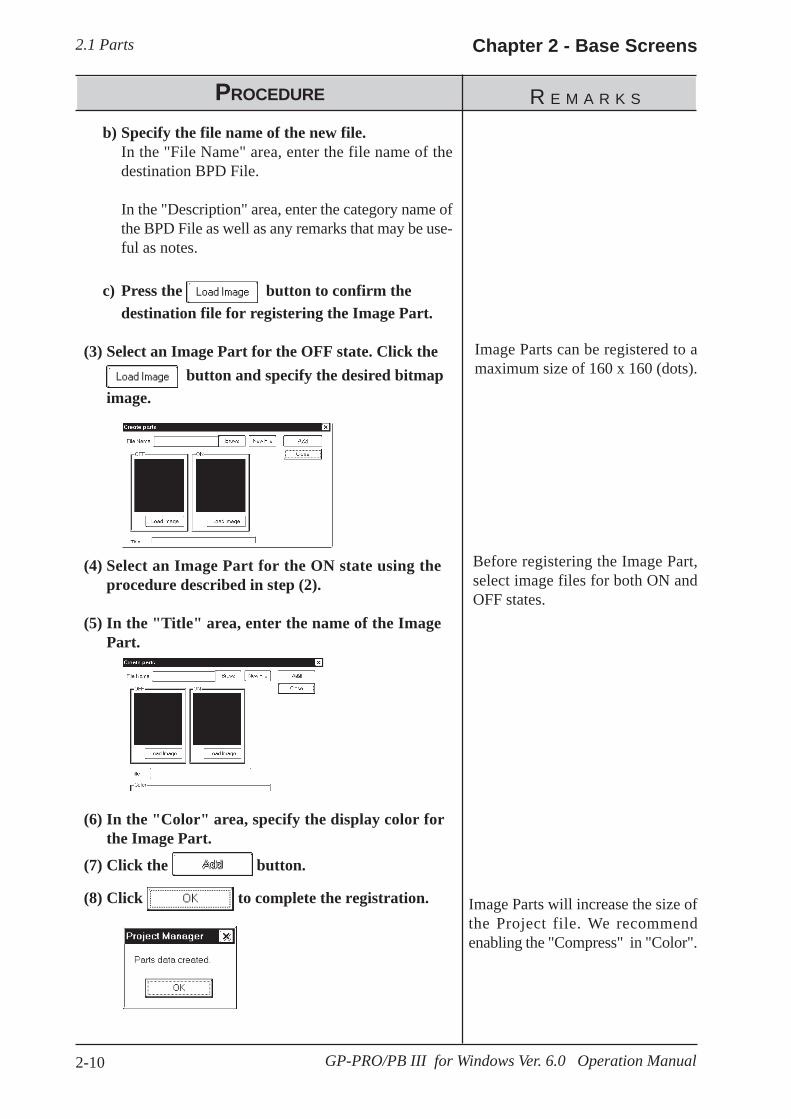
2.1 Parts Chapter 2 - Base Screens
2-10 GP-PRO/PB III for Windows Ver. 6.0 Operation Manual
R E M A R K SPROCEDURE
b) Specify the file name of the new file.In the "File Name" area, enter the file name of thedestination BPD File.
In the "Description" area, enter the category name ofthe BPD File as well as any remarks that may be use-ful as notes.
c) Press the button to confirm thedestination file for registering the Image Part.
(3) Select an Image Part for the OFF state. Click the button and specify the desired bitmap
image.
(4) Select an Image Part for the ON state using theprocedure described in step (2).
(5) In the "Title" area, enter the name of the ImagePart.
(6) In the "Color" area, specify the display color forthe Image Part.
(7) Click the button.
(8) Click to complete the registration.
Image Parts can be registered to amaximum size of 160 x 160 (dots).
Before registering the Image Part,select image files for both ON andOFF states.
Image Parts will increase the size ofthe Project file. We recommendenabling the "Compress" in "Color".
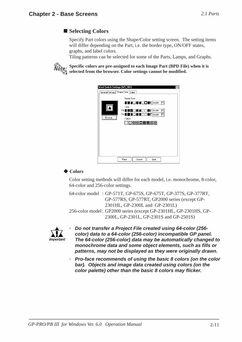
2.1 PartsChapter 2 - Base Screens
2-11GP-PRO/PB III for Windows Ver. 6.0 Operation Manual
ColorsColor setting methods will differ for each model, i.e. monochrome, 8-color,64-color and 256-color settings.
64-color model : GP-571T, GP-675S, GP-675T, GP-377S, GP-377RT,GP-577RS, GP-577RT, GP2000 series (except GP-2301HL, GP-2300L and GP-2301L)
256-color model : GP2000 series (except GP-2301HL, GP-2301HS, GP-2300L, GP-2301L, GP-2301S and GP-2501S)
· Do not transfer a Project File created using 64-color (256-color) data to a 64-color (256-color) incompatible GP panel.The 64-color (256-color) data may be automatically changed tomonochrome data and some object elements, such as fills orpatterns, may not be displayed as they were originally drawn.
· Pro-face recommends of using the basic 8 colors (on the colorbar). Objects and image data created using colors (on thecolor palette) other than the basic 8 colors may flicker.
Selecting ColorsSpecify Part colors using the Shape/Color setting screen. The setting itemswill differ depending on the Part, i.e. the border type, ON/OFF states,graphs, and label colors.Tiling patterns can be selected for some of the Parts, Lamps, and Graphs.
Note: Specific colors are pre-assigned to each Image Part (BPD File) when it isselected from the browser. Color settings cannot be modified.

2.1 Parts Chapter 2 - Base Screens
2-12 GP-PRO/PB III for Windows Ver. 6.0 Operation Manual
<When using an 8-color or monochrome GP unit (incompatible with 64-color screens)>
There are 8 colors available in the color bar. Use this bar to select theforeground (Fg), background (Bg) and other colors. On a monochrome GPscreen, black, blue, green, and cyan will be displayed as black (same asbackground); red, magenta, yellow, and white will be displayed as white.
White (dis-played)
Black (notdisplayed)
Color GP unit
Monochrome GP unit
BK BL GR CY RD MG YL WH
<When using a 64-color GP unit>
There are 64 colors available via the color palette. Use the palette bar toselect the foreground (Fg), background (Bg) and other colors.
Color palette
Color palette(other than basic 8colors)Color palette
(basic 8 colors)
Color bar

2.1 PartsChapter 2 - Base Screens
2-13GP-PRO/PB III for Windows Ver. 6.0 Operation Manual
After converting 64 color data to8 color data, each color will bedisplayed like this:
After converting 64 color data tomonochrome data, each colorwill be displayed like this:
<When using a 256-color GP2000 series unit>
Color paletteColor bar
The following tables describe the changes in the display when the GP type ischanged from a 64-color model to a 256-color model.
0 1 2 3 4 5 6 78 9 10 11 12 13 14 1516 17 18 19 20 21 22 2324 25 26 27 28 29 30 3132 33 34 35 36 37 38 3940 41 42 43 44 45 46 4748 49 50 51 52 53 54 5556 57 58 59 60 61 62 63
0 1 2 3 4 5 6 78 9 10 11 12 13 14 1516 17 18 19 20 21 22 2324 25 26 27 28 29 30 3132 33 34 35 36 37 38 3940 41 42 43 44 45 46 4748 49 50 51 52 53 54 5556 57 58 59 60 61 62 63
0 1 2 3 4 5 6 78 9 10 11 12 13 14 1516 17 18 19 20 21 22 2324 25 26 27 28 29 30 3132 33 34 35 36 37 38 3940 41 42 43 44 45 46 4748 49 50 51 52 53 54 5556 57 58 59 60 61 62 63
255 250 72 75 140 143 100 103248 249 160 161 162 163 192 193194 195 73 74 120 121 122 123168 169 170 171 200 201 202 20380 81 82 83 132 133 134 135
180 181 182 183 212 213 214 21592 93 94 95 141 142 188 189
190 191 220 221 222 223 101 102
0 1 2 3 4 5 6 78 9 10 11 12 13 14 1516 17 18 19 20 21 22 2324 25 26 27 28 29 30 3132 33 34 35 36 37 38 3940 41 42 43 44 45 46 4748 49 50 51 52 53 54 5556 57 58 59 60 61 62 63
232 235 104 107 244 247 116 119233 234 144 145 146 147 224 225226 227 105 106 236 237 238 239148 149 150 151 228 229 230 231108 109 110 111 240 241 242 243152 153 154 155 64 65 66 67112 113 114 115 245 246 156 157158 159 68 69 70 71 117 118
0 1 2 3 4 5 6 78 9 10 11 12 13 14 1516 17 18 19 20 21 22 2324 25 26 27 28 29 30 3132 33 34 35 36 37 38 3940 41 42 43 44 45 46 4748 49 50 51 52 53 54 5556 57 58 59 60 61 62 63
251 254 76 79 136 139 96 99252 253 164 165 166 167 196 197198 199 77 78 124 125 126 127172 173 174 175 204 205 206 20784 85 86 87 128 129 130 131
176 177 178 179 208 209 210 21188 89 90 91 137 138 184 185
186 187 216 217 218 219 97 98
64-color No blink 64-color Blink
64-color Fast 64-color Slow
Color bar
Color palette
Color bar
Color palette

2.1 Parts Chapter 2 - Base Screens
2-14 GP-PRO/PB III for Windows Ver. 6.0 Operation Manual
Note:Transparent mode can be selected as the background color (Bg) text andMark objects. This function is useful when overlaying text on Switches,Lamps, and other objects.
For example: Change the background color of the label from "Black" to"Transparent".
Blink
Blink settings will also differ slightly depending on whether a single speedBlink GP model or a three speed Blink GP model is used. Digital’s threespeed blink models are the GP-571T, GP-675S, GP-675T, GP-377S, GP-377RT, GP-577RS, GP-577RT and GP2000 series units (except GP-2301HL, GP-2300L and GP-2301L). Other GP models have only oneblinking speed. When 256-colors are selected in a project, the “Blink” featurecannot be used for any of that project’s screens.
<Using a three speed Blink type GP>
Next to the Check Box, there is a Button that will display a range of 3speeds and “No Blk” (indicates no blinking). When one of the blink speedsis selected, the color bar is displayed in a darker color and the specified Partwill blink on the GP screen.
When the GP model is changed from a three speed Blink type to a singlespeed type, the “Mid” and “Slow” speeds will be changed to the singlespeed GP’s “Blink” speed, and “No Blk” and “Fast” will be changed to “NoBlk”. The blinking rate for a single speed GP model is equal to the “Mid”setting of the three speed type.
No Blk No blinkMid BlinkFast No blinkSlow Blink
<Using a single speed Blink type GP>
When the Blink (Blk) Check Box checked , the color bar is displayed in adarker color and the specified Part will blink on the GP’s screen.
Blink Check Box
The normal blink speed is “Mid.”“Fast” is twice as fast as “Mid”and “Slow” is half as fast as“Mid”. When “No Blk” is se-lected, the Part will not blink.
Blink speed settings
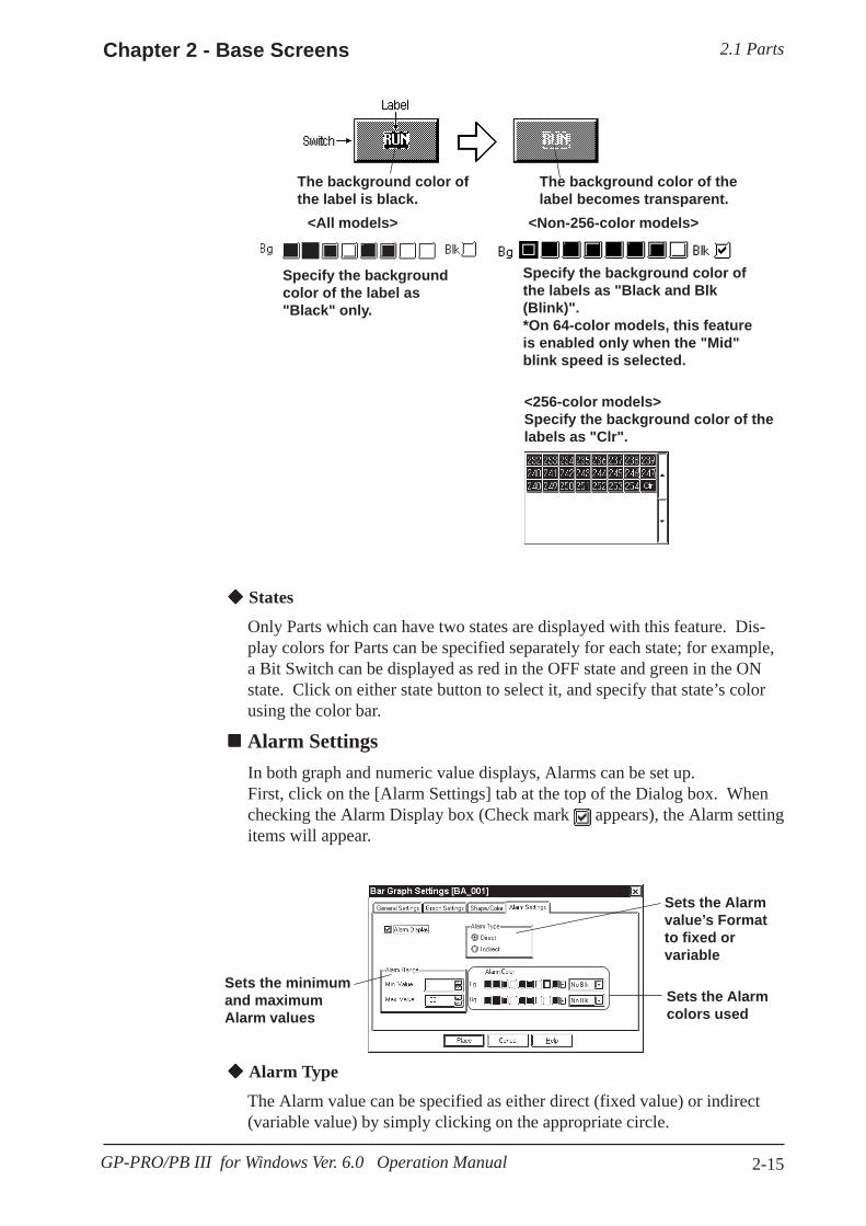
2.1 PartsChapter 2 - Base Screens
2-15GP-PRO/PB III for Windows Ver. 6.0 Operation Manual
Sets the minimumand maximumAlarm values
Sets the Alarmvalue’s Formatto fixed orvariable
Sets the Alarmcolors used
States
Only Parts which can have two states are displayed with this feature. Dis-play colors for Parts can be specified separately for each state; for example,a Bit Switch can be displayed as red in the OFF state and green in the ONstate. Click on either state button to select it, and specify that state’s colorusing the color bar.
Alarm SettingsIn both graph and numeric value displays, Alarms can be set up.First, click on the [Alarm Settings] tab at the top of the Dialog box. Whenchecking the Alarm Display box (Check mark appears), the Alarm settingitems will appear.
Alarm Type
The Alarm value can be specified as either direct (fixed value) or indirect(variable value) by simply clicking on the appropriate circle.
<256-color models>Specify the background color of thelabels as "Clr".
The background color of thelabel becomes transparent.
The background color ofthe label is black.
<All models>
Specify the backgroundcolor of the label as"Black" only.
Specify the background color ofthe labels as "Black and Blk(Blink)".*On 64-color models, this featureis enabled only when the "Mid"blink speed is selected.
<Non-256-color models>
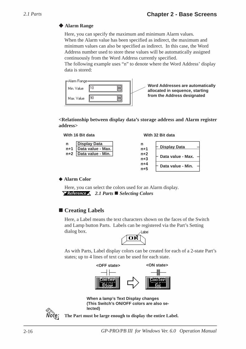
2.1 Parts Chapter 2 - Base Screens
2-16 GP-PRO/PB III for Windows Ver. 6.0 Operation Manual
<Relationship between display data’s storage address and Alarm registeraddress>
Alarm Color
Here, you can select the colors used for an Alarm display. 2.1 Parts Selecting Colors
Creating LabelsHere, a Label means the text characters shown on the faces of the Switchand Lamp button Parts. Labels can be registered via the Part’s Settingdialog box.
Word Addresses are automaticallyallocated in sequence, startingfrom the Address designated
With 16 Bit data
<OFF state>
When a lamp’s Text Display changes(This Switch’s ON/OFF colors are also se-lected)
<ON state>
The Part must be large enough to display the entire Label.
As with Parts, Label display colors can be created for each of a 2-state Part’sstates; up to 4 lines of text can be used for each state.
n Display Datan+1 Data value - Max.n+2 Data value - Min.
With 32 Bit data
Display Data
Data value - Max.
Data value - Min.
nn+1n+2n+3n+4n+5
Note:
Alarm Range
Here, you can specify the maximum and minimum Alarm values.When the Alarm value has been specified as indirect, the maximum andminimum values can also be specified as indirect. In this case, the WordAddress number used to store these values will be automatically assignedcontinuously from the Word Address currently specified.The following example uses “n” to denote where the Word Address’ displaydata is stored:

2.1 PartsChapter 2 - Base Screens
2-17GP-PRO/PB III for Windows Ver. 6.0 Operation Manual
Direct Text
The text entered in the text entry field is placed directly as a fixed textstring.
Index Text
Select and add the index text. 4.6.3 Selecting the index character string Entering
the index character string Image fonts
Windows fonts are displayed in bitmap format.This feature is enabled only when the "direct text" mode is selected.
2.2.9 Text Image Font
The Image Font is supported only by the GP2000 series.
Label
Here, you can type in the text displayed on a button. When typing in text,press the key to move to a new line. When the [Tracking] check box ischecked (enabled), after the Part has been placed on the screen, if theLabel’s size or position is changed, for either state, the alternate state’sLabel size and position will be also automatically changed. If, however, theLabel’s size and position need to be specified independently for each state,DO NOT check this box. 2.4.3 Scaling Up/Down
Copy from Description
The characters entered in the Description filed are copied to the label in theselected state.
If using thedirect text asImage Font,place a checkmark in thecheck box.
Select the text type. Enter characters to bedisplayed as direct text.
Select thecharacter’ssize.
Select thecharacter’stype.
Copies the charac-ters to the label forthe Off state.
Copies the charactersfrom the Descriptionfield to the label of thecurrent state.
Select the label’scolor here.
Note:
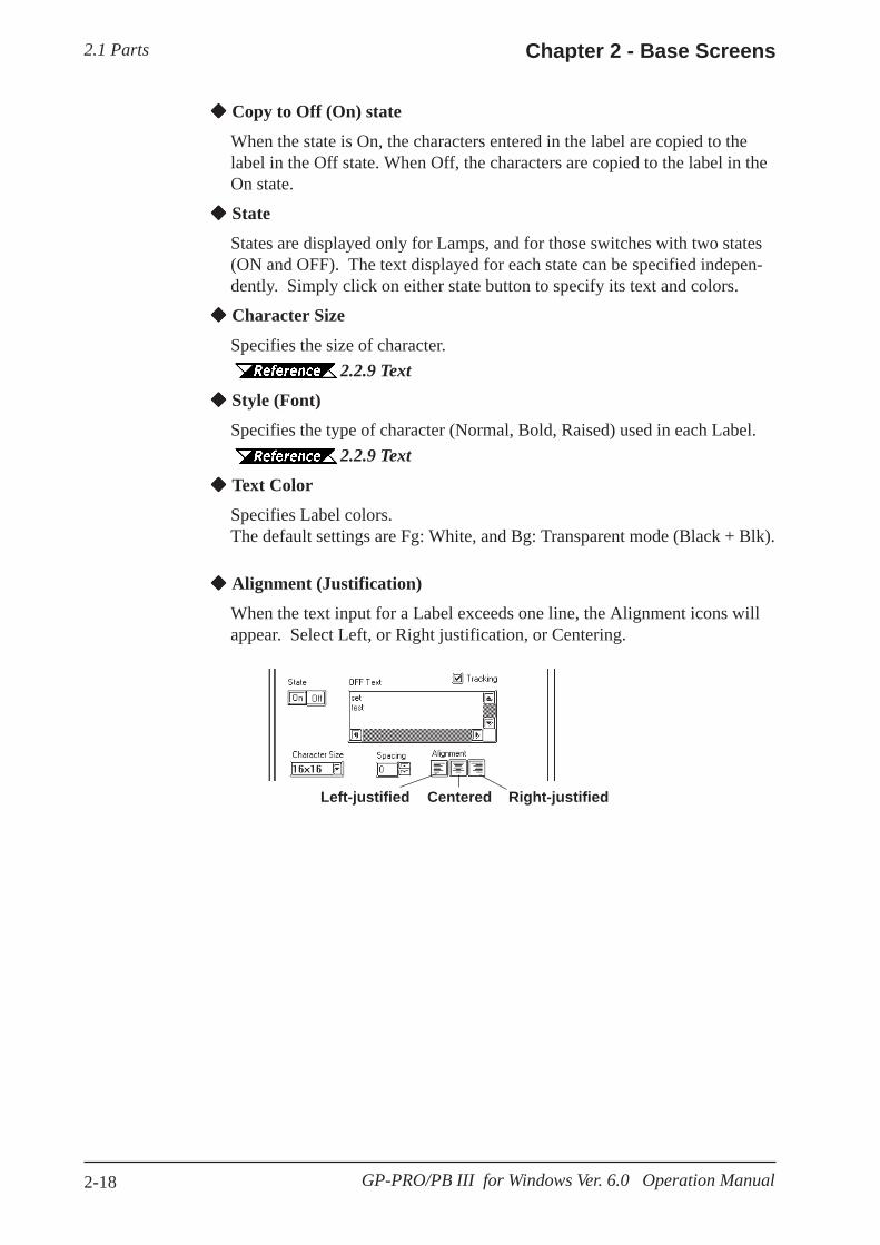
2.1 Parts Chapter 2 - Base Screens
2-18 GP-PRO/PB III for Windows Ver. 6.0 Operation Manual
Copy to Off (On) state
When the state is On, the characters entered in the label are copied to thelabel in the Off state. When Off, the characters are copied to the label in theOn state.
State
States are displayed only for Lamps, and for those switches with two states(ON and OFF). The text displayed for each state can be specified indepen-dently. Simply click on either state button to specify its text and colors.
Character Size
Specifies the size of character.2.2.9 Text
Style (Font)
Specifies the type of character (Normal, Bold, Raised) used in each Label.2.2.9 Text
Text Color
Specifies Label colors.The default settings are Fg: White, and Bg: Transparent mode (Black + Blk).
Right-justifiedLeft-justified Centered
Alignment (Justification)
When the text input for a Label exceeds one line, the Alignment icons willappear. Select Left, or Right justification, or Centering.

2.1 PartsChapter 2 - Base Screens
2-19GP-PRO/PB III for Windows Ver. 6.0 Operation Manual
ID NumbersWhen creating a Part, an ID number is automatically assigned to the Partbefore it is placed on the screen. This number shows how many of that kindof Part were previously placed on the current screen. When a Part is deletedfrom a screen, all following Part numbers will be adjusted downwards.
Example of an ID number
Indicates that this Part is a BitSwitch(Varies according to the Part)
BS _ 010
Indicates the placement/creation order of the Part; inthis case, it is the 10th.
The ID number is displayed in the title bar at the top of the Setting dialogbox.
The ID number can be entered so that it is displayed during Base screendrawing. 2.8.2 Screen Property Settings
Even if the ID number is entered to be displayed during Base screen draw-ing, it will not be displayed on the GP panel after screen data transfer.
<ID Number List>
Note:
Part Name ID Number Part Name ID Number Bit Switch BS-** Keypad KE-*** Word Switch WS-*** Keypad Input Display KD-*** Function Switch
FS-*** Alarm Display AL-***
Toggle Switch TS-*** File Name Display FD-*** Lamp LA-*** Data Logging Display LG-*** 4-state Lamp LF-*** Numeric Display ND-*** Bar Graph BA-*** Message Display
(Operation Mode: Bit) MB-***
Pie Graph PI-*** Message Display (Operation Mode: Word)
MW-***
Half-Pie Graph HP-*** Date Display DD-*** Tank Graph SG-*** Time Display TD-*** Meter MT-*** Picture Display
(Motion mode: Bit) LB-***
Trend Graph TR-*** Picture Display (Motion mode: Word)
LW-***
Window Parts WI-***

2.1 Parts Chapter 2 - Base Screens
2-20 GP-PRO/PB III for Windows Ver. 6.0 Operation Manual
Maximum Number of Automatically Created Part LibrariesWhen a Part is used in a project, a Part Library will be automatically createdin preparation for data transfer. The number of Part Library items arelimited to 6000 per project. If this number exceeds 6000, all Parts in excessof 6000 cannot be transferred to the GP. To avoid this, please remember thefollowing:
1. Automatic Library creation will be performed follows: (per screen)Switches: 2 (only switches with the Monitor function selected)Lamps: 2Messages: 2 to 16 (depending on the number of states used)Picture Displays : 2 to 16 (depending on the number of states used)Trends: 1 to 20 (depending on the number of channels)
However, Part Libraries using the same Parts (i.e. Part’s that are thesame size, same attributes, and without labels or other items) will be usedcommonly.
For example:When 30 Switches (Monitor function is selected) and 20 Lamps areplaced on a single Base screen, (30 × 2) + (20 × 2) = 100 Part Libraryitems will be automatically created. Therefore, 60 of these sizescreens can be used in one project('s data).
2. When using the same Parts for multiple Base screens, register the Part onone Base screen and then place it other Base screens using the LoadScreen function. Thus, when multiple Base screens use those Parts, onlyone Part Library will be used, thereby reducing the Project File’s size.
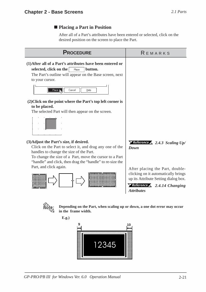
2.1 PartsChapter 2 - Base Screens
2-21GP-PRO/PB III for Windows Ver. 6.0 Operation Manual
Placing a Part in PositionAfter all of a Part’s attributes have been entered or selected, click on thedesired position on the screen to place the Part.
R E M A R K SPROCEDURE
Depending on the Part, when scaling up or down, a one dot error may occurin the frame width.
E.g.)
2.4.3 Scaling Up/Down
After placing the Part, double-clicking on it automatically bringsup its Attribute Setting dialog box.
2.4.14 ChangingAttributes
(3)Adjust the Part’s size, if desired.Click on the Part to select it, and drag any one of thehandles to change the size of the Part.To change the size of a Part, move the cursor to a Part“handle” and click, then drag the “handle” to re-size thePart, and click again.
(2)Click on the point where the Part’s top left corner isto be placed.The selected Part will then appear on the screen.
(1)After all of a Part’s attributes have been entered orselected, click on the button.The Part’s outline will appear on the Base screen, nextto your cursor.
Note:
9 10
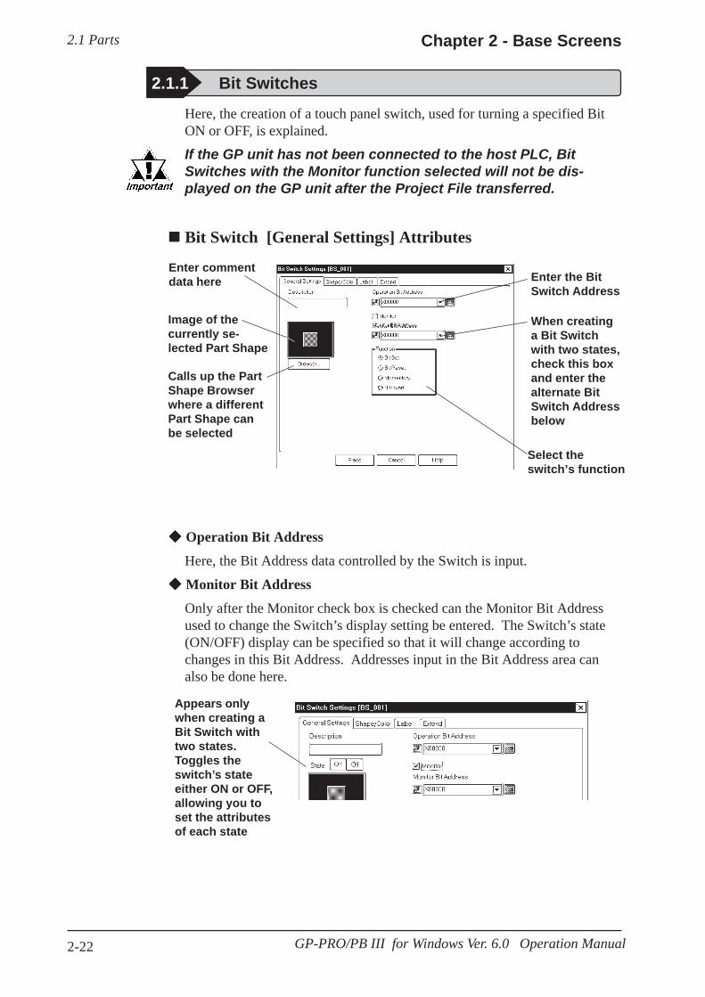
2.1 Parts Chapter 2 - Base Screens
2-22 GP-PRO/PB III for Windows Ver. 6.0 Operation Manual
Here, the creation of a touch panel switch, used for turning a specified BitON or OFF, is explained.
If the GP unit has not been connected to the host PLC, BitSwitches with the Monitor function selected will not be dis-played on the GP unit after the Project File transferred.
Bit Switch [General Settings] Attributes
2.1.1 Bit Switches
Enter commentdata here
Select theswitch’s function
When creatinga Bit Switchwith two states,check this boxand enter thealternate BitSwitch Addressbelow
Enter the BitSwitch Address
Calls up the PartShape Browserwhere a differentPart Shape canbe selected
Image of thecurrently se-lected Part Shape
Operation Bit Address
Here, the Bit Address data controlled by the Switch is input.
Monitor Bit Address
Only after the Monitor check box is checked can the Monitor Bit Addressused to change the Switch’s display setting be entered. The Switch’s state(ON/OFF) display can be specified so that it will change according tochanges in this Bit Address. Addresses input in the Bit Address area canalso be done here.
Appears onlywhen creating aBit Switch withtwo states.Toggles theswitch’s stateeither ON or OFF,allowing you toset the attributesof each state
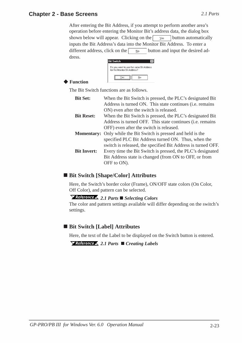
2.1 PartsChapter 2 - Base Screens
2-23GP-PRO/PB III for Windows Ver. 6.0 Operation Manual
Function
The Bit Switch functions are as follows.
Bit Set: When the Bit Switch is pressed, the PLC’s designated BitAddress is turned ON. This state continues (i.e. remainsON) even after the switch is released.
Bit Reset: When the Bit Switch is pressed, the PLC’s designated BitAddress is turned OFF. This state continues (i.e. remainsOFF) even after the switch is released.
Momentary: Only while the Bit Switch is pressed and held is thespecified PLC Bit Address turned ON. Thus, when theswitch is released, the specified Bit Address is turned OFF.
Bit Invert: Every time the Bit Switch is pressed, the PLC’s designatedBit Address state is changed (from ON to OFF, or fromOFF to ON).
After entering the Bit Address, if you attempt to perform another area’soperation before entering the Monitor Bit’s address data, the dialog boxshown below will appear. Clicking on the button automaticallyinputs the Bit Address’s data into the Monitor Bit Address. To enter adifferent address, click on the button and input the desired ad-dress.
Bit Switch [Shape/Color] AttributesHere, the Switch’s border color (Frame), ON/OFF state colors (On Color,Off Color), and pattern can be selected.
2.1 Parts Selecting ColorsThe color and pattern settings available will differ depending on the switch’ssettings.
Bit Switch [Label] AttributesHere, the text of the Label to be displayed on the Switch button is entered.
2.1 Parts Creating Labels

2.1 Parts Chapter 2 - Base Screens
2-24 GP-PRO/PB III for Windows Ver. 6.0 Operation Manual
Bit Switch [Extend] AttributesSet up the Interlock and Buzzer functions.
The “Bit Off” feature is available only with the GP-377, GP77R and GP2000series.
Interlock
Only when a bit designated via Interlock Address is in a state that has beenselected via [Touch available condition], the switch becomes effective.Whether the switch is effective in ON state or in OFF state is selectablehere.
Buzzer
Select ON or OFF for the buzzer sound.
When buzzer setting is enabled, the buzzer sounds while the touch switch isbeing pressed.
One-Shot
Enable/disable the "One-Shot" feature.
This setting can be enabled only when "Momentary" mode is selected in the"Function" area in the "General Settings" tab. When the "One-Shot" featureis enabled, the buzzer will sound briefly only at the moment the touchswitch is pressed.
Tag Reference Manual, 2.23.4 One-Shot Buzzer for T-tagmomentary
The "One-Shot" feature is available only with the GP-377, GP77R andGP2000 series.
Can be set at themomentary
Selects the Inter-lock function
Touch Available Condition
Interlock AddressStatus
Touch Available/Not Available
ON Touch AvailableOFF Touch Not AvailableON Touch Not Available
OFF Touch Available
Bit ON
Bit OFF

2.1 PartsChapter 2 - Base Screens
2-25GP-PRO/PB III for Windows Ver. 6.0 Operation Manual
PROCEDURE R E M A R K S
Enter M0016
Select the BitInvert function
When the switch’sstate can change,click here
2.1 Parts Select-ing a Part Shape
When the Change State function se-lected, after entering the Bit Ad-dress, if you attempt to performanother area’s operation before en-tering the Monitor Bit Address, thedialog box shown below will ap-pear. Click on the buttonto input the same address as usedfor the Bit Address. To enter a dif-ferent address, click on the
button and input the de-sired address.
(3)Select a Part Shape from the Browser.Specify settings for Shape/Color, Label and ExtensionSettings if necessary.
(2)In the [General Settings] screen, input the Bit Ad-dress and select the Bit’s Function.
(1)Select the [Parts] menu - [Bit Switch] command, orclick on the icon.
Placing a Bit SwitchAn example of how to place a Reverse Switch is shown below.
First press of the Switchsets M0016
The next press resets M0016
(4)After all of a Part’s attributes have been entered orselected, click on the button.
The Switch’s outline will appear on the Base screen, nextto your cursor.
Image Parts can be used with theGP2000 series.
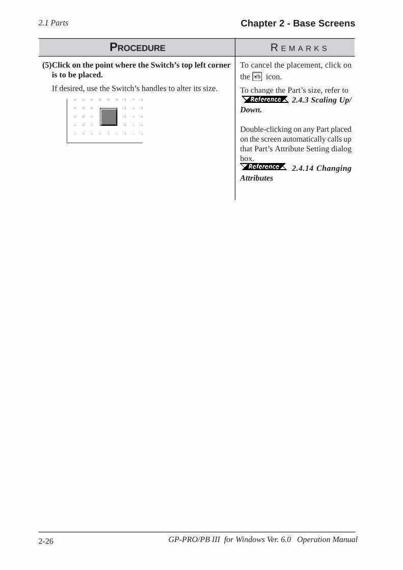
2.1 Parts Chapter 2 - Base Screens
2-26 GP-PRO/PB III for Windows Ver. 6.0 Operation Manual
To cancel the placement, click onthe icon.
To change the Part’s size, refer to2.4.3 Scaling Up/
Down.
Double-clicking on any Part placedon the screen automatically calls upthat Part’s Attribute Setting dialogbox.
2.4.14 ChangingAttributes
PROCEDURE R E M A R K S
(5)Click on the point where the Switch’s top left corneris to be placed.
If desired, use the Switch’s handles to alter its size.

2.1 PartsChapter 2 - Base Screens
2-27GP-PRO/PB III for Windows Ver. 6.0 Operation Manual
2.1.2 Word Switches
Enter commentdata here Enter the Word
Address youwish to use
Enter the datafor the Switchto send to theWord Address
Select theSwitch’s func-tion
Calls up the PartShape Browserwhere a differentPart Shape canbe selected
Image of thecurrently se-lected WordSwitch
Word Address
Here, the desired Word Address is entered.
Constant
Here, number registered to the Word Address is input. The data format isDecimal (Base 10), and the input range is from -32768 to 32767.
Function
The Word Switch’s functions are as follows:
Word Set: When the Word Switch is pressed, constant data is writtento the PLC’s designated Word Address. Fixed or defaultvalues will be written to the timer, counter, etc.
Add/Sub: Every time the Word Switch is pressed, the Data value isadded to the data currently in the PLC’s designated WordAddress, and the result is then written to the PLC’s address.If a Data value is positive, the function will increment, andif it is negative, it will decrement.
Digit (ADD): Every time the Word Switch is pressed, the designateddecimal place’s data will be added by the Constant’s value.The result will not be carried up to the next digit, so “9”simply rolls around to “0”. Select the data format from Binand BCD.
Digit (SUB): Every time the Word Switch is pressed, the designateddecimal place’s data will be subtracted by the Constant’svalue. The result will not be carried down to the lowerdigit, so “9” simply rolls around “0”. Select the dataformat from Bin and BCD.
Here, a touch panel switch for setting data to a specified Word Address canbe created.
Word Switch [General Settings] Attributes
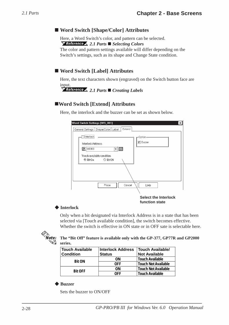
2.1 Parts Chapter 2 - Base Screens
2-28 GP-PRO/PB III for Windows Ver. 6.0 Operation Manual
Word Switch [Shape/Color] AttributesHere, a Word Switch’s color, and pattern can be selected.
2.1 Parts Selecting ColorsThe color and pattern settings available will differ depending on theSwitch’s settings, such as its shape and Change State condition.
Word Switch [Label] AttributesHere, the text characters shown (engraved) on the Switch button face areinput.
2.1 Parts Creating Labels
Word Switch [Extend] AttributesHere, the interlock and the buzzer can be set as shown below.
Interlock
Only when a bit designated via Interlock Address is in a state that has beenselected via [Touch available condition], the switch becomes effective.Whether the switch is effective in ON state or in OFF sate is selectable here.
Touch Available Condition
Interlock Address Status
Touch Available/ Not Available
ON Touch Available Bit ON OFF Touch Not Available ON Touch Not Available Bit OFF OFF Touch Available
The “Bit Off” feature is available only with the GP-377, GP77R and GP2000series.
Buzzer
Sets the buzzer to ON/OFF
Select the Interlockfunction state

2.1 PartsChapter 2 - Base Screens
2-29GP-PRO/PB III for Windows Ver. 6.0 Operation Manual
PROCEDURE R E M A R K S
(1)Select the [Parts] menu - [Word Switch] command,or click on the icon.
Placing a Word SwitchAn example of how to place a Data Set Switch is shown below.
(2)In the [General Settings] area, input the Word Ad-dress and Constant data, and select a function.
Enter D0001
Select Word Set
Enter 34
2.1 Parts Select-ing a Part Shape
(3)Select a Part Shape from the Browser.Specify settings for Shape/Color, Label and ExtensionSettings if necessary.
(4)After all of the Part’s attributes have been enteredor selected, click on the button.
The Switch’s outline will appear on the Base screen, nextto your cursor.
Image Parts can be used with theGP2000 series.
When the button is pressed, 34 is sent to D00001.

2.1 Parts Chapter 2 - Base Screens
2-30 GP-PRO/PB III for Windows Ver. 6.0 Operation Manual
(5)Click on the point where the Switch’s top left corneris to be placed.
If desired, use the Switch’s handles to alter its size.
PROCEDURE R E M A R K S
To cancel the placement, click onthe icon.
To change thePart’s size, refer to 2.4.3 ScalingUp/Down
Double-clicking on any Part placedon the screen automatically calls upthat Part’s attribute settings.
2.4.14 ChangingAttributes

2.1 PartsChapter 2 - Base Screens
2-31GP-PRO/PB III for Windows Ver.6.0 Operation Manual
Function (Switch Operation)
The Function Switch’s attributes are as follows:
Previous Screen: When the Switch is pressed, the currentlydisplayed screen on the GP will change tothe previously displayed one.
Go To Screen: When the Switch is pressed, the currentlydisplayed screen on the GP will change tothe specified screen. Input the screennumber to be changed (jumped) to. TheData Format can be either Bin or BCD.
If a screen number is specified in the BCD data format to place the corre-sponding screen, it is still displayed in the BIN data format when the screen isclosed and then opened.
Reset GP: When the Switch is pressed, the GP will bereset to the save status as when the GP’spower was turned ON.
File Name Key: This is a function switch corresponding tothe File Name Display and is the same asthe one that is automatically placed togetherwith the File Name Display.Designate the same ID number as the one ofthe File Name Display and select a opera-tion mode.
2.1.16 File Name Display
2.1.3 Function Switches
Enter commentdata here Select the
Switch’s opera-tion
When “Go ToScreen” isselected, the(Go To)screen’s num-ber and dataformat must beentered
Calls up the PartShape Browserwhere a differentPart Shape canbe selected
Image of thecurrently se-lected FunctionSwitch
Here, a touch panel with special functions can be created.
Function Switch [General Settings] Attributes
Note:

2.1 Parts Chapter 2 - Base Screens
2-32 GP-PRO/PB III for Windows Ver. 6.0 Operation Manual
Data Logging Key: This is a function switch corresponding tothe Data Logging Display and is the sameas the one that is automatically placedtogether with the Data Logging Display.Designate the scroll direction and thenumber of lines being rolled up or down.
2.1.17 Data Logging Display
OFFLINE: When this switch is pressed, the GP entersthe OFFLINE mode.
Function Switch [Shape/Color] AttributesThe Switch’s color, and pattern are selected here.
2.1 Parts Selecting ColorsThe color and pattern settings available will differ depending on the switchshape.
Function Switch [Label] AttributesHere, the characters shown (drawn) on the Switch button face are entered.
2.1 Parts Creating Labels
Function Switch [Extend] AttributesHere, the interlock and the buzzer are set.
Select the Inter-lock functionstate

2.1 PartsChapter 2 - Base Screens
2-33GP-PRO/PB III for Windows Ver.6.0 Operation Manual
Touch AvailableCondition
Interlock AddressStatus
Touch Available/Not Available
ON Touch AvailableOFF Touch Not AvailableON Touch Not AvailableOFF Touch Available
Bit ON
Bit OFF
The “Bit Off” is available only with the GP-377, GP77R and GP2000 series.
Interlock
Only when a bit designated via Interlock Address is in a state that has beenselected via [Touch available condition], the switch becomes effective.Whether the switch is effective in ON state or in OFF sate is selectable here.
Buzzer
Sets the buzzer to ON/OFF.
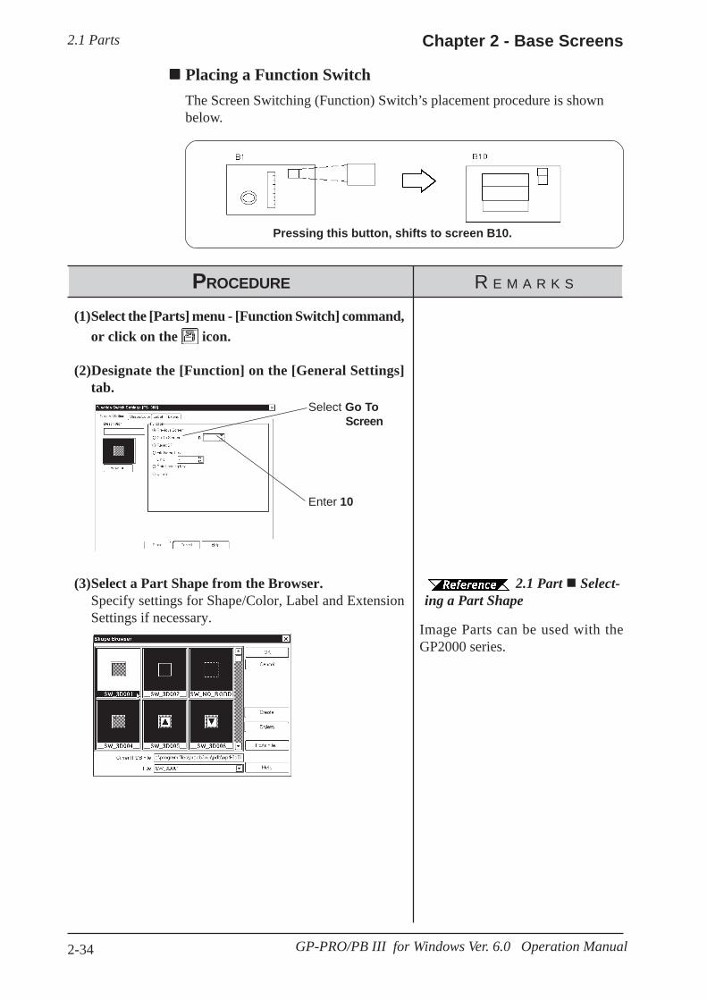
2.1 Parts Chapter 2 - Base Screens
2-34 GP-PRO/PB III for Windows Ver. 6.0 Operation Manual
PROCEDURE R E M A R K S
Select Go ToScreen
Enter 10
2.1 Part Select-ing a Part Shape
(3)Select a Part Shape from the Browser.Specify settings for Shape/Color, Label and ExtensionSettings if necessary.
(1)Select the [Parts] menu - [Function Switch] command,or click on the icon.
(2)Designate the [Function] on the [General Settings]tab.
Placing a Function SwitchThe Screen Switching (Function) Switch’s placement procedure is shownbelow.
Pressing this button, shifts to screen B10.
Image Parts can be used with theGP2000 series.
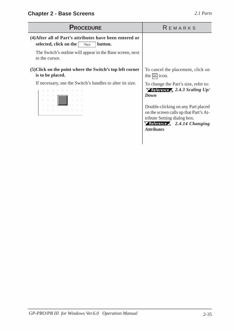
2.1 PartsChapter 2 - Base Screens
2-35GP-PRO/PB III for Windows Ver.6.0 Operation Manual
PROCEDURE R E M A R K S
To cancel the placement, click onthe icon.
To change the Part’s size, refer to:2.4.3 Scaling Up/
Down
Double-clicking on any Part placedon the screen calls up that Part’s At-tribute Setting dialog box.
2.4.14 ChangingAttributes
(4)After all of Part’s attributes have been entered orselected, click on the button.
The Switch’s outline will appear in the Base screen, nextto the cursor.
(5)Click on the point where the Switch’s top left corneris to be placed.
If necessary, use the Switch’s handles to alter its size.
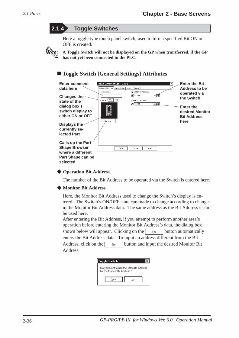
2.1 Parts Chapter 2 - Base Screens
2-36 GP-PRO/PB III for Windows Ver. 6.0 Operation Manual
2.1.4 Toggle Switches
Enter commentdata here
Enter thedesired MonitorBit Addresshere
Calls up the PartShape Browserwhere a differentPart Shape can beselected
Displays thecurrently se-lected Part
Changes thestate of thedialog box’sswitch display toeither ON or OFF
Operation Bit Address
The number of the Bit Address to be operated via the Switch is entered here.
Monitor Bit Address
Here, the Monitor Bit Address used to change the Switch’s display is en-tered. The Switch’s ON/OFF state can made to change according to changesin the Monitor Bit Address data. The same address as the Bit Address’s canbe used here.After entering the Bit Address, if you attempt to perform another area’soperation before entering the Monitor Bit Address’s data, the dialog boxshown below will appear. Clicking on the button automaticallyenters the Bit Address data. To input an address different from the BitAddress, click on the button and input the desired Monitor BitAddress.
Here a toggle type touch panel switch, used to turn a specified Bit ON orOFF is created.A Toggle Switch will not be displayed on the GP when transferred, if the GPhas not yet been connected to the PLC.
Toggle Switch [General Settings] Attributes
Note:
Enter the BitAddress to beoperated viathe Switch
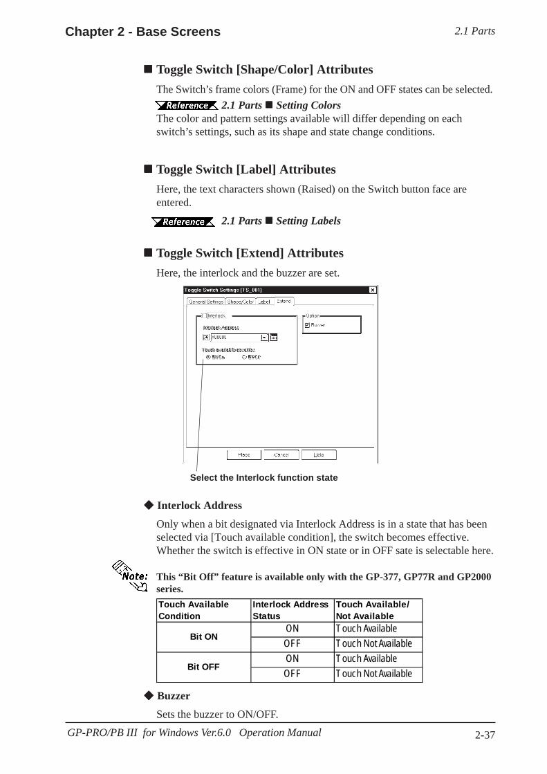
2.1 PartsChapter 2 - Base Screens
2-37GP-PRO/PB III for Windows Ver.6.0 Operation Manual
Toggle Switch [Shape/Color] AttributesThe Switch’s frame colors (Frame) for the ON and OFF states can be selected.
2.1 Parts Setting ColorsThe color and pattern settings available will differ depending on eachswitch’s settings, such as its shape and state change conditions.
Toggle Switch [Label] AttributesHere, the text characters shown (Raised) on the Switch button face areentered.
2.1 Parts Setting Labels
Select the Interlock function state
Toggle Switch [Extend] AttributesHere, the interlock and the buzzer are set.
Touch AvailableCondition
Interlock AddressStatus
Touch Available/Not Available
ON Touch AvailableOFF Touch Not AvailableON Touch AvailableOFF Touch Not Available
Bit ON
Bit OFF
Interlock Address
Only when a bit designated via Interlock Address is in a state that has beenselected via [Touch available condition], the switch becomes effective.Whether the switch is effective in ON state or in OFF sate is selectable here.
This “Bit Off” feature is available only with the GP-377, GP77R and GP2000series.
Buzzer
Sets the buzzer to ON/OFF.

2.1 Parts Chapter 2 - Base Screens
2-38 GP-PRO/PB III for Windows Ver. 6.0 Operation Manual
Enter M0016
2.1 Parts Select-ing a Part Shape
(3)Select a Part Shape from the Browser.Specify settings for Shape/Color, Label and ExtensionSettings if necessary.
(2)In the [General Settings] area, input the OperationBit Address.
Clicking on the buttonautomatically inputs the OperationBit Address into the Monitor BitAddress area. To input an addressdifferent from the Bit Address,click on the button.
After entering the Operation BitAddress, if you attempt to performanother area’s operation before en-tering the Monitor Bit Addressdata, the dialog box shown belowwill appear.
(4)After all of a Part’s attributes have been entered orselected, click on the button.
The Switch’s outline will appear in the Base screen, nextto your cursor.
PROCEDURE R E M A R K S
(1)Select the [Parts] menu - [Toggle Switch] command,or click on the icon.
Placing a Toggle SwitchThe Toggle Switch placement procedure is shown below.

2.1 PartsChapter 2 - Base Screens
2-39GP-PRO/PB III for Windows Ver.6.0 Operation Manual
To cancel the placement, click onthe icon.
To change a Part’s size, refer to
2.4.3 Scaling Up/Down
Double-clicking on any Part placedon the screen automatically calls upthat Part’s attribute settings.
2.4.14 ChangingAttributes
PROCEDURE R E M A R K S
(5) Click on the point where the Switch’s top left corner is to be placed.
If desired, use the Switch’s handles to alter its size.

2.1 Parts Chapter 2 - Base Screens
2-40 GP-PRO/PB III for Windows Ver. 6.0 Operation Manual
2.1.5 Lamps
Enter commentdata here Enter the
desired BitAddress here
Changes thestate of thedialog box’sswitch displayto either ON orOFF
Calls up the PartShape Browser.Part Shapes canbe selecteddirectly from here
Displays the cur-rently selected Part
Bit Address
The Bit Address to be monitored is entered here.
Lamp [Shape/Color] AttributesHere, border colors for both ON and OFF states, and Lamp’s colors andtiling pattern in each state can be selected.
2.1 Parts Selecting ColorsThe color and pattern settings available will differ depending on each lampshape.
Lamp [Label] AttributesHere, the text characters shown on a Lamp button’s face are entered.
2.1 Parts Creating Labels
Here a lamp is created, which turns ON or OFF according to the PLC’sMonitor Bit Address state.
· Lamps will not display on the GP unless the GP has beenconnected to the PLC.
· When placing a Lamp, DO NOT overlap it with other objects. Ifyou do so, it may not be displayed correctly.
Lamp [General Setting] Attributes

2.1 PartsChapter 2 - Base Screens
2-41GP-PRO/PB III for Windows Ver.6.0 Operation Manual
PROCEDURE R E M A R K S
Enter X0017 here
With the Blink check box checked, and if the Bit is turned ON, the
Lamp will blink. Lamp blinkingcan also be seen via the pull downmenu [View]’s [Preview] com-mand.
2.8.3 PreviewScreen
2.1 Parts Select-ing a Part Shape
(3)Select a Part Shape from the Browser.Select Colors and input a Label, if desired.
(1)Select the [Parts] menu - [Lamp] command, or clickon the icon.
(2)In the [General Settings] area, enter a Bit Address.
Placing a LampThe procedures for creating and placing a Lamp are shown below.
When X0017is ON...
the Lamplights up.
When X0017is OFF...
the Lampturns off.
(4)Switch the state of the lamp with the On/Off but-tons, and then select Colors and input a Label.
(5)After all of the Lamp’s attributes have been enteredor selected, click on the button.
The Lamp’s outline will appear in the Base screen, nextto your cursor.
Image Parts can be used with theGP2000 series.

2.1 Parts Chapter 2 - Base Screens
2-42 GP-PRO/PB III for Windows Ver. 6.0 Operation Manual
PROCEDURE R E M A R K S
To cancel the placement, click onthe icon.
To change the Part’s size, refer to
2.4.3 Scaling Up/Down
Double-clicking on any Part placedon the screen automatically calls upthat Part’s attribute settings.
2.4.14 ChangingAttributes
(6)Click on the point where the Lamp’s top left corneris to be placed.
If necessary, use the Lamp’s handles to alter its size.
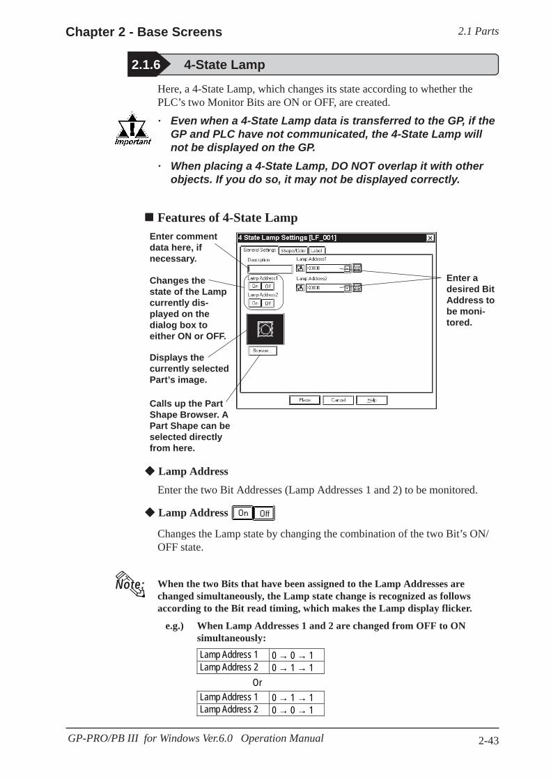
2.1 PartsChapter 2 - Base Screens
2-43GP-PRO/PB III for Windows Ver.6.0 Operation Manual
2.1.6 4-State Lamp
Here, a 4-State Lamp, which changes its state according to whether thePLC’s two Monitor Bits are ON or OFF, are created.
· Even when a 4-State Lamp data is transferred to the GP, if theGP and PLC have not communicated, the 4-State Lamp willnot be displayed on the GP.
· When placing a 4-State Lamp, DO NOT overlap it with otherobjects. If you do so, it may not be displayed correctly.
Features of 4-State Lamp
Enter adesired BitAddress tobe moni-tored.
Enter commentdata here, ifnecessary.
Changes thestate of the Lampcurrently dis-played on thedialog box toeither ON or OFF.
Displays thecurrently selectedPart’s image.
Calls up the PartShape Browser. APart Shape can beselected directlyfrom here.
Lamp Address
Enter the two Bit Addresses (Lamp Addresses 1 and 2) to be monitored.
Lamp Address
Changes the Lamp state by changing the combination of the two Bit’s ON/OFF state.
When the two Bits that have been assigned to the Lamp Addresses arechanged simultaneously, the Lamp state change is recognized as followsaccording to the Bit read timing, which makes the Lamp display flicker.
e.g.) When Lamp Addresses 1 and 2 are changed from OFF to ONsimultaneously:
Note:
Lamp Address 1 0 → 0 → 1Lamp Address 2 0 → 1 → 1
OrLamp Address 1 0 → 1 → 1Lamp Address 2 0 → 0 → 1
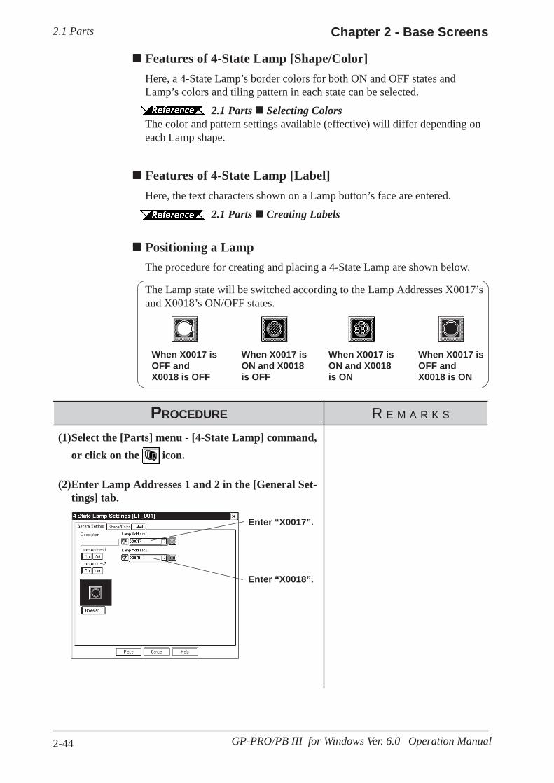
2.1 Parts Chapter 2 - Base Screens
2-44 GP-PRO/PB III for Windows Ver. 6.0 Operation Manual
Features of 4-State Lamp [Shape/Color]Here, a 4-State Lamp’s border colors for both ON and OFF states andLamp’s colors and tiling pattern in each state can be selected.
2.1 Parts Selecting ColorsThe color and pattern settings available (effective) will differ depending oneach Lamp shape.
Features of 4-State Lamp [Label]Here, the text characters shown on a Lamp button’s face are entered.
2.1 Parts Creating Labels
Positioning a LampThe procedure for creating and placing a 4-State Lamp are shown below.
The Lamp state will be switched according to the Lamp Addresses X0017’sand X0018’s ON/OFF states.
When X0017 isOFF andX0018 is OFF
When X0017 isON and X0018is OFF
When X0017 isON and X0018is ON
When X0017 isOFF andX0018 is ON
PROCEDURE R E M A R K S
(1)Select the [Parts] menu - [4-State Lamp] command,or click on the icon.
(2)Enter Lamp Addresses 1 and 2 in the [General Set-tings] tab.
Enter “X0017”.
Enter “X0018”.

2.1 PartsChapter 2 - Base Screens
2-45GP-PRO/PB III for Windows Ver.6.0 Operation Manual
PROCEDURE R E M A R K S
(3) Select a Part Shape from the Browser.
Select Colors and set up a Label, if desired.
(4) User either or button to change the LampAddress states and select Colors and Pattern for eachstate.
Set up a Label for each state, if desired.
(5) After all of a Part’s attributes have been entered orselected, click on the button.
The 4-State Lamp’s outline will appear on the Basescreen, next to your cursor.
(6) Click on the point where the 4-State Lamp’s top cor-ner is to be placed.
Use the 4-State Lamp’s handles to alter its size, if nec-essary.
2.1 Parts Select-ing a Part Shape
To cancel the placement, click onthe icon.
To change thePart’s size, refer to 2.4.3 ScalingUp/Down.
Double-clicking on any Part placedon the screen automatically calls upthat Part’s attribute settings.
2.4.14 ChangingAttributes
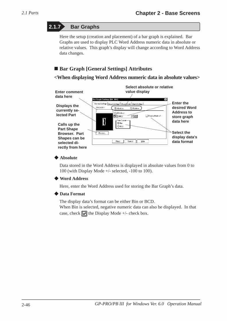
2.1 Parts Chapter 2 - Base Screens
2-46 GP-PRO/PB III for Windows Ver. 6.0 Operation Manual
Calls up thePart ShapeBrowser. PartShapes can beselected di-rectly from here
Here the setup (creation and placement) of a bar graph is explained. BarGraphs are used to display PLC Word Address numeric data in absolute orrelative values. This graph’s display will change according to Word Addressdata changes.
Bar Graph [General Settings] Attributes<When displaying Word Address numeric data in absolute values>
2.1.7 Bar Graphs
Select absolute or relativevalue display
Enter thedesired WordAddress tostore graphdata here
Select thedisplay data’sdata format
Displays thecurrently se-lected Part
Absolute
Data stored in the Word Address is displayed in absolute values from 0 to100 (with Display Mode +/- selected, -100 to 100).
Word Address
Here, enter the Word Address used for storing the Bar Graph’s data.
Data Format
The display data’s format can be either Bin or BCD.When Bin is selected, negative numeric data can also be displayed. In thatcase, check the Display Mode +/- check box.
Enter commentdata here
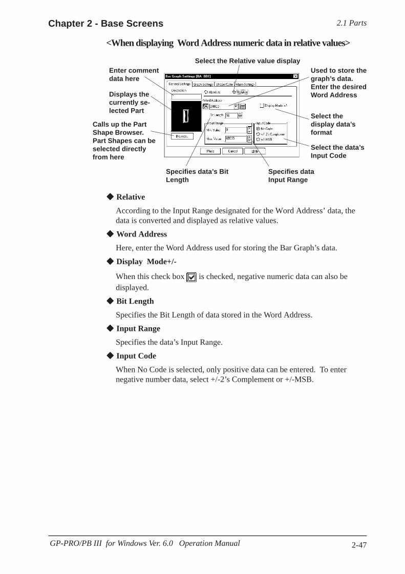
2.1 PartsChapter 2 - Base Screens
2-47GP-PRO/PB III for Windows Ver. 6.0 Operation Manual
Enter commentdata here
Select the Relative value displayUsed to store thegraph’s data.Enter the desiredWord Address
Select thedisplay data’sformat
Select the data’sInput Code
Specifies dataInput Range
Specifies data’s BitLength
Displays thecurrently se-lected Part
Relative
According to the Input Range designated for the Word Address’ data, thedata is converted and displayed as relative values.
Word Address
Here, enter the Word Address used for storing the Bar Graph’s data.
Display Mode+/-
When this check box is checked, negative numeric data can also bedisplayed.
Bit Length
Specifies the Bit Length of data stored in the Word Address.
Input Range
Specifies the data’s Input Range.
Input Code
When No Code is selected, only positive data can be entered. To enternegative number data, select +/-2’s Complement or +/-MSB.
<When displaying Word Address numeric data in relative values>
Calls up the PartShape Browser.Part Shapes can beselected directlyfrom here

2.1 Parts Chapter 2 - Base Screens
2-48 GP-PRO/PB III for Windows Ver. 6.0 Operation Manual
Direction
The graph’s display direction can be specified as either Up, Left, Down, orRight.
If [Display Direction] is changed for a 3D part, its shade is rotated along withthat part. To let the shade displayed properly, click on the button,and select the part again from [Shape Browser].
Axis Divisions
For a graph which has graduations, the number of divisions are entered here.If the number of the divisions is specified to 10, then 11 division lines areused. When graduations are not necessary, specify the number of the divi-sions as 0.
Whether the graduations are necessary or not will differ depending on thePart’s shape.
Bar Graph [Shape/Color] AttributesThe graph’s border color, division color (Axis Color), display data color(Graph Color), and display data patterns are selected here.
2.1 Parts Selecting Colors
Bar Graph [Alarm Settings] AttributeIf desired, an Alarm can be setup here by toggling the Alarm check box.
2.1 Parts Setting Alarms
Select thegraph’s displaydirection
Only when agraph withgraduationshas beenselected willthis boxappear.Enter thenumber ofdivisionsdesired here
Bar Graph [Graph Settings] Attributes
Note:
Note:

2.1 PartsChapter 2 - Base Screens
2-49GP-PRO/PB III for Windows Ver. 6.0 Operation Manual
PROCEDURE R E M A R K S
Enter D00102here
Select BCD
Level pointer
2.1 Parts Se-lecting a Part ShapeIf the Bar Graph’s Alarm value isspecified as Variable, a pointershowing levels will be displayed.This pointer’s position will moveaccording to the specified Alarmvalue.
(3)Select a Part Shape that has graduations from theBrowser.Here, you can enter Alarm settings and select Colors, ifdesired.
(1)Select the [Parts] menu - [Bar Graph] command, orclick on the icon.
(2)In the [General Settings] tab, input a Word Addressand select a Data Format.
Placing a Bar GraphAn example of the Bar Graph’s creation and placement procedures areshown below.
When the value 34 is stored in D00102,the graph will look like this:
Data stored in D00102 displays on the BarGraph
BG_3D002U
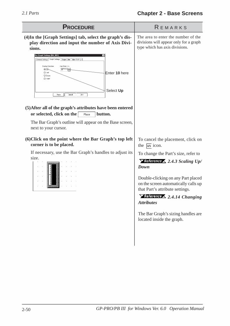
2.1 Parts Chapter 2 - Base Screens
2-50 GP-PRO/PB III for Windows Ver. 6.0 Operation Manual
PROCEDURE R E M A R K S
Enter 10 here
Select Up
To cancel the placement, click onthe icon.
To change the Part’s size, refer to
2.4.3 Scaling Up/Down
Double-clicking on any Part placedon the screen automatically calls upthat Part’s attribute settings.
2.4.14 ChangingAttributes
The Bar Graph’s sizing handles arelocated inside the graph.
The area to enter the number of thedivisions will appear only for a graphtype which has axis divisions.
(5)After all of the graph’s attributes have been enteredor selected, click on the button.
The Bar Graph’s outline will appear on the Base screen,next to your cursor.
(6)Click on the point where the Bar Graph’s top leftcorner is to be placed.
If necessary, use the Bar Graph’s handles to adjust itssize.
(4)In the [Graph Settings] tab, select the graph’s dis-play direction and input the number of Axis Divi-sions.
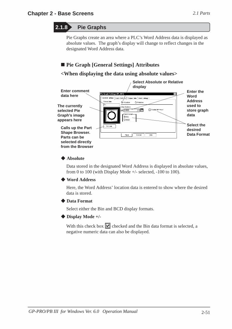
2.1 PartsChapter 2 - Base Screens
2-51GP-PRO/PB III for Windows Ver. 6.0 Operation Manual
2.1.8 Pie Graphs
Enter commentdata here
Select Absolute or Relativedisplay
Enter theWordAddressused tostore graphdata
Select thedesiredData Format
Calls up the PartShape Browser.Parts can beselected directlyfrom the Browser
The currentlyselected PieGraph’s imageappears here
Absolute
Data stored in the designated Word Address is displayed in absolute values,from 0 to 100 (with Display Mode +/- selected, -100 to 100).
Word Address
Here, the Word Address’ location data is entered to show where the desireddata is stored.
Data Format
Select either the Bin and BCD display formats.
Display Mode +/-
With this check box checked and the Bin data format is selected, anegative numeric data can also be displayed.
Pie Graphs create an area where a PLC’s Word Address data is displayed asabsolute values. The graph’s display will change to reflect changes in thedesignated Word Address data.
Pie Graph [General Settings] Attributes<When displaying the data using absolute values>
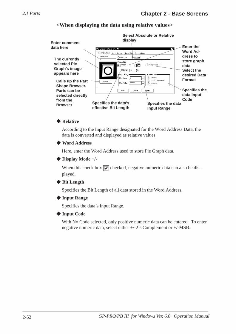
2.1 Parts Chapter 2 - Base Screens
2-52 GP-PRO/PB III for Windows Ver. 6.0 Operation Manual
Enter commentdata here
Select Absolute or Relativedisplay
Enter theWord Ad-dress tostore graphdataSelect thedesired DataFormat
Specifies thedata InputCode
Specifies the dataInput Range
Specifies the data’seffective Bit Length
Calls up the PartShape Browser.Parts can beselected directlyfrom theBrowser
The currentlyselected PieGraph’s imageappears here
Relative
According to the Input Range designated for the Word Address Data, thedata is converted and displayed as relative values.
Word Address
Here, enter the Word Address used to store Pie Graph data.
Display Mode +/-
When this check box checked, negative numeric data can also be dis-played.
Bit Length
Specifies the Bit Length of all data stored in the Word Address.
Input Range
Specifies the data’s Input Range.
Input Code
With No Code selected, only positive numeric data can be entered. To enternegative numeric data, select either +/-2’s Complement or +/-MSB.
<When displaying the data using relative values>

2.1 PartsChapter 2 - Base Screens
2-53GP-PRO/PB III for Windows Ver. 6.0 Operation Manual
Display
Here, the graph’s data display start point, either Clkws. From Top or Clkws.From Bottom, can be selected.
If [Display Direction] is changed for a 3D part, its shade is rotated along withthat part. To let the shade displayed properly, click on the button,and select the part again from [Shape Browser].
Axis Divisions
The number of segments the Pie Graph will be divided into is entered here.If the number of Axis Divisions is specified as 10, 10 division lines will bedisplayed. When no divisions are necessary, simply enter 0.
Pie Graph [Shape/Color] AttributesA Pie Graph’s border color, division line color (Axis Color), data displaycolor (Graph Color - Fg and Bg), and data display pattern can all be selectedhere.
2.1 Parts Selecting Colors
Pie Graph [Alarm Settings] AttributesClicking on the Alarm Display check box will call up the Alarm Settings.
2.1 Parts Alarm Settings
Select the PieGraph’s (datadisplay)Direction
Enter thegraph’snumber ofdivisions
Pie Graph [Graph Settings] Attributes
Note:
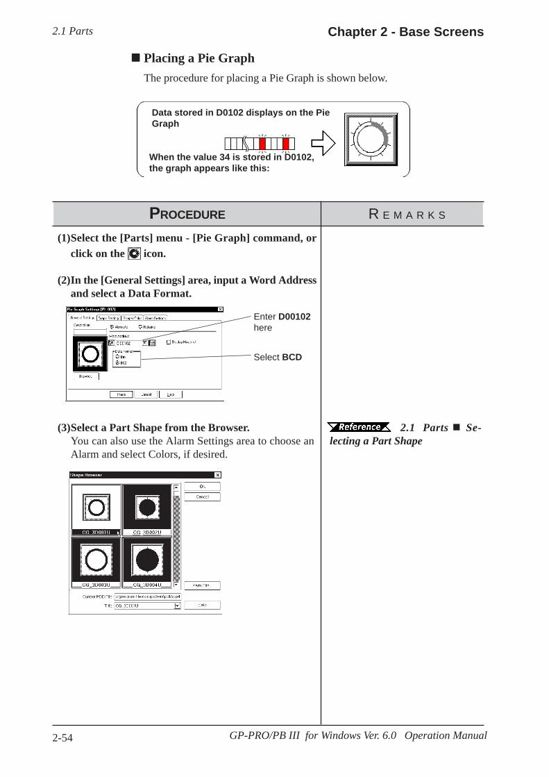
2.1 Parts Chapter 2 - Base Screens
2-54 GP-PRO/PB III for Windows Ver. 6.0 Operation Manual
PROCEDURE R E M A R K S
Enter D00102here
Select BCD
2.1 Parts Se-lecting a Part Shape
(3)Select a Part Shape from the Browser.You can also use the Alarm Settings area to choose anAlarm and select Colors, if desired.
(1)Select the [Parts] menu - [Pie Graph] command, orclick on the icon.
(2)In the [General Settings] area, input a Word Addressand select a Data Format.
Placing a Pie GraphThe procedure for placing a Pie Graph is shown below.
Pie
When the value 34 is stored in D0102,the graph appears like this:
Data stored in D0102 displays on the PieGraph
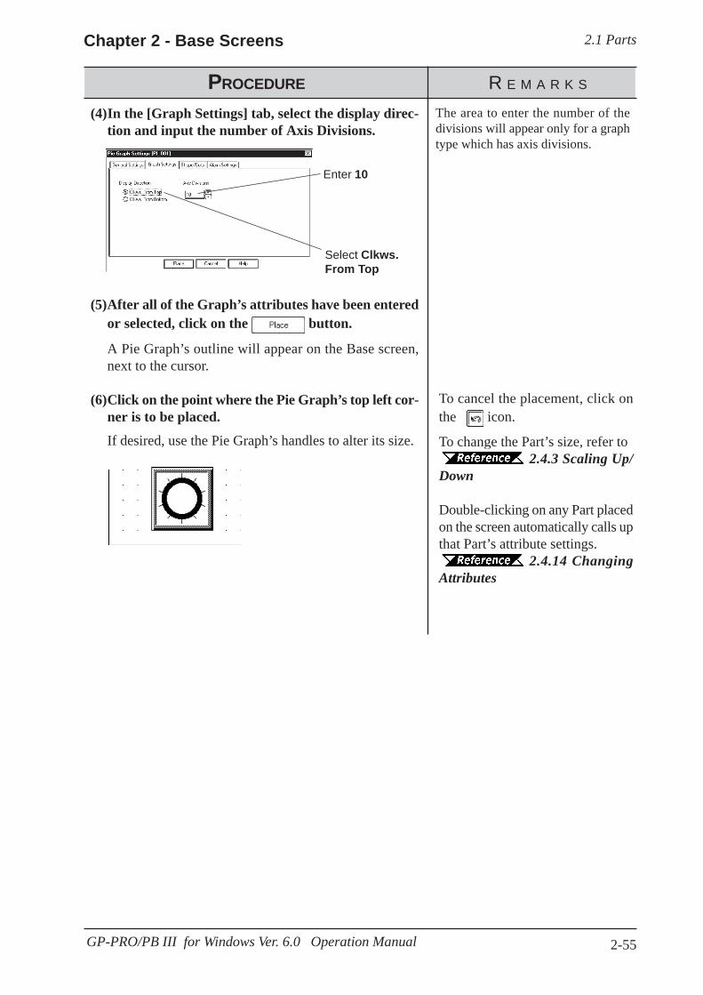
2.1 PartsChapter 2 - Base Screens
2-55GP-PRO/PB III for Windows Ver. 6.0 Operation Manual
PROCEDURE R E M A R K S
Enter 10
Select Clkws.From Top
To cancel the placement, click onthe icon.
To change the Part’s size, refer to2.4.3 Scaling Up/
Down
Double-clicking on any Part placedon the screen automatically calls upthat Part’s attribute settings.
2.4.14 ChangingAttributes
The area to enter the number of thedivisions will appear only for a graphtype which has axis divisions.
(5)After all of the Graph’s attributes have been enteredor selected, click on the button.
A Pie Graph’s outline will appear on the Base screen,next to the cursor.
(6)Click on the point where the Pie Graph’s top left cor-ner is to be placed.
If desired, use the Pie Graph’s handles to alter its size.
(4)In the [Graph Settings] tab, select the display direc-tion and input the number of Axis Divisions.

2.1 Parts Chapter 2 - Base Screens
2-56 GP-PRO/PB III for Windows Ver. 6.0 Operation Manual
This graph displays a Word Address’ numeric data (received from a PLC) asabsolute or relative values in a Half-Pie graph. The graph’s display will alsochange to reflect Word Address data changes.
Half Pie Graph [General Settings] Attributes<When displaying the data in absolute values>
2.1.9 Half Pie Graphs
Enter commentdata here
Select Absolute orRelative display
Enter theWord Ad-dress tostore graphdata
Select thedesired DataFormat
Calls up the PartShape Browser.Parts can beselected directlyfrom the Browser
The currentlyselected Half PieGraph’s imageappears here
Absolute
Data stored in the designated Word Address is displayed as absolute values,from 0 to 100 (with Display Mode +/- selected, -100 to 100).
Word Address
Enter the Word Address where the data will be stored.
Data Format
Select the display data format from Bin and BCD.
Display Mode +/-
When this check box is checked and Bin data format is selected, nega-tive numeric data can be displayed.

2.1 PartsChapter 2 - Base Screens
2-57GP-PRO/PB III for Windows Ver. 6.0 Operation Manual
Enter commentdata here
Select Absolute orRelative display Enter the
Word Ad-dress used tostore graphdata
Selects thedesired DataFormat
Specifies thedata’s InputCode
Specifies the data’sInput Range
Specifies the data’seffective Bit Length
Calls up the PartShape Browser.Parts can beselected directlyfrom the Browser
The currentlyselected Half PieGraph’s imageappears here
Relative
According to the Input Range designated for the Word Address Data thedata is converted and displayed as relative values.
Word Address
Here, enter the Word Address used to store Half Pie Graph data.
Display Mode +/-
When this check box checked, negative number data can be displayed.
Bit Length
Specifies the Bit Length of all data stored in the Word Address.
Input Range
Specifies the data’s Input Range.
Input Code
With No Code selected, only positive numeric data can be entered. To enternegative numeric data, select either +/-2’s Complement or +/-MSB.
<When displaying the data in relative values>
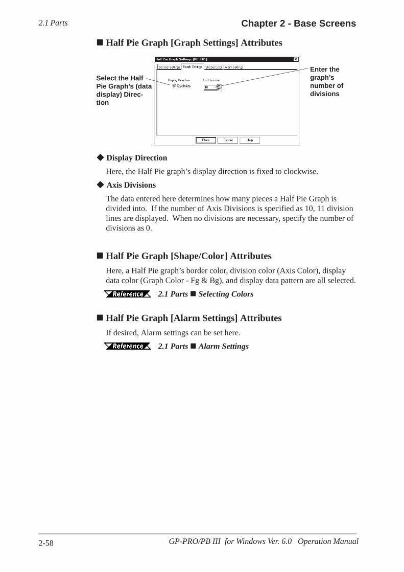
2.1 Parts Chapter 2 - Base Screens
2-58 GP-PRO/PB III for Windows Ver. 6.0 Operation Manual
Display Direction
Here, the Half Pie graph’s display direction is fixed to clockwise.
Axis Divisions
The data entered here determines how many pieces a Half Pie Graph isdivided into. If the number of Axis Divisions is specified as 10, 11 divisionlines are displayed. When no divisions are necessary, specify the number ofdivisions as 0.
Half Pie Graph [Shape/Color] AttributesHere, a Half Pie graph’s border color, division color (Axis Color), displaydata color (Graph Color - Fg & Bg), and display data pattern are all selected.
2.1 Parts Selecting Colors
Half Pie Graph [Alarm Settings] AttributesIf desired, Alarm settings can be set here.
2.1 Parts Alarm Settings
Select the HalfPie Graph’s (datadisplay) Direc-tion
Enter thegraph’snumber ofdivisions
Half Pie Graph [Graph Settings] Attributes

2.1 PartsChapter 2 - Base Screens
2-59GP-PRO/PB III for Windows Ver. 6.0 Operation Manual
PROCEDURE R E M A R K S
Enter D00102
Select BCD
2.1 Parts Se-lecting a Part Shape
(3)Select a Part Shape from the Browser.You can also use the Alarm Settings area to enter Alarmsettings and select Colors, if desired.
(1)Select the [Parts] menu - [Half Pie Graph] command,or click on the icon.
(2)In the [General Settings] area, input the Word Ad-dress and Data Format.
Placing a Half Pie GraphThe procedure for placing a Half Pie Graph is as shown below.
Semicircle Graph
When data 34 is stored in D0102, theHalf Pie graph will appear as follows:
Data stored in D0102 displays on the Semicircle Graph
HG_3D001
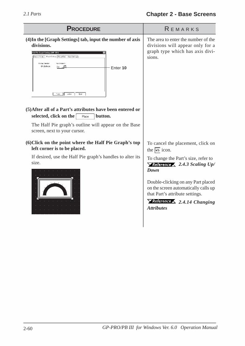
2.1 Parts Chapter 2 - Base Screens
2-60 GP-PRO/PB III for Windows Ver. 6.0 Operation Manual
PROCEDURE R E M A R K S
To cancel the placement, click onthe icon.
To change the Part’s size, refer to2.4.3 Scaling Up/
Down
Double-clicking on any Part placedon the screen automatically calls upthat Part’s attribute settings.
2.4.14 ChangingAttributes
The area to enter the number of thedivisions will appear only for agraph type which has axis divi-sions.
(5)After all of a Part’s attributes have been entered orselected, click on the button.
The Half Pie graph’s outline will appear on the Basescreen, next to your cursor.
(6)Click on the point where the Half Pie Graph’s topleft corner is to be placed.
If desired, use the Half Pie graph’s handles to alter itssize.
(4)In the [Graph Settings] tab, input the number of axisdivisions.
Enter 10

2.1 PartsChapter 2 - Base Screens
2-61GP-PRO/PB III for Windows Ver. 6.0 Operation Manual
2.1.10 Tank Graphs
Enter commentdata here
Select Absolute orRelative display
Enter the WordAddress tostore graphdata
Select thedesired DataFormatCalls up the Part
Shape Browser.Parts Shapes canbe selecteddirectly from theBrowser
The currentlyselected TankGraph’s imageappears here
Absolute
Data stored in the designated Word Address is displayed as absolute values,from 0 to 100 (with Display Mode +/- selected, -100 to 100).
Word Address
Enter the Word Address where the data will be stored.
Display Mode
Select the display data format from Bin and BCD.
Display Mode +/-
When this check box is checked and Bin data format is selected, nega-tive numeric data can be displayed.
This Part creates an area where a Word Address’ numeric data received fromthe Host (PLC) is displayed as absolute or relative values in a special “Tank”shaped graph. The graph’s display will change to reflect changes in WordAddress data.
Regarding the following parts, if the value of 100 on the scale is displayed, thegraph area may not be filled completely depending on display magnification.In this case, the graph can be displayed properly by enlarging or reducing thepart by one dot.
· Part file name: op4-3d01.pdbGR_3D007, GR_3D008, GR_3D010, GR_3D015, GR_3D017
· Part file name: op4-p101.pdbGR_PL007, GR_PL008, GR_PL010, GR_PL015, GR_PL017
Tank Graph [General Settings] Attributes<When displaying data in absolute values>
Note:
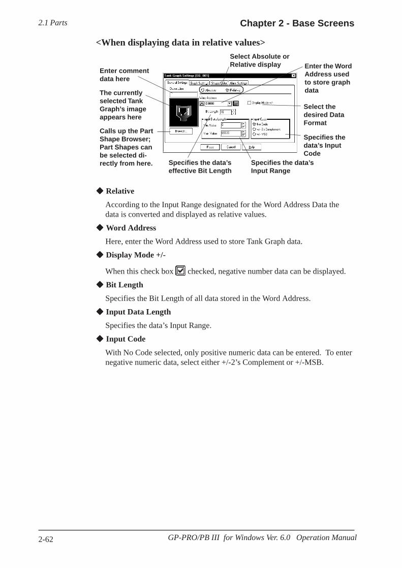
2.1 Parts Chapter 2 - Base Screens
2-62 GP-PRO/PB III for Windows Ver. 6.0 Operation Manual
Enter commentdata here
Select Absolute orRelative display Enter the Word
Address usedto store graphdata
Select thedesired DataFormat
Specifies thedata’s InputCode
Specifies the data’sInput Range
Specifies the data’seffective Bit Length
Calls up the PartShape Browser;Part Shapes canbe selected di-rectly from here.
The currentlyselected TankGraph’s imageappears here
Relative
According to the Input Range designated for the Word Address Data thedata is converted and displayed as relative values.
Word Address
Here, enter the Word Address used to store Tank Graph data.
Display Mode +/-
When this check box checked, negative number data can be displayed.
Bit Length
Specifies the Bit Length of all data stored in the Word Address.
Input Data Length
Specifies the data’s Input Range.
Input Code
With No Code selected, only positive numeric data can be entered. To enternegative numeric data, select either +/-2’s Complement or +/-MSB.
<When displaying data in relative values>
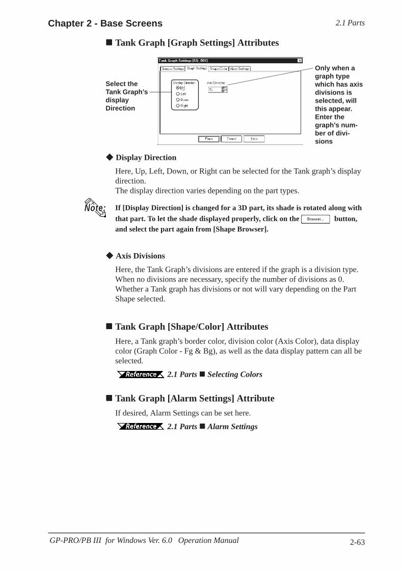
2.1 PartsChapter 2 - Base Screens
2-63GP-PRO/PB III for Windows Ver. 6.0 Operation Manual
Display Direction
Here, Up, Left, Down, or Right can be selected for the Tank graph’s displaydirection.The display direction varies depending on the part types.
If [Display Direction] is changed for a 3D part, its shade is rotated along withthat part. To let the shade displayed properly, click on the button,and select the part again from [Shape Browser].
Axis Divisions
Here, the Tank Graph’s divisions are entered if the graph is a division type.When no divisions are necessary, specify the number of divisions as 0.Whether a Tank graph has divisions or not will vary depending on the PartShape selected.
Tank Graph [Shape/Color] AttributesHere, a Tank graph’s border color, division color (Axis Color), data displaycolor (Graph Color - Fg & Bg), as well as the data display pattern can all beselected.
2.1 Parts Selecting Colors
Tank Graph [Alarm Settings] AttributeIf desired, Alarm Settings can be set here.
2.1 Parts Alarm Settings
Select theTank Graph’sdisplayDirection
Only when agraph typewhich has axisdivisions isselected, willthis appear.Enter thegraph’s num-ber of divi-sions
Tank Graph [Graph Settings] Attributes
Note:

2.1 Parts Chapter 2 - Base Screens
2-64 GP-PRO/PB III for Windows Ver. 6.0 Operation Manual
Data stored in D0102 displays on the Tank Graph
When data 34 is stored in D0102, the TankGraph will appear as follows:
PROCEDURE R E M A R K S
Enter D00102
Select BCD
2.1 Parts Se-lecting a Part Shape
(3)Select a Part Shape from the Browser.You can also use the Alarm Settings area to enter Alarmsettings and select Colors, if desired.
(1)Select the [Parts] menu - [Tank Graph] command,or click on the icon.
(2)In the [General Settings] area, input the Word Ad-dress and Data Format.
Placing a Tank GraphThe procedure for placing a Tank Graph is as shown below.
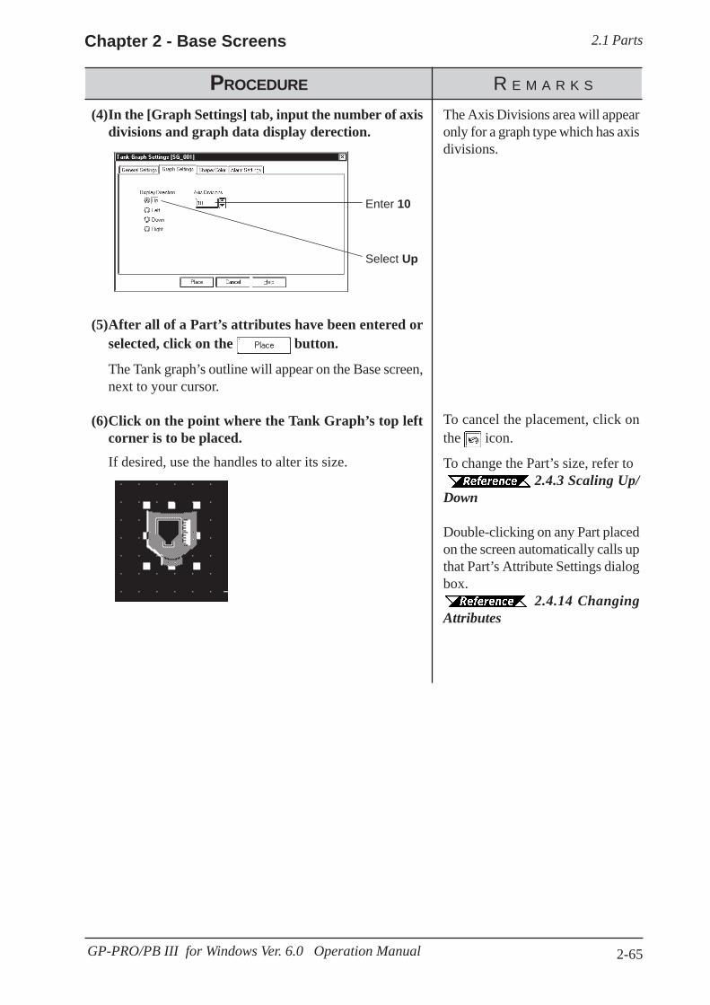
2.1 PartsChapter 2 - Base Screens
2-65GP-PRO/PB III for Windows Ver. 6.0 Operation Manual
PROCEDURE R E M A R K S
Enter 10
Select Up
To cancel the placement, click onthe icon.
To change the Part’s size, refer to2.4.3 Scaling Up/
Down
Double-clicking on any Part placedon the screen automatically calls upthat Part’s Attribute Settings dialogbox.
2.4.14 ChangingAttributes
The Axis Divisions area will appearonly for a graph type which has axisdivisions.
(5)After all of a Part’s attributes have been entered orselected, click on the button.
The Tank graph’s outline will appear on the Base screen,next to your cursor.
(6)Click on the point where the Tank Graph’s top leftcorner is to be placed.
If desired, use the handles to alter its size.
(4)In the [Graph Settings] tab, input the number of axisdivisions and graph data display derection.

2.1 Parts Chapter 2 - Base Screens
2-66 GP-PRO/PB III for Windows Ver. 6.0 Operation Manual
This Part creates an area where a PLC’s Word Address’ numeric data isdisplayed as absolute or relative values in a Meter (i.e. a needle moves toshow the value). The graph’s display will change to reflect PLC WordAddress data changes.
Meter [General Settings] Attributes<When displaying data in absolute values>
2.1.11 Meters
Enter commentdata here
Select Absolute orRelative display
Enter thedesired WordAddress data
Select thedesired DataFormat
Calls up the PartShape Browser;Parts Shapes canbe selecteddirectly from theBrowser.
The currentlyselected MeterGraph’s imageappears here
Absolute
Data stored in the designated Word Address is displayed as absolute values,from 0 to 100 (with Display Mode +/- selected, -100 to 100).
Word Address
Enter the Word Address where the data will be stored.
Data Format
Select the display data format from Bin and BCD.
Display Mode +/-
When this check box is checked and Bin data format is selected, nega-tive numeric data can be displayed.
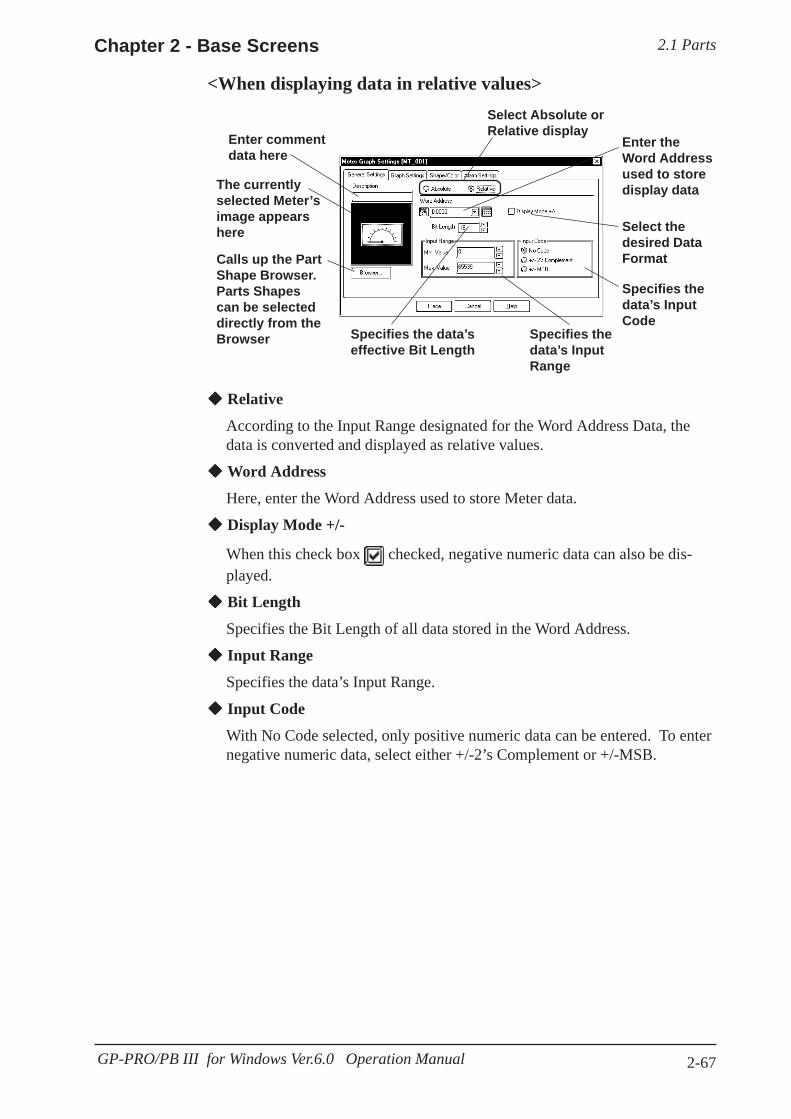
2.1 PartsChapter 2 - Base Screens
2-67GP-PRO/PB III for Windows Ver.6.0 Operation Manual
Enter commentdata here
Select Absolute orRelative display
Enter theWord Addressused to storedisplay data
Select thedesired DataFormat
Specifies thedata’s InputCode
Specifies thedata’s InputRange
Specifies the data’seffective Bit Length
Calls up the PartShape Browser.Parts Shapescan be selecteddirectly from theBrowser
The currentlyselected Meter’simage appearshere
Relative
According to the Input Range designated for the Word Address Data, thedata is converted and displayed as relative values.
Word Address
Here, enter the Word Address used to store Meter data.
Display Mode +/-
When this check box checked, negative numeric data can also be dis-played.
Bit Length
Specifies the Bit Length of all data stored in the Word Address.
Input Range
Specifies the data’s Input Range.
Input Code
With No Code selected, only positive numeric data can be entered. To enternegative numeric data, select either +/-2’s Complement or +/-MSB.
<When displaying data in relative values>
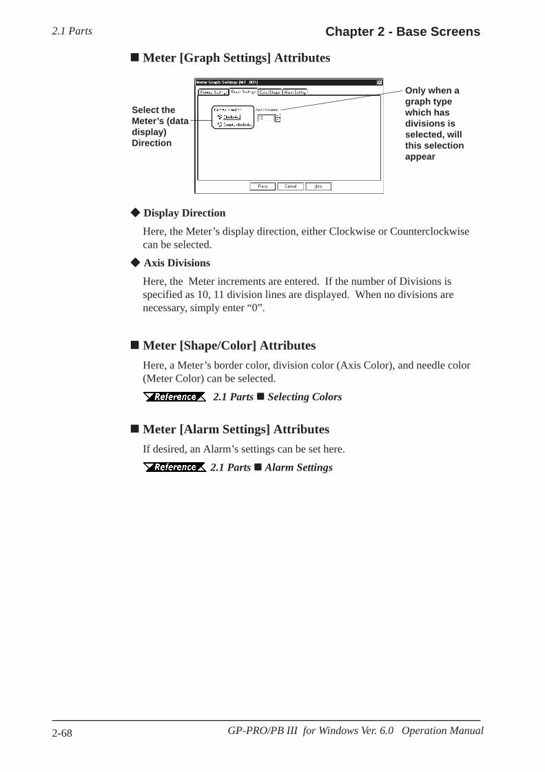
2.1 Parts Chapter 2 - Base Screens
2-68 GP-PRO/PB III for Windows Ver. 6.0 Operation Manual
Select theMeter’s (datadisplay)Direction
Only when agraph typewhich hasdivisions isselected, willthis selectionappear
Display Direction
Here, the Meter’s display direction, either Clockwise or Counterclockwisecan be selected.
Axis Divisions
Here, the Meter increments are entered. If the number of Divisions isspecified as 10, 11 division lines are displayed. When no divisions arenecessary, simply enter “0”.
Meter [Shape/Color] AttributesHere, a Meter’s border color, division color (Axis Color), and needle color(Meter Color) can be selected.
2.1 Parts Selecting Colors
Meter [Alarm Settings] AttributesIf desired, an Alarm’s settings can be set here.
2.1 Parts Alarm Settings
Meter [Graph Settings] Attributes
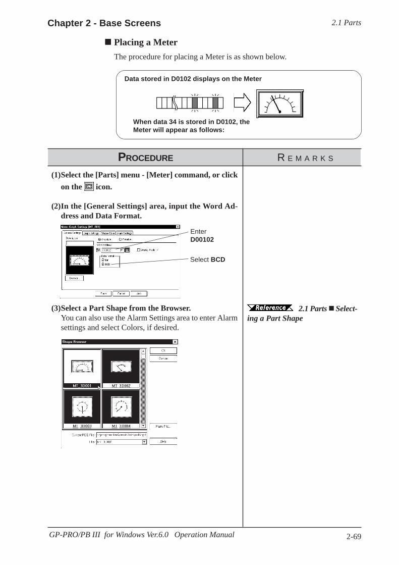
2.1 PartsChapter 2 - Base Screens
2-69GP-PRO/PB III for Windows Ver.6.0 Operation Manual
Data stored in D0102 displays on the Meter
When data 34 is stored in D0102, theMeter will appear as follows:
PROCEDURE R E M A R K S
EnterD00102
Select BCD
2.1 Parts Select-ing a Part Shape
(3)Select a Part Shape from the Browser.You can also use the Alarm Settings area to enter Alarmsettings and select Colors, if desired.
(1)Select the [Parts] menu - [Meter] command, or clickon the icon.
(2)In the [General Settings] area, input the Word Ad-dress and Data Format.
Placing a MeterThe procedure for placing a Meter is as shown below.

2.1 Parts Chapter 2 - Base Screens
2-70 GP-PRO/PB III for Windows Ver. 6.0 Operation Manual
To cancel the placement, click onthe icon.
To change the Part’s size, refer to2.4.3 Scaling Up/
Down
Double-clicking on any Part placedon the screen automatically calls upthat Part’s attribute settings.
2.4.14 ChangingAttributes
PROCEDURE R E M A R K S
Enter 10
Select Clockwise
The Axis Divisions will appear fora Meter type which has axis divi-sions.
(5)After all of a Part’s attributes have been entered orselected, click on the button.
The Meter’s outline will appear on the Base screen, nextto your cursor.
(6)Click on the point where the Meter’s top left corneris to be placed.
If desired, use the Meter’s handle to alter its size.
(4)In the [Graph Settings] area, input the number ofdivisions and data display direction.
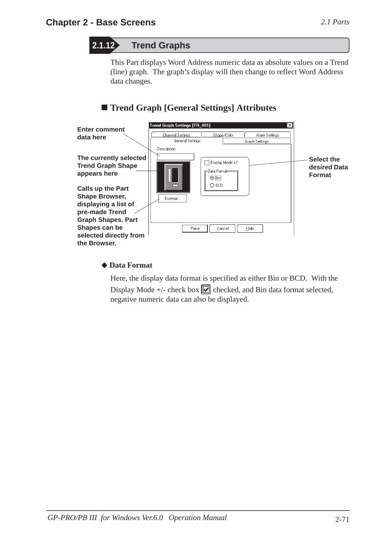
2.1 PartsChapter 2 - Base Screens
2-71GP-PRO/PB III for Windows Ver.6.0 Operation Manual
This Part displays Word Address numeric data as absolute values on a Trend(line) graph. The graph’s display will then change to reflect Word Addressdata changes.
Trend Graph [General Settings] Attributes
2.1.12 Trend Graphs
Enter commentdata here
Select thedesired DataFormat
Calls up the PartShape Browser,displaying a list ofpre-made TrendGraph Shapes. PartShapes can beselected directly fromthe Browser.
The currently selectedTrend Graph Shapeappears here
Data Format
Here, the display data format is specified as either Bin or BCD. With theDisplay Mode +/- check box checked, and Bin data format selected,negative numeric data can also be displayed.

2.1 Parts Chapter 2 - Base Screens
2-72 GP-PRO/PB III for Windows Ver. 6.0 Operation Manual
Using “Pen-Recorder”:A specified Word Address’s data changes are displayedover time in a Trend Graph. The data’s display alwaysbegins with “0”. As each sampling period elapses, thegraph’s poly(gonal) line is shifted one division oppositethe specified display Direction. The latest data isalways displayed at the very limit (in this example, theright side) of the Trend Graph’s display area.
E.g.) Display direction: Right
Note:
Select a graph type
Enter the No. ofSamples, Scrollvalue, and Sam-pling Time
Enter the numberof X and Y divi-sions
Select the datadisplay direction
Graph Settings
Using “Normal”: The specified Word Address’s data changes are dis-played over time in a Trend Graph. Display dataalways starts at the “0” point. As each (time) samplingperiod elapses, the latest data is added in the specifieddisplay Direction. When the graph’s poly (gonal) linereaches the limit of the Trend Graph, the graph isshifted in the display Direction for the number unitsspecified in “Scroll”.
E.g.) Display Direction: Right
Trend Graph [Graph Settings] Attributes
Enter screen scrollsat this point
Begin Display
Begin Display

2.1 PartsChapter 2 - Base Screens
2-73GP-PRO/PB III for Windows Ver.6.0 Operation Manual
Designates orenters the num-ber of data lines(channels) to bedisplayed on theTrend Graph
Enters theWord Addressused to storethe currentchannel’sdisplay data
Selects thecolor and typeof line usedfor the currentchannel
Designates thechannel beingcurrently se-lected
Number of Channels
Enter the number of channels used in the Trend Graph. Use the “CurrentChannel” area to select which channel is being specified. Up to 8 channelscan be designated for a single screen, and up to 20 channels can be enteredin a Project file (PRW file).
Word Address
Enter the Word Address used to indicate where the Trend graph’s data isstored.
Data Samples
Data Samples: The number of data “units” to be displayed in a singleTrend Graph. Up to 638 can be used.
Scroll: The number of data units to be scrolled when thepolygonal line reaches the limit of the Trend Graph’sdisplay area.
Sampling Time: The data read interval (from the host PLC) is input inseconds.
Display Direction
Select the Trend Graph’s display direction, either Up, Left, Down, or Right.If [Display Direction] is changed for a 3D part, its shade is rotated along withthat part. To let the shade displayed properly, click on the button,and select the part again from [Shape Browser].
Axis Scale
Enter the number of units that the X and Y axes are to be divided into.When no divisions are necessary, input “0”.
Trend Graph [Channel Settings] Attributes

2.1 Parts Chapter 2 - Base Screens
2-74 GP-PRO/PB III for Windows Ver. 6.0 Operation Manual
Trend Graph [Shape/Color] AttributesThe Trend Graph’s border color, division color (Axis Color), and TrendGraph’s display area color (Graph Area Color) can be selected.
2.1 Parts Selecting Colors
Trend Graph [Alarm Settings] AttributesIf desired, an alarm’s settings can be set here.
2.1 Parts Alarm Settings
Placing a Trend GraphAn example of a Trend Graph (scrolling left to right) is shown below.
PROCEDURE R E M A R K S
Select Bin
Data in the range of 0 to 100 canbe displayed on the Trend Graph.When the data range is from -100to 100, check the Display Mode+/- check box.
(1)Select the [Parts] menu - [Trend Graph] command,or click on the icon.
(2)After clicking on the [General Settings] tab, selectthe data format.
Data stored in D0102 is displayed on the Trend Graph
When 34 is stored in D0102the graph will look like this:
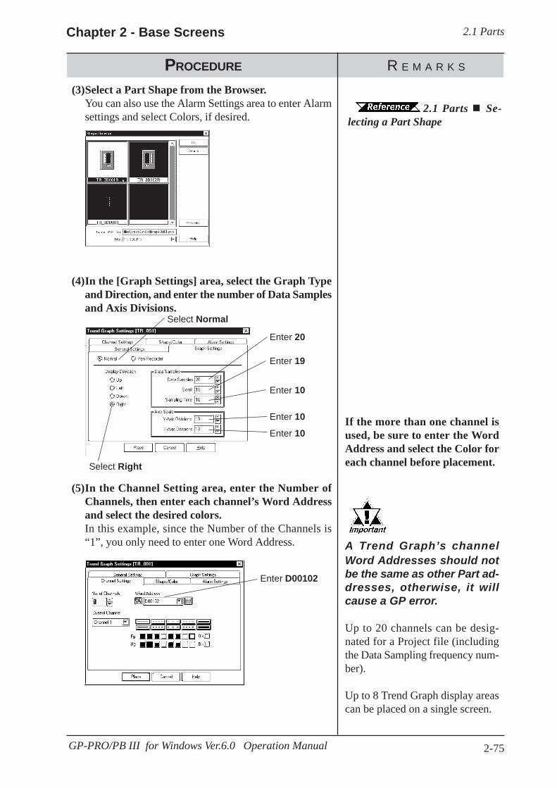
2.1 PartsChapter 2 - Base Screens
2-75GP-PRO/PB III for Windows Ver.6.0 Operation Manual
PROCEDURE R E M A R K S
2.1 Parts Se-lecting a Part Shape
(3)Select a Part Shape from the Browser.You can also use the Alarm Settings area to enter Alarmsettings and select Colors, if desired.
Select Normal
Enter 20
Enter 19
Enter 10
Enter 10Enter 10
Select Right
Enter D00102
If the more than one channel isused, be sure to enter the WordAddress and select the Color foreach channel before placement.
A Trend Graph’s channelWord Addresses should notbe the same as other Part ad-dresses, otherwise, it willcause a GP error.
Up to 20 channels can be desig-nated for a Project file (includingthe Data Sampling frequency num-ber).
Up to 8 Trend Graph display areascan be placed on a single screen.
(5)In the Channel Setting area, enter the Number ofChannels, then enter each channel’s Word Addressand select the desired colors.In this example, since the Number of the Channels is“1”, you only need to enter one Word Address.
(4)In the [Graph Settings] area, select the Graph Typeand Direction, and enter the number of Data Samplesand Axis Divisions.

2.1 Parts Chapter 2 - Base Screens
2-76 GP-PRO/PB III for Windows Ver. 6.0 Operation Manual
PROCEDURE R E M A R K S
To cancel the placement, click onthe icon.
To change a Part’s size, refer to2.4.3 Scaling Up/
DownDouble-clicking on any Part placedon the screen automatically calls upthat Part’s attribute settings.
2.4.14 ChangingAttributes
(6)After all of Part’s attributes have been entered orselected, click on the button.
The Trend Graph’s outline will appear in the Basescreen, next to your cursor.
(7)Click on the point where the Trend Graph’s top leftcorner is to be placed.
If desired, use the Trend Graph’s handles to alter itssize, after placement.
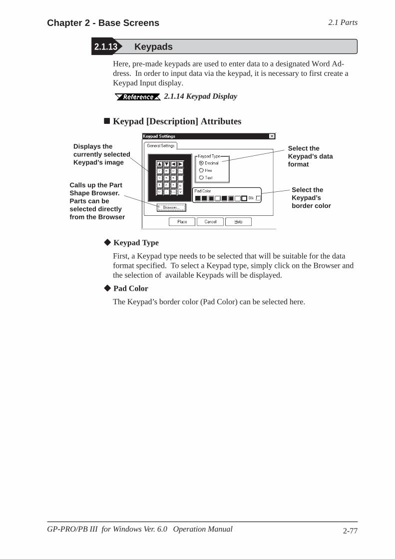
2.1 PartsChapter 2 - Base Screens
2-77GP-PRO/PB III for Windows Ver. 6.0 Operation Manual
Here, pre-made keypads are used to enter data to a designated Word Ad-dress. In order to input data via the keypad, it is necessary to first create aKeypad Input display.
2.1.14 Keypad Display
Keypad [Description] Attributes
2.1.13 Keypads
Select theKeypad’s dataformat
Keypad Type
First, a Keypad type needs to be selected that will be suitable for the dataformat specified. To select a Keypad type, simply click on the Browser andthe selection of available Keypads will be displayed.
Pad Color
The Keypad’s border color (Pad Color) can be selected here.
Displays thecurrently selectedKeypad’s image
Calls up the PartShape Browser.Parts can beselected directlyfrom the Browser
Select theKeypad’sborder color
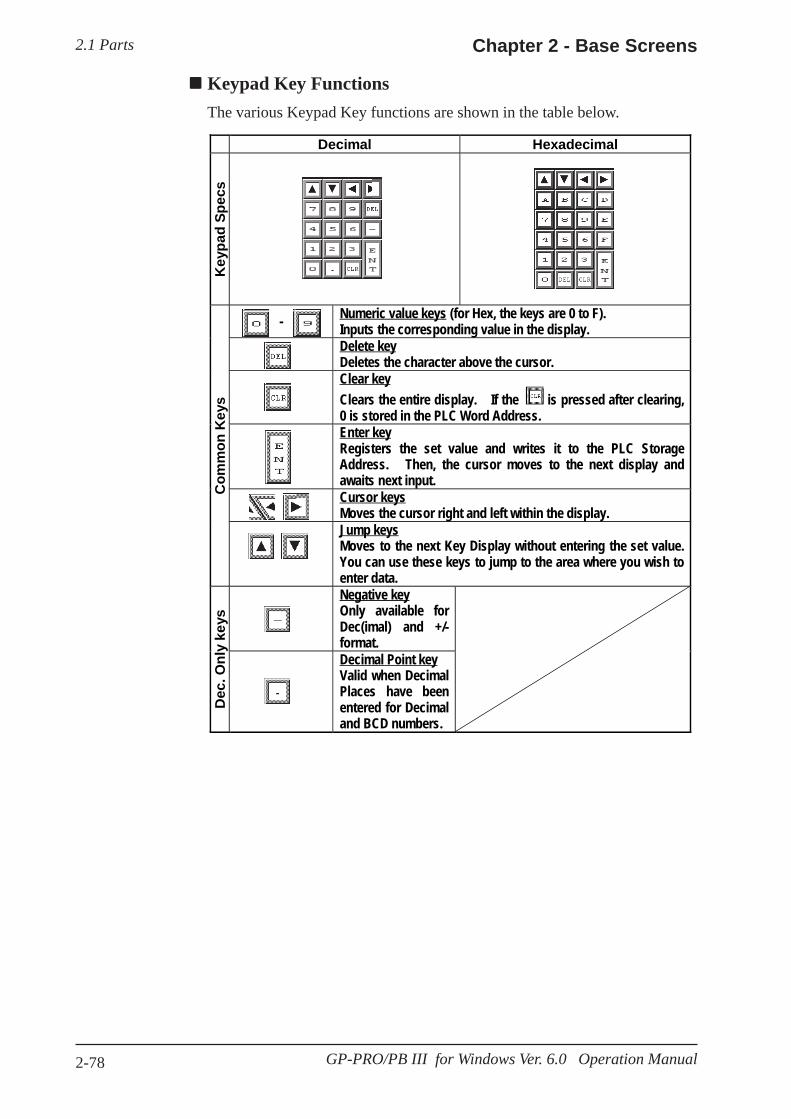
2.1 Parts Chapter 2 - Base Screens
2-78 GP-PRO/PB III for Windows Ver. 6.0 Operation Manual
Keypad Key FunctionsThe various Keypad Key functions are shown in the table below.
Decimal Hexadecimal
Key
pad
Spec
s
- Numeric value keys (for Hex, the keys are 0 to F).Inputs the corresponding value in the display.Delete keyDeletes the character above the cursor.Clear keyClears the entire display. If the is pressed after clearing,0 is stored in the PLC Word Address.Enter keyRegisters the set value and writes it to the PLC StorageAddress. Then, the cursor moves to the next display andawaits next input.Cursor keysMoves the cursor right and left within the display.
Com
mon
Key
s
Jump keysMoves to the next Key Display without entering the set value.You can use these keys to jump to the area where you wish toenter data.Negative keyOnly available forDec(imal) and +/-format.
Dec
. Onl
y ke
ys
Decimal Point keyValid when DecimalPlaces have beenentered for Decimaland BCD numbers.
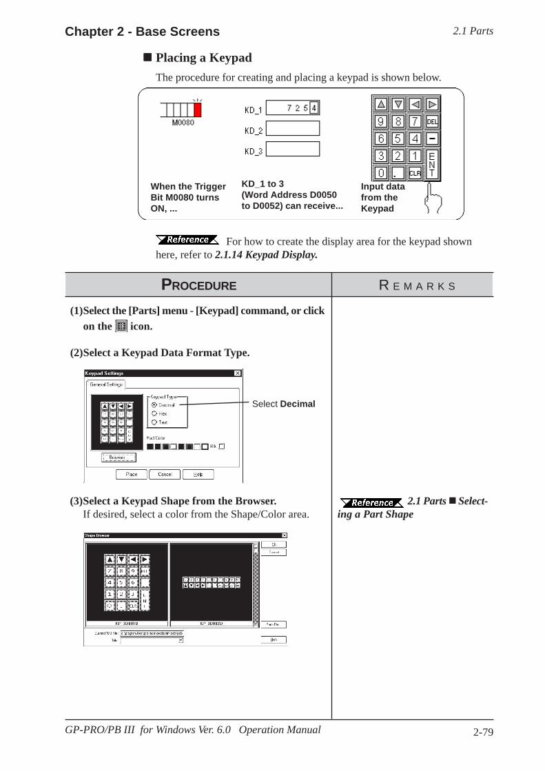
2.1 PartsChapter 2 - Base Screens
2-79GP-PRO/PB III for Windows Ver. 6.0 Operation Manual
2.1 Parts Select-ing a Part Shape
(3)Select a Keypad Shape from the Browser.If desired, select a color from the Shape/Color area.
For how to create the display area for the keypad shownhere, refer to 2.1.14 Keypad Display.
PROCEDURE R E M A R K S
Select Decimal
(1)Select the [Parts] menu - [Keypad] command, or clickon the icon.
(2)Select a Keypad Data Format Type.
Placing a KeypadThe procedure for creating and placing a keypad is shown below.
When the TriggerBit M0080 turnsON, ...
KD_1 to 3(Word Address D0050to D0052) can receive...
Input datafrom theKeypad
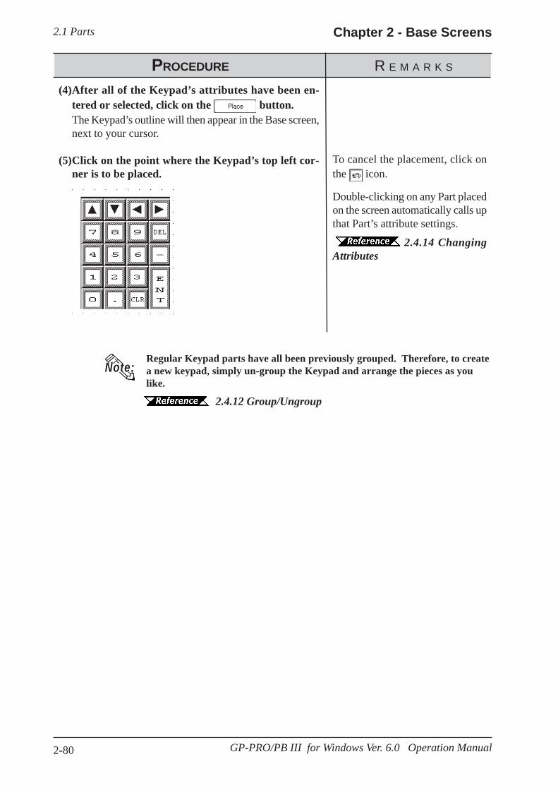
2.1 Parts Chapter 2 - Base Screens
2-80 GP-PRO/PB III for Windows Ver. 6.0 Operation Manual
PROCEDURE R E M A R K S
Note:Regular Keypad parts have all been previously grouped. Therefore, to createa new keypad, simply un-group the Keypad and arrange the pieces as youlike.
2.4.12 Group/Ungroup
Double-clicking on any Part placedon the screen automatically calls upthat Part’s attribute settings.
2.4.14 ChangingAttributes
To cancel the placement, click onthe icon.
(4)After all of the Keypad’s attributes have been en-tered or selected, click on the button.The Keypad’s outline will then appear in the Base screen,next to your cursor.
(5)Click on the point where the Keypad’s top left cor-ner is to be placed.
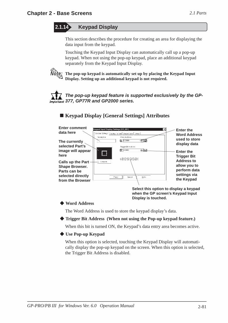
2.1 PartsChapter 2 - Base Screens
2-81GP-PRO/PB III for Windows Ver. 6.0 Operation Manual
Enter commentdata here
2.1.14 Keypad Display
Enter theWord Addressused to storedisplay data
Enter theTrigger BitAddress toallow you toperform datasettings viathe Keypad
Calls up the PartShape Browser.Parts can beselected directlyfrom the Browser
The currentlyselected Part’simage will appearhere
Word Address
The Word Address is used to store the keypad display’s data.
Trigger Bit Address (When not using the Pop-up keypad feature.)
When this bit is turned ON, the Keypad’s data entry area becomes active.
Use Pop-up Keypad
When this option is selected, touching the Keypad Display will automati-cally display the pop-up keypad on the screen. When this option is selected,the Trigger Bit Address is disabled.
Keypad Display [General Settings] Attributes
Note:
The pop-up keypad feature is supported exclusively by the GP-377, GP77R and GP2000 series.
Select this option to display a keypadwhen the GP screen’s Keypad InputDisplay is touched.
The pop-up keypad is automatically set up by placing the Keypad InputDisplay. Setting up an additional keypad is not required.
This section describes the procedure for creating an area for displaying thedata input from the keypad.
Touching the Keypad Input Display can automatically call up a pop-upkeypad. When not using the pop-up keypad, place an additional keypadseparately from the Keypad Input Display.
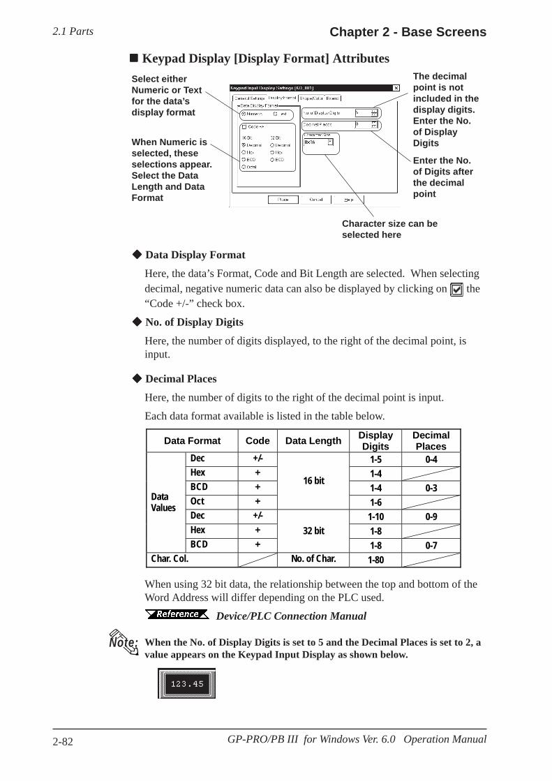
2.1 Parts Chapter 2 - Base Screens
2-82 GP-PRO/PB III for Windows Ver. 6.0 Operation Manual
Data Display Format
Here, the data’s Format, Code and Bit Length are selected. When selectingdecimal, negative numeric data can also be displayed by clicking on the“Code +/-” check box.
No. of Display Digits
Here, the number of digits displayed, to the right of the decimal point, isinput.
Select eitherNumeric or Textfor the data’sdisplay format
The decimalpoint is notincluded in thedisplay digits.Enter the No.of DisplayDigits
Enter the No.of Digits afterthe decimalpoint
Character size can beselected here
When Numeric isselected, theseselections appear.Select the DataLength and DataFormat
Keypad Display [Display Format] Attributes
Data Format Code Data Length Display Digits
Decimal Places
Dec +/- 1-5 0-4 Hex + 1-4 BCD + 1-4 0-3 Oct +
16 bit
1-6 Dec +/- 1-10 0-9 Hex + 1-8
Data Values
BCD + 32 bit
1-8 0-7 Char. Col. No. of Char. 1-80
When using 32 bit data, the relationship between the top and bottom of theWord Address will differ depending on the PLC used.
Device/PLC Connection Manual
When the No. of Display Digits is set to 5 and the Decimal Places is set to 2, avalue appears on the Keypad Input Display as shown below.
Decimal Places
Here, the number of digits to the right of the decimal point is input.
Each data format available is listed in the table below.
Note:

2.1 PartsChapter 2 - Base Screens
2-83GP-PRO/PB III for Windows Ver. 6.0 Operation Manual
Character Size
The label’s character size is selected here.
2.2.9 Text
Keypad Display [Color/Shape] AttributesThe Keypad Display’s border color, data display color (Text), and interiorcolor (Plate) are selected here.
2.1 Parts Selecting Colors
Keypad Display [Extend] AttributesSelect the desired input style.
Input Style
• Auto Clear OFF
The previous input is not cleared and displayed in the input area. The newinput is appended to existing data. To clear the existing values, enter "CLR"from the Touch Keypad.
• Auto Clear ON
The previous input is cleared when the first character (except the cursorkeys, ENT, DEL and BS keys) is entered.
• Auto Clear & Input Digit Monitor
When barcode input is performed in this mode, the Auto Clear function isenabled and the input data are monitored so that it matches the No. DisplayDigit. If the data length is inappropriate, it is not written into the wordaddress. When data is input from the Touch Keypad, only the Auto Clearfunction is enabled.
• Barcode Input
Selecting this feature enables input from the Touch Keypad and barcodereaders.
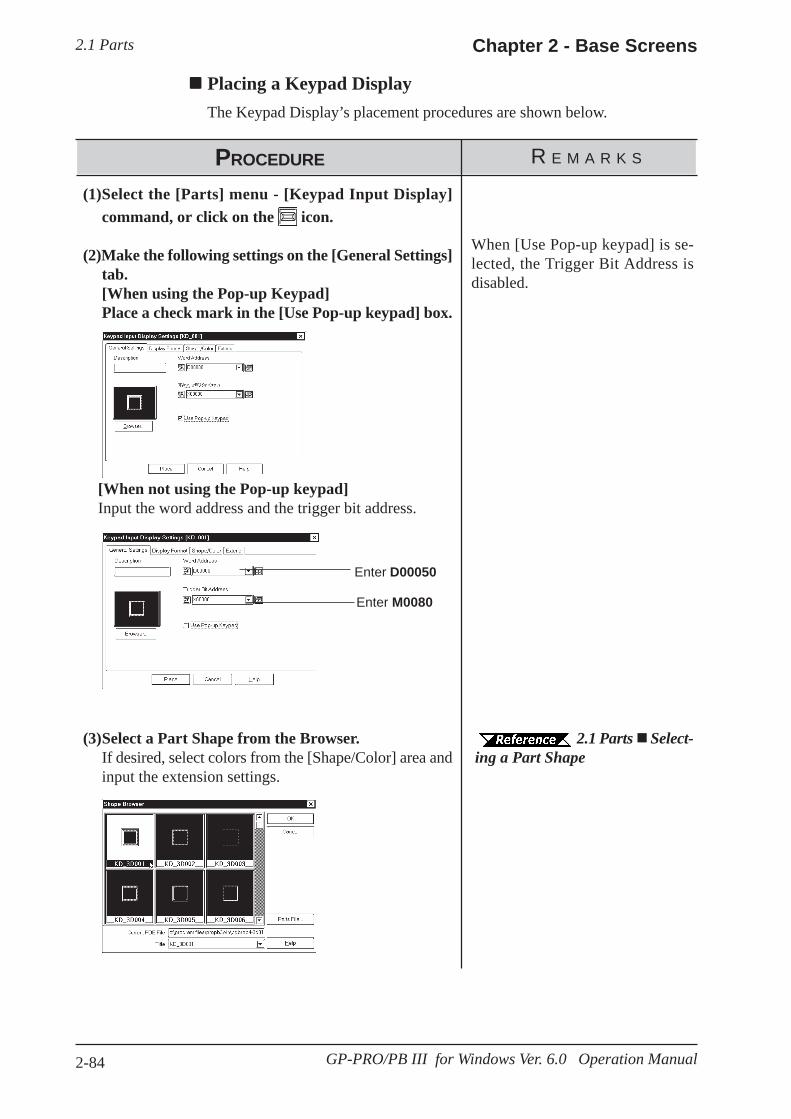
2.1 Parts Chapter 2 - Base Screens
2-84 GP-PRO/PB III for Windows Ver. 6.0 Operation Manual
2.1 Parts Select-ing a Part Shape
(3)Select a Part Shape from the Browser.If desired, select colors from the [Shape/Color] area andinput the extension settings.
PROCEDURE R E M A R K S
(1)Select the [Parts] menu - [Keypad Input Display]command, or click on the icon.
(2)Make the following settings on the [General Settings]tab.[When using the Pop-up Keypad]Place a check mark in the [Use Pop-up keypad] box.
Placing a Keypad DisplayThe Keypad Display’s placement procedures are shown below.
When [Use Pop-up keypad] is se-lected, the Trigger Bit Address isdisabled.
[When not using the Pop-up keypad]Input the word address and the trigger bit address.
Enter D00050
Enter M0080
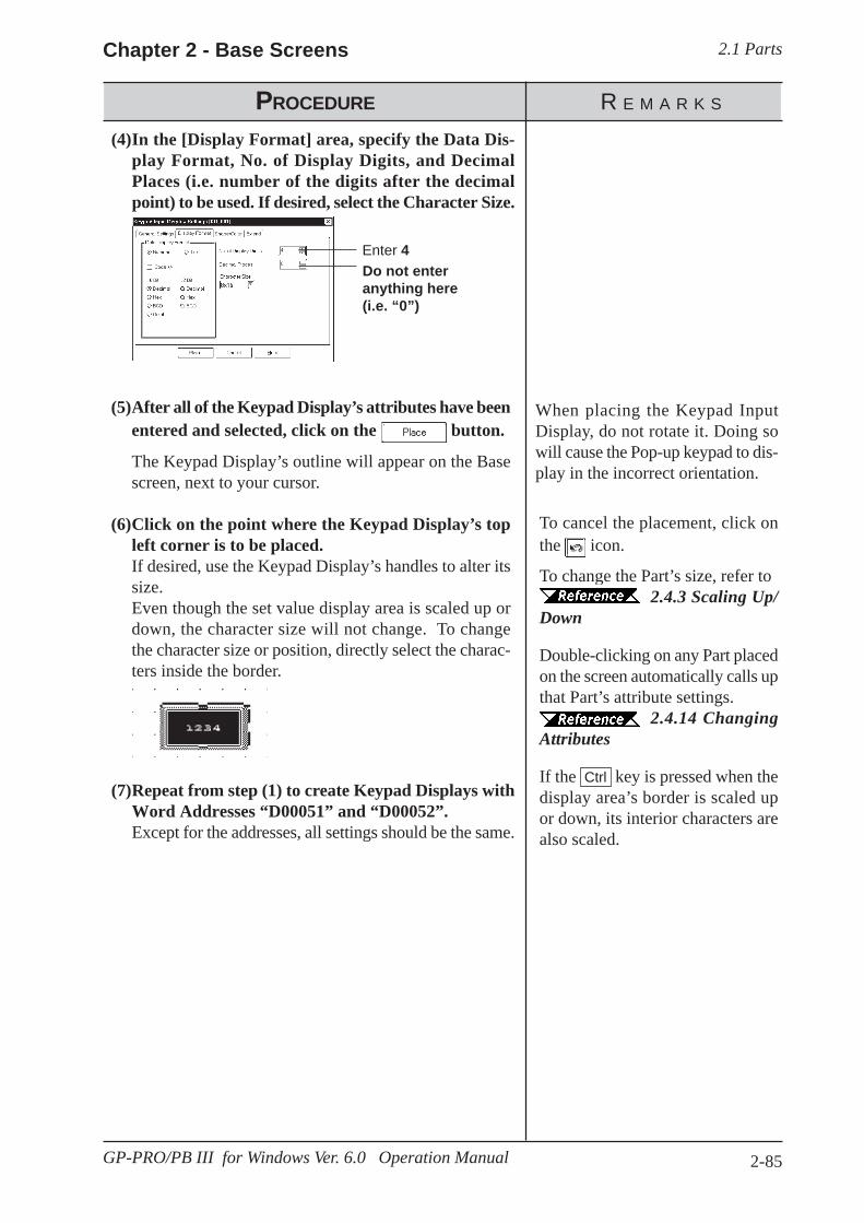
2.1 PartsChapter 2 - Base Screens
2-85GP-PRO/PB III for Windows Ver. 6.0 Operation Manual
To cancel the placement, click onthe icon.
To change the Part’s size, refer to2.4.3 Scaling Up/
Down
Double-clicking on any Part placedon the screen automatically calls upthat Part’s attribute settings.
2.4.14 ChangingAttributes
If the Ctrl key is pressed when thedisplay area’s border is scaled upor down, its interior characters arealso scaled.
PROCEDURE R E M A R K S
Enter 4Do not enteranything here(i.e. “0”)
(7)Repeat from step (1) to create Keypad Displays withWord Addresses “D00051” and “D00052”.Except for the addresses, all settings should be the same.
(5)After all of the Keypad Display’s attributes have beenentered and selected, click on the button.
The Keypad Display’s outline will appear on the Basescreen, next to your cursor.
(6)Click on the point where the Keypad Display’s topleft corner is to be placed.If desired, use the Keypad Display’s handles to alter itssize.Even though the set value display area is scaled up ordown, the character size will not change. To changethe character size or position, directly select the charac-ters inside the border.
(4)In the [Display Format] area, specify the Data Dis-play Format, No. of Display Digits, and DecimalPlaces (i.e. number of the digits after the decimalpoint) to be used. If desired, select the Character Size.
When placing the Keypad InputDisplay, do not rotate it. Doing sowill cause the Pop-up keypad to dis-play in the incorrect orientation.

2.1 Parts Chapter 2 - Base Screens
2-86 GP-PRO/PB III for Windows Ver. 6.0 Operation Manual
PROCEDURE R E M A R K S
ID No.KD _1
KD _2
KD _3
PLC
For how to createa Keypad, refer to 2.1.13 Keypads
For how to createa Keypad Display, refer to 2.1.14Keypad Display Placing a Key-pad Display
(3)First, the Keypad Display KD_1’s display reverses(highlights) and waits for input.The square box shown below represents the cursor’s po-sition.
(2)Then, when the PLC’s internal Trigger Bit M0080turns ON,
(1)Here, three Direct Call-Ups have been set to share acommon start bit.
Using a Keypad to Input ValuesWhen not using the Pop-up keypad
The procedures for entering setting values via a Keypad on the GP screenare shown below.
When the TriggerBit M0080 turnsON...
KD_1 to 3(Word AddressD0050 to D0052)can receive...
Input datafrom theKeypad
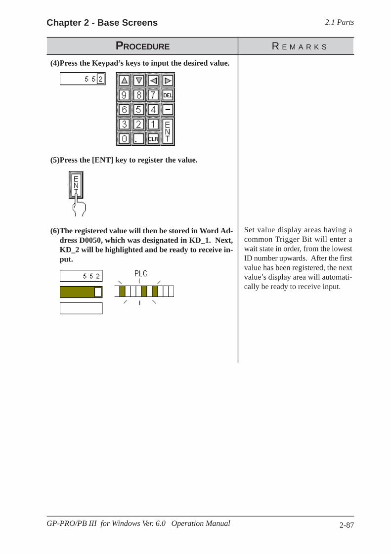
2.1 PartsChapter 2 - Base Screens
2-87GP-PRO/PB III for Windows Ver. 6.0 Operation Manual
PROCEDURE R E M A R K S
Set value display areas having acommon Trigger Bit will enter await state in order, from the lowestID number upwards. After the firstvalue has been registered, the nextvalue’s display area will automati-cally be ready to receive input.
(6)The registered value will then be stored in Word Ad-dress D0050, which was designated in KD_1. Next,KD_2 will be highlighted and be ready to receive in-put.
(5)Press the [ENT] key to register the value.
(4)Press the Keypad’s keys to input the desired value.

2.1 Parts Chapter 2 - Base Screens
2-88 GP-PRO/PB III for Windows Ver. 6.0 Operation Manual
When using the Pop-up keypad
The procedure for positioning the Keypad Input Display featuring the Pop-up Keypad is shown below.
When the KD_1Keypad InputDisplay istouched. . .
The Pop-up Keypadappears, and thetouched display waitsfor input.
Input datausing thePop-upKeypad.
KD_1KD_1 7 2 5 4
PROCEDURE R E M A R K S
(1) The Keypad Input Display "KD_1" is displayed onthe GP screen.
(2) When the KD_1 Keypad Input Display is touched. . .
KD_1ID Number
KD_1
(3) The Pop-up Keypad appears, and the touched display waits for input. The square box shown below represents the cursor’s position.
5 5 2
(4) Touch the appropriate key on the Pop-up Keypad toenter the value.
In the following two cases, the pop-up keypad will disappear with noconfirmation of the input duringdata input:When the active Keypad Input Dis-play is touchedWhen another Keypad InputDisplay is touched during datainput (only when the [Use Pop-up keypad] feature is enabled forKeypad Input Display)
The Keypad Input Display that hasbeen touched becomes active and isdisplayed in reverse video, callingup the pop-up keypad for display onthe screen.
For how to create a Keypad Dis-play, 2.1.14 Key-pad Display Placing a KeypadDisplay
Select this option to display a key-pad when the GP screen’s KeypadInput Display is touched.
WordaddressD0050

2.1 PartsChapter 2 - Base Screens
2-89GP-PRO/PB III for Windows Ver. 6.0 Operation Manual
PROCEDURE R E M A R K S
(5) Press the ENT key to register the value.The Pop-up Keypad will then close.
(6) The registered value will then be stored in Word Ad-dress D0050, which was designated in KD_1.
D0050
When [Cancel] is touched, the Pop-up Keypad closes without register-ing the input value.
Notes for using Pop-up Keypad• Do not specify [High Speed] from [Designated Window] of a U-tag when using
Pop-up Keypad with the Keypad Input Display.• Do not rotate the Keypad Input Display when you position it. Otherwise, the
Pop-up Keypad will not appear in the proper orientation. Restictions for using Pop-up Keypad• If the Keypad Input Display selected does not use the Pop-up Keypad feature or
if the trigger bit in the K-tag is set to ON, the Pop-up Keypad will not appear.• The Pop-up Keypad will appear to the right of the Keypad Input Display.
If there is insufficient space to the right of the Keypad Input Display to displaythe Pop-up Keypad, the Keypad automatically appears in a position eitherabove, below, or to the left of the Keypad Input Display.
• If there is insufficient space in each of these positions, the Keypad will appearin the lower right corner of the screen. In this case, the Pop-up Keypad and theKeypad Input Display may overlap so that you cannot see the input value.
• The Pop-up Keypad is displayed as a local window. When two local windowsare already displayed on the screen, the Pop-up Keypad does not appear even ifthe Keypad Input Display is touched. In this case, the Keypad Input Displaywill not wait for input.
• When the pop-up keypad and other windows overlap, touch the desired window to bring it to the front.
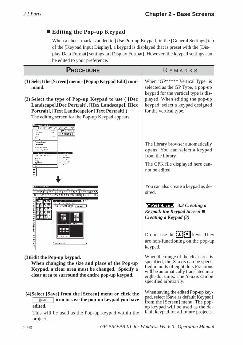
2.1 Parts Chapter 2 - Base Screens
2-90 GP-PRO/PB III for Windows Ver. 6.0 Operation Manual
Editing the Pop-up KeypadWhen a check mark is added to [Use Pop-up Keypad] in the [General Settings] tabof the [Keypad Input Display], a keypad is displayed that is preset with the [Dis-play Data Format] settings in [Display Format]. However, the keypad settings canbe edited to your preference.
PROCEDURE R E M A R K S
(1) Select the [Screen] menu - [Popup Keypad Edit] com-mand.
(2) Select the type of Pop-up Keypad to use ( [DecLandscape],[Dec Portrait], [Hex Landscape], [HexPortrait], [Text Landscape]or [Text Portrait].)The editing screen for the Pop-up Keypad appears.
(3)Edit the Pop-up keypad.When changing the size and place of the Pop-upKeypad, a clear area must be changed. Specify aclear area to surround the entire pop-up keypad.
When "GP***** Vertical Type" isselected as the GP Type, a pop-upkeypad for the vertical type is dis-played. When editing the pop-upkeypad, select a keypad designedfor the vertical type.
The library browser automaticallyopens. You can select a keypadfrom the library.
The CPK file displayed here can-not be edited.
You can also create a keypad as de-sired.
3.3 Creating aKeypad: the Keypad Screen Creating a Keypad (3)
Do not use the keys. Theyare non-functioning on the pop-upkeypad.
When the range of the clear area isspecified, the X-axis can be speci-fied in units of eight dots.Fractionswill be automatically translated intoeight-dot units. The Y-axis can bespecified arbitrarily.
(4)Select [Save] from the [Screen] menu or click the icon to save the pop-up keypad you have
edited.This will be used as the Pop-up keypad within theproject.
When saving the edited Pop-up key-pad, select [Save as default Keypad]from the [Screen] menu. The pop-up keypad will be used as the de-fault keypad for all future projects.

2.1 PartsChapter 2 - Base Screens
2-91GP-PRO/PB III for Windows Ver. 6.0 Operation Manual
When the PLC Monitor Bit has been turned ON, messages registered in theAlarm Summary by the Alarm Editor, can be displayed in a list.
Chapter 5 CREATING AND EDITING ALARMSMessage display order is decided according to which Monitor Bit is in thelowest position in the Alarm Summary display area. It is recommended thatMonitor Bit assignment begins from the message with the highest priority.Be sure to input only one message per line. The characters of a messagethat exceed one line will be truncated.The number of the characters that can be displayed in one line will varydepending on the character size and GP type. When the size is 1 x 1, themaximum number of characters that can be displayed per line for each GPmodel is:
Alarm Summary [Description] Attributes
2.1.15 Alarm Display
Enter Commentdata here
Enter the startaddress foreachmessage’sMonitor Bit
Enter thenumber ofWords allo-cated for aMonitor Bit
Select the displayarea border(frame)
In this case, Y010 isdesignated
In this case, M0144 isdesignated
Border Type
The display area frame types are No Border, Outside, and Outside + Inside.
Word Address
The Monitor Bit’s first address for the messages specified by the AlarmEditor is input. Input this address in word units.
E.g.) How to designate a Word Address (MELSEC-A Series - Mitsubishi):When designating the Word Address for the input/output or internalrelay, the Word Address is designated from the Least Significant Bit.
← High Low→ LSB ← High Low→ LSB
Maximum Number ofCharacters GP Type
40 GP-H70, GP-270, GP-370, GP-377, GP-377R, GP-2301H, GP-2300, GP-2301
80 GP-470, GP-570, GP-571, GP-870, GP-477R, GP-577R, GP-2401H, GP-2400, GP-2500, GP-2501
100 GP-675, GP-2600
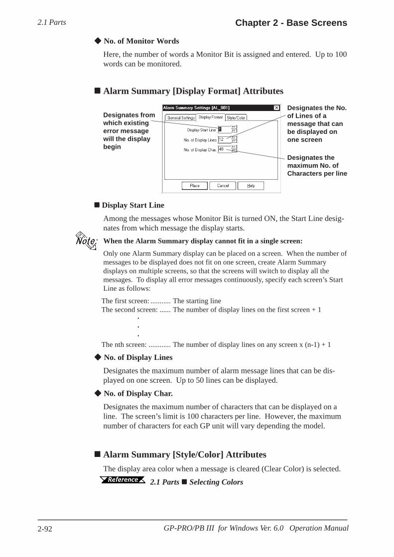
2.1 Parts Chapter 2 - Base Screens
2-92 GP-PRO/PB III for Windows Ver. 6.0 Operation Manual
Display Start Line
Among the messages whose Monitor Bit is turned ON, the Start Line desig-nates from which message the display starts.When the Alarm Summary display cannot fit in a single screen:
Only one Alarm Summary display can be placed on a screen. When the number ofmessages to be displayed does not fit on one screen, create Alarm Summarydisplays on multiple screens, so that the screens will switch to display all themessages. To display all error messages continuously, specify each screen’s StartLine as follows:
The first screen: ........... The starting lineThe second screen: ...... The number of display lines on the first screen + 1
···
The nth screen: ............ The number of display lines on any screen x (n-1) + 1
No. of Display Lines
Designates the maximum number of alarm message lines that can be dis-played on one screen. Up to 50 lines can be displayed.
No. of Display Char.
Designates the maximum number of characters that can be displayed on aline. The screen’s limit is 100 characters per line. However, the maximumnumber of characters for each GP unit will vary depending the model.
Alarm Summary [Style/Color] AttributesThe display area color when a message is cleared (Clear Color) is selected.
2.1 Parts Selecting Colors
Designates fromwhich existingerror messagewill the displaybegin
Designates the No.of Lines of amessage that canbe displayed onone screen
Designates themaximum No. ofCharacters per line
No. of Monitor Words
Here, the number of words a Monitor Bit is assigned and entered. Up to 100words can be monitored.
Alarm Summary [Display Format] Attributes
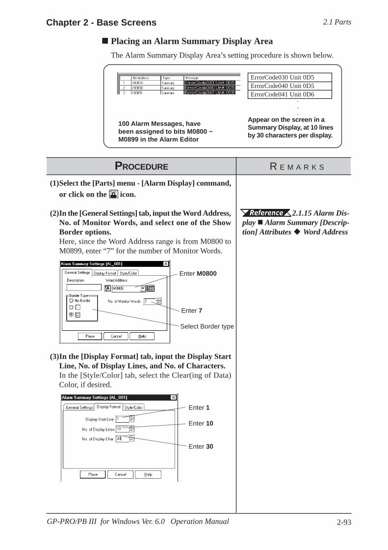
2.1 PartsChapter 2 - Base Screens
2-93GP-PRO/PB III for Windows Ver. 6.0 Operation Manual
Enter 1
Enter 30
Enter 10
(3)In the [Display Format] tab, input the Display StartLine, No. of Display Lines, and No. of Characters.In the [Style/Color] tab, select the Clear(ing of Data)Color, if desired.
100 Alarm Messages, havebeen assigned to bits M0800 ~M0899 in the Alarm Editor
Appear on the screen in aSummary Display, at 10 linesby 30 characters per display.
PROCEDURE R E M A R K S
ErrorCode030 Unit 0D5ErrorCode040 Unit 0D5ErrorCode041 Unit 0D6
···
Enter M0800
Select Border type
Enter 7
2.1.15 Alarm Dis-play Alarm Summary [Descrip-tion] Attributes Word Address
(1)Select the [Parts] menu - [Alarm Display] command,or click on the icon.
(2)In the [General Settings] tab, input the Word Address,No. of Monitor Words, and select one of the ShowBorder options.Here, since the Word Address range is from M0800 toM0899, enter “7” for the number of Monitor Words.
Placing an Alarm Summary Display AreaThe Alarm Summary Display Area’s setting procedure is shown below.

2.1 Parts Chapter 2 - Base Screens
2-94 GP-PRO/PB III for Windows Ver. 6.0 Operation Manual
PROCEDURE R E M A R K S
To cancel placement, click on the icon.
To change the Part size, refer to2.4.3 Scaling Up/
Down
Double-clicking on any Part placedon the screen automatically calls upthat Part’s Attribute Settings dialogbox.
2.4.14 ChangingAttributes
Be sure to use the AlarmSummary’s display area onlyfor displaying Alarm Mes-sages, i.e. never place, over-lap, or overlay another Part orobject in this area.
(4)After all of the Part’s attributes have been enteredand selected, click on the button.The Alarm Summary display area’s border will appearin the Base screen, next to your cursor.
(5)Click on the point where the Alarm Summary dis-play area’s top left corner is to be placed.If desired, use the Alarm Summary display handles toalter its size. When the Alarm Summary display is scaledup or down, the displayed character size will also change,according to the border’s size.

2.1 PartsChapter 2 - Base Screens
2-95GP-PRO/PB III for Windows Ver. 6.0 Operation Manual
Data registered in the Filing Data settings is displayed.
Set up the Filing Data Settings before placing the File NameDisplay. For information on registering the Filing Data:
File Name Display [General Settings] Attributes
2.1.16 File Name Display
Enter a descrip-tion if desired
Specifywhether or notto use the LSarea
Enter the startword addressof the LS area
Enter the IDnumber for theFile NameDisplay and itsfunction switch
Description
Enter a description using a maximum of 20 single-byte characters.
ID No.
The File Name Display is linked to its function switch (File Name Key).Specify the number to identify this link is here. This number is available upto 255.
File No.
Enter the file number registered in the Filing Data list (1 to 2047). Thenames under this number are displayed when the file is opened.
Tag Reference Manual, 4.2 Filing Data (Recipe) Function By Way of LS
When Filing Data is transferred between backup SRAM and the PLC, it canbe modified on the GP screen by routing it via the LS area (the data is storedtemporarily in the LS area). If data transfer via the LS area is used, specifythe LS area’s start-word address where Filing Data will be stored from. Theaddress where the data can be stored is from LS0020 to LS2031, andLS2096 to LS4095 (LS2096 to LS8191 for GP2000 series).
PLC Transfer
This Bit is turned ON when filing data transfer to the PLC is completed.Since this Bit does not turned OFF automatically, to use the PLC TransferCompleted Bit again, turn it OFF beforehand.
When the PLC Transfer Completed Bit Address has been entered, in the casewhere filing data cannot be transferred to the PLC, the GP’s special relayLS2032 Bit 10 will be turned ON.
Enter the File No.of filing data tobe displayed.
Set up thePLC TransferCompleted BitAddress.
Tag Reference Manual, 4.2 Filing Data (Recipe) Function

2.1 Parts Chapter 2 - Base Screens
2-96 GP-PRO/PB III for Windows Ver. 6.0 Operation Manual
File Name Display [Display] Attributes
Specify the nameselection method
Enter thenumber ofnames beingdisplayed
Enter thenumber ofcharactersused for thenames beingdisplayed
Specify thecursor positionretention
No. of Display
Specify the number of Filing Data rows displayed on the GP. A maximum of50 rows may be specified.
No. of Display Characters
Specify the number of Filing Data characters used on each row. A maximumof 100 characters may be specified.
Direct Selection
Select a File Name Display being placed on the GP by directly touching itsborder. If [Direct Selection] is not used, select the file name using the datascroll switches [Roll Up/Roll Down].
File Name Display [Switch Settings] Attributes
Cursor Position Control
Even when the screens are changed on the GP , the current screen’s cursorposition can be retained. When turning the GP’s main power switch ON orresetting the GP, however, the cursor will appear in the first line.
The cursor position will be stored for each ID No. To retain the cursor posi-tion, be sure that the File Name Display ID Nos. will not be overlappedthrough all the screens.
File Name Display [Style/Color] AttributesSpecify a color [display color (Fg)] for characters in the Filing Data displayarea, and a color [display color (Bg)] of the Filing Data display area.
2.1 Parts Selecting Colors
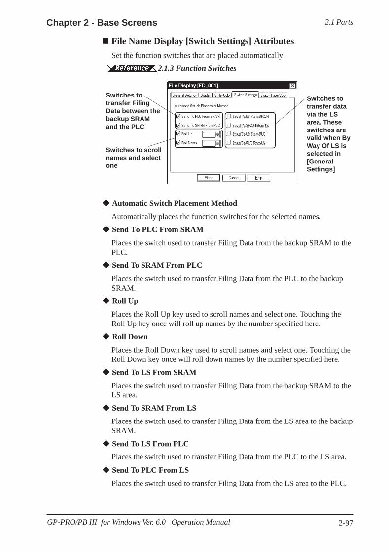
2.1 PartsChapter 2 - Base Screens
2-97GP-PRO/PB III for Windows Ver. 6.0 Operation Manual
File Name Display [Switch Settings] AttributesSet the function switches that are placed automatically.
2.1.3 Function Switches
Switches totransfer FilingData between thebackup SRAMand the PLC
Switches totransfer datavia the LSarea. Theseswitches arevalid when ByWay Of LS isselected in[GeneralSettings]
Switches to scrollnames and selectone
Automatic Switch Placement Method
Automatically places the function switches for the selected names.
Send To PLC From SRAM
Places the switch used to transfer Filing Data from the backup SRAM to thePLC.
Send To SRAM From PLC
Places the switch used to transfer Filing Data from the PLC to the backupSRAM.
Roll Up
Places the Roll Up key used to scroll names and select one. Touching theRoll Up key once will roll up names by the number specified here.
Roll Down
Places the Roll Down key used to scroll names and select one. Touching theRoll Down key once will roll down names by the number specified here.
Send To LS From SRAM
Places the switch used to transfer Filing Data from the backup SRAM to theLS area.
Send To SRAM From LS
Places the switch used to transfer Filing Data from the LS area to the backupSRAM.
Send To LS From PLC
Places the switch used to transfer Filing Data from the PLC to the LS area.
Send To PLC From LS
Places the switch used to transfer Filing Data from the LS area to the PLC.
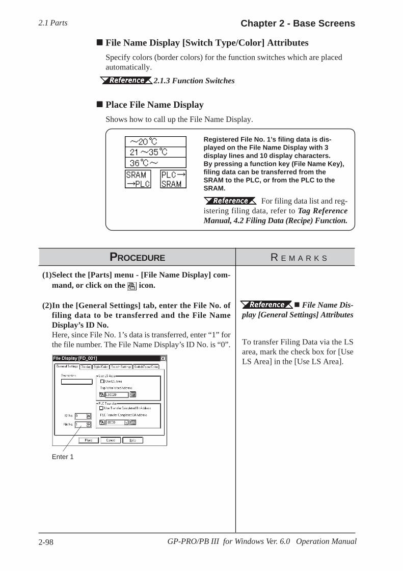
2.1 Parts Chapter 2 - Base Screens
2-98 GP-PRO/PB III for Windows Ver. 6.0 Operation Manual
File Name Display [Switch Type/Color] AttributesSpecify colors (border colors) for the function switches which are placedautomatically.
2.1.3 Function Switches
Place File Name DisplayShows how to call up the File Name Display.
Registered File No. 1’s filing data is dis-played on the File Name Display with 3display lines and 10 display characters.By pressing a function key (File Name Key),filing data can be transferred from theSRAM to the PLC, or from the PLC to theSRAM.
For filing data list and reg-istering filing data, refer to Tag ReferenceManual, 4.2 Filing Data (Recipe) Function.
PROCEDURE R E M A R K S
Enter 1
File Name Dis-play [General Settings] Attributes
To transfer Filing Data via the LSarea, mark the check box for [UseLS Area] in the [Use LS Area].
(1)Select the [Parts] menu - [File Name Display] com-mand, or click on the icon.
(2)In the [General Settings] tab, enter the File No. offiling data to be transferred and the File NameDisplay’s ID No.Here, since File No. 1’s data is transferred, enter “1” forthe file number. The File Name Display’s ID No. is “0”.
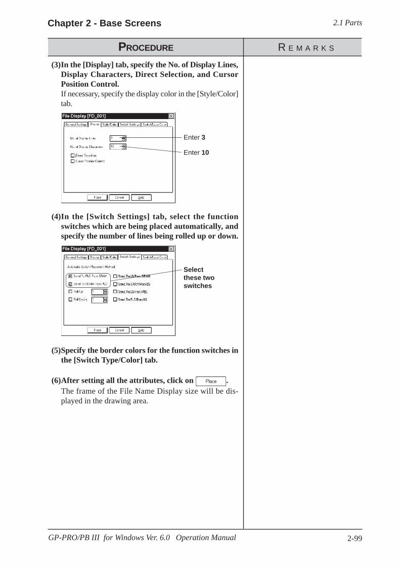
2.1 PartsChapter 2 - Base Screens
2-99GP-PRO/PB III for Windows Ver. 6.0 Operation Manual
PROCEDURE R E M A R K S
(4)In the [Switch Settings] tab, select the functionswitches which are being placed automatically, andspecify the number of lines being rolled up or down.
(3)In the [Display] tab, specify the No. of Display Lines,Display Characters, Direct Selection, and CursorPosition Control.If necessary, specify the display color in the [Style/Color]tab.
Enter 3
Enter 10
(5)Specify the border colors for the function switches inthe [Switch Type/Color] tab.
(6)After setting all the attributes, click on .The frame of the File Name Display size will be dis-played in the drawing area.
Selectthese twoswitches

2.1 Parts Chapter 2 - Base Screens
2-100 GP-PRO/PB III for Windows Ver. 6.0 Operation Manual
PROCEDURE R E M A R K S
To cancel the placement, click onthe icon.
(7)Click the mouse button where you want to place eachattribute.
(8) Select the placed File Name Display. Then, select the[Edit] menu - [Ungroup] command, or click on the
icon to ungroup the File Name Display and altereach item’s position and size.
The File Name Displays aregrouped. To change any attribute,first ungroup the File Name Dis-plays, and then change the attribute.
2 .4 .12 Group/Ungroup
2.4.14 ChangingAttributesIf the By Way Of LS area is se-lected, the address for the LS areacan be changed after ungroupingthe File Name Displays.
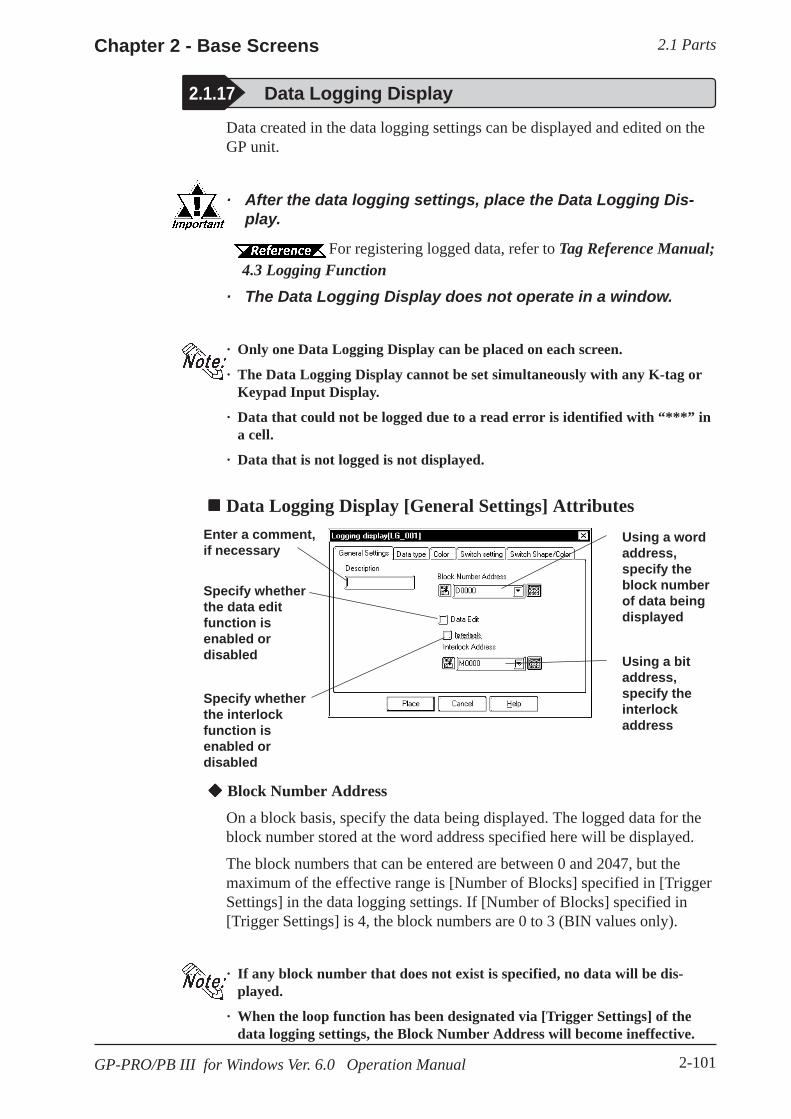
2.1 PartsChapter 2 - Base Screens
2-101GP-PRO/PB III for Windows Ver. 6.0 Operation Manual
Data created in the data logging settings can be displayed and edited on theGP unit.
· After the data logging settings, place the Data Logging Dis-play.
For registering logged data, refer to Tag Reference Manual; 4.3 Logging Function· The Data Logging Display does not operate in a window.
· Only one Data Logging Display can be placed on each screen.
· The Data Logging Display cannot be set simultaneously with any K-tag orKeypad Input Display.
· Data that could not be logged due to a read error is identified with “***” ina cell.
· Data that is not logged is not displayed.
Data Logging Display [General Settings] Attributes
Block Number Address
On a block basis, specify the data being displayed. The logged data for theblock number stored at the word address specified here will be displayed.
The block numbers that can be entered are between 0 and 2047, but themaximum of the effective range is [Number of Blocks] specified in [TriggerSettings] in the data logging settings. If [Number of Blocks] specified in[Trigger Settings] is 4, the block numbers are 0 to 3 (BIN values only).
· If any block number that does not exist is specified, no data will be dis-played.
· When the loop function has been designated via [Trigger Settings] of thedata logging settings, the Block Number Address will become ineffective.
Using a wordaddress,specify theblock numberof data beingdisplayed
Using a bitaddress,specify theinterlockaddress
2.1.17 Data Logging Display
Enter a comment,if necessary
Specify whetherthe data editfunction isenabled ordisabled
Specify whetherthe interlockfunction isenabled ordisabled
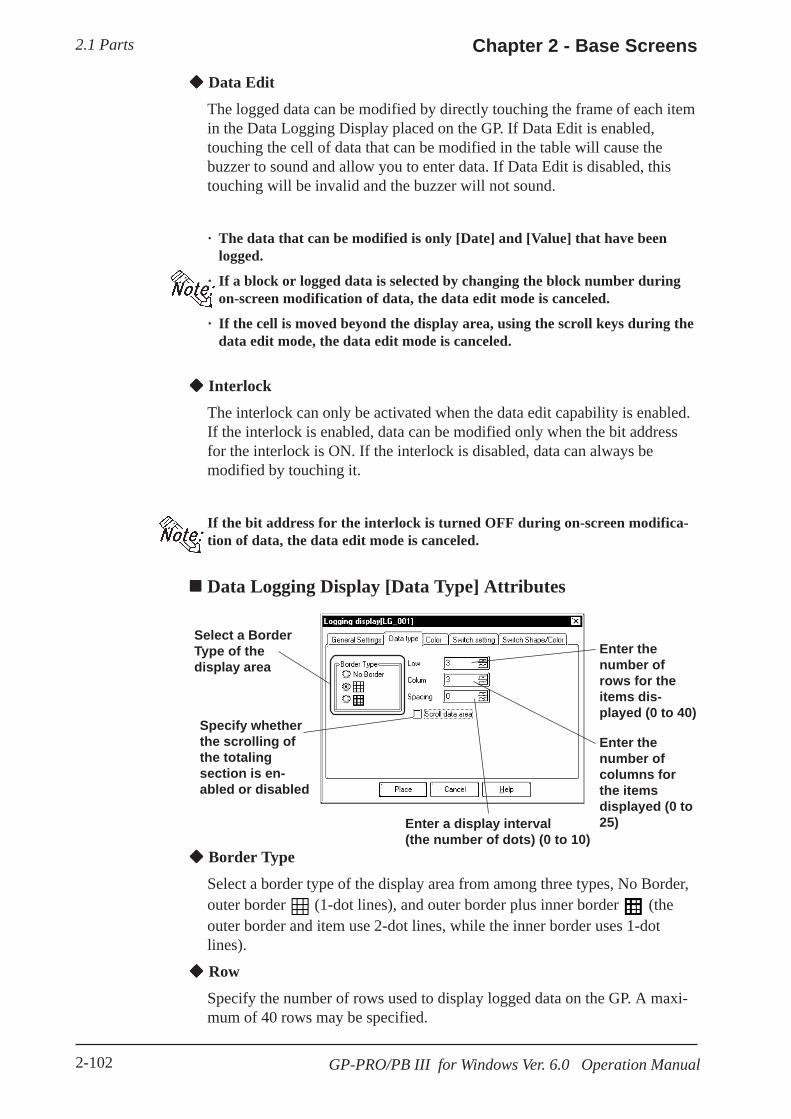
2.1 Parts Chapter 2 - Base Screens
2-102 GP-PRO/PB III for Windows Ver. 6.0 Operation Manual
Data Edit
The logged data can be modified by directly touching the frame of each itemin the Data Logging Display placed on the GP. If Data Edit is enabled,touching the cell of data that can be modified in the table will cause thebuzzer to sound and allow you to enter data. If Data Edit is disabled, thistouching will be invalid and the buzzer will not sound.
· The data that can be modified is only [Date] and [Value] that have beenlogged.
· If a block or logged data is selected by changing the block number duringon-screen modification of data, the data edit mode is canceled.
· If the cell is moved beyond the display area, using the scroll keys during thedata edit mode, the data edit mode is canceled.
Interlock
The interlock can only be activated when the data edit capability is enabled.If the interlock is enabled, data can be modified only when the bit addressfor the interlock is ON. If the interlock is disabled, data can always bemodified by touching it.
If the bit address for the interlock is turned OFF during on-screen modifica-tion of data, the data edit mode is canceled.
Data Logging Display [Data Type] Attributes
Select a BorderType of thedisplay area
Enter thenumber ofrows for theitems dis-played (0 to 40)
Specify whetherthe scrolling ofthe totalingsection is en-abled or disabled
Enter thenumber ofcolumns forthe itemsdisplayed (0 to25)Enter a display interval
(the number of dots) (0 to 10) Border Type
Select a border type of the display area from among three types, No Border,outer border (1-dot lines), and outer border plus inner border (theouter border and item use 2-dot lines, while the inner border uses 1-dotlines).
Row
Specify the number of rows used to display logged data on the GP. A maxi-mum of 40 rows may be specified.

2.1 PartsChapter 2 - Base Screens
2-103GP-PRO/PB III for Windows Ver. 6.0 Operation Manual
Border (the gap between theborder and the cell is not filledwith the clear color)
Cell
Draw the border sothat it does notoverlap any cell.
If the scroll data area is enabled, the totaling section is scrolled together withthe data section. If the totaling section scroll is disabled, the totaling sectionalways appears on the screen.
Data Logging Display [Color] AttributesSelect a color (clear color) displayed when the border of each item iscleared. 2.1 Parts Selecting Colors
Column
Specify the number of columns used to display logged data on the GP. Amaximum of 25 columns may be specified.
Spacing
Specify spacing at which to display logged data on the GP. A maximum of10 dots may be specified. This entry is only valid when the display areaborder type is specified as No. Border. Draw the border line using thedrawing tool.
The gap equivalent to the specified display spacing is provided between thecell and the border line. The entire cell is filled with the clear color specifiedin the Data Logging Display [Color] Attributes. However, the gap is notdisplayed in the clear color, but its background is displayed. If No Border isselected to draw an arbitrary border, ensure that the border is drawn usingthe same width as the specified display interval without overlapping the cell.
<Display Spacing>
Scroll data area

2.1 Parts Chapter 2 - Base Screens
2-104 GP-PRO/PB III for Windows Ver. 6.0 Operation Manual
Data Logging Display [Switch Shape/Color] AttributesSpecify a color (border color) of each function switch.
2.1 Parts Selecting Colors
Select thefunctionswitch type tobe placed
Enter thenumber ofrows/columnsscrolled
Data Logging Display [Switch Settings] AttributesThe number of rows and that of columns specified in [Data type] are dis-played on the Data Logging Display. If any data exceeding these numbersexists in the GP, use the function switches to scroll the data.
2.1.3 Function Switches

2.1 PartsChapter 2 - Base Screens
2-105GP-PRO/PB III for Windows Ver. 6.0 Operation Manual
PROCEDURE R E M A R K S
Enter D0100
(2)In the [General Settings] tab, specify the block num-ber designated address, data edit, and whether theinterlock is enabled or disabled.Specify D0100 for the block number designated address.
2.1.17 DataLogging Display [General Set-tings] Attributes Block NumberAddress
(3)In the [Data Type] tab, specify the display settings.If necessary, select a clear color in the [Color] tab.
Enter 7
Enter 4
(1)Select the [Parts] menu - [Data Logging Display] com-mand, or click on the icon.
The logged data for the block number stored at the block number desig-nated address is displayed.
015
The logged data in block No. 3will be displayed.
Placing the Data Logging DisplayThe procedure for setting the Data Logging Display is described below:
Date Time Data1LP
1st 98/10/16 09:14:00 1442nd 98/10/16 09:14:00 145
EM3rd 98/10/16 09:14:01 1464th 98/10/16 09:14:01 147 R5th 98/10/16 09:14:01 148
730 LTOTALIf 3 is stored at D0100.

2.1 Parts Chapter 2 - Base Screens
2-106 GP-PRO/PB III for Windows Ver. 6.0 Operation Manual
PROCEDURE R E M A R K S
(5)After entering and selecting all the attributes, clickon the button.The border of the Data Logging Display size will be dis-played in the drawing area.
To cancel the placement, click onthe icon.
The Data Logging Displays aregrouped. To change any attribute,ungroup the Data Logging Displaysby clicking on the icon before-hand.
2 .4 .12 Group/Ungroup
If you double-click on the functionswitch placed on the screen, theaddress confirmation screen forparts will appear, enabling you tochange the address.
2.4.14 ChangingAttributes
(4)In the [Switch Settings] tab, select the function switchtype that is to be placed automatically, and specifythe number of rows, columns scrolled.If necessary, select a color for the special switch in the[Switch Shape/Color] tab.
(6)Click on the point where the function switch is to beplaced.

2.1 PartsChapter 2 - Base Screens
2-107GP-PRO/PB III for Windows Ver. 6.0 Operation Manual
2.1.18 Numeric Displays
Select theData Formatand DataLength
Enter the total numberof digits used (notincluding the decimalpoint) in the display
Enter the number ofdigits to be displayedafter the decimal point
Select the size used forthe label’s characters
Data Display Format
Here, the Data Display Format, Code, and data length are selected. Choosea data format of either Decimal (base 10), BCD, Hexadecimal (base 16), orOctal (base 8). With the Code +/- check box checked, when you select“Decimal”, negative numeric data can also be displayed.
No. of Display Digits
Here, enter the total number of digits used (not including the decimal point)in the display.
When the No. of Display Digits is set to 5 and the Decimal Places is set to 2, avalue appears on the Numeric Display as shown below.
Word Address
Here, input the Word Address where the display data is to be stored.
Numeric Display [Display Format] Attributes
This Part displays host Word Address numeric data as an absolute value.
Numeric Display [General Settings] Attributes
Enter Commentdata here Enter the Word
Address wherethe displaydata is stored
Display’s thecurrently se-lected Part’simage
Calls up the PartShape Browser

2.1 Parts Chapter 2 - Base Screens
2-108 GP-PRO/PB III for Windows Ver. 6.0 Operation Manual
The relationship between upper and lower position Word Addresses when32 bit data is used will differ depending on each Device/PLC Type.
Device/PLC Connection Manual Character Size
The label’s Character Size is selected here. 2.2.9 Text
Only when the GP type is the GP-77R , GP-377R, or GP2000 series, is the 8 x16 setting valid. For any GP other than the GP-77R , GP-377R or GP2000series, selecting 8 x 16 in the editor will display 16 x 16 on the GP.
Numeric Display [Shape/Color] AttributesHere, the Numeric Display area’s border color, value display color (Numbercolor), and interior color (Plate color) are selected.
2.1 Parts Selecting Colors
Numeric Display [Alarm Settings] AttributesIf desired, specify a variety of Alarm settings.
2.1 Parts Alarm Settings
Decimal Places
Here, enter the number of digits to be displayed after the decimal point
The types of numeric data that can be used with each data format are listedbelow.
Data Form Code Data Length No. of DisplayDigits
DecimalPlaces
+ only 0-65535+/- -32768-32767
+ only 0-4294967295
+/- -2147483648-2147483647
16 bit 1-4 0-332 bit 1-8 0-716 bit 1-432 bit 1-8
Oct + 16 bit only 1-6
Hex + 0-FFFF0-FFFFFFFF
0-177777
BCD + 0-99990-99999999
Alarm Range
Dec +/-
16 bit 1-5 0-4
32 bit 1-10 0-9
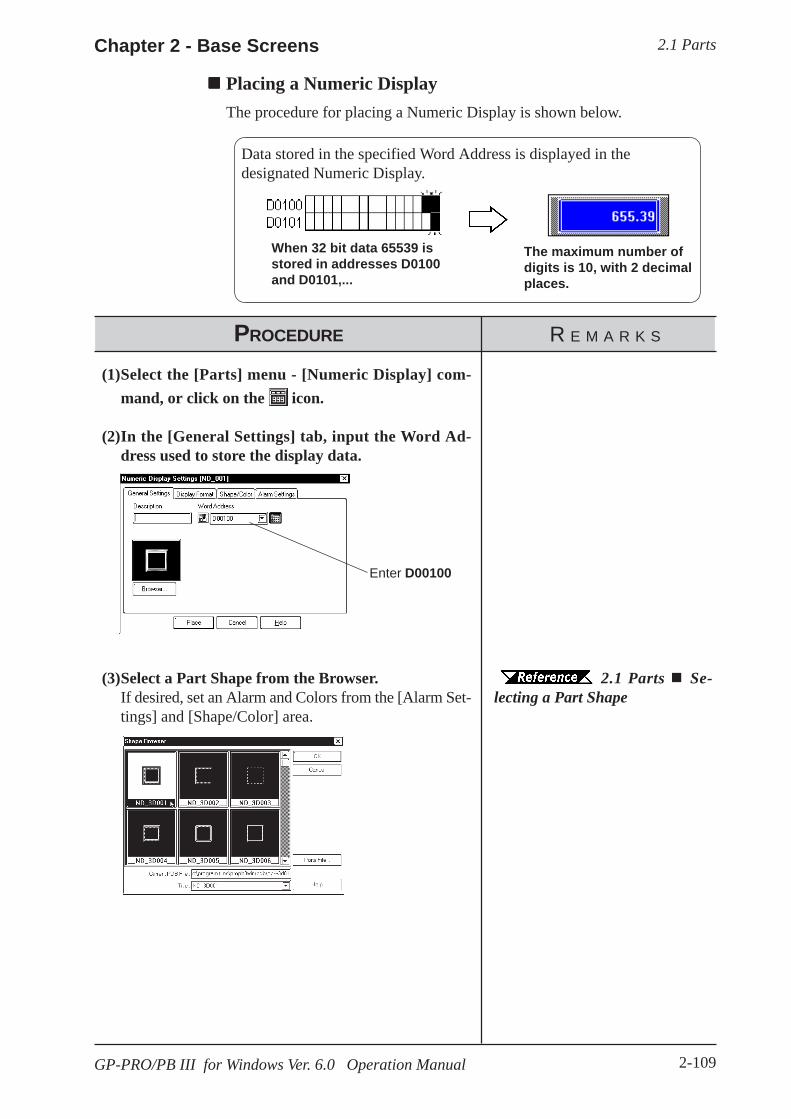
2.1 PartsChapter 2 - Base Screens
2-109GP-PRO/PB III for Windows Ver. 6.0 Operation Manual
PROCEDURE R E M A R K S
Enter D00100
2.1 Parts Se-lecting a Part Shape
(3)Select a Part Shape from the Browser.If desired, set an Alarm and Colors from the [Alarm Set-tings] and [Shape/Color] area.
(1)Select the [Parts] menu - [Numeric Display] com-mand, or click on the icon.
(2)In the [General Settings] tab, input the Word Ad-dress used to store the display data.
Placing a Numeric DisplayThe procedure for placing a Numeric Display is shown below.
When 32 bit data 65539 isstored in addresses D0100and D0101,...
The maximum number ofdigits is 10, with 2 decimalplaces.
Data stored in the specified Word Address is displayed in thedesignated Numeric Display.

2.1 Parts Chapter 2 - Base Screens
2-110 GP-PRO/PB III for Windows Ver. 6.0 Operation Manual
(5)After all of the Part’s attributes have been enteredand selected, click on the button.The Numeric Display’s outline will appear on the Basescreen, next to your cursor.
(6)Click on the point where the Numeric Display’s topleft corner is to be placed.If necessary, use the Numeric Display’s handles to alterits size after placement.Regardless of whether the numeric data display area isscaled up or down, the character size will not change.To change the character size and position, select the char-acters inside the border directly.
To cancel the placement, click onthe icon.
To change a Part’ssize, refer to 2.4.3 Scaling Up/Down
Pressing the Ctrl key while re-siz-ing an area’s border will also re-size that area’s characters.
Double-clicking on any Part placedon the screen automatically calls upthat Part’s attribute settings.
2.4.14 ChangingAttributes
PROCEDURE R E M A R K S
Enter 10
Select 32 bitDecimal
Enter 2
(4)In the [Display Format] area, specify the Data Dis-play Format, and input the No. of Display Digits andthe Decimal Places.Specify the Character Size, if desired.

2.1 PartsChapter 2 - Base Screens
2-111GP-PRO/PB III for Windows Ver. 6.0 Operation Manual
2.1.19 Message Display
Address
Enter an Address to be monitored. Select either Bit Address or Word Ad-dress according to (operation) Mode.
Border Color
The Message Display’s Border color can be selected.
2.1 Parts Selecting Colors
Alignment
Here, the text’s alignment can be selected.
This display is used to show single-line alarm messages in response tochanges in PLC Word Address data. A total of 16 messages can be dis-played, in order of occurrence, in a message display area.
Message Display [General Settings] Attributes
Enter Commentdata here
Select theWord or BitAddress to bemonitored
The currentlyselected PartShape is dis-played hereCalls up the PartShape Browser;Part Shapes canbe selecteddirectly from theBrowser
Select a BordercolorSelect the typeof alignmentdesired for thetext of theDisplay
Select aCharacter Size
Select theOperationMode
Mode
There are two methods to change messages displayed on the MessageDisplay, i.e. via Bit’s turning ON/OFF and Word state changes. Here, selecteither mode.
Mode: When selecting BitMessages will change according to the specified Bit Addresschanges.
Left Right
Center

2.1 Parts Chapter 2 - Base Screens
2-112 GP-PRO/PB III for Windows Ver. 6.0 Operation Manual
Num bers ofM essages
Num ber ofBits Used
2 14 28 3
16 4
When the value set inthe No. of Messages is16, bits 00 ~ 03 areused. When the value set in the
No. of Messages area is 4,bits 00 and 01 are used
When the value set in theNo. of Messages area is 2,only bit 00 is used
When the value set in the No. ofMessages is 8, bits 00 ~ 02 areused
The remaining bits can beused for other purposes
03 02 01 00
Mode: When selecting Word
Messages will change according to the state changes of the desig-nated bits, consecutively from the specified Address’s 00 bit.According to the number of the messages (either 2, 4, 8, or 16), abit is automatically assigned from the specified Address’s 00 bit.

2.1 PartsChapter 2 - Base Screens
2-113GP-PRO/PB III for Windows Ver. 6.0 Operation Manual
No. of Messages
The number of the messages (number of states) can be selected from 2, 4, 8, and16.
Display Characters
Here, the maximum number of characters displayed in a message is selected.Up to 40 characters can be input. If the number of a message charactersexceeds the specified value, characters that do not fit in the area will betruncated.
Message
According to the No. of Messages, designate a message for each state.
Operation Mode: Bit Designate a message for each state (ON and OFF).
Operation Mode: Word As many buttons as the number of the specified messages will be displayed.Designate a message for each state.
Selected Message
Messages are entered here. After entering a message, the message will bedisplayed in the selected color(s). The default value setting is “Undefined”.
Color
Here, each message’s display colors can be selected.Default settings are = Char. color - White; Plate (background) color - Blue.
Message Display [Messages] Attributes(Operation Mode example: When using Word Address)
Enter the numberof messages(states) here
Enter the message’stext here
Enter the maxi-mum No. ofCharactersThe state indica-tion buttonsappear accordingto the No. ofMessages
Copies all thecharacters inthe SelectedMessage fieldto all states.
Select the message’s(display) Color
Select the Char-acter Type
Copies thecharacters inthe Descriptionfield to theSelectedMessage field.
Deletes thecurrentlyselectedmessage, andspecifies themessage (andits color) asundefined.
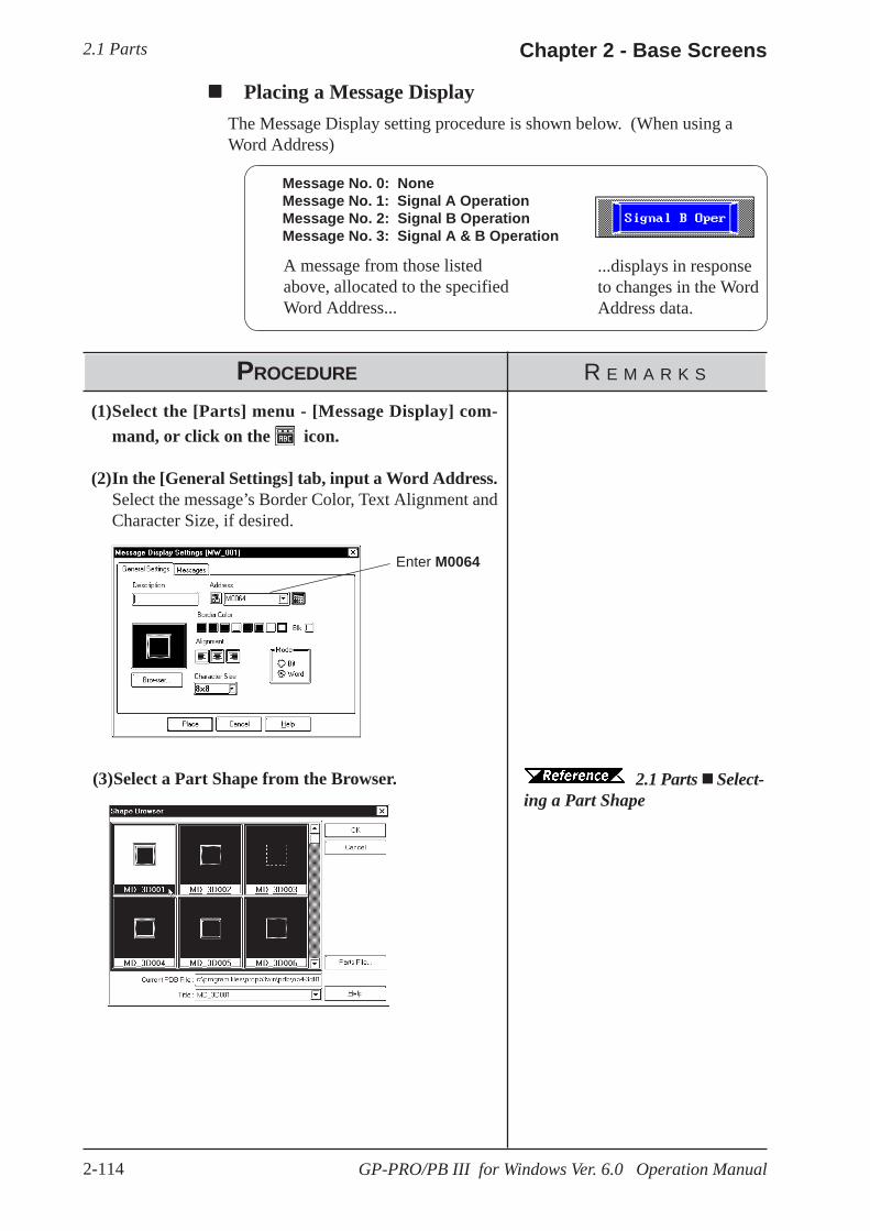
2.1 Parts Chapter 2 - Base Screens
2-114 GP-PRO/PB III for Windows Ver. 6.0 Operation Manual
Message No. 0: NoneMessage No. 1: Signal A OperationMessage No. 2: Signal B OperationMessage No. 3: Signal A & B Operation
...displays in responseto changes in the WordAddress data.
A message from those listedabove, allocated to the specifiedWord Address...
Placing a Message DisplayThe Message Display setting procedure is shown below. (When using aWord Address)
PROCEDURE R E M A R K S
Enter M0064
(1)Select the [Parts] menu - [Message Display] com-mand, or click on the icon.
(2)In the [General Settings] tab, input a Word Address.Select the message’s Border Color, Text Alignment andCharacter Size, if desired.
2.1 Parts Select-ing a Part Shape
(3)Select a Part Shape from the Browser.

2.1 PartsChapter 2 - Base Screens
2-115GP-PRO/PB III for Windows Ver. 6.0 Operation Manual
(6)After all of the Part’s attributes have been enteredand selected, click on the button.The Message Display’s outline will appear on the Basescreen, next to your cursor.
PROCEDURE R E M A R K S
Enter 16
Enter 4
Enter A UnitOperating
Select 1
Any characters entered thatare over the limit specified instep (4) will be cut from theGP’s display.
If the text “Undefined” is not de-leted, it will be registered and thendisplayed as a message.
(5)Enter your Alarm Messages.Select the message number to be registered and enterthe message. When displaying a border with no mes-sage, be sure to delete the words “Undefined”. SelectColors and Character Size, if necessary.(Example) When registering the message “A Unit Op-erating” as message Number 1:
(4)In the [Messages] area, input the number of the mes-sages and characters used.
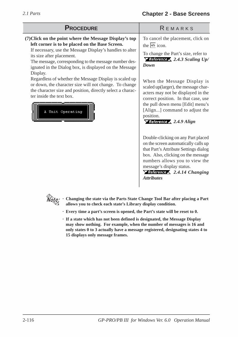
2.1 Parts Chapter 2 - Base Screens
2-116 GP-PRO/PB III for Windows Ver. 6.0 Operation Manual
· Changing the state via the Parts State Change Tool Bar after placing a Partallows you to check each state’s Library display condition.
· Every time a part’s screen is opened, the Part’s state will be reset to 0.
· If a state which has not been defined is designated, the Message Displaymay show nothing. For example, when the number of messages is 16 andonly states 0 to 3 actually have a message registered, designating states 4 to15 displays only message frames.
To cancel the placement, click onthe icon.
To change the Part’s size, refer to2.4.3 Scaling Up/
Down
When the Message Display isscaled up(larger), the message char-acters may not be displayed in thecorrect position. In that case, usethe pull down menu [Edit] menu’s[Align...] command to adjust theposition.
2.4.9 Align
Double-clicking on any Part placedon the screen automatically calls upthat Part’s Attribute Settings dialogbox. Also, clicking on the messagenumbers allows you to view themessage’s display status.
2.4.14 ChangingAttributes
(7)Click on the point where the Message Display’s topleft corner is to be placed on the Base Screen.If necessary, use the Message Display’s handles to alterits size after placement.The message, corresponding to the message number des-ignated in the Dialog box, is displayed on the MessageDisplay.Regardless of whether the Message Display is scaled upor down, the character size will not change. To changethe character size and position, directly select a charac-ter inside the text box.
PROCEDURE R E M A R K S

2.1 PartsChapter 2 - Base Screens
2-117GP-PRO/PB III for Windows Ver. 6.0 Operation Manual
2.1.20 Date Displays
Enter Commentdata here Select the Data
Format
Select theBorder (frame),Text and Plate(background)colors
Calls up the PartShape Browser.Parts can be se-lected directly fromthe Browser
The currently se-lected Part’s imageis displayed here
Data Format
The following display formats are available:
yy/mm/dddd/mm/yymm/dd/yy20yy/mm/dd*1
dd/mm/20yy*1
mm/dd/20yy*1
(yy: year, mm: month, dd: day)
Color
The Date Display’s border color, character display color (Text), and interiorcolor (Plate) can be selected here.
2.1 Parts Selecting Colors
Character Size
The label’s Character Size is selected here. 2.2.9 Text
Date display data is created using the GP’s internal calendar and formattedas;
February 11th, 2001, or 01/02/11; however, the date format can be changed.
Date Display [General Settings] Attributes
*1 The characters used for the display of 2000’s first two characters (“20”) are single-bytecharacters.

2.1 Parts Chapter 2 - Base Screens
2-118 GP-PRO/PB III for Windows Ver. 6.0 Operation Manual
PROCEDURE R E M A R K S
Select the yy/mm/dd format
2.1 Parts Select-ing a Part Shape
(4)After all of the Part’s attributes have been enteredand selected, click on the [Place] button.The Date Display’s outline will appear in the Base screen,next to your cursor.
(3)Select a Part Shape from the Browser.If desired, select Colors and Character Size.
(1)Select the [Parts] menu - [Date Display] command,or click on the icon.
(2)In the [General Settings] area, select a display format.
Placing a Date DisplayThe Date Display placement procedure is shown below.
Used to display the date.
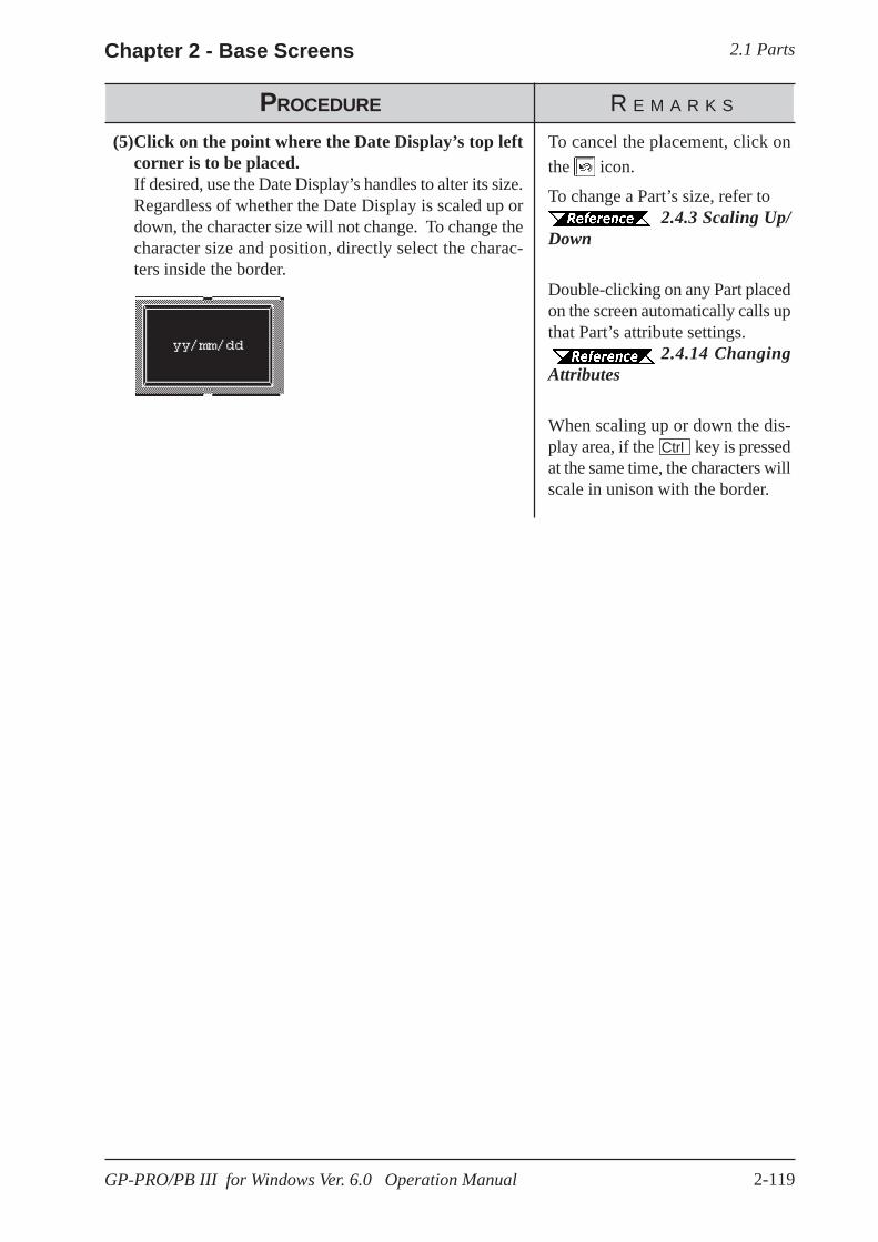
2.1 PartsChapter 2 - Base Screens
2-119GP-PRO/PB III for Windows Ver. 6.0 Operation Manual
To cancel the placement, click onthe icon.
To change a Part’s size, refer to2.4.3 Scaling Up/
Down
Double-clicking on any Part placedon the screen automatically calls upthat Part’s attribute settings.
2.4.14 ChangingAttributes
When scaling up or down the dis-play area, if the Ctrl key is pressedat the same time, the characters willscale in unison with the border.
PROCEDURE R E M A R K S
(5)Click on the point where the Date Display’s top leftcorner is to be placed.If desired, use the Date Display’s handles to alter its size.Regardless of whether the Date Display is scaled up ordown, the character size will not change. To change thecharacter size and position, directly select the charac-ters inside the border.

2.1 Parts Chapter 2 - Base Screens
2-120 GP-PRO/PB III for Windows Ver. 6.0 Operation Manual
2.1.21 Time Displays
Enter Commentdata here
Select theCharacter Size
Select Border,Character, andPlate colors
Calls up the PartShape Browser.Part Shapes can beselected directlyfrom the Browser
The currentlyselected item’simage appearshere
Color
Here, the Time Display’s Border color, character display color (Text), andbackground color (Plate) can each be selected.
2.1 Parts Selecting Colors
Time Display areas can be created, based on the GP’s internal calendarfunction. Time will be expressed in 24 hour format.
(E.g.) 2:25 pm > 14:25
Only one Time Display Part can be used per screen.
Time Display [General Settings] Attributes

2.1 PartsChapter 2 - Base Screens
2-121GP-PRO/PB III for Windows Ver. 6.0 Operation Manual
PROCEDURE R E M A R K S
To cancel the placement, click onthe icon.
To change a Part’ssize, refer to 2.4.3 Scaling Up/Down
When scaling up or down the dis-play area, if the Ctrl key is pressedsimultaneously, the characters arealso scaled up or down togetherwith the border.
Double-clicking on any Part placedon the screen automatically calls upthat Part’s attribute settings.
2.4.14 ChangingAttributes
2.1 Parts Select-ing a Part Shape
(3)After all of the Part’s attributes have been enteredand selected, click on the button.The Time Display Part’s outline will appear on the Basescreen, next to your cursor.
(4)Click on the point where the Time Display’s top leftcorner is to be placed.Change the size if necessary.Regardless of whether the Time Display is scaled up ordown, the character size will not change. To change thecharacter size and position, select the characters directly.
(1)Select the [Parts] menu - [Time Display] command,or click on the icon.
(2)Select a Part Shape from the Browser.If desired, select Colors and Character Size.
Placing a Time DisplayThe Time Display is placed using the following procedure.
Display the time.
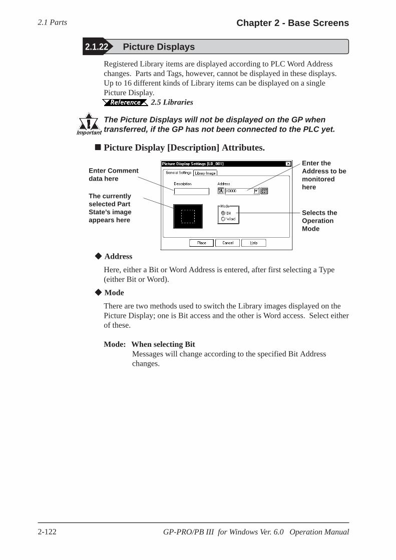
2.1 Parts Chapter 2 - Base Screens
2-122 GP-PRO/PB III for Windows Ver. 6.0 Operation Manual
Address
Here, either a Bit or Word Address is entered, after first selecting a Type(either Bit or Word).
Mode
There are two methods used to switch the Library images displayed on thePicture Display; one is Bit access and the other is Word access. Select eitherof these.
Mode: When selecting BitMessages will change according to the specified Bit Addresschanges.
Registered Library items are displayed according to PLC Word Addresschanges. Parts and Tags, however, cannot be displayed in these displays.Up to 16 different kinds of Library items can be displayed on a singlePicture Display.
2.5 Libraries
The Picture Displays will not be displayed on the GP whentransferred, if the GP has not been connected to the PLC yet.
Picture Display [Description] Attributes.
2.1.22 Picture Displays
Enter Commentdata here
Enter theAddress to bemonitoredhere
Selects theOperationMode
The currentlyselected PartState’s imageappears here

2.1 PartsChapter 2 - Base Screens
2-123GP-PRO/PB III for Windows Ver. 6.0 Operation Manual
Num bers ofM essages
Num ber ofBits Used
2 14 28 3
16 4
When the value set inthe No. of Messages is16, bits 00 ~ 03 areused.
When the value set in theNo. of Messages area is 4,bits 00 and 01 are used
When the value set in theNo. of Messages area is 2,only bit 00 is used
When the value set in the No. ofMessages is 8, bits 00 ~ 02 areused
The remaining bits can beused for other purposes
03 02 01 00
Mode: When selecting WordMessages will change according to the state changes of the desig-nated bits, consecutively from the specified Address’s 00 bit.According to the number of the messages (either 2, 4, 8, or 16), abit is automatically assigned from the specified Address’s 00 bit.
Browser
When clicking on the button, the Library Browser (Library list)will appear. Select a desired Library from this list and drag it to the insideof the Library image display border on the Dialog box.
2.5 Libraries
Displays thecurrentlyselectedLibrary image
Calls up theLibrary Browser.Library items canbe selecteddirectly from here
Deletes thecurrently selectedLibrary item
Selects the item’sbackground andforeground colors(used for clearing)
Reflects thecurrentlyselected item’sdesignatedstate
Picture Display [Library Image] Attributes
2.1 Parts Chapter 2 - Base Screens
2-124 GP-PRO/PB III for Windows Ver. 6.0 Operation Manual
Delete
The selected Library item is deleted and the display will disappear.
No. of Lib.
Displays only when Type’s Word is selected. The number of Library images(number of states) to be displayed on the Picture Display can then be input.Select any of 2, 4, 8, or 16.
Library
Here, the Library item used for each state is specified. Settings will differdepending on the Type selection.
Mode: When selecting BitSpecify a Library item’s ON and OFF states, respectively.
Mode: When selecting WordThe n.umber of buttons will match the designated number ofLibrary items. Specify a Library item for each state.
Changing the state via the Parts State Change Tool Bar after placing a Partallows you to check each state’s Library display condition.
Color
The background square colors (Clear Fg, Clear Bg)) and pattern (Pattern)are selected. The default settings are black. The square colors can beselected so as to match the Picture Display placement area background’scolor.<Back Ground Square>The Library item to be displayed while the GP is running needs the filledsquare for the background to be the rearmost, so that the items(images) donot overlay each other when they are switched. When designating a Libraryitem, the GP-PRO/PBIII for Windows program will draw this colored squareautomatically.Right after the Library item(s) is/are placed, the background square will matchthe size of the largest Library item designated. After the items are placed, itcan be scaled larger or smaller, independently from the Library items.For a state with no designated Library item, only a background square willbe displayed and it will become the Library’s deletion screen, i.e. it will beoverlaid on top of an existing item to “delete” that item.

2.1 PartsChapter 2 - Base Screens
2-125GP-PRO/PB III for Windows Ver. 6.0 Operation Manual
Placing a Picture DisplayThe Picture Display’s creation procedure is shown below.
The 3 pictures registered as libraries, as illustrated above, will changein response to changes in the state of Word Address D00250.
PROCEDURE R E M A R K S
Enter D00250
Select Word
Enter 4
(3)In the [Library Image] area, input the No. of libraryitems (No. of Lib.) used.
(1)Select the [Parts] menu - [Picture Display] command,or click on the icon.
(2)In the [General Settings] area, enter an Address andselect a Mode.
State 0 State 3State 2State 1
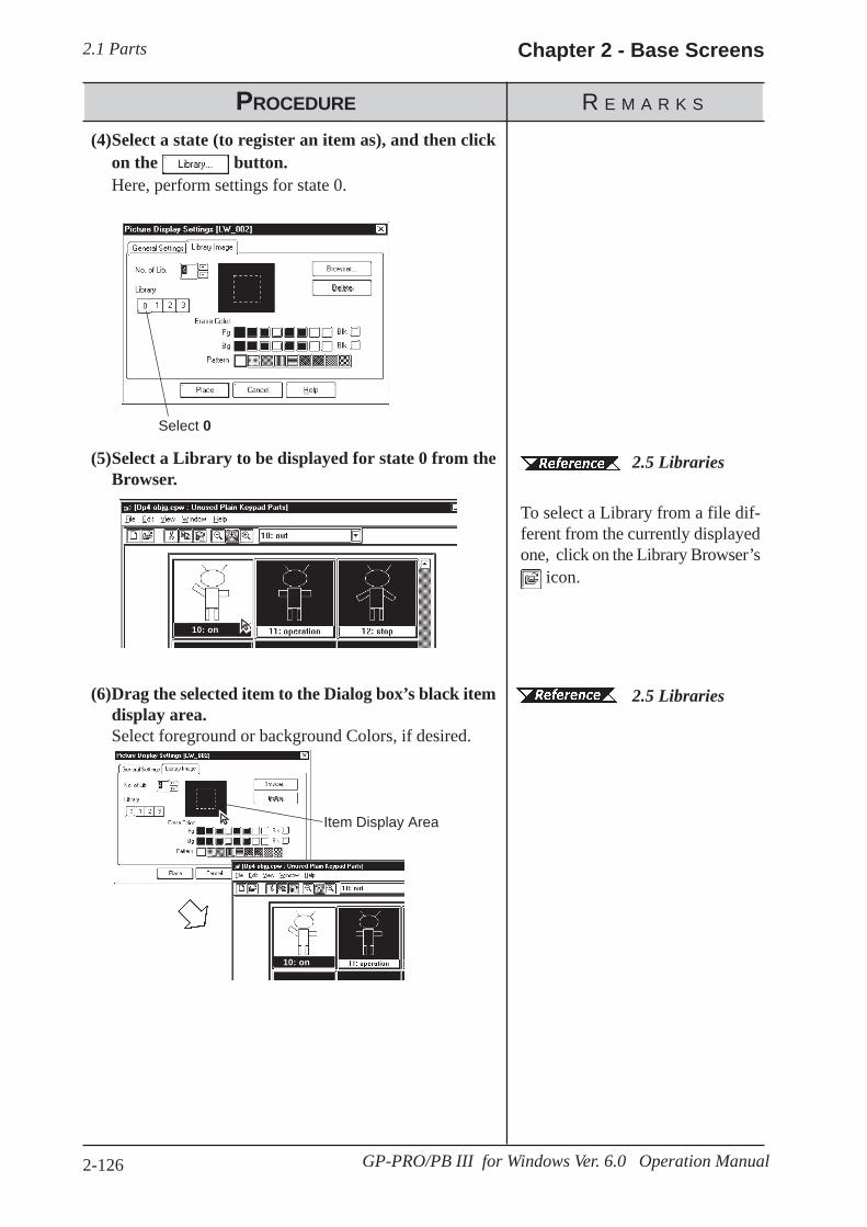
2.1 Parts Chapter 2 - Base Screens
2-126 GP-PRO/PB III for Windows Ver. 6.0 Operation Manual
PROCEDURE R E M A R K S
Select 0
2.5 Libraries
2.5 Libraries
To select a Library from a file dif-ferent from the currently displayedone, click on the Library Browser’s
icon.
(6)Drag the selected item to the Dialog box’s black itemdisplay area.Select foreground or background Colors, if desired.
(5)Select a Library to be displayed for state 0 from theBrowser.
(4)Select a state (to register an item as), and then clickon the button.Here, perform settings for state 0.
Item Display Area
10: on
10: on
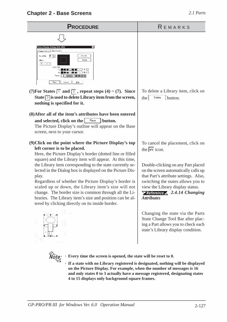
2.1 PartsChapter 2 - Base Screens
2-127GP-PRO/PB III for Windows Ver. 6.0 Operation Manual
· Every time the screen is opened, the state will be reset to 0.
· If a state with no Library registered is designated, nothing will be displayedon the Picture Display. For example, when the number of messages is 16and only states 0 to 3 actually have a message registered, designating states4 to 15 displays only background square frames.
PROCEDURE R E M A R K S
To cancel the placement, click onthe icon.
Double-clicking on any Part placedon the screen automatically calls upthat Part’s attribute settings. Also,switching the states allows you toview the Library display status.
2.4.14 ChangingAttributes
Changing the state via the PartsState Change Tool Bar after plac-ing a Part allows you to check eachstate’s Library display condition.
To delete a Library item, click onthe button.
(7)For States and , repeat steps (4) ~ (7). SinceState is used to delete Library item from the screen,nothing is specified for it.
(8)After all of the item’s attributes have been enteredand selected, click on the button.The Picture Display’s outline will appear on the Basescreen, next to your cursor.
(9)Click on the point where the Picture Display’s topleft corner is to be placed.Here, the Picture Display’s border (dotted line or filledsquare) and the Library item will appear. At this time,the Library item corresponding to the state currently se-lected in the Dialog box is displayed on the Picture Dis-play.Regardless of whether the Picture Display’s border isscaled up or down, the Library item’s size will notchange. The border size is common through all the Li-braries. The Library item’s size and position can be al-tered by clicking directly on its inside border.

2.1 Parts Chapter 2 - Base Screens
2-128 GP-PRO/PB III for Windows Ver. 6.0 Operation Manual
2.1.23 Window Parts
Calls up the window onto the Base Screen (B). Register the windows to theWindow Registration via the Window Screen (U). This operation is easierthan using the U-tag.
Window Parts Attributes
This displaysthe WindowNumber of thewindowregistered onthe WindowScreen (U).
Select the Win-dow Number youwant to call uponto the BaseScreen (B).
Specify theWindow ControlAddress.
Preview thewindow associ-ated with theselected Win-dow Number inthis area.
Window Control Address
Enter the address to control the Hide/Show status of the windows. 15 02 01 00 Bits
Show[0]: Hide the window[1]: Show the windowChanging the order of window layer
[0]: Touching the window willchange the order of the layer.
[1]: Touching the window will NOTchange the order of the layer.
3.7.1 Overview of Window Display, 3.7.2 Window Registration on the U Screen
Enter commentdata here.

2.1 PartsChapter 2 - Base Screens
2-129GP-PRO/PB III for Windows Ver. 6.0 Operation Manual
Placing Window PartsProcedure for placing Window Parts will be shown below.
OFF
ON
OFF
ON
Show window
WindowDisplay
WindowDisplay
Place a window (such as a bar graph for Window Registration on the U Screen)on the Base Screen (such as B2). (Call up the window.)
PROCEDURE R E M A R K S
(1)Select [Window Parts] from the [Parts] menu or
click the icon.
(2)Select the window to be displayed on the BaseScreen (B) from the "Window Number" field.Specify the Window Control Address as well.
For Window Registration of partson the Window Screen (U)
3.7.2 WindowRegistration on the U Screen
(3) Click the button after setting all at-tributes.The border of the window area is displayed on thedrawing area.
(4) Click on the point where the Window Part is tobe placed.
When the specified area is over-lapped by objects on the Base Screen,the object will be hidden while thewindow is displayed.

2.2 Drawing Chapter 2 - Base Screens
2-130 GP-PRO/PB III for Windows Ver. 6.0 Operation Manual
2.2 Drawing
Straight lines, rectangles, and oval objects can be drawn, using drawingtools.
An object’s attributes such as line types and colors are designated in itsdialog box. After designating the object’s attributes, move the cursor andstart to draw the object directly in the drawing area.
These objects can also be drawn via the Keypad and Trend Graph screens.Note:
[Draw] →→→→→
Usage Pattern
Select a drawingcommand
Set any attributes Draw the object→→→→→ →→→→→
Select a desired drawing icon from theDraw Tool Bar.
Drawing ToolsIcons contained in the Draw Tool Bar and their corresponding drawingobjects are as follows:
Selecting Line Types10 selections are available for straight and poly-lines, and for graph divi-sions. 6 selections are available for rectangles, circles, arcs and pie sections.
Select one of thesepatterns
Icon Object Types Icon Object Types
Dot Filled Polygon
Line/Poly-line Scale
Square/Rectangle Text
Circle/Oval Load Screen
Arc/Pie Load Mark
Fill
or

2.2 DrawingChapter 2 - Base Screens
2-131GP-PRO/PB III for Windows Ver. 6.0 Operation Manual
Select a pattern
When a square or circle is drawn, only the line type will be displayed ini-tially. To display the pattern selections, check the Fill check box. (checkmark will appear)
2.2.1 Dot
Dots can be drawn in 1, 2, 3, and 5 dot units. To draw a dot, simply click onthe desired point.
Dot Attributes
Select the dot unit usedfor drawing
Select colors and blink-ing, if desired
Displays the currentlyselected dot’s image
Selecting ColorsFor color and blink attribute settings, use the procedure same as for Parts.
2.1 Parts Part Attributes - Selecting Colors
Tiling PatternsNine different tiling patterns are available. These patterns can be selectedfor squares, circles, filled squares and polygonal objects. When combiningforeground (Fg) and background (Bg) colors, a variety of filled patterns canbe drawn.

2.2 Drawing Chapter 2 - Base Screens
2-132 GP-PRO/PB III for Windows Ver. 6.0 Operation Manual
If an arrow ( ) is selected, theline’s end point will become an ar-row.
When using the keyboard to drawa dot, move the cursor to the de-sired point and press the key.
To cancel/delete the dot, click on
the icon.
Double-clicking on any objectdrawn on the screen automaticallycalls up that object’s Attribute Set-tings dialog box.
2.4.14 ChangingAttributes
Creating a Dot
(1)Select the [Draw] menu - [Dot] command, or click onthe icon.
(2)Set the attributes of a dot to be drawn.Select a dot type and colors, if desired.
(3)Move the cursor to the drawing area. A dot will bedrawn at the point clicked on.
PROCEDURE R E M A R K S
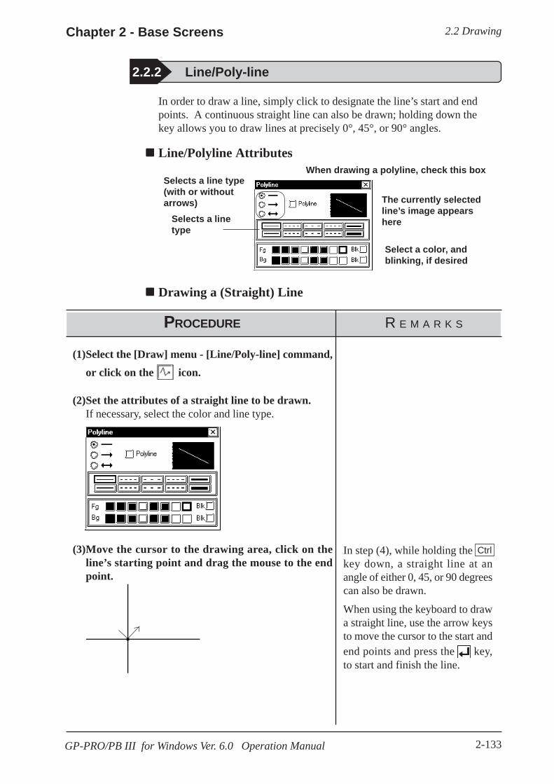
2.2 DrawingChapter 2 - Base Screens
2-133GP-PRO/PB III for Windows Ver. 6.0 Operation Manual
In order to draw a line, simply click to designate the line’s start and endpoints. A continuous straight line can also be drawn; holding down thekey allows you to draw lines at precisely 0°, 45°, or 90° angles.
Line/Polyline Attributes
2.2.2 Line/Poly-line
Selects a line type(with or withoutarrows)
Selects a linetype
Select a color, andblinking, if desired
The currently selectedline’s image appearshere
When drawing a polyline, check this box
Drawing a (Straight) Line
PROCEDURE R E M A R K S
(1)Select the [Draw] menu - [Line/Poly-line] command,or click on the icon.
(2)Set the attributes of a straight line to be drawn.If necessary, select the color and line type.
(3)Move the cursor to the drawing area, click on theline’s starting point and drag the mouse to the endpoint.
In step (4), while holding thekey down, a straight line at anangle of either 0, 45, or 90 degreescan also be drawn.
When using the keyboard to drawa straight line, use the arrow keysto move the cursor to the start andend points and press the key,to start and finish the line.
Ctrl

2.2 Drawing Chapter 2 - Base Screens
2-134 GP-PRO/PB III for Windows Ver. 6.0 Operation Manual
(4)Click again; a straight line is drawn (registered). To cancel the placement, click onthe icon.
Double-clicking on any objectdrawn on the screen automaticallycalls up that object’s attribute set-tings.
2.4.14 ChangingAttributes
Drawing PolylinesWhen the Polyline check box is checked, Polylines can be drawn. Click on thestarting point then drag the mouse, clicking the left mouse button at each point ofthe desired directional change of the line; and, click on the right mouse button atthe end point of the line.
· When drawing, if the Keyboard’s key is pressed instead of clickingon the mouse right button, the start and end points of a polyline object willbe automatically connected.
· You can draw a line that looks hand-drawn by holding down the mouse’sleft button when drawing a polyline.
Note:C
PROCEDURE R E M A R K S
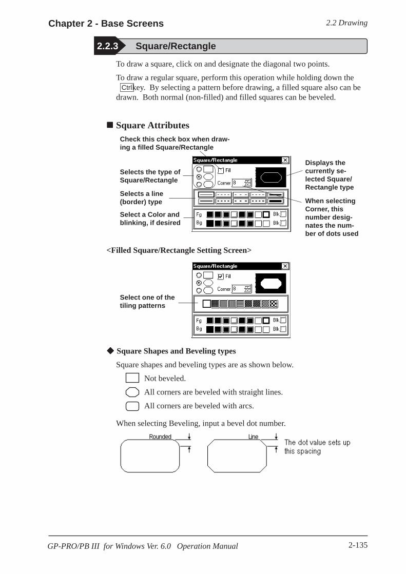
2.2 DrawingChapter 2 - Base Screens
2-135GP-PRO/PB III for Windows Ver. 6.0 Operation Manual
To draw a square, click on and designate the diagonal two points.
To draw a regular square, perform this operation while holding down the key. By selecting a pattern before drawing, a filled square also can bedrawn. Both normal (non-filled) and filled squares can be beveled.
Square Attributes
Square Shapes and Beveling types
Square shapes and beveling types are as shown below.
Not beveled.
All corners are beveled with straight lines.
All corners are beveled with arcs.
When selecting Beveling, input a bevel dot number.
2.2.3 Square/Rectangle
<Filled Square/Rectangle Setting Screen>
Selects the type ofSquare/Rectangle
Selects a line(border) type
Select a Color andblinking, if desired
When selectingCorner, thisnumber desig-nates the num-ber of dots used
Displays thecurrently se-lected Square/Rectangle type
Check this check box when draw-ing a filled Square/Rectangle
Select one of thetiling patterns
Ctrl
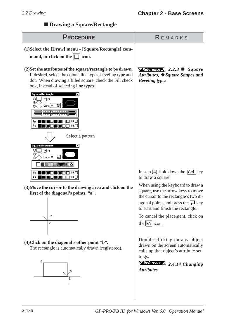
2.2 Drawing Chapter 2 - Base Screens
2-136 GP-PRO/PB III for Windows Ver. 6.0 Operation Manual
Drawing a Square/Rectangle
PROCEDURE R E M A R K S
(1)Select the [Draw] menu - [Square/Rectangle] com-mand, or click on the icon.
(2)Set the attributes of the square/rectangle to be drawn.If desired, select the colors, line types, beveling type anddot. When drawing a filled square, check the Fill checkbox, instead of selecting line types.
Select a pattern
(3)Move the cursor to the drawing area and click on thefirst of the diagonal’s points, “a”.
(4)Click on the diagonal’s other point “b”.The rectangle is automatically drawn (registered).
a
2.2.3 SquareAttributes, Square Shapes andBeveling types
In step (4), hold down the keyto draw a square.
When using the keyboard to draw asquare, use the arrow keys to movethe cursor to the rectangle’s two di-agonal points and press the keyto start and finish the rectangle.
To cancel the placement, click onthe icon.
Double-clicking on any objectdrawn on the screen automaticallycalls up that object’s attribute set-tings.
2.4.14 ChangingAttributes
Ctrl
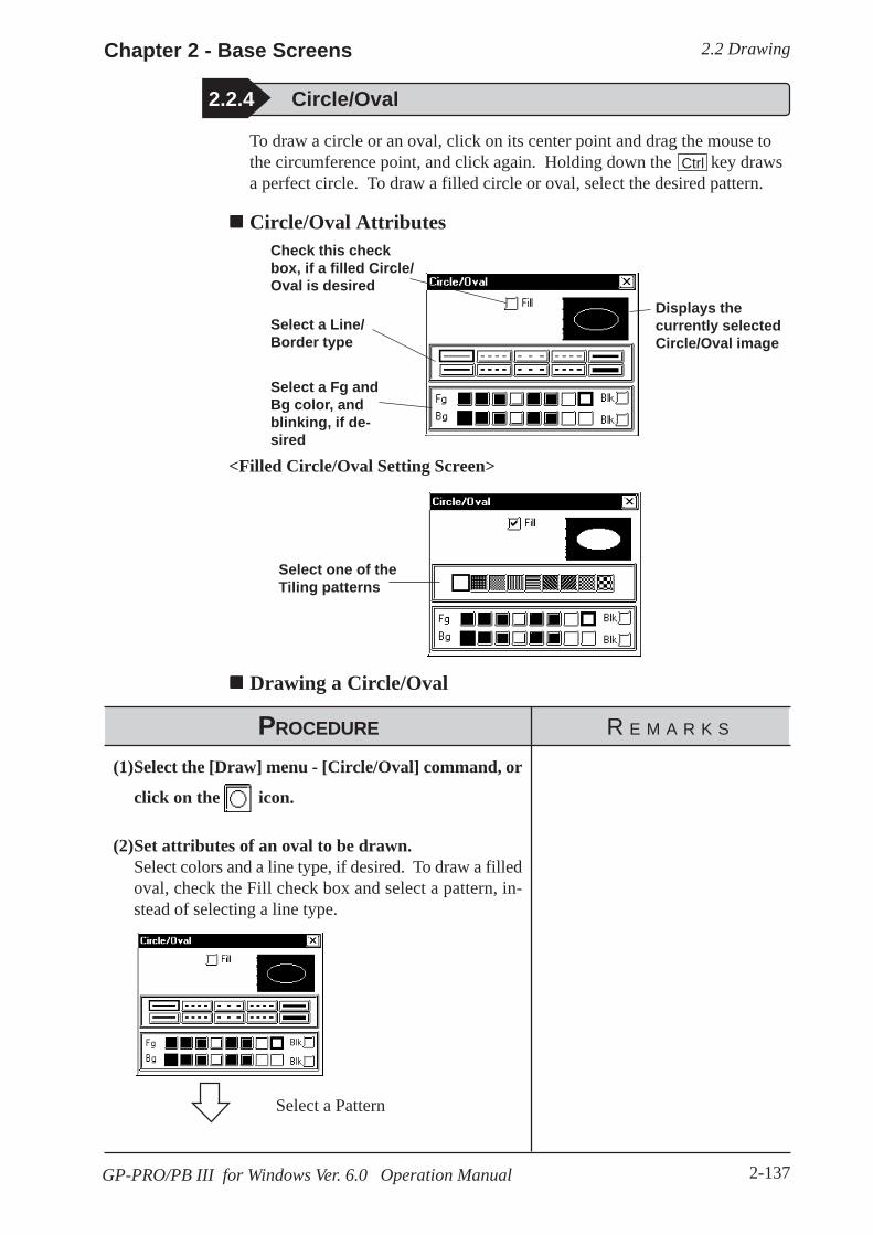
2.2 DrawingChapter 2 - Base Screens
2-137GP-PRO/PB III for Windows Ver. 6.0 Operation Manual
2.2.4 Circle/Oval
To draw a circle or an oval, click on its center point and drag the mouse tothe circumference point, and click again. Holding down the key drawsa perfect circle. To draw a filled circle or oval, select the desired pattern.
Circle/Oval Attributes
<Filled Circle/Oval Setting Screen>
Drawing a Circle/Oval
(1)Select the [Draw] menu - [Circle/Oval] command, or
click on the icon.
(2)Set attributes of an oval to be drawn.Select colors and a line type, if desired. To draw a filledoval, check the Fill check box and select a pattern, in-stead of selecting a line type.
Select a Pattern
PROCEDURE R E M A R K S
Displays thecurrently selectedCircle/Oval image
Ctrl
Select a Line/Border type
Select a Fg andBg color, andblinking, if de-sired
Check this checkbox, if a filled Circle/Oval is desired
Select one of theTiling patterns

2.2 Drawing Chapter 2 - Base Screens
2-138 GP-PRO/PB III for Windows Ver. 6.0 Operation Manual
PROCEDURE R E M A R K S
(3)Move the cursor over the drawing area, and click onthe center point, shown here by “a”.
(4)As the cursor is moved, the oval will expand or con-tract.Click on the point shown by b. The drawn oval will beregistered.
In step (3), if the key is helddown, you can draw an oval whichcontacts a specified area (i.e. theside(s) of a square). This functionis useful when drawing an inscribedcircle and can also be used in step(4), together with the key.
To draw a regular circle, hold the key down in step (4).
When using the keyboard to drawan oval, use the arrow keys to movethe cursor to the center point andthen, to the point which defines itscircumference (radius point), press-ing the key each time.
To cancel a drawing action, clickon the icon.
Double-clicking on any objectdrawn on the screen automaticallycalls up that object’s attribute set-tings.
2.4.14 ChangingAttributes
Shift
Ctrl
Ctrl
a
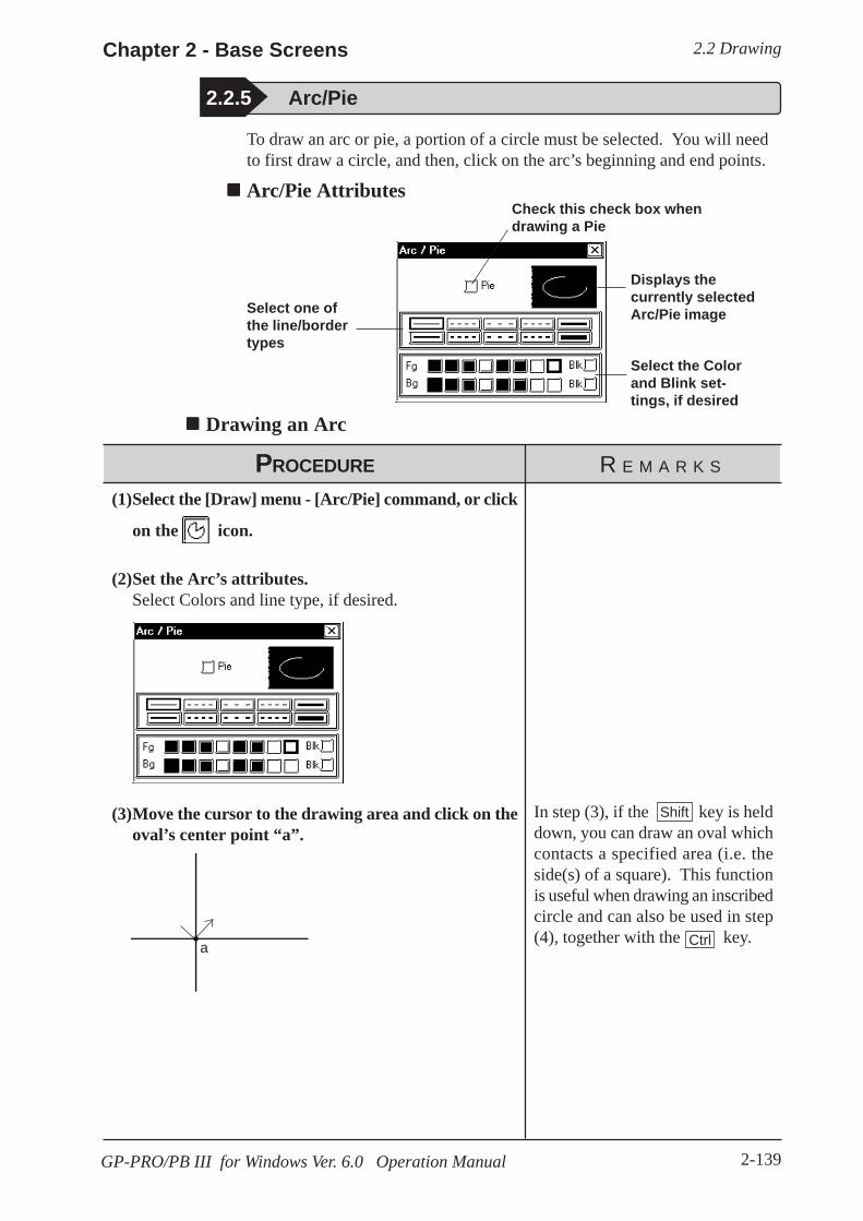
2.2 DrawingChapter 2 - Base Screens
2-139GP-PRO/PB III for Windows Ver. 6.0 Operation Manual
2.2.5 Arc/Pie
To draw an arc or pie, a portion of a circle must be selected. You will needto first draw a circle, and then, click on the arc’s beginning and end points.
Arc/Pie Attributes
Select one ofthe line/bordertypes
Select the Colorand Blink set-tings, if desired
Displays thecurrently selectedArc/Pie image
Check this check box whendrawing a Pie
Drawing an Arc
PROCEDURE R E M A R K S
(1)Select the [Draw] menu - [Arc/Pie] command, or click
on the icon.
(2)Set the Arc’s attributes.Select Colors and line type, if desired.
(3)Move the cursor to the drawing area and click on theoval’s center point “a”.
a
In step (3), if the key is helddown, you can draw an oval whichcontacts a specified area (i.e. theside(s) of a square). This functionis useful when drawing an inscribedcircle and can also be used in step(4), together with the key.Ctrl
Shift

2.2 Drawing Chapter 2 - Base Screens
2-140 GP-PRO/PB III for Windows Ver. 6.0 Operation Manual
PROCEDURE R E M A R K S
(4)Click on the oval’s radius point “b”.An oval will appear and the arc’s base line will be dis-played.
(5)Click on the arc’s start point “c” or on its elongation.
(6)Click on the arc’s end point “d”.The arc will be drawn (registered).
In step (4), holding down thekey draws a circular arc.
Ctrl
When using the keyboard to drawan arc, use the arrow keys to movethe cursor first, to its center point,then, to another point on its circum-ference (radius point), and then, toits start and end points. Press the
key after specifying each ofthese points.
To cancel the drawing action, clickon the icon.Double-clicking on any objectdrawn on the screen automaticallycalls up that object’s attribute set-tings.
2.4.14 ChangingAttributes
Drawing a Pie (Sector)Follow the same steps used for the drawing of Arcs.
When using the same procedure to draw an Arc:

2.2 DrawingChapter 2 - Base Screens
2-141GP-PRO/PB III for Windows Ver. 6.0 Operation Manual
To use the Fill command, simply left-click your cursor on top of an object’senclosed area. The selected Fill pattern will then spread outward until itreaches a boundary. A boundary can be any line or Fill that is the samecolor as that chosen for the Fill’s foreground, background, or border.
<Cautions when Filling an Object> Be sure that the area to be filled is completely enclosed with
solid lines. Dotted lines can not be used as an enclosure.A space of only one dot on the border of an enclosed area isenough to allow Fill to leak into other areas of the screen. Beespecially careful when drawing polygon vertexes and fillingan object while the display is set to 50%.DO NOT attempt to fill objects that have been designated asblinking.When filling an image that uses an arc, Fill may leak whenthat image is actually displayed on the GP panel display. Toprevent this, use a line to connect any gaps in the image.
Fill Attributes
2.2.6 Fill
· To select the background color for all the screens used, use the [Option]menu’s [Screen Settings] command.
2.8.2 Setting Screen Property - [Color]· To cancel the application of a Fill due to a mistake, such as having desig-
nated the wrong Fill point, press the key.Esc
Note:
Select one of thetiling patterns
Select a Color
Displays thecurrently selectedFill type
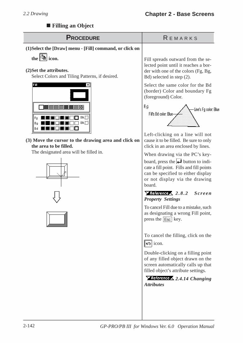
2.2 Drawing Chapter 2 - Base Screens
2-142 GP-PRO/PB III for Windows Ver. 6.0 Operation Manual
Left-clicking on a line will notcause it to be filled. Be sure to onlyclick in an area enclosed by lines.
When drawing via the PC’s key-board, press the button to indi-cate a fill point. Fills and fill pointscan be specified to either displayor not display via the drawingboard.
2 . 8 . 2 S c r e e nProperty SettingsTo cancel Fill due to a mistake, suchas designating a wrong Fill point,press the key.
To cancel the filling, click on the icon.
Double-clicking on a filling pointof any filled object drawn on thescreen automatically calls up thatfilled object’s attribute settings.
2.4.14 ChangingAttributes
Filling an Object
PROCEDURE R E M A R K S
(1)Select the [Draw] menu - [Fill] command, or click on
the icon.
(2)Set the attributes.Select Colors and Tiling Patterns, if desired.
(3) Move the cursor to the drawing area and click onthe area to be filled.The designated area will be filled in.
Esc
Fill spreads outward from the se-lected point until it reaches a bor-der with one of the colors (Fg, Bg,Bd) selected in step (2).
Select the same color for the Bd(border) Color and boundary Fg(foreground) Color.

2.2 DrawingChapter 2 - Base Screens
2-143GP-PRO/PB III for Windows Ver. 6.0 Operation Manual
To draw a Polygon, either Left-click or press the key to indicate thePolygon’s vertices. To complete the Polygon, either right-click or press the to automatically connect the beginning and end points.Holding down the key while drawing a Polygon will snap the polygon’ssegments to 45 degree angles.
Polygon Attributes
2.2.7 Line / Polygon
CCtrl
Drawing a Polygon
PROCEDURE R E M A R K S
(1)Select the [Draw] menu - [Filled Polygon] command,
or click on the icon.
(2)Set attributes of a polygon to be drawn.Select Colors and Tiling Pattern, if desired.
(3)Move the cursor to the drawing area and click on thestart point “a”.
a
Select one ofthe tiling pat-terns
Sets the Colorand blinking, ifdesired
Displays thecurrently se-lected Polygon
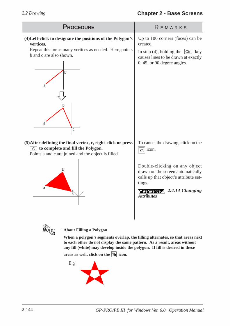
2.2 Drawing Chapter 2 - Base Screens
2-144 GP-PRO/PB III for Windows Ver. 6.0 Operation Manual
PROCEDURE R E M A R K S
(4)Left-click to designate the positions of the Polygon’svertices.Repeat this for as many vertices as needed. Here, pointsb and c are also shown.
(5)After defining the final vertex, c, right-click or press to complete and fill the Polygon.Points a and c are joined and the object is filled.
Up to 100 corners (faces) can becreated.
In step (4), holding the keycauses lines to be drawn at exactly0, 45, or 90 degree angles.
Ctrl
To cancel the drawing, click on the icon.
Double-clicking on any objectdrawn on the screen automaticallycalls up that object’s attribute set-tings.
2.4.14 ChangingAttributes
· About Filling a Polygon
When a polygon’s segments overlap, the filling alternates, so that areas nextto each other do not display the same pattern. As a result, areas withoutany fill (white) may develop inside the polygon. If fill is desired in theseareas as well, click on the icon.
Note:
C
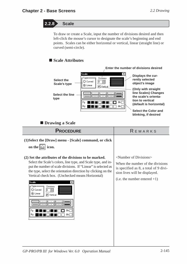
2.2 DrawingChapter 2 - Base Screens
2-145GP-PRO/PB III for Windows Ver. 6.0 Operation Manual
2.2.8 Scale
To draw or create a Scale, input the number of divisions desired and thenleft-click the mouse’s cursor to designate the scale’s beginning and endpoints. Scales can be either horizontal or vertical, linear (straight line) orcurved (semi-circle).
Scale Attributes
Drawing a Scale
PROCEDURE R E M A R K S
(1)Select the [Draw] menu - [Scale] command, or click
on the icon.
(2) Set the attributes of the divisions to be marked.Select the Scale’s colors, line type, and Scale type, and in-put the number of scale divisions. If “Linear” is selected asthe type, select the orientation direction by clicking on theVertical check box. (Unchecked means Horizontal)
Select theScale’s type
Select the linetype
Select the Color andblinking, if desired
(Only with straightline Scales) Changesthe scale’s orienta-tion to vertical(default is horizontal)
Displays the cur-rently selectedobject’s image
Enter the number of divisions desired
<Number of Divisions>
When the number of the divisionsis specified as 8, a total of 9 divi-sion lives will be displayed.
(i.e. the number entered +1)

2.2 Drawing Chapter 2 - Base Screens
2-146 GP-PRO/PB III for Windows Ver. 6.0 Operation Manual
PROCEDURE R E M A R K S
The following explanation is divided into two parts; first,when creating a linear type scale, and second, whencreating a curved type scale.
[Creating a Linear type scale- (Vertical, with 8 divi-sions)]Specify the area of division lines by a rectangle.
(3)Use the mouse’s cursor to create a rectangle in thedrawing area, i.e. left-click to indicate the linear scale’sstart point, a.
(4)Complete the rectangle by left-clicking on the Scale’send point, b.The rectangle shape will disappear, and be replaced bydivision lines.
[Creating a Curved type scale- (8 divisions)]Specify the area of division lines, using double circles.
(3)Use the mouse’s cursor to create a circle on the draw-ing area, i.e. left-click to indicate the curved scale’sstart point, a.
Holding down the key whileperforming step (4) will draw a per-fect square.
When using the keyboard to per-form drawing, press the key todesignate the start and finish points.
To cancel the drawing, click on the icon.
Ctrl

2.2 DrawingChapter 2 - Base Screens
2-147GP-PRO/PB III for Windows Ver. 6.0 Operation Manual
PROCEDURE R E M A R K S
(4)Click on the radius point “b”, which is of a scale’souter circle.
(5)Draw another circle inside the circle drawn in step(4) to decide the width of the scale. Click on this in-ner circle’s radius point “c”.
(6)Rotate the displayed segment and click on the scalestart point “d” or on its elongation.
(7)Then, rotate the segment again until you reach thedesired end point e, and click to designate the end ofthe scale’s divisions.Division lines appear inside the area surrounded withthe double circles and the two segments. They will bedrawn clockwise from the start point to the end point.
When using the keyboard to drawdivisions, press the key aftermoving the cursor to the divisioncircle’s center point, to the otherpoint on its circumference (radiuspoint), and then to the divisions’start and end points.
To cancel the drawing, click on the icon.
Double-clicking on any objectdrawn on the screen automaticallycalls up that object’s attribute set-tings.
2.4.14 ChangingAttributes

2.2 Drawing Chapter 2 - Base Screens
2-148 GP-PRO/PB III for Windows Ver. 6.0 Operation Manual
2.2.9 Text
From the keyboard enter the text and then place it on the screen. Thissoftware has two methods of placing text on the screen. The first methoddefines the placement point, and the second defines the area where the textwill be centered.
Text AttributesSelect the type of text.
Select the text’s displaydirection. (This featureis not available withImage Font.)
Select the Fg and Bgcolors, and blinking.
Displays a sample of thecurrent text’s attributes.
Specify the charactersize.
Select the style of thetext. (This feature isnot available withImage Font.)
Enter the text used asdirect text.
Select the desired fontwhen using Image Fontfor Direct Text.
Image text is com-pressed when thisoption is selected.
Direct Text
The text entered in the text entry field is placed directly as a fixed text string.A maximum of 100 characters can be entered per line, and 100 lines perscreen.
Index Text
Select and add the Index Text.4.6.3 Selecting the index character string Entering
the index character string
Image Font
Text using Windows fonts is displayed in bitmap format. This feature isenabled only when "Direct Text" mode is selected.
· Image Font is supported by the GP-2000 series only.
Click the [Select Font] button and specify the Font, Style and Size settings.
Note:
Displays a sample of thecurrent text’s attributes
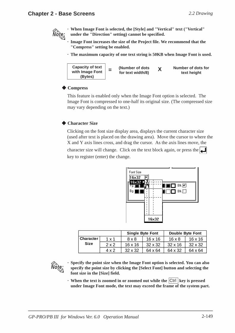
2.2 DrawingChapter 2 - Base Screens
2-149GP-PRO/PB III for Windows Ver. 6.0 Operation Manual
· When Image Font is selected, the [Style] and "Vertical" text ("Vertical"under the "Direction" setting) cannot be specified.
· Image Font increases the size of the Project file. We recommend that the"Compress" setting be enabled.
· The maximum capacity of one text string is 50KB when Image Font is used.
Note:
Capacity of textwith Image Font
(Bytes)
(Number of dotsfor text width/8)
Number of dots fortext height= X
Compress
This feature is enabled only when the Image Font option is selected. TheImage Font is compressed to one-half its original size. (The compressed sizemay vary depending on the text.)
Character Size
Clicking on the font size display area, displays the current character size(used after text is placed on the drawing area). Move the cursor to where theX and Y axis lines cross, and drag the cursor. As the axis lines move, thecharacter size will change. Click on the text block again, or press the key to register (enter) the change.
1 x 1 8 x 8 16 x 16 16 x 8 16 x 162 x 2 16 x 16 32 x 32 32 x 16 32 x 324 x 2 32 x 32 64 x 64 64 x 32 64 x 64
Single Byte Font Double Byte FontCharacter
Size
· Specify the point size when the Image Font option is selected. You can alsospecify the point size by clicking the [Select Font] button and selecting thefont size in the [Size] field.
· When the text is zoomed in or zoomed out while the key is pressedunder Image Font mode, the text may exceed the frame of the system part.
Note:
Ctrl

2.2 Drawing Chapter 2 - Base Screens
2-150 GP-PRO/PB III for Windows Ver. 6.0 Operation Manual
Note: · When text character backgrounds (Bg) is specified to Black + Blk (Blink),transparent mode is used, thereby displaying that area as transparent. For256-color mode, select the last (255th) color, which is “Clr”. However, forthe GP unit with three blink speeds, this mode can be specified only whenthe “Mid” speed is selected. If an object has been drawn underneath thesecharacters, they (the characters) will appear transparent, showing theobject behind. This function is useful when overlaying text on objects, i.e.,over the face of Switches and Lamps.
2.2 Selecting Colors· You cannot specify the style when Image font is selected.
Changing to a New Text Line and Line SettingsWhen entering characters, simply press the key to move to a new line.When there are 2 or more lines of text, icons will appear to allow adjust-ments in line spacing, and justification.
Justification
Horizontal text’s alignment can be changed to either Left, Center, Right orFull justified.
Right justified
Left justified
Centered
Controls theselectedtext’sjustification
Style
Characters can be either Normal, Bold, or Raised.
Full justified
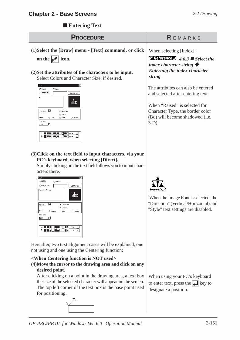
2.2 DrawingChapter 2 - Base Screens
2-151GP-PRO/PB III for Windows Ver. 6.0 Operation Manual
Entering Text
PROCEDURE R E M A R K S
(1)Select the [Draw] menu - [Text] command, or click
on the icon.
(2)Set the attributes of the characters to be input.Select Colors and Character Size, if desired.
(3)Click on the text field to input characters, via yourPC’s keyboard, when selecting [Direct].Simply clicking on the text field allows you to input char-acters there.
Hereafter, two text alignment cases will be explained, onenot using and one using the Centering function:
<When Centering function is NOT used>(4)Move the cursor to the drawing area and click on any
desired point.After clicking on a point in the drawing area, a text boxthe size of the selected character will appear on the screen.The top left corner of the text box is the base point usedfor positioning.
The attributes can also be enteredand selected after entering text.
When “Raised” is selected forCharacter Type, the border color(Bd) will become shadowed (i.e.3-D).
When using your PC’s keyboardto enter text, press the key todesignate a position.
When selecting [Index]:
4.6.3 Select theindex character string Enterinig the index characterstring
·When the Image Font is selected, the"Direction" (Vertical/Horizontal) and"Style" text settings are disabled.

2.2 Drawing Chapter 2 - Base Screens
2-152 GP-PRO/PB III for Windows Ver. 6.0 Operation Manual
PROCEDURE R E M A R K S
(5)Move the cursor to the desired position and left-clickthe mouse to place it on the screen.
<When the Centering function IS used>
(4)Move the cursor over the desired placement area and,while holding down the key, click on anydesired point.After clicking on a point in the drawing area, the textbox will appear on the screen in dotted line.
Shift
(5)Select a centering area that is the same size or largerthan the previously selected text area.The designated size’s text box will appear in the centerof the selected area.
To cancel the placement, click onthe icon.
Double-clicking on any objectdrawn on the screen automaticallycalls up that object’s attribute set-tings.
2.4.14 ChangingAttributes
To cancel the designated area, clickthe right mouse button.
2.2 DrawingChapter 2 - Base Screens
2-153GP-PRO/PB III for Windows Ver. 6.0 Operation Manual
· GP-PRO/PBIII for Windows uses the PC’s font. As a result, the text thatyou see on the GP display and that shown on the PC may differ.
· In both GP-PROIII and GP-PRO/PBIII (DOS Ver.), when an object isoverlaid on a text block, the text block will be displayed in the foreground.With GP-PRO/PBIII for Windows, however, the text block will be placedbehind the object. When the GP-PROIII and GP-PRO/PBIII (DOS Ver.)’sdata is used in the GP-PRO/PBIII for Windows, the text block will bedisplayed in the foreground.
Note:

2.2 Drawing Chapter 2 - Base Screens
2-154 GP-PRO/PB III for Windows Ver. 6.0 Operation Manual
Graphics created on screens in a project can be loaded and used repeatedlyon others with GP-PRO/PB III for Windows. Thus, a single screen’s con-tents can be used repeatedly elsewhere. The Load Screen function is also agood way to cut down on your screen’s actual size, since you only need tocall up items to your screen, not save them on it.
Screens that can be loaded to other screens
2.2.10 Load Screens
Only one (1) Keypad can be loaded onto a Base screen. The screen cur-rently being edited cannot be loaded on to itself.
If any portion of a Trend Graph screen extends over a Basescreen’s border, the Trend Graph screen will not display cor-rectly on the GP screen.
If a portion of an Image screen extends over a Base screen’s Y axis border,that portion will not be displayed on the GP screen. When the Image screenis placed over the Base screen laterally, however, any part that extends overthe Base screen X axis border will be squeezed onto the GP screen.(i.e. notcut)
Example)
DrawingAreas
When using the GPpanel display
When using GP-PRO/PB III for Windows
Current Screen Loadable ScreensB (Base) screen
T (Trend graph) screenK (Keypad) screenI (Image) screen
I (Image) screen-CF cardB (Base) screenI (Image) screen
I (Image) screen-CF cardB (Base) screenI (Image) screen
I (Image) screen-CF cardB (Base) screenI (Image) screen
I (Image) screen-CF cardU (Window) screen
B (Base) screen
T (Trend graph) screen
K (Keypad) screen

2.2 DrawingChapter 2 - Base Screens
2-155GP-PRO/PB III for Windows Ver. 6.0 Operation Manual
NestingScreens can be nested up to 10 times (11 layers). However, if your PC’ssystem memory is low, a loaded screen/object may not be displayed. Later,however, when the data is transferred to the GP, the display will appearnormally.
E.g.) Nesting Objects Twice (3 layers)
The load screen nesting condition can be viewed via the load screen nestingdisplay function.
2.8.9 Display of Screen Level Change Structure
PROCEDURE R E M A R K S
(1)Select the [Draw] menu - [Load Screen] command,
or click on the icon.
(2)Select a desired screen from the list or enter thatscreen’s number directly on the [Screen No.] field viathe keyboard, and then click on the button.Then, the screen’s outline and center point will appear inthe drawing area, next to your cursor.
Only screens in the currently usedProject file can be loaded. Screensin other project files can not beloaded.
The current (selected) Screen can-not be loaded on to itself.
Loading a Screen

2.2 Drawing Chapter 2 - Base Screens
2-156 GP-PRO/PB III for Windows Ver. 6.0 Operation Manual
When calling up a filled object:
When the current screen’s graphics overlap loaded filled (painted) graph-ics, depending on the color used, unfilled areas may be created. To correctthis, add a fill to the current screen’s unfilled area.
2.2.6 Fill
PROCEDURE R E M A R K S
(3)Click on the point where the Screen’s top left corneris to be placed.The image’s center point is left top corner of its border,and for other objects, the screen center mark will be theplacement point.
A loaded screen cannot be editedwhile it is being used on a different(i.e. loaded) screen. You will needto open the original screen to per-form any editing.
To cancel the loading, click on the icon.
· If a background color is selected for the screen used forscreen call-up, the object placed on the screen will not bedisplayed on the GP.
· To call up the screen for which a background color has beenselected, specify the center of the screen as the call-up posi-tion and then place the screen.
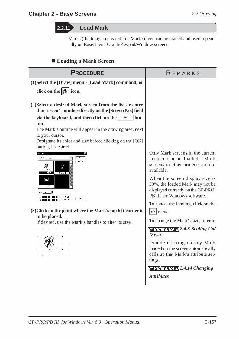
2.2 DrawingChapter 2 - Base Screens
2-157GP-PRO/PB III for Windows Ver. 6.0 Operation Manual
2.2.11 Load Mark
Marks (dot images) created in a Mark screen can be loaded and used repeat-edly on Base/Trend Graph/Keypad/Window screens.
Loading a Mark Screen
PROCEDURE R E M A R K S
(1)Select the [Draw] menu - [Load Mark] command, or
click on the icon.
(2)Select a desired Mark screen from the list or enterthat screen’s number directly on the [Screen No.] fieldvia the keyboard, and then click on the but-ton.The Mark’s outline will appear in the drawing area, nextto your cursor.Designate its color and size before clicking on the [OK]button, if desired.
(3)Click on the point where the Mark’s top left corner isto be placed.If desired, use the Mark’s handles to alter its size.
Only Mark screens in the currentproject can be loaded. Markscreens in other projects are notavailable.
When the screen display size is50%, the loaded Mark may not bedisplayed correctly on the GP-PRO/PB III for Windows software.
To cancel the loading, click on the icon.
To change the Mark’s size, refer to
2.4.3 Scaling Up/DownDouble-clicking on any Markloaded on the screen automaticallycalls up that Mark’s attribute set-tings.
2.4.14 Changing
Attributes

2.2 Drawing Chapter 2 - Base Screens
2-158 GP-PRO/PB III for Windows Ver. 6.0 Operation Manual
This section describes how to convert image data (bitmap: BMP file andJPEG: JPEG file), created from other drawing software or imported from ascanner, for use on a GP Image (I) screen.
For Image Conversion data, refer to 3.5 Creating anImage: the Image Screen
Converting and Placing an Image
2.2.12 Convert (Import) Image
PROCEDURE R E M A R K S
(3)Click on the button.The data is then saved as an Image screen.
(1) From the munu bar of the screen editor [Draw]menu’s [Convert Image...] command.
(2)Set all conversion settings and click on the button.
Once an image has been converted,it can be placed on a screen usingthe Load Screen function.
2.2.10 LoadScreensFor each setting item,
3.5 Creating anImage: the Image screen
Before conversion, the image dis-played in the Import Image dialogbox is still compressed and mayappear different from the actual dis-play (after conversion).
To cancel the conversion, simplyclick on the button.

2.2 DrawingChapter 2 - Base Screens
2-159GP-PRO/PB III for Windows Ver. 6.0 Operation Manual
PROCEDURE R E M A R K S
(4)Click on the button.The Image screen’s border will appear on the currentscreen.
(5)Click on the point where the Image screen is to beplaced.The Image screen will appear on your screen.
To cancel the placement, click onthe icon.
If the Image screen(I) is placed outside the drawing area vertically, theportion of the image that does not fit in the drawing area will not be dis-played on the GP screen. However, if the Image screen is placed outside thedrawing area horizontally, the portion that does not fit will be squeezed sothat it is displayed on the GP screen.
E.g.)
Screendisplayarea
On your PC's screen On the GP panel
Pasting images with other file formatsThe paste function can be used for images copied onto the Clipboard *1.Executing the [Paste] command from screen editor while a copied image isin the clipboard will display the "Paste Image" dialog box on the screen. The“Source” tab will not be displayed on the screen.When images cannot bepasted with this procedure, convert the images into bitmap files or JPEGfiles with other image processing software before copying and pasting it tothe screen editor.
*1 The clipboard is a storage location where copied or cut data is temporarily stored. Thedata stored on the clipboard can be copied or moved by pasting it.

2.3 Tags Chapter 2 - Base Screens
2-160 GP-PRO/PB III for Windows Ver. 6.0 Operation Manual
Tags are one of the GP-PRO/PBIII for Windows program’s many powerfulfeatures. When you create a Tag, you can transform a square on the screeninto a switch, or create an animated display that changes according to datafrom the Host PLC. Tags are created and placed on the screen where youwant a function to be; and, while most of the applications for Tags are on aBase screen, they can be used with Keypad screens, as well as a variety ofother screens.Here, topics such as Previously Created Tags, Changing of Tags, and Delet-ing Tags, are discussed.For further details of tags, refer to the Tag Reference Manual.
Points to Consider when Creating TagsWhen creating a Tag, please be aware of the following points:
When creating a number of tags on identical screens, if one Tag’s posi-tion overlaps that of another Tag, the Tags will overlap when they arecalled up and may not be displayed correctly. Please be aware of thiswhen loading (calling up) multiple Tags.
Using the Copy or Paste functions to place Tags with the same name onsimilar screens can make identifying Tags difficult. It is suggested thatyou either change the Tag’s attributes (i.e. name) directly, or use the TagSummary to change the name. When 2 or more K Tags have been usedto operate a common Trigger Bit, it is especially important that the Tagnames used are different.
Tag Reference Manual 2.12 K-tag (Key Input) The maximum number of tags designated on the same screen is as fol-lows. This total includes tags on any screens that have been called up, orare included in a window that is used. The figure below, however, doesnot include any k tags or R tags.
Refer to the figure below for the enabled tags.
<Example: when using GP-470>
2.3 Tags
GP SeriesGP-470GP-570GP-675
GP-270GP-370GP-H70
GP-377GP77RGP2000
Number of tags 256 128 384
Screen B2 Screen B1 Screen B3
Combined number of Tags = 10(B2) + 25 (B3) + 30(B1) = 65 ≤ ≤ ≤ ≤ ≤ 256
30 tags(previously
created)
Number of tags can be viewed from the Screen Informa-tion in GP-PRO/PBIII.
10 tags 25 tags
LoadScreen
LoadScreen
25 tags(B3)
10 tags(B2)
2.3 TagsChapter 2 - Base Screens
2-161GP-PRO/PB III for Windows Ver. 6.0 Operation Manual
Though all of a Tag’s identifying marks, lines, etc. can be seen on thescreen that it was created on, after that Tag’s screen is called up to a Basescreen, those Marks can no longer be seen and it can not be edited. Inexample 1 above, even though screen tags B2 and B3 are added to B1’stotal tag count, their identification data is not displayed on B1 (Drawingarea, Tag List, etc.) and can not be edited from that screen. To edit theseMarks, call up the Base screen on which each Tag was specified.
The order in which each Tag is created is recorded, and when the total tagcount for that screen exceeds 256 (Digital’s GP-H70, GP-270 and GP-370 count up to 128 tags. GP-377, GP37W2, GP-377R, GP77R andGP2000 can use up to 384 tags.), those excess tags are ineffective. Whenthe tags used on a screen have been called up from a window, those tagsare added to the total, in the order that the window was called up. Thus,when calling up multiple windows for use on a screen, be sure that thetotal number of tags used in all the windows does not exceed the abovelimit, or certain tags will become invalid.
Approximately 90 reserved tags are used for the Device Monitor func-tion. When using Device Monitor together with regular screen tags, theymust be added to the screen’s total tag count. Thus, be sure that the tagsused for the Device Monitor are included in your tag count calculation. Ifthe total becomes greater than that screen’s limit, the message “Total No.of Tags is over limit.” will appear. Until the number of tags is reduced,there is a possibility that the Device Monitor function will not workcorrectly. If using the Device Monitor function will cause a screen’s totaltag count to exceed its limit, you should not use Device Monitor functionon that screen.
4.8 Device Monitor
The actual amount of space required (in bytes) for each tag will vary.When placing tags on a screen, please consider the number of tags thathave already been created, the size of each tag, and the panel’s tag limit.
Information such as the current screen capacity and number of tags usedcan be viewed in the [Screen Information] dialog box.
4.5.2 Screen InformationFor each tag size, refer to the following table.

2.3 Tags Chapter 2 - Base Screens
2-162 GP-PRO/PB III for Windows Ver. 6.0 Operation Manual
<Tag Size List>
Be aware of the following points:
• The total number of t-tags that can be used on the GP-470, 570, 571, 675and 870 is 128; with the GP-270, 370, and H70, it is 64; with the GP-377,GP-37W2, GP77R and GP2000 series, it is 192.
• Only one (1) A, a, and C- tag can be used per screen.• A total of 30 R tags are possible on one screen. The total number of
points used for R-tag data can be up to 406 per screen. However, whencalling up multiple screens, the total points allowable is 512.
• The number of windows that can be displayed on one screen at one timeis up to 3, i.e. one global window and two local windows via the U-tag.
• Tih, and Tiw tags cannot be used on the GP-H70, GP-270, GP-370, GP-57J, GP-377, GP-37W2, GP-377R and GP2000 series units, since theydo not have AUX I/F Touch Switch output (TSW0 to 7).
Tag Name Function Tag Size(Byte)
A Alarm Summary Text Display 56a Alarm Summary Display 34C Clock Display 28D Statistic Graph Display 48d Statistic Data Display 74E Numeric Data Display extended function 32 to 122F Free Library Display 42G Graph Display 40g Graph Display extended function 38 to 158H Drawing Object Display 42J Moving Mark Display 38K Key Input 46, 58k Keypad Setup 28L Library Display 34I Library State Display 40 to 102
M Mark Display 34N Numeric Data Display 36n Alarm Boundary Display 30P Numeric Display in Predefined Format 118Q Alarm Summary Display extended function 46, 66, 98R Rail Settings 20S String Display 32
T(including Tih, Tiw) Touch Panel Input 36t Selector Switch Input 56U Window Display 34V Video Window Display 30v Video Window Extended Features 42W Write to a Device 32X Text Data Display 40

2.3 TagsChapter 2 - Base Screens
2-163GP-PRO/PB III for Windows Ver. 6.0 Operation Manual
2.3.1 Designating Tags
The tag setting items will differ depending on each tag type. Here, the basicsetting procedures are described.
After a Tag is selected, that tag’s dialog box will appear. Here all the tag’sattribute data, such as the setting address, are entered. After all of the Tag’sattributes have been entered, click on the button and designate thepoint or area on the screen where the Tag will function.
Usage Pattern
[Tag] →→→→→Select a Tagfrom the list →→→→→
Enter the Tag’ssetting data →→→→→
Designate thefunctioning area
Select a desired command iconfrom the Tag Tool Bar.
or
Tag SettingsAn example of a Tag’s dialog box is shown below.In the [General Info] area, the Tag’s name and description data are entered.Also, the Tag’s general settings are displayed.
E.g.) L Tag
The actual setting items displayed will differ, depending on the tag.
Tag Reference Manual
Clicking here willbring up theScreen Accesssettings (Itemswill vary depend-ing on the tagtype
Shows thecurrentlyselected Tag’ssettings
Enter Com-ment datawithin 20characters here
Enter the Tag’sname (number)within 5charactershere
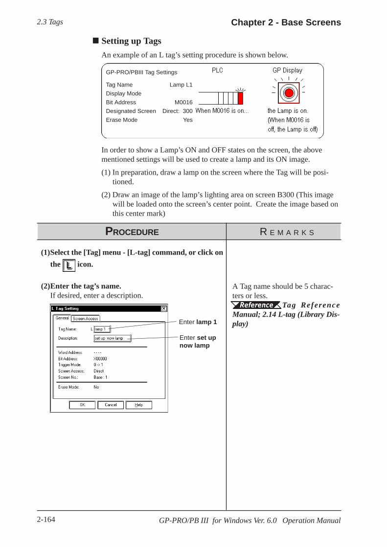
2.3 Tags Chapter 2 - Base Screens
2-164 GP-PRO/PB III for Windows Ver. 6.0 Operation Manual
Setting up TagsAn example of an L tag’s setting procedure is shown below.
GP-PRO/PBIII Tag Settings
Tag Name Lamp L1Display ModeBit Address M0016Designated Screen Direct: 300Erase Mode Yes
In order to show a Lamp’s ON and OFF states on the screen, the abovementioned settings will be used to create a lamp and its ON image.
(1) In preparation, draw a lamp on the screen where the Tag will be posi-tioned.
(2) Draw an image of the lamp’s lighting area on screen B300 (This imagewill be loaded onto the screen’s center point. Create the image based onthis center mark)
PROCEDURE R E M A R K S
(1)Select the [Tag] menu - [L-tag] command, or click onthe icon.
(2)Enter the tag’s name.If desired, enter a description.
Enter lamp 1
Enter set upnow lamp
A Tag name should be 5 charac-ters or less.
Tag ReferenceManual; 2.14 L-tag (Library Dis-play)
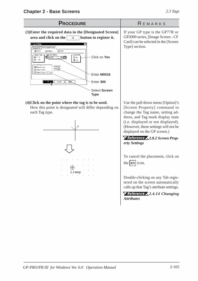
2.3 TagsChapter 2 - Base Screens
2-165GP-PRO/PB III for Windows Ver. 6.0 Operation Manual
Use the pull down menu [Option]’s[Screen Property] command tochange the Tag name, setting ad-dress, and Tag mark display state(i.e. displayed or not displayed).(However, these settings will not bedisplayed on the GP screen.)
2.8.2 Screen Prop-erty Settings
To cancel the placement, click onthe icon.
Double-clicking on any Tab regis-tered on the screen automaticallycalls up that Tag’s attribute settings.
2.4.14 ChangingAttributes
(4)Click on the point where the tag is to be used.How this point is designated will differ depending oneach Tag type.
PROCEDURE R E M A R K S
(3)Enter the required data in the [Designated Screen]area and click on the button to register it.
Enter 300
Click on Yes
Enter M0016
If your GP type is the GP77R orGP2000 series, [Image Screen - CFCard] can be selected in the [ScreenType] section.
Select ScreenType

2.4 Object Editing Chapter 2 - Base Screens
2-166 GP-PRO/PB III for Windows Ver. 6.0 Operation Manual
2.4 Object EditingParts, objects, text, and Tags previously placed or drawn (hereafter called“Objects”), can be edited using various functions, such as Copy and Delete.To edit an object, first, use the cursor to select the object, and then select thetype of edit operation.
Usage Pattern
→→→→→Select anObject
[Edit]or
Tool Bar→→→→→
Select the type ofediting to perform →→→→→
Perform theediting
Types of Editing FunctionsIcons contained in the Edit Tool Bar and their corresponding edit operationare as follows:
*1 This function is enabled only when GP Type selection is a GLC series unit. Pro-Control Editor Operation Manual
Some of the editing tools listed above can be selected from the menu
displayed on the screen by right-clicking the mouse.
Icon Edit Type Icon Edit TypeUndo Group
Redo Ungroup
Cut Bring to Front
Copy Send to Back
Paste Change Attribute
Command Data Paste *1 Change Coordinates
Duplicate Vertex Editing
Delete Transferring Screen toClipboard
Align Converting Screen to BitmapFile
Rotate Left Redraw Screen
Rotate Right Select All
Mirror X-axis Select
Mirror Y-axis

2.4 Object EditingChapter 2 - Base Screens
2-167GP-PRO/PB III for Windows Ver. 6.0 Operation Manual
2.4.1 Selecting Objects
Two methods are available for selecting objects: 1) clicking on an objectdirectly, or 2) dragging the mouse to enclose and select single or multipleobjects.
Also, you can select individual objects that have other objects either on topof, or overlapping them.
When the tool bar’s icon is clicked on (active), an object can be se-lected. To activate this icon, click on it directly, or select the pull down[Edit] menu’s [Select] command. Also, while drawing objects, right-clicking anywhere on a desired object allows you to select it.
Either a or a mark will be displayed on the sides of the selected object.These square marks are called “handles”.
Handle Types
There are two types of handles, those that can be used to scale the object andthose that can not. Refer to 2.4.3 Scaling Up/Down
: Can be used to scale the object : Cannot be used to scale
When an object has been be selected, the Selection Tool box will automati-cally appear. When multiple objects are selected, all the selection Toolbox’s functions are available.
After selecting either
or , clicking on either
or selects the nextobject or type
Selects all of theobjects in a group
After selecting a groupof objects, selects oneof that group
After selecting a group ofobjects, selects one typeof object (i.e. squares,circles, etc.)
These keys are used toselect Tags when the Tagbox is checked
Objects may be selected using the Screen Data List, instead of selecting themon the screen.
2.8.4 Screen Data List· When the tag check box for the selection tool box is marked with a check,
tags can be selected even if the tag names and marks are hidden.
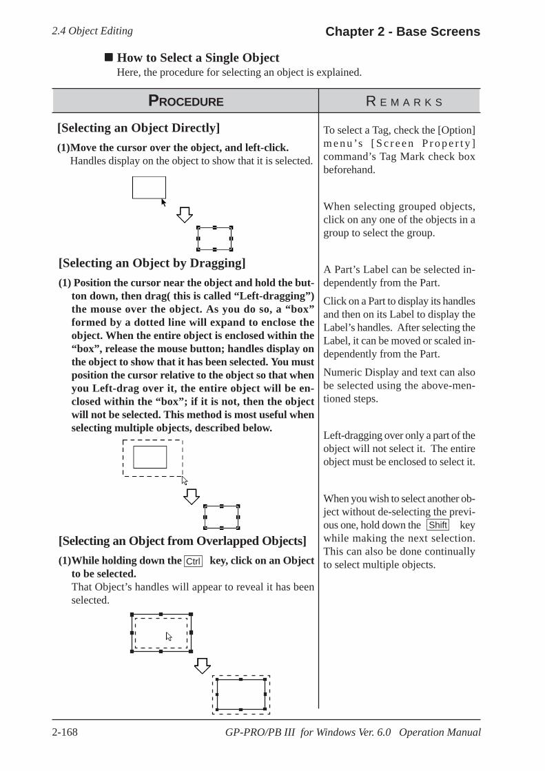
2.4 Object Editing Chapter 2 - Base Screens
2-168 GP-PRO/PB III for Windows Ver. 6.0 Operation Manual
PROCEDURE R E M A R K S
How to Select a Single ObjectHere, the procedure for selecting an object is explained.
[Selecting an Object Directly](1)Move the cursor over the object, and left-click.
Handles display on the object to show that it is selected.
[Selecting an Object by Dragging](1) Position the cursor near the object and hold the but-
ton down, then drag( this is called “Left-dragging”)the mouse over the object. As you do so, a “box”formed by a dotted line will expand to enclose theobject. When the entire object is enclosed within the“box”, release the mouse button; handles display onthe object to show that it has been selected. You mustposition the cursor relative to the object so that whenyou Left-drag over it, the entire object will be en-closed within the “box”; if it is not, then the objectwill not be selected. This method is most useful whenselecting multiple objects, described below.
[Selecting an Object from Overlapped Objects](1)While holding down the key, click on an Object
to be selected.That Object’s handles will appear to reveal it has beenselected.
Ctrl
To select a Tag, check the [Option]m e n u ’s [ S c r e e n P r o p e r t y ]command’s Tag Mark check boxbeforehand.
When selecting grouped objects,click on any one of the objects in agroup to select the group.
A Part’s Label can be selected in-dependently from the Part.
Click on a Part to display its handlesand then on its Label to display theLabel’s handles. After selecting theLabel, it can be moved or scaled in-dependently from the Part.
Numeric Display and text can alsobe selected using the above-men-tioned steps.
Left-dragging over only a part of theobject will not select it. The entireobject must be enclosed to select it.
When you wish to select another ob-ject without de-selecting the previ-ous one, hold down the keywhile making the next selection.This can also be done continuallyto select multiple objects.
Shift
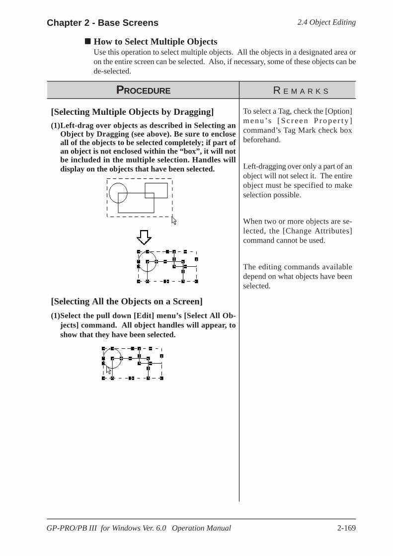
2.4 Object EditingChapter 2 - Base Screens
2-169GP-PRO/PB III for Windows Ver. 6.0 Operation Manual
How to Select Multiple ObjectsUse this operation to select multiple objects. All the objects in a designated area oron the entire screen can be selected. Also, if necessary, some of these objects can bede-selected.
PROCEDURE R E M A R K S
[Selecting Multiple Objects by Dragging](1)Left-drag over objects as described in Selecting an
Object by Dragging (see above). Be sure to encloseall of the objects to be selected completely; if part ofan object is not enclosed within the “box”, it will notbe included in the multiple selection. Handles willdisplay on the objects that have been selected.
[Selecting All the Objects on a Screen](1)Select the pull down [Edit] menu’s [Select All Ob-
jects] command. All object handles will appear, toshow that they have been selected.
To select a Tag, check the [Option]m e n u ’s [ S c r e e n P r o p e r t y ]command’s Tag Mark check boxbeforehand.
Left-dragging over only a part of anobject will not select it. The entireobject must be specified to makeselection possible.
When two or more objects are se-lected, the [Change Attributes]command cannot be used.
The editing commands availabledepend on what objects have beenselected.
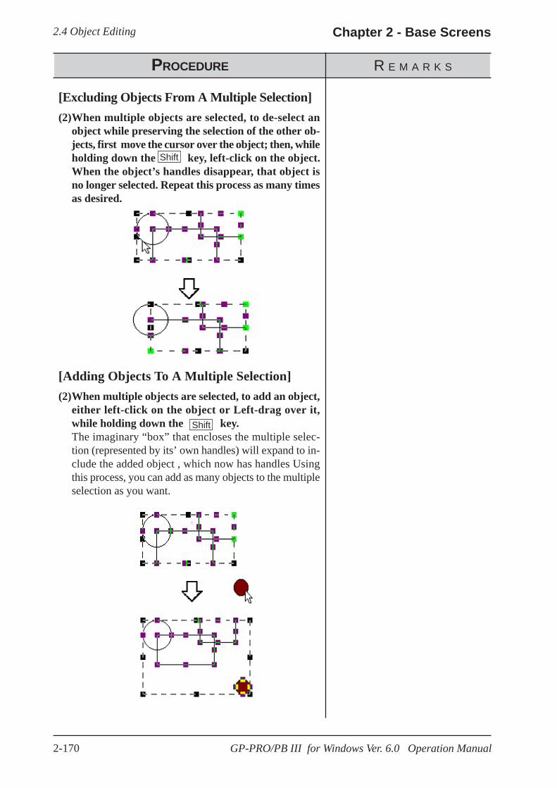
2.4 Object Editing Chapter 2 - Base Screens
2-170 GP-PRO/PB III for Windows Ver. 6.0 Operation Manual
PROCEDURE R E M A R K S
[Excluding Objects From A Multiple Selection](2)When multiple objects are selected, to de-select an
object while preserving the selection of the other ob-jects, first move the cursor over the object; then, whileholding down the key, left-click on the object.When the object’s handles disappear, that object isno longer selected. Repeat this process as many timesas desired.
[Adding Objects To A Multiple Selection](2)When multiple objects are selected, to add an object,
either left-click on the object or Left-drag over it,while holding down the key.The imaginary “box” that encloses the multiple selec-tion (represented by its’ own handles) will expand to in-clude the added object , which now has handles Usingthis process, you can add as many objects to the multipleselection as you want.
Shift
Shift

2.4 Object EditingChapter 2 - Base Screens
2-171GP-PRO/PB III for Windows Ver. 6.0 Operation Manual
PROCEDURE R E M A R K S
[Selecting One Object in a Multiple Selection](2)First, make a multiple selection; then, click on the
Selection Tool box’s icon. All the objects in themultiple selection will become de-selected, except forone.
(3) Use the and icons to “scroll” through all theobjects originally in the multiple selection; clickingon these arrow keys will change the selected item,one at a time. Clicking on the icon will selectthe next object, and clicking on the icon willselect the previons object , inthe order that theywere drawn.
If you wish to re-select all theobjects originally in the multipleselection, click on the SelectionTool box’s button.
To select an Object from over-lapped Objects.
How to Select aSingle Object
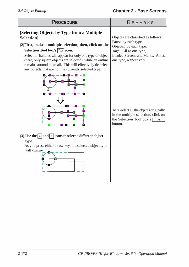
2.4 Object Editing Chapter 2 - Base Screens
2-172 GP-PRO/PB III for Windows Ver. 6.0 Operation Manual
PROCEDURE R E M A R K S
[Selecting Objects by Type from a MultipleSelection](2)First, make a multiple selection; then, click on the
Selection Tool box’s icon.Selection handles will appear for only one type of object(here, only square objects are selected), while an outlineremains around them all. This will effectively de-selectany objects that are not the currently selected type.
(3) Use the and icons to select a different objecttype.
As you press either arrow key, the selected object typewill change.
Objects are classified as follows:Parts: by each type,Objects: by each type,Tags: All as one type,Loaded Screens and Marks: All asone type, respectively.
To re-select all the objects originallyin the multiple selection, click onthe Selection Tool box’s button.

2.4 Object EditingChapter 2 - Base Screens
2-173GP-PRO/PB III for Windows Ver. 6.0 Operation Manual
2.4.2 Moving Objects
In this section, the procedures for moving objects are described.
How to Move an Object
PROCEDURE R E M A R K S
(1)Click on the desired object. The object’s handles willappear, showing that it has been selected.
(2)Place the cursor over the object, away from thehandles, and after the cursor changes to , drag itto the desired location.
2.4.1 SelectingObjects
The keyboard’s , , , and keys can also be used when theobject’s handles are displayed.
If an object is too small to selectand move (i.e. it is only scaled upor down), click on and drag the ob-ject while holding down the Altkey.
Also, you can move the object byzooming out the screen or using thekeyboard.
1.3.2 Display Area(50%, 100%, 200%)
To cancel the movement, click onthe icon.
↓↓↓↓↓
←←←←←→→→→→↑↑↑↑↑
· To move an object horizontally or vertically, do so while holding the [Shift]key down. In this case, the object will be moved in either the horizontal orvertical direction where the moving distance is greater.
· To move and scale up/down an object, designating its coordinates can beused.
2.4.15 Changing Coordinates
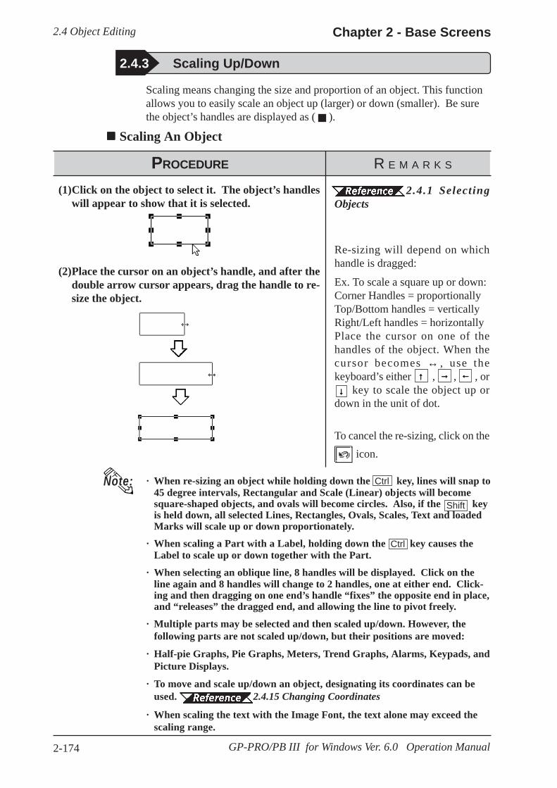
2.4 Object Editing Chapter 2 - Base Screens
2-174 GP-PRO/PB III for Windows Ver. 6.0 Operation Manual
· When re-sizing an object while holding down the key, lines will snap to45 degree intervals, Rectangular and Scale (Linear) objects will becomesquare-shaped objects, and ovals will become circles. Also, if the keyis held down, all selected Lines, Rectangles, Ovals, Scales, Text and loadedMarks will scale up or down proportionately.
· When scaling a Part with a Label, holding down the key causes theLabel to scale up or down together with the Part.
· When selecting an oblique line, 8 handles will be displayed. Click on theline again and 8 handles will change to 2 handles, one at either end. Click-ing and then dragging on one end’s handle “fixes” the opposite end in place,and “releases” the dragged end, and allowing the line to pivot freely.
· Multiple parts may be selected and then scaled up/down. However, thefollowing parts are not scaled up/down, but their positions are moved:
· Half-pie Graphs, Pie Graphs, Meters, Trend Graphs, Alarms, Keypads, andPicture Displays.
· To move and scale up/down an object, designating its coordinates can beused. 2.4.15 Changing Coordinates
· When scaling the text with the Image Font, the text alone may exceed thescaling range.
PROCEDURE R E M A R K S
2.4.3 Scaling Up/Down
(1)Click on the object to select it. The object’s handleswill appear to show that it is selected.
(2)Place the cursor on an object’s handle, and after thedouble arrow cursor appears, drag the handle to re-size the object.
Scaling means changing the size and proportion of an object. This functionallows you to easily scale an object up (larger) or down (smaller). Be surethe object’s handles are displayed as ( ).
Scaling An Object
2.4.1 SelectingObjects
Re-sizing will depend on whichhandle is dragged:
Ex. To scale a square up or down:Corner Handles = proportionallyTop/Bottom handles = verticallyRight/Left handles = horizontallyPlace the cursor on one of thehandles of the object. When thecursor becomes ↔ , use thekeyboard’s either , , , or key to scale the object up ordown in the unit of dot.
To cancel the re-sizing, click on the icon.
Note: Ctrl
Shift
↓↓↓↓↓
←←←←←→→→→→↑↑↑↑↑
Ctrl
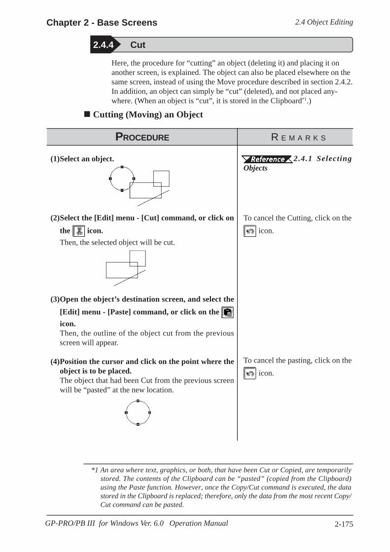
2.4 Object EditingChapter 2 - Base Screens
2-175GP-PRO/PB III for Windows Ver. 6.0 Operation Manual
2.4.4 Cut
Here, the procedure for “cutting” an object (deleting it) and placing it onanother screen, is explained. The object can also be placed elsewhere on thesame screen, instead of using the Move procedure described in section 2.4.2.In addition, an object can simply be “cut” (deleted), and not placed any-where. (When an object is “cut”, it is stored in the Clipboard*1.)
Cutting (Moving) an Object
PROCEDURE R E M A R K S
(1)Select an object.
(2)Select the [Edit] menu - [Cut] command, or click onthe icon.Then, the selected object will be cut.
(3)Open the object’s destination screen, and select the[Edit] menu - [Paste] command, or click on the icon.Then, the outline of the object cut from the previousscreen will appear.
(4)Position the cursor and click on the point where theobject is to be placed.The object that had been Cut from the previous screenwill be “pasted” at the new location.
2.4.1 SelectingObjects
To cancel the Cutting, click on the icon.
To cancel the pasting, click on the icon.
*1 An area where text, graphics, or both, that have been Cut or Copied, are temporarilystored. The contents of the Clipboard can be “pasted” (copied from the Clipboard)using the Paste function. However, once the Copy/Cut command is executed, the datastored in the Clipboard is replaced; therefore, only the data from the most recent Copy/Cut command can be pasted.

2.4 Object Editing Chapter 2 - Base Screens
2-176 GP-PRO/PB III for Windows Ver. 6.0 Operation Manual
2.4.5 Copy
PROCEDURE R E M A R K S
Here, the procedure for “copying” an object (without deleting it) and placingit elsewhere, is explained. (When an object is “copied”, it is stored in theClipboard*1.)
Copying an Object
(1)Select the desired object(s).
(2)Select the [Edit] menu - [Copy] command, or clickon the icon.The selected object(s) will be Copied to the Clipboard.
(3)Select the [Edit] menu - [Paste] command, or clickon the icon.Then, the outline of the object copied from the previousscreen to the Clipboard will appear.
(4)Position the cursor and click on the point where theobject is to be placed.The object stored in the Clipboard will be Copied to thespecified location.
2.4.1 SelectingObjects
To cancel the Copying, click on the
icon.
When “pasting” the Copied objecton another screen, be sure to openthat screen first.
Selecting and dragging an object toanther screen while holding downthe Esc key can also be used tocopy the object.
To cancel the pasting, click on the
icon.
*1 An area where text, graphics, or both, that have been Cut or Copied, are temporarilystored. The contents of the Clipboard can be “pasted” (copied from the Clipboard)using the Paste function. However, once the Copy/Cut command is executed, the datastored in the Clipboard is replaced; therefore, only the data from the most recent Copy/Cut command can be pasted.

2.4 Object EditingChapter 2 - Base Screens
2-177GP-PRO/PB III for Windows Ver. 6.0 Operation Manual
2.4.6 Paste
Here, the procedure for “pasting” an object, that has been Copied (or Cut) tothe Clipboard*1, is explained.
Pasting an Object
PROCEDURE R E M A R K S
(1)First, Copy (or Cut) an object.
(2)Select the [Edit] menu - [Paste] command, or clickon the icon.Then, the outline of the object copied from the previousscreen to the Clipboard will appear.
(3)Position the cursor and click on the point where theobject is to be Pasted.The object stored in the Clipboard will be Pasted to thenew location.
2.4.5 Copy
To cancel the paste, click on the icon.
When an object is copied from an-other screen, it will be automati-cally placed at the same coordinatesas its original ones. To place theobject at different coordinates,move it after this automatic place-ment.
*1 An area where text, graphics, or both, that have been Cut or Copied, are temporarilystored. The contents of the Clipboard can be “pasted” (copied from the Clipboard)using the Paste function. However, once the Copy/Cut command is executed, the datastored in the Clipboard is replaced; therefore, only the data from the most recent Copy/Cut command can be pasted.

2.4 Object Editing Chapter 2 - Base Screens
2-178 GP-PRO/PB III for Windows Ver. 6.0 Operation Manual
When Duplicating an object, its positioning will be decided based on the topleft handle of the copied (master) object. However, if a Bar Graph’s handlesare located in a graph display area, the object will be placed based on thegraph display area, not the graph’s border. Therefore, when setting thespacing, be sure to not overlap any of the graphs’ borders.
Note:
2.4.7 Duplicate
This command allows you to easily make multiple copies of any object. Theaddress of the copies can be set up so as to increment automatically fromcopy to copy, or simply reuse the address of the original object.
Duplicate Setting Dialog BoxWhen this command is used, the Duplicate dialog box for entering the copyspecifications, will appear as shown below.
Number of Copies
Here, how many times an object will be copied in the X and Y directions isentered. When “1” is entered for either direction, copying will not beperformed in that direction.The number of copies is also limited by the copied object’s location, size,the Duplicate dialog box’s Spacing settings, and any other related settings.
Spacing
Enter the spacing interval of dot (screen pixel) units to be used when theobject is copied for both the Horizontal and Vertical directions.
Enter thenumber ofcopies in theX and Ydirections
Enter theline spacing,in dot units
When copying Parts or Tagsthat require addresses, click-ing here will automaticallyassign new, incrementedaddresses for each copy
The device comment corre-sponding to an addressassigned by the automaticaddress increment is reflectedin the Description field.
Address Increment
To copy multiple tags and parts, specify the direction of the automaticaddress increment. According to the automatic address increment, consecu-tive Addresses will be assigned in the designated direction. When theoriginal object’s Address is a Bit Address, the automatic address incrementis performed in the unit of bit, and when it is a Word Address, the auto-matic address increment is performed in the unit of word.If the automatic address increment is not used, tags and parts will be copiedusing the same address as their original ones.
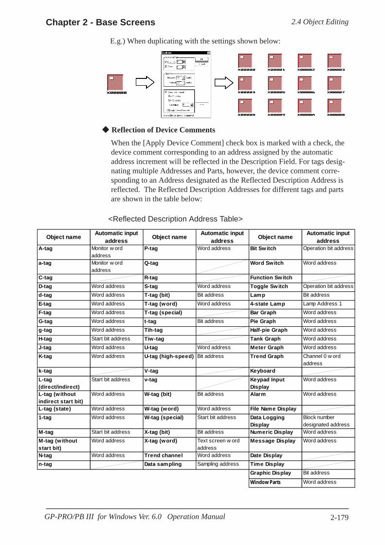
2.4 Object EditingChapter 2 - Base Screens
2-179GP-PRO/PB III for Windows Ver. 6.0 Operation Manual
Reflection of Device Comments
When the [Apply Device Comment] check box is marked with a check, thedevice comment corresponding to an address assigned by the automaticaddress increment will be reflected in the Description Field. For tags desig-nating multiple Addresses and Parts, however, the device comment corre-sponding to an Address designated as the Reflected Description Address isreflected. The Reflected Description Addresses for different tags and partsare shown in the table below:
<Reflected Description Address Table>
Object name Automatic inputaddress Object name Automatic input
address Object name Automatic inputaddress
A-tag Monitor w ordaddress
P-tag Word address Bit Switch Operation bit address
a-tag Monitor w ordaddress
Q-tag Word Switch Word address
C-tag R-tag Function SwitchD-tag Word address S-tag Word address Toggle Switch Operation bit addressd-tag Word address T-tag (bit) Bit address Lamp Bit addressE-tag Word address T-tag (word) Word address 4-state Lamp Lamp Address 1F-tag Word address T-tag (special) Bar Graph Word addressG-tag Word address t-tag Bit address Pie Graph Word addressg-tag Word address Tih-tag Half-pie Graph Word addressH-tag Start bit address Tiw-tag Tank Graph Word addressJ-tag Word address U-tag Word address Meter Graph Word addressK-tag Word address U-tag (high-speed) Bit address Trend Graph Channel 0 w ord
addressk-tag V-tag KeyboardL-tag(direct/indirect)
Start bit address v-tag Keypad InputDisplay
Word address
L-tag (withoutindirect start bit)
Word address W-tag (bit) Bit address Alarm Word address
L-tag (state) Word address W-tag (word) Word address File Name Display1-tag Word address W-tag (special) Start bit address Data Logging
DisplayBlock numberdesignated address
M-tag Start bit address X-tag (bit) Bit address Numeric Display Word addressM-tag (withoutstart bit)
Word address X-tag (word) Text screen w ordaddress
Message Display Word address
N-tag Word address Trend channel Word address Date Displayn-tag Data sampling Sampling address Time Display
Graphic Display Bit address
Window Parts Word address
E.g.) When duplicating with the settings shown below:
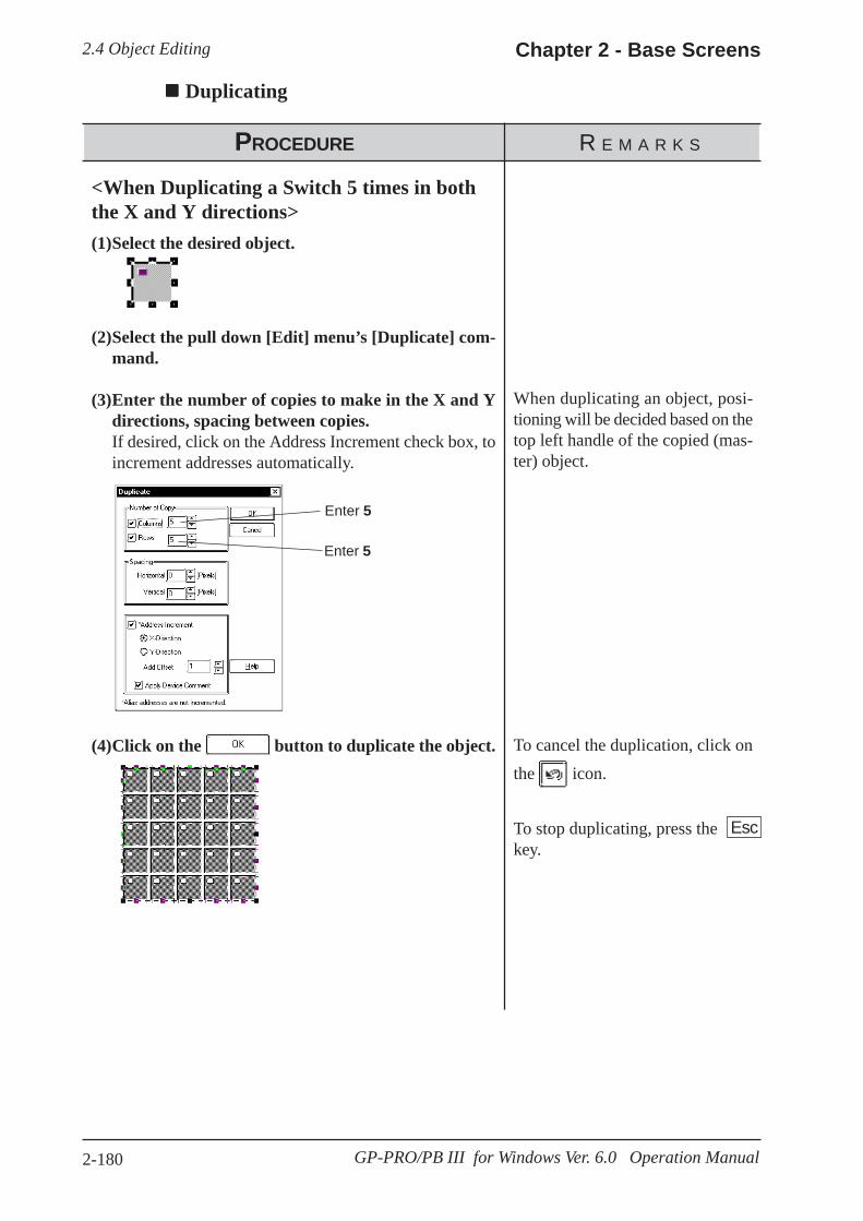
2.4 Object Editing Chapter 2 - Base Screens
2-180 GP-PRO/PB III for Windows Ver. 6.0 Operation Manual
PROCEDURE R E M A R K S
<When Duplicating a Switch 5 times in boththe X and Y directions>(1)Select the desired object.
(2)Select the pull down [Edit] menu’s [Duplicate] com-mand.
(3)Enter the number of copies to make in the X and Ydirections, spacing between copies.If desired, click on the Address Increment check box, toincrement addresses automatically.
(4)Click on the button to duplicate the object.
Enter 5
Enter 5
When duplicating an object, posi-tioning will be decided based on thetop left handle of the copied (mas-ter) object.
To cancel the duplication, click onthe icon.
To stop duplicating, press thekey.
Duplicating
Esc

2.4 Object EditingChapter 2 - Base Screens
2-181GP-PRO/PB III for Windows Ver. 6.0 Operation Manual
2.4.8 Delete
Here, the procedure for deleting an object is explained.
Deleting an Object
PROCEDURE R E M A R K S
(1)Select an object.
(2)Select the pull down [Edit] menu’s [Delete] command. Instead of selecting the [Delete]command, the computerkeyboard’s key can also beused.
To cancel the deletion, click onthe icon.
Delete

2.4 Object Editing Chapter 2 - Base Screens
2-182 GP-PRO/PB III for Windows Ver. 6.0 Operation Manual
2.4.9 Align
Here, the procedure for aligning and centering object(s) are explained.
Alignment Dialog Box
Aligning Object Positions
PROCEDURE R E M A R K S
(1)Select all the desired objects to be aligned.
(2)Select the [Edit] menu - [Align] command, or clickon the icon.
(3)Select the type of alignment from the Alignment dia-log box.In this example, select the icon (X-axis: Bottom)and do not select any vertical (Y-axis) position.
(4)Click on the button to align the objects.
2.4.1 SelectingObjects
While an individual label can bealigned, groups of labels cannot.(Click on an object to select itshandles and then click on its Labelto select the Label’s handles.) Textcharacters on both Numeric or othertypes of Displays can be aligned inthe same manner.
To align objects, combine the se-lections shown below:
Horizontal position: Up, Center,Bottom
Vertical position: Left, Center,Right
To cancel the alignment, click onthe icon.
Shows thecurrent align-ment settings
Resets the Yaxis settings
Aligns to the rightof the Y axis
Aligns on the Yaxis
Aligns to the leftof the Y axis
Aligns above theX axis
Aligns on the XaxisAligns below theX axis
Resets the X axissettings
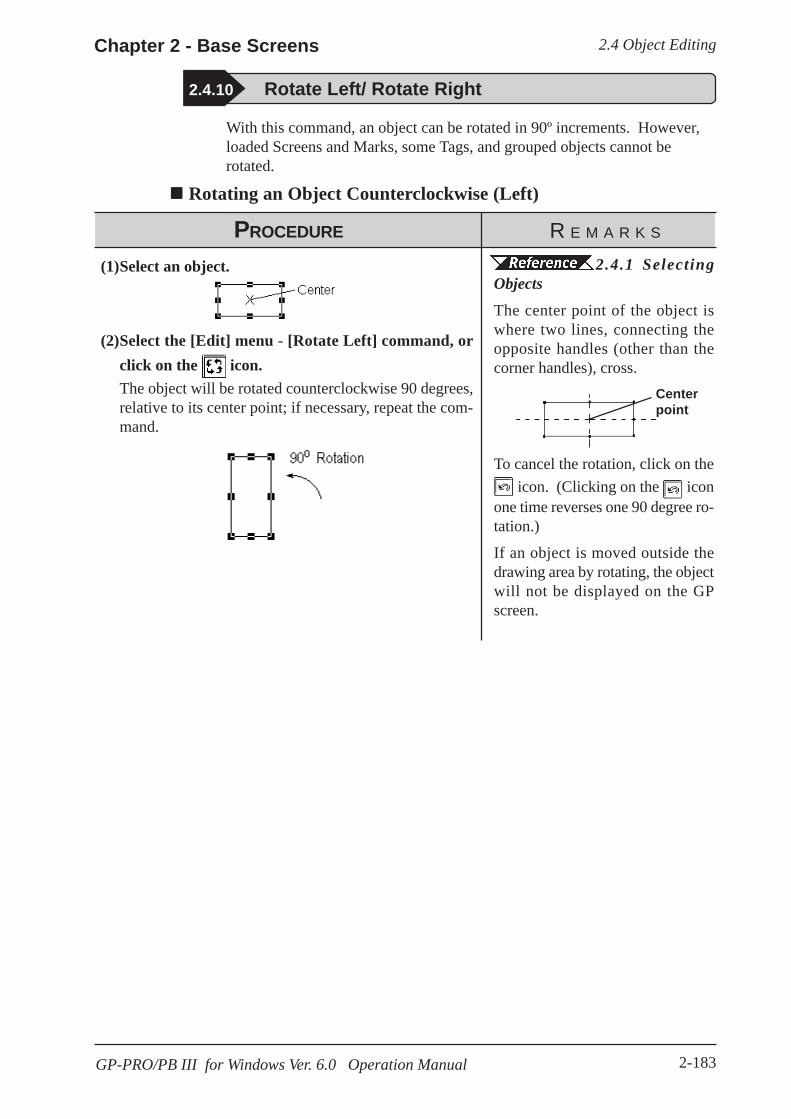
2.4 Object EditingChapter 2 - Base Screens
2-183GP-PRO/PB III for Windows Ver. 6.0 Operation Manual
2.4.10 Rotate Left/ Rotate Right
With this command, an object can be rotated in 90º increments. However,loaded Screens and Marks, some Tags, and grouped objects cannot berotated.
Rotating an Object Counterclockwise (Left)
PROCEDURE R E M A R K S
(1)Select an object.
(2)Select the [Edit] menu - [Rotate Left] command, orclick on the icon.The object will be rotated counterclockwise 90 degrees,relative to its center point; if necessary, repeat the com-mand.
2.4.1 SelectingObjectsThe center point of the object iswhere two lines, connecting theopposite handles (other than thecorner handles), cross.
To cancel the rotation, click on the icon. (Clicking on the icon
one time reverses one 90 degree ro-tation.)
If an object is moved outside thedrawing area by rotating, the objectwill not be displayed on the GPscreen.
Centerpoint

2.4 Object Editing Chapter 2 - Base Screens
2-184 GP-PRO/PB III for Windows Ver.6.0 Operation Manual
Rotating an Object Clockwise (Right)
PROCEDURE R E M A R K S
(1)Select a desired object.
(2)Select the [Edit] menu - [Rotate Right] command, orclick on the icon.The object will be rotated clockwise 90 degrees, relativeto its center point. If necessary, repeat the command.
2.4.1 SelectingObjects
The center point of the object iswhere two lines, connecting theopposite handles (other than thecorner handles), cross.
To cancel the rotation, click on the icon. (Clicking on the icon
once reverses one 90 degree rota-tion.)
If an object is moved outside thedrawing area by rotating, the objectwill not be displayed on the GPscreen.
Centerpoint
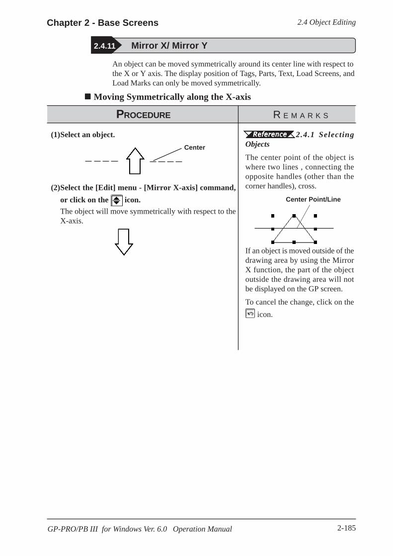
2.4 Object EditingChapter 2 - Base Screens
2-185GP-PRO/PB III for Windows Ver. 6.0 Operation Manual
2.4.11 Mirror X/ Mirror Y
An object can be moved symmetrically around its center line with respect tothe X or Y axis. The display position of Tags, Parts, Text, Load Screens, andLoad Marks can only be moved symmetrically.
Moving Symmetrically along the X-axis
PROCEDURE R E M A R K S
(1)Select an object.
(2)Select the [Edit] menu - [Mirror X-axis] command,or click on the icon.The object will move symmetrically with respect to theX-axis.
2.4.1 SelectingObjectsThe center point of the object iswhere two lines , connecting theopposite handles (other than thecorner handles), cross.
If an object is moved outside of thedrawing area by using the MirrorX function, the part of the objectoutside the drawing area will notbe displayed on the GP screen.
To cancel the change, click on the icon.
Center
Center Point/Line
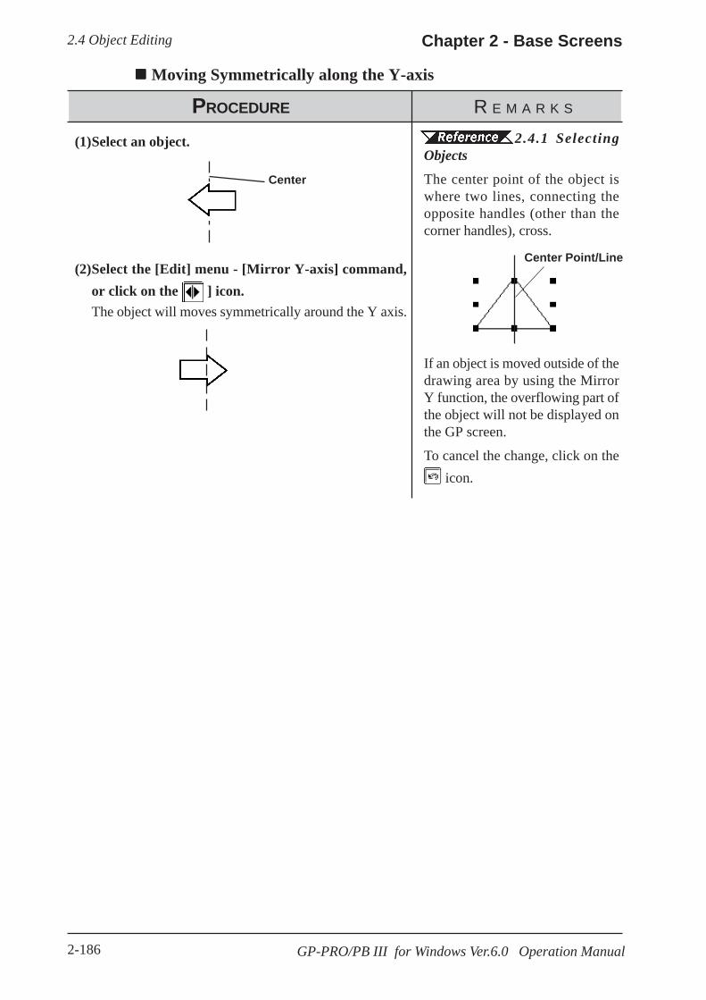
2.4 Object Editing Chapter 2 - Base Screens
2-186 GP-PRO/PB III for Windows Ver.6.0 Operation Manual
Moving Symmetrically along the Y-axis
PROCEDURE R E M A R K S
(1)Select an object.
(2)Select the [Edit] menu - [Mirror Y-axis] command,or click on the ] icon.The object will moves symmetrically around the Y axis.
Center
2.4.1 SelectingObjectsThe center point of the object iswhere two lines, connecting theopposite handles (other than thecorner handles), cross.
If an object is moved outside of thedrawing area by using the MirrorY function, the overflowing part ofthe object will not be displayed onthe GP screen.
To cancel the change, click on the icon.
Center Point/Line

2.4 Object EditingChapter 2 - Base Screens
2-187GP-PRO/PB III for Windows Ver. 6.0 Operation Manual
2.4.12 Group/Ungroup
This function can be used to “group” multiple objects, enabling you tomanipulate the “group” as a single object, even after changing screens orusing a different editing function.
Grouping Objects
PROCEDURE R E M A R K S
(2)Select the [Edit] menu - [Group] command, or clickon the icon.
(1)Select the objects to be Grouped. 2.4.1 SelectingObjects
To cancel the Grouping, click on the icon.
· When a Part is included in a group, its handles appear as , so that theindividual Part cannot be scaled up/down independent of the group. Thus,you must first ungroup the objects in order to scale any individual object.
· When a Part is included in a group, double click on the group to bring upthe Confirm Device Address dialog box, where address changes can bemade.
2.4.14 Changing Attributes

2.4 Object Editing Chapter 2 - Base Screens
2-188 GP-PRO/PB III for Windows Ver.6.0 Operation Manual
Ungrouping ObjectsThis function changes a Group of objects to a selection of multiple objects.
PROCEDURE R E M A R K S
(1)Select a group of objects.
(2)Select the [Edit] menu - [Ungroup] command, or clickon the icon.
2.4.1 SelectingObjectsTo select a group including tags,place a check mark in the Tag checkbox in the Select Tool Box.
To cancel the ungrouping, click onthe icon.
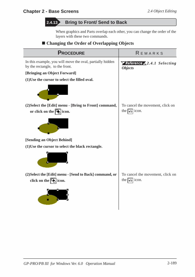
2.4 Object EditingChapter 2 - Base Screens
2-189GP-PRO/PB III for Windows Ver. 6.0 Operation Manual
2.4.13 Bring to Front/ Send to Back
When graphics and Parts overlap each other, you can change the order of thelayers with these two commands.
Changing the Order of Overlapping Objects
PROCEDURE R E M A R K S
In this example, you will move the oval, partially hiddenby the rectangle, to the front.
[Bringing an Object Forward]
(1)Use the cursor to select the filled oval.
(2)Select the [Edit] menu - [Bring to Front] command,or click on the icon.
[Sending an Object Behind]
(1)Use the cursor to select the black rectangle.
(2)Select the [Edit] menu - [Send to Back] command, orclick on the icon.
2.4.1 SelectingObjects
To cancel the movement, click onthe icon.
To cancel the movement, click onthe icon.

2.4 Object Editing Chapter 2 - Base Screens
2-190 GP-PRO/PB III for Windows Ver.6.0 Operation Manual
2.4.14 Changing Attributes
Here, you can change any of an object’s attributes, i.e. its color, address, etc.Also, with objects of the same type, you can change the same attribute of allthe objects of that type at the same time.
Changing Attributes
PROCEDURE R E M A R K S
(1)First, select an object, to change its’ attributes.In this case, an unfilled rectangle drawn with a solid line.
(2)Select the [Edit] menu - [Change Attribute] command,or click on the icon.
(3)Select a new attribute from the dialog box.Here, a dotted line is selected.
(4)Click on the button to register your change.
2.4.1 SelectingObjects
While the attributes of Grouped ob-jects generally, cannot be changed,the same type objects can bechanged at the same time. WhenGrouped Parts have been selected,only their addresses can bechanged.
Confirming Ad-dresses
Instead of clicking on the icon,simply double-click on the objectwhen selecting it, to display the At-tribute Settings dialog box ( skipstep {2}).
To cancel the attribute changes,click on the button in thedialog box.
Even af ter c l ick ing on the, you can reverse the at-
tributes changes (only for the mostrecent change) by clicking on the
icon.
You can select more than one object of the same type and change the at-tributes of each, at the same time. With all the desired objects selected, clickon the Tool box’s button; then, proceed with step (2).
2.4.1 Selecting Objects, How to Select Multiple Objects,[Selecting Objects by Type from a Multiple Selection]
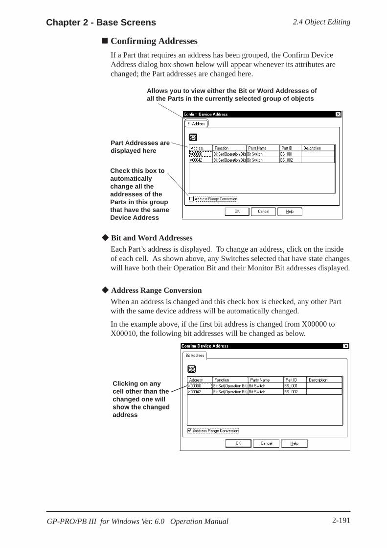
2.4 Object EditingChapter 2 - Base Screens
2-191GP-PRO/PB III for Windows Ver. 6.0 Operation Manual
Confirming AddressesIf a Part that requires an address has been grouped, the Confirm DeviceAddress dialog box shown below will appear whenever its attributes arechanged; the Part addresses are changed here.
Bit and Word AddressesEach Part’s address is displayed. To change an address, click on the insideof each cell. As shown above, any Switches selected that have state changeswill have both their Operation Bit and their Monitor Bit addresses displayed.
Address Range ConversionWhen an address is changed and this check box is checked, any other Partwith the same device address will be automatically changed.
In the example above, if the first bit address is changed from X00000 toX00010, the following bit addresses will be changed as below.
Clicking on anycell other than thechanged one willshow the changedaddress
Allows you to view either the Bit or Word Addresses ofall the Parts in the currently selected group of objects
Part Addresses aredisplayed here
Check this box toautomaticallychange all theaddresses of theParts in this groupthat have the sameDevice Address

2.4 Object Editing Chapter 2 - Base Screens
2-192 GP-PRO/PB III for Windows Ver.6.0 Operation Manual
2.4.15 Changing Coordinates
Object positions and sizes can be changed by specifying their coordinates.
Using Coordinates to Change an Object’s Position
Check this checkbox to changethe size. Enter the object’s
left top coordi-nates.
Enter the object’sright bottom coordi-nates.
PROCEDURE R E M A R K S
(1)Select a desired object.
(2)Select the [Edit] menu - [Change Coordinates] com-mand.
(3)Enter the object’s left top and right bottom coordi-nates.
(4)Click on the button to execute the command.
2.4.1 SelectingObjects
To change the size, check theChange size check box in step (3).
To cancel the coordinates change,click on the button.
To undo the coordinates change,click on the icon.

2.4 Object EditingChapter 2 - Base Screens
2-193GP-PRO/PB III for Windows Ver. 6.0 Operation Manual
2.4.16 Editing the Node of a Multi-segment Line
Creating, Editing, or deleting a node can be performed on a multi-segmentline and a filled polygon.
The [Node Edit] dialogdisplays.
If the node edit is selected, the selected pointin the displayed dialog is marked with across.
Deletes the selected peak.
Adds a node. The addednode is the same as theselected node. If the screencapacity is exceeded by theadded value, the [Insert inFront] and [Insert in Back]buttons are highlighted andcannot be specified.
Editing a Node on a Continuous Line
PROCEDURE R E M A R K S
(1)Select the desired continuous line.
(2)Select [Node Edit(K)] from [Edit(E)].
(3)Select the coordinate value that you want to edit.
(4)Click on the button.
(5)Enter the X/Y coordinate values in the coordinatechange dialogs.
(6)Click on the button to run the coordinatechange.
2.4.1 SelectingObjects
To cancel the coordinate change,Click on the button.
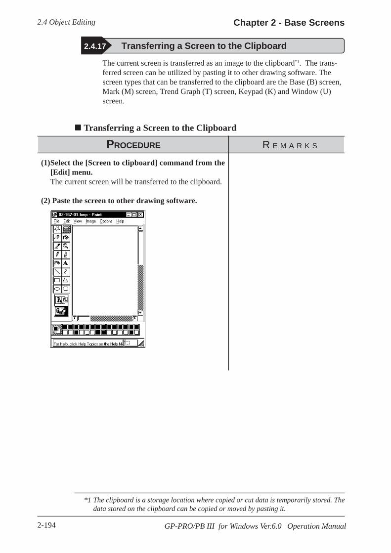
2.4 Object Editing Chapter 2 - Base Screens
2-194 GP-PRO/PB III for Windows Ver.6.0 Operation Manual
2.4.17 Transferring a Screen to the Clipboard
The current screen is transferred as an image to the clipboard*1. The trans-ferred screen can be utilized by pasting it to other drawing software. Thescreen types that can be transferred to the clipboard are the Base (B) screen,Mark (M) screen, Trend Graph (T) screen, Keypad (K) and Window (U)screen.
Transferring a Screen to the Clipboard
PROCEDURE R E M A R K S
(1)Select the [Screen to clipboard] command from the[Edit] menu.The current screen will be transferred to the clipboard.
(2) Paste the screen to other drawing software.
*1 The clipboard is a storage location where copied or cut data is temporarily stored. Thedata stored on the clipboard can be copied or moved by pasting it.
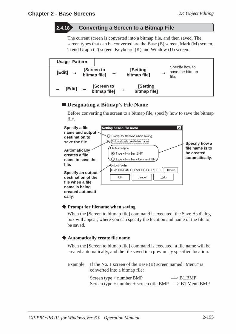
2.4 Object EditingChapter 2 - Base Screens
2-195GP-PRO/PB III for Windows Ver. 6.0 Operation Manual
2.4.18 Converting a Screen to a Bitmap File
The current screen is converted into a bitmap file, and then saved. Thescreen types that can be converted are the Base (B) screen, Mark (M) screen,Trend Graph (T) screen, Keyboard (K) and Window (U) screen.
Usage Pattern
[Edit] →→→→→ [Screen tobitmap file] →→→→→
[Settingbitmap file] →→→→→
Specify how tosave the bitmapfile.
→→→→→ [Edit] →→→→→ [Screen tobitmap file] →→→→→
[Settingbitmap file]
Designating a Bitmap’s File NameBefore converting the screen to a bitmap file, specify how to save the bitmapfile.
Specify how afile name is tobe createdautomatically.
Specify a filename and outputdestination tosave the file.
Automaticallycreates a filename to save thefile.
Specify an outputdestination of thefile when a filename is beingcreated automati-cally.
Prompt for filename when savingWhen the [Screen to bitmap file] command is executed, the Save As dialogbox will appear, where you can specify the location and name of the file tobe saved.
Automatically create file name
When the [Screen to bitmap file] command is executed, a file name will becreated automatically, and the file saved in a previously specified location.
Example: If the No. 1 screen of the Base (B) screen named “Menu” isconverted into a bitmap file:
Screen type + number.BMP —> B1.BMPScreen type + number + screen title.BMP —> B1 Menu.BMP
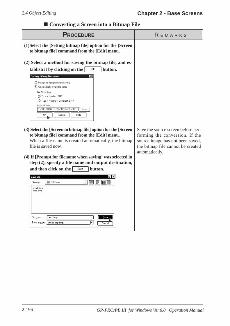
2.4 Object Editing Chapter 2 - Base Screens
2-196 GP-PRO/PB III for Windows Ver.6.0 Operation Manual
Converting a Screen into a Bitmap File
PROCEDURE R E M A R K S
(1)Select the [Setting bitmap file] option for the [Screento bitmap file] command from the [Edit] menu.
(2) Select a method for saving the bitmap file, and es-tablish it by clicking on the button.
(3) Select the [Screen to bitmap file] option for the [Screento bitmap file] command from the [Edit] menu.When a file name is created automatically, the bitmapfile is saved now.
(4) If [Prompt for filename when saving] was selected instep (2), specify a file name and output destination,and then click on the button.
Save the source screen before per-forming the conversion. If thesource image has not been saved,the bitmap file cannot be createdautomatically.

2.4 Object EditingChapter 2 - Base Screens
2-197GP-PRO/PB III for Windows Ver. 6.0 Operation Manual
2.4.19 Redraw Screen
This command updates the current drawing area display to reflect the latestdrawing data. When the Auto Redraw feature is not used, filling and editingobjects can cause after-images to remain on the screen. Use this function toremove these images and show the screen as it will appear on the actual GPdisplay.
Redrawing a Screen
PROCEDURE R E M A R K S
Sometimes, when removing an object’s filled color, onlythe fill point area’s color will be removed, resulting in asmall, non-colored square.
123456789012341234567890123412345678901234123456789012341234567890123412345678901234123456789012341234567890123412345678901234123456789012341234567890123412345678901234
123456789012312345678901231234567890123123456789012312345678901231234567890123123456789012312345678901231234567890123123456789012312345678901231234567890123
+Pointwhere fillbegan
Fill point is deleted
(1)Select the [Edit] menu - [Redraw] command, or clickon the icon.The screen will automatically be refreshed and all thefill color will be removed.

2.4 Object Editing Chapter 2 - Base Screens
2-198 GP-PRO/PB III for Windows Ver.6.0 Operation Manual
2.4.20 Undo
With this function, an operation can be “undone” and the screen displayreturned to the previous condition. Every time the icon is clicked on,depending on memory, previous operations will be undone, in succession.
The Redraw Screen function cannot be undone.
Canceling an Action
PROCEDURE R E M A R K S
In this example, a circle has been accidentally deleted.
(1)Select the [Edit] menu - [Undo] command, or clickon the icon.The circle will reappear and the screen is displayed as itwas prior to the deletion.
To cancel the Undo operation,click on the icon.
2.4.21 Redo
2.4.21 Redo
With this function, an operation previously undone with the Undo commandcan be “redone”, if performed immediately after the Undo command is used.
Redoing the Previous Undo Command
PROCEDURE R E M A R K S
In this example, the undone circle deletion will be re-done (i.e. deleted again).
(1)Select the [Edit] menu - [Undo] command, or clickon the icon.The circle will reappear.
(2)Select the [Edit] menu - [Redo] command, or click onthe icon.The circle will disappear.
To cancel the Redo operation, clickon the icon.
2.4.20 Undo

2.5 LibrariesChapter 2 - Base Screens
2-199GP-PRO/PB III for Windows Ver. 6.0 Operation Manual
Library Browser
When either or icon is clicked on, the Library Browser will appear.
Displays the currently selected item’s registration number and title;clicking on the triangle brings up a list of the items in the currentlibrary
Menu BarTool Bar
Status Bar
Scrollsthroughthe differ-ent items,either left,right, up,or down
Reverse videoindicates thatthis item iscurrently se-lected
Displays theitem’s registra-tion numberand title
2.5 LibrariesThe objects you created can be registered. These registered objects arecalled “Libraries”. You can call up and use the registered Libraries, when-ever necessary. Like a pre-made Part Shape, the objects registered in theselibraries can be viewed and selected using the Browser function.Multiple objects can be combined and registered, and Marks created onMark screens can also be registered.
3.1 Creating a Mark: the Mark ScreenThese items are stored in a Library file (CPW file), separate from Project(PRW) files . When library data is a Mark, it will be saved in a Mark Li-brary (MRK) file. Moving from one Library file to the other allows objectsto be called up that were previously used in a variety of screens and Projectfiles.
To call up an item from a Library, or save an item to a Library, either selectone of the tool bar’s icons or use the pull down menu’s [Library]commands.With both Base and Mark screens open, when the Base screen where theLibrary Browser is remained open is changed to the Mark screen, the MarkLibrary Browser cannot be open on the Mark screen. When changing thescreen, first close the Library Browser and change the screen, and then openthe Library Browser on the newly opened screen.
Objects called up via the [Load Screen], [Load Mark] or [Window Parts (W)]command, as well as D-script cannot be registered.

2.5 Libraries Chapter 2 - Base Screens
2-200 GP-PRO/PB III for Windows Ver. 6.0 Operation Manual
Editing Library ItemsThree Library Item editing functions are available.
Cuts a Library item (which is then moved to the Clipboard); theLibrary item can then be moved to another screen using the [Paste]function.
Copies the selected Library item to the Clipboard.
Pastes the Library item Cut or Copied, and temporarily stored in theClipboard, to another screen. The Library item can also be Pasted toanother Library file.
You can remove a Library item using the Delete function. To do so, selectthe [Delete] command from the Library dialog box’s pull down [Edit]menu.
2.5.3 Editing Library Items
Changing the Library’s DisplayThe Library’s image display size and type can be changed. Also, you canchange from one Library file to another.
Library Size
When either the , , or icon is clicked on, or the pull down[View] menu’s either [Normal], [Adjust to Fit], or [Full Screen] command isselected, and the Library display size can be changed. When Normal isselected, each Library size will be displayed relatively, allowing you tocheck the relationship between Libraries for their size. When the Adjust toFit function is selected, the Library item will be enlarged until it fits insidethe Library window’s borders. When Full Screen is selected, the Libraryitem will be displayed in its actual (GP) screen size.
Library Type
When the pull down [View] menu’s [All Objects], [Part & Tag Objects], or[Graphic Objects] is selected, the Library type(s) shown on the Browser canbe selected.
[All Objects] Displays all the Library items in the selected Libraryfile.
[Part & Tag Objects] Displays only those items that are either Parts orTags.
[Graphic Objects] Displays only those items which are neither Parts norTags (i.e. drawn objects).

2.5 LibrariesChapter 2 - Base Screens
2-201GP-PRO/PB III for Windows Ver. 6.0 Operation Manual
Selecting (Calling Up) another Library FileWhen the icon is clicked on, or the pull down [File] menu’s [SelectFile] command is selected, the Library file list will appear. By selecting(dragging) the desired Library file from this list, other Library files can becalled up.
Two types of Library files are available; the Library files created using theGP-PRO/PBIII (DOS Version) (DOS Library file: *. CPL), and the Libraryfiles created using GP-PRO/PBIII (Windows Version) (Windows Libraryfile: *. CPW and *.MRK). Select either one.
Files created using Parts Box (*. CPL) can be converted into GP-PRO/PBIIIfor Windows format (*. CPW).
12.1 File Converter
Shows thecurrentlydisplayed file’sfolder
Lists all thefiles in thecurrentlyselected folder
Displays the currently selectedfile’s Description data (if any)
Currently selected file’sformat (type)
Currently selectedfile’s name (Ifdesired, can beentered)
Lists fileinformationin detail
Lists the files insummary format
Creates a newfolder
Moves up one filelevel
R
Switching Library Files Creating a New Library FileWhen the icon is clicked on, or the pull down [File] menu’s [New]command is selected, the Dialog box shown below will appear. When aDescription is input and the button is clicked on, a new Libraryfile will appear.

2.5 Libraries Chapter 2 - Base Screens
2-202 GP-PRO/PB III for Windows Ver. 6.0 Operation Manual
Modifying Library File Names (Titles)Library filenames can also be changed. Simply select a library from the filelist, then select [Property] from the [Edit] menu, and the Property screenwill appear. Type in the filename (title) that you wish to use and click onOK.
Displaying the Browser at the Top of the Normal ScreenIf the [Always on Top] option is selected from the [Window] menu, when-ever the Library Browser is called up, it will be placed at the top of thecurrent window. If this option is not selected, selecting another screen willplace that screen over the Library screen, hiding it from view.

2.5 LibrariesChapter 2 - Base Screens
2-203GP-PRO/PB III for Windows Ver. 6.0 Operation Manual
2.5.1 Registering Library Items
Here, the procedure for registering a Library is explained.
PROCEDURE R E M A R K S
(1)Select objects to be registered as Library items.
(2)Select the [Library] menu - [Register Library] com-mand, or click on the icon.
<A. When registering a new Library item tothe currently open Library file:>(3)Enter the Library’s registration number and descrip-
tion.In the Cell Number area, the smallest of the currentlyopen Library file’s unused numbers will be automati-cally displayed. To change it, simply enter the desirednumber.
(4)Click on the button to register the number.The registered Library will then be displayed in theBrowser.
2.4.1 SelectingObjectsD-scripts as well as objects calledup via the [Load Screen (O)],[Load Mark (M)] and [WindowParts (W)] commands cannot beregistered.
If the Library Browser is alreadyshowing, click on either or
icon in the screen editor
drawing area, and the icon inthe Library Browser, which willperform the function of step (2).
The following procedures willdiffer depending on the Libraryfile registered.• When registering a new Library
item to the currently openLibrary file:
• When no Library file is dis-played:
• When registering a Library itemto a new Library file:
• When registering a Library itemto a Library file other than thecurrently open one:
Up to 200 Library items can beregistered in one file.
100: switch
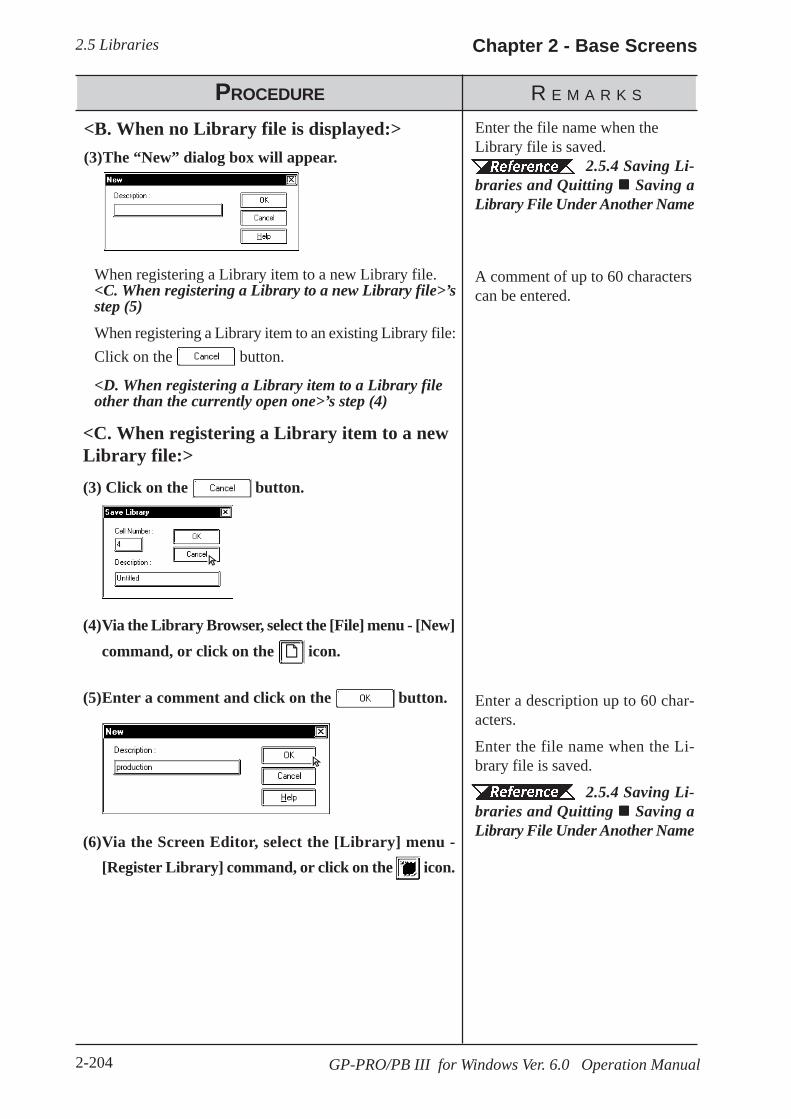
2.5 Libraries Chapter 2 - Base Screens
2-204 GP-PRO/PB III for Windows Ver. 6.0 Operation Manual
PROCEDURE R E M A R K S
<B. When no Library file is displayed:>(3)The “New” dialog box will appear.
(4)Via the Library Browser, select the [File] menu - [New]command, or click on the icon.
(5)Enter a comment and click on the button.
Enter the file name when theLibrary file is saved.
2.5.4 Saving Li-braries and Quitting Saving aLibrary File Under Another Name
Enter a description up to 60 char-acters.
Enter the file name when the Li-brary file is saved.
2.5.4 Saving Li-braries and Quitting Saving aLibrary File Under Another Name
A comment of up to 60 characterscan be entered.
<C. When registering a Library item to a newLibrary file:>
(3) Click on the button.
When registering a Library item to an existing Library file:Click on the button.
<D. When registering a Library item to a Library fileother than the currently open one>’s step (4)
When registering a Library item to a new Library file.<C. When registering a Library to a new Library file>’sstep (5)
(6)Via the Screen Editor, select the [Library] menu -[Register Library] command, or click on the icon.
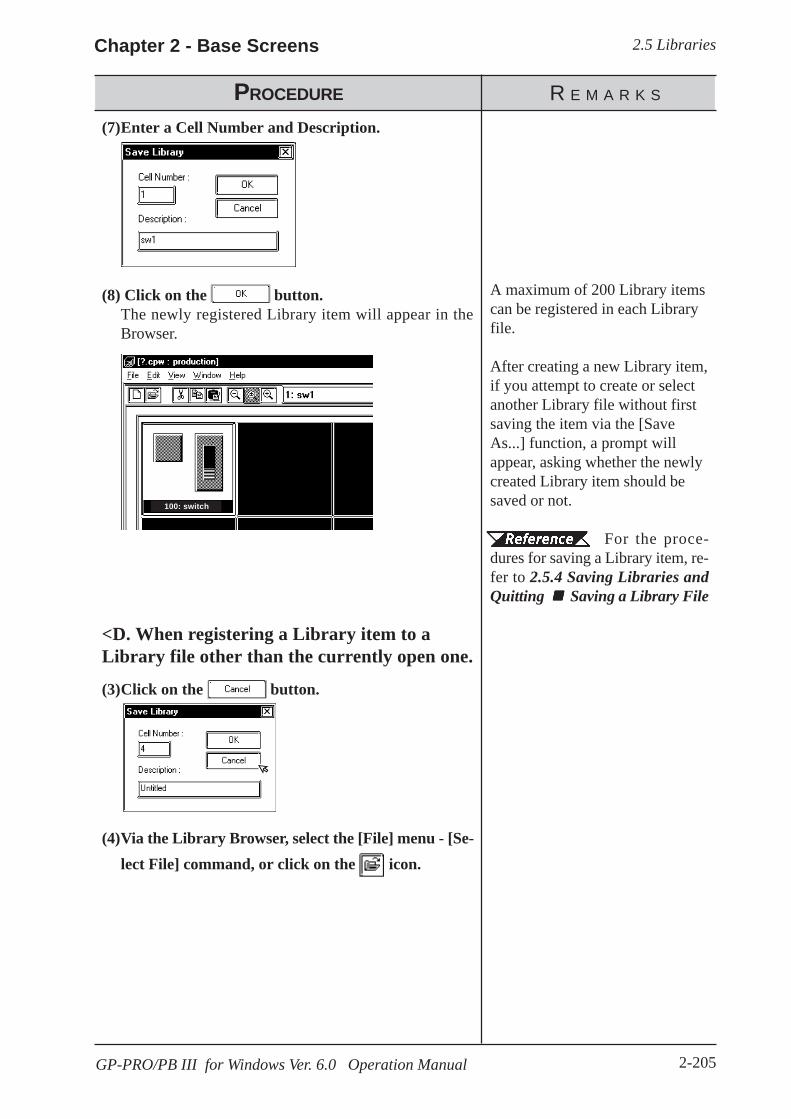
2.5 LibrariesChapter 2 - Base Screens
2-205GP-PRO/PB III for Windows Ver. 6.0 Operation Manual
<D. When registering a Library item to aLibrary file other than the currently open one.
(3)Click on the button.
(4)Via the Library Browser, select the [File] menu - [Se-lect File] command, or click on the icon.
PROCEDURE R E M A R K S
(7)Enter a Cell Number and Description.
(8) Click on the button.The newly registered Library item will appear in theBrowser.
A maximum of 200 Library itemscan be registered in each Libraryfile.
After creating a new Library item,if you attempt to create or selectanother Library file without firstsaving the item via the [SaveAs...] function, a prompt willappear, asking whether the newlycreated Library item should besaved or not.
For the proce-dures for saving a Library item, re-fer to 2.5.4 Saving Libraries andQuitting Saving a Library File
100: switch

2.5 Libraries Chapter 2 - Base Screens
2-206 GP-PRO/PB III for Windows Ver. 6.0 Operation Manual
PROCEDURE R E M A R K S
(5)Select the desired Library file from the list, or inputthe Library file name in the file name area.
(6)Click on the button to display the selectedLibrary file.
In step (5), simply move the cursorto the desired Library file name anddouble-click on it to open it. Bydoing so, the (Step 6) but-ton does not need to be used.
2.5 Libraries Switching Library Files
When selecting a Library file in an-other directory, use the [Look in:]window.Select “Op4-
lib1.cpw”.
(7)Via the Screen Editor, select the [Library] menu -[Register Library] command, or click on the iconon the Draw Tool Bar.
(8)Input a Cell Number and Description.In the Cell Number area, the smallest of the currentlyopen Library file’s unused numbers will be automati-cally displayed. To change it, enter the desired number.

2.5 LibrariesChapter 2 - Base Screens
2-207GP-PRO/PB III for Windows Ver. 6.0 Operation Manual
(9)Click on the button to register the item.The registered Library item will appear in the Browser.
Up to 200 libraries can be regis-tered in one file.
PROCEDURE R E M A R K S
Using the Cut, Copy, and Paste FunctionsLibrary items can be Cut, Copied and Pasted from the screen drawing areato Browser. First, select the desired Library item in the drawing area, andthen either Cut or Copy it; then, Paste it to the current Library Browser.
100: switch

2.5 Libraries Chapter 2 - Base Screens
2-208 GP-PRO/PB III for Windows Ver. 6.0 Operation Manual
PROCEDURE R E M A R K S
2.5.2 Placing Library Items
Here, items registered in a Library file are placed on a drawing area.
(1)Via the Screen Editor, select the [Library] menu -
[Call Up Library] command, or click on the iconon the Draw Tool Bar.
(2)Select a Library Item to be read out from the Browser.
(3)Drag the Library item to the desired position in thedrawing area.The Library item can be placed on any open screens,and will be displayed in the drawing area. If desired usethe sizing handles to alter the item’s size.
Library items Cut, Copied, orPasted between the screen and theBrowser. Simply select the desiredLibrary item and perform the com-mand.
When calling up an item from a filedifferent than the currently dis-played file, click on the icon tobring up a file list.
2.5 Libraries Switching Library Files
The Library item’s top left corneris the placement point.
To cancel the placement, click onthe screen editor’s icon.
To change a Li-brary item’s size, refer to 2.4.3Scaling Up/DownItems called up are automaticallygrouped. They can be freely editedafter ungrouping them by clickingon the icon.
2.4.12 Group/UngroupGrouped library items containingParts cannot be scaled up or down.
10: on
10: on
10: on

2.5 LibrariesChapter 2 - Base Screens
2-209GP-PRO/PB III for Windows Ver. 6.0 Operation Manual
When a Library that contains Parts is called up, the Confirm Device Addressscreen will appear. After entering each Part’s address, click on the button. To cancel these settings, click on the button.
2.4.14 Changing Attributes, Confirming AddressesWhen the Library placed on the screen is double-clicked on, the ConfirmDevice Address dialog box shown below will appear, allowing you tochange the Part’s previously entered addresses.
After a Tag is registered in a Library, if multiple identical librar-ies are then placed on the screen, their Tag names will be dupli-cated. After placing them, be sure to change their Tag namesvia either their attribute dialog boxes, or the Tag List; especiallyif a common start up bit has been created for a K-tag.
For Changing Attributes, refer to 2.4.14 Changing AttributesFor Tag List, refer to 2.8.6 Tag ListFor K-tags, refer to Tag Reference Manual, 2. 11 K-Tag(Keypad Input)
Using the Cut, Copy, and Paste FunctionsLibrary items can be Cut, Copied, and Pasted from the screen drawing areato the Browser. First, select the desired Library item in the drawing areaand Cut or Copy it; then, Paste it to the Library Browser.
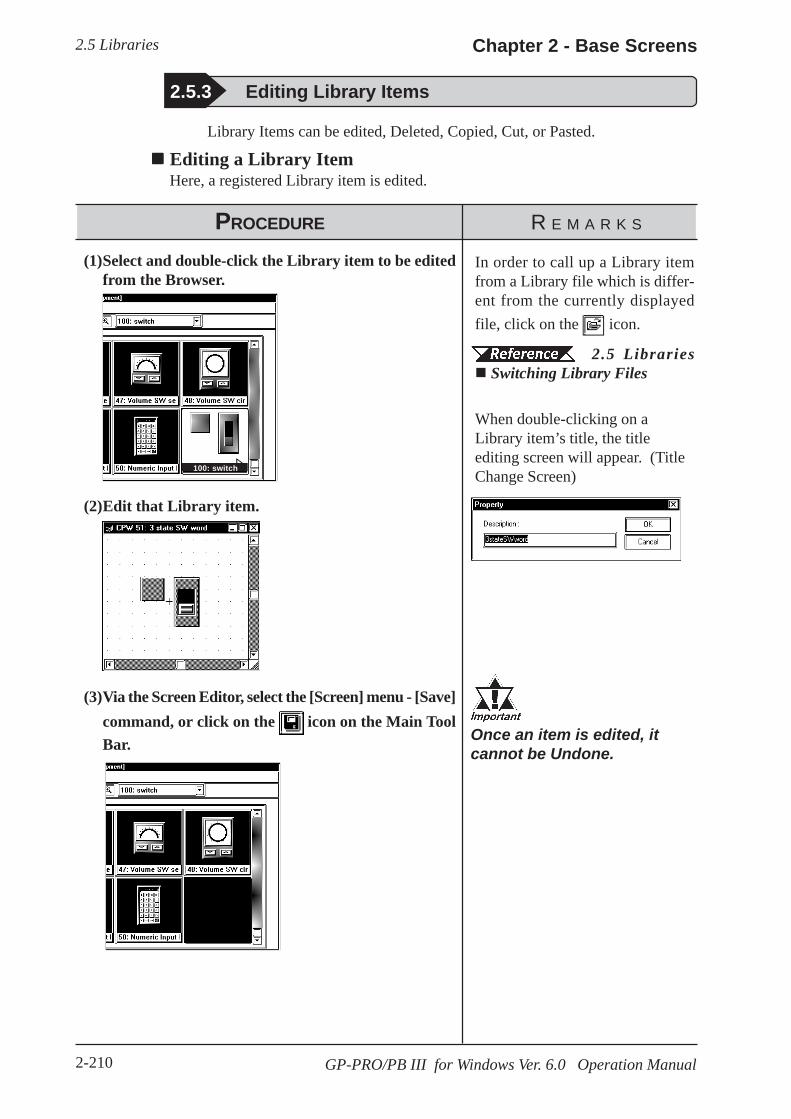
2.5 Libraries Chapter 2 - Base Screens
2-210 GP-PRO/PB III for Windows Ver. 6.0 Operation Manual
2.5.3 Editing Library Items
Library Items can be edited, Deleted, Copied, Cut, or Pasted.
Editing a Library ItemHere, a registered Library item is edited.
PROCEDURE R E M A R K S
(1)Select and double-click the Library item to be editedfrom the Browser.
(2)Edit that Library item.
(3)Via the Screen Editor, select the [Screen] menu - [Save]command, or click on the icon on the Main ToolBar.
In order to call up a Library itemfrom a Library file which is differ-ent from the currently displayedfile, click on the icon.
2.5 Libraries Switching Library Files
When double-clicking on aLibrary item’s title, the titleediting screen will appear. (TitleChange Screen)
Once an item is edited, itcannot be Undone.
100: switch
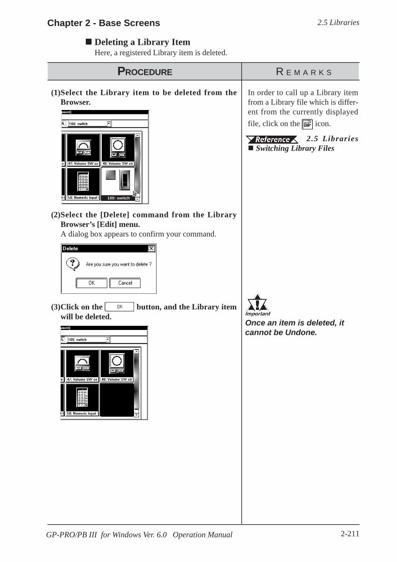
2.5 LibrariesChapter 2 - Base Screens
2-211GP-PRO/PB III for Windows Ver. 6.0 Operation Manual
PROCEDURE R E M A R K S
Deleting a Library ItemHere, a registered Library item is deleted.
(1)Select the Library item to be deleted from theBrowser.
(2)Select the [Delete] command from the LibraryBrowser’s [Edit] menu.A dialog box appears to confirm your command.
In order to call up a Library itemfrom a Library file which is differ-ent from the currently displayedfile, click on the icon.
2.5 Libraries Switching Library Files
Once an item is deleted, itcannot be Undone.
(3)Click on the button, and the Library itemwill be deleted.
100: switch
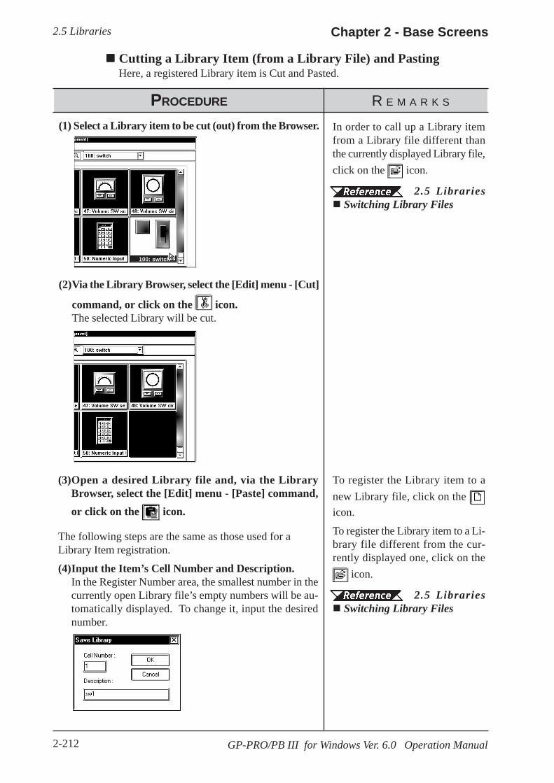
2.5 Libraries Chapter 2 - Base Screens
2-212 GP-PRO/PB III for Windows Ver. 6.0 Operation Manual
Cutting a Library Item (from a Library File) and PastingHere, a registered Library item is Cut and Pasted.
PROCEDURE R E M A R K S
(1) Select a Library item to be cut (out) from the Browser.
(2)Via the Library Browser, select the [Edit] menu - [Cut]
command, or click on the icon.The selected Library will be cut.
(3)Open a desired Library file and, via the LibraryBrowser, select the [Edit] menu - [Paste] command,or click on the icon.
In order to call up a Library itemfrom a Library file different thanthe currently displayed Library file,click on the icon.
2.5 Libraries Switching Library Files
To register the Library item to anew Library file, click on the icon.
To register the Library item to a Li-brary file different from the cur-rently displayed one, click on the
icon.
2.5 Libraries Switching Library Files
The following steps are the same as those used for aLibrary Item registration.
(4)Input the Item’s Cell Number and Description.In the Register Number area, the smallest number in thecurrently open Library file’s empty numbers will be au-tomatically displayed. To change it, input the desirednumber.
100: switch
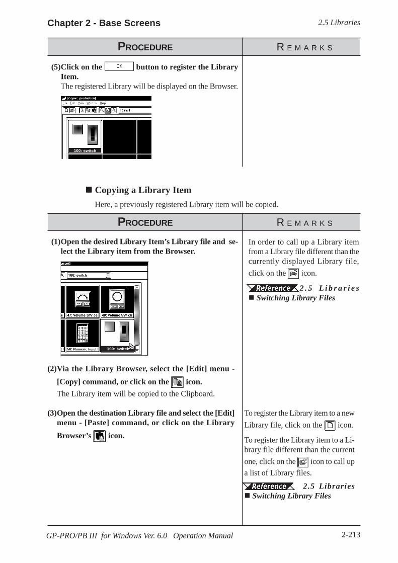
2.5 LibrariesChapter 2 - Base Screens
2-213GP-PRO/PB III for Windows Ver. 6.0 Operation Manual
(2)Via the Library Browser, select the [Edit] menu -[Copy] command, or click on the icon.The Library item will be copied to the Clipboard.
(3)Open the destination Library file and select the [Edit]menu - [Paste] command, or click on the LibraryBrowser’s icon.
To register the Library item to a newLibrary file, click on the icon.
To register the Library item to a Li-brary file different than the currentone, click on the icon to call upa list of Library files.
2.5 Libraries Switching Library Files
PROCEDURE R E M A R K S
(5)Click on the button to register the LibraryItem.The registered Library will be displayed on the Browser.
Copying a Library ItemHere, a previously registered Library item will be copied.
PROCEDURE R E M A R K S
(1)Open the desired Library Item’s Library file and se-lect the Library item from the Browser.
In order to call up a Library itemfrom a Library file different than thecurrently displayed Library file,click on the icon.
2 . 5 L i b r a r i e s Switching Library Files
100: switch
100: switch

2.5 Libraries Chapter 2 - Base Screens
2-214 GP-PRO/PB III for Windows Ver. 6.0 Operation Manual
PROCEDURE R E M A R K S
Hereafter, steps are the same as Library Item Registra-tion.
(4)Input the Item’s Cell Number and Description.In the Register Number area, the smallest of the currentlyopen Library file’s unused numbers will be automaticallydisplayed. To change it, enter the desired number.
(5) Click on the button to register the Item.The registered Item will appear in the Browser.
100: switch

2.5 LibrariesChapter 2 - Base Screens
2-215GP-PRO/PB III for Windows Ver. 6.0 Operation Manual
(3)Click on the button to save the Library.When a project with the same name already exists, aprompt asking whether the new name should overwritethe old name will appear; to do so, click on the button. When you do not want to overwrite, click on the
button.
2.5.4 Saving Libraries and Quitting
Saving a Library FileWhen a Library file’s contents are changed, the changed data will automati-cally overwrite the old data and be saved. However, if the Library file hasbeen newly created, when you attempt to create or select another Libraryfile, a prompt will appear asking if whether the new file is to be saved ornot. When is clicked on, the [Save As...] Dialog box will appear.
2.5.4 Saving a Library File Under Another Name
Saving a Library File Under Another NameHere, the Library File will be saved under a different name.
PROCEDURE R E M A R K S
(1)Select the [Save As...] command from the LibraryBrowser’s [File] menu.
(2)The currently selected Library file name and its com-ment data, if any, will appear.Input a new file name and change the desired settings.
The file name can be input within255 characters, including a path andextension.

2.5 Libraries Chapter 2 - Base Screens
2-216 GP-PRO/PB III for Windows Ver. 6.0 Operation Manual
Quitting the Library Browser
PROCEDURE R E M A R K S
(1)Select the pull down menu [File]’s [Exit] command.If a newly created Library file has not been saved yet, aprompt asking whether the new Library file should besaved, will appear. When the button is clicked,the “Save As..” dialog box will appear, and when the
button is clicked, the Library file will not besaved and the Library Browser will quit. Then, a Li-brary file creation or selection screen will appear.
Clicking on the Library Browser’stop right mark can also beused to quit.
Saving a Li-brary File Under Another Name
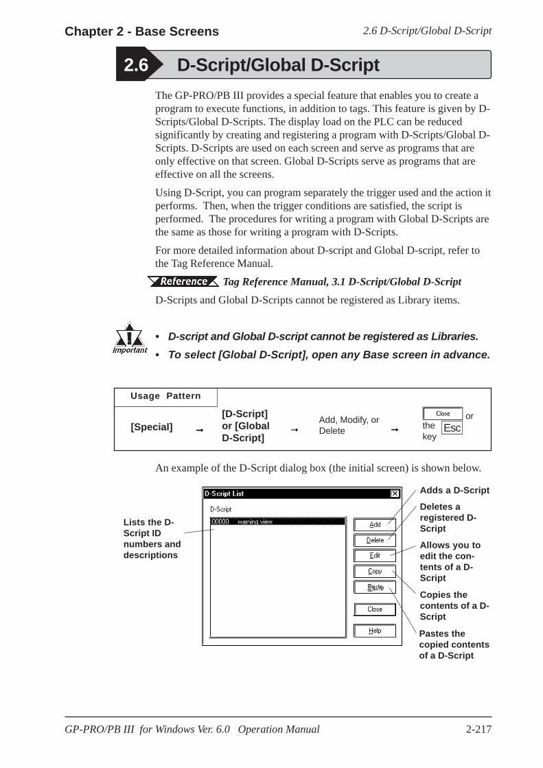
2.6 D-Script/Global D-ScriptChapter 2 - Base Screens
2-217GP-PRO/PB III for Windows Ver. 6.0 Operation Manual
The GP-PRO/PB III provides a special feature that enables you to create aprogram to execute functions, in addition to tags. This feature is given by D-Scripts/Global D-Scripts. The display load on the PLC can be reducedsignificantly by creating and registering a program with D-Scripts/Global D-Scripts. D-Scripts are used on each screen and serve as programs that areonly effective on that screen. Global D-Scripts serve as programs that areeffective on all the screens.
Using D-Script, you can program separately the trigger used and the action itperforms. Then, when the trigger conditions are satisfied, the script isperformed. The procedures for writing a program with Global D-Scripts arethe same as those for writing a program with D-Scripts.
For more detailed information about D-script and Global D-script, refer tothe Tag Reference Manual.
Tag Reference Manual, 3.1 D-Script/Global D-ScriptD-Scripts and Global D-Scripts cannot be registered as Library items.
• D-script and Global D-script cannot be registered as Libraries.• To select [Global D-Script], open any Base screen in advance.
2.6 D-Script/Global D-Script
Usage Pattern
→→→→→[Special] →→→→→[D-Script]or [GlobalD-Script]
Add, Modify, orDelete →→→→→
orthekey
Esc
An example of the D-Script dialog box (the initial screen) is shown below.
Adds a D-Script
Lists the D-Script IDnumbers anddescriptions
Pastes thecopied contentsof a D-Script
Copies thecontents of a D-Script
Allows you toedit the con-tents of a D-Script
Deletes aregistered D-Script

2.6 D-Script/Global D-Script Chapter 2 - Base Screens
2-218 GP-PRO/PB III for Windows Ver. 6.0 Operation Manual
Registering D-Script SettingsHere, additional D-Scripts can be registered. When the button isclicked on, the D-Script Editor will appear.
Enter the D-Script’s ID No. (from 00000 to 99999)
Enter adescriptionhere
Displays theD-Script’scommandtool box
The pro-grammed“actions”(commands)of the D-Script
Messagearea(window)
Displaysdefinedfunctionnames
Triggerarea
D-Script Tool BoxThe D-Script tool box contains icons for D-Script commands and State-ments and constant input icons.
Tag Reference Manual, 3.1 D-Script/Global D-ScriptWhen the tool box check box is checked, the following tool box will appear.

2.6 D-Script/Global D-ScriptChapter 2 - Base Screens
2-219GP-PRO/PB III for Windows Ver. 6.0 Operation Manual
Deleting D-Script SettingsHere, existing D-Script settings can be deleted. After selecting the D-Scriptsettings to be deleted from the listing, and clicking on the button,the Confirm Script Delete dialog box will appear. When the button is clicked on, the D-Script settings will be deleted. When the
button is clicked on, the deletion command will be canceled.
Definition of FunctionsPrograms to be used for D-Script are defined as functions. The definedfunctions can called up to the activated program and used. Also thesefunctions can be nested up to 10 layers. When the icon is clicked on inthe D-Scrip Editor, the D-Script function setting screen will appear.
Only alphanumerics and the “_ (under bar)” can be used for function names;up to 20 characters can be entered.
Enter a functionname
Enter the D-Script’s action(program) toperform
Message area(window)
Displays the D-Script command tool boxwhen this check box is checked
Displaysdefined func-tion names

2.6 D-Script/Global D-Script Chapter 2 - Base Screens
2-220 GP-PRO/PB III for Windows Ver. 6.0 Operation Manual
Editing D-Script SettingsHere, registered D-Script settings are changed. After selecting the D-Scriptsettings to be changed from the D-Script list and clicking on the button, an additional registration screen will appear. Click on the button to change the D-Script settings. To cancel the Change command,click on the button.
· It is not possible to use the Project Manager [Utility]’s [Con-vert Address] area to modify addresses used in a D-Script.Any D-Script program that requires address conversion willneed to be edited manually.
· If the [Save As..] function has been used to change a projectfile’s Device/PLC Type, the D-Script program will not be ableto automatically change those addresses.
· Be sure to not use D-Script to perform any life-threatening, orpossibly damaging actions!

2.6 D-Script/Global D-ScriptChapter 2 - Base Screens
2-221GP-PRO/PB III for Windows Ver. 6.0 Operation Manual
PROCEDURE R E M A R K S
D-Script Settings: Copy and Paste
(1)Select the pull down [Special] menu’s [D-Script] com-mand.
(2)Click on the button.
(3)When the button is clicked on, the D-Scriptcopied in step (2) will be added. The D-Script’s IDnumber will automatically be assigned to the small-est number currently available.
This D-Script can also be copied toanother screen.
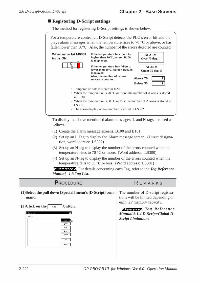
2.6 D-Script/Global D-Script Chapter 2 - Base Screens
2-222 GP-PRO/PB III for Windows Ver. 6.0 Operation Manual
Registering D-Script settingsThe method for registering D-Script settings is shown below.
If the temperature has fallen tolower than 30°C, screen B101 isdisplayed.Also, the number of occur-rences is counted.
If the temperature has risen tohigher than 70°C, screen B100is displayed.
Above 70 1Below 30 1
When error bit M0001turns ON...
ALARMOver 70 deg. !!
ALARMUnder 30 deg. !!
For a temperature controller, D-Script detects the PLC’s error bit and dis-plays alarm messages when the temperature rises to 70 °C or above, or hasfallen lower than 30°C. Also, the number of the errors detected are counted.
• Temperature data is stored in D200.• When the temperature is 70 °C or more, the number of Alarms is stored
in LS300.• When the temperature is 30 °C or less, the number of Alarms is stored in
LS301.• The alarm display screen number is stored in LS302.
To display the above mentioned alarm messages, L and N-tags are used asfollows:
(1) Create the alarm message screens, B100 and B101.(2) Set up an L Tag to display the Alarm message screen. (Direct designa-
tion, word address: LS302)(3) Set up an N-tag to display the number of the errors counted when the
temperature rises to 70 °C or more. (Word address: LS300)(4) Set up an N-tag to display the number of the errors counted when the
temperature falls to 30 °C or less. (Word address: LS301) For details concerning each Tag, refer to the Tag Reference
Manual, 1.3 Tag List.
PROCEDURE R E M A R K S
(1)Select the pull down [Special] menu’s [D-Script] com-mand.
(2)Click on the button.
The number of D-script registra-tions will be limited depending oneach GP memory capacity.
Tag ReferenceManual 3.1.4 D-Script/Global D-Script Limitations

2.6 D-Script/Global D-ScriptChapter 2 - Base Screens
2-223GP-PRO/PB III for Windows Ver. 6.0 Operation Manual
(5)Click on the button to quit registration.
The currentregistrationinformation isshown here.
PROCEDURE R E M A R K S
(3)Perform settings for each item such as ID, Trigger,Formula, etc.
Setting to “bitrising”
Enter M0001
A description can be entered of upto 20 characters.
Tag ReferenceManual, 3.1 D-Script/Global D-Script
In the area, the SyntaxAssistant and Syntax Checkfunctions can be used.
Enter Alarm DisplayEnter 00000
(4) Click on the button.
Programif ([W:D00200] >=70){ //When the temperature is 70°C or higher:[W:LS0302] =100 //Assign screen No. 100 for the "Over 70°C" alarm message.[W:LS0300] =[W:LS0300] +1 //The number of errors counted increases.}endif
if ([W:D00200] <=30){ //When the temperature is 30°C or lower:[W:LS0302] =101 //Assign screen No. 101 for the "Under 30°C" Alarm message.[W:LS0301] =[W:LS0301] +1 //The number of errors counted increases.}endif

2.7 Data Sampling Chapter 2 - Base Screens
2-224 GP-PRO/PB III for Windows Ver. 6.0 Operation Manual
2.7 Data SamplingAddress data designated in the PLC is sampled and stored (backed up) in theGP unit. When using this function for a graph (Tag or Part)’s channel,Trend graph data can also be stored (backed up).Up to 20 sets of Data Sampling can be entered, including the number ofchannels; the setting attributes can also be confirmed in the Tag List (DataSampling).
For more detailed information about data sampling, refer to the Tag Refer-ence Manual.
Tag Reference Manual, 3.2 Data Sampling Settings
Usage Pattern
→→→→→[Special] [Data Sampling] →→→→→Add, Edit, orDelete
orthekey
Esc→→→→→
An example of the Data Sampling Setting dialog box is shown below.
Registers additionalData SamplingSettings
Lists theregistered DataSamplingSettings’ Tagname anddescription
Changes the DataSampling Settingattributes
Deletes the regis-tered Data SamplingSettings
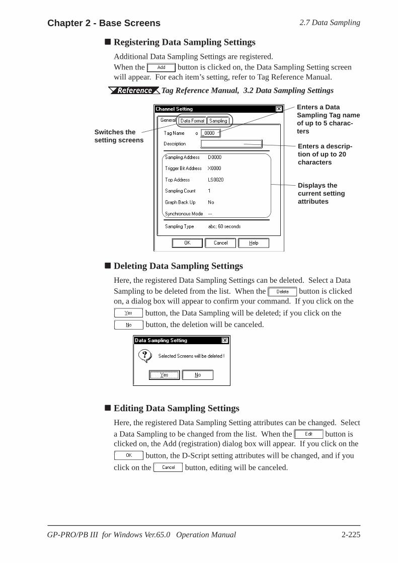
2.7 Data SamplingChapter 2 - Base Screens
2-225GP-PRO/PB III for Windows Ver.65.0 Operation Manual
Registering Data Sampling SettingsAdditional Data Sampling Settings are registered.When the button is clicked on, the Data Sampling Setting screenwill appear. For each item’s setting, refer to Tag Reference Manual.
Tag Reference Manual, 3.2 Data Sampling Settings
Deleting Data Sampling SettingsHere, the registered Data Sampling Settings can be deleted. Select a DataSampling to be deleted from the list. When the button is clickedon, a dialog box will appear to confirm your command. If you click on the
button, the Data Sampling will be deleted; if you click on the button, the deletion will be canceled.
Editing Data Sampling SettingsHere, the registered Data Sampling Setting attributes can be changed. Selecta Data Sampling to be changed from the list. When the button isclicked on, the Add (registration) dialog box will appear. If you click on the
button, the D-Script setting attributes will be changed, and if youclick on the button, editing will be canceled.
Enters a DataSampling Tag nameof up to 5 charac-tersSwitches the
setting screens
Displays thecurrent settingattributes
Enters a descrip-tion of up to 20characters

2.7 Data Sampling Chapter 2 - Base Screens
2-226 GP-PRO/PB III for Windows Ver. 6.0 Operation Manual
Setting Up Data SamplingThe Data Sampling setting method is shown below.
PROCEDURE R E M A R K S
(1) Select [Data Sampling] from the [Special] pull downmenu.
(2) Click on the button.
(3) Perform the data sampling settings. After the settingsare all completed, click on the button.
Up to 20 Data Sampling sets, in-cluding Trend graph channels, canbe entered.
Enter a Tag name of up to 5 char-acters.
Tag ReferenceManual, 3.2 Data Sampling Set-tings
(4) Click on the button to quit the registration.
Displays theregistered items

2.8 Efficient Drawing TechniquesChapter 2 - Base Screens
2-227GP-PRO/PB III for Windows Ver. 6.0 Operation Manual
2.9.1 Grid/Snap
Display
Sets the Grid Point display state (displayed or not displayed).
Grid pattern display can also be changed in the Grid Tool Bar’s grid patternselection list box.
Snap
When the Snap check box is checked, the cursor will “snap” to the grid;objects can only be drawn on points (start & end) along the grid.
2.8 Efficient Drawing TechniquesThis section explains how the use of grids, changing display states, and thehelp function can all help to increase your drawing efficiency.
Grid Points are placed at regular intervals on your screen and divide thedrawing area into a coordinate “grid” pattern; when the Snap to Grid func-tion is enabled, objects that are drawn will automatically “snap” (be aligned)on this “grid” pattern. Use the Grid Point Spacing command to adjust thedensity of the Grid points, and to display the grid or not. Also, grid pointscan be displayed as grid lines, not as dots. Grid Points are not shown on theGP unit’s display.Select the pull down menu [Option]’s [Grid/Snap] command.
Grid/Snap Settings dialog box
Turns the displayof the Grid PointsON or OFF
Designates theGrid Pointdisplay’s beingdrawn on top of, orunder, screenobjects
Turns the Snapfunction ON or OFF
Registers a Grippattern.
Registers the gridpattern that has beendesignated in Spacingto the position high-lighted in the GridSpacing List.
Sets up the gridto the optimal 20××××× 20 dot size
Enters thedesired Grid Pointspacing
Designates the griddisplay style, i.e. as dotsor grid lines.
Enter the coordi-nate for the startpoint.
Set the start pointin a center areathat is to be thestart point forcalling up thescreen. (The startpoint is set as thedefault value.)
2.8.1 Grid/Snap

2.8 Efficient Drawing Technmiques Chapter 2 - Base Screens
2-228 GP-PRO/PB III for Windows Ver. 6.0 Operation Manual
Turning the Snap function ON or OFF can also be performed via the Grid/
Snap Tool Bar’s icons and .
Spacing
The Grid Point intervals are entered here. The unit is a dot. Input theinterval value for the X and Y axes, respectively. The default value is 20dots.
When clicking on [Touch Area], a 20 x 20 dot spacing will be automaticallydesignated, which is most suitable for the touch panel.
Select a desired grid pattern in Spacing and click on the button.Then, the selected grid pattern will be reflected to the current screen and willalso be displayed as the 6th selection of the Grid Tool Bar’s grid patternselection list.
Grid Spacing List
Clicking on the button changes Grid Spacing List’s highlighted setvalue to Spacing’s set value and registers it.
The grid patterns registered here will be displayed on the Grid Tool Bar’sgrid pattern selection list box. A grid pattern selected from the grid patternselection list box will be reflected to the current screen.
Start Point
When the GP type is changed to a model that has a different screen size, thestart point of the grid is the start point that is set in a center area
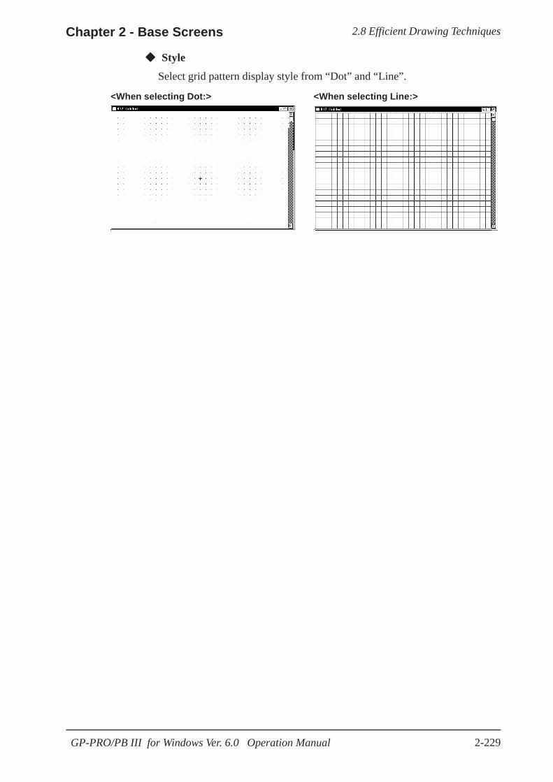
2.8 Efficient Drawing TechniquesChapter 2 - Base Screens
2-229GP-PRO/PB III for Windows Ver. 6.0 Operation Manual
<When selecting Dot:> <When selecting Line:>
Style
Select grid pattern display style from “Dot” and “Line”.
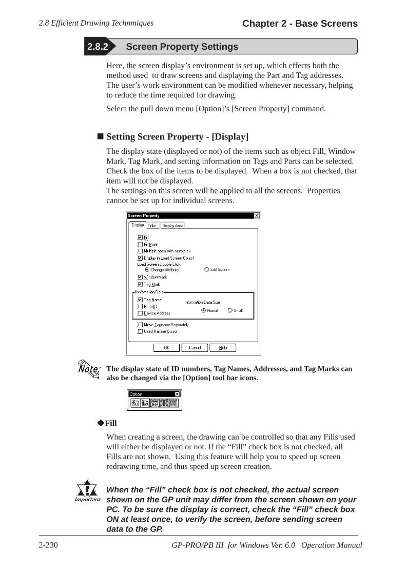
2.8 Efficient Drawing Technmiques Chapter 2 - Base Screens
2-230 GP-PRO/PB III for Windows Ver. 6.0 Operation Manual
2.8.2 Screen Property Settings
Here, the screen display’s environment is set up, which effects both themethod used to draw screens and displaying the Part and Tag addresses.The user’s work environment can be modified whenever necessary, helpingto reduce the time required for drawing.
Select the pull down menu [Option]’s [Screen Property] command.
Setting Screen Property - [Display]The display state (displayed or not) of the items such as object Fill, WindowMark, Tag Mark, and setting information on Tags and Parts can be selected.Check the box of the items to be displayed. When a box is not checked, thatitem will not be displayed.The settings on this screen will be applied to all the screens. Propertiescannot be set up for individual screens.
The display state of ID numbers, Tag Names, Addresses, and Tag Marks canalso be changed via the [Option] tool bar icons.
Fill
When creating a screen, the drawing can be controlled so that any Fills usedwill either be displayed or not. If the “Fill” check box is not checked, allFills are not shown. Using this feature will help you to speed up screenredrawing time, and thus speed up screen creation.
When the “Fill” check box is not checked, the actual screenshown on the GP unit may differ from the screen shown on yourPC. To be sure the display is correct, check the “Fill” check boxON at least once, to verify the screen, before sending screendata to the GP.

2.8 Efficient Drawing TechniquesChapter 2 - Base Screens
2-231GP-PRO/PB III for Windows Ver. 6.0 Operation Manual
Fill Point
When this feature is selected, specified Fill points will appear with an “X”mark, which is especially useful when selecting Fill points.If the Fill Points are not displayed, Fill cannot be performed while editing.
The X (cursor position) mark’s color can be designated in the system’s[Color] area.
Multiple Open with Next/Prev
When selecting [Previous Screen]/[Next Screen] from the [Screen] menu, oropening a screen with the Open Screen switch , specify whether thenext screen is opened with the currently active screen open or after thatactive screen is closed. Up to 20 screens may be opened continuously.
Display in Load Screen Object
You can specify whether tag and part addresses, ID numbers, tag names, andtag marks on a screen which has been called up using the [Load Screen]command are displayed or hidden.
Load Screen Double Click
Specify an edit method for editing a screen that has been called up onanother screen where the [Load Screen] command was executed, or forediting a screen on the Screen List.
If [Change Attribute] is specified, the Load Screen dialog box will beopened, enabling you to select a screen to be called up (screen number).
If [Edit Screen] is specified, the screen that has been called up will beopened, allowing you to edit the data.
Window Mark
Designates the window mark display state, i.e. displayed or not displayed.The window mark shows an area that has been registered as a window.
3.7 Window Display, Window(U) Screen and Base(B) Screen
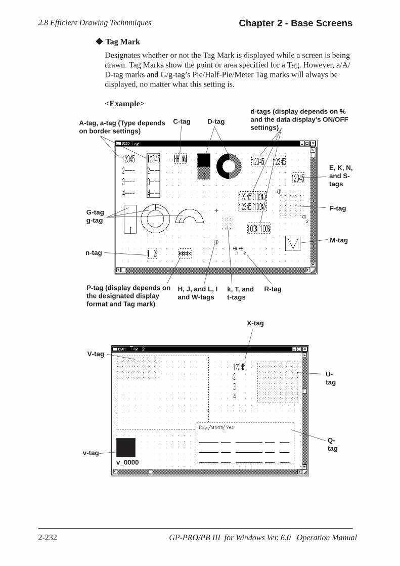
2.8 Efficient Drawing Technmiques Chapter 2 - Base Screens
2-232 GP-PRO/PB III for Windows Ver. 6.0 Operation Manual
A-tag, a-tag (Type dependson border settings)
G-tagg-tag
n-tag
P-tag (display depends onthe designated displayformat and Tag mark)
H, J, and L, Iand W-tags
k, T, andt-tags
R-tag
M-tag
F-tag
E, K, N,and S-tags
d-tags (display depends on %and the data display’s ON/OFFsettings)
D-tagC-tag
V-tag
Q-tag
U-tag
X-tag
Tag Mark
Designates whether or not the Tag Mark is displayed while a screen is beingdrawn. Tag Marks show the point or area specified for a Tag. However, a/A/D-tag marks and G/g-tag’s Pie/Half-Pie/Meter Tag marks will always bedisplayed, no matter what this setting is.
<Example>
v_0000v-tag

2.8 Efficient Drawing TechniquesChapter 2 - Base Screens
2-233GP-PRO/PB III for Windows Ver. 6.0 Operation Manual
Tag Name
Designates whether or not the Tag Name is displayed while a screen is beingdrawn.
Parts ID
Designates whether or not a Part’s ID number is displayed on the Basescreen.
Device Address
Designates whether or not Part and Tag Addresses are displayed on the Basescreen. Part Addresses appear below the ID number, and on Tags, below theTag Name.
Information Data Size
Selects the character size displayed from Standard (half size) and Minimized(1/4 size) for ID No., Tag names, and Address.
Move Tagname Separately
Whether or not the Tag Name and Address display position is also movedwhen Tag Marks are moved is designated during screen creation. If thisfunction is selected, when Tag Marks are moved, Tag Names and Addresseswill be not moved.
Used Hairline Cursor
Changes the arrow cursor to the hairline cursor.

2.8 Efficient Drawing Technmiques Chapter 2 - Base Screens
2-234 GP-PRO/PB III for Windows Ver. 6.0 Operation Manual
Setting Screen Property - [Color]Select the Grid, Fill Point, and Screen Background colors here. When thedrawn image data’s and system’s colors are the same, the screens will behard to see. Here, these colors can be changed to remedy that.
Grid Color
Selects the grid point’s color.
Fill Point Color
Fill Points designate the point where a fill will begin; this setting determinesthe color of the fill point.
Screen Background
Select the Base screen’s background color; the color selected here is alsodisplayed on the GP.
· If any background color is specified for the screen to beloaded, no on-screen object will be displayed on the GP unit.
· To load a screen whose background color was specified,specify the loading position at the center of the screen.
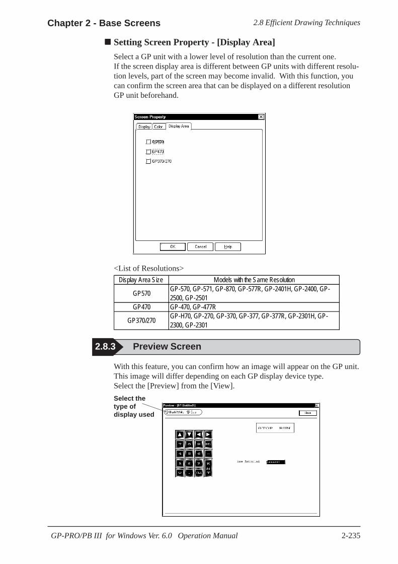
2.8 Efficient Drawing TechniquesChapter 2 - Base Screens
2-235GP-PRO/PB III for Windows Ver. 6.0 Operation Manual
Setting Screen Property - [Display Area]Select a GP unit with a lower level of resolution than the current one.If the screen display area is different between GP units with different resolu-tion levels, part of the screen may become invalid. With this function, youcan confirm the screen area that can be displayed on a different resolutionGP unit beforehand.
2.8.3 Preview Screen
With this feature, you can confirm how an image will appear on the GP unit.This image will differ depending on each GP display device type.Select the [Preview] from the [View].Select thetype ofdisplay used
<List of Resolutions>Display Area Size Models with the Same Resolution
GP570 GP-570, GP-571, GP-870, GP-577R, GP-2401H, GP-2400, GP-2500, GP-2501
GP470 GP-470, GP-477R
GP370/270 GP-H70, GP-270, GP-370, GP-377, GP-377R, GP-2301H, GP-2300, GP-2301

2.8 Efficient Drawing Technmiques Chapter 2 - Base Screens
2-236 GP-PRO/PB III for Windows Ver. 6.0 Operation Manual
Screen Data DisplayThe designated type of object(s) data is displayed. If a grouped objectcontains at least one object whose type has been designated, it is displayedas an grouped object.The Screen Data List displays the following information:
Drawing ................. Type and coordinates of a drawing objectTag ......................... Tag Name and AddressPart ......................... ID Number and AddressGrouped object ...... Grouped object’s coordinates and each grouped object’s
information
D-Scripts are displayed as tags. Each D-Script shows ID and descriptioninformation.
Selecting an ObjectThe object selected from the list will be displayed with handles (i.e. se-lected) in the Screen Editor. To select multiple objects from the list, Left-drag them, or hold the or key down and click on desired ones.
Link Select
Normally, when any object is selected with the Screen Editor, it will not bedisplayed on the list. If the check box for [Link Select] is marked, an objectselected with the Screen Editor will also be selected (highlighted) on the list.
2.8.4 Screen Data List
The currently displayed screen’s object locations and setting attributes arelisted in the Screen Data List.
Screen Data ListAn example of the Screen Data List is shown below.
Displays the objectplaced on thecurrently displayedscreen
Edits the objectselected fromthe Screen DataList
Deletes the objectselected from theScreen Data List
Designates thetype of the objectto be displayed inthe Screen DataList
Shift Ctrl
Highlights anobject selected onthe screen.
Changes the orderof drawing objects

2.8 Efficient Drawing TechniquesChapter 2 - Base Screens
2-237GP-PRO/PB III for Windows Ver. 6.0 Operation Manual
Editing an Object
To edit an object, select it from the list and click on the button; orsimply double-click on the object.
If the object is D-Script, D-Script Editor will be actuated.
Clicking on the button deletes the selected object.
Change Order
Objects are displayed on the list in the order where they have been drawn. Ifthe order of objects on the list is changed, the overlapping order of drawnobjects and the executing order of tags and parts can also be changed.
Copying
Any object on the list can be copied by pressing the + key, or pastedby pressing the + keys. Multiple objects can be copied at a time byselecting them.
Delete
CCtrlVCtrl

2.8 Efficient Drawing Techniques Chapter 2 - Base Screens
2-238 GP-PRO/PB III for Windows Ver. 6.0 Operation Manual
2.8.5 Part Reference List
When either modifying or deleting...
or the
Esc key
After selection,either modify ordelete the Part
SelectdesiredPart
[Parts List][View]
Usage Pattern
→→→→→→→→→→→→→→→→→→→→
Shows a list ofthe Parts on thecurrentlyselectedscreen. Simplyclick on thedesired Part
Deletes theselected Part
Changes Part’ssettings
Closes the current screen.(The Esc key can also beused)
Use this scroll barto view all the dataon a long screen
Can be edited directly Can be edited bydouble-clicking
Editing Items on the Part Reference ListPart setting data can be changed directly on the Part Reference List.Click on the left-most number of a Part to be changed, and it will be high-lighted; then, click on the button, and the Part’s Dialog box willappear and its settings can be changed.Setting items, such as the Description and Address areas, can be changed viathe Part Reference List. Also, items displayed in gray can be changed in thedialog box by double-clicking on the inside of their border.
An example of the Part Reference List on a screen is shown below.
The settings for each Part placed on the currently edited screen are listedhere, for each Part type. Part settings can also be changed on the PartReference List.
Copies a part
Pastes a part
Reflection of device commentThe device comment corresponding to anentered device address overwrites the Descrip-tion field.
The tab width for each item can be adjusted by placing the mouse pointer onthe border between items and then dragging it.
Stores theParts listinformation asa CSV file.
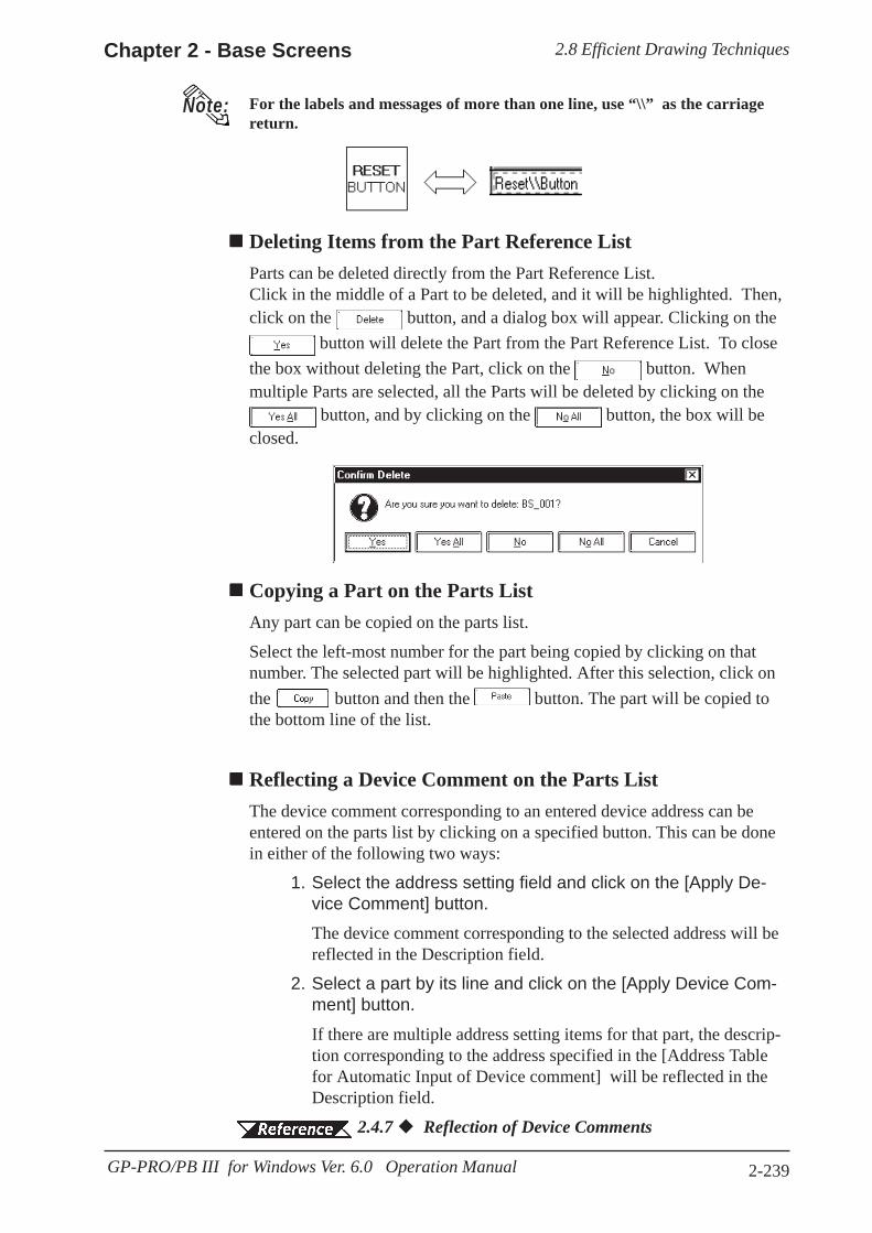
2.8 Efficient Drawing TechniquesChapter 2 - Base Screens
2-239GP-PRO/PB III for Windows Ver. 6.0 Operation Manual
Note: For the labels and messages of more than one line, use “\\” as the carriagereturn.
Deleting Items from the Part Reference ListParts can be deleted directly from the Part Reference List.Click in the middle of a Part to be deleted, and it will be highlighted. Then,click on the button, and a dialog box will appear. Clicking on the
button will delete the Part from the Part Reference List. To closethe box without deleting the Part, click on the button. Whenmultiple Parts are selected, all the Parts will be deleted by clicking on the
button, and by clicking on the button, the box will beclosed.
Copying a Part on the Parts ListAny part can be copied on the parts list.
Select the left-most number for the part being copied by clicking on thatnumber. The selected part will be highlighted. After this selection, click onthe button and then the button. The part will be copied tothe bottom line of the list.
Reflecting a Device Comment on the Parts ListThe device comment corresponding to an entered device address can beentered on the parts list by clicking on a specified button. This can be donein either of the following two ways:
1. Select the address setting field and click on the [Apply De-vice Comment] button.The device comment corresponding to the selected address will bereflected in the Description field.
2. Select a part by its line and click on the [Apply Device Com-ment] button.If there are multiple address setting items for that part, the descrip-tion corresponding to the address specified in the [Address Tablefor Automatic Input of Device comment] will be reflected in theDescription field.
2.4.7 Reflection of Device Comments
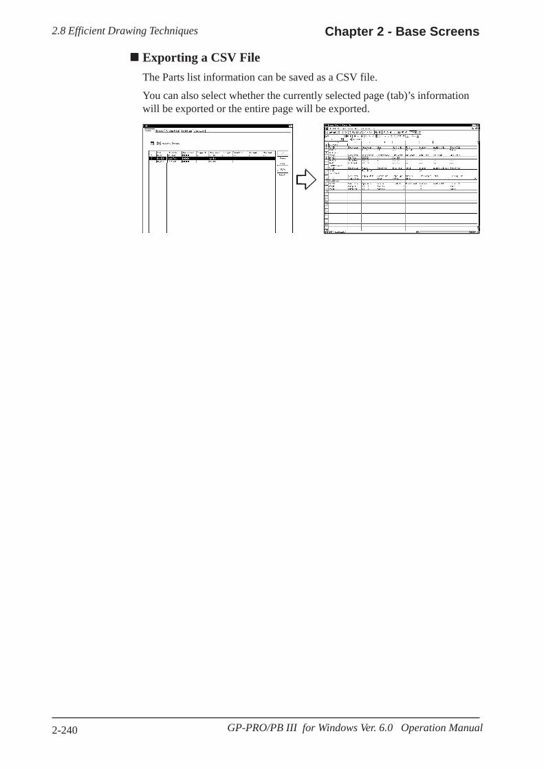
2.8 Efficient Drawing Techniques Chapter 2 - Base Screens
2-240 GP-PRO/PB III for Windows Ver. 6.0 Operation Manual
Exporting a CSV FileThe Parts list information can be saved as a CSV file.
You can also select whether the currently selected page (tab)’s informationwill be exported or the entire page will be exported.
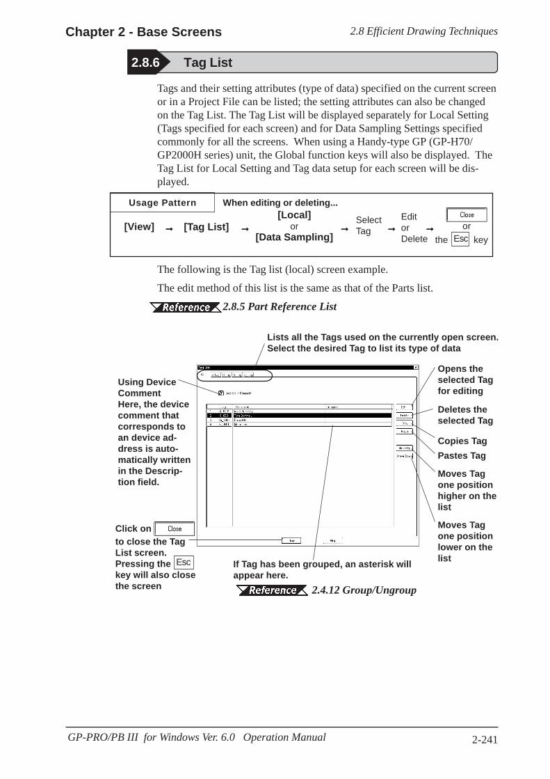
2.8 Efficient Drawing TechniquesChapter 2 - Base Screens
2-241GP-PRO/PB III for Windows Ver. 6.0 Operation Manual
2.8.6 Tag List
Tags and their setting attributes (type of data) specified on the current screenor in a Project File can be listed; the setting attributes can also be changedon the Tag List. The Tag List will be displayed separately for Local Setting(Tags specified for each screen) and for Data Sampling Settings specifiedcommonly for all the screens. When using a Handy-type GP (GP-H70/GP2000H series) unit, the Global function keys will also be displayed. TheTag List for Local Setting and Tag data setup for each screen will be dis-played.
The following is the Tag list (local) screen example.
The edit method of this list is the same as that of the Parts list.
2.8.5 Part Reference List
Lists all the Tags used on the currently open screen.Select the desired Tag to list its type of data
Click on to close the TagList screen.Pressing thekey will also closethe screen
If Tag has been grouped, an asterisk willappear here.
2.4.12 Group/Ungroup
Moves Tagone positionlower on thelist
Moves Tagone positionhigher on thelist
Deletes theselected Tag
Opens theselected Tagfor editing
Esc
Using DeviceCommentHere, the devicecomment thatcorresponds toan device ad-dress is auto-matically writtenin the Descrip-tion field.
Copies TagPastes Tag
Usage Pattern When editing or deleting...
[View] →→→→→ [Tag List][Local]
or[Data Sampling]
→→→→→SelectTag→→→→→
EditorDelete
→→→→→ →→→→→ orthe keyEsc

2.8 Efficient Drawing Techniques Chapter 2 - Base Screens
2-242 GP-PRO/PB III for Windows Ver. 6.0 Operation Manual
· The tab width for each item can be adjusted by positioning the mousepointer on the border between items and then dragging it.
· For Handy-type GP (GP-H70/GP2000H Series) unit, the Tag names speci-fied via the Local function keys will become “OP_*_***” or “F*_*_***”,thereby allowing you to distinguish in the Tag List whether the Tag was setup via the Local function keys or on the screen.
2.9.1 Function Keys
Changing the Tag Setting OrderThe Tags will function in the order that they have been set up (the orderdisplayed on all the pages of the Tag List) on the GP screen. To change thisorder, click on either the or key. When multiple Tags aregrouped, that group will be moved up or down.
Exporting a CSV FileThe Parts list information can be saved as a CSV file.
You can also select whether the currently selected page (tab)’s informationwill be exported or the entire page will be exported.
2.8.5 Part Reference List Exporting a CSV File
Scrolls thedisplay left, right,up and downwhen the Tag Listis bigger than thescreen size
<Individual Tag List Screen>
Saves the TagList in a CSV file
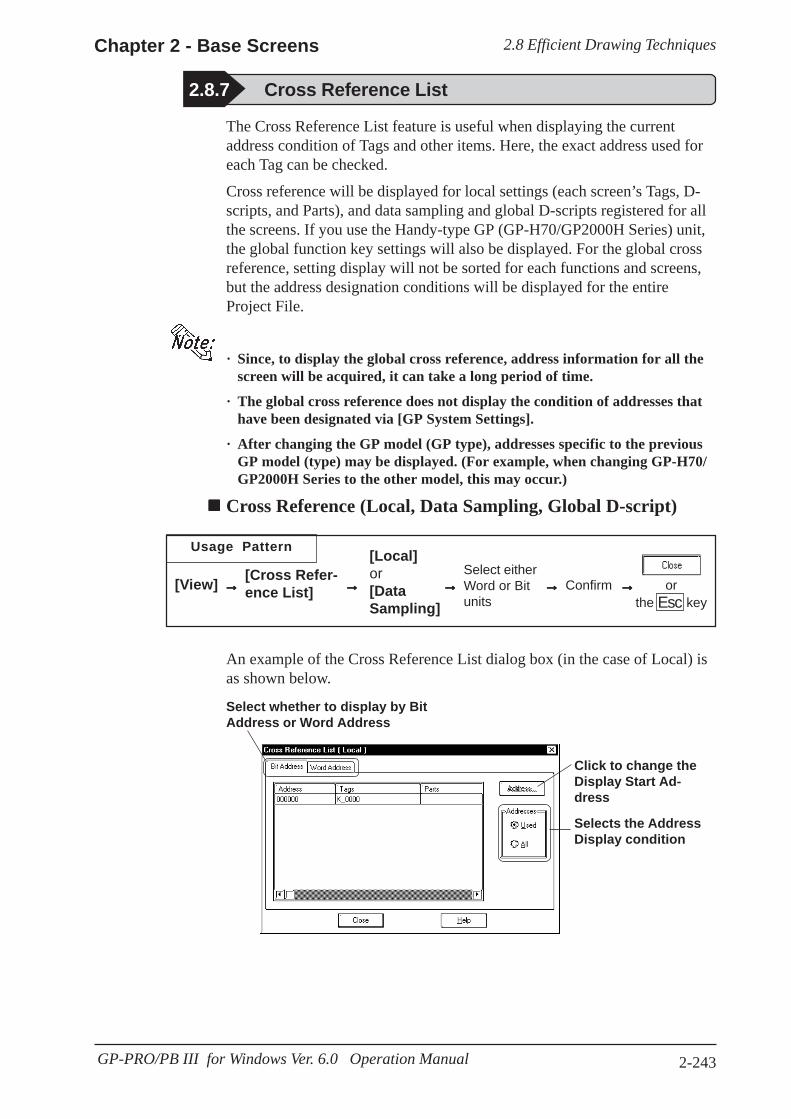
2.8 Efficient Drawing TechniquesChapter 2 - Base Screens
2-243GP-PRO/PB III for Windows Ver. 6.0 Operation Manual
2.8.7 Cross Reference List
The Cross Reference List feature is useful when displaying the currentaddress condition of Tags and other items. Here, the exact address used foreach Tag can be checked.
Cross reference will be displayed for local settings (each screen’s Tags, D-scripts, and Parts), and data sampling and global D-scripts registered for allthe screens. If you use the Handy-type GP (GP-H70/GP2000H Series) unit,the global function key settings will also be displayed. For the global crossreference, setting display will not be sorted for each functions and screens,but the address designation conditions will be displayed for the entireProject File.
· Since, to display the global cross reference, address information for all thescreen will be acquired, it can take a long period of time.
· The global cross reference does not display the condition of addresses thathave been designated via [GP System Settings].
· After changing the GP model (GP type), addresses specific to the previousGP model (type) may be displayed. (For example, when changing GP-H70/GP2000H Series to the other model, this may occur.)
Cross Reference (Local, Data Sampling, Global D-script)
Usage Pattern
→→→→→[View] →→→→→[Cross Refer-ence List]
Select eitherWord or Bitunits
→→→→→ orthe key
An example of the Cross Reference List dialog box (in the case of Local) isas shown below.
Esc
[Local]or[DataSampling]
→→→→→ Confirm →→→→→
Select whether to display by BitAddress or Word Address
Selects the AddressDisplay condition
Click to change theDisplay Start Ad-dress

2.8 Efficient Drawing Techniques Chapter 2 - Base Screens
2-244 GP-PRO/PB III for Windows Ver. 6.0 Operation Manual
Global Cross ReferenceThe global cross reference has two display methods, i.e. list display same asthe standard cross reference and address map display.
Usage Pattern
→→→→→[Utility] →→→→→[Global CrossReference] Start address search.
→→→→→
The following is the overview for the global cross reference screens.
List Display
For local settings, which screen is used, and for global settings, functiontype will be displayed, respectively.
[List]or
[Map]→→→→→
Confirm →→→→→Select either Word orBit Address.
orthe keyEsc→→→→→
Selects whether setting conditions are dis-played for Bit Addresses or for Word Addresses.
Changes the displaystart address to bedisplayed.
Selects the range ofAddresses to bedisplayed.
Address Map Display
When selecting Word Address, the table cells from Word Address Bits 0 to15 (for 32 bit device, from 0 to 32) will all be filled. When selecting BitAddress, only bit cells currently used will be filled.
Selects whethersetting condi-tions are dis-played for BitAddresses or forWord Addresses.
Displays the Bitlocation.
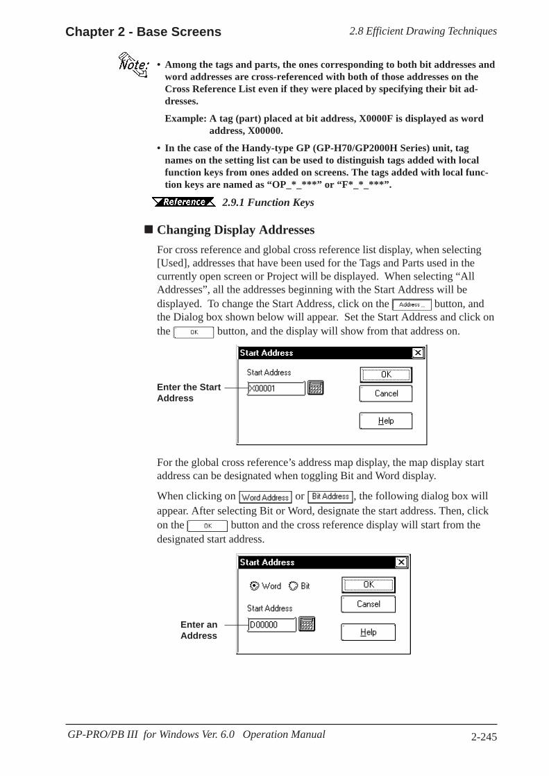
2.8 Efficient Drawing TechniquesChapter 2 - Base Screens
2-245GP-PRO/PB III for Windows Ver. 6.0 Operation Manual
• Among the tags and parts, the ones corresponding to both bit addresses andword addresses are cross-referenced with both of those addresses on theCross Reference List even if they were placed by specifying their bit ad-dresses.
Example: A tag (part) placed at bit address, X0000F is displayed as wordaddress, X00000.
• In the case of the Handy-type GP (GP-H70/GP2000H Series) unit, tagnames on the setting list can be used to distinguish tags added with localfunction keys from ones added on screens. The tags added with local func-tion keys are named as “OP_*_***” or “F*_*_***”.
2.9.1 Function Keys
Changing Display AddressesFor cross reference and global cross reference list display, when selecting[Used], addresses that have been used for the Tags and Parts used in thecurrently open screen or Project will be displayed. When selecting “AllAddresses”, all the addresses beginning with the Start Address will bedisplayed. To change the Start Address, click on the button, andthe Dialog box shown below will appear. Set the Start Address and click onthe button, and the display will show from that address on.
Enter the StartAddress
For the global cross reference’s address map display, the map display startaddress can be designated when toggling Bit and Word display.
When clicking on or , the following dialog box willappear. After selecting Bit or Word, designate the start address. Then, clickon the button and the cross reference display will start from thedesignated start address.
Enter anAddress
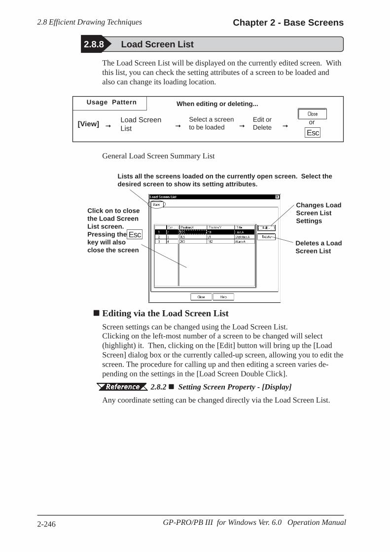
2.8 Efficient Drawing Techniques Chapter 2 - Base Screens
2-246 GP-PRO/PB III for Windows Ver. 6.0 Operation Manual
The Load Screen List will be displayed on the currently edited screen. Withthis list, you can check the setting attributes of a screen to be loaded andalso can change its loading location.
When editing or deleting...
[View] Load ScreenList→→→→→ →→→→→
Select a screento be loaded →→→→→
Edit orDelete
orEsc
→→→→→
General Load Screen Summary List
Lists all the screens loaded on the currently open screen. Select thedesired screen to show its setting attributes.
Click on to closethe Load ScreenList screen.Pressing thekey will alsoclose the screen
Deletes a LoadScreen List
Changes LoadScreen ListSettings
Esc
Editing via the Load Screen ListScreen settings can be changed using the Load Screen List.Clicking on the left-most number of a screen to be changed will select(highlight) it. Then, clicking on the [Edit] button will bring up the [LoadScreen] dialog box or the currently called-up screen, allowing you to edit thescreen. The procedure for calling up and then editing a screen varies de-pending on the settings in the [Load Screen Double Click].
2.8.2 Setting Screen Property - [Display]Any coordinate setting can be changed directly via the Load Screen List.
2.8.8 Load Screen List
Usage Pattern
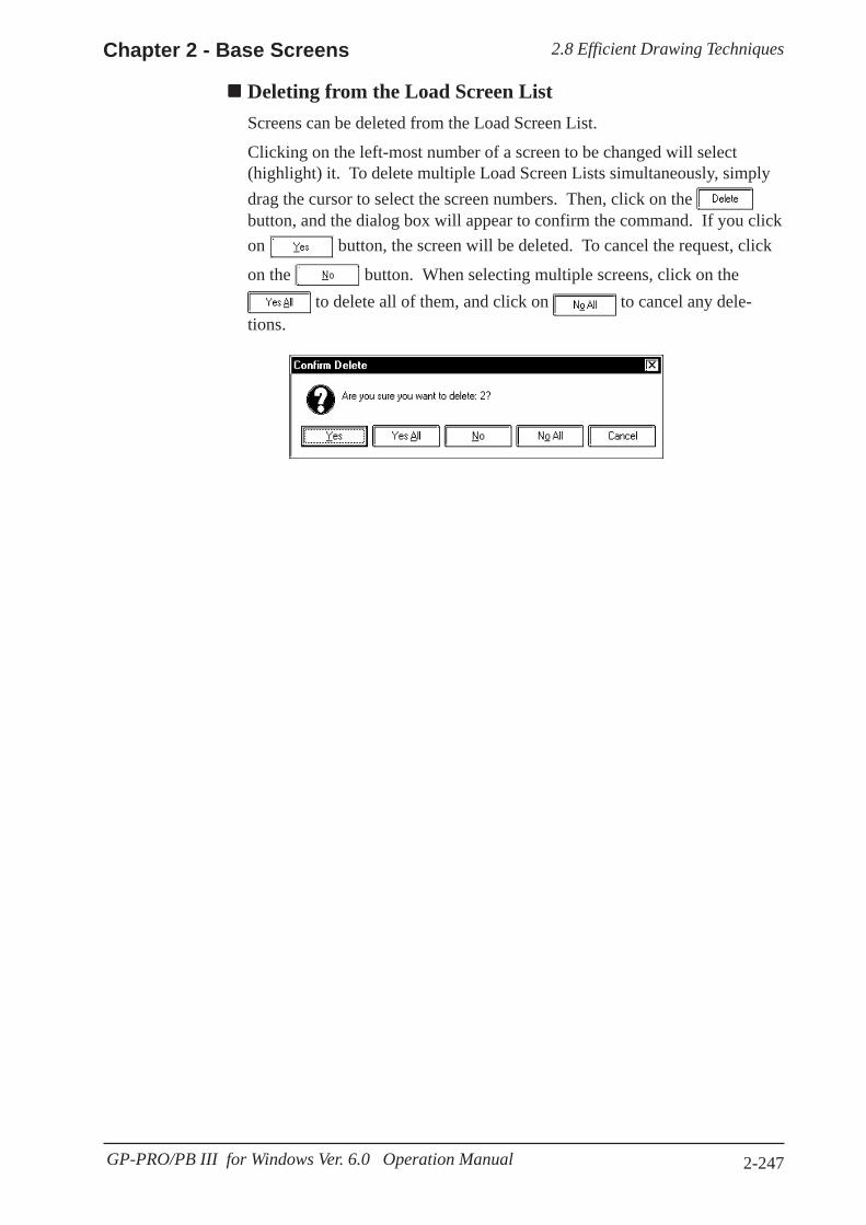
2.8 Efficient Drawing TechniquesChapter 2 - Base Screens
2-247GP-PRO/PB III for Windows Ver. 6.0 Operation Manual
Deleting from the Load Screen ListScreens can be deleted from the Load Screen List.
Clicking on the left-most number of a screen to be changed will select(highlight) it. To delete multiple Load Screen Lists simultaneously, simplydrag the cursor to select the screen numbers. Then, click on the button, and the dialog box will appear to confirm the command. If you clickon button, the screen will be deleted. To cancel the request, click
on the button. When selecting multiple screens, click on the to delete all of them, and click on to cancel any dele-
tions.

2.8 Efficient Drawing Techniques Chapter 2 - Base Screens
2-248 GP-PRO/PB III for Windows Ver. 6.0 Operation Manual
The nesting of Load Screens that have been set up on the currently editedscreen is displayed. In this way, a multiple nesting condition can be viewed.
2.2.10 Load Screens NestingSelect the [View] menu - [Load Screen Nesting Display] command.
2.8.9 Display of Screen Level Change Structure
Each screen will be displayed via the following symbols:
Screen Type SymbolBase screen BMark screen MTrend Graph screen TKeypad screen KImage screen IImage screen - CF card I(CF)Window screen U
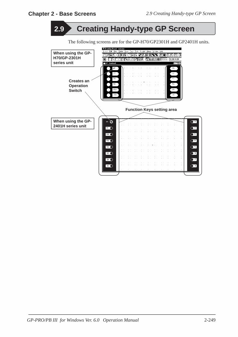
2.9 Creating Handy-type GP ScreenChapter 2 - Base Screens
2-249GP-PRO/PB III for Windows Ver. 6.0 Operation Manual
2.9 Creating Handy-type GP ScreenThe following screens are for the GP-H70/GP2301H and GP2401H units.
Creates anOperationSwitch
Function Keys setting area
When using the GP-H70/GP-2301Hseries unit
When using the GP-2401H series unit
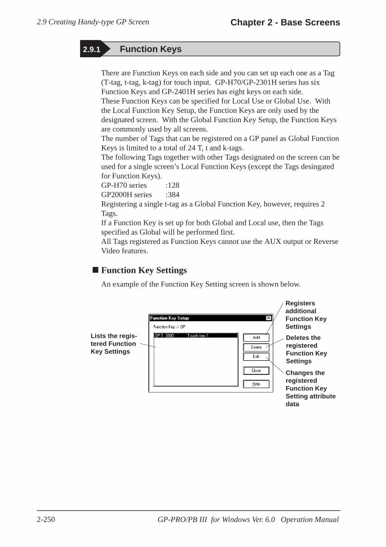
2.9 Creating Handy-type GP Screen Chapter 2 - Base Screens
2-250 GP-PRO/PB III for Windows Ver. 6.0 Operation Manual
There are Function Keys on each side and you can set up each one as a Tag(T-tag, t-tag, k-tag) for touch input. GP-H70/GP-2301H series has sixFunction Keys and GP-2401H series has eight keys on each side.These Function Keys can be specified for Local Use or Global Use. Withthe Local Function Key Setup, the Function Keys are only used by thedesignated screen. With the Global Function Key Setup, the Function Keysare commonly used by all screens.The number of Tags that can be registered on a GP panel as Global FunctionKeys is limited to a total of 24 T, t and k-tags.The following Tags together with other Tags designated on the screen can beused for a single screen’s Local Function Keys (except the Tags desingatedfor Function Keys).GP-H70 series :128GP2000H series :384Registering a single t-tag as a Global Function Key, however, requires 2Tags.If a Function Key is set up for both Global and Local use, then the Tagsspecified as Global will be performed first.All Tags registered as Function Keys cannot use the AUX output or ReverseVideo features.
Function Key SettingsAn example of the Function Key Setting screen is shown below.
Lists the regis-tered FunctionKey Settings
RegistersadditionalFunction KeySettings
Changes theregisteredFunction KeySetting attributedata
Deletes theregisteredFunction KeySettings
2.9.1 Function Keys

2.9 Creating Handy-type GP ScreenChapter 2 - Base Screens
2-251GP-PRO/PB III for Windows Ver. 6.0 Operation Manual
Setting Up Local Function KeysThe Local Function Key Setting procedure is described. An example of using theGPH70L/GPH70S/GP2301HL/GP2301HS is as follows.
PROCEDURE R E M A R K S
(1)Double-click on any of the Function Keys displayed.
(2)Click on the [Function Key Settings] screen’s button.
(3)Click on the Tag Name to be used. Multiple Tags can be assigned to aFunction Key; however, there is alimit to the number that can be used.
(4)Enter the Tag setting data. After all the attributeshave been entered, click on the button toregister the entered data.
For details of eachTag’s setting data, refer to the TagReference Manual, Chapter 2Active Image Functions
When using the GP-2401H seriesunit, there are eight Function Keysincluding the Operation switch oneach side .
When using the GPH70L/GPH70S/GP2301HL/GP2301HS series

2.9 Creating Handy-type GP Screen Chapter 2 - Base Screens
2-252 GP-PRO/PB III for Windows Ver. 6.0 Operation Manual
PROCEDURE R E M A R K S
Displays theregistereditem
(5)Click on the button to quit the FunctionKey registration.
Setting Up Global Function KeysThe Global Function Key Setting procedure is described. An example of using theGP-H70/GP-2301H series is as follows.
PROCEDURE R E M A R K S
(1)Click on the [Special] menu’s [Global Fn Key].
(3)Click on the button.
(2)Double-click on any of the Function Keys displayed.
Before this selection, open anyBase screen.
To register another item, DO NOTquit here, rather start again fromstep (2).
When using the GP-2401H seriesunit, there are eight Function Keysincluding the Operation switch oneach side .
When using the GP-H70/GP-2301H series

2.9 Creating Handy-type GP ScreenChapter 2 - Base Screens
2-253GP-PRO/PB III for Windows Ver. 6.0 Operation Manual
PROCEDURE R E M A R K S
(4)Click on the Tag Name to be used.
(6)Click on the button to quit the Function Keyregistration.
(5)Enter the Tag setting data. After all the attributeshave been entered, click on the button toregister the entered data.
Multiple Tags can be assigned to aFunction Key, however, there is alimit to the maximum number.
For details of eachTag’s setting data, refer to the TagReference Manual Chapter 2 Ac-tive Image Function.
Displays theregistereditem
To perform the registration continu-ously, DO NOT quit here, start fromstep (3) again.
Notes for the Function KeysIf changing your GP type from GP-2401H series (16 Function Keys) to GP-H70/GP-2301H series (12 Function Keys) or vice versa, some keys may beshifted from the designated place due to the difference of Function Keys.

2.9 Creating Handy-type GP Screen Chapter 2 - Base Screens
2-254 GP-PRO/PB III for Windows Ver. 6.0 Operation Manual
2.9.2 Setting Up the Operation Switch
Rear Face Operation SwitchFront Face Operation Switch
This section describes the procedures for setting up the Operation Switchessupported by the GP-H70/GP2000H series.
The features of the Operation Switch are as follows:
(1) An Operation Switch can be used as a Function Switch.
(2) An Operation Switch can be used to enable Inputs from the touch panel and Function Keys.
For details of feature (1), see the setup procedures in Section 2.9.1 "FunctionKeys."
Feature (2) is activated only when the Operation Switch is enabled. Theprocedure for enabling the Operation Switches is described below. If theOperation Switches are disabled, only feature (1) is available.
· The function of the Operation Switch can be "enabled" or "disabled" in theGP’s OFF-LINE mode. Refer to GP-H70 Series User's Manual/GP2000HSeries User's Manual.
Setting Up the Operation Switches with the GP-H70 The Position of the switches
The GP-H70 has two Operation Switches; one on the front face and one onthe rear face.
Usage Pattern
→→→→→[Screen/Setup] →→→→→[GP Setup]
Check the box to activate"Operation SW"
→→→→→
[ExtendedSettings] →→→→→
or to close the dialog box
→→→→→or
Default Settings of the switches
According to the default settings of the GP-H70, both Operation Switchesare enabled with the dialog box below.
The "Operation SW” is checked by default.
<Front View> <Rear View>

2.9 Creating Handy-type GP ScreenChapter 2 - Base Screens
2-255GP-PRO/PB III for Windows Ver. 6.0 Operation Manual
Settings for Using the GP2000H Series in GP-H70 StandardModeThis setting allows you to use the switch located on the rear of theGP2000H series as an Operation Switch. Change the hardware settings ofthe GP2000H and select "GP-H70 Standard Mode."
For detailed procedures on setting up the hardware, refer tothe GP2000H Series User's Manual.To ensure that inputs from the touch panel and Function Keys are enteredonly when the Operation Switches are being pressed, change the defaultsetting and select the "Enable" setting option of the Operation Switch.
· The switch located on the rear of the GP2000H can be pressed down in twopositions. Pressing down the switch firmly to the second position disablesthe touch inputs. Be sure to press down the switch to the first position only.
· If the Operation Switches are enabled, do not hold down both the frontOperation Switch and rear Operation Switch simultaneously when per-forming touch input. Doing so disables touch input. Make touch input whileholding down only one of the switches.
Setting Up the Operation Switches with the GP2000H Positions of the switches
The GP2000H has one Operation Switch on the front.<Front View>
Operation Switch
Default Setting of the switch
According to the default settings of the GP2000H, the Operation Switch isdisabled. When the GP is operated under the default settings, the inputsfrom the touch panel and Function Keys are enabled.
The “Operation SW” is unchecked by default
· The GP2000H and the GP-H70 differ in the number of Operation Switchesand the default settings of the switches. Note this difference when switchingfrom the GP-H70 series to the GP2000H model.
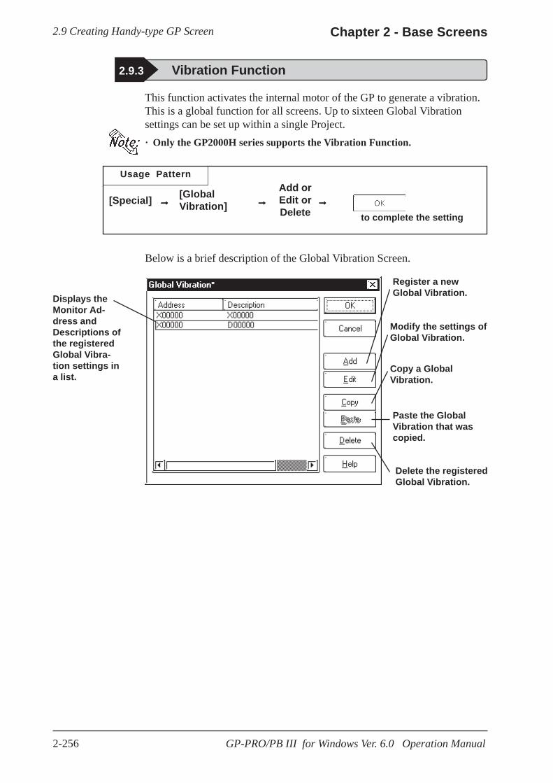
2.9 Creating Handy-type GP Screen Chapter 2 - Base Screens
2-256 GP-PRO/PB III for Windows Ver. 6.0 Operation Manual
2.9.3 Vibration Function
Usage Pattern
→→→→→[Special] →→→→→[GlobalVibration]
Add orEdit orDelete
→→→→→
This function activates the internal motor of the GP to generate a vibration.This is a global function for all screens. Up to sixteen Global Vibrationsettings can be set up within a single Project.· Only the GP2000H series supports the Vibration Function.
to complete the setting
Below is a brief description of the Global Vibration Screen.
Delete the registeredGlobal Vibration.
Displays theMonitor Ad-dress andDescriptions ofthe registeredGlobal Vibra-tion settings ina list.
Register a newGlobal Vibration.
Modify the settings ofGlobal Vibration.
Copy a GlobalVibration.
Paste the GlobalVibration that wascopied.
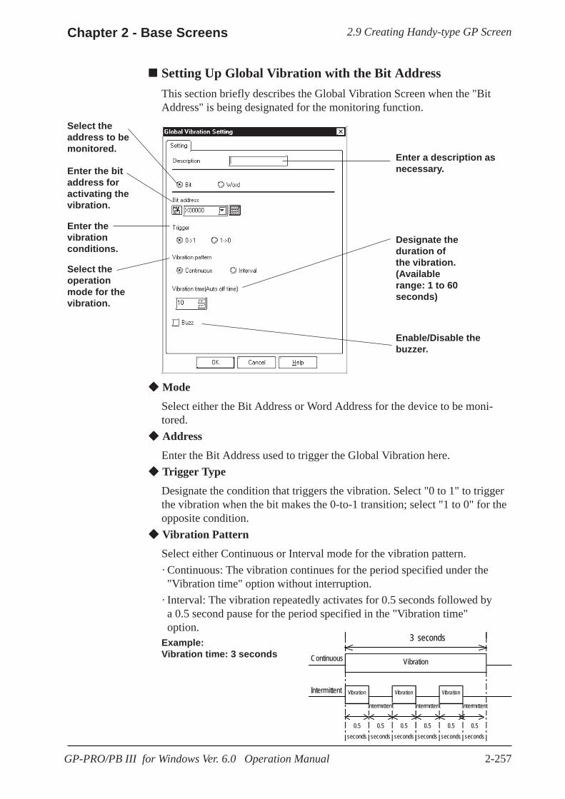
2.9 Creating Handy-type GP ScreenChapter 2 - Base Screens
2-257GP-PRO/PB III for Windows Ver. 6.0 Operation Manual
Setting Up Global Vibration with the Bit AddressThis section briefly describes the Global Vibration Screen when the "BitAddress" is being designated for the monitoring function.
Enter a description asnecessary.
Select theaddress to bemonitored.
Enter the bitaddress foractivating thevibration.
Enter thevibrationconditions.
Select theoperationmode for thevibration.
Designate theduration ofthe vibration.(Availablerange: 1 to 60seconds)
Enable/Disable thebuzzer.
Mode
Select either the Bit Address or Word Address for the device to be moni-tored. Address
Enter the Bit Address used to trigger the Global Vibration here. Trigger Type
Designate the condition that triggers the vibration. Select "0 to 1" to triggerthe vibration when the bit makes the 0-to-1 transition; select "1 to 0" for theopposite condition. Vibration Pattern
Select either Continuous or Interval mode for the vibration pattern.· Continuous: The vibration continues for the period specified under the "Vibration time" option without interruption.· Interval: The vibration repeatedly activates for 0.5 seconds followed by a 0.5 second pause for the period specified in the "Vibration time" option.Example:Vibration time: 3 seconds
3 seconds
Continuous
Intermittent
Intermittent Intermittent Intermittent
0.5seconds
0.5seconds
0.5seconds
0.5seconds
0.5seconds
0.5seconds
Vibration Vibration Vibration
Vibration

2.9 Creating Handy-type GP Screen Chapter 2 - Base Screens
2-258 GP-PRO/PB III for Windows Ver. 6.0 Operation Manual
Vibration time (Auto OFF time)
Specifies the duration of time after the vibration has been triggered.
The available range is from 1 to 60 seconds. The default setting is 10 sec-onds.
Buzzer
When this option is enabled, the buzzer sounds according to the selectedVibration Pattern.
The buzzer will not sound if "Touch Buzzer Sound" is disabled in [SystemSetup] under the Project Manager's window, even when the"Buzzer" function is enabled here.

2.9 Creating Handy-type GP ScreenChapter 2 - Base Screens
2-259GP-PRO/PB III for Windows Ver. 6.0 Operation Manual
Mode
Select either the Bit Address or Word Address for the device to be moni-tored.
Address
Enter the Word Address used to trigger the Global Vibration here.
Alarm Range
The vibration is triggered when the value of the word address being moni-tored exceeds the specified range. The Word Address is 16 bit, unsigned.
Vibration Pattern
Select either Continuous or Interval mode for the vibration pattern.
· Continuous: The vibration continues for the period specified under the "Vibration Period" option without interruption.
· Interval: The vibration repeatedly activates for 0.5 seconds followed by a 0.5 second pause for the period specified in the "Vibration Time" option.Example:Vibration time: 3 seconds
Setting Up Global Vibration with the Word AddressThis section briefly describes the Global Vibration Screen when the "WordAddress" is being designated for the monitoring function.
Enter a description asnecessary.Select the
address to bemonitored.
Enter theword addressfor activatingthe vibration.
Enter thevibrationconditions.
Select theoperationmode for thevibration.
Designate theduration ofthe vibration.(Availablerange: 1 to 60seconds)
Enable/Disable thebuzzer.
3 seconds
Continuous
Intermittent
Intermittent Intermittent Intermittent
0.5seconds
0.5seconds
0.5seconds
0.5seconds
0.5seconds
0.5seconds
Vibration Vibration Vibration
Vibration

2.9 Creating Handy-type GP Screen Chapter 2 - Base Screens
2-260 GP-PRO/PB III for Windows Ver. 6.0 Operation Manual
Vibration time (Auto OFF time)
Specifies the duration of time after the vibration has been triggered.
The available range is from 1 to 60 seconds. The default setting is 10 sec-onds.
Buzzer
When this option is enabled, the buzzer sounds according to the selectedVibration Pattern.
The buzzer will not sound if "Touch Buzzer Sound" is disabled in [SystemSetup] under the Project Manager's window, even when the"Buzzer" function is enabled here.
Vibration ModesOperation examples of vibration*1 are shown below.
1) The vibration of the GP unit is triggered according to the settings when the specified Condition is satisfied*2.
Satisfied
Vibration ConditionNot satisfied
Vibration Vibration
2) The vibration is not triggered a second time even if the Vibration Condition is satisfied again while the vibration is ON.
Satisfied
Vibration ConditionNot satisfied
Vibration Vibration
*1: The vibration continues for the period specified in the "Vibration time"option in the [Global Vibration Settings] dialog box. The vibration is triggeredwhen the Vibration Condition is satisfied regardless of the period required forthe vibration to be completed, automatically stopping after the specified pe-riod has elapsed.
*2: To trigger two consecutive vibration responses, hold the Trigger OFF time(the state in which the Vibration Condition is not satisfied) for the longer ofthe following two periods: the communication cycle time or the tag scan time.

2.9 Creating Handy-type GP ScreenChapter 2 - Base Screens
2-261GP-PRO/PB III for Windows Ver. 6.0 Operation Manual
3) The vibration in response to Vibration Condition (2) is triggered after the vibration in response to Vibration Condition (1) ends.
SatisfiedVibration Condition 1
SatisfiedVibration Condition 2
Vibration Vibration 1 Vibration 2
Not satisfied
Not satisfied
4) If Vibration Condition (2) is not satisfied, no vibration is triggered after the vibration in response to Vibration Condition (1) ends
Satisfied
Not satisfiedsatisfied
Not satisfied
Vibration Condition 1
Vibration Condition 2
Vibration Vibration 1
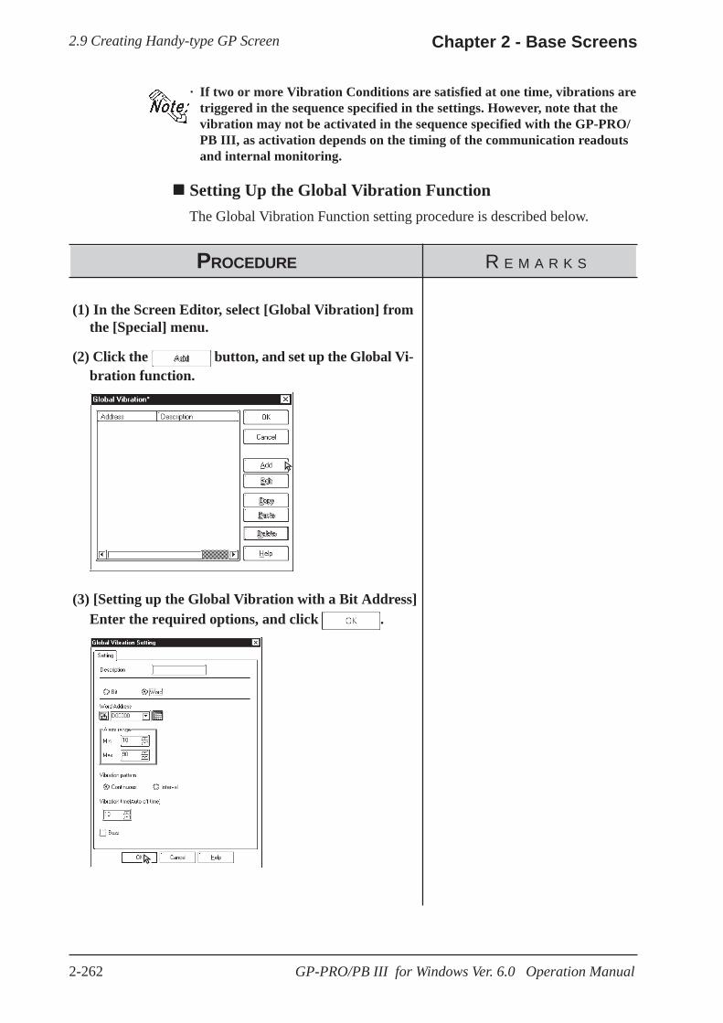
2.9 Creating Handy-type GP Screen Chapter 2 - Base Screens
2-262 GP-PRO/PB III for Windows Ver. 6.0 Operation Manual
PROCEDURE R E M A R K S
· If two or more Vibration Conditions are satisfied at one time, vibrations aretriggered in the sequence specified in the settings. However, note that thevibration may not be activated in the sequence specified with the GP-PRO/PB III, as activation depends on the timing of the communication readoutsand internal monitoring.
Setting Up the Global Vibration FunctionThe Global Vibration Function setting procedure is described below.
(1) In the Screen Editor, select [Global Vibration] fromthe [Special] menu.
(2) Click the button, and set up the Global Vi-bration function.
(3) [Setting up the Global Vibration with a Bit Address]Enter the required options, and click .
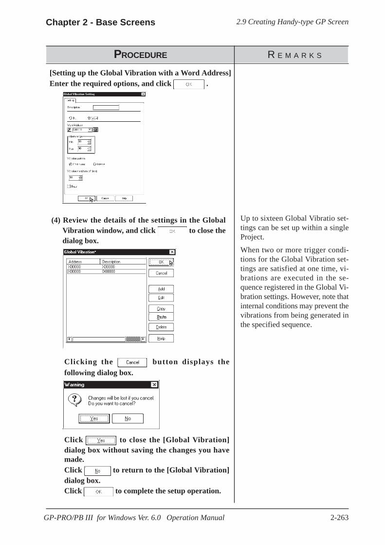
2.9 Creating Handy-type GP ScreenChapter 2 - Base Screens
2-263GP-PRO/PB III for Windows Ver. 6.0 Operation Manual
PROCEDURE R E M A R K S
[Setting up the Global Vibration with a Word Address]Enter the required options, and click .
(4) Review the details of the settings in the Global Vibration window, and click to close the dialog box.
Up to sixteen Global Vibratio set-tings can be set up within a singleProject.
When two or more trigger condi-tions for the Global Vibration set-tings are satisfied at one time, vi-brations are executed in the se-quence registered in the Global Vi-bration settings. However, note thatinternal conditions may prevent thevibrations from being generated inthe specified sequence.
Clicking the button displays thefollowing dialog box.
Click to close the [Global Vibration]dialog box without saving the changes you havemade.Click to return to the [Global Vibration]dialog box.Click to complete the setup operation.
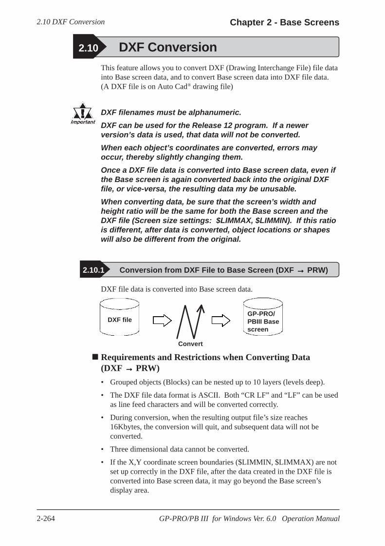
2.10 DXF Conversion Chapter 2 - Base Screens
2-264 GP-PRO/PB III for Windows Ver. 6.0 Operation Manual
2.10 DXF ConversionThis feature allows you to convert DXF (Drawing Interchange File) file datainto Base screen data, and to convert Base screen data into DXF file data.(A DXF file is on Auto Cad® drawing file)
DXF filenames must be alphanumeric.DXF can be used for the Release 12 program. If a newerversion’s data is used, that data will not be converted.When each object’s coordinates are converted, errors mayoccur, thereby slightly changing them.Once a DXF file data is converted into Base screen data, even ifthe Base screen is again converted back into the original DXFfile, or vice-versa, the resulting data my be unusable.When converting data, be sure that the screen’s width andheight ratio will be the same for both the Base screen and theDXF file (Screen size settings: $LIMMAX, $LIMMIN). If this ratiois different, after data is converted, object locations or shapeswill also be different from the original.
2.10.1 Conversion from DXF File to Base Screen (DXF →→→→→ PRW)
Requirements and Restrictions when Converting Data(DXF →→→→→ PRW)• Grouped objects (Blocks) can be nested up to 10 layers (levels deep).
• The DXF file data format is ASCII. Both “CR LF” and “LF” can be usedas line feed characters and will be converted correctly.
• During conversion, when the resulting output file’s size reaches16Kbytes, the conversion will quit, and subsequent data will not beconverted.
• Three dimensional data cannot be converted.
• If the X,Y coordinate screen boundaries ($LIMMIN, $LIMMAX) are notset up correctly in the DXF file, after the data created in the DXF file isconverted into Base screen data, it may go beyond the Base screen’sdisplay area.
DXF file data is converted into Base screen data.
DXF file
Convert
GP-PRO/PBIII Basescreen
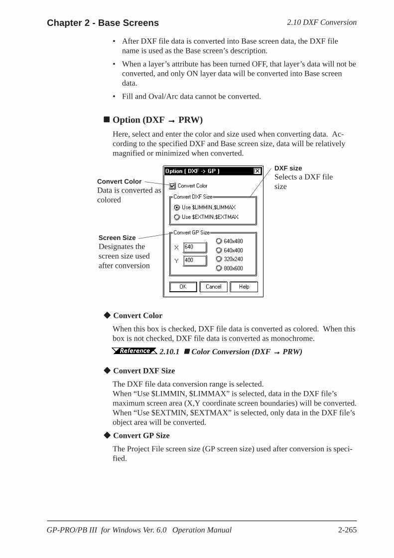
2.10 DXF ConversionChapter 2 - Base Screens
2-265GP-PRO/PB III for Windows Ver. 6.0 Operation Manual
• After DXF file data is converted into Base screen data, the DXF filename is used as the Base screen’s description.
• When a layer’s attribute has been turned OFF, that layer’s data will not beconverted, and only ON layer data will be converted into Base screendata.
• Fill and Oval/Arc data cannot be converted.
Option (DXF →→→→→ PRW)Here, select and enter the color and size used when converting data. Ac-cording to the specified DXF and Base screen size, data will be relativelymagnified or minimized when converted.
Convert Color
When this box is checked, DXF file data is converted as colored. When thisbox is not checked, DXF file data is converted as monochrome.
2.10.1 Color Conversion (DXF →→→→→ PRW)
Convert DXF Size
The DXF file data conversion range is selected.When “Use $LIMMIN, $LIMMAX” is selected, data in the DXF file’smaximum screen area (X,Y coordinate screen boundaries) will be converted.When “Use $EXTMIN, $EXTMAX” is selected, only data in the DXF file’sobject area will be converted.
Convert GP Size
The Project File screen size (GP screen size) used after conversion is speci-fied.
DXF sizeSelects a DXF filesize
Convert ColorData is converted ascolored
Screen SizeDesignates thescreen size usedafter conversion

2.10 DXF Conversion Chapter 2 - Base Screens
2-266 GP-PRO/PB III for Windows Ver. 6.0 Operation Manual
Color Conversion (DXF →→→→→ PRW)When the [Option] dialog box’s [Convert Color Data] check box is checked,the DXF file’s color data will be converted as follows:
DXF File Base Screen CONTINUOUS Solid line DASHED Broken line HIDDEN Broken line CENTER A dot-dash-line PHANTOM Two dot-dash-line Other Solid line
The background color will be converted into Black.
Line Type Conversion (DXF →→→→→ PRW)Each DXF file’s line type will be converted as follows:
The user defined line types will be converted into solid lines.
Object Conversion (DXF →→→→→ PRW)The DXF file’s objects will be converted as follows.Colors and line types will be converted as shown above. Tiling patterns willbe converted into solid Fill.
Objects other than the above will not be converted.
DXF File Base Screen LINE Straight line POINT (dot) Straight line (The start and end are the
same point) CIRCLE Regular circle ARC Arc TRACE (thick line) Filled polygon SOLID (filled object) Filled polygon TEXT (characters and signs) Text DIMENSION (dimension indicator) Straight line INSERT (inserting object) Conversion breaks down complex
objects into component parts (objects) ATTRIB (attribute) Conversion breaks down complex
objects into component parts (objects) POLYLINE(polyline/donut-shaped/ oval/polygon/rectangle) Continuous straight line
VERTEX Vertex coordinates of a continuous straight line
DXF File Color No. Base Screen
1 (red), 1X (red-based) Red2 (yellow), 5X (yellow-based) Yellow3 (green), 9X (green-based) Green
4 (light blue), 13X (light blue-based) Light blue5 (blue), 17X (blue-based) Blue
6 (purple), 21X (purple-based) Purple7 (white) White
Other colors White
2.10 DXF ConversionChapter 2 - Base Screens
2-267GP-PRO/PB III for Windows Ver. 6.0 Operation Manual
Each object’s elements, other than colors and line types, will be converted asfollows: POINT (dot)• A dot’s pattern will be converted into “0” (point), and its display size will
be converted into “0,0”.• A dot will be converted to a straight line, with the start and end coordi-
nates at the same point. TEXT (characters and signs)• A rotation angle will be converted into an angle closer to 90°, 180°, 270°,
or 360°. (in 90° units)• The character size will be converted into a size closer to either 1, 2, 4, or
8 x magnification.• Special characters that will be converted are %%d (°), %%c (φ), and
%%p (±).• When text contains more than 100 characters, it will be divided every
100 characters into records of data and then converted.• When more than 100 character text is divided into records of data, groups
of overflowing characters after the first 100 characters will be dislocatedtoward the right bottom for a few dots.
• Tilting angles, character fonts, and character spacing will not be con-verted.
• Text will be converted based on the ASCII code; therefore, the characterstyle (Standard, Bigfont, etc.) or font file settings will be ignored.
• When text with half-sized and full-sized characters mixed in verticallines is converted, the half-sized characters will be centered.
DIMENSION (Dimension Indicator)• During conversion, the breaking down of a grouped object (Block) is
performed by referring to the Block’s sections, which indicate the Block’scomponent parts (objects). However, dots will not be converted.
INSERT (Inserting Object)• A grouped object defined in the Block section will be broken down into
each drawing object and converted.• Up to 10 layers of nested data will be converted. However, since all the
data will be converted into a single layer on a single screen, the objectsover the limit (file capacity) will not be converted.
• Although the rotating angles, and the number of lines and columns can beconverted (lines and columns of the objects over the limit will not beconverted), their ratio (scaling) will not be converted.
• The grouped object created in Layer “0” will be converted based on theinserted layer’s colors and line types, however, a grouped object createdin an other layer level will not be converted based on the inserted layer’scolors and line types. In this case, if BYBLOCK is specified to thegrouped object, the inserted layer’s colors and line types will be used.
• Simulated object sectioning (hatching) data cannot be converted, since,when the Block section’s hatching data pattern is converted into eachdrawing object, that data size can exceed the GP file capacity.
• If another file’s grouped object has been inserted or another file is re-ferred, that grouped object will not be converted.
ATTRIB (attribute)ATTRIB (attribute) data is part of INSERT data.• Attribute data will be converted in the same manner as TEXT conversion.
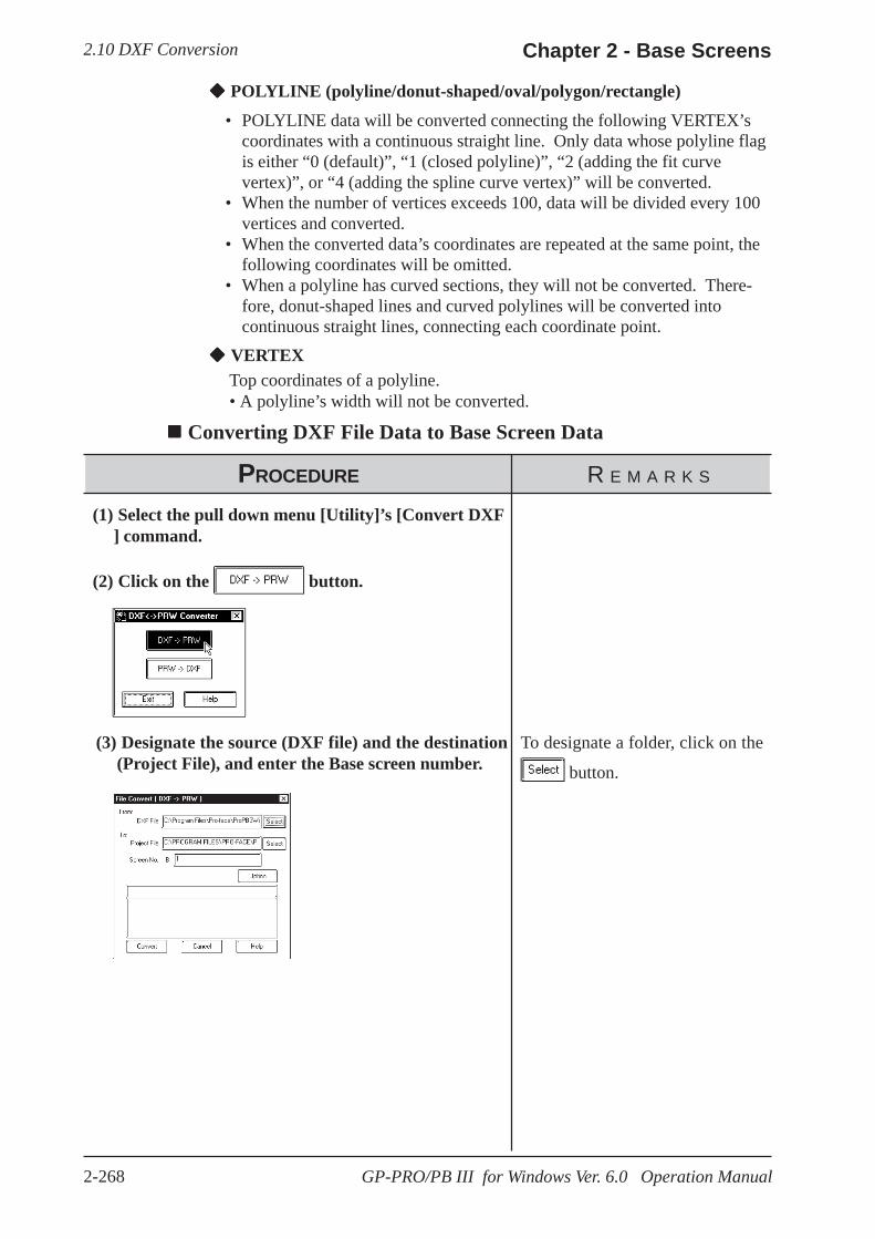
2.10 DXF Conversion Chapter 2 - Base Screens
2-268 GP-PRO/PB III for Windows Ver. 6.0 Operation Manual
POLYLINE (polyline/donut-shaped/oval/polygon/rectangle)• POLYLINE data will be converted connecting the following VERTEX’s
coordinates with a continuous straight line. Only data whose polyline flagis either “0 (default)”, “1 (closed polyline)”, “2 (adding the fit curvevertex)”, or “4 (adding the spline curve vertex)” will be converted.
• When the number of vertices exceeds 100, data will be divided every 100vertices and converted.
• When the converted data’s coordinates are repeated at the same point, thefollowing coordinates will be omitted.
• When a polyline has curved sections, they will not be converted. There-fore, donut-shaped lines and curved polylines will be converted intocontinuous straight lines, connecting each coordinate point.
VERTEXTop coordinates of a polyline.• A polyline’s width will not be converted.
Converting DXF File Data to Base Screen Data
PROCEDURE R E M A R K S
(1) Select the pull down menu [Utility]’s [Convert DXF] command.
(2) Click on the button.
(3) Designate the source (DXF file) and the destination(Project File), and enter the Base screen number.
To designate a folder, click on the
button.

2.10 DXF ConversionChapter 2 - Base Screens
2-269GP-PRO/PB III for Windows Ver. 6.0 Operation Manual
PROCEDURE R E M A R K S
(4) Click on the button and enter the conver-sion conditions.
(5) After all the attributes have been entered, click onthe button to registered the entered data.
(6) Click on the button to start conversion.
(8) Click on the button to quit.
(7) After the conversion is completed, click on the button. The [DXF<->PRW Converter] dia-
log box will reappear.
2.10.1 Option(DXF → PRW)
To convert another DXF file, DONOT cancel here; rather, start fromstep (3) again.
If the designated screen number al-ready exists, a prompt will appear,asking whether the new numbershould overwrite the old number.When the button is clickedon, the new number will overwritethe old one, and when the button is clicked on, the new num-ber will not overwrite the old one.
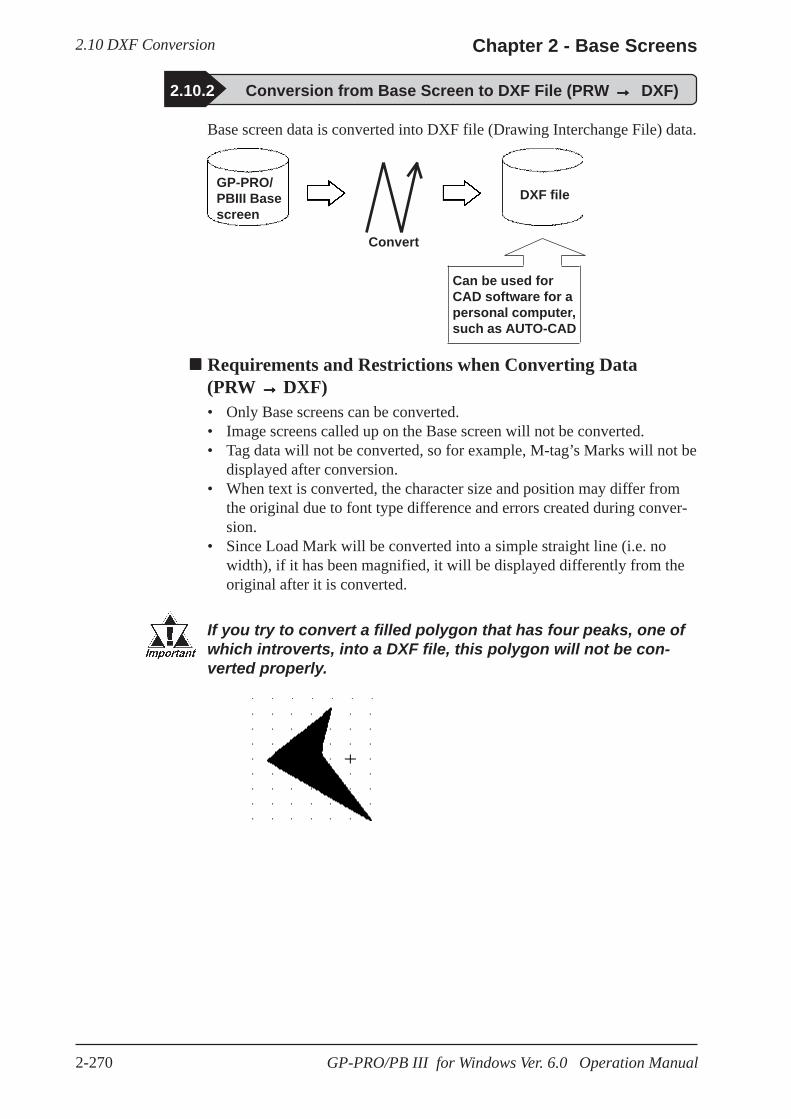
2.10 DXF Conversion Chapter 2 - Base Screens
2-270 GP-PRO/PB III for Windows Ver. 6.0 Operation Manual
2.10.2 Conversion from Base Screen to DXF File (PRW → → → → → DXF)
Base screen data is converted into DXF file (Drawing Interchange File) data.
DXF file
Convert
GP-PRO/PBIII Basescreen
Can be used forCAD software for apersonal computer,such as AUTO-CAD
Requirements and Restrictions when Converting Data (PRW →→→→→ DXF)
• Only Base screens can be converted.• Image screens called up on the Base screen will not be converted.• Tag data will not be converted, so for example, M-tag’s Marks will not be
displayed after conversion.• When text is converted, the character size and position may differ from
the original due to font type difference and errors created during conver-sion.
• Since Load Mark will be converted into a simple straight line (i.e. nowidth), if it has been magnified, it will be displayed differently from theoriginal after it is converted.
If you try to convert a filled polygon that has four peaks, one ofwhich introverts, into a DXF file, this polygon will not be con-verted properly.
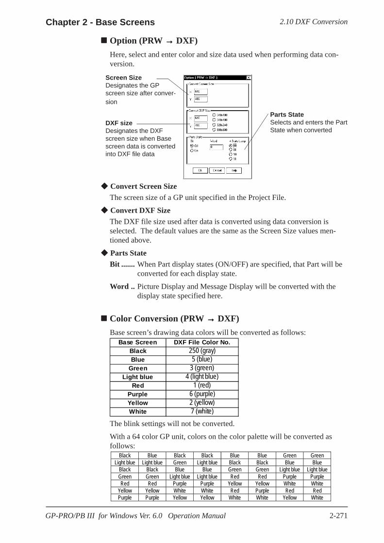
2.10 DXF ConversionChapter 2 - Base Screens
2-271GP-PRO/PB III for Windows Ver. 6.0 Operation Manual
Convert Screen SizeThe screen size of a GP unit specified in the Project File.
Convert DXF SizeThe DXF file size used after data is converted using data conversion isselected. The default values are the same as the Screen Size values men-tioned above.
Parts StateBit ....... When Part display states (ON/OFF) are specified, that Part will be
converted for each display state.
Word .. Picture Display and Message Display will be converted with thedisplay state specified here.
Color Conversion (PRW →→→→→ DXF)Base screen’s drawing data colors will be converted as follows:
The blink settings will not be converted.
With a 64 color GP unit, colors on the color palette will be converted asfollows:
Black Blue Black Black Blue Blue Green GreenLight blue Light blue Green Light blue Black Black Blue Blue
Black Black Blue Blue Green Green Light blue Light blueGreen Green Light blue Light blue Red Red Purple PurpleRed Red Purple Purple Yellow Yellow White White
Yellow Yellow White White Red Purple Red RedPurple Purple Yellow Yellow White White Yellow White
Parts StateSelects and enters the PartState when converted
Screen SizeDesignates the GPscreen size after conver-sion
DXF sizeDesignates the DXFscreen size when Basescreen data is convertedinto DXF file data
Option (PRW →→→→→ DXF)Here, select and enter color and size data used when performing data con-version.
Base Screen DXF File Color No.Black 250 (gray)Blue 5 (blue)
Green 3 (green)Light blue 4 (light blue)
Red 1 (red)Purple 6 (purple)Yellow 2 (yellow)White 7 (white)
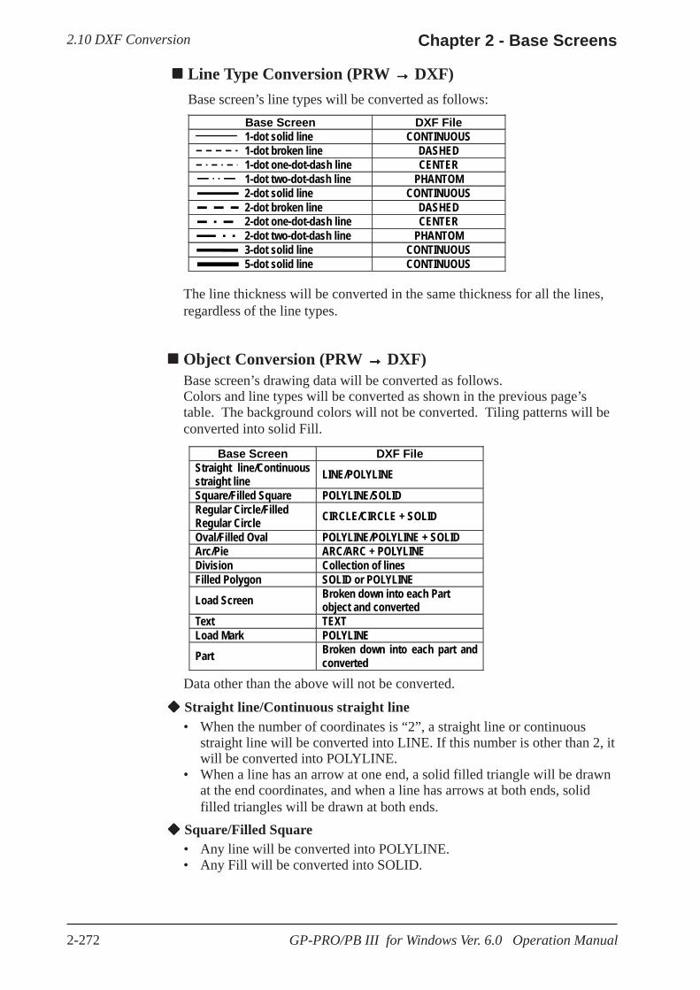
2.10 DXF Conversion Chapter 2 - Base Screens
2-272 GP-PRO/PB III for Windows Ver. 6.0 Operation Manual
Base Screen DXF File Straight line/Continuous straight line LINE/POLYLINE Square/Filled Square POLYLINE/SOLID Regular Circle/Filled Regular Circle CIRCLE/CIRCLE + SOLID Oval/Filled Oval POLYLINE/POLYLINE + SOLID Arc/Pie ARC/ARC + POLYLINE Division Collection of lines Filled Polygon SOLID or POLYLINE Load Screen Broken down into each Part
object and converted Text TEXT Load Mark POLYLINE Part Broken down into each part and
converted Data other than the above will not be converted.
Straight line/Continuous straight line• When the number of coordinates is “2”, a straight line or continuous
straight line will be converted into LINE. If this number is other than 2, itwill be converted into POLYLINE.
• When a line has an arrow at one end, a solid filled triangle will be drawnat the end coordinates, and when a line has arrows at both ends, solidfilled triangles will be drawn at both ends.
Square/Filled Square• Any line will be converted into POLYLINE.• Any Fill will be converted into SOLID.
Line Type Conversion (PRW →→→→→ DXF)Base screen’s line types will be converted as follows:
The line thickness will be converted in the same thickness for all the lines,regardless of the line types.
Object Conversion (PRW →→→→→ DXF)Base screen’s drawing data will be converted as follows.Colors and line types will be converted as shown in the previous page’stable. The background colors will not be converted. Tiling patterns will beconverted into solid Fill.
Base Screen DXF File1-dot solid line CONTINUOUS1-dot broken line DASHED1-dot one-dot-dash line CENTER1-dot two-dot-dash line PHANTOM2-dot solid line CONTINUOUS2-dot broken line DASHED2-dot one-dot-dash line CENTER2-dot two-dot-dash line PHANTOM3-dot solid line CONTINUOUS5-dot solid line CONTINUOUS

2.10 DXF ConversionChapter 2 - Base Screens
2-273GP-PRO/PB III for Windows Ver. 6.0 Operation Manual
Regular Circle/Filled Regular Circle• Filled regular circle’s border will be converted into CIRCLE and its
filling will be converted into SOLID.
Oval/Filled Oval• Any lines will be converted into POLYLINE.• Filled oval’s border will be converted into CIRCLE and its filling will be
converted into SOLID.
Arc/Pie• Pie’s straight line section will be converted into POLYLINE.
Divisions• When the divisions are marked on a straight axis, their coordinates will
be calculated based on their start and end coordinates, direction, and thenumber of divisions, and will be converted into LINE.
• When the divisions are marked on an arc axis, their coordinates will becalculated based on their start and end angles, external circle’s radius,internal circle’s radius, number of divisions, and will be converted intoLINE.
Filled Polygon• Fill will be converted into SOLID. However, if the number of vertices is
more than 5, Fill will not be converted and only its trace will be con-verted into POLYLINE (CONTINUOUS).
Load Screen• The screen will be retrieved from its attributes, and screen number and if
it exists, and each drawing data will be converted.• The called up screen’s data will be converted in the same layer as other
drawing data.• Only Base, Keypad, and Trend Graph screens will be converted.
TEXT• Characters written horizontally will be converted into BIGFONT. Those
written vertically will be converted into TATEGAKI (vertical type ofBIGFONT).
• 1/4-sized characters will be all converted into half-sized characters.• Half-sized (1/4-sized) characters written horizontally will be converted
with a relative scale of 1/2 in the X direction, and other size characterswill be converted with a relative scale of 1.
• Both half and full-sized characters written vertically will be convertedwith a scale of 1 for their height and width. Therefore, the half-sizedcharacters will become the same size as the full-sized characters.
• Character types of “Bold” and “Raised” will not be converted.• Due to font difference and other elements, text will be different from the
Base screen, after conversion.
Load Mark• The Mark screen will be retrieved from the screen number, if that screen
exists, the dot pattern will be converted into POLYLINE (CONTINUOUS).
Part• Each Part’s data will be converted into drawing data.
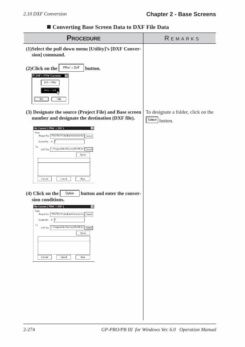
2.10 DXF Conversion Chapter 2 - Base Screens
2-274 GP-PRO/PB III for Windows Ver. 6.0 Operation Manual
Converting Base Screen Data to DXF File Data
PROCEDURE R E M A R K S
To designate a folder, click on the
button.
(1)Select the pull down menu [Utility]’s [DXF Conver-sion] command.
(2)Click on the button.
(3) Designate the source (Project File) and Base screennumber and designate the destination (DXF file).
(4) Click on the button and enter the conver-sion conditions.
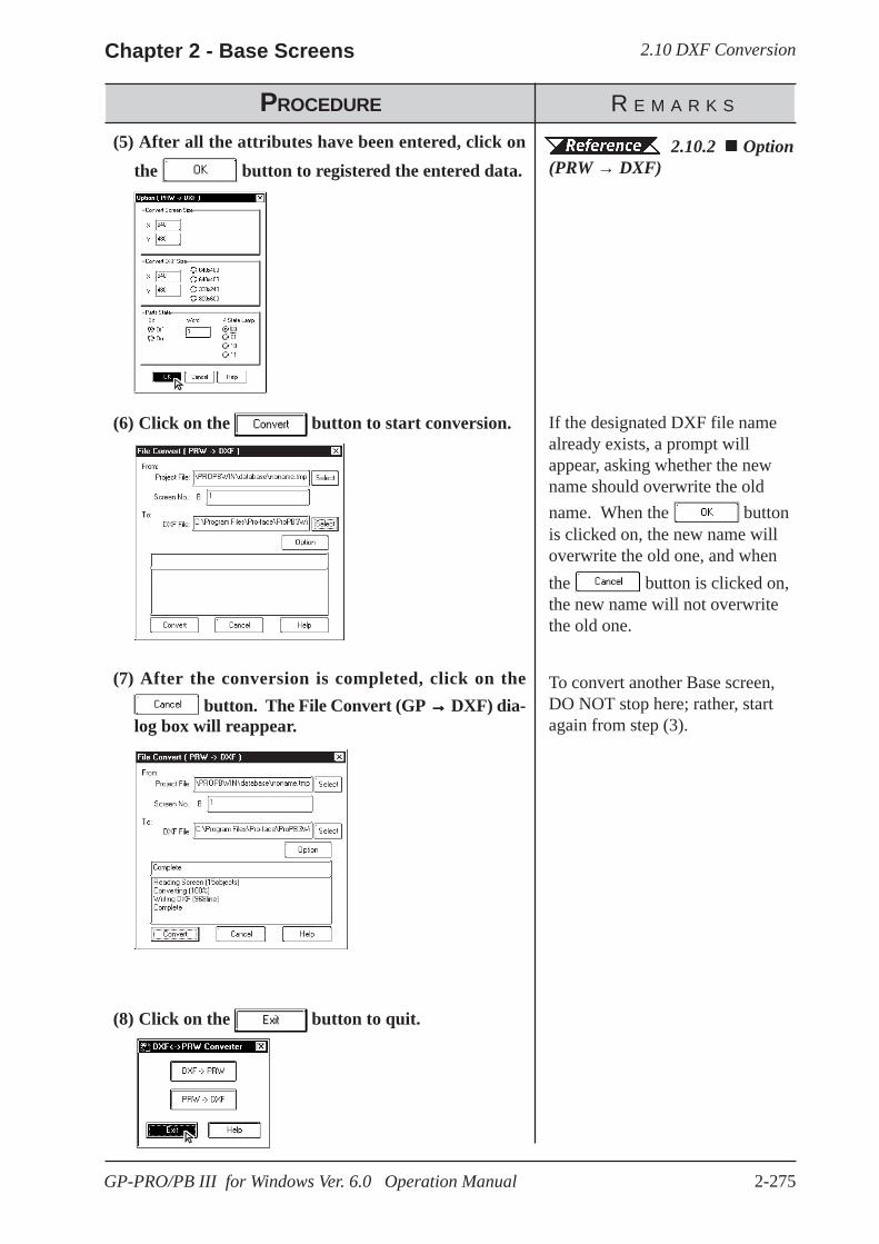
2.10 DXF ConversionChapter 2 - Base Screens
2-275GP-PRO/PB III for Windows Ver. 6.0 Operation Manual
PROCEDURE R E M A R K S
(5) After all the attributes have been entered, click onthe button to registered the entered data.
(6) Click on the button to start conversion.
(7) After the conversion is completed, click on the button. The File Convert (GP →→→→→ DXF) dia-
log box will reappear.
(8) Click on the button to quit.
If the designated DXF file namealready exists, a prompt willappear, asking whether the newname should overwrite the oldname. When the buttonis clicked on, the new name willoverwrite the old one, and whenthe button is clicked on,the new name will not overwritethe old one.
2.10.2 Option(PRW → DXF)
To convert another Base screen,DO NOT stop here; rather, startagain from step (3).

2.10 DXF Conversion Chapter 2 - Base Screens
2-276 GP-PRO/PB III for Windows Ver. 6.0 Operation Manual
Memo
3-1GP-PRO/PB III for Windows Ver. 6.0 Operation Manual
P-PRO/PB III for Windows provides various screens for specificpurposes (for example: for creating marks and messages), in
addition to the Base screens which are the fundamental screen used for alldrawing modes. Other screens can then be loaded onto Base screens aslibraries. Also, you can load them directly onto the GP series panel usingspecified tags.
This chapter describes the procedure for creating these screens and theirapplications.
3 DRAWING APPLICATIONS - CREATING and USING SCREENS
G
3.1 ............................. Creating a Mark: the Mark Screen
3.2 ... Creating a Trend Graph: the Trend Graph Screen
3.3 ...................... Creating a Keypad: the Keypad Screen
3.4 .......................................... Text Input: the Text Screen
3.5 ......................... Creating an Image: the Image Screen
3.6 ......................................... Video Data Display (V Screen)
3.7 ............................. Window Display: Window (U) Screenand Base (B) Screen
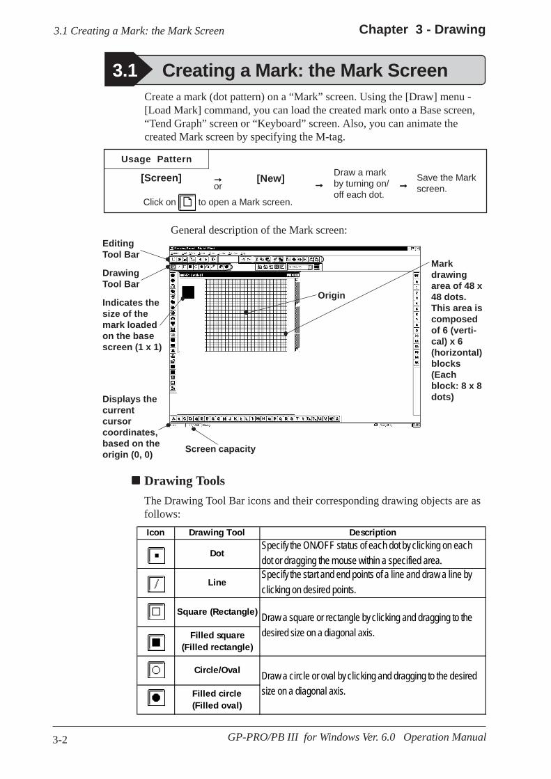
3-2
Chapter 3 - Drawing
GP-PRO/PB III for Windows Ver. 6.0 Operation Manual
3.1 Creating a Mark: the Mark Screen
3.1 Creating a Mark: the Mark Screen
Usage Pattern
EditingTool Bar
Save the Markscreen.
Draw a markby turning on/off each dot.
[New][Screen] →→→→→ →→→→→ →→→→→
Markdrawingarea of 48 x48 dots.This area iscomposedof 6 (verti-cal) x 6(horizontal)blocks(Eachblock: 8 x 8dots)
Screen capacity
Displays thecurrentcursorcoordinates,based on theorigin (0, 0)
Indicates thesize of themark loadedon the basescreen (1 x 1)
DrawingTool Bar
General description of the Mark screen:
Create a mark (dot pattern) on a “Mark” screen. Using the [Draw] menu -[Load Mark] command, you can load the created mark onto a Base screen,“Tend Graph” screen or “Keyboard” screen. Also, you can animate thecreated Mark screen by specifying the M-tag.
or
Click on to open a Mark screen.
Drawing ToolsThe Drawing Tool Bar icons and their corresponding drawing objects are asfollows:
Origin
Icon Drawing Tool Description
DotSpecify the ON/OFF status of each dot by clicking on eachdot or dragging the mouse within a specified area.
LineSpecify the start and end points of a line and draw a line byclicking on desired points.
Square (Rectangle)
Filled square(Filled rectangle)
Circle/Oval
Filled circle(Filled oval)
Draw a square or rectangle by clicking and dragging to thedesired size on a diagonal axis.
Draw a circle or oval by clicking and dragging to the desiredsize on a diagonal axis.

3-3
Chapter 3 - Drawing
GP-PRO/PB III for Windows Ver. 6.0 Operation Manual
3.1 Creating a Mark: the Mark Screen
Editing ToolsThe Editing Tool Bar icons and their corresponding functions are as follows:
Icon Editing Tool Description
CutUsed to delete an entire Mark screen and store it in theclipboard*1. Using the [Paste] command, you can then pastethe Mark screen onto another screen.
CopyUsed to copy the data of the selected Mark screen in theclipboard.
PasteUsed to paste the data temporarily stored in the clipboardonto a desired place.
Duplicate Used to duplicate a Mark screen’s specified area.
Delete Used to delete a mark.
UndoUsed to cancel the command executed immediately before,and return to the previous condition. (Undo)
RedoUsed to redo the command canceled with the [Undo]command. (Redo)
Mirror XUsed to move the dot pattern symmetrically relative to thevertical axis. The symmetry axis is the vertical line that dividesthe screen into two equal sections.
Mirror YUsed to move the dot pattern symmetrically relative to thehorizontal axis. The symmetry axis is the horizontal line thatdivides the screen into two equal sections.
Turncounterclockwise Used to turn the mark counterclockwise by 90°.
Turn clockwise Used to turn the mark clockwise 90°.
Reverse Used to reverse the white/black area of a mark.
Transparent/Background color
If no dots are turned ON in a block (8 x 8 dots), this blockbecomes transparent.
Icon Drawing Tool Description
FillFill in an area with a desired color by clicking in the area(enclosed within lines and shapes).
Text Enter the text to be displayed in the mark drawing area.
Call Up MarkLibrary Select a Mark from the Mark Library
Register MarkLibrary Register a created Mark as a Mark Library.
*1 When the [Copy] or [Cut] command is used, the copied or cut data is temporarilystored in the clipboard.When you use the [Paste] command, the data stored in the clipboard are pasted tothe selected position.

3-4
Chapter 3 - Drawing
GP-PRO/PB III for Windows Ver. 6.0 Operation Manual
3.1 Creating a Mark: the Mark Screen
When drawing a mark you can use GP-PRO/PBIII for Windows’ standarddrawing functions. Here, the procedures for using each function are described.
Drawing with DotsYou can draw a mark by turning ON/OFF each dot. When you click the leftmouse button in the mark drawing area, each dot turns ON (white). Whenyou click the right mouse button in the mark drawing area, each dot turnsOFF (black).A mark is created with dots, and displayed in a block (8 x 8 dots). If at leastone dot is turned ON in a block, the whole block is displayed when theMark screen is loaded onto a Base screen. In this status, the ON dots aredisplayed in the current display color (Fg), and the OFF dots are displayed inthe background color (Bg).
3.1.1 Drawing a Mark
This dot is ON.
Mark Drawing Area StructureThe mark drawing area has the following structure. When you edit a mark,you can use this for your reference.
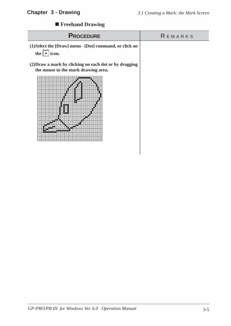
3-5
Chapter 3 - Drawing
GP-PRO/PB III for Windows Ver. 6.0 Operation Manual
3.1 Creating a Mark: the Mark Screen
Freehand Drawing
PROCEDURE R E M A R K S
(2)Draw a mark by clicking on each dot or by draggingthe mouse in the mark drawing area.
(1)Select the [Draw] menu - [Dot] command, or click onthe icon.
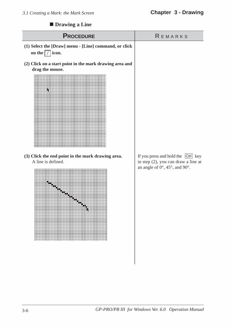
3-6
Chapter 3 - Drawing
GP-PRO/PB III for Windows Ver. 6.0 Operation Manual
3.1 Creating a Mark: the Mark Screen
Drawing a Line
PROCEDURE R E M A R K S
If you press and hold the keyin step (2), you can draw a line atan angle of 0°, 45°, and 90°.
(3) Click the end point in the mark drawing area. A line is defined.
(2) Click on a start point in the mark drawing area and drag the mouse.
(1) Select the [Draw] menu - [Line] command, or click on the icon.
Ctrl
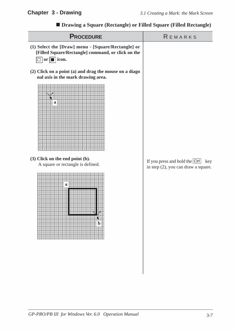
3-7
Chapter 3 - Drawing
GP-PRO/PB III for Windows Ver. 6.0 Operation Manual
3.1 Creating a Mark: the Mark Screen
Drawing a Square (Rectangle) or Filled Square (Filled Rectangle)
PROCEDURE R E M A R K S
If you press and hold the keyin step (2), you can draw a square.
(3) Click on the end point (b). A square or rectangle is defined.
(2) Click on a point (a) and drag the mouse on a diago nal axis in the mark drawing area.
(1) Select the [Draw] menu - [Square/Rectangle] or[Filled Square/Rectangle] command, or click on the
or icon.
a
a
b
Ctrl

3-8
Chapter 3 - Drawing
GP-PRO/PB III for Windows Ver. 6.0 Operation Manual
3.1 Creating a Mark: the Mark Screen
Drawing Circle (Oval) or Filled Circle (Filled Oval)
PROCEDURE R E M A R K S
If you press and hold the key instep (2), you can draw a circle.
(3) Click on the end point (b). A circle or oval is defined.
(2) Click on a point (a) and drag the mouse on a diago nal axis in the mark drawing area.
(1)Select the [Draw] menu - [Circle/Oval] or [FilledCircle/Filled Oval] command, or click on the or
icon.
a
b
a
Ctrl
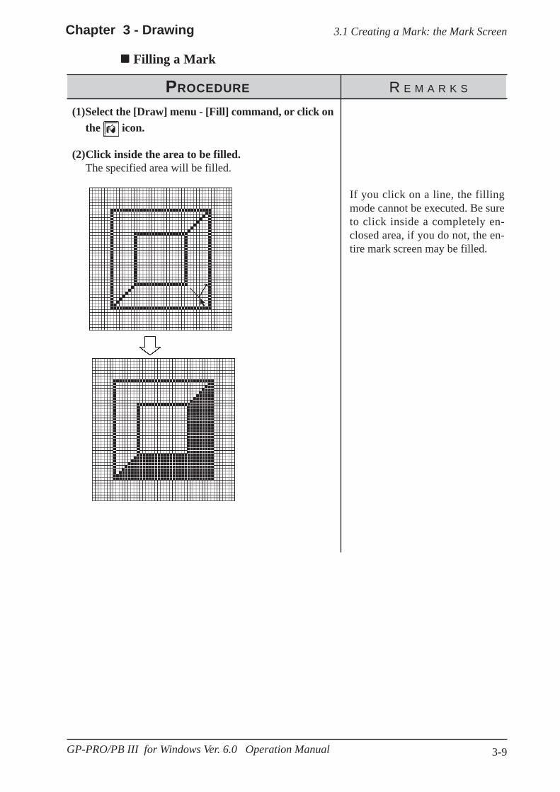
3-9
3.1 Creating a Mark: the Mark ScreenChapter 3 - Drawing
GP-PRO/PB III for Windows Ver. 6.0 Operation Manual
PROCEDURE R E M A R K S
Filling a Mark
(1)Select the [Draw] menu - [Fill] command, or click onthe icon.
(2)Click inside the area to be filled.The specified area will be filled.
If you click on a line, the fillingmode cannot be executed. Be sureto click inside a completely en-closed area, if you do not, the en-tire mark screen may be filled.

3-10
Chapter 3 - Drawing3.1 Creating a Mark: the Mark Screen
GP-PRO/PB III for Windows Ver. 6.0 Operation Manual
PROCEDURE R E M A R K S
Entering TextThe “Text” mode allows you to enter text on a Mark screen.
(1)Select the [Draw] menu - [Text] command, or clickon the icon.
(2)Enter character(s) and select either 8 x 16 dot font orWindows font.
(3)To use the Windows font, click on the and
click on the button.
Select Font
(4)Click on the button.An outline corresponding to the entered character(s) willappear.

3-11
3.1 Creating a Mark: the Mark ScreenChapter 3 - Drawing
GP-PRO/PB III for Windows Ver. 6.0 Operation Manual
PROCEDURE R E M A R K S
(5)Move the box to the desired position where the char-acter pattern will be displayed.The character pattern is displayed in the position whereyou click. A Mark can be created using this pattern.
If you move the character patternto a position where another char-acter pattern has already been cre-ated, the new pattern will overwritethe existing pattern, and the exist-ing pattern will be deleted.
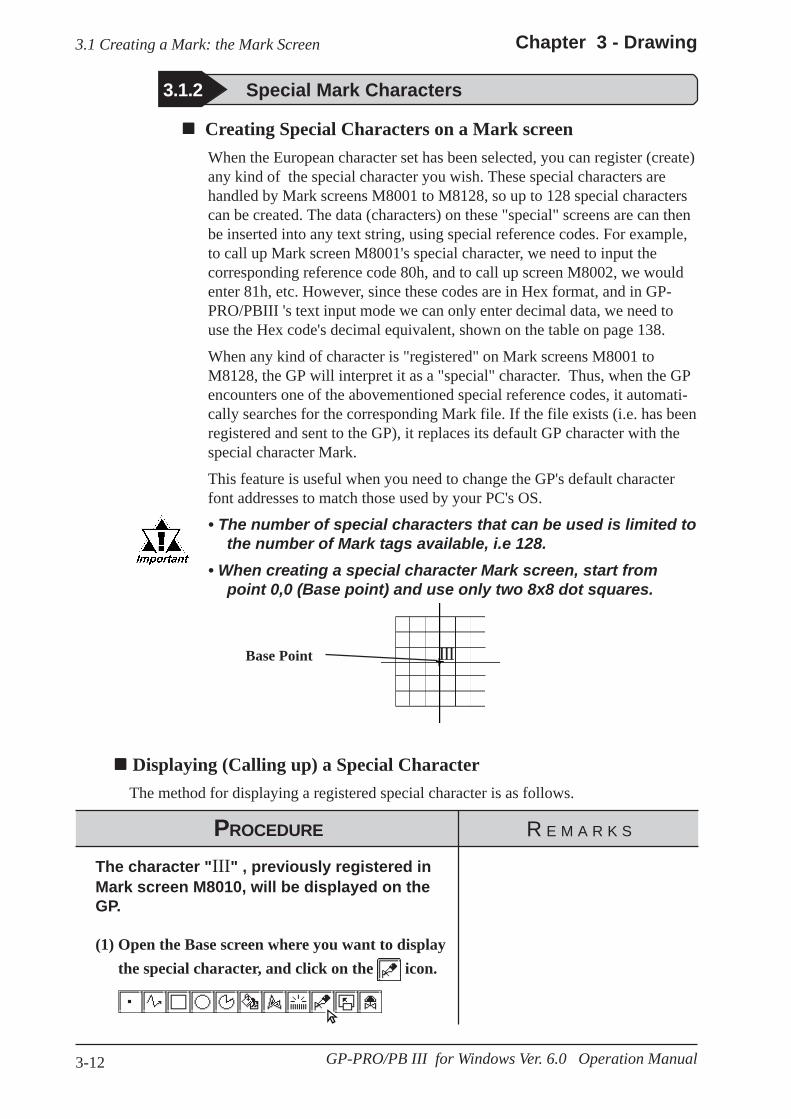
3-12
Chapter 3 - Drawing3.1 Creating a Mark: the Mark Screen
GP-PRO/PB III for Windows Ver. 6.0 Operation Manual
Creating Special Characters on a Mark screenWhen the European character set has been selected, you can register (create)any kind of the special character you wish. These special characters arehandled by Mark screens M8001 to M8128, so up to 128 special characterscan be created. The data (characters) on these "special" screens are can thenbe inserted into any text string, using special reference codes. For example,to call up Mark screen M8001's special character, we need to input thecorresponding reference code 80h, and to call up screen M8002, we wouldenter 81h, etc. However, since these codes are in Hex format, and in GP-PRO/PBIII 's text input mode we can only enter decimal data, we need touse the Hex code's decimal equivalent, shown on the table on page 138.
When any kind of character is "registered" on Mark screens M8001 toM8128, the GP will interpret it as a "special" character. Thus, when the GPencounters one of the abovementioned special reference codes, it automati-cally searches for the corresponding Mark file. If the file exists (i.e. has beenregistered and sent to the GP), it replaces its default GP character with thespecial character Mark.
This feature is useful when you need to change the GP's default characterfont addresses to match those used by your PC's OS.
• The number of special characters that can be used is limited tothe number of Mark tags available, i.e 128.
• When creating a special character Mark screen, start frompoint 0,0 (Base point) and use only two 8x8 dot squares.
Displaying (Calling up) a Special Character The method for displaying a registered special character is as follows.
PROCEDURE R E M A R K S
The character "III" , previously registered inMark screen M8010, will be displayed on theGP.
(1) Open the Base screen where you want to displaythe special character, and click on the icon.
3.1.2 Special Mark Characters
Base Point III
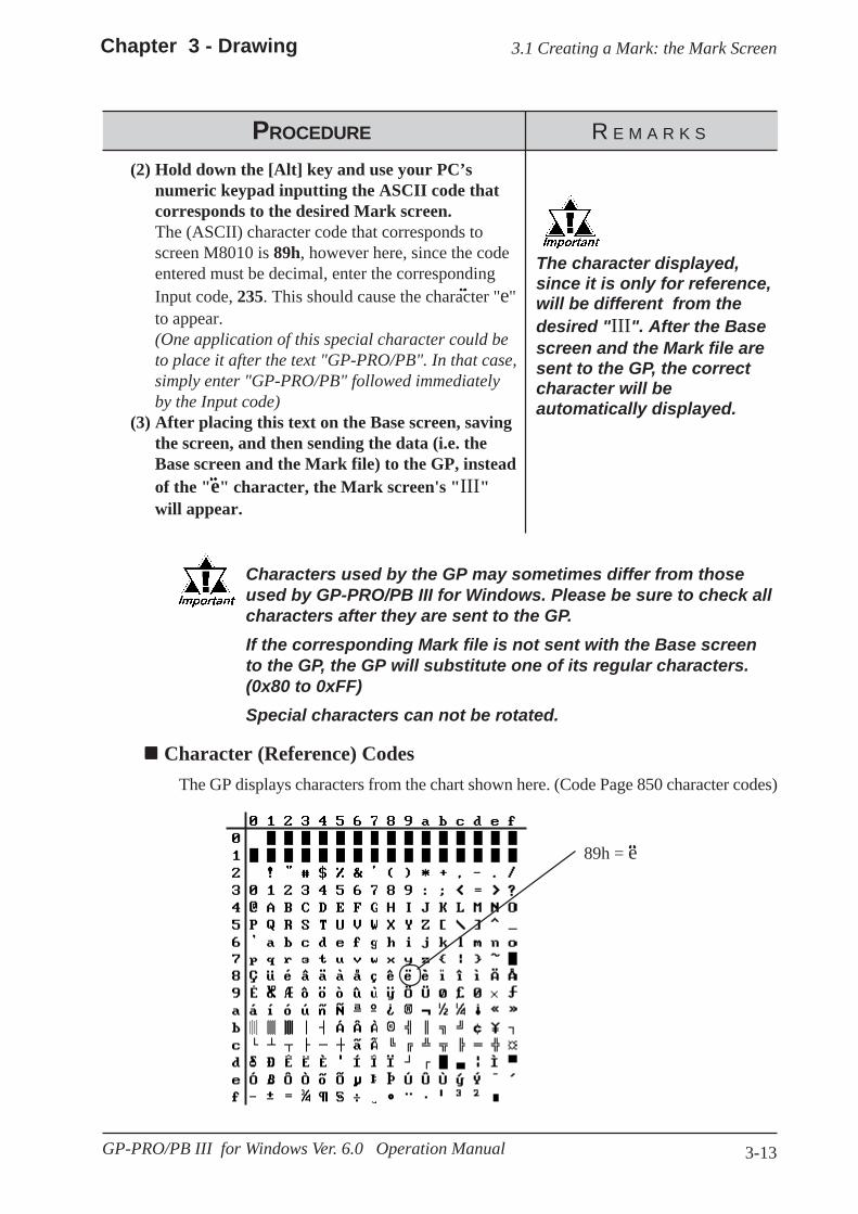
3-13
3.1 Creating a Mark: the Mark ScreenChapter 3 - Drawing
GP-PRO/PB III for Windows Ver. 6.0 Operation Manual
PROCEDURE R E M A R K S
Characters used by the GP may sometimes differ from thoseused by GP-PRO/PB III for Windows. Please be sure to check allcharacters after they are sent to the GP.If the corresponding Mark file is not sent with the Base screento the GP, the GP will substitute one of its regular characters.(0x80 to 0xFF)Special characters can not be rotated.
The character displayed,since it is only for reference,will be different from thedesired "III". After the Basescreen and the Mark file aresent to the GP, the correctcharacter will beautomatically displayed.
89h = e
(2) Hold down the [Alt] key and use your PC’snumeric keypad inputting the ASCII code thatcorresponds to the desired Mark screen.The (ASCII) character code that corresponds toscreen M8010 is 89h, however here, since the codeentered must be decimal, enter the correspondingInput code, 235. This should cause the character "e"to appear.(One application of this special character could beto place it after the text "GP-PRO/PB". In that case,simply enter "GP-PRO/PB" followed immediatelyby the Input code)
(3) After placing this text on the Base screen, savingthe screen, and then sending the data (i.e. theBase screen and the Mark file) to the GP, insteadof the "e" character, the Mark screen's "III"will appear.
Character (Reference) Codes The GP displays characters from the chart shown here. (Code Page 850 character codes)
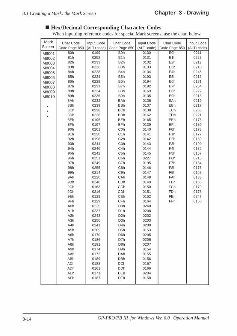
3-14
Chapter 3 - Drawing3.1 Creating a Mark: the Mark Screen
GP-PRO/PB III for Windows Ver. 6.0 Operation Manual
Hex/Decimal Corresponding Character Codes When inputting reference codes for special Mark screens, use the chart below.
Mark Screen
M8001M8002M8003M8004M8005M8006M8007M8008M8009M8010
• • •
Char Code Input Code Char Code Input Code Char Code Input CodeCode Page 850 (ALT+code) Code Page 850 (ALT+code) Code Page 850 (ALT+code)
80h 0199 B0h 0130 E0h 021181h 0252 B1h 0131 E1h 022382h 0233 B2h 0132 E2h 021283h 0226 B3h 0133 E3h 021084h 0228 B4h 0134 E4h 024585h 0224 B5h 0193 E5h 021386h 0229 B6h 0194 E6h 018187h 0231 B7h 0192 E7h 025488h 0234 B8h 0169 E8h 022289h 0235 B9h 0135 E9h 02188Ah 0232 BAh 0136 EAh 02198Bh 0239 BBh 0137 EBh 02178Ch 0238 BCh 0138 ECh 02538Dh 0236 BDh 0162 EDh 02218Eh 0196 BEh 0165 EEh 01758Fh 0197 BFh 0139 EFh 018090h 0201 C0h 0140 F0h 017391h 0230 C1h 0141 F1h 017792h 0198 C2h 0142 F2h 015993h 0244 C3h 0143 F3h 019094h 0246 C4h 0144 F4h 018295h 0242 C5h 0145 F5h 016796h 0251 C6h 0227 F6h 021597h 0249 C7h 0195 F7h 018498h 0255 C8h 0146 F8h 017699h 0214 C9h 0147 F9h 01689Ah 0220 CAh 0148 FAh 01839Bh 0248 CBh 0149 FBh 01859Ch 0163 CCh 0150 FCh 01799Dh 0216 CDh 0151 FDh 01789Eh 0128 CEh 0152 FEh 02479Fh 0129 CFh 0164 FFh 0160A0h 0225 D0h 0240A1h 0237 D1h 0208A2h 0243 D2h 0202A3h 0250 D3h 0203A4h 0241 D4h 0200A5h 0209 D5h 0153A6h 0170 D6h 0205A7h 0186 D7h 0206A8h 0191 D8h 0207A9h 0174 D9h 0154AAh 0172 DAh 0155ABh 0189 DBh 0156ACh 0188 DCh 0157ADh 0161 DDh 0166AEh 0171 DEh 0204AFh 0187 DFh 0158
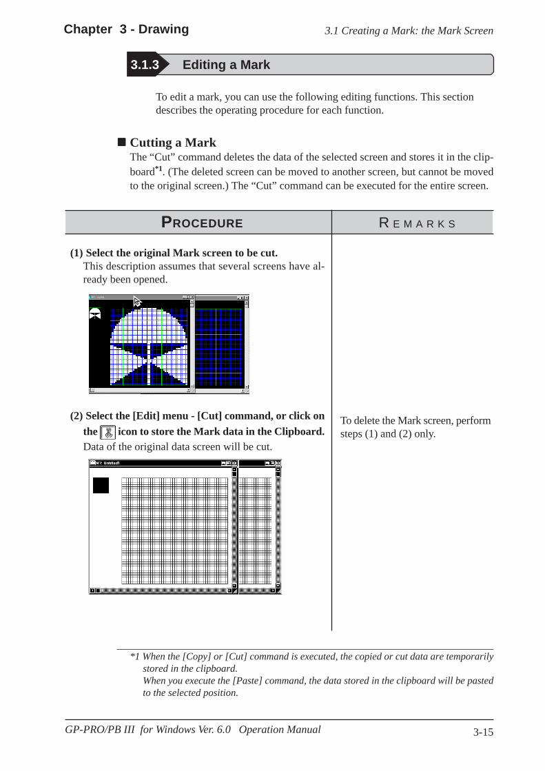
3-15
3.1 Creating a Mark: the Mark ScreenChapter 3 - Drawing
GP-PRO/PB III for Windows Ver. 6.0 Operation Manual
3.1.3 Editing a Mark
PROCEDURE R E M A R K S
To edit a mark, you can use the following editing functions. This sectiondescribes the operating procedure for each function.
Cutting a MarkThe “Cut” command deletes the data of the selected screen and stores it in the clip-board*1. (The deleted screen can be moved to another screen, but cannot be movedto the original screen.) The “Cut” command can be executed for the entire screen.
(1) Select the original Mark screen to be cut.This description assumes that several screens have al-ready been opened.
(2) Select the [Edit] menu - [Cut] command, or click onthe icon to store the Mark data in the Clipboard.Data of the original data screen will be cut.
To delete the Mark screen, performsteps (1) and (2) only.
*1 When the [Copy] or [Cut] command is executed, the copied or cut data are temporarilystored in the clipboard.When you execute the [Paste] command, the data stored in the clipboard will be pastedto the selected position.

3-16
Chapter 3 - Drawing3.1 Creating a Mark: the Mark Screen
GP-PRO/PB III for Windows Ver. 6.0 Operation Manual
PROCEDURE R E M A R K S
(3) Select the mark screen (destination) to which the se-lected Mark screen will be pasted.
(4) Select the [Edit] menu - [Paste] command, or clickon the icon.Data of the Mark screen will be pasted.

3-17
3.1 Creating a Mark: the Mark ScreenChapter 3 - Drawing
GP-PRO/PB III for Windows Ver. 6.0 Operation Manual
PROCEDURE R E M A R K S
Copying a ScreenThe selected screen data are copied in the clipboard. Unlike the [Cut] command, theoriginal screen data will not be deleted.
To copy a mark into the original screen, use the [Duplicate] command.
(1) Select the original Mark screen to be copied.This description assumes that several screens have al-ready been opened.
(2) Select the [Edit] menu - [Copy] command, or click on
the icon to store the mark in the Clipboard.
(3) Select the mark screen (destination) to which the se-lected Mark screen will be copied.
(4) Select the [Edit] menu - [Paste] command, or clickon the icon.Data will be copied from the original Mark screen andpasted onto the destination Mark screen.
Note:
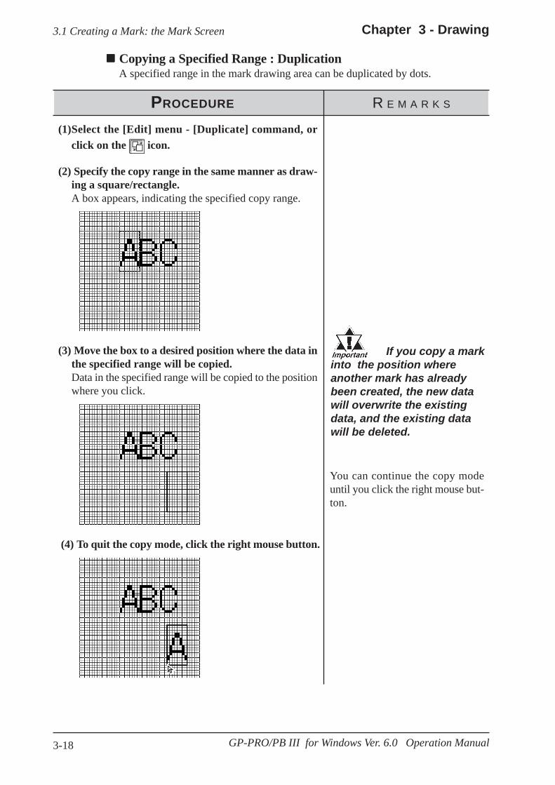
3-18
Chapter 3 - Drawing3.1 Creating a Mark: the Mark Screen
GP-PRO/PB III for Windows Ver. 6.0 Operation Manual
PROCEDURE R E M A R K S
Copying a Specified Range : DuplicationA specified range in the mark drawing area can be duplicated by dots.
(1)Select the [Edit] menu - [Duplicate] command, orclick on the icon.
(2) Specify the copy range in the same manner as draw-ing a square/rectangle.A box appears, indicating the specified copy range.
(3) Move the box to a desired position where the data inthe specified range will be copied.Data in the specified range will be copied to the positionwhere you click.
If you copy a markinto the position whereanother mark has alreadybeen created, the new datawill overwrite the existingdata, and the existing datawill be deleted.
You can continue the copy modeuntil you click the right mouse but-ton.
(4) To quit the copy mode, click the right mouse button.
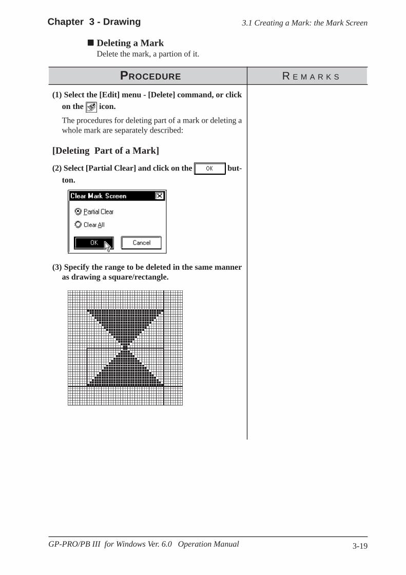
3-19
3.1 Creating a Mark: the Mark ScreenChapter 3 - Drawing
GP-PRO/PB III for Windows Ver. 6.0 Operation Manual
(3) Specify the range to be deleted in the same manneras drawing a square/rectangle.
PROCEDURE R E M A R K S
Deleting a MarkDelete the mark, a partion of it.
(1) Select the [Edit] menu - [Delete] command, or clickon the icon.
The procedures for deleting part of a mark or deleting awhole mark are separately described:
[Deleting Part of a Mark]
(2) Select [Partial Clear] and click on the but-ton.

3-20
Chapter 3 - Drawing3.1 Creating a Mark: the Mark Screen
GP-PRO/PB III for Windows Ver. 6.0 Operation Manual
PROCEDURE R E M A R K S
(4) Click in the range to be deleted.The specified range will be deleted.
[Deleting the Entire Mark](2) Select [Clear All].
(3) Click on the button to delete the entiremark.The entire mark will be deleted.
PROCEDURE R E M A R K S
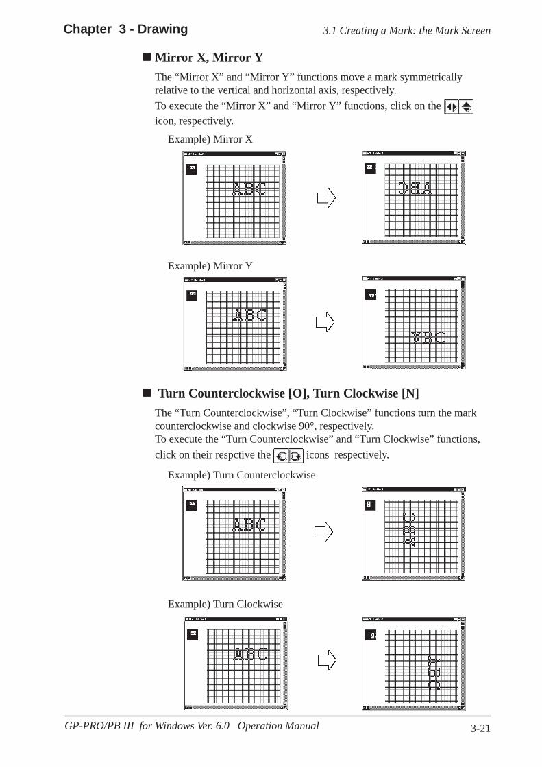
3-21
3.1 Creating a Mark: the Mark ScreenChapter 3 - Drawing
GP-PRO/PB III for Windows Ver. 6.0 Operation Manual
Example) Turn Clockwise
Mirror X, Mirror YThe “Mirror X” and “Mirror Y” functions move a mark symmetricallyrelative to the vertical and horizontal axis, respectively.To execute the “Mirror X” and “Mirror Y” functions, click on the icon, respectively.
Example) Mirror X
Turn Counterclockwise [O], Turn Clockwise [N]The “Turn Counterclockwise”, “Turn Clockwise” functions turn the markcounterclockwise and clockwise 90°, respectively.To execute the “Turn Counterclockwise” and “Turn Clockwise” functions,click on their respctive the icons respectively.
Example) Turn Counterclockwise
Example) Mirror Y

3-22
Chapter 3 - Drawing3.1 Creating a Mark: the Mark Screen
GP-PRO/PB III for Windows Ver. 6.0 Operation Manual
ReverseThis function reverses the white and black areas. In the reverse display mode, all ONdots are turned OFF, and all OFF-dots are turned ON.To execute this function, click on the icon.
Example)

3-23
Chapter 3 - Drawing 3.1 Creating a Mark: the Mark Screen
GP-PRO/PB III for Windows Ver. 6.0 Operation Manual
Transparent/Background ColorIf no dots are turned ON in a block, this block becomes transparent. When thisfunction is set to “Background color”, a block without any ON dots is displayed inthe background color (Bg).
PROCEDURE R E M A R K S
The block with no ONdots is displayed in thebackground color.
These blockscontain noON-dots.
If at least one dot is ON in ablock, this block is dis-played in the backgroundcolor.The block with no ON dotsbecomes transparent, andyou can see the objects onthe base screen.
When this function is set to “Background color”:
Display When Called Up to a B (Base) ScreenWhen this function is set to “Transparent”:
(3) Click the right mouse button to register the abovesetting.
(2) Click in the block to be displayed in the backgroundcolor.The border line of the specified block is changed. Everytime you click in the block, the color setting is switched.
(1) Select the [Edit] menu - [Background Color] com-mand, or click on the icon.

3-24
Chapter 3 - Drawing3.1 Creating a Mark: the Mark Screen
GP-PRO/PB III for Windows Ver. 6.0 Operation Manual
Canceling a Command: UndoThis function is used to cancel a command and return to the previous conditionimmediately before the command was made.[Undo] is only effective for the command immediately before it.
PROCEDURE R E M A R K S
After deleting a circle unintentionally:(1)Select the icon.
The deleted circle is restored, and the screen returns tothe previous condition.
Redo CommandThis function is used to redo the command canceled with the [Undo] command.The [Redo] command is effective only for the command immediately before it.
PROCEDURE R E M A R K S
After deleting a circle, you have selected the icon toreturn to the previous condition, but you realize that ac-tually, the circle must be deleted:
(1)Select the icon.The screen returns to the condition where the circle hasbeen deleted and harmony is restored.

3-25
Chapter 3 - Drawing 3.1 Creating a Mark: the Mark Screen
GP-PRO/PB III for Windows Ver. 6.0 Operation Manual
3.1.4 Registering and Placing a Mark Library Item
You can register a mark created in the mark drawing area and the registeredmark can be loaded whenever required. The Mark Library Item (mark list)can be saved as a mark library file (MRK file). The GP-PRO/PB III enablesyou to manage MRK files independent of project (PRW) files . This functionallows you to use the same mark for several projects, since you can select adesired mark while checking the image displayed in the browser.Registration, placement, and other editing operations of Mark Library areperformed in the same manners as those of the standard Libraries.
2.5 Libraries
GP-PRO/PB III for Windows has pre-made MRK files in correspondencewith the ISO7000 Series marks and symbols.
Note:
Parts List Manual
Drawing symbolnumber MRK file name Title
0001-0200 IS07-1 0001-02000201-0400 IS07-2 0201-04000401-0600 IS07-3 0401-06000601-0800 IS07-4 0601-08000801-1000 IS07-5 0801-10001001-1140 IS07-6 1001-1140

3-26
Chapter 3 -Drawing
GP-PRO/PB III for Windows Ver. 6.0 Operation Manual
3.2 Creating a Trend Graph: the Trend Graph Screen
The effective setting range of the“pitch”, “Number of display data”and “Scroll” parameters for the [SetScreen] command varies depend-ing on the setting values. Be sureto set these parameters.
3.2 Creating a Trend Graph: the Trend Graph Screen
Save theTrendGraphscreen.
Usage Pattern
Open a Trend Graph screen byselecting the [Screen] menu[New] command, or by clickingon the icon.
Draw the graph axis andscales by using the drawingtool.
Set the screen by selectingthe [Tag] menu - [SetScreen] command, or byclicking on the icon.
Set the channel by selectingthe [Tag] menu - [SetChannel] command, or byclicking on the icon.
→→→→→
→→→→→ →→→→→ →→→→→
PROCEDURE R E M A R K S
Tag ReferenceManual, 2.31 Trend Graph Dis-play/, Setting Origin, 100% ofheight and pitch.
1.1.3 Opening/Closing/Saving a Screen
(4) Set the parameters for the [Screen Settings] screen.
(3) Select the [Tag] menu - [Set Screen] command, orclick on the icon.
(2) Select a Trend Graph screen.
(1) Select the [Screen] menu - [New] command, or clickon the icon.
You can create a trend graph with the Trend Graph screen. Using the [Draw]menu - [Load Screen] command, you can load a trend graph from the TrendGraph screen onto a Base screen. The specified loading point is placed at thecenter of the screen. Up to eight Trend Graph screens can be loaded ontoone Base screen.
[Draw] [Load Screen]or
Click on to call up a TrendGraph.
The selected TrendGraph screen will bedisplayed on theBase screen.
Open a Basescreen[Draw]
→→→→→→→→→→→→→→→
Creating a Trend Graph

3-27
Chapter 3 - Drawing 3.2 Creating a Trend Graph: the Trend Graph Screen
GP-PRO/PB III for Windows Ver. 6.0 Operation Manual
PROCEDURE R E M A R K S
2.2 Drawing 2.4 Object Edit-
ing
Draw the graph axis and scales out-side the graph display area so thatthey will not overlap with the graphdisplay area. If the graph axis andscales are placed in the graph dis-play area, they cannot be displayedwhen the Trend Graph screen isoperated on the GP series’ panel.
You can execute the same opera-tion by selecting the [Tag] menu -[Set Channel] command, instead ofclicking on the icon.
2.4 Object Edit-ing
(7) Select the [Tag] menu - [Set Channel] command, orclick on the icon.
(6) Draw the graph axis and scales.
(5) After setting all items, click on the but-ton to register the above settings.The graph display area is displayed with handles in thedrawing area. Change the size and position of the graphdisplay area, as required.
(8) Click on the button in the [Channel Set-tings] dialog box.

3-28
Chapter 3 -Drawing
GP-PRO/PB III for Windows Ver. 6.0 Operation Manual
3.2 Creating a Trend Graph: the Trend Graph Screen
Each function of the trend graphdisplay is called “Channel” insteadof “Tag”.
To specify a channel name, you canuse up to five characters (includ-ing alphanumerics and symbols.)
To specify a channel’s description,you can use up to twenty charac-ters.
PROCEDURE R E M A R K S
Up to twenty trend graphs (includ-ing tags and parts) can be displayedfor one project.
Tag ReferenceManual, 2.31 Trend Graph Dis-play
(10) After setting all items, click on the but-ton to register the settings.To display several trend graphs in the same graph dis-play area, repeat the above procedure from step (7).
(9)Designate [Channel Settings]' each item.
(11) Click on the button to close the [Chan-nel Settings] dialog box.
1.1.3 Saving aScreen
(12) After setting all items, save the Trend Graph screen.
(13) Open a Base screen. Then, select the [Draw] menu- [Load Screen] command, or click on the icon tocall up a Trend Graph screen.
2.2.10 LoadScreens

3-29
Chapter 3 - Drawing 3.2 Creating a Trend Graph: the Trend Graph Screen
GP-PRO/PB III for Windows Ver. 6.0 Operation Manual
(14) Select a screen you want to call up from the list,
and then click on the button.
(15) The selected screen will be placed in the positionyou have clicked on.
PROCEDURE R E M A R K S

3-30
Chapter 3 -Drawing
GP-PRO/PB III for Windows Ver. 6.0 Operation Manual
3.2 Creating a Trend Graph: the Trend Graph Screen
Editing a Channel
PROCEDURE R E M A R K S
To select several channels, click onthe channel names while pressingthe key.
To select an individual channel,click on the channel name whilepressing the key.
(2)Click on the button.The setting item dialog box will be opened, enablingyou to edit the channel.
(1)Select the channel to be edited.
Ctrl
Shift
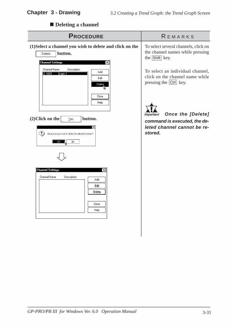
3-31
Chapter 3 - Drawing 3.2 Creating a Trend Graph: the Trend Graph Screen
GP-PRO/PB III for Windows Ver. 6.0 Operation Manual
Deleting a channel
PROCEDURE R E M A R K S
Once the [Delete]command is executed, the de-leted channel cannot be re-stored.
To select several channels, click onthe channel names while pressingthe key.
To select an individual channel,click on the channel name whilepressing the key.
(2)Click on the button.
(1)Select a channel you wish to delete and click on the button.
Shift
Ctrl

3-32
Chapter 3 - Drawing
GP-PRO/PB III for Windows Ver. 6.0 Operation Manual
3.3 Creating a Keypad: the Keypad Screen
3.3 Creating a Keypad: the Keypad Screen
Usage Pattern
The Keypadscreen appears onthe Base screen.
[Tag] [K-tag]or
Click on and set up k-tag.
[Screen] [New]or
Click on to open a Keypad screen.
→→→→→→→→→→
→→→→→
PROCEDURE R E M A R K S
2.2 Drawing
1.1.3 Opening/Closing/Saving a Screen
(3)Draw a keypad.
(2)Open a Keypad screen.
(1)Select the [Screen] menu - [New] command, or clickon the icon.
You can create a keyboard with the Keypad screen. Using the [Draw] menu -[Load Screen] command, you can load a keypad from the Keypad screenonto a Base screen. When the Keypad screen is loaded, the specified loadingpoint is placed at the center of the screen.
2.2.10 Load ScreensThe GP-PRO/PB III provides several sample keyboards. Using the samplekeyboards, there is no need to create a keyboard on each screen.
3.3 Creating a Keypad: the Keypad Screen, Applicationof Sample Keypads
To use a keypad Part, place it on a Base screen directly.2.1.13 Keypad Display
Creating a Keypad
→→→→→Draw akeypad usingdrawing tools.
→→→→→
Save theKeypadscreen.
→→→→→Open aBasescreen.
→→→→→[Draw] [Load Screen]
or
Click on to call up the Keypad screen.→→→→→
→→→→→

3-33
Chapter 3 - Drawing
GP-PRO/PB III for Windows Ver. 6.0 Operation Manual
3.3 Creating a Keypad: the Keypad Screen
Specify the touch area so that it willnot overlap with the touch area ofanother tag.
(8)Specify the touch area (where the specified tag willbe activated) in the same manner as drawing asquare/rectangle.Repeat steps (4) through (8) to set the k-tag for all keys.
To specify a tag name, you can useup to five characters (including al-phanumer ics , symbols and“Double-sized” characters.)
Tag ReferenceManual, 2.12 K-tag (Key Input)To specify a channel name, you canuse up to twenty characters.
PROCEDURE R E M A R K S
(7)Specify the tag name position by clicking on a de-sired point.
(6)After setting all items, click on the buttonto register the settings.
(5)Enter or designate k-tag's each setting item.
(4)Select the [Tag] menu - [k-tag] command, or click onthe icon.
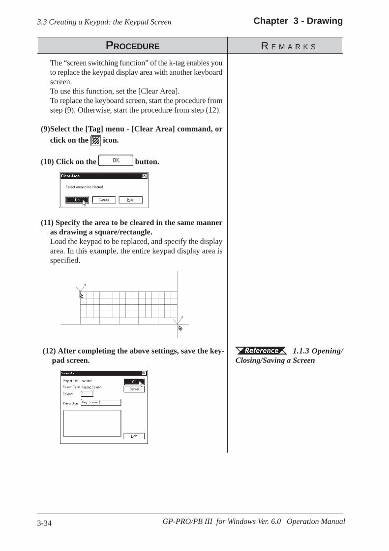
3-34
Chapter 3 - Drawing
GP-PRO/PB III for Windows Ver. 6.0 Operation Manual
3.3 Creating a Keypad: the Keypad Screen
PROCEDURE R E M A R K S
(11) Specify the area to be cleared in the same manneras drawing a square/rectangle.Load the keypad to be replaced, and specify the displayarea. In this example, the entire keypad display area isspecified.
(10) Click on the button.
The “screen switching function” of the k-tag enables youto replace the keypad display area with another keyboardscreen.To use this function, set the [Clear Area].To replace the keyboard screen, start the procedure fromstep (9). Otherwise, start the procedure from step (12).
(9)Select the [Tag] menu - [Clear Area] command, orclick on the icon.
1.1.3 Opening/Closing/Saving a Screen
(12) After completing the above settings, save the key-pad screen.

3-35
Chapter 3 - Drawing
GP-PRO/PB III for Windows Ver. 6.0 Operation Manual
3.3 Creating a Keypad: the Keypad Screen
Application of Sample KeypadsSeveral sample keypads (files created with the GP-PRO III) are provided in the“KEYLIB” folder below the folder (C:\PROPBWIN) where the GP-PRO/PB III hasbeen installed. You can use the sample keypads, and also edit them to create a newkeypad. To use the sample keypads, load the keypad screens (files created with theGP-PRO III) into the current project.
Instead of the sample keypads, keypad Parts can also be used.Note:
2.1.13 Keypad Display
The following is the general procedure for using the sample keyboards:(1) Load a file of the memory link type (K8***.DLM) from
“C:\PROPBWIN\KEYLIB” into the current project. Load the necessarykeyboard screen from “C:\PROPBWIN\KEYLIB” into the currentproject.
12.1.1 Conversion from GP-PRO II or GP-PRO III(2) Open a keypad screen and edit the screen, as required.
1.1.3 Opening a New Screen
The following sample keypads are provided:
File name Keyboard shape and input modeK8000.DLM Ten-key pad, Decimal inputK8001.DLM Ten-key pad, Hexadecimal inputK8002.DLM Ten-key pad, Control keys, HorizontalK8003.DLM Full keys, Horizontal, NumbersK8004.DLM Full keys, Horizontal, SymbolsK8005.DLM Full keys, Horizontal, Uppercase alphabetK8006.DLM Full keys, Horizontal, Lowercase alphabetK8009.DLM Full keys, Horizontal, Basic typeK8010.DLM Ten-key pad, Control keys, VerticalK8011.DLM Full keys, Vertical, NumbersK8012.DLM Full keys, Vertical, SymbolsK8013.DLM Full keys, Vertical, Uppercase alphabetK8014.DLM Full keys, Vertical, Lowercase alphabetK8017.DLM Full keys, Vertical, Basic type

3-36
Chapter 3 - Drawing
GP-PRO/PB III for Windows Ver. 6.0 Operation Manual
3.3 Creating a Keypad: the Keypad Screen
Ten-key pad,Decimal input
Full keys, Horizontal, Lowercase Alphabets
Full keys, Vertical,Uppercase alphabets
Example) K8000 Example) K8007
Example) K8013

3-37
Chapter 3 - Drawing
GP-PRO/PB III for Windows Ver. 6.0 Operation Manual
3.4 Text Input: the Text Screen
Editing FunctionsThe Editing Tool Bar icons and their corresponding functions are as follows:
Open a Text screen by selecting the[Screen] menu’s [New] commandor by clicking on the icon.
Quit theGP TextEditor.
Save theTextscreen.
Enter text.
Usage Pattern
3.4 Text Input: the Text Screen
→→→→→ →→→→→ →→→→→
Editingfunction toolbar
Screen capacity
Coordinates ofcurrent cursorposition
Input characterdisplay area
Cursor
General description of the Text screen:
Create text data with the Text screen. There are two methods of creating textdata: Open an existing Text screen and edit this screen using the GP TextEditor, or paste the text created with another editor onto the Text screen forthe GP series using the [Cut] and [Copy] command.The created text data can also be animated; there are two methods: Display-ing text by a specified number of lines (specified by X-tag), and a list witherror guidance (specified by A-tag).
Tag Reference Manual, 2.1 A-tag (Alarm Summary TEXTDisplay)/ 2.30 X-tag (Display Text Data)
Line No.
Icon Editing Tool Description
CutUsed to delete the selected text, and store it in the clipboard.You can use this function to delete or move text.
CopyUsed to store the selected text in the clipboard. Unlike the[Cut] command, the original text will not be deleted.
PasteUsed to paste the data temporarily stored in the clipboardonto a desired place.
Delete Used to delete the selected text.

3-38
Chapter 3 - Drawing
GP-PRO/PB III for Windows Ver. 6.0 Operation Manual
3.4 Text Input: the Text Screen
PROCEDURE R E M A R K S
1.1.3 Openinga New Screen
(3)Enter text in the text display area through the key-board.Be sure to press the key at the end of each line.
(2)Open a Text screen.
(1)Select the [Screen] menu - [New] command, or clickon the icon to open a Text screen.
· When you select characters and click the right mouse button, the followingshortcut menu appears.
Icon Editing Tool Description
UndoUsed to cancel the command executed immediately before,and return to the previous condition. (Undo)
RedoUsed to redo the command canceled with the [Undo]command. (Redo)
You can enter up to 512 lines on onescreen. Line number 513 or subse-quent lines cannot be displayed.
Maximumnumber ofcharacters
GP type
40
GP-H70, GP-270, GP-370,GP-377, GP-37W2, GP-377R, GP-2301H, GP-2300,GP-2301
80
GP-470, GP-570, GP-571,GP-870, GP-477R, GP-577R, GP-2401H, GP-2400,GP-2500, GP-2501
100 GP-675, GP-2600
Input the Text
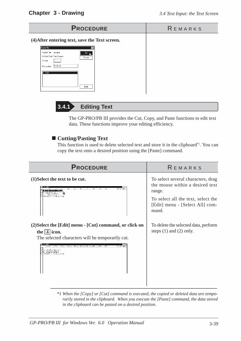
3-39
Chapter 3 - Drawing
GP-PRO/PB III for Windows Ver. 6.0 Operation Manual
3.4 Text Input: the Text Screen
The GP-PRO/PB III provides the Cut, Copy, and Paste functions to edit textdata. These functions improve your editing efficiency.
Cutting/Pasting TextThis function is used to delete selected text and store it in the clipboard*1. You cancopy the text onto a desired position using the [Paste] command.
PROCEDURE R E M A R K S
3.4.1 Editing Text
PROCEDURE R E M A R K S
To select several characters, dragthe mouse within a desired textrange.
To select all the text, select the[Edit] menu - [Select All] com-mand.
(1)Select the text to be cut.
(4)After entering text, save the Text screen.
(2)Select the [Edit] menu - [Cut] command, or click onthe icon.The selected characters will be temporarily cut.
To delete the selected data, performsteps (1) and (2) only.
*1 When the [Copy] or [Cut] command is executed, the copied or deleted data are tempo-rarily stored in the clipboard. When you execute the [Paste] command, the data storedin the clipboard can be pasted on a desired position.

3-40
Chapter 3 - Drawing
GP-PRO/PB III for Windows Ver. 6.0 Operation Manual
3.4 Text Input: the Text Screen
PROCEDURE R E M A R K S
(3)Move the cursor to the text's destination. Then, se-lect the [Edit] menu - [Paste] command, or click onthe icon.The deleted characters will be pasted at the specifiedposition.
PROCEDURE R E M A R K S
To select several characters, dragthe mouse within the desired textrange.
To select all the text, select the[Edit] menu - [Select All] com-mand.
(2)Select the [Edit] menu - [Copy] command, or clickon the icon.The selected characters will be copied into the clipboard.
(1)Select the text data to be copied.
Copying TextCopy selected text data, and store the text data into the clipboard.
(3)Move the cursor to the copy's destination. Then, se-lect the [Edit] menu - [Paste] command, or click onthe icon.The text data stored in the clipboard will be pasted atthe specified position.

3-41
Chapter 3 - Drawing
GP-PRO/PB III for Windows Ver. 6.0 Operation Manual
3.4 Text Input: the Text Screen
Deleting TextDelete text data.
PROCEDURE R E M A R K S
You can execute the same opera-tion by pressing the key ofyour personal computer’s key-board, instead of clicking on the icon.
To cancel the [Delete] command,click on the icon.
To select several characters, dragthe mouse within the desired textrange.
To select all the text, select the[Edit] menu - [Select All] com-mand.
(2)Select the [Edit] menu - [Delete] command, or clickon the icon.The selected characters will be deleted.
(1)Select the text data to be deleted.
Delete

3-42
Chapter 3 - Drawing
GP-PRO/PB III for Windows Ver. 6.0 Operation Manual
3.4 Text Input: the Text Screen
Searching for TextSearch for a desired character string.
PROCEDURE R E M A R K S
To differentiate between the upper-case and lowercase characters dur-ing the search operation, use the“Match Case” function.
(3)Click on the button to execute the searchoperation.The search operation will be started in the specified di-rection. To continue the search operation for the samecharacter string, click on the button until thereis no matching string. When there is no matching string,the search operation will stop.
(2)Enter the character string to be searched for and se-lect the search direction, i.e. upward or downward.The cursor position indicates the search start position.
(1)Select the [Search] menu - [Find] command.

3-43
Chapter 3 - Drawing
GP-PRO/PB III for Windows Ver. 6.0 Operation Manual
3.4 Text Input: the Text Screen
Utilizing Other Text FilesOther text files formatted for Windows can be used for the GP series. The procedurefor using the Windows NotePad data for the GP series is as follows:
PROCEDURE R E M A R K S
(3)Using the Notepad’s [Edit] menu - [Copy] command,load the selected strings from NotePad into the clip-board.
(2)Select the character strings to be used for the GP series.
(1)Start the NotePad, and open the file to be used.
(4)Move the cursor to the position where you wish topaste the selected text. Then, select the [Edit] menu -[Paste] command, or click on the icon.The strings stored in the clipboard will be pasted to thespecified position.
To differentiate between the upper-case and lowercase characters dur-ing the search operation, use the“Match Case” function.
Maximumnumber ofcharacters
GP type
40
GP-H70, GP-270, GP-370,GP-377, GP-37W2, GP-377R, GP-2301H, GP-2300,GP-2301
80
GP-470, GP-570, GP-571,GP-870, GP-477R, GP-577R, GP-2401H, GP-2400,GP-2500, GP-2501
100 GP-675, GP-2600

3-44
Chapter 3 - Drawing
GP-PRO/PB III for Windows Ver. 6.0 Operation Manual
3.4 Text Input: the Text Screen
Setting the Maximum Number of Characters per LineYou can set the maximum number of characters that can be entered per line.To set the maximum number of characters per line, move the ruler. Thespecified number of characters is displayed at the right of the ruler.When the input data exceeds the specified number of characters per line, thecharacters will be automatically entered in the next line.If you reduce the specified maximum number of characters after data input,the characters exceeding the current limit will be automatically entered inthe next line.
Ruler
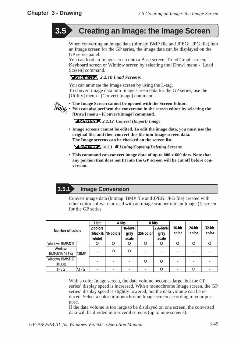
3-45GP-PRO/PB III for Windows Ver. 6.0 Operation Manual
3.5 Creating an Image: the Image ScreenChapter 3 - Drawing
When converting an image data (bitmap: BMP file and JPEG: .JPG file) intoan Image screen for the GP series, the image data can be displayed on theGP series panel.You can load an Image screen onto a Base screen, Trend Graph screen,Keyboard screen or Window screen by selecting the [Draw] menu - [LoadScreen] command.
2.2.10 Load ScreensYou can animate the Image screen by using the L-tag.To convert image data into Image screen data for the GP series, use the[Utility] menu - [Convert Image] command.• The Image Screen cannot be opened with the Screen Editor.• You can also perform the conversion in the screen editor by selecting the
[Draw] menu - [Convert/Image] command.2.2.12 Convert (Import) Image
• Image screens cannot be edited. To edit the image data, you must use theoriginal file, and then convert this file into Image screen data.The Image screens can be checked on the screen list.
4.1.1 Listing/Copying/Deleting Screens
• This command can convert image data of up to 800 x 600 dots. Note thatany portion that does not fit into the GP screen will be cut off before con-version.
3.5 Creating an Image: the Image Screen
3.5.1 Image ConversionConvert image data (bitmap: BMP file and JPEG: JPG file) created withother editor software or read with an image scanner into an Image (I) screenfor the GP series.
With a color Image screen, the data volume becomes large, but the GPseries’ display speed is increased. With a monochrome Image screen, the GPseries’ display speed is slightly lowered, but the data volume can be re-duced. Select a color or monochrome Image screen according to your pur-pose.If the data volume is too large to be displayed on one screen, the converteddata will be divided into several screens (up to nine screens).
1 bit2 colors(black &
white)16 colors
16-levelgrayscale
256 color256-level
grayscale
Windows BMP/DIB O O O O O O O OWindows
BMP/DIB(RLE4)- O O - - - - -
Windows BMP/DIB(RLE8)
- - - O O - - -
JPEG *.JPG - - - - O - O -
*.BMP
16-bitcolor
24-bitcolor
32-bitcolor
4 bits 8 bits
Number of colors

3-46
Chapter 3 - Drawing
GP-PRO/PB III for Windows Ver. 6.0 Operation Manual
3.5 Creating an Image: the Image Screen
Enter the name ofthe image file tobe converted, orselect the imagefile from the filelist by clicking onthe [Browse]button
Register the above settings to execute the imageconversion. If you save the converted image data,the image screen of the screen number specifiedin [Screen Setting] will be created
Displays theimage of theimage file to beconverted.However, thisimage is differ-ent from theimage that willbe displayed onthe GP series
Select the imagefile to be con-verted
Displays thedimensions (hori-zontal x vertical) ofthe image data
Displays the sizeof the image file
Displays infor-mation on datacolors (e.g. 16colors, 256colors)
Converting/Placing an Image: [Source]Specify the image file to be converted. The information on the specifiedimage file will be displayed.
Y (V
ertic
al)
X (Horizontal)
Y (V
ertic
al)GP
GP
· If the longitudinal dimension of the original image data is less than“4” for color data, or less than “8” for monochrome data, the imagedata cannot be converted.
X (Horizontal)
· Make sure that the original image data’s longitudinal dimension (“X”for the horizontal type, and “Y” for the vertical type in the figurebelow) is a multiple of “4” for color data, or a multiple of “8” formonochrome data. Otherwise the fractional data will be deleted fromthe right edge of the screen after conversion.

3-47GP-PRO/PB III for Windows Ver. 6.0 Operation Manual
3.5 Creating an Image: the Image ScreenChapter 3 - Drawing
Use Default Effects
When you specify Use Default Effects, the original data will be automati-cally converted into the image data with the optimum brightness and displayquality.
Brightness
Used to convert bitmap data according to the brightness level. The referencevalue can be changed between levels “0” and “15”. A larger value indicatesa brighter image, and a smaller value indicates a darker image.
Dithering
Used to set the converted data’s display quality.
BlinkUsed to make the converted data blink.
Blink cannot be used when the screen is displayed at 256 col-ors.
CompressUsed to compress the original bitmap data during conversion.
MirrorUsed to replace the original bitmap data symmetrically relative to the X-axisor Y-axis during conversion.
Converting/Placing an Image: [Effects]Specify the brightness, resolution, blinking, compression, and mirror func-tions for the converted image data.
Used to set the bright-ness and displayquality automatically Used to manually
set the individualoptions of thebrightness anddisplay quality
When 256-colors areselected, “Blink”cannot be selected

3-48
Chapter 3 - Drawing
GP-PRO/PB III for Windows Ver. 6.0 Operation Manual
3.5 Creating an Image: the Image Screen
Image ColorSelect the type of the converted bitmap file: Monochrome, 8-colors, 64-colors or 256-colors. The screen size and the number of screen divisionsvary depending on the selected type. Select "256 colors with No Blk" modeon the GP System Setup dialog box before selecting the "256 Color" optionon the GP2000 (except GP-2301HL, GP-2301HS, GP-2300L, GP-2300Tand GP-2501S) series.
6.1 Tab Setting Items Initial Screen Settings First ScreenEnter the screen number of the Image screen. If no screen number is speci-fied, an Image screen of the currently displayed screen number will becreated.
Screen TypeSelect whether the image screen is to be saved on the GP’s internal memoryor the CF card.
Tag Reference Manual, 4.4 Using the CF Card
· You can select the CF card if your GP is a GP77R series or a GP2000 series.Using the GP77R series requires the optional Multi Unit.
· When the CF card is specified, the drawing speed on a screen where theimage screen is placed become slower than GP memory is specified.
Screen TitleEnter the title of the Image screen. Even if the converted data are dividedinto several screens, only one title can be specified for one original file.
SizeDisplays the size of the converted screen.
Converting/Placing an Image: [Destination]
Select the numberof colors of theconverted imagefile
Displays the sizeof the convertedscreen
Enter the title ofthe Image screen
Enter the screennumber of theImage screen
Select a destionto save theimage screen
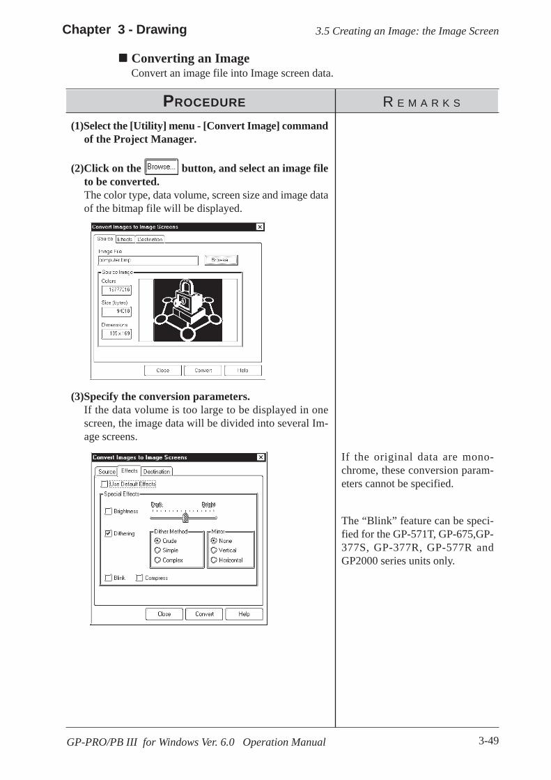
3-49GP-PRO/PB III for Windows Ver. 6.0 Operation Manual
3.5 Creating an Image: the Image ScreenChapter 3 - Drawing
Converting an ImageConvert an image file into Image screen data.
PROCEDURE R E M A R K S
If the original data are mono-chrome, these conversion param-eters cannot be specified.
The “Blink” feature can be speci-fied for the GP-571T, GP-675,GP-377S, GP-377R, GP-577R andGP2000 series units only.
(3)Specify the conversion parameters.If the data volume is too large to be displayed in onescreen, the image data will be divided into several Im-age screens.
(2)Click on the button, and select an image fileto be converted.The color type, data volume, screen size and image dataof the bitmap file will be displayed.
(1)Select the [Utility] menu - [Convert Image] commandof the Project Manager.

3-50
Chapter 3 - Drawing
GP-PRO/PB III for Windows Ver. 6.0 Operation Manual
3.5 Creating an Image: the Image Screen
PROCEDURE R E M A R K S
To cancel conversion, click on the button.
When an image is converted by se-lecting the [Convert Image] com-mand from the [Draw] menu on theScreen Editor, pressing the [Place]button allows the converted imagescreen to be placed.
The “64-color” mode can be speci-fied for the GP-571T, GP-675, GP-377S, GP-377R, GP-577R andGP2000 series only.
The “256-color” mode can bespecified for the GP2000 (exceptGP-2301HL and GP-2300L) seriesonly. 6.1 Ini-tial Screen Settings
The number of colors specified for[Screen Color] must be equal to thenumber of display colors supportedby your GP series.
· If the number of colors is differ-ent, the display speed will be low-ered.
· Any colors that are not supportedwith your GP series cannot bedisplayed.
Only when your GP type is the GR-77R or GP2000 series, the CF cardcan be specified in the [ScreenType] section.
Tag ReferenceManual, 4.4 Using the CF CardIf the same screen number alreadyexists, the system asks if you wantto replace the existing screen withthe one you are attempting to save.If so, select ; otherwise,
select .
(6)If the displayed image is correct, click on the button.An Image screen is created.
(5)Click on the button to perform data con-version.The image data conversion starts. Then, the convertedimage will be displayed.
(4)Enter the screen number and title of a new Image,and designate Screen Type.If you do not set a title, the title of the original Imagefile will be specified.

3-51GP-PRO/PB III for Windows Ver. 6.0 Operation Manual
3.5 Creating an Image: the Image ScreenChapter 3 - Drawing
To compress an Image screen(bitmap data) of another project, se-lect the project.
1.1.2 Selectingan Existing ProjectTo select several screens, click onthe screen numbers while pressingthe key.To select a specified screen, clickon the screen number while press-ing the key.If the CF card is specified in step(2) when your GP type is the GP-77R series or GP2000 series, theimage screen on the CF card canbe compressed.
Tag ReferenceManual, 4.4 Using the CF Card
PROCEDURE R E M A R K S
The compression and decompression procedures areseparately described as follows:
(2)Select the screen to be compressed or decompressedfrom the list.
(1)Select the [Utility] menu - [Compress Bitmap] com-mand of the Project Manager.
If the size of the Image screen is large, you can compress it to reduce thedata size. The data is compressed to one-fifth the size of the source data.The compressed Image screen data can then be displayed directly to the GPseries. With the compressed Image screen, however, the GP series’ displayspeed will be slower.
(7) Click on the button to quit the conver-sion mode.
Ctrl
Shift
PROCEDURE R E M A R K S
3.5.2 Compressing/Decompressing an Image Screen
2.2.12 Convert (Im-port) ImageSelect the [Load Screen] commandfrom the [Draw] menu to place theconverted image.
2.2.10 LoadScreens

3-52
Chapter 3 - Drawing
GP-PRO/PB III for Windows Ver. 6.0 Operation Manual
3.5 Creating an Image: the Image Screen
[Decompression](3)Click on the button to perform data de-
compression.The process is finished when the word “Normal” ap-pears.
[Compression](3)Click on the button to execute data com-
pression.The process is finished when the word “Compressed”appears.
R E M A R K SPROCEDURE
3-53GP-PRO/PB III for Windows Ver. 6.0 Operation Manual
3.6 Video Data Display (V Screen)Chapter 3 - Drawing
Use a v-tag to call up the video window on the Video Screen (V file) ontothe Base Screen (V file). This feature allows the video display to be dis-played on the GP screen when necessary.
This feature is supported only by the GP-2500T and GP-2600T.The optional VM Unit is required.
The following two procedures can be used to display video windows: (1)Use a v-tag to display the video window on the specific Base Screen (B); or(2) display the video window as a global window for all screens.In procedure (1), place a v-tag on the Base Screen (B). Select the [v-Tag]from the [Tag] menu to make the settings.
Tag Reference Manual, 2.28 v-tag (Extended Video Win-dow Display)A v-tag can be set up only when "Extend(small v-tag)" is enabled. Selectthis mode using the following procedure before setting up a v-tag. Select[GP Setup] from the Project Manager and select [Extended Settings] and[Video Settings].(2) For details of the global display:
3.6.2 Video Window SettingsSelect the [Video Setting] command from the [Tag] menu on the VideoScreen (V) to set up a video window. If necessary, select [T-tag] from the[Tag] menu to set up a touch-switch for use in the video data display.The environmental settings for video operation can be made by selecting[Video Setting] on [Extended Feature Settings] from the [GP Setup], or byselecting [Video Operation Settings] on the OFFLINE menu of the GP unit.GP’s screen drawing objects cannot be placed on video screens. You cancheck the contents of your video screens via the [Screen List] feature.
4.1.1 Listing/Copying/Deleting Screen
3.6 Video Data Display (V Screen)

3-54
Chapter 3 - Drawing
GP-PRO/PB III for Windows Ver. 6.0 Operation Manual
3.6 Video Data Display (V Screen)
Usage Pattern
• To Create a Video ScreenClick on Tagmenu[Screen] →→→→→ →→→→→[New] →→→→→ Click on Video
Settingsor
Click on icon
or
Click on to set up avideo screen
Save the videoscreen→→→→→Click on
Tag menu→→→→→ →→→→→Click on T-Tagor
Click on to set
up a touch switch
Save the Basescreen→→→→→Click on
Tag menu→→→→→ →→→→→Click on v-Tag
• To Create a Base Screen
or
Click on to set
up video settings.
Open the Basescreen
ExtendedSettings
→→→→→Click onScreen/Setupmenu
→→→→→ →→→→→Click on GP-Setup
• To use the GP Setup screen to enter video setting data.
Click on to set up video settings.
or→→→→→ Video Settings
This feature is enabled by performing the above procedure.
Select “Video Screen”

3-55GP-PRO/PB III for Windows Ver. 6.0 Operation Manual
3.6 Video Data Display (V Screen)Chapter 3 - Drawing
Entering Video Settings
PROCEDURE R E M A R K S
1.1.3 Opening/Closing/Saving a Screen
(2) Select the “Video Screen”.The “Wizard” button is enabled only when video screenis selected. Clicking on the “Wizard” button calls up adialog box that explains the video settings.Basic settings can be made in the Wizard dialog box.For detailed settings, adjust the settings on the [VideoSetting] dialog box in step (3).
(1) From the screen editor, select the [Screen] menu -[New] command, or click on the icon.
(3) From the [Tag] menu, select [Video Setting], or clickon the icon.
(4) Enter the desired video settings in the [Video Set-ting] tab screens.
(5) After all settings are entered, click on the button.
(6) Place the video data display area icon where you wishto have the video display on the GP screen. Re-sizethe icon to reflect the actual size of the display.
Tag ReferenceManual, 2.28 v-tag (ExtendedVideo Window Display)
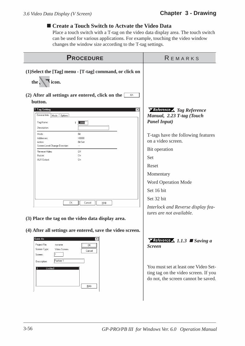
3-56
Chapter 3 - Drawing
GP-PRO/PB III for Windows Ver. 6.0 Operation Manual
3.6 Video Data Display (V Screen)
PROCEDURE R E M A R K S
T-tags have the following featureson a video screen.
Bit operation
Set
Reset
Momentary
Word Operation Mode
Set 16 bit
Set 32 bit
Interlock and Reverse display fea-tures are not available.
(2) After all settings are entered, click on the button.
(1)Select the [Tag] menu - [T-tag] command, or click on
the icon.
Create a Touch Switch to Actvate the Video DataPlace a touch switch with a T-tag on the video data display area. The touch switchcan be used for various applications. For example, touching the video windowchanges the window size according to the T-tag settings.
(3) Place the tag on the video data display area.
(4) After all settings are entered, save the video screen.
Tag ReferenceManual, 2.23 T-tag (TouchPanel Input)
1.1.3 Saving aScreen
You must set at least one Video Set-ting tag on the video screen. If youdo not, the screen cannot be saved.
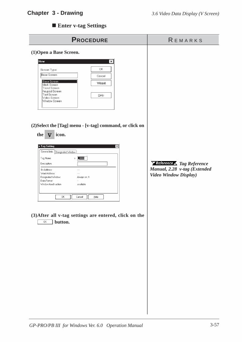
3-57GP-PRO/PB III for Windows Ver. 6.0 Operation Manual
3.6 Video Data Display (V Screen)Chapter 3 - Drawing
PROCEDURE R E M A R K S
(3)After all v-tag settings are entered, click on the button.
(2)Select the [Tag] menu - [v-tag] command, or click on
the icon.
Enter v-tag Settings
Tag ReferenceManual, 2.28 v-tag (ExtendedVideo Window Display)
(1)Open a Base Screen.

3-58
Chapter 3 - Drawing
GP-PRO/PB III for Windows Ver. 6.0 Operation Manual
3.6 Video Data Display (V Screen)
PROCEDURE R E M A R K S
(2) Click on the [Extended Settings] tab and then clickon the [Video Settings] button.
Use the [GP Setup] area’s [Video Setting] selection
(1) Click on the Project Manager’s icon,or click on the [Screen/Setup] menu’s [GP Setup]selection.
(3) Specify settings for the parameters on [Video Set-ting]. 3.6.1 Video Settings

3-59GP-PRO/PB III for Windows Ver. 6.0 Operation Manual
3.6 Video Data Display (V Screen)Chapter 3 - Drawing
Video Control Start Address
This area (Video Control Area) is used to designate the various controlfeatures for the display of the video screen on a GP.
Device/PLC Connection Manual, 1.1.2 LS Area Structure
Use the following table when seting the Video Control Area’s start address.
In Standard mode, 22 words are automatically allocated for the VideoControl Area, starting from the Start Address. In Extend mode, 43 words areallocated.
Tag Reference Manual 4.9.3 Standard Mode
Tag Reference Manual 4.9.4 Extended Mode Center Zoom
Clicking on this selection, if the mode is changed from Standard to Zoom,designates that the center of standard mode’s video screen will be enlarged.This selection is enabled only in Extend mode.
Used in the GP570VMand GP870VM. Cannotbe used via a v-tag,only with a V-tag.
Set when the VideoWindow is used as aGlobal Window.
3.6.2 VideoWindow Settings
Designate whether a VideoControl Start Address isused or not. Enabled onlyin [Extend] mode.
Tag Refer-ence Manual, 4.10 VM UnitExtended Features
3.6.1 Video Settings
This feature is used with the GP2000 series unit’s [Extend]mode. It cannot be used via a V-tag, only with a v-tag.
This section describes the procedure for specifying the Video Setting. SelectStandard or Extended Mode according to the GP Type.
Only "Standard Mode" can be enabled with the GP-570VM and GP-870VM.
Mode Video Control Area Start AddressStandard LS20 to LS2010, LS2096 to LS4072 (to LS8170 for GP2000 series units)Extend LS20 to LS1989, LS2096 to LS4053 (to LS8149 for GP2000 series units)
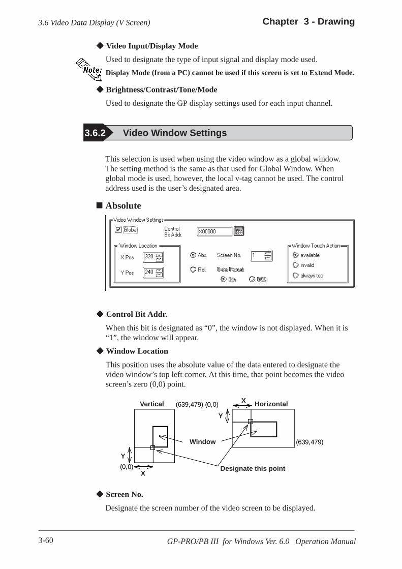
3-60
Chapter 3 - Drawing
GP-PRO/PB III for Windows Ver. 6.0 Operation Manual
3.6 Video Data Display (V Screen)
Video Input/Display Mode
Used to designate the type of input signal and display mode used.Display Mode (from a PC) cannot be used if this screen is set to Extend Mode.
Brightness/Contrast/Tone/Mode
Used to designate the GP display settings used for each input channel.
3.6.2 Video Window Settings
This selection is used when using the video window as a global window.The setting method is the same as that used for Global Window. Whenglobal mode is used, however, the local v-tag cannot be used. The controladdress used is the user’s designated area.
Absolute
Control Bit Addr.
When this bit is designated as “0”, the window is not displayed. When it is“1”, the window will appear.
Window Location
This position uses the absolute value of the data entered to designate thevideo window’s top left corner. At this time, that point becomes the videoscreen’s zero (0,0) point.
Screen No.
Designate the screen number of the video screen to be displayed.
X(639,479) (0,0)
(639,479)
(0,0)
HorizontalVertical
Window
Designate this point
Y
X
Y

3-61GP-PRO/PB III for Windows Ver. 6.0 Operation Manual
3.6 Video Data Display (V Screen)Chapter 3 - Drawing
Window Touch Action
Available If the desired window is currently behind another window,touching anywhere on the desired window will bring thatwindow to the front.
Invalid If the desired window is currently behind another window,touching anywhere on the desired window will have no effectand the window will remain in its current position.
Always top This setting keeps the desired window always on the “top”(front most) of the display. However, if the GP unit’s systemwindow is used (display of parameters, errors, alarm messages, etc.), this screen will be placed behind the systemwindow
RelativeThis setting uses a variable to designate the display screen and the displayposition. Thus, as data is saved to the designated Word Address, the displaywill change.
Control Word Addr.
When this bit is designated as “0”, the window is not displayed. When it is“1”, the window will appear.
15 02 01 00 bit
+0 Video Window Control+1 VideoWindow Screen Number+2 Video Window Display Position (X coord. data)+3 Video Window Display Position (Y coord. data)
[Window Control]
Display
[0] = No display[1] = DisplayDesignate this point
[00] = Available[01] = Not available[10] = Always top[11] = Reserved (not available)
3-62
Chapter 3 - Drawing
GP-PRO/PB III for Windows Ver. 6.0 Operation Manual
3.6 Video Data Display (V Screen)
Data Format
BIN
BCD
Designates the type of data used for the display position and window num-ber data.

3-63
Chapter 3 - Drawing
GP-PRO/PB III for Windows Ver. 6.0 Operation Manual
3.7 Window Display: Window (U) Screen and Base (B) Screen
3.7 Window Display: Window (U) Screen and Base (B) Screen
3.7.1 Overview of Window DisplayCall up the windows registered on the Window Screen (U) or Base Screen(B) and display them on the Base Screen (B).
Additional windows can be displayed on the GP screen when necessary.
Example: Make the settings for displaying a bar graph by turning ON thewindow display switch.
<GP Screen>
<GP-PRO/PB III Screen>
1)Registering a window on the U Screen
2)Registering a window on the B Screen
OFF
OFF
ON Window Display O
NWindow Display
Window Display
Turn ON theswitch
Window Display
Turn ON theswitch
Turn OFF theswitch
Turn ON theswitch
Call up the bargraph from U300 toB2 using a windowpart.
Use a U-tag to callup the bar graphfrom B300 to B2
B2
B2
B2
B2
U300
B300
OFF
ON
OFF
ON

3-64
Chapter 3 - Drawing
GP-PRO/PB III for Windows Ver. 6.0 Operation Manual
3.7 Window Display: Window (U) Screen and Base (B) Screen
Window Registration can be performed on the Window Screen (U) or BaseScreen (B).
The following two types of Window Display are available.
Local Window Display
Set up a U-tag to call up a window registered on the Base Screen (B) to theBase Screen (B).
3.7.3 Window Registration on the B ScreenTag Reference Manual; 2.26 U-tag (Window Display)
Set up a window part or a U-tag to call up a window registered on the Win-dow (U) to the Base Screen (B).
2.1.23 Window Parts, 3.7.2 Window Registration on the U Screen, Tag Reference Manual; 2.26 U-tag (Window Display)
Global Window Display
Displays a single window on all Base Screens (B) as a global window. Tocall up the window, make the "Global Window" settings on the OFFLINEsettings of the GP unit or on the [GP Setup] of the Program Manager in GP-PRO/PB III..
Tag Reference Manual, 2.26 U-tag (Window Display), GP series User Manual, 5.3.3 Global Window Setup
K-tags, U-tags, V-tags, v-tags, trend graphs (T Screen andparts), Keypad Input Display and Logging Display will not func-tion from the registered window.
Window registered on the B Screen Window registered on the U ScreenWindow part Not availableU-tag
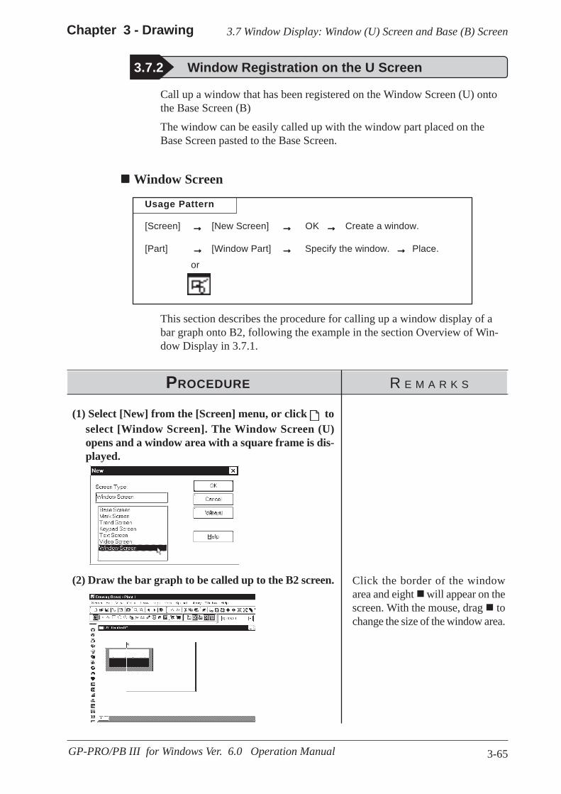
3-65
Chapter 3 - Drawing
GP-PRO/PB III for Windows Ver. 6.0 Operation Manual
3.7 Window Display: Window (U) Screen and Base (B) Screen
3.7.2 Window Registration on the U Screen
Call up a window that has been registered on the Window Screen (U) ontothe Base Screen (B)
The window can be easily called up with the window part placed on theBase Screen pasted to the Base Screen.
Window Screen
Usage Pattern
→→→→→[Screen] [New Screen] OK Create a window.
[Part] [Window Part] Specify the window. Place.
→→→→→ →→→→→
→→→→→→→→→→→→→→→or
This section describes the procedure for calling up a window display of abar graph onto B2, following the example in the section Overview of Win-dow Display in 3.7.1.
PROCEDURE R E M A R K S
(1) Select [New] from the [Screen] menu, or click toselect [Window Screen]. The Window Screen (U)opens and a window area with a square frame is dis-played.
(2) Draw the bar graph to be called up to the B2 screen. Click the border of the windowarea and eight will appear on thescreen. With the mouse, drag tochange the size of the window area.
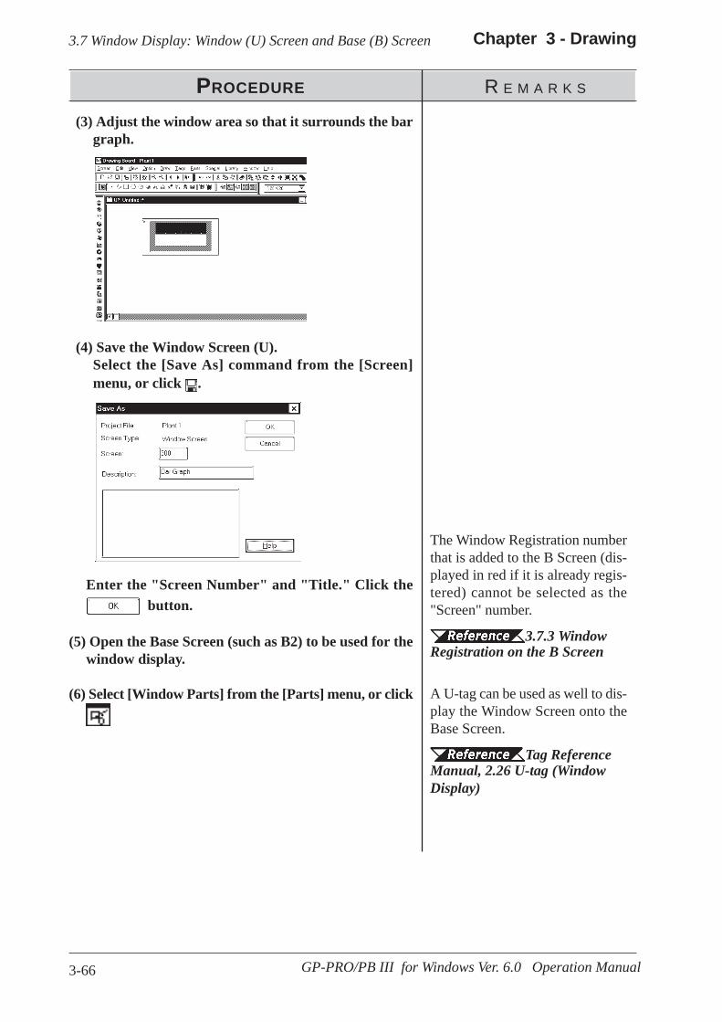
3-66
Chapter 3 - Drawing
GP-PRO/PB III for Windows Ver. 6.0 Operation Manual
3.7 Window Display: Window (U) Screen and Base (B) Screen
PROCEDURE R E M A R K S
(3) Adjust the window area so that it surrounds the bargraph.
(4) Save the Window Screen (U).Select the [Save As] command from the [Screen]menu, or click .
The Window Registration numberthat is added to the B Screen (dis-played in red if it is already regis-tered) cannot be selected as the"Screen" number.
3.7.3 WindowRegistration on the B Screen
A U-tag can be used as well to dis-play the Window Screen onto theBase Screen.
Tag ReferenceManual, 2.26 U-tag (WindowDisplay)
Enter the "Screen Number" and "Title." Click the button.
(5) Open the Base Screen (such as B2) to be used for thewindow display.
(6) Select [Window Parts] from the [Parts] menu, or click.
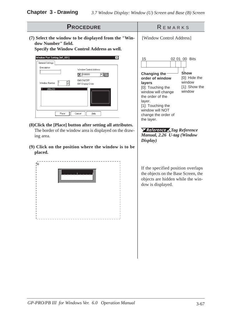
3-67
Chapter 3 - Drawing
GP-PRO/PB III for Windows Ver. 6.0 Operation Manual
3.7 Window Display: Window (U) Screen and Base (B) Screen
PROCEDURE R E M A R K S
[Window Control Address](7) Select the window to be displayed from the "Win-dow Number" field.Specify the Window Control Address as well.
(8)Click the [Place] button after setting all attributes.The border of the window area is displayed on the draw-ing area.
(9) Click on the position where the window is to beplaced.
If the specified position overlapsthe objects on the Base Screen, theobjects are hidden while the win-dow is displayed.
15 02 01 00 Bits
Show[0]: Hide thewindow[1]: Show thewindow
Changing theorder of windowlayers[0]: Touching thewindow will changethe order of thelayer.[1]: Touching thewindow will NOTchange the order ofthe layer.
Tag ReferenceManual, 2.26 U-tag (WindowDisplay)

3.7 Window Display: Window (U) Screen and Base (B) Screen Chapter 3 - Drawing
3-68 GP-PRO/PB III for Windows Ver. 6.0 Operation Manual
To display a window during the GP’s RUN mode, you must first register it;the window can be either all or part of a Base screen.There are two types of window displays, Global and Local, and both areregistered and deleted using the same methods.
Tag Reference Manual, 2.26 U-tag (Window Display)
Windows registered on the U Screen are displayed in red. Editing, deletingand copying are not available here.
→→→→→
Usage Pattern
→→→→→[Screen][WindowRegistration] →→→→→
Add,Modify, orDelete
orthekey
Esc
Lists theWindow’sregistrationinformation
Deletes a regis-tered window
Modifies windowregistration Sizeand/or Descrip-tion
Adds new win-dow registrationdata
Copies a regis-tered window
Registering WindowsHere, an additional window can be registered. When clicking on the
button, the window registration setting dialog box will appear.
Refer to next page: Registering a Window
3.7.3 Window Registration on the B Screen
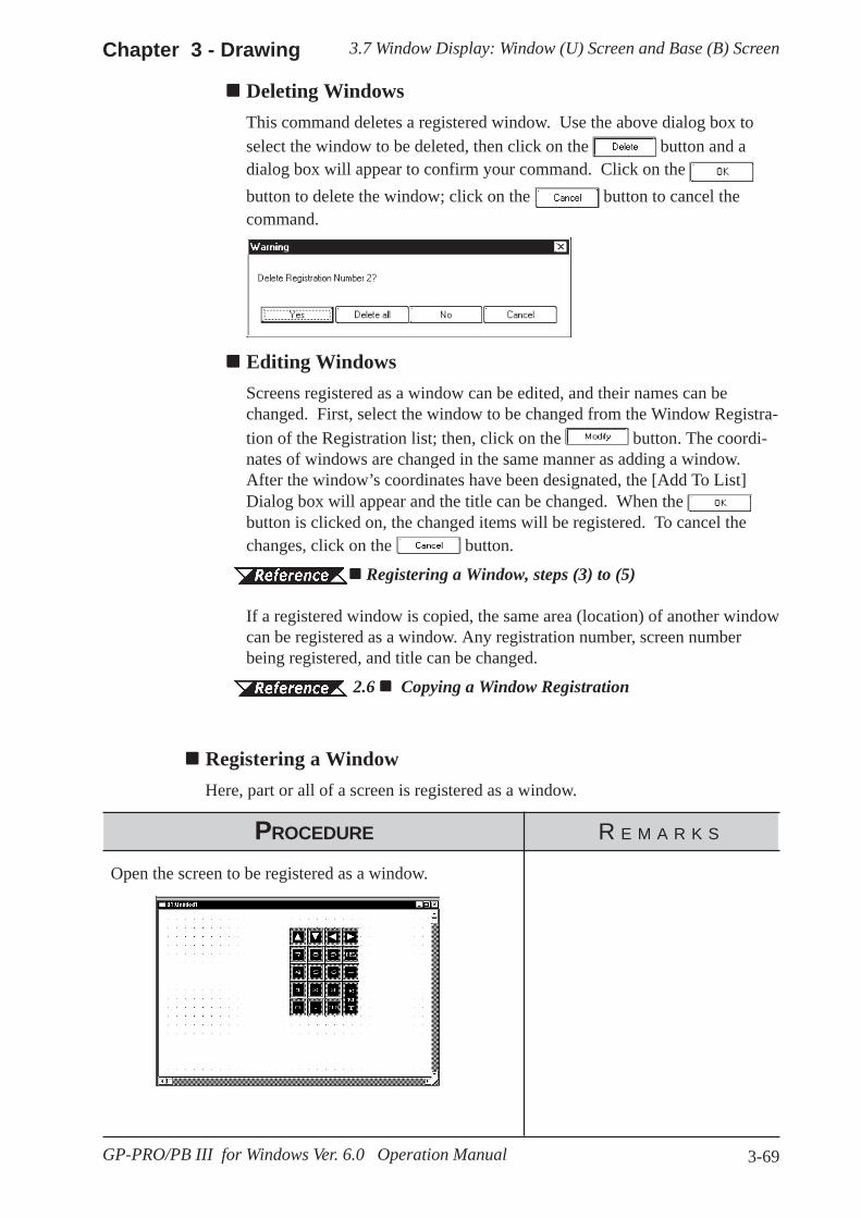
3.7 Window Display: Window (U) Screen and Base (B) ScreenChapter 3 - Drawing
3-69GP-PRO/PB III for Windows Ver. 6.0 Operation Manual
Editing WindowsScreens registered as a window can be edited, and their names can bechanged. First, select the window to be changed from the Window Registra-tion of the Registration list; then, click on the button. The coordi-nates of windows are changed in the same manner as adding a window.After the window’s coordinates have been designated, the [Add To List]Dialog box will appear and the title can be changed. When the button is clicked on, the changed items will be registered. To cancel thechanges, click on the button.
Registering a Window, steps (3) to (5)
If a registered window is copied, the same area (location) of another windowcan be registered as a window. Any registration number, screen numberbeing registered, and title can be changed.
2.6 Copying a Window Registration
Registering a WindowHere, part or all of a screen is registered as a window.
Deleting WindowsThis command deletes a registered window. Use the above dialog box toselect the window to be deleted, then click on the button and adialog box will appear to confirm your command. Click on the button to delete the window; click on the button to cancel thecommand.
Open the screen to be registered as a window.
PROCEDURE R E M A R K S
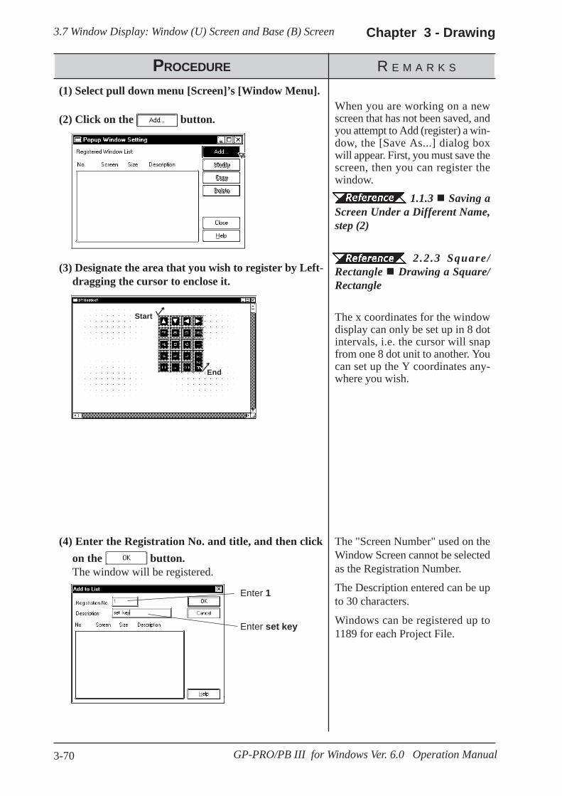
3.7 Window Display: Window (U) Screen and Base (B) Screen Chapter 3 - Drawing
3-70 GP-PRO/PB III for Windows Ver. 6.0 Operation Manual
(4) Enter the Registration No. and title, and then clickon the button.The window will be registered.
Enter set key
Enter 1
The "Screen Number" used on theWindow Screen cannot be selectedas the Registration Number.
The Description entered can be upto 30 characters.
Windows can be registered up to1189 for each Project File.
PROCEDURE R E M A R K S
(2) Click on the button.
(3) Designate the area that you wish to register by Left-dragging the cursor to enclose it.
When you are working on a newscreen that has not been saved, andyou attempt to Add (register) a win-dow, the [Save As...] dialog boxwill appear. First, you must save thescreen, then you can register thewindow.
1.1.3 Saving aScreen Under a Different Name,step (2)
2.2.3 Square/Rectangle Drawing a Square/Rectangle
The x coordinates for the windowdisplay can only be set up in 8 dotintervals, i.e. the cursor will snapfrom one 8 dot unit to another. Youcan set up the Y coordinates any-where you wish.
(1) Select pull down menu [Screen]’s [Window Menu].
Start
End

3.7 Window Display: Window (U) Screen and Base (B) ScreenChapter 3 - Drawing
3-71GP-PRO/PB III for Windows Ver. 6.0 Operation Manual
PROCEDURE R E M A R K S
(5) Click on the button to finish registration.When registering another window on the same screen,do not quit here, rather, start again from step (2).
[Window Registration]
By changing Size in the RegisteredWindow List of the Popup WindowSetting, a larger number of regis-tered items can be displayed.
Place the cursor at the bottom-rightcorner of the screen. The cursorchanges to a black arrow. Adjust thesize of the dialog box while hold-ing the left mouse button.
Shows the Window’sregistration data

3.7 Window Display: Window (U) Screen and Base (B) Screen Chapter 3 - Drawing
3-72 GP-PRO/PB III for Windows Ver. 6.0 Operation Manual
(4) Click on the button to copy the window.
(1) Select the [Screen] menu - [Window Registration]command.
(2) Select a window to be copied, and then click on the button.
PROCEDURE R E M A R K S
Copying Window Registration DataIf a registered window is copied, the same area (location) of another window can beregistered as a window.
To select multiple windows at atime, drag through the windowsbeing selected on the list, or selectthose windows by clicking on themwhile holding down the or key.
(3) Enter the registration number of a new window, thescreen number to which the window is to be copied,and that screen’s title.
If multiple windows have been se-lected in step (2), specify the startwindow number and screen num-ber of the destination. The windownumbers and screen numbers willbe assigned relatively so that thesmallest window number amongthose of the source windows corre-sponds to the start window num-ber.
ShiftCtrl

3.7 Window Display: Window (U) Screen and Base (B) ScreenChapter 3 - Drawing
3-73GP-PRO/PB III for Windows Ver. 6.0 Operation Manual
How to Display WindowsThe method used for calling up a registered window will differ dependingon whether the window’s type is global or local.
Global Window Display
You can set the “Global Window”area in the [Global Window Setup] fromthe GP panel’s OFFLINE menu or you can use the Global Window dialogbox, located in the GP-PRO/PBIII Project Manager screen’s [GP Setup]’s[Extended Settings] dialog. Click on the “Global Window” button to bringup this dialog.
Tag Reference Manual, 2.26 U-tag (Window Display) , GPSeries Users Manual, 5.3.3 Global Window Setup
Local Window Display
Here, a U-tag is used on a Base screen to display a window.
Tag Reference Manual, 2.26 U-tag (Window Display)

3-74 GP-PRO/PB III for Windows Ver. 6.0 Operation Manual
Memo
s you use this Screen Editor Software, file management work such ascopying and deleting created screens and projects will become easier,
thereby improving your work efficiency. This chapter covers “InformationManagement of your PRO-PB III data.”
A
4 SCREEN AND PROJECT MANAGEMENT
4.1 ................................................................Screen Editing
4.2 ...............................................................Project Editing
4.3 .......................... Project Compression/Decompression
4.4 ...................................................... Comparing Projects
4.5 ...................................................... Information Display
4.6 ................................... Table Editor Character Strings
4.7 ................................................................Symbol Editor
4.8 .............................................................. Device Monitor
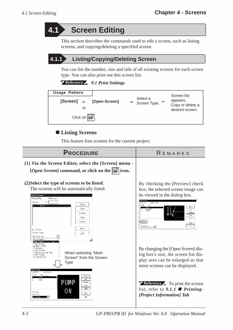
4-2
Chapter 4 - Screens
GP-PRO/PB III for Windows Ver. 6.0 Operation Manual
4.1 Screen Editing
4.1.1 Listing/Copying/Deleting Screen
Usage PatternSelect aScreen Type.[Screen] →→→→→ →→→→→
You can list the number, size and title of all existing screens for each screentype. You can also print out this screen list.
9.1 Print Settings
This section describes the commands used to edit a screen, such as listingscreens, and copying/deleting a specified screen.
4.1 Screen Editing
[Open Screen]
Listing ScreensThis feature lists screens for the current project.
To print the screenlist, refer to 9.1.1 Printing-[Project Information] Tab
By checking the [Preview] checkbox, the selected screen image canbe viewed in the dialog box.
(1) Via the Screen Editor, select the [Screen] menu -[Open Screen] command, or click on the icon.
(2)Select the type of screens to be listed.The screens will be automatically listed.
→→→→→Screen listappears.Copy or delete adesired screen.or
Click on .
By changing the [Open Screen] dia-log box's size, the screen list dis-play area can be enlarged so thatmore screens can be displayed.
PROCEDURE R E M A R K S
When selecting “MarkScreen” from the ScreenType
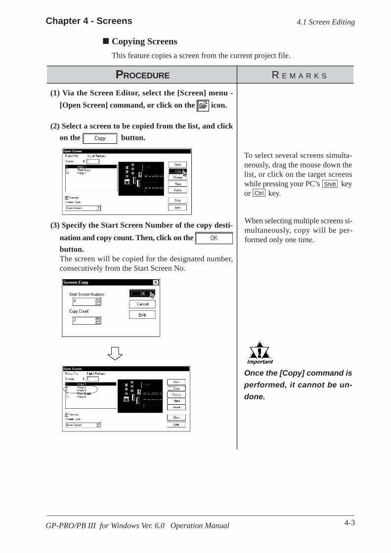
4-3
Chapter 4 - Screens
GP-PRO/PB III for Windows Ver. 6.0 Operation Manual
Copying ScreensThis feature copies a screen from the current project file.
PROCEDURE R E M A R K S
Once the [Copy] command isperformed, it cannot be un-done.
To select several screens simulta-neously, drag the mouse down thelist, or click on the target screenswhile pressing your PC’s keyor key.
(3) Specify the Start Screen Number of the copy desti-nation and copy count. Then, click on the button.The screen will be copied for the designated number,consecutively from the Start Screen No.
(1) Via the Screen Editor, select the [Screen] menu -[Open Screen] command, or click on the icon.
(2) Select a screen to be copied from the list, and clickon the button.
4.1 Screen Editing
ShiftCtrl
When selecting multiple screens si-multaneously, copy will be per-formed only one time.

4-4
Chapter 4 - Screens
GP-PRO/PB III for Windows Ver. 6.0 Operation Manual
Deleting ScreensThis feature deletes a screen from the current project file.
PROCEDURE R E M A R K S
Once the [Delete] command isperformed, it cannot be un-done.
To select several screens simulta-neously, drag the mouse down thelist, or click on the target screenswhile pressing your PC’s keyor key .
(3)Click on the button to delete the screen.
(1) Via the Screen Editor, select the [Screen] menu -[Open Screen] command, or click on the icon.
(2) Select a screen to be deleted from the list, and clickon the button.
4.1 Screen Editing
ShiftCtrl

4-5
Chapter 4 - Screens
GP-PRO/PB III for Windows Ver. 6.0 Operation Manual
Changing Screen Numbers and TitlesThis feature allows you to change screen numbers and titles in the current project file.
PROCEDURE R E M A R K S
If any existing screen num-ber is specified, it will beoverwritten.
The currently open screen cannotbe changed.
(3)Change the screen number and title, and then clickon the button to delete the screen.
[Changing only One Screen](1) Via the Screen Editor, select the [Screen] menu -
[Open Screen] command, or click on the icon.
(2) Select a screen to be changed from the list, and clickon the button.
4.1 Screen Editing
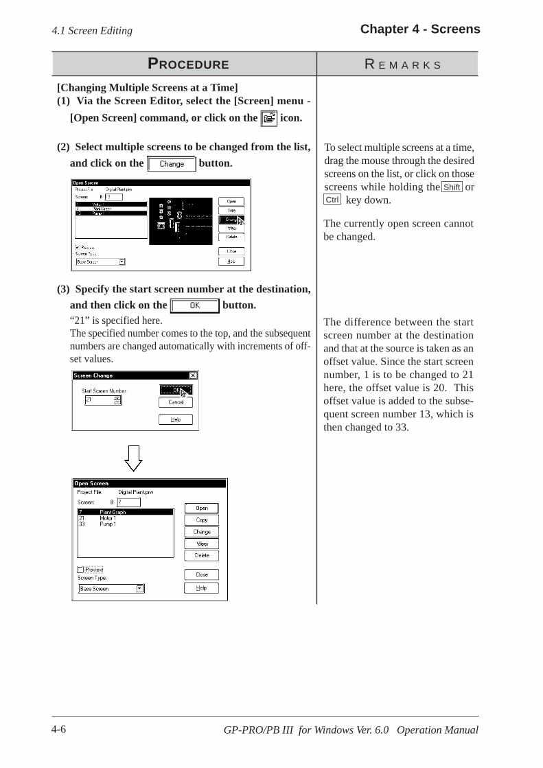
4-6
Chapter 4 - Screens
GP-PRO/PB III for Windows Ver. 6.0 Operation Manual
PROCEDURE R E M A R K S
To select multiple screens at a time,drag the mouse through the desiredscreens on the list, or click on thosescreens while holding the or key down.
(3) Specify the start screen number at the destination,and then click on the button.“21” is specified here.The specified number comes to the top, and the subsequentnumbers are changed automatically with increments of off-set values.
[Changing Multiple Screens at a Time](1) Via the Screen Editor, select the [Screen] menu -
[Open Screen] command, or click on the icon.
(2) Select multiple screens to be changed from the list,and click on the button.
ShiftCtrl
4.1 Screen Editing
The difference between the startscreen number at the destinationand that at the source is taken as anoffset value. Since the start screennumber, 1 is to be changed to 21here, the offset value is 20. Thisoffset value is added to the subse-quent screen number 13, which isthen changed to 33.
The currently open screen cannotbe changed.
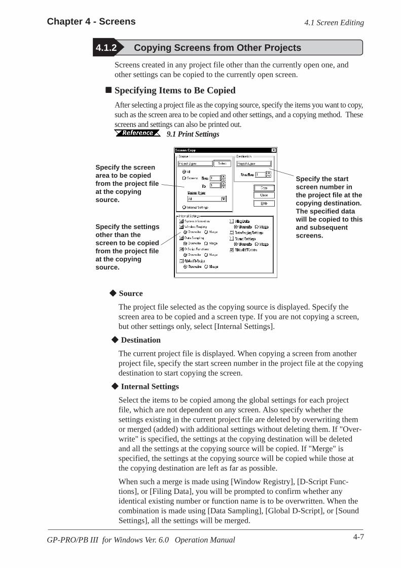
4-7
Chapter 4 - Screens
GP-PRO/PB III for Windows Ver. 6.0 Operation Manual
Specifying Items to Be CopiedAfter selecting a project file as the copying source, specify the items you want to copy,such as the screen area to be copied and other settings, and a copying method. Thesescreens and settings can also be printed out. 9.1 Print Settings
4.1.2 Copying Screens from Other ProjectsScreens created in any project file other than the currently open one, andother settings can be copied to the currently open screen.
4.1 Screen Editing
Specify the screenarea to be copiedfrom the project fileat the copyingsource.
Specify the settingsother than thescreen to be copiedfrom the project fileat the copyingsource.
Specify the startscreen number inthe project file at thecopying destination.The specified datawill be copied to thisand subsequentscreens.
Source
The project file selected as the copying source is displayed. Specify thescreen area to be copied and a screen type. If you are not copying a screen,but other settings only, select [Internal Settings].
Destination
The current project file is displayed. When copying a screen from anotherproject file, specify the start screen number in the project file at the copyingdestination to start copying the screen.
Internal Settings
Select the items to be copied among the global settings for each projectfile, which are not dependent on any screen. Also specify whether thesettings existing in the current project file are deleted by overwriting themor merged (added) with additional settings without deleting them. If "Over-write" is specified, the settings at the copying destination will be deletedand all the settings at the copying source will be copied. If "Merge" isspecified, the settings at the copying source will be copied while those atthe copying destination are left as far as possible.
When such a merge is made using [Window Registry], [D-Script Func-tions], or [Filing Data], you will be prompted to confirm whether anyidentical existing number or function name is to be overwritten. When thecombination is made using [Data Sampling], [Global D-Script], or [SoundSettings], all the settings will be merged.

4-8
Chapter 4 - Screens
GP-PRO/PB III for Windows Ver. 6.0 Operation Manual
PROCEDURE R E M A R K S
<When [All] is selected>
All screens in the Project are cop-ied.
<Notes on copying windows regis-tered with the Window Screen orBase Screen>
(1) When copying a window regis-tered with the Window Screen,select [All], or specify theScreen Type as "WindowScreen" under the [ScreenFrom/To] option in the [Source]field.
(2) When copying a window regis-tered with the Base Screen,check the "Window Registry"option in the "Internal Settings"field.
<When Windows of the same No.exist in the both the Source andDestination Projects>
A window registered with the BaseScreen cannot be copied onto awindow registered with the Win-dow Screen.
(3) Enter the screen type and screen number of the origi-nal screen.Those screens corresponding to the specified initialscreen number through the final screen number will becopied.
To select a screen located in a dif-ferent folder, you must change tothat folder.
1.1.2 Selectingan Existing Project
The currently opened project can-not be selected.
When you double-click on theproject name selected in step (2),you can skip the com-mand.
First, open the copy designation project.
(1) Select the Project Manager’s [Utility] menu - [ScreenCopy] command.
(2) Select the project file to be copied (original projectfile) from the screen list, or enter the target projectname, then click on the button.
4.1 Screen Editing
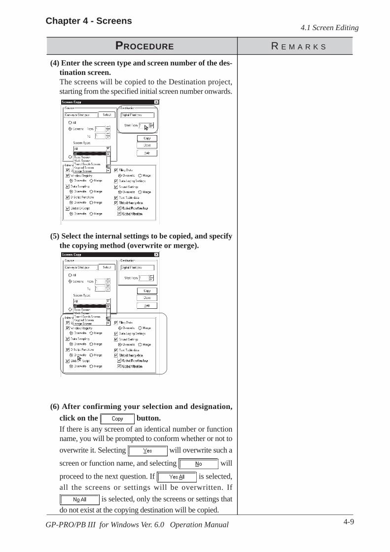
4-9
Chapter 4 - Screens
GP-PRO/PB III for Windows Ver. 6.0 Operation Manual
PROCEDURE R E M A R K S
(5) Select the internal settings to be copied, and specifythe copying method (overwrite or merge).
(4) Enter the screen type and screen number of the des-tination screen.The screens will be copied to the Destination project,starting from the specified initial screen number onwards.
4.1 Screen Editing
(6) After confirming your selection and designation,click on the button.If there is any screen of an identical number or functionname, you will be prompted to conform whether or not tooverwrite it. Selecting will overwrite such a
screen or function name, and selecting will
proceed to the next question. If is selected,all the screens or settings will be overwritten. If
is selected, only the screens or settings thatdo not exist at the copying destination will be copied.

4-10
Chapter 4 - Screens
GP-PRO/PB III for Windows Ver. 6.0 Operation Manual
PROCEDURE R E M A R K S
After replacing the screens,you must re-enter all Tag de-vice addresses.
To subsequently copy any otherscreen in the same project file, re-peat the procedures starting withstep (3).
(7) Click on the button to exit the screen copymode.The number of screens copied will be displayed in thedialog box.
4.1 Screen Editing
(8) Click on the button.
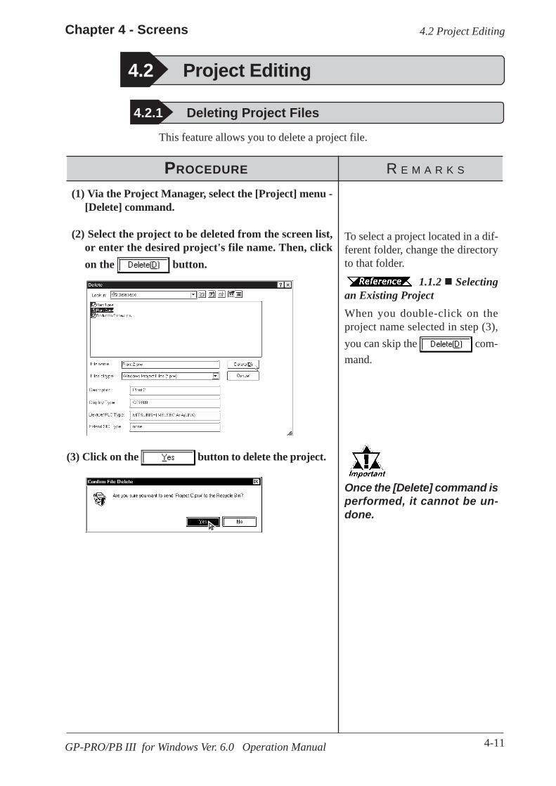
4-11
Chapter 4 - Screens
GP-PRO/PB III for Windows Ver. 6.0 Operation Manual
4.2 Project Editing
4.2.1 Deleting Project Files
PROCEDURE R E M A R K S
To select a project located in a dif-ferent folder, change the directoryto that folder.
1.1.2 Selectingan Existing Project
Once the [Delete] command isperformed, it cannot be un-done.
When you double-click on theproject name selected in step (3),you can skip the com-mand.
(3) Click on the button to delete the project.
(1) Via the Project Manager, select the [Project] menu -[Delete] command.
(2) Select the project to be deleted from the screen list,or enter the desired project's file name. Then, clickon the button.
This feature allows you to delete a project file.
4.2 Project Editing

4-12
Chapter 4 - Screens
GP-PRO/PB III for Windows Ver. 6.0 Operation Manual
4.2.2 Rebuilding A Project (Rebuild)
9. Parts and Tags placed on the GP-PRO/PB III for Windows programscreen cannot be displayed on the GP unit, or, a different screen thandesired is displayed on the GP unit. (i.e. the relationship between thescreen data and Parts data is not correct)
If this error message is displayed, GP-PRO/PB III for Windows programcannot read the target file until this file is rebuilt.If a file’s data cannot be completely restored with the “Rebuild” tool, thesystem treats this data as abnormal data and deletes it. In this case, you mustedit this PRW file using GP-PRO/PB III for Windows program after the“Rebuild” command is performed.
File Rebuilding requires approximately three times the hard disk spaceoccupied by the Project file.
The “Rebuild” tool is used to both check the contents of the PRW files, PROfiles, CPW files, CPL files and MRK files created with GP-PRO/PB III forWindows, as well as to rebuild these files if they are damaged.
In the following cases, use the “Rebuild” command to restore file data.
1. You personal computer is either reset or shut down while you aresaving data.
2. The system crashed while you were saving data.3. Your floppy disk or hard disk is damaged.4. Your personal computer’s disk drive is defective.5. A system error (an error not specified in the error message list, such as
a partition or checksum error) occurs while a screen is being opened ortransferred.
6. The desired project file does not display as a PRW file during projectselection, or an existing screen’s number is not displayed when you tryto open that screen.
7. You cannot select a project file when you try to perform the [SelectProject] command. (i.e. the GP-PRO/PB III for Windows programcannot recognize the project file as a PRW file)
8. When you try to open a file, an error message appears, indicating thatthe file is damaged.
4.2 Project Editing
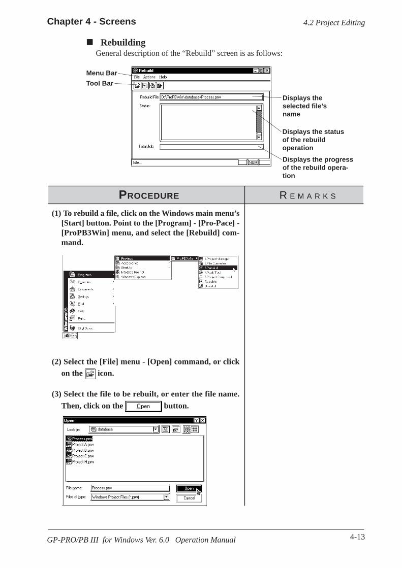
4-13
Chapter 4 - Screens
GP-PRO/PB III for Windows Ver. 6.0 Operation Manual
RebuildingGeneral description of the “Rebuild” screen is as follows:
Menu Bar
Displays the progressof the rebuild opera-tion
Displays the statusof the rebuildoperation
Displays theselected file’sname
Tool Bar
PROCEDURE R E M A R K S
(2) Select the [File] menu - [Open] command, or clickon the icon.
(1) To rebuild a file, click on the Windows main menu’s[Start] button. Point to the [Program] - [Pro-Pace] -[ProPB3Win] menu, and select the [Rebuild] com-mand.
4.2 Project Editing
(3) Select the file to be rebuilt, or enter the file name.Then, click on the button.
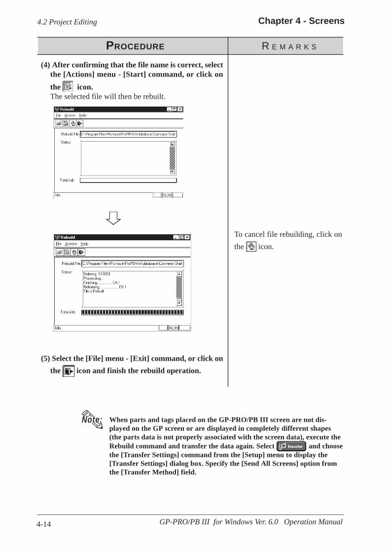
4-14
Chapter 4 - Screens
GP-PRO/PB III for Windows Ver. 6.0 Operation Manual
PROCEDURE R E M A R K S
To cancel file rebuilding, click onthe icon.
4.2 Project Editing
(4) After confirming that the file name is correct, selectthe [Actions] menu - [Start] command, or click onthe icon.The selected file will then be rebuilt.
(5) Select the [File] menu - [Exit] command, or click onthe icon and finish the rebuild operation.
When parts and tags placed on the GP-PRO/PB III screen are not dis-played on the GP screen or are displayed in completely different shapes(the parts data is not properly associated with the screen data), execute theRebuild command and transfer the data again. Select and choosethe [Transfer Settings] command from the [Setup] menu to display the[Transfer Settings] dialog box. Specify the [Send All Screens] option fromthe [Transfer Method] field.
Note:

4-15
Chapter 4 - Screens
GP-PRO/PB III for Windows Ver. 6.0 Operation Manual
In word address conversion mode,Tag addresses specified by a bit ad-dress can also be changed, withina specified range.
When using any of the followingPLCs, specify the PLC number, aswell:FACTORY ACE, 1:n communica-tion (Yokogawa Electric Corp.)TOYOPUC-PC2, 1:n communica-tion (Toyota Machine Works)TOYOPUC-PC3J, 1:n communi-cation (Toyota Machine Works)CP9200SH Series (YasukawaElectric Corp.)SDC Series (Yamatake ElectricCorp.)T H E R M A C N E O s e r i e s(OMRON)
4.2.3 Converting Addresses and Device Codes
PROCEDURE R E M A R K S
PLC No.
To convert the addresses of tags as-signed to the global functions keysfor the GP-H70/GP2000H at atime, previously select the [HandyGlobal Tag] option from the[Screen Type] menu beforehand.
When converting addresses, besure that the address settings meetthe following condition:“Final address before conver-sion” - “Initial address beforeconversion” ≤≤≤≤≤ “Final address af-ter conversion” - “Initial ad-dress after conversion”If the left side is larger than theright side in the above formula, theTags corresponding to the surplusaddresses will be assigned to thefinal address of the same device.
(3) Enter the address conversion range and the updatedinitial address.Before this step is performed, be sure that the first andlast device codes used are the same. You cannot specifyan address conversion range for a different device.
(1) Via the Project Manager, select the [Utility] menu -[Convert Addresses] command.
(2) Select the type of the address conversion to perform:Word Address or Bit Address.
This feature allows you to change a Tag’s addresses. This address conver-sion can be performed on either word or bit addresses. This command isuseful for changing both addresses or an address’ device code.
4.2 Project Editing
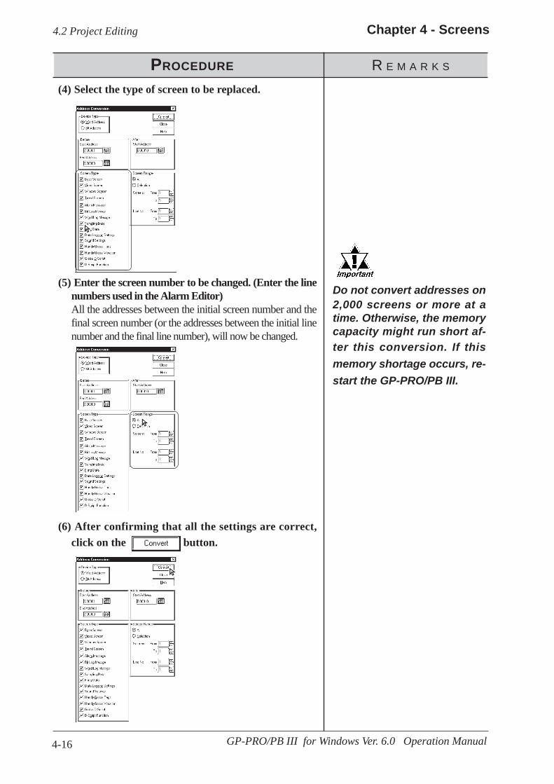
4-16
Chapter 4 - Screens
GP-PRO/PB III for Windows Ver. 6.0 Operation Manual
PROCEDURE R E M A R K S
(6) After confirming that all the settings are correct,click on the button.
(5) Enter the screen number to be changed. (Enter the linenumbers used in the Alarm Editor)All the addresses between the initial screen number and thefinal screen number (or the addresses between the initial linenumber and the final line number), will now be changed.
(4) Select the type of screen to be replaced.
4.2 Project Editing
Do not convert addresses on2,000 screens or more at atime. Otherwise, the memorycapacity might run short af-ter this conversion. If thismemory shortage occurs, re-start the GP-PRO/PB III.
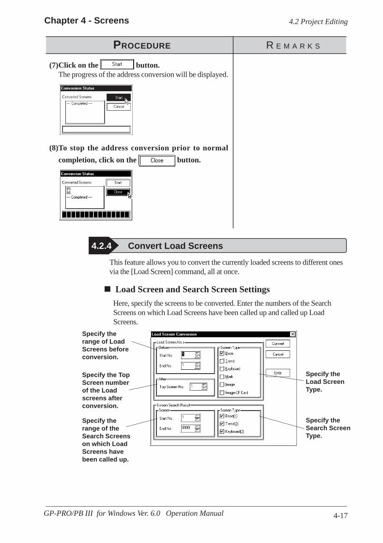
4-17
Chapter 4 - Screens
GP-PRO/PB III for Windows Ver. 6.0 Operation Manual
PROCEDURE R E M A R K S
(8)To stop the address conversion prior to normalcompletion, click on the button.
(7)Click on the button.The progress of the address conversion will be displayed.
4.2 Project Editing
Load Screen and Search Screen SettingsHere, specify the screens to be converted. Enter the numbers of the SearchScreens on which Load Screens have been called up and called up LoadScreens.
4.2.4 Convert Load ScreensThis feature allows you to convert the currently loaded screens to different onesvia the [Load Screen] command, all at once.
Specify therange of LoadScreens beforeconversion.
Specify the TopScreen numberof the Loadscreens afterconversion.
Specify therange of theSearch Screenson which LoadScreens havebeen called up.
Specify theSearch ScreenType.
Specify theLoad ScreenType.
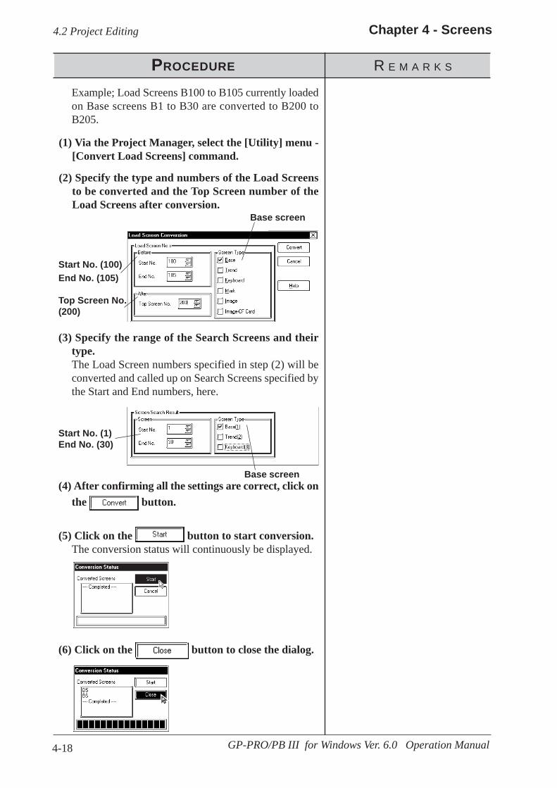
4-18
Chapter 4 - Screens
GP-PRO/PB III for Windows Ver. 6.0 Operation Manual
(2) Specify the type and numbers of the Load Screensto be converted and the Top Screen number of theLoad Screens after conversion.
4.2 Project Editing
PROCEDURE R E M A R K S
(6) Click on the button to close the dialog.
Example; Load Screens B100 to B105 currently loadedon Base screens B1 to B30 are converted to B200 toB205.
(3) Specify the range of the Search Screens and theirtype.The Load Screen numbers specified in step (2) will beconverted and called up on Search Screens specified bythe Start and End numbers, here.
(4) After confirming all the settings are correct, click onthe button.
(5) Click on the button to start conversion.The conversion status will continuously be displayed.
(1) Via the Project Manager, select the [Utility] menu -[Convert Load Screens] command.
Start No. (100)End No. (105)
Top Screen No.(200)
Base screen
Start No. (1)End No. (30)
Base screen

4-19
Chapter 4 - Screens
GP-PRO/PB III for Windows Ver. 6.0 Operation Manual
The drawing area, commands andmemory used by this change willvary depending on the selected GPtype. Be sure to check these itemsbefore changing the GP type to besure that your change(s) will becompatible with your existingproject’s data.
(2)To change the GP type, click on the desired GP type.
(3)Click on the button.
You can change the GP type of your current project.· After changing the GP type, you can save the current project using the
[Project] menu - [Save As] command.
1.1.2 Saving a Project Under a Different Name
4.2.5 Changing a Project’s GP Type
Note:
(1)Via the Project Manager, click on the icon, or se-lect the [Project] menu - [Change GP Type] command.
PROCEDURE R E M A R K S
Do not open screens other than theProject Manager. Doing so will dis-able the selection of the GP Type.
4.2 Project Editing

4-20
Chapter 4 - Screens
GP-PRO/PB III for Windows Ver. 6.0 Operation Manual
Horizontal type
ABC
AB
C
Vertical type
• When a high-resolution type GP unit is replaced with a low-resolutiontype, data beyond the display range cannot be displayed.If a project file is changed to a low-resolution type and then changedback to the high-resolution type again, data beyond the display range(data that cannot be displayed with the low-resolution type GP panel)will be restored.
• The maximum number of characters used for an alarm summarydiffers according to the GP unit screen’s resolution. For example, if analarm message is created for a high-resolution type GP and thenchanged for the low-resolution type, data beyond the message areacannot be displayed.
• When a vertical type GP unit is replaced with a horizontal type orvice- versa, the displayed screen is rotated 90º . Therefore, you mustalso edit the screen using the [Rotate] command. After editing, be sureto check that the displayed data is as desired.
Example)
4.2 Project Editing
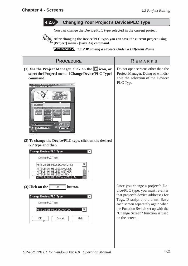
4-21
Chapter 4 - Screens
GP-PRO/PB III for Windows Ver. 6.0 Operation Manual
4.2.6 Changing Your Project’s Device/PLC Type
Note:
PROCEDURE R E M A R K S
Once you change a project’s De-vice/PLC type, you must re-enterthat project’s device addresses forTags, D-script and alarms. Saveeach screen separately again whenthe Function Switch set up with the"Change Screen" function is usedon the screen.
(2) To change the Device/PLC type, click on the desiredGP type and then.
You can change the Device/PLC type selected in the current project.
After changing the Device/PLC type, you can save the current project using[Project] menu - [Save As] command.
1.1.2 Saving a Project Under a Different Name
(3)Click on the button.
(1) Via the Project Manager, click on the icon, orselect the [Project] menu - [Change Device/PLC Type]command.
Do not open screens other than theProject Manager. Doing so will dis-able the selection of the Device/PLC Type.
4.2 Project Editing

4-22
Chapter 4 - Screens
GP-PRO/PB III for Windows Ver. 6.0 Operation Manual
You can change the Extend SIO Type selected in the current project. 1.1.2 Creating a New Project
This feature is available only with the GP-2000 Series (except the GP-2301and GP-2501).After changing the Extend SIO Type, you can save the current project using[Project] menu - [Save As] command.
1.1.2 Saving a Project File under a Different Name
4.2.7 Changing Extend SIO Type
Note:
PROCEDURE R E M A R K S
(2)To change the Extend SIO Type, click on the desiredExtend SIO type and then.
(3)Click on the button.
(1) Via the Project Manager, click on the icon, orselect the [Project] menu - [Change Extend SIO Type]command.
Do not open screens otherthan the Project Manager.Doing so will disable theselection of the Extend SIOType.
4.2 Project Editing

4-23
Chapter 4 - Screens
GP-PRO/PB III for Windows Ver. 6.0 Operation Manual
4.3 Project Compression/Decompression
4.3 Project Compression/Decompression
Displays the filename of the projectto be compressed/decompressed
Displays the overallprogress of theproject file compres-sion/decompression
Displays the statusof the project filecompression/decom-pression
Usage Pattern
Pack ToolPROPB3WinStart →→→→→→→→→→→→→→→
Compressing a project file reduces the size of its data to accomodate astandard floppy disk’s limited capacity. A compressed project file and itsscreens however, cannot be edited. To edit the screens, you must first de-compress the project file.
A general description of the compression tool is as follows:
[Action] [Compress Project File]/[Decompress Project File]
Designate a Projectfile to be compressed ordecompressed.
→→→→→ →→→→→ →→→→→ Click on the
button.or
Click on or .

4-24
Chapter 4 - Screens
GP-PRO/PB III for Windows Ver. 6.0 Operation Manual
A Project file can be compressed to a smaller size. At this time, a large sized file can bedivided into smaller files automatically according to the specified capacity. After a projectfile is divided into several files during compression, serial numbers are assigned to thefirst character of each file extension (or assigned to the first and second characters if thefile number has two digits).Example) *.0PW, *.1PW...*.9PW, *.10W, *.11W
4.3.1 Compressing a Project File
PROCEDURE R E M A R K S
(1) First, click the Windows [Start] button. Then, clickon the [Programs] - [Pro-face] - [ProPB3Win] menuand click the [4. Pack Tool] menu item. You can alsoselect [Pack Tool...] from the PRO-PB Utility pull-down menu.
Enter the file name ofthe project file to becompressed, or select adesired file name fromthe list by clicking onthe [Browse] button
Used to selectthe file sizelimit
Used to locatethe project fileto be com-pressed
The compressedproject file is automati-cally divided intoseveral files accordingto the specified file size
4.3 Project Compression/Decompression
From Windows Main Menu From GP-PRO ProgramManager Utility Menu

4-25
Chapter 4 - Screens
GP-PRO/PB III for Windows Ver. 6.0 Operation Manual
PROCEDURE R E M A R K S
To call up a menu of all the avail-able folders, click on the button.
(4)To divide the project file during compression, clickon the [Separate File] check box, and select the de-sired file size limit.
(3)Select the folder and project file to be compressed,or enter the file name.The file name of the desired project file will be displayedin the “Pack” screen.
(2)Select the [Action] menu - [Compress Project File]command, or click on the icon.
The compressed project file will bestored in the same folder as theoriginal project file.
(5)Click on the button.If the same file name already exists, the system asks ifthe existing file must be overwritten. If you select
, the existing file will be overwritten. If youselect , the existing file will not be overwrit-ten, and you will return to the previous dialog box.
4.3 Project Compression/Decompression

4-26
Chapter 4 - Screens
GP-PRO/PB III for Windows Ver. 6.0 Operation Manual
PROCEDURE R E M A R K S
(6) Select the [Action] menu - [Exit] command, or clickon the icon.
4.3 Project Compression/Decompression

4-27
Chapter 4 - Screens
GP-PRO/PB III for Windows Ver. 6.0 Operation Manual
4.3.2 Decompressing a Project FileA compressed project file (0PW file) cannot be edited. To edit the com-pressed project file, you must first decompress it.
Enter the file name ofthe project file to bedecompressed, orselect the desired filename from the list byclicking on the[Browse] button
Used to locate theproject file to bedecompressed
(1)Click on the Windows desktop’s [Start] button. Then,point to the [Programs] - [Pro-face] - [ProPB3win]menu and click on the [4. Pack Tool] menu.
PROCEDURE R E M A R K S
4.3 Project Compression/Decompression

4-28
Chapter 4 - Screens
GP-PRO/PB III for Windows Ver. 6.0 Operation Manual
(2) Select the [Action] menu-[Decompress Project File]command, or click on the icon.
PROCEDURE R E M A R K S
To select a folder, click on the button.
To decompress a com-pressed project file that hasbeen divided into severalfiles, make sure that all di-vided files are available.However, when you specifythe file name to be decom-pressed, the system displaysthe first file name (*.0PW)only.
The decompressed project file willbe stored in the same folder as thecompressed file.
(3) Select a folder and Project file to be decompressedor enter the file name, and click on the button.If the same file name already exists, the system asks ifthe existing file must be overwritten. If you select
, the existing file will be overwritten. If you
select , the existing file will not be over-written, and you will return to the previous dialog box.
(4) Select the [Action] menu - [Exit] command, or clickon the icon.
4.3 Project Compression/Decompression
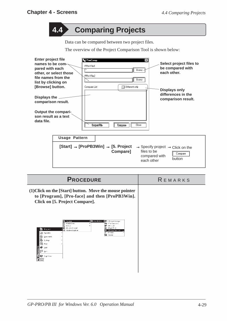
4-29
Chapter 4 - Screens
GP-PRO/PB III for Windows Ver. 6.0 Operation Manual
4.4 Comparing Projects
Usage Pattern
Specify projectfiles to becompared witheach other
[5. ProjectCompare]
[Start] →→→→→ →→→→→
Data can be compared between two project files.
The overview of the Project Comparison Tool is shown below:
Enter project filenames to be com-pared with eachother, or select thosefile names from thelist by clicking on[Browse] button.
Displays thecomparison result.
Output the compari-son result as a textdata file.
Select project files tobe compared witheach other.
Displays onlydifferences in thecomparison result.
Click on the
button
→→→→→[ProPB3Win] →→→→→
PROCEDURE R E M A R K S
(1)Click on the [Start] button. Move the mouse pointerto [Program], [Pro-face] and then [ProPB3Win].Click on [5. Project Compare].
4.4 Comparing Projects

4-30
Chapter 4 - Screens
GP-PRO/PB III for Windows Ver. 6.0 Operation Manual
(2) Select a Project file to be compared or enter the filename, and click on the button.
PROCEDURE R E M A R K S
Checking the [Different only]check box will enable you to togglebetween displaying only differ-ences in the comparison result anddisplaying all the details of thecomparison result.
Specify folders
Clicking on the [Output File] but-ton will enable you to output thecomparison result as a text file(*.txt).
4.4 Comparing Projects
(3) Select the [Action] menu - [Exit] command, or clickon the icon.
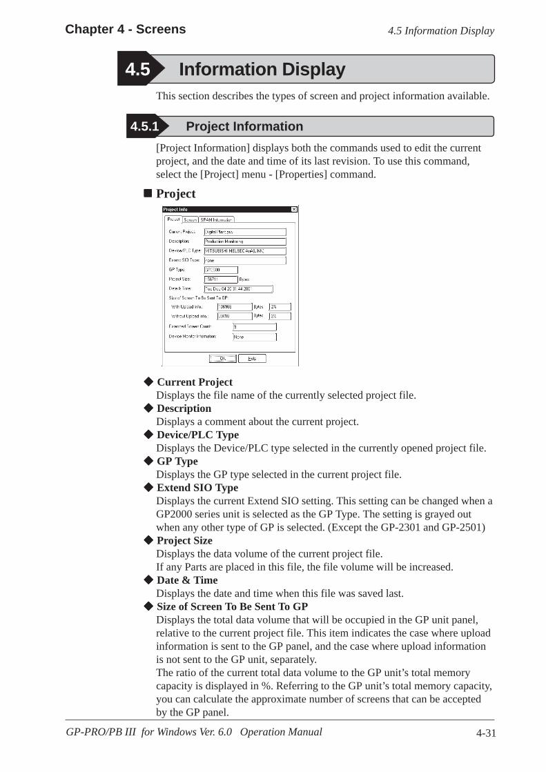
4-31
Chapter 4 - Screens
GP-PRO/PB III for Windows Ver. 6.0 Operation Manual
[Project Information] displays both the commands used to edit the currentproject, and the date and time of its last revision. To use this command,select the [Project] menu - [Properties] command.
Project
4.5 Information Display
4.5.1 Project Information
Current ProjectDisplays the file name of the currently selected project file. DescriptionDisplays a comment about the current project. Device/PLC TypeDisplays the Device/PLC type selected in the currently opened project file. GP TypeDisplays the GP type selected in the current project file. Extend SIO TypeDisplays the current Extend SIO setting. This setting can be changed when aGP2000 series unit is selected as the GP Type. The setting is grayed outwhen any other type of GP is selected. (Except the GP-2301 and GP-2501) Project SizeDisplays the data volume of the current project file.If any Parts are placed in this file, the file volume will be increased. Date & TimeDisplays the date and time when this file was saved last. Size of Screen To Be Sent To GPDisplays the total data volume that will be occupied in the GP unit panel,relative to the current project file. This item indicates the case where uploadinformation is sent to the GP panel, and the case where upload informationis not sent to the GP unit, separately.The ratio of the current total data volume to the GP unit’s total memorycapacity is displayed in %. Referring to the GP unit’s total memory capacity,you can calculate the approximate number of screens that can be acceptedby the GP panel.
This section describes the types of screen and project information available.
4.5 Information Display
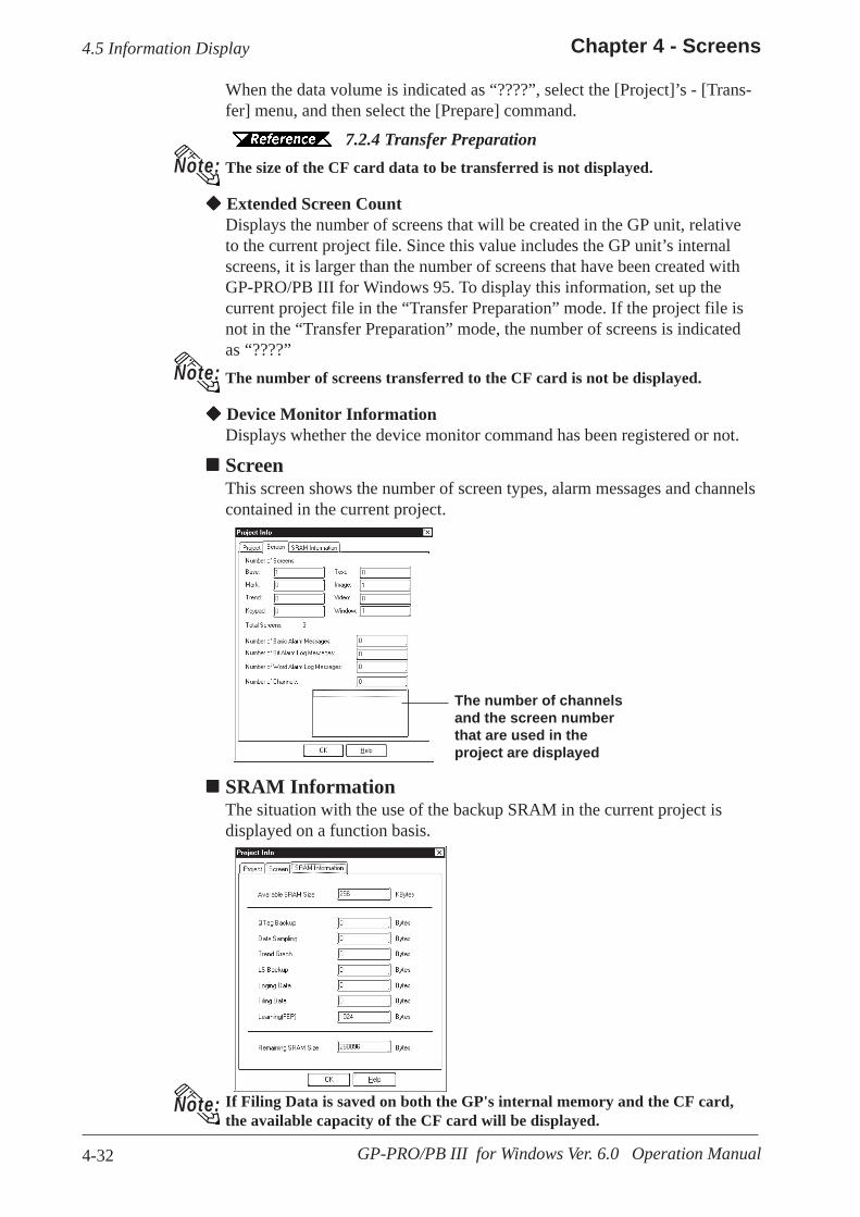
4-32
Chapter 4 - Screens
GP-PRO/PB III for Windows Ver. 6.0 Operation Manual
When the data volume is indicated as “????”, select the [Project]’s - [Trans-fer] menu, and then select the [Prepare] command.
7.2.4 Transfer PreparationThe size of the CF card data to be transferred is not displayed.
Extended Screen CountDisplays the number of screens that will be created in the GP unit, relativeto the current project file. Since this value includes the GP unit’s internalscreens, it is larger than the number of screens that have been created withGP-PRO/PB III for Windows 95. To display this information, set up thecurrent project file in the “Transfer Preparation” mode. If the project file isnot in the “Transfer Preparation” mode, the number of screens is indicatedas “????”The number of screens transferred to the CF card is not be displayed.
Device Monitor InformationDisplays whether the device monitor command has been registered or not.
ScreenThis screen shows the number of screen types, alarm messages and channelscontained in the current project.
If Filing Data is saved on both the GP's internal memory and the CF card,the available capacity of the CF card will be displayed.
Note:
Note:
SRAM InformationThe situation with the use of the backup SRAM in the current project isdisplayed on a function basis.
Note:
4.5 Information Display
The number of channelsand the screen numberthat are used in theproject are displayed

4-33
Chapter 4 - Screens
GP-PRO/PB III for Windows Ver. 6.0 Operation Manual
Project NameDisplays the file name of the currently selected project file.
Device/PLC TypeDisplays the Device/PLC type selected in the current project file.
Current ScreenDisplays the screen type and screen number of the current screen.
DescriptionDisplays the title of the current screen.
SizeDisplays the data volume of the current screen. If any Parts are placed onthis screen, the screen data volume will be increased.
Tag
Used TagsDisplays the number of Tags specified on the current screen.
Available Number of TagsDisplays the acceptable number of Tags after subtracting the number of Tagsspecified on the current screen from the allowable maximum number ofTags.
The [Screen Information] screen displays the settings for the currently openscreen, as well as the date and time of its last revision. To use this command,select the [Project] menu’s - [Screen Information] command.
Screen
4.5 Information Display
4.5.2 Screen Information

4-34
Chapter 4 - Screens
GP-PRO/PB III for Windows Ver. 6.0 Operation Manual
4.5 Information Display
4.5.3 Version Information
<Project Manager Version Information>
[Version Information] displays the GP-PRO/PB III Project Manager andEditor’s version information. To see this data, select the [Help] menu -[About] command.
Maximum Number of TagsDisplays the maximum number of Tags available on the current screen. Theallowable maximum number of Tags varies depending on the selected GPtype.
GP-270, GP-370, GP-H70 ....................................128 TagsGP-470, GP-570, GP-571, GP-675, GP-870 ........256 TagsGP-377, GP-77R, GP2000 series .........................384 Tags
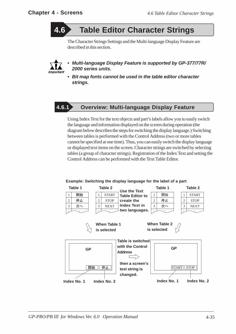
4-35
Chapter 4 - Screens
GP-PRO/PB III for Windows Ver. 6.0 Operation Manual
4.6 Table Editor Character Strings
1
2
3: :
1
2
3:
START
STOP
NEXT:
1
2
3: :
1
2
3:
START
STOP
NEXT:
START STOP
Table 1
The Character Strings Settings and the Multi-language Display Feature aredescribed in this section.
• Multi-language Display Feature is supported by GP-377/77R/2000 series units.
• Bit map fonts cannot be used in the table editor characterstrings.
Table 2 Table 1 Table 2
When Table 1is selected
When Table 2is selected
then a screen’stext string ischanged.
4.6 Table Editor Character Strings
4.6.1 Overview: Multi-language Display Feature
Using Index Text for the text objects and part’s labels allow you to easily switchthe language and information displayed on the screen during operation (thediagram below describes the steps for switching the display language.) Switchingbetween tables is performed with the Control Address (two or more tablescannot be specified at one time). Thus, you can easily switch the display languageor displayed text items on the screen. Character strings are switched by selectingtables (a group of character strings). Registration of the Index Text and setting theControl Address can be performed with the Text Table Editor.
Index No. 1
Example: Switching the display language for the label of a part
Use the TextTable Editor tocreate theIndex Text intwo languages.
Index No. 2 Index No. 1 Index No. 2
GPGP
Table is switchedwith the ControlAddress

4-36
Chapter 4 - Screens
GP-PRO/PB III for Windows Ver. 6.0 Operation Manual
4.6 Table Editor Character Strings
Precautions for switching tables with the Alarm function
• When a table is switched while an alarm message (Flow display) is displayed,the switched table is not used until the next message is issued.
• Switching tables uses the same process as switching screens.Therefore, some screen displays drawn with tags may not beable to be refreshed.
• The following character strings cannot be changed even whenthe tables are switched.
– [A-tag] character strings– [K-tag] character strings– [S-tag] character strings– [P-tag] format character strings– [X-tag] character strings– Filing Feature– Loging Feature– Message Display
ENGLISH
A PRESSURE ERROR TANK A PRESS
ENGLISH ENGLISH
GP
(Direction of thedisplay flow)
(Direction of the display flow)
Switch the tables
Japanese toEnglish
GP
ALARM AALARM BALARM C
GPJapanese toEnglish
Switch thetables
• When the print setting is enabled for the Alarm Message Function (Flowdisplay), the alarm message of the table (language) displayed at the momentwhen the alarm is triggered or reset will print.
• When a table is switched while real-time printing is set to print the alarmsummary (a-tag) or log alarms (Q-tags), the switched table will be used startingfrom the next print job.
A
A
BC

4-37
Chapter 4 - Screens
GP-PRO/PB III for Windows Ver. 6.0 Operation Manual
4.6 Table Editor Character Strings
4.6.2 Table Editor Index Character StringsThe Table Editor is used to create a table’s index character strings.
Table Editor Index Character Strings can be exported in CSV format. You canalso import a CSV file to use as an index character string.
Click here tospecify theControl Address
Select a table toenter characterstrings. Up to 16tables can beregistered
Index No.Up to 3,000character stringscan be registered
Set the font(language) for theselected table
Double-click onthis area to call upa message dialogbox (Up to 1,200characters)
[Screen/Setup]
Operation procedures
Start →→→→→→→→→→ →→→→→ →→→→→
Table Editor Features
[TextTable...]
AssignControlAddress.
Select fontfrom [FontSetting]menu.
→→→→→Enter indexcharacterstring.
→→→→→Save tabledata.
• When a table is switched while log alarms (Q-tags) are being written into theCF Card as a CSV file, the switched table is used immediately.
• The steps for switching tables are similar to those for switching screens. There-fore, the Sub Display, Cursor Display and Scroll Display that were displayedbefore the switching with the Log Alarm (Q-tag) will not be reproduced.
After setting upthe text, specifythe line and clickthe [Go to] buttonto jump to thespecified line.
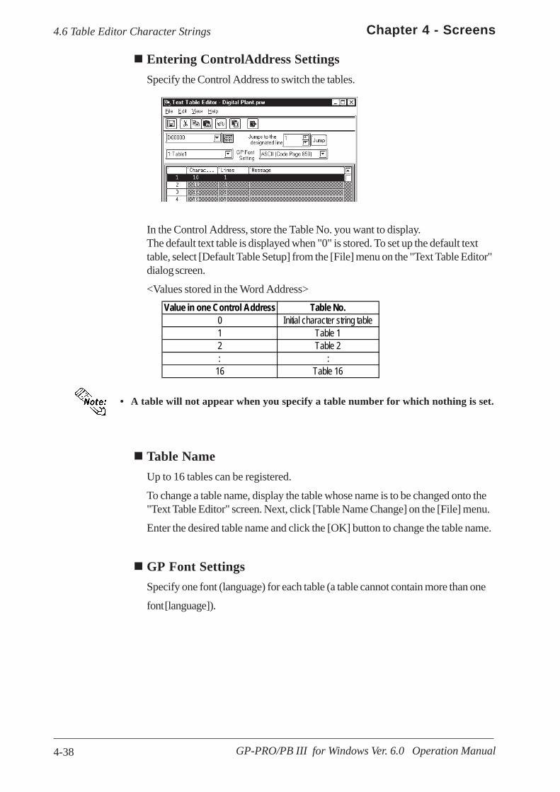
4-38
Chapter 4 - Screens
GP-PRO/PB III for Windows Ver. 6.0 Operation Manual
4.6 Table Editor Character Strings
Entering ControlAddress SettingsSpecify the Control Address to switch the tables.
In the Control Address, store the Table No. you want to display.The default text table is displayed when "0" is stored. To set up the default texttable, select [Default Table Setup] from the [File] menu on the "Text Table Editor"dialog screen.
<Values stored in the Word Address>
• A table will not appear when you specify a table number for which nothing is set.
Value in one Control Address Table No.0 Initial character string table1 Table 12 Table 2: :
16 Table 16
Table NameUp to 16 tables can be registered.
To change a table name, display the table whose name is to be changed onto the"Text Table Editor" screen. Next, click [Table Name Change] on the [File] menu.
Enter the desired table name and click the [OK] button to change the table name.
GP Font SettingsSpecify one font (language) for each table (a table cannot contain more than one
font [language]).
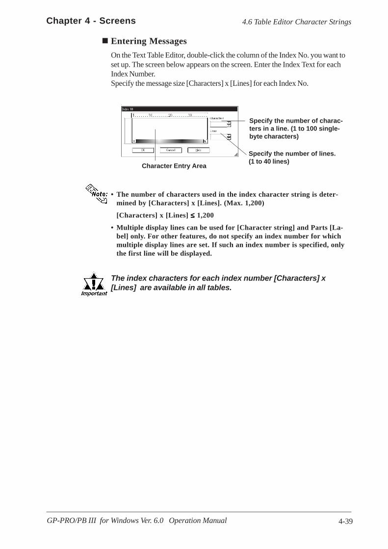
4-39
Chapter 4 - Screens
GP-PRO/PB III for Windows Ver. 6.0 Operation Manual
4.6 Table Editor Character Strings
Entering MessagesOn the Text Table Editor, double-click the column of the Index No. you want toset up. The screen below appears on the screen. Enter the Index Text for eachIndex Number.Specify the message size [Characters] x [Lines] for each Index No.
Character Entry Area
Specify the number of charac-ters in a line. (1 to 100 single-byte characters)
Specify the number of lines.(1 to 40 lines)
• The number of characters used in the index character string is deter-mined by [Characters] x [Lines]. (Max. 1,200)
[Characters] x [Lines] ≤≤≤≤≤ 1,200
• Multiple display lines can be used for [Character string] and Parts [La-bel] only. For other features, do not specify an index number for whichmultiple display lines are set. If such an index number is specified, onlythe first line will be displayed.
The index characters for each index number [Characters] x[Lines] are available in all tables.

4-40
Chapter 4 - Screens
GP-PRO/PB III for Windows Ver. 6.0 Operation Manual
4.6 Table Editor Character Strings
PROCEDURE REMARKS
The table name can be modified byselecting [File] menu - [Table NameChange].
You can choose from the following fiveselections.• ASCII (Code Page 850)• CHINA (GB2312)• JAPAN(JIS)• KOREA (KS-C5601)• TAIWAN (Big5)
The number of characters used in theindex character string is determinedby [Characters] x [Lines]. (Max.1,200)[Characters] x [Lines] ≤ 1,200
Multiple display lines can be used for[Character string] and Parts [Label]only. For other features, do not specifyan index number for which multipledisplay lines are set. If such an indexnumber is specified, only the first linewill be displayed.
(5) Enter the desired [Characters] and [Lines] accordingto the index character string.
(1) In the Project Manager, select the [Screen/Setup]menu - [Text Table...] command.
(2) Click on the icon and enter the [Control Address].
(3) Select a font from the [Font Setting] menu .Select a table from on the right of the "Table 1" fieldand select a font (language) from o n the right of the "GPFont Settings" field.
(4) Double-click the index character string entry area.
Index Character String Registration

4-41
Chapter 4 - Screens
GP-PRO/PB III for Windows Ver. 6.0 Operation Manual
4.6 Table Editor Character Strings
PROCEDURE REMARKS
(7) Click the button to confirm the charac-ters.
(8) Repeat the same steps to set the index characterstrings for the other index numbers.
(9) Repeat the same steps to create other tables.
(10)Select the [File] menu - [Save] command or click onthe icon to save the setting.
(6) Enter the index character string.
Up to 16 tables can be registered.
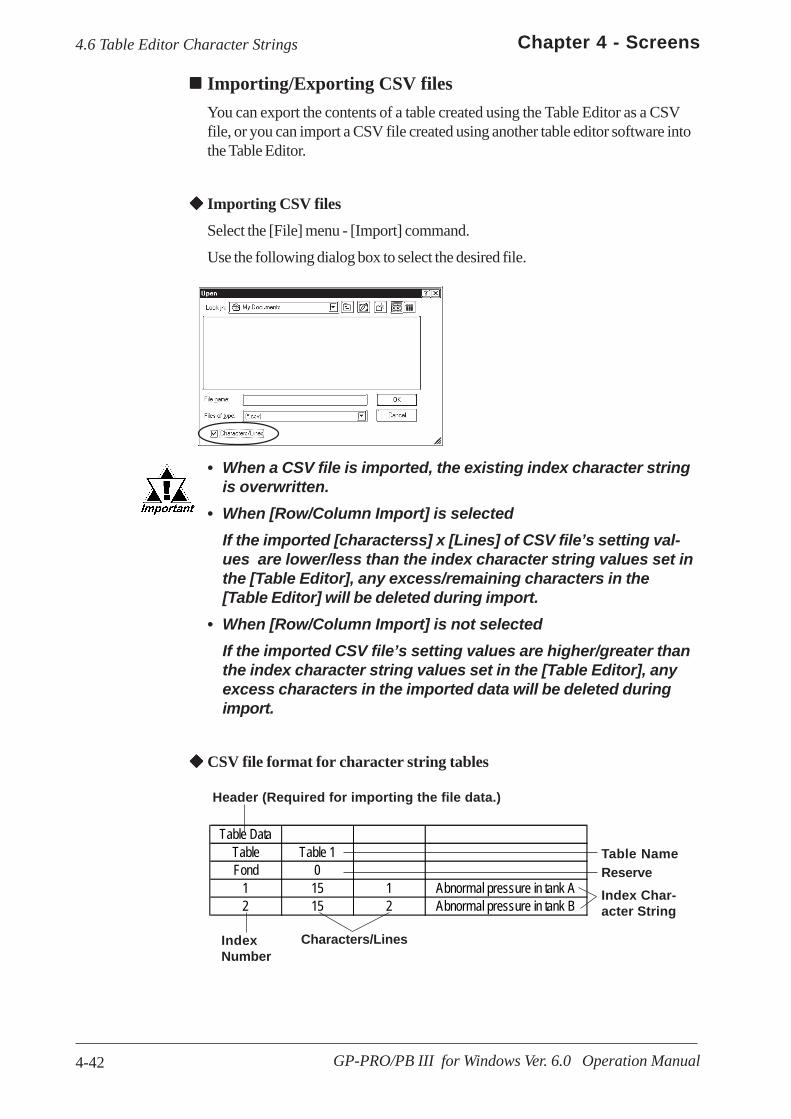
4-42
Chapter 4 - Screens
GP-PRO/PB III for Windows Ver. 6.0 Operation Manual
4.6 Table Editor Character Strings
Importing/Exporting CSV filesYou can export the contents of a table created using the Table Editor as a CSVfile, or you can import a CSV file created using another table editor software intothe Table Editor.
Importing CSV files
Select the [File] menu - [Import] command.
Use the following dialog box to select the desired file.
• When a CSV file is imported, the existing index character stringis overwritten.
• When [Row/Column Import] is selectedIf the imported [characterss] x [Lines] of CSV file’s setting val-ues are lower/less than the index character string values set inthe [Table Editor], any excess/remaining characters in the[Table Editor] will be deleted during import.
• When [Row/Column Import] is not selectedIf the imported CSV file’s setting values are higher/greater thanthe index character string values set in the [Table Editor], anyexcess characters in the imported data will be deleted duringimport.
CSV file format for character string tables
Header (Required for importing the file data.)
Table DataTable Table 1Fond 0
1 15 1 Abnormal pressure in tank A2 15 2 Abnormal pressure in tank B
Table NameReserveIndex Char-acter String
Characters/LinesIndexNumber

4-43
Chapter 4 - Screens
GP-PRO/PB III for Windows Ver. 6.0 Operation Manual
4.6 Table Editor Character Strings
Selecting the drawing tableFrom the menu bar in the Screen Editor, select the table to use for drawing. Whena table is changed, the character strings used in the Screen Editor also change.
Selecting the index character string Entering the index character string
Click on the [Index] to switch the screen to the one used to enter the indexcharacter string.
Select the desired index character string from those shown in the [Table Editor].To add a new index character string, click the button to start the
[Table Editor].
4.6.2 Table Editor Index Character Strings Index Char-acter String Registration
The size of any text object placed on the drawing area automaticallychanges according to the size specified in the Table Editor ([Characters] x[Lines]). Switching tables does not change the text size.
4.6.3 Entering Settings via the Screen Editor
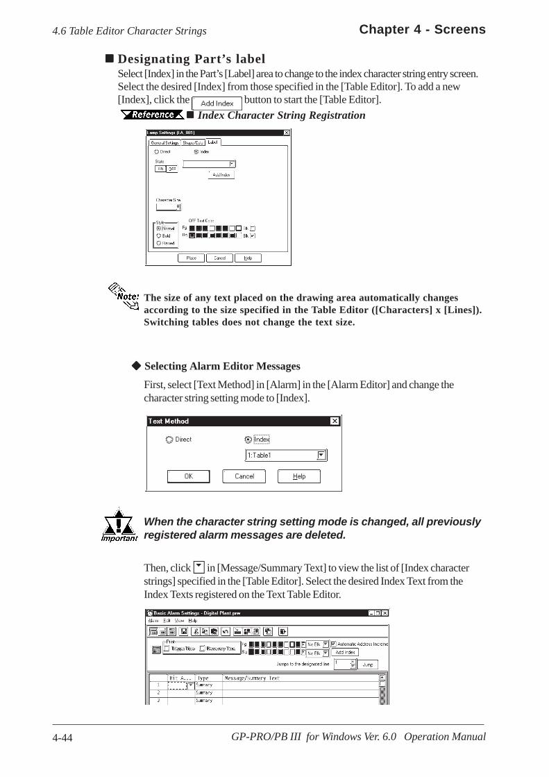
4-44
Chapter 4 - Screens
GP-PRO/PB III for Windows Ver. 6.0 Operation Manual
4.6 Table Editor Character Strings
Then, click in [Message/Summary Text] to view the list of [Index characterstrings] specified in the [Table Editor]. Select the desired Index Text from theIndex Texts registered on the Text Table Editor.
Selecting Alarm Editor Messages
First, select [Text Method] in [Alarm] in the [Alarm Editor] and change thecharacter string setting mode to [Index].
When the character string setting mode is changed, all previouslyregistered alarm messages are deleted.
Designating Part’s labelSelect [Index] in the Part’s [Label] area to change to the index character string entry screen.Select the desired [Index] from those specified in the [Table Editor]. To add a new[Index], click the button to start the [Table Editor].
Index Character String Registration
The size of any text placed on the drawing area automatically changesaccording to the size specified in the Table Editor ([Characters] x [Lines]).Switching tables does not change the text size.
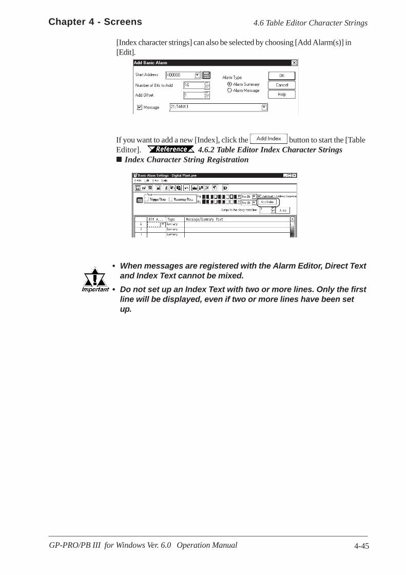
4-45
Chapter 4 - Screens
GP-PRO/PB III for Windows Ver. 6.0 Operation Manual
4.6 Table Editor Character Strings
[Index character strings] can also be selected by choosing [Add Alarm(s)] in[Edit].
If you want to add a new [Index], click the button to start the [TableEditor]. 4.6.2 Table Editor Index Character Strings
Index Character String Registration
• When messages are registered with the Alarm Editor, Direct Textand Index Text cannot be mixed.
• Do not set up an Index Text with two or more lines. Only the firstline will be displayed, even if two or more lines have been setup.
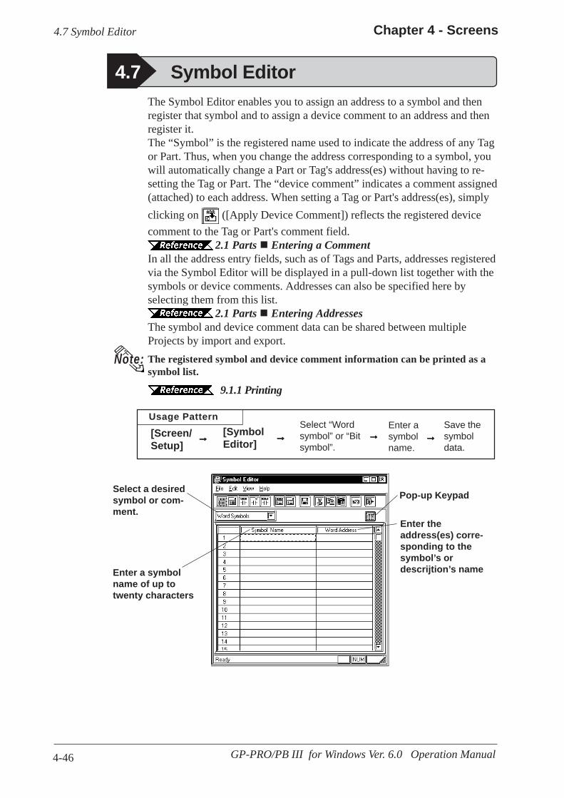
4-46
Chapter 4 - Screens
GP-PRO/PB III for Windows Ver. 6.0 Operation Manual
4.7 Symbol Editor
Usage PatternSave thesymboldata.
Enter asymbolname.
Select “Wordsymbol” or “Bitsymbol”.
[SymbolEditor]
[Screen/Setup]
→→→→→→→→→→→→→→→→→→→→
Select a desiredsymbol or com-ment.
Enter theaddress(es) corre-sponding to thesymbol’s ordescrijtion’s name
Pop-up Keypad
Enter a symbolname of up totwenty characters
The Symbol Editor enables you to assign an address to a symbol and thenregister that symbol and to assign a device comment to an address and thenregister it.The “Symbol” is the registered name used to indicate the address of any Tagor Part. Thus, when you change the address corresponding to a symbol, youwill automatically change a Part or Tag's address(es) without having to re-setting the Tag or Part. The “device comment” indicates a comment assigned(attached) to each address. When setting a Tag or Part's address(es), simplyclicking on ([Apply Device Comment]) reflects the registered devicecomment to the Tag or Part's comment field.
2.1 Parts Entering a CommentIn all the address entry fields, such as of Tags and Parts, addresses registeredvia the Symbol Editor will be displayed in a pull-down list together with thesymbols or device comments. Addresses can also be specified here byselecting them from this list.
2.1 Parts Entering AddressesThe symbol and device comment data can be shared between multipleProjects by import and export.The registered symbol and device comment information can be printed as asymbol list.
9.1.1 Printing
Note:
4.7 Symbol Editor
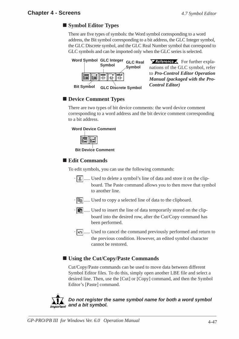
4-47
Chapter 4 - Screens
GP-PRO/PB III for Windows Ver. 6.0 Operation Manual
4.7 Symbol Editor
Device Comment TypesThere are two types of bit device comments: the word device commentcorresponding to a word address and the bit device comment correspondingto a bit address.
For further expla-nations of the GLC symbol, referto Pro-Control Editor OperationManual (packaged with the Pro-Control Editor)
Symbol Editor TypesThere are five types of symbols: the Word symbol corresponding to a wordaddress, the Bit symbol corresponding to a bit address, the GLC Integer symbol,the GLC Discrete symbol, and the GLC Real Number symbol that correspond toGLC symbols and can be imported only when the GLC series is selected.
Word Symbol
Word Device Comment
Bit Symbol
Bit Device Comment
GLC IntegerSymbol GLC Real
Symbol
GLC Discrete Symbol
Edit CommandsTo edit symbols, you can use the following commands:
· ..... Used to delete a symbol’s line of data and store it on the clip-board. The Paste command allows you to then move that symbolto another line.
· ..... Used to copy a selected line of data to the clipboard.
· ..... Used to insert the line of data temporarily stored on the clip-board into the desired row, after the Cut/Copy command hasbeen performed.
· ..... Used to cancel the command previously performed and return tothe previous condition. However, an edited symbol charactercannot be restored.
Using the Cut/Copy/Paste CommandsCut/Copy/Paste commands can be used to move data between differentSymbol Editor files. To do this, simply open another LBE file and select adesired line. Then, use the [Cut] or [Copy] command, and then the SymbolEditor’s [Paste] command.
Do not register the same symbol name for both a word symboland a bit symbol.

4-48
Chapter 4 - Screens
GP-PRO/PB III for Windows Ver. 6.0 Operation Manual
4.7 Symbol Editor
· If alphanumeric numerals are used at the end of a symbolname, executing the [Copy] and [Paste] command will automati-cally change the symbol’s name.· When Chinese characters and numbers are used in a symbol name:
All the Arabic numbers to the right of the Chinese character(s)will be deleted. Sequence numbers starting from “2” will beassigned after the Chinese characters.
· When Roman characters and Arabic numbers are used in asymbol name:Example) ABC123All the Arabic numerals to the right of Roman character(s) willbe deleted and replaced by a sequence number.
· When only Arabic numbers are used in a symbol name:Only the first number is retained, and all other digits are trun-cated and replaced with a sequence number.
PROCEDURE R E M A R K S
(1)Via the Project Manager, select the [Screen/Setup]menu - [Symbol Editor] command.
(2)Select symbol or device comment type.In this example, please select “Word Symbols”.
Registering Symbols and Device Comments
If the GLC series is selected for theGP type, the GLC symbol can bespecified.
Pro-Control Edi-tor Operation Manual (packagedwith the Pro-Control Editor).

4-49
Chapter 4 - Screens
GP-PRO/PB III for Windows Ver. 6.0 Operation Manual
4.7 Symbol Editor
Importing Symbols and Device CommentsThe previously saved Symbol Editor data can be imported to and shared with thecurrently open Symbol Editor. Files with the extension of "*.LBE" or "*.CSV" canbe imported.CSV files that have been created via a text editor, Microsoft Excel, or other applica-tions can be used as symbol or device comment data via the Symbol Editor afterimported.Symbol data and device comment's CSV file formats are as follows:
<Symbol Data CSV Format>
"GP_SYMBOL""Symbol Name", "Word Address" <Give one line feed between a word address and a bit address>"Symbol Name", "Bit Address"
Example"Line A (1 to 5): Word","D00100""Line A (6 to 10): Word","D00101"
One line feed"Line A (1 to 5): Bit","X00100""Line A (6 to 10): Bit","X00101"
To enter a symbol name, you canuse up to twenty alphanumericcharacters, or up to ten Chinesecharacters.
The entered characters are not case-sensitive.
You can perform the [Delete] or[Copy] and [Paste] commands af-ter selecting multiple messages.
PROCEDURE R E M A R K S
(4) After all the necessary items are registered, selectthe [File] menu - [Save] command, or click on the
icon.
(3) Enter symbol names and addresses.
The symbols [],\, ?, and the key cannot be used inthe Symbol Editor.
Tab
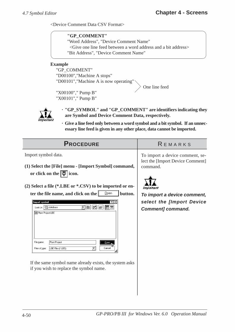
4-50
Chapter 4 - Screens
GP-PRO/PB III for Windows Ver. 6.0 Operation Manual
4.7 Symbol Editor
<Device Comment Data CSV Format>
"GP_COMMENT""Word Address", "Device Comment Name" <Give one line feed between a word address and a bit address>"Bit Address", "Device Comment Name"
Example"GP_COMMENT""D00100","Machine A stops""D00101","Machine A is now operating"
One line feed"X00100"," Pump B""X00101"," Pump B"
· "GP_SYMBOL" and "GP_COMMENT" are identifiers indicating theyare Symbol and Device Comment Data, respectively.
· Give a line feed only between a word symbol and a bit symbol. If an unnec-essary line feed is given in any other place, data cannot be imported.
PROCEDURE R E M A R K S
Import symbol data.
(1) Select the [File] menu - [Import Symbol] command,or click on the icon.
(2) Select a file (*.LBE or *.CSV) to be imported or en-ter the file name, and click on the button. To import a device comment,
select the [Import DeviceComment] command.
If the same symbol name already exists, the system asksif you wish to replace the symbol name.
To import a device comment, se-lect the [Import Device Comment]command.

4-51
Chapter 4 - Screens
GP-PRO/PB III for Windows Ver. 6.0 Operation Manual
4.7 Symbol Editor
(3)Select an import method and execute it.To import the specified symbol according to the currentsettings, click on the button. To import the cur-rent Project file's all the symbols according to the currentsettings, click on the button. To cancel the im-port, click on the button.
PROCEDURE R E M A R K S
[Import as]Enter the symbol name to be re-placed.If no symbol name is entered, theoriginal symbol name plus se-quence numbers will be imported.[Replace]The same symbol name will beoverwritten.[Do not import]The same symbol name will not beimported.
• GP-PRO/PB III for Windows has "CMTCNV.EXE", a tool to convertMitsubishi's Windows GPP function software SWOD-GPPW commentdata to CSV files. For more detailed information about this tool, refer to"Readme.txt" in the folder "\ProPB_Win\CMTCNV" created at GP-PRO/PB III for Windows installation.
• Amount of the Symbol data created or imported via the Symbol Editor isnot limited. However, the number of device comment characters is up to 20.
• Items with an inappropriate device name are not imported.
Note:

4-52
Chapter 4 - Screens
GP-PRO/PB III for Windows Ver. 6.0 Operation Manual
4.7 Symbol Editor
Exporting Symbols and Device CommentsData registered via the Symbol Editor is exported and saved as an LBE or CSV file.By importing this data, the Symbol Editor data can be shared among Projects.
Export symbol data.
(1)Via the Symbol Editor, select the [File] menu - [Ex-port Symbol] command, or click on the icon.
(2)Specify the name and type (*.LBE or *.CSV) of thefile to save the exported data with, and click on the
button.If the same file name already exists, the system asks ifthe existing file must be overwritten. If it must be over-written, select . If you do not wish to over writeit, select .
PROCEDURE R E M A R K S
To export a device comment, selectthe [Export Device Comment]command.
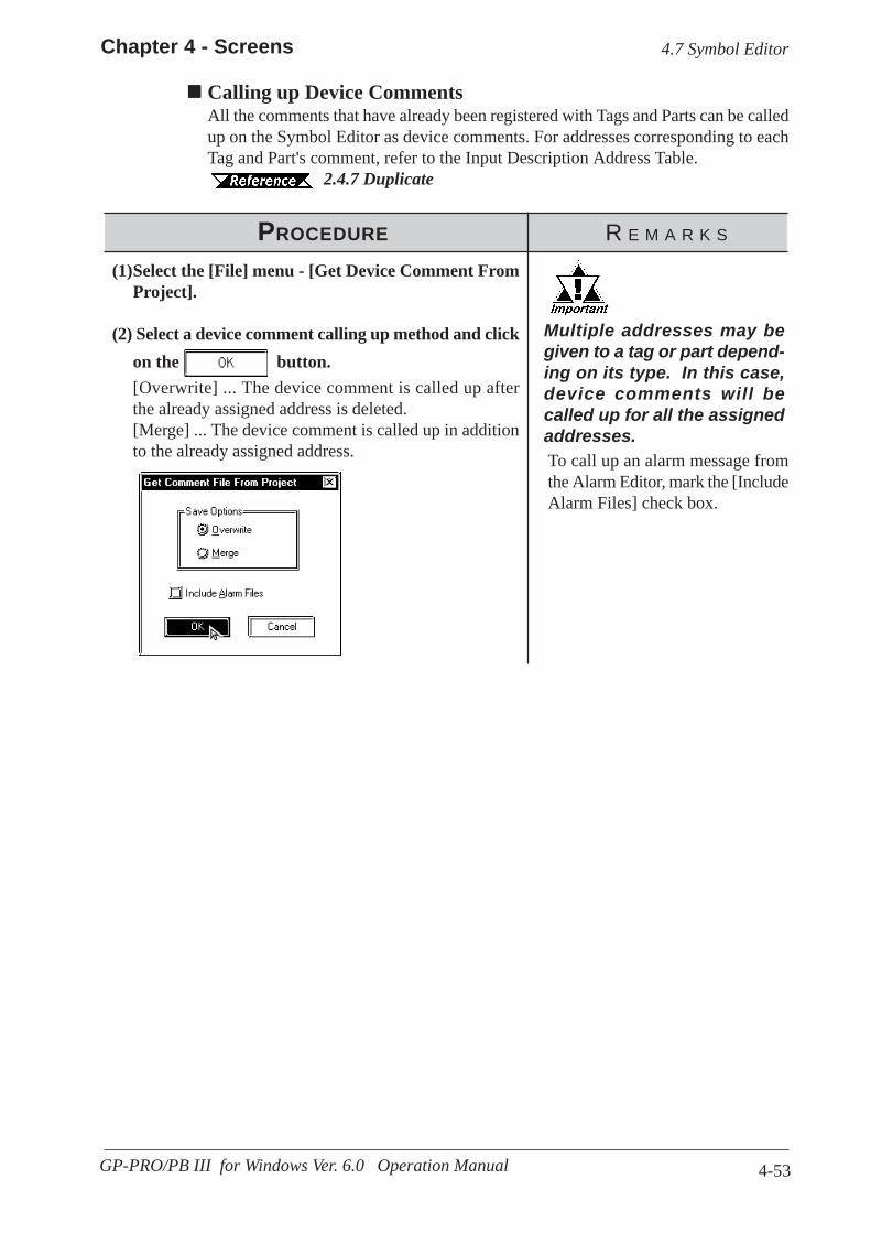
4-53
Chapter 4 - Screens
GP-PRO/PB III for Windows Ver. 6.0 Operation Manual
4.7 Symbol Editor
Calling up Device CommentsAll the comments that have already been registered with Tags and Parts can be calledup on the Symbol Editor as device comments. For addresses corresponding to eachTag and Part's comment, refer to the Input Description Address Table.
2.4.7 Duplicate
PROCEDURE R E M A R K S
To call up an alarm message fromthe Alarm Editor, mark the [IncludeAlarm Files] check box.
(1)Select the [File] menu - [Get Device Comment FromProject].
(2) Select a device comment calling up method and clickon the button.[Overwrite] ... The device comment is called up afterthe already assigned address is deleted.[Merge] ... The device comment is called up in additionto the already assigned address.
Multiple addresses may begiven to a tag or part depend-ing on its type. In this case,device comments will becalled up for all the assignedaddresses.

4-54
Chapter 4 - Screens
GP-PRO/PB III for Windows Ver. 6.0 Operation Manual
4.8 Device Monitor
4.8 Device Monitor
If you change the Device/PLC typeafter the device monitor commandis registered, the device monitorcommand will not operate correctlyon the GP unit. To change the De-vice/PLC type, first, delete the de-vice monitor registration beforesaving the current file.
PROCEDURE R E M A R K S
(3)Click on the button.This completes registration of the device monitor fea-ture. After the registration is completed, the followingmessage appears.
(1) Select the [Screen/Settings] menu - [Device Moni-tor] command.Register the Device Monitor.
(2)Specify which version of device monitor is to be used,the Japanese version or the English version.
You can monitor and change a desired area of device memory via the GPunit’s Global Window screen. In this section, you must specify whether ornot to register the “device monitor” command for the current GP unit.This registration is effective only when GP and PLC types which support thedevice monitor command are selected. Device/PLC Connection Manual, Appendix 3: Device Monitor
To cancel the device monitor registration data, the fol-lowing message will appear in step (2). Then, click onthe button to cancel it.
To use the device monitor com-mand, be sure to select the “Indi-rect (Binary)” operation mode inthe [GP Setup] - [Extended Set-tings] - [Global Window Settings].
5-1GP-PRO/PB III for Windows Ver. 6.0 Operation Manual
his feature allows you to register text data to be displayed as alarmmesages. This chapter describes how to create and edit these alarm
messages.T
5 CREATING AND EDITING ALARMS
5.1 ........................................ Alarm Creation and Editing

5-2
Chapter 5 - Alarms
GP-PRO/PB III for Windows Ver. 6.0 Operation Manual
5.1 Alarm Creation and Editing
5.1 Alarm Creation and EditingWith this feature you can register the messages to be displayed in the “AlarmSummary” (specified by an “a-Tag” or a “Q-Tag”) and “Alarm Message” (rightto left scrolling display). You can also set up a monitor bit for each message.According to the monitor bit’s ON/OFF status, the specified messages are thendisplayed in the “Alarm Summary” or “Alarm Message” mode.
Tag Reference manual, 2.2 a-tag (Alarm Summary Dis-play), 2.20 Q-tag (Alarm Summary Display)The “Alarm Summary” mode lists messages. The “Alarm Message” modedisplays a flowing message at the bottom of the screen.With “Alarm Message” text, the horizontal and vertical size of the text is speci-fied in the [Setup Area’s (Initial Setup screen)] menu or in the GP unit’s [Setup]mode. Character sizes can be set to either “x 1”, “x 2”, or “x 4”.When the horizontal and vertical sizes are set to “1 x 1”, an alphanumericcharacter occupies 16 x 8 dots, and a Chinese character occupies 16 x 16 dots.The “Alarm Summary” and “Alarm Message” will display on the GP unit’spanel screen as shown below:
Usage Pattern
Save the AlarmEditor.
Set up [AlarmMessage/Summary].
Enter amessage.
Select the alarm type:[Alarm Message/Sum-mary].
[Alarm Editor][Project]
→→→→→→→→→→
→→→→→→→→→→
Right to left scroll-ing display
Alarm Message DisplayAlarm Summary Display
or
Click on
→→→→→
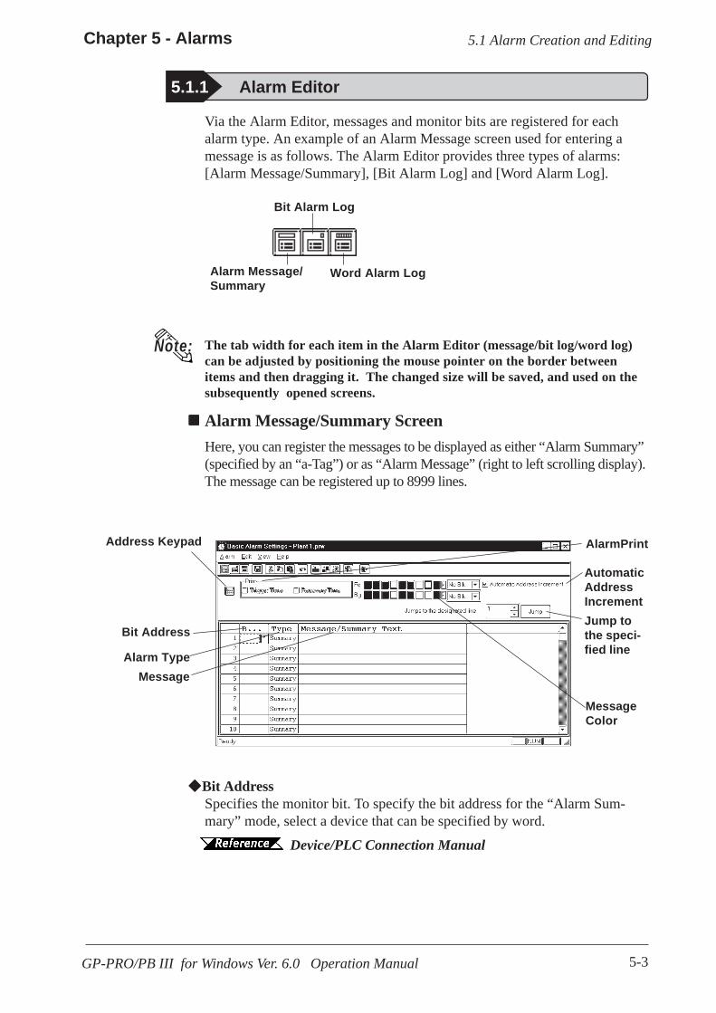
5-3
Chapter 5 - Alarms
GP-PRO/PB III for Windows Ver. 6.0 Operation Manual
5.1 Alarm Creation and Editing
Via the Alarm Editor, messages and monitor bits are registered for eachalarm type. An example of an Alarm Message screen used for entering amessage is as follows. The Alarm Editor provides three types of alarms:[Alarm Message/Summary], [Bit Alarm Log] and [Word Alarm Log].
Alarm Message/Summary
Word Alarm Log
Bit Alarm Log
The tab width for each item in the Alarm Editor (message/bit log/word log)can be adjusted by positioning the mouse pointer on the border betweenitems and then dragging it. The changed size will be saved, and used on thesubsequently opened screens.
Note:
Alarm Message/Summary ScreenHere, you can register the messages to be displayed as either “Alarm Summary”(specified by an “a-Tag”) or as “Alarm Message” (right to left scrolling display).The message can be registered up to 8999 lines.
Address Keypad
MessageColor
AlarmPrint
MessageAlarm Type
Bit Address
Bit AddressSpecifies the monitor bit. To specify the bit address for the “Alarm Sum-mary” mode, select a device that can be specified by word.
Device/PLC Connection Manual
5.1.1 Alarm Editor
Jump tothe speci-fied line
AutomaticAddressIncrement
5-4
Chapter 5 - Alarms
GP-PRO/PB III for Windows Ver. 6.0 Operation Manual
5.1 Alarm Creation and Editing
Alarm TypeThe Alarm Editor provides two types of alarms: [Alarm Summary] and[Alarm Message].The [Alarm Summary] mode lists messages specified by an “a-Tag”.The [Alarm Message] mode displays a scrolling message at the bottom ofthe GP’s screen. Up to 512 messages can be entered into the Alarm Editor(up to 128 messages for GP70 series units). However, the monitor bit doesnot exceed 128 words. Any message beyond this setting range will notoperate on the GP unit’s panel screen.
MessageEnter your message here. Up to 160 alphanumeric characters can be enteredfor one message. Index Text can be used to switch messages on the GP-377,GP77R and GP2000 series.
4.6.3 Entering Settings via the Screen Selecting AlarmEditor Messages
Address KeypadA address keypad is displayed, allowing you to enter the bit address usingthe mouse.
Message ColorDesignates message’s color. Select the display color (Fg) and backgroundcolor (Bg), and specify whether to blinking (Blk) is used or not.
Automatic Address IncrementAfter entering and registering a message in a line and moving to the nextline, an address that is one bit larger will be automatically entered for thenew line.
Jump to the designated line.Specify a line and click to jump to the line.
PrintAn Alarm Message (like a bulletin board) can be printed out when the alarmis triggered and when recovered. Specify if the Alarm Message is printedout at the triggering of the alarm and at the recovery from the alarm, respec-tively. When [Summary] is selected, this setting becomes ineffective.This function is supported only by the GPs with a printer interface.
5-5
Chapter 5 - Alarms
GP-PRO/PB III for Windows Ver. 6.0 Operation Manual
5.1 Alarm Creation and Editing
Trigger Time: Prints out the time when the Alarm Message started.Recovery Time: Prints out the time when the Alarm Message is finished.
Printing Example
Trigger 10/15 16:07 No.1 errorRecovery 10/15 16:30 No.1 errorTrigger 10/21 11:25 No.1 errorTrigger 10/21 11:28 No.3 errorRecovery 10/21 15:45 No.1 error
• Up to 1,000 Alarm Message triggering and recovery eventscan be stored in the GP. When the GP is not connected to aprinter, up to 1,000 events will be stored in the GP, whichenters a printing stand-by mode. When the number of theevents exceeds 1,000, the excessive events will not bestored.
• When a printer becomes offline mode due to the running outof printing paper during printing, DO NOT turn the GP'spower OFF. Refill the paper and return the printer to onlinemode. Event information stored in the GP in the printeroffline mode will be output to the printer when the printermode returns to online.
• If the printer's power is turned OFF during printing, eventinformation transferred from the GP to the printer while theprinter's power is OFF will not be printed.
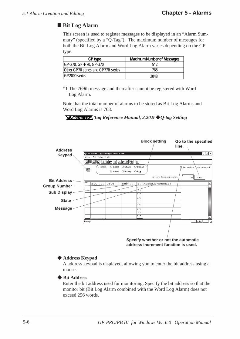
5-6
Chapter 5 - Alarms
GP-PRO/PB III for Windows Ver. 6.0 Operation Manual
5.1 Alarm Creation and Editing
Bit Log AlarmThis screen is used to register messages to be displayed in an “Alarm Sum-mary” (specified by a “Q-Tag”). The maximum number of messages forboth the Bit Log Alarm and Word Log Alarm varies depending on the GPtype.
Sub Display
AddressKeypad
Message
State
Group NumberBit Address
Block setting
Specify whether or not the automaticaddress increment function is used.
Go to the specifiedline.
GP type Maximum Number of MessagesGP-270, GP-H70, GP-370 512Other GP70 series and GP77R series 768GP2000 series 2048*1
*1 The 769th message and thereafter cannot be registered with Word Log Alarm.
Note that the total number of alarms to be stored as Bit Log Alarms andWord Log Alarms is 768. Tag Reference Manual, 2.20.9 Q-tag Setting
Address KeypadA address keypad is displayed, allowing you to enter the bit address using amouse.
Bit AddressEnter the bit address used for monitoring. Specify the bit address so that themonitor bit (Bit Log Alarm combined with the Word Log Alarm) does notexceed 256 words.

5-7
Chapter 5 - Alarms
GP-PRO/PB III for Windows Ver. 6.0 Operation Manual
5.1 Alarm Creation and Editing
Group No.Enter a group number for counting alarms.The counting of alarms with the same group number will be stored in thesame LS area. LS areas are automatically reserved, for as many groupnumbers as have been specified. Bit log alarms and word log alarms withthe same group number are counted as the same group.In order to set up the area in which the number of alarm occurrences iswritten, select [GP Setup] from the Project Manager. Select [TriggeredAlarm Count Address] from the [Q-Tag Settings] menu on the [ExtendedFeatures] tab.
Select [System Settings] from the [Alarm] menu on the Alarm Editor screen,or click to enter the "Q-Tag Settings" dialog box.
Sub DisplayTo perform sub-display with a Q-tag, specify here a desired sub-displayscreen number corresponding to each message and the same number as awindow registration number. These number may be entered in a rangebetween 0 and 8999.Example 1: To sub-display a screen of B2, enter 2.Example 2: If no sub-display is required, enter 0 (default value is 0).
StateSpecify the monitor bit status (ON/OFF) that activates the alarm output.
MessageEnter a message. Up to 100 alphanumeric characters can be entered for onemessage. Index Text can be used to switch messages on the GP-377, GP77Rand GP-2000 series.
4.6.3 Entering Settings via the Screen Selecting AlarmEditor Messages
Block SettingIf “Block” is selected for the GP-377, GP37W2, GP77R and GP2000 series,the attribute of “Active”, “Log” or “History” can be given to each block. Upto three blocks can be set.
Tag Reference Manual, 2.20 Q-tag (Alarm Summary Dis-play)
Automatic Address IncrementAfter entering and registering a message in a line and moving to the nextline, an address that is one bit larger is automatically entered for the newline.

5-8
Chapter 5 - Alarms
GP-PRO/PB III for Windows Ver. 6.0 Operation Manual
5.1 Alarm Creation and Editing
Address KeypadClicking here displays a address keypad, allowing you to enter bit addressdata using your mouse.
Alarm Value Data FormatSelects the alarm value’s data format.
Word AddressSet up a word address. Specify the bit address so that the monitor bit (BitLog Alarm combined with the Word Log Alarm) does not exceed 256words.
Address Keypad
Message
Alarm Value DataFormat
Monitor Bit
Group Number
Word Address
Sub Display
Alarm Value
Block setting
Specify whetheror not the auto-matic addressincrement func-tion is used.
Word Alarm LogThis screen is used to register the messages to be displayed in an “AlarmSummary” (specified by a “Q-Tag”). The maximum number of messagesfor both the Bit Log Alarm and Word Log Alarm varies depending on theGP type.
GP type Maximum Number of MessagesGP-270, GP-H70, GP-370 512Other GP70 series and GP77R series 768GP2000 series 2048*1
*1 The 769th message and thereafter cannot be registered with Word Log Alarm.
Note that the total number of alarms to be stored as Bit Log Alarms andWord Log Alarms is 768. Tag Reference Manual, 2.20.9 Q-tag Setting
Go to the specified line.

5-9
Chapter 5 - Alarms
GP-PRO/PB III for Windows Ver. 6.0 Operation Manual
5.1 Alarm Creation and Editing
Group No.Enter a group number for counting alarms.The counting of alarms with the same group number will be stored in thesame LS area. LS areas are automatically reserved, for as many groupnumbers as have been specified. Bit log alarms and word log alarms withthe same group number are counted as the same group.In order to set up the area in which the number of alarm occurrences iswritten, select [GP System Setup] of the Project Manager. Select [TriggeredAlarm Count Address] from the [Q-Tag Settings] menu on the [ExtendedFeature Settings] tab.
Select [System Settings] from the [Alarm] menu on the Alarm Editor screen,or click to enter the "Q-Tag Settings" dialog box.
Sub DisplayTo perform sub-display with a Q-tag, specify here a desired sub-displayscreen number corresponding to each message and the same number as awindow registration number. These number may be entered in a rangebetween 0 and 8999.Example 1: To sub-display a screen of B2, enter 2.Example 2: If no sub-display is required, enter 0 (default value is 0). Alarm ValueSpecify the limit value of the monitor word used to activate the alarm’soutput. Monitor BitSelect “16 bits” for single-word monitoring, or “32 bits” for two-wordmonitoring. MessageEnter a message. Up to 100 alphanumeric characters can be entered for onemessage. Index Text can be used to switch messages on the GP-377, GP77Rand GP2000 series.
4.6.3 Entering Settings via the Screen Selecting AlarmEditor Messages
Block SettingIf “Block” is selected for the GP-377, GP37W2, GP77R and GP2000 series,the attribute of “Active”, “Log” or “History” can be given to each block.Up to three blocks can be set. Tag Reference Manual, 2.20 Q-tag (Alarm Summary Display)
Automatic address incrementAfter entering and registering a message in a line and moving to the nextline, an address that is one bit larger is automatically entered for the newline.

5-10
Chapter 5 - Alarms
GP-PRO/PB III for Windows Ver. 6.0 Operation Manual
5.1 Alarm Creation and Editing
Editing ToolsThe Alarm Editor has the following editing features.
*1 When the [Copy] or [Cut] command is executed, the copied or deleted data is tempo-rarily stored on the clipboard.When you execute the [Paste] command, the data storedon the clipboard can be copied or moved to a desired position.
Icon Editing Tool Description
CutUsed to delete a symbol’s line of data and store it on theclipboard. The [Paste] command allows you to then movethat symbol to another line.
Copy Used to copy a selected line of data to the clipboard.*1
PasteUsed to insert the line of data temporarily stored on theclipboard into the desired row, after the Cut/Copy commandhas been performed.
UndoUsed to cancel the command previously performed andreturn to the previous condition. However, an edited symbolcharacter cannot be restored.
Add AlarmAdds an address. If the selected alarm number already exists,that data can be overwritten.
Change Attribute Allows you to change the alarm attributes.
Apply DeviceComment
Inputs device comments for all the selected devices in theMessage Column.
System SettingsAllows you to go to the "Q-tag Settings" dialog box from the"Alarm Editor". Press the [OK] button to save the settings forthe Q-tag.
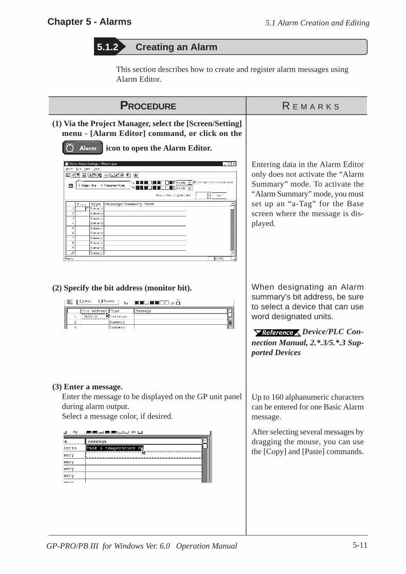
5-11
Chapter 5 - Alarms
GP-PRO/PB III for Windows Ver. 6.0 Operation Manual
5.1 Alarm Creation and Editing
PROCEDURE R E M A R K S
Entering data in the Alarm Editoronly does not activate the “AlarmSummary” mode. To activate the“Alarm Summary” mode, you mustset up an “a-Tag” for the Basescreen where the message is dis-played.
(2) Specify the bit address (monitor bit).
(1) Via the Project Manager, select the [Screen/Setting]menu - [Alarm Editor] command, or click on the
icon to open the Alarm Editor.
When designating an Alarmsummary’s bit address, be sureto select a device that can useword designated units.
Device/PLC Con-nection Manual, 2.*.3/5.*.3 Sup-ported Devices
This section describes how to create and register alarm messages usingAlarm Editor.
After selecting several messages bydragging the mouse, you can usethe [Copy] and [Paste] commands.
Up to 160 alphanumeric characterscan be entered for one Basic Alarmmessage.
(3) Enter a message.Enter the message to be displayed on the GP unit panelduring alarm output.Select a message color, if desired.
5.1.2 Creating an Alarm
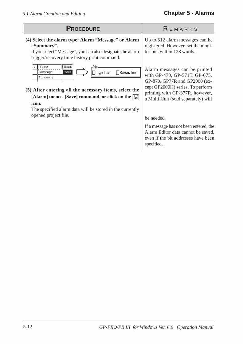
5-12
Chapter 5 - Alarms
GP-PRO/PB III for Windows Ver. 6.0 Operation Manual
5.1 Alarm Creation and Editing
PROCEDURE R E M A R K S
Alarm messages can be printedwith GP-470, GP-571T, GP-675,GP-870, GP77R and GP2000 (ex-cept GP2000H) series. To performprinting with GP-377R, however,a Multi Unit (sold separately) will
(5) After entering all the necessary items, select the[Alarm] menu - [Save] command, or click on the icon.The specified alarm data will be stored in the currentlyopened project file.
(4) Select the alarm type: Alarm “Message” or Alarm“Summary”.If you select “Message”, you can also designate the alarmtrigger/recovery time history print command.
be needed.
If a message has not been entered, theAlarm Editor data cannot be saved,even if the bit addresses have beenspecified.
Up to 512 alarm messages can beregistered. However, set the moni-tor bits within 128 words.
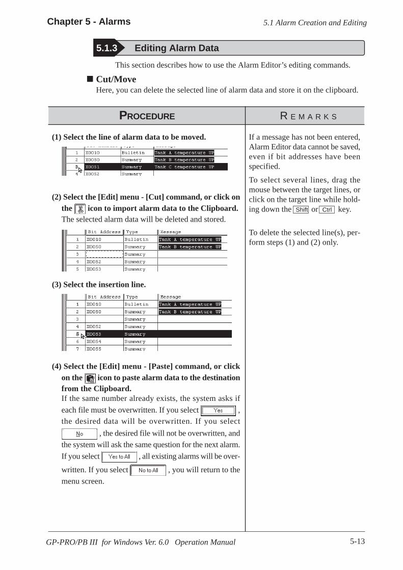
5-13
Chapter 5 - Alarms
GP-PRO/PB III for Windows Ver. 6.0 Operation Manual
5.1 Alarm Creation and Editing
PROCEDURE R E M A R K S
5.1.3 Editing Alarm Data
If a message has not been entered,Alarm Editor data cannot be saved,even if bit addresses have beenspecified.
To select several lines, drag themouse between the target lines, orclick on the target line while hold-ing down the Shift or Ctrl key.
To delete the selected line(s), per-form steps (1) and (2) only.
(4) Select the [Edit] menu - [Paste] command, or clickon the icon to paste alarm data to the destinationfrom the Clipboard.If the same number already exists, the system asks ifeach file must be overwritten. If you select ,the desired data will be overwritten. If you select
, the desired file will not be overwritten, andthe system will ask the same question for the next alarm.If you select , all existing alarms will be over-
written. If you select , you will return to themenu screen.
(3) Select the insertion line.
(2) Select the [Edit] menu - [Cut] command, or click onthe icon to import alarm data to the Clipboard.The selected alarm data will be deleted and stored.
(1) Select the line of alarm data to be moved.
This section describes how to use the Alarm Editor’s editing commands.
Cut/MoveHere, you can delete the selected line of alarm data and store it on the clipboard.
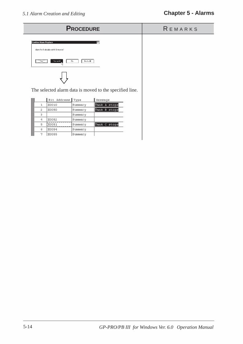
5-14
Chapter 5 - Alarms
GP-PRO/PB III for Windows Ver. 6.0 Operation Manual
5.1 Alarm Creation and Editing
PROCEDURE R E M A R K S
The selected alarm data is moved to the specified line.
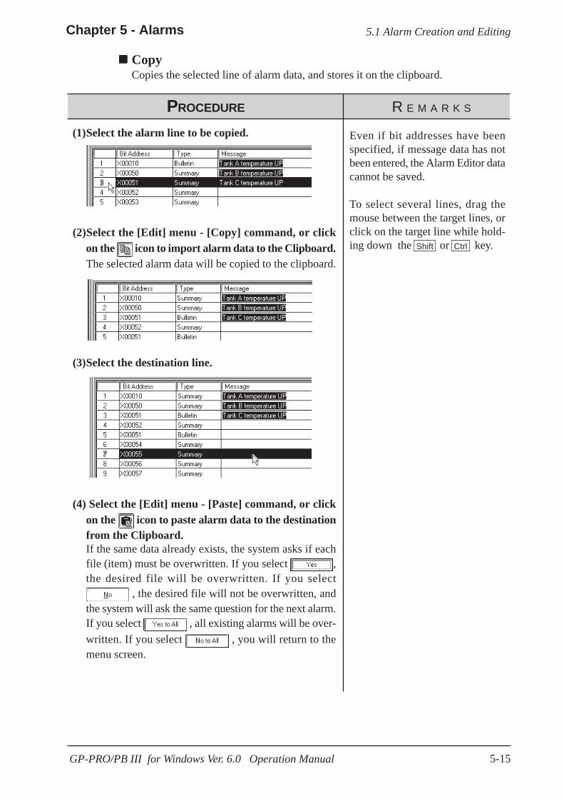
5-15
Chapter 5 - Alarms
GP-PRO/PB III for Windows Ver. 6.0 Operation Manual
PROCEDURE R E M A R K S
Even if bit addresses have beenspecified, if message data has notbeen entered, the Alarm Editor datacannot be saved.
To select several lines, drag themouse between the target lines, orclick on the target line while hold-ing down the or key.
(4) Select the [Edit] menu - [Paste] command, or clickon the icon to paste alarm data to the destinationfrom the Clipboard.If the same data already exists, the system asks if eachfile (item) must be overwritten. If you select ,the desired file will be overwritten. If you select
, the desired file will not be overwritten, andthe system will ask the same question for the next alarm.If you select , all existing alarms will be over-written. If you select , you will return to themenu screen.
(3)Select the destination line.
(2)Select the [Edit] menu - [Copy] command, or clickon the icon to import alarm data to the Clipboard.The selected alarm data will be copied to the clipboard.
(1)Select the alarm line to be copied.
Shift Ctrl
5.1 Alarm Creation and Editing
CopyCopies the selected line of alarm data, and stores it on the clipboard.

5-16
Chapter 5 - Alarms
GP-PRO/PB III for Windows Ver. 6.0 Operation Manual
The selected alarm data is copied to the specified line(s).
PROCEDURE R E M A R K S
PROCEDURE R E M A R K S
When an alarm has been unintentionally deleted:
(1) Select the [Edit] menu - [Undo] command, or clickon the icon.
UndoThis feature allows you to cancel the previously performed command, and return tothe previous condition.
5.1 Alarm Creation and Editing
Edited message characters cannotbe restored with the [Undo] com-mand.
An alarm can be pasted onto alarmsof different types. (For example, analarm copied from "Alarm Mes-sage/Alarm Summary" can bepasted onto the "Bit Log Alarm".)
Note that only the "message" willbe pasted in this operation. Optionsother than the "message" must beset separately.

5-17
Chapter 5 - Alarms
GP-PRO/PB III for Windows Ver. 6.0 Operation Manual
Word Alarm Log
Bit Alarm Log
Adding Alarm DataHere, you can add alarms for the specified number of bits or words from the linewhose item is enclosed with dotted lines. Addresses are automatically assigned toeach alarm from the start address in series, according to the designated address add-ing increment. In addition, when messages have been entered, they are copied for allthe alarms to be added.If an alarm number to be added already exists, a prompt will appear asking if thenewly set data overwrites the old one.The dialog box that appears will vary depending on the alarm type selected:
Alarm Message/Summary
5.1 Alarm Creation and Editing

5-18
Chapter 5 - Alarms
GP-PRO/PB III for Windows Ver. 6.0 Operation Manual
PROCEDURE R E M A R K S
(3)After entering the necessary settings, click on the button.
If the same number already exists, the system asks if eachfile must be overwritten. If you select , the de-sired file will be overwritten. If you select , thedesired file will not be overwritten, and the system will askabout the next alarm. If you select , all existingalarms will be overwritten. If you select , youwill return to the menu screen.
5.1 Alarm Creation and Editing
If a symbol is specified for the startaddress, the added addresses willbe displayed as follows:Example: Assume that the start ad-dress is TEST (← Symbol), and thatthe number of added bits is 4. Theaddresses are consecutively addedas shown below:TESTTEST + 1TEST + 2TEST + 3
Set the address adding incrementbetween 0 and 255.
(2)Select the [Edit] menu - [Add Alarm] command, orclick on the icon.
(1)Select the address line where the specified numberof addresses will be added. (Shown here with a dot-ted line around its border)

5-19
Chapter 5 - Alarms
GP-PRO/PB III for Windows Ver. 6.0 Operation Manual
Word Alarm Log
5.1 Alarm Creation and Editing
Bit Alarm Log
Changing Alarm AttributesYou can easily change any alarm’s attributes. The dialog box that appears will varydepending on the alarm type selected.
Alarm Message/Summary

5-20
Chapter 5 - Alarms
GP-PRO/PB III for Windows Ver. 6.0 Operation Manual
PROCEDURE R E M A R K S
If several lines are selected, the at-tributes of the selected lines can allbe simultaneously changed.
To select several lines, drag the mousebetween the desired lines, or click onthe desired line while pressing the or key.
(3) After entering the necessary items, click on the button.
(2) Select the [Edit] menu - [Change Attributes] com-mand, or click on the icon.
(1) Select the line of the alarm to be changed.In this example, we will change an attribute of an itemin the alarm message/alarm summary area.
Shift Ctrl
5.1 Alarm Creation and Editing

5-21
Chapter 5 - Alarms
GP-PRO/PB III for Windows Ver. 6.0 Operation Manual
5.1 Alarm Creation and Editing
Reflecting Device CommentsThis feature is used to reflect all the comment information corresponding to a se-lected device in the Message field.
(1) Select an alarm for which comment information isto be reflected, on a row basis.Here, reflect the comment in the device for the alarmmessage/alarm summary.
(2) Select the [Edit] menu - [Apply Device Comment]command, or click on the icon.
(3) A confirmation dialog box appears. Click on the button to execute the command
(4) The device comment corresponding to the addresswill be included in the messages.
PROCEDURE R E M A R K S

5-22
Chapter 5 - Alarms
GP-PRO/PB III for Windows Ver. 6.0 Operation Manual
The created Alarm data can be exported to and saved as an ALA or CSVfile. Then, by importing the saved alarm data, it can be shared amongProjects. CSV files created via a text editor or Microsoft Excel can beimported and used on the Alarm Editor.Alarm data's CSV file formats are asfollows:
“Block”, “1” Block designation status
“Block1”, “0” Block 1 attributes“Block2”, “1” Block 2 attributes“Block3”, “2” Block 3 attributes“Basic Alarm” Message/Summary settings“M0064”, “Function A in suspension”, “0”, “0”, “7”, “0”, “0”, “0”
“M0065”, “Function B in suspension”, “1”, “1”, “1”, “1”, “2”, “1”
“M0066”, “Function C in suspension”, “2”, “0”, “3”, “0”, “5”, “1”
“Bit Log1” Bit log alarm Block 1 settings“M0351”, “Tank A: Abnormal pressure”, “0”, “0”, “0”
“M0352”, “Tank B: Abnormal pressure”, “768”, “8999”, “1”
“Bit Log2” Bit log alarm Block 2 settings“M0353”, “Tank C: Abnormal pressure”, “0”, “0”, “0”
“M0354”, “Tank D: Abnormal pressure”, “768”, “8999”, “1”
“Bit Log3” Bit log alarm Block 3 settings“M0355”, “Tank E: Abnormal pressure”, “0”, “0”, “0”
“M0356”, “Tank F: Abnormal pressure”, “768”, “8999”, “1”
“Word Log1” Word log alarm: Block 1 settings“R00101”, “Tank A: Water level low”, “0”, “0”, “0”, “0”
“R00102”, “Tank B: Water level low”, “768”, “8999”, “65535”, “1”
“Word Log2” Word log alarm: Block 2 settings“R00103”, “Tank C: Water level low”, “0”, “0”, “0”, “0”
“R00104”, “Tank D: Water level low”, “768”, “8999”, “65535”, “1”
“Word Log3” Word log alarm: Block 3 settings“R00105”, “Tank E: Water level low”, “0”, “0”, “0”, “0”
“R00106”, “Tank F: Water level low”, “768”, “8999”, “65535”, “1”
5.1 Alarm Creation and Editing
5.1.4 Alarm Import/Export
“Bit Address”,“Message” “Printingstatus”, “Fg”, “Blk”,“Bg”, “Blk”
“Bit Address”, “Mes-sage”, “Group No.”,“Sub-display Screen”,“State”
“Word Address”,“Message”,“Group No.”,“Sub-displayScreen”, “AlarmValue”, “Numberof Monitor Bits”

5-23
Chapter 5 - Alarms
GP-PRO/PB III for Windows Ver. 6.0 Operation Manual
5.1 Alarm Creation and Editing
• CSV Import
GP Settings Data Operation64-color 63 or less Normal import256-color 64 or more Import with color setting: 0 to 255
GP Settings Data Operation64-color 63 or less Normal export
256-color 64 or moreExport with blink setting: 0 to 255
Export with blink setting 0: Not blink
Note:
• CSV Export
Block DesignationStatus
Block Attributes
Non-supporting model 0: Not blink 1: Blink 2: Not blink 3: BlinkSupporting model 0: Not blink 1: Middle speed 2: High speed 3: Low speed
Group No.
Sub-display Screen
Number of MonitorBits
Alarm ValueNumber of Monitor Bits: 16 : 0 to 65,535Number of Monitor Bits: 32 : 0 to 4,294,967,295
0: 16 bits 1: 32 bits
Message Colors
Blink (Blk)
0 to 768 (GP2000 series: 0 to 2012)
0 to 8999
8-color compatible models: 0 to 764-color compatible models: 0 to 63256-color compatible models: 0 to 255
Foreground color(Fg)Background color(Bg)
0: Specified 1: Not specified
0: Active 1: History 2: Log
Printing Status
0: When Alarm is triggered, OFF/When recovered, OFF1: When Alarm is triggered, ON/When recovered, OFF2: When Alarm is triggered, OFF/When recovered, ON3: When Alarm is triggered, ON/When recovered, ON
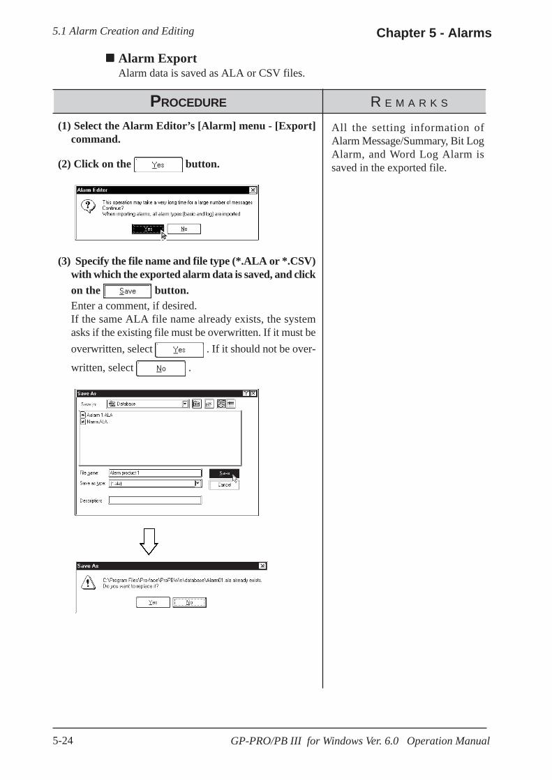
5-24
Chapter 5 - Alarms
GP-PRO/PB III for Windows Ver. 6.0 Operation Manual
Alarm ExportAlarm data is saved as ALA or CSV files.
5.1 Alarm Creation and Editing
All the setting information ofAlarm Message/Summary, Bit LogAlarm, and Word Log Alarm issaved in the exported file.
(3) Specify the file name and file type (*.ALA or *.CSV)with which the exported alarm data is saved, and clickon the button.Enter a comment, if desired.If the same ALA file name already exists, the systemasks if the existing file must be overwritten. If it must beoverwritten, select . If it should not be over-
written, select .
(1) Select the Alarm Editor’s [Alarm] menu - [Export]command.
PROCEDURE R E M A R K S
(2) Click on the button.
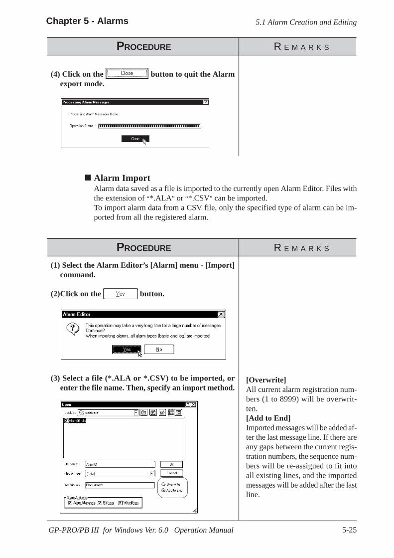
5-25
Chapter 5 - Alarms
GP-PRO/PB III for Windows Ver. 6.0 Operation Manual
(3) Select a file (*.ALA or *.CSV) to be imported, orenter the file name. Then, specify an import method.
PROCEDURE R E M A R K S
(1) Select the Alarm Editor’s [Alarm] menu - [Import]command.
Alarm ImportAlarm data saved as a file is imported to the currently open Alarm Editor. Files withthe extension of “*.ALA” or “*.CSV” can be imported.To import alarm data from a CSV file, only the specified type of alarm can be im-ported from all the registered alarm.
(4) Click on the button to quit the Alarmexport mode.
5.1 Alarm Creation and Editing
PROCEDURE R E M A R K S
[Overwrite]All current alarm registration num-bers (1 to 8999) will be overwrit-ten.[Add to End]Imported messages will be added af-ter the last message line. If there areany gaps between the current regis-tration numbers, the sequence num-bers will be re-assigned to fit intoall existing lines, and the importedmessages will be added after the lastline.
(2)Click on the button.

5-26
Chapter 5 - Alarms
GP-PRO/PB III for Windows Ver. 6.0 Operation Manual
PROCEDURE R E M A R K S
Once you complete the [Import]command, it cannot be undone.
(5) After entering all the necessary items, click on the button.
If the selected Device/PLC type is different between thecurrently open project and the imported ALA file, the sys-tem asks if the preset addresses should be overwritten. Ifthe preset addresses must be overwritten, select . If they must not be overwritten, select .
5.1 Alarm Creation and Editing
(4)When selecting CSV file as imported file type, specifythe type of alarm to be imported.Only the type of alarm specified here will be imported.
When selecting ALA file as im-ported file type, skip step (4).
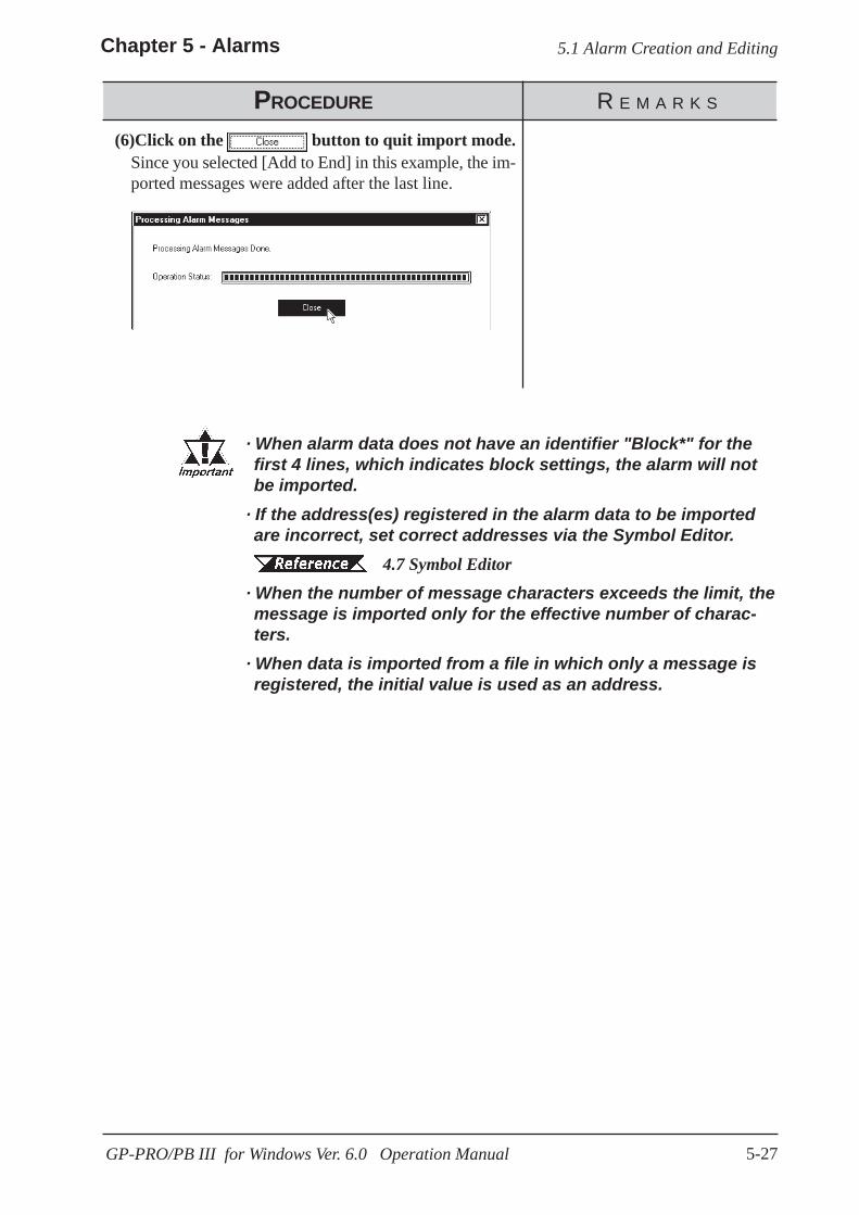
5-27
Chapter 5 - Alarms
GP-PRO/PB III for Windows Ver. 6.0 Operation Manual
· When alarm data does not have an identifier "Block*" for thefirst 4 lines, which indicates block settings, the alarm will notbe imported.
· If the address(es) registered in the alarm data to be importedare incorrect, set correct addresses via the Symbol Editor.
4.7 Symbol Editor· When the number of message characters exceeds the limit, themessage is imported only for the effective number of charac-ters.
· When data is imported from a file in which only a message isregistered, the initial value is used as an address.
5.1 Alarm Creation and Editing
(6)Click on the button to quit import mode.Since you selected [Add to End] in this example, the im-ported messages were added after the last line.
PROCEDURE R E M A R K S

5-28
Chapter 5
GP-PRO/PB III for Windows Ver. 6.0 Operation Manual
Memo
6-1GP-PRO/PB III for Windows Ver. 6.0 Operation Manual
ou can select many of the GP unit’s initial settings through theGP-PRO/PB III for Windows program. This program area is called
“System Settings”. When “System Settings” data is sent to the GP unit, youwill not need to manually perform the initial setup of the GP unit.A description of each GP unit setting item is provided in your “GP SeriesUser’s Manual” (sold separately). For details, refer to that manual.
Y
6 GP INITIAL AND SYSTEM SETTINGS
6.1 .....................................Menu Setting Items: GP Setup
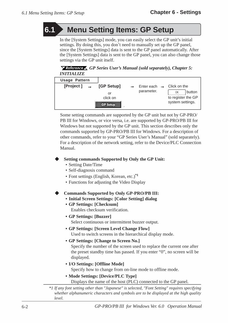
6-2
Chapter 6 - Settings
GP-PRO/PB III for Windows Ver. 6.0 Operation Manual
In the [System Settings] mode, you can easily select the GP unit’s initialsettings. By doing this, you don’t need to manually set up the GP panel,since the [System Settings] data is sent to the GP panel automatically. Afterthe [System Settings] data is sent to the GP panel, you can also change thosesettings via the GP unit itself.
GP Series User’s Manual (sold separately), Chapter 5:INITIALIZEUsage Pattern
Click on the button
to register the GPsystem settings.
Enter eachparameter.
[GP Setup]or
click on
.
[Project ] →→→→→→→→→→→→→→→
6.1 Menu Setting Items: GP Setup
*1 If any font setting other than "Japanese" is selected, "Font Setting" requires specifyingwhether alphanumeric characters and symbols are to be displayed at the high qualitylevel.
6.1 Menu Setting Items: GP Setup
Some setting commands are supported by the GP unit but not by GP-PRO/PB III for Windows, or vice versa, i.e. are supported by GP-PRO/PB III forWindows but not supported by the GP unit. This section describes only thecommands supported by GP-PRO/PB III for Windows. For a description ofother commands, refer to your “GP Series User’s Manual” (sold separately).For a description of the network setting, refer to the Device/PLC ConnectionManual.
Setting commands Supported by Only the GP Unit:• Setting Date/Time• Self-diagnosis command• Font settings (English, Korean, etc.)*1
• Functions for adjusting the Video Display
Commands Supported by Only GP-PRO/PB III:• Initial Screen Settings: [Color Setting] dialog• GP Settings: [Checksum]
Enables checksum verification.• GP Settings: [Buzzer]
Select continuous or intermittent buzzer output.• GP Settings: [Screen Level Change Flow]
Used to switch screens in the hierarchical display mode.• GP Settings: [Change to Screen No.]
Specify the number of the screen used to replace the current one afterthe preset standby time has passed. If you enter “0”, no screen will bedisplayed.
• I/O Settings: [Offline Mode]Specify how to change from on-line mode to offline mode.
• Mode Settings: [Device/PLC Type]Displays the name of the host (PLC) connected to the GP panel.
6-3
Chapter 6 - Settings
GP-PRO/PB III for Windows Ver. 6.0 Operation Manual
• Mode Settings: [Option]This setting is necessary only when specific Device/PLC types areselected.
• Extended Settings: [K-tag Priority]Designates the K-Tag processing mode. “Standard” mode executes theK-tag once per scan time, and “Twice” mode executes the K-tag twotimes per scan time.
• Extended Settings: [Backup Settings]Used to back up the GP unit's LS area data. Specify the initial addressof the backup range, and the number of words used.
• Extended Settings: [Delete Error Display](Only for programless type)Displays an error message when an communication error occurs withthe GP, and deletes the error message when the communication error isreset. System errors however cannot be reset, regardless of this setting.
• Extended Settings: [Watch Dog]Monitors the communication status between the GP and a PLC. TheGP unit writes the data (00FFh) to the word address of the PLC atspecified time intervals. (Specify in the range of 0 to 65535 seconds.The Watch Dog function is disabled when "0" is specified.) Thisfunction enables the PLC to check the communication states with theGP by periodically monitoring the data (00FFh) written by the GP.After the data are reviewed by the PLC, execute the "0 Clear" com-mand to clear the data and allow for monitoring of new data written bythe GP unit.
• Extended Settings: [CF Card Data Storage Settings]Used to specify a control word address when saving data on the CFCard for the GP-77R and GP2000 series. The GP unit writes thiscontrol word address data to the CF card.
• Extended Settings: [Available CF Card Space]When using a CF Card on the GP77R and GP2000 Series, specify theaddress to store the information on available CF card space.
Tag Reference Manual, 4.4 Using the CF Card• Extended Settings: [Q-tag Settings]
When using a Q-tag, specify display and printing settings as well asextended settings.
Tag Reference Manual, 2.20 Q-tag (Alarm SummaryDisplay)
• Extended Settings: [Capture Settings]Designates the settings for the Control Word Address used for produc-ing hard copies of the GP screen displaying video images.
Tag Reference Manual 4.4.9 Screen Capture• Extended Settings: [Video Settings] (Video Window Operation Settings)
Settings used for displaying a video window as a global window 3.6.2 Video Window Settings
• Extended Settings: [FEP Setting]• Extended Settings: [Serial 2-D code reader] (includes LS storage start address/Read complete bit address/Data
storage settings)
6.1 Menu Setting Items: GP Setup

6-4
Chapter 6 - Settings
GP-PRO/PB III for Windows Ver. 6.0 Operation Manual
Tab Setting ItemsEach tab's setting items are described here.
The setting items may differ depending on the GP type or Device/PLC typebeing used.
GP Settings
System SettingItems
Touch Panel Settings
Printer Settings (“Verticalprinting” is possible only withthe GP-675, and GP-2600)
LCD Settings (forthe GP-H70L, GP-270L, GP-370L,GP-377L, GP-2301HL, GP-2300Land GP-2301Lonly)
I/O Settings
6.1 Menu Setting Items: GP Setup
Frame Refresh Rate Settings(GP-377, GP-577RS only)
Sets up the function fordetecting errors in TouchPanel operation (availableonly with the GP77R andGP2000 series).
• Communication Settings: [Send Wait]If the GP unit sends a command to the PLC immediately after receiv-ing a response from the PLC, the PLC cannot receive the command,which will cause a communication error, depending on the Device/PLC type. In this case, enter a value for the transmission wait time. Ifa transmission wait time has been entered, the GP unit waits for thepreset time duration after receiving the PLC’s response, and thensends the next command to the PLC.
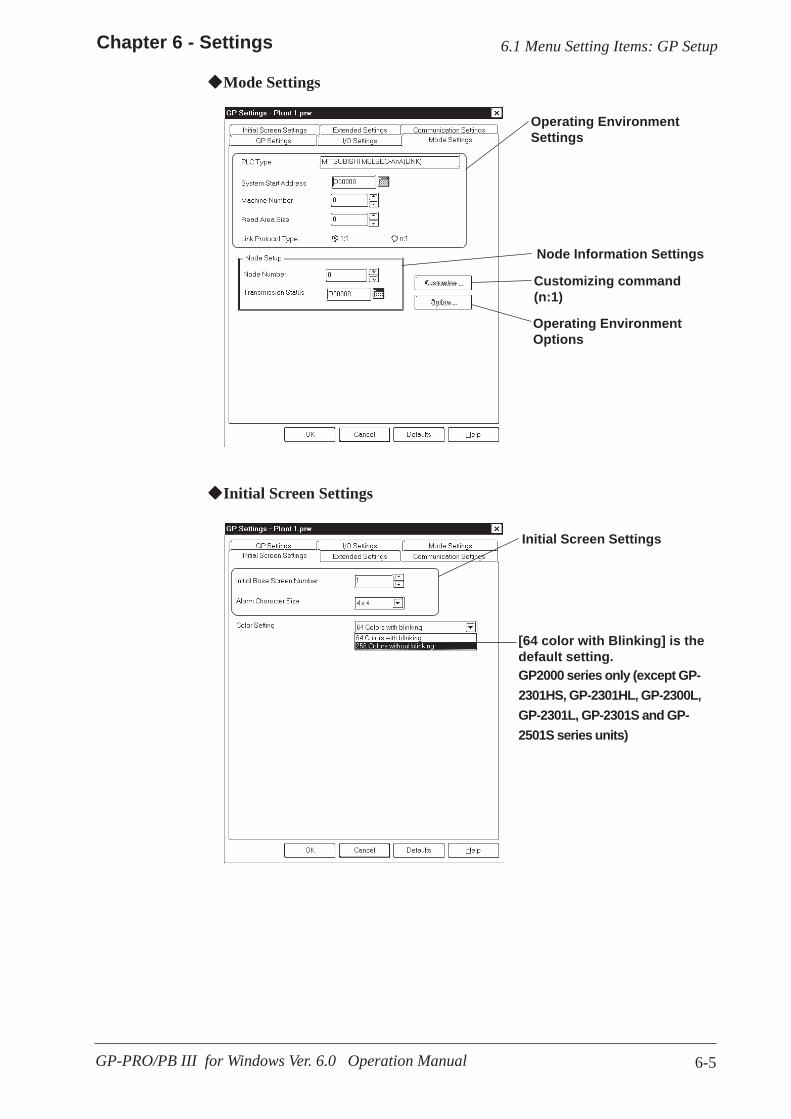
6-5
Chapter 6 - Settings
GP-PRO/PB III for Windows Ver. 6.0 Operation Manual
Operating EnvironmentSettings
Initial Screen Settings
Operating EnvironmentOptions
Customizing command(n:1)
Node Information Settings
Initial Screen Settings
Mode Settings
6.1 Menu Setting Items: GP Setup
[64 color with Blinking] is thedefault setting.GP2000 series only (except GP-2301HS, GP-2301HL, GP-2300L,GP-2301L, GP-2301S and GP-2501S series units)
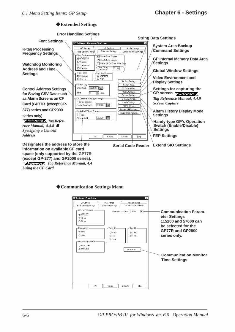
6-6
Chapter 6 - Settings
GP-PRO/PB III for Windows Ver. 6.0 Operation Manual
Communication Param-eter Settings115200 and 57600 canbe selected for theGP77R and GP2000series only.
Communication MonitorTime Settings
Communication Settings Menu
Error Handling Settings
Handy-type GP’s OperationSwitch (Enable/Disable)Settings
Video Environment andDisplay Settings
GP Internal Memory Data AreaSettings
String Data Settings
Extended Settings
Font Settings
K-tag ProcessingFrequency Settings
Watchdog MonitoringAddress and TimeSettings
Control Address Settingsfor Saving CSV Data suchas Alarm Screens on CFCard (GP77R (except GP-377) series and GP2000series only)
Tag Refer-ence Manual, 4.4.8 Specifying a ControlAddress
6.1 Menu Setting Items: GP Setup
Alarm History Display ModeSettings
Global Window Settings
FEP Settings
Extend SIO SettingsSerial Code ReaderDesignates the address to store theinformation on available CF cardspace (only supported by the GP77R(except GP-377) and GP2000 series).
Tag Reference Manual, 4.4Using the CF Card
Settings for capturing theGP screenTag Reference Manual, 4.4.9Screen Capture
System Area BackupCommand Settings
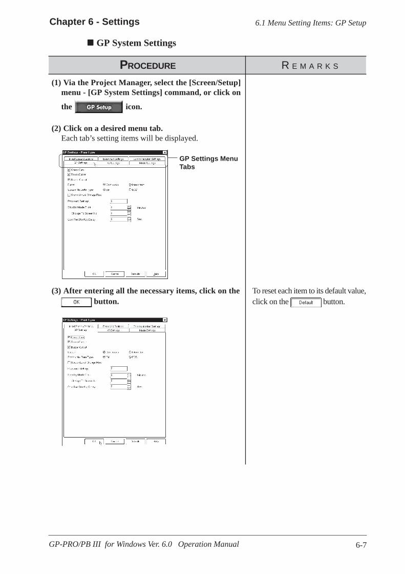
6-7
Chapter 6 - Settings
GP-PRO/PB III for Windows Ver. 6.0 Operation Manual
PROCEDURE R E M A R K S
(2) Click on a desired menu tab.Each tab’s setting items will be displayed.
(1) Via the Project Manager, select the [Screen/Setup]menu - [GP System Settings] command, or click on
the icon.
GP System Settings
6.1 Menu Setting Items: GP Setup
GP Settings MenuTabs
To reset each item to its default value,click on the button.
(3) After entering all the necessary items, click on the button.

6-8 GP-PRO/PB III for Windows Ver. 6.0 Operation Manual
Memo

7-1GP-PRO/PB III for Windows Ver. 6.0 Operation Manual
o display screens created with GP-PRO/PB III on the GP unit, youmust first transfer the screen data to the GP. Conversely, with the
GP-PRO/PB III program, you can also transfer screen data stored in the GPunit back to your personal computer for additional editing.
This chapter describes how to transfer screen data to and from the GP unit.
7 TRANSFERRING DATA
T
7.1 ........................................... Prior to Transferring Data
7.2 ..................................................... Transferring Screens
7.3 ........................................................................... Options
7.4 ........... Setting Up Your GP via an Ethernet Network
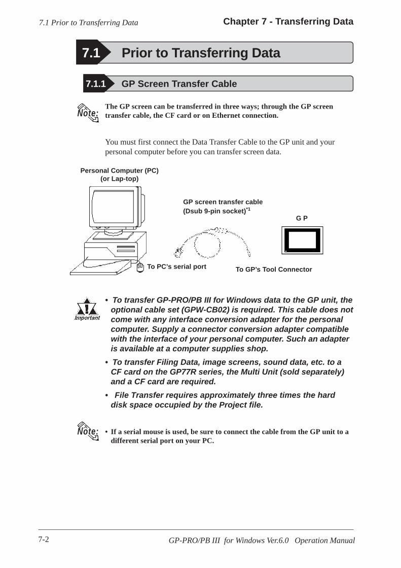
7-2
Chapter 7 - Transferring Data
GP-PRO/PB III for Windows Ver.6.0 Operation Manual
7.1 Prior to Transferring Data
• To transfer GP-PRO/PB III for Windows data to the GP unit, theoptional cable set (GPW-CB02) is required. This cable does notcome with any interface conversion adapter for the personalcomputer. Supply a connector conversion adapter compatiblewith the interface of your personal computer. Such an adapteris available at a computer supplies shop.
• To transfer Filing Data, image screens, sound data, etc. to aCF card on the GP77R series, the Multi Unit (sold separately)and a CF card are required.
• File Transfer requires approximately three times the harddisk space occupied by the Project file.
• If a serial mouse is used, be sure to connect the cable from the GP unit to adifferent serial port on your PC.
Note:
The GP screen can be transferred in three ways; through the GP screentransfer cable, the CF card or on Ethernet connection.
You must first connect the Data Transfer Cable to the GP unit and yourpersonal computer before you can transfer screen data.
7.1 Prior to Transferring Data
To GP’s Tool Connector
GP screen transfer cable(Dsub 9-pin socket)*1
Personal Computer (PC)(or Lap-top)
G P
To PC’s serial port
7.1.1 GP Screen Transfer Cable
Note:
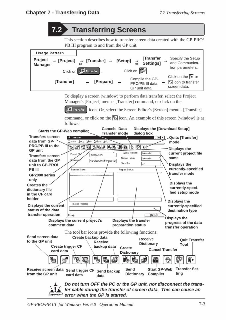
7-3
Chapter 7 - Transferring Data
GP-PRO/PB III for Windows Ver. 6.0 Operation Manual
Usage Pattern
Click on the or icon to transfer
screen data.
Compile the GP-PRO/PB III dataGP unit data.
[Prepare][Transfer]
Specify the Setupand Communica-tion parameters.
[TransferSettings][Setup]
or
Click on .
[Transfer]ProjectManager
→→→→→→→→→→→→→→→
→→→→→→→→→→→→→→→→→→→→
Transfers screendata from GP-PRO/PB III to theGP unit
Displays theprogress of the datatransfer operation
Displays the transferpreparation status
Displays the current project’scomment data
Displays the currentstatus of the datatransfer operation
Displays thecurrently-specifieddestination type
Displays thecurrently-speci-fied setup mode
Displays thecurrently-specifiedtransfer mode
Displays thecurrent project filename
Quits [Transfer]mode
Displays the [Download Setup]dialog box
Cancels DataTransfer mode
Transfers screendata from the GPunit to GP-PRO/PB III
Send screen datato the GP unit Quit Transfer
Tool
Transfer Set-ting
Cancel Transfer
Receive screen datafrom the GP unit
The tool bar icons provide the following functions:
To display a screen (window) to perform data transfer, select the ProjectManager's [Project] menu - [Transfer] command, or click on the
icon. Or, select the Screen Editor's [Screen] menu - [Transfer]
command, or click on the icon. An example of this screen (window) is asfollows:
This section describes how to transfer screen data created with the GP-PRO/PB III program to and from the GP unit.
7.2 Transferring Screens
[Project] →→→→→
7.2 Transferring Screens
Do not turn OFF the PC or the GP unit, nor disconnect the trans-fer cable during the transfer of screen data. This can cause anerror when the GP is started.
or
Click on .
GP2000 seriesonly
Starts the GP-Web compiler
Start GP-WebCompiler
CreateDictionary
ReceiveDictionary
SendDictionary
Create trigger CFcard data
Send trigger CFcard data
Create backup data
Send backupdata
Receivebackup data
Creates thedictionary filein the CF cardholder
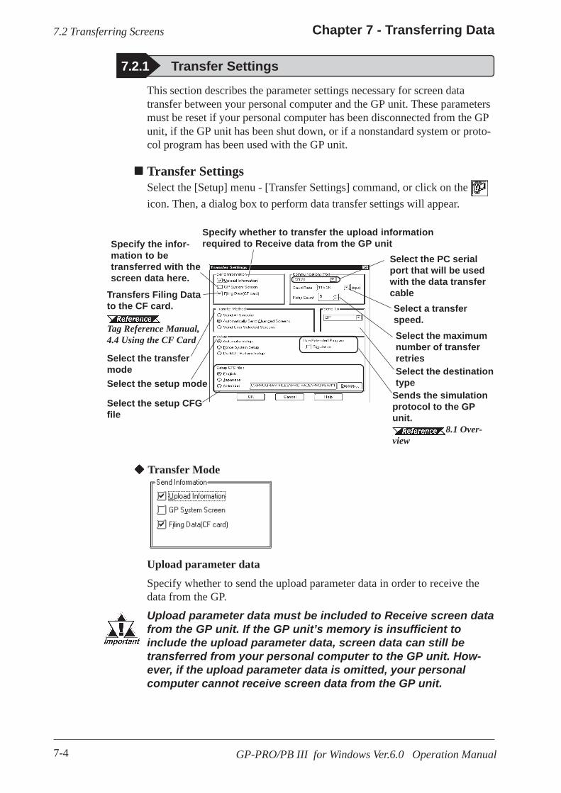
7-4
Chapter 7 - Transferring Data
GP-PRO/PB III for Windows Ver.6.0 Operation Manual
Specify the infor-mation to betransferred with thescreen data here.
7.2.1 Transfer Settings
Select the setup CFGfile
Select the setup modeSelect the destinationtype
Select the PC serialport that will be usedwith the data transfercable
Specify whether to transfer the upload informationrequired to Receive data from the GP unit
Select the transfermode
Transfers Filing Datato the CF card.
Tag Reference Manual,4.4 Using the CF Card
This section describes the parameter settings necessary for screen datatransfer between your personal computer and the GP unit. These parametersmust be reset if your personal computer has been disconnected from the GPunit, if the GP unit has been shut down, or if a nonstandard system or proto-col program has been used with the GP unit.
Select a transferspeed.
Sends the simulationprotocol to the GPunit.
8.1 Over-view
Transfer SettingsSelect the [Setup] menu - [Transfer Settings] command, or click on the icon. Then, a dialog box to perform data transfer settings will appear.
Transfer Mode
Upload parameter data
Specify whether to send the upload parameter data in order to receive thedata from the GP.
Upload parameter data must be included to Receive screen datafrom the GP unit. If the GP unit’s memory is insufficient toinclude the upload parameter data, screen data can still betransferred from your personal computer to the GP unit. How-ever, if the upload parameter data is omitted, your personalcomputer cannot receive screen data from the GP unit.
7.2 Transferring Screens
Select the maximumnumber of transferretries
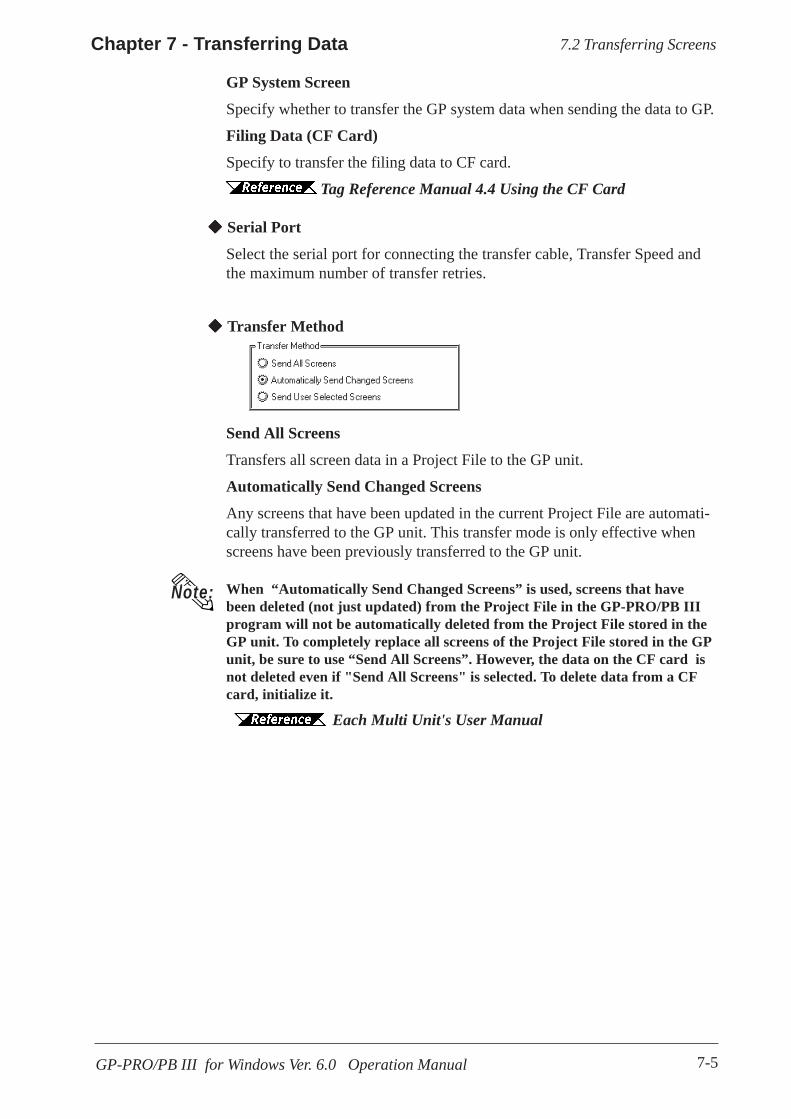
7-5
Chapter 7 - Transferring Data
GP-PRO/PB III for Windows Ver. 6.0 Operation Manual
GP System Screen
Specify whether to transfer the GP system data when sending the data to GP.
Filing Data (CF Card)
Specify to transfer the filing data to CF card.
Tag Reference Manual 4.4 Using the CF Card
Serial Port
Select the serial port for connecting the transfer cable, Transfer Speed andthe maximum number of transfer retries.
Transfer Method
Send All Screens
Transfers all screen data in a Project File to the GP unit.
Automatically Send Changed Screens
Any screens that have been updated in the current Project File are automati-cally transferred to the GP unit. This transfer mode is only effective whenscreens have been previously transferred to the GP unit.
When “Automatically Send Changed Screens” is used, screens that havebeen deleted (not just updated) from the Project File in the GP-PRO/PB IIIprogram will not be automatically deleted from the Project File stored in theGP unit. To completely replace all screens of the Project File stored in the GPunit, be sure to use “Send All Screens”. However, the data on the CF card isnot deleted even if "Send All Screens" is selected. To delete data from a CFcard, initialize it.
Each Multi Unit's User Manual
Note:
7.2 Transferring Screens
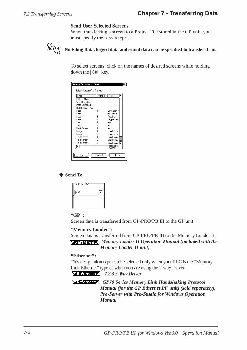
7-6
Chapter 7 - Transferring Data
GP-PRO/PB III for Windows Ver.6.0 Operation Manual
“GP”:Screen data is transferred from GP-PRO/PB III to the GP unit.
“Memory Loader”:Screen data is transferred from GP-PRO/PB III to the Memory Loader II.
Memory Loader II Operation Manual (included with theMemory Loader II unit)
“Ethernet”:This designation type can be selected only when your PLC is the “MemoryLink Ethernet” type or when you are using the 2-way Driver.
7.2.3 2-Way Driver GP70 Series Memory Link Handshaking ProtocolManual (for the GP Ethernet I/F unit) (sold separately),Pro-Server with Pro-Studio for Windows OperationManual
Send To
7.2 Transferring Screens
Send User Selected ScreensWhen transferring a screen to a Project File stored in the GP unit, youmust specify the screen type.
No Filing Data, logged data and sound data can be specified to transfer them.
To select screens, click on the names of desired screens while holdingdown the key.Ctrl
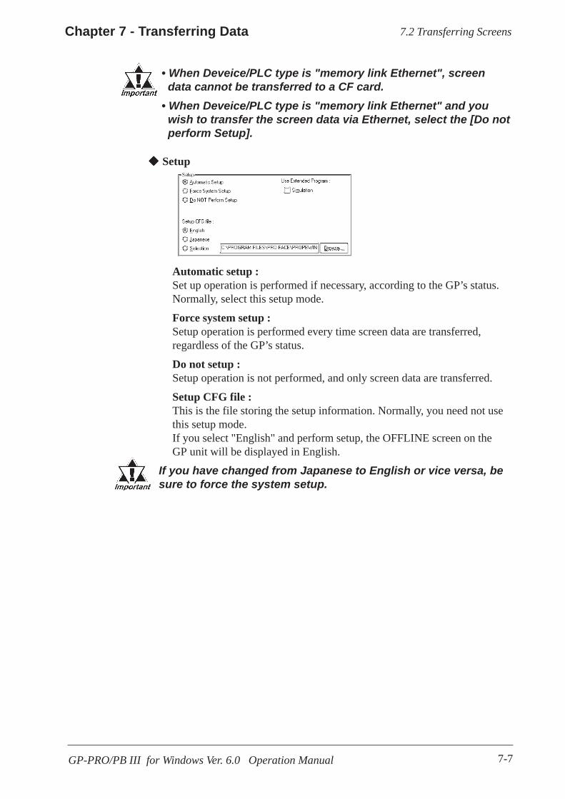
7-7
Chapter 7 - Transferring Data
GP-PRO/PB III for Windows Ver. 6.0 Operation Manual
Automatic setup :Set up operation is performed if necessary, according to the GP’s status.Normally, select this setup mode.
Force system setup :Setup operation is performed every time screen data are transferred,regardless of the GP’s status.
Do not setup :Setup operation is not performed, and only screen data are transferred.
Setup CFG file :This is the file storing the setup information. Normally, you need not usethis setup mode.If you select "English" and perform setup, the OFFLINE screen on theGP unit will be displayed in English.
If you have changed from Japanese to English or vice versa, besure to force the system setup.
Setup
7.2 Transferring Screens
• When Deveice/PLC type is "memory link Ethernet", screen data cannot be transferred to a CF card.• When Deveice/PLC type is "memory link Ethernet" and you wish to transfer the screen data via Ethernet, select the [Do not perform Setup].

7-8
Chapter 7 - Transferring Data
GP-PRO/PB III for Windows Ver.6.0 Operation Manual
Registering a PasswordYou can enter a password to restrict user access to the screen transfer func-tion.
• Be sure to keep a copy of the password in a safe place. If youforget the password, the “Transfer” function cannot be executed.
• The password is limited to 24 characters and only alphanu-meric data (no symbols) can be used.
7.2.2 Passwords
PROCEDURE R E M A R K S
If a password has already been reg-istered, the [Change Password] dia-log box will appear.
(1) Via the Project Manager, select the [Project] menu -
[Transfer] command, or click on the icon. Or, via the Screen Editor, select the [Screen]menu - [Transfer] command, or click on the icon.
(2) Select the [Setup] menu - [Password] command.
(3) Enter a password.
If the currently open Project Filehas not yet been saved in stop, thesystem will ask you to do so beforeregistering a password.
(4) Enter the same password again for confirmation, andthen, click on the button.
Also, if the currently edited screenhas not been saved via the ScreenEditor, a prompt will appear ask-ing if screen data is saved beforetransfer.
7.2 Transferring Screens

7-9
Chapter 7 - Transferring Data
GP-PRO/PB III for Windows Ver. 6.0 Operation Manual
PROCEDURE R E M A R K S
To cancel the password, after en-tering the currently registered pass-word in step (2), DO NOT enter anew password in step (3) and sim-ply click on the button.
If the currently open Project Filehas not yet been saved in stop (1),the system will ask you to do so be-fore registering a password.
(4) Enter a new password.
(3) In order to change a password, you must first en-ter the currently registered password.
(1) Via the Project Manager, select the [Project] menu -
[Transfer] command, or click on the icon. Or, via the Screen Editor, select the [Screen]menu - [Transfer] command, or click on the icon.
Changing a PasswordThe registered password can be changed or canceled.
(2) Select the [Setup] menu - [Password] command.
(5) Enter the same password again for confirmation, andthen, click on the button.
Also, if the currently edited screenhas not been saved via the ScreenEditor, a prompt will appear ask-ing if screen data is saved beforetransfer.
7.2 Transferring Screens
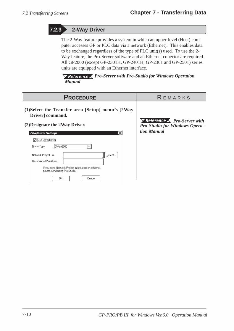
7-10
Chapter 7 - Transferring Data
GP-PRO/PB III for Windows Ver.6.0 Operation Manual
7.2.3 2-Way DriverThe 2-Way feature provides a system in which an upper-level (Host) com-puter accesses GP or PLC data via a network (Ethernet). This enables datato be exchanged regardless of the type of PLC unit(s) used. To use the 2-Way feature, the Pro-Server software and an Ethernet conector are required.All GP2000 (except GP-2301H, GP-2401H, GP-2301 and GP-2501) seriesunits are equipped with an Ethernet interface.
Pro-Server with Pro-Studio for Windows Operation Manual
PROCEDURE R E M A R K S
(1)Select the Transfer area [Setup] menu’s [2WayDriver] command.
(2)Designate the 2Way Driver. Pro-Server with
Pro-Studio for Windows Opera-tion Manual
7.2 Transferring Screens
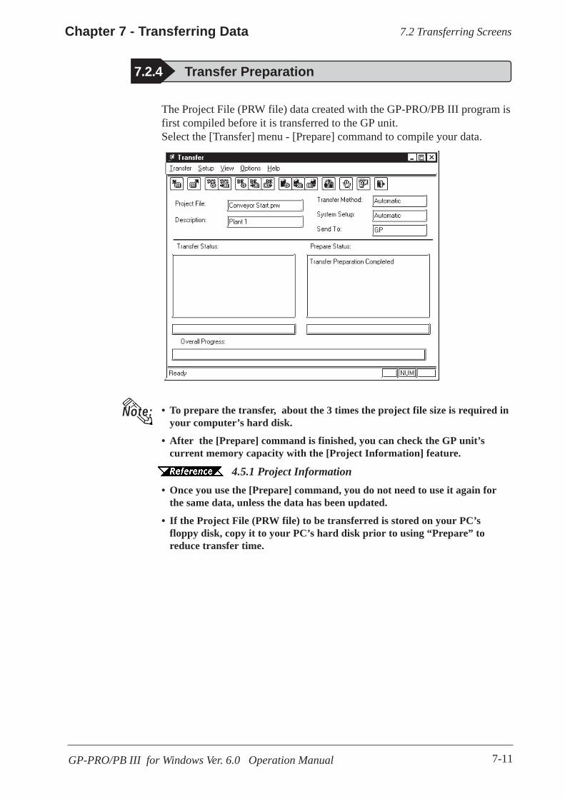
7-11
Chapter 7 - Transferring Data
GP-PRO/PB III for Windows Ver. 6.0 Operation Manual
The Project File (PRW file) data created with the GP-PRO/PB III program isfirst compiled before it is transferred to the GP unit.Select the [Transfer] menu - [Prepare] command to compile your data.
7.2.4 Transfer Preparation
Note: • To prepare the transfer, about the 3 times the project file size is required inyour computer’s hard disk.
• After the [Prepare] command is finished, you can check the GP unit’scurrent memory capacity with the [Project Information] feature.
4.5.1 Project Information• Once you use the [Prepare] command, you do not need to use it again for
the same data, unless the data has been updated.
• If the Project File (PRW file) to be transferred is stored on your PC’sfloppy disk, copy it to your PC’s hard disk prior to using “Prepare” toreduce transfer time.
7.2 Transferring Screens
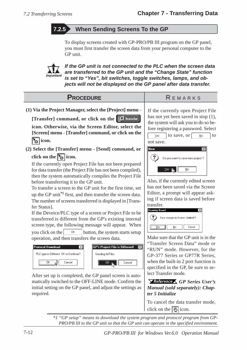
7-12
Chapter 7 - Transferring Data
GP-PRO/PB III for Windows Ver.6.0 Operation Manual
To display screens created with GP-PRO/PB III program on the GP panel,you must first transfer the screen data from your personal computer to theGP unit.
If the GP unit is not connected to the PLC when the screen dataare transferred to the GP unit and the “Change State” functionis set to “Yes”, bit switches, toggle switches, lamps, and ob-jects will not be displayed on the GP panel after data transfer.
7.2.5 When Sending Screens To the GP
PROCEDURE R E M A R K S
Make sure that the GP unit is in the“Transfer Screen Data” mode or“RUN” mode. However, for theGP-377 Series or GP77R Series,when the built-in 2 port function isspecified in the GP, be sure to se-lect Transfer mode.
GP Series User’sManual (sold separately): Chap-ter 5 InitializeTo cancel the data transfer mode,click on the icon.
(2) Select the [Transfer] menu - [Send] command, orclick on the icon.If the currently open Project File has not been preparedfor data transfer (the Project File has not been compiled),then the system automatically compiles the Project Filebefore transferring it to the GP unit.To transfer a screen to the GP unit for the first time, setup the GP unit*1 first, and then transfer the screen data.The number of screens transferred is displayed in [Trans-fer Status].If the Deveice/PLC type of a screen or Project File to betransferred is different from the GP's existing internalscreen type, the following message will appear. Whenyou click on the button, the system starts setupoperation, and then transfers the screen data.
If the currently open Project Filehas not yet been saved in stop (1),the system will ask you to do so be-fore registering a password. Select
to save, or tonot save.
*1 “GP setup” means to download the system program and protocol program from GP-PRO/PB III to the GP unit so that the GP unit can operate in the specified environment.
(1) Via the Project Manager, select the [Project] menu -
[Transfer] command, or click on the icon. Otherwise, via the Screen Editor, select the[Screen] menu - [Transfer] command, or click on the
icon.
Also, if the currently edited screenhas not been saved via the ScreenEditor, a prompt will appear ask-ing if screen data is saved beforetransfer.
After set up is completed, the GP panel screen is auto-matically switched to the OFF-LINE mode. Confirm theinitial setting on the GP panel, and adjust the settings asrequired.
7.2 Transferring Screens
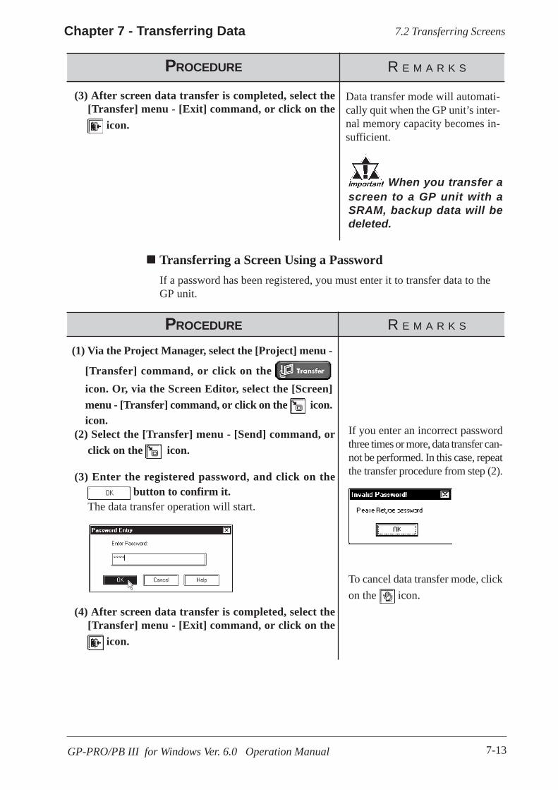
7-13
Chapter 7 - Transferring Data
GP-PRO/PB III for Windows Ver. 6.0 Operation Manual
(3) After screen data transfer is completed, select the[Transfer] menu - [Exit] command, or click on the
icon.
PROCEDURE R E M A R K S
To cancel data transfer mode, clickon the icon.
If you enter an incorrect passwordthree times or more, data transfer can-not be performed. In this case, repeatthe transfer procedure from step (2).
(4) After screen data transfer is completed, select the[Transfer] menu - [Exit] command, or click on the
icon.
(2) Select the [Transfer] menu - [Send] command, orclick on the icon.
(1) Via the Project Manager, select the [Project] menu -
[Transfer] command, or click on the icon. Or, via the Screen Editor, select the [Screen]menu - [Transfer] command, or click on the icon.icon.
Transferring a Screen Using a PasswordIf a password has been registered, you must enter it to transfer data to theGP unit.
When you transfer ascreen to a GP unit with aSRAM, backup data will bedeleted.
Data transfer mode will automati-cally quit when the GP unit’s inter-nal memory capacity becomes in-sufficient.
PROCEDURE R E M A R K S
(3) Enter the registered password, and click on the button to confirm it.
The data transfer operation will start.
7.2 Transferring Screens
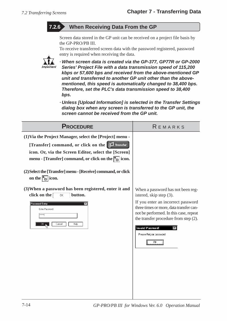
7-14
Chapter 7 - Transferring Data
GP-PRO/PB III for Windows Ver. 6.0 Operation Manual
PROCEDURE R E M A R K S
7.2.6 When Receiving Data From the GP
(3)When a password has been registered, enter it andclick on the button.
(2)Select the [Transfer] menu - [Receive] command, or clickon the icon.
(1)Via the Project Manager, select the [Project] menu -
[Transfer] command, or click on the icon. Or, via the Screen Editor, select the [Screen]menu - [Transfer] command, or click on the icon.
Screen data stored in the GP unit can be received on a project file basis bythe GP-PRO/PB III.To receive transferred screen data with the password registered, passwordentry is required when receiving the data.
· When screen data is created via the GP-377, GP77R or GP-2000Series' Project File with a data transmission speed of 115,200kbps or 57,600 bps and received from the above-mentioned GPunit and transferred to another GP unit other than the above-mentioned, this speed is automatically changed to 38,400 bps.Therefore, set the PLC's data transmission speed to 38,400bps.
· Unless [Upload Information] is selected in the Transfer Settingsdialog box when any screen is transferred to the GP unit, thescreen cannot be received from the GP unit.
When a password has not been reg-istered, skip step (3).If you enter an incorrect passwordthree times or more, data transfer can-not be performed. In this case, repeatthe transfer procedure from step (2).
7.2 Transferring Screens
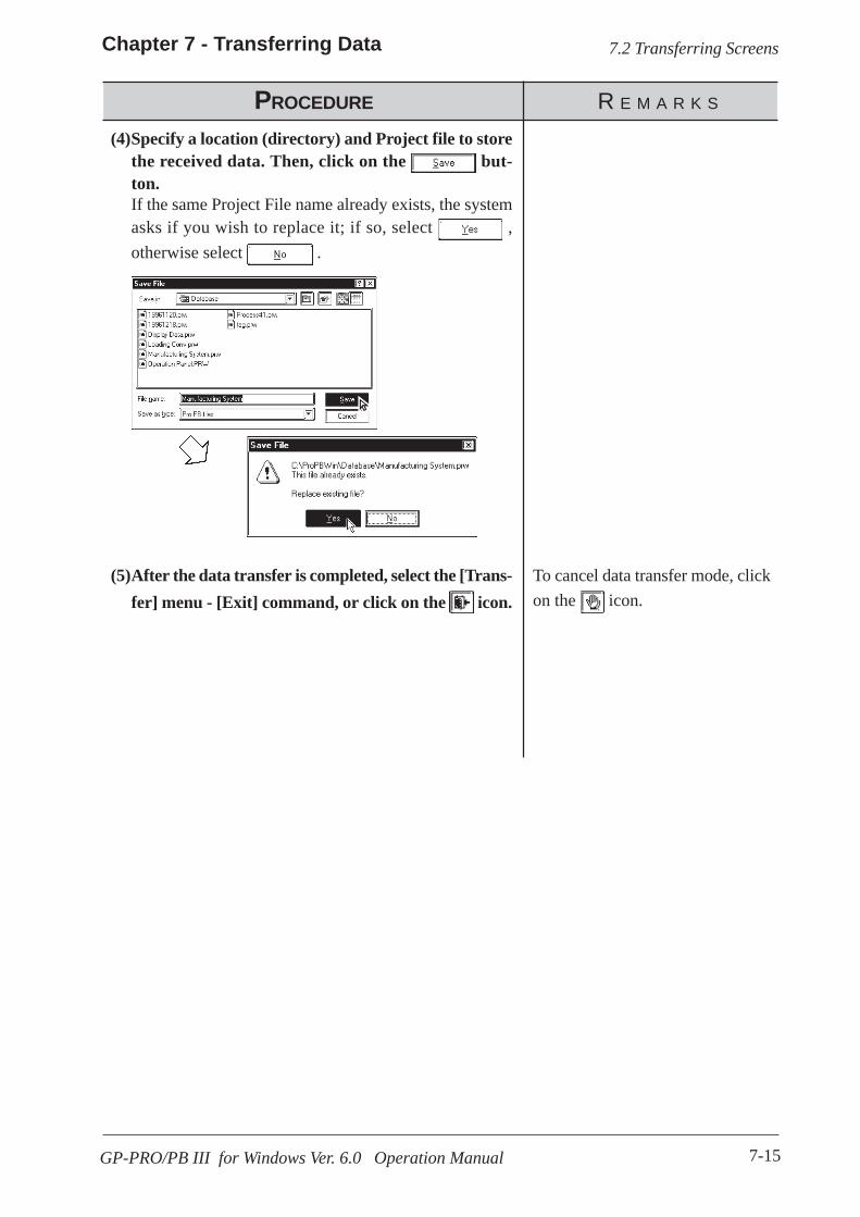
7-15
Chapter 7 - Transferring Data
GP-PRO/PB III for Windows Ver. 6.0 Operation Manual
PROCEDURE R E M A R K S
(5)After the data transfer is completed, select the [Trans-fer] menu - [Exit] command, or click on the icon.
(4)Specify a location (directory) and Project file to storethe received data. Then, click on the but-ton.If the same Project File name already exists, the systemasks if you wish to replace it; if so, select ,otherwise select .
To cancel data transfer mode, clickon the icon.
7.2 Transferring Screens

7-16
Chapter 7 - Transferring Data
GP-PRO/PB III for Windows Ver. 6.0 Operation Manual
7.2.7 Sending/Receiving Dictionary FileThis feature allows you to create, send and receive a dictionary file used in aJapanese FEP. This feature is available only with the GP2000 series.Receiving and sending via Ethernet is also available.
Creating a Dictionary FileSelect [Create Dictionary] from the [Transfer] menu to create a dictionary.
The dictionary created (about 500KB) is written into the CF Card outputfolder. If a dictionary file already exists on the CF Card output folder, thefollowing dialog box appears asking whether the existing file should beoverwritten
Sending a Dictionary FileSelect [Send Dictionary] from the [Transfer] menu to create and send adictionary file to the CF Card attached to the GP unit.
The dictionary created is written into the CF Card output folder before it issent. If a dictionary file already exists on the CF Card output folder, thefollowing dialog box appears asking whether a new dictionary should becreated.
7.2 Transferring Screens
Note:
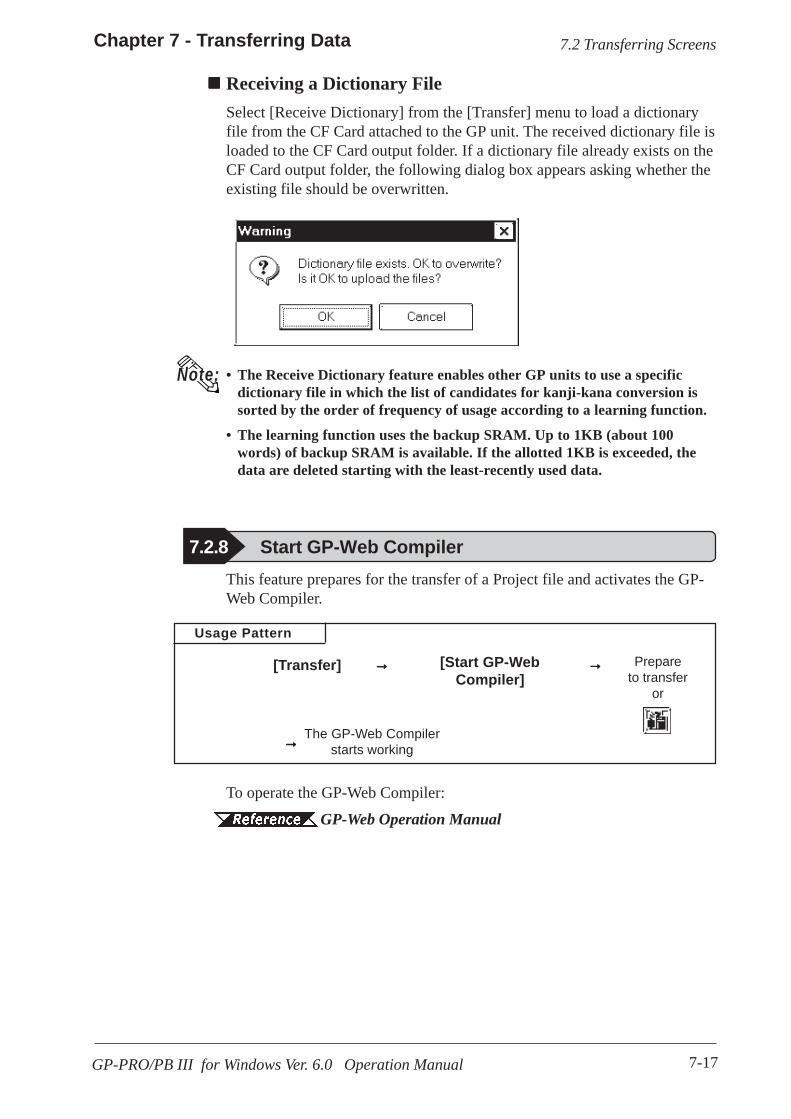
7-17
Chapter 7 - Transferring Data
GP-PRO/PB III for Windows Ver. 6.0 Operation Manual
Receiving a Dictionary FileSelect [Receive Dictionary] from the [Transfer] menu to load a dictionaryfile from the CF Card attached to the GP unit. The received dictionary file isloaded to the CF Card output folder. If a dictionary file already exists on theCF Card output folder, the following dialog box appears asking whether theexisting file should be overwritten.
• The Receive Dictionary feature enables other GP units to use a specificdictionary file in which the list of candidates for kanji-kana conversion issorted by the order of frequency of usage according to a learning function.
• The learning function uses the backup SRAM. Up to 1KB (about 100words) of backup SRAM is available. If the allotted 1KB is exceeded, thedata are deleted starting with the least-recently used data.
Note:
7.2.8 Start GP-Web Compiler
Usage Pattern
[Transfer] →→→→→
→→→→→
→→→→→
This feature prepares for the transfer of a Project file and activates the GP-Web Compiler.
To operate the GP-Web Compiler:
GP-Web Operation Manual
7.2 Transferring Screens
[Start GP-WebCompiler]
Prepareto transfer
or
The GP-Web Compilerstarts working
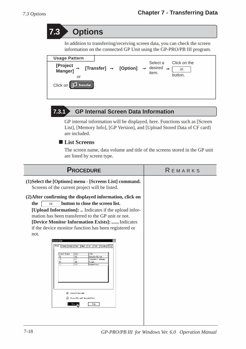
7-18
Chapter 7 - Transferring Data
GP-PRO/PB III for Windows Ver. 6.0 Operation Manual
Usage Pattern
7.3 Options
Click on the
button.
Select adesireditem.
[Option][Transfer]
or
Click on .
[ProjectManger] →→→→→ →→→→→→→→→→→→→→→
7.3.1 GP Internal Screen Data Information
PROCEDURE R E M A R K S
(2)After confirming the displayed information, click onthe button to close the screen list.[Upload Information]: .. Indicates if the upload infor-mation has been transferred to the GP unit or not.[Device Monitor Information Exists]: ...... Indicatesif the device monitor function has been registered ornot.
(1)Select the [Options] menu - [Screens List] command.Screens of the current project will be listed.
GP internal information will be displayed, here. Functions such as [ScreenList], [Memory Info], [GP Version], and [Upload Stored Data of CF card]are included.
List ScreensThe screen name, data volume and title of the screens stored in the GP unitare listed by screen type.
In addition to transferring/receiving screen data, you can check the screeninformation on the connected GP Unit using the GP-PRO/PB III program.
7.3 Options

7-19
Chapter 7 - Transferring Data
GP-PRO/PB III for Windows Ver. 6.0 Operation Manual
7.3 Options
PROCEDURE R E M A R K S
Number of banks provided in eachGP model:
GP-H70: 16 banksGP-270: 4 banksGP-370: 16 banksGP-470: 16 banksGP-570: 16 banksGP-571: 48 banksGP-675: 32 banksGP-870: 16 banksGP-377: 16 banksGP77R: 32 banksGP-2301H: 16 banksGP-2401H: 32 banksGP-2300: 32 banksGP-2301: 16 banksGP-2400: 64 banksGP-2500: 64 banksGP-2501: 32 banksGP-2600: 64 banks
(The capacity for each bank is59526 bytes.)
A single screen file cannot be storedin several banks. Therefore, thesum of the remaining memory ca-pacity for each bank is not alwaysequal to the transferrable screendata volume.
(2)After confirming the displayed information, click onthe button to close the memory informa-tion window.[Max Available] ............Displays the GP unit’s allow-able memory capacity.[Used] ............................Displays the data volume cur-rently used in the GP unit.[Free] .............................Displays the amount of “free”,or remaining memory.[Available on CF Card] ... Shows the remaining ca-pacity of the CF card.
(1)Select the [Options] menu - [Memory Info] command.The receiving of memory information begins.
Memory InformationThe GP unit’s current memory capacity for each bank is displayed. Its maximuminternal memory capacity is also displayed.
GP VersionThe GP unit’s version is displayed.
PROCEDURE R E M A R K S
(1)Select the [Options] menu - [GP Version] command.The receiving of the version information begins.
(2)After confirming the displayed information, click onthe button to quit.

7-20
Chapter 7 - Transferring Data
GP-PRO/PB III for Windows Ver. 6.0 Operation Manual
PROCEDURE R E M A R K S
(1)Select the [Options] menu - [Upload Stored Data ofCF Card] command.The files stored on the GP unit’s CF card will be listed.
Receiving CF Card DataData (*.CSV) stored on a GP’s CF Card such as alarms, trend graphs, sampled data,and logged data, can be read into your PC by GP-PRO/PBIII for Windows and thenused in Microsoft Excel.
7.3 Options
This feature is supported only by the GP77R and GP2000 series.With GP77R series units, this feature requires the optional MultiUnit (sold separately).
(2)Select data to be uploaded to your PC and click onthe button.
Tag Reference Manual, 4.4 Using the CF Card
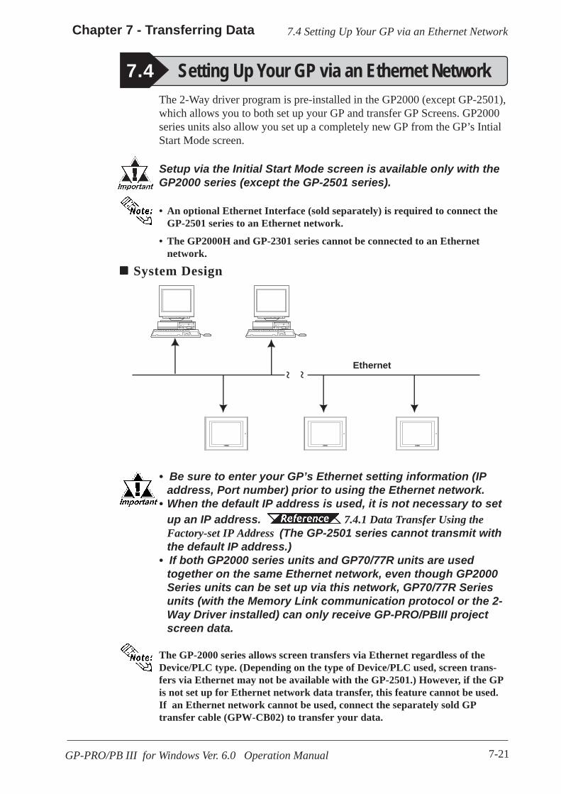
7-21
Chapter 7 - Transferring Data
GP-PRO/PB III for Windows Ver. 6.0 Operation Manual
7.4 Setting Up Your GP via an Ethernet Network
The 2-Way driver program is pre-installed in the GP2000 (except GP-2501),which allows you to both set up your GP and transfer GP Screens. GP2000series units also allow you set up a completely new GP from the GP’s IntialStart Mode screen.
Setup via the Initial Start Mode screen is available only with theGP2000 series (except the GP-2501 series).
• An optional Ethernet Interface (sold separately) is required to connect theGP-2501 series to an Ethernet network.
• The GP2000H and GP-2301 series cannot be connected to an Ethernetnetwork.
System Design
7.4 Setting Up Your GP via an Ethernet Network
• Be sure to enter your GP’s Ethernet setting information (IPaddress, Port number) prior to using the Ethernet network.
• When the default IP address is used, it is not necessary to setup an IP address. 7.4.1 Data Transfer Using theFactory-set IP Address (The GP-2501 series cannot transmit withthe default IP address.)
• If both GP2000 series units and GP70/77R units are usedtogether on the same Ethernet network, even though GP2000Series units can be set up via this network, GP70/77R Seriesunits (with the Memory Link communication protocol or the 2-Way Driver installed) can only receive GP-PRO/PBIII projectscreen data.
The GP-2000 series allows screen transfers via Ethernet regardless of theDevice/PLC type. (Depending on the type of Device/PLC used, screen trans-fers via Ethernet may not be available with the GP-2501.) However, if the GPis not set up for Ethernet network data transfer, this feature cannot be used.If an Ethernet network cannot be used, connect the separately sold GPtransfer cable (GPW-CB02) to transfer your data.
Ethernet
~ ~
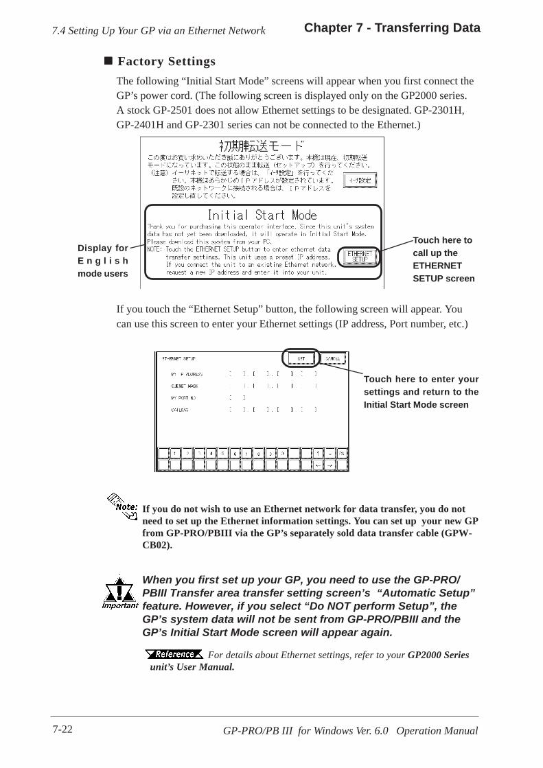
7-22
Chapter 7 - Transferring Data
GP-PRO/PB III for Windows Ver. 6.0 Operation Manual
7.4 Setting Up Your GP via an Ethernet Network
Factory SettingsThe following “Initial Start Mode” screens will appear when you first connect theGP’s power cord. (The following screen is displayed only on the GP2000 series.A stock GP-2501 does not allow Ethernet settings to be designated. GP-2301H,GP-2401H and GP-2301 series can not be connected to the Ethernet.)
If you do not wish to use an Ethernet network for data transfer, you do notneed to set up the Ethernet information settings. You can set up your new GPfrom GP-PRO/PBIII via the GP’s separately sold data transfer cable (GPW-CB02).
When you first set up your GP, you need to use the GP-PRO/PBIII Transfer area transfer setting screen’s “Automatic Setup”feature. However, if you select “Do NOT perform Setup”, theGP’s system data will not be sent from GP-PRO/PBIII and theGP’s Initial Start Mode screen will appear again.
For details about Ethernet settings, refer to your GP2000 Seriesunit’s User Manual.
Display forE n g l i s hmode users
Touch here tocall up theETHERNETSETUP screen
If you touch the “Ethernet Setup” button, the following screen will appear. Youcan use this screen to enter your Ethernet settings (IP address, Port number, etc.)
Touch here to enter yoursettings and return to theInitial Start Mode screen
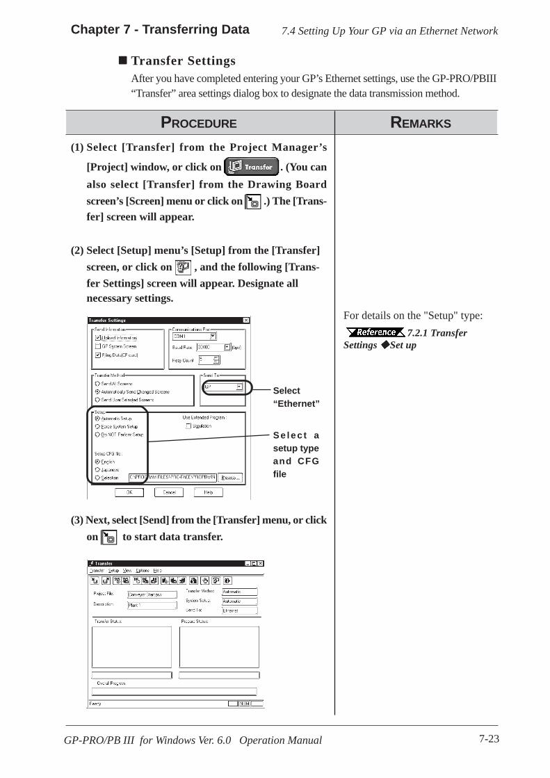
7-23
Chapter 7 - Transferring Data
GP-PRO/PB III for Windows Ver. 6.0 Operation Manual
7.4 Setting Up Your GP via an Ethernet Network
Transfer SettingsAfter you have completed entering your GP’s Ethernet settings, use the GP-PRO/PBIII“Transfer” area settings dialog box to designate the data transmission method.
(2) Select [Setup] menu’s [Setup] from the [Transfer]screen, or click on , and the following [Trans-fer Settings] screen will appear. Designate allnecessary settings.
(1) Select [Transfer] from the Project Manager’s
[Project] window, or click on . (You canalso select [Transfer] from the Drawing Boardscreen’s [Screen] menu or click on .) The [Trans-fer] screen will appear.
PROCEDURE REMARKS
(3) Next, select [Send] from the [Transfer] menu, or clickon to start data transfer.
Select“Ethernet”
Se lec t asetup typeand CFGfile
For details on the "Setup" type:7.2.1 Transfer
Settings Set up

7-24
Chapter 7 - Transferring Data
GP-PRO/PB III for Windows Ver. 6.0 Operation Manual
7.4 Setting Up Your GP via an Ethernet Network
(4) Select the IP address of the GP you wish to trans-
fer data to, and click on .
Next, the [Node List/Send screens] dialog box will ap-pear. Here you can see the IP addresses of all GPs con-nected to the network.
When receiving data, only one ad-dress can be selected.The [Node list/Send screens] win-dow only lists the GPs which cor-respond to the subnet masks of thePCs used for data transfer.
REMARKSPROCEDURE
Searches for thecurrently desig-nated GP
Click on and the [Network Data Search]dialog box will appear. This dia-log box allows you to searchfor a specific GP using theGP’s IP address. The result willbe displayed on the [Node List/Send screens] dialog box. Ifyou do not change the currentsearch condition, this featurewill automatically search usingthe current data. Therefore, besure when using this featurethat the current search condi-tion is the one that is actuallydesired.

7-25
Chapter 7 - Transferring Data
GP-PRO/PB III for Windows Ver. 6.0 Operation Manual
7.4 Setting Up Your GP via an Ethernet Network
7.4.1 Data Transfer Using the Factory-set IP Address
The default IP address of the GP is set at the factory for high-speed trans-fers of setups and screens via Ethernet.
• This function is available only with GP2000 (except GP-2301H, GP-2401H, GP-2301, GP-2501) series units.
The IP address of the GP unit is factory-configured. The IP address is usedwhen the IP address/Subnet Mask setup on the GP is "0.0.0.0".
Requirements for the use of the factory-set IP address
• Be sure to set the TCP/IP data (IP address should be set from10.255.255.1 to 10.255.255.254) and the subnet mask(255.0.0.0) of a PC that is running GP-PRO/PB III for Windows,and where Ethernet screen transfer will be performed. Also,some PCs must be rebooted for the TCP/IP setting to beactivated.
• When the GP unit’s IP address and subnet mask are set (anS200 file is generated), the TCP/IP data (IP address andsubnet mask) used by the PC should be the same.
• Do not use the factory-set IP address when a private address(10.***.***.***) is used on the same network. Otherwise, anetwork communication error may occur.
IP address / subnet mask IP Settings UsedIf set to 0.0.0.0 Factory set IP address
any other IP address IP address set up arbitrarily

7-26
Chapter 7 - Transferring Data
GP-PRO/PB III for Windows Ver. 6.0 Operation Manual
7.4 Setting Up Your GP via an Ethernet Network
Click on the "Send" icon and GP-PRO/PBIII will search for the IP addressesof the GP units connected to the network. If a GP unit is connected to theEthernet network and the user has not yet entered IP address settings forthat unit, that unit's factory-set IP address will be used, and that address willappear in the "Node List" shown below. Next, use the standard steps totransfer data to the desired GP unit.
The following "Node List" shows the result of a search. In this case, the GPunit found has no user-designated IP address settings and the factory-set IPaddress is listed.

8-1GP-PRO/PB III for Windows Ver. 6.0 Operation Manual
efore transferring screen data to the GP unit and connecting the GPunit to the host PLC, you can check the GP panel operation by
running a simulation of your GP-PRO/PB III for Windows program.
This chapter describes the program simulation procedure.
8 SIMULATION
B
8.1 ........................................................................ Overview
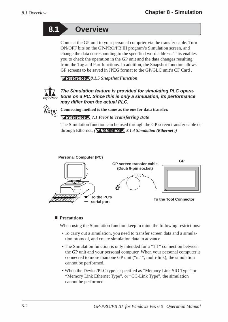
8-2
Chapter 8 - Simulation
GP-PRO/PB III for Windows Ver. 6.0 Operation Manual
8.1 OverviewConnect the GP unit to your personal comprter via the transfer cable. TurnON/OFF bits on the GP-PRO/PB III program’s Simulation screen, andchange the data corresponding to the specified word address. This enablesyou to check the operation in the GP unit and the data changes resultingfrom the Tag and Part functions. In addition, the Snapshot function allowsGP screens to be saved in JPEG format to the GP/GLC unit’s CF Card .
8.1.5 Snapshot Function
The Simulation feature is provided for simulating PLC opera-tions on a PC. Since this is only a simulation, its performancemay differ from the actual PLC.Connecting method is the same as the one for data transfer.
7.1 Prior to Transferring DateThe Simulation function can be used through the GP screen transfer cable orthrough Ethernet. ( 8.1.4 Simulation (Ethernet ))
8.1 Overview
Personal Computer (PC)
To the Tool Connector
GPGP screen transfer cable
(Dsub 9-pin socket)
Precautions
When using the Simulation function keep in mind the following restrictions:
• To carry out a simulation, you need to transfer screen data and a simula-tion protocol, and create simulation data in advance.
• The Simulation function is only intended for a “1:1” connection betweenthe GP unit and your personal computer. When your personal computer isconnected to more than one GP unit (“n:1”, multi-link), the simulationcannot be performed.
• When the Device/PLC type is specified as “Memory Link SIO Type” or“Memory Link Ethernet Type”, or “CC-Link Type”, the simulationcannot be performed.
To the PC’sserial port
8-3
Chapter 8 - Simulation
GP-PRO/PB III for Windows Ver. 6.0 Operation Manual
• When the display address for the E-Tag or K-Tag is indirectly specified(“Indirect” is selected for the [Data Format] tab) and “Area subsequent tothe display address” is specified as the indirectly-specified area, thesimulation cannot be performed.
• With a device specified in [GP System Setting] (n:1 communicationinformation, watchdog, video control area, alarm count, HITACHI HIDICS I/O extended memory device, etc.), the simulation cannot be per-formed.
• No simulation can be carried out for any address larger than 32768(8000h). To perform a simulation for such an address, temporarily changethe address to 32767 or smaller.
• The GP unit’s device monitor feature cannot be used.
• Do not press any touch panel switch on the GP unit before the simulationhas begun; and, do not change the screen on the GP panel. Otherwise, asystem error will occur.
• The LS device simulation is only effective for the GP-377 series, GP77Rseries and GP2000 series.
• If the backup function for the LS area is selected, or if a D-Script, W-tag,etc. uses an LS area special relay for its start bit, no LS device can besimulated.
• If the LS device is frequently written using the D-script during the LSdevice simulation, actions such as a slide transition will be slow.
• When performing simulation on the GP-377 series, GP77R series orGP2000 seires, DO NOT specify [GP System Settings] - [ExtendedSettings] tab - [Reset GP On Data Write Error].
• When using Yamatake's SDC Series Device/PLC, deselect [GP Settings]- [Extended Settings] tab - [System Area Settings].
• When using the GP77R series or GP2000 series and Mitsubishi Electric'sCPU direct connection type Device/PLC (such as Mitsubishi MELSEC-AnA (CPU)), with the GP offline mode's [Setup Operating Environment]- [Built-in] selected, the simulation function cannot be used. Select[Adapter] or [Direct] and then perform simulation.
• The Simulation function is disabled when the Device/PLC type is set to"THERMAC NEO series (OMRON)".
8.1 Overview
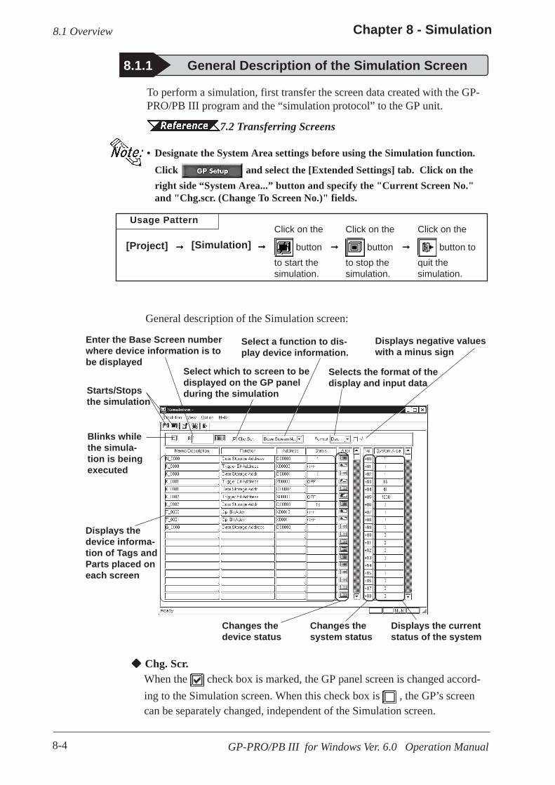
8-4
Chapter 8 - Simulation
GP-PRO/PB III for Windows Ver. 6.0 Operation Manual
8.1.1 General Description of the Simulation Screen
General description of the Simulation screen:
To perform a simulation, first transfer the screen data created with the GP-PRO/PB III program and the “simulation protocol” to the GP unit.
7.2 Transferring Screens
• Designate the System Area settings before using the Simulation function.Click and select the [Extended Settings] tab. Click on theright side “System Area...” button and specify the "Current Screen No."and "Chg.scr. (Change To Screen No.)" fields.
8.1 Overview
Enter the Base Screen numberwhere device information is tobe displayed
Changes thesystem status
Changes thedevice status
Displays the currentstatus of the system
Blinks whilethe simula-tion is beingexecuted
Starts/Stopsthe simulation
Displays negative valueswith a minus sign
Selects the format of thedisplay and input data
Select which to screen to bedisplayed on the GP panelduring the simulation
Displays thedevice informa-tion of Tags andParts placed oneach screen
Select a function to dis-play device information.
Usage Pattern
Chg. Scr.When the check box is marked, the GP panel screen is changed accord-ing to the Simulation screen. When this check box is , the GP’s screencan be separately changed, independent of the Simulation screen.
Click on the
button toquit thesimulation.
Click on the
buttonto stop thesimulation.
Click on the
buttonto start thesimulation.
[Simulation][Project] →→→→→→→→→→→→→→→→→→→→
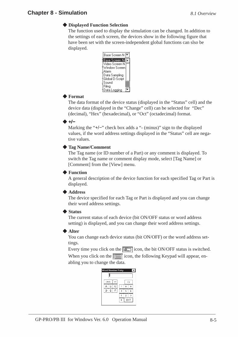
8-5
Chapter 8 - Simulation
GP-PRO/PB III for Windows Ver. 6.0 Operation Manual
Displayed Function SelectionThe function used to display the simulation can be changed. In addition tothe settings of each screen, the devices show in the following figure thathave been set with the screen-independent global functions can slso bedisplayed.
FormatThe data format of the device status (displayed in the “Status” cell) and thedevice data (displayed in the “Change” cell) can be selected for “Dec”(decimal), “Hex” (hexadecimal), or “Oct” (octadecimal) format.
+/−+/−+/−+/−+/−Marking the “+/−” check box adds a “- (minus)” sign to the displayedvalues, if the word address settings displayed in the “Status” cell are nega-tive values.
Tag Name/CommentThe Tag name (or ID number of a Part) or any comment is displayed. Toswitch the Tag name or comment display mode, select [Tag Name] or[Comment] from the [View] menu.
FunctionA general description of the device function for each specified Tag or Part isdisplayed.
AddressThe device specified for each Tag or Part is displayed and you can changetheir word address settings.
StatusThe current status of each device (bit ON/OFF status or word addresssetting) is displayed, and you can change their word address settings.
AlterYou can change each device status (bit ON/OFF) or the word address set-tings.Every time you click on the icon, the bit ON/OFF status is switched.When you click on the icon, the following Keypad will appear, en-abling you to change the data.
8.1 Overview
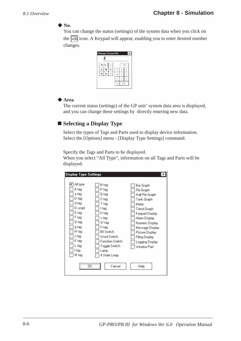
8-6
Chapter 8 - Simulation
GP-PRO/PB III for Windows Ver. 6.0 Operation Manual
AreaThe current status (settings) of the GP unit’ system data area is displayed,and you can change these settings by directly entering new data.
Selecting a Display TypeSelect the types of Tags and Parts used to display device information.Select the [Options] menu - [Display Type Settings] command.
Specify the Tags and Parts to be displayed.When you select “All Type”, information on all Tags and Parts will bedisplayed.
No.You can change the status (settings) of the system data when you click onthe icon. A Keypad will appear, enabling you to enter desired numberchanges.
8.1 Overview
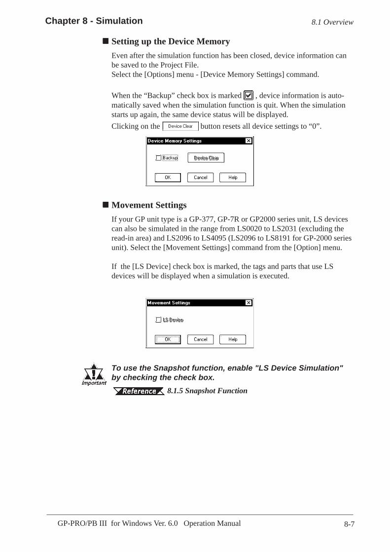
8-7
Chapter 8 - Simulation
GP-PRO/PB III for Windows Ver. 6.0 Operation Manual
8.1 Overview
Movement SettingsIf your GP unit type is a GP-377, GP-7R or GP2000 series unit, LS devicescan also be simulated in the range from LS0020 to LS2031 (excluding theread-in area) and LS2096 to LS4095 (LS2096 to LS8191 for GP-2000 seriesunit). Select the [Movement Settings] command from the [Option] menu.
If the [LS Device] check box is marked, the tags and parts that use LSdevices will be displayed when a simulation is executed.
Setting up the Device MemoryEven after the simulation function has been closed, device information canbe saved to the Project File.Select the [Options] menu - [Device Memory Settings] command.
When the “Backup” check box is marked , device information is auto-matically saved when the simulation function is quit. When the simulationstarts up again, the same device status will be displayed.Clicking on the button resets all device settings to “0”.
To use the Snapshot function, enable "LS Device Simulation"by checking the check box.
8.1.5 Snapshot Function

8-8
Chapter 8 - Simulation
GP-PRO/PB III for Windows Ver. 6.0 Operation Manual
8.1 Overview
Address RegistrationSimulation can be performed for any registered address, not for each screenor function.The simulation result is displayed by selecting the registered address fromthe display function pull-down list's [Address Registration].To register/edit an address, select the [Simulation] menu - [Address Regis-tration] command.
Adding a registered addressYou can add a new address. Click on the button, and the followingdialog box will appear. Then, enter an address and the number of addressesto be added, and specify Bit or Word.
After entering a number of addresses to be added, addresses are added fromthe designated number in series.
You can enter a desired name as a function name with up to 20 half-sizedcharacters.
Editing a registered addressYou can change the registered address settings. Select an address to beedited and click on the button. Then, a dialog box that is the sameas for the adding of a registered address will appear.

8-9
Chapter 8 - Simulation
GP-PRO/PB III for Windows Ver. 6.0 Operation Manual
8.1 Overview
Deleting a registered addressYou can delete a registered address. Select an address to be deleted and clickon the button. Then, a dialog box will appear to confirm thecommand. If you execute the delete command, click on the but-
ton, and if you cancel it, click on the button.
Copying and pasting a registered addressSelect an address to be copied and click on the button. Then, click
on the button to add the copied address at the end of the list.

8-10
Chapter 8 - Simulation
GP-PRO/PB III for Windows Ver. 6.0 Operation Manual
To simulate the GP panel’s actual operation using the GP-PRO/PB IIIprogram, transfer the screen data created with the GP-PRO/PB III programalong with the “simulation protocol” to the GP unit.
7.2 Transferring Screens
Simulation ProtocolBefore executing the simulation, you must first transfer the simulationprotocol to the GP unit, regardless of the Device/PLC type specified for theproject file.Check the “Use Extended Program” area’s “Simulation” Check Box in the[Transfer Settings] dialog box so that when screens are transferred, thesimulation protocol will be transferred to the GP unit.
7.2.1 Transfer Settings
8.1.2 Transferring Simulation Protocol
8.1 Overview
→→→→→
→→→→→
Usage Pattern
Click on the iconto transfer the screendata and simulationprotocol to the GPunit.
Compile the ProjectFile with the GP-PRO/PB III program so thatit is formatted for theGP unit used for thesimulation.
[Prepare][Transfer]
Check the“Use ExtendedProgram”area’s“Simulation”Check Box.
[TransferSettings]
[Setup][Transfer]
→→→→→→→→→→→→→→→
→→→→→→→→→→→→→→→[Project Manager]or or
If you are using a GP70 Series unit, normal communi-cations with the Device/PLC cannot be carried out withthe simulation protocol. To re-establish the link withthe Device/PLC after executing a simulation, be sure tosend the GP Unit communication protocol for the De-vice/PLC type, and then re-set the GP unit.• When a simulation is executed with the GP77R series or GP2000
series, you need to transfer the simulation protocol only for thefirst screen transfer.
• If you are using a GP other than GP77R or GP2000 Series unit,“Set Up Operation Surroundings” in the GP unit’s PLC setupmenu cannot be used while the simulation protocol is trans-ferred.
Click on . Click on .

8-11
Chapter 8 - Simulation
GP-PRO/PB III for Windows Ver. 6.0 Operation Manual
8.1.3 Performing a Simulation
To perform a simulation, first connect the GP unit to your personal computerusing the Data Transfer Cable.
8.1 Overview
Before performing a simulation, you must transfer thesimulation protocol to the GP unit.
8.1.2 Transferring Simulation Protocol
Performing a Simulation
8.1.1 GeneralDescription of the SimulationScreen
During communication, the icon blinks, like this .
Prior to starting simulation, set theGP unit to the RUN mode.
If the simulation protocol has notbeen transferred to the GP unit instep (1), the following dialog boxwill appear, and the simulation can-not be started.
You can check the GP panel operation by switchingscreens or changing the device settings using the or icon displayed in the [Alter] cell. Also, you cancheck the device status changes via the GP’s touch keys.
Connect the GP unit to your personal computer with theData Transfer Cable.
1) Via the Project Manager, select the [Project] menu -
[Simulation] command, or click on the icon.
2) Click on the button to begin communication withthe GP unit.The device information on the current GP panel screenis displayed.
PROCEDURE R E M A R K S

8-12
Chapter 8 - Simulation
GP-PRO/PB III for Windows Ver. 6.0 Operation Manual
PROCEDURE R E M A R K S
Simulation protocol cannotbe used for normal commu-nication with a PLC. To re-es-tablish the link with the PLCafter executing a simulation,be sure to send the GP Unitcommunication protocol forthe Device/PLC type, and thenre-set the GP unit.When using a GP77R orGP2000 series unit, you donot need to set up your GPunit again.
8.1 Overview
3) Click on the button to quit the simulation.
4) Click on the button to quit the simulation mode.When you quit the simulation mode, the system asks ifyou wish to again set up the GP unit for communicationwith the PLC.If you select , the system will set up the GPUnit. If you select , the system returns to theProject Manager without setting up the GP Unit.
During simulation, screen data can-
not be transferred. Click on the icon and stop simulation beforetransferring screen data.

8-13
Chapter 8 - Simulation
GP-PRO/PB III for Windows Ver. 6.0 Operation Manual
8.1 Overview
8.1.4 Simulation (Ethernet)
Simulation via an Ethernet NetworkOnly GP2000 series can use this function.
• Using the function with the GP-2501 requires a large-scale Multi Unit E ora GP Ethernet Interface unit.
• The GP-2301H, GP-2401H and GP-2301 cannot be connected to anEthernet network.
The simulation function using Ethernet provides the same level of function-ality as when using the data transfer cable. The limitations for this featureare the same as for the transfer cable.
• To perform a simulation, download the screen data and thespecial simulation protocol to the GP via the Ethernet net-work.
• Simulations via Ethernet and the transfer cable cannot beperformed simultaneously.
• LS device simulation can be also performed.• When using the simulation function, do not transfer screens
to the GP.
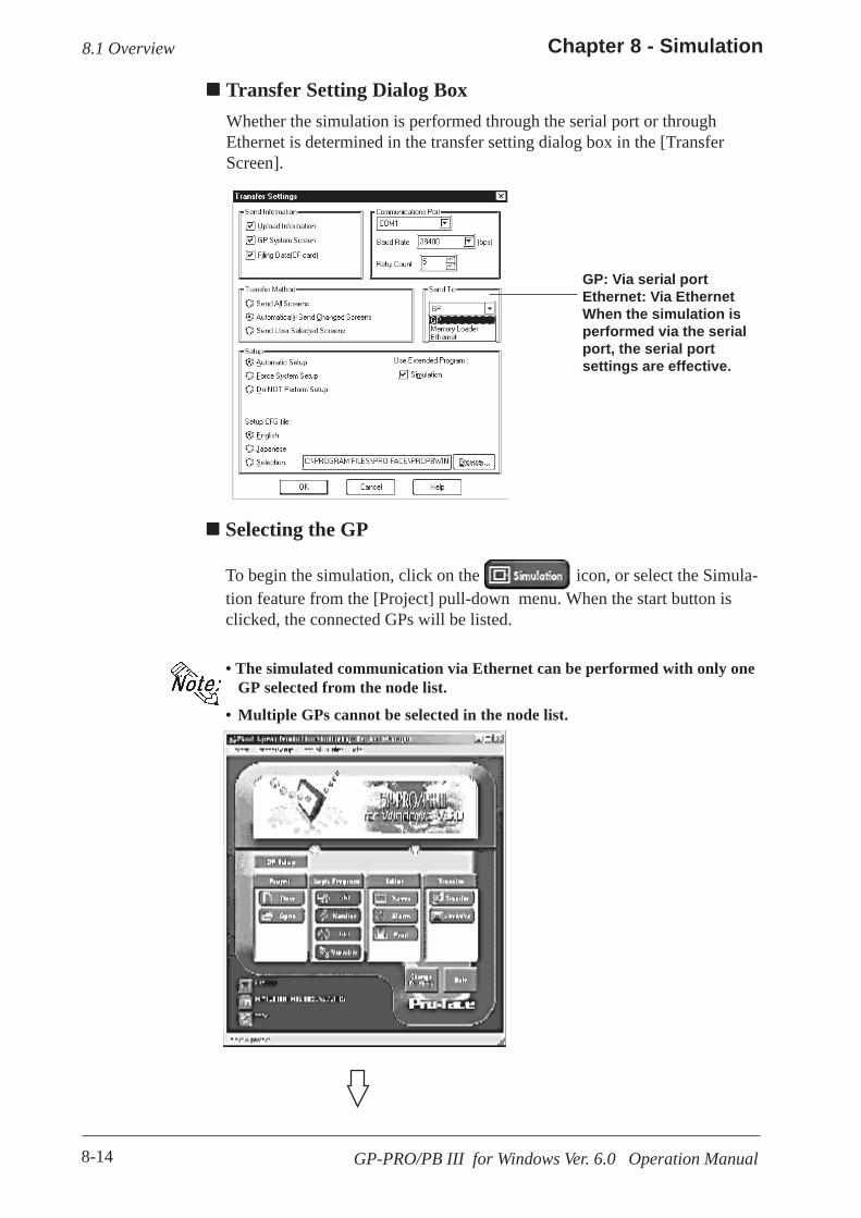
8-14
Chapter 8 - Simulation
GP-PRO/PB III for Windows Ver. 6.0 Operation Manual
8.1 Overview
GP: Via serial portEthernet: Via EthernetWhen the simulation isperformed via the serialport, the serial portsettings are effective.
Transfer Setting Dialog BoxWhether the simulation is performed through the serial port or throughEthernet is determined in the transfer setting dialog box in the [TransferScreen].
Selecting the GP
To begin the simulation, click on the icon, or select the Simula-tion feature from the [Project] pull-down menu. When the start button isclicked, the connected GPs will be listed.
• The simulated communication via Ethernet can be performed with only oneGP selected from the node list.
• Multiple GPs cannot be selected in the node list.

8-15
Chapter 8 - Simulation
GP-PRO/PB III for Windows Ver. 6.0 Operation Manual
8.1 Overview
• If you stop the simulation and then click the [Start] button again, the nodelist will be displayed again.
• While the simulation is being performed, the target GP cannot be changed.
• To use the factory-set IP address, the IP address and the subnet mask in thePC should be changed.
Click on the start button to begin searching for all GPs connectedto the Ethernet network. All connected GPs will be appear in thenode list.
After you select a GP fromthe list and click the Startbutton, the node list dialogbox will close and the simu-lation screen will appear.
8-16
Chapter 8 - Simulation
GP-PRO/PB III for Windows Ver. 6.0 Operation Manual
8.1.5 Snapshot Function
This feature allows Simulation screens of the GP to be written onto a CFCard in JPEG file format with the ease of taking a snapshot.
• A CF Card is required to use the Snapshot function.• This function is available only with the GP2000 series.
Performing a Snapshot Function
8.1.3 Performinga SimulationEnable "LS Device Simulation" inthe Movement Settings.
8.1.1 GeneralDescription of the SimulationScreen Movement Settings
(1)Perform a simulation.
(2)When the screen to be simulated is displayed on theGP screen, select [Snapshot] from the [Simulation]menu on the "Simulation" screen or click onyour PC screen (GP-PRO/PB III).The JPEG file captured with the snapshot function isautomatically stored on the CF Card attached to the GPunit. The complete operation takes five or six seconds.
PROCEDURE R E M A R K S
JPEG File NameJPEG files are automatically assigned a file name according to a numericalsequence. The file name of a saved JPEG file will be"\CAPTURE\CPXXXXX.JPG" (XXXXX is a number from 0 to 65535,assigned sequentially). The number is automatically incremented by one(XXXXX) from the largest file number existing on the CF Card. The Snap-shot function is disabled when the number sequence exceeds "65535" or thefree space on the CF Card is insufficient.
Reverse Black & WhiteWhen the "Reverse Black & White" feature is enabled under the ScreenCapture function ( Tag Reference Manual, 4.4.9 ScreenCapture), black and white are reversed in the snapshot image of the simula-tion. Tag Reference Manual, 4.4.9 Reverse Black &White
8.1 Overview

8-17
Chapter 8 - Simulation
GP-PRO/PB III for Windows Ver. 6.0 Operation Manual
Snapshot ErrorsThe following error messages are displayed on your PC when CF Carderrors occur during the Snapshot operation. If a warning is displayed, noJPEG file is created on the CF Card.
8.1 Overview
Error Message Error Conditions
No CF Card is inserted in the GP. -No CF Card is inserted.-The CF Card cover is not completely closed.
The snapshot cannot be written to theCF Card inserted in the GP.
-Insufficient free space remains on the CF Card.-The CF Card was removed while data was being saved.
Invalid CF Card is inserted in the GP. -An operation failure has been detected with the CF Card,or the CF Card is unformatted.

8-18 GP-PRO/PB III for Windows Ver. 6.0 Operation Manual
Memo
9-1GP-PRO/PB III for Windows Ver. 6.0 Operation Manual
9 PRINTING
printed copy of created screens and Tag designation status is oftenuseful when debugging. This chapter describes the printing proce-
dure and print settings.A
9.1 ................................................................. Print Settings
9.2 ................................................. Sample Printer Output
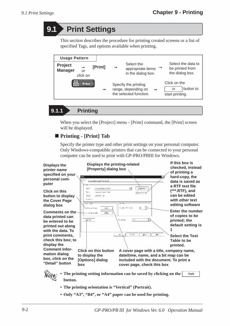
9-2
Chapter 9 - Printing
GP-PRO/PB III for Windows Ver. 6.0 Operation Manual
• The printing setting information can be saved by clicking on the button.
• The printing orientation is “Vertical” (Portrait).
• Only “A3”, “B4”, or “A4” paper can be used for printing.
9.1 Print Settings
Usage Pattern
Click on the button to
start printing.
Specify the printingrange, depending onthe selected function.
Select the data tobe printed fromthe dialog box.
Select theappropriate itemsin the dialog box.
[Print]ProjectManager
→→→→→→→→→→
→→→→→→→→→→→→→→→
When you select the [Project] menu - [Print] command, the [Print] screenwill be displayed.
Printing - [Print] TabSpecify the printer type and other print settings on your personal computer.Only Windows-compatible printers that can be connected to your personalcomputer can be used to print with GP-PRO/PBIII for Windows.
This section describes the procedure for printing created screens or a list ofspecified Tags, and options available when printing.
9.1 Print Settings
orclick on
9.1.1 Printing
Displays theprinter namespecified on yourpersonal com-puter
Click on thisbutton to displaythe Cover Pagedialog box
Click on this buttonto display the[Options] dialogbox
Enter the numberof copies to beprinted; thedefault setting is1
If this box ischecked, insteadof printing ahard-copy, thedata is saved asa RTF text file(***.RTF), andcan be editedwith other textediting software
Displays the printing-related[Property] dialog box
Comments on thedata printed canbe entered to beprinted out alongwith the data. Toprint comments,check this box; todisplay theComment Infor-mation dialogbox, click on the“Detail” button
A cover page with a title, company name,date/time, name, and a bit map can beincluded with the document. To print acover page, check this box
Select the TextTable to beprinted.

9-3
Chapter 9 - Printing
GP-PRO/PB III for Windows Ver. 6.0 Operation Manual
Options Dialog Box
Settings in the Options dialog box allow you to format the pages of thedocument to be printed. You can specify the range of page numbers to beprinted, the screen color, and margin size.
Comment Information Dialog Box
Cover Page Dialog Box
9.1 Print Settings
Check this box toprint a title on thecover page
Click on this button to preview the cover pagelayout. When Bit-map printing is selected, theplacement of the Bit-map on the cover page can bechanged.
Enter the namehere
Check this box toprint a name onthe cover page
Check this box toprint a companyname on thecover page
Check this box toinclude a Bit-map onthe cover page
Check this box toinclude the date andtime of printing onthe cover page
Enter a title or acompany name of upto 3 lines (40 charac-ters per line)
Enter a commentof up to 40 lines(80 charactersper line)
Prints the black/white-reversedscreen color
Specify the upper,lower, right andleft margin sizes
Enter the initialpage number tobe printed on thefirst page of thedocument
When printing pagenumbers, specify ifthe cover page is tobe numbered
Check this box toprint the pagenumber on eachpage of the docu-ment

9-4
Chapter 9 - Printing
GP-PRO/PB III for Windows Ver. 6.0 Operation Manual
Handy Global Setting ListSelect whether to print the summaryor details of the Handy global set-tings.
Date Sampling Settings ListSelect whether to print the summary ordetails of the data sampling settings.
Alarm ListSelect the alarm type to be printed.
Details Click on the button to specify detailed information of printing.
Printing - [Project Information] TabYou can check the created screens and Tag designation status through printeroutput.
9.1 Print Settings
Prints a projectinformationsummary list
Prints the listof settings ofthe itemmarked with acheck.
Displays thecurrently-selected item
Screen ListSelect the screen type to be printed.

9-5
Chapter 9 - Printing
GP-PRO/PB III for Windows Ver. 6.0 Operation Manual
Details
Click on the button to specify detailed information of printing.
Base ScreenSpecify the printing items related to a Base Screen.
Printing - [Screen] TabSelect the screen type and contents to be printed.
9.1 Print Settings
Select the screentype to be printed
Displays thecurrently-selected item
Specify theprinting range byscreen numbers.When you select[All (A)], allscreens will beprinted.
Prints a list of thescreens loadedonto a specifiedscreen
When makinga screen hardcopy, TheParts’ ON/OFFstatus can bespecified. Thesame status isspecified forall screens tobe printed
Prints a list of theParts placed onthe Base Screen.Select whether toprint the sum-mary or details ofthe Part list
Outputsscreen hardcopies.The printingitems can bespecified
Prints the address designationfor Tags.Only the “preset addresses”can be printed 2.8.7 CrossReference List
Prints the D-Scriptsettings
Prints a list of thespecified Tags.Select whether toprint the sum-mary or details ofthe Tag list
When the summary of the Part list is printed, its right edge may get outsidethe paper. In this case, open the Option dialog box by clicking on button in the [Print] tab, and then reduce the left margin.
Select Infor-mationcahacter'sprinting size.When select-ing [Small], 1/4-sized char-acters areused

9-6
Chapter 9 - Printing
GP-PRO/PB III for Windows Ver. 6.0 Operation Manual
9.1 Print Settings
Keypad ScreenSpecify the printing items related to aKeypad screen.
Trend Graph ScreenSpecify the printing items related to aTrend Graph screen.
Video ScreenSpecify the printing items related to aVideo screen.
Window ScreenSpecify the printing items related to aWindow screen.

9-7
Chapter 9 - Printing
GP-PRO/PB III for Windows Ver. 6.0 Operation Manual
By selecting the [Project] menu - [Print Preview], you can preview thescreen image to be printed.
Setting items are the same as those of printing. Instead of clicking on the button, click on the button.
Print Preview Screen
9.1.2 Print Preview
Print dateand projectfile name
Startsprinting
Previewsthe nextpage
Previewsthe previ-ous page
Toggles betweenpreviewing one pageper screen andpreviewing twopages per screen
Scales up/down thepreview
Closes theprintpreviewscreen
9.1 Print Settings

9-8
Chapter 9 - Printing
GP-PRO/PB III for Windows Ver. 6.0 Operation Manual
9.2 Sample Printer OutputThis section provides sample printing of various data such as a createdscreen or a list of specified Tags.The following data can be printed.
Printing
Cover Page
Select whether the cover page is to be printed or not.
9.2 Sample Printer Output
Comment Information
Select whether comment information is to be printed or not. Commentinformatoin is a function to add supplemental information to the printeddata. Up to 40 lines of 80 characters can be entered.
Project Information
SummaryPrints a project summary list.
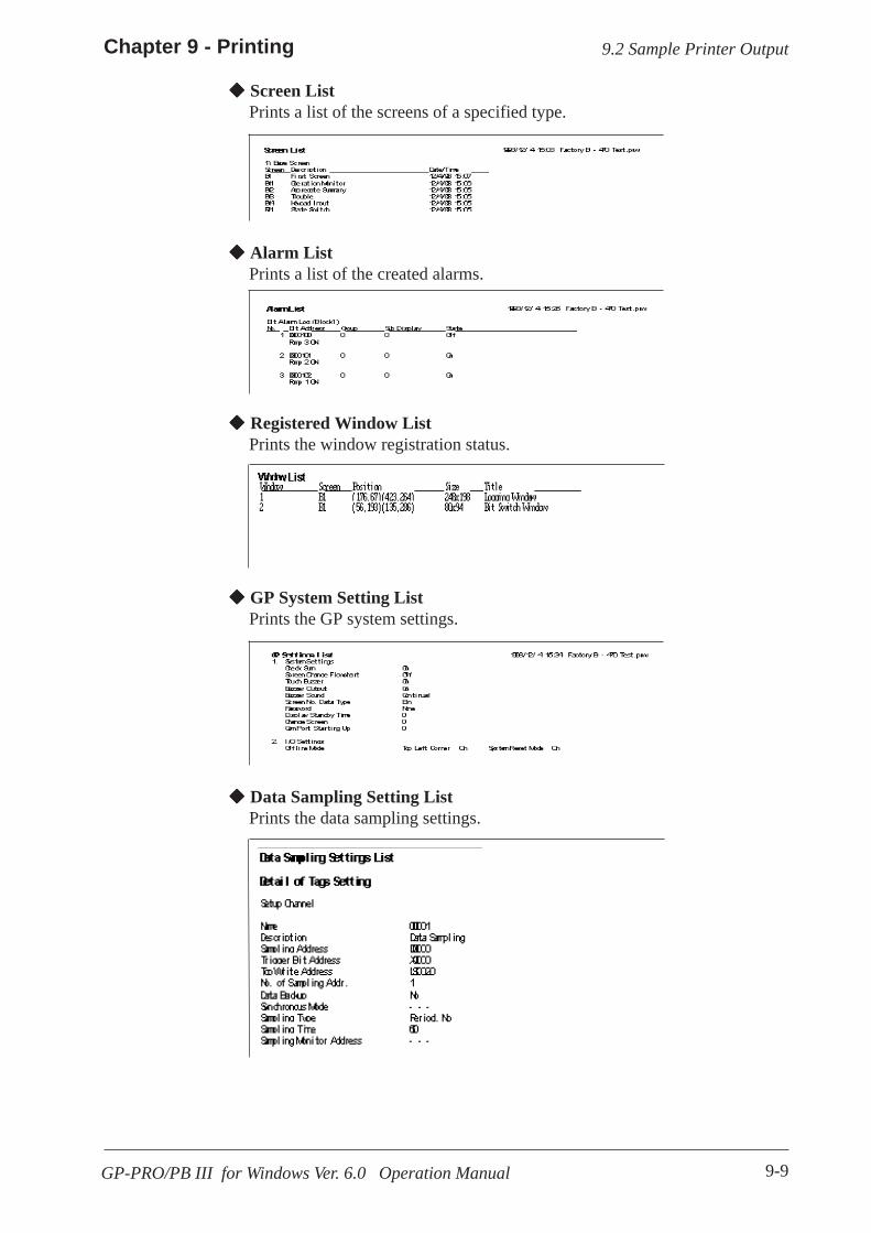
9-9
Chapter 9 - Printing
GP-PRO/PB III for Windows Ver. 6.0 Operation Manual
9.2 Sample Printer Output
Screen ListPrints a list of the screens of a specified type.
Alarm ListPrints a list of the created alarms.
Registered Window ListPrints the window registration status.
GP System Setting ListPrints the GP system settings.
Data Sampling Setting ListPrints the data sampling settings.

9-10
Chapter 9 - Printing
GP-PRO/PB III for Windows Ver. 6.0 Operation Manual
Handy Global Setting List(Function Keys)/(Vibration)
Filing Data Setting List
Data Logging Settings
9.2 Sample Printer Output
Prints the Handy global settings.
Prints the Filing Data settings.
Prints the data logging settings.
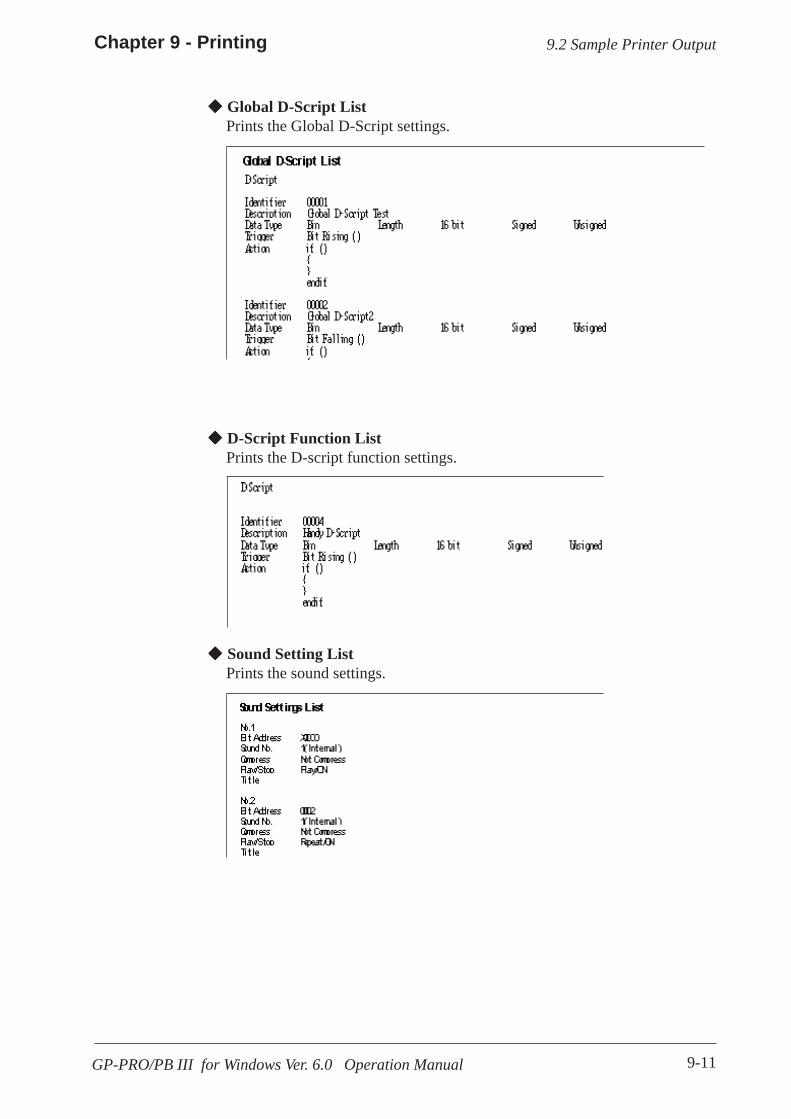
9-11
Chapter 9 - Printing
GP-PRO/PB III for Windows Ver. 6.0 Operation Manual
D-Script Function ListPrints the D-script function settings.
Sound Setting ListPrints the sound settings.
Global D-Script ListPrints the Global D-Script settings.
9.2 Sample Printer Output

9-12
Chapter 9 - Printing
GP-PRO/PB III for Windows Ver. 6.0 Operation Manual
Screen Information Loaded Screen List
Tag List
9.2 Sample Printer Output
Prints a list of the screens loaded onto a specified screen.
Prints a list of specified Tags.
Symbol List
Global Cross Reference List
The Symbol Editor's Symbol setting status is printed out.
The entire Project's address designation status, such as via Tags, are printedout. This command is executed for all the screens in the Project.
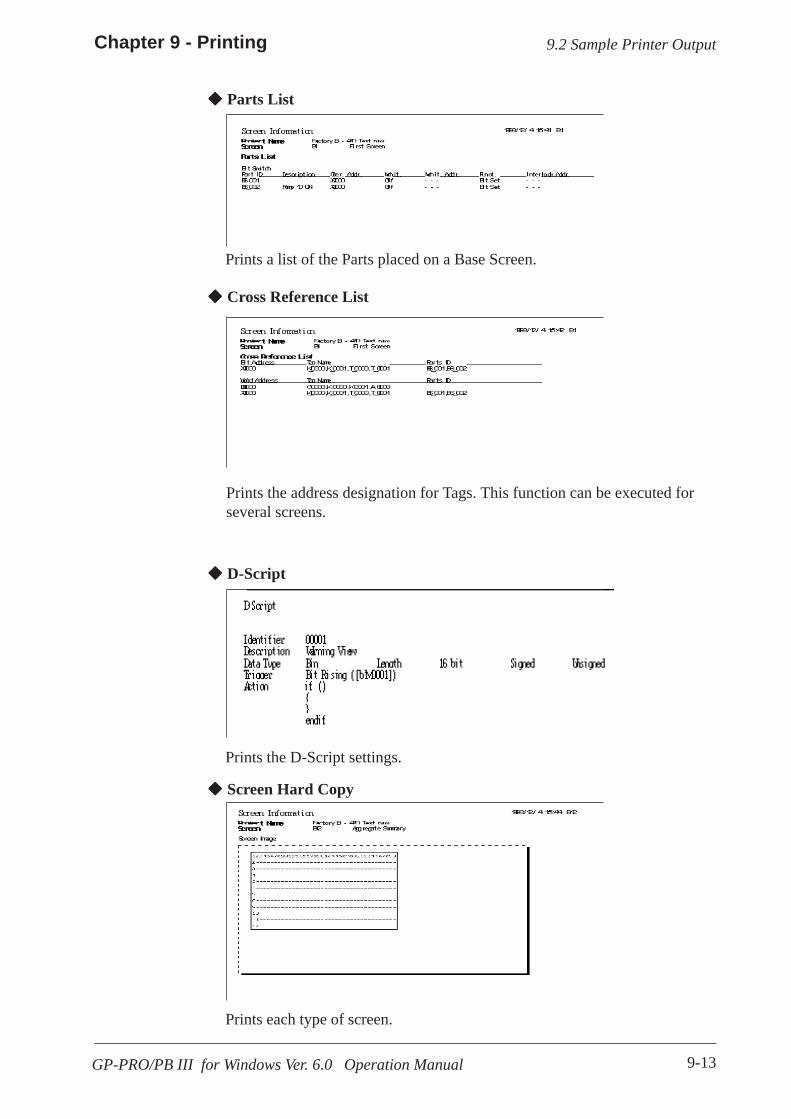
9-13
Chapter 9 - Printing
GP-PRO/PB III for Windows Ver. 6.0 Operation Manual
D-Script
Screen Hard Copy
Parts List
Cross Reference List
9.2 Sample Printer Output
Prints the D-Script settings.
Prints each type of screen.
Prints a list of the Parts placed on a Base Screen.
Prints the address designation for Tags. This function can be executed forseveral screens.

9-14 GP-PRO/PB III for Windows Ver. 6.0 Operation Manual
Memo

10-1GP-PRO/PB III for Windows Ver. 6.0 Operation Manual
10 ADVANCED FEATURES
T
10.1 .................................................................Sound Output
10.2 .......................................................Filing Data (Recipe)
10.3 ........................................................................... Logging
10.4 .......................................................................... CF Card
10.5 ....... Creating/Transferring CF Memory Loader Tool
10.6 .............................................. CF Memory Loader Tool
he sound output, filing data (recipe), and logging functionsare advanced features to use the GP with even higher performance.
For the detailed information about these features, please refer to Tag Refer-ence Manual. In addition, regarding the CF Card, the CF Card tool used onGP-PRO/PB III is described. For CF Card usage requirements as well asusage that is linked with other features, also refer to Tag Reference Manual.

10-2 GP-PRO/PB III for Windows Ver. 6.0 Operation Manual
Chapter 10 - Advanced Features
This feature outputs sound data from a speaker connected to the GP byturning ON a specified bit. Via Alarm or message sounds, information canbe sent to operators even if they are not looking at the GP screen. In addi-tion, this feature can be used for a variety of applications such as operationguides and multimedia information.
Tag Reference Manual, 4.1 Sound OutputSound settings can only be used with Digital’s GP477R,GP577R and GP2000 (except GP-2300 and GP-2301) seriesunits. Also, to output sound data from a GP77R Series unit, theoptional Multi Unit (sold separately) is required.
10.1 Sound Output
10.2 Filing Data (Recipe)Setting data that you have created and stored on the GP can be easily trans-ferred to the PLC whenever necessary, using GP touch keys or by specifyingbit addresses in the PLC. Also, Filing (Recipe)Data that has been trans-ferred to the PLC can be then sent back to the GP, edited, and then trans-ferred again to the PLC.
When using the GP77R series and GP2000 series, Filing Data stored in a CFCard can be transferred.
Tag Reference Manual, 4.2 Filing Data (Recipe) Func-tion
The Filing Data feature has been supported only by the GP-377Series, GP77R series and GP2000 series. Also, to transfer FilingData from the CF Card by the GP77R series, the Multi Unit (soldseparately) is required.
Setting 1
Setting 2
Setting 3
GP PLC

10-3
Chapter 10 - Advanced Features
GP-PRO/PB III for Windows Ver. 6.0 Operation Manual
10.3 Logging Feature / 10.4 CF Card
The PLC data is loaded to the GP's backup SRAM at bit-based or time-specified timings to display it in a tabular form on the screen or print it onthe printer.The acquired data can also be integrated into a database so that it can beanalyzed.Digital’s GP77R series and GP2000 series units enable you to save loggeddata as a CSV file onto a CF Card. The CSV file can then be sent from theCF Card to any PC, and its information used for a database, or displayed asa graph for analysis.
10.3 Logging
Use of the CF Card with a GP77R series unit requires theDigital’s optional Multi Unit (sold separately).
Tag Reference Manual, 4.3 Logging Function
10.4 CF CardDigital’s GP77R series and GP2000 series units all allow you to use the CFCard to store data.The CF Card is intended primarily as an external storage device, for thestorage of CSV files and backing up GP screen data.
For detailed CF Card information, refer to the Tag Reference Manual.
Tag Reference Manual, 4.4 Using the CF Card
10.4.1 Using CF Card Tools
The use of the CF Card Tool enables you to copy data in your project’s CFCard data output folder to the CF Card, as well as to copy data saved on theCF Card to the project. The data that can be copied using the CF Card Toolincludes image screens, sound data, and Filing Data.
To use the CF Card Tool your PC must be equipped with a PCcard slot.

10-4 GP-PRO/PB III for Windows Ver. 6.0 Operation Manual
Chapter 10 - Advanced Features10.4 CF Card
Overview of the CF Card ToolWhen you select the [Utility] menu - [CF Card Tool] option, the CF CardTool is activated. The overview of the CF Card Tool is given below.
Displays the disk capacityand file information
Lists thefiles in theCF Carddata outputfolder
CF Card data output folder CF Card drive
Lists thefiles savedon the CFCard
The toolbar icons have the following functions:
Selects a project Copies data to the project file
Selects a CF Card folder Copies data to the CFCard
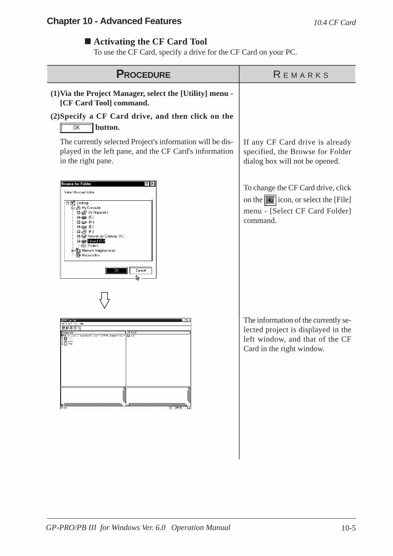
10-5
Chapter 10 - Advanced Features
GP-PRO/PB III for Windows Ver. 6.0 Operation Manual
10.4 CF Card
Activating the CF Card ToolTo use the CF Card, specify a drive for the CF Card on your PC.
PROCEDURE R E M A R K S
(1)Via the Project Manager, select the [Utility] menu -[CF Card Tool] command.
(2)Specify a CF Card drive, and then click on the button.
The currently selected Project's information will be dis-played in the left pane, and the CF Card's informationin the right pane.
If any CF Card drive is alreadyspecified, the Browse for Folderdialog box will not be opened.
To change the CF Card drive, clickon the icon, or select the [File]menu - [Select CF Card Folder]command.
The information of the currently se-lected project is displayed in theleft window, and that of the CFCard in the right window.

10-6 GP-PRO/PB III for Windows Ver. 6.0 Operation Manual
Chapter 10 - Advanced Features10.4 CF Card
Copying Data to the CF CardThe data (image screens, sound data, and Filing Data) saved in the CF Card outputfolder can be copied from the project to the CF Card as follows.
PROCEDURE R E M A R K S
(1)Start the CF Card Tool.
(2)Select the [Edit] menu - [Project to Card] command,or click on the icon.
The image screen, sound data, and Filing Data in the CFCard data output folder will be copied to the CF Card.
Activating theCF Card ToolTo change the CF Card drive, clickon the icon, or select the [File]menu - [Select CF Card Folder]option.
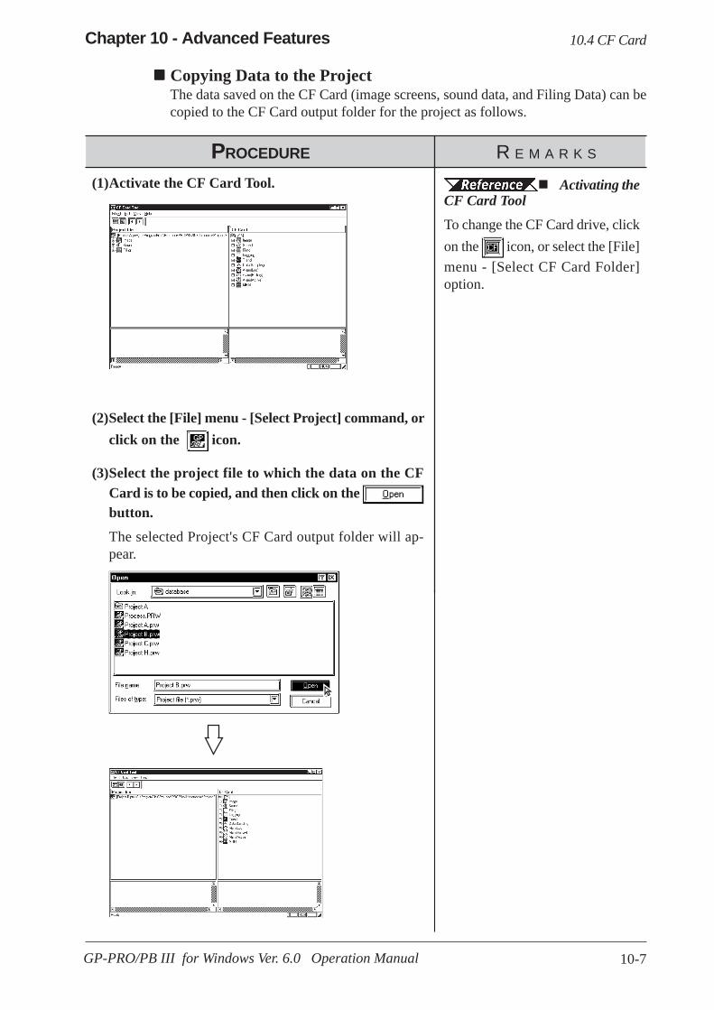
10-7
Chapter 10 - Advanced Features
GP-PRO/PB III for Windows Ver. 6.0 Operation Manual
10.4 CF Card
Copying Data to the ProjectThe data saved on the CF Card (image screens, sound data, and Filing Data) can becopied to the CF Card output folder for the project as follows.
PROCEDURE R E M A R K S
(1)Activate the CF Card Tool.
(2)Select the [File] menu - [Select Project] command, orclick on the icon.
(3)Select the project file to which the data on the CFCard is to be copied, and then click on the button.
The selected Project's CF Card output folder will ap-pear.
Activating theCF Card ToolTo change the CF Card drive, clickon the icon, or select the [File]menu - [Select CF Card Folder]option.
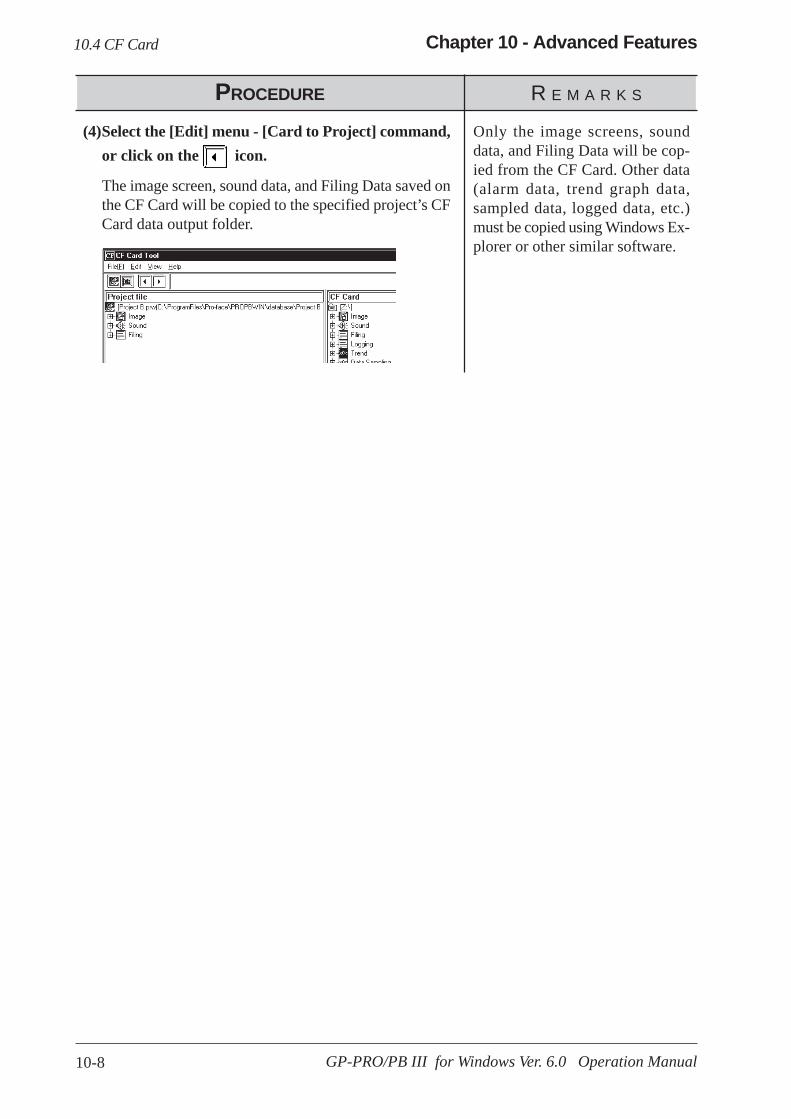
10-8 GP-PRO/PB III for Windows Ver. 6.0 Operation Manual
Chapter 10 - Advanced Features
PROCEDURE R E M A R K S
(4)Select the [Edit] menu - [Card to Project] command,or click on the icon.
The image screen, sound data, and Filing Data saved onthe CF Card will be copied to the specified project’s CFCard data output folder.
Only the image screens, sounddata, and Filing Data will be cop-ied from the CF Card. Other data(alarm data, trend graph data,sampled data, logged data, etc.)must be copied using Windows Ex-plorer or other similar software.
10.4 CF Card

10-9
Chapter 10 - Advanced Features
GP-PRO/PB III for Windows Ver. 6.0 Operation Manual
10.5 Creating/Transferring CF Memory Loader Tool
10.5.1 CF Memory Loader Tool / Backup Data
GP-PRO/PBIII to CF Card, then to GP (via “CF Card Tool”)
(1)
(2) (3)
GP (with CFCard inserted)
(1) Creating backup data: Create GP backup data and “CF Memory Loader Tool”in the CF Card Data Output Floder.
10.5.5 Creating Backup Data
(2) Copy data via “CF Card Tool”: Copy backup data in the CF Card Data Outputfolder and “CF Memory Tool” to the CF Card, using GP-PRO/PBIII’s “CFCard Tool” feature.
10.5.8 Transferring “CF Memory Loader Tool” data via CFCard Tool
(3) Download data using “CF Memory Loader Tool”: Transfer the CF Card’sbackup data to the GP.
10.6 CF Memory Loader Tool
The total space required for using Filing Data and Image Data inaddition to the CF Memory Loader Tool and Backup Data is atleast 8 MB. The capacity of the CF Card may be insufficient. Donot use the GP077-CF10 (8 MB) when using the CF MemoryLoader Tool.
10.5 Creating/Transferring CF Memory Loader Tool
CF Card
Name Model NumberCF Card (16MB) GP077-CF20CF Card (32MB) GP077-CF30
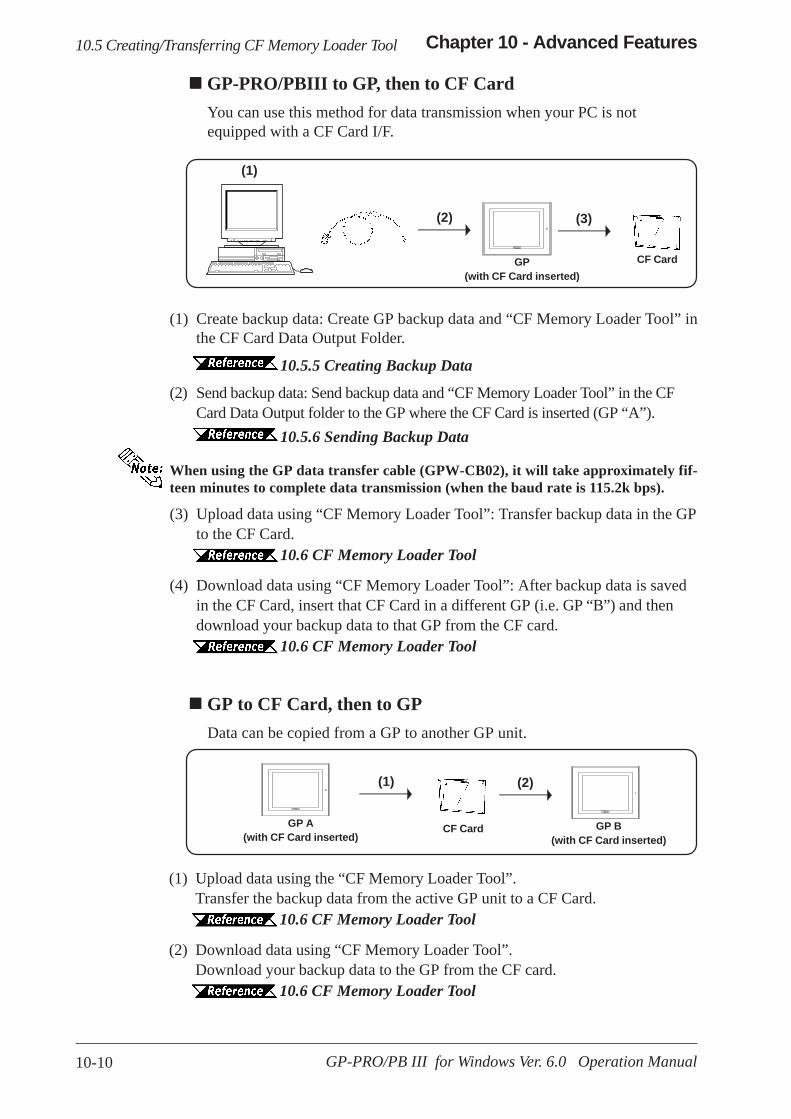
10-10 GP-PRO/PB III for Windows Ver. 6.0 Operation Manual
Chapter 10 - Advanced Features
GP-PRO/PBIII to GP, then to CF CardYou can use this method for data transmission when your PC is notequipped with a CF Card I/F.
(1) Create backup data: Create GP backup data and “CF Memory Loader Tool” inthe CF Card Data Output Folder.
10.5.5 Creating Backup Data
(2) Send backup data: Send backup data and “CF Memory Loader Tool” in the CFCard Data Output folder to the GP where the CF Card is inserted (GP “A”).
10.5.6 Sending Backup Data
When using the GP data transfer cable (GPW-CB02), it will take approximately fif-teen minutes to complete data transmission (when the baud rate is 115.2k bps).
(3) Upload data using “CF Memory Loader Tool”: Transfer backup data in the GPto the CF Card.
10.6 CF Memory Loader Tool
(4) Download data using “CF Memory Loader Tool”: After backup data is savedin the CF Card, insert that CF Card in a different GP (i.e. GP “B”) and thendownload your backup data to that GP from the CF card.
10.6 CF Memory Loader Tool
GP to CF Card, then to GPData can be copied from a GP to another GP unit.
(1)
(2)
GP(with CF Card inserted)
(3)
10.5 Creating/Transferring CF Memory Loader Tool
(1)
GP B(with CF Card inserted)
(2)
GP A(with CF Card inserted)
CF Card
CF Card
(1) Upload data using the “CF Memory Loader Tool”.Transfer the backup data from the active GP unit to a CF Card.
10.6 CF Memory Loader Tool
(2) Download data using “CF Memory Loader Tool”.Download your backup data to the GP from the CF card.
10.6 CF Memory Loader Tool

10-11
Chapter 10 - Advanced Features
GP-PRO/PB III for Windows Ver. 6.0 Operation Manual
You need to call up the GP-PRO/PBIII [Transfer] screen to enter or use the CFMemory Loader’s settings. To do this, select [Transfer] from the Project
Manager’s (main screen’s) [Project] window, or click on the icon.
You can also select [Transfer] from the Drawing Area screen’s [Screen] menu, orsimply click on the icon. The following explanation describes the [Transfer]screen’s CF Memory Loader settings.
10.5.2 CF Memory Loader Settings
Create system boot data of CF CardThis feature allows you to create a copy of the "CF Memory Loader Tool" in the CF CardData Output folder. Backup data creation, however, is NOT possible with this feature.Send system boot data to CF CardThis feature allows you to download the “CF Memory Loader Tool” to your GP’sCF Card from your GP’s CF Card Data Output folder. Backup data creation,however, is NOT possible with this feature.Create backup dataThis feature allows you to create a copy of your GP backup data, as well as the“CF Memory Loader Tool”, in the CF Card Data Output folder.Send backup dataThis feature allows you to download the CF Card Data Output folder’s GP backupdata and “CF Memory Loader Tool” to your CF Card.Receive backup dataTransfers the backup data saved in your GP’s CF Card to your PC’s GP-PRO/PBIIIsoftware. However, the “CF Memory Loader Tool” itself cannot be transferred.
You can also select these features via the GP-PRO/PBIII Transfer Screen’s toolbar icons.
CF MemoryLoader settingsmenu
10.5 Creating/Transferring CF Memory Loader Tool
Send system boot data of CF CardCreate backupdata
Receive backup data
Create system bootdata of CF Card
Send backup data Receive system boot data ofCF Card

10-12 GP-PRO/PB III for Windows Ver. 6.0 Operation Manual
Chapter 10 - Advanced Features
To use the “CF Memory Loader Tool”, you need to first create (prepare) the “CFMemory Loader Tool “ (IPL.SYS, MLD****.SYS, GPBACKUP.INF) in GP-PRO/PBIII via the “Create system boot data of CF Card” feature, and download itto your GP’s CF Card. Then, upload the “CF Memory Loader Tool“ program datafrom the CF Card to the GP. The GP can then use the “CF Memory Loader Tool”saved on the CF Card. The following steps explain how to create the “CF MemoryLoader Tool” in GP-PRO/PBIII.
10.5.3 Creating System Boot Data for CF Card
The “****” code in the above file name “MLD****.SYS” will vary according to theGP model.
(2) Select the [Transfer] menu’s [Create system bootdata of CF Card], or click on . The “CFMemory Loader Tool” will then be created in theCF Card Data Output folder.
(1) Select [Transfer] from the Project Manager’s[Project] window, or click on . (You can
also select [Transfer] from the Drawing Boardscreen’s [Screen] menu or click on ).
If the “CF Memory Loader Tool”is previously saved in the CF Carddata output folder, the followingwindow will appear. If you wish tooverwrite it with new data, click onthe [OK] button.
PROCEDURE REMARKS
10.5 Creating/Transferring CF Memory Loader Tool
GP Type GP Code GP Type GP CodeGP2301HL 2240 GP2300T 2256GP2301HS 2242 GP2400T 2261GP2401H 2244 GP2500T 2266GP2300L 2252 GP2501T 2267GP2301L 2250 GP2600T 2276GP2500L 226F GLC2300L 225AGP2301S 2251 GLC2300T 225EGP2500S 226D GLC2400T 2269GP2501S 2268 GLC2600T 227E

10-13
Chapter 10 - Advanced Features
GP-PRO/PB III for Windows Ver. 6.0 Operation Manual
(2) Select the [Transfer] menu’s [Send system boot
data to CF Card], or click on . Backup datawill then be created in the CF Card Data Outputfolder .
(1) Select [Transfer] from the Project manager’s
[Project] window, or click on . (You canalso select [Transfer] from the Drawing Boardscreen’s [Screen] menu or click on ).
If there is backup data previouslysaved in the CF Card data outputfolder, the following window willappear. If you wish to overwrite theexisting data in the CF Card withthe new backup data, select [OK].If not, select [Cancel].
PROCEDURE REMARKS
10.5.4 Sending System Boot Data to CF Card
This feature is used when transferring the “CF Memory Loader Tool” to the CF Card.
(2) Select the [Transfer] menu’s [Send system boot
data to CF Card], or click on . The “CFMemory Loader Tool” in the CF Card Data Out-put folder is then downloaded to the CF Card.
(1) Select [Transfer] from the Project manager’s
[Project] window, or click on . (You canalso select [Transfer] from the Drawing Boardscreen’s [Screen] menu or click on ).
If there is a “CF Memory LoaderTool” previously saved in the CFCard data output folder, the follow-ing window will appear. If you wishto send the old (existing) “CFMemory Loader Tool” in the CFCard to the CF Card, select [Sendingcurrent file], if you wish to send thenew data, select [Sending new file].
REMARKSPROCEDURE
10.5.5 Creating Backup Data
• The “****” code in the above file name ” BK****.MEM” will vary according to the GPmodel.
• If you wish to send only "CF Memory Loader Tool" data to the CF Card, you do not need tocreate GP backup data. Simply use the [Send system boot data to CF Card] feature.
• Only one project’s backup data can be created in a single CF Card.
Use this feature to create “CF Memory Loader Tool” and the GP’s backup data(BK****.MEM) that consists of system program data, screen data, expantionprogram data and communication protocol data.
10.5 Creating/Transferring CF Memory Loader Tool

10-14 GP-PRO/PB III for Windows Ver. 6.0 Operation Manual
Chapter 10 - Advanced Features
10.5.6 Sending Backup DataThis feature allows you to send GP backup data created in the GP-PRO/PBIII to the CF Card. There are two methods, you can use:Method 1: Transfer backup data from GP-PRO/PBIII directly to your PC’sCF Card.Method 2: Transfer backup data from GP-PRO/PBIII to a GP, then from theGP to that GP’s CF Card.The following section explains Method 2.
(2) Select the [Transfer] menu’s [Send backup data toCF Card], or click on . The backup data willthen be transferred from your PC to the CF CardData Output folder.
(1) Select [Transfer] from the Project manager’s[Project] window, or click on . (You can
also select [Transfer] from the Drawing Boardscreen’s [Screen] menu or click on ).
If the connected GP unit is not aGP2000 Series unit, the backup datatransfer error message will appear andthe backup data cannot be transferred.If there is backup data previouslysaved in the CF Card data outputfolder, the following window willappear. If you wish to overwrite theexisting backup data in the CF Cardwith the current project’s backup data,select [OK].
PROCEDURE REMARKS
10.5.7 Receiving Backup DataHere the CF Card’s backup data “BK****.MEM” is transferred from theGP to GP-PRO/PBIII in your PC. The received backup data cannot bedirectly opened as a Project file. Transfer the backup data to the GP unit andload the data from the GP unit. The received data are converted to a Projectfile (*.prw).The “****” code in the above file name ” BK****.MEM” will vary accordingto the GP model.
10.5 Creating/Transferring CF Memory Loader Tool

10-15
Chapter 10 - Advanced Features
GP-PRO/PB III for Windows Ver. 6.0 Operation Manual
10.5.8 Transferring “CF Memory Loader Tool” data via CF Card Tool
(2) Select [Transfer]’s [Send system boot data to CF
Card], or click on .
(1) Select [Transfer] from the Project manager’s[Project] window, or click on . (You canalso select [Transfer] from the Drawing Boardscreen’s [Screen] menu or click on ).
If there is backup data previouslysaved in the CF Card data outputfolder, the following window willappear. If you wish to overwrite theexisting data in the CF Card withthe new backup data, select [OK].If not, select [Cancel].
REMARKSPROCEDURE
This feature allows you to confirm the type of backup data present, or copy data fromGP-PRO/PBIII to the CF Card, and also from the CF Card to the GP-PRO/PBIII.
• If there is no "CF Memory Loader Tool" data, the CF Cardcannot be used as a system boot disk, and the boot systemdata will not appear in the CF Card Tool window. Also, if thereis no backup data, it will not appear in the CF Card Tool win-dow.
• In order to use the CF Card Tool, your PC must be equippedwith a CF Card Slot.
If your PC is equipped with a CF Card Slot, using the CF Card Tool totransfer data to/from the CF Card is recommended since this transfermethod takes less time than when using the GP.
Yo u c a nview the listo f f i l e ssaved in theC F C a r ddata outputfolder here.
You can view thelist of files saved inthe CF Card here.
Here, the title of theproject file createdin the CF Card isshown. However,when the projectfile’s backup data iscreated via the CFMemory LoaderTool, the title maynot be shown here.
10.5 Creating/Transferring CF Memory Loader Tool
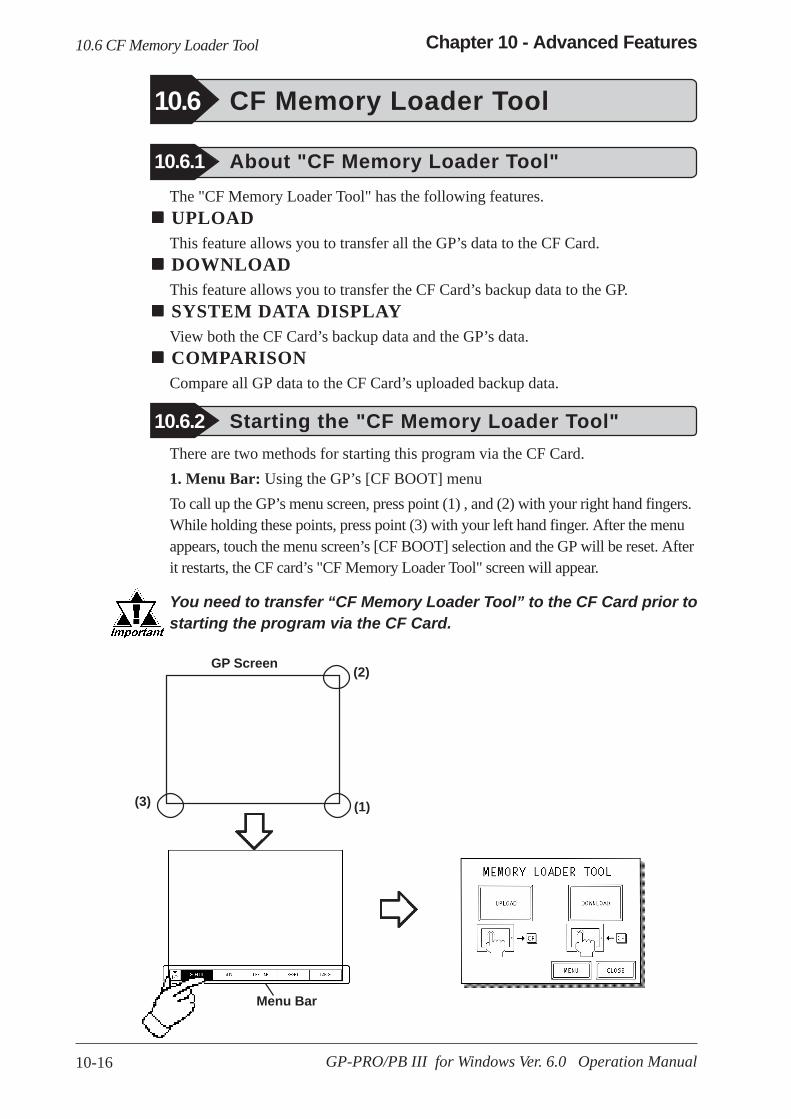
10-16 GP-PRO/PB III for Windows Ver. 6.0 Operation Manual
Chapter 10 - Advanced Features
The "CF Memory Loader Tool" has the following features. UPLOADThis feature allows you to transfer all the GP’s data to the CF Card. DOWNLOADThis feature allows you to transfer the CF Card’s backup data to the GP. SYSTEM DATA DISPLAYView both the CF Card’s backup data and the GP’s data. COMPARISONCompare all GP data to the CF Card’s uploaded backup data.
10.6 CF Memory Loader Tool
10.6.1 About "CF Memory Loader Tool"
10.6.2 Starting the "CF Memory Loader Tool"There are two methods for starting this program via the CF Card.1. Menu Bar: Using the GP’s [CF BOOT] menuTo call up the GP’s menu screen, press point (1) , and (2) with your right hand fingers.While holding these points, press point (3) with your left hand finger. After the menuappears, touch the menu screen’s [CF BOOT] selection and the GP will be reset. Afterit restarts, the CF card’s "CF Memory Loader Tool" screen will appear.
Menu Bar
GP Screen
(1)
(2)
(3)
You need to transfer “CF Memory Loader Tool” to the CF Card prior tostarting the program via the CF Card.
10.6 CF Memory Loader Tool
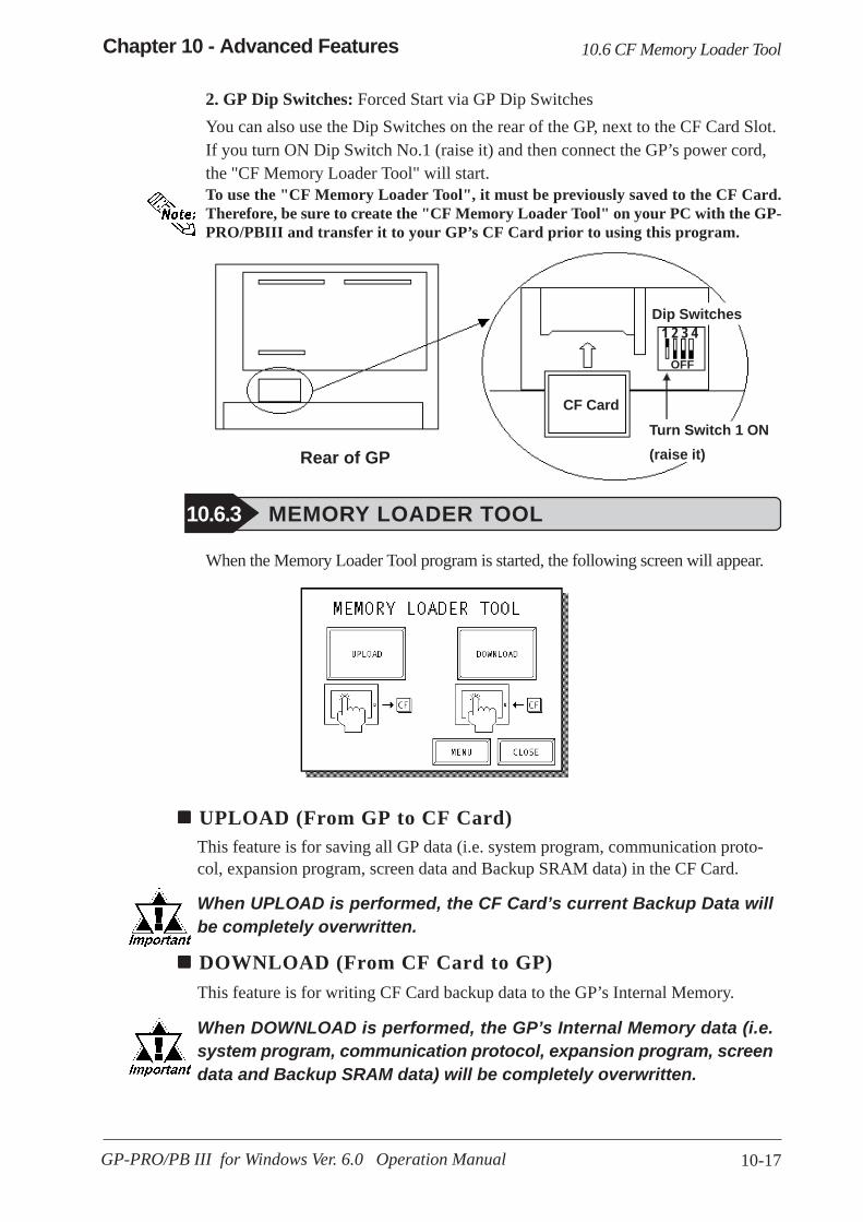
10-17
Chapter 10 - Advanced Features
GP-PRO/PB III for Windows Ver. 6.0 Operation Manual
To use the "CF Memory Loader Tool", it must be previously saved to the CF Card.Therefore, be sure to create the "CF Memory Loader Tool" on your PC with the GP-PRO/PBIII and transfer it to your GP’s CF Card prior to using this program.
10.6.3 MEMORY LOADER TOOL
When the Memory Loader Tool program is started, the following screen will appear.
UPLOAD (From GP to CF Card)This feature is for saving all GP data (i.e. system program, communication proto-col, expansion program, screen data and Backup SRAM data) in the CF Card.
When UPLOAD is performed, the CF Card’s current Backup Data willbe completely overwritten.
DOWNLOAD (From CF Card to GP)This feature is for writing CF Card backup data to the GP’s Internal Memory.
When DOWNLOAD is performed, the GP’s Internal Memory data (i.e.system program, communication protocol, expansion program, screendata and Backup SRAM data) will be completely overwritten.
CF Card
Dip Switches1 2 3 4
OFF
Rear of GPTurn Switch 1 ON(raise it)
2. GP Dip Switches: Forced Start via GP Dip SwitchesYou can also use the Dip Switches on the rear of the GP, next to the CF Card Slot.If you turn ON Dip Switch No.1 (raise it) and then connect the GP’s power cord,the "CF Memory Loader Tool" will start.
10.6 CF Memory Loader Tool
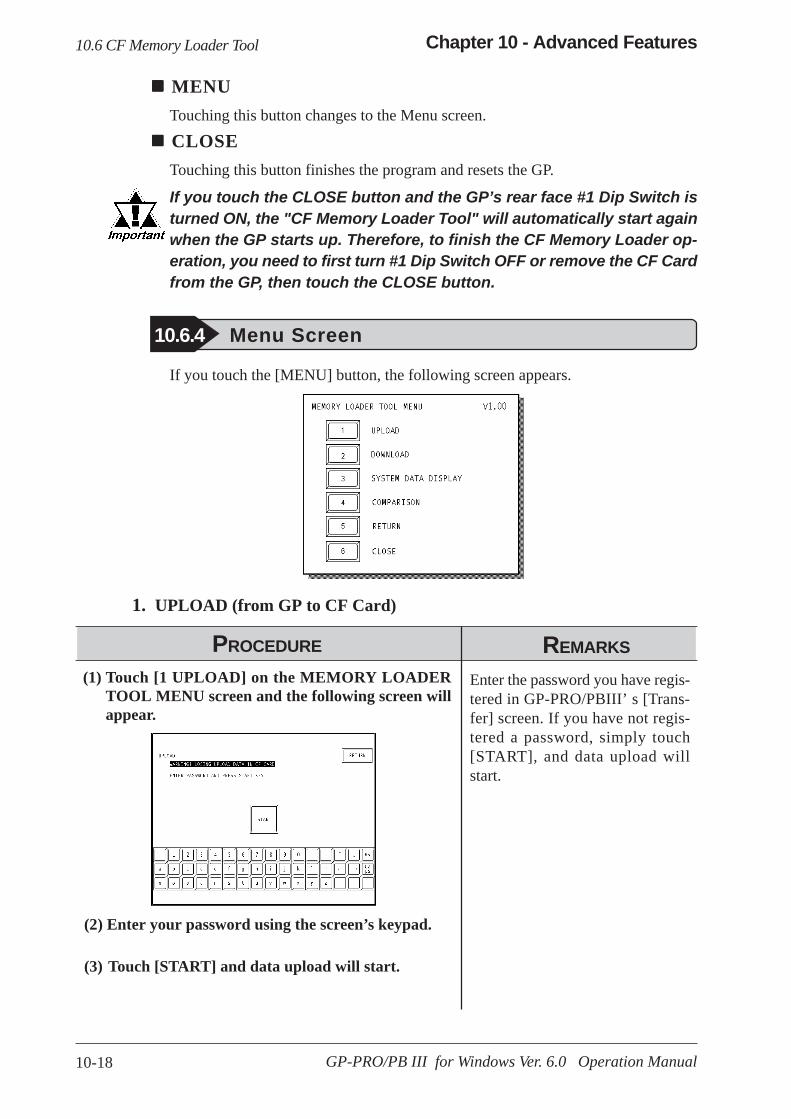
10-18 GP-PRO/PB III for Windows Ver. 6.0 Operation Manual
Chapter 10 - Advanced Features
(2) Enter your password using the screen’s keypad.
(3) Touch [START] and data upload will start.
(1) Touch [1 UPLOAD] on the MEMORY LOADERTOOL MENU screen and the following screen willappear.
Enter the password you have regis-tered in GP-PRO/PBIII’ s [Trans-fer] screen. If you have not regis-tered a password, simply touch[START], and data upload willstart.
MENUTouching this button changes to the Menu screen.
CLOSETouching this button finishes the program and resets the GP.
If you touch the CLOSE button and the GP’s rear face #1 Dip Switch isturned ON, the "CF Memory Loader Tool" will automatically start againwhen the GP starts up. Therefore, to finish the CF Memory Loader op-eration, you need to first turn #1 Dip Switch OFF or remove the CF Cardfrom the GP, then touch the CLOSE button.
10.6.4 Menu Screen
If you touch the [MENU] button, the following screen appears.
1. UPLOAD (from GP to CF Card)
PROCEDURE REMARKS
10.6 CF Memory Loader Tool
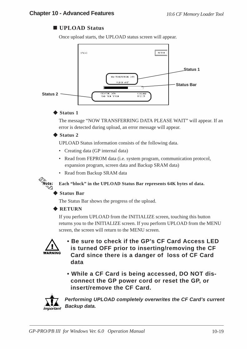
10-19
Chapter 10 - Advanced Features
GP-PRO/PB III for Windows Ver. 6.0 Operation Manual
• Be sure to check if the GP’s CF Card Access LEDis turned OFF prior to inserting/removing the CFCard since there is a danger of loss of CF Carddata
• While a CF Card is being accessed, DO NOT dis-connect the GP power cord or reset the GP, orinsert/remove the CF Card.
Status 1The message “NOW TRANSFERRING DATA PLEASE WAIT” will appear. If anerror is detected during upload, an error message will appear. Status 2UPLOAD Status information consists of the following data.• Creating data (GP internal data)• Read from FEPROM data (i.e. system program, communication protocol,
expansion program, screen data and Backup SRAM data)• Read from Backup SRAM data
Each “block” in the UPLOAD Status Bar represents 64K bytes of data.
Status BarThe Status Bar shows the progress of the upload. RETURNIf you perform UPLOAD from the INITIALIZE screen, touching this buttonreturns you to the INITIALIZE screen. If you perform UPLOAD from the MENUscreen, the screen will return to the MENU screen.
UPLOAD StatusOnce upload starts, the UPLOAD status screen will appear.
Status 1
Status 2
Status Bar
10.6 CF Memory Loader Tool
Performing UPLOAD completely overwrites the CF Card’s current Backup data.
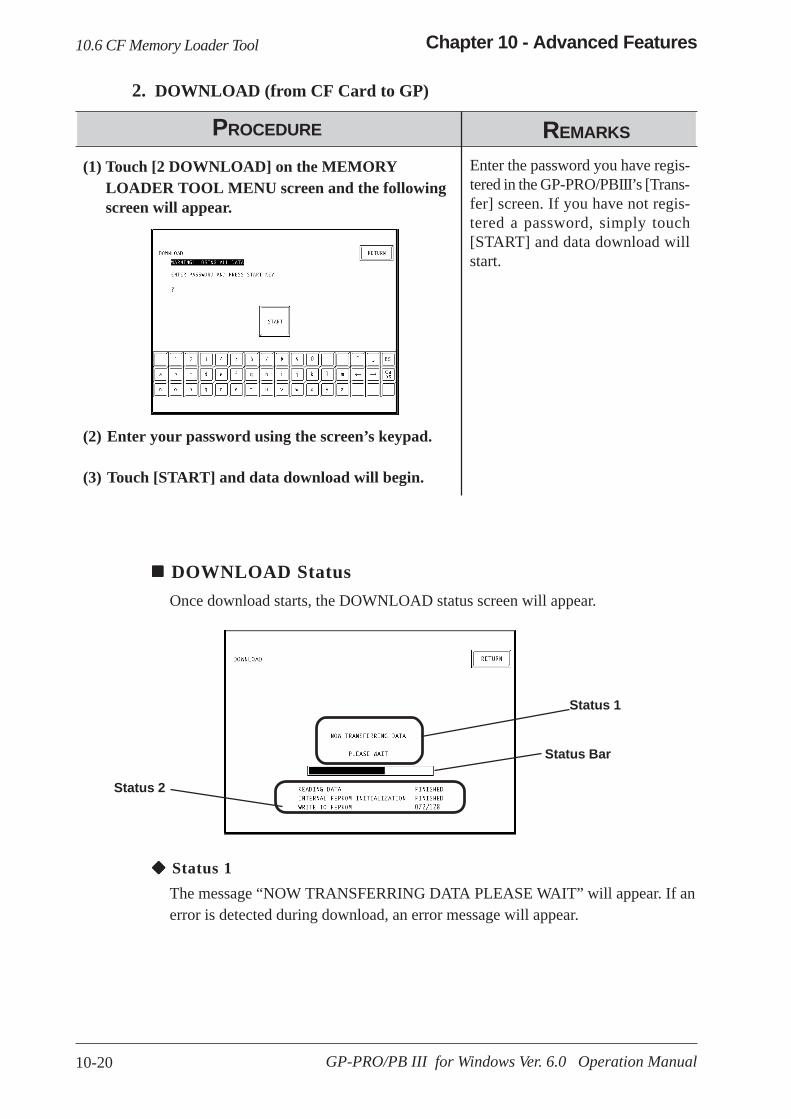
10-20 GP-PRO/PB III for Windows Ver. 6.0 Operation Manual
Chapter 10 - Advanced Features
PROCEDURE REMARKS
Enter the password you have regis-tered in the GP-PRO/PBIII’s [Trans-fer] screen. If you have not regis-tered a password, simply touch[START] and data download willstart.
2. DOWNLOAD (from CF Card to GP)
DOWNLOAD StatusOnce download starts, the DOWNLOAD status screen will appear.
Status 1
Status 2
Status Bar
Status 1The message “NOW TRANSFERRING DATA PLEASE WAIT” will appear. If anerror is detected during download, an error message will appear.
(2) Enter your password using the screen’s keypad.
(3) Touch [START] and data download will begin.
(1) Touch [2 DOWNLOAD] on the MEMORYLOADER TOOL MENU screen and the followingscreen will appear.
10.6 CF Memory Loader Tool

10-21
Chapter 10 - Advanced Features
GP-PRO/PB III for Windows Ver. 6.0 Operation Manual
• Be sure to check if the GP’s CF Card Access LEDis urned OFF prior to inserting/removing the CFCard since there is a danger of loss of CF Carddata.
• While a CF Card is being accessed, DO NOT dis-connect the GP power cord or reset the GP, orinsert/remove the CF Card.
Status 2DOWNLOAD Status information consists of the following data.
• Reading data (GP internal data)• Initialize Internal FEPROM data• Write to Internal FEPROM data• Write to Backup SRAM data
Each “block” in the DOWNLOAD Status Bar represents 64K bytes of data.
Status BarThe Status Bar shows the progress of download.
RETURNIf you perform DOWNLOAD from the INITIALIZE screen, touching this buttonreturns you to the INITIALIZE screen. If you perform DOWNLOAD from theMENU screen, the screen will return to the MENU screen.
If you touch [3 SYSTEM DATA DISPLAY], the following screen will appear.Here, you can see details of both the CF Card’s uploaded data and the GP’s inter-nal data. If you wish to see GP internal data details, touch the [INTERNAL]button.
3. SYSTEM DATA DISPLAY
10.6 CF Memory Loader Tool
Performing DOWNLOAD completely overwrites all data (the System,Communication Protocol, Extended Programs, Screen Data andBackup SRAM Data).
Displays the CF Card'suploaded data details.
Displays the controlinformation of theGLC's internal datawhen the selected GPtype is a GLC.
Pro-Control EditorOperation Manual

10-22 GP-PRO/PB III for Windows Ver. 6.0 Operation Manual
Chapter 10 - Advanced Features
The following are System Data Display examples.
SYSTEM DATA DISPLAY (CF CARD’S DATA)This screen allows you to check the CF Card’s uploaded data. SYSTEM DATA <Display Example>
UNIT TYPE :GP2600SYSTEM VERSION :V3.30COMMUNICATION PROTOCOL :MELSEC-ANA V1.41ETHERNET PROTOCOL :V4.00SIMULATION :V3.33EXPANSION SIO :EXT-SIO-GEN V1.10
• The “SIMULATION” data will change to “LADDER MONITOR” when there is aladder monitor program.
• If there is no system program in the CF Card’s uploaded data, the “SYSTEM VER-SION” will be “NONE”.
SCREEN DATA <Display Example>SCREEN EDITOR VERSION :V6.00PROJECT COMMENT :A PLANT SYSTEM (Up to 60
characters can be used)If there is no Upload Information Data in the GP, an error message will appear in-forming you that there is no Upload Information Data, and the Screen Data will notbe displayed.
UPLOAD DATA SIZE <Display Example>DATA SIZE :1K byteINTERNAL FEPROM SIZE :8192K bytesSRAM SIZE :512K bytesTOTAL SIZE :8705K bytes
SYSTEM DATA DISPLAY (INTERNAL DATA)If you touch the [INTERNAL] button, the following screen will appear. You cancheck GP Internal data with this screen.
10.6 CF Memory Loader Tool
Displays GP internaldata information
Displays the control informa-tion of the GLC's internal datawhen the selected GP type isa GLC.
Pro-ControlEditor Operation Manual

10-23
Chapter 10 - Advanced Features
GP-PRO/PB III for Windows Ver. 6.0 Operation Manual
SYSTEM DATA <Display Example>UNIT TYPE : GP2600SYSTEM VERSION : V3.30COMMUNICATION PROTOCOL :MELSEC-ANA V1.41ETHERNET PROTOCOL :V4.00SIMULATION :V3.33EXPANSION SIO :EXT-SIO-GEN V1.10
The “SIMULATION” data will change to “LADDER MONITOR” when there is aladder monitor program. SCREEN DATA <Display Example>
SCREEN EDITOR VERSION :V6.00PROJECT COMMENT :A PLANT SYSTEM (Up to 60
characters can be used)
If Upload Information Data is not transferred when transferring Screen Data, anerror message informs you that there is no Upload Information Data, and the ScreenData will not be displayed.
UPLOAD DATA SIZE <Display Example>INTERNAL FEPROM SIZE :8192K bytesSRAM SIZE :512K bytes
PROCEDURE REMARKS
4. COMPARISONIf you select [4. COMPARISON], the following screen will appear. This screen allowsyou to compare all the GP’s data (i.e. system program, communication protocol,expansion program, screen data and Backup SRAM data) with backup data that isuploaded in the CF Card.
(1) Touch [COMPARISON] on the MEMORY LOADERTOOL MENU screen and the following screen willappear.
(2) Touch the [START] button. The [COMPARISON]feature will compare all GP data with backup datathat is uploaded in the CF Card.
10.6 CF Memory Loader Tool
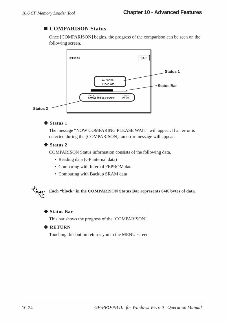
10-24 GP-PRO/PB III for Windows Ver. 6.0 Operation Manual
Chapter 10 - Advanced Features
COMPARISON StatusOnce [COMPARISON] begins, the progress of the comparison can be seen on thefollowing screen.
Status 1
Status 2
Status Bar
Status 1The message “NOW COMPARING PLEASE WAIT” will appear. If an error isdetected during the [COMPARISON], an error message will appear.
Status 2COMPARISON Status information consists of the following data.
• Reading data (GP internal data)• Comparing with Internal FEPROM data• Comparing with Backup SRAM data
Each “block” in the COMPARISON Status Bar represents 64K bytes of data.
Status BarThis bar shows the progress of the [COMPARISON].
RETURNTouching this button returns you to the MENU screen.
10.6 CF Memory Loader Tool

10-25
Chapter 10 - Advanced Features
GP-PRO/PB III for Windows Ver. 6.0 Operation Manual
10.6.5 Self Diagnosis
You can check the CF Card’s "CF Memory Loader Tool" using the OFFLINEmode’s SELF DIAGNOSIS area. For example, if you touched three corners of theGP screen, selected [CF BOOT] on the Menu Bar and the CF Card failed tooperate correctly, you can check the status of the "CF Memory Loader Tool" (i.e.IPL.SYS, MLD****.SYS) with this feature.
Calls up the CF CardMemory Loader filecheck screen.
PROCEDURE REMARKS
(2) Touching [START] checks the following points.• The status of the CF Card Start Dip Switches• Whether the "CF Memory Loader Tool" is in the CF Card or not• If the CF Memory Loader program has errors
(1) Touch [F CF CARD MEMORY LOADER FILECHECK] and the following screen will appear.
10.6 CF Memory Loader Tool

10-26 GP-PRO/PB III for Windows Ver. 6.0 Operation Manual
Memo

11-1
Chapter 11 - Project Manager
GP-PRO/PB III for Windows Ver. 6.0 Operation Manual
he Project Manager can display the hierarchical structure of ProjectFiles and screens. This function enables you to easily view Project
Files and screens when moving or copying. This chapter describes how tooperate the Project Manager in the hierarchical display mode.
11 PROJECT MANAGER HIERARCHICAL DISPLAY
11.1 ..................... Project Manager - Hierarchical Display
11.2 ................................ Using Hierarchical Display Mode
T
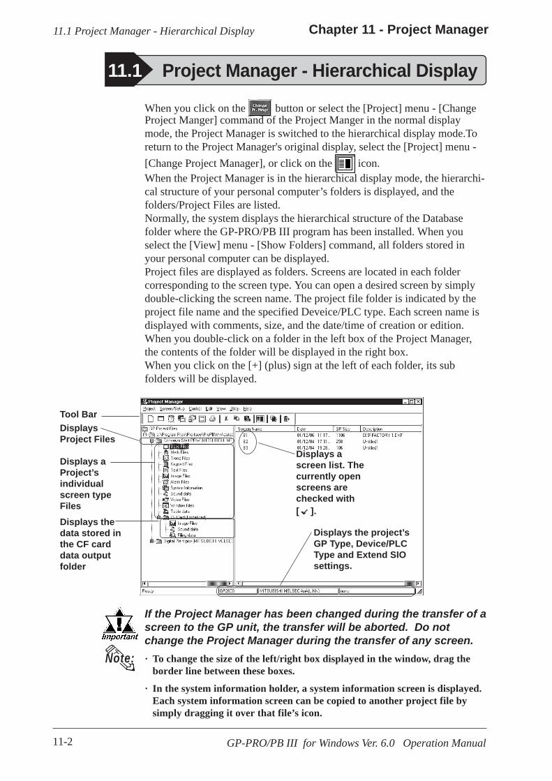
11-2
Chapter 11 - Project Manager
GP-PRO/PB III for Windows Ver. 6.0 Operation Manual
11.1 Project Manager - Hierarchical Display
When you click on the button or select the [Project] menu - [ChangeProject Manger] command of the Project Manger in the normal displaymode, the Project Manager is switched to the hierarchical display mode.Toreturn to the Project Manager's original display, select the [Project] menu -[Change Project Manager], or click on the icon.When the Project Manager is in the hierarchical display mode, the hierarchi-cal structure of your personal computer’s folders is displayed, and thefolders/Project Files are listed.Normally, the system displays the hierarchical structure of the Databasefolder where the GP-PRO/PB III program has been installed. When youselect the [View] menu - [Show Folders] command, all folders stored inyour personal computer can be displayed.Project files are displayed as folders. Screens are located in each foldercorresponding to the screen type. You can open a desired screen by simplydouble-clicking the screen name. The project file folder is indicated by theproject file name and the specified Deveice/PLC type. Each screen name isdisplayed with comments, size, and the date/time of creation or edition.When you double-click on a folder in the left box of the Project Manager,the contents of the folder will be displayed in the right box.When you click on the [+] (plus) sign at the left of each folder, its subfolders will be displayed.
11.1 Project Manager - Hierarchical Display
Tool BarDisplaysProject Files
Displays aProject’sindividualscreen typeFilesDisplays thedata stored inthe CF carddata outputfolder
Displays ascreen list. Thecurrently openscreens arechecked with[ ].
Note:
If the Project Manager has been changed during the transfer of ascreen to the GP unit, the transfer will be aborted. Do notchange the Project Manager during the transfer of any screen.· To change the size of the left/right box displayed in the window, drag the
border line between these boxes.
· In the system information holder, a system information screen is displayed.Each system information screen can be copied to another project file bysimply dragging it over that file’s icon.
Displays the project’sGP Type, Device/PLCType and Extend SIOsettings.

11-3
Chapter 11 - Project Manager
GP-PRO/PB III for Windows Ver. 6.0 Operation Manual
11.2 Using Hierarchical Display ModeThis section describes the basic operations of the Project Manager in thehierarchical display mode.
Creating a New ProjectClick on the folder where you wish to create a new Project File. Select the[Project] menu - [New] command, or click on the icon. The [New]dialog box will appear.
1.1.2 Creating a New ProjectWhen a new Project File is created , a new folder “(new_project_name).prw” will be added to the directory.
Selecting a Project File from the Existing ProjectsClick on the Project File to be selected. The right box lists the folders of theselected Project File by screen type.
RenameTo change a Project File name or screen name, select the target Project Fileor screen, and then select the [Project] menu - [Rename] command.
Opening a New ScreenSelect a Project file. And then select the [Screen/Setup] menu - [New]command, or click on the icon. The [New] dialog box will appear.Select the type of screen to be created and click on the button.Then, a new screen will open.
1.1.3 Opening a New Screen
Opening an Existing ScreenSelect a Project file to create a screen. When selecting the [Screen/Setup]menu - [New] command, with the screen type folder specified, the [New]dialog box will appear with the specified screen type selected. Then, clickon the button to open a new screen.
Opening a ScreenWhen you select the Project File including the target screen and then clickon the folder corresponding to the target screen type, the screen name will bedisplayed at the right of the box. When you double-click on the target screenname, the Screen Editor will start up, and the selected screen will be opened.After selecting a desired screen, select the [Screen/Setup] menu - [Editor]command, or click on the icon to open the screen.
When clicking on the icon with the Project File selected, a dialog boxto open a screen will appear. Select a desired screen and click on the
button.
11.2 Using Hierarchical Display Mode
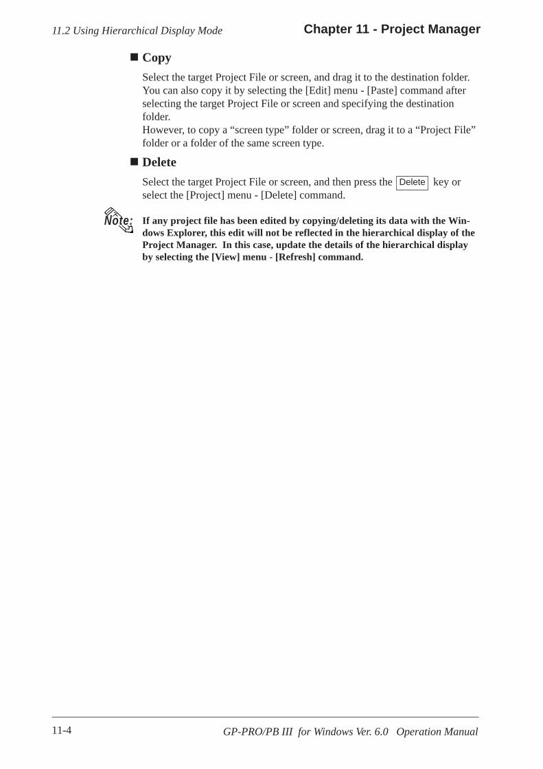
11-4
Chapter 11 - Project Manager
GP-PRO/PB III for Windows Ver. 6.0 Operation Manual
CopySelect the target Project File or screen, and drag it to the destination folder.You can also copy it by selecting the [Edit] menu - [Paste] command afterselecting the target Project File or screen and specifying the destinationfolder.However, to copy a “screen type” folder or screen, drag it to a “Project File”folder or a folder of the same screen type.
DeleteSelect the target Project File or screen, and then press the key orselect the [Project] menu - [Delete] command.
11.2 Using Hierarchical Display Mode
If any project file has been edited by copying/deleting its data with the Win-dows Explorer, this edit will not be reflected in the hierarchical display of theProject Manager. In this case, update the details of the hierarchical displayby selecting the [View] menu - [Refresh] command.
Note:
Delete

12-1GP-PRO/PB III for Windows Ver. 6.0 Operation Manual
creen data created with other screen editor software can be converted into files that can be used with the GP-PRO/PB III forWindows program.
12 DATA COMPATIBILITY
12.1 ................................................................ File Converter
S
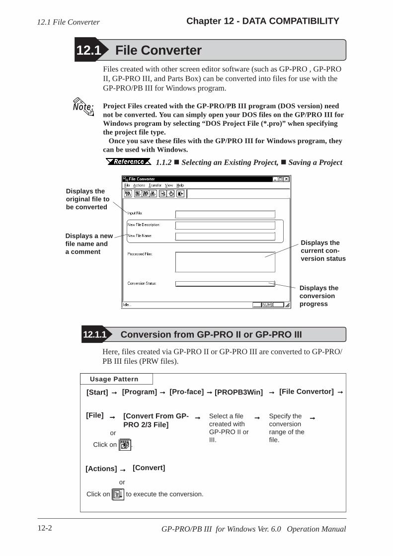
12-2
Chapter 12 - DATA COMPATIBILITY
GP-PRO/PB III for Windows Ver. 6.0 Operation Manual
Files created with other screen editor software (such as GP-PRO , GP-PROII, GP-PRO III, and Parts Box) can be converted into files for use with theGP-PRO/PB III for Windows program.
Project Files created with the GP-PRO/PB III program (DOS version) neednot be converted. You can simply open your DOS files on the GP/PRO III forWindows program by selecting “DOS Project File (*.pro)” when specifyingthe project file type.
Once you save these files with the GP/PRO III for Windows program, theycan be used with Windows.
1.1.2 Selecting an Existing Project, Saving a Project
12.1 File Converter
Note:
12.1.1 Conversion from GP-PRO II or GP-PRO III
Usage Pattern
Specify theconversionrange of thefile.
Select a filecreated withGP-PRO II orIII.
[Convert From GP-PRO 2/3 File]
[File Convertor][PROPB3Win][Start]
→→→→→→→→→→→→→→→
→→→→→ →→→→→→→→→→
Here, files created via GP-PRO II or GP-PRO III are converted to GP-PRO/PB III files (PRW files).
12.1 File Converter
→→→→→
Displays theoriginal file tobe converted
Displays a newfile name anda comment
Displays thecurrent con-version status
Displays theconversionprogress
[Program]
[File] →→→→→
or
Click on .
[Convert]→→→→→ or
Click on to execute the conversion.
[Actions]
→→→→→[Pro-face]

12-3
Chapter 12 - DATA COMPATIBILITY
GP-PRO/PB III for Windows Ver. 6.0 Operation Manual
Selecting a GP-PRO II/III File
12.1 File Converter
Selects all theGP-PRO II andIII screen fileslisted
Selects thescreen fileselected fromthe list
Cancel selectionof the specifiedscreen file
Cancel selec-tion of allscreen files
Displays theDevice/PLCtype specifiedfor the GP-PRO II or IIIfile
Lists the selectedscreen files
Creates a newProject File
Addsscreen datainto anexistingProject Filewith thesame filename
Selecting a Destination FolderSpecify the Project File (PRW file) converted form the GP-PRO II or GP-PRO III file.

12-4
Chapter 12 - DATA COMPATIBILITY
GP-PRO/PB III for Windows Ver. 6.0 Operation Manual
PROCEDURE R E M A R K S
(2)Select the [File] menu - [Convert From GP-PRO 2/3File] command, or click on the icon.
(3) Select a desired GP-PRO II or GP-PRO III file'sDevice/PLC type.The files corresponding to the selected Device/PLC typewill be displayed.
(1)Click on the [Start] button, and point to the [Program ] -[Pro-face] - [ProPB3Win] menu. Then, click on the[2.File Convertor] command.
12.1 File Converter
Converting a GP-PRO II/GP-PRO III File

12-5
Chapter 12 - DATA COMPATIBILITY
GP-PRO/PB III for Windows Ver. 6.0 Operation Manual
PROCEDURE R E M A R K S
(4)Select a desired GP-PRO II or GP-PRO III file orenter the file name, and click on the but-ton.The selected file will appear in the Files to Convert list.
12.1 File Converter
To convert all files, click on the button.
To cancel file selection, click on the or button.
(5) After selecting the GP-PRO II or III file, click onthe button.

12-6
Chapter 12 - DATA COMPATIBILITY
GP-PRO/PB III for Windows Ver. 6.0 Operation Manual
PROCEDURE R E M A R K S
To import a file from a differentfolder, first change the folder.
1.1.2 Selectingan Existing Project[Display Type]Select the GP unit type for the tar-get Project File.[Device/PLC Type]Select the Device/PLC type for thetarget Project File.
When the destination Projectfile's Device/PLC type is dif-ferent from that of the origi-nal file, you must specify theTag device address again af-ter the Project File is im-ported.
12.1 File Converter
(6) Enter the folder and Project File name where theconverted file will be stored. Also, specify the GP andDevice/PLC types.If the Device/PLC types are different before and afterconversion, a dialog box will appear confirming the con-version command. If you wish to convert the file, clickon the button.
(7)After confirming the conversion command, click onthe button.
If the same file already exists, thesystem asks if this file must be over-written. If you select , thefile will be overwritten. If you select
, the file will not be over-written, and you will return to theprevious dialog box.

12-7
Chapter 12 - DATA COMPATIBILITY
GP-PRO/PB III for Windows Ver. 6.0 Operation Manual
PROCEDURE R E M A R K S
12.1 File Converter
(8)Click on the button to confirm the originaland destination file settings.
• After importing the system (SO) screen from GP-PRO II or GP-PRO III, be sure to check the [System Settings] data.
• When the system (SO) screen imported by the [Convert FromGP-PRO 2/3 File] command is transferred to the GP70/77R/2000 series unit, you will need to perform [Font Setup]. Enterthe GP’s the OFFLINE mode, and set up the necessary fonts(language).
GP Series User’s Manual (sold separately), FONT SETTINGS
(9) After confirming the settings, select the [Actions]menu - [Convert] command, or click on the icon.The current status of the file conversion will be displayed.When the file conversion has been completed, “DONE”will be displayed in the status display area.

12-8
Chapter 12 - DATA COMPATIBILITY
GP-PRO/PB III for Windows Ver. 6.0 Operation Manual
Usage Pattern
12.1.2 Conversion from Parts Box
Select a filecreated withParts Box.
[2.File Converter][ProPB3win][Start]
→→→→→→→→→→
→→→→→→→→→→→→→→→
Selecting a Destination FolderSpecify the destination folder to store the Project File (PRW file) convertedfrom the SCD file and CPL file.
Selecting a Parts Box File
Here, system files (SCD file) created via Parts Box are converted to GP-PRO/PBIII files (*.PRW).
Select the SCD File andCPL File created with PartsBox
Displays thedestinationProject File(PRW file)
Displays the Device/PLCtype of the system file(SCD file)
The Easy series name isautomatically convertedinto the following GPseries names :[Easy20]: GP-270 series[Easy40/50] : GP-470 series
Displays a comment at-tached to the SCD or CPLfile.
Displays Parts Box'ssystem file (SCD file) andLibrary file (CPL file).
[Program] →→→→→
[File] [Convert From Parts Box]or click on .
→→→→→ Specifyconvertdestination.
[Actions] [Convert] or
Click on to execute the conversion
→→→→→
→→→→→[Pro-face]
12.1 File Converter

12-9
Chapter 12 - DATA COMPATIBILITY
GP-PRO/PB III for Windows Ver. 6.0 Operation Manual
(1)Click on the [Start] button, and point to the [Pro-gram] - [Pro-face] - [ProPB3Win] menu. Then, clickon the [2.File Convertor] command.
PROCEDURE R E M A R K S
(3) Select a Parts Box file to be converted or enter thefile name, and click on the button.
(2) Select the [File] menu - [Convert From Parts Box]command, or click on the icon.
Converting a Parts Box File
To import a file from a differentfolder, you must change to that folder.
1.1.2 Selectingan Existing Project
(4) Enter the folder and Project file name where the con-verted file is saved, and click on the [Save] button.
When selecting a Library file (CPLfile), select [Parts Box Library File(*.cpl)] in the Files of type pull-downlist.
To change the destination file's GPor Device/PLC type, do so after con-version.
To import a file from another folder,change the folder.
4.2.5 Changing aProject's GP Type, 4.2.6 Chang-ing Your Project's Device/PLCType
12.1 File Converter

12-10
Chapter 12 - DATA COMPATIBILITY
GP-PRO/PB III for Windows Ver. 6.0 Operation Manual
12.1 File Converter
PROCEDURE R E M A R K S
(5)After confirming the settings, select the [Actions]menu - [Convert] command, or click on the icon.The current status of the file conversion will be displayed.When the file conversion has been completed, “DONE”will be displayed in the status display area.
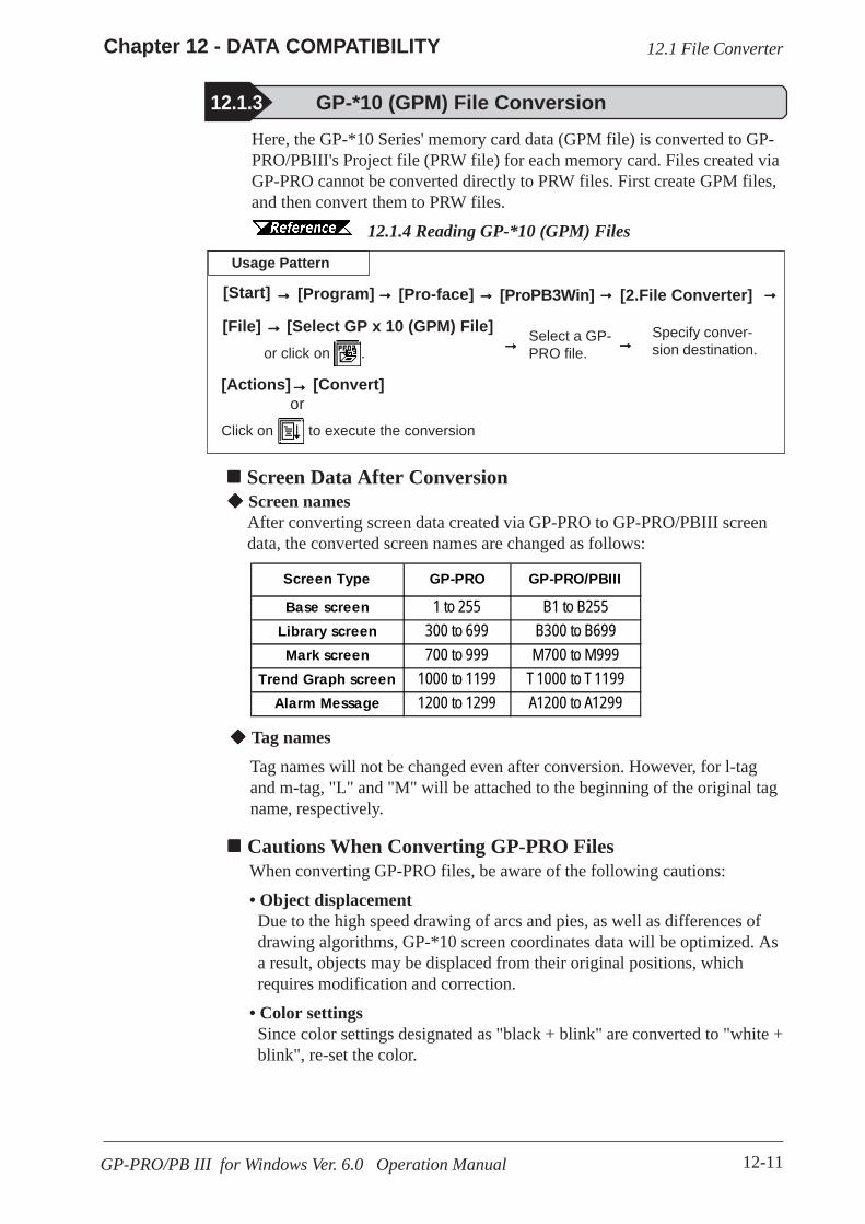
12-11
Chapter 12 - DATA COMPATIBILITY
GP-PRO/PB III for Windows Ver. 6.0 Operation Manual
12.1 File Converter
Usage Pattern
12.1.3 GP-*10 (GPM) File Conversion
Select a GP-PRO file.
[2.File Converter][ProPB3Win][Start]
→→→→→→→→→→
→→→→→→→→→→→→→→→
Screen Data After Conversion
Here, the GP-*10 Series' memory card data (GPM file) is converted to GP-PRO/PBIII's Project file (PRW file) for each memory card. Files created viaGP-PRO cannot be converted directly to PRW files. First create GPM files,and then convert them to PRW files.
12.1.4 Reading GP-*10 (GPM) Files
[Program] →→→→→
[File] [Select GP x 10 (GPM) File]or click on .
→→→→→ Specify conver-sion destination.
[Actions] [Convert] or
Click on to execute the conversion
→→→→→
Screen namesAfter converting screen data created via GP-PRO to GP-PRO/PBIII screendata, the converted screen names are changed as follows:
Tag names
Tag names will not be changed even after conversion. However, for l-tagand m-tag, "L" and "M" will be attached to the beginning of the original tagname, respectively.
Cautions When Converting GP-PRO FilesWhen converting GP-PRO files, be aware of the following cautions:
• Object displacementDue to the high speed drawing of arcs and pies, as well as differences ofdrawing algorithms, GP-*10 screen coordinates data will be optimized. Asa result, objects may be displaced from their original positions, whichrequires modification and correction.
• Color settingsSince color settings designated as "black + blink" are converted to "white +blink", re-set the color.
Screen Type GP-PRO GP-PRO/PBIII
Base screen 1 to 255 B1 to B255Library screen 300 to 699 B300 to B699Mark screen 700 to 999 M700 to M999
Trend Graph screen 1000 to 1199 T1000 to T1199Alarm Message 1200 to 1299 A1200 to A1299
→→→→→[Pro-face]

12-12
Chapter 12 - DATA COMPATIBILITY
GP-PRO/PB III for Windows Ver. 6.0 Operation Manual
12.1 File Converter
• Chinese character fontsChinese character fonts used on the GP-*10 series are different from theones on the GP70/GP77R/GP377/GP2000 Series units.
• Numeric keysGP-PRO/PBIII does not support N699. After conversion, re-create numerickeys and display on the GP-PRO/PBIII.
• K-tagSince GP-PRO does not have a function to display data for K-tag, N-tag isused to enter set values via the screen's numeric keys. However, since GP-PRO/PB III supports the K-tag display function, the N-tag settings are notrequired.
• System data areas +6 and +7The GP-*10 Series uses system data areas +6 and +7 for N699 numeric keyentry and K-tag. However, the GP70/GP77R/GP377/GP2000 Series use +6for status and +7 for reserved area, and K-tag reads and writes PLC datadirectly, without using the system data areas. When system data areas +6and +7 have been used for the tags or ladder program, correct the addresssettings.
• Requirements for 32-bit dataRelationship between 32-bit data upper and lower addresses may be differ-ent between the GP-*10 Series and the GP70/GP77R/GP377/GP2000Series, depending on Device/PLC types. Due to this, the PLC's ladderprogram may require correction.
• Device/PLC typeThe data for Device/PLC types which are not supported by GP-PRO/PB IIIcannot be converted.
• Data check after conversionBe sure to check all the settings such as of tags, after conversion.
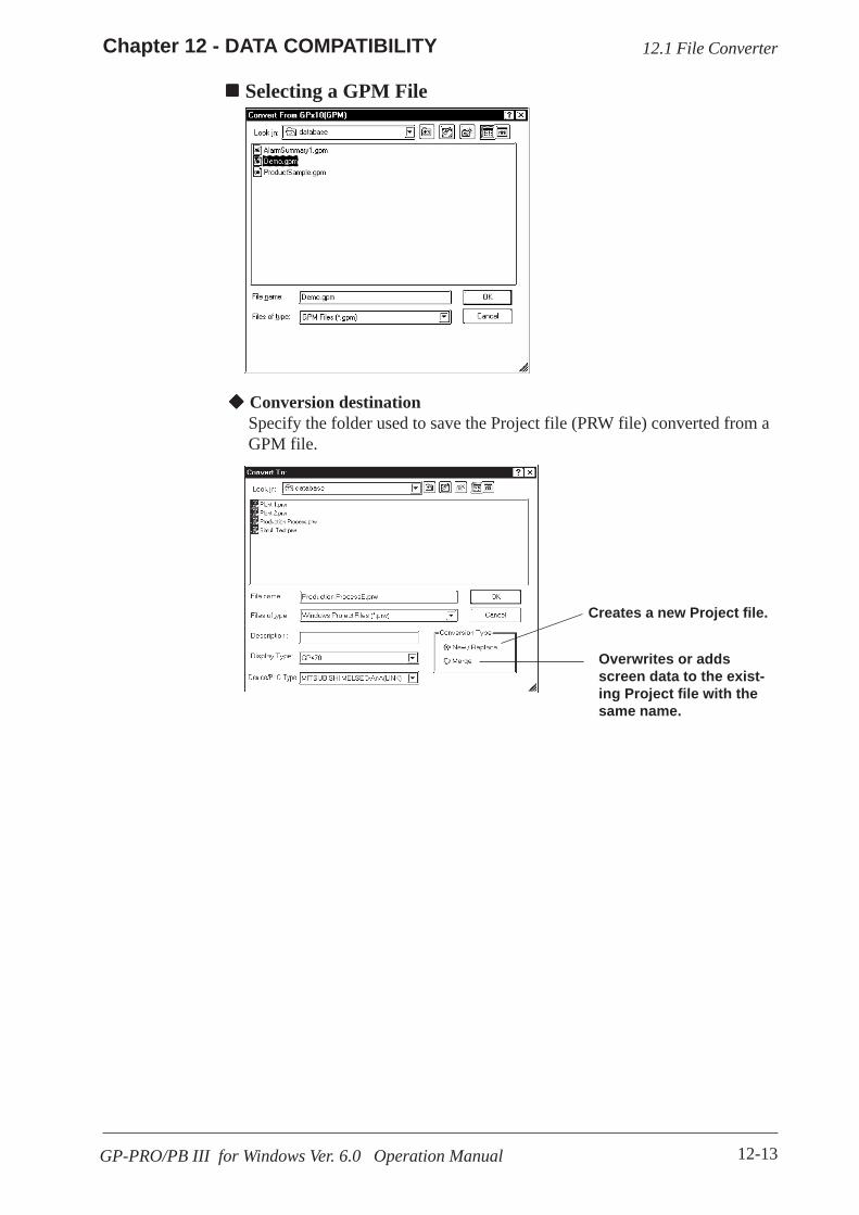
12-13
Chapter 12 - DATA COMPATIBILITY
GP-PRO/PB III for Windows Ver. 6.0 Operation Manual
12.1 File Converter
Selecting a GPM File
Conversion destinationSpecify the folder used to save the Project file (PRW file) converted from aGPM file.
Overwrites or addsscreen data to the exist-ing Project file with thesame name.
Creates a new Project file.
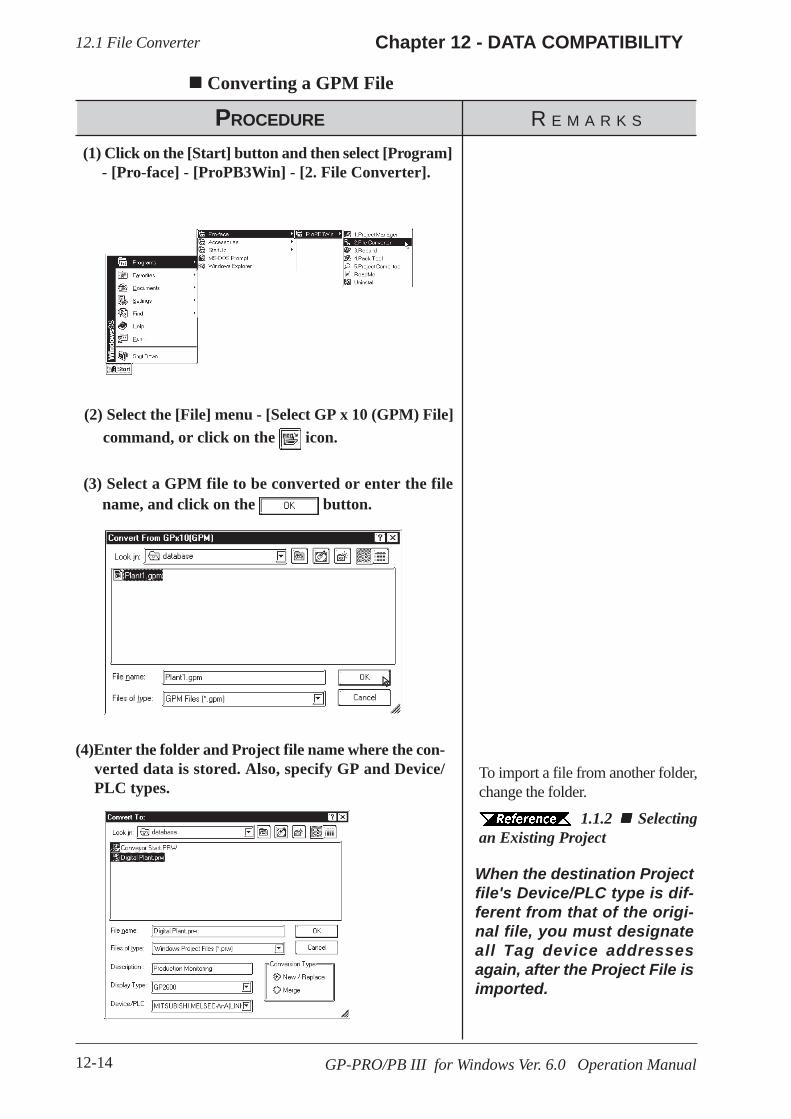
12-14
Chapter 12 - DATA COMPATIBILITY
GP-PRO/PB III for Windows Ver. 6.0 Operation Manual
Converting a GPM File
(1) Click on the [Start] button and then select [Program]- [Pro-face] - [ProPB3Win] - [2. File Converter].
PROCEDURE R E M A R K S
(3) Select a GPM file to be converted or enter the filename, and click on the button.
(2) Select the [File] menu - [Select GP x 10 (GPM) File]command, or click on the icon.
(4)Enter the folder and Project file name where the con-verted data is stored. Also, specify GP and Device/PLC types.
To import a file from another folder,change the folder.
1.1.2 Selectingan Existing Project
When the destination Projectfile's Device/PLC type is dif-ferent from that of the origi-nal file, you must designateall Tag device addressesagain, after the Project File isimported.
12.1 File Converter

12-15
Chapter 12 - DATA COMPATIBILITY
GP-PRO/PB III for Windows Ver. 6.0 Operation Manual
(5)After confirming the settings, click on the button.
(6) After confirming the settings, select the [Actions]menu - [Convert] command, or click on the icon.The conversion status will continuously be displayed.When "Completed" is displayed in the [Status] field, con-version is completed.
PROCEDURE R E M A R K S
If the same file already exists, thesystem asks if this file must be over-written. If you select , thefile will be overwritten. If you select
, the file will not be over-written, and you will return to theprevious dialog box.
12.1 File Converter
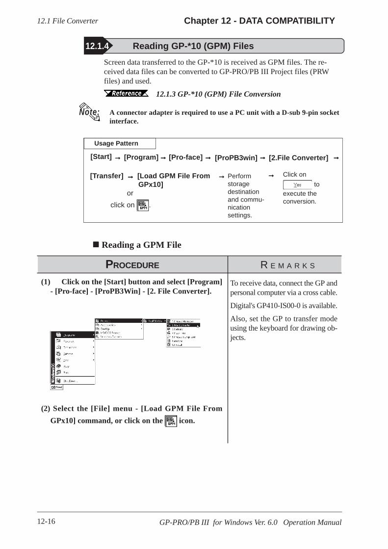
12-16
Chapter 12 - DATA COMPATIBILITY
GP-PRO/PB III for Windows Ver. 6.0 Operation Manual
Usage Pattern
12.1.4 Reading GP-*10 (GPM) Files
Performstoragedestinationand commu-nicationsettings.
[2.File Converter][ProPB3win][Start]
→→→→→→→→→→
→→→→→→→→→→→→→→→
Reading a GPM File
Screen data transferred to the GP-*10 is received as GPM files. The re-ceived data files can be converted to GP-PRO/PB III Project files (PRWfiles) and used.
12.1.3 GP-*10 (GPM) File Conversion
A connector adapter is required to use a PC unit with a D-sub 9-pin socketinterface.
[Program] →→→→→
[Transfer] [Load GPM File From GPx10]
or click on .
→→→→→ Click on to
execute theconversion.
(1) Click on the [Start] button and select [Program]- [Pro-face] - [ProPB3Win] - [2. File Converter].
PROCEDURE R E M A R K S
(2) Select the [File] menu - [Load GPM File FromGPx10] command, or click on the icon.
To receive data, connect the GP andpersonal computer via a cross cable.
Digital's GP410-IS00-0 is available.
Also, set the GP to transfer modeusing the keyboard for drawing ob-jects.
12.1 File Converter
→→→→→[Pro-face]
Note:
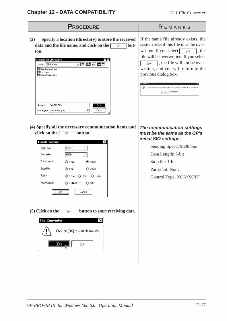
12-17
Chapter 12 - DATA COMPATIBILITY
GP-PRO/PB III for Windows Ver. 6.0 Operation Manual
(4) Specify all the necessary communication items andclick on the button.
PROCEDURE R E M A R K S
(5) Click on the button to start receiving data.
The communication settingsmust be the same as the GP'sinitial SIO settings.
Sending Speed: 9600 bps
Data Length: 8-bit
Stop bit: 1-bit
Parity bit: None
Control Type: XON/XOFF
12.1 File Converter
(3) Specify a location (directory) to store the receiveddata and the file name, and click on the but-ton.
If the same file already exists, thesystem asks if this file must be over-written. If you select , thefile will be overwritten. If you select
, the file will not be over-written, and you will return to theprevious dialog box.

12-18
Chapter 12 - DATA COMPATIBILITY
GP-PRO/PB III for Windows Ver. 6.0 Operation Manual
12.1 File Converter
PROCEDURE R E M A R K S
(6) After confirming the data receiving command, se-lect the [Actions] menu - [Convert] command, or clickon the icon.The conversion status will continuously be displayed.When "Completed" is displayed in the [Status] field,conversion is completed.

Appendix-1GP-PRO/PB III for Windows Ver. 6.0 Operation Manual
APPENDICES
his section contains a list of error messages and corrective actions, aswell as address conversion tables.T
Appendix 1 ........................................................ Error Messages
Appendix 2 ....................................................... Troubleshooting
Appendix 3 .................................... Address Conversion Tables
Appendix 4 ........................................ Software Trouble Report
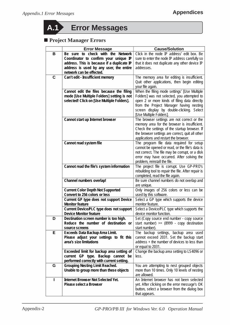
Appendix-2
Appendices
GP-PRO/PB III for Windows Ver. 6.0 Operation Manual
Appendix.1 Error Messages
A.1 Error Messages Project Manager Errors
Error Message Cause/Solution B Be sure to check with the Network
Coordinator to confirm your unique IP address. This is because if a duplicate IP address is used by any user, the entire network can be effected.
Click in the node IP address’ edit box. Be sure to enter the node IP address carefully so that it does not duplicate any other device IP addresses.
Can’t edit - Insufficient memory The memory area for editing is insufficient. Quit other applications, then begin editing your file again.
Cannot edit the files because the filing mode [Use Multiple Folders] setting is not selected! Click on [Use Multiple Folders].
When the filing mode settings’ [Use Multiple Folders] was not selected, you attempted to open 2 or more kinds of filing data directly from the Project Manager having nesting screen display by double-clicking. Select [Use Multiple Folders].
Cannot start up Internet browser The browser settings are not correct or the memory area for the browser is insufficient. Check the settings of the startup browser. If the browser settings are correct, quit all other applications and restart the browser.
Cannot read system file The program file data required for setup cannot be opened or read, or the file’s data is not correct. The file may be corrupt, or a disk error may have occurred. After solving the problem, reinstall the file.
Cannot read the file’s system information The project file is corrupt. Use GP-PRO’s rebuilding tool to repair the file. After repair is completed, read the file again.
Channel numbers overlap! Be sure channel numbers do not overlap and are unique.
Current Color Depth Not Supported Convert to 256 colors or less
Only images of 256 colors or less can be used by this software.
Current GP type does not support Device Monitor feature
Select a GP type which supports the device monitor feature.
C
Current Device/PLC type does not support Device Monitor feature
Select a Device/PLC type which supports the device monitor function.
D Destination screen number is too high. Reduce the number of destination or source screens
Set (Copy source end number - copy source start number) >= (8999 - copy destination start number).
Exceeds Data Backup Area Limit. Please adjust your settings to fit this area’s size limitations
The backup settings, backup area used cannot exceed 2031. Set the backup start address + the number of devices to less than or equal to 2031.
E
Exceeded limit for backup area setting of current GP type. Backup cannot be performed correctly with current setting.
Change the backup area setting to LS4096 or less.
G Grouping Nesting Limit Reached. Unable to group more than these objects
You are attempting to nest grouped objects more than 10 times. Only 10 levels of nesting are allowed.
I Internet Browser Not Selected Yet. Please select a Browser
An Internet browser has not been selected yet. After clicking on the error message’s OK button, select a browser from the dialog box that appears.
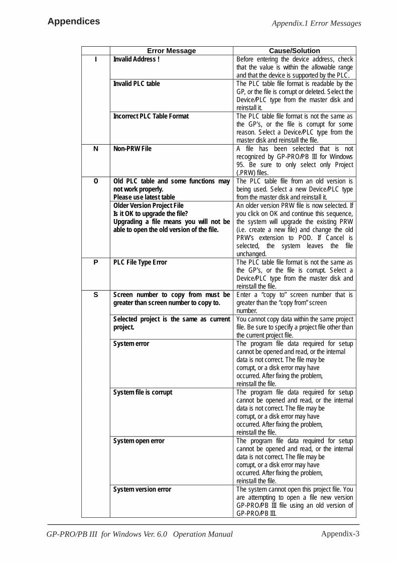
Appendix-3
Appendices
GP-PRO/PB III for Windows Ver. 6.0 Operation Manual
Appendix.1 Error Messages
Error Message Cause/Solution Invalid Address ! Before entering the device address, check
that the value is within the allowable range and that the device is supported by the PLC.
Invalid PLC table The PLC table file format is readable by the GP, or the file is corrupt or deleted. Select the Device/PLC type from the master disk and reinstall it.
I
Incorrect PLC Table Format The PLC table file format is not the same as the GP’s, or the file is corrupt for some reason. Select a Device/PLC type from the master disk and reinstall the file.
N Non-PRW File A file has been selected that is not recognized by GP-PRO/PB III for Windows 95. Be sure to only select only Project (.PRW) files.
Old PLC table and some functions may not work properly. Please use latest table
The PLC table file from an old version is being used. Select a new Device/PLC type from the master disk and reinstall it.
O
Older Version Project File Is it OK to upgrade the file? Upgrading a file means you will not be able to open the old version of the file.
An older version PRW file is now selected. If you click on OK and continue this sequence, the system will upgrade the existing PRW (i.e. create a new file) and change the old PRW’s extension to POD. If Cancel is selected, the system leaves the file unchanged.
P PLC File Type Error The PLC table file format is not the same as the GP’s, or the file is corrupt. Select a Device/PLC type from the master disk and reinstall the file.
Screen number to copy from must be greater than screen number to copy to.
Enter a “copy to” screen number that is greater than the “copy from” screen number.
Selected project is the same as current project.
You cannot copy data within the same project file. Be sure to specify a project file other than the current project file.
System error The program file data required for setup cannot be opened and read, or the internal data is not correct. The file may be corrupt, or a disk error may have occurred. After fixing the problem, reinstall the file.
System file is corrupt The program file data required for setup cannot be opened and read, or the internal data is not correct. The file may be corrupt, or a disk error may have occurred. After fixing the problem, reinstall the file.
System open error The program file data required for setup cannot be opened and read, or the internal data is not correct. The file may be corrupt, or a disk error may have occurred. After fixing the problem, reinstall the file.
S
System version error The system cannot open this project file. You are attempting to open a file new version GP-PRO/PB III file using an old version of GP-PRO/PB III.

Appendix-4
Appendices
GP-PRO/PB III for Windows Ver. 6.0 Operation Manual
Appendix.1 Error Messages
Error Message Cause/Solution S System write error The program file data required for setup
cannot be opened and read, or the internal data is not correct. The file may be corrupt, or a disk error may have occurred. After fixing the problem, reinstall the file.
Unable to convert file. Please check disk. The destination disk does not have sufficient free space. Prepare a disk that has sufficient space and re-try.
Unable to read current project information The project file is corrupt. Use the GP-PRO rebuilding tool to repair the file, and then read the file again.
U
Unrecognizable Image File may be corrupted
The selected image file is either corrupted or unusable by this software.
Project Manager Errors (from previous page)
Error Message Cause/Solution B Bitmap size is too large. The maximum
bitmap size that can be registered is 160x160 pixels.
The maximum size of a bitmap that can be registered as an image Part is 160 dots x 160 dots. Be sure the image registered is within these limits.
Can’t edit - Insufficient memory The memory area is insufficient for editing. Quit all other applications and resume editing.
Can’t open more than 20 screens The screen editor can have up to 20 screens open at one time.
Cannot place screen on itself You cannot call the screen being edited. Cannot register since this number is already being used by the U screen.
Delete the window screen.
Change request will exceed maximum number of tags. Changes canceled
This change will exceed the tag upper limit.
Number of Tags “2.3
Tags”
C
(Channel) Alarms cannot be used together with Fill Below Line in a channel setting.
When you attempted to use “Fill Below Line”, you set the channel’s Alarm feature “ON”. Undo Graph Fill and reset the channel.
D Device address out of range When the specified command is performed, the device address exceeds the upper limit. Specify an address within the allowable range.
Screen Editor Errors
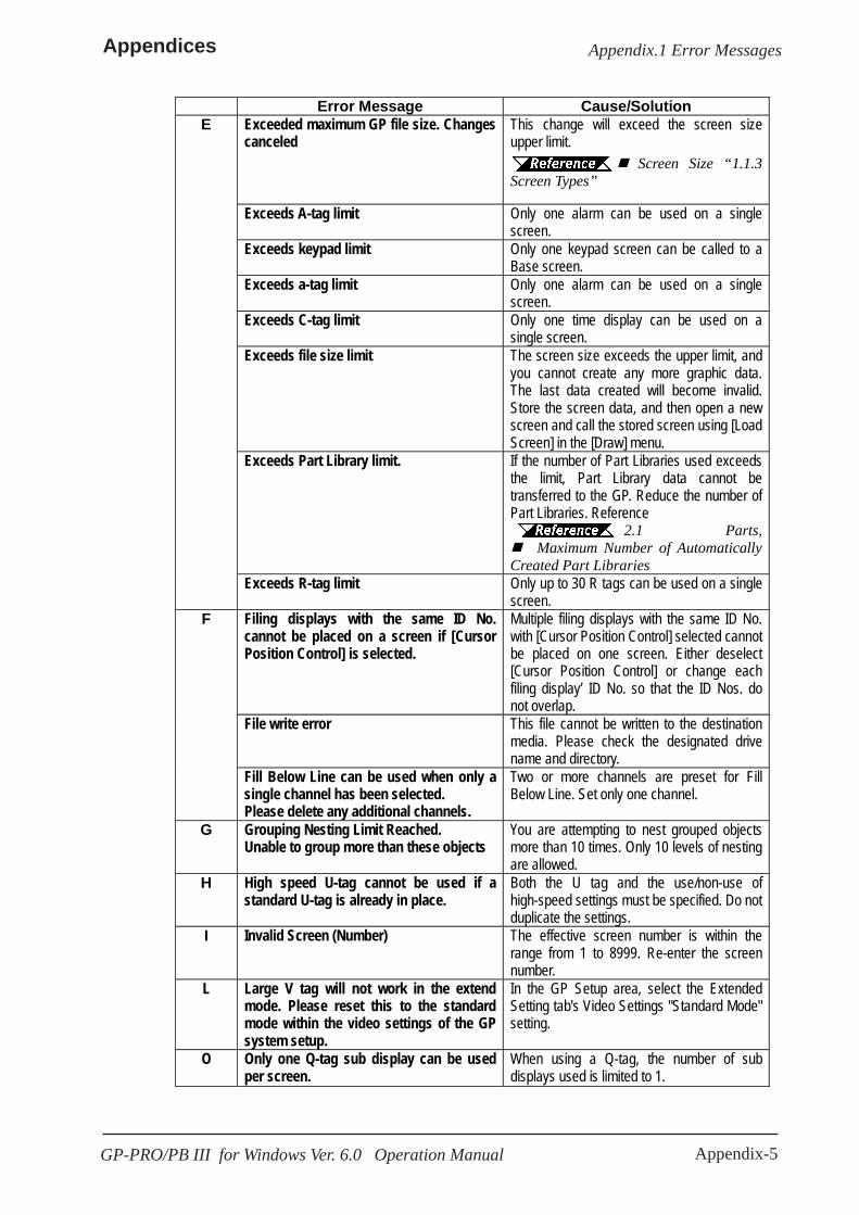
Appendix-5
Appendices
GP-PRO/PB III for Windows Ver. 6.0 Operation Manual
Appendix.1 Error Messages
Error Message Cause/Solution Exceeded maximum GP file size. Changes canceled
This change will exceed the screen size upper limit. Screen Size “1.1.3 Screen Types”
Exceeds A-tag limit Only one alarm can be used on a single screen.
Exceeds keypad limit Only one keypad screen can be called to a Base screen.
Exceeds a-tag limit Only one alarm can be used on a single screen.
Exceeds C-tag limit Only one time display can be used on a single screen.
Exceeds file size limit The screen size exceeds the upper limit, and you cannot create any more graphic data. The last data created will become invalid. Store the screen data, and then open a new screen and call the stored screen using [Load Screen] in the [Draw] menu.
Exceeds Part Library limit. If the number of Part Libraries used exceeds the limit, Part Library data cannot be transferred to the GP. Reduce the number of Part Libraries. Reference 2.1 Parts, Maximum Number of Automatically
Created Part Libraries
E
Exceeds R-tag limit Only up to 30 R tags can be used on a single screen.
Filing displays with the same ID No. cannot be placed on a screen if [Cursor Position Control] is selected.
Multiple filing displays with the same ID No. with [Cursor Position Control] selected cannot be placed on one screen. Either deselect [Cursor Position Control] or change each filing display’ ID No. so that the ID Nos. do not overlap.
File write error This file cannot be written to the destination media. Please check the designated drive name and directory.
F
Fill Below Line can be used when only a single channel has been selected. Please delete any additional channels.
Two or more channels are preset for Fill Below Line. Set only one channel.
G Grouping Nesting Limit Reached. Unable to group more than these objects
You are attempting to nest grouped objects more than 10 times. Only 10 levels of nesting are allowed.
H High speed U-tag cannot be used if a standard U-tag is already in place.
Both the U tag and the use/non-use of high-speed settings must be specified. Do not duplicate the settings.
I Invalid Screen (Number) The effective screen number is within the range from 1 to 8999. Re-enter the screen number.
L Large V tag will not work in the extend mode. Please reset this to the standard mode within the video settings of the GP system setup.
In the GP Setup area, select the Extended Setting tab's Video Settings "Standard Mode" setting.
O Only one Q-tag sub display can be used per screen.
When using a Q-tag, the number of sub displays used is limited to 1.

Appendix-6
Appendices
GP-PRO/PB III for Windows Ver. 6.0 Operation Manual
Appendix.1 Error Messages
Screen Editor Errors (from previous page)
Error Message Cause/Solution P Parts and tags are not valid objects. A library item containing Parts or tags cannot
be used in a Picture Display. Screen No. is out of range. Re-enter a different Screen No.
Screen No. used after conversion is out of the Screen No. range. Enter the correct number.
Small v tag will not work in the standard mode. Please reset this to the extend mode within the video settings of the GP system setup.
In the GP Setup area, select the Extended Setting tab's Video Settings "Extend Mode" setting.
S
The sum total of all the data saved by the GP’s data backup features now exceeds the backup memory unit’s limit. Please reduce this amount.
The backup size exceeds the SRAM capacity. Reduce the number of sampling data, or set this item’s backup setting to “None”.
The area available for data sampling has been exceeded. Please re-enter this item’s settings.
The storage address used exceeds 2031. Set the storage start address + the number of sampling data to less than or equal to 2031.
The amount entered for the data sampling feature is combined with the number of Trend graph channels created, and their combined total cannot exceed 20.
When 20 channels are preset, the Add button is clicked in the data sampling setting list display dialog box. Delete unnecessary settings so that the total of Trend Graph channel settings and the data sampling settings will be within 20.
The current GP type setting does not support video. Video tag will have no effect
Select the GP type for the VM Unit.
The font used for this text cannot be found. Only font type and color can be changed.
The designated font cannot be found in the PC's Font folder. Either select a different font, or install the desired font.
There are no screens created for this screen type.
The screen that you attempt to open cannot be created with the specified screen type. Open a new screen.
The designated screen does not exist. The screen that you attempted to open cannot be found in this project. Select a screen from different existing project.
This object has a non-black background and may not display properly on the GP. Also, be sure that your loaded screen’s center point is aligned with the object (loaded to) screen’s center point.
If this screen is used as the screen for the background color, be sure to align its center point correctly with the destination screen.
This rail number is already in use. Please enter another number.
All rail numbers used on a single base screen must be unique.
This screen cannot be edited. Delete the window screen.
T
This tag does not support portrait mode. Continue anyway?
The vertical type GP does not support the tag that you are attempting to use.
U Unrecognizable Bitmap File may be corrupted
The selected bit map file is either corrupted or unusable by this software.
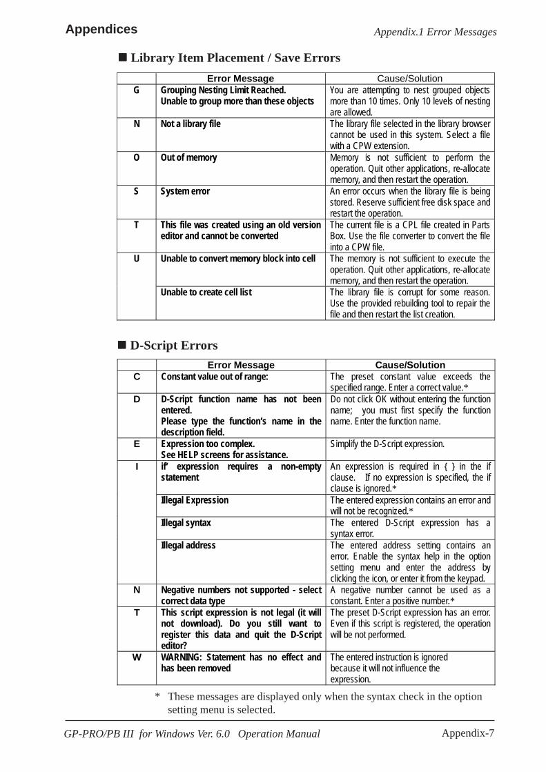
Appendix-7
Appendices
GP-PRO/PB III for Windows Ver. 6.0 Operation Manual
Appendix.1 Error Messages
Library Item Placement / Save Errors Error Message Cause/Solution
G Grouping Nesting Limit Reached. Unable to group more than these objects
You are attempting to nest grouped objects more than 10 times. Only 10 levels of nesting are allowed.
N Not a library file The library file selected in the library browser cannot be used in this system. Select a file with a CPW extension.
O Out of memory Memory is not sufficient to perform the operation. Quit other applications, re-allocate memory, and then restart the operation.
S System error An error occurs when the library file is being stored. Reserve sufficient free disk space and restart the operation.
T This file was created using an old version editor and cannot be converted
The current file is a CPL file created in Parts Box. Use the file converter to convert the file into a CPW file.
Unable to convert memory block into cell The memory is not sufficient to execute the operation. Quit other applications, re-allocate memory, and then restart the operation.
U
Unable to create cell list The library file is corrupt for some reason. Use the provided rebuilding tool to repair the file and then restart the list creation.
D-Script Errors Error Message Cause/Solution
C Constant value out of range: The preset constant value exceeds the specified range. Enter a correct value.*
D D-Script function name has not been entered. Please type the function’s name in the description field.
Do not click OK without entering the function name; you must first specify the function name. Enter the function name.
E Expression too complex. See HELP screens for assistance.
Simplify the D-Script expression.
if’ expression requires a non-empty statement
An expression is required in { } in the if clause. If no expression is specified, the if clause is ignored.*
Illegal Expression The entered expression contains an error and will not be recognized.*
Illegal syntax The entered D-Script expression has a syntax error.
I
Illegal address The entered address setting contains an error. Enable the syntax help in the option setting menu and enter the address by clicking the icon, or enter it from the keypad.
N Negative numbers not supported - select correct data type
A negative number cannot be used as a constant. Enter a positive number.*
T This script expression is not legal (it will not download). Do you still want to register this data and quit the D-Script editor?
The preset D-Script expression has an error. Even if this script is registered, the operation will be not performed.
W WARNING: Statement has no effect and has been removed
The entered instruction is ignored because it will not influence the expression.
* These messages are displayed only when the syntax check in the optionsetting menu is selected.
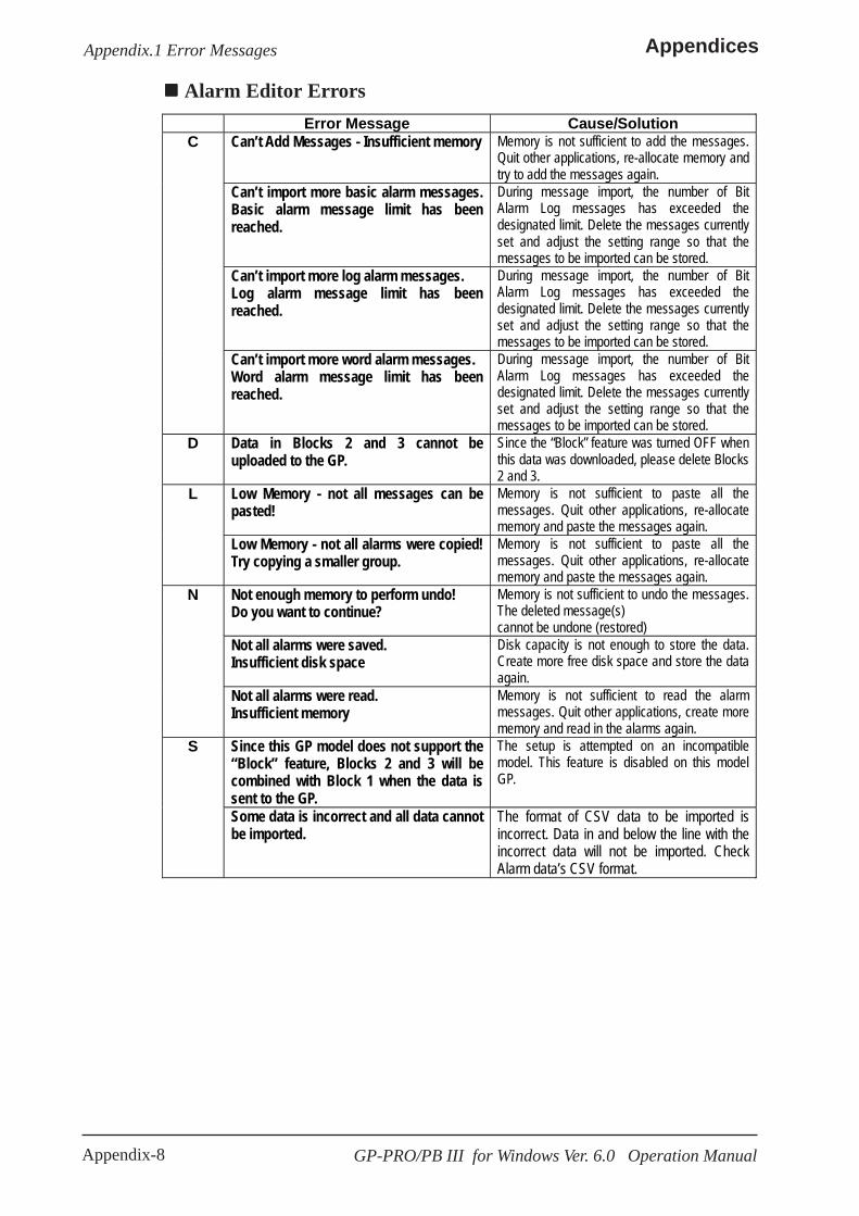
Appendix-8
Appendices
GP-PRO/PB III for Windows Ver. 6.0 Operation Manual
Appendix.1 Error Messages
Alarm Editor Errors Error Message Cause/Solution
Can’t Add Messages - Insufficient memory Memory is not sufficient to add the messages. Quit other applications, re-allocate memory and try to add the messages again.
Can’t import more basic alarm messages. Basic alarm message limit has been reached.
During message import, the number of Bit Alarm Log messages has exceeded the designated limit. Delete the messages currently set and adjust the setting range so that the messages to be imported can be stored.
Can’t import more log alarm messages. Log alarm message limit has been reached.
During message import, the number of Bit Alarm Log messages has exceeded the designated limit. Delete the messages currently set and adjust the setting range so that the messages to be imported can be stored.
C
Can’t import more word alarm messages. Word alarm message limit has been reached.
During message import, the number of Bit Alarm Log messages has exceeded the designated limit. Delete the messages currently set and adjust the setting range so that the messages to be imported can be stored.
D Data in Blocks 2 and 3 cannot be uploaded to the GP.
Since the “Block” feature was turned OFF when this data was downloaded, please delete Blocks 2 and 3.
Low Memory - not all messages can be pasted!
Memory is not sufficient to paste all the messages. Quit other applications, re-allocate memory and paste the messages again.
L
Low Memory - not all alarms were copied! Try copying a smaller group.
Memory is not sufficient to paste all the messages. Quit other applications, re-allocate memory and paste the messages again.
Not enough memory to perform undo! Do you want to continue?
Memory is not sufficient to undo the messages. The deleted message(s) cannot be undone (restored)
Not all alarms were saved. Insufficient disk space
Disk capacity is not enough to store the data. Create more free disk space and store the data again.
N
Not all alarms were read. Insufficient memory
Memory is not sufficient to read the alarm messages. Quit other applications, create more memory and read in the alarms again.
Since this GP model does not support the “Block” feature, Blocks 2 and 3 will be combined with Block 1 when the data is sent to the GP.
The setup is attempted on an incompatible model. This feature is disabled on this model GP.
S
Some data is incorrect and all data cannot be imported.
The format of CSV data to be imported is incorrect. Data in and below the line with the incorrect data will not be imported. Check Alarm data’s CSV format.
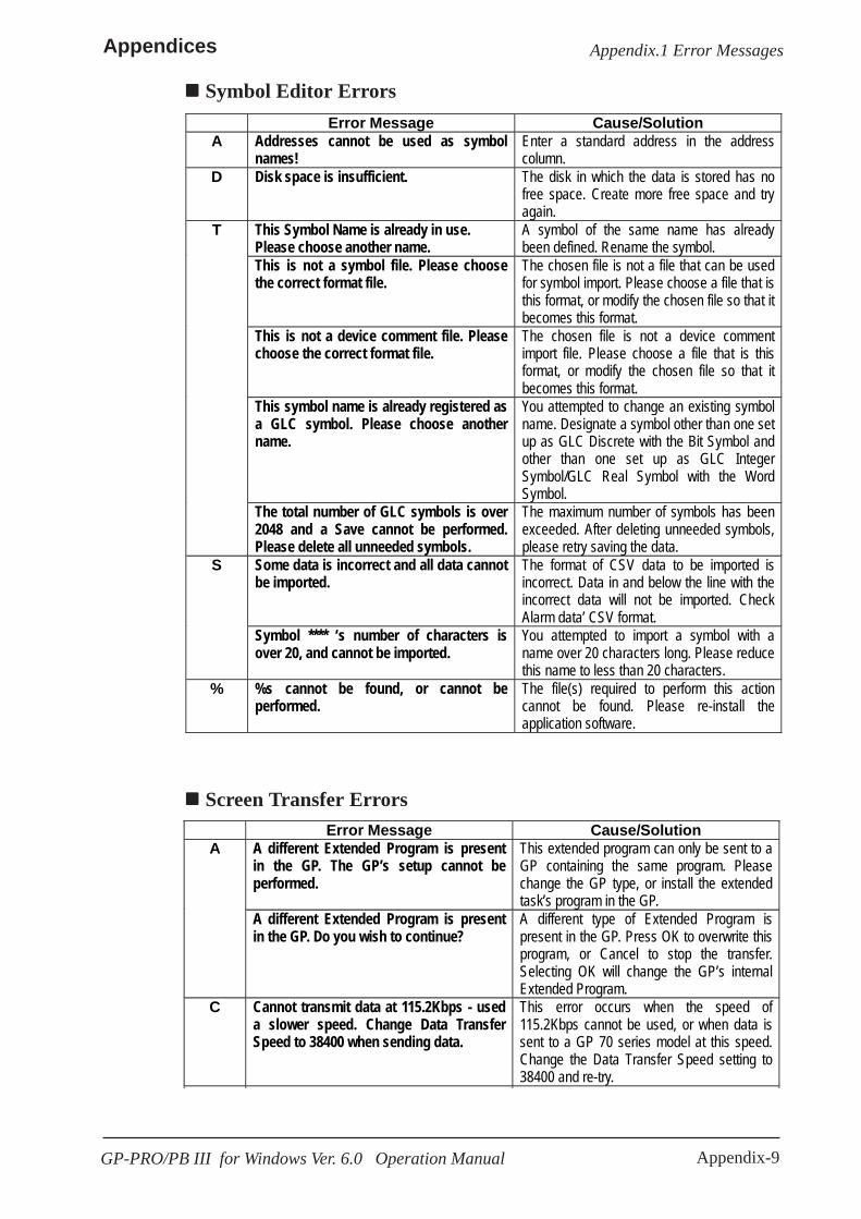
Appendix-9
Appendices
GP-PRO/PB III for Windows Ver. 6.0 Operation Manual
Appendix.1 Error Messages
Symbol Editor Errors Error Message Cause/Solution
A Addresses cannot be used as symbol names!
Enter a standard address in the address column.
D Disk space is insufficient. The disk in which the data is stored has no free space. Create more free space and try again.
This Symbol Name is already in use. Please choose another name.
A symbol of the same name has already been defined. Rename the symbol.
This is not a symbol file. Please choose the correct format file.
The chosen file is not a file that can be used for symbol import. Please choose a file that is this format, or modify the chosen file so that it becomes this format.
This is not a device comment file. Please choose the correct format file.
The chosen file is not a device comment import file. Please choose a file that is this format, or modify the chosen file so that it becomes this format.
This symbol name is already registered as a GLC symbol. Please choose another name.
You attempted to change an existing symbol name. Designate a symbol other than one set up as GLC Discrete with the Bit Symbol and other than one set up as GLC Integer Symbol/GLC Real Symbol with the Word Symbol.
T
The total number of GLC symbols is over 2048 and a Save cannot be performed. Please delete all unneeded symbols.
The maximum number of symbols has been exceeded. After deleting unneeded symbols, please retry saving the data.
Some data is incorrect and all data cannot be imported.
The format of CSV data to be imported is incorrect. Data in and below the line with the incorrect data will not be imported. Check Alarm data’ CSV format.
S
Symbol **** ‘s number of characters is over 20, and cannot be imported.
You attempted to import a symbol with a name over 20 characters long. Please reduce this name to less than 20 characters.
% %s cannot be found, or cannot be performed.
The file(s) required to perform this action cannot be found. Please re-install the application software.
Screen Transfer Errors Error Message Cause/Solution
A different Extended Program is present in the GP. The GP’s setup cannot be performed.
This extended program can only be sent to a GP containing the same program. Please change the GP type, or install the extended task’s program in the GP.
A
A different Extended Program is present in the GP. Do you wish to continue?
A different type of Extended Program is present in the GP. Press OK to overwrite this program, or Cancel to stop the transfer. Selecting OK will change the GP’s internal Extended Program.
C Cannot transmit data at 115.2Kbps - used a slower speed. Change Data Transfer Speed to 38400 when sending data.
This error occurs when the speed of 115.2Kbps cannot be used, or when data is sent to a GP 70 series model at this speed. Change the Data Transfer Speed setting to 38400 and re-try.
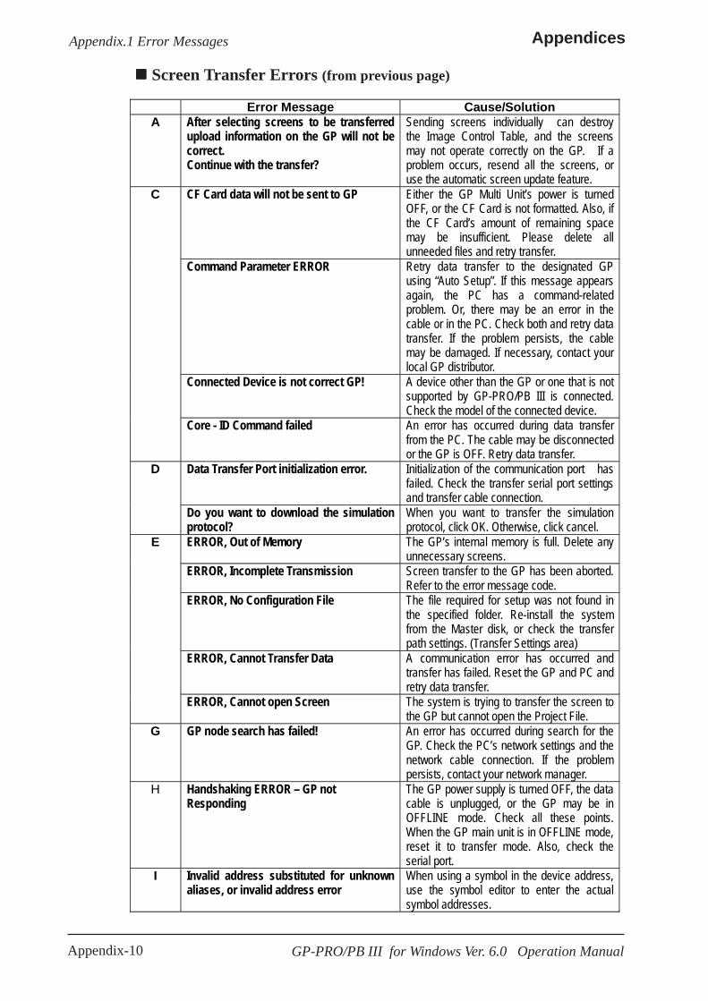
Appendix-10
Appendices
GP-PRO/PB III for Windows Ver. 6.0 Operation Manual
Appendix.1 Error Messages
Screen Transfer Errors (from previous page)
Error Message Cause/Solution A After selecting screens to be transferred
upload information on the GP will not be correct. Continue with the transfer?
Sending screens individually can destroy the Image Control Table, and the screens may not operate correctly on the GP. If a problem occurs, resend all the screens, or use the automatic screen update feature.
CF Card data will not be sent to GP Either the GP Multi Unit’s power is turned OFF, or the CF Card is not formatted. Also, if the CF Card’s amount of remaining space may be insufficient. Please delete all unneeded files and retry transfer.
Command Parameter ERROR Retry data transfer to the designated GP using “Auto Setup”. If this message appears again, the PC has a command-related problem. Or, there may be an error in the cable or in the PC. Check both and retry data transfer. If the problem persists, the cable may be damaged. If necessary, contact your local GP distributor.
Connected Device is not correct GP! A device other than the GP or one that is not supported by GP-PRO/PB III is connected. Check the model of the connected device.
C
Core - ID Command failed An error has occurred during data transfer from the PC. The cable may be disconnected or the GP is OFF. Retry data transfer.
Data Transfer Port initialization error. Initialization of the communication port has failed. Check the transfer serial port settings and transfer cable connection.
D
Do you want to download the simulation protocol?
When you want to transfer the simulation protocol, click OK. Otherwise, click cancel.
ERROR, Out of Memory The GP’s internal memory is full. Delete any unnecessary screens.
ERROR, Incomplete Transmission Screen transfer to the GP has been aborted. Refer to the error message code.
ERROR, No Configuration File The file required for setup was not found in the specified folder. Re-install the system from the Master disk, or check the transfer path settings. (Transfer Settings area)
ERROR, Cannot Transfer Data A communication error has occurred and transfer has failed. Reset the GP and PC and retry data transfer.
E
ERROR, Cannot open Screen The system is trying to transfer the screen to the GP but cannot open the Project File.
G GP node search has failed! An error has occurred during search for the GP. Check the PC’s network settings and the network cable connection. If the problem persists, contact your network manager.
H Handshaking ERROR – GP not Responding
The GP power supply is turned OFF, the data cable is unplugged, or the GP may be in OFFLINE mode. Check all these points. When the GP main unit is in OFFLINE mode, reset it to transfer mode. Also, check the serial port.
I Invalid address substituted for unknown aliases, or invalid address error
When using a symbol in the device address, use the symbol editor to enter the actual symbol addresses.
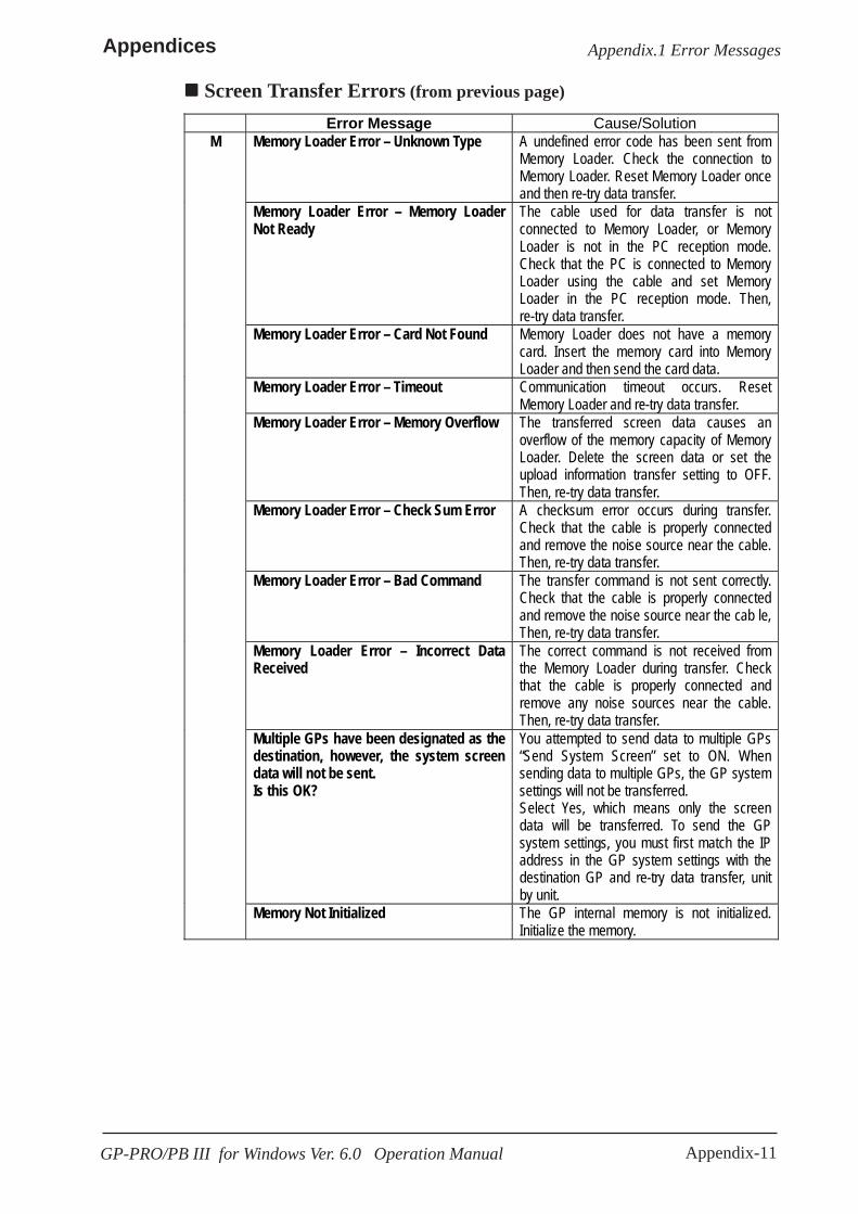
Appendix-11
Appendices
GP-PRO/PB III for Windows Ver. 6.0 Operation Manual
Appendix.1 Error Messages
Screen Transfer Errors (from previous page)
Error Message Cause/Solution Memory Loader Error – Unknown Type A undefined error code has been sent from
Memory Loader. Check the connection to Memory Loader. Reset Memory Loader once and then re-try data transfer.
Memory Loader Error – Memory Loader Not Ready
The cable used for data transfer is not connected to Memory Loader, or Memory Loader is not in the PC reception mode. Check that the PC is connected to Memory Loader using the cable and set Memory Loader in the PC reception mode. Then, re-try data transfer.
Memory Loader Error – Card Not Found Memory Loader does not have a memory card. Insert the memory card into Memory Loader and then send the card data.
Memory Loader Error – Timeout Communication timeout occurs. Reset Memory Loader and re-try data transfer.
Memory Loader Error – Memory Overflow The transferred screen data causes an overflow of the memory capacity of Memory Loader. Delete the screen data or set the upload information transfer setting to OFF. Then, re-try data transfer.
Memory Loader Error – Check Sum Error A checksum error occurs during transfer. Check that the cable is properly connected and remove the noise source near the cable. Then, re-try data transfer.
Memory Loader Error – Bad Command The transfer command is not sent correctly. Check that the cable is properly connected and remove the noise source near the cab le, Then, re-try data transfer.
Memory Loader Error – Incorrect Data Received
The correct command is not received from the Memory Loader during transfer. Check that the cable is properly connected and remove any noise sources near the cable. Then, re-try data transfer.
Multiple GPs have been designated as the destination, however, the system screen data will not be sent. Is this OK?
You attempted to send data to multiple GPs “Send System Screen” set to ON. When sending data to multiple GPs, the GP system settings will not be transferred. Select Yes, which means only the screen data will be transferred. To send the GP system settings, you must first match the IP address in the GP system settings with the destination GP and re-try data transfer, unit by unit.
M
Memory Not Initialized The GP internal memory is not initialized. Initialize the memory.
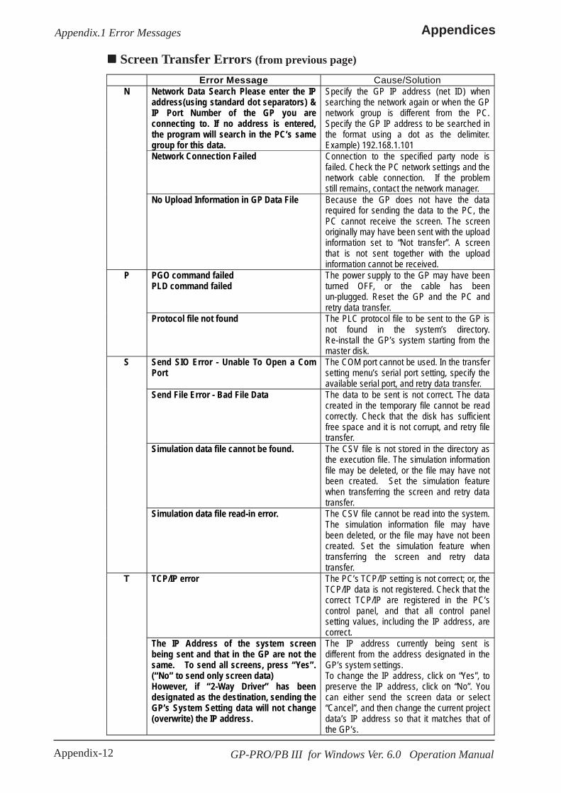
Appendix-12 GP-PRO/PB III for Windows Ver. 6.0 Operation Manual
Appendices
Screen Transfer Errors (from previous page)
Error Message Cause/Solution Network Data Search Please enter the IP address(using standard dot separators) & IP Port Number of the GP you are connecting to. If no address is entered, the program will search in the PC’s same group for this data.
Specify the GP IP address (net ID) when searching the network again or when the GP network group is different from the PC. Specify the GP IP address to be searched in the format using a dot as the delimiter. Example) 192.168.1.101
Network Connection Failed Connection to the specified party node is failed. Check the PC network settings and the network cable connection. If the problem still remains, contact the network manager.
N
No Upload Information in GP Data File Because the GP does not have the data required for sending the data to the PC, the PC cannot receive the screen. The screen originally may have been sent with the upload information set to “Not transfer”. A screen that is not sent together with the upload information cannot be received.
PGO command failed PLD command failed
The power supply to the GP may have been turned OFF, or the cable has been un-plugged. Reset the GP and the PC and retry data transfer.
P
Protocol file not found The PLC protocol file to be sent to the GP is not found in the system’s directory. Re-install the GP’s system starting from the master disk.
Send SIO Error - Unable To Open a Com Port
The COM port cannot be used. In the transfer setting menu’s serial port setting, specify the available serial port, and retry data transfer.
Send File Error - Bad File Data The data to be sent is not correct. The data created in the temporary file cannot be read correctly. Check that the disk has sufficient free space and it is not corrupt, and retry file transfer.
Simulation data file cannot be found. The CSV file is not stored in the directory as the execution file. The simulation information file may be deleted, or the file may have not been created. Set the simulation feature when transferring the screen and retry data transfer.
S
Simulation data file read-in error. The CSV file cannot be read into the system. The simulation information file may have been deleted, or the file may have not been created. Set the simulation feature when transferring the screen and retry data transfer.
TCP/IP error The PC’s TCP/IP setting is not correct; or, the TCP/IP data is not registered. Check that the correct TCP/IP are registered in the PC’s control panel, and that all control panel setting values, including the IP address, are correct.
T
The IP Address of the system screen being sent and that in the GP are not the same. To send all screens, press “Yes”. (“No” to send only screen data) However, if “2-Way Driver” has been designated as the destination, sending the GP’s System Setting data will not change (overwrite) the IP address.
The IP address currently being sent is different from the address designated in the GP’s system settings. To change the IP address, click on “Yes”, to preserve the IP address, click on “No”. You can either send the screen data or select “Cancel”, and then change the current project data’s IP address so that it matches that of the GP’s.
Appendix.1 Error Messages

Appendix-13GP-PRO/PB III for Windows Ver. 6.0 Operation Manual
Appendices
Error Message Cause/Solution The Extended Program cannot be found. The Extended Program required for setting
up the GP cannot be found. Please check the CFG file’s directory. Also, you may need to change the GP’s type.
The Extended Program cannot be found in the GP. The GP’s Setup cannot be performed.
Unable to locate the program’s destination GP for setup. Check the GP type settings and the GP type selected. Change the GP type, if needed.
The currently selected Device/PLC type does not support the Simulation feature.
The currently selected Device/PLC type does not support the Simulation feature. This feature cannot be used with the destination Device/PLC. Deselect this feature and re-send the data.
This GP does not support Extended Programs. The GP’s setup cannot be performed.
The destination GP does not support Extended Features. Either change the GP Type, or send data that is designed for the designated GP type.
T
Timeout Error Communication timeout has occurred. Reset the GP and re-try data transfer.
Winsock return Error An error has been returned from Winsock. The error is in the network line. Check the PC’s network settings and the network cable connection. If the problem still remains, contact your network manager.
W
Write Error An error has occurred while reading the data to GP internal memory. Re-try data transfer. If the error occurs again, use the GP’s self-diagnosis feature and identify the problem. If necessary, contact your local GP distributor.
File Converter Errors
Screen Transfer Errors (from previous page)
Error Message Cause/Solution Cannot read system information An error is recognized in the SCD file. Check
that the SCD file is created by Parts Box Version 2.0.
Conversion aborted - database space insufficient!
The disk space is not sufficient to perform data conversion. Reserve sufficient free space and retry file conversion.
Conversion destination (convert to) folder is not designated.
The conversion destination folder where the converted file will be stored is not specified. Specify it.
C
Conversion parameters are not set The conversion parameters for the information to be converted (conversion source, conversion destination file information) are not set. Set the required information.
Insufficient memory The memory required for file conversion is insufficient. Quit all other applications, then retry file conversion.
I
Invalid PLC table The PLC table file is not a GP file, is corrupt for some reason, or has been deleted. Re-install the Device/PLC type master data file from the master disk.
Appendix.1 Error Messages

Appendix-14 GP-PRO/PB III for Windows Ver. 6.0 Operation Manual
Appendices
Project Compression and Execution Errors Error Message Cause/Solution
Disk Error - File Error During Read The file cannot be opened. The most probable cause is corruption of the file or disk failure. Solve the problem and try again to read the file.
D
Disk Error - File Error During Write The disk is write-protected. Take off the write protection. This error also occurs when the disk is defective.
Unable to open file ‘***’. Would you like to try to find it elsewhere?
A portion of the file cannot be found. To recover divided files and recreate the original project file, all the divided files are required.
U
Unable to open file ‘***’ for reading, aborting...
The file cannot be opened. The file is corrupt or the disk has a problem. After correcting the problem, re-try opening the file.
* The file named is inserted here ***.
Rebuild Tool Errors Error Message Cause/Solution
F File version does not match The specified file contains settings for a version which is not supported by this rebuilding tool. Re-specify a project file (PRW file) compatible with GP-PRO/PB III for Windows.
R Rebuilding the File has Failed Recovery of the file has failed. This file is damaged and cannot be rebuilt.
S PRW header is destroyed The file header information is corrupt. This file cannot be rebuilt and cannot be used.
Error Message Cause/Solution Old CPL files from DOS version PROPB must be selected directly from the library browser’s file type menu
The specified CPL file has been created by the GP-PRO/PB III DOS version. Select the file from the file selection menu of the screen editor’s library browser.
O
Old PLC table and some functions may not work properly. Please use latest PLC table
An old version of the PLC table file is installed. Re-install the new version of the Device/PLC type file from the master disk.
PLC file error The PLC table file is not the type used for GP files, is corrupt for some reason, and has been deleted. Re-install the Device/PLC type master file from the master disk.
P
PLC file not found The specified PLC table file could not be found in the directory, or it is not the type used for a GP file. Re-install the Device/PLC type master file from the master disk.
File Converter Errors (from previous page)
Appendix.1 Error Messages
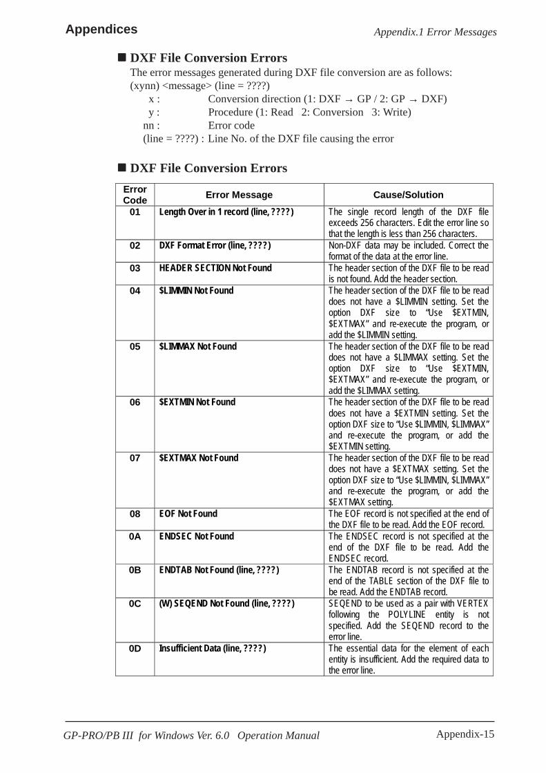
Appendix-15GP-PRO/PB III for Windows Ver. 6.0 Operation Manual
Appendices
DXF File Conversion ErrorsThe error messages generated during DXF file conversion are as follows:(xynn) <message> (line = ????)
x : Conversion direction (1: DXF → GP / 2: GP → DXF) y : Procedure (1: Read 2: Conversion 3: Write)nn : Error code(line = ????) : Line No. of the DXF file causing the error
DXF File Conversion ErrorsErrorCode Error Message Cause/Solution
01 Length Over in 1 record (line, ????) The single record length of the DXF fileexceeds 256 characters. Edit the error line sothat the length is less than 256 characters.
02 DXF Format Error (line, ????) Non-DXF data may be included. Correct theformat of the data at the error line.
03 HEADER SECTION Not Found The header section of the DXF file to be readis not found. Add the header section.
04 $LIMMIN Not Found The header section of the DXF file to be readdoes not have a $LIMMIN setting. Set theoption DXF size to “Use $EXTMIN,$EXTMAX” and re-execute the program, oradd the $LIMMIN setting.
05 $LIMMAX Not Found The header section of the DXF file to be readdoes not have a $LIMMAX setting. Set theoption DXF size to “Use $EXTMIN,$EXTMAX” and re-execute the program, oradd the $LIMMAX setting.
06 $EXTMIN Not Found The header section of the DXF file to be readdoes not have a $EXTMIN setting. Set theoption DXF size to “Use $LIMMIN, $LIMMAX”and re-execute the program, or add the$EXTMIN setting.
07 $EXTMAX Not Found The header section of the DXF file to be readdoes not have a $EXTMAX setting. Set theoption DXF size to “Use $LIMMIN, $LIMMAX”and re-execute the program, or add the$EXTMAX setting.
08 EOF Not Found The EOF record is not specified at the end ofthe DXF file to be read. Add the EOF record.
0A ENDSEC Not Found The ENDSEC record is not specified at theend of the DXF file to be read. Add theENDSEC record.
0B ENDTAB Not Found (line, ????) The ENDTAB record is not specified at theend of the TABLE section of the DXF file tobe read. Add the ENDTAB record.
0C (W) SEQEND Not Found (line, ????) SEQEND to be used as a pair with VERTEXfollowing the POLYLINE entity is notspecified. Add the SEQEND record to theerror line.
0D Insufficient Data (line, ????) The essential data for the element of eachentity is insufficient. Add the required data tothe error line.
Appendix.1 Error Messages
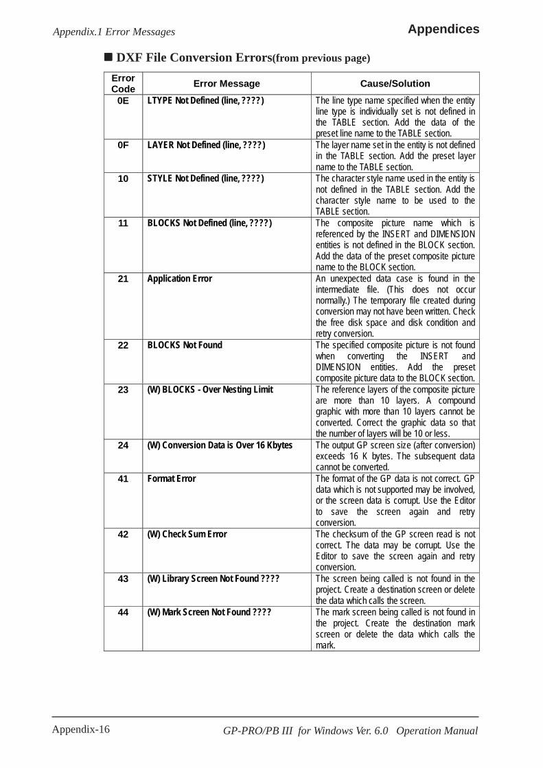
Appendix-16 GP-PRO/PB III for Windows Ver. 6.0 Operation Manual
Appendices
DXF File Conversion Errors(from previous page)
ErrorCode Error Message Cause/Solution
0E LTYPE Not Defined (line, ????) The line type name specified when the entityline type is individually set is not defined inthe TABLE section. Add the data of thepreset line name to the TABLE section.
0F LAYER Not Defined (line, ????) The layer name set in the entity is not definedin the TABLE section. Add the preset layername to the TABLE section.
10 STYLE Not Defined (line, ????) The character style name used in the entity isnot defined in the TABLE section. Add thecharacter style name to be used to theTABLE section.
11 BLOCKS Not Defined (line, ????) The composite picture name which isreferenced by the INSERT and DIMENSIONentities is not defined in the BLOCK section.Add the data of the preset composite picturename to the BLOCK section.
21 Application Error An unexpected data case is found in theintermediate file. (This does not occurnormally.) The temporary file created duringconversion may not have been written. Checkthe free disk space and disk condition andretry conversion.
22 BLOCKS Not Found The specified composite picture is not foundwhen converting the INSERT andDIMENSION entities. Add the presetcomposite picture data to the BLOCK section.
23 (W) BLOCKS - Over Nesting Limit The reference layers of the composite pictureare more than 10 layers. A compoundgraphic with more than 10 layers cannot beconverted. Correct the graphic data so thatthe number of layers will be 10 or less.
24 (W) Conversion Data is Over 16 Kbytes The output GP screen size (after conversion)exceeds 16 K bytes. The subsequent datacannot be converted.
41 Format Error The format of the GP data is not correct. GPdata which is not supported may be involved,or the screen data is corrupt. Use the Editorto save the screen again and retryconversion.
42 (W) Check Sum Error The checksum of the GP screen read is notcorrect. The data may be corrupt. Use theEditor to save the screen again and retryconversion.
43 (W) Library Screen Not Found ???? The screen being called is not found in theproject. Create a destination screen or deletethe data which calls the screen.
44 (W) Mark Screen Not Found ???? The mark screen being called is not found inthe project. Create the destination markscreen or delete the data which calls themark.
Appendix.1 Error Messages

Appendix-17GP-PRO/PB III for Windows Ver. 6.0 Operation Manual
Appendices
ErrorCode Error Message Cause/Solution
45 (W) Library Screen Type Error (0x????) The type of the screen used in the screen callmenu is not a base, mark, trend graph,keypad, or an image screen. GP data whichis not supported may be involved, or thescreen data may be corrupt. Use the Editor tosave the screen again and retry conversion.
46 (W) Screens – Over Nesting Limit The screen calling layers are greater than 10.Screens with more than 10 layers cannot beconverted. Correct the data so that thenumber of layers will be 10 screens or less.
81 Disk Full When writing the temporary file or output file,the disk has become full. Increase theamount of free disk space for the temporaryfile and output file.
82 Insufficient Memory The process is interrupted because ofinsufficient memory area during operation.Close all other applications and retry theoperation.
FF User Abort The user has interrupted the operation duringconversion.
DXF File Conversion Errors(from previous page)
File Management Errors Error Message Cause/Solution
C Cannot Write File ???? The data cannot be written to the specified output file name. Check the amount of free disk, or if the disk is write-protected.
Input File Name Format Error The specified input file name is different from the file name created by the editor. Specify the correct file name.
I
Input File Not Found The specified input file is not found. Check the file name and specify the existing file.
O Output File Name Format Error The specified output file name cannot be recognized by the editor. Specify the correct file name.
W Work Directory Not Found ???? The folder in which the temporary file is created is not found. Specify the existing folder using the environment variable TEMP.
Appendix.1 Error Messages

Appendix-18 GP-PRO/PB III for Windows Ver. 6.0 Operation Manual
Appendices
Simulation Errors
Appendix.1 Error Messages
Error Message Cause/Solution A Abnormal CF card in GP Slot. Check that the CF Card is the correct type for
the GP. If it is, retry. Cannot read data in project file. The screen data cannot be read from the
project file. Quit other functions and re-execute.
Cannot write simulation information data. Unable to start simulation.
The system cannot write the data to the simulation information file. Check that the simulation file (TAGDATA.CSV) is not used in other applications and that the directory in which EXE exists is not write-protected.
C
CF card in GP Slot has file [CAPTURE¥¥CP65535.JPG] already. GP cannot generate more filename and snapshot file. ¥n¥n Please make rearrange files in CF card.
Delete the CF Card's "CAPTURE/CP65535.JPG" file, reorganize the CF Card's files, and retry.
GP cannot find CF card. Check that the CF Card is securely inserted into the CF Card Slot.
G
GP cannot write snapshot to CF card. Check that the amount of free space on the CF Card is sufficient, and if it is, retry.
N Not enough memory. Please close other applications.
Retry this action after closing other active applications.
P PLC Data File cannot be found. The PLC table file does not exist in the specified directory. The PLC table file is deleted or it is not for the GP. Select the Device/PLC type file from the master disk and reinstall the file.
Simulation aborted by link down. ¥n Please restart GP hardware.
A problem such as a cable disconnection, etc. has caused the PC and the GP to not be able to communicate, which has led to the halting of the Simulation. To restart the Simulation feature, first manually reset the GP (including checking the power cord), and confirming that the Data Transfer cable is securely connected to both the PC and the GP. Next, restart the Simulation.
Simulation start failed. The GP does not respond to the simulation start command. The GP may be in another mode, or data transfer may have failed. Check the communication port settings, cable connections, GP unit power supply, and then retry the simulation data transfer.
Simulation data file cannot be found. The simulation information file (TAGDATA.CSV) does not exist in the specified directory. Check (turn on) the Transfer menu [Settings] area’s [Simulation] selection, then retry the Simulation.
Simulation link goes down. Do you want to abort simulation?
If you wish to continue the Simulation, check that the Data Transfer cable is securely connected, and click [No]. Normally, after a brief pause the Simulation will be restored. However, timing and other problems can prevent restoration, and will cause this message to reappear. In that case, click on [No] and quit the simulation.
S
Snapshot incomplete. Check that the GP's Data Transfer cable is securely connected and retry.
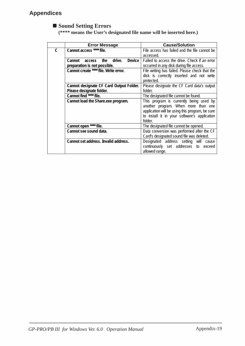
Appendix-19GP-PRO/PB III for Windows Ver. 6.0 Operation Manual
Appendices
Error Message Cause/Solution Cannot access **** file. File access has failed and the file cannot be
accessed. Cannot access the drive. Device preparation is not possible.
Failed to access the drive. Check if an error occurred in any disk during file access.
Cannot create **** file. Write error. File writing has failed. Please check that the disk is correctly inserted and not write protected.
Cannot designate CF Card Output Folder. Please designate folder.
Please designate the CF Card data’s output folder.
Cannot find **** file. The designated file cannot be found. Cannot load the Share.exe program. This program is currently being used by
another program. When more than one application will be using this program, be sure to install it in your software’s application folder.
Cannot open **** file. The designated file cannot be opened. Cannot see sound data. Data conversion was performed after the CF
Card’s designated sound file was deleted.
C
Cannot set address. Invalid address. Designated address setting will cause continuously set addresses to exceed allowed range.
Sound Setting Errors(**** means the User’s designated file name will be inserted here.)
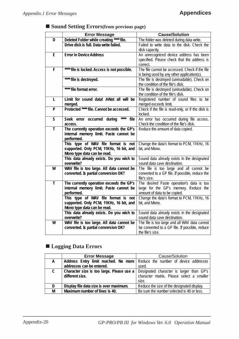
Appendix-20 GP-PRO/PB III for Windows Ver. 6.0 Operation Manual
AppendicesAppendix.1 Error Messages
Error Message Cause/Solution Deleted Folder while creating **** file. The folder was deleted during data write. D Drive disk is full. Data write failed. Failed to write data to the disk. Check the
disk capacity. E Error in Device Address An unrecognized device address has been
specified. Please check that the address is correct.
**** file is locked. Access is not possible. The file cannot be accessed. Check if the file is being used by any other application(s).
**** file is destroyed. The file is destroyed (unreadable). Check on the condition of the file’s disk.
F
**** file format error. The file is destroyed (unreadable). Check on the condition of the file’s disk.
L Limit for sound data! /nNot all will be merged.
Registered number of sound files to be merged exceeds limit.
P Protected **** file. Cannot be accessed. Check if the file is read-only, or if the disk is locked.
S Seek error occurred during **** file access.
An error has occurred during file access. Check the condition of the file’s disk.
The currently operation exceeds the GP’s internal memory limit. Paste cannot be performed.
Reduce the amount of data copied.
This type of WAV file format is not supported. Only PCM, 11KHz, 16 bit, and Mono type data can be read.
Change the data’s format to PCM, 11KHz, 16 bit, and Mono.
T
This data already exists. Do you wish to overwrite?
Sound data already exists in the designated sound data save destination.
W WAV file is too large. All data cannot be converted. Is partial conversion OK?
The file is too large and all cannot be converted to a GP file. If possible, reduce the file’s size.
The currently operation exceeds the GP’s internal memory limit. Paste cannot be performed.
The desired Paste operation’s data is too large for the GP’s memory. Reduce the amount of data to be copied.
This type of WAV file format is not supported. Only PCM, 11KHz, 16 bit, and Mono type data can be read.
Change the data’s format to PCM, 11KHz, 16 bit, and Mono.
T
This data already exists. Do you wish to overwrite?
Sound data already exists in the designated sound data save destination.
W WAV file is too large. All data cannot be converted. Is partial conversion OK?
The file is too large and all WAV data cannot be converted to a GP file. If possible, reduce the file’s size.
Sound Setting Errors(from previous page)
Logging Data Errors
Error Message Cause/Solution A Address Entry limit reached. No more
addresses can be entered. Reduce the number of device addresses used.
C Character size is too large. Please use a different size.
Designated character is larger than GP’s character matrix. Please select a smaller size.
D Display file data size is over maximum. Reduce the size of the designated display. M Maximum number of lines is 40. Be sure the number selected is 40 or less.

Appendix-21GP-PRO/PB III for Windows Ver. 6.0 Operation Manual
Appendices
Error Message Cause/Solution C Copy has failed. Please check the disk for any problems.
CF Card Tool Errors
Error Message Cause/Solution Data could not be created. An error occurred while 2-Way Driver data
was being created. Check the volume available of the disk being used. Also, check if the project file exists or not.
D
Data could not be saved. An error occurred while 2-Way Driver data was being saved. Check both disk memory and if the project file exists or not.
2-Way Driver Setting Errors
Filing Data ErrorsError Message Cause/Solution
C Cannot import CSV file. Data is out ofrange or format is incorrect.
The number of blocks or data amounts isinappropriate in the CSV file to be imported.Enter the correct value(s).
D Data is larger than designated data range.Please check the data settings.
Data from outside the Filing Data’s range ispresent. Check the designated data rangesettings and change them if necessary.
E Exceeds folder addition limit. Up to 64 folders can be stored in the internalmemory and up to 8999 folders can be storedin the CF card. Any folder cannot be addedbecause the number of folders will exceedthe limit.
F File cannot be accessed and data cannotbe saved. Please check the CF Card’soutput folder.
Check if the CF Card is write-protected.Either remove the write protection or changethe destination folder.
I Internal memory is not sufficient to savedata. Please reduce the block or datasettings.
The current settings will overflow the GP’smemory. Please reduce either the block ordata settings.
P Please enter a Block name. Nothing has been entered for the FilingData’s Block data. Please enter a name.
T The currently selected data range exceedsthe maximum amount allowed. Pastecannot be performed.
Please reduce either the amount of datacopied or the number of blocks copied.
W When using 32 bit data settings themaximum number of data items is 20. OKto delete items over 20?
When using 16 bit data, up to 40 items canbe used; with 32 bits, maximum is 20. Besure the data type fits your data needs.
Logging Data Errors(from previous page)Error Message Cause/Solution
Paste failed. The current paste settings (range, etc.) arenot the same as the paste destination. Or, thepaste action may delete a column or effectanother data item’s settings.
P
Printer file data size is over. Reduce the size of the area/amount of datato be printed.
Time settings cannot exceed 24 hours.Please adjust the settings.
Change the settings so that the time value is24 hours or less.
T
The no. of times x no. of blocks should beless than or equal to 2048.
Be sure the number of times and number ofblocks produces a result that is 2048 or less.
Appendix.1 Error Messages

Appendix-22 GP-PRO/PB III for Windows Ver. 6.0 Operation Manual
AppendicesAppendix.2 Troubleshooting
A.2 TroubleshootingThis section describes how to solve problems generated when using GP-PRO/PB III.Before you begin troubleshooting, please check the following items again. Ifyou answer “Yes” to all the questions, start troubleshooting. If you answer“No” to any one of the questions, set the required item and then starttroubleshooting.If the error still occurs after troubleshooting, fill the details on the error inthe provided trouble report sheet and contact DIGITAL.
Item Check Is your personal computer’s OS Windows 95/ 98/ Me/ NT/ 2000
Is the memory capacity greater than 32 Mbytes? Is your PC hard disk’s amount of free space sufficient?
Error Cause/Solution Are all the environment settings correct? CD Jacket Is your personal computer hard disk’s free space amount sufficient? Double-click on the Windows icon. Double-click on the drive in which GP-PRO/PB III has been installed. Use the [File] menu’s [Property] feature to check the amount of free disk space. If the free disk space is insufficient, empty the trash box or delete unnecessary files from the hard disk. Is the PC’s RAM memory capacity sufficient? Memory of 16 M byte or more is required. Click the Windows [Start] button first, and then click on the [Settings], [Control Panel], and [System] selections. Click the virtual memory button in the system property dialog box and check that “Auto Setting (recommended)” is selected. If “Manual Setting” is selected, change the setting to “Auto Setting (recommended)”. Restart the PC and then restart GP-PRO/PB III.
GP-PRO/PB III will not start up
Some applications do not work well with GP-PRO/PB III and such an application may interfere with the startup of GP-PRO/PB III. Quit all running applications and delete them from the Startup menu ([Startup] in the Windows [Program] menu. Restart the PC and then restart GP-PRO/PB III.
A.2.1 Troubleshooting List

Appendix-23GP-PRO/PB III for Windows Ver. 6.0 Operation Manual
Appendices
Error Cause/Solution Is the Editor’s screen open? With GP-PRO/PB III, you must select the project file and open a drawing screen before you can draw any objects. Create a new a screen or open an existing one. Does the disk have enough free space? Prepare a disk which has enough free space.
Cannot draw graphic data
Is the symbol editor started? The screen editor and the symbol editor cannot be started at the same time. Check that the symbol editor window has been closed. Is the file write-protected? Check whether the floppy disk is write-protected using the [Property] feature.
Cannot save the screen file’s data Does the disk you are saving to have enough free space?
Prepare a disk which has enough free space. Is the proper cable being used? Be sure to use the DIGITAL transfer cable (option). Is the GP in the “Screen Data Transfer Mode” or “Run Mode”? If not, communications between the PC and the GP will not be possible. GP User Manual When receiving data from the GP, does your PC’s hard disk have enough space? Prepare the disk so that it has enough free space. Is the communication port setting correct? Check that the transfer cable’s serial port matches the port set in [Transfer].
Cannot communicate between the PC and the GP
Does another application use the same communication port? Check whether there is competition between the GP and a modem, or other applications which require the communication port.
If: the Buzzer won't stop. The GP wont display data. Data transfer fails.
The Data Transfer cable may be loose or connected to the wrong COM port. Also, the System Data area may be incorrectly accessed, or the GP may be incorrectly set up. For details, see the next page's Appendix 2.2.
The printer does not run/ hard copy is not printed correctly
Is the OS’s (Windows) printer setting correct? Check the printer setting using the Control Panel’s printer property.
The desired Device/PLC type and GP type are not listed when creating a new project
Did you select the required Device/PLC and GP types when installing GP-PRO/PB III? (Custom Installation) When customizing the system installation, you can select the PLC and the GP types. You cannot install a Device/PLC type or a GP type if it has not been selected previously. Re-install the system with the desired PLC and GP types.
Simulation cannot be performed
Possible causes are that LS area data is being backed up to the GP, via the [GP System Settings], or that an LS area Special Relay is being used via D-Script or by a W-tag start up bit. If any of these are true, the simulation cannot be performed. Deselect the [Option] menu - [Settings] - [LS Device Simulation].
The GP2000 series cannot be booted. Nothing is displayed on the screen and a buzzer intermittently sounds
The GP was not successfully set up. For details, refer to “Buzzer will not Stop/No Display on the GP/Transfer Disabled”.
Appendix.2 Troubleshooting
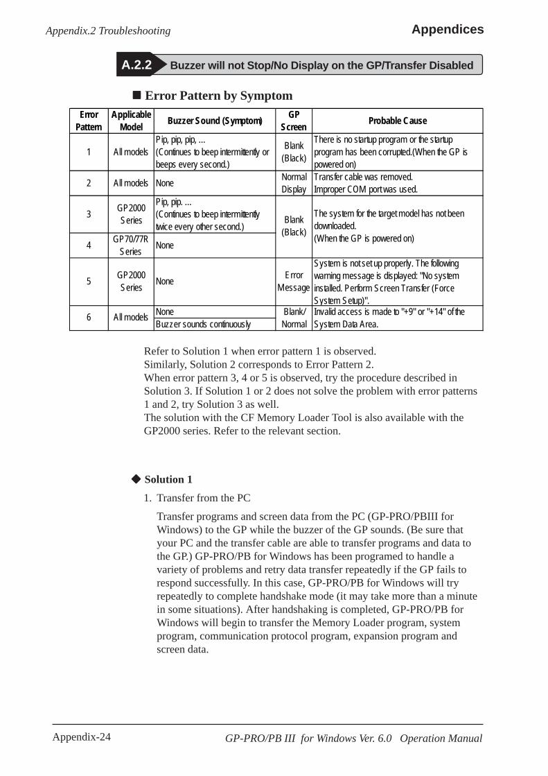
Appendix-24 GP-PRO/PB III for Windows Ver. 6.0 Operation Manual
AppendicesAppendix.2 Troubleshooting
Error Pattern by Symptom
Solution 1
1. Transfer from the PC
Transfer programs and screen data from the PC (GP-PRO/PBIII forWindows) to the GP while the buzzer of the GP sounds. (Be sure thatyour PC and the transfer cable are able to transfer programs and data tothe GP.) GP-PRO/PB for Windows has been programed to handle avariety of problems and retry data transfer repeatedly if the GP fails torespond successfully. In this case, GP-PRO/PB for Windows will tryrepeatedly to complete handshake mode (it may take more than a minutein some situations). After handshaking is completed, GP-PRO/PB forWindows will begin to transfer the Memory Loader program, systemprogram, communication protocol program, expansion program andscreen data.
A.2.2 Buzzer will not Stop/No Display on the GP/Transfer Disabled
ErrorPattern
ApplicableModel Buzzer Sound (Symptom) GP
Screen Probable Cause
1 All modelsPip, pip, pip, …(Continues to beep intermittently orbeeps every second.)
Blank(Black)
There is no startup program or the startupprogram has been corrupted.(When the GP ispowered on)
2 All models None NormalDisplay
Transfer cable was removed.Improper COM port was used.
3 GP2000Series
Pip, pip. …(Continues to beep intermittentlytwice every other second.)
4 GP70/77RSeries None
5 GP2000Series None Error
Message
System is not set up properly. The followingwarning message is displayed: "No systeminstalled. Perform Screen Transfer (ForceSystem Setup)".
NoneBuzzer sounds continuously
6 All models
Blank(Black)
The system for the target model has not beendownloaded.(When the GP is powered on)
Invalid access is made to "+9" or "+14" of theSystem Data Area.
Blank/Normal
Refer to Solution 1 when error pattern 1 is observed.Similarly, Solution 2 corresponds to Error Pattern 2.When error pattern 3, 4 or 5 is observed, try the procedure described inSolution 3. If Solution 1 or 2 does not solve the problem with error patterns1 and 2, try Solution 3 as well.The solution with the CF Memory Loader Tool is also available with theGP2000 series. Refer to the relevant section.
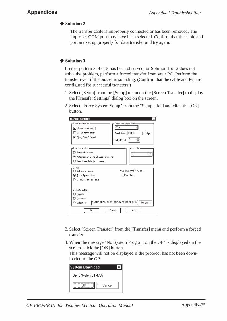
Appendix-25GP-PRO/PB III for Windows Ver. 6.0 Operation Manual
Appendices
Solution 2
The transfer cable is improperly connected or has been removed. Theimproper COM port may have been selected. Confirm that the cable andport are set up properly for data transfer and try again.
Solution 3
If error pattern 3, 4 or 5 has been observed, or Solution 1 or 2 does notsolve the problem, perform a forced transfer from your PC. Perform thetransfer even if the buzzer is sounding. (Confirm that the cable and PC areconfigured for successful transfers.)
1. Select [Setup] from the [Setup] menu on the [Screen Transfer] to displaythe [Transfer Settings] dialog box on the screen.
2. Select "Force System Setup" from the "Setup" field and click the [OK]button.
3. Select [Screen Transfer] from the [Transfer] menu and perform a forcedtransfer.
4. When the message "No System Program on the GP" is displayed on thescreen, click the [OK] button.This message will not be displayed if the protocol has not been down-loaded to the GP.
Appendix.2 Troubleshooting

Appendix-26 GP-PRO/PB III for Windows Ver. 6.0 Operation Manual
Appendices
CF Memory Loader Operation (GP2000 series only)
Insert the CF Card containing the CF Memory Loader programs* into theGP and set the DIP SW No.1 located next to the CF Card slot to ON (seefigure below). Then turn ON the GP’s power supply. The CF MemoryLoader will then automatically start.*IPL. SYS, MLD****. SYS, BK****. MEM; where **** represents the modelcode of the target GP.
10.5.5 Creating Backup Data, 10.5.6 Sending Backup Data
Appendix.2 Troubleshooting
5. The message "Select GP Type" is displayed on the screen. Select themodel type and click the [OK] button.
Usually, the system automatically selects the connected model. However,confirm the model type of the connected GP.
If an improper model type is selected here before a forced trans-fer, the symptoms will recur.
6. Check the GP type and click the [OK] button. The system begins transfer-ring the System Program, Protocol Program and screen data.The restoration is completed when the transfer is completed successfully.In some cases, the "handshaking" (transfer to the GP unit) with the GPmay not be successful.If handshaking is unsuccessful, the system displays the following messageon the screen to ensure successful handshaking with the GP.
Power the GP OFF and ON again. The system will automatically resume the
transfer.
Solution 4
Check whether an incorrect value has been entered into the GP in "+9" or"+14" of the System Data Area, or an invalid Start Address has been as-signed for the System Data Area.

Appendix-27GP-PRO/PB III for Windows Ver. 6.0 Operation Manual
Appendices
Rear of GPDIP SW
CF Card
Use the CF Memory Loader Tool to download the data to the GP.
After data download is finished, remove the CF Card, set DIP SW No.1to OFF and restart your GP.
The buzzer may sound as described below when a problem is handledwith the CF Memory Loader Tool.
ErrorPattern
ApplicableModel Buzzer Sound (Symptom) Probable Cause
1 GP2000Serise
Pip, pip, pip. …(Continues to beep intermittentlythree times every other second.)
MLD****. SYS of the CF memory loader does not exist or hasbeen corrupted. (This symptom may occur when the GP ispowered on by switching on switch No.1 of the DIP SW nearthe CF card slot or the CF startup is performed through the 3-point pressing menu.)
2 GP2000Serise
Pip, pip, pip, pip. …(Continues to beep intermittentlyfour times every other second.)
IPL. SYS of the CF memory loader exists but has beencorrupted. (This symptom may occur only if the CF startup isperformed through the 3-point pressing menu.)
Appendix.2 Troubleshooting
Solution of Error Pattern 1
If there is no “MLD****. SYS” for the target GP present in the CF Card,copy or transfer it from your PC.
If the file “MLD****. SYS” is present in the CF Card and the problem stilloccurs, reformat the CF Card and resend both this file and “IPL. SYS” or“MLD****. SYS,” to the CF Card.
Solution of Error Pattern 2
Reformat the CF Card and then send the necessary files, including “IPL.SYS” or “MLD****. SYS” to the CF Card.
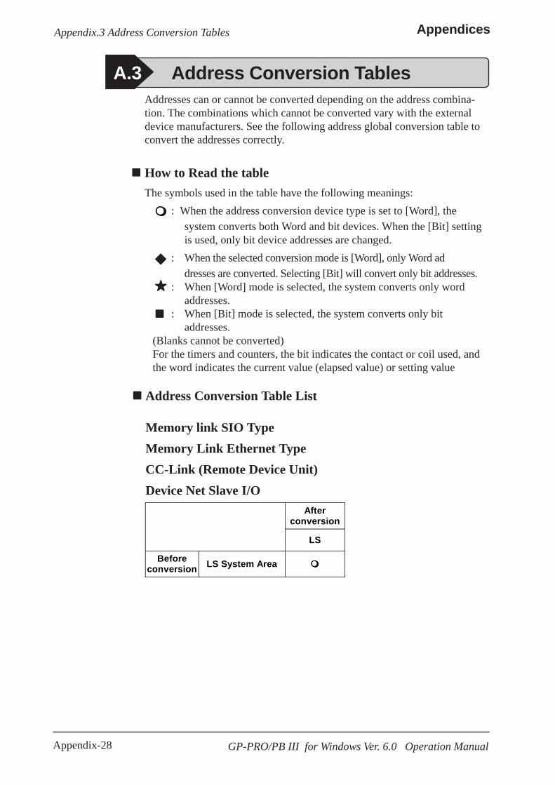
Appendix-28
Appendices
GP-PRO/PB III for Windows Ver. 6.0 Operation Manual
Appendix.3 Address Conversion Tables
A.3 Address Conversion TablesAddresses can or cannot be converted depending on the address combina-tion. The combinations which cannot be converted vary with the externaldevice manufacturers. See the following address global conversion table toconvert the addresses correctly.
How to Read the tableThe symbols used in the table have the following meanings:
: When the address conversion device type is set to [Word], thesystem converts both Word and bit devices. When the [Bit] settingis used, only bit device addresses are changed.
: When the selected conversion mode is [Word], only Word addresses are converted. Selecting [Bit] will convert only bit addresses.
: When [Word] mode is selected, the system converts only wordaddresses.
: When [Bit] mode is selected, the system converts only bitaddresses.
(Blanks cannot be converted)For the timers and counters, the bit indicates the contact or coil used, andthe word indicates the current value (elapsed value) or setting value
After conversion
LS
Before conversion LS System Area
Address Conversion Table List
Memory link SIO TypeMemory Link Ethernet TypeCC-Link (Remote Device Unit)Device Net Slave I/O

Appendix-29
Appendices
GP-PRO/PB III for Windows Ver. 6.0 Operation Manual
Appendix.3 Address Conversion Tables
Mitsubishi Electric MELSEC-AAfter Conversion
X Y M L F B TS/TC/TN CS/CC/CN D W R LS X
Input Relay
Y Output Relay
M Internal Relay, Special Relay
L Latch Relay
F Annunciator
B Link Relay
TS/TC/TN Timer
) )
CS/CC/CN Counter
) )
D Data/Special
Register
W Link Register
R File Register
Bef
ore
Con
vers
ion
LS System Area
After Conversion
X Y M L F B TS/TC/TN CS/CC/CN D W R LS X
Input Relay
Y Output Relay
M Internal Relay, Special Relay
L Latch Relay
F Annunciator
B Link Relay
TS/TC/TN Timer
CS/CC/CN Counter
D Data/Special
Register
W Link Register
R File Register
Bef
ore
Con
vers
ion
LS System Area
Mitsubishi Electric MELSEC-N
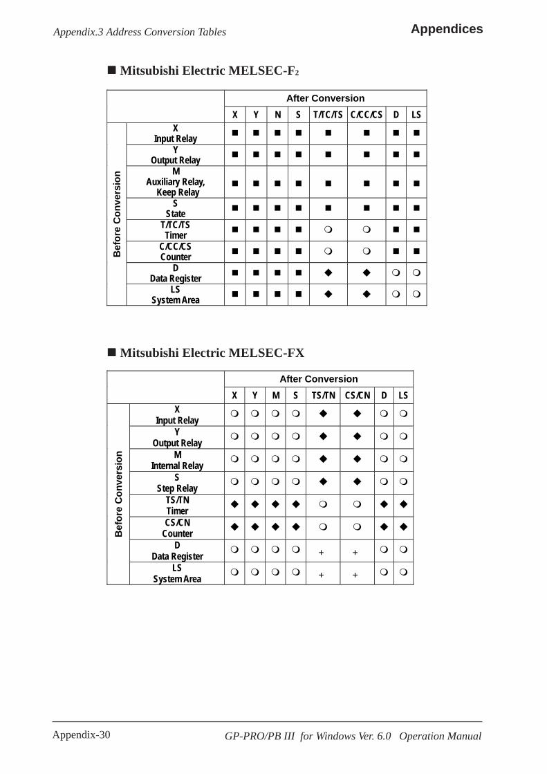
Appendix-30
Appendices
GP-PRO/PB III for Windows Ver. 6.0 Operation Manual
Appendix.3 Address Conversion Tables
After Conversion
X Y N S T/TC/TS C/CC/CS D LS X
Input Relay Y
Output Relay M
Auxiliary Relay, Keep Relay
S State
T/TC/TS Timer
C/CC/CS Counter
D Data Register
Bef
ore
Con
vers
ion
LS System Area
Mitsubishi Electric MELSEC-F2
Mitsubishi Electric MELSEC-FX
After Conversion
X Y M S TS/TN CS/CN D LS X
Input Relay Y
Output Relay M
Internal Relay S
Step Relay TS/TN Timer CS/CN
Counter D
Data Register + +
Bef
ore
Con
vers
ion
LS System Area + +

Appendix-31GP-PRO/PB III for Windows Ver. 6.0 Operation Manual
Appendices Appendix.3 Address Conversion Tables
Mitsubishi Electric MELSEC-FX2N
After Conversion
X Y M S TS/CS TN/CN D LS X
Input Relay Y
Output Relay M
Internal Relay S
Step Relay TS/CS Timer TN/CN
Counter D
Data Register
Bef
ore
Con
vers
ion
LS System Area
Mitsubishi Electric FREQROL Series
- P All devices exceptfor parameter LS
Parameter exceptfor FR-S500,E500's Pr-37
P
Parameter for FR-S500, E500's Pr-37All devices exceptfor parameter
LSSystem Area
Befo
re C
onve
rsio
n
After Conversion

Appendix-32 GP-PRO/PB III for Windows Ver. 6.0 Operation Manual
AppendicesAppendix.3 Address Conversion Tables
Mitsubishi Electric MELSEC-QnA
X Y M SM L F V S B SB TS TC SS SC CS CC TN SN CN D SD W SW R0R
31RLS
XInput Relay
YOutput Relay
MInternal Relay
SMSpecial Relay
LLatch Relay
FAnnunciator
VEdge Relay
SStep Relay
BLink Relay
SBSpecial Link Relay
TSTimer (contact)
TCTimer (coil)
SSAggregate Timer
(contact)SC
Aggregate Timer (coil)CS
Counter (contact)CC
Counter (coil)TN
Timer (current value)SN
Aggregate Timer(current value)
CNCounter (current
value)D
Data RegisterSD
Special Data RegisterW
Link Data RegisterSW
Special Link RegisterR
File Register (normal)0R - 31R
File Register (serial)LS
System Area
After Conversion
Bef
ore
Con
vers
ion

Appendix-33GP-PRO/PB III for Windows Ver. 6.0 Operation Manual
Appendices Appendix.3 Address Conversion Tables
X Y M SM L F V S B SB TS TC SS SC CS CC TN SN CN D SD W SW R0R
31RLS
XInput Relay
YOutput Relay
MInternal Relay
SMSpecial Relay
LLatch Relay
FAnnunciator
VEdge Relay
SStep Relay
BLink Relay
SBSpecial Link Relay
TSTimer (contact)
TCTimer (coil)
SSAggregate Timer
(contact)SC
Aggregate Timer (coil)CS
Counter (contact)CC
Counter (coil)TN
Timer (current value)SN
Aggregate Timer(current value)
CNCounter (current
value)D
Data RegisterSD
Special Data RegisterW
Link Data RegisterSW
Special Link RegisterR
File Register (normal)0R - 31R
File Register (serial)LS
System Area
After ConversionB
efor
e C
onve
rsio
n
MELSEC- Q Series (Q Mode CPU)
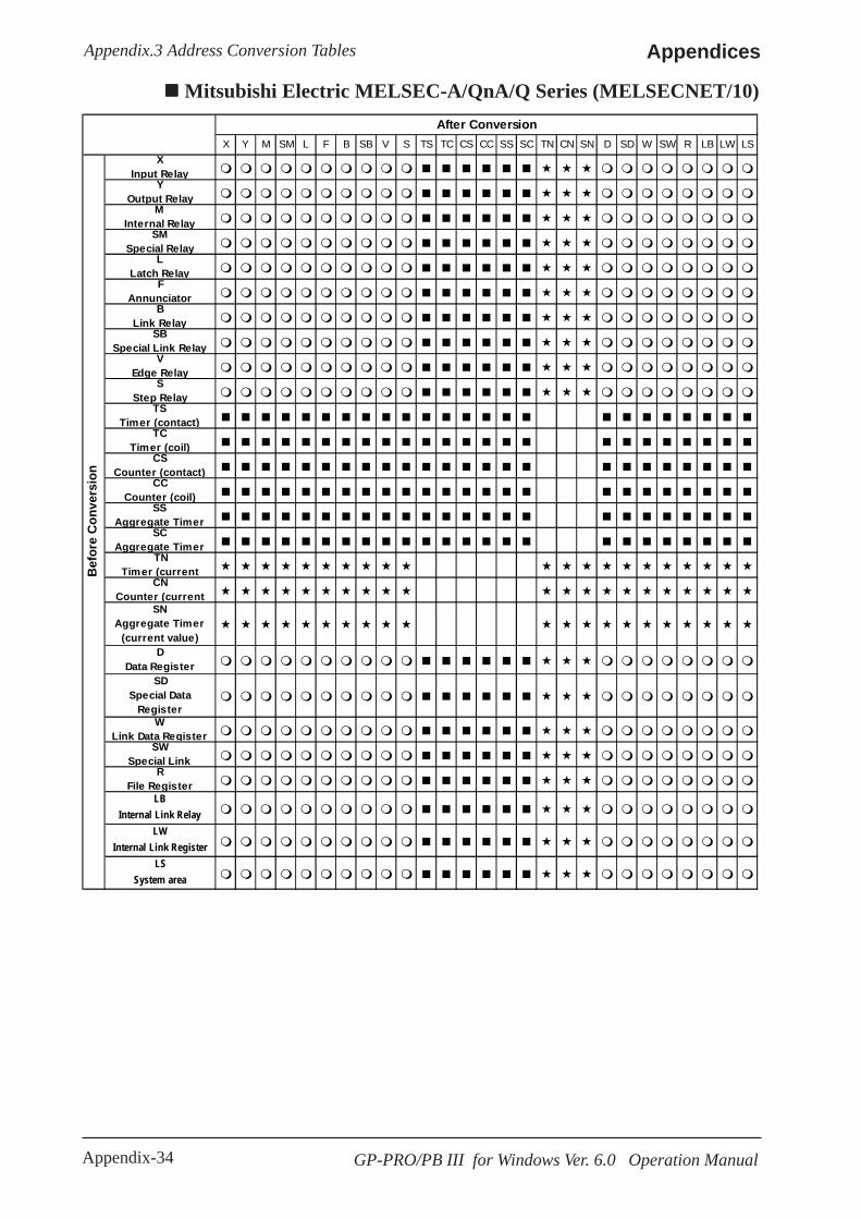
Appendix-34 GP-PRO/PB III for Windows Ver. 6.0 Operation Manual
AppendicesAppendix.3 Address Conversion Tables
Mitsubishi Electric MELSEC-A/QnA/Q Series (MELSECNET/10)After Conversion
X Y M SM L F B SB V S TS TC CS CC SS SC TN CN SN D SD W SW R LB LW LSX
Input RelayY
Output RelayM
Internal RelaySM
Special RelayL
Latch RelayF
AnnunciatorB
Link RelaySB
Special Link RelayV
Edge RelayS
Step RelayTS
Timer (contact)TC
Timer (coil)CS
Counter (contact)CC
Counter (coil)SS
Aggregate TimerSC
Aggregate TimerTN
Timer (currentCN
Counter (currentSN
Aggregate Timer(current value)
DData Register
SDSpecial Data
RegisterW
Link Data RegisterSW
Special LinkR
File RegisterLB
Internal Link RelayLW
Internal Link RegisterLS
System area
Bef
ore
Con
vers
ion
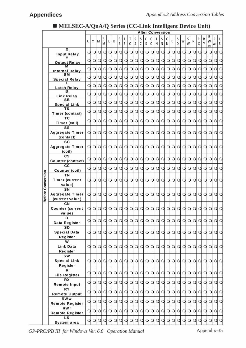
Appendix-35GP-PRO/PB III for Windows Ver. 6.0 Operation Manual
Appendices Appendix.3 Address Conversion Tables
MELSEC-A/QnA/Q Series (CC-Link Intelligent Device Unit)
X Y M SM L B S
BTS
TC
SS
SC
CS
CC
TN
SN
CN D S
D W SW R R
XRY
RWw
Rwr
LS
X Input Re lay
Y Output Re lay
MInterna l Re lay
SMSpecia l Re lay
LLatch Re lay
BLink Re lay
SBSpecia l Link
TSTimer (contact)
TCTimer (coil)
SSAggregate Timer
(contact)SC
Aggregate Timer(coil)
CSCounter (contact)
CC Counter (coil)
TNTimer (current
va lue)SN
Aggregate Timer(current va lue)
CNCounter (current
va lue)D
Data RegisterSD
Specia l DataRegister
WLink DataRegister
SWSpecia l Link
RegisterR
File RegisterRX
Remote InputRY
Remote OutputRW w
Remote RegisterRW r
Remote RegisterLS
System area
Bef
ore
Con
vers
ion
Afte r Conversion

Appendix-36 GP-PRO/PB III for Windows Ver. 6.0 Operation Manual
AppendicesAppendix.3 Address Conversion Tables
After Conversion
CH LR AR HR A TIM /T
CNT /C D LS
CH Relay
LR Data Link Relay
AR Auxiliary Memory Relay
HR Hold Relay
A Special Auxiliary Relay
TIM/T Timer
CNT/C Counter
D Data Memory
Bef
ore
Con
vers
ion
LS System Area
LR (Data Link Relay), AR (Auxiliary Memory Relay) and HR (Hold Relay) are onlyfor SYSMAC C/SYSMAC-α. A (Special Auxiliary Relay) is only for SYSMAC CV.
Omron SYSMAC C/ααααα/CV
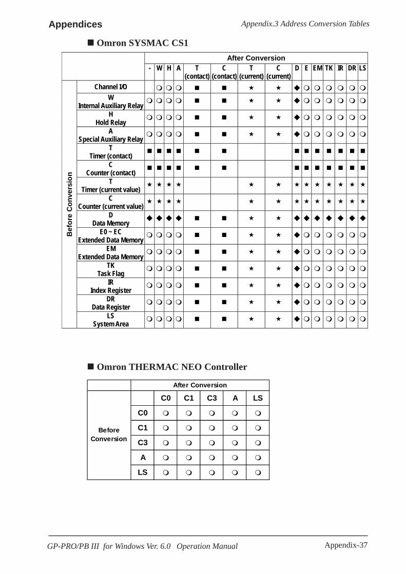
Appendix-37GP-PRO/PB III for Windows Ver. 6.0 Operation Manual
Appendices Appendix.3 Address Conversion Tables
After Conversion - W H A T
(contact) C
(contact) T
(current) C
(current) D E EM TK IR DR LS
Channel I/O W
Internal Auxiliary Relay H
Hold Relay A
Special Auxiliary Relay T
Timer (contact) C
Counter (contact) T
Timer (current value) C
Counter (current value) D
Data Memory E0 ~ EC
Extended Data Memory EM
Extended Data Memory TK
Task Flag IR
Index Register DR
Data Register
Bef
ore
Con
vers
ion
LS System Area
Omron SYSMAC CS1
After Conversion
C0 C1 C3 A LS
C0
C1
C3
A
LS
BeforeConversion
Omron THERMAC NEO Controller

Appendix-38 GP-PRO/PB III for Windows Ver. 6.0 Operation Manual
AppendicesAppendix.3 Address Conversion Tables
After Conversion
X Y M L T/TS C/CS D W R LS X
Input Relay Y
Output Relay
M Internal Relay
L Latch Relay
T/TS Timer C/CS
Counter D
Data Register W
Link Register
R File Register
Bef
ore
Con
vers
ion
LS System Area
Fuji Electric FLEX-PC
After Conversion
B/M/K/D/L W24 F A TR TS CR CS BD/DI/SI W30~W34 LS B/M/K/D/L
Relay W24
Direct I/O
F Special Relay
A Announce Relay
TR Timer (current)
TS Timer (setup) )
CR Counter (current)
CS Counter (setup)
BD/DI/SI Data Memory
W30 ~ W34 File Memory
Bef
ore
Con
vers
ion
LS System Area
Fuji Electric MICREX-F/MICREX-F FLT-ASFK

Appendix-39GP-PRO/PB III for Windows Ver. 6.0 Operation Manual
Appendices Appendix.3 Address Conversion Tables
Fuji Electric FRENICS, FVR Series
F E C P H A o S M LSFundamental
FunctionF
Terminal FunctionE
Control FunctionC
Motor 1P
High-level FunctionH
Motor 2A
OptionO
Command DataS
Monitor DataM
System AreaLS
After Conversion
Bef
ore
Con
vers
ion
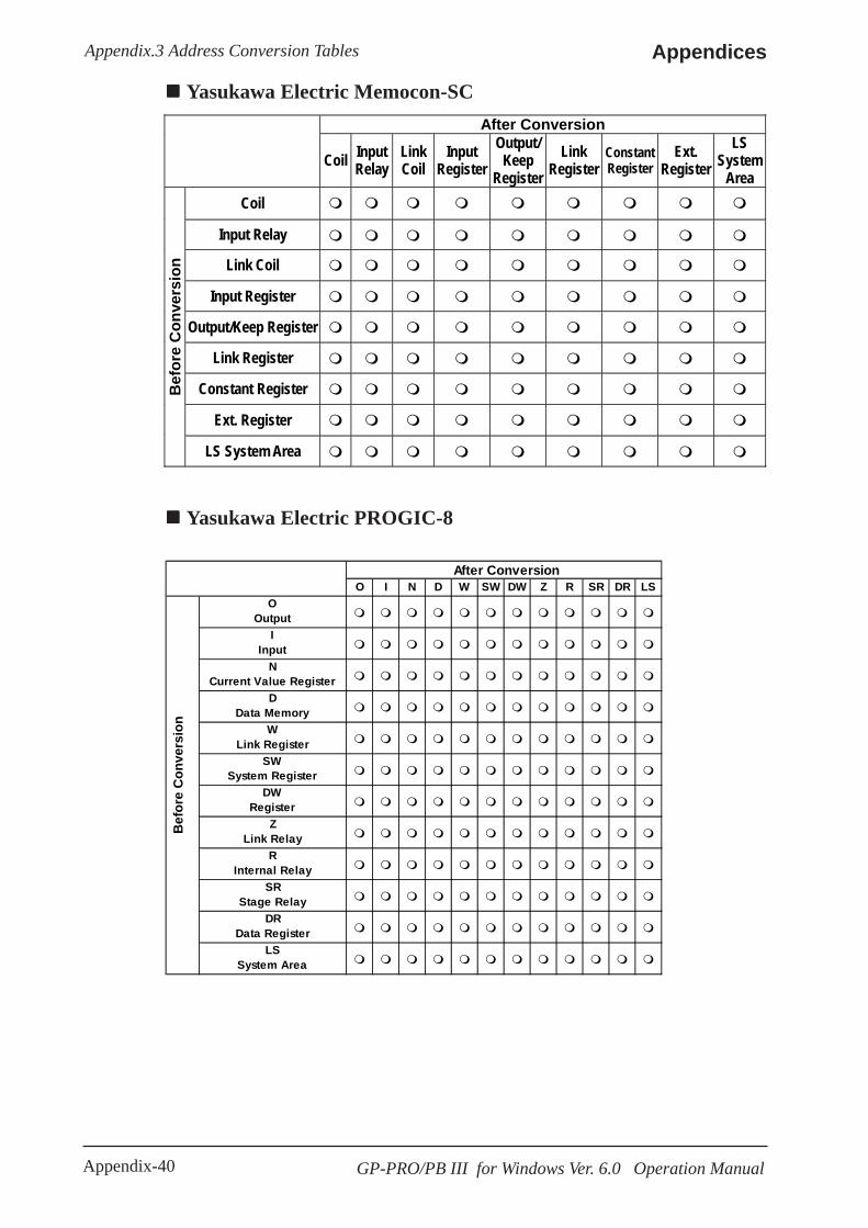
Appendix-40 GP-PRO/PB III for Windows Ver. 6.0 Operation Manual
AppendicesAppendix.3 Address Conversion Tables
After Conversion
Coil Input Relay
Link Coil
Input Register
Output/ Keep
Register Link
Register Constant Register
Ext. Register
LS System
Area Coil
Input Relay
Link Coil
Input Register
Output/Keep Register
Link Register
Constant Register
Ext. Register
Bef
ore
Con
vers
ion
LS System Area
Yasukawa Electric Memocon-SC
Yasukawa Electric PROGIC-8
After ConversionO I N D W SW DW Z R SR DR LS
OOutput
IInput
NCurrent Value Register
DData Memory
WLink Register
SWSystem Register
DWRegister
ZLink Relay
RInternal Relay
SRStage Relay
DRData Register
LSSystem Area
Bef
ore
Con
vers
ion

Appendix-41GP-PRO/PB III for Windows Ver. 6.0 Operation Manual
Appendices Appendix.3 Address Conversion Tables
After Conversion X Y M T/C LS
GMB Output Coil
GIB Input Coil
GMW Hold Register
GIW Input Register
Befo
re C
onve
rsio
n
LS System Area
Yasukawa Electric CP-9200SH
Yasukawa Electric GL 120/130After Conversion
O I D X Y M P Q 3 4 R 7 LSO
Output RelayI
Input RelayD
Data MemoryX
Input RelayY
Output RelayM
Internal RelayP
RelayQ
Relay3
4
RLink Register
7
LSSystem Area
Bef
ore
Con
vers
ion

Appendix-42 GP-PRO/PB III for Windows Ver. 6.0 Operation Manual
AppendicesAppendix.3 Address Conversion Tables
Hitachi Ltd. HIDIC S10 ααααα
After Conversion
X Y R G E K T U C TC TS UC US CC CS DW SW EW FW MS LS X
Input Relay Y
Output Relay R
Internal Relay G
Global Link SW
System Register EW
E word E
Event K
Keep Relay T
On-Delay Timer U
One-shot Timer C
Up/down Counter TC
On-delay Timer (calculated)
TS On-delay Timer
(setup)
UC One-shot Timer
(calculated)
US One-shot Timer
(setup)
CC Up/down Counter
(calculated)
CS Up/down Counter
(setup)
DW Data Register
FW Work Register
MS Extended Register
Bef
ore
Con
vers
ion
LS System Area

Appendix-43GP-PRO/PB III for Windows Ver. 6.0 Operation Manual
Appendices Appendix.3 Address Conversion Tables
After Conversion X Y M T/C LS
X External Input
Y External Output
M Internal Output
T/C Timer/Counter
Bef
ore
Con
vers
ion
LS System Area
Hitachi Ltd. HIZAC EC
Hitachi Ltd. HIDIC H (HIZAC H)/HIDIC H2
*1: TD/SS/WDT/MS/TMR for Timers. CU/RCU/CT for counters.
After Conversion
X Y R L M T/C WR WN LS X
Input
Y Output
R Internal Output
L CPU Link
M Data Area
T/C *1 Timer/Counter
WR Word Internal Output
WN Network Area
Bef
ore
Con
vers
ion
LS System Area
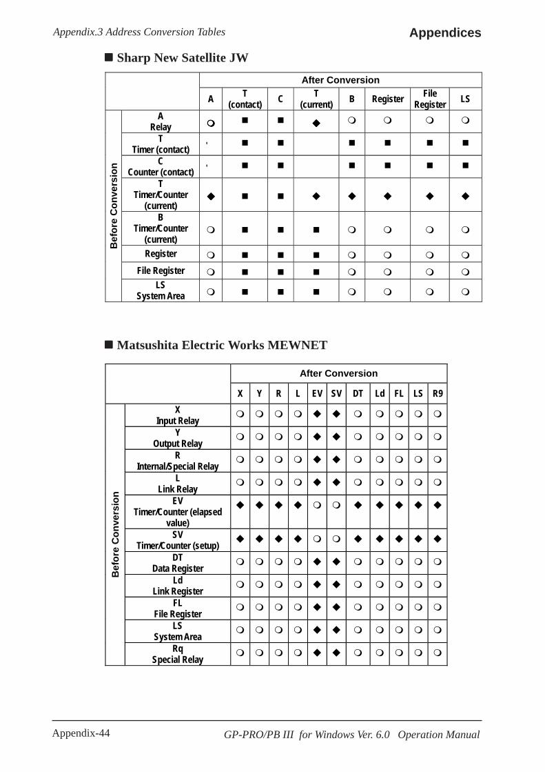
Appendix-44 GP-PRO/PB III for Windows Ver. 6.0 Operation Manual
AppendicesAppendix.3 Address Conversion Tables
After Conversion
A T (contact) C T
(current) B Register File Register LS
A Relay
T Timer (contact) '
C Counter (contact) '
T Timer/Counter
(current)
B Timer/Counter
(current)
Register File Register
Bef
ore
Con
vers
ion
LS System Area
Matsushita Electric Works MEWNET
Sharp New Satellite JW
After Conversion
X Y R L EV SV DT Ld FL LS R9 X
Input Relay
Y Output Relay
R Internal/Special Relay
L Link Relay
EV Timer/Counter (elapsed
value)
SV Timer/Counter (setup)
DT Data Register
Ld Link Register
FL File Register
LS System Area
Bef
ore
Con
vers
ion
Rq Special Relay

Appendix-45GP-PRO/PB III for Windows Ver. 6.0 Operation Manual
Appendices Appendix.3 Address Conversion Tables
After Conversion X Y I E M L T C TP CP TS CS D B R Z W LS
X Input Relay
Y Output Relay
I Internal Relay
E Common Relay
M Special Relay
L Link Relay
T Timer (contact)
C Counter (contact)
TP Timer (current)
CP Counter (current)
TS Timer (setup)
CS Counter (setup)
D Data Register
B File Register
R Joint Register
Z Special Register
W Link Register
Bef
ore
Con
vers
ion
LS System Area
R Joint Register is only for FA-M3.
Yokogawa Electric FACTORY ACE
Yokogawa Electric UT2000/Yokogawa M&C Green Series
D I LS
DD Register
II Relay
LSSystem
AreaBef
ore
Con
vers
ion
After Conversion
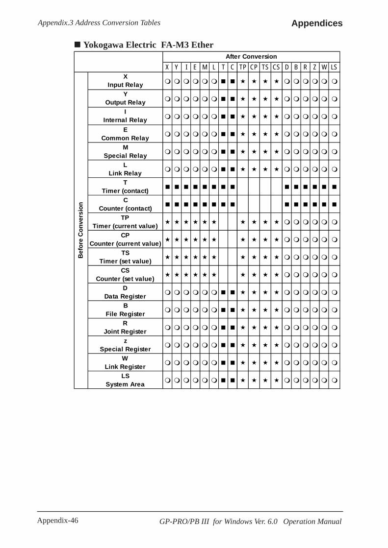
Appendix-46 GP-PRO/PB III for Windows Ver. 6.0 Operation Manual
AppendicesAppendix.3 Address Conversion Tables
Yokogawa Electric FA-M3 Ether
X Y I E M L T C TP CP TS CS D B R Z W LSX
Input RelayY
Output RelayI
Internal RelayE
Common RelayM
Special RelayL
Link RelayT
Timer (contact)C
Counter (contact)TP
Timer (current value)CP
Counter (current value)TS
Timer (set value)CS
Counter (set value)D
Data RegisterB
File RegisterR
Joint Registerz
Special RegisterW
Link RegisterLS
System Area
Bef
ore
Con
vers
ion
After Conversion

Appendix-47GP-PRO/PB III for Windows Ver. 6.0 Operation Manual
Appendices Appendix.3 Address Conversion Tables
Toyota Machine Works TOYOPUC-PC2After Conversion
X Y M K L C N D R B S LS
X Input Relay
Y Output Relay
M Internal Relay
K Keep Relay
L Link Relay
V Special Relay
N Current Value Register
D Data Register
R Link Register
B File Register
S Special Register
Bef
ore
Con
vers
ion
LS System Area
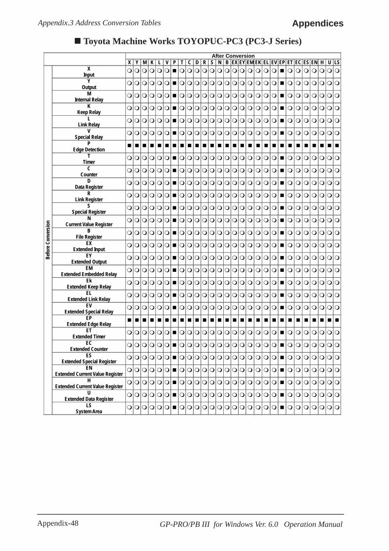
Appendix-48 GP-PRO/PB III for Windows Ver. 6.0 Operation Manual
AppendicesAppendix.3 Address Conversion Tables
After Conversion X Y M K L V P T C D R S N B EX EY EM EK EL EV EP ET EC ES EN H U LS
X Input
Y Output
M
Internal Relay K
Keep Relay L
Link Relay V
Special Relay P
Edge Detection
T Timer
C Counter
D
Data Register R
Link Register
S Special Register
N Current Value Register
B
File Register
EX Extended Input
EY Extended Output
EM
Extended Embedded Relay Ek
Extended Keep Relay
EL Extended Link Relay
EV Extended Special Relay
EP
Extended Edge Relay ET
Extended Timer
EC Extended Counter
ES
Extended Special Register EN
Extended Current Value Register
H Extended Current Value Register
U Extended Data Register
Befo
re C
onve
rsio
n
LS System Area
Toyota Machine Works TOYOPUC-PC3 (PC3-J Series)

Appendix-49GP-PRO/PB III for Windows Ver. 6.0 Operation Manual
Appendices Appendix.3 Address Conversion Tables
After Conversion
X Y R S Z L T C D W F LS X
External Input Y
External Output R
Internal Relay S
Special Relay Z
Link Register Relay L
Link Relay T
Timer C
Counter D
Data Register W
Link Register F
File Register
Bef
ore
Con
vers
ion
LS System area
Toshiba PROSEC T
After Conversion
X Y R Z T C D LS X
External Input Y
External Output
R Auxiliary Relay
Z Link Relay
T Timer
C Counter
D Data Register
Bef
ore
Con
vers
ion
LS System Area
Toshiba PROSEC EX(2000)

Appendix-50 GP-PRO/PB III for Windows Ver. 6.0 Operation Manual
AppendicesAppendix.3 Address Conversion Tables
After Conversion
X Y R S Z L LW T C D W F LS X
External Input Y
External Output R
Internal Relay S
Special Relay Z
Link Register Relay ' ' ' ' L
Link Relay ' ' ' ' LW
Link Relay T
Timer C
Counter D
Data Register W
Link Register F
File Register
Bef
ore
Con
vers
ion
LS System area
Toshiba PROSEC T (Ethernet)

Appendix-51GP-PRO/PB III for Windows Ver. 6.0 Operation Manual
Appendices Appendix.3 Address Conversion Tables
After Conversion
X Y R/G/H A L S E T C P/V D/B LS X
Input Relay Y
Output Relay R/G/H
Internal Relay A
Special auxiliary Relay L
Latch Relay S
Shift Register E
Edge Relay T
Timer (contact) C
Counter (contact) P/V
Timer/counter (current/setup)
D/B Generic Register
Bef
ore
Con
vers
ion
LS System Area
Timers and Counters use words and bits for contacts, current values, and setup values.Conversion is performed only on the word or bit of the corresponding value. For ex-ample, when converting the current value, conversion takes place only on the currentvalue bit and does not affect the contact or setup.
Toshiba PROVISOR B (same asToshiba Machine PROVISOR TC200)
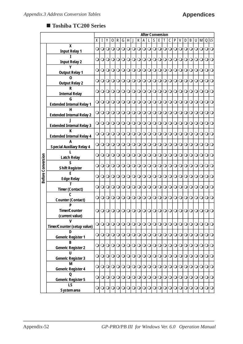
Appendix-52 GP-PRO/PB III for Windows Ver. 6.0 Operation Manual
AppendicesAppendix.3 Address Conversion Tables
X I Y O R G H J K A L S E T C P V D B U M Q LSX
Input Relay 1I
Input Relay 2Y
Output Relay 1O
Output Relay 2R
Internal RelayG
Extended Internal Relay 1H
Extended Internal Relay 2J
Extended Internal Relay 3K
Extended Internal Relay 4A
Special Auxiliary Relay 4L
Latch RelayS
Shift RegisterE
Edge RelayT
Timer (Contact)C
Counter (Contact)P
Timer/Counter(current value)
VTimer/Counter (setup value)
DGeneric Register 1
BGeneric Register 2
UGeneric Register 3
MGeneric Register 4
QGeneric Register 5
LSSystem area
Befo
re C
onve
rsio
n
After Conversion
Toshiba TC200 Series

Appendix-53GP-PRO/PB III for Windows Ver. 6.0 Operation Manual
Appendices Appendix.3 Address Conversion Tables
Koyo Electronic KOSTAC SR
Koyo Electronic KOSTAC SG/SU/SZ
A fte r C o n ve rs io n
(1 ) (2 ) (3 ) (4 ) (5 ) (6 ) (7 ) (1 )
In p u t/O u p u t (2 )
C o n tro l R e lay (3 )
S h ift R e g is ter (4 )
T im e r/C o u n te r (c o n ta c t)
(5 ) T im e r/C o u n te r (e la p s e d v a lu e )
(6 ) D a ta R e g is te r
Bef
ore
Co
nve
rsio
n
(7 ) S y s te m A re a
After Conversion
I Q M S GI SP T C R LS I
Input Relay Q
Output Relay M
Control Relay S
Stage GI
Link Relay SP
Specified Relay T
Timer C
Counter R
Variable Memory/ Data Register
Bef
ore
Con
vers
ion
LS System Area
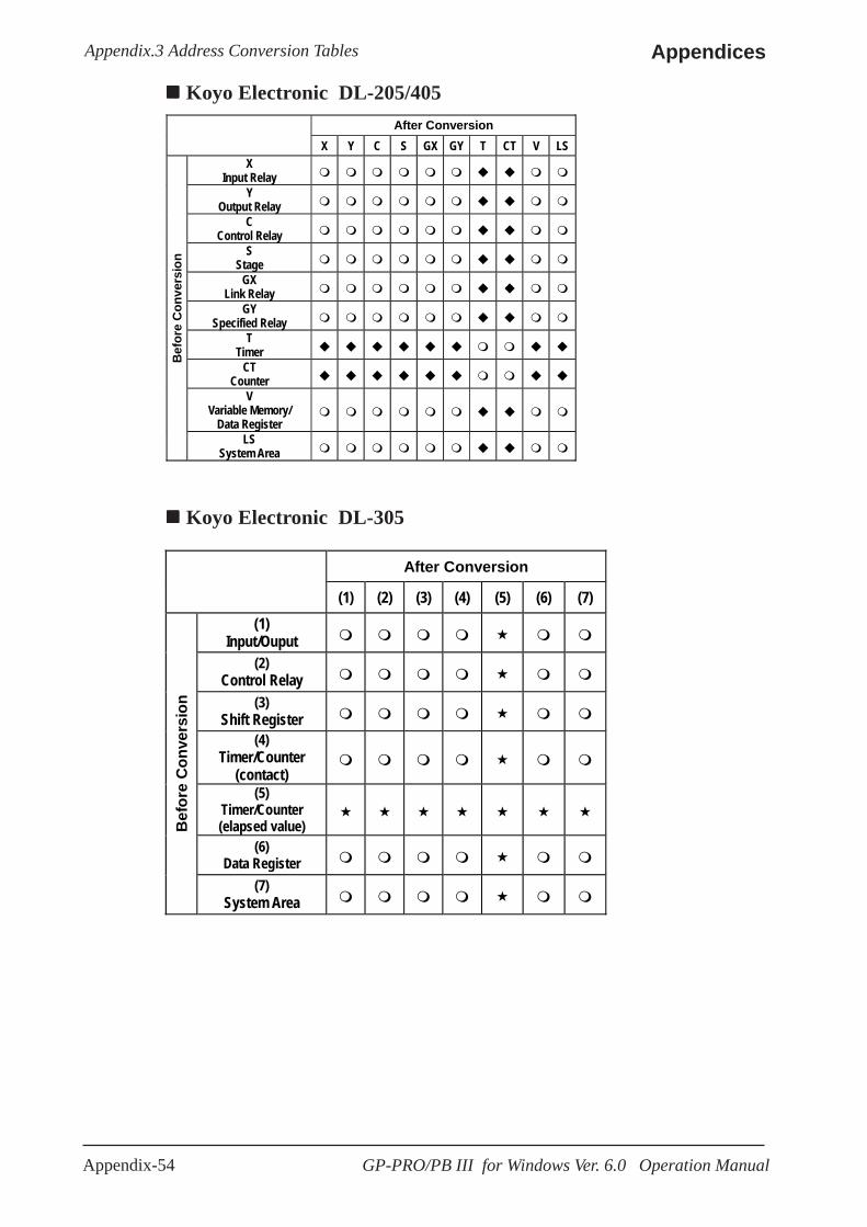
Appendix-54 GP-PRO/PB III for Windows Ver. 6.0 Operation Manual
AppendicesAppendix.3 Address Conversion Tables
Koyo Electronic DL-205/405After Conversion
X Y C S GX GY T CT V LS
X Input Relay
Y Output Relay
C Control Relay
S Stage
GX Link Relay
GY Specified Relay
T Timer
CT Counter
V Variable Memory/
Data Register
Bef
ore
Con
vers
ion
LS System Area
Koyo Electronic DL-305
After Conversion
(1) (2) (3) (4) (5) (6) (7) (1)
Input/Ouput (2)
Control Relay (3)
Shift Register (4)
Timer/Counter (contact)
(5) Timer/Counter (elapsed value)
(6) Data Register
Bef
ore
Con
vers
ion
(7) System Area

Appendix-55GP-PRO/PB III for Windows Ver. 6.0 Operation Manual
Appendices Appendix.3 Address Conversion Tables
Automation GE FANUC Series 90-70/90-30After Conversion
I Q M G T SA SB SC S R AI AQ LS I
Input Relay
Q Output Relay
M Control Relay
G Global Relay
T Timer Relay
SA System Relay
SB System Relay
SC System Relay
S System Relay
R Register
AI Analog Input
AQ Analog Output
Bef
ore
Con
vers
ion
LS System Area
I Q M G T SA SB SC S R AI AQ LSInput Relay (I)Output Relay (Q)Internal Relay (M)Global Relay (G)Temporary Relay (T)System Status RelaySystem Status RelaySystem Status RelaySystem Status RelayRegister (R)Analog Input (AI)Analog Output (AQ)LS Area (LS)
After Conversion
Befo
re C
onve
rsio
n
GE Fanuc 90-30/90-70 SNP

Appendix-56 GP-PRO/PB III for Windows Ver. 6.0 Operation Manual
AppendicesAppendix.3 Address Conversion Tables
Fanuc FANUC Power MateAfter Conversion
X Y R K T C D LS
X Input Relay
Y Output Relay
R Control Relay
K Keep Relay
T Timer
C Counter
D Data Table
Bef
ore
Con
vers
ion
LS System Area
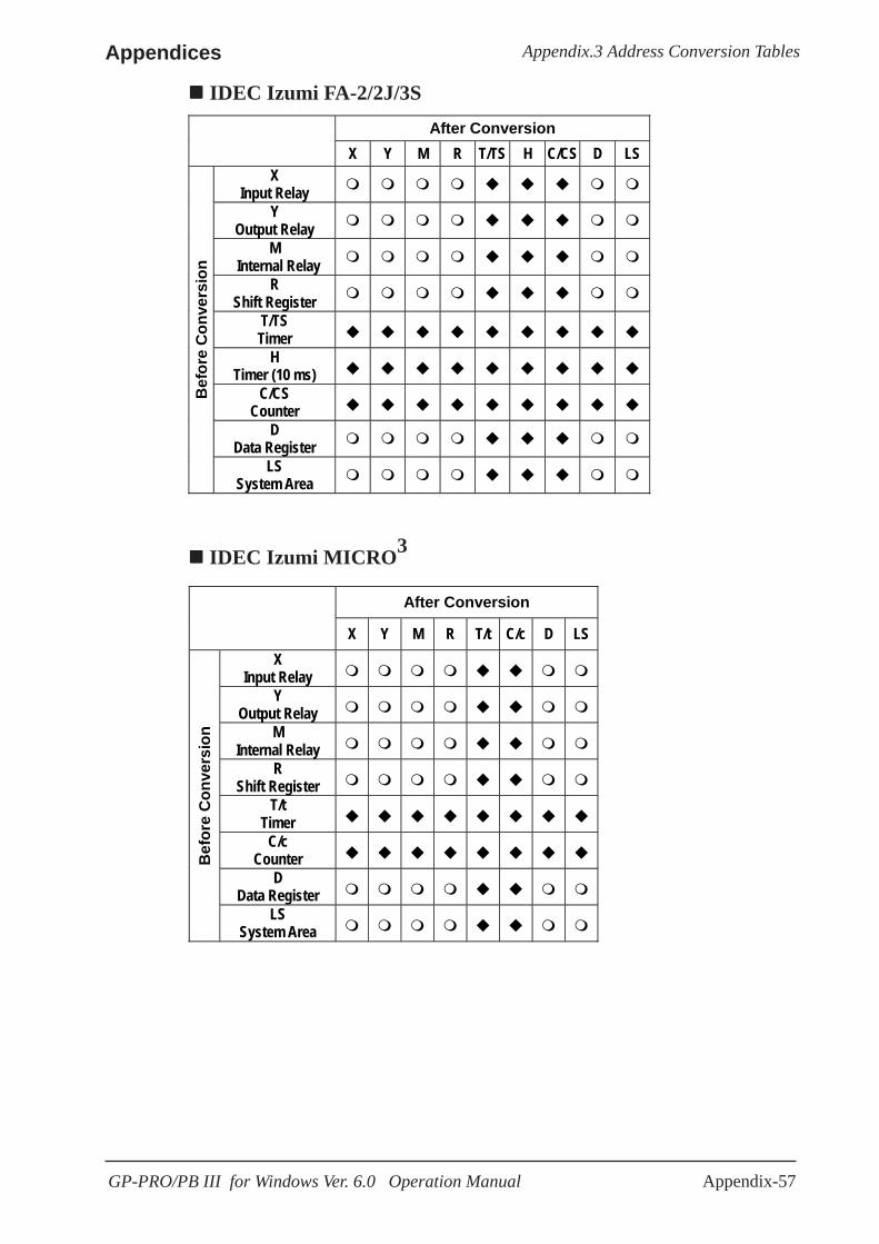
Appendix-57GP-PRO/PB III for Windows Ver. 6.0 Operation Manual
Appendices Appendix.3 Address Conversion Tables
After Conversion
X Y M R T/TS H C/CS D LS X
Input Relay Y
Output Relay M
Internal Relay R
Shift Register T/TS Timer
H Timer (10 ms)
C/CS Counter
D Data Register
Bef
ore
Con
vers
ion
LS System Area
IDEC Izumi FA-2/2J/3S
After Conversion
X Y M R T/t C/c D LS X
Input Relay Y
Output Relay M
Internal Relay R
Shift Register T/t
Timer C/c
Counter D
Data Register
Bef
ore
Con
vers
ion
LS System Area
IDEC Izumi MICRO3
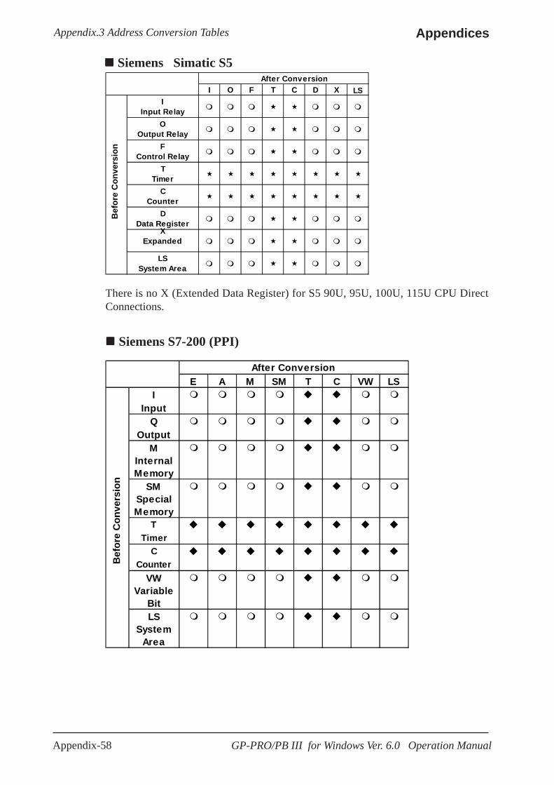
Appendix-58 GP-PRO/PB III for Windows Ver. 6.0 Operation Manual
AppendicesAppendix.3 Address Conversion Tables
Siemens S7-200 (PPI)
Siemens Simatic S5
There is no X (Extended Data Register) for S5 90U, 95U, 100U, 115U CPU DirectConnections.
After ConversionI O F T C D X LS
IInput Relay
OOutput Relay
FControl Relay
TTimer
CCounter
DData Register
XExpanded
LSSystem Area
Bef
ore
Co
nve
rsio
n
E A M SM T C VW LSI
InputQ
OutputM
InternalMemory
SMSpecialMemory
TTimer
CCounter
VWVariable
BitLS
SystemArea
After Conversion
Bef
ore
Co
nve
rsio
n
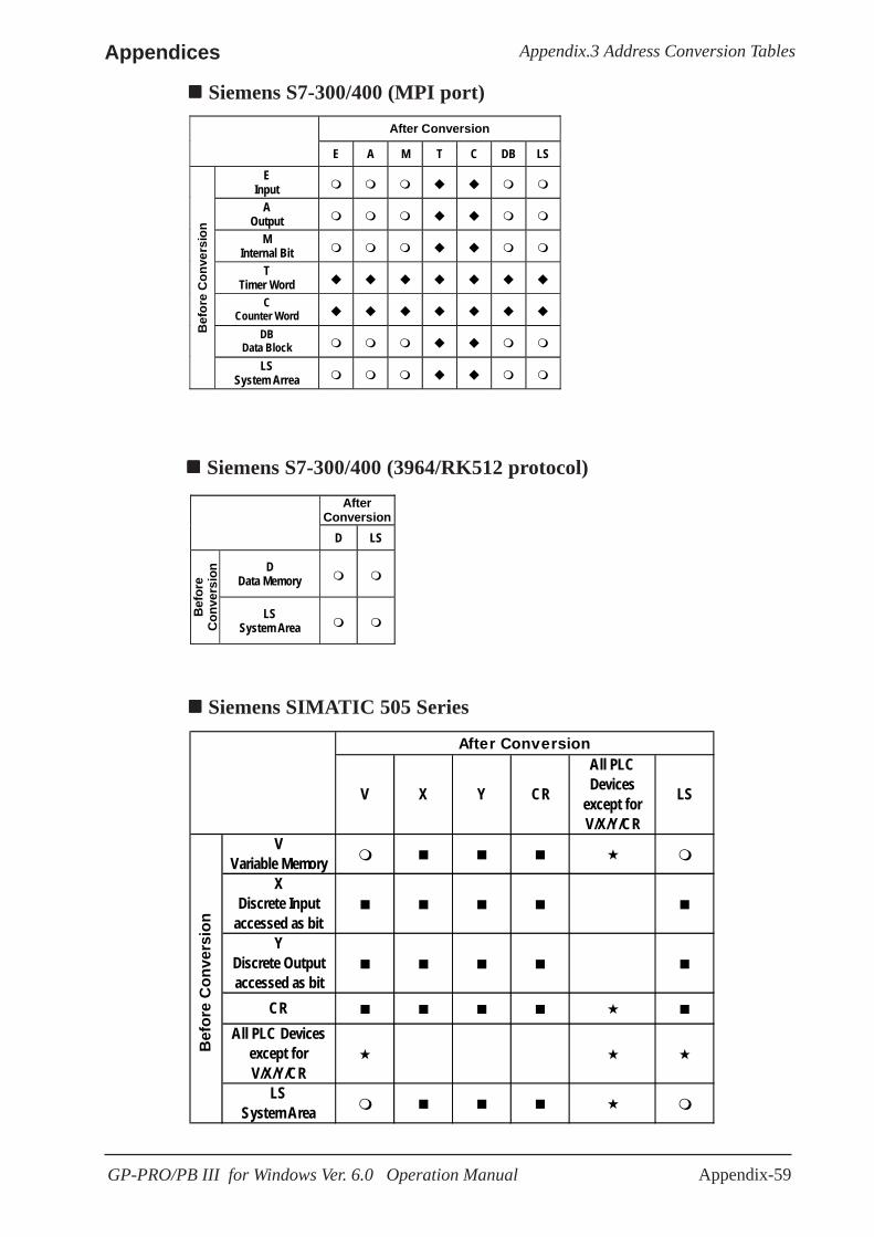
Appendix-59GP-PRO/PB III for Windows Ver. 6.0 Operation Manual
Appendices Appendix.3 Address Conversion Tables
Siemens S7-300/400 (MPI port)After Conversion
E A M T C DB LS
E Input
A Output
M Internal Bit
T Timer Word
C Counter Word
DB Data Block
Bef
ore
Con
vers
ion
LS System Arrea
Siemens S7-300/400 (3964/RK512 protocol)After
Conversion D LS
D Data Memory
Bef
ore
Con
vers
ion
LS System Area
Siemens SIMATIC 505 Series
After Conversion
V X Y CR
All PLCDevices
except forV/X/Y/CR
LS
VVariable Memory
XDiscrete Input
accessed as bitY
Discrete Outputaccessed as bit
CRAll PLC Devices
except forV/X/Y/CR
LSSystem Area
Bef
ore
Con
vers
ion
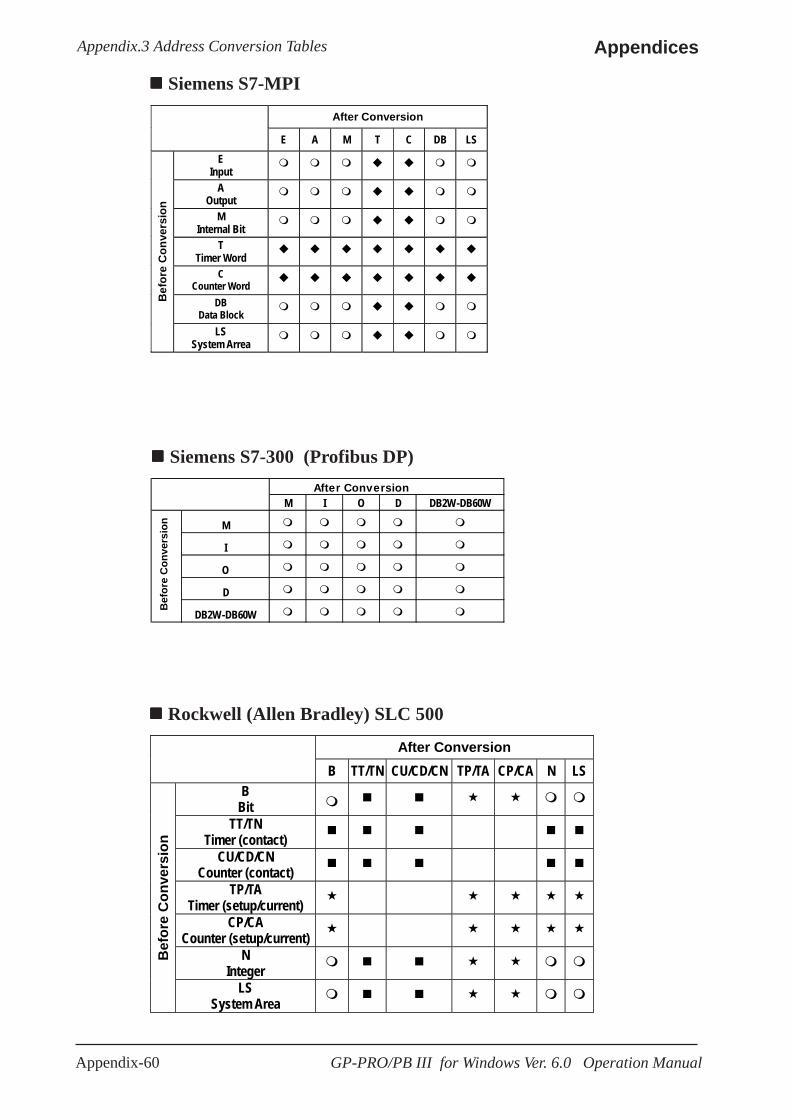
Appendix-60 GP-PRO/PB III for Windows Ver. 6.0 Operation Manual
AppendicesAppendix.3 Address Conversion Tables
After Conversion
B TT/TN CU/CD/CN TP/TA CP/CA N LS B
Bit TT/TN
Timer (contact)
CU/CD/CN Counter (contact)
TP/TA Timer (setup/current)
CP/CA Counter (setup/current)
N Integer B
efor
e C
onve
rsio
n
LS System Area
Rockwell (Allen Bradley) SLC 500
Siemens S7-300 (Profibus DP)After Conversion
M I O D DB2W-DB60W
M
I
O
D
DB2W-DB60W
Bef
ore
Con
vers
ion
Siemens S7-MPIAfter Conversion
E A M T C DB LS
E Input
A Output
M Internal Bit
T Timer Word
C Counter Word
DB Data Block
Bef
ore
Con
vers
ion
LS System Arrea

Appendix-61GP-PRO/PB III for Windows Ver. 6.0 Operation Manual
Appendices Appendix.3 Address Conversion Tables
After Conversion
I O B TT/TD CC/CD TA/TP CA/CP N/D/A LS I
Input Relay O
Output Relay B
Internal Relay TT/TD
Timer (contact) CC/CD
Counter (contact) TA/TP Timer CA/CP
Counter
N/D/A Data Register
Bef
ore
Con
vers
ion
LS System Area
Rockwell (Allen Bradley) PLC-5
Rockwell (Allen Bradley) (Remote I/O)
After Conversion I O BTR BTW LS
I Input
O Output
BTR Block Transfer(Read)
BTW Block Transfer(Write)
Bef
ore
Con
vers
ion
LS System Area

Appendix-62 GP-PRO/PB III for Windows Ver. 6.0 Operation Manual
AppendicesAppendix.3 Address Conversion Tables
Allen Bradley SLC 500 <Data Highway>
0 1 S B T C R N F A ST LS01SBTCRNFA
STLS
After Conversion
Bef
ore
Con
vers
ion
After Conversion 0000 to 02EE LS
0000 to 02EE
Bef
ore
Con
vers
ion
LS
Interbus-S

Appendix-63GP-PRO/PB III for Windows Ver. 6.0 Operation Manual
Appendices Appendix.3 Address Conversion Tables
Keyence KZ - A500 (Link I/F)
After Conversion
Relay T C DM TM LS
Relay T
Timer C
Counter
DM Data memory
TM Temporary data memory
Bef
ore
Con
vers
ion
LS System area
Keyence KZ-300, KZ-500 (Direct Connection)
After Conversion- T C CTC TC CC TS CS DM TM AT CTH CTC LS
RelayT
Timer (contact)C
Counter (contact)CTC
High-speed CounterComparator (contact)
TCTimer (setup value)
CCCounter (setup value)
TSTimer (current value)
CSCounter (current value)
DMData Memory
TMTemporary Data Memory
ATDigital Trimmer
CTHHigh-speed Counter
(current value)CTC
High-speed CounterComparator (setup value)
LSLS Area
Bef
ore
Con
vers
ion

Appendix-64 GP-PRO/PB III for Windows Ver. 6.0 Operation Manual
AppendicesAppendix.3 Address Conversion Tables
Keyence KV Series
After Conversion- T C CTC TC CC TS CS DM TM AT CTH CTC LS
RelayT
Timer (contact)C
Counter (contact)CTC
High-speed CounterComparator (contact)
TCTimer (setup value)
CCCounter (setup value)
TSTimer (current value)
CSCounter (current value)
DMData Memory
TMTemporary Data Memory
ATDigital Trimmer
CTHHigh-speed Counter
(current value)CTC
High-speed CounterComparator (setup value)
LSLS Area
Bef
ore
Con
vers
ion
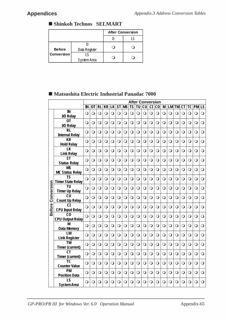
Appendix-65GP-PRO/PB III for Windows Ver. 6.0 Operation Manual
Appendices Appendix.3 Address Conversion Tables
After Conversion IN OT RL KR LK ST MS TS TU CU CI CO M LM TM CT TC PM LS IN
I/O Relay OT
I/O Relay RL
Internal Relay KR
Hold Relay LK
Link Relay ST
Status Relay
MS MC Status Relay
TS Timer State Relay
TU Timer Up Relay
CU Count Up Relay
CI CPU Input Relay
CO CPU Output Relay
M Data Memory
LM Link Register
TM Timer (current)
CT Timer (current)
TC Counter Value
PM Position Data
Bef
ore
Con
vers
ion
LS System Area
Matsushita Electric Industrial Panadac 7000
Shinkoh Technos SELMART
D LSD
Data RegisterLS
System Area
BeforeConversion
After Conversion
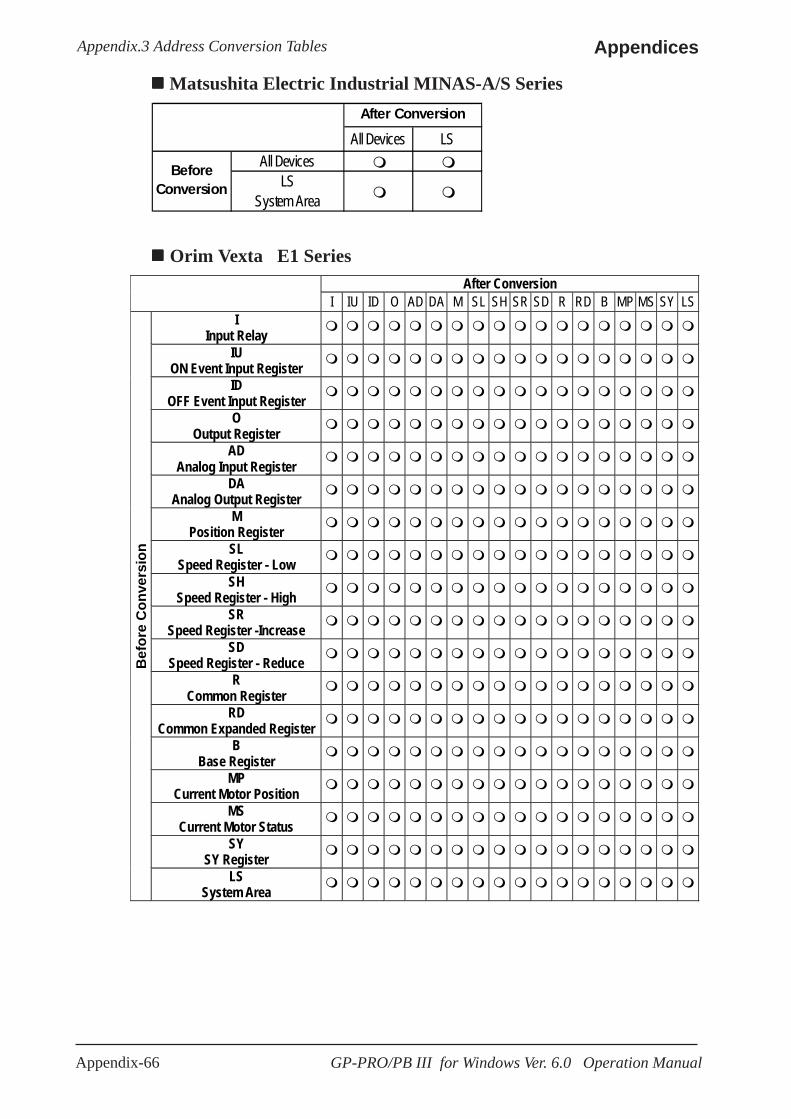
Appendix-66 GP-PRO/PB III for Windows Ver. 6.0 Operation Manual
AppendicesAppendix.3 Address Conversion Tables
After Conversion
I IU ID O AD DA M SL SH SR SD R RD B MP MS SY LS I
Input Relay
IU ON Event Input Register
ID OFF Event Input Register
O Output Register
AD Analog Input Register
DA Analog Output Register
M Position Register
SL Speed Register - Low
SH Speed Register - High
SR Speed Register -Increase
SD Speed Register - Reduce
R Common Register
RD Common Expanded Register
B Base Register
MP Current Motor Position
MS Current Motor Status
SY SY Register
Bef
ore
Con
vers
ion
LS System Area
Orim Vexta E1 Series
Matsushita Electric Industrial MINAS-A/S Series
All Devices LSAll Devices
LSSystem Area
BeforeConversion
After Conversion

Appendix-67GP-PRO/PB III for Windows Ver. 6.0 Operation Manual
Appendices Appendix.3 Address Conversion Tables
S C LS
--------
Setting Value Memory
Channel
LS Area LS
BeforeConversion
After Conversion
Shinkoh Technos C/FC/FIR/GC/FCL/PC-900 Series
Rika Kohgyou CB/SR-Mini Series
0000 to 02EE LS0000 to 02EE
LSBefore
Conversion
After Conversion
After Conversion Data LS
Data B
efor
e C
onve
rsio
n
LS System Area
Yamatake Yamatake SDC Series/DMC10
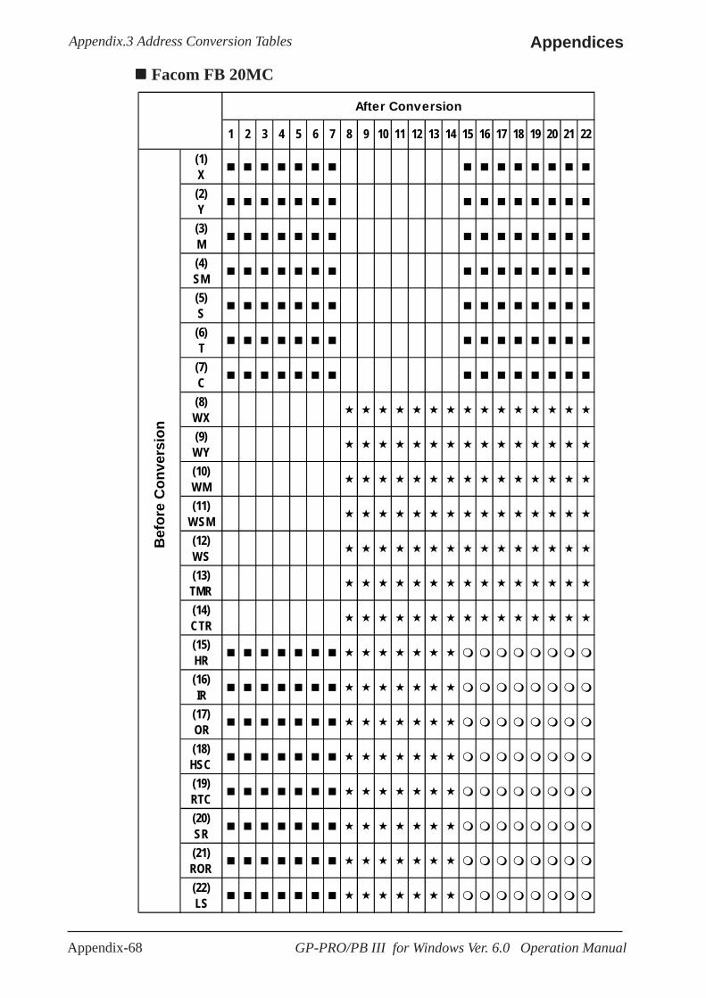
Appendix-68 GP-PRO/PB III for Windows Ver. 6.0 Operation Manual
AppendicesAppendix.3 Address Conversion Tables
Facom FB 20MC
1 2 3 4 5 6 7 8 9 10 11 12 13 14 15 16 17 18 19 20 21 22
(1)X(2)Y(3)M(4)SM(5)S(6)T
(7)C(8)WX(9)WY(10)WM(11)
WSM(12)WS(13)TMR(14)CTR(15)HR(16)IR
(17)OR(18)HSC(19)RTC(20)SR(21)ROR(22)LS
After Conversion
Bef
ore
Con
vers
ion
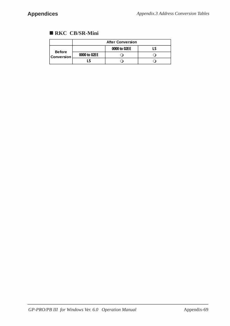
Appendix-69GP-PRO/PB III for Windows Ver. 6.0 Operation Manual
Appendices Appendix.3 Address Conversion Tables
0000 to 02EE LS0000 to 02EE
LS
After Conversion
BeforeConversion
RKC CB/SR-Mini
Appendix-70 GP-PRO/PB III for Windows Ver. 6.0 Operation Manual
AppendicesAppendix 4 Software Trouble Report
A.4 Software Trouble Report
When problems continue after following “Troubleshooting”adviceIf following the steps outlined in the troubleshooting section does not solve yourproblem, please make a copy of the next page’s Software Trouble Report, fill in anyrelevant information, and fax it to your local Pro-face service center.Please include any relevant details, including project data and/or screens so that theproblem can be duplicated. We guarantee all this data will remain confidential.Also, please take the time to use the “OSCHECK” tool installed with your GP-PRO/PBIII software, and include a printout of its result with your fax.
Using the “OSCHECK” ProgramThis program, after it completes its test, produces a text file (*.txt). Please be sure toprint out this data and include it with your Software Trouble Report.1) Click on the Windows main screen’s [Start] button and then on the [Run]
selection.
2) Here, use the [Browse] feature to find the OSCHECK.EXE program, locatedin your PC’s “ProPBWin” folder. Once you find it, click on to start the program.
3) Designate the status report’s Save folder and filename.
4)Click again on and the text file will be created.
• When inquiring, be sure to write down your software’s serialNo. Without your software’s serial No., your question(s) can-not be answered.
• Understand that it may take some time for us to respond, sinceyour question must be carefully checked and recreated.
Pro-face FAX and Email Information:• Pro-face Europe: FAX No. +31-(0)20-6464-358 Email: [email protected]
• Pro-Face Korea: FAX No. +82-(0)2-3664-6839 Email: [email protected]
• Pro-Face Taiwan: FAX No. +886-(0)2-8773-7892 Email: [email protected]
• Pro-face America / Xycom (North and South): FAX No. +1-734-429-1010Email: [email protected]
Digital (Japan) FAX and Email Information:• Digital Electronics Corporation: FAX No. +81-(0)6-6613-5982 Email: [email protected], if you require instruction about the correct usage of your GP-PRO/PBIII forWindows software, please use the above information to contact your local GP-PRO/PBIII distributor.
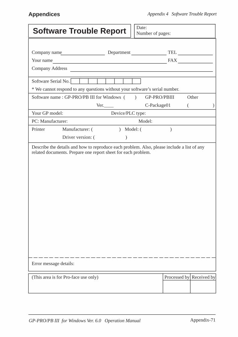
Appendix-71GP-PRO/PB III for Windows Ver. 6.0 Operation Manual
Appendices Appendix 4 Software Trouble Report
Describe the details and how to reproduce each problem. Also, please include a list of anyrelated documents. Prepare one report sheet for each problem.
Error message details:
(This area is for Pro-face use only) Processed by Received by
Company name Department TEL
Your name FAX
Company Address
Software Serial No.
* We cannot respond to any questions without your software’s serial number.
Software name : GP-PRO/PB III for Windows ( ) GP-PRO/PBIII Other
Ver.____ C-Package01 ( )
Your GP model: Device/PLC type:
PC: Manufacturer: Model:
Printer Manufacturer: ( ) Model: ( )
Driver version: ( )
Date:Number of pages: Software Trouble Report

Appendix-72 GP-PRO/PB III for Windows Ver. 6.0 Operation Manual
AppendicesAppendix 4 Software Trouble Report
Memo