Goodnal STP ST041 Sewage Delivery (Amarex KRT ...
96
Cust. Doc. No.:GDSTP-24090-MAN-0003-P2 KSB Doc. No.:KSB-88980-056 KSB REF No: 88980/ 20 & 30 Client : Thiess Pty Ltd Project : Goodna Sewerage Treatment Plant Upgrage [Stage 4A] P.O. No. : GDSTP-24090-CON-0000 Equipment / Tag No. : Site Foul Liquor Pumps PU-0110-010/020 : PTA Foul Liquor Pumps PU-0200-010/020 OPERATING AND MAINTENANCE INSTRUCTIONS KSB Australia Pty Ltd ABN 29 006 414 642 A Quality Endorsed Company AS/NZ ISO9001:2008 Sales and Service Phone : (07) 3436 8600 Fax : (07) 3436 8699 Email : [email protected] Spares : 1300 KSB SPARES ( 1300 572 772 ) Issue Date: 13/12/2011 Goodnal STP ST041 Sewage Delivery (Amarex KRT Submersible Motor Pump) Vendor Manual Q-Pulse Id VM362 Active 29/10/2013 Page 1 of 96
-
Upload
khangminh22 -
Category
Documents
-
view
1 -
download
0
Transcript of Goodnal STP ST041 Sewage Delivery (Amarex KRT ...

Cust. Doc. No.:GDSTP-24090-MAN-0003-P2
KSB Doc. No.:KSB-88980-056
KSB REF No: 88980/ 20 & 30 Client : Thiess Pty Ltd
Project : Goodna Sewerage Treatment Plant Upgrage [Stage 4A]
P.O. No. : GDSTP-24090-CON-0000
Equipment / Tag No. : Site Foul Liquor Pumps PU-0110-010/020
: PTA Foul Liquor Pumps PU-0200-010/020
OPERATING AND
MAINTENANCE
INSTRUCTIONS
K S B A u s t r a l i a P t y L t d A B N 2 9 0 0 6 4 1 4 6 4 2 A Q u a l i t y E n d o r s e d C o m p a n y A S / N Z I S O 9 0 0 1 : 2 0 0 8
Sales and Service Phone : (07) 3436 8600 Fax : (07) 3436 8699 Email : [email protected] Spares : 1300 KSB SPARES ( 1300 572 772 )
Issue Date: 13/12/2011
Goodnal STP ST041 Sewage Delivery (Amarex KRT Submersible Motor Pump) Vendor Manual
Q-Pulse Id VM362 Active 29/10/2013 Page 1 of 96

INDEX 1. Pump
• Amarex KRT Pumps Installation/ Operating Manual 2. Additional Data
• Pump Data Sheet (Site Foul Liquor) • Pump Data Sheet (PTA Foul Liquor)
3. Drawings
• Certified G.A. Drawing No.A3-UK00019 (Site Foul Liquor Pumps) • Certified G.A. Drawing No.A3-UK00018 (PTA Foul Liquor Pumps )
4. Tests
• I.T.P.s (Site Foul Liquor Pumps) • I.T.P.s (PTA Foul Liquor Pumps)
Goodnal STP ST041 Sewage Delivery (Amarex KRT Submersible Motor Pump) Vendor Manual
Q-Pulse Id VM362 Active 29/10/2013 Page 2 of 96
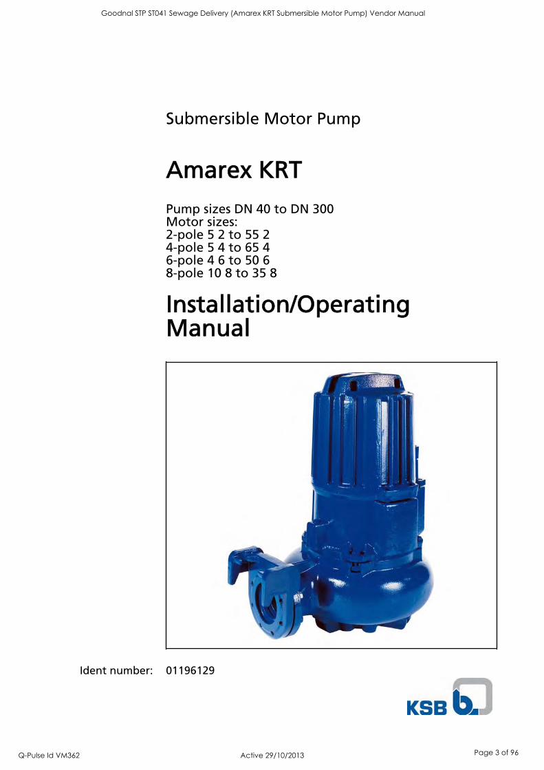
Submersible Motor Pump
Amarex KRT
Pump sizes DN 40 to DN 300Motor sizes:2-pole 5 2 to 55 24-pole 5 4 to 65 46-pole 4 6 to 50 68-pole 10 8 to 35 8
Installation/OperatingManual
Ident number: 01196129
Goodnal STP ST041 Sewage Delivery (Amarex KRT Submersible Motor Pump) Vendor Manual
Q-Pulse Id VM362 Active 29/10/2013 Page 3 of 96

Installation/Operating Manual Amarex KRTOriginal operating manual KSB Aktiengesellschaft Pegnitz All rights reserved. Contents provided herein must neither be distributed, copied, reproduced,processed for any other purpose, nor otherwise transmitted to a third party without KSB´s expresswritten consent. Subject to technical modification without prior notice. © KSB Aktiengesellschaft Frankenthal 05.01.2009
Goodnal STP ST041 Sewage Delivery (Amarex KRT Submersible Motor Pump) Vendor Manual
Q-Pulse Id VM362 Active 29/10/2013 Page 4 of 96

Contents
Glossary ................................................................................................ 5
1 General ................................................................................................ 6
1.1 Principles .......................................................................................................... 6
1.2 Installation of partly completed machinery .................................................. 6
1.3 Target group ................................................................................................... 7
1.4 Other applicable documents .......................................................................... 7
1.5 Symbols ............................................................................................................ 7
2 Safety ................................................................................................... 8
2.1 Key to safety symbols/markings ..................................................................... 8
2.2 General ............................................................................................................ 8
2.3 Intended use .................................................................................................... 8
2.4 Personnel qualification and training ........................................................... 10
2.5 Consequences and risks caused by non-compliance with these operatinginstructions .................................................................................................... 10
2.6 Safety awareness ........................................................................................... 10
2.7 Safety instructions for the operator/user .................................................... 10
2.8 Safety information for maintenance, inspection and installation work ... 11
2.9 Unauthorised modes of operation ............................................................... 11
2.10 Explosion protection ..................................................................................... 11
3 Transport/Temporary Storage/Disposal ........................................... 13
3.1 Transport ....................................................................................................... 13
3.2 Storage and preservation ............................................................................. 13
3.3 Return to supplier ......................................................................................... 14
3.4 Disposal .......................................................................................................... 14
4 Description of the Pump (Set) .......................................................... 15
4.1 General description ....................................................................................... 15
4.2 Designation ................................................................................................... 15
4.3 Name plate .................................................................................................... 15
4.4 Design details ................................................................................................ 16
4.5 Types of installation ...................................................................................... 16
4.6 Design and function ...................................................................................... 17
4.7 Scope of supply ............................................................................................. 17
4.8 Dimensions and weights ............................................................................... 18
5 Installation at Site ............................................................................. 19
5.1 Safety regulations ......................................................................................... 19
5.2 Checking the site before installation ........................................................... 19
5.3 Installing the pump set ................................................................................. 21
5.4 Electrical connection ..................................................................................... 27
Contents
Amarex KRT 3 of 74
Goodnal STP ST041 Sewage Delivery (Amarex KRT Submersible Motor Pump) Vendor Manual
Q-Pulse Id VM362 Active 29/10/2013 Page 5 of 96

6 Commissioning/Start-up/Shutdown ................................................. 32
6.1 Commissioning/start-up ................................................................................ 32
6.2 Operating limits ............................................................................................ 32
6.3 Shutdown/storage/preservation ................................................................... 35
6.4 Returning to service ...................................................................................... 35
7 Servicing/Maintenance ...................................................................... 37
7.1 Safety regulations ......................................................................................... 37
7.2 Servicing/inspection ...................................................................................... 37
7.3 Drainage/disposal .......................................................................................... 43
7.4 Dismantling the pump set ............................................................................ 43
7.5 Reassembling the pump set .......................................................................... 46
7.6 Tightening torques ....................................................................................... 52
7.7 Spare parts stock ........................................................................................... 52
8 Trouble-shooting ............................................................................... 54
9 Related Documents ........................................................................... 55
9.1 General assembly drawings .......................................................................... 55
9.2 Wiring diagrams ............................................................................................ 67
9.3 Flamepaths of explosion-proof motors ....................................................... 68
9.4 Sectional drawings of the mechanical seal .................................................. 69
10 EC Declaration of Conformity .......................................................... 71
11 Certificate of Decontamination ....................................................... 72
Index .................................................................................................. 73
Contents
4 of 74 Amarex KRT
Goodnal STP ST041 Sewage Delivery (Amarex KRT Submersible Motor Pump) Vendor Manual
Q-Pulse Id VM362 Active 29/10/2013 Page 6 of 96
Glossary
Back pull-out unitPump without pump casing; partly completedmachinery
Certificate of decontaminationA certificate of decontamination certifies thatthe pump (set) has been properly drained toeliminate any environmental and healthhazards arising from components in contactwith the fluid handled.
Close-coupled designMotor directly fitted to the pump via a flangeor a drive lantern
Hydraulic systemThe part of the pump in which the kineticenergy is converted into pressure energy.
Glossary
Amarex KRT 5 of 74
Goodnal STP ST041 Sewage Delivery (Amarex KRT Submersible Motor Pump) Vendor Manual
Q-Pulse Id VM362 Active 29/10/2013 Page 7 of 96

1 General
1.1 Principles
This manual is supplied as an integral part of the type series and variants indicatedon the front cover (for details, please refer to the table below).
Table 1: Variants covered by this manual
Pumpsizes
Impellertypes
Material variantsCast iron Industrial materials
G G1 G2 GH H C1 C240-250 F, K, S F, K, S F,K F F, K F, K F, K F, K80-250 E, F E, F F F F - - -80-251 F F - - - - - -80-315 D, E, F,
KD, E, F,
KD, F, K F F, K F, K F, K F, K
80-316 F F - - - - - -100-240 F F F F F F F F100-250 E, F, K E, F, K F, K F F, K F, K F, K F, K100-251 D D D - - - - -100-315 D, E, F,
KD, E, F,
KD, F, K F F, K F, K F, K F, K
100-316 D D D - - - - -100-401 E, F, K E, F, K F, K F F, K F, K F, K F, K150-251 D D D - - - - -150-315 D, E, F,
KD, E, F,
KD, F, K F F, K F, K F, K F, K
150-400 D D D - - - - -150-401 D, E, F,
KD, E, F,
KD, F F F,K F, K F, K F, K
151-401 K K K - K K K K200-315 D, K D,K D, K - K K K K200-316 K K - - K K K K200-330 K K K - K K K K200-400 D D D - - - - -200-401 E, K E, K K - K K K K250-400 D, K D,K D, K - K K K K250-401 K K K - K K K K300-400 D, K D, K D, K - K K K K300-401 K K K - K K K K
This manual describes the proper and safe use of this equipment in all phases ofoperation.
The name plate indicates the type series and size, the main operating data, the ordernumber and the order item number. The order number and order item numberclearly identify the pump set and serve as identification for all further businessprocesses.
In case of damage, immediately contact your nearest KSB Service centre to maintainthe right to claim under warranty.
1.2 Installation of partly completed machinery
To install partly completed machinery supplied by KSB, please refer to the sub-sections under Servicing/Maintenance.
1 General
6 of 74 Amarex KRT
Goodnal STP ST041 Sewage Delivery (Amarex KRT Submersible Motor Pump) Vendor Manual
Q-Pulse Id VM362 Active 29/10/2013 Page 8 of 96

1.3 Target group
This manual is aimed at the target group of trained and qualified specialist technicalpersonnel. ( Section 2.4 Page 10)
1.4 Other applicable documents
Table 2: Overview of other applicable documents
Document ContentsTechnical data sheet Description of the technical data of the pump
setGeneral arrangement drawing/outline drawing
Description of mating and installationdimensions for the pump set
Hydraulic characteristic curve Characteristic curves showing head, flow rate,efficiency and power input
General assembly drawing1) Sectional drawing of the pump set
Sub-supplier documentation1) Operating manuals and other documentationof accessories and integrated machinerycomponents
Spare parts lists1) Description of spare partsSupplementary operatinginstructions1)
For example for special accessories
1.5 Symbols
Table 3: Symbols used in this manual
Symbol Description Conditions which need to be fulfilled before proceeding with the
step-by-step instructions⊳ Safety instructions Result of an action Cross-references1.
2.
Step-by-step instructions
NoteRecommendations and important information on how to handlethe product
1) If agreed to be included in the scope of supply
1 General
Amarex KRT 7 of 74
Goodnal STP ST041 Sewage Delivery (Amarex KRT Submersible Motor Pump) Vendor Manual
Q-Pulse Id VM362 Active 29/10/2013 Page 9 of 96

2 SafetyAll the information contained in this section refers to hazardous situations.
2.1 Key to safety symbols/markings
Table 4: Definition of safety symbols/markings
Symbol Description
! DANGER DANGERThis signal word indicates a high-risk hazard which, if not avoided,will result in death or serious injury.
! WARNING WARNINGThis signal word indicates a medium-risk hazard which, if notavoided, could result in death or serious injury.
CAUTION CAUTIONThis signal word indicates a hazard which, if not avoided, couldresult in damage to the machine and its functions.Explosion protectionThis symbol identifies information about avoiding explosions inpotentially explosive atmospheres in accordance with EC Directive94/9/EC (ATEX).General hazardIn conjunction with one of the signal words this symbol indicates ahazard which will or could result in death or serious injury.
Electrical hazardIn conjunction with one of the signal words this symbol indicates ahazard involving electrical voltage and identifies informationabout protection against electrical voltage.Machine damage In conjunction with the signal word CAUTION this symbol indicatesa hazard for the machine and its functions.
2.2 General
This manual contains general installation, operating and maintenance instructionsthat must be observed to ensure safe pump operation and prevent injury anddamage to property.
The safety instructions in all sections of this manual must be complied with.
This manual must be read and completely understood by the responsible specialistpersonnel/operators prior to installation and commissioning.
The contents of this manual must be available to the specialist personnel at the siteat all times.
Instructions attached directly to the pump must always be complied with and be keptin a perfectly legible condition at all times. This applies to, for example:
Arrow indicating the direction of rotation
Markings for connections
Name plate
The operator is responsible for meeting all local regulations which are not taken intoaccount in this manual.
2.3 Intended use
Only operate the pump (set) within the application limits specified in the otherapplicable documents.
Only operate pump sets which are in perfect technical condition.
Do not operate partially assembled pump sets.
! DANGER
2 Safety
8 of 74 Amarex KRT
Goodnal STP ST041 Sewage Delivery (Amarex KRT Submersible Motor Pump) Vendor Manual
Q-Pulse Id VM362 Active 29/10/2013 Page 10 of 96

Only use the pump to handle the fluids described in the data sheet or productliterature of the pump model.
Never operate the system without the fluid to be handled.
Observe the limits for continuous operation specified in the data sheet orproduct literature (Qmin
2) and Qmax3) ) (prevention of damage such as shaft
fracture, bearing failure, damaged mechanical seal, etc).
When handling untreated waste water the duty points in continuous operationlie within 0.7 to 1.2 x Qopt
4) to minimise the risk of clogging/hardening.
Avoid duty points for continuous operation at very low speeds and small flowrates (<0.7 x Qopt
4) ).
Observe the information on the maximum flow rates provided in the data sheetor technical product literature (prevention of overheating damage, cavitationdamage, bearing damage, etc).
Do not throttle the flow rate on the suction side of the system (prevention ofcavitation damage).
For any operating modes which are not specified in the data sheet or productliterature, contact the manufacturer.
Only use the respective impeller types in combination with the fluids describedbelow.
Impeller with cutter (impeller type S)
Suitable for the following fluids:Faeces, domestic sewage and waste watercontaining long fibres
Free-flow impeller (impeller type F)
Suitable for the following fluids:Fluids containing solids and stringymaterial as well as fluids with entrappedair or gas
Closed single vaneimpeller(impeller type E)
Suitable for the following fluids:Fluids containing solids and stringymaterial
Closed multi-vaneimpeller (impeller type K)
Suitable for the following fluids:Contaminated, solids-laden, non-gaseousfluids not liable to plait
2) Minimum permissible flow rate3) Maximum permissible flow rate4) Optimum efficiency
2 Safety
Amarex KRT 9 of 74
Goodnal STP ST041 Sewage Delivery (Amarex KRT Submersible Motor Pump) Vendor Manual
Q-Pulse Id VM362 Active 29/10/2013 Page 11 of 96

Open, diagonal singlevane impeller (impeller type D)
Suitable for the following fluids:Waste water with solid substances andlong fibres
Prevention of foreseeable misuse
Observe the minimum flow velocities for fully open swing check valves to preventthe reduction of pressure and risk of clogging.(Contact the manufacturer for the required minimum flow velocities/losscoefficients.)
Never exceed the permissible application limits specified in the data sheet and inthe product literature regarding pressure, temperature, etc.
Observe all safety notes and instructions in this manual.
2.4 Personnel qualification and training
All personnel involved must be fully qualified to install, operate, maintain andinspect the machinery this manual refers to.
The responsibilities, competence and supervision of all personnel involved ininstallation, operation, maintenance and inspection must be clearly defined by theoperator.
Deficits in knowledge must be rectified by sufficiently trained specialist personneltraining and instructing the personnel who will carry out the respective tasks. Ifrequired, the operator can commission the manufacturer/supplier to train thepersonnel.
Training on the pump (set) must always be supervised by technical specialistpersonnel.
2.5 Consequences and risks caused by non-compliance with these operatinginstructions
Non-compliance with these operating instructions will lead to forfeiture ofwarranty cover and of any and all rights to claims for damages.
Non-compliance can, for example, have the following consequences:
– Hazards to persons due to electrical, thermal, mechanical and chemicaleffects and explosions
– Failure of important product functions
– Failure of prescribed maintenance and servicing practices
– Hazard to the environment due to leakage of hazardous substances
2.6 Safety awareness
In addition to the safety information contained in this manual and the intended use,the following safety regulations shall be complied with:
Accident prevention, health and safety regulations
Explosion protection regulations
Safety regulations for handling hazardous substances
Applicable standards and laws
2.7 Safety instructions for the operator/user
The operator shall fit contact guards for hot, cold and moving parts, and checkthat the guards function properly.
Never remove the contact guard when the pump is in operation.
2 Safety
10 of 74 Amarex KRT
Goodnal STP ST041 Sewage Delivery (Amarex KRT Submersible Motor Pump) Vendor Manual
Q-Pulse Id VM362 Active 29/10/2013 Page 12 of 96

Provide the personnel with protective equipment and make sure it is used.
Contain leakages (e.g at the shaft seal) of hazardous fluids handled (e.g.explosive, toxic, hot) so as to avoid any danger to persons and the environment.Adhere to all relevant laws.
Eliminate all electrical hazards. (In this respect refer to the applicable nationalsafety regulations and/or regulations issued by the local energy supplycompanies.)
2.8 Safety information for maintenance, inspection and installation work
Modifications or alterations of the pump are only permitted with themanufacturer's prior consent.
Use only original spare parts or parts authorised by the manufacturer. The use ofother parts can invalidate any liability of the manufacturer for consequentialdamage.
The operator ensures that all maintenance, inspection and installation work isperformed by authorised, qualified specialist personnel who are thoroughlyfamiliar with the manual.
Carry out work on the pump (set) during standstill only.
The pump casing must have cooled down to ambient temperature.
Pump pressure must have been released and the pump must have been drained.
When taking the pump set out of service always adhere to the proceduredescribed in the manual.
Decontaminate pumps which handle fluids posing a health hazard.
As soon as the work is complete, re-install and/or re-activate any safety-relevantand protective devices. Before returning the product to service, observe allinstructions on commissioning. ( Section 6.1 Page 32)
2.9 Unauthorised modes of operation
Never operate the pump (set) outside the limits stated in the data sheet and in thismanual.
The warranty relating to the operating reliability and safety of the supplied pump(set) is only valid if the equipment is used in accordance with its intended use.
2.10 Explosion protection
Always observe the information on explosion protection given in this section whenoperating an explosion-proof pump set.
Sections of the manual marked by the Ex symbol apply to explosion-proof pump setsalso when temporarily operated outside potentially explosive atmospheres.Only pumps/pump sets marked as explosion-proof and identified as such in the datasheet must be used in potentially explosive atmospheres.
Special conditions apply to the operation of explosion-proof pump sets in accordancewith EC Directive 94/9/EC (ATEX). When operating explosion-proof pump sets, especially adhere to the additionalrequirements marked by the Ex symbol. The explosion-proof status of the pump set is only assured if the pump set is used inaccordance with its intended use. Never operate the pump (set) outside the limits stated in the data sheet and on thename plate.Prevent impermissible modes of operation at all times.
2.10.1 Repair
Special regulations apply to repair work on explosion-proof pumps. Modifications oralteration of the pump set may affect explosion protection and are only permittedafter consultation with the manufacturer.
! DANGER
2 Safety
Amarex KRT 11 of 74
Goodnal STP ST041 Sewage Delivery (Amarex KRT Submersible Motor Pump) Vendor Manual
Q-Pulse Id VM362 Active 29/10/2013 Page 13 of 96

Repair work at the flameproof joints must only be performed in accordance with themanufacturer's instructions. Repair to the values in tables 1 and 2 of EN 60079-1 isnot permitted.
2 Safety
12 of 74 Amarex KRT
Goodnal STP ST041 Sewage Delivery (Amarex KRT Submersible Motor Pump) Vendor Manual
Q-Pulse Id VM362 Active 29/10/2013 Page 14 of 96

3 Transport/Temporary Storage/Disposal
3.1 Transport
DANGERImproper transportDanger to life from falling parts!Damage to the pump set!
▷ Use the attachment point provided (eyebolt, lifting lug or bail) for attachinglifting tackle.
▷ Never suspend the pump set by its power cable.
▷ Never use the chains or lifting ropes included in KSB's scope of supply for liftingloads other than the KSB product supplied.
▷ Securely attach the lifting ropes or chains to the pump and crane.
Transport the pump set as illustrated.
Fig. 1: Transporting the pump set
3.2 Storage and preservation
If commissioning is to take place some time after delivery, we recommend that thefollowing measures be taken for pump storage:
CAUTIONImproper storageDamage to the power cables!
▷ Support the power cables at the cable entry to prevent permanent deformation.
▷ Only remove the protective caps from the power cables at the time ofinstallation.
CAUTIONDamage during storage by humidity, dirt, or verminCorrosion/contamination of the pump (set)!
▷ For outdoor storage cover the pump (set) or the packaged pump (set) andaccessories with waterproof material.
CAUTIONWet, contaminated or damaged openings and connectionsLeakage or damage to the pump set!
▷ Only remove caps/covers from the openings of the pump set at the time ofinstallation.
3 Transport/Temporary Storage/Disposal
Amarex KRT 13 of 74
Goodnal STP ST041 Sewage Delivery (Amarex KRT Submersible Motor Pump) Vendor Manual
Q-Pulse Id VM362 Active 29/10/2013 Page 15 of 96
Table 5: Ambient conditions for storage
Ambient conditions ValueRelative humidity 5 % to 85 %
(non-condensing)Ambient temperature - 10 °C to + 70 °C
Store the pump set under dry and vibration-free conditions, if possible in itsoriginal packaging.
1. Spray-coat the inside wall of the pump casing, and in particular the impellerclearance areas, with a preservative.
2. Spray the preservative through the suction and discharge nozzles.It is advisable to then close the pump nozzles (e.g. with plastic caps or similar).
NOTEObserve the manufacturer's instructions for application/removal of the preservative.
3.3 Return to supplier
1. Drain the pump as per operating instructions. ( Section 7.3 Page 43)
2. Always flush and clean the pump, particularly if it has been used for handlingnoxious, explosive, hot or other hazardous fluids.
3. If the fluids handled by the pump leave residues which might lead to corrosiondamage when coming into contact with atmospheric humidity, or which mightignite when coming into contact with oxygen, the pump set must also beneutralised, and anhydrous gas must be blown through the pump for dryingpurposes.
4. Always complete and enclose a certificate of decontamination when returningthe pump (set). ( Section 11 Page 72)Always indicate the safety and decontamination measures taken.
NOTEIf required, a blank certificate of decontamination can be downloaded from the KSB website at: www.ksb.com/certificate_of_decontamination
3.4 Disposal
WARNINGFluids posing a health hazardHazardous to persons and the environment!
▷ Collect and properly dispose of flushing liquid and any fluid residues.
▷ Wear safety clothing and a protective mask, if required.
▷ Observe all legal regulations on the disposal of fluids posing a health hazard.
1. Dismantle the pump (set).Collect greases and other lubricants during dismantling.
2. Separate and sort the pump materials, e.g. by:- Metals- Plastics- Electronic waste- Greases and other lubricants
3. Dispose of materials in acc. with local regulations or in another controlledmanner.
3 Transport/Temporary Storage/Disposal
14 of 74 Amarex KRT
Goodnal STP ST041 Sewage Delivery (Amarex KRT Submersible Motor Pump) Vendor Manual
Q-Pulse Id VM362 Active 29/10/2013 Page 16 of 96

4 Description of the Pump (Set)
4.1 General description
Pump for handling untreated waste water containing long fibres and solidsubstances, fluids containing gas and air as well as raw, activated and digestedsludge. ( Section 2.3 Page 8)
4.2 Designation
Example: KRTK 150-315/164XG-S
Table 6: Key to the designation
Code DescriptionKRT Type seriesK Impeller type, e.g. K = channel impeller150 Nominal discharge nozzle diameter (DN) [mm]315 Maximum nominal impeller diameter [mm]16 Motor size4 Number of polesX Motor version e.g. X = explosion-proof to ATEX II 2GT3G Material variant e.g., G = complete pump in cast ironS Installation type, e.g. S = stationary wet installation
without cooling system
4.3 Name plate
Typ
No. 9971143406
Q 300 m3/h
P2 16 kW 400/690 V 50 Hz
cos φ 0,81
40 °C
33/19 A 1475 min-1
Aktiengesellschaft67227 Frankenthal
Ident-No. 01080556 ZN 3826-M12
2007
IP 68 S1 IA/IN 4,9 150 kg Class F
DKN 160.4-12 3~
H 14 m
M.-No. 123456
Nicht unter Spannung öffnen.Ne pas ouvrir sous tension.Non aprire con motore sotto tensione.
Non abrir bajo tensión.Do not open while energised.
21
3
4
56
789
1011
12
131415
17
1819
16
Amarex KRTK 150-315/164UG-S Typ Amarex KRTK 150-315/164XG-S
No. 9971143406 2007
Q 300 m3/h
DKN 160.4-12 3~
P2 16 kW
1475 min-1
400/690 V
33/19 A
IP 68 S1 Ia /In 4,9 150 kg
H 14 m
M.-No. 123456
50 Hz 40 °C
cos φ 0,81
WARNING - DO NOT OPEN WHEN ENERGIZEDWARNUNG - NICHT UNTER SPANNUNG ÖFFNEN
AVERTISSEMENT - NE PAS OUVRIR SOUS TENSIONIdent-No. 01080556 ZN 3826-M16
Aktiengesellschaft67227 Frankenthal
0035 II2G Ex d IIB T 3 PTB 02 Atex 1055
Class F
20
20
a) b)
Fig. 2: Name plate a) Standard pump set b) Explosion-proof pump set
1 Designation ( Section 4.2 Page 15) 2 KSB order number3 Flow rate 4 Motor type5 Rated power 6 Rated speed7 Rated voltage 8 Rated current9 Enclosure 10 Mode of operation11 Starting current ratio 12 Year of construction13 Head 14 Motor number15 Maximum fluid and ambient temperature 16 Rated frequency17 Power factor at design point 18 Thermal class of winding insulation19 Total weight 20 Marking for explosion-proof pump sets
4 Description of the Pump (Set)
Amarex KRT 15 of 74
Goodnal STP ST041 Sewage Delivery (Amarex KRT Submersible Motor Pump) Vendor Manual
Q-Pulse Id VM362 Active 29/10/2013 Page 17 of 96

4.4 Design details
Design
Fully floodable submersible motor pump
Not self-priming
Close-coupled design
Impel ler type
Various, application-based impeller types ( Section 2.3 Page 8)
Shaft seal
Two bi-directional mechanical seals in tandem arrangement, with liquid reservoir
Reinforced bearings with leakage chamber
Standard bear ing assembly
Grease-packed bearings sealed for life
Maintenance-free
Reinforced bearing assembly
Motor-end bearing:
Grease-packed bearings sealed for life
Maintenance-free
Pump-end bearing:
Grease-packed bearings sealed for life
Re-lubrication possible
The following hydraulic system/motor combinations have reinforced bearings:
Table 7: Reinforced bearings
Size ofhydraulicsystem
Motor size and number of poles372 552 554 504 654
D 80-315 X X - - -D 100-315 X X - - -D 150-400 - - X X XD 150-401 - - - X XD 200-400 - - - X XD 250-400 - - X X X
Drive
Three-phase asynchronous squirrel-cage motor
Explosion-proof pump sets are supplied with an integrated motor of Ex d IIB type ofprotection.
4.5 Types of installation
Two design variants are available, depending on the installation type:
Stationary wet installation (type of installation S)
Transportable wet installation (type of installation P)
The pump set is designed for continuous operation in submerged condition. Themotor is cooled by the fluid handled on the motor surface. Operation with the motoroutside the fluid handled is possible for short periods.
4 Description of the Pump (Set)
16 of 74 Amarex KRT
Goodnal STP ST041 Sewage Delivery (Amarex KRT Submersible Motor Pump) Vendor Manual
Q-Pulse Id VM362 Active 29/10/2013 Page 18 of 96
4.6 Design and function
1
34
6
7
8
9
10
5
2
Fig. 3: Sectional drawing
1 Casing wear ring 2 Discharge nozzle3 Discharge cover 4 Shaft5 Bearing bracket 6 Suction nozzle7 Impeller 8 Shaft seal9 Bearing, pump end 10 Bearing, motor end
The pump is designed with an axial fluid inlet and a radial outlet. The hydraulicsystem sits on the extended motor shaft. The shaft runs in common bearings.
The fluid enters the pump axially via a suction nozzle (6) and is accelerated outwardin a cylindrical flow by the rotating impeller (7). The flow profile of the pump casingconverts the kinetic energy of the fluid into pressure energy. The fluid is pumped tothe discharge nozzle (2), where it leaves the pump. The casing wear ring (1) preventsany fluid from flowing back from the casing into the inlet. At the rear side of theimpeller, the shaft (4) enters the casing via the discharge cover (3). The shaft passagethrough the discharge cover is sealed towards the atmosphere with a shaft seal (8).The shaft runs in rolling element bearings (9 and 10), which are supported by abearing bracket (5) linked with the pump casing and/or discharge cover.
The pump is sealed by two bi-rotational mechanical seals in tandem arrangement.A lubricant reservoir in-between the seal elements ensures cooling and lubrication ofthe mechanical seals.
4.7 Scope of supply
Depending on the model, the following items are included in the scope of supply:
Stat ionary wet instal lat ion (type of instal lat ion S)
Pump set complete with electric cables
Claw with sealing material and mounting elements
Lifting rope or chain
Mounting bracket with mounting elements
Design
Function
Sealing
4 Description of the Pump (Set)
Amarex KRT 17 of 74
Goodnal STP ST041 Sewage Delivery (Amarex KRT Submersible Motor Pump) Vendor Manual
Q-Pulse Id VM362 Active 29/10/2013 Page 19 of 96
Duckfoot bend with mounting elements
Guiding equipment(guide rails are not included in KSB's scope of supply)
Transportable wet instal lat ion (type of instal lat ion P)
Pump set complete with electric cables
Foot pad or pump stool with mounting elements
Lifting rope or chain
NOTEA separate name plate is included in KSB's scope of supply.This name plate must be attached in a clearly visible position outside the place ofinstallation, e.g. at the control panel, pipeline or mounting bracket.
4.8 Dimensions and weights
For dimensions and weights please refer to the general arrangement drawing/outlinedrawing or data sheet of the pump set.
4 Description of the Pump (Set)
18 of 74 Amarex KRT
Goodnal STP ST041 Sewage Delivery (Amarex KRT Submersible Motor Pump) Vendor Manual
Q-Pulse Id VM362 Active 29/10/2013 Page 20 of 96

5 Installation at Site
5.1 Safety regulations
DANGERImproper installation in potentially explosive atmospheresExplosion hazard!Damage to the pump set!
▷ Comply with the applicable local explosion protection regulations.
▷ Observe the information given in the data sheet and on the name plate of thepump set.
DANGERPersons in the tank during pump operationElectric shock!
▷ Never start up the pump set when there are persons in the tank.
5.2 Checking the site before installation
5.2.1 Checking the operating data
Before installing the pump set, verify that the name plate data matches the datagiven in the purchase order and the site system data.
5.2.2 Preparing the place of installation
Place of instal lat ion for stat ionary models
WARNINGInstallation on foundations which are unsecured and cannot support the loadPersonal injury and damage to property!
▷ Make sure the foundation concrete is of sufficient strength (min. C25/30 toDIN 1045).
▷ Make sure the foundation has set firmly before placing the duckfoot bend on it.
▷ Only place the duckfoot bend on horizontal and level surfaces.
▷ Refer to the weights given in the data sheet/name plate.
Any resonances at the usual excitation frequencies (1x and 2x rotational frequency,rotational noise) must be prevented both in the foundation and in the connectedpiping, as such frequencies may cause extreme vibrations.
1. Check the structural requirements. All structural work required must have been prepared in accordance with thedimensions stated in the outline drawing/general arrangement drawing.
Place of instal lat ion for transportable models
WARNINGInstallation on unsecured, uneven mounting surfacesPersonal injury and damage to property!
▷ Always install the pump set vertically with the motor on top on secured andlevel mounting surfaces.
▷ Observe the weights specified on the data sheet/name plate.
Resonances
5 Installation at Site
Amarex KRT 19 of 74
Goodnal STP ST041 Sewage Delivery (Amarex KRT Submersible Motor Pump) Vendor Manual
Q-Pulse Id VM362 Active 29/10/2013 Page 21 of 96

Any resonances at the usual excitation frequencies (1x and 2x rotational frequency,rotational noise) must be prevented both in the foundation and in the connectedpiping, as such frequencies may cause extreme vibrations.
1. Check the structural requirements. All structural work required must have been prepared in accordance with thedimensions stated in the outline drawing/general arrangement drawing.
5.2.3 Checking the lubricant level
The lubricant reservoirs are filled with an environmentally-friendly, non-toxiclubricant at the factory.
1. Install the pump set as illustrated.
903.03411.03903.03
411.03
Fig. 4: Checking the lubricant level
2. Unscrew screwed plug 903.03 with joint ring 411.03.
The lubricant must be level with the filler opening.
3. If the lubricant level is lower, fill the lubricant reservoir via the filler openinguntil the reservoir overflows. ( Section 7.2.2.1.4 Page 41)
4. Close screwed plug 903.03 with joint ring 411.03 again.
5.2.4 Checking the direction of rotation
DANGERPump set running dryExplosion hazard!
▷ The direction of rotation of explosion-proof pump sets must be checked outsidethe potentially explosive atmosphere.
WARNINGHands or objects inside the pump casingRisk of injuries, damage to the pump!
▷ Never insert your hands or any other objects into the pump.
▷ Check that the inside of the pump is free from any foreign objects.
CAUTIONPump set running dryIncreased vibrations!Damage to mechanical seals and bearings!
▷ Never operate the pump set for more than 60 seconds outside the fluid to behandled.
The pump set has been connected to the power supply. ( Section 5.4.2 Page30)
1. Start up the pump set and switch it off again immediately to check the directionof rotation of the motor.
Resonances
5 Installation at Site
20 of 74 Amarex KRT
Goodnal STP ST041 Sewage Delivery (Amarex KRT Submersible Motor Pump) Vendor Manual
Q-Pulse Id VM362 Active 29/10/2013 Page 22 of 96

2. Check the direction of rotation. When looking at the pump mouth, the impeller must turn in anti-clockwisedirection (on some pump casings, the direction of rotation is marked by anarrow).
Fig. 5: Checking the direction of rotation.
3. If the impeller runs in the wrong direction of rotation, check the connection ofthe pump and the switchgear, if any.
4. Disconnect the pump set from the power supply again and make sure it cannotbe switched on accidentally.
5.3 Installing the pump set
Always observe the general arrangement drawing/outline drawing when installingthe pump set.
5.3.1 Stationary wet installation
5.3.1.1 Fastening the duckfoot bend
Depending on the pump size, the duckfoot bend is either fastened with anchor boltsand/or foundation rails.
Fastening the duckfoot bend with anchor bolts
1. Position duckfoot bend 72-1 at the bottom of the tank/well.
2. Insert anchor bolts 90-3.38.
3. Screw duckfoot bend 72-1 to the floor with anchor bolts 90-3.38.
Fig. 6: Fastening theduckfoot bend
5 Installation at Site
Amarex KRT 21 of 74
Goodnal STP ST041 Sewage Delivery (Amarex KRT Submersible Motor Pump) Vendor Manual
Q-Pulse Id VM362 Active 29/10/2013 Page 23 of 96

Table 8: Anchor bolt dimensions
Bolt size do
[mm]t=hreq
[mm]tfix
[mm]WAF[mm]
M[mm]
Hex.headWAF[mm]
Torque[Nm]
M 10x130 12 90 20 17 10 7 20M 12x160 14 110 25 19 12 8 40M 16x190 18 125 35 24 16 12 60M 20x260 25 170 65 30 20 12 120M 24x3005) 28 210 65 36 24 - 150
M 30x3805) 35 280 65 46 30 - 300
Table 9: Curing times of mortar cartridge
Floor temperature Curing time[min]
-5 to 0 2400 to +10 45+10 to +20 20> +20 °C 10
5.3.1.2 Connecting the piping
DANGERThe permissible loads on the flange of the duckfoot bend have been exceededDanger to life from leakage of hot, toxic, corrosive or flammable fluids!
▷ Do not use the pump as an anchorage point for the piping.
▷ Anchor the pipelines in close proximity to the pump and connect them withouttransmitting any stresses or strains.
▷ Observe the permissible flange loads.
▷ Take appropriate measures to compensate thermal expansion of the piping.
NOTEWhen the pump set is used for draining low-level building areas, install a swing checkvalve in the discharge line to avoid backwash from the sewer system.
CAUTIONCritical speedIncreased vibrations!Damage to mechanical seals and bearings!
▷ Install a swing check valve in longer riser pipes to prevent the pump fromexcessive running in reverse.When fitting a swing check valve, make sure that the unit can still be ventedproperly.
t=
hre
qt f
ix
WAFMHex. Head WAF
do
l
Fig. 7: Dimensions
5) Mounting accessories of respective manufacturer required.
5 Installation at Site
22 of 74 Amarex KRT
Goodnal STP ST041 Sewage Delivery (Amarex KRT Submersible Motor Pump) Vendor Manual
Q-Pulse Id VM362 Active 29/10/2013 Page 24 of 96
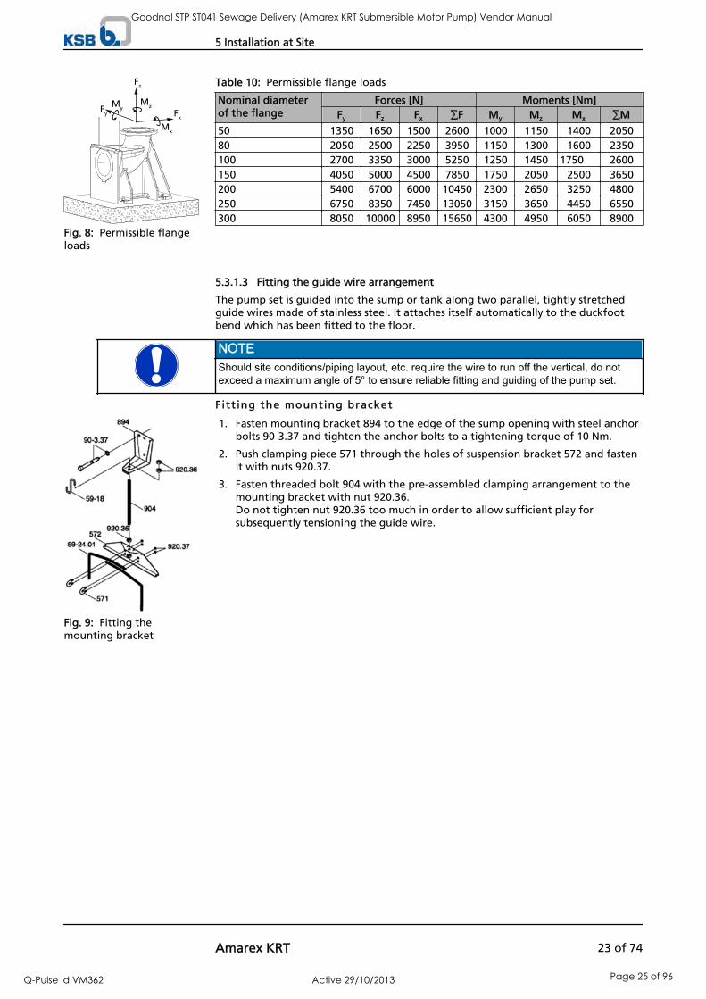
Table 10: Permissible flange loads
Nominal diameterof the flange
Forces [N] Moments [Nm]Fy Fz Fx ∑F My Mz Mx ∑M
50 1350 1650 1500 2600 1000 1150 1400 205080 2050 2500 2250 3950 1150 1300 1600 2350100 2700 3350 3000 5250 1250 1450 1750 2600150 4050 5000 4500 7850 1750 2050 2500 3650200 5400 6700 6000 10450 2300 2650 3250 4800250 6750 8350 7450 13050 3150 3650 4450 6550300 8050 10000 8950 15650 4300 4950 6050 8900
5.3.1.3 Fitting the guide wire arrangement
The pump set is guided into the sump or tank along two parallel, tightly stretchedguide wires made of stainless steel. It attaches itself automatically to the duckfootbend which has been fitted to the floor.
NOTEShould site conditions/piping layout, etc. require the wire to run off the vertical, do notexceed a maximum angle of 5° to ensure reliable fitting and guiding of the pump set.
Fitt ing the mounting bracket
1. Fasten mounting bracket 894 to the edge of the sump opening with steel anchorbolts 90-3.37 and tighten the anchor bolts to a tightening torque of 10 Nm.
2. Push clamping piece 571 through the holes of suspension bracket 572 and fastenit with nuts 920.37.
3. Fasten threaded bolt 904 with the pre-assembled clamping arrangement to themounting bracket with nut 920.36.Do not tighten nut 920.36 too much in order to allow sufficient play forsubsequently tensioning the guide wire.
Fx
Fz
Fy
MyMz
Mx
Fig. 8: Permissible flangeloads
Fig. 9: Fitting themounting bracket
5 Installation at Site
Amarex KRT 23 of 74
Goodnal STP ST041 Sewage Delivery (Amarex KRT Submersible Motor Pump) Vendor Manual
Q-Pulse Id VM362 Active 29/10/2013 Page 25 of 96

Insert ing the guide wire
1. Lift clamping piece 571 and insert one end of the guide wire.
2. Run wire 59-24.01 around duckfoot bend 72-1 and back again to suspensionbracket 572 and insert it into clamping piece 571.
3. Manually tension wire 59-24.01 and secure it by means of hexagon nuts 920.37.
4. Pull the wire taut by tightening hexagon nut(s) 920.36 on the upper side of themounting bracket.Observe the table "Guide wire tension".
5. Secure the nut(s) with a second hexagon nut.
6. The loose wire ends at the guide wire suspension bracket 572 can either betwisted into a ring or the end can be cut off. After length adjustment, tape the ends to avoid fraying.
7. Attach hook 59-18 to mounting bracket 894 for attaching the lifting chain/ropeat a later stage.
Table 11: Guide wire tension
DN Tightening torqueM A[Nm]
Guide wire tensionP [N]
100 14 6000150200250 30 10000300
5.3.1.4 Fitting the guide rail arrangement
The pump set is guided into the sump or tank along two vertical guide rails. Itattaches itself automatically to the duckfoot bend which has been fitted to the floor.
NOTEThe guide rails are not included in KSB's scope of supply.Select guide rail materials based on the fluid handled or as specified by the operator.
Observe the following dimensions for the guide rails:
Table 12: Guide rail dimensions
Size of hydraulicsystem
Outside diameter[mm]
Wall thickness [mm]6)
Minimum MaximumDN 40 ... DN 150 60 2 5DN 200 ... DN 700 89 3 6
Fitt ing the mounting bracket
1. Fasten mounting bracket 894 to the edge of the sump opening with steel anchorbolts 90-3.37 and tighten the anchor bolts to a tightening torque of 10 Nm.Observe the hole pattern for the anchor bolts. (See outline drawing.)
F itt ing the guide rai l s
CAUTIONImproper installation of the guide railsDamage to the guide rail arrangement!
▷ Always adjust the guide rails so that they are in a perfectly vertical position.
Fig. 10: Inserting theguide wire
90-3.37
894
Fig. 11: Fitting themounting bracket
6) To DIN 2440/2442/2462 or equivalent standards
5 Installation at Site
24 of 74 Amarex KRT
Goodnal STP ST041 Sewage Delivery (Amarex KRT Submersible Motor Pump) Vendor Manual
Q-Pulse Id VM362 Active 29/10/2013 Page 26 of 96

NOTEFor installation depths > 6 m, the scope of supply may include brackets as a middlesupport for the guide rails. The mounting brackets also serve as spacers between thetwo guide rails.
1. Place rails 710 onto the conical bosses provided on duckfoot bend 72-1 andposition vertically.
2. Mark the length of rails 710 (up to the lower edge of the mounting brackets),taking into account the adjusting range of the slotted holes in mounting bracket894.
3. Shorten rails 710 with a 90° cut to the pipe axis and debur them inside andoutside.
4. Insert mounting bracket 894 with elastic sleeves 520.37 into guide rails 710 untilthe mounting bracket rests on the rail ends.
5. Tighten nuts 920.37.This pulls clamping sleeves 81-51.37 upwards and expands sleeves 520.37 againstthe inside pipe diameter.
6. Secure nuts 920.37 with a second nut.
5.3.1.5 Preparing the pump set
Fitt ing the c law
1. Fasten claw 732 to the discharge flange with studs 902.35, discs 550.35 and nuts920.35. Observe the tightening torques. ( Section 7.6 Page 52)
2. Fit profile joint 410 or round cord seal 99-6 into the groove of the claw. This will seal the duckfoot bend / pump connection.
Attaching the l i f t ing chain/rope
Attaching the liftingchain/rope - stationarywet installation
Stationary wet installation1. Attach the lifting chain or rope to the lug/eyebolt/bail at the pump set on the
opposite side of the discharge nozzle.This attachment point achieves a forward inclination of the pump set towards thedischarge nozzle, which allows the pump claw to hook onto the duckfoot bend.
Attaching the liftingchain/rope - transportablewet installation
Transportable wet installation
1. Attach the lifting chain or rope to the lug/eyebolt/bail on the discharge nozzle sideof the pump set.
920.37
894
520.3781-51.37901.37
710
Fig. 12: Fitting the guiderails
902.35
732
550.35
920.35
Fig. 13: Fitting the claw
5 Installation at Site
Amarex KRT 25 of 74
Goodnal STP ST041 Sewage Delivery (Amarex KRT Submersible Motor Pump) Vendor Manual
Q-Pulse Id VM362 Active 29/10/2013 Page 27 of 96

Table 13: Types of attachment
Illustration Type of attachment
920.26914.26 Chain attached directly to the motor housing
914.26 Socket head cap screw920.26 Nut
59-24.02 Looped lifting rope59-24.02 Rope
59-24.02 / 885
59-17914.26920.26
Shackle with lifting rope or chain at the bail59-17 Shackle59-24.02 Rope885 Chain914.26 Socket head cap screw920.26 Nut
885
Chain attached to the eyebolt with a shackle59-17 Shackle885 Chain
59-24.02
571
Lifting rope attached to the bail59-24.02 Rope571 Bail
5.3.1.6 Installing the pump set
NOTEMake sure the pump set with the pre-assembled claw can easily be slipped over themounting bracket, threaded onto the guide rails and lowered down. If required, alter theposition of the crane during installation.
1. Guide the pump set over the suspension bracket/mounting bracket, thread itonto the guide wires/rails and slowly lower it down.The pump set attaches itself to duckfoot bend 72-1.
2. Attach lifting chain/rope to hook 59-18 at the mounting bracket.
5.3.2 Transportable wet installation
Instal l ing the pump foot pad or pump stool
Before installing the pump, remove the pump foot pad or pump stool. Tighten the screws as specified, see table “Tightening torques”. ( Section 7.6 Page52)
Attaching the l i f t ing chain/rope
1. Attach the lifting chain or rope to the lug/eyebolt on the side of the dischargenozzle (see illustration and table "Types of attachment").
Fig. 14: Attaching thelifting chain/rope
5 Installation at Site
26 of 74 Amarex KRT
Goodnal STP ST041 Sewage Delivery (Amarex KRT Submersible Motor Pump) Vendor Manual
Q-Pulse Id VM362 Active 29/10/2013 Page 28 of 96

Connect ing the piping
The DIN connection is suitable for connecting rigid or flexible pipes.
Fig. 15: Types of connection
5.4 Electrical connection
5.4.1 Information for planning the control system
For the electrical connection of the pump set observe the wiring diagrams containedin the Annex. ( Section 9.2 Page 67)The pump set is supplied with power cables; it is designed for direct starting. Star-delta starting is also possible.
NOTEWhen laying a cable between the control system and the pump set's connection point,make sure that the number of conductors is sufficient for the sensors. A minimum cross-section of 1.5 mm² is required.
The motors may be connected to electrical low-voltage grids with nominal voltagesand voltage tolerances to IEC 38 or other grids or power supply facilities withmaximum nominal voltage tolerances of ± 10 %.
5.4.1.1 Overload protection
1. Protect the pump set against overloading by a thermal time-lag overloadprotection device in accordance with IEC 947 and local regulations.
2. Set the overload protection device to the rated current specified on the nameplate. ( Section 4.3 Page 15)
5.4.1.2 Level control
DANGERPump set running dryExplosion hazard!
▷ Never allow an explosion-proof pump set to run dry!
CAUTIONFluid level below the specified minimumDamage to the pump set by cavitation!
▷ Never allow the fluid level to drop below the specified minimum.
Automatic operation of the pump set in a tank requires the use of level controlequipment.Observe the specified minimum fluid level. ( Section 6.2.3 Page 33)
5 Installation at Site
Amarex KRT 27 of 74
Goodnal STP ST041 Sewage Delivery (Amarex KRT Submersible Motor Pump) Vendor Manual
Q-Pulse Id VM362 Active 29/10/2013 Page 29 of 96

5.4.1.3 Frequency inverter operation
The pump set is suitable for frequency inverter operation as per IEC 60034-17.
DANGEROperation outside the permitted frequency rangeExplosion hazard!
▷ Never operate explosion-proof pump sets outside the specified range.
DANGERIncorrect setting of frequency inverter current limitExplosion hazard!
▷ Set the current limit to max. 1.2 times the rated current indicated on the nameplate.
When selecting a frequency inverter, check the following details:
Data provided by the manufacturer
Electrical data of the pump set, particularly the rated current
Ensure short start ramps (maximum 5 seconds)
Only start speed-controlled operation after a minimum of 2 minutes.Pump start-up with long start ramps and low frequency may cause clogging.
For frequency inverter operation of the pump set observe the following limits:
Only utilise up to 95 % of the motor rating P2 indicated on the name plate. (Section 4.3 Page 15)
Frequency range 25-50 Hz ( Section 2.3 Page 8)
Frequency inverter operation produces RFI emissions of various extents, dependingon the inverter used (type, interference suppression, make). To prevent the drivesystem, consisting of a submersible motor and a frequency inverter, from exceedingthe limits stipulated in EN 50081 always observe the EMC instructions of the invertermanufacturer. If the inverter manufacturer recommends using a shielded powercable, make sure to use a pump (set) with a shielded power cable.
The pump set generally meets the immunity requirements to EN 50082. To monitorthe fitted sensors the operator is responsible for providing interference immunity byselecting suitable cables for the system and laying them properly. The power cable/control cable of the pump set does not need to be modified. Suitable analysisequipment has to be selected. To monitor the leakage sensor inside the motor, it isrecommended to use a special relay available from KSB.
5.4.1.4 Sensors
DANGEROperating an incompletely connected pump setExplosion hazard!Damage to the pump set!
▷ Never start up a pump set with incompletely connected power cables or non-operational monitoring devices.
CAUTIONIncorrect connection to power supplyDamage to the sensors!
▷ Observe the limits stated in the following sections of this manual whenconnecting the sensors.
The pump set is equipped with sensors designed to prevent hazards and damage tothe pump set.
Selection
Start-up
Operation
Electromagneticcompatibility
Generic immunity
5 Installation at Site
28 of 74 Amarex KRT
Goodnal STP ST041 Sewage Delivery (Amarex KRT Submersible Motor Pump) Vendor Manual
Q-Pulse Id VM362 Active 29/10/2013 Page 30 of 96

Measuring transducers are required for analysing the sensor signals supplied. Suitabledevices for 230V~ can be supplied by KSB.
NOTEReliable and safe operation of the pump within the scope of our warranty is only possibleif the sensor signals are properly analysed as stipulated in these operating instructions.
All sensors are located inside the pump set and are connected to the power cable. For information on wiring and core marking please refer to the wiring diagrams. (Section 9.2 Page 67)The individual sensors and the limit values to be set are described in the followingsections.
5.4.1.4.1 Motor temperature
DANGERInsufficient coolingExplosion hazard!Winding damage!
▷ Never operate a pump set without operational temperature monitoring.
▷ For explosion-proof pump sets use a thermistor tripping unit with manual resetwhich is ATEX-approved for monitoring the temperature of explosion-proofmotors in "flameproof enclosure" Ex type of protection.
The pump set is equipped with double monitoring of the winding temperature. Twobimetal switches (terminals 21 and 22, max. 250V~/2A) serve as temperature controldevices which open when the winding temperature is too high.
Opening of the switch contacts must result in the pump set cutting out. Automaticre-start is permissible. For explosion-proof pump sets, the three additional, series-connected (PTC)thermistors with terminals 10 and 11 must be used. They must be connected to athermistor tripping unit with manual reset and ATEX approval for monitoring thetemperature of explosion-proof motors in "flameproof enclosure Ex d" type ofprotection.
5.4.1.4.2 Leakage inside the motor
PE
K 1
9
B2
Connecting the electrode relay
B2
Position of the electrode in the motor housing
An electrode fitted inside the motor monitors the winding and connection space forleakage. This electrode must be connected to an electrode relay (conductor marked9). Tripping of the electrode relay must result in the pump set cutting out.
The electrode relay (K1) must meet the following requirements:
5 Installation at Site
Amarex KRT 29 of 74
Goodnal STP ST041 Sewage Delivery (Amarex KRT Submersible Motor Pump) Vendor Manual
Q-Pulse Id VM362 Active 29/10/2013 Page 31 of 96

Sensor circuit 10 to 30V ~
Tripping current 0.5 to 3 mA(equivalent to a tripping resistance of 3 to 60 kΩ)
5.4.1.4.3 Leakage at the mechanical seal (only for pump sets with reinforcedbearings)
The chamber for mechanical seal leakage is equipped with a float switch (conductormarking 3 and 4). The contact (maximum 250 V~/2 A) opens when leakage isdetected in the leakage chamber. Opening of the contact shall trigger an alarmsignal. ( Section 9.2 Page 67)
5.4.1.4.4 Bearing temperature
As an option, the pump set can be supplied with temperature monitoring in the areaof the lower bearing.Check sheet whether the pump set is equipped with bearing temperaturemonitoring.
The bearing temperature sensor is a PT100 resistance thermometer. It has to beconnected to a temperature control device with a PT100 input and 2 separateoutputs for two different switching points (sensor circuit maximum 6V/2mA).
Set the following limits:
Alarm at 110 °C
Cut-out of the pump set at 130°C
5.4.2 Electrical connection
DANGERWork on the pump set by unqualified personnelDanger of death from electric shock!
▷ Always have the electrical connections installed by a trained electrician.
▷ Observe regulations IEC 30364 (DIN VDE 0100) and, for explosion-proof pumpsets, IEC 60079 (DIN VDE 0165).
WARNINGIncorrect connection to the mainsDamage to the mains network, short circuit!
▷ Observe the technical specifications of the local energy supply companies.
CAUTIONImproper wiringDamage to the power cables!
▷ Never move the power cables at temperatures below -25 °C.
▷ Never bend or crush the power cables.
▷ Never use the power cables to lift up the pump set.
CAUTIONMotor overloadDamage to the motor!
▷ Protect the motor against overloading by a thermal time-lag overloadprotection device in accordance with IEC 947 and local regulations.
Fig. 16: Float switch
5 Installation at Site
30 of 74 Amarex KRT
Goodnal STP ST041 Sewage Delivery (Amarex KRT Submersible Motor Pump) Vendor Manual
Q-Pulse Id VM362 Active 29/10/2013 Page 32 of 96

For the connection to power supply observe the wiring diagrams ( Section 9.2 Page67) in the Annex and the information on planning the control system. ( Section5.4.1 Page 27)
The pump set is supplied complete with power cables. Always use all cables providedand connect all marked cores of the control cable.
DANGERIncorrect wiringExplosion hazard!
▷ The core ends must be connected outside of the potentially explosiveatmosphere or inside electrical equipment approved to equipment categoryII2G.
DANGEROperating an incompletely connected pump setExplosion hazard!Damage to the pump set!
▷ Never start up a pump set with incompletely connected power cables or non-operational monitoring devices.
CAUTIONFlow-induced motionDamage to the power cable!
▷ Run the power cable upwards with as little slack as possible.
1. Run the power cables upwards without slack and fasten them.
2. Only remove the protective caps from the power cables immediately beforeconnecting the cables.
3. If necessary, adjust the length of the power cables to the site requirements.
4. After shortening the cables, correctly transfer the markings of the individualcores at the cable ends.
The pump set does not have an external PE connection (risk of corrosion).
DANGERIncorrect wiringExplosion hazard!
▷ Explosion-proof pump sets installed in a tank must never be retrofitted with anexternal potential equalisation connection!
DANGERTouching the pump set during operationElectric shock!
▷ Make sure that the pump set cannot be touched during operation.
Fig. 17: Fastening thepower cables
Potential equalisation
5 Installation at Site
Amarex KRT 31 of 74
Goodnal STP ST041 Sewage Delivery (Amarex KRT Submersible Motor Pump) Vendor Manual
Q-Pulse Id VM362 Active 29/10/2013 Page 33 of 96
6 Commissioning/Start-up/Shutdown
6.1 Commissioning/start-up
6.1.1 Prerequisites for commissioning/start-up
Before commissioning/starting up the pump set, ensure that the following conditionsare met:
The pump set has been properly connected to the electric power supply and isequipped with all protection devices.
The pump has been primed with the fluid to be pumped.
The direction of rotation has been checked.
The lubricant has been checked.
If the pump (set) has been shut down for a prolonged period of time, themeasures described in ( Section 6.4 Page 35) have been carried out.
6.1.2 Commissioning/start-up
CAUTIONRe-starting while motor is still running downDamage to the pump set!
▷ Do not re-start the pump set before it has come to a standstill.
▷ Never start up the pump set while the pump is running in reverse.
The fluid level is sufficiently high.
CAUTIONPump start-up against a closed shut-off elementIncreased vibrations!Damage to mechanical seals and bearings!
▷ Never operate the pump set against a closed shut-off element.
1. Fully open the discharge line shut-off element, if any.
2. Start up the pump set.
6.2 Operating limits
DANGERNon-compliance with operating limitsDamage to the pump set!
▷ Comply with the operating data indicated in the data sheet.
▷ Avoid operation against a closed shut-off element.
▷ Never operate an explosion-proof pump set at ambient and fluid temperaturesexceeding those specified in the data sheet or on the name plate.
▷ Never operate the pump set outside the limits specified below.
6.2.1 Temperature of the fluid handled
The pump set is designed for transporting liquids. The pump set is not operationalunder freezing conditions.
6 Commissioning/Start-up/Shutdown
32 of 74 Amarex KRT
Goodnal STP ST041 Sewage Delivery (Amarex KRT Submersible Motor Pump) Vendor Manual
Q-Pulse Id VM362 Active 29/10/2013 Page 34 of 96

CAUTIONDanger of frost/freezingDamage to the pump set!
▷ Drain the pump set or protect it against freezing.
Refer to the maximum permissible fluid and ambient temperature on the name plateand in the data sheet.
6.2.2 Frequency of starts
CAUTIONExcessive frequency of startsDamage to the motor!
▷ Never exceed the specified frequency of starts.
To prevent high temperature increases in the motor and excessive loads on themotor, seal elements and bearings, the frequency of starts shall not exceed thenumber of starts per hour given below and a total number of 5,000 starts per year.
Table 14: Frequency of starts
Motor rating [kW] Maximum No. of starts [Starts/hour]
≤ 7.5 30> 7.5 10
These values apply to mains start-up (direct or with star-delta contactor,autotransformer, soft starter). The limit does not apply to frequency inverteroperation.
CAUTIONRe-starting while motor is still running downDamage to the pump set!
▷ Do not re-start the pump set before it has come to a standstill.
▷ Never start up the pump set while the pump is running in reverse.
6.2.3 Minimum fluid level
DANGERPump set running dryExplosion hazard!
▷ Never allow an explosion-proof pump set to run dry!
CAUTIONFluid level below the specified minimumDamage to the pump set by cavitation!
▷ Never allow the fluid level to drop below the specified minimum.
The pump set is designed for continuously submerged operation. This condition hasto be fulfilled for the motor to be cooled sufficiently.
The pump is ready for operation as soon as the motor is fully submerged (dimensionA). Exact dimensions see general arrangement drawing/outline drawing.
The pump can be operated at a lower fluid level for short periods. If the motor is not sufficiently cooled, an internal temperature monitoring device willtrip the pump set and automatically re-start it after the motor has cooled down. Thefluid level must not drop below the specified minimum (dimension B). Exactdimensions see general arrangement drawing/outline drawing.
Ready for operation
6 Commissioning/Start-up/Shutdown
Amarex KRT 33 of 74
Goodnal STP ST041 Sewage Delivery (Amarex KRT Submersible Motor Pump) Vendor Manual
Q-Pulse Id VM362 Active 29/10/2013 Page 35 of 96

A AB B
Fig. 18: Minimum fluid level
NOTECompliance with dimension B does not guarantee trouble-free operation of the pump set.Depending on the pump's duty point, higher fluid levels may be required. Observe theNPSH values indicated in the characteristic curve (see hydraulic characteristic curves).
6.2.4 Density of the fluid handled
The power input of the pump increases in proportion to the density of the fluidhandled.
CAUTIONExcessive density of the fluid handledMotor overload!
▷ Observe the information on fluid density indicated in the data sheet.
▷ Make sure the power reserve of the motor is sufficient.
6.2.5 Supply voltage
DANGERNon-compliance with permissible supply voltage tolerancesExplosion hazard!
▷ Never operate an explosion-proof pump (set) outside the specified range.
The maximum permissible supply voltage deviation is ±10%, for explosion-proofpump sets ±5% of the rated voltage. The voltage difference between the individualphases must not exceed 1%.
6.2.6 Frequency inverter operation
DANGEROperation outside the permitted frequency rangeExplosion hazard!
▷ Never operate explosion-proof pump sets outside the specified range.
Frequency inverter operation of the pump set is permissible in the frequency rangefrom 25 to 50 Hz.
6 Commissioning/Start-up/Shutdown
34 of 74 Amarex KRT
Goodnal STP ST041 Sewage Delivery (Amarex KRT Submersible Motor Pump) Vendor Manual
Q-Pulse Id VM362 Active 29/10/2013 Page 36 of 96

CAUTIONPumping solids-laden fluids at reduced speedIncreased wear and clogging!
▷ Never operate the pump set with flow velocities below 0.7 m/s in horizontalpipes and 1.2 m/s in vertical pipes.
6.3 Shutdown/storage/preservation
6.3.1 Measures to be taken for shutdown
The pump set remains instal led
WARNINGPump set started up inadvertentlyRisk of injury by moving parts!
▷ Always make sure the electrical connections are disconnected before carryingout work on the pump set.
▷ Make sure that the pump set cannot be switched on accidentally.
WARNINGFluids posing a health hazard or hot fluidsRisk of personal injury!
▷ Observe all relevant laws.
▷ When draining the fluid take appropriate measures to protect persons and theenvironment.
▷ Decontaminate pumps handling fluids posing a health hazard.
CAUTIONDanger of frost/freezingDamage to the pump set!
▷ If there is any danger of frost/freezing, remove the pump set from the fluidhandled and clean, preserve and store it.
Make sure sufficient fluid is available for the operation check run of the pumpset.
1. For prolonged shutdown periods, start up the pump set regularly between oncea month and once every three months for approximately one minute. This will prevent the formation of deposits within the pump and the pumpintake area.
The pump (set) i s removed from the pipe and stored
All safety regulations are observed. ( Section 7.1 Page 37)
1. Clean the pump set.
2. Preserve the pump set.
3. Observe the instructions given in .
Also see• Storage and preservation [ 13]
6.4 Returning to service
For returning the pump set to service observe the sections on commissioning/start-up( Section 6 Page 32) and the operating limits ( Section 6.2 Page 32).
6 Commissioning/Start-up/Shutdown
Amarex KRT 35 of 74
Goodnal STP ST041 Sewage Delivery (Amarex KRT Submersible Motor Pump) Vendor Manual
Q-Pulse Id VM362 Active 29/10/2013 Page 37 of 96

For returning the pump set to service after storage also follow the instructions formaintenance/inspection. ( Section 7.2 Page 37)
WARNINGFailure to re-install or re-activate protective devicesRisk of personal injury from moving parts or escaping fluid!
▷ As soon as the work is complete, re-install and/or re-activate any safety-relevantand protective devices.
NOTEOn pumps/pump sets older than 5 years we recommend replacing all elastomer seals.
6 Commissioning/Start-up/Shutdown
36 of 74 Amarex KRT
Goodnal STP ST041 Sewage Delivery (Amarex KRT Submersible Motor Pump) Vendor Manual
Q-Pulse Id VM362 Active 29/10/2013 Page 38 of 96

7 Servicing/Maintenance
7.1 Safety regulations
The operator ensures that all maintenance, inspection and installation work isperformed by authorised, qualified specialist personnel who are thoroughly familiarwith the manual.
DANGERSparks produced during maintenance workExplosion hazard!
▷ Always perform maintenance work on explosion-proof pump sets outsidepotentially explosive atmospheres only.
WARNINGPump set started up inadvertentlyRisk of injury by moving parts!
▷ Always make sure the electrical connections are disconnected before carryingout work on the pump set.
▷ Make sure that the pump set cannot be switched on accidentally.
WARNINGFluids posing a health hazard or hot fluidsRisk of personal injury!
▷ Observe all relevant laws.
▷ When draining the fluid take appropriate measures to protect persons and theenvironment.
▷ Decontaminate pumps handling fluids posing a health hazard.
NOTESpecial regulations apply to repair work on explosion-proof pump sets. Modification oralteration of the pump set may affect explosion protection and are only permitted afterconsultation with the manufacturer.
A regular maintenance schedule will help avoid expensive repairs and contribute totrouble-free, reliable operation of the pump (set) with a minimum of maintenanceexpenditure and work.
NOTEAll maintenance, service and installation work can be carried out by KSB Service. Findyour contact in the attached "Addresses" booklet or on the Internet at www.ksb.com/contact".
Never use force when dismantling and reassembling a pump set.
7.2 Servicing/inspection
KSB recommends the following schedule for pump set maintenance:
Table 15: Overview of maintenance work
Maintenance interval Maintenance work For details see ...After 4,000 operating hours7) Insulation resistance test ( Section 7.2.1.3 Page 38)
Checking the power cables ( Section 7.2.1.2 Page 38)Visual inspection of lifting chain/rope ( Section 7.2.1.1 Page 38)
7) At least once a year
7 Servicing/Maintenance
Amarex KRT 37 of 74
Goodnal STP ST041 Sewage Delivery (Amarex KRT Submersible Motor Pump) Vendor Manual
Q-Pulse Id VM362 Active 29/10/2013 Page 39 of 96

Maintenance interval Maintenance work For details see ...After 10,000 operating hours8) Checking the sensors ( Section 7.2.1.4 Page 39)
Checking the mechanical seal leakage ( Section 7.2.1.5 Page 39)Lubricant change ( Section 7.2.2.1.4 Page 41)Lubrication of bearings ( Section 7.2.2.2.3 Page 42)
Every five years General overhaul
7.2.1 Inspection work
7.2.1.1 Checking the lifting chain/rope
The pump set has been pulled out of the pump sump and cleaned.
1. Inspect the lifting chain or rope as well as the attachment for any visible damage.
2. Replace any damaged components by original spare parts.
7.2.1.2 Checking the power supply cables
The pump set has been pulled out of the pump sump and cleaned.
1. Inspect the power supply cables for any visual damage.
2. Replace any damaged components by original spare parts.
The pump set has been pulled out of the pump sump and cleaned.
1. Measure the resistance between earth conductor and earth.The resistance measured must be less than 1 Ω.
2. Replace any damaged components by original spare parts.
DANGERDefective earth conductorElectric shock!
▷ Never switch on a pump set with a defective earth conductor.
7.2.1.3 Measuring the insulation resistance
Measure the insulation resistance of the motor winding during annual maintenancework.
The pump set has been disconnected in the control cabinet.
Use an insulation resistance measuring device.
The maximum measuring voltage equals 1000 V.
1. Measure winding against earth.To do so, connect all winding ends together.
2. Measure winding temperature sensor against earth.To do so, connect all conductor ends of the winding temperature sensorstogether and connect all winding ends to earth.
The insulation resistance of the conductor ends against earth must not be lowerthan 1 MΩ.If the resistance measured is lower, cable and motor resistance must be measuredseparately. Disconnect the power cable from the motor for this purpose.
NOTEIf the insulation resistance for one of the power supply cables is less than 1 MΩ, thecable is defective and must be replaced.
Visual inspection
Checking the earthconductor
8) At least every three years
7 Servicing/Maintenance
38 of 74 Amarex KRT
Goodnal STP ST041 Sewage Delivery (Amarex KRT Submersible Motor Pump) Vendor Manual
Q-Pulse Id VM362 Active 29/10/2013 Page 40 of 96

NOTEIf the insulation resistance values measured on the motor are too low, the windinginsulation is defective. The pump set must not be returned to service in this case.
7.2.1.4 Checking the sensors
CAUTIONExcessive test voltageDamage to the sensors!
▷ Never test the sensors with voltages exceeding 30 V.
The tests described below measure the resistance at the conductor ends of thecontrol cable. The actual sensor function is not tested.
Table 16: Resistance measurement
Measurement between terminals ... Resistance21 and 22 < 1 Ω10 and 11 200 Ω - 750 Ω
If the specified tolerances are exceeded, disconnect the power cable at the pump setand conduct another test inside the motor.If the tolerances are exceeded again, the motor must be opened and overhauled. Thetemperature sensors are fitted in the stator winding and cannot be replaced.
Table 17: Measuring resistance of leakage sensor in the motor
Measurement between terminals ... Resistance9 and earth conductor (PE) > 60 kΩ
Lower resistance values suggest water ingress into the motor. In this case the motormust be opened and overhauled.
Table 18: Resistance measurement of the float switch
Measurement between terminals ... Resistance3 and 4 < 1 Ω
If the readings suggest an open switch, check for mechanical seal leakage.
Table 19: Resistance measurement of the bearing temperature sensor
Measurement between terminals ... Resistance15 and 16 100 Ω - 120 Ω
7.2.1.5 Checking the mechanical seal leakage (only pump sets with reinforcedbearings)
WARNINGFluids posing a health hazardHazardous to persons and the environment!
▷ Collect and properly dispose of flushing liquid and any fluid residues.
▷ Wear safety clothing and a protective mask, if required.
▷ Observe all legal regulations on the disposal of fluids posing a health hazard.
NOTESlight wear of the mechanical seal is unavoidable. This will be aggravated by abrasivesubstances contained in the fluid handled.
The pump set has been placed in vertical position.
1. Place a suitable container under screwed plug 903.34.
2. Remove screwed plug 903.34 and joint ring 411.34.
Temperature sensors inthe motor winding
Leckage sensor in themotor
Float switch (mechanicalseal leakage)
(only pump sets withreinforced bearings (
Section 4.4 Page 16)
Bearing temperaturesensor
7 Servicing/Maintenance
Amarex KRT 39 of 74
Goodnal STP ST041 Sewage Delivery (Amarex KRT Submersible Motor Pump) Vendor Manual
Q-Pulse Id VM362 Active 29/10/2013 Page 41 of 96

3. Drain the leakage.
NOTEIf more than 0.25 litres of leakage should escape we recommend to replace themechanical seals.
4. Close screwed plug 903.34 with joint ring 411.34 again.
7.2.2 Lubrication and lubricant change
7.2.2.1 Lubricating the mechanical seal
The mechanical seal is supplied with lubricant from the lubricant reservoir.
7.2.2.1.1 Intervals
Replace the lubricant after every 10,000 operating hours but at least every 3 years. (Section 7.2 Page 37)
7.2.2.1.2 Lubricant quality
The lubricant reservoir is filled at the factory with an environmentally friendly, non-toxic lubricant of medical quality (unless otherwise required by the customer).The following lubricants can be used for lubricating the mechanical seals:
Thin-bodied paraffin oil; made by Merck, No.: 7174
Merkur white oil Pharma 40; made by DEA
Equivalent brand of medical quality, non-toxic
Water-glycol mixture
All non-doped and doped motor oils of classes SAE 10W to SAE 20W
WARNINGContamination of fluid handled by lubricantHazardous to persons and the environment!
▷ Using machine oil is only permitted if the oil is disposed of properly.
7.2.2.1.3 Lubricant quantity
Table 20: Lubricant quantity
Motor sizes 5 2, 6 2, 8 2, 12 2, 17 2, 5 4, 7 4, 11 4, 16 4,4 6, 6 6, 9 6, 12 6
23 2, 23 4, 29 4,20 6, 26 6, 10 8, 17 8, 21 8
37 2, 55 2,35 4, 50 4, 65 4,32 6, 40 6, 50 6,26 8, 35 8
Pump size
40-250 2.1 l - -80-25080-251100-240100-250/251150-25180-315/316 4.6 l 7 l 2.1 l100-315100-316 -150-315200-315/316100-401 - 4.5 l 6.5 l
(D impellers: 2.1 l)150-400/401151-401
Recommended quality oflubricant
Alternative:
7 Servicing/Maintenance
40 of 74 Amarex KRT
Goodnal STP ST041 Sewage Delivery (Amarex KRT Submersible Motor Pump) Vendor Manual
Q-Pulse Id VM362 Active 29/10/2013 Page 42 of 96

Motor sizes 5 2, 6 2, 8 2, 12 2, 17 2, 5 4, 7 4, 11 4, 16 4,4 6, 6 6, 9 6, 12 6
23 2, 23 4, 29 4,20 6, 26 6, 10 8, 17 8, 21 8
37 2, 55 2,35 4, 50 4, 65 4,32 6, 40 6, 50 6,26 8, 35 8
Pump size
200-330200-400/401250-400/401300-400/401
7.2.2.1.4 Changing the lubricant
WARNINGLubricants posing a health hazardRisk to persons and the environment!
▷ When draining the lubricant take appropriate measures to protect persons andthe environment.
▷ Observe all legal regulations on the disposal of liquids posing a health hazard.
WARNINGExcess pressure in the lubricant reservoirLiquid spurting out when the lubricant reservoir is opened at operating temperature!
▷ Open the screwed plug of the lubricant reservoir very carefully.
1. Position the pump set as illustrated.
903411.03
Fig. 19: Draining the lubricant
2. Place a suitable container under the screwed plug.
3. Unscrew screwed plug 903 or 903.03 with joint ring 411.03 and, if applicable,screwed plug 903.04 with joint ring 411.05. Drain the lubricant.
1. Position the pump set as illustrated.
903.03411.03903.03
411.03
Fig. 20: Filling in the lubricant
2. Pour lubricant into the lubricant filler opening until the lubricant reservoiroverflows.
3. Close screwed plug 903.03 again with a new joint ring 411.03.
7.2.2.2 Lubricating the rolling element bearings
The rolling element bearings of the pump sets are grease-packed and maintenance-free, with the exception of those described below.
Draining the lubricant
Filling in the lubricant
7 Servicing/Maintenance
Amarex KRT 41 of 74
Goodnal STP ST041 Sewage Delivery (Amarex KRT Submersible Motor Pump) Vendor Manual
Q-Pulse Id VM362 Active 29/10/2013 Page 43 of 96

On pump sets with reinforced bearings ( Section 4.4 Page 16) the pump-end rollingelement bearings can be re-lubricated. Relubricate these bearings as part of themaintenance work.
7.2.2.2.1 Grease quality
The following greases can be used to lubricate the rolling element bearings:
Lithium soap grease suitable for high temperatures
ESSO UNIREX N3
FAG ARCANOL L40
TEXACO HYTEX EP3/DEA Pragon
7.2.2.2.2 Grease quantity
Use 60g grease to lubricate the rolling element bearings.
7.2.2.2.3 Re-lubrication
An encapsulated water-tight lubricating nipple allows re-lubrication of the angularcontact ball bearings without opening the pump.
DANGERDry runningRisk of explosion!
▷ Re-lubricate explosion-proof pump sets outside potentially explosiveatmospheres.
WARNINGHands or objects inside the pump casingRisk of injuries, damage to the pump!
▷ Never insert your hands or any other objects into the pump.
▷ Check that the inside of the pump is free from any foreign objects.
CAUTIONIncomplete re-lubricationBearing damage!
▷ Always re-lubricate the bearings with the pump set in operation.
The pump set has been positioned on a level surface.
The pump set is secured against tipping over.
1. Remove screwed plug 903.46 and joint ring 411.46.
2. Connect the pump set to the power supply. ( Section 5.4.2 Page 30)
CAUTIONPump set running dryIncreased vibrations!Damage to mechanical seals and bearings!
▷ Never operate the pump set for more than 60 seconds outside the fluid to behandled.
3. Start up the pump set.
4. Fill in grease via lubricating nipple 636.02
5. Disconnect the pump set from the power supply again and make sure it cannotbe switched on accidentally.
Grease quality
Recommendedcommercially available
brands
Pump sets with reinforcedbearings ( Section 4.4
Page 16)
7 Servicing/Maintenance
42 of 74 Amarex KRT
Goodnal STP ST041 Sewage Delivery (Amarex KRT Submersible Motor Pump) Vendor Manual
Q-Pulse Id VM362 Active 29/10/2013 Page 44 of 96

6. Close screwed plug 903.46 with joint ring 411.46 again.
7.3 Drainage/disposal
WARNINGFluids posing a health hazardHazardous to persons and the environment!
▷ Collect and properly dispose of flushing liquid and any fluid residues.
▷ Wear safety clothing and a protective mask, if required.
▷ Observe all legal regulations on the disposal of fluids posing a health hazard.
1. Always flush the pump if it has been used for handling noxious, explosive, hot orother hazardous fluids.
2. Always flush and clean the pump before sending it to the workshop.Make sure to add a certificate of decontamination. ( Section 11 Page 72)
7.4 Dismantling the pump set
7.4.1 General information/Safety regulations
WARNINGUnqualified personnel performing work on the pump (set)Risk of personal injury!
▷ Always have repair and maintenance work performed by specially trained,qualified personnel.
WARNINGHot surfaceRisk of personal injury!
▷ Allow the pump set to cool down to ambient temperature.
Observe the general safety instructions and information.
For dismantling and reassembly observe the general assembly drawing.
In case of damage you can always contact our service staff.
DANGERInsufficient preparation of work on the pump (set)Risk of personal injury!
▷ Properly shut down the pump set.
▷ Close the shut-off elements in the suction and discharge line.
▷ Drain the pump and release the pump pressure.
▷ Close any auxiliary connections.
▷ Allow the pump set to cool down to ambient temperature.
7.4.2 Preparing the pump set
The notes and steps stated in ( Section 7.4.1 Page 43) have been observed/carried out.
1. Completely disconnect the pump set from the power supply.
2. Drain the lubricant.
3. Drain the leakage chamber and leave it open during dismantling.
7 Servicing/Maintenance
Amarex KRT 43 of 74
Goodnal STP ST041 Sewage Delivery (Amarex KRT Submersible Motor Pump) Vendor Manual
Q-Pulse Id VM362 Active 29/10/2013 Page 45 of 96

7.4.3 Dismantling the pump section
Dismantle the pump section in accordance with the relevant general assemblydrawing. ( Section 9.1 Page 55)
7.4.3.1 Removing the back pull-out unit
1. Unscrew screwed connection 902.01 and 920.01 and pull the complete back pull-out unit out of pump casing 101.
2. Place the back pull-out unit in a safe and dry installation area and secure itagainst tipping over or rolling off.
7.4.3.2 Removing the impeller
7.4.3.2.1 Removing the impeller with tapered fit
1. Unscrew socket head cap screw 914.10 with disc 550.23.
2. Completely screw the grub screw into the shaft thread.
3. Use a forcing screw to pull off impeller 230.
NOTEThe forcing screw is not included in the scope of supply. It can be ordered separatelyfrom KSB.
Table 21: Forcing screws for pulling off the impeller
Pump size Impeller type Forcing screwThread Code
40-250 F, K, S M16 ADS 180-250 E, F100-240 F100-250 E, F, K80-251 F M20 ADS 280-315 E, F, K80-316 F100-315 E, F, K150-315 E, F, K200-315 200-316 100-251 D M16 ADS 3150-25180-315 D M20 ADS 4100-315100-316150-315200-31580-315 D - reinforced
bearing assemblyM24 ADS 5
100-315150-400 D M24 ADS 5150-401200-400
914.10550.23
230
Fig. 21: Removing theimpeller
7 Servicing/Maintenance
44 of 74 Amarex KRT
Goodnal STP ST041 Sewage Delivery (Amarex KRT Submersible Motor Pump) Vendor Manual
Q-Pulse Id VM362 Active 29/10/2013 Page 46 of 96

Pump size Impeller type Forcing screwThread Code
250-400300-400
7.4.3.2.2 Removing the impeller with cylindrical interference fit with key
1. Unscrew socket head cap screw 914.10 and impeller hub cap 260.
2. Pull off impeller with a special puller. ( Section 7.4.3.2.2.1 Page 45)
3. Remove key 940.01.
7.4.3.2.2.1 Using a special puller
1. Screw hexagon head bolt 1 into the shaft end to prevent the shaft thread frombeing damaged.
2. Screw part 2 into the impeller.
3. Screw threaded bolt 3 into part 2 and pull off the impeller.
Table 22: Special pullers for removing the impeller
Pump size Impeller type Puller100-401150-401151-401200-330250-400250-401300-400300-401
E, F, K AV1
200-401 K200-401 E AV2
7.4.3.3 Dismantling the mechanical seal
Dismantle the mechanical seal in accordance with the general arrangementdrawings.
7.4.3.3.1 Dismantling the pump-end mechanical seal
The back pull-out unit and the impeller have been removed as described above.
1. Pull the rotating assembly of mechanical seal 433.02 off shaft 210.
2. Remove discharge cover 163 from bearing bracket 330.
3. Push the stationary seat of mechanical seal 433.02 out of discharge cover 163.
7.4.3.3.2 Dismantling the motor-end mechanical seal
The back pull-out unit and the impeller have been removed as described above.
1. Remove taper lock ring 515 or circlip 932.03.
2. Pull the rotating assembly of mechanical seal 433.01 off shaft 210.
914.10
260
940.01
Fig. 22: Cylindricalinterference fit
3
2
1
Fig. 23: Puller
7 Servicing/Maintenance
Amarex KRT 45 of 74
Goodnal STP ST041 Sewage Delivery (Amarex KRT Submersible Motor Pump) Vendor Manual
Q-Pulse Id VM362 Active 29/10/2013 Page 47 of 96

7.4.3.4 Removing the wear plate
The back pull-out unit has been separated from the pump casing.
The inside of the casing has been cleaned.
Result of visual inspection: The wear plate needs to be replaced.
1. On transportable models, separate the pump casing from the piping.
2. Undo hexagon socket head cap screws 914.12.
3. Remove wear plate 135.01 and O-rings 412.34.
7.4.4 Dismantling the motor section
NOTESpecial regulations apply to repair work on explosion-proof pump sets. Modifications oralteration of the pump set may affect explosion protection and are only permitted afterconsultation with the manufacturer.
NOTEThe motors of explosion-proof pump sets are supplied in "flameproof enclosure" type ofprotection. Any work on the motor section which may affect explosion protection, such asre-winding and machining repairs, must be inspected and approved by an approvedexpert or performed by the motor manufacturers. No modifications must be made to theinternal configuration of the motor space. Repair work at the flameproof joints must onlybe performed in accordance with the manufacturer's instructions. Repair to the values intables 1 and 2 of EN 60079-1 is not permitted.
When dismantling the motor section and the power cables make sure that the cores/terminals are clearly marked for future reassembly.
7.5 Reassembling the pump set
7.5.1 General information/Safety regulations
CAUTIONImproper reassemblyDamage to the pump!
▷ Reassemble the pump (set) in accordance with the general rules of soundengineering practice.
▷ Use original spare parts only.
NOTEBefore reassembling the motor section, check that all joints relevant to explosionprotection (flamepaths) are undamaged. Replace any components with damagedflamepaths. Refer to the "Flamepaths" annex for the position of the flamepaths.
Always reassemble the pump set in accordance with the corresponding generalassembly drawing.
O-rings
– Check O-rings for any damage and replace by new O-rings, if required.
– Never use O-rings that have been glued together from material sold by themetre.
Assembly adhesives
– Avoid the use of assembly adhesives, if possible.
During reassembly tighten all screws and bolts as specified in this manual. ( Section7.6 Page 52)
914.12
135101
Fig. 24: Removing thewear plate
Sequence
Seal elements
Tightening torques
7 Servicing/Maintenance
46 of 74 Amarex KRT
Goodnal STP ST041 Sewage Delivery (Amarex KRT Submersible Motor Pump) Vendor Manual
Q-Pulse Id VM362 Active 29/10/2013 Page 48 of 96
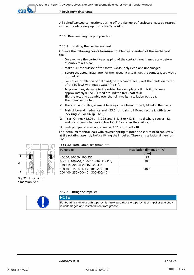
All bolted/screwed connections closing off the flameproof enclosure must be securedwith a thread-locking agent (Loctite Type 243).
7.5.2 Reassembling the pump section
7.5.2.1 Installing the mechanical seal
Observe the following points to ensure trouble-free operation of the mechanicalseal:
Only remove the protective wrapping of the contact faces immediately beforeassembly takes place.
Make sure the surface of the shaft is absolutely clean and undamaged.
Before the actual installation of the mechanical seal, wet the contact faces with adrop of oil.
For easier installation of bellows-type mechanical seals, wet the inside diameterof the bellows with soapy water (no oil).
To prevent any damage to the rubber bellows, place a thin foil (thicknessapproximately 0.1 to 0.3 mm) around the free shaft stub. Slip the rotating assembly over the foil into its installation position. Then remove the foil.
The shaft and rolling element bearings have been properly fitted in the motor.
1. Push drive-end mechanical seal 433.01 onto shaft 210 and secure it with taperlock ring 515 or circlip 932.03.
2. Insert O-rings 412.04 or 412.35 and 412.15 or 412.11 into discharge cover 163,and press them into bearing bracket 330 as far as they will go.
3. Push pump-end mechanical seal 433.02 onto shaft 210.
For special mechanical seals with covered spring, tighten the socket head cap screwat the rotating assembly before fitting the impeller. Observe installation dimension"A".
Table 23: Installation dimension "A"
Pump size Installation dimension "A"[mm]
40-250, 80-250, 100-250 2980-251, 100-251, 150-251, 80-315/-316,150-315, 200-315/-316, 100-316
38.5
100-401, 150-401, 151-401, 200-330,200-400, 250-400/-401, 300-400/-401
48.3
7.5.2.2 Fitting the impeller
NOTEFor bearing brackets with tapered fit make sure that the tapered fit of impeller and shaftis undamaged and installed free from grease.
A
Fig. 25: Installationdimension "A"
7 Servicing/Maintenance
Amarex KRT 47 of 74
Goodnal STP ST041 Sewage Delivery (Amarex KRT Submersible Motor Pump) Vendor Manual
Q-Pulse Id VM362 Active 29/10/2013 Page 49 of 96

The shaft and rolling element bearings have been properly installed.
The mechanical seals have been properly installed.
1. Slip impeller 230 onto the shaft end.
2. Screw in impeller screw 914.10 and disc 550.23. Tighten them with a torquewrench.
Table 24: Tightening torque for the impeller screw
Pump size Thread Tightening torque[Nm]
40-250, 80-250, 100-250,150-251, D 100-251
M 10 35
80-251, F, E, K 100-251,80-315/-316, 150-315,200-315/-316, 100-316
M 16 150
100-401, 150-401, 151-401,200-330, 200-400,250-400/-401, 300-400/-401
M 20 290
7.5.2.2.1 Fitting the impeller with a special puller
1. Fit the impeller with a special puller. ( Section 7.5.2.2.1.1 Page 48)
2. Insert impeller hub cap 260 and fasten it with impeller screw 914.10.
7.5.2.2.1.1 Using a special puller
1. Screw part 2 of the puller into the shaft end of the pump set.
2. Screw part 1 to the threaded bolt part 2.
914.10550.23
230
Fig. 26: Fitting theimpeller
914.10550.23
230
Fig. 27: Fitting theimpeller
230
1
2
Fig. 28: Special puller
7 Servicing/Maintenance
48 of 74 Amarex KRT
Goodnal STP ST041 Sewage Delivery (Amarex KRT Submersible Motor Pump) Vendor Manual
Q-Pulse Id VM362 Active 29/10/2013 Page 50 of 96

7.5.2.2.2 Fitting the cutter
Fig. 29: Fitting the cutter
The pump-end mechanical seal 433.02 has been installed.
1. Slip impeller 230 onto the conical shaft end.
2. Insert grooved pin 561.01 into the impeller and place impeller body 23-7 ontothe centring hub.
3. Screw in impeller screw 914.10 and use a torque wrench to tighten the screw to atorque of 50 Nm.
4. Fit the pump casing including O-ring 412.15 with hexagon head bolts 901.14. Usea torque wrench to tighten the bolts to a tightening torque of 60 Nm.
5. Insert O-ring 412.16 in suction cover 162.
6. Fasten ring 500.02 with socket head cap screw 914.07 in the suction cover.
7. Insert the suction cover into the pump casing, making sure the suction cover sitsclose to the impeller vanes. (Make sure that socket head cap screws 914.15 do not protrude from thethreaded holes in the suction cover.)
8. Screw in hexagon head bolt 901.15 to hold the suction cover in place. Do nottighten the bolt yet.
9. Measure the distance between the pump casing and the suction cover.Distance S should measure approximately 0.2 ± 0.1 mm.
10. If required, adjust the position of the suction cover with socket head cap screw914.15 in relation to the pump casing.
11. Tighten hexagon head bolt 901.15 to a torque of 30 Nm.
12. Rotate the impeller body to check that the impeller turns smoothly.Make sure that the suction cover and impeller do not touch each other.
7.5.2.3 Installing the back pull-out unit
7.5.2.3.1 Design with axial clearance
NOTEAfter casing wear rings with a radial clearance have been fitted in pump casing 101, theyhave the required inner diameter and do not need to be readjusted.
1. Use a rubber mallet to push casing wear ring 502 into pump casing 101 as far asit will go.
2. Insert the complete back pull-out unit in the pump casing.
7 Servicing/Maintenance
Amarex KRT 49 of 74
Goodnal STP ST041 Sewage Delivery (Amarex KRT Submersible Motor Pump) Vendor Manual
Q-Pulse Id VM362 Active 29/10/2013 Page 51 of 96

3. Evenly tighten screwed connection 920.01 between pump casing and bearingbracket.
CAUTIONAxial displacement of the rotorDamage to shaft seal and bearings!
▷ Always adjust and check the axial clearance with the pump set in verticalposition.
4. Use a rubber mallet to push casing wear ring 502 in until it is close to impeller230.
5. Suspend the pump set vertically, as illustrated.
6. Lift off the pump set and adjust the axial clearance to 0.3 ± 0.1 mm.
7.5.2.3.2 Design with wear plate
The shaft, rolling element bearings, mechanical seal and impeller have beenassembled properly.
0.4 +0.2m
m
914.12
412.34
914.24
135 412.33 230
101
Fig. 32: Fitting the wear plate
1. Equip wear plate 135 with two new O-rings 412.33 and 412.34.
2. Insert wear plate 135 into pump casing 101.
3. Fasten wear plate 135 to pump casing 101 with socket head cap screws 914.12.
Fig. 30: Suspending thepump set
502
904.01 101
230
0,3±0,1 mm
Fig. 31: Fitting the casingwear ring
7 Servicing/Maintenance
50 of 74 Amarex KRT
Goodnal STP ST041 Sewage Delivery (Amarex KRT Submersible Motor Pump) Vendor Manual
Q-Pulse Id VM362 Active 29/10/2013 Page 52 of 96

4. Adjust the clearance between impeller 230 and wear plate 135 by loosening andtightening screws 914.12 and 914.24.
Screw 914.24 pushes the wear plate in the direction of the impeller.
The clearance equals 0.4 +0.2 mm (measured on the suction side from theouter surface of the impeller vane to the wear plate).
5. Insert the complete back pull-out unit into the pump casing.
6. Evenly tighten screwed connection 920.01 between pump casing and bearingbracket.
7.5.3 Reassambling the motor section
NOTEBefore reassembling the motor section, check that all joints relevant to explosionprotection (flamepaths) are undamaged. Any components with damaged flamepathsmust be replaced. Only use original spare parts made by KSB for explosion-proofpumps. Observe the flamepath positions specified in the Annex. Secure all screwedconnections closing off a flameproof enclosure with a thread-locking agent (Loctite type243).
DANGERIncorrect screws are being usedExplosion hazard!
▷ Always use the original screws for assembling an explosion-proof pump set.
▷ Never use screws of different dimensions or of a lower property class.
7.5.4 Performing a leak test
After reassembly the mechanical seal area/lubricant reservoir must be tested forleakage. The lubricant filler opening is used for leak testing.
Observe the following values for leak testing:
Test medium: compressed air
Test pressure: 0.8 bar (max.)
Test period: 2 minutes
P0.5 bar
Fig. 33: Screwing in the testing device
1. Unscrew and remove the screwed plug and joint ring of the lubricant reservoir.
2. Tightly screw the testing device into the filler opening for the lubricant.
3. Perform the leak test to the above conditions.The pressure must not drop during the test period.If the pressure does drop, check the seals and screwed connections.Then perform another leak test.
7 Servicing/Maintenance
Amarex KRT 51 of 74
Goodnal STP ST041 Sewage Delivery (Amarex KRT Submersible Motor Pump) Vendor Manual
Q-Pulse Id VM362 Active 29/10/2013 Page 53 of 96

4. Once the leak test has been successful, fill in the lubricant. ( Section 7.2.2.1 Page40)
7.5.5 Checking the connection of motor/power supply
After reassembly, carry out the measures specified in ( Section 7.2.1 Page 38).
7.6 Tightening torques
Table 25: Tightening torques
Thread Tightening torque [Nm]M 5 4M 6 7M 8 17M 10 35M 12 60M 16 150M 20 290M 24 278M 27 409M 30 554
7.7 Spare parts stock
7.7.1 Ordering spare parts
Always quote the following data when ordering replacement or spare parts:
Pump type
KSB order number
Motor number
Refer to the name plate for all data. ( Section 4.3 Page 15)
Also supply the following data:
Part description
Part No.
Quantity of spare parts
Shipping address
Mode of dispatch (freight, mail, express freight, air freight)
Refer to the general assembly drawing for part numbers and descriptions. ( Section9.1 Page 55)
7.7.2 Recommended spare parts stock for 2 years' operation to DIN 24296
Table 26: Quantity of spare parts for recommended spare parts stock9)
Part No. Part description Number of pump sets (including stand-by pump sets)2 3 4 5 6 and 7 8 and 9 10 and
more80-1 Motor section - - - 1 1 2 30 %834 Cable gland 1 1 2 2 2 3 40 %818 Rotor - - - 1 1 2 30 %230 Impeller 1 1 1 2 2 3 30 %502 Casing wear ring 2 2 2 3 3 4 50 %
9) For two years of continuous operation or 17,800 operating hours
7 Servicing/Maintenance
52 of 74 Amarex KRT
Goodnal STP ST041 Sewage Delivery (Amarex KRT Submersible Motor Pump) Vendor Manual
Q-Pulse Id VM362 Active 29/10/2013 Page 54 of 96

Part No. Part description Number of pump sets (including stand-by pump sets)2 3 4 5 6 and 7 8 and 9 10 and
more433.01 Mechanical seal, motor
end2 3 4 5 6 7 90 %
433.02 Mechanical seal, pumpend
2 3 4 5 6 7 90 %
321.01 / 322 Rolling element bearing,motor end
1 1 2 2 3 4 50 %
320 / 321.02 Rolling element bearing,pump end
1 1 2 2 3 4 50 %
99-9 Set of seal elements forthe motor
4 6 8 8 9 10 100 %
99-9 Set of seal elements forthe hydraulic system
4 6 8 8 9 10 100 %
7 Servicing/Maintenance
Amarex KRT 53 of 74
Goodnal STP ST041 Sewage Delivery (Amarex KRT Submersible Motor Pump) Vendor Manual
Q-Pulse Id VM362 Active 29/10/2013 Page 55 of 96
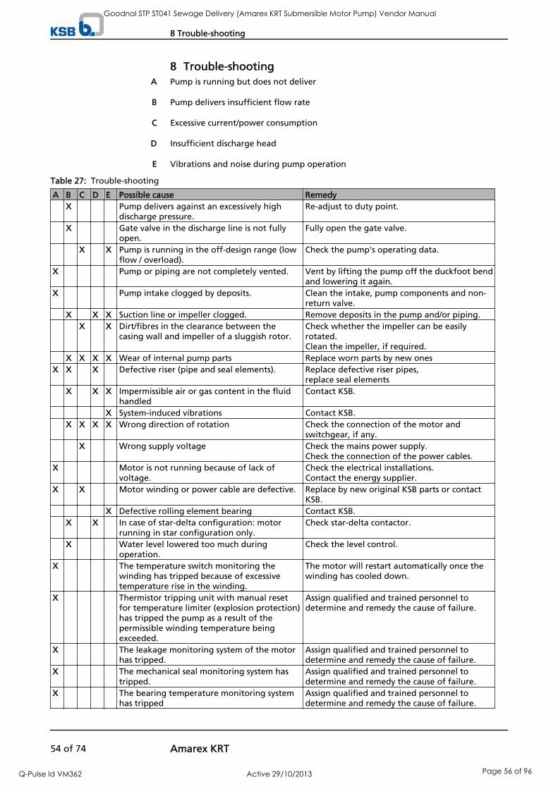
8 Trouble-shootingPump is running but does not deliver
Pump delivers insufficient flow rate
Excessive current/power consumption
Insufficient discharge head
Vibrations and noise during pump operation
Table 27: Trouble-shooting
A B C D E Possible cause Remedy X Pump delivers against an excessively high
discharge pressure.Re-adjust to duty point.
X Gate valve in the discharge line is not fullyopen.
Fully open the gate valve.
X X Pump is running in the off-design range (lowflow / overload).
Check the pump's operating data.
X Pump or piping are not completely vented. Vent by lifting the pump off the duckfoot bendand lowering it again.
X Pump intake clogged by deposits. Clean the intake, pump components and non-return valve.
X X X Suction line or impeller clogged. Remove deposits in the pump and/or piping. X X Dirt/fibres in the clearance between the
casing wall and impeller of a sluggish rotor.Check whether the impeller can be easilyrotated.Clean the impeller, if required.
X X X X Wear of internal pump parts Replace worn parts by new onesX X X Defective riser (pipe and seal elements). Replace defective riser pipes,
replace seal elements X X X Impermissible air or gas content in the fluid
handledContact KSB.
X System-induced vibrations Contact KSB. X X X X Wrong direction of rotation Check the connection of the motor and
switchgear, if any. X Wrong supply voltage Check the mains power supply.
Check the connection of the power cables.X Motor is not running because of lack of
voltage.Check the electrical installations.Contact the energy supplier.
X X Motor winding or power cable are defective. Replace by new original KSB parts or contactKSB.
X Defective rolling element bearing Contact KSB. X X In case of star-delta configuration: motor
running in star configuration only.Check star-delta contactor.
X Water level lowered too much duringoperation.
Check the level control.
X The temperature switch monitoring thewinding has tripped because of excessivetemperature rise in the winding.
The motor will restart automatically once thewinding has cooled down.
X Thermistor tripping unit with manual resetfor temperature limiter (explosion protection)has tripped the pump as a result of thepermissible winding temperature beingexceeded.
Assign qualified and trained personnel todetermine and remedy the cause of failure.
X The leakage monitoring system of the motor has tripped.
Assign qualified and trained personnel todetermine and remedy the cause of failure.
X The mechanical seal monitoring system hastripped.
Assign qualified and trained personnel todetermine and remedy the cause of failure.
X The bearing temperature monitoring systemhas tripped
Assign qualified and trained personnel todetermine and remedy the cause of failure.
A
B
C
D
E
8 Trouble-shooting
54 of 74 Amarex KRT
Goodnal STP ST041 Sewage Delivery (Amarex KRT Submersible Motor Pump) Vendor Manual
Q-Pulse Id VM362 Active 29/10/2013 Page 56 of 96

9 Related Documents
9.1 General assembly drawings
NOTEFor detailed view of the general assembly drawing (e.g. upper bearing) see the followingtable.
* If applicable
*1) Sectional drawings of the mechanical seal
*2) For material variant C1/C2Sizes of hydraulic system40-25080-250/25180-315/316100-240/250100-251100-315/316150-251150-315200-315/316
Motor sizes5 2, 6 2, 8 2, 12 2, 17 2,23 25 4, 7 4, 11 4, 16 4, 23 4,29 44 6, 6 6, 9 6, 12 6
General assembly drawing with motor type DKN 132/160/161/181 and tapered fit(impeller type F)
9 Related Documents
Amarex KRT 55 of 74
Goodnal STP ST041 Sewage Delivery (Amarex KRT Submersible Motor Pump) Vendor Manual
Q-Pulse Id VM362 Active 29/10/2013 Page 57 of 96

Table 28: Detailed views of general assembly drawing with motor type DKN 132/160/161/181 and tapered fit
Section Detailed viewCable gland
Upper bearing
Motor sizes5 2, 6 2, 8 2,5 4, 7 4,4 6, 6 6
Upper bearing
Motor sizes12 2, 17 2, 23 2,11 4, 16 4, 23 4,29 4,9 6, 12 6
Impeller type D
550.23
914.10
135
412.34
914.12
163
230
101
412.33
914.24
Impeller type E
101 904.01* 230 502
* Only for E 150-315
9 Related Documents
56 of 74 Amarex KRT
Goodnal STP ST041 Sewage Delivery (Amarex KRT Submersible Motor Pump) Vendor Manual
Q-Pulse Id VM362 Active 29/10/2013 Page 58 of 96

Section Detailed viewImpeller type K
230 502 503*
* If applicable
Only K200-315/316
230 503* 502
* If applicableImpeller type S
Part No. Description Part No. Description23-7 Impeller body 421.01 Lip seal69-14 Leakage sensor 433.01/.02 Mechanical seal80-1 Motor section 441 Shaft seal housing81-17 Butt joint 500.02 Ring81-44.28 Clamping piece 502 Casing wear ring81-51 Shim 503 Impeller wear ring81-59 Stator 529 Bearing sleeve99-17 Dessicant 550.11/.23/.24 Disc101 Pump casing 561.01 Grooved pin113 Intermediate casing 811 Motor housing131 Inlet ring 818 Rotor135 Wear plate 834 Cable gland162 Suction cover 900.28 Screw163 Discharge cover 901.14/.15/.20 Hexagon head bolt230 Impeller 903 Screwed plug320 Rolling element
bearing904.01 Grub screw
321.01/.02 Radial ball bearing 914.02/.04/.10/.15/.12/.24/.26 Socket head cap screw322 Radial roller bearing 920.01/.26 Nut330 Bearing bracket 930.28 Safety device360 Bearing cover 931 Lockwasher
9 Related Documents
Amarex KRT 57 of 74
Goodnal STP ST041 Sewage Delivery (Amarex KRT Submersible Motor Pump) Vendor Manual
Q-Pulse Id VM362 Active 29/10/2013 Page 59 of 96
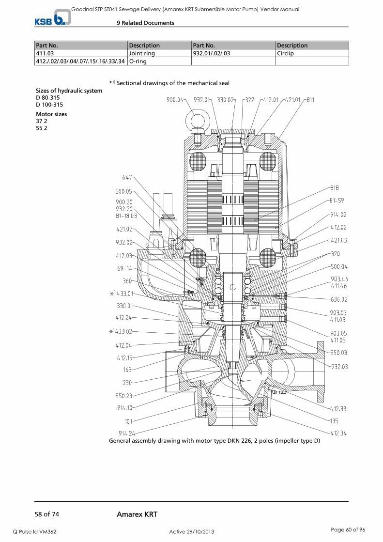
Part No. Description Part No. Description411.03 Joint ring 932.01/.02/.03 Circlip412./.02/.03/.04/.07/.15/.16/.33/.34 O-ring
*1) Sectional drawings of the mechanical seal Sizes of hydraulic systemD 80-315D 100-315
Motor sizes37 255 2
General assembly drawing with motor type DKN 226, 2 poles (impeller type D)
9 Related Documents
58 of 74 Amarex KRT
Goodnal STP ST041 Sewage Delivery (Amarex KRT Submersible Motor Pump) Vendor Manual
Q-Pulse Id VM362 Active 29/10/2013 Page 60 of 96
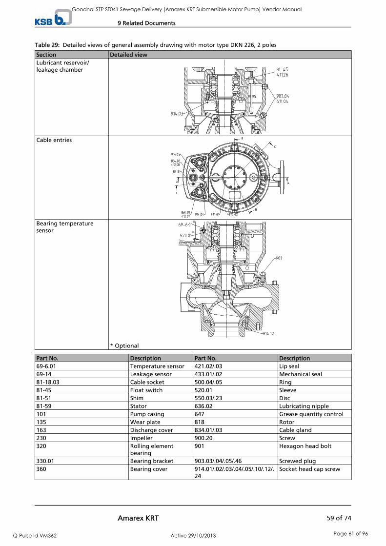
Table 29: Detailed views of general assembly drawing with motor type DKN 226, 2 poles
Section Detailed viewLubricant reservoir/leakage chamber
Cable entries
Bearing temperaturesensor
* Optional
Part No. Description Part No. Description69-6.01 Temperature sensor 421.02/.03 Lip seal69-14 Leakage sensor 433.01/.02 Mechanical seal81-18.03 Cable socket 500.04/.05 Ring81-45 Float switch 520.01 Sleeve81-51 Shim 550.03/.23 Disc81-59 Stator 636.02 Lubricating nipple101 Pump casing 647 Grease quantity control135 Wear plate 818 Rotor163 Discharge cover 834.01/.03 Cable gland230 Impeller 900.20 Screw320 Rolling element
bearing901 Hexagon head bolt
330.01 Bearing bracket 903.03/.04/.05/.46 Screwed plug360 Bearing cover 914.01/.02/.03/.04/.05/.10/.12/.
24Socket head cap screw
9 Related Documents
Amarex KRT 59 of 74
Goodnal STP ST041 Sewage Delivery (Amarex KRT Submersible Motor Pump) Vendor Manual
Q-Pulse Id VM362 Active 29/10/2013 Page 61 of 96

Part No. Description Part No. Description411.03/.05/.26/.46 Joint ring 932.03/.20 Circlip412.02/.04/.07/.08/.15/.24/.33/.34 O-ring 970.02 Plate
* If applicable
*1) Sectional drawings of the mechanical seal
*2) For material variant C1/C2Sizes of hydraulic system100-401150/151-401200-330200-400250-400/401300-400/401
Motor sizes23 4, 29 420 6, 26 610 8, 17 8, 21 8
General assembly drawing pump set with motor type DKN 161/181 and cylindricalinterference fit (impeller type K/E)
9 Related Documents
60 of 74 Amarex KRT
Goodnal STP ST041 Sewage Delivery (Amarex KRT Submersible Motor Pump) Vendor Manual
Q-Pulse Id VM362 Active 29/10/2013 Page 62 of 96

Table 30: Detailed views of general assembly drawing pump set with motor type DKN 161/181 and cylindricalinterference fit
Section Detailed viewImpeller type F
Cable gland
Part No. Description Part No. Description13-6 Casing insert 433.01/.02 Mechanical seal69-14 Leakage sensor 441 Shaft seal housing81-17 Butt joint 502 Casing wear ring81-44.28 Clamping piece 529 Bearing sleeve81-51 Shim 811 Motor housing81-59 Stator 818 Rotor99-17 Dessicant 834 Cable gland101 Pump casing 900.28 Screw163 Discharge cover 901.20 Hexagon head bolt260 Impeller hub cap 902.01 Stud230 Impeller 903.03/.05 Screwed plug321.02 Radial ball bearing 914.02/.10/.04/.26 Socket head cap screw322 Radial roller bearing 920.01/.26 Nut330 Bearing bracket 930.28 Safety device411.03/.05 Joint ring 932.01/.02/.22 Circlip412.02/.03/.04/.07/.15 O-ring 940 Key421.01 Lip seal 970.03/.04 Plate
9 Related Documents
Amarex KRT 61 of 74
Goodnal STP ST041 Sewage Delivery (Amarex KRT Submersible Motor Pump) Vendor Manual
Q-Pulse Id VM362 Active 29/10/2013 Page 63 of 96

* If applicable
*1) Sectional drawings of the mechanical seal
*2) For material variant C1/C2Sizes of hydraulic system100-401150/151-401200-330200-400250-400/401300-400/401
Motor sizes35 4, 50 4, 65 432 6, 40 6, 50 626 8, 35 8
General assembly drawing pump set with motor type DKN 226 (impeller type K/E)
9 Related Documents
62 of 74 Amarex KRT
Goodnal STP ST041 Sewage Delivery (Amarex KRT Submersible Motor Pump) Vendor Manual
Q-Pulse Id VM362 Active 29/10/2013 Page 64 of 96

Table 31: Detailed views of general assembly drawing of pump set with motor type DKN 226
Section Detailed viewCable entries
Impeller type F
Part No. Description Part No. Description13-6 Casing insert 433.01/.02 Mechanical seal59-17 Shackle 441 Shaft seal housing69-14 Leakage sensor 502 Casing wear ring81-29 Terminal 550.01/.03/.44 Disc81-51 Shim 811 Motor housing81-59 Stator 818 Rotor101 Pump casing 834/.03 Cable gland163 Discharge cover 900.04/.20 Screw230 Impeller 902.01 Stud260 Impeller hub cap 903.03/.05 Screwed plug322 Radial roller bearing 914.01/.02/.04/.05/.10 Socket head cap screw330.01/.02 Bearing bracket 920.01 Nut321.02 Radial ball bearing 932.01/.02/.03/.20/.22 Circlip411.03/.05 Joint ring 940 Key412.01/.02/.03/.04/.07/.08/.15
O-ring 970.03/.04 Plate
421.01 Lip seal
9 Related Documents
Amarex KRT 63 of 74
Goodnal STP ST041 Sewage Delivery (Amarex KRT Submersible Motor Pump) Vendor Manual
Q-Pulse Id VM362 Active 29/10/2013 Page 65 of 96

*1) Sectional drawings of the mechanical seal Sizes of hydraulic systemD 80-315D 100-315D 150-400D 150-401D 200-400D 250-400D 300-400
Motor sizes35 4, 50 4, 65 432 6, 40 6, 50 626 8, 35 8
General assembly drawing of pump set with motor type DKN 226, 4/6/8 poles (impellertype D)
9 Related Documents
64 of 74 Amarex KRT
Goodnal STP ST041 Sewage Delivery (Amarex KRT Submersible Motor Pump) Vendor Manual
Q-Pulse Id VM362 Active 29/10/2013 Page 66 of 96

Table 32: Detailed views of general assembly drawing of pump set with motor type DKN 226, 4/6/8 poles
Section Detailed viewCable entries
Bearing temperature sensor
Lubricant reservoir/leakagechamber
9 Related Documents
Amarex KRT 65 of 74
Goodnal STP ST041 Sewage Delivery (Amarex KRT Submersible Motor Pump) Vendor Manual
Q-Pulse Id VM362 Active 29/10/2013 Page 67 of 96

Part No. Description Part No. Description69-6.01 Temperature sensor 433.01/.02 Mechanical seal69-14 Leakage sensor 500.04/.05 Ring81-18.03 Cable socket 520.01 Sleeve81-45 Float switch 550.01/.03/.23/.44 Disc81-51 Shim 636.02 Lubricating nipple81-59 Stator 647 Grease quantity control101 Pump casing 811 Motor housing135 Wear plate 818 Rotor163 Discharge cover 834.01/.03 Cable gland230 Impeller 900.04/.20 Screw320 Rolling element bearing 902.01 Stud322 Radial roller bearing 903.03/.04/.05/.46 Screwed plug330.01/.02 Bearing bracket 914.01/.02/.03/.04/.05/.10/.12/.24 Socket head cap screw360 Bearing cover 920.01 Nut411.03/.04/.05/.26/.46 Joint ring 932.01/.02/.03/.20 Circlip412.01/.02/.03/.04/.07/.08/.15/.24/.33/.34
O-ring 970.02 Plate
421.01/.02/.03 Lip seal
9 Related Documents
66 of 74 Amarex KRT
Goodnal STP ST041 Sewage Delivery (Amarex KRT Submersible Motor Pump) Vendor Manual
Q-Pulse Id VM362 Active 29/10/2013 Page 68 of 96

9.2 Wiring diagrams
Motors: 5 2, 6 2, 8 2, 12 2, 17 2, 23 25 4, 7 4, 11 4, 16 4, 23 4, 29 4, 4 6, 6 6, 9 6, 26 6, 10 8, 17 8, 21 8
Motors:37 2, 55 2, 35 4, 50 4, 65 4, 32 6, 40 6, 50 6, 26 8, 35 8
U1 V1 W1
W2V2U2
21 22 10 11 9
F4 R1
R2
R3
B2
F5
3 ~
12 x ... mm2
7 x ... +5 x 1,5 mm2
U1 U2V1 V2W2W1 21 22
12
11 9 PE
(1)
(1)
(1)
(2)
(2)
(2)
(3)
(3)
(3)
(6)
(6)
(4)
(4)
(4)
(5)
(5)
(5)
(7)
(8)
(9)
(10)
(11)
U1
U1
V1
V1
W1
W1
U2
U2
V2
V2
W2
W2
PE
21 22 10 11 9
Y
U1
V1
W1
U2
V2
W2
Y-
L1
L1
L2
L2
L3
L3
0W380161-00
11
B2
11V1
PE U1
W1
21 22 PE
(2)
(3)
(4)
(5)
(1)
(6)
(7)
(8)
(11)
(10)
(9)
4910
124
PEU2
V2
W2
3 4
F4
21 22 3 4
F5
910
B3
R3
R1
R2
W2U2
U1 W1
V2
3~
V1
0W366474-00
U1
U2
V1
V2
W1
W2
PE PE (21)
(22)
(10)
(11)
(3)
(4)
(9)
U1
U1
U2
U2
V1
V1
V2
V2
W1
W1
W2
W2
PEPE PE
PE (21)
(22)
(10)
(11)
(3)
(4)
(9)
(21)
(22)
(10)
(11)
(3)
(4)
(9)
Y
Y
-
L1 L2 L3 PE
*
* Only for reinforced bearings ( Section 4.4 Page 16)
9 Related Documents
Amarex KRT 67 of 74
Goodnal STP ST041 Sewage Delivery (Amarex KRT Submersible Motor Pump) Vendor Manual
Q-Pulse Id VM362 Active 29/10/2013 Page 69 of 96
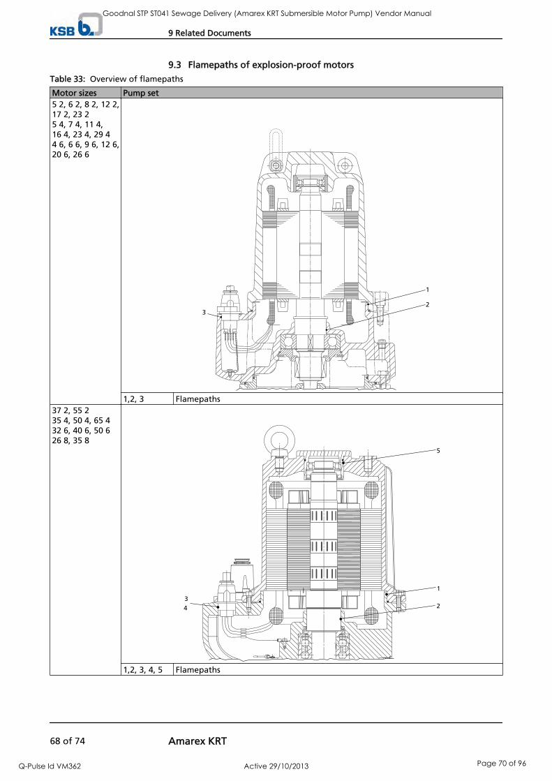
9.3 Flamepaths of explosion-proof motors
Table 33: Overview of flamepaths
Motor sizes Pump set5 2, 6 2, 8 2, 12 2,17 2, 23 25 4, 7 4, 11 4,16 4, 23 4, 29 44 6, 6 6, 9 6, 12 6,20 6, 26 6
1
23
1,2, 3 Flamepaths37 2, 55 235 4, 50 4, 65 432 6, 40 6, 50 626 8, 35 8
5
1
4
32
1,2, 3, 4, 5 Flamepaths
9 Related Documents
68 of 74 Amarex KRT
Goodnal STP ST041 Sewage Delivery (Amarex KRT Submersible Motor Pump) Vendor Manual
Q-Pulse Id VM362 Active 29/10/2013 Page 70 of 96

9.4 Sectional drawings of the mechanical seal
Table 34: Sectional drawings of the mechanical seal
Section Sectional drawingSizes of hydraulic system40-25080-250100-240100-250
Motor sizes5 2, 6 2, 8 2, 12 2, 17 25 4, 7 4, 11 4, 16 4
433.01 Mechanical seal (bellows-type mechanical seal) 433.01
515
433.02
OW 309130-00
515 Taper lock ring433.02 Mechanical seal (bellows-
type mechanical seal)
433.01 Mechanical seal (bellows-type mechanical seal)
A
433.01
433.02
OW 309130-05
515
515 Taper lock ring433.02 Mechanical seal (mechanical
seal with covered springs -HJ)
Sizes of hydraulic system80-25180-315100-315150-315200-315/316D 80-315D 100-251D 100-315/316D 150-251D 150-315D 200-315
Motor sizes5 2, 6 2, 8 2, 12 2, 17 2,23 25 4, 7 4, 11 4, 16 4, 23 4,29 44 6, 6 6, 9 6, 12 6
433.01 Mechanical seal (bellows-type mechanical seal)
433.01
515
433.02
OW 309131-00
932.03
515 Taper lock ring433.02 Mechanical seal (bellows-
type mechanical seal)932.03 Circlip
433.02 Mechanical seal (mechanicalseal with covered springs -HJ)
433.02
OW 309131-05
A
9 Related Documents
Amarex KRT 69 of 74
Goodnal STP ST041 Sewage Delivery (Amarex KRT Submersible Motor Pump) Vendor Manual
Q-Pulse Id VM362 Active 29/10/2013 Page 71 of 96

Section Sectional drawingSizes of hydraulic system100-401150/151-401200-330200-400250-400/401300-400-401D 80-315D 100-315
Motor sizes37 2, 55 223 4, 29 4, 35 4, 50 4, 65 420 6, 26 6, 32 6, 40 6,50 610 8, 17 8, 21 8, 26 8, 35 8
433.01 Mechanical seal (bellows-type mechanical seal) 433.01
932.03
433.02
550.44
550.03
550.03 Disc932.03 Circlip433.02 Mechanical seal (bellows-
type mechanical seal)Disc
550.44
412.17 O-ring
433.02 Mechanical seal (mechanicalseal with covered springs -HJ)
433.02
A
9 Related Documents
70 of 74 Amarex KRT
Goodnal STP ST041 Sewage Delivery (Amarex KRT Submersible Motor Pump) Vendor Manual
Q-Pulse Id VM362 Active 29/10/2013 Page 72 of 96
10 EC Declaration of Conformity
Manufacturer: KSB AktiengesellschaftJohann-Klein-Straße 9
67227 Frankenthal (Germany)
The manufacturer herewith declares that the pump/pump set:
Amarex KRT
KSB order number: ...................................................................................................
is in conformity with the provisions of the following directives as applicable in their current version:
– EC Machinery Directive 2006/42/EC
The manufacturer also declares that
the following harmonised international standards were applied:
– ISO 12100-1/A1, ISO 12100-2/A1,
– ISO 14121-1,
– EN 809/A1,
– EN 60034-1, EN 60034-5/A1
Halle, 29.12.2009
...........................................................
Name
Function
Responsible for compiling the technical documentationKSB Aktiengesellschaft
Turmstraße 92
06110 Halle (Germany)
10 EC Declaration of Conformity
Amarex KRT 71 of 74
Goodnal STP ST041 Sewage Delivery (Amarex KRT Submersible Motor Pump) Vendor Manual
Q-Pulse Id VM362 Active 29/10/2013 Page 73 of 96

11 Certificate of Decontamination
Type ................................................................................................................................Order number/Order item number10) ................................................................................................................................ Delivery date ................................................................................................................................ Field of application: ................................................................................................................................ Fluid handled10) : ................................................................................................................................
Please tick where applicable10) :
⃞ ⃞ ⃞ ⃞radioactive explosive corrosive toxic
⃞ ⃞ ⃞ ⃞harmful bio-hazardous highly flammable safe
Reason for return10) : ................................................................................................................................ Comments: ................................................................................................................................ ................................................................................................................................ The pump/accessories have been carefully drained, cleaned and decontaminated inside and outside prior to dispatch/placingat your disposal.
On sealless pumps, the rotor has been removed from the pump for cleaning.
⃞ No special safety precautions are required for further handling.⃞ The following safety precautions are required for flushing fluids, fluid residues and disposal:
............................................................................................................................................................... ............................................................................................................................................................... We confirm that the above data and information are correct and complete and that dispatch is effected in accordance withthe relevant legal provisions.
.................................................................... ....................................................... .......................................................Place, date and signature Address Company stamp
10) Required fields
11 Certificate of Decontamination
72 of 74 Amarex KRT
Goodnal STP ST041 Sewage Delivery (Amarex KRT Submersible Motor Pump) Vendor Manual
Q-Pulse Id VM362 Active 29/10/2013 Page 74 of 96

Index
AApplication limits 8
BBearing temperature monitoring 30
CCertificate of decontamination 72Clearance gaps 50Commissioning/start-up 32Connection to power supply 31
DDesignation 15Direction of rotation 21Dismantling 43Disposal 14
EElectromagnetic compatibility 28Explosion protection 11, 19, 20, 27, 28, 29, 31, 32, 33,34, 37, 42, 51
FFlamepaths 68Frequency inverter operation 28, 34Function 17
GGeneral assembly drawing 55Generic immunity 28Grease lubrication
Grease quality 42Grease quantity 42Intervals 38
IInstallation
Transportable installation 26Insulation resistance test 37Intended use 8
LLeakage monitoring 29Level control 27Lubricant
Intervals 38Quality 40Quantity 40
MMaintenance work 37Mechanical seal 38, 69Mechanical seal leakage 30Minimum fluid level 34Misuse 10
OOrder number 6Other applicable documents 7Overload protection 27
PPartly completed machinery 6Permissible flange loads 23Piping 23Place of installation 19Preservation 13Product description 15
RReassembly 43Return to supplier 14Returning to service 35
SSafety 8Safety awareness 10Scope of supply 17Sensors 29Shutdown 35Spare parts stock 52Start-up 32Storage 13, 35Supply voltage 34
TTemperature monitoring 29Tightening torques 52Trouble-shooting 54
WWiring diagrams 67
Index
Amarex KRT 73 of 74
Goodnal STP ST041 Sewage Delivery (Amarex KRT Submersible Motor Pump) Vendor Manual
Q-Pulse Id VM362 Active 29/10/2013 Page 75 of 96

KSB AktiengesellschaftP.O. Box 200743 • 06008 Halle (Saale) • Turmstraße 92 • 06110 Halle (Germany)Tel. +49 345 4826-0 • Fax +49 345 4826-4699www.ksb.com
2553
.86/
3-10
Goodnal STP ST041 Sewage Delivery (Amarex KRT Submersible Motor Pump) Vendor Manual
Q-Pulse Id VM362 Active 29/10/2013 Page 76 of 96

REV:
INITIALS: DATE: INITIALS: RPEQ No: DATE: INITIALS: DATE:
P0 GMB 23/06/2010
P1 GMB 2/07/2010 SW 2/07/2010
P2 SG 12/11/2010 MS 16/11/2010
P3 MS 26/11/2010
P4 MS 10/05/2011
P5 MS 15/07/2011
P2
P2
VENDOR DOCUMENT NUMBER IW‐GDSTP‐24090‐DST‐0009 A Date
PROJECT: IPSWICH CITY INFRASTRUCTURE PROJECT
PLANT LOCATION &ID: 80% Issue for Client Review
TAG NO.:
PU-0110-010, PU-0110-020
IW-IPSTP-0-MEC-SPEC-0062 Technical Specification for Pumps
DESIGN: DESIGN CHECKED:
DESIGN MANAGER APPROVED:
DESCRIPTION:
IW-GDSTP-4A-ELE-DSHT-6007
CLIENT:- QUEENSLAND URBAN UTILITIES
DATA SHEET NO.: P&ID DRAWING NO.:
IW-GDSTP-4A-MEC-DSHT-1256 IW-GDSTP-4A-PRO-0100-5280
TITLE:
TECHNICAL INFORMATION SHEET
SITE FOUL LIQUOR PUMP 1 & 2
GOODNA STP
IW-IPSTP-0-MEC-SPEC-0100 Technical Specification for Environment, Site Services and Fluid
QUU Comments
Revised levels and outlet conditions
Revised operating parameters
REFERENCE DOCUMENTS
IW-IPSTP-0-MEC-SPEC-0001 Technical Specification for General Mechanical
REV
IW-GDSTP-4A-ELE-SPEC-6003 Technical Specification for Electrical & Instrumentation
Quantity required 2
DESCRIPTION PURCHASER'S REQUIREMENTS
2
Wet well/Discharge pedestal & guide rails
Pipework Modifications
WET MOUNTED SUBMERSIBLE CENTRIFUGAL
PUMP TYPE:
Electrical Datasheet for Low Voltage Motor
France
Internal Review
Comply
Vendor to nominate
General Information
Site foul liquor
VENDOR OFFER UNITS
KSB
Model no. Vendor to nominate KRTE 80-250/114UG-S
Service
Vendor to nominate
Manufacturer
Country of manufacture
Installation/mounting
Operation 1 Duty / 1 Standby (Note 1) Ok
⁰C
⁰C P2
Ave. Nom Max.
L/s P5
m P4
m P5
L/s @ m P5
kW
m (abs) P4
m
%
kW
%
kW
RPMdB (A) @ 1m
mm
mm
mm
mm
Sound pressure level Vendor to nominate
Motor speed <1500
Max duty power absorbed (at motor terminals) Vendor to nominate
Vendor to nominate
Pump discharge diameter Vendor to nominate
Pump Data
Performance Data
Operating Environment
Fluid Bunded drainage / Raw sewage
Ambient air temperature min: -5 , max: 45
Flowrate (per pump) 47.6
Min. Max.
10.3
Fluid temperature min: 10 , max: 30
Pump Duty (Guarantee point)
Maximum shut off head Vendor to nominate
Static head
Total head
Vendor to nominate
NPSHr: n/a
Non-overloading pump power Vendor to nominate
Motor efficiency Vendor to nominate
NPSHa (worst case) 10.0
Pump efficiency Vendor to nominate
Impeller type Vendor to nominate
Impeller diameter
9.0
14.8
Pump power draw (shaft)
47.6 L/s @ Vendor to Nominate m
≥ 75
Method of fixing impeller to shaft Vendor to nominate
80
270
15.0
Single vane Non-clog
n/a
1470
ok
49.2
ok
ok
72.5
11.3
88
49.00 L/s @ 15.08 m
30
Min.
12.9
Maximum impeller diameter Vendor to nominate
Solids handling capability
270
76
bolt
GDSTP‐24090‐DST‐0009_A.xls 1 of 3
KSB Document No: KSB-88980-025 Page 1 of 8
Goodnal STP ST041 Sewage Delivery (Amarex KRT Submersible Motor Pump) Vendor Manual
Q-Pulse Id VM362 Active 29/10/2013 Page 77 of 96
vchisa
Text Box

REVDESCRIPTION PURCHASER'S REQUIREMENTS VENDOR OFFER UNITS
V
ph / Hz
kW
P2
m
hrs
Enclosure class (IP rating) IP68
Rated power
Maximum starts per hour Vendor to nominate
SS 420
Fasteners
Cast iron
Mechanical seal facesNickel bonded tungsten carbide on Silicon
Carbide or Silicon carbide on Silicon Carbide
Shaft
SS 304
Impeller wear rings Bronze
Seal o-ring Viton
Nickel Chrome steel
Manufacturer's name Vendor to nominate
Drive type (VSD/DOL) DOL
Gasket Vendor to nominate
Country of manufacture Vendor to nominate
Transmission Direct coupled
Motor Data
Mechanical seal type Double shaft seal separated by oil bath
Rated voltage 415
Phase/hertz for direct drive 3 / 50
Cooling method
Vendor to nominate
Enclosure type
10
Bearing type
Seal metal components
Bearing life L10 100,000
Casing wearing ring Bronze
Impeller
Comply
Casing and cover S.G Cast iron
Discharge pedestal / elbow Cast iron
Material Data
Required motor cable length
Ball/Roller
Lubrication Vendor to nominate
Submersible
Comply
Comply
Ok
15
Comply
10
By submerged fluid
Cast Iron
Comply
Comply
11.8
Sealed for life
Comply
Comply
Cast Iron
Stainless Steel
Comply
Comply
KSB
France
Comply
NBR
Comply
Comply
Comply
NBR
Comply
kg
N/A
Surface preparation Vendor to nominate
Priming coat Vendor to nominate
Grit blasted & coated with Jotacote 412 or equivalent 2-pack epoxy
Weight of pump unit Vendor to nominate
Vendor to nominate
Testing
Guide rails Required, SS 316
Finish coat colour AS 2700 N15 Home Brush Grey
Discharge Pedestal / Elbow
Seal failure detection
< 12kW Type test certificates
> 12kW Certified performance to Grade 2 AS2417
Finishing coat Vendor to nominate
No. finishing coats
Casing hydrostatic tests Certified
Lifting chains Required, SS 316
External coating Vendor to nominate
Ok
N/A
Seating rings
Motor temperature PTC Thermistors
Cast Iron
Hydro primer, water based
2-component Epoxy 150micron
DI probe required ≥ 5kW
Identification plate Stainless Steel with Stainless Steel Fixings
Lifting Equipment
Protection
Protective Coatings
Bi-metal switch + PTC
1
OilTasteless and odourless paraffin oil as per
FDA172.878
Comply
Comply
Ok - 6m included
Ok - 6m included
KSB A1
Clean/Blast
160
N/A
External Water in Oil sensor
Ultramarine Blue RAL 5002
as above (other POA)
GDSTP‐24090‐DST‐0009_A.xls 2 of 3
KSB Document No: KSB-88980-025 Page 2 of 8
Goodnal STP ST041 Sewage Delivery (Amarex KRT Submersible Motor Pump) Vendor Manual
Q-Pulse Id VM362 Active 29/10/2013 Page 78 of 96
vchisa
Text Box

REVDESCRIPTION PURCHASER'S REQUIREMENTS VENDOR OFFER UNITS
1. P2
2.
3.
General Arrangement Drawings
Sectionalised Drawings
Manufacturer's Pump Specification Sheet
Pump Performance Curve
Information to be submitted with Tender
Spare Parts for two (2) years & itemised cost
General Notes
The system duty, flowrate per pump and operation configuration nominated are for the purpose of sizing the pump units. Pump arrangement should allow standby pump to operate in parallel with duty pump (ie in duty / duty assist arrangement) if required for instantaneous flows greater than the system duty
GDSTP‐24090‐DST‐0009_A.xls 3 of 3
KSB Document No: KSB-88980-025 Page 3 of 8
Goodnal STP ST041 Sewage Delivery (Amarex KRT Submersible Motor Pump) Vendor Manual
Q-Pulse Id VM362 Active 29/10/2013 Page 79 of 96
vchisa
Text Box

Data sheet
Customer item no.: Site Foul Liquor (REV) Order dated: Goodna STP Number: Order no.: Item no.: 100 Quantity: 2 Date: 01/06/2011 Page: 1 / 6
Amarex KRTE 80-250/114UG-S Version no.: 1
Operating data
Requested flow rate 52.600 l/s Requested developed head 16.00 m Pumped medium Wastewater, municipal untreated Materials are not affected by
chemical and mech. substances
Fluid temperature 20.0 °C Fluid density 1030 kg/m³ Fluid viscosity 1.00 mm²/s
Actual flow rate 49.003 l/s Actual developed head 15.08 m Efficiency 72.6 % Power absorbed 10.28 kW Pump speed of rotation 1470 rpm Max. power on curve 11.33 kW Min. allow. flow rate 6.594 l/s Min. allow. mass flow rate 6.79 kg/s
Static head 9.00 m NPSH available 9.67 m
Shutoff head 30.04 m Design Single system 1 x 100 %
Design
Design Close-coupled submersible Orientation Vertical
Suction flange (DN1) unmachined Discharge flange (DN2) drilled according to
EN 1092-2 / DN 80 / PN 16 /21/B
Shaft seal 2 mech. seals in tandem arrangement with oil reservoir
Manufacturer KSB Type (MS inboard) MG
Material code (MS inboard) SIC/SIC/NBR Pumped liquid not liable to plait
Impeller type Single vane, radial flow (E) Wear ring Casing wear ring Impeller diameter 270.0 mm Free passage size 76.0 mm Direction of rotation from drive Clockwise
Driver, accessories
Driver type Electric motor Model (make) KSB Motor const. type KSB Sub. motor Frequency 50 Hz Operating voltage 415 V Rated power P2 11.80 kW Rated current 22.7 A Starting current ratio 5.6 Insulation class F to IEC 34-1 Motor enclosure IP68 Cos phi at 4/4 load 0.82 Motor efficiency at 4/4 load 88.0 % Temperature sensor Bimetallic switch 2x
Motor winding 415 / 720 V Number of poles 4 Starting mode Direct/Star-delta possible Connection mode Delta Motor cooling method Surface cooling Motor version U Cable design Rubber hose Cable entry Sealed along entire length Power cable S1BN8-F 12G1.5 Number of power cables 1 Moisture sensor with
Cable length 15.00 m
Materials G
Pump casing (101) Grey cast iron JL 1040 Intermediate casing (113) Grey cast iron JL 1040 Discharge cover (163) Grey cast iron JL 1040 Shaft (210) Chrome steel 1.4021+QT800 Impeller (230) Grey cast iron JL 1040 O-Ring (412) Nitrile rubber NBR
Casing wear ring (502.1) Grey cast iron JL 1040 Impeller wear ring (503) Stainless Steel VG434 Motor housing (811) Grey cast iron JL 1040 Motor casing cover materials (812)
Grey cast iron JL 1040
Motor cable (824) Chloroprene rubber Hexagon socket head cap screw (914)
CrNiMo steel A4
KSB Document No: KSB-88980-025 Page 4 of 8
Goodnal STP ST041 Sewage Delivery (Amarex KRT Submersible Motor Pump) Vendor Manual
Q-Pulse Id VM362 Active 29/10/2013 Page 80 of 96

Data sheet
Customer item no.: Order dated: Number: Order no.: Item no.: 100 Quantity: 2 Date: 01/06/2011 Page: 2 / 6
Amarex KRTE 80-250/114UG-S Version no.: 1
Nameplates
Nameplates language international
Duplicate nameplate with
Inspections
Hydraulic performance test Acceptance standard ISO 9906 class 2 Quantity meas. points Q-H 5 Quantity meas. points NPSH 0
Certificate Inspection cert. 3.1 to EN 10204
Test participation Non-witnessed Quantity, non-witnessed 1 Quantity, witnessed 0
Coating
KSB coating code A1 to AA-0080-06-01 / 1 Surface preparatory Free from dirt, grease, rust Primer Zinc phosphate synthetic resin
Final coating 2-component epoxy resin high solid
Color Ultramarine blue (RAL 5002) KSB-blue
Total film thickness approx. 150 µm
Installation parts
Scope of supply Pump with installation parts Installation type stationary 2 guide rail For guide rail arrangements,
the guide rails are not included in KSB's scope of supply.
Installation depth 4.50 m Material concept G
Duckfoot bend Size DN 80 / 100 Flange design EN Material Grey cast iron JL 1040
Mounting type Composite anchor bolts Foundation rail Without
Claw Design straight Size DN 80 Lifting equipment Without
KSB Document No: KSB-88980-025 Page 5 of 8
Goodnal STP ST041 Sewage Delivery (Amarex KRT Submersible Motor Pump) Vendor Manual
Q-Pulse Id VM362 Active 29/10/2013 Page 81 of 96

Performance curve
Customer item no.: Site Foul Liquor (REV) Order dated: Goodna STP Number: Order no.: Item no.: 100 Quantity: 2 Date: 01/06/2011 Page: 3 / 6
Amarex KRTE 80-250/114UG-S Version no.: 1
0 10 20 30 40 50 60[l/s]
10
20
30
[m]
225.0
Qmin
270.0
Qmin
270.0
Qmin
To
tal d
ev
elo
pe
d h
ea
d
0 10 20 30 40 50 60[l/s]
5
10
[m]
NP
SH
re
q.
0 10 20 30 40 50 60[l/s]
0
50
[%] Eff
icie
nc
y
0 10 20 30 40 50 60[l/s]
5
10
[kW]
Po
we
r In
pu
t
Flow
Curve data
Speed of rotation 1470 rpm Fluid density 1030 kg/m³ Viscosity 1.00 mm²/s Flow rate 49.003 l/s Requested flow rate 52.600 l/s Total developed head 15.08 m Requested developed head 16.00 m
Efficiency 72.6 % Power absorbed 10.28 kW NPSH required 6.02 m Curve number K42578s Effective impeller diameter 270.0 mm Acceptance standard ISO 9906 class 2
KSB Document No: KSB-88980-025 Page 6 of 8
Goodnal STP ST041 Sewage Delivery (Amarex KRT Submersible Motor Pump) Vendor Manual
Q-Pulse Id VM362 Active 29/10/2013 Page 82 of 96

Motor data sheet
Customer item no.: Order dated: Number: Order no.: Item no.: 100 Quantity: 2 Date: 01/06/2011 Page: 4 / 6
Amarex KRTE 80-250/114UG-S Version no.: 1
Motor data
Motor material Grey cast iron JL 1040 Voltage 415 V Frequency 50 Hz Motor power 11.80 kW Rated current 22.7 A Rated speed 1465 rpm Starting current ratio 5.6
Starting mode Direct/Star-delta possible Power cable Number of power cables 1 Power cable Ø min. 16.6 mm Power cable Ø max. 17.6 mm Cable standard VDE Switching frequency 10.00 1/h
Curve data
The no-load point is not a guarantee point within the meaning of IEC 60034 Load 0.0 % 25.0 % 50.0 % 75.0 % 100.0 % P2 0.00 kW 2.95 kW 5.90 kW 8.85 kW 11.80 kW n 1500 rpm 1491 rpm 1483 rpm 1474 rpm 1465 rpm P1 1.00 kW 3.70 kW 6.80 kW 10.10 kW 13.40 kW I 9.7 A 10.8 A 13.9 A 18.1 A 22.7 A Eta 0.0 % 79.3 % 86.2 % 87.9 % 88.0 % cos phi 0.06 0.48 0.69 0.77 0.82
1500
[rpm]
n1460
0 2 4 6 8 10 12[kW]
0 2 4 6 8 10 12[kW]
0
20
40
60
80
[kW]
180
0.0
0.2
0.4
0.6
0.8
[1]
0
20
40
60
80
100
120
140
160
[A]
0
20
40
60
80
[%]
P1
cos phi
I
eta
mechanical power P2
KSB Document No: KSB-88980-025 Page 7 of 8
Goodnal STP ST041 Sewage Delivery (Amarex KRT Submersible Motor Pump) Vendor Manual
Q-Pulse Id VM362 Active 29/10/2013 Page 83 of 96

Installation plan
Customer item no.: Order dated: Number: Order no.: Item no.: 100 Quantity: 2 Date: 01/06/2011 Page: 6 / 6
Amarex KRTE 80-250/114UG-S Version no.: 1
Motor Motor manufacturer KSB Motor size 11 Motor power 11.80 kW Speed of rotation 1465 rpm
Connections Suction flange (DN1) unmachined Duckfoot bend size DN 80 / 100 Weight net Pump, Motor, Cable 160 kg Claw / Foot 10 kg Total 170 kg
Connect pipes without stress or strain! Dimensional tolerances for shaft axis height: DIN 747 Dimensions without tolerances, middle tolerances to: ISO 2768-m Connection dimensions for pumps: EN735 Dimensions without tolerances - welded parts: ISO 13920-B Dimensions without tolerances - gray cast iron parts: ISO 8062-CT9
For auxiliary connections see separate drawing.
KSB Document No: KSB-88980-025 Page 8 of 8
Goodnal STP ST041 Sewage Delivery (Amarex KRT Submersible Motor Pump) Vendor Manual
Q-Pulse Id VM362 Active 29/10/2013 Page 84 of 96

REV:
INITIALS: DATE: INITIALS: RPEQ No: DATE: INITIALS: DATE:
P0 CL 25/10/2010 MS 25/10/2010
P1 SG 12/11/2010 MS 16/11/2010
P2 MS 4/05/2011
DATA SHEET NO.: P&ID DRAWING NO.:TAG NO.:
PU-0200-010, PU-0200-020
Technical Specification for Pumps
DESIGN: DESIGN CHECKED:
DESIGN MANAGER APPROVED:
DESCRIPTION:
PROJECT: IPSWICH CITY INFRASTRUCTURE PROJECT
80% Issue for Client Review
CLIENT:- QUEENSLAND URBAN UTILITIES
IW-GDSTP-4A-PRO-0100-5123
Revised Duty
TITLE:
TECHNICAL INFORMATION SHEET
IW-GDSTP-4A-MEC-DSHT-1257
PTA FOUL LIQUOR PUMP 1 & 2
GOODNA STP
Internal Review
PLANT LOCATION &ID:
1 Duty / 1 Standby (Note 1)
Comply
Vendor to nominate
General Information
ok
Model no. Vendor to nominate
Installation/mounting Wet well/Discharge pedestal & guide rails
KRTE 80-250/74UG-S
ok
Operation
France
IW-IPSTP-0-MEC-SPEC-0100 Technical Specification for Environment, Site Services and Fluid
REFERENCE DOCUMENTS
IW-IPSTP-0-MEC-SPEC-0001 Technical Specification for General Mechanical
Vendor to nominate
Manufacturer
IW-IPSTP-0-MEC-SPEC-0062
UNITS REV
IW-GDSTP-4A-ELE-SPEC-6003 Technical Specification for Electrical & Instrumentation
KSB
IW-GDSTP-4A-ELE-DSHT-6007
DESCRIPTION PURCHASER'S REQUIREMENTS
Electrical Datasheet for Low Voltage Motor
PUMP TYPE:
WET MOUNTED SUBMERSIBLE CENTRIFUGAL
VENDOR OFFER
Service PTA foul liquor
Quantity required 2
Country of manufacture
VENDOR DOCUMENT NUMBER IW‐GDSTP‐24090‐DST‐0011 A date
⁰C
⁰C
Ave. Ave. Max.
- 35.8 L/s
- 10.3 m P2
- 12.1 m P2
L/s 2 m P2
kW
m (abs) P2
m
%
kW
%
kW
RPMdB (A) @ 1m
mm
mm
mm
mm
Motor efficiency
Sound pressure level Vendor to nominate
Motor speed <1500
Max duty power absorbed (at motor terminals) Vendor to nominate
Vendor to nominate
Impeller diameter
35.8 L/s @ 12.1 m
6
Min. Max.
Performance Data
Flowrate (per pump) - 33.7
Pump Duty (Guarantee point) 33.7 L/s @ 11.9 m
- 11.9
Vendor to nominate
Pump Data
Ambient air temperature
Operating Environment
Fluid Bunded drainage/Raw sewage
min: -5 , max: 45
Fluid temperature min: 10 , max: 30
NPSHr: n/a
Non-overloading pump power
Vendor to nominate
Pump discharge diameter
Vendor to nominate
Pump efficiency Vendor to nominate 72.8
7
84.6
23.5
Vendor to nominate
Maximum shut off head
Vendor to nominate
Static head
Total head
NPSHa (worst case) 10.3
Vendor to nominate
9.6 10.3
Pump power draw (shaft)
Maximum impeller diameter Vendor to nominate
Solids handling capability ≥ 75
Method of fixing impeller to shaft Vendor to nominate
80
Impeller type
8.4
1440
N/A
Single vane Non-clog
240
270
76
bolt
ok
ok
ok
Min.
GDSTP‐24090‐DST‐0011_A.xls 1 of 3
KSB Document No: KSB-88980-024 Page 1 of 9
Goodnal STP ST041 Sewage Delivery (Amarex KRT Submersible Motor Pump) Vendor Manual
Q-Pulse Id VM362 Active 29/10/2013 Page 85 of 96
vchisa
Text Box
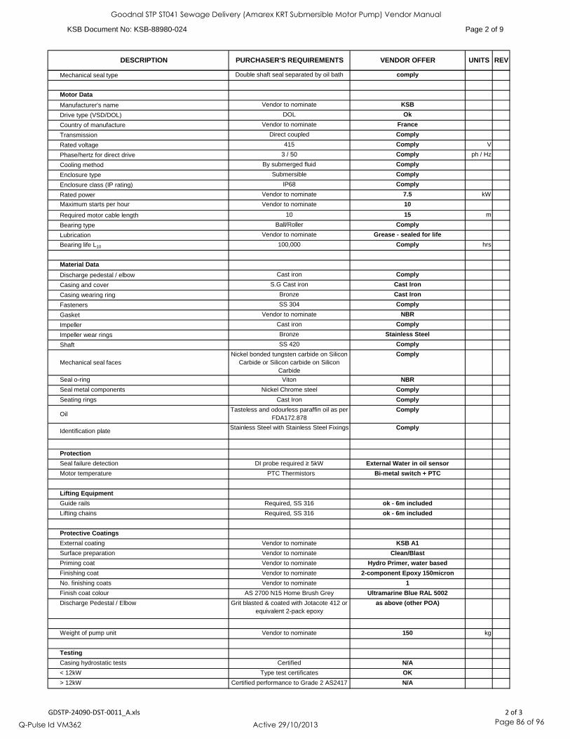
UNITS REVDESCRIPTION PURCHASER'S REQUIREMENTS VENDOR OFFER
V
ph / Hz
kW
m
hrs
Fasteners
Cast iron
Bronze
Gasket Vendor to nominate
Material Data
Nickel Chrome steel
Phase/hertz for direct drive 3 / 50
Cooling method By submerged fluid
Transmission Direct coupled
Drive type (VSD/DOL) DOL
Rated voltage 415
Motor Data
Country of manufacture Vendor to nominate
comply
Manufacturer's name Vendor to nominate
Mechanical seal type Double shaft seal separated by oil bath
Submersible
Impeller wear rings
Enclosure type
S.G Cast iron
Discharge pedestal / elbow
Seal o-ring Viton
Nickel bonded tungsten carbide on Silicon Carbide or Silicon carbide on Silicon
Carbide
Shaft SS 420
Cast iron
Mechanical seal faces
Impeller
Vendor to nominate
Vendor to nominate
Seal metal components
Bearing life L10 100,000
Casing wearing ring Bronze
Casing and cover
Comply
Comply
7.5
15
Enclosure class (IP rating) IP68
Rated power
Required motor cable length 10
Maximum starts per hour
KSB
Ok
France
Comply
Grease - sealed for life
Comply
10
Comply
Comply
Comply
Cast Iron
Comply
NBR
Comply
Comply
Cast Iron
Comply
Stainless Steel
Comply
Comply
Lubrication Vendor to nominate
Bearing type Ball/Roller
SS 304
NBR
Comply
kg
Finish coat colour AS 2700 N15 Home Brush Grey
Discharge Pedestal / Elbow Grit blasted & coated with Jotacote 412 or equivalent 2-pack epoxy
Weight of pump unit Vendor to nominate
< 12kW Type test certificates
> 12kW Certified performance to Grade 2 AS2417
Protective Coatings
External coating Vendor to nominate
OK
N/A
N/A
150
Vendor to nominate
Vendor to nominate
Seating rings
Ultramarine Blue RAL 5002
as above (other POA)
DI probe required ≥ 5kW
Oil
No. finishing coats
Testing
Identification plate Stainless Steel with Stainless Steel Fixings
Lifting Equipment
Casing hydrostatic tests Certified
Guide rails Required, SS 316
Cast Iron
1
Bi-metal switch + PTC
External Water in oil sensor
Comply
Comply
Vendor to nominate
Finishing coat Vendor to nominate
ok - 6m included
ok - 6m included
Surface preparation
2-component Epoxy 150micron
Motor temperature PTC Thermistors
Lifting chains Required, SS 316
Priming coat
KSB A1
Clean/Blast
Hydro Primer, water based
Protection
Tasteless and odourless paraffin oil as per FDA172.878
Seal failure detection
Comply
GDSTP‐24090‐DST‐0011_A.xls 2 of 3
KSB Document No: KSB-88980-024 Page 2 of 9
Goodnal STP ST041 Sewage Delivery (Amarex KRT Submersible Motor Pump) Vendor Manual
Q-Pulse Id VM362 Active 29/10/2013 Page 86 of 96
vchisa
Text Box

UNITS REVDESCRIPTION PURCHASER'S REQUIREMENTS VENDOR OFFER
1.
2.
3.
General Notes
The system duty, flowrate per pump and operation configuration nominated are for the purpose of sizing the pump units. Pump arrangement should allow standby pump to operate in parallel with duty pumps (ie in duty / duty assist arrangement) if required for instantaneous flows greater than the system duty
General Arrangement Drawings
Sectionalised Drawings
Manufacturer's Pump Specification Sheet
Pump Performance Curve
Information to be submitted with Tender
Spare Parts for two (2) years & itemised cost
GDSTP‐24090‐DST‐0011_A.xls 3 of 3
KSB Document No: KSB-88980-024 Page 3 of 9
Goodnal STP ST041 Sewage Delivery (Amarex KRT Submersible Motor Pump) Vendor Manual
Q-Pulse Id VM362 Active 29/10/2013 Page 87 of 96
vchisa
Text Box

Data sheet
Customer item no.: PTA Foul Liquor (REV) Order dated: Goodna STP Number: Order no.: Item no.: 100 Quantity: 2 Date: 01/06/2011 Page: 1 / 6
Amarex KRTE 80-250/74UG-S Version no.: 1
Operating data
Requested flow rate 33.700 l/s Requested developed head 11.90 m Pumped medium Wastewater, municipal untreated Materials are not affected by
chemical and mech. substances
Fluid temperature 20.0 °C Fluid density 1030 kg/m³ Fluid viscosity 1.00 mm²/s
Actual flow rate 35.893 l/s Actual developed head 12.12 m Efficiency 72.8 % Power absorbed 6.03 kW Pump speed of rotation 1453 rpm Max. power on curve 7.01 kW Min. allow. flow rate 6.005 l/s Min. allow. mass flow rate 6.19 kg/s
Static head 10.30 m NPSH available 9.67 m
Shutoff head 23.50 m Design Single system 1 x 100 %
Design
Design Close-coupled submersible Orientation Vertical
Suction flange (DN1) unmachined Discharge flange (DN2) drilled according to
EN 1092-2 / DN 80 / PN 16 /21/B
Shaft seal 2 mech. seals in tandem arrangement with oil reservoir
Manufacturer KSB Type (MS inboard) MG
Material code (MS inboard) SIC/SIC/NBR Pumped liquid not liable to plait
Impeller type Single vane, radial flow (E) Wear ring Casing wear ring Impeller diameter 240.0 mm Free passage size 76.0 mm Direction of rotation from drive Clockwise
Driver, accessories
Driver type Electric motor Model (make) KSB Motor const. type KSB Sub. motor Frequency 50 Hz Operating voltage 415 V Rated power P2 7.50 kW Rated current 14.7 A Starting current ratio 4.8 Insulation class F to IEC 34-1 Motor enclosure IP68 Cos phi at 4/4 load 0.85 Motor efficiency at 4/4 load 83.5 % Temperature sensor Bimetallic switch 2x
Motor winding 415 / 720 V Number of poles 4 Starting mode Direct/Star-delta possible Connection mode Delta Motor cooling method Surface cooling Motor version U Cable design Rubber hose Cable entry Sealed along entire length Power cable S1BN8-F 12G1.5 Number of power cables 1 Moisture sensor with
Cable length 15.00 m
Materials G
Pump casing (101) Grey cast iron JL 1040 Intermediate casing (113) Grey cast iron JL 1040 Discharge cover (163) Grey cast iron JL 1040 Shaft (210) Chrome steel 1.4021+QT800 Impeller (230) Grey cast iron JL 1040 O-Ring (412) Nitrile rubber NBR
Casing wear ring (502.1) Grey cast iron JL 1040 Impeller wear ring (503) Stainless Steel VG434 Motor housing (811) Grey cast iron JL 1040 Motor casing cover materials (812)
Grey cast iron JL 1040
Motor cable (824) Chloroprene rubber Hexagon socket head cap screw (914)
CrNiMo steel A4
KSB Document No: KSB-88980-024 Page 4 of 9
Goodnal STP ST041 Sewage Delivery (Amarex KRT Submersible Motor Pump) Vendor Manual
Q-Pulse Id VM362 Active 29/10/2013 Page 88 of 96
vchisa
Text Box

Data sheet
Customer item no.: Order dated: Number: Order no.: Item no.: 100 Quantity: 2 Date: 01/06/2011 Page: 2 / 6
Amarex KRTE 80-250/74UG-S Version no.: 1
Nameplates
Nameplates language international
Duplicate nameplate with
Inspections
Hydraulic performance test Acceptance standard ISO 9906 class 2 Quantity meas. points Q-H 5 Quantity meas. points NPSH 0
Certificate Inspection cert. 3.1 to EN 10204
Test participation Non-witnessed Quantity, non-witnessed 1 Quantity, witnessed 0
Coating
KSB coating code A1 to AA-0080-06-01 / 1 Surface preparatory Free from dirt, grease, rust Primer Zinc phosphate synthetic resin
Final coating 2-component epoxy resin high solid
Color Ultramarine blue (RAL 5002) KSB-blue
Total film thickness approx. 150 µm
Installation parts
Scope of supply Pump with installation parts Installation type stationary 2 guide rail For guide rail arrangements,
the guide rails are not included in KSB's scope of supply.
Installation depth 4.50 m Material concept G
Duckfoot bend Size DN 80 / 100 Flange design EN Material Grey cast iron JL 1040
Mounting type Composite anchor bolts Foundation rail Without
Claw Design straight Size DN 80 Lifting equipment Without
KSB Document No: KSB-88980-024 Page 5 of 9
Goodnal STP ST041 Sewage Delivery (Amarex KRT Submersible Motor Pump) Vendor Manual
Q-Pulse Id VM362 Active 29/10/2013 Page 89 of 96
vchisa
Text Box

Performance curve
Customer item no.: PTA Foul Liquor (REV) Order dated: Number: Order no.: Item no.: 100 Quantity: 2 Date: 01/06/2011 Page: 3 / 6
Amarex KRTE 80-250/74UG-S Version no.: 1
0 10 20 30 40 50 60[l/s]
10
20
30
[m]
225.0
Qmin
270.0
Qmin
240.0
Qmin
To
tal d
ev
elo
pe
d h
ea
d
0 10 20 30 40 50 60[l/s]
2
14
10
[m]
NP
SH
re
q.
0 10 20 30 40 50 60[l/s]
0
50
[%] Eff
icie
nc
y
0 10 20 30 40 50 60[l/s]
2
4
6
[kW]
Po
we
r In
pu
t
Flow
Curve data
Speed of rotation 1453 rpm Fluid density 1030 kg/m³ Viscosity 1.00 mm²/s Flow rate 35.893 l/s Requested flow rate 33.700 l/s Total developed head 12.12 m Requested developed head 11.90 m
Efficiency 72.8 % Power absorbed 6.03 kW NPSH required 4.48 m Curve number K42578s Effective impeller diameter 240.0 mm Acceptance standard ISO 9906 class 2
KSB Document No: KSB-88980-024 Page 6 of 9
Goodnal STP ST041 Sewage Delivery (Amarex KRT Submersible Motor Pump) Vendor Manual
Q-Pulse Id VM362 Active 29/10/2013 Page 90 of 96
vchisa
Text Box

Motor data sheet
Customer item no.: Order dated: 01/06/2011 Number: Order no.: Quick quote Item no.: 100 Quantity: 2 Date: 01/06/2011 Page: 4 / 6
Amarex KRTE 80-250/74UG-S Version no.: 1
Motor data
Motor material Grey cast iron JL 1040 Voltage 415 V Frequency 50 Hz Motor power 7.50 kW Rated current 14.7 A Rated speed 1441 rpm Starting current ratio 4.8
Starting mode Direct/Star-delta possible Power cable Number of power cables 1 Power cable Ø min. 16.6 mm Power cable Ø max. 17.6 mm Cable standard VDE Switching frequency 30.00 1/h
Curve data
The no-load point is not a guarantee point within the meaning of IEC 60034 Load 0.0 % 25.0 % 50.0 % 75.0 % 100.0 % P2 0.00 kW 1.88 kW 3.75 kW 5.63 kW 7.50 kW n 1500 rpm 1485 rpm 1471 rpm 1456 rpm 1441 rpm P1 0.50 kW 2.50 kW 4.48 kW 6.65 kW 8.98 kW I 6.3 A 7.4 A 9.0 A 11.8 A 14.7 A Eta 0.0 % 75.0 % 83.7 % 84.6 % 83.5 % cos phi 0.11 0.47 0.69 0.79 0.85
1500
[rpm]n
1420
0 1 2 3 4 5 6 7 8[kW]
0 1 2 3 4 5 6 7 8[kW]
0
20
40
60
80
[kW]
180
0.0
0.2
0.4
0.6
0.8
[1]
0
20
40
60
80
100
120
140
160
[A]
0
20
40
60
80
[%]
P1
cos phi
I
eta
mechanical power P2
KSB Document No: KSB-88980-024 Page 7 of 9
Goodnal STP ST041 Sewage Delivery (Amarex KRT Submersible Motor Pump) Vendor Manual
Q-Pulse Id VM362 Active 29/10/2013 Page 91 of 96
vchisa
Text Box

Installation plan
Customer item no.: Order dated: 01/06/2011 Number: Order no.: Quick quote Item no.: 100 Quantity: 2 Date: 01/06/2011 Page: 6 / 6
Amarex KRTE 80-250/74UG-S Version no.: 1
Motor Motor manufacturer KSB Motor size 7 Motor power 7.50 kW Speed of rotation 1441 rpm
Connections Suction flange (DN1) unmachined Duckfoot bend size DN 80 / 100 Weight net Pump, Motor, Cable 149 kg Claw / Foot 10 kg Total 159 kg
Connect pipes without stress or strain! Dimensional tolerances for shaft axis height: DIN 747 Dimensions without tolerances, middle tolerances to: ISO 2768-m Connection dimensions for pumps: EN735 Dimensions without tolerances - welded parts: ISO 13920-B Dimensions without tolerances - gray cast iron parts: ISO 8062-CT9
For auxiliary connections see separate drawing.
KSB Document No: KSB-88980-024 Page 9 of 9
Goodnal STP ST041 Sewage Delivery (Amarex KRT Submersible Motor Pump) Vendor Manual
Q-Pulse Id VM362 Active 29/10/2013 Page 92 of 96
vchisa
Text Box

Goodnal STP ST041 Sewage Delivery (Amarex KRT Submersible Motor Pump) Vendor Manual
Q-Pulse Id VM362 Active 29/10/2013 Page 93 of 96
vchisa
Typewritten Text
KSB Document No: KSB-88980-033 Customer Document No: IW-GDSTP-4A-VEN-0110-2000-P2
vchisa
Typewritten Text

Goodnal STP ST041 Sewage Delivery (Amarex KRT Submersible Motor Pump) Vendor Manual
Q-Pulse Id VM362 Active 29/10/2013 Page 94 of 96
vchisa
Typewritten Text
KSB Document No: KSB-88980-032 Customer Document No: IW-GDSTP-4A-VEN-0200-2000-P2
vchisa
Typewritten Text

Goodnal STP ST041 Sewage Delivery (Amarex KRT Submersible Motor Pump) Vendor Manual
Q-Pulse Id VM362 Active 29/10/2013 Page 95 of 96

Goodnal STP ST041 Sewage Delivery (Amarex KRT Submersible Motor Pump) Vendor Manual
Q-Pulse Id VM362 Active 29/10/2013 Page 96 of 96