zero/near-zero emissions yard tractor testing & demonstration ...
Upload
washingtonCategory
view
1download
0
GETTING TO NET-ZERO IN A SUPER HIGH PERFORMANCE SEATTLE OFFICE BUILDING
Robert Peña
Department of Architecture University of Washington
Seattle, WA 98195 [email protected]
ABSTRACT The Bullitt Foundation is leading a visionary effort to develop the nation’s first urban mid-rise commercial office building to achieve the Living Building Challenge (LBC), a standard for super high performance buildings that includes achieving net-zero energy use on an annual basis. The Cascadia Center for Sustainable Design and Construction (CCSDC), to be located in Seattle’s Capitol Hill district, is in the final stages of design and is scheduled for completion in the summer of 2012. The development of this building will set a new standard for performance-based design and will increase our understanding of design approaches for sustainable building design, construction and operation. Achieving an annual net-zero energy balance for a multi-story building on an urban site requires reducing the demands for electricity to an absolute minimum, and using every available surface to collect and convert sunlight to electricity. These two goals are frequently in competition for the same solar resource. Resolving these conflicts requires thoughtful design and analysis to identify the relative contribution, impact, cost and benefit of each design strategy. This paper describes the architectural and building systems strategies aimed at balancing these competing demands with the goal of achieving net-zero energy use. 1. INTRODUCTION Architecture 2030 and other energy performance standards benchmark energy consumption by building type and location using Commercial Buildings Energy Consumption Survey (CBECS) data, or by comparing a proposed design to a comparable building meeting local codes or ASHRAE standards. Figure one shows that nearly two-thirds of the energy consumed in a typical midrise office building in Seattle is used for heating, lighting, and equipment (plug
loads). Cooling and ventilation accounts for an additional 20% of energy use. The operational energy budget for the CCSDC has been established by a more direct performance metric: the amount of solar electricity that can be generated on- using building-integrated photovoltaic panels. Organizing these solar panels to get the most solar electricity possible within the constraints of the site and the building form has to be balanced against how the panels impact daylighting, views, passive solar heating, and the neighbors, and what land use and zoning codes will allow.
Fig. 1: Percent of Building Energy Use in a Typical Seattle Office Building (PAE Consulting Engineering, Inc.). To drive down the demand for heating, cooling and lighting the design team has employed an integration of design, technology and operational strategies for achieving high levels of performance. The building is predicted to achieve an EUI of ~16 kBTU/ft2yr, meeting the net zero energy goal through a combination of strategies applied to the building form and envelope, it’s mechanical and electrical systems, and strategies for user engagement to manage and minimize the building’s plug loads.

2. BUILDING FORM The CCSDC is designed as a six-story commercial office building housing four floors of offices above two ground-level commercial floors. A two-story concrete base and partial basement built lot-line-to-lot-line supports the four office floors above that are setback 15 feet on the Madison and alley sides. The gross floor area of the building will be approximately 43,000 sq ft. A photovoltaic roof canopy floats approximately four feet above the building roof and extends to the curb-line on the Madison and 15th street sides, sloping slightly to the southwest following the grade of Madison Street. A vertical extension of the PV array extends down from the south-facing edge to about 26 feet above the ground. As an approved participant in the City of Seattle’s Living Building Pilot Program, departures from the Land Use Code were granted to extend the PV array over the public right-of-way.
Fig. 2: The CCSDC looking south at the Madison St. and 15th Ave. façade of the building (Miller Hull Architects). The 10,000 sq. ft. site fronts Madison Street, 15th Avenue, Pike Street and an alley. The site is 100 feet deep with about 75 feet of northwest frontage on Madison Street, 90 feet of west-facing frontage on 15th Avenue, and just 45 feet facing due south, with another 85 feet facing southeast. The site slopes upward at an approximately 10% grade from 15th Avenue to the east, where it meets a neighboring apartment building. The resulting 10-foot grade change sets up the possibility of two on-street commercial entries. Developing the form and organizing the building program required the design team to address not only the City of Seattle’s Land Use Policies, but satisfy the economic imperative of creating a replicable development model while satisfying the requirements of the Living Building Challenge.
Fig. 3: Site plan for the CCSDC (Miller Hull Architects). In addition to zoning and land use codes mandating such matters as allowable uses, height (65 feet), and floor area ratios (4.25), the City requires that the perceived bulk, height and scale of the building address anticipated future development, and that the building provides a transition to less intensive zones. Topography, significant vegetation and views particular to this site must also be addressed in the form and organization of the building. Locating ~17,000 sf of photovoltaic panels had a significant influence on how the form of the building was developed. Another LBC requirement that influenced the building’s design is the imperative for all occupiable spaces to have direct access to fresh air and daylight, a requirement that suggests narrow floor plates with occupied zones located near the building’s perimeter. Surface-to-volume (s/v) ratio, which affects the building’s susceptibility to environmental stress, was identified during pre-design analysis as influential on the building’s heating load. In comparing multiple massing configurations from low surface-to-volume cube-like forms to more crenelated forms having a higher surface-to-volume ratio, the low s/v “climate-rejecting” forms used less energy than those with a higher s/v area, even though these form studies had greater potential for direct solar gain in the winter. These competing demands informed three design concepts developed to find the form that best serves the project’s high performance objectives, satisfies the requirements for daylight and fresh air, responds to the neighborhood context and anticipated future development, and is the most cost effective and therefore most likely to serve as a reproducible model for commercial office development.

2.1 Building Form Design and Analysis Before the early part of the 20th century when buildings used largely used non-mechanical means for heating, cooling and lighting, a letter of the alphabet could describe the form of most commercial office buildings. In a return to these climate responsive “alphabet buildings,” the first scheme studied is an “O” form in plan. This design maximizes the floor area having access to daylight and fresh air with a twenty-four foot deep floor plate and no setbacks from the perimeter of the site. The resulting light well accommodates vertical circulation and facilitates cross and stack ventilation. While this form works well for light and air, the open-air light well results in a high surface-to-volume ratio and does not perform well thermally, driving up the building’s energy use index (EUI). Because of the space dedicated to the light well the allowable floor area ratio can’t be achieved, driving up the cost of this scheme. In this scheme daylight and energy production are in direct competition, as the opening in the roof vies for critical photovoltaic area. Its difficult to provide the panels necessary to achieve net zero energy with this scheme. In the “U” scheme, the building is divided into two halves connected by a service and circulation bar with an enclosed central atrium space opening west towards the park. The atrium brings daylight into the building’s core and allows for stack ventilation. Because this scheme’s atrium is covered, it doesn’t have the same heat loss issues as the “O” scheme, but like that scheme the skylight competes with the photovoltaics. Upon further study, the daylight contributed by the atrium on the 3rd and 4th floors was relatively low, possibly due to the narrow geometry, glazed surfaces, and circulation blocking light into the adjacent spaces. The third scheme uses a more traditional approach, narrowing the entire floor plate to put most of the occupied area within access to a perimeter window. In this “T” shaped plan, the upper four floors step back about 15 feet from the two lower levels on the north and south sides. Service spaces occupy the core and east sides with occupied spaces organized along the perimeter. The top of the “T” is formed by a transparent stair tower that will be a beacon along Madison Street, clearly marking the entry to the offices, and a stack of PV-clad sun rooms on the south that extend the usable floor space on the southeast corners of floors 3-6. This form has the best surface-to-volume ratio of the three, performing well thermally, and the narrower floor plates help meet the daylighting requirements. While there is no longer an opportunity for stack ventilation, the relatively narrow open floor plates allow for effective cross ventilation. In this scheme the photovoltaic canopy extends over the pedestrian right-of-way carried by exposed steel columns that create a sense of rhythm along the street and bring a civic scale to the project.
“O” scheme, typical upper floor plan
“U” scheme, typical upper floor plan
“T” scheme, typical upper floor plan Fig. 4: Building massing and organization trials, exploring different strategies for accessing light and air while reducing energy use and cost (Miller Hull Architects).

3. BUILDING ENVELOPE Electric lighting and space heating account for approximately half of the energy used in a typical Seattle office building of this scale (Fig. 1). Reducing energy through the design of a high-performance building envelope sets up a territorial competition between the glazing seeking to increase the potential for daylighting and insulated opaque walls working to keep the heat in and the cold out in the winter. More glass also means a greater need for shading to reduce solar heat gains in the summer. Recent high performance offices in Seattle have favored fully glazed facades with operable openings aimed at lowering energy demand through natural ventilation and daylighting. While these schemes reduce electric lighting demand, heating demand increases proportionally, particularly in buildings employing only natural ventilation without heat recovery. To better balance thermal and lighting demands, glazing in the CCSDC’s envelope is a relatively smaller proportion of the wall area, opaque portions have higher levels of insulation, and solar control is achieved through a combination of movable exterior and interior blinds. 3.1 Insulation and Infiltration Pre-design analysis using simple Ecotect form studies suggested that there might be significant potential to lower the building’s heating loads by increasing the insulation levels in the walls and roof, and by improving the performance of the windows. In these early models of the building increasing the R-values from R-19 to R-25 in the walls and from R-30 to R-39 in the roof while improving the window U-factors from 0.60 (insulated glass) to 0.14 (multi-pane/film assembly), results in a 62% reduction in the heating load.
In the proposed design of the CCSDC the typical exterior wall assembly has 4 inches of rigid insulation (R-16.8) outboard of a light steel-framed wall with batt insulation (R-19) resulting in an R-value of about 36. Accounting for framing and other wall assemblies having somewhat lower levels of insulation, the area weighted average R-value for the opaque insulated walls in the CCSDC is 21.4 (Table 1). Infiltration can be one of the largest individual heating loads in a building. Careful detailing, construction and testing will be required to achieve the targeted infiltration rate of 0.24 cfm/sf at 75 Pa. This will include developing a whole-building air barrier plan identifying all air barrier components in the construction documents along with details of all joints, interconnections and penetrations. It is likely that during construction an envelope mockup and test will occur, and upon completion a whole building air tightness test will be conducted. 3.2 Windows and Solar Control During the design process numerous window types and configurations were evaluated for energy and thermal performance. The façade is designed as a very high performance Schüco curtain wall system with Sungate 500 glazing, with 50% of the glass area being operable. An all glass curtain wall encloses the two street level commercial floors, while floors 3 through 6 have alternating vertical bands of glazed curtain wall and insulated opaque wall panels. Exterior motorized aluminum blinds on the northwest and west facades will deploy independently as direct sunlight reaches these windows. On the south and southeast facades, interior blinds will be deployed manually by building users for solar and glare control as needed. All blinds are designed to be fully retractable to maximize access to daylight.
TABLE 1: BUILDING ENVELOPE CONSTRUCTION
Seattle Code ASHRAE 90.1-2010 Proposed Design
Walls R-Value 18.2 21.4
Overall U-Factor 0.055 0.064 0.047
Roof R-Value 38.0 38.0
Overall U-Factor 0.026 0.048 0.026
Windows
% Wall Area 0 - 30% 0 - 40% 29% R-Value 2.6 1.8 4.0
Assembly U-Factor 0.38 0.50 0.25 SHGC 0.35 0.40 0.43
Visible Light Trans. not regulated not regulated 0.53 Infiltration cfm/sq ft @ 75 Pa 0.40 not regulated 0.24
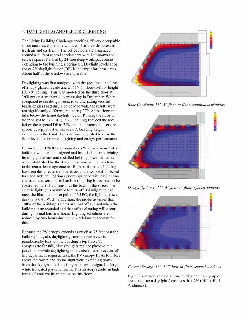
4. DAYLIGHTING AND ELECTRIC LIGHTING The Living Building Challenge specifies, “Every occupiable space must have operable windows that provide access to fresh air and daylight.” The office floors are organized around a 21-foot central service core with bathrooms and service spaces flanked by 24-foot deep workspace zones extending to the building’s perimeter. Daylight levels at or above 2% daylight factor (DF) is the target for these areas. About half of the windows are operable. Daylighting was first analyzed with the presumed ideal case of a fully glazed façade and an 11’- 6” floor-to-floor height (10’- 9” ceiling). This was modeled on the third floor at 3:00 pm on a uniformly overcast day in December. When compared to the design scenario of alternating vertical bands of glass and insulated opaque wall, the results were not significantly different, but nearly 77% of the floor area falls below the target daylight factor. Raising the floor-to-floor height to 13’- 10” (13’- 1” ceiling) reduced the area below the targeted DF to 38%, and bathrooms and service spaces occupy most of this area. A building height exception to the Land Use code was requested to raise the floor levels for improved lighting and energy performance. Because the CCSDC is designed as a “shell-and-core” office building with tenant designed and installed electric lighting, lighting guidelines and installed lighting power densities were established by the design team and will be written-in to the tenant lease agreements. High performance lighting has been designed and modeled around a workstation-based task and ambient lighting system equipped with daylighting and occupant sensors, and ambient lighting is assumed to be controlled by a photo sensor at the back of the space. The electric lighting is assumed to turn off if daylighting can meet the illumination set point of 35 FC; the lighting power density is 0.40 W/sf. In addition, the model assumes that 100% of the building’s lights are shut off at night when the building is unoccupied and that office cleaning will occur during normal business hours. Lighting schedules are reduced by two hours during the weekdays to account for this. Because the PV canopy extends as much as 25 feet past the building’s façade, daylighting from the perimeter is paradoxically least on the building’s top floor. To compensate for this, nine skylights replace photovoltaic panels to provide daylighting on the sixth floor. Because of fire department requirements, the PV canopy floats four feet above the roof plane, so the light wells extending down from the skylights to the ceiling plane are designed as large white truncated pyramid forms. This strategy results in high levels of uniform illumination on this floor.
Base Condition: 11’- 6” floor-to-floor, continuous windows
Design Option 1: 11’- 6” floor-to-floor, spaced windows
Current Design: 13’- 10” floor-to-floor, spaced windows Fig. 5: Comparative daylighting studies; the light purple areas indicate a daylight factor less than 2% (Miller Hull Architects).

5. BUILDING SYSTEMS Most of the heating, cooling and lighting for this building is addressed architecturally by the building’s form, its tight, well-insulated envelope and it’s carefully arranged and controlled windows. These strategies result in a building with a design balance point temperature of about 46oF, leaving only about 962 heating degree days and about 78 hours when the indoor temperatures can be expected to exceed 80oF when only natural ventilation and night flush cooling is used. The remainder of the heating and cooling for the building is accomplished with high performance, low-energy mechanical systems. 5.1 Mechanical Heating and Cooling The building’s heating and cooling system is based on 37, 5” diameter, 300’ deep, closed loop geothermal wells that provide a heat source and sink during the winter and summer. Water-to-water heat pumps draw energy from the ground during the heating season and return it in the summer when cooling is needed. This warm water is delivered to an in-floor radiant heating system embedded in a 3-inch topping slab on each floor. In the summer water can be circulated to cool the slab. This water can be chilled as needed to maintain indoor temperatures below the summer set point of 80oF at minimal energy costs. Demand controlled mechanical ventilation is used exclusively for fresh air and heat recovery. The air handling system supplies only as much ventilation air as required to maintain the worst zone’s CO2 level at 500 PPM above outside levels. The air handler is equipped with a heat recovery wheel that captures energy from the building’s exhaust to temper the incoming outside air. The heat recovery wheel’s effectiveness is 65%. 5.2 Natural Ventilation and Passive Cooling Approximately 29% of the perimeter wall area is glazed and 50% of these windows are operable. This results in an operable window area that is approximately 4% of the ventilated floor area. The building is equipped with motorized window actuators that are controlled for night ventilation as well as cross ventilation during the day. The natural ventilation system provides fresh air but is designed primarily as a passive cooling system. The system eliminates about 750 hours during which the building’s cooling system would otherwise be operating. The windows are assumed to open when the interior temperature exceeds 70o F. If the outside temperature exceeds the inside temperature the windows are assumed to be closed. The windows are assumed to operate in this fashion at all times.
Fig. 6: CCSDC heating, cooling and ventilation systems (PAE Consulting Engineers, Inc.). 6. ENERGY BALANCE PAE Consulting Engineers in Portland, Oregon, have created a computational model of the proposed building using eQUEST/DOE2.2. eQUEST is used to perform hourly analysis of building energy use accounting for local weather, the proposed architectural, mechanical, electrical, and plumbing systems designs, and the anticipated use of this building. The results of this analysis show that the building will meet its net-zero target with about a 12% buffer. The predicted annual energy demand for the building is 236,394 kWh/year, or a EUI of 15.8 kBTU/sf yr. The latest PV power production estimates predict 264,600 kWh/year of annual production.
Fig. 7: Energy use comparison of the proposed building (PAE Consulting Engineers, Inc.).

The building’s high levels of energy efficiency are attributable to the combination of measures described in this paper: building form and high performance envelope; closed loop geothermal system; radiant in-floor heating and cooling and natural ventilation; a dedicated outside air system with heat recovery; a very efficient electric lighting design integrated with effective daylight design strategies; and aggressive plug load reduction through careful selection of equipment and user engagement in the use of electricity.
Fig. 8: Percent of building energy use by end use (PAE Consulting Engineers, Inc.). 6.1 Occupant Engagement The building’s plug loads dominate the end-use breakdown of the building’s total energy demand at 44% of the energy budget. In addition to careful sourcing of efficient office equipment, a number of strategies and technologies are being proposed to engage building users in effective energy management. Ideally all equipment at each workstation will be connected to a plug strip where each outlet has its own address and relay, allowing it to be monitored and managed through a ZigBee linked web-based interface. A dashboard system will provide a real-time graphic display of energy use from the level of each desk to the entire building. Occupancy sensors will help manage lights and equipment and smartphone apps will allow users to manage their energy using equipment remotely. Lease agreements are under development that will specify an energy budget for each building tenant. Once tenants are monitoring and using electricity in predicable way, they can engage in internal energy trading, swapping surplus electricity to more energy intensive neighbors for future credits.
To encourage building users to avoid using the elevator, the main stairway is located and designed to be one of the most attractive spaces in the building. This “irresistible stair” is a glazed beacon projecting slighting over the pedestrian right-of-way on Madison Street with panoramic views of Seattle and the Puget Sound to the west. The building does not contain any car parking, but does have places for over 40 bicycles in a secured garage and loading bay in the building off of the alleyway. Showers on each floor will make it more attractive for building occupants to commute by bicycle. 6.2 Photovoltaics Using the allowable gross floor area and a very aggressive EUI target of ~16 kBTU/sf yr, still requires approximately 17,000 sf of the most efficient photovoltaic panels available to generate the needed electricity on an annual basis. Given that the site is only 10,000 sf, and the roof plane is the most effective surface for collecting solar energy, the solution is to extend the roof plane beyond the building and over the pedestrian right-of-way all the way to the curb lines on Madison Street and 15th Ave. Additional PV area comes from a vertical south-facing array extending down from the edge of the roof array. The ideal tilt of a fixed array in Seattle is about 25 degrees, oriented slightly west of south. However, sloping individual panels or portions of the array is problematic because of height limitations, and because spacing panels sufficiently to avoid shading each other reduces the energy production density to less than if the panels were organized in a continuous flat plane.
Fig. 9: PV production and energy use (PAE Consulting Engineers, Inc.).

Analysis of various configurations concluded that to meet the required energy production the best PV array configuration is an uninterrupted plane in combination with a large south facing vertical array. The large array follows the plane of the roof, sloping slightly to the southwest, and will generate about 85% of the solar electricity. It will use Sunpower 415 panels that are largely opaque, with white backs that will be visible at the overhanging portions of the array. The south-facing vertical array will use Sanyo double 215 panels, a bi-facial panel that is about 7% translucent, and will supply the remaining 15% of solar electricity. 7. CONCLUSIONS Finding the appropriate balance among the many competing requirements of a building with this level of performance expectations requires great vigilance and the nearly constant interaction of an integrated design team. For instance, the trade-‐off between PV area and a skylight, or the use of high visible light transmitting glass versus low solar heat gain glass, requires a series of exchanges between multiple members of the design team – ME, architect, daylight or PV consultant – to resolve appropriately and with the recognition that the consequences of these decisions will be felt for years to come. Denis Hayes, the President of the Bullitt Foundation and the visionary leader behind this project, has charged the design and construction team to create an inspiring, beautiful, super high performance building that will last 250 years. With this mandate, every design decision will indeed be played-‐out over a very long time. 8. ACKNOWLEDGMENTS Much of the analysis described in this paper was done by the engineering design team at PAE Consulting Engineers, Inc., under the direction of Paul Schwer, PE, as Principle in Charge of this project. I’m grateful to PAE for allowing me to present their excellent work and make use of their clear and articulate graphics. The design team at the Miller Hull Partnership has worked tirelessly, and with great conviction and discipline, on a project that is challenging on so many levels. Under the steady leadership of the Project Manager, Margaret Sprug, AIA, and the talented design team that includes Brian Court, Jim Hanford, Steve Doub, and design Principals Craig Curtis, Ron Rochon, and Dave Miller, Denis Hayes’ vision for this project is being well served. This project is being produced and managed by Chris Rogers and Chris Faul of Point 32, two exceptionally talented and resourceful developers who are changing the paradigm of commercial real estate.
9. REFERENCES (1) The Living Building Challenge: A Visionary Path to a Restorative Future, v2.0, November 2009 http://ilbi.org/lbc/Standard-Documents/LBC2-0.pdf (2) Peña, Robert and Weller, Michael, Getting to Carbon Neutral: Meeting the Living Building Challenge in a Mid-Rise Mixed-Use Building in Seattle, Proceedings of the 38th National Solar Conference, American Solar Energy Society, 2009 (3) Cascadia Center for Sustainable Design and Construction: Comfort Report, November 16, 2010, PAE Consulting Engineers, Inc., Portland, Oregon (4) Cascadia Center for Sustainable Design and Construction: Energy Report, November 17, 2010, PAE Consulting Engineers, Inc., Portland, Oregon (5) Cascadia Center for Sustainable Design and Construction: Early Design Guidance Packet, March 17, 2010, Miller Hull Architects, Seattle, Washington (6) Cascadia Center for Sustainable Design and Construction: Capitol Hill Design Review Board Recommendation Packet, November 17, 2010, Miller Hull Architects, Seattle, Washington
Copyright © 2022 FDOKUMEN