Generation of Ultra-Wide-Band Pulse Signal
10
IRJMST Volume 5 Issue 1 Online ISSN 2250 - 1959 International Research Journal of Management Science & Technology http:www.irjmst.com Page 263 Generation of Ultra-Wide-Band Pulse Signal Vikash kumar 1 Dr. Hari sumiran Singh 2 1 Research Scholar Faculty of Science(Electronics) Magadh University Shiv-Mani Sadan Purvi Rupaspur Sahay nagar Patna-801506 [email protected] 2 Assosiate Profesor J.D.W. CollegeBaily Road Patna-800023 [email protected] Abstract –Ultra-wideband (UWB) communication techniques have attracted a great interest in both academia and industry in the past few years for applications in short- range wireless mobile systems. This is due to the potential advantages of UWB transmissions such as low power, high rate, immunity to multi-path propagation, less complex transceiver hardware, and low interference. However, tremendous R&D efforts are required to face various technical challenges in developing UWB wireless systems, including UWB channel characterization, transceiver design, coexistence and inter working with other narrowband wireless systems, design of the link and network layers to benefit from UWB transmission characteristics.A method for generating sub nano second pulse signals with time-jitter as low as 100 ps was described and theoreticaly analyzed. Keywords—ultra wide band(UWB), Gaussian pulse I. INTRODUCTION Ultra-Wide-Band (UWB) wireless technology became in recent years one of very promising technologies after recognition of their commercial potential [1]. World wide interest in UWB wireless increased greatly after year 2002, when US Federal Communication Comission (FCC) gave first authorization for it. In INDIA the National Frequency Allocation Plan 2011 (NFAP- 2011) has the following provision for UWB IND73 “Use of Ultra Wide Band (UWB) equipment may be considered in the frequency band6.0–7.25 GHz with maximum (Equivalent Isotropic Radiated Power) EIRP density of -41 dBm/MHz in any 1MHz bandwidth with maximum 500 MHz on non exclusive and non protection basis.” Other names for this techniques are somewhere in use: impulse communications, impulse radio, subnanosecond communications, as well as carrier-free , nonsinusoidal communications etc.[2] How UWB Works:
-
Upload
independent -
Category
Documents
-
view
0 -
download
0
Transcript of Generation of Ultra-Wide-Band Pulse Signal
IRJMST Volume 5 Issue 1 Online ISSN 2250 - 1959
International Research Journal of Management Science & Technology http:www.irjmst.com Page 263
Generation of Ultra-Wide-Band Pulse Signal
Vikash kumar1
Dr. Hari sumiran Singh2 1Research Scholar Faculty of Science(Electronics)
Magadh University
Shiv-Mani Sadan Purvi Rupaspur
Sahay nagar Patna-801506
[email protected] 2Assosiate Profesor J.D.W. CollegeBaily Road
Patna-800023
Abstract –Ultra-wideband (UWB) communication techniques have attracted a great
interest in both academia and industry in the past few years for applications in short-
range wireless mobile systems. This is due to the potential advantages of UWB
transmissions such as low power, high rate, immunity to multi-path propagation, less
complex transceiver hardware, and low interference. However, tremendous R&D efforts
are required to face various technical challenges in developing UWB wireless systems,
including UWB channel characterization, transceiver design, coexistence and inter
working with other narrowband wireless systems, design of the link and network layers to
benefit from UWB transmission characteristics.A method for generating sub nano second
pulse signals with time-jitter as low as 100 ps was described and theoreticaly analyzed.
Keywords—ultra wide band(UWB), Gaussian pulse
I. INTRODUCTION
Ultra-Wide-Band (UWB) wireless technology became in recent years one of very promising
technologies after recognition of their commercial potential [1]. World wide interest in UWB
wireless increased greatly after year 2002, when US Federal Communication Comission (FCC)
gave first authorization for it. In INDIA the National Frequency Allocation Plan 2011 (NFAP-
2011) has the following provision for UWB IND73 “Use of Ultra Wide Band (UWB) equipment
may be considered in the frequency band6.0–7.25 GHz with maximum (Equivalent Isotropic
Radiated Power) EIRP density of -41 dBm/MHz in any 1MHz bandwidth with maximum 500
MHz on non exclusive and non protection basis.” Other names for this techniques are somewhere
in use: impulse communications, impulse radio, subnanosecond communications, as well as
carrier-free , nonsinusoidal communications etc.[2]
How UWB Works:
IRJMST Volume 5 Issue 1 Online ISSN 2250 - 1959
International Research Journal of Management Science & Technology http:www.irjmst.com Page 264
Since the capacity of a communications channel in a non-fading environment is expressed as:
C = B * log2 (1+S/N)
Where
C = channel capacity (bit/s)
B = channel bandwidth „BW‟ (Hz)
S = signal power (watts)
N = noise power (watts)
According to above equation, the capacity can be
increased by either increasing B or S/N. It is obvious
that the capacity can be increased more by increasing
B rather than S/N.
UWB systems could also suffer from interference from other wireless technologies that
exist in the vicinity of operation, but this problem can be mitigated by using adaptive selection of
frequency bands in multi band UWB systems.
According to actual FCC statement, UWB is any signal that occupies at least of 500 MHz of
bandwidth in the spectrum range between 3.1 and 10.6 GHz. Because this technology is
developping very fast we could expect some changes in the regulation area. In the practice,
signals covering the spectrum range from 1to5 GHz and higher are considered as UWB also.
Additional requirement is that the fractional bandwidth, defined as
LH
LH
ff
ffFB 2
(1)
is higher than 0.25, where: fH is the upper and fL lower frequency limits, which define frequency
range containing dominant part of total signal energy. It is evident that this definition avoids
requirement for definition of the center frequency. In practice it is often defined by the relation
2
LHC
fff
(2)
Speaking in the time-domaine, UWB technique involves transmitting, receiving and processing
of stream of low power (in the region of microwatts), very short pulses in the order of 10
picoseconds to 1000 picoseconds.[3]
IRJMST Volume 5 Issue 1 Online ISSN 2250 - 1959
International Research Journal of Management Science & Technology http:www.irjmst.com Page 265
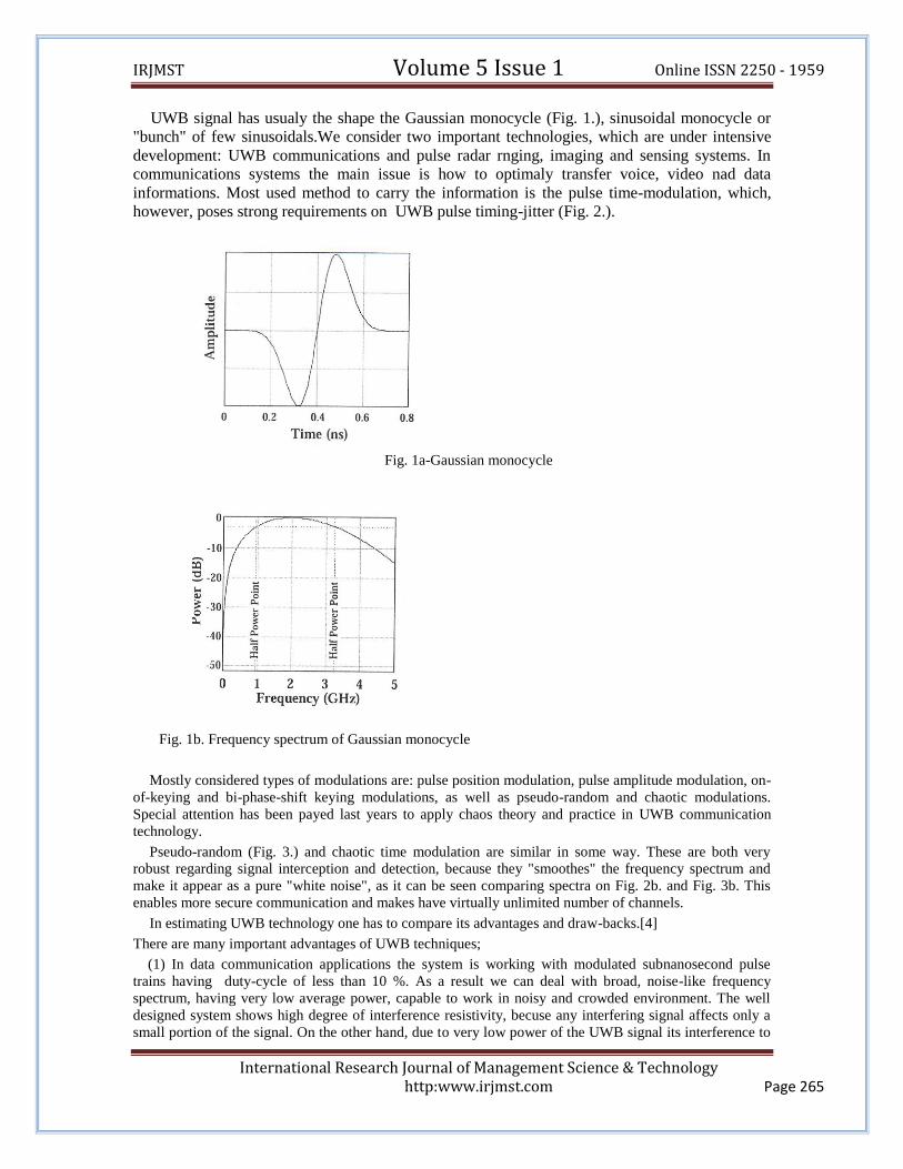
UWB signal has usualy the shape the Gaussian monocycle (Fig. 1.), sinusoidal monocycle or
"bunch" of few sinusoidals.We consider two important technologies, which are under intensive
development: UWB communications and pulse radar rnging, imaging and sensing systems. In
communications systems the main issue is how to optimaly transfer voice, video nad data
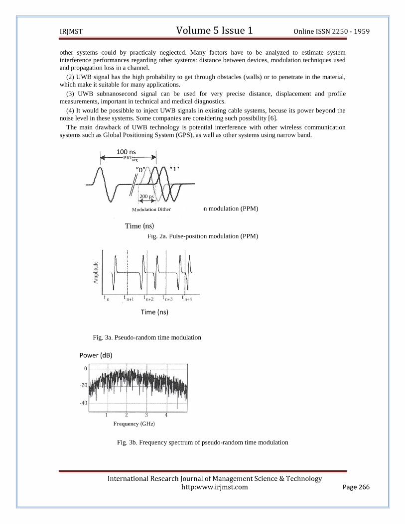
informations. Most used method to carry the information is the pulse time-modulation, which,
however, poses strong requirements on UWB pulse timing-jitter (Fig. 2.).
Fig. 1a-Gaussian monocycle
Fig. 1b. Frequency spectrum of Gaussian monocycle
Mostly considered types of modulations are: pulse position modulation, pulse amplitude modulation, on-
of-keying and bi-phase-shift keying modulations, as well as pseudo-random and chaotic modulations.
Special attention has been payed last years to apply chaos theory and practice in UWB communication
technology.
Pseudo-random (Fig. 3.) and chaotic time modulation are similar in some way. These are both very
robust regarding signal interception and detection, because they "smoothes" the frequency spectrum and
make it appear as a pure "white noise", as it can be seen comparing spectra on Fig. 2b. and Fig. 3b. This
enables more secure communication and makes have virtually unlimited number of channels.
In estimating UWB technology one has to compare its advantages and draw-backs.[4]
There are many important advantages of UWB techniques;
(1) In data communication applications the system is working with modulated subnanosecond pulse
trains having duty-cycle of less than 10 %. As a result we can deal with broad, noise-like frequency
spectrum, having very low average power, capable to work in noisy and crowded environment. The well
designed system shows high degree of interference resistivity, becuse any interfering signal affects only a
small portion of the signal. On the other hand, due to very low power of the UWB signal its interference to
IRJMST Volume 5 Issue 1 Online ISSN 2250 - 1959
International Research Journal of Management Science & Technology http:www.irjmst.com Page 266
other systems could by practicaly neglected. Many factors have to be analyzed to estimate system
interference performances regarding other systems: distance between devices, modulation techniques used
and propagation loss in a channel.
(2) UWB signal has the high probability to get through obstacles (walls) or to penetrate in the material,
which make it suitable for many applications.
(3) UWB subnanosecond signal can be used for very precise distance, displacement and profile
measurements, important in technical and medical diagnostics.
(4) It would be possibble to inject UWB signals in existing cable systems, becuse its power beyond the
noise level in these systems. Some companies are considering such possibility [6].
The main drawback of UWB technology is potential interference with other wireless communication
systems such as Global Positioning System (GPS), as well as other systems using narrow band.
Fig. 2a. Pulse-position modulation (PPM)
Fig. 2a. Pulse-position modulation (PPM)
Fig. 3a. Pseudo-random time modulation
Fig. 3b. Frequency spectrum of pseudo-random time modulation
100 ns
200 ps
0 1
Time (ns)
Power (dB)
IRJMST Volume 5 Issue 1 Online ISSN 2250 - 1959
International Research Journal of Management Science & Technology http:www.irjmst.com Page 267
II. CHARACTERISTICS AND METHODS OF GENERATIONS OF UWB PULSE SIGNALS
Pulse Generator
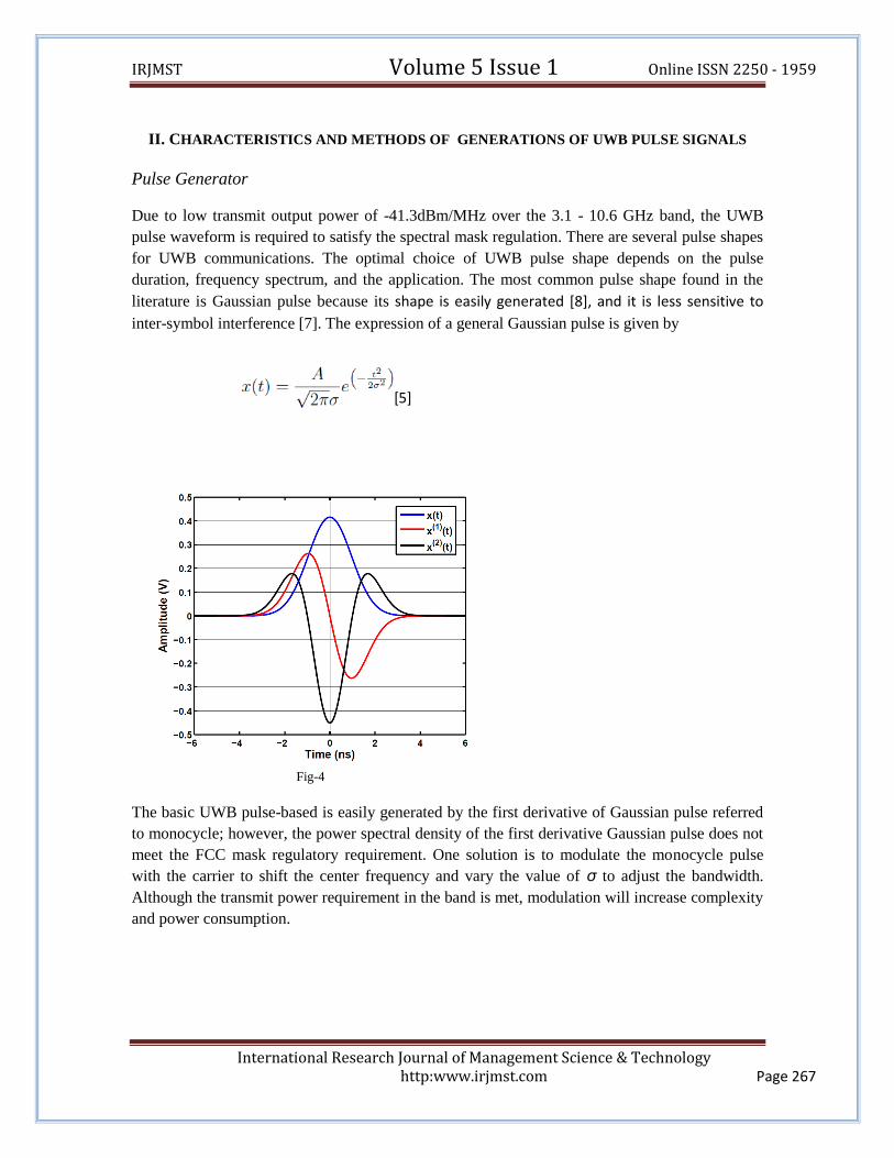
Due to low transmit output power of -41.3dBm/MHz over the 3.1 - 10.6 GHz band, the UWB
pulse waveform is required to satisfy the spectral mask regulation. There are several pulse shapes
for UWB communications. The optimal choice of UWB pulse shape depends on the pulse
duration, frequency spectrum, and the application. The most common pulse shape found in the
literature is Gaussian pulse because its shape is easily generated [8], and it is less sensitive to
inter-symbol interference [7]. The expression of a general Gaussian pulse is given by
[5]
Fig-4
The basic UWB pulse-based is easily generated by the first derivative of Gaussian pulse referred
to monocycle; however, the power spectral density of the first derivative Gaussian pulse does not
meet the FCC mask regulatory requirement. One solution is to modulate the monocycle pulse
with the carrier to shift the center frequency and vary the value of σ to adjust the bandwidth.
Although the transmit power requirement in the band is met, modulation will increase complexity
and power consumption.
IRJMST Volume 5 Issue 1 Online ISSN 2250 - 1959
International Research Journal of Management Science & Technology http:www.irjmst.com Page 268
0 833n 1.67u 2.5u 3.33u 4.17u 5u-900m
-600m
-300m
0
300m
600m
900m
Xa: 4.967u Xb: 91.67n
Yc: 900.0m Yd:-900.0m
a-b: 4.875u
c-d: 1.800
freq: 205.1k
Ref=Ground X=833n/Div Y=voltage
d
cb a
A
L2
2000nHC21nF
+ V315V
Q22N3796 R2
47R
0 833n 1.67u 2.5u 3.33u 4.17u 5u-21m
-14m
-7m
0
7m
14m
21m
Xa: 5.000u Xb: 0.000
Yc: 21.00m Yd:-21.00m
a-b: 5.000u
c-d: 42.00m
freq: 200.0k
Ref=Ground X=833n/Div Y=voltage
d
cb a
A
An alternative approach is the higher-order derivatives of the Gaussian pulse [9]. In the time
domain, the higher-order derivatives of the Gaussian pulse appear as sinusoidal waveforms
modulated by a Gaussian pulse-shaped envelope. It is clear that increasing the order of the
derivatives results in the increment of the number of zero-crossing in time, corresponding to a
higher carrier frequency sinusoids modulated by an equivalent Gaussian envelope as shown in
Fig. 4. By selecting the optimal order of the derivative and a pulse width, the transmit power
requirement and the maximum bandwidth can be obtained. It shows that at least the 5th
derivative should be used for indoor systems while at least the 7th derivative should be used for
outdoor systems [9]. Pulse shapes or the derivative operation can be implemented by the
highpass filtering.
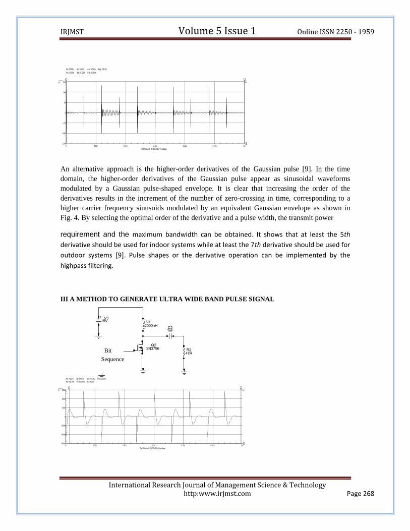
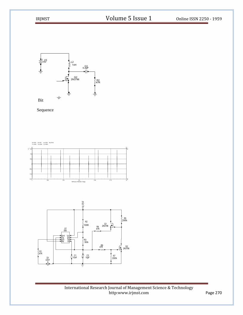
III A METHOD TO GENERATE ULTRA WIDE BAND PULSE SIGNAL
Bit
Sequence

IRJMST Volume 5 Issue 1 Online ISSN 2250 - 1959
International Research Journal of Management Science & Technology http:www.irjmst.com Page 269
0 833n 1.67u 2.5u 3.33u 4.17u 5u-2m
-1m
0
1m
2m
3m
4m
Xa: 5.000u Xb: 0.000
Yc: 4.000m Yd:-2.000m
a-b: 5.000u
c-d: 6.000m
freq: 200.0k
Ref=Ground X=833n/Div Y=voltage
d
cb a
A
L2
2nHC21pF
+ V315V
Q22N3796 R2
47R
L2
0.2nHC21pF
+ V315V
Q22N3796 R2
47R
Bit
Sequence
Bit
Sequence
IRJMST Volume 5 Issue 1 Online ISSN 2250 - 1959
International Research Journal of Management Science & Technology http:www.irjmst.com Page 270
0 833n 1.67u 2.5u 3.33u 4.17u 5u-2.4m
-1.6m
-800u
0
800u
1.6m
2.4m
Xa: 5.000u Xb: 0.000
Yc: 2.400m Yd:-2.400m
a-b: 5.000u
c-d: 4.800m
freq: 200.0k
Ref=Ground X=833n/Div Y=voltage
d
cb a
A
L2
1nHC2
0.2pF
+ V315V
Q22N3796 R2
47R+
C310pF
C110nF
+V
Vs5V
D1LED1
Q22N3796
Q12N3796
GndTrgOutRst Ctl
ThrDisVcc
U1555
R72000k
R647R
R52000k
R447R
R3500k
R2
1000K
R147R
Bit
Sequence
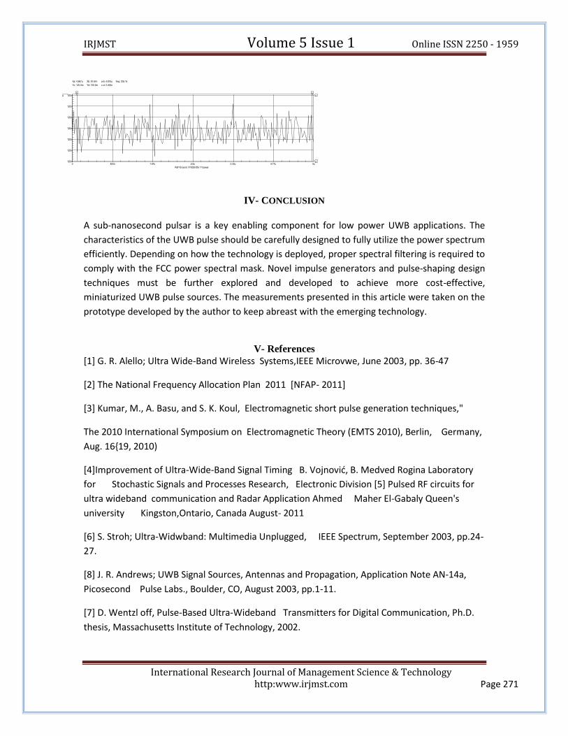
IRJMST Volume 5 Issue 1 Online ISSN 2250 - 1959
International Research Journal of Management Science & Technology http:www.irjmst.com Page 271
0 833n 1.67u 2.5u 3.33u 4.17u 5u120m
120m
120m
120m
120m
120m
120m
Xa: 4.967u Xb: 91.67n
Yc: 120.0m Yd: 120.0m
a-b: 4.875u
c-d: 2.400n
freq: 205.1k
Ref=Ground X=833n/Div Y=power
d
cb a
A
IV- CONCLUSION
A sub-nanosecond pulsar is a key enabling component for low power UWB applications. The
characteristics of the UWB pulse should be carefully designed to fully utilize the power spectrum
efficiently. Depending on how the technology is deployed, proper spectral filtering is required to
comply with the FCC power spectral mask. Novel impulse generators and pulse-shaping design
techniques must be further explored and developed to achieve more cost-effective,
miniaturized UWB pulse sources. The measurements presented in this article were taken on the
prototype developed by the author to keep abreast with the emerging technology.
V- References
[1] G. R. Alello; Ultra Wide-Band Wireless Systems,IEEE Microvwe, June 2003, pp. 36-47
[2] The National Frequency Allocation Plan 2011 [NFAP- 2011]
[3] Kumar, M., A. Basu, and S. K. Koul, Electromagnetic short pulse generation techniques,"
The 2010 International Symposium on Electromagnetic Theory (EMTS 2010), Berlin, Germany,
Aug. 16{19, 2010)
[4]Improvement of Ultra-Wide-Band Signal Timing B. Vojnovid, B. Medved Rogina Laboratory
for Stochastic Signals and Processes Research, Electronic Division [5] Pulsed RF circuits for
ultra wideband communication and Radar Application Ahmed Maher El-Gabaly Queen's
university Kingston,Ontario, Canada August- 2011
[6] S. Stroh; Ultra-Widwband: Multimedia Unplugged, IEEE Spectrum, September 2003, pp.24-
27.
[8] J. R. Andrews; UWB Signal Sources, Antennas and Propagation, Application Note AN-14a,
Picosecond Pulse Labs., Boulder, CO, August 2003, pp.1-11.
[7] D. Wentzl off, Pulse-Based Ultra-Wideband Transmitters for Digital Communication, Ph.D.
thesis, Massachusetts Institute of Technology, 2002.
IRJMST Volume 5 Issue 1 Online ISSN 2250 - 1959
International Research Journal of Management Science & Technology http:www.irjmst.com Page 272
[8] M. Ghavami, Ultra Wideband Signals and Systems in Communications Engineering, John
Wiley and Sons, Inc., New York, 2007.
[9] H. Sheng, P. Orlik, A.M. Haimovich, Jr. Cimini, L.J., and J. Zhang, “On the Spectral and
Power Requirements for Ultra-Wideband Transmission,” in Proc. IEEE Int. ommunications
Conf., 2003, vol.1, pp.738–742.