Probing cosmic strings by reconstructing polarization rotation ...

NANO EXPRESS Open Access
Generating and measuring the anisotropic elasticbehaviour of Co thin films with oriented surfacenano-strings on micro-cantileversVicente Madurga*, José Vergara and Cristina Favieres
Abstract
In this research, the elastic behaviour of two Co thin films simultaneously deposited in an off-normal angle methodwas studied. Towards this end, two Si micro-cantilevers were simultaneously coated using pulsed laser depositionat an oblique angle, creating a Co nano-string surface morphology with a predetermined orientation. The selectedposition of each micro-cantilever during the coating process created longitudinal or transverse nano-strings. Theanisotropic elastic behaviour of these Co films was determined by measuring the changes that took place in theresonant frequency of each micro-cantilever after this process of creating differently oriented plasma coatings hadbeen completed. This differential procedure allowed us to determine the difference between the Young’s modulusof the different films based on the different direction of the nano-strings. This difference was determined to be, atleast, the 20% of the Young’s modulus of the bulk Co.PACS: 62.25.-g; 81.16.Rf; 68.60.Bs; 81.15.Fg; 68.37.Ef; 85.85.+j
IntroductionThe study of the elastic and mechanical properties of thinfilms is of interest in basic and applied research becausethin films are used extensively in micro-electronic andmicro-electromechanical systems. Because the elastic con-stants of thin films are different from those of bulk mate-rial of the same composition, the elastic constants of thebulk material cannot be used to design thin film devices.Consequently, it is very important to accurately determinethe elastic constants of thin films. These properties can bestudied using a wide variety of techniques, including theanalysis of the substrate curvature [1], micro-beam testing[2], micro-tensile testing [3], cantilever-bending resonance[4], nano-indentation [5], Rayleigh-wave velocity measure-ments [6] and Brillouin scattering [7]. Among others,Young’s modulus is an important parameter for thin-filmtechnological applications.Micro-cantilevers (MCLs) are mechanical devices with
attractive applications; for instance, they are widely usedas high-sensitivity sensors in different physical, chemicaland biological technologies [8,9]. Another use of MCLs
is in the study of the mechanical properties of thin films[10]. This type of analysis is possible because of the rela-tion between the resonant frequency of MCLs andYoung’s modulus. If a MCL is coated with a thin film, achange results in the resonant frequency. By measuringthis change, one can compute the Young’s modulus ofthe thin film deposited on the MCL.We conducted a study that demonstrated that the off-
normal pulsed laser deposition (PLD) technique allowsthe simultaneous growth and sculpting of soft magneticnano-strings with an orientation that is perpendicular tothe incidence plane of the plasma and a medium widththat can be selected between 8 and 30 nm by selectingan off-normal angle and the appropriate deposition time[11]. Uniaxial in-plane magnetic anisotropy was thengenerated in the films that would have a value between103 and 104 J/m3, depending on the deposition para-meters [11]. In addition to magnetic anisotropy, thesenano-scale patterned Co films also presented controlledelectrical, optical [12] and mechanical anisotropies [13].In an extension of the study, MCLs were coated withthese magnetic nano-strings so that their magneto-mechanical properties were analysed [14].In this study, we produced Co nano-strings over Si
MCLs, validating a differential method of studying the
* Correspondence: [email protected] of Magnetism, Department of Physics, Public University ofNavarre, Campus Arrosadía s/n, Pamplona 31006, Spain
Madurga et al. Nanoscale Research Letters 2011, 6:325http://www.nanoscalereslett.com/content/6/1/325
© 2011 Madurga et al; licensee Springer. This is an Open Access article distributed under the terms of the Creative CommonsAttribution License (http://creativecommons.org/licenses/by/2.0), which permits unrestricted use, distribution, and reproduction inany medium, provided the original work is properly cited.

elastic anisotropy of these Co thin films in connectionwith their nano-string morphology. This techniqueallowed us to determine the difference between theYoung’s modulus of the films depending on their nano-string direction.
Experimental proceduresSi MCLs, 450 × 50 × ≈ 2 μm3 were coated with Cousing PLD via an off-normal-incidence plasma proce-dure. A Nd:YAG laser beam (l = 1054 nm, 20-Hz repe-tition rate, 240 mJ per 4.5-ns pulse, ≈12 GW, targetspot area ≈12 mm2) was driven onto a pure, polishedCo target located inside a chamber with a base pressureof 10-6 mbar. The target rotated at 32 rpm and angle ofthe laser beam from normal to the target was 45°. TheMCLs were positioned at a distance of 73 mm from thetarget and were placed on the lateral surface of a conewith an angle of π-2θ; the axis of the cone was parallelto the direction of the plasma to allow deposition at anoff-normal angle, θ, as shown in Figure 1. In this study,the plasma generated reached two MCLs at an off-nor-mal angle of θ = 55°. The cone rotated around its axisat 73 rpm. MCL holders were designed to allow thesimultaneous off-normal coating of two MCLs, one par-allel (PA-MCL) and one perpendicular (PE-MCL) to thegeneratrix of the cone, as shown in Figure 1b. EachMCL was located at each end of the diameter of a circle,a circular section perpendicular to the cone axis. Due tothe cone rotation and the position of the two MCLs, theMCLs travelled through the plasma in exactly the samecircumference, which ensured that each was coated withthe same amount of material.This designed, homemade device allowed the inci-
dence plane of the plasma to be parallel or perpendicu-lar to the longitudinal direction of each MCL.Therefore, the nano-strings generated in the off-normaldeposited film were perpendicular (transverse) or paral-lel (longitudinal) to the longitudinal direction of eachMCL, as shown in the right part of Figure 1b. In addi-tion, two glass circles that were 7 mm in diameter weresituated on the cone’s lateral surface in the same cir-cumference of the two MCLs. This made it possible toperform magnetic measurements.The two MCLs were selected after the resonant fre-
quency of each, νo, had been determined. The two MCLswere similar because of their equal dimensions andbecause we did not allow differences between the fre-quencies of the two selected MCLs higher than 20 Hz in≈10000 Hz. The two MCLs were simultaneously coatedwith Co in consecutive processes, either with the samecoating time or with different coating times, whereas therest of the parameters remained unchanged.The same device was used to coat two MCLs with Au
under the same conditions, which ensured that our
device coated the two MCLs with the same amount ofmaterial.The mechanical resonant frequency of the MCLs, νo
prior to coating and ν(C-MCL) after coating, was deter-mined through location as the working MCL in thehead of an atomic force microscope (AFM) [15]. Thesystem performed a driving frequency scan for mechani-cal oscillation of the MCL, measuring the amplitude andthe phase of the MCL’s deflection. In this way, theMCL’s resonant frequency, ν, was determined. Theaccuracy of the ν measurements was ± 1/10000.Scanning tunnelling microscopy (STM) was performed
to image the surface morphology of the coated glass cir-cles and also the coated MCLs.The magnetic hysteresis loops of the coated glass cir-
cles were determined using a vibrating sample magnet-ometer [14]. The value of the measured magnetic
Figure 1 Schematic representation of the device used in thesimultaneous off-normal coating of the two micro-cantilevers.(a) General view showing the plasma and the cone with the twoMCLs. (b) (Left) Magnification of the cone with the MCLs: the PA-MCL is parallel to the cone generatrix, and the PE-MCL isperpendicular to the cone generatrix. Each MCL is located at oneend of the diameter of a circle, which is a circular sectionperpendicular to the axis of the cone. Note that the two MCLstravel through the plasma in exactly the same circumference. (b)(Right) Schematic picture of the MCLs indicating the coating plasmadirection and the transverse (PA-MCL) or longitudinal (PE-MCL)nano-strings generated.
Madurga et al. Nanoscale Research Letters 2011, 6:325http://www.nanoscalereslett.com/content/6/1/325
Page 2 of 7

moment of each film was used to deduce its thickness.A deposition rate of ≈1.02 nm/min was used in thisstudy. The different films had thicknesses between 0.25and 28 nm.
Results and discussionOur previous studies of the surface morphology andphysical properties of off-normal PLD Au thin filmsshowed that no nano-strings, no electrical anisotropyand no optical anisotropy were generated in these sam-ples. These results were different from those of off-normal PLD Co. Figure 2 shows the results for the twoMCLs simultaneously coated with Au using depositiontime td = 4 min. The resonant frequencies of the MCLsbefore they were coated with Au, νo, and afterwards, ν(C-MCL), are indicated in this figure. The resonant fre-quency of a MCL before coating satisfies the expressionνo
2 ~ ko/mo with ko the spring constant of the MCL andmo its mass. For the coated MCL, the C-MCL, the ratioν2(C-MCL)/νo
2 = (k(C-MCL)/m(C-MCL))/(ko/mo) will varywhen k or m changes: an increase in mass will decreasethis ratio, and an increase in the spring constant willincrease this ratio. For the PA-MCL, Figure 2a showsthe difference between its resonant frequency, νo, and itsfrequency after coating with its longitudinal directionparallel to the cone generatrix, frequency ν(CPA-MCL). Itis apparent that resonant frequency changes after coat-ing, and the value of ν2(CPA-MCL)/νo
2 is 0.8965. Figure 2bshows the corresponding results for the PE-MCL posi-tioned with its longitudinal direction perpendicular tothe cone generatrix. The corresponding frequency ratiois ν2(CPE-MCL)/νo
2 = 0.8967. The measurements indicatethat this ratio is equal for the two simultaneously Au-coated MCLs; the same shift in resonant frequency wasdetected. These first results suggest that no mechanicalanisotropy was induced in the Au off-normal coatedMCLs. Also, important evidence emerged indicating thatthe mass deposited on the PA-MCL was identical tothat deposited on the PE-MCL. This last fact confirmsthat our system allows differential studies for bothMCLs.The results for the off-normal Co-coated MCLs are
different to those for the Au -coated MCLs. Figure 3bshows the surface morphology of a Co-coated PA-MCL,demonstrating the generation of the transverse nano-strings. Figure 3c shows the surface morphology of aCo-coated PE-MCL with longitudinal nano-strings. Theaverage width of the nano-strings was 12 nm. Thisnano-scale patterned was correlated with the elastic andmechanical properties of the MCLs, as shown in thenext results.The top of Figure 4a shows the resonant frequencies
of the PA-MCL: νo, before the coating process andν(CPA-MCL) after the coating process for a deposition
time t = 4 min. For this coated PA-MCL, the ratio ν2
(CPA-MCL)/νo2 is 0.9778. The PE-MCL, simultaneously
coated with the PA-MCL, also exhibited a shift in itsresonant frequency such that ν2(CPE-MCL)/νo
2 = 0.9864,as shown on the bottom of Figure 4a. Unlike the twoAu-coated MCLs (for which the two ratios were equal:0.8965 and 0.8967), these two simultaneously Co-coated
Figure 2 Resonant frequencies of two simultaneously Aucoated MCLs: isotropic elasticity of the films. (a) Resonantfrequency of an MCL before coating, νo, and the correspondingfrequency, ν(CPA-MCL) of the same MCL (now referred to as the CPA-MCL) after 4 min Au coating and positioned with its longitudinaldirection parallel to the cone generatrix. (b) Resonant frequenciesfor the MCL prior to coating and the same MCL (now referred to asthe CPE-MCL) after 4 min simultaneous Au coating and positionedwith its longitudinal direction perpendicular to the cone generatrix.Note that the same value of the ratio ν2(C-MCL)/νo
2 was measured forCPA-MCL and CPE-MCL. Evidence that the mass deposited on thePA-MCL is identical to that deposited on the PE-MCL is also shown.
Madurga et al. Nanoscale Research Letters 2011, 6:325http://www.nanoscalereslett.com/content/6/1/325
Page 3 of 7
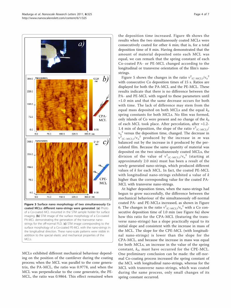
MCLs exhibited different mechanical behaviour depend-ing on the position of the cantilever during the coatingprocess; when the MCL was parallel to the cone genera-trix, the PA-MCL, the ratio was 0.9778, and when theMCL was perpendicular to the cone generatrix, the PE-MCL, the ratio was 0.9864. This effect remained when
the deposition time increased. Figure 4b shows theresults when the two simultaneously coated MCLs wereconsecutively coated for other 4 min; that is, for a totaldeposition time of 8 min. Having demonstrated that theamount of material deposited onto each MCL wasequal, we can remark that the spring constant of eachCo-coated PA- or PE-MCL changed according to thelongitudinal or transverse orientation of the film’s nano-strings.Figure 5 shows the changes in the ratio ν2(C-MCL)/νo
2
with consecutive Co deposition times of 15 s. Ratios aredisplayed for both the PA-MCL and the PE-MCL. Theseresults indicate that there is no difference between thePA- and PE-MCL with regard to these parameters until≈1.0 min and that the same decrease occurs for bothwith time. The lack of difference may stem from theequal mass deposited on both MCLs and the equal k0spring constants for both MCLs. No film was formed,only islands of Co were present and no change of the k0of each MCL took place. After percolation, after ≈1.2-1.4 min of deposition, the slope of the ratio ν2(C-MCL)/νo
2 versus the deposition time, changed. The decrease inν2(C-MCL)/νo
2 produced by the increase in m wasbalanced out by the increase in k produced by the per-colated film. Because the same quantity of material wasdeposited on the two simultaneously coated MCLs, thedivision of the value of ν2(C-MCL)/νo
2 (starting atapproximately 2.0 min) must has been a result of thenewly generated nano-strings, which produced differentvalues of k for each MCL. In fact, the coated PE-MCLwith longitudinal nano-strings exhibited a value of khigher than the corresponding value for the coated PA-MCL with transverse nano-strings.At higher deposition times, when the nano-strings had
begun to grow successfully, the difference between themechanical behaviour of the simultaneously off-normalcoated PA- and PE-MCLs increased, as shown in Figure6. The changes in the ratio ν2(C-MCL)/νo
2 with a Co con-secutive deposition time of 1.0 min (see Figure 6a) showhow this ratio for the CPA-MCL (featuring the trans-verse nano-strings) has a slope practically equal to itsinitial slope and consistent with the increase in mass ofthe MCL. The slope for the CPE-MCL (with longitudi-nal nano-strings) is lower than the slope for theCPA-MCL, and because the increase in mass was equalfor both MCLs, an increase in the value of the springconstant, k0, must have occurred for the CPE-MCL.One preliminary conclusion can be made: the off-nor-mal Co-coating process increased the spring constant ofthe MCL with longitudinal nano-strings, whereas for theMCL with transverse nano-strings, which was coatedduring the same process, only small changes of itsspring constant occurred.
Figure 3 Surface nano morphology of two simultaneously Cocoated MCLs: different nano-strings were generated. (a) Photoof a Co-coated MCL mounted in the STM sample holder for surfaceimaging. (b) STM image of the surface morphology of a Co-coatedPA-MCL demonstrating the generation of the transverse nano-strings for the off-normal PLD. (c) STM image corresponding to thesurface morphology of a Co-coated PE-MCL with the nano-strings inthe longitudinal direction. These nano-scale patterns were visible inaddition to the special elastic and mechanical properties of theMCLs.
Madurga et al. Nanoscale Research Letters 2011, 6:325http://www.nanoscalereslett.com/content/6/1/325
Page 4 of 7

This behaviour was also observed for other two simul-taneously off-normal Co-coated MCLs with a consecu-tive deposition time of 4.0 min, as shown in Figure 6b.Taking into account [16,17] that
ν0 = (C2t/2πL2)(E0/12ρ0)1/2 = 0.162(t/L2)(E0/ρ0)1/2 (1)
being C = 1.875 and the resonant frequencies νo (inthe interval (8665 ± 5) Hz), the density of the Si (r0 =
2.33 × 10³ kg/m3), the Si Young’s modulus (E0 = 1.69 ×10¹¹ Pa), and the length (L = 450 μm) and width (w =50 μm) of the two MCLs in Figure 6a, the followingvalues were deduced for MCL: mass, mo = 6.66 × 10⁻¹¹
kg, ko = 0.200 N/m and thickness t = 1.7 μm. The reso-nant frequency of a coated MCL is [16,17]:
ν2C−MCL ∼ E0(wt/12) + Eδ{(w + 2δ)[(1/2) + (δ/t) + (δ2/2t2)] + t/6}
ρ0wt + 2ρδ(w + t + 2δ)(2)
Figure 4 Resonant frequencies of two simultaneously Co coated MCLs: anisotropic elasticity of the films. (a) (Top) Resonant frequenciesfor the PA-MCL: νo representing the resonant frequency before the coating process and ν(CPA-MCL) representing the resonant frequency after theCo coating process with deposition time t = 4 min. ν2(CPA-MCL)/νo
2 = 0.9778. (Bottom) Resonant frequencies for the simultaneously coated PE-MCL: νo representing the resonant frequency prior to the coating process and ν(CPE-MCL) representing the resonant frequency after the coatingprocess; ν2(CPE-MCL)/νo
2 = 0.9864. (b) Resonant frequencies of the two simultaneously coated MCLs coated consecutively for 4 min: that is, for atotal deposition time of 8 min. ν2(CPA-MCL)/νo
2 = 0.9532 and ν2(CPE-MCL)/νo2 = 0.9768. Note the significant difference between the PA-MCL and PE-
MCL ratios for the two cases and the difference between these results and those displayed in Figure 2.
Madurga et al. Nanoscale Research Letters 2011, 6:325http://www.nanoscalereslett.com/content/6/1/325
Page 5 of 7

where δ is the thickness of the deposited Co film andE its Young’s modulus. Considering that δ = 10 nm,that t ≈ 2000 nm, that w = 50000 nm and that the twoMCLs are practically equal, we have approximated thislast equation, resulting:
ν2CPE - MCL/ν2
CPA - MCL = (12E0 + Elng)/(12E0 + Etrs) = 1.025, (3)
with Elng and Etrs the Young’s modulus of the CPEfilm and CPA film, respectively, and 1.025 the experi-mental value of the MCLs in Figure 4b. Working fromthis last equation, we obtain the following:
Elng − Etrs = 0.3E0. (4)
Given the E0 value, this difference is ≈20% of theYoung’s modulus of the micro-crystalline hcp bulk Co.
ConclusionsA specially designed homemade device combined with aPLD system allowed the off-normal simultaneous coatingof two Si MCLs at different controlled locations withrespect to the incidence plane of the plasma. For a fixedoff-normal angle of θ = 55°, two positions were used forthe two MCLs: a position parallel to the incidence planeof the plasma and one perpendicular to that plane. Thetwo off-normal Au-coated MCLs exhibited equalmechanical behaviour, indicating the in-plane isotropicelasticity of these Au pulsed-laser deposited films. Thisequal mechanical behaviour ensured that the amount ofmaterial deposited on both simultaneously coated MCLs
was equal and made it possible to conduct a differentialanalysis between both. The two simultaneously off-normal Co-coated MCLs exhibited the following beha-viour. First, after percolation and nano-string generation,different mechanical behaviour occurred due to theincrease in the spring constant for the MCL with Conano-strings parallel to the longitudinal direction,
Figure 5 Evolution of the ratio ν2(C-MCL)/νo2 with a consecutive
Co deposition time of 15 s. This ratio is shown for both the PA-MCL and the PE-MCL. The percolation in the deposited Co over theMCLs was deduced for a total deposition time of ≈1.2 to 1.4 minwhen ν2(C-MCL)/νo
2 changed its slope.
Figure 6 Evolution of the ratio ν2(C-MCL)/νo2 with consecutive Co
deposition times. (a) Evolution of the ratio ν2(C-MCL)/νo2 with a
consecutive deposition time of 1.0 min. This ratio for the CPA-MCL(featuring transverse nano-strings) has a slope that is practicallyequal to its initial slope and is consistent with the increment inmass of the C-MCL. This slope for the coated CPE-MCL (longitudinalnano-strings) is smaller than the slope for the CPA-MCL: an increasein the value of its spring constant, ko, must have occurred becausethe increase in mass was the same for the two MCLs. (b) The samebehaviour was observed for the other two simultaneously off-normal Co-coated micro-cantilevers with consecutive depositiontimes of 4.0 min.
Madurga et al. Nanoscale Research Letters 2011, 6:325http://www.nanoscalereslett.com/content/6/1/325
Page 6 of 7
whereas the MCL with Co nano-strings transverse to thelongitudinal direction experienced changes in the reso-nant frequency mostly produced by the increase in mass.Secondly, these results were connected with the anisotro-pic elastic behaviour of the Co film with nano-stringsmorphology. Thirdly, the Young’s modulus of the off-normal deposited Co film was 20% of the Young’s modu-lus of the bulk Co higher for the film direction parallel tothe nano-strings than for the film direction transverse tothe nano-strings.
AbbreviationsAFM: atomic force microscope; C-MCL: coated micro-cantilever; CPA: filmdeposited over the microcantilever parallel to the cone generatrix; CPE: filmdeposited over the microcantilever perpendicular to the cone generatrix;CPA-MCL: coated micro-cantilever parallel to the cone generatrix; CPE-MCL:coated micro-cantilever perpendicular to the cone generatrix; C(PA or PE)-MCL: coated micro-cantilever parallel to the cone generatrix or coatedmicro-cantilever perpendicular: to the cone generatrix; MCLs: micro-cantilevers; Nd:YAG: neodymium-doped yttrium aluminium garnet; PA-MCL:micro-cantilever parallel to the cone generatrix; PE-MCL: micro-cantileverperpendicular to the cone generatrix; PLD: pulsed laser deposition; STM:scanning tunnelling microscopy.
AcknowledgementsThis work was partially supported by the Spanish government under projectMAT2007-66252.
Authors’ contributionsVM, CF and JV participated from the beginning in devising the differentsteps of the work. Specially, VM with the preparation of the device for off-normal PLD, supports and microcantilever holders and during the coatingprocesses. CF with mechanical characterization of microcantilever andsubsequent determination of mechanical resonances. JV with the STMsurface observation nano-strings of the microcantilever and VSM magneticdeterminations. VM, CF and JV participated at the discussions and analysis ofthe results and during the preparation of manuscript. Specially CF dedicatedextra time for this part.
Competing interestsThe authors declare that they have no competing interests.
Received: 5 November 2010 Accepted: 12 April 2011Published: 12 April 2011
References1. Nix WD: Mechanical properties of thin films. Metall Trans A Phys Metall
Mater Sci 1989, 20A:2217-2245.2. Florando JN, Nix WD: A microbeam bending method for studying stress-
strain relations for metal thin films on silicon substrates. J Mech PhysSolids 2005, 53:619-638.
3. Badawi KF, Villain P, Goudeau Ph, Renault PO: Measuring thin film andmultilayer elastic constants by coupling in situ tensile testing with x-raydiffraction. Appl Phys Lett 2002, 80:4705-4707.
4. Yamaguchi T, Song W, Yamaguchi A, Yamamoto R: The anelastic study ofAg/Pd multilayers. J Alloys Compd 1994, 211-212:442-445.
5. Chen X, Vlassak J: Numerical study on the measurement of thin filmmechanical properties by means of nanoindentation. J Mater Res 2001,16:2974-2982.
6. Danner R, Huebener RP, Chun CS, Grimsditch M, Schuller IK: Surfaceacoustic waves in Ni/V superlattices. Phys Rev B 1986, 33:3696-3701.
7. Mirkarimi PB, Shinn M, Barnett SA, Kumar S, Grimsditch M: Elasticproperties of TiN/(VxNb1-x)N superlattices measured lby Brillouinscattering. J Appl Phys 1992, 71:4955-4958.
8. Craighead HG, Waggoner PS: Micro- and nanomechanical sensors forenvironmental, chemical, and biological detection. Lab Chip 2007,7:1238-1255.
9. Finot E, Passian A, Thundat T: Measurement of mechanical properties ofcantilever shaped materials. Sensors 2008, 8:3497-3541.
10. McShane GJ, Boutchich M, Srikantha Phani A, Moore DF, Lu TJ: Young’smodulus measurement of thin-film materials using micro-cantilevers.J Micromech Microeng 2006, 16:1926-1938.
11. Madurga V, Vergara J, Favieres C: Magnetic domain structures and nano-string morphology of laser off-normal deposited amorphous cobalt filmswith controlled magnetic anisotropy. J Magn Magn Matter 2004, 272-276:1681-1683.
12. Madurga V, Vergara J, Favieres C: Surface nano-string morphology ofoblique pulsed laser deposited cobalt thin films. International ConferenceTNT “Trends in Nanotechnology": 29 August-2 September 2005, Oviedo, Spain .
13. Madurga V, Vergara J, Favieres C: Soft magnetic nano-stringssimultaneously grown and sculpted on Si micro-cantilevers. J MagnMagn Matter 2010, 322:1519-1522.
14. Madurga V, Favieres C, Vergara J: Growth and sculpting of Co nano-strings on Si micro-cantilevers: magneto-mechanical properties.Nanotechnology 2010, 21:095702-6.
15. Horcas I, Hernández R, Gómez-Rodríguez JM, Colchero J, Gómez-Herrero J,Baró A: WSXM: A software for scanning probe microscopy and a tool fornanotechnology. Rev Sci Instrum 2007, 78:013705-8.
16. Bishop RDE, Johnson DC: The Mechanics of Vibration Cambrigde:CambridgeUniversity Press; 1960.
17. Salvadori MC, Grown IG, Vaz AR, Melo LL, Cattani MC: Measurement of theelastic modulus of nanostructured gold and platinum thin Films. PhysRev B 2003, 67:153404-4.
doi:10.1186/1556-276X-6-325Cite this article as: Madurga et al.: Generating and measuring theanisotropic elastic behaviour of Co thin films with oriented surfacenano-strings on micro-cantilevers. Nanoscale Research Letters 2011 6:325.
Submit your manuscript to a journal and benefi t from:
7 Convenient online submission
7 Rigorous peer review
7 Immediate publication on acceptance
7 Open access: articles freely available online
7 High visibility within the fi eld
7 Retaining the copyright to your article
Submit your next manuscript at 7 springeropen.com
Madurga et al. Nanoscale Research Letters 2011, 6:325http://www.nanoscalereslett.com/content/6/1/325
Page 7 of 7
Copyright © 2022 FDOKUMEN