
General settings
136
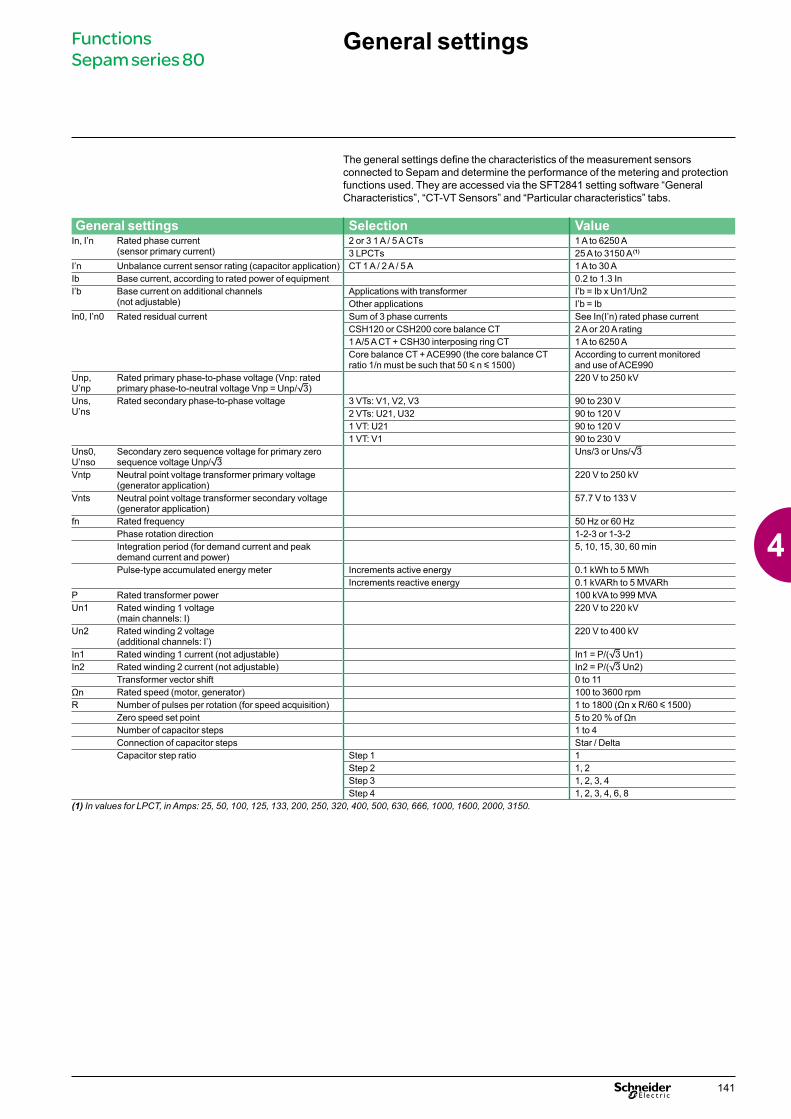
The general settings define the characteristics of the measurement sensors connected to Sepam and determine the performance of the metering and protection functions used. They are accessed via the SFT2841 setting software “General Characteristics”, “CT-VT Sensors” and “Particular characteristics” tabs. General settings Selection Value In, I’n Rated phase current (sensor primary current) 2 or 3 1 A / 5 A CTs 1 A to 6250 A 3 LPCTs 25 A to 3150 A (1) I’n Unbalance current sensor rating (capacitor application) CT 1 A / 2 A / 5 A 1 A to 30 A Ib Base current, according to rated power of equipment 0.2 to 1.3 In I’b Base current on additional channels (not adjustable) Applications with transformer I’b = Ib x Un1/Un2 Other applications I’b = Ib In0, I’n0 Rated residual current Sum of 3 phase currents See In(I’n) rated phase current CSH120 or CSH200 core balance CT 2 A or 20 A rating 1 A/5 A CT + CSH30 interposing ring CT 1 A to 6250 A Core balance CT + ACE990 (the core balance CT ratio 1/n must be such that 50 y n y 1500) According to current monitored and use of ACE990 Unp, U’np Rated primary phase-to-phase voltage (Vnp: rated primary phase-to-neutral voltage Vnp = Unp/3) 220 V to 250 kV Uns, U’ns Rated secondary phase-to-phase voltage 3 VTs: V1, V2, V3 90 to 230 V 2 VTs: U21, U32 90 to 120 V 1 VT: U21 90 to 120 V 1 VT: V1 90 to 230 V Uns0, U’nso Secondary zero sequence voltage for primary zero sequence voltage Unp/3 Uns/3 or Uns/3 Vntp Neutral point voltage transformer primary voltage (generator application) 220 V to 250 kV Vnts Neutral point voltage transformer secondary voltage (generator application) 57.7 V to 133 V fn Rated frequency 50 Hz or 60 Hz Phase rotation direction 1-2-3 or 1-3-2 Integration period (for demand current and peak demand current and power) 5, 10, 15, 30, 60 min Pulse-type accumulated energy meter Increments active energy 0.1 kWh to 5 MWh Increments reactive energy 0.1 kVARh to 5 MVARh P Rated transformer power 100 kVA to 999 MVA Un1 Rated winding 1 voltage (main channels: I) 220 V to 220 kV Un2 Rated winding 2 voltage (additional channels: I’) 220 V to 400 kV In1 Rated winding 1 current (not adjustable) In1 = P/(3 Un1) In2 Rated winding 2 current (not adjustable) In2 = P/(3 Un2) Transformer vector shift 0 to 11 Ωn Rated speed (motor, generator) 100 to 3600 rpm R Number of pulses per rotation (for speed acquisition) 1 to 1800 (Ωn x R/60 y 1500) Zero speed set point 5 to 20 % of Ωn Number of capacitor steps 1 to 4 Connection of capacitor steps Star / Delta Capacitor step ratio Step 1 1 Step 2 1, 2 Step 3 1, 2, 3, 4 Step 4 1, 2, 3, 4, 6, 8 (1) In values for LPCT, in Amps: 25, 50, 100, 125, 133, 200, 250, 320, 400, 500, 630, 666, 1000, 1600, 2000, 3150. General settings Functions Sepam series 80 141 4
-
Upload
khangminh22 -
Category
Documents
-
view
2 -
download
0
Transcript of General settings
The general settings define the characteristics of the measurement sensors connected to Sepam and determine the performance of the metering and protection functions used. They are accessed via the SFT2841 setting software “General Characteristics”, “CT-VT Sensors” and “Particular characteristics” tabs.
General settings Selection ValueIn, I’n Rated phase current
(sensor primary current)2 or 3 1 A / 5 A CTs 1 A to 6250 A3 LPCTs 25 A to 3150 A (1)
I’n Unbalance current sensor rating (capacitor application) CT 1 A / 2 A / 5 A 1 A to 30 AIb Base current, according to rated power of equipment 0.2 to 1.3 InI’b Base current on additional channels
(not adjustable) Applications with transformer I’b = Ib x Un1/Un2Other applications I’b = Ib
In0, I’n0 Rated residual current Sum of 3 phase currents See In(I’n) rated phase currentCSH120 or CSH200 core balance CT 2 A or 20 A rating1 A/5 A CT + CSH30 interposing ring CT 1 A to 6250 ACore balance CT + ACE990 (the core balance CT ratio 1/n must be such that 50 y n y 1500)
According to current monitored and use of ACE990
Unp, U’np
Rated primary phase-to-phase voltage (Vnp: rated primary phase-to-neutral voltage Vnp = Unp/3)
220 V to 250 kV
Uns, U’ns
Rated secondary phase-to-phase voltage 3 VTs: V1, V2, V3 90 to 230 V2 VTs: U21, U32 90 to 120 V1 VT: U21 90 to 120 V1 VT: V1 90 to 230 V
Uns0, U’nso
Secondary zero sequence voltage for primary zero sequence voltage Unp/3
Uns/3 or Uns/3
Vntp Neutral point voltage transformer primary voltage (generator application)
220 V to 250 kV
Vnts Neutral point voltage transformer secondary voltage (generator application)
57.7 V to 133 V
fn Rated frequency 50 Hz or 60 HzPhase rotation direction 1-2-3 or 1-3-2Integration period (for demand current and peak demand current and power)
5, 10, 15, 30, 60 min
Pulse-type accumulated energy meter Increments active energy 0.1 kWh to 5 MWhIncrements reactive energy 0.1 kVARh to 5 MVARh
P Rated transformer power 100 kVA to 999 MVAUn1 Rated winding 1 voltage
(main channels: I)220 V to 220 kV
Un2 Rated winding 2 voltage (additional channels: I’)
220 V to 400 kV
In1 Rated winding 1 current (not adjustable) In1 = P/(3 Un1)In2 Rated winding 2 current (not adjustable) In2 = P/(3 Un2)
Transformer vector shift 0 to 11Ωn Rated speed (motor, generator) 100 to 3600 rpmR Number of pulses per rotation (for speed acquisition) 1 to 1800 (Ωn x R/60 y 1500)
Zero speed set point 5 to 20 % of ΩnNumber of capacitor steps 1 to 4Connection of capacitor steps Star / DeltaCapacitor step ratio Step 1 1
Step 2 1, 2Step 3 1, 2, 3, 4Step 4 1, 2, 3, 4, 6, 8
(1) In values for LPCT, in Amps: 25, 50, 100, 125, 133, 200, 250, 320, 400, 500, 630, 666, 1000, 1600, 2000, 3150.
General settings Functions Sepam series 80
141
4

MeteringSepam is a precision metering unit. All the metering and diagnosis data used for commissioning and required for the operation and maintenance of your equipment are available locally or remotely, expressed in the units concerned (A, V, W, etc.).
Phase currentRMS current for each phase, taking into account harmonics up to number 13.Different types of sensors may be used to meter phase current:b 1 A or 5 A current transformersb LPCT type current sensors.
Residual currentFour types of residual current values are available depending on the type of Sepam and sensors connected to it:b 2 residual currents I0Σ and I’0Σ, calculated by the vector sum of the 3 phase currents b 2 measured residual currents I0 and I’0.Different types of sensors may be used to measure residual current:b CSH120 or CSH200 specific core balance CT b conventional 1 A or 5 A current transformer with CSH30 interposing ring CTb any core balance CT with an ACE990 interface.
Demand current and peak demand currentsDemand current and peak demand currents are calculated according to the 3 phase currents I1, I2 and I3:b demand current is calculated over an adjustable period of 5 to 60 minutesb peak demand current is the greatest demand current and indicates the current drawn by peak loads.Peak demand currents may be cleared.
Voltage and frequencyThe following measurements are available according to the voltage sensors connected:b phase-to-neutral voltages V1, V2, V3 and V’1, V’2, V’3b phase-to-phase voltages U21, U32, U13 and U’21, U’32, U’13b residual voltage V0, V’0 or neutral point voltage Vntb positive sequence voltage Vd, V’d and negative sequence voltage Vi, V’ib frequency measured on the main and additional voltage channels.
PowerPowers are calculated according to the phase currents I1, I2 and I3:b active power b reactive powerb apparent powerb power factor (cos φ).According to the sensors used, power calculations may be based on the 2 or 3 wattmeter method. The 2 wattmeter method is only accurate when there is no residual current and it is not applicable if the neutral is distributed.The 3 wattmeter method gives an accurate calculation of 3-phase and phase by phase powers in all cases, regardless of whether or not the neutral is distributed.
Peak demand powers The greatest demand active and reactive power values calculated over the same period as the demand current. The peak demand powers may be cleared.
Energy b 4 accumulated energies calculated according to voltages and phase currents I1, I2 and I3 measured: active energy and reactive energy in both directionsb 1 to 4 additional accumulated energy meters for the acquisition of active or reactive energy pulses from external meters.
Temperature Accurate measurement of temperature inside equipment fitted with Pt100, Ni100 or Ni120 type RTDs, connected to the optional remote MET148-2 module.
Rotation speed Calculated by the counting of pulses transmitted by a proximity sensor at each passage of a cam driven by the rotation of the motor or generator shaft.Acquisition of pulses on a logic input.
Phasor diagram A phasor diagram is displayed by SFT2841 software and the mimic-based UMI to check cabling and assist in the setting and commissioning of directional and differential protection functions.According to the connected sensors, all current and voltage information can be selected for display in vector form.
Metering and diagnosisDescription
Functions Sepam series 80
142
4

Metering and diagnosisDescription
Network diagnosis assistanceSepam provides network power quality metering functions, and all the data on network disturbances detected by Sepam are recorded for analysis purposes.
Tripping contextStorage of tripping currents and I0, Ii, U21, U32, U13, V1, V2, V3, V0, Vi, Vd, F, P, Q, Idiff, It and Vnt values when tripping occurs. The values for the last five trips are stored.
Tripping currentStorage of the 3 phase currents and earth fault current at the time of the last Sepam trip order, to indicate fault current.The values are stored in the tripping contexts.
Number of trips2 trip counters:b number of phase fault trips, incremented by each trip triggered by ANSI 50/51, 50V/51V and 67 protection functions b number of earth fault trips, incremented by each trip triggered by ANSI 50N/51 and 67N/67NC protection functions.
Negative sequence / unbalanceNegative sequence component of phase currents I1, I2 and I3 (and I’1, I’2 and I’3), indicating the degree of unbalance in the power supplied to the protected equipment.
Total harmonic distortionTwo THD values calculated to assess network power quality, taking into account harmonics up to number 13:b current THD, calculated according to I1b voltage THD, calculated according to V1 or U21.
Phase displacementb phase displacement φ1, φ2, φ3 between phase currents l1, l2, l3 and voltages V1, V2, V3 respectivelyb phase displacement φ0 between residual current and residual voltage.
Disturbance recordingRecording triggered by user-set events:b all sampled values of measured currents and voltagesb status of all logic inputs and outputs logic data: pick-up, …
Recording characteristicsNumber of recordings in COMTRADE format Adjustable from 1 to 19Total duration of a recording Adjustable from 1 to 11 sNumber of samples per period 12 or 36Duration of recording prior to occurrence of the event Adjustable from 0 to 99 periodsMaximum recording capabilityNetwork frequency 12 samples
per period36 samples per period
50 Hz 22 s 7 s60 Hz 18 s 6 s
Voltage comparison for synchro-checkFor the synchro-check function, the MCS025 module continuously measures the amplitude, frequency and phase differences between the 2 voltages to be checked.
Out-of-sync contextStorage of amplitude, frequency and phase differences between the 2 voltages measured by the MCS025 module when a closing order is inhibited by the synchro-check function.
Functions Sepam series 80
143
4

Machine diagnosis assistanceSepam assists facility managers by providing:b data on the operation of their machinesb predictive data to optimize process managementb useful data to facilitate protection function setting and implementation.
Thermal capacity usedEquivalent temperature buildup in the machine, calculated by the thermal overload protection function. Displayed as a percentage of rated thermal capacity.
Remaining operating time before overload trippingPredictive data calculated by the thermal overload protection function. The time is used by facility managers to optimize process management in real time by deciding to:b interrupt according to procedures b continue operation with inhibition of thermal protection on overloaded machine.
Waiting time after overload trippingPredictive data calculated by the thermal overload protection function. Waiting time to avoid further tripping of thermal overload protection by premature re-energizing of insufficiently cooled down equipment.
Running hours counter / operating timeEquipment is considered to be running whenever a phase current is over 0.1 Ib. Cumulative operating time is given in hours.
Motor starting / overload current and timeA motor is considered to be starting or overloaded when a phase current is over 1.2 Ib. For each start / overload, Sepam stores:b maximum current drawn by the motorb starting / overload time.The values are stored until the following start / overload.
Number of starts before inhibition/start inhibit timeIndicates the number of starts still allowed by the starts per hour protection function and, if the number is zero, the waiting time before starting is allowed again.
Differential and through currentValues calculated to facilitate the implementation of ANSI 87T and 87M differential protection functions.
Current phase displacementPhase shift between the main phase currents and additional phase currents to facilitate implementation of ANSI 87T differential protection function.
Apparent positive sequence impedance ZdValue calculated to facilitate the implementation of the underimpedance field loss protection (ANSI 40).
Apparent phase-to-phase impedances Z21, Z32, Z13Values calculated to facilitate the implementation of the backup underimpedance protection function (ANSI 21B).
Third harmonic neutral point or residual voltageValues measured to facilitate the implementation of the third harmonic undervoltage / 100 % stator earth fault protection function (ANSI 27TN/64G2).
CapacitanceMeasurement, for each phase, of the total capacitance of the connected capacitor bank steps. This measurement is used to monitor the condition of the capacitors.
Capacitor unbalance currentMeasurement of the unbalance current for each capacitor bank step. This measurement is possible when the steps are connected in a double star arrangement.
Metering and diagnosisDescription
Functions Sepam series 80
144
4
Switchgear diagnosis assistanceSwitchgear diagnosis data give facility managers information on:b mechanical condition of breaking deviceb Sepam auxiliaries and assist them for preventive and curative switchgear maintenance actions.The data are to be compared to switchgear manufacturer data.
ANSI 60/60FL - CT/VT supervisionUsed to monitor the entire metering chain:b CT and VT sensorsb connectionb Sepam analog inputs.Monitoring includes:b consistency checking of currents and voltages measuredb acquisition of phase or residual voltage transformer protection fuse blown contacts.In the event of a loss of current or voltage measurement data, the assigned protection functions may be inhibited to avoid nuisance tripping.
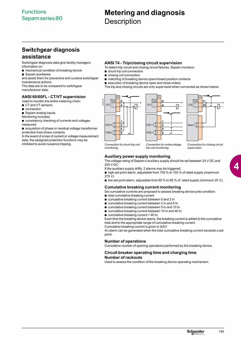
ANSI 74 - Trip/closing circuit supervisionTo detect trip circuit and closing circuit failures, Sepam monitors:b shunt trip coil connectionb closing coil connectionb matching of breaking device open/closed position contactsb execution of breaking device open and close orders.The trip and closing circuits are only supervised when connected as shown below.
DE
8813
8
Connection for shunt trip coil monitoring.
Connection for undervoltage trip coil monitoring.
Connection for closing circuit supervision
Auxiliary power supply monitoringThe voltage rating of Sepam’s auxiliary supply should be set between 24 V DC and 250 V DC.If the auxiliary supply drifts, 2 alarms may be triggered:b high set point alarm, adjustable from 105 % to 150 % of rated supply (maximum 275 V)b low set point alarm, adjustable from 60 % to 95 % of rated supply (minimum 20 V).
Cumulative breaking current monitoringSix cumulative currents are proposed to assess breaking device pole condition:b total cumulative breaking current b cumulative breaking current between 0 and 2 In b cumulative breaking current between 2 In and 5 Inb cumulative breaking current between 5 In and 10 Inb cumulative breaking current between 10 In and 40 Inb cumulative breaking current > 40 In.Each time the breaking device opens, the breaking current is added to the cumulative total and to the appropriate range of cumulative breaking current.Cumulative breaking current is given in (kA)².An alarm can be generated when the total cumulative breaking current exceeds a set point.
Number of operationsCumulative number of opening operations performed by the breaking device.
Circuit breaker operating time and charging time Number of rackoutsUsed to assess the condition of the breaking device operating mechanism.
Metering and diagnosisDescription
Functions Sepam series 80
145
4

Sepam self-diagnosisSepam includes a number of self-tests carried out in the base unit and optional modules. The purpose of the self-tests is to:b detect internal failures that may cause nuisance tripping or failed fault trippingb put Sepam in fail-safe position to avoid any unwanted operationb alert the facility manager of the need for maintenance operations.
Internal failureTwo categories of internal failures are monitored: b major failures: Sepam shutdown (to fail-safe position). The protection functions are inhibited, the output relays are forced to drop out and the “Watchdog” output indicates Sepam shutdownb minor failures: downgraded Sepam operation. Sepam’s main functions are operational and equipment protection is ensured.
Battery monitoringMonitoring of battery voltage to guarantee data is saved in the event of an outage. A battery fault generates an alarm.
Detection of plugged connectorsThe system checks that the current or voltage sensors are plugged in. A missing connector is a major failure.
Configuration checkingThe system checks that the optional modules configured are present and working correctly.The absence or failure of a remote module is a minor failure, the absence or failure of a logic input/output module is a major failure.
Metering and diagnosisDescription
Functions Sepam series 80
146
4

Functions Measurement range Accuracy (1) MSA141 SavingMetering
Phase current 0.02 to 40 In ±0.5 % b
Residual current Calculated 0.005 to 40 In ±1 % b
Measured 0.005 to 20 In0 ±1 % b
Demand current 0.02 to 40 In ±0.5 %Peak demand current 0.02 to 40 In ±0.5 % v
Phase-to-phase voltage Main channels (U) 0.05 to 1.2 Unp ±0.5 % b
Additional channels (U’) 0.05 to 1.2 Unp ±1 %Phase-to-neutral voltage Main channels (V) 0.05 to 1.2 Vnp ±0.5 % b
Additional channels (V’) 0.05 to 1.2 Vnp ±1 %Residual voltage 0.015 to 3 Vnp ±1 %Neutral point voltage 0.015 to 3 Vntp ±1 %Positive sequence voltage 0.05 to 1.2 Vnp ±2 %Negative sequence voltage 0.05 to 1.2 Vnp ±2 %Frequency Main channels (f) 25 to 65 Hz ±0.01 Hz b
Additional channels (f’) 45 to 55 Hz (fn = 50 Hz)55 to 65 Hz (fn = 60 Hz)
±0.05 Hz
Active power (total or per phase) 0.008 Sn to 999 MW ±1 % b
Reactive power (total or per phase) 0.008 Sn to 999 MVAR ±1 % b
Apparent power (total or per phase) 0.008 Sn to 999 MVA ±1 % b
Peak demand active power 0.008 Sn to 999 MW ±1 % v
Peak demand reactive power 0.008 Sn to 999 MVAR ±1 % v
Power factor -1 to + 1 (CAP/IND) ±0.01 b
Calculated active energy 0 to 2.1 x 10⁸ MWh ±1 % ±1 digit v v
Calculated reactive energy 0 to 2.1 x 10⁸ MVARh ±1 % ±1 digit v v
Temperature -30 °C to +200 °C or -22 °F to +392 °F
±1 °C from +20 to +140 °C±1,8 °F from +68 to +384 °F
b
Rotation speed 0 to 7200 rpm ±1 rpmNetwork diagnosis assistance
Tripping context v
Tripping current 0.02 to 40 In ±5 % v
Number of trips 0 to 65535 - v v
Negative sequence / unbalance 1 to 500 % of Ib ±2 %Total harmonic distortion, current 0 to 100 % ±1 %Total harmonic distortion, voltage 0 to 100 % ±1 %Phase displacement φ0 (between V0 and I0) 0 to 359° ±2°Phase displacement φ1, φ2, φ3 (between V and I) 0 to 359° ±2°Disturbance recording v
Amplitude difference 0 to 1.2 Usync1 ±1 %Frequency difference 0 to 10 Hz ±0.5 HzPhase difference 0 to 359° ±2°Out-of-sync context v
Machine operating assistanceThermal capacity used 0 to 800 %
(100 % for phase I = Ib)±1 % b v v
Remaining operating time before overload tripping 0 to 999 min ±1 minWaiting time after overload tripping 0 to 999 min ±1 minRunning hours counter / operating time 0 to 65535 hours ±1 % or ±0.5 h v v
Starting current 1.2 Ib to 40 In ±5 % v
Starting time 0 to 300 s ±300 ms v
Number of starts before inhibition 0 to 60Start inhibit time 0 to 360 min ±1 minDifferential current 0.015 to 40 In ±1 %Through current 0.015 to 40 In ±1 %Phase displacement θ1, θ2, θ3 (between I and I’) 0 to 359° ±2°Apparent impedance Zd, Z21, Z32, Z13 0 to 200 kΩ ±5 %Third harmonic neutral point voltage 0.2 to 30 % of Vnp ±1 %Third harmonic residual voltage 0.2 to 90 % of Vnp ±1 %Capacitance 0 to 30 F ±5 %Capacitor unbalance current 0.02 to 40 I’n ±5 %Switchgear diagnosis assistance
Cumulative breaking current 0 to 65535 kA² ±10 % v v
Auxiliary supply 24 V DC to 250 V DC ±4 V or ±10 % v vNumber of operations 0 to 4 x 10⁹ - v v
Operating time 20 to 100 ms ±1 ms v v
Charging time 1 to 20 s ±0.5 s v v
Number of rackouts 0 to 65535 - v v
b available on MSA141 analog output module, according to setupv saved in the event of auxiliary supply outage, even without batteryv saved by battery in the event of auxiliary supply outage.(1) Under reference conditions (IEC 60255-6), typical accuracy at In or Unp, cos φ > 0.8.
Metering and diagnosisCharacteristics
Functions Sepam series 80
147
4
ProtectionDescription
Current protection functionsANSI 50/51 - Phase overcurrentPhase-to-phase short-circuit protection. 2 modes:b overcurrent protection sensitive to the highest phase current measuredb machine differential protection sensitive to the highest differential phase currents obtained in self-balancing schemes.Characteristicsb 2 groups of settingsb instantaneous or time-delayed trippingb definite time (DT), IDMT (choice of 16 standardized IDMT curves) or customized curveb with or without timer holdb tripping confirmed or unconfirmed, according to parameter setting:v unconfirmed tripping: standardv tripping confirmed by negative sequence overvoltage protection (ANSI 47, unit 1), as backup for distant 2-phase short-circuitsv tripping confirmed by undervoltage protection (ANSI 27, unit 1), as backup for phase-to-phase short-circuits in networks with low short-circuit power.
ANSI 50N/51N or 50G/51G - Earth faultEarth fault protection based on measured or calculated residual current values:b ANSI 50N/51N: residual current calculated or measured by 3 phase current sensorsb ANSI 50G/51G: residual current measured directly by a specific sensor.Characteristics b 2 groups of settingsb definite time (DT), IDMT (choice of 17 standardized IDMT curves) or customized curveb with or without timer holdb second harmonic restraint to ensure stability during transformer energizing, activated by parameter setting.
ANSI 50BF - Breaker failureIf a breaker fails to be triggered by a tripping order, as detected by the non-extinction of the fault current, this backup protection sends a tripping order to the upstream or adjacent breakers.
ANSI 46 - Negative sequence / unbalanceProtection against phase unbalance, detected by the measurement of negative sequence current.b sensitive protection to detect 2-phase faults at the ends of long linesb protection of equipment against temperature build-up, caused by an unbalanced power supply, phase inversion or loss of phase, and against phase current unbalance. Characteristi csb 1 definite time (DT) curve b 9 IDMT curves: 4 IEC curves and 3 IEEE curves, 1 ANSI curve in RI² and 1 specific Schneider curve
ANSI 49RMS - Thermal overloadProtection against thermal damage caused by overloads onb machines (transformers, motors or generators)b cablesb capacitorsThe thermal capacity used is calculated according to a mathematical model which takes into account:b current RMS valuesb ambient temperatureb negative sequence current, a cause of motor rotor temperature rise.The thermal capacity used calculations may be used to calculate predictive data for process control assistance. The protection may be inhibited by a logic input when required by process control conditions.Thermal overload for machines - Characteristicsb 2 groups of settingsb 1 adjustable alarm set pointb 1 adjustable tripping set pointb adjustable initial thermal capacity used setting, to adapt protection characteristics to fit manufacturer’s thermal withstand curvesb equipment heating and cooling time constants. The cooling time constant may be calculated automatically based on measurement of the equipment temperature by a sensor.Thermal overload for cables - Characteristics b 1 group of settingsb cable current carrying capacity, which determines alarm and trip set points b cable heating and cooling time constants.Thermal overload for capacitors - Characteristicsb 1 group of settingsb alarm current, which determines the alarm set pointb overload current, which determines the tripping set pointb hot tripping time and current setting, which determine a point on the tripping curve.
ANSI 51C - Capacitor bank unbalanceDetection of capacitor step internal faults by measuring the unbalance current flowing between the two neutral points of a step connected in a double star arrangement. Four unbalance currents can be measured to protect up to 4 steps.Characteristicsb 2 set points per stepb definite time (DT) curve.
Functions Sepam series 80
148
4
ProtectionDescription
RecloserANSI 79Automation device used to limit down time after tripping due to transient or semi-permanent faults on overhead lines. The recloser orders automatic reclosing of the breaking device after the time delay required to restore the insulation has elapsed.Recloser operation is easy to adapt for different operating modes by parameter setting.Characteristicsb 1 to 4 reclosing cycles, each cycle has an adjustable dead timeb adjustable, independent reclaim time and safety time until recloser ready time delaysb cycle activation linked to instantaneous or time-delayed short-circuit protection function (ANSI 50/51, 50N/51N, 67, 67N/67NC) outputs by parameter setting b inhibition/locking out of recloser by logic input.
Synchro-checkANSI 25This function checks the voltages upstream and downstream of a circuit breaker and allows closing when the differences in amplitude, frequency and phase are within authorized limits.Characteristicsb adjustable and independent set points for differences in voltage, frequency and phaseb adjustable lead time to take into account the circuit-breaker closing timeb 5 possible operating modes to take no-voltage conditions into account.
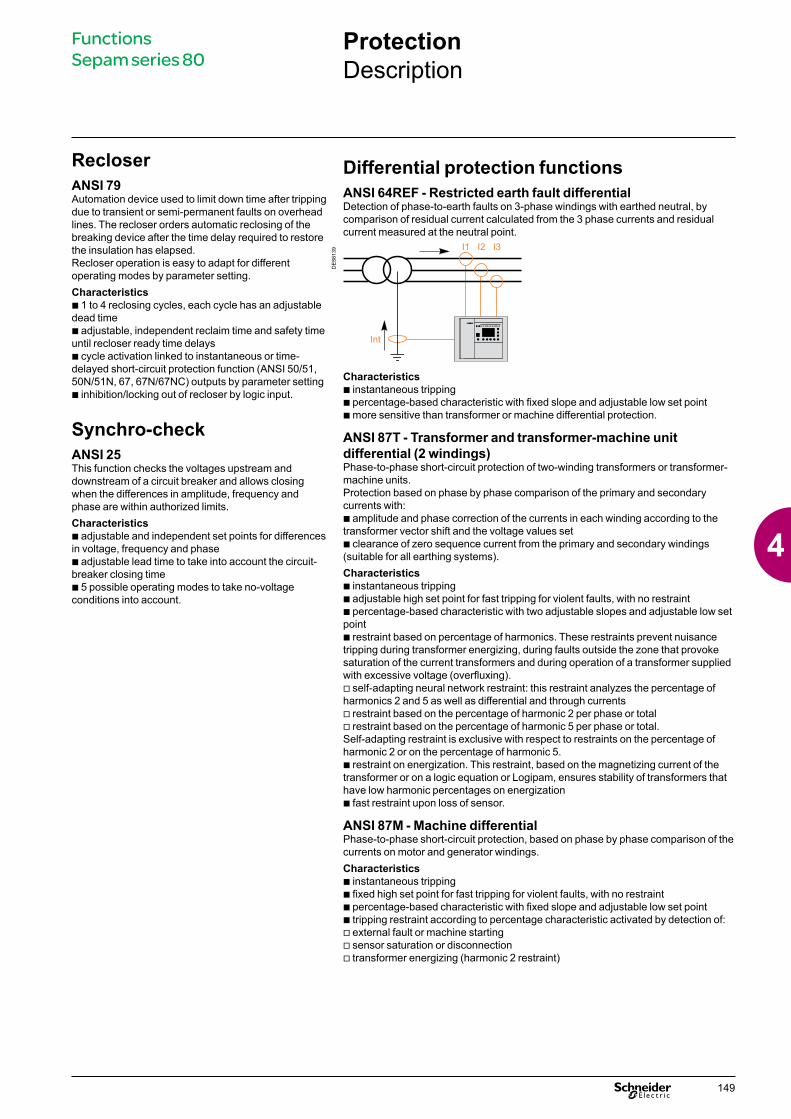
Differential protection functionsANSI 64REF - Restricted earth fault differentialDetection of phase-to-earth faults on 3-phase windings with earthed neutral, by comparison of residual current calculated from the 3 phase currents and residual current measured at the neutral point.
DE
8813
9
Characteristics b instantaneous trippingb percentage-based characteristic with fixed slope and adjustable low set pointb more sensitive than transformer or machine differential protection.
ANSI 87T - Transformer and transformer-machine unit differential (2 windings)Phase-to-phase short-circuit protection of two-winding transformers or transformer-machine units.Protection based on phase by phase comparison of the primary and secondary currents with:b amplitude and phase correction of the currents in each winding according to the transformer vector shift and the voltage values setb clearance of zero sequence current from the primary and secondary windings (suitable for all earthing systems).Characteristicsb instantaneous trippingb adjustable high set point for fast tripping for violent faults, with no restraintb percentage-based characteristic with two adjustable slopes and adjustable low set pointb restraint based on percentage of harmonics. These restraints prevent nuisance tripping during transformer energizing, during faults outside the zone that provoke saturation of the current transformers and during operation of a transformer supplied with excessive voltage (overfluxing).v self-adapting neural network restraint: this restraint analyzes the percentage of harmonics 2 and 5 as well as differential and through currentsv restraint based on the percentage of harmonic 2 per phase or totalv restraint based on the percentage of harmonic 5 per phase or total.Self-adapting restraint is exclusive with respect to restraints on the percentage of harmonic 2 or on the percentage of harmonic 5.b restraint on energization. This restraint, based on the magnetizing current of the transformer or on a logic equation or Logipam, ensures stability of transformers that have low harmonic percentages on energizationb fast restraint upon loss of sensor.
ANSI 87M - Machine differentialPhase-to-phase short-circuit protection, based on phase by phase comparison of the currents on motor and generator windings.Characteristicsb instantaneous trippingb fixed high set point for fast tripping for violent faults, with no restraintb percentage-based characteristic with fixed slope and adjustable low set pointb tripping restraint according to percentage characteristic activated by detection of:v external fault or machine startingv sensor saturation or disconnectionv transformer energizing (harmonic 2 restraint)
Functions Sepam series 80
149
4
ProtectionDescription
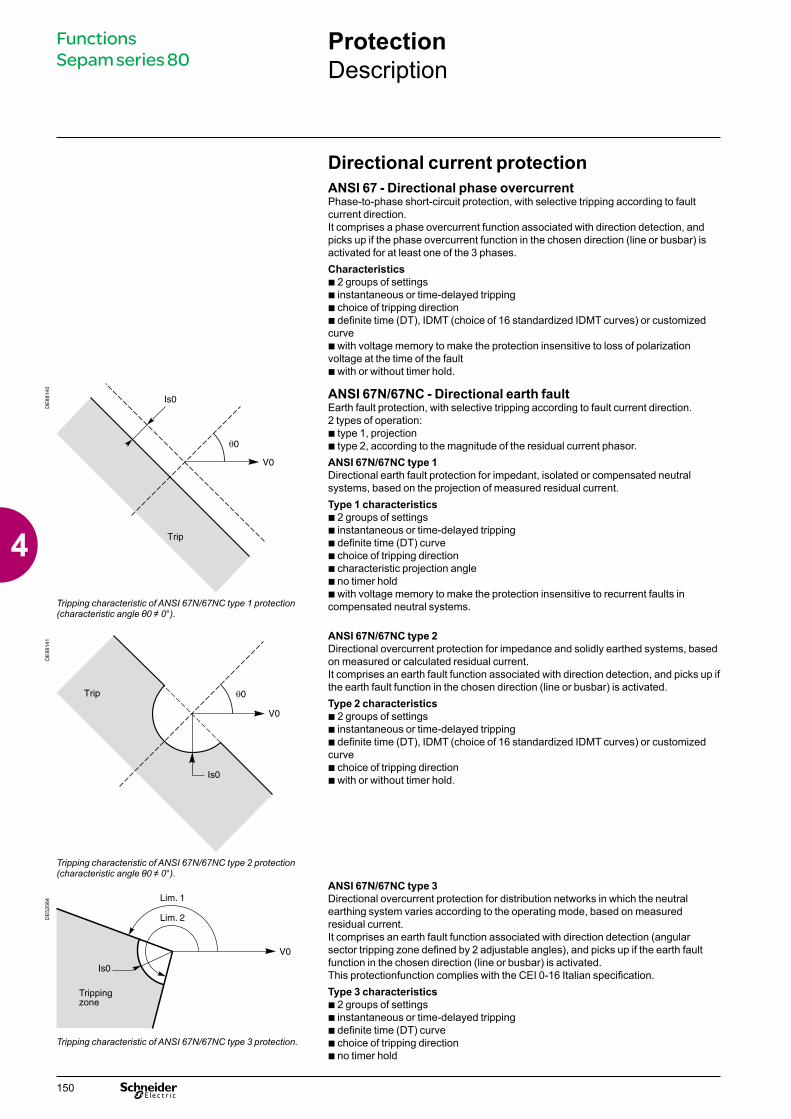
Directional current protectionANSI 67 - Directional phase overcurrentPhase-to-phase short-circuit protection, with selective tripping according to fault current direction.It comprises a phase overcurrent function associated with direction detection, and picks up if the phase overcurrent function in the chosen direction (line or busbar) is activated for at least one of the 3 phases. Characteristics b 2 groups of settingsb instantaneous or time-delayed trippingb choice of tripping directionb definite time (DT), IDMT (choice of 16 standardized IDMT curves) or customized curveb with voltage memory to make the protection insensitive to loss of polarization voltage at the time of the faultb with or without timer hold.
ANSI 67N/67NC - Directional earth faultEarth fault protection, with selective tripping according to fault current direction.2 types of operation:b type 1, projectionb type 2, according to the magnitude of the residual current phasor.ANSI 67N/67NC type 1 Directional earth fault protection for impedant, isolated or compensated neutral systems, based on the projection of measured residual current.Type 1 characteristics b 2 groups of settingsb instantaneous or time-delayed trippingb definite time (DT) curveb choice of tripping directionb characteristic projection angleb no timer holdb with voltage memory to make the protection insensitive to recurrent faults in compensated neutral systems.
ANSI 67N/67NC type 2 Directional overcurrent protection for impedance and solidly earthed systems, based on measured or calculated residual current.It comprises an earth fault function associated with direction detection, and picks up if the earth fault function in the chosen direction (line or busbar) is activated.Type 2 characteristicsb 2 groups of settingsb instantaneous or time-delayed trippingb definite time (DT), IDMT (choice of 16 standardized IDMT curves) or customized curveb choice of tripping directionb with or without timer hold.
DE
8814
0
Tripping characteristic of ANSI 67N/67NC type 1 protection (characteristic angle θ0 ≠ 0°).
DE
8814
1
Tripping characteristic of ANSI 67N/67NC type 2 protection (characteristic angle θ0 ≠ 0°).
DE
5206
4
Tripping characteristic of ANSI 67N/67NC type 3 protection.
ANSI 67N/67NC type 3 Directional overcurrent protection for distribution networks in which the neutral earthing system varies according to the operating mode, based on measured residual current.It comprises an earth fault function associated with direction detection (angular sector tripping zone defined by 2 adjustable angles), and picks up if the earth fault function in the chosen direction (line or busbar) is activated.This protectionfunction complies with the CEI 0-16 Italian specification.Type 3 characteristics b 2 groups of settingsb instantaneous or time-delayed trippingb definite time (DT) curveb choice of tripping directionb no timer hold
Functions Sepam series 80
150
4
ProtectionDescription
Directional power protection functionsANSI 32P - Directional active overpowerTwo-way protection based on calculated active power, for the following applications:b active overpower protection to detect overloads and allow load sheddingb reverse active power protection:v against generators running like motors when the generators consume active power v against motors running like generators when the motors supply active power.
ANSI 32Q - Directional reactive overpowerTwo-way protection based on calculated reactive power to detect field loss on synchronous machines:b reactive overpower protection for motors which consume more reactive power with field lossb reverse reactive overpower protection for generators which consume reactive power with field loss.
ANSI 37P - Directional active underpower Two-way protection based on calculated active powerChecking of active power flows:b to adapt the number of parallel sources to fit the network load power demandb to create an isolated system in an installation with its own generating unit.
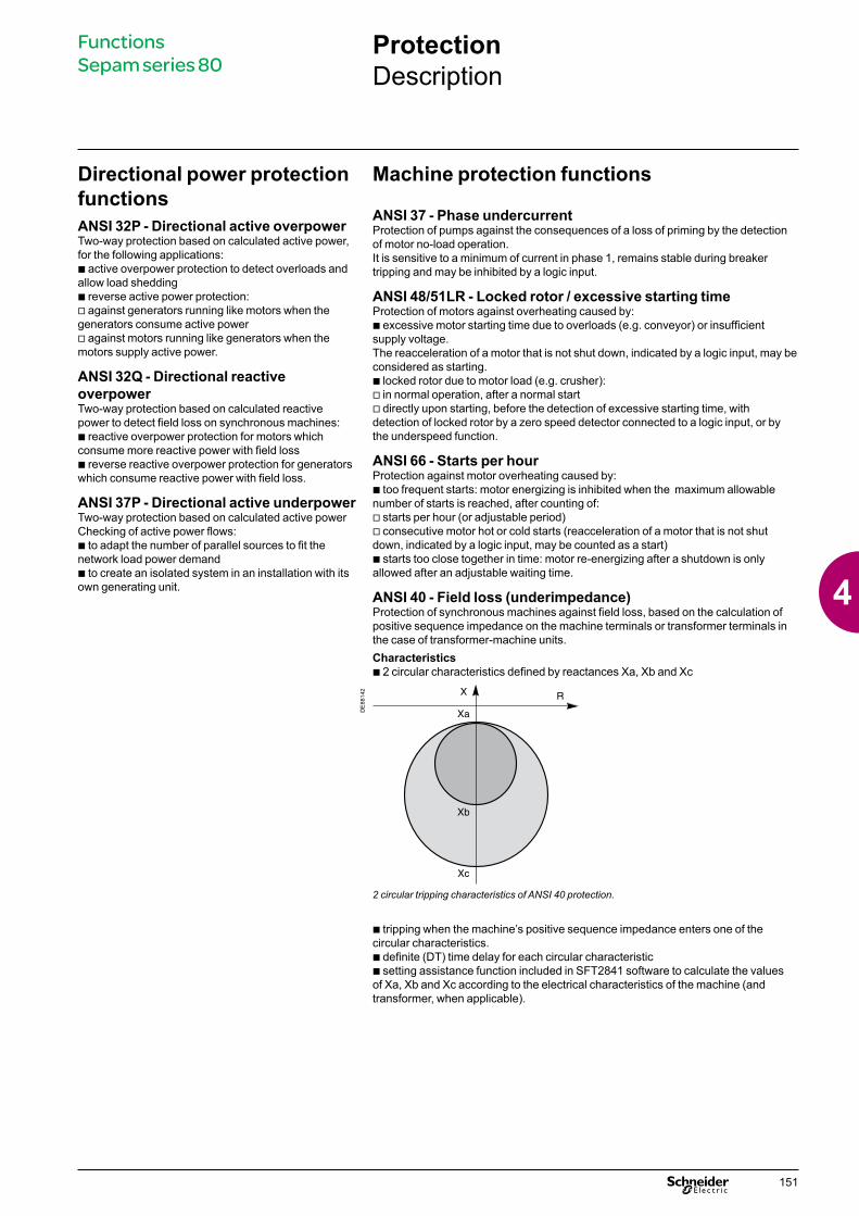
b tripping when the machine’s positive sequence impedance enters one of the circular characteristics.b definite (DT) time delay for each circular characteristicb setting assistance function included in SFT2841 software to calculate the values of Xa, Xb and Xc according to the electrical characteristics of the machine (and transformer, when applicable).
Machine protection functions
ANSI 37 - Phase undercurrentProtection of pumps against the consequences of a loss of priming by the detection of motor no-load operation. It is sensitive to a minimum of current in phase 1, remains stable during breaker tripping and may be inhibited by a logic input.
ANSI 48/51LR - Locked rotor / excessive starting timeProtection of motors against overheating caused by:b excessive motor starting time due to overloads (e.g. conveyor) or insufficient supply voltage. The reacceleration of a motor that is not shut down, indicated by a logic input, may be considered as starting.b locked rotor due to motor load (e.g. crusher):v in normal operation, after a normal startv directly upon starting, before the detection of excessive starting time, with detection of locked rotor by a zero speed detector connected to a logic input, or by the underspeed function.
ANSI 66 - Starts per hourProtection against motor overheating caused by:b too frequent starts: motor energizing is inhibited when the maximum allowable number of starts is reached, after counting of:v starts per hour (or adjustable period)v consecutive motor hot or cold starts (reacceleration of a motor that is not shut down, indicated by a logic input, may be counted as a start)b starts too close together in time: motor re-energizing after a shutdown is only allowed after an adjustable waiting time.
ANSI 40 - Field loss (underimpedance)Protection of synchronous machines against field loss, based on the calculation of positive sequence impedance on the machine terminals or transformer terminals in the case of transformer-machine units.Characteristics b 2 circular characteristics defined by reactances Xa, Xb and Xc
DE
8814
2
2 circular tripping characteristics of ANSI 40 protection.
Functions Sepam series 80
151
4
ProtectionDescription
ANSI 78PS - Pole slipProtection against loss of synchronism on synchronous machines, based on calculated active power.2 types of operation:b tripping according to the equal-area criterion, time-delayedb tripping according to power swing (number of active power swings):v suitable for generators capable of withstanding high electrical and mechanical constraints v to be set as a number of rotations.The 2 types of operation may be used independently or at the same time.
ANSI 12 - OverspeedDetection of machine overspeed, based on the speed calculated by pulse-counting, to detect synchronous generator racing due to loss of synchronism, or for process monitoring, for example.
ANSI 14 - UnderspeedMachine speed monitoring based on the speed calculated by pulse-counting:b detection of machine underspeed after starting, for process monitoring, for example b zero speed data for detection of locked rotor upon starting.
ANSI 50V/51V - Voltage-restrained overcurrentPhase-to-phase short-circuit protection, for generators. The current tripping set point is voltage-adjusted in order to be sensitive to faults close to the generator which cause voltage drops and lowers the short-circuit current.Characteristics b instantaneous or time-delayed trippingb definite time (DT), IDMT (choice of 16 standardized IDMT curves) or customized curveb with or without timer hold.
ANSI 21B - UnderimpedancePhase-to-phase short-circuit protection, for generators, based on the calculation of apparent phase-to-phase impedance.
Z21 U21I2 I1–----------------=
apparent impedance between phases 1 and 2.
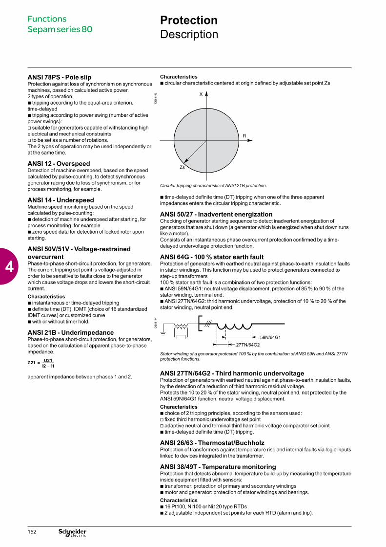
b time-delayed definite time (DT) tripping when one of the three apparent impedances enters the circular tripping characteristic.
ANSI 50/27 - Inadvertent energizationChecking of generator starting sequence to detect inadvertent energization of generators that are shut down (a generator which is energized when shut down runs like a motor).Consists of an instantaneous phase overcurrent protection confirmed by a time-delayed undervoltage protection function.
ANSI 64G - 100 % stator earth faultProtection of generators with earthed neutral against phase-to-earth insulation faults in stator windings. This function may be used to protect generators connected to step-up transformers100 % stator earth fault is a combination of two protection functions:b ANSI 59N/64G1: neutral voltage displacement, protection of 85 % to 90 % of the stator winding, terminal end.b ANSI 27TN/64G2: thrid harmonic undervoltage, protection of 10 % to 20 % of the stator winding, neutral point end.
Characteristicsb circular characteristic centered at origin defined by adjustable set point Zs
DE
8814
3
Circular tripping characteristic of ANSI 21B protection.
DE
8814
4
Stator winding of a generator protected 100 % by the combination of ANSI 59N and ANSI 27TN protection functions.
ANSI 27TN/64G2 - Third harmonic undervoltageProtection of generators with earthed neutral against phase-to-earth insulation faults, by the detection of a reduction of third harmonic residual voltage.Protects the 10 to 20 % of the stator winding, neutral point end, not protected by the ANSI 59N/64G1 function, neutral voltage displacement.Characteristicsb choice of 2 tripping principles, according to the sensors used:v fixed third harmonic undervoltage set pointv adaptive neutral and terminal third harmonic voltage comparator set pointb time-delayed definite time (DT) tripping.
ANSI 26/63 - Thermostat/BuchholzProtection of transformers against temperature rise and internal faults via logic inputs linked to devices integrated in the transformer.
ANSI 38/49T - Temperature monitoringProtection that detects abnormal temperature build-up by measuring the temperature inside equipment fitted with sensors:b transformer: protection of primary and secondary windingsb motor and generator: protection of stator windings and bearings.Characteristicsb 16 Pt100, NI100 or Ni120 type RTDsb 2 adjustable independent set points for each RTD (alarm and trip).
Functions Sepam series 80
152
4

ProtectionDescription
Voltage protection functionsANSI 24 - Overfluxing (V/Hz)Protection which detects overfluxing of transformer or generator magnetic circuits by calculating the ratio between the greatest phase-to-neutral or phase-to-phase voltage divided by the frequency.Characteristicsb machine coupling to be set upb definite time (DT) or IDMT time delays (choice of 3 curves).
ANSI 27D - Positive sequence undervoltageProtection of motors against faulty operation due to insufficient or unbalanced network voltage, and detection of reverse rotation direction.
ANSI 27R - Remanent undervoltage Protection used to check that remanent voltage sustained by rotating machines has been cleared before allowing the busbar supplying the machines to be re-energized, to avoid electrical and mechanical transients.
ANSI 27 - UndervoltageProtection of motors against voltage sags or detection of abnormally low network voltage to trigger automatic load shedding or source transfer.Works with phase-to-phase or phase-to-neutral voltage, each voltage being monitored separately.Characteristicsb definite time (DT) curve b IDMT curve.
ANSI 59 - OvervoltageDetection of abnormally high network voltage or checking for sufficient voltage to enable source transfer. Works with phase-to-phase or phase-to-neutral voltage, each voltage being monitored separately.
ANSI 59N - Neutral voltage displacementDetection of insulation faults by measuring residual voltageb ANSI 59N: in isolated neutral systemsb ANSI 59N/64G1: in stator windings of generators with earthed neutral. Protects the 85 % to 90 % of the winding, terminal end, not protected by the ANSI 27TN/64G2 function, third harmonic undervoltage.Characteristicsb definite time (DT) curve b IDMT curve.
ANSI 47 - Negative sequence overvoltageProtection against phase unbalance resulting from phase inversion, unbalanced supply or distant fault, detected by the measurement of negative sequence voltage.
Frequency protection functionsANSI 81H - OverfrequencyDetection of abnormally high frequency compared to the rated frequency, to monitor power supply quality.
ANSI 81L - UnderfrequencyDetection of abnormally low frequency compared to the rated frequency, to monitor power supply quality.The protection may be used for overall tripping or load shedding. Protection stability is ensured in the event of the loss of the main source and presence of remanent voltage by a restraint in the event of a continuous decrease of the frequency, which is activated by parameter setting.
ANSI 81R - Rate of change of frequencyProtection function used for fast disconnection of a generator or load shedding control. Based on the calculation of the frequency variation, it is insensitive to transient voltage disturbances and therefore more stable than a phase-shift protection function.DisconnectionIn installations with autonomous production means connected to a utility, the "rate of change of frequency" protection function is used to detect loss of the main system in view of opening the incoming circuit breaker to:b protect the generators from a reconnection without checking synchronizationb avoid supplying loads outside the installation.Load sheddingThe "rate of change of frequency" protection function is used for load shedding in combination with the underfrequency protection to:b either accelerate shedding in the event of a large overloadb or inhibit shedding following a sudden drop in frequency due to a problem that should not be solved by shedding.
Functions Sepam series 80
153
4
ProtectionTripping curves
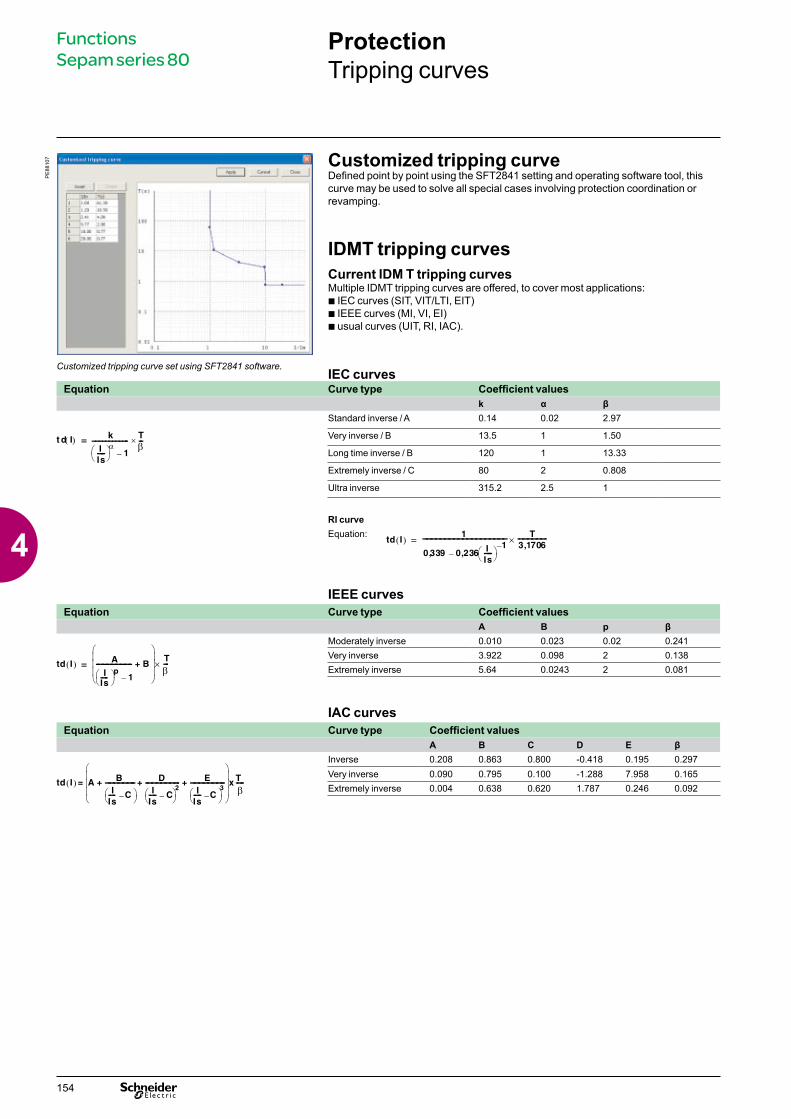
Customized tripping curve Defined point by point using the SFT2841 setting and operating software tool, this curve may be used to solve all special cases involving protection coordination or revamping.
IDMT tripping curves Current IDM T tripping curvesMultiple IDMT tripping curves are offered, to cover most applications:b IEC curves (SIT, VIT/LTI, EIT)b IEEE curves (MI, VI, EI) b usual curves (UIT, RI, IAC).
IEC curves
PE
8810
7
Customized tripping curve set using SFT2841 software.
Equation Curve type Coefficient valuesk α β
t d I( ) k
IIs-----
α 1–
---------------------- Tβ---×=
Standard inverse / A 0.14 0.02 2.97
Very inverse / B 13.5 1 1.50
Long time inverse / B 120 1 13.33
Extremely inverse / C 80 2 0.808
Ultra inverse 315.2 2.5 1
RI curveEquation:
td I( )1
0 339, 0,236 IIs-----
1–
–
-------------------------------------------------------- T3 1706,-------------------×=
IEEE curvesEquation Curve type Coefficient values
A B p β
td I( ) A
IIs----- p 1–
------------------------ B+
Tβ---×=
Moderately inverse 0.010 0.023 0.02 0.241Very inverse 3.922 0.098 2 0.138Extremely inverse 5.64 0.0243 2 0.081
IAC curvesEquation Curve type Coefficient values
A B C D E β
td I( ) A BI
Is----- C– -------------------- D
IIs----- C–
2----------------------- E
IIs----- C–
3-----------------------+ + +
x T β-----=
Inverse 0.208 0.863 0.800 -0.418 0.195 0.297Very inverse 0.090 0.795 0.100 -1.288 7.958 0.165Extremely inverse 0.004 0.638 0.620 1.787 0.246 0.092
Functions Sepam series 80
154
4
ProtectionTripping curves
Functions Sepam series 80Functions Sepam series 80
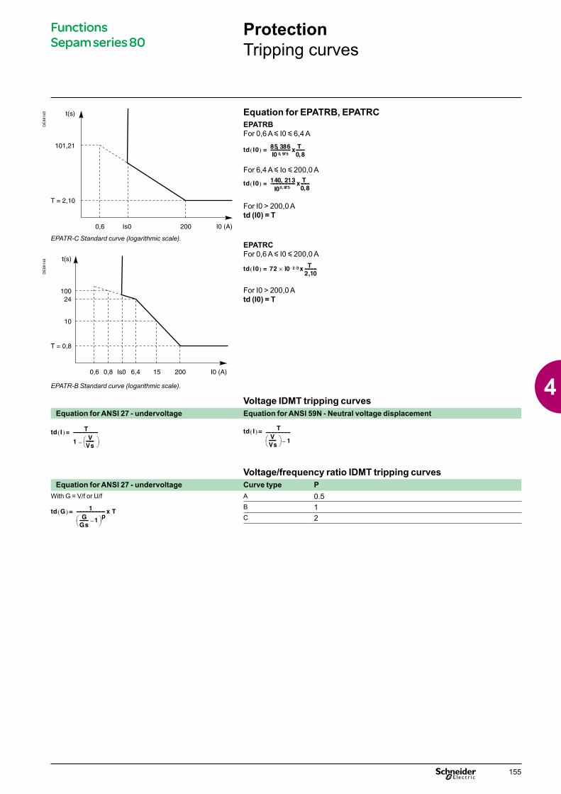
Equation for EPATRB, EPATRCEPATRBFor 0,6 A y I0 y 6,4 A
td I0( ) 85 386,I0 0 975,------------------ x T
0 8,--------=
For 6,4 A y Io y 200,0 A
td I0( ) 140 213,I00 975,
----------------------- x T 0 8,--------=
For I0 > 200,0 Atd (I0) = T
EPATRCFor 0,6 A y I0 y 200,0 A
td I0( ) 72 I0 2 3/–× x T 2 10,-----------=
For I0 > 200,0 Atd (I0) = T
DE
8814
5
EPATR-C Standard curve (logarithmic scale).
DE
8814
6
EPATR-B Standard curve (logarithmic scale).
Voltage IDMT tripping curvesEquation for ANSI 27 - undervoltage Equation for ANSI 59N - Neutral voltage displacement
td I( ) T
1V
Vs------- –
-----------------------= td I( ) TVVs------- 1–
-----------------------=
Voltage/frequency ratio IDMT tripping curvesEquation for ANSI 27 - undervoltage Curve type P
With G = V/f or U/f A 0.5
td G( ) 1G
Gs-------- 1– p--------------------------- x T=
B 1C 2
155
4
ProtectionMain characteristics
Setting of IDMT tripping curvesTime delay T or TMS factor The time delays of current IDMT tripping curves (except for customized and RI curves) may be set as follows:b time T, operating time at 10 x Isb TMS factor, factor shown as T/b in the equations on the left.
DE
8834
0
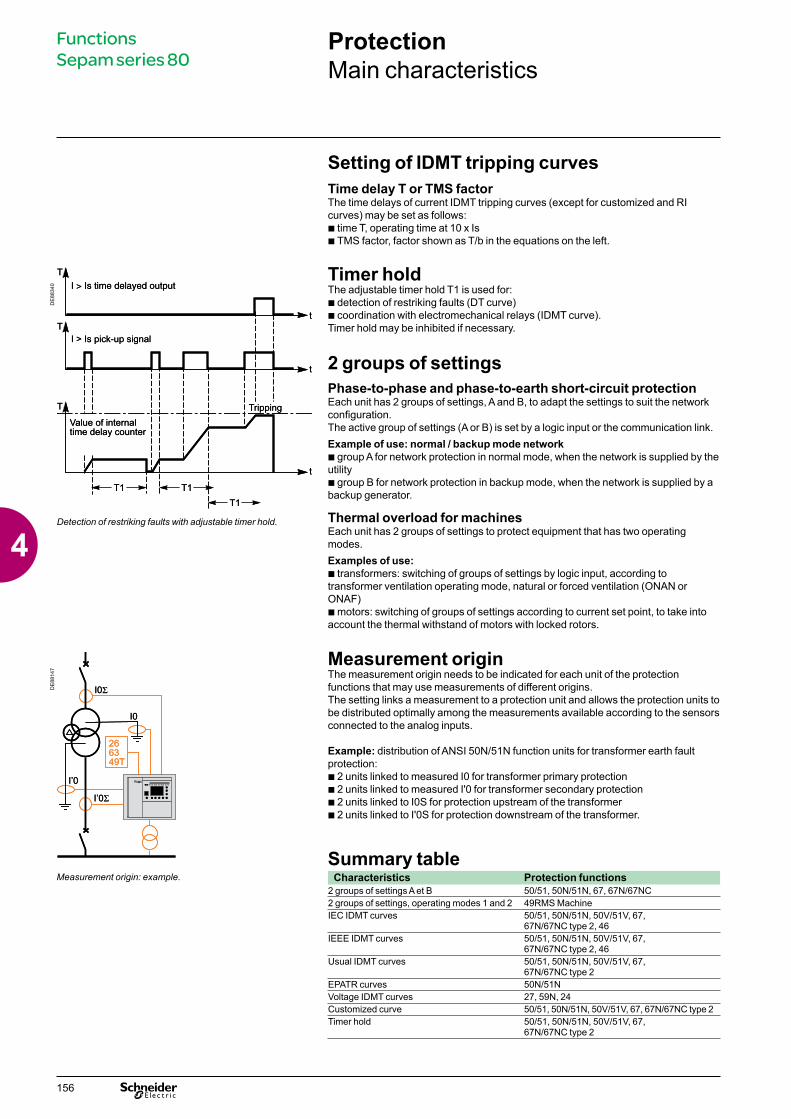
Timer hold The adjustable timer hold T1 is used for:b detection of restriking faults (DT curve)b coordination with electromechanical relays (IDMT curve).Timer hold may be inhibited if necessary.
2 groups of settings Phase-to-phase and phase-to-earth short-circuit protection Each unit has 2 groups of settings, A and B, to adapt the settings to suit the network configuration.The active group of settings (A or B) is set by a logic input or the communication link.Example of use: normal / backup mode networkb group A for network protection in normal mode, when the network is supplied by the utilityb group B for network protection in backup mode, when the network is supplied by a backup generator.
Thermal overload for machinesEach unit has 2 groups of settings to protect equipment that has two operating modes.Examples of use:b transformers: switching of groups of settings by logic input, according to transformer ventilation operating mode, natural or forced ventilation (ONAN or ONAF)b motors: switching of groups of settings according to current set point, to take into account the thermal withstand of motors with locked rotors.
Detection of restriking faults with adjustable timer hold.
DE
8814
7
Measurement origin The measurement origin needs to be indicated for each unit of the protection functions that may use measurements of different origins.The setting links a measurement to a protection unit and allows the protection units to be distributed optimally among the measurements available according to the sensors connected to the analog inputs.
Example: distribution of ANSI 50N/51N function units for transformer earth fault protection:b 2 units linked to measured I0 for transformer primary protectionb 2 units linked to measured I'0 for transformer secondary protectionb 2 units linked to I0S for protection upstream of the transformerb 2 units linked to I'0S for protection downstream of the transformer.
Summary table Measurement origin: example. Characteristics Protection functions
2 groups of settings A et B 50/51, 50N/51N, 67, 67N/67NC2 groups of settings, operating modes 1 and 2 49RMS MachineIEC IDMT curves 50/51, 50N/51N, 50V/51V, 67,
67N/67NC type 2, 46IEEE IDMT curves 50/51, 50N/51N, 50V/51V, 67,
67N/67NC type 2, 46Usual IDMT curves 50/51, 50N/51N, 50V/51V, 67,
67N/67NC type 2EPATR curves 50N/51NVoltage IDMT curves 27, 59N, 24Customized curve 50/51, 50N/51N, 50V/51V, 67, 67N/67NC type 2Timer hold 50/51, 50N/51N, 50V/51V, 67,
67N/67NC type 2
Functions Sepam series 80
156
4
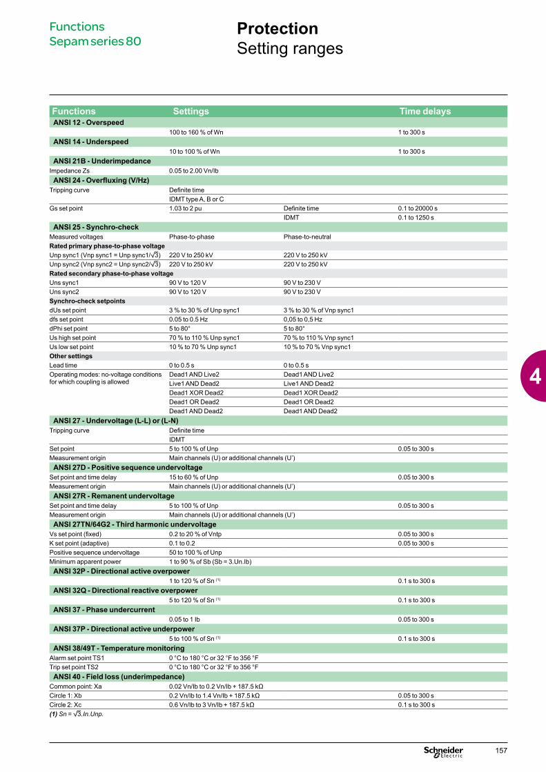
Functions Settings Time delaysANSI 12 - Overspeed
100 to 160 % of Wn 1 to 300 sANSI 14 - Underspeed
10 to 100 % of Wn 1 to 300 sANSI 21B - Underimpedance
Impedance Zs 0.05 to 2.00 Vn/IbANSI 24 - Overfluxing (V/Hz)
Tripping curve Definite timeIDMT type A, B or C
Gs set point 1.03 to 2 pu Definite time 0.1 to 20000 sIDMT 0.1 to 1250 s
ANSI 25 - Synchro-checkMeasured voltages Phase-to-phase Phase-to-neutralRated primary phase-to-phase voltageUnp sync1 (Vnp sync1 = Unp sync1/3) 220 V to 250 kV 220 V to 250 kVUnp sync2 (Vnp sync2 = Unp sync2/3) 220 V to 250 kV 220 V to 250 kVRated secondary phase-to-phase voltageUns sync1 90 V to 120 V 90 V to 230 VUns sync2 90 V to 120 V 90 V to 230 VSynchro-check setpointsdUs set point 3 % to 30 % of Unp sync1 3 % to 30 % of Vnp sync1dfs set point 0.05 to 0.5 Hz 0,05 to 0,5 HzdPhi set point 5 to 80° 5 to 80°Us high set point 70 % to 110 % Unp sync1 70 % to 110 % Vnp sync1Us low set point 10 % to 70 % Unp sync1 10 % to 70 % Vnp sync1Other settingsLead time 0 to 0.5 s 0 to 0.5 sOperating modes: no-voltage conditions for which coupling is allowed
Dead1 AND Live2 Dead1 AND Live2Live1 AND Dead2 Live1 AND Dead2Dead1 XOR Dead2 Dead1 XOR Dead2Dead1 OR Dead2 Dead1 OR Dead2Dead1 AND Dead2 Dead1 AND Dead2
ANSI 27 - Undervoltage (L-L) or (L-N)Tripping curve Definite time
IDMTSet point 5 to 100 % of Unp 0.05 to 300 sMeasurement origin Main channels (U) or additional channels (U’)ANSI 27D - Positive sequence undervoltage
Set point and time delay 15 to 60 % of Unp 0.05 to 300 sMeasurement origin Main channels (U) or additional channels (U’)ANSI 27R - Remanent undervoltage
Set point and time delay 5 to 100 % of Unp 0.05 to 300 sMeasurement origin Main channels (U) or additional channels (U’)ANSI 27TN/64G2 - Third harmonic undervoltage
Vs set point (fixed) 0.2 to 20 % of Vntp 0.05 to 300 sK set point (adaptive) 0.1 to 0.2 0.05 to 300 sPositive sequence undervoltage 50 to 100 % of UnpMinimum apparent power 1 to 90 % of Sb (Sb = 3.Un.Ib)ANSI 32P - Directional active overpower
1 to 120 % of Sn (1) 0.1 s to 300 sANSI 32Q - Directional reactive overpower
5 to 120 % of Sn (1) 0.1 s to 300 sANSI 37 - Phase undercurrent
0.05 to 1 Ib 0.05 to 300 sANSI 37P - Directional active underpower
5 to 100 % of Sn (1) 0.1 s to 300 sANSI 38/49T - Temperature monitoring
Alarm set point TS1 0 °C to 180 °C or 32 °F to 356 °FTrip set point TS2 0 °C to 180 °C or 32 °F to 356 °FANSI 40 - Field loss (underimpedance)
Common point: Xa 0.02 Vn/Ib to 0.2 Vn/Ib + 187.5 kΩCircle 1: Xb 0.2 Vn/Ib to 1.4 Vn/Ib + 187.5 kΩ 0.05 to 300 sCircle 2: Xc 0.6 Vn/Ib to 3 Vn/Ib + 187.5 kΩ 0.1 s to 300 s(1) Sn = 3.In.Unp.
ProtectionSetting ranges
Functions Sepam series 80
157
4
ProtectionSetting ranges
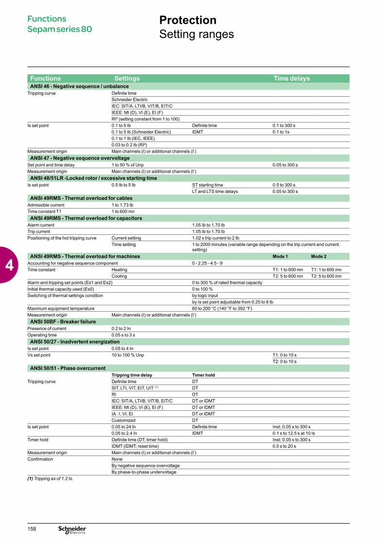
Functions Settings Time delaysANSI 46 - Negative sequence / unbalance
Tripping curve Definite timeSchneider ElectricIEC: SIT/A, LTI/B, VIT/B, EIT/CIEEE: MI (D), VI (E), EI (F)RI² (setting constant from 1 to 100)
Is set point 0.1 to 5 Ib Definite time 0.1 to 300 s0.1 to 5 Ib (Schneider Electric) IDMT 0.1 to 1s0.1 to 1 Ib (IEC, IEEE)0.03 to 0.2 Ib (RI²)
Measurement origin Main channels (I) or additional channels (I’)ANSI 47 - Negative sequence overvoltage
Set point and time delay 1 to 50 % of Unp 0.05 to 300 sMeasurement origin Main channels (I) or additional channels (I’)ANSI 48/51LR -Locked rotor / excessive starting time
Is set point 0.5 Ib to 5 Ib ST starting time 0.5 to 300 sLT and LTS time delays 0.05 to 300 s
ANSI 49RMS - Thermal overload for cablesAdmissible current 1 to 1.73 IbTime constant T1 1 to 600 mnANSI 49RMS - Thermal overload for capacitors
Alarm current 1.05 Ib to 1.70 IbTrip current 1.05 Ib to 1.70 IbPositioning of the hot tripping curve Current setting 1.02 x trip current to 2 Ib
Time setting 1 to 2000 minutes (variable range depending on the trip current and current setting)
ANSI 49RMS - Thermal overload for machines Mode 1 Mode 2Accounting for negative sequence component 0 - 2.25 - 4.5 - 9Time constant Heating T1: 1 to 600 mn T1: 1 to 600 mn
Cooling T2: 5 to 600 mn T2: 5 to 600 mnAlarm and tripping set points (Es1 and Es2) 0 to 300 % of rated thermal capacityInitial thermal capacity used (Es0) 0 to 100 %Switching of thermal settings condition by logic input
by Is set point adjustable from 0.25 to 8 IbMaximum equipment temperature 60 to 200 °C (140 °F to 392 °F)Measurement origin Main channels (I) or additional channels (I’)ANSI 50BF - Breaker failure
Presence of current 0.2 to 2 InOperating time 0.05 s to 3 sANSI 50/27 - Inadvertent energization
Is set point 0.05 to 4 InVs set point 10 to 100 % Unp T1: 0 to 10 s
T2: 0 to 10 sANSI 50/51 - Phase overcurrent
Tripping time delay Timer holdTripping curve Definite time DT
SIT, LTI, VIT, EIT, UIT (1) DTRI DTIEC: SIT/A, LTI/B, VIT/B, EIT/C DT or IDMTIEEE: MI (D), VI (E), EI (F) DT or IDMTIA : I, VI, EI DT or IDMTCustomized DT
Is set point 0.05 to 24 In Definite time Inst; 0.05 s to 300 s0.05 to 2.4 In IDMT 0.1 s to 12.5 s at 10 Is
Timer hold Definite time (DT; timer hold) Inst; 0.05 s to 300 sIDMT (IDMT; reset time) 0.5 s to 20 s
Measurement origin Main channels (I) or additional channels (I’)Confirmation None
By negative sequence overvoltageBy phase-to-phase undervoltage
(1) Tripping as of 1.2 Is.
Functions Sepam series 80
158
4

ProtectionSetting ranges
Functions Settings Time delaysANSI 50N/51N or 50G/51G - Earth fault
Tripping time delay Timer holdTripping curve Definite time DT
SIT, LTI, VIT, EIT, UIT (1) DTRI DTIEC: SIT/A,LTI/B, VIT/B, EIT/C DT or IDMTIEEE: MI (D), VI (E), EI (F) DT or IDMTIAC: I, VI, EI DT or IDMTEPATR-B, EPATR-C DTCustomized DT0.6 to 5 A EPATR-B 0.5 to 1 s0.6 to 5 A EPATR-C 0.1 to 3 s
Is0 set point 0.01 to 15 In0 (min. 0.1 A) Definite time Inst; 0.05 s to 300 s0.01 to 1 In0 (min. 0.1 A) IDMT 0.1 s to 12.5 s at 10 Is0
Timer hold Definite time (DT; timer hold) Inst; 0.05 s to 300 sIDMT (IDMT; reset time) 0.5 s to 20 s
Measurement origin I0 input, I’0 input, sum of phase currents I0Σ or sum of phase currents I’0ΣANSI 50V/51V - Voltage-restrained overcurrent
Tripping time delay Timer holdTripping curve Definite time DT
SIT, LTI, VIT, EIT, UIT (1) DTRI DTIEC : SIT/A, LTI/B, VIT/B, EIT/C DT or IDMTIEEE : MI (D), VI (E), EI (F) DT or IDMTIAC : I, VI, EI DT or IDMTCustomized DT
Is set point 0.5 to 24 In Definite time Inst; 0.05 s to 300 s0.5 to 2.4 In IDMT 0.1 s to 12.5 s at 10 Is0
Timer hold Definite time (DT; timer hold) Inst; 0.05 s to 300 sIDMT (IDMT; reset time) 0.5 s to 20 s
Measurement origin Main channels (I) or additional channels (I’) ANSI 51C - Capacitor bank unbalance
Is set point 0.05 A to 2 I’n Definite time 0.1 to 300 sANSI 59 - Overvoltage (L-L) or (L-N)
Set point and time delay 50 to 150 % of Unp or Vnp 0.05 to 300 sMeasurement origin Main channels (U) or additional channels (U’) ANSI 59N - Neutral voltage displacement
Tripping curve Definite timeIDMT
Set point 2 to 80 % of Unp Definite time 0.05 to 300 s2 to 10 % of Unp IDMT 0.1 to 100 s
Measurement origin Main channels (U), additional channels (U’) or neutral-point voltage VntANSI 64REF - Restricted earth fault differential
Is0 set point 0.05 to 0.8 In (In u 20 A)0.1 to 0.8 In (In < 20 A)
Measurement origin Main channels (I, I0) or additional channels (I’, I’0)ANSI 66 - Starts per hour
Total number of starts 1 to 60 Period 1 to 6 hNumber of consecutive starts 1 to 60 T time delay stop/start 0 to 90 mnANSI 67 - Directional phase overcurrent
Characteristic angle 30°, 45°, 60°Tripping time delay Timer hold delay
Tripping curve Definite time DTSIT, LTI, VIT, EIT, UIT (1) DTRI DTIEC: SIT/A, LTI/B, VIT/B, EIT/C DT or IDMTIEEE: MI (D), VI (E), EI (F) DT or IDMTIAC: I, VI, EI DT or IDMTCustomized DT
Is set point 0.1 to 24 In Definite time Inst; 0.05 s to 300 s0.1 to 2.4 In IDMT 0.1 s to 12.5 s at 10 Is0
Timer hold Definite time (DT; timer hold) Inst; 0.05 s to 300 sIDMT (IDMT; reset time) 0.5 s to 20 s
(1) Tripping as of 1.2 Is.
Functions Sepam series 80
159
4

ProtectionSetting ranges
Functions Settings Time ANSI 67N/67NC - Directional earth fault, projection (type 1)
Characteristic angle -45°, 0°, 15°, 30°, 45°, 60°, 90°Is0 set point 0.01 to 15 In0 (mini. 0,1 A) Definite time Inst; 0.05 s to 300 sVs0 set point 2 to 80 % of UnpMemory time T0mem time 0; 0.05 s to 300 s
V0mem validity set point 0; 2 to 80 % of UnpMeasurement origin I0 input, I’0 inputANSI 67N/67NC - Directional earth fault, according to I0 vector magnitude (type 2)
Characteristic angle -45°, 0°, 15°, 30°, 45°, 60°, 90°Tripping time delay Timer hold delay
Tripping curve Definite time DTSIT, LTI, VIT, EIT, UIT (1) DTRI DTIEC: SIT/A,LTI/B, VIT/B, EIT/C DT or IDMTIEEE: MI (D), VI (E), EI (F) DT or IDMTIAC: I, VI, EI DT or IDMTCustomized DT
Is0 set point 0.1 to 15 In0 (min. 0.1 A) Definite time Inst; 0.05 s to 300 s0.01 to 1 In0 (min. 0.1 A) IDMT 0.1 s to 12.5 s at 10 Is0
Vs0 set point 2 to 80 % of UnpTimer hold Definite time (DT; timer hold) Inst; 0.05 s to 300 s
IDMT (IDMT; reset time) 0.5 s to 20 sMeasurement origin I0 input, I’0 input or sum of phase currents I0SANSI 67N/67NC type 3 - Directional earth fault, according to I0 vector magnitude directionalized on a tripping sector
Tripping sector start angle 0° to 359°Tripping sector end angle 0° to 359°Is0 set point CSH core balance CT (2 A rating) 0.1 A to 30 A Definite time Inst; 0.05 s to 300 s
1 A CT 0.005 to 15 In0 (min. 0.1 A)Core balance CT + ACE990 (range 1) 0.01 to 15 In0 (min. 0.1 A)
Vs0 set point Calculated V0 (sum of 3 voltages) 2 to 80 % of UnpMeasured V0 (external VT) 0.6 to 80 % of Unp
Measurement origin I0 input or I’0 inputANSI 78PS - Pole slip
Time delay of the equal-area criterion 0.1 to 300 sMaximum number of power swings 1 to 30Time between 2 power swings 1 to 300 sANSI 81H - Overfrequency
Set point and time delay 50 to 55 Hz or 60 to 65 Hz 0.1 to 300 sMeasurement origin Main channels (U) or additional channels (U’)ANSI 81L - Underfrequency
Set point and time delay 40 to 50 Hz or 50 to 60 Hz 0.1 to 300 sMeasurement origin Main channels (U) or additional channels (U’)ANSI 81R - Rate of change of frequency
0.1 to 10 Hz/s 0.15 to 300 sANSI 87M - Machine différential
Ids set point 0.05 to 0.5 In (In u 20 A)0.1 to 0.5 In (In < 20 A)
ANSI 87T - Transformer differentialHigh set point 3 to 18 In1
Percentage-based curveIds set point 30 to 100 % In1Slope Id/It 15 to 50 %Slope Id/It2 without, 50 to 100 %Slope change point 1 to 18 In1
Restraint on energizationCurrent threshold 1 to 10 %Delay 0 to 300 s
Restraint on CT lossActivity On / Off
Retenues sur taux d'harmoniques Classic Self-adaptingChoice of restraint Classic Self-adaptingHigh set point On On / OffHarmonic 2 percentage set point off, 5 to 40 %Harmonic 2 restraint per phase / totalHarmonic 5 percentage set point off, 5 to 40 %Harmonic 5 restraint per phase / total
Functions Sepam series 80
160
4
Control and monitoringDescription
Functions Sepam series 80
Sepam performs all the control and monitoring functions required for electrical network operation:b the main control and monitoring functions are predefined and fit the most frequent cases of use. They are ready to use and are implemented by simple parameter setting after the necessary logic inputs / outputs are assigned.b the predefined control and monitoring functions can be adapted for particular needs using the SFT2841 software, which offers the following customization options:v logic equation editor, to adapt and complete the predefined control and monitoring functionsv creation of personalized messages for local annunciationv creation of personalized mimic diagrams corresponding to the controlled devicesv customization of the control matrix by changing the assignment of output relays, LEDs and annunciation messagesb with the Logipam option, Sepam can provide the most varied control and monitoring functions, programmed using the SFT2885 programming software that implements the Logipam ladder language.
Operating principleThe processing of each control and monitoring function may be broken down into 3 phases:b acquisition of input data:v results of protection function processingv external logic data, connected to the logic inputs of an optional MES120 input / output modulev local control orders transmitted by the mimic-based UMIv remote control orders (TC) received via the Modbus communication linkb actual processing of the control and monitoring functionb utilization of the processing results:v activation of outputs to control a devicev information sent to the facility manager:- by message and/or LED on the Sepam display and SFT2841 software- by remote indication (TS) via the Modbus communication link- by real-time indications on device status on the animated mimic diagram.
Logic inputs and outputs
PE
8803
7
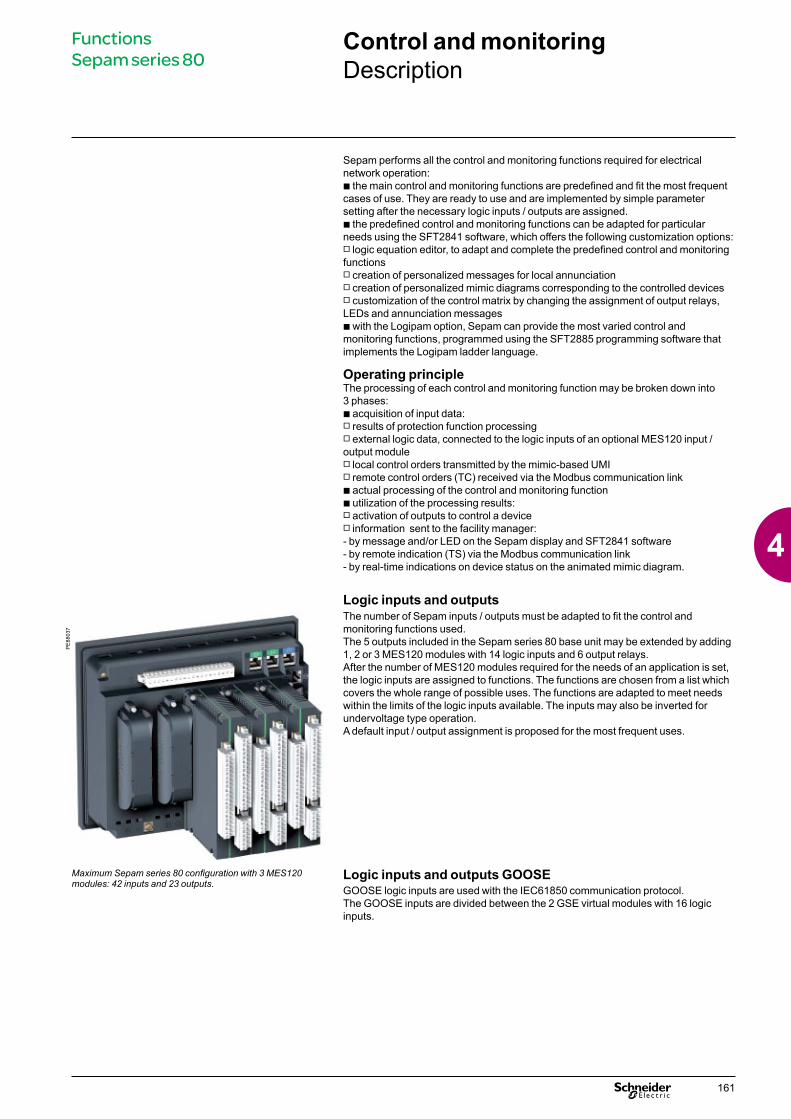
The number of Sepam inputs / outputs must be adapted to fit the control and monitoring functions used.The 5 outputs included in the Sepam series 80 base unit may be extended by adding 1, 2 or 3 MES120 modules with 14 logic inputs and 6 output relays. After the number of MES120 modules required for the needs of an application is set, the logic inputs are assigned to functions. The functions are chosen from a list which covers the whole range of possible uses. The functions are adapted to meet needs within the limits of the logic inputs available. The inputs may also be inverted for undervoltage type operation. A default input / output assignment is proposed for the most frequent uses.
Maximum Sepam series 80 configuration with 3 MES120 modules: 42 inputs and 23 outputs.
Logic inputs and outputs GOOSEGOOSE logic inputs are used with the IEC61850 communication protocol.The GOOSE inputs are divided between the 2 GSE virtual modules with 16 logic inputs.
161
4

Control and monitoringDescription of predefined functions
Each Sepam contains the appropriate predefined control and monitoring functions for the chosen application.
ANSI 94/69 - Circuit breaker/contactor controlControl of breaking devices equipped with different types of closing and tripping coils:b circuit breakers with shunt or undervoltage trip coilsb latching contactors with shunt trip coilsb contactors with latched orders.The function processes all breaking device closing and tripping conditions, based on:b protection functionsb breaking device status datab remote control ordersb specific control functions for each application (e.g. recloser, synchro-check).The function also inhibits breaking device closing, according to the operating conditions.
Automatic transfer (AT)This function transfers busbar supply from one source to another. It concerns substations with two incomers, with or without coupling.
The function carries out:b automatic transfer with a break if there is a loss of voltage or a faultb manual transfer and return to normal operation without a break, with or without synchro-checkb control of the coupling circuit breaker (optional)b selection of the normal operating modeb the necessary logic to ensure that at the end of the sequence, only 1 circuit breaker out of 2 or 2 out of 3 are closed.
The function is distributed between the two Sepam units protecting the two incomers. The synchro-check function (ANSI 25) is carried out by the optional MCS025 module, in conjunction with one of the two Sepam units.
Load shedding - Automatic restartAutomatic load regulation on electrical networks by load shedding followed by automatic restarting of motors connected to the network
Load sheddingThe breaking device opens to stop motors in case of:b detection of a network voltage sag by the positive sequence undervoltage b protection function ANSI 27D b receipt of a load shedding order on a logic input.Automatic restartThe motors disconnected as a result of the network voltage sag are automatically restarted:b after the return of network voltage is detected by the positive sequence undervoltage protection function ANSI 27Db and a time delay has run out, so as to stagger motor restarts.
De-excitationInterruption of a synchronous generator’s excitation supply and tripping of the generator breaking device in case of:b detection of an internal generator faultb detection of an excitation system faultb receipt of a de-excitation order on a logic input or via the communication link.
DE
8832
7
Automatic transfer with synchro-check controlled by Sepam series 80.
Functions Sepam series 80
162
4
Control and monitoringDescription of predefined functions
Genset shutdownShutdown of the driving machine, tripping of the breaking device and interruption of the generator excitation supply in case of:b detection of an internal generator fault b receipt of a genset shutdown order on a logic input or via the communication link.
Control of capacitor banksThis function controls 1 to 4 switches for capacitor steps, taking into account all the closing and tripping conditions determined by the ANSI 94/69 function for control of the switchgear.Manual or automatic control, controlled by an external reactive-energy regulator.
ANSI 68 - Logic discriminationThis function provides:b perfect tripping discrimination with phase-to-phase and phase-to-earth short-circuits, on all types of networkb faster tripping of the breakers closest to the source (solving the drawback of conventional time discrimination).
Each Sepam is capable of:b sending a blocking input when a fault is detected by the phase overcurrent and earth fault protection functions, which may or may not be directional (ANSI 50/51, 50N/51N, 67 or 67N/67NC)b and receiving blocking inputs which inhibit protection tripping. A saving mechanism ensures continued operation of the protection in the event of a blocking link failure.
ANSI 86 - Latching / acknowledgementThe tripping outputs for all the protection functions and all the logic inputs lx can be latched individually. The latched information is saved in the event of an auxiliary power failure.(The logic outputs cannot be latched.)
All the latched data may be acknowledged:b locally, with the key reset
b remotely via a logic input b or via the communication link.
The Latching/acknowledgement function, when combined with the circuit breaker/contactor control function, can be used to create the ANSI 86 "Lockout relay" function.
Output relay testingEach output relay is activated for 5 seconds, to make it simpler to check output connections and connected switchgear operation.
Functions Sepam series 80
163
4

Control and monitoringDescription of predefined functions
ANSI 30 - Local annunciation LED indicationb 2 LEDs, on the front and back of Sepam, indicate the unit operating status, and are visible when a Sepam without a UMI is mounted inside the LV compartment, with access to connectors:v green LED ON: Sepam onv red "key" LED: Sepam unavailable (initialization phase or detection of an internal failure)b 9 yellow LEDs on the Sepam front panel:v pre-assigned and identified by standard removable labelsv the SFT2841 software tool may be used to assign LEDs and personalize labels.
Local annunciation on Sepam displayEvents and alarms may be indicated locally on Sepam’s advanced UMI or on the mimic-based UMI by:b messages on the display unit, available in 2 languages:v English, factory-set messages, not modifiablev local language, according to the version delivered (the language version is chosen when Sepam is set up)b the lighting up of one of the 9 yellow LEDs, according to the LED assignment, which is set using SFT2841.
Alarm processingb when an alarm appears, the related message replaces the current display and the related LED goes on.The number and type of messages depend on the type of Sepam. The messages are linked to Sepam functions and may be viewed on the front-panel display and in the SFT2841 "Alarms" screen.b to clear the message from the display, press the key b after the fault has disappeared, press the key: the light goes off and Sepam is resetb the list of alarm messages remains accessible ( key) and may be cleared by pressing the clear key from “Alarms” screen, but can not be cleared from “Alarm history” screen.
PE
8802
8
Local indications on the Sepam front panel.
PE
8810
8_S
E
SFT2841: alarm history.
Functions Sepam series 80
164
4

Control and monitoringDescription of predefined functions
Local control using the mimic-based UMISepam control modeA key-switch on the mimic-based UMI is used to select the Sepam control mode. Three modes are available : Remote, Local or Test.In Remote mode: b remote control orders are taken into accountb local control orders are disabled, with the exception of the circuit-breaker open order.In Local mode: b remote control orders are disabled, with the exception of the circuit-breaker open orderb local control orders are enabled.Test mode should be selected for tests on equipment, e.g. during preventive-maintenance operations: b all functions enabled in Local mode are available in Test modeb no remote indications (TS) are sent via the communication link.
The Logipam programming software can be used to customize control-mode processing.
View device status on the animated mimic diagramFor safe local control of devices, all information required by operators can be displayed simultaneously on the mimic-based UMI:b single-line diagram of the equipment controlled by Sepam, with an animated, graphic indication of device status in real timeb the desired current, voltage and power measurements.The local-control mimic diagram can be customized by adapting one of the supplied, predefined diagrams or by creating a diagram from scratch.
Local control of devicesAll the devices for which opening and closing are controlled by Sepam can be controlled locally using the mimic-based UMI.The most common interlock conditions can be defined be logic equations or by Logipam.
The sure and simple operating procedure is the following:b select the device to be controlled by moving the selection window using the keys
or . Sepam checks whether local control of the selected device is authorized and informs the operator (selection window with a solid line)b selection confirmation for the device to be controlled by pressing the key (the selection window flashes)b device control by pressing:v key : open orderv or key : close order.
PE
8803
8
Local control using the mimic-based UMI.
Functions Sepam series 80
165
4
The predefined control and monitoring functions can be adapted for particular needs using the SFT2841 software, which offers the following customization options:b logic equation editor, to adapt and complete the predefined control and monitoring functionsb creation of personalized messages for local annunciationb creation of custom mimic diagrams corresponding to the controlled devicesb customization of the control matrix by changing the assignment of output relays, LEDs and annunciation messages.
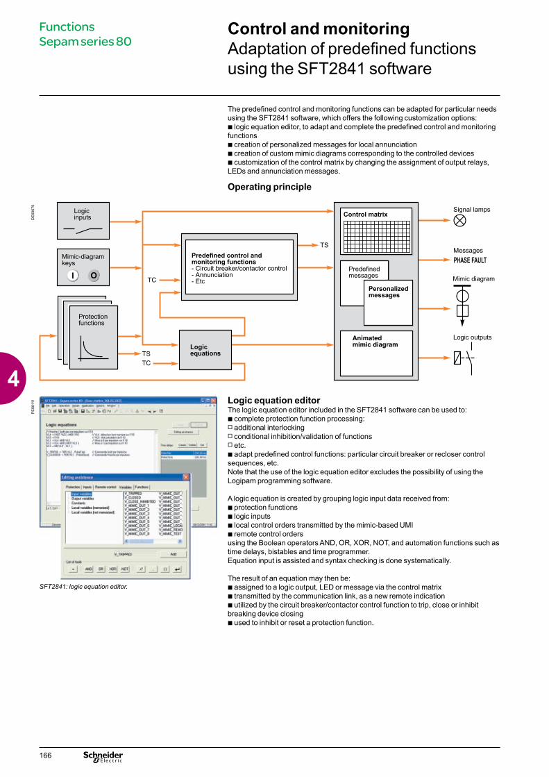
Operating principle
Control and monitoringAdaptation of predefined functions using the SFT2841 software
DE
6067
9P
E88
111
SFT2841: logic equation editor.
Logic equation editorThe logic equation editor included in the SFT2841 software can be used to:b complete protection function processing: v additional interlockingv conditional inhibition/validation of functionsv etc.b adapt predefined control functions: particular circuit breaker or recloser control sequences, etc.Note that the use of the logic equation editor excludes the possibility of using the Logipam programming software.
A logic equation is created by grouping logic input data received from:b protection functionsb logic inputsb local control orders transmitted by the mimic-based UMIb remote control ordersusing the Boolean operators AND, OR, XOR, NOT, and automation functions such as time delays, bistables and time programmer.Equation input is assisted and syntax checking is done systematically.
The result of an equation may then be:b assigned to a logic output, LED or message via the control matrixb transmitted by the communication link, as a new remote indicationb utilized by the circuit breaker/contactor control function to trip, close or inhibit breaking device closingb used to inhibit or reset a protection function.
Functions Sepam series 80
166
4
Personalized alarm and operating messagesThe alarm and operating messages may be personalized using the SFT2841 software tool.The new messages are added to the list of existing messages and may be assigned via the control matrix for display:b on the Sepam displayb in the SFT2841 "Alarms" and "Alarm History" screens.
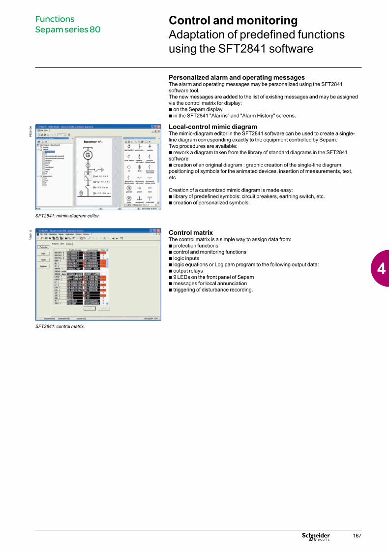
Local-control mimic diagramThe mimic-diagram editor in the SFT2841 software can be used to create a single-line diagram corresponding exactly to the equipment controlled by Sepam.Two procedures are available:b rework a diagram taken from the library of standard diagrams in the SFT2841 softwareb creation of an original diagram : graphic creation of the single-line diagram, positioning of symbols for the animated devices, insertion of measurements, text, etc.
Creation of a customized mimic diagram is made easy: b library of predefined symbols: circuit breakers, earthing switch, etc.b creation of personalized symbols.
Control matrixThe control matrix is a simple way to assign data from:b protection functionsb control and monitoring functionsb logic inputsb logic equations or Logipam program to the following output data:b output relaysb 9 LEDs on the front panel of Sepamb messages for local annunciationb triggering of disturbance recording.
PE
8810
9
SFT2841: mimic-diagram editor.
PE
8811
0
SFT2841: control matrix.
Control and monitoringAdaptation of predefined functions using the SFT2841 software
Functions Sepam series 80
167
4

The SFT2885 programming software (Logipam) can be used to enhance Sepam by programming specific control and monitoring functions.
Only the Sepam series 80 with a cartridge containing the Logipam SFT080 option can run the control and monitoring functions programmed by Logipam.
Operating principle
DE
8834
7P
E88
036
SFT2885: Logipam programming software.
Logipam programming softwareThe Logipam SFT2885 programming software can be used to:b adapt predefined control and monitoring functionsb program specific control and monitoring functions, either to replace the predefined versions or to create completely new functions, to provide all the functions required by the application.It is made up of:b a ladder-language program editor used to address all Sepam data and to program complex control functionsb a simulator for complete program debuggingb a code generator to run the program on Sepam.The ladder-language program and the data used can be documented and a complete file can be printed.
Offering more possibilities than the logic-equation editor, Logipam can be used to create the following functions :b specific automatic transfer functionsb motor starting sequences.It is not possible to combine the functions programmed by Logipam with functions adapted by the logic-equation editor in a given Sepam.
The Logipam program uses the input data from:b protection functionsb logic inputsb remote control ordersb local control orders transmitted by the mimic-based UMI.
The result of Logipam processing may then be:b assigned to a logic output, directly or via the control matrixb assigned to a LED or message via the control matrixb transmitted by the communication link, as a new remote indicationb used by the predefined control and monitoring functions b used to inhibit or reset a protection function.
Control and monitoringCustomized functions using Logipam
Functions Sepam series 80
168
4

Base unitPresentation
User-Machine InterfaceTwo types of User-Machine Interfaces (UMI) are available for Sepam series 80 base units:b mimic-based UMIb advanced UMI.The advanced UMI can be integrated in the base unit or installed remotely on the cubicle. Integrated and remote advanced UMIs offer the same functions.
A Sepam series 80 with a remote advanced UMI is made up of:b a bare base unit without any UMI, for mounting inside the LV compartmentb a remote advanced UMI (DSM303)v for flush mounting on the front panel of the cubicle in the location most suitable for the facility managerv for connection to the Sepam base unit using a prefabricated CCA77x cord.The characteristics of the remote advanced UMI module (DSM303) are presented on page 218.
Comprehensive data for facility managersAll the data required for local equipment operation may be displayed on demand:b display of all measurement and diagnosis data in numerical format with units and/or in bar graphsb display of operating and alarm messages, with alarm acknowledgment and Sepam resettingb display of the list of activated protection functions and the main settings of major protection functionsb adaptation of activated protection function set points or time delays in response to new operating constraintsb display of Sepam and remote module versionsb output testing and logic input status displayb display of Logipam data: status of variables, timersb entry of 2 passwords to protect parameter and protection settings.
Local control of devices using the mimic-based UMIThe mimic-based UMI provides the same functions as the advanced UMI as well as local control of devices:b selection of the Sepam control modeb view device status on the animated mimic diagramb local opening and closing of all the devices controlled by Sepam.
Ergonomic data presentationb keypad keys identified by pictograms for intuitive navigation b menu-guided access to datab graphical LCD screen to display any character or symbolb excellent display quality under all lighting conditions : automatic contrast setting and backlit screen (user activated).
Working languageAll the texts and messages displayed on the advanced UMI or on the mimic-based UMI are available in 2 languages:b English, the default working languageb and a second language, which may bev Frenchv Spanish v another "local" language.Please contact us regarding local language customization.
Connection of Sepam to the parameter setting toolThe SFT2841 parameter setting tool is required for Sepam protection and parameter setting. A PC containing the SFT2841 software is connected to the RS 232 communication port on the front of the unit or through the communication network.
PE
8804
0
Sepam series 80 base unit with integrated advanced UMI.
PE
8804
1
Sepam series 80 base unit with mimic-based UMI.
PE
8804
2
Customized Chinese advanced UMI.
Base units are defined according to the following characteristics:b type of User-Machine Interface (UMI)b working languageb type of base unit connectorb type of current sensor connectorb type of voltage sensor connector.
Characteristics Sepam series 80
169
4

Base unitPresentation
Selection guideBase unit With remote
advanced UMIWith integrated advanced UMI
With mimic-based UMI
PE
8804
3
P
E88
040
PE
8804
1
FunctionsLocal indication
Metering and diagnosis data b b b
Alarms and operating messages b b b
List of activated protection functions b b b
Main protection settings b b b
Version of Sepam and remote modules b b b
Status of logic inputs b b b
Logipam data b b b
Switchgear status on the animated mimic diagram b
Phasor diagram of currents or voltages b
Local controlAlarm acknowledgement b b b
Sepam reset b b b
Output testing b b b
Selection of Sepam control mode b
Device open/close order b
CharacteristicsScreen
Size 128 x 64 pixels 128 x 64 pixels 128 x 240 pixelsAutomatic contrast setting b b b
Backlit screen b b b
KeypadNumber of keys 9 9 14 Control-mode switch Remote / Local / Test
LEDsSepam operating status b base unit: 2 LEDs visible on back
b remote advanced UMI: 2 LEDs visible on front
2 LEDs, visible from front and back 2 LEDs, visible from front and back
Indication LEDs 9 LEDs on remote advanced UMI 9 LEDs on front 9 LEDs on frontMounting
b bare base unit, mounted at the back of the compartment using the AMT880 mounting plate
b DSM303 remote advanced UMI module , flush mounted on the front of the cubicle and connected to the base unit with the CCA77x prefabricated cord
Flush mounted on front of cubicle Flush mounted on front of cubicle
Characteristics Sepam series 80
170
4

Hardware characteristics Removable memory cartridgeThe cartridge contains all the Sepam characteristics:b all Sepam protection and parameter settings b all the metering and protection functions required for the applicationb predefined control functions b functions customized by control matrix or logic equationsb functions programmed by Logipam (optional)b personalized local-control mimic diagramb accumulated energies and switchgear diagnosis values b working languages, customized and otherwise.It may be made tamper-proof by lead sealing.It is removable and easy to access on the front panel of Sepam to reduce maintenance time.If a base unit fails, simply:b switch off Sepam and unplug connectorsb retrieve original cartridge b replace the faulty base unit by a spare base unit (without cartridge) b load the original cartridge into the new base unitb plug in the connectors and switch Sepam on again: Sepam is operational, with all its standard and customized functions, without requiring any reloading of protection and parameter settings.
Backup batteryStandard lithium battery, 1/2 AA format, 3.6 Volts.It allows the following data to be stored in the event of an auxiliary power outage:b time-tagged event tablesb disturbance recording datab peak demands, tripping context, etcb date and time.The battery presence and charge are monitored by Sepam.The main data (e.g. protection and parameter settings) are saved in the event of an auxiliary power outage, regardless of the state of the battery.
Auxiliary power supplyDC power supply voltage from 24 to 250 V DC.
Five relay outputsThe 5 relay outputs O1 to O5 on the base unit must be connected to connector A . Each output can be assigned to a predetermined function using the SFT2841
software. O1 to O4 are 4 control outputs with one NO contact, used by default for the switchgear control function:b O1: switchgear trippingb O2: switchgear closing inhibitionb O3: switchgear closingb O4: available.O5 is an indication output used by default for the watchdog function and has two contacts, one NC and one NO.
Base unitPresentation
PE
8804
4
Sepam series 80 memory cartridge and backup battery.
Characteristics Sepam series 80
171
4

Main connector and voltage and residual current input connector A choice of 2 types of removable, screw-lockable 20-pin connectors:b CCA620 screw-type connectors b or CCA622 ring lug connectors.The presence of the connector is monitored.
Connector for additional voltage inputs (Sepam B83)CCT640 connector, removable and screw-lockable.The presence of the CCT640 connector is monitored.
Phase current input connectorsCurrent sensors connected to removable, screw-lockable connectors according to type of sensors used:b CCA630 or CCA634 connector for 1 A or 5 A current transformers b or CCA671 connector for LPCT sensors. The presence of these connectors is monitored.
Mounting accessoriesSpring clips8 spring clips are supplied with the base unit to flush-mount Sepam in mounting plates 1.5 to 6 mm thick. Simple, tool-free installation.
AMT880 mounting plateIt is used to mount a Sepam without UMI inside the compartment with access to connectors on the rear panel.Mounting used with remote advanced UMI module (DSM303).
AMT820 blanking plateIt fills in the space left when a standard model Sepam 2000 is replaced by a Sepam series 80.
Spare base units The following spares are available to replace faulty base units:b base units with or without UMI, without cartridge or connectorsb all types of standard cartridges, with or without the Logipam option.
AMT852 lead sealing accessoryThe AMT852 lead sealing accessory can be used to prevent unauthorized modification of the settings of Sepam series 80 units with integrated advanced UMIs.The accessory includes: b a lead-sealable cover plateb the screws required to secure the cover plate to the integrated advanced UMI of the Sepam unit.Note: the AMT852 lead sealing accessory can secured only to the integrated advanced UMIs of Sepam series 80 units Contact us to determine the serial number of the device on wich you can fit the lead sealing accessory.
Base unitPresentation
PE
8804
5Characteristics Sepam series 80
172
4

Front panel with advanced UMI
DE
8815
6
Base unitDescription
1 Green LED: Sepam on.2 Red LED: Sepam unavailable.3 9 yellow indication LEDs.4 Label identifying the indication LEDs.
5 Graphical LCD screen.6 Display of measurements.7 Display of switchgear, network and machine
diagnosis data.8 Display of alarm messages.9 Sepam reset (or confirm data entry).10 Acknowledgement and clearing of alarms (or move
cursor up).11 LED test (or move cursor down).12 Display and adaptation of activated protection
settings.13 Display of Sepam and Logipam data.14 Entry of 2 passwords.15 RS 232 PC connection port.
16 Backup battery.17 Memory cartridge.18 Door.
Front panel with mimic-based UMI
DE
6068
2
26
G82
1 Graphical LCD screen.2 Green LED: Sepam on.3 Red LED: Sepam unavailable.4 Local close order.5 Local open order.6 Label identifying the indication LEDs.7 7 yellow indication LEDs, 1 red LED (I), 1 green LED (o).8 Move cursor up.9 Confirm data entry.10 Move cursor down.11 RS 232 PC connection port.12 Transparent door.
13 Entry of 2 passwords.14 Mimic-based UMI display. 15 Sepam reset.16 Display of alarm messages.17 Acknowledgement and clearing of alarms.18 Display of switchgear and network diagnosis data
(or LED test).19 Display and adaptation of activated protection
settings.20 Display of measurements.21 Display of Sepam and Logipam data.22 Three-position key switch to select Sepam control
mode.
23 Backup battery.24 Memory cartridge.25 Door.
Characteristics Sepam series 80
173
4
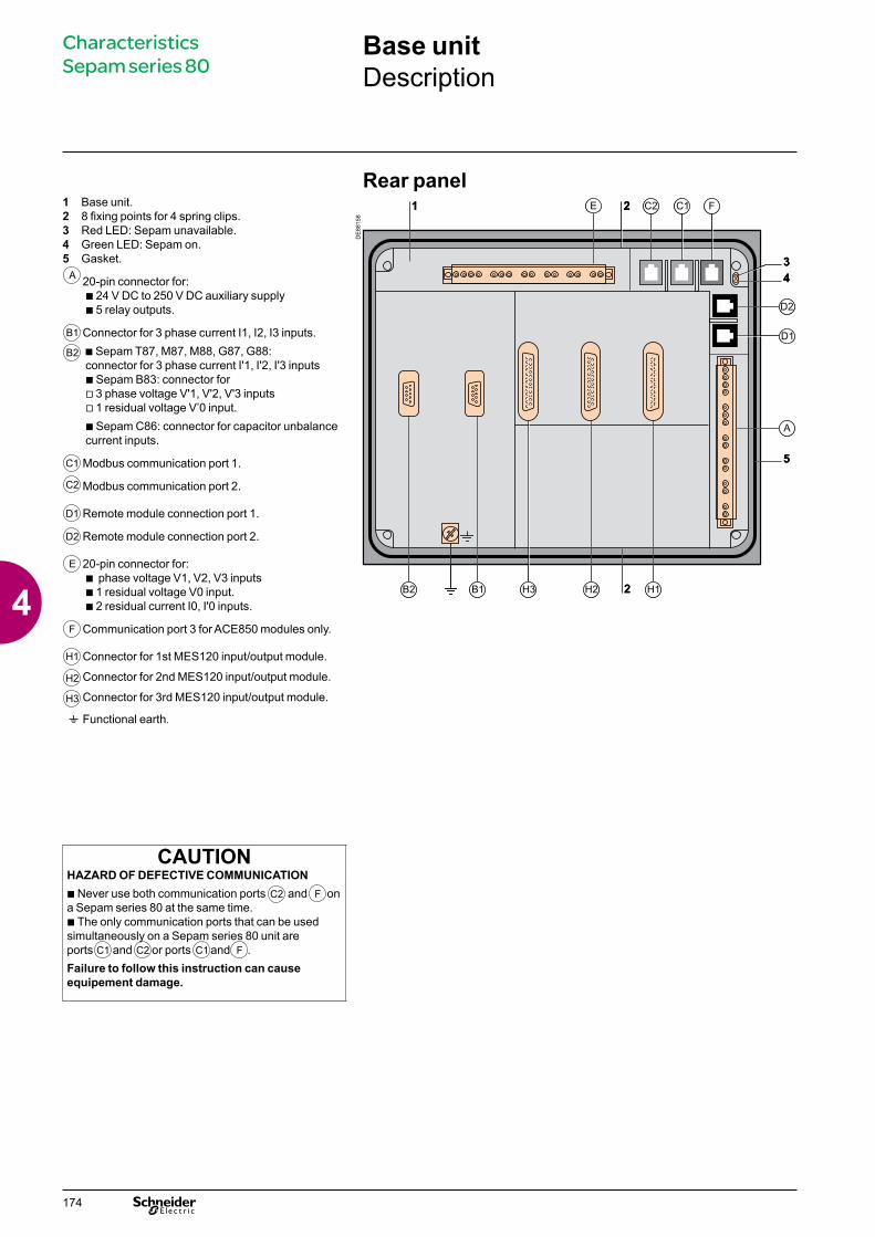
Base unitDescription
Characteristics Sepam series 80
Rear panel1 Base unit.2 8 fixing points for 4 spring clips.3 Red LED: Sepam unavailable.4 Green LED: Sepam on.5 Gasket.
A 20-pin connector for:b 24 V DC to 250 V DC auxiliary supply b 5 relay outputs.
B1 Connector for 3 phase current I1, I2, I3 inputs.
B2 b Sepam T87, M87, M88, G87, G88: connector for 3 phase current I'1, I'2, I'3 inputs b Sepam B83: connector for v 3 phase voltage V'1, V'2, V'3 inputs v 1 residual voltage V’0 input.
b Sepam C86: connector for capacitor unbalance current inputs.
C1 Modbus communication port 1.
C2 Modbus communication port 2.
D1 Remote module connection port 1.
D2 Remote module connection port 2.
E 20-pin connector for:b phase voltage V1, V2, V3 inputsb 1 residual voltage V0 input.b 2 residual current I0, I'0 inputs.
F Communication port 3 for ACE850 modules only.
H1 Connector for 1st MES120 input/output module.
H2 Connector for 2nd MES120 input/output module.
H3 Connector for 3rd MES120 input/output module.
t Functional earth.
DE
8815
8
CAUTIONHAZARD OF DEFECTIVE COMMUNICATIONb Never use both communication ports and on a Sepam series 80 at the same time. b The only communication ports that can be used simultaneously on a Sepam series 80 unit areports and or ports and . Failure to follow this instruction can cause equipement damage.
C2 F
C1 C2 C1 F
174
4
Base unitTechnical characteristics
WeightBase unit with advanced UMI Base unit with mimic-based UMI
Minimum weight (base unit without MES120) 2.4 kg (5.29 lb) 3.0 kg (6.61 lb)Maximum weight (base unit with 3 MES120) 4.0 kg (8.82 lb) 4.6 kg (10.1 lb)
Sensor inputsPhase current inputs 1 A or 5 A CT
Input impedance < 0.02 ΩConsumption < 0.02 VA (1 A CT)
< 0.5 VA (5 A CT)Continuous thermal withstand 4 In1 second overload 100 InVoltage inputs Phase Residual
Input impedance > 100 k Ω > 100 k Ω Consommation < 0.015 VA (100 V VT) < 0.015 VA (100 V VT)Continuous thermal withstand 240 V 240 V1-second overload 480 V 480 VIsolation of inputs in relation to other isolated groups
Enhanced Enhanced
Relay outputsControl relay outputs O101, O201 and O301
Voltage DC 24/48 V DC 127 V DC 220 V DCAC (47.5 to 63 Hz) 100 to 240 V AC
Continuous current 8 A 8 A 8 A 8 ABreaking capacity Resistive load 8 A / 4 A 0.7 A 0.3 A
Load L/R < 20 ms 6 A / 2 A 0.5 A 0.2 ALoad L/R < 40 ms 4 A / 1 A 0.2 A 0.1 AResistive load 8 ALoad p.f. > 0.3 5 A
Making capacity < 15 A for 200 msIsolation of outputs in relation to other isolated groups
Enhanced
Annunciation relay output O5, O102 to O106, O202 to O206 and O302 to O306 Voltage DC 24/48 V DC 127 V DC 220 V DC
AC (47.5 to 63 Hz) 100 to 240 V ACContinuous current 2 A 2 A 2 A 2 ABreaking capacity Load L/R < 20 ms 2 A / 1 A 0.5 A 0.15 A
Load p.f. > 0.3 1 AIsolation of outputs in relation to other isolated groups
Enhanced
Power supplyVoltage 24 to 250 V DC -20 % / +10 %Maximum consumption < 16 WInrush current < 10 A 10 msAcceptable ripple content 12 %Acceptable momentary outages 100 ms
BatteryFormat 1/2 AA lithium 3.6 VService life 10 years Sepam energized
3 years minimum, typically 6 years Sepam not energized (1) Relay outputs comptying with clause 6.7 of standard C 97.90 (30 A, 200 ms, 2000 operations)
Characteristics Sepam series 80
175
4

Base unitEnvironmental characteristics
Electromagnetic compatibility Standard Level / Class ValueEmission tests
Disturbing field emission IEC 60255-25EN 55022 A
Conducted disturbance emission IEC 60255-25EN 55022 A
Immunity tests – Radiated disturbancesImmunity to radiated fields IEC 60255-22-3 10 V/m; 80 MHz - 1 GHz
IEC 61000-4-3 III 10 V/m; 80 MHz - 2 GHzANSI C37.90.2 (2004) 20 V/m; 80 MHz - 1 GHz
Electrostatic discharge IEC 60255-22-2 8 kV air; 6 kV contactANSI C37.90.3 8 kV air; 4 kV contact
Immunity to magnetic fields at network frequency IEC 61000-4-8 4 30 A/m (continuous) - 300 A/m (1-3 s) (4)
Immunity tests – Conducted disturbancesImmunity to conducted RF disturbances IEC 60255-22-6 III 10 VElectrical fast transients/burst IEC 60255-22-4 A and B 4 kV; 2.5 kHz / 2 kV; 5 kHz
IEC 61000-4-4 IV 4 kV; 2.5 kHzANSI C37.90.1 4 kV; 2.5 kHz
1 MHz damped oscillating wave IEC 60255-22-1 2.5 kV CM; 1 kV DMANSI C37.90.1 2.5 kV CM; 2.5 kV DM
100 kHz damped sine wave IEC 61000-4-12 III 2 kV CMSlow damped oscillating wave (100 kHz to 1 MHz) IEC 61000-4-18 III 2 kV CMFast damped oscillating wave (3 MHz, 10 MHz, 30 MHz) IEC 61000-4-18 IIIImpulse wave IEC 61000-4-5 III 2 kV CM; 1 kV DMImmunity to conducted disturbances in common mode from 0 Hz to 150 kHz
IEC 61000-4-16 III
Voltage interruptions IEC 60255-11 100 % during 100 msMechanical robustness Standard Level / Class ValueIn operation
Vibrations IEC 60255-21-1 2 1 Gn; 10 Hz - 150 HzIEC 60068-2-6 Fc 3 Hz - 13.2 Hz; a = ±1 mmIEC 60068-2-64 2M1
Shocks IEC 60255-21-2 2 10 Gn / 11 msEarthquakes IEC 60255-21-3 2 2 Gn (horizontal axes)
1 Gn (vertical axes)De-energized
Vibrations IEC 60255-21-1 2 2 Gn; 10 Hz - 150 HzShocks IEC 60255-21-2 2 27 Gn / 11 msJolts IEC 60255-21-2 2 20 Gn / 16 msClimatic withstand Standard Level / Class ValueIn operation
Exposure to cold IEC 60068-2-1 Ad -25 °CExposure to dry heat IEC 60068-2-2 Bd +70 °CContinuous exposure to damp heat IEC 60068-2-78 Cab 10 days; 93 % RH ; 40 °CSalt mist IEC 60068-2-52 Kb/2 6 daysInfluence of corrosion/Gas test 2 IEC 60068-2-60 C 21 Days, 75% RH, 25°C, 500.10-9
vol/vol H2S; 1000.10-9 vol/vol SO²Influence of corrosion/Gas test 4 IEC 60068-2-60 Method 3 21 Days, 75% RH, 25°C,
10+/-5 H²S; 200+/-20 SO² ; 200+/-20 NO², 10+/-5 Cl² (10-9 vol/vol)
EIA 364-65A IIIA 42 days, 75% RH, 30°C, 100+/-20 H²S; 200+/-50 SO² ; 200+/-50 NO², 20+/-5 Cl² (10-9 vol/vol)
In storage (3)
Temperature variation with specified variation rate IEC 60068-2-14 Nb -25 °C at +70 °C; 5 °C/minExposure to cold IEC 60068-2-1 Ab -25 °CExposure to dry heat IEC 60068-2-2 Bb +70 °CContinuous exposure to damp heat IEC 60068-2-78 Cab 56 days; 93 % RH; 40 °C
IEC 60068-2-30 Db 6 days; 95 % RH; 55 °C(3) Sepam must be stored in its original packing.(4) Iso > 0.1 Ino for the 50n/51n and 67n protection functions, with I0 calculated as the sum of the phase currents.
Characteristics Sepam series 80
176
4
Base unitEnvironmental characteristics
Safety Standard Level / Class ValueEnclosure safety tests
Front panel tightness IEC 60529 IP52 Other panels IP20NEMA Type 12
Fire withstand IEC 60695-2-11 650 °C with glow wireElectrical safety tests
1.2/50 µs impulse wave IEC 60255-5 5 kV (1)
P ower frequency dielectric withstand IEC 60255-5 2 kV 1mn (2)
ANSI C37.90 1 kV 1 mn (indication output)1.5 kV 1 mn (control output)
Functional safetyFunctional safety of electrical/electronic/programmable electronic safety-related systems
IEC 61508, EN 61508 SIL2 Architecture, hardware and firmware assessment
Certificatione
EN 50263 harmonized standard
European Electromagnetic Compatibility Directive (EMCD) 2004 / 108 / EC of 15 December 2004
European Low Voltage Directive (LVD) 2006/95/CE of 12 December 2006
94/9/EC Directive ATEX
b
b
b
UL- UL508 - CSA C22.2 n° 14-95 File E212533
CSA CSA C22.2 n° 14-95 / n° 94-M91 / n° 0.17-00 File 210625(1) Except for communication: 3 kV in common mode and 1 kV in differential mode.(2) Except for communication: 1 kVrms.
Characteristics Sepam series 80
177
4
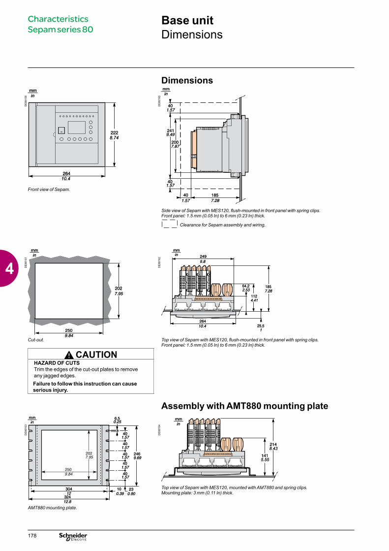
Dimensions
DE
8815
9
DE
8816
0
Front view of Sepam.
Side view of Sepam with MES120, flush-mounted in front panel with spring clips.Front panel: 1.5 mm (0.05 In) to 6 mm (0.23 In) thick.
Clearance for Sepam assembly and wiring.
DE
8816
1
DE
8816
2
Cut-out. Top view of Sepam with MES120, flush-mounted in front panel with spring clips.Front panel: 1.5 mm (0.05 In) to 6 mm (0.23 In) thick.
CAUTIONHAZARD OF CUTSTrim the edges of the cut-out plates to remove any jagged edges.Failure to follow this instruction can cause serious injury.
Assembly with AMT880 mounting plate
DE
8816
3
DE
8816
4
Top view of Sepam with MES120, mounted with AMT880 and spring clips.Mounting plate: 3 mm (0.11 In) thick.
AMT880 mounting plate.
mmin
8.74
10.4
mmin
8.74
10.4
mmin
8.43
5.55
mmin
8.43
5.55
Base unitDimensions
Characteristics Sepam series 80
178
4
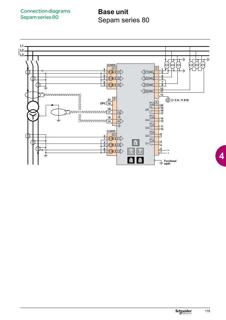
DE
8834
8
Base unitSepam series 80
Connection diagrams Sepam series 80
179
4

Connection characteristicsConnector Type Reference WiringA , E
Screw type CCA620 b wiring with no fittings :v 1 wire with max. cross-section 0.2 to 2.5 mm² (u AWG 24-12)
or 2 wires with max. cross-section 0.2 to 1 mm² (u AWG 24-16)
v stripped length: 8 to 10 mmb wiring with fittings:v recommended wiring with Schneider Electric fittings:- DZ5CE015D for 1 x 1.5 mm² wire (AWG 16)- DZ5CE025D for 1 x 2.5 mm² wire (AWG 12)- AZ5DE010D for 2 x 1 mm² wires (AWG 18)v tube length: 8.2 mm (0.32 in)v stripped length: 8 mm (0.31 in)
6.35 mm ring lugs CCA622 b 6.35 mm ring or spade lugs (1/4”)b maximum wire cross-section of 0.2 to 2.5 mm²
(u AWG 24-12)b stripped length: 6 mmb use an appropriate tool to crimp the lugs on the wiresb maximum of 2 ring or spade lugs per terminalb tightening torque: 1.2 (13.27 lb-in)
C1 , C2White RJ45 plug CCA612
D1 , D2Black RJ45 plug CCA770: L = 0.6 m (2 ft)
CCA772: L = 2 m (6.6 ft)CCA774: L = 4 m (13.1 ft)CCA785 for MCS025 module: L = 2 m (6.6 ft)
Blue RJ45 plug CCA614
DE
8816
6
Functional earth
Ring lug Earthing braid, to be connected to cubicle grounding:b flat copper braid with cross-section u 9 mm²b maximum length: 300 mm (11.8 in)
B1 , B24 mm ring lugs CCA630, CCA634 for
connection of 1 A or 5 A CTsb wire cross-section 1.5 to 6 mm² (AWG 16-10)b tightening torque: 1.2 Nm (13.27 lb-in)
RJ45 plug CCA671, for connection of 3 LPCT sensors
Integrated with LPCT sensor
CAUTION CAUTIONLOSS OF PROTECTION OR RISK OF NUISANCE TRIPPINGIf the Sepam is no longer supplied with power or is in fail-safe position, the protection functions are no longer active and all the Sepam output relays are dropped out. Check that this operating mode and the watchdog relay wiring are compatible with your installation.Failure to follow this instruction can result in equipment damage and unwanted shutdown of the electrical installation.
HAZARD OF ELECTRIC SHOCK, ELECTRIC ARC OR BURNSb Only qualified personnel should install this equipment. Such work should be performed only after reading this entire set of instructions.b NEVER work alone.b Turn off all power supplying this equipment before working on or inside it. Consider all sources of power, including the possibility of backfeeding.b Always use a properly rated voltage sensing device to confirm that all power is off.b Start by connecting the device to the protective earth and to the functional earth.b Screw tight all terminals, even those not in use.Failure to follow these instructions will result in death or serious injury.
Base unitConnection
Connection diagrams Sepam series 80
F
180
4

DE
8834
9
Connection characteristicsConnector Type Reference WiringB1
4 mm ring lugs CCA630, for connection of 1 A or 5 A CTs
1.5 to 6 mm² (AWG 16-10)
B2Screw type CCT640 VT wiring: same as wiring for the CCA620
Earthing connection: by 4 mm ring lugFor connectors A , E , C1 , C2 , D1 , D2 , : see page 180 .
CAUTION CAUTIONLOSS OF PROTECTION OR RISK OF NUISANCE TRIPPINGIf the Sepam is no longer supplied with power or is in fail-safe position, the protection functions are no longer active and all the Sepam output relays are dropped out. Check that this operating mode and the watchdog relay wiring are compatible with your installation.Failure to follow this instruction can result in equipment damage and unwanted shutdown of the electrical installation.
HAZARD OF ELECTRIC SHOCK, ELECTRIC ARC OR BURNSb Only qualified personnel should install this equipment. Such work should be performed only after reading this entire set of instructions.b NEVER work alone.b Turn off all power supplying this equipment before working on or inside it. Consider all sources of power, including the possibility of backfeeding.b Always use a properly rated voltage sensing device to confirm that all power is off.b Start by connecting the device to the protective earth and to the functional earth.b Screw tight all terminals, even those not in use.Failure to follow these instructions will result in death or serious injury.
Base unitSepam B83
Connection diagrams Sepam series 80
181
4
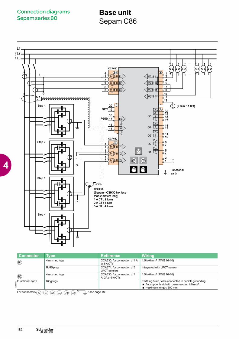
DE
8836
0
Connector Type Reference WiringB1
4 mm ring lugs CCA630, for connection of 1 A or 5 A CTs
1.5 to 6 mm² (AWG 16-10)
RJ45 plug CCA671, for connection of 3 LPCT sensors
Integrated with LPCT sensor
B24 mm ring lugs CCA630, for connection of 1
A, 2A or 5 A CTs1.5 to 6 mm² (AWG 16-10)
DE
8816
6 Functional earth Ring lugs Earthing braid, to be connected to cubicle grounding:b flat copper braid with cross-section u 9 mm²b maximum length: 300 mm
For connectors A , E , C1 , C2 , D1 , D2 , : see page 180.
Base unitSepam C86
Connection diagrams Sepam series 80
182
4

Variant 1: phase current measurement by 3 x 1 A or 5 A CTs (standard connection)
DE
8817
0
Connection of 3 x 1 A or 5 A sensors to the CCA630 connector.
The measurement of the 3 phase currents allows the calculation of residual current.
ParametersSensor type 5 A CT or 1 A CTNumber of CTs I1, I2, I3Rated current (In) 1 A to 6250 A
Variant 2: phase current measurement by 2 x 1 A or 5 A CTs
DE
8817
1
Connection of 2 x 1 A or 5 A sensors to the CCA630 connector.
Measurement of phase 1 and 3 currents is sufficient for all protection functions based on phase current.
This arrangement does not allow the calculation of residual current, nor use of ANSI 87T and 87M differential protection functions on the Sepam T87, M87, M88, G87 and G88.
ParametersSensor type 5 A CT or 1 A CTNumber of CTs I1, I3Rated current (In) 1 A to 6250 A
Variant 3: phase current measurement by 3 LPCT type sensors
DE
8817
2
Connection of 3 Low Power Current Transducer (LPCT) type sensors to the CCA671 connector. It is necessary to connect 3 sensors; if only one or two sensors are connected, Sepam goes into fail-safe position.
Measurement of the 3 phase currents allows the calculation of residual current.
The In parameter, primary rated current measured by an LPCT, is to be chosen from the following values, in Amps: 25, 50, 100, 125, 133, 200, 250, 320, 400, 500, 630, 666, 1000, 1600, 2000, 3150.Parameter to be set using the SFT2841 software tool, to be completed by hardware setting of the microswitches on the CCA671 connector.It is not possible to use LPCT sensors for the following measurements:b phase-current measurements for Sepam T87, M88 and G88 with ANSI 87T transformer differential protection (connectors B1 and B2 )
b phase-current measurements for Sepam B83 (connector B1 )
b unbalance-current measurements for Sepam C86 (connector B2 ).
ParametersSensor type LPCTNumber of CTs I1, I2, I3Rated current (In) 25, 50, 100, 125, 133, 200, 250, 320, 400, 500, 630, 666, 1000,
1600, 2000 or 3150 ANote: Parameter In must be set twice:
b Software parameter setting using the advanced UMI or the SFT2841 software toolb Hardware parameter setting using microswitches on the CCA671 connector
CCA630/CCA634CCA630/CCA634
Connection diagrams Sepam series 80
Base unitPhase current inputs
183
4
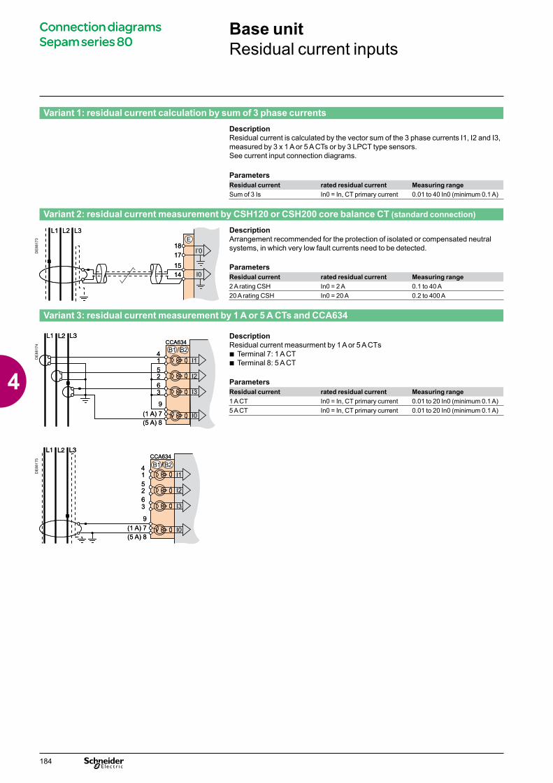
Variant 1: residual current calculation by sum of 3 phase currentsDescriptionResidual current is calculated by the vector sum of the 3 phase currents I1, I2 and I3, measured by 3 x 1 A or 5 A CTs or by 3 LPCT type sensors.See current input connection diagrams.
ParametersResidual current rated residual current Measuring rangeSum of 3 Is In0 = In, CT primary current 0.01 to 40 In0 (minimum 0.1 A)
Variant 2: residual current measurement by CSH120 or CSH200 core balance CT (standard connection)
DE
8817
3
DescriptionArrangement recommended for the protection of isolated or compensated neutral systems, in which very low fault currents need to be detected.
ParametersResidual current rated residual current Measuring range2 A rating CSH In0 = 2 A 0.1 to 40 A20 A rating CSH In0 = 20 A 0.2 to 400 A
Variant 3: residual current measurement by 1 A or 5 A CTs and CCA634
DE
8817
4
DescriptionResidual current measurment by 1 A or 5 A CTsb Terminal 7: 1 A CTb Terminal 8: 5 A CT
ParametersResidual current rated residual current Measuring range1 A CT In0 = In, CT primary current 0.01 to 20 In0 (minimum 0.1 A)5 A CT In0 = In, CT primary current 0.01 to 20 In0 (minimum 0.1 A)
DE
8817
5Base unitResidual current inputs
Connection diagrams Sepam series 80Connection diagrams Sepam series 80
184
4
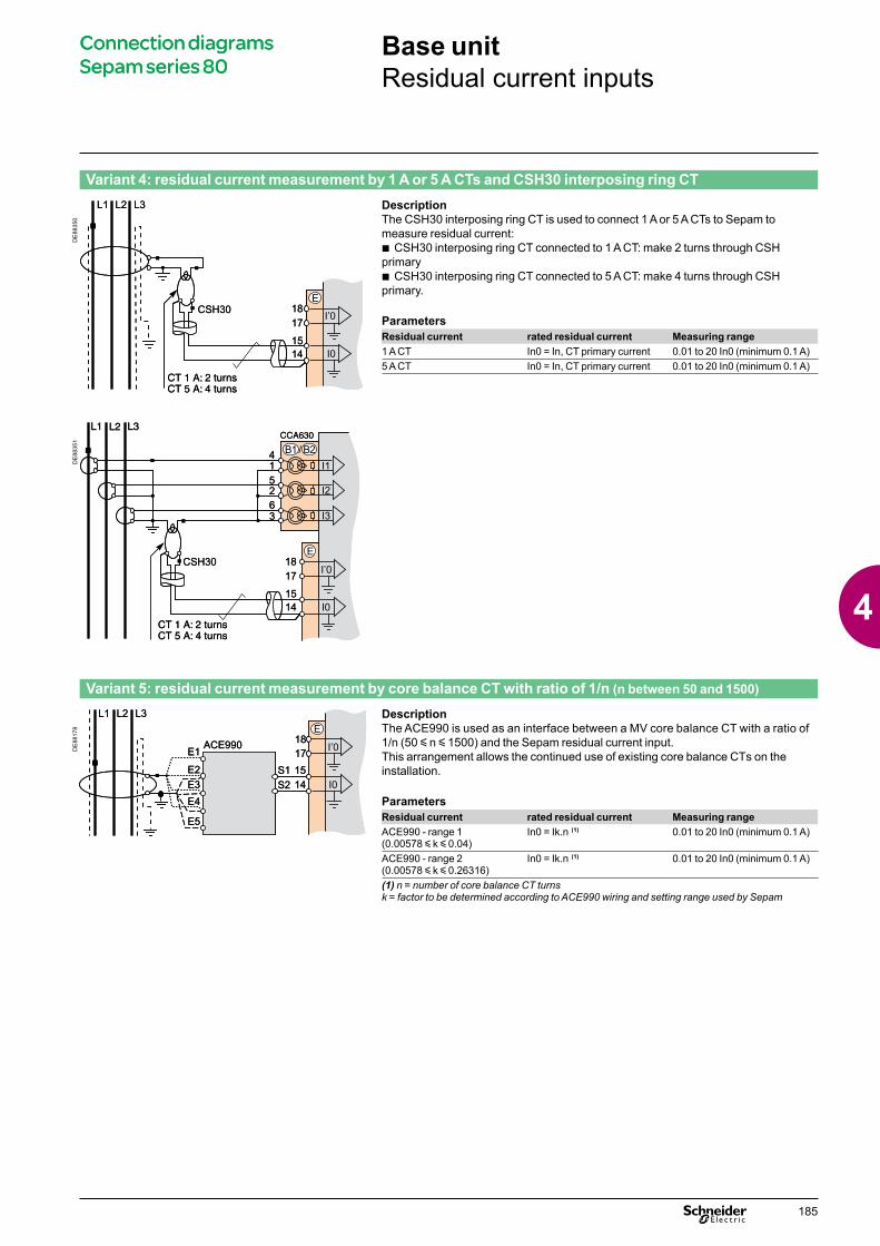
Variant 4: residual current measurement by 1 A or 5 A CTs and CSH30 interposing ring CT
DE
8835
0
DescriptionThe CSH30 interposing ring CT is used to connect 1 A or 5 A CTs to Sepam to measure residual current:b CSH30 interposing ring CT connected to 1 A CT: make 2 turns through CSH primaryb CSH30 interposing ring CT connected to 5 A CT: make 4 turns through CSH primary.
ParametersResidual current rated residual current Measuring range1 A CT In0 = In, CT primary current 0.01 to 20 In0 (minimum 0.1 A)5 A CT In0 = In, CT primary current 0.01 to 20 In0 (minimum 0.1 A)
DE
8835
1
Variant 5: residual current measurement by core balance CT with ratio of 1/n (n between 50 and 1500)
DE
8817
8
DescriptionThe ACE990 is used as an interface between a MV core balance CT with a ratio of 1/n (50 y n y 1500) and the Sepam residual current input.This arrangement allows the continued use of existing core balance CTs on the installation.
ParametersResidual current rated residual current Measuring rangeACE990 - range 1 (0.00578 y k y 0.04)
In0 = Ik.n (1) 0.01 to 20 In0 (minimum 0.1 A)
ACE990 - range 2 (0.00578 y k y 0.26316)
In0 = Ik.n (1) 0.01 to 20 In0 (minimum 0.1 A)
(1) n = number of core balance CT turnsk = factor to be determined according to ACE990 wiring and setting range used by Sepam
Base unitResidual current inputs
Connection diagrams Sepam series 80Connection diagrams Sepam series 80
185
4
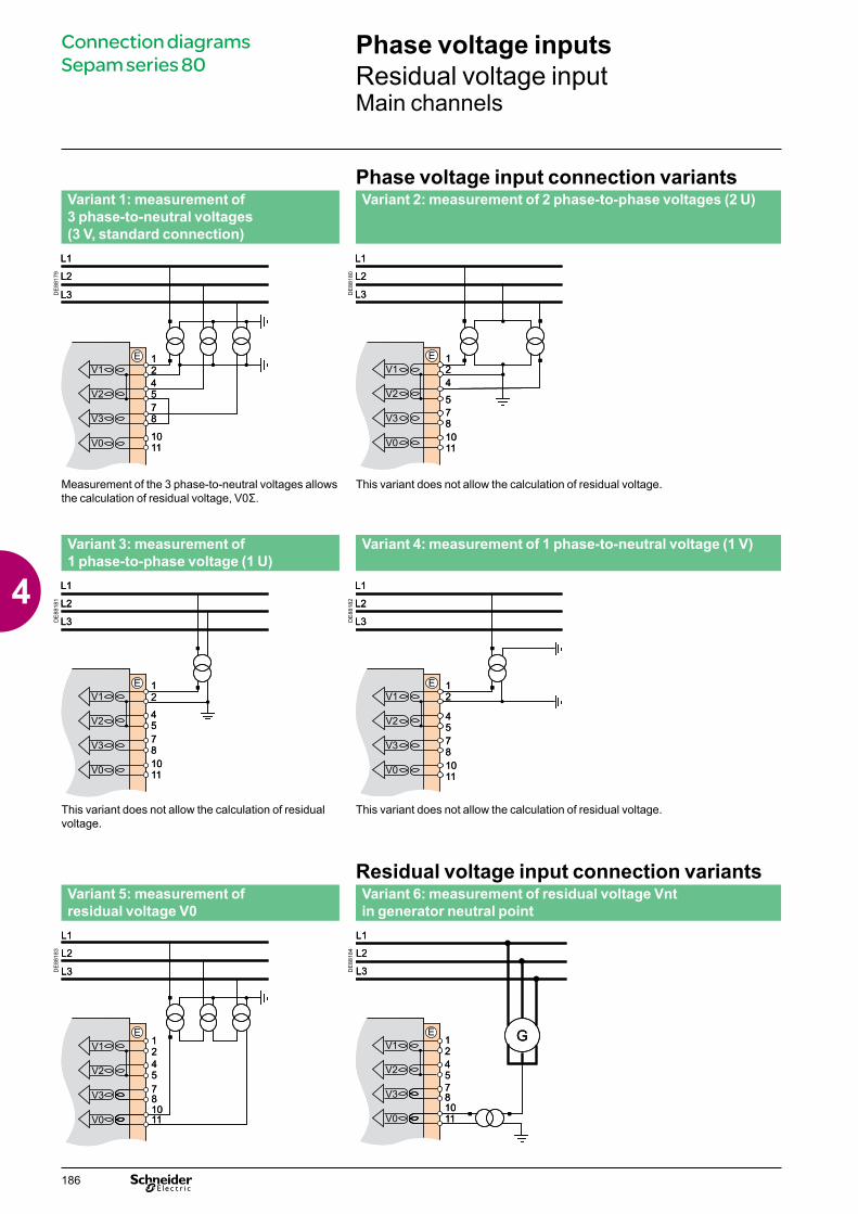
Phase voltage input connection variantsVariant 1: measurement of 3 phase-to-neutral voltages (3 V, standard connection)
Variant 2: measurement of 2 phase-to-phase voltages (2 U)
DE
8817
9
DE
8818
0
Measurement of the 3 phase-to-neutral voltages allows the calculation of residual voltage, V0Σ.
This variant does not allow the calculation of residual voltage.
Variant 3: measurement of 1 phase-to-phase voltage (1 U)
Variant 4: measurement of 1 phase-to-neutral voltage (1 V)
DE
8818
1
DE
8818
2
This variant does not allow the calculation of residual voltage.
This variant does not allow the calculation of residual voltage.
Residual voltage input connection variantsVariant 5: measurement of residual voltage V0
Variant 6: measurement of residual voltage Vnt in generator neutral point
DE
8818
3
DE
8818
4
Phase voltage inputsResidual voltage inputMain channels
Connection diagrams Sepam series 80
186
4

Additional phase voltage input connection variants
Variant 1: measurement of 3 phase-to-neutral voltages (3 V’, standard connection)
Variant 2: measurement of 2 phase-to-phase voltages (2 U’)
DE
8818
5
DE
8818
6
Measurement of the 3 phase-to-neutral voltages allows the calculation of residual voltage, V’0Σ.
This variant does not allow the calculation of residual voltage.
Variant 3: measurement of 1 phase-to-phase voltage (1 U’)
Variant 4: measurement of 1 phase-to-neutral voltage (1 V’)
DE
8818
7
DE
8818
8
This variant does not allow the calculation of residual voltage.
This variant does not allow the calculation of residual voltage.
Additional residual voltage input connectionVariant 5: measurement of residual voltage V’0
DE
8818
9
Phase voltage inputsResidual voltage inputAdditional channels for Sepam B83
Connection diagrams Sepam series 80
187
4

Connection to measure one additional voltage
DE
8835
3
This connection should be used to measure:b three phase-to-neutral voltages V1, V2, V3 on busbars no. 1b one additional phase-to-neutral voltage V’1 (or one additional phase-to-phase voltage U’21) on busbars no. 2.
DE
8835
2
This connection should be used to measure:b two phase-to-phase voltages U21, U32 and one residual voltage V0 on busbars no. 1b one additional phase-to-phase voltage U’21 (or one additional phase-to-neutral voltage V’1) on busbars no. 2.
Phase voltage inputsResidual voltage inputAdditional channel for Sepam B80
Connection diagrams Sepam series 80
188
4
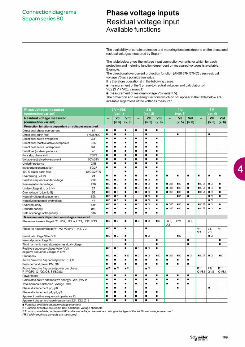
The availability of certain protection and metering functions depend on the phase and residual voltages measured by Sepam.
The table below gives the voltage input connection variants for which for each protection and metering function dependent on measured voltages is available.Example:The directional overcurrent protection function (ANSI 67N/67NC) uses residual voltage V0 as a polarization value.It is therefore operational in the following cases:b measurement of the 3 phase-to-neutral voltages and calculation of V0Σ (3 V + V0Σ, variant 1)b measurement of residual voltage V0 (variant 5).The protection and metering functions which do not appear in the table below are available regardless of the voltages measured.
Phase voltages measured (connection variant)
3 V + V0Σ(var. 1)
2 U (var. 2)
1 U (var. 3)
1 V (var. 4)
Residual voltage measured (connection variant)
– V0 (v. 5)
Vnt (v. 6)
– V0 (v. 5)
Vnt (v. 6)
– V0 (v. 5)
Vnt (v. 6)
– V0 (v. 5)
Vnt (v. 6)
Protection functions dependent on voltages measuredDirectional phase overcurrent 67 b b b b b b
Directional earth fault 67N/67NC b b b b b b
Directional active overpower 32P b b b b b b
Directional reactive active overpower 32Q b b b b b b
Directional active underpower 37P b b b b b b
Field loss (underimpedance) 40 b b b b b b
Pole slip, phase shift 78PS b b b b b b
Voltage-restrained overcurrent 50V/51V b b b b b b
Underimpedance 21B b b b b b b
Inadvertent energization 50/27 b b b b b b
100 % stator earth fault 64G2/27TN b b
Overfluxing (V/Hz) 24 b b b b b b b b b b b b
Positive sequence undervoltage 27D b v b v b b v b v b
Remanent undervoltage 27R b v b v b b v b v b b v U b v b b v U b v b
Undervoltage (L-L or L-N) 27 b v b v b b v b v b b v U b v b b v U b v b
Overvoltage (L-L or L-N) 59 b v b v b b v b v b b v U b v b b v U b v b
Neutral voltage displacement 59N b v b v b b v b b v b b v b
Negative sequence overvoltage 47 b v b v b b b v b b v
Overfrequency 81H b v b v b b v b v b b v U b v b b v U b v b
Underfrequency 81L b v b v b b v b v b b v U b v b b v U b v b
Rate of change of frequency 81R b b b b b b
Measurements dependent on voltages measuredPhase-to-phase voltage U21, U32, U13 or U’21, U’32, U’13 b v b v b b v b v b v U21,
U’21U21 U21
Phase-to-neutral voltage V1, V2, V3 or V’1, V’2, V’3 b v b v b b V1, V’1
V1, V’1
V1
Residual voltage V0 or V’0 b v b v b b v b v b v
Neutral point voltage Vnt b b b b
Third harmonic neutral point or residual voltage b b b b
Positive sequence voltage Vd or V’d / negative sequence voltage Vi or V’i
b v b v b b v b v b
Frequency b v b v b v b v b v b v b v U b v b v b v U b v b v
Active / reactive / apparent power: P, Q, S b b b b b b b b b
Peak demand power PM, QM b b b b b b b b b
Active / reactive / apparent power per phase : P1/P2/P3, Q1/Q2/Q3, S1/S2/S3
b (1) b (1) b (1) b (1) P1/Q1/S1
P1/Q1/S1
P1/Q1/S1
Power factor b b b b b b b b b
Calculated active and reactive energy (±Wh, ±VARh) b b b b b b b b b
Total harmonic distortion, voltage Uthd b b b b b b b b b
Phase displacement φ0, φ’0 b b b b b b
Phase displacement φ1, φ2, φ3 b b b b b b
Apparent positive sequence impedance Zd b b b b b b
Apparent phase-to-phase impedances Z21, Z32, Z13 b b b b b b
b Function available on main voltage channels.v Function available on Sepam B83 additional voltage channels.U Function available on Sepam B80 additional voltage channel, according to the type of the additional voltage measured.(1) If all three phase currents are measured.
Phase voltage inputsResidual voltage inputAvailable functions
Connection diagrams Sepam series 80
189
4

schneider-electric.com The electrical installation guide
This international site allows you to access all the Schneider Electric products in just 2 clicks via comprehensive range data-sheets, with direct links to:
complete library: technical documents, catalogs, FAQs, brochures…
selection guides from the e-catalog.
product discovery sites and their Flash animations.You will also find illustrated overviews, news to which you can subscribe, the list of country contacts…
p
p
p
According to IEC 60364This guide, part of the Schneider Electric offer, is the essential tool to "guide" you any time in your business:
design office, consultantcontractor, panelbuilderteacher, trainer.
Comprehensive and concrete information on:
all the new technical solutionsall the components of an
installation from a global point of view
all the IEC standards modificationsall the fundamental
electrotechnical knowledgeall the design stages, from medium
to low voltage.
ppp
pp
pp
p
TOOLS
190
5
Range description 5Sepam series 20 and Sepam series 40 51 Sepam series 60 89 Sepam series 80 137
Software 193Sepam software 193SFT2841 setting and operating software 194Function 194SFT2841 connection to Sepam 196Adaptation of the predefined functions 197SFT2826 disturbance recording data display software 198SFT850 configuration software for IEC 61850 protocol 199SFT2885 programming software - Logipam 200Power Launcher 202
Logic input / output modules 203MES114 modules 203Logic input / output assignment of Sepam series 20 205Logic input / output assignment of Sepam series 40 206MES120, MES120G, MES120H 14 input / 6 output module 207Presentation 207Installation 208Logic input / output assignment 209
Remote modules 213Selection guide 213Connection 214MET148-2 Temperature sensor module 215MSA141 Analog output module 217DSM303 Remote advanced UMI module 218MCS025 Synchro-check module 220
Other modules 224Sepam 100 LD 224Presentation 224High impedance differential protection 225Sensors and surge limiters 226Description and connection 227Characteristics and dimensions 229Sepam 100 MI 230Presentation 230Block and connection diagrams 231Characteristics and dimensions 235
Additional modules and accessories
Sepam series 20 Sepam series 40 Sepam series 60 Sepam series 80
.../...
191
5

Additional modules and accessories
Communication accessories 236Selection guide 236
Communication interfaces 237Communication interface connection 237ACE949-2 2-wire RS 485 network interface 239ACE959 4-wire RS 485 network interface 240ACE937 Fiber optic interface 241ACE969TP-2 and ACE969FO-2 Network interfaces 242ACE850TP and ACE850FO network interfaces 247
Converters 251ACE909-2 RS 232 / RS 485 converter 251ACE919CA and ACE919CC RS 485 / RS 485 converters 253Sepam IEC 61850 level 1 ECI850 255PowerLogic EGX100 259PowerLogic EGX300 260
Sensors 262Selection guide 2621 A / 5 A current transformers 264LPCT type current sensors 267Test accessories 268CSH120 and CSH200 Core balance CTs 270CSH30 Interposing ring CT 272ACE990 Core balance CT interface 273
Order form 277
Sepam series 20 Sepam series 40 Sepam series 60 Sepam series 80
192
5

PresentationThree types of Sepam PC software are available:b SFT2841 setting and operating softwareb SFT2826 disturbance recording data display softwareb SFT2885 programming software for the Sepam series 80 (Logipam)b SFT850 advanced-configuration software for IEC 61850 protocol.
SFT2841 and SFT2826 softwareSFT2841 and SFT2826 software is provided on the same CD-ROM as the Sepam documentation in PDF format.
PC connection cordIn order to use the SFT2841 software in point to point connected mode:- the CCA783 PC connection cord, to be ordered separately, is designed to connecta PC to the RS 232 port on the front panel of a Sepam unit.- the CCA784 PC connection cord, to be ordered separately, is designed to connecta PC to the USB port on the front panel of a Sepam unit. The USB/RS232 TSXCUSB232 converter may be used with the CCA783 connection cord for connection to a USB port.
SFT2885 softwareSFT2885 is available on a separate CD-ROM.
SFT850 softwareSFT850 is available on a separate CD-ROM.
Minimum configuration requiredSFT2841 and SFT2826 software
Operating systems Microsoft 2000/XPRAM 128 MBSpace on disk 200 MB
SFT2885Operating systems Microsoft 2000/XPRAM 64 MB Space on disk 30 MB
SFT850Operating systems Microsoft 2000/XPRAM 512 MB Space on disk 200 MB
Sepam software
Software
193
5
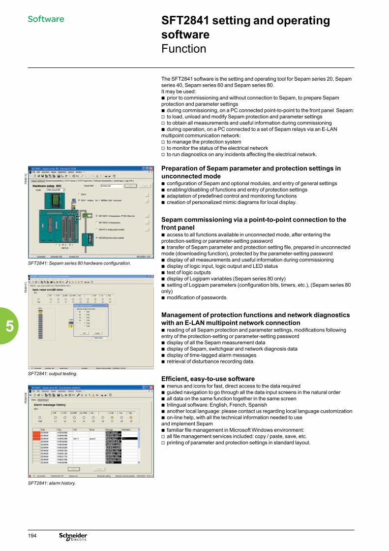
The SFT2841 software is the setting and operating tool for Sepam series 20, Sepam series 40, Sepam series 60 and Sepam series 80.It may be used:b prior to commissioning and without connection to Sepam, to prepare Sepam protection and parameter settingsb during commissioning, on a PC connected point-to-point to the front panel Sepam:v to load, unload and modify Sepam protection and parameter settingsv to obtain all measurements and useful information during commissioningb during operation, on a PC connected to a set of Sepam relays via an E-LAN multipoint communication network:v to manage the protection systemv to monitor the status of the electrical networkv to run diagnostics on any incidents affecting the electrical network.
PE
8811
2
Preparation of Sepam parameter and protection settings in unconnected mode b configuration of Sepam and optional modules, and entry of general settings b enabling/disabling of functions and entry of protection settingsb adaptation of predefined control and monitoring functionsb creation of personalized mimic diagrams for local display.
Sepam commissioning via a point-to-point connection to the front panelb access to all functions available in unconnected mode, after entering the protection-setting or parameter-setting password b transfer of Sepam parameter and protection setting file, prepared in unconnected mode (downloading function), protected by the parameter-setting passwordb display of all measurements and useful information during commissioning b display of logic input, logic output and LED statusb test of logic outputsb display of Logipam variables (Sepam series 80 only)b setting of Logipam parameters (configuration bits, timers, etc.), (Sepam series 80 only)b modification of passwords.
Management of protection functions and network diagnostics with an E-LAN multipoint network connectionb reading of all Sepam protection and parameter settings, modifications following entry of the protection-setting or parameter-setting passwordb display of all the Sepam measurement datab display of Sepam, switchgear and network diagnosis datab display of time-tagged alarm messagesb retrieval of disturbance recording data.
Efficient, easy-to-use softwareb menus and icons for fast, direct access to the data requiredb guided navigation to go through all the data input screens in the natural orderb all data on the same function together in the same screenb trilingual software: English, French, Spanishb another local language: please contact us regarding local language customizationb on-line help, with all the technical information needed to use and implement Sepamb familiar file management in Microsoft Windows environment:v all file management services included: copy / paste, save, etc.v printing of parameter and protection settings in standard layout.
SFT2841: Sepam series 80 hardware configuration.
PE
8811
3
SFT2841: output testing.
PE
8810
8
SFT2841: alarm history.
SFT2841 setting and operating softwareFunction
Software
194
5

PE
8811
4
The table below gives the SFT2841 functions available for each of the 4 Sepam series: Sepam series 20, Sepam series 40, Sepam series 60 and Sepam series 80.NC: function available in unconnected mode.S: function available with SFT2841 connected via Sepam front panel.E: function available with SFT2841 connected to Sepam via E-LAN communication network.
Functions Series 20 Series 40 Series 60 Series 80NC S E NC S E NC S E NC S E
ManagementOn-line help b b b b b b b b b b b b
Management of parameter and protection setting files: creation, saving, downloading and uploading
b b b b b b b b b b b b
Downloading and uploading of parameter and protection setting files
b b b b (1)
b b b b
Exporting of parameter and protection settings in a text file
b b b b
SFT2841: Sepam series 80 sensor parameter setting. Printing of parameter and protection settings
b b b b b b b b b b b b
Modification of passwords, one for parameter setting and one for protection setting
b b b b b b b b
PE
8811
5
SFT2841: Sepam series 80 application, with protection function measurement origin.
Sepam parameter settingDisplay of parameter settings b b b b b b b b b b b b
Hardware configuration and parameter entry protected by parameter setting password
b b b b b b b b b b b b
Graphical parameter setting assistance
b b b b b b
Standard configuration for IEC 61850 network
b b b b b b b b b b b b
Protection settingDisplay of protection settings b b b b b b b b b b b b
Entry of protection settings, protected by protection setting password
b b b b b b b b b b b b
Definition of customized tripping curve b b b b b b
Adaptation of the predefined functionsDisplay and modification of the control matrix
b b b b b b b b b b b b
PE
8811
6
Logic equation editing b b b b b b b b
Number of instructions 100 200 200Number of dedicated remote indications
10 20 20
Display of logic equations b b b b b b
Load the Logipam program b b b
Setting of Logipam parameters b b b
Assignment of LEDs on front b b b b b b b b b b b b
Editing of user messages b b b b b b b b
Number of user messages 30 100 100Editing of personalized mimic diagram b b b b b b
Assistance in commissioning and operating the installationDisplay of all the Sepam measurement data
b b b b b b b b
Display of switchgear diagnosis assistance data
b b b b b b b b
SFT2841: protection settings. Display of machine operating assistance data
b b b b b b b b
PE
8811
7
SFT2841: Sepam diagnosis.
Display of time-tagged alarm messages
b b b b b b b b
Tripping context b b b b b b b b
Retrieval of disturbance recording files
b b b b b b b b
Display of Logipam variables b b
Display of logic input/output status b b b b b b b b
Output testing b b b b b b b b
Sepam diagnosis b b b b b b b b
(1) Except for logic equations and personalized messages.
SFT2841 setting and operating softwareFunction
Software
195
5

SFT2841 connection to the front panel of a SepamConnection of the PC RS232 serial port to the communication port on the front panel of Sepam series 20, Sepam series 40, Sepam series 60 or Sepam series 80 using the CCA783 cord or the USB/RS232 (TSXCUSB232) converter + CCA783.
DE
8835
4
DE
8835
5
SFT2841 connection to a set of Sepam relaysThe SFT2841 can be connected to a set of Sepam relays, themselves connected to a E-LAN communication network in one of the three architectures presented below.These connections do not require any further software development work.
Ethernet connection RS 485 serial connection Telephone-line connectionb connection a set of Sepam to a Modbus RS 485 networkb Ethernet RS 485 link via the EGX100 or EGX300 gateway or the ECI850 serverb embedded Ethernet link via the ACE850 communication interfaceb connection of the PC via its Ethernet port.
b connection a set of Sepam to a Modbus RS 485 network b connection of the PC via its RS 232 port, using the ACE909-2 interface.
b connection a set of Sepam to a Modbus RS 485 network b RS 485-RTC link via an RS 485 modem (Wertermo TD-34 for example)b connection of the PC via its modem port.
DE
6058
6
DE
6058
7
DE
6058
8
SFT2841 setting and operating softwareSFT2841 connection to Sepam
Software
196
5
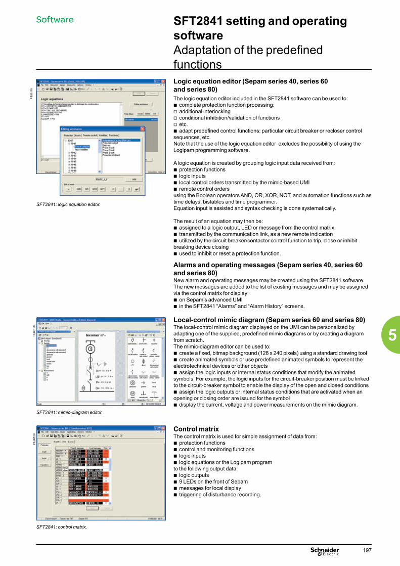
PE
8811
8
SFT2841: logic equation editor.
Logic equation editor (Sepam series 40, series 60 and series 80)The logic equation editor included in the SFT2841 software can be used to:b complete protection function processing: v additional interlockingv conditional inhibition/validation of functionsv etc.b adapt predefined control functions: particular circuit breaker or recloser control sequences, etc.Note that the use of the logic equation editor excludes the possibility of using the Logipam programming software.
A logic equation is created by grouping logic input data received from:b protection functionsb logic inputsb local control orders transmitted by the mimic-based UMIb remote control ordersusing the Boolean operators AND, OR, XOR, NOT, and automation functions such as time delays, bistables and time programmer.Equation input is assisted and syntax checking is done systematically.
The result of an equation may then be:b assigned to a logic output, LED or message from the control matrixb transmitted by the communication link, as a new remote indicationb utilized by the circuit breaker/contactor control function to trip, close or inhibit breaking device closingb used to inhibit or reset a protection function.
Alarms and operating messages (Sepam series 40, series 60 and series 80)New alarm and operating messages may be created using the SFT2841 software.The new messages are added to the list of existing messages and may be assigned via the control matrix for display:b on Sepam’s advanced UMIb in the SFT2841 “Alarms” and “Alarm History” screens.
PE
8810
9
Local-control mimic diagram (Sepam series 60 and series 80)The local-control mimic diagram displayed on the UMI can be personalized by adapting one of the supplied, predefined mimic diagrams or by creating a diagram from scratch.The mimic-diagram editor can be used to:b create a fixed, bitmap background (128 x 240 pixels) using a standard drawing toolb create animated symbols or use predefined animated symbols to represent the electrotechnical devices or other objectsb assign the logic inputs or internal status conditions that modify the animated symbols. For example, the logic inputs for the circuit-breaker position must be linked to the circuit-breaker symbol to enable the display of the open and closed conditionsb assign the logic outputs or internal status conditions that are activated when an opening or closing order are issued for the symbolb display the current, voltage and power measurements on the mimic diagram.
Control matrixThe control matrix is used for simple assignment of data from:b protection functionsb control and monitoring functionsb logic inputsb logic equations or the Logipam programto the following output data:b logic outputs b 9 LEDs on the front of Sepamb messages for local displayb triggering of disturbance recording.
SFT2841: mimic-diagram editor.
PE
8812
0
SFT2841: control matrix.
SFT2841 setting and operating softwareAdaptation of the predefined functions
Software
197
5

Function
PE
8802
6
The SFT2826 software is used to display, analyze and print disturbance data recorded by Sepam.It uses COMTRADE (IEEE standard: Common format for transient data exchange for power systems) files.
Transfer of disturbance recording dataBefore they are analyzed by SFT2826, the disturbance recording data must be transferred from Sepam to the PC: b by the SFT2841 software b or by the Modbus communication link.
Analysis of disturbance recording datab selection of analog signals and logic data for displayb zoom and measurement of time between eventsb display of all numerical values recordedb exporting of data in file formatb printing of curves and/or numerical values recorded.
SFT2826: analysis of a disturbance data record.
CharacteristicsThe SFT2826 software comes with the SFT2841 software:b 4 languages: English, French, Spanish, Italianb on-line help with description of software functions.
SFT2826 disturbance recording data display software
Software
198
5

SFT850 configuration software for IEC 61850 protocol
FunctionThe SFT850 software is used to easily create, modify and consult the SCL (Substation Configuration Language) configuration files for the IEC 61850 communication protocol:b CID (Configured IED description) file for configuration of a device connected to an IEC 61850 networkb SCD (Substation Configuration Description) file for IEC 61850 configuration of substation equipment.The SFT850 software supplements the standard IEC 61850 configuration created with the SFT2841 software in cases where the configuration must be precisely adapted to system requirements.
Adding or deleting equipmentThe SFT850 software can be used to add or delete connected equipment in the IEC 61850 configuration. If a Sepam unit is added, the software uses the supplied ICD (IED capability description) file to start configuration.
Equipment connectionThe SFT850 software describes the data for equipment connection to the network.
Editing the equipment configurationThe configuration of a given device described in a CID or SCD file can be modified:b add, modify or delete datasets. A dataset is used to group data and optimise communicationb add, modify or delete RCBs (Report Control Block). A Report Control Block defines dataset transmission conditionsb add, modify or delete GCBs (Goose Control Block). A Goose Control Block defines how data is exchanged between Sepam unitsb modify dead measurement bands. This parameter is used to optimise communication in that measurements are transmitted only if they have changed significantly.
Generating CID filesThe SFT850 software can generate the CID file for each device on the basis of an SCD file.
Software
199
5

SFT2885 programming software - Logipam
FunctionThe SFT2885 programming software (called Logipam) is intended exclusively for the Sepam series 80 and can be used to:b adapt predefined control and monitoring functionsb program specific control and monitoring functions, either to replace the predefined versions or to create completely new functions, to provide all the functions required by the application.It is made up of:b a ladder-language program editor used to address all Sepam data and to program complex control functionsb a simulator for complete program debuggingb a code generator to run the program on Sepam.The ladder-language program and the data used can be documented and a complete file can be printed. Only the Sepam series 80 with a cartridge containing the Logipam SFT080 option can run the control and monitoring functions programmed by the Logipam SFT2885 software.
The complete Logipam software is made up of the executable program run by Sepam and the source program that can be modified by the Logipam SFT2885 programming software.
The SFT2841 setting and operating software, required for implementation of the Logipam program, offers the following functions:b association of the complete Logipam program with the Sepam parameter and protection settingsb loading and unloading of Logipam program, parameters and settings in the Sepam cartridgeb running of the functions programmed with Logipam:v display of the status of Logipam internal bitsv setting of Logipam parameters: configuration bits, timers, etc.
Operating principle
DE
8835
9Software
200
5

Characteristics
PE
8803
6
Program structureA ladder-language program is made up of a series of rungs executed sequentially:b maximum 1000 lines with 9 contacts and 1 coil maximum per lineb with a maximum total number of 5000 contacts and coils. Comments may be made for each line.SectionsThe program can be broken down into sections and subsections to clarify the structure and facilitate reading. It is possible to set up three levels of sections.Comments may be added for each section. Execution of each section can be subjected to conditions.Variable editorEach variable is defined by an invariable identifier and can be linked to a name or a comment.The programmer can decide to work directly with the identifiers or with the linked names. The list of the variables used and the cross references may be consulted during programming.
Graphic elements in the ladder languageThe graphic elements are the instructions in the ladder language:b NO and NC contactsb rising and falling-edge detection contactsb direct or negated coilsb set and reset coilsb coils and contacts linked to timers, counters and clocks.
Available resourcesSepam variablesAll the data used by Sepam functions can be addressed by Logipam:b all logic inputs and outputsb all remote-control orders and remote indications (the remote-control orders and remote indication used in the Logipam program are no longer used by the predefined functions)b all protection-function inputs and outputs b all inputs and outputs for the predefined control and monitoring functionsb all inputs and outputs for symbols in the mimic-based UMIb all system datab all logic inputs GOOSE
Logipam internal variablesb 64 configuration bits to parameter program processing, settable via the SFT2841 software and the displayb 128 bits used by the control matrix to control LEDs, messages and logic outputsb 128 internal bits that are savedb 512 internal bits that are not saved.Logipam functionsb 60 timers that can be set for a rising edge (TON) or a falling edge (TOF)b 24 incremental counters with adjustable thresholdsb 4 clocks for a given week.
Debugging toolsThe Logipam software offers a complete set of tools for program debugging:b step-by-step or continuous program execution to simulate the programmed functionsb color animation of the rungs and all program variablesb grouping in a table of all program variables requiring monitoring.
DocumentationThe application file can be printed in part or in whole. The application file can be personalized : front page, title block, general description of the program, etc.
SFT2885: ladder-language program, structured in sections.
PE
8805
7
SFT2885: variable editor.
PE
88à5
8
SFT2885: program debugging.
SFT2885 programming software - Logipam
Software
201
5

Power LauncherMakes it easy
Software
Power Launcher makes it easy to have the latest version of all your software compliant with your latest device.b In one glance, you can see the available software for each device family:v Compact NSX & Masterpact circuit breakersv TeSys motor-startersv Sepam relaysv ION,PM and CM metersb Always up to date thanks to the simple notification and download of the latest software updates.b Save time by customizing your own software “favorites”.
DE
6059
5
202
5

FunctionThe 4 outputs included on the Sepam series 20 and 40 may be extended by adding an optional MES114 module with 10 inputs and 4 outputs, available in 3 versions:b MES114: 10 DC inputs voltage from from 24 V DC to 250 V DCb MES114E: 10 inputs, voltage 110-125 V AC or V DCb MES114F: 10 inputs, voltage 220-250 V AC or V DC.
Characteristics
PE
8805
9
MES114 module Weight 0.28 kg (0.617 lb)Operating temperature
-25 °C to +70 °C (-13 °Fto +158 °F)
Environmental characteristics
Same characteristics as Sepam base units
Logical inputs MES114 MES114E MES114FVoltage 24 to
250 V DC110 to 125 V DC
110 V AC 220 to 250 V DC
220 to 240 V AC
Range 19.2 to 275 V DC
88 to 150 VV DC
88 to 132 V AC
176 to 275 V DC
176 to264 V AC
Frequency / / 47 to 63 Hz / 47 to 63 Hz10 input/4 output MES114 module. Typical consumption 3 mA 3 mA 3 mA 3 mA 3 mA
Typical switching threshold
14 V DC 82 V DC 58 V AC 154 V DC 120 V AC
Input limit voltage
At state 1 u 19 V DC u 88 V DC u 88 V AC u 176 V DC u 176 V ACAt state 0 y 6 V DC y 75 V DC y 22 V AC y 137 V DC y 48 V AC
Isolation of inputs from other isolated groups
Enhanced Enhanced Enhanced Enhanced Enhanced
Isolation between inputs
Enhanced Enhanced Enhanced Enhanced Enhanced
O11 control relay outputVoltage DC 24 / 48 V DC 127 V DC 220 V DC 250 V CC
AC(47.5 to 63 Hz)
- - - - 100 to 240 V AC
Continuous current 8 A 8 A 8 A 8 A 8 ABreaking capacity Resistive
load8 / 4 A 0.7 A 0.3 A 0.2 A 8 A
LoadL/R < 20 ms
6 / 2 A 0.5 A 0.2 A - -
LoadL/R < 40 ms
4 / 1 A 0.2 A 0.1 A - -
Loadcos φ > 0.3
- - - - 5 A
Making capacity < 15 A for 200 msIsolation of outputs from other isolated groups
Enhanced
Isolation between outputs
Enhanced
O12 to O14 annunciation relay outputVoltage DC 24 / 48 V DC 127 V DC 220 V DC 250 V DC
AC(47.5 to 63 Hz)
- - - - 100 to 240 V AC
Continuous current 2 A 2 A 2 A 2 A 2 ABreaking capacity Resistive
load2 / 1 A 0.6 A 0.3 A 0.2 A -
LoadL/R < 20 ms
2 / 1 A 0.5 A 0.15 A - -
Loadcos φ > 0.3
- - - - 1 A
Making capacity < 15 A for 200 msIsolation of outputs in relation to other isolated groups
Enhanced
Isolation between outputs
Enhanced
MES114 modules
Logic input / output modules
203
5
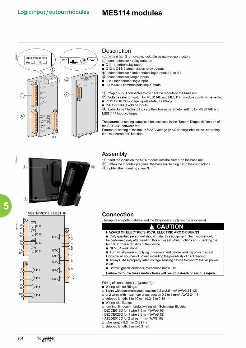
DE
6067
2
DescriptionL , M and K : 3 removable, lockable screw-type connectorsL : connectors for 4 relay outputs:
b O11: 1 control relay outputb O12 to O14: 3 annunciation relay outputsM : connectors for 4 independent logic inputs I11 to I14K : connectors for 6 logic inputs:
b I21: 1 independent logic input b I22 to I26: 5 common point logic inputs.
25-pin sub-D connector to connect the module to the base unit. Voltage selector switch for MES114E and MES114F module inputs, to be set to:b V DC for 10 DC voltage inputs (default setting)b V AC for 10 AC voltage inputs. Label to be filled in to indicate the chosen parameter setting for MES114E and MES114F input voltages.
The parameter setting status can be accessed in the “Sepam Diagnosis” screen of the SFT2841 software tool. Parameter setting of the inputs for AC voltage (V AC setting) inhibits the “operating time measurement” function.
PE
6032
0
Assembly Insert the 2 pins on the MES module into the slots 1 on the base unit. Flatten the module up against the base unit to plug it into the connector 2. Tighten the mounting screw 3.
DE
8819
9
ConnectionThe inputs are potential-free and the DC power supply source is external.
! CAUTIONHAZARD OF ELECTRIC SHOCK, ELECTRIC ARC OR BURNSb Only qualified personnel should install this equipment. Such work should be performed only after reading this entire set of instructions and checking the technical characteristics of the device.b NEVER work alone. b Turn off all power supplying this equipment before working on or inside it. Consider all sources of power, including the possibility of backfeeding.b Always use a properly rated voltage sensing device to confirm that all power is off.b Screw tight all terminals, even those not in use.Failure to follow these instructions will result in death or serious injury.
Wiring of connectors L , M and K :b Wiring with no fittings:v 1 wire with maximum cross-section 0.2 to 2.5 mm2 (AWG 24-12) v or 2 wires with maximum cross-section 0.2 to 1 mm2 (AWG 24-18)v stripped length: 8 to 10 mm (0.315 to 0.39 in)b Wiring with fittings:v terminal 5, recommended wiring with Schneider Electric:- DZ5CE015D for 1 wire 1.5 mm2 (AWG 16)- DZ5CE025D for 1 wire 2.5 mm2 (AWG 12)- AZ5DE010D for 2 wires 1 mm2 (AWG 18)v tube length: 8.2 mm (0.32 in)v stripped length: 8 mm (0.31 in).
MES114 modules
Logic input / output modules
12
3
123
204
5

The use of the preset control and monitoring functions requires exclusive parameter setting and particular wiring of the inputs according to their application and the type of Sepam.The advanced UMI or the SFT2841 software may be used to assign inputs and set the control and monitoring function parameters.Since an input may only be assigned to a single function, not all the functions are available at the same time.Example: if the logic discrimination function is used, the switching of groups of settings function may not be used.
Table of input/output assignment by applicationFunctions S20 S24 T20 T24 M20 B21 - B22 AssignmentLogic inputs
Open position b b b b b b I11Closed position b b b b b b I12Logic discrimination, receive blocking inputSwitching of groups of settings A/B
b b b b I13b b b b b
External resetExternal tripping 4 (1)
bb
bb
bb
bb
bb
bb
I14
External tripping 1 (1)
External network synchronizationbb
bb
b (2)
bb (2)
b
bb
bb
I21
External tripping 2 (1)
Motor re-accelerationb b (3) b
bb I22
External tripping 3 (1)
Buchholz alarm (1) (Buchholz alarm message)Rotor rotation detectionThermistor tripping (1)
Inhibit earth fault protection
b b
b
b (4)
b
b
b (4)
b
b
b
bb
b I23
End of charging positionThermostat alarm (1) (thermostat alarm message)Thermistor alarm (1)
External tripping 5 and 50BF activation (1)
b b
b (1)
bbb
bbbb (1)
b
b
I24
Inhibit remote control, excluding TC1 (1) Inhibit remote control, including TC1 (1) SF6-1
bbb
bbb
bbb
bbb
bbb
bbb
I25
SF6-2Change of thermal settingsInhibit thermal overloadInhibit recloser
b
b
b
b
bbb
bbb
bbb
b I26
Logic outputsTripping b b b b b b O1Inhibit closing b b b b b b O2Watchdog b b b b b b O4Close order b b b b b b O11Note: all of the logic inputs are available via the communication link and are accessible in the SFT2841 control matrix for other non predefined applications.(1) These inputs have parameter setting with the prefix “NEG” for undervoltage type operation.(2) Buchholz/Gas trip message.(3) Thermostat trip message.(4) Pressure trip message.
Logic input / output assignment of Sepam series 20
Logic input / output modules
205
5

Logic input / output assignment of Sepam series 40
Logic input / output modules
Inputs and outputs may be assigned to predefined control and monitoring functions using the SFT2841 software, according to the uses listed in the table below.b all the logic inputs, whether or not assigned to predefined functions, may be used for the SFT2841 customization functions according to specific application needs:v in the control matrix, to link inputs to output relays, LED indications or display messagesv in the logic equation editor, as logic equation variablesb the control logic of each input may be inverted for undervoltage type operation.
Assignment table of logic inputs by applicationFunctions S40 S41 S42 S43 S44 S50 S51 S52 S53 S54 T40 T42 T50 T52 M40 M41 G40 AssignmentLogic inputs
Open position b b b b b b b b b b b b b b b b b I11Closed position b b b b b b b b b b b b b b b b b I12Logic discrimination, receive blocking input 1
b b b b b b b b b b b b b b b Free
Logic discrimination, receive blocking input 2
b b Free
Switching of groups of settings A/B
b b b b b b b b b b b b b b b b b I13
External reset b b b b b b b b b b b b b b b b b FreeExternal tripping 1 b b b b b b b b b b b b b b b b b FreeExternal tripping 2 b b b b b b b b b b b b b b b b b FreeExternal tripping 3 b b b b b b b b b b b b b b b b b FreeBuchholz/gas tripping b b b b FreeThermostat tripping b b b b FreePressure tripping b b b b FreeThermistor tripping b b b b b b b FreeBuchholz/gas alarm b b b b FreeThermostat alarm b b b b FreePressure alarm b b b b FreeThermistor alarm b b b b b b b FreeEnd of charging position
b b b b b b b b b b b b b b b b b Free
Inhibit remote control b b b b b b b b b b b b b b b b b FreeSF6 b b b b b b b b b b b b b b b b b FreeInhibit recloser b b b b b b b b b b FreeExternal synchronization
b b b b b b b b b b b b b b b b b I21
Inhibit thermal overload
b b b b b b b Free
Switching of thermal settings
b b b b b b b Free
Motor re-acceleration b b FreeRotor rotation detection
b b Free
Inhibit undercurrent b b FreeInhibit closing b b b b b b b b b b b b b b b b b FreeOpen order b b b b b b b b b b b b b b b b b FreeClose order b b b b b b b b b b b b b b b b b FreePhase voltage transformer fuse melting
b b b b b b b b b b b b b b b b b Free
Residual voltage transformer fuse melting
b b b b b b b b b b b b b b b b Free
External positive active energy counter
b b b b b b b b b b b b b b b b b Free
External negative active energy counter
b b b b b b b b b b b b b b b b b Free
External positive reactive energy counter
b b b b b b b b b b b b b b b b b Free
External negative reactive energy counter
b b b b b b b b b b b b b b b b b Free
Downstream load start up
b b b b b b b
Logic outputsTripping b b b b b b b b b b b b b b b b O1Inhibit closing b b b b b b b b b b b b b b b b O2Watchdog b b b b b b b b b b b b b b b b O4Close order b b b b b b b b b b b b b b b b O11Note: all of the logic inputs are available via the communication link and are accessible in the SFT2841 matrix for other non predefined applications.
206
5

PE
8806
1
MES120 14 input / 6 output module.
FunctionThe output relays included on the Sepam series 60 and 80 base unit may be extended by adding 1, 2 or 3 MES120 modules with 14 DC logic inputs and 6 outputs relays (1 control relay output and 5 indication relay outputs).
Sepam series Output on base unit
Extendable with nb max of MES120
series 60 4 2series 80 5 3Three modules are available for the different input supply voltage ranges and offer different switching thresholds:b MES120, 14 inputs 24 V DC to 250 V DC with a typical switching threshold of 14 V DCb MES120G, 14 inputs 220 V DC to 250 V DC with a typical switching threshold of 155 V DCb MES120H, 14 inputs 110 V DC to 125 V DC with a typical switching threshold of 82 V DC.
CharacteristicsMES120 / MES120G / MES120H modules
Weight 0,38 kg (0,83 lb)Operating temperature -25 °C to +70 °C (-13 °F to +158 °F)Environmental characteristics Same characteristics as Sepam base unitsLogic inputs MES120 MES120G MES120H
Voltage 24 à 250 V DC 220 to 250 V DC 110 to 125 V DCRange 19.2 à 275 V DC 170 to 275 V DC 88 to 150 V DCTypical consumption 3 mA 3 mA 3 mATypical switching threshold 14 V DC 155 V DC 82 V DCInput limit voltage At state 0 < 6 V DC < 144 V DC < 75 V DC
At state 1 > 19 V DC > 170 V DC > 88 V DCIsolation of inputs from other isolated groups Enhanced Enhanced EnhancedControl relay output Ox01
Voltage DC 24/48 V DC 127 V DC 220 V DC 250 V DCAC (47.5 to 63 Hz) - - - - 100 à 240 V AC
Continuous current 8 A 8 A 8 A 8 A 8 ABreaking capacity Resistive load 8 / 4 A 0.7 A 0.3 A 0.2 A 8 A
Load L/R < 20 ms 6 / 2 A 0.5 A 0.2 A - -Load L/R < 40 ms 4 / 1 A 0.2 A 0.1 A - -Load p.f > 0.3 - - - - 5 A
Making capacity < 15 A for 200 msIsolation of inputs from other isolated groups EnhancedRelay output Ox02 to Ox06
Tension Continue 24/48 V DC 127 V DC 220 V DC 250 V DCAlternative (47.5 à 63 Hz) - - - - 100 to 240 V AC
Continuous current 2 A 2 A 2 A 2 A 2 ABreaking capacity Load L/R < 20 ms 2 / 1 A 0.5 A 0.15 A 0.2 A -
Load p.f > 0.3 - - - - 1 AIsolation of inputs from other isolated groups Enhanced
DE
6067
3
Description3 removable, lockable screw-type connectors.
1 20-pin connector for 9 logic inputs:Ix01 to Ix04: 4 independent logic inputsIx05 to Ix09: 5 common point logic inputs.
2 7-pin connector for 5 common point logic inputs Ix10 à Ix14.3 17-pin connector for 6 relay outputs:
Ox01: 1 control relay outputOx02 to Ox06 : 5 indication relay outputs.
Addressing of MES120 module inputs / outputs:x = 1 for the module connected to H1x = 2 for the module connected to H2x = 3 for the module connected to H3.
4 MES120G, MES120H identification label (MES120 modules have no labels).
b
bb
bb
bbb
mmin
6.69
1.57
4.72
MES120, MES120G, MES120H 14 input / 6 output modulePresentation
Logic input / output modules
207
5

Assembly
PE
6032
1
Installation of an MES120 module on the base unitb insert the 2 pins on the MES module into the slots 1 on the base unitb push the module flat up against the base unit to plug it into the connector H2 b partially tighten the two mounting screws 2 before locking them.MES120 modules must be mounted in the following order:b if only one module is required, connect it to connector H1b if 2 modules are required, connect them to connectors H1 and H2 (maximum configuration for Sepam series 60)b if 3 modules are required (maximum configuration for Sepam series 80 only), the 3 connectors H1 , H2 and H3 are used.
Installation of the second MES120 module, connected to base unit connector H2.
ConnectionThe inputs are potential-free and the DC power supply source is external.
! CAUTIONHAZARD OF ELECTRIC SHOCK, ELECTRIC ARC OR BURNSb Only qualified personnel should install this equipment. Such work should be performed only after reading this entire set of instructions and checking the technical characteristics of the device.b NEVER work alone.b Turn off all power supplying this equipment before working on or inside it.Consider all sources of power, including the possibility of backfeeding.b Always use a properly rated voltage sensing device to confirm that all power is off.b Screw tight all terminals, even those not in use.Failure to follow these instructions will result in death or serious injury.
DE
8820
1 Wiring of connectorsb wiring without fittings:v 1 wire with maximum cross-section 0.2 to 2.5 mm² (u AWG 24-12)v or 2 wires with maximum cross-section 0.2 to 1 mm² (u AWG 24-16)v stripped length: 8 to 10 mm (0.31 to 0.39 in)b wiring with fittings:v recommended wiring with Schneider Electric fittings:- DZ5CE015D for one 1.5 mm² wire (AWG 16)- DZ5CE025D for one 2.5 mm² wire (AWG 12)- AZ5DE010D for two 1 mm² wires (AWG 18)v tube length: 8.2 mm (0.32 in)v stripped length: 8 mm (0.31 in).
MES120, MES120G, MES120H 14 input / 6 output moduleInstallation
Logic input / output modules
208
5

Inputs and outputs may be assigned to predefined control and monitoring functions using the SFT2841 software, according to the uses listed in the table below.The control logic of each input may be inverted for undervoltage type operation.All the logic inputs, whether or not assigned to predefined functions, may be used for the customization functions according to specific application needs:b in the control matrix (SFT2841 software), to connect an input to a logic output, a LED on the front of Sepam or a message for local indication on the displayb in the logic equation editor (SFT2841 software), as logic equation variables
Logic Ox output assignment tableFunctions S60 S62 T60 T62 M61 G60 G62 C60 Assignment
Tripping / contactor control b b b b b b b b O1Inhibit closing b b b b b b b b O2 by defaultClosing b b b b b b b b O3 by defaultWatchdog b b b b b b b b O5Logic discrimination, blocking send 1 b b b b b b b b O102 by defaultLogic discrimination, blocking send 2 b b b b O103 by defaultGenset shutdown b b FreeDe-excitation b b FreeLoad shedding b FreeAT, closing of NO circuit breaker b b b b b b FreeAT, closing of coupling b b b b b b FreeAT, opening of coupling b b b b b b Free
Note: The logic outputs assigned by default may be freely reassigned.
Assignment table for logic Ix inputs common to all applicationsFunctions S60 S62 T61 T62
T67M67 G67 G62
G66C66 Assignment
Closed circuit breaker b b b b b b b b I101Open circuit breaker b b b b b b b b I102Synchronization of Sepam internal clock via external pulse
b b b b b b b b I103
Switching of groups of settings A/B b b b b b b b b FreeExternal reset b b b b b b b b FreeEarthing switch closed b b b b b b b b FreeEarthing switch open b b b b b b b b FreeExternal trip 1 b b b b b b b b FreeExternal trip 2 b b b b b b b b FreeExternal trip 3 b b b b b b b b FreeEnd of charging position b b b b b b b b FreeInhibit remote control (Local) b b b b b b b b FreeSF6 pressure default b b b b b b b b FreeInhibit closing b b b b b b b b FreeOpen order b b b b b b b b FreeClose order b b b b b b b b FreePhase VT fuse blown b b b b b b b b FreeV0 VT fuse blown b b b b b b b b FreeExternal positive active energy meter b b b b b b b b FreeExternal negative active energy meter b b b b b b b b FreeExternal positive reactive energy meter b b b b b b b b FreeExternal negative reactive energy meter b b b b b b b b FreeRacked out circuit breaker b b b b b b b b FreeSwitch A closed b b b b b b b b FreeSwitch A open b b b b b b b b FreeSwitch B closed b b b b b b b b FreeSwitch B open b b b b b b b b FreeClosing-coil monitoring b b b b b b b b Free
MES120, MES120G, MES120H 14 input / 6 output moduleLogic input / output assignment
Logic input / output modules
209
5
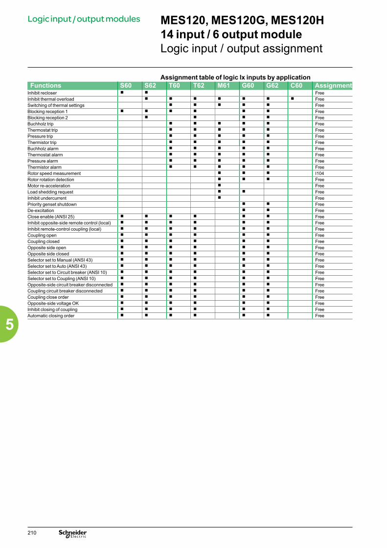
Assignment table of logic Ix inputs by applicationFunctions S60 S62 T60 T62 M61 G60 G62 C60 Assignment
Inhibit recloser b b FreeInhibit thermal overload b b b b b b b FreeSwitching of thermal settings b b b b b FreeBlocking reception 1 b b b b b b FreeBlocking reception 2 b b b b FreeBuchholz trip b b b b b FreeThermostat trip b b b b b FreePressure trip b b b b b FreeThermistor trip b b b b b FreeBuchholz alarm b b b b b FreeThermostat alarm b b b b b FreePressure alarm b b b b b FreeThermistor alarm b b b b b FreeRotor speed measurement b b b I104Rotor rotation detection b b b FreeMotor re-acceleration b FreeLoad shedding request b b FreeInhibit undercurrent b FreePriority genset shutdown b b FreeDe-excitation b b FreeClose enable (ANSI 25) b b b b b b FreeInhibit opposite-side remote control (local) b b b b b b FreeInhibit remote-control coupling (local) b b b b b b FreeCoupling open b b b b b b FreeCoupling closed b b b b b b FreeOpposite side open b b b b b b FreeOpposite side closed b b b b b b FreeSelector set to Manual (ANSI 43) b b b b b b FreeSelector set to Auto (ANSI 43) b b b b b b FreeSelector set to Circuit breaker (ANSI 10) b b b b b b FreeSelector set to Coupling (ANSI 10) b b b b b b FreeOpposite-side circuit breaker disconnected b b b b b b FreeCoupling circuit breaker disconnected b b b b b b FreeCoupling close order b b b b b b FreeOpposite-side voltage OK b b b b b b FreeInhibit closing of coupling b b b b b b FreeAutomatic closing order b b b b b b Free
MES120, MES120G, MES120H 14 input / 6 output moduleLogic input / output assignment
Logic input / output modules
210
5

MES120, MES120G, MES120H 14 input / 6 output moduleLogic input / output assignment
Logic input / output modules
Inputs and outputs may be assigned to predefined control and monitoring functions using the SFT2841 software, according to the uses listed in the table below.The control logic of each input may be inverted for undervoltage type operation.All the logic inputs, whether or not assigned to predefined functions, may be used for the customization functions according to specific application needs:b in the control matrix (SFT2841 software), to connect an input to a logic output, a LED on the front of Sepam or a message for local indication on the displayb in the logic equation editor (SFT2841 software), as logic equation variablesb in Logipam (SFT2885 software) as input variables for the program in ladder language.
Logic Ox output assignment tableFunctions S80 S81 S82 S84 T81 T82
T87M87 M81
M88G87 G82
G88B80 B83 C86 Assignment
Tripping / contactor control b b b b b b b b b b b b b O1Inhibit closing b b b b b b b b b b b b b O2 by defaultClosing b b b b b b b b b b b b b O3 by defaultWatchdog b b b b b b b b b b b b b O5Logic discrimination, blocking send 1 b b b b b b b b b b b b b O102 by defaultLogic discrimination, blocking send 2 b b b b b O103 by defaultGenset shutdown b b FreeDe-excitation b b FreeLoad shedding b b FreeAT, closing of NO circuit breaker b b b b b b b b b b FreeAT, closing of coupling b b b b b b b b b b FreeAT, opening of coupling b b b b b b b b b b FreeTripping of capacitor step (1 to 4) b FreeTripping of capacitor step (1 to 4) b Free
Note: The logic outputs assigned by default may be freely reassigned.
Assignment table for logic Ix inputs common to all applicationsFunctions S80 S81 S82 S84 T81 T82
T87M87 M81
M88G87 G82
G88B80 B83 C86 Assignment
Closed circuit breaker b b b b b b b b b b b b b I101Open circuit breaker b b b b b b b b b b b b b I102Synchronization of Sepam internal clock via external pulse
b b b b b b b b b b b b b I103
Switching of groups of settings A/B b b b b b b b b b b b b b FreeExternal reset b b b b b b b b b b b b b FreeEarthing switch closed b b b b b b b b b b b b b FreeEarthing switch open b b b b b b b b b b b b b FreeExternal trip 1 b b b b b b b b b b b b b FreeExternal trip 2 b b b b b b b b b b b b b FreeExternal trip 3 b b b b b b b b b b b b b FreeEnd of charging position b b b b b b b b b b b b b FreeInhibit remote control (Local) b b b b b b b b b b b b b FreeSF6 pressure default b b b b b b b b b b b b b FreeInhibit closing b b b b b b b b b b b b b FreeOpen order b b b b b b b b b b b b b FreeClose order b b b b b b b b b b b b b FreePhase VT fuse blown b b b b b b b b b b b b b FreeV0 VT fuse blown b b b b b b b b b b b b b FreeExternal positive active energy meter b b b b b b b b b b b b b FreeExternal negative active energy meter b b b b b b b b b b b b b FreeExternal positive reactive energy meter b b b b b b b b b b b b b FreeExternal negative reactive energy meter b b b b b b b b b b b b b FreeRacked out circuit breaker b b b b b b b b b b b b b FreeSwitch A closed b b b b b b b b b b b b b FreeSwitch A open b b b b b b b b b b b b b FreeSwitch B closed b b b b b b b b b b b b b FreeSwitch B open b b b b b b b b b b b b b FreeClosing-coil monitoring b b b b b b b b b b b b b Free
211
5
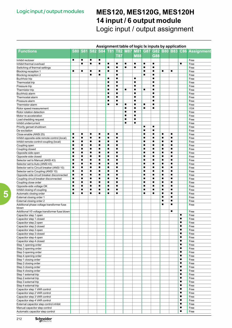
Assignment table of logic Ix inputs by applicationFunctions S80 S81 S82 S84 T81 T82
T87M87 M81
M88G87 G82
G88B80 B83 C86 Assignment
Inhibit recloser b b b b FreeInhibit thermal overload b b b b b b b b b b FreeSwitching of thermal settings b b b b b b FreeBlocking reception 1 b b b b b b b b b b FreeBlocking reception 2 b b b b b FreeBuchholz trip b b b b FreeThermostat trip b b b b FreePressure trip b b b b FreeThermistor trip b b b b b b FreeBuchholz alarm b b b b FreeThermostat alarm b b b b FreePressure alarm b b b b FreeThermistor alarm b b b b b b FreeRotor speed measurement b b b b I104Rotor rotation detection b b FreeMotor re-acceleration b b FreeLoad shedding request b b FreeInhibit undercurrent b b FreePriority genset shutdown b b FreeDe-excitation b b FreeClose enable (ANSI 25) b b b b b b b b b b FreeInhibit opposite-side remote control (local) b b b b b b b b b b FreeInhibit remote-control coupling (local) b b b b b b b b b b FreeCoupling open b b b b b b b b b b FreeCoupling closed b b b b b b b b b b FreeOpposite side open b b b b b b b b b b FreeOpposite side closed b b b b b b b b b b FreeSelector set to Manual (ANSI 43) b b b b b b b b b b FreeSelector set to Auto (ANSI 43) b b b b b b b b b b FreeSelector set to Circuit breaker (ANSI 10) b b b b b b b b b b FreeSelector set to Coupling (ANSI 10) b b b b b b b b b b FreeOpposite-side circuit breaker disconnected b b b b b b b b b b FreeCoupling circuit breaker disconnected b b b b b b b b b b FreeCoupling close order b b b b b b b b b b FreeOpposite-side voltage OK b b b b b b b b b b FreeInhibit closing of coupling b b b b b b b b b b FreeAutomatic closing order b b b b b b b b b b FreeExternal closing order 1 b b FreeExternal closing order 2 b b FreeAdditional phase voltage transformer fuse blown
b b Free
Additional V0 voltage transformer fuse blown b FreeCapacitor step 1 open b FreeCapacitor step 1 closed b FreeCapacitor step 2 open b FreeCapacitor step 2 closed b FreeCapacitor step 3 open b FreeCapacitor step 3 closed b FreeCapacitor step 4 open b FreeCapacitor step 4 closed b FreeStep 1 opening order b FreeStep 2 opening order b FreeStep 3 opening order b FreeStep 4 opening order b FreeStep 1 closing order b FreeStep 2 closing order b FreeStep 3 closing order b FreeStep 4 closing order b FreeStep 1 external trip b FreeStep 2 external trip b FreeStep 3 external trip b FreeStep 4 external trip b FreeCapacitor step 1 VAR control b FreeCapacitor step 2 VAR control b FreeCapacitor step 3 VAR control b FreeCapacitor step 4 VAR control b FreeExternal capacitor step control inhibit b FreeManual capacitor step control b FreeAutomatic capacitor step control b Free
MES120, MES120G, MES120H 14 input / 6 output moduleLogic input / output assignment
Logic input / output modules
212
5
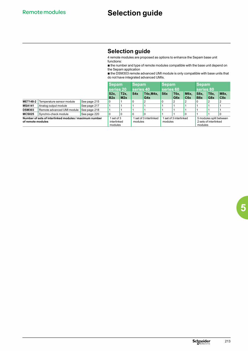
Selection guide
Selection guide4 remote modules are proposed as options to enhance the Sepam base unit functions:b the number and type of remote modules compatible with the base unit depend on the Sepam applicationb the DSM303 remote advanced UMI module is only compatible with base units that do not have integrated advanced UMIs.
Sepam series 20
Sepam series 40
Sepam series 60
Sepam series 80
S2x,B2x
T2x,M2x
S4x T4x,M4x, G4x
S6x T6x,G6x
M6x,C6x
S8x,B8x
T8x,G8x
M8x,C8x
MET148-2 Temperature sensor module See page 215 0 1 0 2 0 2 2 0 2 2MSA141 Analog output module See page 217 1 1 1 1 1 1 1 1 1 1DSM303 Remote advanced UMI module See page 218 1 1 1 1 1 1 1 1 1 1MCS025 Synchro-check module See page 220 0 0 0 0 1 1 0 1 1 0Number of sets of interlinked modules / maximum number of remote modules
1 set of 3 interlinked modules
1 set of 3 interlinked modules
1 set of 3 interlinked modules
5 modules split between 2 sets of interlinked modules
Remote modules
213
5

ConnectionRemote modules
CAUTION Connection Connection cordsDifferent combinations of modules may be connected using cords fitted with 2 black RJ45 connectors, which come in 3 lengths:b CCA770: length = 0.6 m (2 ft)b CCA772: length = 2 m (6.6 ft)b CCA774: length = 4 m (13.1 ft).The modules are linked by cords which provide the power supply and act as functional links with the Sepam unit (connector D to connector Da , Dd to Da , …).
HAZARD OF NON-OPERATIONThe MCS025 module must ALWAYS be connected with the special CCA785 cord, supplied with the module and equipped with an orange RJ45 plug and a black RJ45 plug.Failure to follow this instruction can cause equipment damage.
Rules on inter-module linkingb linking of 3 modules maximumb DSM303 and MCS025 modules may only be connected at the end of the link.
Maximum advisable configurations Sepam series 20, Sepam series 40: just 1 set of interlinked modules
Base Cord Module 1 Cord Module 2 Cord Module 3
DE
8820
3
Series 20 CCA772 MSA141 CCA770 MET148-2 CCA774 DSM303Series 40 CCA772 MSA141 CCA770 MET148-2 CCA774 DSM303Series 40 CCA772 MSA141 CCA770 MET148-2 CCA772 MET148-2Series 40 CCA772 MET148-2 CCA770 MET148-2 CCA774 DSM303
Sepam series 60: just 1 set of interlinked modulesBase Cord Module 1 Cord Module 2 Cord Module 3
DE
6067
4
Series 60 CCA772 MSA141 CCA770 MET148-2 CCA774 DSM303Series 60 CCA772 MSA141 CCA770 MET148-2 CCA785 (1) MCS025Series 60 CCA772 MSA141 CCA770 MET148-2 CCA772 MET148-2Series 60 CCA772 MET148-2 CCA770 MET148-2 CCA774 DSM303Series 60 CCA772 MET148-2 CCA770 MET148-2 CCA785 (1) MCS025
Sepam series 80: 2 sets of interlinked modulesSepam series 80 has 2 connection ports for remote modules, D1 and D2 .Modules may be connected to either port.
Base Cord Module 1 Cord Module 2 Cord Module 3Set 1 D1 CCA772 MET148-2 CCA770 MET148-2 CCA774 DSM303
DE
8820
4
- -
Set 2 D2 CCA772 MSA141 CCA785 (1) MCS025 - -
(1) CCA 785 delivered with MCS025 synchro-check module.
214
5

MET148-2 Temperature sensor module
FunctionThe MET148-2 module can be used to connect 8 temperature sensors (RTDs)of the same type:b Pt100, Ni100 or Ni120 type RTDs, according to parameter settingb 3-wire temperature sensorsb A single module for each Sepam series 20 base unit, to be connected by one of the CCA770 (0.6 or 2 ft), CCA772 (2 m or 6.6 ft) or CCA774 (4 m or 13.1 ft) cordsb 2 modules for each Sepam series 40 or series 80 base unit, to be connected by CCA770 (0.6 or 2 ft), CCA772 (2 m or 6.6 ft) or CCA774 (4 m or 13.1 ft) cordsThe temperature measurement (e.g. in a transformer or motor winding) isutilized by the following protection functions:b Thermal overload (to take ambient temperature into account)b Temperature monitoring.
PE
8806
3
MET148-2 Temperature sensor module.
Characteristics MET148-2 module
Weight 0.2 kg (0.441 lb)Assembly On symmetrical DIN railOperating temperature -25 °C to +70 °C (-13 °F to +158 °F)Environmental characteristics Same characteristics as Sepam base units
Temperature sensors Pt100 Ni100 / Ni120Isolation from earth None NoneCurrent injected in RTD 4 mA 4 mA
DE
8820
5 Description and dimensionsA Terminal block for RTDs 1 to 4.B Terminal block for RTDs 5 to 8.
Da RJ45 connector to connect the module to the base unit with a CCA77x cordDd RJ45 connector to link up the next remote module with a CCA77x cord (according to application).t Grounding/earthing terminal.
1 Jumper for impedance matching with load resistor (Rc), to be set to:b Rc, if the module is not the last interlinked module (default position)b Rc, if the module is the last interlinked module.
2 Jumper used to select module number, to be set to:b MET1: 1st MET148-2 module, to measure temperatures T1 to T8 (default position)b MET2: 2nd MET148-2 module, to measure temperatures T9 to T16(for Sepam series 40, series 60 and series 80 only).(1) 70 mm (2.8 in) with CCA77x cord connected.
5.67
3.46
1.81
mmin
Remote modules
215
5
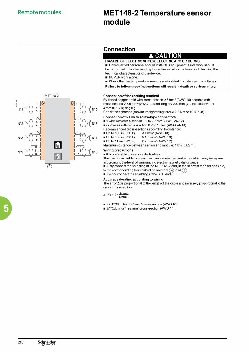
MET148-2 Temperature sensor module
Connection CAUTION
HAZARD OF ELECTRIC SHOCK, ELECTRIC ARC OR BURNSb Only qualified personnel should install this equipment. Such work should be performed only after reading this entire set of instructions and checking the technical characteristics of the device.b NEVER work alone. b Check that the temperature sensors are isolated from dangerous voltages.Failure to follow these instructions will result in death or serious injury.
DE
8820
6
Connection of the earthing terminalBy tinned copper braid with cross-section u 6 mm² (AWG 10) or cable with cross-section u 2.5 mm² (AWG 12) and length y 200 mm (7.9 in), fitted with a 4 mm (0.16 in) ring lug.Check the tightness (maximum tightening torque 2.2 Nm or 19.5 lb-in).Connection of RTDs to screw-type connectorsb 1 wire with cross-section 0.2 to 2.5 mm² (AWG 24-12)b or 2 wires with cross-section 0.2 to 1 mm² (AWG 24-18).Recommended cross-sections according to distance:b Up to 100 m (330 ft) u 1 mm² (AWG 18)b Up to 300 m (990 ft) u 1.5 mm² (AWG 16)b Up to 1 km (0.62 mi) u 2.5 mm² (AWG 12)Maximum distance between sensor and module: 1 km (0.62 mi).Wiring precautionsb It is preferable to use shielded cables.The use of unshielded cables can cause measurement errors which vary in degree according to the level of surrounding electromagnetic disturbanceb Only connect the shielding at the MET148-2 end, in the shortest manner possible, to the corresponding terminals of connectors A and Bb Do not connect the shielding at the RTD end.Accuracy derating according to wiringThe error ∆t is proportional to the length of the cable and inversely proportional to the cable cross-section:
b ±2.1°C/km for 0.93 mm² cross-section (AWG 18)b ±1°C/km for 1.92 mm² cross-section (AWG 14).
( )∆ °C 2 L km( )t 2×S mm
= ----------------------( )
Remote modules
216
5

Function
PE
8074
8
The MSA141 module converts one of the Sepam measurements into an analog signal:b selection of the measurement to be converted by parameter settingb 0-1 mA, 0-10 mA, 4-20 mA, 0-20 mA analog signal according to parameter settingb scaling of the analog signal by setting minimum and maximum values of the converted measurement.Example: the setting used to have phase current 1 as a 0-10 mA analog output with a dynamic range of 0 to 300 A is:v minimum value = 0v maximum value = 3000b a single module for each Sepam base unit, to be connected by one of the CCA770 (0.6m or 2 ft), CCA772 (2m or 6.6 ft) or CCA774 (4m or 13.1 ft) cords.The analog output can also be remotely managed via the communication network.MSA141 analog output module.
CharacteristicsMSA141 module
Weight 0.2 kg (0.441 lb)Assembly On symmetrical DIN railOperating temperature -25 °C to +70 °C (-13 °F to +158 °F)Environmental characteristics Same characteristics as Sepam base units
Analog outputCurrent 0-1 mA, 4-20 mA, 0-20 mA, 0-10 mAScaling(no data input checking)
Minimum valueMaximum value
Load impedance < 600 Ω (including wiring)Accuracy 0.5 %
Measurements available
Unit series 20
series 40
series 60
series 80
Phase and residual currents 0.1 A b b b b
Phase-to-neutral and phase-to-phase voltages
1 V b b b b
Frequency 0.01 Hz b b b b
Thermal capacity used 1 % b b b b
Temperatures 1 °C b b b b
Active power 0.1 kW b b b
Reactive power 0.1 kvar b b b
Apparent power 0.1 kVA b b b
Power factor 0.01 b b
Remote setting via communication link
b b b b
DE
8820
7 Description and dimensionsA Terminal block for analog output.
Da RJ45 socket to connect the module to the base unit with a CCA77x cord.Dd RJ45 socket to link up the next remote module with a CCA77x cord (according to application).t Earthing terminal.
Jumper for impedance matching with load resistor (Rc), to be set to:b Rc, if the module is not the last interlinked module (default position)b Rc, if the module is the last interlinked module.
ConnectionConnection of the earthing terminalBy tinned copper braid with cross-section u 6 mm² (AWG 10) or cable withcross-section u 2.5 mm² (AWG 12) and length y 200 mm (7.9 in), equipped with a 4 mm (0.16 in) ring lug.Check the tightness (maximum tightening torque 2.2 Nm or 19.5 lb-in).Connection of analog output to screw-type connectorb 1 wire with cross-section 0.2 to 2.5 mm² (AWG 24-12)b or 2 wires with cross-section 0.2 to 1 mm² (AWG 24-18).Wiring precautionsb It is preferable to use shielded cablesb Use tinned copper braid to connect the shielding at least at the MSA141 end.
(1) 70 mm (2.8 in) with CCA77x cord connected.
DE
8820
8
3.46
5.671.81
mmin
MSA141 Analog output module
Remote modules
1
217
5
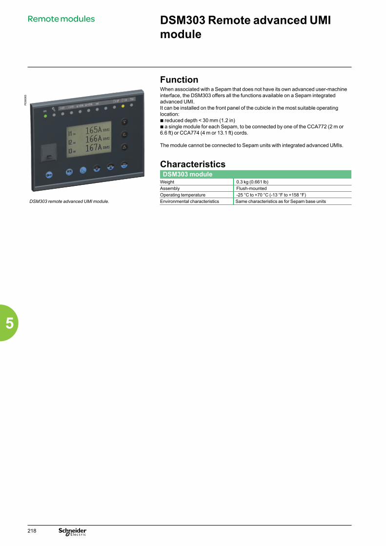
Function
PE
8806
5
When associated with a Sepam that does not have its own advanced user-machine interface, the DSM303 offers all the functions available on a Sepam integrated advanced UMI.It can be installed on the front panel of the cubicle in the most suitable operating location:b reduced depth < 30 mm (1.2 in)b a single module for each Sepam, to be connected by one of the CCA772 (2 m or 6.6 ft) or CCA774 (4 m or 13.1 ft) cords.
The module cannot be connected to Sepam units with integrated advanced UMIs.
CharacteristicsDSM303 module
Weight 0.3 kg (0.661 lb)Assembly Flush-mountedOperating temperature -25 °C to +70 °C (-13 °F to +158 °F)
DSM303 remote advanced UMI module. Environmental characteristics Same characteristics as for Sepam base units
DSM303 Remote advanced UMI module
Remote modules
218
5

Description and dimensionsThe module is simply flush-mounted and secured by its clips. No additional screw-type fastening is required.
Front view Side view
DE
8820
9
DE
8821
0
1 Green LED: Sepam on.2 Red LED:
- steadily on: module unavailable - flashing: Sepam link unavailable.
3 9 yellow LEDs.4 Label identifying the LEDs.5 Graphic LCD screen.6 Display of measurements.7 Display of switchgear, network and machine diagnosis data.8 Display of alarm messages.9 Sepam reset (or confirm data entry).10 Alarm acknowledgment and clearing (or move cursor up).11 LED test (or move cursor down).12 Access to protection settings.13 Access to Sepam parameters.14 Entry of 2 passwords.15 PC connection port.16 Mounting clip.17 Gasket to ensure NEMA 12 tightness
(gasket supplied with the DSM303 module, to be installed if necessary).
Da RJ45 lateral output connector to connect the module to the base unit with a CCA77x cord.
CAUTION Cut-out for flush-mounting (mounting plate thickness < 3 mm or 0.12 in)
HAZARD OF CUTSTrim the edges of the cut-out plates to remove any jagged edges.Failure to follow this instruction can cause serious injury.
DE
8821
1
Connection
DE
8821
2
Da RJ45 socket to connect the module to the base unit with a CCA77x cord.The DSM303 module is always the last interlinked remote module and it systematically ensures impedance matching by load resistor (Rc).
5.99
4.6
mmin
3.78
0.98
0.6
mmin
16 17
5.67
3.8898.5 0,5
mmin
DSM303 Remote advanced UMI module
Remote modules
219
5
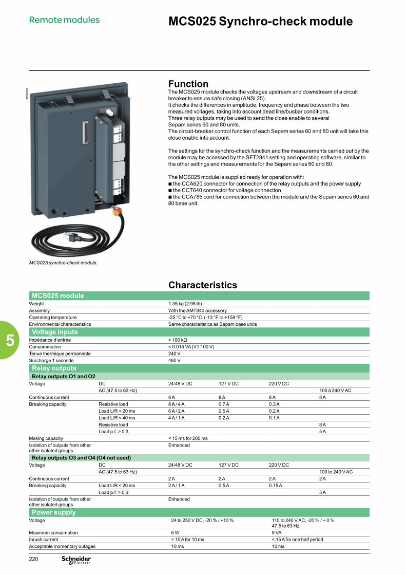
PE
8806
6
FunctionThe MCS025 module checks the voltages upstream and downstream of a circuit breaker to ensure safe closing (ANSI 25). It checks the differences in amplitude, frequency and phase between the two measured voltages, taking into account dead line/busbar conditions. Three relay outputs may be used to send the close enable to several Sepam series 60 and 80 units.The circuit-breaker control function of each Sepam series 60 and 80 unit will take this close enable into account.
The settings for the synchro-check function and the measurements carried out by the module may be accessed by the SFT2841 setting and operating software, similar to the other settings and measurements for the Sepam series 60 and 80.
The MCS025 module is supplied ready for operation with:b the CCA620 connector for connection of the relay outputs and the power supplyb the CCT640 connector for voltage connectionb the CCA785 cord for connection between the module and the Sepam series 60 and 80 base unit.
MCS025 synchro-check module.
Characteristics MCS025 module
Weight 1.35 kg (2.98 lb)Assembly With the AMT840 accessoryOperating temperature -25 °C to +70 °C (-13 °F to +158 °F)Environmental characteristics Same characteristics as Sepam base units
Voltage inputsImpédance d’entrée > 100 kΩConsommation < 0.015 VA (VT 100 V)Tenue thermique permanente 240 VSurcharge 1 seconde 480 V
Relay outputsRelay outputs O1 and O2
Voltage DC 24/48 V DC 127 V DC 220 V DCAC (47.5 to 63 Hz) 100 à 240 V AC
Continuous current 8 A 8 A 8 A 8 ABreaking capacity Resistive load 8 A / 4 A 0.7 A 0.3 A
Load L/R < 20 ms 6 A / 2 A 0.5 A 0.2 ALoad L/R < 40 ms 4 A / 1 A 0.2 A 0.1 AResistive load 8 ALoad p.f. > 0.3 5 A
Making capacity < 15 ms for 200 msIsolation of outputs from other other isolated groups
Enhanced
Relay outputs O3 and O4 (O4 not used)Voltage DC 24/48 V DC 127 V DC 220 V DC
AC (47.5 to 63 Hz) 100 to 240 V ACContinuous current 2 A 2 A 2 A 2 ABreaking capacity Load L/R < 20 ms 2 A / 1 A 0.5 A 0.15 A
Load p.f. > 0.3 5 AIsolation of outputs from other other isolated groups
Enhanced
Power supplyVoltage 24 to 250 V DC, -20 % / +10 % 110 to 240 V AC, -20 % / + 0 %
47.5 to 63 HzMaximum consumption 6 W 9 VAInrush current < 10 A for 10 ms < 15 A for one half periodAcceptable momentary outages 10 ms 10 ms
MCS025 Synchro-check module
Remote modules
220
5

Description1 MCS025 module
A CCA620 20-pin connector for: b auxiliary power supply b 4 relay outputs: v O1, O2, O3: close enable. v O4: not used
B CCT640 connector (phase-to-neutral or phase-to- phase) for the two input voltages to be synchronized
C RJ45 connector, not used
D RJ45 connector for module connection to the Sepam series 80 base unit, either directly or via another remote module.
2 Two mounting clips
3 Two holding pins for the flush-mount position
4 CCA785 connection cord
DE
8821
3
MCS025 Synchro-check moduleRemote modules
221
5

Dimensions
DE
8836
1
DE
8821
4
MCS025.
DE
8810
9
Assembly with AMT840 mounting plateThe MCS025 module should be mounted at the back of the compartment using the AMT840 mounting plate.
DE
8821
6
AMT840 mounting plate.
Connection characteristicsConnector Type Reference Wiring
A Screw-type CCA620 b Wiring with no fittings:v 1 wire with maximum cross-section 0.2 to 2.5 mm² (> AWG 24-
12) or 2 wires with cross-section 0.2 to 1 mm² (>AWG 24-16)v stripped length: 8 to 10 mm (0.31 à 0.39 in)b Wiring with fittings:v recommended wiring with Schneider Electric fittings:- DZ5CE015D for 1 wire 1.5 mm2 (AWG 16)- DZ5CE025D for 1 wire 2.5 mm2 (AWG 12)- AZ5DE010D for 2 x 1 mm² wires (AWG 18)v tube length: 8.2 mm (0.32 in)v stripped length: 8 mm (0.31 in)
B Screw-type CCT640 VT wiring: same as wiring of the CCA620Earthing connection: by 4 mm (0.15 in) ring lug
D
Orange RJ45 connector CCA785, special prefabricated cord supplied with the MCS025 module:b orange RJ45 connector for connection to port D on the
MCS025 moduleb black RJ45 connector for connection to the Sepam series 80
base unit, either directly or via another remote module.
mmin
6.93
8.74
4.84
mmin
MCS025 Synchro-check moduleRemote modules
222
5
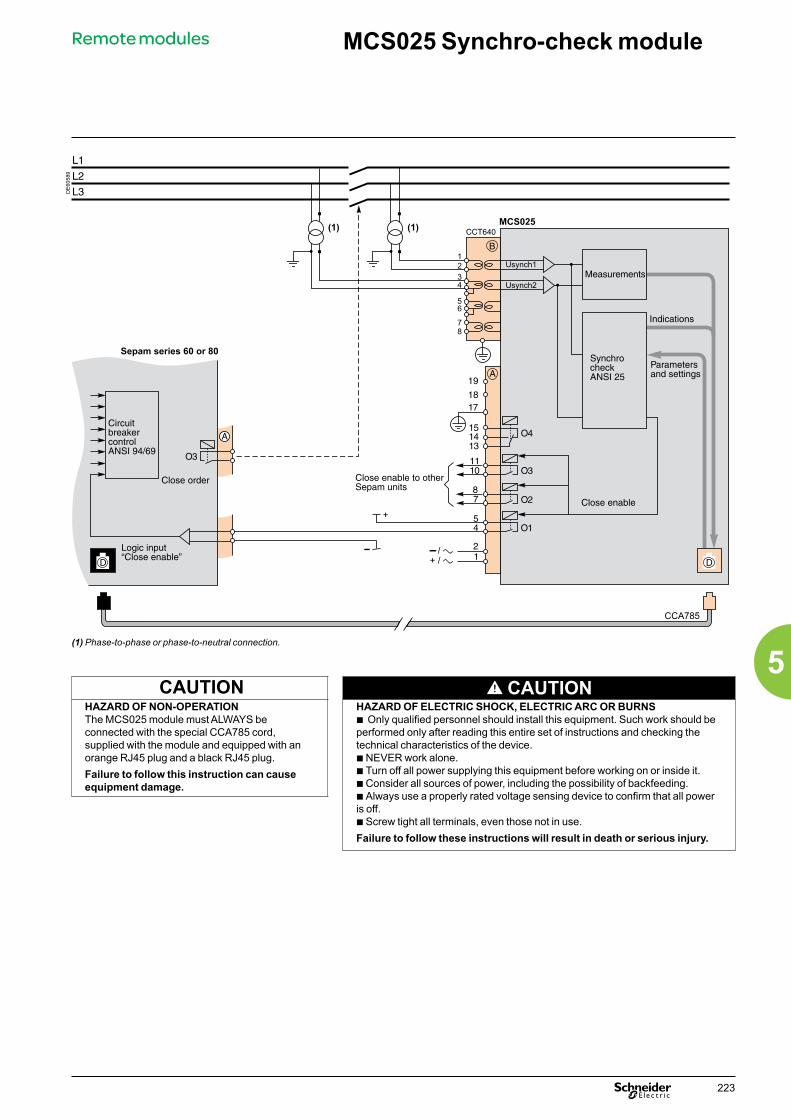
DE
6058
9
(1) Phase-to-phase or phase-to-neutral connection.
CAUTION CAUTIONHAZARD OF NON-OPERATIONThe MCS025 module must ALWAYS be connected with the special CCA785 cord, supplied with the module and equipped with an orange RJ45 plug and a black RJ45 plug.Failure to follow this instruction can cause equipment damage.
HAZARD OF ELECTRIC SHOCK, ELECTRIC ARC OR BURNSb Only qualified personnel should install this equipment. Such work should beperformed only after reading this entire set of instructions and checking thetechnical characteristics of the device.b NEVER work alone.b Turn off all power supplying this equipment before working on or inside it.b Consider all sources of power, including the possibility of backfeeding.b Always use a properly rated voltage sensing device to confirm that all power is off.b Screw tight all terminals, even those not in use.Failure to follow these instructions will result in death or serious injury.
Sepam series 60 or 80
MCS025 Synchro-check moduleRemote modules
223
5

224
5
Other modules Sepam 100 LDPresentation
PE
8806
7
Sepam 100 LD is a high impedance differential relay.It provides restricted earth fault, busbar and machine protection.
Advantagesb stability with respect to external faultsb sensitivity to internal faultsb speed (typical response time: 15 ms to 5 Is)b outputs with or without latchingb local and remote acknowledgmentb high level of immunity to electromagnetic interference.
DescriptionSepam 100 LD is available in 4 versions:b single-phase for restricted earth protectionb three-phase for busbar and machine protectionb 50 or 60 Hz50 Hz single-phase: 100 LD X 51 50 Hz three-phase: 100 LD X 5360 Hz single-phase: 100 LD X 6160 Hz three-phase: 100 LD X 63.The front of Sepam 100 LD includes:b 2 signal lamps:v power “on” indicatorv latching “trip” indicator indicating output relay trippingb protection setting dialb “reset” button for acknowledging output relays and the “trip” indicator. When the button is activated, the “trip” indicator undergoes a lamp test.The back of Sepam 100 LD includes:b input/output connectors:v an 8-pin connector for toroid inputs and remote acknowledgmentv an 8-pin connector for “tripping” outputs and power supplyv a 4-pin connector for “tripping” outputsb a microswitch used to configure the relay “with” or “without” latching.Sepam 100 LD has:b 1 or 3 current inputs with a common point according to whether it is a single-phase or three-phase versionb a logic input (isolated) for remote acknowledgmentb “tripping” output relay with 5 contacts (3 normally open contacts and 2 normally closed contacts).Sepam 100 LD operates in 5 voltage ranges (please specify when ordering):b 24-30 V DCb 48-125 V DCb 220-250 V DC b 100-127 V ACb 220-240 V AC.Sepam 100 LD is associated with a stabilization plate (or 3 plates) with variable resistance, enabling operation with 1 A or 5 A transformers.
Sepam 100 LD.
DE
8821
9
Sepam 100 LD: front panel.
Operation curve Parameter setting
DE
8822
0
0
10
20
30
40
50
60
70
80
90
100
t (ms)
10 2 3 4 5 6 7 8 9 10 l/ls
Microswitch SW1, accessible on the back of Sepam 100 LD, is used to choose “with” or “without” latching.
Without latching:SW1
SW1With latching:
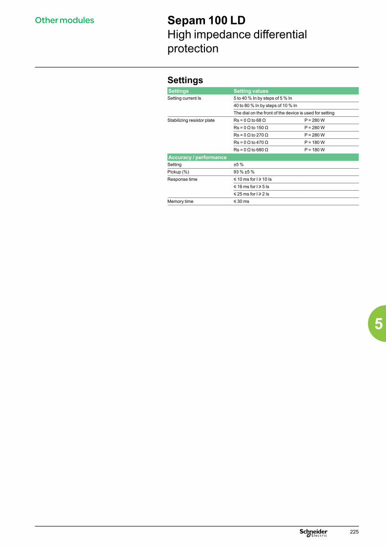
225
5
Other modules Sepam 100 LDHigh impedance differential protection
SettingsSettings Setting valuesSetting current Is 5 to 40 % In by steps of 5 % In
40 to 80 % In by steps of 10 % InThe dial on the front of the device is used for setting
Stabilizing resistor plate Rs = 0 Ω to 68 Ω P = 280 WRs = 0 Ω to 150 Ω P = 280 W Rs = 0 Ω to 270 Ω P = 280 WRs = 0 Ω to 470 Ω P = 180 WRs = 0 Ω to 680 Ω P = 180 W
Accuracy / performanceSetting ±5 %Pickup (%) 93 % ±5 %Response time y 10 ms for I u 10 Is
y 16 ms for I u 5 Isy 25 ms for I u 2 Is
Memory time y 30 ms

226
5
Other modules Sepam 100 LDSensors and surge limiters
DE
6068
0
100 LD
Rf1 Rf2
R1 R2
TC2TC1
RI Rs
Specifying the sensorsCurrent transformersTo ensure the stability and sensitivity of Sepam 100 LD, the stabilization resistor and characteristics of the current transformers (CTs) are calculated as follows.Choice of current transformersb all the CTs must have the same transformation ratio nb the knee-point voltages are chosen so that:Vk > 2 x (R + Rf) x icc
Choice of stabilizing resistor R R f+
is----------------- icc× R s Vk2 is×---------------≤<
Surge limiterThe approximate voltage developed by a CT in the event of an internal fault is:
If the value exceeds 3 kV, it is necessary to add an Rl surge limiter in parallel with the relay and stabilizing resistor in order to protect the CTs (see: surge limiter). Protection sensitivityThe CTs consume magnetizing current and the surge limiter, when installed, creates fault current. The minimum residual primary current detected by the protection is therefore:Id = n x (im1 + …imp + if + is)with b im1, …imp are read on the CT magnetization curves at V = Rs x isb if is the total earth leakage current of the surge limiter for Vs = Rs x is, i.e. the sum of the earth leakage currents of the N limiter units installed in parallel: if = N x ib (see: surge limiter).
Surge limiterIf the calculations have shown that it is necessary to install a surge limiter in parallelwith the relay and Rs to protect the CTs, it is determined as follows.
ChoiceStandard referencesb the surge limiters on offer consist of limiter blocks which are independent of each other. Each block accepts a maximum current of 40 A RMS for 1 s. By installing the blocks in parallel, it is possible to obtain the appropriate limiter for the application.b there are two standard references:v a single module, comprising one blockv a triple module, comprising three independent blocks which are aligned.Calculation of the number of blocks per phaseAccording to i, max. RMS short-circuit current in the secondary winding of a CT, the number of blocks required per phase is calculated:
b for a three-phase relay, N triple modules should be orderedb for a single-phase relay, N blocks, made up of triple and single modules.
Earth leakage currentA limiter block accepts a max. steady state voltage of 325 V RMS and presents an earth fault current lb:
n:p:Rf1, Rf2:
R1, …Rp:
Rs:Rl:icc:
is:if:im1, imp:Vk1, Vkp:
CT transformation ratioNumber of CTsWiring resistance on either side of RsRf = max (Rf1, Rf2)
CT secondary resistancesR = max (R1, …Rp)Stabilizing resistor Surge limiterMaximum external short-circuitcurrent in CT secondary windingProtection setting (A)Current in RlCT magnetizing currentsCT knee-point voltagesVk = min (Vk1,…Vkp)
DE
8822
3
0.001 0.01Ib (A RMS)
0.1100
U (V ms)
1000

227
5
Other modules Sepam 100 LDDescription and connection
Rear panel Functional and connection diagram
DE
8822
4
1
2
3
4
5
6
7
8
1
2
3
4
1
2
3
4
5
6
7
8
A
B
AAS LD
1 0
SW1
1~3~ D
E88
363
4
5
7
8
6
4
3
21
3
5
8
7
4
2
1
3
6
F0
80 %5 %
S1
2
1
&
R
on
trip
1
+-
SW1
F0
F0
0A
1A
1A
1B
phase 1
phase 2
phase 3
remotereset
auxiliarypowersupply
PB reset
without withlatching
trippingoutput
outputsannunciation
Note: only 0A1 and 0A2 terminals are available in the single-phase version.
0A : 8-pin CCA608 connector (toroid and remote reloading inputs); screw terminal wiring with 0.6 to 2.5 mm² wires, each terminal being capable of receiving two 1.5 mm² wires.1A : 8-pin CCA608 connector (power supply and “annunciation and tripping” outputs); screw terminal wiring with 0.6 to 2.5 mm² wires, each terminal being capable of receiving two 1.5 mm² wires.1B : CCA604 connector (“annunciation” outputs); screw terminal wiring with 0.6 to 2.5 mm² wires, each terminal being capable of receiving two 1.5 mm² wires.
Terminal identificationEach terminal is identified by 3 characters.
DE
8836
4
1 A 4
Board slot number (0 to 1)
Connector terminal number
Connector identificationletter (A or B)
: ground terminal
DE
8836
5
Connection of the stabilization plateConnection of CTs and surge limiters:b 5 A rating: between terminals 1-2 and 3-4b 1 A rating: between terminals 1-2 and 5-6b items 1 to 6: clamp screw connections for 6 mm2 wireb items 1, 2: secondary of CSH30 core balance CT, connected to 0A .Wire to be used:b sheathed, shielded wireb min. cross-section 0.93 mm2 (AWG 18) (max. 2.5 mm²)b resistance load per unit length < 100 mΩ/mb min. dielectric strength: 1000 Vb max. length: 2 m.
Connect the wire shielding in the shortest way possible to 0A .The shielding is grounded in Sepam 100 LD. Do not ground the wire by any other means.Press the wire against the metal frame of the cubicle to improve immunity to radiated interference.
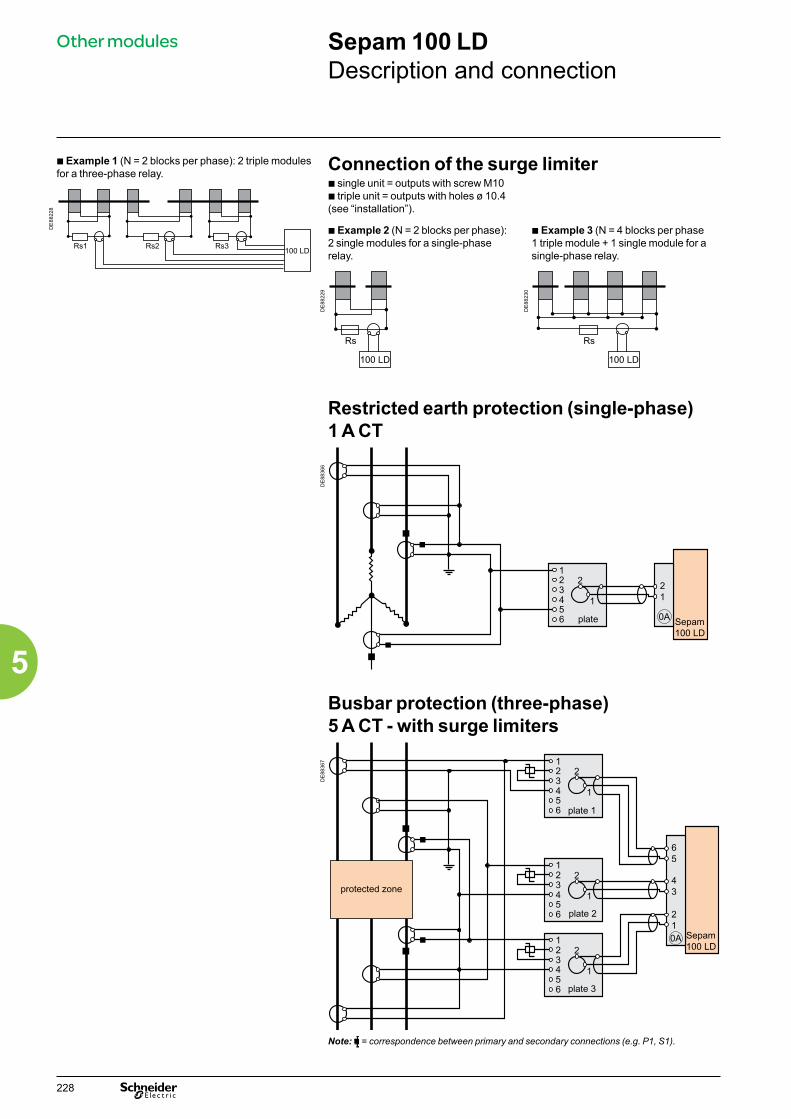
228
5
Other modules Sepam 100 LDDescription and connection
b Example 1 (N = 2 blocks per phase): 2 triple modules for a three-phase relay. Connection of the surge limiter
b single unit = outputs with screw M10b triple unit = outputs with holes ø 10.4 (see “installation”).
DE
8822
8
Rs1 Rs2 Rs3100 LD
b Example 2 (N = 2 blocks per phase): 2 single modules for a single-phase relay.
b Example 3 (N = 4 blocks per phase 1 triple module + 1 single module for a single-phase relay.
DE
8822
9
Rs
100 LD
DE
8823
0
Rs
100 LD
Restricted earth protection (single-phase) 1 A CT
DE
8836
6
Sepam100 LD
123456
2
1
21
0Aplate
Busbar protection (three-phase) 5 A CT - with surge limiters
DE
8836
7
Sepam100 LD
123456
0A
2
1
43
123456
2
1
123456
2
1
21
65
protected zone
plate 1
plate 2
plate 3
Note: = correspondence between primary and secondary connections (e.g. P1, S1).

229
5
Other modules Sepam 100 LDCharacteristics and dimensions
Electrical characteristicsAnalog inputs (with plate)Constant current 10 In3 sec. current 500 InLogic input (remote reloading input) Voltage 24/250 V DC 127/240 V ACMaximum power consumption 3.5 W 3.7 VALogic outputsConstant current 8 AVoltage 24/30 V DC 48 V DC 127 V DC/V AC 220 V DC/V ACBreaking capacity (contact 01)
Resistive dc load 7 A 4 A 0.7 A 0.3 AResistive ac load 8 A 8 A
Breaking capacity (contacts 02 to 05)
Resistive dc load 3.4 A 2 A 0.3 A 0.15 AResistive ac load 4 A 4 A
Power supplyRange Consumption when inactive Max. consumption Inrush current
24/30 V DC ±20 % 2.5 W 6 W < 10 A for 10 ms48/125 V DC ±20 % 3 W 6 W < 10 A for 10 ms220/250 V DC -20 % +10 % 4 W 8 W < 10 A for 10 ms100/127 V AC -20 % +10 % 6 VA 10 VA < 15 A for 10 ms220/240 V AC -20 % +10 % 12 VA 16 VA < 15 A for 10 msOperating frequency 47.5 à 63 Hz
Environmental characteristicsClimaticOperation IEC 60068-2 -5 °C to 55 °CStorage IEC 60068-2 -25 °C to 70 °CDamp heat IEC 60068-2 95 % to 40 °CInfluence of corrosion IEC 60654-4 Class IMechanicalDegree of protection IEC 60529 IP 41 On frontVibrations IEC 60255-21-1 Class IShocks and bumps IEC 60255-21-2 Class IEarthquakes IEC 60255-21-3 Class IFire IEC 60695-2-1 Glow wireElectrical insulationPower frequency IEC 60255-5 2 kV - 1 mn1.2/ 50 µs impulse wave IEC 60255-5 5 kVElectromagnetic compatibilityImmunity to radiation IEC 60255-22-3 Class X 30 V/mElectrostatic sicharges IEC 60255-22-2 Class IIISingle-direction transients IEC 61000-4-5 Damped 1 MHz wave IEC 60255-22-1 Class III5 ns fast transients IEC 60255-22-4 Class IVNote: “e” marking on our product guarantees their conformity to European directives.
DimensionsRelay Cutout Platine de stabilisation
DE
8836
8
3.39 max.
DE
8836
9
Weight: 1.9 kg Weight: 1.7 kg
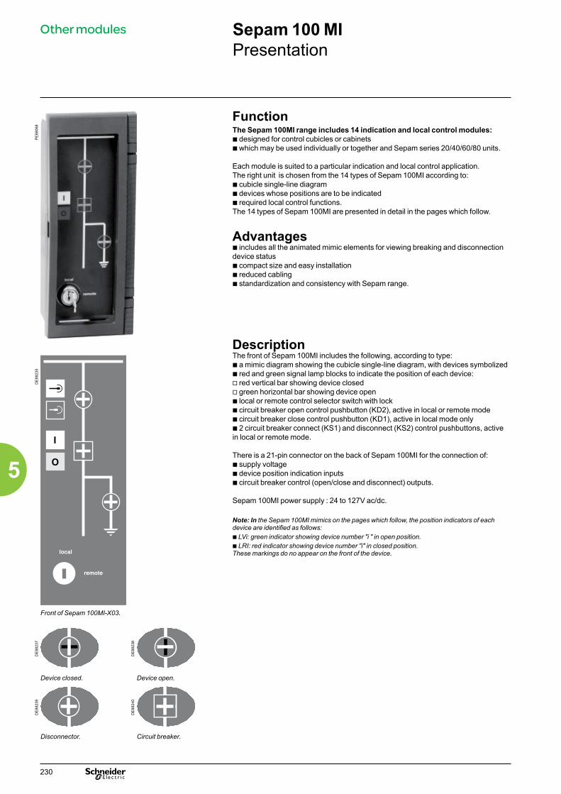
230
5
Other modules Sepam 100 MIPresentation
PE
8806
8
FunctionThe Sepam 100MI range includes 14 indication and local control modules:b designed for control cubicles or cabinetsb which may be used individually or together and Sepam series 20/40/60/80 units.
Each module is suited to a particular indication and local control application.The right unit is chosen from the 14 types of Sepam 100MI according to:b cubicle single-line diagramb devices whose positions are to be indicatedb required local control functions.The 14 types of Sepam 100MI are presented in detail in the pages which follow.
Advantagesb includes all the animated mimic elements for viewing breaking and disconnection device statusb compact size and easy installationb reduced cablingb standardization and consistency with Sepam range.
DescriptionThe front of Sepam 100MI includes the following, according to type:b a mimic diagram showing the cubicle single-line diagram, with devices symbolized b red and green signal lamp blocks to indicate the position of each device: v red vertical bar showing device closedv green horizontal bar showing device openb local or remote control selector switch with lockb circuit breaker open control pushbutton (KD2), active in local or remote modeb circuit breaker close control pushbutton (KD1), active in local mode onlyb 2 circuit breaker connect (KS1) and disconnect (KS2) control pushbuttons, active in local or remote mode.
There is a 21-pin connector on the back of Sepam 100MI for the connection of:b supply voltage b device position indication inputsb circuit breaker control (open/close and disconnect) outputs.
Sepam 100MI power supply : 24 to 127V ac/dc.
Note: In the Sepam 100MI mimics on the pages which follow, the position indicators of each device are identified as follows:b LVi: green indicator showing device number "i " in open position.b LRI: red indicator showing device number "i" in closed position.These markings do no appear on the front of the device.
DE
8823
5
Front of Sepam 100MI-X03.
DE
8823
7
DE
8823
8
Device closed. Device open.
DE
8823
9
DE
8824
0
Disconnector. Circuit breaker.

231
5
Other modules Sepam 100 MIBlock and connection diagrams
Sepam 100MI-X00 and Sepam 100MI-X17Sepam 100MI-X00 mimic diagram
Sepam 100MI-X17 mimic diagram
Connection
DE
8824
1
DE
8824
2
DE
8837
0
Sepam 100MI-X01 and Sepam 100MI-X13Sepam 100MI-X01 mimic diagram
Sepam 100MI-X13 mimic diagram
Connection
DE
8824
5
DE
8824
6
DE
8837
1
Sepam 100MI-X02Sepam 100MI-X02 mimic diagram Connection
DE
8824
7
DE
8837
2

232
5
Other modules Sepam 100 MIBlock and connection diagrams
Sepam 100MI-X16 and Sepam 100MI-X18Sepam 100MI-X16 mimic diagram
Sepam 100MI-X18 mimic diagram
Connection
DE
8824
9
DE
8825
0
DE
8837
3
Sepam 100MI-X03Sepam 100MI-X03 mimic diagram Connection
DE
6059
3
DE
8837
4
Sepam 100MI-X22Sepam 100MI-X22 mimic diagram Connection
DE
6059
4
DE
8837
5
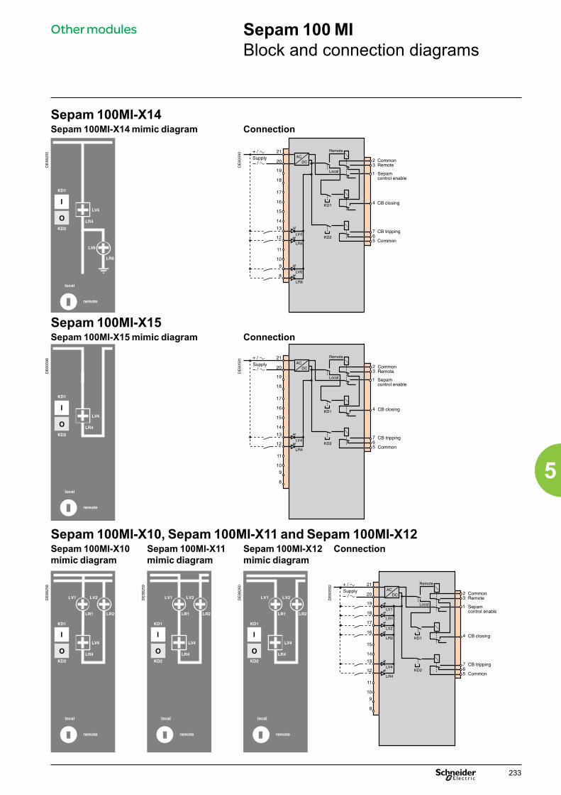
233
5
Other modules Sepam 100 MIBlock and connection diagrams
Sepam 100MI-X14Sepam 100MI-X14 mimic diagram Connection
DE
8825
5
DE
6059
0
Sepam 100MI-X15Sepam 100MI-X15 mimic diagram Connection
DE
6059
6
DE
6059
1
Sepam 100MI-X10, Sepam 100MI-X11 and Sepam 100MI-X12Sepam 100MI-X10 mimic diagram
Sepam 100MI-X11 mimic diagram
Sepam 100MI-X12 mimic diagram
Connection
DE
8825
8
DE
8825
9
DE
8826
0
DE
6059
2

Other modules Sepam 100 MIConnection
234
5
Sepam 100MI-X23 Sepam 100MI-X25Sepam 100MI-X23 mimic diagram
Connection Sepam 100MI-X25 mimic diagram
Connection
DE
6059
7
DE
6060
1
DE
6060
0
DE
6060
4
Sepam 100MI-X26 Sepam 100MI-X27Sepam 100MI-X26 mimic diagram
Connection Sepam 100MI-X27 mimic diagram
Connection
DE
6059
9
DE
6060
3
DE
6059
8
DE
6060
2

235
5
Other modules Sepam 100 MICharacteristics and dimensions
Electrical characteristicsLogic inputsVoltage 24/30 V 48/127 VMax. consumption per input 35 mA 34 mALogic outputs (relays)Voltage 24/30 V 48/127 VPermissible rated current 8 ABreaking capacity DC resistive load 4 A 0,3 A
AC resistive load 8 A 8 ANumber of on-load operations 10000 10000Power supplyAuxiliary power sourceDC or AC current(50 or 60 Hz)
24 to 30 V, -20 % +10 %48 to 127 V, -20 % +10 %
Consumption 24 to 30 V: 7.7 VA max. (at 33 V)48 V: 4 VA110 V: 18 VA
Environmental characteristicsClimaticOperation IEC 60068-2 -10 °C to +70 °CStorage IEC 60068-2 -25 °C to +70 °CDamp heat IEC 60068-2 95 % to 40 °CMechanicalDegree of protection IEC 60529 IP51 Front plateVibrations IEC 60255-21-1 Class IShocks IEC 60255-21-2 Class ISeismic tests IEC 60255-21-3 Class IFire NFC 20455 Glow wire 650 °CDielectricPower frequency IEC 60255-4 (1) 2 kV - 1 mn1.2/50 µs impulse wave IEC 60255-4 (1) 5 kVElectromagneticRadiation IEC 60255-22-3 Class X 30 V/mElectrostatic discharge IEC 60255-22-2 Class IIIDamped 1 MHz wave IEC 60255-22-1 Class III5 ns fast transients IEC 60255-22-4 Class IV(1) Published in 1978 and amended in 1979.The "e" marking on our products guarantees their conformity to European directives.
DimensionsCut out
DE
8837
9
DE
8838
1
Mounting close-up
DE
8838
0
DE
8838
2
Weight: 0.850 kg.

Selection guideCommunication accessories
There are 2 types of Sepam communication accessories:b communication interfaces, which are essential for connecting Sepam to the communication networkb converters and oth er accessories, as options, which are used for complete implementation of the communication network.
Communication-interface selection guideACE949-2 ACE959 ACE937 ACE969TP-2 ACE969FO-2 ACE850TP ACE850FO
Type of networkS-LAN or E-LAN (1)
S-LAN or E-LAN (1)
S-LAN or E-LAN (1)
S-LAN E-LAN S-LAN E-LAN S-LAN and E-LAN
S-LAN and E-LAN
ProtocolModbus RTU b b b b (3) b b (3) b
DNP3 b (3) b (3)
IEC 60870-5-103 b (3) b (3)
Modbus TCP/IP b b
IEC 61850 b b
Physical interfaceRS 485 2-wire b b b b
4-wire b
Fiber optic ST Star b b
Ring b (2)
10/100 base Tx 2 ports b100 base Fx 2 ports b
Power supplyDC Provided by
SepamProvided by Sepam
Provided by Sepam
24 to 250 V 24 to 250 V 24 to 250 V 24 to 250 VAC 110 to 240 V 110 to 240 V 110 to 240 V 110 to 240 VSee details Catalogue
page 239Catalogue page 240
Catalogue page 241
Catalogue page 242
Catalogue page 242
Cataloguepage 247
Cataloguepage 247
(1) Only one connection possible, S-LAN or E-LAN. (2) Except with the Modbus protocol.(3) Not simultaneously (1 protocol per application).
Converter selection guideACE909-2 ACE919CA ACE919CC EGX100 EGX300 ECI850
ConverterPhysical interface 1 port RS 232 1 port
RS 485 port 2-wire1 port RS 485 port 2-wire
1 Ethernet port 10/100 base T
1 Ethernet port 10/100 base T
1 Ethernet port10/100 base T
Modbus RTU b (1) b (1) b (1)
IEC 60870-5-103 b (1) b (1) b (1)
DNP3 b (1) b (1) b (1)
Modbus TCP/IP b b
IEC 61850 b
To SepamPhysical interface 1 port
RS 485 2-wire1 port RS 485 2-wire
1 port RS 485 2-wire
1 port RS 485 2-wire or 4-wire
1 port RS 485 2-wire or 4-wire
1 port RS 485 2-wire or 4-wire
Distributed power supply RS 485
b b b
Modbus RTU b (1) b (1) b (1) b b b
IEC 60870-5-103 b (1) b (1) b (1)
DNP3 b (1) b (1) b (1)
Alimentation DC 24 to 48 V 24 V 24 V 24 VAC 110 to 220 V AC 110 to 220 V AC
See details Catalogue page 251
Catalogue page 253
Catalogue page 253
Catalogue page 259
Catalogue page 260
Catalogue page 255
(1) The supervisor protocol is the same as the Sepam protocol.Note: all these interfaces accept the E-LAN protocol.
236
5

Communication interface connection
Communication interfacesD
E88
266
CCA612 connection cordFunction The CCA612 prefabricated cord is used to connect ACE942-2, ACE959, ACE937, ACE969TP-2 and ACE969FO-2 communication interfaces:b to the white communication port on a Sepam series 20 or series 40 base unit, orb to the white communication port on a Speam series 60 base unit.b to the white communication port or on a Sepam series 80 base unit.
Characteristics b Length = 3 m (9.8 ft)b Fitted with 2 white RJ45 plugs.
Sepam series 20 and Sepam series 40: 1 communication port.
DE
8826
7
Sepam series 80 : 2 communication ports.
CAUTION CCA614 connection cordFunctionThe CCA614 prefabricated cord can be used to connect ACE850TP and ACE850FO communication interfaces:b to the white communication port on a Sepam series 40 base unit, orb to the blue communication port on a Sepam series 60 or series 80 base unit.Characteristicsb Length = 3 m (9.8 ft)b Fitted with 2 blue RJ45 connectorsb Minimum curvature radius = 50 mm (1.97 in)
HAZARD OF DEFECTIVE COMMUNICATIONb Never use both communication ports and on a Sepam series 80 at the same time.b The only communication ports that can be used simultaneously on a Sepam series 80 unit areports and or ports and .Failure to follow this instruction can result in equipment damage.
DE
8043
9
DE
8044
0
Sepam series 40 Sepam series 80
ACE850
CCA614
C
F
ACE850
ACE937
CCA614
CCA612
CF
C2
C1
F
C2 C1 F
C
C1 C2C1
237
5

Connection to the communication networkRS485 network for ACE949-2, ACE959 and ACE969TP-2 interfacesRS 485 network cable 2-wire 2-wire
RS 485 medium 1 shielded twisted pair 2 shielded twisted pairsDistributed power supply (1) 1 shielded twisted pair 1 shielded twisted pairShielding Tinned copper braid, coverage > 65 %Characteristic impedance 120 ΩGauge AWG 24Resistance per unit length < 100 Ω/km (62.1Ω/mi) Capacitance between conductors < 60 pF/m (18.3 pF/ft)Capacitance between conductor and shielding
< 100 pF/m (30.5 pF/ft)
Maximum length 1300 m (4270 ft)
Fiber-optic network for ACE937 and ACE969FO-2 interfacesFiber optic
Fiber type Graded-index multimode silicaWavelength 820 nm (invisible infra-red)Type of connector ST (BFOC bayonet fiber optic connector)Fiber optic diameter (µm)
Numerical aperture (NA)
Maximum attenuation (dBm/km)
Minimum optical power available (dBm)
Maximum fiber length
50/125 0,2 2,7 5,6 700 m (2300 ft)62,5/125 0,275 3,2 9,4 1800 m (5900 ft)100/140 0,3 4 14,9 2800 m (9200 ft)200 (HCS) 0,37 6 19,2 2600 m (8500 ft)
Fiber optic Ethernet network for the ACE850FO communication interfaceFiber optic communication port
Fiber type MultimodeWavelength 1300 nmType of connector SC
Fiber optic diameter (µm)
Minimum optical power TX (dBm)
Maximum optical power TX (dBm)
Sensitivity RX (dBm)
Saturation RX (dBm)
Maximum distance
50/125 -22,5 -14 -33,9 -14 2 km (1,24 mi)62,5/125 -19 -14 -33,9 -14 2 km (1,24 mi)
Wired Ethernet network for the ACE850TP communication interfaceWired communication portType of connector Data Medium Maximum distance
RJ45 10/100 Mbps Cat 5 STP or FTP or SFTP
100 m (328 ft)
Communication interface connection
Communication interfaces
238
5

ACE949-2 2-wire RS 485 network interface
Communication interfaces
Function
PE
8806
9
The ACE949-2 interface performs 2 functions:b Electrical interface between Sepam and a 2-wire RS 485 communication networkb Main network cable branching box for the connection of a Sepam with a CCA612 cord.
CharacteristicsACE949-2 module
Weight 0.1 kg (0.22 lb)ACE949-2 2-wire RS 485 network connection interface. Assembly On symmetrical DIN rail
Operating temperature -25°C to +70°C (-13°F to +158°F)Environmental characteristics Same characteristics as Sepam base units
2-wire RS 485 electrical interfaceStandard EIA 2-wire RS 485 differentialDistributed power supply External, 12 V DC or 24 V DC ±10%Power consumption 16 mA in receiving mode
40 mA maximum in sending mode
Maximum length of 2-wire RS 485 network with standard cable
DE
8826
8
Number of Sepam units
Maximum length with 12 V DC power supply
Maximum length with 24 V DC power supply
5 320 m (1000 ft) 1000 m (3300 ft)10 180 m (590 ft) 750 m (2500 ft)20 160 m (520 ft) 450 m (1500 ft)25 125 m (410 ft) 375 m (1200 ft)
Description and dimensionsA and B Terminal blocks for network cable C RJ45 socket to connect the interface to the base unit with a CCA612 cordt Grounding/earthing terminal
1 Link activity LED, flashes when communication is active (sending or receiving in progress).
2 Jumper for RS 485 network line-end impedance matching with load resistor (Rc = 150 Ω ), to be set to:b Rc, if the module is not at one end of the network (default position)b Rc, if the module is at one end of the network.
3 Network cable clamps (inner diameter of clamp = 6 mm or 0.24 in).
(1) 70 mm (2.8 in) with CCA612 cord connected.
DB
8838
3
Connectionb Connection of network cable to screw-type terminal blocks A and B b Connection of the earthing terminal by tinned copper braid with cross-section u 6 mm² (AWG 10) or cable with cross-section u 2.5 mm² (AWG 12) and length y 200 mm (7.9 in), fitted with a 4 mm (0.16 in) ring lug. Check the tightness (maximum tightening torque 2.2 Nm or 19.5 lb-in).b The interfaces are fitted with clamps to hold the network cable and recover shielding at the incoming and outgoing points of the network cable: v the network cable must be strippedv the cable shielding braid must be around and in contact with the clampb The interface is to be connected to connector C on the base unit using a CCA612 cord (length = 3 m or 9.8 ft, green fittings)b The interfaces are to be supplied with 12 V DC or 24 V DC.
1.81
2.83
3.46
mmin
DC
DC
2-wire
2-wire
networks
networks
Power supply
Power supply
or
or
239
5
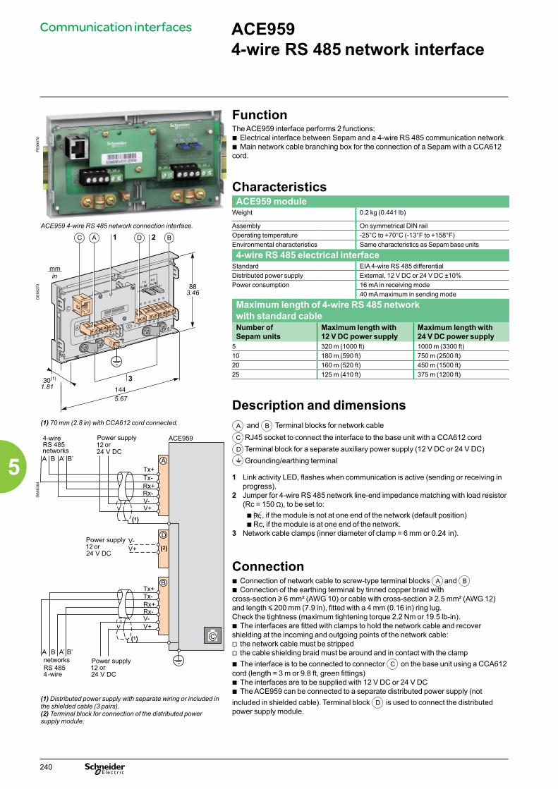
ACE959 4-wire RS 485 network interface
Communication interfaces
Function
PE
8807
0
The ACE959 interface performs 2 functions:b Electrical interface between Sepam and a 4-wire RS 485 communication networkb Main network cable branching box for the connection of a Sepam with a CCA612 cord.
CharacteristicsACE959 module
Weight 0.2 kg (0.441 lb)
ACE959 4-wire RS 485 network connection interface. Assembly On symmetrical DIN railOperating temperature -25°C to +70°C (-13°F to +158°F)Environmental characteristics Same characteristics as Sepam base units
4-wire RS 485 electrical interfaceStandard EIA 4-wire RS 485 differential
DE
8827
0
Distributed power supply External, 12 V DC or 24 V DC ±10%Power consumption 16 mA in receiving mode
40 mA maximum in sending mode
Maximum length of 4-wire RS 485 network with standard cableNumber of Sepam units
Maximum length with 12 V DC power supply
Maximum length with 24 V DC power supply
5 320 m (1000 ft) 1000 m (3300 ft)10 180 m (590 ft) 750 m (2500 ft)20 160 m (520 ft) 450 m (1500 ft)25 125 m (410 ft) 375 m (1200 ft)
Description and dimensions(1) 70 mm (2.8 in) with CCA612 cord connected. A and B Terminal blocks for network cable
C RJ45 socket to connect the interface to the base unit with a CCA612 cordD Terminal block for a separate auxiliary power supply (12 V DC or 24 V DC)t Grounding/earthing terminal
1 Link activity LED, flashes when communication is active (sending or receiving in progress).
2 Jumper for 4-wire RS 485 network line-end impedance matching with load resistor (Rc = 150 Ω), to be set to:b Rc, if the module is not at one end of the network (default position)b Rc, if the module is at one end of the network.
3 Network cable clamps (inner diameter of clamp = 6 mm or 0.24 in).
DB
8838
4
Connectionb Connection of network cable to screw-type terminal blocks A and B b Connection of the earthing terminal by tinned copper braid with cross-section u 6 mm² (AWG 10) or cable with cross-section u 2.5 mm² (AWG 12) and length y 200 mm (7.9 in), fitted with a 4 mm (0.16 in) ring lug. Check the tightness (maximum tightening torque 2.2 Nm or 19.5 lb-in).b The interfaces are fitted with clamps to hold the network cable and recover shielding at the incoming and outgoing points of the network cable: v the network cable must be strippedv the cable shielding braid must be around and in contact with the clampb The interface is to be connected to connector C on the base unit using a CCA612 cord (length = 3 m or 9.8 ft, green fittings)b The interfaces are to be supplied with 12 V DC or 24 V DCb The ACE959 can be connected to a separate distributed power supply (not included in shielded cable). Terminal block D is used to connect the distributed power supply module.
(1) Distributed power supply with separate wiring or included in the shielded cable (3 pairs).(2) Terminal block for connection of the distributed power supply module.
1.81
5.67
3.46
mmin
DC
DC
DC
-wire
-wire
networks
networks
Power supplyor
Power supplyor
Power supplyor
240
5

ACE937 Fiber optic interface
Communication interfaces
Function
PE
8807
1
The ACE937 interface is used to connect Sepam to a fiber optic communication star system.This remote module is connected to the Sepam base unit by a CCA612 cord.
CharacteristicsACE937 module
Weight 0.1 kg (0.22 lb)Assembly On symmetrical DIN railPower supply Supplied by SepamOperating temperature -25°C to +70°C (-13°F to +158°F)
ACE937 fiber optic connection interface. Environmental characteristics Same characteristics as Sepam base units
Fiber optic interfaceFiber type Graded-index multimode silicaWavelength 820 nm (invisible infra-red)Type of connector ST (BFOC bayonet fiber optic connector)
CAUTION Fiber optic diameter (µm)
Numerical aperture (NA)
Maximum attenuation (dBm/km)
Minimum optical power available (dBm)
Maximum fiber length
HAZARD OF BLINDINGNever look directly into the end of the fiber optic.Failure to follow this instruction can cause serious injury.
50/125 0.2 2.7 5.6 700 m (2300 ft)62.5/125 0.275 3.2 9.4 1800 m (5900 ft)100/140 0.3 4 14.9 2800 m (9200 ft)200 (HCS) 0.37 6 19.2 2600 m (8500 ft)
Maximum length calculated with:b Minimum optical power availableb Maximum fiber attenuationb Losses in 2 ST connectors: 0.6 dBmb Optical power margin: 3 dBm (according to IEC 60870 standard).Example for a 62.5/125 µm fiberLmax = (9.4 - 3 - 0.6)/3.2 = 1.8 km (1.12 mi)
Description and dimensions
DE
8827
2
C RJ45 socket to connect the interface to the base unit with a CCA612 cord.
1 Link activity LED, flashes when communication is active (sending or receiving in progress).
2 Rx, female ST type connector (Sepam receiving).3 Tx, female ST type connector (Sepam sending).
(1) 70 mm (2.8 in) with CCA612 cord connected.
DE
8827
3
Connectionb The sending and receiving fiber optic fibers must be equipped with male ST type connectorsb Fiber optics screw-locked to Rx and Tx connectors.The interface is to be connected to connector C on the base unit using a CCA612 cord (length = 3 m or 9.8 ft, green fittings).
1.81
mmin
3.46
2.83
241
5
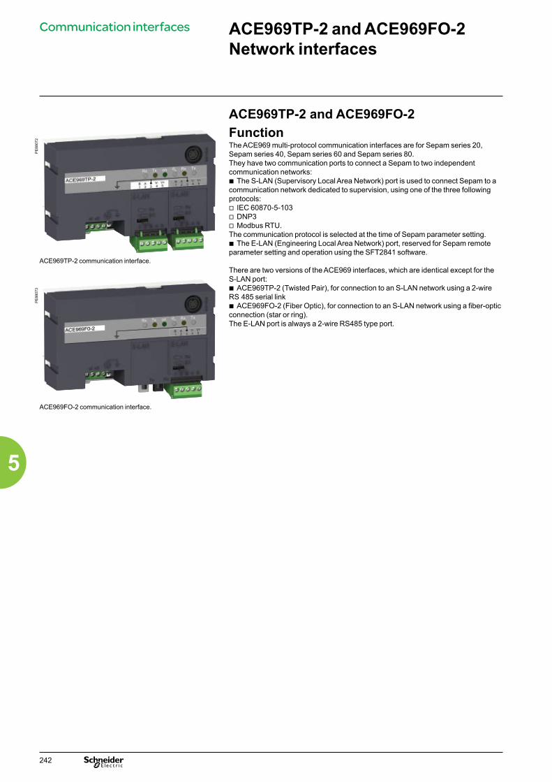
Communication interfaces ACE969TP-2 and ACE969FO-2 Network interfaces
ACE969TP-2 and ACE969FO-2
PE
8807
2
FunctionThe ACE969 multi-protocol communication interfaces are for Sepam series 20, Sepam series 40, Sepam series 60 and Sepam series 80.They have two communication ports to connect a Sepam to two independent communication networks:b The S-LAN (Supervisory Local Area Network) port is used to connect Sepam to a communication network dedicated to supervision, using one of the three following protocols:v IEC 60870-5-103v DNP3v Modbus RTU.The communication protocol is selected at the time of Sepam parameter setting.b The E-LAN (Engineering Local Area Network) port, reserved for Sepam remote parameter setting and operation using the SFT2841 software.
There are two versions of the ACE969 interfaces, which are identical except for the S-LAN port:b ACE969TP-2 (Twisted Pair), for connection to an S-LAN network using a 2-wire RS 485 serial linkb ACE969FO-2 (Fiber Optic), for connection to an S-LAN network using a fiber-optic connection (star or ring).The E-LAN port is always a 2-wire RS485 type port.
ACE969TP-2 communication interface.
PE
8807
3
ACE969FO-2 communication interface.
242
5
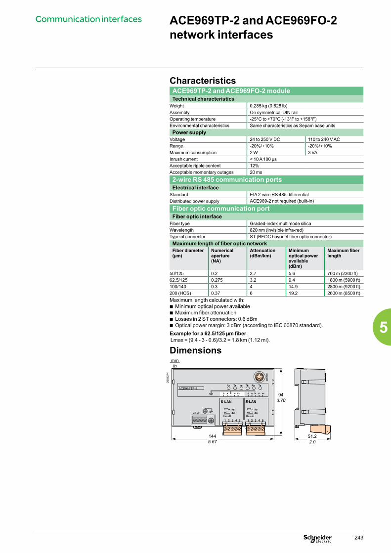
Communication interfaces
CharacteristicsACE969TP-2 and ACE969FO-2 moduleTechnical characteristics
Weight 0.285 kg (0.628 lb)Assembly On symmetrical DIN railOperating temperature -25°C to +70°C (-13°F to +158°F)Environmental characteristics Same characteristics as Sepam base unitsPower supply
Voltage 24 to 250 V DC 110 to 240 V ACRange -20%/+10% -20%/+10%Maximum consumption 2 W 3 VAInrush current < 10 A 100 µsAcceptable ripple content 12%Acceptable momentary outages 20 ms
2-wire RS 485 communication portsElectrical interface
Standard EIA 2-wire RS 485 differentialDistributed power supply ACE969-2 not required (built-in)
Fiber optic communication portFiber optic interface
Fiber type Graded-index multimode silicaWavelength 820 nm (invisible infra-red)Type of connector ST (BFOC bayonet fiber optic connector)Maximum length of fiber optic networkFiber diameter(µm)
Numerical aperture(NA)
Attenuation(dBm/km)
Minimum optical power available(dBm)
Maximum fiber length
50/125 0.2 2.7 5.6 700 m (2300 ft)62.5/125 0.275 3.2 9.4 1800 m (5900 ft)100/140 0.3 4 14.9 2800 m (9200 ft)200 (HCS) 0.37 6 19.2 2600 m (8500 ft)Maximum length calculated with:b Minimum optical power availableb Maximum fiber attenuationb Losses in 2 ST connectors: 0.6 dBmb Optical power margin: 3 dBm (according to IEC 60870 standard).Example for a 62.5/125 µm fiberLmax = (9.4 - 3 - 0.6)/3.2 = 1.8 km (1.12 mi).
Dimensions
51.22.0
ACE969TP-2Rx
e1 e2
Tx on Rx Tx
serv
ice
V+V-AB1 22 3 4 5
V+V-AB1 2 3 4 5
S-LAN E-LAN
1 2 3 4 5
E-LAN
Rc
Rc
Rc
Rc
1 2 3 4 5
mmin
943.70
1445.67
DE
8827
4
ACE969TP-2 and ACE969FO-2 network interfaces
243
5

ACE969-2 communication interfacesACE969TP-2 ACE969FO-2
1 Grounding/earthing terminal using supplied braid2 Power-supply terminal block3 RJ45 connector to connect the interface to the base
unit with a CCA612 cord4 Green LED: ACE969-2 energized5 Red LED: ACE969-2 interface status
b LED off = ACE969-2 set up and communication operational b LED flashing = ACE969-2 not set up or setup incorrect b LED remains on = ACE969-2 has faulted
6 Service connector: reserved for software upgrades7 E-LAN 2-wire RS485 communication port
(ACE969TP-2 and ACE969FO-2)8 S-LAN 2-wire RS485 communication port
(ACE969TP-2)9 S-LAN fiber-optic communication port
(ACE969FO-2).
DE
8827
5
ACE969TP-2
Rx Txon
Rx Tx
B AV- V+
54321
4 5
S-LANE-LAN
S E N S D E L E C T U R E
1 2 3
1 2 3 4 5
1 8 72
3 4 5 6
B AV+
V- 54321
DE
8827
6
ACE969FO-2
Rx Txon
Rx Tx
B AV- V+
54321
1 2 3 4 5
S-LANE-LAN
S E N S D E L E C T U R E
1 9 72
3 4 5 6
2-wire RS485 communication ports1 Draw-out terminal block, with two rows of
connections to the RS485 2-wire network: b 2 black terminals: connection of RS485 twisted-pair (2 wires) b 2 green terminals: connection of twisted-pair for distributed power supply
2 Indication LEDs: b flashing Tx LED: Sepam sending b flashing Rx LED: Sepam receiving.
3 Jumper for RS485 network line-end impedance matching with load resistor (Rc = 150 Ω), to be set to: b Rc, if the interface is not at the line end (default position) b Rc, if the interface is at the line end.
S-LAN port (ACE969TP) E-LAN port (ACE969TP or ACE969FO)
DE
8827
7
Rx Tx on Rx Tx
s
V+V-AB1 22 3 4 5
V+V-AB1 22 3 4 5
S-LAN E-LAN
1 2 3 4 5
E-LAN
Rc
Rc
Rc
Rc
1 2 3 4 5
12
3
DE
8827
8Rx Tx on Rx Tx
s
V+V-AB1 22 3 4 5
LAN E-LAN
1 2 3 4 5
E-LAN
Rc
Rc
12
3
Fiber-optic communication port1 Indication LEDs:
b flashing Tx LED: Sepam sending b flashing Rx LED: Sepam receiving.
2 Rx, female ST-type connector (Sepam receiving)3 Tx, female ST-type connector (Sepam sending).
S-LAN port (ACE969FO)
DE
8827
9
Rx Tx on Rx Tx
V+VAB1 22 3 4 5
S-LAN E-LAN
1 2 3 4 5
E-LAN
Rc
Rc
1
23
Communication interfaces ACE969TP-2 and ACE969FO-2 network interfaces Description
244
5

Power supply and Sepamb The ACE969-2 interface connects to connector C on the Sepam base unit using a CCA612 cord (length = 3 m or 9.84 ft, white RJ45 fittings)b The ACE969-2 interface must be supplied with 24 to 250 V DC or 110 to 240 V AC.
CAUTIONHAZARD OF ELECTRIC SHOCK, ELECTRIC ARC OR BURNSb Only qualified personnel should install this equipment. Such work should be performed only after reading this entire set of instructions and checking the technical characteristics of the device.b NEVER work alone. b Turn off all power supplying this equipment before working on or inside it. Consider all sources of power, including the possibility of backfeeding.b Always use a properly rated voltage sensing device to confirm that all power is off.b Start by connecting the device to the protective earth and to the functional earth.b Screw tight all terminals, even those not in use.Failure to follow these instructions will result in death or serious injury.
ACE969TP-2
Rx Txon
Rx Tx
B AV+
V-54321
4 5
S-LANE-LAN
S E N S D E L E C T U R E
1 2 3
1 2 3 4 5
B AV+
V-54321
CCA612ACE969TP-2
CV DC/V AC
Terminals Type Wiring
DE
8838
5
e1-e2 - supply Screw terminals b Wiring with no fittings:v 1 wire with maximum cross-section 0.2 to
2.5 mm² (u AWG 24-12)or 2 wires with maximum cross-section 0.2 to 1 mm² (u AWG 24-18)v stripped length: 8 to 10 mm (0.31 to 0.39 in)b Wiring with fittings:v recommended wiring with Schneider
Electric fitting:- DZ5CE015D for 1 wire 1.5 mm² (AWG 16)- DZ5CE025D for 1 wire 2.5 mm² (AWG 12)- AZ5DE010D for 2 wires 1 mm² (AWG 18)v tube length: 8.2 mm (0.32 in)v stripped length: 8 mm (0.31 in).
DE
8828
1
Protective earth Screw terminal 1 green/yellow wire, max. length 3 m (9.8 ft)and max. cross-section 2.5 mm² (AWG 12)
DE
8828
2
Functional earth 4 mm (0.16 in) ring lug
Earthing braid, supplied for connection to cubicle grounding
Communication interfaces ACE969TP-2 and ACE969FO-2 network interfaces Connection
245
5

Communication interfacesD
E88
386
2-wire RS 485 communication ports (S-LAN or E-LAN)b Connection of the RS 485 twisted pair (S-LAN or E-LAN) to terminals A and B.b In case of ACE 969TP wired with ACE969TP-2:v connection of twisted pair for distributed power supply to terminals 5(V+) et 4(V-).b In case of ACE969TP-2 only:v connexion only on the terminal 4(V-) ( ground continuity)v no need of external power supply.b The cable shields must be connected to the terminals marked 3(.) on the connection terminal blocks.b Terminal marked 3(.) are linked by an internal connection to the earthing terminals of the ACETP-2 interface (protective an functional earthing): Ie the shielding of the RS 485 cables is earthed as well.b On the ACE960TP-2 interface, the cable clamps for the S-LAN and E-LAN RS 485 networks are earthed by the terminal 3.
If ACE969TP and ACE969TP-2 are used together, the external power supply is required.
DE
8838
7
If ACE969TP-2 is used alone, the external power supply is not required, the V- connectors on the modules must be interconnected.
DE
8838
8
Fiber optic communication port (S-LAN)
CAUTIONHAZARD OF BLINDINGNever look directly into the fiber optic.Failure to follow this instruction can cause serious injury.
The fiber optic connection can be made:b point-to-point to an optic star systemb in a ring system (active echo).The sending and receiving fiber optic fibers must be equipped with male ST type connectors.The fiber optics are screw-locked to Rx and Tx connectors.
ACE969TP-2 and ACE969FO-2 network interfacesConnection
246
5

ACE850TP and ACE850FO
PB
1053
01
FunctionACE850 multi-protocol communication interfaces are for Sepam series 40 and Sepam series 80 units.They have two Ethernet communication ports to connect a Sepam unit to a single Ethernet network depending on the topology (star or ring):b For a star topology, only one communication port is used.b For a ring topology, both Ethernet communication ports are used to provide redundancy. This redundancy conforms to the RSTP 802.1d 2004 standard.
Either port can be used for connection:b To the S-LAN (Supervisory Local Area Network) port to connect a Sepam unit to an Ethernet communication network dedicated to supervision, using either of the following protocols:v IEC 61850v eModbus TCP/IP TRA 15.b To the E-LAN (Engineering Local Area Network) port, reserved for remote parameter setting and operation of a Sepam unit using SFT2841 software.
There are two versions of the ACE850 interface, which are identical except for the type of port featured:b ACE850TP (Twisted Pair), for connection to an Ethernet network (S-LAN or E-LAN) using a copper RJ45 10/100 Base TX Ethernet link.b ACE850FO (Fiber Optic), for connection to an Ethernet network (S-LAN or E-LAN) using a 100Base FX fiber optic connection (star or ring).
Compatible Sepam unitsThe ACE850TP and ACE850FO multi-protocol interfaces are compatible with the following Sepam units:b Sepam series 40, series 60 version u V7.00b Sepam series 80 base version and application version u V6.00 .
ACE850TP communication interface.
PB
1053
00
ACE850FO communication interface.
Communication interfaces ACE850TP and ACE850FO network interfaces
247
5
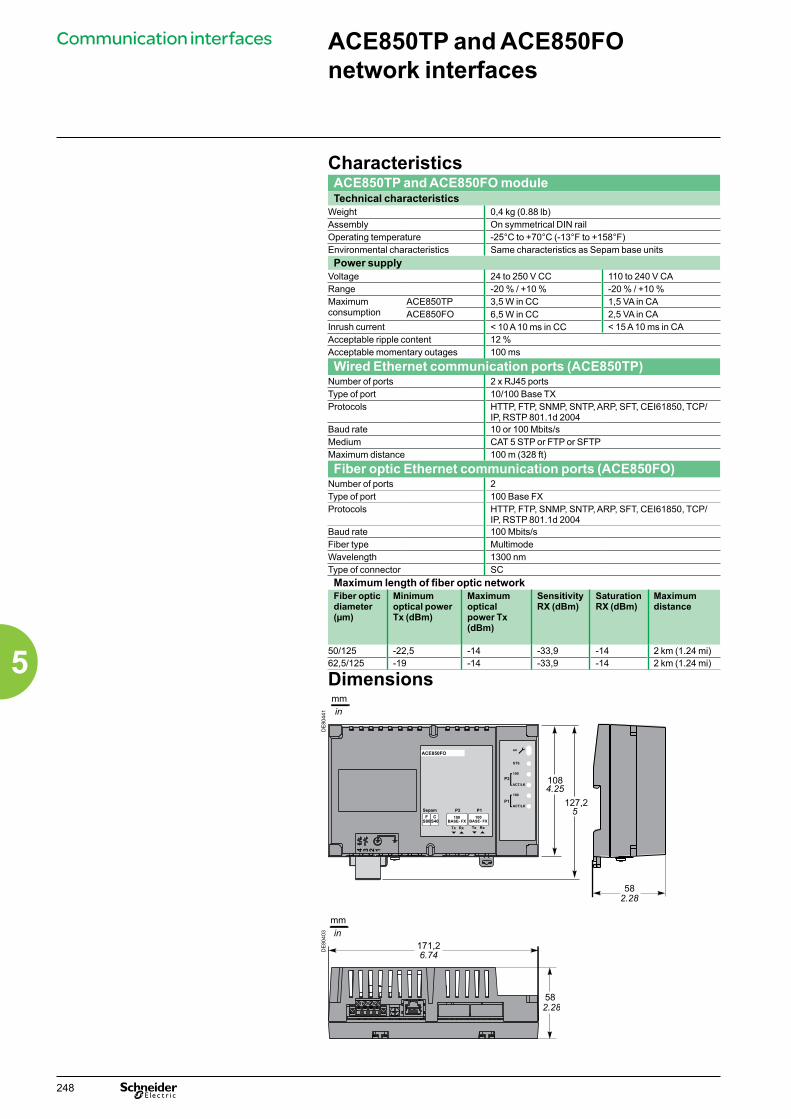
CharacteristicsACE850TP and ACE850FO moduleTechnical characteristics
Weight 0,4 kg (0.88 lb)Assembly On symmetrical DIN railOperating temperature -25°C to +70°C (-13°F to +158°F)Environmental characteristics Same characteristics as Sepam base unitsPower supply
Voltage 24 to 250 V CC 110 to 240 V CARange -20 % / +10 % -20 % / +10 %Maximum consumption
ACE850TP 3,5 W in CC 1,5 VA in CAACE850FO 6,5 W in CC 2,5 VA in CA
Inrush current < 10 A 10 ms in CC < 15 A 10 ms in CAAcceptable ripple content 12 %Acceptable momentary outages 100 ms
Wired Ethernet communication ports (ACE850TP)Number of ports 2 x RJ45 portsType of port 10/100 Base TXProtocols HTTP, FTP, SNMP, SNTP, ARP, SFT, CEI61850, TCP/
IP, RSTP 801.1d 2004Baud rate 10 or 100 Mbits/sMedium CAT 5 STP or FTP or SFTPMaximum distance 100 m (328 ft)
Fiber optic Ethernet communication ports (ACE850FO)Number of ports 2Type of port 100 Base FXProtocols HTTP, FTP, SNMP, SNTP, ARP, SFT, CEI61850, TCP/
IP, RSTP 801.1d 2004 Baud rate 100 Mbits/sFiber type MultimodeWavelength 1300 nmType of connector SCMaximum length of fiber optic networkFiber optic diameter (µm)
Minimum optical power Tx (dBm)
Maximum optical power Tx(dBm)
Sensitivity RX (dBm)
Saturation RX (dBm)
Maximum distance
50/125 -22,5 -14 -33,9 -14 2 km (1.24 mi)62,5/125 -19 -14 -33,9 -14 2 km (1.24 mi)
Dimensions
DE
8044
1D
E80
403
582.28
171,26.74
mmin
mmin
ACE850FO
FS80
100BASE- FX
CS40
P2 P1100
BASE- FXTx Rx Tx Rx
Sepam
1234
1084.25
127,25
582.28
ACE850TP and ACE850FO network interfaces
Communication interfaces
248
5

Communication interfaces ACE850TP and ACE850FO network interfacesConnection
ACE850TP communication interfaces
DE
8043
0
1 ACE850 communication interface status LEDb LED off = ACE850 de-energizedb Green LED permanently on = ACE850 energized and operationalb Red LED flashing = ACE850 not configured and/or not connected to the base unitb Red LED permanently on = ACE850 not operational (initialization in progress or failed)
2 STS LED: communication status: green permanently on = OK3 Ethernet Port 2 100 green LED: off = 10Mbps, permanently on = 100 Mbps4 Ethernet Port 2 activity LED: flashing on transmission/reception5 Ethernet Port 2 100 green LED: off = 10Mbps, permanently on = 100 Mbps6 Ethernet Port 1 activity LED: flashing on transmission/reception
ACE850TP: Front view
DE
8043
1
7 Power-supply terminal block8 Grounding/earthing terminal using supplied braid9 RJ45 socket to connect the interface to the Sepam base unit with a CCA614 cord :
b Sepam series 40: communication port (identified by a white label on the Sepam unit) b Sepam series 80: port (identified by a blue label on the Sepam unit)
10 RJ45 10/100 Base TX Ethernet communication port P2 (E-LAN or S-LAN)11 RJ45 10/100 Base TX Ethernet communication port P1 (E-LAN or S-LAN)
ACE850TP: View of underside
ACE850FO communication interfaces
DE
8043
2
1 ACE850 communication interface status LEDb LED off = ACE850 de-energizedb Green LED permanently on = ACE850 energized and operationalb Red LED flashing = ACE850 not configured and/or not connected to the base unitb Red LED permanently on = ACE850 not operational (initialization in progress or failed)
2 STS LED: communication status: green permanently on = OK3 Ethernet Port 2 100 green LED: permanently on = 100 Mbps4 Ethernet Port 2 activity LED: flashing on transmission/reception5 Ethernet Port 2 100 green LED: permanently on = 100 Mbps6 Ethernet Port 1 activity LED: flashing on transmission/reception
ACE850FO: Front view
DE
8043
3
7 Power-supply terminal block8 Grounding/earthing terminal using supplied braid9 RJ45 socket to connect the interface to the Sepam base unit with a CCA614 cord :
b Sepam series 40: communication port (identified by a white label on the Sepam unit) b Sepam series 80: port (identified by a blue label on the Sepam unit)
12 Tx fiber of 100 Base FX SC connector for Ethernet communication port P2 (E-LAN or S-LAN)13 Rx fiber of 100 Base FX SC connector for Ethernet communication port P2 (E-LAN or S-LAN)14 Tx fiber of 100 Base FX SC connector for Ethernet communication port P1 (E-LAN or S-LAN)15 Rx fiber of 100 Base FX SC connector for Ethernet communication port P1 (E-LAN or S-LAN)
ACE850FO: View of underside
CAUTIONHAZARD OF BLINDINGNever look directly into the fiber optic.Failure to follow this instruction can cause serious injury.
FS80
10/100BASE-TX
CS40
P2 P110/100
BASE-TX
Sepam
ACE850TP 12
54
6
3
7 8 11109
ACE850FO
FS80
100BASE- FX
CS40
P2 P1100
BASE- FXTx Rx Tx Rx
Sepam
123456
7 8 1413129 15
C
F
C
F
249
5
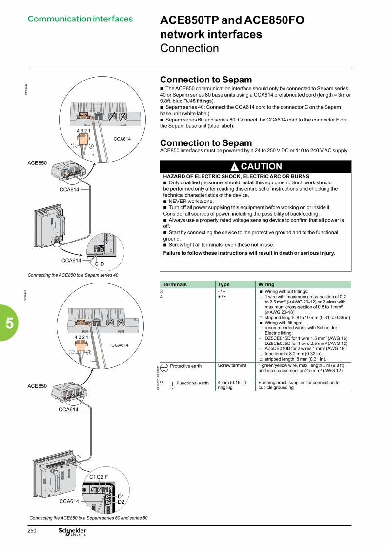
DE
8844
4
Connection to Sepamb The ACE850 communication interface should only be connected to Sepam series 40 or Sepam series 80 base units using a CCA614 prefabricated cord (length = 3m or 9.8ft, blue RJ45 fittings).b Sepam series 40: Connect the CCA614 cord to the connector C on the Sepam base unit (white label).b Sepam series 60 and series 80: Connect the CCA614 cord to the connector F on the Sepam base unit (blue label).
Connection to SepamACE850 interfaces must be powered by a 24 to 250 V DC or 110 to 240 V AC supply.
! CAUTIONHAZARD OF ELECTRIC SHOCK, ELECTRIC ARC OR BURNSb Only qualified personnel should install this equipment. Such work should be performed only after reading this entire set of instructions and checking the technical characteristics of the device.b NEVER work alone.b Turn off all power supplying this equipment before working on or inside it. Consider all sources of power, including the possibility of backfeeding.b Always use a properly rated voltage sensing device to confirm that all power is off.b Start by connecting the device to the protective ground and to the functional ground.b Screw tight all terminals, even those not in use.Failure to follow these instructions will result in death or serious injury.
Connecting the ACE850 to a Sepam series 40
DE
8844
5
Terminals Type Wiring34
- / ~+ / ~
b Wiring without fittings:v 1 wire with maximum cross-section of 0.2
to 2.5 mm² (u AWG 20-12) or 2 wires with maximum cross-section of 0.5 to 1 mm² (u AWG 20-18)
v stripped length: 8 to 10 mm (0.31 to 0.39 in)b Wiring with fittings:v recommended wiring with Schneider
Electric fitting:- DZ5CE015D for 1 wire 1.5 mm² (AWG 16)- DZ5CE025D for 1 wire 2.5 mm² (AWG 12)- AZ5DE010D for 2 wires 1 mm² (AWG 18)v tube length: 8.2 mm (0.32 in).v stripped length: 8 mm (0.31 in).
DE
8828
1 Protective earth Screw terminal 1 green/yellow wire, max. length 3 m (9.8 ft) and max. cross-section 2.5 mm² (AWG 12)
DE
8828
2
Functional earth 4 mm (0.16 in) ring lug
Earthing braid, supplied for connection to cubicle grounding
Connecting the ACE850 to a Sepam series 60 and series 80.
ACE850
C D
CCA614
4 3 2 1
CCA614
CCA614
4 3 2 1
CCA614
CCA614
ACE850
C1C2
D1D2
F
CCA614
ACE850TP and ACE850FO network interfacesConnection
Communication interfaces
250
5

Function
PE
8807
4
The ACE909-2 converter is used to connect a master/central computer equipped with a V24/RS 232 type serial port as a standard feature to stations connected to a 2-wire RS 485 network.Without requiring any flow control signals, after the parameters are set, the ACE909-2 converter performs conversion, network polarization and automatic dispatching of frames between the master and the stations by two-way simplex (half-duplex, single-pair) transmission.The ACE909-2 converter also provides a 12 V DC or 24 V DC supply for the distributed power supply of the Sepam ACE949-2, ACE959 or ACE969 interfaces.The communication settings should be the same as the Sepam and supervisor communication settings.
ACE909-2 RS 232/RS 485 converter.
Characteristics CAUTION Mechanical characteristics
HAZARD OF ELECTRIC SHOCK, ELECTRIC ARC OR BURNSb Only qualified personnel should install this equipment. Such work should be performed only after reading this entire set of instructions and checking the technical characteristics of the device.b NEVER work alone. b Turn off all power supplying this equipment before working on or inside it. Consider all sources of power, including the possibility of backfeeding.b Always use a properly rated voltage sensing device to confirm that all power is off.b Start by connecting the device to the protective earth and to the functional earth.b Screw tight all terminals, even those not in use.Failure to follow these instructions will result in death or serious injury.
Weight 0.280 kg (0.617 lb)Assembly On symmetrical or asymmetrical DIN rail
Electrical characteristicsPower supply 110 to 220 V AC ± 10%, 47 to 63 HzGalvanic isolation between ACE power supply and frame, and between ACE power supply and interface supply
2000 Vrms, 50 Hz, 1 min
Galvanic isolation between RS 232 and RS 485 interfaces
1000 Vrms, 50 Hz, 1 min
Protection by time-delayed fuse 5 mm x 20 mm (0.2 in x 0.79 in)
1 A rating
Communication and Sepam interface distributed supplyData format 11 bits: 1 start, 8 data, 1 parity, 1 stopTransmission delay < 100 nsDistributed power supply for Sepam interfaces
12 V DC or 24 V DC, 250 mA max
Maximum number of Sepam interfaces with distributed supply
12
Environmental characteristicsOperating temperature -5°C to +55°C (+23°F to +131°F)
Electromagnetic compatibility IEC standard
Value
Fast transient bursts, 5 ns 60255-22-4 4 kV with capacitive coupling in common mode2 kV with direct coupling in common mode1 kV with direct coupling in differential mode
1 MHz damped oscillating wave 60255-22-1 1 kV common mode0.5 kV differential mode
1.2/50 µs impulse waves 60255-5 3 kV common mode1 kV differential mode
ACE909-2 RS 232 / RS 485 converter
Converters
251
5

Description and dimensions
DE
8828
6
A Terminal block for RS 232 link limited to 10 m (33 ft).
B Female 9-pin sub-D connector to connect to the 2-wire RS 485 network, with distributed power supply.1 screw-type male 9-pin sub-D connector is supplied with the converter.
C Power-supply terminal block
1 Distributed power supply voltage selector switch, 12 V DC or 24 V DC.2 Protection fuse, unlocked by a 1/4 turn.3 LEDs:
b ON/OFF: on if ACE909-2 is energizedb Tx: on if RS 232 sending by ACE909-2 is activeb Rx: on if RS 232 receiving by ACE909-2 is active.
4 SW1, parameter setting of 2-wire RS 485 network polarization and line impedance matching resistors.
Function SW1/1 SW1/2 SW1/3Polarization at 0 V via Rp -470 Ω ON
DE
8828
7
Polarization at 5 V via Rp +470 Ω ON2-wire RS 485 network impedance matching by 150 Ω resistor
ON
5 SW2, parameter setting of asynchronous data transmission rate and format (same parameters as for RS 232 link and 2-wire RS 485 network).
Rate (bauds) SW2/1 SW2/2 SW2/31200 1 1 12400 0 1 14800 1 0 19600 0 0 119200 1 1 038400 0 1 0
Male 9-pin sub-D connector supplied with the ACE909-2. Format SW2/4 SW2/5With parity check 0
DE
8828
8
Without parity check 11 stop bit (compulsory for Sepam) 12 stop bits 0
Converter configuration when deliveredb 12 V DC distributed power supplyb 11-bit format, with parity checkb 2-wire RS 485 network polarization and impedance matching resistors activated.
ConnectionRS 232 linkb To 2.5 mm² (AWG 12) screw type terminal block A b Maximum length 10 m (33 ft)b Rx/Tx: RS 232 receiving/sending by ACE909-2b 0V: Rx/Tx common, do not earth.2-wire RS 485 link with distributed power supplyb To connector B female 9-pin sub-Db 2-wire RS 485 signals: L+, L-b Distributed power supply: V+ = 12 V DC or 24 V DC, V- = 0 V.Power supplyb To 2.5 mm² (AWG 12) screw type terminal block C b Reversible phase and neutralb Earthed via terminal block and metal case (ring lug on back of case).
mmin
4.13 2.56
1.77
3.344.13
2.22
0.63
1.42
1.75
mmin
ACE909-2 RS 232 / RS 485 converter
Converters
252
5
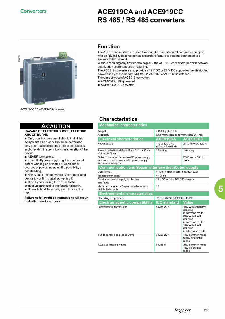
Function
PE
8807
5
The ACE919 converters are used to connect a master/central computer equipped with an RS 485 type serial port as a standard feature to stations connected to a 2-wire RS 485 network.Without requiring any flow control signals, the ACE919 converters perform network polarization and impedance matching.The ACE919 converters also provide a 12 V DC or 24 V DC supply for the distributed power supply of the Sepam ACE949-2, ACE959 or ACE969 interfaces.There are 2 types of ACE919 converter:b ACE919CC, DC-poweredb ACE919CA, AC-powered.
ACE919CC RS 485/RS 485 converter.
Characteristics CAUTION Mechanical characteristics
HAZARD OF ELECTRIC SHOCK, ELECTRIC ARC OR BURNSb Only qualified personnel should install this equipment. Such work should be performed only after reading this entire set of instructions and checking the technical characteristics of the device.b NEVER work alone. b Turn off all power supplying this equipment before working on or inside it. Consider all sources of power, including the possibility of backfeeding.b Always use a properly rated voltage sensing device to confirm that all power is off.b Start by connecting the device to the protective earth and to the functional earth.b Screw tight all terminals, even those not in use.Failure to follow these instructions will result in death or serious injury.
Weight 0.280 kg (0.617 lb)Assembly On symmetrical or asymmetrical DIN rail
Electrical characteristics ACE919CA ACE919CCPower supply 110 to 220 V AC
±10%, 47 to 63 Hz24 to 48 V DC ±20%
Protection by time-delayed fuse 5 mm x 20 mm (0.2 in x 0.79 in)
1 A rating 1 A rating
Galvanic isolation between ACE power supply and frame, and between ACE power supply and interface supply
2000 Vrms, 50 Hz, 1 min
Communication and Sepam interface distributed supplyData format 11 bits: 1 start, 8 data, 1 parity, 1 stopTransmission delay < 100 nsDistributed power supply for Sepam interfaces
12 V DC or 24 V DC, 250 mA max
Maximum number of Sepam interfaces with distributed supply
12
Environmental characteristicsOperating temperature -5°C to +55°C (+23°F to +131°F)
Electromagnetic compatibility IEC standard ValueFast transient bursts, 5 ns 60255-22-4 4 kV with capacitive
coupling in common mode2 kV with direct coupling in common mode1 kV with direct coupling in differential mode
1 MHz damped oscillating wave 60255-22-1 1 kV common mode0.5 kV differential mode
1.2/50 µs impulse waves 60255-5 3 kV common mode1 kV differential mode
ACE919CA and ACE919CC RS 485 / RS 485 converters
Converters
253
5
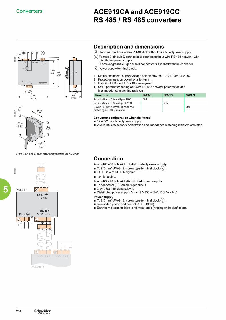
Description and dimensions
DE
8828
9
A Terminal block for 2-wire RS 485 link without distributed power supply.B Female 9-pin sub-D connector to connect to the 2-wire RS 485 network, with
distributed power supply.1 screw-type male 9-pin sub-D connector is supplied with the converter.
C Power supply terminal block.
1 Distributed power supply voltage selector switch, 12 V DC or 24 V DC.2 Protection fuse, unlocked by a 1/4 turn.3 ON/OFF LED: on if ACE919 is energized.4 SW1, parameter setting of 2-wire RS 485 network polarization and
line impedance matching resistors.Function SW1/1 SW1/2 SW1/3
Polarization at 0 V via Rp -470 Ω ONPolarization at 5 V via Rp +470 Ω ON
DE
8828
7
2-wire RS 485 network impedance matching by 150 Ω resistor
ON
Converter configuration when deliveredb 12 V DC distributed power supplyb 2-wire RS 485 network polarization and impedance matching resistors activated.
Male 9-pin sub-D connector supplied with the ACE919.
Connection
DE
8829
0
2-wire RS 485 link without distributed power supplyb To 2.5 mm² (AWG 12) screw type terminal block A b L+, L-: 2-wire RS 485 signalsb t Shielding.2-wire RS 485 link with distributed power supplyb To connector B female 9-pin sub-Db 2-wire RS 485 signals: L+, L-b Distributed power supply: V+ = 12 V DC or 24 V DC, V- = 0 V.Power supply b To 2.5 mm² (AWG 12) screw type terminal block C b Reversible phase and neutral (ACE919CA)b Earthed via terminal block and metal case (ring lug on back of case).
ACE 919CC
2.22
0.63
1.42
1.75
mmin
ACE919CA and ACE919CC RS 485 / RS 485 converters
Converters
254
5

Sepam IEC 61850 level 1 ECI850
FunctionThe ECI850 connects Sepam series 20, Sepam series 40 and Sepam series 80 units to an Ethernet network using the IEC 61850 protocol.It acts as the interface between the Ethernet/IEC 61850 network and a Sepam RS485/Modbus network.1 PRI surge arrester (cat. no. 16339) is supplied with the ECI850 to protect its power supply.
CharacteristicsECI850 moduleTechnical characteristics
Weight 0.17 kg (0,37 lb)Assembly On symmetrical DIN railPower supply
Voltage 24 V DC (±10 %) supplied by a class 2 supplyMaximum consumption 4 WDielectric strength 1.5 kV
Environmental characteristicsOperating temperature -25 °C to +70 °C (-13 °F to +158 °F)Storage temperature -40 °C to +85 °C (-40 °F to +185 °F)Relative humidity 5 to 95 % (without condensation)
at +55 °C (131 °F)Pollution degree Class 2Degree of protection IP30
Electromagnetic compatibilityEmission tests
Emission (radiated and conducted) EN 55022/EN 55011/FCC Class A
Immunity tests – Radiated disturbancesElectrostatic discharge EN 61000-4-2Radiated radio-frequency fields EN 61000-4-3Magnetic fields at power frequency EN 61000-4-8Immunity tests – Conducted disturbances
Fast transient bursts EN 61000-4-4Surges EN 61000-4-5Conducted disturbances, induced by radio-frequency fields
EN 61000-4-6
SafetyInternational IEC 60950United States UL 508/UL 60950Canada cUL (in compliance with CSA C22.2, no. 60950)Australia / New Zealand AS/NZS 60950
CertificationEurope e
2-wire/4-wire RS485 communication portsElectrical interface
Standard EIA 2-wire/4-wire RS485 differentialMax. number of Sepam units per ECI850 2 Sepam series 60 and series 80 or 3 Sepam
series 40 or 5 Sepam series 20Maximum length of 2-wire/4-wire RS485 network
Maximum length of network 1000 m (3300 ft)
Ethernet communication portNumber of ports 1Type of port 10/100 Base TxProtocols HTTP, FTP, SNMP, SNTP, ARP, SFT, IEC 61850
TCP/IPTransmission rate 10/100 Mbits/s
CompatibilityAn ECI850 module can be used on the following Sepam base units, starting from indicated versions:b base S20: V0526b base S40: V3.0b base S60: V1.00b base S80: V3.0
PE
8802
6
Sepam ECI850 server for IEC 61850.
Converters
255
5

Sepam IEC 61850 level 1 ECI850
Characteristics (cont.)PRI surge arresterElectrical characteristics
Utilisation voltage 48 VDCFull discharge current 10 kA (8/20 µs wave)Rated discharge current 5 kA (8/20 µs wave) Level of protection 70 VResponse time < 1 nsConnection
Tunnel terminals Wires with maximum cross-section of 2.5 mm² to 4 mm² (AWG 12-10)
Description
1 / LED: Power on and maintenance2 Serial-link LEDs: b RS485 LED: link to network activated v On: RS485 mode v Off: RS232 mode b flashing TX LED: ECI850 sending b flashing RX LED: ECI850 receiving3 Ethernet LEDs: b green LK LED on: link to network activated b flashing green Tx LED: ECI850 sending b flashing green Rx LED: ECI850 receiving b green 100 LED: v On: transmission rate = 100 Mbit/s v Off: transmission rate = 10 Mbit/s4 10/100 Base Tx port for Ethernet connection via RJ45 connector5 24 V DC connection6 Reset button7 RS485 connector8 RS485 setup switches9 RS232 connector
PE
8807
6
DE
8838
9
2 3 4 5 61
2 3 4 5 61
4 wires
2 wires (default)
Recommended settings
RS485 network setup.
RS485 network setupThe RS485 setup switches are used to select the network-polarisation (bias) and line-impedance matching resistors and the type of RS485 network (2-wire/4-wire). The default settings are for a 2-wire RS485 with network-polarization and line-impedance matching resistors.
Line-impedance matching using resistors
SW1 SW2 SW3 SW4 SW5 SW6
2-wire RS485 OFF ON4-wire RS485 ON ON
Polarisation (bias) SW1 SW2 SW3 SW4 SW5 SW6at 0 V ONat 5 V ON
RS485 network type SW1 SW2 SW3 SW4 SW5 SW62-wire ON ON4-wire OFF OFF
Ethernet link set-upThe TCSEAK0100 configuration kit can be used to connect a PC to the ECI850 to set up the Ethernet link.
Converters
256
5
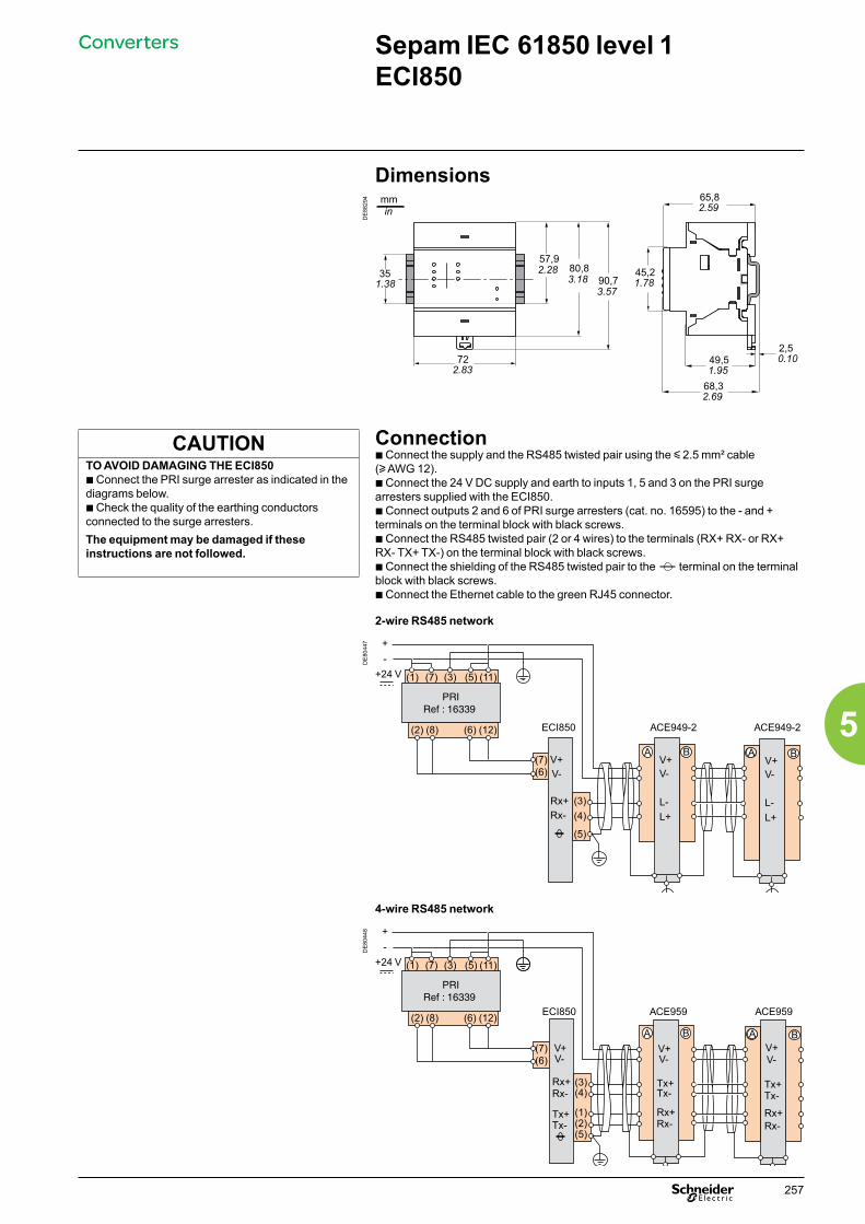
Sepam IEC 61850 level 1 ECI850
CAUTIONTO AVOID DAMAGING THE ECI850b Connect the PRI surge arrester as indicated in the diagrams below.b Check the quality of the earthing conductors connected to the surge arresters.The equipment may be damaged if these instructions are not followed.
Dimensions
DE
8829
4
3557,9
1.382.28 80,8
3.18
722.83
90,73.57
mmin
65,82.59
45,21.78
2,50.1049,5
1.95
68,32.69
Connectionb Connect the supply and the RS485 twisted pair using the y 2.5 mm² cable (u AWG 12).b Connect the 24 V DC supply and earth to inputs 1, 5 and 3 on the PRI surge arresters supplied with the ECI850.b Connect outputs 2 and 6 of PRI surge arresters (cat. no. 16595) to the - and + terminals on the terminal block with black screws.b Connect the RS485 twisted pair (2 or 4 wires) to the terminals (RX+ RX- or RX+ RX- TX+ TX-) on the terminal block with black screws.b Connect the shielding of the RS485 twisted pair to the terminal on the terminal block with black screws.b Connect the Ethernet cable to the green RJ45 connector.
2-wire RS485 network
DE
8044
7
Rx+Rx-
ECI850 ACE949-2
L-
V-V+
(4)
(7)(6)
(5)
A
(3)
+24 V
B
ACE949-2
L-
V-
L+ L+
V+A BA
(1) (3)(7)
(2) (8)
(5) (11)
(6) (12)
V+V-
+-
PRIRef : 16339
4-wire RS485 network
DE
8044
8
Rx+Rx-
ECI850 ACE959
Tx+Tx-
V-V+
(4)
(1)Tx+Tx-
Rx+Rx-(2)
(5)
A
V-V+
(3)
B
ACE959
Tx+Tx-
V-V+
Rx+Rx-
A BA(7)(6)
+24 V (1) (3)(7)
(2) (8)
(5) (11)
(6) (12)
+-
PRIRef : 16339
Converters
257
5
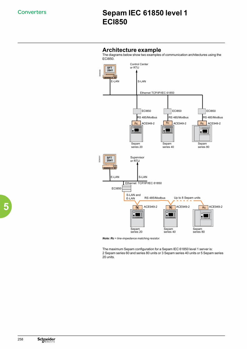
Sepam IEC 61850 level 1 ECI850
Architecture exampleThe diagrams below show two examples of communication architectures using the ECI850.
DE
8839
1
ECI850
RS 485/Modbus
Ethernet TCP/IP/IEC 61850
ACE949-2 ACE949-2 ACE949-2RcRc
Up to 8 Sepam units
Rc
Supervisoror RTU
S-LAN andE-LAN
Sepamseries 20
Sepamseries 40
Sepamseries 80
Note: Rc = line-impedance matching resistor.
The maximum Sepam configuration for a Sepam IEC 61850 level 1 server is:2 Sepam series 60 and series 80 units or 3 Sepam series 40 units or 5 Sepam series 20 units.
Converters
DE
8839
0
Rc
Control Centeror RTU
Sepamseries 20
Sepamseries 40
Sepamseries 80
Ethernet TCP/IP/IEC 61850
258
5

PowerLogic EGX100Ethernet gateway
ConvertersP
E86
138
FunctionThe EGX100 serves as an Ethernet gateway for PowerLogic system devices and for any other communicating devices utilising the Modbus protocol. The EGX100 gateway offers complete access to status and measurement information provided by the connected devices via PowerLogic software installed on a PC.PowerLogic software compatibilityPowerLogic software is recommeded as a user interface because they provide access to all status and measurement information. They also prepare summary reports. The EGX100 is compatible with:b PowerLogic ION EEM enterprise energy management softwareb PowerLogic ION Enterprise power management softwareb PowerLogic System Manager power management softwareb PowerLogic PowerView power monitoring software
ArchitectureD
E88
422
Ethernet EGX100 gateway.
PowerLogic EGX100
SetupSetup via an Ethernet networkOnce connected to an Ethernet network, the EGX100 gateway can be accessed by a standard internet browser via its IP address to:b specify the IP address, subnet mask, and gateway address of the EGX gatewayb configure the serial port parameters (baud rate, parity, protocol, mode, physical interface, and timeout value)b create user accountsb create or update the list of the connected products with their Modbus or PowerLogic communication parametersb configure IP filtering to control access to serial devicesb access Ethernet and serial port diagnostic datab update the firmware.b specify the user language.Setup via a serial connectionSerial setup is carried out using a PC connected to the EGX100 via an RS232 link. This setup:b specifies the IP address, subnet mask, and gateway address of the EGX gatewayb specifies the language used for the setup session.
Part numbersEGX100EGX100 EGX100
PowerLogicsoftware
Ethernet Modbus TCP/IP
EGX100 gateway
Modbus RS-485 serial link
ION6200 PM800 Micrologic Sepam
259
5
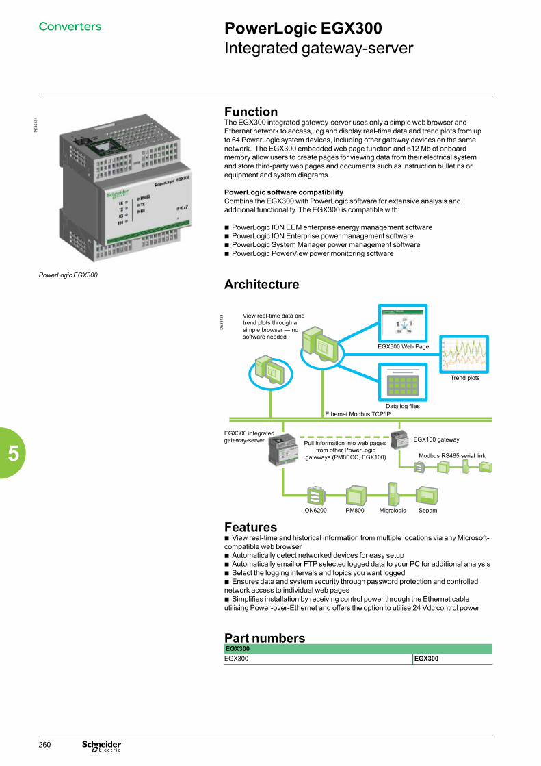
PowerLogic EGX300Integrated gateway-server
ConvertersP
E86
181
FunctionThe EGX300 integrated gateway-server uses only a simple web browser and Ethernet network to access, log and display real-time data and trend plots from up to 64 PowerLogic system devices, including other gateway devices on the same network. The EGX300 embedded web page function and 512 Mb of onboard memory allow users to create pages for viewing data from their electrical system and store third-party web pages and documents such as instruction bulletins or equipment and system diagrams.
PowerLogic software compatibilityCombine the EGX300 with PowerLogic software for extensive analysis and additional functionality. The EGX300 is compatible with:
b PowerLogic ION EEM enterprise energy management softwareb PowerLogic ION Enterprise power management softwareb PowerLogic System Manager power management softwareb PowerLogic PowerView power monitoring software
ArchitecturePowerLogic EGX300
DE
8842
3
Features b View real-time and historical information from multiple locations via any Microsoft-compatible web browserb Automatically detect networked devices for easy setupb Automatically email or FTP selected logged data to your PC for additional analysisb Select the logging intervals and topics you want loggedb Ensures data and system security through password protection and controlled network access to individual web pagesb Simplifies installation by receiving control power through the Ethernet cable utilising Power-over-Ethernet and offers the option to utilise 24 Vdc control power
Part numbersEGX300EGX300 EGX300
View real-time data and trend plots through a simple browser — no software needed
EGX300 Web Page
Trend plots
Data log filesEthernet Modbus TCP/IP
EGX300 integratedgateway-server Pull information into web pages
from other PowerLogic gateways (PM8ECC, EGX100)
EGX100 gateway
Modbus RS485 serial link
ION6200 PM800 Micrologic Sepam
260
5
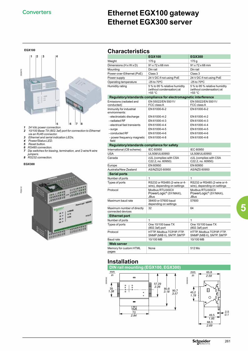
EGX100
1 24 Vdc power connection.2 10/100 Base TX (802.3af) port for connection to Ethernet
via an RJ45 connector.3 Ethernet and serial indication LEDs.4 Power/Status LED.5 Reset button.6 RS485 connection.7 Dip switches for biasing, termination, and 2-wire/4-wire
jumpers.8 RS232 connection.
EGX300
CharacteristicsEGX100 EGX300
Weight 170 g 170 g
DE
8807
9
Dimensions (H x W x D) 91 x 72 x 68 mm 91 x 72 x 68 mmMounting Din rail Din railPower-over-Ethernet (PoE) Class 3 Class 3Power supply 24 V DC if not using PoE 24 V DC if not using PoEOperating temperature -25 to 70ºC -25 to 70ºCHumidity rating 5 % to 95 % relative humidity
(without condensation) at +55 °C
5 % to 95 % relative humidity (without condensation) at +55 °C
Regulatory/standards compliance for electromagnetic interference Emissions (radiated and conducted)
EN 55022/EN 55011/FCC class A
EN 55022/EN 55011/FCC class A
Immunity for industrial environments:
EN 61000-6-2 EN 61000-6-2
- electrostatic discharge EN 61000-4-2 EN 61000-4-2 - radiated RF EN 61000-4-3 EN 61000-4-3 - electrical fast transients EN 61000-4-4 EN 61000-4-4 - surge EN 61000-4-5 EN 61000-4-5 - conducted RF EN 61000-4-6 EN 61000-4-6
- power frequency magnetic field
EN 61000-4-8 EN 61000-4-8
Regulatory/standards compliance for safetyInternational (CB scheme) IEC 60950 IEC 60950USA UL508/UL60950 UL508/UL60950Canada cUL (complies with CSA
C22.2, no. 60950)cUL (complies with CSA C22.2, no. 60950)
Europe EN 60950 EN 60950Australia/New Zealand AS/NZS25 60950 AS/NZS 60950Serial ports
Number of ports 1 1
PE
8618
1
Types of ports RS232 or RS485 (2-wire or 4-wire), depending on settings
RS232 or RS485 (2-wire or 4-wire), depending on settings
Protocol Modbus RTU/ASCIIPowerLogic® (SY/MAX), JBus
Modbus RTU/ASCIIPowerLogic® (SY/MAX), JBus
Maximum baud rate 38400 or 57600 baud depending on settings
57600
Maximum number of directly connected devices
32 64
Ethernet portNumber of ports 1 1Types of ports One 10/100 base TX
(802.3af) portOne 10/100 base TX (802.3af) port
Protocol HTTP, Modbus TCP/IP, FTP, SNMP (MIB II), SNTP, SMTP
HTTP, Modbus TCP/IP, FTP, SNMP (MIB II), SNTP, SMTP
Baud rate 10/100 MB 10/100 MBWeb server
Memory for custom HTML pages
None 512 Mo
InstallationDIN rail mounting (EGX100, EGX300)
DE
8830
2
DE
8830
3
Ethernet EGX100 gateway Ethernet EGX300 server
Converters
261
5

Phase current sensorsTwo types of sensor may be used with Sepam to measure phase current:b 1 A or 5 A current transformersb LPCT (Low Power Current Transducer) type current sensors.
Selection guide1 A or 5 A current sensors are:b to be sized case by case: accuracy, electrical characteristics, etc.b defined according to the IEC 60044-1 standard.The LPCT type current sensors are:b simple to size: a given LPCT sensor is suitable for the measurement of different rated currents: for example, the CLP1 sensor measures rated currents of 25 to 1250 Ab defined according to the IEC 60044-8 standard (rated secondary voltage = 22.5 mV).
Residual current sensorsThe residual current value may be obtained using different sensors and assemblies, which are chosen according to the required performance (measurement accuracy and earth fault protection sensitivity).Residual current may be:b measured by a specific CSH120 or CSH200 core balance CT b measured by a core balance CT with a ratio of 1/n (50 y n y 1500), with an ACE990 adapter.b calculated by Sepam from the vector sum of the 3 phase currents.
Selection guide Measurement sensors Accuracy Recommended
minimum set pointEasy assembly
CSH120 or CSH200core balance CT *** > 1 A *1 or 3 x 1 A or 5 A CT+ CSH30 ** 0.10 InCT (DT)
0.05 InCT (IDMT) **Core balance CT + ACE990 ** 0.10 InCT (DT)
0.05 InCT (IDMT) ***
revampingnew
3 phase CT (I0 calculated by Sepam) * 0.30 InCT (DT) (1)
0.10 InCT (IDMT) (1) ***(1) Recommended minimum set point for ANSI 50N/51N function with H2 restraint:0.10 InCT (DT) or 0.05 InCT (IDMT).
It is advisable not to set the earth fault protection functions below the recommended minimum set point to avoid any risk of unwanted tripping caused by oversensitive detection of residual current or false residual current due to the saturation of a CT.Lower settings may be used to trigger alarms.
Selection guide
Sensors
262
5

Function
PE
8808
3
PE
8808
4
Sepam may be connected to any standard voltage transformer with a rated secondary voltage of 100 V to 220 V.Schneider Electric offers a range of voltage transformers: b to measure phase-to-neutral voltages: voltage transformers with one insulated MV terminalb to measure phase-to-phase voltages: voltage transformers with two insulated MV terminalsb with or without integrated protection fuses.
Consult us for more information.
ConnectionThe voltage transformers connect to Sepam:b directly, for Sepam series 40, Sepam series 60 and Sepam series 80b or via the CCT640 connector for Sepam B21, B22 and the additional voltage inputs for Sepam B83.
The table below presents the different connection possibilities for voltage transformers to Sepam.
VRQ3 without fuses. VRQ3 with fuses.
Sepam B21 and B22
Sepam series 40
Sepam series 60
Sepam series 80
Number of voltage inputs
4 3 3 4 main 4 additional (1)
Intermediate connector
CCT640 - - - CCT640
Sepam connector B E E E B2
(1) Sepam B83 only.
b when voltage transformers are connected directly to the E connector on Sepam, four transformers built into the Sepam base unit ensure matching and isolation between the VTs and the Sepam input circuits.b when voltage transformers are connected via the CCT640 connector, the four transformers for matching and isolation between the VTs and the Sepam input circuits are contained in the CCT640.
Voltage transformers
Sensors
263
5

Function
PE
8808
5
ARJA1.
PE
8808
6
ARJP3.
Sepam may be connected to any standard 1 A or 5 A current transformer.Schneider Electric offers a range of current transformers to measure primary currents from 50 A to 2500 A. Consult us for more information.
Sizing of current transformersCurrent transformers are sized so as not to be saturated by the current values they are required to measure accurately (minimum 5 In).
For overcurrent protection functionsb with DT tripping curve: the saturation current must be 1.5 times greater than the settingb with IDMT tripping curve: the saturation current must be 1.5 times greater than the highest working value on the curve.Practical solution when there is no information on the settings
Rated secondary current (in)
Accuracy burden
Accuracy class
CT secondary resistance RCT
Wiring resistance Rf
1 A 2.5 VA 5P 20 < 3 Ω < 0.075 Ω5 A 7.5 VA 5P 20 < 0.2 Ω < 0.075 Ω
1 A / 5 A current transformers
Sensors
264
5

CCA630/CCA634 connector
DE
8830
8
FunctionThe current transformers (1 A or 5 A) are connected to the CCA630 or CCA634 connector on the rear panel of Sepam:b The CCA630 connector is used to connect 3 phase current transformers to Sepamb The CCA634 connector is used to connect 3 phase current transformers and a residual current transformer to Sepam.The CCA630 and CCA634 connectors contain interposing ring CTs with through primaries, which ensure impedance matching and isolation between the 1 A or 5 A circuits and Sepam when measuring phase and residual currents.The connectors can be disconnected with the power on since disconnection does not open the CT secondary circuit.
DE
8830
9 CAUTIONHAZARD OF ELECTRIC SHOCK, ELECTRIC ARC OR BURNSb Only qualified personnel should install this equipment. Such work should be performed only after reading this entire set of instructions and checking the technical characteristics of the device.b NEVER work alone. b Turn off all power supplying this equipment before working on or inside it. Consider all sources of power, including the possibility of backfeeding.b Always use a properly rated voltage sensing device to confirm that all power is off.b To remove current inputs to the Sepam unit, unplug the CCA630 or CCA634 connector without disconnecting the wires from it. The CCA630 and CCA634 connectors ensure continuity of the current transformer secondary circuits.b Before disconnecting the wires connected to the CCA630 or CCA634 connector, short-circuit the current transformer secondary circuits.Failure to follow these instructions will result in death or serious injury.
CCA634
1 A / 5 A current transformers
Sensors
265
5

1 A / 5 A current transformers
PE
8808
7
Connecting and assembling the CCA630 connector1. Open the 2 side shields for access to the connection terminals. The shields can be removed, if necessary, to make wiring easier. If removed, they must be replaced after wiring.2. If necessary, remove the bridging strap linking terminals 1, 2 and 3. This strap is supplied with the CCA630.3. Connect the wires using 4 mm (0.16 in) ring lugs and check the tightness of the 6 screws that guarantee the continuity of the CT secondary circuits. The connector accommodates wires with cross-sections of 1.5 to 6 mm² (AWG 16-10).4. Close the side shields.5. Plug the connector into the 9-pin inlet on the rear panel (item B ).6. Tighten the 2 CCA630 connector fastening screws on the rear panel of Sepam.
DE
8831
0
DE
8831
1
Connecting and assembling the CCA634 connector1. Open the 2 side shields for access to the connection terminals. The shields can be removed, if necessary, to make wiring easier. If removed, they must be replaced after wiring.2. According to the wiring required, remove or reverse the bridging strap. This is used to link either terminals 1, 2 and 3, or terminals 1, 2, 3 and 9 (see picture opposite).3. Use terminal 7 (1 A) or 8 (5 A) to measure the residual current according to the CT secondary.4. Connect the wires using 4 mm (0.16 in) ring lugs and check the tightness of the 6 screws that guarantee the continuity of the CT secondary circuits. The connector accommodates wires with cross-sections of 1.5 to 6 mm² (AWG 16-10). The wires only exit from the base.5. Close the side shields.6. Insert the connector pins into the slots on the base unit.7. Flatten the connector against the unit to plug it into the 9-pin SUB-D connector (principle similar to that of the MES module).8. Tighten the mounting screw.
Bridging of terminals1, 2, 3 and 9
Bridging of terminals1, 2 and 3
CAUTIONHAZARD OF IMPROPER OPERATIONSepam series 20, Sepam series 40b Do not connect the connector A residual current input I0 (terminals 18 and 19) and the CCA634 residual current input (terminal 9 and 7 or 8) simultaneously.These 2 residual current input use the same Sepam analog channel.Sepam series 60 and series 80b Do not use a CCA634 on connector B1 and residual current input I0 on connector E (terminals 14 and 15) simultaneously.Even if it is not connected to a sensor, a CCA634on connector B1 will disturb input I0 on connector E.b Do not use a CCA634 on connector B2 and residual current input I’0 on connector E (terminals 17 and 18) simultaneously.Even if it is not connected to a sensor, a CCA634on connector B2 will disturb input I’0 on connector E.Failure to follow this instruction can cause equipment damage.
Sensors
266
5

LPCT type current sensors
Function
PE
8808
8
Low Power Current Transducer (LPCT) type sensors are voltage-output sensors, which are compliant with the IEC 60044-8 standard. The Schneider Electric range of LPCTs includes the following sensors: CLP1, CLP2, CLP3,TLP130, TLP160 and TLP190.
CLP1 LPCT sensor
CCA670/CCA671 connector
DE
8831
2
FunctionThe 3 LPCT sensors are connected to the CCA670 or CCA671 connector on the rear panel of Sepam.The connection of only one or two LPCT sensors is not allowed and causes Sepam to go into fail-safe position.The two CCA670 and CCA671 interface connectors serve the same purpose, the difference being the position of the LPCT sensor plugs:b CCA670: lateral plugs, for Sepam series 20 and Sepam series 40b CCA671: radial plugs, for Sepam series 80.
Description1 3 RJ45 plugs to connect the LPCT sensors.2 3 blocks of microswitches to set the CCA670/CCA671 to the rated phase current
value.3 Microswitch setting/selected rated current equivalency table (2 In values per
position). 4 9-pin sub-D connector to connect test equipment (ACE917 for direct connector or
via CCA613).
Rating of CCA670/CCA671 connectorsThe CCA670/CCA671 connector must be rated according to the rated primary current In measured by the LPCT sensors. In is the current value that corresponds to the rated secondary current of 22.5 mV. The possible settings for In are (in A): 25, 50, 100, 125, 133, 200, 250, 320, 400, 500, 630, 666, 1000, 1600, 2000, 3150.The selected In value should be:b entered as a Sepam general settingb configured by microswitch on the CCA670/CCA671 connector.
Operating mode:1. Use a screwdriver to remove the shield located in the “LPCT settings” zone; the shield protects 3 blocks of 8 microswitches marked L1, L2, L3.2. On the L1 block, set the microswitch for the selected rated current to “1” (2 In values per microswitch).b The table of equivalencies between the microswitch settings and the selected rated current In is printed on the connectorb Leave the 7 other microswitches set to “0”.3. Set the other 2 blocks of switches L2 and L3 to the same position as the L1 block and close the shield.
CAUTIONHAZARD OF NON-OPERATIONb Set the microswitches for the CCA670/CCA671 connector before commissioning the device.b Check that only one microswitch is in position 1 for each block L1, L2, L3 and that no microswitch is in the center position.b Check that the microswitch settings on all 3 blocks are identical. Failure to follow these instructions can cause equipement damage.
Sensors
267
5
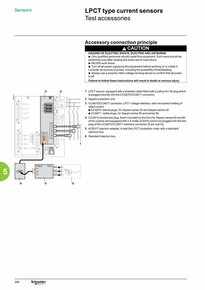
Accessory connection principle CAUTION
HAZARD OF ELECTRIC SHOCK, ELECTRIC ARC OR BURNSb Only qualified personnel should install this equipment. Such work should be performed only after reading this entire set of instructions.b NEVER work alone. b Turn off all power supplying this equipment before working on or inside it. Consider all sources of power, including the possibility of backfeeding.b Always use a properly rated voltage sensing device to confirm that all power is off.Failure to follow these instructions will result in death or serious injury.
DE
8831
3
1 LPCT sensor, equipped with a shielded cable fitted with a yellow RJ 45 plug which is plugged directly into the CCA670/CCA671 connector.
2 Sepam protection unit.3 CCA670/CCA671 connector, LPCT voltage interface, with microswitch setting of
rated current:b CCA670: lateral plugs, for Sepam series 20 and Sepam series 40b CCA671: radial plugs, for Sepam series 60 and series 80.
4 CCA613 remote test plug, flush-mounted on the front for Sepam series 60 and 80 of the cubicle and equipped with a 3-meter (9.84 ft) cord to be plugged into the test plug of the CCA670/CCA671 interface connector (9-pin sub-D).
5 ACE917 injection adapter, to test the LPCT protection chain with a standard injection box.
6 Standard injection box.
LPCT type current sensorsTest accessories
Sensors
268
5
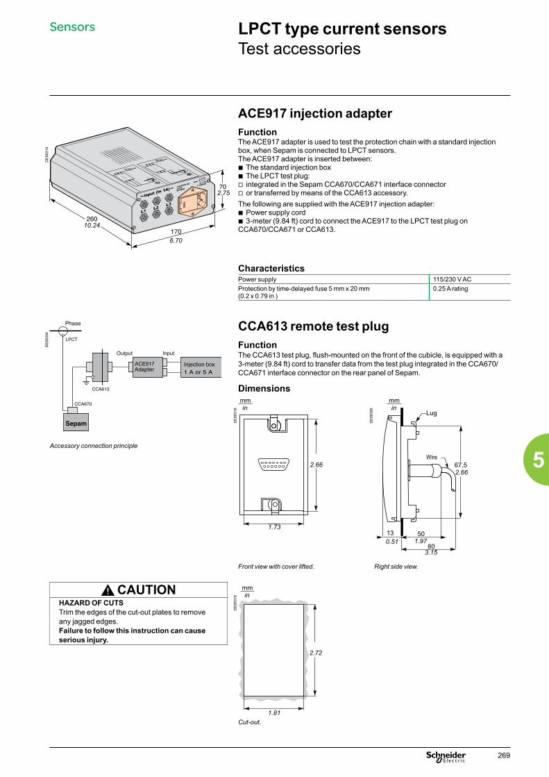
LPCT type current sensorsTest accessories
ACE917 injection adapterFunctionThe ACE917 adapter is used to test the protection chain with a standard injection box, when Sepam is connected to LPCT sensors.The ACE917 adapter is inserted between:b The standard injection boxb The LPCT test plug:v integrated in the Sepam CCA670/CCA671 interface connectorv or transferred by means of the CCA613 accessory.The following are supplied with the ACE917 injection adapter:b Power supply cordb 3-meter (9.84 ft) cord to connect the ACE917 to the LPCT test plug on CCA670/CCA671 or CCA613.
DE
8831
4
CharacteristicsPower supply 115/230 V AC Protection by time-delayed fuse 5 mm x 20 mm(0.2 x 0.79 in )
0.25 A rating
DE
8839
4
Accessory connection principle
CCA613 remote test plugFunctionThe CCA613 test plug, flush-mounted on the front of the cubicle, is equipped with a 3-meter (9.84 ft) cord to transfer data from the test plug integrated in the CCA670/CCA671 interface connector on the rear panel of Sepam.
Dimensions
DE
8831
6
DE
8839
5
Front view with cover lifted. Right side view.
CAUTION
DE
8831
8
HAZARD OF CUTSTrim the edges of the cut-out plates to remove any jagged edges.Failure to follow this instruction can cause serious injury.
Cut-out.
Sensors
10.24
6.70
2.75
mmin
1.73
2.66
Lug
67,5
13 50
80
Wire
0.51 1.97
3.15
2.66
mmin
1.81
2.72
mmin
269
5

CSH120 and CSH200 Core balance CTs
Function
PE
8808
9
The specifically designed CSH120 and CSH200 core balance CTs are for direct residual current measurement. The only difference between them is the diameter. Due to their low voltage insulation, they can only be used on cables.
CharacteristicsCSH120 CSH200
Inner diameter 120 mm (4.7 in) 200 mm (7.9 in)Weight 0.6 kg (1.32 lb) 1.4 kg (3.09 lb)Accuracy ±5% at 20°C (68°F)
±6% max. from -25°C to 70°C (-13°F to +158°F)
Transformation ratio 1/470CSH120 and CSH200 core balance CTs. Maximum permissible current 20 kA - 1 s
Operating temperature -25°C to +70°C (-13°F to +158°F)Storage temperature -40°C to +85°C (-40°F to +185°F)
Dimensions
DE
8839
6
Dimensions A B D E F H J K LCSH120(in)
120 (4.75)
164 (6.46)
44 (1.73)
190 (7.48)
80 (3.14)
40 (1.57)
166 (6.54)
65 (2.56)
35 (1.38)
CSH200(in)
196 (7.72)
256 (10.1)
46 (1.81)
274 (10.8)
120 (4.72)
60 (2.36)
254 (10)
104 (4.09)
37 (1.46)
Sensors
66
270
5
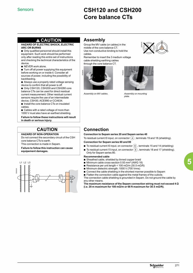
CSH120 and CSH200 Core balance CTs
CAUTION Assembly
DE
8832
5
HAZARD OF ELECTRIC SHOCK, ELECTRIC ARC OR BURNSb Only qualified personnel should install this equipment. Such work should be performed only after reading this entire set of instructions and checking the technical characteristics of the device.b NEVER work alone. b Turn off all power supplying this equipment before working on or inside it. Consider all sources of power, including the possibility of backfeeding.b Always use a properly rated voltage sensing device to confirm that all power is off.b Only CSH120, CSH200 and CSH280 core balance CTs can be used for direct residual current measurement. Other residual current sensors require the use of an intermediate device, CSH30, ACE990 or CCA634.b Install the core balance CTs on insulated cables.b Cables with a rated voltage of more than 1000 V must also have an earthed shielding.Failure to follow these instructions will result in death or serious injury.
Group the MV cable (or cables) in the middle of the core balance CT.Use non-conductive binding to hold the cables.Remember to insert the 3 medium voltage cable shielding earthing cables through the core balance CT.
PE
8809
0
PE
8809
1
Assembly on MV cables. Assembly on mounting plate.
CAUTION ConnectionHAZARD OF NON-OPERATIONDo not connect the secondary circuit of the CSH core balance CTs to earth. This connection is made in Sepam.Failure to follow this instruction can cause equipement damages.
Connection to Sepam series 20 and Sepam series 40To residual current I0 input, on connector A , terminals 19 and 18 (shielding).Connection for Sepam series 60 and 80b To residual current I0 input, on connector E , terminals 15 and 14 (shielding)b To residual current I’0 input, on connector E , terminals 18 and 17 (shielding).
Only for Sepam series 80.Recommended cableb Sheathed cable, shielded by tinned copper braidb Minimum cable cross-section 0.93 mm² (AWG 18)b Resistance per unit length < 100 mΩ/m (30.5 mΩ/ft)b Minimum dielectric strength: 1000 V (700 Vrms)b Connect the cable shielding in the shortest manner possible to Sepamb Flatten the connection cable against the metal frames of the cubicle.The connection cable shielding is grounded in Sepam. Do not ground the cable by any other means.The maximum resistance of the Sepam connection wiring must not exceed 4 Ω (i.e. 20 m maximum for 100 mΩ/m or 66 ft maximum for 30.5 mΩ/ft).
DE
8832
0
Sensors
271
5
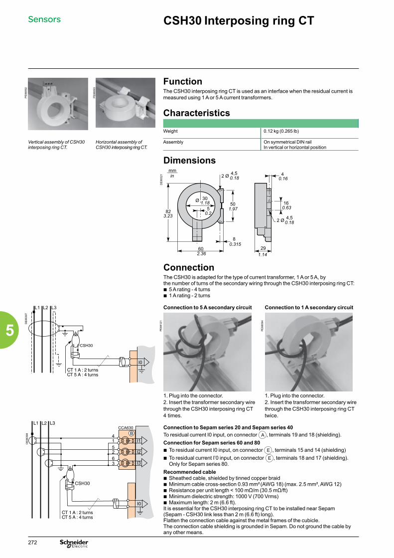
CSH30 Interposing ring CT
PE
8809
2
PE
8809
3
FunctionThe CSH30 interposing ring CT is used as an interface when the residual current is measured using 1 A or 5 A current transformers.
Characteristics
Weight 0.12 kg (0.265 lb)
Vertical assembly of CSH30 interposing ring CT.
Horizontal assembly of CSH30 interposing ring CT.
Assembly On symmetrical DIN railIn vertical or horizontal position
DimensionsD
E88
321
ConnectionThe CSH30 is adapted for the type of current transformer, 1 A or 5 A, by the number of turns of the secondary wiring through the CSH30 interposing ring CT:b 5 A rating - 4 turnsb 1 A rating - 2 turns
DE
8839
7
Connection to 5 A secondary circuit Connection to 1 A secondary circuit
PE
8812
1
PE
8809
4
1. Plug into the connector.2. Insert the transformer secondary wire through the CSH30 interposing ring CT 4 times.
1. Plug into the connector.2. Insert the transformer secondary wire through the CSH30 interposing ring CT twice.
DE
8839
8
Connection to Sepam series 20 and Sepam series 40 To residual current I0 input, on connector A , terminals 19 and 18 (shielding).Connection for Sepam series 60 and 80b To residual current I0 input, on connector E , terminals 15 and 14 (shielding)b To residual current I’0 input, on connector E , terminals 18 and 17 (shielding).
Only for Sepam series 80.Recommended cableb Sheathed cable, shielded by tinned copper braidb Minimum cable cross-section 0.93 mm² (AWG 18) (max. 2.5 mm², AWG 12)b Resistance per unit length < 100 mΩ/m (30.5 mΩ/ft)b Minimum dielectric strength: 1000 V (700 Vrms)b Maximum length: 2 m (6.6 ft).It is essential for the CSH30 interposing ring CT to be installed near Sepam (Sepam - CSH30 link less than 2 m (6.6 ft) long).Flatten the connection cable against the metal frames of the cubicle.The connection cable shielding is grounded in Sepam. Do not ground the cable by any other means.
Sensors
3.23
mmin
1.18
0.2
0.18
1.97
0.315
2.36
0.16
0.63
0.18
1.14
turnsturns
turnsturns
272
5
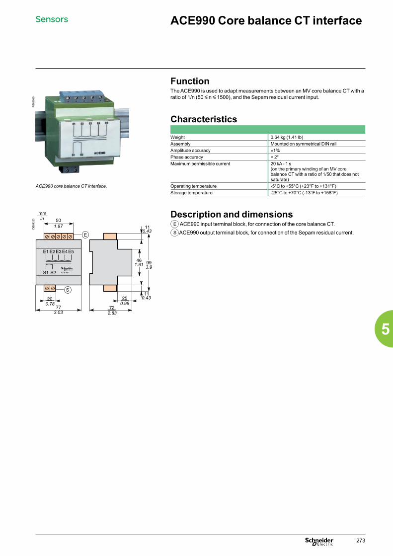
ACE990 Core balance CT interface
Function
PE
8809
5
The ACE990 is used to adapt measurements between an MV core balance CT with a ratio of 1/n (50 y n y 1500), and the Sepam residual current input.
Characteristics
Weight 0.64 kg (1.41 lb)Assembly Mounted on symmetrical DIN railAmplitude accuracy ±1%Phase accuracy < 2°Maximum permissible current 20 kA - 1 s
(on the primary winding of an MV core balance CT with a ratio of 1/50 that does not saturate)
ACE990 core balance CT interface. Operating temperature -5°C to +55°C (+23°F to +131°F)Storage temperature -25°C to +70°C (-13°F to +158°F)
DE
8832
3
Description and dimensionsE ACE990 input terminal block, for connection of the core balance CT.S ACE990 output terminal block, for connection of the Sepam residual current.
Sensors
mmin
1.97
0.78
3.03 2.83
0.98
3.91.81
0.43
0.43
273
5

Connection
DE
8832
4
Connection of core balance CTOnly one core balance CT can be connected to the ACE990 interface.The secondary circuit of the MV core balance CT is connected to 2 of the 5 ACE990 interface input terminals. To define the 2 input terminals, it is necessary to know the following:b Core balance CT ratio (1/n)b Core balance CT powerb Close approximation of rated current In0 (In0 is a general setting in Sepam and defines the earth fault protection setting range between 0.1 In0 and 15 In0).
The table below can be used to determine:b The 2 ACE990 input terminals to be connected to the MV core balance CT secondaryb The type of residual current sensor to set b The exact value of the rated residual current In0 setting, given by the following formula: In0 = k x number of core balance CT turns with k the factor defined in the table below.
The core balance CT must be connected to the interface in the right direction for correct operation: the MV core balance CT secondary output terminal S1 must be connected to the terminal with the lowest index (Ex).
ACE990 Core balance CT interface
Sensors
274
5
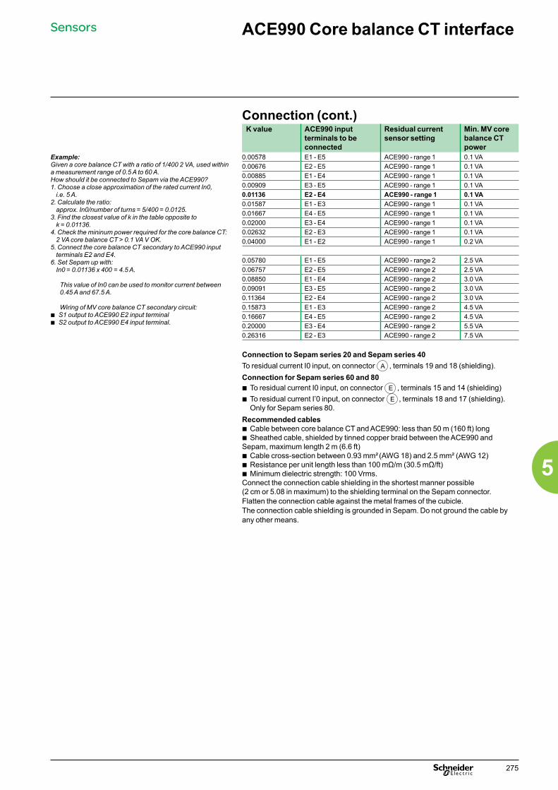
ACE990 Core balance CT interface
Sensors
Connection (cont.)K value ACE990 input
terminals to be connected
Residual current sensor setting
Min. MV core balance CT power
Example: Given a core balance CT with a ratio of 1/400 2 VA, used within a measurement range of 0.5 A to 60 A.How should it be connected to Sepam via the ACE990?1. Choose a close approximation of the rated current In0, i.e. 5 A.2. Calculate the ratio: approx. In0/number of turns = 5/400 = 0.0125.3. Find the closest value of k in the table opposite to k = 0.01136.4. Check the mininum power required for the core balance CT: 2 VA core balance CT > 0.1 VA V OK.5. Connect the core balance CT secondary to ACE990 input terminals E2 and E4.6. Set Sepam up with: In0 = 0.01136 x 400 = 4.5 A.
This value of In0 can be used to monitor current between 0.45 A and 67.5 A.
Wiring of MV core balance CT secondary circuit:b S1 output to ACE990 E2 input terminal b S2 output to ACE990 E4 input terminal.
0.00578 E1 - E5 ACE990 - range 1 0.1 VA0.00676 E2 - E5 ACE990 - range 1 0.1 VA0.00885 E1 - E4 ACE990 - range 1 0.1 VA0.00909 E3 - E5 ACE990 - range 1 0.1 VA0.01136 E2 - E4 ACE990 - range 1 0.1 VA0.01587 E1 - E3 ACE990 - range 1 0.1 VA0.01667 E4 - E5 ACE990 - range 1 0.1 VA0.02000 E3 - E4 ACE990 - range 1 0.1 VA0.02632 E2 - E3 ACE990 - range 1 0.1 VA0.04000 E1 - E2 ACE990 - range 1 0.2 VA
0.05780 E1 - E5 ACE990 - range 2 2.5 VA0.06757 E2 - E5 ACE990 - range 2 2.5 VA0.08850 E1 - E4 ACE990 - range 2 3.0 VA0.09091 E3 - E5 ACE990 - range 2 3.0 VA0.11364 E2 - E4 ACE990 - range 2 3.0 VA0.15873 E1 - E3 ACE990 - range 2 4.5 VA0.16667 E4 - E5 ACE990 - range 2 4.5 VA0.20000 E3 - E4 ACE990 - range 2 5.5 VA0.26316 E2 - E3 ACE990 - range 2 7.5 VA
Connection to Sepam series 20 and Sepam series 40To residual current I0 input, on connector A , terminals 19 and 18 (shielding).Connection for Sepam series 60 and 80b To residual current I0 input, on connector E , terminals 15 and 14 (shielding)b To residual current I’0 input, on connector E , terminals 18 and 17 (shielding).
Only for Sepam series 80.Recommended cablesb Cable between core balance CT and ACE990: less than 50 m (160 ft) longb Sheathed cable, shielded by tinned copper braid between the ACE990 and Sepam, maximum length 2 m (6.6 ft)b Cable cross-section between 0.93 mm² (AWG 18) and 2.5 mm² (AWG 12)b Resistance per unit length less than 100 mΩ/m (30.5 mΩ/ft)b Minimum dielectric strength: 100 Vrms.Connect the connection cable shielding in the shortest manner possible (2 cm or 5.08 in maximum) to the shielding terminal on the Sepam connector.Flatten the connection cable against the metal frames of the cubicle.The connection cable shielding is grounded in Sepam. Do not ground the cable by any other means.
275
5

This international site allows you to access all the Schneider Electric products in just 2 clicks via comprehensive range data-sheets, with direct links to:
complete library: technical documents, catalogs, FAQs, brochures…
selection guides from the e-catalog.
product discovery sites and their Flash animations.You will also find illustrated overviews, news to which you can subscribe, the list of country contacts…
p
p
p
These technical guides help you comply with installation standards and rules i.e.: the electrical installation guide, the protection guide, the switchboard implementation guide,the technical booklets and the co-ordination tables all form genuine reference tools for the design of high performance electrical installations.For example, the LV protection co-ordination guide - discrimination and cascading - optimises choice of protection and connection devices while also increasing markedly continuity of supply in the installations.
schneider-electric.com The technical guide
TOOLS
276276
6