Gemini Coversheet_9.28.07 - WordPress.com
422
Gemini Hyperscale™ Messaging Center (HMC ) Administrator’s Guide Document Release 3.7.5 • August 20, 2009
-
Upload
khangminh22 -
Category
Documents
-
view
0 -
download
0
Transcript of Gemini Coversheet_9.28.07 - WordPress.com
Gemini Hyperscale™ Messaging Center (HMC)
Administrator’s Guide
Document Release 3.7.5 • August 20, 2009

Copyright Notices
Copyright (c) 2009 Gemini Mobile Technologies, Inc. All rights reserved.
Gemini Mobile® and HyperScale® are registered trademarks of Gemini Mobile Technologies, Inc. in the United States and other countries.
Windows® is a registered trademark of Microsoft Corporation in the United States and other countries.
LifeKeeper® is a registered trademark of SteelEye Technology, Inc.
Portions of Gemini products include third-party technology used under license. One or more of the following notices may apply in connection with the license and use of the Gemini products.
Copyright (c) 1994-2000 Carnegie Mellon University. All rights reserved. Redistribution and use in source and binary forms, with or without modification, are permitted provided that the following conditions are met:
1 Redistributions of source code must retain the above copyright notice, this list of conditions, and the following disclaimer.
2 Redistributions in binary form must reproduce the above copyright notice, this list of conditions and the following disclaimer in the documentation and/or other materials provided with the distribution.
3 The name "Carnegie Mellon University" must not be used to endorse or promote products derived from this software without prior written permission. For permission or any legal details, please contact:
Office of Technology TransferCarnegie Mellon University5000 Forbes AvenuePittsburgh, PA 15213-3890(412) 268-4387, fax: (412) [email protected]
4 Redistributions of any form whatsoever must retain the following acknowledgment:
“This product includes software developed by Computing Services at Carnegie Mellon University (http://www.cmu.edu/computing/).”
CARNEGIE MELLON UNIVERSITY DISCLAIMS ALL WARRANTIES WITH REGARD TO THIS SOFTWARE, INCLUDING ALL IMPLIED WARRANTIES OF MERCHANTABILITY AND FITNESS, IN NO EVENT SHALL CARNEGIE MELLON UNIVERSITY BE LIABLE FOR ANY SPECIAL, INDIRECT OR CONSEQUENTIAL DAMAGES OR ANY DAMAGES WHATSOEVER RESULTING FROM LOSS OF USE, DATA OR PROFITS, WHETHER IN AN ACTION OF CONTRACT, NEGLIGENCE OR OTHER TORTIOUS ACTION, ARISING OUT OF OR IN CONNECTION WITH THE USE OR PERFORMANCE OF THIS SOFTWARE.
Contents
PrefacePurpose of This Manual . . . . . . . . . . . . . . . . . . . . . . . . . . . . . . . . . . . . . . . . . . . . . . . . . . . . . . . . . 2
Typographic Conventions . . . . . . . . . . . . . . . . . . . . . . . . . . . . . . . . . . . . . . . . . . . . . . . . . . . . . . 3
Acronyms . . . . . . . . . . . . . . . . . . . . . . . . . . . . . . . . . . . . . . . . . . . . . . . . . . . . . . . . . . . . . . . . . . . . . . 4
Related Documents . . . . . . . . . . . . . . . . . . . . . . . . . . . . . . . . . . . . . . . . . . . . . . . . . . . . . . . . . . . . 6
Gemini Guides . . . . . . . . . . . . . . . . . . . . . . . . . . . . . . . . . . . . . . . . . . . . . . . . . . . . . . . . . . . . . . . . . . . 6
Standards Documents . . . . . . . . . . . . . . . . . . . . . . . . . . . . . . . . . . . . . . . . . . . . . . . . . . . . . . . . . . . 6
Contacting Gemini Mobile Technologies. . . . . . . . . . . . . . . . . . . . . . . . . . . . . . . . . . . . . . . . . 8
1 Overview
HMC Description . . . . . . . . . . . . . . . . . . . . . . . . . . . . . . . . . . . . . . . . . . . . . . . . . . . . . . . . . . . . . . 10
HMC’s HyperScale® Technology . . . . . . . . . . . . . . . . . . . . . . . . . . . . . . . . . . . . . . . . . . . . . . . . 11
HyperScale® I/O Processing. . . . . . . . . . . . . . . . . . . . . . . . . . . . . . . . . . . . . . . . . . . . . . . . . . . . . . 11
Logical Architecture . . . . . . . . . . . . . . . . . . . . . . . . . . . . . . . . . . . . . . . . . . . . . . . . . . . . . . . . . . . 13
Direct Client Interfaces . . . . . . . . . . . . . . . . . . . . . . . . . . . . . . . . . . . . . . . . . . . . . . . . . . . . . . . . . . 14
Other Messaging Interfaces . . . . . . . . . . . . . . . . . . . . . . . . . . . . . . . . . . . . . . . . . . . . . . . . . . . . . 15
Operations/Business Support System Interfaces. . . . . . . . . . . . . . . . . . . . . . . . . . . . . . . . . . 15
Physical Architecture . . . . . . . . . . . . . . . . . . . . . . . . . . . . . . . . . . . . . . . . . . . . . . . . . . . . . . . . . . 16
Processing Nodes . . . . . . . . . . . . . . . . . . . . . . . . . . . . . . . . . . . . . . . . . . . . . . . . . . . . . . . . . . . . . . . 16
Storage Area Network. . . . . . . . . . . . . . . . . . . . . . . . . . . . . . . . . . . . . . . . . . . . . . . . . . . . . . . . . . . 16
Ethernet Switches. . . . . . . . . . . . . . . . . . . . . . . . . . . . . . . . . . . . . . . . . . . . . . . . . . . . . . . . . . . . . . . 16
SAN Switch . . . . . . . . . . . . . . . . . . . . . . . . . . . . . . . . . . . . . . . . . . . . . . . . . . . . . . . . . . . . . . . . . . . . . 17
Redundancy, Reliability, and Availability . . . . . . . . . . . . . . . . . . . . . . . . . . . . . . . . . . . . . . . 18
HMG, HPG Redundancy . . . . . . . . . . . . . . . . . . . . . . . . . . . . . . . . . . . . . . . . . . . . . . . . . . . . . . . . . 18
GMS Redundancy . . . . . . . . . . . . . . . . . . . . . . . . . . . . . . . . . . . . . . . . . . . . . . . . . . . . . . . . . . . . . . . 18
GDS Redundancy . . . . . . . . . . . . . . . . . . . . . . . . . . . . . . . . . . . . . . . . . . . . . . . . . . . . . . . . . . . . . . . 19
NMS and User Portal Redundancy . . . . . . . . . . . . . . . . . . . . . . . . . . . . . . . . . . . . . . . . . . . . . . . 19
Availability Figures Calculated. . . . . . . . . . . . . . . . . . . . . . . . . . . . . . . . . . . . . . . . . . . . . . . . . . . 19
HMC Deployment Modes . . . . . . . . . . . . . . . . . . . . . . . . . . . . . . . . . . . . . . . . . . . . . . . . . . . . . . 21
Person to Person (P2P) HMC . . . . . . . . . . . . . . . . . . . . . . . . . . . . . . . . . . . . . . . . . . . . . . . . . . . . . 21
Application to Person (A2P) HMC . . . . . . . . . . . . . . . . . . . . . . . . . . . . . . . . . . . . . . . . . . . . . . . . 21
Hosted Operator Support . . . . . . . . . . . . . . . . . . . . . . . . . . . . . . . . . . . . . . . . . . . . . . . . . . . . . . 23
Network Administrators . . . . . . . . . . . . . . . . . . . . . . . . . . . . . . . . . . . . . . . . . . . . . . . . . . . . . . . . . 23
Service Provider Administrators . . . . . . . . . . . . . . . . . . . . . . . . . . . . . . . . . . . . . . . . . . . . . . . . . 23
HMC Subsystems . . . . . . . . . . . . . . . . . . . . . . . . . . . . . . . . . . . . . . . . . . . . . . . . . . . . . . . . . . . . . . 25
HyperScale® Messaging Gateway (HMG) . . . . . . . . . . . . . . . . . . . . . . . . . . . . . . . . . . . . . . . . . 25
Gemini Message Store (GMS) . . . . . . . . . . . . . . . . . . . . . . . . . . . . . . . . . . . . . . . . . . . . . . . . . . . . 26
HyperScale Push Gateway (HPG). . . . . . . . . . . . . . . . . . . . . . . . . . . . . . . . . . . . . . . . . . . . . . . . . 26
User Portal. . . . . . . . . . . . . . . . . . . . . . . . . . . . . . . . . . . . . . . . . . . . . . . . . . . . . . . . . . . . . . . . . . . . . . 27
Gemini Directory Service . . . . . . . . . . . . . . . . . . . . . . . . . . . . . . . . . . . . . . . . . . . . . . . . . . . . . . . . 28
Network Management System (NMS) . . . . . . . . . . . . . . . . . . . . . . . . . . . . . . . . . . . . . . . . . . . . 28
2 Features
Interfaces . . . . . . . . . . . . . . . . . . . . . . . . . . . . . . . . . . . . . . . . . . . . . . . . . . . . . . . . . . . . . . . . . . . . . 32
MM1 Interfaces . . . . . . . . . . . . . . . . . . . . . . . . . . . . . . . . . . . . . . . . . . . . . . . . . . . . . . . . . . . . . . . . . 32
User Portal MM1 Interface . . . . . . . . . . . . . . . . . . . . . . . . . . . . . . . . . . . . . . . . . . . . . . . . . . . . . . . 32
MM2 Interface . . . . . . . . . . . . . . . . . . . . . . . . . . . . . . . . . . . . . . . . . . . . . . . . . . . . . . . . . . . . . . . . . . 33
MM3 Interface . . . . . . . . . . . . . . . . . . . . . . . . . . . . . . . . . . . . . . . . . . . . . . . . . . . . . . . . . . . . . . . . . . 33
MM4 Interface . . . . . . . . . . . . . . . . . . . . . . . . . . . . . . . . . . . . . . . . . . . . . . . . . . . . . . . . . . . . . . . . . . 34
SMTP Extension . . . . . . . . . . . . . . . . . . . . . . . . . . . . . . . . . . . . . . . . . . . . . . . . . . . . . . . . . . . . . . . . . . . . 34
Interface with 2-way Server. . . . . . . . . . . . . . . . . . . . . . . . . . . . . . . . . . . . . . . . . . . . . . . . . . . . . . . . . 34
MM5 Interface . . . . . . . . . . . . . . . . . . . . . . . . . . . . . . . . . . . . . . . . . . . . . . . . . . . . . . . . . . . . . . . . . . 35
MM6 Interface . . . . . . . . . . . . . . . . . . . . . . . . . . . . . . . . . . . . . . . . . . . . . . . . . . . . . . . . . . . . . . . . . . 35
MM7 Interface . . . . . . . . . . . . . . . . . . . . . . . . . . . . . . . . . . . . . . . . . . . . . . . . . . . . . . . . . . . . . . . . . . 35
Specifications Compliance . . . . . . . . . . . . . . . . . . . . . . . . . . . . . . . . . . . . . . . . . . . . . . . . . . . . . . . . . 36
VASP Authentication . . . . . . . . . . . . . . . . . . . . . . . . . . . . . . . . . . . . . . . . . . . . . . . . . . . . . . . . . . . . . . . 37
VASP Authorization. . . . . . . . . . . . . . . . . . . . . . . . . . . . . . . . . . . . . . . . . . . . . . . . . . . . . . . . . . . . . . . . . 37
VASP Management. . . . . . . . . . . . . . . . . . . . . . . . . . . . . . . . . . . . . . . . . . . . . . . . . . . . . . . . . . . . . . . . . 38
MM8 Interface . . . . . . . . . . . . . . . . . . . . . . . . . . . . . . . . . . . . . . . . . . . . . . . . . . . . . . . . . . . . . . . . . . 39
Native CDRs . . . . . . . . . . . . . . . . . . . . . . . . . . . . . . . . . . . . . . . . . . . . . . . . . . . . . . . . . . . . . . . . . . . . . . . . 39
Custom CDRs . . . . . . . . . . . . . . . . . . . . . . . . . . . . . . . . . . . . . . . . . . . . . . . . . . . . . . . . . . . . . . . . . . . . . . 39
CDR Log File Rotation . . . . . . . . . . . . . . . . . . . . . . . . . . . . . . . . . . . . . . . . . . . . . . . . . . . . . . . . . . . . . . 40
CDR Retrieval. . . . . . . . . . . . . . . . . . . . . . . . . . . . . . . . . . . . . . . . . . . . . . . . . . . . . . . . . . . . . . . . . . . . . . . 40
Contents
MDR support. . . . . . . . . . . . . . . . . . . . . . . . . . . . . . . . . . . . . . . . . . . . . . . . . . . . . . . . . . . . . . . . . . . . . . . 40
MM9 Interface . . . . . . . . . . . . . . . . . . . . . . . . . . . . . . . . . . . . . . . . . . . . . . . . . . . . . . . . . . . . . . . . . . 41
UAProf Interface (CPI) . . . . . . . . . . . . . . . . . . . . . . . . . . . . . . . . . . . . . . . . . . . . . . . . . . . . . . . . . . . 42
Standard Transcoding Interface (OMA-STI) . . . . . . . . . . . . . . . . . . . . . . . . . . . . . . . . . . . . . . . 42
Distribution List Interface . . . . . . . . . . . . . . . . . . . . . . . . . . . . . . . . . . . . . . . . . . . . . . . . . . . . . . . 43
Distribution Lists Management . . . . . . . . . . . . . . . . . . . . . . . . . . . . . . . . . . . . . . . . . . . . . . . . . . . . . 44
SMPP and Push OTA Towards Handsets Interfaces . . . . . . . . . . . . . . . . . . . . . . . . . . . . . . . 45
Interface Towards SMSCs . . . . . . . . . . . . . . . . . . . . . . . . . . . . . . . . . . . . . . . . . . . . . . . . . . . . . . . . . . . 45
Interface Towards Handsets . . . . . . . . . . . . . . . . . . . . . . . . . . . . . . . . . . . . . . . . . . . . . . . . . . . . . . . . 46
SNMP Interface . . . . . . . . . . . . . . . . . . . . . . . . . . . . . . . . . . . . . . . . . . . . . . . . . . . . . . . . . . . . . . . . . 46
Gemini MIB Specification . . . . . . . . . . . . . . . . . . . . . . . . . . . . . . . . . . . . . . . . . . . . . . . . . . . . . . . . . . . 47
Provisioning Interface . . . . . . . . . . . . . . . . . . . . . . . . . . . . . . . . . . . . . . . . . . . . . . . . . . . . . . . . . . . 55
Bulk Provisioning Using LDIF File Upload . . . . . . . . . . . . . . . . . . . . . . . . . . . . . . . . . . . . . . . . . . . 56
Native HTTP Interface . . . . . . . . . . . . . . . . . . . . . . . . . . . . . . . . . . . . . . . . . . . . . . . . . . . . . . . . . . . . . . 57
HTTP Interface . . . . . . . . . . . . . . . . . . . . . . . . . . . . . . . . . . . . . . . . . . . . . . . . . . . . . . . . . . . . . . . . . . . . . 57
Individual Provisioning From NMS . . . . . . . . . . . . . . . . . . . . . . . . . . . . . . . . . . . . . . . . . . . . . . . . . . 57
GDS Provisioning Details . . . . . . . . . . . . . . . . . . . . . . . . . . . . . . . . . . . . . . . . . . . . . . . . . . . . . . . . . . . 58
Logging . . . . . . . . . . . . . . . . . . . . . . . . . . . . . . . . . . . . . . . . . . . . . . . . . . . . . . . . . . . . . . . . . . . . . . . . 59
Transaction Log . . . . . . . . . . . . . . . . . . . . . . . . . . . . . . . . . . . . . . . . . . . . . . . . . . . . . . . . . . . . . . . . . . . . 59
Application Log . . . . . . . . . . . . . . . . . . . . . . . . . . . . . . . . . . . . . . . . . . . . . . . . . . . . . . . . . . . . . . . . . . . . 60
Statistical Log . . . . . . . . . . . . . . . . . . . . . . . . . . . . . . . . . . . . . . . . . . . . . . . . . . . . . . . . . . . . . . . . . . . . . . 60
Message Routing . . . . . . . . . . . . . . . . . . . . . . . . . . . . . . . . . . . . . . . . . . . . . . . . . . . . . . . . . . . . . . 62
Addressing . . . . . . . . . . . . . . . . . . . . . . . . . . . . . . . . . . . . . . . . . . . . . . . . . . . . . . . . . . . . . . . . . . . . . 62
National Numbering Plans. . . . . . . . . . . . . . . . . . . . . . . . . . . . . . . . . . . . . . . . . . . . . . . . . . . . . . . . . . 62
Short Code Formats . . . . . . . . . . . . . . . . . . . . . . . . . . . . . . . . . . . . . . . . . . . . . . . . . . . . . . . . . . . . . . . . 62
Message Delivery . . . . . . . . . . . . . . . . . . . . . . . . . . . . . . . . . . . . . . . . . . . . . . . . . . . . . . . . . . . . . . . 62
MMS User Delivery . . . . . . . . . . . . . . . . . . . . . . . . . . . . . . . . . . . . . . . . . . . . . . . . . . . . . . . . . . . . . . . . . 63
Legacy User Via SMS Delivery. . . . . . . . . . . . . . . . . . . . . . . . . . . . . . . . . . . . . . . . . . . . . . . . . . . . . . . 63
Users Served By Foreign MMSC Delivery . . . . . . . . . . . . . . . . . . . . . . . . . . . . . . . . . . . . . . . . . . . . 63
Domain Name Delivery. . . . . . . . . . . . . . . . . . . . . . . . . . . . . . . . . . . . . . . . . . . . . . . . . . . . . . . . . . . . . 63
VASP Delivery . . . . . . . . . . . . . . . . . . . . . . . . . . . . . . . . . . . . . . . . . . . . . . . . . . . . . . . . . . . . . . . . . . . . . . 64
Internet Client Delivery . . . . . . . . . . . . . . . . . . . . . . . . . . . . . . . . . . . . . . . . . . . . . . . . . . . . . . . . . . . . . 64
Message Routing . . . . . . . . . . . . . . . . . . . . . . . . . . . . . . . . . . . . . . . . . . . . . . . . . . . . . . . . . . . . . . . 64
Message Notification . . . . . . . . . . . . . . . . . . . . . . . . . . . . . . . . . . . . . . . . . . . . . . . . . . . . . . . . . . 66
Message Received . . . . . . . . . . . . . . . . . . . . . . . . . . . . . . . . . . . . . . . . . . . . . . . . . . . . . . . . . . . . . . 66
Delivery Report . . . . . . . . . . . . . . . . . . . . . . . . . . . . . . . . . . . . . . . . . . . . . . . . . . . . . . . . . . . . . . . . . 66
Contents
Read Reports . . . . . . . . . . . . . . . . . . . . . . . . . . . . . . . . . . . . . . . . . . . . . . . . . . . . . . . . . . . . . . . . . . . 66
Message Storage and Retrieval. . . . . . . . . . . . . . . . . . . . . . . . . . . . . . . . . . . . . . . . . . . . . . . . . 67
Automatic Provisioning and Activation . . . . . . . . . . . . . . . . . . . . . . . . . . . . . . . . . . . . . . . . . . 67
Message Storage. . . . . . . . . . . . . . . . . . . . . . . . . . . . . . . . . . . . . . . . . . . . . . . . . . . . . . . . . . . . . . . . 68
Message Retrieval. . . . . . . . . . . . . . . . . . . . . . . . . . . . . . . . . . . . . . . . . . . . . . . . . . . . . . . . . . . . . . . 68
MMBox . . . . . . . . . . . . . . . . . . . . . . . . . . . . . . . . . . . . . . . . . . . . . . . . . . . . . . . . . . . . . . . . . . . . . . . . . 68
Mailbox Capacity Controls. . . . . . . . . . . . . . . . . . . . . . . . . . . . . . . . . . . . . . . . . . . . . . . . . . . . . . . 69
Message Expiration Controls . . . . . . . . . . . . . . . . . . . . . . . . . . . . . . . . . . . . . . . . . . . . . . . . . . . . 69
Transcoding and Content Adaptation . . . . . . . . . . . . . . . . . . . . . . . . . . . . . . . . . . . . . . . . . . 70
Internal Transcoding . . . . . . . . . . . . . . . . . . . . . . . . . . . . . . . . . . . . . . . . . . . . . . . . . . . . . . . . . . . . 70
OMA-STI interface. . . . . . . . . . . . . . . . . . . . . . . . . . . . . . . . . . . . . . . . . . . . . . . . . . . . . . . . . . . . . . . 71
Regulatory and Security Controls . . . . . . . . . . . . . . . . . . . . . . . . . . . . . . . . . . . . . . . . . . . . . . 72
Authorization of MO and MT . . . . . . . . . . . . . . . . . . . . . . . . . . . . . . . . . . . . . . . . . . . . . . . . . . . . 72
Authorization of VASP. . . . . . . . . . . . . . . . . . . . . . . . . . . . . . . . . . . . . . . . . . . . . . . . . . . . . . . . . . . 72
Maximum Recipients Per Message . . . . . . . . . . . . . . . . . . . . . . . . . . . . . . . . . . . . . . . . . . . . . . . 73
Maximum Incoming Message Size . . . . . . . . . . . . . . . . . . . . . . . . . . . . . . . . . . . . . . . . . . . . . . . 73
Spam Filtering . . . . . . . . . . . . . . . . . . . . . . . . . . . . . . . . . . . . . . . . . . . . . . . . . . . . . . . . . . . . . . . . 74
Keyword Filtering . . . . . . . . . . . . . . . . . . . . . . . . . . . . . . . . . . . . . . . . . . . . . . . . . . . . . . . . . . . . . . . 74
Service Provider White and Black Lists . . . . . . . . . . . . . . . . . . . . . . . . . . . . . . . . . . . . . . . . . . . 74
User White and Black Lists . . . . . . . . . . . . . . . . . . . . . . . . . . . . . . . . . . . . . . . . . . . . . . . . . . . . . . . 75
External Spam Filter Integration . . . . . . . . . . . . . . . . . . . . . . . . . . . . . . . . . . . . . . . . . . . . . . . . . 75
Multiple Language Support . . . . . . . . . . . . . . . . . . . . . . . . . . . . . . . . . . . . . . . . . . . . . . . . . . . . 76
Hosting Services . . . . . . . . . . . . . . . . . . . . . . . . . . . . . . . . . . . . . . . . . . . . . . . . . . . . . . . . . . . . . . 77
Lawful Interception. . . . . . . . . . . . . . . . . . . . . . . . . . . . . . . . . . . . . . . . . . . . . . . . . . . . . . . . . . . . 78
3 Systems Information, N+1 Update
HMC Configuration . . . . . . . . . . . . . . . . . . . . . . . . . . . . . . . . . . . . . . . . . . . . . . . . . . . . . . . . . . . . 82
Processing Nodes . . . . . . . . . . . . . . . . . . . . . . . . . . . . . . . . . . . . . . . . . . . . . . . . . . . . . . . . . . . . . . . 82
Ethernet Switches and VLANs . . . . . . . . . . . . . . . . . . . . . . . . . . . . . . . . . . . . . . . . . . . . . . . . . . . 83
Storage Area Network. . . . . . . . . . . . . . . . . . . . . . . . . . . . . . . . . . . . . . . . . . . . . . . . . . . . . . . . . . . 83
SAN Switch . . . . . . . . . . . . . . . . . . . . . . . . . . . . . . . . . . . . . . . . . . . . . . . . . . . . . . . . . . . . . . . . . . . . . 83
Services. . . . . . . . . . . . . . . . . . . . . . . . . . . . . . . . . . . . . . . . . . . . . . . . . . . . . . . . . . . . . . . . . . . . . . . 84
Failover. . . . . . . . . . . . . . . . . . . . . . . . . . . . . . . . . . . . . . . . . . . . . . . . . . . . . . . . . . . . . . . . . . . . . . . . . 84
Contents
Rack One Description . . . . . . . . . . . . . . . . . . . . . . . . . . . . . . . . . . . . . . . . . . . . . . . . . . . . . . . . . . . 85
Services and Physical Nodes . . . . . . . . . . . . . . . . . . . . . . . . . . . . . . . . . . . . . . . . . . . . . . . . . . . . . . . . 85
Services on Nodes. . . . . . . . . . . . . . . . . . . . . . . . . . . . . . . . . . . . . . . . . . . . . . . . . . . . . . . . . . . . . . . . . . 86
SAN Disk Usage . . . . . . . . . . . . . . . . . . . . . . . . . . . . . . . . . . . . . . . . . . . . . . . . . . . . . . . . . . . . . . . . . . . . 86
Rack Layout . . . . . . . . . . . . . . . . . . . . . . . . . . . . . . . . . . . . . . . . . . . . . . . . . . . . . . . . . . . . . . . . . . . . . . . . 87
Rack Two Description . . . . . . . . . . . . . . . . . . . . . . . . . . . . . . . . . . . . . . . . . . . . . . . . . . . . . . . . . . . 88
Services and Physical Nodes . . . . . . . . . . . . . . . . . . . . . . . . . . . . . . . . . . . . . . . . . . . . . . . . . . . . . . . . 88
Services on Nodes. . . . . . . . . . . . . . . . . . . . . . . . . . . . . . . . . . . . . . . . . . . . . . . . . . . . . . . . . . . . . . . . . . 88
SAN Disk Usage . . . . . . . . . . . . . . . . . . . . . . . . . . . . . . . . . . . . . . . . . . . . . . . . . . . . . . . . . . . . . . . . . . . . 89
Rack Layout . . . . . . . . . . . . . . . . . . . . . . . . . . . . . . . . . . . . . . . . . . . . . . . . . . . . . . . . . . . . . . . . . . . . . . . . 90
Rack Three Description. . . . . . . . . . . . . . . . . . . . . . . . . . . . . . . . . . . . . . . . . . . . . . . . . . . . . . . . . . 91
Services and Physical Nodes . . . . . . . . . . . . . . . . . . . . . . . . . . . . . . . . . . . . . . . . . . . . . . . . . . . . . . . . 91
Services on Nodes. . . . . . . . . . . . . . . . . . . . . . . . . . . . . . . . . . . . . . . . . . . . . . . . . . . . . . . . . . . . . . . . . . 91
SAN Disk Usage . . . . . . . . . . . . . . . . . . . . . . . . . . . . . . . . . . . . . . . . . . . . . . . . . . . . . . . . . . . . . . . . . . . . 92
Rack Layout . . . . . . . . . . . . . . . . . . . . . . . . . . . . . . . . . . . . . . . . . . . . . . . . . . . . . . . . . . . . . . . . . . . . . . . . 93
DL 380 G5 Wiring. . . . . . . . . . . . . . . . . . . . . . . . . . . . . . . . . . . . . . . . . . . . . . . . . . . . . . . . . . . . . . 94
DL 360 G5 Wiring for Rack One . . . . . . . . . . . . . . . . . . . . . . . . . . . . . . . . . . . . . . . . . . . . . . . . . 95
DL 360 G5 Wiring for Rack Two . . . . . . . . . . . . . . . . . . . . . . . . . . . . . . . . . . . . . . . . . . . . . . . . . 96
DL 360 G5 Wiring for Rack Three . . . . . . . . . . . . . . . . . . . . . . . . . . . . . . . . . . . . . . . . . . . . . . . 97
DL 360 SIGTRAN Node Wiring for Racks One and Two . . . . . . . . . . . . . . . . . . . . . . . . . . . 98
Network Switch Wiring, Rack One . . . . . . . . . . . . . . . . . . . . . . . . . . . . . . . . . . . . . . . . . . . . . . 99
Network Switch Wiring, Rack Two . . . . . . . . . . . . . . . . . . . . . . . . . . . . . . . . . . . . . . . . . . . . .100
Network Switch Wiring, Rack Three. . . . . . . . . . . . . . . . . . . . . . . . . . . . . . . . . . . . . . . . . . . .101
SAN One Wiring Diagram . . . . . . . . . . . . . . . . . . . . . . . . . . . . . . . . . . . . . . . . . . . . . . . . . . . . .102
SAN Two Wiring Diagram . . . . . . . . . . . . . . . . . . . . . . . . . . . . . . . . . . . . . . . . . . . . . . . . . . . . .103
SAN Three Wiring Diagram. . . . . . . . . . . . . . . . . . . . . . . . . . . . . . . . . . . . . . . . . . . . . . . . . . . .104
SAN One Switch Wiring . . . . . . . . . . . . . . . . . . . . . . . . . . . . . . . . . . . . . . . . . . . . . . . . . . . . . . .105
SAN Two Switch Wiring . . . . . . . . . . . . . . . . . . . . . . . . . . . . . . . . . . . . . . . . . . . . . . . . . . . . . . .106
SAN Three Switch Wiring . . . . . . . . . . . . . . . . . . . . . . . . . . . . . . . . . . . . . . . . . . . . . . . . . . . . .107
4 Cluster Installation
Initial Data . . . . . . . . . . . . . . . . . . . . . . . . . . . . . . . . . . . . . . . . . . . . . . . . . . . . . . . . . . . . . . . . . . .110
Installation Server Prerequisites . . . . . . . . . . . . . . . . . . . . . . . . . . . . . . . . . . . . . . . . . . . . . . . .110
Hardware and Environment . . . . . . . . . . . . . . . . . . . . . . . . . . . . . . . . . . . . . . . . . . . . . . . . . . . . . . . 110
Software . . . . . . . . . . . . . . . . . . . . . . . . . . . . . . . . . . . . . . . . . . . . . . . . . . . . . . . . . . . . . . . . . . . . . . . . . . 110
Operational Parameters . . . . . . . . . . . . . . . . . . . . . . . . . . . . . . . . . . . . . . . . . . . . . . . . . . . . . . . .111
Contents
Network Infrastructure . . . . . . . . . . . . . . . . . . . . . . . . . . . . . . . . . . . . . . . . . . . . . . . . . . . . . . . . .112
Checklist . . . . . . . . . . . . . . . . . . . . . . . . . . . . . . . . . . . . . . . . . . . . . . . . . . . . . . . . . . . . . . . . . . . . . . . . . . 112
Hardware . . . . . . . . . . . . . . . . . . . . . . . . . . . . . . . . . . . . . . . . . . . . . . . . . . . . . . . . . . . . . . . . . . . . . .112
Passwords . . . . . . . . . . . . . . . . . . . . . . . . . . . . . . . . . . . . . . . . . . . . . . . . . . . . . . . . . . . . . . . . . . . . .113
Installation Server Setup . . . . . . . . . . . . . . . . . . . . . . . . . . . . . . . . . . . . . . . . . . . . . . . . . . . . . . .113
Creating a VMware Installation Server . . . . . . . . . . . . . . . . . . . . . . . . . . . . . . . . . . . . . . . . . .113
Installing VMware Workstation and Windows Utilities . . . . . . . . . . . . . . . . . . . . . . . . . . . . . . 113
Downloading and Configuring Guest OS and RedHat ISO images . . . . . . . . . . . . . . . . . . 114
Create a Shared Folder. . . . . . . . . . . . . . . . . . . . . . . . . . . . . . . . . . . . . . . . . . . . . . . . . . . . . . . . . . . . 118
Setting Up the Install OS. . . . . . . . . . . . . . . . . . . . . . . . . . . . . . . . . . . . . . . . . . . . . . . . . . . . . . . . . . . 119
Configuring NFS Export Directories . . . . . . . . . . . . . . . . . . . . . . . . . . . . . . . . . . . . . . . . . . . . . . . . 120
Download the Gemini Factory (FACT) . . . . . . . . . . . . . . . . . . . . . . . . . . . . . . . . . . . . . . . . . . . . . 120
Configuring Windows Networking . . . . . . . . . . . . . . . . . . . . . . . . . . . . . . . . . . . . . . . . . . . . . . . . 121
Boot Disk Creation . . . . . . . . . . . . . . . . . . . . . . . . . . . . . . . . . . . . . . . . . . . . . . . . . . . . . . . . . . . . .122
Creating Boot Disks . . . . . . . . . . . . . . . . . . . . . . . . . . . . . . . . . . . . . . . . . . . . . . . . . . . . . . . . . . . . . . . 122
Installation Server Usage . . . . . . . . . . . . . . . . . . . . . . . . . . . . . . . . . . . . . . . . . . . . . . . . . . . . . . .123
Network . . . . . . . . . . . . . . . . . . . . . . . . . . . . . . . . . . . . . . . . . . . . . . . . . . . . . . . . . . . . . . . . . . . . . . . . . . 123
Building an HMC Cluster . . . . . . . . . . . . . . . . . . . . . . . . . . . . . . . . . . . . . . . . . . . . . . . . . . . . . .125
Configuring the Network Switches . . . . . . . . . . . . . . . . . . . . . . . . . . . . . . . . . . . . . . . . . . . . .125
Configuring the Network Switches . . . . . . . . . . . . . . . . . . . . . . . . . . . . . . . . . . . . . . . . . . . . . . . . 125
Verifying Switch A (or B) Configuration . . . . . . . . . . . . . . . . . . . . . . . . . . . . . . . . . . . . . . . . . . . . 127
Cross-Connect Cabling . . . . . . . . . . . . . . . . . . . . . . . . . . . . . . . . . . . . . . . . . . . . . . . . . . . . . . . . . . . . 127
SAN Switch Configuration (Optional) . . . . . . . . . . . . . . . . . . . . . . . . . . . . . . . . . . . . . . . . . . .128
SNMP Trap Configuration . . . . . . . . . . . . . . . . . . . . . . . . . . . . . . . . . . . . . . . . . . . . . . . . . . . . . . . . . 128
Firmware Upgrade . . . . . . . . . . . . . . . . . . . . . . . . . . . . . . . . . . . . . . . . . . . . . . . . . . . . . . . . . . . . . . . . 129
Software Management of Ports. . . . . . . . . . . . . . . . . . . . . . . . . . . . . . . . . . . . . . . . . . . . . . . . . . . . 130
Installing the Initial Base OS on Host Nodes . . . . . . . . . . . . . . . . . . . . . . . . . . . . . . . . . . . . .130
Configuring the Host BIOS and Internal Drive . . . . . . . . . . . . . . . . . . . . . . . . . . . . . . . . . . . . . . 131
Installing Red Hat Linux OS . . . . . . . . . . . . . . . . . . . . . . . . . . . . . . . . . . . . . . . . . . . . . . . . . . . . . . . . 132
Installing and Configuring the OS . . . . . . . . . . . . . . . . . . . . . . . . . . . . . . . . . . . . . . . . . . . . . . . . . 133
MSA1000 Connection Settings . . . . . . . . . . . . . . . . . . . . . . . . . . . . . . . . . . . . . . . . . . . . . . . . . . . . 134
Configuring the Serial Port . . . . . . . . . . . . . . . . . . . . . . . . . . . . . . . . . . . . . . . . . . . . . . . . . . . . . . . . 134
Installing the SAN Driver and Bonding the Interface . . . . . . . . . . . . . . . . . . . . . . . . . . . . .135
Installing SAN Drivers and Bonding the Interfaces. . . . . . . . . . . . . . . . . . . . . . . . . . . . . . . . . . 135
Creating SSH Trusts . . . . . . . . . . . . . . . . . . . . . . . . . . . . . . . . . . . . . . . . . . . . . . . . . . . . . . . . . . . . . . . 137
Configuring the MSA1000 Storage Array . . . . . . . . . . . . . . . . . . . . . . . . . . . . . . . . . . . . . . . .138
Creating the RAID Groups (LUNs) on the MSA1000 SAN. . . . . . . . . . . . . . . . . . . . . . . . . . . . 138
Contents

Configuring the SAN for Gemini Software . . . . . . . . . . . . . . . . . . . . . . . . . . . . . . . . . . . . . . . . . 139
Partitioning and Formatting SAN RAID Groups. . . . . . . . . . . . . . . . . . . . . . . . . . . . . . . . . . . . . 142
Creating the File Systems. . . . . . . . . . . . . . . . . . . . . . . . . . . . . . . . . . . . . . . . . . . . . . . . . . . . . . . . . . 143
Obtaining Steeleye's LifeKeeper FlexLM Licensing. . . . . . . . . . . . . . . . . . . . . . . . . . . . . . .145
Generating LifeKeeper Licenses for Nodes . . . . . . . . . . . . . . . . . . . . . . . . . . . . . . . . . . . . . . . . . 145
Enabling Sendmail Autostart (Optional). . . . . . . . . . . . . . . . . . . . . . . . . . . . . . . . . . . . . . . . .145
Gemini Software Installation and Configuration. . . . . . . . . . . . . . . . . . . . . . . . . . . . . . . .147
Pre-installation Setup . . . . . . . . . . . . . . . . . . . . . . . . . . . . . . . . . . . . . . . . . . . . . . . . . . . . . . . . . .147
Setting Up the Installation Packages . . . . . . . . . . . . . . . . . . . . . . . . . . . . . . . . . . . . . . . . . . . . . . . 147
Installation and Configuration . . . . . . . . . . . . . . . . . . . . . . . . . . . . . . . . . . . . . . . . . . . . . . . . . .148
5 N + 1 Installation and Configuration
Configuring LifeKeeper for N+1 (Script Version). . . . . . . . . . . . . . . . . . . . . . . . . . . . . . . .152
Check List. . . . . . . . . . . . . . . . . . . . . . . . . . . . . . . . . . . . . . . . . . . . . . . . . . . . . . . . . . . . . . . . . . . . . .152
Factory File Configuration . . . . . . . . . . . . . . . . . . . . . . . . . . . . . . . . . . . . . . . . . . . . . . . . . . . . . .153
Installing the HPG. . . . . . . . . . . . . . . . . . . . . . . . . . . . . . . . . . . . . . . . . . . . . . . . . . . . . . . . . . . . . .154
Prerequisites. . . . . . . . . . . . . . . . . . . . . . . . . . . . . . . . . . . . . . . . . . . . . . . . . . . . . . . . . . . . . . . . . . .155
Pre-implementation Steps . . . . . . . . . . . . . . . . . . . . . . . . . . . . . . . . . . . . . . . . . . . . . . . . . . . . .155
Implementation Steps . . . . . . . . . . . . . . . . . . . . . . . . . . . . . . . . . . . . . . . . . . . . . . . . . . . . . . . . .156
Post Implementation Steps. . . . . . . . . . . . . . . . . . . . . . . . . . . . . . . . . . . . . . . . . . . . . . . . . . . . .158
Rollback Steps, If Needed. . . . . . . . . . . . . . . . . . . . . . . . . . . . . . . . . . . . . . . . . . . . . . . . . . . . . . .158
Installing the HMG . . . . . . . . . . . . . . . . . . . . . . . . . . . . . . . . . . . . . . . . . . . . . . . . . . . . . . . . . . . . .159
NplusONE Installation Example . . . . . . . . . . . . . . . . . . . . . . . . . . . . . . . . . . . . . . . . . . . . . . .161
Testing Functionality . . . . . . . . . . . . . . . . . . . . . . . . . . . . . . . . . . . . . . . . . . . . . . . . . . . . . . . . .165
Test Case 1 . . . . . . . . . . . . . . . . . . . . . . . . . . . . . . . . . . . . . . . . . . . . . . . . . . . . . . . . . . . . . . . . . . . .165
Test Case 2 . . . . . . . . . . . . . . . . . . . . . . . . . . . . . . . . . . . . . . . . . . . . . . . . . . . . . . . . . . . . . . . . . . . .168
Test Case 3 . . . . . . . . . . . . . . . . . . . . . . . . . . . . . . . . . . . . . . . . . . . . . . . . . . . . . . . . . . . . . . . . . . . .178
6 Basic HMC Provisioning
Logging In . . . . . . . . . . . . . . . . . . . . . . . . . . . . . . . . . . . . . . . . . . . . . . . . . . . . . . . . . . . . . . . . . . .182
Accessing MMSA Using HTTP. . . . . . . . . . . . . . . . . . . . . . . . . . . . . . . . . . . . . . . . . . . . . . . . . . .182
Accessing MMSA Using HTTPS. . . . . . . . . . . . . . . . . . . . . . . . . . . . . . . . . . . . . . . . . . . . . . . . . .182
SSL Digital Certification Using Third-party Certificates . . . . . . . . . . . . . . . . . . . . . . . . . . . . . . 183
Starting the MMSA the First Time . . . . . . . . . . . . . . . . . . . . . . . . . . . . . . . . . . . . . . . . . . . . . . . . . . 183
Contents

Upgrading the MMSA SSL Certificate . . . . . . . . . . . . . . . . . . . . . . . . . . . . . . . . . . . . . . . . . . . . . . 184
Adding a Service Provider . . . . . . . . . . . . . . . . . . . . . . . . . . . . . . . . . . . . . . . . . . . . . . . . . . . .186
Adding a Service Provider Admin . . . . . . . . . . . . . . . . . . . . . . . . . . . . . . . . . . . . . . . . . . . . .188
Configuring the MM1 Interface. . . . . . . . . . . . . . . . . . . . . . . . . . . . . . . . . . . . . . . . . . . . . . . .189
Configuring the MM3 Interface. . . . . . . . . . . . . . . . . . . . . . . . . . . . . . . . . . . . . . . . . . . . . . . .190
Configuring the MM4 Interface. . . . . . . . . . . . . . . . . . . . . . . . . . . . . . . . . . . . . . . . . . . . . . . .191
Configuring the MM7 Interface. . . . . . . . . . . . . . . . . . . . . . . . . . . . . . . . . . . . . . . . . . . . . . . .192
Configuring an SMS Interface . . . . . . . . . . . . . . . . . . . . . . . . . . . . . . . . . . . . . . . . . . . . . . . . .193
Adding a VASP . . . . . . . . . . . . . . . . . . . . . . . . . . . . . . . . . . . . . . . . . . . . . . . . . . . . . . . . . . . . . . .194
Adding VAS Services. . . . . . . . . . . . . . . . . . . . . . . . . . . . . . . . . . . . . . . . . . . . . . . . . . . . . . . . . .195
Enabling LDAP . . . . . . . . . . . . . . . . . . . . . . . . . . . . . . . . . . . . . . . . . . . . . . . . . . . . . . . . . . . . . . .196
Adding a Class of Service . . . . . . . . . . . . . . . . . . . . . . . . . . . . . . . . . . . . . . . . . . . . . . . . . . . . .197
Provisioning Subscribers . . . . . . . . . . . . . . . . . . . . . . . . . . . . . . . . . . . . . . . . . . . . . . . . . . . . .198
Adding a Single Subscriber . . . . . . . . . . . . . . . . . . . . . . . . . . . . . . . . . . . . . . . . . . . . . . . . . . . . .198
Adding Many Subscribers at Once . . . . . . . . . . . . . . . . . . . . . . . . . . . . . . . . . . . . . . . . . . . . . .199
Subscriber LDIF File Reference. . . . . . . . . . . . . . . . . . . . . . . . . . . . . . . . . . . . . . . . . . . . . . . . . . . . . 199
Structure of an Entry . . . . . . . . . . . . . . . . . . . . . . . . . . . . . . . . . . . . . . . . . . . . . . . . . . . . . . . . . . . . . . 200
Establishing the Subscriber Distinguished Name (dn) . . . . . . . . . . . . . . . . . . . . . . . . . . . . . . 200
objectClass Hierarchy . . . . . . . . . . . . . . . . . . . . . . . . . . . . . . . . . . . . . . . . . . . . . . . . . . . . . . . . . . . . . 201
gmtMMSCUser Attributes . . . . . . . . . . . . . . . . . . . . . . . . . . . . . . . . . . . . . . . . . . . . . . . . . . . . . . . . . 202
Example Entries . . . . . . . . . . . . . . . . . . . . . . . . . . . . . . . . . . . . . . . . . . . . . . . . . . . . . . . . . . . . . . . . . . . 206
7 The A2P HMC
Features . . . . . . . . . . . . . . . . . . . . . . . . . . . . . . . . . . . . . . . . . . . . . . . . . . . . . . . . . . . . . . . . . . . . .208
A2P Considerations . . . . . . . . . . . . . . . . . . . . . . . . . . . . . . . . . . . . . . . . . . . . . . . . . . . . . . . . . . . .208
Traffic Bursts . . . . . . . . . . . . . . . . . . . . . . . . . . . . . . . . . . . . . . . . . . . . . . . . . . . . . . . . . . . . . . . . . . .208
Distribution Lists . . . . . . . . . . . . . . . . . . . . . . . . . . . . . . . . . . . . . . . . . . . . . . . . . . . . . . . . . . . . . . .209
Content Provider Management. . . . . . . . . . . . . . . . . . . . . . . . . . . . . . . . . . . . . . . . . . . . . . . . .210
Internal HMC Functions. . . . . . . . . . . . . . . . . . . . . . . . . . . . . . . . . . . . . . . . . . . . . . . . . . . . . . .211
Content Provider Interfaces . . . . . . . . . . . . . . . . . . . . . . . . . . . . . . . . . . . . . . . . . . . . . . . . . . . .211
SOAP Specifications Compliance . . . . . . . . . . . . . . . . . . . . . . . . . . . . . . . . . . . . . . . . . . . . . . . . . . 211
Encryption . . . . . . . . . . . . . . . . . . . . . . . . . . . . . . . . . . . . . . . . . . . . . . . . . . . . . . . . . . . . . . . . . . . . . . . . 212
Commands Supported . . . . . . . . . . . . . . . . . . . . . . . . . . . . . . . . . . . . . . . . . . . . . . . . . . . . . . . . . . . . 212
Authentication . . . . . . . . . . . . . . . . . . . . . . . . . . . . . . . . . . . . . . . . . . . . . . . . . . . . . . . . . . . . . . . . . . . . 212
Authorization . . . . . . . . . . . . . . . . . . . . . . . . . . . . . . . . . . . . . . . . . . . . . . . . . . . . . . . . . . . . . . . . . . . . . 212
Contents
Message Processing . . . . . . . . . . . . . . . . . . . . . . . . . . . . . . . . . . . . . . . . . . . . . . . . . . . . . . . . . .213
Notifications . . . . . . . . . . . . . . . . . . . . . . . . . . . . . . . . . . . . . . . . . . . . . . . . . . . . . . . . . . . . . . . . . . .213
Delivery and Read Reports . . . . . . . . . . . . . . . . . . . . . . . . . . . . . . . . . . . . . . . . . . . . . . . . . . . . .213
Outgoing MM1 Interface . . . . . . . . . . . . . . . . . . . . . . . . . . . . . . . . . . . . . . . . . . . . . . . . . . . . . . .214
Charging . . . . . . . . . . . . . . . . . . . . . . . . . . . . . . . . . . . . . . . . . . . . . . . . . . . . . . . . . . . . . . . . . . . . . .214
Administration . . . . . . . . . . . . . . . . . . . . . . . . . . . . . . . . . . . . . . . . . . . . . . . . . . . . . . . . . . . . . . .215
Content Provider Provisioning. . . . . . . . . . . . . . . . . . . . . . . . . . . . . . . . . . . . . . . . . . . . . . . . . .215
VAS Services . . . . . . . . . . . . . . . . . . . . . . . . . . . . . . . . . . . . . . . . . . . . . . . . . . . . . . . . . . . . . . . . . . .217
MM7 Interface . . . . . . . . . . . . . . . . . . . . . . . . . . . . . . . . . . . . . . . . . . . . . . . . . . . . . . . . . . . . . . . . .218
8 User Portal
About the User Portal. . . . . . . . . . . . . . . . . . . . . . . . . . . . . . . . . . . . . . . . . . . . . . . . . . . . . . . . .220
Webmail Functionality. . . . . . . . . . . . . . . . . . . . . . . . . . . . . . . . . . . . . . . . . . . . . . . . . . . . . . . .221
MMbox Access. . . . . . . . . . . . . . . . . . . . . . . . . . . . . . . . . . . . . . . . . . . . . . . . . . . . . . . . . . . . . . . . .221
Message View . . . . . . . . . . . . . . . . . . . . . . . . . . . . . . . . . . . . . . . . . . . . . . . . . . . . . . . . . . . . . . . . .222
Message Compose . . . . . . . . . . . . . . . . . . . . . . . . . . . . . . . . . . . . . . . . . . . . . . . . . . . . . . . . . . . . .223
MMS Services Preferences Settings . . . . . . . . . . . . . . . . . . . . . . . . . . . . . . . . . . . . . . . . . . . .226
9 Management
The NMS . . . . . . . . . . . . . . . . . . . . . . . . . . . . . . . . . . . . . . . . . . . . . . . . . . . . . . . . . . . . . . . . . . . . .230
System Administrators . . . . . . . . . . . . . . . . . . . . . . . . . . . . . . . . . . . . . . . . . . . . . . . . . . . . . . . . .230
Using the NMS for Configuration . . . . . . . . . . . . . . . . . . . . . . . . . . . . . . . . . . . . . . . . . . . . . . .231
About the HMC Administrator Roles . . . . . . . . . . . . . . . . . . . . . . . . . . . . . . . . . . . . . . . . . . .233
Network Provider Role. . . . . . . . . . . . . . . . . . . . . . . . . . . . . . . . . . . . . . . . . . . . . . . . . . . . . . . . . . . . . 233
Service Provider Role . . . . . . . . . . . . . . . . . . . . . . . . . . . . . . . . . . . . . . . . . . . . . . . . . . . . . . . . . . . . . . 233
Law Enforcement Administrator Role . . . . . . . . . . . . . . . . . . . . . . . . . . . . . . . . . . . . . . . . . . . . . 233
Customer Care Administrator Role . . . . . . . . . . . . . . . . . . . . . . . . . . . . . . . . . . . . . . . . . . . . . . . 233
About the HMC Tabs and Panels . . . . . . . . . . . . . . . . . . . . . . . . . . . . . . . . . . . . . . . . . . . . . .234
Maps Tab . . . . . . . . . . . . . . . . . . . . . . . . . . . . . . . . . . . . . . . . . . . . . . . . . . . . . . . . . . . . . . . . . . . . . .234
Fault Tab . . . . . . . . . . . . . . . . . . . . . . . . . . . . . . . . . . . . . . . . . . . . . . . . . . . . . . . . . . . . . . . . . . . . . .234
Statistics Tab. . . . . . . . . . . . . . . . . . . . . . . . . . . . . . . . . . . . . . . . . . . . . . . . . . . . . . . . . . . . . . . . . . .235
Global Network Statistics:. . . . . . . . . . . . . . . . . . . . . . . . . . . . . . . . . . . . . . . . . . . . . . . . . . . . . . . . . . 235
Service Provider-specific Statistics: . . . . . . . . . . . . . . . . . . . . . . . . . . . . . . . . . . . . . . . . . . . . . . . . . 235
Admin Tab. . . . . . . . . . . . . . . . . . . . . . . . . . . . . . . . . . . . . . . . . . . . . . . . . . . . . . . . . . . . . . . . . . . . .238
Contents

Global Settings Admin . . . . . . . . . . . . . . . . . . . . . . . . . . . . . . . . . . . . . . . . . . . . . . . . . . . . . . . . . . . . 238
HMC Server Details . . . . . . . . . . . . . . . . . . . . . . . . . . . . . . . . . . . . . . . . . . . . . . . . . . . . . . . . . . . . . . . . 239
NMS Server Details . . . . . . . . . . . . . . . . . . . . . . . . . . . . . . . . . . . . . . . . . . . . . . . . . . . . . . . . . . . . . . . . 239
Provisioning Tab . . . . . . . . . . . . . . . . . . . . . . . . . . . . . . . . . . . . . . . . . . . . . . . . . . . . . . . . . . . . . . .239
Administrator Provisioning . . . . . . . . . . . . . . . . . . . . . . . . . . . . . . . . . . . . . . . . . . . . . . . . . . . . . . . . 239
Service Provider Provisioning . . . . . . . . . . . . . . . . . . . . . . . . . . . . . . . . . . . . . . . . . . . . . . . . . . . . . . 240
Provisioning for Service Providers . . . . . . . . . . . . . . . . . . . . . . . . . . . . . . . . . . . . . . . . . . . . . .240
Subscriber Provisioning . . . . . . . . . . . . . . . . . . . . . . . . . . . . . . . . . . . . . . . . . . . . . . . . . . . . . . . . . . . 240
Class of Service Provisioning. . . . . . . . . . . . . . . . . . . . . . . . . . . . . . . . . . . . . . . . . . . . . . . . . . . . . . . 240
Administrator Admin . . . . . . . . . . . . . . . . . . . . . . . . . . . . . . . . . . . . . . . . . . . . . . . . . . . . . . . . . . . . . . 241
Interfaces Tab. . . . . . . . . . . . . . . . . . . . . . . . . . . . . . . . . . . . . . . . . . . . . . . . . . . . . . . . . . . . . . . . . .241
MMS Interfaces. . . . . . . . . . . . . . . . . . . . . . . . . . . . . . . . . . . . . . . . . . . . . . . . . . . . . . . . . . . . . . . . . . . . 241
SMS Interfaces . . . . . . . . . . . . . . . . . . . . . . . . . . . . . . . . . . . . . . . . . . . . . . . . . . . . . . . . . . . . . . . . . . . . 241
Services Tab . . . . . . . . . . . . . . . . . . . . . . . . . . . . . . . . . . . . . . . . . . . . . . . . . . . . . . . . . . . . . . . . . . .241
Service Settings . . . . . . . . . . . . . . . . . . . . . . . . . . . . . . . . . . . . . . . . . . . . . . . . . . . . . . . . . . . . . . . . . . . 242
Billing Settings . . . . . . . . . . . . . . . . . . . . . . . . . . . . . . . . . . . . . . . . . . . . . . . . . . . . . . . . . . . . . . . . . . . . 242
Routing Settings . . . . . . . . . . . . . . . . . . . . . . . . . . . . . . . . . . . . . . . . . . . . . . . . . . . . . . . . . . . . . . . . . . 242
Lawful Interception . . . . . . . . . . . . . . . . . . . . . . . . . . . . . . . . . . . . . . . . . . . . . . . . . . . . . . . . . . . .243
Customer Care . . . . . . . . . . . . . . . . . . . . . . . . . . . . . . . . . . . . . . . . . . . . . . . . . . . . . . . . . . . . . . . . .243
Subscriber Provisioning . . . . . . . . . . . . . . . . . . . . . . . . . . . . . . . . . . . . . . . . . . . . . . . . . . . . . . . . . . . 243
Administrator Provisioning . . . . . . . . . . . . . . . . . . . . . . . . . . . . . . . . . . . . . . . . . . . . . . . . . . . . . . . . 243
Using the Help System. . . . . . . . . . . . . . . . . . . . . . . . . . . . . . . . . . . . . . . . . . . . . . . . . . . . . . . .244
About the Java and JavaScript Implementations . . . . . . . . . . . . . . . . . . . . . . . . . . . . . . . .244
Supported Browsers and Platforms . . . . . . . . . . . . . . . . . . . . . . . . . . . . . . . . . . . . . . . . . . . . .244
Using the Navigation Frame . . . . . . . . . . . . . . . . . . . . . . . . . . . . . . . . . . . . . . . . . . . . . . . . . . . .244
Using the Contents Tab . . . . . . . . . . . . . . . . . . . . . . . . . . . . . . . . . . . . . . . . . . . . . . . . . . . . . . . . . . . 245
Using the Index Tab . . . . . . . . . . . . . . . . . . . . . . . . . . . . . . . . . . . . . . . . . . . . . . . . . . . . . . . . . . . . . . . 245
Using the Search Tab. . . . . . . . . . . . . . . . . . . . . . . . . . . . . . . . . . . . . . . . . . . . . . . . . . . . . . . . . . . . . . 245
Using the Favorites Tab . . . . . . . . . . . . . . . . . . . . . . . . . . . . . . . . . . . . . . . . . . . . . . . . . . . . . . . . . . . 246
Using the Toolbar Frame . . . . . . . . . . . . . . . . . . . . . . . . . . . . . . . . . . . . . . . . . . . . . . . . . . . . . . .246
Working with Alarms . . . . . . . . . . . . . . . . . . . . . . . . . . . . . . . . . . . . . . . . . . . . . . . . . . . . . . . . .248
Accessing the Alarms Page . . . . . . . . . . . . . . . . . . . . . . . . . . . . . . . . . . . . . . . . . . . . . . . . . . . . .248
Customize the Alarms Per Page Count. . . . . . . . . . . . . . . . . . . . . . . . . . . . . . . . . . . . . . . . . . . . . 248
Browse Alarms . . . . . . . . . . . . . . . . . . . . . . . . . . . . . . . . . . . . . . . . . . . . . . . . . . . . . . . . . . . . . . . . . . . . 249
Sort Alarms. . . . . . . . . . . . . . . . . . . . . . . . . . . . . . . . . . . . . . . . . . . . . . . . . . . . . . . . . . . . . . . . . . . . . . . . 249
Print Alarms . . . . . . . . . . . . . . . . . . . . . . . . . . . . . . . . . . . . . . . . . . . . . . . . . . . . . . . . . . . . . . . . . . . . . . . 249
Filtering Alarms . . . . . . . . . . . . . . . . . . . . . . . . . . . . . . . . . . . . . . . . . . . . . . . . . . . . . . . . . . . . . . . .249
Contents
Viewing Related Events . . . . . . . . . . . . . . . . . . . . . . . . . . . . . . . . . . . . . . . . . . . . . . . . . . . . . . . .251
Clearing Alarms . . . . . . . . . . . . . . . . . . . . . . . . . . . . . . . . . . . . . . . . . . . . . . . . . . . . . . . . . . . . . . . .251
Deleting Alarms. . . . . . . . . . . . . . . . . . . . . . . . . . . . . . . . . . . . . . . . . . . . . . . . . . . . . . . . . . . . . . . .252
Picking up and Unpicking Alarms. . . . . . . . . . . . . . . . . . . . . . . . . . . . . . . . . . . . . . . . . . . . . . .252
Searching Alarms . . . . . . . . . . . . . . . . . . . . . . . . . . . . . . . . . . . . . . . . . . . . . . . . . . . . . . . . . . . . . .253
Alarm Properties Page . . . . . . . . . . . . . . . . . . . . . . . . . . . . . . . . . . . . . . . . . . . . . . . . . . . . . . . . .254
Viewing Related Events. . . . . . . . . . . . . . . . . . . . . . . . . . . . . . . . . . . . . . . . . . . . . . . . . . . . . . . . . . . . 254
Picking up and Unpicking Alarms. . . . . . . . . . . . . . . . . . . . . . . . . . . . . . . . . . . . . . . . . . . . . . . . . . 255
Clearing Alarms . . . . . . . . . . . . . . . . . . . . . . . . . . . . . . . . . . . . . . . . . . . . . . . . . . . . . . . . . . . . . . . . . . . 255
Adding Comments to an Alarm. . . . . . . . . . . . . . . . . . . . . . . . . . . . . . . . . . . . . . . . . . . . . . . . .255
Viewing Alarm Annotation and History . . . . . . . . . . . . . . . . . . . . . . . . . . . . . . . . . . . . . . . . . . . . 255
Viewing Related Alarms . . . . . . . . . . . . . . . . . . . . . . . . . . . . . . . . . . . . . . . . . . . . . . . . . . . . . . . . . . . 256
LifeKeeper Administration . . . . . . . . . . . . . . . . . . . . . . . . . . . . . . . . . . . . . . . . . . . . . . . . . . . .257
LifeKeeper Version . . . . . . . . . . . . . . . . . . . . . . . . . . . . . . . . . . . . . . . . . . . . . . . . . . . . . . . . . . . . .257
LifeKeeper Terminology. . . . . . . . . . . . . . . . . . . . . . . . . . . . . . . . . . . . . . . . . . . . . . . . . . . . . . . .257
LifeKeeper Functional Description . . . . . . . . . . . . . . . . . . . . . . . . . . . . . . . . . . . . . . . . . . . . . .258
LifeKeeper Configuration. . . . . . . . . . . . . . . . . . . . . . . . . . . . . . . . . . . . . . . . . . . . . . . . . . . . . . .258
LifeKeeper Management . . . . . . . . . . . . . . . . . . . . . . . . . . . . . . . . . . . . . . . . . . . . . . . . . . . . . . .259
General System Warning. . . . . . . . . . . . . . . . . . . . . . . . . . . . . . . . . . . . . . . . . . . . . . . . . . . . . .260
Cluster Management Tools . . . . . . . . . . . . . . . . . . . . . . . . . . . . . . . . . . . . . . . . . . . . . . . . . . .261
Reinstalling or Upgrading Gemini Application Software . . . . . . . . . . . . . . . . . . . . . . . .268
10 HMC Logging
About HMC Log File Collection . . . . . . . . . . . . . . . . . . . . . . . . . . . . . . . . . . . . . . . . . . . . . . . .270
Setting HMC Log Collection Levels (Priority) . . . . . . . . . . . . . . . . . . . . . . . . . . . . . . . . . . .271
Configuring HMC Logs Using the NMS . . . . . . . . . . . . . . . . . . . . . . . . . . . . . . . . . . . . . . . .272
About HMG Log File Collection. . . . . . . . . . . . . . . . . . . . . . . . . . . . . . . . . . . . . . . . . . . . . . . .279
HMG Log Configuration . . . . . . . . . . . . . . . . . . . . . . . . . . . . . . . . . . . . . . . . . . . . . . . . . . . . . . . .279
HMG Log Rotation. . . . . . . . . . . . . . . . . . . . . . . . . . . . . . . . . . . . . . . . . . . . . . . . . . . . . . . . . . . .280
HMG Application Logging . . . . . . . . . . . . . . . . . . . . . . . . . . . . . . . . . . . . . . . . . . . . . . . . . . . .281
HMG Transaction Logging . . . . . . . . . . . . . . . . . . . . . . . . . . . . . . . . . . . . . . . . . . . . . . . . . . . .284
HMG Statistics Logging . . . . . . . . . . . . . . . . . . . . . . . . . . . . . . . . . . . . . . . . . . . . . . . . . . . . . . .287
Statistics in the Application Log . . . . . . . . . . . . . . . . . . . . . . . . . . . . . . . . . . . . . . . . . . . . . . . .287
Statistics in the Statistics Log . . . . . . . . . . . . . . . . . . . . . . . . . . . . . . . . . . . . . . . . . . . . . . . . . . .288
Contents
Variants of Sending Transaction Statistics . . . . . . . . . . . . . . . . . . . . . . . . . . . . . . . . . . . . . . . . . . 290
Supported Statistics . . . . . . . . . . . . . . . . . . . . . . . . . . . . . . . . . . . . . . . . . . . . . . . . . . . . . . . . . . . . . . . 292
About HPG Log File Collection . . . . . . . . . . . . . . . . . . . . . . . . . . . . . . . . . . . . . . . . . . . . . . . .299
Log Archiving. . . . . . . . . . . . . . . . . . . . . . . . . . . . . . . . . . . . . . . . . . . . . . . . . . . . . . . . . . . . . . . . . .300
HPG Application Logging . . . . . . . . . . . . . . . . . . . . . . . . . . . . . . . . . . . . . . . . . . . . . . . . . . . . .301
Configuring the Application Log . . . . . . . . . . . . . . . . . . . . . . . . . . . . . . . . . . . . . . . . . . . . . . .301
Understanding Application Logs . . . . . . . . . . . . . . . . . . . . . . . . . . . . . . . . . . . . . . . . . . . . . . .303
Statistics Entries to the Application Log . . . . . . . . . . . . . . . . . . . . . . . . . . . . . . . . . . . . . . . . .306
Customized Log Message Levels. . . . . . . . . . . . . . . . . . . . . . . . . . . . . . . . . . . . . . . . . . . . . . . .306
Customizing Severity Levels with the errorcode.cfg File . . . . . . . . . . . . . . . . . . . . . . . . . . . . 307
Structure of the errorcode.cfg File . . . . . . . . . . . . . . . . . . . . . . . . . . . . . . . . . . . . . . . . . . . . . . . . . 307
Customizing Event Severity Levels with the eventname.cfg File . . . . . . . . . . . . . . . . . . . . 308
Structure of the eventname.cfg File . . . . . . . . . . . . . . . . . . . . . . . . . . . . . . . . . . . . . . . . . . . . . . . 308
HPG Transaction Logging . . . . . . . . . . . . . . . . . . . . . . . . . . . . . . . . . . . . . . . . . . . . . . . . . . . . .309
Configuring the Transaction Log . . . . . . . . . . . . . . . . . . . . . . . . . . . . . . . . . . . . . . . . . . . . . . .310
Default Transaction Log Fields. . . . . . . . . . . . . . . . . . . . . . . . . . . . . . . . . . . . . . . . . . . . . . . . . .313
PAP Transaction Format Fields . . . . . . . . . . . . . . . . . . . . . . . . . . . . . . . . . . . . . . . . . . . . . . . . .315
SMSC Transaction Format Fields . . . . . . . . . . . . . . . . . . . . . . . . . . . . . . . . . . . . . . . . . . . . . . . .316
Pushaddr Transaction Format Fields . . . . . . . . . . . . . . . . . . . . . . . . . . . . . . . . . . . . . . . . . . . .318
HPG Statistics Logging. . . . . . . . . . . . . . . . . . . . . . . . . . . . . . . . . . . . . . . . . . . . . . . . . . . . . . . .319
Configuring the Statistics Log . . . . . . . . . . . . . . . . . . . . . . . . . . . . . . . . . . . . . . . . . . . . . . . . . .319
Understanding Statistics Logs . . . . . . . . . . . . . . . . . . . . . . . . . . . . . . . . . . . . . . . . . . . . . . . . . .321
Supported Statistics . . . . . . . . . . . . . . . . . . . . . . . . . . . . . . . . . . . . . . . . . . . . . . . . . . . . . . . . . . . . . . . 323
About GMS Log File Collection . . . . . . . . . . . . . . . . . . . . . . . . . . . . . . . . . . . . . . . . . . . . . . . .325
Log Storage and Rotation . . . . . . . . . . . . . . . . . . . . . . . . . . . . . . . . . . . . . . . . . . . . . . . . . . . . . .325
GMS Application Logging. . . . . . . . . . . . . . . . . . . . . . . . . . . . . . . . . . . . . . . . . . . . . . . . . . . . .326
GMS Transaction Logging. . . . . . . . . . . . . . . . . . . . . . . . . . . . . . . . . . . . . . . . . . . . . . . . . . . . .327
Transaction Log Content . . . . . . . . . . . . . . . . . . . . . . . . . . . . . . . . . . . . . . . . . . . . . . . . . . . . . . .327
Transaction Log Message Codes . . . . . . . . . . . . . . . . . . . . . . . . . . . . . . . . . . . . . . . . . . . . . . . .328
NMS Server Logs . . . . . . . . . . . . . . . . . . . . . . . . . . . . . . . . . . . . . . . . . . . . . . . . . . . . . . . . . . . . .331
Configuring NMS Log Settings. . . . . . . . . . . . . . . . . . . . . . . . . . . . . . . . . . . . . . . . . . . . . . . . . .331
Configuring NMS Log Level Settings for nmserr.txt . . . . . . . . . . . . . . . . . . . . . . . . . . . . . .334
Configuring NMS Log Level Settings for nmsout.txt . . . . . . . . . . . . . . . . . . . . . . . . . . . . .335
Viewing NMS Server Logs . . . . . . . . . . . . . . . . . . . . . . . . . . . . . . . . . . . . . . . . . . . . . . . . . . . . . .337
Viewing NMS Server Log Files . . . . . . . . . . . . . . . . . . . . . . . . . . . . . . . . . . . . . . . . . . . . . . . . . . . . . 337
Contents
Description of NMS Server Log Files . . . . . . . . . . . . . . . . . . . . . . . . . . . . . . . . . . . . . . . . . . . . . . . 338
A Mobile Number Portability
About MNP . . . . . . . . . . . . . . . . . . . . . . . . . . . . . . . . . . . . . . . . . . . . . . . . . . . . . . . . . . . . . . . . . .342
MNP Acronyms . . . . . . . . . . . . . . . . . . . . . . . . . . . . . . . . . . . . . . . . . . . . . . . . . . . . . . . . . . . . . . . .342
References. . . . . . . . . . . . . . . . . . . . . . . . . . . . . . . . . . . . . . . . . . . . . . . . . . . . . . . . . . . . . . . . . . . . .343
NII Markets . . . . . . . . . . . . . . . . . . . . . . . . . . . . . . . . . . . . . . . . . . . . . . . . . . . . . . . . . . . . . . . . . . . .343
HLR Queries . . . . . . . . . . . . . . . . . . . . . . . . . . . . . . . . . . . . . . . . . . . . . . . . . . . . . . . . . . . . . . . . . . .344
Common Assumptions . . . . . . . . . . . . . . . . . . . . . . . . . . . . . . . . . . . . . . . . . . . . . . . . . . . . . . .345
NMS Limitations . . . . . . . . . . . . . . . . . . . . . . . . . . . . . . . . . . . . . . . . . . . . . . . . . . . . . . . . . . . . . . .346
Mexico Market Configuration . . . . . . . . . . . . . . . . . . . . . . . . . . . . . . . . . . . . . . . . . . . . . . . . .347
Mexico Message Flows . . . . . . . . . . . . . . . . . . . . . . . . . . . . . . . . . . . . . . . . . . . . . . . . . . . . . . . . .347
NIIMX Requirement Summary . . . . . . . . . . . . . . . . . . . . . . . . . . . . . . . . . . . . . . . . . . . . . . . . . .347
For MM5 . . . . . . . . . . . . . . . . . . . . . . . . . . . . . . . . . . . . . . . . . . . . . . . . . . . . . . . . . . . . . . . . . . . . . . . . . . 347
For ICM via MM4 address conversion . . . . . . . . . . . . . . . . . . . . . . . . . . . . . . . . . . . . . . . . . . . . . . 348
For SMPP address conversion: . . . . . . . . . . . . . . . . . . . . . . . . . . . . . . . . . . . . . . . . . . . . . . . . . . . . . 348
NIIMX MNP Configuration . . . . . . . . . . . . . . . . . . . . . . . . . . . . . . . . . . . . . . . . . . . . . . . . . . . . . .348
default.properties. . . . . . . . . . . . . . . . . . . . . . . . . . . . . . . . . . . . . . . . . . . . . . . . . . . . . . . . . . . . . .348
operator.properties . . . . . . . . . . . . . . . . . . . . . . . . . . . . . . . . . . . . . . . . . . . . . . . . . . . . . . . . . . . .349
mapsmssubcribers.cfg, mapintercarrierauthz.cfg. . . . . . . . . . . . . . . . . . . . . . . . . . . . . . . .349
mnp.properties . . . . . . . . . . . . . . . . . . . . . . . . . . . . . . . . . . . . . . . . . . . . . . . . . . . . . . . . . . . . . . . .349
mapicminfo.cfg sample config . . . . . . . . . . . . . . . . . . . . . . . . . . . . . . . . . . . . . . . . . . . . . . . . .352
mapmm4authorization.cfg sample config . . . . . . . . . . . . . . . . . . . . . . . . . . . . . . . . . . . . . .352
mapmnpdomain.cfg sample config. . . . . . . . . . . . . . . . . . . . . . . . . . . . . . . . . . . . . . . . . . . . .353
mapdummyimsi.cfg sample config . . . . . . . . . . . . . . . . . . . . . . . . . . . . . . . . . . . . . . . . . . . . .353
Brazil Market Configuration. . . . . . . . . . . . . . . . . . . . . . . . . . . . . . . . . . . . . . . . . . . . . . . . . . .354
NIIIBR MNP Configuration . . . . . . . . . . . . . . . . . . . . . . . . . . . . . . . . . . . . . . . . . . . . . . . . . . . . . .356
default.properties. . . . . . . . . . . . . . . . . . . . . . . . . . . . . . . . . . . . . . . . . . . . . . . . . . . . . . . . . . . . . .356
operator.properties . . . . . . . . . . . . . . . . . . . . . . . . . . . . . . . . . . . . . . . . . . . . . . . . . . . . . . . . . . . .356
mnp.properties . . . . . . . . . . . . . . . . . . . . . . . . . . . . . . . . . . . . . . . . . . . . . . . . . . . . . . . . . . . . . . . .357
mapmnpdomain.cfg sample config. . . . . . . . . . . . . . . . . . . . . . . . . . . . . . . . . . . . . . . . . . . . .360
mapdummyimsi.cfg sample config . . . . . . . . . . . . . . . . . . . . . . . . . . . . . . . . . . . . . . . . . . . . .360
mapmm4peer sample config . . . . . . . . . . . . . . . . . . . . . . . . . . . . . . . . . . . . . . . . . . . . . . . . . . .360
HPG Configuration . . . . . . . . . . . . . . . . . . . . . . . . . . . . . . . . . . . . . . . . . . . . . . . . . . . . . . . . . . .361
Contents
Mexico SMSC Interface Setting . . . . . . . . . . . . . . . . . . . . . . . . . . . . . . . . . . . . . . . . . . . . . . . . .361
Brazil SMSC Interface Setting . . . . . . . . . . . . . . . . . . . . . . . . . . . . . . . . . . . . . . . . . . . . . . . . . . .361
B HSS Server
HSS Features . . . . . . . . . . . . . . . . . . . . . . . . . . . . . . . . . . . . . . . . . . . . . . . . . . . . . . . . . . . . . . . . .364
Supported Messages . . . . . . . . . . . . . . . . . . . . . . . . . . . . . . . . . . . . . . . . . . . . . . . . . . . . . . . . . . .364
About the Ticket Server Interface . . . . . . . . . . . . . . . . . . . . . . . . . . . . . . . . . . . . . . . . . . . . . . . . . . 364
How Traffic Control Features Work. . . . . . . . . . . . . . . . . . . . . . . . . . . . . . . . . . . . . . . . . . . . . . . . . 365
Throttling Control Overview. . . . . . . . . . . . . . . . . . . . . . . . . . . . . . . . . . . . . . . . . . . . . . . . . . . .365
Ticketing Description . . . . . . . . . . . . . . . . . . . . . . . . . . . . . . . . . . . . . . . . . . . . . . . . . . . . . . . . . .366
Ticketing Configuration Parameters . . . . . . . . . . . . . . . . . . . . . . . . . . . . . . . . . . . . . . . . . . . .367
HSS Installation . . . . . . . . . . . . . . . . . . . . . . . . . . . . . . . . . . . . . . . . . . . . . . . . . . . . . . . . . . . . . .369
Prerequisites. . . . . . . . . . . . . . . . . . . . . . . . . . . . . . . . . . . . . . . . . . . . . . . . . . . . . . . . . . . . . . . . . . .369
Pre-Implementation Steps. . . . . . . . . . . . . . . . . . . . . . . . . . . . . . . . . . . . . . . . . . . . . . . . . . . . . . . . . 369
Installing the HSS Service. . . . . . . . . . . . . . . . . . . . . . . . . . . . . . . . . . . . . . . . . . . . . . . . . . . . . . .370
Configuring the HSS . . . . . . . . . . . . . . . . . . . . . . . . . . . . . . . . . . . . . . . . . . . . . . . . . . . . . . . . . . .371
Adding HSS Service to Cluster List . . . . . . . . . . . . . . . . . . . . . . . . . . . . . . . . . . . . . . . . . . . . . .372
Preparing the HMG for HSS Nodes . . . . . . . . . . . . . . . . . . . . . . . . . . . . . . . . . . . . . . . . . . . . . .374
Implementation Steps . . . . . . . . . . . . . . . . . . . . . . . . . . . . . . . . . . . . . . . . . . . . . . . . . . . . . . . . .376
HSS Start-Up and Shut-Down . . . . . . . . . . . . . . . . . . . . . . . . . . . . . . . . . . . . . . . . . . . . . . . . .380
Starting the HSS . . . . . . . . . . . . . . . . . . . . . . . . . . . . . . . . . . . . . . . . . . . . . . . . . . . . . . . . . . . . . . .380
Troubleshooting HSS Start-Up. . . . . . . . . . . . . . . . . . . . . . . . . . . . . . . . . . . . . . . . . . . . . . . . . . . . . 380
Starting An HSS Cluster After A Failure . . . . . . . . . . . . . . . . . . . . . . . . . . . . . . . . . . . . . . . . .381
Restarting the HSS . . . . . . . . . . . . . . . . . . . . . . . . . . . . . . . . . . . . . . . . . . . . . . . . . . . . . . . . . . . . .382
Shutting Down the HSS . . . . . . . . . . . . . . . . . . . . . . . . . . . . . . . . . . . . . . . . . . . . . . . . . . . . . . . .382
Verifying the HSS’s Running Processes . . . . . . . . . . . . . . . . . . . . . . . . . . . . . . . . . . . . . . . . . .383
Checking the HSS Version Number . . . . . . . . . . . . . . . . . . . . . . . . . . . . . . . . . . . . . . . . . . . . .383
HSS Configuration Overview . . . . . . . . . . . . . . . . . . . . . . . . . . . . . . . . . . . . . . . . . . . . . . . . . .385
central.conf . . . . . . . . . . . . . . . . . . . . . . . . . . . . . . . . . . . . . . . . . . . . . . . . . . . . . . . . . . . . . . . . . .386
Working with central.conf . . . . . . . . . . . . . . . . . . . . . . . . . . . . . . . . . . . . . . . . . . . . . . . . . . . . . .386
central.conf Parameters . . . . . . . . . . . . . . . . . . . . . . . . . . . . . . . . . . . . . . . . . . . . . . . . . . . . . . . .387
About Network Monitoring. . . . . . . . . . . . . . . . . . . . . . . . . . . . . . . . . . . . . . . . . . . . . . . . . . . . .392
broker.conf . . . . . . . . . . . . . . . . . . . . . . . . . . . . . . . . . . . . . . . . . . . . . . . . . . . . . . . . . . . . . . . . . .394
Working with broker.conf . . . . . . . . . . . . . . . . . . . . . . . . . . . . . . . . . . . . . . . . . . . . . . . . . . . . . .394
Contents

broker.conf Fields . . . . . . . . . . . . . . . . . . . . . . . . . . . . . . . . . . . . . . . . . . . . . . . . . . . . . . . . . . . . . .395
HSS Logging . . . . . . . . . . . . . . . . . . . . . . . . . . . . . . . . . . . . . . . . . . . . . . . . . . . . . . . . . . . . . . . . .397
HSS Application Logging . . . . . . . . . . . . . . . . . . . . . . . . . . . . . . . . . . . . . . . . . . . . . . . . . . . . . . .397
HSS Statistics Logging. . . . . . . . . . . . . . . . . . . . . . . . . . . . . . . . . . . . . . . . . . . . . . . . . . . . . . . . . .398
Contents

Contents
Preface
This preface provides information that may be helpful before you start using the HyperScale® Messaging Center System Administrator Guide for release 3.7 of Gemini’s HyperScale Messaging Center (HMC).
The chapter covers these topics:
■ Purpose of This Manual‚ on page 2
■ Typographic Conventions‚ on page 3
■ Acronyms‚ on page 4
■ Related Documents‚ on page 6
■ Contacting Gemini Mobile Technologies‚ on page 8
Purpose of This ManualThis manual is intended for network provider administrators of the Gemini HyperScale Messaging Center (HMC), the Multimedia Messaging Service Center (MMSC) application. The manual assumes that the reader is familiar with Linux system administration and with Multimedia Messaging Service.
The manual gives an overview of the HMC and instructions for installing, configuring a basic HMC, and managing the HMC cluster.
See the HMC online help for performing specific tasks such as provisioning the system, configuring the HMC interfaces or managing system faults.
For more complete information concerning configuration settings for Gemini application map and properties files, see the following manuals:
■ HyperScale Messaging Gateway Administrator’s Guide
■ Gemini Message Store Administrator’s Guide
■ HyperScale Push Gateway Administrator’s Guide
To look up log message codes to clear system alarms, see the following manual:
■ Gemini Multimedia Message Suite Error Guide
2 Purpose of This Manual
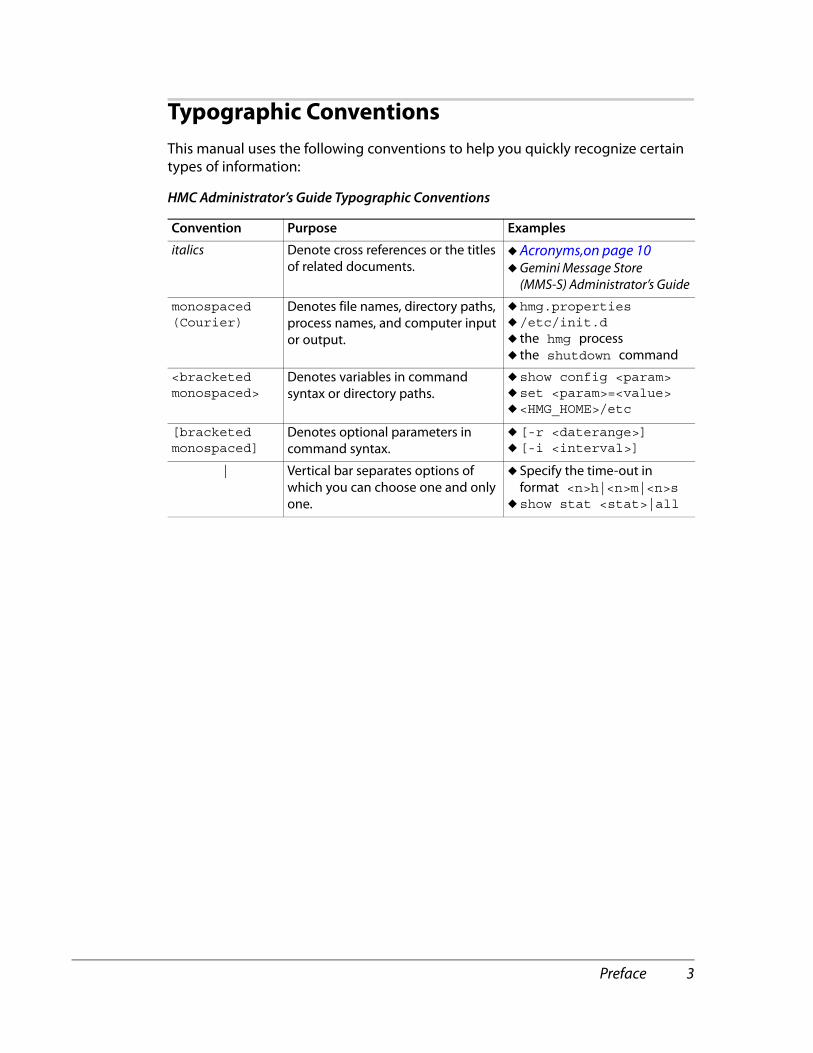
Typographic ConventionsThis manual uses the following conventions to help you quickly recognize certain types of information:
HMC Administrator’s Guide Typographic Conventions
Convention Purpose Examples
italics Denote cross references or the titles of related documents.
◆ Acronyms‚on page 10◆ Gemini Message Store
(MMS-S) Administrator’s Guide
monospaced (Courier)
Denotes file names, directory paths, process names, and computer input or output.
◆ hmg.properties◆ /etc/init.d◆ the hmg process◆ the shutdown command
<bracketed monospaced>
Denotes variables in command syntax or directory paths.
◆ show config <param>◆ set <param>=<value>◆ <HMG_HOME>/etc
[bracketed monospaced]
Denotes optional parameters in command syntax.
◆ [-r <daterange>]◆ [-i <interval>]
| Vertical bar separates options of which you can choose one and only one.
◆ Specify the time-out in format <n>h|<n>m|<n>s
◆ show stat <stat>|all
Preface 3
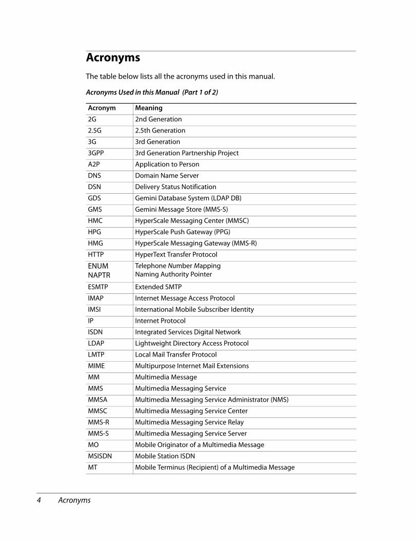
AcronymsThe table below lists all the acronyms used in this manual.
Acronyms Used in this Manual (Part 1 of 2)
Acronym Meaning
2G 2nd Generation
2.5G 2.5th Generation
3G 3rd Generation
3GPP 3rd Generation Partnership Project
A2P Application to Person
DNS Domain Name Server
DSN Delivery Status Notification
GDS Gemini Database System (LDAP DB)
GMS Gemini Message Store (MMS-S)
HMC HyperScale Messaging Center (MMSC)
HPG HyperScale Push Gateway (PPG)
HMG HyperScale Messaging Gateway (MMS-R)
HTTP HyperText Transfer Protocol
ENUM NAPTR
Telephone Number Mapping Naming Authority Pointer
ESMTP Extended SMTP
IMAP Internet Message Access Protocol
IMSI International Mobile Subscriber Identity
IP Internet Protocol
ISDN Integrated Services Digital Network
LDAP Lightweight Directory Access Protocol
LMTP Local Mail Transfer Protocol
MIME Multipurpose Internet Mail Extensions
MM Multimedia Message
MMS Multimedia Messaging Service
MMSA Multimedia Messaging Service Administrator (NMS)
MMSC Multimedia Messaging Service Center
MMS-R Multimedia Messaging Service Relay
MMS-S Multimedia Messaging Service Server
MO Mobile Originator of a Multimedia Message
MSISDN Mobile Station ISDN
MT Mobile Terminus (Recipient) of a Multimedia Message
4 Acronyms

MTA Mail Transfer Agent
NFS Network File System
NTP Network Time Protocol
OMA Open Mobile Alliance
OMADRM Open Mobile Alliance Digital Rights Management
P2P Person to Person
PAP Push Access Protocol
PDU Protocol Data Unit
PPG Push Proxy Gateway
RAID Redundant Array of Independent Disks
SGSN Serving GPRS Support Node
SOAP Simple Object Access Protocol
SMIL Synchronized Multimedia Integration Language
S/MIME Secure MIME
SMSC Short Message Service Center
SMTP Simple Mail Transfer Protocol
SS7 Signaling System 7
UAProf User Agent Profiles
UDB User DataBase
URI Uniform Resource Identifier
VAS Value Added Service
VASP Value Added Service Provider
WAP Wireless Access Protocol
Acronyms Used in this Manual (Part 2 of 2)
Preface 5

Related DocumentsThis manual makes reference to the following user’s guides and specifications:
Gemini Guides
■ Gemini HyperScale Messaging Gateway Administrator’s Guide
■ Gemini Message Store Administrator’s Guide
■ HyperScale Push Gateway Administrator’s Guide
■ HyperScale Messaging Center Online Help
■ Gemini Error Code Reference Manual
Standards Documents
■ [3GPPTS22.140] MMS Service Aspects (V5.4.0). 3rd Generation Partnership Project (December, 2002)
■ [3GPPTS23.140] MMS Functional Description (V5.8.0). 3rd Generation Partnership Project (September, 2003)
■ [RFC-1035] Domain Names Implementation and Specification. RFC-1035. Internet Engineering Task Force (IETF).
■ [RFC-1870] SMTP Service Extension for Message Size Declaration. RFC-1870. Internet Engineering Task Force (IETF).
■ [RFC-2033] Local Mail Transport Protocol. RFC-2033. Internet Engineering Task Force (IETF).
■ [RFC-2060] Internet Message Access Protocol, Version 4.1. RFC-2060. Internet Engineering Task Force (IETF).
■ [RFC-2086] IMAP4 ACL Extension. RFC-2086. Internet Engineering Task Force (IETF).
■ [RFC-2087] IMAP4 QUOTA Extension. RFC-2087. Internet Engineering Task Force (IETF).
■ [RFC-2251] Lightweight Directory Access Protocol (v3). RFC-2251. Internet Engineering Task Force (IETF).
■ [RFC-2359] IMAP4 UIDPLUS Extension. RFC-2359. Internet Engineering Task Force (IETF).
■ [RFC-2821] Simple Mail Transfer Protocol. RFC-2821. Internet Engineering Task Force (IETF).
■ [RFC34364] An Extensible Message Format for Delivery Status Notifications. K. Moore and G. Vaudreuil (The Internet Society: January 2003)
6 Related Documents

■ [WAP-164] Push Access Protocol Specification. Version 8-November-1999. WAP-164-PAP-19991108-a. WAP Forum.
■ [WAP-205] WAP MMS Architecture Overview. WAP-205-MMSArchOverview-20010425-a. WAP Forum.
■ [WAP-206] WAP MMS Client Transactions. Version 15-Jan-2002. WAP-206-MMSCTR-20020115-a. WAP Forum.
■ [WAP-209] WAP MMS Encapsulation Protocol. WAP-209-MMSEncapsulation-20020105-a. WAP Forum.
■ 3rd Generation Partnership Project (3GPP) TS 23.140: Technical Specification Group Terminals - Multimedia Messaging Service (MMS) - Functional description - Stage 2, Version 6.8.0, December 2004.
Download: http://www.3gpp.org/ftp/Specs/archive/23_series/23.140/23140-680.zip
■ Open Mobile Alliance (OMA): Multimedia Messaging Service - Architectural Overview - Version 1.2 - OMA-MMS-ARCH-v1_2-20030920-C, September 2003.
Download: http://www.openmobilealliance.org/release_program/docs/CopyrightClick.asp?pck=MMS&file=V1_2-20030923-C/OMA-MMS-ARCH-V1_2-20030920-C.pdf
■ Open Mobile Alliance (OMA): Multimedia Messaging Service - Client Transactions - Version 1.2 - OMA-MMS-CTR-V1_2-20050301-A, March 2005.
Download: http://member.openmobilealliance.org/ftp/Public_documents/MWG/MMS/Permanent_documents/OMA-MMS-CTR-V1_2-20050301-A.zip
■ Open Mobile Alliance (OMA): Push Over the Air - Candidate Version 2.1 - OMA-WAP-TS-PushOTA-V2_1-20051122-C, November 2005.
Download: http://www.openmobilealliance.org/release_program/docs/Push/V2_1-20051122-C/OMA-WAP-TS-PushOTA-V2_1-20051122-C.pdf
■ SMPP Developers Forum: Short Message Peer to Peer - Protocol Specification v3.4, 12 October 1999, issue 1.2
Download: http://www.smsforum.net/
Preface 7
Contacting Gemini Mobile TechnologiesTo reach Gemini technical support, use the customer-specific email address that Gemini provides you, or use this web page:
http://www.geminimobile.com/support/index.html
To comment on this manual, use this email address:
8 Contacting Gemini Mobile Technologies

1 Overview
This chapter gives a high-level overview of the Gemini’s HyperScale® Messaging Center (HMC)and includes these topics:
■ HMC Description‚ on page 10
■ HMC’s HyperScale® Technology‚ on page 11
■ Logical Architecture‚ on page 13
■ Physical Architecture‚ on page 16
■ Redundancy, Reliability, and Availability‚ on page 18
■ HMC Deployment Modes‚ on page 21
■ Hosted Operator Support‚ on page 23
■ HMC Subsystems‚ on page 25
Chapter 1 Overview 9
HMC DescriptionThe Gemini HMC is a standards-compliant, high performance, carrier-grade and flexible message service center that receives and delivers high volumes of multi-media messages both for person-to-person (P2P) and application-to-person (A2P) purposes.
The HMC can receive, process and forward the following types of messages:
■ MMS messages for P2P and A2P traffic
■ Email messages
■ SMS messages
Acting as a MMSC, the HMC processes messages between a carrier’s subscribers, as well as inter-carrier messages for subscribers whose handsets allows them to send and receive MMS and SMS.
In addition to the features required by a standards-compliant MMSC, the Gemini HMC supports a number of additional functions in the area of protocols and interfaces, routing, VASP management, operators hosting and user access to messages which make it a powerful multi-technology messaging center, able to service high levels of traffic today and providing a guaranteed path to growth in the future.
Gemini’s HMC, built using HyperScale® Technology platform, features independent application modules able to scale quickly and safely. Services can be easily adapted to quickly meet growing needs, increasing a network’s ability to respond to rapidly changing markets. Thanks to its open architecture the HMC can be widely customized with new features to meet customer requirements.
The HMC’s services-based, open systems architecture allows clustering of inexpensive host machines into a high performance, scalable system capable of handling enormous loads while reducing capital and operating expenses.
The next sections discusses the benefits of the HMC built on the HyperScale® Technology platform.
10 HMC Description

HMC’s HyperScale® TechnologyBecause multimedia messaging creates an exciting and positive end-user experience—delivering graphics, animation, video, audio, text captions, Vcards, calendars and other applications in a myriad of formats–most wireless analysts predict MMS will be the preferred medium of exchange, surpassing SMS text messaging by the year 2007.
Most MMSCs on the market today are built from either proprietary email or legacy SMSCs originally designed for text-only messaging. Due to MM size (averaging 100 times the size of SMS messages) a network provider will be holding much more data for 1,000 MMS messages than for 1,000 SMS messages, placing far more demands for I/O processing and storage than SMS.
The new infrastructure must be designed to address the reliable delivery requirements of a paid service while scaling the service to millions of users. This emerging need is already evident in some markets where the increasing number of mobile phones with embedded digital cameras and the growth and cultural acceptance of paid content services are major contributors to the increase in MMS traffic.
One such example is Vodafone Japan which selected Gemini Mobile Technologies to deliver their next generation MMS infrastructure. As the first network provider to introduce camera-phones and multimedia service in 2000, Vodafone clearly set the direction for future technology, services, and capabilities.
Vodafone selected Gemini’s carrier-class HMC because it is built from the ground up using patented HyperScale® Technology, plug-in architecture, persistent queuing and storage, and carrier-friendly efficiencies. This design has proven to increase performance and revenues by lowering capital and operating costs in the world’s most demanding market.
HyperScale® I/O Processing
Gemini’s HyperScale® Messaging Center (HMC) is a Multimedia Messaging Service Center (MMSC) based on HyperScale® Technology, a patented process that bypasses the non-proprietary operating system’s I/O service. Resource management is redesigned using an API layer that provides extreme throughput even at the high volume demands of an I/O-intensive MMSC.
The combination of HyperScale® threading and asynchronous I/O allows the full parallelism of the hardware to be utilized, enabling the HMC to process messages far more quickly with far more simultaneous connections per CPU than systems built on conventional technologies.
Chapter 1 Overview 11

Figure 1 HyperScale® Architecture
The HMC’s proprietary HyperScale® Technology delivers performance-per-cost that far exceeds conventional messaging systems.
The diagram for Figure 1‚ on page 12 shows a few of the plug-in modules available for HyperScale® applications: for P2P and A2P modes, the Messaging Gateway and eXplo. Applications use HyperScale® resource management for accessing off-the-shelf, operating systems’ I/O services.
The HMC employs a standards-based, services-oriented architecture in which plug-in applications implement particular protocols and value-added services while drawing on the HyperScale® foundation for high performance.
Because protocols and business logic are implemented and loaded as independent modules, new features and services can be added inexpensively, rapidly, and safely. Services can be combined and reused to more quickly meet business needs, increasing business agility and efficiency.
A2P MMSC HPG
12 HMC’s HyperScale® Technology
Logical ArchitectureThe Gemini HMC is functionally comprised of six types of services that scale both vertically (within the same machine) and horizontally (clustering host machines). The six types of Gemini services include the following:
■ HyperScale® Messaging Gateway, a MMS-R
■ Gemini Messaging Store, a MMS-S
■ Gemini Database System, a LDAP user database
■ HyperScale® Push Gateway, a PPG
■ Multimedia Messaging Service Administrator, a NMS
■ User Portal, a web-based email user interface
The HMG is responsible for the routing, transcoding, configurable transformation and forwarding of MMS traffic between internal and external SMS, MMS, and e-mail message users. See the Gemini HyperScale® Messaging Gateway Administrator’s Guide for more information.
The storage is responsible for managing users and content provider mailboxes and messages. See the Gemini HyperScale® Message Store Administrator’s Guide for more information. The user database is used to authenticate, authorize, and personalize the service for individual subscribers.
The embedded HyperScale® Push Gateway is responsible for relaying message notifications to mobile users, and delivering short text messages over SMS. The HPG communicates with existing SMSCs or SMS gateways over IP using the SMPP protocol V3.4. In addition the HPG delivers MMS notifications directly to handsets using the HTTP Push OTA protocol. See the Gemini HyperScale® Push Gateway Administrator’s Guide for more information.
The HMC architecture includes a network management system (NMS) to provide a consistent and coherent management of the various components from a single point of administration. See Hosting Data Model Diagram‚ on page 24 for more information about this module. The NMS comes with online help that describes how to use the HMC.
Finally, a User Portal servicing subscriber access to the system through a web or WAP browser.
The following figure illustrates the logical architecture of the Gemini HMC:
Chapter 1 Overview 13
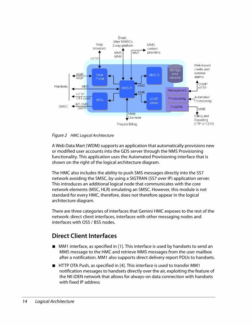
Figure 2 HMC Logical Architecture
A Web Data Mart (WDM) supports an application that automatically provisions new or modified user accounts into the GDS server through the NMS Provisioning functionality. This application uses the Automated Provisioning interface that is shown on the right of the logical architecture diagram.
The HMC also includes the ability to push SMS messages directly into the SS7 network avoiding the SMSC, by using a SIGTRAN (SS7 over IP) application server. This introduces an additional logical node that communicates with the core network elements (MSC, HLR) emulating an SMSC. However, this module is not standard for every HMC, therefore, does not therefore appear in the logical architecture diagram.
There are three categories of interfaces that Gemini HMC exposes to the rest of the network: direct client interfaces, interfaces with other messaging nodes and interfaces with OSS / BSS nodes.
Direct Client Interfaces
■ MM1 interface, as specified in [1]. This interface is used by handsets to send an MMS message to the HMC and retrieve MMS messages from the user mailbox after a notification. MM1 also supports direct delivery report PDUs to handsets.
■ HTTP OTA Push, as specified in [4]. This interface is used to transfer MM1 notification messages to handsets directly over the air, exploiting the feature of the NII iDEN network that allows for always-on data connection with handsets with fixed IP address
14 Logical Architecture

■ HTTP for web-based User Portal access. This interface is for users to access the User Portal with a web browser on a PC or fixed internet workstation.
■ WAP/WSP for WAP User Portal interaction. This interface is for users to access the User Portal through a WAP browser on their handset. Note, however, that a WAP Gateway is needed for users to reach this interface.
Other Messaging Interfaces
The HMC MMSC supports the following interfaces with messaging nodes:
■ MM3 interface
■ MM4 interface
■ MM7 interface
■ SMPP interface
Operations/Business Support System Interfaces
The HMC MMSC supports the following OSS / BSS node interfaces:
■ MM8 / FTP
■ MM9 interface
■ Provisioning
■ SNMP traps
■ HTTP for web-based NMS GUI access.
Chapter 1 Overview 15

Physical ArchitectureThe Gemini HMC is built using standard off-the-shelf hardware technology. It is shipped inside a standard 42U telco rack.
Hardware and wiring diagrams are contained in Systems Information‚ on page 81.
The core hardware elements comprising the HMC's architecture include the following topics:
■ Processing Nodes‚ on page 16
■ Storage Area Network‚ on page 16
■ Ethernet Switches‚ on page 16
■ SAN Switch‚ on page 17
Processing Nodes
The processing nodes are based on Hewlett Packard servers incorporating Intel technology and running RedHat AS 4.0 Linux operating system. The supported HP servers are Proliant DL380 G4 or G5.
To scale the system additional processing nodes running HMG, GMS, GDS, HPG, User Portal, and NMS applications may be added as required by the desired capacity and observed traffic model.
Gemini supports using either the HP Proliant DL380 G4 or HP Proliant DL380 G5 servers, as well as deployment in which the two models coexist in the same system.
Storage Area Network
All data storage, other than boot image, is done using a centralized Storage Area Network (SAN). Access to SAN is through dual Fiber Channel interfaces from every server. The supported SAN system is the HP Modular Smart Area 1000 (MSA-1000) which houses up to 14 73-GB disks. The MSA-1000 can be extended with the use of MSA-30 extension shelves, each of which also houses up to 14 disks. Each MSA-1000 supports up to 2 MSA-30.
To scale the system additional SAN units and shelves can be added.
Ethernet Switches
To ensure security, manageability, and scalability, the subsystems of the HMC are networked via three separate virtual LANs. The virtual LANs are supported from a
16 Physical Architecture
dual redundant Gigabit Ethernet switch. An 'External' V-LAN carries traffic primarily to and from users and external messaging systems. An 'Internal' V-LAN carries traffic between own HMC servers, thus isolating internal traffic. A 'Management' V-LAN carries external traffic between the HMC and the back-end infrastructure of the operator such as provisioning and billing systems.
Gemini recommends the use of Hewlett-Packard Procurve 2848 switches which provide 44 RJ-45 1000Base-T Gigabit Ethernet ports each; however equivalent switches from any manufacturer can be used.
SAN Switch
In a configuration that exhausts the physical Fiber Channel connectors of a single SAN unit or where multiple SAN units are required, or for future system growth, two SAN switches, in a redundant configuration, are used to facilitate the connectivity between a large number of servers and a large number of SAN units. As mentioned earlier, each processing node and each SAN node is connected with two Fiber Channel cables to achieve maximum availability.
Gemini recommends the use of Hewlett-Packard Storage Works 4/16 Fiber Channel Switches.
Chapter 1 Overview 17
Redundancy, Reliability, and AvailabilityThe Gemini HMC uses an active-standby redundancy schema governed by clustering software to guarantee a carrier-grade availability level. In addition, all data in the system, excluding executables and boot data, is kept in the SAN which is configured in a RAID-10 (mirrored) mode.
In general, each active node or pool of nodes has one, or more, standby nodes. The clustering software monitors the health of the active nodes by exchanging heartbeat information, among its instances, installed on all nodes.
If an active node fails, its standby counterpart is immediately activated, inheriting the complete set of IP addresses and ports from the failed node. The standby node mounts the same SAN partition as the failed node and starts processing the traffic as if it were the failed node. Meanwhile, the failed node is restarted and put in standby state.
More information about the software used to manage failover is discussed in the section, LifeKeeper Administration‚ on page 257.
HMG, HPG Redundancy
The HMG and HPG nodes do not keep a long term user state but only service transactions. As such, they do not have a permanent association with a user and so scalability can be achieved by load balancing multiple nodes.
Note The installation described in this document features one HMG and one HPG active at the same time. However, a future system upgrade to service increased traffic may require load balancing.
GMS Redundancy
GMS nodes have a permanent association with a set of users, although the actual mailboxes and message data are stored in the SAN. As such, no L4 load balancing can be done and scalability is achieved using an application-level load balancing betweenGMS servers.
Redundancy is achieved using the same clustering software and standby server pool, as described above. Once the clustering software detects a GMS server failure, it automatically assigns the virtual IP address to any one of the standby servers which assumes responsibility for the mailboxes and messages stored in the SAN. Again, since all information is stored in the SAN, nothing is lost in the failover process.
18 Redundancy, Reliability, and Availability
GDS Redundancy
GDS nodes have a similar redundancy model as GMS nodes. User data is kept on the SAN which is configured in RAID-10 mode for data redundancy. If failover occurs, the standby node inherits the attributes of the failed active node and starts servicingGDS requests from the disk while caching user data in memory. Once caching is complete, the former standby node services the same traffic as the failed node which is transitioned into standby status.
NMS and User Portal Redundancy
The Gemini HMC, NMS and User Portal are both web servers that run on the Tomcat platform. They follow a similar redundancy scheme as the GDS node discussed above, with the difference that the User Portal maintains very little state and can be load-balanced if this is requested for better performance and availability. Neither of these nodes is included in the availability calculations below as they are not essential for the HMC messaging traffic servicing, but provide specialized functionality.
Availability Figures Calculated
Gemini calculates availability figures for the HMC using a combination of historical data and estimated/declared reliability figures for the hardware. The system availability results from the combination of hardware and software availability for the different nodes in terms of Mean Time to Repair (MTR) over Mean Time Between Failures (MTBF). The reliability figures are shown in the following tables.
✴❁❂●❅✑✎✑Hardware Availability
Hours Years Comments
MTBF 21900 2.5 This is a lower limit for enterprise-class internally redundant servers like the supported hardware.
MTR 4 This is the upper limit for telco installation. A spare of everything should be available on-site.
✴❁❂●❅✑✎✒Software Availability
Hours Days Seconds Comments
MTBF 4320 180 This is a lower historical limit for "random" software bugs-related failures (P1). Systematic failures with shorter MTBF are not taken into account as they have been eliminated during QA.
MTR 0.0333 120 This is the upper limit for failover using the LifeKeeper clustering software.
Chapter 1 Overview 19
The overall availability of 1+1 (active+standby) nodes system is defined as the combination of hardware MTBF for 1 node with failover MTR, software MTBF for 1 node with failover MTR, plus (second order of magnitude) the probability of failure for one of the above during MTR. This comes to the figure of 99.99907% availability given the above assumptions.
The Gemini HMC described in this document uses eighteen physical nodes shared by the different services. If any of the service nodes go down, the service suffers in different degrees, depending on which node is not available. The non-availability figure given above must be multiplied by the number of traffic-related logical nodes: HMG, HPG, GMS and GDS. This brings to a global availability figure for the HMC of 99.99628%, equivalent to an average of about 15 minutes of outage per year.
20 Redundancy, Reliability, and Availability
HMC Deployment ModesGemini’s HMC has two deployment modes:
■ P2P—Person to Person
■ A2P—Application to Person
Due to the HMC's advanced hosting features, one system does not need to be devoted to one deployment mode. Instead, the resources of the system can be shared and virtually partitioned to optimally support more than one traffic mix by defining an appropriate configuration of the hosted operators.
In other words, the HMC can be configured to simultaneously perform two roles in the network: acting as a Person-to-Person and an Application-to-Person MMSC. A more complete description of each mode is described below.
Person to Person (P2P) HMC
The Gemini HMC's primary deployment identity is as a person to person (P2P) Multimedia Messaging Service Center (MMSC). As an optional feature, the HMC also offers configuration support for legacy users—subscribers sending and receiving messages with other technologies present in the network, such as SMS and two-way messaging.
As a P2P MMSC, the HMC not only features all the required standard functionality defined for the relay and message storage functions, but also provides the GDS, an LDAP-based, user profiles repository that enables personalized subscriber features, including personal black and white lists, blackout periods for message delivery, language preferences and other similarly detailed attributes.
The GDS repository supports a remote, real-time provisioning interface towards an external application that can be used to update the subscriber information, both by adding or deleting user records and by changing them.
This interface can be used, in some deployments, to push records from the Web Data Mart (WDM) to the MMS service in near-real time.
Application to Person (A2P) HMC
As an Application to Person (A2P) MMSC, the main functionality of the HMC is to receive messages from content providers (VASP) through the MM7 interface, and deliver them with the maximum efficiency and performance possible to users. This functionality is included in the basic HMC deployment model, but an operator may elect to dedicate the Gemini HMC to the task of content distribution. In this
Chapter 1 Overview 21
arrangement, messages are delivered from content providers either to single recipients or to multiple recipients, up to a very high number.
In this latter case distribution lists may be used. The Gemini HMC includes a flexible mechanism to address messages to a distribution list and resolve the list into the individual subscribers.
More information about A2P services are described in the chapter The A2P HMC‚ on page 207.
22 HMC Deployment Modes
Hosted Operator SupportThe Gemini HMC features a very complete and powerful hosting architecture that allows individual operators to share the resources of the platform while keeping management and configuration information, interfaces, content providers, classes of service, subscriber data, and all other operating functions separate and private to the carrier’s network administrator.
This deployment model adapts itself well to the needs of varied MMS traffic, in which each market has specific needs and issues that can be solved by different configurations of the HMC's service-specific parameters.
For example, the HMC can be configured with a carrier’s markets as separate hosted operators, with an additional virtual operator reserved for promotional messages being sent to all the markets.
Each operator, called service provider in the NMS, can access the NMS module of the HMC separately and define administrators of different levels; no service provider administrator can access other operator's data.
Network Administrators
The system defines a “super-user account”, reserved for network administrators. Through this account a network administrator can:
■ Act on the hardware nodes that compose the system, stopping and restarting them if necessary
■ See and act on system-level alerts and alarms
■ Define new hosted operators, together with their administrative accounts to access the system
■ Access system-level statistics in addition to traffic statistics for each of the hosted operators
■ Act in the role of hosted operator administrator to perform tasks in his/her behalf
Service Provider Administrators
Different hosted operators share the system resources in terms of processing power and storage. However, the following aspects are kept separate, effectively offering to each hosted operator a virtual MMSC:
■ Subscribers profiles in the GDS
■ Definition of classes of service to which the subscribers are assigned
Chapter 1 Overview 23

Figure 3 Hosting Data Model Diagram
■ Interfaces configuration
■ Routing rules
■ VASP definition: configuration of the VASPs providing services to each hosted operator's subscribers
■ Billing: definition of what CDRs to write to disk, configuration of the prepaid interface, and configuration of CDR/MDR parameters typical to different markets in a carrier’s network
■ Log files—CDR / MDR log files, transaction logs, application and statistical logs
The following figure outlines the data model followed by the HMC for hosting implementation.
Global System Attributes
…
Class ofService #Y
Class ofService #Y
…
MM1 SettingsMM1 Settings
Routing TablesRouting Tables
Billing & RatingBilling & Rating
VASP DatabaseVASP Database
Class ofService #1
Class ofService #1
ServiceSettingsServiceSettings
HostedOperator #1HostedOperator #1
HostedOperator #2HostedOperator #2
HostedOperator #XHostedOperator #X
Subscriber #1Subscriber #1
Subscriber #2Subscriber #2
Subscriber #NSubscriber #N
…
Class ofService #2
Class ofService #2
HardwareHardware
InterfacesInterfaces
24 Hosted Operator Support

HMC SubsystemsThis section discusses the functionality and features of the different standard nodes that compose the Gemini HMC including:
■ HyperScale® Messaging Gateway, a MMS-R
■ Gemini Messaging Store, a MMS-S
■ Gemini Database System, a MMS-D
■ HyperScale® Push Gateway, a PPG
■ Multimedia Messaging Service Administrator, an NMS
■ User Portal, a web-based email user interface
HyperScale® Messaging Gateway (HMG)
The HMG acts as a MMSC, a protocol-converting gateway that allows messages to move across different network segments requiring varied communications standards. For instance, to enable Internet users to send messages to MMS subscribers, the HMG accepts the messages from border MTA over SMTP; inserts the messages into the message store over LMTP; notifies the recipient and accepts message retrieve requests from the recipient handset over MM1; retrieves the messages from storage over IMAP; and sends the messages on to the recipient over MM1.
To enable MMS subscribers to send messages to conventional Internet email clients, the HMG accepts the messages over MM1, and then relays them to the appropriate Internet MTA over SMTP.
The HMG also executes all the authentication, authorization, content conversion and routing necessary to support messaging from and to users with different capabilities and preferences, after accessing the user LDAP record. It manages the routing rules received from the NMS configuration tool and forwards the message to its recipient over the suitable interface after modifying it, truncating it or transcoding it as needed. The HMG is the core of the system, where most of the intelligence resides.
In its interactions with other network elements, the HMG acts as a server in some types of transactions, as a client in others. In summary, the HMG acts as:
■ MM1 server to MMS handset clients generally connecting via the WAP-GW or directly in some deployments
■ SMTP server (to the border MTA)
■ SMTP client (to internet MTAs)
Chapter 1 Overview 25

■ LDAP client (to the GDS)
■ LMTP client (to the GMS)
■ IMAP client (to the GMS)
■ PAP client (to the HPG)
■ HTTP server (to the VASP)
Gemini Message Store (GMS)
The Gemini Message Store, a MMS-S, is based on a high performance IMAP server, which is optimized by front-ending all the user-related tasks such as authentication, authorization to the HMG and communicating only with the HMG.
The mailbox database is stored in parts of the SAN file system that are private to the IMAP system. The private mailbox database design gives the server large advantages in efficiency, scalability, and administration. Multiple concurrent read/write connections to the same mailbox are permitted. The server supports access control lists on mailboxes and storage quotas on mailbox hierarchies.
The Gemini Message Store has been optimized for communication with the Gemini HMG to support high volume, high performance multimedia message storage and retrieval. The Message Store is configured to accept the HMG as a proxy user that inserts and retrieves messages on behalf of multimedia messaging subscribers.
The Gemini Message Store supports one mailbox per user. The process of creating a user through any of the provisioning interfaces also creates a mailbox for that user. These mailboxes are usually only temporary storage spaces for messages as per MMS 1.0 standards. Once the message has been delivered to the destination handset, it is deleted from storage.
However, the Message Store also supports permanent storage of messages, and implements all the relative commands to retrieve messages several times, delete messages, associate labels to messages to create different logical folders. This also allows hosted operators to offer web-mail functionality based on the Gemini User Portal.
In addition, the Message Store supports mailbox quota enforcement and can be configured with automatic expiration of messages in the mailboxes. In this case, messages older than their allotted time-to-live setting are deleted with no need of an external command.
HyperScale Push Gateway (HPG)
The Gemini HMC includes an integrated PPG that can communicate with SMSCs in the network or directly with the mobile device over HTTP for delivering notification
26 HMC Subsystems

messages. The HPG receives Push requests from the HMG over PAP and sends push message notifications to handsets.
The HPG provides the following functions in the configuration described in this manual:
■ PAP reception from Push Initiator
■ Push Initiators (PI) management
■ HTTP Push OTA
◆ PO-TCP: initiation of a TCP connection from the HPG towards the recipient handset
◆ TO-TCP: handling of a TCP connection request from a handset
■ Retry control features
■ Congestion, persistent queue, and control flow management features
In addition, the HPG communicates with multiple SMSCs through the SMPP (Short Message Peer-to-Peer) protocol, Versions 3.4, to push SMS-based notifications to recipients.
The version of the Gemini HPG that is included in the HMC Release 3.7 has been optimized for use in the NII iDEN network, in which all of the MMS notification traffic travels over HTTP Push OTA. This raises a set of issues compared with a configuration in which the notification traffic uses SMPP like in most GSM and CDMA networks, in that the establishment of a connection (using the PO-TCP method) takes a relatively long time thus tying up HPG resources and lowering the overall performance. This has been solved by increasing the number of simultaneous connections that can be established by the HPG, and introducing a decaying retry algorithm for handsets that are not reachable at the first try.
User Portal
The Gemini User Portal is a web-server based node that allows users to access a number of HMG-related services over the Internet or through a WAP-enabled phone. The User Portal provides a way for users to:
■ View the content of their mailbox
■ Label messages for categorization and selective showing
■ View and play single messages
■ Compose and send messages
■ Compose and store messages as drafts
■ Forward messages to other addresses
Chapter 1 Overview 27

■ Change their MMS service configuration, within the constraints of their assigned Class of Service
The User Portal is implemented as a Tomcat application, and communicates with the HMG by emulating an MMS 1.2 handset using the MM1 PDUs that are defined to manage the MMbox. See the chapter in this document, User Portal‚ on page 219, for more information.
The Gemini User Portal is provided as a functional web application that can be used "out of the box" for an implementation of the above functions. However, the appearance of its pages is "Gemini specific". Any Gemini customer can personalize the User Portal for its different markets as explained in the User Portal Customization Guide.
Gemini Directory Service
The Gemini LDAP is implemented by a GDS server that provides access to the user database that contains all subscription information regarding the services provided by the HMC. This information is used to authenticate users and to authorize them for the particular set of services, as well as to personalize the service to the user's preferences.
Gemini has defined a very complete user profile that supports a host of preference attributes, allowing the operator to personalize services for subscribers. The Gemini HMC provides flexible provisioning tools for applications and human representatives to interact with the User Profile Repository. Furthermore, the information in the user profile defines the nature of billing service to be provided to the user—postpaid CDRs or prepaid billing.
In addition to user subscription information, the User Profile Repository caches the last known handset profile for each subscriber, which is used to efficiently transcode the content bound to the user.
The User Profile Repository is accessed for provisioning from the NMS platform, receiving input from any of the supported provisioning interfaces.
Network Management System (NMS)
The Gemini HMC NMS provides a web-based graphical user interface to access all of the system administration and management functions including:
■ Central configuration of the HMC
■ Presentation and export of health and statistical data
■ Provisioning of the GDS
28 HMC Subsystems
■ Administration of VASP database
■ Certificates management
Multiple administrative accounts with different permission levels can be configured on the management system. Additional accounts may be created to enable access to specific support personnel such as customer care representatives, requiring access only to user data.
The NMS is the main layer in which hosting occurs from the hosted operators' point of view: Service Provider administrators log into the NMS and are presented with the screens and functions private to the carrier they are associated with, while the NMS prevents them from accessing other carriers equivalent screens or system-related functions.
The management system also exposes two different automated provisioning interfaces, based on HTTP transactions from a remote application, and on file upload and import. For each provisioning request the management system provisions both a user record in the GDS server and the corresponding user mailbox in the IMAP server (GMS).
The NMS includes logging/reporting server functionality. All logs generated by the system are transferred to the Logging Server. The logging server's functions are to:
■ Reliably receive and store logs
■ Format and optionally compress logs according to predetermined templates
■ Package logs for applications (such as a postpaid billing system or mediation) for retrieval
■ Generate alerts according to predetermined templates and thresholds. The alerts may be communicated externally via SNMP traps to an external monitoring system of the operator and forwarded to configured email addresses over SMTP.
Chapter 1 Overview 29

30 HMC Subsystems

2 Features
This chapter describes the additional features developed for Gemini’s HMC Release 3.7 and includes these topics:
■ Interfaces‚ on page 32
■ Message Routing‚ on page 62
■ Message Notification‚ on page 66
■ Message Storage and Retrieval‚ on page 67
■ Transcoding and Content Adaptation‚ on page 70
■ Regulatory and Security Controls‚ on page 72
■ Spam Filtering‚ on page 74
■ Multiple Language Support‚ on page 76
■ Hosting Services‚ on page 77
■ Lawful Interception‚ on page 78

InterfacesThis section provides functional details on the various interfaces supported by the Gemini HMC, and the way they are used in this deployment. The HMC allows individual hosted operators to independently configure many aspects of the use of these interfaces through related pages of the NMS GUI.
MM1 Interfaces
The MM1 interface is between the HMC and the individual MMS-capable user handsets. Through the MM1 interface the HMG processes MMS submit and retrieve requests from MMS subscribers, sends out delivery and read-reply reports to handsets and delivers MMS notifications. In addition the MM1 interface can be used by subscribers to access their mailboxes and upload, store draft messages, and delete stored messages.
The HMG complies with the following MM1 related specifications:
■ MMS Architecture Overview. OMA-WAP-MMS-ARCH-v1.2
■ MMS Client Transactions. OMA-WAP-MMS-CTR-v1.2
■ MMS Encapsulation Protocol. OMA-WAP-MMS-ENC-v1.2
Note that MM1 is a logical interface that uses different protocols to communicate with the handsets. While message submission, retrieval and delivery reports are done directly over HTTP / WSP, MMS notification is typically done over SMS. However, for some customers, MMS notifications are also done over HTTP through the Gemini HPG HTTP push OTA interface.
User Portal MM1 Interface
The User Portal emulates MMS 1.2 handsets to communicate with the HMG, access user mailboxes, and send MMS messages. This is accomplished over the MM1 interface, using the following transactions:
■ MM1_submit.REQ / MM1_submit.RES to send a composed message to destination. This is identical to any MMS-enabled handset.
■ MM1_mmbox_upload.REQ / MM1_mmbox_upload.RES to request that a draft message be stored in the MMbox.
■ MM1_mmbox_view.REQ / MM1_mmbox_view.RES to retrieve data on the messages in the Mmbox, or to retrieve a whole message from the Mmbox for viewing on the User Portal.
■ MM1_mmbox_delete.REQ / MM1_mmbox_delete.RES to remove a message from the MMbox.
32 Interfaces

The User Portal uses a separate port and a text-based implementation of the MM1 interface, instead of the binary-encoded one used by handsets, to communicate with the HMG. This allows for increased performance especially for the initial retrieval of the full contents of the MMbox which could involve a heavy data exchange, thus avoiding the need to encode / decode.
Messages from the User Portal generate billing records (MDRs) in which the origination platform is marked in the sender address. This allows the customer to implement different charging policy for these messages compared with those coming from a regular handset.
In addition, the use of a different interface allows messages originated from the User Portal to be routed following different rules than other messages. This can be used by the network provider to, for instance, reject messages from the User Portal addressed to recipients served by other carriers by defining an appropriate set of routing rules.
MM2 Interface
The MM2 interface is internal to the HMC. It is the interface between the HMG and the GMS used to store messages in mailboxes and retrieve them from mailboxes. The Gemini HMC uses a standard email interface for these transactions, storing messages using LMTP (Local Mail Transfer Protocol, RFC 2033), and retrieving them using IMAP .
MM3 Interface
MM3 is the standard email SMTP interoperability interface, used by the HMC to exchange email messages with internet-based nodes such as MTA (Message Transfer Agents).
The HMG's SMTP server handles incoming messages from a border MTA or other message transfer agents, originating from legacy handsets or Internet mail clients, destined for mobile subscribers. Incoming messages are routed to the correct hosted operator using the recipient(s) domain(s), and treated as normal MMS messages, that is, they are stored in the recipient mailbox before a notification is sent to the recipient handset, or transformed into SMS or 2-way messages before being sent out to a non-MMS-enabled recipient, depending on the routing rules.
The HMC supports two configuration modes for the MM3 interface: in one mode, it can receive all traffic destined to all the hosted operators on a single port (the default port is 25, as per SMTP specifications) then de-multiplex it to the different hosted operators based on the destination domain.
In the other configuration option, the HMC defines different ports for different hosted operators, so that traffic is completely separated.
Chapter 2 Features 33
The HMG instead acts as an SMTP client in forwarding messages from MMS subscribers to internet MTAs for delivery on to legacy handsets or internet mail clients, if the original message is addressed to an email address.
The HMG's SMTP server complies with the following specifications:
■ RFC-2821, Simple Mail Transfer Protocol
■ RFC-1870, SMTP Service Extension for Message Size Declaration
MM4 Interface
The Gemini HMC uses the MM4 interface to communicate with remote MMSCs or MMS gateways belonging to other carriers or MMS inter-carrier hubs with which an ICM agreement exist.
SMTP Extension
MM4 is an extension of SMTP. The basic protocol is SMTP, with new headers, and a defined dialog structure of requests and responses. In interfacing with foreign MMSCs, the HMC supports all the PDUs and dialog requirements specified by the 3GPP for the MM4 protocol:
■ MM4_forward.REQ (request message forwarding)
■ MM4_forward.RES (response to message forwarding request)
■ MM4_delivery_report.REQ (request delivery report forwarding)
■ MM4_delivery_report.RES (response to delivery report forwarding request)
■ MM4_read_reply_report.REQ (request read reply report forwarding)
■ MM4_read_reply_report.RES (response to read reply report forwarding request)
The Gemini HMC supports separate configuration settings for the MM4 interfaces towards different partner MMSCs which allow it to adapt for the versions of the MM4 interface supported by the remote nodes and to conduct the MM4 PDU exchange dialog differently depending on the implementation and capabilities of the remote node.
Interface with 2-way Server
The Gemini HMC uses the MM4 interface to communicate with the a 2-way server. This is configured per market, depending on the availability of the 2-way service. The HMC services requests from the 2-way server for incoming messages and routes them as MMS, SMS, or again, 2-way, depending on the recipient handset capability.
34 Interfaces

MM5 Interface
The MM5 interface is for the HMC to access a SS7 or DNS mapping database to correlate the telephone number of a message recipient—with a more informative address format—for purposes of routing.
A typical example in a GSM network is for an MSISDN in a domain in which Mobile Number Portability exists. In this case, the outgoing interface of the message will depend on the carrier serving the subscriber. The IMSI of the recipient contains this information, gotten through a query over the MM5 interface.
The Gemini HMC supports two methods to implement the MM5 interface: a MAP-SEND-ROUTING-INFO-FOR-SM query (SRI-SM) to an HLR over SS7, and an ENUM/DNS query to an ENUM (RFC 3761) server. Either method may be used for different hosted operators, but the SS7-based one requires the presence of the optional SIGTRAN nodes.
Note The MM5 interface is not applicable to all customers for Release 3.7 of the HMC, if they do not require Mobile Number Portability.
MM6 Interface
MM6 is the interface between the HMG and the GDS, used by the HMG to retrieve user information for authentication and authorization and to update user records when necessary. For the Gemini HMC, this is an internal interface implemented using LDAPv3 (RFC 4510).
During an installation of the Gemini HMC the HMG and GDSHMG are pre-integrated, in terms of IP addresses and ports, using the installation script; no further configuration is necessary.
MM7 Interface
The MM7 interface is defined by 3GPP for communication between MMS content providers and an MMSC. The Gemini HMC supports the standard MM7 interface, with a number of additional features like different authentication procedures, encryption, SLA management.
The HMC receives MMS messages from Value Added Service Providers (VASPs) over MM7, addressed to individual users, multiple users or distribution lists, resolves the recipient addresses and forwards the messages to destination using MM1. It also routes messages received from subscribers to the recipient VASP over MM7 by associating short codes to the respective VASPs, assuming that the originating subscribers are enabled to send messages to short codes.
Chapter 2 Features 35

The implementation, performance and services that the HMC offers on the MM7 interface are a qualifying point especially for A2P deployments of the HMC.
Specifications Compliance
MM7 is implemented using the SOAP protocol as defined by W3C Note 08 May 2000 "Simple Object Access Protocol (SOAP) 1.1" (http://www.w3.org/TR/SOAP). SOAP is a lightweight protocol for exchange of information in a decentralized, distributed environment. It is an XML based protocol that consists of three parts: an envelope that defines a framework for describing what is in a message and how to process it, a set of encoding rules for expressing instances of application-defined data types, and a convention for representing remote procedure calls and responses. SOAP can potentially be used in combination with a variety of other protocols; however, the only bindings specified for the MM7 interface is in combination with HTTP and HTTP Extension.
The Gemini HMC implements the 3GPP Version 5.11.0 schema of MM7. The PDUs that the HMC supports are detailed in the following table.
Note The HMC Release 3.7 does not support two PDUs that are included in the 3GPP specification:
■ MM7_cancel.REQ, which would allow a VASP to cancel a message submission while the message is being distributed to the recipients MM7_replace.REQ, which would allow a VASP to replace a message that is being distributed to recipients with another which takes its place and is distributed in its stead.
Supported MM7 PDUs
PDU Comment
MM7_submit.REQMM7_submit.RES
VASP Submits an MM to one or more users.
MM7_deliver.REQMM7_deliver.RES
MMSC Delivers an MM from user to VASP using VASP short code.
MM7_delivery_report.REQMM7_delivery_report.RES
MMSC reports delivery status of MM to VASP
MM7_read_reply_report.RESMM7_read_reply_report.REQ
MMSC delivers a read-reply report associated with an MM to a VASP
MM7_device_profile.RESMM7_device_profile.RES
Returns (a number of ) UAProf URL, given the respective MSISDN. This is a common extension, used to retrieve the profile of a handset.
MM7_RS_error.RESMM7_VASP_error.RES
General Error Message
36 Interfaces
VASP Authentication
The Gemini HMC authenticates VASP MM7 connections to ensure that messages are sent from a configured VASP. The authentication is done against the VASP profile that is configured into the HMC database through the NMS GUI.
The two authentication mechanisms supported are HTTP Basic Authentication and IP Access Control List (ACL). The VASP configuration includes a flag that determines whether authentication via HTTP Basic Authentication is required. If set to "YES", Account Name and Password must match the information in the authentication header. If set to "NO", the IP Access Control List must include at least one address and the VASP source address must match it. Even if HTTP Basic Authentication is used, the operator may provide an ACL list to further enhance security.
All of these parameters are configured - differently for each hosted operator - from the NMS GUI.
VASP Authorization
Each message sent from the VASP typically includes either a VASP ID or VAS ID to be used for authorization. The VASP profile maintains a VASP ID and an optional list of VAS IDs. Each message from the VASP must include either the VASP ID and/or one of the valid VAS IDs. Otherwise, the message is rejected.
If the list is empty, all IDs (or no IDs) are accepted. Similarly, if the VASP message includes a service code, typically used to identify the message for billing purposes, the service code must be listed in the VASP profile.
As a VASP submits a message to the HMC, the message parameters are checked against the VASP attributes in the database for further authorization. If any of the parameters exceed the configured limit, the message is rejected or the parameter value is changed, depending on configuration.
For example, if the VASP exceeds the maximum number of recipients for a message, the HMC will reject the message, but if the maximum time to live is exceeded, the HMC may change it to the configured maximum.
Chapter 2 Features 37
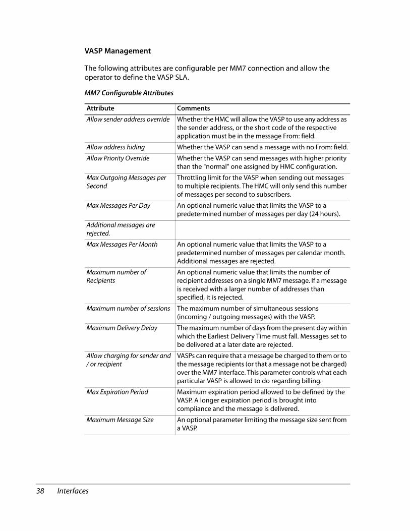
VASP Management
The following attributes are configurable per MM7 connection and allow the operator to define the VASP SLA.
MM7 Configurable Attributes
Attribute Comments
Allow sender address override Whether the HMC will allow the VASP to use any address as the sender address, or the short code of the respective application must be in the message From: field.
Allow address hiding Whether the VASP can send a message with no From: field.
Allow Priority Override Whether the VASP can send messages with higher priority than the "normal" one assigned by HMC configuration.
Max Outgoing Messages per Second
Throttling limit for the VASP when sending out messages to multiple recipients. The HMC will only send this number of messages per second to subscribers.
Max Messages Per Day An optional numeric value that limits the VASP to a predetermined number of messages per day (24 hours).
Additional messages are rejected.
Max Messages Per Month An optional numeric value that limits the VASP to a predetermined number of messages per calendar month. Additional messages are rejected.
Maximum number of Recipients
An optional numeric value that limits the number of recipient addresses on a single MM7 message. If a message is received with a larger number of addresses than specified, it is rejected.
Maximum number of sessions The maximum number of simultaneous sessions (incoming / outgoing messages) with the VASP.
Maximum Delivery Delay The maximum number of days from the present day within which the Earliest Delivery Time must fall. Messages set to be delivered at a later date are rejected.
Allow charging for sender and / or recipient
VASPs can require that a message be charged to them or to the message recipients (or that a message not be charged) over the MM7 interface. This parameter controls what each particular VASP is allowed to do regarding billing.
Max Expiration Period Maximum expiration period allowed to be defined by the VASP. A longer expiration period is brought into compliance and the message is delivered.
Maximum Message Size An optional parameter limiting the message size sent from a VASP.
38 Interfaces
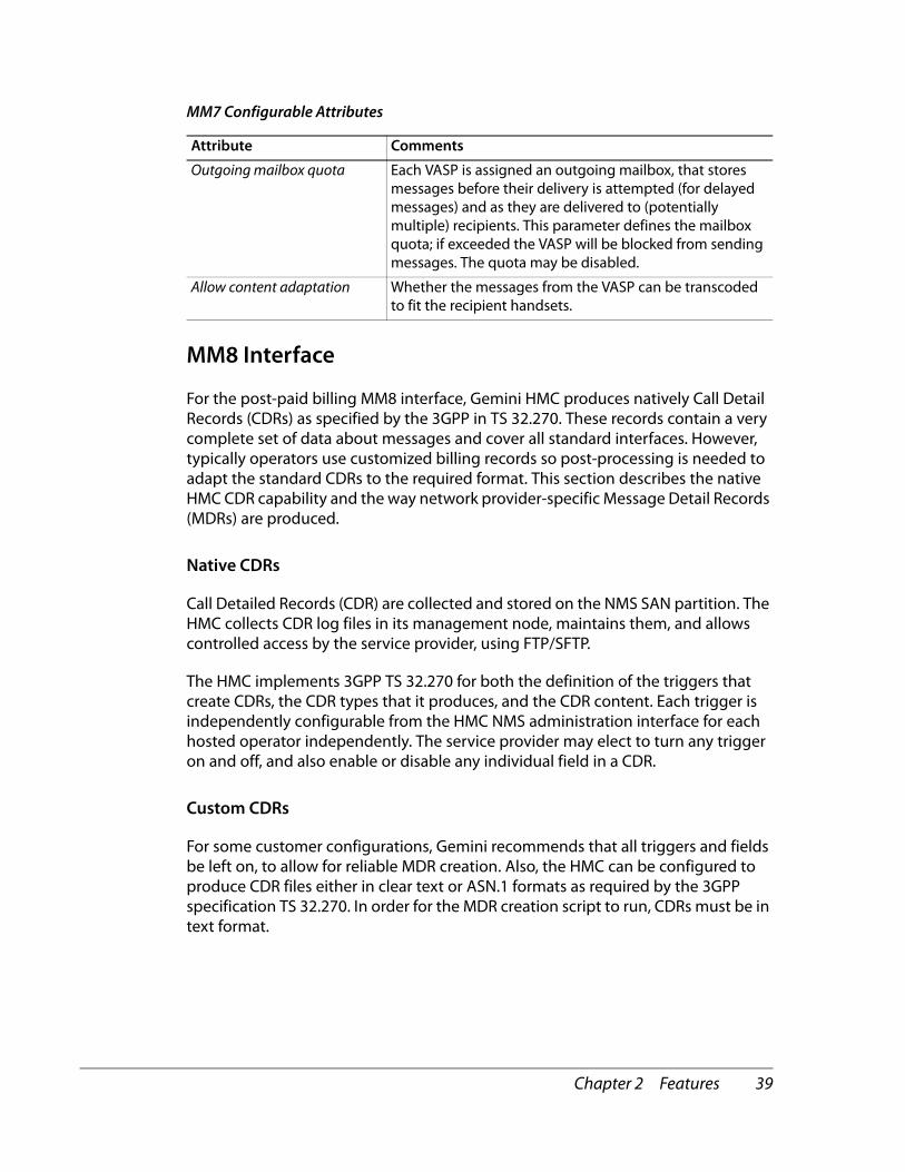
MM8 Interface
For the post-paid billing MM8 interface, Gemini HMC produces natively Call Detail Records (CDRs) as specified by the 3GPP in TS 32.270. These records contain a very complete set of data about messages and cover all standard interfaces. However, typically operators use customized billing records so post-processing is needed to adapt the standard CDRs to the required format. This section describes the native HMC CDR capability and the way network provider-specific Message Detail Records (MDRs) are produced.
Native CDRs
Call Detailed Records (CDR) are collected and stored on the NMS SAN partition. The HMC collects CDR log files in its management node, maintains them, and allows controlled access by the service provider, using FTP/SFTP.
The HMC implements 3GPP TS 32.270 for both the definition of the triggers that create CDRs, the CDR types that it produces, and the CDR content. Each trigger is independently configurable from the HMC NMS administration interface for each hosted operator independently. The service provider may elect to turn any trigger on and off, and also enable or disable any individual field in a CDR.
Custom CDRs
For some customer configurations, Gemini recommends that all triggers and fields be left on, to allow for reliable MDR creation. Also, the HMC can be configured to produce CDR files either in clear text or ASN.1 formats as required by the 3GPP specification TS 32.270. In order for the MDR creation script to run, CDRs must be in text format.
Outgoing mailbox quota Each VASP is assigned an outgoing mailbox, that stores messages before their delivery is attempted (for delayed messages) and as they are delivered to (potentially multiple) recipients. This parameter defines the mailbox quota; if exceeded the VASP will be blocked from sending messages. The quota may be disabled.
Allow content adaptation Whether the messages from the VASP can be transcoded to fit the recipient handsets.
MM7 Configurable Attributes
Attribute Comments
Chapter 2 Features 39
CDR Log File Rotation
The HMC supports configurable CDR log file rotation mechanisms based on file size, or time thresholds. The operator is able to define whether or not to invoke log rotation for each or both of the above cases. Upon log file rotation, the HMC moves the log files to a directory specified by configuration and names them using an operator-provided description.
The HMC then appends the closing time to the file name as well as a unique identifier and serial number to ensure an unambiguous file name. Finally, the file is optionally compressed.
CDR Retrieval
The HMC supports both FTP retrieval of CDR files from an external client (get) and active sending of each file upon rotation to a configured outgoing server (put). For maximum reliability files are not removed once they have been transferred. Instead, files are replaced only when the logging server runs out of the allocated disk space.
MDR support
MDRs are custom records that the system builds by analyzing the corresponding standard CDR and transaction log files. This activity is carried out periodically as a separate task in the NMS platform. MDR generation is actually quite distinct from the HMC processing, and is executed by a separate script launched at configurable intervals.
Several parameters configure the MDRs for each hosted operator in terms of log files management including:
■ Whether MDRs are generated, or not
■ Generation interval
■ Log file naming convention
■ Log file maximum size—if an MDR file exceeds the maximum size, it is rolled over to a new one that receives a new unique name
In addition the MDR record body is configurable for a number of fields, and in particular:
■ Record type—which may be different in different markets for the same type of message route
■ From_address—this is manipulated to encode additional information about the message sender compared with the original From: message header, especially for inter-carrier and VASP-originated messages
40 Interfaces
■ To_address—this is manipulated to encode additional information about the message recipient compared with the original To: message header, especially for inter-carrier and VASP-terminated messages
The MDR production process uses the following configuration information, on a per market basis:
■ A configuration file residing on the NMS SAN partition, that maps internal message types and route characterization to the literal market MDR type code. This is loaded by the MDR generation process before every generation cycle. The file is not under the control of the NMS but can be configured with a editor and pushed to the system.
■ For ICM messages, the domain name of the partner as configured by the MM4 interface configuration pages of the NMS GUI
■ For VASP messages, the VAS and VASP unique ID as configured in the VASP configuration pages of the NMS GUI
MM9 Interface
The HMC prepaid billing interface uses the Diameter protocol as specified in 3GPP TS 32.299 and RFC 4006 - Diameter Credit Control Application—to authorize and charge prepaid users in real time.
Each hosted operator configured what user MMS transactions to charge, and whether the charging process is to be carried out before the MMS transaction, after the transaction has completed, or as a two steps model of funds reservation and subsequent debit is to be used.
In all cases, a user is authorized against the prepaid server with a set of parameters that allows the rating of the service with varied policies. The prepaid server then reserves or deducts the proper amount from the subscriber's prepaid account.
Prepaid transactions occur for all subscribers marked as prepaid in the subscriber repository or by default for all users, depending on a parameter set from the NMS configuration interface. Once the HMC identifies the subscriber—originator or recipient of a message—as a prepaid user, the requested transaction is carried out.
The HMC NMS platform is also used to configure and maintain a list of addresses of prepaid servers that can be accessed alternatively, if any of them is temporarily unavailable.
In addition, the HMC supports refund transactions that can be configured to occur for a number of errors that prevent messages from being delivered, in case the originating subscriber has already been charged.
Chapter 2 Features 41

In the event of a total loss of communication with all of the pre-paid servers, the HMC can be configured to queue the relative prepaid transactions up to a maximum time or number of transactions while either:
■ Continuing without any charging event, or
■ Blocking MO prepaid transactions and/or temporarily queuing MT transactions that were charged to a prepaid account
All prepaid settings, mentioned above, are configured through the NMS GUI, separately for each hosted operator.
UAProf Interface (CPI)
The UAProf interface is used by the HMC to obtain the Capability and Preference Information (CPI) of the mobile client.
Based on the CPI, the HMC performs transcoding of messages, including the push message's character set encoding and images of all the common formats included in a message.
The CC/PP framework specifies how client devices express their capabilities and preferences (the user agent profile) to the server that originates content (the origin server). The HMC supports three basic ways to access a CC/PP database, depending on configuration, to the repository of handset profiles:
1 The actual URL coming in from the handset can be accessed over the Internet using HTTP. This is the location of the UAProf file on a server maintained by the handset manufacturer.
2 The system administrator can maintain a local repository with the CC/PP information and the HMC can be configured to retrieve the profile from there over HTTP.
3 The HMC itself can manage the relevant profiles as internal files.
For ease of use and flexibility, Gemini recommends that access method 1 or 2 be used.
Standard Transcoding Interface (OMA-STI)
The Gemini HMC uses the OMA-STI interface to access a remote transcoder server that will adapt messages to the recipient handset capabilities and then return the transcoded message for delivery. This is necessary to transcode messages with content (MIME) types that are not supported by the HMC's internal transcoder. A list of the content types that are supported by the HMC, natively, is provided in the section Internal Transcoding‚ on page 70.
42 Interfaces
The HMC OMA-STI interface is out of scope for the HMC Release 3.7 deployment, as it was decided that the purchase of an external transcoding server was not cost-effective given the small percentage of traffic carrying MIME types that are not supported internally.
Distribution List Interface
The HMC supports receiving and forwarding MM7 messages addressed to distribution lists. In this context, a message addressed to a distribution list has the name of a list in the To: field, instead of a number of telephone numbers and email addresses.
Distribution lists are associated with a particular VAS application and are particularly useful when the application sends messages to users who subscribe to the service in an on-going basis: the addresses of the list are those of the subscribers to the application.
The HMC supports the association of a distribution lists server and a URL to VASPs through its configuration interface. If a message from the VASP arrives, with a To: address that is not in PTN or email format, the HMC tries to access the configured URL over HTTP. The HMC then retrieves the distribution list file from URL, appending to it name of the list received in the message.
For instance, if the configured URL is http://myserver.vasp1.com/distlist and the distribution list name is appl1users, the HMC will try to retrieve a file called http://myserver.vasp1.com/distlist/appl1users. The file should be in text format, and contain the list of the telephone numbers to address the message to.
Once the distribution list is retrieved, the HMC resolves the list in its individual component addresses and starts forwarding messages to the corresponding recipients. The HMC caches distribution lists internally, so that they can be used if the remote HTTP server is unavailable.
While this method of distribution list retrieval requires the development of back-end infrastructure by the operators and/or VASPs to synchronize the distribution lists with the actual users who subscribe to the service, it is extremely flexible as it allows an independent management of user subscription to applications using the message delivery process. It also allows for complete flexibility of where the distribution list information is located and by whom is controlled—operator or VASPs, independently for each VASP.
Chapter 2 Features 43
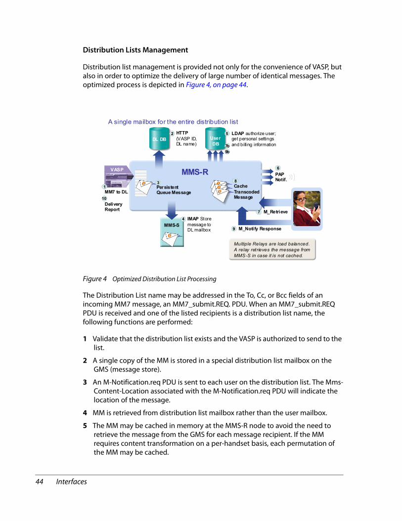
Figure 4 Optimized Distribution List Processing
Distribution Lists Management
Distribution list management is provided not only for the convenience of VASP, but also in order to optimize the delivery of large number of identical messages. The optimized process is depicted in Figure 4‚ on page 44.
The Distribution List name may be addressed in the To, Cc, or Bcc fields of an incoming MM7 message, an MM7_submit.REQ. PDU. When an MM7_submit.REQ PDU is received and one of the listed recipients is a distribution list name, the following functions are performed:
1 Validate that the distribution list exists and the VASP is authorized to send to the list.
2 A single copy of the MM is stored in a special distribution list mailbox on the GMS (message store).
3 An M-Notification.req PDU is sent to each user on the distribution list. The Mms-Content-Location associated with the M-Notification.req PDU will indicate the location of the message.
4 MM is retrieved from distribution list mailbox rather than the user mailbox.
5 The MM may be cached in memory at the MMS-R node to avoid the need to retrieve the message from the GMS for each message recipient. If the MM requires content transformation on a per-handset basis, each permutation of the MM may be cached.
5
6
13
7
9
4
2
8
7b9b
MM7 to DL
HTTP (VASP ID, DL name)
PersistentQueue Message
IMAP Store message to DL mailbox
M_Retrieve
Cache TranscodedMessage
Multiple Relays are load balanced.A relay retrieves the message from MMS-S in case it is not cached.
MMS-R
MMS-S
A single mailbox for the entire distribution list
LDAP authorize user; get personal settings and billing information
M_Notify Response
VASPPAP Notif.
DL DB UserDB
10DeliveryReport
44 Interfaces

6 If M-NotifyResp.ind or M-Acknowledge.ind PDU indicates that the message should be deleted, no delete is performed.
7 Deletion from the GMS mail store is performed only after the message expiry time.
8 The MM is not counted towards the user's storage quota.
9 A delivery report is created for the VASP.
SMPP and Push OTA Towards Handsets Interfaces
The Gemini HMC uses its integrated HPG to send MMS notifications and SMS messages to handsets. The HPG supports two main interfaces for this: SMPP towards an SMSC and HTTP Push Over the Air (OTA) towards individual user handsets.
Interface Towards SMSCs
The Gemini HPG supports SMPP V3.4 and V3.3 to push messages towards multiple configured SMSC nodes in the network. This is used in GSM and CDMA networks to send MMS notifications out to handsets in order for the MMS user agent to acquire the URL where to retrieve the message.
In the iDEN network, this task is accomplished by means of the HTTP Push OTA protocol.
The HPG SMPP interface is the used to forward text messages to handsets that cannot receive MMS or for which SMS is a more cGMSonvenient transport protocol. This is the case for:
■ iDEN handsets that are not MMS enabled. In this case the HMC may drop the multimedia part of the message and truncate the text part to a configured maximum length, or send a link to retrieve the message from the legacy portal depending on configuration, using MT-SMS.
■ Intercarrier messages for partner networks with which an MMS ICM agreement is not in place. In this case the HMC uses its routing tables to determine the destination carrier and forwards the message over SMPP to an SMS gateway.
■ In case the message will fit in an SMS (short text content), the HMC may if thus configured send an intercarrier message to the same SMS gateway, choosing the least cost route for delivery.
The HMC supports the configuration of multiple SMSC or SMS gateway interfaces over SMPP from its NMS configuration GUI. These interfaces can then be used to route particular traffic to the correct node, or to load balance traffic over more than one SMSC node if multiple SMSCs are available in the network.
Chapter 2 Features 45
Interface Towards Handsets
The HTTP Push OTA protocol is used in the iDEN network to deliver MMS notification to handsets directly, without passing from an SMSC. The protocol used is described in the following document:
Open Mobile Alliance (OMA): Push Over the Air - Candidate Version 2.1 - OMA-WAP-TS-PushOTA-V2_1-20051122-C, November 2005. Download: http://www.openmobilealliance.org/release_program/docs/Push/V2_1-20051122-C/OMA-WAP-TS-PushOTA-V2_1-20051122-C.pdf
Consult the sections concerned with PPG-Originated (PO) TCP to initiate a TCP connection towards the handset, and content push (HTTP POST method).
The protocol takes advantage of the “always on” nature of iDEN data handsets and the fixed IP address that each handset uses in the network, for an IP-only delivery of notifications.
This is convenient with respect to having to use the SS7 network as would happen in a GSM environment, but the nature of the protocol and the network limits the performance of the HPG, in terms of messages per second.
SNMP Interface
The Gemini HMC uses SNMP to transmit any event and alarm both internally and towards the configured external NMS platforms. The HMG, GMS, HPG and User Portal nodes produce SNMP traps if a loggable event occurs with a severity exceeding a configured threshold. The traps are sent to the HMC's NMS node which uses them to:
■ Update its alarms database, which is accessible over the web-based GUI by system administrators
■ Forward the traps to multiple SNMP managers, which are configured both for the system administration organization and the hosted operators through the use of the configuration GUI. Depending on the alarm specifics, it is sent to only the system administration organization, only to the hosted operator that is affected, or both.
■ Produce email-based alerts that are sent to a number of addresses also configured through the GUI separately for system administration and hosted operators. Depending on the alarm specifics, it is sent to only the system administration organization, only to the hosted operator that is affected, or both.
The SNMP MIB used by the HMC to produce the traps is the following. There are two MIB specifications, one including the other; the first one defines the basic HMC traps, the second details the traps internal components and values.
46 Interfaces

Gemini MIB Specification
-- File Name : geminiMIB
-- Date : Thu Oct 28 13:38:41 PDT 2004
-- Author : AdventNet Agent Toolkit C Edition - MibEditor 6
GEMINI-MOBILE-MIB DEFINITIONS ::= BEGIN
IMPORTS
MODULE-IDENTITY, OBJECT-TYPE,
NOTIFICATION-TYPE,
Counter32, Unsigned32 FROM SNMPv2-SMI
TEXTUAL-CONVENTION, RowStatus, TimeStamp,
TimeInterval, TruthValue, DateAndTime,
StorageType FROM SNMPv2-TC
MODULE-COMPLIANCE, OBJECT-GROUP,
NOTIFICATION-GROUP FROM SNMPv2-CONF
SnmpAdminString FROM SNMP-FRAMEWORK-MIB
rmon, OwnerString FROM RMON-MIB
protocolDirLocalIndex FROM RMON2-MIB
enterprises FROM SNMPv2-SMI-v1;
mmscMib MODULE-IDENTITY
LAST-UPDATED "200410280000Z" -- October 28, 2004
ORGANIZATION "Gemini Mobile Technologies"
CONTACT-INFO
"Author: Namit Yadav
Phone: +1-650-227-2380
Fax : +1-650-227-0299
Email: [email protected]
Postal: 2600 Campus Drive, Suite 280
San Mateo, CA"
DESCRIPTION
"The MIB module for measuring Gemini Mobile Technologies application HyperScale Push Gateway performance as experienced by end-users. Copyright (C) Gemini Mobile Technologies (2004)."
Chapter 2 Features 47
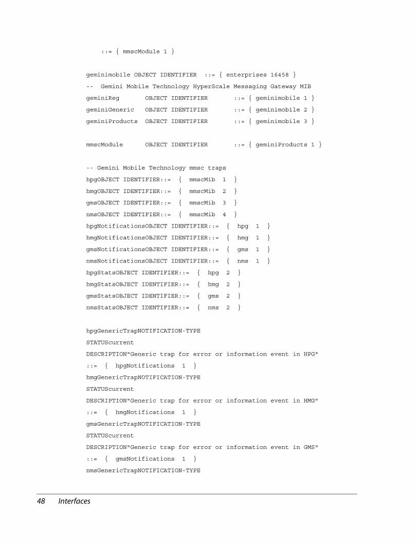
::= { mmscModule 1 }
geminimobile OBJECT IDENTIFIER ::= { enterprises 16458 }
-- Gemini Mobile Technology HyperScale Messaging Gateway MIB
geminiReg OBJECT IDENTIFIER ::= { geminimobile 1 }
geminiGeneric OBJECT IDENTIFIER ::= { geminimobile 2 }
geminiProducts OBJECT IDENTIFIER ::= { geminimobile 3 }
mmscModule OBJECT IDENTIFIER ::= { geminiProducts 1 }
-- Gemini Mobile Technology mmsc traps
hpgOBJECT IDENTIFIER::= { mmscMib 1 }
hmgOBJECT IDENTIFIER::= { mmscMib 2 }
gmsOBJECT IDENTIFIER::= { mmscMib 3 }
nmsOBJECT IDENTIFIER::= { mmscMib 4 }
hpgNotificationsOBJECT IDENTIFIER::= { hpg 1 }
hmgNotificationsOBJECT IDENTIFIER::= { hmg 1 }
gmsNotificationsOBJECT IDENTIFIER::= { gms 1 }
nmsNotificationsOBJECT IDENTIFIER::= { nms 1 }
hpgStatsOBJECT IDENTIFIER::= { hpg 2 }
hmgStatsOBJECT IDENTIFIER::= { hmg 2 }
gmsStatsOBJECT IDENTIFIER::= { gms 2 }
nmsStatsOBJECT IDENTIFIER::= { nms 2 }
hpgGenericTrapNOTIFICATION-TYPE
STATUScurrent
DESCRIPTION"Generic trap for error or information event in HPG"
::= { hpgNotifications 1 }
hmgGenericTrapNOTIFICATION-TYPE
STATUScurrent
DESCRIPTION"Generic trap for error or information event in HMG"
::= { hmgNotifications 1 }
gmsGenericTrapNOTIFICATION-TYPE
STATUScurrent
DESCRIPTION"Generic trap for error or information event in GMS"
::= { gmsNotifications 1 }
nmsGenericTrapNOTIFICATION-TYPE
48 Interfaces
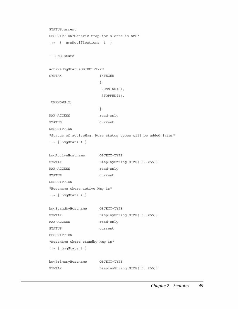
STATUScurrent
DESCRIPTION"Generic trap for alerts in NMS"
::= { nmsNotifications 1 }
-- HMG Stats
activeHmgStatusOBJECT-TYPE
SYNTAX INTEGER
{
RUNNING(0),
STOPPED(1),
UNKNOWN(2)
}
MAX-ACCESS read-only
STATUS current
DESCRIPTION
"Status of activeHmg. More status types will be added later"
::= { hmgStats 1 }
hmgActiveHostname OBJECT-TYPE
SYNTAX DisplayString(SIZE( 0..255))
MAX-ACCESS read-only
STATUS current
DESCRIPTION
"Hostname where active Hmg is"
::= { hmgStats 2 }
hmgStandbyHostname OBJECT-TYPE
SYNTAX DisplayString(SIZE( 0..255))
MAX-ACCESS read-only
STATUS current
DESCRIPTION
"Hostname where standby Hmg is"
::= { hmgStats 3 }
hmgPrimaryHostname OBJECT-TYPE
SYNTAX DisplayString(SIZE( 0..255))
Chapter 2 Features 49

MAX-ACCESS read-only
STATUS current
DESCRIPTION
"Hostname where primary Hmg is"
::= { hmgStats 4 }
hmgBackupHostname OBJECT-TYPE
SYNTAX DisplayString(SIZE( 0..255))
MAX-ACCESS read-only
STATUS current
DESCRIPTION
"Hostname where backup Hmg is"
::= { hmgStats 5 }
-- HPG Stats
activeHpgStatusOBJECT-TYPE
SYNTAX INTEGER
{
RUNNING(0),
STOPPED(1),
UNKNOWN(2)
}
MAX-ACCESS read-only
STATUS current
DESCRIPTION
"Status of activeHpg. More status types will be added later"
::= { hpgStats 1 }
hpgActiveHostname OBJECT-TYPE
SYNTAX DisplayString(SIZE( 0..255))
MAX-ACCESS read-only
STATUS current
DESCRIPTION
"Hostname where active Hpg is"
::= { hpgStats 2 }
50 Interfaces

hpgStandbyHostname OBJECT-TYPE
SYNTAX DisplayString(SIZE( 0..255))
MAX-ACCESS read-only
STATUS current
DESCRIPTION
"Hostname where standby Hpg is"
::= { hpgStats 3 }
hpgPrimaryHostname OBJECT-TYPE
SYNTAX DisplayString(SIZE( 0..255))
MAX-ACCESS read-only
STATUS current
DESCRIPTION
"Hostname where primary Hpg is"
::= { hpgStats 4 }
hpgBackupHostname OBJECT-TYPE
SYNTAX DisplayString(SIZE( 0..255))
MAX-ACCESS read-only
STATUS current
DESCRIPTION
"Hostname where backup Hpg is"
::= { hpgStats 5 }
-- GMS Stats
activeGmsStatusOBJECT-TYPE
SYNTAX INTEGER
{
RUNNING(0),
STOPPED(1),
UNKNOWN(2)
}
MAX-ACCESS read-only
STATUS current
DESCRIPTION
Chapter 2 Features 51
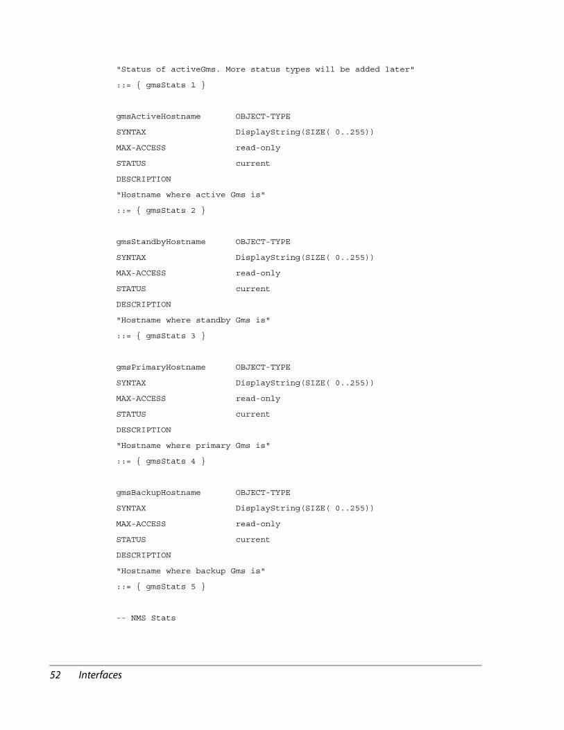
"Status of activeGms. More status types will be added later"
::= { gmsStats 1 }
gmsActiveHostname OBJECT-TYPE
SYNTAX DisplayString(SIZE( 0..255))
MAX-ACCESS read-only
STATUS current
DESCRIPTION
"Hostname where active Gms is"
::= { gmsStats 2 }
gmsStandbyHostname OBJECT-TYPE
SYNTAX DisplayString(SIZE( 0..255))
MAX-ACCESS read-only
STATUS current
DESCRIPTION
"Hostname where standby Gms is"
::= { gmsStats 3 }
gmsPrimaryHostname OBJECT-TYPE
SYNTAX DisplayString(SIZE( 0..255))
MAX-ACCESS read-only
STATUS current
DESCRIPTION
"Hostname where primary Gms is"
::= { gmsStats 4 }
gmsBackupHostname OBJECT-TYPE
SYNTAX DisplayString(SIZE( 0..255))
MAX-ACCESS read-only
STATUS current
DESCRIPTION
"Hostname where backup Gms is"
::= { gmsStats 5 }
-- NMS Stats
52 Interfaces
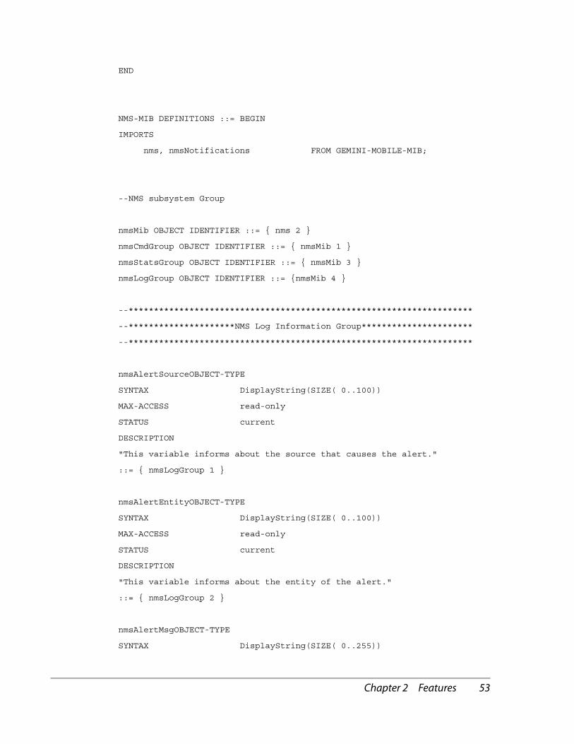
END
NMS-MIB DEFINITIONS ::= BEGIN
IMPORTS
nms, nmsNotifications FROM GEMINI-MOBILE-MIB;
--NMS subsystem Group
nmsMib OBJECT IDENTIFIER ::= { nms 2 }
nmsCmdGroup OBJECT IDENTIFIER ::= { nmsMib 1 }
nmsStatsGroup OBJECT IDENTIFIER ::= { nmsMib 3 }
nmsLogGroup OBJECT IDENTIFIER ::= {nmsMib 4 }
--********************************************************************
--*********************NMS Log Information Group**********************
--********************************************************************
nmsAlertSourceOBJECT-TYPE
SYNTAX DisplayString(SIZE( 0..100))
MAX-ACCESS read-only
STATUS current
DESCRIPTION
"This variable informs about the source that causes the alert."
::= { nmsLogGroup 1 }
nmsAlertEntityOBJECT-TYPE
SYNTAX DisplayString(SIZE( 0..100))
MAX-ACCESS read-only
STATUS current
DESCRIPTION
"This variable informs about the entity of the alert."
::= { nmsLogGroup 2 }
nmsAlertMsgOBJECT-TYPE
SYNTAX DisplayString(SIZE( 0..255))
Chapter 2 Features 53
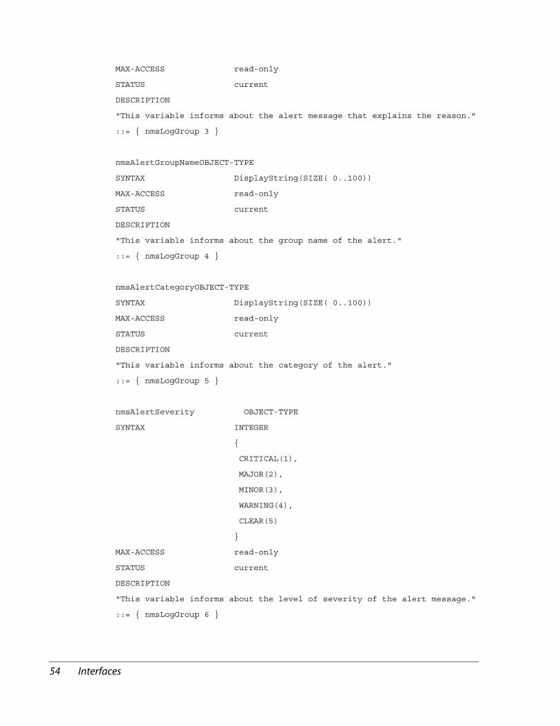
MAX-ACCESS read-only
STATUS current
DESCRIPTION
"This variable informs about the alert message that explains the reason."
::= { nmsLogGroup 3 }
nmsAlertGroupNameOBJECT-TYPE
SYNTAX DisplayString(SIZE( 0..100))
MAX-ACCESS read-only
STATUS current
DESCRIPTION
"This variable informs about the group name of the alert."
::= { nmsLogGroup 4 }
nmsAlertCategoryOBJECT-TYPE
SYNTAX DisplayString(SIZE( 0..100))
MAX-ACCESS read-only
STATUS current
DESCRIPTION
"This variable informs about the category of the alert."
::= { nmsLogGroup 5 }
nmsAlertSeverity OBJECT-TYPE
SYNTAX INTEGER
{
CRITICAL(1),
MAJOR(2),
MINOR(3),
WARNING(4),
CLEAR(5)
}
MAX-ACCESS read-only
STATUS current
DESCRIPTION
"This variable informs about the level of severity of the alert message."
::= { nmsLogGroup 6 }
54 Interfaces
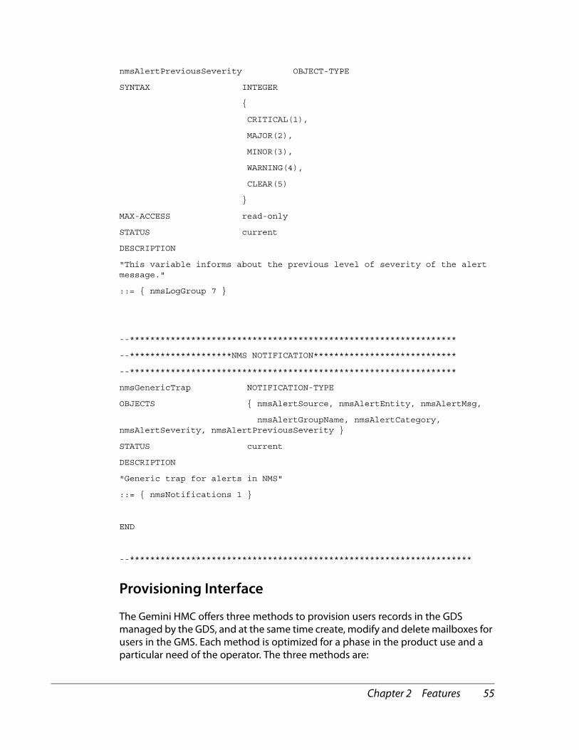
nmsAlertPreviousSeverity OBJECT-TYPE
SYNTAX INTEGER
{
CRITICAL(1),
MAJOR(2),
MINOR(3),
WARNING(4),
CLEAR(5)
}
MAX-ACCESS read-only
STATUS current
DESCRIPTION
"This variable informs about the previous level of severity of the alert message."
::= { nmsLogGroup 7 }
--****************************************************************
--********************NMS NOTIFICATION****************************
--****************************************************************
nmsGenericTrap NOTIFICATION-TYPE
OBJECTS { nmsAlertSource, nmsAlertEntity, nmsAlertMsg,
nmsAlertGroupName, nmsAlertCategory, nmsAlertSeverity, nmsAlertPreviousSeverity }
STATUS current
DESCRIPTION
"Generic trap for alerts in NMS"
::= { nmsNotifications 1 }
END
--*******************************************************************
Provisioning Interface
The Gemini HMC offers three methods to provision users records in the GDS managed by the GDS, and at the same time create, modify and delete mailboxes for users in the GMS. Each method is optimized for a phase in the product use and a particular need of the operator. The three methods are:
Chapter 2 Features 55
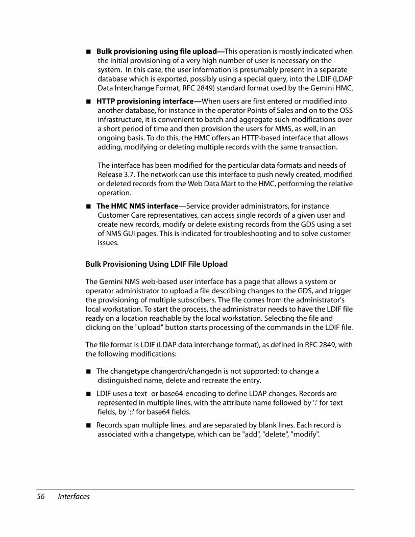
■ Bulk provisioning using file upload—This operation is mostly indicated when the initial provisioning of a very high number of user is necessary on the system. In this case, the user information is presumably present in a separate database which is exported, possibly using a special query, into the LDIF (LDAP Data Interchange Format, RFC 2849) standard format used by the Gemini HMC.
■ HTTP provisioning interface—When users are first entered or modified into another database, for instance in the operator Points of Sales and on to the OSS infrastructure, it is convenient to batch and aggregate such modifications over a short period of time and then provision the users for MMS, as well, in an ongoing basis. To do this, the HMC offers an HTTP-based interface that allows adding, modifying or deleting multiple records with the same transaction. The interface has been modified for the particular data formats and needs of Release 3.7. The network can use this interface to push newly created, modified or deleted records from the Web Data Mart to the HMC, performing the relative operation.
■ The HMC NMS interface—Service provider administrators, for instance Customer Care representatives, can access single records of a given user and create new records, modify or delete existing records from the GDS using a set of NMS GUI pages. This is indicated for troubleshooting and to solve customer issues.
Bulk Provisioning Using LDIF File Upload
The Gemini NMS web-based user interface has a page that allows a system or operator administrator to upload a file describing changes to the GDS, and trigger the provisioning of multiple subscribers. The file comes from the administrator's local workstation. To start the process, the administrator needs to have the LDIF file ready on a location reachable by the local workstation. Selecting the file and clicking on the "upload" button starts processing of the commands in the LDIF file.
The file format is LDIF (LDAP data interchange format), as defined in RFC 2849, with the following modifications:
■ The changetype changerdn/changedn is not supported: to change a distinguished name, delete and recreate the entry.
■ LDIF uses a text- or base64-encoding to define LDAP changes. Records are represented in multiple lines, with the attribute name followed by ':' for text fields, by '::' for base64 fields.
■ Records span multiple lines, and are separated by blank lines. Each record is associated with a changetype, which can be "add", "delete", "modify".
56 Interfaces

Native HTTP Interface
The HMC NMS node implements this interface acting as an HTTP/1.1 server, exposing a remote provisioning interface that utilizes “HTTP Post” to query the repository provisioning multiple subscribers per transaction and retrieve information about subscribers and classes of service.
The NMS authenticates the HTTP transaction against its database of administrators and passwords. The credential of any administrator belonging to the same hosted operator that initiates the transaction will be accepted, as long as he/she has the privilege to provision users.
The protocol defines specific commands, that are followed by a number of attributes, to execute each provisioning task. The server then responds to each command with the appropriate information or result code depending if the transaction is for a query or a provisioning operation.
A detailed description of HMC provisioning interface is in Gemini HMC 3.5 Provisioning Interface Specifications (GMT297-HMCv3.5-Provisioning-Interface) - Version 1.0, November 2006.
HTTP Interface
For this deployment of the HMC Release 3.7, the interface has been tuned and modified to allow direct provisioning of subscribers defined in the WDM into the HMC.
Note that one of the most important attributes that characterizes new users provisioned in this way is their class of service (COS). Mapping needs to be developed between the classes of service defined on the HMC and the service attributes in the WDM so that newly provisioned or modified users can be assigned to the correct COS in the HMC.
Individual Provisioning From NMS
Customer care representatives or other NMS administrators can provision single subscribers through the Gemini NMS GUI, at the pages:
Provisioning > Subscriber admin > Add subscriber, or
Provisioning > Subscriber admin > Modify subscriber
Please refer to the HMC Online Help for a detailed description of the procedure.
Chapter 2 Features 57
GDS Provisioning Details
While deploying the HMC Release 3.7, the administrator needs to provision users directly on the HMC's GDS by means of one of the interfaces described above. Users will be provisioned initially through LDIF file upload and subsequently, at regular intervals, using the HTTP remote provisioning interface from an application associated with the Web Data Mart.
There is a mapping between WDM Service Packages and HMC user attributes to configure the LDAP user records, correctly, depending on the service definition for each user. This can be done in two ways:
■ Using a generic class of service and defining different attributes for each user overriding the COS default
■ Defining multiple classes of service to map the user service packages and simply assigning users to a class of service during provisioning.
Assisted by Gemini, the customer must create the correct classes of services in the GDS, that correspond to the mapping on the WDM. This must be done for each market, separately.
On a day-to-day basis, the following attributes are among those controllable using any of the above-mentioned interfaces for each subscriber:
■ Billing plan of the user (postpaid or prepaid)
■ Sending inter-company messages (on-net). This can be implemented by not setting any other flag in the subscriber capability record, as it is the default capability for sending MMS. Note that the HMC also provides the ability to block a user from sending MMS by removing the "send" capability from the user record.
■ Sending to subscribers of other intra-company markets (distinguishing from users of other operators). This is not currently supported by the BSS infrastructure (WDM, BSCS) and would require additional development to enable.
■ Sending to national ICM messages (off-net)
■ Sending to international ICM messages
■ Sending premium messaging (to all VAS)
■ Supporting MMboxes
■ Receiving emails as MMS
The WDM can provision new subscribers through the HMC HTTP-based provisioning interface with any combination of these attributes or HTTP transactions can be used to change the capabilities of existing subscribers.
58 Interfaces

Logging
The Gemini HMC produces several types of log files, which are used for increased level of tracing and can be transferred to a remote platform for further analysis. These are:
■ Transaction log file (TLOG)
■ Application log file (ALOG)
■ Statistical log file (SLOG)
In addition the HMC produces CDR log files, which are detailed in Postpaid Billing section MM8 Interface‚ on page 39.
These files serve different purposes and are managed differently by the system.
Transaction Log
The Transaction log file contains trace of all the transitions of message through any HMC interface, both external and internal. Using the transaction log file, the path of messages within the HMC can be traced precisely and in a detailed way. The transaction log files are used as a complement to CDR files if additional information is needed to generate MDRs, and are the base of the Customer Care interface tracing capability.
Transaction log files are generated by the HMG and transferred to the NMS that aggregates them if more than one HMG node exists in the system, stores them in a configurable location, and retrieves them for Customer Care queries. The NMS node also manages the access to the transaction logs over FTP.
There are two separate transaction log files series: one recording transactions for system level components (like the GMS and the GDS interfaces) where hosted operators are not considered at the interface level, and one for each hosted operator regarding external transactions.
The format of transaction log entries is configurable through configuration files (not the NMS). By default, the format is the following for both the system and operator-specific log files, and is as follows, with vertical bars as delimiters:
<PID>|<DATE-CLF>|<PROTO>|<TYPE>|<STATUS>|<TRID>|<CLIENT>|<SERVER>|
<DURATION>|{FROM}|<RCPTS>|{Message-ID}{X-Mms-Message-ID}|{X-Mms-Transaction-ID}|<MESSAGE>|<SMS_MESSAGE_TYPE>|<ESME_ID>|
<SMS_COMMAND_STATUS>|<SMS_SEQUENCE_NUMBER>|<SMS_SOURCE_ADDR>|
<SMS_DEST_ADDR>|<SMS_MESSAGE_ID>|<SMS_MESSAGE_ID_32BITS>|
<SMS_MESSAGE_STATE>
Chapter 2 Features 59
Where fields between <> are generated by the HMG, while fields between {} come from message headers. Note that for the 3.7 deployment, since no SMS is directly received, the fields that start with SMS_ will be empty.
For additional details please see Gemini’s HyperScale Messaging Gateway (MMS-R) Administrator's Guide .
Application Log
Application logs are generated by the HMG and HPG nodes as an aid to tracing problems with the system. Generation of the logs and the level of logging depend on the ALOG.loglevel parameter that sets the minimum severity level of entries in the logs. The parameter is changeable in real-time through the HMG and HPG CLI, in addition to being specified in the etc/hmg.properties and etc/hpg.properties configuration files. This parameter is not controlled by the NMS.
Application logs are rotated locally on the machine that generates them but are not transferred to the NMS. They need to be retrieved by logging into the system as a Linux administrator.
Note If used at INFO or even more at DEBUG level, the application log becomes very verbose, affecting both the disk space and the performance of the nodes. It should be set to these levels with caution.
For additional details please see Gemini’s HyperScale Messaging Gateway (MMS-R) Administrator's Guide .
Statistical Log
The HMG writes a wide variety of raw statistical data into the statistics log file. The format of the log records and the fields that are included in the record are configurable through configuration files, not NMS. For additional details please see Gemini’s HyperScale Messaging Gateway (MMS-R) Administrator's Guide .
Entries into the statistics log file are of two basic types:
■ Transaction entries, such as the submitting of an LDAP query or the receiving of a message through the MM4 listener. These individual event records can be tallied by a post-processing tool to produce aggregate counts for specific transaction types, such as total LDAP queries submitted or MM4 messages received, over a specified time interval. In certain cases, a single transaction can result in several types of entries to the statistics log.
60 Interfaces

■ Sample point entries that gauge current HMG conditions, such as the number of connections currently open to the MMSCTR listener or the number of messages currently queued for delivery to MM3 destinations. Sample point data can be used by a post-processing tool to generate minimum, maximum, and average statistics for a specified time interval—for example, the average number of connections open to the MMSCTR listener or the maximum number of messages queued for MM3 delivery during the interval.
Both of these statistics log entry types are composed of these fields in this order, with comma delimitation:
<DATETIME>,<STAT_ID>,<STAT_VALUE>,<DOMAIN>,<STATUS>
For example, the sample below shows two statistics log entries. The first entry is a transactional event, a message received by the MM4 listener for service provider "MobileCo", and the second entry is a sample point for a state statistic, number of open connections to the GDS.
20061210101442,MM4SMTP_MobileCo.received,,mmsc.uk,
20061210101441,LDAPPOOL.conn.open,10,,
For additional details please see Gemini’s HyperScale Messaging Gateway (MMS-R) Administrator's Guide .
Chapter 2 Features 61
Message RoutingThe HMC accepts messages from the following sources:
■ Mobile Originated (MO) messages received via MM1 interface
■ Internet client messages received via MM3 interface
■ Foreign user messages received via MM4 interface
■ VASP originated messages received via MM7 interface
Addressing
The HMC accepts messages addressed to MTs with the following formats:
■ Messages addressed to a valid phone number format
■ Messages addressed to a valid email address format
■ Messages addressed to a valid short-code “VAS” format
National Numbering Plans
When receiving a new MMS, the HMC attempts to normalize the user-provided destination number to an E-164 format. To perform the normalization process the system utilizes the national numbering plan configured by the service provider.
Both fixed length and variable length numbering plans are supported. The sender's address is mapped into the numbering plan to determine the correct normalization. The HMC ignores “+” or IDD when normalizing the address.
Once the system identifies the construction of the sender's number in terms of country code, area code, and own number, it applies the correct normalization to the user-provided destination number where prefixes may be added or dropped.
Short Code Formats
A short code can be any combination of alphanumeric characters that is shorter that the shortest dialed number allowed by the national numbering plan.
Message Delivery
The HMC supports several different messaging route types, enabling MMS subscribers to message among themselves, with legacy handset users, conventional Internet email client users, and applications. In particular, the HMC supports these route types:
62 Message Routing

■ MMS users [Phone number addressing]
■ Legacy user via SMS [Phone number addressing]
■ Legacy user via WEB/WAP portal [Phone number addressing]
■ User on a different MMSC [Phone number addressing]
■ Domain name
■ VASP [Short code]
■ VASP [Phone number addressing]
■ Internet client [Email addressing]
MMS User Delivery
When a message is received addressed to a valid phone number and is determined to be delivered via MMS, a notification will be sent to the MT user who then accesses the HMC and retrieves the message via the MM1 interface.
Legacy User Via SMS Delivery
When a message is received addressed to a valid phone number and is determined to be delivered via SMS, the HMC may crop the text portion of the message to a predetermined maximum size and will convert the MMS message to an SMS message according to the following rules:
■ Include MM plain text into SMS text
■ Include the subject field into SMS text
■ Include the originator address into SMS text
■ Allow/disallow SMS segmentation
■ Support mapping of MM originator address to SMS originator address
■ Set the maximum number of SMS segments per MMS message
Users Served By Foreign MMSC Delivery
When a message is received addressed to a valid phone number and the user is determined to belong to a partner service provider interconnected via MM4, the HMC will attempt to deliver the message via the MM4 interface to the partner's MMSC.
Domain Name Delivery
Domain names typically represent specific applications such as web mail service to support legacy subscribers or unified messaging service to provide integrated
Chapter 2 Features 63

telephony and graphical user interfaces. When a message is received addressed to a valid phone number and is determined to be associated with a particular application, the HMC will send an email message to a predefined destination domain (phone_number@desination_domain).
In addition, the following options are configurable:
■ Email sent with or without SMIL
■ SMS notification to a predefined URL is sent.
VASP Delivery
At least three scenarios may result in a message being delivered to a VASP:
■ Message is specifically addressed by a user to a VASP short code
■ Message is specifically addressed by a user to a VASP address
■ Message is associated with an application hosted as VASP
If a message is received addressed to a valid short code, the HMC will deliver the message to the correct VASP. If a message is received addressed to a phone number identified to be the VASP address, the HMC will deliver the message to the correct VASP. Similarly to the domain name case, VASPs may also be associated with applications. In addition, it may send SMS notification with a predefined URL directing the user to the VASP application.
Internet Client Delivery
When a message is received addressed to a fully qualified domain name (FQDN), the HMC will forward the message to the appropriate Internet MTA, for relay on to the target Internet email client.
Message Routing
As evident from the variety of incoming interfaces and variety of delivery methods, a sophisticated routing logic must be applied by the HMC. The correct destination and routing mechanisms are determined by:
■ Content type of the message
■ Interface on which the message was received
■ Information known about the recipient. This may include:
◆ MSISDN number
◆ IMSI number
64 Message Routing
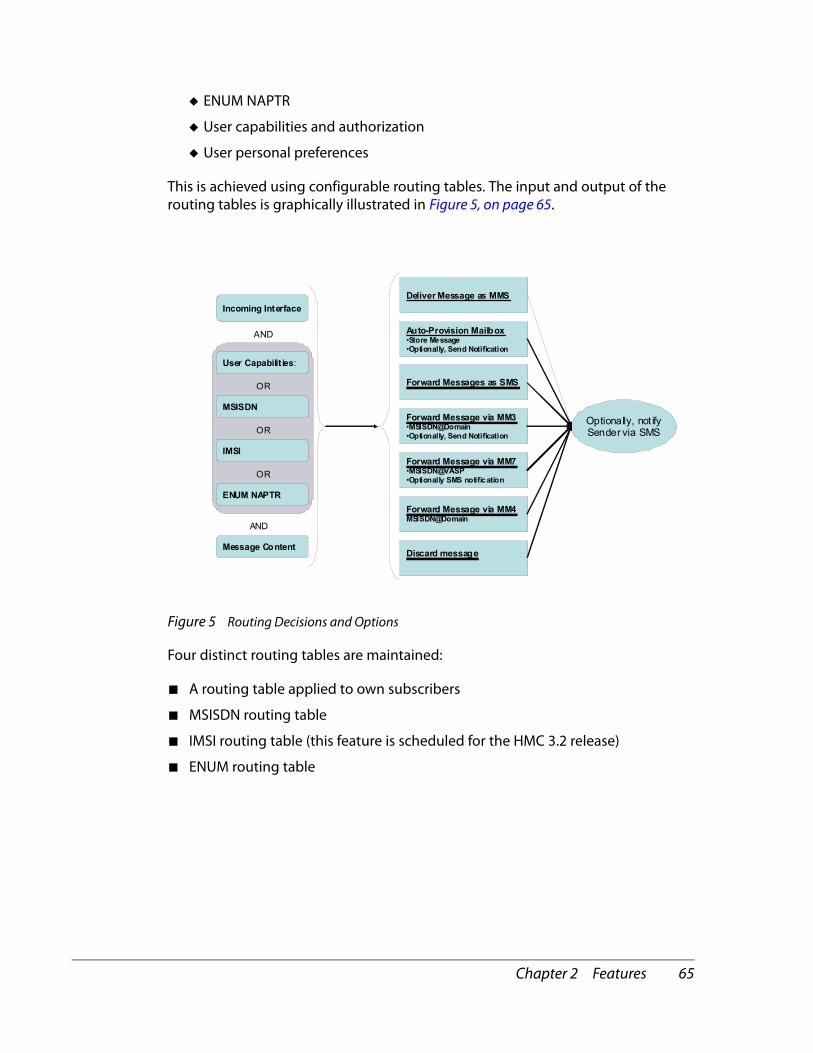
Figure 5 Routing Decisions and Options
◆ ENUM NAPTR
◆ User capabilities and authorization
◆ User personal preferences
This is achieved using configurable routing tables. The input and output of the routing tables is graphically illustrated in Figure 5‚ on page 65.
Four distinct routing tables are maintained:
■ A routing table applied to own subscribers
■ MSISDN routing table
■ IMSI routing table (this feature is scheduled for the HMC 3.2 release)
■ ENUM routing table
Optionally, not ifySender via SMS
Auto-Provision Mailbox•Store Message•Optionally, Send Notification
Forward Messages as SMS
Forward Message via MM3•MSISDN@Domain•Optionally, Send Notification
Forward Message via MM7•MSISDN@VASP•Optionally SMS notification
Discard message
Forward Message via MM4MSISDN@Domain
Incoming Interface
User Capabilit ies:
MSISDN
IMSI
Message Content
ENUM NAPTR
AND
AND
OR
OR
OR
Deliver Message as MMS
Chapter 2 Features 65

Message NotificationThe HMC provides MMS subscribers with these message notification services:
■ Message Received
■ Delivery Report
■ Read Report
Message Received
After successfully inserting a message addressed to an MT into the Gemini Message Store (MMS-S), the HMG sends a message-received notification (M-Notification.ind) to the MT by way of the HPG. The notification includes the stored message's sender name, subject, timestamp, and size, as well as the retrieval URI for the message.
Delivery Report
When an MMS subscriber or VASP sends a multimedia message to another MMS subscriber, the sender may request that the addressee provide them with a delivery report upon retrieval of the message. When messages with a delivery report request header are retrieved by MTs, the HMC sends a delivery report (M-Delivery.ind) to the MO by way of the Push Proxy Gateway. This happens unless the MT declines to allow delivery reports to be sent for their retrieved messages, in which case no delivery report is sent to the MO.
The HMC will also send a delivery report to the MO if the MT rejects the message or if the message expires without being retrieved by the MT. The report will indicate the message's rejected or expiry status.
A Gemini proprietary option is to send a delivery failure (or ‘MIMIC”) report if no DR is requested but the HMC fails to deliver the message.
Read Reports
The HMC supports read reports as introduced in MMS1.2. Both the newly defined MMS 1.0 PDU (M-Read-Orig.ind) is supported as well as the ability to send the read report as a regular MMS for the purpose of backward compatibility. In addition, read reports messages are supported on the MM4 (MM4_Read_Reply_Report.REQ) and MM7 (MM7_Read_Reply_Report.REQ) interfaces.
66 Message Notification

Message Storage and RetrievalThe Gemini HyperScale Messaging Gateway (MMS-R) works in conjunction with the Gemini Message Store (MMS-S) to provide mailbox provisioning, message storage, and message retrieval services for mobile subscribers.
When interfacing with the Message Store, the HMG acts as a proxy on behalf of subscribers: it authenticates and authorizes users to access their mailboxes in the course of message processing, while automatically initiating and maintaining a persistent login session with each running Message Store node. This speeds up the retrieval of information from the GMS, because logins are not required for individual provisioning, storage, or retrieval events. End users never access the Message Store directly.
The Gemini Message Store is not as configurable as the HMG; it performs only a few processing tasks besides efficiently storing and retrieving messages and meta-data from the user mailboxes. Among the few parameters that can be changed on the GMS are the mailbox quota and each message expiry time. These are detailed in the following section.
From the systems point of view, the Message Store is allocated the biggest disk space in the Storage Area Network, as it manages the user mailboxes which are where most of the data resides, either for temporary or permanent storage.
Message Store performance, in terms of messages-per-second, depends mostly on the number of disks that are allocated, as reads and writes to disk occur in parallel with all the disks in the partition. The HMC optimizes the number of disks allocated to the Message Store node by striping the SAN disk space and allocating part of all available disks to the GMS use. All disks in the SAN, in a mirrored configuration, can be accessed in parallel by the GMS, allowing for the maximum physical I/O performance.
Automatic Provisioning and Activation
Upon receiving a message from a MMS user, the HMC checks for the sender's profile in the GDS. If such profile cannot be found, the HMC may create a new user mailbox using preconfigured mailbox defaults or reject the message and send a configurable text message to the user directing them to provision the mailbox. The HMC can be configured to create a user profile automatically based on a predefined Class of Service (COS). This may or may not include predefined mailbox defaults.
Some service providers may be able to provide a parameter that differentiates between prepaid and postpaid users. If there is a way to differentiate a prepaid user from a postpaid user using the information provided by a WAP Gateway, two separate mailbox profiles may be used.
Chapter 2 Features 67

Message Storage
When the HMG receives a message determined to be delivered to an MMS subscriber, after confirming the subscriber's authorization and performing appropriate checks on the message, the HMG inserts the message into the subscriber's mailbox on a Gemini Message Store node using an LMTP transaction.
Note If the recipient mailbox is over quota the insertion fails, and the sender will receive back an error text with a configurable message.
Message Retrieval
When the HMG receives a retrieve request from a handset for a message stored in the Gemini Message Store, the HMG confirms that the requesting user is an authorized subscriber, retrieves the stored message with an IMAP transaction, performs any necessary transformation to adapt the message to the recipient terminal, and sends it to the subscriber.
If the user is not provisioned with a permanent MMbox, the HMG then deletes the message from the Message Store but only after the message is confirmed as received by handset using the appropriate MM1 acknowledgment.
MMBox
The HMC supports the Multimedia Mailbox defined for OMA MMS 1.2. This enables a user to store retrieved and uploaded messages into a permanent personal mailbox that can be accessed anytime for review and handling of the stored messages. This feature has to be provisioned per subscriber, as the HMC, by default, deletes messages from the mailbox after they have been retrieved by the recipient handset.
Currently there are no handsets supporting MMS 1.2, which requires a number of MM1 messages to implement its functionality. So the MMbox is only accessible for users through the Gemini User Portal working in conjunction with the HMG and GMS. In this case, the User Portal implements a variant of web- or WAP-mail for the subscribers that are provisioned with this service.
The complete set of MMbox services include storing and uploading messages using the MM1_mmbox_store.REQ or MM1_mmbox-upload.REQ, viewing the MMbox content using MM1_mmbox_view.REQ, and deleting messages in the MMbox using MM1_mmbox_delete.REQ. These services are all supported transparently through the Gemini User Portal.
68 Message Storage and Retrieval
Mailbox Capacity Controls
The Gemini Message Store supports mailbox quotas. This is an attribute of each subscriber through its class of service and controls the storage space available to the mailbox. If the HMG receives a message for a subscriber whose mailbox is at, or over its limit, the message will be bounced back to the sender. If an incoming message pushes a subscriber's mailbox from being under the storage limit to being over the limit, the message is accepted.
Message Expiration Controls
The message expiry is assigned by the HMG while storing the message and implemented by the GMS when it automatically deletes messages that are still undelivered when it expires. Each MO-MMS message comes in with a requested expiration period. However, the HMC can override this and request a shorter period, based on a parameter configured on a per-hosted operator basis using the NMS GUI.
Chapter 2 Features 69

Transcoding and Content Adaptation The HMC provides a variety of transcoding and content adaptation services to enable message flow between disparate network segments and handsets. Transcoding occurs as a recipient handset retrieves a message, based on the handset UAProf information. See UAProf Interface (CPI)‚ on page 42 for details.
The HMC supports internal image and character set transcoding and conversion.
Note Transcoding and content adaptation of all other MIME types can be done by using the HMC OMA-STI standard interface towards an optional external transcoding platform. This is out of scope for the 3.7 release.
Internal Transcoding
The HMC's internal transcoding uses configuration files to determine how images and character sets should be transcoded over the MM1 interface and per domain configuration on how messages should be transcoded or adapted over the MM3 and MM4 interfaces. This is not configurable using the NMS GUI, as this is usually a one-time configuration changing very infrequently.
Over the MM1 interface, the HMC image and character set transcoding supports the following operations:
■ Character Set Conversion—as specified by the UAProf of the receiving handset
■ Message Truncation—either forwarding over an interface not supporting certain formats or a limiting message size (like MT-SMS or 2-way), or as specified for individual handsets by their UAProf profile
■ Image Conversion and Resizing—as specified by the UAProf of the receiving handset
■ SMIL/MIME Formatting Conversion and SMIL Stripping—if the message is going out towards an interface where SMIL is not supported, such as a web page on the legacy portal
In particular image conversion, which is the most likely conversion to be needed, is performed internally by the HMC. The following table shows a subset of the supported formats that has been requested by customers for support by the iDEN handsets:
Image Conversion Mapping
From To
image/jpeg image/jpeg (resize)
image/gif * image/gif (resize) *
70 Transcoding and Content Adaptation

OMA-STI interface
For MIME types that the HMC cannot transcode internally, a standard OMA-STI interface is provided for integration with an external transcoder. The OMA-STI interface is defined in the OMA document Open Mobile Alliance, Standard Transcoding Interface Specification, Candidate Version 1.0 - 04 Jul 2005 (OMA-TS-STI-V1_0-20050704-C), downloaded at:
http://www.openmobilealliance.org/release_program/docs/STI/V1_0-20050704-C/OMA-TS-STI-V1_0-20050704-C.pdf
Gemini has tested interoperability with the major vendors of transcoding software using this interface, and supports integration with platforms from Adamind, Mobixell and VoiceAge.
However, while native to the HMC and available if the need for it arises, this feature is not used in the Release 3.7 configuration.
image/vnd.wap.wbmp image/jpeg
image/png image/jpeg
image/bmp image/jpeg
image/tiff image/jpeg
Image Conversion Mapping
From To
Chapter 2 Features 71
Regulatory and Security ControlsThe HMC provides a number of features that help the service provider control the flow of messages that traverse the HMC. In particular, the HMC guards against unauthorized or malicious messaging by invoking the following regulatory and security controls:
■ Authorization of MO and MT
■ Authorization of VASP
■ Maximum recipients per message
■ Maximum incoming message size
Authorization of MO and MT
Through the user database, the service provider can control who is authorized to send and receive multimedia messages through the HMG. Each time the HMG receives a message send request from an MMS handset, it checks with the user database to confirm that the sender is an authorized subscriber.
MO's with a valid subscriber number (and proper “capa” value, depending on the message sent) are allowed to send messages, while MO's for whom no subscriber number is found receive service denied errors or are configured to be automatically provisioned.
Likewise, each time the HMC receives a “request to accept a message” addressed to an MMS handset, it confirms that the MT is an authorized subscriber using the MT's MSISDN (if the message originates from an MO) or email address (if the message originates from a legacy handset or internet email client). The user database is then queried for a corresponding subscriber number. If an MT lacks a subscriber number, the HMG transmits an appropriate error code to the sender or applies any of the other legacy delivery mechanisms.
Finally, the HMG confirms the authorization of MTs attempting to retrieve their messages from storage in the Gemini Message Store (MMS-S), using an MSISDN number inserted into the retrieve request by the WAP Gateway to query the user database for a corresponding subscriber number. The HMC authenticates all requests from MT handsets, such as retrieval, notifications, read reports, etc.
Authorization of VASP
VASP databases are manually added and maintained through the GUI interface of the management system. A VASP session is authorized against this database when a new session is established. Once the session is established it is maintained so that
72 Regulatory and Security Controls
the VASP can continue to send messages to users and distribution lists without re-authorization.
Maximum Recipients Per Message
The service provider can set limits on the number of addressees on messages coming into the HMG through the MM1 interface (from MMS handsets), the SMTP interface (from the border MTA), or the VASP interface. The HMC checks whether the number of addressees for the message exceeds the maximum recipient limits and rejects the message if the limit is exceeded.
Maximum Incoming Message Size
The service provider can set limits on the size of messages coming into the HMC through the SMTP interface (from the border MTA), the MM1 interface or the VASP interface. The HMC checks whether the message exceeds the incoming message size limit, and rejects the message if the limit is exceeded.
Chapter 2 Features 73
Spam FilteringThe Gemini HMC offers several features aimed at reducing Spam, or unwanted mass mailing of commercial messages. These include filtering of keywords in the message subject, use of operator-specific black and white lists on the MM3 (email) interface, and support for user-specific black and white lists.
In addition, Spam filtering appliances can be added to the HMC in a transparent fashion as a system integration activity, over the MM1, MM3 and MM7 interfaces, analyzing the message origin and comparing it with a list of known suspicious addresses, maintained by the appliance vendor.
Keyword Filtering
A hosted operator can specify a list of text strings that will cause the HMC to block a message incoming on the MM3 (email) interface if they appear in the message subject header. The HMC has a facility to upload a keywords file from the NMS GUI and use it as the source of the filtering.
Service Provider White and Black Lists
Messages received on the MM1, MM3 (email), MM4 (inter-carrier) and MM7 interfaces, and addressed to each service provider’s domain, are checked against the service provider-wide, black and white lists. These define a list of email domains or single email addresses, and E.164 numbers that are used to match the From: header value in incoming messages.
A service provider must select to use either a white list, black list or no filtering. If a white list is used, then only email from the domains that appear in the list are allowed in. If the black list is used, only email from addresses and domains, not appearing in the list, are allowed. A service provider administrator selects whether the white or black list method is used from a configuration page in the NMS GUI. Note that if the active list is switched from one type to the other, the information in the list which is now inactive, is not lost but remains in the NMS database for possible reuse.
If a message is discarded due to black or white list filtering, no bounce message is returned to sender.
The HMC NMS module provides access to the hosted operator specific black and white lists. The NMS web-based GUI allows administrators to configure the list entries one by one from the Service Settings page. Also, the page supports importing a text file that defines a list of addresses (email or PTN format). When a file is imported, its content is added to the list instead of overwriting it; to remove addresses from the list an administrator must use the GUI instead.
74 Spam Filtering
User White and Black Lists
Users can also provision personal white and black lists in their User Profiles, to be used for filtering unwanted incoming messages. These black and white lists are also mutually exclusive, and individual users can configure whether the black or white list are used via the User Portal self-care page. The HMC supports separate e-mail and MSISDN address black and white lists with separate controls. If a message is filtered, the message is discarded for that recipient and no bounce message is sent back to the sender.
External Spam Filter Integration
The Gemini HMC Spam filtering functionality can be augmented by integrating the platform with an external commercial Spam filter over the MM3 interface. This has no impact on the HMC itself, as the filter simply acts on the incoming traffic forwarding the messages that are not blocked. Gemini is therefore agnostic on the recommendation of such a system.
Chapter 2 Features 75
Multiple Language SupportThe HMC supports multiple languages through the definition of multiple sets of templates for messages that the HMC may send to users over SMS or as responses to user-initiated MMS transactions. The sets of message templates in different languages are defined by the service provider administrators using the NMS GUI.
Each user has a language associated identified in the User Profile. If undefined, the default language to use is a property if the class of service the user belongs configured by the service provider administrator.
The chosen language set is reflected in all communications from the HMC to subscribers. Examples for configurable free text supported in multiple languages include the message to send in case:
■ the MMS subscriber is blocked
■ the MMS subscriber is barred for MO messaging
■ the MMS subscriber has not enough credit
■ of an invalid recipient address
■ of unsuccessful submission for various reasons, e.g. maximum message size exceeded
76 Multiple Language Support

Hosting ServicesThe Gemini HMC architecture supports hosting of multiple service providers on a single HMC cluster. While service providers share the system resources, in terms of processing power and disk space, their application configuration and data is kept completely separate, at the message flow, operation, and management/configuration levels:
■ Users are only accessed by entities registered with the service provider: human administrators or computer applications must be authenticated and be affiliated with an operator for access to provisioning.
■ Administrators at the hosted operator level are distinguished by their affiliation, username and password. They can only access information and configuration functions relative to their organization.
■ Routing rules apply to messages on a pre-hosted operator basis. Service providers are assigned a set of ports used by their messaging traffic for the different supported interfaces. This allows assigning incoming messages to a configured service provider, while messages are then authenticated against the operator's known users and VASPs.
■ Service providers are also distinguished by domain. This is used to route messages to the correct operator over the MM3 (email) interface.
■ Logging, billing, real-time charging transactions can be configured differently for remote servers with which to interact, directories for log files, naming conventions, and file rotation policies.
If a subscriber, of one hosted operator, sends a message to a subscriber of another hosted operator, for instance, between markets, the message is sent through the MM4 interface, to allow the system to generate the necessary CDRs. However, the message does not exit the HMC cluster, as it is routed back at the level of the cluster Ethernet switch.
Hosting of service providers is governed through the NMS GUI by network provider administrators. A network administrator has privileges that include the creation and removal of hosted operators, if the hosted operator has no subscribers. Creation of a service provider requires a license key from Gemini specifying the hosted operator's license details. The act of creating a new hosted operator also requires restarting the system.
Once a hosted operator is created, the system administrator retains the ability to identify himself with a service provider administrator and view or modify specific service parameters on the service provider's behalf.
Chapter 2 Features 77
Lawful InterceptionThe Gemini HMC provides a special type of administrative account to law enforcement agencies wishing to tap into communications associated with specific users. The access to the administrative account is secured and encrypted. The system administrator is requested to create a law enforcement account to start lawful interception operations, after which the law enforcement administrator can log in and manage a list of users whose messages are intercepted. Multiple lawful interception accounts are supported, each with its own list of targets (that can overlap) and its own e-mail destination.
Through the lawful interception administrative account, a law enforcement agent can manage a list of users under surveillance. Up to several hundred users can be tapped. The HMC silently copies any message to and from all users on the list to a configured e-mail address using SMTP. The e-mail generated by the HMC to the law enforcement agency address is encrypted to avoid interception. The user being intercepted is not aware of the process as the original messages are simply forked, copied and forwarded to destination.
The messages sent to the interception address have a configurable subject, with a fixed configurable part and a variable part with a configurable list of headers from the message being intercepted. This allows the law enforcement agency that receives the message, to distinguish from among a large number of intercepted messages and sort them into separate mailboxes.
The fixed part of the message subject has the format [text] <PTN being intercepted> [text]. This for instance could take the form of “Intercepted message for +16505551212: “.
The headers that can be used from the original message to compose the rest of the subject are:
■ To:
■ From:
■ Subject:
■ Timestamp (in date/time format)
An example of the subject field of the message to the law enforcement agency is then:
"Intercepted message for +16505551212: To: +16505551212, From: +14156661515, Subject: let's rob a bank".
78 Lawful Interception

The body of the message sent to the law enforcement agency is simply the complete message being intercepted, comprised of all the headers listed before the intercepted message body.
Chapter 2 Features 79

80 Lawful Interception
3 Systems Information, N+1 Update
This chapter describes the network architecture and system configuration of the Gemini HMC cluster for NII, the Phase Two, N+1 Update.
It includes the updated diagrams for the machines that will have four port network cards to be used for the SIGTRAN multi-homing feature.
The system configuration and network architecture of the twenty-eight node HMC is detailed in the following of this document and consists of these sections:
■ HMC Configuration‚ on page 82
■ Services‚ on page 84
■ DL 380 G5 Wiring‚ on page 94
■ DL 360 G5 Wiring for Rack One‚ on page 95
■ DL 360 G5 Wiring for Rack Two‚ on page 96
■ DL 360 G5 Wiring for Rack Three‚ on page 97
■ DL 360 SIGTRAN Node Wiring for Racks One and Two‚ on page 98
■ Network Switch Wiring, Rack One‚ on page 99
■ Network Switch Wiring, Rack Two‚ on page 100
■ Network Switch Wiring, Rack Three‚ on page 101
■ SAN One Wiring Diagram‚ on page 102
■ SAN Two Wiring Diagram‚ on page 103
■ SAN Three Wiring Diagram‚ on page 104
■ SAN One Switch Wiring‚ on page 105
■ SAN Two Switch Wiring‚ on page 106
■ SAN Three Switch Wiring‚ on page 107
Chapter 3 Systems Information, N+1 Update 81

HMC Configuration The basic configuration of the HMC N+1 system is composed of three racks of the following:
■ Four (4) HP Procurve 2848 Gigabit Ethernet switches
■ Two (2) HP ProCurve 2810-48G Gigabit Ethernet switches
■ Six (6) HP Proliant DL 380 G5 servers
■ Twenty-two (22) HP Proliant DL 360 G5 servers
■ Four (4) HP StorageWorks SAN 4/16 Fibre Channel Switches
■ Two (2) HP StorageWorks SAN 4/32B Fibre Channel Switches
■ Two (2) HP MSA-1000 SAN with 14 72 GigaByte disks each
■ Six (6) HP MSA-30 SAN Extension shelves with 14 72 GigaByte disks each
■ One (1) HP MSA-2012fc SAN with 12 72 GigaByte disks
■ One (1) HP MSA-2000 SAN Extension shelf with 12 72 GigaByte disks
The HMC uses an architecture that eliminates single points of failure to maximize uptime without sacrificing performance.
The system consists of a set of twenty-eight computer servers ('nodes'). Each node hosts a specific service (an application such as HMG, HPG, etc.) and may also be a spare node for another node's service. The nodes are connected to two ethernet switches for redundancy of network connectivity.
Stateful storage is provided by SAN storage arrays. Both the storage arrays and every node have dual (redundant) fiber channel connections into two industry standard fiber channel switches.
The SAN storage is used to hold the shared data for the services executing on the nodes. The storage array supports RAID configurations of the data and is considered highly available and redundant.
Processing Nodes
The processing nodes are based on HP servers incorporating Intel technology and running the Linux operating system. The supported HP servers are ProLiant DL380 and ProLiant DL360.
To scale the system, additional processing nodes running HMG, GMS, GDS, HPG and User Portal applications may be added as required by the desired capacity and observed traffic model. Adding additional nodes will also require adding capacity to the SAN storage array.
82 HMC Configuration

Ethernet Switches and VLANs
To ensure security, manageability and scalability, the HMC nodes are networked via separate virtual LANs (VLANs). The VLANs are configured on the two Ethernet switches.
The 'external' VLAN is used for communication between the HMC system and its external users (such as the Internet and the GGSN/cell provider's networks). The 'internal' VLAN is used for communication between the internal applications of the HMC system without exposure to the outside world.
Storage Area Network
All shared data storage is done into a centralized Storage Area Network (SAN). Access to the SAN is through a Fiber Channel network. Each node has redundant connectivity into this storage network. The supported SAN system is the HP Modular Smart Area 1000 (MSA-1000) with extension shelves (MSA-30), and a MSA-2012fc with an MSA-2000 extension shelf.
SAN Switch
In each or the three racks, two fiber channel SAN switches are used to construct the storage area network. Each node is connected to both switches for redundancy.
Chapter 3 Systems Information, N+1 Update 83
Services The six types of Gemini services include:
■ Seven (7) HMGs, the Gemini MMS-R
■ Ten (10) HPGs, the Gemini Push Proxy Gateway (PPG), nine (9) active, one (1) is a stand-by
■ One (1) GDS, the Gemini Directory Server (LDAP)
■ Six (6) GMS, the Gemini Message Store (MMS-S) where the mailboxes reside
■ One (1) NMS, the Gemini Administration Server (MMS-A)
■ One (1) UP, the Gemini User Portal
■ Two (2) SIGTRAN services
Gemini services run on twenty-eight nodes.
There is another type of non-Gemini services:
■ Two (2) JDKs (used internally)
for a total of 30 services running on 28 physical nodes, hmc-1 through hmc-28, split between three racks.
Physical nodes hmc-1 through hmc-10 are in rack one. Nodes hmc-11 through hmc-18 are housed in rack two, hmc-19 through hmc-28 are housed in rack three.
Failover
Some services have a primary subsytem with a standby secondary subsytem on another server should the primary server fail. For example, HMG #1 uses the physical node hmc-1 as its primary node and hmc-4 as a secondary standby.
When a service fails over, the secondary server becomes the active server for the application. For example, should hmc-1 fail, hmc-4 becomes the active server for hmg-1, while continuing to run the gds-1 and mmsa-1 services.
LifeKeeper software manages failover. See LifeKeeper Administration‚ on page 257 for more information.
Load-balancing
The seven HMG services are load balanced.
84 Services
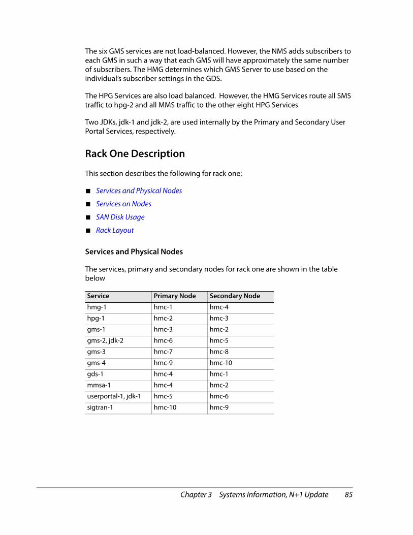
The six GMS services are not load-balanced. However, the NMS adds subscribers to each GMS in such a way that each GMS will have approximately the same number of subscribers. The HMG determines which GMS Server to use based on the individual’s subscriber settings in the GDS.
The HPG Services are also load balanced. However, the HMG Services route all SMS traffic to hpg-2 and all MMS traffic to the other eight HPG Services
Two JDKs, jdk-1 and jdk-2, are used internally by the Primary and Secondary User Portal Services, respectively.
Rack One Description
This section describes the following for rack one:
■ Services and Physical Nodes
■ Services on Nodes
■ SAN Disk Usage
■ Rack Layout
Services and Physical Nodes
The services, primary and secondary nodes for rack one are shown in the table below
Service Primary Node Secondary Node
hmg-1 hmc-1 hmc-4
hpg-1 hmc-2 hmc-3
gms-1 hmc-3 hmc-2
gms-2, jdk-2 hmc-6 hmc-5
gms-3 hmc-7 hmc-8
gms-4 hmc-9 hmc-10
gds-1 hmc-4 hmc-1
mmsa-1 hmc-4 hmc-2
userportal-1, jdk-1 hmc-5 hmc-6
sigtran-1 hmc-10 hmc-9
Chapter 3 Systems Information, N+1 Update 85
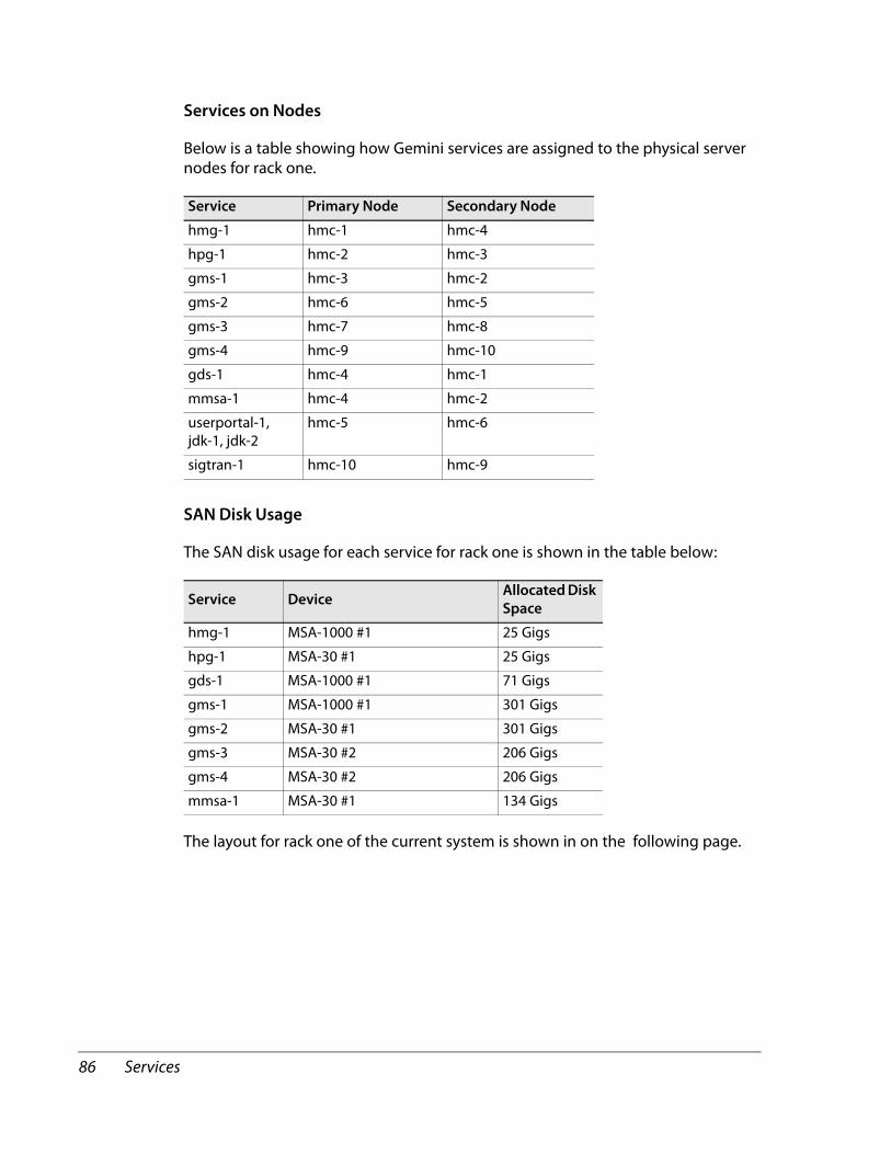
Services on Nodes
Below is a table showing how Gemini services are assigned to the physical server nodes for rack one.
SAN Disk Usage
The SAN disk usage for each service for rack one is shown in the table below:
The layout for rack one of the current system is shown in on the following page.
Service Primary Node Secondary Node
hmg-1 hmc-1 hmc-4
hpg-1 hmc-2 hmc-3
gms-1 hmc-3 hmc-2
gms-2 hmc-6 hmc-5
gms-3 hmc-7 hmc-8
gms-4 hmc-9 hmc-10
gds-1 hmc-4 hmc-1
mmsa-1 hmc-4 hmc-2
userportal-1, jdk-1, jdk-2
hmc-5 hmc-6
sigtran-1 hmc-10 hmc-9
Service DeviceAllocated Disk Space
hmg-1 MSA-1000 #1 25 Gigs
hpg-1 MSA-30 #1 25 Gigs
gds-1 MSA-1000 #1 71 Gigs
gms-1 MSA-1000 #1 301 Gigs
gms-2 MSA-30 #1 301 Gigs
gms-3 MSA-30 #2 206 Gigs
gms-4 MSA-30 #2 206 Gigs
mmsa-1 MSA-30 #1 134 Gigs
86 Services

Figure 6 Rack One Layout, Front and Back
Rack Layout
The first rack layout for the production system is shown in the following figure (front and rear).
Note The rack is configured for easy system growth with several free slots. Gemini recommends that no additional hardware, that is not related with the HMC, be installed in the same rack.
Chapter 3 Systems Information, N+1 Update 87
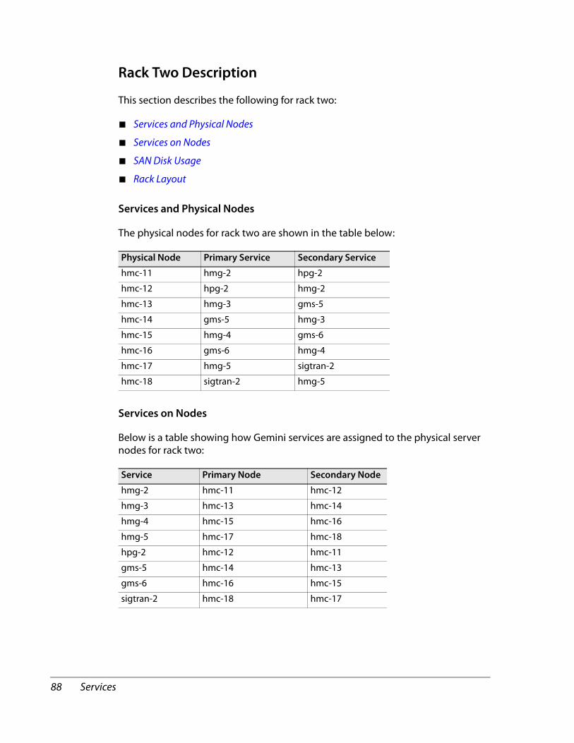
Rack Two Description
This section describes the following for rack two:
■ Services and Physical Nodes
■ Services on Nodes
■ SAN Disk Usage
■ Rack Layout
Services and Physical Nodes
The physical nodes for rack two are shown in the table below:
Services on Nodes
Below is a table showing how Gemini services are assigned to the physical server nodes for rack two:
Physical Node Primary Service Secondary Service
hmc-11 hmg-2 hpg-2
hmc-12 hpg-2 hmg-2
hmc-13 hmg-3 gms-5
hmc-14 gms-5 hmg-3
hmc-15 hmg-4 gms-6
hmc-16 gms-6 hmg-4
hmc-17 hmg-5 sigtran-2
hmc-18 sigtran-2 hmg-5
Service Primary Node Secondary Node
hmg-2 hmc-11 hmc-12
hmg-3 hmc-13 hmc-14
hmg-4 hmc-15 hmc-16
hmg-5 hmc-17 hmc-18
hpg-2 hmc-12 hmc-11
gms-5 hmc-14 hmc-13
gms-6 hmc-16 hmc-15
sigtran-2 hmc-18 hmc-17
88 Services

SAN Disk Usage
SAN disk usage for each service for rack two are shown below:
The rack two layout of the current system is shown in on the following page.
Service Device Allocated Disk Space
hmg-2 MSA-1000 #2 50 Gigs
hmg-3 MSA-30 #3 50 Gigs
hmg-4 MSA-30 #4 50 Gigs
hmg-5 MSA-1000 #2 50 Gigs
hpg-2 MSA-1000 #2 50 Gigs
gms-5 MSA-30 #3 291 Gigs
gms-6 MSA-30 #4 291 Gigs
Chapter 3 Systems Information, N+1 Update 89
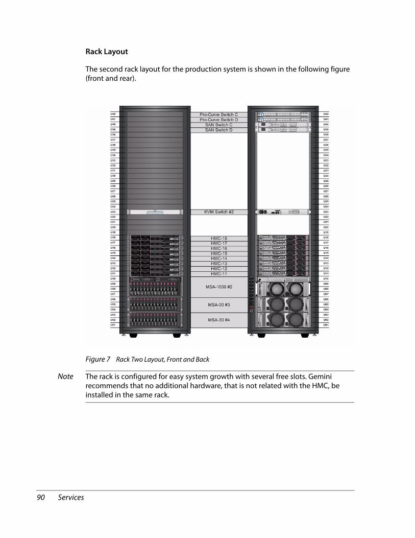
Figure 7 Rack Two Layout, Front and Back
Rack Layout
The second rack layout for the production system is shown in the following figure (front and rear).
Note The rack is configured for easy system growth with several free slots. Gemini recommends that no additional hardware, that is not related with the HMC, be installed in the same rack.
90 Services
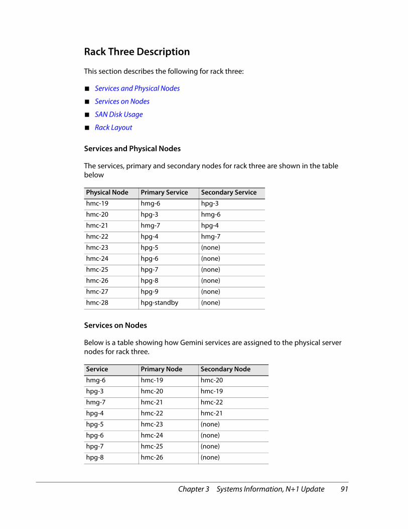
Rack Three Description
This section describes the following for rack three:
■ Services and Physical Nodes
■ Services on Nodes
■ SAN Disk Usage
■ Rack Layout
Services and Physical Nodes
The services, primary and secondary nodes for rack three are shown in the table below
Services on Nodes
Below is a table showing how Gemini services are assigned to the physical server nodes for rack three.
Physical Node Primary Service Secondary Service
hmc-19 hmg-6 hpg-3
hmc-20 hpg-3 hmg-6
hmc-21 hmg-7 hpg-4
hmc-22 hpg-4 hmg-7
hmc-23 hpg-5 (none)
hmc-24 hpg-6 (none)
hmc-25 hpg-7 (none)
hmc-26 hpg-8 (none)
hmc-27 hpg-9 (none)
hmc-28 hpg-standby (none)
Service Primary Node Secondary Node
hmg-6 hmc-19 hmc-20
hpg-3 hmc-20 hmc-19
hmg-7 hmc-21 hmc-22
hpg-4 hmc-22 hmc-21
hpg-5 hmc-23 (none)
hpg-6 hmc-24 (none)
hpg-7 hmc-25 (none)
hpg-8 hmc-26 (none)
Chapter 3 Systems Information, N+1 Update 91

SAN Disk Usage
The SAN disk usage for each service for rack three is shown in the table below
Note The hpg-standby does not have any SAN allocation.
The third rack layout (front and rear) for the production system is shown on the following page.
hpg-9 hmc-27 (none)
hpg-standby hmc-28 (none)
Service Device Allocated Disk Space
hmg-6 MSA-2012fc 74,496
hmg-7 MSA-2000 Shelf 74,496
hpg-3 MSA-2012fc 99,328
hpg-4 MSA-2012fc 99,328
hpg-5 MSA-2012fc 99,328
hpg-6 MSA-2012fc 99,328
hpg-7 MSA-2000 Shelf 99,328
hpg-8 MSA-2000 Shelf 99,328
hpg-9 MSA-2000 Shelf 99,328
Service Primary Node Secondary Node
92 Services
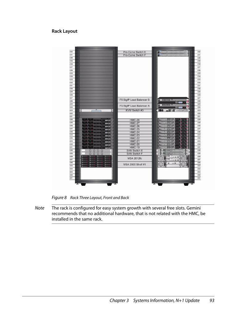
Figure 8 Rack Three Layout, Front and Back
Rack Layout
Note The rack is configured for easy system growth with several free slots. Gemini recommends that no additional hardware, that is not related with the HMC, be installed in the same rack.
Chapter 3 Systems Information, N+1 Update 93

Figure 9 DL 380 G5 Wiring
DL 380 G5 WiringBelow is a cabling diagram for one HP Proliant DL 380 G5 servers used for the HMC platform.
94 DL 380 G5 Wiring

Figure 10 DL360 G5 Wiring for Rack One
DL 360 G5 Wiring for Rack One
Chapter 3 Systems Information, N+1 Update 95
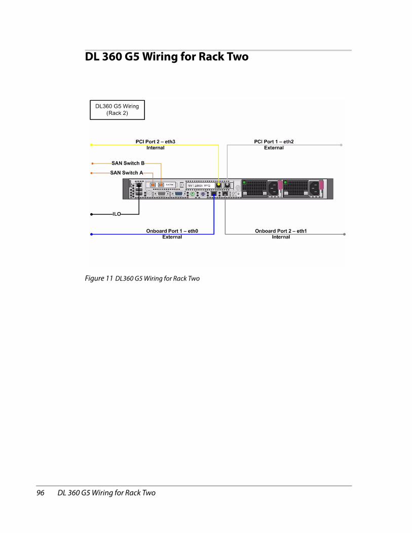
Figure 11 DL360 G5 Wiring for Rack Two
DL 360 G5 Wiring for Rack Two
96 DL 360 G5 Wiring for Rack Two
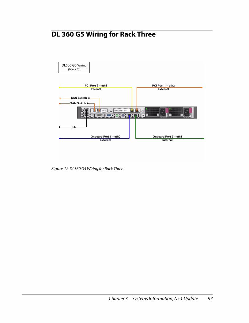
Figure 12 DL360 G5 Wiring for Rack Three
DL 360 G5 Wiring for Rack Three
Chapter 3 Systems Information, N+1 Update 97

Figure 13 DL360 SIGTRAN Node Wiring for Racks One and Two
DL 360 SIGTRAN Node Wiring for Racks One and Two
98 DL 360 SIGTRAN Node Wiring for Racks One and Two
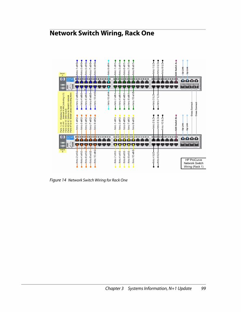
Figure 14 Network Switch Wiring for Rack One
Network Switch Wiring, Rack One
Chapter 3 Systems Information, N+1 Update 99

Figure 15 Network Switch Wiring for Rack Two
Network Switch Wiring, Rack Two
100 Network Switch Wiring, Rack Two
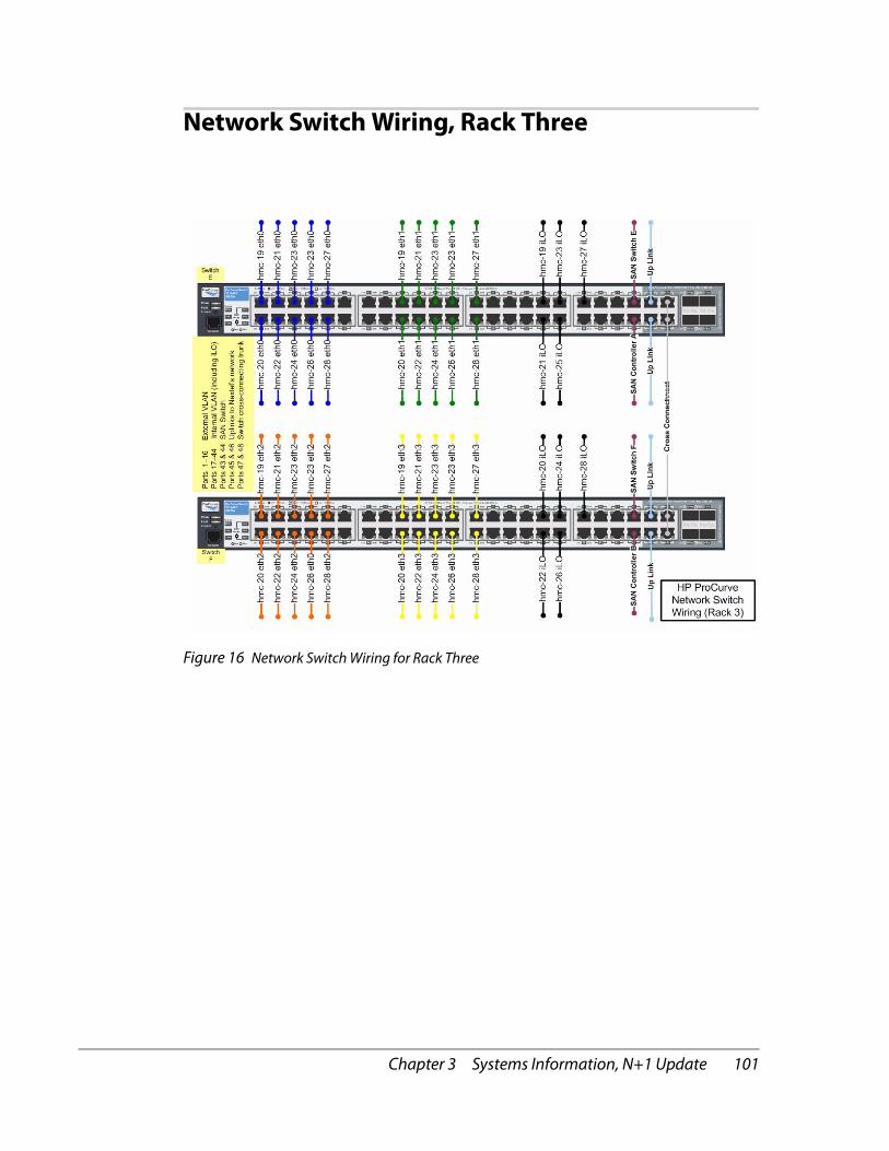
Figure 16 Network Switch Wiring for Rack Three
Network Switch Wiring, Rack Three
Chapter 3 Systems Information, N+1 Update 101
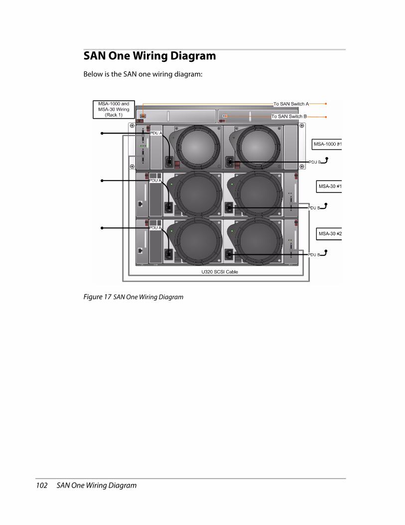
Figure 17 SAN One Wiring Diagram
SAN One Wiring DiagramBelow is the SAN one wiring diagram:
102 SAN One Wiring Diagram

Figure 18 SAN Two Wiring Diagram
SAN Two Wiring DiagramBelow is the SAN two wiring diagram:
Chapter 3 Systems Information, N+1 Update 103

Figure 19 SAN Three Wiring Diagram
SAN Three Wiring DiagramBelow is the SAN three wiring diagram:
104 SAN Three Wiring Diagram
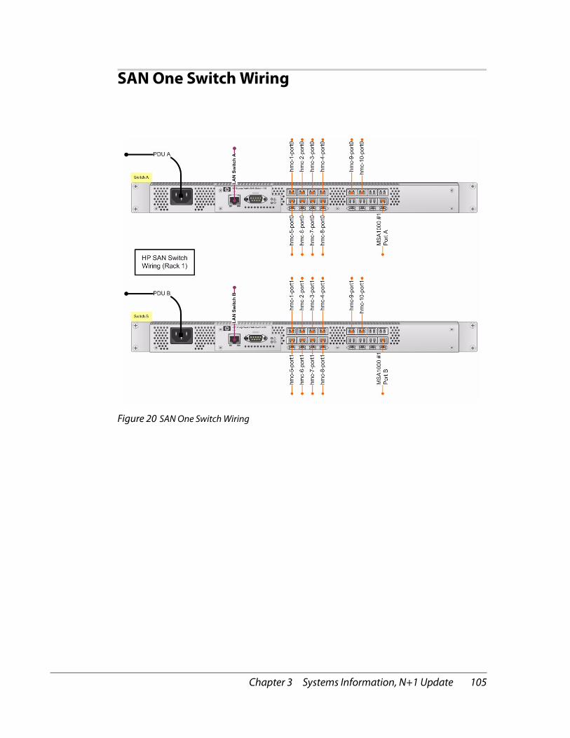
Figure 20 SAN One Switch Wiring
SAN One Switch Wiring
Chapter 3 Systems Information, N+1 Update 105
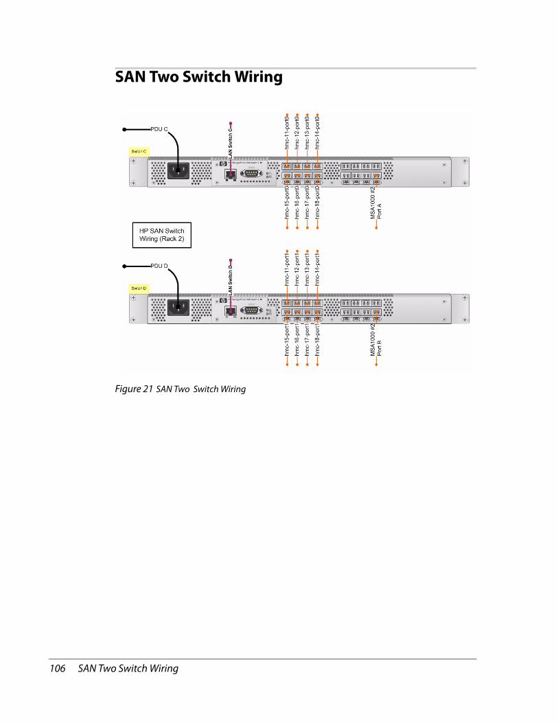
Figure 21 SAN Two Switch Wiring
SAN Two Switch Wiring
106 SAN Two Switch Wiring

Figure 22 SAN Three Switch Wiring
SAN Three Switch Wiring
Chapter 3 Systems Information, N+1 Update 107

108 SAN Three Switch Wiring
4 Cluster Installation
This chapter outlines the procedures for creating and installing all clustering software for applications for the Gemini’s HMC product.
These instructions show a six-node cluster.
Note Your installation may have more or less nodes depending on the configuration entered into your Gemini Site Survey file.
A copy of this file maybe found after installation in /etc/gemini/survey directory. This directory is created during the install and the survey file used to build the cluster is placed therein.
These instructions are covered in these topics:
■ Initial Data‚ on page 110
■ Building an HMC Cluster‚ on page 125
■ Gemini Software Installation and Configuration‚ on page 147
Chapter 4 Cluster Installation 109
Initial DataThe Initial Data section provides a brief overview of the system, software and data requirements needs to install a Gemini HMC for a six node cluster.
The Initial Data section contains these topics:
■ Installation Server Prerequisites‚ on page 110
■ Operational Parameters‚ on page 111
■ Network Infrastructure‚ on page 112
■ Hardware‚ on page 112
■ Passwords‚ on page 113
■ Installation Server Setup‚ on page 113
■ Creating a VMware Installation Server‚ on page 113
■ Boot Disk Creation‚ on page 122
■ Installation Server Usage‚ on page 123
Installation Server Prerequisites
The following prerequisites are required to set up an HMC installation server. Configuration and operation of the installation server is described in the rest of this section.
Hardware and Environment
The installation server is designed to be completely self-contained and independent from the external environment. It attaches to the internal network of the cluster being built. Currently, it is a VMWare instance of RedHat AS4.0 (update 4, 64-bit) running on a Windows-based laptop.
Software
The following software is required for the HMC installation.
■ Operating System—the Red Hat Enterprise Linux AS4.0 (update 4, "AS" license) media for x86.
Note It is the responsibility of the customer to obtain a license for Red Hat Enterprise Linux AS4.0 (update 4, "AS" license). If required, once a license has been acquired, Gemini Support can provide the installation media of AS4.0.
110 Initial Data
■ Required 3rd Party Software—applications.tar, the non-Gemini derived software such as LifeKeeper High Availability software, QLogic pathing software.
Note It is the responsibility of the customer to obtain a license for LifeKeeper High Availability software. Once a license has been acquired, Gemini Support can provide the installation media with applications.tar package.
■ Gemini HMC Software—the Gemini Mobile application software, provided by Gemini.
Operational Parameters
The operational parameters of a cluster deployment are maintained in a .csv file known as the “Gemini Site Survey”. This data is used by the installation server to create a boot disk that is used to perform the initial OS installation and system configuration of each cluster node to allow it to operate as part of the Gemini HMC.
The goal of the Gemini Site Survey file is to:
■ facilitate reliable collection of critical data such as the cluster base name, number of nodes in the cluster, internal and external IP addresses, etc.
■ enable reliable communication of critical data between individuals and organizations.
■ provide reliable communication of deployment parameters between installation and operation phases.
■ facilitate reliable automation within various systems.
■ enable rapid and reliable on-site modification of critical parameters.
■ provide an accurate archive of information.
■ The .csv file format was chosen for the survey file so that the data may be viewed and edited with common office productivity applications or parsed by utilities in an automated manner.
IMPORTANT Care should be taken to save this data as .csv if opened with spreadsheet applications and to not change the overall structural format, for instance, by inserting spurious columns. It is not recommended to use any spreadsheet applications to modify or save Gemini Survey .csv file.
A survey file will be supplied by Gemini Support for each deployment. If any onsite changes are made to the survey file, an updated version must be sent back to Gemini Support for maintenance and support issues.
Chapter 4 Cluster Installation 111
Contact Gemini Technical Support for more information about this file. Once the Gemini software is installed, a copy of this file can be found in the /etc/gemini/survey directory.
Network Infrastructure
To populate the Gemini Site Survey File, obtain the information listed in the Checklist below.
Note Gemini recommends using the 192.168.65.0/24 IP address range for the HMC cluster internal IP addresses.
Checklist
1 Choose a cluster name for the HMC, for example, “hmc1”.
2 Decide the hostnames for the systems in the cluster. These hostnames are the ones used in the Gemini Site Survey file. One of these hosts will be the primary, the first server, in the cluster. For example, in an six-node cluster, the systems in the cluster named "hmc1" could be named hmc1-1, hmc1-2, hmc1-3....hmc1-6 etc. In this case, hmc1-1, is the first, or primary, node in the cluster.
The number of nodes in a deployed cluster is variable and depends on the customers' requirements.
3 Allocate external IP addresses.
4 Obtain the following external network configuration items:
◆ network IP address and netmask
◆ gateway IP address
◆ DNS server IP address
◆ NTP server hostname or IP address
◆ the local DNS domain
5 Register the HMC external host names (i.e. hmc-1-1, hmc-1-2, etc. with the IP addresses on the Admin VLAN) forward and reverse, with the DNS server.
Hardware
Gemini will provide a hardware Bill of Materials (BOM) for your particular HMC cluster.
112 Initial Data

Passwords
The following passwords are used for various accounts during installation. Please do not change these—the field personnel will rely on these exact values.
Installation Server Setup
The Installation Server is a machine which exists during setup to serve data required for initial installation of the HMC nodes.
To setup the Installation Server and use the pre-configured Gemini provided VMWare instance, the following software needs to be independently obtained by the Installation Engineer:
■ VMWare Workstation, Version 5.5 Build 18463 (www.vmware.com)
■ RedHat AS4.0 (update 4, 64-bit) (www.redhat.com)
■ MD5 Sum Generator Utility, Version 1.2.0.5 (www.md5summer.com)
■ PuTTY (SSH Client) and PSCP (SCP Client) (www.putty.nl)
■ CD burning software
After you download and transfer all specified above software and utilities to your Installation Server laptop, proceed to the next section, Creating a VMware Installation Server‚ on page 113.
Creating a VMware Installation Server
Use the following steps to create the Installation Server on your laptop.
Installing VMware Workstation and Windows Utilities
The first step of setting up a Windows laptop Installation Server is to download and install VMWare Workstation 5.5 and the other utilities specified in the section Installation Server Setup‚ on page 113. After downloading the VMware Workstation, Version 5.5 from 11/20/05, Build 18463 executable (.exe) file to your Installation
Use Password
HMC node root account newroot
HMC node mmssys account test1234
HMC node opco1 account test1234
Network switch manager account manager
Network switch operator account operator
SAN switch admin account password (factory default)
Chapter 4 Cluster Installation 113
Server Laptop, make sure you have the VMware Workstation license key before you start the installation. Once you have the license key in your possession, run the VMware-workstation-5.5.0-18463.exe executable on your Windows Installation Server and accept the default selections for each option.
If the My Virtual Machines directory does not already exist in the My Virtual Documents directory of the current Windows user, it will be created at runtime.
The full path to that directory would be C:\Documents and Settings\<windows_user_id>\My Documents\My Virtual
Machines.
For example, if you are logged into Windows as the user, admin-qa, on the Installation Server machine laptop computer, the path to the directory would be:
C:\Documents and Settings\admin-qa\My Documents\My Virtual Machines
This directory will also be used to hold the VMware Workstation guest OS image.
Install the MD5 Sum Generator utility for Windows, downloaded and transferred to the Installation Server laptop as described in the Installation Server Setup section above.
To do this, create an MD5 directory in the My Documents directory and move the md5v12005.exe file into it. Double-click on the md5v12005.exe file. You should be prompted by a Windows MD5sum generator installation window.
Press the OK button to extract two files from the md5v12005 archive to the current directory. You should be prompted with another window called WinZip Self-Extractor - md5v12005.exe.
Press the Unzip button to unzip. Upon the successful unzip operation you should be prompted with a two files unzipped successfully window. Press the OK button to continue, then press the Close button in the WinZip Self-Extractor - md5v12005.exe window to finish the installation of the MD5 Sum Generator utility.
This utility will be used later to verify MD5 sum of the VMware Workstation guest OS image provided by Gemini Support on a CD.
Downloading and Configuring Guest OS and RedHat ISO images
You will now copy from a CD to your Installation Server laptop and configure the VMware Workstation guest OS image, named, <VirtualMachineName>.
Note The <VirtualMachineName> is not the actual name of the VMware Workstation guest OS image.
114 Initial Data

A pre-configured VMware Workstation guest OS image has already been created and tested in the install of a multi-node cluster. Please contact Gemini Support to obtain a CD with the archived VMware Workstation guest OS image.
You will need to allocate approximately 2.5GB of space for the RedHat AS4.0 (update 4, 64-bit) ISO images used to generate the ISO images for each cluster node and approximately 130 MB for VMware Workstation guest OS image. RedHat AS4.0 (update 4, 64-bit) ISO images have to be downloaded as described in the Installation Server Setup section above. The VMware Workstation guest OS image will be provided on a CD by Gemini Support.
1 Insert the Gemini supplied CD with VMware Workstation guest OS image into the CD-DVD ROM drive of your Installation Server laptop.
2 Copy the following:
◆ zipped archive of the VMware Workstation guest OS image
◆ infoZip archiver executable file that will be used to unzip the zipped archive of the guest OS
◆ md5.txt file that holds the md5 sum for the zipped VMware Workstation guest OS image
from the CD to the Installation Server laptop C:\Documents and Settings\<windows_user_id>\My Documents or any other directory.
3 Eject the CD.
4 Generate MD5 sum of the zipped archive of the VMware Workstation guest OS image called <VirtualMachineName>.zip and compare it to the supplied in the md5.txt MD5 sum of the <VirtualMachineName>.zip by performing the following:
◆ In Windows Explorer, navigate to the directory where you have installed MD5 Sum Generator as described in the Installing VMware Workstation and Windows Utilities‚ on page 113.
◆ Double-click on the md5summer.exe file to invoke the MD5 Sum Generator. If a window with "Files with the extension 'md5' are not associated with the md5summner. Should I make the association?" shows up, click No to continue. MD5summer window with directory structure displayed should show up.
◆ In the MD5summer window navigate to the folder where you have copied the zipped VMware Workstation guest OS image called <VirtualMachineName>.zip and select it with your mouse.
◆ Once the directory where <VirtualMachineName>.zip is stored is selected, click on the Create sums button and you should see all the files located in the selected directory, including the <VirtualMachineName>.zip file.
Chapter 4 Cluster Installation 115
◆ Select the <VirtualMachineName>.zip file with mouse and press the Add button. The <VirtualMachineName>.zip file should be added to the smaller window located within the MD5summer window.
◆ Click OK button in the MD5summer window to generate the MD5 Sum of the <VirtualMachineName>.zip file. You should be prompted with the Save As window suggesting to save the generated MD5 sum to your hard drive. Dismiss the window by pressing the Cancel button. You should now see the the MD5sumer window with the name of the <VirtualMachineName>.zip file and its MD5 sum.
◆ Compare the generated MD5 sum against the supplied in the md5.txt file MD5 sum for the <VirtualMachineName>.zip. For the location of the md5.txt file refer to the step 2. above. Both MD5 sums must match.
◆ Close MD5sums window by clicking Close button and click on the "x" to close the main MD5summer window
◆ If MD5 generated sum does not match with the MD5 sum supplied by Gemini on a CD together with <VirtualMachineName>.zip notify Gemini Support immediately.
5 Install infoZip archiver by executing the following:
Open the Windows command line by executing cmd command from the Start->Run menu.
◆ In the command line window navigate to the My Documents directory, or any other directory you copied infoZip to, in step 2. above. For that, type the following command and press the Enter key cd <My_Documents_Directory> In the directory where infoZip executable is located execute the following command and press the Enter key.
Note The "infoZipName.exe" is not the exact name of the package. Use the exact name of the infoZip package that was copied off of a CD.
The above command should extract files from the <infoZipName.exe> self-extracting archive into the current directory i.e. My Documents or any other directory the infoZip was copied to in step 2. above. Do not close the Windows command line window, you'll use it in the next step.
Now that you have installed infoZip archiver you are ready to unzip the zipped archive of the guest OS.
6 Unzip the zipped archive of the guest OS by typing the following command and pressing the Enter key in the same Windows command line window that was used to install the infoZip archiver in step 4. above.
116 Initial Data

Note It is meant that <VirtualMachineName>.zip archive i.e. zipped archive of the VMware Workstation guest OS image was copied into the same as infoZip directory in step 2. above, otherwise you will have to specify the full path to the <VirtualMachineName>.zip file in the below command. unzip.exe <VirtualMachineName>.zip This should extract the <VirtualMachineName>.zip into the current directory as another directory with Virtual Machine files inside.
7 To verify that <VirtualMachineName>.zip archive has been extracted, open Windows Explorer and navigate to the C:\Documents and Settings\<windows_user_id>\My Documents or any other directory that you selected in step 2. above. Visually verify that <VirtualMachineName> folder is present and has files in it.
8 Copy the entire VMware Workstation guest OS image <VirtualMachineName> folder to the My Virtual Machines directory.
9 Start the VMware Workstation 5.5 by invoking it either with the “quick launch” icon on the Windows task bar or using the Start/Programs/VMware/VMware Workstation link.
10 Once the VMware Workstation 5.5 has started, you should see the Home Tab. Select the Open Existing VM or Team link. Press OK if prompted to create a new UID.
11 Browse to the C:\Documents and Settings\<windows_user_id>\My Documents\My Virtual Machines\<VirtualMachineName> directory and select the VM image file, with the vmx extension, e.g., rhel2.vmx or Red Hat Enterprise Linux 2.vmx.
12 Select Open. You should see the <VirtualMachineName> Tab displayed next to the Home Tab. The <VirtualMachineName> Tab should be selected.
13 Start the OS <VirtualMachineName> by pressing the green triangle Start button in the <VirtualMachineName> Tab. Your OS is ready to use now. You can log into it as root using the password, newroot.
When you start the VMWare Linux instance, a pop up window may appear stating that the location of this virtual machine configuration file has changed since it was last powered on.
It will then ask what you would like to do with the UUID. Choose to Keep the UUID.
Chapter 4 Cluster Installation 117
Create a Shared Folder
Note While the shared folder is already created in the guest OS supplied by Gemini Support, sometimes VMWare is unable to access it. To make it accessible by VMWare, you need to delete the shared folder, then re-add it.
You will now delete, then create a Shared Folder that will be used to access files from both the Windows Laptop and the VMware Workstation guest OS image.
A shared folder is needed in Windows to be able to move files between the Windows laptop OS and the VMware Workstation guest OS image that will run in the VMware Workstation.
1 Select the <VirtualMachineName> Tab, if it is not already selected.
2 Start the virtual machine by selecting the Start this virtual machine green triangle in the Commands section of the tab and allow it to boot.
3 From the menu bar select the VM -> Settings menu item.
4 In the Virtual Machine Settings window that just showed up, select the Options Tab.
5 Select Shared Folders from the Settings selections.
6 If the My Virtual Machines\<VirtualMachineName>\shared directory exists, select it and then select the Remove button. This will remove the ability for VMWare to use this shared directory but it wil NOT delete the physical directory.
7 Select the Add button to add a shared folder. You'll be presented with Shared Folder Wizard window.
8 Press the Next button.
9 Enter shared in the Name text box, to name your shared folder shared, or use any other name you like.
10 Browse to the My Virtual Machines/<VirtualMachineName>/shared folder and select the shared folder. Press OK to link it to the shared folder.
11 Press Next to get to the Specify Shared Attributes step of the wizard. Make sure that only the Enable this share check box is checked.
12 Press Finish to complete the Add Shared Folder wizard.
13 Press OK to close the Virtual Machine Settings window.
The newly created shared directory can be found in the VMware Workstation guest OS image under the /mnt/hgfs/shared path. It can be accessed through the Windows OS on the laptop (the Installation Server machine) at the C:\Documents and Settings\<windows_user_id>\My Documents\My Virtual
Machines\<VirtualMachineName>\shared directory.
118 Initial Data
Setting Up the Install OS
IMPORTANT The VMWare Workstation guest OS image that you copied to the Installation Server laptop does not include the RedHat AS4.0 (update 4, 64-bit) ISO images. It is the responsibilty of the customer to obtain a license of RedHat AS4.0 (update 4, 64-bit). If required, once a license has been acquired, Gemini support can provide the installation media of AS4.0. Gemini recommends using a single DVD with the RedHat AS4.0 (update 4, 64-bit) ISO images obtained from RedHat.
The following steps describe copying the RedHat AS4.0 (update 4, 64-bit) ISO images from the DVD, through Windows, into the correct directory under the VMWare Workstation guest OS.
1 Insert the RedHat AS4.0 (update 4, 64-bit) ISO images into the laptop DVD drive.
2 Start Windows Explorer.
3 Browse to the DVD drive. You should see five ISO images in the 4.0_up4-64 subdirectory.
4 Copy the subdirectory containing the ISO images to the Shared Folder My Documents\My Virtual Machines\<VirtualMachineName>\shared.
The copy process could take several minutes.
5 Launch the VMWare workstation if it is not already started.
6 Select the <VirtualMachineName> Tab, if it is not already selected.
7 If it is not already running, start the virtual machine by selecting the Start this virtual machine green triangle in the Commands section of the tab and allow it to boot.
8 Login to the VMWare workstation guest OS as root using the password, newroot.
9 Copy the directory containing the five Red Hat AS 4.0 update 4 ISO images to the NFS exported kickstart server directory:cp -rp /mnt/hgfs/shared/4.0_up4-64 /usr/export/iso/AS/4.0_up4-64
10 Ensure that the permissions to the ISO are set correctly:chmod 644 ‘find /usr/export/iso/AS/4.0_up4-64 -type d‘
chmod 755 ‘find /usr/export/iso/AS/4.0_up4-64 -type f‘
11 Make sure that no corruption has happened during the copy procedure by verifying the MD5 sum of the copied ISO images against the DVD disk source using the following command from the Linux command line:md5sum /usr/export/iso/AS/4.0_up4-64/*.iso
12 Compare the MD5 sums of all ISO images output by the md5sum command against the MD5 sums for all images provided with, or on, the DVD disk source in a text file.
Chapter 4 Cluster Installation 119

13 If MD4 sums of the source and copy do not match, repeat the steps on copying RedHat AS4.0 (update 4, 64-bit) ISO images, or contact Gemini Support for assistance.
14 Take the DVD disk out of the DVD-ROM drive of your Installation Server laptop computer.
Configuring NFS Export Directories
During the installation process, the new cluster nodes will need access to some of the exported laptop (Kickstart Server machine) directories. Configure them using the steps below.
1 Start the guest OS image virtual machine in the VMware Workstation, if it is not started yet.
2 Login as root, password: newroot.
3 Add the following entry to the /etc/exports file:
/usr/export/iso/AS/4.0_up4-64 *(ro,no_root_squash)
4 Export the filesystem by entering:
exportfs -a
5 Check the output of the command. It should show both directories that you entered into the /etc/export file being exported.
6 Check that the permissions are set correctly on the /usr/export/iso/AS/4.0_up4-64 directory.
If they are not correctly set, the cluster node will be unable to access the ISO images and install the operating system.
Download the Gemini Factory (FACT)
You can now copy the Gemini Factory (FACT) build, from a GOLD CD provided by Gemini Support, that contains the applications.tar and the Sample Site Survey file Templates to the C:\Documents and Settings\My Documents\My Virtual Machines\<VirtualMachineName>\shared directory.
Now that the VMWare Workstation application and guest OS image are running and Gemini Factory (FACT) build consisting of applications.tar file has been copied to the Installation Server laptop, we need to load it into the VMware Workstation guest OS image using the /mnt/hgfs/shared directory created in the previous section.
Once the FACT build, consisting of the applications.tar package, is loaded into the My Documents\My Virtual Machines\<VirtualMachineName>\shared folder we can extract it from inside the VMware Workstation guest OS image as follows:
120 Initial Data

1 Start the guest OS virtual machine in the VMware Workstation, if it is not started yet.
2 Log in as root (the password is newroot) to VMware Workstation guest OS image.
3 Change directory using the following command:cd /usr/export/apps_dir
4 Make sure that the directory is empty before you continue with the installation.
5 If there is an applications folder and/or applications.tar present in the /usr/export/apps_dir directory, remove it.
The applications directory is created when we untar the applications.tar archive. This will be done in step 9 that follows.
6 Copy the applications.tar file:cp /mnt/hgfs/shared/<gm_FACT_build_directory>/<FACT_build_subdirectory>/pkg/applications.tar /usr/export/apps_dir
7 Copy the survey file to be used for the cluster kick start into the /usr/export/apps_dir directory.
8 Set the date to the current date in the VMWARE Workstation guest OS image by determining the current date and setting it for the OS.
Note If the date is not set to current when the applications.tar is untarred, you may get multiple error messages saying that the creation date of the files being untarred is in the future.
9 Untar the applications.tar file:%tar xvf applications.tar
10 Ensure that the permissions of the newly created applications directory an contents are set correctly.chmod 755 ‘find /usr/export/apps_dir/applications -type d‘
chmod 755 ‘find /usr/export/apps_dir/applications -type f‘
The survey file must correlate to the cluster you are about to install. Gemini supplies the survey file; some values may have the double pound (##) flags, indicating they should be reviewed and updated as necessary.
You need to edit the IP addresses to correspond to your cluster IPs. The copy of the survey template file can be requested from Gemini Support.
Configuring Windows Networking
For the VMware Workstation guest OS image to be accessible though TCP/IP from the cluster nodes, the Windows network settings on the laptop (Installation Server machine) need to be modified. The Windows Kickstart server will need to use a 192.168.65.XX IP address so it can talk to the cluster on the internal subnet and the
Chapter 4 Cluster Installation 121

cluster nodes can talk to the VMWare image through 192.168.65.201, the IP of the VMware Workstation guest Linux OS, that corresponds to the F_INST_NFS_IP value in the survey file.
1 From Windows OS on the laptop (Kickstart Server machine) go to START -> Settings -> Control Panel.
2 Double click on Network Connections.
3 Right click on the network connection that the laptop (Kickstart Server machine) will use when attached to the cluster and select Properties.
4 Select Internet Protocol (TCP/IP).
5 Click Properties.
6 Select Use the following IP address.
7 Set the IP address to 192.168.65.66 or another 192.168.65.XX address that is not used on the network or the survey file. Do not use the 192.168.65.201 IP address.
8 Set the subnet mask to 255.255.255.0
9 Leave the Default Gateway field blank.
10 Leave the DNS Server Addresses field blank.
11 Select OK twice and allow Windows to configure the network adapter.
Boot Disk Creation
Once the VMWare instance is running, the Installation Server will be used to create boot disks for each node of the HMC installation.
The boot disks will be used to enable each node of the HMC to load the operating system off the Installation Server. Before attempting to create the boot disks, please ensure that you have obtained the following:
■ The applications.tar file as described in the section, Software‚ on page 110.
■ The Gemini Site Survey file that has been edited to have correct information about this deployment site.
Follow the listed procedures below to create boot disks for each node:
Creating Boot Disks
1 Start the VMWare Installation Server instance on the laptop.
2 Log into the Installation Server as root with password newroot.
122 Initial Data
3 Copy the Gemini Site Survey file named, {survey_name}.csv, to the /usr/ export/apps_dir directory.
Be sure to review the survey file to ensure the configuration is correct.
4 As root, create the boot disk ISO images by executing the following commands:cd /usr/export/apps_dir/applications/make_boots/
./make_boots.sh -f /usr/export/apps_dir/{survey_name}.csv
The number of the boot disk ISO images, corresponding to the number of nodes specified in the survey file, can be found in:
/usr/export/apps_dir/applications/make_boots/RESULTS_{yyyymmddhhmm}/{node_name}/{node_name}_boot.iso
where {node_name} is the node name of each host that the boot disk belongs to.
5 Review the files /usr/export/apps_dir/applications/make_boots/ADJ/ packages.dot and /usr/export/apps_dir/applications/make_boots/RESULTS_{yyyymmddhhmm}/{node_name}/ks.cfg to see if the file is complete and no errors are reported.
6 Copy these images to a machine with a CD burner. Often this is the VMWare host’s OS if the installation server is a VMWare guest.
Note In Step 8. the .iso images should be copied only, not moved from the /usr/ export/apps_dir/applications/make_boots/RESULTS_{yyyymmddhhmm}/
{node_name}/ directory. If the .iso images are moved, the install will hang.
7 Burn each .iso image to CD-R or CD-RW media being careful to label each to properly reflect the node name.
Note Always use blank CD-RW media to burn ISOs for maximum reliability.
Installation Server Usage
During the OS installation on the HMC system, the Installation Server will be used as an NFS and HTTP Server to enable remote “kickstarts” using the boot disk ISO images created in the earlier steps.
Network
During the OS construction phase, the Installation Server needs to be attached to the cluster's internal network in order to provide NFS and HTTP services to the con-structed nodes. This internal network is in the 192.168.65.xxx IP range. The Instal-lation Server should be directly connected to the cluster-internal network using any port on the switch appropriate to that VLAN.
Chapter 4 Cluster Installation 123

Once on the internal network, nothing else should be required to be done to the Installation Server. If there are any problems with the Installation Server setup, please contact Gemini Support.
IMPORTANT It is important that the Installation Server remain on-line and connected to the internal network of the cluster being built during the OS installation phase. It should not be configured to sleep or hibernate. During this phase, it will act as an NFS and HTTP data server.
124 Initial Data
Building an HMC ClusterThe following section describes how to physically connect and configure the Gem-ini HMC cluster as well as how to install the Linux Operating System provided by Gemini.
This section contains these topics:
■ Configuring the Network Switches‚ on page 125
■ SAN Switch Configuration (Optional)‚ on page 128
■ Installing the Initial Base OS on Host Nodes‚ on page 130
■ Installing the SAN Driver and Bonding the Interface‚ on page 135
■ Configuring the MSA1000 Storage Array‚ on page 138
■ Obtaining Steeleye's LifeKeeper FlexLM Licensing‚ on page 145
■ Enabling Sendmail Autostart (Optional)‚ on page 145
Configuring the Network Switches
The recommended cluster configuration currently includes two HP 2948 Procurve switches. The switches have to be configured with a few basic global parameters defined and several VLANs to accomodate the networking configuration.
Configuring the Network Switches
1 Disconnect the cross-connect cables connecting the two network switches (ports 47,48) and the uplink cables to the corporate network and mark them down to not lose track of the ports that they were plugged into.
2 When ready to configure the switch, connect a console to the console port of Switch A.
3 Press Return several times to get a prompt.
4 Login into switch A as the manager.
5 Enter erase startup-config to clear the configuration of the switch. This will erase the entire switch setup and cause the switch to reboot.
6 When the switch comes back online, enter the following commands, one line at a time, starting with the config command, replacing any text within <> (angle brackets) with the appropriate data. Do not type the angle brackets. Do type the quotation marks where shown.
The replacement entries for the <> construction include the following:
◆ Assign the appropriate employee as an snmp-server contact.
Chapter 4 Cluster Installation 125
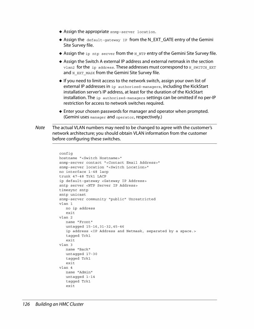
◆ Assign the appropriate snmp-server location.
◆ Assign the default-gateway IP from the N_EXT_GATE entry of the Gemini Site Survey file.
◆ Assign the ip ntp server from the N_NTP entry of the Gemini Site Survey file.
◆ Assign the Switch A external IP address and external netmask in the section vlan2 for the ip address. These addresses must correspond to H_SWITCH_EXT and N_EXT_MASK from the Gemini Site Survey file.
◆ If you need to limit access to the network switch, assign your own list of external IP addresses in ip authorized-managers, including the KickStart installation server’s IP address, at least for the duration of the KickStart installation. The ip authorized-managers settings can be omitted if no per-IP restriction for access to network switches required.
◆ Enter your chosen passwords for manager and operator when prompted. (Gemini uses manager and operator, respectively.)
Note The actual VLAN numbers may need to be changed to agree with the customer’s network architecture; you should obtain VLAN information from the customer before configuring these switches.
confighostname "<Switch Hostname>"snmp-server contact "<Contact Email Address>"snmp-server location "<Switch Location>"no interface 1-48 lacptrunk 47-48 Trk1 LACPip default-gateway <Gateway IP Address>sntp server <NTP Server IP Address>timesync sntpsntp unicastsnmp-server community "public" Unrestrictedvlan 1 no ip address exitvlan 2 name "Front" untagged 15-16,31-32,45-46 ip address <IP Address and Netmask, separated by a space.> tagged Trk1 exitvlan 3 name "Back" untagged 17-30 tagged Trk1 exitvlan 4 name "Admin" untagged 1-14 tagged Trk1 exit
126 Building an HMC Cluster
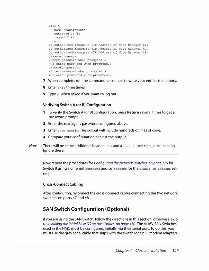
vlan 5 name "Management" untagged 33-44 tagged Trk1 exitip authorized-managers <IP Address of Node Manager #1>ip authorized-managers <IP Address of Node Manager #2>ip authorized-managers <IP Address of Node Manager #3>password manager<Enter password when prompted.><Re-enter password when prompted.>password operator<Enter password when prompted.><Re-enter password when prompted.>
7 When complete, run the command write mem to write your entries to memory.
8 Enter exit three times.
9 Type y when asked if you want to log out.
Verifying Switch A (or B) Configuration
1 To verify the Switch A (or B) configuration, press Return several times to get a password prompt.
2 Enter the manager's password configured above.
3 Enter show config. The output will include hundreds of lines of code.
4 Compare your configuration against the output.
Note There will be some additional header lines and a vlan 1 (DEFAULT_VLAN) section. Ignore these.
Now repeat the procedures for Configuring the Network Switches‚ on page 125 for Switch B using a different hostname and ip address for the vlan2: ip address set-ting.
Cross-Connect Cabling
After configuring, reconnect the cross-connect cables connecting the two network switches on ports 47 and 48.
SAN Switch Configuration (Optional)
if you are using the SAN Switch, follow the directions in this section, otherwise, skip to Installing the Initial Base OS on Host Nodes‚ on page 130. The 4/16V SAN Switches used in the HMC must be configured, initially, via their serial port. To do this, you must use the grey serial cable that ships with the switch (or a null modem adapter).
Chapter 4 Cluster Installation 127
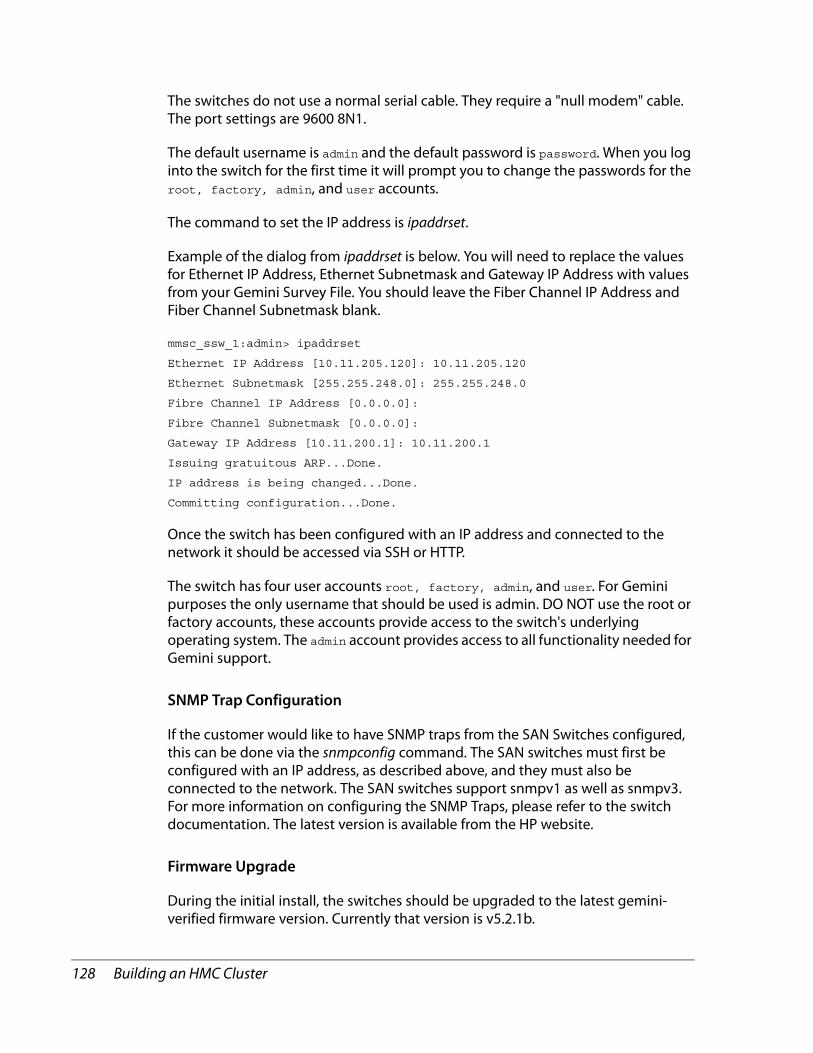
The switches do not use a normal serial cable. They require a "null modem" cable. The port settings are 9600 8N1.
The default username is admin and the default password is password. When you log into the switch for the first time it will prompt you to change the passwords for the root, factory, admin, and user accounts.
The command to set the IP address is ipaddrset.
Example of the dialog from ipaddrset is below. You will need to replace the values for Ethernet IP Address, Ethernet Subnetmask and Gateway IP Address with values from your Gemini Survey File. You should leave the Fiber Channel IP Address and Fiber Channel Subnetmask blank.
mmsc_ssw_1:admin> ipaddrset
Ethernet IP Address [10.11.205.120]: 10.11.205.120
Ethernet Subnetmask [255.255.248.0]: 255.255.248.0
Fibre Channel IP Address [0.0.0.0]:
Fibre Channel Subnetmask [0.0.0.0]:
Gateway IP Address [10.11.200.1]: 10.11.200.1
Issuing gratuitous ARP...Done.
IP address is being changed...Done.
Committing configuration...Done.
Once the switch has been configured with an IP address and connected to the network it should be accessed via SSH or HTTP.
The switch has four user accounts root, factory, admin, and user. For Gemini purposes the only username that should be used is admin. DO NOT use the root or factory accounts, these accounts provide access to the switch's underlying operating system. The admin account provides access to all functionality needed for Gemini support.
SNMP Trap Configuration
If the customer would like to have SNMP traps from the SAN Switches configured, this can be done via the snmpconfig command. The SAN switches must first be configured with an IP address, as described above, and they must also be connected to the network. The SAN switches support snmpv1 as well as snmpv3. For more information on configuring the SNMP Traps, please refer to the switch documentation. The latest version is available from the HP website.
Firmware Upgrade
During the initial install, the switches should be upgraded to the latest gemini-verified firmware version. Currently that version is v5.2.1b.
128 Building an HMC Cluster
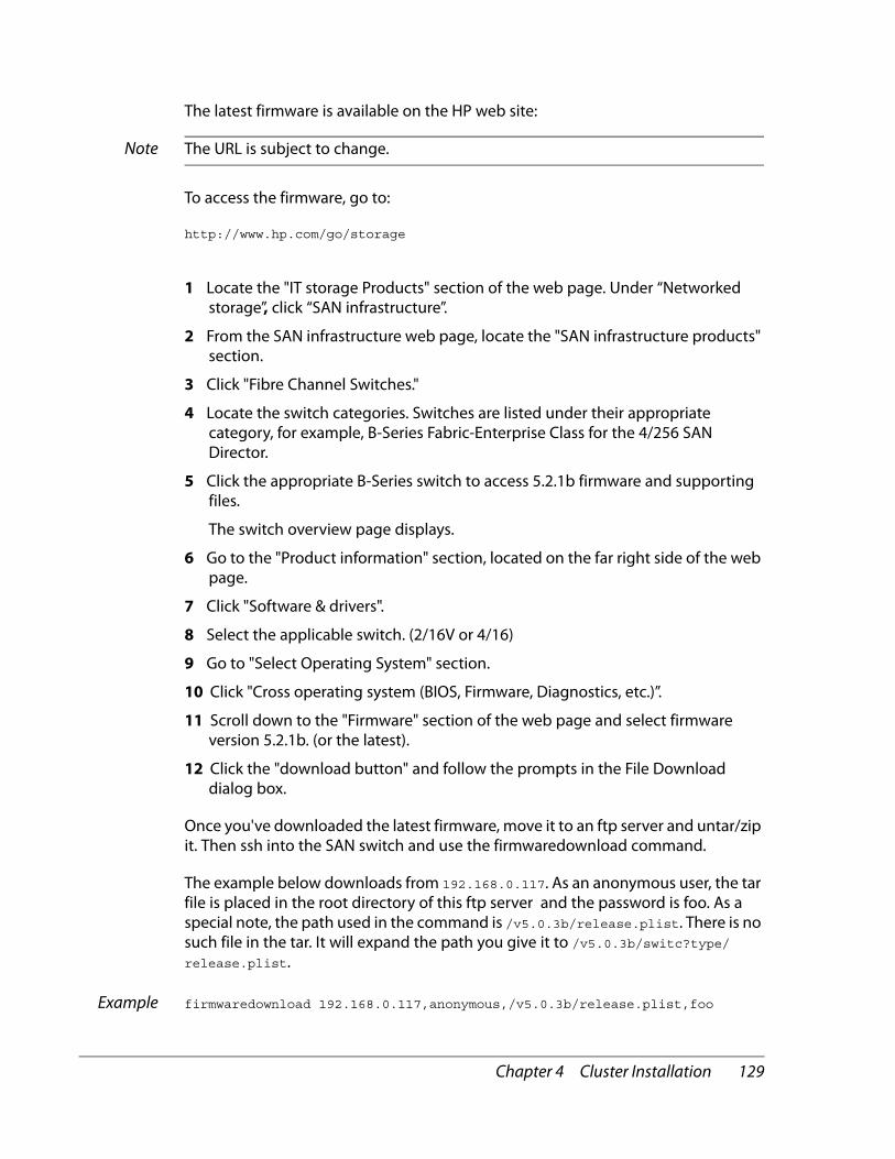
The latest firmware is available on the HP web site:
Note The URL is subject to change.
To access the firmware, go to:
http://www.hp.com/go/storage
1 Locate the "IT storage Products" section of the web page. Under “Networked storage”, click “SAN infrastructure”.
2 From the SAN infrastructure web page, locate the "SAN infrastructure products" section.
3 Click "Fibre Channel Switches."
4 Locate the switch categories. Switches are listed under their appropriate category, for example, B-Series Fabric-Enterprise Class for the 4/256 SAN Director.
5 Click the appropriate B-Series switch to access 5.2.1b firmware and supporting files.
The switch overview page displays.
6 Go to the "Product information" section, located on the far right side of the web page.
7 Click "Software & drivers".
8 Select the applicable switch. (2/16V or 4/16)
9 Go to "Select Operating System" section.
10 Click "Cross operating system (BIOS, Firmware, Diagnostics, etc.)”.
11 Scroll down to the "Firmware" section of the web page and select firmware version 5.2.1b. (or the latest).
12 Click the "download button" and follow the prompts in the File Download dialog box.
Once you've downloaded the latest firmware, move it to an ftp server and untar/zip it. Then ssh into the SAN switch and use the firmwaredownload command.
The example below downloads from 192.168.0.117. As an anonymous user, the tar file is placed in the root directory of this ftp server and the password is foo. As a special note, the path used in the command is /v5.0.3b/release.plist. There is no such file in the tar. It will expand the path you give it to /v5.0.3b/switc?type/release.plist.
Example firmwaredownload 192.168.0.117,anonymous,/v5.0.3b/release.plist,foo
Chapter 4 Cluster Installation 129

Software Management of Ports
To reduce the strain on the fiber cables, it is better to disable the ports using software rather than using hardware.
The recommended way to do this, is to log into the SAN switches for the cluster you are working on and disable port 15. Port 15 connects to the MSA1000. Another easy way to perform this task, is to just power off the MSA1000. In the case where more than one cluster is running against the same MSA1000, it may be better to disable the ports to individual machines.
To accomplish this, use the following commands.
Substitute the actual switch you are using for <switch>.
1 Login to the admin account.
2 Type the following command:ssh admin@<switch>
3 Enter (password) newroot1.
4 To show the current status of the ports, type the following command:
switchshow
5 To disable port 15, use following command:
portdisable 15
Typing portenable 15, enables port 15.
Installing the Initial Base OS on Host Nodes
The following steps configure the host BIOS and create an internal mirrored drive.
Also, if hyper-threading is a configurable option of the server, we wish to turn it off within the BIOS on each host. This is because the processor hyperthreading may cause performance issues for the Gemini HMC. The following steps will explain on how to disable this feature—a requirement to run the Gemini HMC.
Note There is no hyper-threading on multi-core CPUs, i.e. DL360s.
Configuring the Host BIOS and Internal Drive
1 The first step is to create a single mirrored logical drive out of two physical drives. Boot node-1 and monitor the OS startup process. The startup will output the following line to the screen after about 20 seconds from the beginning of the boot process:Integrated Lights Out Advanced, press [F8] to configure.
130 Building an HMC Cluster

Disregard the direction to press F8 here and press F8 when the second line of output shows up on the screen. It will read as follows:
Press [F8] to run the Option ROM Configuration for Arrays Utility.
Note The prompt flashes through the screen and is difficult to catch.
Pressing F8 should bring you to the Option ROM BIOS configuration menu, on the Main Menu screen.
IMPORTANT If any of the nodes has a logical drive already created because it was previously used, it is recommended that you delete and re-create the logical drive again.
To create a single mirrored logical drive:
a) Enter the Create Logical Drive Menu. You should see two physical drives available.
b) Move between areas of the screen using TAB. Select both physical drives by pressing the space bar if they are not already selected with "x" symbol.
c) Using TAB, move the cursor to the RAID Configuration area of the screen.
d) Select the RAID 1+0 option by pressing the space bar.
e) Press Enter and press F8 to save the configuration and create the mirrored logical drive.
f ) Follow the onscreen instructions to complete the process.
g) Check that the configuration was successfully created by entering the View Logical Drive Menu.
h) Visually verify the following:
Logical Drive #1, RAID 1+0, 67,8 GB OK
Size may vary depending on how large the disk drives in your servers are.
i) Press ESC to return to the Main Menu and one more time continue the boot process.
Note You must be ready to press F10 a few seconds after you return to the boot process. See Step 2. below.
2 As the startup process continues, look for the Press [F10] key for System Maintenance line of the output and press F10 to enter the System Maintenance Menu.
3 From this menu, select the Setup Utility menu item and press Enter.
4 Navigate to the Advanced Options menu item and press Enter.
Chapter 4 Cluster Installation 131
5 If the processor supports hyper-threading, navigate to the Processor Hyperthreading menu item and press Enter.
6 Select the Disabled option to disable Processor Hyperthreading and press Enter.
7 Press Escape twice.
8 Press F10 to save.
9 Power off the node.
10 Perform steps 1 through 10 for the remaining nodes.
Installing Red Hat Linux OS
This process involves a KickStart NFS install of a RedHat Linux OS with an exact and reproducible collection of packages. It also performs an adjustment of the system configuration and installation of further software.
The installation server runs as a virtual machine under the Windows OS and provides various services such as NFS.
IMPORTANT The most common problems in the NFS install phase are related to the hosts not being able to contact the NFS server due to network issues, firewall issues, or VMWare issues (such as the VMWare host OS going to sleep). If the Windows OS has firewalls, these can block the services the virtual machine is to provide. This can be difficult to troubleshoot. Frequently, the Windows machine has multiple firewalls installed by other software— for instance, Cisco’s VPN. Often the presence of such firewalls are unknown until a problem presents itself. When NFS problems occur, the hosts being built load their drivers initially from the boot media, then hang and eventually come up with a menu from the RedHat installer asking one to select install media. When things are working correctly, the hosts being built load their disk (qla) drivers from the boot media (which can take about 45 seconds), then after a delay of five to 30 seconds, re-loads them from the NFS server; the automated installation proceeds without need for user intervention.
Installing and Configuring the OS
■ Ensure that the MSA1000 SAN is POWERED DOWN.
Note The RedHat installer known as anaconda may attempt to write to this device. Consider it mandatory that the MSA1000 be powered down in every instance that RedHat’s anaconda system installer is used.
132 Building an HMC Cluster

■ Ensure that the Installation Server laptop is attached to the same internal cluster network and is NFS exporting to the directory assigned to the F_INST_NFS_PATH variable in the Gemini survey file.
To check this, enter:
exportfs
If the directory is not listed as being exported, then edit the file /etc/exports to add it for export. To export these newly added directories, issue the command:
exportfs -a
Note If the switch is not configured correctly, the nodes may be built one at a time by attaching the installation server to the eth1 NIC of each host.
1 Insert each of the node-specific boot CDs with the ISO images created earlier into the respective nodes.
2 One at a time, for each of the hosts:
a) Power on the {node}-1 host machine one monitoring progress on the console.
b) Monitor the machine for completion of the installation process. There is no automated re-boot.
Note If the cluster node is unable to connect to the VMWare image, check the permissions of the NFS server.
IMPORTANT It is critical to remove the CD after the initial installation. Otherwise, the installation of the OS will occur again.
3 When the machines have completed and are at their first reboot prompt, open the CD Disk drive and remove the CD.
4 Go back to step one and repeat the first three steps for the rest of the nodes.
5 Reboot all hosts by selecting REBOOT.
6 When all machines have rebooted, power on the MSA1000 by pressing the Power button on. Monitor the SAN’s health status to verify that it came up successfully.
SAN Configuration
This section describes how to configure the MSA1000 SAN that is part of the HMC cluster.
Chapter 4 Cluster Installation 133

MSA1000 Connection Settings
If the SAN has never been configured, perform the tasks outlined below. If it has been configured, skip to Installing SAN Drivers and Bonding the Interfaces‚ on page 135.
The SAN is accessed via a serial connection. In the Gemini HMC installation, the serial connection will be accessed through the first HMC node via the minicom pro-gram that is included with the RedHat AS4.0 (update 4, 64-bit) operating system installation provided by Gemini.
Configuring the Serial Port
Before connecting to the SAN, the serial port of the HMC node needs to be config-ured via the minicom program. Configure all the serial ports by the following proce-dures:
1 Connect the serial port of one of the nodes (we’ll assume node 1 in the following) to the SAN serial port using the serial cable provided with the MSA1000 SAN.
2 Log into node 1 as root with password newroot.
3 Launch minicom in “setup mode” by typing minicom -s.
4 Press Return.
A warning message might report that a configuration file cannot be found. Ignore and continue.
5 Select Serial Port Setup.
6 Select A to change the Serial Device.
7 Set Serial Device to /dev/ttyS0. (This is zero here.)
8 Select E to change BPS/Parity Bit.
9 Set to 19200 8N1.
10 Select F to change H/W Flow Control.
11 Set to No.
12 Select G to change S/W Flow Control.
13 Set to No.
14 Select Save setup as dfl.
15 Select Exit.
16 Press Ctrl-A Q.
134 Building an HMC Cluster

17 Select Yes.
18 Logout of node 1.
19 Check to see that you can connect to minicom using the following steps:
a) Launch minicom by typing minicom.
b) Exit by using ctl-a z.
20 Repeat steps 1 through 18 for all other nodes if you wish to be able to use them for making serial connections to the SAN; see the Note following step 21.
21 Reconnect the SAN serial cable to the serial port of node 1. The SAN can now be accessed and configured.
Serial ports on all nodes are now properly configured and able to use the mini-com device.
Note Every node’s serial ports are configured in the event the main node (node 1) experiences a failure and another node is needed to reconfigure the SAN in an emergency. It is best to be prepared rather than having to reconfigure the minicom in the future.
Installing the SAN Driver and Bonding the Interface
Now that the SAN is configured, drivers need to be installed on each of the node servers and the interfaces need to be bonded.
Installing SAN Drivers and Bonding the Interfaces
On each node, repeat the following steps:
1 Login as root using password newroot.
2 Change to the post boot script directory:cd ~root/post_boot_scripts
3 Run the first configuration script. (“1” here this is the number 1, not the letter “l”):./lev1-s1.sh
This should obtain further scripts via an HTTP transfer from the installation server. If it does not result in more scripts being loaded into the post_boot_scripts directory, then the HTTP transfer was not successful and the Installation Server should be checked.
4 Run the second level stage 1 configuration script.
Chapter 4 Cluster Installation 135
Note Be careful of ones and “l”s in the following command.
./lev2-s1.sh 2>&1 | tee l2-1.out
5 This has several Continue prompts. Enter y and Return.
This script takes about 15 minutes. After completion, this script should auto-matically reboots the node. If the script does not reboot the node automati-cally, please reboot it using the Unix command, roboot.
IMPORTANT There may be a delay of 5 minutes or so, during the script execution associated with the sendmail program. This is known behavior; be patient and wait until the script completes. Do not terminate the script prematurely, otherwise the installation will fail.
After the HTTP transfer phase is complete on all hosts, there is no longer a need to have the Installation Server attached to the host or internal network.
You will be automatically logged out when the node reboots.
6 Re-login as root using the password newroot.
7 Change to the post boot script directory:cd ~root/post_boot_scripts
8 Check the 12-1.out file for error messages.
9 Run the second level stage 2 configuration script:./lev2-s2.sh 2>&1 | tee l2-2.out
This installs additional software and performs the final network configuration.
When the output is tee’d for debugging as recommended, the script may not exit cleanly.
Press <ctl-c> if needed, when the script states it has completed and it is still tail-ing the file.
10 Check the 12-2.out file for error messages.
11 Complete network interface bonding:/etc/sysconfig/switch_to_bonding.sh
This uses a script created by the above process to switch the networking into “bonding” mode.
12 Shutdown the host with the command: shutdown -h now
Wait for the host to be shutdown as indicated on the front panel lights.
IMPORTANT Run through the steps 1 to 12 above on all cluster nodes before you move on.
136 Building an HMC Cluster

Creating SSH Trusts
When the above process has been repeated on each of the nodes and they have been shutdown, perform the following steps:
1 Shut down the SAN for 30 seconds, to make sure the disks have spun down.
2 Power up the SAN, waiting until is fully on-line and stable. (Verify this by the lights and display on the SAN controllers.)
The display will read, MSA1000 startup complete.
3 Re-start each of the nodes.
4 Monitor that the bonding interfaces come up after the restart. This is done by looking at the console during boot time and making sure that bringing up interface bond0 and bringing up interface bond1 report a status of OK during the startup of each node.
5 Once all nodes are running and functional, login as root using the password, newroot, on the first node.
6 Execute the following script on only the first cluster node:~root/post_boot_scripts/create_trusts
This script was created based on the contents of the survey file. It creates SSH trusts between all desired nodes. If you are working on a cluster which does not have access to the specified DNS server, commenting out the server in /etc/resolv.conf on all nodes will get rid of an unpleasant delay.
Prompts repeat for continuation and both the root and the hmc’s user password (newroot and test1234, respectively). Enter yes and the appropriate password for each prompt.
IMPORTANT If the script fails, or executes with ssh timeouts when connections are attempted, you have to re-run it. If re-running it doesn’t help, manually ssh from node-1 of the cluster to each of the nodes to correct the problem and re-run the script again.
7 Login and log out via ssh, from node-1 of the cluster, into all other nodes sequentially. The procedure is done to initialize ssh on all the nodes. This should ensure the create_trusts script execution is successful in the previous step.
Configuring the MSA1000 Storage Array
The storage array has fourteen disks in a single shelf for this cluster configuration. The storage array now needs to be configured to allocate the disks appropriately.
Creating the RAID Groups (LUNs) on the MSA1000 SAN
Using the survey file that was used to install the operating systems, view the SAN_RG
Chapter 4 Cluster Installation 137

SK114"
SK114"
entries to create RAID Groups on the SAN.
1 Login to the first node as root with password newroot.
2 Start the minicom program using minicom.
3 Check to see if there are any units on the storage array:show units
4 If any units exist, delete them using the following command. You must start by deleting the highest unit (for example, unit #4) first and work your way down in descending order.delete unit <unitName>
IMPORTANT If you had to delete the existing units in the step above, you should save the current configuration by exiting the minicom program. Then you should re-login and create the new units as specified in the step below.
5 Create units on the storage array by copying and pasting the SAN_RG entries from the Gemini Site Survey file. You can find the survey file at /etc/gemini/survey/<site_survey_file_name>.csv file on any node.
The entries should be in a format such as the following three examples:
IMPORTANT The following are only examples and should not be used.
Example Create a RAID 5 group consisting of six drives:
Example Create a two disk RAID 1 group consisting of four drives:
Example Create a two disk RAID 1 group:
6 Verify that the units have been set correctly:show units
This will give output similar to:
Unit 0: In PDLA mode, Unit 0 is Lun 1; In VSA mode, Unit 0 is Lun 0. Unit Identifier : Device Identifier : 600805F3-0008B260-00000000-BC140107 Cache Status : Enabled Max Boot Partition: Enabled Volume Status : VOLUME OK
CLI>add unit 0 raid_level=5 data="DISK105-DISK107 DISK108-DISK110" stripe_size=64 cache=enable spare="DISK101 DI
CLI>add unit 1 raid_level=1 data="DISK102-DISK103 DISK112-DISK113" stripe_size=64 cache=enable spare="DISK101 DI
CLI>add unit 4 raid_level=1 data="DISK107 DISK108" stripe_size=64 cache=enable spare="DISK101 DISK114"
138 Building an HMC Cluster
Mirror Init Status: waiting for first write 4 Data Disk(s) used by lun 0: Disk102: Box 1, Bay 02, (SCSI bus 0, SCSI id 1) Disk103: Box 1, Bay 03, (SCSI bus 0, SCSI id 2) Disk112: Box 1, Bay 12, (SCSI bus 1, SCSI id 4) Disk113: Box 1, Bay 13, (SCSI bus 1, SCSI id 5) Spare Disk(s) used by lun 0: Disk101: Box 1, Bay 01, (SCSI bus 0, SCSI id 0) Disk114: Box 1, Bay 14, (SCSI bus 1, SCSI id 8) Logical Volume Raid Level: MIRROR FAULT TOLERANCE (Raid 1) stripe_size=64kB Logical Volume Capacity : 34,726MB
Unit 1: In PDLA mode, Unit 1 is Lun 2; In VSA mode, Unit 1 is Lun 1. Unit Identifier : Device Identifier : 600805F3-0008B260-00000000-52910108 Cache Status : Enabled Max Boot Partition: Enabled Volume Status : VOLUME OK Mirror Init Status: waiting for first write 2 Data Disk(s) used by lun 1: Disk104: Box 1, Bay 04, (SCSI bus 0, SCSI id 3)
Exit minicom by typing Ctrl+a x and answer yes at the prompt.
Configuring the SAN for Gemini Software
Each SAN device—two host bus adapters (HBAs) per node—having a path to the MSA1000 will have a corresponding connection entry in the MSA1000 connections table. These connections are created automatically when a system is first powered on and the HBAs exchange low level information with the SAN switch. This is why we delay MSA1000 configuration until after the nodes have been powered up.
However, the default created connections do not work correctly with the multi-path software, so some additional work is needed prior to the multi-path software install.
Note It is easy to mistake wwpn and wwnn during this procedure. If you see unknown connections, suspect this problem.
IMPORTANT It is important for all hosts to be powered on and attached to the SAN for this procedure so that all connections exist and can be configured.
On each node repeat the following steps:
1 Connect to the node.
Chapter 4 Cluster Installation 139

2 Log into the node as root with the password, newroot.
3 Determine and record the wwpn data by executing the following command:[root@mmsc4-1 etc]# cat /proc/scsi/qla2xxx/* |grep adapter-port
The output should appear similar to:
scsi-qla0-adapter-port=500110a0001762e8;
scsi-qla1-adapter-port=500110a0001762ea;
The wwpn numbers are the 16 characters with a hyphen added between the eighth and ninth characters, such as:
wwpn 0: 500110a0-001762e8
wwpn 1: 500110a0-001762ea
Remember to record the wwpn numbers as well as the interface and host information associated with each.
4 Once you have collected the wwpn’s for all nodes in the cluster connected to the SAN (there are two per node), connect to node 1 and the SAN using the serial cable provided with the SAN.
5 Log into the node as root with the password, newroot.
6 Launch minicom by typing:minicom
You will see the following prompt:
CLI>
7 Add the properly named connections with the profile set to “Linux”.
For example:
CLI> add connection mmsc4-1-port0 wwpn=500110a0-001762e8 profile = Linux
CLI> add connection mmsc4-1-port1 wwpn=500110a0-001762ea profile = Linux
It is recommended that you name the connection using the node name and interface. This will make it easier to troubleshoot issues that may arise in the future.
140 Building an HMC Cluster

8 When you are finished adding the connections, list the connections to see that their profiles are set correctly:CLI> show connections
The connections profiles should be set similar to the following:
Connection Name: mmsc4-1-port0
Host WWPN = 500110A0-001762E9
Host WWPN = 500110A0-001762E8
Profile Name = Linux
Unit Offset = 0
Controller 1 Port 1 Status = Online
Connection Name: mmsc4-1-port1
Host WWPN = 500110A0-001762EB
Host WWPN = 500110A0-001762EA
Profile Name = Linux
Unit Offset = 0
Controller 2 Port 1 Status = Online
9 Add an ACL for each connection that you created.CLI> add acl connection=mmsc4-1-port0 unit=all
CLI> add acl connection=mmsc4-1-port1 unit=all
The connection name specified in the ACL command must be the same name that you specified when the connection was added in step 7.
10 When finished adding the ACL’s, list the ACLs to see if they have been correctly set:CLI> show acl
The ACL should be set like the following:
ACL is enabled:
mmsc4-1-port0 500110A0-001762EB 0, 1, 2, 3, 4
mmsc4-1-port1 500110A0-001762EA 0, 1, 2, 3, 4
Inaccessible Units:None
11 If the settings are correct, exit out of the minicom program using <ctl-a> followed by an x.
12 Select Yes.
13 Now that the SAN connections have been set correctly, verify that the cluster nodes are able to access the SAN. This can be done by listing the partition table on the cluster node using the fdisk command:# fdisk -l
Ensure that the output of the fdisk command lists data for the /dev/sd[a-e] devices.
Chapter 4 Cluster Installation 141
Note It is acceptable if the command reports that the /dev/sd[a-e]devices do not contain valid partition data. The example output is shown below. Partitions will be set up in the next section. Disk /dev/sda/ doesn’t contain a valid partition table
14 If the cluster node does not list the SAN devices in its partition table, run the following command:# /usr/sbin/hp_rescan -a
When complete, redo step 13.
Partitioning and Formatting SAN RAID Groups
Using the Gemini Site Survey file that was used to install the operating systems, view the SAN_PART and SAN_FS entries and attempt to initialize the file systems.
The exact details of the partition sizes and types are given in the survey and are indicated as elements contained within {} in the examples below.
Reboot the first node of the HMC cluster so that it can see the newly created units on the disk array.
1 Login to the first node as root using the password newroot.
You will need to create a partition table for each of the devices listed in the survey file under SAN_PART.
An example entry in the survey file will look like this:
"SAN_PART","/dev/sda1","p1","x -> x",,,
Using this information, steps 2 through 5 will need to be repeated for each device.
2 Select the device to create partition table for:fdisk /dev/sd{x}
where {x} is given in the survey file as the SAN_PART entry; {x} will most likely have a range of a through e and is the device letter identifier.
3 List the partition table.
Enter p
The partition table should be empty.
4 If the partition table is not empty, delete all entries.
Enter d
142 Building an HMC Cluster
IMPORTANT If you deleted any existing partitions, you must save the configuration by typing the w command. This will save your current configuration. Then re-run the fdisk command from step 2. above.
5 If no partitions exist, create a new partition.
Enter n
6 Select the new partition as a primary or extended, depending on what was in the survey file.
Note The primary partitions are usually shown as p1 in the survey file examples.
Enter p or e
a) Enter {n} for the partition identifier where {n} represents a partition number which should start at 1 and increase by 1 for each new partition added.
b) Enter {o} as the starting cylinder for the partition where {o} represents a starting cylinder number which will start at 1 for the first partition and should be 1 greater than the ending cylinder of the previous partition.
c) Enter {p} as the ending cylinder for the partition where {p} represents an ending cylinder number which will be the cylinder size for the first partition and will be the sum of the previous partition's ending cylinder and the cylinder size of the current partition.
7 List the partition table.
Enter p
8 Save the partition table and exit.
Enter w
IMPORTANT Remember to repeat steps 1 through 8 for each of the devices.
Creating the File Systems
Now that each device has a partition referenced by the SAN_FS entries in the survey file. You need to create the Ext2FS file systems on each partition.
1 Repeat the following command for each device and partition using the following as an example:
For example:
mkfs -t ext2 -j /dev/sd{x}{n}
where {x} is the device letter identifier and {n} is the partition number. This
Chapter 4 Cluster Installation 143
takes several seconds—sometimes even minutes, depending on the size of the partition—to complete.
Note The exact command to use will be specified in the survey file.
2 Shut down the SAN for 30 seconds, to make sure the disks have spun down.
3 Power up the SAN, waiting until is fully on-line and stable. (Verify this by the lights and display on the SAN controllers.)
The display will read, MSA1000 startup complete.
Note It may take five to ten minutes before the on-board controller of the MSA-1000 SAN to come back on line before it makes its devices available to the upstream device. If you are using a cluster with a DL360 node without a SAN switch, where the DL 360 is directly connected to the MSA-1000, Gemini recommends that you wait five to ten minutes before rebooting the servers. If not, there is a possibility that SAN devices will not be accessible from the cluster node, requiring step 6 to be executed.
4 Reboot all remaining nodes so that they may see the new partitions. This can be done by logging into the machine as root and typing reboot.
5 On each nodes of the cluster, verify that the cluster node is able to access each of the SAN devices by using the fdisk command:# fdisk -l
6 If the cluster node does not list the SAN devices in its partition table, run the following command:# /usr/sbin/hp_rescan -a
When the SAN devices are accessible on each of the nodes (i.e. fdisk -l in step 5 can see all the partitions), complete step 7.
7 Test a random sample of hosts to ensure that they may mount arbitrary SAN partitions by running the following commands:a) ssh {cluster-name}-2
b) mkdir -p /mnt/tmp
c) mount /dev/sdb1 /mnt/tmp
d) ls -al /mnt/tmp
You should see lost+found.e) umount /mnt/tmp
f) rmdir /mnt/tmp
144 Building an HMC Cluster
Obtaining Steeleye's LifeKeeper FlexLM Licensing
Use the following procedures to obtain a permanent license key:
1 Pay SteelEye the required fees and obtain authorization codes.
2 Get the hostid of the system, that can be found in the ~root/ lk_flexlm_hostid.txt file. This is required to generate a license key.
3 Each authorization code will allow you to obtain one permanent license key.
a) Go to http://licensing.steeleye.com/permanent/index.php.
b) Create an account.
c) Login.
d) Enter your authorization codes.
e) The hostid for each server being licensed will be needed.
f ) Permanent license keys will be emailed to the account owner.
Generating LifeKeeper Licenses for Nodes
To generate LifeKeeper licenses for all nodes, use the license keys obtained as described above and perform the following procedure on each node in the cluster using the key associated with the node:
1 Run the command:/opt/LifeKeeper/bin/lkkeyins
2 Select y to point to a license key file.
3 Enter full path to the license key file.
Note If you are using this method, the license key file must be a readable file which contains only the text of the license key.
Enabling Sendmail Autostart (Optional)
On every node of the cluster do the following.
4 Verify that sendmail is not running: /etc/init.d/sendmail status
5 If it's stopped—and we expect it to be stopped at this point—the output should be:
sendmail is stopped
Chapter 4 Cluster Installation 145
6 Check that the autostart of sendmail is disabled as well:
/sbin/chkconfig --list sendmail
7 If autostart is disabled—and that is what we expect at this point—the output should read:
sendmail 0:off 1:off 2:off 3:off 4:off 5:off 6:off
8 Start sendmail by executing the following command from each cluster node and monitor how long it takes to start it:
/etc/init.d/sendmail start
9 Once you see the following output, sendmail is started: Starting sendmail: [ OK ]
10 If the start time of sendmail is reasonable i.e. when the DNS server is available on the network —the start time should be several seconds at the maximum—then we are ready to enable the autostart of sendmail at the reboot. To do this, execute the following command:
/sbin/chkconfig sendmail on
If the above command succeeds, you should not see any new output on the screen, just the returned shell prompt.
11 Verify that sendmail autostart is enabled by running: chkconfig --list sendmail
12 If sendmail autostart is enabled, you should see the following output on the screen:
sendmail 0:off 1:off 2:on 3:on 4:on 5:on 6:off
13 If the output you see is different than the above one, escalate the issue to the Gemini Support.
IMPORTANT Perform the above procedures of starting sendmail and activating it’s autostart on all nodes of the cluster.
146 Building an HMC Cluster
Gemini Software Installation and ConfigurationThe procedures in this section are what would be used in an “in-the-field” deploy-ment.
The “Gemini Software Installation and Configuration” section discusses these topics:
■ Pre-installation Setup‚ on page 147
■ Installation and Configuration‚ on page 148
Pre-installation Setup
We need to copy all the HMC installation applications to be installed to specific locations so they can be properly installed.
Please use the following steps to prepare the installation.
Setting Up the Installation Packages
1 Login to node 1 as root.
2 Create the installation directory:mkdir -p /usr/local/gm_inst
3 Create the package directory:mkdir -p /usr/local/gm_inst/pkg_collect
4 Create the staging directory:mkdir -p /usr/local/gm_inst/gemini
5 Place the Gold CD with all Gemini HMC applications into the CD-ROM drive of node 1.
IMPORTANT If there is no Gold CD available, you must download Gemini HMC Software builds from Gemini’s server. In this case, use the scp utility to download the builds in place of steps 5, 6, 7 and 8. Continue the installation with step 9.
6 Create the /mnt/cdrom folder if it doesn’t exist using the following command:mkdir -p /mnt/cdrom
7 Mount the Gold CD:mount /dev/cdrom /mnt/cdrom
8 Copy HMC applications to the package directory:cp -r /mnt/cdrom/pkg_collect/* /usr/local/gm_inst/pkg_collect
9 Create symbolic links from the package directory to the staging directory:
Chapter 4 Cluster Installation 147
application>
pkg HMG
cd /usr/local/gm_inst/gemini
For each HMC application you wish to install:
Here is an example:
10 Once the packages are correctly setup on the primary cluster node, use the push-gm_inst.sh script to copy the binaries and create appropriate simlinks to other cluster nodes.cd /usr/local/gm_inst
./push-gm_inst.sh
Using the survey file, the script will prompt you with a few questions to confirm if you would like to deploy the binaries to the other cluster nodes. Answer the questions appropriately.
Installation and Configuration
1 Log into node 1 as root.
2 Ensure that the Gemini installation binaries are available on each server. If you have six nodes for example, use the following:
for n in 1 2 3 4 5 6 do echo “NODE <cluster-name>-$n” ssh <cluster-name>-$n "ls /usr/local/gm_inst/gemini/* | more" done
Replace <cluster-name> with the actual cluster name (the default is hmc).
Then you should see the files for Gemini application you are installing.
The /usr/local/gm_inst/gemini directories on each server may be mount points, links or real directories. This does not matter as long it contains the structure of the released Gemini Mobile software.
3 Install and create a cluster configuration using the following command:cd /usr/local/gm_inst/gemini/MMSC
./install
Answer y for “yes” when prompted by the install script.
Note The script may run for about 15 minutes and will produce a lot of output. The word FAILED may flash, along with other output, on the screen when the HMC install script is running. Usually this is related to the failure to stop a component because it was already stopped and is perfectly normal.
ln -s /usr/local/gm_inst/pkg_collect/<hmc_application_release>/<host_OS>/pkg <
ln -s /usr/local/gm_inst/pkg_collect/HMG__xxxx_x/Linux_RhAS4-i386_gm_opt/
148 Gemini Software Installation and Configuration

4 Once the HMC install script completes, you should see output similar to the following on the screen:
-------------------------------------------------------------
Status for Node 1:Successful configuration of cluster resources
Status for Node 2:Successful configuration of cluster resources
-------------------------------------------------------------
COMPLETED SETUP OF ALL NODES - examine logs to verify status
gds-1 hmc-1 SECONDARY gds-1 hmc-4 PRIMARY * gms-1 hmc-2 SECONDARY gms-1 hmc-3 PRIMARY * hmg-1 hmc-1 PRIMARY * hmg-1 hmc-4 SECONDARY hpg-1 hmc-2 PRIMARY * hpg-1 hmc-3 SECONDARY jdk-1 hmc-5 PRIMARY jdk-2 hmc-6 PRIMARY mmsa-1 hmc-2 SECONDARY mmsa-1 hmc-4 PRIMARY snmpagent-1 hmc-1 PRIMARY snmpagent-2 hmc-2 PRIMARY snmpagent-3 hmc-3 PRIMARY snmpagent-4 hmc-4 PRIMARY snmpagent-5 hmc-5 PRIMARY snmpagent-6 hmc-6 PRIMARYuserportal-1 hmc-5 PRIMARYuserportal-1 hmc-6 SECONDARY
Installation completed!
Chapter 4 Cluster Installation 149

150 Gemini Software Installation and Configuration

5 N + 1 Installation and Configuration
This appendix covers these subjects :
■ Configuring LifeKeeper for N+1 (Script Version)‚ on page 152
■ NplusONE Installation Example‚ on page 161
■ Testing Functionality‚ on page 165

Configuring LifeKeeper for N+1 (Script Version)Since two of the same instances cannot run simultaneously on the same server, a problem is created concerning how to have multiple instances of the application that:
1 Have the same directory structures, and
2 Use the same port numbers, etc. running on multiple servers, but have the same backup/secondary server.
This section of the appendix describes the LifeKeeper failover work-around that allows one, and only one instance running on the secondary server at any given time. In the event of multiple server failures, only the first instance that grabs the backup/secondary server will be able to start. All other instances will be blocked from starting.
The issues described in items (1) and(2) cause problems with LifeKeeper configuration. During LifeKeeper configuration, the first primary/secondary pair can be configured without any problem. The second primary/secondary pair, if the secondary here is the same secondary server used by the first pair, will cause LifeKeeper conflict. LifeKeeper will detect this configuration conflict and will not allow the configuration to continue.
This section describes setting up Gemini’s HPG application as well as the LifeKeeper configuration so the two can work seamlessly together. It gives details for setting up one server as part of the Gemini N+1 cluster system. This procedure is duplicated for each of the primary servers within the cluster group.
The backup/secondary server needs only to have LifeKeeper installed. During the configuration of the primary server(s), the LifeKeeper configurations will be automatically propagated to the secondary server.
There will be a total of nine Gemini custom scripts playing the role of middleware, the front end satisfies the Gemini HPG application, while the backend satisfies the LifeKeeper sanity check.
Check List
Before starting to configure and start LifeKeeper, the following tasks must already have been completed:
❏ Contact Gemini Technical Support for the list of needed product licenses.
❏ OS installed and Gemini HPG applications in place.
152 Configuring LifeKeeper for N+1 (Script Version)
❏ LifeKeeper modules may, or may not be installed by the automation install scripts. If LifeKeeper modules have not already installed, refer to the document, Installing LifeKeeper for details.
❏ The SAN must be configured per the HPG's requirements. In addition, SAN devices (mpaths) that belong to all the primary servers must be accessible by the backup/secondary server.
For example server1's SAN device is mpath1 and server2's SAN device is mpath2, then the backup/secondary server3 must be able to access the devices that belong to both server1 and server2, that is, mpath1 and mpath2. Server1 and server2 have no relationship between each other, thus do not need to see each other's devices.
❏ HPG must already be configured on all the servers and must be able to start on their own. Once this objective is met, then the following must be performed:
◆ Stop HPG service /etc/init.d/hpg stop
◆ Run command df and note the device name, for instance, /dev/mapper/mpath6 to /usr/local/gemini/hpg/var
◆ Unmount the HPG's SAN mount point, /usr/local/gemini/hpg/var
◆ Delete the /usr/local/gemini/hpg/var directory.
❏ Do not attempt to restart the HPG at this time. LifeKeeper will start HPG once it's configured.
❏ Obtain the Cluster Agent Scripts NplusONE.tgz from Gemini and un-package it under a temporary directory, for instance /tmp .
◆ tar xvfz NplusONE.tgz
◆ See the NplusONE Installation Example‚ on page 161, NplusONE.tgz.docx.
Factory File Configuration
The NplusONE script extracts its information from the factory file. The path and name of the factory file is specified in the NplusONE.conf file. The install script will not work properly if the information inside the factory file is not entirely correct. At this point, reference the Working With Factory file for information about updating the content to meet site specific needs.
Appendix 153
Installing the HPG
The NplusONE script is working only to create the LifeKeeper configurations. The HPG must be installed manually first. Follow the single node/manual HPG install where the packages are normally located in the directory named /usr/local/gm_inst/gemini/HPG directory.
The SAN partition must be first mounted where, during the HPG install, the HPG contents will be writing to the /usr/local/gemini/hpg/var directory.
The HPG install instruction should be something like ./installer-hpg.sh from the primary server. The script will automatically propagate all action to the secondary/backup server, thus there's no need to run the same instruction on the secondary/backup server.
Example From the example of the factory file above:
❏ To install HPG, mount the HPG-var directory first:
◆ [Primary Server] # mount /dev/mapper/mpath3 /usr/local/gemini/hpg/var
❏ Install the HPG:
◆ [Primary Server] # cd /usr/local/gm_inst/gemini/HPG
◆ [Primary Server] # ./installer-hpg.sh
❏ Test that the HPG can come up:
◆ [Primary Server] # /etc/init.d/hpg start
❏ Stop the HPG for now:
◆ [Primary Server] # /etc/init.d/hpg stop
❏ Unount the SAN mount point for now:
◆ [Primary Server] # umount /usr/local/gemini/hpg/var
❏ Delete the var directory.
❏ If you have not already done so, unpack the NplusONE package, see document on NplusONE Package.
❏ Change directory into NplusONE and cat out the contents of the NplusONE.cfg file. Ensure the path of the factory file is correct; the default is /etc/gemini/survey.
154 Configuring LifeKeeper for N+1 (Script Version)

❏ Make sure that no other HPG services are running on the backup/secondary machine:
backup/secondary server] # /opt/LifeKeeper/bin/lcdstatus -q
❏ From the same directory, NplusONE, run the install command:
[Primary Server] # ./install
❏ Refer to NplusONE Installation Example‚ on page 161 for an example of an install.
❏ Check functionality using Testing Functionality‚ on page 165 for test procedures.The servers in Rack 3 are predominantly HPG servers. In a typical high-availability configuration services are configured as active/standby. For this to be accomplished, the standby service must be different from the active service on each server in order to avoid conflicts such as the port number that is used. Since the majority of the services in Rack 3 are HPG services, another approach is needed.
The solution is to implement an N+1 redundancy configuration on the HPG services. This section describes the steps for creating this failover solution.
Prerequisites
NII must provide these two prerequisites:
■ A two-hour maintenance window scheduled for the Phase-2 HMC production cluster re-configuration.
■ The root password must be provided to Gemini Technical Support during this maintenance window period.
Pre-implementation Steps
Prior to the maintenance window, the following steps will be performed:
Appendix 155

1 Upload the NplusONE_1.2.tgz package and the factory_used_nplusone_survey.csv file to hmc-19 and place them in the /usr/home/techsup directory.
2 Login to node hmc-19.
3 Copy the NplusONE_1.2.tgz package and the factory_used_nplusone_survey.csv file to all the nodes in Rack 3 as follows:
for ((n=19;n<29;n++)); do scp -p /usr/home/techsup/NplusONE_1.2.tgz hmc-${n}:/usr/local/gm_inst/pkg_collect/NplusONE_1.2.tgz; done
for ((n=20;n<29;n++)); do scp -p /usr/home/techsup/factory_used_nplusone_survey.csv hmc-${n}:/usr/home/techsup/factory_used_nplusone_survey.csv; done
4 Untar the NplusONE_1.2.tgz package as follows:
for ((n=19;n<29;n++)); do echo -e "hmc-${n}:"; ssh hmc-${n} 'cd /usr/local/gm_inst/pkg_collect; tar -xzvf NplusONE_1.2.tgz'; done
5 Make sure that the F5 BIG-IP load-balancer has been configured to route the hpg-5 through hpg-9 traffic to the other HPG nodes.
Implementation Steps
1 Login to node hmc-23.
2 Stop the hpg-5 through hpg-9 services as follows:
resource_stop hpg-5 hpg-6 hpg-7 hpg-8 hpg-9
3 Unconfigure the hpg-5 through hpg-9 services as follows:
resource_destroy hpg-5 hpg-6 hpg-7 hpg-8 hpg-9
4 Unmount the /usr/local/gemini/hpg/var directory on hmc-23 through hmc-27 as follows:
for ((n=23;n<28;n++)); do echo -e "\nUnmounting /usr/local/gemini/hpg/var on hmc-${n}... \c"; ssh hmc-${n} 'umount /usr/local/gemini/hpg/var'; echo -e "Done."; done
5 Remove the /usr/local/gemini/hpg/var directory from nodes hmc-23 through hmc-28 as follows:
for ((n=23;n<29;n++)); do echo -e "\nRemoving /usr/local/gemini/hpg/var on hmc-${n}... \c"; ssh hmc-${n} 'cd /usr/local/gemini/hpg; rmdir var'; echo -e "Done."; done
Note The /usr/local/gemini/hpg/var-5 directory will be created later for hpg-5 by the N+1 configuration scripts. A soft-link to this directory called var will also be created. Similar var-X directories will be created for the other HPG services.
156 Configuring LifeKeeper for N+1 (Script Version)

6 Copy the new factory_used_nplusone_survey.csv file to the /etc/gemini/survey directory on all the nodes in Rack 3 as follows:
for ((n=19;n<29;n++)); do scp -p /usr/home/techsup/factory_used_nplusone_survey.csv hmc-${n}:/etc/gemini/survey/factory_used_nplusone_survey.csv; done
7 Go to the /usr/local/gm_inst/pkg_collect/NplusONE_1.2 directory:
cd /usr/local/gm_inst/pkg_collect/NplusONE_1.2
8 Issue the following command to create the hpg-5 resources:
./install
9 Repeat steps 7 and 8 for node hmc-24 through hmc-27.
10 Once the new HPG resources have been created, issue the show_cluster command as follows to check the status of the HPG services:
show_cluster | grep hpg
You should see the following output:
hpg-1 hmc-2 PRIMARY *
hpg-1 hmc-3 SECONDARY
hpg-2 hmc-11 SECONDARY
hpg-2 hmc-12 PRIMARY *
hpg-3 hmc-19 SECONDARY
hpg-3 hmc-20 PRIMARY *
hpg-4 hmc-21 SECONDARY
hpg-4 hmc-22 PRIMARY *
hpg-5 hmc-23 PRIMARY *
hpg-5 hmc-28 SECONDARY
hpg-6 hmc-24 PRIMARY *
hpg-6 hmc-28 SECONDARY
hpg-7 hmc-25 PRIMARY *
hpg-7 hmc-28 SECONDARY
hpg-8 hmc-26 PRIMARY *
hpg-8 hmc-28 SECONDARY
hpg-9 hmc-27 PRIMARY *
hpg-9 hmc-28 SECONDARY
Appendix 157
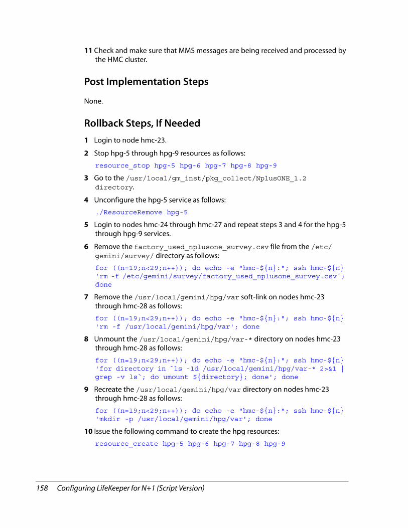
11 Check and make sure that MMS messages are being received and processed by the HMC cluster.
Post Implementation Steps
None.
Rollback Steps, If Needed
1 Login to node hmc-23.
2 Stop hpg-5 through hpg-9 resources as follows:
resource_stop hpg-5 hpg-6 hpg-7 hpg-8 hpg-9
3 Go to the /usr/local/gm_inst/pkg_collect/NplusONE_1.2 directory.
4 Unconfigure the hpg-5 service as follows:
./ResourceRemove hpg-5
5 Login to nodes hmc-24 through hmc-27 and repeat steps 3 and 4 for the hpg-5 through hpg-9 services.
6 Remove the factory_used_nplusone_survey.csv file from the /etc/gemini/survey/ directory as follows:
for ((n=19;n<29;n++)); do echo -e "hmc-${n}:"; ssh hmc-${n} 'rm -f /etc/gemini/survey/factory_used_nplusone_survey.csv'; done
7 Remove the /usr/local/gemini/hpg/var soft-link on nodes hmc-23 through hmc-28 as follows:
for ((n=19;n<29;n++)); do echo -e "hmc-${n}:"; ssh hmc-${n} 'rm -f /usr/local/gemini/hpg/var'; done
8 Unmount the /usr/local/gemini/hpg/var-* directory on nodes hmc-23 through hmc-28 as follows:
for ((n=19;n<29;n++)); do echo -e "hmc-${n}:"; ssh hmc-${n} 'for directory in `ls -1d /usr/local/gemini/hpg/var-* 2>&1 | grep -v ls`; do umount ${directory}; done'; done
9 Recreate the /usr/local/gemini/hpg/var directory on nodes hmc-23 through hmc-28 as follows:
for ((n=19;n<29;n++)); do echo -e "hmc-${n}:"; ssh hmc-${n} 'mkdir -p /usr/local/gemini/hpg/var'; done
10 Issue the following command to create the hpg resources:
resource_create hpg-5 hpg-6 hpg-7 hpg-8 hpg-9
158 Configuring LifeKeeper for N+1 (Script Version)

11 Once the new HPG resources have been created, issue the show_cluster command as follows to check the status of the HPG services:
show_cluster | grep hpg
You should see the following output:
hpg-1 hmc-2 PRIMARY *
hpg-1 hmc-3 SECONDARY
hpg-2 hmc-11 SECONDARY
hpg-2 hmc-12 PRIMARY *
hpg-3 hmc-19 SECONDARY
hpg-3 hmc-20 PRIMARY *
hpg-4 hmc-21 SECONDARY
hpg-4 hmc-22 PRIMARY *
hpg-5 hmc-23 PRIMARY *
hpg-6 hmc-24 PRIMARY *
hpg-7 hmc-25 PRIMARY *
hpg-8 hmc-26 PRIMARY *
hpg-9 hmc-27 PRIMARY *
12 Check and make sure that MMS messages are being received and processed by the HMC-Cluster.
Installing the HMG
The NplusONE script is working only to create the LifeKeeper configurations. The HMG must be installed manually first. Follow the single node/manual HMG install where the packages are normally located in the directory named /usr/local/gm_inst/gemini/HMG directory.
The SAN partition must be first mounted where, during the HMG install, the HMG contents will be writing to the /usr/local/gemini/hmg/var directory.
The HMG install instruction should be something like ./installer-hmg.sh from the primary server. The script will automatically propagate all action to the secondary/backup server, thus there's no need to run the same instruction on the secondary/backup server.
Example From the example of the factory file above:
❏ To install HMG, mount the HMG-var directory first:
Appendix 159
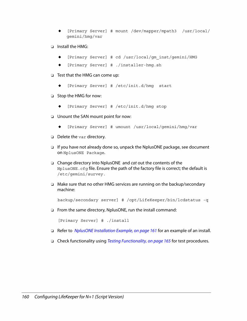
◆ [Primary Server] # mount /dev/mapper/mpath3 /usr/local/gemini/hmg/var
❏ Install the HMG:
◆ [Primary Server] # cd /usr/local/gm_inst/gemini/HMG
◆ [Primary Server] # ./installer-hmg.sh
❏ Test that the HMG can come up:
◆ [Primary Server] # /etc/init.d/hmg start
❏ Stop the HMG for now:
◆ [Primary Server] # /etc/init.d/hmg stop
❏ Unount the SAN mount point for now:
◆ [Primary Server] # umount /usr/local/gemini/hmg/var
❏ Delete the var directory.
❏ If you have not already done so, unpack the NplusONE package, see document on NplusONE Package.
❏ Change directory into NplusONE and cat out the contents of the NplusONE.cfg file. Ensure the path of the factory file is correct; the default is /etc/gemini/survey.
❏ Make sure that no other HMG services are running on the backup/secondary machine:
backup/secondary server] # /opt/LifeKeeper/bin/lcdstatus -q
❏ From the same directory, NplusONE, run the install command:
[Primary Server] # ./install
❏ Refer to NplusONE Installation Example‚ on page 161 for an example of an install.
❏ Check functionality using Testing Functionality‚ on page 165 for test procedures.
160 Configuring LifeKeeper for N+1 (Script Version)
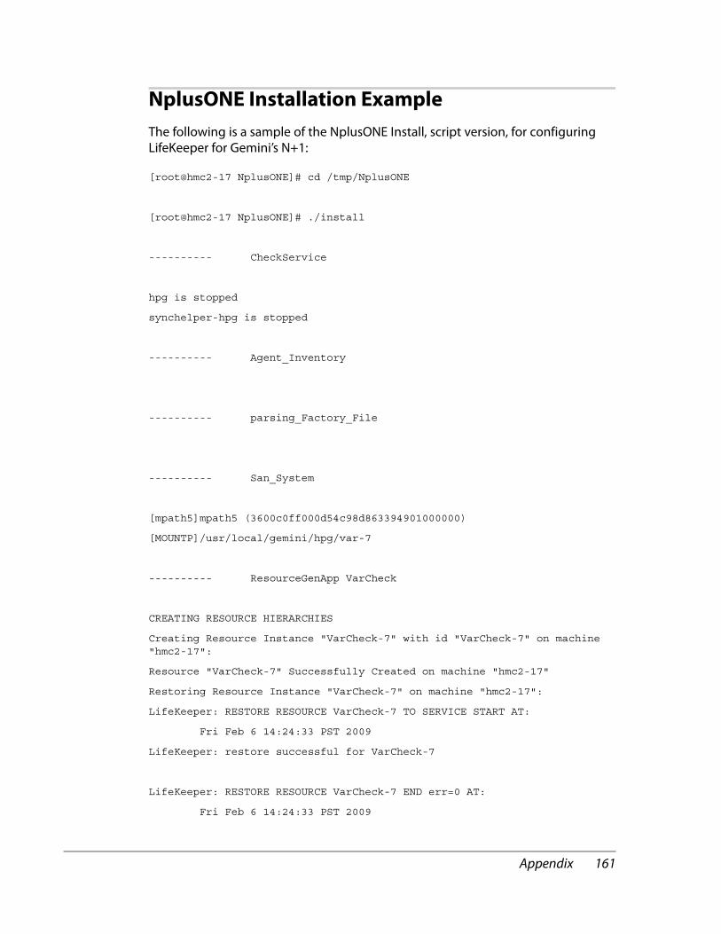
NplusONE Installation ExampleThe following is a sample of the NplusONE Install, script version, for configuring LifeKeeper for Gemini’s N+1:
[root@hmc2-17 NplusONE]# cd /tmp/NplusONE
[root@hmc2-17 NplusONE]# ./install
---------- CheckService
hpg is stopped
synchelper-hpg is stopped
---------- Agent_Inventory
---------- parsing_Factory_File
---------- San_System
[mpath5]mpath5 (3600c0ff000d54c98d863394901000000)
[MOUNTP]/usr/local/gemini/hpg/var-7
---------- ResourceGenApp VarCheck
CREATING RESOURCE HIERARCHIES
Creating Resource Instance "VarCheck-7" with id "VarCheck-7" on machine "hmc2-17":
Resource "VarCheck-7" Successfully Created on machine "hmc2-17"
Restoring Resource Instance "VarCheck-7" on machine "hmc2-17":
LifeKeeper: RESTORE RESOURCE VarCheck-7 TO SERVICE START AT:
Fri Feb 6 14:24:33 PST 2009
LifeKeeper: restore successful for VarCheck-7
LifeKeeper: RESTORE RESOURCE VarCheck-7 END err=0 AT:
Fri Feb 6 14:24:33 PST 2009
Appendix 161
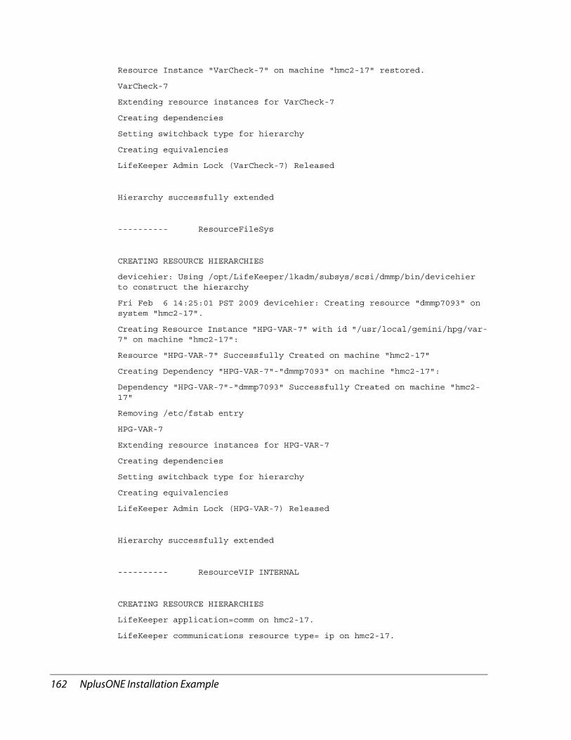
Resource Instance "VarCheck-7" on machine "hmc2-17" restored.
VarCheck-7
Extending resource instances for VarCheck-7
Creating dependencies
Setting switchback type for hierarchy
Creating equivalencies
LifeKeeper Admin Lock (VarCheck-7) Released
Hierarchy successfully extended
---------- ResourceFileSys
CREATING RESOURCE HIERARCHIES
devicehier: Using /opt/LifeKeeper/lkadm/subsys/scsi/dmmp/bin/devicehier to construct the hierarchy
Fri Feb 6 14:25:01 PST 2009 devicehier: Creating resource "dmmp7093" on system "hmc2-17".
Creating Resource Instance "HPG-VAR-7" with id "/usr/local/gemini/hpg/var-7" on machine "hmc2-17":
Resource "HPG-VAR-7" Successfully Created on machine "hmc2-17"
Creating Dependency "HPG-VAR-7"-"dmmp7093" on machine "hmc2-17":
Dependency "HPG-VAR-7"-"dmmp7093" Successfully Created on machine "hmc2-17"
Removing /etc/fstab entry
HPG-VAR-7
Extending resource instances for HPG-VAR-7
Creating dependencies
Setting switchback type for hierarchy
Creating equivalencies
LifeKeeper Admin Lock (HPG-VAR-7) Released
Hierarchy successfully extended
---------- ResourceVIP INTERNAL
CREATING RESOURCE HIERARCHIES
LifeKeeper application=comm on hmc2-17.
LifeKeeper communications resource type= ip on hmc2-17.
162 NplusONE Installation Example
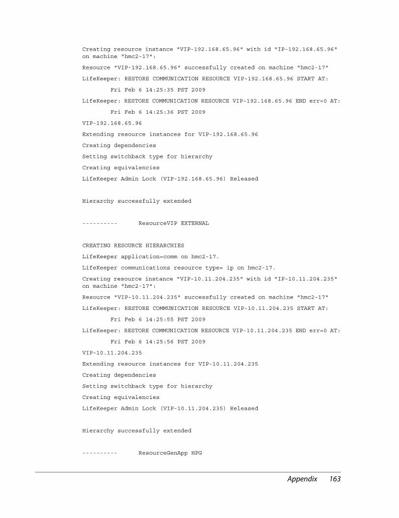
Creating resource instance "VIP-192.168.65.96" with id "IP-192.168.65.96" on machine "hmc2-17":
Resource "VIP-192.168.65.96" successfully created on machine "hmc2-17"
LifeKeeper: RESTORE COMMUNICATION RESOURCE VIP-192.168.65.96 START AT:
Fri Feb 6 14:25:35 PST 2009
LifeKeeper: RESTORE COMMUNICATION RESOURCE VIP-192.168.65.96 END err=0 AT:
Fri Feb 6 14:25:36 PST 2009
VIP-192.168.65.96
Extending resource instances for VIP-192.168.65.96
Creating dependencies
Setting switchback type for hierarchy
Creating equivalencies
LifeKeeper Admin Lock (VIP-192.168.65.96) Released
Hierarchy successfully extended
---------- ResourceVIP EXTERNAL
CREATING RESOURCE HIERARCHIES
LifeKeeper application=comm on hmc2-17.
LifeKeeper communications resource type= ip on hmc2-17.
Creating resource instance "VIP-10.11.204.235" with id "IP-10.11.204.235" on machine "hmc2-17":
Resource "VIP-10.11.204.235" successfully created on machine "hmc2-17"
LifeKeeper: RESTORE COMMUNICATION RESOURCE VIP-10.11.204.235 START AT:
Fri Feb 6 14:25:55 PST 2009
LifeKeeper: RESTORE COMMUNICATION RESOURCE VIP-10.11.204.235 END err=0 AT:
Fri Feb 6 14:25:56 PST 2009
VIP-10.11.204.235
Extending resource instances for VIP-10.11.204.235
Creating dependencies
Setting switchback type for hierarchy
Creating equivalencies
LifeKeeper Admin Lock (VIP-10.11.204.235) Released
Hierarchy successfully extended
---------- ResourceGenApp HPG
Appendix 163

CREATING RESOURCE HIERARCHIES
Creating Resource Instance "HPG-7" with id "HPG-7" on machine "hmc2-17":
Resource "HPG-7" Successfully Created on machine "hmc2-17"
Restoring Resource Instance "HPG-7" on machine "hmc2-17":
LifeKeeper: RESTORE RESOURCE HPG-7 TO SERVICE START AT:
Fri Feb 6 14:26:17 PST 2009
..........
Starting HPG: [ OK ]
..........
Starting Synchelper: [ OK ]
LifeKeeper: RESTORE RESOURCE HPG-7 END err=0 AT:
Fri Feb 6 14:26:38 PST 2009
Resource Instance "HPG-7" on machine "hmc2-17" restored.
HPG-7
Extending resource instances for HPG-7
Creating dependencies
Setting switchback type for hierarchy
Creating equivalencies
LifeKeeper Admin Lock (HPG-7) Released
Hierarchy successfully extended
---------- ResourceDependency VarCheck
---------- ResourceDependency Virtual IP Internal
---------- ResourceDependency Virtual IP External
---------- ResourceDependency HPG
[root@hmc2-17 NplusONE]#
164 NplusONE Installation Example

Testing FunctionalityWe have three functionality test cases for the N+1 Installation and Configuration for LifeKeeper.
Test Case 1
On hmc2-17, the designated primary server for HPG-7:
[root@hmc2-17 NplusONE]# PATH=$PATH:/opt/LifeKeeper/bin
[root@hmc2-17 NplusONE]# lcdstatus -qLOCAL TAG ID STATE PRIO PRIMARYhmc2-17 HPG-7 HPG-7 ISP 1 hmc2-17hmc2-17 VIP-10.11.204.235 IP-10.11.204.235 ISP 1 hmc2-17hmc2-17 VIP-192.168.65.96 IP-192.168.65.96 ISP 1 hmc2-17hmc2-17 HPG-VAR-7 /usr/local/gemini/hpg/var-7 ISP 1 hmc2-17hmc2-17 dmmp7093 3600c0ff000d54c98d863394901000000 ISP 1 hmc2-17hmc2-17 VarCheck-7 VarCheck-7 ISP 1 hmc2-17
MACHINE NETWORK ADDRESSES/DEVICE STATE PRIOhmc2-18 TCP 10.11.204.210/10.11.204.211 ALIVE 1hmc2-18 TCP 192.168.65.67/192.168.65.68 ALIVE 2[root@hmc2-17 NplusONE]#
HPG is the name of this resource.
For convenience, setup LifeKeeper path in the PATH.
Notice the indent pattern.
ISP means it's primary on this server.
Appendix 165
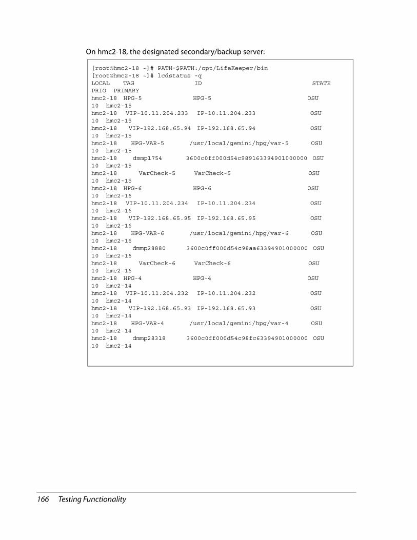
On hmc2-18, the designated secondary/backup server:
[root@hmc2-18 ~]# PATH=$PATH:/opt/LifeKeeper/bin[root@hmc2-18 ~]# lcdstatus -qLOCAL TAG ID STATE PRIO PRIMARYhmc2-18 HPG-5 HPG-5 OSU 10 hmc2-15hmc2-18 VIP-10.11.204.233 IP-10.11.204.233 OSU 10 hmc2-15hmc2-18 VIP-192.168.65.94 IP-192.168.65.94 OSU 10 hmc2-15hmc2-18 HPG-VAR-5 /usr/local/gemini/hpg/var-5 OSU 10 hmc2-15hmc2-18 dmmp1754 3600c0ff000d54c989163394901000000 OSU 10 hmc2-15hmc2-18 VarCheck-5 VarCheck-5 OSU 10 hmc2-15hmc2-18 HPG-6 HPG-6 OSU 10 hmc2-16hmc2-18 VIP-10.11.204.234 IP-10.11.204.234 OSU 10 hmc2-16hmc2-18 VIP-192.168.65.95 IP-192.168.65.95 OSU 10 hmc2-16hmc2-18 HPG-VAR-6 /usr/local/gemini/hpg/var-6 OSU 10 hmc2-16hmc2-18 dmmp28880 3600c0ff000d54c98aa63394901000000 OSU 10 hmc2-16hmc2-18 VarCheck-6 VarCheck-6 OSU 10 hmc2-16hmc2-18 HPG-4 HPG-4 OSU 10 hmc2-14hmc2-18 VIP-10.11.204.232 IP-10.11.204.232 OSU 10 hmc2-14hmc2-18 VIP-192.168.65.93 IP-192.168.65.93 OSU 10 hmc2-14hmc2-18 HPG-VAR-4 /usr/local/gemini/hpg/var-4 OSU 10 hmc2-14hmc2-18 dmmp28318 3600c0ff000d54c98fc63394901000000 OSU 10 hmc2-14
166 Testing Functionality

hmc2-18 VarCheck-4 VarCheck-4 OSU 10 hmc2-14hmc2-18 HPG-7 HPG-7 OSU 10 hmc2-17hmc2-18 VIP-10.11.204.235 IP-10.11.204.235 OSU 10 hmc2-17hmc2-18 VIP-192.168.65.96 IP-192.168.65.96 OSU 10 hmc2-17hmc2-18 HPG-VAR-7 /usr/local/gemini/hpg/var-7 OSU 10 hmc2-17hmc2-18 dmmp7093 3600c0ff000d54c98d863394901000000 OSU 10 hmc2-17hmc2-18 VarCheck-7 VarCheck-7 OSU 10 hmc2-17
MACHINE NETWORK ADDRESSES/DEVICE STATE PRIOhmc2-15 TCP 192.168.65.68/192.168.65.65 DEAD 2hmc2-16 TCP 10.11.204.211/10.11.204.209 ALIVE 1hmc2-16 TCP 192.168.65.68/192.168.65.66 ALIVE 2hmc2-17 TCP 10.11.204.211/10.11.204.210 ALIVE 1hmc2-17 TCP 192.168.65.68/192.168.65.67 ALIVE 2hmc2-14 TCP 192.168.65.68/192.168.65.64 ALIVE 2hmc2-14 TCP 10.11.204.211/10.11.204.207 ALIVE 1hmc2-15 TCP 10.11.204.211/10.11.204.208 ALIVE 1hmc2-15 TCP 10.11.204.211/192.168.65.65 ALIVE 2[root@hmc2-18 ~]#
For the same resource HPG-7, it is OSU means it's a secondary on this machine.
Notice the indent has to be the same as the primary.
Appendix 167

Test Case 2
Failing the resource of some other HPG to the node hmc2-18
[root@hmc2-18 ~]# perform_action -t HPG-4 -a restoreperform_action: LRACI(dorestore) attempting remote remove of resource "VarCheck-4" on machine "hmc2-14"/opt/LifeKeeper/bin/lcdrecover: resource "VarCheck-4" is being removed because of request from machine "hmc2-18"
Stopping HPG: [ OK ]
Stopping Synchelper: [ OK ]Fri Feb 6 14:55:47 PST 2009 remove: BEGIN remove of "dmmp28318" on server "hmc2-14"Fri Feb 6 14:55:47 PST 2009 remove: Flushing buffers on /dev/mapper/mpath6.Fri Feb 6 14:55:47 PST 2009 remove: ioctl.pl -f /dev/mapper/mpath6Fri Feb 6 14:55:47 PST 2009 remove: Unlocking device /dev/mapper/mpath6.Fri Feb 6 14:55:48 PST 2009 remove: Device /dev/mapper/mpath6 successfully unlocked.Fri Feb 6 14:55:48 PST 2009 remove: END successful remove of "dmmp28318" on server "hmc2-14"lcdrecover[267,lcdrecover.C]Fri Feb 6 14:55:48 PST 2009: remote request by "hmc2-18" for removal of resources "VarCheck-4" on "hmc2-14" successfulperform_action: LRACI(dorestore) remote remove of resource "VarCheck-4" on machine "hmc2-14" successfulLifeKeeper: RESTORE RESOURCE VarCheck-4 TO SERVICE START AT: Fri Feb 6 14:55:49 PST 2009
This is a command to fail a
resource to itself.
168 Testing Functionality

LifeKeeper: restore successful for VarCheck-4
LifeKeeper: RESTORE RESOURCE VarCheck-4 END err=0 AT: Fri Feb 6 14:55:49 PST 2009***WARNING*** perform_action;Fri Feb 6 14:55:50 PST 2009: License key (for Kit scsi/dmmp) will expire at midnight in 25 daysFri Feb 6 14:55:51 PST 2009 restore: BEGIN restore of "dmmp28318" on server "hmc2-18"Fri Feb 6 14:55:51 PST 2009 restore: Locking device /dev/mapper/mpath6.Fri Feb 6 14:55:51 PST 2009 restore: path sdd successfully registered for /dev/mapper/mpath6.Fri Feb 6 14:55:51 PST 2009 restore: reserve /dev/mapper/mpath6.Fri Feb 6 14:55:51 PST 2009 restore: Device /dev/mapper/mpath6 successfully locked.Fri Feb 6 14:55:51 PST 2009 restore: END successful restore of "dmmp28318" on server "hmc2-18"LifeKeeper: "fsck"ing file system /usr/local/gemini/hpg/var-4 fsck.ext3 -y /dev/mapper/mpath6e2fsck 1.35 (28-Feb-2004)/dev/mapper/mpath6: clean, 209/2501856 files, 142837/5000192 blocksLifeKeeper: mounting file system /usr/local/gemini/hpg/var-4 mount -text3 -orw /dev/mapper/mpath6 /usr/local/gemini/hpg/var-4LifeKeeper: File system /usr/local/gemini/hpg/var-4 has been successfully mounted.LifeKeeper: RESTORE COMMUNICATION RESOURCE VIP-192.168.65.93 START AT: Fri Feb 6 14:55:55 PST 2009LifeKeeper: RESTORE COMMUNICATION RESOURCE VIP-192.168.65.93 END err=0 AT: Fri Feb 6 14:55:56 PST 2009LifeKeeper: RESTORE COMMUNICATION RESOURCE VIP-10.11.204.232 START AT:
Appendix 169
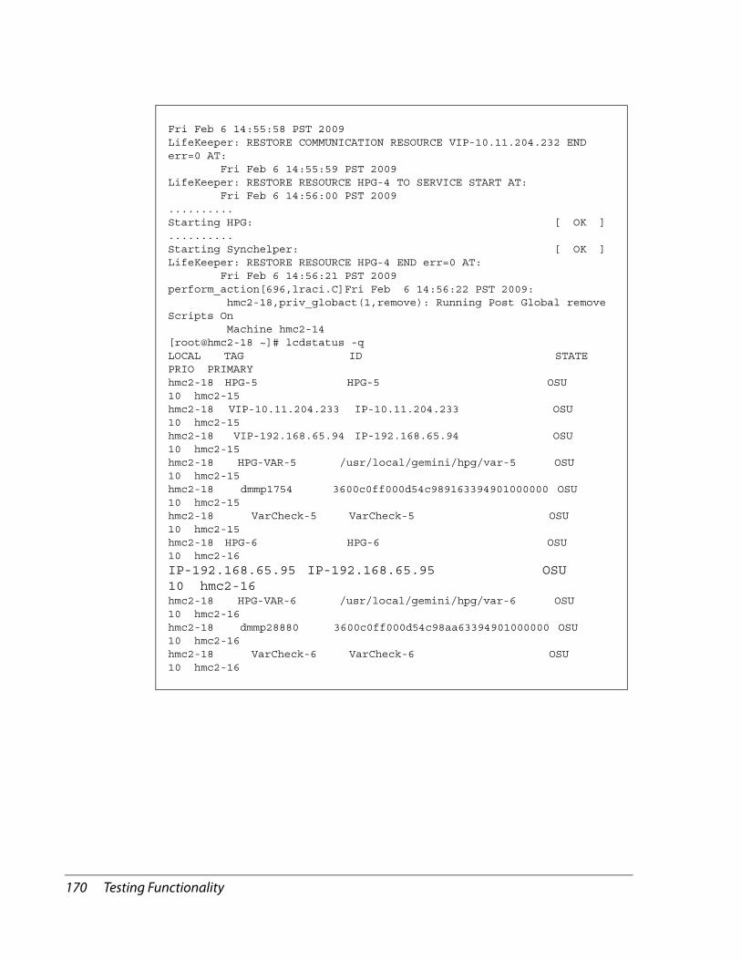
Fri Feb 6 14:55:58 PST 2009LifeKeeper: RESTORE COMMUNICATION RESOURCE VIP-10.11.204.232 END err=0 AT: Fri Feb 6 14:55:59 PST 2009LifeKeeper: RESTORE RESOURCE HPG-4 TO SERVICE START AT: Fri Feb 6 14:56:00 PST 2009..........Starting HPG: [ OK ]..........Starting Synchelper: [ OK ]LifeKeeper: RESTORE RESOURCE HPG-4 END err=0 AT: Fri Feb 6 14:56:21 PST 2009perform_action[696,lraci.C]Fri Feb 6 14:56:22 PST 2009: hmc2-18,priv_globact(1,remove): Running Post Global remove Scripts On Machine hmc2-14[root@hmc2-18 ~]# lcdstatus -qLOCAL TAG ID STATE PRIO PRIMARYhmc2-18 HPG-5 HPG-5 OSU 10 hmc2-15hmc2-18 VIP-10.11.204.233 IP-10.11.204.233 OSU 10 hmc2-15hmc2-18 VIP-192.168.65.94 IP-192.168.65.94 OSU 10 hmc2-15hmc2-18 HPG-VAR-5 /usr/local/gemini/hpg/var-5 OSU 10 hmc2-15hmc2-18 dmmp1754 3600c0ff000d54c989163394901000000 OSU 10 hmc2-15hmc2-18 VarCheck-5 VarCheck-5 OSU 10 hmc2-15hmc2-18 HPG-6 HPG-6 OSU 10 hmc2-16
IP-192.168.65.95 IP-192.168.65.95 OSU 10 hmc2-16hmc2-18 HPG-VAR-6 /usr/local/gemini/hpg/var-6 OSU 10 hmc2-16hmc2-18 dmmp28880 3600c0ff000d54c98aa63394901000000 OSU 10 hmc2-16hmc2-18 VarCheck-6 VarCheck-6 OSU 10 hmc2-16
170 Testing Functionality
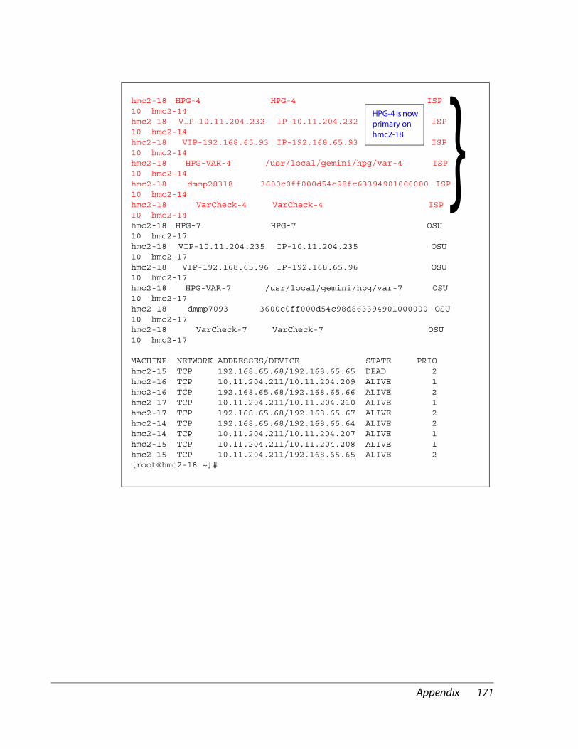
hmc2-18 HPG-4 HPG-4 ISP 10 hmc2-14hmc2-18 VIP-10.11.204.232 IP-10.11.204.232 ISP 10 hmc2-14hmc2-18 VIP-192.168.65.93 IP-192.168.65.93 ISP 10 hmc2-14hmc2-18 HPG-VAR-4 /usr/local/gemini/hpg/var-4 ISP 10 hmc2-14hmc2-18 dmmp28318 3600c0ff000d54c98fc63394901000000 ISP 10 hmc2-14hmc2-18 VarCheck-4 VarCheck-4 ISP 10 hmc2-14hmc2-18 HPG-7 HPG-7 OSU 10 hmc2-17hmc2-18 VIP-10.11.204.235 IP-10.11.204.235 OSU 10 hmc2-17hmc2-18 VIP-192.168.65.96 IP-192.168.65.96 OSU 10 hmc2-17hmc2-18 HPG-VAR-7 /usr/local/gemini/hpg/var-7 OSU 10 hmc2-17hmc2-18 dmmp7093 3600c0ff000d54c98d863394901000000 OSU 10 hmc2-17hmc2-18 VarCheck-7 VarCheck-7 OSU 10 hmc2-17
MACHINE NETWORK ADDRESSES/DEVICE STATE PRIOhmc2-15 TCP 192.168.65.68/192.168.65.65 DEAD 2hmc2-16 TCP 10.11.204.211/10.11.204.209 ALIVE 1hmc2-16 TCP 192.168.65.68/192.168.65.66 ALIVE 2hmc2-17 TCP 10.11.204.211/10.11.204.210 ALIVE 1hmc2-17 TCP 192.168.65.68/192.168.65.67 ALIVE 2hmc2-14 TCP 192.168.65.68/192.168.65.64 ALIVE 2hmc2-14 TCP 10.11.204.211/10.11.204.207 ALIVE 1hmc2-15 TCP 10.11.204.211/10.11.204.208 ALIVE 1hmc2-15 TCP 10.11.204.211/192.168.65.65 ALIVE 2[root@hmc2-18 ~]#
HPG-4 is now primary on hmc2-18
Appendix 171

Now try to fail HPG-7 over
[root@hmc2-18 ~]# perform_action -t HPG-7 -a restoreperform_action: LRACI(dorestore) attempting remote remove of resource "VarCheck-7" on machine "hmc2-17"/opt/LifeKeeper/bin/lcdrecover: resource "VarCheck-7" is being removed because of request from machine "hmc2-18"
Stopping HPG: [ OK ]
Stopping Synchelper: [ OK ]Fri Feb 6 15:01:38 PST 2009 remove: BEGIN remove of "dmmp7093" on server "hmc2-17"Fri Feb 6 15:01:38 PST 2009 remove: Flushing buffers on /dev/mapper/mpath5.Fri Feb 6 15:01:38 PST 2009 remove: ioctl.pl -f /dev/mapper/mpath5Fri Feb 6 15:01:38 PST 2009 remove: Unlocking device /dev/mapper/mpath5.Fri Feb 6 15:01:38 PST 2009 remove: Device /dev/mapper/mpath5 successfully unlocked.Fri Feb 6 15:01:38 PST 2009 remove: END successful remove of "dmmp7093" on server "hmc2-17"lcdrecover[267,lcdrecover.C]Fri Feb 6 15:01:38 PST 2009: remote request by "hmc2-18" for removal of resources "VarCheck-7" on "hmc2-17" successfulperform_action: LRACI(dorestore) remote remove of resource "VarCheck-7" on machine "hmc2-17" successfulLifeKeeper: RESTORE RESOURCE VarCheck-7 TO SERVICE START AT: Fri Feb 6 15:01:40 PST 2009LifeKeeper: restore successful for VarCheck-7
LifeKeeper: RESTORE RESOURCE VarCheck-7 END err=1 AT: Fri Feb 6 15:01:40 PST 2009*ERROR* Restore Generic Application VarCheck-7 has failed***ERROR*** perform_action[272,lraci.C]Fri Feb 6 15:01:40 PST 2009: restore of resource "VarCheck-7" has failed***ERROR*** perform_action[139,lraci.C]Fri Feb 6 15:01:40 PST 2009: resource "dmmp7093" failed restore since child "VarCheck-7" in state "OSF"***ERROR*** perform_action[139,lraci.C]Fri Feb 6 15:01:40 PST 2009: resource "HPG-VAR-7" failed restore since child "dmmp7093" in state "OSU"***ERROR*** perform_action[139,lraci.C]Fri Feb 6 15:01:40 PST 2009: resource "VIP-192.168.65.96" failed restore since child "HPG-VAR-7" in state "OSU"***ERROR*** perform_action[139,lraci.C]Fri Feb 6 15:01:40 PST 2009: resource
172 Testing Functionality

"VIP-10.11.204.235" failed restore since child "VIP-192.168.65.96" in state "OSU"***ERROR*** perform_action[139,lraci.C]Fri Feb 6 15:01:40 PST 2009: resource "HPG-7" failed restore since child "VIP-10.11.204.235" in state "OSU"perform_action[696,lraci.C]Fri Feb 6 15:01:40 PST 2009: hmc2-18,priv_globact(1,remove): Running Post Global remove Scripts On Machine hmc2-17***ERROR*** perform_action[64,lracimain.C]Fri Feb 6 15:01:46 PST 2009: action "restore" on resource with tag "HPG-7" has failed[root@hmc2-18 ~]# lcdstatus -qLOCAL TAG ID STATE PRIO PRIMARYhmc2-18 HPG-5 HPG-5 OSU 10 hmc2-15hmc2-18 VIP-10.11.204.233 IP-10.11.204.233 OSU 10 hmc2-15hmc2-18 VIP-192.168.65.94 IP-192.168.65.94 OSU 10 hmc2-15hmc2-18 HPG-VAR-5 /usr/local/gemini/hpg/var-5 OSU 10 hmc2-15hmc2-18 dmmp1754 3600c0ff000d54c989163394901000000 OSU 10 hmc2-15hmc2-18 VarCheck-5 VarCheck-5 OSU 10 hmc2-15hmc2-18 HPG-6 HPG-6 OSU 10 hmc2-16hmc2-18 VIP-10.11.204.234 IP-10.11.204.234 OSU 10 hmc2-16hmc2-18 VIP-192.168.65.95 IP-192.168.65.95 OSU 10 hmc2-16hmc2-18 HPG-VAR-6 /usr/local/gemini/hpg/var-6 OSU 10 hmc2-16hmc2-18 dmmp28880 3600c0ff000d54c98aa63394901000000 OSU 10 hmc2-16hmc2-18 VarCheck-6 VarCheck-6 OSU 10 hmc2-16
Appendix 173

hmc2-18 HPG-4 HPG-4 ISP 10 hmc2-14hmc2-18 VIP-10.11.204.232 IP-10.11.204.232 ISP 10 hmc2-14hmc2-18 VIP-192.168.65.93 IP-192.168.65.93 ISP 10 hmc2-14hmc2-18 HPG-VAR-4 /usr/local/gemini/hpg/var-4 ISP 10 hmc2-14hmc2-18 dmmp28318 3600c0ff000d54c98fc63394901000000 ISP 10 hmc2-14hmc2-18 VarCheck-4 VarCheck-4 ISP 10 hmc2-14hmc2-18 HPG-7 HPG-7 OSU 10 hmc2-17hmc2-18 VIP-10.11.204.235 IP-10.11.204.235 OSU 10 hmc2-17hmc2-18 VIP-192.168.65.96 IP-192.168.65.96 OSU 10 hmc2-17hmc2-18 HPG-VAR-7 /usr/local/gemini/hpg/var-7 OSU 10 hmc2-17hmc2-18 dmmp7093 3600c0ff000d54c98d863394901000000 OSU 10 hmc2-17hmc2-18 VarCheck-7 VarCheck-7 OSF 10 hmc2-17
MACHINE NETWORK ADDRESSES/DEVICE STATE PRIOhmc2-15 TCP 192.168.65.68/192.168.65.65 DEAD 2hmc2-16 TCP 10.11.204.211/10.11.204.209 ALIVE 1hmc2-16 TCP 192.168.65.68/192.168.65.66 ALIVE 2hmc2-17 TCP 10.11.204.211/10.11.204.210 ALIVE 1hmc2-17 TCP 192.168.65.68/192.168.65.67 ALIVE 2hmc2-14 TCP 192.168.65.68/192.168.65.64 ALIVE 2hmc2-14 TCP 10.11.204.211/10.11.204.207 ALIVE 1hmc2-15 TCP 10.11.204.211/10.11.204.208 ALIVE 1hmc2-15 TCP 10.11.204.211/192.168.65.65 ALIVE 2[root@hmc2-18 ~]#
}By design, HPG-7 not able to failover to hmc2-18 because HPG-4 is already running on hmc2-18 }
174 Testing Functionality
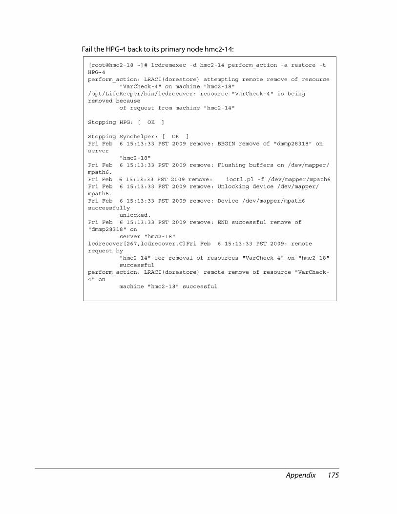
Fail the HPG-4 back to its primary node hmc2-14:
[root@hmc2-18 ~]# lcdremexec -d hmc2-14 perform_action -a restore -t HPG-4perform_action: LRACI(dorestore) attempting remote remove of resource "VarCheck-4" on machine "hmc2-18"/opt/LifeKeeper/bin/lcdrecover: resource "VarCheck-4" is being removed because of request from machine "hmc2-14"
Stopping HPG: [ OK ]
Stopping Synchelper: [ OK ]Fri Feb 6 15:13:33 PST 2009 remove: BEGIN remove of "dmmp28318" on server "hmc2-18"Fri Feb 6 15:13:33 PST 2009 remove: Flushing buffers on /dev/mapper/mpath6.Fri Feb 6 15:13:33 PST 2009 remove: ioctl.pl -f /dev/mapper/mpath6Fri Feb 6 15:13:33 PST 2009 remove: Unlocking device /dev/mapper/mpath6.Fri Feb 6 15:13:33 PST 2009 remove: Device /dev/mapper/mpath6 successfully unlocked.Fri Feb 6 15:13:33 PST 2009 remove: END successful remove of "dmmp28318" on server "hmc2-18"lcdrecover[267,lcdrecover.C]Fri Feb 6 15:13:33 PST 2009: remote request by "hmc2-14" for removal of resources "VarCheck-4" on "hmc2-18" successfulperform_action: LRACI(dorestore) remote remove of resource "VarCheck-4" on machine "hmc2-18" successful
Appendix 175
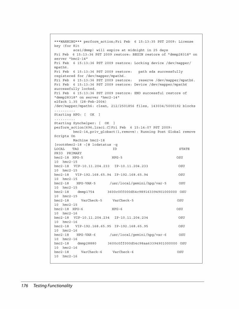
***WARNING*** perform_action;Fri Feb 6 15:13:35 PST 2009: License key (for Kit scsi/dmmp) will expire at midnight in 25 daysFri Feb 6 15:13:36 PST 2009 restore: BEGIN restore of "dmmp28318" on server "hmc2-14"Fri Feb 6 15:13:36 PST 2009 restore: Locking device /dev/mapper/mpath6.Fri Feb 6 15:13:36 PST 2009 restore: path sda successfully registered for /dev/mapper/mpath6.Fri Feb 6 15:13:36 PST 2009 restore: reserve /dev/mapper/mpath6.Fri Feb 6 15:13:36 PST 2009 restore: Device /dev/mapper/mpath6 successfully locked.Fri Feb 6 15:13:36 PST 2009 restore: END successful restore of "dmmp28318" on server "hmc2-14"e2fsck 1.35 (28-Feb-2004)/dev/mapper/mpath6: clean, 212/2501856 files, 143034/5000192 blocks..........Starting HPG: [ OK ]..........Starting Synchelper: [ OK ]perform_action[696,lraci.C]Fri Feb 6 15:14:07 PST 2009: hmc2-14,priv_globact(1,remove): Running Post Global remove Scripts On Machine hmc2-18[root@hmc2-18 ~]# lcdstatus -qLOCAL TAG ID STATE PRIO PRIMARYhmc2-18 HPG-5 HPG-5 OSU 10 hmc2-15hmc2-18 VIP-10.11.204.233 IP-10.11.204.233 OSU 10 hmc2-15hmc2-18 VIP-192.168.65.94 IP-192.168.65.94 OSU 10 hmc2-15hmc2-18 HPG-VAR-5 /usr/local/gemini/hpg/var-5 OSU 10 hmc2-15hmc2-18 dmmp1754 3600c0ff000d54c989163394901000000 OSU 10 hmc2-15hmc2-18 VarCheck-5 VarCheck-5 OSU 10 hmc2-15hmc2-18 HPG-6 HPG-6 OSU 10 hmc2-16hmc2-18 VIP-10.11.204.234 IP-10.11.204.234 OSU 10 hmc2-16hmc2-18 VIP-192.168.65.95 IP-192.168.65.95 OSU 10 hmc2-16hmc2-18 HPG-VAR-6 /usr/local/gemini/hpg/var-6 OSU 10 hmc2-16hmc2-18 dmmp28880 3600c0ff000d54c98aa63394901000000 OSU 10 hmc2-16hmc2-18 VarCheck-6 VarCheck-6 OSU 10 hmc2-16
176 Testing Functionality
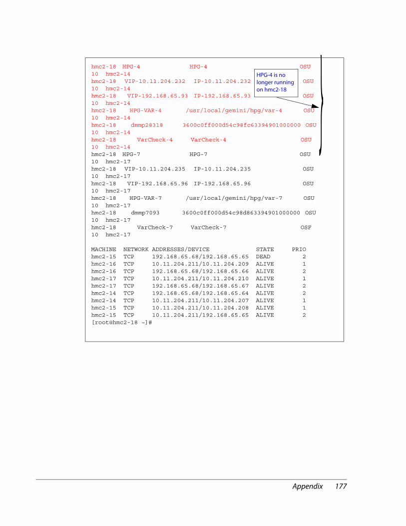
hmc2-18 HPG-4 HPG-4 OSU 10 hmc2-14hmc2-18 VIP-10.11.204.232 IP-10.11.204.232 OSU 10 hmc2-14hmc2-18 VIP-192.168.65.93 IP-192.168.65.93 OSU 10 hmc2-14hmc2-18 HPG-VAR-4 /usr/local/gemini/hpg/var-4 OSU 10 hmc2-14hmc2-18 dmmp28318 3600c0ff000d54c98fc63394901000000 OSU 10 hmc2-14hmc2-18 VarCheck-4 VarCheck-4 OSU 10 hmc2-14hmc2-18 HPG-7 HPG-7 OSU 10 hmc2-17hmc2-18 VIP-10.11.204.235 IP-10.11.204.235 OSU 10 hmc2-17hmc2-18 VIP-192.168.65.96 IP-192.168.65.96 OSU 10 hmc2-17hmc2-18 HPG-VAR-7 /usr/local/gemini/hpg/var-7 OSU 10 hmc2-17hmc2-18 dmmp7093 3600c0ff000d54c98d863394901000000 OSU 10 hmc2-17hmc2-18 VarCheck-7 VarCheck-7 OSF 10 hmc2-17
MACHINE NETWORK ADDRESSES/DEVICE STATE PRIOhmc2-15 TCP 192.168.65.68/192.168.65.65 DEAD 2hmc2-16 TCP 10.11.204.211/10.11.204.209 ALIVE 1hmc2-16 TCP 192.168.65.68/192.168.65.66 ALIVE 2hmc2-17 TCP 10.11.204.211/10.11.204.210 ALIVE 1hmc2-17 TCP 192.168.65.68/192.168.65.67 ALIVE 2hmc2-14 TCP 192.168.65.68/192.168.65.64 ALIVE 2hmc2-14 TCP 10.11.204.211/10.11.204.207 ALIVE 1hmc2-15 TCP 10.11.204.211/10.11.204.208 ALIVE 1hmc2-15 TCP 10.11.204.211/192.168.65.65 ALIVE 2[root@hmc2-18 ~]#
}HPG-4 is no longer running on hmc2-18
Appendix 177
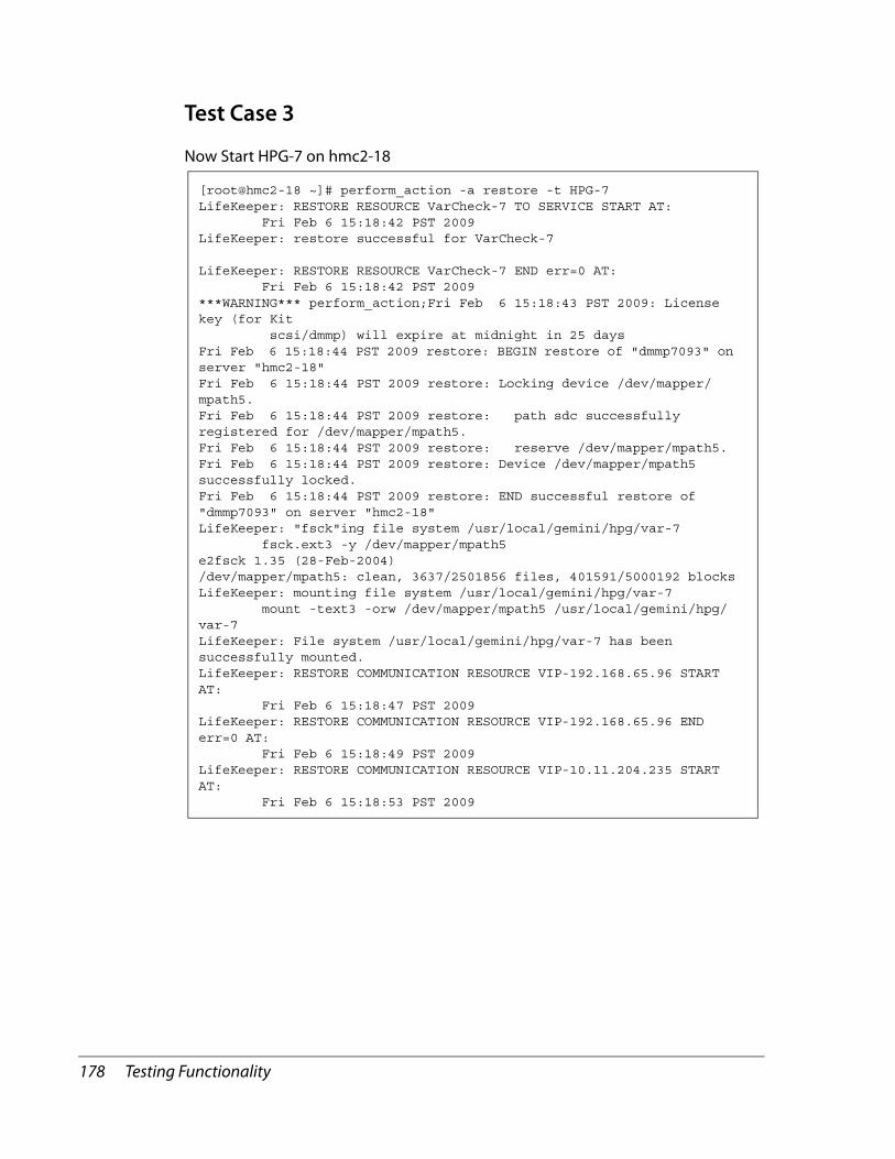
Test Case 3
Now Start HPG-7 on hmc2-18
[root@hmc2-18 ~]# perform_action -a restore -t HPG-7LifeKeeper: RESTORE RESOURCE VarCheck-7 TO SERVICE START AT: Fri Feb 6 15:18:42 PST 2009LifeKeeper: restore successful for VarCheck-7
LifeKeeper: RESTORE RESOURCE VarCheck-7 END err=0 AT: Fri Feb 6 15:18:42 PST 2009***WARNING*** perform_action;Fri Feb 6 15:18:43 PST 2009: License key (for Kit scsi/dmmp) will expire at midnight in 25 daysFri Feb 6 15:18:44 PST 2009 restore: BEGIN restore of "dmmp7093" on server "hmc2-18"Fri Feb 6 15:18:44 PST 2009 restore: Locking device /dev/mapper/mpath5.Fri Feb 6 15:18:44 PST 2009 restore: path sdc successfully registered for /dev/mapper/mpath5.Fri Feb 6 15:18:44 PST 2009 restore: reserve /dev/mapper/mpath5.Fri Feb 6 15:18:44 PST 2009 restore: Device /dev/mapper/mpath5 successfully locked.Fri Feb 6 15:18:44 PST 2009 restore: END successful restore of "dmmp7093" on server "hmc2-18"LifeKeeper: "fsck"ing file system /usr/local/gemini/hpg/var-7 fsck.ext3 -y /dev/mapper/mpath5e2fsck 1.35 (28-Feb-2004)/dev/mapper/mpath5: clean, 3637/2501856 files, 401591/5000192 blocksLifeKeeper: mounting file system /usr/local/gemini/hpg/var-7 mount -text3 -orw /dev/mapper/mpath5 /usr/local/gemini/hpg/var-7LifeKeeper: File system /usr/local/gemini/hpg/var-7 has been successfully mounted.LifeKeeper: RESTORE COMMUNICATION RESOURCE VIP-192.168.65.96 START AT: Fri Feb 6 15:18:47 PST 2009LifeKeeper: RESTORE COMMUNICATION RESOURCE VIP-192.168.65.96 END err=0 AT: Fri Feb 6 15:18:49 PST 2009LifeKeeper: RESTORE COMMUNICATION RESOURCE VIP-10.11.204.235 START AT: Fri Feb 6 15:18:53 PST 2009
178 Testing Functionality

..........Starting HPG: [ OK ]..........Starting Synchelper: [ OK ]LifeKeeper: RESTORE RESOURCE HPG-7 END err=0 AT: Fri Feb 6 15:19:14 PST 2009[root@hmc2-18 ~]# lcdstatus -qLOCAL TAG ID STATE PRIO PRIMARYhmc2-18 HPG-5 HPG-5 OSU 10 hmc2-15hmc2-18 VIP-10.11.204.233 IP-10.11.204.233 OSU 10 hmc2-15hmc2-18 VIP-192.168.65.94 IP-192.168.65.94 OSU 10 hmc2-15hmc2-18 HPG-VAR-5 /usr/local/gemini/hpg/var-5 OSU 10 hmc2-15hmc2-18 dmmp1754 3600c0ff000d54c989163394901000000 OSU 10 hmc2-15hmc2-18 VarCheck-5 VarCheck-5 OSU 10 hmc2-15hmc2-18 HPG-6 HPG-6 OSU 10 hmc2-16hmc2-18 VIP-10.11.204.234 IP-10.11.204.234 OSU 10 hmc2-16hmc2-18 VIP-192.168.65.95 IP-192.168.65.95 OSU 10 hmc2-16hmc2-18 HPG-VAR-6 /usr/local/gemini/hpg/var-6 OSU 10 hmc2-16hmc2-18 dmmp28880 3600c0ff000d54c98aa63394901000000 OSU 10 hmc2-16hmc2-18 VarCheck-6 VarCheck-6 OSU 10 hmc2-16hmc2-18 HPG-4 HPG-4 OSU 10 hmc2-14hmc2-18 VIP-10.11.204.232 IP-10.11.204.232 OSU 10 hmc2-14hmc2-18 VIP-192.168.65.93 IP-192.168.65.93 OSU 10 hmc2-14hmc2-18 HPG-VAR-4 /usr/local/gemini/hpg/var-4 OSU 10 hmc2-14hmc2-18 dmmp28318 3600c0ff000d54c98fc63394901000000 OSU 10 hmc2-14
Appendix 179
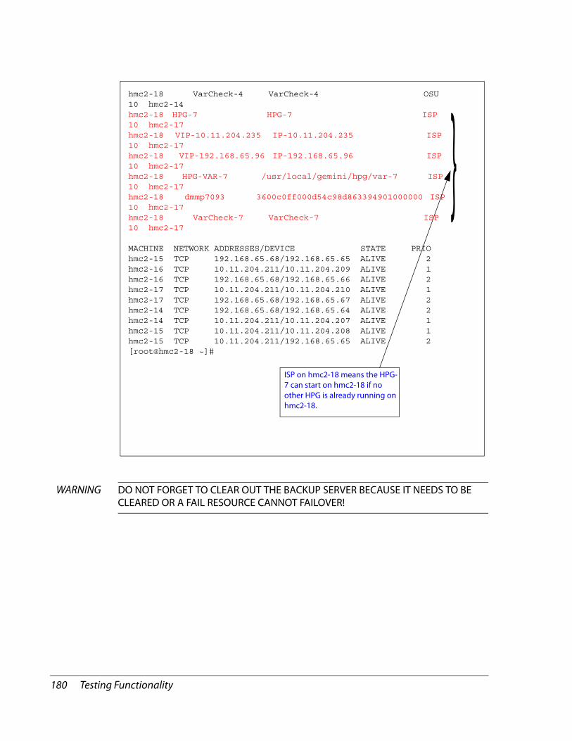
WARNING DO NOT FORGET TO CLEAR OUT THE BACKUP SERVER BECAUSE IT NEEDS TO BE CLEARED OR A FAIL RESOURCE CANNOT FAILOVER!
hmc2-18 VarCheck-4 VarCheck-4 OSU 10 hmc2-14hmc2-18 HPG-7 HPG-7 ISP 10 hmc2-17hmc2-18 VIP-10.11.204.235 IP-10.11.204.235 ISP 10 hmc2-17hmc2-18 VIP-192.168.65.96 IP-192.168.65.96 ISP 10 hmc2-17hmc2-18 HPG-VAR-7 /usr/local/gemini/hpg/var-7 ISP 10 hmc2-17hmc2-18 dmmp7093 3600c0ff000d54c98d863394901000000 ISP 10 hmc2-17hmc2-18 VarCheck-7 VarCheck-7 ISP 10 hmc2-17
MACHINE NETWORK ADDRESSES/DEVICE STATE PRIOhmc2-15 TCP 192.168.65.68/192.168.65.65 ALIVE 2hmc2-16 TCP 10.11.204.211/10.11.204.209 ALIVE 1hmc2-16 TCP 192.168.65.68/192.168.65.66 ALIVE 2hmc2-17 TCP 10.11.204.211/10.11.204.210 ALIVE 1hmc2-17 TCP 192.168.65.68/192.168.65.67 ALIVE 2hmc2-14 TCP 192.168.65.68/192.168.65.64 ALIVE 2hmc2-14 TCP 10.11.204.211/10.11.204.207 ALIVE 1hmc2-15 TCP 10.11.204.211/10.11.204.208 ALIVE 1hmc2-15 TCP 10.11.204.211/192.168.65.65 ALIVE 2[root@hmc2-18 ~]#
ISP on hmc2-18 means the HPG-7 can start on hmc2-18 if no other HPG is already running on hmc2-18.
180 Testing Functionality

6 Basic HMC Provisioning
Once the network, OS and LifeKeeper have been re-configured onsite, you are ready to provision a basic HMC to send and receive messages for P2P Service Type. For A2P configuration, see A2P Administration‚ on page 215.
The procedures for doing so, in the order that they are performed, include:
■ Logging In‚ on page 182
■ Adding a Service Provider‚ on page 186
■ Adding a Service Provider Admin‚ on page 188
■ Configuring the MM1 Interface‚ on page 189
■ Configuring the MM3 Interface‚ on page 190
■ Configuring the MM4 Interface‚ on page 191
■ Configuring the MM7 Interface‚ on page 192
■ Configuring an SMS Interface‚ on page 193
■ Adding a VASP‚ on page 194
■ Adding VAS Services‚ on page 195
■ Enabling LDAP‚ on page 196
■ Adding a Class of Service‚ on page 197
■ Provisioning Subscribers‚ on page 198
This chapter gives only information for required fields. For complete field descriptions for configuration and provisioning parameters, use the system’s online help. The MMSA Chapter in this manual and the online help explain in more detail how to use the MMSA tabs. For details about customizing the HMC modules, refer to the Gemini HMG, HPG and GMS Administrator’s Guides. For full integration into a particular service provider’s environment (for example, integrating a particular site’s billing pre- or postpaid billing software) refer to your third-party billing software’s documentation.
The first step to setting up the system is to login using web-based network management system (NMS).
Chapter 6 Basic HMC Provisioning 181
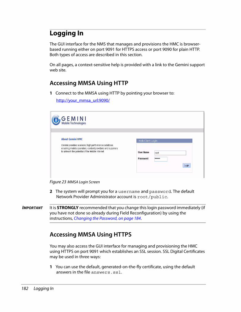
Figure 23 MMSA Login Screen
Logging InThe GUI interface for the NMS that manages and provisions the HMC is browser-based running either on port 9091 for HTTPS access or port 9090 for plain HTTP. Both types of access are described in this section.
On all pages, a context-sensitive help is provided with a link to the Gemini support web site.
Accessing MMSA Using HTTP
1 Connect to the MMSA using HTTP by pointing your browser to:
http://your_mmsa_url:9090/
2 The system will prompt you for a username and password. The default Network Provider Administrator account is root/public.
IMPORTANT It is STRONGLY recommended that you change this login password immediately (if you have not done so already during Field Reconfiguration) by using the instructions, Changing the Password‚ on page 184.
Accessing MMSA Using HTTPS
You may also access the GUI interface for managing and provisioning the HMC using HTTPS on port 9091 which establishes an SSL session. SSL Digital Certificates may be used in three ways:
1 You can use the default, generated-on-the-fly certificate, using the default answers in the file answers.ssl.
182 Logging In

2 You can customize the generated-on-the-fly certificate, using your own answers. This requires editing answers.ssl.
3 You can use a third-party signed certificate. To do this, you must get the files from a Certification Authority (CA), such as VeriSign, then copy and rename these files. This is the recommended way to use SSL Digital Certificates because it is most secure and described below.
SSL Digital Certification Using Third-party Certificates
An SSL digital certificate is an electronic file that uniquely identifies individuals and servers. Digital certificates allow the client (Web browser) to authenticate the server prior to establishing an SSL session. Typically, digital certificates are signed by an independent and trusted third party to ensure their validity. The "signer" of a digital certificate is known as a Certification Authority (CA), such as VeriSign.
Before logging in you must copy the .cer and .key files under the directory:
/usr/local/Gemini/mmsa/etc/toBeImportedSslCrt
and rename them to BEServer.cer and BEServer.key.
The file, answers.ssl, is for personal record keeping and does not have any effect on importing third-party licenses. You may change answers.ssl to provide your information but this is not mandatory.
Starting the MMSA the First Time
Once your certificate and key are set up, start the MMSA.
The MMSA generates the following default certificate on its first run:
a. Country Name:US
b. State or Province Name:California
c. Locality Name: San Mateo
d. Organization Name: Gemini Mobile Technologies Inc.
e. Organizational Unit Name: NMS Group
f. Common Name: <actual host name of the target server>
g. Email Address:[email protected]
h. A challenge password:webnms
i. An optional company name: Gemini
It installs this certificate using the default answers from the answer.ssl file.
Chapter 6 Basic HMC Provisioning 183

Upgrading the MMSA SSL Certificate
There is no extra step needed for upgrading the NMS SSL certificate if you have kept the last license file in mmsa/etc/toBeImportedSslCrt. After upgrading, starting the server will import the certificate again.
▼ Logging Into the MMSA Over HTTPS
1 Access the MMSA by pointing your browser to:
https://your_mmsa_url:9091/
A dialog will appear asking you to accept the certificate.
2 Accept this certificate permanently; this will suppress this dialog in future.
IMPORTANT If you accept this certificate permanently, installing any new certificate on the same server with same serial number will give you following kind of error: You have received an invalid certificate. Please contact the server administrator or email correspondent and give them the following information: Your certificate contains the same serial number as another certificate issued by the certificate authority. Please get a new certificate containing a unique serial number. This happens if you install the default certificate on the NMS server and perform a fresh install, importing the default certificate again. The NMS uses the same serial number, 00, for generating default certificate as it did on the first run. The certificate signature will be different because the time is different but the serial number remains the same. In this case, remove the older certificate for the site from your web browser and access the server again.
3 The system will prompt you for a username and password. The default Network Provider Administrator account is root/public.
IMPORTANT It is STRONGLY recommended that you change this login password immediately (if you have not done so already during Field Reconfiguration) by using the instructions, Changing the Password‚ on page 184.
▼ Changing the Password
Change the password for the root account by following these steps:
1 You must be logged into the MMSA as root.
184 Logging In

Figure 24 Modify Administrator Screen
2 Select the Provisioning tab.
3 Select Modify Administrator.
4 Choose the Administrator you want to modify, in this case root.
5 Select Submit. The following screen will appear:
6 Select the checkbox next to Change Password.
7 Enter the current root password in the Current Password field.
8 Enter your new password in the New Password and Re-type Password fields.
9 Select Save.
IMPORTANT When using the MMSA, do not click your browser’s Refresh or Reload button to refresh a page. This action can resend configuration data, triggering duplicate data entries or redundant commands. When appropriate, a Refresh button is provided within the UI to refresh a page. In general, to revisit a page, you can always navigate to the page using the links in the UI’s left frame.
Chapter 6 Basic HMC Provisioning 185

Figure 25 Add Service Provider Screen
Adding a Service ProviderBefore you can configure any of the HMC interfaces you must first create and define a Service Provider.
1 Select the Provisioning tab.
2 Select Service Provider Administration.
3 Select Add Service Provider. The following screen will appear:
4 Enter the Service Provider you want to add. Make this a unique short name such as CellOne. This name serves as the identifier of the Service Provider in the Service Provider List and in all settings pages pertaining to the Service Provider.
5 Enter the full name or Description for the Service Provider. This description supplements the Service Provider ID and should help you fully identify the Service Provider. The Service Provider List includes this information.
6 Enter the Mail Local Domain Name.
7 Enter P2P (person-to-person) Service Type.
8 Enter the License Code. Get a license key from Gemini Technical Support.
9 Select Save.
186 Adding a Service Provider

IMPORTANT It will take a few minutes for the service provider to be added to the HMC.
Chapter 6 Basic HMC Provisioning 187
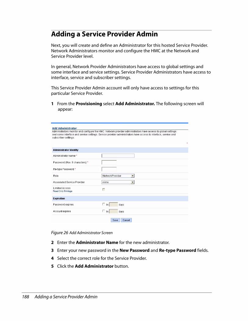
Figure 26 Add Administrator Screen
Adding a Service Provider AdminNext, you will create and define an Administrator for this hosted Service Provider. Network Administrators monitor and configure the HMC at the Network and Service Provider level.
In general, Network Provider Administrators have access to global settings and some interface and service settings. Service Provider Administrators have access to interface, service and subscriber settings.
This Service Provider Admin account will only have access to settings for this particular Service Provider.
1 From the Provisioning select Add Administrator. The following screen will appear:
2 Enter the Administrator Name for the new administrator.
3 Enter your new password in the New Password and Re-type Password fields.
4 Select the correct role for the Service Provider.
5 Click the Add Administrator button.
188 Adding a Service Provider Admin
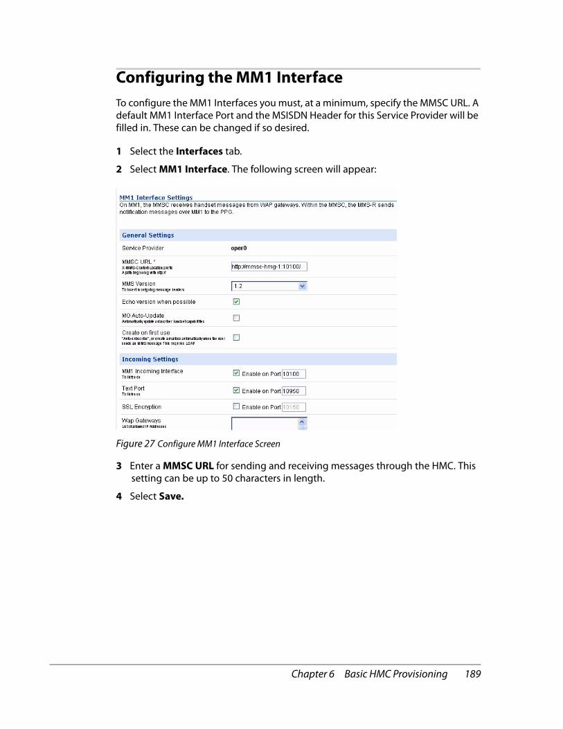
Figure 27 Configure MM1 Interface Screen
Configuring the MM1 InterfaceTo configure the MM1 Interfaces you must, at a minimum, specify the MMSC URL. A default MM1 Interface Port and the MSISDN Header for this Service Provider will be filled in. These can be changed if so desired.
1 Select the Interfaces tab.
2 Select MM1 Interface. The following screen will appear:
3 Enter a MMSC URL for sending and receiving messages through the HMC. This setting can be up to 50 characters in length.
4 Select Save.
Chapter 6 Basic HMC Provisioning 189
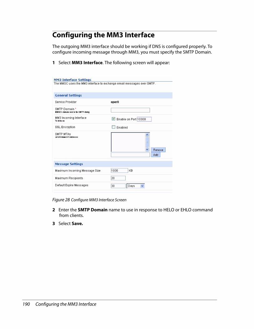
Figure 28 Configure MM3 Interface Screen
Configuring the MM3 InterfaceThe outgoing MM3 interface should be working if DNS is configured properly. To configure incoming message through MM3, you must specify the SMTP Domain.
1 Select MM3 Interface. The following screen will appear:
2 Enter the SMTP Domain name to use in response to HELO or EHLO command from clients.
3 Select Save.
190 Configuring the MM3 Interface

Figure 29 Configuring the MM4 Interface Screen
Configuring the MM4 InterfaceThe outgoing MM4 interface should be working if DNS is configured properly.
1 Select MM4 Interfaces. The following screen will appear:
2 Enter the SMTP Domain name to use in response to HELO or EHLO command from clients.
3 Enter the Originator System. Enter the HMC system address. This address is used in various headers of messages that the HMC sends or forwards, and it is the email address to which external MMSCs can send messages over MM4.
4 Select Add.
Chapter 6 Basic HMC Provisioning 191

Figure 30 Configuring the MM7 Interface Screen
Configuring the MM7 InterfaceNow we will configure the MM7 Interface.
1 Select the MM7 Interfaces. The following screen will appear.
2 Enter MMSR, a MMS-R Server ID to be used in MM7 messages.
3 Select Save.
192 Configuring the MM7 Interface
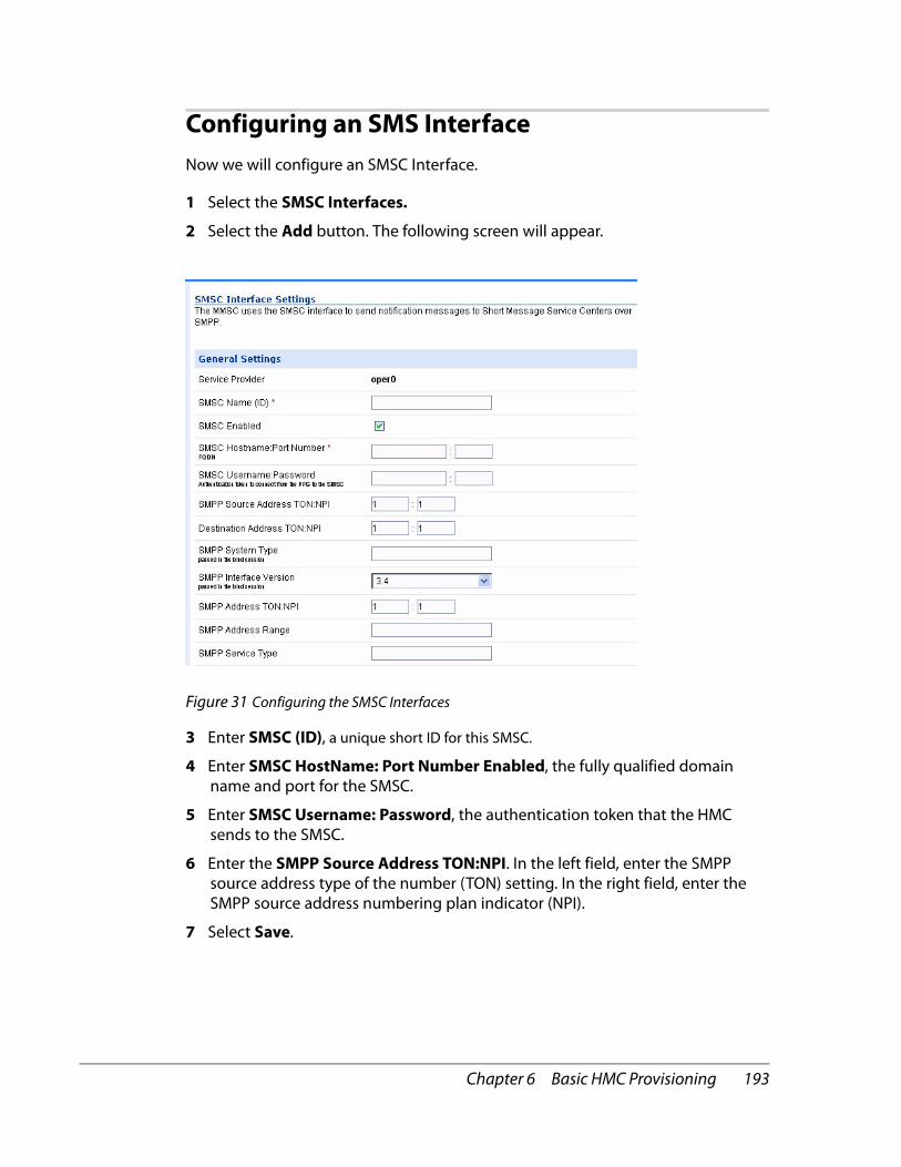
Figure 31 Configuring the SMSC Interfaces
Configuring an SMS InterfaceNow we will configure an SMSC Interface.
1 Select the SMSC Interfaces.
2 Select the Add button. The following screen will appear.
3 Enter SMSC (ID), a unique short ID for this SMSC.
4 Enter SMSC HostName: Port Number Enabled, the fully qualified domain name and port for the SMSC.
5 Enter SMSC Username: Password, the authentication token that the HMC sends to the SMSC.
6 Enter the SMPP Source Address TON:NPI. In the left field, enter the SMPP source address type of the number (TON) setting. In the right field, enter the SMPP source address numbering plan indicator (NPI).
7 Select Save.
Chapter 6 Basic HMC Provisioning 193
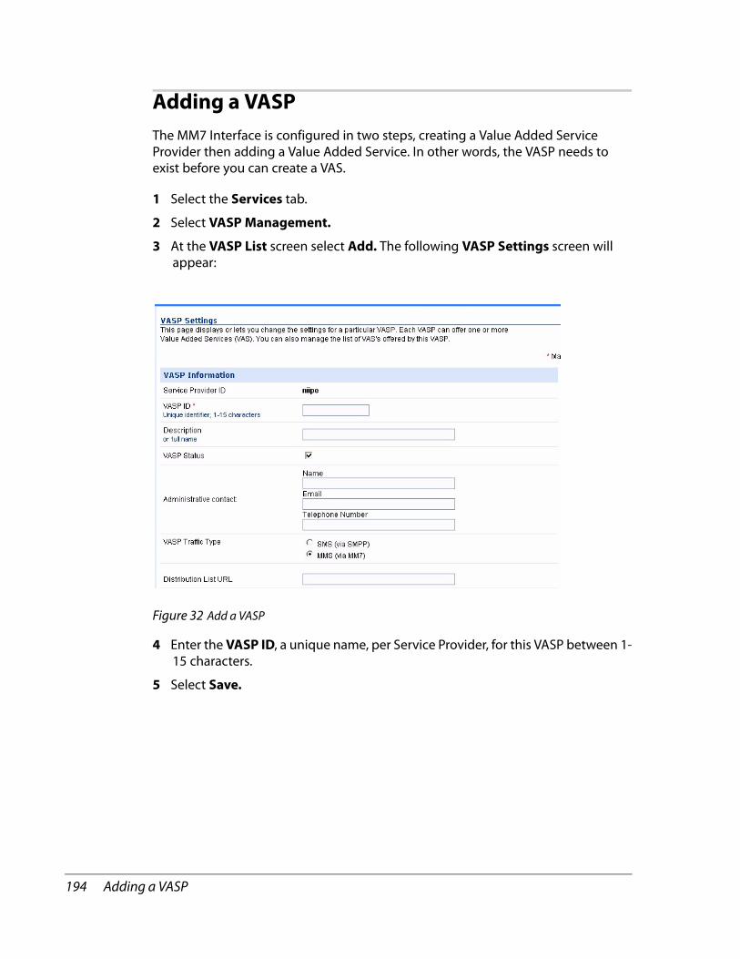
Figure 32 Add a VASP
Adding a VASP The MM7 Interface is configured in two steps, creating a Value Added Service Provider then adding a Value Added Service. In other words, the VASP needs to exist before you can create a VAS.
1 Select the Services tab.
2 Select VASP Management.
3 At the VASP List screen select Add. The following VASP Settings screen will appear:
4 Enter the VASP ID, a unique name, per Service Provider, for this VASP between 1-15 characters.
5 Select Save.
194 Adding a VASP
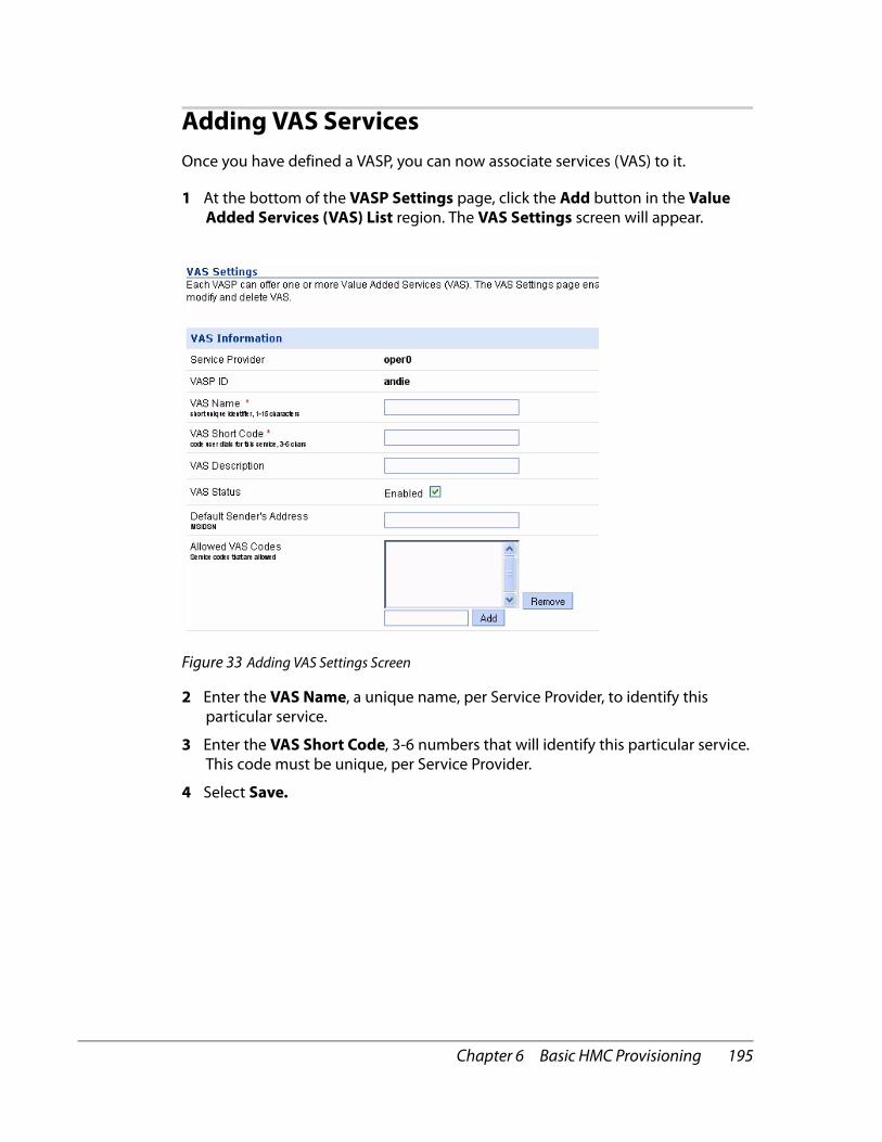
Figure 33 Adding VAS Settings Screen
Adding VAS ServicesOnce you have defined a VASP, you can now associate services (VAS) to it.
1 At the bottom of the VASP Settings page, click the Add button in the Value Added Services (VAS) List region. The VAS Settings screen will appear.
2 Enter the VAS Name, a unique name, per Service Provider, to identify this particular service.
3 Enter the VAS Short Code, 3-6 numbers that will identify this particular service. This code must be unique, per Service Provider.
4 Select Save.
Chapter 6 Basic HMC Provisioning 195
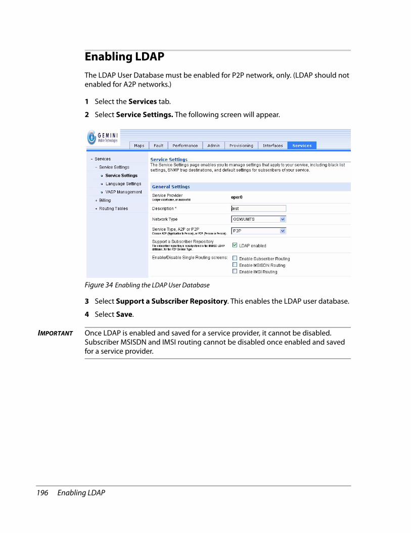
Figure 34 Enabling the LDAP User Database
Enabling LDAPThe LDAP User Database must be enabled for P2P network, only. (LDAP should not enabled for A2P networks.)
1 Select the Services tab.
2 Select Service Settings. The following screen will appear.
3 Select Support a Subscriber Repository. This enables the LDAP user database.
4 Select Save.
IMPORTANT Once LDAP is enabled and saved for a service provider, it cannot be disabled. Subscriber MSISDN and IMSI routing cannot be disabled once enabled and saved for a service provider.
196 Enabling LDAP
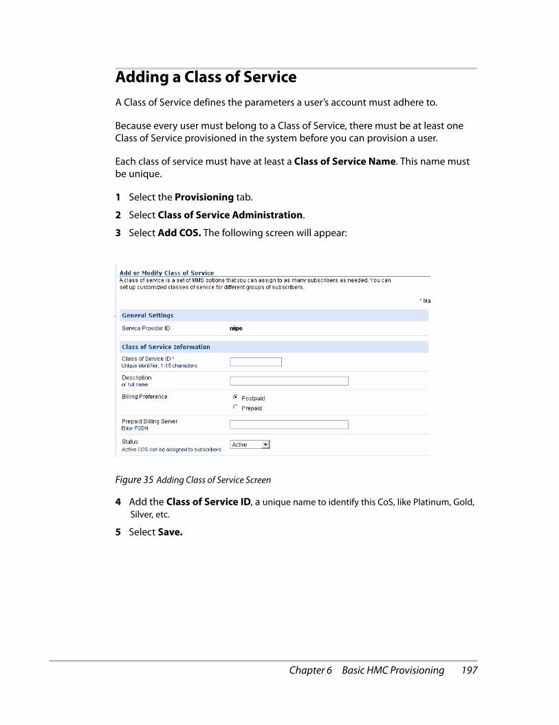
Figure 35 Adding Class of Service Screen
Adding a Class of ServiceA Class of Service defines the parameters a user’s account must adhere to.
Because every user must belong to a Class of Service, there must be at least one Class of Service provisioned in the system before you can provision a user.
Each class of service must have at least a Class of Service Name. This name must be unique.
1 Select the Provisioning tab.
2 Select Class of Service Administration.
3 Select Add COS. The following screen will appear:
4 Add the Class of Service ID, a unique name to identify this CoS, like Platinum, Gold, Silver, etc.
5 Select Save.
Chapter 6 Basic HMC Provisioning 197

Figure 36 Adding a Single Subscriber Screen
Provisioning SubscribersThere are two ways to provision subscribers, by adding a single subscriber using the MMSA or bulk provisioning using an LDIF file.
Adding a Single Subscriber
The following procedure allows you to add a subscriber profile to the GDS (LDAP) database and create a mailbox for the subscriber in the Gemini Message Store.
1 Select Subscriber Administration > Add Subscriber. The following screen will appear:
2 Enter the subscriber’s MSISDN number in ITU E.164 format. This number uniquely identifies the subscriber.
3 Enter the First Name of the subscriber.
4 Enter the Last Name of the subscriber.
5 Click Save. If the MSISDN number you enter is already in use, you will see an error message when you select Save.
198 Provisioning Subscribers
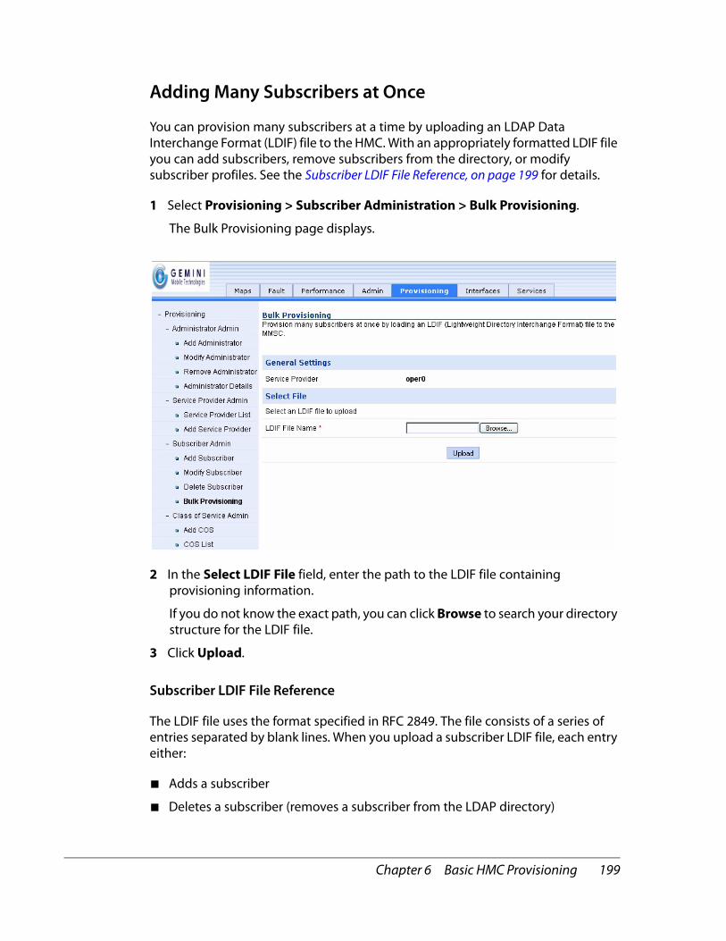
Adding Many Subscribers at Once
You can provision many subscribers at a time by uploading an LDAP Data Interchange Format (LDIF) file to the HMC. With an appropriately formatted LDIF file you can add subscribers, remove subscribers from the directory, or modify subscriber profiles. See the Subscriber LDIF File Reference‚ on page 199 for details.
1 Select Provisioning > Subscriber Administration > Bulk Provisioning.
The Bulk Provisioning page displays.
2 In the Select LDIF File field, enter the path to the LDIF file containing provisioning information.
If you do not know the exact path, you can click Browse to search your directory structure for the LDIF file.
3 Click Upload.
Subscriber LDIF File Reference
The LDIF file uses the format specified in RFC 2849. The file consists of a series of entries separated by blank lines. When you upload a subscriber LDIF file, each entry either:
■ Adds a subscriber
■ Deletes a subscriber (removes a subscriber from the LDAP directory)
Chapter 6 Basic HMC Provisioning 199

■ Modifies a subscriber profile in the LDAP directory; the profile contains all of the subscriber’s capabilities and user privileges
The following sections provide back ground information on LDIF file structure:
■ Structure of an Entry‚ on page 200
■ Establishing the Subscriber Distinguished Name (dn)‚ on page 200
■ objectClass Hierarchy‚ on page 201
■ gmtMMSCUser Attributes‚ on page 202
■ Example Entries‚ on page 206
Structure of an Entry
The high-level structure of an entry representing a subscriber is as follows:
dn: uid=<subscriber’s MSISDN>,<additional dn attributes> objectClass: gmtMMSCUser changetype: <type of change you want to make> <optional additional objectClass specifications> <attributes> ...
The first line of an entry is the distinguished name (dn), which identifies a unique entry for the directory. Every subscriber belongs to the objectClass: gmtMMSCUser. The changetype lines specify what modification to make to the directory. The attributes define the subscriber profile.
Establishing the Subscriber Distinguished Name (dn)
The subscriber’s distinguished name must be a unique key for looking up the subscriber profile. During HMC installation, the following entries set up a default subtree for HMC data. You can modify this subtree with your own organizational names.
dn: dc=geminimobile,dc=com objectclass: dcObject objectclass: organization dc: geminimobile o: Gemini Mobile Inc
dn: ou=mmsc,dc=geminimobile,dc=com objectclass: organizationalUnit ou: mmsc
200 Provisioning Subscribers

dn: ou=Subscribers,ou=mmsc,dc=geminimobile,dc=com objectclass: organizationalUnit ou: Subscribers
With this subtree defined, a typical distinguished name for a subscriber could be:
dn: uid=<MSISDN>,ou=Subscribers,ou=mmsc,dc=geminimobile,dc=com
The MSISDN serves as a unique subscriber identifier within the geminimobile subtree.
objectClass Hierarchy
All HMC subscribers belong to an objectClass named gmtMMSCUser. The gmtMMSCUser object can have any attributes inherited from its superclasses. The class hierarchy to which gmtMMSCUser belongs is:
objectClass: top Superclass of all LDAP object classes (RFC 2256). Type
Abstract Superclass
None. Requires
objectClass.
objectClass: person Generic object that has a cn attribute (RFC 2256). Required for organizationalPerson. Type
Structural Superclass
top Requires
cn, sn Allows
userPassword
objectClass: organizationalPerson A person that is a member of an organization (RFC 2256). Required for inetOrgPerson. Type
Structural Superclass
person Allows
Many attributes, none of which are relevant here.
objectClass: inetOrgPerson Organizational person with Internet connectivity. (RFC 2798). Type
Structural Superclass
organizationalPerson
Chapter 6 Basic HMC Provisioning 201

Allows uid, preferredLanguage.
objectClass: inetLocalMailRecipient Entity that can receive email. (LASER draft specification: LDAP Schema for Intranet Mail Routing) Type
Auxiliary Superclass
top Allows
mailLocalAddress, mailHost.
objectClass: gmtMMSCUser Object that includes all the MMSC-specific attributes. Type
Structural Superclass
inetOrgPerson, inetLocalMailRecipient Requires
uid, mailLocalAddress, mailHost, userBillingModel, cosId, operator, mailMsgFiltering, msisdnMsgFiltering
Allows All other attributes
gmtMMSCUser Attributes
The following table lists the HMC attributetypes that can apply for each gmtMMSCUser. Some attributetypes are mandatory, meaning that when you add a subscriber, you must define these attributetypes. Other attributetypes are optional.
gmtMMSCUser attributetypes
attributetype Description
uid Mandatory. Subscriber’s MSISDN.
mailLocalAddress Mandatory. Subscriber’s email address (for receiving MMS messages).
mailHost Mandatory. Fully qualified domain name of the GMS where the subscriber’s mailbox is located.
userBillingModel Mandatory. This is how the subscriber pays for multi-media messaging service. Possible values: ◆ prepaid◆ postpaid
cosId Mandatory. The identifier (ID) of the class of service to which this subscriber belongs. The ID must be the exact ID of a class of service in the Class of Service List page.
202 Provisioning Subscribers
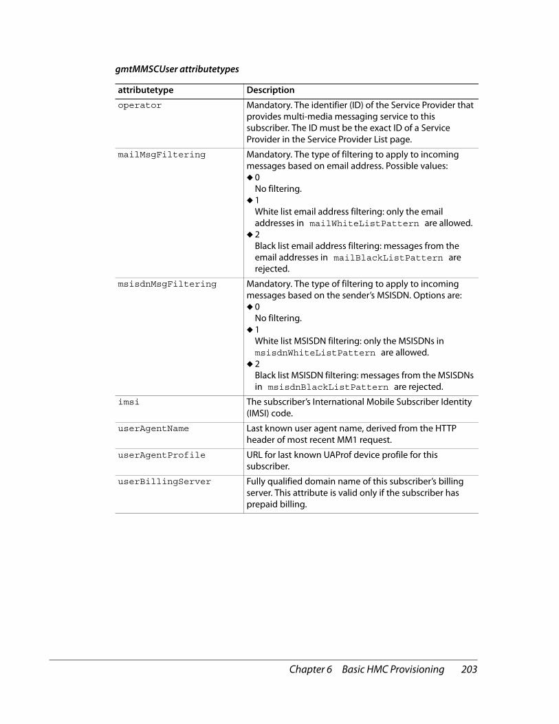
operator Mandatory. The identifier (ID) of the Service Provider that provides multi-media messaging service to this subscriber. The ID must be the exact ID of a Service Provider in the Service Provider List page.
mailMsgFiltering Mandatory. The type of filtering to apply to incoming messages based on email address. Possible values: ◆ 0
No filtering.◆ 1
White list email address filtering: only the email addresses in mailWhiteListPattern are allowed.
◆ 2 Black list email address filtering: messages from the email addresses in mailBlackListPattern are rejected.
msisdnMsgFiltering Mandatory. The type of filtering to apply to incoming messages based on the sender’s MSISDN. Options are:◆ 0
No filtering.◆ 1
White list MSISDN filtering: only the MSISDNs in msisdnWhiteListPattern are allowed.
◆ 2 Black list MSISDN filtering: messages from the MSISDNs in msisdnBlackListPattern are rejected.
imsi The subscriber’s International Mobile Subscriber Identity (IMSI) code.
userAgentName Last known user agent name, derived from the HTTP header of most recent MM1 request.
userAgentProfile URL for last known UAProf device profile for this subscriber.
userBillingServer Fully qualified domain name of this subscriber’s billing server. This attribute is valid only if the subscriber has prepaid billing.
gmtMMSCUser attributetypes
attributetype Description
Chapter 6 Basic HMC Provisioning 203

capa Subscriber capabilities. You can enter several capa: values for a subscriber. Possible values: ◆ active
Allows all capabilities. Remove this flag if, for example, the account is suspended but you want to retain settings.
◆ send Can send messages.
◆ receive Can receive messages.
◆ divert Can send messages to a forwarding address rather than a subscriber mailbox.
◆ store Subscriber can have a mailbox on the GMS.
◆ intercept Enable lawful interception logging.
◆ copy Can copy messages received to another specified address (specified in mailCopyAddress).
◆ rejectAnonMsgs Reject anonymous messages.
◆ rejectEmailMsgs Reject email messages.
◆ msgBlackout Can set a message blackout period, during which no notifications are sent to the handset.
◆ mms Subscriber has an MMS-enabled handset.
◆ sms Subscriber has an SMS-enabled handset.
◆ nosms Subscriber’s handset supports neither MMS nor SMS.
◆ mmbox Subscriber can have a mailbox for messages.
◆ addressHiding Subscriber’s address can be hidden.
mailFromAddress Address used in From header in MMS messages sent from this subscriber over the Internet. Must be an RFC2822 format address.
mailReplyToAddress Address used in ReplyTo header in MMS messages sent from this subscriber over the Internet. Must be an RFC2822 format address.
gmtMMSCUser attributetypes
attributetype Description
204 Provisioning Subscribers
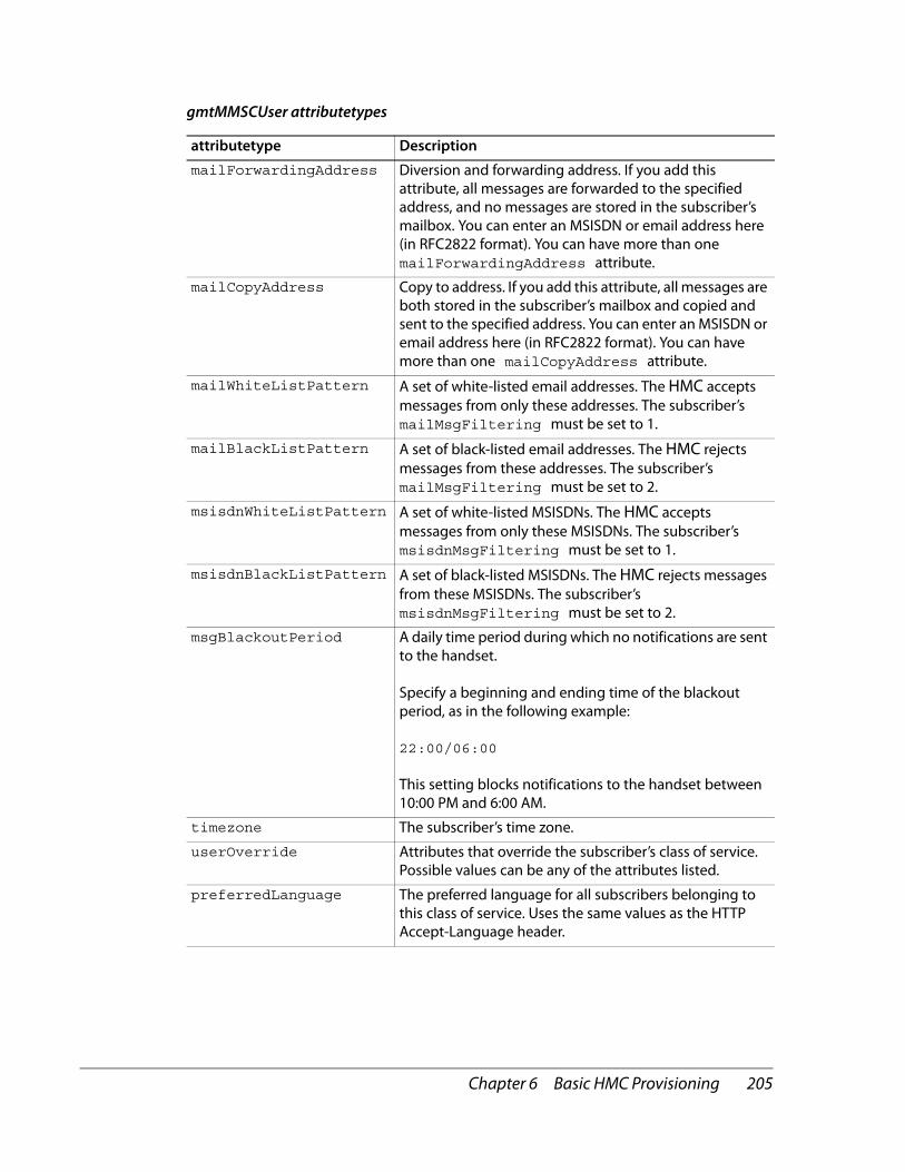
mailForwardingAddress Diversion and forwarding address. If you add this attribute, all messages are forwarded to the specified address, and no messages are stored in the subscriber’s mailbox. You can enter an MSISDN or email address here (in RFC2822 format). You can have more than one mailForwardingAddress attribute.
mailCopyAddress Copy to address. If you add this attribute, all messages are both stored in the subscriber’s mailbox and copied and sent to the specified address. You can enter an MSISDN or email address here (in RFC2822 format). You can have more than one mailCopyAddress attribute.
mailWhiteListPattern A set of white-listed email addresses. The HMC accepts messages from only these addresses. The subscriber’s mailMsgFiltering must be set to 1.
mailBlackListPattern A set of black-listed email addresses. The HMC rejects messages from these addresses. The subscriber’s mailMsgFiltering must be set to 2.
msisdnWhiteListPattern A set of white-listed MSISDNs. The HMC accepts messages from only these MSISDNs. The subscriber’s msisdnMsgFiltering must be set to 1.
msisdnBlackListPattern A set of black-listed MSISDNs. The HMC rejects messages from these MSISDNs. The subscriber’s msisdnMsgFiltering must be set to 2.
msgBlackoutPeriod A daily time period during which no notifications are sent to the handset.
Specify a beginning and ending time of the blackout period, as in the following example:
22:00/06:00
This setting blocks notifications to the handset between 10:00 PM and 6:00 AM.
timezone The subscriber’s time zone.
userOverride Attributes that override the subscriber’s class of service. Possible values can be any of the attributes listed.
preferredLanguage The preferred language for all subscribers belonging to this class of service. Uses the same values as the HTTP Accept-Language header.
gmtMMSCUser attributetypes
attributetype Description
Chapter 6 Basic HMC Provisioning 205

Example Entries
The following entry adds a subscriber named Subscriber1. The default action, if no changetype: field is present, is to add a subscriber.
Example dn: uid=14085551212,ou=mmsc,ou=Subscriber,dc=geminimobile,dc=com objectClass: person objectClass: inetLocalMailRecipient objectClass: gmtMMSCUser cn: A Subscriber1 sn: Subscriber1 uid: 14085551212 imsi: 04414085551212 userBillingModel: postpaid mailLocalAddress: [email protected] mailFromAddress: [email protected] mailHost: mmsc-gmt-int capa:active capa:send capa:receive capa:sms capa:mms cosId: Gold operator: op1 mailMsgFiltering: 0 msisdnMsgFiltering: 0
The following entry deletes a subscriber:
Example dn: uid=14155551212,ou=mmsc,ou=Subscriber,dc=geminimobile,dc=com objectClass: gmtMMSCUser changetype: delete
The following entry modifies a subscriber’s message blackout period (the period during which messages are not sent to the subscriber’s mailbox):
Example dn: uid=16505551212,ou=mmsc,ou=Subscriber,dc=geminimobile,dc=com objectClass: gmtMMSCUser changetype: modify replace: msgBlackoutPeriod msgBlackoutPeriod: 05:15/23:00
206 Provisioning Subscribers

7 The A2P HMC
This chapter is a description of the A2P Mode (Application-to-Person Mode) of HMC operation. This chapter covers these topics:
■ Features‚ on page 208
■ Internal HMC Functions‚ on page 211
■ Message Processing‚ on page 213
■ Administration‚ on page 215
Chapter 7 The A2P HMC 207
FeaturesThe Gemini HMC comes with all the modules and functionality that allow it to act as a flexible, high-performance A2P MMSC. A2P Mode features include the HyperScale® computing, queuing and scheduling nodes. These nodes implement the management of distribution lists, the enforcement of content providers Service Level Agreements, the generation of WAP push notification messages for transport over SMS, all necessary content transformations and handling of OMA-DRM rights objects for separate download of content.
As with the P2P Mode, the HMC in A2P Mode comes with the web-based Network Management System, the NMS.
A2P Considerations
A MMSC specialized for application-to-person services faces a number of challenges compared with a person-to-person MMSC. The most important ones are:
■ A2P traffic is by its nature less random, and more subject to bursts. Many content applications run at fixed times or provide real-time information. As an example, an application providing clips of sports events to subscribers will generate a burst in traffic after a notable play. This requires infrastructure able to sustain a high traffic level, but a licensing scheme flexible enough not to be overly expensive during periods of low traffic.
■ Messages coming in from content providers will be addressed to distribution lists (the subscribers to a specific application). This requires efficient management of these distribution lists and processing ability to optimize disk space and transcoding activity for such messages.
■ Content providers need to be managed closely. Consumers need to be protected from unauthorized content, and the service provider needs a way to enforce existing service level agreements with the tools to define new ones at a fine granularity.
The Gemini HMC running in A2P service mode is designed to solve these challenges and provides a very effective solution to the problems posed by application-to-person traffic.
Traffic Bursts
The Gemini HyperScale® infrastructure defines a limited number of threads dedicated to I/O tasks instead of processing one message per thread. This, coupled with an efficient and secure queuing implementation for optimizing messaging applications, enables the HMC in A2P mode to withstand traffic bursts.
208 Features
Messages are kept on queues on permanent storage and retrieved when necessary for processing. The result is that every message receives a minimal amount of processing for each operation while being securely stored the whole time.
Queuing allows for more effective scheduling of message-related tasks because system resources are not overloaded with too many simultaneous processing tasks, and thus can execute a process in a more orderly way. This also brings the very desirable feature of smoothing out spikes in message reception over time at the system output while keeping the HMC running at maximum speed. No messages are lost while the overall latency time for delivery increases slightly, at the cost of only storage space.
Messages are queued with an associated state. This allows the system to seamlessly recover from failures, as any node can process any message: states are independent from the processing node. The system has been tested in the field with very high message volumes: up to 1000 messages per second in Gemini's largest installation.
In addition, Gemini is very flexible in its licensing schemes. In general, systems are licensed based on their messages-per-second capacity; however, if the instantaneous MPS capacity is reached, the system will not reject incoming messages. Also, for systems experiencing extreme bursts in traffic, the MPS can be calculated over a longer period, thus averaging the effective MPS load for license purposes. For further details about the A2P HMC licensing scheme please contact Gemini directly.
Distribution Lists
In A2P mode ad-hoc distribution lists are enabled. The HMC creates a distribution list “on the fly”, stores the message in the VASP's mailbox and sends notifications through the HPG.
When the HMC is operating in this mode, no GDS is used to determine routing, no user mailboxes are used, and no routing rules are in effect. When operating in this mode, there is essentially no difference between a distribution list and a list of individual recipients, other than the addressing of the message.
When the HMC receives A2P messages, they are always stored to a single VASP mailbox. The HMC keeps track of the original list of recipients for a message and validates that a user retrieving the message is on this list.
The HMG has a distribution list caching feature that stores pre-transcoded versions of the message. These transcoded messages are local to an instance of HMG (stored in HMG's queue) and do not persist across HMG instances.
Chapter 7 The A2P HMC 209

Content Provider Management
The A2P HMC provides a wealth of parameters to characterize the content providers who are allowed to connect with the system. Content providers are provisioned using the NMS web-based interface with security features including username and password for authentication, an access control list for excluding unauthorized servers and available TLS (SSL) encryption for HTTPS access.
The provisioning interface also manages the definition of detailed Service Level Agreement parameters for the content provider as a whole and for the associated VASP applications. The A2P HMC interface process enforces these parameters.
More details about the content provider management features of the A2P HMC follow in this chapter with screenshots of the provisioning interface.
210 Features

Internal HMC FunctionsThe Gemini A2P HMC can be seen as a black box with the following functions:
■ MM7 Interface to content providers
■ Distribution list management
■ Transcoding of whole messages or single attachments
■ Generation and delivery of notifications to message recipients
■ Management of message queues, with operations to perform on queued messages depending on the parameters within the message
■ Content delivery
In addition, the A2P HMC offers the following auxiliary functions:
◆ Billing and logging
◆ Management and configuration interface
Content Provider Interfaces
Value Added Service Providers (VASPs) principally interact with the Gemini A2P HMC using the standard MMS MM7 interface. MM7 provides a way for VASPs to pass multimedia content to the HMC. The underlying protocol is SOAP over HTTP. Messages can be addressed to individual subscribers and to distribution lists.
The MM7 interface is standardized by 3GPP for MMS but the Gemini A2P HMC can use it to handle any kind of content, including text and premium SMS. The flexible routing of the Gemini A2P HMC then ensures that the content will be delivered to the recipient through the intended channel.
MM7 is a fast and powerful interface for content delivery. MM7 messages can be of any size, exceeding the traditional SMPP limits. Submission parameters allow distinguishing between different applications, specifying billing methods, the need for receipt requests and other features. MM7 supports the OMA DRM rights management specifications, allowing secure management of copyrighted content.
SOAP Specifications Compliance
MM7 is implemented using the SOAP protocol as defined by W3C Note 08 May 2000 "Simple Object Access Protocol (SOAP) 1.1" (http://www.w3.org/TR/SOAP). SOAP is a lightweight protocol for exchange of information in a decentralized, distributed environment.
Chapter 7 The A2P HMC 211

It is an XML based protocol that consists of three parts: an envelope that defines a framework for describing what is in a message and how to process it, a set of encoding rules for expressing instances of application-defined data types and a convention for representing remote procedure calls and responses.
SOAP can potentially be used in combination with a variety of other protocols, however, the only bindings specified for the MM7 interface are in combination with HTTP and HTTP Extensions.
Encryption
The Gemini A2P HMC supports encryption over the MM7 interface via TLS (SSL v3) and manages its certificate through the MMSA.
Commands Supported
Authentication
In A2P Mode, the HMC does not perform LDAP authorization of each MT as they request to retrieve messages through the MM1 server. The omission of the LDAP check for each retrieving MT enhances the throughput performance.
Authorization
All incoming MM7 messages are distribution list messages, even if addressed only to individual recipients. MTs are presumed to be authorized to retrieve VAS messages addressed to the distribution lists to which they belong.
All messages originating from a particular VASP will be stored to that VASP’s mailbox on the GMS and not to individual MT mailboxes. For messages with more than a configurable minimum number of recipients, caching is available.
MM7_submit.REQ MM7_submit.RES
VASP submits an MM to one or more users.
MM7_deliver.REQMM7_deliver.RES
MMSC delivers an MM from user to VASP using VASP short code.
MM7_delivery_report.REQ MM7_delivery_report.RES
MMSC reports delivery status of MM to VASP
MM7_read_reply_report.REQ MM7_read_reply_report.RES
MMSC delivers a read-reply report associated with an MM to a VASP
MM7_RS_error.RES MM7_VASP_error.RES
General error message
212 Internal HMC Functions
Message ProcessingThe Gemini A2P HMC processes messages from the MM7 addressed to distribution lists in a highly efficient manner.
Each message processing node of the A2P HMC has knowledge of the defined distribution lists. The information consists of a series of [name, URL] pairs linking the list name to which messages are addressed. Content providers can thus manage user subscription to their services in a completely autonomous way, and the A2P HMC picks up the updated content of a list in real time for every distribution.
When the message needs to be delivered - either as soon as it arrives or some time after, depending on the requested time of delivery - the A2P HMC starts sending out notifications to the subscribers on the distribution list. The HMC assumes that all subscribers are MMS-enabled. The HMC assumes all MTs are on the same network as the content provider.
Notifications
When the A2P HMC has a message ready for a subscriber, it sends a notification to the subscriber's handset. This, in turn, starts the sequence of message retrieval events according to the 3GPP MMS specifications. Notifications go through the HPG.
If a particular handset is not reachable, the A2P HMC supports a configurable schedule for notification retry.
Delivery and Read Reports
When a content provider sends a message to a subscriber, the sender (VASP) may request that the addressee provide them a delivery report upon retrieval of the message through a suitable parameter in the submission PDU.
When messages with a delivery report request header are retrieved by a recipient, the A2P HMC sends a delivery report back to the content provider. This takes the form of an individual message for each recipient, including as a parameter the MSISDN of the subscriber who has received the message. The A2P HMC does not combine recipients into a single delivery report (no delivery report standard exists for this). The A2P HMC will also send back a delivery report to the content provider if the recipient rejects the message.
The A2P HMC also supports read reports, as introduced by MMS 1.1 on the MM7 interface. These are generated when the recipient opens the retrieved message, if the content provider requested the report.
Chapter 7 The A2P HMC 213
Outgoing MM1 Interface
The Gemini A2P HMC uses the MMS MM1 interface to deliver messages to subscribers as standardized by the OMA and 3GPP [TS 23.140] The A2P HMC follows a completely standard MM1 interface and supports all MM1 PDUs.
Charging
The Gemini A2P HMC implements postpaid billing, based on CDRs and complies with the standard 3GPP charging architecture. The postpaid interface can apply to both the transactions with content providers and those with subscribers.
Call Data Records (CDR) are collected and stored on a central server that is typically co-located with the NMS server. The HMC collects CDR log files in its management node, maintains them, and allows controlled access by the service provider using FTP/SFTP.
The triggers that create CDRs are specified by 3GPP TS-32.235 V.5.4.0 for MMS service, plus some Gemini-defined triggers that cover interfaces not specified in this document. Each trigger is independently configurable from the HMC administration interface. The service provider may elect to turn a trigger on and off. This is accomplished through the NMS.
214 Message Processing
AdministrationThe system administrator for the network creates hosted service-providers. The A2P HMC operations are structured so that multiple service providers can be hosted on a single installation. Each service provider has complete control over his own subscribers and services.
The A2P HMC supports multiple MM1and MM7 interfaces, each serving a different service provider. A content provider is associated with a hosted service provider using the FQDN of its server and the port in which the message is received.
The A2P HMC supports service provider provisioning of content providers through the web-based NMS interface. Content providers can be closely managed through detailed service level agreement (SLA) parameters and other content provider and application-specific data. Multiple applications can be defined per content provider, each with its SLA and charging parameters.
Content Provider Provisioning
The parameters that define a content provider for the MM7 interface are the following:
■ Content provider short-id. An identifier for the content provider which is unique within the hosted service provider.
■ The content provider description. This is informational only.
■ The status of the content provider. Enabled or disabled.
■ The URL of the distribution list root. The remote-server directory where the distribution lists are available from the content provider. The actual distribution lists are fetched by naming convention, having the same name as the content distribution application.
■ The content provider server URL. For messages from the A2P HMC to the content provider applications.
■ User name and password that the A2P HMC uses to communicate with the content provider.
■ Indication whether the content provider needs to be authenticated to access the A2P HMC services, and password in this case.
■ Access control list for the content provider servers.
The following parameters allow the service provider to enforce preexisting agreements it may have with content providers:
Chapter 7 The A2P HMC 215
■ Allow override of sender address. This is an indication if the A2P HMC will support the insertion of the default sender address of different applications.
■ Indication if charging sender, recipient or both is allowed.
■ Max messages per day. An optional numeric value that limits the content provider to a predetermined number of messages per day (24 hours). Additional messages are rejected.
■ Max messages per month. An optional numeric value that limits the content provider to a predetermined number of messages per calendar month. Additional messages are rejected.
■ Max recipients per message. An optional numeric value that limits the number of recipient addresses on a single message. If a message is received with a larger number of addresses than specified, it is rejected.
■ Maximum expiration period. This is the maximum expiration period allowed to be defined by the content provider. A longer expiration period is brought into compliance and the message is delivered.
■ Maximum delivery delay period. The maximum number of days from the present day within which the Earliest Delivery Time must fall. Messages set to be delivered at a later date are rejected.
■ Maximum message size. An optional parameter limiting the message size sent from a content provider
■ Outgoing mailbox quota. The maximum size of the combined content the content provider can have in the distribution list and temporary mailboxes.
Use the VASP content provider page from the Services Tab on the NMS GUI to configure these settings.
216 Administration
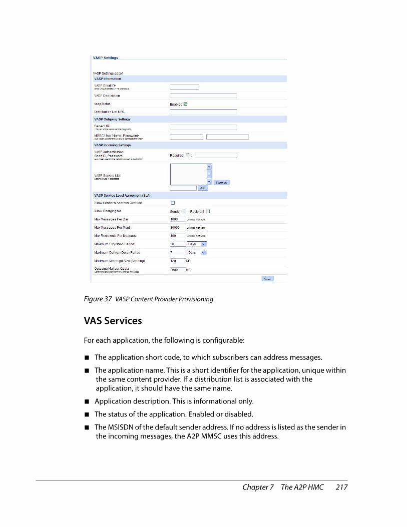
Figure 37 VASP Content Provider Provisioning
VAS Services
For each application, the following is configurable:
■ The application short code, to which subscribers can address messages.
■ The application name. This is a short identifier for the application, unique within the same content provider. If a distribution list is associated with the application, it should have the same name.
■ Application description. This is informational only.
■ The status of the application. Enabled or disabled.
■ The MSISDN of the default sender address. If no address is listed as the sender in the incoming messages, the A2P MMSC uses this address.
Chapter 7 The A2P HMC 217
■ The list of the allowed service codes. The service code is a field in an MM7 message that can be used to further identify the application for billing purposes.
The applications can also be subject to separate SLA parameters which are managed by the Gemini A2P HMC. These parameters are a subset of the ones for content providers, and their value can obviously never exceed the overall content provider ones. Use the VAS Settings provisioning screen to configure these settings.
MM7 Interface
Through this function, an administrator is able to configure the addressing and SLA parameters of all interfaces. This includes port number to listen on, IP address of destination, timeouts, retry interval, maximum number of retries, keep-alive intervals, as well as higher layer parameters such as maximum message size, maximum number of recipients, source domain name, etc.
Use the MM7 interface configuration page from the Interfaces Tab to configure these settings.
218 Administration

8 User Portal
This chapter describes the User Portal webmail features for the 3.7 release of the HMC and includes the following topics:
■ About the User Portal‚ on page 220
■ Webmail Functionality‚ on page 221
■ MMS Services Preferences Settings‚ on page 226
About the User PortalThe Gemini HMC Release 3.7 comes with an optional User Portal that allows users to access two types of services over the Internet:
■ Web-mail-like services for multi-media messages in the users' mailboxes. Enabled users can choose to keep their messages in the HMC-provided MMbox indefinitely or for a time chosen by the operator, to access them multiple times, forward them, categorize them and delete them through the User Portal controls. The User Portal communicates with the HMC over a text-based MM1 interface that supports all the PDUs defined by 3GPP Release 6 and OMA 1.2 MMS specifications. This approach allows complete mimicking of the services available to MMS 1.2 handsets while distinguishing the User Portal interface from the binary MM1 interface used by handsets.
■ Interactive auto-provisioning of service preferences. Users can tune their service parameters to adapt them to their life-style. The parameters that the User Portal shows and allows access to are controlled by the operator via the users' class of service. The User Portal uses an HTTP-based interface to access and change user data through the mediation of the HMC NMS module.
The User Portal integrates with the hosted operator web infrastructure to allow a single sign-on for users and can be customized to mimic the operator web site look and feel. Gemini provides a document to guide third-party developers in the customization process, the User Portal Customization Guide.
The Gemini User Portal is a web-server based node that allows users to access MMS-related services over the Internet or through a WAP-enabled phone. The User Portal provides a way for users to:
■ View the content of their mailbox
■ Label messages for categorization and selective showing
■ View and play single messages
■ Compose and send messages
■ Compose and store messages as drafts
■ Forward messages to other addresses
■ Change their MMS service configuration, within the constraints of their assigned Class of Service
The User Portal is implemented as a Tomcat application and communicates with Gemini’s HMG by emulating an MMS 1.2 handset using the MM1 PDUs that are defined to manage the MMbox.
220 About the User Portal

Webmail FunctionalityThis section describes the User Portal web mail functionality: access to the MMbox, messages viewing and composition and sending of MMS messages.
MMbox Access
Access to the MMbox by users is supported using an advanced web interface based on AJAX technology. This allows for real-time interaction with the web browser and supports features as drag-and-drop of messages into virtual folders, deletion using one keystroke and special effects as collapsible window sections for detail presentation.
The Gemini User Portal follows an established convention in mail client user interfaces, in which the inbox page is presented with control links or widgets in the left side of the screen, grouped in logical areas or frames, and messages presented as a list in the center-right part of the screen, with headers as single fields visible for each message. Buttons above and below the message list execute different actions on selected messages.
The following screen shot shows the Gemini User Portal MMbox page. Note that all the screen shots included in this section are presented with a generic Gemini Mobile skin.
A customized graphical appearance and other attributes of the User Portal are easy to integrate into a network’s web portal infrastructure in different markets. For additional details on the attributes that can be customized and how to change them, see the User Portal Customization Guide.
Chapter 8 User Portal 221

Figure 38 User Portal MMbox Access Screen
The MMbox access screen is the landing page for users with MMbox service enabled who log into the User Portal. From this page, users can access all of the messaging related functions of the portals, either directly or one link away.
Users can select multiple messages by clicking on the associated checkboxes, delete them, archive them (moving them into the archive virtual folder) and categorize them by associating them with a previously created label. Labels tag messages as belonging to custom virtual folders that users can create at will. The Gemini MMbox does not support sub-folders. However, messages are associated with a header that allows showing them grouped together as if this were the case.
Examples of standard headers associated with messages are the "Sent Messages", "Drafts" and "Archived" labels presented in the upper left frame in the example page above. User-defined labels are presented in the frame immediately lower. There are no limits on the number of labels that an MMbox user can define, using the "Add" link at the top of the Label frame.
Message View
By clicking on the subject of a message in the MMbox, users can view the message itself. The message is presented in a single page HTML format if no SMIL part is
222 Webmail Functionality

Figure 39 User Portal Message View screen
available, or if a global parameter in the User Portal configuration instructs the application to do so. Otherwise, the User Portal launches the browser plug-in that can play a SMIL-coordinated set of slides, which is Real Player version 10 or higher.
The figure above presents a screenshot of the Message View function of the User Portal, in which users are shown the first slide of a SMIL-based message or the complete message if in HTML format. From here, users can play SMIL-based messages, and reply to, forward, delete, and archive/categorize the message.
Message Compose
Message composition can be complex, depending on the message. While most handset users will not create messages consisting of a sequence of slides coordinated by SMIL, usually sending an image of a video clip, the User Portal is
Chapter 8 User Portal 223

Figure 40 User Portal Message Compose Screen
designed to make it easy for users to produce sophisticated MMS messages if desired.
The User Portal Compose page allows users to upload different types of content from their local machine into the message, coordinate images, sounds and text, and easily change the sequence of slides. A sample screen is resented in the following figure.
224 Webmail Functionality

The page also provides a tool to play the message for preview purposes, save the message as a draft in the user's MMbox, and, by using the advanced options, specify message parameters such as the requested delivery and expiration time.
Chapter 8 User Portal 225
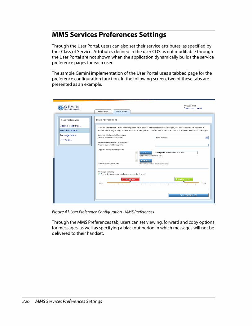
Figure 41 User Preference Configuration - MMS Preferences
MMS Services Preferences SettingsThrough the User Portal, users can also set their service attributes, as specified by ther Class of Service. Attributes defined in the user COS as not modifiable through the User Portal are not shown when the application dynamically builds the service preference pages for each user.
The sample Gemini implementation of the User Portal uses a tabbed page for the preference configuration function. In the following screen, two of these tabs are presented as an example.
Through the MMS Preferences tab, users can set viewing, forward and copy options for messages, as well as specifying a blackout period in which messages will not be delivered to their handset.
226 MMS Services Preferences Settings

Figure 42 User preference configuration - message filters
The Message Filters tab lets users create and maintain personalized black and white lists of email addresses and telephone numbers to screen unwanted messages. Black and white lists are managed by the HMC: a user can choose to use one filtering method or the other at any given moment. Previously defined lists that are not active are stored in the user's profile in the LDAP repository and can be re-activated at the touch of a button.
Chapter 8 User Portal 227

228 MMS Services Preferences Settings
9 Management
This chapter describes procedures for operating, managing and administering the Gemini HMC cluster.
The chapter covers these topics:
■ The NMS‚ on page 230
■ About the HMC Administrator Roles‚ on page 233
■ About the HMC Tabs and Panels‚ on page 234
■ Using the Help System‚ on page 244
■ Working with Alarms‚ on page 248
■ LifeKeeper Administration‚ on page 257
■ General System Warning‚ on page 260
■ Cluster Management Tools‚ on page 261
■ Reinstalling or Upgrading Gemini Application Software‚ on page 268
Chapter 9 Management 229
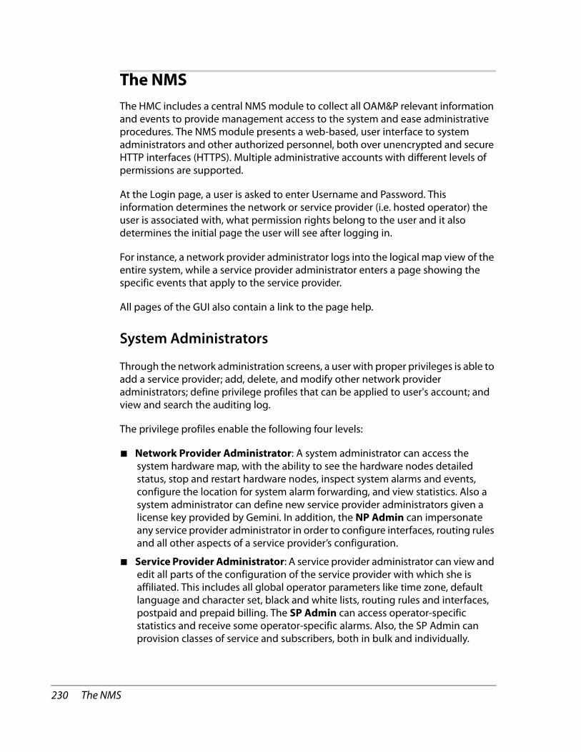
The NMSThe HMC includes a central NMS module to collect all OAM&P relevant information and events to provide management access to the system and ease administrative procedures. The NMS module presents a web-based, user interface to system administrators and other authorized personnel, both over unencrypted and secure HTTP interfaces (HTTPS). Multiple administrative accounts with different levels of permissions are supported.
At the Login page, a user is asked to enter Username and Password. This information determines the network or service provider (i.e. hosted operator) the user is associated with, what permission rights belong to the user and it also determines the initial page the user will see after logging in.
For instance, a network provider administrator logs into the logical map view of the entire system, while a service provider administrator enters a page showing the specific events that apply to the service provider.
All pages of the GUI also contain a link to the page help.
System Administrators
Through the network administration screens, a user with proper privileges is able to add a service provider; add, delete, and modify other network provider administrators; define privilege profiles that can be applied to user's account; and view and search the auditing log.
The privilege profiles enable the following four levels:
■ Network Provider Administrator: A system administrator can access the system hardware map, with the ability to see the hardware nodes detailed status, stop and restart hardware nodes, inspect system alarms and events, configure the location for system alarm forwarding, and view statistics. Also a system administrator can define new service provider administrators given a license key provided by Gemini. In addition, the NP Admin can impersonate any service provider administrator in order to configure interfaces, routing rules and all other aspects of a service provider’s configuration.
■ Service Provider Administrator: A service provider administrator can view and edit all parts of the configuration of the service provider with which she is affiliated. This includes all global operator parameters like time zone, default language and character set, black and white lists, routing rules and interfaces, postpaid and prepaid billing. The SP Admin can access operator-specific statistics and receive some operator-specific alarms. Also, the SP Admin can provision classes of service and subscribers, both in bulk and individually.
230 The NMS

■ Service Provider Administrator, Read-only: This administrator can view all the pages that the SP Admin can, but not edit them. The only active function that this type of administrator can perform is clearing operator-specific alarms.
■ Customer Care Representative: A customer care representative can access and edit individual subscriber information and has access to the customer care tools to search and display the status of messages in the system, related with specific subscribers.
■ Law Enforcement Agent: Once created, a law enforcement agent can only manage screens related with Lawful Intercept.
The privileges of each of the administrative roles include the creation of new administrators with the same or lower rank.
Using the NMS for Configuration
The Gemini HMC enables a wide number of configuration functions for administrators with proper privileges and with the correct operator affiliation through the web-based GUI of the management system.
When the Save button on each NMS configuration page is clicked, the configuration changes are pushed to the different processing nodes (HPG, HMG, etc.) with which they are associated. In general the receiving node then reloads the configuration seamlessly with no need for a system restart. There are some exceptions to this rule: the nodes need to restart when:
■ A new service provider is created or an existing one is removed
■ Any port number is changed
The HMC handles restart in a graceful way, as the standby copy of each affected node is configured first, then the active node is failed over to it, then the previously active node is then changed. However, modifying the two system parameters listed above will cause a brief interruption of service.
The HMC is a distributed network management system that simultaneously manages a large number of network elements. These network elements can include the interconnected computers, switches, SAN, and application processes that comprise the HMC.
The NMS interacts with the control software in every node of HMC through SNMP, HTTP, Shared File System, and LDAP. The SNMP Agent in the control software interprets the SNMP operations and executes them on the nodes.
You manage and monitor the HMC through the NMS’s web based UI.
Chapter 9 Management 231
IMPORTANT When using the NMS UI, do not click your browser’s Refresh or Reload button to refresh a page. This action can resend configuration data, triggering duplicate data entries or redundant commands. When appropriate, a Refresh button is provided within the NMS UI to refresh a page. In general, to revisit a page, you can always navigate to the page using the links in the UI’s left frame.
Typical network management operations include:
■ Configuration Management—Configure and manipulate the other HMC components, such as HMG, HPG, GMS, or GDS including configuring and manipulating the properties files used by these subsystems. Configuration Management can be further divided into four phases: discovery, provisioning, configuring and updating.
■ Fault Management—Detect and maintain faults and events that arise in the network of HMC subsystems and physical nodes. Fault Management can be divided into five phases: detect, analyze, test, rectify and clear.
■ Statistics Management—Monitor, collect and analyze performance-related data from the nodes of HMC. Performance Management can be subdivided into monitor and analyze network performance.
■ Allow secure access to NMS over SSL. To access the NMS in https mode, use port 9091. For information on configuring the NMS to support secure https connections, see the Gemini HyperScale Messaging Center Administrator’s Guide.
■ Allows software distribution for upgrades and patches to HMC applications.
■ Provides seamless integration with northbound management systems.
■ Customer care features enable service provider administrators to track and troubleshoot message traffic for specific MSISDNs.
The NMS provides an easy-to-use, flexible, distributed and scalable interface to these operational procedures. The net effect of a change in the HMC network is transparently propagated efficiently, keeping the entire network in a stable, healthy, and operational state.
232 The NMS

About the HMC Administrator RolesThe HMC supports four administrator roles: network provider, service provider, law enforcement, and customer care.
Network Provider Role
The network provider is responsible for the HMC hardware and software as a whole, and provides HMC services to service providers. Service providers work directly with mobile subscribers. Some of the NMS UI screens are accessible to both network providers and service providers, and some are customized for each role. The help system indicates whether a particular task is allowed for only one role. For example, on some of the Interface pages, only network providers can update field information; service providers can view this information but cannot change field values. Fields that can be updated only by network providers use the following convention in the online help: “Network providers: <help text here>.“
Service Provider Role
To verify the operation of the HMC, at least one service provider must be defined.
On HMCs, only service providers can provision subscribers. To perform service provider administrative tasks, network providers can associate themselves to a particular service provider in the Service Provider List page.
A service provider administrator can be limited to read-only status, and not allowed to make configuration changes.
Law Enforcement Administrator Role
Law enforcement administrators set up lawful interception of message traffic to and from specified MSISDNs and email addresses. Law enforcement administrators perform tasks related only to lawful interception: intercepted message encryption, intercepted message addressing, and administrator password changes.
Customer Care Administrator Role
The customer care administrator role allows service providers to track and troubleshoot message traffic for specific subscribers.
Chapter 9 Management 233
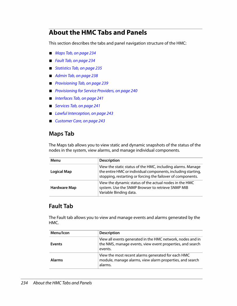
About the HMC Tabs and PanelsThis section describes the tabs and panel navigation structure of the HMC:
■ Maps Tab‚ on page 234
■ Fault Tab‚ on page 234
■ Statistics Tab‚ on page 235
■ Admin Tab‚ on page 238
■ Provisioning Tab‚ on page 239
■ Provisioning for Service Providers‚ on page 240
■ Interfaces Tab‚ on page 241
■ Services Tab‚ on page 241
■ Lawful Interception‚ on page 243
■ Customer Care‚ on page 243
Maps Tab
The Maps tab allows you to view static and dynamic snapshots of the status of the nodes in the system, view alarms, and manage individual components.
Fault Tab
The Fault tab allows you to view and manage events and alarms generated by the HMC.
Menu Description
Logical MapView the static status of the HMC, including alarms. Manage the entire HMC or individual components, including starting, stopping, restarting or forcing the failover of components.
Hardware MapView the dynamic status of the actual nodes in the HMC system. Use the SNMP Browser to retrieve SNMP MIB Variable Binding data.
Menu/Icon Description
EventsView all events generated in the HMC network, nodes and in the NMS, manage events, view event properties, and search events.
AlarmsView the most recent alarms generated for each HMC module, manage alarms, view alarm properties, and search alarms.
234 About the HMC Tabs and Panels

Statistics Tab
The Statistics tab allows you to generate and view reports to monitor the performance of the HMC. To generate reports for a specific module, click on the appropriate icon.
The NMS module of the HMC also performs all the processing needed for reporting. The NMS:
■ Collects various types of statistical information from the SLOG files produced by the processing nodes of the system
■ Aggregates the information produced by the processing nodes (if more than one node of the same type exists in the system)
■ Saves the resulting log files and optionally compresses them into its SAN partition space
■ Displays the information graphically or in table format to administrators with the appropriate privilege level.
The NMS also manages retrieval of the statistics log files from remote applications via (S)FTP, authenticating remote users and managing login directories.
Two types of statistics are gathered: system-level information, that only the system administrator can access, and service provider-level statistics for the multiple hosted operators that might be running on the platform. This latter information is compartmentalized by service provider operator, and accessible by both network and service provider administrators for each single operator. Statistics are presented to administrators in the Performance Tab of the NMS GUI.
The following statistics can be collected per HMG node:
Global Network Statistics:
■ Messages successfully stored to GMS
■ Messages successfully retrieved from GMS
■ Successful queries to User Database
■ MM3 incoming connections open
Service Provider-specific Statistics:
■ Total messages
■ Delivery reports sent to HPG
■ Notifications sent to HPG
■ Read reports sent to HPG
Chapter 9 Management 235

■ New MMS message notifications sent to HPG
■ Delivery problem notifications sent to HPG
■ SMS-formatted messages sent
■ Acknowledgement received
■ Forward requests received
■ HTTP GET requests received
■ MMbox Delete requests received
■ MMbox Store requests received
■ MMbox Upload requests received
■ MMbox View requests received
■ Notify response received
■ Read receipts received
■ MM3 messages sent
■ MM4 messages sent
■ MM7 messages sent
■ MM1 incoming connections open
■ MM3 incoming connections open
■ MM4 incoming connections open
■ MM7 incoming connections open
■ Delivery reports sent to HPG
The following statistics can be collected per HPG node (all system-wide):
■ Total push-message requests received
■ Successful push-message requests received
■ Push-message requests resulting in error
■ Total push-message responses sent
■ Successful push-message responses sent
■ Push-message responses resulting in error
■ Total push-messages processed, per PI
■ Successful push-messages processed, per PI
■ Push-messages resulting in error, per PI
■ Total requests sent to SMSC
■ Successful requests sent to SMSC
236 About the HMC Tabs and Panels
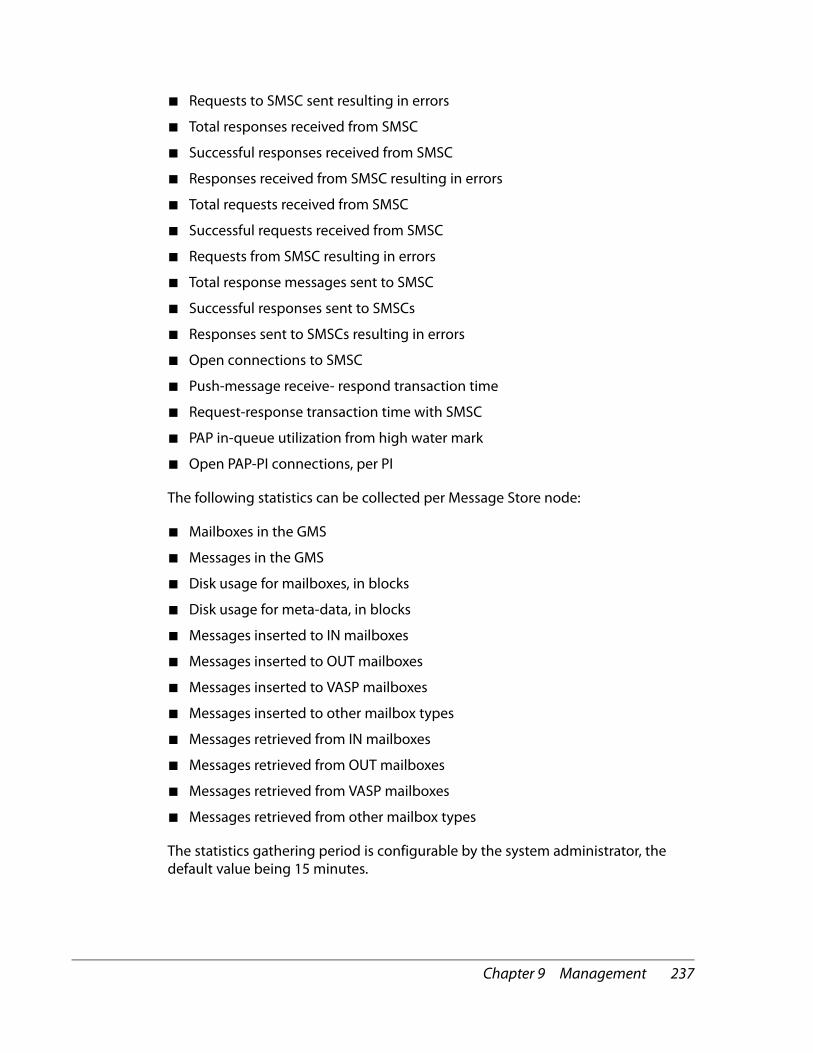
■ Requests to SMSC sent resulting in errors
■ Total responses received from SMSC
■ Successful responses received from SMSC
■ Responses received from SMSC resulting in errors
■ Total requests received from SMSC
■ Successful requests received from SMSC
■ Requests from SMSC resulting in errors
■ Total response messages sent to SMSC
■ Successful responses sent to SMSCs
■ Responses sent to SMSCs resulting in errors
■ Open connections to SMSC
■ Push-message receive- respond transaction time
■ Request-response transaction time with SMSC
■ PAP in-queue utilization from high water mark
■ Open PAP-PI connections, per PI
The following statistics can be collected per Message Store node:
■ Mailboxes in the GMS
■ Messages in the GMS
■ Disk usage for mailboxes, in blocks
■ Disk usage for meta-data, in blocks
■ Messages inserted to IN mailboxes
■ Messages inserted to OUT mailboxes
■ Messages inserted to VASP mailboxes
■ Messages inserted to other mailbox types
■ Messages retrieved from IN mailboxes
■ Messages retrieved from OUT mailboxes
■ Messages retrieved from VASP mailboxes
■ Messages retrieved from other mailbox types
The statistics gathering period is configurable by the system administrator, the default value being 15 minutes.
Chapter 9 Management 237

Admin Tab
The Admin tab allows you to specify global settings for service providers, configure HMC application logs and NMS server logs, and view NMS server details including NMS server port information and NMS server logs.
Global Settings Admin
The Global Settings Admin panel allows you to specify global settings for all service providers, including LDAP, mediation, CLI, FTP, and SNMP trap and alert settings.
Sub-Menu/Icon Description
Global Settings
Specify global settings for all service providers, including SMTP server, LDAP, mediation, CLI, FTP, and SNMP traps and alerts. You can also enable or disable global incoming MM3 messages.
Global MM3 SettingsConfigure incoming MM3 settings that apply to all service providers.
Lawful Interception Global Settings
Configure the from address, subject line, and encryption of lawfully intercepted messages sent to enforcement agencies.
238 About the HMC Tabs and Panels
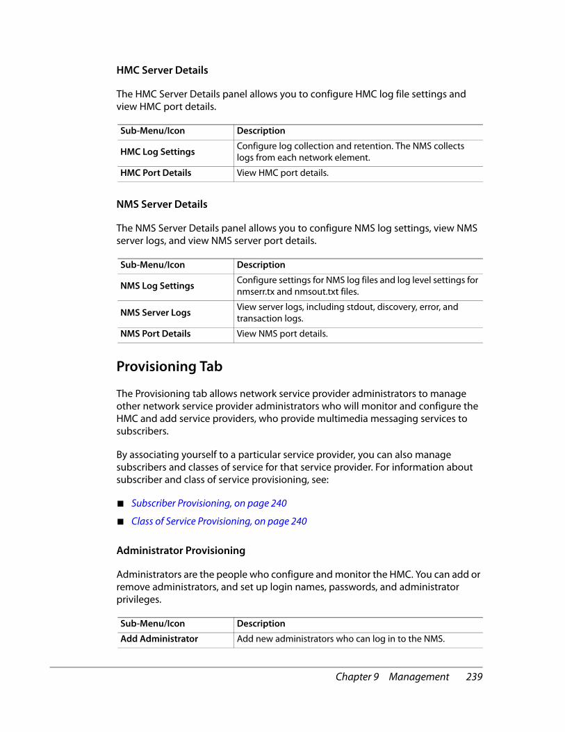
HMC Server Details
The HMC Server Details panel allows you to configure HMC log file settings and view HMC port details.
NMS Server Details
The NMS Server Details panel allows you to configure NMS log settings, view NMS server logs, and view NMS server port details.
Provisioning Tab
The Provisioning tab allows network service provider administrators to manage other network service provider administrators who will monitor and configure the HMC and add service providers, who provide multimedia messaging services to subscribers.
By associating yourself to a particular service provider, you can also manage subscribers and classes of service for that service provider. For information about subscriber and class of service provisioning, see:
■ Subscriber Provisioning‚ on page 240
■ Class of Service Provisioning‚ on page 240
Administrator Provisioning
Administrators are the people who configure and monitor the HMC. You can add or remove administrators, and set up login names, passwords, and administrator privileges.
Sub-Menu/Icon Description
HMC Log SettingsConfigure log collection and retention. The NMS collects logs from each network element.
HMC Port Details View HMC port details.
Sub-Menu/Icon Description
NMS Log SettingsConfigure settings for NMS log files and log level settings for nmserr.tx and nmsout.txt files.
NMS Server LogsView server logs, including stdout, discovery, error, and transaction logs.
NMS Port Details View NMS port details.
Sub-Menu/Icon Description
Add Administrator Add new administrators who can log in to the NMS.
Chapter 9 Management 239
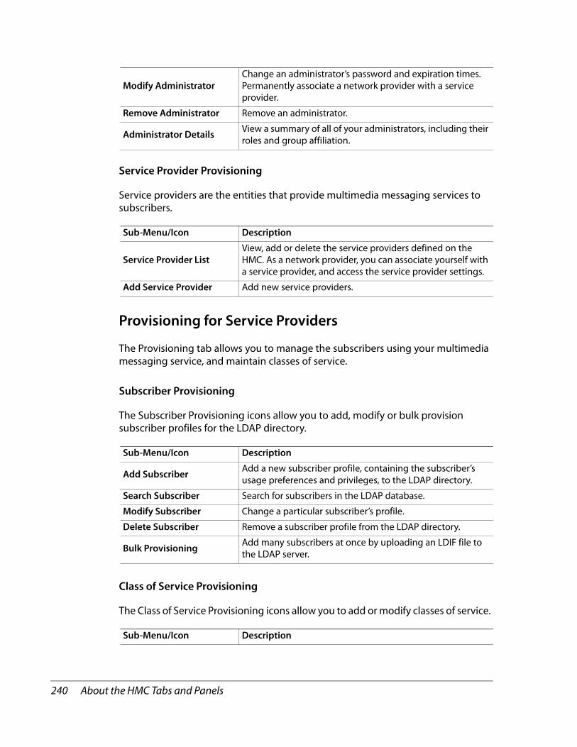
Service Provider Provisioning
Service providers are the entities that provide multimedia messaging services to subscribers.
Provisioning for Service Providers
The Provisioning tab allows you to manage the subscribers using your multimedia messaging service, and maintain classes of service.
Subscriber Provisioning
The Subscriber Provisioning icons allow you to add, modify or bulk provision subscriber profiles for the LDAP directory.
Class of Service Provisioning
The Class of Service Provisioning icons allow you to add or modify classes of service.
Modify AdministratorChange an administrator’s password and expiration times. Permanently associate a network provider with a service provider.
Remove Administrator Remove an administrator.
Administrator DetailsView a summary of all of your administrators, including their roles and group affiliation.
Sub-Menu/Icon Description
Service Provider ListView, add or delete the service providers defined on the HMC. As a network provider, you can associate yourself with a service provider, and access the service provider settings.
Add Service Provider Add new service providers.
Sub-Menu/Icon Description
Add SubscriberAdd a new subscriber profile, containing the subscriber’s usage preferences and privileges, to the LDAP directory.
Search Subscriber Search for subscribers in the LDAP database.
Modify Subscriber Change a particular subscriber’s profile.
Delete Subscriber Remove a subscriber profile from the LDAP directory.
Bulk ProvisioningAdd many subscribers at once by uploading an LDIF file to the LDAP server.
Sub-Menu/Icon Description
240 About the HMC Tabs and Panels
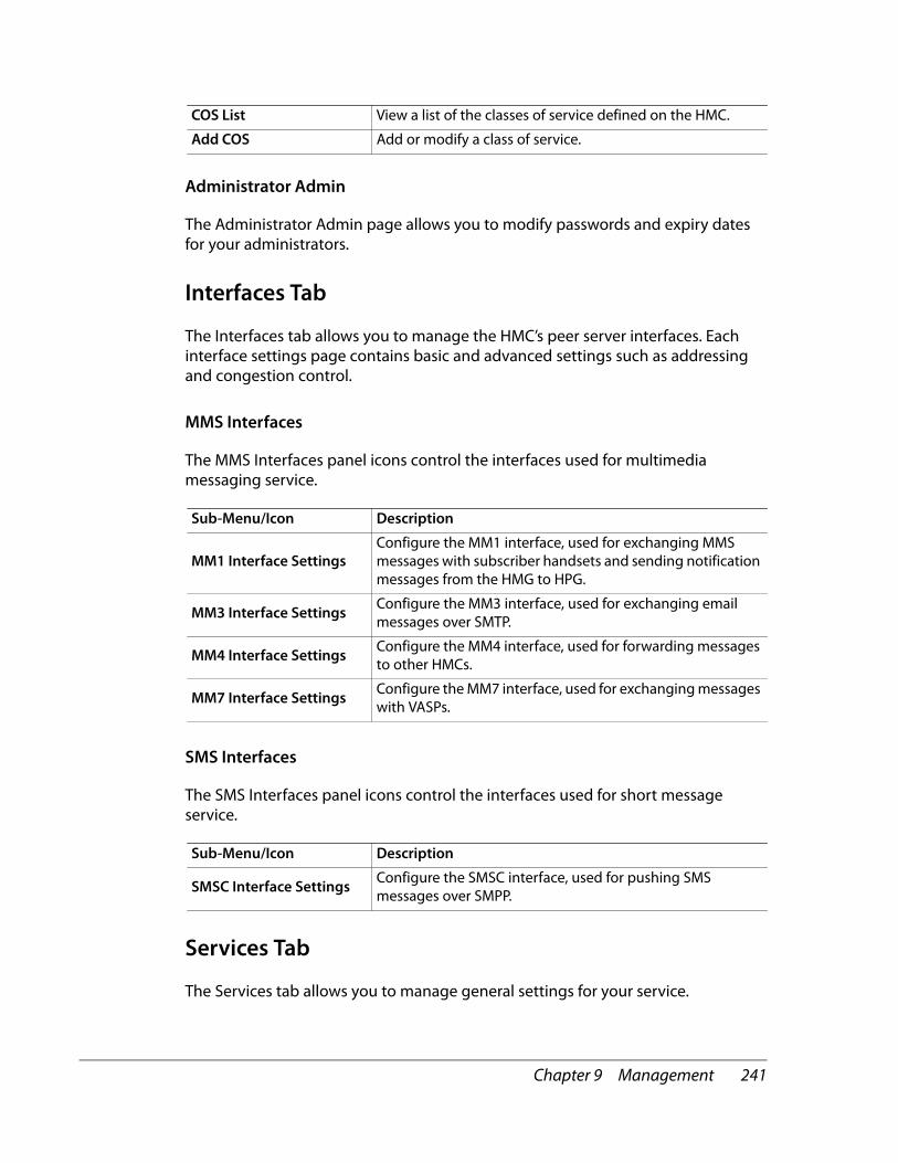
Administrator Admin
The Administrator Admin page allows you to modify passwords and expiry dates for your administrators.
Interfaces Tab
The Interfaces tab allows you to manage the HMC’s peer server interfaces. Each interface settings page contains basic and advanced settings such as addressing and congestion control.
MMS Interfaces
The MMS Interfaces panel icons control the interfaces used for multimedia messaging service.
SMS Interfaces
The SMS Interfaces panel icons control the interfaces used for short message service.
Services Tab
The Services tab allows you to manage general settings for your service.
COS List View a list of the classes of service defined on the HMC.
Add COS Add or modify a class of service.
Sub-Menu/Icon Description
MM1 Interface SettingsConfigure the MM1 interface, used for exchanging MMS messages with subscriber handsets and sending notification messages from the HMG to HPG.
MM3 Interface SettingsConfigure the MM3 interface, used for exchanging email messages over SMTP.
MM4 Interface SettingsConfigure the MM4 interface, used for forwarding messages to other HMCs.
MM7 Interface SettingsConfigure the MM7 interface, used for exchanging messages with VASPs.
Sub-Menu/Icon Description
SMSC Interface SettingsConfigure the SMSC interface, used for pushing SMS messages over SMPP.
Chapter 9 Management 241
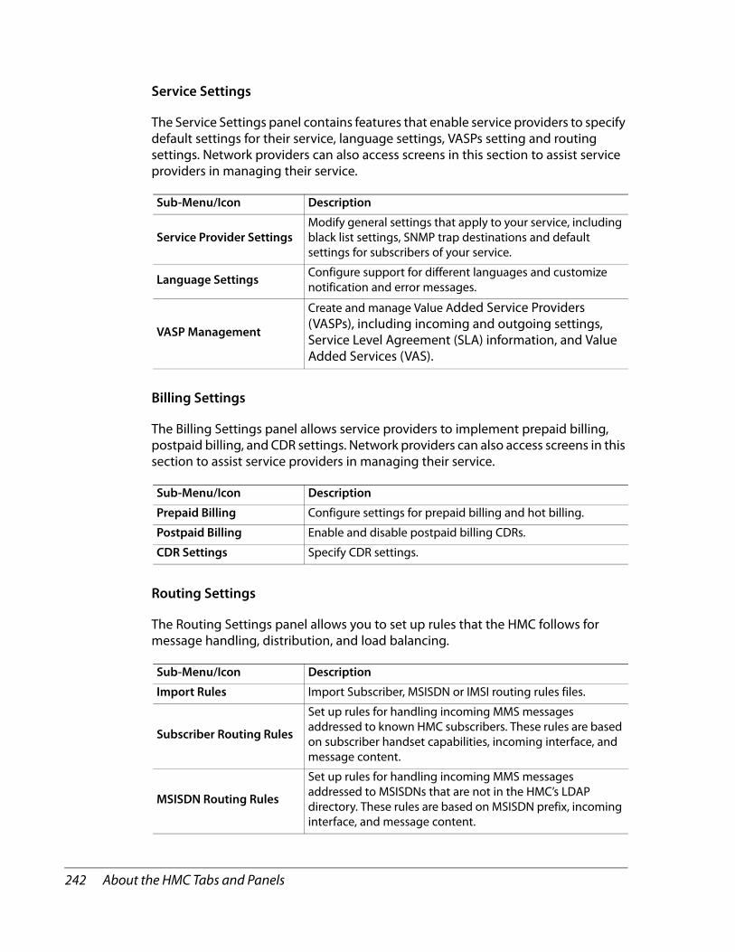
Service Settings
The Service Settings panel contains features that enable service providers to specify default settings for their service, language settings, VASPs setting and routing settings. Network providers can also access screens in this section to assist service providers in managing their service.
Billing Settings
The Billing Settings panel allows service providers to implement prepaid billing, postpaid billing, and CDR settings. Network providers can also access screens in this section to assist service providers in managing their service.
Routing Settings
The Routing Settings panel allows you to set up rules that the HMC follows for message handling, distribution, and load balancing.
Sub-Menu/Icon Description
Service Provider SettingsModify general settings that apply to your service, including black list settings, SNMP trap destinations and default settings for subscribers of your service.
Language SettingsConfigure support for different languages and customize notification and error messages.
VASP Management
Create and manage Value Added Service Providers (VASPs), including incoming and outgoing settings, Service Level Agreement (SLA) information, and Value Added Services (VAS).
Sub-Menu/Icon Description
Prepaid Billing Configure settings for prepaid billing and hot billing.
Postpaid Billing Enable and disable postpaid billing CDRs.
CDR Settings Specify CDR settings.
Sub-Menu/Icon Description
Import Rules Import Subscriber, MSISDN or IMSI routing rules files.
Subscriber Routing Rules
Set up rules for handling incoming MMS messages addressed to known HMC subscribers. These rules are based on subscriber handset capabilities, incoming interface, and message content.
MSISDN Routing Rules
Set up rules for handling incoming MMS messages addressed to MSISDNs that are not in the HMC’s LDAP directory. These rules are based on MSISDN prefix, incoming interface, and message content.
242 About the HMC Tabs and Panels
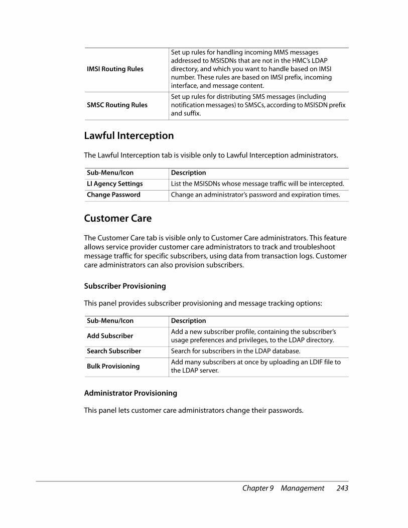
Lawful Interception
The Lawful Interception tab is visible only to Lawful Interception administrators.
Customer Care
The Customer Care tab is visible only to Customer Care administrators. This feature allows service provider customer care administrators to track and troubleshoot message traffic for specific subscribers, using data from transaction logs. Customer care administrators can also provision subscribers.
Subscriber Provisioning
This panel provides subscriber provisioning and message tracking options:
Administrator Provisioning
This panel lets customer care administrators change their passwords.
IMSI Routing Rules
Set up rules for handling incoming MMS messages addressed to MSISDNs that are not in the HMC’s LDAP directory, and which you want to handle based on IMSI number. These rules are based on IMSI prefix, incoming interface, and message content.
SMSC Routing RulesSet up rules for distributing SMS messages (including notification messages) to SMSCs, according to MSISDN prefix and suffix.
Sub-Menu/Icon Description
LI Agency Settings List the MSISDNs whose message traffic will be intercepted.
Change Password Change an administrator’s password and expiration times.
Sub-Menu/Icon Description
Add SubscriberAdd a new subscriber profile, containing the subscriber’s usage preferences and privileges, to the LDAP directory.
Search Subscriber Search for subscribers in the LDAP database.
Bulk ProvisioningAdd many subscribers at once by uploading an LDIF file to the LDAP server.
Chapter 9 Management 243

Using the Help SystemThe HMC online help is based on Quadralay WebWorks 4.0 Help and incorporates two distinct implementations: one based on Java and the other based on JavaScript. This section provides the following information:
■ About the Java and JavaScript Implementations‚ on page 244
■ Supported Browsers and Platforms‚ on page 244
■ Using the Navigation Frame‚ on page 244
■ Using the Toolbar Frame‚ on page 246
About the Java and JavaScript Implementations
The Java implementation uses a Java applet to display the Contents, Index, Search, and Favorites tabs. The JavaScript implementation provides similar functionality using JavaScript, but the Favorites tab is not supported.
When you launch the help system, WebWorks tries to first run the Java implementation. If Java is disabled or not supported in the user's browser, or if the Java applet fails to load, the JavaScript implementation is used instead. If both Java and JavaScript are disabled in the user's browser, the user cannot view the online help system.
Supported Browsers and Platforms
Windows, Macintosh, or UNIX running version 4 or later of Internet Explorer or a current version of Mozilla or Safari. Netscape 6.0 is not supported on any platform; Netscape 6.1 and later are supported.
Note: The Java implementation is not supported by Internet Explorer on UNIX or Netscape 4.x on Macintosh. For these browser/platform combinations, the JavaScript implementation is always used.
Note: The step numbering in the online help does not display correctly on the Macintosh OS running Safari; on this browser all steps appear to have the number “1”.
Using the Navigation Frame
The navigation frame displays four tabs: Contents, Index, Search, and Favorites. These tabs provide the core navigational features in the help system. The Contents, Index, and Search tabs are available in both the Java and JavaScript implementations. The Favorites tab is available only in the Java implementation.
244 Using the Help System

Using the Contents Tab
The Contents tab displays the table of contents of the help system in the form of an expandable/collapsible tree view. Closed book icons represent TOC entries that have subentries. Click a closed book to open it and see its contents. When you expand a book, the closed book icon is replaced by an open book icon. You can click the book again to close it. The page icons represent individual help topics.
Using the Index Tab
The Index tab displays the index entries in the help system. You can scroll through the list to find the index entry you want, or you can type the first few letters of the term in the text box, and the index will scroll automatically as you type. Double-click an index entry to display the corresponding help topic, or select an index entry and then click the Display button.
Note: the Display button is available in the Java version only.
If multiple help topics correspond to a particular index entry, double-clicking that entry displays a list of topics that you can choose from. For the Java implementation, the list of choices is displayed in a Multiple Topics Found dialog box. For the JavaScript implementation, the multiple topics found list is displayed in the topic frame.
Using the Search Tab
The Search tab lets you search the entire contents of the help system using keywords. Type the word or phrase to search for, and then click Go. The Search tab displays a list of all the topics that contain the word or phrase you entered. If you search for multiple words, the search finds help topics that contain all of the words you entered. The topics found by search are ranked in order of relevance. The higher the ranking, the more likely the topic includes the word or phrase you searched for.
Click the drop-down arrow next to the search field to see a history of words you have searched for. You can then select one of those words to perform the same search again.
When you click one of the topics found by search, each occurrence of the term or terms you searched for appears highlighted in the help topic that displays in the help system.
Note: The search highlighting feature works only in Internet Explorer on the Windows platform.
Chapter 9 Management 245
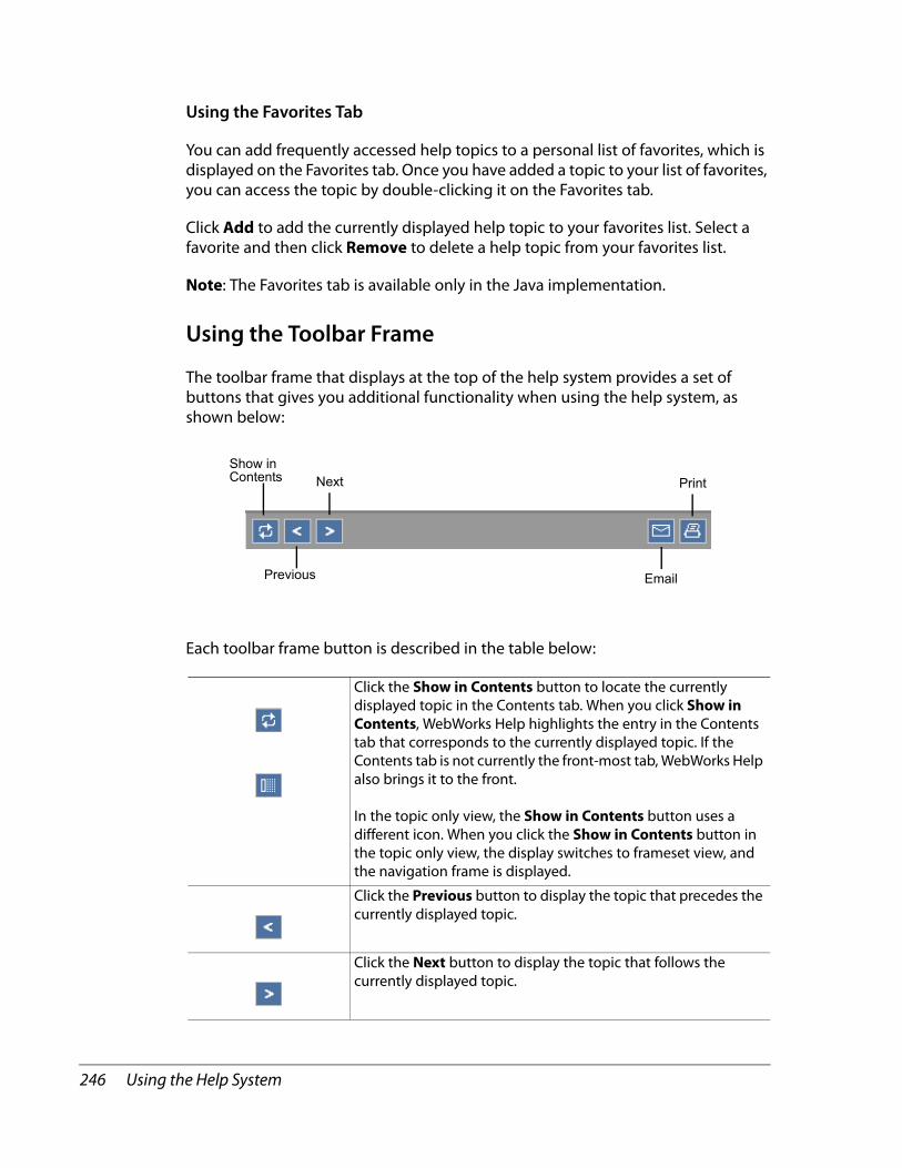
Using the Favorites Tab
You can add frequently accessed help topics to a personal list of favorites, which is displayed on the Favorites tab. Once you have added a topic to your list of favorites, you can access the topic by double-clicking it on the Favorites tab.
Click Add to add the currently displayed help topic to your favorites list. Select a favorite and then click Remove to delete a help topic from your favorites list.
Note: The Favorites tab is available only in the Java implementation.
Using the Toolbar Frame
The toolbar frame that displays at the top of the help system provides a set of buttons that gives you additional functionality when using the help system, as shown below:
Each toolbar frame button is described in the table below:
Click the Show in Contents button to locate the currently displayed topic in the Contents tab. When you click Show in Contents, WebWorks Help highlights the entry in the Contents tab that corresponds to the currently displayed topic. If the Contents tab is not currently the front-most tab, WebWorks Help also brings it to the front.
In the topic only view, the Show in Contents button uses a different icon. When you click the Show in Contents button in the topic only view, the display switches to frameset view, and the navigation frame is displayed.
Click the Previous button to display the topic that precedes the currently displayed topic.
Click the Next button to display the topic that follows the currently displayed topic.
Previous
Show in Contents Next Print
246 Using the Help System
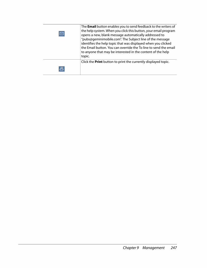
The Email button enables you to send feedback to the writers of the help system. When you click this button, your email program opens a new, blank message automatically addressed to “[email protected]”. The Subject line of the message identifies the help topic that was displayed when you clicked the Email button. You can override the To line to send the email to anyone that may be interested in the content of the help topic.
Click the Print button to print the currently displayed topic.
Chapter 9 Management 247

Working with AlarmsAlarms are messages that are generated for each module that require an administrator’s attention. Alarms result from a correlation of events and represent failures or faults in a network element that may need immediate attention. Events are converted to alarms based on their significance—if an event has a severity level greater than or equal to Minor, the event is converted to an alarm. Events include a variety of information, including module connectivity errors, status messages, and license error messages.
The Alarms page off the Fault tab lists only one alarm per module; each alarm that displays is essentially the most recent event for the module. Using the Alarms page you can you can view the list of all alarms generated by the HMC, sort alarms, view alarm properties, search alarms, clear and pickup alarms, and perform other tasks.
Accessing the Alarms Page
To access the Alarms page, select Fault > Alarms. The Alarms page displays. For each alarm, the NMS displays the status of the alarm, the failure object, the alarm group, the owner of the alarm, the date and time that the alarm was generated, and the message associated with the alarm. Alarms can have the following statuses:
Customize the Alarms Per Page Count
By default, 25 alarms are shown on each of the Alarms list pages. You can increase the number of alarms that are shown by selecting a higher value from the entries per page drop-down box.
Critical alarms
Major alarms
Minor alarms
Informational alarms
Clear, no alarms
248 Working with Alarms

Browse Alarms
To browse through the list of alarms, use the First, Previous, Next, and Last navigation links located above the Alarms list view.
Sort Alarms
When you navigate to the Alarms page, the NMS automatically displays a list of the most recent alarms, sorted by the Date/Time field. To change the sort order of the alarms, click on the column headers at the top of the page.
Print Alarms
To print alarms, click the “Print version” link at the top of the page. A new page opens that displays the alarms in a printable format. Click Print to print the alarms list.
Filtering Alarms
Use the following instructions to filter alarms by significance:
▼ To filter alarms according to significance:
1 Select Fault > Alarms.
The Alarms page displays.
2 Select the alarm of interest by clicking on the alarm link in the Failure Object column.
The Alarm Properties page displays. Each alarm property field is described in the table below:
Field Description
Failure Object
Specifies the failure object or entity which is primarily responsible for the alarm.
For example, “HPG_hpg-1_PRIMARY”.
Source
Specifies the exact source (component, network, node, interface) of the alarm.
For example, “HPG_hpg-1_PRIMARY”.
CreatedSpecifies the date and time when the alarm was created.
For example, “Oct 09,2005 03:17:12 PM”.
Chapter 9 Management 249

Last UpdatedSpecifies the date and time when the alarm was last updated.
For example, “Oct 09,2005 05:30:28 PM”.
Severity
Specifies the severity of the alarm, such as:◆ Critical◆ Major ◆ Minor◆ Clear◆ Info
Previous Severity
Specifies the previous severity of the alarm, such as:◆ Critical◆ Major ◆ Minor◆ Clear◆ Info
Message
Specifies the message associated with the alarm. For more information about the error message and suggested corrective action, click on the link in the LogMsgCode field.
For example, “failed to make a connection to host [host name] port [port number]”.
CategorySpecifies the category of the alarm.
For example, “License” or “Fault”.
OwnerSpecifies the owner of the alarm, if the alarm has been assigned to a work group or a user.
Group NameSpecifies the group name to which the alarm belongs.
For example, “NetworkProvider”.
Priority The priority assigned to the alarm.
ProcId
Identifier of the application process that generated the message. Because multiple HMC processes write to the application log, sometimes nearly simultaneously, it is important to pay attention to the PID associated with each message.
For example, “18592”.
LogSeverity
Specifies the severity that corresponds to the alarm entry in the log file.
For example, “Warning” or “Information”.
250 Working with Alarms

Viewing Related Events
Events record all of the occurrences in the network, nodes and NMS. Events are converted to alarms based on their significance—if an event has a severity level associated with it, the event is converted to an alarm. From the Alarms page, you can view the events that are related to a specific alarm.
▼ To view related events:
1 On the Alarms page, select the check box next to the alarm of interest. To view related events for more than one alarm, select multiple check boxes. To view related events for all alarms, click the check box at the top of the page, next to the header columns.
2 Click View Alarms.
The Events view with all the events related to the selected alarms display on the Events page. The events are displayed in a descending order based on the time of modification.
Clearing Alarms
An alarm can be cleared when it has been resolved or if it is inconsequential.
Note: You can also clear alarms on the Alarm Properties page. See Clearing Alarms‚ on page 255 for more information.
LogMsgCode
The specific error code that corresponds to the alarm entry in the log file. Click on the link to view the error message and the suggested corrective action.
For example, “0090002”.
The codes are seven-digit numbers. The first two digits correspond to the software module that generated the message. ◆ The 00xxxxx series pertain to HyperScale core software. ◆ The 01xxxxx series pertain to MMS. ◆ The 02xxxxx series pertain to WAP. ◆ The 03xxxxx series pertain to SMS. ◆ The 04xxxxx series pertain to PPG. ◆ The 05xxxxx series pertain to SMSC. ◆ The 10xxxxx series pertain to NHRE. ◆ The 20xxxxx series pertain to MMS-S. for more information about the error code modules, see the Gemini HMC Error Reference Guide.
ComponentSpecifies the internal HMC component that generated the alarm.
For example, “STATSMGR” or “MM3SMTP”.
Chapter 9 Management 251
▼ To clear status of an alarm:
1 On the Alarms page, select the check box of the alarm that you want to clear. To clear the status of more than one alarm, select multiple check boxes.
2 Click Clear.
Deleting Alarms
You also have an option to delete an alarm when you feel the alarm is not significant or the alarm has been cleared. By default, the alarms that are in Clear status for more than 24 hours are deleted and this deletion happens automatically every 60 minutes. But if you want to manually delete the cleared alarms, use this option.
▼ To delete alarms:
1 On the Alarms page, select the alarm that you want to delete. To delete more than one alarm, select multiple check boxes.
2 Click Delete.
Picking up and Unpicking Alarms
Pickup is a mechanism that helps in assigning a particular alarm/fault of a device to a work group or user. This ensures that all problems are picked up and work is not duplicated. It is also possible to unpick an Alarm which has already been assigned to a user or work group.
An alarm annotation entry will be entered with the name of the user who has picked up or unpicked the alarm and the time it was performed.
Note: You can also pick up and unpick alarms on the Alarm Properties page. See Picking up and Unpicking Alarms‚ on page 255 for more information.
▼ To pick up an alarm:
1 Select the check box next to the alarm that you want to pick up. To pick up multiple alarms, select multiple check boxes. To pick up all alarms, click the check box at the top of the page, next to the header columns.
2 Click Pickup.
▼ To unpick an alarm:
1 Select the check box next to the alarm that you want to unpick. To unpick multiple alarms, select multiple check boxes. To unpick all alarms, click the check box at the top of the page, next to the header columns.
2 Click Unpick.
252 Working with Alarms

Searching Alarms
The search option in the NMS facilitates searching for one or more alarms. The search operation is performed on the entire database and is not restricted to the displayed view alone. You can search for a required alarm based on a general condition or specific criteria.
▼ To search for alarms:
1 Select Fault > Alarms.
The Alarms page displays.
2 Click the “Search” link from the top of the Alarms page. The Advanced Search page displays. The diagram below shows each field on the page that you can use to perform your search for alarms:
3 Select the Match any of the Following option if you want to perform a search operation that returns results that match any of the criteria that you specify. Select the Match all of the Following option if you want to return results that match all of the criteria that you specify.
4 In the Properties field, select the property based on which you want to perform your search. For example, if you want to search for all alarms that occurred for the module “HPG_hpg-1_PRIMARY”, select “source” in this field. If you want to search for all alarms that have a particular severity level, select “severity” in this field.
If you select a property that is related to time or date, the Date Input Helper appears on the page. You can use this feature to open a calendar that lets you easily select date and time criteria instead of manually entering this information on the page.
5 In the Conditions field, select the condition based on which you want to restrict your search.
6 In the Value text field, enter the exact information you are looking for. For example, if you selected “source” in the Properties field, then specify the name of the module, such as “HPG_hpg-1_PRIMARY”, in this field. If you selected “severity” in the Properties field, then specify the severity level such as “Major” in this field.
Chapter 9 Management 253

7 To specify additional criteria, click More and repeat steps 4 through 6. You can use the Fewer option to remove the last row of search criteria from the page.
8 To begin the search, click Search.
After you perform a search, all of the alarms that match your search criteria display on the page. To change your search criteria, enter new values in the search fields.
▼ Example Search
Let’s take an example where you need to look for major alarms of a particular node, say 'Node_A'.
1 On the Alarms page, click the “Search” link. The Advanced Search page displays.
2 Select the Match all of the Following option.
3 Select “node” from the Properties field, “equals” from the Conditions field, and enter the node name, for example, “Node_A”, in the Value text field.
4 Click More.
5 In the new fields that are displayed, select “severity” from the Properties field, “equals” from the Conditions field, and enter the value “Major” in the Value field.
6 Click Search.
Alarm Properties Page
The Alarm Properties page displays detailed information associated with a specific alarm. Using this page you can perform the following tasks:
■ Viewing Related Events‚ on page 251
■ Picking up and Unpicking Alarms‚ on page 255
■ Clearing Alarms‚ on page 255
■ Adding Comments to an Alarm‚ on page 255
■ Viewing Alarm Annotation and History‚ on page 255
■ Viewing Related Alarms‚ on page 256
Viewing Related Events
On the Alarm Properties page, click the “Events” link. Any events associated with the alarm display on the Events page.
254 Working with Alarms
Picking up and Unpicking Alarms
Pickup is a mechanism that helps in assigning a particular alarm/fault of a device to a work group or user. This ensures that all problems are picked up and work is not duplicated. It is also possible to Unpick an Alarm which has already been assigned to a user or work group.
An alarm annotation entry will be entered with the name of the user who has picked up or unpicked the alarm and the time it was performed.
Note: You can also pick up and unpick alarms on the Alarms page. See Picking up and Unpicking Alarms‚ on page 252 for more information.
To pick up an alarm, click the “Pickup” link on the Alarm Properties page. To unpick an alarm that is assigned to you, click the “Unpick” link on the Alarm Properties page.
Clearing Alarms
An alarm can be cleared when it has been resolved or if it is inconsequential. To clear an alarm, click the “Clear” link on the Alarm Properties page.
Note: You can also clear alarms on the Alarms page. See Clearing Alarms‚ on page 251 for more information.
Adding Comments to an Alarm
It is important to track any actions that you have taken to fix an alarm or any new information you have gathered about the alarm. The annotate option can be used to add notes to an alarm for future reference. For example, the solution for a problem resolved by you can be entered by using the Annotate option. This enables other users to solve the same problem with less effort by reading the annotation.
▼ To add comments to an alarm:
1 On the Alarm Properties page, click the “Annotate” link.
The Annotate form displays.
2 Enter your comments in the Message field.
3 Click Annotate.
Viewing Alarm Annotation and History
To view all of the user-defined annotations and the history of the alarm, click the “Annotation & History” link on the Alarm Properties page.
Chapter 9 Management 255

The Annotations region displays all of the user-defined annotations along with the time of annotation and any pickup or unpick entries.
The History region provides complete information on the status of the alarms, such as when the alarm was created and fixed, and any severity changes. For example, when a critical alarm is generated, the Alarms region displays the current status of the alarm. If the problem has been fixed, an alarm with a clear severity will update the one with a critical severity.
Click the “Merge History” link if you want to combine the Annotation and History views into a single view on the page ordered by the time when actions occurred. To return to the separate views of annotation and history, click the “Annotation & History” link again.
Viewing Related Alarms
To view other alarms generated for the same network element, click the “Related Alarms” link on the Alarm Properties page.
256 Working with Alarms

LifeKeeper AdministrationThe current Gemini Mobile HMC product uses Steeleye Corporation's LifeKeeper product to provide high availability for the HMC servers and the applications running on them.
This information is provided as an aid for describing how to use the LifeKeeper product to provide high availability for Gemini’s HMC. It is not meant to replace the Steeleye LifeKeeper documentation, rather, to supplement it with specific usage information for the HMC product.
LifeKeeper Version
The version of Steeleye's LifeKeeper being used is Life Keeper for Linux version 5.0.2, release 2. This version information may be obtained on an installed system using the command:
rpm -q -i steeleye-lk
LifeKeeper Terminology
Below is a list of terms useful for understanding LifeKeeper High Availability.
■ HMC System—a cluster of servers providing MMS services
■ LifeKeeper Resource—any entity (hardware or software) being managed and controlled by the LifeKeeper software
■ LifeKeeper Resource Hierarchy —a collection of LifeKeeper resources having dependency relationships amongst themselves
■ HMC Service —one of several applications provided by the HMC system. LifeKeeper always refers to higher level software components as applications.
■ PRIMARY Server—the server which is the preferred host for a given resource. The priority number configured for a server for a certain resource determines its precedence for hosting a resource. The lower the priority number, the more preferred that server is. A PRIMARY server always has a priority of 1.
■ SECONDARY Server —any server which is not the PRIMARY server. The priority number will always be greater than 1 and will be used to choose which SECONDARY server to use when a failover has to occur from the PRIMARY.
■ ACTIVE Server —the server which is currently hosting a resource. Normally, this will be the PRIMARY server but after a failover, it will be one of the SECONDARY servers.
Chapter 9 Management 257
■ STANDBY Server —any server which is capable of hosting the resource but is not currently. This is normally a SECONDARY server, however, after a failover, it may be a PRIMARY server.
LifeKeeper Functional Description
The LifeKeeper product is clustering software that provides automatic failover support for software processes from one server in the system to another.
LifeKeeper uses the term resource to describe services which are being protected. The term, resource, does not necessarily correspond to a one-to-one relationship with software processes. A resource is a functional collection. It may be composed of one or more software processes, hardware and configurations, that provide a targeted service. For instance, there is a resource definition for virtual IP addresses.
Resources may have dependencies defined between them creating resource hierarchies. For example, the Gemini Mail Storage has a resource defined for the HMC application which depends upon two virtual IP address resources (one for the service on the internal subnet and one on the external subnet) and which also depends upon a shared filesystem resource.
The GMS application and its dependent resources form a resource hierarchy. When any application in the hierarchy has a problem, it affects the entire resource hierarchy. If the GMS filesystem resource has a problem and needs to failover to a standby server, the entire hierarchy will failover as well.
The LifeKeeper processes also monitor and detect the health of the physical servers that are configured to be running in the cluster. If a server experiences a crash or power failure, LifeKeeper daemons detect it and fail over any applications executing on the failed server.
LifeKeeper Configuration
LifeKeeper has been configured with the following information:
■ Servers participating in the cluster
■ Communication paths between these servers
◆ Each server has connections to other servers on two different subnets. This is to protect against link or switch failures causing detection of a false server death.
◆ The communication paths configured in a robust topology.
■ Resources to be managed
◆ Which server is the primary server for the resource (priority 1)
258 LifeKeeper Administration
◆ Which server(s) are the secondary server(s) for the resource (priority > 1)
◆ LifeKeeper scripts defined for each resource being managed. These are:
check script—called by default every two minutes to determine the health (status) of the resource.
recover script—called when the check script determines that the resource is impaired. This script will attempt to do a local recovery of the resource and will return the status of the local recovery attempt. If the local recovery fails then the resource is failed over to the secondary server with the highest priority.
restore script—called to start the resource on the server
remove script—called to stop the resource on the server
LifeKeeper Management
LifeKeeper management can be done through a LifeKeeper GUI interface or through command line interfaces. The LifeKeeper GUI provides an informative display of the resources being managed and mappings to the servers configured to host them. To bring up the LifeKeeper GUI, execute the following command on any server in the cluster:
/opt/LifeKeeper/bin/lkGUIapp &
To display a text only version of the resource mappings, use the following command line call:
/opt/LifeKeeper/bin/lcdstatus
Resource hierarchies will be created at initialization time through the use of the LifeKeeper Staging Process.
Chapter 9 Management 259
General System WarningIf your system shows signs of file system or integrity problems that require a file system check, do it. DO NOT WAIT. Here are some examples of critical error messages appearing in the system's "syslog" /var/adm/messages file: kernel: Unexpected dirty buffer encountered at
do_get_write_access:59 (08:01 blocknr 49428) kernel: EXT3-fs error (device sd(8,1)): ext3_free_blocks: bit
already cleared for block 42838249 kernel: Assertion failure in unmap_underlying_metadata() at
buffer.c:1542: !buffer_jlist_eq(old_bh, 3)
IMPORTANT If the boot sequence recommends or requires a file system check, DO NOT circumvent or interrupt the check. Doing so risks corrupting your file system.
260 General System Warning
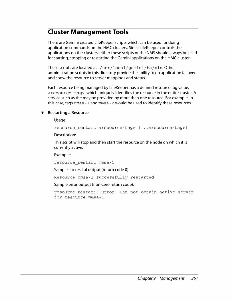
Cluster Management ToolsThere are Gemini created LifeKeeper scripts which can be used for doing application commands on the HMC clusters. Since LifeKeeper controls the applications on the clusters, either these scripts or the NMS should always be used for starting, stopping or restarting the Gemini applications on the HMC cluster.
These scripts are located at /usr/local/gemini/ha/bin. Other administration scripts in this directory provide the ability to do application failovers and show the resource to server mappings and status.
Each resource being managed by LifeKeeper has a defined resource tag value, <resource tag>, which uniquely identifies the resource in the entire cluster. A service such as the may be provided by more than one resource. For example, in this case, tags mmsa-1 and mmsa-2 would be used to identify these resources.
▼ Restarting a Resource
Usage:
resource_restart <resource-tag> [...<resource-tag>]
Description:
This script will stop and then start the resource on the node on which it is currently active.
Example:
resource_restart mmsa-1
Sample successful output (return code 0):
Resource mmsa-1 successfully restarted
Sample error output (non-zero return code):
resource_restart: Error: Can not obtain active server for resource mmsa-1
Chapter 9 Management 261
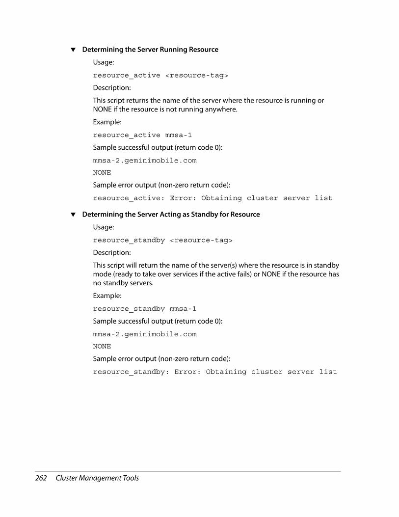
▼ Determining the Server Running Resource
Usage:
resource_active <resource-tag>
Description:
This script returns the name of the server where the resource is running or NONE if the resource is not running anywhere.
Example:
resource_active mmsa-1
Sample successful output (return code 0):
mmsa-2.geminimobile.com
NONE
Sample error output (non-zero return code):
resource_active: Error: Obtaining cluster server list
▼ Determining the Server Acting as Standby for Resource
Usage:
resource_standby <resource-tag>
Description:
This script will return the name of the server(s) where the resource is in standby mode (ready to take over services if the active fails) or NONE if the resource has no standby servers.
Example:
resource_standby mmsa-1
Sample successful output (return code 0):
mmsa-2.geminimobile.com
NONE
Sample error output (non-zero return code):
resource_standby: Error: Obtaining cluster server list
262 Cluster Management Tools

▼ Determining the Primary Server for Resource
Usage:
resource_primary <resource-tag>
Description:
This script will return the name of the primary server for the specified resource or NONE if the resource does not have a primary server defined.
Example:
resource_primary mmsa-1
Sample successful output (return code 0):
mmsa-1.geminimobile.com
NONE
Sample error output (non-zero return code):
resource_primary: Error: Obtaining cluster server list
▼ Determining the Secondary Server for a Resource
Usage:
resource_secondary <resource-tag>
This script will return the name of the secondary server(s) for the specified resource or NONE if the resource does not have any secondary servers defined.
Example:
resource_secondary mmsa-1
Sample successful output (return code 0):
mmsa-4.geminimobile.com
NONE
Sample error output (non-zero return code):
resource_secondary: Error: Obtaining cluster server list
Chapter 9 Management 263
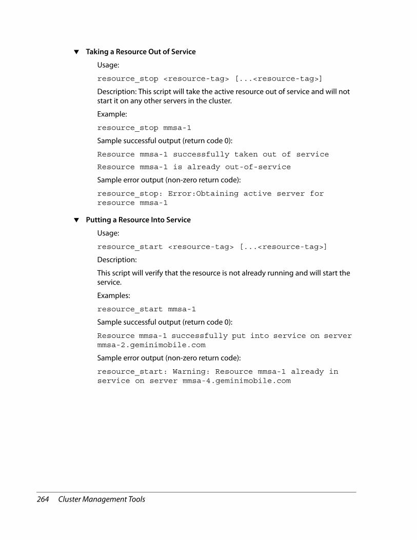
▼ Taking a Resource Out of Service
Usage:
resource_stop <resource-tag> [...<resource-tag>]
Description: This script will take the active resource out of service and will not start it on any other servers in the cluster.
Example:
resource_stop mmsa-1
Sample successful output (return code 0):
Resource mmsa-1 successfully taken out of service
Resource mmsa-1 is already out-of-service
Sample error output (non-zero return code):
resource_stop: Error:Obtaining active server for resource mmsa-1
▼ Putting a Resource Into Service
Usage:
resource_start <resource-tag> [...<resource-tag>]
Description:
This script will verify that the resource is not already running and will start the service.
Examples:
resource_start mmsa-1
Sample successful output (return code 0):
Resource mmsa-1 successfully put into service on server mmsa-2.geminimobile.com
Sample error output (non-zero return code):
resource_start: Warning: Resource mmsa-1 already in service on server mmsa-4.geminimobile.com
264 Cluster Management Tools
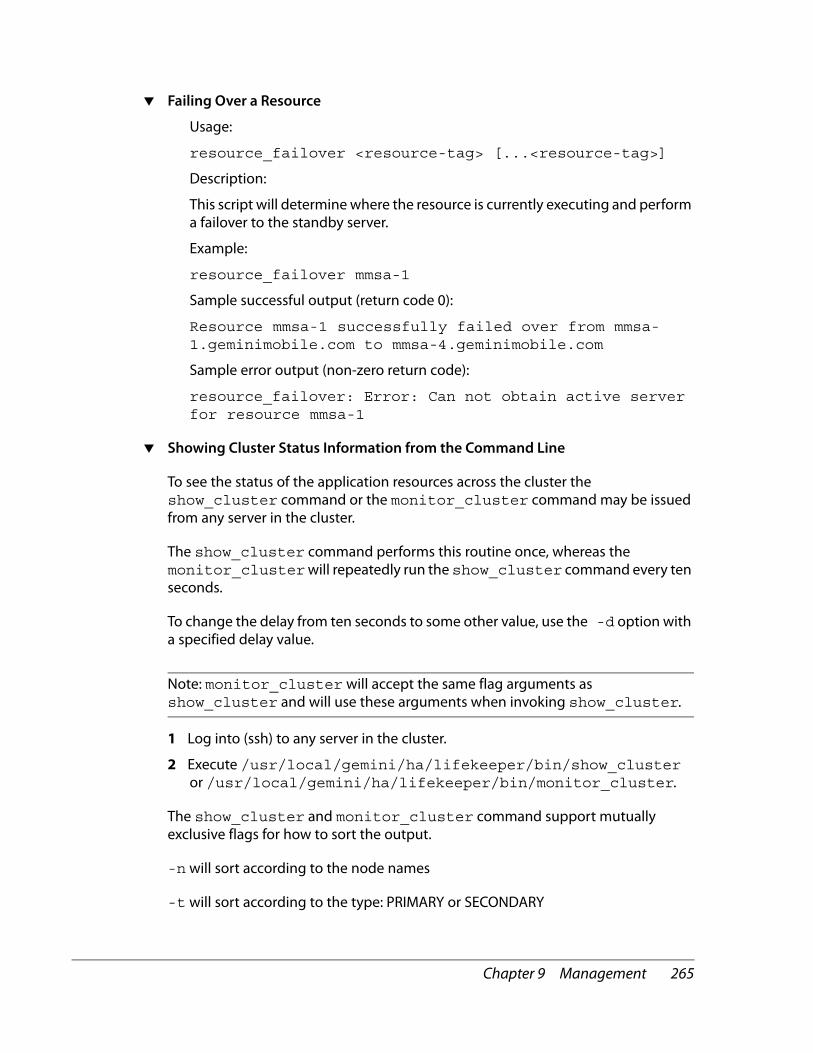
▼ Failing Over a Resource
Usage:
resource_failover <resource-tag> [...<resource-tag>]
Description:
This script will determine where the resource is currently executing and perform a failover to the standby server.
Example:
resource_failover mmsa-1
Sample successful output (return code 0):
Resource mmsa-1 successfully failed over from mmsa-1.geminimobile.com to mmsa-4.geminimobile.com
Sample error output (non-zero return code):
resource_failover: Error: Can not obtain active server for resource mmsa-1
▼ Showing Cluster Status Information from the Command Line
To see the status of the application resources across the cluster the show_cluster command or the monitor_cluster command may be issued from any server in the cluster.
The show_cluster command performs this routine once, whereas the monitor_cluster will repeatedly run the show_cluster command every ten seconds.
To change the delay from ten seconds to some other value, use the -d option with a specified delay value.
Note: monitor_cluster will accept the same flag arguments as show_cluster and will use these arguments when invoking show_cluster.
1 Log into (ssh) to any server in the cluster.
2 Execute /usr/local/gemini/ha/lifekeeper/bin/show_cluster or /usr/local/gemini/ha/lifekeeper/bin/monitor_cluster.
The show_cluster and monitor_cluster command support mutually exclusive flags for how to sort the output.
-n will sort according to the node names
-t will sort according to the type: PRIMARY or SECONDARY
Chapter 9 Management 265
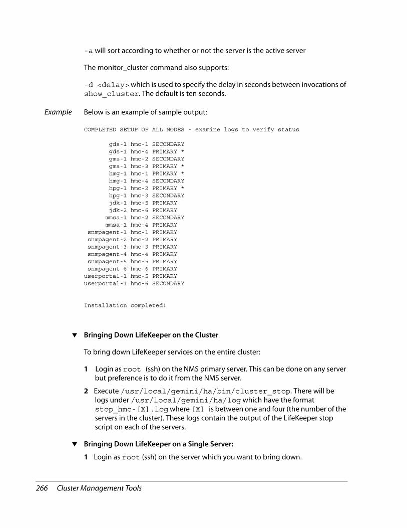
-a will sort according to whether or not the server is the active server
The monitor_cluster command also supports:
-d <delay> which is used to specify the delay in seconds between invocations of show_cluster. The default is ten seconds.
Example Below is an example of sample output:
COMPLETED SETUP OF ALL NODES - examine logs to verify status
gds-1 hmc-1 SECONDARY gds-1 hmc-4 PRIMARY * gms-1 hmc-2 SECONDARY gms-1 hmc-3 PRIMARY * hmg-1 hmc-1 PRIMARY * hmg-1 hmc-4 SECONDARY hpg-1 hmc-2 PRIMARY * hpg-1 hmc-3 SECONDARY jdk-1 hmc-5 PRIMARY jdk-2 hmc-6 PRIMARY mmsa-1 hmc-2 SECONDARY mmsa-1 hmc-4 PRIMARY snmpagent-1 hmc-1 PRIMARY snmpagent-2 hmc-2 PRIMARY snmpagent-3 hmc-3 PRIMARY snmpagent-4 hmc-4 PRIMARY snmpagent-5 hmc-5 PRIMARY snmpagent-6 hmc-6 PRIMARYuserportal-1 hmc-5 PRIMARYuserportal-1 hmc-6 SECONDARY
Installation completed!
▼ Bringing Down LifeKeeper on the Cluster
To bring down LifeKeeper services on the entire cluster:
1 Login as root (ssh) on the NMS primary server. This can be done on any server but preference is to do it from the NMS server.
2 Execute /usr/local/gemini/ha/bin/cluster_stop. There will be logs under /usr/local/gemini/ha/log which have the format stop_hmc-[X].log where [X] is between one and four (the number of the servers in the cluster). These logs contain the output of the LifeKeeper stop script on each of the servers.
▼ Bringing Down LifeKeeper on a Single Server:
1 Login as root (ssh) on the server which you want to bring down.
266 Cluster Management Tools

2 Execute /usr/local/gemini/ha/bin/cluster_stop <server_name>.
3 This will not bring down the resources on this server. If you also want to bring down the resources, then provide the -d flag before the <server_name>. For example
cluster_stop - d
Note When LifeKeeper is brought down in this manner it will not restart automatically.
▼ Bringing Up LifeKeeper on the Cluster
To bring up LifeKeeper services on the entire cluster:
1 Login as root (ssh) on the NMS primary server. This can be done on any server but preference is to do it from the NMS server.
2 Execute /usr/local/gemini/ha/bin/cluster_start. There will be logs under /usr/local/gemini/ha/log which have the format start_<application_name>-[X].log where [X] is between one and four (the number of the servers in the cluster). These logs contain the output of the LifeKeeper startup on each of the servers.
▼ Bringing Up LifeKeeper on a Single Server:
1 Login as root (ssh) to the server which you want to bring up.
2 Execute /usr/local/gemini/ha/bin/cluster_start <server_name>. This will start the LifeKeeper software on the specified server.
Note: This script brings up all of the applications along with the LifeKeeper application. LifeKeeper will now restart automatically at system boot.
Chapter 9 Management 267
Reinstalling or Upgrading Gemini Application SoftwareReinstallation of the HMC software is accomplished by following the same procedures as an initial installation.
LifeKeeper enables continuous operations during system maintenance or application upgrades, significantly reducing or eliminating system downtime.
New software packages must be placed onto each node in the cluster in the same manner as the original packages were.The system_upgrade command is executed which will perform the upgrade of all defined services in the HMC system.
Upgrade software allows roll backs to the initial version, if desired.
268 Reinstalling or Upgrading Gemini Application Software
10 HMC Logging
This chapter covers HMC logging for the HMG, HPG, GMS and NMS nodes. This section covers these topics:
■ About HMC Log File Collection‚ on page 270
■ Setting HMC Log Collection Levels (Priority)‚ on page 271
■ Configuring HMC Logs Using the NMS‚ on page 272
■ About HMG Log File Collection‚ on page 279
■ HMG Log Rotation‚ on page 280
■ HMG Application Logging‚ on page 281
■ HMG Transaction Logging‚ on page 284
■ HMG Statistics Logging‚ on page 287
■ About HPG Log File Collection‚ on page 299
■ HPG Application Logging‚ on page 301
■ HPG Transaction Logging‚ on page 309
■ HPG Statistics Logging‚ on page 319
■ About GMS Log File Collection‚ on page 325
■ GMS Application Logging‚ on page 326
■ GMS Transaction Logging‚ on page 327
■ NMS Server Logs‚ on page 331
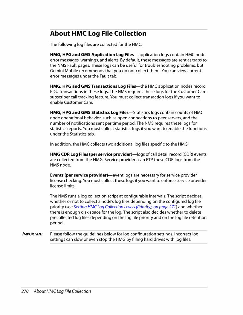
About HMC Log File CollectionThe following log files are collected for the HMC:
HMG, HPG and GMS Application Log Files—application logs contain HMC node error messages, warnings, and alerts. By default, these messages are sent as traps to the NMS Fault pages. These logs can be useful for troubleshooting problems, but Gemini Mobile recommends that you do not collect them. You can view current error messages under the Fault tab.
HMG, HPG and GMS Transactions Log Files—the HMC application nodes record PDU transactions in these logs. The NMS requires these logs for the Customer Care subscriber call tracking feature. You must collect transaction logs if you want to enable Customer Care.
HMG, HPG and GMS Statistics Log Files—Statistics logs contain counts of HMC node operational behavior, such as open connections to peer servers, and the number of notifications sent per time period. The NMS requires these logs for statistics reports. You must collect statistics logs if you want to enable the functions under the Statistics tab.
In addition, the HMC collects two additional log files specific to the HMG:
HMG CDR Log Files (per service provider)—logs of call detail record (CDR) events are collected from the HMG. Service providers can FTP these CDR logs from the NMS node.
Events (per service provider)—event logs are necessary for service provider license checking. You must collect these logs if you want to enforce service provider license limits.
The NMS runs a log collection script at configurable intervals. The script decides whether or not to collect a node’s log files depending on the configured log file priority (see Setting HMC Log Collection Levels (Priority)‚ on page 271) and whether there is enough disk space for the log. The script also decides whether to delete precollected log files depending on the log file priority and on the log file retention period.
IMPORTANT Please follow the guidelines below for log configuration settings. Incorrect log settings can slow or even stop the HMG by filling hard drives with log files.
270 About HMC Log File Collection
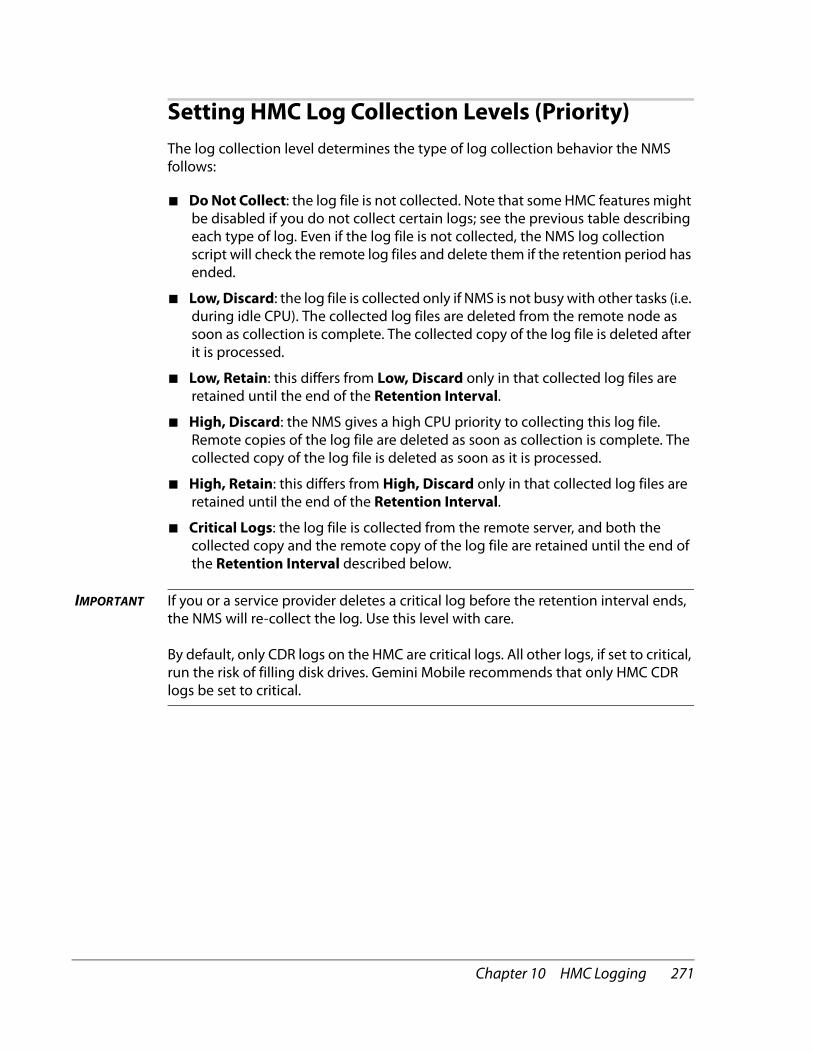
Setting HMC Log Collection Levels (Priority)The log collection level determines the type of log collection behavior the NMS follows:
■ Do Not Collect: the log file is not collected. Note that some HMC features might be disabled if you do not collect certain logs; see the previous table describing each type of log. Even if the log file is not collected, the NMS log collection script will check the remote log files and delete them if the retention period has ended.
■ Low, Discard: the log file is collected only if NMS is not busy with other tasks (i.e. during idle CPU). The collected log files are deleted from the remote node as soon as collection is complete. The collected copy of the log file is deleted after it is processed.
■ Low, Retain: this differs from Low, Discard only in that collected log files are retained until the end of the Retention Interval.
■ High, Discard: the NMS gives a high CPU priority to collecting this log file. Remote copies of the log file are deleted as soon as collection is complete. The collected copy of the log file is deleted as soon as it is processed.
■ High, Retain: this differs from High, Discard only in that collected log files are retained until the end of the Retention Interval.
■ Critical Logs: the log file is collected from the remote server, and both the collected copy and the remote copy of the log file are retained until the end of the Retention Interval described below.
IMPORTANT If you or a service provider deletes a critical log before the retention interval ends, the NMS will re-collect the log. Use this level with care. By default, only CDR logs on the HMC are critical logs. All other logs, if set to critical, run the risk of filling disk drives. Gemini Mobile recommends that only HMC CDR logs be set to critical.
Chapter 10 HMC Logging 271
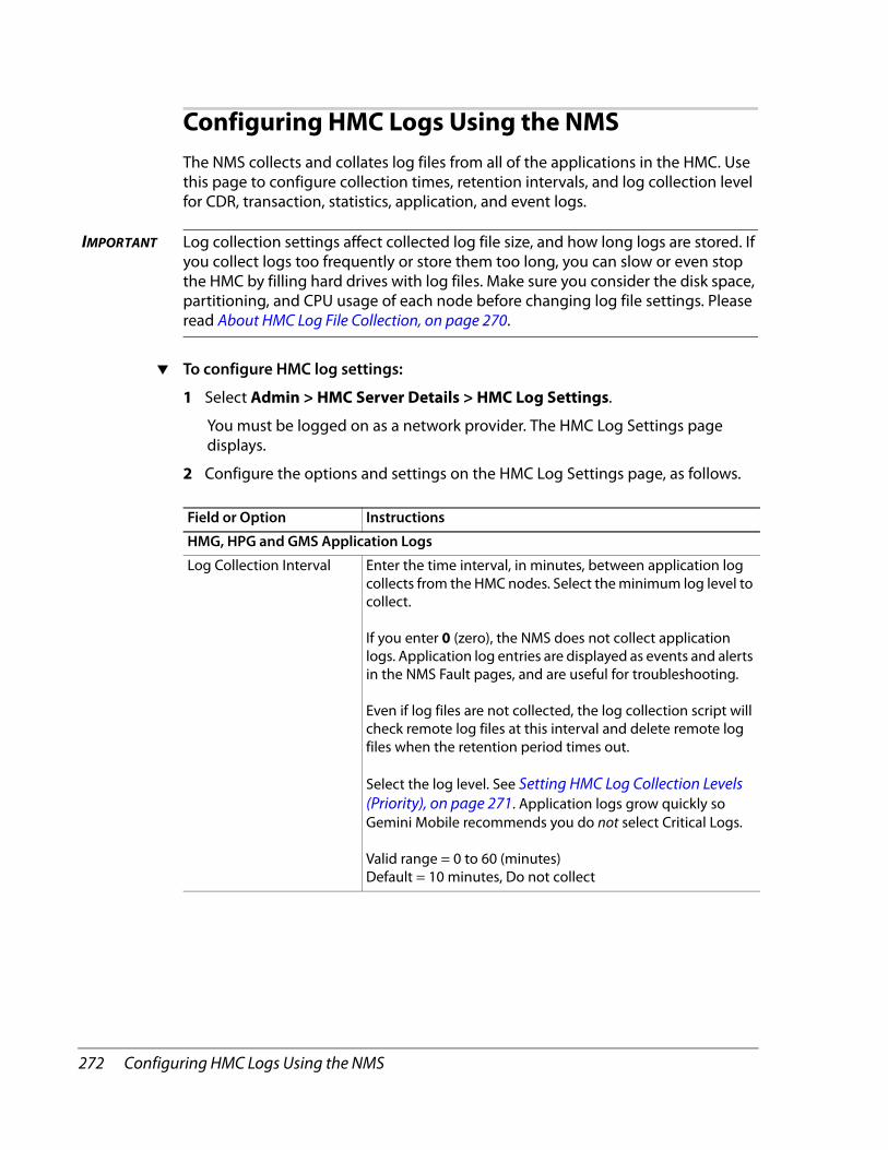
Configuring HMC Logs Using the NMS The NMS collects and collates log files from all of the applications in the HMC. Use this page to configure collection times, retention intervals, and log collection level for CDR, transaction, statistics, application, and event logs.
IMPORTANT Log collection settings affect collected log file size, and how long logs are stored. If you collect logs too frequently or store them too long, you can slow or even stop the HMC by filling hard drives with log files. Make sure you consider the disk space, partitioning, and CPU usage of each node before changing log file settings. Please read About HMC Log File Collection‚ on page 270.
▼ To configure HMC log settings:
1 Select Admin > HMC Server Details > HMC Log Settings.
You must be logged on as a network provider. The HMC Log Settings page displays.
2 Configure the options and settings on the HMC Log Settings page, as follows.
Field or Option Instructions
HMG, HPG and GMS Application Logs
Log Collection Interval Enter the time interval, in minutes, between application log collects from the HMC nodes. Select the minimum log level to collect.
If you enter 0 (zero), the NMS does not collect application logs. Application log entries are displayed as events and alerts in the NMS Fault pages, and are useful for troubleshooting.
Even if log files are not collected, the log collection script will check remote log files at this interval and delete remote log files when the retention period times out.
Select the log level. See Setting HMC Log Collection Levels (Priority)‚ on page 271. Application logs grow quickly so Gemini Mobile recommends you do not select Critical Logs.
Valid range = 0 to 60 (minutes)Default = 10 minutes, Do not collect
272 Configuring HMC Logs Using the NMS

Retention Interval, Format Enter the amount of time to keep collected application logs on the NMS server. The lower the priority of a log, the more likely the log will be deleted before the retention period ends.
Select the unit of time (either hours or days).
Check the Zipped box if you want the files compressed.
Valid range = 1 hour to 90 daysDefault = 7 days, zipped
Log File Name You cannot change this field. This field shows the template for naming the log files. By default, each log file name includes a time stamp. The HMC nodes roll log files at regular intervals; thus log file names are not static. In the naming format for rotated logs, the <TIME> field will be in format YYYYMMDDHHMMSS, and the <SEQNUM> field is a locally generated sequence number unique for the node and file type.
Default ...-app_.*
HMG, HPG and GMS Transaction Logs
Log Collection Interval Enter the time interval, in minutes, between transaction log harvests from the HMC nodes. Select the minimum log level to collect.
Even if log files are not collected, the log collection script will check remote log files at this interval and delete remote log files when the retention period times out.
If you enter 0 (zero), the NMS does not collect transaction logs.
The transaction logs record transactions between the HMG and HPG and peer servers (such as the HMG exchanges with E-mail or FAX servers, and HPG exchanges with SMSCs and handsets).Important: these logs are required for the Customer Care feature.
Select the log level. See Setting HMC Log Collection Levels (Priority)‚ on page 271. Transaction logs grow quickly so Gemini Mobile does not recommend a setting of Critical Logs.
Valid range = 0 to 60 (minutes)Default = 10 minutes, Low Priority, Retain
Field or Option Instructions
Chapter 10 HMC Logging 273

Retention Interval, Format Enter the amount of time to keep collected transaction logs on the NMS server. The lower the priority of a log, the more likely the log will be deleted before the retention period ends.
Select the unit of time (either hours or days).
Check the Zipped box if you want the files compressed.
Valid range = 1 hour to 90 daysDefault = 7 days, zipped
Log File Name You cannot change this field. This field shows the template for naming the log files. By default, each log file name includes a time stamp. The HMC nodes roll log files at regular intervals; thus log file names are not static. In the naming format for rotated logs, the <TIME> field will be in format YYYYMMDDHHMMSS, and the <SEQNUM> field is a locally generated sequence number unique for the node and file type.
Default ...-tx_.*
HMG, HPG and GMS Statistics Logs
Log Collection Interval Enter the time interval, in minutes, between statistics log harvests from the HMC nodes. Select the minimum log level to collect.
If you enter 0 (zero), the NMS does not collect statistics logs.
Even if log files are not collected, the log collection script will check remote log files at this interval and delete remote log files when the retention period times out.
Select the log level. See Setting HMC Log Collection Levels (Priority)‚ on page 271.
Important: You must collect these logs if you want to enable Statistics tab functions.
Valid range = 0 to 60 (minutes)Default = 10 minutes, High Priority, Discard (these files have high priority but can be deleted after processing).
Field or Option Instructions
274 Configuring HMC Logs Using the NMS
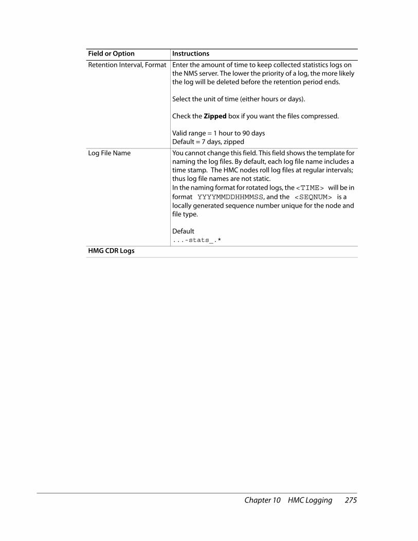
Retention Interval, Format Enter the amount of time to keep collected statistics logs on the NMS server. The lower the priority of a log, the more likely the log will be deleted before the retention period ends.
Select the unit of time (either hours or days).
Check the Zipped box if you want the files compressed.
Valid range = 1 hour to 90 daysDefault = 7 days, zipped
Log File Name You cannot change this field. This field shows the template for naming the log files. By default, each log file name includes a time stamp. The HMC nodes roll log files at regular intervals; thus log file names are not static. In the naming format for rotated logs, the <TIME> will be in format YYYYMMDDHHMMSS, and the <SEQNUM> is a locally generated sequence number unique for the node and file type.
Default ...-stats_.*
HMG CDR Logs
Field or Option Instructions
Chapter 10 HMC Logging 275
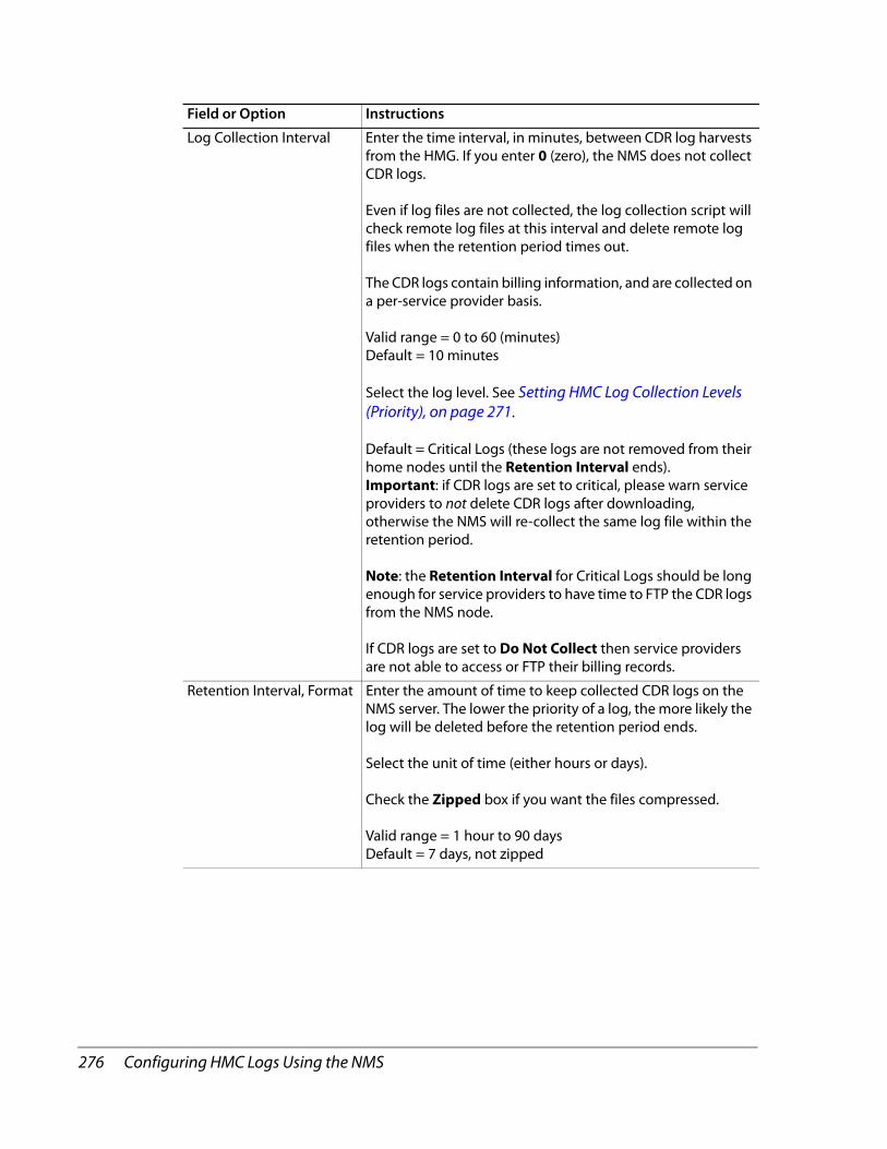
Log Collection Interval Enter the time interval, in minutes, between CDR log harvests from the HMG. If you enter 0 (zero), the NMS does not collect CDR logs.
Even if log files are not collected, the log collection script will check remote log files at this interval and delete remote log files when the retention period times out.
The CDR logs contain billing information, and are collected on a per-service provider basis.
Valid range = 0 to 60 (minutes)Default = 10 minutes
Select the log level. See Setting HMC Log Collection Levels (Priority)‚ on page 271.
Default = Critical Logs (these logs are not removed from their home nodes until the Retention Interval ends).Important: if CDR logs are set to critical, please warn service providers to not delete CDR logs after downloading, otherwise the NMS will re-collect the same log file within the retention period.
Note: the Retention Interval for Critical Logs should be long enough for service providers to have time to FTP the CDR logs from the NMS node.
If CDR logs are set to Do Not Collect then service providers are not able to access or FTP their billing records.
Retention Interval, Format Enter the amount of time to keep collected CDR logs on the NMS server. The lower the priority of a log, the more likely the log will be deleted before the retention period ends.
Select the unit of time (either hours or days).
Check the Zipped box if you want the files compressed.
Valid range = 1 hour to 90 daysDefault = 7 days, not zipped
Field or Option Instructions
276 Configuring HMC Logs Using the NMS

Log File Name You cannot change this field. This field shows the template for naming the log files. By default, each log file name includes a time stamp. The HHC nodes roll log files at regular intervals; thus log file names are not static. In the naming format for rotated logs, the <TIME> field will be in format YYYYMMDDHHMMSS, and the <SEQNUM> field is a locally generated sequence number unique for the node and file type.
Default ...-cdr_.*
HMG Event Logs
Log Collection Interval Enter the time interval, in minutes, between event log harvests from the HMC nodes.
If you enter 0 (zero), the NMS does not collect event logs.
Important: Without event logs, service provider license enforcement does not work. The event logs contain per-service provider messaging counts, which the NMS tracks for licensing purposes. Each service provider has a messages per second limit (MPS) and the NMS sends alerts if the limit is exceeded.
Set the log level. See Setting HMC Log Collection Levels (Priority)‚ on page 271. Gemini Mobile recommends a level of High Priority, Discard to save disc space (files are deleted after processing).
Caution: Do not set the event log level to Critical as this will slow down license processing due to redundancy.
Valid range = 0 to 60 (minutes)Default = 10 minutes, High Priority, Discard
Field or Option Instructions
Chapter 10 HMC Logging 277
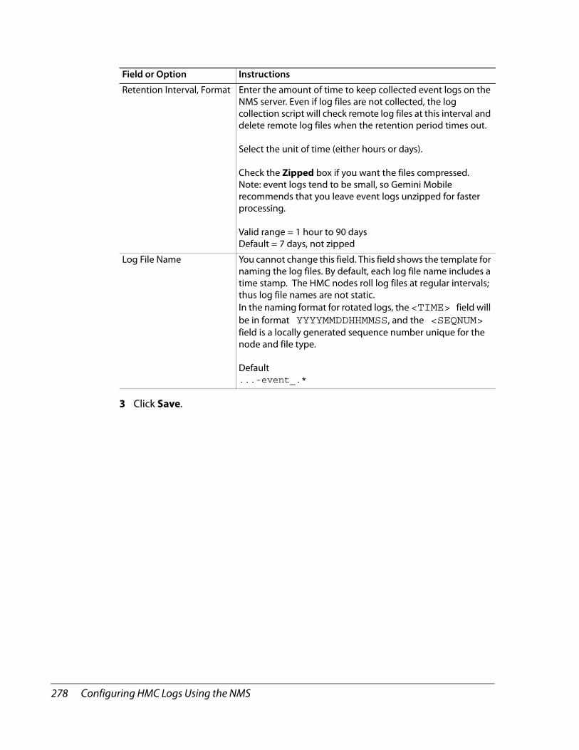
3 Click Save.
Retention Interval, Format Enter the amount of time to keep collected event logs on the NMS server. Even if log files are not collected, the log collection script will check remote log files at this interval and delete remote log files when the retention period times out.
Select the unit of time (either hours or days).
Check the Zipped box if you want the files compressed. Note: event logs tend to be small, so Gemini Mobile recommends that you leave event logs unzipped for faster processing.
Valid range = 1 hour to 90 daysDefault = 7 days, not zipped
Log File Name You cannot change this field. This field shows the template for naming the log files. By default, each log file name includes a time stamp. The HMC nodes roll log files at regular intervals; thus log file names are not static. In the naming format for rotated logs, the <TIME> field will be in format YYYYMMDDHHMMSS, and the <SEQNUM> field is a locally generated sequence number unique for the node and file type.
Default ...-event_.*
Field or Option Instructions
278 Configuring HMC Logs Using the NMS
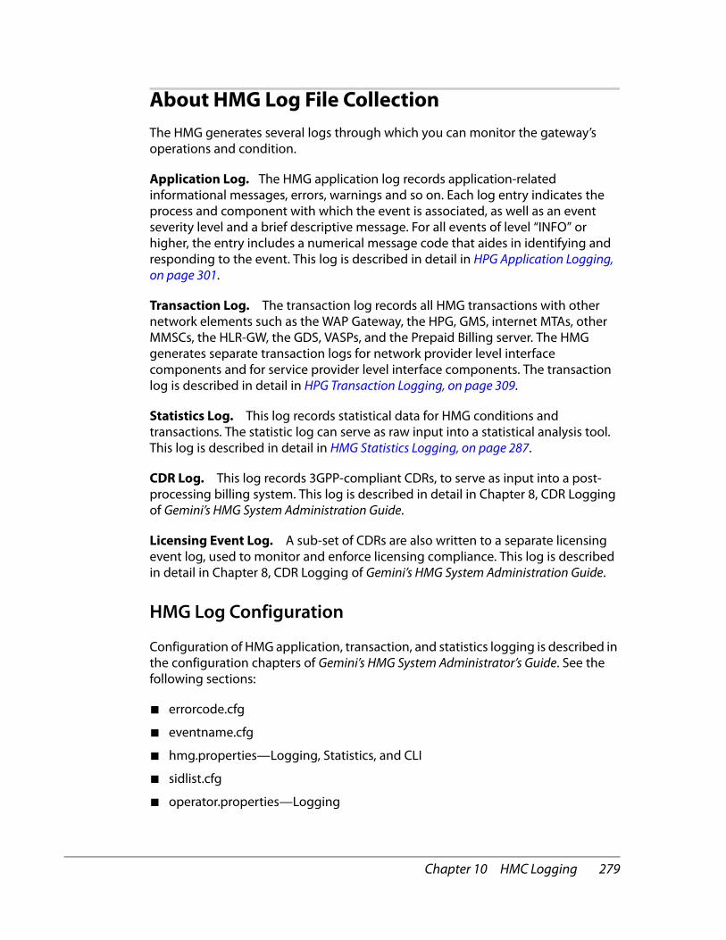
About HMG Log File CollectionThe HMG generates several logs through which you can monitor the gateway’s operations and condition.
Application Log. The HMG application log records application-related informational messages, errors, warnings and so on. Each log entry indicates the process and component with which the event is associated, as well as an event severity level and a brief descriptive message. For all events of level “INFO” or higher, the entry includes a numerical message code that aides in identifying and responding to the event. This log is described in detail in HPG Application Logging‚ on page 301.
Transaction Log. The transaction log records all HMG transactions with other network elements such as the WAP Gateway, the HPG, GMS, internet MTAs, other MMSCs, the HLR-GW, the GDS, VASPs, and the Prepaid Billing server. The HMG generates separate transaction logs for network provider level interface components and for service provider level interface components. The transaction log is described in detail in HPG Transaction Logging‚ on page 309.
Statistics Log. This log records statistical data for HMG conditions and transactions. The statistic log can serve as raw input into a statistical analysis tool. This log is described in detail in HMG Statistics Logging‚ on page 287.
CDR Log. This log records 3GPP-compliant CDRs, to serve as input into a post-processing billing system. This log is described in detail in Chapter 8, CDR Logging of Gemini’s HMG System Administration Guide.
Licensing Event Log. A sub-set of CDRs are also written to a separate licensing event log, used to monitor and enforce licensing compliance. This log is described in detail in Chapter 8, CDR Logging of Gemini’s HMG System Administration Guide.
HMG Log Configuration
Configuration of HMG application, transaction, and statistics logging is described in the configuration chapters of Gemini’s HMG System Administrator’s Guide. See the following sections:
■ errorcode.cfg
■ eventname.cfg
■ hmg.properties—Logging, Statistics, and CLI
■ sidlist.cfg
■ operator.properties—Logging
Chapter 10 HMC Logging 279
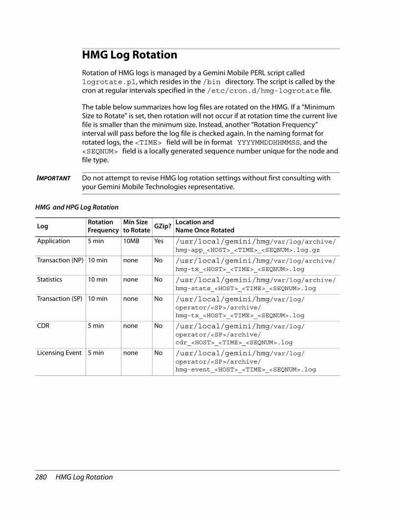
HMG Log RotationRotation of HMG logs is managed by a Gemini Mobile PERL script called logrotate.pl, which resides in the /bin directory. The script is called by the cron at regular intervals specified in the /etc/cron.d/hmg-logrotate file.
The table below summarizes how log files are rotated on the HMG. If a “Minimum Size to Rotate” is set, then rotation will not occur if at rotation time the current live file is smaller than the minimum size. Instead, another “Rotation Frequency” interval will pass before the log file is checked again. In the naming format for rotated logs, the <TIME> field will be in format YYYYMMDDHHMMSS, and the <SEQNUM> field is a locally generated sequence number unique for the node and file type.
IMPORTANT Do not attempt to revise HMG log rotation settings without first consulting with your Gemini Mobile Technologies representative.
HMG and HPG Log Rotation
LogRotation Frequency
Min Size to Rotate
GZip?Location and Name Once Rotated
Application 5 min 10MB Yes /usr/local/gemini/hmg/var/log/archive/hmg-app_<HOST>_<TIME>_<SEQNUM>.log.gz
Transaction (NP) 10 min none No /usr/local/gemini/hmg/var/log/archive/ hmg-tx_<HOST>_<TIME>_<SEQNUM>.log
Statistics 10 min none No /usr/local/gemini/hmg/var/log/archive/ hmg-stats_<HOST>_<TIME>_<SEQNUM>.log
Transaction (SP) 10 min none No /usr/local/gemini/hmg/var/log/operator/<SP>/archive/ hmg-tx_<HOST>_<TIME>_<SEQNUM>.log
CDR 5 min none No /usr/local/gemini/hmg/var/log/operator/<SP>/archive/ cdr_<HOST>_<TIME>_<SEQNUM>.log
Licensing Event 5 min none No /usr/local/gemini/hmg/var/log/operator/<SP>/archive/ hmg-event_<HOST>_<TIME>_<SEQNUM>.log
280 HMG Log Rotation
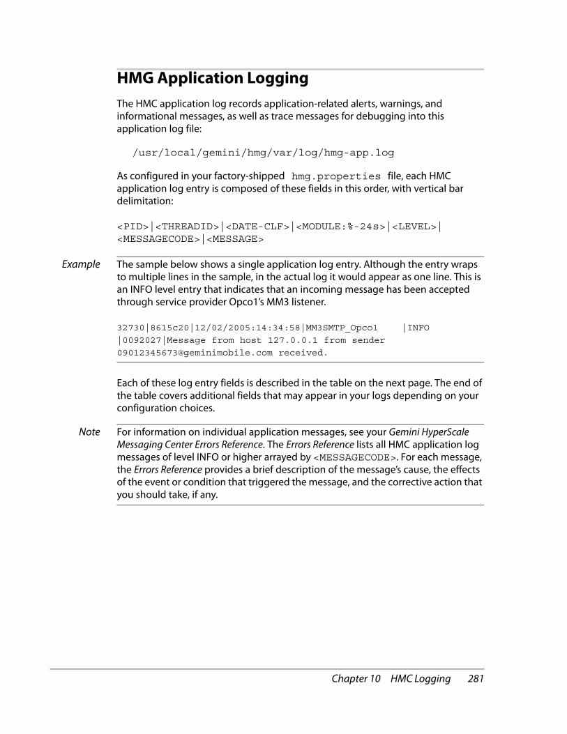
HMG Application LoggingThe HMC application log records application-related alerts, warnings, and informational messages, as well as trace messages for debugging into this application log file:
/usr/local/gemini/hmg/var/log/hmg-app.log
As configured in your factory-shipped hmg.properties file, each HMC application log entry is composed of these fields in this order, with vertical bar delimitation:
<PID>|<THREADID>|<DATE-CLF>|<MODULE:%-24s>|<LEVEL>| <MESSAGECODE>|<MESSAGE>
Example The sample below shows a single application log entry. Although the entry wraps to multiple lines in the sample, in the actual log it would appear as one line. This is an INFO level entry that indicates that an incoming message has been accepted through service provider Opco1’s MM3 listener. 32730|8615c20|12/02/2005:14:34:58|MM3SMTP_Opco1 |INFO
|0092027|Message from host 127.0.0.1 from sender
[email protected] received.
Each of these log entry fields is described in the table on the next page. The end of the table covers additional fields that may appear in your logs depending on your configuration choices.
Note For information on individual application messages, see your Gemini HyperScale Messaging Center Errors Reference. The Errors Reference lists all HMC application log messages of level INFO or higher arrayed by <MESSAGECODE>. For each message, the Errors Reference provides a brief description of the message’s cause, the effects of the event or condition that triggered the message, and the corrective action that you should take, if any.
Chapter 10 HMC Logging 281

Application Log Fields (Part 1 of 2)
Field Description
<PID> System-assigned process identifier (PID) of the HMC process that generated the log message. Because multiple HMC processes write to the application log, sometimes nearly simultaneously, it is important to pay attention to the PID associated with each message.
A running HMC will be composed of two or more hmg processes (a parent process plus one or more child processes as configured in hmg.prop?rties), plus several synchelper processes (a parent, a child, plus one grand-child for each queue data file). Each of these processes will have its own PID.
<THREADID> Internal processing thread with which the message is associated.
<DATE-CLF> The date and time of the log entry in the following format: DD/MM/YYYY:HH:MM:SS
<MODULE:%-24s> The internal HMC component with which the message is associated. For example, the component may be a particular listener or queue processor or connection pool. If the component is a service provider level component (used exclusively for a particular hosted service provider), a service provider ID suffix is part of the component name.
This field is a minimum of 24 spaces. If the component name is less than 24 characters, it is appended with blank spaces until the 24 space minimum is reached for the field.
<LEVEL> The severity level of the message. The level will be one of the following: ◆ ALERT
A condition requiring immediate correction.◆ WARNG
A warning message, indicating a potential problem.◆ INFO
An informational message, indicating normal activity.◆ DEBUG
A highly granular, process-descriptive message potentially of use when debugging the application.
<MESSAGECODE> Integer code assigned to all messages of level ‘INFO’ level or higher. For DEBUG messages this field will be empty.
For an overview of the message code schema and for a complete list of messages arrayed by message code, see your Gemini HyperScale Messaging Center Errors Reference.
<MESSAGE> The message itself—a brief description of the event being logged.
282 HMG Application Logging

Additional Supported Fields
<TIME-24> Timestamp in format HH:MM:SS.
<UNIX-TIME> Timestamp in seconds since 1/1/70 00:00:00 GMT.
Application Log Fields (Part 2 of 2)
Field Description
Chapter 10 HMC Logging 283
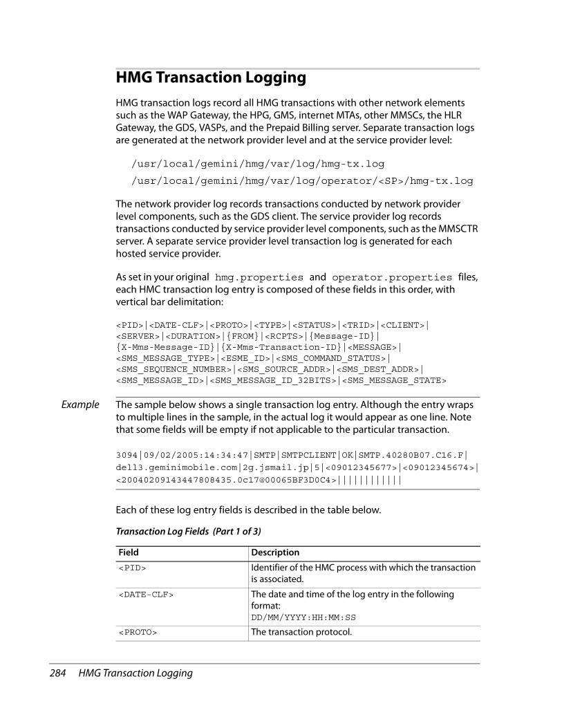
HMG Transaction LoggingHMG transaction logs record all HMG transactions with other network elements such as the WAP Gateway, the HPG, GMS, internet MTAs, other MMSCs, the HLR Gateway, the GDS, VASPs, and the Prepaid Billing server. Separate transaction logs are generated at the network provider level and at the service provider level:
/usr/local/gemini/hmg/var/log/hmg-tx.log
/usr/local/gemini/hmg/var/log/operator/<SP>/hmg-tx.log
The network provider log records transactions conducted by network provider level components, such as the GDS client. The service provider log records transactions conducted by service provider level components, such as the MMSCTR server. A separate service provider level transaction log is generated for each hosted service provider.
As set in your original hmg.properties and operator.properties files, each HMC transaction log entry is composed of these fields in this order, with vertical bar delimitation:
<PID>|<DATE-CLF>|<PROTO>|<TYPE>|<STATUS>|<TRID>|<CLIENT>| <SERVER>|<DURATION>|{FROM}|<RCPTS>|{Message-ID}| {X-Mms-Message-ID}|{X-Mms-Transaction-ID}|<MESSAGE>| <SMS_MESSAGE_TYPE>|<ESME_ID>|<SMS_COMMAND_STATUS>| <SMS_SEQUENCE_NUMBER>|<SMS_SOURCE_ADDR>|<SMS_DEST_ADDR>| <SMS_MESSAGE_ID>|<SMS_MESSAGE_ID_32BITS>|<SMS_MESSAGE_STATE>
Example The sample below shows a single transaction log entry. Although the entry wraps to multiple lines in the sample, in the actual log it would appear as one line. Note that some fields will be empty if not applicable to the particular transaction. 3094|09/02/2005:14:34:47|SMTP|SMTPCLIENT|OK|SMTP.40280B07.C16.F|
dell3.geminimobile.com|2g.jsmail.jp|5|<09012345677>|<09012345674>|
<20040209143447808435.0c17@00065BF3D0C4>||||||||||||
Each of these log entry fields is described in the table below.
Transaction Log Fields (Part 1 of 3)
Field Description
<PID> Identifier of the HMC process with which the transaction is associated.
<DATE-CLF> The date and time of the log entry in the following format:DD/MM/YYYY:HH:MM:SS
<PROTO> The transaction protocol.
284 HMG Transaction Logging
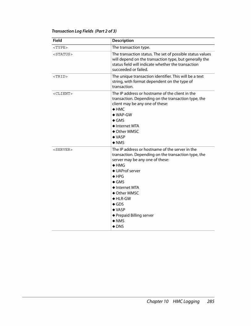
<TYPE> The transaction type.
<STATUS> The transaction status. The set of possible status values will depend on the transaction type, but generally the status field will indicate whether the transaction succeeded or failed.
<TRID> The unique transaction identifier. This will be a text string, with format dependent on the type of transaction.
<CLIENT> The IP address or hostname of the client in the transaction. Depending on the transaction type, the client may be any one of these:◆ HMC◆ WAP-GW◆ GMS◆ Internet MTA◆ Other MMSC◆ VASP◆ NMS
<SERVER> The IP address or hostname of the server in the transaction. Depending on the transaction type, the server may be any one of these:◆ HMG◆ UAProf server◆ HPG◆ GMS◆ Internet MTA◆ Other MMSC◆ HLR-GW◆ GDS◆ VASP◆ Prepaid Billing server◆ NMS◆ DNS
Transaction Log Fields (Part 2 of 3)
Field Description
Chapter 10 HMC Logging 285
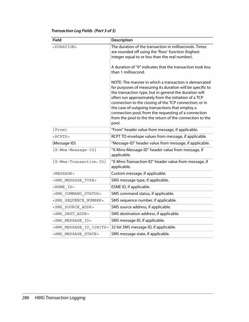
<DURATION> The duration of the transaction in milliseconds. Times are rounded off using the ‘floor’ function (highest integer equal to or less than the real number).
A duration of “0” indicates that the transaction took less than 1 millisecond.
NOTE: The manner in which a transaction is demarcated for purposes of measuring its duration will be specific to the transaction type, but in general the duration will often run approximately from the initiation of a TCP connection to the closing of the TCP connection; or in the case of outgoing transactions that employ a connection pool, from the requesting of a connection from the pool to the the return of the connection to the pool.
{From} “From” header value from message, if applicable.
<RCPTS> RCPT TO envelope values from message, if applicable.
{Message-ID} “Message-ID” header value from message, if applicable.
{X-Mms-Message-ID} “X-Mms-Message-ID” header value from message, if applicable.
{X-Mms-Transaction-ID} “X-Mms-Transaction-ID” header value from message, if applicable.
<MESSAGE> Custom message, if applicable.
<SMS_MESSAGE_TYPE> SMS message type, if applicable.
<ESME_ID> ESME ID, if applicable.
<SMS_COMMAND_STATUS> SMS command status, if applicable.
<SMS_SEQUENCE_NUMBER> SMS sequence number, if applicable.
<SMS_SOURCE_ADDR> SMS source address, if applicable.
<SMS_DEST_ADDR> SMS destination address, if applicable.
<SMS_MESSAGE_ID> SMS message ID, if applicable.
<SMS_MESSAGE_ID_32BITS> 32 bit SMS message ID, if applicable.
<SMS_MESSAGE_STATE> SMS message state, if applicable.
Transaction Log Fields (Part 3 of 3)
Field Description
286 HMG Transaction Logging

HMG Statistics LoggingThe HMG makes statistics available to you in three different ways:
■ A limited set of real-time statistics is available through the HMG’s command line interface. Through the show stat command you can instantly check on important state indicators such as the number of open connections currently held by HMG listeners and connection pools or the number of messages in HMG delivery queues.
■ The same set of statistics that is available through the CLI for real-time viewing can also be recorded to the HMG’s application log at a configurable interval, providing a series of snapshots of HMG status throughout the day.
■ A broader, comprehensive set of transaction and state data is recorded to a raw statistics log, to serve as input to a statistics analysis tool. If you are using the Gemini Mobile Technologies NMS, the NMS will retrieve these raw statistics logs and use them to generate performance reports.
This section describes how the HMG records statistics in the application log and in the statistics log. The material is divided into these sub-sections:
■ Statistics in the Application Log‚ on page 287
■ Statistics in the Statistics Log‚ on page 288
Statistics in the Application Log
If you wish, you can have the HMG periodically write to the application log the same set of statistics that you can view in real time through the CLI. There are settings for enabling or disabling this feature, and for setting the write interval.
At each writing, the HMG logs all of the CLI-viewable statistics, with one log entry line for each statistic. The entries are formatted in the same way as other application log entries. The log severity level is “INFO”, and the statistic name and value appear in the <MESSAGE> field, prefixed by the string “STATS DUMP”. For description of application log formatting, see page 301.
Example These sample entries show how writes of HMG statistics to the application log are formatted. Although each entry wraps to a second line in the sample, in the actual log each entry would appear as one line. All statistics are written at the same time, with one line for each statistic. The MM4SMTP listener statistics are for service provider “MobileCo.” 10312|16815c20|12/02/2005:12:34:58|STATSMGR |INFO |0090002|STATS DUMP: CLI.conn.ope
Chapter 10 HMC Logging 287

= 10312|16815c20|12/02/2005:12:34:58|STATSMGR |INFO |0090002|STATS DUMP: CLI.conn.handled=3 10312|16815c20|12/02/2005:12:34:58|STATSMGR |INFO |0090002|STATS DUMP: MM4SMTP_MobileCo.conn.open=4 10312|16815c20|12/02/2005:12:34:58|STATSMGR |INFO |0090002|STATS DUMP: MM4SMTP_MobileCo.conn.handled=58 ...
Statistics in the Statistics Log
The HMG writes a wide variety of raw statistical data into the statistics log file, which by default is:
/usr/local/gemini/hmg/var/log/hmg-stats.log
You can configure which statistics to log, the format of statistics log entries, and the frequency with which to log sample point data.
Entries into the statistics log file are of two basic types:
■ Transaction entries, such as the submitting of a GDS query or the receiving of a message through the MM4 listener. These individual event records can be tallied by a post-processing tool to produce aggregate counts for specific transaction types (such as total GDS queries submitted or MM4 messages received) over a specified time interval. In certain cases, a single transaction can result in several types of entries to the statistics log as described in Variants of Sending Transaction Statistics‚ on page 290.
■ Sample point entries that gauge current HMG conditions, such as the number of connections currently open to the MMSCTR listener or the number of messages currently queued for delivery to MM3 destinations. Sample point data can be used by a post-processing tool to generate minimum, maximum, and average statistics for a specified time interval—for example, the average number of connections open to the MMSCTR listener or the maximum number of messages queued for MM3 delivery during the interval.
Both of these statistics log entry types are composed of these fields in this order, with comma delimitation:
<DATETIME>,<STAT_ID>,<STAT_VALUE>,<DOMAIN>,<STATUS>
Example The sample below shows two statistics log entries. The first entry is a transactional event (a message received by the MM4 listener for service provider “MobileCo”) and the second entry is a sample point for a state statistic (number of open connections
288 HMG Statistics Logging
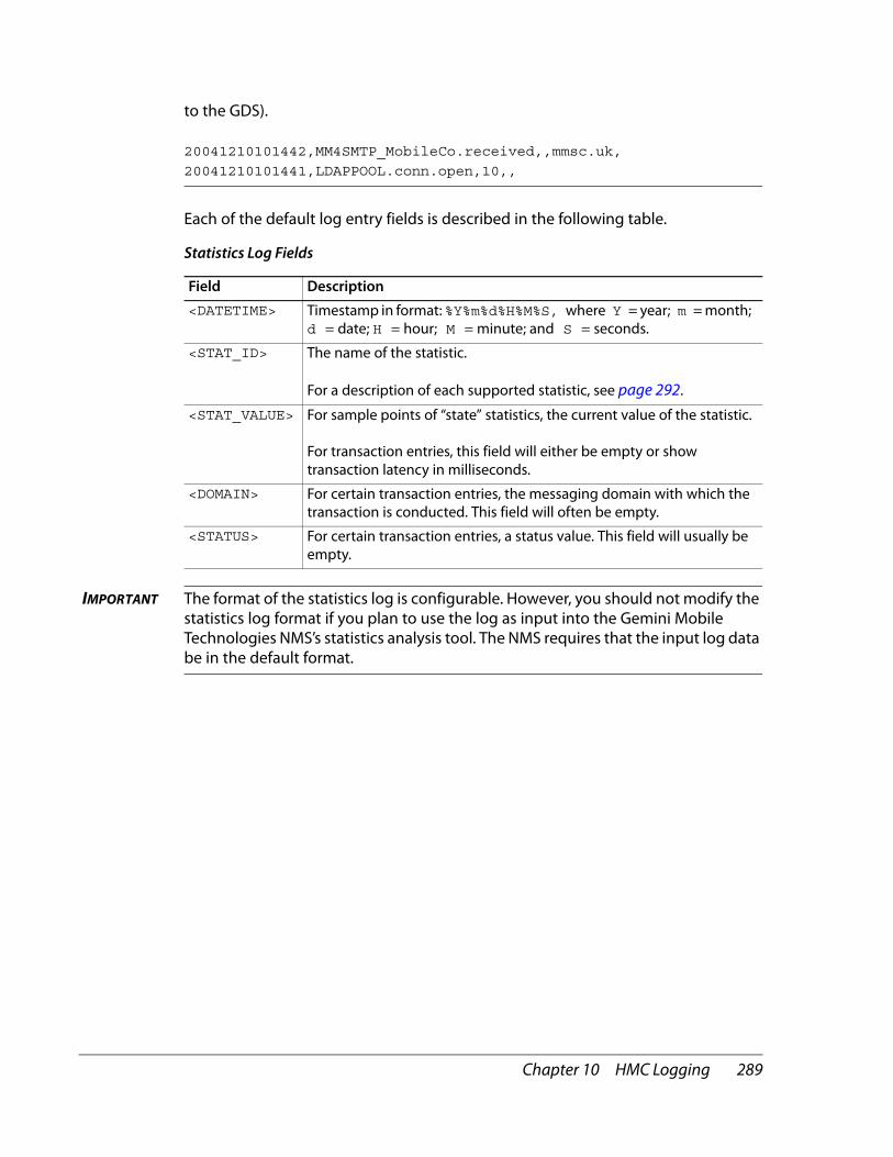
to the GDS). 20041210101442,MM4SMTP_MobileCo.received,,mmsc.uk, 20041210101441,LDAPPOOL.conn.open,10,,
Each of the default log entry fields is described in the following table.
IMPORTANT The format of the statistics log is configurable. However, you should not modify the statistics log format if you plan to use the log as input into the Gemini Mobile Technologies NMS’s statistics analysis tool. The NMS requires that the input log data be in the default format.
Statistics Log Fields
Field Description
<DATETIME> Timestamp in format: %Y%m%d%H%M%S, where Y = year; m = month; d = date; H = hour; M = minute; and S = seconds.
<STAT_ID> The name of the statistic.
For a description of each supported statistic, see page 292.
<STAT_VALUE> For sample points of “state” statistics, the current value of the statistic.
For transaction entries, this field will either be empty or show transaction latency in milliseconds.
<DOMAIN> For certain transaction entries, the messaging domain with which the transaction is conducted. This field will often be empty.
<STATUS> For certain transaction entries, a status value. This field will usually be empty.
Chapter 10 HMC Logging 289

Variants of Sending Transaction Statistics
For messages or queries that the HMG sends to target servers, several variants of statistics are supported for each message or query type:
■ <COMPONENT>.<requesttype>—This statistic indicates an attempt by the HMC to send a message or query to a target server. This statistic is logged for an initial attempt at sending the message or query, and also for each retry attempt in the event that the first attempt encounters a temporary error.
■ <COMPONENT>.<requesttype>.initial—This statistic indicates an initial attempt by the HMG to send a message or query to a target server. This statistic is not logged for retry attempts.
■ <COMPONENT>.<requesttype>.success—This statistic indicates a successful attempt by the HMC to send a message or query to a target server.
■ <COMPONENT>.<requesttype>.expire—This statistic indicates that a message or query has expired due to retry limits being reached, after repeatedly encountering temporary errors.
■ <COMPONENT>.<requesttype>.permerror—This statistic indicates that an attempt to send a message or query has encountered a permanent error.
In most cases, a single sending transaction will result in several entries to the statistics log.
Example The example below shows the entries that are recorded to the statistics log when the HMC submits a query to the GDS and the query succeeds on the first attempt. 20050510101441,LDAPMGR.query,,, 20050510101441,LDAPMGR.query.initial,,, 20050510101441,LDAPMGR.query.success,,, The single GDS transaction results in three separate entries to the raw statistics log which in post-processing can support three separate tallies: total number of queries to the GDS server; number of initial queries to the GDS server (excluding retries); and number of successful queries to the GDS server.
Example The example below shows the entries that are recorded to the statistics log when a retry attempt at storing a message to the GMS encounters a permanent error. 20050612111434,MM2IF.store,,, 20050612111434,MM2IF.store.permerror,,, Note that there is no MM2IF.store.initial entry because the sending attempt was a retry.
290 HMG Statistics Logging
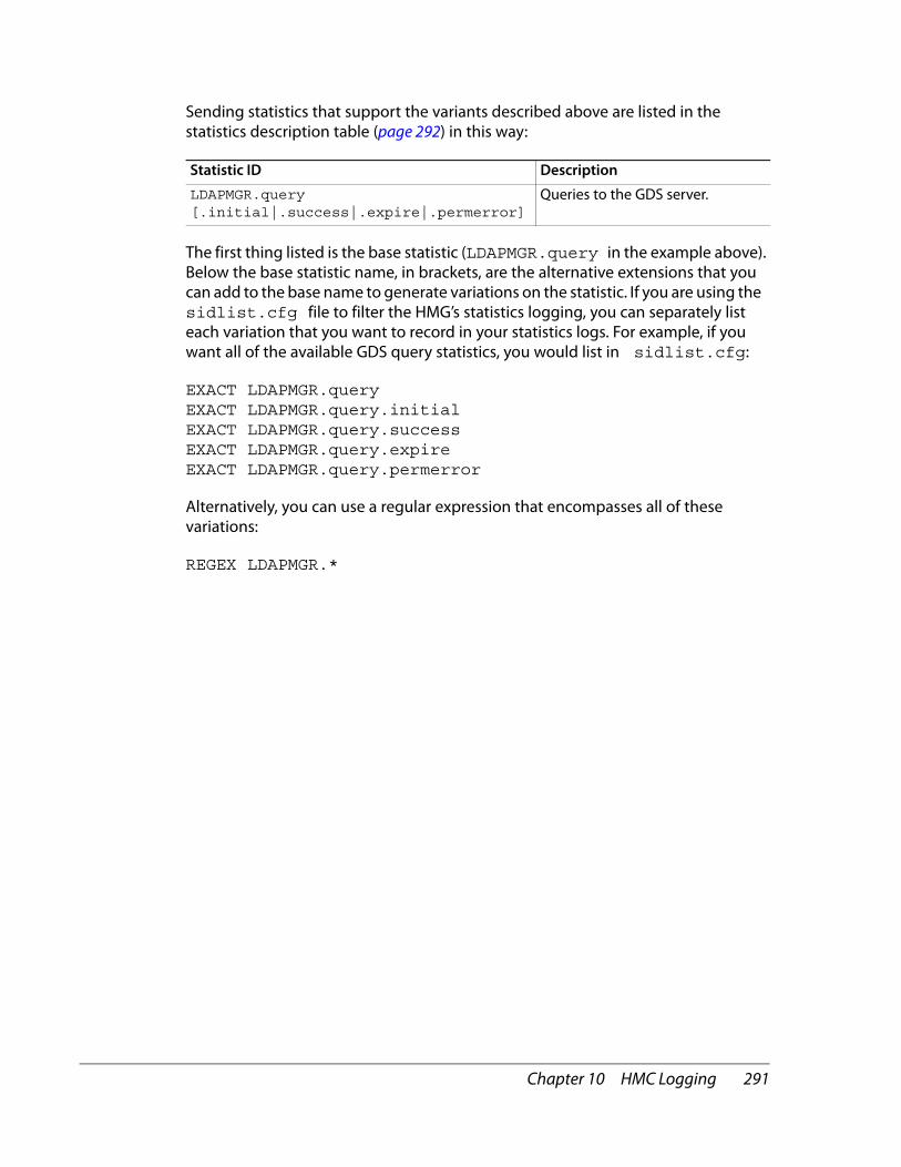
Sending statistics that support the variants described above are listed in the statistics description table (page 292) in this way:
The first thing listed is the base statistic (LDAPMGR.query in the example above). Below the base statistic name, in brackets, are the alternative extensions that you can add to the base name to generate variations on the statistic. If you are using the sidlist.cfg file to filter the HMG’s statistics logging, you can separately list each variation that you want to record in your statistics logs. For example, if you want all of the available GDS query statistics, you would list in sidlist.cfg:
EXACT LDAPMGR.query EXACT LDAPMGR.query.initial EXACT LDAPMGR.query.success EXACT LDAPMGR.query.expire EXACT LDAPMGR.query.permerror
Alternatively, you can use a regular expression that encompasses all of these variations:
REGEX LDAPMGR.*
Statistic ID Description
LDAPMGR.query[.initial|.success|.expire|.permerror]
Queries to the GDS server.
Chapter 10 HMC Logging 291
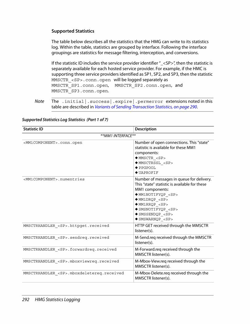
Supported Statistics
The table below describes all the statistics that the HMG can write to its statistics log. Within the table, statistics are grouped by interface. Following the interface groupings are statistics for message filtering, interception, and conversions.
If the statistic ID includes the service provider identifier “_<SP>”, then the statistic is separately available for each hosted service provider. For example, if the HMC is supporting three service providers identified as SP1, SP2, and SP3, then the statistic MMSCTR_<SP>.conn.open will be logged separately as MMSCTR_SP1.conn.open, MMSCTR_SP2.conn.open, and MMSCTR_SP3.conn.open.
Note The .initial|.success|.expire|.permerror extensions noted in this table are described in Variants of Sending Transaction Statistics‚ on page 290.
Supported Statistics Log Statistics (Part 1 of 7)
Statistic ID Description
**MM1 INTERFACE**
<MM1COMPONENT>.conn.open Number of open connections. This “state” statistic is available for these MM1 components:◆ MMSCTR_<SP>◆ MMSCTRSSL_<SP>◆ PPGPOOL◆ UAPROFIF
<MM1COMPONENT>.numentries Number of messages in queue for delivery. This “state” statistic is available for these MM1 components:◆ MM1NOTIFYQP_<SP>◆ MM1DRQP_<SP>◆ MM1RRQP_<SP>◆ SMSNOTIFYQP_<SP>◆ SMSSENDQP_<SP>◆ SMSWARNQP_<SP>
MMSCTRHANDLER_<SP>.httpget.received HTTP GET received through the MMSCTR listener(s).
MMSCTRHANDLER_<SP>.sendreq.received M-Send.req received through the MMSCTR listener(s).
MMSCTRHANDLER_<SP>.forwardreq.received M-Forward.req received through the MMSCTR listener(s).
MMSCTRHANDLER_<SP>.mboxviewreq.received M-Mbox-View.req received through the MMSCTR listener(s).
MMSCTRHANDLER_<SP>.mboxdeletereq.received M-Mbox-Delete.req received through the MMSCTR listener(s).
292 HMG Statistics Logging
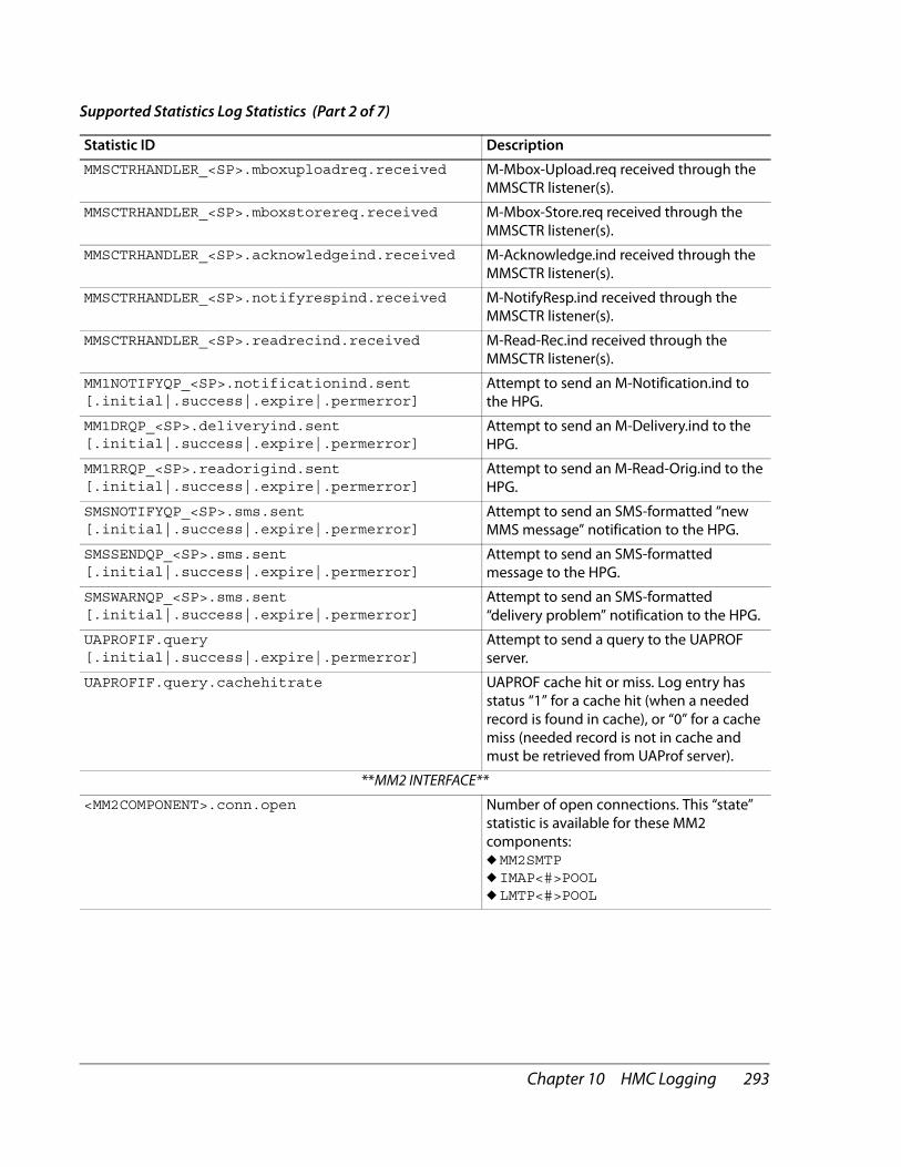
MMSCTRHANDLER_<SP>.mboxuploadreq.received M-Mbox-Upload.req received through the MMSCTR listener(s).
MMSCTRHANDLER_<SP>.mboxstorereq.received M-Mbox-Store.req received through the MMSCTR listener(s).
MMSCTRHANDLER_<SP>.acknowledgeind.received M-Acknowledge.ind received through the MMSCTR listener(s).
MMSCTRHANDLER_<SP>.notifyrespind.received M-NotifyResp.ind received through the MMSCTR listener(s).
MMSCTRHANDLER_<SP>.readrecind.received M-Read-Rec.ind received through the MMSCTR listener(s).
MM1NOTIFYQP_<SP>.notificationind.sent[.initial|.success|.expire|.permerror]
Attempt to send an M-Notification.ind to the HPG.
MM1DRQP_<SP>.deliveryind.sent[.initial|.success|.expire|.permerror]
Attempt to send an M-Delivery.ind to the HPG.
MM1RRQP_<SP>.readorigind.sent[.initial|.success|.expire|.permerror]
Attempt to send an M-Read-Orig.ind to the HPG.
SMSNOTIFYQP_<SP>.sms.sent[.initial|.success|.expire|.permerror]
Attempt to send an SMS-formatted “new MMS message” notification to the HPG.
SMSSENDQP_<SP>.sms.sent[.initial|.success|.expire|.permerror]
Attempt to send an SMS-formatted message to the HPG.
SMSWARNQP_<SP>.sms.sent[.initial|.success|.expire|.permerror]
Attempt to send an SMS-formatted “delivery problem” notification to the HPG.
UAPROFIF.query[.initial|.success|.expire|.permerror]
Attempt to send a query to the UAPROF server.
UAPROFIF.query.cachehitrate UAPROF cache hit or miss. Log entry has status “1” for a cache hit (when a needed record is found in cache), or “0” for a cache miss (needed record is not in cache and must be retrieved from UAProf server).
**MM2 INTERFACE**
<MM2COMPONENT>.conn.open Number of open connections. This “state” statistic is available for these MM2 components:◆ MM2SMTP◆ IMAP<#>POOL◆ LMTP<#>POOL
Supported Statistics Log Statistics (Part 2 of 7)
Statistic ID Description
Chapter 10 HMC Logging 293

<MM2COMPONENT>.numentries Number of messages in queue for delivery. This “state” statistic is available for these MM2 components:◆ MM2INSERTQP_<SP>◆ MM2DEFERQP_<SP>◆ MM2MIMICQP_<SP>◆ MM2DLINSERTQP_<SP>◆ MM2COMMANDQP_<SP>
MM2IF.store[.initial|.success|.expire|.permerror]
Attempt to store a message to the GMS.
MM2IF.retrieve[.initial|.success|.expire|.permerror]
Attempt to retrieve a message from GMS.
MM2IF.listretrieve[.initial|.success|.expire|.permerror]
Attempt to retrieve mailbox information from the GMS in support of an M-Mbox-View request.
MM2MIMICQP_<SP>.mimicreport[.initial|.success|.expire|.permerror]
Mimic report created for an MM1 sender and stored to GMS.
MM2DISPATCH.expiry.received “Message expired” notice received through the MM2 SMTP listener.
MM2DISPATCH.deferreddelivery.received “Message ready for deferred delivery” notice received through the MM2 SMTP listener.
**MM3 INTERFACE**
<MM3COMPONENT>.conn.open Number of open connections. This “state” statistic is available for these MM3 components:◆ MM3SMTP_<SP>◆ MM3SEND_<SP>
<MM3COMPONENT>.numentries Number of messages in queue for delivery. This “state” statistic is available for these MM3 components:◆ MM3QP_<SP>◆ MM3DSNQP_<SP>
MM3SMTP_<SP>.received Message received through MM3 SMTP listener.
MM3SMTP_<SP>.smtperror MM3 SMTP receiving error other than the specific errors in the following rows of this table.
MM3SMTP_<SP>.smtperror.maxsessionlimit MM3 SMTP receiving error for exceeding simultaneous session limit.
MM3SMTP_<SP>.smtperror.maxrecipientslimit MM3 SMTP receiving error for exceeding maximum recipient limit.
Supported Statistics Log Statistics (Part 3 of 7)
Statistic ID Description
294 HMG Statistics Logging
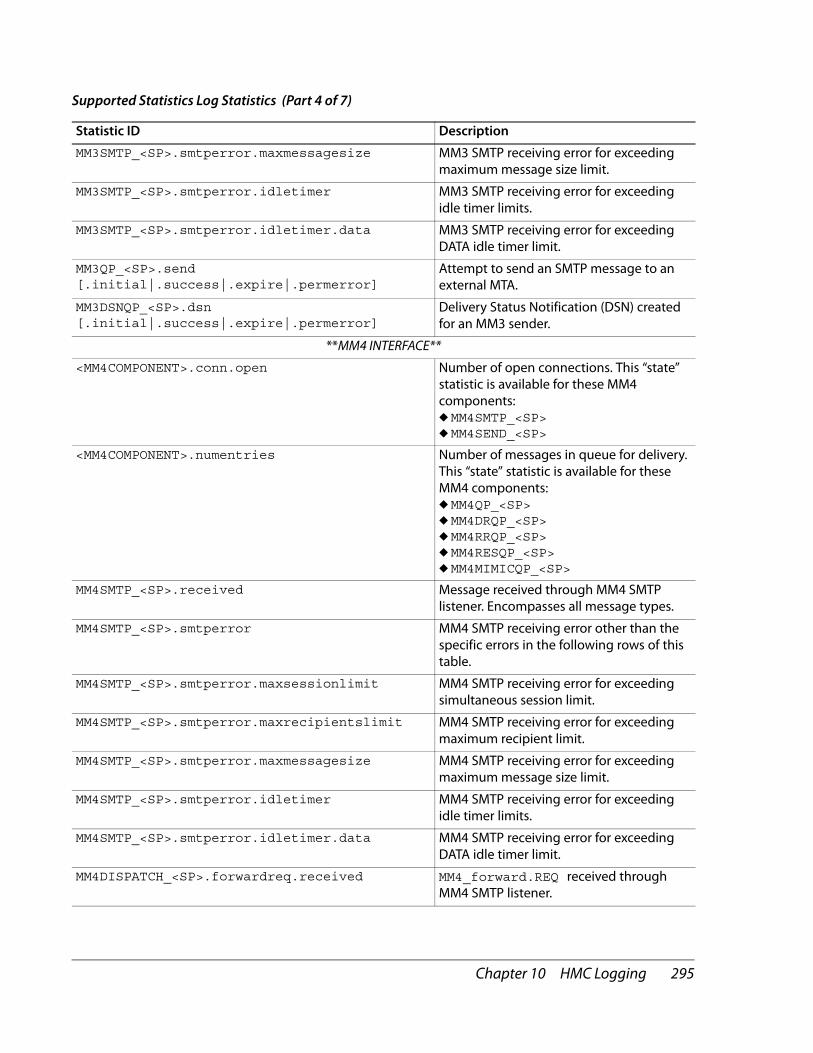
MM3SMTP_<SP>.smtperror.maxmessagesize MM3 SMTP receiving error for exceeding maximum message size limit.
MM3SMTP_<SP>.smtperror.idletimer MM3 SMTP receiving error for exceeding idle timer limits.
MM3SMTP_<SP>.smtperror.idletimer.data MM3 SMTP receiving error for exceeding DATA idle timer limit.
MM3QP_<SP>.send[.initial|.success|.expire|.permerror]
Attempt to send an SMTP message to an external MTA.
MM3DSNQP_<SP>.dsn[.initial|.success|.expire|.permerror]
Delivery Status Notification (DSN) created for an MM3 sender.
**MM4 INTERFACE**
<MM4COMPONENT>.conn.open Number of open connections. This “state” statistic is available for these MM4 components:◆ MM4SMTP_<SP>◆ MM4SEND_<SP>
<MM4COMPONENT>.numentries Number of messages in queue for delivery. This “state” statistic is available for these MM4 components:◆ MM4QP_<SP>◆ MM4DRQP_<SP>◆ MM4RRQP_<SP>◆ MM4RESQP_<SP>◆ MM4MIMICQP_<SP>
MM4SMTP_<SP>.received Message received through MM4 SMTP listener. Encompasses all message types.
MM4SMTP_<SP>.smtperror MM4 SMTP receiving error other than the specific errors in the following rows of this table.
MM4SMTP_<SP>.smtperror.maxsessionlimit MM4 SMTP receiving error for exceeding simultaneous session limit.
MM4SMTP_<SP>.smtperror.maxrecipientslimit MM4 SMTP receiving error for exceeding maximum recipient limit.
MM4SMTP_<SP>.smtperror.maxmessagesize MM4 SMTP receiving error for exceeding maximum message size limit.
MM4SMTP_<SP>.smtperror.idletimer MM4 SMTP receiving error for exceeding idle timer limits.
MM4SMTP_<SP>.smtperror.idletimer.data MM4 SMTP receiving error for exceeding DATA idle timer limit.
MM4DISPATCH_<SP>.forwardreq.received MM4_forward.REQ received through MM4 SMTP listener.
Supported Statistics Log Statistics (Part 4 of 7)
Statistic ID Description
Chapter 10 HMC Logging 295

MM4DISPATCH_<SP>.deliveryreportreq.received MM4_delivery_report.REQ received through MM4 SMTP listener.
MM4DISPATCH_<SP>.readreplyreportreq.received MM4_read_reply_report.REQ received through MM4 SMTP listener.
MM4QP_<SP>.forwardreq[.initial|.success|.expire|.permerror]
Attempt to send an MM4_forward.REQ to an external MMSC.
MM4DRQP_<SP>.deliveryreportreq[.initial|.success|.expire|.permerror]
Attempt to send an MM4_delivery_report.REQ to an external MMSC.
MM4RRQP_<SP>.readreplyreportreq[.initial|.success|.expire|.permerror]
Attempt to send an MM4_read_reply_report.REQ to an external MMSC.
MM4MIMICQP_<SP>.mimicreport[.initial|.success|.expire|.permerror]
Mimic report created for an MM4 sender.
**MM5 INTERFACE**
TCAPPPOOL_<SP>.conn.open Number of open connections to the SIGTRAN stack. This is a “state” statistic.
MAPTRANSPORT_<SP>.dialog.open Number of MAP dialog sessions in progress. This is a “state” statistic.
<MM5COMPONENT>.numentries Number of messages in queue for delivery. This “state” statistic is available for these MM5 components:◆ MM5QP_<SP>◆ ENUMQP_<SP>◆ ENUMDRQP_<SP>◆ ENUMRRQP_<SP>
MM5QP_<SP>.mm5lookup Attempt to send a query to the HLR.
ENUMQP_<SP>.enumlookup Attempt to send a query to the ENUM server.
**MM6 INTERFACE**
<MM6COMPONENT>.conn.open Number of open connections. This “state” statistic is available for these MM6 components:◆ LDAPPOOL◆ MM6PROVISIONPOOL
PROVISIONQP_<SP>.numentries Number of messages in queue for delivery. This is a “state” statistic.
LDAPMGR.query[.initial|.success|.expire|.permerror]
Attempt to send a query to the GDS.
Supported Statistics Log Statistics (Part 5 of 7)
Statistic ID Description
296 HMG Statistics Logging

**MM7 INTERFACE**
<MM7COMPONENT>.conn.open Number of open connections. This “state” statistic is available for these MM7 components:◆ MM7HTTP_<SP>◆ MM7HTTPSSL_<SP>
<MM7COMPONENT>.numentries Number of messages in queue for delivery. This “state” statistic is available for these MM7 components:◆ MM7QP_<SP>◆ MM7DRQP_<SP>◆ MM7RRQP_<SP>
MM7DISPATCH_<SP>.mm7submitreq MM7_submit.req received through the MM7 listener(s).
MM7DISPATCH_<SP>.mm7submitreq.error MM7_submit.req received through the MM7 listener(s) to which the HMC returned an error.
MM7QP_<SP>.mm7deliver[.initial|.success|.expire|.permerror]
Attempt to send an MM7_deliver.req to a VASP server.
MM7DRQP_<SP>.mm7drreq[.initial|.success|.expire|.permerror]
Attempt to send an MM7_delivery_report.req to a VASP server.
MM7RRQP_<SP>.mm7rrreq[.initial|.success|.expire|.permerror]
Attempt to send an MM7_read_reply_report.req to a VASP server.
**MM9 INTERFACE**
PREPAIDPOOL<#>_<SP>.conn.open Number of open connections to the prepaid billing server. This is a “state” statistic.
PREPAIDQP.numentries Number of messages in queue for delivery to the prepaid billing server. This is a “state” statistic.
**COMMAND LINE INTERFACE**
CLI.conn.open Number of open connections to the command line interface server. This is a “state” statistic.
**MESSAGE FILTERING AND INTERCEPTION**
LIQP.conn.open Number of open connections to government agency servers, for delivery of intercepted messages. This is a “state” statistic.
Supported Statistics Log Statistics (Part 6 of 7)
Statistic ID Description
Chapter 10 HMC Logging 297
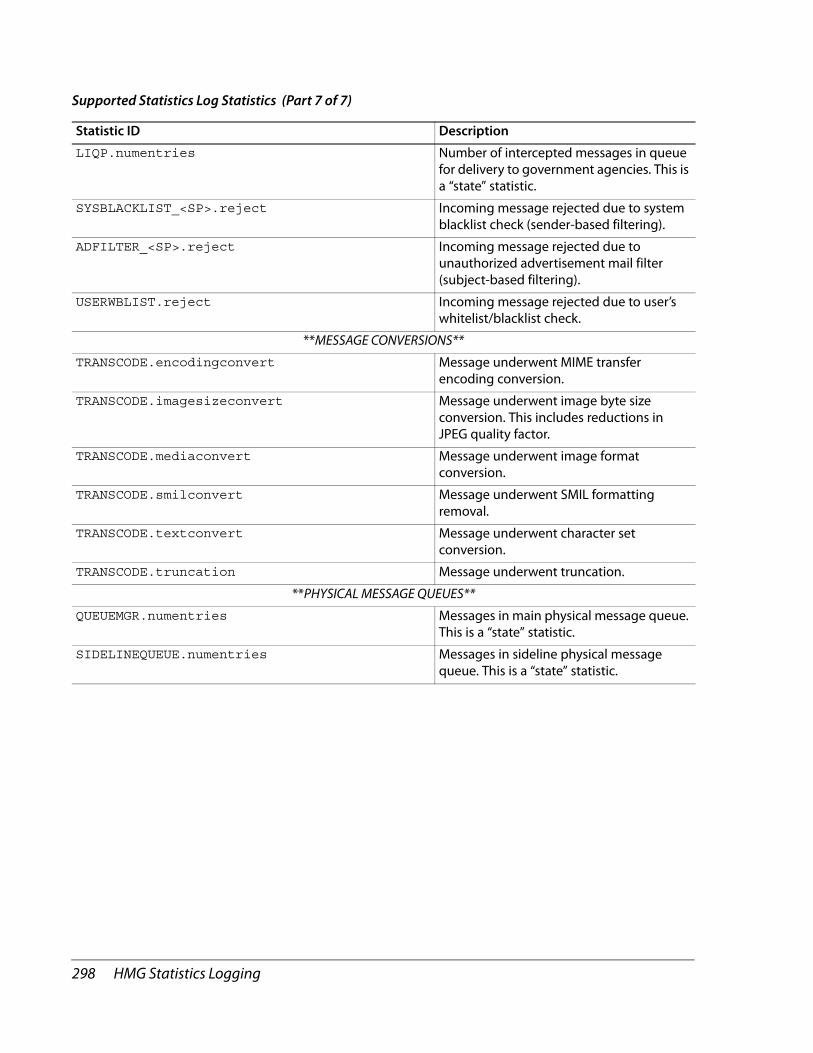
LIQP.numentries Number of intercepted messages in queue for delivery to government agencies. This is a “state” statistic.
SYSBLACKLIST_<SP>.reject Incoming message rejected due to system blacklist check (sender-based filtering).
ADFILTER_<SP>.reject Incoming message rejected due to unauthorized advertisement mail filter (subject-based filtering).
USERWBLIST.reject Incoming message rejected due to user’s whitelist/blacklist check.
**MESSAGE CONVERSIONS**
TRANSCODE.encodingconvert Message underwent MIME transfer encoding conversion.
TRANSCODE.imagesizeconvert Message underwent image byte size conversion. This includes reductions in JPEG quality factor.
TRANSCODE.mediaconvert Message underwent image format conversion.
TRANSCODE.smilconvert Message underwent SMIL formatting removal.
TRANSCODE.textconvert Message underwent character set conversion.
TRANSCODE.truncation Message underwent truncation.
**PHYSICAL MESSAGE QUEUES**
QUEUEMGR.numentries Messages in main physical message queue. This is a “state” statistic.
SIDELINEQUEUE.numentries Messages in sideline physical message queue. This is a “state” statistic.
Supported Statistics Log Statistics (Part 7 of 7)
Statistic ID Description
298 HMG Statistics Logging

About HPG Log File CollectionEach HPG node produces three logs through which you can monitor the gateway’s operations and condition.
Application Log. The HPG application log records application-related informational messages, errors, warnings and so on. Each log entry indicates the process and component with which the event is associated, as well as an event severity level and a brief descriptive message. For all events of level “INFO” or higher, the entry includes a numerical message code that aides in identifying and responding to the event. All application log entries are sent to the NMS UI and appear in the Fault > Events page.
Transaction Log. This log records all sessions between the HPG and peer servers, such as PIs or SMSCs, and CLI sessions.
Statistics Log. This log records statistical data for HPG conditions and transactions.
All HPG log files are stored in this directory by default:
/usr/local/gemini/hpg/log/
The files are by default named:
■ hpg-app.log (application log)
■ hpg-tx.log (transaction log)
■ hpg-stats.log (statistics log)
The HPG’s logging is highly configurable. You can modify settings such as log file permissions, filtering by severity level, and output formatting. By configuring log output formatting, you can ensure that the HPG logs are compatible with your network management system and intrusion detection system.
For complete information on configuring the HPG application, transaction, and statistic logs, see:
■ Configuring the Application Log‚ on page 301
■ Configuring the Transaction Log‚ on page 310
■ Configuring the Statistics Log‚ on page 319
Chapter 10 HMC Logging 299
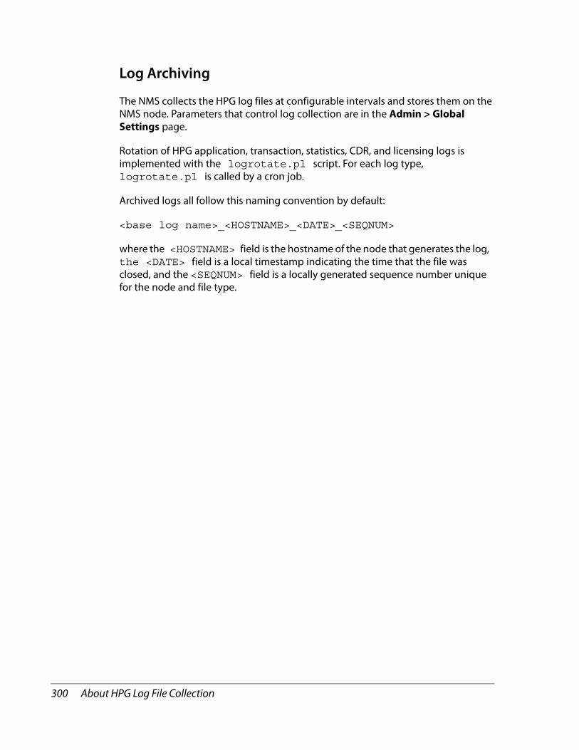
Log Archiving
The NMS collects the HPG log files at configurable intervals and stores them on the NMS node. Parameters that control log collection are in the Admin > Global Settings page.
Rotation of HPG application, transaction, statistics, CDR, and licensing logs is implemented with the logrotate.pl script. For each log type, logrotate.pl is called by a cron job.
Archived logs all follow this naming convention by default:
<base log name>_<HOSTNAME>_<DATE>_<SEQNUM>
where the <HOSTNAME> field is the hostname of the node that generates the log, the <DATE> field is a local timestamp indicating the time that the file was closed, and the <SEQNUM> field is a locally generated sequence number unique for the node and file type.
300 About HPG Log File Collection
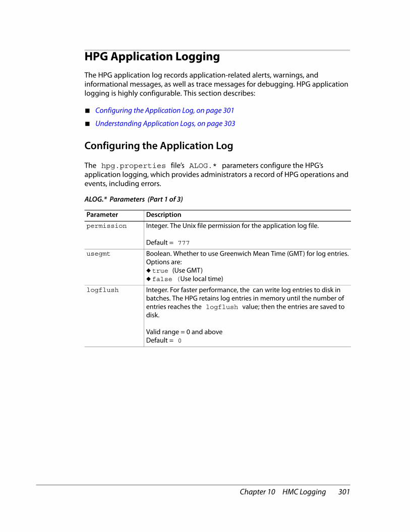
HPG Application LoggingThe HPG application log records application-related alerts, warnings, and informational messages, as well as trace messages for debugging. HPG application logging is highly configurable. This section describes:
■ Configuring the Application Log‚ on page 301
■ Understanding Application Logs‚ on page 303
Configuring the Application Log
The hpg.properties file’s ALOG.* parameters configure the HPG’s application logging, which provides administrators a record of HPG operations and events, including errors.
ALOG.* Parameters (Part 1 of 3)
Parameter Description
permission Integer. The Unix file permission for the application log file.
Default = 777
usegmt Boolean. Whether to use Greenwich Mean Time (GMT) for log entries. Options are:◆ true (Use GMT)◆ false (Use local time)
logflush Integer. For faster performance, the can write log entries to disk in batches. The HPG retains log entries in memory until the number of entries reaches the logflush value; then the entries are saved to disk.
Valid range = 0 and aboveDefault = 0
Chapter 10 HMC Logging 301

loglevel The lowest level of messages to include in the application log.
The HPG will log messages of the level that you specify for .loglevel as well as all higher level messages.
Choose one of these settings, listed in order from highest severity level to lowest:◆ ALERT◆ WARNG◆ INFO◆ DEBUG◆ ON◆ OFF
For example, with loglevel set to its default of INFO, the HPG will log messages of all levels except DEBUG. For a brief description of each level, see Understanding Application Logs‚ on page 303.
NOTES: ◆ You can set loglevel to OFF if you do not want any messages
written to the application log.◆ Setting loglevel to DEBUG will result in a very large number of
messages being logged. You should use the DEBUG setting only when you are testing or troubleshooting the system.
Default = INFO
ALOG.* Parameters (Part 2 of 3)
Parameter Description
302 HPG Application Logging
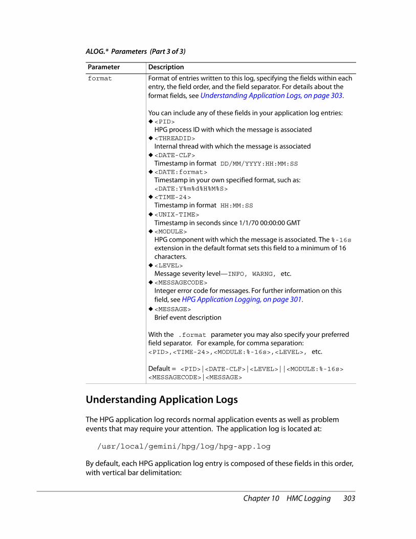
Understanding Application Logs
The HPG application log records normal application events as well as problem events that may require your attention. The application log is located at:
/usr/local/gemini/hpg/log/hpg-app.log
By default, each HPG application log entry is composed of these fields in this order, with vertical bar delimitation:
format Format of entries written to this log, specifying the fields within each entry, the field order, and the field separator. For details about the format fields, see Understanding Application Logs‚ on page 303.
You can include any of these fields in your application log entries:◆ <PID>
HPG process ID with which the message is associated◆ <THREADID>
Internal thread with which the message is associated◆ <DATE-CLF>
Timestamp in format DD/MM/YYYY:HH:MM:SS◆ <DATE:format>
Timestamp in your own specified format, such as: <DATE:Y%m%d%H%M%S>
◆ <TIME-24> Timestamp in format HH:MM:SS
◆ <UNIX-TIME> Timestamp in seconds since 1/1/70 00:00:00 GMT
◆ <MODULE> HPG component with which the message is associated. The %-16s extension in the default format sets this field to a minimum of 16 characters.
◆ <LEVEL> Message severity level—INFO, WARNG, etc.
◆ <MESSAGECODE> Integer error code for messages. For further information on this field, see HPG Application Logging‚ on page 301.
◆ <MESSAGE> Brief event description
With the .format parameter you may also specify your preferred field separator. For example, for comma separation: <PID>,<TIME-24>,<MODULE:%-16s>,<LEVEL>, etc.
Default = <PID>|<DATE-CLF>|<LEVEL>||<MODULE:%-16s> <MESSAGECODE>|<MESSAGE>
ALOG.* Parameters (Part 3 of 3)
Parameter Description
Chapter 10 HMC Logging 303
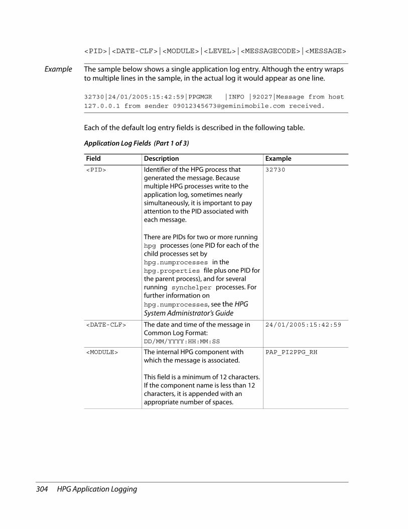
<PID>|<DATE-CLF>|<MODULE>|<LEVEL>|<MESSAGECODE>|<MESSAGE>
Example The sample below shows a single application log entry. Although the entry wraps to multiple lines in the sample, in the actual log it would appear as one line. 32730|24/01/2005:15:42:59|PPGMGR |INFO |92027|Message from host
127.0.0.1 from sender [email protected] received.
Each of the default log entry fields is described in the following table.
Application Log Fields (Part 1 of 3)
Field Description Example
<PID> Identifier of the HPG process that generated the message. Because multiple HPG processes write to the application log, sometimes nearly simultaneously, it is important to pay attention to the PID associated with each message.
There are PIDs for two or more running hpg processes (one PID for each of the child processes set by hpg.numprocesses in the hpg.properties file plus one PID for the parent process), and for several running synchelper processes. For further information on hpg.numprocesses, see the HPG System Administrator’s Guide
32730
<DATE-CLF> The date and time of the message in Common Log Format:DD/MM/YYYY:HH:MM:SS
24/01/2005:15:42:59
<MODULE> The internal HPG component with which the message is associated.
This field is a minimum of 12 characters. If the component name is less than 12 characters, it is appended with an appropriate number of spaces.
PAP_PI2PPG_RH
304 HPG Application Logging
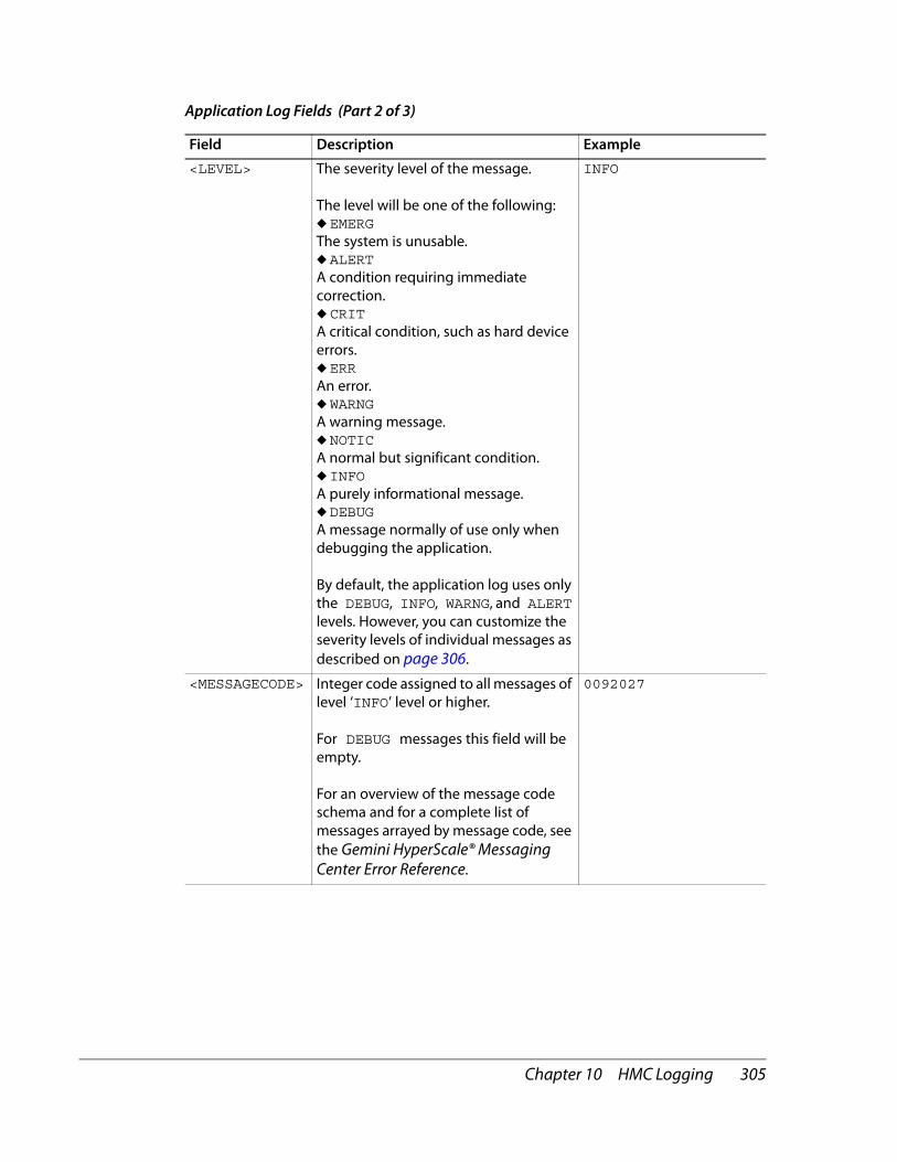
<LEVEL> The severity level of the message. The level will be one of the following: ◆ EMERGThe system is unusable.◆ ALERTA condition requiring immediate correction.◆ CRITA critical condition, such as hard device errors.◆ ERRAn error.◆ WARNGA warning message.◆ NOTICA normal but significant condition.◆ INFOA purely informational message.◆ DEBUGA message normally of use only when debugging the application.
By default, the application log uses only the DEBUG, INFO, WARNG, and ALERT levels. However, you can customize the severity levels of individual messages as described on page 306.
INFO
<MESSAGECODE> Integer code assigned to all messages of level ‘INFO’ level or higher. For DEBUG messages this field will be empty.
For an overview of the message code schema and for a complete list of messages arrayed by message code, see the Gemini HyperScale® Messaging Center Error Reference.
0092027
Application Log Fields (Part 2 of 3)
Field Description Example
Chapter 10 HMC Logging 305
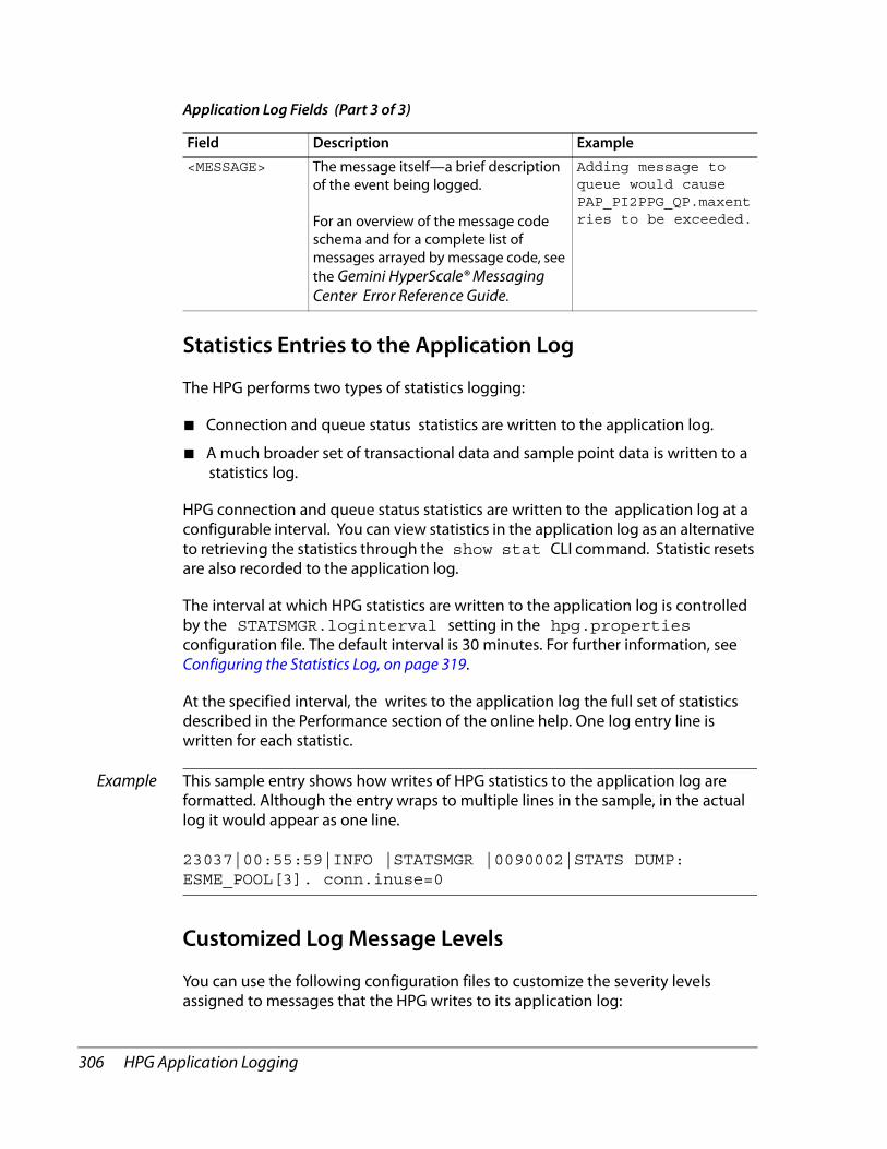
Statistics Entries to the Application Log
The HPG performs two types of statistics logging:
■ Connection and queue status statistics are written to the application log.
■ A much broader set of transactional data and sample point data is written to a statistics log.
HPG connection and queue status statistics are written to the application log at a configurable interval. You can view statistics in the application log as an alternative to retrieving the statistics through the show stat CLI command. Statistic resets are also recorded to the application log.
The interval at which HPG statistics are written to the application log is controlled by the STATSMGR.loginterval setting in the hpg.properties configuration file. The default interval is 30 minutes. For further information, see Configuring the Statistics Log‚ on page 319.
At the specified interval, the writes to the application log the full set of statistics described in the Performance section of the online help. One log entry line is written for each statistic.
Example This sample entry shows how writes of HPG statistics to the application log are formatted. Although the entry wraps to multiple lines in the sample, in the actual log it would appear as one line. 23037|00:55:59|INFO |STATSMGR |0090002|STATS DUMP: ESME_POOL[3]. conn.inuse=0
Customized Log Message Levels
You can use the following configuration files to customize the severity levels assigned to messages that the HPG writes to its application log:
<MESSAGE> The message itself—a brief description of the event being logged.
For an overview of the message code schema and for a complete list of messages arrayed by message code, see the Gemini HyperScale® Messaging Center Error Reference Guide.
Adding message to queue would cause PAP_PI2PPG_QP.maxentries to be exceeded.
Application Log Fields (Part 3 of 3)
Field Description Example
306 HPG Application Logging
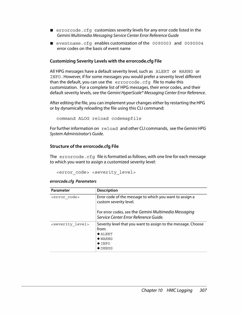
■ errorcode.cfg customizes severity levels for any error code listed in the Gemini Multimedia Messaging Service Center Error Reference Guide
■ eventname.cfg enables customization of the 0090003 and 0090004 error codes on the basis of event name
Customizing Severity Levels with the errorcode.cfg File
All HPG messages have a default severity level, such as ALERT or WARNG or INFO.However, if for some messages you would prefer a severity level different than the default, you can use the errorcode.cfg file to make this customization. For a complete list of HPG messages, their error codes, and their default severity levels, see the Gemini HyperScale® Messaging Center Error Reference.
After editing the file, you can implement your changes either by restarting the HPG or by dynamically reloading the file using this CLI command:
command ALOG reload codemapfile
For further information on reload and other CLI commands, see the Gemini HPG System Administrator’s Guide.
Structure of the errorcode.cfg File
The errorcode.cfg file is formatted as follows, with one line for each message to which you want to assign a customized severity level:
<error_code> <severity_level>
errorcode.cfg Parameters
Parameter Description
<error_code> Error code of the message to which you want to assign a custom severity level.
For error codes, see the Gemini Multimedia Messaging Service Center Error Reference Guide.
<severity_level> Severity level that you want to assign to the message. Choose from:◆ ALERT◆ WARNG◆ INFO◆ DEBUG
Chapter 10 HMC Logging 307
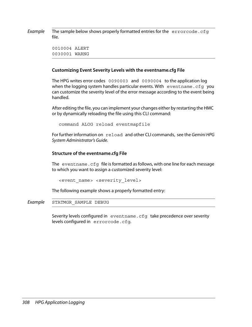
Example The sample below shows properly formatted entries for the errorcode.cfg file. 0010004 ALERT 0030001 WARNG
Customizing Event Severity Levels with the eventname.cfg File
The HPG writes error codes 0090003 and 0090004 to the application log when the logging system handles particular events. With eventname.cfg you can customize the severity level of the error message according to the event being handled.
After editing the file, you can implement your changes either by restarting the HMC or by dynamically reloading the file using this CLI command:
command ALOG reload eventmapfile
For further information on reload and other CLI commands, see the Gemini HPG System Administrator’s Guide.
Structure of the eventname.cfg File
The eventname.cfg file is formatted as follows, with one line for each message to which you want to assign a customized severity level:
<event_name> <severity_level>
The following example shows a properly formatted entry:
Example STATMGR_SAMPLE DEBUG
Severity levels configured in eventname.cfg take precedence over severity levels configured in errorcode.cfg.
308 HPG Application Logging
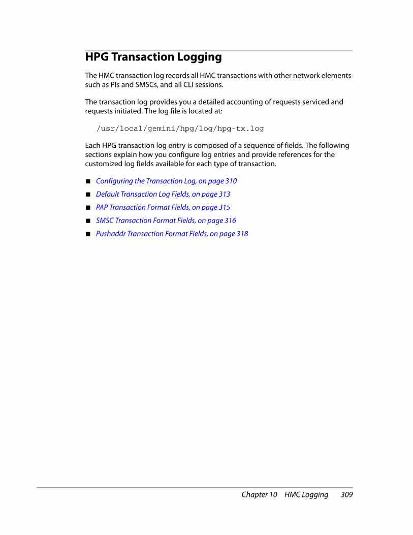
HPG Transaction LoggingThe HMC transaction log records all HMC transactions with other network elements such as PIs and SMSCs, and all CLI sessions.
The transaction log provides you a detailed accounting of requests serviced and requests initiated. The log file is located at:
/usr/local/gemini/hpg/log/hpg-tx.log
Each HPG transaction log entry is composed of a sequence of fields. The following sections explain how you configure log entries and provide references for the customized log fields available for each type of transaction.
■ Configuring the Transaction Log‚ on page 310
■ Default Transaction Log Fields‚ on page 313
■ PAP Transaction Format Fields‚ on page 315
■ SMSC Transaction Format Fields‚ on page 316
■ Pushaddr Transaction Format Fields‚ on page 318
Chapter 10 HMC Logging 309

Configuring the Transaction Log
The hpg.properties file’s TLOG.* parameters configure the HPG’s transaction logging, which provides administrators a record of the HPG interactions with clients and servers. You can set up customized log entry formats for each type of transaction.
Log rotation is carried out by the system’s logrotate facility. For more information on log rotation set-up, see Log Archiving‚ on page 300.
The following table describes the HPG’s transaction logging configuration parameters:
TLOG.* Parameters in hpg.properties (Part 1 of 3)
Parameter Description
permission Integer. The Unix file permission for the transaction log file.
Default = 777
usegmt Boolean. Whether to use Greenwich Mean Time (GMT) for log entries. Options are:◆ true (Use GMT)◆ false (Use local time)
logflush Integer. For faster performance, the HPG can write log entries to disk in batches. The HPG retains log entries in memory until the number of entries reaches the logflush value; then the entries are saved to disk.
Valid range = 0 and aboveDefault = 1
loglevel Whether transaction logging is turned on or off. Options are:◆ ON◆ OFF◆ ALERT◆ WARNG◆ INFO◆ DEBUG
The HPG writes SMSC READ and WRITE transactions to the transaction log only if the loglevel is DEBUG or ON.
Default = INFO
310 HPG Transaction Logging

format Default format of entries written to this log, specifying the fields within each entry, the order of those fields, and the field separator. The HPG supports additional format fields customized for each transaction type; see subsequent rows of this table. This default format is used only when specific formats are not defined.
You can use any of the fields specified in Default Transaction Log Fields‚ on page 313.
In addition, you can include any of these MIME headers, enclosed in braces: {Message-ID},{From},{To},{Cc}. These fields will be empty in log entries for transactions in which these headers are not relevant.With the .format parameter you can also:◆ Specify your preferred field separator (for example, for comma
separation: <PID>,<DATE-CLF>,<TYPE>, etc.)◆ Specify text strings to appear along with the data fields in your logs
(for example: PROCESS:<PID>|TIMESTAMP:<DATE-CLF>| etc.)
Default = <PID>|<DATE-CLF>|<TYPE>|<STATUS>|<PROTO>| <TRID>| <CLIENT>|<SERVER>|<DURATION>|<MESSAGE>
format_pap The format used for PAP transaction log entries. Configure this field as you would configure the format field, using any of the format fields specified in Default Transaction Log Fields‚ on page 313 and PAP Transaction Format Fields‚ on page 315.
Default = <PID>|<DATE-CLF>|<TYPE>|<STATUS>|<PROTO>| <TRID>|<CLIENT>|<SERVER>|<DURATION>|<MESSAGE>| <PAP_PI_USERNAME>|<PAP_MESSAGE_TYPE>|<PAP_PUSH_ID>|<PAP_PUSH_ADDRESS>|<PAP_PLMNADDR>| <PUSHADDR_MESSAGE_ID>|<PAP_RES_CODE>| <HTTP_REQ_LINE>|<HTTP_REQ_HOST>|<HTTP_REQ_SIZE>| <HTTP_REQ_BODY_SIZE>|<HTTP_RES_CODE>| <HTTP_RES_SIZE>|<HTTP_RES_BODY_SIZE>
TLOG.* Parameters in hpg.properties (Part 2 of 3)
Parameter Description
Chapter 10 HMC Logging 311
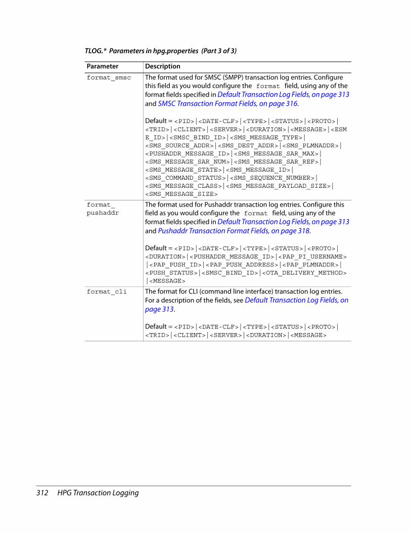
format_smsc The format used for SMSC (SMPP) transaction log entries. Configure this field as you would configure the format field, using any of the format fields specified in Default Transaction Log Fields‚ on page 313 and SMSC Transaction Format Fields‚ on page 316.
Default = <PID>|<DATE-CLF>|<TYPE>|<STATUS>|<PROTO>| <TRID>|<CLIENT>|<SERVER>|<DURATION>|<MESSAGE>|<ESME_ID>|<SMSC_BIND_ID>|<SMS_MESSAGE_TYPE>| <SMS_SOURCE_ADDR>|<SMS_DEST_ADDR>|<SMS_PLMNADDR>| <PUSHADDR_MESSAGE_ID>|<SMS_MESSAGE_SAR_MAX>| <SMS_MESSAGE_SAR_NUM>|<SMS_MESSAGE_SAR_REF>| <SMS_MESSAGE_STATE>|<SMS_MESSAGE_ID>| <SMS_COMMAND_STATUS>|<SMS_SEQUENCE_NUMBER>| <SMS_MESSAGE_CLASS>|<SMS_MESSAGE_PAYLOAD_SIZE>| <SMS_MESSAGE_SIZE>
format_ pushaddr
The format used for Pushaddr transaction log entries. Configure this field as you would configure the format field, using any of the format fields specified in Default Transaction Log Fields‚ on page 313 and Pushaddr Transaction Format Fields‚ on page 318.
Default = <PID>|<DATE-CLF>|<TYPE>|<STATUS>|<PROTO>| <DURATION>|<PUSHADDR_MESSAGE_ID>|<PAP_PI_USERNAME>|<PAP_PUSH_ID>|<PAP_PUSH_ADDRESS>|<PAP_PLMNADDR>| <PUSH_STATUS>|<SMSC_BIND_ID>|<OTA_DELIVERY_METHOD>|<MESSAGE>
format_cli The format for CLI (command line interface) transaction log entries. For a description of the fields, see Default Transaction Log Fields‚ on page 313.
Default = <PID>|<DATE-CLF>|<TYPE>|<STATUS>|<PROTO>| <TRID>|<CLIENT>|<SERVER>|<DURATION>|<MESSAGE>
TLOG.* Parameters in hpg.properties (Part 3 of 3)
Parameter Description
312 HPG Transaction Logging

Default Transaction Log Fields
You can use the following log fields in any TLOG.format* parameter, including TLOG.format.
For information on configuring HPG transaction log content and formatting, including options for alternative timestamp fields, see Configuring the Transaction Log‚ on page 310.
Transaction Log Fields (Part 1 of 2)
Field Description Example
Default Fields
<PID> Identifier of the HPG process with which the transaction is associated.
32730
<DATE-CLF> The date and time of the log entry in the following format:DD/MM/YYYY:HH:MM:SS
24/01/2005:15:44:30
<TIME-24> The time of the log entry in the following format: HH:MM:SS
15:44:30
<UNIX-TIME> The time of the log entry in seconds after 1/1/70 00:00:00 GMT.
<TYPE> The transaction type. Outputs one of the following:◆ PAP_PI2PPG◆ PAP_PI2PPG_QP◆ ESME_POOL[i]: generated for every
outgoing SMS message from the ith ESME connection pool defined in map_esme.cfg and incoming SMS message from the SMSC
◆ CLI
<STATUS> The transaction status. The set of possible status values will depend on the transaction type, but generally the status field will indicate whether the transaction succeeded or failed.
OK
<PROTO> The protocol used in the transaction. One of the following: ◆ CLI◆ PAPIN◆ PUSHADDR◆ SMPP
<TRID> The unique transaction identifier. This will be a text string, with format dependent on the type of transaction.
PI_A.4013035E.7FDA.1
Chapter 10 HMC Logging 313

<CLIENT> The IP address or host name of the client in the transaction.
<HOST> The IP address or host name of the server in the transaction.
127.0.0.1
<DURATION> The duration of the transaction in milliseconds.
1001
{Message-ID}{From} {To} {Cc}
SMTP header values extracted from the messages being transacted.
For transactions in which these message headers are not relevant, such as CLI requests, these fields will be empty.
20031105230512<+819012345676><+999012345673><+990123456789>
<MESSAGE> Custom message appropriate for certain transaction types. This field is empty if no message is applicable to the transaction.
250 DATA message received.
Transaction Log Fields (Part 2 of 2)
Field Description Example
314 HPG Transaction Logging
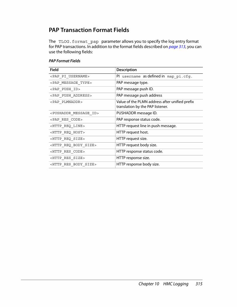
PAP Transaction Format Fields
The TLOG.format_pap parameter allows you to specify the log entry format for PAP transactions. In addition to the format fields described on page 313, you can use the following fields:
PAP Format Fields
Field Description
<PAP_PI_USERNAME> PI username as defined in map_pi.cfg.
<PAP_MESSAGE_TYPE> PAP message type.
<PAP_PUSH_ID> PAP message push ID.
<PAP_PUSH_ADDRESS> PAP message push address
<PAP_PLMNADDR> Value of the PLMN address after unified prefix translation by the PAP listener.
<PUSHADDR_MESSAGE_ID> PUSHADDR message ID.
<PAP_RES_CODE> PAP response status code.
<HTTP_REQ_LINE> HTTP request line in push message.
<HTTP_REQ_HOST> HTTP request host.
<HTTP_REQ_SIZE> HTTP request size.
<HTTP_REQ_BODY_SIZE> HTTP request body size.
<HTTP_RES_CODE> HTTP response status code.
<HTTP_RES_SIZE> HTTP response size.
<HTTP_RES_BODY_SIZE> HTTP response body size.
Chapter 10 HMC Logging 315
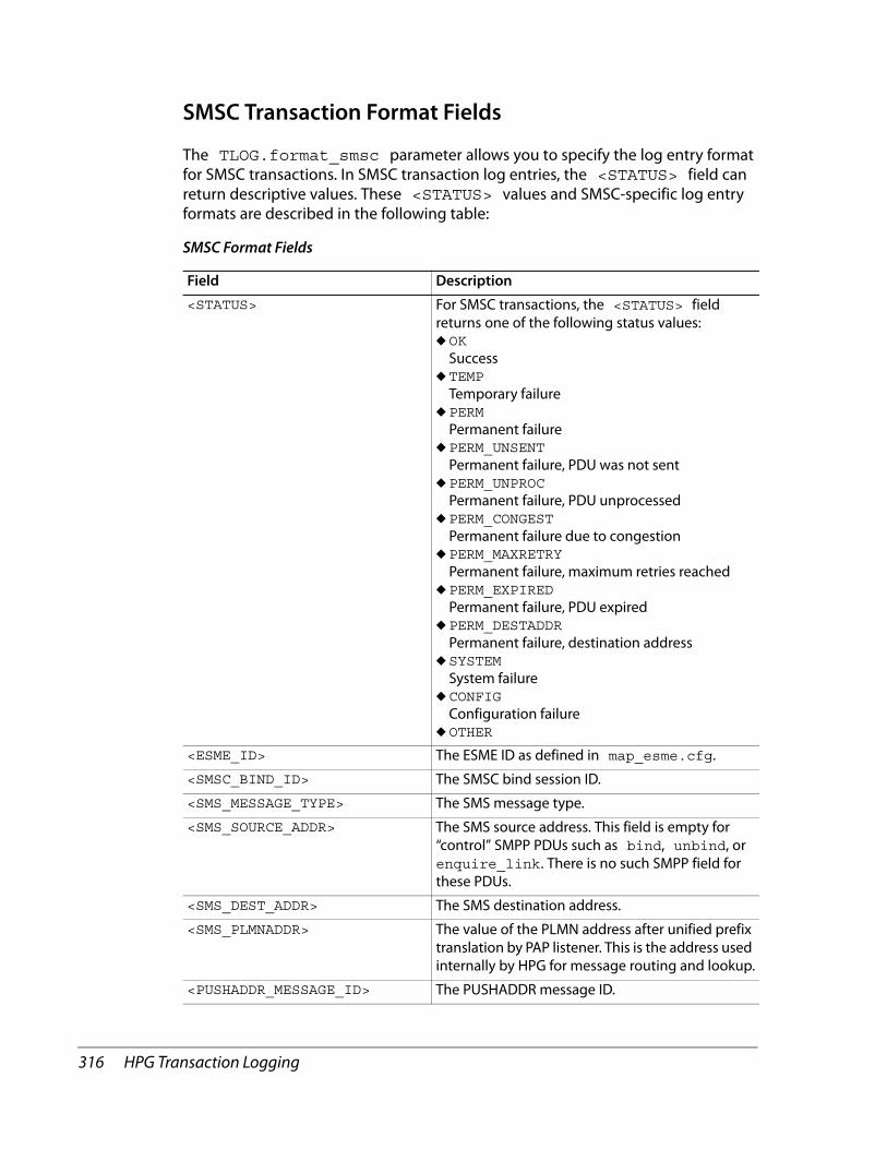
SMSC Transaction Format Fields
The TLOG.format_smsc parameter allows you to specify the log entry format for SMSC transactions. In SMSC transaction log entries, the <STATUS> field can return descriptive values. These <STATUS> values and SMSC-specific log entry formats are described in the following table:
SMSC Format Fields
Field Description
<STATUS> For SMSC transactions, the <STATUS> field returns one of the following status values: ◆ OK
Success◆ TEMP
Temporary failure◆ PERM
Permanent failure◆ PERM_UNSENT
Permanent failure, PDU was not sent◆ PERM_UNPROC
Permanent failure, PDU unprocessed◆ PERM_CONGEST
Permanent failure due to congestion◆ PERM_MAXRETRY
Permanent failure, maximum retries reached◆ PERM_EXPIRED
Permanent failure, PDU expired◆ PERM_DESTADDR
Permanent failure, destination address◆ SYSTEM
System failure◆ CONFIG
Configuration failure◆ OTHER
<ESME_ID> The ESME ID as defined in map_esme.cfg.
<SMSC_BIND_ID> The SMSC bind session ID.
<SMS_MESSAGE_TYPE> The SMS message type.
<SMS_SOURCE_ADDR> The SMS source address. This field is empty for “control” SMPP PDUs such as bind, unbind, or enquire_link. There is no such SMPP field for these PDUs.
<SMS_DEST_ADDR> The SMS destination address.
<SMS_PLMNADDR> The value of the PLMN address after unified prefix translation by PAP listener. This is the address used internally by HPG for message routing and lookup.
<PUSHADDR_MESSAGE_ID> The PUSHADDR message ID.
316 HPG Transaction Logging

<SMS_MESSAGE_SAR_MAX> The SMS message SAR maximum number of segments.
<SMS_MESSAGE_SAR_NUM> The SMS message SAR segment number.
<SMS_MESSAGE_SAR_REF> The SMS message SAR reference number.
<SMS_MESSAGE_STATE> The SMS message state. This field is optionally filled for deliver_sm and data_sm PDUs as a hexidecimal integer value.
<SMS_MESSAGE_ID> This field corresponds to the message ID in the submit_sm_resp/data_sm_resp SMPP PDUs returned by the SMSC and also used as the received message ID in deliver_sm/data_sm SMPP PDUs sent by the SMSC.
<SMS_COMMAND_STATUS> The SMS command status code.
<SMS_SEQUENCE_NUMBER> The SMS sequence number assigned to each SMPP PDU.
<SMS_MESSAGE_CLASS> The SMS message class. The return value is one of the following:
◆ RD read
◆ WR_EREQ write ESME request
◆ WR_SRES write SMSC response
◆ WR_EREQ_RETRY write ESME request retry
◆ WR_SRES_RETRY write SMSC response retry
◆ EREQ ESME request
◆ ERES ESME response
◆ SREQ SMSC request
◆ SRES SMSC response
◆ OTHER other
<SMS_MESSAGE_PAYLOAD_SIZE> The SMS message payload size.
<SMS_MESSAGE_SIZE> The SMS message size.
SMSC Format Fields
Field Description
Chapter 10 HMC Logging 317

Pushaddr Transaction Format Fields
The HPG logs PUSHADDR events at the end of push message processing.
■ If result notification is required, the HPG writes a PUSHADDR log entry after successfully sending the resultnotification message to the PI.
■ If result notification is not required, the HPG writes a PUSHADDR log entry after the final state of the push message is determined.
The TLOG.format_pushaddr parameter allows you to specify the log entry format for PUSHADDR transactions. In addition to the format fields described on page 313, you can use the following fields:
PUSHADDR Format Fields
Field Description
<PUSHADDR_MESSAGE_ID> The PUSHADDR message ID.
<PAP_PI_USERNAME> The PI username as defined in map_pi.cfg.
<PAP_PUSH_ID> The PAP push message ID.
<PAP_PUSH_ADDRESS> The PAP push address.
<PAP_PLMNADDR> The value of the PLMN address after unified prefix translation by the PAP listener. This is the address used internally by the HPG for message routing and lookup.
<PUSH_STATUS> The push delivery state.
<SMSC_BIND_ID> The SMSC bind session ID.
<OTA_DELIVERY_METHOD> The OTA delivery method. The only method supported is OTA-WSP-Connectionless.
<ESME_ID> The ESME ID as defined in the map_esme.cfg file. This field is blank if an SMS message was not delivered to an SMSC.
318 HPG Transaction Logging
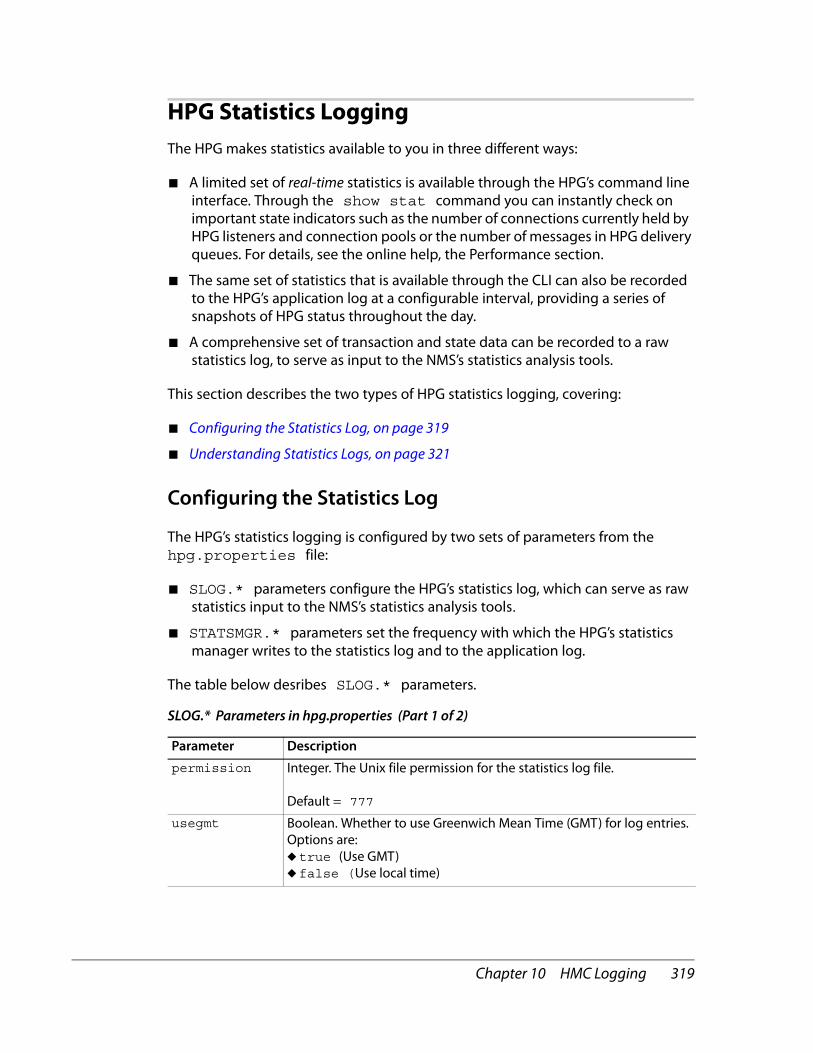
HPG Statistics LoggingThe HPG makes statistics available to you in three different ways:
■ A limited set of real-time statistics is available through the HPG’s command line interface. Through the show stat command you can instantly check on important state indicators such as the number of connections currently held by HPG listeners and connection pools or the number of messages in HPG delivery queues. For details, see the online help, the Performance section.
■ The same set of statistics that is available through the CLI can also be recorded to the HPG’s application log at a configurable interval, providing a series of snapshots of HPG status throughout the day.
■ A comprehensive set of transaction and state data can be recorded to a raw statistics log, to serve as input to the NMS’s statistics analysis tools.
This section describes the two types of HPG statistics logging, covering:
■ Configuring the Statistics Log‚ on page 319
■ Understanding Statistics Logs‚ on page 321
Configuring the Statistics Log
The HPG’s statistics logging is configured by two sets of parameters from the hpg.properties file:
■ SLOG.* parameters configure the HPG’s statistics log, which can serve as raw statistics input to the NMS’s statistics analysis tools.
■ STATSMGR.* parameters set the frequency with which the HPG’s statistics manager writes to the statistics log and to the application log.
The table below desribes SLOG.* parameters.
SLOG.* Parameters in hpg.properties (Part 1 of 2)
Parameter Description
permission Integer. The Unix file permission for the statistics log file.
Default = 777
usegmt Boolean. Whether to use Greenwich Mean Time (GMT) for log entries. Options are:◆ true (Use GMT)◆ false (Use local time)
Chapter 10 HMC Logging 319

logflush Integer. For faster performance, the HPG can write log entries to disk in batches. The HPG retains log entries in memory until the number of entries reaches the logflush value; then the entries are saved to disk.
Valid range = 0 and aboveDefault = 1
loglevel Loglevel. Turns statistics logging on or off. Options are:◆ ON◆ OFFIf you set the loglevel to OFF, a statistics log file is still generated but it will be empty. Default = ON
format Format of entries written to this log, specifying the fields within each entry, the order of those fields, and the field separator.
Statistics log entries consist of these fields in this order:◆ <DATETIME>◆ <STAT_ID>◆ <STAT_VALUE>◆ <DOMAIN>◆ <STATUS>
For field descriptions, see Understanding Statistics Logs‚ on page 321.
IMPORTANT: If you plan to use the NMS for statistics analysis, do not change the default setting for format. The NMS requires the default format.
Default = <DATETIME>,<STAT_ID>, <STAT_VALUE>, <DOMAIN>,<STATUS>
SLOG.* Parameters in hpg.properties (Part 2 of 2)
Parameter Description
320 HPG Statistics Logging
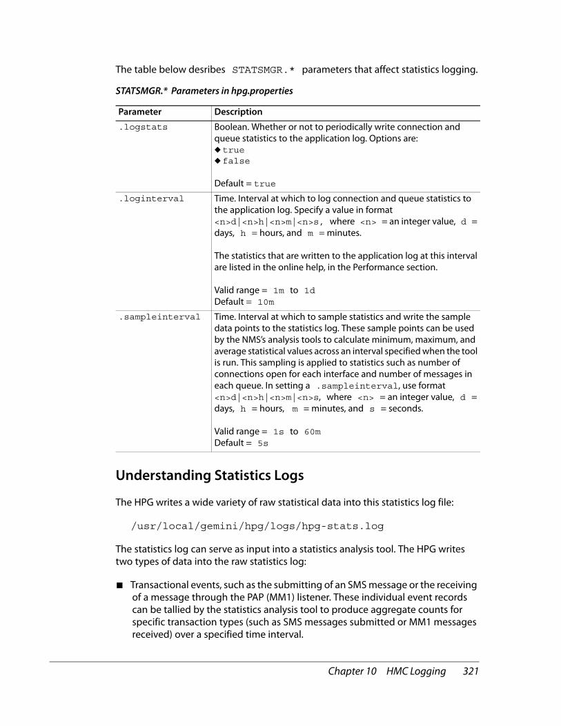
The table below desribes STATSMGR.* parameters that affect statistics logging.
Understanding Statistics Logs
The HPG writes a wide variety of raw statistical data into this statistics log file:
/usr/local/gemini/hpg/logs/hpg-stats.log
The statistics log can serve as input into a statistics analysis tool. The HPG writes two types of data into the raw statistics log:
■ Transactional events, such as the submitting of an SMS message or the receiving of a message through the PAP (MM1) listener. These individual event records can be tallied by the statistics analysis tool to produce aggregate counts for specific transaction types (such as SMS messages submitted or MM1 messages received) over a specified time interval.
STATSMGR.* Parameters in hpg.properties
Parameter Description
.logstats Boolean. Whether or not to periodically write connection and queue statistics to the application log. Options are:◆ true◆ false
Default = true
.loginterval Time. Interval at which to log connection and queue statistics to the application log. Specify a value in format <n>d|<n>h|<n>m|<n>s, where <n> = an integer value, d = days, h = hours, and m = minutes.
The statistics that are written to the application log at this interval are listed in the online help, in the Performance section.
Valid range = 1m to 1dDefault = 10m
.sampleinterval Time. Interval at which to sample statistics and write the sample data points to the statistics log. These sample points can be used by the NMS’s analysis tools to calculate minimum, maximum, and average statistical values across an interval specified when the tool is run. This sampling is applied to statistics such as number of connections open for each interface and number of messages in each queue. In setting a .sampleinterval, use format <n>d|<n>h|<n>m|<n>s, where <n> = an integer value, d = days, h = hours, m = minutes, and s = seconds.
Valid range = 1s to 60mDefault = 5s
Chapter 10 HMC Logging 321
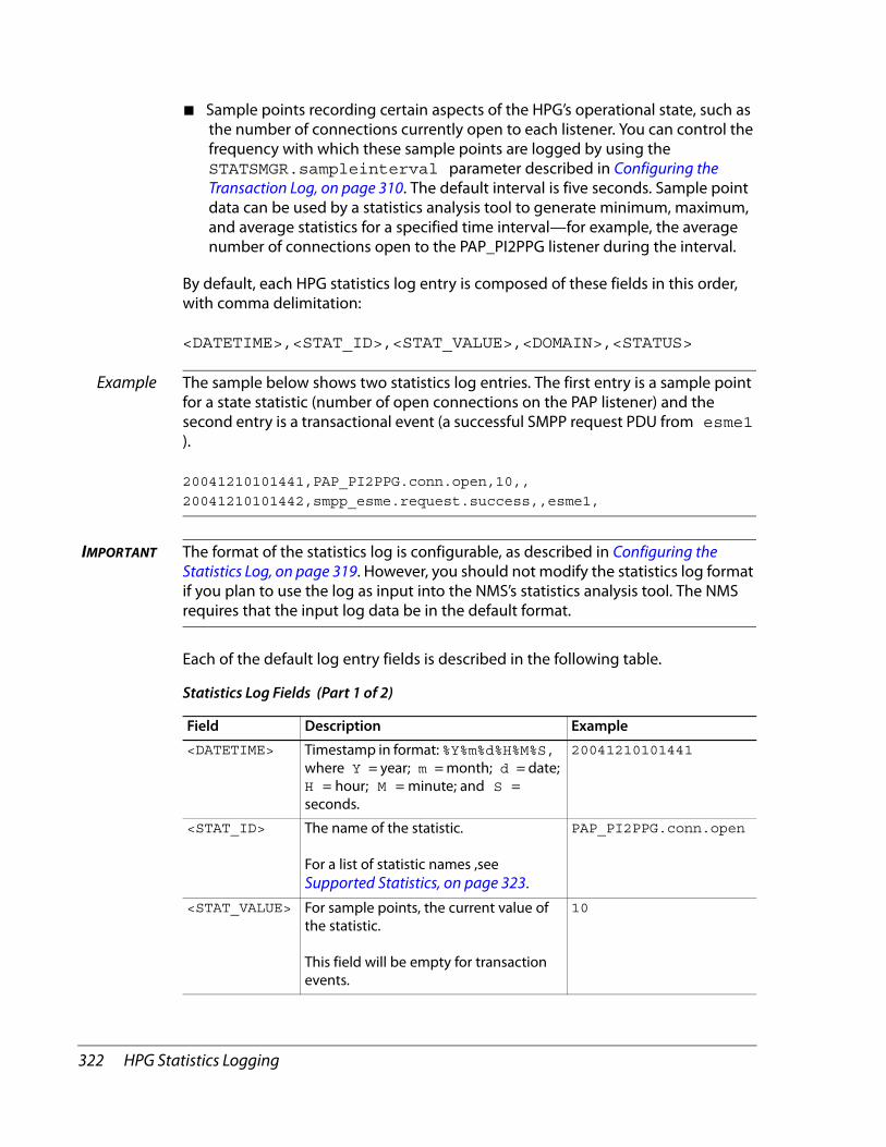
■ Sample points recording certain aspects of the HPG’s operational state, such as the number of connections currently open to each listener. You can control the frequency with which these sample points are logged by using the STATSMGR.sampleinterval parameter described in Configuring the Transaction Log‚ on page 310. The default interval is five seconds. Sample point data can be used by a statistics analysis tool to generate minimum, maximum, and average statistics for a specified time interval—for example, the average number of connections open to the PAP_PI2PPG listener during the interval.
By default, each HPG statistics log entry is composed of these fields in this order, with comma delimitation:
<DATETIME>,<STAT_ID>,<STAT_VALUE>,<DOMAIN>,<STATUS>
Example The sample below shows two statistics log entries. The first entry is a sample point for a state statistic (number of open connections on the PAP listener) and the second entry is a transactional event (a successful SMPP request PDU from esme1 ). 20041210101441,PAP_PI2PPG.conn.open,10,, 20041210101442,smpp_esme.request.success,,esme1,
IMPORTANT The format of the statistics log is configurable, as described in Configuring the Statistics Log‚ on page 319. However, you should not modify the statistics log format if you plan to use the log as input into the NMS’s statistics analysis tool. The NMS requires that the input log data be in the default format.
Each of the default log entry fields is described in the following table.
Statistics Log Fields (Part 1 of 2)
Field Description Example
<DATETIME> Timestamp in format: %Y%m%d%H%M%S, where Y = year; m = month; d = date; H = hour; M = minute; and S = seconds.
20041210101441
<STAT_ID> The name of the statistic.
For a list of statistic names ,see Supported Statistics‚ on page 323.
PAP_PI2PPG.conn.open
<STAT_VALUE> For sample points, the current value of the statistic.
This field will be empty for transaction events.
10
322 HPG Statistics Logging

Supported Statistics
The following table lists the statistics supported in the HPG statistics log. The Type of statistic can be one of the following:
■ C type statistics are cumulative. They are cumulative totals since the HPG start-up.
■ S type statistics are snapshots. They are a current value of a changing quantity such as the number of open SMSC connections. The NMS calculates average, maximum, and minimum values for these statistics. The daily performance report contains data at fifteen-minute intervals, and the weekly performance report contains data at two-hour intervals.
<DOMAIN> For certain transaction statistics, the PI or ESME ID with which the transaction is conducted. This field will often be empty.
esme1
<STATUS> For certain transaction statistics, a status value. This field will usually be empty.
OK
Statistics Log Fields (Part 2 of 2)
Field Description Example
Supported Statistics
Stat-ID Type Description
pap_pi.push-message.request.total C Number of PAP push-messages received from the HMG.
pap_pi.push-message.request.success
C Number of successfully pushed messages.
pap_pi.push-message.request.permerror
C Number of PAP push-message that were not successfully pushed due to permanent errors.
pap_pi.push-message.response.total
C Number of PAP push-message responses sent to the HMG.
pap_pi.push-message.response.success
C Number of successful PAP push-message responses sent to the HMG.
pap_pi.push-message.response.permerror
C Number of PAP push-message responses that had permanent errors.
pap_pi.push-message.total.txtime S The time it takes for PAP push-message processing.
smpp_esme.total.txtime S Transaction time for SMPP PDU processing.
queue_pap_pi.utilization S The utilization of the PAP queue.
PAP_PI2PPG.conn.open S Number of simultaneous connections.
pushaddr.total C Number of push messages completely processed.
Chapter 10 HMC Logging 323
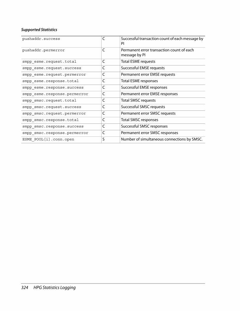
pushaddr.success C Successful transaction count of each message by PI
pushaddr.permerror C Permanent error transaction count of each message by PI
smpp_esme.request.total C Total ESME requests
smpp_esme.request.success C Successful EMSE requests
smpp_esme.request.permerror C Permanent error EMSE requests
smpp_esme.response.total C Total ESME responses
smpp_esme.response.success C Successful EMSE responses
smpp_esme.response.permerror C Permanent error EMSE responses
smpp_smsc.request.total C Total SMSC requests
smpp_smsc.request.success C Successful SMSC requests
smpp_smsc.request.permerror C Permanent error SMSC requests
smpp_smsc.response.total C Total SMSC responses
smpp_smsc.response.success C Successful SMSC responses
smpp_smsc.response.permerror C Permanent error SMSC responses
ESME_POOL[i].conn.open S Number of simultaneous connections by SMSC.
Supported Statistics
324 HPG Statistics Logging

About GMS Log File CollectionThe GMS logs two types of data:
■ Application messages
■ IMAP and LMTP transaction records
The GMS application log records application-related informational messages, errors, warnings and so on. Each log entry indicates the process and component with which the event is associated, as well as an event severity level and a brief descriptive message. For all events of level “INFO” or higher, the entry includes a numerical message code that aides in identifying and responding to the event. IMAP and LMTP transaction records are sent to a special file whose name and location you can configure.
GMS logging is enabled by default. For information on configuring GMS Logging in the GMS System Administration Guide.
Log Storage and Rotation
You can set the target path for the application log file using the gmt_applog_path parameter in the imapd.conf file. You can also set the target path for the transaction log file using the gmt_txn_logpath parameter in the imapd.conf file. For further information on configuring GMS logging parameters in imapd.conf, see Configuring the IMAP and LMTP Servers (imapd.conf) in the GMS System Administration Guide.
Use your system’s logrotate utility to set GMS application and transaction log storage and rotation. See the logrotate(8) man page for information on how to use this utility.
Chapter 10 HMC Logging 325
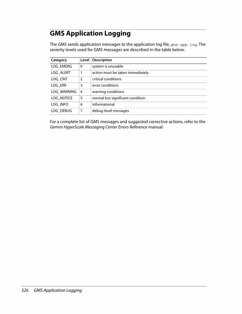
GMS Application Logging The GMS sends application messages to the application log file, gms-app.log. The severity levels used for GMS messages are described in the table below.
For a complete list of GMS messages and suggested corrective actions, refer to the Gemini HyperScale Messaging Center Errors Reference manual.
Category Level Description
LOG_EMERG 0 system is unusable
LOG_ALERT 1 action must be taken immediately
LOG_CRIT 2 critical conditions
LOG_ERR 3 error conditions
LOG_WARNING 4 warning conditions
LOG_NOTICE 5 normal but significant condition
LOG_INFO 6 informational
LOG_DEBUG 7 debug-level messages
326 GMS Application Logging

GMS Transaction LoggingThe GMS can log all requests received by its IMAP and LMTP servers into a file of your choosing. The log entries also indicate the servers’ response to the requests, such as OK or ERRORs of various types.
Transaction logging is enabled by default. For information on configuring GMS transaction logging, see Configuring the IMAP and LMTP Servers (imapd.conf ) in the GMS System Administration Guide. To set up automatic rotation of the GMS transaction log, use your system’s logrotate utility, after setting gmt_txnlog_path in imapd.conf. See the logrotate(8) man page for instructions.
Transaction Log Content
GMS transaction log entries by default have four fields:
<DATE-CLF>|<PID>|<CLIENT-IP>|<MESSAGE>
For example:
Example 27/04/2006:00:03:52|30697|127.0.0.1|CREATE user.0.OUT: OK
The four default transaction log entry fields are described in the table below, along with other entries that you may include by setting the gmt_txnlog_format parameter in the imapd.conf configuration file.
Transaction Log Entry Fields (Part 1 of 2)
Field Description
Default Fields
<DATE-CLF> Date and time of log entry in Common Log Format: DD/MM/YY:HH:MM:SS
<PID> Process ID of the process handling the transaction.
<MESSAGECODE> Seven-digit integer code assigned to entry based on message type. For further information, see Transaction Log Message Codes‚ on page 328.
<MESSAGE> Text message composed of IMAP or LMTP command (with argument, if applicable), a colon, then the command status (with descriptive string, if applicable).
When appropriate, <mailbox> may be a part of this text message.
Chapter 10 HMC Logging 327
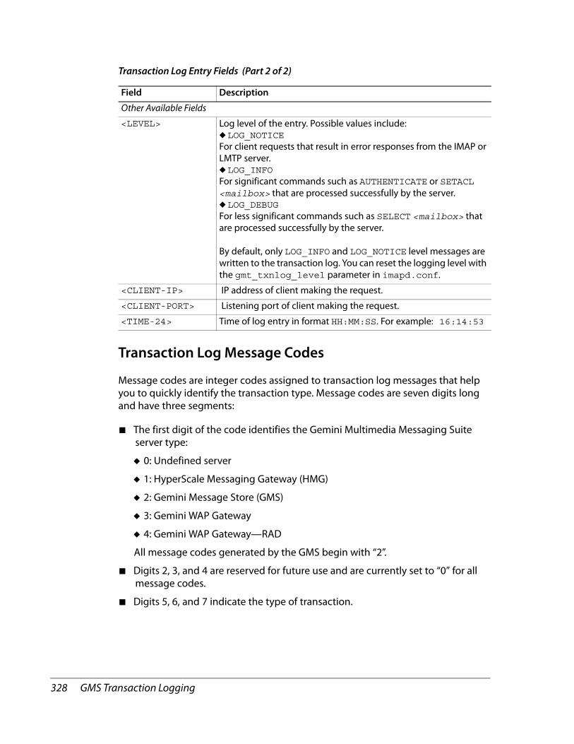
Transaction Log Message Codes
Message codes are integer codes assigned to transaction log messages that help you to quickly identify the transaction type. Message codes are seven digits long and have three segments:
■ The first digit of the code identifies the Gemini Multimedia Messaging Suite server type:
◆ 0: Undefined server
◆ 1: HyperScale Messaging Gateway (HMG)
◆ 2: Gemini Message Store (GMS)
◆ 3: Gemini WAP Gateway
◆ 4: Gemini WAP Gateway—RAD
All message codes generated by the GMS begin with “2”.
■ Digits 2, 3, and 4 are reserved for future use and are currently set to “0” for all message codes.
■ Digits 5, 6, and 7 indicate the type of transaction.
Other Available Fields
<LEVEL> Log level of the entry. Possible values include:◆ LOG_NOTICEFor client requests that result in error responses from the IMAP or LMTP server.◆ LOG_INFOFor significant commands such as AUTHENTICATE or SETACL <mailbox> that are processed successfully by the server.◆ LOG_DEBUGFor less significant commands such as SELECT <mailbox> that are processed successfully by the server.
By default, only LOG_INFO and LOG_NOTICE level messages are written to the transaction log. You can reset the logging level with the gmt_txnlog_level parameter in imapd.conf.
<CLIENT-IP> IP address of client making the request.
<CLIENT-PORT> Listening port of client making the request.
<TIME-24> Time of log entry in format HH:MM:SS. For example: 16:14:53
Transaction Log Entry Fields (Part 2 of 2)
Field Description
328 GMS Transaction Logging
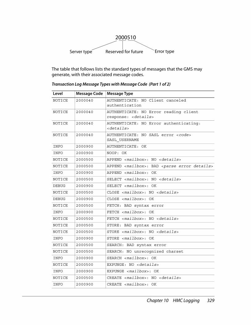
The table that follows lists the standard types of messages that the GMS may generate, with their associated message codes.
Transaction Log Message Types with Message Code (Part 1 of 2)
Level Message Code Message Type
NOTICE 2000040 AUTHENTICATE: NO Client canceled authentication
NOTICE 2000040 AUTHENTICATE: NO Error reading client response: <details>
NOTICE 2000040 AUTHENTICATE: NO Error authenticating: <details>
NOTICE 2000040 AUTHENTICATE: NO SASL error <code> SASL_USERNAME
INFO 2000900 AUTHENTICATE: OK
INFO 2000900 NOOP: OK
NOTICE 2000500 APPEND <mailbox>: NO <details>
NOTICE 2000500 APPEND <mailbox>: BAD <parse error details>
INFO 2000900 APPEND <mailbox>: OK
NOTICE 2000500 SELECT <mailbox>: NO <details>
DEBUG 2000900 SELECT <mailbox>: OK
NOTICE 2000500 CLOSE <mailbox>: NO <details>
DEBUG 2000900 CLOSE <mailbox>: OK
NOTICE 2000500 FETCH: BAD syntax error
INFO 2000900 FETCH <mailbox>: OK
NOTICE 2000500 FETCH <mailbox>: NO <details>
NOTICE 2000500 STORE: BAD syntax error
NOTICE 2000500 STORE <mailbox>: NO <details>
INFO 2000900 STORE <mailbox>: OK
NOTICE 2000500 SEARCH: BAD syntax error
NOTICE 2000500 SEARCH: NO unrecognized charset
INFO 2000900 SEARCH <mailbox>: OK
NOTICE 2000500 EXPUNGE: NO <details>
INFO 2000900 EXPUNGE <mailbox>: OK
NOTICE 2000500 CREATE <mailbox>: NO <details>
INFO 2000900 CREATE <mailbox>: OK
2000510
Reserved for futureServer type Error type
Chapter 10 HMC Logging 329
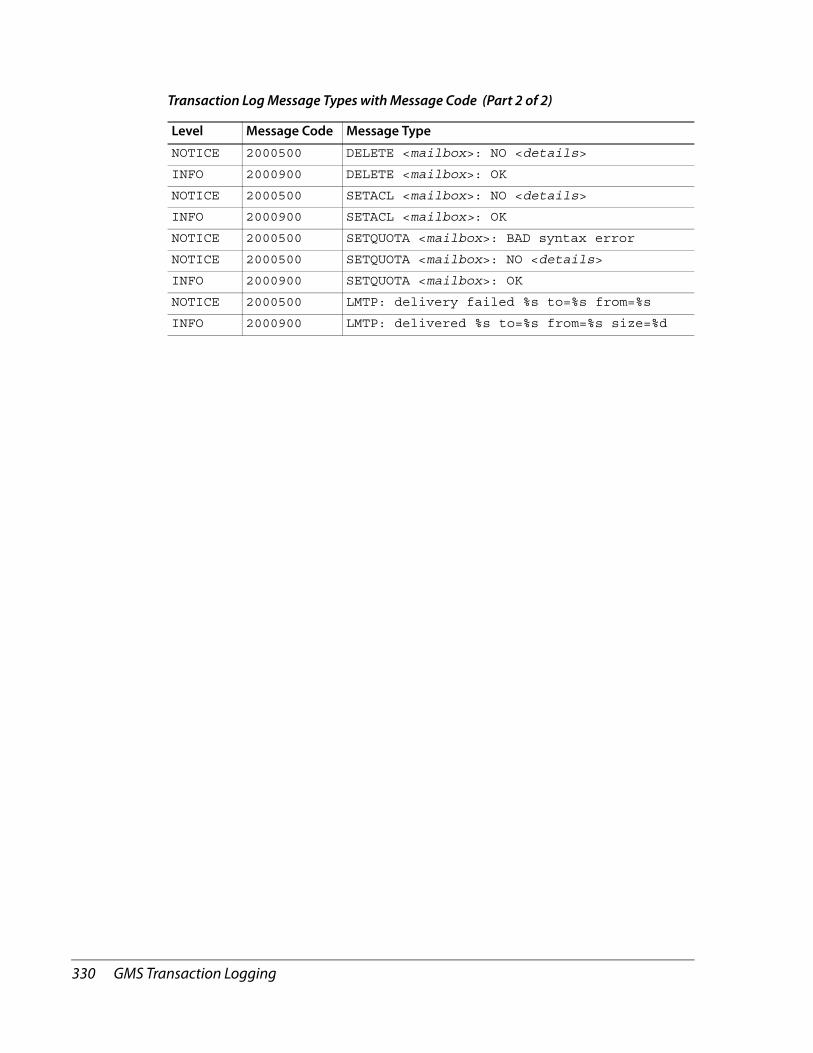
NOTICE 2000500 DELETE <mailbox>: NO <details>
INFO 2000900 DELETE <mailbox>: OK
NOTICE 2000500 SETACL <mailbox>: NO <details>
INFO 2000900 SETACL <mailbox>: OK
NOTICE 2000500 SETQUOTA <mailbox>: BAD syntax error
NOTICE 2000500 SETQUOTA <mailbox>: NO <details>
INFO 2000900 SETQUOTA <mailbox>: OK
NOTICE 2000500 LMTP: delivery failed %s to=%s from=%s
INFO 2000900 LMTP: delivered %s to=%s from=%s size=%d
Transaction Log Message Types with Message Code (Part 2 of 2)
Level Message Code Message Type
330 GMS Transaction Logging

NMS Server LogsThe NMS Server Details pages enable you to configure NMS logs and NMS server logs. This section contains the following information:
■ Configuring NMS Log Settings‚ on page 331
■ Configuring NMS Log Level Settings for nmserr.txt‚ on page 334
■ Configuring NMS Log Level Settings for nmsout.txt‚ on page 335
■ Viewing NMS Server Logs‚ on page 337
In addition, you can view NMS port information using the NMS Server Details page. Consult the NMS online help for information concerning this task.
Configuring NMS Log Settings
The NMS Log Settings page enables you to configure NMS log settings to ensure that the log files contain the information that you need for NMS debugging and auditing purposes. Using this page, you can specify the number of lines that each file can contain, the number of files to generate, the maximum number of lines to cache and the log severity level to write to the log file. You can also customize the NMS error and output files to specify the specific modules that should write messages to the log files. This page is available only to Network Providers. For more information about the NMS log files, see Viewing NMS Server Logs‚ on page 337.
▼ To configure NMS log settings:
1 Select Admin > NMS Server Details > NMS Log Settings.
The NMS Log Settings page displays.
2 Configure the options and settings on the NMS Log Settings page, as follows.
Field or Option Instructions
File name Displays the name of the log file that you can customize.
Max Lines / File Select the maximum number of lines that can be written in the log file. You can specify values of 5000, 10000 or 20000 lines. If a log files exceeds the number of lines specified by this parameter, the NMS prints additional lines in a new file. For example, if you select 10000 as the value for this file, the first 10000 lines will be printed in one file. If there are additional log entries, the next set of lines will go to a new file. For example, if the current file nmsout.txt file reaches the maximum line count, then a new file nmsout1.txt will be opened for further recording of log entries.
Default = 10000
Chapter 10 HMC Logging 331
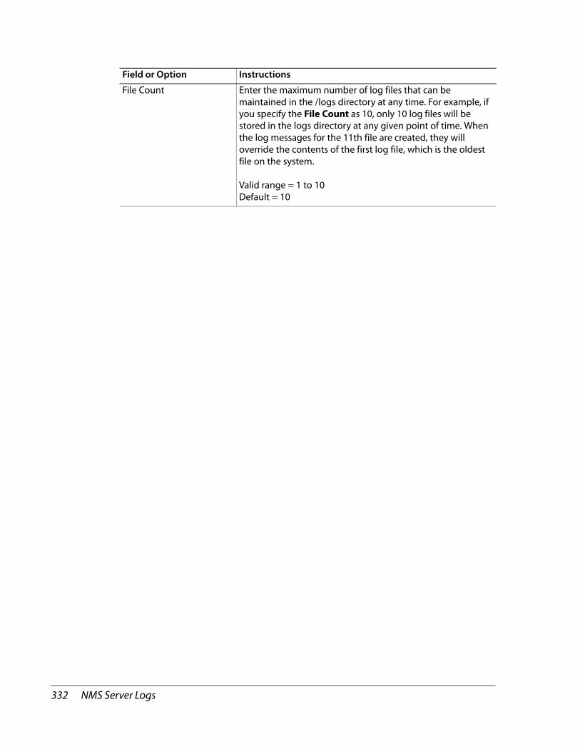
File Count Enter the maximum number of log files that can be maintained in the /logs directory at any time. For example, if you specify the File Count as 10, only 10 log files will be stored in the logs directory at any given point of time. When the log messages for the 11th file are created, they will override the contents of the first log file, which is the oldest file on the system.
Valid range = 1 to 10Default = 10
Field or Option Instructions
332 NMS Server Logs
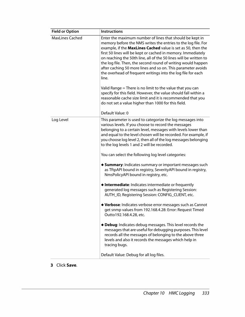
3 Click Save.
MaxLines Cached Enter the maximum number of lines that should be kept in memory before the NMS writes the entries to the log file. For example, if the MaxLines Cached value is set as 50, then the first 50 lines will be kept or cached in memory. Immediately on reaching the 50th line, all of the 50 lines will be written to the log file. Then, the second round of writing would happen after caching 50 more lines and so on. This parameter avoids the overhead of frequent writings into the log file for each line.
Valid Range = There is no limit to the value that you can specify for this field. However, the value should fall within a reasonable cache size limit and it is recommended that you do not set a value higher than 1000 for this field.
Default Value: 0
Log Level This parameter is used to categorize the log messages into various levels. If you choose to record the messages belonging to a certain level, messages with levels lower than and equal to the level chosen will be recorded. For example, if you choose log level 2, then all of the log messages belonging to the log levels 1 and 2 will be recorded.
You can select the following log level categories:
◆ Summary: Indicates summary or important messages such as TftpAPI bound in registry, SeverityAPI bound in registry, NmsPolicyAPI bound in registry, etc.
◆ Intermediate: Indicates intermediate or frequently generated log messages such as Registering Session: AUTH_ID, Registering Session: CONFIG_CLIENT, etc.
◆ Verbose: Indicates verbose error messages such as Cannot get snmp values from 192.168.4.28: Error: Request Timed Outto192.168.4.28, etc.
◆ Debug: Indicates debug messages. This level records the messages that are useful for debugging purposes. This level records all the messages of belonging to the above three levels and also it records the messages which help in tracing bugs.
Default Value: Debug for all log files.
Field or Option Instructions
Chapter 10 HMC Logging 333
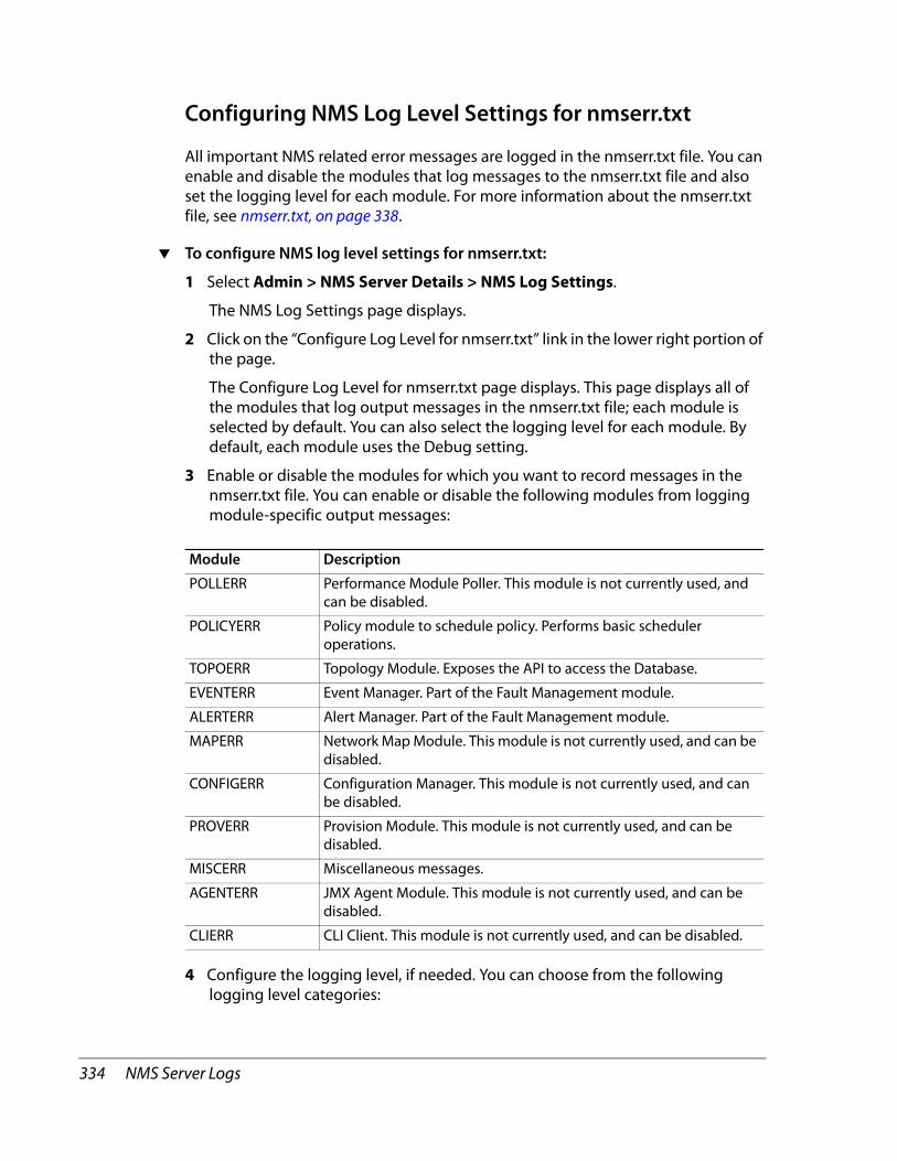
Configuring NMS Log Level Settings for nmserr.txt
All important NMS related error messages are logged in the nmserr.txt file. You can enable and disable the modules that log messages to the nmserr.txt file and also set the logging level for each module. For more information about the nmserr.txt file, see nmserr.txt‚ on page 338.
▼ To configure NMS log level settings for nmserr.txt:
1 Select Admin > NMS Server Details > NMS Log Settings.
The NMS Log Settings page displays.
2 Click on the “Configure Log Level for nmserr.txt” link in the lower right portion of the page.
The Configure Log Level for nmserr.txt page displays. This page displays all of the modules that log output messages in the nmserr.txt file; each module is selected by default. You can also select the logging level for each module. By default, each module uses the Debug setting.
3 Enable or disable the modules for which you want to record messages in the nmserr.txt file. You can enable or disable the following modules from logging module-specific output messages:
4 Configure the logging level, if needed. You can choose from the following logging level categories:
Module Description
POLLERR Performance Module Poller. This module is not currently used, and can be disabled.
POLICYERR Policy module to schedule policy. Performs basic scheduler operations.
TOPOERR Topology Module. Exposes the API to access the Database.
EVENTERR Event Manager. Part of the Fault Management module.
ALERTERR Alert Manager. Part of the Fault Management module.
MAPERR Network Map Module. This module is not currently used, and can be disabled.
CONFIGERR Configuration Manager. This module is not currently used, and can be disabled.
PROVERR Provision Module. This module is not currently used, and can be disabled.
MISCERR Miscellaneous messages.
AGENTERR JMX Agent Module. This module is not currently used, and can be disabled.
CLIERR CLI Client. This module is not currently used, and can be disabled.
334 NMS Server Logs
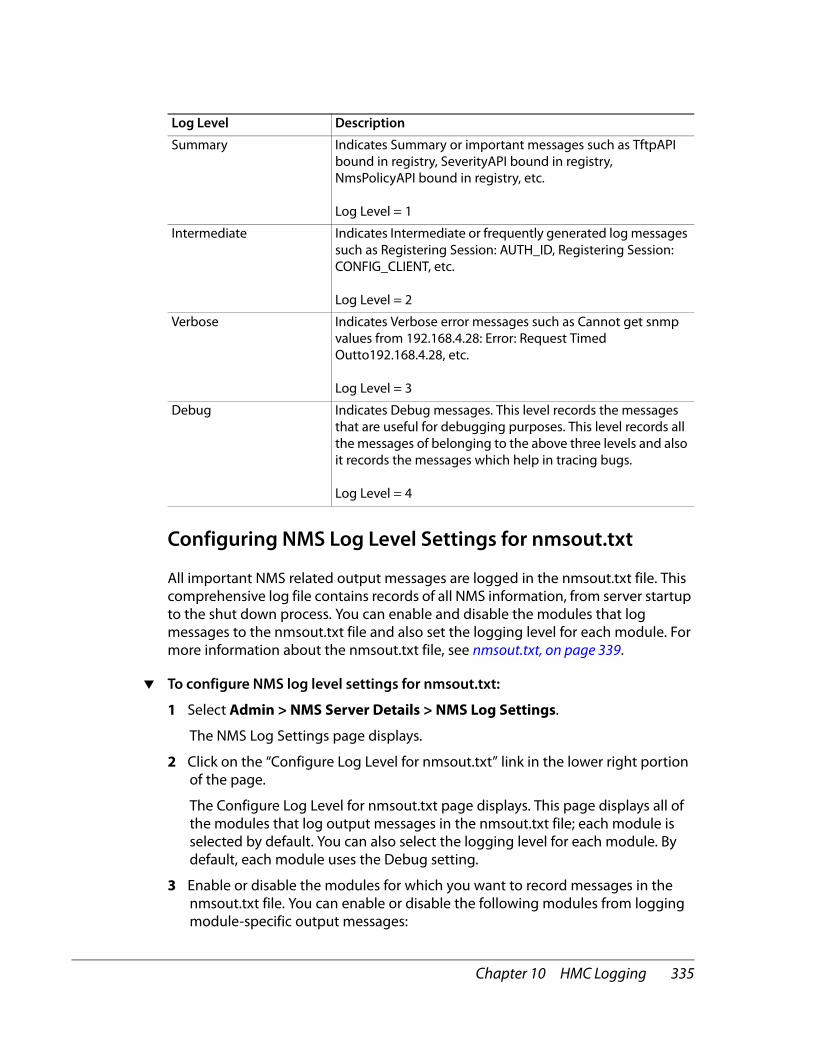
Configuring NMS Log Level Settings for nmsout.txt
All important NMS related output messages are logged in the nmsout.txt file. This comprehensive log file contains records of all NMS information, from server startup to the shut down process. You can enable and disable the modules that log messages to the nmsout.txt file and also set the logging level for each module. For more information about the nmsout.txt file, see nmsout.txt‚ on page 339.
▼ To configure NMS log level settings for nmsout.txt:
1 Select Admin > NMS Server Details > NMS Log Settings.
The NMS Log Settings page displays.
2 Click on the “Configure Log Level for nmsout.txt” link in the lower right portion of the page.
The Configure Log Level for nmsout.txt page displays. This page displays all of the modules that log output messages in the nmsout.txt file; each module is selected by default. You can also select the logging level for each module. By default, each module uses the Debug setting.
3 Enable or disable the modules for which you want to record messages in the nmsout.txt file. You can enable or disable the following modules from logging module-specific output messages:
Log Level Description
Summary Indicates Summary or important messages such as TftpAPI bound in registry, SeverityAPI bound in registry, NmsPolicyAPI bound in registry, etc.
Log Level = 1
Intermediate Indicates Intermediate or frequently generated log messages such as Registering Session: AUTH_ID, Registering Session: CONFIG_CLIENT, etc.
Log Level = 2
Verbose Indicates Verbose error messages such as Cannot get snmp values from 192.168.4.28: Error: Request Timed Outto192.168.4.28, etc.
Log Level = 3
Debug Indicates Debug messages. This level records the messages that are useful for debugging purposes. This level records all the messages of belonging to the above three levels and also it records the messages which help in tracing bugs.
Log Level = 4
Chapter 10 HMC Logging 335

4 Configure the logging level, if needed. You can choose from the following logging level categories:
Module Description
POLLERR Performance Module Poller. This module is not currently used, and can be disabled.
POLICYERR Policy module to schedule policy. Performs basic scheduler operations.
TOPOERR Topology Module. Exposes the API to access the Database.
EVENTERR Event Manager. Part of the Fault Management module.
ALERTERR Alert Manager. Part of the Fault Management module.
MAPERR Network Map Module. This module is not currently used, and can be disabled.
CONFIGERR Configuration Manager. This module is not currently used, and can be disabled.
PROVERR Provision Module. This module is not currently used, and can be disabled.
MISCERR Miscellaneous messages.
AGENTERR JMX Agent Module. This module is not currently used, and can be disabled.
CLIERR CLI Client. This module is not currently used, and can be disabled.
Log Level Description
Summary Indicates Summary or important messages such as TftpAPI bound in registry, SeverityAPI bound in registry, NmsPolicyAPI bound in registry, etc.
Log Level = 1
Intermediate Indicates Intermediate or frequently generated log messages such as Registering Session: AUTH_ID, Registering Session: CONFIG_CLIENT, etc.
Log Level = 2
336 NMS Server Logs

Viewing NMS Server Logs
NMS server logs enable you to track configuration errors, performance issues, and view audit logs to keep track of various actions taking place in the server. The NMS Server Logs page displays an index of all of the NMS log files stored in the installation /logs directory. Using the links on this page, you can view the details of the log files that have been generated by the NMS. For more information about configuring NMS log file settings, see NMS Server Logs‚ on page 331.
This section contains the following information:
■ Viewing NMS Server Log Files‚ on page 337
■ Description of NMS Server Log Files‚ on page 338
Viewing NMS Server Log Files
You can easily access the NMS server log files that are generated by the NMS and stored on the server.
▼ To view NMS server log files:
1 Select Admin > NMS Server Details > NMS Server Logs.
The Index of /logs page displays. The NMS generates the following log files. Click on a log file link to view more information about the log file.
■ alert_audit.txt‚ on page 338
■ discoveryLogs.txt‚ on page 338
■ mserr.txt‚ on page 338
■ nmsout.txt‚ on page 339
■ nativeping_logs.txt‚ on page 338
■ nmserr.txt‚ on page 338
■ nmsout.txt‚ on page 339
Verbose Indicates Verbose error messages such as Cannot get snmp values from 192.168.4.28: Error: Request Timed Outto192.168.4.28, etc.
Log Level = 3
Debug Indicates Debug messages. This level records the messages that are useful for debugging purposes. This level records all the messages of belonging to the above three levels and also it records the messages which help in tracing bugs.
Log Level = 4
Chapter 10 HMC Logging 337
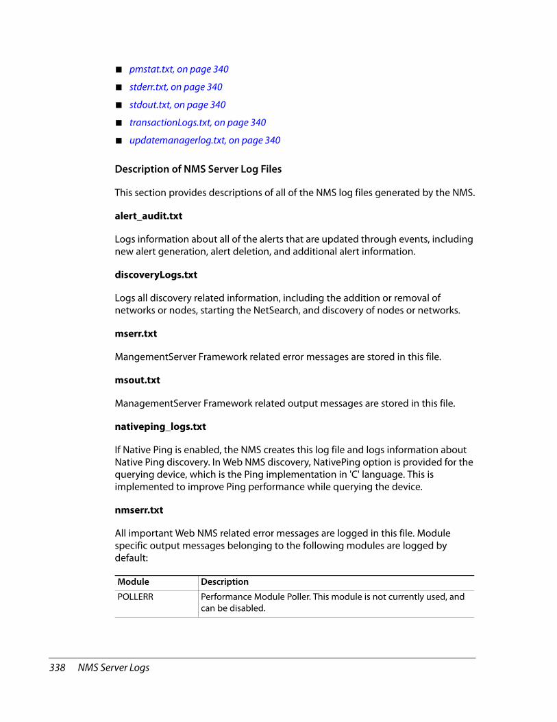
■ pmstat.txt‚ on page 340
■ stderr.txt‚ on page 340
■ stdout.txt‚ on page 340
■ transactionLogs.txt‚ on page 340
■ updatemanagerlog.txt‚ on page 340
Description of NMS Server Log Files
This section provides descriptions of all of the NMS log files generated by the NMS.
alert_audit.txt
Logs information about all of the alerts that are updated through events, including new alert generation, alert deletion, and additional alert information.
discoveryLogs.txt
Logs all discovery related information, including the addition or removal of networks or nodes, starting the NetSearch, and discovery of nodes or networks.
mserr.txt
MangementServer Framework related error messages are stored in this file.
msout.txt
ManagementServer Framework related output messages are stored in this file.
nativeping_logs.txt
If Native Ping is enabled, the NMS creates this log file and logs information about Native Ping discovery. In Web NMS discovery, NativePing option is provided for the querying device, which is the Ping implementation in 'C' language. This is implemented to improve Ping performance while querying the device.
nmserr.txt
All important Web NMS related error messages are logged in this file. Module specific output messages belonging to the following modules are logged by default:
Module Description
POLLERR Performance Module Poller. This module is not currently used, and can be disabled.
338 NMS Server Logs

You can enable and disable the modules that log messages to the nmserr.txt file using the NMS UI. See Configuring NMS Log Level Settings for nmserr.txt‚ on page 334 for more information.
nmsout.txt
All important Web NMS related output messages are logged in this file. This comprehensive log file contains records of all NMS information, from server startup to the shut down process. Module specific output messages belonging to the following modules are logged by default:
POLICYERR Policy module to schedule policy. Performs basic scheduler operations.
TOPOERR Topology Module. Exposes the API to access the Database.
EVENTERR Event Manager. Part of the Fault Management module.
ALERTERR Alert Manager. Part of the Fault Management module.
MAPERR Network Map Module. This module is not currently used, and can be disabled.
CONFIGERR Configuration Manager. This module is not currently used, and can be disabled.
PROVERR Provision Module. This module is not currently used, and can be disabled.
MISCERR Miscellaneous messages.
AGENTERR JMX Agent Module. This module is not currently used, and can be disabled.
CLIERR CLI Client. This module is not currently used, and can be disabled.
Module Description
POLLERR Performance Module Poller. This module is not currently used, and can be disabled.
POLICYERR Policy module to schedule policy. Performs basic scheduler operations.
TOPOERR Topology Module. Exposes the API to access the Database.
EVENTERR Event Manager. Part of the Fault Management module.
ALERTERR Alert Manager. Part of the Fault Management module.
MAPERR Network Map Module. This module is not currently used, and can be disabled.
CONFIGERR Configuration Manager. This module is not currently used, and can be disabled.
PROVERR Provision Module. This module is not currently used, and can be disabled.
MISCERR Miscellaneous messages.
Chapter 10 HMC Logging 339
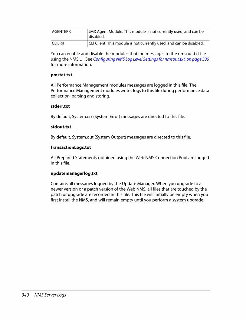
You can enable and disable the modules that log messages to the nmsout.txt file using the NMS UI. See Configuring NMS Log Level Settings for nmsout.txt‚ on page 335 for more information.
pmstat.txt
All Performance Management modules messages are logged in this file. The Performance Management modules writes logs to this file during performance data collection, parsing and storing.
stderr.txt
By default, System.err (System Error) messages are directed to this file.
stdout.txt
By default, System.out (System Output) messages are directed to this file.
transactionLogs.txt
All Prepared Statements obtained using the Web NMS Connection Pool are logged in this file.
updatemanagerlog.txt
Contains all messages logged by the Update Manager. When you upgrade to a newer version or a patch version of the Web NMS, all files that are touched by the patch or upgrade are recorded in this file. This file will initially be empty when you first install the NMS, and will remain empty until you perform a system upgrade.
AGENTERR JMX Agent Module. This module is not currently used, and can be disabled.
CLIERR CLI Client. This module is not currently used, and can be disabled.
340 NMS Server Logs

APPENDIX A Mobile Number Portability
This appendix describes the MNP feature for the release 2.2 of the HMC for NII and is divided into these sections:
■ About MNP‚ on page 342
■ Common Assumptions‚ on page 345
■ Mexico Market Configuration‚ on page 347
■ Brazil Market Configuration‚ on page 354
■ HPG Configuration‚ on page 361

About MNPMobile Number Portability (MNP) enables mobile telephone users to retain their mobile telephone numbers when changing from one mobile network operator to another.
In other words, a mobile ported number is one that was originally registered with one operator and has been ported to another carrier, i.e. Nextel.
A “dummy number” is one that was originally assigned by Nextel but was not owned by Nextel. As a result, dummy numbers may not be ported out of Nextel.
MNP Acronyms
The following acronyms are used for Mobile Number Portability:
Table of MNP Acronyms
ABBREVIATION MEANING
ACQ All Call Query
ICM Inter-carrier Messaging
ICV Inter-carrier Vendor
LNP Local Number Portability – used interchangeably with MNP
IDD Id Of Destination Donor—used interchangeably with RN
MAP Mobile Application Part
MMS Multimedia Messaging Service
MM5 A 3GPP standard interface specification for querying an HLR
MMSC Multimedia Messaging Service Center
MNP Mobile Number Portability – used interchangeably with LNP
MO Mobile Originated
MT Mobile Terminated
P2A Person to Application
P2P Person to Person
PTN Personal Telephone Number
RN Routing Number
SRI-SM Send Routing Information – Short Message
STP Signal Transfer Point
TD Technical Development team
342 About MNP

References
The following table lists the references used in the development of this appendix:
NII Markets
NII’s HMC maintains a single, consistent code base with sufficient operational flexibility to support MNP in all markets with a minimum of modifications to the core MMSC platform.
Mobile number portability has been phased into NII’s markets with each market having different routing scenarios. Even though each market’s routing is different than the other three NII markets, the changes to the HMC are simple.
A significant technical aspect of MNP is related to the routing of calls or mobile messages (SMS, MMS) to a number once it has been ported.
References List
Ref. ID
Document Title Rev.Company/Author
[1] High level description of number portability. Network Aspects(NA); TR 101 119
V.1.1.1 ETSI
[2] Support of Mobile Number Portability (MNP); Service Description; Stage 1 Release 6. 3GPP TS 22.066
V.6.1.0 3GPP
[3] High level network architecture and solutions to support number portability; ETSI TR 101 118
V 1.1.1 ETSI
[4] SIP: Session Initiation Protocol. RFC 3261 June 2002 IETF
[5] Especificaciones operativas para la implantación de portabilidad de números geográficos y no geográficos
September, 2007 COFETEL
[6] Digital cellular telecommunications system (Phase 2+). Technical realization of the Short Message Service (SMS) Point-to-Point (PP) GSM 03.40
V.5.3.0 ETSI
[7] Mobile Application Part (MAP) Specification (Release) 1998
V.7.15.0 3GPP
[8] Digital Cellular Telecommunications System (Phase 2+); Network Architecture; (GSM 03.02 version 7.0.0 Release 1998) 3GPP TS 100 522
V.7.0.0 3GPP
[9] Number Portability Parameters for the “tel” URI. RFC 4694
October 2006 IETF
[10] Gemini HMC-MM5 Interface Configuration TBA – not yet released
Gemini
343

Each carrier is assigned a unique three-digit routing number. To get a routing number for a particular number (MSISDN), an HLR query is issued to the MNP solution software.
HLR Queries
The HMC routes MAP messages to the MNP solution which is responsible for obtaining the proper routing information from either the MNP database directly or from an HLR. The HMC accepts responses from multiple HLRs. When the MNP forwards the request to any HLR, the proper response comes back to the HMC.
A MM5 query from the HMC to the HLR database returns a range of dummy numbers in the IMSI field of the response. This range of dummy number is configurable.
The RN (routing carrier id) is in the network node number field of the response.
All ICM MMS are sent to Verisign gateway.
344 About MNP

Common AssumptionsMAP-SRI / MAP-SRI-SM is the primary implementation scheme for all markets. The HMC uses a SIGTRAN gateway to convert between an IP network and the SS7 network for handling MAP messages.
Mexican and Brazilian operators have defined the Direct Routing – All Call Query (ACQ) method—for implementing MNP. In ACQ, the calls are routed directly from the originating network to the correct terminating mobile network, requiring the former to determine the appropriate network for a given number.
Numeric ranges from the operators are currently maintained in text files on the HMC. In some markets, the MNP solution provides the correct routing for all numbers, even un-ported numbers. As a result, these block number files are no longer be needed. However, not all of NII’s markets use this implementation.
Therefore, the maintenance and use of the block number files is maintained and used only when the MNP does not return routing information.
Note Dummy Numbers must not be ported.
If a ported number is provisioned on a Nextel Network, the new subscriber is able to use the Nextel VAS (Value Added Services), such as SMS, MMS, and other packet data applications. The corresponding record is registered on the Web Data Mart (WDM). If a ported number is provisioned on the Nextel Network with MMS services, the WDM will provision the HMC to allow user service.
All subscribers on the WDM are Nextel subscribers. If a NII number is ported out, the Billing system is updated in the LDAP via the current provisioning capabilities, i.e. a cancel service request. Therefore, NII numbers ported out no longer appear in the LDAP.
Messages are first validated against the HMC’s LDAP. Only numbers that are not found in the LDAP require an MNP lookup. This avoids querying the NPDB for Nextel MMS/2way subscribers.
NII provides the required Signaling Gateway (SG) hardware and/or software. Gemini HMC requirements end at the interface to the SG. The HMC interfaces with the SG in a standards compliant method and protocol.
The categories of routes are processed in a fixed order as follows:
1 Subscriber Capabilities—any handset found in the LDAP the PTN is assumed to belong to NII.
2 Subscriber Capabilities—for any handset not found in the LDAP, the HMC checks the number in one or more number range files for additional information. This
345
step determines if the number belongs to NII or another carrier. If it is another carrier, this step also determines if the ICM capabilities support SMPP, MM4 or both. Therefore, an MNP check must be done in place of, or in addition to the number range lookup.
3 MSISDN Routes—a message is routed based on one or more digits within the normalized MSISDN of the terminating handset. In our current implementation, each market has a MSISDN route for the Country Code (CC) of the other three NII markets. If one of these CCs exists, the message is forwarded—either to a gateway or back to the MMSC—via MM4 for the destination NII country.
4 IMSI Routes—not currently used but represents processing for MM5. Essentially, the MM5 interface will check for a configurable string of digits in the IMSI field of the MAPSRI-SM response. Similar to MSISDN routes, the message may be forwarded virtually anywhere via an interface (direct to a carrier, to a gateway ) and via virtually any protocol (MM4, SMPP) 3.1.4
NMS Limitations
There is a current bug in the NMS which allows a service provider administrator to make changes which affect all markets by restarting some or all components of the MMSC. Until that bug is fixed, access to the NMS screens associated with MM5 configuration may not be provided to the markets. Instead, a portion of configuration variables is set via text files.
See Mexico Market Configuration‚ on page 347, Brazil Market Configuration‚ on page 354 and HPG Configuration‚ on page 361 for configuration details.
346 Common Assumptions

Mexico Market ConfigurationNumber Portability in Mexico for local numbers, geographic numbers and non-geographic numbers have been defined in the COFETEL document “Especificaciones operativas para la implantación de portabilidad de números geográficos y no geográficos), September 19, 2007.
Mexico Message Flows
A MAP SRI-SM request from the MMSC to the NPDB for MM4 ICM flows is shown below:
NIIMX Requirement Summary
The MM5 query is issued for NIIMX SMS and ICM subscribers
For MM5
■ If NII subs, the IMSI field of the response will contain a valid value.
■ If ICM subs, the response IMSI field contains a dummy value (configurable) and network node number contains a valid ICM routing.
■ The ICM routing may be a combination IDD-IDO-MSISDN or IDD-MSISDN or MSISDN.
■ HMC must be able to handle any format based on cofiguration.
1. Generate MMS Destination 5555001064Donor: lusacellDoned: Telcel
MMSC STP NPDB HLR
Number is ported
2. MAP-SRI-SMMSISDN = 525555001064
2. MAP-SRI-SMMSISDN = 525555001064
Forward Short Message todestination (MM4) usingTelcel MM4 routing information
3. MAP-SRI-SM AckIMSI Filed populated withIDD + IDO + MSISDN orIDD + MSISDN
347
For ICM via MM4 address conversion
■ The number is prefixed with the routing number or a combination of routing number and IDO. This feature is configurable.
■ Mexico does not deploy an MM4 gateway, the routing domain is used to convert recipient address.
For SMPP address conversion:
The SMPP to NII SMS Gwateway avoids an extra MNP lookup at the NII SMS Gateway. The number is prefixed with the routing number or IDO or combination of both. The service type field of the SMPP PDU to NII SMS Gateway is "FINAL".
To other SMS Gateway the number is not prefixed with the RN.
To avoid circular routing, incoming MM3 are forwarded to NIIBR subscribers only. ICM MM4 is forwarded to NIIBR subscribers only.
NIIMX MNP Configuration
The following configuration files are modified for the Mexico market:
■ default.properties‚ on page 348
■ operator.properties‚ on page 349
■ mapsmssubcribers.cfg, mapintercarrierauthz.cfg‚ on page 349
■ mnp.properties‚ on page 349
■ mapicminfo.cfg sample config‚ on page 352
■ mapmm4authorization.cfg sample config‚ on page 352
■ mapmnpdomain.cfg sample config‚ on page 353
■ mapdummyimsi.cfg sample config‚ on page 353
■ mapmm4peer sample config‚ on page 360
See Gemini’s HyperScale Messaging Gateway (HMG) System Administrator’s Guide for detailed information on how to configure these files.
default.properties
Modify the router to authorize recipients from LDAP only (MTAUTH). If not found in LDAP, an MNP query will be issued for recipient setting the parameter:
MMSROUTER_niimx.mtauth = MTAUTH.
348 Mexico Market Configuration
operator.properties
Remove the standard HLR query interface which is not used in NII deployment setting the parameter:
MM5QP_niimx.imsilookup = MM5MAPLOOKUP_niimx
mapsmssubcribers.cfg, mapintercarrierauthz.cfg
Remove obsolete MM3 recipient authorization module (NIIMTICMAUTH_niimx) that uses LDAP by setting the map files mapsmssubcribers.cfg and mapintercarrierauthz.cfg to the parameter:
MM3RCPTAUTH_niimx.authorization=NIIMTICMAUTH_niimx
Remove obsolete CDR recipient authorization module (NIIMTICMAUTH_niimx)
CDRDATACSV_niimx.authorization=NIIMTICMAUTH_niimx
Add new MNP objects and configuration by including the mnp.properties file
include operator/niimx/mnp.properties
mnp.properties #configuration for SMS message.
# preprend_idd: prepend the idd to the SMS recipient
# mnpparser: object to parse idd from MNP response.
DEFAULT_niimx.prepend_idd = true
DEFAULT_niimx.mnpparser = NIIMNPPARSER_niimx
# niixx idd. Each market should have its own IDD or RN.
# For Mexico after a MNP lookup, the returned idd is compared
# to this to detect if a recipient is NIIMX SMS subscriber.
DEFAULT_niimx.idd = 190
# authorization config for MM3 listener.
# NIIMNPMTAUTH authorization object accepts only NII subscribers
# (in LDAP or NIIMX SMS)
MM3RCPTAUTH_niimx.authorization = NIIMNPMTAUTH_niimx
# authorization config for MM4 listener.
349
# all MNPParser object specified in MAPMNPAUTHORIZATION must be
# set in preopen.
MM4SMTP_niimx.command_rcpt= MM4MNPRCPTAUTH_niimx
MM4SMTP_niimx.mapauthorization=MAPMNPAUTHORIZATION_niimx
MM4SMTP_niimx.preopen=
# MM4 authorization object.
# Retrieve the authorization object from MAPMNPAUTHORIZATION
# based on domain of "MAIL FROM" envelope
# Use defaultDomain if "MAIL FROM" envelope does not have domain.
MM4MNPRCPTAUTH_niimx.type = MM4MNPRcptAuth
MM4MNPRCPTAUTH_niimx.searchkeyin=uid
MM4MNPRCPTAUTH_niimx.defaultDomain=DefaultMNPDomain
MM4MNPRCPTAUTH_niimx.mapauthorization=MAPMNPAUTHORIZATION_niimx
# MAPMNPAUTHORIZATION table consists of
# key is the domain of "MAIL FROM" envelope
# Authorization object.
# MNP parser objects (to parse pre-pended IDD/IDO)
# ALl MNP parser object in this table must be set in
# MM4SMTP_niimx.preopen
# see mapmm4authorization.cfg for more details.
MAPMNPAUTHORIZATION_niimx.type = NewMap
MAPMNPAUTHORIZATION_niimx.mapfile = operator/niimx/mapmm4authorization.cfg
MAPMNPAUTHORIZATION_niimx.default_keytype = EXACT
# Outgoing MM4 config
# iddstr is string used in address conversion (mapmm4peers.cfg) for IDD
# idostr is string used in address conversion (mapmm4peers.cfg) for IDO
# mnpparser is object to parse the IDD and IDO from MNP response.
# mnpdomain should be empty for NIIMX because NIIMX does not deploy
# an MM4 gateway for routing ICM messages.
MM4QP_niimx.iddstr = IDD
MM4QP_niimx.idostr = IDO
MM4QP_niimx.mnpparser = NIIMNPPARSER_niimx
MM4QP_niimx.mnpdomain = NIIMNPDOMAIN_niimx
350 Mexico Market Configuration
# NIIMNPDOMAIN is table to specify the domain if ICM to be used
# in address conversion when MM4 traffic will be routed via an
# MM4 gateway
NIIMNPDOMAIN_niimx.type = NewMap
NIIMNPDOMAIN_niimx.mapfile = operator/niimx/mapmnpdomain.cfg
NIIMNPDOMAIN_niimx.default_keytype = EXACT
# Configuration for NII MNP query
MM5QP_niimx.imsilookup = NIIMNPLOOKUP_niimx
# Configuration for NII MNP object
NIIMNPLOOKUP_niimx.type = NIIMNPLookup
NIIMNPLOOKUP_niimx.mtserviceif=MTSMSSERVICEIF_niimx
NIIMNPLOOKUP_niimx.dummyIMSI = DUMMYIMSI_niimx
#uncomment this line to test without SIGTRAN/MNP solution
#NIIMNPLOOKUP_niimx.testMnp = TESTMNP_niimx
# DUMMYIMSI table
DUMMYIMSI_niimx.type = NewMap
DUMMYIMSI_niimx.mapfile = operator/niimx/mapdummyimsi.cfg
DUMMYIMSI_niimx.default_keytype = EXACT
# this is not used in production.
TESTMNP_niimx.type = NewMap
TESTMNP_niimx.mapfile = operator/niimx/maptestmnp.cfg
TESTMNP_niimx.default_keytype = EXACT
# MNP Response parser object.
NIIMNPPARSER_niimx.type = NIIMNPParser
NIIMNPPARSER_niimx.iddlen = 3
NIIMNPPARSER_niimx.idolen = 0
NIIMNPPARSER_niimx.msisdnlen = 0
# NIIMNPMTAUTH object
# authorization = MTAUTH lookup in LDAP first
351
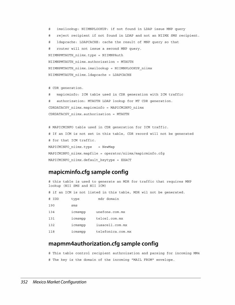
# imsilookup: NIIMNPLOOKUP: if not found in LDAP issue MNP query
# reject recipient if not found in LDAP and not an NIIMX SMS recipient.
# ldapcache: LDAPCACHE: cache the result of MNP query so that
# router will not issue a second MNP query.
NIIMNPMTAUTH_niimx.type = NIIMNPAuth
NIIMNPMTAUTH_niimx.authorization = MTAUTH
NIIMNPMTAUTH_niimx.imsilookup = NIIMNPLOOKUP_niimx
NIIMNPMTAUTH_niimx.ldapcache = LDAPCACHE
# CDR generation.
# mapicminfo: ICM table used in CDR generation with ICM traffic
# authorization: MTAUTH LDAP lookup for MT CDR generation.
CDRDATACSV_niimx.mapicminfo = MAPICMINFO_niimx
CDRDATACSV_niimx.authorization = MTAUTH
# MAPICMINFO table used in CDR generation for ICM traffic.
# If an ICM is not set in this table, CDR record will not be generated
# for that ICM traffic.
MAPICMINFO_niimx.type = NewMap
MAPICMINFO_niimx.mapfile = operator/niimx/mapicminfo.cfg
MAPICMINFO_niimx.default_keytype = EXACT
mapicminfo.cfg sample config # this table is used to generate an MDR for traffic that requires MNP lookup (NII SMS and NII ICM)
# if an ICM is not listed in this table, MDR wil not be generated.
# IDD type mdr domain
190 sms
134 icmsmpp unefone.com.mx
131 icmsmpp telcel.com.mx
132 icmsmpp iusacell.com.mx
118 icmsmpp telefonica.com.mx
mapmm4authorization.cfg sample config # This table control recipient authroization and parsing for incoming MM4
# The key is the domain of the incoming "MAIL FROM" envelope.
352 Mexico Market Configuration
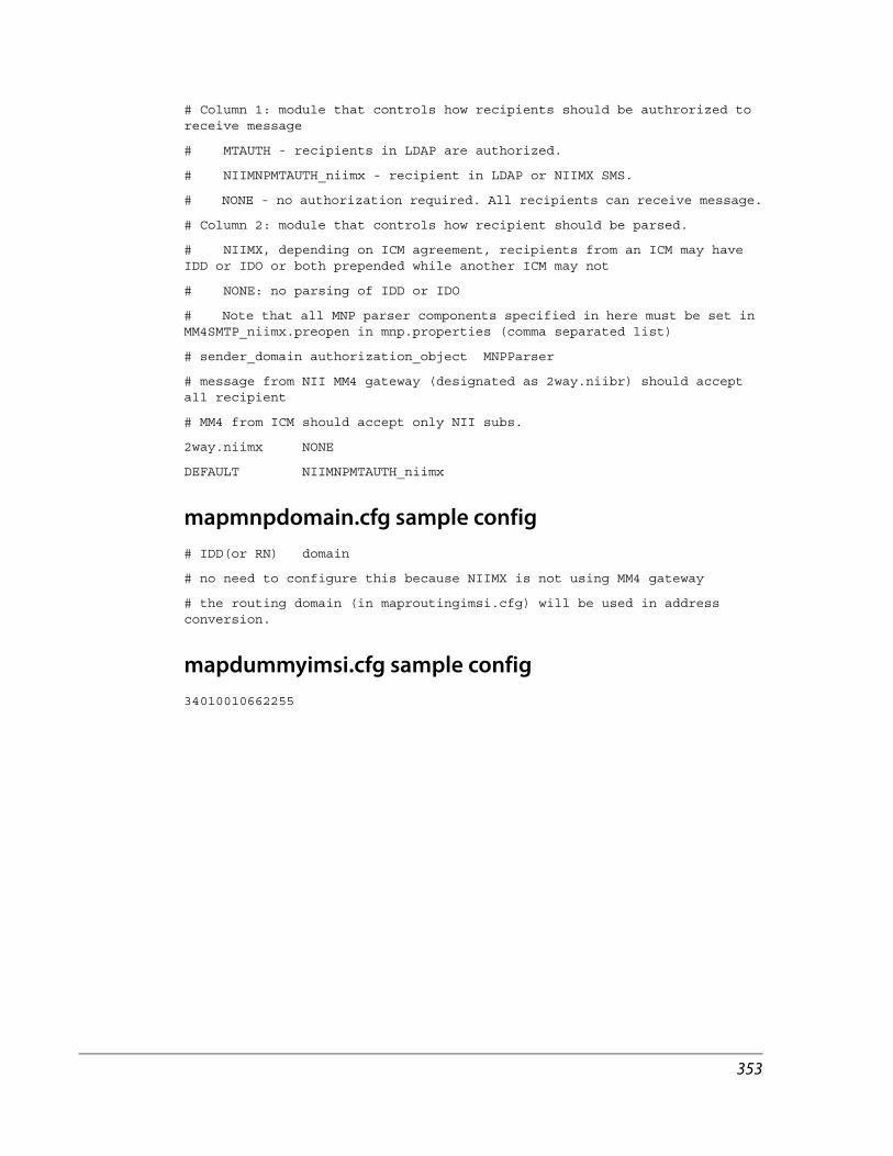
# Column 1: module that controls how recipients should be authrorized to receive message
# MTAUTH - recipients in LDAP are authorized.
# NIIMNPMTAUTH_niimx - recipient in LDAP or NIIMX SMS.
# NONE - no authorization required. All recipients can receive message.
# Column 2: module that controls how recipient should be parsed.
# NIIMX, depending on ICM agreement, recipients from an ICM may have IDD or IDO or both prepended while another ICM may not
# NONE: no parsing of IDD or IDO
# Note that all MNP parser components specified in here must be set in MM4SMTP_niimx.preopen in mnp.properties (comma separated list)
# sender_domain authorization_object MNPParser
# message from NII MM4 gateway (designated as 2way.niibr) should accept all recipient
# MM4 from ICM should accept only NII subs.
2way.niimx NONE
DEFAULT NIIMNPMTAUTH_niimx
mapmnpdomain.cfg sample config # IDD(or RN) domain
# no need to configure this because NIIMX is not using MM4 gateway
# the routing domain (in maproutingimsi.cfg) will be used in address conversion.
mapdummyimsi.cfg sample config 34010010662255
353

Brazil Market ConfigurationBrazil deployment requires all MM4 traffic to go through an MM4 gateway, Verisign. The Routing Domain is Versign where the messages are forwarded.
Address conversion uses the domain of the ICM carrier, not the routing domain.
■ "RCPT TO" envelope is converted.
■ "TO" field addresses is converted.
■ the number is not be prefixed withthe routing number
■ The domain is of the ICM carrier. For example:
◆ Routing domain is "mms.verisign.com"
◆ ICM carrier is telcel.br.com
◆ MM4 message wil be sent to "mms.verisign.com"
◆ "RCPT TO: [email protected]"
◆ "To: [email protected]"
# 5556501112222 is the rcipient number without RN
# telcel.br.com is the domain of the recipient carrier.
SMPP address conversion is configurable per SMS interface.
SMPP to NII SMS Gateway avoids an extra MNP lookup at the NII SMS Gateway. The number is prefixed with the routing number Service type field of the SMPP PDU to NII SMS Gateway must be "FINAL". To other SMS gateways, the number must not be prefixed with the RN.
Circular routing is avoided by having incoming MM3 forwarded to NIIBR subscribers only. ICM MM4 is forwarded to NIIBR subscribers only.
NIIBR is a trunk carrier and their numbers are not portable to other carriers. NIIBR mapsmssubscribers.cfg will still be valid.
354 Brazil Market Configuration

The following topology diagrams shows Nextel Brazil, MMS to ICM SMS:
The following topology diagrams shows Nextel Brazil, MMS to ICM SMS, if there is ICM MMS:
355

NIIIBR MNP Configuration
The following configuration files are modified for the Brazil Market:
■ default.properties‚ on page 356
■ operator.properties‚ on page 356
■ mnp.properties‚ on page 357
■ mapmnpdomain.cfg sample config‚ on page 360
■ mapdummyimsi.cfg sample config‚ on page 360
■ mapmm4peer sample config‚ on page 360
See Gemini’s HyperScale Messaging Gateway (HMG) System Administrator’s Guide for detailed information on how to configure these files.
default.properties
Modify the router to authorize recipient from LDAP and mapsmssubscribers.cfg (NIIMTAUTH_niibr). If not found, an MNP query will be issued for recipient:
MMSROUTER_niibr.mtauth = NIIMTAUTH_niibr
operator.properties
Because we don't need the file, operator/niibr/mapintercarrierauthz.cfg in MNP:
MM4RCPTAUTH_niibr.authorization = NIIMTAUTH_niibr
Remove the standard HLR query interface which is not used in NII deployment:
MM5QP_niibr.imsilookup = MM5MAPLOOKUP_niibr
Remove the obsolete MM3 recipient authentication module (NIIMTICMAUTH_niibr) that uses LDAP, mapsmssubcribers.cfg, and mapintercarrierauthz.cfg:
MM3RCPTAUTH_niibr.authorization=NIIMTICMAUTH_niibr
Remove obsolete CDR recipient authentication module (NIIMTICMAUTH_niibr):
CDRDATACSV_niibr.authorization=NIIMTICMAUTH_niibr
Add new MNP objects and configuration by including the mnp.properties file:
include operator/niibr/mnp.properties
356 Brazil Market Configuration
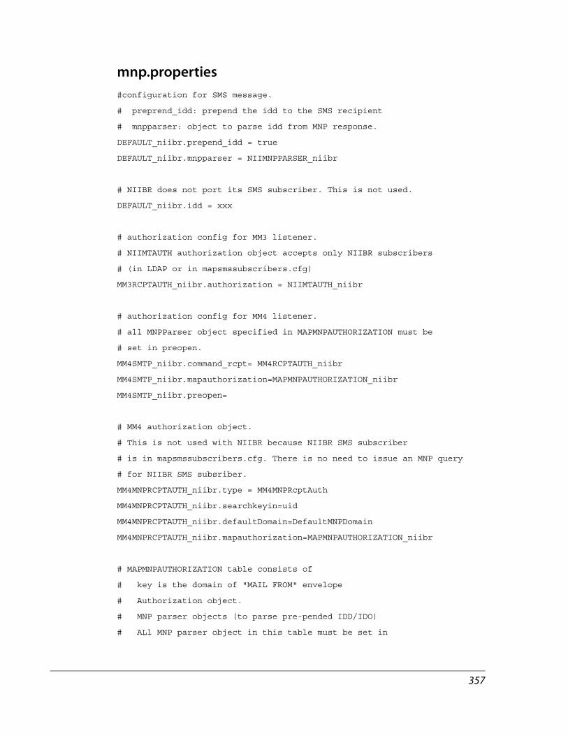
mnp.properties #configuration for SMS message.
# preprend_idd: prepend the idd to the SMS recipient
# mnpparser: object to parse idd from MNP response.
DEFAULT_niibr.prepend_idd = true
DEFAULT_niibr.mnpparser = NIIMNPPARSER_niibr
# NIIBR does not port its SMS subscriber. This is not used.
DEFAULT_niibr.idd = xxx
# authorization config for MM3 listener.
# NIIMTAUTH authorization object accepts only NIIBR subscribers
# (in LDAP or in mapsmssubscribers.cfg)
MM3RCPTAUTH_niibr.authorization = NIIMTAUTH_niibr
# authorization config for MM4 listener.
# all MNPParser object specified in MAPMNPAUTHORIZATION must be
# set in preopen.
MM4SMTP_niibr.command_rcpt= MM4RCPTAUTH_niibr
MM4SMTP_niibr.mapauthorization=MAPMNPAUTHORIZATION_niibr
MM4SMTP_niibr.preopen=
# MM4 authorization object.
# This is not used with NIIBR because NIIBR SMS subscriber
# is in mapsmssubscribers.cfg. There is no need to issue an MNP query
# for NIIBR SMS subsriber.
MM4MNPRCPTAUTH_niibr.type = MM4MNPRcptAuth
MM4MNPRCPTAUTH_niibr.searchkeyin=uid
MM4MNPRCPTAUTH_niibr.defaultDomain=DefaultMNPDomain
MM4MNPRCPTAUTH_niibr.mapauthorization=MAPMNPAUTHORIZATION_niibr
# MAPMNPAUTHORIZATION table consists of
# key is the domain of "MAIL FROM" envelope
# Authorization object.
# MNP parser objects (to parse pre-pended IDD/IDO)
# ALl MNP parser object in this table must be set in
357
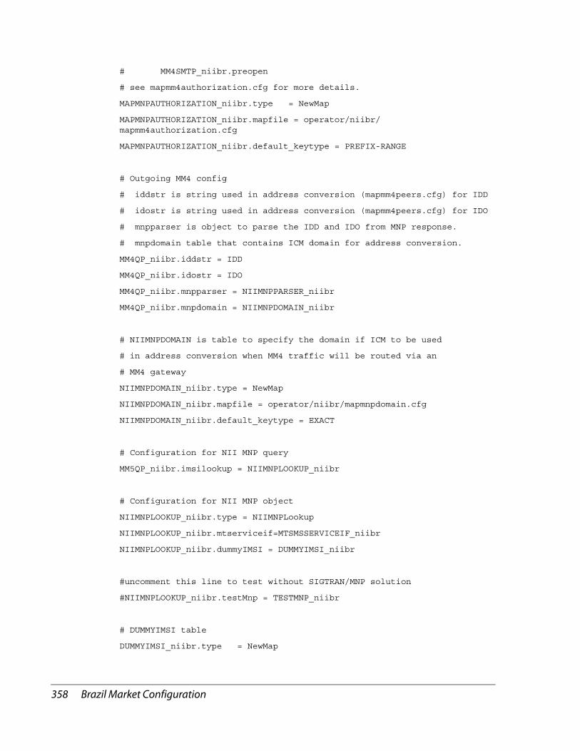
# MM4SMTP_niibr.preopen
# see mapmm4authorization.cfg for more details.
MAPMNPAUTHORIZATION_niibr.type = NewMap
MAPMNPAUTHORIZATION_niibr.mapfile = operator/niibr/mapmm4authorization.cfg
MAPMNPAUTHORIZATION_niibr.default_keytype = PREFIX-RANGE
# Outgoing MM4 config
# iddstr is string used in address conversion (mapmm4peers.cfg) for IDD
# idostr is string used in address conversion (mapmm4peers.cfg) for IDO
# mnpparser is object to parse the IDD and IDO from MNP response.
# mnpdomain table that contains ICM domain for address conversion.
MM4QP_niibr.iddstr = IDD
MM4QP_niibr.idostr = IDO
MM4QP_niibr.mnpparser = NIIMNPPARSER_niibr
MM4QP_niibr.mnpdomain = NIIMNPDOMAIN_niibr
# NIIMNPDOMAIN is table to specify the domain if ICM to be used
# in address conversion when MM4 traffic will be routed via an
# MM4 gateway
NIIMNPDOMAIN_niibr.type = NewMap
NIIMNPDOMAIN_niibr.mapfile = operator/niibr/mapmnpdomain.cfg
NIIMNPDOMAIN_niibr.default_keytype = EXACT
# Configuration for NII MNP query
MM5QP_niibr.imsilookup = NIIMNPLOOKUP_niibr
# Configuration for NII MNP object
NIIMNPLOOKUP_niibr.type = NIIMNPLookup
NIIMNPLOOKUP_niibr.mtserviceif=MTSMSSERVICEIF_niibr
NIIMNPLOOKUP_niibr.dummyIMSI = DUMMYIMSI_niibr
#uncomment this line to test without SIGTRAN/MNP solution
#NIIMNPLOOKUP_niibr.testMnp = TESTMNP_niibr
# DUMMYIMSI table
DUMMYIMSI_niibr.type = NewMap
358 Brazil Market Configuration
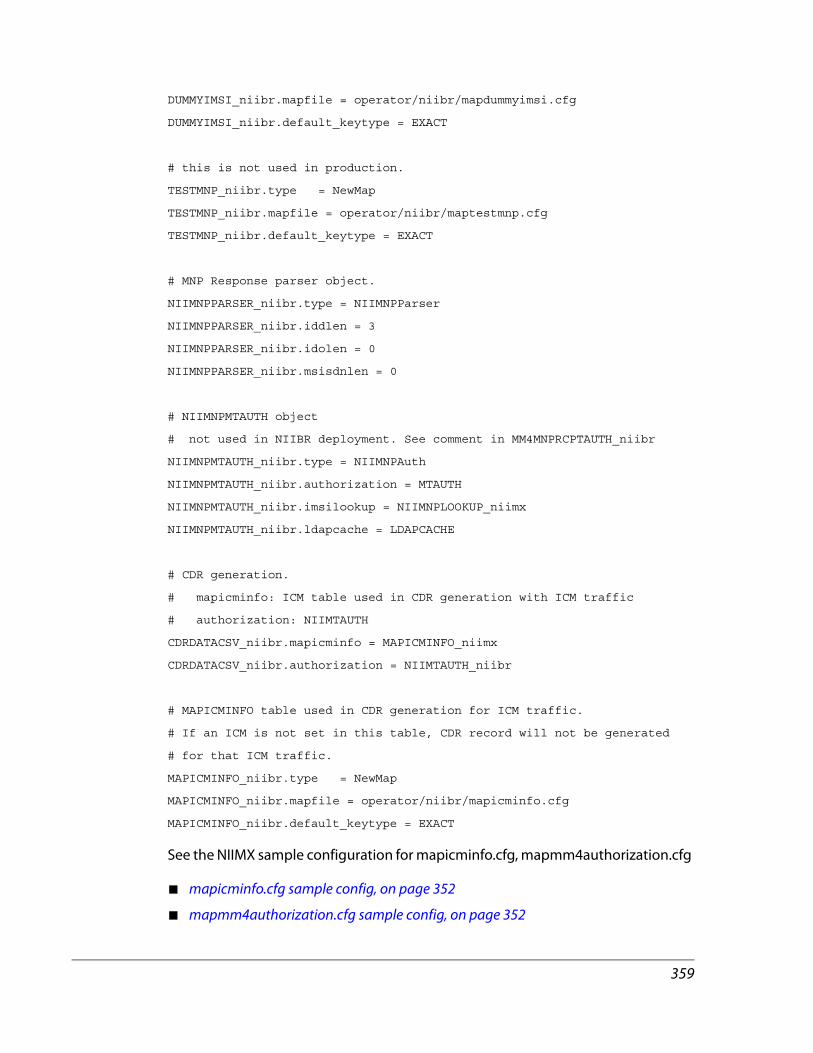
DUMMYIMSI_niibr.mapfile = operator/niibr/mapdummyimsi.cfg
DUMMYIMSI_niibr.default_keytype = EXACT
# this is not used in production.
TESTMNP_niibr.type = NewMap
TESTMNP_niibr.mapfile = operator/niibr/maptestmnp.cfg
TESTMNP_niibr.default_keytype = EXACT
# MNP Response parser object.
NIIMNPPARSER_niibr.type = NIIMNPParser
NIIMNPPARSER_niibr.iddlen = 3
NIIMNPPARSER_niibr.idolen = 0
NIIMNPPARSER_niibr.msisdnlen = 0
# NIIMNPMTAUTH object
# not used in NIIBR deployment. See comment in MM4MNPRCPTAUTH_niibr
NIIMNPMTAUTH_niibr.type = NIIMNPAuth
NIIMNPMTAUTH_niibr.authorization = MTAUTH
NIIMNPMTAUTH_niibr.imsilookup = NIIMNPLOOKUP_niimx
NIIMNPMTAUTH_niibr.ldapcache = LDAPCACHE
# CDR generation.
# mapicminfo: ICM table used in CDR generation with ICM traffic
# authorization: NIIMTAUTH
CDRDATACSV_niibr.mapicminfo = MAPICMINFO_niimx
CDRDATACSV_niibr.authorization = NIIMTAUTH_niibr
# MAPICMINFO table used in CDR generation for ICM traffic.
# If an ICM is not set in this table, CDR record will not be generated
# for that ICM traffic.
MAPICMINFO_niibr.type = NewMap
MAPICMINFO_niibr.mapfile = operator/niibr/mapicminfo.cfg
MAPICMINFO_niibr.default_keytype = EXACT
See the NIIMX sample configuration for mapicminfo.cfg, mapmm4authorization.cfg
■ mapicminfo.cfg sample config‚ on page 352
■ mapmm4authorization.cfg sample config‚ on page 352
359

mapmnpdomain.cfg sample config # NIIBR deploys a MM4 gateway (versign) to route traffic to ICM.
# The routing domain is that of verisign gateway but the ICM domain used incaddress conversion must be specified in this table
# IDD(RN) domain
124 braziltele.com.br
mapdummyimsi.cfg sample config #prefix low high
111111 5000 6000
mapmm4peer sample config # braziltele requires prepended IDD
EXACT braziltele.com.br|+IDD%c%n%s%T%D|<%pIDD%c%n%s%T%D>|%c%n%s|%c%n%s|true|true|false|false|false|false|false|false|UTF-8|Base64|UTF-8|Base64|Base64|false|307200|SEND
360 Brazil Market Configuration
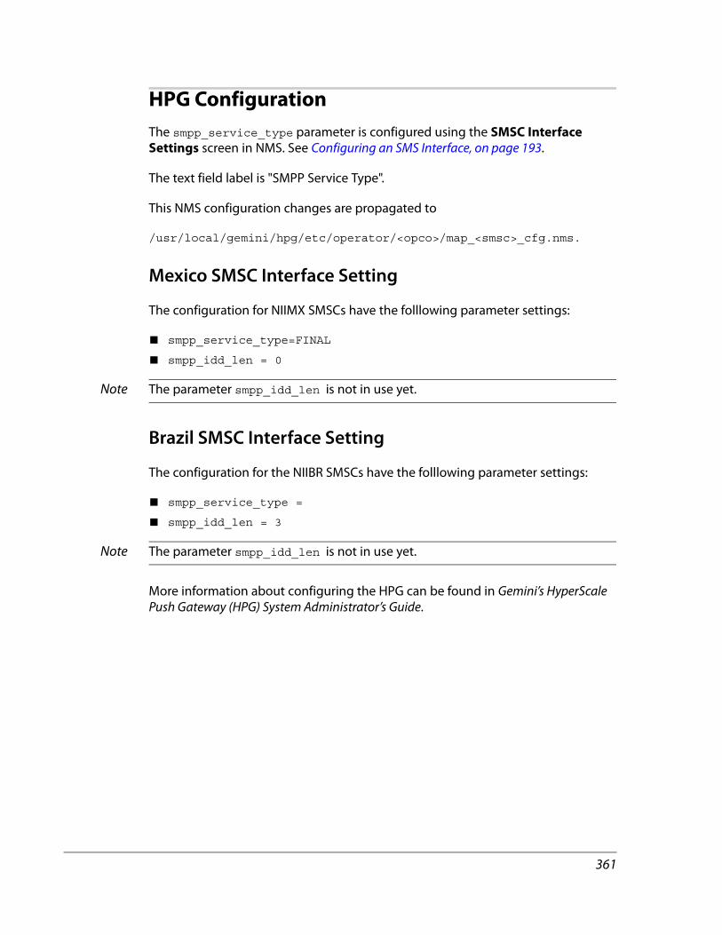
HPG ConfigurationThe smpp_service_type parameter is configured using the SMSC Interface Settings screen in NMS. See Configuring an SMS Interface‚ on page 193.
The text field label is "SMPP Service Type".
This NMS configuration changes are propagated to
/usr/local/gemini/hpg/etc/operator/<opco>/map_<smsc>_cfg.nms.
Mexico SMSC Interface Setting
The configuration for NIIMX SMSCs have the folllowing parameter settings:
■ smpp_service_type=FINAL
■ smpp_idd_len = 0
Note The parameter smpp_idd_len is not in use yet.
Brazil SMSC Interface Setting
The configuration for the NIIBR SMSCs have the folllowing parameter settings:
■ smpp_service_type =
■ smpp_idd_len = 3
Note The parameter smpp_idd_len is not in use yet.
More information about configuring the HPG can be found in Gemini’s HyperScale Push Gateway (HPG) System Administrator’s Guide.
361

362 HPG Configuration

APPENDIX B HSS Server
This appendix describes the HSS feature for the release Phase 2 of the HMC for NII and is divided into these sections:
■ HSS Features‚ on page 364
■ HSS Installation‚ on page 369
■ HSS Configuration Overview‚ on page 385
■ central.conf‚ on page 386
■ broker.conf‚ on page 394
■ HSS Logging‚ on page 397
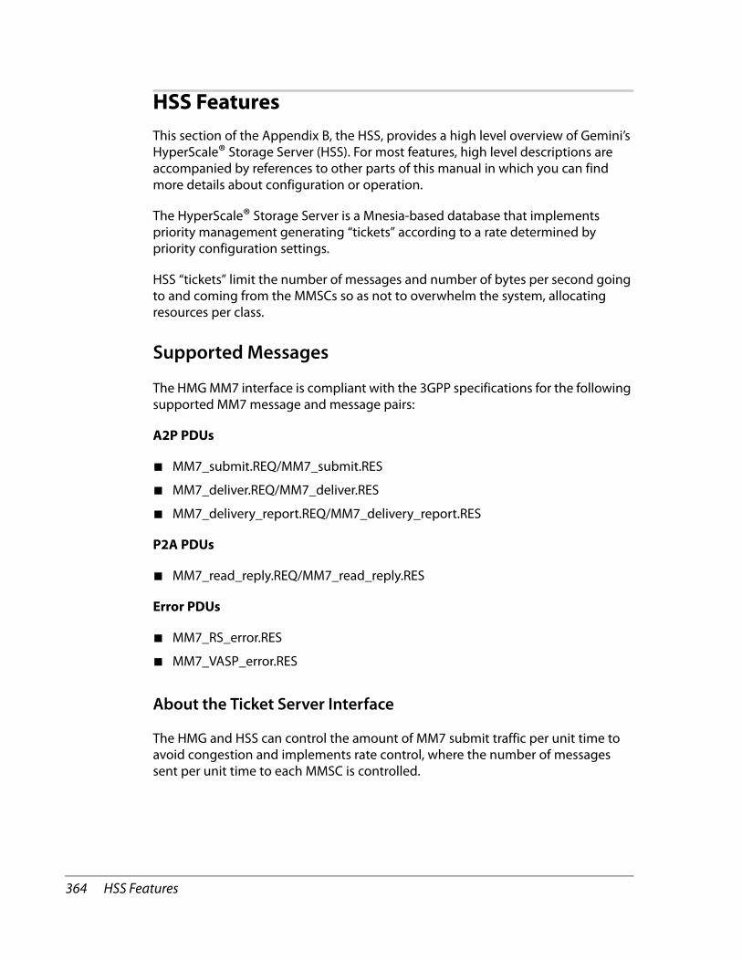
HSS FeaturesThis section of the Appendix B, the HSS, provides a high level overview of Gemini’s HyperScale® Storage Server (HSS). For most features, high level descriptions are accompanied by references to other parts of this manual in which you can find more details about configuration or operation.
The HyperScale® Storage Server is a Mnesia-based database that implements priority management generating “tickets” according to a rate determined by priority configuration settings.
HSS “tickets” limit the number of messages and number of bytes per second going to and coming from the MMSCs so as not to overwhelm the system, allocating resources per class.
Supported Messages
The HMG MM7 interface is compliant with the 3GPP specifications for the following supported MM7 message and message pairs:
A2P PDUs
■ MM7_submit.REQ/MM7_submit.RES
■ MM7_deliver.REQ/MM7_deliver.RES
■ MM7_delivery_report.REQ/MM7_delivery_report.RES
P2A PDUs
■ MM7_read_reply.REQ/MM7_read_reply.RES
Error PDUs
■ MM7_RS_error.RES
■ MM7_VASP_error.RES
About the Ticket Server Interface
The HMG and HSS can control the amount of MM7 submit traffic per unit time to avoid congestion and implements rate control, where the number of messages sent per unit time to each MMSC is controlled.
364 HSS Features
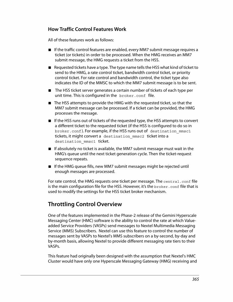
How Traffic Control Features Work
All of these features work as follows:
■ If the traffic control features are enabled, every MM7 submit message requires a ticket (or tickets) in order to be processed. When the HMG receives an MM7 submit message, the HMG requests a ticket from the HSS.
■ Requested tickets have a type. The type name tells the HSS what kind of ticket to send to the HMG, a rate control ticket, bandwidth control ticket, or priority control ticket. For rate control and bandwidth control, the ticket type also indicates the ID of the MMSC to which the MM7 submit message is to be sent.
■ The HSS ticket server generates a certain number of tickets of each type per unit time. This is configured in the broker.conf file.
■ The HSS attempts to provide the HMG with the requested ticket, so that the MM7 submit message can be processed. If a ticket can be provided, the HMG processes the message.
■ If the HSS runs out of tickets of the requested type, the HSS attempts to convert a different ticket to the requested ticket (if the HSS is configured to do so in broker.conf ). For example, if the HSS runs out of destination_mmsc1 tickets, it might convert a destination_mmsc2 ticket into a destination_mmsc1 ticket.
■ If absolutely no ticket is available, the MM7 submit message must wait in the HMG’s queue until the next ticket generation cycle. Then the ticket-request sequence repeats.
■ If the HMG queue fills, new MM7 submit messages might be rejected until enough messages are processed.
For rate control, the HMG requests one ticket per message. The central.conf file is the main configuration file for the HSS. However, it’s the broker.conf file that is used to modify the settings for the HSS ticket broker mechanism.
Throttling Control Overview
One of the features implemented in the Phase-2 release of the Gemini Hyperscale Messaging Center (HMC) software is the ability to control the rate at which Value-added Service Providers (VASPs) send messages to Nextel Multimedia Messaging Service (MMS) Subscribers. Nextel can use this feature to control the number of messages sent by VASPs to Nextel's MMS subscribers on a by-second, by-day and by-month basis, allowing Nextel to provide different messaging rate tiers to their VASPs.
This feature had originally been designed with the assumption that Nextel's HMC Cluster would have only one Hyperscale Messaging Gateway (HMG) receiving and
365
processing all incoming and outgoing MMS messages. However, in order to accommodate Nextel's current and future MMS traffic rates, additional HMGs were added to the HMC Cluster.
While there was only one HMG in the HMC cluster, the single HMG could track the number and the rate of messages sent by VASPs and enforce throttling limits. However, with multiple HMGs, the problem becomes much more complex. There were two possible solutions, modyfying the HMG or introduce a ticketing server, the HSS.
Modifying the HMG so that all HMGs in the cluster can communicate with and send/receive VASP message rates to each other was impractical as it would introduce additional throttling data traffic between the HMGs and adversely affect the messaging throughput of these servers. As the number of HMGs in the cluster increases linearly, the throttling data traffic required would increase exponentially.
Introducing a new, separate server whose sole responsibility will be to track the VASP message rate and apply throttling controls as necessary was far more practical in that the throttling data traffic between the HMGs and the new server increase linearly as the number of HMGs in the cluster increases.
Gemini Mobile has installed and configured a Hyperscale Storage Server (HSS) and upgraded the HMG server software in the Production HMC Cluster to implement the multi-HMG VAPS Throttling feature. The HMGs will communicate with the HSS and obtain the required data in order to apply throttling controls to VAS messages.
Ticketing Description
The Hyperscale Storage Server has a feature whereby it generates 'Tickets' that can be provided to the HMG servers. Each Ticket permits an HMG to process and send a single VAS message to a Nextel MMS subscriber. If the HMG cannot obtain a Ticket from the HSS for the VAS message that it is attempting to process and send, the HMG will reject the VAS message.
The HSS will generate a configurable number of Tickets for any desired VAS during each cycle. When the HMG receives a new VAS message, it sends a request to the HSS for a Ticket for that VAS. The HSS will then give a Ticket to the requesting HMG.
This will decrease the number of Tickets available for the VAS by one. If all the Tickets generated for the VAS have been consumed by the HMGs, no additional Tickets will be given to the HMGs until the next cycle when new Tickets will be generated by the HSS.
366 HSS Features
Ticketing Configuration Parameters
For each configured VAS, there are three parameters which control the number of Tickets generated during each cycle. The parameters are as follows:
vasp_maxmps_vasid_vaspid,TTP,TPL,TTTL
vasp_maxmpd_vasid_vaspid_TTP,TPL,TTTL
vasp_maxmpm_vasid_vaspid_TTP,TPL,TTTL
vasp_maxmps— This parameter controls the number of Tickets generated per second for the VAS.
vasp_maxmpd—This parameter controls the number of Tickets generated per day for the VAS.
vasp_maxmpm —This parameter controls the number of Tickets generated per month for the VAS.
The above parameters have five fields:
vasid—Specifies the name of the VAS
vaspid—Specifies the name of the VASP
Note The values of the vasid and vaspid fields are case-sensitive and must match the VASP and VAS ID's configured in the NMS GUI.
TTP (Tickets per Time Period)—This value specifies how many Tickets will be generated for each Time Period.
TPL (Time Period Length)—This value specifies the length of each Time Period in milliseconds.
TTTL (Ticket Time-To-Live)—This value specifies for how many cycles each Ticket will be valid. The default value is 1. If this value is greater than 1, then Tickets not consumed during a cycle will still be available in the next cycle until they are either consumed or until they expire.
The above parameters must be added and configured in the /usr/local/gemini/hss/etc/broker.conf file.
The following are some examples of how these parameters are configured:
Example vasp_maxmps_niimx_cnn_weather,10,1000,1
367
In the above example, 10 Tickets will be generated each 1000 milliseconds for Nextel Mexico's (niimx) VAS 'weather' of the 'cnn' VASP. Unused Tickets will expire in 1 cycle.
Example vasp_maxmpd_niipe_tiaxa_tiaxa01,300,86400000,2
In the above example, 300 Tickets will be generated each 86400000 milliseconds (1 day) for Nextel Peru's (niipe) 'tiaxa01' VAS of the 'cnn' VASP. Unused Tickets will expire in 2 cycles, i.e. any unused Tickets will be available for one additional day.
Example vasp_maxmpm_niibr_HANZO_hanzo-20,2000,2592000000,1
In the above example, 2000 Tickets will be generated each 2592000000 milliseconds (30 days) for Nextel Brazil's (niibr) VAS 'hanzo-20' of the 'HANZO' VASP. Unused Tickets will expire in 1 cycle.
Please note that whenever a new VASP or VAS is added, deleted, enabled or disabled using the NMS GUI, the broker.conf file on both HSS Servers will need to be updated accordingly. Once the broker.conf file has been updated, issue the following command to reload the broker.conf file into the HSS Servers:
for ((n=1;n<3;n++)); do echo "reload broker.conf" | nc hmc-hss-${n} 6028; done
368 HSS Features
HSS InstallationFor VASP management and usage, the HMC should include the following NII requirements:
■ Extend the short code length to a maximum of 7 characters.
■ The number of messages per second per VASP should be configurable per market.
■ Setting max messages per day for the VAS is not working. Messages sent after the set limit still get through.
■ Setting max messages per month for the VAS is not working. Messages sent after the set limit still get through.
■ Setting max messages per second for the VAS is not working. Messages sent after the set limit still get through.
■ This doesn't work for any of the interfaces. It accepts all messages regardless of the limit.
■ The ability to monitor the amount of messages per VASP per market and shutdown that interface when it hits a predefined threshold.
■ VASP: The status of the application. Enabled or disabled. Scheduling of applications shall also be supported
Gemini Technical Support will perform the upgrade of HMG software and the installation of HSS software for the accomplishment of the above requirements.
Prerequisites
A 3-hour Maintenance Window will need to be scheduled for the Phase-2 HMC Production Cluster.
NII will require configuring a Load Balancer (LB) between the two HSS nodes (hmc-5 and hmc-18).
Pre-Implementation Steps
Prior to the Maintenance Window, the following steps will be performed.
1 Upload the latest versions of HMG into hmc-1. (HMG__mmsc-nii.Pl4.40.200904281021)
2 Upload the latest HSS version HSS-MMSG__1264_3 to hmc-5 and hmc-18 nodes
3 Upload latest ERT version ERT__1264_1 to the hmc-5 and hmc-8 nodes
369
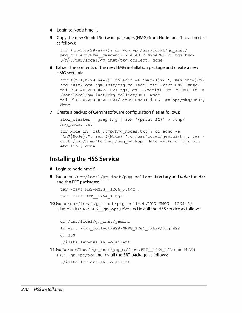
4 Login to Node hmc-1.
5 Copy the new Gemini Software packages (HMG) from Node hmc-1 to all nodes as follows:
for ((n=2;n<29;n++)); do scp -p /usr/local/gm_inst/pkg_collect/HMG__mmsc-nii.Pl4.40.200904281021.tgz hmc-${n}:/usr/local/gm_inst/pkg_collect; done
6 Extract the contents of the new HMG installation package and create a new HMG soft-link:
for ((n=1;n<29;n++)); do echo -e "hmc-${n}:"; ssh hmc-${n} 'cd /usr/local/gm_inst/pkg_collect; tar -xzvf HMG__mmsc-nii.Pl4.40.200904281021.tgz; cd ../gemini; rm -f HMG; ln -s /usr/local/gm_inst/pkg_collect/HMG__mmsc-nii.Pl4.40.200904281021/Linux-RhAS4-i386__gm_opt/pkg/HMG'; done
7 Create a backup of Gemini software configuration files as follows:
show_cluster | grep hmg | awk '{print $2}' > /tmp/hmg_nodes.txt
for Node in `cat /tmp/hmg_nodes.txt`; do echo -e "\n${Node}:"; ssh ${Node} 'cd /usr/local/gemini/hmg; tar -czvf /usr/home/techsup/hmg_backup-`date +%Y%m%d`.tgz bin etc lib'; done
Installing the HSS Service
8 Login to node hmc-5.
9 Go to the /usr/local/gm_inst/pkg_collect directory and untar the HSS and the ERT packages:
tar –xzvf HSS-MMSG__1264_3.tgz .
tar -xzvf ERT__1264_1.tgz .
10 Go to /usr/local/gm_inst/pkg_collect/HSS-MMSG__1264_3/Linux-RhAS4-i386__gm_opt/pkg and install the HSS service as follows:
cd /usr/local/gm_inst/gemini
ln –s ../pkg_collect/HSS-MMSG_1264_3/Li*/pkg HSS
cd HSS
./installer-hss.sh -o silent
11 Go to /usr/local/gm_inst/pkg_collect/ERT__1264_1/Linux-RhAS4-i386__gm_opt/pkg and install the ERT package as follows:
./installer-ert.sh -o silent
370 HSS Installation

Configuring the HSS
12 Issue the following commands, to create the .erlang.cookie file:
a) Start the HSS service:
/etc/init.d/hss start
You will see the following output:
Starting hssd: [ OK ]
Starting hssd2: [ OK ]
Creating HSS lock file: [ OK ]
HyperScale Storage Server (HSS) start status: [ OK ]
b) Stop the HSS service:
/etc/init.d/hss stop
You will see the following result:
Stopping both HSS service daemons: [ OK ]
Removing HSS lock file: [ OK ]
HyperScale Storage Server (HSS) stop status: [ OK ]
13 Issue the following command to copy the /home/mmssys/.erlang.cookie file from hmc-5 to hmc-18.
scp -p /home/mmssys/.erlang.cookie hmc-18:/home/mmssys/.
14 Make sure that the file is owned by the mmssys user and has permissions 0400 on both servers, hmc-5 and hmc-18.
chown mmssys:mmssys /home/mmssys/.erlang.cookie
chmod 400 /home/mmssys/.erlang.cookie
15 Login to node hmc-18 and repeat steps 9 through 11.
371
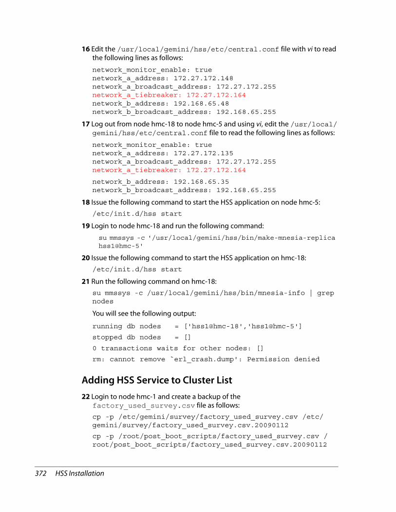
16 Edit the /usr/local/gemini/hss/etc/central.conf file with vi to read the following lines as follows:
network_monitor_enable: true network_a_address: 172.27.172.148 network_a_broadcast_address: 172.27.172.255 network_a_tiebreaker: 172.27.172.164 network_b_address: 192.168.65.48 network_b_broadcast_address: 192.168.65.255
17 Log out from node hmc-18 to node hmc-5 and using vi, edit the /usr/local/gemini/hss/etc/central.conf file to read the following lines as follows:
network_monitor_enable: true network_a_address: 172.27.172.135 network_a_broadcast_address: 172.27.172.255 network_a_tiebreaker: 172.27.172.164
network_b_address: 192.168.65.35 network_b_broadcast_address: 192.168.65.255
18 Issue the following command to start the HSS application on node hmc-5:
/etc/init.d/hss start
19 Login to node hmc-18 and run the following command:
su mmssys -c '/usr/local/gemini/hss/bin/make-mnesia-replica hss1@hmc-5'
20 Issue the following command to start the HSS application on hmc-18:
/etc/init.d/hss start
21 Run the following command on hmc-18:
su mmssys -c /usr/local/gemini/hss/bin/mnesia-info | grep nodes
You will see the following output:
running db nodes = ['hss1@hmc-18','hss1@hmc-5']
stopped db nodes = []
0 transactions waits for other nodes: []
rm: cannot remove `erl_crash.dump': Permission denied
Adding HSS Service to Cluster List
22 Login to node hmc-1 and create a backup of the factory_used_survey.csv file as follows:
cp -p /etc/gemini/survey/factory_used_survey.csv /etc/gemini/survey/factory_used_survey.csv.20090112
cp -p /root/post_boot_scripts/factory_used_survey.csv /root/post_boot_scripts/factory_used_survey.csv.20090112
372 HSS Installation

23 Replace the current factory_used_survey.csv file with the new csv file which contains the hss-1 service:
cp -p /usr/home/techsup/factory_used_survey_Rack_1.20090420.csv /etc/gemini/survey/factory_used_survey.csv
cp -p /usr/home/techsup/factory_used_survey_Rack_1.20090420.csv /root/post_boot_scripts/factory_used_survey.csv
24 Copy the factory_used_survey files to all the ten hmc servers on Rack 1 as follows:
for ((n=1;n<11;n++)); do scp -p /etc/gemini/survey/factory_used_survey.csv* hmc-${n}:/etc/gemini/survey; done
for ((n=1;n<11;n++)); do scp -p /etc/gemini/survey/factory_used_survey.csv* hmc-${n}:/root/post_boot_scripts/factory_used_survey.csv; done
25 In order to add the hss-1 under Lifekeeper, run the following command:
resource_create hss-1
26 Verify that hss-1 service was added by running the show_cluster command.
27 Login to node hmc-11 and create a backup of the factory_used_survey.csv file as follows:
cp -p /etc/gemini/survey/factory_used_survey.csv /etc/gemini/survey/factory_used_survey.csv.20090112
cp -p /root/post_boot_scripts/factory_used_survey.csv /root/post_boot_scripts/factory_used_survey.csv.20090112
28 Replace the current factory_used_survey.csv file with the new csv file which contains the hss-2 service:
scp -p hmc-1:/usr/home/techsup/factory_used_survey_Rack_2.20090420.csv /etc/gemini/survey/factory_used_survey.csv
scp -p hcm-1:/usr/home/techsup/factory_used_survey_Rack_2.20090420.csv /root/post_boot_scripts/factory_used_survey.csv
29 Copy the factory_used_survey files to all the eight hmc servers on Rack 2 as follows:
for ((n=11;n<19;n++)); do scp -p /etc/gemini/survey/factory_used_survey.csv* hmc-${n}:/etc/gemini/survey; done
for ((n=11;n<19;n++)); do scp -p /etc/gemini/survey/factory_used_survey.csv* hmc-${n}:/root/post_boot_scripts/factory_used_survey.csv; done
373
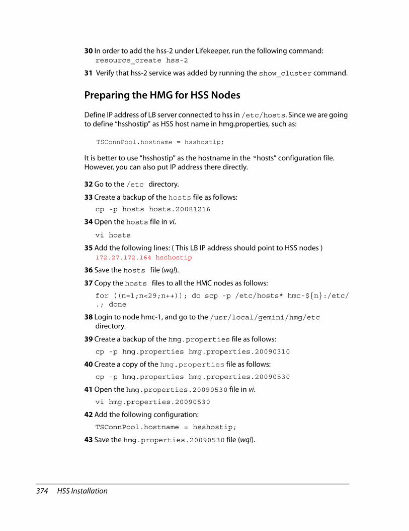
30 In order to add the hss-2 under Lifekeeper, run the following command: resource_create hss-2
31 Verify that hss-2 service was added by running the show_cluster command.
Preparing the HMG for HSS Nodes
Define IP address of LB server connected to hss in /etc/hosts. Since we are going to define “hsshostip” as HSS host name in hmg.properties, such as:
TSConnPool.hostname = hsshostip;
It is better to use “hsshostip” as the hostname in the “hosts” configuration file. However, you can also put IP address there directly.
32 Go to the /etc directory.
33 Create a backup of the hosts file as follows:
cp -p hosts hosts.20081216
34 Open the hosts file in vi.
vi hosts
35 Add the following lines: ( This LB IP address should point to HSS nodes ) 172.27.172.164 hsshostip
36 Save the hosts file (wq!).
37 Copy the hosts files to all the HMC nodes as follows:
for ((n=1;n<29;n++)); do scp -p /etc/hosts* hmc-${n}:/etc/.; done
38 Login to node hmc-1, and go to the /usr/local/gemini/hmg/etc directory.
39 Create a backup of the hmg.properties file as follows:
cp -p hmg.properties hmg.properties.20090310
40 Create a copy of the hmg.properties file as follows:
cp -p hmg.properties hmg.properties.20090530
41 Open the hmg.properties.20090530 file in vi.
vi hmg.properties.20090530
42 Add the following configuration:
TSConnPool.hostname = hsshostip;
43 Save the hmg.properties.20090530 file (wq!).
374 HSS Installation
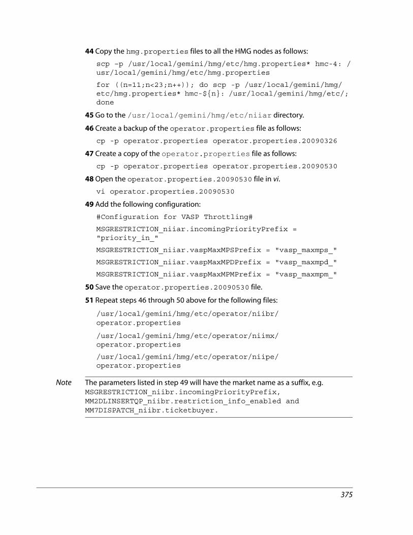
44 Copy the hmg.properties files to all the HMG nodes as follows:
scp –p /usr/local/gemini/hmg/etc/hmg.properties* hmc-4: /usr/local/gemini/hmg/etc/hmg.properties
for ((n=11;n<23;n++)); do scp -p /usr/local/gemini/hmg/etc/hmg.properties* hmc-${n}: /usr/local/gemini/hmg/etc/; done
45 Go to the /usr/local/gemini/hmg/etc/niiar directory.
46 Create a backup of the operator.properties file as follows:
cp -p operator.properties operator.properties.20090326
47 Create a copy of the operator.properties file as follows:
cp -p operator.properties operator.properties.20090530
48 Open the operator.properties.20090530 file in vi.
vi operator.properties.20090530
49 Add the following configuration:
#Configuration for VASP Throttling#
MSGRESTRICTION_niiar.incomingPriorityPrefix = "priority_in_"
MSGRESTRICTION_niiar.vaspMaxMPSPrefix = "vasp_maxmps_"
MSGRESTRICTION_niiar.vaspMaxMPDPrefix = "vasp_maxmpd_"
MSGRESTRICTION_niiar.vaspMaxMPMPrefix = "vasp_maxmpm_"
50 Save the operator.properties.20090530 file.
51 Repeat steps 46 through 50 above for the following files:
/usr/local/gemini/hmg/etc/operator/niibr/operator.properties
/usr/local/gemini/hmg/etc/operator/niimx/operator.properties
/usr/local/gemini/hmg/etc/operator/niipe/operator.properties
Note The parameters listed in step 49 will have the market name as a suffix, e.g. MSGRESTRICTION_niibr.incomingPriorityPrefix, MM2DLINSERTQP_niibr.restriction_info_enabled and MM7DISPATCH_niibr.ticketbuyer.
375

52 Copy the operator.properties.20090530 files to HMG #1's secondary node as follows:
for market in niiar niibr niimx niipe; do scp -p /usr/local/gemini/hmg/etc/operator/${market}/operator.properties.20090530 hmc-4:/usr/local/gemini/hmg/etc/operator/${market}/;
53 Repeat Steps 45 through 52 for the remaining HMG #2 through HMG #7 Services.
Implementation Steps
54 Switch to the original ha scripts:
for ((n=1;n<29;n++)); do echo -e "hmc-${n}:"; ssh hmc-${n} 'cd /usr/local/gemini/ha; mv bin bin.20081215; mv bin.20070704 bin; cd /usr/local/gemini/install; mv bin bin.20081215; mv bin.20080704 bin'; done
55 Update the hmg.properties files to all the HMG Nodes as follows:
cp –p /usr/local/gemini/hmg/etc/hmg.properties.20090530 /usr/local/gemini/hmg/etc/hmg.properties
scp –p /usr/local/gemini/hmg/etc/hmg.properties.20090530 hmc-4:/usr/local/gemini/hmg/etc/hmg.properties
for ((n=11;n<23;n++)); do scp -p /usr/local/gemini/hmg/etc/hmg.properties.20090530 hmc-${n}:/usr/local/gemini/hmg/etc/; done
376 HSS Installation
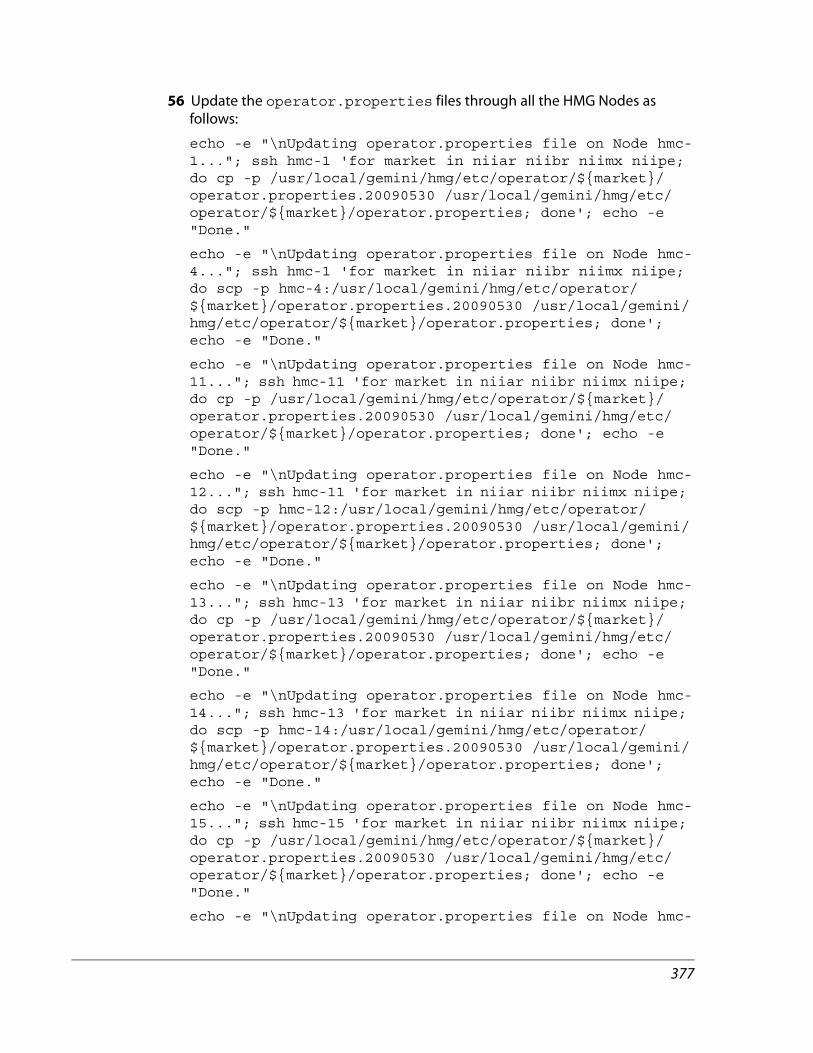
56 Update the operator.properties files through all the HMG Nodes as follows:
echo -e "\nUpdating operator.properties file on Node hmc-1..."; ssh hmc-1 'for market in niiar niibr niimx niipe; do cp -p /usr/local/gemini/hmg/etc/operator/${market}/operator.properties.20090530 /usr/local/gemini/hmg/etc/operator/${market}/operator.properties; done'; echo -e "Done."
echo -e "\nUpdating operator.properties file on Node hmc-4..."; ssh hmc-1 'for market in niiar niibr niimx niipe; do scp -p hmc-4:/usr/local/gemini/hmg/etc/operator/${market}/operator.properties.20090530 /usr/local/gemini/hmg/etc/operator/${market}/operator.properties; done'; echo -e "Done."
echo -e "\nUpdating operator.properties file on Node hmc-11..."; ssh hmc-11 'for market in niiar niibr niimx niipe; do cp -p /usr/local/gemini/hmg/etc/operator/${market}/operator.properties.20090530 /usr/local/gemini/hmg/etc/operator/${market}/operator.properties; done'; echo -e "Done."
echo -e "\nUpdating operator.properties file on Node hmc-12..."; ssh hmc-11 'for market in niiar niibr niimx niipe; do scp -p hmc-12:/usr/local/gemini/hmg/etc/operator/${market}/operator.properties.20090530 /usr/local/gemini/hmg/etc/operator/${market}/operator.properties; done'; echo -e "Done."
echo -e "\nUpdating operator.properties file on Node hmc-13..."; ssh hmc-13 'for market in niiar niibr niimx niipe; do cp -p /usr/local/gemini/hmg/etc/operator/${market}/operator.properties.20090530 /usr/local/gemini/hmg/etc/operator/${market}/operator.properties; done'; echo -e "Done."
echo -e "\nUpdating operator.properties file on Node hmc-14..."; ssh hmc-13 'for market in niiar niibr niimx niipe; do scp -p hmc-14:/usr/local/gemini/hmg/etc/operator/${market}/operator.properties.20090530 /usr/local/gemini/hmg/etc/operator/${market}/operator.properties; done'; echo -e "Done."
echo -e "\nUpdating operator.properties file on Node hmc-15..."; ssh hmc-15 'for market in niiar niibr niimx niipe; do cp -p /usr/local/gemini/hmg/etc/operator/${market}/operator.properties.20090530 /usr/local/gemini/hmg/etc/operator/${market}/operator.properties; done'; echo -e "Done."
echo -e "\nUpdating operator.properties file on Node hmc-
377
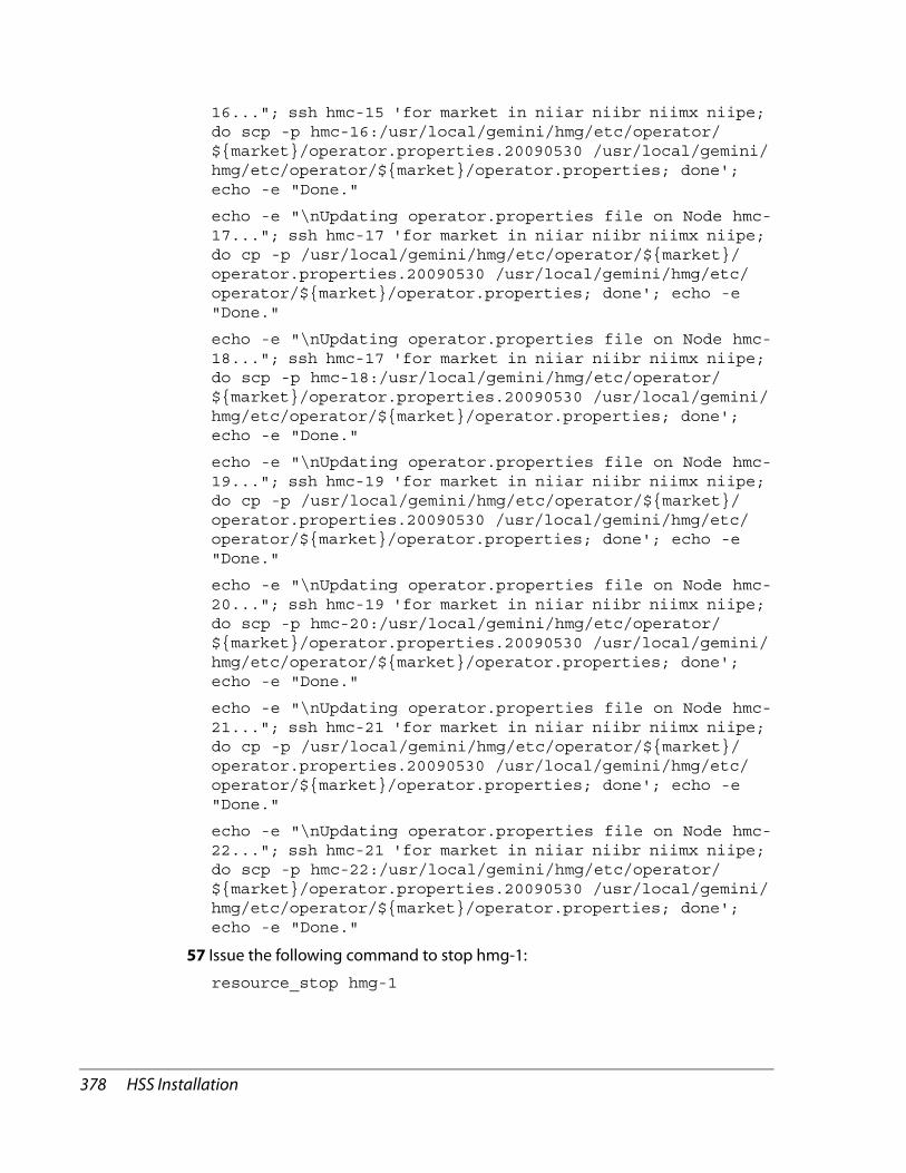
16..."; ssh hmc-15 'for market in niiar niibr niimx niipe; do scp -p hmc-16:/usr/local/gemini/hmg/etc/operator/${market}/operator.properties.20090530 /usr/local/gemini/hmg/etc/operator/${market}/operator.properties; done'; echo -e "Done."
echo -e "\nUpdating operator.properties file on Node hmc-17..."; ssh hmc-17 'for market in niiar niibr niimx niipe; do cp -p /usr/local/gemini/hmg/etc/operator/${market}/operator.properties.20090530 /usr/local/gemini/hmg/etc/operator/${market}/operator.properties; done'; echo -e "Done."
echo -e "\nUpdating operator.properties file on Node hmc-18..."; ssh hmc-17 'for market in niiar niibr niimx niipe; do scp -p hmc-18:/usr/local/gemini/hmg/etc/operator/${market}/operator.properties.20090530 /usr/local/gemini/hmg/etc/operator/${market}/operator.properties; done'; echo -e "Done."
echo -e "\nUpdating operator.properties file on Node hmc-19..."; ssh hmc-19 'for market in niiar niibr niimx niipe; do cp -p /usr/local/gemini/hmg/etc/operator/${market}/operator.properties.20090530 /usr/local/gemini/hmg/etc/operator/${market}/operator.properties; done'; echo -e "Done."
echo -e "\nUpdating operator.properties file on Node hmc-20..."; ssh hmc-19 'for market in niiar niibr niimx niipe; do scp -p hmc-20:/usr/local/gemini/hmg/etc/operator/${market}/operator.properties.20090530 /usr/local/gemini/hmg/etc/operator/${market}/operator.properties; done'; echo -e "Done."
echo -e "\nUpdating operator.properties file on Node hmc-21..."; ssh hmc-21 'for market in niiar niibr niimx niipe; do cp -p /usr/local/gemini/hmg/etc/operator/${market}/operator.properties.20090530 /usr/local/gemini/hmg/etc/operator/${market}/operator.properties; done'; echo -e "Done."
echo -e "\nUpdating operator.properties file on Node hmc-22..."; ssh hmc-21 'for market in niiar niibr niimx niipe; do scp -p hmc-22:/usr/local/gemini/hmg/etc/operator/${market}/operator.properties.20090530 /usr/local/gemini/hmg/etc/operator/${market}/operator.properties; done'; echo -e "Done."
57 Issue the following command to stop hmg-1:
resource_stop hmg-1
378 HSS Installation
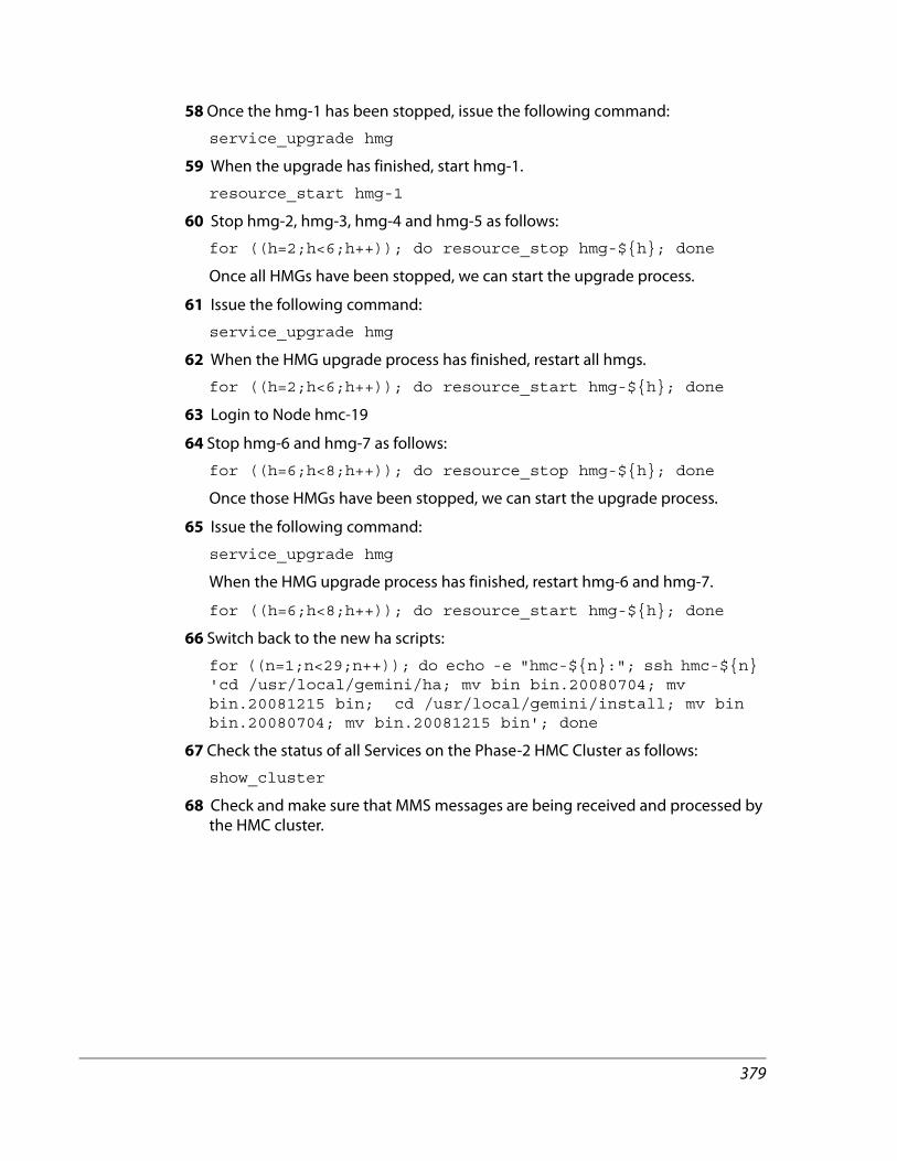
58 Once the hmg-1 has been stopped, issue the following command:
service_upgrade hmg
59 When the upgrade has finished, start hmg-1.
resource_start hmg-1
60 Stop hmg-2, hmg-3, hmg-4 and hmg-5 as follows:
for ((h=2;h<6;h++)); do resource_stop hmg-${h}; done
Once all HMGs have been stopped, we can start the upgrade process.
61 Issue the following command:
service_upgrade hmg
62 When the HMG upgrade process has finished, restart all hmgs.
for ((h=2;h<6;h++)); do resource_start hmg-${h}; done
63 Login to Node hmc-19
64 Stop hmg-6 and hmg-7 as follows:
for ((h=6;h<8;h++)); do resource_stop hmg-${h}; done
Once those HMGs have been stopped, we can start the upgrade process.
65 Issue the following command:
service_upgrade hmg
When the HMG upgrade process has finished, restart hmg-6 and hmg-7.
for ((h=6;h<8;h++)); do resource_start hmg-${h}; done
66 Switch back to the new ha scripts:
for ((n=1;n<29;n++)); do echo -e "hmc-${n}:"; ssh hmc-${n} 'cd /usr/local/gemini/ha; mv bin bin.20080704; mv bin.20081215 bin; cd /usr/local/gemini/install; mv bin bin.20080704; mv bin.20081215 bin'; done
67 Check the status of all Services on the Phase-2 HMC Cluster as follows:
show_cluster
68 Check and make sure that MMS messages are being received and processed by the HMC cluster.
379
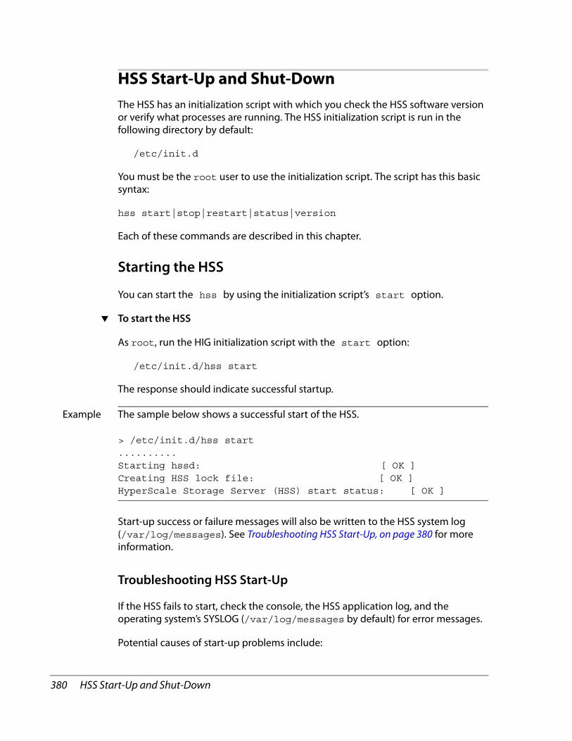
HSS Start-Up and Shut-Down The HSS has an initialization script with which you check the HSS software version or verify what processes are running. The HSS initialization script is run in the following directory by default:
/etc/init.d
You must be the root user to use the initialization script. The script has this basic syntax:
hss start|stop|restart|status|version
Each of these commands are described in this chapter.
Starting the HSS
You can start the hss by using the initialization script’s start option.
▼ To start the HSS
As root, run the HIG initialization script with the start option:
/etc/init.d/hss start
The response should indicate successful startup.
Example The sample below shows a successful start of the HSS. > /etc/init.d/hss start .......... Starting hssd: [ OK ] Creating HSS lock file: [ OK ] HyperScale Storage Server (HSS) start status: [ OK ]
Start-up success or failure messages will also be written to the HSS system log (/var/log/messages). See Troubleshooting HSS Start-Up‚ on page 380 for more information.
Troubleshooting HSS Start-Up
If the HSS fails to start, check the console, the HSS application log, and the operating system’s SYSLOG (/var/log/messages by default) for error messages.
Potential causes of start-up problems include:
380 HSS Start-Up and Shut-Down
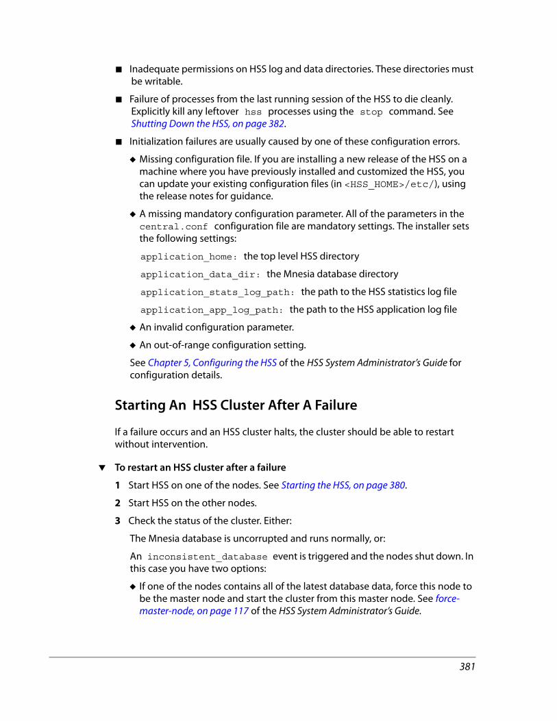
■ Inadequate permissions on HSS log and data directories. These directories must be writable.
■ Failure of processes from the last running session of the HSS to die cleanly. Explicitly kill any leftover hss processes using the stop command. See Shutting Down the HSS‚ on page 382.
■ Initialization failures are usually caused by one of these configuration errors.
◆ Missing configuration file. If you are installing a new release of the HSS on a machine where you have previously installed and customized the HSS, you can update your existing configuration files (in <HSS_HOME>/etc/), using the release notes for guidance.
◆ A missing mandatory configuration parameter. All of the parameters in the central.conf configuration file are mandatory settings. The installer sets the following settings:
application_home: the top level HSS directory
application_data_dir: the Mnesia database directory
application_stats_log_path: the path to the HSS statistics log file
application_app_log_path: the path to the HSS application log file
◆ An invalid configuration parameter.
◆ An out-of-range configuration setting.
See Chapter 5‚ Configuring the HSS of the HSS System Administrator’s Guide for configuration details.
Starting An HSS Cluster After A Failure
If a failure occurs and an HSS cluster halts, the cluster should be able to restart without intervention.
▼ To restart an HSS cluster after a failure
1 Start HSS on one of the nodes. See Starting the HSS‚ on page 380.
2 Start HSS on the other nodes.
3 Check the status of the cluster. Either:
The Mnesia database is uncorrupted and runs normally, or:
An inconsistent_database event is triggered and the nodes shut down. In this case you have two options:
◆ If one of the nodes contains all of the latest database data, force this node to be the master node and start the cluster from this master node. See force-master-node‚ on page 117 of the HSS System Administrator’s Guide.
381
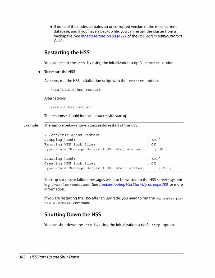
◆ If none of the nodes contains an uncorrupted version of the most current database, and if you have a backup file, you can restart the cluster from a backup file. See mnesia-restore‚ on page 121 of the HSS System Administrator’s Guide.
Restarting the HSS
You can restart the hss by using the initialization script’s restart option.
▼ To restart the HSS
As root, run the HSS initialization script with the restart option:
/etc/init.d/hss restart
Alternatively,
service hss restart
The response should indicate a successful startup.
Example The sample below shows a successful restart of the HSS. > /etc/init.d/hss restart Stopping hssd: [ OK ] Removing HSS lock file: [ OK ] HyperScale Storage Server (HSS) stop status: [ OK ] .......... Starting hssd: [ OK ] Creating HSS lock file: [ OK ] HyperScale Storage Server (HSS) start status: [ OK ]
Start-up success or failure messages will also be written to the HSS server’s system log (/var/log/messages). See Troubleshooting HSS Start-Up‚ on page 380 for more information.
If you are restarting the HSS after an upgrade, you need to run the upgrade-gcx-table-schema command.
Shutting Down the HSS
You can shut down the hss by using the initialization script’s stop option.
382 HSS Start-Up and Shut-Down

▼ To shut down the HSS
As root, run the HSS initialization script with the stop option:
/etc/init.d/hss stop
The response should indicate success or failure of the operation.
Example The sample below shows a successful shut down of the HSS. > /etc/init.d/hss stop Stopping hssd: [ OK ] Removing HSS lock file: [ OK ] HyperScale Storage Server (HSS) stop status: [ OK ]
Verifying the HSS’s Running Processes
You can verify the running HSS processes by using the initialization script’s status option.
▼ To verify the HSS’s running processes
As root, run the HSS initialization script with the status option:
/etc/init.d/hss status
The response should confirm the running processes.
Example The sample below shows the hss status response when the HSS is running properly. > /etc/init.d/hss status hss (pid 2693 2692 2676) is running...
Example The sample below shows the hss status response when the HSS is not running. > /etc/init.d/hss status hss is stopped
Checking the HSS Version Number
You can check the version number of the HSS and supporting processes by using the initialization script’s version option.
383
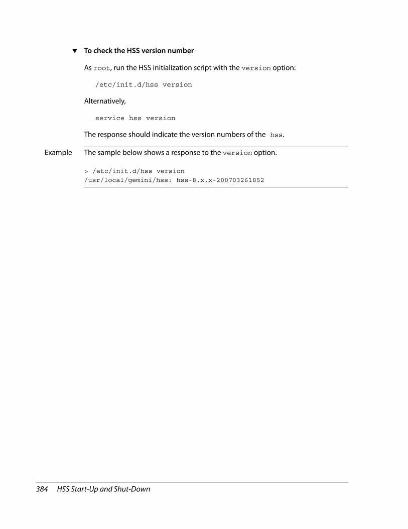
▼ To check the HSS version number
As root, run the HSS initialization script with the version option:
/etc/init.d/hss version
Alternatively,
service hss version
The response should indicate the version numbers of the hss.
Example The sample below shows a response to the version option. > /etc/init.d/hss version /usr/local/gemini/hss: hss-8.x.x-200703261852
384 HSS Start-Up and Shut-Down

HSS Configuration Overview
The HyperScale Inter-Carrier Gateway allows you configuration control over service and operation settings. If you completed a Pre-Configuration Worksheet for Gemini Technical Support, the HIG’s starting configuration will reflect your network environment and operation preferences. You can subsequently modify your HIG configuration if the need arises, by editing the HIG configuration files.
The HIG has two configuration files:
■ central.conf‚ on page 386
■ broker.conf‚ on page 394
385
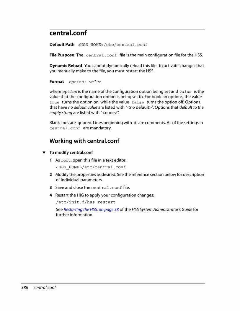
central.conf
Default Path <HSS_HOME>/etc/central.conf
File Purpose The central.conf file is the main configuration file for the HSS.
Dynamic Reload You cannot dynamically reload this file. To activate changes that you manually make to the file, you must restart the HSS.
Format option: value
where option is the name of the configuration option being set and value is the value that the configuration option is being set to. For boolean options, the value true turns the option on, while the value false turns the option off. Options that have no default value are listed with “<no default>”. Options that default to the empty string are listed with “<none>”.
Blank lines are ignored. Lines beginning with # are comments. All of the settings in central.conf are mandatory.
Working with central.conf
▼ To modify central.conf
1 As root, open this file in a text editor:
<HSS_HOME>/etc/central.conf
2 Modify the properties as desired. See the reference section below for description of individual parameters.
3 Save and close the central.conf file.
4 Restart the HIG to apply your configuration changes:
/etc/init.d/hss restart
See Restarting the HSS‚ on page 38 of the HSS System Administrator’s Guide for further information.
386 central.conf

central.conf Parameters
The table that follows describes the options that appear in the default central.conf file..
central.conf Configuration Reference (Part 1 of 6)
ParameterDescription
Valid Range Default
application_home
The HSS top-level directory. set by installer
application_nodename
The nodename used by the message ID status server. hss1
application_nodename2
The nodename used by the message ID generator and ticket server.
hss2
application_data_dir
Data directory for the Mnesia database. set by installer
application_app_log_path
Path to HSS application log files. set by installer
application_stats_log_path
Path to HSS statistics log files. set by installer
application_stats_log_interval
Statistics dump interval, in seconds. 60
Ticket Server
ticket_server_tcp_port
TCP port used by HSS ticket server. set by installer
387

ticket_server_distributed_nodes
Comma-separated list of all nodes running the distributed ticket server. Each HSS server is assigned a node name, consisting of three parts: ◆ the value of application_nodename2, by
default hss2 ◆ the @ symbol◆ the hostname of the physical machine running the
server; the output of the command . This hostname must match the DNS name for that physical machine. If the output of contains a ".", for example "newbb.example.com", then this third part of the node name will only contain the left-most part of the name, for example "newbb.example".
For high availability, make sure you include all node names running in the cluster.
Note: if a node name contains a hyphen, the node name must be entered in quotes. Example: ‘hss2@node-1’,’hss2@node-2’
set by installer
ExistingMessage-ID Server
cmcc_msgid_db_server_port
TCP port used by the message ID server. This is where the HSS listens for requests from the MGW to return a previously generated message ID.
set by installer
cmcc_msgid_db_notification_host
The host to which to send message expiry notifications via SMTP.
set by installer
cmcc_msgid_db_notification_pool_size
Maximum number of TCP connections to make to the message expiry notification host.
100
central.conf Configuration Reference (Part 2 of 6)
ParameterDescription
Valid Range Default
388 central.conf

cmcc_msgid_db_notification_pool_idle
Timeout before idle TCP connections are closed, in seconds.
30
cmcc_msgid_db_throttle_time
Time to sleep (per transaction) when protocol rate is throttled, in milliseconds.
500
cmcc_msgid_db_cli_port
TCP port for CLI server (listens for command to reload broker.conf ).
set by installer
cmcc_msgid_db_cmib_dir
Path to compiled MIB directory. set by installer
cmcc_msgid_db_minimum_trap_level
Minimum log level for sending an SNMP trap. LOG_INFO
New Message-ID Server
cmcc_msgid_gen_server_tcp_port
TCP port used by the message ID generator server. This is where the HSS listens for the MGW’s requests to generate new message IDs.
set by installer
Network Partition
network_monitor_enable
Enable network monitoring for network partitions. See About Network Monitoring‚ on page 392. Network partition detector. Server configurations that have the network partition detector disabled or incorrectly configured are not supported.
true or false set by installer
central.conf Configuration Reference (Part 3 of 6)
ParameterDescription
Valid Range Default
389
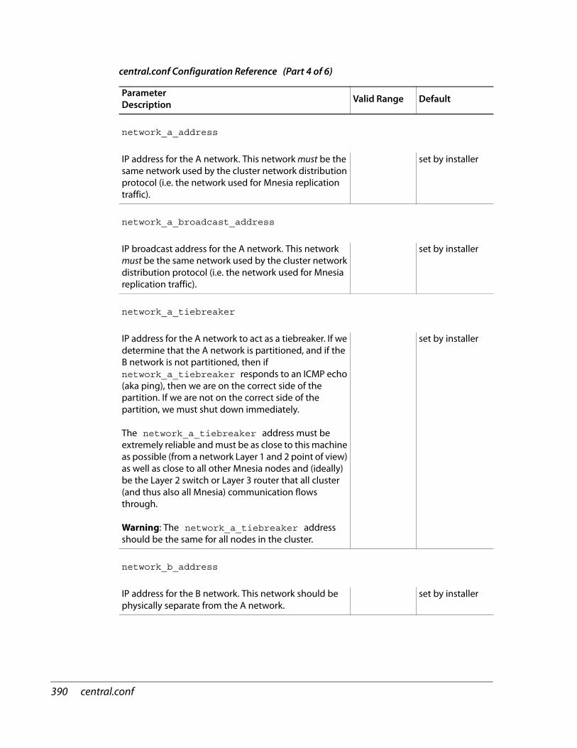
network_a_address
IP address for the A network. This network must be the same network used by the cluster network distribution protocol (i.e. the network used for Mnesia replication traffic).
set by installer
network_a_broadcast_address
IP broadcast address for the A network. This network must be the same network used by the cluster network distribution protocol (i.e. the network used for Mnesia replication traffic).
set by installer
network_a_tiebreaker
IP address for the A network to act as a tiebreaker. If we determine that the A network is partitioned, and if the B network is not partitioned, then if network_a_tiebreaker responds to an ICMP echo (aka ping), then we are on the correct side of the partition. If we are not on the correct side of the partition, we must shut down immediately.
The network_a_tiebreaker address must be extremely reliable and must be as close to this machine as possible (from a network Layer 1 and 2 point of view) as well as close to all other Mnesia nodes and (ideally) be the Layer 2 switch or Layer 3 router that all cluster (and thus also all Mnesia) communication flows through.
Warning: The network_a_tiebreaker address should be the same for all nodes in the cluster.
set by installer
network_b_address
IP address for the B network. This network should be physically separate from the A network.
set by installer
central.conf Configuration Reference (Part 4 of 6)
ParameterDescription
Valid Range Default
390 central.conf
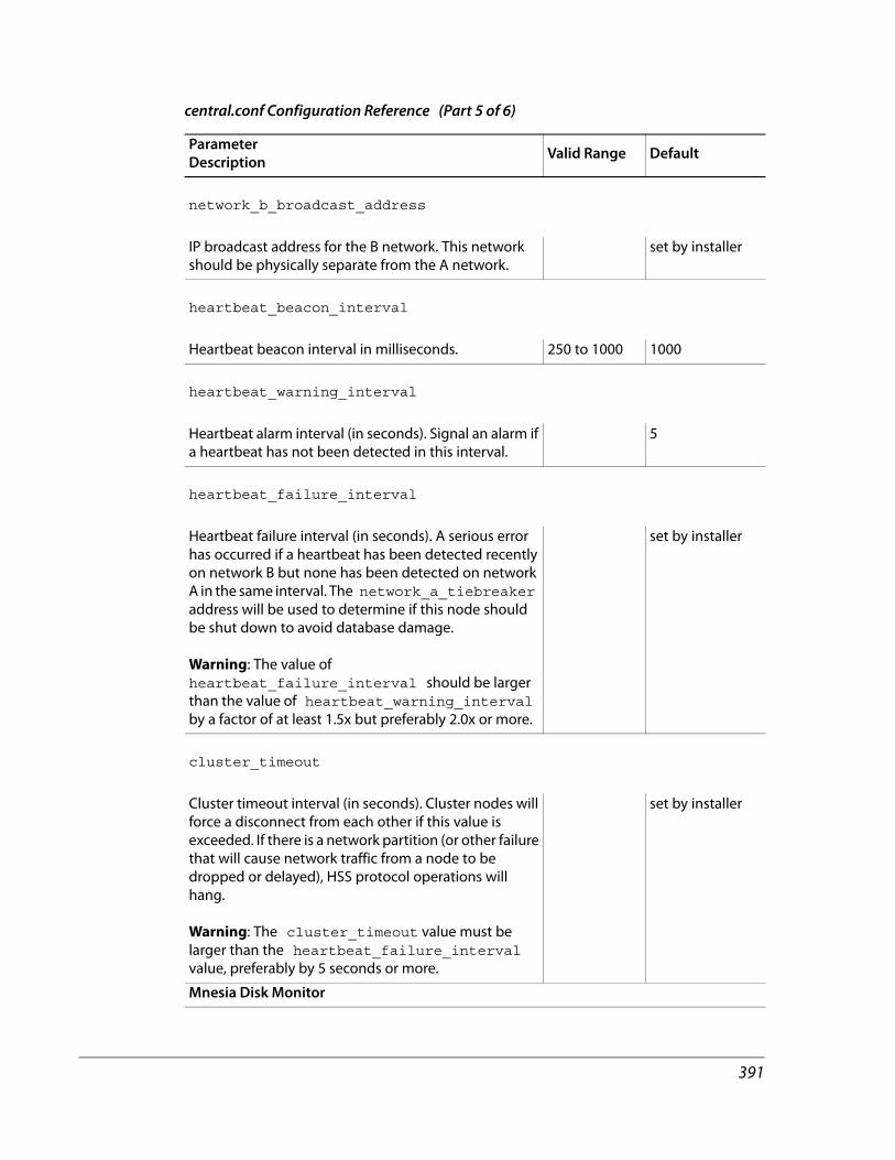
network_b_broadcast_address
IP broadcast address for the B network. This network should be physically separate from the A network.
set by installer
heartbeat_beacon_interval
Heartbeat beacon interval in milliseconds. 250 to 1000 1000
heartbeat_warning_interval
Heartbeat alarm interval (in seconds). Signal an alarm if a heartbeat has not been detected in this interval.
5
heartbeat_failure_interval
Heartbeat failure interval (in seconds). A serious error has occurred if a heartbeat has been detected recently on network B but none has been detected on network A in the same interval. The network_a_tiebreaker address will be used to determine if this node should be shut down to avoid database damage.
Warning: The value of heartbeat_failure_interval should be larger than the value of heartbeat_warning_interval by a factor of at least 1.5x but preferably 2.0x or more.
set by installer
cluster_timeout
Cluster timeout interval (in seconds). Cluster nodes will force a disconnect from each other if this value is exceeded. If there is a network partition (or other failure that will cause network traffic from a node to be dropped or delayed), HSS protocol operations will hang.
Warning: The cluster_timeout value must be larger than the heartbeat_failure_interval value, preferably by 5 seconds or more.
set by installer
Mnesia Disk Monitor
central.conf Configuration Reference (Part 5 of 6)
ParameterDescription
Valid Range Default
391
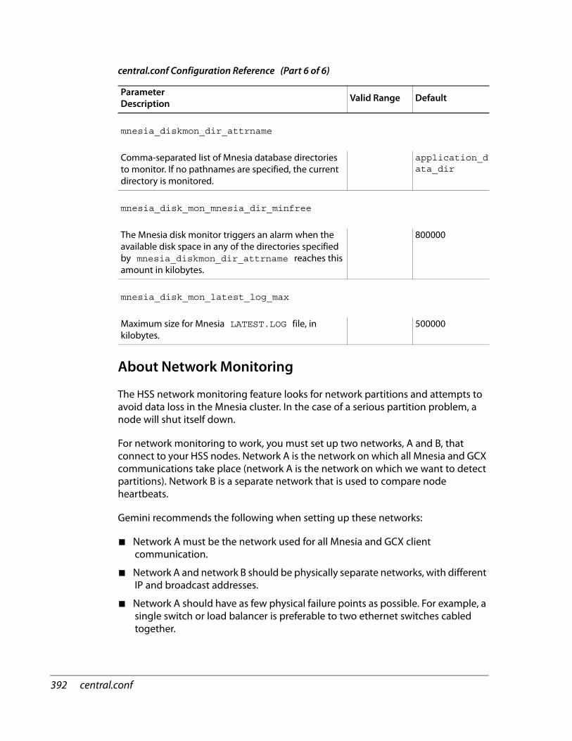
About Network Monitoring
The HSS network monitoring feature looks for network partitions and attempts to avoid data loss in the Mnesia cluster. In the case of a serious partition problem, a node will shut itself down.
For network monitoring to work, you must set up two networks, A and B, that connect to your HSS nodes. Network A is the network on which all Mnesia and GCX communications take place (network A is the network on which we want to detect partitions). Network B is a separate network that is used to compare node heartbeats.
Gemini recommends the following when setting up these networks:
■ Network A must be the network used for all Mnesia and GCX client communication.
■ Network A and network B should be physically separate networks, with different IP and broadcast addresses.
■ Network A should have as few physical failure points as possible. For example, a single switch or load balancer is preferable to two ethernet switches cabled together.
mnesia_diskmon_dir_attrname
Comma-separated list of Mnesia database directories to monitor. If no pathnames are specified, the current directory is monitored.
application_data_dir
mnesia_disk_mon_mnesia_dir_minfree
The Mnesia disk monitor triggers an alarm when the available disk space in any of the directories specified by mnesia_diskmon_dir_attrname reaches this amount in kilobytes.
800000
mnesia_disk_mon_latest_log_max
Maximum size for Mnesia LATEST.LOG file, in kilobytes.
500000
central.conf Configuration Reference (Part 6 of 6)
ParameterDescription
Valid Range Default
392 central.conf

All HSS nodes send heartbeat messages to one another every second, and each node keeps track of heartbeat history. If heartbeats fail on both A and B, a node might have a problem. If heartbeats fail on A but not on B, a network partition on A might cause the problem. If heartbeats fail on B but not A, then network B might have a partition problem (but this is less serious because Mnesia and GCX communication does not take place on network B).
Alarms are also raised/cleared if the network partition detector loses/regains heartbeat packets on the respective physical networks.
If the heartbeat_warning_interval threshold is reached, (on A or B), a warning message is written to the application log. If this threshold is reached on network A, the node compares the heartbeat history for network B.
The heartbeat_failure_interval threshold is used to determine a network partition. If a network partition occurs on network A (heartbeats from A have stopped, but heartbeats from B continue), then the network_a_tiebreaker address is pinged to determine whether the HSS node is on the “correct” side of the network partition on network A. If there is no response to the ping, the node shuts itself down.
You can restart the cluster using the procedure described in force-master-node‚ on page 117, or mnesia-restore‚ on page 121, of the HSS System Administrator’s Guide, depending on the situation.
If a network partition occurs on network B, a message is written to the application log.
393
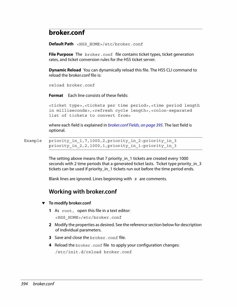
broker.conf
Default Path <HSS_HOME>/etc/broker.conf
File Purpose The broker.conf file contains ticket types, ticket generation rates, and ticket conversion rules for the HSS ticket server.
Dynamic Reload You can dynamically reload this file. The HSS CLI command to reload the broker.conf file is:
reload broker.conf
Format Each line consists of these fields:
<ticket type>,<tickets per time period>,<time period length in milliseconds>,<refresh cycle length>,<colon-separated list of tickets to convert from>
where each field is explained in broker.conf Fields‚ on page 395. The last field is optional.
Example priority_in_1,7,1000,2,priority_in_2:priority_in_3 priority_in_2,2,1000,1,priority_in_1:priority_in_3
The setting above means that 7 priority_in_1 tickets are created every 1000 seconds with 2 time periods that a generated ticket lasts. Ticket type priority_in_3 tickets can be used if priority_in_1 tickets run out before the time period ends.
Blank lines are ignored. Lines beginning with # are comments.
Working with broker.conf
▼ To modify broker.conf
1 As root, open this file in a text editor:
<HSS_HOME>/etc/broker.conf
2 Modify the properties as desired. See the reference section below for description of individual parameters.
3 Save and close the broker.conf file.
4 Reload the broker.conf file to apply your configuration changes:
/etc/init.d/reload broker.conf
394 broker.conf

broker.conf Fields
The table that follows describes the fields that you can configure per line of the broker.conf file..
broker.conf Fields (Part 1 of 2)
FieldDescription
Valid Entries
ticket type
The name of the ticket type. Enter one ticket type per line. The HSS generates tickets of this type at the rate you specify.
If the ticket is for rate control, the name must begin with the prefix configured in MM7SUBMITQP_opco1.ticketname in operator.properties, and end with an MMSC ID configured in mmscdb.cfg.
If the ticket is for volume control, the name must begin with the prefix configured in MM7SUBMITQP_opco1.volumeticket in operator.properties, and end with an MMSC ID configured in mmscdb.cfg.
If the ticket is for priority control, the name must begin with a prefix configured in: MSGRESTRICTION_opco1.incomingPriorityPrefixMSGRESTRICTION_opco1.outgoingPriorityPrefixMSGRESTRICTION_opco1.outgoingDestinationPrefix
in operator.properties, and end with a priority configured in:MSGRESTRICTION_opco1.specialEventOnDemandSuffixMSGRESTRICTION_opco1.specialEventFlatRateSuffixMSGRESTRICTION_opco1.strategicPartnerOnDemandSuffixMSGRESTRICTION_opco1.normalPartnerOnDemandSuffixMSGRESTRICTION_opco1.strategicPartnerFlatRateSuffixMSGRESTRICTION_opco1.normalPartnerFlatRateSuffix
tickets per time period
The HSS generates this many tickets of this type per time period. 1 to xxx
time period length
The length of the ticket generating period, in milliseconds. 1 to xxx
395
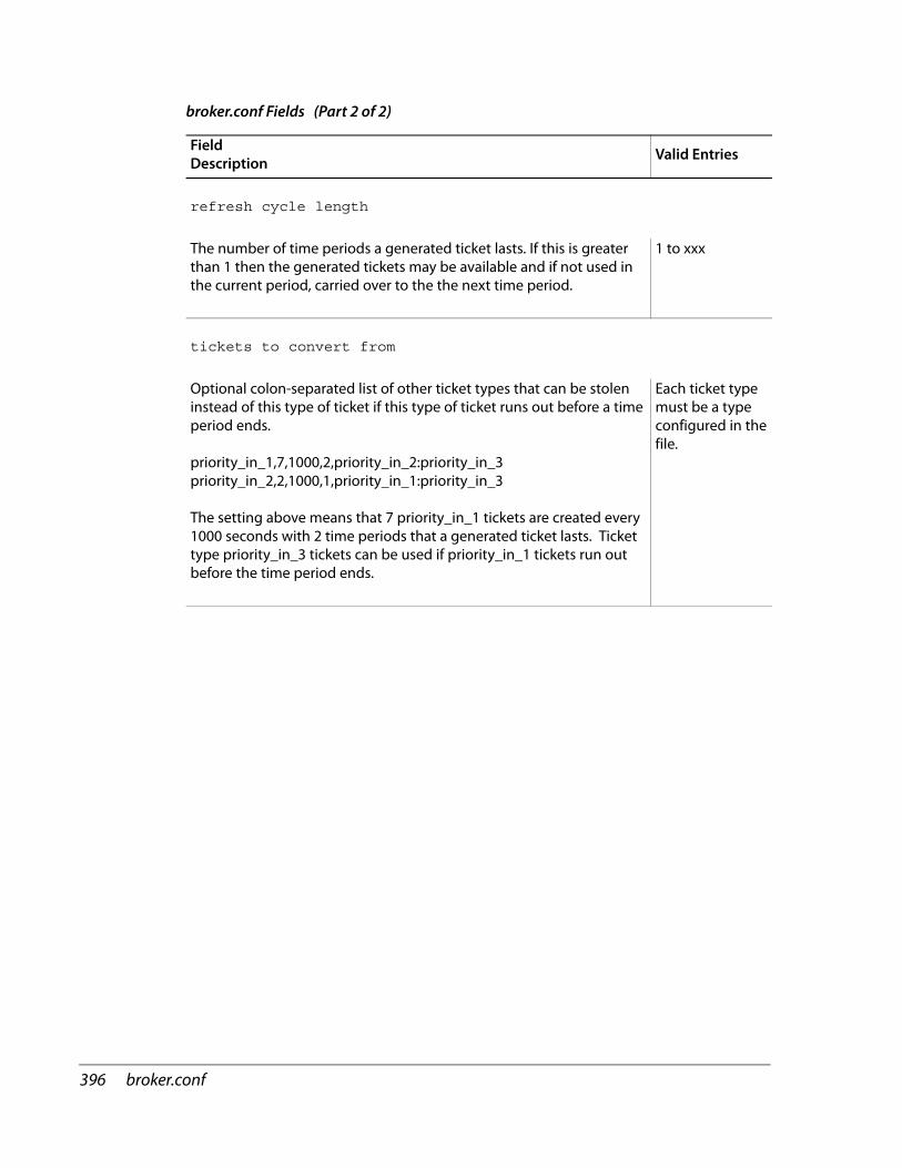
refresh cycle length
The number of time periods a generated ticket lasts. If this is greater than 1 then the generated tickets may be available and if not used in the current period, carried over to the the next time period.
1 to xxx
tickets to convert from
Optional colon-separated list of other ticket types that can be stolen instead of this type of ticket if this type of ticket runs out before a time period ends.
priority_in_1,7,1000,2,priority_in_2:priority_in_3priority_in_2,2,1000,1,priority_in_1:priority_in_3
The setting above means that 7 priority_in_1 tickets are created every 1000 seconds with 2 time periods that a generated ticket lasts. Ticket type priority_in_3 tickets can be used if priority_in_1 tickets run out before the time period ends.
Each ticket type must be a type configured in the file.
broker.conf Fields (Part 2 of 2)
FieldDescription
Valid Entries
396 broker.conf

HSS LoggingThe HSS creates two types of log files:
■ Application messages
■ Statistics counts
The application log records application-related informational messages, errors, warnings and so on. Each log entry indicates the process and component with which the event is associated, as well as an event severity level and a brief descriptive message. For all events of level “INFO” or higher, the entry includes a numerical message code that aides in identifying and responding to the event.
You can configure the application log file path in the central.conf file.
The statistics log contains several types of statistics:
■ TCP statistics (connections, bytes transferred)
■ HSS protocol statistics (counts of PDUs exchanged)
■ Mnesia database statistics
You can configure the statistics log file path and the time interval over which statistics are counted in the central.conf file.
HSS logging is enabled by default. For information on configuring logging, see central.conf Parameters‚ on page 102 of the HSS System Administrator’s Guide.
HSS Application Logging
The HSS sends application messages to its application log file, hss-app.log. The severity levels used for HSS messages are described in the table below.
Category Level Description
LOG_EMERG 0 system is unusable
LOG_ALERT 1 action must be taken immediately
LOG_CRIT 2 critical conditions
LOG_ERR 3 error conditions
LOG_WARNING 4 warning conditions
LOG_NOTICE 5 normal but significant condition
LOG_INFO 6 informational
LOG_DEBUG 7 debug-level messages
397
HSS Statistics Logging
The statistics log contains several types of statistics:
■ TCP statistics (connections, bytes transferred)
■ HSS protocol statistics (counts of PDUs exchanged)
■ Mnesia database statistics
You can configure the statistics log file path and the time interval over which statistics are counted in the central.conf file.
HSS logging is enabled by default. For information on configuring logging, see central.conf Parameters‚ on page 102 of the HSS System Administrator’s Guide.
398 HSS Logging
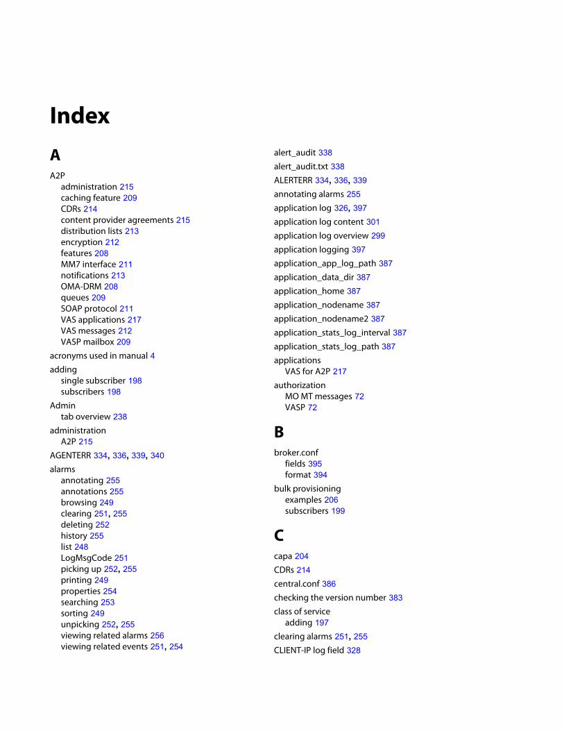
Index
AA2P
administration 215caching feature 209CDRs 214content provider agreements 215distribution lists 213encryption 212features 208MM7 interface 211notifications 213OMA-DRM 208queues 209SOAP protocol 211VAS applications 217VAS messages 212VASP mailbox 209
acronyms used in manual 4adding
single subscriber 198subscribers 198
Admintab overview 238
administrationA2P 215
AGENTERR 334, 336, 339, 340
alarmsannotating 255annotations 255browsing 249clearing 251, 255deleting 252history 255list 248LogMsgCode 251picking up 252, 255printing 249properties 254searching 253sorting 249unpicking 252, 255viewing related alarms 256viewing related events 251, 254
alert_audit 338
alert_audit.txt 338
ALERTERR 334, 336, 339
annotating alarms 255
application log 326, 397
application log content 301
application log overview 299
application logging 397
application_app_log_path 387
application_data_dir 387
application_home 387
application_nodename 387
application_nodename2 387
application_stats_log_interval 387
application_stats_log_path 387
applicationsVAS for A2P 217
authorizationMO MT messages 72VASP 72
Bbroker.conf
fields 395format 394
bulk provisioningexamples 206subscribers 199
Ccapa 204
CDRs 214
central.conf 386
checking the version number 383
class of serviceadding 197
clearing alarms 251, 255
CLIENT-IP log field 328

CLIENT-PORT log field 328
CLIERR 334, 336, 339, 340
cluster_timeout 391
cmcc_msgid_db_cli_port 389
cmcc_msgid_db_cmib_dir 389
cmcc_msgid_db_minimum_trap_level 389
cmcc_msgid_db_notification_host 388
cmcc_msgid_db_notification_pool_idle 389
cmcc_msgid_db_notification_pool_size 388
cmcc_msgid_db_server_port 388
cmcc_msgid_db_throttle_time 389
cmcc_msgid_gen_server_tcp_port 389
commandsresource_restart 382resource_start 380version 383
CONFIGERR 334, 336, 339
configuring MMSC log settings 272
configuring NMS log settings 331
configuring nmserr.txt 334
configuring nmsout.txt 335
configuring the IMAP server 386
configuring the LMTP server 386
contacting Gemini Mobile Technologies 8Contents tab
using the help system 245
conventions, typographic 3cosId 202
CRIT 326, 397
Customer CareMMSA roles 233tab overview 243
DDATE-CLF log field 304, 313, 327
deleting alarms 252
deletion of logs 300
deliverydomain name 63foreign MMSCs 63Internet client 64legacy user via SMS 63MMS user 63reports 66, 213
discoveryLogs.txt 338
distribution listA2P 213VASP authorization 44
dn 200
EERR 326, 397
errorcode.cfg 307
EVENTERR 334, 336, 339
eventname.cfg 308
FFault
tab overview 234
favorites tabusing the help system 246
featuresA2P caching 209A2P service type 208
File Count 332
formatTLOG 311
format_cli 312
format_pap 311
format_pushaddr 312
format_smsc 312
GGemini Mobile Technologies, contacting 8GMS
restarting 382starting 380
gmtMMSCUser 200
Hheartbeat_beacon_interval 391
heartbeat_failure_interval 391
heartbeat_warning_interval 391
help command 319
help systemabout Java implementation 244about JavaScript implementation 244supported browsers and platforms 244using the Contents tab 245
Index

using the Favorites tab 246using the Index tab 245using the navigation frame 244using the Search tab 245using the toolbar frame 246
hmg-app.log 301
hmg-tx.log 309
HTTP access 182
HTTPS access 182
HyperScale 11
II/O processing 11
IMAP logging 327
IMAP server, configuring 386
imapd.conf 386
imsigmtMMSCUser 203
Index tabusing the help system 245
INFO 326, 397
interfaceconfiguring MM1 189configuring MM3 190configuring MM4 191configuring MM7 192configuring SMSC 193MM7 A2P configuration 218
Interfacestab overview 241
interfacesMM7 and A2P 211
Llaw enforcement administrator
MMSA roles 233
Lawful Interceptiontab overview 243
LDIF entry examples 206
LDIF file 199
LEVEL log field 305, 328
LifeKeeper 258management 259
LMTP logging 327
LMTP server, configuring 386
local 6 326
log contentapplication log 301transaction log 309
log filesalert_audit.txt 338configuring MMSC log settings 272configuring NMS log settings 331discoveryLogs.txt 338log level 334, 336mserr.txt 338msout.txt 338nativeping_logs.txt 338nmserr.txt 334, 338nmsout.txt 335, 339pmstat.txt 340stderr.txt 340stdout.txt 340transactionLogs.txt 340updatemanager.txt 340
Log Level 333, 334, 336
log levels 326, 397
log naming 300
log rotation 300, 325
log storage 300
logflushTLOG 310
loggingof statistics 306
logging of IMAP transactions 327
logging of LMTP transactions 327
logging overview 299, 325
login, MMSA 182
loglevelTLOG 310
LogMsgCodealarms 251
MmailBlackListPattern 205
mailbox auto provisioning 67
mailCopyAddress 205
mailForwardingAddress 205
mailFromAddress 204
mailHost 202
mailLocalAddress 202
Index
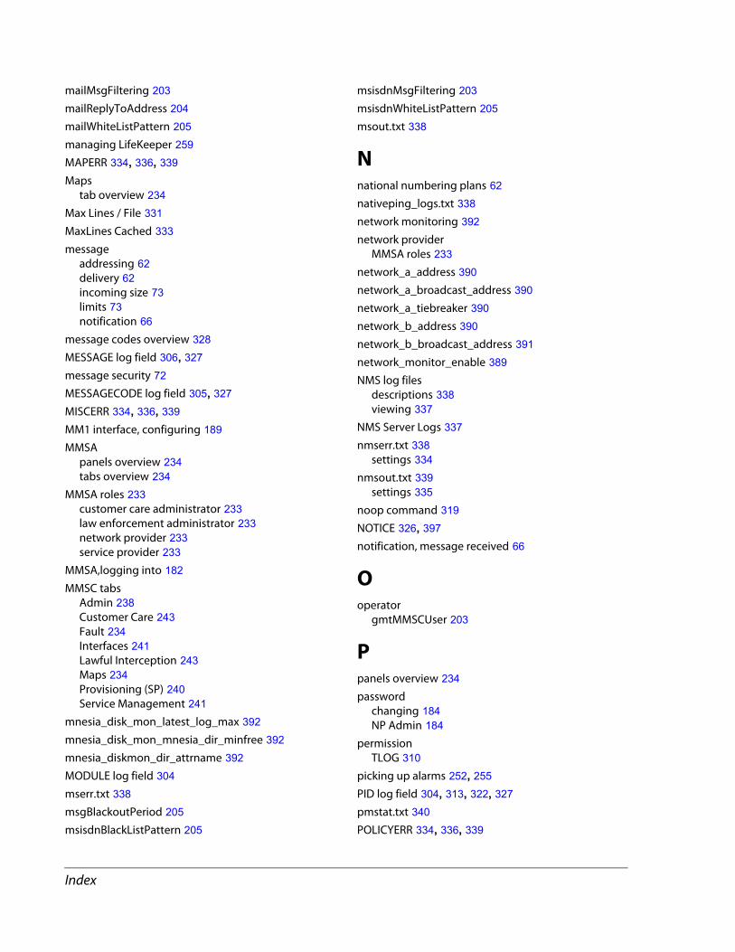
mailMsgFiltering 203
mailReplyToAddress 204
mailWhiteListPattern 205
managing LifeKeeper 259
MAPERR 334, 336, 339
Mapstab overview 234
Max Lines / File 331
MaxLines Cached 333
messageaddressing 62delivery 62incoming size 73limits 73notification 66
message codes overview 328
MESSAGE log field 306, 327
message security 72
MESSAGECODE log field 305, 327
MISCERR 334, 336, 339
MM1 interface, configuring 189
MMSApanels overview 234tabs overview 234
MMSA roles 233customer care administrator 233law enforcement administrator 233network provider 233service provider 233
MMSA,logging into 182
MMSC tabsAdmin 238Customer Care 243Fault 234Interfaces 241Lawful Interception 243Maps 234Provisioning (SP) 240Service Management 241
mnesia_disk_mon_latest_log_max 392
mnesia_disk_mon_mnesia_dir_minfree 392
mnesia_diskmon_dir_attrname 392
MODULE log field 304
mserr.txt 338
msgBlackoutPeriod 205
msisdnBlackListPattern 205
msisdnMsgFiltering 203
msisdnWhiteListPattern 205
msout.txt 338
Nnational numbering plans 62
nativeping_logs.txt 338
network monitoring 392
network providerMMSA roles 233
network_a_address 390
network_a_broadcast_address 390
network_a_tiebreaker 390
network_b_address 390
network_b_broadcast_address 391
network_monitor_enable 389
NMS log filesdescriptions 338viewing 337
NMS Server Logs 337
nmserr.txt 338settings 334
nmsout.txt 339settings 335
noop command 319
NOTICE 326, 397
notification, message received 66
Ooperator
gmtMMSCUser 203
Ppanels overview 234
passwordchanging 184NP Admin 184
permissionTLOG 310
picking up alarms 252, 255
PID log field 304, 313, 322, 327
pmstat.txt 340
POLICYERR 334, 336, 339
Index
POLLERR 334, 336, 338, 339
preferredLanguage 205
propertiesalarms 254
PROVERR 334, 336, 339
Provisioning (SP)tab overview 240
Qquit command 319
Rrefresh 232
reload 232
reportingread 66
resource_restart 382
resource_start 380
restart 382
restarting the GMS 382
rolling of logs 300
rotation of logs 300, 325
routing 64
SSearch tab
using the help system 245
searching alarms 253
Service Managementtab overview 241
service provideradding 186adding an admin 188MMSA roles 233
severity levels of messages 326, 397
short code formats 62
single subscriber, adding 198
SOAP protocol 211
SSL 232
SSL digital certification 183
starting the GMS 380
starting the PSS 380
statistics
logging 306
status 383
status command 383
stderr.txt 340
stdout.txt 340
stoppping the PSS 382
subscribers, adding 198
support, contacting 8syslog 326
Ttabs overview 234
ticket_server_distributed_nodes 388
ticket_server_tcp_port 387
TIME-24 log field 328
timezone, gmtMMSCUser 205
TOPOERR 334, 336, 339
transacation server log field 314
transaction client log field 314
transaction duration log field 314
transaction ID log field 313
transaction log content 309
transaction log overview 299
transaction logging 327
transaction protocol log field 313
transaction status log field 313
transaction type log field 313
transactionLogs.txt 340
typographic conventions 3
Uuid 202
unpicking alarms 252, 255
updatemanagerlog.txt 340
usegmtTLOG 310
User Portalcomposing messages 223MMbox access 221overview 220preferences 223
userAgentName 203
userAgentProfile 203
Index
userBillingModel 202
userBillingServer 203
userOverride 205
VVASP
authorization 72mailbox 209
verifying running processes 383
version 383
viewing NMS log files 337
WWARNING 326, 397
Index