
GBS SG v10.09.28.pdf - Noodlez.org
132
-
Upload
khangminh22 -
Category
Documents
-
view
0 -
download
0
Transcript of GBS SG v10.09.28.pdf - Noodlez.org


Table of Contents
Chapter 1 Introduction to Global Broadcast Service 1 Chapter 2 Integrated Receiver Decoder (IRD) Configuration 53 Chapter 3 Crypto Configuration 77 Chapter 4 Network Integration 107 Chapter 5 Troubleshooting and Maintenance 117

TAB
Insert Tab # 1 Here

Introduction to Global Broadcast
Service (GBS)

2

3
Global Broadcast Service (GBS)
AN/TSR-8 GBS Receive Suite Course

4
SFC Crews, Joshua [email protected]
410-417-2283DSN 867-2283
Instructors
CLASS HOUR
COURSE DAYDAY 1 DAY 2 DAY 3 DAY 4 DAY 5
1
Introductions and course Overview AN/TSR-8 Assembly and
Preparation for UseAN/TSR-8 Assembly and
Preparation for UseAN/TSR-8 Assembly and
Preparation for UseAN/TSR-8 Assembly and
Preparation for UseGBS System Overview
2Introduction to AN/TSR-8 IRD Manual Configuration Crypto Unit Configuration Network Configuration Troubleshooting &
Maintenance
AN/TSR-8 Assembly and Preparation for Use
IRD Manual Configuration Crypto Unit Configuration Network Configuration Troubleshooting & Maintenance
3
4 Familirization of the GBS Receive Suite
Lunch
5 Familirization of the GBS Receive Suite
Kencast Fazzt Enterprise Client Normal Operations IFD Operations Course Review & Exam Prep
Kencast Fazzt Enterprise Client Configuration
Normal Operations Setup and Configuration IFD Operations
6 ExaminationPre-Mission Planning
7 Properly Fill out GMR Student Critiques and Certificates
AN/TSR-8 System Tear Down and Pack up8 AN/TSR-8 System Tear
Down and Pack upAN/TSR-8 System Tear
Down and Pack upAN/TSR-8 System Tear
Down and Pack upAN/TSR-8 System Tear
Down and Pack up
Course Schedule

5
Global Broadcast Service (GBS) Overview.
• Purpose of GBS
• Three segments of GBS
• TM and Reference Overview
• Operational characteristics of GBS
Introduction to GBS

6
GBS is a Department of Defense (DoD) directed program to provide the warfighter with a near worldwide, high-throughput broadcast information system for one-way, high-speed information flow.
1.1 Mb Data Package using Milstar MDR = 5.7 sec
GBS = .38 secLarger Throughput = Faster Dissemination = Better Service to Warfighter
Purpose of GBS
Purpose of Global Broadcast Service GBS is a Department of Defense (DoD) directed program to provide the warfighter with a near worldwide, high-throughput broadcast information system for one way, high-speed information flow. Information can be disseminated using either smart push or user pull. Smart push is when some information is deemed necessary for mission accomplishment, possibly by an outside agency, and that information is automatically “pushed” to the user. User pull is when the user finds some information that he needs that can be sent over GBS and requests that information. Users request information via GBS using the GBS Mission Request (GMR) form, which will be discussed later in this course.

7
ThroughputExample
Information
512 KbpsSIPRNET
1.1 MbpsSky Media
1.5 MbpsTrojan Sprit
23.5 MbpsGBS
Large Fly Through
IMINT Product4 GB
17.4 hrs 8.1 hrs 5.8 hrs 23 min
Full Frame Image 1.5 GB
6.5 hrs 3 hrs 2.2 hrs 8.7 min
ImageryAnnotated
400 Mb1.7 hrs 48.5 min 35 min 2.3 min
45.0 MbpsFuture GBS
11.5 min
4.3 min
1.15
Efficient information dissemination to multiple recipients via single transmission (Broadcast)
GBS Data Rate
GBS Data Rate Comparison Global Broadcast Service (GBS) is a one-way transmit suite to receive suite that can reach data speeds of 23.5 Megabits up to 45 Megabits per second (Mbps). In comparison, a 1.1 Mb Data package using the MILSTAR Medium Data Rate (MDR) takes approximately 5.6 seconds to transmit. With GBS, that same package can be transmitted in less than one-half second.

8
13-Inch Steerable
Patch Array
Transponders
3
1
2
4
B
A
C
DownlinkSteerable Spot Beams
Theater Injection Point (TIP)
4 x 23.5to 29.5Mbps
(500 nm)
(500 nm)
23.5 Mbps23.5 Mbps
(2000 nm)
Transmit Segment
23.5Mbps
Space Segment
Primary Injection Point (PIP)Wahiawa, HI, Norfolk, VA & Sigonella, IT
SBM
PIP
TIP
23.5 Mbps
Receive Segment
GBS UFO Ka Architecture
GBS Ka ARCHITECTURE GBS consists of three segments, Transmit Segment, Space Segment, and Receive Segment. GBS uses transponders from two Ka-band Ultra High Frequency (UHF) Follow-On (UFO) satellites (UFO8 and UFO10), TWO Ka-band Wideband Global Satellite Communications (WGS) satellites, and various Ku and Ka-band commercial satellites. Each satellite is served by a primary uplink site (Transmit Suite). The Transmit Suite assembles and transmits information to the satellite, which relays it to multiple GBS Receive Suites within a large geographical area. The satellites downlink the information via wide beam to a large area or by narrow beam to specific localized spots. GBS also provides the capability to transmit pre-assembled information directly from information sources through the SBM. Information may also be transmitted directly from the theater served by GBS through a transportable Theater Injection Point (TIP) system. Receive Suites receive and decode the information, then distribute it to end users over Local Area Networks (LANs). There are various types of Receive Suites, including transportable ground, shipboard, and sub-surface. All Receive Suites are equipped with a Crypto Unit that decrypts Classified broadcasts. A Receive Suite (RS) consists of a Receive Terminal (RT) and either one or two RBMs.]

9
The Transmit Segment consists of the fixed site Transmit Suites and the transportable Theater Injection Points (TIP). Both work in a similar manner, they may however, handle different information. Either one will get its information from some data source. The Satellite Broadcast Manager (SBM) will take that information and package it for transmission. The SBM will forward that information to the Primary Injection Point (PIP) for transmission to the Space Segment. TRANSMIT SUITE The Transmit Suites consist of the Primary Injection Point (PIP) and the SBM. The PIP is a fixed site, satellite communications terminal, that transmits information received from the SBM to satellites. It tracks and transmits signals at Ka-band to UFO and WGS satellites and at Ku and Ka-band to commercial satellites. The SBM is a facility containing multiple bays of broadcast and communications equipment. There is an SBM dedicated to each of the UFO and WGS satellites. In addition, the SBMs can also uplink to commercial Ku-band satellites, when required. The SBM creates the final uplink programming data streams for each transponder of their satellite(s). The SBM has the capabilities and information to build the transponder streams, network management, program guides, security services (i.e., encryption, decryption, key management, source authentication, Over the Air Re-key (OTAR) and multilevel security), directory services, and downlink management scheduling. THEATER INJECTION POINT The TIP is a transportable GBS broadcast management and uplink system that provides Joint Force Commanders (JFCs) a means of transmitting theater information (map overlays, Air Tasking Order (ATO), weather, etc.) to subordinate forces. Because the TIP is transportable and under the direct control of the commander, it significantly enhances the commander's ability to deliver information to assigned forces. Use of the TIP is coordinated with the SBM and approved by the TIM of the responsible Combatant Command (COCOM). A TIP is composed of a Transportable Satellite Broadcast Manager (TSBM) AN/TSQ-246 and the Satellite Communications System AN/TSC-156B (Phoenix Terminal). TSBM performs many of the same functions as the SBM at the fixed sites. The Phoenix Terminal is a transportable Tactical Satellite Communications Terminal (TACSAT) which operates at Super High Frequency (SHF) bands (C, X, Ku, and Ka) over commercial and military satellites. It performs function similar to the PIP at the fixed site. SPACE SEGMENT The space segment consists of two Ka-band UFO, Ka-band WGS satellites, and various Ku and Ka-band commercial satellites.

10
RECEIVE SEGMENT The Receive Segment, also known as the Receive Suite (RS), consists of the NGRT and RBM. There are several categories of Receive Suites including ground, shipboard, and subsurface and there are several versions within each category. This course covers the RS AN/TSR-8 commonly known as the TSR-8. It is one of the ground receive suites. The AN/TSR-8 has two servers, one housed in the RBM transit case, and the other located in the NGRT transit case, both of which are configured with GBS Unique Software (GUS).

11
PIPHawaii
SBMNorfolk
UFO - 8Ka BandSatellite
UFO - 10Ka BandSatellite
PIPItaly
GBS UFO Ka Satellite Coverage
Satellite Coverage: UFO Satellites The UFO satellites are geosynchronous, meaning they orbit the earth at the same speed as the earth rotates and therefore stay in nearly fixed locations in the sky. Their exact location however varies slightly throughout the year in a figure-eight pattern. The location of the satellite is initially given to a RS operator as an azimuth and elevation angle relative to the location of the RS. The precise location of a UFO satellite is then determined from the additional information called the Two-Line Element (TLE) ephemeris data. The ephemeris data varies daily and after about 3 weeks, the values are far enough off that the operator may need new ephemeris data to reacquire the satellite, if tracking has stopped. The SBM Help Desk furnishes the ephemeris data to the RS operators. The NGRT has ephemeris data for commonly used satellites stored in memory, eliminating the need to contact the SBM. The UFO satellites are equipped with four transponders. Each transponder transmits data at a specific frequency. Transponders have a nominal bandwidth of 23.5 Mbps. Some transponders have an increased bandwidth of 29.5 Mbps. Signals are broadcast digitally using a commonly used modulation technique called Quadrature Phase Shift Keying (QPSK). With QPSK, the frequency and amplitude of the signal remain constant; however, the phase of the signal shifts 0, 90, 180, or 270 degrees based on the digital signal content. Each phase represents a pair of bits (00, 01, 10, and 11). The UFO satellites each have two

12
steerable 500 nautical mile spot beams and one steerable 2000 nautical mile beam. Beam movement is planned at the SBM based on RBM locations and mission priorities. The beams provide coverage from approximately 65° N to 65° S latitude. Currently, there are two UFO satellites (UFO 8 and UFO 10) with GBS payloads. They provide four transponders each with Ka-band downlink frequencies of 20.295, 20.425, 20.475, and 20.595 GHz respectively.

13
WGS Ka Architecture
WGS Satellites WGS satellites are geosynchronous, meaning they orbit the earth at the same speed as the earth rotates and therefore stay in nearly fixed locations in the sky. Their exact location however varies slightly throughout the year in a figure-eight pattern. The location of the satellite is initially given to a RS operator as an azimuth and elevation angle relative to the location of the RS. The precise location of WGS satellites is then determined from the additional information called the TLE ephemeris data. The ephemeris data varies daily and after about 3 weeks, the values are far enough off that the operator may need new ephemeris data to reacquire the satellite, if tracking has stopped. The SBM Help Desk furnishes the ephemeris data to the RS operators. The NGRT has ephemeris data for commonly used satellites stored in memory, eliminating the need to contact the SBM. Each WGS satellite comes equipped with six Narrow Coverage Area (NCA) antennas, or spot beams, that provide up to 500 nautical miles of coverage. Each of the six transponders transmits data at a specific frequency. Transponders have a nominal bandwidth of 23.5 Mbps, but can operate up to a maximum of 45 Mbps per transponder on demand. Using frequency reuse and digital channelization, each WGS satellite can process more than 4.8 GHz of

14
bandwidth, with up to 3.6 Gbps of throughput. In addition, digital channelization allows the SBM to divide the overall bandwidth into 1,900 independently routable (2.6 MHz) sub channels, thereby providing greater flexibility in coverage. Signals are broadcast digitally using a commonly used modulation technique called Quadrature Phase Shift Keying (QPSK). With QPSK, the frequency and amplitude of the signal remain constant; however, the phase of the signal shifts 0, 90, 180, or 270 degrees based on the digital signal content. Each phase represents a pair of bits (00, 01, 10, and 11). Beam movement is planned at the SBM, based on RBM locations and mission priorities. The plan is then forwarded to the Wideband Satellite Communications (SATCOM) Operations Center (WSOC), which controls antenna movement on the WGS satellites. Using high power transponders and focused spot beams and/or area coverage beams, users in different areas can be provided targeted, high bandwidth video/data. Using a fanned network configuration, the SBM can transmit up to six NCA spot beams over a standard four beam broadcast. An example of a fanned SBM broadcast, using NCA 1 (T212) and NCA 6 (T10212) as well as NCA 3 (T214) and NCA 8 (T10214).

15
WGS-1, WGS-2 WGS-3
WGS Ka Coverage
WGS Coverage Currently, there are three WGS satellites (WGS 1 and WGS 2 and WGS-3) with GBS payloads. They each provide six NCA antennas with Ka-band downlink frequencies.

16
KUC5 HORIZON1, KUE6 TELSTAR12, KAE9 SPAINSAT (Ka)
Commercial Ku and Ka Satellites
COMMERCIAL Ku and Ka SATELLITES Commercial satellites are used to broadcast to locations not covered by the UFO satellites (such as North America, Atlantic Ocean, Spain, and parts of western Africa) and to areas requiring additional capacity (such as Europe). The commercial satellites are geostationary as opposed to UFO satellites, which are geosynchronous. Geostationary means they are in fixed locations in the sky and do not move. Therefore, commercial satellites do not require updated TLE ephemeris data. GBS leases commercial satellites and the specific satellites used can change from year to year. Commercial satellites typically use Ku-band frequencies and can be either circularly or linearly polarized. KAE9 is a unique commercial satellite for its ability to broadcast in Ka-band frequencies. This satellite is currently being used to enhance Ka-band coverage to the Atlantic Ocean and western Africa. GBS content reaches KAE9 through an intermediate Ku-band satellite, Telestar 12 (T12). GBS content is forwarded from the Norfolk SBM to a WSOC in Landstuhl, Germany. T12 receives GBS content in the Ku-band from the WSOC, and transmits to a T12 receiver in Rota, Spain. The GBS content is directed to a deployable, Ka-band, earthbound Satellite Transportable Terminal (STT). The STT transmits to KAE9, which broadcasts

17
GBS content in the Ka-band to end users. Because the leasing of GBS supported commercial satellites will change from year to year, specific satellite names are not mentioned here.

18
• Identify the TM format
• Identify the TM content
• Identify the AN/TSR-8 COTS Reference Manuals
• Community of Practice (CoP) Website
TM and Reference Overview

19
TM is written:– IAW MIL-STD-40051-2 ch3
– Output in PDF format
– Available at LOGSA ETMsOnline and from APD (PIN 084227)
– https://www.logsa.army.mil
TM Format
Chapter 1 General Information, Equipment Description, & Theory of Operation
Chapter 2 Controls and Indicators
Chapter 3 Operation
WP 301 Security Summary
WP 302 Assembly and Preparation for Use
WP 303 System Power-Up
WP 304 Normal Operation
WP 305 System Power-Down
WP 306 Teardown and Pack-Up
WP 309 RBM Lan Setup and Operation
Chapter 4 Troubleshooting
Chapter 5 PMCS
Chapter 6 Corrective Maintenance
Chapter 7 LRU Configuration
WP 703 IRD Configuration
WP 707 Crypto Unit Configuration
Chapter 8 RPSTL
Chapter 9 Support Information
TM Content (1)

20
• COTS Reference Manuals are provided on the “Community of Practice” Web site.
– AmiNET125 Set-Top Box Guide – Panasonic CF-74 Laptop– Panasonic Personal Computer Operating Instructions
Model No. CF-74 Series– IDC-IRD User Guide – MiLAN Managed Ethernet Switch – Titan COMSEC Tray Technical Manual – ViaSat KG-250 Crypto Unit Interface & Operator’s Guide
& Hardware Maintenance Manual for the AltaSec® KG-250
TM Content (2)

21
Uniformed personnel with a CAC and a .mil email address can register for an Air Force portal
account at: www.my.af.milRefer to: WP 0713 00-2
GBS Community of Practice

22
Common Operating Picture (COP)Daily OPS and INTEL BriefsNGA Imagery and Mapping
Intelligence ProductsPackaged Websites
Top Products List from Joint StaffUAV Video ImageryLive Video
Operational Characteristics of GBS
OPERATIONAL CHARACTERISTICS OF GBS Can include; classified and unclassified weather information, mapping images, intelligence data, classified and unclassified video, and web sites. User Pull – This service uses an abbreviated request that compliments the regularly scheduled broadcast. End-users request, without a GMR, immediately needed information products and/or very large information products that may be required only once. User Pull employs Immediate File Delivery (IFD). User Pull assumes the end-user has a secure means to communicate with the SBM. Communications channels are usually SIPRNET. Smart Push – This is the primary method for delivering information products to the end-user. End-users identify information products required on a reoccurring, non-emergency basis. These products may be located on the Program Catalogue, SEPG or other repository. Products are requested by submitting information on a GMR.

23
File Based Services (queued) based on PriorityImmediate File Delivery (IFD) -The IFD Service allows an
authorized source to create an IFD hot folder at the SBM. A source is then able to File Transfer Protocol (FTP) files into this hot folder at the SBM that will be immediately prepared for broadcast.
Web Service - Allows web crawl to pull information of interest from Web Sources by the SBM.
GBS Delivery Services (Data)
GBS DELIVERY SERVICES The Planning and Management (P&M) software used by the SBM provides a suite of editors on the SIPRNET designed for Theater Information Managers (TIMS), Sources and Units to view, add, edit and delete the data in the GBS database. This interface is used to model the system and control the broadcast from the Unclassified and Classified SBM enclaves using two types of services; File Based and Streaming. FILE BASED SERVICES Immediate File Delivery (IFD) Service The IFD Service allows an authorized source to create an IFD hot folder at the SBM. A source is then able to File Transfer Protocol (FTP) files into this hot folder at the SBM that will be immediately prepared for broadcast. If the intended Receive Suites are illuminated, the file is immediately sent out over the broadcast. For Receive Suites that are not illuminated, the files are queued and delivered when those Receive Suites are illuminated. If the freshness period of the file expires before transmission, the program is not sent. WEB SERVICE The Mirrored Web Service mirrors selected contents of a source website over the satellite to the Receive Suite. The SBM Collection Manager crawls the web site and creates an internally linked web package. The web data is collected

24
according to the crawl configuration parameters set up when the program is registered. The crawls are repeated based on the refresh parameters, and are made available to the end user through a web browser interface.

25
Streaming Services (scheduled):
• Video – Video products arriving at the SBM from sources (NTSC, MPEG over ATM/IP) encoded and delivered to the RBM as IP over MPEG with or without FEC added.
– UAV/Predator – To receive UAV/Predator video products, requestor must submit request via Chain of Command. (Contact CENTCOM TIM)
• Streaming Packet – Any multicast or UDP product that is tunneled through the SBM for which GBS does not have visibility into the content. This could be a source encrypted IP data.
GBS Delivery Services (Video)
STREAMING SERVICES Internet Protocol (IP) to IP Video and Streaming Packet Services can be encoded with Forward Error Correction (FEC). FEC increases video stream reliability and adds latency proportionate to the amount of FEC applied. IP to IP Video Service (Predator/UAV feeds) The IP to IP Video Service allows a source to define and send an IP video to the SBM for broadcast. The Receive Suite provides an IP video stream to the end user. Users must submit request to CENTCOM TIM via appropriate Chain of Command. Form is located on CENTCOM TIM Website. Streaming Packet Service The Streaming Packet Service allows a source to define and send an IP multicast or unicast stream to the SBM for broadcast. The Receive Suite provides an identical IP stream for end user consumption.

26
AN/TSR-8Type 1 Enclave Receives Type 1 Data and VideoType 1 Enclave Receives Type 1 Data and Video
Type 2 Enclave Receives Type 2 Data and VideoType 2 Enclave Receives Type 2 Data and Video
1 Meter Separation
RBM / TYPE 1RBM / TYPE 1 TYPE 2TYPE 2NGRTNGRT
AN/TSR-8 Assemblies
AN/TSR-8 ASSEMBLIES Next Generation Receive Terminal (NGRT)) The NGRT automatically acquires and tracks Ka- or Ku-band satellites within a 30-degree cone. It continuously tracks satellites with inclination of up to 10 degrees at any nominal orientation including 90 degrees. Ka or Ku-band signals transmitted from an inclined geosynchronous satellite are received at the antenna reflector surface and reflected to a secondary reflector in the Feedome, which in turn reflects and focuses the signals on the Feed/Low Noise Block (LNB) Assembly. The LNB amplifies and down-converts the received signal to an Intermediate Frequency (IF) L-band signal. DC power for the LNB amplifier is supplied by the Satellite Tracking Receiver Controller (STRC). The IF signal is then routed to the STRC, which sends the signal to the RBM’s Integrated Receiver Decoder (IRD). The IRD demodulates the IF Signal and delivers Internet Protocol (IP) content via the UMES to other RS components. If the antenna finds multiple satellites, it will track the four strongest signals. To determine which is the correct satellite the IRD must be properly configured. Configuration information for the antennas is on the Mission Data Sheet, to be discussed later in the class.

27
Receive Broadcast Manager (RBM) Receive Suite AN/TSR-8 has two servers, Type 1 (RBM) and Type 2 (NGRT). The Type 1 server (RBM Server) is housed in the RBM Transit case and is used for receiving and processing Type 1 (Classified) information. It is also used to access and configure the KG-250 and Managed Ethernet Switch.

28
IF from NGRTThru 4-Way
Splitter
Type 1 Type 2
NTSC Converter or
User’s Unclassified
LAN
MES User’s Classified
LAN
User’sMedia
Equipment
NTSC Converter
KG-250
COMSEC TrayAssembly
RBM Server
NGRT Server
UMES
IDC IRDPatch Panel
With Internal Smart Card Reader
Patch Panel
RBM Block Diagram
RBM BLOCK DIAGRAM IRD - The International Datacasting Corporation (IDC) Integrated Receiver Decoder (IRD) extracts IP content from incoming MPEG-2/DVB-S and MPEG-4/DVB-S2 transport streams and routes the content over an Ethernet connection. The IDC IRD has two internal Smart Card Readers, which support both unicast and multicast traffic, but does not have an external Smart Card Reader. It processes compressed audio and video program material carried in an MPEG-2 or MPEG- 4 transport stream. The Conditional Access System (CAS) capability of the IDC IRD provides descrambling of Type 2 (commercial) encrypted signals as needed. If the start of an MPEG-2 or MPEG-4 packet indicates a scrambled stream, then the CAS uses the Smart Card key to change the packet into the MPEG-2/DVB-S or MPEG-4/DVB-S2 transport type, which the rest of the system can process. The IDC IRD has two receivers allowing reception from two transponders simultaneously. The IDC IRD also has two Ethernet LAN ports, ETH0 and ETH1. Each one has its own IP address. ETH0 is used for forwarding of IP packets. ETH1 is used for IDC IRD control. The IDC IRD requires setup for each mission. If the IDC IRD is replaced, the IP address of the new IDC IRD may need to be changed. Once the IP address is set, the IDC IRD can be configured for the mission. The IDC IRD automatically adjusts to operate from 120 VAC or 220 VAC input power.

29
Smart Card Reader/CAS Smart Card – The Smart Card Reader resides in the IDC IRD. The IRD has built-in Conditional Access System (CAS) software referred to as SkyCAS. The smart card reader provides the key necessary to decrypt the incoming Type 2 commercially encrypted signal. The smart card is enabled using the IRD Web interface. A smart card, entitled by the SBM, is needed to enable SkyCAS. If a smart card has not been used for 1 month, it may take up to 30 minutes under a broadcast to re-entitle the smart card. If a smart card has not been used for 255 days, it well be rendered useless and a new smart card must be ordered, and entitled once received. The Smart Card is an essential component of the Type2 decryption process. The Smart Card resembles a credit card however, it has small gold chip on one side. The chip is actually a set of electrical contacts that interface with corresponding contacts inside the Smart Card Reader. The Smart Card has memory and processing circuitry. Power for the Smart Card is provided by the Smart Card Reader. The Smart Card stores the current Exploitation Key and its own Group Key. It uses these keys to decrypt the Control Word from the ECM and forwards the Control Word to the IRD decoder. If the Smart Card is not used for 1 month, it may take up to 30 minutes under a broadcast to fully entitle the Smart Card. This is because the Smart Card must wait to receive the new Exploitation Key for that month. If the Smart Card has not been used to receive a broadcast for more than 255 days, the Smart Card is permanently deactivated. If this occurs, a new Smart Card must be obtained. UMES - The UMES is a replaceable component of the COMSEC Tray Assembly. It is a 5-port switch that routes unclassified (black) Ethernet traffic among the unclassified (black) RBM assemblies. There are two models of UMES. Newer COMSEC Tray Assemblies have the MILAN UMES while older models have the SMC UMES. The switches are physically and functionally identical, and are interchangeable. They both feature five 10/100 Mbps half/full duplex auto-negotiation ports. They both require 9 VDC power, which is provided by the COMSEC Tray Assembly power supply. CRYPTO Unit - The Crypto Unit resides in the Type 1 RBM enclave only. It is the entry point for signals going into the Type 1 RBM, and provides red/black signal separation. It receives type 1 classified (military) encrypted IP data (Ciphered text) over an Ethernet connection from the IRD (via the Unclassified Managed Ethernet Switch) and outputs decrypted IP data (Plain Text) over an Ethernet connection to the Classified Managed Ethernet Switch. The classified data is routed to the Type 1 RBM server and stored for use and distribution to end users on a classified LAN. The Crypto Unit mounts into the COMSEC Tray Assembly. Managed Ethernet Switch (MES) - The MILAN Managed Ethernet Switch (MES) controls the Ethernet traffic among the assemblies of the RBM and to external networks and devices. The MILAN MES features nine auto-sensing 10/100/1000 Mbps Ethernet RJ45 ports, two Small Form-factor Pluggable (SFP) copper combo ports and a serial RS-232 CONSOLE connector. The MILAN

30
MES requires no setup other than to set the administrator password (optional). If the MILAN MES is replaced, the IP address of the new MILAN MES may need to be changed. Once the IP address is set, the MILAN MES will operate correctly with all other settings in the factory default condition. The MILAN MES automatically adjusts to operate from 120 VAC or 220 VAC input power. Receive Broadcast Manager Server – There are several models of the Panasonic Toughbook in use in the GBS Receive Suites. The operator interface (form, fit, and function) for all versions is similar; therefore, operating procedures are the same for all versions. The RBM Server is a Panasonic® Toughbook laptop computer. The RBM Server is installed in the RBM transit case on a retractable shelf. The laptop is loaded with Windows XP or (Windows 2000) operating system and GBS Unique Software (GUS) including KenCast FAZZT Enterprise Client software. The RBM Server is used to process classified (red) Type 1 products. The RBM Server performs several functions. It stores the received products on its hard drive, forwards the products to end users connected to it by a LAN. The RBM Server also can be used to view streaming IP video. In addition, the RBM Server is used to configure the other devices (MES, Crypto Unit) through the devices’ Web browser interfaces and also through RS-232 connections. The RBM/NGRT Servers are loaded with a set of software applications referred to as the GBS Unique Software (GUS). One of the key applications in the GUS is the KenCast Fazzt Enterprise Client Administration software. It is the client half of the client-server KenCast software system. KenCast Server software is used at the transmit site to process the outgoing broadcast products and the KenCast Client software is used at the Receive Suites to receive the products. KenCast Client is a browser-based tool that provides an organized way for RBM operators to retrieve products received and to view reports important to broadcast reception, including an automated file accounting system showing files expected, files received, and files missed. Logs concerning user logins, broadcast statistics, transponder period, as well as a program catalog for requesting and pushing new products are also found in KenCast. Another key feature of KenCast is the ability to forward (push) products to end users and user groups. After a product is received, KenCast can push the files to designated end users connected on the LAN. In addition to the KenCast Fazzt Enterprise Client Administrator software, the RBM Server also has the KenCast Fazzt Enterprise Client for Users. This is a simplified version that allows LANconnected end users to access products stored on the RBM Server. National Television Standards Committee (NTSC) Video Converter – The RBM has a NTSC Video Converter. It converts Internet Protocol (IP) Packets to NTSC Video to provide an interface between the broadband network and the user provided monitor (television set). It receives streaming MPEG audio and video data in compressed format and converts the data format into NTSC video output. The Video Converter is pre-programmed to receive channels of unclassified and classified video. It uses a remote control and can be located a

31
distance of up to 300 feet from the RBM. Currently only one NTSC Converter is supplied with the Receive Suite. SIGNAL FLOW The down converted L-band IF signal that is output by the NGRT, goes to the RF inputs of the IRD. The IRD de-multiplexes the MPEG-2 or MPEG-4 transport stream, decapsulates the IP traffic, decrypts the Unclassified Type 2 (commercial) encrypted signals using Conditional Access System (CAS) software and a Smart Card, and forwards the IP packets over an Unmanaged Ethernet Switch (UMES) to the other RS components. Classified IP packets are routed from the UMES to the Crypto Unit. The signal arrives at the Crypto Unit cipher port as Type 1 (military) encrypted black cipher text (CT) and exits the Crypto Unit as decrypted red plaintext (PT) data and is routed to the Managed Ethernet Switch (MES) which routes the information to one or more of the following: RBM Server, to store the received files on its hard drive. A Classified Video Converter for viewing classified video on a TV monitor. Classified LAN Once the data products are received by the RBM Server they may then be forwarded (through the MES) to users connected to the RBM by a classified Local Area Network (LAN). Classified IP video is output by the IRD through the Crypto Unit and MES and can be viewed by LAN-connected end users with MediaStream (or equivalent) display software. Unclassified IP packets are routed from the UMES to the Patch Panel. The Patch Panel routes the information to the following: NGRT Server to store the received files on its hard drive. Unclassified Video Converter (if connected) for viewing unclassified video on site TV monitor. Once the data products are received by the NGRT Server, they may be forwarded (through the UMES and Patch Panel) to users connected to the RBM Patch Panel by an unclassified Local Area Network (LAN). Unclassified IP video is output. For Unclassified, data, audio, and video, GBS uses a version of a commercial grade (Type 2) Conditional Access System (CAS) called Iredeto Cyphercast, which is similar to encryption systems used for subscription television. There are two models of IRD (IDC and Skystream) that are fielded for GBS. Both models use Type 2 encryption based on Iredeto Cyphercast. This system involves the use of a Smart Card and Smart Card Reader. The Type 2 CAS works as follows. An encryption system at the SBM generates a random Control Word every 10 seconds or so. The Control Word is used to scramble the Unclassified broadcast products. The Control Word itself is encrypted by an Exploitation Key (also generated at the SBM) and transmitted in encrypted form in the Entitlement Control Message (ECM). Every 10 seconds, each RBM receives the ECM, which contains the current Control Word necessary to descramble the current scrambled unclassified

32
broadcast. The scrambled products and the encrypted Control Word are received by the IRD. The current Exploitation Key (or at least, the most recently received Exploitation Key) is stored on the Smart Card inserted in the Smart Card Reader. The encrypted Control Word is decrypted using the Exploitation Key by the Smart Card. The Smart Card sends the decrypted Control Word back to the decoder in the IRD. The scrambled products are descrambled by the decoder using the decrypted Control Word. The Exploitation Key is changed every month or so. An Entitlement Management Message (EMM) is transmitted monthly, received by the IRD, and is stored in the Smart Card. The EMM contains the Exploitation Key in an encoded form. A Group Key assigned to the Smart Card enables it to decode the encoded Exploitation Key. The ECM and EMM are broadcast to the RBMs using the MultiCast Address (MCA) 227.92.12.8. This MCA is referred to as the Heartbeat Address on the GBS Mission Data Sheet. It is important to note that the EMM/ECM heartbeat is different from the KenCast heartbeat, which is transmitted as a data packet within each active satellite channel. KenCast Software – Each RBM Server is loaded with customized browser-based administration software that controls reception parameters of the IRD and collects, organizes, and presents received data and reports to the RBM operator and to end users via LAN connection. This software interfaces with the IRD to change IRD tuner settings in auto-tuning mode until a Tuning Plan is received. Once the Tuning Plan is downloaded, KenCast follows the plan to change IRD frequency, symbol rate, and Viterbi rate as needed to receive scheduled products from the SBM or TIP. KenCast also provides an organized way for RBM operators and end users to retrieve products received and to view reports important to broadcast reception, including an automated file accounting system showing files expected, files received and files missed. Logs concerning user logins, broadcast statistics, transponder period, as well as a program catalog for requesting and pushing new products are also found in KenCast. KenCast also allows for the set-up of pushes of products either to individuals or to groups. Equipment Internet Protocol (IP) Addresses – Each major component (i.e. IRD, Server, Managed Switch, etc) is assigned a unique network IP address. Each Line Replaceable Unit (LRU) has been configured by the field installation team or will come preconfigured from the factory. If a LRU is changed out, instructions on how to change the IP address (if needed) are provided in Chapter 4, Section II of the Technical Order.

33
• Placing System in Service• Pre-Mission Planning• Practical Exercise Placing System in Service
Assembly and Preparation for Use
• Gather information required for mission• Perform equipment setup procedures• Configure IRD• Initialize NGRT• Acquire Satellite signal lock• Configure Crypto unit• Configure Kencast Fazzt Client• Verify Data and Video Reception
Placing System in Service

34
PERFORM WORK PACKAGEAssembly & Preparation for Use WP - 302
System Power Up WP - 303
Normal Operation WP - 304
System Power Down WP - 305
Teardown and Pack-up WP - 306
RBM LAN Setup WP - 309
IRD Configuration WP - 703
Crypto Configuration WP - 707
Preparation for Use

35
Assembly and Preparation(1)
ASSEMBLY AND PREPARATION FOR USE NGRT Assembly and Preparation for Use The Next Generation Receive Terminal (NGRT) is shown in Figure 1. The NGRT is transported in two Transit Cases:
1. Reflector 2. Controller
The NGRT also uses a Grounding Kit, which is in a separately bundled bag. Open NGRT Transit Cases (Figure 1) as follows:
1. Press RELIEF VALVE. 2. Open latches. 3. Open covers.

36
Assembly and Preparation (2)
Set up the Tripod (Figure 2) as follows: 1. Remove the Tripod legs and Tripod Hub from Transit Cases. 2. Rotate the three Tripod Leg collars clockwise onto Tripod Hub. 3. Stand Tripod upright.
NOTE
If heading data is available, orient Tripod per step D., otherwise proceed to the next step.
Step D. Orient Tripod such that draw latch attachment notch points towards satellite heading on Mission Data Sheet (MDS). Next Step: Ensure white alignment mark on Tripod Hub (Figure 3) is pointing opposite the draw latch attachment notch.
1. Loosen Tripod locking nut. 2. Rotate Tripod Hub white alignment mark so that it is pointing opposite the
draw latch attachment notch. 3. While holding Tripod Hub in place, tighten Tripod locking nut.

37
Assembly and Preparation (3)
Install Pedestal/Motor Assembly (Figure 3) onto Tripod as follows: 1. Remove Pedestal/Motor Assembly from Reflector Transit Case. 2. Loosen Pedestal/Motor Assembly T-bolt band clamp. 3. Line up Pedestal/Motor Assembly and Tripod Hub white alignment marks
on clamping block. 4. Lower Pedestal/Motor Assembly onto clamping block. 5. Tighten the T-bolt band clamp.

38
Assembly and Preparation (4)
Install STRC (Figure 4) as follows:
WARNING Have one person hold STRC from the front with both hands, fully supporting its
weight, while another secures the draw latch from the back. Failure to do so may result in damage to equipment or injury to personnel.
1. Remove STRC from Controller Transit Case. 2. Support STRC underside and slide STRC mounting slot onto STRC
Tripod attachment bracket. 3. Pull STRC draw latch up and secure in attachment notch. STRC
automatically positions against Tripod Hub saddle points. 4. Ensure that STRC ON/OFF circuit breaker is set to OFF.

39
Assembly and Preparation (5)
Assemble the Reflector Assembly (Figure 5) as follows: 1. Remove Reflector Hub from Reflector Transit Case.
NOTE
The Reflector Hub mounts onto the Pedestal/Motor Assembly at four mounting points.
The two mounting points at the bottom of the Pedestal/Motor Assembly have raised bosses, which mate with the two counter sunk holes at the bottom of the Reflector Hub.
2. Align the Reflector Hub onto the Pedestal/Motor Assembly ensuring mounting points mate with their counterparts (boss to counter bore), and tighten four thumbscrews.
3. Remove the Reflector Petals from Reflector Transit Case.
NOTE
All Petals are interchangeable.
4. Starting at bottom of Reflector Hub, insert a Petal onto the Hub guide pins.

40
5. Latch the Hub and Petal together and support Petal until next Petal is attached.
6. Insert another Petal next to the first.
7. Latch the Hub and Petal together.
8. Latch the Petals together.
9. Repeat for the remaining Petals.
10. Check to ensure that all latches are secure.

41
Assembly and Preparation (6)
1. Remove Feedome from Controller Transit Case. 2. Refer to MDS for required feed configuration, Ka- or Ku-band feed, and
configure the Feedome as follows: • Determine required band LNB Feed Assembly (Figure 6). • Ensure correct LNB Feed Assembly is installed. • If required LNB is installed, go to step 10. • If required LNB is not installed, continue to step 9.

42
Assembly and Preparation (7)
Step 9 Install LNB Feed Assembly into Feedome (Figure 7) as follows:
NOTE LNB Feed Assembly can be installed in two orientations (180°). Either is
acceptable.
1. Using flat-tip screwdriver, loosen four captive screws securing LNB Feed Assembly.
2. Remove LNB Feed Assembly from Feedome. 3. Position required LNB Feed Assembly in Feedome. 4. Secure by tightening four captive screws.

43
Assembly and Preparation (8)
Step 10 Install Feedome (Figure 8) as follows:
CAUTION All cabling between Pedestal/Motor Assembly and center of Multi-Piece Reflector must pass through side opening opposite the AZ motor. Failure to comply may
result in damage to equipment. This task requires two persons: one to support the item and another to
remove/replace attaching hardware. Failure to comply may result in damage to equipment.
Hold Feedome while attaching it to Reflector Hub to avoid dropping Feedome and its components.
1. Insert LNB IF Interface Cable W1 through opening in Reflector Hub. 2. Route cable through Pedestal/Motor Assembly side opening opposite
Azimuth Motor.
NOTE Polarity orientation of the Feedome is arbitrary when first installed. The
orientation will be adjusted later.
3. Engage and tighten two Feedome draw latches to support ring.

44
Assembly and Preparation (9)
J1 – LNB IF Interface Cable W1 J2 – L-band IF Receiver Interface Cable W2 J3 – AC Power Interface Cable W3 J4 – Not used (Was used for Handheld Interface Unit) 10ft Interface Cable W4 J5 – 150ft Interface Cable W5 J6 – GPS Interface Cable W6 J7 – Motor Power / Switch Cable W7

45
Assembly and Preparation (10)
Attach the STRC shield as follows:
1. Remove STRC shield from Controller Transit Case. 2. Wrap STRC Shield (Figure 11) around Tripod below locking nut. Position
Shield opening in front of cable connectors. 3. Fasten snaps and Velcro. 4. Secure bungies to Tripod Foot hardware under self-locking nut. 5. Tug STRC Shield gently to ensure it is secured in position.

46
Assembly and Preparation for Use
Practical Exercise

47
Pre-Mission Planning
• State the purpose of a GBS Mission Request (GMR)
• Properly fill out the GMR
• State the purpose of a Mission Data Sheet (MDS)
• PE: Complete a properly formatted GMR

48
• GMR is used when initiating, adding, dropping or changing GBS services.
• An initial GMR needs to be submitted no later than 14 days prior to required delivery date through the proper chain of commands. (GMR’s used to update a mission take 3 days to be processed)
• A Theater Information Manager (TIM) needs to approve all GMRs.
Purpose of the GMR
The Global Broadcast Service Mission Request (GMR) is used when initiating, adding, dropping or changing GBS services. Changes may include a change in operational status, user location, period of service, programs, etc. An initial GMR needs to be submitted no later than 14 days prior to required delivery date. Additions and changes to current missions require three calendar days prior to required delivery date. When transitioning from one AOR to another, GMR coordination should occur no later than seven days prior to transition occurring. The SBM publishes a Product Catalog (PC) that is a helpful tool for determining what information products are currently available. A list of available “Information Products” can also be viewed at the associated satellite SBM website. Where do you get one? SBM websites, Combatant Commander (COCOM) Theater Information Managers (TIM) and the Technical Manuals all have copies of the GMR form. Who Initiates? Basically, anyone who has an information need that can be satisfied through GBS and an operational system can submit a GMR. Unit information requests should be compiled and submitted on one GMR. How your unit will handle GMRs is up to your unit. Where does it go? A consolidated request with all other requests for GBS products, and submits a single GMR to the Higher Headquarters. The GMR

49
continues up the appropriate approval and consolidation chain to the COCOM TIM. When broadcast coverage and products are requested using the GMR, the COCOM TIM has the final authority to approve or deny access. The decision is based on user’s roles, ongoing missions, and the priority listed on the GMR form. Once the information is validated and approved by the TIM, the TIM will let the unit know about the approval or disapproval of programs as requested through the GMR process via SIPRNET email or secure fax. How does it get there? GMRs are submitted to the COCOM TIM via Secret Internet Protocol Routing Network (SIPRNET) or other secure means. Most of the GMR is self-explanatory; however, there are things that need to be highlighted.

50
A Mission Data Sheet provides necessary information for configuring LRU’s of the GBS Receive Suite.
• Most information provided by the SBM• Site information • Antenna information• IRD configuration information• Crypto Unit configuration information• KenCast configuration information• Point of Contact (POC) information
Purpose of the Mission Data Sheet (MDS)

51
Assigned COCOM: *
Mailing Address: *DMS Address: *POC Name/Rank: * Duty Title:
Organization: * Date Submitted:
Commercial Telephone: * DSN Telephone: *SIPRNET Address: * NIPRNET Address: *
Mission Name:
Requested CJCS 6250 Priority: (Priorities) *Provide Satellite DataBase (SDB) Number: *Provide References for Priority (see note): *
Mission start and stop times (ZULU): *
Receive Suite availability period (ZULU): *Mission impact if denied or lower priority:
Special handling instruction(s):
Receive Suite (RS) location(s) during mission (lat/long // PIM): *
Classified Unclassified
RBM Name:
RBM KENCAST S/N: SMART CARD S/N: N/A
Associated unit(s) to RS:
RS Type (i.e. TAG 88XR, etc):
CLASSIFICATION *_ ___________________GLOBAL BROADCAST SERVICE (GBS) MISSION REQUEST (GMR) FORM
* Denotes a required field and must be completed.
Provide classified ship/submarine PIM data or deployment location in “User Comments” and revise overall classification of form.
Is RBM a NON-JPO procured? Yes / No
CLASSIFICATION ____________________REQUESTED PROGRAM INFORMATION:Assign a priority to each requested program in the “Notes” column.
DELETE REMAINING PAGES WHEN REQUEST IS SUBMITTED
In Program Guide
Program Name (from Guide) Product Classification
Program / URL(New programs only)
Levels Program Type(Web, IFD, etc)
Periodicity of Transmission
Notes
User Comments:
Classified by: Multiple SourcesDeclassify on:

52
• Question: What are the three segments of GBS?• Answer: Transmit Segment, Space Segment, and Receive
Segment.
• Question: What does STRC stand for?• Answer: Satellite Tracking Receiver Controller.
• Question: What is the nominal throughput data rate of the GBS?• Answer: 23.5 Mbps.
• Question: What is the purpose of the Unmanaged Ethernet Switch?
• Answer: Routes Unclassified Ethernet traffic among the Unclassified Receive Suite assemblies.
Summary
Any Questions?

TAB
Insert Tab # 2 Here

Integrated Receiver Decoder (IRD) Configuration

54

55
Integrated Receiver Decoder (IRD)
• IRD Characteristics, Capabilities, and Features• IRD Manual Configurations

56
Integrated Receiver Decoder
• User Interface• Web Browser Interface• Command Line Interface (CLI)• Front Panel Keypad / LCD Display
EQUIPMENT CHARACTERISTICS, CAPABILITIES, AND FEATURES The International Datacasting Corporation (IDC) Integrated Receiver Decoder (IRD) (Figure 1) extracts IP content from incoming MPEG-2/DVB-S and MPEG-4/DVB-S2 transport streams and routes the content over an Ethernet connection. The IDC IRD has two internal Smart Card Readers, which support both unicast and multicast traffic, but does not have an external Smart Card Reader. It processes compressed audio and video program material carried in an MPEG-2 or MPEG-4 transport stream. The Conditional Access System (CAS) capability of the IDC IRD provides descrambling of Type 2 (commercial) encrypted signals as needed. If the start of an MPEG-2 or MPEG-4 packet indicates a scrambled stream, then the CAS uses the Smart Card key to change the packet into the MPEG-2/DVB-S or MPEG-4/DVB-S2 transport type, which the rest of the system can process. The IDC IRD has two receivers allowing reception from two transponders simultaneously. The IDC IRD also has two Ethernet LAN ports, ETH0 and ETH1. Each one has its own IP address. ETH0 is used for forwarding of IP packets. ETH1 is used for IDC IRD control. The IDC IRD requires setup for each mission. If the IDC IRD is replaced, the IP address of the new IDC IRD may need to be changed. Once the IP address is set, the IDC IRD can be configured for the mission. The IDC IRD

57
automatically adjusts to operate from 120 VAC or 220 VAC input power. For additional information about the IDC IRD, refer to the SuperFlex User Guide (WP 0902 00). User Interface The IDC IRD user interface can be accessed by three methods: • Web browser interface • Command Line Interface (CLI) • Front Panel Keypad / LCD Display Web Browser Interface The Web browser interface uses the ETH1 Ethernet connection between the IDC IRD and the NGRT Server. The Web browser interface is the recommended interface; however, you must first know the IP address of the IDC IRD in order to access its built-in Web page. The front panel keypad / LCD is the recommended method for obtaining the IDC IRD IP addresses. Command Line Interface (CLI) The CLI method requires connection of a null modem cable between the NGRT Server and the CONSOLE connector on the IDC IRD. If the IP address is unknown, you must initially access the IDC IRD using the CLI or front panel keypad / LCD display. The front panel keypad / LCD display is the recommended method. Using the CLI interface, you can find the IP address of the IDC IRD and change it as required. Once you have set the IP address of the IDC IRD, you can access the Web browser interface by entering the IP address in the address box of your Web browser if your server IP address is on the same sub network. Front Panel Keypad / LCD Display The front panel keypad / LCD display allows limited configuration of the IDC IRD. The ETH0 and ETH1 IP addresses, tuner frequencies, and several other IDC IRD settings can be changed through the front panel keypad. If the IDC IRD IP address is unknown; the front panel keypad is the recommended method for obtaining this information. Once you have set the IP address of the IDC IRD, the Web browser interface can be accessed by entering the IP address in the address box of your Web browser, if your server IP address is on the same sub network

58
IRD Manual Configuration
1. At NGRT Server, start Internet Explorer. 2. Click on Favorites menu. Select IRD from favorites list. If IRD is not
listed on Favorites, enter IRD IP address (e.g. 172.16.10.25) in Address field and click Go. If you do not know the IP address, you can get it using HyperTerminal and the CLI (see above), or by looking it up on the front panel display (see WP 0701 00). The IRD login screen is displayed (Figure 4).

59
IRD Main Screen
3. Enter the appropriate Username (default is admin) and Password (default is 12345) and click Login. The IRD main screen is displayed (Figure 5).
NOTE The area-highlighted green at the top of Figure 5 will be referred to as the main menu throughout the following procedures. The main menu remains on the top
of every screen in the IDC IRD Web interface after the initial login.
CHANGE PASSWORD After logging into the IRD for the first time, it is recommended that all passwords be changed for security purposes. By default, there are two usernames stored in the IRD. They are:
• Monitor limits the user to only viewing IRD status. • Admin allows the operator full control over all of the IRD functions.

60
Configuration Screen
Complete the following steps to change factory default password:
1. From the main menu (Figure 5), select Configuration. The Configuration screen is displayed (Figure 6).
2. Select Password Manager. The Change Password screen is
displayed (Figure 7).

61
Change Password
3. From the Change Password screen, select User: admin from the drop-down menu.
4. At the New Password field, enter in a new password. 5. At the New Password again field, re-enter the new password. 6. Select Change Password, to update the password in the IRD.

62
Identity Screen
CHECK IDC FIRMWARE VERSION To check the IDC firmware, complete the following steps.
1. From the IDC main menu, select Identity. The Identity screen is displayed (Figure 8).
2. Note the numbers to the right of the Firmware Version and DAs. Major
firmware updates have a unique Firmware Version number. Smaller firmware updates do not have a unique Firmware Version number, but do have a unique DAs number.

63
Upgrade Screen
UPGRADE IDC FIRMWARE To upgrade the IDC firmware, complete the following steps.
NOTE Before beginning IDC firmware upgrade, make sure the upgrade file is located on
the NGRT server.
1. Perform Check IDC Firmware Version. Note the Firmware Version and DAs numbers.
2. From IDC main menu, select Upgrade. The Upgrade screen is displayed (Figure 9).
3. Select Browse and find the upgrade file on the server. 4. Select the upgrade file and click OK. 5. Click the Send Upgrade button. The file will load and the IRD will
reboot. 6. After the IRD reboots, enter the appropriate Username (default is admin)
and Password (default is 12345) and click Login. The IRD main screen is displayed (Figure 5).
7. Perform Check IDC Firmware Version. If either the Firmware Version or DAs numbers have increased since the last check, an upgrade occurred.

64
Restore IDC Defaults
RESTORE IDC DEFAULTS
NOTE This procedure will change all IRD settings to factory defaults. All IP addresses, PIDs, passwords, LNB properties, and other settings will be reset to their original
values. It is sometimes easier to configure an IRD from the factory default settings, than to fix a severely misconfigured IRD. Only perform this if the
operator wishes to reconfigure from the factory default settings. To reconfigure the IRD, see Table 1.
1. From the IDC main menu, select Utilities. The Utilities screen is
displayed (Figure 10).
2. From the Utilities screen, select Backup and Restore. The Backup and Restore Configurations screen is displayed (Figure 11).

65
Backup and Restore Screen
3. Select Restore IDC Defaults from the left of the screen. The IRD reboots.
4. At the Security Information popup, select Yes. 5. Close the browser.

66
Set and Change IP
SET/CHANGE IP ADDRESS Complete the following steps to set or change the IDC IRD IP addresses:
NOTE Changing the IP addresses using the Web interface will cause loss of connection
to the Web interface. Once the new addresses have been set and the update sent, the operator will need to close the Web interface window and start the web
interface using the new IP address.
1. From the main menu (Figure 5), select Identity. The Identity screen is displayed (Figure 8).
2. Select Edit from the menu on the left side of the screen and the Identity editing screen opens (Figure 12).
3. Set or change IP addresses as needed. 4. Click Send Update from the menu at the left of the screen.

67
DVB Carrier Screen
Tuner Mode Screen

68
Edit Tuner Mode
L Band 1

69
Edit Carrier A
Data Delivery

70
PID List
Add New PID

71
Cyphercast Config

72
Multicast Routing
1. From main menu select Data Delivery then select Multicast Routing.

73
– State the purpose of KenCast FazztEnterprise Client Software
– Explain the features of KenCast Software• Administrator interface (WP 708)
• User interface (WP 709)
KenCast Fazzt Enterprise Client Administration
• KenCast server software is used at the transmit site to process the outgoing broadcast products and the KenCastclient software is used at the receive suite to receive, process, and distribute the received products.
• KenCast is a browser-based tool that provides an organized way for RBM Operators to retrieve and forward products received as well as to view reports important to broadcast reception.
Purpose of KenCast SW

74
• User Interface– https://172.16.0.1/user/index.fsp
• Client Users must have unique Username and Password
• Log In Username and Password is set by RBM Administrator
KenCast Client Access
KenCast Client Admin Homepage

75
KenCast Client Admin Homepage with Update

76
• Question: What are the three user interfaces of the IRD?• Answer: Web Browser Interface, Command Line Interface (CLI),
Front Panel Keypad / LCD Display.
• Question: What does KenCast Fazzt software allow the GBS operator to do at the receive suite?
• Answer: Provides an organized way for RBM Operators to retrieve and forward products received as well as to view reports important to broadcast reception.
Summary
Any Questions?

TAB
Insert Tab # 3 Here

Crypto Configuration

78

79
• KG-250 Controls and Indicators• Crypto Ignition Key (CIK) Installation• Load SSL Certificate• Crypto Unit Web Interface• Change Password• Load Image Wrapping Key Split (IWKS)• Provision Blank CIK• Set Real Time Clock• Assign Pre-Placed Keys (PPK)• Traffic Flow Security (TFS) Settings• Add Secure Tunnels.
Crypto Unit Configuration

80
KG-250 Controls and Indicators
PWR/READY indicator Normal status is on. If lit red, indicates power is applied to the unit (but not operational). When lit green, indicates that the unit is in traffic processing state [i.e., an Operational Crypto Ignition Key (CIK) is inserted and at least one Security Association (SA) is set up with the appropriate key]. When lit by a 1/4-second flash, indicates that the Crypto Unit is in a normal out of box status, ready for configuration. When lit by a 1-second flash, indicates that the Crypto Unit is in an active tamper state and can be recovered (version 1.4) with a Field Tamper Recovery (FTR) CIK. ALARM indicator Normal status is off. When steadily lit red, indicates an internal fault and the Crypto Unit is in alarm state. If the detected alarm cannot be cleared by three alarm checks or a failure occurs during an alarm check, then the Crypto Unit goes into the alarm state. During an alarm check, the ALARM LED will flicker as the alarm signal turns on and off. Resetting the Crypto Unit can sometimes clear the alarm condition.

81
LOW BATTERY indicator Normal status is off. If not lit, then battery power is OK. If lit, then battery power is low. When lit red, indicates that the internal battery is low. When lit blue, indicates that the external battery is low. When lit purple, indicates that both the internal and external batteries are low. ZERO buttons Simultaneous activation of these buttons will delete (Panic Zeroize) all Crypto keys and the IWKS files from device. RESET button Pressing button initiates a software-reboot of the device.

82
Crypto Ignition Key (CIK) Installation
INSERT CIK CAUTION
Never remove or insert a CIK with the Crypto Unit powered on.
NOTE This procedure assumes RBM is powered up and Crypto Unit is installed into
COMSEC Tray Assembly
1. At front of COMSEC Tray Assembly, set POWER ON/OFF switch to OFF.
2. Insert CIK (supplied with the Crypto Unit) into CIK Interface on front of Crypto Unit and turn clockwise to lock CIK in place.
3. At front of COMSEC Tray Assembly, set POWER ON/OFF switch to ON. 4. After 30 seconds, verify the following:
a. If CIK is blank, PWR/READY LED will blink red and green and ZEROIZED LED will remain lit red.
b. If CIK has been provisioned (made operational), PWR/READY LED will be lit red (indicating a non-valid key) or will be lit green (indicating a valid key).

83
Load SSL Certificates (1)
LOAD SSL CERTIFICATES NOTE
Ensure SSL Certificates CD matches Crypto Unit Serial Number. Crypto Unit Serial number is located on top left corner; it may be obscured by Crypto Unit
faceplate. Loading Crypto Unit SSL certificates into RBM Server enables RBM Server to access Crypto Unit secure Web interface.
1. Insert SSL certificates CD into DVD-ROM/CD-RW Drive. 2. Right-click on Start button, select Explore and navigate to D drive to
access SSL CD. NOTE
File extensions are visible when Folder Options has been configured to show file extensions.
3. Right-click file that ends in ccert.p12. 4. Click Install PFX. 5. Verify Welcome to the Certificate Import Wizard window appears. 6. Click Next button. 7. Verify File to Import window appears. 8. Click Next button. 9. Verify Password window appears. 10. Leaving password field blank, click Next button.

84
11. Verify Certificate Store window appears. 12. Verify automatically select the certificate store based on the type of
certificate button is selected. 13. Click Next button. 14. Verify Completing the Certificate Import Wizard window appears. 15. Click Finish button. 16. Import was successful window appears. 17. Click OK.

85
Load SSL Certificates (2)
18. In Windows Explorer window, select certificate ending in scert. 19. Right-click and select Install Certificate. 20. Verify Welcome to the Certificate Import Wizard window appears. 21. Click Next button. 22. Verify Certificate Store window appears. 23. Verify Automatically select the certificate store based on the type of
certificate button is selected. 24. Click Next button. 25. Verify Completing the Certificate Import Wizard window appears. 26. Click Finish button.
Verify a Security Warning message box appears, displaying a message asking whether user wants to install this certificate.
27. From Security Warning message box, click Yes button. 28. Import was successful window appears. 29. Click OK button. 30. Close Windows Explorer. 31. Remove CD from RBM Server DVD-ROM/CD-RW drive and store it in
accordance with local COMSEC procedures.

86
Log into Crypto Unit Web Interface (1)
LOG INTO CRYPTO UNIT WEB INTERFACE
NOTE User will not be able to log in to the Crypto Unit Web interface if the ALARM
indicator is lit.
Three unsuccessful login attempts by the operator will result in the Crypto Unit locking. The Crypto Unit will have to powered off and powered on again, and the operator will have to wait a minimum of 10 minutes after power on before attempting to login. If the Username and Password are unknown, the operator should reset the Crypto Unit to factory defaults per Resetting the KG-250 to Factory Default (Serial console) in the Crypto Interface & Operator’s Guide and Hardware Maintenance Manual for the AltaSec® KG-250. This procedure provides the steps to log into the Crypto Unit Web Interface.
1. Access Crypto Unit Web interface by performing one of the following: a. Open Internet Explorer and type Crypto Unit IP address (default
https://192.168.1.1) or the Red IP address (https://172.16.1.30) if the unit has been previously configured, and press Enter. OR:
b. Double-click desktop icon. The Client Authentication window is displayed (Figure 11).
Figure 11. Client Authentication Window.

87
NOTE Crypto Unit Serial number is located on top left corner; it may be obscured by
Crypto Unit faceplate.
2. Highlight the certificate from the Identification box that corresponds to the serial number of Crypto Unit being configured.
3. Click OK. The Security Alert message box is displayed (Figure 12). 4. Click Yes. The ViaSat Web Administration Login window is displayed
(Figure 13). 5. Click on Privileged User Login (Figure 13). The Network Password
dialog box is displayed (Figure 14).

88
Log into Crypto UnitWeb Interface (2)
6. From the Enter Network Password window, complete the following: a. At User Name field, type admin. b. At Password field, type appropriate password (default is
changeme). 7. Click OK. If this is the first time logging in to the Crypto Unit, a
prompt to change your password will appear. 8. Perform Change Password procedure, then log out, and log back in.
89
Change Password
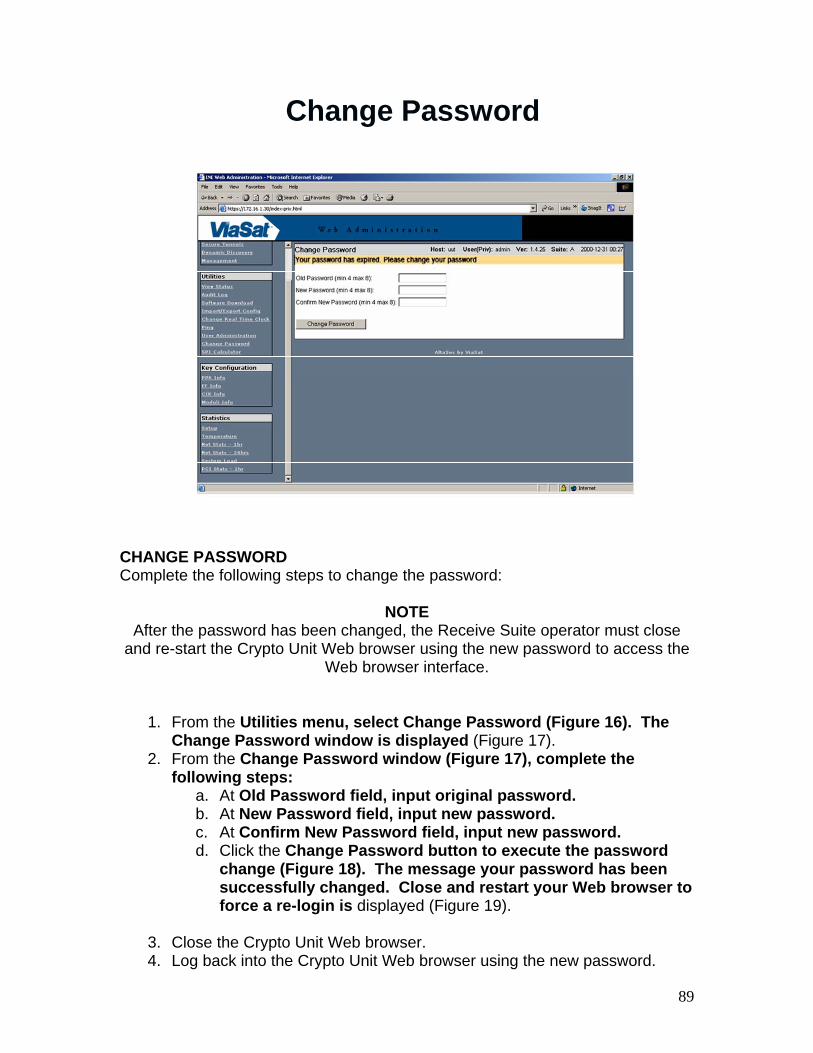
CHANGE PASSWORD Complete the following steps to change the password:
NOTE After the password has been changed, the Receive Suite operator must close
and re-start the Crypto Unit Web browser using the new password to access the Web browser interface.
1. From the Utilities menu, select Change Password (Figure 16). The Change Password window is displayed (Figure 17).
2. From the Change Password window (Figure 17), complete the following steps:
a. At Old Password field, input original password. b. At New Password field, input new password. c. At Confirm New Password field, input new password. d. Click the Change Password button to execute the password
change (Figure 18). The message your password has been successfully changed. Close and restart your Web browser to force a re-login is displayed (Figure 19).
3. Close the Crypto Unit Web browser. 4. Log back into the Crypto Unit Web browser using the new password.

90
Load Image Wrapping Key Split (IWKS) 1
LOAD IMAGE WRAPPING KEY SPLIT (IWKS) Each Crypto Unit comes with a User Image CD containing a set of Image Wrapping Keys. This procedure provides the steps to load the IWKS into the Crypto Unit from the CD.
1. Insert User Image Key CD into DVD-ROM/CD-RW drive. 2. From the Key Configuration menu, click on CIK Info. The CIK Info
page is displayed (Figure 20).
NOTE It is a security violation to save the IWKS file to the server hard drive.
3. Next to the Image Key File field, click the Browse button (Figure 20).
The Choose File window is displayed (Figure 21). 4. From the Choose file window, navigate to D drive and select the A
image key unless otherwise directed. 5. Verify the selected Image Key name appears in File name field, and
then click the Open button (Figure 21). 6. Verify the selected Image Key file name is displayed in the Image Key
File field (Figure 22). 7. From the User Must Load Image Keys to Provision CIK section, click
the Load button (Figure 22). A Confirm image key file load popup prompt is displayed (Figure 23).

91
8. Click the OK button. The Load Image Keys Result window is displayed (Figure 24).
9. Click the Back button (Figure 24) in the center of the screen. The CIK Info window is displayed (Figure 25).

92
Load Image Wrapping Key Split (IWKS) 2
10. Verify the correct Suite version (e.g. Suite: A) is now displayed on the top right hand side of the screen (Figure 25).
11. Remove User Image CD from DVD-ROM/CD-RW drive.

93
Provision Blank CIK
PROVISION THE BLANK CIK CAUTION
Never remove or insert CIK with Crypto Unit powered on.
The CIK can be one of two types: blank CIK or operational CIK. The blank CIK is a key with no recognized contents. The operational CIK is the key required for the Crypto Unit to perform its intended function. Provisioning a blank CIK makes it an operational CIK. This procedure provides the steps to provision a blank CIK:
1. Ensure blank CIK is inserted correctly. 2. Ensure COMSEC Tray Assembly POWER ON/OFF switch is set to ON. 3. Ensure ALARM LED is not lit. 4. If necessary, perform Log into Crypto Unit Web Interface procedure. 5. In Key Configuration menu, select CIK Info. 6. Verify CIK Info page is displayed with the correct Suite installed
(Figure 25). If the Suite has not been installed, then refer to the section of this work package titled: Load Image Wrapping Key Split (IWKS) for instructions.
7. In CIK Label field, under Provision CIK, type in the serial number of the Crypto Unit (Figure 26).
8. From Security Classification field, select the appropriate security classification from the drop-down menu.

94
9. From the COI field, select US, unless otherwise directed, from the drop-down menu.
10. Click on the Provision CIK button (Figure 26). 11. Verify the CIK Info screen displays Provision CIK: Working (Figure
27). 12. Verify the CIK Info screen displays Provision CIK: Done (Figure 28). 13. From the Provision CIK: Done field, click the Back button to return to
the CIK Info main menu.

95
Set the Real Time Clock (RTC)
Caution: Setting the RTC backwards will delete the PPKs.
SET CRYPTO UNIT REAL TIME CLOCK (RTC) The Crypto Unit RTC needs to be set to GMT and checked prior to PPK load and periodically during normal operation.
CAUTION Setting the RTC backwards will delete the PPKs.
1. If necessary, perform Log into Crypto Unit Web Interface procedure. 2. Perform the following to access the Crypto Unit Change Real Time
Clock screen: a. In Utilities menu, select Change Real Time Clock. b. Verify Change Real Time Clock screen is displayed (Figure 43).
3. Perform the following to change Crypto Unit RTC: c. Set date to current date (in GMT) by selecting appropriate values
from Month, Day, and Year drop-down menus. d. Set time to current time (in GMT) by selecting appropriate values
from HH, MM, and SS drop-down menus. e. Click the Submit button. f. If prompted with the following message, click the Submit button:
Setting the Real Time Clock backwards may cause you to lose your keys. Click SUBMIT again to confirm, and then reset the unit.
g. At front of Crypto Unit, press RESET button and wait for ALARM LED to extinguish.

96
Assign Pre-Placed Keys (PPK)
ASSIGN PPKS Perform the following to assign PPKs (if required):
1. If necessary, perform Log into Crypto Unit Web Interface procedure. 2. From the Key Configuration menu, select PPK Info. The PPK Info
screen is displayed (Figure 44).
NOTE GBS uses a Key Sequence named ppk0. If ppk0 is not listed in the
Assigned Key Sequences of the PPK Info screen (Figure 44), it must be added. Each Short Title needs its own Key Sequence and all Key Sequences
must be type BATON.
3. If it is necessary to add ppk0, perform the following, else skip to step 4. a. In the Create a New Key Sequence section of the screen, add
ppk0 to the Name text box field. b. Select BATON from the Algorithm drop down box. c. Click the NewSeq command button.
4. Scroll down to Unassigned PPK List section (Figure 45). 5. Select radio button (under Selected column) next to Short Title of
desired PPK. 6. Next to Chain, verify ppk0 is selected. 7. Next to Month, verify month of assigned PPK from drop-down menu. 8. Next to Year, verify year of assigned PPK from drop-down menu.

97
9. To assign PPK, click on Assign button next to Year drop-down menu. 10. Scroll to Assigned PPK Sequences section. 11. Verify assigned PPK appears under ppk0.

98
Traffic Flow Security (TFS) Settings
NOTE: TFS Settings must be changed before Secure Tunnels are added;otherwise, KenCast will not obtain a transponder lock.
1. If necessary, perform Log into Crypto Unit Web Interface procedure. 2. In Network Configuration menu, select TFS Settings. 3. Verify TFS Settings screen is displayed (Figure 46). 4. In Black ICMP field, select Disabled from drop-down menu. 5. In MTEK/MTEK Update field, select Enabled from drop-down menu. 6. In HIKE Reconnect field, verify Configured SAs Only from drop-down
menu. 7. In Crypto Block Size field, select 48 from drop-down menu. 8. In IP DF Bit field, select Set from drop-down menu. 9. In Fixed Packet Length field, select off from drop-down menu. 10. In Length field, type in 0. 11. In Red/PT MTU Size field, type in 1424. 12. In IP TTL Value field, type in 60. 13. Click the Submit button (Figure 46). 14. Click OK at confirmation pop-up. 15. Press the RESET button to submit the changes and wait for the
ALARM LED to extinguish.

99
Add Secure Tunnels
ADD SECURE TUNNELS Secure tunnels allow Crypto Unit interfaces to communicate with each other. All Crypto Units must have secure tunnels set up in order to pass secure traffic.
1. If necessary, perform Log into Crypto Unit Web Interface procedure. 2. In Network Configuration menu, select Secure Tunnels. The Secure
Tunnels screen is displayed (Figure 47). 3. In the Add Tunnels section (Figure 48):
a. In CT Endpoint field, enter MCA for classified information (refer to MDS).
b. In PT Dest Network/Endpoint field, enter MCA for classified information (refer to MDS).
c. In PT Endpoint field, enter MCA for classified information (refer to MDS).
d. In Subnet mask field, enter 255.255.255.255. e. In Key drop-down menu, select ppk0. f. Click the Add Tunnel button.
4. Reset Crypto Unit and wait for ALARM LED to extinguish. 5. At front of Crypto Unit, verify PWR/READY LED is lit green. 6. Verify Secure Tunnels screen refreshes and displays the newly
created tunnel in Current Tunnels section of the screen (Figure 49). 7. Repeat step 3 as required for additional assigned MCAs.

100
8. In Current Tunnels section of Secure Tunnels screen, under Status column, verify Up is displayed next to
9. tunnel (Figure 49). 10. If it does not display Up, then at front of Crypto Unit, press RESET
button and wait for ALARM LED to 11. Extinguish. 12. Crypto Unit is now ready for use.

101
• Prerequisites• Normal Operation procedure • Change Password• Change Password
Normal Operations (1)
Normal Operation (2)
Prerequisites
Before you can begin the Normal Operation procedures, the following tasks must have been performed:
1. Submit GBS Mission Request (GMR) form. See WP 0909 00 for a sample GMR. When initiating, adding, dropping, or changing GBS services, you must use a GMR form.
2. Obtain a Mission Data Sheet (MDS). See WP 0909 00 for a sample MDS. Before beginning your mission, obtain a current MDS from the Satellite Broadcast Manager (SBM). The MDS lists all mission-specific data required to set up and configure your TSR-8 to receive products broadcast by the SBM.

102
Normal Operation (3)
Prerequisites (Cont)
3. Comply with Defense Information Systems Agency (DISA) Information Assurance & Vulnerability Assessment (IAVA) directives by routinely reporting Server IAVA status in accordance with local procedures. The Department of Defense (DOD) is vigilant to protect their information systems and networks from being compromised. The DISA IAVA process is part of DISA’s overall vulnerability management and risk avoidance.
4. Confirm with SBM that your Smart Card is entitled.
5. Perform Assembly and Preparation for Use (WP 0302 00).
6. Perform System Power Up (WP 0303 00).
7. Obtain Crypto Ignition Keys (CIKs) and a Pre-Placed Key (PPK) for Crypto Unit.
Normal Operation (4)
The Normal Operation procedure (WP 0304, Table 1) covers the following tasks:
1. Configure IRD (Skystream or IDC) for Mission
2. Antenna Initialization
3. Configure KenCast for Mission on NGRT Server
4. Configure KenCast for Mission on RBM Server
5. Verify Operational Crypto Unit
6. Verify and Monitor Reception of KenCast Products
7. Monitor Streaming Video Using MediaStream Player

103
DISA Password CriteriaThe Defense Information Systems Agency (DISA) requires that all systems in a DoD
facility comply with the applicable Security Technical Implementation Guide (STIG). The STIG is the configuration standard for DoD Information
Assurance (IA) and IA-enabled devices/systems. GBS RBM software has been designed to meet or exceed the STIG passwords criteria. STIG password criteria are as follows:
1. Must meet current DoD complexity guidance consisting of a random mixture of uppercase characters (A thru Z), lowercase characters (a thru z), numbers (0-9), and non-alphabetic characters (such as !, @, #, $).
2. Must be a minimum of 14 characters in length.3. Cannot have been changed in the last 1 day.4. Cannot be a password used in the previous 24 passwords.5. Must be changed every 60 days
Change Password (1)
Windows PasswordsEach RBM user must have their own Windows account with a unique Windows
username and password. Procedures for creating new Windows user accounts are provided in WP 0715 00. Procedures for changing the password of an existing account are provided later in this Work Package (See Changing Administrator/User Password).
GBS Windows passwords must meet the following requirements:
1. Must be a minimum of 14 characters in length.2. Cannot contain the user’s account or full name.3. Must contain at least two characters from at least three of the following four
character groups: English uppercase characters (A thru Z), English lowercase characters (a thru z), numbers (0-9), and non-alphabetic characters (such as !, @, #, $).
4. Cannot be a password used in the previous 24 passwords.5. Cannot have been changed in the last 1 day.6. Must be changed every 60 days or as directed by local security regulations.
Change Password (2)

104
The GBS password requirements also apply to services that use Windows passwords, including the following:1. Apache2 Windows Service2. MSSQLSERVER Windows Service3. KenCast Fazzt Windows Service
Change Password (3)

105
• Question: What does a purple battery indicator mean?• Answer: Both the internal and external batteries are low.
• Question: What happens if you set the Real Time Clock backwards?
• Answer: The KG-250 will delete the PPKs.
• Question: When you change the GBS password what services need the passwords changed?
• Answer: Apache2, MSSQL Server, KenCast Fazzt.
Summary
Any Questions?

106
This page Intentionally Left Blank

TAB
Insert Tab # 4 Here

Network Integration

108

109
• Network Integration Configurations• IP Addresses• Video Converter
Network Integration
Explain how to configure the servers to connect to a site LAN (WP 0309)
GBS Network Integration

110
No WAN connectivity• Obtain DISA-approved IP addresses from LAN Administrator for
the RBM and NGRT Servers.
• End user must have a compatible, and authorized, IP Video player.
• End user must have FIPS 140-2 compliant FTP server software for FTP Push of products to End User Client.
• Add KenCast site users. WP 0309 00-3• Login as user WP 0709 00-1• Set up individual Push WP 0309 00-6• Create Push Lists WP 0309 00-8
GBS Integration Configuration
LRULRU IP AddressIP Address RemarksRemarks
RBM/NGRT ServerRBM/NGRT Server 172.16.0.1172.16.0.1172.16.10.1172.16.10.1172.16.1.1172.16.1.1192.168.1.2192.168.1.2
IRDIRD 172.16.0.25172.16.0.25172.16.10.25172.16.10.25
Eth0 = DataEth0 = DataEth1 = ControlEth1 = Control
MESMES 172.16.0.5172.16.0.5
UMESUMES N/AN/A
NTSC ConverterNTSC Converter 172.16.0.10172.16.0.10
KGKG--250 (CIPHER)250 (CIPHER) 172.16.0.30172.16.0.30 BlackBlack
KGKG--250 (PLAIN)250 (PLAIN) 172.16.1.30172.16.1.30 RedRed
AN/TSR-8 IP Addresses

111
Video Converter
The Video Converter (Figure 1) consists of the Video Converter itself (also known as the Set Top Box or STB), STB stand, remote control, AC Adapter, Audio/Video Cable, and Ethernet Cable. The parts are stored in the RBM Transit Case front cover pouch. The Video Converter is an Internet Protocol (IP) STB that provides the video interface between the RBM and a standard television. It receives IP video from the RBM and converts it to National Television System Committee (NTSC) video, which can be viewed on a standard television. The Multi-Cast Address (MCA) of each IP video input must be stored in the Video Converter and assigned to a channel. An RBM software application called STBConfig allows the operator to change channels from the Server as an alternative to using the remote control. The channel buttons displayed by the STBConfig utility can be added, edited, and deleted. The STBConfig utility can display a maximum of 48 channel buttons, however additional instances of the utility can be installed to accommodate more channels (WP 0713 00). The Video Converter is fielded with all standard GBS video MCAs pre-programmed into it. If the Video Converter is replaced, the new Video Converter will come pre-loaded with a set of standard MCAs.

112
Another utility, called the Set IP Utility, allows the operator to change the IP address of the Video Converter and to add/delete MCAs. For further information about the Video Converter and remote control, refer to the applicable AmiNET publication. See WP 0902 00.

113
• IFD Account• IFD Login• IFD Folder
IFD Operations
IFD Accounts
IFD Accounts requested via GMR to SBMUser must provide: • Name, Rank, SIPR Account,• IP Address• CAC Certificate • Computer name
IFD Address, User name and Passwordwill be sent via SIPR by SBM

114
IFD Login

115
IFD Folder (1)
IFD Folder (2)

116
• Question: Can the GBS RS be connected to the Military network?
• Answer: No.
• Question: Can the GBS operator access the IFD folder from the RS?
• Answer: No.
Summary
Any Questions?

TAB
Insert Tab # 5 Here

Troubleshooting and
Maintenance

118

119
• Troubleshooting• PMCS• Practical Exercise Troubleshooting
Troubleshooting andMaintenance (1)
Fault isolation procedures help the maintenance technician identify and repair an equipment failure to a Line Replaceable Unit (LRU). The troubleshooting methodology used to diagnose and repair faults within the TSR-8 consists of performing the following steps:
1. Fault Identification - Identification of a fault based on symptoms observed during normal operation.
2. Fault Isolation - Isolation of a fault to a specific faulty LRU. 3. LRU Removal and Replacement - Removal and replacement of the faulty
LRU to correct the fault. After an equipment failure has been repaired, verify the problem has been corrected and the system has been restored to normal operation (WP 0304 00).

120
PERFORM WORK PACKAGE
Troubleshooting Chapter 4
Preventive Maintenance Checks and Services (PMCS)
Chapter 5
Corrective Maintenance Chapter 6
Norfolk SBM Helpdesk DSN: 312-564-9190Comm: 757-444-9190
Wahiawa SBM Helpdesk DSN: 315-453-5050Comm: 808-653-5050
Troubleshooting and Maintenance (2)
The GBS Help Desk is available to provide assistance in the operation and maintenance of the GBS TSR-8. The Help Desk must be contacted when any problems are encountered, prior to starting a troubleshooting task, to ensure that all problems are logged and analyzed and to provide updated troubleshooting information. The GBS Help Desk can be reached by phone, fax, or e-mail. When submitting a problem to the Help Desk via fax, use the supplied Trouble Ticket Form. For Smart Card problems, there is a separate Trouble Ticket Form which may be downloaded from the GBS Community of Practice (CoP) Website (see WP 0716 00). It is also helpful to use the form for recording problems prior to calling the Help Desk. Refer to Table 1 to contact the Help Desk supporting your location.

121
1. If power is on, perform the System Power Down Procedure (WP 0305 00).2. Ensure all cables, internal and external, are secure and connected correctly. Refer to System Cabling
Diagrams (WP 0601 00).3. Ensure site power is supplied to the NGRT and RBM power sources.4. Perform the System Power Up Procedure (WP 0303 00).5. Ensure GFCI on antenna power cable has not tripped.6. Ensure Power Controller Unit circuit breaker has not tripped.7. Ensure power is applied to all LRUs.8. Ensure system is configured per Mission Data Sheet (MDS).9. Verify software services are running by moving mouse pointer over task bar icons (pop-up message
indicates status of each service):a. Fazztb. Apachec. MSSQL Serverd. Symantec Anti-virus
10. Call the GBS Help Desk and ensure the following:a. Satellite is broadcasting and RS is under the satellite beam.b. MDS values are correct and then verify correct feed assembly (Ka or Ku) is installed.c. Smart Card is entitled.d. Crypto Keys are valid.
Preliminary System Checks
NOTE If Smart Card has not been used for 1 month, it may take 30 minutes under
broadcast to fully entitle Smart Card. After 255 days of inactivity, the Smart Card will expire and cannot be used in the future.

122
1. Perform Ping Test2. Digital Multimeter (DMM) Operation
a. Checking Voltageb. Continuity Check
General Troubleshooting Procedures
Troubleshooting Index

123
Troubleshooting Flowchart
PMCS Table
WP 0502 has the PMCS Table.

124
Summary
• Question: What Work Package is the PMCS table?• Answer: WP 0502.
• Question: What is the first step in troubleshooting?• Answer: Ensure all cables, internal and external,
are secure and connected correctly.
• Question: How long does it take for the smart card to become unentitled?
• Answer: 1 Month.
Any Questions?