Gas Measurement Requirements and Procedures
44
Gas Measurement Requirements and Procedures ***** 2019
-
Upload
khangminh22 -
Category
Documents
-
view
0 -
download
0
Transcript of Gas Measurement Requirements and Procedures
Gas Measurement Requirements and Procedures
***** 2019

About Gas Industry Co.
Gas Industry Co is the gas industry body and co-regulator under the Gas Act. Its role is to:
• develop arrangements, including regulations where appropriate, which improve:
o the operation of gas markets;
o access to infrastructure; and
o consumer outcomes;
• develop these arrangements with the principal objective to ensure that gas is delivered to existing and new customers in a safe, efficient, reliable, fair and environmentally sustainable manner; and
• oversee compliance with, and review such arrangements.
Gas Industry Co is required to have regard to the Government’s policy objectives for the gas sector, and to report on the achievement of those objectives and on the state of the New Zealand gas industry.
Gas Industry Co’s corporate strategy is to ‘optimise the contribution of gas to New Zealand’.
DATE ISSUED: ******
INQUIRIES: +64 472 1800
4
Contents
1. Introduction 7
1.1 Objective of this report 7
1.2 Some basics 7
2. Gas Measurement Fundamentals 9
2.1 The energy content of gas 9
2.2 Standardisation of metered quantities 9
The Ideal Gas Law 9
Adjusting for altitude 9
Adjusting for compressibility 10
2.3 The calculation of billing quantities 11
2.4 Mass based approach to gas measurement 12
2.5 Where energy quantities are calculated 12
3. Overview of Gas Measurement Systems 13
3.1 Purpose and location of GMSs 13
3.2 Components of a GMS 14
3.3 Main types of meter technology 16
3.4 GMS Safety 18
3.5 Advanced Metering 19
4. Legal framework 20
4.1 Legislation 20
4.2 Contracts 24
Other contracts 25
4.3 Technical standards 26
BS EN 1776:2015 Gas infrastructure. Gas measuring systems. Functional requirements 26
NZS 5259:2004 Gas measurement 26
American Gas Association publications 26
ISO standards 27
AS/NZS 2885 1997 Pipelines - Gas and liquid petroleum 28
4.4 How the framework fits together 28
4.5 Transmission GMS requirements 30
4.6 Distribution GMS requirements 31
5
5. GMS operation and maintenance 33
5.1 Transmission GMS operation and maintenance 33
5.2 Distribution GMS operation and maintenance 33
6. GMS testing 35
6.1 Transmission GMS testing 35
6.2 Distribution GMS testing 35
7. GMS documentation 39
7.1 Transmission GMS documentation 39
7.2 Distribution GMS documentation 39
8. Auditing 42
Glossary 43
Appendix A Governance of this Document 44
6
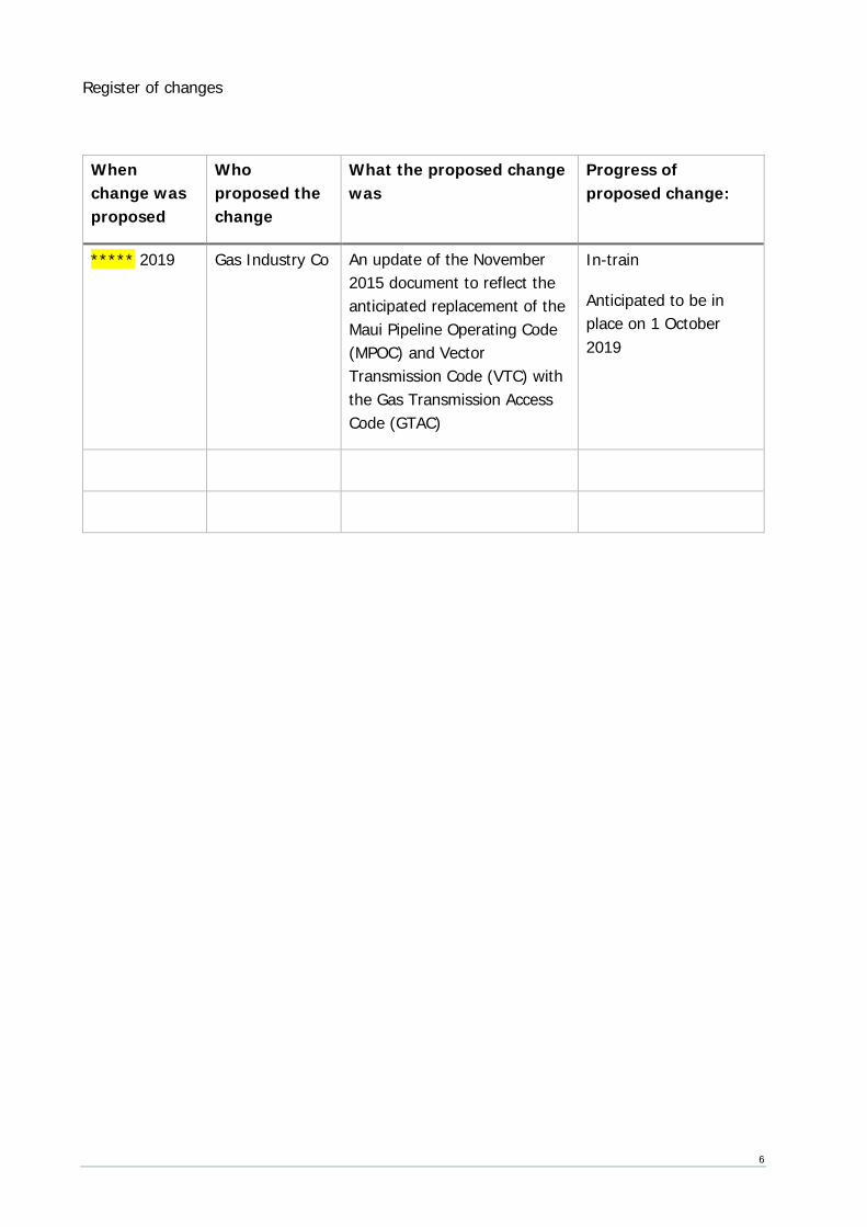
Register of changes
When change was proposed
Who proposed the change
What the proposed change was
Progress of proposed change:
***** 2019 Gas Industry Co An update of the November 2015 document to reflect the anticipated replacement of the Maui Pipeline Operating Code (MPOC) and Vector Transmission Code (VTC) with the Gas Transmission Access Code (GTAC)
In-train
Anticipated to be in place on 1 October 2019
7
1. Introduction
In New Zealand gas must be sold by energy content measured by a gas measurement system (GMS)1. The Gas Act 1992 defines a GMS as:
… a system for measuring the quantity of any gas or the energy content of any gas, whether by actual measurement or estimation; and includes any equipment that forms part of, or is ancillary to, any such system.
This broad description is needed because it applies to the full spectrum of arrangements for measuring gas from GMSs at major plants such as power stations, petrochemical plants and industrial complexes to small residential GMSs.
The GMS at a major plant is in some ways the easiest to understand because all its component parts are located at one physical metering station. In contrast, the on-site elements of a residential GMS comprise just the meter itself (to measure gas volume) and a pressure regulator (to maintain a stable delivery pressure). The other elements of a residential GMS are remote from the meter location. They include ancillary equipment such as gas chromatographs (instruments that measure the energy quantity of standard volumes of gas) and the hardware and software for calculating the various adjustments necessary to convert the measured volume into an energy quantity.
1.1 Objective of this report This report provides an overview of the legal requirements and technical standards that apply to gas measurement, and a description of common industry practice and terminology. It will also tell you where to find more detailed information. If you’re not an expert in this area we’re sure you’ll find the report useful, but please let us know if anything isn’t clear. If you are an expert, please let us know if you spot anything that isn’t correct.
You shouldn’t assume this report is a complete and accurate description of all metering requirements. It’s not meant to be a replacement for original documents. Go back to the source document if you need to get into the detail.
1.2 Some basics In New Zealand, metric units are used to measure gas flow.
A ‘standard’ volume of gas is the volume it occupies at ‘standard conditions’, ie at a temperature of 15°C and a pressure 101.325 kPa (kilopascals absolute)2.
1 Gas (Safety and Measurement) Regulations 2010 r21(2) 2 NZS 5259:2004 s1.2.3.2
8
The energy content of gas is commonly measured in gigajoules and may be scaled down to megajoules or up to terajoules or even petajoules, depending on the quantum of gas.
Megajoule (MJ) – is equal to one million joules (106)
Gigajoule (GJ) – is equal to one billion joules (109)
Terajoule (TJ) – is equal to one trillion joules (1012)
Petajoule (PJ) – is equal to one quadrillion joules (1015)
An average residential user consumes around 24 GJs/year.
Residential gas bills frequently express energy usage in kilowatt hours (kWh) (1 GJ is approximately 278 kWh). All other commercial gas transactions reference GJs.
The total quantity of gas consumed in New Zealand in 2018 was 192 PJs.3
3 2018 Energy in New Zealand
9
2. Gas Measurement Fundamentals
This chapter describes the basic physics of gas measurement including the various conversions necessary to convert actual measured volumes into energy.
2.1 The energy content of gas The energy content of a standard volume of gas – its calorific value (CV) – is generally measured in units of megajoules (MJ) per standard cubic meter (scm). Here ‘standard’ refers to standard conditions of 15 degrees centigrade (⁰C) and 101.325 kilopascals (KPa). The CV is a measure of the amount of heat that would be generated by combustion of a standard cubic meter of gas.
Natural gas sold in New Zealand typically has a CV in the range of 39-41 MJ/scm.
2.2 Standardisation of metered quantities A gas meter measures the volume of gas passing through it at actual conditions, i.e., at the prevailing temperature and pressure of gas at the gas meter. This volume is recorded in units of actual cubic meters (acm). However, in order to calculate how much energy that measured volume contains, it is necessary to first convert the measured volume (in acm) to a standard volume (in scm). This is done using the Ideal Gas Law, possibly adjusted for altitude and compressibility, as explained below.
The Ideal Gas Law The volume of a gas increases as its temperature increases (Charles’ Law) and decreases as its pressure increases (Boyle’s Law). This relationship is described in the ‘Ideal Gas Law’:
P1V1/T1 = P2V2/T2
where P is the absolute pressure of gas; V is the volume of gas; and T is the absolute temperature of the gas. For example, the first state (1) could be at actual metering conditions and the second state (2) could be at standard conditions. The formula can then be transposed to give:
Vstandard = Vactual × ( Pactual / Pstandard ) × ( Tstandard / Tactual )
= Vactual × FP × FT
Adjusting for altitude As noted earlier, the ‘P’ factor in the Ideal Gas equation is ‘absolute’ pressure, i.e., measured with reference to a vacuum. On-site pressure measurement devices typically measure gauge pressure (i.e. the difference between the absolute pressure of gas in the pipeline and the ambient atmospheric pressure), so the atmospheric pressure must be added to the gauge pressure measurements to obtain the absolute pressure.
10
The atmospheric pressure is usually assumed to be the ‘standard’ pressure of 101.325kPa. This standard was adopted in 19544 based on the average atmospheric pressure at mean sea level at the latitude of Paris, France. It is also a reasonable proxy for atmospheric pressure at sea level in New Zealand.5
However, atmospheric pressure varies significantly with altitude, so simply adding 101.325kPa to a gauge pressure to obtain an absolute pressure is not always good enough. For example, Stratford is at an elevation of approximately 312m so the atmospheric pressure there is about 3.7kPa lower than 101.325kPa, ie about 3.6% lower6. Stratford is an extreme example, but even within Wellington there are areas nearly at sea level – like Lyle Bay and Petone – and parts that are much higher – like Mount Victoria, at nearly 200m above sea level – so the effect can be significant.
Care is therefore needed to ensure that absolute pressures derived by adding atmospheric pressure to gauge pressure readings take account of altitude effects. To make this explicit the altitude adjustment is specified as a separate adjustment, ie where FP has been calculated by adding 101.325 kPa to the Gauge pressure, a separate factor FA is introduced to adjust for the altitude of the meter.7
Adjusting for compressibility Natural gas is not an ‘ideal’ gas, so the Ideal Gas Law requires some adjustment. The adjustment is known as ‘compressibility’ (Z), and its value depends on the physical composition of the gas as well as the temperature and pressure it is measured at. The effect is particularly marked at low metering temperatures or high metering pressures.
In relation to meters at gas transmission receipt and delivery points, First gas recognises all methods referenced in NZS 5259 s 3.8.2.4 for calculating compressibility8, including the most commonly used method in the New Zealand gas industry, the American Gas Association Report no 8 (AGA8) methodology (see section 4.3 below for more detail on American Gas Association publications). The simplest method provided by AGA8 is the ‘gross characterisation method’ which requires as inputs the Specific Gravity (SG) of the gas and the concentrations of carbon dioxide (CO2) and nitrogen (N2) in the gas.
4 It was adopted by the 10th Conférence Générale des Poids et Mesures, and later incorporated into the International System of Units in 1960. 5 For example, Conference Paper #69 (1999) entitled The Measurement of Whole Building Energy Usage for New Zealand Houses, Andrew R. Pollard, presented at the IPENZ Technical Conference in Auckland, July 11-12, 1999, noted (s4.3.3 Gas Pressure) that ‘Hourly reduced mean sea-level pressure data from the NIWA Climate database was examined for 1998 from Wellington Airport (NIWA agent no 3445). The hourly pressure data had a sample standard deviation of 0.9 kPa. Using the standard pressure (101.325 kPa) in-place of the hourly data will consequently result in an uncertainty of approximately 0.9 kPa.’ 6 To give some indication of the relative importance of altitude, the difference between high and low pressure weather systems is typically about 20mbar or 2kPa, and residential meters typically operate at a pressure of 1.5kPa… so altitude can be relatively more significant than either of those. 7 Note that no altitude adjustment is required if the absolute pressure is measured directly (and absolute pressure transducers are becoming more common). In that case the FP factor is calculated using that absolute pressure directly. 8 See GTAC Metering Requirements p 14.
11
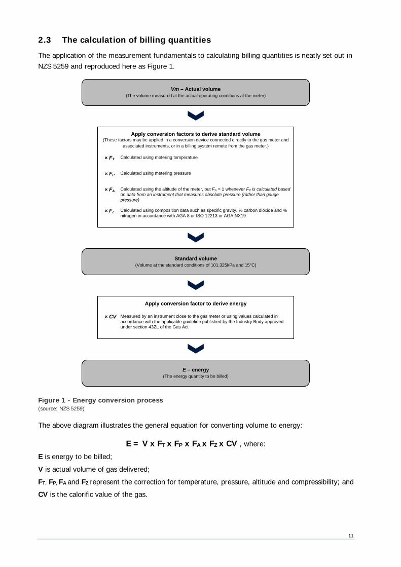
2.3 The calculation of billing quantities The application of the measurement fundamentals to calculating billing quantities is neatly set out in NZS 5259 and reproduced here as Figure 1.
× FT
Vm – Actual volume(The volume measured at the actual operating conditions at the meter)
E – energy(The energy quantity to be billed)
Apply conversion factors to derive standard volume(These factors may be applied in a conversion device connected directly to the gas meter and
associated instruments, or in a billing system remote from the gas meter.)
Standard volume(Volume at the standard conditions of 101.325kPa and 15°C)
Apply conversion factor to derive energy
× CV
Calculated using metering temperature
× FP Calculated using metering pressure
× FA Calculated using the altitude of the meter, but FA = 1 whenever FP is calculated based on data from an instrument that measures absolute pressure (rather than gauge pressure)
× FZ Calculated using composition data such as specific gravity, % carbon dioxide and % nitrogen in accordance with AGA 8 or ISO 12213 or AGA NX19
Measured by an instrument close to the gas meter or using values calculated in accordance with the applicable guideline published by the Industry Body approved under section 43ZL of the Gas Act
Figure 1 - Energy conversion process (source: NZS 5259)
The above diagram illustrates the general equation for converting volume to energy:
E = V x FT x FP x FA x FZ x CV , where: E is energy to be billed; V is actual volume of gas delivered; FT, FP, FA and FZ represent the correction for temperature, pressure, altitude and compressibility; and CV is the calorific value of the gas.
12
. ass based a pproac h to gas mea surement
The previous sections of this chapter relate to the gas measurement calculations required where a meter measures the volume of the flowing gas. The vast majority of gas flow meters measure volume, but several technologies – thermal meters and Coriolis meters – allow for the direct measurement of mass flow. Aside from the inherent properties of these meters (discussed in Section 3.3), mass meters substantially simplify the conversion to energy units.
Mass can be converted to a standard volume if the specific gravity of the gas is known:
E = M / (SG x ρ(air)) x CV , where: E is energy to be billed; M is mass of gas delivered; SG is the specific gravity (or relative density) of dry gas to dry air at standard conditions; ρ(air) is the density of dry air at standard conditions; and CV is the calorific value of the gas measured in units of MJ/scm. Or, if the CV is measured in units of MJ/Kg, the mass can be converted to energy in a single step:
E = M x CVM , where: E is energy to be billed; M is mass of gas delivered; and CVM is the mass-based calorific value measured in units of MJ/Kg.
2.5 Where energy quantities are calculated Only the largest GMSs perform the full conversion of measured volume to energy on-site. For other GMSs, common practice is to calculate energy quantities as a ‘back-office routine’ in a retailer’s billing system.
Retailers commonly obtain metering services from third-party service providers and must be careful to identify which parts of the energy calculation are done on-site (and are already allowed for in the ‘meter readings’ they obtain from the service provider), and which parts remain to be done in the retailer’s own billing system.
Where the meter readings are obtained directly from the dial on the face a gas meter that records ‘actual volume’, all the conversion factors listed in Figure 1 must be applied to derive ‘standard volume’. In other cases, the meter readings may be obtained from on-site flow computers that have already applied all the necessary conversions. In all cases, the retailer’s billing system will apply the CV to the corrected volumes to obtain the energy quantity to be billed.
To assist retailers to comply with the legal requirements and industry best-practice, Gas Industry Co issues a guideline on how the calculations to convert volume to energy should be done: Gas (Downstream Reconciliation) Rules 2008 Billing Factors Guidelines.10
10 The Billing Factors Guidelines can be found at http://www.gasindustry.co.nz/dmsdocument/2849.
13
3. Overview of Gas Measurement Systems
This chapter describes the components that make up a GMS and the common types of gas meter technology.
3.1 Purpose and location of GMSs Gas flows can be measured for system monitoring and control (operational) purposes and/or for commercial (fiscal) purposes. As a general rule, a higher standard of accuracy is required for fiscal measurement, but frequently one measurement system will serve both purposes.
The focus of this report is fiscal measurement, which needs to occur at all locations where the ownership or control (custody) of gas changes. These locations are illustrated by the shaded boxes in Figure 2.
Figure 2 - Fiscal Measurement Locations
At each location where fiscal measurement is required, a metering station comprising at least a pressure regulator, a meter and a set of isolation valves is present. More complex arrangements exist at high volume stations, particularly where gas is injected and withdrawn from the gas transmission system. Such stations include ‘transmission system receipt points’ where producers
Gas Transmission SystemReceipt Points
Gas Transmission System Delivery Points(‘gate stations’)
Gas Treatment Stations
Transmission Pipelines
Transmission System End-Users (‘direct connects’)
Distribution System End-Users
14
inject gas into the transmission pipeline, and ‘transmission system delivery points’ where gas is supplied to major industrial factories, petrochemical plants, electricity generation stations, and distribution networks (for on-sale to downstream consumers). A GMS at a transmission receipt points, or a large transmission delivery point will be self-contained, including all the equipment necessary to determine the quantities of energy delivered. Such a GMS would typically comprise:
• several metering ‘streams’ to provide a degree of redundancy and an ability to cross-check;
• a gas analyser to provide real time measurement of gas composition from which CV and SG can be derived; and
• one or more flow computers to perform all the calculations necessary to give real time energy readouts.
By contrast, small metering installations, such as those for residential consumers, operate at low-pressure and only have a few components of the GMS located on-site. These installations rely on remote systems to measure gas composition, CV and SG. So, while the volume of gas delivered is measured on-site, the flow calculations (i.e., the conversion of metered quantities to energy) are generally done by retailers’ back-office billing systems on a batch basis when invoices are prepared.
3.2 Components of a GMS The equipment components of a GMS include:
• Meter: one or more meters to measure the amount of gas being delivered;
• Temperature measurement device: to measure the flowing gas temperature;
• Pressure measurement device: to measure the flowing gas pressure;
• Gas analyser: to analyse the chemical composition of the gas and calculate its properties, such as its calorific value and specific gravity;
• Conversion device: to perform the flow calculations (this can be an on-site device known as ‘flow computer’ or ‘corrector’, or a back-office billing system);
• Regulator: one or more regulators to reduce the pipeline pressure to a stable metering pressure;
• Filter, flow conditioning device, flow restrictor, and isolation valves: a filter to remove contaminants from the gas stream; a flow conditioner to remove any swirl in the gas stream caused by upstream pipework configurations that could otherwise affect the accuracy of the meter; a flow restrictor to prevent excess flow through the meter; and isolation valves to allow for meter removal; and
• Indexes and gauges: to allow instruments and conversion devices to display measurements and indicate the quantity of gas measured (these can be mechanical or electronic).
The system components of a GMS include:
15
• Systems for determining gas composition and properties: where gas composition and properties are not measured on-site, systems exist for calculating the gas composition and properties of the different mixtures of gas delivered at various other locations (there are currently 14 such ‘gas types’); and
• Systems for calculating energy from measurement inputs: these systems may be entirely automated (for example, in a flow computer at a large metering installation) or be a combination of administrative arrangements and software (as in the arrangements for bringing together all the elements of a residential gas invoice: meter readings; conversion factors for pressure, temperature, altitude and compressibility; and CV).
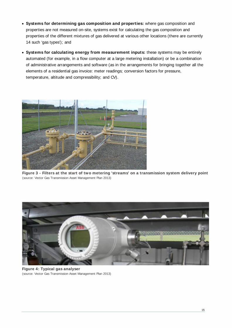
Figure 4: Typical gas analyser (source: Vector Gas Transmission Asset Management Plan 2013)
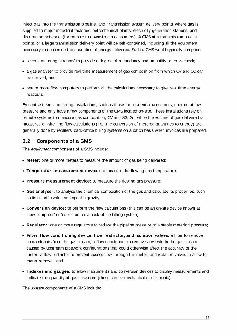
Figure 3 - Filters at the start of two metering 'streams' on a transmission system delivery point (source: Vector Gas Transmission Asset Management Plan 2013)
16
3.3 Main types of meter technology
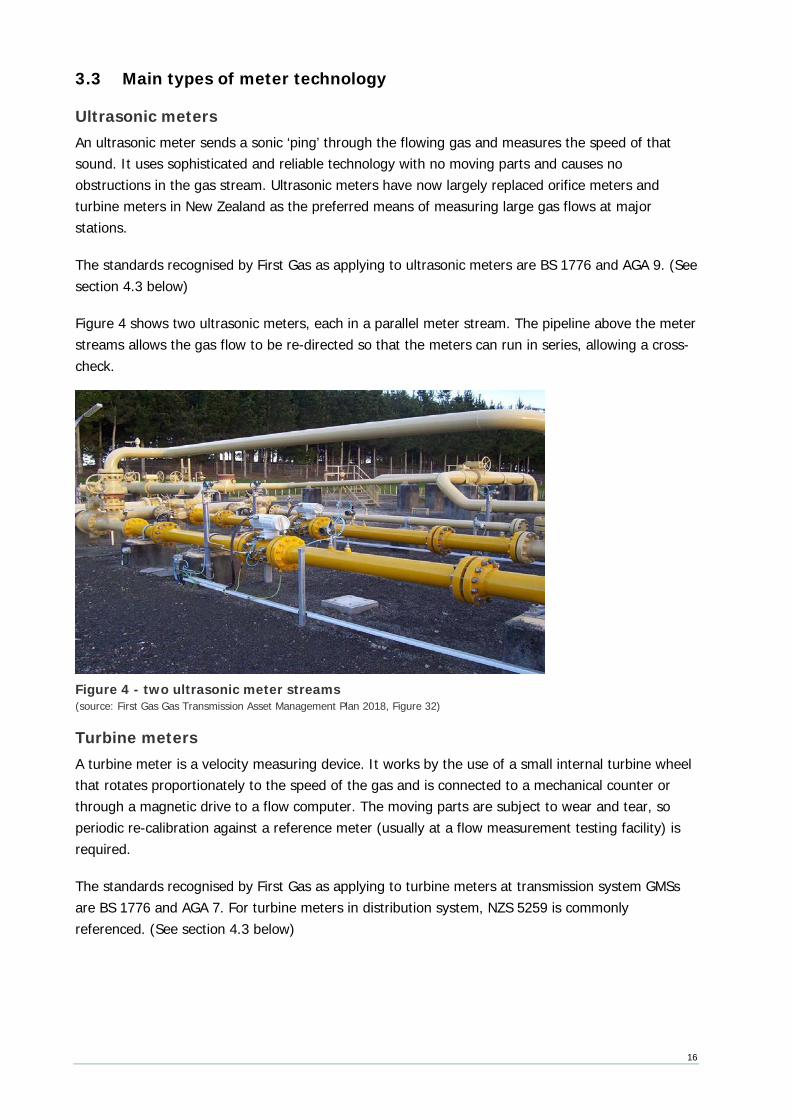
Ultrasonic meters An ultrasonic meter sends a sonic ‘ping’ through the flowing gas and measures the speed of that sound. It uses sophisticated and reliable technology with no moving parts and causes no obstructions in the gas stream. Ultrasonic meters have now largely replaced orifice meters and turbine meters in New Zealand as the preferred means of measuring large gas flows at major stations.
The standards recognised by First Gas as applying to ultrasonic meters are BS 1776 and AGA 9. (See section 4.3 below)
Figure 4 shows two ultrasonic meters, each in a parallel meter stream. The pipeline above the meter streams allows the gas flow to be re-directed so that the meters can run in series, allowing a cross-check.
Turbine meters A turbine meter is a velocity measuring device. It works by the use of a small internal turbine wheel that rotates proportionately to the speed of the gas and is connected to a mechanical counter or through a magnetic drive to a flow computer. The moving parts are subject to wear and tear, so periodic re-calibration against a reference meter (usually at a flow measurement testing facility) is required.
The standards recognised by First Gas as applying to turbine meters at transmission system GMSs are BS 1776 and AGA 7. For turbine meters in distribution system, NZS 5259 is commonly referenced. (See section 4.3 below)
Figure 4 - two ultrasonic meter streams (source: First Gas Gas Transmission Asset Management Plan 2018, Figure 32)
17
Coriolis meters A Coriolis meter measures gas by vibrating a section of pipe carrying the flowing gas. Sensors measure changes in frequency and produce a signal that is proportional to the mass flow rate. It is accurate over a wide range of flow rates. When CNG was used as an automotive fuel in New Zealand, Coriolis meters were used to measure gas flow from the CNG dispensers. Although generally more expensive, they are often considered as an alternative to ultrasonic meters for large sites.
The standards recognised by First Gas as applying to transmission system Coriolis meters are BS 1776 and AGA 11. For Coriolis meters in distribution system GMSs, NZS 5259 is likely to be referenced. (See section 4.3 below)
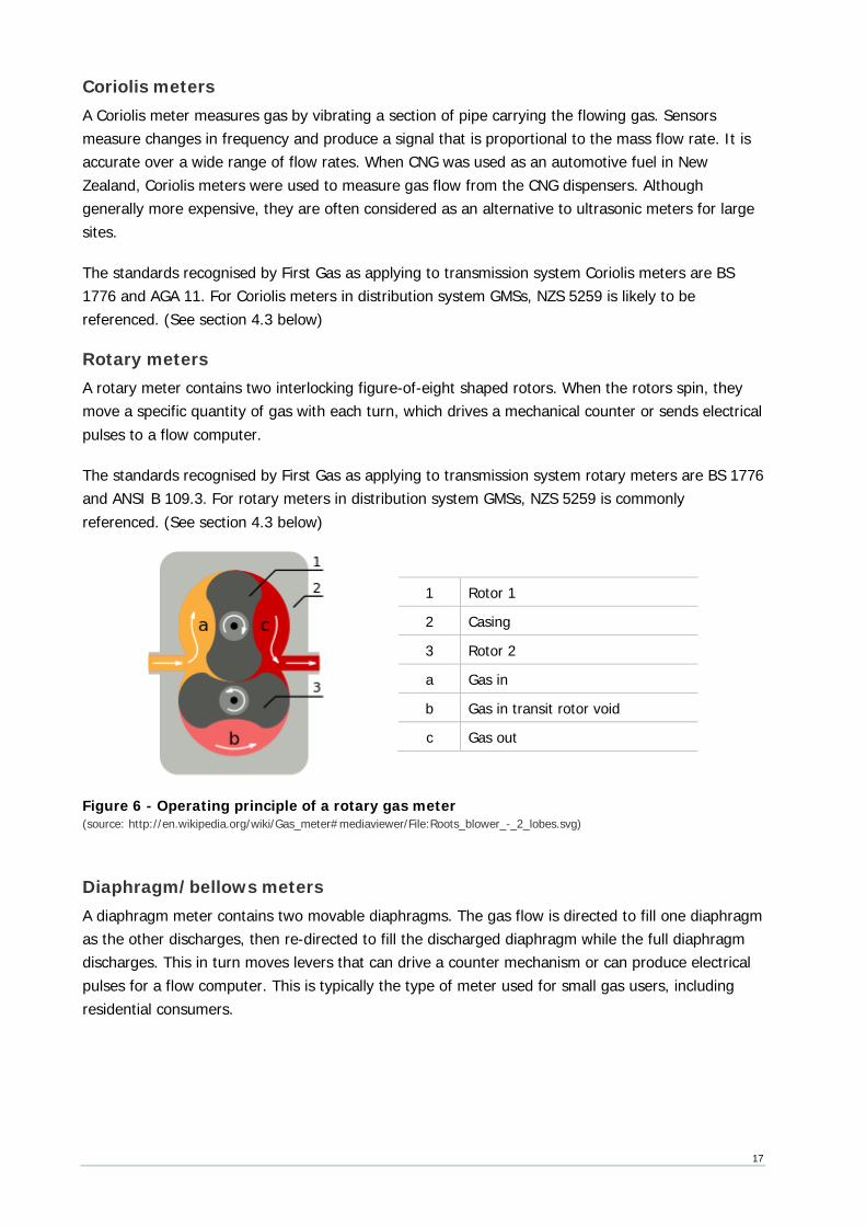
Rotary meters A rotary meter contains two interlocking figure-of-eight shaped rotors. When the rotors spin, they move a specific quantity of gas with each turn, which drives a mechanical counter or sends electrical pulses to a flow computer.
The standards recognised by First Gas as applying to transmission system rotary meters are BS 1776 and ANSI B 109.3. For rotary meters in distribution system GMSs, NZS 5259 is commonly referenced. (See section 4.3 below)
Figure 6 - Operating principle of a rotary gas meter (source: http://en.wikipedia.org/wiki/Gas_meter#mediaviewer/File:Roots_blower_-_2_lobes.svg)
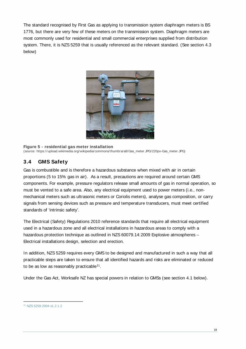
Diaphragm/bellows meters A diaphragm meter contains two movable diaphragms. The gas flow is directed to fill one diaphragm as the other discharges, then re-directed to fill the discharged diaphragm while the full diaphragm discharges. This in turn moves levers that can drive a counter mechanism or can produce electrical pulses for a flow computer. This is typically the type of meter used for small gas users, including residential consumers.
1 Rotor 1
2 Casing
3 Rotor 2
a Gas in
b Gas in transit rotor void
c Gas out
18
The standard recognised by First Gas as applying to transmission system diaphragm meters is BS 1776, but there are very few of these meters on the transmission system. Diaphragm meters are most commonly used for residential and small commercial enterprises supplied from distribution system. There, it is NZS 5259 that is usually referenced as the relevant standard. (See section 4.3 below)
Figure 5 - residential gas meter installation (source: https://upload.wikimedia.org/wikipedia/commons/thumb/a/a8/Gas_meter.JPG/220px-Gas_meter.JPG)
3.4 GMS Safety Gas is combustible and is therefore a hazardous substance when mixed with air in certain proportions (5 to 15% gas in air). As a result, precautions are required around certain GMS components. For example, pressure regulators release small amounts of gas in normal operation, so must be vented to a safe area. Also, any electrical equipment used to power meters (i.e., non-mechanical meters such as ultrasonic meters or Coriolis meters), analyse gas composition, or carry signals from sensing devices such as pressure and temperature transducers, must meet certified standards of ‘intrinsic safety’.
The Electrical (Safety) Regulations 2010 reference standards that require all electrical equipment used in a hazardous zone and all electrical installations in hazardous areas to comply with a hazardous protection technique as outlined in NZS 60079.14:2009 Explosive atmospheres – Electrical installations design, selection and erection.
In addition, NZS 5259 requires every GMS to be designed and manufactured in such a way that all practicable steps are taken to ensure that all identified hazards and risks are eliminated or reduced to be as low as reasonably practicable11.
Under the Gas Act, Worksafe NZ has special powers in relation to GMSs (see section 4.1 below).
11 NZS 5259:2004 s1.2.1.2
19
3.5 Advanced Metering Advanced meters record energy consumption in intervals of an hour or less and allow two-way communication between the meter and a centralised system. Some can also be programmed to remotely disconnect and reconnect the gas supply, and some have the ability to apply a temperature correction. However, they generally do not have the wide functionality of electricity smart meters, such as communicating with domestic appliances or providing data directly to consumers.
Because of the safety issues that arise when electricity is in close proximity to areas where gas and air could potentially mix, advanced gas meters are very low-power devices designed to run on batteries. To prolong battery life, the meters are not always ‘live’, and are generally programmed only to communicate with the central system once a day (and only to retry once or twice more if initial contact fails). This sacrifices some aspects of what might be described as pure ‘smart’ metering as the communication is effectively only one way.
The principal benefit of advanced metering is the saving of meter reading costs, so it is gas retailers who would be motivated to adopt this new technology. However, different retailers have different internal system requirements for communication, different data formats and different data content requirements. So it has proved difficult to define a common metering service standard for advanced metering.
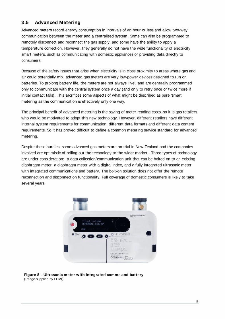
Despite these hurdles, some advanced gas meters are on trial in New Zealand and the companies involved are optimistic of rolling out the technology to the wider market. Three types of technology are under consideration: a data collection/communication unit that can be bolted on to an existing diaphragm meter, a diaphragm meter with a digital index, and a fully integrated ultrasonic meter with integrated communications and battery. The bolt-on solution does not offer the remote reconnection and disconnection functionality. Full coverage of domestic consumers is likely to take several years.
Figure 8 - Ultrasonic meter with integrated comms and battery (Image supplied by EDMI)
20
4. Legal framework
This chapter outlines the main Acts, Regulations, Rules, contracts and technical standards relating to gas measurement. These address a wide range of matters from the design and operation of the pipelines/stations/GMSs to the methods for calculating the quantities of energy delivered.
4.1 Legislation
Health and Safety at Work Act 2015 (HS Act) The HS Act provides a framework to secure the health and safety of workers and workplaces. It does not relate directly to gas measurement, but is the empowering Act referenced by the (amended12) Health and Safety in Employment (Pipelines) Regulations 1999.
Health and Safety in Employment (Pipelines) Regulations 1999 (HS Pipeline Regulations) The HS Pipeline Regulations12 are made under the Health and Safety at Work Act 2015 and apply to high pressure transmission pipelines (and not to distribution pipelines)13.
HS Pipeline Regulations reg 8 requires an employer to take all practicable steps to ensure the pipeline is designed, constructed, operated, maintained and suspended or abandoned in accordance with:
• AS 2885 Pipelines - Gas and liquid petroleum; or
• NZS 5223 Code of Practice for High Pressure and Petroleum Liquids Pipelines 1987; or
• the provisions of ANSI B 31 American National Standards Institute Code for Pressure Piping; or
• if none of these are applicable to any part of the pipeline operation, a generally accepted and appropriate industry practice.
As owner of New Zealand’s open access transmission system, First Gas has opted to use AS 2885. The requirements of that standard in relation to gas measurement are outlined in section 4.3 below.
Gas Act 1992 (Gas Act) The Gas Act regulates the supply and use of gas in New Zealand and includes provisions relating to gas measurement, including:
• Gas Act s2 Interpretation
12 The HS Pipeline Regulations were amended on 4 April 2016 to reference the Health and Safety at Work Act 2015 rather than the Health and Safety in Employment Act 1992 13 As defined in HS Pipeline Regulations reg 2
21
GMS is defined as ‘… a system for measuring the quantity of any gas or the energy content of any gas, whether by actual measurement or estimation; and includes any equipment that forms part of, or is ancillary to, any such system.’
• Gas Act s7 Inspection of distribution systems, etc.
This section enables WorkSafe to inspect any part of any distribution system, gas installation or gas appliance, including the testing of any GMS. (Gas Act s7(4)(b))
• Gas Act s9 Special powers of WorkSafe
WorkSafe may require any gas wholesaler, gas distributor, gas retailer or consumer to replace any GMS (or part of a GMS) it owns, and deliver the replaced system (or part of the system) for inspection and testing. This applies where the GMS is part of a distribution system or gas installation. (Gas Act s9(2)(a)&(b))
• Gas Act s54 Regulations
This section allows for the making of regulations for the purpose of:
o regulating and controlling the installation, use and maintenance of any GMS used for or in connection with the supply or use of gas (Gas Act s54(1)(f));
o providing for the testing and sealing of GMSs and calibration equipment; prescribing the manner in which and the means by which such testing and sealing shall be done and regulating the manner in which and the means by which GMSs and calibration equipment are reassembled in connection with such testing (Gas Act s54(1)(m));
o requiring types or categories of GMSs to be approved by WorkSafe before being offered for sale in New Zealand (Gas Act s54(3)); and
o requiring compliance with any gas code of practice or official standards (ie within the meaning of the Standards Act 1988) (Gas Act s54(2)).
Gas (Safety and Measurement) Regulations 2010 (SM Regulations) The SM Regulations detail responsibilities and obligations for the safe supply of gas. Part 3 ‘Requirements for all gas distribution systems about measurement of gas’ requires:
• SM Regulations reg 21 Gas measurement
o gas must be sold in accordance with NZS 5259 unless the seller and purchaser have agreed otherwise in writing (SM Regulations reg 21(1));
o gas must be sold by energy content measured by a GMS, and must not exceed margins of error listed. In essence, these are:
○ For meters: ± 2% on installation and ± 3% in service;
22
○ For corrections to standard volume: ± 1% on installation and ± 1.5% in service;
○ For CV measurements: ±0.5%;
○ (SM Regulations reg 21(2));
o every GMS owner must manage the system to ensure accuracy and ensure records are kept (SM Regulations reg 21(3));
o compliance with NZS 5259 is sufficient to be deemed compliant with this Regulation’s accuracy and record keeping requirements (SM Regulations reg 21(4)); and
o any person not complying with these requirements is liable to Level 2 penalties14.
• SM Regulations reg 22 Testing and installation of GMSs
When a GMS is being placed in service, or being returned to service after maintenance or recalibration:
o it must be tested for accuracy and sealed by a competent authority (SM Regulations reg 22(2)). Compliance with part 2 of NZS 5259 is sufficient to comply with this requirement (SM Regulations reg 22(3));
o a GMS that does not pass the test must not be sealed, and any seal that may have been placed on the system must be removed or destroyed (SM Regulations reg 22(4));
o the GMS owner must ensure that the calibration is unaffected by the GMS being transported before being put into service (SM Regulations reg 22(5));
o any person who installs or uses a GMS contrary to this regulation is liable to a Level 2 penalty (SM Regulations reg 22(6));
o any competent organisation that seals a GMS contrary to this regulation is liable to a Level 2 penalty (SM Regulations reg 22(7)); and
o any person, who is not a competent organisation, but breaks the seal of any GMS is liable to a Level 1 penalty15.
• SM Regulations reg 23 Records of GMS tests must be kept
o reg 22 test results must be kept by the competent authority undertaking the test and the operator of the GMS (SM Regulations reg 23(1));
o the operator must keep the records for as long as it operates the GMS (SM Regulations reg 23(2)); and
14 SM Regulations Reg 6 provides that a level 2 penalty is, in the case of an individual, a fine not exceeding $10,000; and (b) in any other case, a fine not exceeding $50,000. 15 Reg 6 provides that a level 1 penalty is, in the case of an individual, a fine not exceeding $2,000; and (b) in any other case, a fine not exceeding $10,000.
23
o a GMS operator who fails to keep any test result records is liable to a Level 1 penalty.
Gas (Downstream Reconciliation) Rules 2008 (DRRs) The purpose of the DRRs is to establish a set of uniform processes that will enable the fair, efficient, and reliable allocation and reconciliation of downstream gas quantities (DRR rule 2). Most of the DRR provisions relate to office-based allocation and reconciliation processes, but some apply to site-based metering equipment.
(More information about the reconciliation and allocation aspects of the Reconciliation Rules can be found in Gas Industry Co’s Gas Reconciliation Requirements and Procedures paper)
The focus of the DRRs is the allocation of amounts of gas delivered into a distribution network at a ‘gas gate’ among the gas retailers operating on that network.
The DRRs do not use the term GMS but instead refer to ‘meters’ and ‘metering equipment’. Metering equipment includes equipment used to measure gas supplied to an individual consumer (termed an installation control point or ICP) or gas injected at an allocated gas gate.
In the DRRs, a ‘meter owner’ means the person who owns or controls a meter used to measure gas consumption for a consumer installation.
• DRR rule 27 Metering equipment accuracy
o meter owners must ensure that equipment complies with NZS 5259 (DRR 27.1.1);
o metering equipment is considered to be accurate if within the margin of error specified in NZS 5259 (DRR rule 27.1.2); and
o verification of accuracy must be done in accordance with NZS 5259 (DRR rule 27.1.3).
• DRR rule 28 General obligations of retailers
Retailers have a number of DRR obligations, but in respect of metering equipment each retailer is required to ensure:
o metering equipment is installed and interrogated at each installation it is responsible for (DRR rule 28.1); and
o the conversion of measured volume to volume at standard conditions, and the conversion of volume at standard conditions to energy, comply with NZS 5259 (DRR rule 28.2).
• DRR rule 29 Retailer to ensure certain metering interrogation requirements are met
DRR rule 29 lays out the requirements on retailers for metering equipment installation and interrogation for consumer installations with different consumption levels. In summary, each retailer is required to:
24
o ensure a time of use (ToU) meter is installed within 3 months of becoming aware that the annual consumption at a consumer installation exceeds, or is likely to be, 10 TJ (DRR rule 29.1.1);
o ensure a ToU or non-ToU meter is installed at all other consumer installations (DRR rule 29.2.1);
o assign the consumer installation to the appropriate allocation group, depending on the size of the installation, whether ToU or non-ToU meters have been installed, whether there is telemetry and the type of profile to be applied (if relevant) (DRR rule 29.1.2 and 29.2.2); and
o ensure register readings (meter readings) are recorded each day for sites over 10TJ per annum, every month for sites between 250GJ and 10TJ per annum, and every 12 months for all other sites. In addition, each retailer must ensure readings are obtained at least every 4 months for 90% of their consumer installations with non-time of use meters.
• DRR Schedule 1 – Correcting for consumer metering errors and Schedule 1A – Correcting for gas gate metering errors
o DRR Schedule 1 notes the requirement for retailers and transmission system owners to use the best information available to them when calculating daily metered energy quantities. Tables set out the measures that should be taken in the event of various equipment failures and data loss scenarios.
. ont racts
First Gas Interconnection Agreements (ICAs) The common terms of transmission ICAs are set out in the Gas Transmission Access Code (GTAC) Schedule 5 (receipt points) and Schedule 6 (delivery points). These schedules provide that:
The Metering Owner is to ensure that the design, construction, installation, operation and maintenance of the Metering complies with the Metering Requirements.
[GTAC Schedule 5 s4.1 and Schedule 6 s4.1]
For transmission system receipt points the Metering Owner is generally the gas producer whereas at transmission system delivery points the owner is generally First Gas. In either case, the GTAC Metering Requirements document provides that the design, installation, operation, commissioning/decommissioning, testing and maintenance of Metering will comply with the requirements of BS EN 1776 (2015) (except as provided for in a TSA, ICA or elsewhere in the Metering Requirements).
The GTAC Metering Requirements specify:
1. any requirements for information or other matters, supplementary to BS EN 1776; and
2. how corrections are to be made when inaccuracies are found with gas measuring devices, flow computers/correctors, and gas analysers.
In respect of item 1, some points of interest are:
25
• GMS accuracy requirements are as per NZS 5259:2015;
• unless agreed by First Gas, Calorific Value, Density, Relative Density and Wobbe Index are to be calculated in accordance with ISO 6976;
• the Metering Owner, if not First Gas, will: - provide First Gas with calibration/verification and maintenance records in an agreed way and at an agreed frequency; - permit First Gas to witness any maintenance work; and - allow Affected Parties to view calibration/verification and maintenance records.
In respect of item 2, some points of interest are:
• the Metering Owner will correct for any metering found to be inaccurate for the period of inaccuracy or, if that cannot be determined, the lesser of 60 days and half the period since it previously tested as accurate; and
• corrections may rely on back-up instruments, manual calculation from raw data or historic data.
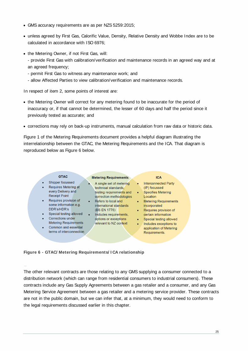
Figure 1 of the Metering Requirements document provides a helpful diagram illustrating the interrelationship between the GTAC, the Metering Requirements and the ICA. That diagram is reproduced below as Figure 6 below.
Figure 6 - GTAC/Metering Requirements/ICA relationship
ther contracts
The other relevant contracts are those relating to any GMS supplying a consumer connected to a distribution network (which can range from residential consumers to industrial consumers). These contracts include any Gas Supply Agreements between a gas retailer and a consumer, and any Gas Metering Service Agreement between a gas retailer and a metering service provider. These contracts are not in the public domain, but we can infer that, at a minimum, they would need to conform to the legal requirements discussed earlier in this chapter.
26
4.3 Technical standards Legislative and contractual arrangements refer to various technical standards. The standards most relevant to gas measurement are outlined below.
BS EN 1776:2015 Gas infrastructure. Gas measuring systems. Functional requirements The standard applies to metering at receipt points and delivery points on the transmission system. In its Metering Requirements document (overviewed in Section 4.2 above), First Gas notes that BS EN 1776 is an outcomes-based standard that applies to design, construction, testing etc. but should be read in conjunction with NZS 5259 for energy determination (since that standard is better tailored to NZ circumstances).
As well as specifying the functional requirements for the design, construction, testing, commissioning/decommissioning, operation, maintenance, and calibration of metering systems, the standard also specifies accuracy classes of measuring systems and thresholds applicable to these classes.
NZS 5259:2004 Gas measurement The standard contains mandatory requirements, advice and recommendations. Part 1 covers scope and definitions, Part 2 sets out the performance measures for a GMS and its components, and Part 3 includes a means of compliance with Part 2.
Part 2, section 1.2.3.1, specifies:
• maximum permissible errors for meters;
• maximum permissible errors for other components of the GMS; and
• how to convert measured volume to energy.
Part 3 provides information about equipment selection, installation, operation and maintenance, including acceptance testing intervals for GMS components. It also sets out methods for calculating the various factors for converting measured volume to energy.
NZS 5259 is referenced by most industry supply and transportation contracts and key legislation such as the SM Regulations, and the DRRs.
American Gas Association publications Certain American Gas Association publications relating to gas measurement are occasionally cited in NZ standards, operating procedures and the GTAC Metering Requirements document:
• AGA Report no. 3:
Orifice metering of natural gas and other related hydrocarbon fluids: relates to the design of orifice meters and the calculation of flow through orifice meters. Although orifice meters are no longer
27
used for fiscal measurement in New Zealand, they are still commonly used as process meters in industrial plants.
• AGA Report no. 7:
Measurement of natural gas by turbine meter: specifically aimed at the measurement of gas by turbine meters, but the AGA 7 flow equations are also applicable to any kind of meter that produces a known count of pulses per unit volume flowed, such as ultrasonic meters.
• AGA Report no. 8:
Compressibility factor of natural gas and related hydrocarbon gases: AGA 8 is the most frequently referenced authority for calculating compressibility. It offers three alternative calculation methods, requiring different input detail.
• AGA Report no. 9
Measurement of gas by multipath ultrasonic meters: specifies performance standards and outlines the method for calculating uncorrected volumes using an ultrasonic meter.
• AGA Report no. 10
Speed of sound in natural gas and other related hydrocarbon gases: sets out how to calculate the speed of sound in natural gas, necessary for the calibration of ultrasonic meters.
• AGA Report no. 11
Measurement of natural gas by Coriolis meter: specifies performance standards for flow measurement of natural gas by Coriolis meter.
ISO standards ISO (International Organization for Standardization) is an independent, non-governmental membership organization and the world's largest developer of voluntary International Standards. Several of these standards are occasionally cited in New Zealand standards and operating procedures:
• ISO 6976:1995
Sets out methods for calculating calorific values, density, relative density and Wobbe index from gas composition.
• ISO 2213-2:1997 (E) and 2213-3: 1997 (E)
Provides an alternative to AGA 8 for calculating gas compressibility.
28
AS/NZS 2885 1997 Pipelines - Gas and liquid petroleum First Gas has elected to design and operate its pipelines according to AS 2885, one of the standards cited as a means of compliance by the HS Pipeline Regulations. The standard is in several parts:
• Part 1 – Design and construction;
• Part 2 – Welding;
• Part 3 – Operation and maintenance;
• Part 4 – Submarine pipeline systems; and
• Part 5 – Field pressure testing.
Section 6 of Part 1 relates to gas metering and provides that proprietary equipment such as meters, regulators, and testing and monitoring equipment will comply with a nominated standard or, where none exists, an approved standard, which may include the manufacturer’s standard.
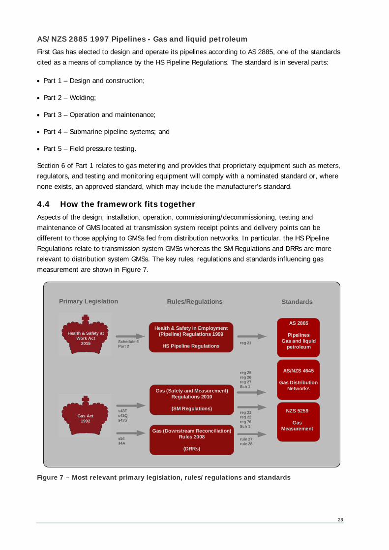
4.4 How the framework fits together Aspects of the design, installation, operation, commissioning/decommissioning, testing and maintenance of GMS located at transmission system receipt points and delivery points can be different to those applying to GMSs fed from distribution networks. In particular, the HS Pipeline Regulations relate to transmission system GMSs whereas the SM Regulations and DRRs are more relevant to distribution system GMSs. The key rules, regulations and standards influencing gas measurement are shown in Figure 7.
Figure 7 – Most relevant primary legislation, rules/regulations and standards
Gas Act 1992
Health & Safety at Work Act
2015
Gas (Safety and Measurement) Regulations 2010
(SM Regulations)
Gas (Downstream Reconciliation) Rules 2008
(DRRs)
Health & Safety in Employment (Pipeline) Regulations 1999
HS Pipeline Regulations
NZS 5259
Gas Measurement
Schedule 5 Part 2
s54s4A
s43Fs43Qs43S
AS 2885
PipelinesGas and liquid
petroleumreg 21
rule 27rule 28
reg 21reg 22reg 76Sch 1
AS/NZS 4645
Gas Distribution Networks
Primary Legislation Rules/Regulations Standards
reg 25reg 26reg 27Sch 1
29
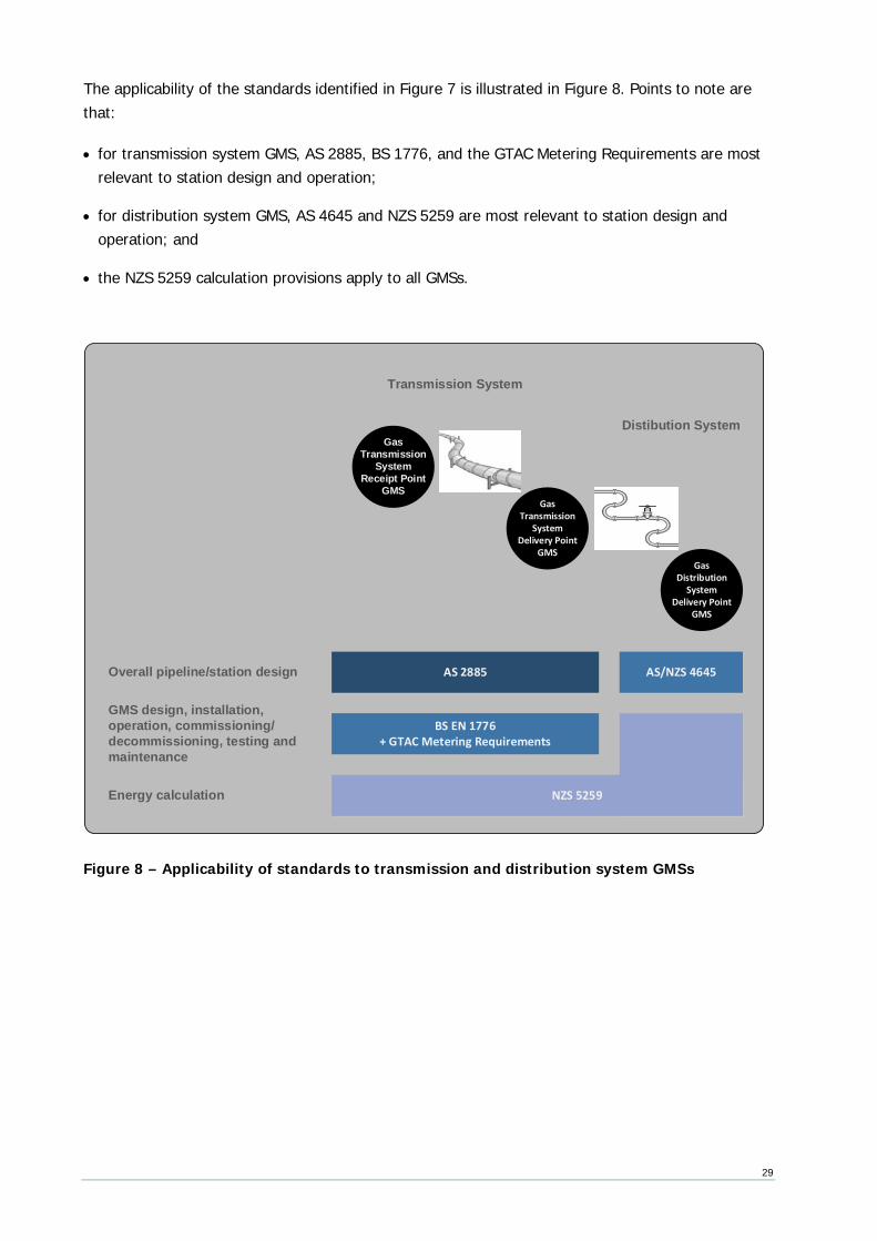
The applicability of the standards identified in Figure 7 is illustrated in Figure 8. Points to note are that:
• for transmission system GMS, AS 2885, BS 1776, and the GTAC Metering Requirements are most relevant to station design and operation;
• for distribution system GMS, AS 4645 and NZS 5259 are most relevant to station design and operation; and
• the NZS 5259 calculation provisions apply to all GMSs.
Figure 8 – Applicability of standards to transmission and distribution system GMSs
Transmission System
Distibution System
Gas Distribution
System Delivery Point
GMS
Energy calculation
Overall pipeline/station design
GMS design, installation, operation, commissioning/decommissioning, testing and maintenance
Gas Transmission
System Delivery Point
GMS
Gas Transmission
System Receipt Point
GMS
AS 2885 AS/NZS 4645
BS EN 1776+ GTAC Metering Requirements
NZS 5259
30
desig n and installation
This chapter describes the basic requirements for the design and installation of GMSs located on transmission and distribution systems.
4.5 Transmission GMS requirements The basic provisions of the GTAC and the GTAC Metering Requirements (largely reflecting BS 1776) relating to GMS design and installation are:
A GMS at a receipt points is required to have a primary and a verification meter
All receipt point GMS will allow for in-service verification of meters by having a primary meter and a verification meter that can be run in series when required. (Metering Requirements, p 14, as per BS 1775 s7.6.1)
A GMS will include a chromatograph
The gas composition will be determined by a gas chromatograph. (Metering Requirements, p 12, as per BS 1775 s6.2.3.1)
Unless otherwise agreed by First Gas, the GMS will calculate Calorific Value, Density, Relative Density and Wobbe Index in accordance with ISO 6976. (Metering Requirements, p 12, and BS 1775 s6.2.3.2)
Where relevant, meter overspeed correction is required
Where a meter could be damaged by excess flow, the GMS must include flow restricting devices (GTAC Schedule 5 s1.2(k) and Metering Requirements, p 14, as per BS 1775 s7.6.1)
A GMS at a receipt point will include a filter/separator
A receipt point GMS must include a filter/separator immediately upstream of the meter to remove contaminants larger than 3 microns. (Metering Requirements, p 14, as per BS 1775 s7.17)
A GMS will permit remote monitoring by First Gas
Every GMS will include equipment to enable First Gas to remotely monitor it, retrieve data and other information and (if required) control any of its equipment. That equipment may at First Gas’ discretion include a remote terminal unit for First Gas’ SCADA (‘Supervisory, Control and Data Acquisition’) system, radio or other communications equipment, and related ancillary equipment. (GTAC Schedule 5 s1.3 and Schedule 6 s1.3)
An uninterruptible power supply (UPS) may be required
31
If an external supply of electricity is required to operate any GPS equipment, a UPS must be installed, incorporating batteries providing 4 hours supply to critical equipment. (GTAC Schedule 5 s1.7 and Schedule 6 s1.9)
First Gas approvals required
The GMS owner, if not First Gas, will require First Gas approval of:
• the GMS design; and
• the calibration certificates for all major GMS components.
(Metering Requirements, p 15, and BS 1775 Annex F)
Design for self-diagnosis and automatic malfunction alarms
Coriolis meters must have a self-diagnostic capability.
All GMS designs will allow for agreed malfunction signals to be sent to the GMS owner and First Gas. (Metering Requirements, p 14, as per BS 1775 s11.3)
. istribut ion re quireme nts
The basic provisions of NZS 5259 relating to GMS design and installation are:
NZS 5259 s2.2 - General requirements
• General Every GMS shall be suitable for the duty required.
• Safety Every GMS shall be designed and manufactured to ensure hazards and risks are eliminated or reduced to be as low as practicable.
• Materials Every GMS shall be made of materials and be constructed to withstand likely physical, chemical and thermal conditions and fulfil its purpose for its service life. Every GMS exposed to outdoor environments shall be suitable for the New Zealand climate.
• Soundness Every GMS that will be exposed to gas pressure shall be gastight up to its maximum working pressure.
• Integrity of data Data transmitted between components or stored in the GMS shall be accurate to meet the maximum permissible errors (MPEs) of table 2 and 3 NZS 5259.
• Traceability of data Every GMS shall accurately and traceably store or record data and transmit those data between components.
• Protection against external interference Every GMS shall be designed, manufactured and installed such that interference or tampering capable of affecting accuracy is discouraged and is readily detectible.
32
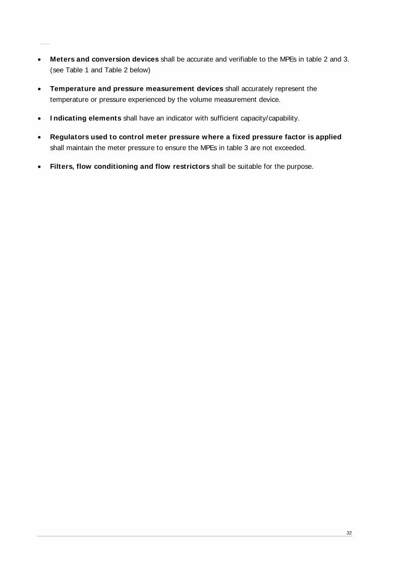
. - pecific suita bil ity re quireme nts
• Meters and conversion devices shall be accurate and verifiable to the MPEs in table 2 and 3. (see Table 1 and Table 2 below)
• Temperature and pressure measurement devices shall accurately represent the temperature or pressure experienced by the volume measurement device.
• Indicating elements shall have an indicator with sufficient capacity/capability.
• Regulators used to control meter pressure where a fixed pressure factor is applied shall maintain the meter pressure to ensure the MPEs in table 3 are not exceeded.
• Filters, flow conditioning and flow restrictors shall be suitable for the purpose.
33
5. GMS operation and maintenance
This chapter describes the basic requirements for the operation and maintenance of GMSs located on transmission and distribution systems.
5.1 Transmission GMS operation and maintenance The basic provisions of the GTAC and the GTAC Metering Requirements (largely reflecting BS 1776) relating to GMS operation and maintenance are:
Planned maintenance schedules to be available
The Metering Owner will provide reasonable technical information relating to the GMS and a copy of its planned maintenance schedules. (GTAC Schedule 5 s4.4 and Schedule 6 s4.4)
Calorific value determination devices (CVDDs) to be tested at least every 6 months
Each CVDD will be programmed to auto-calibrate at least weekly and CV determination will be verified by a calibration laboratory at intervals of no more than 6 months. (Metering Requirements, p 16, and BS 1775 s11.5)
First Gas approvals required
The GMS owner, if not First Gas, will require First Gas approval of:
• the maintenance plan for all major GMS components; and
• the plan for GMS fault detection and rectification.
(Metering Requirements, p 15, and BS 1775 Annex F)
5.2 Distribution GMS operation and maintenance The basic provisions of NZS 5259 relating to GMS operation and maintenance are:
GMS components are to be operated and maintained to ensure overall accuracy
The performance of GMS components and populations of GMS components shall be monitored to ensure that in-service performance requirements of NZS 5259 tables 2 and 3 are met (see Table 1 and Table 2 below). (NZS 5259 s1.2.6)
Plans and procedures for safe operation are to be described, documented and implemented
(NZS 5259 2.1.5)

34
The on-going performance of meters and conversion devices are to be monitored for accuracy
(NZS 5259 2.5 through to 2.5.2)
There will be a preventative maintenance programme for all GMSs based on regular inspections and reported faults
(NZS 5259 2.5.3 and 2.5.4)
35
6. GMS testing
This chapter describes the basic requirements for testing of GMSs located on transmission and distribution systems.
6.1 Transmission GMS testing The basic provisions of the GTAC and the GTAC Metering Requirements (largely reflecting BS 1776) relating to GMS testing are:
New GMS to be tested
The Metering Owner will test each new custody transfer GMS before that Metering is placed into service. Where there is a verification meter, an in-situ verification test will be performed as soon as practicable after that metering is placed into service.
If the Metering is found to be inaccurate, the Metering Owner will service, repair, re-calibrate or replace it, then re-test it to establish that it is Accurate. The Metering Owner will provide written evidence of testing. (GTAC Schedule 5 s4.4 and Schedule 6 s4.4)
First Gas representatives may witness maintenance
The GMS owner must permit a First Gas representative to witness any maintenance. (Metering Requirements, p 15, and BS 1775 Annex F)
6.2 Distribution GMS testing The basic provisions of NZS 5259 relating to GMS testing24 are:
All components of a GMS that may affect accuracy are to pass acceptance testing prior to installation
For meters, acceptance testing shall confirm identity, gas tightness, and accuracy of registration. The acceptance test comprises:
(a) identification test (NZS 5259 s3.4.5.1);
(b) external leakage test (NZS 5259 s 3.4.5.4);
(c) accuracy of registration test (NZS 5259 s 3.4.5.6); and
24 The standard also provides specific requirements for testing equipment and test areas in its appendices (Requirements of testing equipment and test area 2.3.5)
36
(d) internal leakage test (NZS 5259 s 3.4.5.9).
For conversion devices, acceptance testing shall confirm identity and accuracy of conversion.
(NZS 5259 s1.2.4)
All components of a GMS that may affect the accuracy shall pass an acceptance test:
• before a new device is placed in service;
• if anything that may affect its accuracy has occurred; and
• before a device is returned to service if 12 months has elapsed since acceptance testing.
(NZS 5259 s2.3.1)
The acceptance test for meters comprises:
• identification test;
• external leakage test;
• accuracy of registration test; and
• internal leakage test.
(NZS 5259 s2.3.3.1)
The acceptance test for conversion devices comprises:
• identification test; and
• accuracy of conversions test.
(NZS 5259 s2.3.4.1)
An as-found test may serve as an acceptance test if all the tests specified for an acceptance test were carried out and no repairs, maintenance or adjustment which would affect the calibration of the meter or conversion device have been carried out subsequently.
(NZS 5259 s2.3.7)
Meters and conversion devices removed from service are to be subject to as-found testing
The as-found test for meters comprises an accuracy of registration test.
The as-found test for conversion devices comprises an accuracy of conversion test.
(NZS 5259 s2.3.3.2 and s2.3.4.2)
37
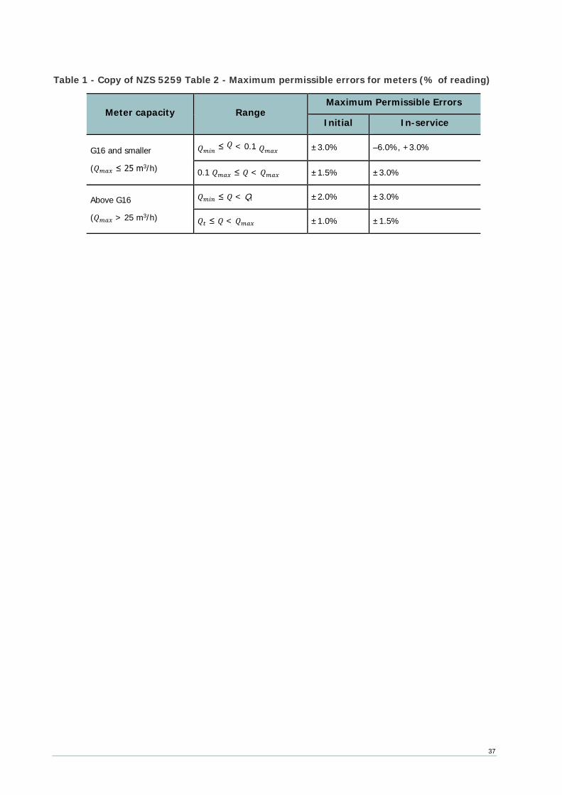
Table 1 - Copy of NZS 5259 Table 2 - Maximum permissible errors for meters (% of reading)
Meter capacity Range Maximum Permissible Errors
Initial In-service
G16 and smaller
(𝑄𝑄𝑚𝑚𝑚𝑚𝑚𝑚 ≤ 25 m3/h)
𝑄𝑄𝑚𝑚𝑚𝑚𝑚𝑚 ≤ 𝑄𝑄 < 0.1 𝑄𝑄𝑚𝑚𝑚𝑚𝑚𝑚 ±3.0% –6.0%, +3.0%
0.1 𝑄𝑄𝑚𝑚𝑚𝑚𝑚𝑚 ≤ 𝑄𝑄 < 𝑄𝑄𝑚𝑚𝑚𝑚𝑚𝑚 ±1.5% ±3.0%
Above G16
(𝑄𝑄𝑚𝑚𝑚𝑚𝑚𝑚 > 25 m3/h)
𝑄𝑄𝑚𝑚𝑚𝑚𝑚𝑚 ≤ 𝑄𝑄 < Qt ±2.0% ±3.0%
𝑄𝑄𝑡𝑡 ≤ 𝑄𝑄 < 𝑄𝑄𝑚𝑚𝑚𝑚𝑚𝑚 ±1.0% ±1.5%
38
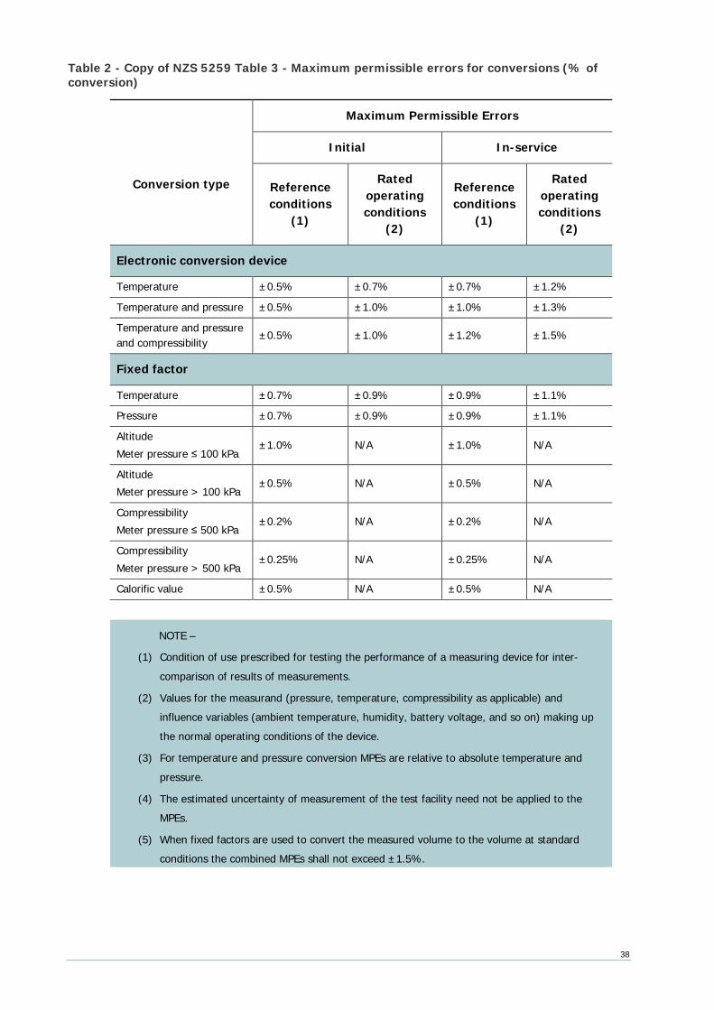
Table 2 - Copy of NZS 5259 Table 3 - Maximum permissible errors for conversions (% of conversion)
Conversion type
Maximum Permissible Errors
Initial In-service
Reference conditions
(1)
Rated operating conditions
(2)
Reference conditions
(1)
Rated operating conditions
(2)
Electronic conversion device
Temperature ±0.5% ±0.7% ±0.7% ±1.2%
Temperature and pressure ±0.5% ±1.0% ±1.0% ±1.3%
Temperature and pressure and compressibility ±0.5% ±1.0% ±1.2% ±1.5%
Fixed factor
Temperature ±0.7% ±0.9% ±0.9% ±1.1%
Pressure ±0.7% ±0.9% ±0.9% ±1.1%
Altitude Meter pressure ≤ 100 kPa
±1.0% N/A ±1.0% N/A
Altitude Meter pressure > 100 kPa
±0.5% N/A ±0.5% N/A
Compressibility Meter pressure ≤ 500 kPa
±0.2% N/A ±0.2% N/A
Compressibility Meter pressure > 500 kPa
±0.25% N/A ±0.25% N/A
Calorific value ±0.5% N/A ±0.5% N/A
NOTE –
(1) Condition of use prescribed for testing the performance of a measuring device for inter-comparison of results of measurements.
(2) Values for the measurand (pressure, temperature, compressibility as applicable) and influence variables (ambient temperature, humidity, battery voltage, and so on) making up the normal operating conditions of the device.
(3) For temperature and pressure conversion MPEs are relative to absolute temperature and pressure.
(4) The estimated uncertainty of measurement of the test facility need not be applied to the MPEs.
(5) When fixed factors are used to convert the measured volume to the volume at standard conditions the combined MPEs shall not exceed ±1.5%.
39
7. GMS documentation
This chapter describes the basic requirements for GMS-related documentation on transmission and distribution systems.
7.1 Transmission GMS documentation The basic provisions of MPOC Schedule 1 and the Vector Metering Requirements relating to GMS documentation are:
Each Metering Owner to maintain a Metering Manual
The GMS owner will maintain a Metering Manual describing the GMS design, the maintenance plan for all major measuring system components, the fault detection and rectification plan and an archive of the calibration certificates for all major measuring system components. The Metering Manual will be available for First Gas inspection at any time. (GTAC Metering Requirements p15, and BS1775 s7.23 and Annex F)
Test records to be available
On request of the other party, the Metering Owner will provide reasonable technical information relating to the GMS and the results of any testing. First Gas may publish a summary of the results of such testing (whether scheduled or unscheduled) on OATIS. (GTAC Schedule 5 s4.3 and Schedule 6 s4.3)
Calibration testing records to be available for inspection and kept for 7 years
The calibration certificates for all major components of the GMS are to be kept and the calibration/verification and maintenance records to be viewed by any party with a direct interest in the GMS measurements25. The owner of the measuring system shall retain records of all testing for not less than 7-years and provide an Affected Party with copies on request. (Metering Requirements, p 15, and BS 1775 Annex F)
7.2 Distribution GMS documentation The basic provisions of NZS 5259 relating to GMS documentation are:
Records are to be kept for all GMS components and complete systems
25 This includes First Gas. The Metering Requirements document uses the term ‘Affected Party’ to refer to a party to an ICA or TSA, a Gas Transfer Agent or Allocation Agent with a direct interest in a GMS. However, the same term has a different meaning in the GTAC, where it means a party affected by a force majeure event. To avoid confusion, we refer to ‘any party with a direct interest in the GMS measurements’.
40
The records for the GMS components will include:
• the suitability of all gas meters, conversion devices, regulators, filters, flow conditioning devices, flow restrictors, temperature measurement elements and pressure measurement elements;
• acceptance testing, installation, operating conditions and maintenance of the components of the GMS;
• information for each type of regulator used including the ranges of operating conditions for which it is suitable and its performance over those conditions;
• the results of acceptance and as-found tests; and
• the date and details of all maintenance.
In relation to each complete GMS, records will be kept detailing all inspections, maintenance and changes to components. This will include:
• The identity, location and date of installation of each installed component;
• Periodic maintenance test results, including time, date, operator;
• The next scheduled date for maintenance; and
• The next scheduled date for test or replacement.
(NZS 5259 1.2.8, 2.2.6, 2.6.1 and 2.6.2)
A record of the factor is to be kept where a fixed factor is applied
(NZS 5259 2.7.3.2)
There is to be documented procedures for the conversion of volume to energy
(NZS 5259 2.7.5)
Competency of persons involved in critical GMS activities is to be described and documented
(NZS 5259 1.2.9 and 2.8)
Management policies to ensure safe management and operation are to be recorded and reviewed
(NZS 5259 2.1.5)
Records of testing procedures and test results are to be kept
(NZS 5259 2.3.3, 2.3.4 and 2.3.9)

41
The results of monitoring the on-going performance of meters and conversion devices for accuracy are to be documented
(NZS 5259 2.5 including 2.5.3.6)
42
8. Auditing
The DRRs have auditing provisions intended to ensure that allocation participants comply with the Rules. Event audits can be commissioned for instances where there is a particular issue that needs investigating, such as abnormally high levels of unaccounted-for gas. In such a case, it is likely that the auditor would want to examine the installation and maintenance records of GMSs that could be contributing to the problem.
Laboratories that undertake GMS testing are subject to audit to achieve their International Accreditation New Zealand accreditation, but this has a relatively narrow focus and does not extend to the design and installation of meters or other activities undertaken by technicians in the field.
NZS 5259 s2.10 provides that: ‘Requirements for audit and review in order to verify compliance with this standard shall be described, documented, and implemented.’ NZS 5259 Appendix C provides an extensive audit checklist. It is for the documents that reference the Standard to specify how often, and by whom, an audit should be conducted.
43
Glossary
CV Calorific Value, the energy content of a gas, usually measured in units of MJ/scm
GMS A Gas Act term meaning a system for measuring the quantity of any gas or the energy content of any gas, whether by actual measurement or estimation; and includes any equipment that forms part of, or is ancillary to, any such system
Open Access Transmission Information System (OATIS)
A GTAC term meaning First Gas’ internet-based open access transmission information system or any replacement system, whose homepage First Gas shall notify to Shippers and Interconnected Parties
Points of transfer A point where gas moves from one system to another, including from gas producer to transmission system; from transmission system to a major user or distribution network (gate station), or from distribution system to end user (ICP)
scm Standard cubic meters, a volume measured at standard conditions
Standard conditions A temperature of 15 degrees centigrade (⁰C) and a pressure 101.325 kilopascals (KPa)
Time of Use (ToU) Refers to gas measurement systems that record the gas quantities that have passed during fixed time intervals, such as every hour or every day. These quantities are recorded on a data logging device.
44
Appendix A Governance of this Document
Gas Industry Co wishes this document to accurately reflect the views of industry participants on what the requirements for gas reconciliation are and how they are managed. It is also necessary to provide arrangements that allow any participant to propose changes, to have that proposal considered and for a new version of the document to be issued if required. These arrangements are described in this Appendix.
Proposing changes Any person may propose a change to this document by writing to Gas Industry Co describing the proposed change and the reasons why the person believes it is worth making.
Processing proposed changes On receiving a request to change the document, Gas Industry Co will discuss it with the proposer and seek comment from industry experts before making any changes.
Issuing a revised document Gas Industry Co will decide whether the document should be changed or not but, regardless of its decision, it will maintain a register of all proposed changes together with a summary of any issues arising. When reissued, the document will be given a revision number and a table of revisions will be included in the document.