G ONE - Audiotec Fischer
20
G ONE 1-Kanal Class D Verstärker 1-channel Class D amplifier deutsch / english
-
Upload
khangminh22 -
Category
Documents
-
view
1 -
download
0
Transcript of G ONE - Audiotec Fischer
G ONE1-Kanal Class D Verstärker1-channel Class D amplifier
deut
sch
/ eng
lish

Sehr geehrter Kunde,
Wir gratulieren Ihnen zum Kauf dieses hochwer-tigen HELIX Verstärkers.
Audiotec Fischer setzt mit der HELIX G ONE neue Maßstäbe in puncto Preis-Leistungsverhältnis. Dabei profitieren Sie als Kunde direkt von unserer nahezu 30-jährigen Erfahrung in der Forschung und Entwicklung von Audiokomponenten.
Dieser Verstärker wurde von uns nach neuesten technischen Erkenntnissen entwickelt und zeichnet sich durch hervorragende Verarbeitung und eine überzeugende Anwendung ausgereifter Technolo-gien aus.
Viel Freude an diesem Produkt wünscht Ihnen dasTeam von
AUDIOTEC FISCHER
Allgemeines zum Einbau von HELIX-Kompo-nenten
Um alle Möglichkeiten des Produktes optimal aus-schöpfen zu können, lesen Sie bitte sorgfältig die nachfolgenden Installationshinweise. Wir garantie-ren, dass jedes Gerät vor Versand auf seinen ein-wandfreien Zustand überprüft wurde.
Vor Beginn der Installation unterbrechen Sie den Minusanschluss der Autobatterie. Wir empfehlen Ihnen, die Installation von einem Einbauspezialisten vornehmen zu lassen, da der Nachweis eines fachgerechten Einbaus und An-schlusses des Gerätes Voraussetzung für die Ga-rantieleistungen sind.
Installieren Sie Ihren Verstärker an einer trocke-nen Stelle im Auto und vergewissern Sie sich, dass der Verstärker am Montageort genügend Kühlung erhält. Montieren Sie das Gerät nicht in zu kleine, abgeschlossene Gehäuse ohne Luftzirkulation oder in der Nähe von wärmeabstrahlenden Teilen oder elektronischen Steuerungen des Fahrzeuges. Im Sinne der Unfallsicherheit muss der Verstärker professionell befestigt werden. Dieses geschieht über Schrauben, die in eine Montagefläche ein-geschraubt werden, die wiederum genügend Halt bieten muss.
Bevor Sie die Schrauben im Montagefeld befesti-gen, vergewissern Sie sich, dass keine elektrischen Kabel und Komponenten, hydraulische Bremslei-tungen, der Benzintank etc. dahinter verborgen
sind. Diese könnten sonst beschädigt werden. Ach-ten Sie bitte darauf, dass sich solche Teile auch in der doppelten Wandverkleidung verbergen können.
Allgemeines zum Anschluss des G ONE Ver-stärkers
Der Verstärker darf nur in Kraftfahrzeuge eingebaut werden, die den 12 V-Minuspol an Masse haben. Bei anderen Systemen können der HELIX Verstär-ker und die elektrische Anlage des Kfz beschädigt werden. Die Plusleitung für die gesamte Anlage sollte in einem Abstand von max. 30 cm von der Batterie mit einer Hauptsicherung abgesichert wer-den. Der Wert der Sicherung errechnet sich aus der maximalen Stromaufnahme der Car-Hifi Anlage.
Verwenden Sie zum Anschluss des Verstärkers an die Stromversorgung des Fahrzeugs aus-schließlich geeignete Kabel mit ausreichen-dem Kabelquerschnitt. Die Sicherungen im Verstärker dürfen nur mit den gleichen Werten (3 x 40 A) ersetzt werden, um eine Beschädi-gung des Gerätes zu verhindern. Höhere Werte können zu gefährlichen Folgeschäden führen!
Die Kabelverbindungen müssen so verlegt sein, dass keine Klemm-, Quetsch- oder Bruchgefahr be-steht. Bei scharfen Kanten (Blechdurchführungen) müssen alle Kabel gegen Durchscheuern gepols-tert sein. Ferner darf das Versorgungskabel niemals mit Zuleitungen zu Vorrichtungen des Kfz (Lüfter-motoren, Brandkontrollmodulen, Benzinleitungen etc.) verlegt werden.
Herzlichen Glückwunsch!
2
Allgemeine Hinweise
Anschluss- und Bedienelemente
3
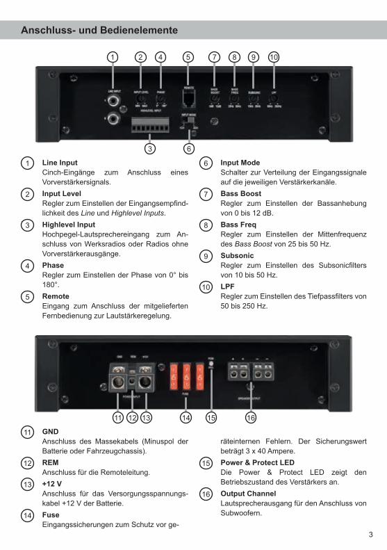
11 GND Anschluss des Massekabels (Minuspol der
Batterie oder Fahrzeugchassis).
12 REM Anschluss für die Remoteleitung.
13 +12 V Anschluss für das Versorgungsspannungs-
kabel +12 V der Batterie.
14 Fuse Eingangssicherungen zum Schutz vor ge-
räteinternen Fehlern. Der Sicherungswert beträgt 3 x 40 Ampere.
15 Power & Protect LED Die Power & Protect LED zeigt den
Betriebszustand des Verstärkers an.
16 Output Channel Lautsprecherausgang für den Anschluss von
Subwoofern.
1 Line Input Cinch-Eingänge zum Anschluss eines
Vorverstärkersignals.
2 Input Level Regler zum Einstellen der Eingangsempfind-
lichkeit des Line und Highlevel Inputs. .
3 Highlevel Input Hochpegel-Lautsprechereingang zum An-
schluss von Werksradios oder Radios ohne Vorverstärkerausgänge.
4 Phase Regler zum Einstellen der Phase von 0° bis
180°.
5 Remote Eingang zum Anschluss der mitgelieferten
Fernbedienung zur Lautstärkeregelung.
6 Input Mode Schalter zur Verteilung der Eingangssignale
auf die jeweiligen Verstärkerkanäle.
7 Bass Boost Regler zum Einstellen der Bassanhebung
von 0 bis 12 dB.
8 Bass Freq Regler zum Einstellen der Mittenfrequenz
des Bass Boost von 25 bis 50 Hz.
9 Subsonic Regler zum Einstellen des Subsonicfilters
von 10 bis 50 Hz.
10 LPF Regler zum Einstellen des Tiefpassfilters von
50 bis 250 Hz.
11 12 1513 14 16
1 2 5 7 8 9
3
104
6
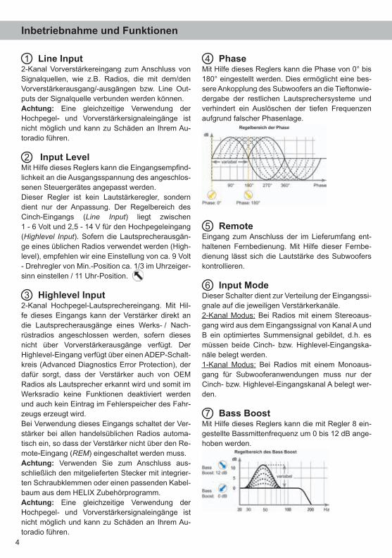
1 Line Input2-Kanal Vorverstärkereingang zum Anschluss von Signalquellen, wie z.B. Radios, die mit dem/den Vorverstärkerausgang/-ausgängen bzw. Line Out-puts der Signalquelle verbunden werden können.Achtung: Eine gleichzeitige Verwendung der Hochpegel- und Vorverstärkersignaleingänge ist nicht möglich und kann zu Schäden an Ihrem Au-toradio führen.
2 Input LevelMit Hilfe dieses Reglers kann die Eingangsempfind-lichkeit an die Ausgangsspannung des angeschlos-senen Steuergerätes angepasst werden.Dieser Regler ist kein Lautstärkeregler, sondern dient nur der Anpassung. Der Regelbereich des Cinch-Eingangs (Line Input) liegt zwischen 1 - 6 Volt und 2,5 - 14 V für den Hochpegeleingang (Highlevel Input). Sofern die Lautsprecherausgän-ge eines üblichen Radios verwendet werden (High-level), empfehlen wir eine Einstellung von ca. 9 Volt - Drehregler von Min.-Position ca. 1/3 im Uhrzeiger-sinn einstellen / 11 Uhr-Position.
3 Highlevel Input2-Kanal Hochpegel-Lautsprechereingang. Mit Hil-fe dieses Eingangs kann der Verstärker direkt an die Lautsprecherausgänge eines Werks- / Nach-rüstradios angeschlossen werden, sofern dieses nicht über Vorverstärkerausgänge verfügt. Der Highlevel-Eingang verfügt über einen ADEP-Schalt-kreis (Advanced Diagnostics Error Protection), der dafür sorgt, dass der Verstärker auch von OEM Radios als Lautsprecher erkannt wird und somit im Werksradio keine Funktionen deaktiviert werden und auch kein Eintrag im Fehlerspeicher des Fahr-zeugs erzeugt wird. Bei Verwendung dieses Eingangs schaltet der Ver-stärker bei allen handelsüblichen Radios automa-tisch ein, so dass der Verstärker nicht über den Re-mote-Eingang (REM) eingeschaltet werden muss.Achtung: Verwenden Sie zum Anschluss aus-schließlich den mitgelieferten Stecker mit integrier-ten Schraubklemmen oder einen passenden Kabel-baum aus dem HELIX Zubehörprogramm.Achtung: Eine gleichzeitige Verwendung der Hochpegel- und Vorverstärkersignaleingänge ist nicht möglich und kann zu Schäden an Ihrem Au-toradio führen.
4 PhaseMit Hilfe dieses Reglers kann die Phase von 0° bis 180° eingestellt werden. Dies ermöglicht eine bes-sere Ankopplung des Subwoofers an die Tieftonwie-dergabe der restlichen Lautsprechersysteme und verhindert ein Auslöschen der tiefen Frequenzen aufgrund falscher Phasenlage.
5 Remote Eingang zum Anschluss der im Lieferumfang ent-haltenen Fernbedienung. Mit Hilfe dieser Fernbe-dienung lässt sich die Lautstärke des Subwoofers kontrollieren.
6 Input ModeDieser Schalter dient zur Verteilung der Eingangssi-gnale auf die jeweiligen Verstärkerkanäle.2-Kanal Modus: Bei Radios mit einem Stereoaus-gang wird aus dem Eingangssignal von Kanal A und B ein optimiertes Summensignal gebildet, d.h. es müssen beide Cinch- bzw. Highlevel-Eingangska-näle belegt werden. 1-Kanal Modus: Bei Radios mit einem Monoaus-gang für Subwooferanwendungen muss nur der Cinch- bzw. Highlevel-Eingangskanal A belegt wer-den.
7 Bass BoostMit Hilfe dieses Reglers kann die mit Regler 8 ein-gestellte Bassmittenfrequenz um 0 bis 12 dB ange-hoben werden.
Inbetriebnahme und Funktionen
4

5
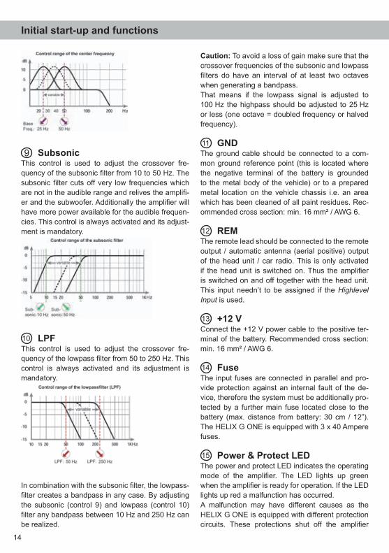
8 Bass FrequenzMit Hilfe dieses Reglers kann die Mittenfrequenz des Bass Boost von 25 Hz bis 50 Hz eingestellt werden. Mit dem Regler 7 kann diese dann um 0 bis 12 dB angehoben werden. Dies ist sinnvoll, wenn bestimmte Frequenzen des Subwoofers oder Kickbasses hervorgehoben oder korrigiert werden sollen.
9 SubsonicMit Hilfe dieses Reglers kann der Subsonicfilter von 10 Hz bis 50 Hz eingestellt werden. Dieses Filter dient dazu, sehr tiefe Frequenzen außerhalb des Hörspektrums herauszufiltern und so den Sub-woofer und den Verstärker zu entlasten, um mehr Leistung für die wahrnehmbaren Frequenzen zur Verfügung zu haben. Dieser Regler ist immer aktiv und muss zwingend eingestellt werden.
10 LPFMit Hilfe dieses Reglers kann das Tiefpassfilter von 50 bis 250 Hz eingestellt werden. Dieser Regler ist immer aktiv und muss zwingend eingestellt werden.
Das Tiefpassfilter bildet in Verbindung mit dem Sub-sonicfilter in jedem Fall einen Bandpass.So kann mit Hilfe dieser beiden Regler ein Band-pass von 10 Hz bis 250 Hz gebildet werden.Achtung: Bitte vergewissern Sie sich, dass beim Einstellen eines Bandpasses die Übernahmefre-quenzen von Subsonic- und Tiefpassfilter minde-stens zwei Oktaven auseinander liegen, um einen Pegelverlust zu vermeiden! Das heißt: Wird das Tiefpasssignal z.B. auf 100 Hz eingestellt, so sollte der Subsonicfilter um mindestens zwei Oktaven tiefer auf ca. 25 Hz eingestellt werden. (1 Oktave = Frequenzverdopplung oder Frequenzhalbierung).
11 GNDDas Massekabel sollte am zentralen Massepunkt (dieser befindet sich dort wo der Minuspol der Bat-terie zum Metallchassis des Kfz geerdet ist) oder an einer blanken, von Lackresten befreiten Stelle des Kfz-Chassis angeschlossen werden. Der empfohle-ne Querschnitt beträgt mindestens 16 mm².
12 REMDie Remoteleitung wird mit dem Remote-Ausgang /Antennenanschluss des Steuergerätes (Radio) ver-bunden. Dieser ist nur aktiviert, wenn das Steuer-gerät eingeschaltet ist. Somit wird der Verstärker mit dem Steuergerät ein- und ausgeschaltet. Dieser Eingang muss nicht belegt werden, wenn der Hochpegel-Lautsprechereingang (Highlevel Input) benutzt wird.
13 +12 VDas +12 V Versorgungskabel ist am Pluspol der Batterie anzuschließen. Der empfohlene Quer-schnitt beträgt mindestens 16 mm².
14 FuseDie Eingangssicherungen sind parallel geschaltet und schützen vor einem geräteinternen Fehler, d.h. die Anlage muss mit einer zusätzlichen Sicherung in Nähe der Batterie (max. 30 cm entfernt) abgesi-chert werden. Der Sicherungswert für den Verstär-ker beträgt 3 x 40 Ampere.
15 Power & Protect LEDDie Power & Protect LED zeigt den Betriebszustand des Verstärkers an. Leuchtet die LED grün, ist der Verstärker eingeschaltet und betriebsbereit.
6
Die HELIX G ONE wird wie nachfolgend be-schrieben an das Autoradio angeschlossen.
Achtung: Für die Durchführung der nachfolgenden Schritte werden Spezialwerkzeuge und Fachwissen benötigt. Um Anschlussfehler und Beschädigungen zu vermeiden, fragen Sie im Zweifelsfall Ihren Ein-bauspezialisten und beachten Sie zwingend die allgemeinen Anschluss- und Einbauhinweise (siehe Seite 2).
1. Anschluss der VorverstärkereingängeDiese Eingänge (Line Input) können mit ent-sprechenden Kabeln (RCA / Cinch-Kabel) an die Vorverstärker- / Lowlevel- / Cinch-Ausgän-ge des Radios angeschlossen werden. Dabei müssen nicht zwingend beide Eingän-ge belegt werden. Wird nur ein Kanal belegt, ist Kanal A zu verwenden und den Input Mode Schalter auf „1CH“ zu stellen. Bei Belegung bei-der Kanäle wählen Sie bitte die Schalterstellung „2CH“ (siehe Seite 4 Punkt 6; Input Mode). Die Einschaltautomatik des Verstärkers funk-tioniert bei den Vorverstärkereingängen nicht, so dass der Remote-Eingang (REM) zwingend belegt werden muss.Achtung: Eine gleichzeitige Verwendung der Hochpegel- und Vorverstärkersignaleingänge ist nicht möglich und kann zu Schäden an Ihrem Autoradio führen.
2. Anschluss der Highlevel-Lautsprecherein-gängeDie Hochpegel-Lautsprechereingänge A und B (High level Input) können direkt mit den Laut-
sprecherausgängen des Werks- bzw. Nachrü-stradios mit Hilfe entsprechender Kabel (Laut-sprecherkabel mit max. 1 mm² Querschnitt) verbunden werden. Dabei müssen nicht zwingend beide Eingänge belegt werden. Wird nur ein Kanal belegt, emp-fehlen wir den Kanal A zu verwenden und den Input Mode Schalter auf „1CH“ zu stellen. Bei Belegung beider Kanäle wählen Sie bitte die Schalterstellung „2CH“ (siehe Seite 4 Punkt 6; Input Mode). Achten Sie bitte auf eine korrekte Polung! Wenn Sie einen Anschluss verpolen, kann da-durch die Funktion des Verstärkers beeinträch-tigt werden. Bei Verwendung dieses Eingangs muss der Remote-Eingang (REM) nicht belegt werden, da sich der Verstärker automatisch ein-schaltet, sobald ein Lautsprechersignal anliegt.
3. Einstellung der EingangsempfindlichkeitAchtung: Es ist zwingend notwendig die Eingangsempfindlichkeit der G ONE an die Signalquelle anzupassen, um Schäden am Verstärker zu vermeiden. Um die Eingangsempfindlichkeit zu verändern, verwenden Sie den Drehregler (siehe Seite 4 Punkt 2; Input Level). Die Einstellung dieses Reglers beeinflusst sowohl die Vorverstärke-reingänge (Line Input) als auch die Hochpegel-Lautsprechereingänge (Highlevel Input)! Sofern die Lautsprecherausgänge eines üblichen Ra-dios verwendet werden (Highlevel), empfehlen wir eine Einstellung von ca. 9 Volt - Drehregler von Min.-Position ca. 1/3 im Uhrzeigersinn ein-stellen / 11 Uhr-Position.
Bei rot leuchtender LED besteht eine Fehlfunktion des Verstärkers. Diese Fehlfunktion kann unter-schiedliche Ursachen haben, da die G ONE mit verschiedenen elektronischen Schutzschaltungen ausgestattet ist. Diese schalten den Verstärker bei Überhitzung, Über- und Unterspannung, Kurz-schluss am Lautsprecherausgang und Fehlan-schluss ab. Prüfen Sie in diesem Fall alle Anschlüs-se auf Fehler, wie z.B. Kurzschlüsse, fehlerhafte
Verbindungen oder Falscheinstellungen und Über-temperatur. Sollte sich der Verstärker nach Besei-tigung der Fehlerquelle nicht wieder einschalten lassen, liegt ein Defekt vor.
16 Output ChannelDieser Anschluss dient als Lautsprecherausgang. Die minimale Lastimpedanz darf 1 Ohm nicht un-terschreiten.
Einbau und Installation
Inbetriebnahme und Funktionen
7
4. Anschluss der LautsprecherausgängeDie Lautsprecherausgänge können direkt mit den Lautsprecherleitungen verbunden werden.Hinweis: Die Lautsprecherausgänge sind in-tern parallel geschaltet. D.h. an beiden Plus-Ausgängen (+) bzw. beiden Minus-Ausgängen (-) liegt jeweils das gleiche Signal an.Verbinden Sie niemals die Lautsprecherlei-tungen mit der Kfz-Masse (Fahrzeugkaros-serie). Dies kann Ihren Verstärker zerstören. Sofern Sie zwei Lautsprecher parallel anschlie-ßen, achten Sie bitte darauf, dass die Phase identisch ist, d.h. Plus zu Plus und Minus zu Minus. Vertauschen von Plus und Minus hat einen Totalverlust der Basswiedergabe zur Fol-ge. Der Pluspol ist bei den meisten Lautspre-chern gekennzeichnet. Die Gesamtimpedanz darf 1 Ohm nicht unterschreiten, da sonst die Schutzschaltung des Verstärkers aktiviert wird. Beispiele für den Lautsprecheranschluss finden Sie auf Seite 7 und 8.
5. Anschluss der Stromversorgung Vor dem Anschluss des +12 V Versorgungs-
kabels an das Bordnetz muss die Autobatte-rie abgeklemmt werden.
Das +12 V Stromkabel ist am Pluspol der Bat-terie anzuschließen. Die Plusleitung sollte in einem Abstand von max. 30 cm von der Batterie mit einer Hauptsicherung abgesichert werden. Der Wert der Sicherung errechnet sich aus der maximalen Stromaufnahme der gesamten Car-Hifi Anlage (G ONE = max. 120 A RMS bei 12 V Bordnetz).
Verwenden Sie bei kurzen Leitungen (< 1 m) einen Querschnitt von mindestens 16 mm². Bei längeren Leitungen empfehlen wir einen Quer-schnitt von 25 mm² bis 35 mm².
Das Massekabel (gleicher Querschnitt wie das +12 V Kabel) muss an einem blanken, von Lackresten befreiten Massepunkt des Kfz-Chassis oder direkt an dem Minuspol der Autobatterie angeschlossen werden.
6. Anschluss des Remote-Eingangs Der Remote-Eingang (REM) muss mit dem Re-
mote-Ausgang des Radios verbunden sein, so-fern die Vorverstärkereingänge des Verstärkers als Signaleingänge genutzt werden. Es wird dringend davon abgeraten, den Remote-Ein-gang des Verstärkers über das Zündungsplus des Fahrzeugs zu steuern, um Störgeräusche beim Ein- und Ausschalten zu vermeiden. Bei Verwendung des Highlevel-Eingangs ( Highlevel Input) muss der Remote-Eingang nicht belegt werden, sofern das angeschlossene Radio über BTL-Ausgangsstufen verfügt.
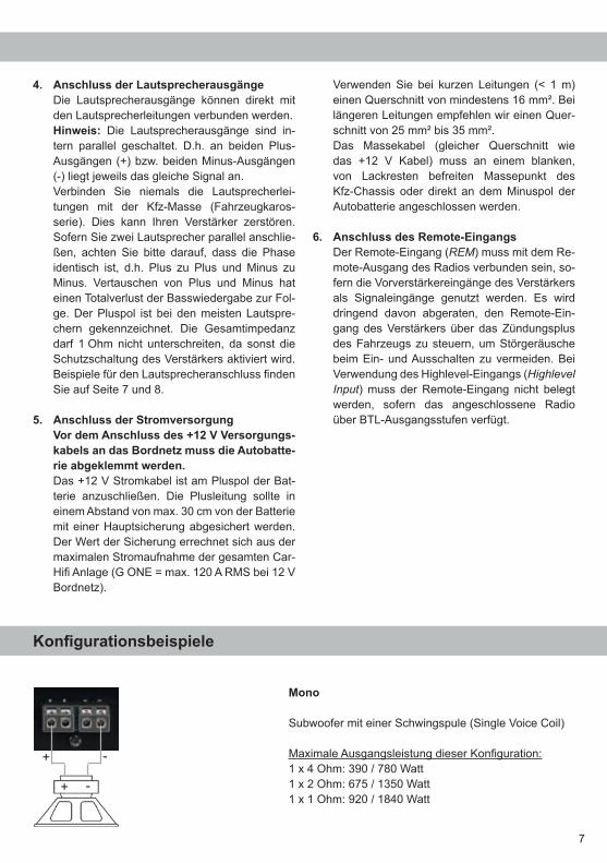
Mono
Subwoofer mit einer Schwingspule (Single Voice Coil)
Maximale Ausgangsleistung dieser Konfiguration:1 x 4 Ohm: 390 / 780 Watt1 x 2 Ohm: 675 / 1350 Watt1 x 1 Ohm: 920 / 1840 Watt
Konfigurationsbeispiele
8
Konfigurationsbeispiele
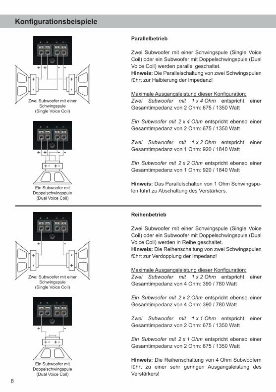
Parallelbetrieb
Zwei Subwoofer mit einer Schwingspule (Single Voice Coil) oder ein Subwoofer mit Doppelschwingspule (Dual Voice Coil) werden parallel geschaltet.Hinweis: Die Parallelschaltung von zwei Schwingspulen führt zur Halbierung der Impedanz!
Maximale Ausgangsleistung dieser Konfiguration:Zwei Subwoofer mit 1 x 4 Ohm entspricht einer Gesamtimpedanz von 2 Ohm: 675 / 1350 Watt
Ein Subwoofer mit 2 x 4 Ohm entspricht ebenso einer Gesamtimpedanz von 2 Ohm: 675 / 1350 Watt
Zwei Subwoofer mit 1 x 2 Ohm entspricht einer Gesamtimpedanz von 1 Ohm: 920 / 1840 Watt
Ein Subwoofer mit 2 x 2 Ohm entspricht ebenso einer Gesamtimpedanz von 1 Ohm: 920 / 1840 Watt
Hinweis: Das Parallelschalten von 1 Ohm Schwingspu-len führt zu Abschaltung des Verstärkers.
Zwei Subwoofer mit einer Schwingspule
(Single Voice Coil)
Ein Subwoofer mit Doppelschwingspule
(Dual Voice Coil)
Reihenbetrieb
Zwei Subwoofer mit einer Schwingspule (Single Voice Coil) oder ein Subwoofer mit Doppelschwingspule (Dual Voice Coil) werden in Reihe geschaltet.Hinweis: Die Reihenschaltung von zwei Schwingspulen führt zur Verdopplung der Impedanz!
Maximale Ausgangsleistung dieser Konfiguration:Zwei Subwoofer mit 1 x 2 Ohm entspricht einer Gesamtimpedanz von 4 Ohm: 390 / 780 Watt
Ein Subwoofer mit 2 x 2 Ohm entspricht ebenso einer Gesamtimpedanz von 4 Ohm: 390 / 780 Watt
Zwei Subwoofer mit 1 x 1 Ohm entspricht einer Gesamtimpedanz von 2 Ohm: 675 / 1350 Watt
Ein Subwoofer mit 2 x 1 Ohm entspricht ebenso einer Gesamtimpedanz von 2 Ohm: 675 / 1350 Watt
Hinweis: Die Reihenschaltung von 4 Ohm Sub woofern führt zu einer sehr geringen Ausgangsleistung des Verstärkers!
Zwei Subwoofer mit einer Schwingspule
(Single Voice Coil)
Ein Subwoofer mit Doppelschwingspule
(Dual Voice Coil)
9
Um die Installation der G ONE an ein Werks- oder Nachrüstradio deutlich zu vereinfachen, kann der Verstärker auch mit Hilfe des optional erhältlichen Easy Plug Kabels (EPC 5) angeschlossen werden. Über dieses Kabel wird die G ONE mit den Laut-sprechersignalen des Radios versorgt. Zudem muss bei dieser Installation kein Kabel des Werks-soundsystems durchtrennt werden. Das Easy Plug Kabel nutzt die Hochpegel-Lautsprechereingänge A - B.Hinweis: Die Versorgungsspannungsleitungen des Easy Plug Kabels dürfen unter keinen Um-ständen zur Spannungsversorgung des Verstär-kers verwendet werden! Im Folgenden wird der Anschluss an das Werksra-dio beschrieben:
1. Nachdem das Radio mit Hilfe der entspre-chenden Werkzeuge ausgebaut ist, trennen Sie den Fahrzeugkabelbaum vom Autoradio. Ver-binden Sie den Fahrzeugkabelbaum anschlie-ßend mit der Kupplung des Easy Plug Kabels.
Je nach Fahrzeugtyp benötigen Sie hierfür gegebenenfalls einen fahrzeugspezifischen ISO-Adapter. Eine Liste aller Fahrzeuge und der eventuell benötigten Adapter finden Sie auf www.audiotec-fischer.com.
2. Verbinden Sie die Stecker des Easy Plug Ka-bels mit dem Autoradio.
3. Verbinden Sie den Highlevel-Stecker (8-poliger Stecker) mit den jeweiligen Eingängen des Ver-stärkers. Der Stromversorgungsstecker (4-po-liger Stecker) bleibt ungenutzt!
Hinweis: MOST-BusBei einigen Fahrzeugen kann es notwendig sein, die Lichtleiterverbindung aus dem Original-Radio-anschlussstecker auszulösen und stattdessen in den Radio-Stecker eines ISO-Adapters einzuste-cken. Hierfür ist extra eine Aussparung im ISO- Adapter vorhanden. Dies ist zwingend bei allen Fahrzeugen notwendig, die einen Lichtleiteran-schluss im Originalradiokabelbaum haben.
Anschluss mit Hilfe des „Easy Plug Cables“
Intelligenter Highlevel-EingangModerne, ab Werk verbaute Autoradios werden bezüglich der Diagnose der angeschlossenen Laut-sprecher immer intelligenter. Wird ein Verstärker stattdessen an das Radio angeschlossen, kommt es meist zu Fehlermeldungen bis hin zum Wegfall einzelner Funktionen (wie z.B. Fader). Der neue ADEP-Schaltkreis (Advanced Diagnos-tics Error Protection) verhindert all diese Probleme ohne die Lautsprecherausgänge des Radios bei ho-hen Pegeln unnötig zu belasten.
Start-StopfähigkeitDas Netzteil im HELIX G ONE Verstärker stellt die interne Spannungsversorgung auch bei kurzfri-stigen Einbrüchen bis hinab zu 6 Volt sicher.Damit ist gewährleistet, dass die HELIX G ONE auch beim Motorstart voll funktionsfähig bleibt.
Spezielle Features der HELIX G ONE
10
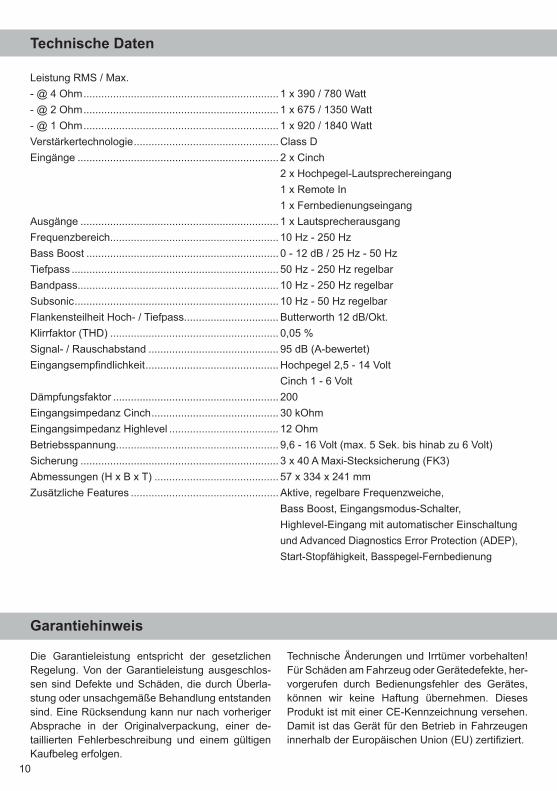
Leistung RMS / Max.- @ 4 Ohm .................................................................. 1 x 390 / 780 Watt- @ 2 Ohm .................................................................. 1 x 675 / 1350 Watt- @ 1 Ohm .................................................................. 1 x 920 / 1840 WattVerstärkertechnologie ................................................. Class DEingänge .................................................................... 2 x Cinch 2 x Hochpegel-Lautsprechereingang 1 x Remote In 1 x FernbedienungseingangAusgänge ................................................................... 1 x LautsprecherausgangFrequenzbereich......................................................... 10 Hz - 250 HzBass Boost ................................................................. 0 - 12 dB / 25 Hz - 50 HzTiefpass ...................................................................... 50 Hz - 250 Hz regelbarBandpass.................................................................... 10 Hz - 250 Hz regelbarSubsonic ..................................................................... 10 Hz - 50 Hz regelbarFlankensteilheit Hoch- / Tiefpass................................ Butterworth 12 dB/Okt.Klirrfaktor (THD) ......................................................... 0,05 %Signal- / Rauschabstand ............................................ 95 dB (A-bewertet)Eingangsempfindlichkeit ............................................. Hochpegel 2,5 - 14 Volt Cinch 1 - 6 VoltDämpfungsfaktor ........................................................ 200Eingangsimpedanz Cinch ........................................... 30 kOhmEingangsimpedanz Highlevel ..................................... 12 Ohm Betriebsspannung....................................................... 9,6 - 16 Volt (max. 5 Sek. bis hinab zu 6 Volt)Sicherung ................................................................... 3 x 40 A Maxi-Stecksicherung (FK3)Abmessungen (H x B x T) .......................................... 57 x 334 x 241 mmZusätzliche Features .................................................. Aktive, regelbare Frequenzweiche, Bass Boost, Eingangsmodus-Schalter, Highlevel-Eingang mit automatischer Einschaltung und Advanced Diagnostics Error Protection (ADEP), Start-Stopfähigkeit, Basspegel-Fernbedienung
Technische Daten
Die Garantieleistung entspricht der gesetzlichen Regelung. Von der Garantieleistung ausgeschlos-sen sind Defekte und Schäden, die durch Überla-stung oder unsachgemäße Behandlung entstanden sind. Eine Rücksendung kann nur nach vorheriger Absprache in der Originalverpackung, einer de-taillierten Fehlerbeschreibung und einem gültigen Kaufbeleg erfolgen.
Technische Änderungen und Irrtümer vorbehalten! Für Schäden am Fahrzeug oder Gerätedefekte, her-vorgerufen durch Bedienungsfehler des Gerätes, können wir keine Haftung übernehmen. Dieses Produkt ist mit einer CE-Kennzeichnung versehen. Damit ist das Gerät für den Betrieb in Fahrzeugen innerhalb der Europäischen Union (EU) zertifiziert.
Garantiehinweis
11
Dear Customer,
Congratulations on your purchase of this innovative and high-qual ity HELIX product.
The HELIX G ONE highlights best quality, excellent manufacturing and state-of-the-art technology. After 30 years of experiences in research & devel-opment of audio products this amplifier generation
sets new standards with an excellent price/perfor-mance ratio.
We wish you many hours of enjoyment with your new HELIX amplifier.
Yours,AUDIOTEC FISCHER Team
General installation instructions for HELIX components
To prevent damage to the unit and possible injury, read this manual carefully and follow all installation instructions. This product has been checked for proper function prior to shipping and is guaranteed against manufacturing defects.
Before starting your installation, disconnect the battery’s negative terminal to prevent damage to the unit, fire and/or risk of injury. For a proper performance and to ensure full warranty coverage, we strongly recommend to get this product installed by an authorized HELIX dealer.
Install your G ONE in a dry location with sufficient air circulation for proper cooling of the equipment. The amplifier should be secured to a solid mounting surface using proper mounting hardware. Before mounting, carefully examine the area around and behind the proposed installation location to ensure that there are no electrical cables or components, hydraulic brake lines or any part of the fuel tank lo-cated behind the mounting surface. Failure to do so may result in unpredictable damage to these com-ponents and possible costly repairs to the vehicle.
General instruction for connecting the HELIX G ONE amplifier
The HELIX G ONE amplifier may only be installed in vehicles which have a 12 Volts negative terminal connected to the chassis ground. Any other system could cause damage to the amplifier and the electri-cal system of the vehicle. The positive cable from the battery for the complete system should be provided with a main fuse at a distance of max. 30 cm from the battery. The val-ue of the fuse is calculated from the maximum total current input of the car audio system.
Use only suitable cables with sufficient cable cross-section for the connection of the HELIX G ONE. The fuses may only be replaced by iden-tically rated fuses (3 x 40 A) to avoid damage of the amplifier.
Prior to installation, plan the wire routing to avoid any possible damage to the wire harness. All cabling should be protected against possible crush-ing or pinching hazards. Also avoid routing cables close to potential noise sources such as electric motors, high power accessories and other vehicle harnesses.
Congratulations!
General instructions
12
Connectors and control units
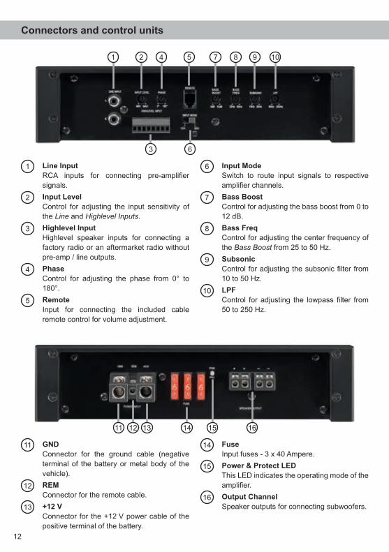
11 GND Connector for the ground cable (negative
terminal of the battery or metal body of the vehicle).
12 REM Connector for the remote cable.
13 +12 V Connector for the +12 V power cable of the
positive terminal of the battery.
14 Fuse Input fuses - 3 x 40 Ampere.
15 Power & Protect LED This LED indicates the operating mode of the
amplifier.
16 Output Channel Speaker outputs for connecting subwoofers.
1 Line Input RCA inputs for connecting pre-amplifier
signals.
2 Input Level Control for adjusting the input sensitivity of
the Line and Highlevel Inputs..
3 Highlevel Input Highlevel speaker inputs for connecting a
factory radio or an aftermarket radio without pre-amp / line outputs.
4 Phase Control for adjusting the phase from 0° to
180°.
5 Remote Input for connecting the included cable
remote control for volume adjustment.
6 Input Mode Switch to route input signals to respective
amplifier channels.
7 Bass Boost Control for adjusting the bass boost from 0 to
12 dB.
8 Bass Freq Control for adjusting the center frequency of
the Bass Boost from 25 to 50 Hz.
9 Subsonic Control for adjusting the subsonic filter from
10 to 50 Hz.
10 LPF Control for adjusting the lowpass filter from
50 to 250 Hz.
11 12 1513 14 16
1 2 5 7 8 9
3
104
6
13
Initial start-up and functions
1 Line Input2-channel pre-amplifier input to connect signal sourc es such as head units / radios / DSPs. Important: It is strictly forbidden to use the Highlevel Input and pre-amplifier inputs (Line Input) at the same time. This may cause severe damage to the pre-amplifier outputs of your head unit / car ra-dio.
2 Input LevelThis control is used to adapt the input sensitivity to the output voltage of the connected signal source. This is not a volume control, it´s only for adjusting the amplifier gain. The control range of the RCA / Line Input is 1 - 6 Volts and 2.5 - 14 Volts for the Highlevel Input.If the Highlevel Input is used with a standard car radio we recommend an input sensitivity of roughly 9 Volts - turn the control from min position to 1/3 position - 11 o’clock position.
3 Highlevel Input2-channel highlevel loudspeaker input to connect the amplifier directly to the loudspeaker outputs of OEM / aftermarket radios that do not have any pre-amplifier outputs. The Highlevel Input is equipped with our proprietary ADEP circuit (Advanced Diagnostics Error Protec-tion) which ensures that the car radio detects the amplifier as a speaker and thus neither any function of the radio (e.g. fader) will be deactivated nor any error log in the CPU of the car will be created.If this input is used the remote input (REM) does not need to be connected as the amplifier will automatically turn on once a loudspeaker signal is applied. Attention: Solely use the pluggable screw-terminal for the highlevel connector which is included in de-livery or an optional available cable harness from the HELIX accessory assortment!Important: It is strictly forbidden to use the Highlevel Input and pre-amplifier inputs (Line Input) at the same time. This may cause severe damage to the pre-amplifier outputs of your car radio.
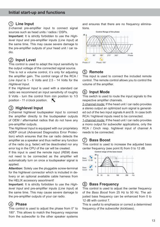
4 PhaseThis control is used to adjust the phase from 0° to 180°. This allows to match the frequency response from the subwoofer to the other speaker systems
and ensures that there are no frequency elimina-tions.
5 RemoteThis input is used to connect the included remote control. The remote control allows you to control the volume of the amplifier.
6 Input ModeThis switch is used to route the input signals to the respective amplifier channels. 2-channel mode: If the head unit / car radio provides a stereo output an optimized sum signal is generat-ed out of the two input signals A and B. In case both RCA / highlevel inputs need to be connected. 1-channel mode: If the head unit / car radio provides a mono output for subwoofer applications, only the RCA / Cinch resp. highlevel input of channel A needs to be connected.
7 Bass BoostThis control is used to increase the adjusted bass center frequency (see point 8) from 0 to 12 dB.
8 Bass FrequencyThis control is used to adjust the center frequency of the Bass Boost from 25 Hz to 50 Hz. The ad-justed bass frequency can be enhanced from 0 to 12 dB with control 7. This is useful to emphasize or correct a determined frequency of the subwoofer (kickbass).
14
Initial start-up and functions
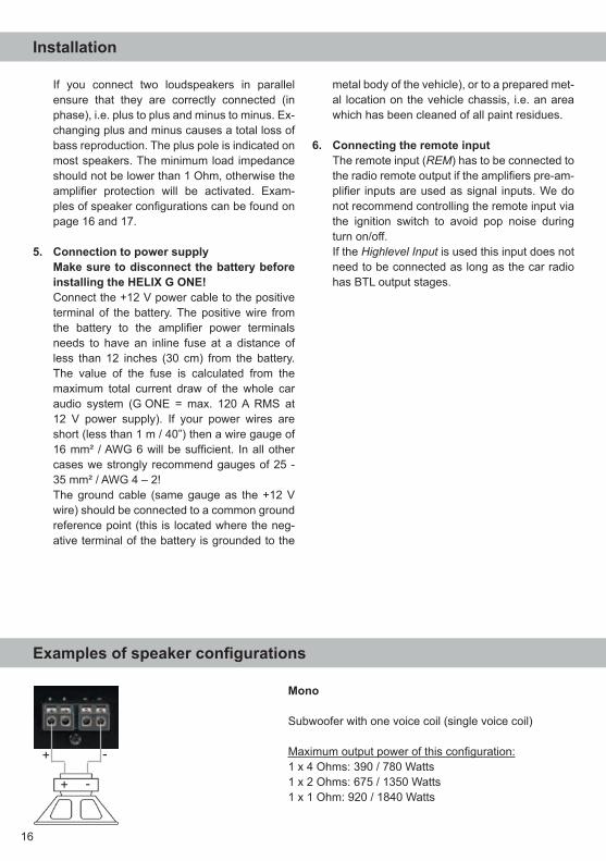
9 SubsonicThis control is used to adjust the crossover fre-quency of the subsonic filter from 10 to 50 Hz. The subsonic filter cuts off very low frequencies which are not in the audible range and relives the amplifi-er and the subwoofer. Additionally the amplifier will have more power available for the audible frequen-cies. This control is always activated and its adjust-ment is mandatory.
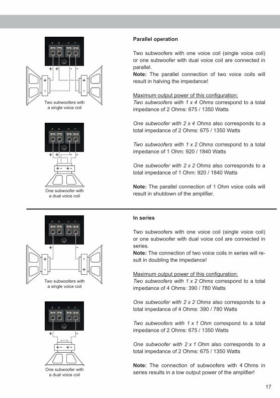
10 LPFThis control is used to adjust the crossover fre-quency of the lowpass filter from 50 to 250 Hz. This control is always activated and its adjustment is mandatory.
In combination with the subsonic filter, the lowpass-filter creates a bandpass in any case. By adjusting the subsonic (control 9) and lowpass (control 10) filter any bandpass between 10 Hz and 250 Hz can be realized.
Caution: To avoid a loss of gain make sure that the crossover frequencies of the subsonic and lowpass filters do have an interval of at least two octaves when generating a bandpass.That means if the lowpass signal is adjusted to 100 Hz the highpass should be adjusted to 25 Hz or less (one octave = doubled frequency or halved frequency).
11 GNDThe ground cable should be connected to a com-mon ground reference point (this is located where the negative terminal of the battery is grounded to the metal body of the vehicle) or to a prepared metal location on the vehicle chassis i.e. an area which has been cleaned of all paint residues. Rec-ommended cross section: min. 16 mm² / AWG 6.
12 REMThe remote lead should be connected to the remote output / automatic antenna (aerial positive) output of the head unit / car radio. This is only activated if the head unit is switched on. Thus the amplifier is switched on and off together with the head unit. This input needn’t to be assigned if the Highlevel Input is used.
13 +12 VConnect the +12 V power cable to the positive ter-minal of the battery. Recommended cross section: min. 16 mm² / AWG 6.
14 FuseThe input fuses are connected in parallel and pro-vide protection against an internal fault of the de-vice, therefore the system must be additionally pro-tected by a further main fuse located close to the battery (max. distance from battery: 30 cm / 12”). The HELIX G ONE is equipped with 3 x 40 Ampere fuses.
15 Power & Protect LEDThe power and protect LED indicates the operating mode of the amplifier. The LED lights up green when the amplifier is ready for operation. If the LED lights up red a malfunction has occurred.A malfunction may have different causes as the HELIX G ONE is equipped with different protection circuits. These protections shut off the amplifier

15
Installation
Connection of HELIX G ONE to the head unit/car radio:
Caution: Carrying out the following steps will re-quire special tools and technical knowledge. In or-der to avoid connection mistakes and / or damage, ask your dealer for assistance if you have any ques-tions and follow all instructions in this manual (see page 11). It is recommended that this unit will be installed by an authorized HELIX dealer.
1. Connecting the pre-amplifier inputsUse the correct cable (RCA / cinch cable) to connect these inputs to the pre-amplifier / lowlev el / cinch outputs of your car radio. It is not mandatory to use both pre-amplifier inputs. If only one channel will be connected use chan-nel A and set the Input Mode switch to “1CH”. When both channels will be used please choose switch position “2CH” (see page 13 point 6; Input Mode). The automatic turn-on circuit does not work when using the pre-amplifier inputs. In this case the remote input (REM) has to be con-nected to activate the HELIX G ONE.Important: It is strictly forbidden to use the Highlevel Input and pre-amplifier inputs (Line Input) at the same time. This may cause severe damage to the pre-amplifier outputs of your car radio.
2. Connecting the highlevel speaker inputsThe highlevel loudspeaker inputs can be con-nected directly to the loudspeaker outputs of an OEM or aftermarket radio using appropriate ca-bles (loudspeaker cables with 1 mm² / AWG 18 max.). Actually it is not mandatory to use both high-
level speaker inputs. If only one channel will be connected we recommend to use the channel A and set the Input Mode switch to “1CH”. When both channels will be used please choose switch position “2CH” (see page 13 point 6; Input Mode). Make sure that the polarity is cor-rect. If one connection has reversed polarity it may affect the performance of the amplifier. If this input is used the remote input (REM) does not need to be connected as the amplifier will automatically turn on once a loudspeaker signal is applied.
3. Adjustment of the input sensitivityAttention: It is mandatory to properly adapt the input sensitivity of the G ONE to the sig-nal source in order to avoid damage to the amplifier.If you want to change the input sensitivity use the Input Level control (see page 13 point 2; Input Level). The setting of the control affects both the lowlevel (Line Input) and the highlevel speaker inputs ( Highlevel Input)! If the Highlevel Input is used with a standard car radio we recommend an input sensitivity of roughly 9 Volts - turn the control from min position to 1/3 position - 11 o’clock position.
4. Connecting the loudspeaker outputsThe loudspeaker outputs can be connected directly to the wires of the loudspeakers. Note: Outputs are wired in parallel internally. This means that both plus outputs (+) resp. both minus outputs (-) deliver the same output signal.Never connect any of the loudspeaker cables with the chassis ground as this will damage your amplifier and your speakers.
in case of overheating, over- and undervoltage, short-circuit on loudspeakers and false connection.Please check for connecting failures such as short-circuits, wrong connections, wrong adjust-ments and over temperature. If the amplifier does not turn on it is defective and has to be send to your local authorized dealer for
repair service. A detailed description of the malfunc-tion and the purchase receipt has to be attached.
16 Output ChannelSpeaker outputs to connect a subwoofer. The min-imum load impedance should not be lower than 1 Ohm.
If you connect two loudspeakers in parallel ensure that they are correctly connected (in phase), i.e. plus to plus and minus to minus. Ex-changing plus and minus causes a total loss of bass reproduction. The plus pole is indicated on most speakers. The minimum load impedance should not be lower than 1 Ohm, otherwise the amplifier protection will be activated. Exam-ples of speaker configurations can be found on page 16 and 17.
5. Connection to power supplyMake sure to disconnect the battery before installing the HELIX G ONE!Connect the +12 V power cable to the positive terminal of the battery. The positive wire from the battery to the amplifier power terminals needs to have an inline fuse at a distance of less than 12 inches (30 cm) from the battery. The value of the fuse is calculated from the maximum total current draw of the whole car audio system (G ONE = max. 120 A RMS at 12 V power supply). If your power wires are short (less than 1 m / 40”) then a wire gauge of 16 mm² / AWG 6 will be sufficient. In all other cases we strongly recommend gauges of 25 - 35 mm² / AWG 4 – 2! The ground cable (same gauge as the +12 V wire) should be connected to a common ground reference point (this is located where the neg-ative terminal of the battery is grounded to the
metal body of the vehicle), or to a prepared met-al location on the vehicle chassis, i.e. an area which has been cleaned of all paint residues.
6. Connecting the remote inputThe remote input (REM) has to be connected to the radio remote output if the amplifiers pre-am-plifier inputs are used as signal inputs. We do not recommend controlling the remote input via the ignition switch to avoid pop noise during turn on/off.If the Highlevel Input is used this input does not need to be connected as long as the car radio has BTL output stages.
16
Installation
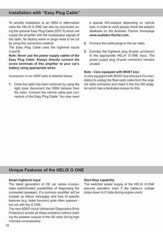
Mono
Subwoofer with one voice coil (single voice coil)
Maximum output power of this configuration:1 x 4 Ohms: 390 / 780 Watts1 x 2 Ohms: 675 / 1350 Watts1 x 1 Ohm: 920 / 1840 Watts
Examples of speaker configurations
17
Parallel operation
Two subwoofers with one voice coil (single voice coil) or one subwoofer with dual voice coil are connected in parallel.Note: The parallel connection of two voice coils will result in halving the impedance!
Maximum output power of this configuration:Two subwoofers with 1 x 4 Ohms correspond to a total impedance of 2 Ohms: 675 / 1350 Watts
One subwoofer with 2 x 4 Ohms also corresponds to a total impedance of 2 Ohms: 675 / 1350 Watts
Two subwoofers with 1 x 2 Ohms correspond to a total impedance of 1 Ohm: 920 / 1840 Watts
One subwoofer with 2 x 2 Ohms also corresponds to a total impedance of 1 Ohm: 920 / 1840 Watts
Note: The parallel connection of 1 Ohm voice coils will result in shutdown of the amplifier.
Two subwoofers with a single voice coil
One subwoofer with a dual voice coil
In series
Two subwoofers with one voice coil (single voice coil) or one subwoofer with dual voice coil are connected in series.Note: The connection of two voice coils in series will re-sult in doubling the impedance!
Maximum output power of this configuration:Two subwoofers with 1 x 2 Ohms correspond to a total impedance of 4 Ohms: 390 / 780 Watts
One subwoofer with 2 x 2 Ohms also corresponds to a total impedance of 4 Ohms: 390 / 780 Watts
Two subwoofers with 1 x 1 Ohm correspond to a total impedance of 2 Ohms: 675 / 1350 Watts
One subwoofer with 2 x 1 Ohm also corresponds to a total impedance of 2 Ohms: 675 / 1350 Watts
Note: The connection of subwoofers with 4 Ohms in series results in a low output power of the amplifier!
Two subwoofers with a single voice coil
One subwoofer with a dual voice coil
18
Smart highlevel inputThe latest generation of OE car radios incorpo-rates sophisticated possibilities of diagnosing the connected speakers. If a common amplifier will be hooked up failure messages and loss of specific features (e.g. fader function) quite often appears - but not with the G ONE.The new ADEP circuit (Advanced Diagnostics Error Protection) avoids all these problems without load-ing the speaker outputs of the OE radio during high volumes unnecessarily.
Start-Stop capabilityThe switched power supply of the HELIX G ONE assures operation even if the battery’s voltage drops down to 6 Volts during engine crank.
Unique Features of the HELIX G ONE
Installation with “Easy Plug Cable”
To simplify installation to an OEM or aftermarket radio the HELIX G ONE can also be connected us-ing the optional Easy Plug Cable (EPC 5) which will supply the amplifier with the loudspeaker signals of the radio. No factory wires or plugs need to be cut by using this connection method.The Easy Plug Cable uses the highlevel inputs A and B. Note: Never use the power supply cables of the Easy Plug Cable. Always directly connect the screw terminals of this amplifier to your car’s battery using appropriate wires.
Connection to an OEM radio is detailed below:
1. Once the radio has been removed by using the right tools disconnect the OEM harness from the radio. Connect the vehicle cable jack con-nectors of the Easy Plug Cable. You may need
a special ISO-adaptor depending on vehicle type. In order to verify please check the adaptor database on the Audiotec Fischer homepage www.audiotec-fischer.com.
2. Connect the cable plugs to the car radio.
3. Connect the highlevel plug (8-pole connector) to the appropriate HELIX G ONE input. The power supply plug (4-pole connector) remains unused.
Note - Cars equipped with MOST bus:In cars equipped with MOST bus structure it is man-datory to unplug the fiber-optic cable from the origi-nal radio connector and insert it into the ISO-adap-tor which has a dedicated recess for this.
19
The limited warranty comply with legal regulations. Failures or damages caused by overload or im-proper use are not covered by the warranty. Please return the defective product only with a valid proof of purchase and a detailed malfunction description. Technical specifications are subject to change!
Errors are reserved! For damages on the vehicle and the device, caused by handling errors of the module, we can’t assume liability. These devic-es are certified for the use in vehicles within the European Community (EC).
Technical Data
Warranty Disclaimer
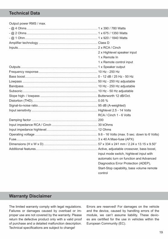
Output power RMS / max.- @ 4 Ohms ............................................................................... 1 x 390 / 780 Watts- @ 2 Ohms ............................................................................... 1 x 675 / 1350 Watts- @ 1 Ohm ................................................................................. 1 x 920 / 1840 WattsAmplifier technology .................................................................. Class DInputs ......................................................................................... 2 x RCA / Cinch 2 x Highlevel speaker input 1 x Remote In 1 x Remote control inputOutputs ...................................................................................... 1 x Speaker outputFrequency response .................................................................. 10 Hz - 250 HzBass boost ................................................................................. 0 - 12 dB / 25 Hz - 50 HzLowpass .................................................................................... 50 Hz - 250 Hz adjustableBandpass................................................................................... 10 Hz - 250 Hz adjustableSubsonic .................................................................................... 10 Hz - 50 Hz adjustableSlope high- / lowpass ................................................................ Butterworth 12 dB/Oct.Distortion (THD) ......................................................................... 0.05 %Signal-to-noise ratio................................................................... 95 dB (A-weighted) Input sensitivity .......................................................................... Highlevel 2.5 - 14 Volts RCA / Cinch 1 - 6 VoltsDamping factor .......................................................................... 200Input impedance RCA / Cinch ................................................... 30 kOhmsInput impedance highlevel ......................................................... 12 Ohms Operating voltage ...................................................................... 9.6 - 16 Volts (max. 5 sec. down to 6 Volts)Fuse........................................................................................... 3 x 40 A Maxi-fuse (APX)Dimensions (H x W x D) ............................................................ 57 x 334 x 241 mm / 2.24 x 13.15 x 9.50”Additional features ..................................................................... Active, adjustable crossover, bass boost, input mode switch, highlevel input with automatic turn on function and Advanced Diagnostics Error Protection (ADEP), Start-Stop capability, bass volume remote control

Audiotec Fischer GmbHHünegräben 26 · 57392 Schmallenberg · Germany
Tel.: +49 2972 9788 0 · Fax: +49 2972 9788 88 E-mail: [email protected] · Internet: www.audiotec-fischer.com