Radiochromic film for medical radiation dosimetry - CiteSeerX
Upload
independentCategory
view
5download
0
Functionalization of High Frequency SAW RFIDDevices for Ozone Dosimetry
Ryan S. Westafer∗, Galit Levitin†, Dennis W. Hess†, Michael H. Bergin‡, Peter J. Edmonson§, and William D. Hunt∗¶∗School of Electrical and Computer Engineering
Georgia Institute of Technology, Atlanta, Georgia 30332–0250, USAEmail: [email protected]
†School of Chemical and Biomolecular EngineeringGeorgia Institute of Technology, Atlanta, Georgia 30332, USA
‡School of Environmental EngineeringGeorgia Institute of Technology, Atlanta, Georgia 30332, USA
§Zen Sensing, LTD¶Corresponding author: [email protected]
Abstract—In this paper we report new work on the gravimetricdetection of ozone at EPA and OSHA relevant concentrations(approximately 100 ppb) in filtered ambient air. We haveextended our proof-of-concept work which used both quartzcrystal microbalance (QCM) and surface acoustic wave (SAW)resonators. We now enable detection using our high frequencySAW RFID devices. Such surface wave devices are extremelysensitive to the viscosity, thickness, and uniformity of the reactiveor sorbent coating. We report laboratory characterization of ourpolymer-coated SAW sensors operating between 200 and 600MHz on lithium niobate substrates. Return loss measurementsconfirm adequate load bearing even at 550 MHz. We compareboth the temperature and ozone sensitivity of the RFID devicesto conventional resonators. In conclusion, we suggest the designimprovements to yield a next generation of SAW RFID ozonesensors with even greater sensitivity.
I. INTRODUCTION
Recently, surface acoustic wave devices have been em-ployed as passive wireless sensors. These radio frequencyidentification (RFID) devices sense environmental perturba-tions, typically temperature and/or pressure [1], through me-chanical changes in the substrate material. Desiring similarfunctionality for ambient ozone monitoring, we prepared SAWRFID devices with polybutadiene (PB) coatings. After somerefinement and validation trials, our results show ozone de-tection at low concentrations relevant to environmental andoccupational regulations.
A. Ozone Standards and Measures
On March 12, 2008 the United States EPA revised thenational air quality standards (NAAQS), reducing the “eighthour primary ozone standard” to 75 ppb (parts-per-billion).The Occupational Safety & Health Administration (OSHA)has published a maximum allowable permissible exposurelimit at 100 ppb over 8 hours. In New Zealand, “alert” categoryozone threshold is reached at 47 ppb, and “action” categoryis above 70 ppb. These are 1 hour averages published by theMinistry for the Environment (2002). There is an internationalinterest in detection of ambient ozone in the ppb range.
In addition to its production in the atmosphere, ozone iscommonly produced indoors by ultraviolet lamps and electricmachinery such as photocopiers and arcing in brushed motors.This form of pollution occurs in workplaces around the world.Because toxicity has been reported at concentrations as lowas 100 ppb, wireless personal exposure monitoring could beof great benefit.
The dosimeter modality is particularly advantageous forpersonal exposure monitoring. While one probably could notcarry most photometric monitors on the person, a simplesingle-chip SAW RFID badge can easily accompany a personthroughout a workday much as radiation badges and RFIDaccess cards are presently worn or carried by employees.
Continuous online monitoring of ozone is typically per-formed by photometric gas analyzers, particularly using ul-traviolet (UV) spectrophotometry. This method is known tobe very precise and very good accuracy may be obtained,even over long range optical atmospheric measurements [2].However, confounding factors can complicate tropospheric(low-altitude) spectroscopic measurements: SO2 concentrationand varying background UV intensity (e.g. reflected sunlight,clouds, etc.) [3], [4]. We employ a method which enables SAWsensors to detect ozone by its chemical reactivity rather thanits optical resonance.
B. Acoustic Ozone Sensing
Acoustic gravimetric ozone sensors were reported in 1985by Fog et al. [5]. That work used quartz crystal microbalance(QCM) sensors coated with an alkene polymer (polybutadiene)which demonstrated mass increase after ozone reaction. Thefrequency dependence of acoustic resonators due to massloading is well known. Density or temperature changes andother factors alter the acoustic velocity. In one view, thecharacteristic time (τ0 = 1/f0) of a resonator is increasedby mass adsorption to its free surface. We performed similarproof-of-concept experiments with our coatings on 10 MHzQCM resonators [6]. An example sensitivity plot is shown in
978-1-4244-5335-1/09/$26.00 ©2009 IEEE 1747 IEEE SENSORS 2009 Conference
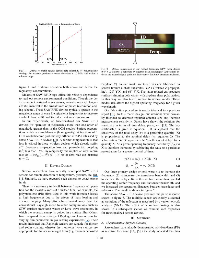
Fig. 1. Quartz resonator results demonstrate suitability of polybutadienecoatings for acoustic gravimetric ozone detection at 10 MHz and within arelevant range.
figure 1, and it shows operation both above and below theregulatory concentrations.
Makers of SAW RFID tags utilize this velocity dependenceto read out remote environmental conditions. Though the de-vices are not designed as resonators, acoustic velocity changesare still manifest in the arrival times of pulses (a common cod-ing scheme). These SAW RFID devices typically operate in themegahertz range or even low gigahertz frequencies to increaseavailable bandwidth and to reduce antenna dimensions.
In our experiments, we functionalized our SAW RFIDdevices for operation at frequencies more than one order ofmagnitude greater than in the QCM studies. Surface prepara-tions which are troublesome (homogeneity) at fractions of 1GHz would become prohibitively difficult at 2.45 GHz used bysome SAW RFID devices [7]). A further complication is thatloss is critical in these wireless devices which already sufferr−4 free-space propagation loss and piezoelectric coupling(k2) less than 15%. By reciprocity this implies an ideal returnloss of 10 log10(0.152) ≈ −16 dB at zero read-out distance(r = 0).
II. DEVICE DESIGN
Several researchers have recently developed SAW RFIDsensors for remote detection of temperature, pressure, etc. [8],[1]. Similarly, we have prepared such devices to detect ozonein air.
There is a necessary trade-off between frequency of opera-tion and the mass/thickness of a surface film. For example, thepolybutadiene (PB) films used in this work introduce lossesat high frequencies due to the effects of mass loading andviscous damping. Many efforts have moved away from theconventional Rayleigh mode to other configurations such asSTW (surface transverse wave) or Love wave resonators, inwhich the acoustic energy is guided in a surface film. Othershave compared the sensitivity of Rayleigh and Love sensors forvarying film parameters in gas sensing experiments [9]. Theirresults indicated that Rayleigh sensors are suitable for thickerand softer coatings whereas the transverse wave sensors areappropriate for thinner more rigid films (e.g. vacuum deposited
Fig. 2. Optical micrograph of our highest frequency STW mode device(64 Y-X LiNbO3 ) patterned by electron beam lithography. Annotations in-dicate the acoustic signal paths and interconnect for future antenna attachment.
Parylene C). In our work, we tested devices fabricated onseveral lithium niobate substrates: Y-Z (Y rotated Z propagat-ing), 128 Y-X, and 64 Y-X. The latter rotated cut producessurface-skimming bulk waves with in-plane shear polarization.In this way we also tested surface transverse modes. Thesemodes also afford the highest operating frequency for a givenwavelength.
Our fabrication procedure is nearly identical to a previousreport [10]. In this recent design, our revisions were primar-ily intended to decrease required antenna size and increasemeasurement sensitivity. Others have shown the relations forsensitivity in terms of time delay, phase, etc. [11]. The keyrelationship is given in equation 1. It is apparent that thesensitivity of the total delay (τ ) to a perturbing quantity (X)is proportional to the nominal delay (τ0; equation 2). Theabbreviation “XCD” represents the “coefficient of delay” for aquantity X. At a given operating frequency, sensitivity (SX) toX is therefore increased by subjecting the wave to a particularperturbation for a greater period of time.
τ(X) = τ0(1 + XCD ·X) (1)
SX =∂τ
∂X= τ0 ·XCD (2)
Our three primary design criteria were: (1) to increase thefrequency, (2) to increase the transducer bandwidth, and (3)to increase the delays. To do this we have more than doubledthe operating center frequency and transducer bandwidth, andwe increased the separation distances between transducer andreflectors. The result is shown in figure 2.
The above SAW RFID device produced the pulse responseshown in figure 3. The multiple echoes are clearly discernedas variations of the reflection as measured by a vector networkanalyzer (VNA). The effect of a surface coating is alsoshown. In a subsequent section we examine such responsesfor functionalized sensor devices.
III. METHODS
A. Chemisensitive Surface CoatingResearchers have already demonstrated polybutadiene (PB)
as selective for ozone [12], [5]. One study indicated less than
1748

0 0.5 1 1.5 2
x 10−6
−120
−100
−80
−60
−40
−20
0
Time [s]
|Γ|2
[dB
]Time Domain Reflected Power
No FilmPB Film
Fig. 3. Temporal reflection magnitude of the 64 Y-X LiNbO3 RFID deviceof figure 2 at room temperature. The center frequency for this structure isapproximaterly 580 MHz.
6% interference across many other salient gas constituentsincluding: toluene, nitric oxide, and relative humidity. Watervapor and solvent absorption are important factors affectingacoustic properties of polymer films, so the relatively lowinterference makes this PB film a good choice.
In a prior study, we verified the mass increase in the coatingafter ozone exposure [6]. In that study, we applied two tech-niques. The first was x-ray photoelectron spectroscopy (XPS),which indicated a decrease in carbon double bonds and anincrease in carbonyl groups, i.e. carbon bonded to oxygen. Oursecond measurement employed acoustic gravimetric detectionof ozone using 10 MHz quartz crystal microbalance (QCM)devices. We reported 2.3 Hz min−1 at 100 ppb ozone, andothers before us have demonstrated similar results [12].
In the present study, we coated our SAW devices witha similar solution of 5000 molecular weight polybutadieneobtained from Scientific Polymer Products, Inc. The PB wasdissolved in toluene to 5% weight and filtered through 0.2µm syringe filters. Finally, the solution was deposited directlyonto devices and spun at approximately 5600 RPM for 60seconds. We obtained film thickness less than 300 nm usingthis method.
In undiluted form the polybutadiene was a viscous liquid atroom temperature and pressure. Even after solvent evaporation,we expect the film still exhibits a high viscosity. Acousticmeasurements on Rayleigh mode resonators confirmed this;the responses were squelched. Even the STW RFID devicesdid not work with that coating. To solidify the thin films, webake them between 30 minutes and 2 hours at 110 C. Thickerfilms require longer bake times. The baking step accomplishestwo primary objectives: (1) to decrease the viscosity of the film(and accompanying acoustic losses) by solvent bake-out, and(2) to stiffen the film by cross-linking. We demonstrate thesuccess of this approach in a subsequent section.
B. Ozone Challenge
The test air stream was conditioned as shown in Figure 4.Ambient room air was drawn through a filter into a pump and
Dryer
Absorber
Filter
Pump
Air
*49C O3 Calibrator, Primary Standard, Thermo Electron Corporation
Ozone Calibrator*
VNA
Fig. 4. Schematic of experimental setup. Solid arrows denote sample flow,and dotted arrows indicate electrical interconnect.
0 0.2 0.4 0.6 0.8 1
x 10−5
−120
−100
−80
−60
−40
−20
0
Time [s]
|S11
||2[d
B]
Time Domain Reflected Power
No FilmPB Film
Fig. 5. Time domain responses of a Y-Z LiNbO3SAW RFID device bothbefore and after coating. This substrate demonstrated the strongest acousticreflections.
delivered to the Thermo Electron Inc. ozone calibrator unit(Primary Standard) after passing through a DrieRite desiccantdryer and an activated carbon filter. The calibrator’s outlet wasconnected by 1/4 inch polyethylene tubing to the aluminumand steel box which housed the sensor(s). The gas flow ratewas 3.70 SLPM, as measured with a DryCal DC-2 flowcalibrator (BIOS International).
C. RF Measurement
For the initial measurements, we used a Cascade Microtechprobe station and an HP8753C network analyzer to electri-cally characterize the RFID SAW devices. For temperaturemeasurements we used a Temptronic temperature controllerconnected to the probe station vacuum chuck. The specificRF measurement we use is the frequency-dependent 1-portscattering parameter, S11(ω). A typical device response isshown later in Figure 8. Though reflections are manifestas ripples in the response passband, time-domain conversion(inverse Fourier transform of S11(ω)) reveals the multiple-echoRFID response one expects (refer to Figure 5).
For ozone measurements, we designed a LABVIEW (Na-tional Instruments) program to record S11(ω) responses to file
1749
every 10 seconds. For device and coating characterization,this arrangement allows observation of the full response (bothmagnitude and phase versus frequency) over the course of eachozone exposure trial. Subsequent processing in MATLAB(Mathworks) produced the temporal pulse response.
IV. RESULTS & DISCUSSION
A. Film Uniformity
A non-uniform film scatters the surface acoustic wave. Thiswas evident in other work on the functionalization of SAWsensors [13]. The surface preparation must be uniform towithin a fraction of one wavelength, and so this challengebecomes more difficult at higher frequencies.
For deposition of extremely thin polymer films, plasmacleaning and conformal silica coating have been used toimprove homogeneity of sensing films since at least 1995[14]. We adopted this technique but found it unnecessary forcoating lithium niobate devices with polybutadiene. Cleaningand dehydration of the wafer surface were sufficient. On quartzsubstrates we did observe “dewetting” of the nonpolar films asthe solvent evaporated and the film contracted anisotropicallyalong the surface electrodes and reflectors.
The “dewetting” behavior occurred to some extent on mostsubstrates with polar surfaces. This was especially trouble-some on quartz or silica-coated lithium niobate. Our primarysolution to this problem was to bake (and thereby dehydrate)the devices prior to coating. Application of a nonpolar surfacecoating (e.g. HMDS) also reduced the phenomenon but thisadded a processing step which we found can be avoided forlithium niobate devices by simply baking prior to coating.
B. Film Chemistry
The film mass is increased by irreversible attack of availablealkene bonds, and deposited mass (oxygen) corresponds touseful life. Even after baking the films for two hours, ourprevious QCM trials demonstrated ozone detection both aboveand below the regulatory ranges. Further demonstration of thefilm’s tolerance to baking is evident by more recent trials inwhich we baked the films overnight at approximately 200 C.While the ozone sensitivity was not significantly reduced, thesensor lifetime decreased. This indicates a decrease in doublebonds available for reaction. Literature indicates the alkene(π) bond is relatively stable below 300 C [15]. Even at lowertemperatures the alkene bonds of the PB film may very slowlybecome saturated, making a more rigid film. This saturationprocess reduces the film’s reactive capacity and we suggest ithappens, albeit slowly, at lower temperatures. We have not,however, observed consequences of this effect experimentally,including tests run more than 48 hours at room temperature(20± 2 C). In open-air shelf life tests, we found only slightreduction in sensitivity and useful life after two weeks ofstorage in ambient air at room temperature. For best results,we suggest baking and storing the coated devices in an inertatmosphere and at moderate temperature.
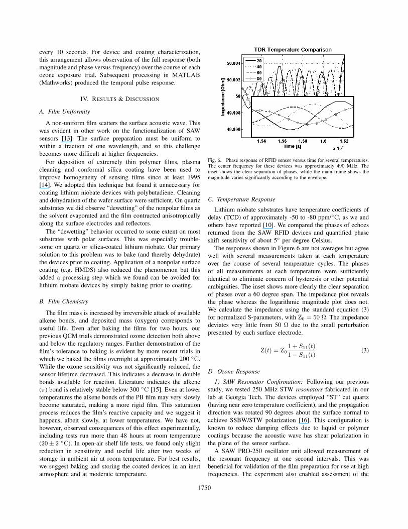
Fig. 6. Phase response of RFID sensor versus time for several temperatures.The center frequency for these devices was approximately 490 MHz. Theinset shows the clear separation of phases, while the main frame shows themagnitude varies significantly according to the envelope.
C. Temperature Response
Lithium niobate substrates have temperature coefficients ofdelay (TCD) of approximately -50 to -80 ppm/C, as we andothers have reported [10]. We compared the phases of echoesreturned from the SAW RFID devices and quantified phaseshift sensitivity of about 5 per degree Celsius.
The responses shown in Figure 6 are not averages but agreewell with several measurements taken at each temperatureover the course of several temperature cycles. The phasesof all measurements at each temperature were sufficientlyidentical to eliminate concern of hysteresis or other potentialambiguities. The inset shows more clearly the clear separationof phases over a 60 degree span. The impedance plot revealsthe phase whereas the logarithmic magnitude plot does not.We calculate the impedance using the standard equation (3)for normalized S-parameters, with Z0 = 50 Ω. The impedancedeviates very little from 50 Ω due to the small perturbationpresented by each surface electrode.
Z(t) = Z01 + S11(t)1− S11(t)
(3)
D. Ozone Response
1) SAW Resonator Confirmation: Following our previousstudy, we tested 250 MHz STW resonators fabricated in ourlab at Georgia Tech. The devices employed “ST” cut quartz(having near zero temperature coefficient), and the propagationdirection was rotated 90 degrees about the surface normal toachieve SSBW/STW polarization [16]. This configuration isknown to reduce damping effects due to liquid or polymercoatings because the acoustic wave has shear polarization inthe plane of the sensor surface.
A SAW PRO-250 oscillator unit allowed measurement ofthe resonant frequency at one second intervals. This wasbeneficial for validation of the film preparation for use at highfrequencies. The experiment also enabled assessment of the
1750
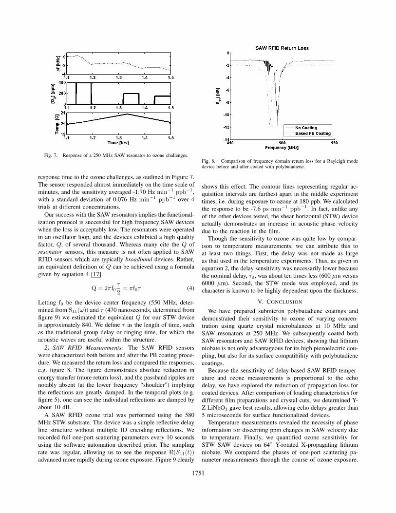
Fig. 7. Response of a 250 MHz SAW resonator to ozone challenges.
response time to the ozone challenges, as outlined in Figure 7.The sensor responded almost immediately on the time scale ofminutes, and the sensitivity averaged -1.70 Hz min−1 ppb−1,with a standard deviation of 0.076 Hz min−1 ppb−1 over 4trials at different concentrations.
Our success with the SAW resonators implies the functional-ization protocol is successful for high frequency SAW deviceswhen the loss is acceptably low. The resonators were operatedin an oscillator loop, and the devices exhibited a high qualityfactor, Q, of several thousand. Whereas many cite the Q ofresonator sensors, this measure is not often applied to SAWRFID sensors which are typically broadband devices. Rather,an equivalent definition of Q can be achieved using a formulagiven by equation 4 [17].
Q = 2πf0τ
2= πf0τ (4)
Letting f0 be the device center frequency (550 MHz, deter-mined from S11(ω)) and τ (470 nanoseconds, determined fromfigure 9) we estimated the equivalent Q for our STW deviceis approximately 840. We define τ as the length of time, suchas the traditional group delay or ringing time, for which theacoustic waves are useful within the structure.
2) SAW RFID Measurements: The SAW RFID sensorswere characterized both before and after the PB coating proce-dure. We measured the return loss and compared the responses,e.g. figure 8. The figure demonstrates absolute reduction inenergy transfer (more return loss), and the passband ripples arenotably absent (at the lower frequency “shoulder”) implyingthe reflections are greatly damped. In the temporal plots (e.g.figure 5), one can see the individual reflections are damped byabout 10 dB.
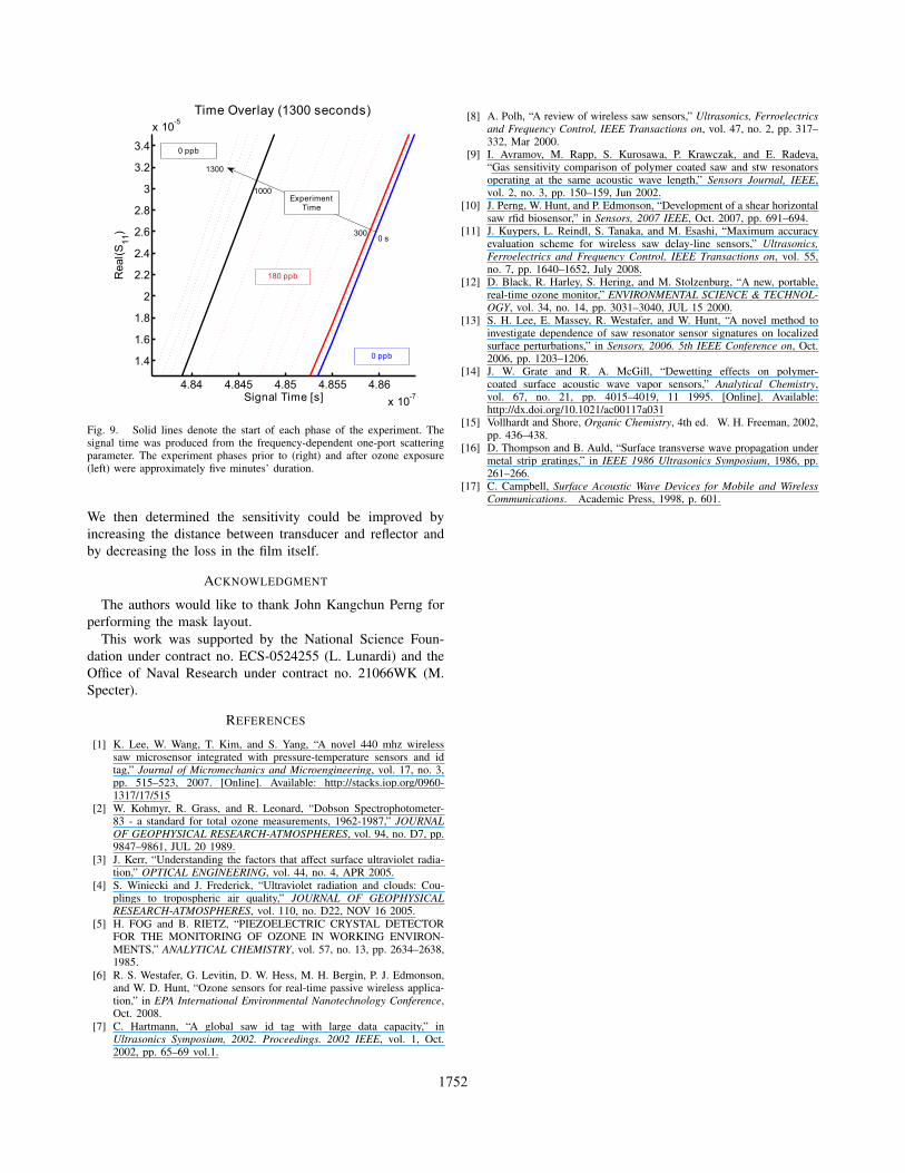
A SAW RFID ozone trial was performed using the 580MHz STW substrate. The device was a simple reflective delayline structure without multiple ID encoding reflections. Werecorded full one-port scattering parameters every 10 secondsusing the software automation described prior. The samplingrate was regular, allowing us to see the response <(S11(t))advanced more rapidly during ozone exposure. Figure 9 clearly
Fig. 8. Comparison of frequency domain return loss for a Rayleigh modedevice before and after coated with polybutadiene.
shows this effect. The contour lines representing regular ac-quisition intervals are farthest apart in the middle experimenttimes, i.e. during exposure to ozone at 180 ppb. We calculatedthe response to be -7.6 ps min−1 ppb−1. In fact, unlike anyof the other devices tested, the shear horizontal (STW) deviceactually demonstrates an increase in acoustic phase velocitydue to the reaction in the film.
Though the sensitivity to ozone was quite low by compar-ison to temperature measurements, we can attribute this toat least two things. First, the delay was not made as largeas that used in the temperature experiments. Thus, as given inequation 2, the delay sensitivity was necessarily lower becausethe nominal delay, τ0, was about ten times less (600 µm versus6000 µm). Second, the STW mode was employed, and itscharacter is known to be highly dependent upon the thickness.
V. CONCLUSION
We have prepared submicron polybutadiene coatings anddemonstrated their sensitivity to ozone of varying concen-tration using quartz crystal microbalances at 10 MHz andSAW resonators at 250 MHz. We subsequently coated bothSAW resonators and SAW RFID devices, showing that lithiumniobate is not only advantageous for its high piezoelectric cou-pling, but also for its surface compatibility with polybutadienecoatings.
Because the sensitivity of delay-based SAW RFID temper-ature and ozone measurements is proportional to the echodelay, we have explored the reduction of propagation loss forcoated devices. After comparison of loading characteristics fordifferent film preparations and crystal cuts, we determined Y-Z LiNbO3 gave best results, allowing echo delays greater than5 microseconds for surface functionalized devices.
Temperature measurements revealed the necessity of phaseinformation for discerning ppm changes in SAW velocity dueto temperature. Finally, we quantified ozone sensitivity forSTW SAW devices on 64 Y-rotated X-propagating lithiumniobate. We compared the phases of one-port scattering pa-rameter measurements through the course of ozone exposure.
1751
4.84 4.845 4.85 4.855 4.86
x 10-7
1.4
1.6
1.8
2
2.2
2.4
2.6
2.8
3
3.2
3.4
x 10-5
Signal Time [s]
Rea
l(S11
)Time Overlay (1300 seconds)
0 ppb
0 ppb
180 ppb
ExperimentTime
0 s
1000
1300
300
Fig. 9. Solid lines denote the start of each phase of the experiment. Thesignal time was produced from the frequency-dependent one-port scatteringparameter. The experiment phases prior to (right) and after ozone exposure(left) were approximately five minutes’ duration.
We then determined the sensitivity could be improved byincreasing the distance between transducer and reflector andby decreasing the loss in the film itself.
ACKNOWLEDGMENT
The authors would like to thank John Kangchun Perng forperforming the mask layout.
This work was supported by the National Science Foun-dation under contract no. ECS-0524255 (L. Lunardi) and theOffice of Naval Research under contract no. 21066WK (M.Specter).
REFERENCES
[1] K. Lee, W. Wang, T. Kim, and S. Yang, “A novel 440 mhz wirelesssaw microsensor integrated with pressure-temperature sensors and idtag,” Journal of Micromechanics and Microengineering, vol. 17, no. 3,pp. 515–523, 2007. [Online]. Available: http://stacks.iop.org/0960-1317/17/515
[2] W. Kohmyr, R. Grass, and R. Leonard, “Dobson Spectrophotometer-83 - a standard for total ozone measurements, 1962-1987,” JOURNALOF GEOPHYSICAL RESEARCH-ATMOSPHERES, vol. 94, no. D7, pp.9847–9861, JUL 20 1989.
[3] J. Kerr, “Understanding the factors that affect surface ultraviolet radia-tion,” OPTICAL ENGINEERING, vol. 44, no. 4, APR 2005.
[4] S. Winiecki and J. Frederick, “Ultraviolet radiation and clouds: Cou-plings to tropospheric air quality,” JOURNAL OF GEOPHYSICALRESEARCH-ATMOSPHERES, vol. 110, no. D22, NOV 16 2005.
[5] H. FOG and B. RIETZ, “PIEZOELECTRIC CRYSTAL DETECTORFOR THE MONITORING OF OZONE IN WORKING ENVIRON-MENTS,” ANALYTICAL CHEMISTRY, vol. 57, no. 13, pp. 2634–2638,1985.
[6] R. S. Westafer, G. Levitin, D. W. Hess, M. H. Bergin, P. J. Edmonson,and W. D. Hunt, “Ozone sensors for real-time passive wireless applica-tion,” in EPA International Environmental Nanotechnology Conference,Oct. 2008.
[7] C. Hartmann, “A global saw id tag with large data capacity,” inUltrasonics Symposium, 2002. Proceedings. 2002 IEEE, vol. 1, Oct.2002, pp. 65–69 vol.1.
[8] A. Polh, “A review of wireless saw sensors,” Ultrasonics, Ferroelectricsand Frequency Control, IEEE Transactions on, vol. 47, no. 2, pp. 317–332, Mar 2000.
[9] I. Avramov, M. Rapp, S. Kurosawa, P. Krawczak, and E. Radeva,“Gas sensitivity comparison of polymer coated saw and stw resonatorsoperating at the same acoustic wave length,” Sensors Journal, IEEE,vol. 2, no. 3, pp. 150–159, Jun 2002.
[10] J. Perng, W. Hunt, and P. Edmonson, “Development of a shear horizontalsaw rfid biosensor,” in Sensors, 2007 IEEE, Oct. 2007, pp. 691–694.
[11] J. Kuypers, L. Reindl, S. Tanaka, and M. Esashi, “Maximum accuracyevaluation scheme for wireless saw delay-line sensors,” Ultrasonics,Ferroelectrics and Frequency Control, IEEE Transactions on, vol. 55,no. 7, pp. 1640–1652, July 2008.
[12] D. Black, R. Harley, S. Hering, and M. Stolzenburg, “A new, portable,real-time ozone monitor,” ENVIRONMENTAL SCIENCE & TECHNOL-OGY, vol. 34, no. 14, pp. 3031–3040, JUL 15 2000.
[13] S. H. Lee, E. Massey, R. Westafer, and W. Hunt, “A novel method toinvestigate dependence of saw resonator sensor signatures on localizedsurface perturbations,” in Sensors, 2006. 5th IEEE Conference on, Oct.2006, pp. 1203–1206.
[14] J. W. Grate and R. A. McGill, “Dewetting effects on polymer-coated surface acoustic wave vapor sensors,” Analytical Chemistry,vol. 67, no. 21, pp. 4015–4019, 11 1995. [Online]. Available:http://dx.doi.org/10.1021/ac00117a031
[15] Vollhardt and Shore, Organic Chemistry, 4th ed. W. H. Freeman, 2002,pp. 436–438.
[16] D. Thompson and B. Auld, “Surface transverse wave propagation undermetal strip gratings,” in IEEE 1986 Ultrasonics Symposium, 1986, pp.261–266.
[17] C. Campbell, Surface Acoustic Wave Devices for Mobile and WirelessCommunications. Academic Press, 1998, p. 601.
1752
Copyright © 2022 FDOKUMEN