FRONT COVER FPO - UConn Engineering
180
-
Upload
khangminh22 -
Category
Documents
-
view
1 -
download
0
Transcript of FRONT COVER FPO - UConn Engineering

3
FRONT COVER FPO

44
3
27
41
57
75
95
101
107
130
Biomedical Engineering
Chemical & Biomolecular Engineering
Civil Engineering
Computer Science & Engineering
Electrical and Computer Engineering
Environmental Engineering
Management & Engineering for Manufacturing
Materials Science & Engineering
Mechanical Engineering
Sponsors177

1
GREETINGS!
I am delighted to welcome you to our Engineering Senior Design Demonstration Expo.
Perhaps more than any other academic area of study, engineering is an applied discipline aimed at solving real-world challenges—from the nano- to vast astronomical scales, inventing new products and processes, and enhancing the quality of life for humans across the globe. Senior Design is the pinnacle learning experience of an engineering student’s undergraduate education, a year-long process during which principles and theories gain substantive form and relevance to societal needs. Students learn and apply the principles of design; the complex interplay among engineering solutions and societal, environmental, economic and ethical considerations; the language of industry; and the power of engineering to catalyze new solutions to entrenched problems such as sustainable energy, access to clean water, agriculture, transportation and health. As you stroll through the exhibits displayed here today, described succinctly within the pages of this booklet, I encourage you to engage our students to better understand the problem-solving tools they employed in developing their prototypes and simulation models. Their answers will afford you rare insight into the issues they encountered and the exceptional quality of their engineering skills.
Within days, they will embark on their engineering careers or perhaps graduate school. They are our future, and I take great pride in the role UConn Engineering played in preparing them to become industry leaders, entrepreneurs and innovators, and technology visionaries of the 21st century.
Cordially,
KAZEM KAZEROUNIANDean and Professor, Mechanical Engineering
BENEFITS TO SPONSORS
Dedicated attention to a genuine design challenge, and the fresh
perspective, of an agile and energetic engineering team.
Opportunity to immerse students in a unique engineering design culture and to assess students
as they progress through the design process.
Opportunity to recruit top students
for full-time entry-level positions following graduation.
Collaborative relationship with
UConn engineering faculty.
Opportunity to contribute toward a more design and business-savvy
engineering workforce.

22

33

4
Team 1: Design of a PCR Thermocycler Using an Arduino Microcontroller Sponsored by: University of Connecticut Sponsor Advisor: Dr. Guoan Zheng
A Polymerase Chain Reaction (PCR) allows sequencing and amplification of a desired piece of genetic information from a given strand of DNA. The development of this technology has proven to be invaluable as it has been used in many applications including diagnostic testing, forensics, and genomic science. Though PCR is an increasingly influential technique, equipment is neither widely available nor cheap. Limited access to such important science can stunt research progression. Therefore, the main motivation for this project is to create a unique thermocycler device for smaller laboratories and scientists who do not have access to expensive PCR equipment.
PCR is reliant on a precise thermal cycling process that involves heating and cooling. Working with DNA requires a great deal of delicacy and precision, which is why these reactions are extremely dependent on proper thermal cycling. This design will be focused on ensuring smooth transitions between the thermal stages and will be controlled by the Arduino Mega 2560 microcontroller, which will function to rapidly turn the heating element on and off. The thermal sensor will combine a k-type thermocouple and amplifier breakout board that will measure the temperature of the PCR block in real-time and feed this data into feedback loops to control heating and cooling. The PCR device will be able to be controlled manually via an LCD and joystick. The heating and cooling component will mainly be controlled with a thermo-electric cooler (TEC) fan module that generates a temperature differential across the top and bottom of the plate. The outer shell of the device will be 3D-printed from plastic Acrylonitrile butadiene styrene (ABS). This material is easy to machine and will help the device be lightweight and portable. The casing will contain features including vents, feet, and an opening for the fan on the bottom and is designed for heating efficiency, while also including proper ventilation for safe removal of heat. The Arduino and power components will be housed in a separate box nearby to avoid the risk of exposing the Arduino and other electrical components to extreme heat. The final device is intended to make performing a PCR more user-friendly and economically feasible by using cost-effective materials and new strategies to make more reliable experiments for the researcher.
Rachel Winsor, Alyssa Fasciano, and Nabid Ahmed
BIO
MED
ICA
L ENG
INEER
ING

5
Team 2: Field-Portable Microscope for Resource Limited Environments Sponsored by: Smart Imaging Laboratory Sponsor Advisor: Dr. Guoan Zheng
Technology to detect infectious diseases is something that is widely available in wealthier areas of the world. However, access to medical centers in third-world countries is much more difficult which leads to thousands of people becoming infected and dying each year from curable diseases such as malaria. Therefore, there is a demand for a cost-effective microscope that can easily reach the people who are suffering from such infections. We designed a microscope which can be cheaply manufactured and will be small enough to be easily transportable to any region. Keeping cost to a minimum is a major focus for this device and is achieved by using only a few simple pieces of equipment. The microscope will be comprised of an 8x8 LED array, an iPhone camera lens and a CCD camera. Using 3D printing technology, these pieces of equipment will be housed in a small plastic box-like structure where samples can be placed to be examined. In order to overcome the low resolution associated with the cell phone camera lens, the microscope will utilize a technique called Fourier Ptychography to create a high quality final image. To apply Fourier Ptychography, each LED will illuminate the sample one at a time and a low resolution picture will be taken for every LED position. This process will occur three times for three different LED colors (red, blue, green) for a total of 192 raw images. A software developed by Dr. Zheng’s laboratory takes advantage of the fact that each LED illuminates the sample at a slightly different incident angle and superimposes these raw images together to create a final image that has a very high resolution. The microscope will be connected to a laptop to power and control the device, so users will be able to quickly analyze samples right on site and give a certain diagnosis to the patient.
Team 2 members from left to right: Michael Armanini, Paul Calderan, Chengqian Che
BIO
MED
ICA
L ENG
INEER
ING

6
Team #3: Biodegradable Injectable Implant for Long-Term Delivery of Contraceptives and Other Therapeutics Sponsored by: Kumbar Lab, UConn Health Sponsor Advisor: Sangamesh G. Kumbar, Ph.D.
Although there has been significant global progress with regards to the use of contraceptives, there is still a high unmet need for family planning, especially in developing nations across the world. Family planning allows individuals and couples to better anticipate and manage the birth of their children, their desired number of children, or delay their next child. According to the World Health Organization (WHO), as of May 2013, there is an estimated 222 million women of reproductive age in developing countries that would like to delay or stop childbearing, but are not using any method of contraception due to issues of reliability and economic feasibility. Additionally, more widespread use and availability of economically efficient and practical contraceptive therapies could lead to significant decrease in maternal deaths and improve child survival by lengthening time between pregnancies.
Commercially available contraceptive methods have proven great effectiveness in preventing unwanted pregnancy; however, they also present significant limitations to women in developing countries. The most common contraceptive method remains the oral contraceptive, containing a combination of estrogen and progestogen hormones. Although this method has shown 99% effectiveness with consistent use, they require daily oral ingestion at the same time each day, with effectiveness dropping to roughly 90% with common use. Alternatively, contraceptive implants have shown 99% effectiveness, but must be inserted and removed by health-care providers via surgical procedure, while also retaining high cost making them economically infeasible and an inviable option for women in developing countries.
In an effort to overcome the limitations of the aforementioned contraceptive methods, the implant system being designed will be composed of a novel, fully biodegradable hybrid-polymer providing long-term (one year), contraceptive protection via intra-muscular injection. The hybrid system consists of an inner, central core of drug loaded, polymeric microspheres, encapsulated by a drug-loaded, cylindrical elastomeric shell of novel formulation, which is compliant to muscle tissue. The implant takes advantage of a novel dual-layer hybrid approach in order to achieve therapeutic efficacy sooner, maintaining therapeutic dosage for up to a year, as well as a stable, intact polymer system, avoiding troublesome fragmenting for simpler removal if required. In the future, such implants could be modified to deliver other therapeutics such as painkillers.
Asim Ahmad, Christopher D. Marin, and Ohan S. Manoukian
BIO
MED
ICA
L ENG
INEER
ING

7
Team #4: Design and development of two component hydrogel ejector Sponsor Advisor: Lakshmi S. Nair, M.Phil., Ph.D. Laboratory for Regenerative Biomaterials and Cell-based Therapies, UConn Health Center 263 Farmington Avenue Farmington, CT 06030
Hydrogels are networks of highly absorbent hydrophilic polymer chains. They are useful in wound healing and tissue engineering applications as they possess a degree of flexibility similar to that of natural tissue due to their high water content. The medical industry does not yet have access to a device that can quickly synthesize and inject hydrogels in a required form. This project aims to create a device that allows for fast extrusion and injection of hydrogels for biomedical applications. Chitosan hydrogels can be formed quickly via an enzymatic process through the mixing of the modified polymer with horseradish peroxidase (HRP), an enzyme from the horseradish plant, and hydrogen peroxide (H2O2). In this project, a device was designed for the purpose of mixing two solutions—one containing HRP and modified chitosan, the other containing H2O2 and modified chitosan to quickly form an injectable hydrogel. The key challenges in designing such a device was to minimize the possibility of the hydrogel forming too early, thus clogging the device and to design the ejector that allows uniform mixing of the two solutions for successful hydrogel formation. Several designs of the device were drafted in SketchUp and 3D printed using a Makerware MakerBot 2 printer. The different designs were tested to assess the degree of homogeneity of the ejected hydrogel film. This testing process was facilitated by including fluorophores of different colors in each of the two input solutions. After several rounds of testing, the team decided to use one design featuring a series of alternating channels. In this design, the two input solutions were inserted into the top of the device via syringes. Each solution was distributed into two smaller channels. All four of these small channels met at the bottom of the device in an alternating fashion. In this way, the two solutions would meet to initiate the gelation process shortly before exiting the device. The device was designed to be disposable in order to avoid the cost and inconvenience of repeated sterilization. The design team also designed an external battery pack component to house an Arduino Nano microprocessor and vibration motors that would aid in enhancing the mixing of the input solutions during gelation. The battery pack is reusable, and can be easily attached to the disposable mixing component of the device. In this way, the vibration motors can aid in the mixing process without significantly increasing the cost of the device.
Jessica Deschamps, Thomas Dunkle, and Connie Dam
BIO
MED
ICA
L ENG
INEER
ING
Figure 1: The optimal design of the hydrogel ejector, as viewed in SketchUp.
Figure 3: One of the hydrogels that has been formed (indicated by arrow)
Figure 2: The hydrogel ejector’s input is 0.5mL of each solution, and its output is a 1mL hydrogel. Both solutions contain HPP modified glycol chitosan. Solution A has had HRP added to it, whereas 0.25% H2O2 was added to Solution B.

8

9
Team 6: Low Cost Transport Neonatal Incubator for 3rd World/Impoverished Nations

10
1. Nucleus Medical Media. "External Electronic Fetal Heart Rate Monitoring With 3 Types of Output."Nucleus Catalog. 3 Apr 2009 10:20 EDT. Nucleus Medical Media. 27 Feb 2015
Team 7: NI myDAQ Fetal Doppler Phantom
Sponsored by: Engineering World Health Sponsor Advisor: Dr. Kazunori Hoshino
Engineering World Health works to provide developing countries with inexpensive and sustainable ways to improve their health care. They do this by sending both supplies and trained professionals to these areas in hopes that they can train the local healthcare providers. One specific area of interest for Engineering World Health is the improvement of prenatal and postnatal care. One of the main instruments for prenatal health care is the fetal doppler monitor, a handheld device that is used to monitor the fetal heart rate. The NI myDAQ Fetal Doppler Phantom is a low cost device that mimics the heartbeat of a fetus in utero as a means of troubleshooting fetal doppler monitors. Although fetal doppler monitors are easily replaced in developed countries, this is not cost effective. By providing a known signal source, the phantom will allow technicians to test and repair the fetal doppler monitors. The goal of this project is to create a device that will provide a reliable signal, while still being simple enough for minimally trained technicians in the target area to use. The fetal doppler phantom will generate a heartrate waveform using LabVIEW, with the specific beats per minute of the heartrate being controlled by a user input. This allows for the doppler to be tested for the various heartrates that are encountered during pregnancy. The signal is then transmitted through the NI myDAQ to a speaker that is used to replicate the movement of the heart. Since fetal doppler monitors utilize the principles of the Doppler Effect to send and receive signals as they bounce off of moving objects, the slight and fast movements of the speaker will allow for the same principles to be used. A synthetic, gelatin-based material is used to mimic both the soft tissue of the abdomen and womb. The material matches both the speed of sound and attenuation factor of soft tissue, 1550 m/s and 0.5 dB/cm• MHz, respectively. On top of the tissue is a stabilizing ring used to better direct the signal from the doppler towards the speaker. The material and speaker are incased in PVC piping, which will prevent any external signals from interfering with the device. This will also allow the device to be easily transportable, biologically safe and cost effective.
Kristi Mancini, Rebekah Marotta, Kemsen Searles
1 [1]
BIO
MED
ICA
L ENG
INEER
ING

11
Team 8: Two Phase Growth Factor Delivery for Cartilage Regeneration Sponsored by: Dr. Wendy Vanden Berg-Foels Sponsor Advisor: Dr. Wendy Vanden Berg-Foels
Traumatic injuries to the knee due to sports or automobile accidents often result in injuries to the articular cartilage. Cartilage has a weak healing response, resulting in significant pain, cartilage degeneration, and patient disability. Unfortunately, current clinical repair strategies are complex, invasive, and costly. Thus, there is an unmet need for a simple, effective, and lower cost drug delivery system to stimulate healing of cartilage injury defects. Successful tissue healing is orchestrated by a temporal series of growth factor signals. Biomaterial-based solutions in tissue engineering offer great promise for healing articular cartilage defects and restoring the mechanical properties of the knee. The purpose of this project is to design a two-phase growth factor delivery system to mimic the temporal sequence that occurs during successful tissue healing. The goal is to facilitate regeneration within articular cartilage defects using an arthroscopically implanted biomaterial delivery system to release growth factors within the joint space. The design for this two-phase delivery system is composed of an injectable polysaccharide hydrogel embedded with polysaccharide microspheres. The methacrylated hyaluronic acid hydrogel will be used as a scaffold to contain the embedded poly(allylamine hydrochloride) (PAH) and poly(sodium 4-styrenesulfonate) (PSS) nanolayered chitosan microspheres. The first phase growth factors, which stimulate chemotaxis and proliferation, will be loaded into the hydrogel. The second phase growth factors, which stimulate chondrogenic differentiation, will be encapsulated within the microspheres. The first phase delivery will have a burst release ending after 3-5 days followed by a sustained release for the second phase beginning at ## days and continuing for at least ## days. Layer-by-layer coating applied to the microspheres will allow a tunable delay for the onset of the second phase. Addition of the individual layers and the corresponding size increase of the microspheres was confirmed using a zeta potential analyzer while the surface morphology of the microspheres was evaluated using scanning electron microscopy. Bovine serum albumin (BSA) was used as the model protein to test the loading efficiency and to tune the temporal release profiles of the microspheres and hydrogel by conducting release assays. The results show the release of BSA from the hydrogel for the first 3-5 days, and with an extended release profile from the microspheres beginning at 3-5 days and continuing for at least 10 days.
Team members (from left to right): Emily Itzkowitz, Kristi Sharma, Brian Addorisio, Mark Milleville
BIO
MED
ICA
L ENG
INEER
ING

12
Team 9: Completely Automated Device to Concentrate Bone Marrow Aspirate Sponsored by: Dr. Syam Nukavarapu Sponsor Advisor: Dr. Wendy Vanden Berg-Foels
The current method for concentrating Bone Marrow Aspirate (BMA) and peripheral blood is a time consuming manual process where BMA and peripheral blood are separated into three component layers by centrifugation: platelet poor plasma (PPP); a buffy coat containing platelets, MSCs, stromal cells and leukocytes; and red blood cells (RBCs). These components are used in medical and research applications, including the preparation of platelet rich plasma (PRP) for fibrin scaffold construction, tissue regeneration and stem cell research. The purpose of this device is to design an automated system to collect the individual component layers: the PPP, buffy coat and RBC components; and then prepare a degradable autologous fibrin scaffold using the fibrinogen in PPP. Fibrin scaffolds are constructed by adding calcium chlorate to the PPP. The device will therefore provide an automated extraction process. By eliminating the manual process, accurate repeatable results will be easily attainable for the intra-operative scientist who will no longer have the need of the assistance of a lab technician. The design of the device for the automated concentration of BMA involves the use of Arduino microcontrolled elements in combination with LabVIEW software for the administration of the 12 V Arduino stepper motors. By having the motors run at timed intervals, the automated syringes will be able to extract and expel their contents in conjunction with the circular turntable located at the bottom of the device. This rotating platform will be programmed to rotate to a specified degree to allow the automated syringe pumps to extract PPP and deposit the buffy coat into a separate syringe for later use. The program will include a time delay between the rotations, allowing the automated syringe pumps time to extract and deposit the desired elements. When the extraction is complete and the needle has been returned to the original position, the rotating vial platform will again activate, positioning an empty vial below the syringe containing the buffy coat layer. The buffy coat layer will be deposited into the empty vial. The syringe used to extract the PPP can then be removed from the system. The surgeon will take this syringe and connect it to a Y syringe, so that calcium chlorate could be added to the PPP vial produced so that a fibrin scaffold could be formed.
Team Members: Brandon Mehnert, Christopher Ackell,
Justin Fleischacker, and Nicholas O’Leary
BIO
MED
ICA
L ENG
INEER
ING
PPP
Buffy Coat
RBCs

13
Team 10: Miniature Cell Culture Incubator with Live Cell Imaging for Microscopes Sponsored by: University of Connecticut Sponsor Advisor: Dr. Hoshino
Cell cultures are vital to the medical world. They are used for testing and growing cells under controlled conditions that mimic their natural environment. Cells commonly need to be viewed live under a light or inverted microscope for analysis of growth, cell counts, differentiation, and a multitude of other observations. Mammalian cells require environmental temperature, carbon dioxide level, and media components to be maintained. Because cells need to be kept in very specific conditions, viewing them under a microscope live can be done only for a limited time without causing changes to their natural behavior or cell death. The current option for long-term live cell imaging is to use a camera-equipped microscope with an enclosed stage that keeps the temperature and carbon dioxide levels regulated. Although these microscopes do provide both a hospitable environment for cells and good imaging options, they are extraordinarily expensive and not readily available in most labs. The purpose of this project was to create an inverted microscope stage-top incubator for use with cell culture studies. The device regulates the carbon dioxide and temperature levels around a petri dish or microchip. This will provide a suitable environment for long term live cell imaging on an inverted microscope. Specifically, the device consists of an open platform that has interchangeable slots for both petri dishes and glass slides encased in a chamber. The temperature is regulated by a temperature sensor controlled by an Arduino platform. A fan is placed outside the case to circulate airflow and ensure consistent heating throughout. The carbon dioxide is regulated with a valve that is opened and closed automatically by digital logic gates controlled by a sensor within the case. The entire casing is about 5.950 in. by 6.875 in. by 0.820 in. so that it can easily fit on the stage of an inverted microscope. This small encasing will provide a convenient and cost efficient way to keep cells thriving through the imaging process with commonly used microscopes that are already available in most labs.
Casey Settle, Alyssa Merkle and Kim Curran
GROUP PHOTO GOES HERE Photo should be a color, high resolution JPG
and placed in THIS location shown by the blue rectangle. Blue box is to show you location
and size only. Please delete it once you place the photo
LOGO GOES HERE Logo should be a color, high resolution JPG
and placed in the location shown above by the blue rectangle. Blue box is to show you
location and size only. Please delete it once you place the logo
OTHER PHOTO GOES HERE Photo should be a color, high
resolution JPG and placed in THIS location shown by the blue rectangle. Blue box is to show you location and size only. Please delete it once you
place the photo
OTHER PHOTO GOES HERE Photo should be a color, high resolution JPG and placed in
THIS location shown by the blue rectangle. Blue box is to show
you location and size only. Please delete it once you place
the photo
OTHER PHOTO GOES HERE Photo should be a color, high
resolution JPG and placed in THIS location shown by the blue rectangle. Blue box is to show you location and size only. Please delete it once you
place the photo
BIO
MED
ICA
L ENG
INEER
ING

14
Team 11: Noninvasive Device for the Diagnosis of Acute Compartment Syndrome Sponsored by: UConn Health Center Sponsor Advisor: Dr. Chen Xu
Acute Compartment Syndrome (ACS) is a serious medical condition which typically accompanies severe limb trauma. This condition occurs when blood and body fluids from said trauma fill and pressurize a fascial-bound muscle compartment. As intracompartmental pressure (ICP) approaches the local blood supply pressure, blood fails to effectively perfuse the area, resulting in local hypoxia. This hypoxia, in turn, induces neuron atrophy and death, resulting in total loss of sensation in the affected limb and all downstream nervous tissue. Though this condition is easily treatable via fasciotomy, it is an extremely invasive surgical procedure, and should be approached with caution. The best diagnostic tools available today are inaccurate and involve significant patient discomfort, and so often go unused by physicians, unwilling to submit their patients to unnecessary trauma. Thus, the consequences of either positive or negative misdiagnosis are severe. This study aims to develop a novel, noninvasive method to accurately determine ICP using ultrasound technology as a method of diagnosing compartment syndrome.
From left to right: Richard Lin, Takumi Otsuka, Tim Donahoe, Lior Trestman
BIO
MED
ICA
L ENG
INEER
ING

15
Team 12: Integration of Motion Capture, Wireless EMG and Force Platform Data in to AnyBody Technology to Create a Musculoskeletal Leg Model for Injury Diagnostics
Sponsored by: Dr. Krystyna Gielo-Perczak Sponsor Advisor: Dr. Krystyna Gielo-Perczak
By incorporating and synchronizing data from motion capture software, wireless EMG sensors and a force platform into AnyBody Technology, a comprehensive musculoskeletal leg simulation can be derived for reliable injury diagnostics. After determining the most efficient method to integrate all three systems, an instruction manual will be developed in order to provide the steps for the installation, use, and troubleshooting of our diagnostic procedure in a medical setting. After clinicians are provided with our methodology, they will be able to diagnose injuries to the knee and determine if there is need for a total knee replacement.
The methodology that will be developed will incorporate the Motion Monitor system, the AMTI AccuSway Force Platform and Delsys Trigno Wireless electromyography (EMG) sensors to record the necessary data to develop a lower musculoskeletal knee model to assess the need for a total knee replacement. Musculoskeletal modeling allows for the use of computational mechanical analysis of the human body to solve problems related to human joints and body movement. Quantifying movement and applied forces on joints is necessary to understand muscular activity around the entire joint for an appropriate diagnosis for each individual. Utilizing the EMG recording software provides the ability to create a model within AnyBody Technology encompassing all major muscles around the knee. The methodology will incorporate the use of these wireless EMG recordings while the patient stands on the AccuSway force plate and shifts their body weight through different standing positions. While the patient is performing these normal daily activities, the motion capture cameras and the Motion Monitor software will record and display precise measurements of the body’s movement in real-time. After the data collection process has been completed, the data will be input into AnyBody Technology software where it will be used to compute the forces and moments acting on the bones and joints around the knee, to develop a model.
Through the use of the three component system an appropriate diagnosis for knee injury and
replacement can be determined. By analyzing the muscle action potential, the forces and moments that act on the knee, and the musculoskeletal model, the state of the subject’s leg can be determined. The graphical data will highlight any irregularities unobtainable through a normal physical exam and point out specifically the area responsible. This insight provided by this system and methodology will further aid clinicians in the advancement of knee injury diagnostics.
Ryan Schafer, John Chomack, and Nick Lombardi
BIO
MED
ICA
L ENG
INEER
ING

16
Team 13: Female Stress Urinary Incontinence Device
Sponsored by: Covidien now part of Medtronic Sponsor Advisor: Jeff Miller
Female stress urinary incontinence (SUI) is a condition that affects 15 million women nationwide. Women with this condition experience involuntary urine leakage during activities that increase the pressure on the abdomen, which in turn puts pressure on the bladder. Failure of multiple mechanisms including weakening of the pubourethral ligament and other pelvic floor muscles, and stiffening of the urethral walls, can lead to female SUI. For most women with mild to moderate SUI, the only solutions to this condition are behavioral changes to avoid activities that increase bladder pressure. For those women with severe SUI, the main solutions are invasive surgical procedures. This project focuses on a fixation device that will house a valve that will work to alleviate the symptoms of SUI. The device would be inserted through the urethra, secured in the neck of the bladder as seen in bottom left image, and have the option for transurethral removal. This minimally invasive solution would allow the procedure to be performed in an office setting, rather than at a hospital. This device will provide an alternative solution to women who are suffering from female stress urinary incontinence, but who are not yet ready, or unsure of invasive surgery and its possible complications. To determine the effectiveness of this design, multiple tests were performed using porcine bladders that closely mimic human bladders in size and properties. One of these tests included a watertight test to ensure that there is no urine leakage around the device. Another was the maximum pressure test, which involved pressurizing a full bladder and checking for leakage to simulate the pressure applied from human detrusor muscles and the weight of the urine. Finally, a simulated motion experiment tested how the device performed in different body positions such as sitting, laying down, and jumping. Tests were also completed to test the strength and biocompatibility of the urethane material in the bladder environment. This was important because the urethane must remain viable surrounded by urine for an extended period of time, while being compressed and stretched repeatedly. The experimental data collected through the testing of this device so far shows that this device could be a successful housing device for a valve that will alleviate the symptoms of Female Stress Urinary Incontinence. This device will provide women with a non-surgical solution to SUI, as this valve will prevent unwanted urine leakage.
From left to right, Nicole Piscopo, Haley Strassner, Rebecca Calafiore, Monika Bushko
BIO
MED
ICA
L ENG
INEER
ING

17
Team 14: Inexpensive Tester for Plantar Neuropathy
Sponsored by: Engineering World Health Sponsor Advisor: Patrick D. Kumavor
Project Description: Plantar Neuropathy is a degenerative disease of the neural tissue of the foot that causes mild to severe pain and discomfort for the patient. Beginning with a slight tingling sensation, patients with plantar neuropathy may begin to state that it is painful to stand on their feet for a short duration of time. As the disease progresses the patient’s foot may experience a steady, burning pain that inhibits them from preforming daily activities. In its final and most severe stage, the neurons of the foot have completely degraded, resulting in complete numbness of the foot. Numbness thereby increases the chances of infection and disease if the patient were to continue to walk with potentially open lacerations. Current testing methods to diagnose plantar neuropathy have an array of limitations. Most commonly, the tuning fork method is used by clinicians where a metal probe simulates minor vibrations that are eventually exposed to the plantar region of the patient’s foot. Based upon the patient’s responses clinicians can quantify the severity of degrading neurons. This in turn creates both patient and doctor variability between responses and testing procedures. In a more advanced setting, nerve conduction velocity tests (NCV) as well as magnetic resonance imaging (MRI) can be used for diagnosis. While said methods are extremely accurate they require intensive operator training and are fairly expensive to maintain. Research using vibrations has been done to quantify the damage of the nerves, but has not been widely used clinically. The goal of this project was to design an inexpensive and more accurate tester for plantar neuropathy that can be widely used. Utilizing potentiometer-based circuitry, a novel device was engineered to simulate a range of vibrations that mimic those of the tuning fork method through use of a vibration motor. Transmitting the created vibrations into a small steel probe allow for accurate testing of the varying regions of the foot. The device is completely portable and is contained in a handheld carrying case. The interior is home to the protected and hidden circuit elements as well as the testing location, with a magnetic stand, and holster that eliminates doctor variability. The self-powering device is equipped with a durable solar panel exterior that provides the necessary voltage and current into a rechargeable battery.
Left to Right: Delaney Turner, Jeffery Lipinski, and Amy Mitchell
BIO
MED
ICA
L ENG
INEER
ING

18
Team 15: Virtual Reality Technology for Gait Rehabilitation Sponsored by: US Department of Veterans Affairs Sponsor Advisor: Dr. Krystyna Gielo-Perczak Susan D’Andrea, Ph.D
Walking disabilities occur frequently among patients who have had a trans-tibial amputation below the knee. Conventional rehabilitation techniques involve lightly exercising target muscles or practice walking up and down the hospital corridors. The experience that patients are exposed to in physical therapy is much different than the activities of daily life such as walking up stairs or hills. This walking assisted virtual reality device aims to simulate real life situations while keeping the patient at a comfortable pace and safe from accidents. The design consists of three main components: a customized dual-belt treadmill, a motion capture system, and a virtual reality display. The dual-belt treadmill has four mechanical actuators which enable the treadmill belts to move vertically and simulate stairs. Several Qualisys motion cameras situated around the treadmill track the patient’s movements as they walk. The motion data is sent to the Unity3D graphics engine which generates a live simulation of the patient walking. The system acts as a mirror which permits for the patient to visually track their gait and posture by means of a virtual representation of their body. The goal of the study which accompanies the system is to compare gait improvement of trans-tibial amputee patients who undergo traditional physical therapy against those subjected to virtual reality assisted therapy.
Our team’s main focus was to improve the visual graphics and realism of the virtual reality software. The system’s graphics engine was updated from the Vizard engine to the new Unity3D engine. The Unity3D engine is a huge upgrade because it offers superior graphics and simplified content creation. A graphical user interface (GUI) was designed by us to allow an administrator to control the placement of the virtual modules. These modules are analogous to difficulty levels in a game, and different patients may require different exercises. The modules are freely interchangeable and attach together to create unique experience for each patient. Furthermore, the appearance of the virtual avatar that the patient sees can also be customized. The motion of this avatar is created through means of the Qualisys motion capture software interfacing with Unity 3D. As the patient’s avatar traverses the virtual environment and climbs stairs and hills or walks around corners, commands are sent to the treadmill in order to replicate the terrain found within the virtual world in the form of raising belts or changing belt speeds. The end result is a complete motion capture system where a patient can see their real-time movements as they undergo gait rehabilitation on a treadmill.
Gavin Donahue, Daniel Gero, Dennis Ping
BIO
MED
ICA
L ENG
INEER
ING

19
Team 16: Three-Dimensional Imaging and Analysis of Cartilage Morphology Sponsored by: UConn im Lab Sponsor Advisor: Dr. David M. Pierce
Articular cartilage refers to the cartilage that covers the articular surfaces of bones – this forms a synovial joint. It provides a smooth, lubricated surface for articulation, allowing for a low coefficient of friction for the day-to-day load bearing of biomechanical stresses. Through an in-depth study of this particular form of cartilage, it is important to be able to perform a reliable analysis to determine the morphological characteristics. The design aspect of this project is to fabricate a program that is capable of processing a 3-D image of articular cartilage in order to determine the collagen fiber orientation and volume fraction through a graphical user interface. Through the formulation of this program, there are several aspects that were considered prior to the final design. With the resources that are readily available on campus, the most appropriate imaging technique for obtaining viable images of articular cartilage to be used for the program needed to be chosen. The final design involves 3-D imaging of tissue samples with two-photon microscopy. This provides the enhanced detail and contrast which is needed to determine constituents and collagen fiber orientation. The program has been designed to automatically calculate the volume fraction of proteoglycans, chondrocytes and collagen fibers in each specific cartilage images. Then the collagen fiber direction is calculated using the structure tensor method, in which the gradients of the 3-D image are analyzed in each direction and outputs a local orientation map (Figure 1). The direction of the collagen fibers is determined to be the angle at which the gradient is minimized. The program also includes an informative, step by step process GUI in which the user can select any number of images to create a 3-D construct to be analyzed (Figure 2). The user can then select the number of voxels in the x,y and z directions to find the spatial dependence of the calculated variables. Finally, the GUI outputs the results in a table and provides an image of a 2-D orientation map (Figure 3.). Overall, this software will be relevant for a range from simple lab use to practical clinical application, providing a paramount enlightenment of particular features of patient-specific articular cartilage.
Zachary Woods, Hiten Trivedi, Alexander Urizar
BIO
MED
ICA
L ENG
INEER
ING
Figure 1. Test fiber images and output orientation map (d).
Figure 2. Basic 3-D GUI. Figure 3. Output results in GUI.

20
Team 17: iOS Based Tocodynamometer iMonitor Baby App Sponsored by: Engineering World Health Sponsor Advisor: Dr. Chen Xu
A tocodynamometer is a medical device used to measure the duration, frequency, and relative strengths of uterine contractions. It outputs a partogram of graphed uterine contraction data so that clinicians can compare it with fetal electrocardiogram (ECG) readings to determine the health of the fetus. External fetal monitoring is an important method to regulate the progress of labor. There is a global need for this type of technology, however, current devices are bulky and expensive making them unattainable to third world regions. Engineering World Health (EWH) is a dynamic global organization that inspires engineers, scientists, and medical professionals to redesign medical devices for use in the underdeveloped world. The design of this device aims to reduce the cost and size of current tocodynamometers by implementing an iPad-based application. This will display a dynamic graph of electrical uterine activity, fetal heart rate, and maternal heart rate collected from biopotential electrodes
This design uses sodium-chloride electrodes to receive the electrical activity of the uterine muscle from the fundus of the abdomen. This signal is transmitted to the Muscle Sensor v3 where it is amplified and rectified. Simultaneously, the maternal and fetal ECG signals are collected from separate electrodes and sent to a protoboard for signal processing. The signals from both the Muscle Sensor and protoboard are sent to an Arduino Uno R3 for further processing and analog to digital conversion. The Arduino board also functions to separate the fetal and maternal heart rates. A BLE shield then transmits the signals to a nearby iPad via Bluetooth. The transmitted signals are received by a programmed iPad software application that compiles and processes the data to continuously graph the uterine contractions, fetal heart rate, and maternal heart rate dynamically over time. The time of onset, duration, and frequency of uterine contractions are also displayed in a dynamic table.
One iPad will receive and display data from up to four devices. One device includes the encased circuitry and electrodes for one patient. A kit will house one iPad and four devices. This design makes first-world technology accessible to third-world regions by providing the same capabilities as current tocodynamometers, while significantly reducing the size and cost. By improving accessibility, this device aims to lower fetal and maternal death rates in underdeveloped areas.
Taylor Henault, Rachel Adams, Michele Dalena
BIO
MED
ICA
L ENG
INEER
ING

21
Team 19: Engineering a Microfluidic Organ Model Using 3-Dimensional Micropatterned Cellular Constructs Sponsored by: Mechanical and Biomedical Engineering Departments, University of Connecticut Sponsor Advisor: Dr. Savas Tasoglu *Set as Arial italic, 12pt, gray color as shown
This novel design represents a broadly applicable three-dimensional technique for fabricating an “organ-on-a-chip” that can serve as a viable platform for engineered tissue studies. Current methods of biological research rely on animal testing and 2-dimensional tissue cultures, but fail to provide physiologically accurate models of human tissue. This demonstrates a pressing need for convenient, physiologically relevant tissue models to advance biomedical research. Advances in microfluidics and cell encapsulation within hydrogels have made significant strides in trying to meet these needs, but the potential to use these technologies for engineering physiologically relevant tissue models has yet to be fully realized. Here, we present a microfluidic device which will integrate three-dimensional micro-patterned cellular constructs subjected to flow through microfluidic channels. This microphysiological platform takes advantage of microfluidics, cell encapsulation within 3-dimensional constructs, and microscale patterning of different cell types. The microfluidic device design (shown in A) has two inputs which allow for testing of varying concentrations of growth factors, metabolites, or other variables under controllable conditions. The chip contains three columns which each house four distinct co-culture islands of cells encapsulated in 3-dimensional patterned hydrogels. Using a double UV-crosslinking method, two different cell types may be encapsulated adjacent to each other within a single hydrogel island (shown in B). Fluid flows from the two inputs through the channels and chambers (as demonstrated with fluorescent dye in C). The left column of chambers is used test a controlled gradient of the desired inputs. The composition of media entering each chamber in this column is predictable based on the mixing column to the left of the chambers. The middle column uses the output of the first chamber as the input of the subsequent chamber, allowing for evaluation of cell-cell signaling through soluble factors. The right column creates control experiments to provide a reference with which to analyze any results. Fluid flow is initiated and controlled using a syringe pump (as shown in D) and outputs may be collected for subsequent analysis. Here, we aim to model bone tissue using MC-3T3 mouse calvarial osteoblast precursor cells, but the developed technology is generally applicable to any tissue or organ in either the healthy or diseased state. This work represents a significant improvement to tools in biomedical research and an improvement over the tissue models currently available.
Stephanie Knowlton, Erik Clement, and Talya Mandelkern
BIO
MED
ICA
L ENG
INEER
ING
5 mm
A B
C
D

22

23
Sponsored by: Dr. George Lykotrafitis Sponsor Advisor: Dr. George Lykotrafitis
Jessica Hockla, Divya Kamireddi, Catherine Oliver, TA Rebecca Nowak, Advisor George Lykotrafitis.
Team 21: Design of a simple device for accurate measurement of human blood viscosity in oxygenated and deoxygenated conditions
Our client, Dr. George Lykotrafitis of the Biomedical and Mechanical Engineering Departments at the University of Connecticut, requested the design of a simple, portable, inexpensive device to measure whole blood viscosity (WBV) under oxygenated and deoxygenated conditions. WBV is affected by diseases such as sickle cell disease (SCD) and cardiovascular disease, conditions that can lead to serious or life-threatening conditions and largely affect individuals in areas with little access to healthcare. While WBV is recognized as a point-of-care measurement for conditions such as SCD and cardiovascular disease, the use of conventional rheometers in areas without healthcare facilities is not practical as testing methods are expensive, time consuming, require large blood samples, and/or are not usable outside of a laboratory setting. Here, a microfluidic rheometer consisting of two serpentine channels of varied width and two sets of straight channels is proposed for the measurement of WBV. The device employs capillary pressure to drive the flow of a reference fluid of known viscosity and a blood sample of unknown viscosity through the microfluidic array. The WBV of the blood sample is calculated using the known channel dimensions, the calculated capillary pressure, the reference fluid viscosity, and the sample fluid velocity through the channels. During a single test, the device allows for the calculation of WBV over a range of shear rates found in the human body. The device performance was assessed through a comparison of performance against a conventional parallel-plate rheometer. For testing of the device in deoxygenated conditions, a polycarbonate deoxygenation chamber usable with both the device and a parallel-plate rheometer was constructed. The microfluidic device is fabricated using a soft lithography method and has a projected cost of approximately $0.30 per device if produced on a commercial scale. The proposed device is novel in that it requires a small blood sample, is portable, does not require power, and allows for measurement of WBV over a range of shear rates that are clinically meaningful. It overcomes the obstacles that limit the operation of currently available viscometers outside of a laboratory setting and meets the client specified objectives of portability, simplicity, and cost.
BIO
MED
ICA
L ENG
INEER
ING

24
Team 22: Development of a Motorized Knee-Ankle-Foot Orthosis for Mobility Assistance Sponsored by: University of Connecticut Department of Biomedical Engineering Sponsors Advisor: Dr. Krystyna Gielo-Perczak, Dr. Shalabh Gupta
This project involved the development of a motorized orthosis for mobility assistance and rehabilitation. It functions to assist the recovery of individuals who have cerebral palsy and patients with weakened, or injured, lower limbs by facilitating sit-to-stand (STS) movement. The device implemented a servo motor, gearbox, sensors, microcontrollers, and measuring devices. These components were used for real-time data acquisition and mechanical output. It also included a knee-ankle-foot orthosis with metallic side frames that served as interfaces for the electrical and mechanical components. The models chosen were determined by musculoskeletal modeling and simulations, and computer-aided design (CAD) using the AnyBody Modeling System and SolidWorks respectively.
To determine the best base design of the device, two different rehabilitation devices were considered: a locked knee-ankle-foot orthosis (KAFO) and a ligament protection redefined (LPR) knee brace developed by Breg, a rehabilitative device manufacturer. In order to choose and validate the optimal design, force platform testing was performed. After the subject was tested with both devices during various body positions, the overall stability of the brace device was quantified by obtaining the 95% ellipse area; its magnitude corresponded to the variation of the patient’s center of pressure location (area of movement). The resultant data showed that the KAFO provided greater stability to the lower body.
A SolidWorks model of a KAFO was constructed to test the overall device after the implementation of the motorized components. AnyBody software was used to determine the maximum moment at the knee which corresponded to the maximum amount of torque the motor –gearbox system had to provide to facilitate STS. This critical value was then reduced to decrease the extent of assistance the device will provide, with its magnitude being within the range of 10-30%.
Upon completion of the project, further modifications will be made to the device in the future to establish a product that will be patented and put into publication. The finished device will be able to assist the rehabilitation of patients with neuromuscular disorders like cerebral palsy and other patients with injured, or weakened, lower limbs. The ultimate goals of this device is for it to be eventually used in the clinical setting and that it will be able to give patients a means of gaining greater mobility, more independence, and a better quality of life.
From left to right: Shaniel Bowen, Rachelle Aekins Not Shown: Evita Vigante, James Yee
BIO
MED
ICA
L ENG
INEER
ING

25
Team 23: Modeling Bone Fixation Implants with Absorbable Polymers Using 3-D Printing Sponsored by: Teleflex Medical OEM Sponsor Advisor: James Olson
Current methods for repairing a bone fracture consist of cast or brace immobilization, external fixation, or open reduction and internal fixation. External and internal fixation treatments require the use of hardware in order to properly heal the bone. Orthopedic fixation devices are typically made of non-ferromagnetic metals such as titanium; these metallic implants have served as an effective method for years. However, metallic implants that are left in the body for many years can lead to multiple complications, such as corrosion, particulate debris, fretting, fragmentation, fibrosis, and stress shielding. As a result, there is a need for a material that provides the same structural integrity as a titanium implant, but reacts with the body in a more compatible and successful way. Biodegradable implants are desirable in orthopedic and soft tissue applications because they degrade into natural products in the body, interact well with surrounding tissue, and do not require an additional removal surgery. Polymers such as polylactic acid, polyglycolic acid, and different polymer composites, are desirable biomaterials because they can degrade after they are no longer needed in the body, their degradation rates can be controlled, and their mechanical properties better resemble those of bone. However, many improvements need to be made before bioabsorbable fixation devices can be considered a completely effective treatment option. We have developed a novel material combination of poly(L-lactic) acid (PLLA), hydroxyapatite, and other additives to be used in conjunction with a 3-D printer to quickly and efficiently fabricate biodegradable orthopedic bone screws. The material should have superb mechanical strength between the printed layers, and be able to withstand strong torsional forces applied to it when printed into the shape of a screw. Our novel material aims to balance mechanical strength with degradation abilities so that as the device degrades, it is still able to support the defect site. In vitro degradation testing will ensure that the material degrades at an ideal rate. The ability of our screw device to degrade in vivo renders the need for a second surgery for removal obsolete.
From left to right: Nathaniel Nicotera, Hannah Theriault, Benjamin Mazzarese
BIO
MED
ICA
L ENG
INEER
ING
Screw model made in SolidWorks Chemical composition of PLLA 3-D printer creating screw model

2626

2727

28
Team 1: Oxygen Generation via CO2 and H2O Splitting for NASA Manned Space Missions Sponsored by: UCONN School of Engineering Faculty Advisor: Professor Georgios M. Bollas From left to right: Thomas Gay, Ari Fischer, and
Oscar Nordness.
Reactor setup including fixed bed reactor in electric furnace (left) and fixed bed reactor (right).
Ceria-cobalt oxygen carrier currently under investigation.
Preliminary experimental results showing no O2 release from the oxygen carrier.
A continuous oxygen is supply is critical to meeting the life-support demands of NASA manned space missions. A reliable means of oxygen generation capable of recovering oxygen from respiration products is essential for long missions. The first place a new oxygen generation technology is likely to be implemented is the ISS (International Space Station). The ISS is a proving ground for space flight technologies, allowing them to be evaluated in practice on a regularly resupplied manned vessel. At present, the ISS ECLSS (Environmental Control and Life Support System) uses electrolysis to generate oxygen and hydrogen from water and recovers oxygen from CO2 via the Sabatier process. The goal of this project is to replace (or supplement) the ISS OGS (Oxygen Generation System) with a chemical looping process implementing a metal oxide oxygen carrier. Potential benefits of the proposed CLOU system include reduced size and mass of the oxygen generation system as well as improved electrical efficiency. The proposed process uses CLOU (chemical-looping with oxygen uncoupling) with a metal oxide oxygen carrier to recover oxygen from water and CO2. In the first stage of the process, the oxygen carrier splits and stores oxygen from CO2 and water. In the second stage of the process, the oxygen carrier releases oxygen. The oxygen carrier currently under investigation is a mixture of ceria and cobalt. The purpose of this mixture is to combine the water and CO2 splitting properties of ceria with the oxygen storage and uncoupling properties of Cobalt.
CH
EMIC
AL &
BIO
MO
LECU
LAR
ENG
INEER
ING

29
Team 2: In-Situ Resource Generation and Optimization on Mars Sponsored by: UCONN School of Engineering Faculty Advisor: Professor Daniel D. Burkey Left to Right: Haley MacPhee, Arunkumar Sangan,
Natalie Von Achen.
http://ww
w.space.com
http://ww
w.telegraph.co.uk/science
The universe offers infinite opportunities. Although humans have not created technology capable of exploring the entirety of our solar system, we have made progress. Today’s chemical processes allow us to create desired products from available resources. These processes give us the opportunity to make the next step in space exploration: a manned mission to Mars. Optimization and resource generation is a process that can be implemented not only in this capacity, but also as a low cost way to generate resources anywhere they are needed. The goal of this project is to design a low weight, efficient in-situ resource generation scheme to be used by four astronauts living in a habitat on the surface of Mars for one Martian year (approximately two Earth years). An in-situ resource generation system uses what is available in the environment to create products needed in the area. On Mars, the atmosphere is 96% carbon dioxide and it will be a main component in the production of resources usable by astronauts. The setup is based around the Sabatier reaction: a well-researched process that converts gaseous hydrogen (brought from Earth) and native carbon dioxide into methane (fuel) and water. Water can be used as potable water, drinking water, or be electrolyzed into oxygen, used to sustain life, and hydrogen, to recycle into the system. Ethylene can also be produced to make higher order hydrocarbons to create building material for the habitat. This modeled series of reactors will be combined with existing NASA technology to design a complete system that can fully support life on the red planet. To begin the mission, the reactors and an intelligent rover will be sent up to start producing oxygen and water as well as establish the habitat. Once that mission is complete, the human crew will then be sent up to continue the process and begin exploration. With a two-launch mission, one of the main concerns is the weight of everything being transported to Mars due to the fact that a larger weight translates to a higher cost. Keeping this in mind, the scheme needs to be optimized not only to provide enough products for the survival of the astronauts, but to minimize the weight and cost of the units.
An illustration of a rover and astronaut on Mars
A shuttle lands on surface of Mars
http://ww
w.aero.jaxa.jp
Diagram of Sabatier/Electrolysis reactor
s
CH
EMIC
AL &
BIO
MO
LECU
LAR
ENG
INEER
ING

30
Team 3: Designing a Human Habitat on Mars
Sponsored by: UCONN School of Engineering Faculty Advisor: Professor Daniel D. Burkey
From left to right: Dr. Daniel Burkey, Malgorzata Chwatko, Kamil Charubin, Michael Rottier.
Artist’s drawing of Orion spacecraft in orbit. Image Credit: NASA
Basic CO2 reaction chemistry which can be used on Mars.
Artist’s impression of a Martian Base. Image Credit: J. Kozicki & J. Kozicka
Humans have a long history of exploring, breaking boundaries and celebrating new discoveries. In 1969 humans landed on the Moon, and in 1998 launched the International Space Station, which brings us to an important question: what is the next step in the human space exploration? While it may seem that human colonization of other planets is a task for future generations, the reality is that the required technology is already available. As such, it has been proposed that the first human mission to Mars will take place in the 2030s, and NASA has already started testing the new Orion Spacecraft, capable of transporting a crew to the Martian surface and back. Therefore, now is the time to develop the technologies critical to reaching this milestone. The goal of this Capstone Design project is to design an in-situ resource generation system that will enable four humans to live safely on Mars for 2 years. One of the major challenges of this mission is that Mars does not have easily accessible sources of O2, H2O, and hydrocarbons, and thus the crew would need to bring these resources with them. The disadvantage of transporting all of the needed resources is the total weight would be too large to transport all the supplies to Mars. The solution to this problem is to have the crew ‘live off the land’ by the use of the Sabatier, reverse water-gas shift, and water electrolysis reactions which would be utilized to produce the necessary H2O, O2, and rocket fuel. The Martian atmosphere is composed of 96% CO2, and will serve as the source of carbon and oxygen, while H2 will be imported from the Earth. Additionally, this system would be capable of recycling H2O from the human waste, and will be optimized to minimize the weight of the necessary equipment and imported H2, thus minimizing the mission cost. A mission of this magnitude will require a large investment without any immediate monetary return. On the other hand, this mission will help us shed light on the formation of life in the universe, and the future of Earth, by allowing human scientist to perform in-situ analysis far beyond the capabilities of any rover.
CH
EMIC
AL &
BIO
MO
LECU
LAR
ENG
INEER
ING

31
Team 4: Defluoridation of Ethiopian Groundwater for Human Consumption Sponsored by: UCONN School of Engineering Faculty Advisor: Professor Douglas J. Cooper
From left to right: George Shaw, Gabriella Frey, Jack Edmonds.
GROUP PHOTO GOES HERE Photo should be a color, high resolution JPG
and placed in THIS location shown by the blue rectangle. Blue box is to show you location
and size only. Please delete it once you place the photo
OTHER PHOTO GOES HERE Photo should be a color, high
resolution JPG and placed in THIS location shown by the blue rectangle. Blue box is to show you location and size only. Please delete it once you
place the photo
OTHER PHOTO GOES HERE Photo should be a color, high resolution JPG and placed in
THIS location shown by the blue rectangle. Blue box is to show
you location and size only. Please delete it once you place
the photo
The effect of skeletal fluorosis on joints. https://coto2.wordpress.com
Sample of pure magnesium oxide. http://www.feedproducts.net
Final product is potable drinking water. https://researchethiopia.files.wordpress.com
Water scarcity affects almost one fourth of the world’s population (1.6 billion people), due in part to poor infrastructure and pollution. Efforts have been made by the Ethiopian government to ensure that villagers have access to the required amount of water by digging new wells. Unfortunately, many of these wells are heavily contaminated with fluoride. Excessive fluoride exposure causes several debilitating diseases including joint pain, joint damage and eventually skeletal and dental degradation due to the reaction between fluoride ions and calcium in bones. In the Wonji Shoa Sugar Estate in Ethiopia, skeletal fluorosis affects 65.7% of the adult population. The World Health Organization has determined that safe concentrations of fluoride in drinking water cannot exceed 1.5 mg/L, yet fluoride levels can reach up to 20 mg/L in some areas. Additionally, these areas have limited funds for defluoridating the contaminated water, and therefore need a method that is also cost effective. The goal of this Capstone Design project is to design a cost effective method to remove 90-95% of the fluoride ions from the groundwater that is used for human consumption. Current defluoridating technologies involve using activated alumina, which needs to be imported from China. This method, while effective at removing the required amounts of fluoride, is expensive and vulnerable to shipping delays. Therefore, a new method was chosen that is more cost effective and is more locally sourced, making it less prone to shipping issues: magnesium oxide. Magnesium oxide was chosen due to its low cost, local production (multiple vendors can be found in Egypt), high removal of fluoride, and low environmental impact. This project has two phases: first the optimization of using magnesium oxide to treat the fluoridated water, and then a case study on the construction of a magnesium oxide manufacturing plant in Ethiopia. Ethiopia has many deposits of magnesium oxide, and the government has already shown strong interest in building more manufacturing plants.
CH
EMIC
AL &
BIO
MO
LECU
LAR
ENG
INEER
ING

32
Team 5: The Formulation and Stability Analysis of Erythritol-Based Ice Cream Sponsored by: UCONN School of Engineering Faculty Advisor: Professor Anson W.K. Ma Technical Consultant: William Sciturro Team Members (Left to Right): Nicholas Fleming,
Leonora Yokubinas, and Anh Nguyen
Experimental ice cream made in a small scale batch freezer.
Erythritol (dot) has more desirable health characteristics when compared to sucrose (dash), and maintains approximately the same sweetness. *Indicates how carbohydrates raise blood glucose.
The molecular structure of the natural alternative sweetener, Erythritol.
The goal of this Capstone Design project is to formulate a new, reduced-sugar ice cream recipe for the UCONN Creamery. Obesity is a problem in the United States, affecting 35% of adults and 17% of youth in 2010, leading many Americans to suffer from obesity-related conditions including heart disease, type 2 diabetes, and certain types of cancer. UCONN is combatting this problem by providing healthier foods in dining halls and encouraging students to choose these alternatives. The UCONN Creamery, producer of the high quality ice cream sold at the UCONN Dairy Bar, has started to join this initiative by offering a dairy-free sorbet which contains 98% fewer calories from fat per scoop than their ice cream. While being a less caloric option, the sorbet contains 110% more sucrose per scoop. By developing a reduced-sugar ice cream option, the UCONN Creamery can provide a product that will satiate those who are health-conscious. The proposed design replaces the sucrose in the current formulation with erythritol, a natural sweetener derived from corn. Polling performed here at the university revealed higher consumer demand for natural sweeteners versus artificial ones. Therefore, while there are many ice cream products currently on the market that contain artificial sweeteners, natural sweeteners were investigated in order to meet the local market demand. In addition, despite the alteration of the sweetener, it was desired to maintain the physical properties of butter fat and solid content which contribute to the Creamery’s characteristically rich taste. To accomplish this, small-scale formulations were made of the new formulation and tested against a sucrose-based control. By comparing the rate of melting and flow properties, a reduced-sugar formulation was derived. The stability of the ice crystals in post-production ice cream is crucial to the texture of the product when it reaches the consumer. Therefore, heat transfer and ice recrystallization was modeled to determine how storage conditions affect product stability and to evaluate the Creamery’s current storage practices. In order to predict the formulation and process viability, economic and environmental analyses were considered for the UCONN Creamery, evaluating new operating costs and externalities. In addition, a proposed new facility was evaluated to consider capital investment, operating costs, extraneous impacts, and project payout.
0
5
Calories per Gram
Comparison
0
0.5
1
Glycemix Index*
Comparison
0
0.5
1
Sweetness Index
Comparison
CH
EMIC
AL &
BIO
MO
LECU
LAR
ENG
INEER
ING
0.2
4.0
0.01
0.65 0.7
1.0
commons.wikiedia.org

33
Team 6: Reduced Sugar Ice Cream for the UCONN Creamery
Sponsored by: UCONN School of Engineering Faculty Advisor: Professor Anson W.K. Ma Technical Consultant: William Sciturro From left to right: Ivan Nguyen, Christina Fenny,
and Mason Gao.
The process of flash freezing ice cream was performed using liquid nitrogen.
The product was made in partnership with the UCONN Dairy Bar.
Our finite element simulation of the mold was used to determine the heat transfer from the liquid nitrogen to the ice cream base.
The UCONN Dairy Bar opened in 1953 to sell dairy products made in-house from the UCONN Creamery. Today, the UCONN Creamery manufactures ice cream based on its original recipe dating back to the early 1900s. Over 200,000 customers visit the Dairy Bar each year to enjoy 24 different flavors of freshly prepared ice cream. Recently, the Dairy Bar has made a sorbet in order to cater to lactose intolerant customers. However, there is currently no reduced sugar option to cater to diabetics, or customers who simply want to enjoy a more “guilt-free” dessert. The goal of this Capstone Design project is to design a reduced sugar ice cream product that can cater to the aforementioned customers who may want to reduce their sugar intake. Other considerations we took while designing our reduced sugar ice cream included FDA and CT Food regulation standards, as well as the overall product quality, such as taste, texture, and durability. Since the UCONN Creamery is a non-profit organization, more money can be spent on ingredients to ensure a higher quality ice cream. In addition, the reduced sugar recipe must be easily implemented in the current UCONN Creamery production facility. Our approach is to produce ice cream by flash freezing an ice cream base with liquid nitrogen. Flash freezing allows for some flexibility in terms of the ice cream base composition because it freezes the ice cream quickly enough to form extremely small ice crystals. Thus, the ice cream can be lower in fat, sugar, and air content while achieving a desirable texture. Our team developed and optimized a stainless steel mold that allowed our ice cream base to freeze quickly, efficiently, and evenly. The mold was designed through finite element analysis of three-dimensional heat transfer. The economic, environmental, health, and safety impacts of this project were also analyzed.
CH
EMIC
AL &
BIO
MO
LECU
LAR
ENG
INEER
ING

34
Team 7: Integration of a Falling Film Gas Stripper into an Osmotic Heat Engine Sponsored by: UCONN School of Engineering Faculty Advisors: Professor Jeffrey R. McCutcheon And Daniel Anastasio
From Left to Right: Louis Nocera, Bianca Sousa, Anthony Williams.
Energy management is a pressing issue facing engineers today. Currently in industry, a large amount of potentially useful energy is lost as waste heat. The majority of this waste heat is low-grade, or has a temperature of less than 177ºC, making it difficult to convert to mechanical or electrical energy. The osmotic heat engine is a technology that uses pressure-retarded osmosis to create electricity. First, a pressure gradient is created across a semi-permeable membrane by using a concentrated ammonium bicarbonate draw solution. Osmosis through the membrane then causes a pressure differential, and a part of this pressure gradient is converted into mechanical and electrical energy. Finally, the draw solution is regenerated by stripping ammonia and carbon dioxide from the now diluted solution using waste heat. The falling film gas stripper is a yet unproven technology that has potential benefits for draw solution recovery. The gas stripper works by flowing an inert gas past a thin film of draw solution, stripping ammonia and carbon dioxide from the draw solution. The geometry of the stripper is comprised of a bundle of thin tubes surrounded by a steam jacket. The large surface area allows for efficient heat transfer while potentially being more compact than other systems that use waste-heat for electricity production. The goal of this Capstone Design project is to evaluate the performance of a falling film gas stripper to regenerate the draw solution of an osmotic heat engine in terms of process economics, efficiency, and size considerations. This process is compared to other current technologies that use waste heat for electricity production. Aspen Plus was used to create a model of a falling film gas stripper integrated into an osmotic heat engine. The gas stripper was modeled and verified experimentally by constructing a pilot scale falling gas stripper. Membrane data provided by the Sustainable Water and Energy Learning Laboratory was used to design the osmosis driven portion of the model. The model was sized based on the steam availability of UConn’s Co-Generation Plant.
CH
EMIC
AL &
BIO
MO
LECU
LAR
ENG
INEER
ING
A diagram of an osmotic heat engine that uses heat to regenerate a draw solution that drives the osmotic process. Image Source: energy.gov
This pilot scale falling film gas stripper was used to strip ammonia and carbon dioxide from an aqueous solution.

35
Team 8: UConn Water System Optimization
Sponsored by: UCONN School of Engineering Faculty Advisor: Professor Jeffrey R. McCutcheon Team members (from left): Ryan Clauss, Adam
Olczyk, and Michael Krynicki.
OTHER PHOTO GOES HERE Photo should be a color, high resolution JPG and placed in
THIS location shown by the blue rectangle. Blue box is to show
you location and size only. Please delete it once you place
the photo
The Central Utilities Plant, located on the UCONN Storrs campus
A nanofiltration membrane separates Mg2+/Ca2+ from Na+/Cl-.
A part of the Fenton River, which helps supply UCONN water, ran dry in 2005. Image: www.courant.com
The availability of fresh water is becoming a problem globally today, and the University of Connecticut strives to preserve this natural resource. After a stretch of the nearby Fenton River ran dry in 2005, UCONN took action with the installation of their state of the art Reclaimed Water Facility. Completed in 2013, this facility produces reclaimed wastewater for use in place of potable water at UCONN’s Central Utility Plant, which provides heat and power for the campus. The alteration of UCONN’s water cycle with the installation of this plant, however, did not come without some problems. Due to the increased amount of water recycling, accumulation of solutes over time has made process water unfit for use at the cogeneration plant. The facility must spend additional money and resources to repeatedly flush the system so that the water can be used. The goal of this Capstone Design project is to identify the causes of the rise in solutes within the water cycle, and to propose alternative water treatment processes. One issue relates to the current method for removing water hardness. The Central Utilities Plant uses an ion exchange process, where hardness is removed and sodium chloride is added. Ion exchange does the job of removing hardness, but requires significant addition of sodium chloride. The conductivity of the water is increased, and processes downstream are stressed. Our strategy is to replace the ion exchange softeners with nanofiltration membranes. Nanofiltration is capable of removing divalent ions, including the Mg2+ and Ca2+ that contribute to water hardness, as well as some monovalent salts. Nanofiltration would eliminate the need to add salt to the system while still reducing water hardness. A mathematical model created in MATLAB will be used to predict the accumulation rate of salt in the system with the membranes in place, which is expected to be much lower than current rate. Operators can use this model to predict the timing of system flushing. In addition, we will analyze the return on investment for the installation of this water softening process.
CH
EMIC
AL &
BIO
MO
LECU
LAR
ENG
INEER
ING

36
Dissolved air flotation unit used for wastewater treatment at Unilever Englewood Cliffs, NJ.
Current wastewater treatment system at the Trumbull North America Facility Source: Malone Environmental, Inc.
Unilever is a multinational industrial production company headquartered in London, England that produces a number of commodity products as well as food products across the globe. The Trumbull North America Facility is a pilot plant that handles personal care products in a research and design setting and provides testing of new processes and new mixtures for larger Unilever production facilities. From product research and development activities, the facility produces wastewater that contains oil and grease, silica, zinc, and various surfactants. The current treatment process involves pH treatment with sodium bicarbonate and an in-ground oil-water separation tank that processes 3,000 gallons of wastewater on an average day. This tank currently discharges to a sanitary sewer with no further treatment. The goal of this Capstone Design project is to design a water treatment process that utilizes the process wastewater for irrigation, melting and preventing ice on sidewalks as a calcium chloride solution, or other purposes based on the water quality. One of the largest challenges in designing a wastewater reuse strategy at a pilot plant location is the fluctuation in water contaminants due to the facilities’ dynamic operation schedule. Because Unilever produces a variety of recipes and products, the designed system must be capable of handling varying concentrations of different contaminants, while producing a consistent quality of treated water.
The first approach this team took toward a solution strategy was to research current industrial wastewater treatment and reuse practices. Based on separation performance, water reuse purpose, capital investment, and return on investment, the team determined that integrating a microfiltration membrane system with pre-filtration would be optimal. The pre-filtration step is important because it removes the majority of the oil, grease, zinc, and suspended solids in the wastewater and any particulate matter, like silica, that would quickly foul the membrane. The microfiltration membrane can remove particles as small as 0.2 µm in diameter at a pressure of 29 psi, which makes the membrane ideal for producing higher quality treated wastewater.
Team 9: Unilever Wastewater Treatment for Facility Irrigation
Sponsored by: Unilever Sponsor Advisor: Peter Divone Faculty Advisor: Professor Jeffrey McCutcheon
Senior Design Team Members (left to right): Conor Collins, Chris Hanson, Thomas Taing
Legend: 1 – Sumps 2 – pH controller 3 – NaHCO3 tank 4 – Separator tank
1
1
2
3
4
CH
EMIC
AL &
BIO
MO
LECU
LAR
ENG
INEER
ING

37
Team 10: Novel Production and Purification of Manganese Dioxide
Sponsored by: Duracell Sponsor Advisor: Dr. Michael Pozin Faculty Advisor: Prof. William E. Mustain Left to Right: Naomi Tennakoon, Abbey
Wangstrom, Andrea DiVenere, Gianna Credaroli, Nicole Beauregard, and Prof. William E. Mustain
A bench scale reactor was used to produce electrolytic manganese dioxide.
The diagram illustrates the primary components of an alkaline battery. Source:http://www1.duracell.com/oem/primary/Zinc/zinc_air_tech.asp *Set as Arial italic, 9pt, gray color as
A finite element simulation calculates the current efficiency at the anode.
Duracell, a division of Proctor & Gamble, is the world's leading manufacturer of alkaline batteries. The active materials of Duracell alkaline batteries consist of zinc at the anode and electrolytic manganese dioxide (EMD) at the cathode. The intrinsic properties of their EMD material imposes a limitation on the batteries' capacity. The existing EMD synthesis procedure incorporates impurities into the material that shorten the lifespan of the final battery product. The existing analytical method is inadequate in achieving the desired precision to quantify these impurities. This diminished product life reduces the economic worth of the battery and increases the environmental footprint of its waste. From a production standpoint, the inability to definitively quantify the presence of impurities has become a burden in both optimizing the synthesis process and marketing the final product. The goal of this Capstone Design is to develop novel procedures for both the production and characterization of a more pure electrolytic manganese dioxide for Duracell’s use in their alkaline batteries. Incorporating electrolyte additives has been hypothesized that using will decrease the impurities in the material. A scaled-up procedure and a production plant design will allow integration of these improvements into manufacturing facilities. The solution strategy employed a combination of experimental and computational work to optimize the electrolysis procedure and thereby diminish the presence of EMD impurities. Testing several additives in the electrolytic bath and varying the electrolysis conditions produced in-house EMD. These experiments also provided parametric inputs for a computational model, which was developed to better understand the effects of these new conditions. To characterize each EMD synthesized, thermogravimetric analysis has been used for its superior precision to the existing analytical method in quantifying the product’s quality. With the scaled-up production and more definitive quantification of a more electrochemically pure EMD material, Duracell can improve the quality of their leading product. A battery with higher capacity can improve Duracell sales, lessen the environmental burden of battery waste products, and enhance the consumers’ trust in their power.
CH
EMIC
AL &
BIO
MO
LECU
LAR
ENG
INEER
ING

38
Team 11: New Environmentally Friendly Flame Retardants
Sponsored by: UCONN School of Engineering Faculty Advisor: Professor Luyi Sun Left to right: Lauren Kovacs, Arie Havasov,
Brittany Bendel.
Firefighters responding to a house fire. http://blog.al.com/live/2008/07/house_fire_on_michael_donald_a.html
http://www.na-ntx.com/epa-rewards-colleges-for-environmental-solutions/
Comparison of non coated and flame retardant coated foam after direct exposure to a flame for 10 seconds.
The National Fire Protection Association (NFPA) reported that in 2013, fire departments in the United States responded to over 1,240,000 home structure fires which resulted in 3,240 civilian deaths, 15,925 civilian injuries, and over $11.5 billion in damages. There is a need for flame retardants to help delay the spread of fire, allow for more time to escape, and reduce damage to belongings. Chemical-based flame retardants in use today are a double edge sword: while they provide the desired protection, they also are linked health risks that have led to their banning in the past. The goal of this Capstone Design project was to develop an effective alternative flame retardant that will minimize the flame retardant’s impact on human life and the environment compared to polybrominated dimethylethers (PBDEs) the harmful chemical flame retardants. The newly developed flame retardants will be similar or lower in cost to the PBDEs due to the low raw material cost of the flame retardant components: clay and polymer binder. Furthermore, there is less and easier processing involved with manufacturing the new flame retardants and coating. The coating process itself is a simple, gravity-assisted self-assembly process which can be applied to various materials. There are no toxic chemicals in the product that can leak into the environment during production or use, and there are minimal gases produced when burned. This Capstone Design project has three main components: 1) studying the thermal barrier properties of the inorganic nano-composite flame retardant, 2) modeling the heat barrier effect to meet NFPA standards, and 3) designing an industrial manufacturing process for the coating. Different combinations of clays and polymer binders were tested at varying ratios to determine an optimal coating formulation. The experimentally-determined properties are used in conjugation with literature correlations in the finite-element simulation for conducting case studies and validation. The proposed manufacturing process accounts for several different formulation grades, depending on the desired substrate to be coated. The process and coatings are evaluated for flame retarding abilities, economic viability and environmental impact.
CH
EMIC
AL &
BIO
MO
LECU
LAR
ENG
INEER
ING
No Coating Coating

39
Team 12: Gas Absorption with a Wetted Wall Column and Stirring Mechanism Sponsored by: UCONN School of Engineering Faculty Advisor: Prof. Aravind Suresh Group Members (L-R): Michael Siteman, Joshua
Giambra, Jiries Hanania
In June of 2014, the Environmental Protection Agency (EPA), along with President Barack Obama, proposed rules to cut existing carbon dioxide emissions from United States’ power plants. The new plan would require plants to cut their emissions from their totals in 2005 by 30% by the year 2030. This will remain a proposal until June of 2015, but optimism has grown for this climate action plan. The plan’s goal is to fight the growing notion of global warming which is the warming of the Earth’s atmosphere due to greenhouse gas emissions, which include carbon dioxide. One common method for removing carbon dioxide from industrial plant emissions is using a gas absorption column. These columns run a gas mixture counter-currently with an absorbing solvent that “strips” the carbon dioxide from the gas mixture. The columns are typically filled with various types of packing to increase the surface area that the reaction occurs on. Additionally, columns can operate by only flowing liquid down the walls with no packing, giving this variety the name of a wetted-wall column. The goal of this Capstone Design project is to prove a concept which is that a wetted-wall column with stirring mechanism through the center of the column can theoretically force the gas against the wall and increase the mass transfer between the gas and a solvent. The project aims to experimentally test this concept and determine whether this novel method of gas absorption should be tested on a larger scale to see if it may replace other absorption columns in industry. A lab scale model was designed and fabricated out of Pyrex with NaOH as the absorbent solution, and incorporating magnetic stirring. Five different combinations of gas flow rates and liquid flow rates will be tested with a fixed stirring speed. The outlet carbon content in the gas will be recorded using a CO2 sensor, while the outlet liquid will be determined through multiple titrations. After testing the wetted wall column with a stirrer, a packed column of the same size will be tested. CO2 capture will be predicted through the modeling software Aspen Rate-Sep, and compared with experimental data. At the end of the project a determination will be made on if the concept indeed does increase the CO2 absorption if so, a larger scale model can be taken into consideration.
CH
EMIC
AL &
BIO
MO
LECU
LAR
ENG
INEER
ING
Figure 1: The phenomenon of Gas Absorption
Figure 2: Experimental setup of the apparatus
Figure 3: The stirring mechanism of the wetted-wall column
In June 2014, the Environmental Protection Agency (EPA), along with President Barack Obama, proposed rules to cut existing CO2 emissions from coal-fired power plants in the United States. The new plan would require plants to cut their 2005 emission levels by 30% by the year 2030. The plan, which will remain at the proposal stage till June 2015, aims to tackle the effects of climate change by reducing emissions of greenhouse gases. A common method for removing CO2, a significant greenhouse gas, from industrial emissions involves using an absorption column in which a gas mixture is counter-currently contacted with an absorbing solvent that “strips” the CO2 from the gas mix-ture. The columns are typically filled with various types of packing to increase the surface area of contact. Addition-ally, columns can operate without packing by having the liquid solvent flow down along the wall; such an apparatus is called a wetted-wall column.
The goal of this Capstone Design project is to improve the separation capability of a wetted-wall column by adding a stirring mechanism along the length of the column that can force the gas against the liquid flowing down the wall and thereby increase the rate of mass transfer between the two phases. The project aims to experimentally test the concept of a stirred wetted-wall column and determine whether the novel method of gas absorption is viable to be tested on a larger scale as an alternative to industry standards like packed columns.
A bench-scale column has been designed and fabricated out of borosilicate glass. Aqueous NaOH has been chosen as the absorbing solution. The gas mixture of CO2 in air will be agitated using a custom-made stirring rod driven by a magnetic stirrer. Five different combinations of gas and liquid flow rates will be tested along with different stirring speeds. The carbon content in the outlet gas will be recorded using a CO2 sensor while that in the outlet liquid will be determined through multiple titrations. After testing the wetted-wall column with a stirrer, a packed column of comparable dimensions will also be tested. The extent of CO2 capture will be predicted using the modeling software Aspen Rate-Based Distillation and compared with experimental data. At the end of the project, a determination will be made on the effectiveness of the concept in increasing CO2 absorption as well as on the scientific and economic potential of building a larger-scale stirred wetted-wall column.

40
Team 13: Desulfurization of Diesel and Biodiesel Fuels via Adsorption Sponsored by: UCONN School of Engineering Faculty Advisors: Professors Ioullia Valla and Richard S. Parnas
From left to right: Nicholas DePietro, Tyler McGarry, and Zachary Gladding.
Diesel and Biodiesel mixture Source:http://centexgreaserecovery.com/what-is-bio-diesel/
Dibenzothiophene: one of the many undesired sulfur-containing compounds in diesel fuel.
Metal impregnated Zeolite Y. Source: http://what-when-how.com/nanoscience-and-nanotechnology/basic-nanostructured-catalysts-part-1-nanotechnology/
Sulfur containing compounds are inevitable yet undesired components in petroleum based fuels. When these compounds combust to form SO2, they become extremely toxic to the environment and human population. Due to strict EPA regulations, the allowable sulfur content in diesel fuels is set for a maximum of 10ppm in 2017, down from 30ppm in 2006. Due to the limitations of the current method of desulfurization, we designed a novel method of adsorption to remove large sulfur containing compounds. Diverting from the traditional hydrodesulfurization (HDS) method is desirable because of its predicted cost to meet the new regulations, and HDS is not selective for only sulfur compounds. Using HDS, the last 6% of sulfur to be removed (30ppm to 10ppm) is estimated to cost as much as the first 90% to achieve 30ppm. The goal of this Capstone Design project is to design a method of adsorption that cheaply and efficiently removes large sulfur compounds, such as dimethylbenzothiophene (DMBT) from diesel and biodiesel. The first of two steps to achieve our goal was to perform batch adsorption experiments using zeolites as adsorbents to determine the amount of sulfur removed from diesel fuels spiked with sulfur. These static experiments are effective ways to predict the behavior of zeolites using an adsorption column. By varying the types of zeolites, temperature, and initial concentration of sulfur compounds, optimal adsorption conditions were found by experimentation. The second step was to use the Langmuir adsorption model in MatLab with known kinetics to compare theoretical breakthrough curves with those found experimentally. This determined which zeolites and conditions allowed for maximum sulfur removal. Additionally, reactor sizing for this novel process is presented through experimental findings. Using Ce(NO3) impregnated zeolites, compounds containing sulfur can be selectively removed from diesel and biodiesel. Due to the effectiveness of HDS for removing compounds the same size or smaller than DMBT, it would be economically advantageous to include adsorption following HDS of diesel on an industry scale. Adsorption is a more efficient and cheaper method of eliminating large sulfur compounds compared to deep HDS. Utilizing less hydrogen to desulfurize fuels would also be safer and more environmentally friendly, since hydrogen is a highly flammable, explosive compound. Deep HDS requires a large supply of hydrogen and energy to produce it, making adsorption a more sustainable option.
CH
EMIC
AL &
BIO
MO
LECU
LAR
ENG
INEER
ING

4141

42
Team 1: Mansfield Retaining Wall Design
Sponsored by: Town of Mansfield, CT Sponsor Advisor: John C. Carrington, P.E.
Our project is to design a replacement retaining wall for the town of Mansfield, CT Transfer Station. Our newly designed wall will be a durable, economic, and conventional feature that presents an ease-of-use for users and a long-term, hassle-free solution for our client. The existing retaining wall has been degraded by normal weathering and wear and has been declared for replacement. The wall is currently comprised of cement mafia blocks, however, we are looking to use an alternative material and method for the new wall in order to increase durability, strength, and longevity. Our client has also requested some additional criteria be met that we are implementing into our design. One of these requests was that the top of the retaining wall be at least 48” from the top of the recycling canister to comply with OSHA requirements. If not, a new railing system is to be implemented. Environmental and Load resultant issues are also being considered when designing the new retaining wall to ensure a safe and useful design. Some examples of these issues are truck traffic above the wall, groundwater drainage, and canister contact with the face of the wall. At the Recycling Station trucks frequently back up to the edge of the top of the wall and dump material into the canisters, resulting in large live loads on the wall. Groundwater can degrade the integrity of concrete over long periods of time so we must find an efficient and effective way to relocate groundwater away from the wall. The client also brought to our attention that upon pick-up and delivery of the canisters, damage to the wall has occurred. We researched many possible solutions for this problem and we have determined that a type of rubber bumper system on the wall to reduce impact damage is the optimal solution. Taking all things into consideration we came to a final design that solved all presented problems and even handles problems which have not yet arisen, but may in the future after settling, weathering, and normal wear.
Group Members from Left to Right: Kevin Peterson, Khamani Harrison (now consulting for team #3), Reed Feery, Nicholas DiGirolamo
CIVIL &
ENVIR
ON
MEN
TAL EN
GIN
EERIN
G

43
Team 2: Mansfield Center Transfer Station Retaining Wall Project Sponsored by: Town of Mansfield Sponsor Advisor: John Carrington
The Mansfield Center Transfer Station allows community members to dispose of trash and other unwanted items themselves, rather than pay for curbside collection services. There are eight bays at the transfer station, with seven bays currently in use. Each bay consists of a concrete floor slab which the dumpsters sit upon and an L-shaped retaining wall allowing access to the dumpsters. The existing retaining walls are large solid concrete blocks placed at different depths and angles to hold forty-foot long industrial dumpsters. However, the roll-off dumpster trucks that are used to transfer the waste have damaged the concrete blocks. Over the years these blocks have shifted, creating uneven surfaces and conditions that are not safe for either the customers or the workers. The clients for this project have asked for a redesign of the five bays that are located near the exit of the transfer station. This redesign will consist of new floor slabs and retaining walls for each of the five bays, constructed with cast-in-place reinforced concrete and a bumper system. The bumper system will protect the new retaining walls and fill in the gap between the dumpsters and the top of the retaining wall, eliminating the safety hazard that the bays currently have. Various bays at the Transfer Station are presently not in compliance with the Occupational Safety and Health Administration (OSHA). OSHA requires a minimum clearance of 42 inches between the pavement and the top of the dumpsters to remove the falling hazard where there is a six foot drop. To eliminate this hazard, some bays will be raised and railings will be installed to protect the community and workers. McGreen-Delin estimates that it will take 21 weeks to complete all design phases of the project. Along with the inspection, research, and analysis costs, McGreen-Delin is committed to working 10 hours a week on the final design for the entirety of the project. The total cost for the design of this project is estimated to be $31,000. This estimate does not include the time and material that will be provided by the Town of Mansfield.
Michael DeJohn, Stephanie Greenman, Kaitlin Seidensticker, Kerry McCaffrey
CIVIL EN
GIN
EERIN
G

44
Team 3: Waterbury DOT Retaining Wall
Sponsored by: State of Connecticut DOT Sponsor Advisor: Rabih M Barakat, P.E.
A retaining wall is used to hold back the earth behind it to allow for large elevation changes without using slopes to maintain the stability of the earth. The retaining wall that is being considered is located in Waterbury, CT, on Huntingdon Ave. alongside of Rt. 8 in the southbound direction. The site is located halfway between exit 36 (Huntingdon ave. /Colonial ave.) and exit 34 (West Main St.). The wall, constructed in 1962, supports the earth underneath a rt. 8 overpass on the south-most side of the overpass. The existing wall is a metal bin style retaining wall that ranges from 6 feet to 16 feet tall over a 100-foot long span of 10 bins. The wall is old and weathered, with many signs of rot concentrated at the bin joints and near the base of the wall. Earth is coming through, in spots, from behind the wall, and causing concern for the stability of the structure as well as being aesthetically displeasing. Failure of this wall could lead to extremely dangerous circumstances. This wall holds up the soil that a Highway overpass is built on top of. If this wall fails, the highway would be unsafe to use, and could collapse. Preliminary reports showed that this wall isn’t in immediate danger of collapse, but it isn’t up to DOT standards. The goal is to design a way to remedy any issues with the wall, as determined by field inspection, focusing on keeping the wall aesthetically pleasing, structurally sound, and economic while disturbing as little of the surrounding area as possible.
We have designed a solution to strengthen the current retaining wall. Our design includes using soil tieback anchors to first reinforce the existing wall. These anchors have been selected and spaced in such a way that they can withstand the load from the soil behind the wall. Once these anchors are in place, the next step is to pour a new reinforced concrete wall over the face of the existing wall. This will protect the wall from harsh New England weather conditions while leaving a nice aesthetic appeal. We have also taken into consideration the need for drainage to prevent cracking in the concrete, as well as right-of-way limitations to avoid striking any conduits or sewer lines with the tiebacks. Once the new wall is constructed, the new wall will be able to serve its purpose for the future years to come.
Ryan Brennan, Connor Ryan, Zachary Kraus
OEC Engineering
CIVIL EN
GIN
EERIN
G

45

46
Team 5: Offshore and Coastal Projects: Design of Hose Tower
Sponsored by: Ocean and Coastal Consultants Sponsor Advisor: Dr. Wei Zhang
The purpose of this senior design project is to design a hose tower for the transfer of liquid product from vessel to containment tanks. The project is sponsored by our corporate advisors Alex Mora and Atieh Anbary at Ocean and Coastal Consultants. Our design parameters call for a hose tower that will have a steel pipe pile foundation and will be analyzed for environmental loads (wave, wind, seismic) and applied loads (live load surcharge, dead load from weight of the structure, and crane loads). Our clients at Ocean and Coastal Consultants mandated that the design will include an access level loading platform constructed with steel framing and topped with a concrete deck. Additionally, the client specified that the loading platform will be supported by steel pipe pile foundation. Finally, the hose tower and platform shall be considered on structure. Our client has also specified we identify all types of connections used on the offshore structure. The structure is designed to support 250 psf on the loading and top platforms, as well as 100 psf on intermediate platforms. The structure supports a crane load of with a maximum axial force of 37000 lb, maximum overturning moment of 432,000 lb-ft. and a crane weight of 10,700 lb. The wave loads are applied as 1000 lb on each pipe pile acting at mean low water level in the north to south direction. The seismic loads are calculated using the seismic coefficients determined from the United States Geological Survey Earthquake Maps, along with the applicable design code. Wind loads are calculated using the project coordinates and risk category of the structure to determine the wind speed, from which the appropriate design code is used. Design for the offshore hose tower will take place over a four month period spanning January - April 2015. Initial design phases will include designing the steel frame using SAP2000 version 17. The concrete deck will be designed using Structure Point design software. All calculations in this design will use U.S customary units. Our design standards will include AISC Steel Construction Manual 14, ASCE 7-10, ACI 318-11.
Group Members: (from left to right) James Curtis, Michael Kölln, Brooks Brown
CIVIL EN
GIN
EERIN
G

47
Team 6: Offshore & Coastal Projects: Design of Hose Tower
Sponsored by: Ocean and Coastal Consultants Sponsor Advisor: Dr. Wei Zhang
Group Members: (from left to right) Lukas McNaboe, Christopher Strycharz, Drew Lyon
The purpose of our senior project is to design an offshore hose tower. The structure’s proposed site is located on the southern tip of Bayonne, New Jersey, in the canal leading into the Newark Bay. The site is a global hub for marine trade, and the high boat traffic unavoidably creates considerable wakes. This tower is used to transfer liquid from large, ocean bound vessels to containment tanks. It must be designed to withstand various environmental loads, including the pressure from gusts of wind, the force of waves due to a high return period, and it must bear any shear forces that can be applied due to a seismic event. The structure must also support the load from a 10,700 lb crane located on the top story, in addition to substantial live loads. The hose tower’s base layer consists of a single concrete slab which must be accounted for. Our team will focus on designing a sustainable, economic, and serviceable unit that will withstand the rigorous combination of applied and environmental loads. Our design is based off of three construction codes. We referenced ASCE 7-10 to calculate the environmental loadings and the maximum combination of loads that must be accounted for. The USGS provided mapped acceleration parameters for the calculation of seismic loads; we were able to use this data and procedures from ASCE 7-10 to determine the seismic loads. This manual was used with a soil boring log (provided by OCC) to determine the depth to which the steel piles must be driven to support this structure. We used AISC 325-11 and ACI 318-11 to design the tower’s steel and concrete components, respectively. Software such as SAP2000 was used extensively to model the tower and eventually was applied for structural analysis. The concrete deck was designed using Structure Point’s spMats program; this model and all other computer models were verified with hand calculations and Excel spreadsheets. We appreciate the thorough support from Mr. Alex Mora and Ms. Atieh Anbary of OCC with their helpful advice and guidance throughout the past year. We hope that the client finds our design satisfactory, economic, and functional.
CIVIL EN
GIN
EERIN
G

48
Team 7: Rehabilitation of the Merritt Parkway Bridge over the Saugatuck River Sponsored by: Connecticut Department of
Transportation Sponsor Advisor: Rabih Barakat, PE, Jon Hagert, PE
and David Gruttadauria, PE
The Merritt Parkway Bridge over the Saugatuck River, ConnDOT Bridge #00728, is located in Westport, CT. It is an open spandrel steel arch bridge and was constructed in 1938. Over the past 76 years, the Saugatuck River Bridge has survived the tests of time and is still operating despite the large amount of corrosion that the structural members of the bridge have experienced. The bridge was repaired once in 1990. During a recent routine inspection in December 2012, several superstructure members of the bridge were found to be structurally deficient.
The purpose of our project was to determine which structural members within the superstructure were critical and in need of repair. We primarily focused on columns, stringers, floor beams, and ribs. Suggested rehabilitation methods were provided for those critical members to restore the structural capacity of the bridge. Using the program CSI Bridge, we have developed two 3D models of the entire superstructure and deck of the bridge. The first model is the bridge as it was in 1990 and the second is the bridge in its current condition including section loss due to corrosion. We compared the capacities of each structural member and applied a load rating in order to determine critical members. HL- 93 loading, which is the minimum load that all bridges in the US, was applied to the models in order to determine its response. Since the Merritt is a limited service parkway, it is not imperative for the bridge to service HL-93 loading. Therefore we tested the response of the models against the permit loads.
This bridge has major importance in the transportation network of Connecticut because it is the main commuter route between Connecticut and New York. The Merritt Parkway has also been recognized as a National Scenic Byway and is listed in the National Register of Historic Places. Our approach increases the capacity of the bridge while still maintaining its historic architecture. Our design suggestions comply with the ConnDOT Merritt Parkway Bridge Restoration Guide. The rehabilitation methods that will be used to repair the Merritt Parkway Bridge over the Saugatuck River will increase the capacity of the structure to allow it to continue to service daily traffic and will maintain the architectural appeal of the original design.
Kevin McMullen, Ivan Anderson, Kelly Kitchell, and Hamza Aslam
CIVIL EN
GIN
EERIN
G

49
Team 8: Rehabilitation of Structure No. 00728, Route 15 over the Saugatuck River in Westport, CT Sponsored by: Connecticut Department of
Transportation Sponsor Advisor: Rabih Barakat, P.E. Jon Hagert, P.E. David Gruttadauria, P.E.
Structure No. 00728 is an open-spandrel arch bridge originally built in 1938. It is located in Westport,
CT over the Saugatuck River along Route 15, also known as the Merritt Parkway. In 1990, the bridge was widened from its original 67’7” to a new width of 70’4” to allow for better flow of modern traffic. On December 20, 2010 a routine inspection was completed downgrading the bridge to an overall condition of a four on a scale from zero to nine. Any structure rating less than five requires attention. Due to the results of the routine inspection, the Connecticut Department of Transportation (CONNDOT) initiated a refurbishment project for Structure No. 00728 to ensure the bridge remains structurally sound.
AMEA Engineering Associates Inc. was tasked with finding the load rating factors for the structure in both its current state and reference state, the structure after the 1990 rehabilitation and widening. The load rating factors for the reference structure are needed in order to determine whether the bridge could handle the loading in perfect condition. The current load rating is needed in order to determine what the bridge can handle with its current section loss.
CSiBridge was used in order to model and analyze the structure to find the load rating factors. One type of each element (column, stringer, floor beam) was load rated. In order to select the members, analysis was run on the whole bridge to determine where in the structure each type of element is most critical. Following determination of critical members and modeling the structure, load rating factors were calculated for the structure as designed and the structure given section losses. Due to the historic nature of the Merritt Parkway and accompanying restrictions, analysis was limited to the Permit Loads the structure is exposed to.
From Left: Alexandra Hain, Adam Przekopski, Matthew MacMurray, Eli Español
CIVIL EN
GIN
EERIN
G

50
Team 9: Design for the Replacement of Bridge 09223R
Sponsored by: H.W. Lochner Sponsor Advisor: Arash E. Zaghi
Bridge 09223R is a six-span, timber structure that crosses the Hollenbeck River in Canaan, Connecticut. This bridge currently serves two trains per day, five days a week. Given the poor condition of the substructure and superstructure of this bridge, The Connecticut Department of Transportation has declared a replacement is needed. Our team worked under the guidance of H.W. Lochner to design a 100-foot, single span, steel bridge with a ballast deck to replace the existing structure. This project involves numerous deliverables which were completed to display the design of the replacement bridge. Initially, the team created a 3D model and analysis using CSiBridge as modeling software. To accomplish this, a reference bridge was used to obtain example section properties and member sizes. Additionally, the model was analyzed under AREMA load combinations. Based on the analysis, the section properties and member sizes were refined until they complied with the requirements of H.W. Lochner. All calculations in the design of steel members were done using the standards in Chapter 15 of the AREMA Manual. Once the primary structural elements were defined in CSiBridge, the elements were drafted in AutoCAD Civil 3D. Using the member sizes and section properties from CSiBridge, a detailed drawing of the bridge and each member were produced. Working with the analysis produced from CSiBridge, the team determined the type of loads each connection must be able to resist. The connections that will be designed are the knee brace to floor beam, the floor beam to girder, and the diaphragm to floor beam. Shop drawings were made that detail every piece of the bridge that the client has requested a design for. This includes plate girders, floor beams, diaphragms, knee-braces, H-Piles, and the ballast pans.
Team 9 (from left to right): Christopher Regan, Edward Greener, Taylor DesCamp, Jack Klucznik Team Members (Left to Right): Christopher Regan, Edward Greener, Taylor DesCamp, Jack Klucznik
CIVIL EN
GIN
EERIN
G
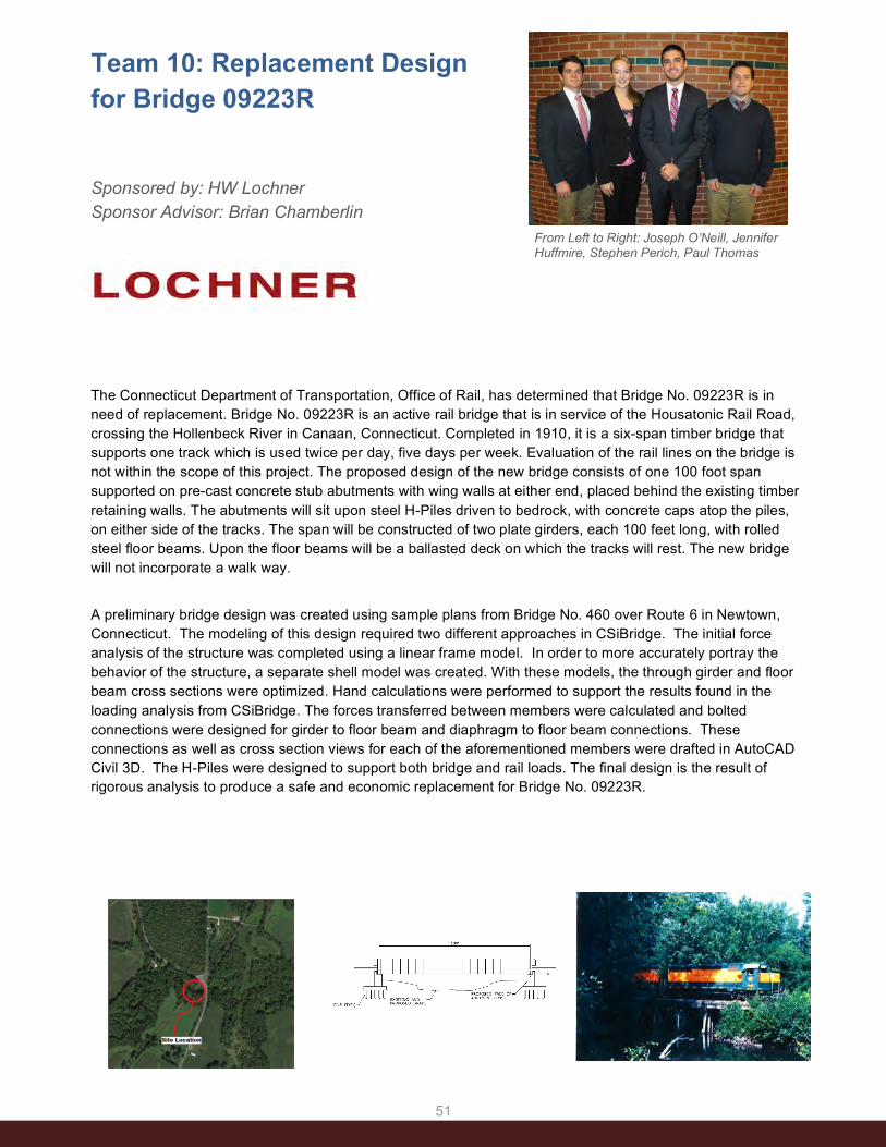
51
Team 10: Replacement Design for Bridge 09223R
Sponsored by: HW Lochner Sponsor Advisor: Brian Chamberlin
The Connecticut Department of Transportation, Office of Rail, has determined that Bridge No. 09223R is in need of replacement. Bridge No. 09223R is an active rail bridge that is in service of the Housatonic Rail Road, crossing the Hollenbeck River in Canaan, Connecticut. Completed in 1910, it is a six-span timber bridge that supports one track which is used twice per day, five days per week. Evaluation of the rail lines on the bridge is not within the scope of this project. The proposed design of the new bridge consists of one 100 foot span supported on pre-cast concrete stub abutments with wing walls at either end, placed behind the existing timber retaining walls. The abutments will sit upon steel H-Piles driven to bedrock, with concrete caps atop the piles, on either side of the tracks. The span will be constructed of two plate girders, each 100 feet long, with rolled steel floor beams. Upon the floor beams will be a ballasted deck on which the tracks will rest. The new bridge will not incorporate a walk way.
A preliminary bridge design was created using sample plans from Bridge No. 460 over Route 6 in Newtown, Connecticut. The modeling of this design required two different approaches in CSiBridge. The initial force analysis of the structure was completed using a linear frame model. In order to more accurately portray the behavior of the structure, a separate shell model was created. With these models, the through girder and floor beam cross sections were optimized. Hand calculations were performed to support the results found in the loading analysis from CSiBridge. The forces transferred between members were calculated and bolted connections were designed for girder to floor beam and diaphragm to floor beam connections. These connections as well as cross section views for each of the aforementioned members were drafted in AutoCAD Civil 3D. The H-Piles were designed to support both bridge and rail loads. The final design is the result of rigorous analysis to produce a safe and economic replacement for Bridge No. 09223R.
From Left to Right: Joseph O’Neill, Jennifer Huffmire, Stephen Perich, Paul Thomas
CIVIL EN
GIN
EERIN
G

52
Team 11: Mansfield Roundabout Replacement Design Sponsored by: Town of Mansfield Sponsor Advisor: John Carrington
The current intersection at Birch Road and Hunting Lodge Road in Mansfield, Connecticut consists of a roundabout served by three incoming lanes of traffic. After meeting with John Carrington—the Mansfield Director of Public Works—we were informed that the town is experiencing problems with the intersection concerning functionality, snow removal, and school bus safety. Constructed in 2007, the roundabout has also sustained structural and aesthetic damage over time due to an inappropriate design for the location. To resolve these issues, our group has envisioned and designed a conventional stop-‐controlled intersection by realigning Hunting Lodge Road to meet the current intersection from the south (See Figure below). The new intersection will call for a stop sign for both approaches on Birch Road allowing drivers on Hunting Lodge Road to have the right of way through a safer, more functional intersection. The design will eliminate the current confusion of who is granted the right of way at the roundabout and also address speed concerns through the intersection around the existing roundabout. Additionally, the new four way intersection will aid in snow removal as the plows can continue to move the snow to through the intersection instead of up onto the roundabout. Lastly, the school bus drivers will not have to worry about driving up and onto the roundabout as they turn.
In addition to the intersection design, our team was asked to address drainage issues in front of Goodwin School, which is north of the intersection on Birch Road. Drainage issues are apparent due to ponding and visual erosion along the roadway; which threaten the longevity of Birch Road. We have modeled both the existing and proposed drainage system to ensure functionality of the design to improve the current drainage and implement drainage for the new intersection.
Team 11: Robert Sandolo, Steven Kondej, Eamon Flannery, Jonathan Bossi
CIVIL EN
GIN
EERIN
G

53
Team 12: Mansfield Roundabout Replacement Design Sponsored by: Town Of Mansfield Sponsor Advisor: John Carrington
The Town of Mansfield, Connecticut assigned the task of redesigning a local intersection as well as a drainage plan for the surrounding area. The site being evaluated for the redesign is located at the intersection of Birch Road and Hunting Lodge Road. The intersection serves an integral role in connecting Route 44 to the University of Connecticut, Storrs campus. Between Route 44 and the intersection lies Dorothy C. Goodwin Elementary school as well as residential housing. The roundabout was initially installed as a traffic calming measure, however it has been ineffective and only caused confusion for drivers and difficulty for buses and plows. Because both Hunting Lodge and Birch Roads continue after the intersection, drivers have a difficult time determining right of way before the roundabout construction, plows had difficulty determining where the roundabout is in the snow, and buses find the intersection too difficult to navigate without hitting a curb. Because of the angle of the roads entering the intersection, as well as the placement of the roundabout within the intersection, it is extremely uncomfortable for the driver to navigate. As a result, the roundabout is currently failing to serve the community of Mansfield effectively. Additionally, the side of the road along Hunting Lodge Road has begun to erode due to lack of effective drainage. As a result, the current drainage along Hunting Lodge Road is failing, as water pools near the edges of the road and leaves build up where the erosion occurs. In order to improve the intersection to better serve the Town of Mansfield, we plan to redesign the approach of the Hunting Lodge and Birch Road to create an intersection that suits the traffic needs of the area and clearly shows drivers the correct way to enter. The placement of the new junction and the materials chosen will be suitable for the local traffic speeds and for larger vehicles to navigate. We will create new drainage plans along Hunting Lodge Road to accommodate the erosion and pedestrian traffic to the elementary school. With our new plans, the intersection of Birch Road and Hunting Lodge will finally become a well serving intersection providing effective traffic control and access for many types of vehicles and pedestrians. The intersection will finally be effective.
From Left: Christopher Dionne, Dianna Santella, Mateo Palo, and William Kresic
OTHER PHOTO GOES HERE Photo should be a color, high
resolution JPG and placed in THIS location shown by the blue rectangle. Blue box is to show you location and size only. Please delete it once you
place the photo
CIVIL EN
GIN
EERIN
G

54
Team 13: East Coast Greenway Connection in Bolton Notch Sponsored by: Connecticut Dept. of Transportation Sponsor Advisor: William Britnell
This project involves the design of a multi-use trail facility to connect Route 44 to the Hop River trail in Bolton, CT. Currently, the combined Route 44/Route 6 Expressway through Bolton Notch bans pedestrians and bicyclists due to safety concerns. This ban has meant that areas to the east of Bolton Notch on Route 44 cannot directly access the Hop River trail, the Charter Oak Greenway or New Bolton Road with access towards downtown Manchester. Alternatives do exist, but these access points lay several miles north or south of the intersection of Quarry Rd and Route 44 near the Bolton Post Office. Even without adequate facilities, it’s clear that demand exists to connect these two areas as ConnDOT reports that it is quite common for cyclist and pedestrians to utilize the shoulder of the Expressway, even though it is illegal to do so. Thus, connection to the Hop River trail is seen as an important link to pedestrian and bicycle accessibility in the region especially since the Hop River trail is a designated segment of the East Coast Greenway, a planned off-road trail spanning from Florida to Maine. In the fall of 2014 our team presented our proposal for design to the Connecticut Department of Transportation which consisted of three alternatives to the east of the intersection of Route 6 and Route 44. In our discussion with ConnDOT at the end of last semester, we decided to pursue design of an alignment off the end of Howard Road (Alternative #2) towards and crossing Route 6 and onto its terminus at the Hop River Trail. This alignment would take advantage of state owned land between Route 44 and Route 6, which would substantially reduce land acquisition costs associated with the project. Furthermore, this alignment has advantages of staying away from steep terrain and sensitive cultural sites that surround Bolton Notch and the roadways that go through it. The scope of this project consists of the design of an ADA compliant trail, specification of material design, design of a challenging at-grade crossing at Route 6, drainage design, and construction cost estimates.
Parker Sorenson, Jeff Baptiste, Laura Newton, Patrick Shea
CIVIL EN
GIN
EERIN
G

55
Team 14: East Coast Greenway Connection in Bolton Notch
Sponsored by: Connecticut Department of Transportation Sponsor Advisor: William Britnell *Set as Arial italic, 12pt, gray color as shown
The East Coast Greenway is a motor vehicle free path that connects cities from Florida to Maine all along the East Coast. The purpose of our project is to connect the East Coast Greenway through Bolton, Connecticut along the intersection of route 44 and I-84. Before making any designs however, we need to analyze the feasibility of existing plans. The proposed blueprint to connect the shared path was made by CRCOG. Our initial task is to analyze the preliminary proposal and determine whether of such a design is viable according to accessibility standards laid out by the department of transportation. Currently, the path follows the westbound shoulder of route 44 before coming to an abrupt halt just before the interchange. We face many challenges in our efforts to complete this portion of the East Coast Greenway, from extremely narrow shoulders and adjacent private property, to poorly placed utility poles and naturally occurring rock formations next to the highway interchange. There is even a well-known and consequently untouchable cave within the rock formation that our group must ultimately design around. Using information and data of the surrounding area, compliments of ConnDOT, our group hopes to create a safe and inexpensive way for residents of the Bolton area to use and enjoy this shared use path. The main obligation of this project remains to design an efficient route for the mixed use path which accommodates regulations that constitute the path as part of the East Coast Greenway. This is the main task even if the CRCOG blueprint is feasible, as efficiency is a priority in an area where space for the path is not abundant.
Abed Yacoub, Danilo Sena, Kristin Floberg, Zachary Duell
CIVIL EN
GIN
EERIN
G

5656

5757

58
Team 1: Route Bidding Solution
Sponsored by: Rogo Distributors Sponsor Advisor: David Heller Faculty Advisor: Bing Wang
The goal of the project is to design and implement Route Bidding Solution (RBS) that streamlines the bidding process for the truck drivers at Rogo Distributors, a beverage delivery company. Currently, truck drivers at Rogo manually pick their routes based on seniority every morning, which is cumbersome and time consuming. RBS allows the drivers to conveniently pick their routes electronically the night before, through a mobile application or the web. It saves time for the truck drivers the next morning. More importantly, it provides the benefits that a driver can be assigned a fixed truck that he drives every day, leading to more responsible behavior and better care of the trucks. In addition, the streamlining provided by RBS allows data to be more conveniently archived and mined to further improve delivery efficiency. The scope of this project involves pulling data from Roadnet, a commercial routing application, displaying the route data to the user through a user-friendly interface, and sending back to Roadnet the drivers’ picks. Another major functionality of RBS is that in the event that a driver cannot or does not want to choose a route on his own, there will be an option to auto-draft. With this, the driver can select some route preferences, and the application will automatically prioritize and choose the best available route based on that criteria. RBS spans across multiple platforms, including web, iOS, and Android. It is implemented using Objective C, Java, and HTML/PHP for the iOS, Android, and web apps, respectively. A SQL server is used as an intermediate medium for route data from Roadnet. It populates the fields on the website as well as those on the iOS/Android app.
From left to right: Vinkei Wong, Hardy Chen, Matthew Bruzik, Maxwell Madonna, Robert
Kowalczyk
CO
MPU
TER SC
IENC
E & EN
GIN
EERIN
G

59
Team 2: IBM Blue Rideshare
Sponsored by: IBM Sponsor Advisors: Konrad Lagarde, David Leip and Amy Travis Faculty Advisor: Thomas Peters
The Blue Rideshare application for Android devices is designed to aid IBM workers in carpooling to work every day. Carpooling to work has many benefits: it saves gasoline, promotes social networking, and provides a convenience for workers who may usually rely on other means of transport. With over 400,000 employees worldwide, it is extremely probable that many of these workers travel similar routes to work each day. The intent of our application is to ease the carpooling process by providing a simple user interface supported by the robust backend services offered by IBM Bluemix. Our application works by allowing users to create and search for “Rideshares,” or carpool events to their workplace. Any user who wishes to carpool to the same location can view the logistics of the Rideshare, such as the host (person who is driving), meeting times, and distance from their home. Additionally, we provide a mini-map as a visual aid in deciding which Rideshare is most convenient. After choosing an appropriate Rideshare, buttons are available to easily call or send an email to the host expressing a desire to carpool. Overall, the goal of our application is to provide a simple medium through which IBM employees can contact one another and make carpooling arrangements. The intuitive user interface makes the process easy and eliminates the stressful overhead of trying to coordinate sharing a ride to work.
Front left to right: Dayoung Kim, Colby Scotta Back left to right: Jeff Luong, Conor Finnegan,
Eric Luria
CO
MPU
TER SC
IENC
E & EN
GIN
EERIN
G
Office listings screen Rideshare listing for an office in Somers, NY
Rideshare creation screen

60
Team 3: AcroFinder
Sponsored by: International Business Machines Sponsor Advisors: Konrad Lagarde, David Leip, and Amy Travis Faculty Advisor: Thomas Peters
AcroFinder is an iOS application developed through the new Apple programming language, Swift. It is a simple way for users to search and look up the meanings to specific acronyms related to International Business Machines (IBM). Easily allowing the user to search the meanings of different acronyms, AcroFinder also provides various in-depth descriptions of the searched item(s). Two different versions of this application were implemented, one that allows only IBM employees to make additions to the acronym word bank and the other that offers only general public usage. This application also comes with user-friendly options that include the ability to “favorite” certain acronyms for an easy-to-navigate future reference, a quick look of recently searched terms, and the ability to view the Most-Viewed Acronyms of All Time, This Month, and This Week. By using this easy, at hand resource, developers can work more efficiently and productively with AcroFinder.
From left to right: Krupa Nesadia, Sherwin Yu, Michael Byon, and Axcel Duarte Espinoza
CO
MPU
TER SC
IENC
E & EN
GIN
EERIN
G

61
Team 4: Logicbroker Mobile Packing Application Sponsored by: Logicbroker Sponsor Advisor: Jordan Robidas Faculty Advisor: Swapna S. Gokhale
Logicbroker is a cloud-based software system developed, and owned, by the Logicbroker Company. This “software as a service” automates the many tasks involved in successfully running a company’s eCommerce system. Whereas in the past performing these tasks manually may have sufficed, the pace of today’s market requires a reliable solution that can perform tirelessly and without human error. Logicbroker provides its clients with solutions necessary to keep up with the modern pace of their customers’ demand. Logicbroker software enables a trading partner to use EDI (Electronic Data Interchange)- a communication standard that allows the transfer of electronic data between multiple companies without ambiguity. This translation of a company’s data standard to EDI and back occurs under the hood. On the front end, retailers and suppliers interact with Logicbroker’s online portal- a visual interface for order management. Retailers are able to receive and fulfill orders, while trading partners can view, acknowledge orders, and prepare for shipping. The functions implemented by trading partners have been the focus of our work. The goal of our project is to improve the user experience of trading partners. To achieve this, we developed a mobile application that synchronizes practical portability with the functionality of Logicbroker’s portal. Ideally, trading partners are able to ship products as quickly as they receive orders from their retailers. As it currently stands, someone in the warehouse must package the order and then use a desktop computer to enter exactly how the order was packaged into the Logicbroker portal before shipping. The mobile packing application assists in a natural, more practical, process by eliminating a constant warehouse to office trip. Our application is built from two main components, the Logicbroker API and PhoneGap software. Logicbroker’s API is a recent development that allows our application to send, or retrieve, data from the existing portal. This means, in addition to developing this application, we have also been working with them to test, and improve, their technology. PhoneGap is a mobile development framework that allows developers to apply existing web development skills to create and deploy mobile applications- for Android, iOS, Windows Phone, and more- using a single, universal, source code package.
From left to right: Nico Pizzo, Kenneth Philcox, Christian Pinho, Jeff Daniewicz
CO
MPU
TER SC
IENC
E & EN
GIN
EERIN
G

62
Team 5: Belcan Relational Database: Information Management Tool Sponsored by: Belcan Corporation Sponsor Advisor: Shaila Kambli Faculty Advisor: Swapna S. Gokhale
As companies have technologically matured, the capability to gather and organize exceedingly large volumes of data has become imperative. Many companies are currently in a transition period where their data storage and analysis techniques hinder their abilities to make the necessary connections between their data. In order to maintain a competitive advantage, it is increasingly the case that companies need to automate the tasks that are performed manually and present the data in a compact manner. The goal of our senior design project is to provide Belcan Corporation a tool to gain such a competitive advantage through automation of data management, analysis and reporting. The department within Belcan that our team is working with needs to keep track of software test data associated with Pratt & Whitney jet engines. There are three features that are essential to successfully handle the requirements set by this project. These include data consolidation, ease of access, and insight gathering. To effectively consolidate data, our job is to provide seamless import functionality that takes currently existing spreadsheet documents and inserts them into a universally accessible database. For this requirement, it is crucial for the software to be able to adapt to multiple document formats. In order to preserve the integrity of the data, checks need to be made to ensure the imported documents align to a set of predetermined specifications. Ease of access encapsulates the ability to intuitively interact, view, and edit the data. This is accomplished through a web-based GUI accessible from Belcan’s intranet. We gather insights to build relations across data that was previously stored in disparate spreadsheets. These relations may then be used to generate reports from dynamically selected criteria. This is important because it allows Belcan to make informed decisions based on concrete data that was not readily available. The tools that our team has opted to use include Visual Studio and Microsoft SQL Server. Both Visual Studio and SQL Server were chosen due to their synergy with the ASP.NET framework. Within this framework, we have opted to use the MVC design pattern to structure our code.
From left to right: Michael Milone, Sokhouth Chay, Kyle Reing, Matthew
Bruhin, Nicholas Eng, Eric Boivie
CO
MPU
TER SC
IENC
E & EN
GIN
EERIN
G

63
Team 6: Cloud-Based Transcriptome Quantification from RNA-Sequencing Reads Sponsored by: Smpl Bio LLC Faculty Advisor: Ion Mandoiu
From left to right: David Chen, Nicholas Kruczek, Reynaldo Morillo, Matthew Bemis
and Zachary Dicesare.
Smpl Bio LLC is a UConn spin-off based in Tolland, CT. The company is focused on delivering powerful yet easy to use bioinformatics solutions for targeted genomics, including best-in-class tools for biomarker selection, experimental design, and data analysis. These tools are delivered to users within a Software as a Service (SaaS) framework hosted on the Amazon Elastic Compute Cloud (EC2). The system is designed to leverage the scalable nature of cloud-based computing for performing complex analyses quickly and reliably. Access to the system is provided to researchers through a representational state transfer (REST) application program interface (API) server.
The Senior Design team composed of Matthew Bemis, David Chen, Zachary Dicesare, Nicholas Kruczek, and Reynaldo Morillo, five Computer Science/Computer Science and Engineering students, worked under the supervision of faculty advisor Ion Mandoiu with Smpl Bio software engineers James Lindsay and Mike Lydon on implementing a cloud-based transcriptome quantification API that will allow researchers to apply Smpl Bio’s algorithms starting directly from RNA sequencing (RNA-Seq) reads.
In the first phase of the project the team conducted interviews with RNA-Seq users across the UConn campus and distilled their feedback into a set of requirements. They also performed a preliminary evaluation of existing RNA-Seq quantification tools, selecting for their implementation the recently published Sailfish algorithm. Sailfish focuses on speeding up the RNA-Seq expression estimation process without sacrificing accuracy. The algorithm operates on a set of reference transcript sequences and RNA-seq reads given in fastq format. Reads are analyzed using a two-step process consisting of read and transcript indexing followed by quantification via Expectation-Maximization. The most salient feature of Sailfish is the replacement of the read mapping step used by other methods with very fast k-mer indexing and counting algorithms based on hashing. This allows Sailfish to quantify transcript abundances over 20 times faster than other existing tools.
In the second phase of the project the RNA-Seq quantification API based on Sailfish was implemented and deployed on the Amazon EC2. The implementation was done in Python and was built using the powerful Celery distributed task queue system for handling asynchronous tasks and scheduling. Algorithms developed during this project will be integrated within Smpl Bio’s SaaS framework to ensure high availability and scalability and provide users access without costly investments in high-performance computing infrastructure.
CO
MPU
TER SC
IENC
E & EN
GIN
EERIN
G
Sequencer Results!
Amazon cloud

64
Team 7: F4U Corsair Aircraft Flight Simulator Sponsored by: Connecticut Corsair Sponsor Advisor: Craig McBurney Faculty Advisor: Bing Wang
The CSE team’s ultimate goal is creating an authentic simulator for F4U Corsair that will respond to user input via the airplane’s controls. This is part of a larger multidisciplinary project that aims to renovate and design the simulator for F4U Corsair, an American fighter aircraft that served in World War II and the Korean War.
The CSE design team is in charge of creating the simulated environment that the user will experience inside the cockpit. Prepar3D will be used to simulate the view. Prepar3D software development will be done through SimConnect SDK and add-ons can be developed through the use of various languages such as C, C++, C#.net or VB.net. The Prepar3D software contains preloaded settings that will be simple to adjust to our requirements for development and contains options to add features to the simulation such as custom missions, weather manipulation, control view, and or other artificial intelligence (AI) aircrafts.
The CSE team is currently planning on creating three modules within Prepar3D to target three different audiences. The audiences include children, attracting donations, and appealing to veterans. The module pertaining to amateur flyers, such as children will take the user on a flight programmed to work with limited input to start the plane, and then the program will take control to continue with a predetermined flight pattern of small maneuvers and a landing. For the remaining modules, added user controls will be implemented. Those interested in the project will be able to start the plane and have the capability to control several small maneuvers and complete a landing. This will allow them to experience the input instruments and the reactions of the plane simulation to these inputs. For veterans, the simulator will allow for complete control of the input and the flight patterns. In addition, the veteran’s module will have a few combat interfaces and AI to mimic experiences from World War II.
Finally, the team has been given the objective to plan, and if time allows, create a vision system for the simulator. There have been many different forms of displays for simulators predating our own, so research has to be done to choose the display to best fit our needs. The only display option that is being looked into at this moment is immersive display which is a domed shape canvas that allows for the complete “immersion” of the pilot in the simulated environment.
From left to right: John Foster, Leon Gunzl, and Julian Schwartz. Not pictured: Alexander
Dow, Sandra Hamilla
OTHER PHOTO GOES HERE Photo should be a color, high
resolution JPG and placed in THIS location shown by the blue rectangle. Blue box is to show you location and size only. Please delete it once you
place the photo
OTHER PHOTO GOES HERE Photo should be a color, high
resolution JPG and placed in THIS location shown by the blue rectangle. Blue box is to show you location and size only. Please delete it once you
place the photo
CO
MPU
TER SC
IENC
E & EN
GIN
EERIN
G

65
Team 8: WirelessHART on IEEE 802.15.4e: Feasibility Analysis, Implementation & Evaluation
From left to right: Marcus Li, Timothy Barron, Duy Bui, Tyler Plude, and Tao Gong
Sponsored by: Emerson Process Management Sponsor Advisor: Eric Rotvold Faculty Advisor: Song Han
WirelessHART, the first international industrial wireless standard (IEC 62591), is built on top of the IEEE 802.15.4 standard, which defines the physical layer and data link layer for low power, low data rate, personal area wireless sensor networks. Both standards have progressed since the WirelessHART incarnation. WirelessHART has gone through a major release, added support for discrete devices, and lately turned attention to real-time wireless control. While WirelessHART is still based on IEEE 802.15.4-2003, IEEE 802.15.4 has progressed to the latest version of IEEE 802.15.4e in 2012, with lots of new features that used to be exclusively in WirelessHART. In this senior design project, we are going to study the relationship between these two international standards, and give a feasibility analysis on building the latest WirelessHART standard on 802.15.4e physical and data link layers. We shall develop the WirelessHART communication stack on top of an open-source 802.15.4e implementation, and on energy-efficient embedded platforms provided by two chip vendors. The WirelessHART communication stack will be enhanced with a 6LoWPAN layer to support both WirelessHART and Internet applications. We shall also design and develop a software-based Gateway and Network Manager to manage network resource and regulate real-time traffics in WirelessHART networks. Representative reliable routing and real-time scheduling algorithms will be implemented to satisfy stringent end-to-end timing constraints for safety- and mission-critical applications. A visualization tool will also be developed to demonstrate the real-time network traffic and device health information. Our performance evaluation will focus on 1) the timing accuracy and synchronization performance of the 10 millisecond time slot on three different hardware platforms, 2) energy efficiency of the communication stack and hardware platforms, 3) the co-existence between WirelessHART networks based on 802.15.4-2003 and 802.15.4e standards respectively, and 4) the efficiency of the resource management protocols proposed in the developed Gateway and Network Manager.
CO
MPU
TER SC
IENC
E & EN
GIN
EERIN
G

66
Team 9: Mass Mailer Project Sponsored by: Academic Keys Sponsor Advisor: Keith Palmer Faculty Advisor: Steven A. Demurjian
From left to right: Chao Lai, Christopher Mechler, Jevic Jardeleza, Thanoj Singh, Michael Miller
AcademicKeys.com is the premier source for academic employment and was founded by a University of Connecticut Civil Engineering professor. AcademicKeys.com’s 17 discipline-focused sites offer comprehensive information about faculty, educational resources, research interests, and professional activities pertinent to institutions of higher education. More than 89% of the top 120 universities (as ranked by US News and World Report) are posting their available higher education jobs with AcademicKeys.com. One of the major computing requirements that is needed in support of AcademicKeys.com is the ability to send tens of thousands of batch emails to subscribers organized on different mailing lists. In support of AcademicKeys.com, this project has designed and developed Mass Mailer, a PHP-based web application that will manage and handle a large amount of mailing recipients each tied to one or more mailing lists. Each mailing list can be modified to add, delete or update any recipient. Furthermore new mailing lists can be created or deleted. In conjunction, users or other applications will have the ability to generate and modify either plaintext or HTML emails and send them to the various mailing lists. This application must be able to handle the ability to send, at the bare minimum, upwards of 60,000 emails per day and store upwards of 1,000,000 mailing recipients. Manipulation of these interfaces will primarily be done through a series of HTTP calls to a REST compliant back-end API.
The ultimate goal of Mass Mailer was to create a REST API that can operate as an efficient mailer that can handle a large amount of data being stored, retrieved and sent. Furthermore, another goal is for the code base to be neat and efficient allowing future upgrades, features, and preventive, corrective, and adaptive maintenance to be a simple and easy process. A model view controller design pattern in conjunction with a robust existing PHP framework has been utilized be support these goals. The Mass Mailer was coded in PHP5 to set up the page content and employed HTML and CSS to create a simple user interface for the ease of users. A comprehensive REST API was designed and implemented to allow information to be exchanged via JSON. All aspects of the REST API are accessed through a series of HTTP calls depending on the way that the information must be used (i.e. modified, retrieved, etc.). Input for applicable HTTP calls is in a JSON format. Output from each call, when applicable, is returned in JSON format. JSON was chosen since its RESTful API’s are fast, reliable, and easy to use. Laravel, a PHP web application framework for the development of the MVC web applications, was selected as the framework for front-end views and back-end API.
CO
MPU
TER SC
IENC
E & EN
GIN
EERIN
G

67
Team 10: Scann3D Hub
Sponsored by: University of Connecticut Faculty Advisor: Bing Wang
3D printing is being touted by many as the next industrial revolution. It has already had an immense impact in the manufacturing industry and has grown exponentially in the commercial setting. The goal of this extraordinary research opportunity is to create a flexible database to house 3D “blueprints” for use in both the private and public sector. Users of our program can upload scan files to share with others, creating a growing 3D printing community. No longer will people have to scour the web looking for a specific design when our database acts as a warehouse for users to browse for scan files in order to get the exact print that they desire. The user also has the option to download the scan file locally, allowing for the user to tweak and edit the file to their liking. Another critical element of our product is collaboration. Users possess the ability to edit and share files together easing the design process while stimulating creativity. Never before in such a simple bundle has 3D manufacturing been so easy.
From step one, the primary concern was maintaining simplicity without sacrificing performance or functionality. Using Java3D coupled with creative programming has lead us to develop a natural feeling GUI (Graphical User Interface) that encourages users to act on intuition rather than waste time struggling to find where certain features are located. Through development, we found that Java3D provided a much easier and cleaner way to build the GUI as opposed to using Java Swing. The GUI acts as the bridge between the user and the database, meaning the two need to pair together well. Basing the GUI design off of the key elements in the database, as well as incorporating a Model View Controller and Proxy design style has allowed us to create certain features such as an extremely responsive search menu that updates in real time through Get/Pull requests. Though there are other competing 3D printing databases, we believe that we have created a product that users and businesses will trust. Certain desirable features such as the ability to share prints privately, collaborate on projects, or even include critical variables such as the temperature or atmospherics at the time of the print are currently lacking in the industry. Our product aims to solve these problems and help grow the 3D community.
From left to right: Kazi Shahjahan, Dave Ruhlemann, Mitch Thornton, John Guttermuth,
Lachezar Shumkov
`
CO
MPU
TER SC
IENC
E & EN
GIN
EERIN
G

68
Team 11: Twitter Data Acquisition and Analysis
Sponsored by: University of Connecticut Faculty Advisor: Swapna S. Gokhale
Social networks contain a myriad of information which people may not know that they can utilize. Millions of people sharing their thoughts and perceptions, combined with relevant geographic and network data can give academics and businesses alike a grand new perspective. Data from social networks like Twitter, in conjunction with various machine learning algorithms can be used to see how people are connected, what their perceptions are and even what actions they might take. The problem is that much of the research is done with quick scripts and other batch style code. This process in neither efficient nor organized. In fact, there is a lot of code that gets rewritten for each project. Tasks like gathering data from Twitter can be time consuming. If researchers were relieved from this overhead they would be able to accomplish more in less time. We are building a suite of reusable tools for researchers in order to boost their productivity by reducing their development overhead. These tools include a client for gathering data from twitter, a parser for creating various different datasets for machine learning algorithms, and a network analysis and graphing tool. Throughout the process we are aiming to provide a smooth and intuitive workflow so that researchers can get to their specific interest with minimal effort. However, each tool is also a stand-alone component that can be used however the user sees fit. The data sets from Twitter are perfect for learning about machine learning as well as performing leading edge analysis. Our hope is that by building and releasing these tools we will be help to further the use of Twitter for academic purposes.
From left to right: Moolchand Ojha, Kimberly Sayre, Russell Bentley. Not pictured: Nicholas Rose
GROUP PHOTO GOES HE Photo should be a color, high resolution JPG
and placed in THIS location shown by the blue rectangle. Blue box is to show you location
and size only. Please delete it once you place the photo
CO
MPU
TER SC
IENC
E & EN
GIN
EERIN
G

69
Team 12: Drone Wars -
Augmented Reality
Drone Dogfight Application
Sponsored by: Team Members Faculty Advisor: Steven A. Demurjian
As the era of manned warfare draws to a close and unmanned aerial vehicles take to the skies, prepare to take a seat in the command center of a drone. Battle with friends to become an ace pilot by taking out enemy drones in the epic new game of Drone Wars, the augmented reality drone dogfighting app for Android. Drone Wars utilizes unmodified Parrot AR.Drone 2.0 and their on board front-facing 720p HD video camera in combination with an Android smartphone to simulate aerial warfare. With Drone Wars’ integrated servers, playing and competing with friends can be done anywhere. Earn the rank of Top Gun by becoming the top ranked player. Players can track their statistics like wins, losses and shot accuracy to compete for total dominance of the skies in Drone Wars’ global leaderboard. The setup is as simple as turning your drone on, launching the Drone Wars application and selecting your drone. The server utilizes two wireless interfaces to force drones to connect as clients and then pair them each players corresponding smartphone. Thus, all the drones share a local wireless network to route all flight and video data between paired devices. The game consists of having the players use their Android devices to control their drones. While controlling their drones, players need to line up the aiming reticle with an enemy drone. The aiming reticle and other game dynamics are overlaid on top of the video input from the camera. Tapping the fire button when the opponent’s drone is correctly targeted will result in the targeting player’s virtual ammunition count decrementing and the targeted player’s life count decreasing by one and allowing them a small window of time where they are invulnerable. The game ends when either the game time runs out or there is only one player with at least 1 life left, who will be the winner. The amount of game time and the number of lives per player is determined at the beginning of the game by the administrative player.
From left to right: Peter Zaffetti, Krystian Charubin, Michael Grillo, Dustin Peirolo, Chunze Chen, Dake Lu
CO
MPU
TER SC
IENC
E & EN
GIN
EERIN
G

70
Team 13: Integrated Pest Management App
The Integrated Pest Management (IPM) App for plant pests provides information that agricultural producers need to address pest problems and assist with pest-management decision making to reduce pesticide applications that may impact flora, fauna, groundwater, and human populations. This has been accomplished by allowing for identification of key plant pests that may cause crop losses or reductions in aesthetic quality to ensure effective directed action against them and providing preemptive knowledge of possible outbreaks by charting the movement of pests, blights and disease across the state, region and nation.
The IPM App for Plant Pests is an application for Android powered devices that allows direct access to a database of information on plant pests in the field. The application helps the user identify plant pests by using photo comparison between damage found on crops and pictures of known infestations, while simultaneously providing resources about the pest and how to manage it using photos, videos, text, and links to web resources. IPM provides information on pests found in Connecticut, with the plan to eventually expand to other states; the application could grow to include the entire United States with enough time and effort once the app is successfully implemented in Connecticut. In order to accomplish this, the IPM App has been designed and executed with state differentiation in mind to easily include additional states and their specific crops and pests. IPM also uses a searchable database of most pests based on category selection such as crop types (vegetables, fruits, ornamentals, herbs, turf, etc.), geographic location and area of plant affected (leaves, stem, roots, fruit). The database also provides photos of the various types of damage for comparison purposes; a user can simply search for pest information by comparing crop damage symptoms and photos of possible pests to explore.
From left to right: Gregory Rendeiro, Ricky Jia, Milod Kazerounian, John Chow, Dillon Shea
Sponsored By: UCONN Plant Science and Landscape Agriculture Sponsor Advisor: Donna Ellis Faculty Advisor: Steven A. Demurjian
CO
MPU
TER SC
IENC
E & EN
GIN
EERIN
G

71
Team 14: Parkshark Mobile App
Sponsored by: Team Members Faculty Advisor: Steven A. Demurjian
The ParkShark system was developed in order to address the issue of commuter parking on the University of Connecticut’s Storrs Campus. Commuters travel between 1-3 parking lots per day, sometimes several times per day; during peak hours this creates unnecessary extra traffic on the already crowded roads, and can cause the commuter to be late to class if there are few remaining spaces. ParkShark is an application system which is intended to shorten the time that users spend trying to find a parking space. The main purpose of the system is to provide a convenient service to UConn’s Commuters - reducing the time it takes to get to where the user needs to go and reducing traffic generated by vehicles searching for parking spaces. The ParkShark system is comprised of several main components which allow it to operate: a network of small sensors, a database to store pertinent information, and user interfaces on multiple platforms. Each sensor is contained within a weather-proof enclosure in order to survive tough winter conditions and abuse. Additionally, the sensor is built to be low-powered and to recharge itself via solar power - thus minimizing the replacement frequency and maintenance cost. The sensor registers vehicles entering or exiting the lot through the use of a magnetometer; once a vehicle is registered, a message containing lot data and the number of cars involved is sent to the server for processing. The server will update the database accordingly, which is then used to convey information to the user appropriately. The user interfaces are available on the Android and iOS mobile platforms, as well as a web application for administrative use. Through the use of the mobile apps, a user may visualize the current status of each parking lot, and be routed to the nearest convenient parking lot to the location that they are attempting to reach. The administrative application gives the user the ability to manage parking lot data and user data, including but not limited to: parking lots available on campus, parking lot capacities, permitted parking permits for each parking lot, lot closures, and permitted administrative users.
From left to right: Cameron Panagrosso, Steven Gerhard, Steven Grasso, Justin
Timmons
CO
MPU
TER SC
IENC
E & EN
GIN
EERIN
G

72
Team 15: Stormwise Mobile App
Sponsored by: UConn Forestry Sponsor Advisor: Thomas Worthley Faculty Advisor: Steven A. Demurjian
The STORMWISE program at UConn (http://www.stormwise.org) is intended to mitigate damage associated with power outages caused by large storms (hurricanes, snow storms, thunderstorms, etc.). A successful STORMWISE initiative needs an improved understanding of patterns and modes of tree failure. Since tree structure is complex and highly variable, the establishment of a competent tree failure model has proved elusive. Currently, since we have a poor ability to overcome such complexity, it is vital to build a data collection tool to advance our understanding and knowledge of tree structure, stability, modes of failure, and biomechanics. Data collection fields have been developed in collaboration with Connecticut Light and Power to optimize the speed of data collection. The Stormwise app makes it easy to input data about the fallen tree including manual measurements, images taken on the device’s camera, and location based on GPS. The user interface (UI) of the Stormwise app for tree assessment has been designed in order to collect the pieces of information about the tree that are most important to report and which are helpful, but not necessary. The tree risk assessment component of the mobile app is focused on the user who would like to do a self-assessment of a tree. This component of the Stormwise app adheres to the International Society of Arboriculture’s Best Management Practices for Tree Risk Assessment and provides the questions and guidance (including knowledge briefs) needed to perform assessment of risk that allows users to reach a much greater level of awareness of the risk of a tree. Users have the ability to report their knowledge level regarding trees and tree structure. Subsequent questions or data fields are dynamic and flexible by asking more detailed information from experts. Data is marked with user knowledge level when analysis of the data is conducted. The assessment of tree risk has become more precise, but it is largely unknown how accurate the assessments are. Tracking the fate of assessed trees can reveal accuracy of assessments so our Stormwise app will take notice of trees users have assessed and recognize if that tree is reported broken in the database. The Stormwise app is utilized in two ways: to gather information for reporting, and to feed a website that collects this data and pinpoints where these incidents occur with a ticketing system that will give status changes as the situation changes. The interfaces for both the Stormwise app and website will be dependent on which end the current user is on, the app or the website. There will be a log on for town officials for ticket handling, and users will be able to track their tickets. Note, however, the website app is focused towards the town officials and possibly some utility workers as far as needing to manage and attend to issues/tickets.
From left to right: Kirk Gardner, Andrew Debarge, Jonathan Chi, Ammad Shakih
CO
MPU
TER SC
IENC
E & EN
GIN
EERIN
G

73
Team 16: The J1 – A Modular CNC Machine with an Open-Source Web Interface Sponsored by: University of Connecticut Faculty Advisor: Thérèse Smith
Our project is to create a small, modular Computer Numeric Control (CNC) machine with a flexible web-based user interface. Our goal is to enable people with no CNC experience to take advantage of the repeatability and precision of the platform. We have chosen to extend the open-source “Chilipeppr” interface with the ability to draw simple shapes and convert those shapes into instructions for movement, which Chilipeppr can then send to the machine for execution. Our CNC machine is called the J1, and was developed by Dillon Jones with funding from the UConn IDEA Grant. The J1 is able to use the movement instructions (known as GCode) and create sketches using a ballpoint pen, or laser etchings using our own laser diode and optics configuration. The fall of 2014 brought with it a lot of work researching possible solutions to the problem we want to solve and defining the scope of the project. The specification has set the scope of our project. In it we described the web technologies and the hardware that we plan on using to make your dreams a reality. On the web side of things we have been using a mix of Bootstrap, JSON, and the open source project Chilipeppr to web enable the J1 through the chrome browser. The J1 makes use of a TI Beagle Bone Black (BBB) as a web server, a Sythetos TinyG to handle coordinate interpretation, four stepper motors to drive the gantry, and peripherals. With all the i’s dotted and t’s crossed, it’s time to use the sum of our engineering educations and create. This semester we plan to finalize designs for the laser etcher and extend Chilipeppr’s web interface, which will include designing circuits and PCB’s, web development, and use of web-based 3D graphics. Our modifications will enable Chilipeppr to support the creation of simple, machineable shapes directly on the web page. Finally, we will design and implement a testing strategy to objectively qualify the J1 and web interface for use outside our team.
From left to right: Will Percival, Dillon Jones, Nolan Grant, Thérèse Smith, Ryan Powers,
Parth Dalsania
C
OM
PUTER
SCIEN
CE &
ENG
INEER
ING

74
Team 17: Electronic Engine Control Fault Data Analysis
Sponsored by: Pratt & Whitney Sponsor Advisor: Jeffrey Grout Faculty Advisor: Thomas Peters
Our group was tasked with the creation of an application to analyze Electronic Engine Control (EEC) fault data for Pratt & Whitney’s commercial airline engines. This data is recorded by the EEC whenever the plane’s sensors detect something out of the ordinary. Analysis of this data is critical to discovering the source of engine defects, but the raw data is completely unintelligible on its own. Our application will allow the user to leverage powerful tools to view and analyze this engine fault data. Due to the sensitive nature of the data being handled our application will not be displayed at Gampel Pavilion.
From left to right: Simi Hartstein, Regi Zhang, Kyle Bussmann, Matt Verderame, Jeff White,
and Ethan Sperry
+-‐
CO
MPU
TER SC
IENC
E & EN
GIN
EERIN
G

7575

76
Team 1501: High Frequency Piezo-Driven Droplet Maker
Sponsored by: Amastan Technologies LLC Faculty Advisor: Rajeev Bansal
The goal of this project is the design of a high frequency piezo-driven Droplet Maker (DM) capable of delivering a uniform droplet stream of solution precursor for improved coatings or powder making of interest to thermal processing industry. The improvement is achieved through control of the size and homogeneity of solution droplets. When combined with a uniform melt state process such as UniMelt™ where droplets undergo pyrolysis, one can achieve precise control of powder size and size distribution, morphology, and homogeneity and purity of phase microstructure. The size of the particles dealt with is in the range of micrometers to nanometers, and they need to be content homogeneous and uniform in size. As the size of the droplet is inversely proportional to frequency, the DM needs to operate at high frequencies with sufficient current or voltage drives to achieve liquid jet break up into uniform droplets.
The High Frequency Piezo-Driven Droplet Maker is made up of three major parts: The Solution
Dispenser, The Droplet Maker, and the High Frequency Electronics Driver. The High Frequency Electronics Driver needs to be improved to further the development of the current Droplet Maker design. A higher frequency than its current capability. This will allow the droplets to be more quickly separated and evenly spaced while possibly reducing them in size to the desired dimension of one micron diameter uniform droplets. Power and voltage must also be reconsidered, which must allow for a design capable of driving multiple capillary nozzles from a single apparatus, while still consistently producing uniform droplets.
Joseph Eaton (EE), Rajeev Bansal (Advisor), Colin Mack Nair (EE), Jacob Wolf (EE)
ELECTR
ICA
L & C
OM
PUTER
ENG
INEER
ING

77
Team 1502: CT Corsair Flight Simulator Restoration
Sponsored by: CT Corsair Sponsor Advisor: Craig McBurney
Connecticut Corsair has sponsored teams of students from the University of Connecticut as well as from the University of New Haven and Trinity College to continue the restoration of the Corsair simulator. The simulator in question is a Gyro IPT simulator and was developed by Electronics Tectonics Corporation. This is a multi-year project with various phases of the restoration. Last year’s UConn team found that, in order to meet motional requirements of the simulator base, the best solution would be to use servo motors to replace the existing induction motors. The team was successful in acquiring and replacing one of the motors with a new servo motor and was able to achieve a limited range of motion of the simulator.
The scope of this year’s project involves the replacement of the two other existing induction motors with servo motors and creating complete three dimensional movement of the base. The project also requires interfacing the controls and visual feedback from the cockpit such as flight levers, throttle, and other basic flight controls. The visual feedback will include gauges displaying different values from the Prepar3d flight simulator software. This 3 dimensional motion will be taking user input from the cockpit via a mounted joystick. We will also be introducing the use of Prepar3d for the flight environment and implementing an “autopilot” function. The UConn team is made up of students from the Computer Science and Engineering (CSE), Electrical and Computer Engineering (ECE), and Mechanical Engineering (ME) departments. This year’s goal for the Electrical Engineering team is to make the base’s movement 3 dimensional with the use of servo motors. The goal for the Mechanical Engineering team is to improve the motor mounts and develop a cockpit to put in use. The goal for the Computer Science Engineering team is to develop a Corsair aircraft with flight environment in Prepar3d and interface the software with the physical design.
The University of New Haven team of students is taking on the task to reverse engineer the cockpit of the Corsair. When the cockpit is delivered to the University of Connecticut it will be incorporated into the design of the simulator.
Kevin Whitton, Joseph DeCola, Quinton Pittman
ELECTR
ICA
L & C
OM
PUTER
ENG
INEER
ING

78
Team 1503: Design and Construction of Unmanned Air Vehicles
Sponsored by: UConn ECE Department and L.I.N.K.S. Sponsor Advisor: Shalabh Gupta
Most (aerial) robotic agents operating in an indoor or underground environment depend on external positioning data, such as that of a GPS or VICON motion capture system. This provides extremely accurate location data, but constrains the robot to where GPS signal is available or in a predefined room, respectively. The goal of our project was to design an autonomous unmanned aerial vehicle (UAV) that can generate a 3D map, avoid obstacles, and navigate in an unknown, GPS-denied environment with off-the-shelf components. To complete this task, we have built a robot that utilizes just two sensors: an inertial measurement unit (IMU) and a depth sensing camera. The camera provides both depth data and traditional RGB image data (RGBD) while the IMU outputs angular state information. Using a robotics software framework (ROS) in tandem with the camera, we developed a system that uses a SLAM algorithm (simultaneous localization and mapping) to generate a 3D map and output estimates of our robot’s position in real-time. Simultaneously, our robot also uses the camera to detect obstacles from sequential image frames. To ensure robust flight, we wrote a complete flight stabilization system using our IMU sensor. The robust nature of our robot has wide applications to search and rescue missions, firefighting scenarios, and other military operations. Furthermore, by using a multirotor frame equipped with a single-board ARM computer, flight controller, compact battery power system, and the aforementioned sensors, we were able to complete our project at a very low cost – compared to similar autonomous UAV projects.
(Left to Right) Andrew Lawson, Chung-Ting Yang, Kristofer Balisciano
ELECTR
ICA
L & C
OM
PUTER
ENG
INEER
ING

79
Team 1504: Command and Control of Autonomous Underwater Vehicles Sponsored by: UConn ECE Dept. L.I.N.K.S. and UWSN Sponsor Advisor: Prof. Shalabh Gupta and Shengli Zhou Shengli Zhou
Oceanic exploration and monitoring is quickly becoming an area of intense focus and interest that touches industries and academic pursuits as diverse as energy extraction, shipping, and climatology. Autonomous Underwater Vehicles or AUVs have the ability to monitor a large section of seafloor, loiter near an undersea cable laying operation, inspect shipwrecks, or traverse great distances while gathering valuable oceanographic data, all without any human interaction or guidance. Current AUVs rely on surfacing momentarily to fix their position with GPS for navigation and radio or satellite connections to upload data intermittently, so they are unable to communicate, send data, or fix their position while underwater due to the physical limits of microwave transmission through water. Senior Design Team 1504’s goal was to realize the guidance and navigation system for an Autonomous Underwater Vehicle. The outcome is an AUV that can receive a destination coordinate encoded as an acoustic signal, fix its positon using a network of acoustic communication modems, and move towards the destination without needing to surface. Now the AUV’s ability to remain underwater is only limited by its battery life. The AUV itself is a combination of an off-the-shelf remote-controlled Thunder Tiger Neptune SB-1 submersible and a fully custom-built electronics package containing a single board computer, Arduino, and the integral acoustic modem processing board among other devices. The electronics package is housed inside a custom Plexiglas box which sits on top of the submersible allowing it to receive commands and communicate with a network of acoustic modems while submerged. The team built upon the hardware designs from previous senior design teams and the graduate students of the UWSN lab, and made key adjustments to the power delivery circuitry inside the electronics package to increase reliability. Significant enhancements to the AUV’s control software were made by incorporating the Robot Operating System, an open source robotics software middleware kit, into the project allowing future teams to easily add hardware and software capabilities to the AUV such as cameras for feature detection. A PID controller was also realized in software, which allows the AUV to maintain a given heading and speed by integrating data from a specialized marine compass and accelerometer chip.
Daanish Zaidi, Samantha McNellis, Clancy Emanuel
ELECTR
ICA
L & C
OM
PUTER
ENG
INEER
ING

80
Team 1505: A Robotic Rehabilitation Device for Sit-to-Stand Assistance Laboratory of Intelligent Networks and Knowledge-Perception Systems Sponsor Advisor: Shalabh Gupta, Krystyna Gielo-Perczak
The Compact Sit to Stand Assistive Device is an innovative solution to give mobility to individuals
affected by lower extremity disorders. This target demographic may suffer from muscle atrophy, arthritis or cerebral palsy. In other cases these individual are recovering from surgery or other forms of trauma. However, as a whole, this group’s mobility, quality life of life, and recovery time is limited by their inability to complete a simple sit to stand motion.
This innovation is a dramatically different approach from currently available solutions on the market by giving 100% assistance to individuals weighing up to 170 lbs. The Compact Sit to Stand Device employs a battery powered modified scissor lift design. The innovation of this device is in the mechanical advantage gained by employing a geared motor, along with a jack, and lead screw. Thereby, the Compact Sit to Stand Assistive Device reduces the required output torque of the motor and the weight of the overall design.
The design constraints were set by AnyBody simulation software, demonstrating that the required vertical force to lift a 170 lb individual is 620 N if the device bears 100% of the body weight. The design verification will be performed in SolidWorks to determine the maximum weight that can be lifted by the device given the output torque of the geared motor. Further a stress analysis will be conducted at every mechanical joint, showing the number of sit to stand cycles that the material can withstand under the maximum load.
Evita Vigante, James Yee, Shaniel Bowen, Rachelle Aekins
ELECTR
ICA
L & C
OM
PUTER
ENG
INEER
ING

81
Team 1506: Induction Motor Emulation Sponsored by: Lenze Sponsor: Christopher Johnson Faculty Advisor: Ali Bazzi
Motion control devices are a critical piece in an electro-mechanical system. To control an AC motor’s speed and torque a motion control device adjusts the input voltage and frequency of the motor; one such motion control device is a variable frequency drive. Some common applications that use variable frequency drives to adjust the rotational speeds of electrical motors are: product transportation, pump control, automotive construction, among others. Since variable frequency drives are commonly used, the production of a well tested and well performing product is what can set apart one company’s product from another. Due to this fact, our sponsor, Lenze, finds it critical that all of their device lines be properly tested to ensure the performance and reliability of their products. Currently Lenze utilizes many induction motors and dynamometers to test their variable frequency drives. This method of testing consequently takes up a large area of space and gives off a significant amount of heat. To facilitate Lenze’s testing the use of a variable induction motor emulator can reduce space, eliminate moving mechanical parts, and allow for a variety of test scenarios for variable frequency drive testing, with the same accuracy and reliability as an induction motor and dynamometer pair. Our team’s goal is to design and create a variable motor emulator that can accurately emulate the multiple loads of an actual motor. To emulate various induction motors our emulator will output loads of 0.5, 1.0, and 2.0 horsepower without the consequences of taking up a large space and moving parts. To accomplish our variable induction motor emulator we used a 3 KVA delta connected transformer connected in series with a delta-connected resistive load. The resistive load we created is a resistor bank of four parallel power resistors per phase, which upon testing are selected using relays and a graphical user interface (GUI). Using the resistor banks and GUI a user can select the power of the intended emulated motor along with the emulator to run a steady state or transient response. By using solid-state relays, power resistors, a GUI, and a transformer we successfully created a small induction motor emulator with no moving parts that can accurately emulate various induction motors.
From left to right: Geoffrey Roy, Amber Reinwald, & Matthew Geary
ELECTR
ICA
L & C
OM
PUTER
ENG
INEER
ING

82
Team 1507: Software-Defined MIMO Radio Transceiver
Sponsored by: The MITRE Corporation Sponsor Advisor: Michael J. Wentz Faculty Advisors: Prof. John Chandy and
Prof. Shengli Zhou
Being an integral facet of the modern era, great efforts have been made to increase the capabilities of communications technologies. One recent, yet critical advancement in the field is the use of Multiple-Input-Multiple-Output (MIMO) schemes. MIMO communication allows for several advantages over its singular predecessor including faster data transmission, more reliability, and greater signal strength. However, introducing MIMO functions into a system requires more complex data processing algorithms. Traditional radio systems required extensive hardware implementations that limited their flexibility and user-accessibility. Today’s developments in software, as well as reconfigurable digital logic hardware (field programmable gate arrays (FPGA) and digital signal processors (DSP)) have led to new software-defined radio (SDR) systems which allow for the use of personal computers to communicate via the broadcast and reception of radio signals. GNU Radio is one such software package, and one of its greatest features, aside from it being free, is that it is open-source which makes it highly customizable. This software provides the necessary tools for digital signal processing in a block diagram/ signal flow type configuration. The goal of this project is to develop, the currently nonexistent, MIMO modules in SDR for data transmission over noisy channels and to test and compare their reliability to SISO (Single-Input-Single-Output) systems. Field tests serve for evaluation of performance across different outdoor environments and distances. The MITRE Corporation is a not-for-profit company that conducts government-funded research and development projects for institutions such as Homeland Security. The long-term goal of the software-defined MIMO project is to develop new and more flexible communication systems for applications such as air-to-ground transmission for emergency service vehicles and drones. This research was supported by The MITRE Corporation ® as an independent research project. The views, opinions, and findings are those of the authors and are not intended to convey or imply an official position of the The MITRE Corporation ®.
From left: Benjamin Brown, Kelsey Dutta, and Cliffroy Henry
ELECTR
ICA
L & C
OM
PUTER
ENG
INEER
ING

83
The development and advancement of alternative energy sources, which are novel but can exhibitintermittency not tolerable in conventional electricity grids, is of great interest in order to solve the loomingenergy supply problem. In order to deal with these issues and seamlessly integrate these sources into the grid ,it is necessary to design a special power inverter and battery energy storage solution with flexibility, reliability,efficiency, and cost in mind.
The goal for the International Future Energy Challenge is thus to design a storage and inverter solution tobridge four lead acid batteries in series with the grid. The system needs to be bi-directional to either charge thebattery off the grid, or supply energy from the battery to the grid. It must have protection for the battery in caseof fault conditions. Increasing efficiency, power density, and reducing manufacturing cost are key goals. Theoutput will mimic synchronous generators to facilitate connection to the grid by means of frequency, voltage,active power and reactive power control and offer seamless transition from grid to stand-alone mode.
Senior design team 1508 has taken on the challenges set forth by the International Future EnergyChallenge Committee. We have designed a battery energy storage unit with bidirectional capability that isenergy efficient and cost-effective. We have taken into consideration bidirectional topologies, devices, andother parameters and, from that, designed and implemented a working bidirectional circuit for charging anddischarging a battery.
ELECTRICAL &COMPUTE
RENGINEERING
Team 1508: Battery Storage
with an Inverter that Mimics
Synchronous Generators
Sponsored by: UConn ECE DepartmentSponsor Advisor: Professor Sung Yeul Park
Group members from left to right are David Hooper,Sabahudin Lalic, and Nerian Kulla.

84
Team 1509: Wireless Sensor Monitoring Sponsored by: Phonon Sponsor Advisor: Craig Babcock
Wireless sensor networks are used to detect, monitor, and then transmit information from a source. Phonon Corporation focuses on the development and manufacturing of Surface Acoustic Wave (SAW) components which are used for defense and space equipment. To be competitive, Phonon implements quality checks during the manufacturing process of its products. These quality checks monitor a variety of information, ranging from the thickness of the metal to the temperature of the room. Ensuring quality is essential to meet both customer and regulation standards. Currently, these sensors are performing their checks in the clean room where the SAW components are being produced. Housing the sensors in the clean room creates many restrictions to their access. All employees entering the clean room must wear designated protective uniforms to ensure the clean room remains dust free. However, each time employees must enter the clean room increases the contamination of the room. Our goal is to create a wireless communication system between the sensors and a central computer located outside of the clean room. This will allow Phonon to receive data from their sensors anywhere in their facility with ease. Ultimately, the use of this wireless network will reduce the amount of time spent in the clean room and allow employees to better monitor the manufacturing process. Our system will utilize ZigBee wireless protocol to transmit the data from the sensors to the main coordinator. By using ZigBee, we are able to create a mesh network which allows us to transmit signals from multiple sources to one common coordinator. Additionally, ZigBee requires low power to operate which will allow our transceivers to run off of a simple battery.
Brian Reilly, Daniel Eke, Steven Shih

85
Team 1510: Augmented Reality
Sponsored by: Qualtech Systems, Inc. Sponsor Advisor: Diego Martinez, Moises Soto Faculty Advisor: John Chandy
When a technician is trying to diagnose a faulty system, it is helpful to have information about the system directly available. Qualtech Systems currently has a mobile application (“PackNGo”) which a worker can use to input the name of the system being diagnosed along with any error codes or visible problems. The application will then give instructions on how to repair the system by asking the user to inspect components of the system. Using a series of yes or no questions, the database helps the technician to find the root cause of the problem with the faulty system.
To access this database, the worker would need to use a laptop, phone, or similar device. However,
using these devices requires the worker to look away from the system they are working on, negatively impacting their efficiency and safety.
The intent of this design project is to integrate the existing Qualtech software for Google Glass. Using
Glass will allow the worker to navigate the PackNGo database using voice commands while viewing a simple graphical user interface displayed in their field of vision. The combination of hands-free operation and a virtual reality display will give the user access to the necessary information with as little distraction as possible.
Redesigning the application for the Glass platform requires a full interface overhaul due to Glass’s
minimalist design, in contrast with the more complex mobile interface. The original source code provided by Qualtech, written in Javascript, was modified using the Glass Development Kit.
Augmented Reality Senior Design group (1510) Amy Clark(left), Daniel Adamowicz(center), Victoria Tran(right)
GROUP PHOTO GOES HERE Photo should be a color, high resolution JPG
and placed in THIS location shown by the blue rectangle. Blue box is to show you location
and size only. Please delete it once you place the photo
ELECTR
ICA
L & C
OM
PUTER
ENG
INEER
ING

86

87
Team #1512: Automated Counterfeit IC Physical Defect Detection Sponsored by: UConn ECE Department and CHASE Sponsor Advisor: Mohammad Tehranipoor Domenic Forte Navid Asadizanjani
A counterfeit IC, integrated circuit, is any unauthorized copy, reproduction of, or refurbished version of an original and authentic IC. The counterfeit IC market has shown significant increase over the past decade, showing an annual increase in counterfeit components of 25% from 2004 to 2012, 75% of which being tied directly to IC’s. Reports by HIS estimate a potential $169 billion annual risk from counterfeit IC’s. Not only does the counterfeit market pose a financial threat, but it also threatens the reputation of businesses in the electronic device manufacturing industry, military and national security, and most importantly healthcare and safety. With counterfeit IC’s floating around in the market, a company’s name could be crippled by component failure and their reputation tarnished with unreliable products. In the military sector of a nations government, missions to protect and save lives could be failed due to destructive or low quality IC’s. Finally, medical equipment in hospitals can malfunction or fail if they were manufactured using counterfeit IC’s. Essentially, there needs to be more research and preventative steps taken against the counterfeit marketplace. Our project focuses on the physical inspection and detection of counterfeit IC’s. We utilize digital microscopy and x-ray imaging technology to examine both interior and exterior defects specific to each type of chip. Producing a database to host all the information analyzed, which helps deciding whether or not an IC is a counterfeit. The automated software design will ideally examine images of a suspected IC and recognize if there are any internal or external physical defects to accurately draw a conclusion of the authenticity of the chip. We hope this inspection and detection software will provide, if not a solution, a pathway for the overall prevention and extermination of the counterfeit IC market.
From left to right: Anthony Schend, Tyler Rich, Navid Asadizanjani, Michael Vetri
ELECTR
ICA
L & C
OM
PUTER
ENG
INEER
ING
Soldering material detected on IC leads
The microscopy analysis set up in the CHASE lab
3D image showing depth of dimple on an IC package

88

89
Team 1514: Solar Panel Project
Sponsored by: Uconn Spring Valley Farm Sponsor Advisor: Dr. Ali Bazzi
To continue the University’s sustainability vision, the Spring Valley Student Farm reached out to the Office of Service Learning for help determining technical collaborators to study the feasibility of installing solar panels. The farm’s goal is to take sustainability to a next level from sustainable agriculture to sustainable energy. This senior design team has been formed of electrical engineering senior students and the team’s advisor to help the Spring Valley Farm come closer to realizing its goal of energy sustainability.
The purpose of this project is to design electrical and thermal solar systems that will reduce the farm’s
dependence on energy generated from nonrenewable sources. Another objective is to provide the farm with a study outlining appropriate system sizing and estimates of energy yield from potential solar thermal and solar photovoltaic installations. Among the benefits of generating electricity and heat from renewable sources, will be the reduction of the farm’s carbon footprint. This will be accomplished by improving the farm’s energy efficiency and by harnessing energy from renewable sources.
A grid-tied solar panel system can transform sunlight into electricity that is then fed back into the
electric grid. The amount of energy that the panels generate could offset all of the power consumed by the farm and lead to a decrease in money spent on electricity. Electricity in Connecticut currently has an average cost of about $0.20 per kWh, among the highest rates in the United States. A solar thermal system can harness energy from the sun to heat water, which will in turn heat the greenhouse during the early spring. This system will decrease the amount of money spent on propane, which has had an average cost of $2.97 per gallon over the past five years in Connecticut.
These systems will, therefore, not only increase the farm’s energy sustainability, but also help the farm become more economically sustainable. The service learning component of this project focuses at ensuring that the community benefits from sustainable energy on this farm as it maintains organic produces. This farm is expected to become a model sustainable farm in terms of both agriculture and energy for other farms in Connecticut and across the country.
From left to right: Faheem Dalal, Stephanie Mesick, Jorge Llivichuzhca.
ELECTR
ICA
L & C
OM
PUTER
ENG
INEER
ING

90
Team 1515: Microgrids
Sponsored by: United Illuminating Sponsor Advisor: Jim Mader Faculty Advisor: Professor Peng Zhang
Samuel Hake (Left) EE, Michael Massie (Middle) EE, Daniel Patnaude (Right) EE
The state of Connecticut created a $15 million grant program to be used for the creation of microgrids around the state. Woodbridge was one of nine communities awarded funds for the creation of a microgrid to keep critical facilities energized during prolonged outages experienced due to extreme weather. Woodbridge’s project includes a microgrid capable of powering the town’s police and fire stations, Department of Public Works, Town Hall, Community Center, and the Amity Regional High School. The microgrid will use underground cables to connect all of these facilities together and will be powered by a 2.2 MW fuel cell. The $3 million grant can only be used to improve the infrastructure connecting critical facilities within the microgrid and cannot be used to purchase the fuel cell. The town engaged United Illuminating (UI) to help transform this basic idea into a feasible plan. UI created numerous designs for both the infrastructure and generation placement around the town center. It was decided that locating the generation next to the high school was the most efficient use of the generation because the waste heat created by the fuel cell could be captured to heat the school. Currently, Woodbridge, CT does not have a method to maintain power to all of its critical facilities in order to provide basic needs to its residents in the event of a failure on the electrical distribution system. Thanks to the state grant the town now has the means to install a microgrid to provide power in the case of an emergency or extreme weather event. UI has requested the assistance of the above UConn senior design team to help with verification of design specifications and perform a detailed analysis of the microgrid loading. This project was completed with analysis of load data for the area encompassing the microgrid and a brief report of the load analysis findings. The microgrid system was also simulated using current industry standard software to ensure proper operation under a variety of load conditions and contingencies. This project will help to fulfill a basic requirement that every town requires, the need for emergency power during prolonged outages.

91
Team 1516: Energy Efficiency Planning
Sponsored by: United Illuminating Sponsor Advisor: Donna Wells Faculty Advisor: Ali Bazzi
United Illuminating (UI) is an electric distribution company that offers Connecticut Energy Efficiency Fund (CEEF) Programs which provide technical assistance to customers who want to improve energy efficiency. UI must use benefit-cost methodologies in order to ensure that these programs are cost-effective and yield positive net benefits to customers. To provide this data, the company utilizes an Excel based screening tool consisting of large multilayer spreadsheets. As multiple engineers have utilized this tool, the layout and functionality have become cumbersome and confusing.
To solve this problem, our team has created a GUI (Graphical User Interface) that allows engineers to edit and compare data in the tool without being able to change the overall format. This will be utilized in a password protected master Excel tool that will function as a cleaner and more user-friendly version of the current tool.
Two main macros will be included in the master tool and can be used for extracting data and exporting it to a new Excel sheet for visualization purposes. The macro enables users to select and export the data specified in a prompt which appears when the export button is pressed. This will be utilized by users who are looking to temporarily alter and compare data, not permanently change it.
A dashboard will also be on the master tool. This tab allows users to easily compare high-level energy consumption data and streamline the creation of presentable reports. The data reported can be chosen from individual programs or all of them at once, and it includes interactive charts that change as the user chooses different measures from a drop down menu.
Apart from the master Excel there will be another five separate tools, one to represent each program (HES, HES-IE, Retail Products, RNC, and HVAC). A user guide for the models will be created which will include flowcharts of fundamental energy consumption models. Both the master tool and the five separated tools will include new features such as buttons to hide/unhide columns, finding a data set, editing data, and prompts to export specified data. The function of these macros and a descriptive explanation of our code will be included in the user guide so that future users will be able to alter the code as new data is added to the tool.
From left to right: Taniya Singh, Lindsay Sullivan, and Emily Simonelli
ELECTR
ICA
L & C
OM
PUTER
ENG
INEER
ING
Team 1516: Energy Efficiency Planning

92
Team 1517: Smart Ocean Wave Power Generator System
Sponsored by: University of Connecticut Sponsor Advisor: Dr. Zhou & Dr. Zhang
The University of Connecticut engages in aquatic research in Long Island Sound. Some of this research requires the use of underwater sensor systems for collecting and relaying data. These sensor systems are not hard wired to land based computers or power sources so they must satisfy their power requirements independently from the main land based grids. Currently these computers are mostly powered by solar panels that have been found insufficient for sustainable operations. Recently, wave power generators are identified as a promising power source for cyber aquatic systems. The University has allocated two thousand dollars to the development of wave power generators for the 2014/2015 fiscal year to replace current aquatic charging apparatus’s. The goal of this project is to build upon the techniques explored by an NSF REU team led by Taofeek over the summer. The wave power generator will reach new higher power generation levels during the development for this year and will implement power electronics circuitry to regulate power flow into a battery for storage. The wave power generator will be constructed using a linear design. In this design a set of magnets will pass through a coil of wire. To capture this motion, either the magnets will be attached to a floatation device while the coils are attached to the spar that connects to a heave plate for vertical stability. This will keep one part of the generator stationary while the other can move freely with the wave motion, generating the magnetic flux needed for power generation. Depending on wave conditions, output voltage is then amplified using a transformer, and the amplified ac signal is then rectified before be applied to a buck-boost converter that will regulate the voltage and current being supplied to the battery.
Team members: Charles Conway (EE), Patrick Vicente (EE), Steve Haldezos (ME), Patrick Kalagher (ME) Taofeek Orekan (Graduate Student)
ELECTR
ICA
L & C
OM
PUTER
ENG
INEER
ING

93
Team 1518: Collaborative Jamming and Anti-Jamming in Underwater Acoustic Networks Sponsored by: ECE Department and the UWSN lab Sponsor Advisor: Dr. Shengli Zhou
Underwater Acoustic Networks is a growing industry due to their ease of installation and low cost implementation compared to wired underwater networks. As UANs rely on an open environment to transmit signals, it is important to understand the communication vulnerabilities and jamming techniques and implement means of increasing security. Previous research has identified vulnerabilities on the physical layer in a simple two modem network from a single source of interference, but in larger networks multiple sources of interference may be present. Cooperative jamming may produce interference that is more effective than that of a single or an uncoordinated group of jammers by acting as multiple sources of interference. To understand the effectiveness we tested underwater acoustic modems for vulnerabilities specific to multiple sources of interference against a single network link. Data acquired from the tests was used in developing anti-jamming protocols to improve communication performance. The goal of this study is threefold: to test current Underwater Acoustic Network modems in a working environment, to determine the effect of Cooperative Jamming on a single network link, and to develop an Anti-Jamming Protocol with to increase the robustness of a network against increased interference. An experiment to determine communication performance was first run with three Underwater Acoustic Modems based on OFDM, FSK, and DSSS technologies. The modems were placed in a local lake environment. One of the modems was instructed to send a predetermined message and the other modem to record the received message while using a single jammer to target the network link. The received message was compared to the sent message to determine the interference from the working environment and jammer. This result was then compared to a control where the modems encountered a single jammer in a lab setting. The OFDM modem was then tested in the working environment against the influence of two jammers. The two jammers utilized different methods of jamming: attacking two frequency channels, attacking a sweep of frequency channels as well as a single channel, and both attacking the same channel. The results of each methods were recorded and compared to the single jammer test. An anti-jamming protocol was developed and implemented in the network, and was subsequently tested against these modes of attack.
Dr. Zhou, Michael Kowalski, Robert Draper, Daniel McCulley.
ELECTR
ICA
L & C
OM
PUTER
ENG
INEER
ING

94
Team 1519: Design and Construction of a Photodetector Array for Medical Imaging UCONN School of Engineering Faculty Advisor Dr. Quing Zhu
We were tasked with constructing a photodetecting array for medical imaging. This project was influenced by the need to address the overwhelming problem of breast cancer in America and abroad. Presently the ability of current systems to accurately image breast cancer is subpar at best and low resolution images force medical professionals to proceed with purely precautionary measures, which results in an extremely costly and inconvenient procedures. These imagers typically have the ability to produce reliable information at depths of a little more than just one centimeter which is an issue because cancer sites can often be much deeper (as far as up to seven centimeters in breast tissue) and be very small, so overlooking or mistaking them is very easy to do. By creating a successful system, unnecessary procedures can be bypassed and the health and safety of breast cancer patients can be improved. Additionally the realization of this improved imaging system is sought to be met with an overall price reduction, as compared to current ones. This is being done so to create a diagnostic tool that will be readily available for any and all sufferers of breast cancer. Our design consists of a light sensing and amplifying circuit designed to work with a near infrared (NIR) light source. Samples must be placed between the source and probe for imaging. The infrared light source is driven by a function generator. The sensing circuit consists of sixteen NIR photodetectors. The amplifying circuit will condition the sixteen captured signals in three stages using a preamplifer, a second stage amplifier, and a filter for each channel. The amplifying circuit provides a computer data acquisition card with information from the imaged sample. Our designs are mounted on printed circuit boards and enclosed in 3-D printed probe. The probe is handheld and powered by common 12V batteries. The system was tested in a dark, low-noise environment. The entire system can easily be stored and used in a medical environment. This is the first step toward a low-cost, noninvasive breast cancer diagnosis procedure.
Matthew Hillier (EE), James Kwan (BME), Mateusz
Fortuna (EE)
ELECTR
ICA
L & C
OM
PUTER
ENG
INEER
ING

9595

96
Team 1: Remediation of Legacy Petroleum Refinery Waste Sponsored by: GZA GeoEnvironmental, Inc. Sponsor Advisor: Karen Kinsella and Tom Stark
In the early 20th century, there were very few laws regulating the proper disposal of petroleum refinery waste. As a result, companies dumped waste products directly into the ground in pits contained by earthen berms. One such area is Site XXX, a 70-acre property that served as a sludge disposal area from 1925-1971. The long-term storage of the sludge has caused water quality issues in a creek neighboring the site. Our team was tasked with proposing a remedial strategy to prevent the metals from reaching the creek. Over time, the acidic sludge has caused native metals to leach out of the subsurface rock and into the groundwater. Upon discharge into the stream, the metals oxidize and form unsightly metal hydroxide flocs. The first step to completing this task was performing a thorough characterization of the site and the sludge. Data such as pH, metal concentrations and boring logs were gathered from monitoring wells and test pits to help characterize the sludge, groundwater, and subsurface stratigraphy. Using this information, a conceptual site model was developed to identify contaminant migration pathways. As the groundwater moved from the pit toward the stream, the groundwater showed a decrease in pH coupled with increasing metal concentrations. Iron, aluminum and manganese were identified as the main metals of concern. Discharge to the stream appears to be occurring predominantly via subsurface flow, but there is some contribution from overland flow as well. Several remediation options were explored. Possible design solutions include excavation, subsurface interceptor trenches, and reactive treatment walls. Excavation requires digging up the acidic sludge waste followed by neutralization so that it can be properly disposed. Subsurface interceptor trenches capture the contaminated groundwater prior to it entering the stream. The water can then be pumped out of the trench and treated. Reactive treatment walls are also situated below ground in line of the groundwater pathway. The wall is designed to treat the contaminated groundwater as it flows through, resulting in cleaner water exiting on the other side of the wall, which is then able to flow to the stream. Cost, feasibility, and treatment efficiency were compared in order to select the best treatment option. .
L-R: Tyler Lucas, Faye Koenigsmark, Grant Bedard, and Stefanie Shea.
CIVIL &
ENVIR
ON
MEN
TAL EN
GIN
EERIN
G

97
Team 2: Woodridge Lake Recovery
Sponsored by: Woodridge Lake Association and the Town of West Hartford Sponsor Advisor: Timothy Vadas
Woodridge Lake is a 60 acre man-made recreational lake built in 1912, located in West Hartford, CT. Over the past decade, the lake has had poor water quality from excess nutrient and sediment loading. Over the years, the sediment loading has decreased the depth of the lake while the phosphorus loading creates a eutrophic environment resulting in the growth of algae. Eutrophication is the leading cause of damage to freshwater and coastal marine ecosystems across the world. Algae consumes much of the dissolved oxygen in the water and kills other organisms. The Woodridge Lake Association (run by lake residents) has tried a variety of algae treatments attempting to remediate the lake and prevent significant eutrophication from occurring but with little success. Our goal was first to determine the major source(s) of this excess loading and then design and asses various solutions, including best management practices and treatment systems, to return the lake to a healthy state.
The potential sources included internal loading from legacy lake sediment, surface runoff from surrounding residents and a nearby golf course, groundwater inflow from septic system leakage, and lastly base flow loadings through the three major inflows. Various tests were run on the lake and models such as WiLMS, a lake water quality planning tool, were used to quantify each source and asses the overall lake system. The potential solutions explored were the introduction of algaecides, taking into account the previous attempts and results, introduced species, such as carp fish that eat algae, and best management practices (both nonstructural and structural) to treat the inflows, based on the major source(s) determined. The nonstructural best management practices include decreasing impervious surfaces and decreasing fertilizer use in the area. While the golf course was originally suspected of heavy fertilizer use with phosphorus, this was not the case as golf courses in Connecticut were recently banned of using such products, however residents are able to use such fertilizers on their own lawns. The structural best management practices include construction of a treatment system, either a detention basin or treatment wetland, to address the loading issues. All solutions were assessed based on any restricting site conditions, cost, maintenance, life span, and impacts on the local habitat and community.
Nicholas Tamburini, Brianna Datti, Michael Didomizio, David Burnett
CIVIL &
ENVIR
ON
MEN
TAL EN
GIN
EERIN
G

98
Team 3: University of Connecticut Water Reuse Management Plan Sponsored by: Woodard & Curran Sponsor Advisor: Mike Burns
In May of 2013 the University of Connecticut celebrated the opening of the new Reclaimed Water Facility. The building treats effluent from UConn’s Water Pollution Control Facility for use at the University’s Central Utilities Plant, in the place of potable well water. The University’s Central Utilities Plant is the largest on-campus consumer of water, and substituting potable water for reclaimed wastewater significantly reduces campus water usage. The Central Utilities Plant uses the water primarily for steam creation in the boilers with some additional needs for cooling. Shortly after the Reclaimed Water Facility went into operation, the Central Utilities Plant began noticing a higher than anticipated increase in conductivity levels. To prevent conductivity from reducing the lifespan of the equipment at the Central Utilities Plant, interim steps of partial blending, or exclusive use, of well water were implemented. The goal of this project is to design a solution that provides boiler water makeup with conductivity level of below 20 µS/cm from the reclaimed water facility. High conductivity waste streams from the boilers and cooling towers are sent to the UConn Water Pollution Control Facility, then to the Reclaimed Water Facility, and finally back to the Central Utilities Plant. This arrangement of the three facilities results in a semi–closed loop of water. Our approach was to develop a conceptual model of all three facilities and to use mass balance analyses to determine the root causes of the current problems. Water softener operation in the Central Utilities plant is the predominant source of elevated conductivity levels. Salts in the softeners return back to the Water Pollution Control Facility and effectively re-cycle through the system. We proposed a Water Reuse Management Plan that uses both engineering and management solutions. In our final plan, we outlined some possible design options to pursue, including upgrading the CUP’s lift station and removing high conductivity water to be treated offsite, adding additional treatment steps to the Reclaimed Water Facility, and managing chemical additions and disinfection steps throughout the system.
Nicole Anagnostaras, Daniel Thompson, Adam Dassouki, and Kristen Montes-de-Oca
CIVIL &
ENVIR
ON
MEN
TAL EN
GIN
EERIN
G

99
Team #: North Branch Park River Watershed Improvement Project: Connecticut Historical Society
The Connecticut Historical Society, which is located along the North Branch Park River, faces stormwater runoff issues from the museum rooftop and parking lots. Stormwater runoff impacts both water quality and water quantity issues. Stormwater runoff occurs when precipitation from snowmelt or rain flows over the ground. Impervious surfaces, such as parking lots, sidewalks, and streets prevent stormwater from naturally infiltrating into the ground. As development continues, there is a decrease in vegetation, which is caused by the increase of impervious surfaces. This development in combination with an increase in volume, rate, and contamination of stormwater runoff creates many problems. Luckily, many of these problems can be mitigated with the implementation of Best Management Practices (BMPs). Stormwater BMPs can reduce both water pollution and flood risks. This mechanism has become popular, as there are many BMP options available for many different types of areas. Our design group will implement BMPs into the Connecticut Historical Society site to reduce stormwater runoff while simultaneously improving water quality. In order to complete our design project, we will be working with Mary Pelletier, the Director of the Park River Watershed Revitalization Initiative, also known as Park Watershed, Inc. The watershed management plan aims to “improve the health of the river, including physical on-the-ground improvements, infrastructure improvements including green infrastructure and sustainable design.” Editing past management planning with 21st century design techniques for this site is important for the North Branch Park River Watershed considering it is located along the North Branch Park River. The objective of this management plan is “to provide short and long term strategies that can improve water quality within this urban-suburban watershed.” This plan calls for the protection and restoration of water resources within the watershed. The objectives for the Connecticut Historical Society Stormwater Retrofit include stormwater treatment, flood detention, and public outreach. By completing this project and implementing a stormwater BMP for the site, we are contributing to the success of this plan. In order to select a BMP for the Connecticut Historical Society site, we had to determine all of the existing stormwater infrastructure and disclose all of the current drainage problems. Our design group had to perform a hydrologic analysis using topographic maps and Bentley software programs. This information was used in order to find the best possible BMP option. This BMP will be implemented at the Connecticut Historical Society to reduce runoff and control pollution.
Sponsored by: Park Watershed, Inc. Sponsor Advisor: Mary Pelletier Pictured: Kaylene Wall, Caroline Rando, Erin
Robartes, & John Tallent
CIVIL &
ENVIR
ON
MEN
TAL EN
GIN
EERIN
G
4:

100100

101101

102
Process Optimization for MorphoTrust Services Sponsored by: Safran MorphoTrust Sponsor Advisor: Jamie Gagnon
Morphotrust, a branch of Safran, provides industry-defining solutions that enable trusted transactions.
They have provided numerous industry firsts such as secure ID issuance, biometrics, and enrollment services.
They are recognized for superior accuracy and performance. Due to acquisitions, multiple enrollment platforms
are used for drivers license procurement, TSA pre-check, and hazmat endorsement and MorphoTrust wishes
to consolidate these processes. The company has recently downsized from seven different enrollment forms
to two that are currently in operation now. Several opinions are floating around the company on whether
consolidation is possible, however no studies have been done to validate these opinions. The goals for this
project include determining if moving to one form is possible by examining the current workflows and cycles,
identifying any opportunities available when moving to one common platform, and determining an effective,
customer satisfying design of the enrollment platform.
(L-R) Alicia Benjamin, Maggie Li, and Kayla Kamerer
MA
NA
GEM
ENT A
ND
ENG
INEER
ING
FOR
MA
NU
FAC
TUR
ING

103
Frito Lay- Killingly Drain Covers Design
Sponsored by: Frito Lay - PepsiCo Sponsor Advisor: Christopher Eber
Project Description There are floor drains in the manufacturing areas of the Frito Lay facilities that are used to drain water coming from the food equipment cleaning operations. There is, also, food waste that makes its way during the cleaning operations to the floor drains and clogs them. Finished product food waste is allowable down the drains, as it is captured in the waste water treatment process and does not damage the equipment; however, foreign material and whole potatoes are not allowed down the drains. The floor drain covers limit the amount of foreign material and whole potatoes moving through the Frito Lay waste water treatment system, thereby minimizing mechanical damage to pumps, seals, etc. The floor drain covers also ensure team member safety, not allowing people or equipment traffic to get caught in the drains. The current drain cover design can be easily removed and is done so by teams in the manufacturing area to maximize drainage of the waste water. This, however, increase the problems that impact other groups downstream who maintain the waste water treatment system. The current drain covers are perforated stainless steel. Wet chips clog the perforations and the water backs up. Instead of brushing the chip waste out of the way, frequently teams remove the covers and let the finished product food waste and water go down the drain. Often the drain covers are not repositioned properly after cleaning; therefore, allowing foreign materials and whole potatoes down the drains which causes mechanical problems. The drain covers cannot be permanently secured as weekly cleaning to sanitize the drain and drain line system is required to be done. The primary objective of this Frito-Lay project is to design and fabricate a drainage system for two separate areas of the Killingly facility. These prototypes will be designed to meet the needs and requirements of all stakeholders in order to prevent foreign objects from entering the drainage piping while minimizing clogs and blockages that build up on the drain covers. Font is Arial, 10pt, black, please limit to 375 words.
From left to right: Benjamin Sharpe, Alisha Washer, Liliana Oro Tapia, Joseph D’Amico.
MA
NA
GEM
ENT A
ND
ENG
INEER
ING
FOR
MA
NU
FAC
TUR
ING

104
Thermoplastic Recycling
Sponsored by: Professor Diane Van Scoter Sponsor Advisor: Professor Diane Van Scoter
Project Description High-density polyethylene bottles are a form of imperishable waste that damage the environment. Possible damages include, but are not limited to, chemical contamination of food supplies, and pollution of the world’s oceans and soils. Effective recycling methods are required to minimize damages and convert high-density polyethylene waste into useful raw material. Raw material can be converted into salable products for economic gain. The goal of this project is to design a device that can shred high-density polyethylene into small, uniform pieces. These pieces will serve as an input for an extrusion process to yield a workable raw material to be used in craft making. Specifically, this project is designed to aid emerging communities where employment and opportunities are limited, such as settlements in South Africa, Mozambique, Namibia, and Botswana. A device to shred high-density polyethylene waste was designed and created. The device has three subsystems: preprocessing, shredding, and powering. The preprocessing method utilized is hand washing and cutting. The shredding mechanism is a double shaft shredder. The powering mechanism is a hand crank. Each subsystem was rated against other existing designs for factors including, but not limited to, quantity of production yield, time to shear material, and cost effectiveness. The resultant device takes high-density polyethylene in the form of shampoo, detergent, and milk bottles as input. The device shreds down the bottles into uniform plastic output.
Alexander Kosakowski, Adam Duong, Aaron Hagewood
`
MA
NA
GEM
ENT A
ND
ENG
INEER
ING
FOR
MA
NU
FAC
TUR
ING

105
BIO EZ – Prototype Testing
Sponsored by: Waste to Water Sponsor Advisor: Prof. Richard Parnas, Diane VanScoter
From left: Steev Lukose, Dan Myers, Max Stefani, and Peter Surovic
The BIO EZ XL prototype test project was written to test the capabilities of the Bio EZ prototype compared to their original BIO EZ XL machine. These machines, manufactured by the company Waste to Water LLC, can be used in high volume restaurants and cafeterias to environmentally dispose solid food waste. This is in contrast to the popular methods of composting or sending food waste to a landfill. The prototype is the second generation of BIO EZ XL model, which has the capability of converting up to 1500 pounds of solid food waste per day into fluid that could be disposed into a sewer system. The purpose of this project is to push the limits of the prototype and see if the prototype satisfies the set requirements of its predecessor.
The first model operated proficiently, however it had a very high manufacturing cost. In attempt to procure a lower machine cost, Waste to Water designed the Beta machine. In order to verify the performance of the updated model, Waste to Water installed the machine at Putnam dining hall and assigned the senior design team to test its limitations. The team decided to test the water and power usage, food waste throughput and effluent chemical composition. We have installed a water flow meter and plan to add an amp meter. We have also recorded the type of waste that is added into the machine and we plan to collect samples of effluent and test them at the Center for Environmental Sciences and Engineering at UConn for chemical composition data. This data is required to ensure the effluent meets wastewater treatment plant standards in CT, NY and CA. After this project, the team will be able to provide requested data along with recommendations to Waste to Water as to what changes need to be made to the prototype before the machine goes into production and is commercialized.
MA
NA
GEM
ENT A
ND
ENG
INEER
ING
FOR
MA
NU
FAC
TUR
ING

106
Tyco SimplexGrinnell Customer Returns Process Improvement
Sponsored by: Tyco SimplexGrinnell Sponsor Advisor: John Amarello
The purpose of this project is to improve the customer returns process at Tyco SimplexGrinnell. This improvement has the goal of improving customer satisfaction and prepare the company for an anticipated increase in amount of returns. Studies show that 95 % of customers will not continue purchasing products from a company with which they have had a bad returns experience. Better returns experience equals better quality, so the demand and profitability subsequently increase. By reducing the average response time to customers, the sponsor will improve the customer experience. This project is to reduce the average response time of written reports during the returns process to customers by 20 % (minimum of 5 %). More efficient methods (handling time for valve products and storage of evidence in general) of handling the returned products have to be determined. The current system’s time starts when the part is received, which is followed by testing to determine the root cause and an evaluation of products returned by its customers. These faulty products are generally due to technical issues such as leakage and corrosion. Customers send the previously installed product to the sponsor’s Technology Center in Cranston, Rhode Island via the Returns Material Authorization (RMA) process. The products are received in Cranston, photographed, and logged into a database. An engineer, to validate the reason for return and to determine the root cause of the problem, evaluates the parts. The engineer will generate a written report that is forwarded to the customer upon completion. One reason that pertains to why required performance has not been obtained is the amount of time it takes to evaluate a received product. This may be a result from the period of time it takes to schedule a test in a facility or by an outside resource. Another reason for delayed response time is insufficient information provided by the customer. This ultimately leads to repeated conversations with the customer to acquire all the necessary details. This project addresses these issues and aims to deliver a solution to them.
Camilla de Verdier, Jared Dubin, Jason Schneiderman & Jacob Karlsson
MA
NA
GEM
ENT A
ND
ENG
INEER
ING
FOR
MA
NU
FAC
TUR
ING

107107

108
Team 1: Additive Metal Processing for the Production of Surgical Device Components Sponsored by: Covidien Sponsor Advisor: Dr. William Powers
Covidien, a global medical device company, is focused on creating innovative devices for surgeons that provide better clinical outcomes for their patients. Additive Metal Processing has the potential for producing complex components for advanced surgical instruments. Specifically, Direct Metal Laser Sintering (DMLS) is a relatively new additive manufacturing technique and Covidien is seeking to investigate laser processing variables and understand their effect on resulting component properties. This project focused on the analysis and improvement of the mechanical properties of Alloy 17-4 PH stainless steel. The objectives of the project were to design and analyze a process that maximizes the build speed for DMLS 17-4 PH steel without a significant loss in tensile strength and to provide a greater understanding of the capabilities and limitations of DMLS. The initial experimental analysis for this project consisted of imaging 21 samples of 17-4 PH stainless steel that were manufactured by DMLS at Linear Mold & Engineering. These samples were produced by an EOS M280 machine using a variety of laser power outputs as well as differing laser scan speeds. The volume fraction porosity in each sample was calculated using optical metallography and ImageJ software. These results were used to define the laser process parameters for the subsequent experimental portion of the project. The final part of the project involved analyzing differences in mechanical properties between traditionally manufactured 17-4 PH stainless steel bar stock samples and DMLS 17-4 PH material. Cylindrical tensile samples were machined from the bar stock material by Covidien and 54 samples of the same design were produced using DMLS by Linear Mold & Engineering. The samples were produced to a final precipitation hardened condition of H900 using appropriate heat treatments prior to mechanical testing. The DMLS samples required solution heat treatment prior to the subsequent H900 age-hardening heat treatment. The 54 DMLS-produced cylindrical tensile samples consisted of 6 samples at each of 3 different settings of laser process parameters and 3 different build orientations. The mechanical properties measured included yield strength, ultimate tensile strength, and % elongation to failure. In addition, Scanning Electron Microscopy (SEM) was used to analyze resulting fracture surfaces. The results from the two different processing methods (conventional bar stock and DMLS 17-4 PH) were compared and contrasted.
Andrew Fasano & Pamela Dyer
MA
TERIA
LS SCIEN
CE &
ENG
INEER
ING

109
Team 2: Salt Penetrometry for Design of Reduced Defect Filters Sponsored by: KX Technologies Sponsor Advisor: Bruce Taylor, William Li
Water is possibly the most valuable resources on the planet. All over the globe, people suffer from a lack of access to clean water. Contaminants like viruses, bacteria, and heavy metals all can affect how clean water is. KX Technologies produces pleated and extruded carbon water filters that can filter out these contaminants. To ensure the filters are defect free, KX Technologies tests their filters. Current testing methods destroy filters that are being tested which prevent each filter from being sold. A non-destructive testing method needs to be developed so a greater number of filters can be tested and then can be sold. This project focuses on the creation and evaluation of a non-destructive testing method for the water filters made by KX Technologies. Creating a faster testing method that is more consistent and reproducible was also an important goal for this project. The method of testing that was explored is known as salt penetrometry. Salt penetrometry is a non-destructive filter testing method that is commonly used to test air filters. The goal of this project is to develop a testing method using salt penetrometry that will work to identify large in water filters while being non-destructive. Initially, the project started with oil penetrometry, which uses the similar principles for testing as salt penetrometry, but oil penetrometry was still destructive to the filters. After successful testing with oil penetrometry the project transitioned to salt penetrometry once the testing machine was ready for use. The testing parameters that were developed when using oil penetrometry were applied to the testing with salt penetrometry. Both testing methods easily identify a variety of defects that can be present in the filters. Developing a testing procedure for KX Technologies using salt penetrometry was the goal of this project. The procedure developed accurately identifies defects and is non-destructive. This effective procedure will eventually lead to KX Technologies testing most if not all of their filters with salt penetrometry as part of the production line. This represents yet another innovation by KX technologies.
From left to right: Jason Monnes, Marc Bennett, and Noveen Delaram
MA
TERIA
LS SCIEN
CE &
ENG
INEER
ING

110
Team 3: Marmon Utility ESP Cable Systems Sponsored by: Marmon Utility-Kerite Pump Cable Sponsor Advisors: Michael Norton, Mohamed Alameh
Marmon Utility is a leading producer of electrical submersible pump (ESP) cable systems. The cable is designed for performance, durability, cost, and effectiveness. Because of the depth and geographic locations of some wells, specific high temperature, and high corrosion resistant cables must be used. High temperatures and aggressive oil conditions can cause unexpected cable failure. Currently, there are multiple layers intended to protect the copper conductor (see figure below). The polymeric EPDM layer is the first to be added to the copper conductor. Its purpose is to insulate electricity. Next, a lead layer is added to increase corrosion resistance. Then, a fabric tape is wrapped around the cable to prevent mechanical damage from the last layer, a steel wrap. If the EPDM insulation layer is compromised, then the resistance will be lowered, arcing occurs, and the cable fails. The goal of the project is to improve Kerite’s high temperature cable by investigating and testing the limitations of the current layers. Another important aspect of this project is to deliver useful results pertaining to the material properties of the cable. Testing the mechanical properties of the materials used in the cable is important in understanding the limitations of each layer. Some of the tests include tensile test, hardness test, fatigue test and swell test outlined by IEEE and ASTM standards. The insulation layer of EPDM has electrical properties that are also tested. The EPDM is tested against a new EPDM in accelerated conditions. The electrical conductivity will change in varying oil chemistries. Volume change, hardness change and the resulting structure are also investigated. All of these tests are useful in understanding how and why oil penetrates the cable. Using background knowledge as well as results obtained, the root cause of the failure is determined. Ultimately, this knowledge is used to design or recommend better material choices for the high temperature ESP cable.
From left to right: Cody Andelin and Jackson MacMillan.
MA
TERIA
LS SCIEN
CE &
ENG
INEER
ING

111
© 2015 United Technologies Corporation. Does not contain technical data subject to the EAR or the ITAR.
Team 4: Al-Li Alloy Peening and Impact on HCF Behavior
Sponsored by: Pratt & Whitney Sponsor Advisor: James Hansen
Recent fatigue testing of aluminum-lithium (Al-Li) alloy by Pratt & Whitney (P&W) has shown diminished or no benefit in high cycle fatigue (HCF) capability from shot peening. This result is unexpected given prior P&W experience with peening of legacy aluminum alloys. Since the Al-Li alloy in the forged state is anisotropic, i.e., the elastic and yield properties change relative to the forging frame of reference, it is believed that residual stress effects from peening may vary depending on orientation. The first major objective of the design project is to understand the relationship between surface treatment process parameters and Al-Li material behavior with respect to residual stress and fatigue life. The second major objective is to optimize the peening process so that it provides an HCF benefit over the baseline Al-Li material while generating a sufficient amount of damage tolerance against corrosion pitting. Two studies were completed in parallel. First, residual stress effects from peening at different intensities and at different angles relative to the forging direction were quantitatively measured via X-ray diffraction (XRD) on test blocks machined from an extruded Al-Li forging. The longitudinal-longitudinal transverse (L-LT), longitudinal transverse-short transverse (LT-ST), longitudinal-short transverse (L-ST), and 45 degree-short transverse (45°-ST) surfaces were peened at 11N, 15N, or 20N intensities. Stress versus depth profiles for each were plotted to compare the residual stress effects of different peening intensities in a given orientation, and the effects a given intensity imparts in different orientations. The second portion of the design project involved machining axial fatigue test specimens with standard specimen geometry from an extruded Al-Li alloy forging and peening them at 11N, 15N, and 20N intensities. Fatigue testing was then completed to generate an S-N curve out to 3.0E+07 cycles. All testing was performed with an R-ratio of -1, indicating fully reversed loading during each load cycle, and at a temperature simulating the expected engine operating temperature. Test data showed a minor benefit in HCF capability associated with the 11N peening intensity versus baseline (no peen). Post-mortem analyses of failed specimens, such as fractography, metallography, and orientation image mapping (OIM), were completed to characterize fracture morphologies and microstructural effects relative to peening intensity.
Timothy James
MA
TERIA
LS SCIEN
CE &
ENG
INEER
ING

112
© 2015 United Technologies Corporation This document does not contain technical information subject to the EAR or the ITAR
Team 5: Impact of Alloy Overageing on Mechanical Properties Sponsored by: Pratt & Whitney Sponsor Advisor: Dr. Max A. Kaplan
Project Description: Pratt & Whitney produces aerospace materials that are used in gas turbine engine applications. The material considered in this study is ME16, a powder metallurgy Nickel-based superalloy that is commonly used to produce critical rotating components, specifically turbine disks. Because of the nature of turbines, the disks are exposed to high stresses, high temperatures and aggressive environments. In rare instances the Ni-based superalloy can be exposed to temperatures that unintentionally exceed the designated operating temperatures, known as “overtemp” events. These events can occur as either short transient excursions to metal temperatures that are above the material’s intended design space or as long continuous rises in metal temperatures that are narrowly greater than predicted. Pratt & Whitney asks for deeper investigation as to how overtemp events affect the properties of this Ni-based superalloy. The study will analyze how different overtemp events affect the mechanical properties and microstructure of a Nickel-based superalloy specimen. The overtemp events are recreated by using heat treatment ovens in the temperature range of 1400-2000° F and a duration from 1 to 100 hours. A mathematical model of precipitation hardening, via Matlab, is used to predict the critical precipitate size for the maximum strength. The model outputs the trending curve of the property deterioration due to the effects of the exposures to extreme environments and the microstructural changes that follows it. The change in specimen microstructure due to overtemp events is found using Scanning Electron Microscope (SEM) imaging to measure the volume fraction of secondary phase particles, known as γ’. The change in specimen hardness due to overtemp events is found using Rockwell C Hardness testing. Our intention is to find a correlation between specimen hardness value, volume fraction of γ’ and overtemp conditions.
Group members James Lee and Riordan Hoffman
MA
TERIA
LS SCIEN
CE &
ENG
INEER
ING
Illustrated Diagram of Pratt & Whitney GP7200
SEM image of Ni-based Superalloy, pg 2656, J. Mater. Res., Vol. 18, No. 11, Nov 2003, Wusatowska-Sarnek, Ghosh and Olson, Blackburn and Aindow
Turbine entry temperature (TET) during a typical flight cycle of a civil aircraft, The Superalloys Fundamentals and Applications, pg. 5, Reed, 2006

113© 2015 United Technologies Corporation. Does not contain technical data subject tot eh EAR or the ITAR
Team 6: Temperature and Time Limitations on PTFE Material
Sponsored by: Pratt & Whitney Sponsor Advisor: Dr. Curtis Riewe
The purpose of this project is to investigate the compressive creep behavior of polytetrafluoroethylene (PTFE) when it is heated to high temperatures, ultimately determining an equation which accurately models PTFE creep as a function of temperature, time, and mechanical stress. This will be accomplished through analysis of deformation when the material is held at specific loads and temperatures over extended periods of time. (As there are two potential suppliers of PTFE for practical application, materials from both suppliers will be investigated and compared.) By modeling PTFE creep behavior, it will be possible to select the more desirable of the two materials and more accurately predict the useful lifespan of PTFE components. Testing will be performed over two primary stages. The first stage of testing will be a preliminary test using simple weights and ovens. The deformation of several PTFE samples will be observed over the course of several hours, determining what combinations of temperatures and stresses will cause the material to deform significantly. Based on initial results, the second stage of testing will focus on closely measuring PTFE deformation over a range of temperatures and stresses deemed during preliminary testing to be most significant. These tests will be performed using thermomechanical analysis (TMA) apparatus, which measure deformation, temperature, and applied stress with high precision. X-ray diffraction will also be performed, before and after testing, to determine whether crystallinity is affected by deformation under the conditions in question. Data obtained through TMA testing will be used to extrapolate an equation governing the creep behavior of each material as a function of applied stress, heating temperature, and duration of stress and heat application. These equations should make it possible to predict creep behavior under conditions beyond those applied during testing.
Luke McCarthy (left); Samuel Wentworth (right)
MA
TERIA
LS SCIEN
CE &
ENG
INEER
ING
© 2015 United Technologies Corporation. Does not contain technical data subject tot eh EAR or the ITAR
Team 6: Temperature and Time Limitations on PTFE Material
Sponsored by: Pratt & Whitney Sponsor Advisor: Dr. Curtis Riewe
The purpose of this project is to investigate the compressive creep behavior of polytetrafluoroethylene (PTFE) when it is heated to high temperatures, ultimately determining an equation which accurately models PTFE creep as a function of temperature, time, and mechanical stress. This will be accomplished through analysis of deformation when the material is held at specific loads and temperatures over extended periods of time. (As there are two potential suppliers of PTFE for practical application, materials from both suppliers will be investigated and compared.) By modeling PTFE creep behavior, it will be possible to select the more desirable of the two materials and more accurately predict the useful lifespan of PTFE components. Testing will be performed over two primary stages. The first stage of testing will be a preliminary test using simple weights and ovens. The deformation of several PTFE samples will be observed over the course of several hours, determining what combinations of temperatures and stresses will cause the material to deform significantly. Based on initial results, the second stage of testing will focus on closely measuring PTFE deformation over a range of temperatures and stresses deemed during preliminary testing to be most significant. These tests will be performed using thermomechanical analysis (TMA) apparatus, which measure deformation, temperature, and applied stress with high precision. X-ray diffraction will also be performed, before and after testing, to determine whether crystallinity is affected by deformation under the conditions in question. Data obtained through TMA testing will be used to extrapolate an equation governing the creep behavior of each material as a function of applied stress, heating temperature, and duration of stress and heat application. These equations should make it possible to predict creep behavior under conditions beyond those applied during testing.
Luke McCarthy (left); Samuel Wentworth (right)
M
ATER
IALS SC
IENC
E & EN
GIN
EERIN
G

114
Team 7: Oxidation Effects on Nickel Base Superalloys at Intermediate Temperatures Sponsored by: Pratt & Whitney Sponsor Advisor: Dr. Mario Bochiechio
Nickel-based superalloys are a category of high-temperature structural materials whose development has revolutionized the world of aerospace and power generation. These alloys exhibit strength, creep resistance and oxidation resistances that are far superior to those of traditional ferrous structural alloys. These properties have been achieved as a result of extensive metallurgical engineering. Modern nickel base superalloys contain a complex mixture of alloying elements such as aluminum, titanium, cobalt and chromium. The resulting microstructures are carefully controlled through thermal mechanical processing routes. The major strengthening phase in Ni-based superalloy is an intermetallic compound with the chemical formula Ni3Al, which is more commonly referred to as the γ’ phase. The γ’ phase is coherent with the surrounding nickel matrix, resulting in a strong, tough microstructure that efficiently bears the loads applied to the material.
The exceptional strength, creep resistance and oxidation resistance of these alloys at temperatures
above 800˚C has led to them being a key enabling technology in modern gas turbine engines; such engines are the centerpieces of contemporary commercial aircraft and power-plants. There is significant interest in leveraging the extensive investments that have been made in superalloy development by extending the range of applications and environments in which these materials are applied. With that goal in mind, the aim of this project is to explore the intermediate temperature oxidation behavior of two types of nickel-based superalloys: a single crystal alloy and a powder metallurgy alloy.
The main objective of this study is the quantification of the oxidation properties for these two alloys
between 760˚C and 872˚C. The characteristics of interest include: sample weight gain; oxide scale thickness, morphology and composition; and the character and thickness of any depletion zone in the alloy at the interface. This will be accomplished through the use of a series of isothermal oxidation heat treatments for various times at temperatures within the range of interest. The alloy samples will be held at the desired temperatures for times of 2 - 168 hours to capture both the initial transient rapid growth and the longer-term steady-state growth of the oxide scale. Once the oxidation treatments have been completed, the resulting oxide will be analyzed using a combination of scanning electron microscopy and x-ray diffractometry.
Benjamin Bedard, primary student investigator.
MA
TERIA
LS SCIEN
CE &
ENG
INEER
ING

115
Team 8: Local Heat Treatment Sponsored by: PTR Precision Technologies Sponsor Advisor: Dr. Amber Black, John Rugh
PTR Precision Technologies is investigating the effectiveness of a localized heat treatment performed with an electron beam. This is a solution intended for the problem posed by parts with a low weld volume compared to the overall volume of the part. A traditional heat treatment of such parts would apply the heat treatment to an unnecessary volume of material. A localized heat treatment performed by a dispersed electron beam would be a cheaper and more efficient alternative to a furnace heat treatment. PTR Precision Technologies aims to develop a heat treatment to achieve an effective and efficient heat treatment process with the rapid electron beam reflection technology utilized by PTR. This heat treatment must effectively relieve the internal stress as well as homogenize the precipitated phases that can result from the self-quenching process of high mass parts. To achieve this, the dispersed electron beam will be run in repeated scans along the weld line to hold the weld line and heat affected zone (HAZ) at the temperature required for the time designated by the standard heat treatment for the material. To test the effectiveness of the heat treatment, a computation model was developed using ANSYS as well as a MATLAB program utilizing finite deferential method. These goal of these models is to calculate the temperature distribution of a weld line as a function of time, grid power, scan speed and periodicity, and the material properties. The accuracy of this model will be tested by applying the same heat treatment to a sample of SAE 4140 steel, with the variables tested in the model. The test piece has a 1” x 1” dispersed electron grid scanned repeatedly along a weld line previously performed. To simulate the self-quench of larger parts, the edges of the test piece are held against copper chills. To test the effectiveness of the heat treatment, the test piece is sectioned, and hardness values of the weld bead and HAZ are taken at various depths. This is compared against a test group that has been furnace heat treated. The effectiveness of the local heat treatment will be determine by the heat treatments ability to lower the hardness of the weld bead and HAZ to match the furnace heat treatment.
John Rugh, Amber Black, James Kos, Gary Laflamme.
MA
TERIA
LS SCIEN
CE &
ENG
INEER
ING

116
Team 9: Hydrogen Embrittlement in High Purity Copper Conductors
Sponsored by: Rockbestos-Suprenant Cable Company Sponsor Advisor: Ivan Stannard, Daniel Masakowski
R-SCC is investigating the effects of hydrogen embrittlement on two high purity copper conductor grades that vary in oxygen concentration. In order for a cable to be certified for fire safety it needs to establish circuit integrity in a fire scenario. At elevated temperatures starting at 400oC, hydrogen diffuses through the surface of the cable and reacts with pre-existing oxygen to form cuprous oxides at the grain boundaries. The fire responsive conductors experience a ductile to brittle transition as intercrystalline cracks lead to vertical strength failure. A comparative analysis of Electrolytic Tough Pitch (ETP) and Oxygen Free High Thermal (OFHC) conductors that vary in copper purity will be conducted to determine which will subdue hydrogen embrittlement and thus prolong failure time. The experimental design requires a hydrogen gas environment during heat treatment to simulate fire development – this can be dangerous as hydrogen flames are nearly invisible and explosive in nature. An effective testing environment is required to obtain accurate experimental and numerical data exhibiting the brittle transition. Mechanical tests were performed using tensile testing techniques on one OFHC and two ETP conductors that consist of 3, 208, and 231 PPM oxygen. Admet Wire grips ensured that the cylindrical samples were properly elongated until fracture. These tests were conducted for samples as received and after heat treatment, where they were exposed to two varying hydrogen atmospheres. The conductors prior to heat treatment were predicted to have a higher percent elongation than samples after heat treatment, as they demonstrate ductile properties as received. A representative grain boundary and fracture surface for each conductor type was imaged via Visual Light and Scanning Electron Microscopy to see how oxygen, intergranular cracks, and cuprous oxide affect sample exposed to hydrogen. Results show that both conductor types experience an increase in cuprous oxides, but more so in ETP than OFHC. It is understood that the lower concentration of oxygen that OFHC conductors provide allow for favorable mechanical properties that subdue embrittlement and prolong failure time.
Wieslaw Kapalczynski (left) Samantha Brantley (right)
MA
TERIA
LS SCIEN
CE &
ENG
INEER
ING

117
Team 10: Tooling and Processing Optimization for Complex Geometry, Nonferrous Castings Sponsored by: Sikorsky Aircraft Corporation Sponsor Advisor: Paul Inguanti, Dr. William Fallon
When casting complex geometries, the formation of defects during the pouring of metal and during the solidification process is very common. Currently Sikorsky Aircraft Corporation is having a low yield of their complex castings due to various defects being found in each of the castings. Casting defects affect the appearance and structural soundness of the product. The castings being produced are not of acceptable quality and cannot be applied to the final product. Many components require post pour weld repair or are scrapped due to extensive defect concentrations. These issues result in a long qualification period and long delivery times for good castings. Sikorsky would like to evaluate a casting simulation program, called ProCAST, and its effectiveness at determining expected defects in the casting ahead of time. The goal is to determine whether or not ProCAST will accurately predict the defects of interest which are microporosity and oxide skins. By using a simulation to study fluid flow and cooling methods in the casting, Sikorsky hopes to increase efficiency in the casting process in terms of material and time use. To determine ProCAST’s abilities, an experimental procedure was created so that both ProCAST simulations and actual castings were run concurrently. Since this was a continuation project, the first step was to redesign last year’s model in order to promote the previously mentioned defects. Once that was done, the design was sent to the Institute of Materials Science Machine Shop to be made into a pattern board for real castings. The pattern boards provide a model for sand molds to be created with and then cast into. With the castings poured, analyses of defects commence using non-destructive and destructive testing methods. A Scanning Electron Microscope (SEM) is capable of evaluating both porosity volumes and oxide concentrations. While the castings are being made and analyzed, ProCAST is also running casting simulations of the same design. Defects are evaluated using ProCAST’s analyzers and the results are compared against the metallurgical lab results of the real castings. The last stage of the project is to repeat the procedure with a modified design that is optimized by iterative modeling to reduce or eliminate casting defects. The success of this project is based on ProCAST’s ability to accurately predict defects in the original model and effectively aid modifications made for the new model.
Group Photo: Kevin La and Lauren Salisbury.
MA
TERIA
LS SCIEN
CE &
ENG
INEER
ING

118
Team 11: Design of Stress-relief Heat Treatments of Austenitic Stainless Steels Sponsored by: Ulbrich Stainless Steels & Special Metals Inc. Sponsor Advisor: Sean Ketchum
Jennifer Heiser (left) and Allie Clark (right)
The purpose of this capstone project is to design a method of heat-treatment depending on how time and temperature affect the performance of temper rolled austenitic stainless steel. Ulbrich Stainless Steel and Special Metals treats their grade 302 austenitic stainless steel for customers that favor its properties for their specific applications. The steel is treated via a very time consuming method of heat-treatment, where it is passed through a continuous annealing furnace. This stress-relief heat-treatment alters the mechanical properties of the metal in order to improve the condition of the material for the specific applications the customers need it for. The relief of internal stresses improves the bending performance of the material. This is a benefit when using the material to create complicated part geometries. Saving time for production will speed up the heat-treatment process and therefore increase productivity in the Ulbrich mill. Increasing the efficiency of the heat-treating process can be accomplished by determining the optimal temperature and minimum time at which the steel can be heated while obtaining comparable mechanical properties gained by the steel through Ulbrich’s current heat-treatment method. The first objective of this project is to determine the processing parameters that satisfy the customer’s needs in a more energy and time efficient manner. The second objective is to design a quality control technique in order to verify that the desired material condition is achieved. The third objective is to determine the properties and microstructure of heat-treated steal that makes it more workable. The steel that has been treated by Ulbrich’s heat treatment method is being tested for stress-relief using X-ray Diffractometry (XRD). The material is being tested via XRD both before and after heat-treatment in order to identify changes to the spectra. A faster heat-treatment method is being designed by determining the maximum temperature of the furnace and minimum time the stainless steel will be heat-treated in order to achieve the optimal change in mechanical properties. A plethora of data is being gathered via mechanical testing, visual light microscopy (VLM), and XRD before and after heat-treatment at a range of temperatures under one minute to uncover a quicker (and therefore, more efficient) stress-relief method as well as enhance Ulbrich employees’ knowledge and understanding of this material and its behavior.
MA
TERIA
LS SCIEN
CE &
ENG
INEER
ING
0
200
400
600
800
0 20 40 60 80 100

119
Nicholas DeMello and Douglas Hendrix
Team 12: Impact Testing of Circuit Breaker Enclosures to Simulate Short Circuit Conditions Sponsored by: GE Energy Management Sponsor Advisor: Dr. Haritha Namduri
GE Energy produces many types of residential and commercial circuit breakers in very high volumes. Circuit breakers protect an electrical circuit from damage by interrupting the current flow when a fault condition is detected. One such fault condition is a short circuit. When a short circuit occurs, by design, arcing occurs within the circuit breaker plastic enclosure. This arcing produces temperatures up to 5000 K in a very short amount of time. As a result of outgassing, there is a significant pressure wave that is built up. It is very important that the plastic enclosure can contain the effects of this explosion-like arcing. Currently, all enclosure designs must undergo short circuit testing. This is an expensive test and requires many safety measures. This project aims to develop a test that will act as a filter for the short circuit testing. This test will simulate the expansion of gas seen in a short circuit event. The goal is to reach 200 psi in 5-7 ms within the enclosure. This new test method is very important to the design process of circuit breakers. It will increase efficiency since the new method will not use high currents, reducing energy consumption. It will also increase the speed of redesigning enclosures, as this test will be quick to implement. This new test will also be safer than short circuit testing because there will be no combustion or current. However, it is important that materials failure is similar in both short circuit testing and the new test method. A main goal of this project is to develop a test method that has the ability to be used over a range of pressures and volumes. Since GE produces many circuit breakers of all shapes and sizes, it is important that this test method can be used on a wide range of enclosures. The test that is currently being designed is for use on smaller residential circuit breakers. Our current test method will use nitrogen as the source gas. The gas will be pressurized to about double the desired pressure in a plenum. An electronic solenoid valve will release the gas very quickly into the enclosure. To ensure the correct pressure and time within the enclosure, pressure sensors will be used. National Instruments modules and LabView will be used to control the valve and acquire data from the pressure sensors.
MA
TERIA
LS SCIEN
CE &
ENG
INEER
ING
100 µm

120
Team 13: Zeiss MultiSEM Sample Mount
Sponsored by: Zeiss Sponsor Advisor: Pascal Anger, Kyle Crosby
Carl Zeiss has built a multi beam scanning electron microscope (MultiSEM) to be used by a research team, led by Dr. Jeff Lichtman, at Harvard University. The team is using the 61 beam MultiSEM to image small sectional slices of a mouse brain, which are then layered upon each other to create a three dimensional map of neurons and their synapses. This process involves taking thousands of SEM images and subsequently processing them, therefore a major obstacle the team faces is the time required to image the brain slice samples. The advantage of the MultiSEM is that it uses 61 electron beams to image the sample, instead of just one beam which would be found in a conventional SEM, which allows for a much larger area to be captured in each image, greatly reducing the time required to build the three dimensional map of the mouse brain. The Harvard research team processes the samples by adhering them to 4 in diameter silicon wafers, which are then imaged using a visible light microscope (VLM), followed by the high-magnification high-resolution (4nm) image capture using the MultiSEM. The current system and mount used by the research team allow for relatively fast image capture; however the process flow and mounting system still need to be optimized. The goal of the senior design group is to design a new sample mount for the MultiSEM that can be used in both the VLM and the MultiSEM to increase the accuracy and the reproducibility of the images taken. Initial work on the project consisted of materials research to determine the optimal material to be used for the sample mount. The current mounts use nickel plated aluminum, as aluminum is cheap and conductive but will produce a water absorbent oxide when exposed to atmospheric air, and a nickel coating will stop this oxide growth. This material choice works well and is one of the most cost effective options. A new sample mount will be designed and prototyped using SolidWorks. This design will incorporate an adapter mount and permanent mount per wafer, both using a dovetail mounting system. This will allow for each wafer sample to have a designated mount, increasing the reproducibility of the images taken. Additional alternatives were investigated, including using pre-machined aluminum plates for use as the permanent wafer mounts.
Senior design group standing in front of the MultiSEM microscope at Harvard. From left to right: Stephen Ecsedy, Jeff Lichtman, Kyle Keeley, and Eric Bousfield
MA
TERIA
LS SCIEN
CE &
ENG
INEER
ING

121

122
Team 15: Evaluation of Electric Discharge Machining (EDM) of Aerospace Alloys Sponsored by: UTC Aerospace Systems Sponsor Advisor: Stephen Pasakarnis
Electric Discharge Machining (EDM) is a precision manufacturing technique, commonly used to fabricate aerospace alloys. Highly concentrated electrical discharges (sparks) are used to create erosion at the surface of a material. EDM is capable of producing parts with complex geometries, which would otherwise be impossible by means of conventional machining. United Technologies Aerospace Systems (UTAS) is one of the world’s largest suppliers of advanced aerospace products and regularly uses EDM to manufacture their aerospace alloys. The high temperatures present during the erosion process, lead to rapid re-solidification at the material’s surface. As a result, formation of an undesirable Heat-Affected Zone (HAZ) and recast layer becomes present. Micro cracks within the recast layer lead to strength reductions for a given material. UTAS currently bases their strength reductions on 30 year old EDM technology. This study will evaluate the performance of two different aerospace alloys (Al 6061-T6, IN-718) which are machined via EDM. Each alloy will be subjected to an aggressive, and moderate, EDM cutting rate. The goal is to provide UTAS with an up-to-date understanding between the initial EDM parameters and the resulting material’s performance. This proposal will enable Materials Science & Engineering to reset design allowable levels for both fatigue and static properties. Experimentation will consist of mechanical testing and the characterization of EDM cut tensile and fatigue specimens. Fatigue testing will be performed off-site by the part manufacturer, while tensile testing will be performed on campus. Data collected from tensile testing will include various mechanical properties, including ultimate tensile strength, yield strength, percent elongation and percent reduction in area. Light microscopy will be used in order to determine the effects of current EDM technology on the cut surface. This includes measuring the thickness of HAZ and recast layers, as well as identifying the presence of microcracks on the cut surface. In addition, the fracture surfaces of failed specimens will be imaged in order to determine the fracture mechanics present in the different sample and parameter types. Scanning Electron Microscopy (SEM) will be used in order to determine the composition and phases present in the HAZ.
From left to right: David Twohill, Eric Anderson
OTHER PHOTO GOES HERE Photo should be a color, high resolution JPG and placed in
THIS location shown by the blue rectangle. Blue box is to show
you location and size only. Please delete it once you place
the photo
MA
TERIA
LS SCIEN
CE &
ENG
INEER
ING
(1) EDM Machined Parts (3) Wire EDM Diagram (2) AISI P20 Steel Recast Layer, HAZ

123
Team 16: Mechanical Properties of Al6061 with Al4043 Welds Sponsored by: UTC Aerospace Systems Sponsor Advisor: Callie Benson
UTC Aerospace Systems is developing new technology for its projects all over the world. Aerospace technology requires materials that are light, strong, and widely applicable. Alloys of aluminum, in combination with cold working or heat treating, is a widely used material because it fits these properties of low density and high strength. This project specifically investigated the properties of Al6061, an alloy of aluminum with magnesium, silicon, and copper in small amounts, and Al4043, a weld filler of aluminum and silicon.
Gas Tungsten Arc welding (GTAW) is a form of fusion welding that results in favorable post-weld
qualities for aluminum. Fusion welding allows for limited heat-affected zone (HAZ) formation and greater weld consistency due to the high arc temperature.
The purpose of this project was to investigate aluminum and GTAW properties for variable quality,
namely sample thickness, sample length, and weld geometry. These three variables were to be analyzed by characterization. Visual microscopy, hardness testing, and tensile testing were to be completed by a factorial design of the variables in a two level test: Thick and thin for the width, short and long for the length, and a butt weld versus a v-groove weld.
Benjamin Bilancieri, Nicholas Poulos, and Terry Ng
MA
TERIA
LS SCIEN
CE &
ENG
INEER
ING

124
17: UTAS Additive Manufacturing of a Cold Plate
Sponsored by: UTC Aerospace Systems Sponsor Advisor: Colette Fennessy
Cold plate heat exchangers are commonly used in aerospace applications to cool high energy density electronics. There is a significant potential to reduce the overall foot print of these heat exchangers by innovative designs incorporating straight and curved cooling circuits. However, current conventional manufacturing method of brazing and welding of multiple plates and heat exchanger fins are not suitable for fine three dimensional channels and cooling designs. By virtue of layer by layer building of a part, 3D printing or additive manufacturing eliminates the need for joining operations and can accommodate complex internal geometry. As a continuation of the 2014 senior design project, the team was tasked with designing and fabricating a cold plate heat exchanger using additive manufacturing to maximize the heat rejection from an electrical box. Based off the previous results, preliminary research was conducted to understand the fabrication limits of various additive technologies such as laser sintering, electron beam melting, and ultrasonic additive while comparing as-built chemistry and microstructure to the bulk material. The heat map and test rig from the 2014 project were provided as well as the physical loading and fluid flow requirements. In order to optimize fluid flow in the passageways, small scale testing coupons were designed and manufactured, using direct metal laser sintering, DMLS, to determine construction and loading limits as well as material properties and thermal analysis. A full scale cold plate was constructed based on the preliminary findings of the coupons and adjustments to structural geometry design and thermal properties were implemented.
Gabrielle Charno and Spencer Lambrecht
MA
TERIA
LS SCIEN
CE &
ENG
INEER
ING
Team 17: UTAS Additive Manufacturing of a Cold Plate
Sponsored by: UTC Aerospace Systems Sponsor Advisor: Colette Fennessy
Cold plate heat exchangers are commonly used in aerospace applications to cool high energy density electronics. There is a significant potential to reduce the overall foot print of these heat exchangers by innovative designs incorporating straight and curved cooling circuits. However, current conventional manufacturing method of brazing and welding of multiple plates and heat exchanger fins are not suitable for fine three dimensional channels and cooling designs. By virtue of layer by layer building of a part, 3D printing or additive manufacturing eliminates the need for joining operations and can accommodate complex internal geometry. As a continuation of the 2014 senior design project, the team was tasked with designing and fabricating a cold plate heat exchanger using additive manufacturing to maximize the heat rejection from an electrical box. Based off the previous results, preliminary research was conducted to understand the fabrication limits of various additive technologies such as laser sintering, electron beam melting, and ultrasonic additive while comparing as-built chemistry and microstructure to the bulk material. The heat map and test rig from the 2014 project were provided as well as the physical loading and fluid flow requirements. In order to optimize fluid flow in the passageways, small scale testing coupons were designed and manufactured, using direct metal laser sintering, DMLS, to determine construction and loading limits as well as material properties and thermal analysis. A full scale cold plate was constructed based on the preliminary findings of the coupons and adjustments to structural geometry design and thermal properties were implemented.
Gabrielle Charno and Spencer Lambrecht
MA
TERIA
LS SCIEN
CE &
ENG
INEER
ING

125
Team 18: Bimodal HDPE Resin Grades for Bottle Weight Reduction and Equivalency Sponsored by: Unilever Sponsor Advisor: Warren Kleeman and Julie Zaniewski
With over 400 different brands in 190 different countries, Unilever is a global company whose products are used by over two billion people every day. Such widespread impact drives a need for sustainability and environmental awareness which Unilever has outlined in the Sustainable Living Plan. The goal of this initiative is to reduce environmental imprint while doubling the size of the business and continuing to inspire positive social impact. One way to reduce the overall impact on the environment is to reduce the amount of material needed to make the bottles many Unilever products are packaged in. Specifically, reducing the amount of material used by 10% is an efficient way to work towards the overall goal of reducing the environmental footprint by one third. Currently, Unilever has an extensive resin portfolio. However, in order to increase the economic value by way of harmonization throughout brands, it is necessary to use the same kind of resins for each brand in all regions. High density polyethylene (HDPE) resin is one such material that often comes in many forms. Typically, Europe uses bimodal HDPE while North America historically uses unimodal HDPE. The main difference between the two is that bimodal HDPE undergoes a two reactor process in polymerization while unimodal HDPE undergoes a single reactor process. The two reactor process is said to increase the strength to weight ratio of the resin, thus allowing for lighter weight bottles and improved environmental stress crack resistance. This project focuses specifically on the interchangeability of common unimodal and bimodal resins by confirming the bottle strengths and functional features of each. To determine the equivalency of the resins, extrusion blow molding will be used to create bottles at three different weights for each resin being tested. During the blow molding process, all parameters are diligently recorded for an assessment of how the resins respond to changes during manufacturing. The finished bottles will then undergo a number of functional mechanical tests, including impact and compression tests, to determine the overall performance consistency among each of the three gram weights.
Alexandra Merkouriou
OTHER PHOTO GOES HERE Photo should be a color, high
resolution JPG and placed in THIS location shown by the blue rectangle. Blue box is to show you location and size only. Please delete it once you
place the photo
OTHER PHOTO GOES HERE Photo should be a color, high resolution JPG and placed in
THIS location shown by the blue rectangle. Blue box is to show
you location and size only. Please delete it once you place
the photo
OTHER PHOTO GOES HERE Photo should be a color, high
resolution JPG and placed in THIS location shown by the blue rectangle. Blue box is to show you location and size only. Please delete it once you
place the photo
MA
TERIA
LS SCIEN
CE &
ENG
INEER
ING

126
Team 19: Improving Tensile Strength Consistency Around High Carbon Steel Rings Sponsored by: Nucor Steel Connecticut Sponsor Advisor: Charlie Hyatt
Team 19 Photo: Brenden Mil-Homens (right) and Joseph Pacheco (left)
Project Description: Nucor Steel Connecticut (NCST) is branching out into the High Carbon Steel Industry to increase their product diversity and profitability. HCQ Rod offers higher selling prices which in turn gives them a better product margin and increases their overall profitability. NCST uses a Stelmor cooling deck, which takes rings of plain carbon and alloy wire-rod steel at temperatures between 1550 and 1750°F, and lays them in an overlapping pattern. This allows them to cool off at a controlled rate. The cooling rate, which is the key for controlling the tensile strength around the rings of steel, is controlled by three parameters. First, the deck has five cooling fans underneath, which blow air over the rings as they are pulled up the length of the deck. The cooling rate increases with more air usage. Next, the variable deck speed allows for control over the ring spacing. Faster deck speeds lead to greater ring spacing, yielding faster cooling and higher tensile strengths. Lastly, the laying head temperature, or the temperature at which the steel rings exit the rolling part of the process, can be controlled. Hotter laying head temperatures allow for a faster cooling rate, leading to higher tensile strengths. Currently, the tensile strength around the high carbon steel rings is somewhat variable, which is due to the inconsistent cooling between the top and bottom of the rings relative to the overlapped side portions of the ring. We must improve tensile consistency to ensure customer satisfaction. This consistency will be measured by performing tensile tests at various points around the ring and finding the standard deviation. Cooling profiles along the Stelmor cooling deck will also be gathered during the cooling process. After finding the relationship between Stelmor parameters, temperature profiles, and tensile strength around the ring, we will search for ways to improve cooling control, with the ultimate goal of increasing tensile consistency to world class standards.
MA
TERIA
LS SCIEN
CE &
ENG
INEER
ING

127
Team 20: Non-Destructive Test for Incoming Nylon Fabrics Prior to Metalizing Sponsored by: Swift Textile Metalizing Sponsor Advisor: Tony Luna
Swift Textile Metalizing takes various types of nylon fabrics and metallizes them for military, medical, and commercial applications. The metalized fabrics are used in to provide protection for people and equipment from electromagnetic interference, radio frequency interference, and static discharge. Swift is in need of a non-destructive test to analyze their incoming fabrics. This test must be cost-effective, rapid and must be performed in house to grade contamination levels that could adversely affect the coating process. Fourier Transform Infrared Spectroscopy (FTIR) and Scanning Electron Microscopy (SEM) were initially performed because the contaminants on the materials are unknown. The destructive tests concluded that processing contaminants were on the fibers from the weaving process. Background research on types of non-destructive tests has been done throughout the length of the project in order to find the best standardized test for the company. One promising method is electrical conductivity testing. By measuring the volume resistivity of the fabric, a difference between clean and dirty fabric can be determined. After plasma treating samples to ensure cleanliness, electrical conductivity measurements of both cleaned and uncleaned fabrics were tested. To then determine the volume resistivity. Significant differences in resistivity were observed. Success of this project will be determined by finding a standardized test the company will be able to use for the nylon fabrics of different weaves. It was recommended that existing standardized tests for contaminants be considered first in order to have rapid acceptance of the testing method. This will allow STM to hold their suppliers to a higher standard and produce better products.
From right to left: Dr. Fiona Leek, Rheanna Ward, Kacie Wells, Dr. Pamir Alpay
MA
TERIA
LS SCIEN
CE &
ENG
INEER
ING

128
Team 21: Improved Methods of Pretreating Polymer Fiber Prior to Metalizing Sponsored by: Swift Textile Metalizing LLC Sponsor Advisor: Antonio Luna
Swift Textile Metalizing LLC (STM) is a manufacturing company based in Bloomfield, CT that specializes in the production and fabrication of metalized fabrics. These products are used in a variety of industries including aerospace, military, and medical fields. STM uses a proprietary metalizing process to coat nylon fibers with conductive metals. Through the use on an intermediate layer, applied by a specific pretreatment method, metalizing agents adhere to the fabrics. STM is investigating improved pretreatment methods to improve adhesion performance. The objective of this project is to explore an alternative pretreatment method in order to improve the adhesion between a silver film on a nylon fiber. The proposed method must be easily integrated into the existing metalizing process in a cost effective manner. In order to validate silver adhesion, an appropriate adhesion test will need to be determined. STM’s metalizing process cannot be changed, although, the pretreatment process may be modified to accommodate the alternative pretreatment. The alternative pretreatment must fall within the constraints of being commercially available, cost-effective, and adhere to environmental and safety regulations. Success will be measured by how well the silver will adhere to the nylon fabric after alternative pretreatment methods have been used. Samples will be tested to ensure the integrity of the metalized silver in aggressive environments. The major experimental task in this project is the testing of the adhesion of the silver to the nylon fabrics after alternative pretreatments have been applied. The current pretreatment method, and factors that affects adhesion will be primarily evaluated prior to testing alternative pretreatments. This includes the examination of a number of samples that have undergone metallization, samples that have not been coated, and samples that have shown signs of wear after being exposed to aggressive environments. Then, samples will be fabricated using determined alternative pretreatments and tested by an appropriate adhesion test method.
Team#21: Alexander Westlund (Left), Bartek Wojciechowski (Right)
MA
TERIA
LS SCIEN
CE &
ENG
INEER
ING

129129

130130

131
Team 1: Adaptive Wing Design
John Christian, Alexander Groom, Geoffrey Cheston, Faculty Advisor Prof. Brice Cassenti
Adaptive Aviation is a prospective start-up company that focuses on innovating airplane and wing design. Adaptive Aviation’s first venture is Adaptive Wing Technology; creating highly modular wings that are less complex to manufacture and assemble. Adaptive Wing Technology is a sectional, modular wing that can be easily assembled and disassembled for convenience of wing maintenance. Initially, this concept’s application would be concentrated on hobbyists and light aircrafts. In order to proceed with this venture, the Adaptive Aviation needs to establish that use of Adaptive Wing Technology
would not compromise the airworthiness of an aircraft. First, research was done into various materials that could be used for Adaptive Wing Technology. Using metrics such as cost, weight, and strength, XPS foam was chosen for the core of the wing, and 6061 aluminum for the spar. A preliminary design of the locking mechanism, used to hold the Adaptive Wing Technology wing together, was then made. Next, a 3D CAD model in SolidWorks of a standard Kitfox Model IV and a Kitfo Model IV wing that used Adaptive Wing Technology were developed. Finite element
analysis (FEA) was then used to find stresses within the wing. In order to obtain pressure fields for performing FEA on the wing, a fluid-structure interaction (FSI) approach was taken. This entailed simulating airflow over the Kitfox Model IV and the Adaptive Wing Technology in ANSYS using Fluent, a computational fluid dynamics (CFD) program. Fluent was coupled with ANSYS mechanical, an FEA program, in such a way that the pressure fields along the wing surface from Fluent were used as the force inputs for the FEA. This allowed the depiction the stress concentrations, fluid flow characteristics, and the structural integrity of both designs. Finally, the stress and flight characteristics of the Adaptive Wing Technology Wing wing were compared to the standard Kitfox Model VI wing.
Sponsored by: Adaptive AviationSponsor Advisor: Douglas Yeager

132
Team 2: Coatings Evaluation for Concentrated Solar Power Systems
Faculty Advisor Prof. Ugur Pasaogullari, Joseph Biolsi, Steven Hinkle, Kimberly Reindl, Zachary Tobin
Alstom Power is a global leader in power generation with operations in 70 countries. With nearly 25% of the world’s power production capacity depending on Alstom products or services, Alstom offers technologies and solutions involving fossil fuels, nuclear, biomass and renewable energy sources such as the sun. Concentrated solar power (CSP) is one such technology whereby thousands of garage door-sized mirrors called heliostats track, reflect and concentrate the sun’s energy onto a receiver mounted atop a central tower. The efficiency of the CSP system can be improved if the heat energy absorbed by the receiver is maximized. Application of a coating to the surface of the receiver can help increase the receiver’s absorptivity, the ratio of radiation contacting a material to how much of the radiation is transmitted through. The current coating in industrial use, Pyromark 2500, has an
absorptivity of 95%, but quickly experiences thermal degradation making it necessary to reapply every 5 years. This degradation is a result of operating temperatures that exceed 700 degrees Celsius and the thermal cycling experienced due to the sun rising and setting with each day. Alternative and potentially longer-lasting coatings have been evaluated to compare against the industry standard. Metal oxides, carbides, and commercially available coatings were chosen based on their absorptivity, durability, and
cost effectiveness. Each of these coatings have undergone accelerated thermal cycle and prolonged heat exposure testing and had their absorptivity evaluated incrementally with a spectrophotometer. These coatings were then ranked based on their performance in their real life application.
Sponsored by: Alstom PowerSponsor Advisors: Pedro Iñigo and David McGrane

133
Team 3: Variable Nozzle Pressure Drop Evaluation
Peter Sabourin, Osken Berdaulet, Faculty Advisor Prof. Michael Renfro, Victoria Kallsen
With nearly 25% of the world’s power production depending on their technology, Alstom has remained an industry leader in thermal power and energy. Among their many accomplishments is the Radially Stratified Flame Core (RSFC) Burner, and the chief focus of this project has been on the nozzle attached to this coal combustion
burner. The challenge posed is determination of the change in pressure between the entry and exit of air in this nozzle and to verify that it is negligible. Pressure drop is correlated to the flow rate and should be as low as possible to ensure efficient use of resources. Analytical results would first be found in ANSYS Fluent, and then experimentally in a testing rig that best simulated the real-life environment. To validate this process, this was done with laminar and turbulent flows before proceeding with Fluent analysis on the nozzle’s design imported from Solidworks and laboratory testing on a 3D printed model provided by Alstom. Since laminar and turbulent results from both theoretical and experimental results could then be confirmed with existing equations, this method and the results it provided for the Alstom nozzle were confirmed as accurate. The results are instrumental in assisting Alstom in their future dealings with the Radially Stratified Flame Core (RSFC) Burner and their ability to market it to their customers.
Sponsored by: Alstom PowerSponsor Advisor: Douglas Hart

134
Team 4: High Load Clamping Redesign
Kevin Champagne, Faculty Advisor Prof. Zbignew Bzymek, Shelby Foster, Anthony Divanna
ASML is the industry-leading manufacturer of lithography systems that produce integrated circuit patterns on small semiconducting chips that are used in many electronic systems today. High energy lasers turn microscopic droplets of tin into plasma whose EUV light is projected onto a silicon wafer covered with a light sensitive film; which then gets inscribed with a portion of the desired layout of the integrated circuit pattern. Power from the EUV light is critical to the process, but is scattered by particles in the air. ASML combats this problem by creating a vacuum chamber inside the lithography chamber. In order to create a serviceable seal to these machines, ASML utilizes two bolt options to close the vacuum chamber shut: a small amount of large bolts, or a large amount of small bolts. Servicing these bolts are time consuming and release particles in the air that will negatively affect clean room requirements. The senior design team developed two alternative methods of sealing the vacuum chamber. The first method utilizes CAM-action fasteners while the second method utilizes a wedged circular clamp. The new proposed solutions minimize particle generation, service time, and tooling changes. Finite Element Analysis was used to run structural simulation to ensure the designs provided adequate clamping force to the seal, as well as hand calculations to ensure clamping strength and leakage rate. A proof-of-concept report was presented to ASML showing the designs as viable alternatives for sealing
vacuum chambers.
Sponsored by: ASML Sponsor Advisor: Andy Judge

135
Team 5: Passive Damping Analytic Development
Faculty Advisor Prof. Nejat Olgac, Ryan Gilmour, Bradley Koval
ASML is a world leader in the design and development of lithography machines for the semiconductor industry. The systems produced by ASML are essential to the production of integrated circuits and chips. ASML’s lithography machines use cutting-edge technology to manufacture feature sizes with 22 nanometer resolution. Due to the extreme cost and atomic sensitivity of this application, it is essential that these lithography machines be capable of effectively damping shocks, vibrations and potential disruptions. ASML currently uses a variety of active damping techniques, but would like to begin using viscoelastic materials as a source of passive damping in their products. `For this project, clean room safe viscoelastic materials were researched and tested to obtain their damping properties. The equivalent damping constants of various viscoelastic materials were calculated using data from cyclic load and shear testing. A 1-DOF Simulink model was developed to calculate and optimize the energy dissipation of systems containing viscoelastic materials, based on their equivalent damping constants and corresponding hysteresis loops. The Simulink model was also designed to predict the responses of passively damped systems under a variety of different forcing functions. The results of this project were verified by a series of experiments for which two testing rigs were specifically constructed. These testing devices were used to confirm the responses predicted by the Simulink model for systems in which viscoelastic materials were in tension, compression and shear.
Sponsored by: ASML Sponsor Advisor: Andy Judge

136
Team 6: Design of a Compact Hydraulic Copier For Vertical Lathe
Mary Daudish, Michael Abarca, Geno Bologna, Faculty Advisor Prof. Zbignew Bzymek
Barnes Aerospace is a leading international manufacturer and overhaul and repair company in the aerospace and aviation industry. The Windsor Airmotive Division in East Granby receives used jet engine casings that no longer meet manufacturer and industry specifications for operation. During the overhaul of these parts, it is desired to have their surface machined to a smooth finish while maintaining the needed thickness of an outer flange. The machining of the inner diameter of the flange is a lengthy and expensive process because the casing is no longer perfectly in round and cannot be machined to a uniform thickness until the casing is forced round again. The goal of Senior Design Team 6 is to design a compact copier with 0.250-inch linear travel (±0.125 inch) for use on existing equipment that will drastically reduce the amount of time, effort, materials, and equipment needed
to repair the casings. In order to achieve this, the copier will trace the smooth outer diameter of the flange while machining the inner diameter based on the contour of the out-of-round surface with a tolerance of ±.001”. The casing will be able to be machined on a vertical lathe without restoring roundness, as the cutting tool will move based on the casing diameter, machining the flange to a uniform thickness. Research on cutting processes was conducted, and CAD models of the assembly were created. The final design consists of a rail type linear
actuator coupled with a laser measuring device. This design requires minimal set-up time and effort to operate. It will also be able to be utilized on different style lathes, in different orientations, and to machine a variety of different aircraft components. The team designed, built, and tested the final working copier which will be put into use by Barnes Aerospace. By utilizing the custom copier, steps in the overhaul process have been eliminated and shortened, leading to significant time and cost savings for the Company.
Sponsored by: Barnes AerospaceSponsor Advisor: Eric Cutiongco

137
Team 7: Improvements to Reliability Test Fixture
Antoine Graf, Dawid Oleksak, John Derewianka, Faculty Advisor Prof. Vito Moreno
Capewell Life Support/Aerial Delivery Systems is located in South Windsor, CT, and is a supplier of both commercial and military markets. One of Capewell’s product lines is a parachute release mechanism originally developed during World War II for the U.S. Army. This mechanism attaches the parachute to the parachutist, allowing him/her to easily disengage from the parachute upon landing. Recently, Capewell has redesigned this mechanism in order to take advantage of new manufacturing techniques; to this end they sought a simple and reliable automated method to test the operation of said mechanism through many cycles of use under extreme conditions (temperatures ranging from -65 F to 160 F). To this end, the team was tasked with improving the reliability test fixture created by a 2013/14 UConn Senior Design team (and before them, a 2010/11 team, although the scope of the test rig has changed significantly since this initial project). This test rig functioned fine at ambient temperatures, however the pneumatic control system would malfunction at extreme temperatures. Furthermore, the rig required significant operator adjustment of cylinder pressures at startup and was prone to robustness concerns. Motion tracking video analyses were performed on the major components of the test rig, and used to justify the addition of an on-delay-make timer to its control system to resolve the timing errors being experienced by the rig. Furthermore, piston seals were replaced to accommodate the required temperature extremes. 3D printed locking washers were installed in the cylinder pressure regulators, locking them in place at the required pressures for proper rig operation, and thus eliminating the need for manual operator adjustment. To make the rig more robust, the existing hose system consisting of ¼” OD vinyl tubing and plastic push-to-connect fittings was replaced with ½” OD braid-reinforced air lines and industrial-style metal quick release connectors. To make the rig easier to use, a spring-
loaded clamping mechanism was developed that allows for the test article to be easily inserted/removed in less than 10 seconds (vs. 3 minutes + partial disassembly of both the test rig and parachute release). These modifications enhance the capability of Capewell’s reliability rig and these new features have been demonstrated in Capewell’s environmental chamber.
Sponsored by: Capewell Life Support/Aerial Delivery SystemsSponsor Advisor: Steve Parkinson

138
Team 8: Brushless Motor Control Through Closed-loop Feedback
Michael Moustakakis, Yang Ni, Zoila Jurado Quiroga, Dominic Folino, Faculty Advisor Prof. Kenneth Gordon
CLARCOR Engine Mobile Solutions (EMS) is part of the Engine/Mobile division of CLARCOR Inc. located in Windsor, Connecticut, which produces a wide variety of diesel fuel filters and pumps. CLARCOR EMS focuses strictly on the section of diesel fuel systems between the fuel tank and high pressure diesel fuel pump. Any part of a diesel fuel system that requires filtration, or distribution of fuel to the main injector fuel pump, is designed and produced by CLARCOR EMS. CLARCOR EMS supplies filtration products to over one hundred OEM engine manufacturers worldwide for truck, automotive, heavy equipment, marine, industrial, and agricultural use. CLARCOR uses DC motor powered lift pumps to pump fuel through their filters, the flow in the fuel lines being controlled by an expensive mechanical regulator that caused inefficiencies in the fuel system. The team removed the need of this mechanical regulator by developing a closed loop control algorithm to create a smarter, cheaper and more efficient fuel pump/controller system. The control functions by determining pressure in the fuel lines through recognizing
different electrical inputs and correlating those inputs to pressure values determined experimentally, then adjusting DC motor speeds accordingly.
Sponsored by: Clarcor EMSSponsor Advisor: Justin Pribanic
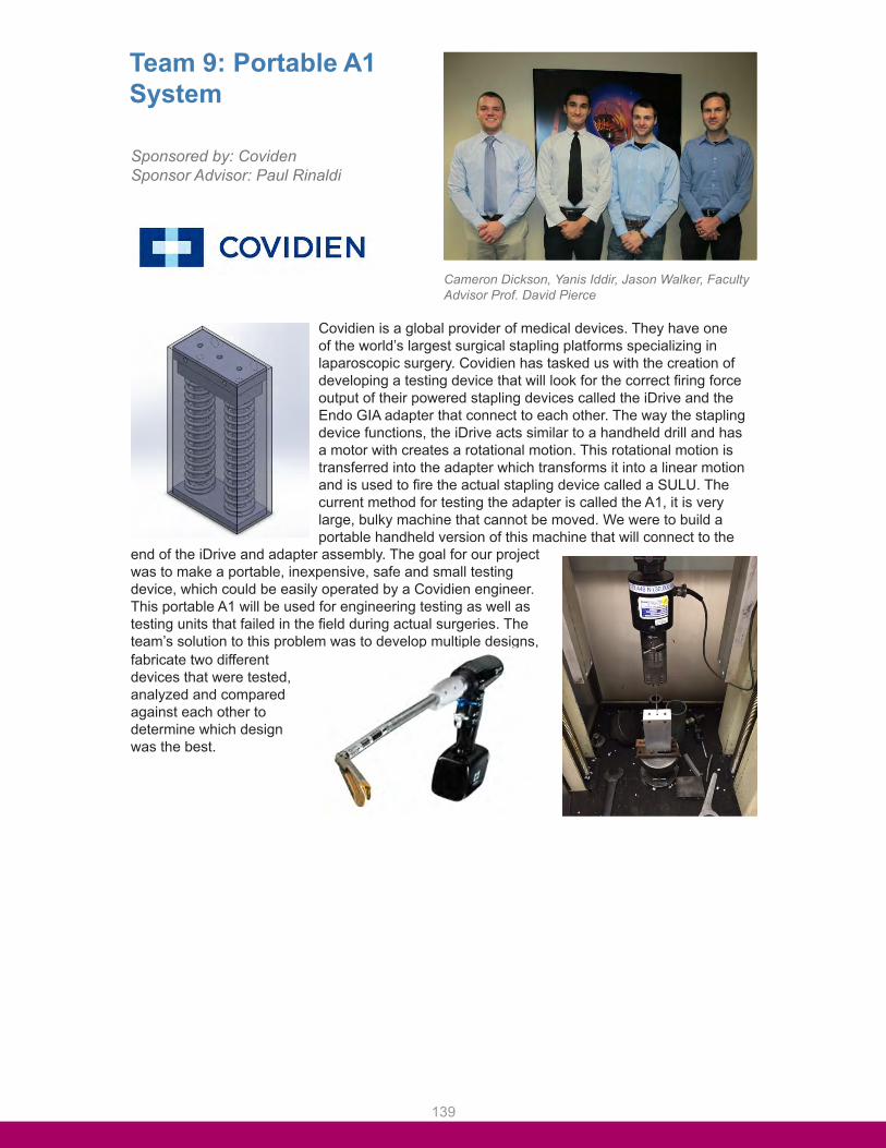
139
Team 9: Portable A1 Sysyem
Cameron Dickson, Yanis Iddir, Jason Walker, Faculty Advisor Prof. David Pierce
Covidien is a global provider of medical devices. They have one of the world’s largest surgical stapling platforms specializing in laparoscopic surgery. Covidien has tasked us with the creation of developing a testing device that will look for the correct firing force output of their powered stapling devices called the iDrive and the Endo GIA adapter that connect to each other. The way the stapling device functions, the iDrive acts similar to a handheld drill and has a motor with creates a rotational motion. This rotational motion is transferred into the adapter which transforms it into a linear motion and is used to fire the actual stapling device called a SULU. The current method for testing the adapter is called the A1, it is very large, bulky machine that cannot be moved. We were to build a portable handheld version of this machine that will connect to the
end of the iDrive and adapter assembly. The goal for our project was to make a portable, inexpensive, safe and small testing device, which could be easily operated by a Covidien engineer. This portable A1 will be used for engineering testing as well as testing units that failed in the field during actual surgeries. The team’s solution to this problem was to develop multiple designs, fabricate two different devices that were tested, analyzed and compared against each other to determine which design was the best.
Sponsored by: CovidenSponsor Advisor: Paul Rinaldi
Team 9: Portable A1System
Sponsored by: CovidenSponsor Advisor: Paul Rinaldi
Cameron Dickson, Yanis Iddir, Jason Walker, FacultyAdvisor Prof. David Pierce
Covidien is a global provider of medical devices. They have oneof the world’s largest surgical stapling platforms specializing in laparoscopic surgery. Covidien has tasked us with the creation of developing a testing device that will look for the correct firing force output of their powered stapling devices called the iDrive and the Endo GIA adapter that connect to each other. The way the stapling device functions, the iDrive acts similar to a handheld drill and has a motor with creates a rotational motion. This rotational motion is transferred into the adapter which transforms it into a linear motion and is used to fire the actual stapling device called a SULU. The current method for testing the adapter is called the A1, it is very large, bulky machine that cannot be moved. We were to build a portable handheld version of this machine that will connect to the
end of the iDrive and adapter assembly. The goal for our projectwas to make a portable, inexpensive, safe and small testing device, which could be easily operated by a Covidien engineer.This portable A1 will be used for engineering testing as well as testing units that failed in the field during actual surgeries. The team’s solution to this problem was to develop multiple designs, fabricate two differentdevices that were tested,analyzed and compared against each other to determine which design was the best.

140
Team 10: F4U-4 Flight Simulator
Shayna McLevy, Nichole Aquino, Manal Tahhan, Faculty Advisor Prof. Kamal Kumar
Connecticut Corsair, LLC is a volunteer-based organization focused on the restoration of the F4U Corsair, Connecticut’s official state aircraft. Environmental Tectonics Corporation (ETC) donated a prototype flight simulator motion base to Connecticut Corsair which has three axes of motion and was originally controlled by three induction motors. The flight simulator is necessary to encourage interest in the F4U Corsair and Connecticut Corsair’s restoration efforts. Significant progress in the reconstruction of the motion base has been accomplished over the last two years. The three induction motors are being replaced by servo motors which required the design and analysis of new motor mounts. A static structural analysis of previously designed mounts in Ansys
determined the mounts to be acceptable for the system. The new mounts have been fabricated by outside volunteers. A cockpit cage has been designed and mounted on top of the motion base. The cage consists of four bulkheads and two longerons, which are supporting structures, a rectangular base plate which is attached to the supporting structures with brackets, and a seat cage. The bulkheads designed are closely based on drawings of the original Corsair bulkheads so that the size and shape of the cockpit is accurate. The base plate will replace the current triangular plate on top of the
motion base so that the cage is directly mounted to the motion base. Ansys was also used to conduct a structural and fatigue analysis of the designed cage. The cage has been 3D printed in plastic at UConn at one tenth of the original size. The seat cage is designed to be fully adaptable so that any future seat design can be attached to the cockpit using the seat cage. It was designed in Solidworks and physically modeled using PVC piping. The result of this restoration effort is a completed flight simulator which creates an experience comparable to flying an actual F4U Corsair.
Sponsored by: Connecticut Corsair, LLCSponsor Advisor: Craig McBurney

141
Team 11: Redesign of Electrical Panel Board Mounting
Faculty Advisor Prof. David Giblin, Alejandro Pirez, Tao Jiang, Ryan Russell
The General Electric Company is one of the best known companies in the world. General Electric creates a wide variety of products including energy management, transportation, healthcare and many areas that are related to engineering. For this project GE has a major issue with their industrial-sized electrical panel boards which are used to control power input and output in hospitals and other large buildings. The issue with these panel boards is that during seismic activity certain models they fail to remain fixed to the wall. These panels must pass the building
code created by the California Office of Statewide Health Planning and Development (O.S.H.P.D.) known as Special Seismic Preapproval (O.S.P.) program. These certification tests can be performed on uniaxial, bi-axial or multi-axial seismic shaking table in order to replicate the effects of an earthquake. General Electric has sponsored Team 11 to generate a report listing possible causes of failure for their panel bracket fixture, proposals redesigns/optimization suggestions and analytical models to justify the proposed redesigns. Using Solidworks to create a simplified model of General Electric’s panel fixture design then exporting the model to ANSYS for finite element analysis, team 11 was able to pinpoint areas of failure, validate
redesign ideas and then compare against a physical seismic test to validate assumptions made.
Sponsored by: General ElectricSponsor Advisor: Mariusz Duda

142
Team 12: Testing of Surface Ware on Floor Mounted Fittings
Yan Cheng, Eric Stoller, Filip Bundra, Faculty Advisor Prof. Kamal Kumar
Legrand is a world leader in products and systems for electrical installation applications and information management originating in France. The company is operating globally and holds a leading position in markets in its main areas of business in 27 countries, including the United States, France and Italy, as well as in new economies such as Brazil, Russia, China and India. The overall objective of this senior design project was to design and manufacture an experimental procedure to test the surface wear of specified floor mounted fitting covers provided by our sponsor Legrand. This procedure was created in order to validate and compare future prototype coatings to current production coatings through the process of wearing current floor outlet covers to the end of its specific life cycle. The given wear time will then be applied to future coatings for comparison. This task has been accomplished through
the introduction of a testing apparatus which applies an abrasive grit against the surface of the floor outlet cover. To allow an efficient coating life cycle test time, the abrasive grit was chosen to be adhered to a freely rotating wheel. This was applied to the desired floor outlet’s surface through the application of a pneumatic cylinder, which was chosen in order to simulate the vertical force created by the weight of an average human’s foot step. Furthermore due to varied geometries as well as size parameters that Legrand’s line of floor outlets present, the surface motion of the testing apparatus was instrumented through the implementation of a designed X-Y carriage system. This system when coupled to two electronic servomotors, allows the testing apparatus to testing the wear of the coatings against the abrasive for all of Legrand’s various floor outlet covers. The servomotors were operated through the implementation of Labview case structures, allowing the varied geometry outlet covers to be tested respectively. This final system was then coupled to an 80/20 frame to ensure structural rigidity as well as build efficiency.
Sponsored by: LagrandSponsor Advisor: Marc Galasso
Team 12: Testing ofSurface Wear on FloorMounted Fittings
Sponsored by: LagrandSponsor Advisor: Marc Galasso
Yan Cheng, Eric Stoller, Filip Bundra, Faculty AdvisorProf. Kamal Kumar
Legrand is a world leader in products and systems for electricalinstallation applications and information management originating in France. The company is operating globally and holds a leading position in markets in its main areas of business in 27 countries, including the United States, France and Italy, as well as in new economies such as Brazil, Russia, China and India. The overall objective of this senior design project was to design and manufacture an experimental procedure to test the surface wear of specifiedfloor mounted fitting covers provided by our sponsor Legrand. This procedure was created in order to validate and compare future prototype coatings to current production coatings through the process of wearing current floor outlet covers to the end of itsspecific life cycle. The given wear time will then be applied to futurecoatings for comparison. This task has been accomplished through
the introduction of a testing apparatus which applies an abrasive grit against the surface of the floor outlet cover. To allow an efficient coating life cycle test time, the abrasive grit was chosen to be adhered to a freely rotating wheel. This was applied to the desired floor outlet’s surfacethrough the application of a pneumatic cylinder, which was chosen in order to simulate the vertical force created by the weight of an average human’s foot step.Furthermore due to varied geometries as well as size parametersthat Legrand’s line of floor outlets present, the surface motion ofthe testing apparatus was instrumented through the implementation of a designed X-Y carriage system. This system when coupled to two electronic servomotors, allows the testing apparatus to testing the wear of the coatings against the abrasive for all of Legrand’svarious floor outlet covers. The servomotors were operated through the implementation of Labview case structures, allowing the varied geometry outlet covers to be tested respectively. This final system was then coupled to an 80/20 frame to ensure structural rigidity as well as build efficiency.

143
Team 13: Innovative Brake Design ForTall Buildings
Michael Belmont, Tyler Sibley, Shenlong Lu, Faculty Advisor Prof Horea Ilies
Otis Elevator Company is the world’s largest manufacturer and elevators and escalators. Otis currently has 2.5 million elevators and escalators installed worldwide. With the rise of mega tall buildings, it is desired to move the holding brake from machine room onto the elevator. This brake must be one hundred percent reliable and able to hold the elevator car anywhere in the elevator shaft for an indefinite amount of time. The holding brake must also not consume power when engaged. Other design parameters include size, weight and noise level, which are also main challenges of this project. Our goal is to meet all of the requirements by modeling and validating our design using
engineering software. This project began with brainstorming and down-selection process of the early stage designs. With the help of Pugh chart, a couple of final designs were chosen among a dozen of designs. 3D models have been generated in SolidWorks to simulate and refine the engagement and disengagement of the brake. The life cycle calculation of the elevator was conducted under certain assumptions using Microsoft Office Excel, which paved the way for finite element analysis in ANSYS. These results are the basis for the holding brake design and lay the groundwork for its future development.
Sponsored by: Otis Elevator Co.Sponsor Advisors: Marty Hardesty, Dang Nyugen, Tadeusz Witczak

144
Team 14: Optimization of a Natural Gas Proportional Valve
Jonathan Melite, Faculty Advisor Prof. Xu Chen, Zijun Qu
This proportional valve works by utilizing a solenoid driven by Pulse Width Modulation control to create a magnetic field and thus a linear pull force on the plunger. This plunger then is pulled upwards revealing an entrance and exit for the fuel to flow through. This allows for the amount of fuel going from the tank to the piston chamber to be controlled via current. Using Ansys Maxwell’s optimization program Optimetrics, flux clumping at key locations inside the valve were analyzed, and dimensional changes were applied to the native Inventor CAD file. These key locations included the working air gap, Teflon bearings and plunger. This analysis was performed to optimize the linear pull force that was imposed on the plunger from the magnetic field. A new valve was machined based on this data and tested at UCONN in a test rig designed and built by team 14 to evaluate the performance.
Parker Hannifin Corporation is one of the largest companies in the world in motion control technologies. The Fluid Control Division (located in New Britain, CT) specializes in Parker’s solenoid valve product line. After recalling 3,200 CNG vans, GM needs a replacement for a fatigue risk regulator that is posing a fire hazard. Parker worked jointly with Team 14 in order to optimize a proportional valve that effectively replaces the regulator by eliminating the fire hazard without sacrificing in performance.
Sponsored by: : Parker HannifinSponsor Advisor: Robert Zeiner

145
Team 15: Prediction of Static Fracture of Bearings
Faculty Advisor Prof. Vito Moreno, Tyler Gromko, Matthew Joakim, Joel Nason
RBC Bearings is proudly the number one producer worldwide of airframe control products, and has dominated this sector with virtually every series and size in accordance with military standards. RBC currently uses hand calculations to determine maximum and safe operational loads for the inner ball member of their slot loaded spherical bearings. However, RBC requires the analysis and prediction process for these failure load calculations to be both updated and validated using Finite Element Analysis (FEA). Team 15 has been assigned the task of analyzing and validating a more accurate and versatile method for determining when the spherical ball bearing will crack due to static load on the surrounding system and part. Team 15’s process was a three-pronged approach: create an FEA model to simulate loading on the bearings under various loading conditions, then create a set of hand calculations and physically load the bearings to failure on a test apparatus in order to validate the computer model failure results. With these three methods in agreement, RBC has a greater understanding of the physical limits of their bearings. In addition, several parameters were tested
to provide RBC valuable insight into what loading conditions create the most stress in the ball.
Sponsored by: RBC BearingsSponsor Advisors: John Cowles, Ben Anderson

146
Team 16: Optimization of Support Structure For Additive Manufacturing
Thao Le, Lyndsey Williams, Faculty Advisor Prof. Leila Ladani, Jason Graham
A division of United Technologies Corporation, Pratt & Whitney is a company that designs and manufactures military and commercial aircraft engines. Pratt & Whitney is investing in newer, smarter technologies, which will introduce new capabilities and improve efficiency for future production. Additive manufacturing (AM) is one of those smarter technologies, specifically direct metal laser sintering (DMLS). Support structures, additional constructs to prevent part failure, are an essential part additive manufacturing. The current process of generating support structures in AM is an iterative process that involves analyzing support structures and redesigning until a structure meeting the desired requirements is accomplished. Factors that are taken into account when designing include: tensile strength, structure concentration, heat sink capability, and powder removal. However, this current process is overly complex and uneconomical in terms of time and material. Team 16 has been tasked with researching the material properties of 3D-printed Inconel 718, and then to optimize support structure for
Inconel 718 parts. Most importantly, the support structure needs to be strong enough to maintain the integrity of the build. Test specimens were built at various orientations (vertical, horizontal, and at a 45° angle) and pulled apart in the tensile tester to produce stress-strain curves of the 3D-printed Inconel 718. A metallography study was also conducted to analyze the microstructure of the sintered Inconel and find the width of a single laser pass. X-ray diffraction was used to determine the various
levels of residual stresses, which vary based on print orientation. A simple heat transfer was used to predict how quickly the heat dissipates through the support structure, affecting the hardness of the part. Powder removal methods were also studied. From analysis of the data, Team 16 will produce a guideline for Pratt & Whitney to aid in the construction of future support structure based on part geometry.
© 2015 United Technologies Corporation” & “Does not contain technical data subject to the EAR or the ITAR.The P&W logo is a registered trademark of United Technologies Corporation and is reproduced with permission – all rights reserved.
Sponsored by: Pratt and WhitneySponsor Advisors: Christopher O’Neil
Team 16: Optimizationof Support Structure ForAdditive Manufacturing
Sponsored by: Pratt and WhitneySponsor Advisors: Christopher O’Neil
Thao Le, Lyndsey Williams, Faculty Advisor Prof.Leila Ladani, Jason Graham
A division of United Technologies Corporation, Pratt & Whitney is acompany that designs and manufactures military and commercial aircraft engines. Pratt & Whitney is investing in newer, smarter technologies, which will introduce new capabilities and improveefficiency for future production. Additive manufacturing (AM) isone of those smarter technologies, specifically direct metal laser sintering (DMLS). Support structures, additional constructs to prevent part failure, are an essential part additive manufacturing. The current process of generating support structures in AM isan iterative process that involves analyzing support structuresand redesigning until a structure meeting the desired requirements is accomplished. Factorsthat are taken into account when designing include: tensile strength, structure concentration, heat sink capability, and powder removal. However, this current process is overly complex and uneconomical in terms of time and material. Team 16 has been tasked with researchingthe material properties of 3D-printed Inconel 718, and then to optimize support structure for
Inconel 718 parts. Most importantly, the support structureneeds to be strong enough to maintain the integrity of the build. Test specimens were built at various orientations (vertical,horizontal, and at a 45° angle) and pulled apart in the tensiletester to produce stress-strain curves of the 3D-printed Inconel718. A metallography study was also conducted to analyze themicrostructure of the sintered Inconel and find the width of a singlelaser pass. X-ray diffraction was used to determine the various
levels of residual stresses, which vary based on print orientation.A simple heat transfer was used to predict how quickly the heat dissipates through the support structure, affecting the hardnessof the part. Powder removal methods were also studied. From analysis of the data, Team 16 will produce a guideline for Pratt& Whitney to aid in the construction of future support structurebased on part geometry.
© 2015 United Technologies Corporation, Does not contain technical data subject to the EAR or the ITAR.The P&W logo is a registered trademark of United Technologies Corporation and is reproduced with permission – all rights reserved.

147
Team 17: Bolted Joint Stiffness Analysis Method
Nicholas Choma, Justin Wasserstein, Evan Winebrenner, Faculty Advisor Prof. Vito Moreno
A world leader in the design and manufacturing of commercial and military jet engines, Pratt & Whitney – a subsidiary of the United Technologies Corporation – employs bolted flange joints to connect sections of their aircraft engines together. Bolted flange joints are used to aid in manufacturability, ease of service and repair, and to reduce overall engine
cost – both in manufacturing and throughout the life of the engine. The goal in designing a bolted flange is to create a homogeneous joint: one that connects two sections of material together, but effectively functions as one continuous piece. While Pratt & Whitney has performed rigorous testing and analysis on overall joint strength, less is known about stiffness, which may lend insight to further optimization of bolted flange joints. Simplifying the joint to include two flat plates fastened by one bolt, the team performed both hand calculations using common industry methods as well as Pratt & Whitney’s current methods, and Finite Element Analysis (FEA) to produce baseline expected stiffnesses for several common joint configurations. Configurations varied by flange material, bolt diameter and thread pitch, and flange thickness to produce an understanding of their individual effects on stiffness. Then using tensile and compression testing rigs retrofitted to hold an accuracy of .0001”, bolt and flange stiffness was tested independently for each configuration. Using testing, FEA, and analytical results, a new model was then created such that
bolted flange joint stiffness can be accurately calculated.
© 2015 United Technologies Corporation” & “Does not contain technical data subject to the EAR or the ITAR.The P&W logo is a registered trademark of United Technologies Corporation and is reproduced with permission – all rights reserved.
Sponsored by: Pratt and WhitneySponsor Advisors: John Tirone
Team 16: Optimizationof Support Structure ForAdditive Manufacturing
Sponsored by: Pratt and WhitneySponsor Advisors: Christopher O’Neil
Thao Le, Lyndsey Williams, Faculty Advisor Prof.Leila Ladani, Jason Graham
A division of United Technologies Corporation, Pratt & Whitney is acompany that designs and manufactures military and commercial aircraft engines. Pratt & Whitney is investing in newer, smarter technologies, which will introduce new capabilities and improveefficiency for future production. Additive manufacturing (AM) isone of those smarter technologies, specifically direct metal laser sintering (DMLS). Support structures, additional constructs to prevent part failure, are an essential part additive manufacturing. The current process of generating support structures in AM isan iterative process that involves analyzing support structuresand redesigning until a structure meeting the desired requirements is accomplished. Factorsthat are taken into account when designing include: tensile strength, structure concentration, heat sink capability, and powder removal. However, this current process is overly complex and uneconomical in terms of time and material. Team 16 has been tasked with researchingthe material properties of 3D-printed Inconel 718, and then to optimize support structure for
Inconel 718 parts. Most importantly, the support structureneeds to be strong enough to maintain the integrity of the build. Test specimens were built at various orientations (vertical,horizontal, and at a 45° angle) and pulled apart in the tensiletester to produce stress-strain curves of the 3D-printed Inconel718. A metallography study was also conducted to analyze themicrostructure of the sintered Inconel and find the width of a singlelaser pass. X-ray diffraction was used to determine the various
levels of residual stresses, which vary based on print orientation.A simple heat transfer was used to predict how quickly the heat dissipates through the support structure, affecting the hardnessof the part. Powder removal methods were also studied. From analysis of the data, Team 16 will produce a guideline for Pratt& Whitney to aid in the construction of future support structurebased on part geometry.
© 2015 United Technologies Corporation, Does not contain technical data subject to the EAR or the ITAR.The P&W logo is a registered trademark of United Technologies Corporation and is reproduced with permission – all rights reserved.

148
Team 18: Variable High/Low Flame Velocity Torch For Gradient Rig
Timothy Biesiadecki, Faculty Advisor Prof. Baki Cetegen, Sagar Shah
Pratt & Whitney, a division of the United Technologies Corporation, located in East Hartford, Connecticut, is a world leader in the design, manufacture and service of aircraft engines and auxiliary power units. In gas turbine engines, higher fuel efficiency is associated with an increase in the temperature of the turbine in the hot section of the engine. A thermal barrier coating (TBC) is applied to the turbine blades which decreases their surface temperature, enabling them to withstand higher temperatures.During the operation of a gas turbine engine, particles from the atmosphere in the form of calcium magnesium alumina silicates (CMAS) melt in the combustor of the engine and deposit onto the TBC on the turbine blades in the hot
section. This molten CMAS infiltrates TBC by wicking and chemical reaction which causes TBC spallation followed by a reduction in the life of the turbine blades. A test rig was built at UConn in order to study the effects of CMAS on the thermal barrier coatings. The current torch sprays the CMAS from the side of the flame by utilizing liquid CMAS precursors at low flame temperatures and velocities. Our task was to select and modify a new torch that functions on propane and oxygen and axially injects CMAS particles through the flame onto a substrate at the
required temperature and velocity ranges. The particles must also melt before impact. Through research and analysis, we have selected and modified a thermal spray torch to meets these demands. Using this torch in conjunction with our fluidized bed feeder, Pratt & Whitney and the researchers at UConn will be able to simulate CMAS deposition more realistically in their existing test rig and therefore study the effects of CMAS attack more accurately.
© 2015 United Technologies Corporation” & “Does not contain technical data subject to the EAR or the ITAR.The P&W logo is a registered trademark of United Technologies Corporation and is reproduced with permission – all rights reserved.
Sponsored by: Pratt and WhitneySponsor Advisors: Rob Hutchinson
Team 16: Optimizationof Support Structure ForAdditive Manufacturing
Sponsored by: Pratt and WhitneySponsor Advisors: Christopher O’Neil
Thao Le, Lyndsey Williams, Faculty Advisor Prof.Leila Ladani, Jason Graham
A division of United Technologies Corporation, Pratt & Whitney is acompany that designs and manufactures military and commercial aircraft engines. Pratt & Whitney is investing in newer, smarter technologies, which will introduce new capabilities and improveefficiency for future production. Additive manufacturing (AM) isone of those smarter technologies, specifically direct metal laser sintering (DMLS). Support structures, additional constructs to prevent part failure, are an essential part additive manufacturing. The current process of generating support structures in AM isan iterative process that involves analyzing support structuresand redesigning until a structure meeting the desired requirements is accomplished. Factorsthat are taken into account when designing include: tensile strength, structure concentration, heat sink capability, and powder removal. However, this current process is overly complex and uneconomical in terms of time and material. Team 16 has been tasked with researchingthe material properties of 3D-printed Inconel 718, and then to optimize support structure for
Inconel 718 parts. Most importantly, the support structureneeds to be strong enough to maintain the integrity of the build. Test specimens were built at various orientations (vertical,horizontal, and at a 45° angle) and pulled apart in the tensiletester to produce stress-strain curves of the 3D-printed Inconel718. A metallography study was also conducted to analyze themicrostructure of the sintered Inconel and find the width of a singlelaser pass. X-ray diffraction was used to determine the various
levels of residual stresses, which vary based on print orientation.A simple heat transfer was used to predict how quickly the heat dissipates through the support structure, affecting the hardnessof the part. Powder removal methods were also studied. From analysis of the data, Team 16 will produce a guideline for Pratt& Whitney to aid in the construction of future support structurebased on part geometry.
© 2015 United Technologies Corporation, Does not contain technical data subject to the EAR or the ITAR.The P&W logo is a registered trademark of United Technologies Corporation and is reproduced with permission – all rights reserved.

149
Team 19: Electrical Capacitance Tomography For Main Burners
Faculty Advisor Prof. Zhaoyan Fan, Allen Copas, Nirav Shah, Timothy Krupski, Faculty Advisor Prof. Robert Gao
Pratt and Whitney, a UTC company, is a leader in the production of commercial and military jet engines. Pratt and Whitney has been working with UConn, and in particular, Dr. Robert Gao and Dr. Zhaoyan Fan to develop the application of Electrical Capacitance Tomography (ECT) to provide non-intrusive imaging of the location of the flame in a combustion chamber. ECT can reconstruct the distribution of the flame in the combustor by sensing the dielectric properties within the chamber using specialized circuitry and a series of electrodes attached outside the combustor. Dr. Gao and Dr. Fan have developed a working ECT system that has been demonstrated using a simple cylinder geometry. The objective of this project is to reconfigure their existing software to operate on an annular combustion chamber geometry. In addition, we developed a test rig to validate the ECT using PVC sheets to represent the annular geometry and mounted copper electrodes to detect a Teflon target representing the flame in the jet engine combustor.
The results of this work can be used to optimize the electrode configuration to provide the greatest system accuracy and resolution. Development of an ECT system will allow Pratt & Whitney to image the flame behavior in a jet engine to provide better understanding of flame propagation and optimization in future designs.
© 2015 United Technologies Corporation” & “Does not contain technical data subject to the EAR or the ITAR.The P&W logo is a registered trademark of United Technologies Corporation and is reproduced with permission – all rights reserved.
Sponsored by: Pratt and WhitneySponsor Advisors: Jeffrey Lovett
Team 16: Optimizationof Support Structure ForAdditive Manufacturing
Sponsored by: Pratt and WhitneySponsor Advisors: Christopher O’Neil
Thao Le, Lyndsey Williams, Faculty Advisor Prof.Leila Ladani, Jason Graham
A division of United Technologies Corporation, Pratt & Whitney is acompany that designs and manufactures military and commercial aircraft engines. Pratt & Whitney is investing in newer, smarter technologies, which will introduce new capabilities and improveefficiency for future production. Additive manufacturing (AM) isone of those smarter technologies, specifically direct metal laser sintering (DMLS). Support structures, additional constructs to prevent part failure, are an essential part additive manufacturing. The current process of generating support structures in AM isan iterative process that involves analyzing support structuresand redesigning until a structure meeting the desired requirements is accomplished. Factorsthat are taken into account when designing include: tensile strength, structure concentration, heat sink capability, and powder removal. However, this current process is overly complex and uneconomical in terms of time and material. Team 16 has been tasked with researchingthe material properties of 3D-printed Inconel 718, and then to optimize support structure for
Inconel 718 parts. Most importantly, the support structureneeds to be strong enough to maintain the integrity of the build. Test specimens were built at various orientations (vertical,horizontal, and at a 45° angle) and pulled apart in the tensiletester to produce stress-strain curves of the 3D-printed Inconel718. A metallography study was also conducted to analyze themicrostructure of the sintered Inconel and find the width of a singlelaser pass. X-ray diffraction was used to determine the various
levels of residual stresses, which vary based on print orientation.A simple heat transfer was used to predict how quickly the heat dissipates through the support structure, affecting the hardnessof the part. Powder removal methods were also studied. From analysis of the data, Team 16 will produce a guideline for Pratt& Whitney to aid in the construction of future support structurebased on part geometry.
© 2015 United Technologies Corporation, Does not contain technical data subject to the EAR or the ITAR.The P&W logo is a registered trademark of United Technologies Corporation and is reproduced with permission – all rights reserved.

150
Team 20: Honeycomb Knife Edge CFD
Faculty Advisor Prof. Tianfeng Lu, Alexander Arena, Bradley Farnum, Gilberto Valentin Jr.
Pratt & Whitney is a leading manufacturer of military and commercial gas turbine engines. They have been in business since the 1920’s and are a major component of United Technologies Corporation as well as a major employer in Connecticut. Pratt & Whitney supplies engines for a number of different applications including power generation systems, commercial transportation, and military aviation. In the past decade, the gas turbine engine industry has been focusing heavily on the fuel efficiency. This project aims to support Pratt & Whitney’s goal of a more efficient engine by characterizing the physics behind a component known as a honeycomb knife edge seal. These imperfect seals are located throughout the engine and are used to seal the interface between the primary gas path and secondary flow when both rotating and non-rotating hardware are present. This type of seal has been used for decades but its leakage rates have only been characterized experimentally and not including the number of parameters this project aims to characterize. The honeycomb knife edge seal has displayed unusual and unexpected effects under certain conditions. It is these conditions that this team aimed to develop a physical understanding of. This characterization was done using three dimensional computational fluid dynamics (CFD). The honeycomb knife edge seal geometry was modeled in Solidworks, than imported into Star CCM+ to be meshed. This mesh was then imported into ANSYS Fluent to run the CFD simulations. This team ran simulations while varying a
number of parameters including the mass flow through the seal and the gap clearance of the knife. Validation of the CFD simulations was carried out using a non-rotating model of the knife edge seal. The results of these simulations were used to understand the complex fluid interactions of the honeycomb knife edge seal. With this understanding in place, the team was able to create a function for Pratt & Whitney to use to accurately simulate the effects of this seal in lower order calculations.
© 2015 United Technologies Corporation” & “Does not contain technical data subject to the EAR or the ITAR.The P&W logo is a registered trademark of United Technologies Corporation and is reproduced with permission – all rights reserved.
Sponsored by: Pratt and WhitneySponsor Advisors: Grham Philbrick
Team 16: Optimizationof Support Structure ForAdditive Manufacturing
Sponsored by: Pratt and WhitneySponsor Advisors: Christopher O’Neil
Thao Le, Lyndsey Williams, Faculty Advisor Prof.Leila Ladani, Jason Graham
A division of United Technologies Corporation, Pratt & Whitney is acompany that designs and manufactures military and commercial aircraft engines. Pratt & Whitney is investing in newer, smarter technologies, which will introduce new capabilities and improveefficiency for future production. Additive manufacturing (AM) isone of those smarter technologies, specifically direct metal laser sintering (DMLS). Support structures, additional constructs to prevent part failure, are an essential part additive manufacturing. The current process of generating support structures in AM isan iterative process that involves analyzing support structuresand redesigning until a structure meeting the desired requirements is accomplished. Factorsthat are taken into account when designing include: tensile strength, structure concentration, heat sink capability, and powder removal. However, this current process is overly complex and uneconomical in terms of time and material. Team 16 has been tasked with researchingthe material properties of 3D-printed Inconel 718, and then to optimize support structure for
Inconel 718 parts. Most importantly, the support structureneeds to be strong enough to maintain the integrity of the build. Test specimens were built at various orientations (vertical,horizontal, and at a 45° angle) and pulled apart in the tensiletester to produce stress-strain curves of the 3D-printed Inconel718. A metallography study was also conducted to analyze themicrostructure of the sintered Inconel and find the width of a singlelaser pass. X-ray diffraction was used to determine the various
levels of residual stresses, which vary based on print orientation.A simple heat transfer was used to predict how quickly the heat dissipates through the support structure, affecting the hardnessof the part. Powder removal methods were also studied. From analysis of the data, Team 16 will produce a guideline for Pratt& Whitney to aid in the construction of future support structurebased on part geometry.
© 2015 United Technologies Corporation, Does not contain technical data subject to the EAR or the ITAR.The P&W logo is a registered trademark of United Technologies Corporation and is reproduced with permission – all rights reserved.

151
Team 21: Atmospheric Turbulence Model Development
Shane Hudson, Benjamin Hamilton, Bryan Fowler, Faculty Advisor Prof. Jackie Sung
Pratt and Whitney is a world leader in manufacturing and designing of Military and Commercial aircraft engines as well as auxiliary power units. Pratt and Whitney’s new geared turbofan engine is more susceptible to the turbulence found in the atmosphere. Our group was tasked with creating an atmospheric turbulence model utilizing Matlab and Simulink. Pratt and Whitney will use this model to adapt their control systems to account for the additional turbulent behavior. This simulation would
accurately output realistic values for the total pressure and total temperature experienced at the inlet of the aircraft engine. The total pressure and total temperature outputs are sent to an engine control system to simulate flight test data so that the overall engine response can be evaluated. Our model is based off of the work of NASA engineer George Kopasakis and his paper “Atmospheric Turbulence Modeling for Aero Vehicles: Fractional Order Fits”. Our group has expanded on his work by combining the turbulent behavior he modeled with the ambient atmospheric pressure and temperature. We validated our model by adapting it to fit a small scale wind turbine located on UConn’s campus. Our simulation will be used to help Pratt and Whitney adjust their engine models to adapt to turbulent conditions.
© 2015 United Technologies Corporation” & “Does not contain technical data subject to the EAR or the ITAR.The P&W logo is a registered trademark of United Technologies Corporation and is reproduced with permission – all rights reserved.
Sponsored by: Pratt and WhitneySponsor Advisors: Richard Meisner
Team 16: Optimizationof Support Structure ForAdditive Manufacturing
Sponsored by: Pratt and WhitneySponsor Advisors: Christopher O’Neil
Thao Le, Lyndsey Williams, Faculty Advisor Prof.Leila Ladani, Jason Graham
A division of United Technologies Corporation, Pratt & Whitney is acompany that designs and manufactures military and commercial aircraft engines. Pratt & Whitney is investing in newer, smarter technologies, which will introduce new capabilities and improveefficiency for future production. Additive manufacturing (AM) isone of those smarter technologies, specifically direct metal laser sintering (DMLS). Support structures, additional constructs to prevent part failure, are an essential part additive manufacturing. The current process of generating support structures in AM isan iterative process that involves analyzing support structuresand redesigning until a structure meeting the desired requirements is accomplished. Factorsthat are taken into account when designing include: tensile strength, structure concentration, heat sink capability, and powder removal. However, this current process is overly complex and uneconomical in terms of time and material. Team 16 has been tasked with researchingthe material properties of 3D-printed Inconel 718, and then to optimize support structure for
Inconel 718 parts. Most importantly, the support structureneeds to be strong enough to maintain the integrity of the build. Test specimens were built at various orientations (vertical,horizontal, and at a 45° angle) and pulled apart in the tensiletester to produce stress-strain curves of the 3D-printed Inconel718. A metallography study was also conducted to analyze themicrostructure of the sintered Inconel and find the width of a singlelaser pass. X-ray diffraction was used to determine the various
levels of residual stresses, which vary based on print orientation.A simple heat transfer was used to predict how quickly the heat dissipates through the support structure, affecting the hardnessof the part. Powder removal methods were also studied. From analysis of the data, Team 16 will produce a guideline for Pratt& Whitney to aid in the construction of future support structurebased on part geometry.
© 2015 United Technologies Corporation, Does not contain technical data subject to the EAR or the ITAR.The P&W logo is a registered trademark of United Technologies Corporation and is reproduced with permission – all rights reserved.

152
Team 22: Vibration Damping System
Faculty Advisor Prof. Jiong Tang, William O’Brien, Jose Brito
Pratt & Whitney is a world leader in the design and manufacture of gas turbine engines. They were interested in improving the damping performance of the structural guide vanes used on their jet engines. The system currently in place erodes material from the inner walls of the vanes affecting their lifetime resulting in more frequent replacements of the part. A new damping system was desired that could function passively, increase the operation lifetime of the vanes, and offered damping performance equal to or greater than the system in place. Two types of possible damping systems were investigated, a piezoelectric damping system as well as a particle impact damping system. A piezoelectric system is dependent on the strain of the beam so it was fine-tuned using a resistor and inductor to dissipate the energy in the beam. The beam strains during the vibrations induce a charge in the piezoelectric material. This charge can be dissipated through a resistor and inductor creating a damped electrical mechanical system. Particle impact damping functions by converting kinetic vibrational energy into heat losses. This is accomplished by dissipating energy through momentum exchange and friction between the particles and the walls of their container. Tests for each system were conducted on
a cantilever beam modelling the structural guide vane. Each system was evaluated on its damping performance, weight, and reliability, before selecting the final damping system design.
© 2015 United Technologies Corporation” & “Does not contain technical data subject to the EAR or the ITAR.The P&W logo is a registered trademark of United Technologies Corporation and is reproduced with permission – all rights reserved.
Sponsored by: Pratt and WhitneySponsor Advisors: Charles Gendrich and Austin Cosby
Team 16: Optimizationof Support Structure ForAdditive Manufacturing
Sponsored by: Pratt and WhitneySponsor Advisors: Christopher O’Neil
Thao Le, Lyndsey Williams, Faculty Advisor Prof.Leila Ladani, Jason Graham
A division of United Technologies Corporation, Pratt & Whitney is acompany that designs and manufactures military and commercial aircraft engines. Pratt & Whitney is investing in newer, smarter technologies, which will introduce new capabilities and improveefficiency for future production. Additive manufacturing (AM) isone of those smarter technologies, specifically direct metal laser sintering (DMLS). Support structures, additional constructs to prevent part failure, are an essential part additive manufacturing. The current process of generating support structures in AM isan iterative process that involves analyzing support structuresand redesigning until a structure meeting the desired requirements is accomplished. Factorsthat are taken into account when designing include: tensile strength, structure concentration, heat sink capability, and powder removal. However, this current process is overly complex and uneconomical in terms of time and material. Team 16 has been tasked with researchingthe material properties of 3D-printed Inconel 718, and then to optimize support structure for
Inconel 718 parts. Most importantly, the support structureneeds to be strong enough to maintain the integrity of the build. Test specimens were built at various orientations (vertical,horizontal, and at a 45° angle) and pulled apart in the tensiletester to produce stress-strain curves of the 3D-printed Inconel718. A metallography study was also conducted to analyze themicrostructure of the sintered Inconel and find the width of a singlelaser pass. X-ray diffraction was used to determine the various
levels of residual stresses, which vary based on print orientation.A simple heat transfer was used to predict how quickly the heat dissipates through the support structure, affecting the hardnessof the part. Powder removal methods were also studied. From analysis of the data, Team 16 will produce a guideline for Pratt& Whitney to aid in the construction of future support structurebased on part geometry.
© 2015 United Technologies Corporation, Does not contain technical data subject to the EAR or the ITAR.The P&W logo is a registered trademark of United Technologies Corporation and is reproduced with permission – all rights reserved.

153
Team 23: Air Stream Integrated Heat Exchanger System Performance
Steven Kingston, Shaun Fritts, Faculty Advisor Prof. Amir Faghri
The current heat management systems in aircraft jet engines developed by Pratt and Whitney, a UTC company, use heat exchangers in the bypass flow ducts. The bypass duct is a duct surrounding the core of the jet engine. Its purpose is create additional thrust as well as an effective system for heat management. The addition of heat exchangers for heat management creates disturbances in the flow through the duct and increases the pressure drop of the system. This has a negative effect on the bypass duct’s performance to produce extra thrust. The project’s
goal is to increase the performance of the bypass duct and the related heat exchangers. Pratt and Whitney has tasked the senior design team to study the performance of an intake shroud and nozzle on a heat exchanger in a duct system and observe the system as far as fluid flow around and within the heat exchanger is concerned. Through ANSYS FLUENT simulations and experiments, it was confirmed that the heat exchanger, for which a representative was used, does increase the pressure drop of the system and installing an intake shroud and nozzle decreases this effect. Further experimentation involved the introduction of obstructions to simulate pipes protruding from the main engine into the bypass duct. These also create disturbances in the airflow and have an effect on the performance of the intake shroud and nozzle. The results obtained from the simulations and experiments will be scaled for use in practical purposes.
© 2015 United Technologies Corporation” & “Does not contain technical data subject to the EAR or the ITAR.The P&W logo is a registered trademark of United Technologies Corporation and is reproduced with permission – all rights reserved.
Sponsored by: Pratt and WhitneySponsor Advisors: Lauren Gray
Team 16: Optimizationof Support Structure ForAdditive Manufacturing
Sponsored by: Pratt and WhitneySponsor Advisors: Christopher O’Neil
Thao Le, Lyndsey Williams, Faculty Advisor Prof.Leila Ladani, Jason Graham
A division of United Technologies Corporation, Pratt & Whitney is acompany that designs and manufactures military and commercial aircraft engines. Pratt & Whitney is investing in newer, smarter technologies, which will introduce new capabilities and improveefficiency for future production. Additive manufacturing (AM) isone of those smarter technologies, specifically direct metal laser sintering (DMLS). Support structures, additional constructs to prevent part failure, are an essential part additive manufacturing. The current process of generating support structures in AM isan iterative process that involves analyzing support structuresand redesigning until a structure meeting the desired requirements is accomplished. Factorsthat are taken into account when designing include: tensile strength, structure concentration, heat sink capability, and powder removal. However, this current process is overly complex and uneconomical in terms of time and material. Team 16 has been tasked with researchingthe material properties of 3D-printed Inconel 718, and then to optimize support structure for
Inconel 718 parts. Most importantly, the support structureneeds to be strong enough to maintain the integrity of the build. Test specimens were built at various orientations (vertical,horizontal, and at a 45° angle) and pulled apart in the tensiletester to produce stress-strain curves of the 3D-printed Inconel718. A metallography study was also conducted to analyze themicrostructure of the sintered Inconel and find the width of a singlelaser pass. X-ray diffraction was used to determine the various
levels of residual stresses, which vary based on print orientation.A simple heat transfer was used to predict how quickly the heat dissipates through the support structure, affecting the hardnessof the part. Powder removal methods were also studied. From analysis of the data, Team 16 will produce a guideline for Pratt& Whitney to aid in the construction of future support structurebased on part geometry.
© 2015 United Technologies Corporation, Does not contain technical data subject to the EAR or the ITAR.The P&W logo is a registered trademark of United Technologies Corporation and is reproduced with permission – all rights reserved.

154
Team 24: Male Body System Initiative
Tyler Malboeuf, Kyle Donelan, Lauren Ambler, Faculty Advisor Prof. Zbigniew Bzymek
The design team’s goal was to research and develop a product for Schick that would appeal to an untapped market: male body grooming. Traditionally, men’s wet shave razors are utilized only for facial shaving; however, there is a recent trend indicating that there is a growing percentage of men that include body shaving in their grooming habits. The team researched key features and attributes that males would like in a body grooming razor via questionnaire; the survey not only
determined the percentage of males who participate in body grooming, but also determined the frequency and physical locations in which they do so. In order to conduct the research in an effective and appropriate manner, Institutional Review Board approval was requested and granted. After gathering over 350 responses, the team found that the majority of men between the ages of 18-25 do body groom. Responses show that men are looking for a new, body grooming-friendly razor that is able to adjust to the human’s natural contours, which differs from what is currently on the market. Finite Element Analysis was conducted on current Schick razors as well as the team’s design in order to establish a consistent strength basis. Each razor was fixed to simulate normal use and a load applied to the face of the razor, representing the approximate force of a razor on a person’s body. Close attention was paid to the key areas and curves on each model. The final design concept is a rapid prototype model that represents a single, simple, and intuitive solution that meets consumer needs indicated by the survey results.
Sponsored by: Schick-Wilkinson SwordSponsor Advisors: Jay Bunnell and Andrew Hitchcock

155
Team 25: Rivet Tension Capacity
Robert Wilson, Stephen Mondak, Matthew Richardson, Faculty Advisor Prof. Bryan Weber
Sikorsky Aircraft Corporation (Sikorsky) is a helicopter manufacturer based in Stratford, Connecticut specializing in both the military and civilian aircraft industry. Sikorsky tasked Team 25 with developing an automated testing procedure for bucked aluminum rivets. Aluminum rivets are used in helicopter beams and frames that are highly weight sensitive and often are subjected to post buckling load requirements. The automated test procedure desired by Sikorsky consists of two parts. In the first part, small square coupons were used to measure the tensile capability
of a single rivet in thin gage sheet metal. These results were then compared to previous data available from the National Advisory Committee for Aeronautics (NACA) and to a computational analysis conducted in SolidWorks. The comparison between the team’s data and the NACA data showed a similar relationship which then allowed the team to conclude that the maximum load for rivet failure is dependent on sheet thickness. The second part of the testing procedure used the conclusions of the small scale test to perform a test representative of a helicopter beam subsection. Two aluminum panels were tested to validate failure predictions developed from the small-scale test data. Overall our team has created an automated small-scale testing procedure, plots of predicted rivet tension failure curves, and two large aluminum panel tests to validate rivet tensile load allowable curves.
Sponsored by: SikorskySponsor Advisors: Alexander Weintraub

156
Team 26: Un-Crashable Helicopter
Daniel Boudreau, Michael Johnson, Nataliya Nechyporenko, Faculty Advisor Prof. Chengyu Cao
Sikorsky Aircraft, a subsidiary of United Technologies Corporation (UTC), is one of the world’s leading designers and manufacturers of commercial and military helicopters. Even with the technological advancements of the modern age, accidents still happen. The most skilled pilots in the world can still have difficulty trying to fly and control a helicopter during low visibility scenarios. With extra instrumentation, sensors and advanced flight algorithms, pilots can now be aided in the control of the helicopter in these risky situations. Given the cost of full size helicopter modifications, it is prudent to scale down, substituting a quad-copter for experimentation before looking to implement full size changes. By integrating range sensors along with onboard gyroscopes and accelerometers into the quad-copter hardware, it was then able to carry out automated maneuvers if the craft became unstable or the pilot was unknowingly approaching a hazardous obstacle. The team designed a control system for the copter to avoid obstacles such
as a vertical wall or the ground which simulate natural or manmade hazards for a real helicopter. In a similar manner our quad-copter was able to automatically recover from an excessive angle of pitch or roll without a need for manual input from the pilot. The main focus of this project was to use onboard data collected by the integrated sensors to assess any hazards or obstacles on the flight path. Should the algorithms detect such a scenario, the quad-copter computer would override manual controls, systematically reacting and recovering to a stable hover. This was all in pursuit of the Sikorsky ideal of creating an “Un-Crashable” aircraft.
Sponsored by: SikorskySponsor Advisors: Paul Inguanti

157
Team 27: Express Swing Security Solution
Faculty Advisor Prof. Vito Moreno, Jeffrey Winecki, Nathan Brochu, Christopher Lee
Stanley Access Technologies, a division of Stanley Black & Decker, specializes in manufacturing automated commercial door packages. Included in their diverse line of products is their new express swing door. What makes this new package unique is its automatic bidirectional motion, meaning the door can open in both directions. The door also utilizes sensors so that it will not close on those passing through nor will it open into anyone in the door’s swing path. Currently the Express Swing Door uses a mechanical two or three point locking mechanism. Stanley Access Technologies wants to improve their door package by adding the option for a remote controlled locking system. The remotely activated security solution needed to be contained completely within the header and mounted to the top structural panel of the header. The design had to be robust, compliant with building codes, and compact enough to fit within the strict volume constraints of the header. In
order to meet these constraints stress analysis was performed on the lock and its supports. Utilizing brackets allowed for the stresses to be reacted out to the top structural panel of the header. The design used an electromechanical actuator to facilitate wireless activation. To validate the design, the lock system was subjected to feasibility, repeatability, and strength testing using a prototype. The data acquired from tests and analysis was used to refine the prototype design. The refined design was proposed to Stanley Access Technologies for the Express Swing Door security solution.
Sponsored by: Stanley SecuritySponsor Advisor: Vinay Patel

158
Team 28: Reinforced Aluminum Wear Evaluation
Simon Villegas, Jaime Kessler, Marc Musacchio, Faculty Advisor Prof. Eric Jordan
United Technologies Aerospace Systems (UTAS) is a worldwide leader in the manufacture of aerospace components, serving a variety of industries including commercial and military aircraft, as well as the international space program. UTAS seeks to improve engine performance by decreasing the weight of components, but without raising production costs or sacrificing service life. A recently patented material, Fiber Reinforced Aluminum (FRA), has been identified as a possible replacement for Stainless Steel actuators that are currently in use. FRA is a lightweight aluminum alloy randomly reinforced with a ceramic that provides increased strength and wear resistance, making it an ideal candidate for aerospace applications. UTAS is
particularly interested in the material’s response to fretting wear, which is a wear mode characterized by small linear displacements as in the oscillatory motion of the actuators. The goal of this project was to define material properties and wear behavior of FRA through a literature review, to design and build a pin-on-disc type wear test, and to utilize a full-scale rig for wear testing of prototype valves. Improving upon previous full-scale testing methods, modifications were made to the existing
test rig to apply greater side loads and generate more measureable wear on the test samples. Using stainless steel test samples as a baseline, data was collected and analyzed to validate the ability of FRA to perform as required in field service conditions.
Sponsored by: United Technologies Aerospace SystemsSponsor Advisor: William Rhoden

159
Team 29: Phase Change Material Heat Sink
Faculty Advisor Prof. Wilson Chiu, David Morgan, Winston Averill, Justin Liquori
United Technologies Aerospace Systems (UTAS), is a world leader in aerospace and defense products. They operate and conduct business in over 26 countries and are comprised of approximately 42,000 industry professionals. UTAS is the result of a merger between Hamilton Sunstrand and Goodrich
Corporation in 2012. Their expertise lies in designing and providing solutions for commercial, military, regional, and business aerospace applications. UTAS is pursuing advancing areas of the aerospace industry through the use of custom phase change heat sinks to cool electronic devices. An emerging application of phase change materials (PCM) is their utilization as an integral part of these heat sinks. The heat sink provides a steady state temperature while absorbing the ongoing heat energy output from the electronics over the heat load duration.
A final design for a heat sink has been developed utilizing a paraffin wax and graphite foam internal to an aluminum housing. Finite element analysis models yielded satisfactory results in terms of heat dispersion and heat capacity. Both a simplified test model and final device were manufactured and tested. This resulted in a successful building and testing phase which generated valuable deliverables for UTAS.
Sponsored by: United Technologies Aerospace SystemsSponsor Advisors: Mark Zaffetti and Jesse Stieber

160
Team 30: Low Noise Cooling Blower
Jeffrey Warner, Kevin Robino, Michael Thai, Faculty Advisor Prof. Bryan Weber
Ward Leonard, an electric motor and control company, tasked our team with creating a low noise forced-air cooling solution. Forced air-cooling is a standard for many high power electric motor applications. These motors are used in a variety of industrial applications in close proximity to workers. One primary concern with this type of cooling is the generated noise and the need to actively or passively abate for worker safety. An alternative method to eliminate blower noise is to use liquid cooling, however; this is significantly more costly to implement and maintain. The development of a system for moving cooling air that can achieve noise levels below 80dB, measured at the industry standard one meter, would represent a significant improvement in the technology and creates a market advantage. Current blower technology produces noise levels around 120dB, making our initial goal 99.99% reduction in effective sound pressure (as dB is measured on a logarithmic scale). Our approach was to investigate radical ways to change the general design of the traditional forced air blower in such a way to abate as much noise generation as possible while maintaining a nearly identical physical footprint and functionality. The result is a blower system featuring dual inlets. The idea was based off of a simple calculation of the conservation of mass that indicated that if you double the size of an inlet while maintaining the same outlet velocity, you effectively halve the inlet velocity. Turbulent airflow is the primary source of noise propagation in a blower system and is caused by what is called system interference. Lowering
the air speed velocity and consequently the turbulence can abate the amplitude of the noise caused by interference. The prototype rig developed is a proof-of-concept, which was designed to be taken to the next level with additional engineering. The rig was made to be modular enabling the team to test many different blower designs. The team also tested many different part geometries, such as impellers, and determine which would be the most effective at reducing noise levels
Sponsored by: Ward Leonard, LLCSponsor Advisor: Paris Thalassinos

161
Team 31: Mixing to Optimize Throughput
Faculty Advisor Prof. Savas Tasoglu, Michael Bradley, Christopher Kilborn, Matthew Fonseca
Finding solutions to the world’s energy and sustainability problems has become one of the major challenges for engineering companies in the 21st century. Waste to Water is a recent startup who looks to do its part in solving the world’s sustainability crisis. Waste to Water’s flagship product, the Bio-EZ, uses mechanical and biochemical processes to breakdown food waste from any commercial kitchen or dining hall to water that is safe to be dumped in any city’s sewage line. The Bio-EZ houses two shaft-paddle
assemblies that are designed to disintegrate large food items as well as aerate the food waste liquid so the biochemical mixture can further breakdown remaining waste. Team 31 has been tasked to improve the mixing capabilities of the shaft-paddle design to promote better mixing within the Bio-EZ tub. The team first researched how to improve mixing capabilities by looking at current industrial mixing equipment as well as looking into academically published research papers that have sought to model velocity and pressure gradients in rotating cylinder designs. After understanding the physics that
govern mixing, the team used ANSYS-Fluent to simulate what the mixing capabilities of the current Bio-EZ. Also, a scaled experimental test rig was constructed to test how long it would take for newly added food waste to be fully mixed within the tub. The team then implemented design changes to the shaft, paddles. These design changes include increasing the tub surface roughness, altering the paddle angles, changing rotation speed, and adding fluid interrupting baffles to the tub surface. These changes were demonstrated in an experimental rig.
Sponsored by: Waste to Water & IdeazSponsor Advisor: David Mathieu

162
Team 32: Bio-Ez Weighing System
Nicholas Fessenden, Jonathan Del Gallo, Tyler Imbriaco, Ryan Shettles, Faculty Advisor Prof. Julian Norato
Waste to Water, LLC is a company that designs food waste processing units. Their patent pending machine is called the BIO-EZ. The BIO-EZ takes organic waste and digests it into a nutrient-rich water solution. The machine can process up to 3000 pounds of food waste every 24 hours. The mixture is digested using a patent pending “Bio-Helper” microbe formula and the solution is safe to then drain into a sanitary sewer system. One of the tasks assigned to the team was to design a weighing system. In order to lease the machine and charge the user per pound, the BIO-EZ must accurately weigh the input to the machine. The
weighing system designed must meet the requirements for fair trade set by the National Institute of Standards and Technology. The weighing system records the change in weight each time new food is added. It is accomplished by a four load cell configuration, one at each corner of the BIO-EZ. The final weight is a sum of the values from all four load cells. A computer records the new weight value and adds it to the company’s running total for the billing period once the weighing is complete. The second task was to optimize the frame of the machine. The prototype given for optimization was overdesigned which results in an expensive custom fabricated frame with a large lead time. The goals for the frame optimization design were a more economical, durable frame
with a short lead time and increased transportability. The current frame design was optimized using welded steel members. The design was made using beam theory hand calculations as well as Siemens NX simulations. The simulations tested the strength of the frame under static loading, transportation conditions, and the cyclic loading of the food weight. The final frame provides Waste to Water with cost savings, less material, and improved transportability.
Sponsored by: Waste to Water & IdeazSponsor Advisor: David Mathieu

163
Team 33: Seal Thermal Analysis
Gabriella Arroyo, Brian Rothermich, Nicholas Latella, Faculty Advisor Prof. Amir Faghri
Reactor Coolant Pump (RCP) seals are used in nuclear power plant design to prevent leakage of reactor coolant from the reactor into the containment vessel. These seals are kept in a temperature range of 120 to 150 °F with a system of injection cooling water that maintains the RCP seal pressure slightly above the Reactor Coolant System RCS. During a station blackout (SBO) event it is postulated that all onsite and off-site sources of power are lost. Under these conditions, the cooling system to the seals shuts off and all AC power in the pump is lost. Without the seal injection over-pressure, the RCS fluid (~ 560°F) will leak into the seal assembly, and eventually into the containment area. Deformation of the seal faces a and loss of sub cooling of the liquid will cause the seal flow to flash, causing the seal faces to separate. Two RCP operational strategies exist for the event of a SBO. A controlled bleed off (CBO) valve can be either left open or closed (isolated) during a SBO, the latter of which prevents any flow to continue through the seal faces. Not isolating CBO results in a rapid heat-
up of the RCP seal. This senior design team was tasked with predicting the thermal distribution in the seal assembly over various periods of time, and the associated leakage rates and operational strategies. Utilizing Computational Fluid Dynamics (CFD) with ANSYS Fluent, a detailed model of the RCP seal was developed. The team determined that the temperature of the seal faces approaches 560°F within an hour when the CBO is not isolated. The leakage rate remained stable. However, if the seal stages were to fail after extended exposure to high temperatures, the leakage rate could increase. An analysis was performed with CBO isolation to determine the maximum temperature reached over 24 hours. The leakage rate with the CBO isolated remained stable at the normal operating rate. Isolation of the CBO prevents rapid heat-up of the seals, allowing more time for the plant to return to normal operation.
Sponsored by: WestinghouseSponsor Advisors: Kyle Hope & Ray Schneider

164
Team 34: Tornado Missile Impact Modeling
Faculty Advisor Prof. Brice Cassenti, Jemma O’Donnell, Tyler Condon, Christopher Sarmiento-Salas
The presence of tornados in areas of nuclear power plants poses a threat to the structural integrity of the plant. Failure of key safety components could potentially result in a nuclear disaster. The Nuclear Regulatory Commission (NRC) has recently become stricter in their safety regulations as they pertain to natural disasters in the vicinity of nuclear power plants. Westinghouse Electric Company has responded to this by attempting to better understand the response of structures at their power plants to impact by debris thrown by tornadoes, termed tornado missiles. The objective of this project is to establish fragility data for several of these structures by performing impact analyses of tornado missile trajectories using the finite element analysis program, LS-DYNA. Tornado missile velocities for various objects in tornadoes classified F3-F5 were calculated by the previous year’s Westinghouse senior design team and were used to develop the FEA models used in this project. These initial velocities are paired with the correct missile and target geometries and material properties in order to properly determine the impact force and stresses felt by the target. These output forces and stresses are then used in conjunction with the proper failure theory (depending on the material of the target being impacted) in order to determine whether or not the structure will fail. Variables tested in these models include initial velocity of missile, material and geometry of targets and missiles, and contact angle. A validation experiment was run to ensure proper usage of LS-DYNA that included shooting a ball bearing at a steel plate and measuring the force felt by
the plate, then modeling the same situation in LS-DYNA and comparing the output graphs to the experimental graphs. Ultimately, Westinghouse will be able to utilize the fragility data developed through the use of LS-DYNA to better guard their at-risk plants from failure due to impact from tornado missiles, and thus protect the general population from a nuclear disaster.
Sponsored by: WestinghouseSponsor Advisor: Ray Schneider

165
Team 35: Windham Dental
Eric Howard, Faculty Advisor Prof. George Lykotrafitis, Mark Rubano
The installation of dental implants is a process that requires multiple procedures and significant recovery time to complete. There is a very strong demand to decrease treatment time. While implants are meant to permit the same chewing functions as a healthy tooth, the structural integrity of the implant is not optimal until it is properly installed into the jaw bone. The healing process for the jaw bone once the implant is installed is a process called osseointegration which generally takes 4-6 months. As a result of this lengthy healing time, Dr. Dennis Flanagan of the Windham Dental Group is in need of an equation to determine under what conditions immediate implant loading can be safely applied to the human jaw bone. Several important parameters will be considered to determine how little or how greatly they affect one another under the conditions of a normal human jaw. These parameters may include: Number of implants, jaw force, cortical bone thickness, distance between implants, implant diameter, and bone quality. Using stress, strain, and deformation results from finite element analysis simulations, a mathematical model was created relating each important parameter. This mathematical model allows the dentist
know if it is safe to provide immediate functional loading of dental implants to a particular patient.
Sponsored by: Windham Dental GroupSponsor Advisor: Dennis Flanagan

166
Team 36: Centrifugal Pump Passive Runout Control Device Design
Faculty Advisor Prof. Michael Pettes, Dawid Herman, Nicholas Caruso, Kristin Hakenjos
Zachry Nuclear Engineering is a subdivision of Zachry Holdings Inc. which focuses on the engineering, design, and management of projects within the nuclear power industry. A key component to a nuclear system is the centrifugal pump which is used to transport water. Each pump upon being manufactured is supplied with a pump curve which shows the limits of operation and the operating conditions at different flow rates for that specific
pump. The maximum flow rate at which a pump can safely operate is called the runout point. Due to these limitations, Zachry is interested in the development of a device which will prevent a pump from operating beyond this point. The design of such a device requires that it be passive, compact, fail-safe, cannot degrade pump function by more than 5%, and be capable of preventing runout in the pump. Several concepts were considered, and after preliminary analysis, one concept (pictured) was chosen due to the outcome of a decision matrix comparing all the different designs. This concept, a valve, was designed to use the forces and pressures of the flowing water to operate it. Under normal conditions the valve would remain open, but near the runout point the forces created by the moving fluid would close the valve. Analysis was performed on the valve to see the behavior of the flow around the center body and what the net axial forces were. These results will be used for anticipating the valve’s behavior in future prototype testing.
Sponsored by: Zachry Nuclear EngineeringSponsor Advisor: Jeffrey F. Lundy

167
Team 37: Magnetic Suspension Bearing
Daniel Coxe, Faculty Advisor Prof. Chengyu Cao
Active Magnetic Bearing (AMBs) are the application of electro and/or permanent magnets for the purpose of replacing mechanical bearings. More than just maintain rotation concentricity, AMBs can provide active vibration control and damping.This project aims to employ an adaptive control algorithm to the AMB system for improved robustness and response. However, sensing technology must be applied for this control scheme to work. Stepping away from the standard approach (Eddy Current/induction Sensors), a novel state measurement system has been developed. Presented today is a 3D camera sensor system. As the name would imply, a 3D camera records relative height data in addition to a pixel’s horizontal and vertical position information. Using the camera’s data and applying image processing and edge detection algorithms, an object’s position can be fully described in the sensor’s frame of reference. This information combined with
the knowledge of the sensor’s relative orientation and position, transformations into any other working frame can be made.
Sponsored by: National Science Foundation

168
Team 38: Thermal Modelling of Electron Beam Additive Manufacturing
Magda Sadowski, Faculty Advisor Prof. Leila Ladani
Powder bed additive manufacturing technologies are a widely growing industry with capabilities in the aerospace, automotive, medical, and industrial fields. With this technology, lightweight, custom built parts with complex geometries can be manufactured and designers can rapidly prototype their designs as a proof of concept. This is an invaluable technology that can be used to create high quality parts. However there exists a caveat; changing process parameters leads to unknown final part microstructure. Research surrounding metal additive manufacturing methods is abundant, but with many process parameters affecting the properties of the finished part, users are not yet able to guarantee part quality
from one batch of parts to the next. One 3D printing technology in particular, Electron Beam Melting (EBM), is used to create fully dense parts which have metallurgical properties equivalent to their cast or machined counterparts. EBM uses an electron beam to create the required energy needed to melt and fuse metal powders layer by layer. Unlike laser sintering machines, the beam is not controlled by any mechanical parts and can therefore travel across the powder bed at speeds of 8000m/s. Using ANSYS Mechanical apdl, a finite element model was developed to simulate transient heat flow during the building process. The model is able to simulate phase change between solid, liquid and powder states and by inputting various process parameters, it can assess their effect on temperature profiles and melt pool geometries within the powder bed. By understanding the thermal response of the system, we can optimize the process parameters to create parts with desired mechanical properties.
Sponsored by: UCONN

169
Team 39: Electron Band Structure Modification in Mesoporous Bismuth Networks
Jason Wu, Faculty Advisor Prof. Michael Pettes
More than two decades ago, Hicks & Dresselhaus (Phys. Rev. B 47, 12727) theoretically predicted that the thermoelectric figure of merit of two dimensional semiconductor materials will be enhanced by an order of magnitude through quantum confinement effects when characteristic sizes are comparable to or smaller than the electron wavelength, on the order of 10-55 nm for bismuth. However, realizing materials which exhibit quantum confinement effects has been limited due to experimental difficulty. The use of block copolymer templating, which can offer characteristic sizes on the order of 10 nm, is a promising approach for realizing the potentially revolutionary promise of the original Dresselhaus theory in a macroscale material system. To realize these small characteristic sizes, commercially available amphilic block copolymers (BCP), such as poly(styrene)–b-poly(lactic acid), offer a potentially transformative templating structure and have been used to create inorganic material networks with characteristic sizes on the order of 5-10 nm using electrodeposition into the removed hydrophilic block. I am developing chemically compatible Bi electrodeposition techniques and investigate the role of solution chemistry, electroplating wave-form, and annealing on the structure. As polycrystallinity is an issue with electrodeposition, I am closely investigate post-synthesis thermal annealing, which has been shown to enable formation of single-crystalline thin films. Currently, in order to better understand the fundamental theories of the electroplating method, I have developed electrodeposition methods for thin film bismuth, which suffers from anisotropic growth, non-uniform deposition, and unpredictable grain size when solution chemistry, bath temperature, and other important parameters are not optimized. I have performed characterization of atomic and microstructural ordering of these films and of BCPs using small-angle X-ray scattering, X-ray diffraction, scanning electron microscopy, and transmission electron microscopy. This preliminary study of the control of grain size will provide valuable insight as it is applied to electrodeposition into the nanoporous networks of the BCP. A Hall bar measurement scheme will be used to characterize the electrical properties of the nanostructured Bi, and will enable me to determine the underlying electron mobility and carrier concentration.
Sponsored by: UCONN

170
Team 40: Simulation of Turbulent Flames Subjected to Local Extinction
Nicholas Wixom, Faculty Advisor Prof. Michael Renfro
In designing engines for use in the aerospace industry, it is desirable to reduce emissions and increase engine efficiency. In order to accomplish these goals, the fuel is rapidly mixed with air upon entering the combustor. Unfortunately, this causes areas of high mixing (characterized by the scalar dissipation rate), which can cause extinction of the flame if the rate of mixing is too high compared to the rate of the chemical reactions that produce heat. Models that predict global extinction rely on models of local extinction, so it follows that to better understand global extinction, the relationship between scalar dissipation and local
extinction of a turbulent flame must be further researched. Using Ansys Fluent v15.0, flames undergoing local extinction have been simulated and trends between the scalar dissipation rate and the formation of local extinction points (flame edges) have been determined. Scalar dissipation rate is a value calculated by combing thermal conductivity, density, specific heat, and mixture fraction (a combination of species mass fractions) and is commonly used as a marker for extinction. Based on a previously designed burner, a turbulent simulation has been developed that represents the trends seen in the experimental flame at the same conditions. This model can be used to design a second generation burner that will allow for further study of a turbulent flame edge and extinguishing flames.
Sponsored by: UCONN

171
Team 41: Gas Sampling Valve
Faculty Advisor Prof. Jackie Sung, Michael DiFrancesco, Faculty Advisor Prof. Bryan Weber
Research in the field of combustion has led to an improved understanding of the process that has resulted in improvements of combustion techniques. With large energy demands and the need to reduce pollution, even small improvements are very beneficial. One tool making up the fundamental understanding of combustion is chemical kinetic models. These models are created through rigorous calculations and thus require experimental data to be validated. A rapid compression machine (RCM), which rapidly compresses fuels to auto-ignition, serves as a tool to collect data on fuels’ combustion properties. One technique to analyze a fuel’s combustion properties is gas sampling. The combustion gasses are analyzed by Gas Chromatography and Mass Spectroscopy (GC/MS) to measure the chemical components that are present and their concentrations. This was traditionally done by ceasing the entire reaction for analysis. That technique is referred to as global sampling. The goal of the project was to repurpose a gas sampling valve (GSV) intended measure engine exhaust to sample combustion gasses from a rapid compression
machine. The GSV was placed in the RCM to collect a sample from a local area. The advantage of a local sample is that it captures less of the system boundary conditions which are not part of the chemical kinetic model. This was validated through CFD simulations of the valve in the chamber to determine the properties of the sample area. The GSV required the sample mass be measured to allow for calibrated GC/MS analysis. This was done by attaching the GSV to a pressurized chamber and analyzing the flow through it with a mass flow meter. Due to the design of the GSV, it needed to be routed in such a way that the sample would be extracted from it without creating a pressure difference that would cause the GSV to leak. This was accomplished by routing the flow to an electronically controlled valve that could switch positions. The positions were directing the transfer gas out or to a containment chamber. The valve position would change to the containment chamber when a sample was taken then revert to exhaust when complete. With a functional local sampling device, data was collected that validated chemical kinetic models.
Sponsored by: National Science Foundation and Department of Energy

172
Team 42: Developing An Electromagnetic Acoustic Transducer
Faculty Advisor Prof. Jiong Tang, Jane Larson
Pratt and Whitney (P&W) is an aerospace manufacturer based in East Hartford, CT specializing in gas turbine engines for commercial and military applications. They conduct vibration testing on integrally bladed rotors (IBRs), because a small imperfection could grow into a large crack under the high temperatures, pressures and vibration of flight conditions. Commercial non-contact devices exist to measure, but not to excite, vibration. This project tested the feasibility of using an electromagnetic acoustic transducer (EMAT) for non-contact
© 2015 United Technologies Corporation” & “Does not contain technical data subject to the EAR or the ITAR.The P&W logo is a registered trademark of United Technologies Corporation and is reproduced with permission – all rights reserved.
excitation. The goal for the device was to excite vibration to a frequency of up to 80 kHz. The amplitude needed to be measurable by a commercial non-contact device. The excitation force application area was required to be a size small enough to avoid inadvertently exciting node positions. An EMAT consists of a wire coil surrounding a cylindrical permanent magnet. The dynamic magnetic field produced by alternating current through the coil induces circular eddy currents in the conductive test specimen surface. A Lorentz force is exerted on the charges moving through the magnet’s static magnetic field. A two-way magneto-mechanical coupling links the test plate and device. A numerical model was written in MATLAB to calculate the theoretical harmonic force magnitude exerted on the plate under known geometric, material and electrical parameters. Finite element analysis (FEA) computed the vibration behavior under this applied force. A test EMAT was designed to excite a 1 in. square titanium plate. The theoretical and
experimental results were correlated to validate the analytical model results. A trade-off study was conducted on the following parameters: vibration amplitude, lift-off distance, excitation area, excitation frequency and the device power requirements. As a further application, this EMAT device could be used to simulate traveling wave excitation. The first
set of blades induces a tangential swirl on airflow passing through the engine. The air is spatially staggered at the next compressor stages. By exciting vibration in each blade with an individual EMAT device, this effect could be simulated.
Sponsored by: Pratt and WhitneySponsor Advisor: Robert Morris and Richard Lomenzo
Team 16: Optimizationof Support Structure ForAdditive Manufacturing
Sponsored by: Pratt and WhitneySponsor Advisors: Christopher O’Neil
Thao Le, Lyndsey Williams, Faculty Advisor Prof.Leila Ladani, Jason Graham
A division of United Technologies Corporation, Pratt & Whitney is acompany that designs and manufactures military and commercial aircraft engines. Pratt & Whitney is investing in newer, smarter technologies, which will introduce new capabilities and improveefficiency for future production. Additive manufacturing (AM) isone of those smarter technologies, specifically direct metal laser sintering (DMLS). Support structures, additional constructs to prevent part failure, are an essential part additive manufacturing. The current process of generating support structures in AM isan iterative process that involves analyzing support structuresand redesigning until a structure meeting the desired requirements is accomplished. Factorsthat are taken into account when designing include: tensile strength, structure concentration, heat sink capability, and powder removal. However, this current process is overly complex and uneconomical in terms of time and material. Team 16 has been tasked with researchingthe material properties of 3D-printed Inconel 718, and then to optimize support structure for
Inconel 718 parts. Most importantly, the support structureneeds to be strong enough to maintain the integrity of the build. Test specimens were built at various orientations (vertical,horizontal, and at a 45° angle) and pulled apart in the tensiletester to produce stress-strain curves of the 3D-printed Inconel718. A metallography study was also conducted to analyze themicrostructure of the sintered Inconel and find the width of a singlelaser pass. X-ray diffraction was used to determine the various
levels of residual stresses, which vary based on print orientation.A simple heat transfer was used to predict how quickly the heat dissipates through the support structure, affecting the hardnessof the part. Powder removal methods were also studied. From analysis of the data, Team 16 will produce a guideline for Pratt& Whitney to aid in the construction of future support structurebased on part geometry.
© 2015 United Technologies Corporation, Does not contain technical data subject to the EAR or the ITAR.The P&W logo is a registered trademark of United Technologies Corporation and is reproduced with permission – all rights reserved.

173
Team 43: Smart Ocean Wave Power Generation System
Steve Haldezos, Patrick Kalagher, Faculty Advisor Prof. Bryan Weber
The UCONN Power and Energy Systems Lab is developing a fleet of Autonomous Underwater Vehicles (AUV) to maintain underwater communication cable networks. An electrical recharging network needs to be developed in support of the AUV fleet. Our team has designed, built and tested a wave energy converter prototype that allows the generation and storage of power through wave motion. Our UCONN sponsored multidisciplinary team, consisting of both electrical and mechanical engineering students, has gone through
a variety of different power generating techniques and designs and ultimately settled on a buoy equipped with a linear drive to generate power through the sinusoidal motion of ocean waves. A physical test rig was created in Solidworks to test the design, and ANSYS Maxwell was used to simulate the up and down motion of a stationary magnet moving through a set of coils to induce a current. With this small scale data, a larger full-size buoy was modeled and built. The large full-size buoy assembly consists of a spar which is held in stationary position in the water through the use of a heavy
plate which acts as a damper. Inside the spar is a magnet. The buoy itself moves independent of the spar and rides the vertical motion of passing waves. Inside this buoy is copper coils which move past the stationary magnet in the spar. This movement induces a current which is used to charge a battery.Along with the linear drive to generate power from the movement of water, solar cells were added to the top of the buoy structure to use the abundant sunlight available at sea. A vertical axis turbine was design and built as well to harness some of the available wind. Both these supplementary forms of power generation feed into the onboard batteries to keep them charged in nearly any weather condition.
Sponsored by: UCONNSponsor Advisor: Bryan Weber

174
Team 44: New PIV Based Method for Spray Characterization
Kyle Forgette, Faculty Advisor Prof. Jackie Sung
The combustion diagnostics lab is concerned with experimental and computational analysis of combustion processes. The study of combustion processes provides the knowledge necessary to achieve more efficient and clean combustion. Fuel injectors are a very important part of the combustion process because they determine the quality of the fuel spray. A very fine, evenly dispersed spray will result in more efficient combustion. The fuel injector also determines the velocity profile of the fuel spray. The velocity profile affects the temperature profile when the fuel is ignited and the temperature of combustion affects the emissions produced. In order to design a fuel injector that yields clean and efficient combustion, one must be able to accurately measure the velocity and droplet sizing of the fuel particles in the spray. Traditional Particle Image Velocimetry (PIV) is a laser diagnostic technique that can measure two velocity components of the fuel particles but not the droplet sizes. The goal of my senior design project was to build a test rig and Matlab code that was capable of determining the three-dimensional velocity components of the fuel spray. One constraint on this goal was that it must be done with equipment already present in the lab. Additional hardware and software packages are available that allow the traditional PIV to measure 3D velocity and droplet sizing, but they are very costly. The rig consists of a laser that illuminates the seeding particles in the fuel spray. The scattered light passes through an optical setup that reflects two different viewing angles of the light into a camera. One viewing angle is imaged by the bottom half of the camera and the other is imaged by the top half. This process is completed twice to obtain an image pair, which can be processed using Matlab. A cross correlation between the two images can performed and the 3D velocity components can be extracted using Matlab. This method extracts 3D velocity components with only one camera, whereas typical methods require two. Since this is an accelerated masters project, modifications to the rig and the Matlab code will continue into the following year until droplet sizing is accomplished. Once this new method is entirely complete, in can be used to perform an in depth analysis of the performance of a next generation fuel injector stored in the lab.
Sponsored by: Combustion Diagnostics Lab Nuclear EngineeringSponsor Advisor: Jackie Sung

175
Team 45: Additive Manufacturing of a Cold Plate
Gabrielle Charno and Spencer Lambrecht(Material Science Engineering/Mechanical Engineering)
Cold plate heat exchangers are commonly used in aerospace applications to cool high energy density electronics. There is a significant potential to reduce the overall foot print of these heat exchangers by innovative designs incorporating straight and curved cooling circuits. However, current conventional manufacturing method of brazing and welding of multiple plates and heat exchanger fins are not suitable for fine three dimensional channels and cooling designs. By virtue of layer by layer building of a part, 3D printing or additive manufacturing eliminates the need for joining operations and can accommodate complex internal geometry. As a continuation of the 2014 senior design project, the team was tasked with designing and fabricating a cold plate heat exchanger using additive manufacturing to maximize the heat rejection from an electrical box. Based off the previous results, preliminary research was conducted to understand the fabrication limits of various additive technologies such as laser sintering, electron beam melting, and ultrasonic additive while comparing as-built chemistry and microstructure to the bulk material. The heat map and test rig from the 2014 project were provided as well as the physical loading and fluid flow requirements. In order to optimize fluid flow in the passageways, small scale
testing coupons were designed and manufactured, using direct metal laser sintering, DMLS, to determine construction and loading limits as well as material properties and thermal analysis. A full scale cold plate was constructed based on the preliminary findings of the coupons and adjustments to structural geometry design and thermal properties were implemented.
Sponsored by: UTC Aerospace SystemsSponsor Advisor: Colette Fennessy

176176

177
INSIDE BACK COVER FPO
SPONSORSAcademic KeysAdaptive AviationAlstom PowerAmastanASMLBarnes AerospaceBelcan CorporationCapewellCarl Zeiss Microscopy, LLCCentral Centerless GrindingCLARCOR EMSComputer Science & Engineering Team MembersConnecticut CorsairConnecticut Department of TransportationCovidienEmerson Process ManagementFLEXconGeneral Electric CompanyGZA GeoEnvironmental, Inc.H.W. LochnerIBMJohnson & Johnson, DePuy Synthes Mitek Sports MedicineKX Technologies, LLCLegrandLenzeLogicbrokerMarmon Wire & Cable, IncMedtronic Nucor Steel Connecticut, IncOcean and Coastal ConsultantsOtis ElevatorPark Watershed, Inc.Parker Hannifin Qualtech Systems, Inc.RBC BearingsRogo DistributorsPhonon Corporation
Pratt & WhitneyPTR Precision Technologies, IncSchick Wilkinson SwordSikorsky Aircraft CorpSilicon DFx, Inc.Smpl Bio LLCStanley Access Technologies Swift Textile Metalizing, LLCTeleflex Medical OEMThe MITRE CorporationTown of Mansfield, CTTrans-TekUlbrich Stainless Steels and Special Metals, Inc.Unilever United IlluminatingUnited Technologies Aerospace SystemsUniversity of ConnecticutUniversity of Connecticut Department of Biomedical EngineeringUniversity of Connecticut Department of Electrical and Computer EngineeringUniversity of Connecticut ForestryUniversity of Connecticut Health CenterUniversity of Connecticut Health Center Institute of Regenerative EngineeringUniversity of Connecticut Plant Science & Landscape AgricultureUniversity of Connecticut Spring Valley FarmUS Department of Veterans AffairsWard LeonardWaste to WaterWestinghouse Electric CompanyWindham DentalWoodard & CurranWoodridge Lake Association and the Town of West HartfordZachry Nuclear Engineering
177

178
BACK COVER FPO
seniordesign.engr.uconn.edu
BIOMEDICAL ENGINEERINGDr. Ki Chon, [email protected](860) 486-4767
Dr. Krystyna Gielo-Perczak [email protected](860) 486-0370
CHEMICAL & BIOMOLECULAR ENGINEERINGDr. Doug Cooper, [email protected] (860) 486-4020
CIVIL ENGINEERING Dr. Amvrossios Bagtzoglou, [email protected] (860) 486-4017
COMPUTER SCIENCE & ENGINEERING Dr. Alexander Shvartsman, [email protected](860) 486-2672
ELECTRICAL AND COMPUTER ENGINEERING Dr. John Chandy, [email protected] (860) 486-5047
ENVIRONMENTAL ENGINEERING Dr. Allison MacKay, [email protected](860) 486-2450
MANAGEMENT & ENGINEERING FOR MANUFACTURING Dr. Diane Van Scoter, [email protected] (860) 486-0415
MATERIALS SCIENCE & ENGINEERING Dr. Rainer Hebert, [email protected](860) 486-3155
MECHANICAL ENGINEERING Dr. Vito Moreno, [email protected] (860) 486-5342