FR-1971-12-02.pdf - Govinfo.gov
152
THURSDAY, DECEMBER 2, 1971 WASHINGTON, D.C. Volume 36 ■ Number 232 Pages 22895-23040 HIGHLIGHTS OF THIS ISSUE This listing does not affect the legal status of any document published in this issue. Detailed table of contents appears inside. SURETY COMPANIES— Treasury Dept, proposed schedule of fees for services; comments within 30 days...... ............... .................... ........... ...... .... 22985 UPLAND COTTON— USDA amendment on 1972 base acreage allotments; effective 11-23-71. .. 22966 INTEREST RATES— FHLBB amendments relating to deposits and advances; effective 12-2—71 ...... 22979 CAPITAL GAINS— SEC regulations limiting fre- quency of distributions........... .............. ...... ..... 22900 UNEMPLOYMENT COMPENSATION— Labor Dept, regulation relating to increased pay for ex- servicemen ...... ............. ....... ..... ..................... ....... 22975 INSECTICIDE— EPA regulation establishing toler- ance for citrus fruits; effective 12—2—71 .. . . ... 22900 GIFT TAX— IRS amendment to regulations........... 22899 EMPLOYMENT/STUDENT LEARNERS— Labor Dept, regulation relating to temporary certificates for minors; effective 12-2-71_____________ ______ 22976 EMPLOYEE CLASSIFICATION— Labor Dept, defi- nitions; effective 12-2-71. ___ _____ _________ _______ 22976 FEDERAL MOTOR VEHICLE SAFETY STAND- ARDS— DOT recodification..................... .............. . 22902 REAL ESTATE LOANS— FHLBB proposal relating to loans by Federal savings and loan associations; comments by 2-1-72 ......... ............................. ............... ............. 22992 Treasury Dept, regulation relating to national banks acting as insurance agents or brokers in procuring loans; effective 12-2-71 ................ 22979 (Continued inside)
-
Upload
khangminh22 -
Category
Documents
-
view
0 -
download
0
Transcript of FR-1971-12-02.pdf - Govinfo.gov

THURSDAY, DECEMBER 2, 1971
WASHINGTON, D.C.
Volume 36 ■ Number 232
Pages 22895-23040
HIGHLIGHTS OF THIS ISSUEThis listing does not affect the legal status of any document published in this issue. Detailed table of contents appears inside.SURETY COMPANIES— Treasury Dept, proposedschedule of fees for services; comments within 30 days...... ............... .................... ........... ...... .... 22985
UPLAND COTTON— USDA amendment on 1972 base acreage allotments; effective 11-23-71. .. 22966
INTEREST RATES— FHLBB amendments relating to deposits and advances; effective 12-2—71...... 22979
CAPITAL GAINS— SEC regulations limiting frequency of distributions........... .............. ...... ..... 22900
UNEMPLOYMENT CO M PEN SA TIO N — Labor Dept, regulation relating to increased pay for ex- servicemen ...... ............. ....... ..... ............................ 22975
INSECTICIDE— EPA regulation establishing tolerance for citrus fruits; effective 12—2—7 1 .. . . ... 22900
GIFT TAX— IRS amendment to regulations........... 22899
EMPLOYMENT/STUDENT LEARNERS— Labor Dept, regulation relating to temporary certificates for minors; effective 12-2-71_____________ ______ 22976
EMPLOYEE CLASSIFICATION— Labor Dept, definitions; effective 12-2-71 .___ _____ _________ _______ 22976
FEDERAL MOTOR VEHICLE SAFETY STANDARDS— DOT recodification..................... .............. . 22902
REAL ESTATE LOANS—FHLBB proposal relating to loans by Federal savings and loan associations; comments by2 -1 -72 ......... ............................................ ............. 22992Treasury Dept, regulation relating to national banks acting as insurance agents or brokers in procuring loans; effective 12-2-71 ................ 22979
(Continued inside)

Latest Edition
Guide to Record RetentionRequirements
[Revised as of January 1, 1971]
This useful reference tool is designed to keep businessmen and the general public informed concerning the many published requirements in Federal laws and regulations relating to record retention.The 90-page “Guide” contains over 1,000 digests which tell the user (1) what type records must be kept, (2) who must keep them, and (3) how long
they must be kept. Each digest carries a reference to the full text of the basic law or regulation providing for such retention.The booklet’s index, numbering over 2,200 items, lists for ready reference the categories of persons, companies, and products affected by Federal record retention requirements.
Price: $1 .00
Compiled by Office of the Federal Register, National Archives and Records Service, GeneralServices Administration
Order from Superintendent of Documents, U.S. Government Printing Office Washington, D.C. 20402
a n W a W F i r r i C T m P u blish ed daily, T u esd ay th ro u g h S a tu rd ay (n o p u b lica tio n on Sund ays, Mondays, o■ r I I I K / a l M w n r l l l > I r l l on th e day a fte r an official F ed era l h o lid a y ), by th e Office o f th e Fed eral Register, Nat on■ I l l i U I U * A rchives an d R ecord s Serv ice , G en eral Serv ices A d m in istratio n , W ash ing ton , D -°- 20‘v.8’
-™i»w PHone 962-8626 p u rsu a n t to th e a u th o r ity co n ta in ed in th e F ed eral R eg is ter A ct, approved Ju ly 26,(49 S ta t . 600, a s am ended ; 44 U .S.C ., C h. 1 5 ) , u n d er re g u la tio n s p rescrib ed by th e A d m in istrative C om m ittee o f th e Fed eral Register, approved by th e P resid e n t (1 C F R Ch. I ) . D is tr ib u tio n is m ade on ly by th e S u p e rin te n d e n t o f D ocu m en ts, TJ.S. G ov ern m en t Printing o . W ash in g to n , D.C. 20402. . . in
T h e F ederal R egister w ill b e fu rn ish e d b y m ail to su b scrib ers, free o f postage, fo r $2.50 p er m o n th or $25 per year, payao _ ad v an ce. T h e ch arg e fo r in d iv id u al copies is 20 ce n ts fo r ea ch issu e , o r 20 c e n ts fo r ea ch group o f pages as a c tu a lly bound. R em it c ec m oney order, m ade p ayab le to th e S u p e rin te n d e n t o f D ocu m en ts, U .S . G ov ern m en t P r in t in g Office, W ash in g ton , D .C. 20402. suant
T h e reg u la to ry m a te r ia l ap p earin g h ere in is keyed to th e Code o f F ederal R egulations, w h ich is p u blish ed , u n d er 50 tit le s , pur ^ to se c tio n 11 o f th e F ed era l R e g is te r A ct, as am en ded (44 U .S.C . 1 5 1 0 ) . T h e Code o f F ederal Regulations is sold by th e Superin o f D o cu m en ts. P riees o f new books a re lis ted in th e f irs t F ederal R egister issu e o f e a ch m o n th .
T h e re a re n o re s tr ic tio n s on th e re p u b lica tio n o f m a te r ia l ap p earin g in th e F ederal R egister or th e Code o f F ederal R egulatio

HIGHLIGHTS— ContinuedMEDICARE— HEW proposal relating to reimbursement of provider costs; comments by 1-1—72.... 22987INSIDER TRADING— SEC proposal regarding non- transferable options; comments by 12-17-71 ... 22994FROZEN FRIED FISHSTICKS— Commerce Dept, proposed revision of standards; comments within 30 days......_______ _________ 22986COTTON TEXTILES— Interagency Textile Admin.Com. regulation establishing restraints on imports from Thailand......... .......... ................................ 23014
DRUGS-— FDA notices relating to certain mouthwash preparations and throat lozenges (2 documents) ...... ......... ......... .................... 23000
FOOD ADDITIVES— FDA notices of petitions for certain substances (2 documents)..... .............. ...... 23000
APPROVED EQUIPMENT— Coast Guard notices regarding additions and deletions (2 documents) 23001,
23003
OWNERSHIP REPORTS— SEC proposed revision of forms; comments by 12-17-71...... ................. 22994
ContentsAGRICULTURAL STABILIZATION
AND CONSERVATION SERVICE
Rules and RegulationsUpland cotton; 1972 base acreage
allotments___________________ 22966
AGRICULTURE DEPARTMENTSee Agricultural Stabilization and
Conservation Service; Consumer and Marketing Service.
ATOMIC ENERGY COMMISSIONNoticesBoston Edison Co.; order resched
uling time for evidentiary hearing--------------------------------------- 23005
Consumers Power Co.; order cancelling evidentiary hearing___ 23006
Determinations not to suspend construction activities:
Arkansas Power and Light CJo_ 23004Baltimore Gas and Electric Co_ 23004 Connecticut Light and Power
Co., et al. (2 documents)___ 23005Commonwealth Edison Co___ _ 23006Omaha Public Power District_ 23007Philadelphia Electric Co., et al_. 23007Wisconsin Public Service Corp_ 23008
Wisconsin Electric Power Co.; order setting evidentiary hearing, 23008
CIVIL SERVICE COMMISSIONRules and Regulations Excepted service:
Action ------------------------------ 22899Federal Home Loan Bank
B oard------------------ 22899Health, Education, and Welfare
Department,_______________ 22899Interior Department (2 docu
ments) ---------------------------- 22899Labor Department—__________ 22899
NoticesNoncareer executive assignments;
grants and revocations of authority:
Health, Education, and WelfareDepartment (2 documents)_ 23009
Justice Department (2 docu-ments) ____________________ 23009
veterans Administration_____ 23009
COAST GUARDNoticesApproved equipment; additions
and deletions (2 documents)__ 23001,23003
COMMERCE DEPARTMENTSee National Oceanic and Atmos
pheric Administration.
COMPTROLLER OF THE CURRENCY
Rules and RegulationsRescission of regulations________ 22979
CONSUMER AND MARKETING SERVICE
Rules and Regulations Navel oranges grown in Arizona
and designated part of California; handling limitations_____ 22975
Proposed Rule Making Papayas grown in Hawaii; han
dling ------------------------------------- 22985
FEDERAL HOME LOAN BANK BOARD
Rules and Regulations Interest rates; deposits and ad-
vances ____________ 22979Proposed Rule MakingReal estate loans_______________ 22992
FEDERAL POWER COMMISSIONNotices Hearings, etc.:
Gulf Oil Corp., et al___________ 23009Windsor Gas Corp., et al_______ 23012Yates, Martin m , et àl________ 23010
FEDERAL RESERVE SYSTEMNoticesSeilon, Inc.; application for ap
proval of acquisition of shares ofbank _______________________ 23013
FISCAL SERVICERules and Regulations
Surety companies; proposed schedule of fees for services_____ ____ 22985
FISH AND WILDLIFE SERVICERules and Regulations Sport fishing in certain wildlife
refuges:K an sas---------------------------------- 22983New Mexico__________________ 22983North Dakota-________________ 22983U ta h ----------------------------- 22984
FOOD AND DRUG ADMINISTRATION
Rules and RegulationsInsecticide; tolerance for citrus
fruits -------------------- 22900NoticesDrugs; certain mouthwash prepa
rations and throat lozengers (2 documents) __:____________ 23000
Food additives; petitions regarding certain substances (2 documents) ---------------------------------- 23000
HEALTH, EDUCATION, AND WELFARE DEPARTMENT
See also Food and Drug Administration; Social Security Administration.
Rules and RegulationsProcurement regulations_________ 22979
INTERAGENCY TEXTILEADMINISTRATIVE COMMITTEE
NoticesCertain cotton textiles produced or
manufactured in Thailand; entry or withdrawal from warehouse for consumption_____ ____ 23014
INTERIOR DEPARTMENTSee Fish and Wildlife Service;
Land Management Bureau^(C o n t in u e d o n n e x t p a g e )
22897

22898 CONTENTS
INTERNAL REVENUE SERVICERules and RegulationsGift tax; revision of cross refer
ences to actuarial tables_______ 22899NoticesAssistant Commissioner (Compli
ance) and Director, Alcohol, Tobacco, and Firearms Division; delegation of * authority; correction __________________ 22999
INTERSTATE COMMERCE COMMISSION
NoticesFourth section applications for
relief (2 documents)__________ 23037Motor carrier, broker, water car
rier and freight forwarder applications ---------- -------------- — 23019
Motor carrier temporary authority applications_______________ 23037
Motor carrier transfer proceedings ___ __ ;_____ — ------- 23039
LABOR DEPARTMENTSee Manpower Administration;
Wage and Hour Division.
LAND MANAGEMENT BUREAUNoticesIdaho; partial termination of pro
posed withdrawal and reservation of lands_________________ 22999
Nevada; proposed withdrawal andreservation of lands__________ 22999
MANPOWER ADMINISTRATIONfRules and Regulations Unemployment compensation; in
creased pay for ex-servicemen. 22975
NATIONAL HIGHWAY TRAFFIC SAFETY ADMINISTRATION
Rules and Regulations Federal motor vehicle safety
standards; recodification_____ 22902
NATIONAL OCEANIC AND ATMOSPHERIC ADMINISTRATION
Proposed Rule Making Frozen fried fishsticks; revision of
standards ___________________ 22986NoticesGeorge, Alan; notice of loan
application __________________ 23000
SECURITIES AND EXCHANGE COMMISSION
Rules and Regulations Capital gains; limitation on fre
quency of distributions________ 22900Proposed Rule Making Insider trading; non-transferable
options__________ 22994Ownership reports; proposed re
vision of forms._____________ 22994Notices Hearings, etc.:
Continental Vending MachineCorp. _____________________ 23014
Ecological Science Corp_____ 23014Homblower & Weeks—Hemp
hill, Noyes-------------------------- 23015Keystone Custodian Funds, Inc.,
and Erwin D. Canham______ 23016LaSalle Street Capital Corp___ 23016West Penn Railways Co., and
Allegheny Power System,I n c .__________ 23017
Wheeling Electric Co_________ 23017
SOCIAL SECURITY ADMINISTRATION
Proposed Rule MakingMedicare; reimbursement of pro
vider costs----------------------------- 22987
TARIFF COMMISSIONNoticesClosed toe circular hosiery knit
ting machines and devices; notice of complaint received_____ 23018
Worker’s petition for determination of eligibility to apply for adjustment assistance; notice of investigation___________ 23018
TENNESSEE VALLEY AUTHORITY
Rules and RegulationsApproval of construction in Ten
nessee River System and regulation of structures; correction._ 22901
TRANSPORTATION DEPARTMENTSee Coast Guard; National High
way Traffic Safety Administration.
TREASURY DEPARTMENTSee Comptroller of the Currency;
Fiscal Service; Internal Revenue Service.
WAGE AND HOUR DIVISIONRules and Regulations Employee classification; defini
tions ______________________ 22976Employment of student learners;
work experience and career exploration programs__________ 22976
List of CFR Parts AffectedThe following numerical guide is a list of the parts of each title of the Code of Federal Regulations affected by
documents published in today's issue. A cumulative list of parts affected, covering the current month to date, appears following the Notices section of each issue beginning with the second issue of the month.
A cumulative guide is published separately at the end of each month. The guide lists the parts and sections affected by documents published since January 1, 1971, and specifies how they are affected.
5 CFR213 (6 documents)_______________ 22899
7 CFR722_____________________________ 22966907___________ 22975P r o p o s e d R u l e s :928_____________ 22985
12 CFR2_____________ 22979524_______________ 22979525._______________ 22979P r o p o s e d R u l e s :545—________ 22992
17 CFR270________________ 22900
P r o p o s e d R u l e s :240_____________________________ 22994249_____________________________ 22994259______________________________ 22994274____ 22994
18 CFR304—. ________ 22901
20 CFR614____ 22975P r o p o s e d R u l e s :405___________ 22987
21 CFR121_________ 22900
26 CFR25_______________________________ 22899
29 CFR •520_________ ______541__________________
___ 22976 __ 22976
31 CFRP r o p o s e d R u l e s :223._________________ ____ 22985
41 CFR3-1— _______________ __ 22979
49 CFR571 _ 22902
50 CFR33 (4 documents) -------P r o p o s e d R u l e s :261
22983,22984
__ 22986276__________________ __ 22986

22899
Rules and Regulations
Title 5— ADMINISTRATIVE PERSONNEL
Chapter I— Civil Service Commission PART 213— EXCEPTED SERVICE
Department of Health, Education, and Welfare
Section 213.3116 is amended to show that 10 additional positions of social insurance representative in the district offices of the Social Security Administration (5 in the State of Arizona and 5 in the State of New Mexico) are in Schedule A when filled by persons of one-fourth or more Indian blood.
Effective on publication in the F e d e r a l Reg ister (12-2-71), subparagraphs (1) and (2) of paragraph (d) of § 213.3116 are amended as set out below.§213.3116 Department of Health, Ed
ucation, and Welfare.* * * * *
(d) Social Security Administration. (1) Six positions of social insurance representative in the district offices of the Social Security Administration in the State of Arizona when filled by the appointment of persons of one-fourth or more Indian blood.
(2) Seven positions of social insurance representative in the district offices of the Social Security Administration in the State of New Mexico when filled by the appointment of persons of one-fourth or more Indian blood. <
* * * * *
(5 U.S.C. section s 3301, 3302, E.O . 10577; 3 CFR 1954-58 Com p., p. 218)
U n it e d S t a t e s C i v i l S e r v ic e C o m m i s s io n ,
[sea l] J a m e s C . S p r y ,Executive Assistant to
the Commissioners.(PR D oc.71-17614 P iled 1 2 -1 -7 1 ;8 :5 0 am ]
PART 213— EXCEPTED SERVICEDepartment of the Interior
In the F e d e r a l R e g is t e r ( F .R . D o c . 71-16574) November 12, 1971, on page 21665 subparagraph (35) was added to Paragraph (a). It should appear as (a) (36) as set out below.§ 213.3312 Department of the Interior.
(a) Office o f the Secretary. * * * (36) One Confidential Assistant to th
Assistant Secretary for Program Polic:
(5 U .S.C . sec tio n s 3301, 3302, E.O. 10577; 3 C F R 1954—58 Com p., p. 218)
U n it e d S t a t e s C i v i l S e r v ic e C o m m i s s io n ,
[ s e a l ] J a m e s C . S p r y ,Executive Assistant to
th e Commissioners. [F R D oc.71-17617 F ile d 1 2 -1 -7 1 ;8 :5 0 am ]
PART 213— EXCEPTED SERVICEDepartment of the Interior
Section 213.3312 is amended to show that one position of Confidential Assistant to the High Commissioner of the Trust Territory is no longer excepted under Schedule C.
Effective on publication in the F e d e r a l R e g is t e r (12-2-71), subparagraph (12) of paragraph (1) of § 213.3312 is revoked.(5 U .S.C . sec tio n s 3301, 3302, E.O. 10577; 3 C F R 1954-58 Com p., p. 218)
U n it e d S t a t e s C i v i l S e r v ic e C o m m i s s io n ,
[ s e a l ] J a m e s C. S p r y ,Executive Assistant to
the Commissioners. [F R D oc.71-17616 F iled 1 2 -1 -7 1 ;8 :5 0 am ]
PART 213— EXCEPTED SERVICEDepartment of Labor
Section 213.3315 is amended to show that one position of Special Assistant to the Director, Office of Program Operations, Occupational Safety and Health Administration, is excepted under Schedule C.
Effective on publication in the F e d e r a l R e g is t e r (12-2-71), subparagraph (24) is added to paragraph (a) of § 213.3315 as set out below.§ 213.3315 Department of Labor.
(a) Office o f the Secretary. * * * (24) One Special Assistant to the
Director, Office of Program Operations, Occupational Safety and Health Administration.(5 P .S.C . se c tio n s 3301, 3302, E.O. 10577; 3 C F R 1964—58 Com p., p. 218)
U n it e d S t a t e s C i v i l S e r v ic e C o m m i s s io n ,
[ s e a l ] J a m e s C . S p r y ,Executive Assistant to
th e Commissioners. [ F R D oc.71-17618 F ile d 1 2 -1 -T 1 ;8 :5 0 am ]
PART 213— EXCEPTED SERVICE.Federal Home Loan Bank BoardSection 213.3354 is amended to reflect
the following title change: from Assist
ant to the Chairman to Special Assistant to the Chairman.
Effective on publication in the F e d e r a l R e g is t e r (12-2-71), paragraph (c) is amended and paragraph (g) is added to § 213.3354 as set out below.§ 213.3354 Federal Home Loan Bank
Board.* * * * *
(c) One Assistant to the Chairman of the Board and one Assistant to the other two Board Members.
* * * * *(g) One Special Assistant to the
Chairman of the Board.(5 U .S.C . se c tio n s 3301, 3302, E.O. 10677; 3 C F R 1954—58 Coanp., p. 218)
U n it e d S t a t e s C i v i l S e r v ic e C o m m i s s io n ,
[ s e a l ] J a m e s C . S p r y ,Executive Assistant to
th e Commissioners. [F R D o c.71-17615 F iled 1 2 -1 -7 1 ;8 :5 0 am ]
PART 213— EXCEPTED SERVICE Action
Section 213.3359 is amended to show that one position of Deputy Associate Director for Citizens Placement is excepted under Schedule C.
Effective on publication in the F e d e r a l R e g is t e r (12-2-71), paragraph (c) is added to § 213.3359 as set out below.§ 213 .3359 Action.
* * * * *(c) One Deputy Associate Director for
Citizens Placement.(5 U .S.C . secs. 3301, 3302, E.O. 10577; 3 C F R 1954-58 Com p., p. 218)
U n it e d S t a t e s C i v i l S e r v ic e C o m m is s io n ,
[ s e a l ] J a m e s C. S p r y ,Executive Assistant to
th e Commissioners. [F R D oc. 71 -17613 F iled 1 2 -1 -7 1 ;8 :5 0 am ]
Title 26-INTERNAL REVENUEChapter I——Internal Revenue Service,
Department of the TreasurySUBCHAPTER B— ESTATE AND GIFT TAXES
[T .D . 7150]
PART 25— GIFT TAX; GIFTS MADE AFTER DECEMBER 31, 1954
Revision of Cross References to Actuarial Tables
On December 4, 1970, Treasury Decision 7077 with respect to the amendment
FEDERAL REGISTER, VOL. 36, NO. 232— THURSDAY, DECEMBER 2, 1971

22900
of the Estate Tax Regulations (26 CFR Part 20) and the Gift Tax Regulations (26 CFR Part 25) to provide new tables of actuarial values was published in the F e d e r a l R e g is t e r (35 F.R. 18461). In order to conform certain cross-references in the Gift Tax Regulations to T.D. 7077, such regulations are amended to read as follows:
P a ra g ra ph 1. Section 25.2511-1 is amended by revising subparagraphs (6) and (7) of paragraph (h) to read as follows:§ 25.2511—1 Transfers in general;
* * * * *(h) * * *(6) If A is possessed of a vested re
mainder interest in property, subject to being divested only in the event he should fail to survive one or more individuals or the happening of some other event, an irrevocable assignment of all or any part of his interest would result in a transfer includible for Federal gift tax purposes. See especially paragraph (e) of § 25.- 2512-5 or paragraph (e) of § 25.2512-9, whichever is applicable, for the valuation of an interest of this type.
(7) If A, without retaining a power to revoke the trust or to change the beneficial interests therein, transfers property in trust whereby B is to receive the income for life and at his death the trust is to terminate and the corpus is to be returned to A, provided A survives, but if A predeceases B the corpus is to pass to C, A has made a gift equal to the total value of the property less the value of his retained interest. See paragraph (e) of § 25.2512-5 or paragraph (e) of § 25.2512- 9, whichever is applicable, for the valuation of the donor’s retained interest.
* * * * *P a r . 2. Section 25.2515-2 is amended by
revising paragraph (c) to read as follows:§ 25.2515—2 Tenancies by the entirety;
transfer treated as gifts; manner of election and valuation.4c * * * *
(c) Factors representing the respective interests of the spouses, under a tenancy by-the entirety, at their attained ages at the time of the transaction may, be found in, or readily computed with the use of, the tables contained in the actuarial pamphlet (including any supplement thereto) referred to in paragraph (e) of § 25.2512-5 (in the case of gifts made before January 1, 1971) or paragraph (e) of § 25.2512-9 (in the case of gifts made after December 31, 1970). State law may provide that the husband only is entitled to all of the income or other enjoyment of the real property held as tenants by the entirety, and the wife’s interest consists only of the right of survivorship with no right of severance. In such a case, a special factor may be needed to determine the value of the interests of the respective spouses. See paragraph (e) of § 25.2512-5 or paragraph (e) of § 25.2512-9, whichever is appropriate, for the procedure for obtaining special factors from the Commissioner in cases requiring their use.
* * * * *
RULES AND REGULATIONSBecause the amendments made by this
Treasury decision make only those changes in the Gift Tax Regulations which are necessary to conform certain cross-references to the amendments made by Treasury Decision 7077, it is hereby found that it is unnecessary to issue this Treasury decision with notice and public procedure thereon under subsection (b) of section 553 of title 5 of the United States Code or subject to the effective date limitation of subsection(d) of that section.(T h is T reasu ry d ecisio n is issued u n d er th e a u th o r ity co n ta in e d in se c tio n 7805 o f th e In te r n a l R ev en u e Code o f 1954 (68A S ta t . 917; 26 U .S.C . 7 8 0 5 ))
[ s e a l ] J o h n n ie M . W a l t e r s ,Commissioner o f Internal Revenue.
Approved: November 26, 1971.E d w in S. C o h e n ,
Assistant Secretary o f the Treasury.
[F R D oc.71-17582 F ile d 1 2 -1 -7 1 ;8 :4 7 am ]
Title 21— FOOD AND DRUGSChapter I— Food and Drug Adminis
tration, Department of Health, Education, and Welfare
SUBCHAPTER B— FOOD AND FOOD PRODUCTSPART 121— FOOD ADDITIVES
Subpart C— Food Additives Permitted in Feed and Drinking Water of Animals or for the Treatment of Food- Producing Animals
F o r m e t a n a t e H y d r o c h l o r id e
A pesticide petition (PP 1F1141) was filed with the Environmental Protection Agency by Nor-Am Agricultural Products, Inc., 11710 Lake Avenue, Wood- stock, IL 60098, in accordance with provisions of the Federal Food, Drug, and Cosmetic Act (21 U.S.C. 346a), proposing establishment of tolerances (21 CFR Part 420) for residues of the insecticide formetanate hydrochloride (m- [ [ (di- methylamino) methylene] amino]phenyl methylcarbamate hydrochloride) in or on the raw agricultural commodities grapefruit and tangerine at 4 parts per million.
The Reorganization Plan No. 3 of 1970, published in the F e d e r a l R e g is t e r of October 6,1970 (35 F.R. 15623), transferred (effective December 2, 1970) to the Administrator of the Environmental Protection Agency the functions vested in the Secretary of Health, Education, and Welfare for establishing tolerances for pesticide chemicals under sections 406, 408, and 409 of the Federal Food, Drug, and Cosmetic Act, as amended (21 U.S.C. 346, 346a, and 348).
Having evaluated the data in the pesticide petition and other relevant material, it is concluded that a tolerance should be established for the residues which occur in citrus molasses as a result of application of the insecticide to the growing citrus fruits.
Therefore, pursuant to provisions of the act (sec. 409(c)(1), (4), 72 Stat 1786; 21 U.S.C. 348(c) (1), (4 )) , the authority transferred to the Administrator (35 F.R. 15623), and the authority delegated by the Administrator to the Deputy Assistant Administrator for Pesticides Programs of the Environmental Protection Agency (36 F.R. 9038), Part 121 is amended by adding the following new section to Subpart C:§ 121.337 Formetanate hydrochloride.
A tolerance of 10 parts per million is established for residues of the insecticide formetanate hydrochloride (m-[[(di- methylamino) methylene ] amino ] phenyl methylcarbamate hydrochloride) in citrus molasses resulting from application of the insecticide to the growing raw agricultural commodities grapefruit, lemons, limes, oranges, and tangerines!
Any person who will be adversely affected by the foregoing order may at any time within 30 days after its date of publication in the F e d e r a l R e g is t e r file with the Objections Clerk, Environmental Protection Agency, Room 3175, South Agriculture Building, 12th Street and Independence Avenue SW., Washington, D.C. 20460, written objections thereto in quintuplicate. Objections shall show wherein the person filing will be adversely affected by the order and specify with particularity the provisions of the order deemed objectionable and the grounds for the objections. If a hearing is requested, the objections must state the issues for the hearing. A hearing will be granted if the objections are supported by grounds legally sufficient to justify the relief sought. Objections may be accompanied by a memorandum or brief in support thereof.
Effective date. This order shall become effective on its date of publication in the F e d e r a l R e g is t e r (12-2-71).(S e c . 4 0 9 (c ) ( 1 ) , ( 4 ) , 72 S ta t . 1786; 21 U.S.C. 3 4 8 ( c ) ( 1 ) , ( 4 ) )
Dated: November 16, 1971.W il l ia m M . U p h o l t ,
Deputy Assistant Administrator fo r Pesticides Programs.
[F R D o c.71-17577 F iled 1 2 -1 -7 1 ;8 :4 6 am]
Title 17— COMMODITIES AND SECURITIES EXCHANGES
Chapter II— Securities and Ex ch a n g e Commission
[R elease No. IC -6834]
PART 270— GENERAL RULES AND REGULATIONS, INVESTMENT COMPANY ACT OF 1940
Limitation of Frequency of Distributions of Capital Gains
On October 1, 1971, in In v e stm e n t Company Act Release No. 6735, andin the F e d e r a l R e g is t e r of October 7, 1971 (36 F.R. 19516), the Securities and Exchange Commission published notice that
FEDERAL REGISTER, VOL. 36, NO. 232— THURSDAY, DECEMBER 2, 1971
it had under consideration the adoption of Rule 19b-l (17 CFR 270.19b-l) under section 19(b) of the Investment Company Act of 1940 (Act) to limit the frequency of distributions of capital gains by registered investment companies. In that notice the Commission invited all interested persons to submit views and comments on the proposed rule. The Commission has considered the written comments received and has determined to adopt the proposed rule, with certain modifications, in the form set forth herein.
Section 19(b) was added to the Act by the Investment Company Amendments Act of 1970, Public Law 91-547 (84 Stat. 1422), and will become effective December 14,1971. It reads as follows:
(b) i t sh all b e u n law fu l in co n tra v e n tio n of such ru les, re g u la tio n s, o r ord ers a s th e Commission m ay p rescrib e a s n ecessary o r appropriate in th e p u b lic in te r e s t o r fo r th e protection o f in v esto rs fo r an y reg istered in vestment com p any to d is tr ib u te lo n g -te rm capital gains, as defined in th e In te rn a l Revenue Code o f 1954, m ore o fte n th a n o n ce every twelve m o n th s .
The Report of the Committee on Banking and Currency, U.S. Senate, 91st Congress, first session (S. Rept. No. 91-184, May 21, 1969), stated that the section would incorporate the views expressed in the Investment Company Institute’s “Guide to Business Standards”. The guide suggested that no member should make a distribution of realized capital gains to shareholders in a manner that would indicate that they are part of regular dividends from investment income and that distributions of capital gains other than at fiscal year ends, or soon thereafter, could have such an effect. The Committee report stated that section 19(b) would minimize any confusion on the part of investors which might arise from their failure to differentiate regular distributions of capital gains from distributions of investment income.
The Commission had previously recommended in its report to the Congress on the ‘‘Public Policy Implications of Investment Company Growth” (H. Rept. No. 2337, 89th Congress, second session, December 2, 1966, pages 194- 195), that a limitation on capital gains distributions to not more than once a year be extended to all investment companies by an amendment to the Act. The Commission said that such a prohibition would relieve managers from pressure to realize such gains on a frequent and regular basis, mitigate improper sales practices related to the distribution of such gains, and eliminate the administrative expenses attending quarterly or semiannual capital gains distributions.
Paragraph (a) of Rule 19b-l, as adopted, limits a registered investment company, which is a “regulated investment company” as defined in the Internal Revenue Code (Code), to a single distribution with respect to the longterm capital gains realized by the company during any one taxable year, except for a supplemental distribution under section 855 of the Code which does not exceed 10 percent of the company’s prior capital gains distribution.
RULES AND REGULATIONSThis limited exception in the rule to the requirement for a single distribution in a taxable year permits a regulated investment company to take advantage of the “spillover” provisions of the Code under which certain distributions made after the close of a taxable year are considered as made during such year. This enables such companies to distribute such realized gains so that they are not taxable to the company.
Paragraph (b) of Rule 19b-l limits a registered investment company which is not a “regulated investment company” to one distribution of long-term capital gains in any one taxable year. As adopted, it includes a clarifying provision which permits a unit investment trust to distribute capital gain dividends received from a “regulated investment company” within a reasonable time after receipt.
Paragraph (c) has been included in Rule 19b-l to provide a means by which a registered investment company may, in unforeseen circumstances, request timely authorization to make a distribution which would not otherwise be permitted by the rule. The Commission contemplates that relief would be granted under this provision to a “regulated investment company” only where the initial distribution with respect to a taxable year was made late in such year and the likelihood of a “spillover” distribution exceeding 10 percent of the initial distribution could not reasonably have been foreseen. It may be noted in this connection that under the Code a “regulated investment company” may avoid a “spillover” distribution by making a single distribution with respect to a taxable year after the close of such year.
Hie text of the Rule (17 CFR 270.- 19b-l) as adopted by the Commission pursuant to the authority granted to it in sections 19(b) and 38(a) of the Act, is as follows:
Commission action:I. Part 270 of Chapter II of Title 17
of the Code of Federal Regulations is amended by redesignating the present § 270.19-1 as § 270.19a-l.
n . Part 270 of Chapter n of Title 17 of the Code of Federal Regulations is amended by adding thereunder a new § 270.19b-l reading as follows:§ 270.19b—1 Frequency of distribution
of capital gains.(a) No registered investment company
which is a “regulated investment company” as defined in section 851 of the Internal Revenue Code of 1954 (Code) shall distribute more than one capital gain dividend (distribution), as defined in section 852(b)(3)(C ) of the Code, with respect to any 1 taxable year of the company, other than a distribution pursuant to section 855 of the Code which is supplemental to the prior distribution with respect to the same taxable year of the company and which does not exceed 10 percent of the amount of such prior distribution.
(b) No registered investment company which is not a “regulated investment company” as defined in section 851 of the Code shall make more than one distribu-
22901
tion of long-term capital gains, as defined in the Code, in any one taxable year of the company; provided that a unit investment trust may distribute capital gain dividends received from a “regulated investment company” within a reasonable time after receipt.
(c) If a registered investment company because of unforeseen circumstances in a particular taxable year proposes to make a distribution which would be prohibited by the provisions of this section, it may file a request with the Commission for authorization to make such a distribution. Such request shall comply with the requirements of § 270.0- 2 of this chapter and shall set forth the pertinent facts and explain the circumstances which the company believes justify such distribution. The request shall be deemed granted unless the Commission within 15 days after receipt thereof shall deny such request as not being necessary or appropriate in the public interest or for the protection of investors and notify the company in writing of such denial.(S e c . 19, 3 8 ( a ) , 54 S t a t . 821, 841; sec. 11, 84 S ta t . 1422; 15 U .S.C . 8 0 a -1 9 ( b ) , 8 0 a - 3 7 ( a ) )
Section 270.19b-l is declared effective with respect to distributions made in taxable years beginning on or after January 1,1972, other than a distribution pursuant to section 855 of the Code of gains realized prior to that date.
By the Commission, November 19, 1971.
[ s e a l ] R o n a ld F . H u n t ,Secretary.
[F R D oc.71-17583 F iled 1 2 -1 -7 1 ;8 :4 7 am ]
Title 18— CONSERVATION OF POWER AND WATER RESOURCES
Chapter II— Tennessee Valley Authority
PART 304— APPROVAL OF CONSTRUCTION IN THE TENNESSEERIVER SYSTEM AND REGULATION OF STRUCTURES
Floating Boathouses and Nonnavi- gable Houseboats; Correction
In F.R. Doc. 71-15380, appearing at page 20423 in the issue of Friday, October 22, 1971, the third word from the end of the first sentence in paragraph(d) of §304.204 at 36 F.R. 20427 now reading “unusuable” should read “unusable”; and the heading identifying the contents of § 304.205 at 36 F.R. 20427 now reading “Approval of floating boathouses and nonnavigable houseboats” should read “Approval of plans for floating boathouses and nonnavigable houseboats.”
Dated: November 23, 1971.L y n n S e e b e r ,
G eneral Manager.[F R D oc.71-17594 F ile d 1 2 -1 -7 1 ;8 :4 9 am ]
FEDERAL REGISTER, VOL. 36, NO. 232— THURSDAY, DECEMBER 2, 1971

22902 RULES AND REGULATIONS
Title 49— TRANSPORTATIONChapter V— National Highway Traffic
Safety Administration, Department of Transportation
PART 571— FEDERAL MOTOR VEHICLE SAFETY STANDARDS
RecodificationThe Motor Vehicle Safety Standards
formerly contained in § 571.21 of Title 49 are being recodified and reissued as Subpart B of Part 571 (§§ 571.101 through 571.302). The recodification is for convenience and ease in incorporating future amendments, particularly those amendments with future effective dates.
These sections are keyed to the numbers of the existing standards. Regulations for concurrent standards bearing the same standard number and becoming effective at a future date involving a time period of a year or more, are identified with the suffix “a", “b”, etc. The suffix will be dropped from the new standard when the effective date is reached. This in effect denotes a super- sedure of the former standard. Amendments published in the F e d e r a l R e g is t e r to these standards are reflected in the recodification and have been incorporated in these regulations through November 11, 1971.
D o u g l a s W . T o m s ,Administrator.
Subpart B— Federal Motor Vehicle Safety Standards
Sec.571.101
571.101a
571.102
571.103
571.104
571.105
571.106
571.107
571.108
671.108
571.109
571.110
571.111
671.112
671.113
671.114571.115
S ta n d a rd No. 101; C on tro l lo ca tio n an d id e n tif ica tio n .
S ta n d a rd No. 101a; C on tro l lo ca tio n , id e n tif ica tio n , an d il lu m in a tio n . (E ffectiv e J a n . 1, 1972, w ith am en d m en ts effectiv e S e p t. 1, 1972, an d M ar. 1, 1973)
S ta n d a rd No. 102; T ran sm iss io n s h i f t lever seq u en ce, s ta r te r in te rlo ck , an d tra n sm issio n b ra k in g effect.
S ta n d a rd No. 103; W in d sh ie ld d efro stin g an d defogging system s.
S ta n d a rd No. 104; W ind sh ie ld w ipin g an d w ashin g system s.
S ta n d a rd No. 105; H yd rau lic servic e b rak e , em ergen cy b ra k e an d p ark in g b rak e system s.
S ta n d a rd No. 106; H yd rau lic b rak e h oses.
S ta n d a rd No. 107; R efle ctin g su rfaces .
S ta n d a rd No. 108; Lam ps, re flectiv e devices, an d asso cia ted eq u ip m en t. (E ffectiv e J a n . 1, 1972)
S ta n d a rd No. 108; L am p s, re flectiv e devices, an d asso cia ted eq u ip m en t. (R eflectin g am en d m en ts e ffectiv e J a n . 1, 1973)
S ta n d a rd No. 109; New p n eu m a tic tire s .
S ta n d a rd No. 110; T ire se lec tio n an d rim s.
S ta n d a rd No. I l l ; R earv iew m ir rors.
S ta n d a rd No. 112; H eadlam p co n ce a lm e n t devices.
S ta n d a rd No. 113; Hood la tc h system .
S ta n d a rd No. 114; T h e f t p ro tec tio n .S ta n d a rd No. 115; V eh icle id e n ti
fic a tio n n u m b er.
Sec.571.116 S ta n d a rd No. 116; M otor vehicle
h y d rau lic b rak e flu ids.571.116a S ta n d a rd No. 116a; M otor veh icle
b rak e flu id s. (E ffectiv e M ar. 1, 1972)
571.117 S ta n d a rd No. 117; R etread ed p n eu m a tic tires .
571.118 S ta n d a rd No. 118; P ow er-op eratedw indow system s.
571.121 S ta n d a rd No. 121; Air b rak e system s. (E ffectiv e Ja n . 1, 1973)
571.201 S ta n d a rd No. 201; O ccu p an t prote c t io n in in te r io r im p act.
571.202 S ta n d a rd No. 202; H ead re s tra in ts .571.203 S tan d ard No. 203; Im p a ct p ro tec
tio n fo r th e driver fro m th e steerin g co n tro l system .
571.204 S ta n d a rd No. 204; S te e r in g co n tro lrearw ard d isp lacem en t.
571.205 S ta n d a rd No. 205; G lazin g m a te ria ls .
571.206 S ta n d a rd No. 206; D oor lo ck s an ddoor re te n tio n com p on en ts.
571.207 S ta n d a rd No. 207; S e a tin g system s.(E ffectiv e Ja n . 1, 1972)
571.208 S ta n d a rd No. 208; ' O ccu p an t cra shp ro tec tio n . (E ffectiv e J a n . 1, 1972)
571.209 S ta n d a rd No. 209; S e a t b e lt assem b lies.
571.210 S ta n d a rd No. 210; S e a t b e lt assem b ly an ch orag es.
571.211 S ta n d a rd No. 211; W h eel n u ts ,w heel d iscs, an d h u b caps.
571.212 S ta n d a rd No. 212; W ind sh ieldm o u n tin g .
571.213 S ta n d a rd No. 213; C h ild sea tin gsystem s.
571.214 S ta n d a rd No. 214; S id e doorstre n g th . (E ffectiv e J a n . 1, 1973)
571.215 S ta n d a rd No. 215 ; E x te r io r p ro tec tio n . (E ffectiv e S e p t. 1, 1972, w ith am en d m en ts effectiv e S e p t. 1, 1973, S e p t. 1, 1974, an d
* " S ep t. 1 ,1 9 7 5 )571.301 S ta n d a rd No. 301; F u e l ta n k s , fu e l
ta n k fille r p ipes, an d fu el ta n k co n n ectio n s.
571.302 • S ta n d a rd No. 302; F la m m a b ilityo f in te r io r m a ter ia ls . (E ffectiv e S e p t. 1, 1972)
Au th o rity : T h e provisions o f th is S u b p a rt B issued u n d er secs. 103, 119, 80 S t a t . 719, 728; 15 U 8 .C . 1392, 1407.
Subpart B— Federal Motor Vehicle Safety Standards
§ 571.101 Standard No. 101 ; Control location and identification.
51. Purpose and scope. This standard specifies the requirements for location and identification of certain controls to facilitate their selection and ensure their accessibility.
52. Application. This standard applies to passenger cars.
53. Requirem ents.S3.1 Location. Control of the follow
ing shall be provided within operational reach of a person seated at the controls, restrained by a Type 2 seat belt system with a reasonable degree of slack in the upper torso portion of the belt assembly:
(a) Steering;(b) Horn;(c) Transmission, e x c e p t transfer
case;(d) Ignition;(e) Headlamps;(f) Turn signal;(g) Windshield wiping system;(h) Windshield washing system;
(i) Choke (if manual) ; and,(j) Driver’s sun visor.S3.2 Identification. The following
controls, when mounted on the instrument panel, shall be identified to permit recognition, by words or symbols, under daylight lighting conditions:
(a) Headlamps;(b) Windshield wiping system ;(c) Windshield washing system;(d) Windshield defrosting and defog
ging system ; and,(e) Choke (if manual).
§ 571.101a Standard No. 101a; Control location, identification, and illumination. (Effective Jan. 1, 1972, with amendments effective Sept. 1, 1972, and Mar. 1 ,1 9 7 3 )
51. Scope. This standard specifies requirements for the location, identification, and illumination of motor vehicle controls.
52. Purpose. The purpose of this standard is to insure the accessibility of motor vehicle controls and to facilitate their selection under daylight and nighttime conditions, in order to reduce the hazards caused by the diversion of the driver’s attention from the motoring environment.
53. Application. This standard applies to passenger cars, multipurpose passenger vehicles, trucks, and buses.
54. Requirem ents. Each passenger car, multipurpose passenger vehicle, truck, and bus manufactured with any control listed in S4.1 or Column 1 of Table 1, shall meet the requirements of this standard for the location, identification, and illumination of such control.
54.1 Control location. This section applies to each passenger car manufactured on or after January 1,1972, and to each multipurpose passenger vehicle, truck, and bus manufactured on or after September 1, 1972. Each of the following controls shall be operable, under the conditions of S5, by a person seated at the controls:
(a) Steering wheel.(b) Horn control.(c) Transmission shift lever, except
transfer case.(d) Ignition switch.(e) Headlamp switch.(f ) Turn signal control.(g) Illumination intensity control.(h) Windshield wiper control.(i) Windshield washer control.(j) Manual choke.(k) Driver’s sun visor.54.2 Control identification. This sec
tion applies to each passenger car manufactured on or after January 1,1972, and to each multipurpose passenger vehicle, truck, and bus manufactured on or after September 1, 1972. If any control listed in Column 1 of Table 1 is manually operated, the control shall be identified by the word or abbreviation specified in Column 2. Each position of an automatic vehicle speed control and a heating and air conditioning system control, other than an intermediate position of a rocker-type or push-pull type control, shall be identified. A control may, in addition, be identified by a symbol, but
FEDERAL REGISTER, VOL. 36, NO. 232— THURSDAY, DECEMBER 2, 1971

RULES AND REGULATIONS 22903
only a symbol shown in Column 3 shall be used.
S4.3 Control illumination. This section applies to each passenger car, and to each multipurpose passenger vehicle, truck, and bus with a GVWR of 10,000 pounds or less manufactured on or after September 1, 1972, and to each multipurpose passenger vehicle, truck, and bus with a GVWR of more than 10,000 pounds manufactured on or after March 1, 1973. Except for foot-operated controls or manually operated controls mounted upon the steering column, the identification of any control listed in Column 1 of Table 1 and accompanied by the word ‘yes’ in the corresponding space in Column 4 shall be illuminated whenever the headlamps are activated. Control identification need not be illuminated when the headlamps are being flashed. Control identification for a heating and air-conditioning system need not be illuminated if the system does not direct air directly upon the windshield. A con
trol shall be provided to adjust the intensity of control illumination, continuously variable from an ‘off’ position to a position providing illumination sufficient for the vehicle operator to readily identify controls under conditions of reduced visibility.
S5 Conditions.55.1 Except as specified in S5.2, the
person seated at the controls is restrained by nonextending upper torso and pelvic restraints fastened so that the upper torso restraint can be moved 4 inches away from the sternum and there is no slack between the lap belt and the pelvis.
55 .2 The person seated at the controls of a multipurpose passenger vehicle or truck with a gross vehicle weight rating of more than 10,000 pounds, convertible, open-body type vehicle, walk-in van-type truck, or bus is restrained by a nonextending pelvic restraint fastened so that there is no slack between the lap belt and the pelvis.
TABLE 1 - Control Identification and Illumination
COLUMN 1 ' COLUMN 2 COLUMN 3 dOUJMN ^
Motor Vehicle Equipment Control
Word or Abbreviation
PermissibleSymbol
Illumination
Engine Start ENGINE START 1 None
Engine Stop ENGINE STOP 1 None1 .
Yes
Manual Choke CHOKE None
Hand Throttle THROTTLE None
Automatic Vehicle Speed Control
None Yes
Headlamps and Tail!amps LIGHTS2 IDVehicular Hazard Warning Signal ‘hazard A Yes
Clearance Lamps CLEARANCE IAMPS 3 or CL LPS 0 Jr ’ •Yes
__ Identification LampsI dentification lamps
or ID LPS None Yes
Windshield Wiping System
WIPER or WIPE Yes
Windshield Washing — System
WASHER or WASH
/ T »i Yes '
Windshield Defrosting — and Defogging System
DEFROST orDEP None Yes
Heating and Air — Conditioning System None Ye31 Use when en gin e co n tro l is sep ara te fro m th e key lo ck in g system .•Use also w hen c learan ce , id e n tif ica tio n lam ps and/or side m ark e r lam ps are co n tro lled
with the headlam p sw itch .Use also w hen c lea ra n ce lam p s, id e n tif ica tio n lam p s and/or side m ark er lam p s are co n -
wolled with on e sw itch o th e r th a n th e h ead lam p sw itch .
§ 571.102 Standard No. 102 ; Transmission shift lever sequence, starter interlock, and transmission braking effect.
SI. Purpose and scope. This standard s&ecifles the requirements for the trans-
mission shift lever sequence, a starter interlock, and for a braking effect of automatic transmissions, to reduce the likelihood of shifting errors, starter engagement with vehicle in drive position, and to provide supplemental braking at speeds below 25 miles per hour.
52. Application. This standard applies to passenger cars, multipurpose passenger vehicles, trucks, and buses.
53. Requirem ents.53.1 Automatic transmissions.53.1.1 Location o f transmission shift
lever positions on passenger cars. A neutral position shall be located between forward drive and reverse drive positions. If a steering-column-mounted transmission shift lever is used, movement from neutral position to forward drive position shall be clockwise. If the transmission shift lever sequence includes a park position, it shall be located at the end, adjacent to the reverse drive position.
53.1.2 Transmission braking effect. In vehicles having more than one forward transmission gear ratio, one forward drive position shall provide a greater degree of engine braking than the highest speed transmission ratio at vehicle speeds below 25 miles per hour.
53.1.3 Starter interlock. The engine starter shall be inoperative when the transmission shift lever is in a forward or reverse drive position.
S3.2 Autom atic and m anual transmissions. Identification of shift lever positions of automatic transmissions and of the shift lever pattern of manual transmissions, except three forward speed manual transmissions having the standard “H” pattern, shall be permanently displayed in view of the driver.§ 571.103 Standard No. 103; Windshield
defrosting and defogging systems.51. Scope. This, standard specifies re
quirements for windshield defrosting and defogging systems.
52. Application. This standard applies to passenger cars, multipurpose passenger vehicles, trucks, and buses, manufactured for sale in the continental United States.
53. Definitions. “Road load” means the power output required to move a given motor vehicle at curb weight plus 400 pounds on level, clean, dry, smooth port- land cement concrete pavement (or other surface with equivalent coefficient of surface friction) at a specified speed through still air at 68* F. and standard barometric pressure (29.92" of Hg.) and includes driveline friction, rolling friction, and air resistance.
54. Requirem ents.54.1 Each vehicle shall have a wind
shield defrosting and defogging system.54.2 Each passenger car windshield
defrosting and defogging system shall meet the requirements of section 3 of SAE Recommended Practice J902, “Passenger Car Windshield Defrosting Systems,” August 1964, when tested in accordance with S4.3, except that “the critical area” specified in paragraph 3.1 of SAE Recommended Practice J902 shall be that established as Area C in accordance with Motor Vehicle Safety Standard No. 104, “Windshield Wiping and Washing Systems,” and “the entire windshield” specified in paiagraph 3.3 of SAE Recommended Practice J902 shall be that established as Area A in accordance with § 571.104.
54.3 Dem onstration procedure. The passenger car windshield defrosting and
No. 232-------2FEDERAL REGISTER, VOL. 36, NO. 232— THURSDAY, DECEMBER 2, Ï971

22904 RULES AND REGULATIONSdefogging system shall be tested In accordance with the portions of paragraphs4.1 through 4.4.7 of SAE Recommended Practice J902, August 1964, or SAE Recommended Practice J902a, March 1967, applicable to that system, except that—
(a) During the first 5 minutes of the test, the engine speed or speeds may be those which the manufacturer recommends ,as the warmup procedure for cold weather starting;
(b) During the last 35 minutes of the test period (or the entire test period if the 5-minute warmup procedure is not used), either—
(i) The engine speed shall not exceedl, 500 r.p.m. in neutral gear; or
(ii) The engine speed and load shall not exceed the speed and load at 25m. p.h. in the manufacturer’s recommended gear with road load;
(c) A room air change of 90 times per hour is not required;
(d) The windshield wipers may be used during the test if they are operated without manual assist;
(e) One or two windows may be open a total of 1 inch;
(f) The defroster blower may be turned on at any time; and
(g) The wind velocity may not exceed 5 m.p.h.§ 571.104 Standard No. 104 ; Windshield
- wiping and washing systems.51. Scope. This standard specifies
requirements for windshield wiping and washing systems.
52. Application. This standard applies to passenger cars, multipurpose passenger vehicles, trucks, and buses.
53. Definitions.The term “seating reference point” is
substituted for the terms “manikin H point” and “H point” wherever either of those terms appears in any SAE Standard or SAE Recommended Practice referred to in this standard.
“Daylight opening” means the maximum unobstructed opening through the glazing surface, as defined in paragraph 2.3.12 of section E, Ground Vehicle Practice, SAE Aerospace-Automotive Drawing Standards, September 1963.
“Glazing surface reference line” means the line resulting from the intersection of the glazing surface and a horizontal plane 25 inches above the seating reference point, as shown in Figure 1 of SAE Recommended Practice J903a, "Passenger Car Windshield Wiper Systems,” May 1966.
“Overall width” means the maximum overall body width dimension “W116”, as defined in section E, Ground Vehicle Practice, SAE Aerospace-Automotive Drawing Standards, September 1963.
“Plan view reference line” means—(a) For vehicles with bench-type seats,
a line parallel to the vehicle longitudinal centerline outboard of the steering wheel centerline 0.15 times the difference between one-half of the shoulder room dimension and the steering wheel center- line-to-car-centerline dimension as shown in Figure 2 of SAE Recommended Practice J903a, May 1966; or
(b) For vehicles with individual-type seats, either—
(i) A line parallel to the vehicle longi
tudinal centerline which passes through the center of the driver’s designated seating position; or
(ii) A line parallel to the vehicle longitudinal centerline located so that the geometric center of the 95 percent eye range contour is positioned on the longitudinal centerline of the driver’s designated seating position.
“Shoulder room dimension” means the front shoulder room dimension “W3” as defined in section E, Ground Vehicle Practice, SAE Aerospace-Automotive Drawing Standards, September 1963.
“95 percent eye range contour” means the 95th percentile tangential cutoff specified in SAE Recommended Practice, J941, “Passenger Car Driver’s Eye Range,” November 1965.
S4. Requirem ents.54.1 W indshield wiping system. Each
vehicle shall have a power-driven windshield wiping system that meets the requirements of S4.1.1.
54.1.1 Frequency.54.1.1.1 Each windshield wiping sys
tem shall have at least two frequencies or speeds.
54.1.1.2 One frequency or speed shall be at least 45 cycles per minute regardless of engine load and engine speed.
54.1.1.3 Regardless of engine speed and engine load, the highest and one lower frequency or speed shall differ by at least 15 cycles per minute. Such lower frequency or speed shall be at least 20 cycles per minute regardless of engine speed and engine load.
54.1.1.4 Compliance with subparagraphs S4.1.1.2 and S4.1.1.3 may be demonstrated by testing under the conditions specified in sections 4.1.1 and4.1.2 of SAE Recommended Practice J903a, May 1966.
54.1.2 W iped area. When tested wet in accordance with SAE Recommended Practice J903a, May 1966, each passenger car windshield wiping system shall wipe the percentage of Areas A, B, and C of the windshield (established in accordance with S4.1.2.1) that (1) is specified in column 2 of the applicable table following subparagraph S4.1.2.1; and (2) is within the area bounded by a perimeter line on the glazing surface 1 inch from the edge of the daylight opening.
54.1.2.1 Areas A, B, and C shall be established as shown in Figures 1 and 2 of SAE Recommended Practice J903a, May 1966, using the angles specified in Columns 3 through 6 of Table I, II, m , or IV, as applicable.
54.2 W indshield washing system.5.4.2.1 Each passenger car shall have
a windshield washing system that meets the requirements of SAE Recommended Practice J942, “Passenger Car Windshield Washer Systems,” November 1965, except that the reference to “the effective wipe pattern defined in SAE J903, paragraph 3.1.2” in paragraph 3.1 of SAE Recommended Practice J942 shall be deleted and “the areas established in accordance with subparagraph S4.1.2.1 of Motor Vehicle Safety Standard No. 104” shall be inserted in lieu thereof.
S4.2.2. Each multipurpose passeng- ger vehicle truck, and bus shall have a windshield washing system that meets the requirements of SAE Recom
mended Practice J942, November 1965, except that the reference to “the effective wipe pattern defined in SAE J903, paragraph 3.1.2” in paragraph 3.1 oi SAE Recommended Practice J942 shall be deleted and “the pattern designed by the manufacturer for the windshield wiping system on the exterior surface of the windshield glazing” shall be inserted in lieu thereof.T a b l e I—P a s s e n g e r C a r s or L e s s T han 60 Inches
i n O v e r a l l W id t h
Col- Col- Col- Col- Col- Column 1 umn 2 umn 3 umn 4 umn 5 umn 6
Minimum Angles in degreesArea percent —. - ------
to be wiped Left Bight Up Dow<
A.............— 80 16 49 7 5B .................... 94 13 46 4 3C................... 99 7 IS 3 1
Table n — P assenger Cars or 60 or M o r e B u t L ess T han 64 Inches in Overall W id th
Col- Col- Col- Col- Col- Column 1 nmn 2 umn 3 umn 4 umn 6 umn 6
Minimum Angles in degreesArea percent —■— :---------------------------------
to be wiped Left Bight Up Down
A.................. 80 17 61 8 lB„-_______________ 94 13 49 4 3C.................. 99 7 IS 3 1T a b l e I I I .— P a s s e n g e r C a r s o r 64 o h M ore But
L e s s T h a n 68 I n c h e s in O v e r a l l W id th
Col- Col- Col- Col-Column 1 Column 2 umn umn umn umn
3 4 5 6Minimum
Area percent Angles in degreesto be --------------------------- —--------
wiped Left Bight Up Down
A ................. 80 17 S3 9 6B „ ............... 94 14 51 5 3C .„ ..........— 99 8 15 4 1
T a b l e I V . — P a s s e n g e r C a r s o r 68 o r M o r e I nches i n O v e r a l l W id t h
Col- Col- Col- Col-Column 1 Column 2 umn umn umn umn
3 4 5 6
AreaMinimum
percent to be wiped
Angles in degrees
Left Bight Up Down
§ 571.105 Standard No. 105 ; Hydraulic service brake, emergency brake arid
51. Purpose and scope. This standard specifies requirements for hydraulic service brake, emergency brake, and parking brake systems intended to ensure adequate braking performance under normal and emergency conditions.
52. Application. This standard applies to passenger cars.
53. Definitions. “ P ressu re compo- nent” means any internal compohent oi the brake master cylinder or master control unit, wheel brake cylinder, brake line; brake hose, or equivalent, except vacuum assist components.
S4. Requirem ents.S4.1 Service brake system. The per
formance ability of the fully operational service brake system for passenger car shall be not less than that described in Section D of Society of Automotive engineers Recommended Practice >
FEDERAL REGISTER, VOL. 36, NO. 232— THURSDAY, DECEMBER 2, 1971

RULES AND REGULATIONS 22905
“Service Brake System Performance Requirements—Passenger Cars”, June 1966, and tested in accordance with SAE Recommended Practice J843a, “Brake System Road Test Code—Passenger Cars”, June 1966, except that the following is substituted for section (D )(7 )(a ) of SAE Recommended Practice J937:
“Brakes to recover within +20% , -40% of check stop pedal force by stop 15 or within +20 lbs., —40% of check stop pedal force by stop 10. (Based on the average of initial pedal force of the three check stops)
S4.2 Emergency brake system. Rupture or leakage-type failure of any single pressure component of the service brake system, except structural failures of the brake master cylinder body or effectiveness indicator body, shall not result in complete loss of function of the vehicle brakes when force on the brake pedal is continued.
54.2.1 Emergency System Perform ance. If failure of a pressure component or insufficient hydraulic fluid in the system causes loss of pressure in any part of the brake system, the remaining portion of the brake system shall provide a stop of the vehicle loaded in accordance with SAE Recommended Practice J843a, June 1966, from a speed of 60 m.ph., in not more than 646 feet, without pulling or swerving to the extent that would cause the vehicle to leave a level, 12-foot wide lane on a clean, dry, smooth, Portland cement concrete pavement (or other surface with equivalent coefficient of surface friction).
54.2.2 Emergency brake system effectiveness indication. An electrically operated red light, mounted on the instrument panel in view of the driver, shall illuminate before or upon application of the brakes in the event of a hydraulic- type complete failure of a partial system. The indicator light shall have sufficient luminous intensity to he plainly visible in daylight and shall include a means for testing by the vehicle operator to ensure that the bulb is operable. No single failure in the interned components of toe system effectiveness indicator, except toe body of the device, shall permit the total loss of effectiveness of the braking system.
S4.3 Parking brake system. A parking brake system of a friction type with a solely mechanical means to retain engagement shall be provided that will hold the vehicle loaded in accordance with SAE Recommended Practice J843a, June 1966, to the limit of traction of the braked wheels in both forward and reverse directions on clean, dry, smooth, Portland cement concrete pavement (or other surface with equivalent coefficient of surface friction) of a 30 percent grade.
No t e : (1) T h e d efin itio n o f th e te rm “em ergency brake” co n ta in ed in § 5 7 1 .3 (b ) does n o t f t r to a system t h a t w ould provide a m ean s
oi bringing a veh icle to a s top a fte r a to ta l allure of th e e n tire h y d rau lic serv ice b rak e
since parag rap h S4 .2 o f th e S ta n d a rd Provides th a t ru p tu re or leak ag e-ty p e fa ilu re
®ny single pressure co m p o n en t o f th e m ce brake system , ex cep t s tru c tu ra l fa i l -
oi to e brak e m a ste r cy lin d er body or ectiveness in d ica to r body sh a ll n o t re su lt tompiete loss o f fu n c t io n o f th e v eh icle
b rak es w h en fo rce on th e b ra k e ped al Is co n tin u ed .
(2 ) P arag rap h S4.2 .1 ap p lies to lo ss o f pressu re in a p a r t o f th e b ra k e sy stem re su ltin g fro m fa ilu re o f a pressure co m p o n en t or in su ffic ien t h y d rau lic flu id in t h a t p a r t o f th e system .
(3 ) T h e re q u irem en t o f p arag rap h S4.2 .2 th a t a n in d ica to r l ig h t i llu m in a te b e fo re or u p on ap p lica tio n o f th e brak es in th e ev en t o f a h y d ra u lic -ty p e co m p le te fa ilu re o f a p a rtia l sy stem m ay b e m e t w ith a m a ste r cy lin d er reserv oir level in d ica to r l ig h t or system p ressu re in d ica to r lig h t. T h e in d ica to r l ig h t n eed n o t illu m in a te d u rin g th a t a p p lica tio n o f b rak e p ressu re t h a t c o n tr ib u ted to th e fa ilu re .
§ 571.106 Standard No. 106 ; Hydraulic brake hoses.
51. Purpose and scope. This standard specifies requirements for hydraulic brake hoses that will reduce brake failures due to fluid leakage.
52. Application. This standard applies to hydraulic brake hoses for use in passenger cars and multipurpose passenger vehicles.
53. Requirem ents. Hydraulic brake hoses shall meet the requirements of Society of Automotive Engineers Standard J40b, “Automotive Brake Hoses,” July 1966, except as follows:
(a) Delete “Water Absorption Test.”(b) Add “viscose” and “polyester” to
acceptable braid materials.(c) Specify the following dates for
referenced ASTM tests:(1) ASTM D 571—1955; and(2) ASTM B 117— 1964.(d) Revise “End Connections” para
graph to read: “Exposed steel or brass end connections of the hose assembly shall be protected against rust or corrosion.”§ 571.107 Standard No. 107 ; Reflecting
surfaces.51. Purpose and scope. This stand
ard specifies reflecting surface requirements for certain vehicle components in the driver’s field of view.
52. Application. This standard applies to passenger cars, multipurpose passenger vehicles, trucks, and buses.
53. Definitions.“Field of view” means the area for
ward of a lateral vertical plane which is located tangent to the rearmost boundary of the SAE 99th percentile eye range contour of SAE Recommended Practice J941, November 1965. “Specular gloss” means the luminous fractional reflectance of a specimen at the specular direction.
54. Requirem ents. The specular gloss of the surface of the materials used for the following bright metal components in the driver’s field of view shall not exceed 40 units when measured by the 20* method of ASTM Standard D523-62T, June 1962—
(a) Windshield wiper arms and blades;(b) Inside windshield mouldings;(c) Horn ring and hub of steering
wheel assembly; and(d) Inside rearview mirror frame and
mounting bracket.§ 571.108 Standard No. 108 ; Lamps,
reflective devices, and associated equipment. (Effective Jan. 1, 1972)
Note: The standard that appears below
is a revision that is effective with respect to vehicles manufactured on or after January 1, 1972. The standard that is effective before that date appears at 32 F.R. 18033, Dec. 16, 1967, 33 F.R. 2994, Feb. 15, 1968, 34 F.R. 14691, Sept. 23, 1969, and 35 F.R. 2409, Feb. 3, 1970.
51. Purpose and scope. This standard specifies requirements for original and replacement lamps, reflective devices, and associated equipment necessary for signaling and for the safe operation of motor vehicles during darkness and other conditions of reduced visibility.
52. Application. This standard applies to passenger cars, multipurpose passenger vehicles, trucks, buses, trailers (except pole trailers and trailer converter dollies), and motorcycles, and to lamps, reflective devices, and associated equipment for replacement of like equipment on vehicles to which this standard applies.
53. Definitions. “Flash” means a cycle of activation and deactivation of a lamp by automatic means continuing until stopped either automatically or manually.
S4 .R equirem ents.54.1 Required m otor vehicle lighting
equipment.54.1.1 Except as provided in S4.1.1.1
through S4.1.1.15, each vehicle shall be equipped with at least the number of lamps, reflective devices, and associated equipment specified in Tables I and HI, as applicable. Required equipment shall be designed to conform to the SAE Standards or Recommended Practices referenced in those tables. Table I applies to multipurpose passenger vehicles, trucks, trailers, and buses, 80 or more inches in overall width. Table n i applies to passenger cars and motorcycles and to multipurpose passenger vehicles, trucks, trailers, and buses, less than 80 inches in overall width.
S4.1.1.1. A truck tractor need not be equipped with turn signal lamps mounted on the rear if the turn signal lamps at or near the front are so constructed (double-faced) and so located that they meet the requirements for double-faced turn signals specified in SAE Standard J588d, “Turn Signal Lamps”, June 1966.
54.1.1.2 A truck tractor need not be equipped with any rear side marker devices, rear clearance lamps, and rear identification lamps.
54.1.1.3 Intermediate side marker devices are not required on vehicles less than 30 feet in overall length.
54.1.1.4 Reflective material conforming to Federal Specification D-S-300, “Sheeting and Tape, Reflective; Nonex- posed Lens, Adhesive Backing,!’ September 7, 1965, may be used for side reflex reflectors if this material, as used on the vehicle, meets the performance standards in Table I of SAE Standard J594d, “Reflex Reflectors,” March 1967.
54.1.1.5 The turn signal operating unit on each passenger car, and multipurpose passenger vehicle, truck, and bus less than 80 inches in overall width manufactured on or after January 1, 1973, shall be self-canceling by steering wheel rotation and capable of cancellation by a manually operated control.
FEDERAL REGISTER, VOL. 36, NO. 232— THURSDAY, DECEMBER 2, 1971

22906
54.1.1.6 A stop lamp on any vehicle manufactured on or after January 1, 1973, shall meet the photometric minimum candlepower requirements for Class A red turn signal lamps specified in SAE Standard J575d, “Test for Motor Vehicle Lighting Devices and Components,” August 1967.
54.1.1.7 Stop lamps on each passenger car manufactured on or after January 1, 1973, and turn signal lamps on each passenger car shall meet the photometric minimum candlepower requirements for Class A turn-signal lamps, and shall have effective projected illuminated areas not less than those of Class B lamps as specified in SAE Standard J588d, ‘Turn Signal Lamps,’ June 1966. If multiple compartment lamps or multiple lamps are used, the effective projected illuminated area of each compartment or lamp shall be not less than that of a Class B lamp; however, Class A photometric requirements may be met by a combination of compartments or lamps.
54.1.1.8 For each passenger car, and each multipurpose passenger vehicle, truck, trailer, and bus of less than 80 inches in overall width the photometric minimum candlepower requirements for side marker lamps specified in SAE Standard J592c, “Clearance, Side Marker, Identification, and Parking Lamps,” November 1968, may be met for all inboard test points at a distance of 15 feet from the vehicle and on a vertical plane that is perpendicular to the longtitudinal axis of the vehicle and located midway between the front and rear side marker lamps.
54.1.1.9 Boat trailers need not be equipped with both front and rear clearance lamps provided an amber (to front) and red (to rear) clearance lamp is located at or near the midpoint on each side of the trailer so as to indicate its extreme width.
54.1.1.10 Multiple license plate lamps and backup lamps may be used to fulfill the requirements of the SAE Standards applicable to such lamps referenced in Tables I and m .
54.1.1.11 The minimum and maximum candlepower for parking lamps shall be;
Test point (degrees) Minimum' Maximum candlepower candlepower
ion .................. 10L.............. 0.8 125V .- .............. .8 12510R.............. .8 125
5U_ ................. 201,.............. .4 12510L.............. .8 1255L................ 1.4 125V .................. 2.8 1255 R -............. 1.4 12510R-............ .8 12520R............. .4 125
H__ ................. 20L.............. .4 12510L___ . . . . 1.4 125BL................ 3.6 125V .................. 4.0 1255R................ 3.6 12510R.............. 1.4 12520R.............. .4 125
6D. ................. 20L.............. .4 25010L.............. .8 2505L................ 1.4 250V .................. 2.8 2505R................ 1.4 25o10R.............. .8 25o20R.............. .4 250
10D.................. 10L.............. .8 25oV .................. .8 25o10................. .8 2Ö0
U=up L=left R=right H=horizontal V=. vertical D=down.
RULES AND REGULATIONS54.1.1.12 A motorcycle manufactured
before January 1, 1973, need not be equipped with turn signal lamps, flashers, and switches.
54.1.1.13 In lieu of conformance with SAE Standard J593c, February 1968, a vehicle manufactured before January 1, 1973, may be equipped with backup lamps conforming to SAE Standard J593b, May 1966, and the installation requirements of SAE Standard J593c, • February 1968.
54.1.1.14 A vehicle manufactured before January 1, 1973, may be equipped with license plate lamps conforming to SAE Standard J587b, April 1964, instead of SAE Standard J587d, March 1969, and the lamps need not illuminate the plate from the top or sides.
54.1.1.15 All passenger cars, and multipurpose passenger vehicles, trucks, and buses of less than 80 inches overall width manufactured before January 1, 1973, may be equipped with Class B turn signal operating units. Such vehicles manufactured on or after January 1, 1973, shall be equipped with turn signal operating units designed to complete a durability test of 100,000 cycles.
S4.1.2. Plastic materials used for optical parts such as lenses and reflectors shall conform to SAE Recommended Practice J576b, “Platic Materials for Use in Optical Parts, such as Lenses and Reflectors, of Motor Vehicle Lighting Devices,” August 1966. Plastic materials used as inner lenses or those covered by another material and not exposed directly to sunlight shall meet the requirements of paragraphs 3.4 and 4.2 of SAE J576b when covered by the outer lens or other material. Except for a stop lamp lens or a backup lamp lens, each plastic lens shall conform to section L, ‘Warpage Test Devices with Plastic Lenses’, of SAE Standard J575d, ‘Test for Motor Vehicle Lighting Devices and Components’, August 1967. A plastic lens for a stop lamp or a backup lamp manufactured on or after January 1, 1973, shall conform to section L of SAE Standard J575d and shall be tested with the lamp cycled on for 10 minutes and off for 10 minutes through the 1-hour warpage test.
54.1.3 No additional lamp, reflective device, or other motor vehicle equipment shall be installed that impairs the effectiveness of lighting equipment required by this standard.
54.1.4 Each school bus shall be equipped with a system of either:
(a) Four red signal lamps designed to conform to SAE Standard J887, “School Bus Red Signal Lamps," July 1964, and installed in accordance with that standard; or
(to) Four red signal lamps designed to conform to SAE Standard J887, “School Bus Red Signal Lamps,” July 1964, and four amber signal lamps designed to conform to that standard, except for their color, and except that their candlepower shall be at least 2% times that specified for red signal lamps. Both red and amber lamps shall be installed in accordance with SAE Standard J887, except that:
(i) Each amber signal lamp shall be located near each red signal lamp, at the same level, but closer to the vertical centerline of the bus; and
(ii) The system shall be wired so that the amber signal lamps are activated only by manual or foot operation, and if activated, are automatically deactivated and the red signal lamps automatically activated when the bus entrance door is opened.
S4.1.5 The color in all lighting equipment covered by this standard shall be in accordance with SAE Standard J578a, April 1965, “Color Specification for Electric Signal Lighting Devices”.
54.2 Other requirements.54.2.1 The words “it is recommended
that,” “recommendations,” or “should be” appearing in any SAE Standard or Recommended Practice referenced or subreferenced in this standard shall be read aS setting forth mandatory requirements, except that the aiming pads on the lens face and the black area surrounding the signal lamp, recommended in SAE Standard J887, “School Bus Red Signal Lamps,” July 1964, are not required.
54.3 Location o f required equipment.54.3.1 Except as provided in S4.3.1.1
through S4.3.1.8, each lamp, reflective device, and item of associated equipment shall be securely mounted on a rigid part of the vehicle other than glazing that is not designed to be removed except for repair, in accordance with the requirements of Table I or III and in locations specified in Table n (multipurpose passenger vehicles, trucks, trailers, and buses 80 or more inches in overall width) or Table IV (all passenger cars, and motorcycles, and multipurpose passenger vehicles, trucks, trailers, and buses less than 80 inches in overall width), as applicable.
54.3.1.1 Each lamp and reflective device shall be located so that it meets the visibility requirements specified in any applicable SAE Standard or Recommended Practice. In addition, no part of the vehicle shall prevent the device from meeting the photometric output at any test point specified in any applicable SAE Standard or Recommended Practice. However, if motor vehicle equipment (e.g., mirrors, snow plows,* wrecker booms, backhoes, and winches) prevents compliance with this paragraph by any required lamp or reflective device, an auxiliary lamp or device meeting the requirements of this paragraph shall be provided.
54.3.1.2 When testing the photometric minimum candlepower specified in SAE Standard J594d, “Reflex Reflectors,” March 1967, the axis of the side reflex reflectors shall be perpendicular to a vertical plane through the longitudinal axis of the vehicle.
54.3.1.3 On a truck tractor, the red rear reflex reflectors may be mounted on the back of the cab, at a minimum height not less than 4 inches above the height of the rear tires.
54.3.1.4 On a trailer, the amber front side reflex reflectors and amber front side marker lamps may be located as far
FEDERAL REGISTER,-VOL. 36, NO. 232— THURSDAY, DECEMBER 2, 1971

RULES AND REGULATIONS 22907
forward as practicable exclusive of the trailer tongue.
54.3.1.5 When the rear identification lamps are mounted at the extreme height of a vehicle, rear clearance lamps need not meet the requirement of Table n that they be located as close as practicable to the top of the vehicle.
54.3.1.6 The center of the lens referred to in SAE Standard J593c, “Backup Lamps,” February 1968, is the optical center.
54.3.1.7 On a truck tractor, clearance lamps mounted on the cab may be located to indicate the width of the cab, rather than the overall width of the vehicle.
54.4 Equipment combinations.54.4.1 Two or more lamps, reflective
devices, or items of associated equipment may be combined if the requirements for each lamp, reflective device, and item of associated equipment are met, except that no clearance lamp may be combined optically with any tail- lamp or identification lamp.
S4.4.2. Each combination turn signal and hazard warning signal flasher shall, when tested consecutively in accordance with SAE Standard J590b, “Automotive Turn Signal Flasher”, October 1965, and then SAE Standard J945, “Vehicular Hazard Warning Signal Flasher”, February 1966, meet the requirements of both these standards.
54.5 Special wiring requirements.54.5.1 Each vehicle shall have a
means of switching between lower and upper headlamp beams that conforms to SAE Recommended Practice J564a, "Headlamp Beam Switching,” April 1964, or to SAE Recommended Practice J565b, “Semi-Automatic Headlamp Beam Switching Devices,” February 1969.
54.5.2 Each vehicle shall have a means for indicating to the driver when the upper beams of the headlamps are on that conforms to SAE Recommended Practice J564a, April 1964, except that the signal color need not be red.
54.5.3 The taillamps on each vehicle shall be activated when the headlamps are activated in a steady-burning state.
54.5.4 The stoplamps on each vehicle shall be activated upon application of the service brakes.
54.5.5 The vehicular hazard warning signal operating unit on each vehicle shall operate independently of the ignition or equivalent switch, and when activated, shall cause to flash simultaneously sufficient turn signal lamps to meet the turn signal lamp photometric requirements of S4.1.1.7 (for passenger cars), or Class A photometric values as specified in SAE Standard J588d, “Turn Sipal Lamps,” June 1966 (for all other vehicles).
54.5.6 Each vehicle equipped with a turn signal operating unit shall also have an illuminated pilot indicator. Except on a truck, bus, or multipurpose passenger vehicle 80 or more inches in overall width and on any other vehicle equipped to tow trailers, failure of one or more turn signal lamps to operate shall be indicated in accordance with SAE Standard J588d, “Turn Signal Lamps,” June 1966.
54.5.7 On all passenger cars, and motorcycles, and multipurpose passenger vehicles, trucks, and buses of less than 80 inches overall width:
(a) When the parking lamps are activated, the taillamps, license plate lamps, and side marker lamps shall also be activated; and
(b) When the headlamps are activated in a steady-burning state, the tail- lamps, parking lamps, license plate lamps and side marker lamps shall also be activated.
S4.6 When activated:(a) Turn signal lamps, hazard warn
ing signal lamps, and school bus warning lamps shall flash; and
(b) All other lamps shall be steadyburning, except that means may be provided to flash headlamps and side marker lamps for signaling purposes.
S4.7 R eplacem ent equipm ent. Each lamp, reflective device, or item of associated equipment manufactured to replace any lamp, reflective device, or item of associated equipment on any vehicle to which this standard applies, shall be designed to conform with this standard.
S5. Subreferenced SAE Standards and R ecom m ended Practices.
55.1 SAE Standards and Recommended Practices subreferenced by the SAE Standards and Recommended Practices included in Tables I and in and paragraphs S4.1.4 and S4.5.1 are those published in the 1970 edition of the SAE Handbook.
55.2 In subreferenced SAE Standard J575d, “Tests of Motor Vehicle Lighting Devices and Components,” August 1967, the maximum photometric candlepower values for one-compartment and two- compartment stop lamps shall be 300 candlepower.
T a b l e I . — R e q u i r e d M o t o r V e h i c l e L ig h t in g E q u ip m e n t
MULTIPURPOSE PASSENGER VEHICLES, TRUCKS, TRAILERS, AND B U SE S, O i 80 OR MORE INCHES OVERALL WIDTE
Item Multipurpose passenger vehicles, trucks, and buses Trailers Applicable SAE standard
or recommended practice
Headlamps. 2 white, 7-inch, Type 2 headlamp None, units; or 2 white, 5%-inch, Type 1 headlamp units and 2 white C linch , Type 2 headlamp units.
J680a, June 1966; J579a, August 1966; and J 666, January 1960.
Taillamps.......... ................2 red................................................................2 re d ........................ J686c, June 1966.
Stoplamps...........................2 red i..............................................................2 red »........................ J586b, June 1966.
License plate lam p___.1 1 white * *.................................................... 1 white * » ... J687d, March 1969.Reflex reflectors--------- . . 4 red; 2 amber •............................... .......4 red; 2 amber. J694d, March 1967.Side marker lamps............2 red; 2 amber •............................................ 2 red; 2 amber. J592c, November 1968.Backup lamp.....................1 white * «.......... ............................................None.......................... J693c, February 1968.
Turn signal lamps............ 2 Class A red or amber; 2 Class A 2 Class A red or_________________________ amber.* amber.Turn signal operating
unit.
J 688d, June 1966.
1 ................. - ................................................ None.......................... J589, April 1964.
Turn signal flasher...........1*.....................................................................None. J590b, October 1966.
Vehicular hazard warning signal operating unit.
* ........................... - ............ ........................ None— .............. .......J910, January 1966.
Vehicular hazard warn- 1 f __ing signal flasher. None— ------------- J946, February 1966.
Identification lamps........ 3 amber; 3 red * . . . .■ ............................ 3 red......................... J692c, November 1968.
Clearance lamps................2 amber; 2 red *............................................ 2 amber, 2 red.......... J692c. November 1968.
^markertem8 6 2 SmbW * ................. — .............................2 amber *................... J692c, November 1968.
Intermediate reflex reflectors. 2 amber *......................................................2 amber *................... J594d, March 1967.
• See 84.1.1.6. * See S4.1.1.10.• See S4.1.1.16, « Bee S4.1.1.14.
* See S4.6.6. 1 See S4.4.2.
« See S4.1.1.3. • See S4.1.1.2.
FEDERAL REGISTER, VOL. 36, NO. 232— THURSDAY, DECEMBER 2, 1971

Ta
bl
e I
I.—
Lo
ca
tio
n o
f R
eq
uir
ed
Eq
uip
me
nt
MU
LTIP
UR
POSE
PA
SSEN
GER
VE
HIC
LE
S, T
RU
CK
S, T
RA
ILE
RS,
AN
D B
USE
S, O
F 80
OB
MO
RE
INC
HES
OV
ERA
LL
WID
TH
Loca
tion
on—
Hei
ght a
bove
road
su
rfac
e m
easu
red
from
ce
nter
of i
tem
on
vehi
cle
at c
urb
wei
ght
Item
Mul
tipur
pose
pas
seng
er v
ehic
les,
tr
ucks
, and
bus
esTr
aile
rs
Hea
dlam
ps__
_Ty
pe
1 he
adla
mps
at
th
e sa
me
heig
ht, 1
on
each
side
of t
he v
ertic
al
cent
erlin
e; T
ype
2 he
adla
mps
at
the
sam
e he
ight
, 1
on e
ach
side
of
the
vert
ical
cen
terl
ine;
as
far a
part
as
pra
ctic
able
.
Not
req
uire
d....
........
......
......
......
......
....
Not
less
than
24
inch
es, n
or m
ore t
han
54 in
ches
.
Taill
amps
......
..O
n th
e re
ar,
1 on
eac
h si
de o
f th
e ve
rtic
al
cent
erlin
e, a
t th
e sa
me
heig
ht, a
nd a
s fa
r ap
art
as p
ract
ica
ble.
On
the
rear
, 1
oh e
ach
side
of
the
vert
ical
cen
terl
ine,
at
the
sam
e he
ight
, and
as
far
apar
t as
pra
cti
cabl
e.
Not
less
than
15
inch
es, n
or m
ore
than
72
inch
es.
Stop
lam
ps...
.....
On
the
rear
, 1
on e
ach
side
of
the
vert
ical
cen
terl
ine,
at
the
sam
e he
ight
, and
as
far
apar
t as
pra
cti
cabl
e.
On
the
rear
, 1
on e
ach
side
of
the
vert
ical
cen
terl
ine,
at
the
sam
e he
ight
, and
as
far
apar
t as
pra
cti
cabl
e.
Not
less
than
15
inch
es, n
or m
ore
than
72
inch
es.
Lice
nse
plat
e la
mp.
At
rear
lic
ense
pla
te,
to i
llum
inat
e th
e pl
ate
from
the
top
or s
ides
.A
t re
ar l
icen
se p
late
, to
iU
umin
ate
the
plat
e fr
om th
e to
p or
sid
es.
No
requ
irem
ent.
Back
up la
mp.
.. O
n th
e re
ar...
......
......
......
......
......
......
.....
Not
req
uire
d....
......
......
......
......
......
......
.N
o re
quir
emen
t.
Turn
sig
nal
lam
ps.
At
or n
ear
the
fron
t—1
ambe
r on
ea
ch s
ide
of th
e ve
rtic
al c
ente
rlin
e,
at t
he s
ame
heig
ht,
and
as f
ar
apar
t as
prac
ticab
le.
On
the
rear
—1
red
or a
mbe
r on
eac
h si
de o
f th
e ve
rtic
al c
ente
rlin
e, a
t th
e sa
me
heig
ht, a
nd a
s fa
r ap
art
as p
ract
icab
le.
On
the
rear
—1
red
or a
mbe
r on
eac
h si
de o
f th
e ve
rtic
al c
ente
rlin
e, a
t th
e sa
me
heig
ht,
and
as f
ar a
part
as
pra
ctic
able
.
Not
less
than
15
inch
es, n
or m
ore
than
83
inch
es.
Iden
tific
atio
nla
mps
.O
n th
e fr
ont
and
rear
—3
lam
ps,
ambe
r in
fron
t, re
d in
rear
, as c
lose
as
pra
ctic
able
to
the
top
of t
he
vehi
cle,
at
the
sam
e he
ight
, on
e on
the
vert
ical
cen
terl
ine,
and
one
on
eac
h si
de o
f the
ver
tical
cen
ter-
lin
e w
ith l
amp
cent
ers
spac
ed n
ot
less
tha
n 6
inch
es o
r m
ore
than
12
inch
es a
part
.
On
the
rear
—3
red
lam
ps a
s cl
ose
as
prac
ticab
le t
o th
e to
p of
the
ve
hicl
e, a
t th
e sa
me
heig
ht,
one
on
the
vert
ical
cen
terl
ine,
and
one
on
each
sid
e of
the
vert
ical
cen
terl
ine
with
lam
p ce
nter
s sp
aced
not
less
th
an6i
nche
s or
mor
etha
nl2i
nche
s ap
art.
On
the
fron
t onl
y—N
o pa
rt o
f the
lam
ps
• or m
ount
ings
sha
ll ex
tend
bel
ow th
e to
p of
the
vehi
cle’
s w
inds
hiel
d.
Cle
aran
cehu
mps
.O
n th
e fr
ont
and
rear
—2
ambe
r la
mps
on
fron
t, 2
red
lam
ps o
n re
ar, t
o in
dica
te th
e ov
eral
l wid
th
of th
e ve
hicl
e, o
ne o
n ea
ch s
ide
of
the
vert
ical
cen
terl
ine,
at t
he sa
me
heig
ht,
and
as n
ear
the
top
as
prac
ticab
le.*
On
the
fron
t an
d re
ar—
2 am
ber
lam
ps o
n fr
ont,
2 re
d la
mps
on
rear
, to
indi
cate
the
over
all w
idth
of
the
vehi
cle,
one
on
each
sid
e of
th
e ve
rtic
al c
ente
rlin
e, a
t the
sam
e he
ight
, and
as n
ear t
he to
p th
ereo
f as
pra
ctic
able
.* *8
No
requ
irem
ent.
Inte
rmed
iate
si
de m
arke
r la
mps
.
Qn
each
side
—1 a
mbe
r lam
p lo
cate
d at
or
near
the
mid
poin
t be
twee
n th
e fr
ont
and
rear
sid
e m
arke
r la
mps
.
On
each
side
—1
ambe
r lam
p lo
cate
d at
or
near
the
mid
poin
t be
twee
n th
e fr
ont
and
rear
sid
e m
arke
r la
mps
.
Not
less
than
15 i
nche
s
Inte
rmed
iate
si
de re
flex
refle
ctor
s.
On
each
sid
e—1
ambe
r lo
cate
d at
or
near
the
mid
poin
t be
twee
n th
e fr
ont a
nd re
ar si
de re
flex
refle
ctor
s.
On
each
sid
e—1
ambe
r lo
cate
d at
or
near
the
mid
poin
t be
twee
n th
e fr
ont a
nd re
ar si
de re
flex
refle
ctor
s.
Not
less
than
15
inch
es
nor m
ore
than
60
Indi
es.
Refle
xre
flect
ors.
On
the
rear
—1
red
on e
ach
side
of
the
vert
ical
ce
nter
line,
as
fa
r ap
art
as p
ract
icab
le,
and
at t
he
sam
e he
ight
.*O
n ea
ch s
ide—
1 re
d as
far
to
the
rear
as
prac
ticab
le,
and
1 am
ber
as fa
r to
the
fron
t as
prac
ticab
le.
On
the
rear
—1
red
on e
ach
side
of
the
vert
ical
ce
nter
line,
as
fa
r ap
art
as p
ract
icab
le,
and
at t
he
sam
e he
ight
.O
n ea
ch s
ide—
1 re
d as
far
to
the
rear
as
prac
ticab
le,
and
1 am
ber
as fa
r to
the
fron
t as
pra
ctic
able
.
Not
less
than
15
inch
es
nor m
ore
than
60
inch
es.
FED
ERAL
REG
ISTE
R, V
OL.
36
, N
O.
TA
BL
E I
I.—
Lo
ca
tio
n o
f
Re
qu
ire
d E
qu
ipm
en
t—
Con
tinue
dM
ULT
IPU
RPO
SE P
ASS
ENG
ER V
EHIC
LES,
TR
UC
KS,
TR
AIL
ER
S, A
ND
BU
SES,
OF
80 O
R M
OR
E IN
CH
ES O
VER
ALL
WID
TH
Item
Loca
tion
on—
Hei
ght a
bove
road
su
rfac
e m
easu
red
from
ce
nter
of i
tem
on
vehi
cle
at c
urb
wei
ght
Mul
tipur
pose
pas
seng
er v
ehic
les,
tr
ucks
, and
bus
esTr
aile
rs
Side
mar
ker
lam
ps.
On
each
sid
e—1
red
as f
ar t
o th
e re
ar a
s pr
actic
able
, an
d 1
ambe
r as
far t
o th
e fr
ont a
s pr
actic
able
.
On
each
sid
e—1
red
as f
ar t
o th
e re
ar a
s pra
ctic
able
, and
1 am
ber a
s fa
r to
the
fron
t as
prac
ticab
le.
Not
less
than
15 i
nche
s.
* See
S4.
3.1.
7.
* See
S4.
3.1.
3.
« See
S4.
3.1.
5.8 S
ee S
4.1.
1.9.
Ta
bl
e I
II.—
Re
qu
ire
d M
ot
or
Ve
hic
le
Lig
ht
ing
Eq
uip
me
nt
ALL
PA
SSEN
GER
CA
RS A
ND
MO
TOR
CY
CLE
S, A
ND
MU
LTIP
UR
POSE
PA
SSEN
GER
VEH
ICLE
S, T
RU
CK
S O
F L
ESS
TH
AN
80
INC
HES
OV
ERA
LL W
IDTH
, T
RA
ILE
RS,
AN
D B
USE
S,
Item
Pass
enge
r car
s, m
ultip
urpo
se
pass
enge
r ve
hicl
es,
truc
ks, a
nd b
uses
Trai
lers
M
otor
cycl
esA
pplic
able
SA
E st
anda
rd o
r rec
om
men
ded
prac
tice
Hea
dlam
ps__
. 2
whi
te, 7
-inch
, Tvr
» 2
head
lam
p un
its; o
r 2
whi
te, 5
54-in
ch, T
ype
1 he
adla
mp
units
and
2
whi
te, 5
54-in
ch, T
ype
2 he
adla
mp
units
.
J580
a, Ju
ne 1
966,
J5
79a,
Aug
ust 1
965,
an
d J5
66, J
anua
ry
1960
.
......
......
......
......
......
.1 w
hite
......
......
......
...J5
84, A
pril
1964
and
J5
66, J
anua
ry 1
960
Taill
amps
...........
2 re
d.............
.........
...
2 re
d.............
. 1
red.
.............
J585
c, Ju
ne 1
966.
Stop
lam
ps. ..........
2 re
d8*
......................
. 2
red
*..........
.. 1
red
1.....
......
......
.....
J586
b, Ju
ne 1
966.
Lice
nse
plat
e la
mp
...1
whi
te *
11.....
......
......
......
....
1 w
hite
*11_
____
_.
1 w
hit
e*11_
_______
J587
d, M
arch
196
9.
Park
ing
lam
ps.......
2 am
ber
or w
hite
8.......
...
Non
e........
....
..
Non
e.....
........
. J5
92c,
Nov
embe
r 196
8.
Ref
lex
refle
ctor
s.....
4 re
d; 2
am
ber
8...........
...
4 re
d; 2
am
ber___
,. 3
red
; 2 a
mbe
r___
_J5
94d,
Mar
ch 1
967.
Inte
rmed
iate
side
re
flex
refle
ctor
s.2
ambe
r10 ................
....
2 a
mbe
r10..........
Non
e.............
J594
d, M
arch
196
7.
Inte
rmed
iate
sid
e m
arke
r lam
ps.
_ N
one.
.............
J592
c, N
ovem
ber
1968
.
Side
mar
ker l
amp
s...
2 re
d; 2
am
ber8__________
_...
2 re
d; 2
am
ber___
Non
e...
..........
J592
c, N
ovem
ber
1968
.
Back
up la
mp.
......
......
1 w
hite
*u.
......
......
......
......
.....
. N
one...
......
......
...._
Non
e...
......
......
......
J593
c, F
ebru
ary
1968
.
Turn
sign
al la
mp
s...
2 C
lass
A re
d or
am
ber;
2 C
lass
A a
mbe
r.* *
2 C
lass
A r
ed o
r am
ber.
2 C
lass
B a
mbe
r;2
Cla
ss B
red
or
ambe
r.* *
u
J588
d, Ju
ne 1
966.
Turn
sig
nal
oper
atin
g un
it.1
1 14
1 18
14 ...
......
...J5
89, A
pril
1964
.
Turn
sig
nal f
lash
er...
1«......................
. 1
U................
J590
b, O
ctob
er 1
965,
Veh
icul
ar h
azar
d w
arni
ng si
gnal
op
erat
ing
unit.
...
Non
e...
.........
Non
e______________
J910
, Jan
uary
196
6.
V eh
lcul
ar h
azar
d1
8.........................
.. N
one.
............
. J9
45. F
ebru
ary
1966
.w
arni
ng s
igna
l fla
sher
.
i Se
e S4
.1.1
.6.
«See
S4.
4.2.
n
See
S4.1
.1.1
6.
* See
S4.
1.1.
7.
* See
S4.
1.1.
10.
‘ See
S4.
1.1.
12.
8 See
S4.
1.1.
2.t S
ee S
4.5.
6.
• See
S4.
1.1.
11.
• See
S4.
1.1.
5.
“ Se
e S4
.1.1
.3.
u Se
e S4
.1.1
.14.
«
See
S4.U
.13.
“
See
S4.1
.1.I6
.
232-
---TH
URSD
AY,
DEC
EMBE
R 2,
19
71
22908 RULES AND REGULATIONS

RULES AND REGULATIONS 22909T a b l e IV .—L o c a t io n or R e q u i r e d E q u ip m e n t
ILL PASSENGER CARS AND MOTORCYCLES, AND MULTIPURPOSE PASSENGER VEHICLES, TRUCES, TRAILERS, AND BU SES,O I LESS THAN 8 0 INCHES OVERALL WIDTH
Location on Height above roadItem
Column 1
Passenger cars, multipurpose passenger vehicles, trucks, trailers, ana buses
Column 2
Motorcycles
Column 3
surface measured from center of item on vehicle at curb weight
Column 4
Headlamps... . Type 1 headlamps at the same height, 1 on each side of the vertical centerline; Type 2 headlamps at the same height 1 on each side of the vertical centerline; as far apart as practicable.
On the vertical centerline, except that if two are used, they shall be' symmetrically disposed about the vertical centerline.
Not less than 24 inches, nor more than 54 inches.
Talllamps___ . On the rear— 1 on each side of the vertical centerline, at the same height, and as far apart as practicable.
On the rear— on the vertical centerline except that if two are used, they shall be symmetrically disposed about the vertical centerline.
Not less than 15 inches, nor more than 72 inches.
Stoplamps___ . On the rear— 1 on each side of the vertical centerline, at the same height, and as far apart as practicable.
On the rear—on the vertical center- line except that if two are used, they shall be symmetrically disposed about the vertical center- fine.
Not less than 15 inches, nor more than 72 inches.
License plate lamp.
At rear license plate, to illuminate the plate from the top or sides.
At rear license plate..................... . . No requirement.
Parking lamps.. On the front—1 on each side of the vertical centerline, at the same height, and as far apart as practicable. «
Not required.......................... Not less than 15 Inches, nor more than 72 inches.
Beflexreflectors.
On the rear—1 red on each side of the vertical centerline, at the same height, and as far apart as practicable.
On each side—1 red as far to the rear as practicable, and 1 amber as far to the front as practicable.
On the rear— 1 red on the vertical centerline except that, if two are used on the rear, they shall be symmetrically disposed about the vertical centerline. .
On each side— 1 red as far to the rear as practicable, and 1 amber as far to the front as practicable.
Not less than 15 inches nor more than 60 inches.
Backup lamp.. On the rear____ _____ Not required.................................... No requirement.Turn signal
lamps.1At or near the front—1 amber on
each side of the vertical centerline, at the same height, and as far apart as practicable.
On the rear— 1 red or amber on each side of the vertical centerline, at the same height, and as far apart as practicable.
At or near the front— 1 amber on each side of the vertical centerline at the same height, and having a minimum horizontal separation distance (centerline of lamps) of 16 inches. Minimum edge to edge separation distance between lamp and headlamp is 4 inches.
At or near the rear— 1 red or amber on each side of the vertical center- line, at the same height and having a minimum horizontal separation distance (centerline to centerline of lamps) of 9 inches.
, Minimum edge to edge separation distance between lamp and tail or stop lamp is 4 inches.
Not less than 15 inches, nor more than 83 inches.
Side marker lamps. On each side— 1 red as far to the
rear as practicable; afid 1 amber as far to the front as practicable.
Not required-....................................... Not less than 15 inches.
Intermediate side marker lamps.
On each side— 1 amber located at or near the midpoint between the front and rear side marker lamps.
Not required........................... Not less than 15 inches.
intermediate side marker reflectors.
On each side— 1 amber located at or near the midpoint between the front and rear side marker reflectors.
Not required...... .............. ............... Not less than 15 inches, nor more than 60 inches.
1 Front turn signal lamps not required for trailers.
Note: (1 ) T h e te rm “overall w id th ” re fers to toe nom inal design d im en sio n o f th e w idest part of th e veh icle , exclu siv e o f s ig n a l Bfflps, m arker lam ps, o u tsid e rearview m ir
rors, flexible fe n d er ex ten sio n s, an d m u d aps, determ ine w ith doors an d window s
closed, and th e w heels in th e s tra ig h t-a h e a d position.
This supersedes th e in te rp re ta tio n o f th e term overall w id th ” ap p earin g in th e Fed-
Register o f M arch 1 ,1 9 6 7 (32 F JR . 3 3 9 0 ). s , „ agraph S 8 -1 T a b le s I an d m o f lOOTv ■ aS am ended (32 F .R . 18033, D ec. 16, «hoii specify th a t c e r ta in lam p assem blies snail conform to a p p licab le SA E S tan d ard s , suhiii th ese b asica lly referen ced stan d ard s uDreferences b o th SA E S ta n d a rd J5 7 5 (te s ts
vehicle lig h tin g d evices an d co m - P nents) w hich in tu r n re feren ces SA E
andiu-d J5 7 3 on bu lb s, an d SA E S ta n d a rd J567 on bu lb sockets.
(3) Paragraph C o f SA E S ta n d a rd J5 7 5 8 ln *)a r t: “W h ere sp ecia l b u lb s a re sp e c-
e ’ they should b e su b m itte d w ith th e de
vices an d th e sam e or s im ila r b u lb s used in th e te s ts an d op erated a t th e ir ra te d w w m sp h erica l cand lepow er.” T h e A d m in istra to r h a s d e term in ed t h a t th is p rov ision o f .SA E S ta n d a rd J5 7 5 p erm its th e u se o f sp e cia l b u lb s, In c lu d in g tu b u la r-ty p e b u lb s , w h ich do n o t co n fo rm to th e d e ta iled re q u irem en ts o f T a b le I o f SA E S ta n d a rd J5 7 3 . I t fo llow s t h a t th e so ck ets fo r sp ecia l b u lb s n eed n o t co n fo rm to th e d e ta iled re q u ire m e n ts o f SA E S ta n d a rd J5 6 7 . T h e se prov isions fo r sp ec ia l b u lb s in n o way ex cep t th e lam p assem b lies fro m m eetin g a ll p erfo rm an ce re q u ire m e n ts sp ecified in F e d era l S ta n d a rd No. 108, in c lu d in g th o se sp ecified in th e b a sica lly re feren ced SA E S ta n d a rd s , an d in th e su b re feren ced SA E S ta n d a rd J5 7 5 .
§ 571.108 ^Standard No. 1 0 8 ; Lamps, reflective devices, and associated equipment.
SI. Purpose and scope. This standard specifies requirements for original and
replacement lamps, reflective devices, and associated equipment necessary for signaling and for the safe operation of motor vehicles during darkness and other conditions of reduced visibility.
52. Application. This standard applies to passenger cars, multipurpose passenger vehicles, trucks, buses, trailers (except pole trailers and trailer converter dollies), and motorcycles, and to lamps, reflective devices, and associated equipment for replacement of like equipment on vehicles to which this standard applies.
53. Definitions. “Flash” means a cycle of activation and deactivation of a lamp by automatic means continuing until stopped either automatically or manually.
54. Requirem ents.54.1 Required m otor vehicle lighting
equipment.54.1.1 Except as provided in S4.1.1.1
through S4.1.1.16, each vehicle shall be equipped with at least the number of lamps, reflective devices, and associated equipment specified in Tables I and in, as applicable. Required equipment shall be designed to conform to the SAE Standards or Recommended Practices referenced in those tables. Table I applies to multipurpose passenger vehicles, trucks, trailers, and buses, 80 or more inches in overall width. Table in applies to passenger cars and motorcycles and to multipurpose passenger vehicles, trucks, trailers, and buses, less than 80 inches in overall width.
S4.1.1.1. A truck tractor need not be equipped with turn signal lamps mounted on the rear if the turn signal lamps at or near the front are so constructed (double-faced) and so located that they meet the requirements for double-faced turn signals specified in SAE Standard J588d, “Turn Signal Lamps”, June 1966.
54.1.1.2 A truck tractor need not be equipped with any rear side marker devices, rear clearance lamps, and rear identification lamps.
54.1.1.3 Intermediate side marker devices are not required on vehicles less than 30 feet in overall length.
54.1.1.4 Reflective material conforming to Federal Specification L-S-300, “Sheeting and Tape, Reflective; Nonex- posed Lens, Adhesive Backing,” September 7, 1965, may be used for side reflex reflectors if this material, as used on the vehicle, meets the performance standards in Table I of SAE Standard J594d, “Reflex Reflectors,” March 1967.
54.1.1.5 The turn signal operating unit on each passenger car, and multipurpose passenger vehicle, truck, and bus less than 80 inches in overall width manufactured on or after January 1, 1973, shall be self-canceling by steering wheel rotation and capable of cancellation by a manually operated control.
54.1.1.6 A stop lamp on any vehicle manufactured on or after January 1, 1973, shall meet the photometric minimum candlepower requirements for Class A red turn signal lamps specified in SAE Standard J575d, “Test for Motor Vehicle lighting Devices and Components,” August 1967.
FEDERAL REGISTER, VOL. 36, NO. 232— THURSDAY, DECEMBER 2, 1971

22910
54.1.1.7 Stop lamps on each passenger car manufactured on or after January 1, 1973, and turn signal lamps on each passenger car shall meet the photometric minimum candlepower requirements for Class A turn signal lamps, and shall have effective projected illuminated areas not less than those of Class B lamps as specified in SAE Standard J588d, ‘Turn Signal Lamps,’ June 1966. If multiple compartment lamps or multiple lamps are used, the effective projected illuminated area of each compartment or lamp shall be not less than that of a Class B lamp; however, Class A photometric requirements may be met by a combination of compartments or lamps.
54.1.1.8 For each passenger car, and each multipurpose passenger vehicle, truck, trailer, and bus of less than 80 inches in overall width the photometric m in im u m candlepower requirements for side marker lamps specified in SAE Standard J592c, “Clearance, Side Marker, Identification, and Parking Lamps,” November 1968, may be met for all inboard test points at a distance of 15 feet from the vehicle and on a vertical plane that is perpendicular to the longitudinal axis of the vehicle and located midway between the front and rear side marker lamps.
54.1.1.9 Boat trailers need not be equipped with both front and rear clearance lamps provided an amber (to front) and red (to rear) clearance lamp is located at or near the midpoint on each side of the trailer so as to indicate its extreme width.
54.1.1.10 Multiple license plate lamps and backup lamps may be used to fulfill the requirements of the SAE Standards applicable to such lamps referenced in Tables I and HI.
54.1.1.11 The minimum and maximum candlepower for parking lamps shall be:
Test point (degrees) Minimum Maximum candlepower candlepower
10TJ- . . . ........10L.................. 0.8 125V ................ . .8 12610R................ .8 125
5U . . ........20L.................. .4 12510L................ .8 1256L .................. 1.4 125V .................... 2.8 1255 R ................. 1.4 12510R................ .8 12520R................ .4 125
H ............ ........20L................ l .4 12510L................ 1.4 1255L.................. 3.6 125V .................... 4.0 1255R ................. 3.6 12510R............... 1.4 12520R................ .4 125
6D .......... ........ 20L.................. .4 25010L................ .8 2505L.................. 1.4 250V .............. . 2.8 250SR ................. 1.4 25010R................ .8 25020R................ .4 250
10D____ ........10Ii.................. .8 . 250v .................... .8 25010................ .8 250
TJ=up L=left R=right H=horizontal V == vertical D=down.
S4.1.1.12 A motorcycle manufactured before January 1, 1973, need not be
RULES AND REGULATIONSequipped with turn signal lamps, flashers, and switches.
54.1.1.13 . In lieu of conformance with SAE Standard J593c, February 1968, a vehicle manufactured before January 1, 1973, may be equipped with backup lamps conforming to SAE Standard J593b, May 1966, and the installation requirements of SAE Standard J593c, February 1968.
54.1.1.14 A vehicle manufactured before January 1, 1973, may be equipped with license plate lamps conforming to SAE Standard J587b, April 1964, instead of SAE Standard J587d, March 1969, and the lamps need not illuminate the plate from the top or sides.
54.1.1.15 All passenger cars, and multipurpose passenger vehicles, trucks, and buses of less than 80 inches overall width manufactured before January 1, 1973, may be equipped with Class B turn signal operating units. Such vehicles manufactured on or after January 1, 1973, shall be equipped with turn signal operating units designed to complete a durability test of 100,000 cycles.
54.1.1.16 In addition to the equipment required by Table I or Table m , each passenger car, multipurpose passenger vehicle, truck, and bus shall be equipped with a turn signal flasher and a hazard warning signal flasher, and each motorcycle shall be equipped with a turn signal flasher, that meets the requirements of paragraph S4.6 of this standard.
54.1.2 Plastic materials used for optical parts such as lenses' and reflectors shall conform to SAE Recommended Practice J576b, “Plastic Materials for Use in Optical Parts, such as Lenses and Reflectors, of Motor Vehicle Lighting Devices,” August 1966. Plastic materials used as inner lenses or those covered by another material and not exposed directly to sunlight shall meet the requirements of paragraphs 3.4 and 4.2 of SAE J576b when covered by the outer lens or other material. Except for a stop lamp lens or a backup lamp lens, each plastic lens shall conform to section L, “Warpage Test Devices with Plastic Lenses”, of SAE Standard J575d, “Test for Motor Vehicle Lighting Devices and Components”, August 1967. A plastic lens for a stop lamp or a backup lamp manufactured on or after January 1, 1973, shall conform to section L of SAE Standard J575d and shall be tested with the lamp cycled on for 10 minutes and off for 10 minutes through the 1-hour warpage test.
54.1.3 No additional lamp, reflective device, or other motor vehicle equipment shall be installed that impairs the effectiveness of lighting equipment required by this standard.
54.1.4 Each school bus shall be equipped with a system of either:
(a) Four red signal lamps designed to conform to SAE Standard J887, “School Bus Red Signal Lamps,” July 1964, and installed in accordance with that standard; or
(b) Four red signal lamps designed to conform to SAE Standard J887,
“School Bus Red Signal Lamps,” July 1964, and four amber signal lamps designed to conform to that standard, except for their color, and except that their candlepower shall be at least 2V2 times that specified for red signal lamps. Both red and amber lamps shall be installed in accordance with SAE Standard J887, except that:
(i) Each amber signal lamp shall be located near each red signal lamp, at the same level, but closer to the vertical centerline of the bus; and
(ii) The system shall be wired so that the amber signal lamps are activated only by manual or foot operation, and if activated, are automatically deactivated and the red signal lamps automatically activated when the bus entrance door is opened.
S4.1.5 The color in all lighting equipment covered by this standard shall be in accordance with SAE Standard J578a, April 1965, “Color Specification for Electric Signal Lighting Devices”.
54.2 Other requirements.54.2.1 The words “it is recommended
that,” “recommendations,” or “should be” appearing in any SAE Standard or Recommended Practice referenced or subreferenced in this standard shall be read as setting forth mandatory requirements, except that the aiming pads on the lens face and the black area surrounding the signal lamp, recommended in SAE Standard J887, “School Bus Red Signal Lamps,” July 1964, are not required.
54.3 Location o f required equipment.54.3.1 Except as provided in S4.3.1.1
through S4.3.1.8, each lamp, reflective device, and item of associated equipment shall be securely mounted on a rigid part of the vehicle other than glazing that is not designed to be removed except for repair, in accordance with the requirements of Table I or III and in locations specified in Table n (multipurpose passenger vehicles, trucks, trailers, and buses 80 or more inches in overall width) or Table IV (all passenger cars, and motorcycles, and multipurpose passenger vehicles, trucks, trailers, and buses less than 80 inches in overall width), as applicable.
54.3.1.1 Each lamp and reflective device shall be located so that it meets the visibility requirements specified in any applicable SAE Standard or Recommended Practice. In addition, no part of the vehicle shall prevent the device from meeting the photometric output at any test point specified in any applicable SAE Standard or Recommended Practice. However, if motor vehicle equipment (e.g., mirrors, snow plows, wrecker booms, backhoes, and winches) prevents compliance with this paragraph by any required lamp or reflective device, an auxiliary lamp or device meeting the requirements of this paragraph shall be provided.
54.3.1.2 When testing the photometric minimum candlepower specified
FEDERAL REGISTER, VOL. 36, NO. 232— THURSDAY, DECEMBER 2, 1971

in SAE Standard J594d, “Reflex Reflectors,” March 1967, the axis of the side reflex reflectors shall be perpendicular to a vertical plane through the longitudinal axis of the vehicle.
54.3.1.3 On a truck tractor, the red rear reflex reflectors may be mounted on the back of the cab, at a minimum height not less than 4 inches above the height of the rear tires.
54.3.1.4 On a trailer, the amber front side reflex reflectors and amber front side marker lamps may be located as far forward as practicable exclusive of the trailer tongue.
54.3.1.5 When the rear identification lamps are mounted at the extreme height of a vehicle, rear clearance lamps need not meet the requirement of Table II that they be located as close as practicable to the top of the vehicle.
54.3.1.6 The center of the lens referred to in SAE Standard J593c, “Backup Lamps,” February 1968, is the optical center.
54.3.1.7 On a truck tractor, clearance lamps mounted on the cab may be located to indicate the width of the cab, rather than the overall width of the vehicle.
54.4 Equipment com binations.54.4.1 Two or more lamps, reflective
devices, or items of associated equipment may be combined if the requirements for each lamp, reflective device, and item of associated equipment are met, except that no clearance lamp may be combined optically with any tail- lamp or identification lamp.
54.5 Special wiring requirements.54.5.1 Each vehicle shall have a
means of switching between lower and upper headlamp beams that conforms to SAE Recommended Practice J564a, “Headlamp Beam Switching,” April 1964, or to SAE Recommended Practice J565b, “Semi-Automatic Headlamp Beam Switching Devices,” February,1969.
54.5.2 Each vehicle shall have a means for indicating to the driver when the upper beams of the headlamps are on that conforms to SAE Recommended Practice J564a, April 1964, except that the signal color need not be red.
54.5.3 The taillamps on each vehicle shall be activated when the headlamps are activated in a steady-burning state.
54.5.4 The stoplamps on each vehicle shall be activated upon application of the service brakes.
54.5.5 The vehicular hazard warning sipial operating unit on each vehicle Miall operate independently of the ignition or equivalent switch, and when activated, shall cause to flash simultaneously sufficient turn signal lamps to meet the turn signal lamp photometric requirements of S.4.1.1.7 (for passenger cars), or Class A photometric values as specified in SAE Standard J588d, “Turn signal Lamps,” June 1966 (for all other vehicles).
54.5.6 Each vehicle equipped with a « * - « ■ 1 operating unit shall also have
an illuminated pilot indicator. Except on a truck, bus, or multipurpose passenger
RULES AND REGULATIONSvehicle 80 or more inches in overall width and on any other vehicle equipped to tow trailers, failure of one or more turn signal lamps to operate shall be indicated in accordance with SAE Standard J588d, “Turn Signal Lamps,” June 1966.
54.5.7 On all passenger cars, and motorcycles, and multipurpose passenger vehicles, trucks, and buses of less than 80 inches overall width:
(a) When the parking lamps are activated, the taillamps, license plate lamps, and side marker lamps shall also be activated; and
(b) When the headlamps are activated in a steady-burning state, the taillamps, parking lamps, license plate lamps and side marker lamps shall also be activated.
54.5.8 When activated:(a) Turn signal lamps, hazard warn
ing signal lamps, and school bus warning lamps shall flash; and
(b) All other lamps shall be steadyburning, except that means may be provided to flash headlamps and side marker lamps for signaling purposes.
S4.6 Turn signal flashers ; hazard warning signal flashers. Each turn signal flasher and hazard warning signal flasher shall meet the following performance and durability requirements when tested in accordance with SAE Standard J823b, “Flasher Test Equipment,” April 1968. The design load used in testing each flasher used as original motor vehicle equipment shall be the design current of the motor vehicle on which the flasher is installed. The design load used in testing each fixed-load flasher used as replacement motor vehicle equipment shall be stated by the flasher manufacturer as a single design load. The design load used in testing each variable-load flasher used as replacement motor vehicle equipment shall be stated by the flasher manufacturer as minimum and maximum design loads. The maximum design load shall be used to determine voltage drop (S4.6.1.2) and conformance to durability requirements (S4.6.2). The minimum and maximum design loads shall both be used to determine starting time (S4.6.1.1) and percent current “on” time (S4.6.1.3).
S4.6.1 Perform ance requirements.§34.6.1.1 Starting time. When tested
under the following conditions, the time required for closed contacts to open (on a flasher with normally closed contacts) or for open contacts to close and open again (on a flasher with normally open contacts) shall not exceed 2 seconds for a turn signal flasher, and 3 seconds for a hazard warning signal flasher.
(a) Ambient temperature is 75° F.(b) Measurement of time starts when
the voltage is initially applied.(c) The design load is connected in
the standard test circuit with the power source adjusted as specified in SAE Standard J823b.
(d) The test is run three times, each of which is separated by a cooling interval of 5 minutes, and the results are averaged to determine starting time.
J 22911
S.4.6.1.2 Voltage drop. When tested under the following conditions, the lowest voltage drop across a flasher shall not exceed 0.8 volt.
(a) Ambient temperature is 75° F.(b) The design load is connected in
the standard test circuit with the power source adjusted as specified in SAE Standard J823b.
(c) The voltage drop is measured between the input and the load terminals at the flasher and during the “on” period after the flasher has completed at least five consecutive cycles.
S4.6.1.3 F lash rate and percent current “on” tim e. The flash rate and the percent current “on” time of normally closed type flashers shall be within the unshaded portion of Figure 1 and those for normally open type flashers shall be within the entire rectangle of Figure 1, including the shaded areas.
40 60 80 )00 120 140
FLASH RATH (FLASHfS PCR MIN'ITT
Figure lEach flasher shall meet these require
ments under the following conditions:(a) The flash rate and percent cur
rent “on” time are measured after the flasher has been operating for five consecutive cycles, and is calculated upon an average of not less than three consecutive cycles.
(b) For turn signal flashers, the operating tolerances apply over the combinations of bulb voltages and temperatures listed below as applicable:
(i) 12.8 or 6.4 volts; 75° F.(ii) 12.0 or 6.0 volts; 0° F.(iii) 15.0 or 7.5 volts; 0° F.(iv) 11.0 or 5.5 volts; 125° F.(v) 14.0 or 7.0 volts; 125° F.(c) For hazard warning signal flash
ers, the operating tolerances apply over the combinations of bulb voltages and ambient temperatures listed below as applicable:
(i) 12.8 or 6.4 volts; 75° F.(ii) 11.0 or 5.5 volts; 0° F.(iii) 13.0 or 6.5 volts; 0° F.(iv) 11.0 or 5.5 volts; 125° F.<v) 13.0 or 6.5 volts; 125° F.S4.6.2 Durability requirements.S4.6.2.1 Turn signal flashers. Each
turn signal flasher shall operate continuously for not less than 25 hours with the design load connected in the standard test circuit with the power source adjusted to apply 14 volts or 7.0 volts to the input terminals of the circuit. Each flasher shall then meet the requirements of paragraphs S4.6.1.1, S4.6.1.2, and
No. 232-----a FEDERAL REGISTER, VOL. 36, NO. 232— THURSDAY, DECEMBER 2, 1971

S4.6
.1.3
und
er t
he c
ondi
tions
of
S4.6
.1.3
(a)
and
(b) (
i).
The
am
bien
t te
mpe
ra
ture
for
the
dur
abili
ty t
est i
s 75
° F.
S4 6
.2.2
H
azar
d w
arni
ng s
igna
l fla
sh
ers.
Eac
h ha
zard
war
ning
sig
nal
flas
her
shal
l op
erat
e co
ntin
uous
ly f
or n
ot l
ess
than
12
hour
s w
ith t
he d
esig
n lo
ad c
on
nect
ed i
n th
e st
anda
rd t
est
circ
uit
with
th
e po
wer
sou
rce
adju
sted
to
appl
y 13
vo
lts o
r 6.
5 vo
lts t
o th
e in
put
term
inal
s of
the
cir
cuit
. Ea
ch f
lash
er s
hall
then
m
eet
the
requ
irem
ents
of
pa
ragr
aphs
S4.6
.1.1
, S4
.6.1
.2,
and
S4.6
.1.3
und
er t
he
cond
ition
s of
S4
.6.1
.3
(a)
and
(c)
(i).
The
am
bien
t te
mpe
ratu
re f
or t
he d
ura
bilit
y te
st is
75°
F.
S4.6
.3
Com
bina
tion
fla
sher
s.
Each
co
mbi
natio
n tu
rn
sign
al
and
haza
rd
war
ning
sig
nal
flas
her
shal
l m
eet
the
requ
irem
ents
of
par
agra
ph S
4.6.
1 an
dS4
.6.2
w
hen
test
ed
in
the
follo
win
g se
quen
ce:
(a)
For
perf
orm
ance
as
a tu
rn s
igna
l fl
ashe
r pu
rsua
nt t
o pa
ragr
aph
S4.6
.1;
(b)
For
perf
orm
ance
as
a
haza
rd
war
ning
sig
nal f
lash
er p
ursu
ant t
o pa
ra
grap
h S4
.6.1
;
(c)
For
dura
bilit
y as
a
turn
sig
nal
flas
her
purs
uant
to
para
grap
h S4
.6.2
.1;
and (d
) Fo
r du
rabi
lity
as a
haz
ard
war
nin
g si
gnal
fla
sher
pur
suan
t to
par
agra
phS4
.6.2
.2.
S4.7
R
epla
cem
ent
equi
pmen
t. Ea
ch
lam
p, r
efle
ctiv
e de
vice
, or
ite
m o
f as
so
ciat
ed e
quip
men
t m
anuf
actu
red
to r
epl
ace
any
lam
p, r
efle
ctiv
e de
vice
, or
item
of
ass
ocia
ted
equi
pmen
t on
any
veh
icle
to
whi
ch t
his
stan
dard
app
lies,
shal
l be
de
sign
ed t
o co
nfor
m w
ith t
his
stan
dard
.S5
. Su
bref
eren
ced
SAE
Stan
dard
s an
d R
ecom
men
ded
Pra
ctic
es.
55.1
SA
E St
anda
rds
and
Rec
om
men
ded
Prac
tice
s su
bref
eren
ced
by t
he
SAE
Stan
dard
s an
d R
ecom
men
ded
Pra
ctic
es i
nclu
ded
in T
able
s I
and
in a
nd
para
grap
hs S
4.1.
4 an
d S4
.5.1
are
tho
se
publ
ishe
d in
the
197
0 ed
ition
of
the
SAE
Han
dboo
k.55
.2
In s
ubre
fere
nced
SA
E St
anda
rd
J575
d, “
Tes
ts o
f M
otor
Veh
icle
Lig
htin
g D
evic
es a
nd C
ompo
nent
s,”
Aug
ust
1967
, th
e m
axim
um p
hoto
met
ric
cand
lepo
wer
va
lues
fo
r on
e-co
mpa
rtm
ent
and
two-
co
mpa
rtm
ent
stop
la
mps
sh
all
be 3
00
cand
lepo
wer
.T
ab
le
I.—
Re
qu
ire
d M
ot
or
Ve
hic
le
Lig
ht
ing
Eq
uip
me
nt
MU
LTIP
UR
POSE
PA
SSEN
GER
V
EH
ICLE
S,
TRU
CK
S,
TR
AIL
ER
S,
AN
D
BU
SES,
O
F 80
OR
M
OR
E IN
CH
ES
OV
ERA
LL
WID
TH
Item
M
ultip
urpo
se p
asse
nger
veh
icle
s,
Trai
lers
A
pplic
able
SA
E st
anda
rdtr
ucks
, and
bus
es
or re
com
men
ded
prac
tice
Hea
dlam
ps...
......
......
......
..2
whi
te,
7-in
ch,
Type
2
head
lam
p un
its;
or 2
whi
te,
5^-in
ch,
Type
1
head
lam
p un
its a
nd 2
whi
te C
lin
ch, T
ype
2 he
adla
mp
units
.
Non
e....
......
......
......
J580
a, J
une
1966
; J57
9a.
Aug
ust 1
965;
and
J666
, Ja
nuar
y 19
60.
Taill
amps
......
......
......
......
.. 2
red_
___*
......
......
......
......
.2
red_
____
____
__.
J585
c, J
une
1966
.
Stop
lam
ps...
......
......
......
....
2 re
d 1..
......
......
......
......
......
.....
2 re
d L
,___
____
. J5
86b,
Jun
e 19
66.
Lice
nse
plat
e la
mp .
......
....
1 w
hite
» *...
......
......
......
.......
1 w
hite
* *..
......
.....
. J5
87d,
Mar
ch 1
969.
Refle
x re
flect
ors..
......
......
. 4
red;
2 a
mbe
r»...
......
......
....
4 re
d; 2
am
ber_
__.
J594
d, M
arch
196
7.
Side
mar
ker l
amps
......
....
2 re
d; 2
am
ber
8.....
......
......
..2
red;
2 a
mbe
r___
. J5
92c,
Nov
embe
r 19
68.
Back
up la
mp
......
......
......
1 w
hite
28...
......
......
......
......
... N
one.
......
......
......
..J6
93c,
Feb
ruar
y 19
68.
Turn
sig
nal l
amps
......
....
2 C
lass
A r
ed o
r am
ber;
ambe
r.»2
Cla
ss A
2 C
lass
A r
ed o
r am
ber.
JB88
d, J
une
1966
.
Turn
sig
nal o
pera
ting
unit.
1....
......
......
......
......
......
......
.....
. N
one.
......
......
......
..J5
89, A
pril
1964
.
Veh
icul
ar h
azar
d w
arn
ing
sign
al o
pera
ting
unit.
1....
......
......
......
......
......
......
....
Non
e....
......
......
...J9
10, J
anua
ry 1
966.
FED
ERAL
REG
ISTE
R, V
OL.
36
, N
O.
Ta
bl
e L
—R
eq
uir
ed
Mo
to
r V
eh
icl
e L
igh
tin
g E
qu
ipm
en
t—
Cont
inue
dM
ULT
IPU
RPO
SE P
ASS
ENG
ER V
EHIC
LES,
TR
UC
KS,
TR
AIL
ER
S, A
ND
BU
SES,
Of
80 O
R M
OR
E IN
CH
ES O
VER
ALL
WID
TH—
Cpn.
Item
Mul
tipur
pose
pas
seng
er v
ehic
les,
tr
ucks
, and
bus
esTr
aile
rsA
pplic
able
SA
E st
anda
rd
or re
com
men
ded
prac
tice
Iden
tific
atio
n la
mp
s...
.. 3
am
ber;
3 re
d 8 ..
......
......
......
......
......
......
... 3
red.
......
......
......
..
J592
c, N
ovem
ber
1968
.
Cle
aran
ce la
mps
____
_..
2 a
mbe
r; 2
red
8.....
......
......
......
......
......
.....
2 a
mbe
r, 2
red
...J5
92c,
Nov
embe
r 19
68.
Inte
rmed
iate
sid
e m
arke
r la
mps
.2
ambe
r8...
......
......
......
......
......
......
.....
.....
.. 2
am
ber
4.....
......
.J5
92c,
Nov
embe
r 19
68.
Inte
rmed
iate
refle
x re
flect
ors.
2 am
ber
4.....
......
......
.A...
......
.....
.....—
2 am
ber4
......
......
...
Jf>94
d, M
arch
196
7.
i See
S4.
1.1.
6.
’ See
84.
1.10
. » S
ee S
4.5.
6.
* See
S4.
1.1.
3.
/5 S
ee 84
.1.1.
18.
’ See
S4.
1.1.
14.
8 See
S4.
1.1.
2.T
ab
le
II
.—L
oc
ati
on
op
Req
uir
ed E
qu
ipm
ent
MU
LTIP
UR
POSE
PA
SSEN
GER
VEH
ICLE
S, T
RU
CK
S, T
RA
IL E
RS,
AN
D B
USE
S, O
P 80
OR
MO
RE
INC
HES
OV
ERA
LL W
IDTH
Hei
ght a
bove
road
Loca
tion
on—
su
rfac
e m
easu
red
Item
Mul
tipur
pose
pas
seng
er v
ehic
les,
truc
ks, a
nd b
uses
Trai
lers
from
cen
ter
oi it
em
on v
ehic
le a
t cu
rb w
eigh
t
Hea
dlam
ps.
......
....
Type
1
head
lam
ps
at
the
sam
e he
ight
, 1
on
each
si
de
of
the
vert
ical
cen
terl
ine;
Ty
pe 2
hea
d la
mps
at
the
sam
e he
ight
, 1
on
each
side
of t
he v
ertic
al c
ente
rline
; as
far
apar
t as
prac
ticab
le.
Not
requ
ired
......
......
......
......
......
......
... -
Not
less
than
24
inch
es, n
or m
ore
than
54
in
ches
.
Taill
amps
'. ....
......
....
On
the
rear
, 1
on e
ach
side
of
the
. ve
rtic
al c
ente
rlin
e, a
t th
e sa
me
heig
ht, a
nd a
s fa
r ap
art
as p
ract
ica
ble.
On
the
rear
, 1
on e
ach
side
of
the
vert
ical
cen
terl
ine,
at
th
e sa
me
heig
ht, a
nd a
s fa
r ap
art
as p
ract
ica
ble.
Not
less
than
15
iiich
es, n
or m
ore
than
72
inch
es.
Stop
lam
ps...
......
... .
On
the
rear
, 1
on e
ach
side
of
the
vert
ical
cen
terl
ine,
at
the
sa
me
heig
ht, a
nd a
s fa
r ap
art a
s pr
acti
cabl
e.
On
the
rear
, 1
on e
ach,
sid
e of
the
ve
rtic
al
cent
erlin
e,
at t
he s
ame
heig
ht, a
nd a
s fa
r ap
art
as p
ract
ica
ble.
Not
less
than
15
inch
es, n
or m
ore
than
72
inch
es.
Lice
nse
plat
e la
mp.
At
rear
lic
ense
pla
te,
to i
llum
inat
e th
e pl
ate
from
the
top
or si
des.
At
rear
lic
ense
pla
te,
to i
llum
irtat
e th
e pl
ate
from
the
top
or si
des.
No
requ
irem
ent.
Back
up la
mp.
......
...O
n th
e re
ar...
........
......
......
......
......
......
...N
ot r
equi
red.
......
......
......
......
......
......
.....
No
requ
irem
ent.
Turn
sig
nal
lam
ps.
At
or n
ear
the
fron
t—1
ambe
r on
ea
ch s
ide
of th
e ve
rtic
al c
ente
rlin
e,
at th
e sa
me
heig
ht, a
nd a
s far
apa
rt
as p
ract
icab
le.
On
the
rear
—I r
ed o
r am
ber
on e
ach
side
of
the
vert
ical
cen
terl
ine,
at
the
sam
e he
ight
, an
d as
far
apa
rt
as p
ract
icab
le.
On
the
rear
—1 r
ed o
r am
ber o
n ea
ch
side
of
the
vert
ical
cen
terl
ine,
at
the
sam
e he
ight
, and
as
far
apar
t as
pra
ctic
able
.
Not
less
than
15
inch
es, n
or m
ore
than
83
inch
es.
Iden
tific
atio
nla
mps
.O
n th
e fr
ont
and
rear
—3
lam
ps,
ambe
r in
fron
t, re
d in
rear
, as c
lose
as
pra
ctic
able
to
the
top
of t
he
vehi
cle,
at
the
sam
e he
ight
, on
e on
the
vert
ical
cen
terl
ine,
and
one
on
eac
h si
de o
f the
ver
tical
cen
ter-
lin
e w
ith la
mp
cent
ers;
spac
ed n
ot
less
than
6 in
ches
or m
ore
than
12
inch
es a
part
.
On
the
rear
—3
red
lam
ps a
s cl
ose
as
prac
ticab
le t
o th
e to
p of
the
ve
hicl
e, a
t th
e sa
me
heig
ht,
one
on
the
vert
ical
cen
terl
ine,
and
one
on
each
sid
e of
the
vert
ical
cen
terl
ine
with
lam
p ce
nter
s sp
aced
not
less
th
an 6
inc
hes
or m
ore
than
12
inch
es a
part
.
On
the f
ront
onl
y—
No
part
of t
he
lam
ps o
r m
ount
in
gs s
hall
exte
nd
belo
w t
he t
op o
f th
e ve
hicl
e’s
win
dshi
eld.
Cle
aran
ce la
mp
s...
On
the
fron
t an
d re
ar—
2 am
ber
lam
ps o
n fr
ont,
2 re
d la
mps
on
rear
, to
indi
cate
the
over
all w
idth
of
the
vehi
cle,
one
on
each
sid
e of
th
e ve
rtic
al c
ente
rlin
e at
the
sam
e he
ight
, an
d as
nea
r th
e to
p as
pr
actic
able
.»
On
the
fron
t an
d re
ar—
2 am
ber
lam
ps o
n fr
ont,
2 re
d la
mps
on
rear
, to
indi
cate
the
over
all w
idth
of
the
veh
icle
, one
on
each
sid
e of
th
e ve
rtic
al c
ente
rlin
e, a
t the
sam
e he
ight
, and
as
near
the
top
ther
eof
as p
ract
icab
le.2
48
No
requ
irem
ent.
Inte
rmed
iate
sid
e m
arke
r lam
ps.
On
each
sid
e—1
ambe
r la
mp
loca
ted
at o
r ne
ar t
he m
idpo
int
betw
een
the
fron
t an
d re
ar s
ide
mar
ker
lam
ps.
On
each
sid
e—1 a
mbe
r lam
p lo
cate
d at
or
near
the
mid
poin
t be
twee
n th
e fr
ont
and
rear
sid
e m
arke
r la
mps
.
Not
le
ss
than
15
in
ches
.
See
foo
tnot
es a
t en
d o
f ta
ble
.23
2----
THUR
SDAY
, D
ECEM
BER
2,
1971
22912 RULES AND REGULATIONS

Ta
bl
e I
I.—
Lo
ca
tio
n o
f R
eq
uir
ed
Eq
uip
me
nt
—C
onti
nu
ed
MU
LT
IPU
RP
OS
E P
AS
SE
NG
ER
VE
HIC
LE
S;
TR
UC
KS
, T
RA
ILE
RS
, A
ND
BU
SE
S,
OF
80
OR
M
OR
E
INC
HE
S
OV
ER
AL
Lw
idt
h—
'Con
tinue
d
Item
Loca
tion
on—
Hei
ght a
bove
road
su
rfac
e m
easu
red
from
cen
ter
of it
em
on v
ehic
le a
t cu
rb
wei
ght
Mul
tipur
pose
pas
seng
er v
ehic
les,
tr
ucks
, and
bus
esTr
aile
rs
Inte
rmed
iate
si
de re
flex
refle
ctor
s.
On
each
sid
e—1
ambe
r loc
ated
at o
r ne
ar t
he m
idpo
int
betw
een
the
fron
t and
rea
r sid
e ref
lex
refle
ctor
s.
On
each
s‘id
e—1
ambe
r lo
cate
d at
or
near
the
mid
poin
t be
twee
n th
e fr
ont a
nd re
ar si
de re
flex
refle
ctor
s.
Not
less
than
15
inch
es n
or m
ore
than
60
inch
es.
Refle
x re
flect
ors_
_.
On
the
rear
—1
red
on e
ach
side
of
the
vert
ical
ce
nter
line,
as
fa
r ap
art
as p
ract
icab
le,
and
at t
he
sam
e he
ight
.«O
n ea
ch s
ide—
1 re
d as
far
to
the
rear
as
prac
ticab
le,
and
1 am
ber
as f
ar t
o th
e fr
ont
as p
ract
icab
le.
On
the
rear
—I
red
on e
ach
side
of
the
vert
ical
ce
nter
line,
as
fa
r ap
art
as p
ract
icab
le, a
nd a
t sam
e he
ight
.O
n ea
ch s
ide—
1 re
d as
far
to
the
rear
as
prac
ticab
le,
and
1 am
ber
as f
ar t
o th
e fr
ont
as p
ract
icab
le.
Not
less
than
15
inch
es n
or m
ore
than
60
inch
es.
Side
mar
ker l
amps
. . O
n ea
ch s
ide—
1 re
.d a
s fa
r to
the
re
ar a
s pr
actic
able
, an
d 1
ambe
r as
far t
o th
„ fr
ont
as p
ract
icab
le.
On
each
sid
e—1
red
as f
ar t
o th
e re
ar a
s pra
ctic
able
, and
1 a
mbe
r as
far
to th
e fr
ont a
s pr
actic
able
.
Not
less
than
15
inch
es.
2 See
S4.
3.1.
71« S
ee S
4.3.
1.3.
* S
ee S
4.3.
1.5.
« S
ee S
4.1.
1.9.
Ta
bl
e I
II.—
Re
qu
ire
d M
oto
r V
ehic
le
Lig
ht
ing
Eq
uip
me
nt
ALL
PA
SSEN
GER
CA
RS A
ND
MO
TOR
CYC
LES,
AN
D M
ULT
IPU
RPO
SE P
ASS
ENG
ER V
EHIC
LES,
TR
UC
KS,
TR
AIL
ERS,
AN
D B
USE
S,
OP
LE
SS T
HA
N 8
0 IN
CH
ES O
VER
ALL
WID
TH
Item
Pass
enge
r ca
rs,
mul
tipur
pose
pa
ssen
ger v
ehic
les,
truc
ks, a
nd b
uses
Trai
lers
Mot
orcy
cles
App
licab
le S
AE
stan
dard
or r
ecom
m
ende
d pr
actic
e
Hea
dlam
ps..-
. .....
.... ..
2 w
hite
, 7-in
ch, T
ype
2 he
adla
mp
units
; or
2 w
hite
, 6%
-inch
, Typ
e 1
head
lam
p un
its a
nd 2
w
hite
, 6?4
-inch
, Ty
pe 2
he
adla
mp
units
.
J580
a, J
une
1966
, J5
79a,
Aug
ust 1
965,
and
J566
, Jan
uary
19
60.
_ 1
whi
te...
......
......
.....
J584
, Apr
il 19
64 a
nd
J566
, Jan
uary
196
0.
Taill
amps
......
......
..... .
. 2
red.
......
......
......
......
......
......
.....
2 re
d....
......
......
......
1 re
d....
......
......
......
..J5
85c,
Jun
e 19
66.
Stop
lam
ps...
......
......
.. 2
red
1«...
......
......
......
......
......
.....
2 re
d 1_
____
____
__ 1
red
1.....
......
......
..... .
J58
6b, J
une
1966
.
Lice
nse
plat
e la
mp.
... 1
whi
te *
u ...
......
......
......
......
lwh
ite*
u_
.. 1
whi
te8 u
......
......
.J5
87d,
Mar
ch 1
969.
Park
ing
lam
ps...
......
,. 2
ambe
r or
whi
te4..
......
......
....
Non
e....
......
......
....
Non
e....
......
......
......
..J5
92c,
Nov
embe
r 19
68.
Refle
x re
flect
ors .
......
.. 4
red;
2 a
mbe
r5...
......
......
......
..4
red;
2 a
mbe
r__
„ 3
red;
2 a
mbe
r.....
.... J
594d
, Mar
ch 1
967.
Inte
rmed
iate
sid
e re
flex
refle
ctor
s.2
ambe
r w .
......
......
......
......
......
..2
ambe
r w.
......
......
Non
e....
......
......
......
. J59
4d, M
arch
196
7.
Inte
rmed
iate
sid
e m
arke
r la
mps
.2
ambe
r 10 .
......
......
......
......
......
..2
ambe
r 10.
......
......
. N
one—
......
......
......
..J5
92c,
Nov
embe
r 19
68.
Side
mar
ker
lam
ps...
. 2
red;
2 a
mbe
r *...
......
......
......
..2
red;
2 a
mbe
r___
. N
one.
......
........
......
..J5
92c,
Nov
embe
r 19
68.
Back
up la
mp
......
.....
1 w
hite
812.
......
......
......
......
......
......
......
....
Non
e....
......
......
......
. N
one.
........
......
......
.J5
93c,
Feb
ruar
y 19
68.
Turn
sig
nal l
amps
....
2 C
lass
A re
d or
am
ber;
2 C
lass
A a
mbe
r.«7
2 C
lass
A r
ed o
r am
ber.
2 C
lass
B a
mbe
r!2
Cla
ss B
red
or
ambe
r.7 *
u
J588
d, J
une
1966
.
Turn
sig
nal
oper
atin
g un
it.1
0 14
Non
e ___
____
....
1 13
14
J589
, Apr
il 19
64.
Ta
bl
e I
V.—
Lo
ca
tio
n o
f
Re
qu
ire
d E
qu
ipm
en
t
AL
L P
ASS
EN
GE
R C
AR
S A
ND
MO
TO
RC
YC
LE
S, A
ND
MU
LT
IPU
RP
OSE
PA
SSE
NG
ER
VE
HIC
LE
S, T
RU
CK
S, T
RA
ILE
RS,
AN
D B
US
ES
, O
F L
ESS
TH
AN
80
IN
CH
ES
OV
ER
AL
L W
IDT
H
Loca
tion
onH
eigh
t ab
ove
road
su
rfac
e m
easu
red
from
cen
ter
of
item
on
vehi
cle
at c
urb
wei
ght
Col
umn
4
Item
Col
umn
1
Pass
enge
r ca
rs,
mul
tipur
pose
pas
se
nger
veh
icle
s, tr
ucks
, tr
aile
rs,
and
buse
sC
olum
n 2
Mot
orcy
cles
Col
umn
3
Hea
dlam
ps...
......
. — T
ype
1 he
adla
mps
at
th
e sa
me
heig
ht, 1
on
each
sid
e of
the
vert
ica
l ce
nter
line;
Typ
e 2
head
lam
ps
at t
he s
ame
heig
ht, 1
on
each
sid
e of
the
ver
tical
cen
terl
ine;
as
far
apar
t as p
ract
icab
le.
On
the
vert
ical
cen
terl
ine,
exc
ept
that
if tw
o ar
e us
ed, t
hey
shal
l be
sym
met
rica
lly d
ispo
sed
abou
t the
ve
rtic
al ce
nter
line.
Not
les
s th
an 2
4 in
ches
, no
r m
oré
tha
i 5
inch
es.
Taill
amps
......
......
.. O
n th
e re
ar—
1 on
eac
h si
de o
f th
e ve
rtic
al c
ente
rlin
e, a
t th
e sa
me
heig
ht,
and
as
far
apar
t as
.
prac
ticab
le.
On
the
rear
—on
the
vert
ical
cen
ter-
lin
e ex
cept
tha
t if
two
are
used
, th
ey s
hall
be s
ymm
etri
cally
dis
po
sed
abou
t th
e ve
rtic
al c
ente
r-
line.
Not
les
s th
an 1
5 in
ches
, nor
mor
e th
an 7
2 in
ches
.
Stop
lam
ps...
......
......
On
the
rear
—1
on e
ach
side
of
the
vert
ical
cen
terl
ine,
at
th
e sa
me
heig
ht,
and
as
far
apar
t as
pr
actic
able
. -
On
the
rear
—on
the
ver
tical
cen
ter-
lin
e ex
cept
th
at if
tw
o ar
e us
ed,
they
sha
ll be
sym
met
rica
lly d
is
pose
d ab
out
the
vert
ical
cen
ter
line.
Not
les
s th
an 1
5 in
ches
, nor
mor
e th
an 7
2 in
ches
.
Lice
nse
plat
e la
mp.
At
rear
lic
ense
pla
te,
to i
llum
inat
e th
e pl
ate
from
the
top
or si
des.
At r
ear l
icen
se p
late
......
......
......
......
......
.N
o re
quir
emen
t.
Park
ing
lam
ps.
..—
On
the
fron
t—1
on e
ach
side
of t
he
vert
ical
cen
terl
ine,
at
tin
sa
me
heig
ht,
and
as
far
apar
t as
pr
actic
able
.
Not
requ
ired
......
......
......
......
......
......
.N
ot l
ess
than
16
inch
es, n
or m
ore
than
72
inch
es.
Refle
xre
flect
ors.
On
the
rear
—1
red
on e
ach
side
of
the
vert
ical
cen
terl
ine,
at t
he sa
me
heig
ht,
and
as fa
r ap
art a
s pr
acti
cabl
e.O
n ea
ch s
ide—
1 red
as
far t
o th
e re
ar
as p
ract
icab
le, a
nd 1
am
ber
as fa
r to
the
fron
t as p
ract
icab
le.
On
the
rear
—1
red
on t
he v
ertic
al
cent
erlin
e ex
cept
tha
t, if
two
are
used
on
the
rear
, th
ey s
hall
be
sym
met
rica
lly d
ispo
sed
abou
t the
ve
rtic
al ce
nter
line.
On
each
sid
e—1
red
as f
ar t
o th
e re
ar a
s pr
actic
able
, an
d 1
ambe
r as
far t
o th
e fr
ont a
s pra
ctic
able
.
Not
les
s th
án 1
5 in
ches
, no
r m
ore
than
60
inch
es.
Back
up la
mp_
__...
On
the
rear
......
......
......
......
......
......
... N
ot r
equi
red.
......
......
......
......
......
......
....
No
requ
irem
ent.
Turn
sig
nal
lam
ps.*
1
At
or n
ear
the
fron
t—1
ambe
r on
ea
ch si
de o
f the
ver
tical
cen
terli
ne,
at
the
sam
e he
ight
, an
d as
far
ap
art a
s pra
ctic
able
.O
n th
e re
ar—
1 red
or a
mbe
r on
eac
h si
de o
f th
e ve
rtic
al c
ente
rlin
e, a
t th
e sa
me
heig
ht, a
nd a
s fa
r ap
art
as p
ract
icab
le.
At
or n
ear
the
fron
t—1
ambe
r on
ea
ch s
ide
of th
e ve
rtic
al c
ente
rlin
e at
the
sam
e he
ight
; and
hav
ing
a m
inim
um
horiz
onta
l se
para
tion
dist
ance
(ce
nter
line
of l
amps
) of
16
inc
hes.
Vfin
imu
n ed
ge t
o ed
ge
sepa
ratio
n di
stan
ce b
etw
een
lam
p an
d he
adla
mp
is 4
inch
es.
At
or n
ear
the
rear
—1
red
or a
mbe
r on
eac
h si
de o
f the
ver
tical
cen
ter-
lin
e,
at
the
sam
e he
ight
an
d ha
ving
a
min
imum
ho
rizon
tal
sepa
ratio
n di
stan
ce (
cent
erlin
e to
ce
nter
line
of l
amps
) of
9 i
nche
s. A
Jinim
um e
dge
to e
dge
sepa
ratio
n di
stan
ce b
etw
een
lam
p an
d ta
il or
stop
lam
p is
4 in
ches
.
Nor
les
s th
an 1
5 in
ches
, nor
mor
e th
an 8
3 in
ches
.
Side
mar
ker
lam
ps.
On
each
sid
e—1
red
as f
ar t
o th
e re
ar a
s pr
actic
able
, an
d 1
ambe
r as
far t
o th
e fr
ont a
s pra
ctic
able
.
Not
req
uire
d....
......
......
......
......
......
...N
ot l
ess
than
15
inch
es.
Inte
rmed
iate
si
de m
arke
r la
mps
.
On
each
sid
e—1
ambe
r lo
cate
d at
or
near
the
mid
poin
t be
twee
n th
e fr
ont a
nd r
ear
side
mar
ker
lam
ps.
Not
req
uire
d....
......
......
...N
ot l
ess
than
15
inch
es.
Inte
rmed
iate
O
n ea
ch s
ide—
1 am
ber
loca
ted
at
Not
req
uire
d ....
......
......
._...
......
......
......
..Not
les
s th
an 1
5si
de m
arke
r or
ne
ar
the
mid
poin
t be
twee
n ...
......
. in
ches
nor
mor
ere
flect
ors.
th
e fr
ont
and
rear
sid
e m
arke
r th
an 6
0 in
ches
refle
ctor
s.
1 Fro
nt tu
rn si
gnal
lam
ps n
ot re
quir
ed fo
r tra
ilers
.
Veh
icul
ar h
azar
d 1.
......
........
......
......
......
......
......
...N
one_
____
____
___
Non
e___
____
___
__J9
10, J
anua
ry 1
966.
war
ning
sig
nal
oper
atin
g un
it.
» See
S4.
1.1.
6.
2 See
S4.
1.1.
7.
» See
S4.
1.1.
10.
‘ See
S4.
1.1.
12.
« See
S4.
1.1.
2.
7 See
S4.
5.6.
» S
ee S
4.L1
.11.
• See
S4.
1.1.
5.
»# Se
e S4
.1.1
.3.
» Se
e S4
.1.1
.15.
12
See
S4.U
.14.
u
see
S4.1
.1.1
3.
“ Se
e S4
.1.1
.16.
FEDE
RAL
REGI
STER
, VO
L. 36
, NO
. 23
2—TH
URSD
AY,
DECE
MBE
R 2,
197
1
RULES AND REGULATIONS 22913

22914 RULES AND REGULATIONS
§ 571.109 Standard No. 109 ; New pneumatic tires.
51. Purpose and scope. This standard specifies tire dimensions and laboratory test requirements for bead unseating resistance, strength, endurance and high speed performance; defines tire load ratings; specifies labeling requirements; and sets forth the limited conditions under which passenger car tires that are not certified as complying with this standard may be sold.
52. Application. This standard applies to new pneumatic tires for use on passenger cars manufactured after 1948.
53. Definitions.“Bead” means that part of the tire
made of steel wires, wrapped or reinforced by ply cords, that is shaped to fit the rim.
“Bead separation” means a breakdown of bond between components in the bead area.
“Bias ply tire” means a pneumatic tire in which the ply cords that extend to the beads are laid at alternate angles substantially less than 90° to the center- line of the tread.
“Carcass” means the tire structure, except tread and sidewall rubber.
“ C h u n k in g ” m e a n s th e b re a k in g a w a y of p ie ce s of th e t re a d .
“Cord” means the strands forming the plies in the tire.
“Cord separation” means cords parting away from adjacent rubber compounds.’ “Groove” means the space between
two adjacent tread ribs^“Load rating” means the maximum
load a tire is rated to carry for a given inflation pressure.
“Maximum permissible inflation pressure” means the maximum cold inflation pressure to which a tire may be Inflated.
“Maximum load rating” means the load rating at the maximum permissible inflation pressure for that tire.
“Overall width” means the linear distance between the exteriors of the side- walls of an inflated tire, including elevations due to labeling, decorations, or protective bands or ribs.
"Ply” means a layer of rubber-coated parallel cords.
“Ply separation” means a parting of rubber compound between adjacent plies.
“Pneumatic tire” means a mechanical device made of rubber, chemicals, fabric and steel or other materials, which, when mounted on an automotive wheel, provides the traction and contains the gas or fluid that sustains the load.
“Radial ply tire” means a pneumatic tire in which the ply cords which extend to the beads are laid at substantially 90° to the centerline of the tread.
“Reclassified tire” means a tire designed for passenger car use that is not certified as complying with the requirement of this standard.
“Rim” means a metal support for a tire or a tire and tube assembly upon which the tire beads are seated.
“Section width” means the linear distance between the exteriors of the sidewalls of an Inflated tire, excluding
elevations due to labeling, decoration, or protective bands.
“Sidewall” means that portion of a tire between the tread and the bead.
“Size factor” means the sum of the section width and the outer diameter of a tire determined on the test rim.
“Test rim” means any rim of the applicable rim width specified in Table I for a particular tire size designation with the rim dimensions shown in the 1987 Tire and Rim Assocatlon Year Book, the 1967 Tire and Rim Association Supplementary Service Data Book, the Tyre and Wheel Engineering Data Book dated 1965/1966 of the Society of Motor Manufacturers and Traders Limited (SMMT), the Japan Automobile Tire Manufacturers Association, 1966 edition, the Japanese Industrial Standards (JIS-D4202) dated 1966, the European Tire and Rim Technical Organization practices (E.T.R.T.O.), the Deutsche Industrie Norm (DIN) 7818 dated June 1959, or Deutsche Industrie Norm (DIN) 7817 dated August 1962 or an approved equivalent rim.
“Tread” means that portion of a tire that comes into contact with the road.
“Tread rib” means a tread section running circumferentially around a tire.
“Tread separation” means p u l l i n g away of the tread from the tire carcass.
S4. Requirem ents.54.1 Size and Construction. Each tire
shall be designed to fit each rim specified for its size designation in each reference cited in the definition of “test rim” inS.3.
54.2 Perform ance Requirem ents.54.2.1 G eneral. Except as provided in
S6, each tire shall conform to each of the following:
(a) It shall meet the requirements specified in S4.2.2 for its tire size designation, type, and maximum permissible inflation pressure.
(b) Its maximum permissible inflation pressure shall be either 32, 36, or 40 p á í .
(c) Its load rating shall be that specified in Table I for its size designation, type, and each appropriate inflation pressure.
(d) If manufactured on or after August 1, 1968, it shall incorporate a tread wear indicator that will provide a visual indication that the tire has worn to a tread depth of inch.
54.2.2 Test requirements.54.2.2.1 Test sample. For each test
sample use—(a) One tire for physical dimensions,
resistance to bead u n s e a t i n g , and strength, in sequence;
(b) Another tire for tire endurance; and
(c) A third tire for high speed performance.
54.2.2.2 Physical Dimensions. Each tire, when measured in accordance withS5.1, shall conform to each of the fol
lowing:(a) Its actual section width and over
all width shall not exceed by more than 7 percent the section width specified in Table I for its size designation and type; and
(b) Its size factor shall be at least as large as that specified in Table I for its size designation and type.
54.2.2.3 Tubeless tire resistance to bead unseating. When tested in accordance with 85.2, the applied force required to unseat the tire bead at the point of contact shall not be less than :
(a) 1,500 pounds for tires with a designated section width of less than six (6) Inches;
(b) 2,000 pounds for tires with a designated section width of six (6) inches or more but less than eight (8) Inches;
(c) 2,500 pounds for tires with a designated section width of eight (8) inches or more, using the section width specified in Table I for the applicable tire size designation and type.
84.2.2.4 Tire strength. Each tire shall meet the requirements for minimum breaking energy specified in Table n when tested in accordance with 85.3.
84.2.2.5 Tire endurance. After completion of the laboratory test wheel endurance test specified in 85.4, no tire shall have tread, ply, cord, or bead separation; chunking; or broken cords.
84.2.2.6 H i g h speed performance. After completion of the laboratory high speed performance test specified in 85.5, no tire shall have tread, ply, cord, or bead separation; chunking; or broken cords.
S4.3 Labeling requirements. Except as provided in S4.3.1 and S4.3.2, each tire shall be conspicuously labeled on both sidewalls with each of the following permanently molded into or onto the tire:
(a) One size designation, except that equivalent inch and metric size designations may be used.
(b) Maximum permissible inflation pressure.
(c) Maximum load rating.(d) Composition of the material used
in the ply cord.(e) Actual number of plies in the side-
wall and the actual number of plies in the tread area, if different.
(f) The word “tubeless” or “tube type”, as applicable.
(g) The word “radial”, if a radial ply tire.
54.3.1 Each tire shall be labeled with the symbol DOT in the manner specified in Part 574 of this chapter, which shal! constitute a certification that the tire conforms to applicable Federal motor vehicle safety standards.
54.3.2 Each tire shall be labeled with the name of the manufacturer, or brand name and number assigned to the manufacturer in the manner specified in Part 574.
54.3.3 Each tire manufactured between March 1, 1971, and May 22, 1971, shall either
(a) Comply with S4.3(d) (2) and S4.3Q) (as effective until May 22, 1971) ; or
(b) Be labeled with the tire identification number required by 574.5 of this chapter and comply with 84.3.1 and S4.3.2 (as effective on and after May 22, 1971).
S5. Test procedures.S5.1 Physical Dimensions. Determine
tire physical dimensions under uniform ambient conditions as follows:
FEDERAL ''REGISTER, VOL. 36, NO. 232— THURSDAY, DECEMBER 2, 1971

RULES AND REGULATIONS 22915
(a) Mount the tire on a test rim and Inflate It to the applicable pressure specified In Table m .
(b) Condition It at ambient room temperature for at least 24 hours.
(c) Readjust pressure to that specified in (a).
(d) Caliper the section width and overall width at six points approximately equally spaced around the tire circumference.
(e) Record the average of these measurements as the section width and overall width, respectively.
(f) Determine tire outer diameter by measuring the maximum circumference of the tire and dividing this dimension by pi (3.14).
S5.2 Tubeless tire bead unseating resistance.
55.2.1 Preparation o f tire-w heel assembly.
55.2.1.1 Wash the tire, dry it at the beads, and mount It without lubrication or adhesives on a clean, painted test rim.
55.2.1.2 Inflate It to the applicable pressure specified in Table m at ambient room temperature.
55.2.1.3 Mount the wheel and tire in the fixture shown In Figure 2, and force the standard block shown In Figure 3 against the tire sidewall as required by the geometry of the fixture.
S5.2.2 Test procedure.55.2.2.1 Apply a load through the
block to the tire outer sidewall at the distance specified in Figure 2 for the applicable wheel size at a rate of 2 Inches per minute, with the load arm substantially parallel to the tire and rim assembly at the time of engagement.
55.2.2.2 Increase the load until the bead unseats or the applicable value specified in S4.2.2.3 is reached.
55.2.2.3 Repeat the test at least four places equally spaced around the tire circumference.
55.3 Tire strength.55.3.1 Preparation o f tire.55.3.1.1 Mount the tire on a test rim
and inflate It to the applicable pressure specified in Table m ;
55.3.1.2 Condition it at room temperature for at least 3 hours; and
55.3.1.3 Readjust its pressure to that specified In S5.3.1.1.
S5.3.2 Test “procedure.55.3.2.1 Force a %-inch diameter
cylindrical steel plunger with a hemispherical end perpendicularly Into the tiead rib as near to the centerline as Possible, avoiding penetration Into the tread groove, at the rate of 2 Inches per minute.
55.3.2.2 Record the force and penetration at five test points equally spaced around the circumference of the tire. If the tire fails to break before the plunger *s stopped by reaching the rim, record tbe force and penetration as the rim Is reached and use these values In S5.3.2.3.
55.3.2.3 Compute the breaking energy for each test point by means of the following formula:
w hereW = E n ergy, in ch -p o u n d s;F = F o r c e , p ou nd s; an dP = P e n e tr a t io n , in ch es .55.3.2.4 Determine the b r e a k i n g
energy value for the tire by computing the average of the five values obtained in accordance with S5.3.2.3.
55.4 Tire endurance.55.4.1 Preparation o f tire.55.4.1.1 Mount a new tire on a test
rim and inflate it to the applicable pressure specified In Table m .
55.4.1.2 Condition the tire assembly to 100d=5° F. for at least three hours.
55.4.1.3 Readjust tire pressure to that specified in S5.4.1.X immediately before testing.
S5.4.2 Test procedure.S5.4.2.1 Mount the tire and wheel
assembly on a test axle and press It
against a fiat-faced steel test wheel 67.23 Inches In diameter and at least as wide as the section width of the tire to be tested or an approved equivalent test wheel, with the applicable test load specified In Table I for the tire’s size designation, type, and maximum permissible Inflation pressure.
55.4.2.2 During the test, the air surrounding the test area shall be 100±5° F.
55.4.2.3 Conduct the test at 50 miles per hour In accordance with the following schedule without pressure adjustment or other interruptions:
Maximumpermissible
Load (from table I)—
inflation pressure (p.s.i.) For 4 hours For 6 hours For 24 hours
32............................. 24 p.s.i. column.
28 p.s.l. column.
32 p.s.l. column;
36............................. 28 p.s.i. column.
32 p.s.i. column.
36 p.s.i. column;
40............................. 32 p.s.i. column.
36 p.s.i. column.
40 p.s.i. column;
S5.5 High speed perform ance.
FEDERAL REGISTER, VOL. 36, NO. 232— THURSDAY, DECEMBER 2, 1971

22916 RULES AND REGULATIONS
55.5.1 After preparing the tire In accordance with S5.4.1, mount the tire and wheel assembly in accordance withS5.4.2.1, and press it against the test wheel with the load specified in Table I for the tire’s size designation and the applicable pressure specified in Column B of the following table:
A BMaximum permissible
inflation pressure Load from(p.s.i.) Table I
3 2 __________________ 24 p.8.1. colum n.s e : : : : : : : : . : _____ - ______28 p^.i. column.4 o : : : : :__________________ 32 p.s.i. column.
55.5.2 Break in the tire by running it for 2 hours at 50 m.p.h.
55.5.3 Allow it to cool to 100 ±5* F. and readjust the inflation pressure to the applicable pressure specified in Table HL
55.5.4 Without readjusting inflation pressure, test at 75 m.p.h. for 30 minutes, 80 m.pJi. for 30 minutes, and 85 m.p.h. for 30 minutes.
S6. Requirem ents fo r reclassified tires. Reclassified tires may be sold by the manufacturer under the following conditions only:
S6.1 Labeling. Each reclassified tire shall be labeled on both sidewalls with the information described in subparagraphs (a ) , (b ), (c ) , and (d ), permanently molded into or onto the tires, except that the number assigned the manufacturer and the information described in subparagraph (d) need only appear on one sidewall. All other labeling required by § 571.109 shall be removed.
(a) Size designation.(b) Name of manufacturer or brand
name and number assigned manufacturer pursuant to Part 574 of this chapter.
(c) The word “tubeless” or “tube type”, as applicable.
(d) A serial number that enables the manufacturer or band name owner to identify the week and year of production.
S6.2 Reporting. On July 31, 1971, each manufacturer reclassifying passenger car tires shall submit to: Reclassified Tires, National Highway Traffic Safety Administration, 400 Seventh Street SW., Washington, DC 20590 a report containing the information specified below for the period covering December 1, 1970 through June 30, 1971. Thereafter, each manufacturer reclassifying passenger car tires shall submit a report containing the information specified below on July 31 of each year for the period covering the preceding January 1 to June 30 and on January 31 of each year for the period covering the preceding July 1 to December 31.
(a) The number of tires reclassified that are not certified as meeting this standard and that are reclassified and branded “Unsafe for Highway Use.”
(b) A list of the serial numbers of the tires reclassified and the distributors or dealers to whom these tires were sold.
A p p e n d ix A
t
MATERIAU Cast Aluminum $365 T 'S Condition Finid) - 40 Micro Inch
56.1.1 Each reclassified tire shall have the words “Unsafe for Highway Use” impressed on both sidewalls in letters not less than one-half of an inch high between the maximum section width and tread. The depth and the stroke of the letters shall be not less than one-sixteenth of an inch.
56.1.2 Each reclassified tire Shall have two labels affixed to the tread surface, approximately 180* apart, in a manner so that they are not easily removable, and containing the following information in the English language in lettering not less than three thirty- seconds of an inch high:
(a) Name of manufacturer;(b) The word “Manufactured,” fol
lowed by the week of the year and the year, expressed numerically, as “25-70.”
(c) The following statement:T h is T ire Does N ot C on form to th e R e
q u ire m e n ts o f th e Fed eral M otor V eh icle S a fe ty S ta n d a rd fo r P assen ger C ar T ire s an d S h o u ld N ot B e U sed fo r P assen ger C ars. A nyo n e W ho S e lls T h is T ir e fo r U se o n a P a s sen ger C ar, or W ho R em oves T h is L abel B e fo re S a le to th e U ser, or W ho R em oves or A lters th e L egen d “U n safe fo r H ighw ay U se” Im p rin te d o n T h is T ire I s S u b je c t to a C ivil P en a lty o f up to $1,000.
The following tables list tire sizes and tire constructions with proper load and inflation values. The tables group tires of related constructions and load/infla- tion values. Persons requesting the addition of new tire sizes to the tables or the addition of tables for new tire constructions may, when the additions requested are compatible with existent groupings, or when adequate justification for new tables exists, submit five (5) copies of information and data supporting the request to the Secretary of Transportation, Attention : Motor Vehicle Programs, National Highway Traffic Safety Administration, U.S. Department of Transportation, Washington, D.C. 20590.
The information should contain the following:
1. The tire size designation, and a statement either that the tire is an addition to a category of tires listed in the tables or that it is in a new category for which a table has not been developed.
2. The tire dimensions, including aspect ratio, size factor, section width, overall width, and test rim size.
3. The load-inflation schedule of the tire.
4. A statement that the tire size desig-- nation and load inflation schedule has been coordinated with the Tire and Rim Association, the European Tire and Rim Technical Organisation, the Society of Manufacturers and Traders Limited, the Japan Automobile Tire Manufacturers Association, the Deutsche Industrie Norm and the Scandanavian Tire and Rim Organization.
5. Copies of test data sheets show ing test conditions, results and conclu sion s ¿ obtained for individual tests sp ecified in
§ 571.109.✓ 6. ^Justification for the additional tire sizes.
FEDERAL REGISTER, VOL. 36, NO. 232— THURSDAY, DECEMBER 2, 1971

RULES AND REGULATIONS 22917T a b l e I-A
(Amendment No. 5)
TIB E LOAD EATINGS, TEST RIM S, MINIMUM SIZE FACTORS, AND SECTION IDTHS FOR CONVENTIONAL AND LOW SECTION HEIGHT BIA S PLV TIRES
Tire size designation i Maximum tire loads (pounds) at various cold inflation pressures (p.s.i.) Testrim
width(inches)
Minimum Section16 18 2 0 2 2 2 4 2 6 2 8 3 0 32 3 4 3 6 3 8 40
sizefactor(inches)
width * (inches)
6.00- 13......... 7706.60- 13............................................ - ..................................... 8907.00- 13.............................................................. - .................... 9806.00- 14.................................................................... 8406.45- 14............. 8606.50- 14. 9306.95-14........................................... : ....................... .............. 9607.00- 14................................., .............................................. .. 1,0307.35- 14..................... 1,0407.50- 14..................................................... i ........... ................. 1,1607.75- 14.................................................................... 1,1608.00- 14............... 1,2408.25- 14............................. 1,2608.50- 14. 1,3308.55- 14. 1,3608.85- 14............................................... 1,4309.00- 14........................................ 1,4309.50- 14................................................................... 1,6406.00- 16. 8906.50- 15. 9806.70- 15.................................................................. 1,1106.85- 15.................................................................................... 9507.00- 15..................................................... 1,170 1,240 1,3107.10-15..................: ................................................................ 1,1907.35- 15.................... ............................................... 1,0707.60- 15....................................... 1,3107.75- 16........ ..............: ......................................................... 1,1608.00- 15................................................................. 1,3808.15- 15................................................................... 1,2408.20-15...................................................... •_.................... 1,4708.25- 16.......... 1,030 1,190 1,2608.45- 15....................................................Î.......................... 1,3408.55- 15.................................................... 1,220 1,290 1,3608.85- 15................................................................... 1,4308.90-15................................................ 1 . . . . ...................... 1,7009.00- 15.............................................. ............... ..................... 1,4609.15- 15................................................................... 1,6106.00- 16............................................................... .. 1 0756.50- 16.................................................... 1,090 1,160 1,2156.70- 16.................................................... ............ .. 1,185 1,2407.00- 16....... •_.......................................................................... 13657.50- 16.................................................................... 16656.50- 17.................................................................... 1,215 1,275L84-15.................................................................................... 1 610
820 860 900 930 970 1,010 1,040930 980 1,030 1,070 1,110 1,150 1,190
1,030 1,080 1,130 1,180 1,230 1,270 1,310900 930 980 1,020 1,060 1,100 1,130910 960 1,000 1,040 1,080 1,120 1,160990 1,030 1,080 1,130 1,170 1,210 1,250
1,000 1,050 1,100 1,140 1,190 1,230 1,2701,100 1,140 1,190 1,240 1,290 1,340 1,3801,100 1,160 1,210 1,260 1,310 Ì , 360 1,4001,230 1,280 1,340 1,390 1,450 1,500 1,6501,210 1,270 1,330 1,390 1,440 1,500 1,5501,320 1,380 1,440 1,600 1,660 1,620 1,6701,310 1,380 1,440 1,600 1,660 1,620 1,6701,420 1,480 1,550 1,610 1,670 1,740 1,7901,430 1,510 1,580 1,640 1,710 1,770 1,8301,510 1,580 1,660 1,730 1,790 1,860 1,9201,610 1,580 1,660 1,730 1,790 1,860 1,9201,640 1,700 1,780 1,850 1,930 2,000 2,060
940 980 1,030 1,070 1,110 1,150 1,1901,040 1,080 1,130 1,180 1,230 1,270 1,3201,190 1,230 1,290 1,340 1,400 1,450 1,5001,000 1,050 1,100 1,140 1,190 1,230 1,2701,380 1,450 1,515 1,580 1,640 1,700 1,7601,270 1,320 1,380 1,440 1,500 1,550 1,6001,130 1,180 1,240 1,290 1,340 1,390 1,4401,400 1,450 1,520 1,580 1,640 1,710 1,7601,210 1,270 1,330 1,380 1,440 1,490 1,6401,470 1,530 1,600 1,670 1,730 1,800 1,8601,300 1,370 1,430 1,490 1,550 1,610 1,6601,570 1,630 1,710 1,780 1,850 1,920 1,9801,310 1,380 1,440 1,500 1,560 1,620 1,6701,410 1,480 1,650 1,620 1,680 1,740 - 1,8001,430 1,510 1,580 1,640 1,710 1,770 1,8301,510 1,580 1,650 1,720 1,790 1,860 1,9201,810 1,880 1,970 2,050 2,130 2,210 2,2901,540 1,620 1,690 1,760 1,830 1,900 1,9701,600 1,680 1,750 1,830 1,900 1,970 2,0301,135 1,195 1,250 1,300 1,350 1,400 1,4501,280 1,345 1,405 1,465 1,525 1,580 1,6351,300 1,355 1,410 1,465 1,525 1,580 1,6351,440 1,515 1,585 1,650* 1,715 1,780 1,8401,650 1,735 1,810 1,890 1,960 2,035 2,1051,330 1,390 1,450 1,500 1,560 1,620 1,6801,600 1,680 1,750 1,830 1,900 1,970 2,030
1,080 1,110 1,140 4 29.37 6.001,230 1,270 1,300 m 30.75 6.601,360 1,400 1,440 5 31.88 7.101,170 1,210 1,240 4 30.64 6.101,200 1,240 1,270 m 30.92 6.601,300 1,330 1,370 m 31.75 6.601,310 1,350 1,390 6 . 31.96T 7.001,430 1,470 1,620 6 32.88 7.101,450 1,490 1,540 5 32.92 7.301,600 1,650 1,700 m 34.19 7.651,600 1,650 1,690 m 34.09 7.751,730 1,780 1,830 6 35.17 8.101,730 1,780 1,830 6 35.11 8.201,850 1,910 1,960 6 35.91 8.351,890 1,950 2,000 6 36.06 8.501,990 2,050 2,100 m 36.82 8.951,990 2,060 2,100 m 36.91 8.802,130 2,200 2,260 m 37.74 9.051,230 1,270 1,300 4 31.64 6.101,360 1,400 1,440 32.76 6.601,550 1,590 1,640 m 33.95 7.001,320 1,360 1,390 5 32.48 6.901,820 1,870 1,930 5 36.02 7.351,660 1,710 1,760 5 34.89 7.401,480 1,530 1,570 33.86 7.501,820 1,880 1,930 m 36.05 7.901,590 1,640 1,690 m 34.53 7.651,920 1,980 2,040 6 36.84 8.301,720 1,770 1,820 6 35.50 8.152,050 2,110 2,170 6 37.50 8.501,730 1,780 1,830 6 35.57 8.201,860 1,920 1,970 6 36.37 8.351,890 1,950 2,000 6 36T57 8. 451,980 2,040 2,100 m 37.29 8.802,360 2,430 2,500 m 39.54 9.302,030 2,090 2,150 6 37.45 8.502,100 2,160 2,230 m 37.92 9.051,500 . _____ v ____ 4 34.17 6.251,690 1,740 1,790 m 35.59 6.801,690 1,740 1,795 m 35.60 7.401,900 . 5 37.02 7.352,175 . 5)4 38.78 8.001,740 1,795 1,850 5 37.00 7.602,100 2,160 2,230 6 37.88 8.65
■„TheJei;ter“H”’,“ S” ’ ? l l ‘Vl,, l na7,J,elncludedirianysPecifiedtiresizedesi8natl011 2 Actual 'section width and overall width shall not exceed the specified section adjacent to or m place of the “dash”. width by more than 7 percent.Changes: Reissued with no changes.
T a ble I -B(Amendment No. 7)
TIRE LOA p RATINGS, TEST RIMS, MINIMUM SIZE FACTORS, AND SECTION WIDTHS FOR “ 70 SE R IE S” BIAS PLV TIRES .
„ . . Maximum tire loads (pounds) at various cold inflation pressures (p.s.i.) Test Minimum SectionI ire Size * ------------------ ---------------------------------------------------------- ——------------------ ---- ---------------------------------------- ---- rim = i*A wIHtti
designation 16 18 20 22 24 26 28 30 32 34 36 38---------- rim
40 Width * (inches)
size width2 factor (inches)
(inches)
A70-13D70-13D70-14E70-14F70-14G70-14 ..............H70-14170-14 ...........L70-14C70-15 .............D70-15 ........... 7"E70-15F70-15 ............G70-15 .............H70-15J70-15 ........... *
770 810 860 900 940 980 1,020 1,060 1,090 1,130 1,160 1,200 5)4 30.27 7.30950 1,010 1,070 1,120 1,170 1,220 1,270 1,320 1,360 1,410 1,450 1,490 5)4 32.34 8. CO950 1,010 1,070 1,120 1,170 1,220 -1,270 1,320 1,360 1,410 1,450 1,490 5)4 32.81 7.851,010 1,070 1,130 1,190 1.240 1,300 1,350 1,400 1,440 1,490 1,540 1,580 5 )4 33.45 8.051,090 1,160 1,220 1,280 1,340 1,400 1,450 1,500 1,550 1,610 1,650 1,700 5)4 34.16 8.301,180 1,250 1,310 1,380 1,440 1,500 1,660 1,620 1,680 1,730 1,780 1,830 6 35.18 8 751,290 1,360 1,440 1,610 1,680 1,650 1,710 1,770 1,830 1,890 1,950 2,010 6 36.19 9.101,360 1,430 1,500 1,580 1,650 1,720 1,790 1,860 1,920 1,980 2,040 2,100 6Yi 36.87 9.501,430 1,620 1,600 1,680 1,750 1,830 1,900 1,970 2,040 2,100 2,170 2,230 m 37.62 9.75890 950 1,000 1,050 1,100 1,140 1,190 1,230 1,270 1,320 1,360 1,390 5)4 32.75 7.50950 1,010 1,070 1,120 1,170 1,220 1,270 1,320 1,360 1,410 1,460 1,490 5)4 33.37 7. 701,010 1,070 1,130 1,190 1,240 1,300 1,350 1,400 1,440 1,490 1,540 1,580 6 34.13 8.101,090 1,160 1,220 1,280 1,340 1,400 1,450 1,500 1,550 1,610 1,650 1,700 6 34.89 8.351,180 1,250 1,310 1,380 1,440 1,500 1,560 1,620 1,680 1,730 1,780 1,830 a 35.66 8. 601,290 1,360 1,440 1,510 1,580 1,650 1,710 1,770 1,830 1,890 1,950 2,010 6 36.64 8.951,350 1,430 1,500 1,580 1,650 1,720 1,790 1,860 1,920 1,980 2,040 2,100 6)4 37.36 9.35L70-15 1,380 1,460 1,540 1,620 1,690 1,770 1,830 1,900 1,970 2,030 2,090 2,150 6)4 37.66 9.401,430 1,620 1,600 1,680 1,750, 1,830 1,900 1,970 2,040 2 ,100 2,170 2,230 6)1 38.09 9.60
1 “8” . ° r ‘‘Y ” may be included in any specified tire size designation 2 Actual section width and overall width shall not exceed the specified section widthjatent to or in place of the dash” . by more than 7 percent.
Changes: A70-13 Max. load @26# corrected to 940.
FEDERAL REGISTER, VOL. 36, NO. 232— THURSDAY, DECEMBER 2, 1971

22918 RULES AMD REGULATIONST a ble I -C
Tire size designation1
(Amendment No. 4)TIKE LOAD EATINGS, TEST BIM S, MINIMUM SIZE FACTOES, AND SECTION WIDTHS FOE BIAS PLY TIEES
Maximum tire loads (pounds) at various cold Inflation pressures (p.sJ.) Test rim Minimum Section__________________________________________...-----— ------------------------------------—— ----------------- width size factor width*16 is 20 22 24 26 28 30 32 34 36 38 40 (inches) (inches) (inches)
“Super Balloon" Sizes
4.80-10.................................................. 320 366 390 430 470 490 510 535 555 575 695 .715
3M 23.90 5.006.20-10.................................................. 350 395 440 485 630 655 575 605 625 650 670 695 3M 24.84 6.206.90-10............................................... 386 430 475 615 560 680 605 630 650 676 700 .
8104 24.00 6.80
6.20-12................................................. 396 446 495 645 695 626 655 685 710 735 760 786 3M 26.79 6.205.60-12.................................................. 460 620 675 620 670 715 760 795 825 855 885 916 940 4 27.83 6.715.90-12.................................................. 460 606 660 596 640 665 700 730 755 785 810 . 4 26.00 5.906.20-12.................................................. 606 655 605 665 705 735 775 805 835 865 895 . 4M 27.00 6.305.20-13.................................................. 430 485 540 690 640 670 710 740 765 795 820 850 876 m 27.72 5.206.60-13............ .1 .................................. 495 560 620 675 725 770 810 850 880 910 945 975 1,005 4 28.92 5.716.90-13.................................................. 665 626 695 756 815 860 895 935 970 1,005 1,040 1,075 1,106 4 29.74 5.916.20-13 620 680 640 700 750 780 820 850 880 910 945 .
1,2104M 28.00 6.30
6.40-13 .............................................. 630 705 785 845 915 945 985 1,025 1,060 1,100 1,140 1,175 4 M 31.26 6.426.70-13.................................................. 690 775 860 935 1,000 1,045 1,090 1,135 1,175 1,220 1,260 1,305 1,340 4 M 32.14 6.696.90-13 .............................................. 695 745 795 845 915 955 1,005 1,045 1,085 1,120 1,160 .
9755 30.00 7.20
5.20-14 . 475 635 695 645 695 735 785 825 855 885 915 945 3M 28.89 5.206.60-14 ................................................ 630 596 660 715 770 815 855 890 920 955 990 1,020 1,050 4 29.94 6.715.90-14 . . . . . 686 660 730 785 850 880 925 970 1,005 1,040 1,080 1,115 1,145 4 30.76 5.916.40-14 ............................................ 660 745 826 890 960 1,000 1,050 1,090 1,130 1,170 1,210 1,250 1,290 4M 32.19 6.426.45-14 860 910 960 1,000 1,040 1,080 1,120 .
1,0304M 30.92 6.60
5.20-15 605 570 630 685 740 780 830 870 900 935 965 1,000 3M 29.73 5.206.60-15 .......... 555 625 695 755 815 860 895 935 970 1,005 1,040 1,075 1,105 4 30.87 5.716.90-15 ................................................ 615 695 770 825 890 935 980 1,015 1,050 1,090 1,130 M65 1,200 4 31.77 5.916.40-15.................................................. 875 950 1,010 1,055 1,100 1,150 1,190 1,230 1,260 . 4M 33.20 6.42
“Low Section” Sizes
6.00-12............................................... 370 420 465 505 540 565 580 605 625 650 670 695 715 3M 26.62 5.046.50-12 415 470 520 560 605 635 665 695 720 745 770 800 820 4 26.93 5.596.00-12 485 545 695 655 705 735 785 815 845 875 905 935 965 4M 28.33 6.146.00-13 410 460 510 545 585 610 635 660 685 710 735 755 780 3M 26.64 5.045 50-13 445 495 550 595 640 670 710 740 765 795 820 850 875 4 27.95 5.597.25-13 730 825 915 990 1,070 1,110 1,160 1,200 1,245 1/290 1,335 1,380 1,420 5 32.31 7.247.50-13 775 875 970 1,040 1,120 1,180 1,225 1,270 1,315 1,365 1,410 1,460 1,500 6 M 33.22 7.485 50-16Ta 605 570 630 675 725 760 800 840 870 900 935 965 995 4 29.97 5.59
695 665 740 800 860 890 930 970 1,005 1,040 1,080 1,115 1,145 4M 31.29 6.14fi 60-16T.1 676 755 840 900 970 1,010 1,060 1,105 1,145 1,185 1,230 1,270 1,305 4M 32.68 6.547.00-15L.............................................. 760 865 950 1,025 1,100 1,145 1,190 1,235 1,280 1,325 1,375 1,420 1,460 5 33.85 7.0l
“ Super Low Section” Sizes
^4B-\0IB.9B-\0...................................125-12/5.35-12 . ...................
380 430 475 515 650 580 605 630 650 675 700 725 745 4 24.76 5.79336 380 420 450 485 510 535 550 570 590 610 630 650 3M 24.68
135-12/5.65-12 . _______ 370 420 465 505 540 570 590 620 640 665 690 710 730 4 23.33 d> U«7145-12/5.95-12.....................................155-12/6.15-12 ...............
440 495 650 595 640 665 700 730 756 785 810 840 865 4485 545 605 655 705 735 775 805 835 865 895 925 950 4M 29.36
135-13/5.66-13 ................. — 415 470 620 555 695 - 625 655 685 710 735 760 785 810 4 5« 39145-13/5.96-13................ - ................ -155-13/6.15-13.....................................165-13/6.46-13....... ........... ...............175-13/6.95-13.....................................186-13/7.35-13................ - ................135-14/5.65-14................. ............ .145-14/5.95-14___________ ______155-14/6.15-14................... ...............125-15/5.35-15....................................135-15/5.66-15____ ________-.........145-15/5.95-15....................................155-15/6.35-15....................... ............175-15/7.15-15....................................
470615575
525575645
685640715
620700770
670750825
705780865
745820905
770850935
800880970
825910
1,005
855945
1,040
885975
1,075
9101,0051,105
4M4M
28.4429.62
6.186.57
635695440495540395460520585705650
715785495560610445520585660795715
795870550620675495575650730880770
845945595665730535610710780955815
9151,010
640715780570660760835
1,020880
9551,060
665750825600690790875
1,070925
1,005 1,115
700 785 860 625 720 830 915
1,125 970
1,045 1,160
730 815 895 650 750 860 950
1,170 1,000
1,085 1,205
755 845 925 675 775 890 985
1,215 1,035
1,120 1,245
785 875 960 700 805 925
1,020 1,255 1,080
1,160 1,290 "810 905 995 720 835 955
1,055 1,300 1,115
1,2001,335
840935
1,030745860985
1,0901,3451,145
1,235 1,370
865 965
1,060 770 885
1,015 1,125 1,385 1,170
5m444M3M444M54M
31.41 27.5428.6429.45 27.69 28.5329.6430.4632.42 31.22
7.406.595.78 6.19 5.00 6.395.79 6.18
- 7.01 6.57
715 780 850 915 980 1,025 1,070 1,115 1,160 1,200 1,235 1,270 1,310 5805 870 940 1,000 1,080 1,135 1,190 1,235 1,290 1,325 1,370 1,400 1,435 BM 33.13860 950 1,025 1,105 1,180 1,235 1,290 1,345 1,400 1,445 1,490 1,535 1,580 BM ¿10940 1,025 1,115 1,190 1,270 1,335 1,400 1,455 1,510 1,565 1,610 1,655 1,700 33.36 g 58
1,015 L 115 1,200 1,290 1,380 1,445 1,520 1,590 1,640 1,700 1,740 1,785 1,830225-14..................................................165-15..............................................185-15......................................- .........195-15..................................................
. 1,080 685 815 880 970
li 180 750 905 970
1,060
280805970
1,0601,145
1,380860
1,0501,1351,225
1,465 915
. 1,115 1,215 1,300
1,540970
1,1801,2801,370
1,6201,0151,2351,3351,445
1,700 1,060 1,280 1,390 1,500
1,750 1,105 1,325 1,445 1,565
1,8101,1351,3701,4501,610
1,850 1,180 1,410 1,535 1,665
1,9151,2001,4451,5801,720
1,9701,235'1,4901,6201,766
BM4MBMBM6
32.1634.f)935.1236.30
6.57 7.40 7.80 8.198.57
215-15..................................................235-15..................................................6.0-15............ ........................ ...........6.5-15..................................................
. 1,050 - 1,150 . ,460
620
1,1451,295
520585
1,2351,435
575650
1,3351,545
610710
1,435 1,660
660 760
1,5001,735
690790
1,6901,826
720830
1,6401,895
750860
1,7001,965
775890
1,7402,035
805925
1,8002,110
835955
1,8602,180
860985
1,9102,245
8861,015
BM44
38.2628.5329.64
9.385.39 5.79
1 The letter “H” , “S”, or “V ” may be included in any specified tire size designation adjacent to or in place of the “dash” .
* Actual section width and overall width shall not exceed the specified section width by more than 7 percent.
Changes: Reissued with no changes.
FEDERAL REGISTER, VOL. 36, NO. 232— THURSDAY, DECEMBER 2, 1971

RULES AND REGULATIONS 22919
Table I-D .[Amdt. No. 4]
TIRE LOAD RATINGS, TEST RIM S, MINIMUM SIZE FACTORS, AND SECTION WIDTHS FOR DASH (— ) RADIAL PLY TIRES
Tire size designation 1Maximum tire loads (pounds) at various cold inflation pressures (p.s.i.)
Test rim width
(inches)
Minimumsize
factor(inches)
Section width * (inches)16 18 20 22 24 26 28 30 32 34 36 38 40
145-10............................... ........ 495 525 645 565 585 605 625 640 655 670 685 700 710 4M 24.76 5. 79125-12......................................... . ' 430 445 465 480 495 505 525 535 550 560 575 580 3 M 24.68 6.00136-12......................................... 510 530 550 565 585 600 620 635 650 665 675 685 4 25.53 5. 39145-12..................... i ~ — ------- ........ 570 605 625 650 675 695 715 740 760 775 790 805 815 4 26.69 5. 79155-12......................................... ........ 630 670 695 720 745 770 795 820 840 860 875 890 905 4M 27. 36 6.18135-13..,.................................. 545 565 690 610 630 650 670 690 705 715 730 740 4 26.63 6 39145-13......................................... . 640 665 695 720 740 765 790 815 830 845 855 870 4 27.61 5. 79155-13......................................... ......... 670 710 735 765 790 815 840 870 895 910 925 940 955 4M 28.44 6.18165-13.......................... ............. .___ 700 750 800 850 890 930 970 1,010 1,050 1,090 1,130 1,170 1,200 4M 29.52 6:57175-13................................ ... 810 860 920 980 1,040 1,100 1,150 1,200 1,240 1,300 1,350 4M 30.30 6. 75185-13................................— "... 870 940 1,010 1,080 1,140 1,210 1,270 1,330 1,390 1,450 1,510 5 31. 42 7. 25195-13....... ..........................— - 970 1,040 1,110 1,180 1,250 1,320 1,400 1,450 1,520 1, 580 1,640 5M 32.38 7. 70135-14.......................... .......... 585 610 635 655 675 695 720 740 750 765 780 790 4' 27. 54 5 39145-14........................................ ......... 645 680 710 735 760 785 810 840 865 885 905 920 935 4 28. 54 5 79155-14......... ......... ....................___ 630 680 720 760 800 840 880 920 950 980 1,010 1,040 1,070 29. 45 6.18165-14----------- ------------------- ___ 740 790 840 890 940 980 1,020 1,060 1,100 1,140 V180 1,220 1,250 4M 30. 53 6. 57175-14.......................— .............. 830 900 960 1,030 1,100 1,160 1,230 1,280 1,350 1,400 1,470 5 31. 63 7.00185-14......................................... 920 1,000 1,070 1,140 1,220 1,290 1,360 1,420 1,500 1,560 1,640 5 32. 59 7.30195-14................, ................. 1,020 1,100 1,180 1,270 1,340 1,420 1,500 1,570 1,650 1,720 1,800 5M 33. 69 7.80205-14.......................................... 1,100 1,180 1,270 1,380 1,450 1, 540 1,620 1,700 1,770 1,860 1,940 6 34.82 8.80215-14.......................................... 1,200 1,300 1,390 1,510 1,580 1,670 1, 770 1,850 1,920 2,010 2,100 6 35.79 8.60225-14.......................................... 1,320 1,420 1, 510 1,610 1,710 1,800 1,900 1,970 2,050 2,150 2,230 6M 36. 44 8.95125-15.......................................... ___ 495 525 545 565 585 605 625 640 655 670 685 700 710 3M 27.69 5.00135-15......................................... ___ 685 620 645 670 695 715 735 755 775 795 810 825 840 28.63 5.39145-15...........................................___ 680 720 750 780 805 830 855 875 895 920 940 960 975 4 29.54 5 79155-15...........................................___ 740 785 815 850 880 905 930 955 980 1,006 1,025 1,045 1,060 '4M 30.45 6.18165-15...........................................___ 770 820 870 920 970 1,020 1,070 1,110 1,150 1,190 1,230 li 270 1,310 4M 31.45 6.57175-15........................................... 990 1,050 1,100 1,150 1,200 1,250 1,300 1,350 1,400 1,440 1,480 5 32.41 7 00180-15...................................... . ___ 925 980 1,020 1,060 1,095 1,130 1,170 1,190 1,230 1,260 1,280 1,305 1,325 4M* 32.04 6.62185-15..................... i ................... 1,000 1,070 1,140 1,210 1,280 1,350 1,420 1,480 1,540 1,600 1,660 5M 33.58 7.45195-15.............................. ........... 1,080 1,160 1,240 1,330 1,400 1,470 1,550 1,620 1,680 1,760 ■ 1,820 5M 34.22 7.6*'205-15........................................... 1,190 1,280 1,370 1,450 1,530 1,620 1,700 1,760 1,840 1,920 2,000 6 35.20 8.10215-15.___ ___________ «__ _ 1,280 1,380 1,480 1,570 1,660 1,760 1,860 1,940 2,020 2,100 2,200 6 36.00 8*35226-15.......................................... 1,370 1,470 1,580 1,670 1,780 1,880 1,980 2,060 2,150 2,240 2,340 6M 36.94 8. 80230-15.......................................... 1,405 1,515 1,625 1,725 1,825 1,925 2,020 2,110 2,190 2,280 2,360 6 37.30 8. 60235-15_______ _____________ 1,430 1,640 1,640 1,750 1,850 1,960 2,060 2,160 2,250 2.350 2,450 6M 37.76 9. 05185-16____________________ 1,140 1,210 1,270 1,330 1,390 1,450 1,500 1,550 1,600 1,650 1,700 5M 34.14 7. 40165-400.........................................___ 800 860 920 980 1,030 1,080 1,130 1.180 1,220 1,260 1,300 1,340 1,380 4.65 32.04 6.62
1. The letter “H”, “S”, or “V” may be included in any specified tire size desig- 2. Actual section width and overall width shall not exceed the sneeifled seetinnnation adjacent to or in place of the dash . width by more than 7 percent.
Changes: New size 230-15 added.
T a b l e I- E(Amendment No. 2)
TIRE LOAD RATINGS, TEST RIMS, MINIMUM SIZE FACTORS, AND SECTION WIDTHS FOR *‘77 SE RIES” BIAS PLY TIRES
Tire size » designation Maximum tire loads (pounds) at various cold inflation pressures (p.s.i.) Test Minimum Section16 18 20 22 24 26 28 30 32 34 36 38 40 width factor (inches)
_ (inches) (inches)
G77-14......... ( 1,250 1,310 1,380 1,440 1,500 1,560 1,620 1,680 1,730 1,780 1,830 6 35. 04 8 45430 475 615 550 580 605 630 660 675 700 . 4 24. 00 5 865.9-12.... 505 550 595 640 665 700 730 755 785 810 . 4 26. 00 5 90545 605 655 705 735 775 805 835 865 895 926 950 4 27. 21 6. 00575 640 700 750 780 820 850 880 910 945 975 1,005 4 28.19 6 06ü'n"}?'*’ ---------------------------- 645 715 770 825 865 905 935 970 1,005 1,040 1,075 1,105 4M 29.18 6. 54715 795 845 915 955 1,005 1,045 1,085 1,120 1,160 . 4M 29.92 6 77660 730 780 835 875 915 950' 985 1,020 1,055 1,090 1,125 4 30.17 ô! 06795 880 955 1,020 1,070 1,125 1,170 1,215 1,255 1,300 1,345 1,385 4M 31.93 6. 77
. 1 . h® tetter “H”, “S”, or “V” may be included in any specified tire size designation adjacent to or in place of the “dash”. 2 Actual section width and overall width shall not exceed the specified section width
by more than 7 percent.Changes: New adoption 6.6-13 added.
No. 232-------4 FEDERAL REGISTER, VOL. 36, NO. 232— THURSDAY, DECEMBER 2, 1971

22920 RULES AND REGULATIONST A B L E I-F
(Amendment No. 3)TIRE LOAD RATINGS, TEST RIM S, MINIMUM SIZE FACTORS, AND SECTION WIDTHS FOR TYPE “ R " RADIAL PLY TIRES
Maximum tire loads (pounds) at various cold inflation pressures (p.s.i.) Test Minimum Section___________ - - r im d v o (Tire size désignation »
16 18 20 22 24 26 28 30 32 34 36 38 40run
width(inches)
sizefactor
(inches)width»(inches)
5.20R10 ..................................... 436 460 485 610 636 660 686 615 636 660 685 710 735 m 24.84 5.205.00R12 ...... .............................. 480 695 615 635 665 675 595 616 636 650 670 690 710 6)4 25.62 5.045.20R12 ...................................... 616 640 666 590 615 640 666 695 715 740 765 790 815 3)4 26.79 5.205.60R12 ..................................... . 620 645 670 695 620 660 670 705 726 760 775 800 825 4 26.93 5.595.60R12 .......... .............................. 600 630 666 686 715 740 770 800 825 860 875 905 930 4 27.83 5.715.00R13 ......___.......... 636 566 675 590 615 630 650 670 690 705 725 745 765 6)4 26.64 5.016.20R13 ................................... . 670 696 620 645 670 695 720 750 770 795 820 845 870 m 27.72 5.205.50R13 676 600 626 650 675 695 725 750 775 795 825 850 . 875 4 27.95 5.595.60 R 13 666 686 710 740 765 795 825 865 880 905 935 960 990 4 28.92 5.71R.00R13 _ _ ........ .................. 675 705 736 760 790 815 845 876- 900 926 950 975 1,005 4 29.37 6.00-5.00R13 706 780 805 830 860 885 915 940 966 990 1,016 1,045 1,070 4 29.74 5.916.40R13 810 840 870 905 940 970 1,005 1,040 1,070 1,100 1,135 1,165 1,200 4)4 31.26 6.426 50R13 800 830 860 890 926 960 995 1,030 1,060 1,090 1,120 1,160 1,180 4 )4 30.75 6.606.70 R 13 ................................. 690 775 860 ‘ 936 1,000 1,045 1,090 1,136 1,175 1,220 1,260 1,305 1,340 4 )4 32.14 6.697.00R13 870 910 960 986 1,025 1,060 1,100 1,145 1,175 1,215 1,256 1,295 1,335 5 31.88 7.107.26R13 ................................. 940 980 1,020 1,060 1,100 1,136 1,176 1,215 1,265 1,290 1,330 1,370 1,410 5 32.51 7.24fi 20R14 605 640 670 700 730 760 795 830 856 885 915 950 980 6)4 28.89 5.206.90R14 760 785 815 846 875 906 936 970 996 1,025 1,066 1,085 1,115 4 30.76 5.917.00R14 926 960 1,000 1,040 1,075 1,116 1,155 1,195 1,235 1,270 1,320 1,350 1,380 5 32.88 7.107.B0R14 . . . 1,065 1,100 1,140 1,180 1,220 1,260 1,300 1,340 1,380 1,415 1,460 1,500 1,540 6)4 34.19 7.656 60R15 706 780 805 830 860 886 916 940 965 990 1,015 1,045 1,070 4 30.87 5.716 40R15 886 926 965 1,006 1,040 1,080 1,120 1,160 1,200 1,235 1,276 1,310 1,350 4)4 33.26 6.426.70R15 975 1,015 1,066 1,095 1,130 1,170 1,215 1,265 1,290 1,325 1,365 1,405 1,445 4)4 33.95 7.007.60R16......................................— . . . 1,160 1,200 1,246 1,286 1,326 1,370 1,415 1,466 1,500 1,535 1,675 1,610 1,665 6)4 36.00 7.90
1 The letter “H” , “ S” , or “V ” may be included in any specified tire size designationadjacent to the “ R ” . „ . _ _ • . . . .
2 Actual section width and overall width shall not exceed the specified width by more than 7 percent.
Changes: Reissued with no changes.
T a b l e I - G •(Amendment No. 5)
d
TIRE LOAD RATINGS, TEST RIM S, MINIMUM SIZE FACTORS, AND SECTION WIDTHS FOR “ 70 SE R IE S” TYPE “ R ” RADIAL PLY TIRES
Maximum tire loads (pounds) at various cold inflation pressures (p.s.i.) Test Minimum Section_________________ ______________________________________________________________ —----- —----- -— rim width size factor width*
Tire size designation» 16 18 20 22 24 26 28 30 32 34 36 38 40 (inches) (inches) (inches)
DR70-13......... - ............ __________ 890 950 1,010CR70-14............... ......... __________ 840 890 950DR70-14____________ __________ 890 950 1,010E R70-14. __________ ........~ ____ 950 1,010 1,070FR70-14_________ _ ..................... 1,020 1,090 1,160GR70-14........................ ..................... 1,100 1,180 1,250HR70-14....................... ................. . 1,200 1,290 1,360JR70-14..................... . __________ 1,260 1,350 1,430LR70-14____________ .................... 1,340 1,430 1,520DR70-15--..................... __________ 890 950 1,010ER70-15____________ ............. ....... 950 1,010 1,070FR70-15......................... ..................... 1,020 1,090 1,160GR70-15...... .................. ________ 1,100 1,180 1,250HR70-15....................... .................... 1,200 1,290 1,360JR70-15........ .................. __________ 1,260 1,350 1,430KR70-15..........- .......... - ............. . 1,290 1,380 1,460LR70-15___________ - .........., ........ 1,340 1,430 1,520
1,070 1,120 1,170 1,220 1,270 1,320 1,3601,000 1,050 1,100 1,140 1,190 1,230 1,2701,070 1,120 1,170 1,220 1,270v 1,320 1,3601,130 1,190 1,240 1,300 1,350 1,400 1,4401,220 1,280 1,340 1,400 1,450 1,500 1,5501,310 1,380 1,440 1,500 1,560 1,620 1,6801,440 1,510 1,580 1,650 1,710 1,770 1,8301,500 1,580 1,650 1,720 1,790 1,860 1,9201,600 1,680 1,750 1,830 1,900 1,970 2,0401,070 1,120 1,170 1,220 1,270 1,320 1,3601,130 1,190 1,240 1,300 1,350 1,400 1,4401,220 1,280 1,340 1,400 1,450 1,500 1,5501,310 1,380 1,440 1,500 1,560 1,620 1,6801,440 1,510 1,580 1,650 1,710 1,770 1,8301,500 1,580 1,650 1,720 1,790 1,860 1,9201,540 1,620 1,690 1,770 1,830 1,900 1,9701,600 1,680 1,750 1,830 1,900 1,970 2,040
1,410 1,450 1,490 6)4 32.29 8.051,320 1,360 1,400 6)4 32.23 7.651,410 1,460 1,490 6)4 32.78 7.901,490 1,640 1,580 6)4 33.42 8.101,610 1,650 1,700 6 34.34 8.551,730 1,780 1,830 6 35.12 8.851,890 1,950 2,010 6)4 36.31 9.401,980 2,040 2,100 6)4 36.86 9.552,100 2,170 2,230 6Mi 37.59 9.801,410 1,450 1,490 6Yi 33.34 ' 7.701,490 1,540 1,580 6)4 33.91 7.951,610 1,650 1,700 6 34.87 8.451,730 1,780 1,830 6 35.65 8.601,890 1,960 2,010 6)4 36.83 9.251,980 2,040 2,100 6)4 37.31 9.402,030 2,090 2,150 6)4 . 37. 62 9.502,100 2,170 2,230 6)4 38.06 9.60
»The letters “H R ”, “SR or “V R ” may be included in any specified tire size Changes—New tire sizes DR70-13, CR70-14.designation adjacent to or in place of the “dash” .
2 Actual section width and overall width shall not exceed the specified section width by more than 7 percent.
FEDERAL REGISTER, VOL. 36, NO. 2 3 2 — THURSDAY, DECEMBER 2, 1971
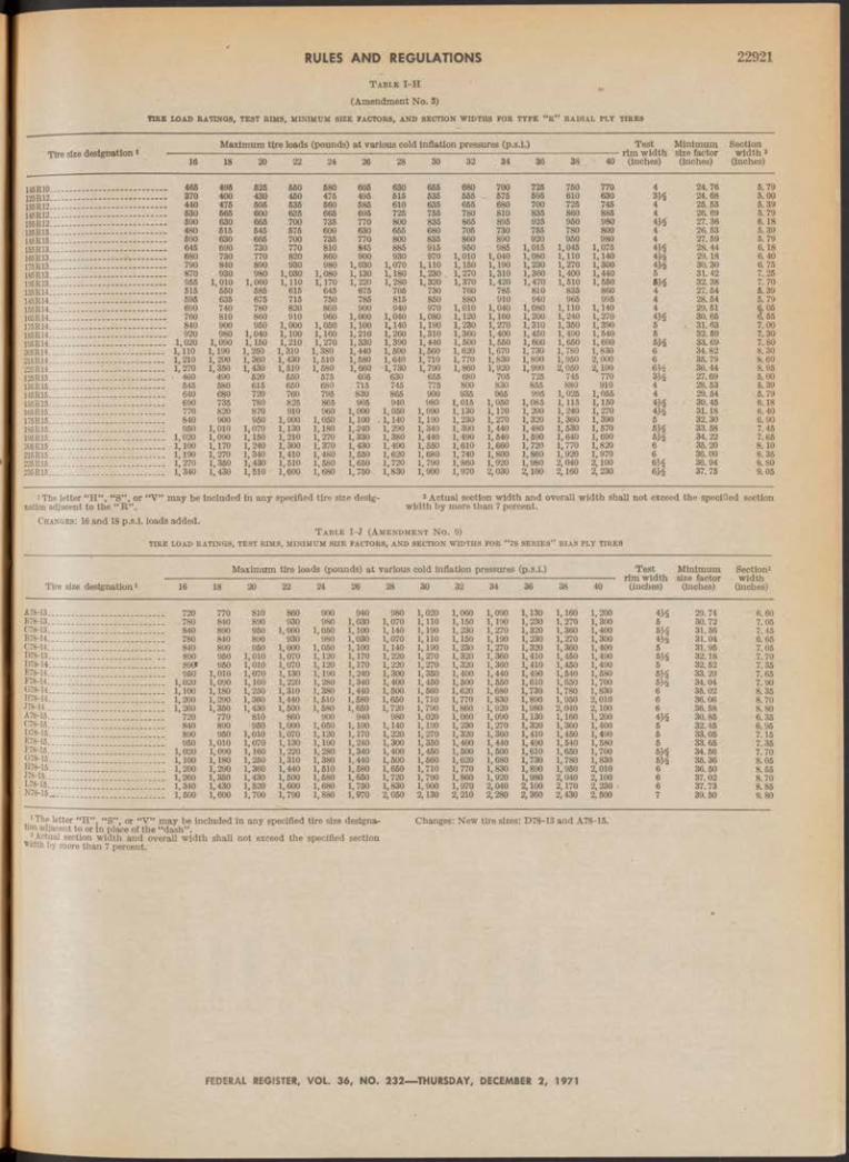
RULES AND REGULATIONS 22921
T a b l e I - H
(Amendment No. 3)
TIRE LOAD EATINGS, TEST BIM S, MINIMUM SIZE FACTORS, AND SECTION WIDTHS FOR TYPE “ R " RADIAL PLY TIRES
Tire size designation *Maximum tire loads (pounds) at various cold inflation pressures (p.s.i.) Test
rim width (inches)
Minimum size factor (inches)
Section width2
(inches)16 18 20 22 24 26 . 28 30 32 34 36 38 40
145R10....................................... ......... 466 496 625 550 680 605 630 655 680 700 725 750 770 4 24.76 5.79125R12....................................... ......... 370 400 430 450 475 495 515 535 555 - 575 695 610 630 24.68 5.00135R12.................................. — ......... 440 475 505 635 560 585 610 635 665 680 700 725 745 4 25.53 5.39145R12....................... — ................... 630 565 600 636 665 695 725 755 780 810 835 860 885 4 26. 69 5.79155R12....................................... .......... 690 630 665 700 735 770 800 835 865 895 925 950 980 27.36 6.18i36R13....... .......................................... 480 515 545 675 600 630 655 680 706 730 755 780 800 4 26.53 5.39145R13....................................... .......... 690 630 665 700 735 770 800 835 860 890 920 950 980 4 27.59 5. 79155R13....................................... .......... 645 690 730 770 810 845 885 915 950 985 1,015 1,045 1,075 4A 28.44 6.18166R13......................... ........................ 680 730 770 820 860 900 930 970 1,010 1,040 1,080 1,110 1,140 29.18 6.40175R13...........- .......................... .......... 790 840 890 930 980 1,030 1,070 1,110 1,150 1,190 1,230 1,270 1,300 30.30 6.75185R13....................................... .......... 870 930 980 1,030 1,080 1,130 1,180 1,230 . 1,270 1,310 1,360 1,400 1,440 5 31.42 7.25195R13....................................... .......... 955 1,010 1,060 1,110 1,170 1,220 1,280 1,320 1,370 1,420 1,470 1,510 1,550 32.38 7.70135R14....................................... .......... 515 650 585 616 645 675 705 730 760 785 810 835 860 4 27.54 5.39145R14.............................—-----.......... 595 635 675 715 750 785 815 850 880 910 940 965 995 4 28.54 5.79155R14__i...... ...................................... 690 740 780 820 860 900 940 970 1,010 1,040 1,080 1,110 1,140 4 29.51 6.05165R14....................... - ........................ 760 810 860 910 960 1,000 1,040 1,080 1,120 1,160 1,200 1,240 1,270 4M 30.65 6.55175R14....... ................. ........— ........ 840 900 950 1,000 1,050 1,100 1,140 1,190 1,230 1,270 1,310 1,350 1,390 5 . 31.63 7.00185R14............ - ............ . .......... 920 980 1,040 1,100 1,160 1,210 1,260 1,310 1,360 1,400 1,450 1,490 1,540 5 32.69 7.30195R14........................................ ........ 1,020 1,090 1,150 1,210 1,270 1,330 1,390 1,440 1,500 1,550 1,600 1,650 1,690 33.69 7.80205R14....................................... ........ 1,110 1,190 1,250 1,310 1,380 1,440 1,500 1,560 1,620 1,670 1,730 1,780 1,830 6 34.82 8.30215R14.............................. ......... ____ 1,210 1,290 1,360 1,430 1,510 1,580 1,640 1, 710 1,770 1,830 1,890 1,950 2,000 6 35. 79 8.60225R14-..................................... ........ 1,270 1,350 1,430 1,510 1,580 1,660 1,730 1,790 1,860 1,920 1,990 2,050 2,100 m 36.44 8.95I25R15..... ..................................____ • 460 490 620 550 575 605 630 655 680 705 725 745 770 27.69 5.00135R15.......... ..................... ... ........ 645 680 615 650 680 . 715 745 775 800 830 855 880 910 4 28.53 5.39145R15..... .......................- ......... ........ 640 680 720 760 795 830 865 900 935 965 995 1,026 1,055 4 29.54 6.79156R15....................................... ........ 690 735 780 825 865 905 940 980 1,015 1,050 1,085 1,115 1,150 m 30.45 6.18165 R16................................ ....... ........ 770 820 870 910 960 1,000 1,050 1,090 1,130 1,170 1,200 1,240 1,270 4A 31.18 6.40175R15....................................... ........ 840 900 950 1,000 1,050 1,100 ,. 1,140 1,190 1,230 1,270 1,320 1,360 1,390 5 32.30 6.901S5R15................: ..................... ........ 950 1,010 1,070 1,130 1,180 1,-240 1,290 1,340 1,390 1,440 1,480 1,530 1,570 t>A 33.58 7.45195R15.................. ........... . ........ 1,020 1,090 1,150 1, 210 1,270 1,330 1,380 1,440 1,490 1,540 1,590 1,640 1,690 &A 34.22 7.65205R15....................................... ........ 1,100 1,170 1,240 1,300 1,370 1,430 1,490 1,550 1,610 1,660 1,720 1,770 1,820 6 35.20 8.10215R15............................. 1___ ........ 1,190 1,270 1,340 1,410 1,480 1,550 1,620 1,680 1,740 1,800 1,860 1,920 1,970 6 36.00 8.35225R15-........ .......................... ____ 1,270 1,350 1,430 1,610 1,580 1,650 1,720 1,790 1,860 1,920 1,980 2,040 2,100 m 36.94 8.80235R15..................................... ........ 1,340 1,430 1,510 1,600 1,680 1,750v 1,830 1,900 1,970 2,030 2,100 2,160 2,230 6A 37.75 9.05
1 The letter “H” , “S” , or “V” may be included in any specified tire size desig- 2 Actual section width and overall width shall not exceed the specified sectionnation adjacent to the “ R” . width by more than 7 percent.
Changes: 16 and 18 p.s.i. loads added.T a b l e I - J (A m e n d m e n t N o . 9)
TIBE LOAD RATINGS, TEST RIM S, MINIMUM SIZE FACTORS, AND SECTION WIDTHS FOR “ 78 SE R IE S’’ BIAS PLy TIRES
Maximum tire loads (pounds) at various cold inflation pressures (p.s.i.) Test Minimum Section2rim width size factor width
Tire size designation1 16 18 20 22 24 26 28 30 32 34 36 38 40 (inches) (inches) (inches)
À78-13........................................ ........ 720 770 810 860 900 940 980 1,020 1,060 1,090 1,130 1,160 1,200 4Ms 29.74 6.60B78-13_______ ........ 780 840 890 930 980 1,030 1,070 1,110 1,150 1,190 1,230 1,270 1,300 5 30.72 7.05C78-13___ ____ 840 890 950 1,000 1,050 1,100 1,140 1,190 1,230 1,270 1,320 1,360 1,400 31.56 7.45B78-14.. ____ 780 840 890 930 980 1,030 1,070 1,110 1,150 1,190 1,230 1,270 1,300 m 31.04 ' 6.65C78-14. ____ 840 890 950 1,000 1,050 1,100 1,140 1,190 1,230 1,270 1,320 1,360 1,400 5 31.95 7.05D78-13... ____ 890 950 1,010 1,070 1,120 1,170 1,220 1,270 1,320 1,360 1,410 1,450 1,490 m 32.18 7.70D78-14 ____ 890t 950 1,010 1,070 1,120 1,170 1,220 1,270 1,320 1,360 1,410 1,450 1,490 5 32.52 7.35E78-14 ........ 950 1,010 1,070 1,130 1,190 1,240 1,300 1,350 1,400 1,440 1,490 1,540 1,580 m 33.29 7.65F78-14.. ____ 1,020 1,090 1,160 1,220 1,280 1,340 1,400 1,450 1,500 1,550 1,610 1,650 1,700 m 34.04 7.90G78-14. ........ 1,100 1,180 1,250 1,310 1,380 1,440 1,500 1,560 1,620 1,680 1,730 1,780 1,830 6 35.02 8.35H78-14 ____ 1,200 1,290 1,360 1,440 1,510 1,580 1,660 1,710 1,770 1,830 1,890 1,950 2,010 6 36.06 8.70J78-14.. ........ 1,260 1,350 1,430 1,500 1,580 1,650 1,720 1,790 1,860 1,920 1,980 2,040 2,100 6 36.58 8.80A78-15. ........ 720 770 810 ’ 860 900 940 980 1,020 1,060 1,090 1,130 1,160 1,200 30.85 6.35C78-15 ____ 840 890 950 1,000 1,050 1,100 1,140 1,190 1,230 1,270 1,320 1,360 1,400 5 32.45 6.95D78-15. ........ 890 950 1,010 1,070 1,120 1,170 1,220 1,270 1,320 1,360 1,410 1,450 1,490 5 33.05 7.15E78-15 ........ 950 1,010 1,070 1,130 1,190 1,240 1,300 1,350 1,400 1,440 1,490 1,540 1,580 5 33.65 7.35P78-15-. ____ 1,020 1,090 1,160 1,220 1,280 1,340 1,400 1,450 1,500 1,500 1,610 1,650 1,700 b a 34.56 7.70G78-15- 1,180 1,260 1,310 1,380 1,440 1,500 1,560 1,620 1,680 1,730 1,780 1,830 m 35.36 8.05H78-15 ____ 1,200 1,290 1,360 1,440 1,510 1,580 1,650 1,710 1,770 1,830 1,890 1,950 2,010 6 36.50 8.56J78—15_ 1,350 1,430 1,500 1,580 1,650 1,720 1,790 1,860 1,920 1,980 2,040 2,100 6 37.02 8.70L78-15._ 1,430 1,520 1,600 1,680 1,760 1,830 1,900 1,970 2,040 2,100 2,170 2,230 6 37.73 8.85N78-lfi_ ........ 1,500 1,600 1,700 1,790 1,880 1,970 2,050 2,130 2,210 2,280 2,360 2,430 2,500 7 39.50 9.80
•Theletter "H”, “S”, or “V” may be included in any specified tire size designs- Changes: New tire sizes: D78-13 and A78-15.adjacent to or in place of the “dash”.
1 Actual section width and overall width shall not exceed the specified section width by more than 7 percent.
FEDERAL REGISTER, VOL. 36, NO. 232— THURSDAY, DECEMBER 2, 1971

22922 RULES AND REGULATIONST a ble I -K
(Amendment 7)TIRE LOAD RATINGS, TEST RIM S, MINIMUM SIZE FACTORS, AND SECTION WIDTHS FOR “ 60 SE R IE S” BIAS PLY TIRES
Tire size designation*Maximum tire loads (pounds) at various cold inflation pressures (p.s.i.)
3634
Test Minimum Sectionrim width size factor width *
(inches) (inches) (inches)
wfiO-14 ________ 950 1,010£¿¿174............- - - - - - - .................. i>020 1,090G60K14 - moo usoH60-14" — ................................. 1.200 1,290m ï ï u ........ , .......... 1,260 1,350
E fi£l5 ............... .................. 950 1,010F60-15*" ...... ...........................— - 1,020 1,090G60I 15 ..........- .............. - ......... 1,100 1,180J60-Ï5 . 1,260 1,350K s : : : : : : : : : . . : . ............... — 1,340 1,430
1,070 1,130 1,190 1,240 1,300 1,350 1,400 1,440 1,4901 160 lj 220 1,280 1,340 1,400 1,450 1,500 1,550 1,6101,250 li 310 1,380 1,440 1,500 1,560 1,620 1,680 1,7301,360 l ’ 440 1,510 1,580 1,650 1,710 1,770 1,830 1,8901 430 1,500 1,580 1,650 1,720 1,790 1,860 1,920 1,980I , R20 1 600 i;680 1,750 1,830 1,900 1,970 2,040 2 ,1 0 0
1,070 1,130 1,190 1,240 1,300 1,350 1,400 1,440 1,4901,160 1,220 1,280 1,340 1,400 1,450 1,500 1, 550 1,6101,250 1,310 1,380 1,440 1,500 1,560 1,620 1,680 1,7301,360 1,440 1,510 1,580 1,650 1,710 1,770 1,830 1,8901,430 1,500 l j 580 1,650 1,720 1,790 1,860 1,920 1,9801,520 1, 600 1,680 1,750 1,830 1,900 1,970 2,040 2 ,1 0 0
1.5401.6501.7801.9502.0402.1701.5401.6501.7801.9502.0402.170
1.5801.7001.830 2,010 2,1002.2301.5801.7001.830 2,010 2,1002.230
33.69 34.44 35.23 36.4136.7037.8333.83 34.94 35.7336.70 37.20 37.91
9.309.559.85
10.25 10.45 11.108.70 9.409.70
10.0510.26 10.50
Changes: Test Rim for J60-14, J 60-15, and L60—15 changed to 7-inch.* The letter “H” “S” or “V” may be included in any specified tire size designation
» d ' t S width sh11 not th , specified sectionwidth by more than 7 percent. T a ble 1-L
(Amendment No. 2)TIRE LOAD RATINGS, TEST RIM S, MINIMUM SIZE FACTORS AND SECTION WIDTHS FOR SE RIES 50 CANTILEVERED SIDEWALL TIRES
Maximum tire loads (pounds) at various cold inflation pressures (p s.i.)^ Test Minimum
Tire size designation *rim width size factor
Sectionwidth*
20 22 24 26 28 30 32 34 36 38 40 (inches) (inches) (inches)
1,070 1,160 1,250 1,360 1,520
1,130 1,220 1,310 1,440 1,600
1,190 1,280 1,380 1,510 1,680
1,240 1,340 1,440 1,580 1,750
1,300 1,400 1,500 1,650 1,830
1,350 1,450 1,560 1,710 1,900
1,400 1,500 1,620 1,770 1,970
1,440 1,550 1,680 1,830 2,040
1,490 1,610 1,730 1,890 2,100
1,540 1,650 1,780 1,950 2,170
1,580I , 700J. , 830 2,010 2,230
3 )33 )33)33 )33 )3
33.31 34.04 35.34 36.30
/ 38.00
7.958.208.458.809.10
* The letter “ H” , “ S” or “V” may be included in any specified tire size designation adjacent to or in place of the “dash” .
2 Actual section width and overall width shall not exceed the specifif by more than 7 percent.
Changes: Reissued with no changes.
:1 section width
T a ble I-M (Amendment No. 4)
TIRE LOAD RATINGS, TEST RIMS, MINIMUM SIZE FACTORS AND SECTION WIDTHS FOR “ 78 SE RIES” RADIAL PLY TIRES
Tire size designation*Maximum tire loads (pounds) at various cold inflation pressures (p.s.i.)
AR78-13. BR78-13. CR78-13. BR78-14. CR78-14. DR78-14. E R78-14.
AR78-15.BR78-15.ER78-15.
16 18 20 22 24 26 28 30 32
720 770 810 860 900 940 980 1,020 1,060780 840 890 930 980 1,030 1,070 1,110 1,150840 890 950 1,000 1,050 1,100 1,140 1,190 1, 230780 840 890 930 980 1,030 1,070 1,110 1,150840 890 950 1,000 1,050 1,100 1,140 1,190 1,230890 950 1,010 1,070 1,120 1,170 1,220 1,270 1,320950 1,010 1,070 1,130 1,190 1,240 1,300 1,350 1,400
1,020 1,090 1,160 1,220 1,280 1,340 1,400 - 1,450 1, 500\, 100 1,180 1,250 1,310 1,380 1,440 1,500 1,560 1,6201200 1,290 1,360 1,440 1,510 1,580 1,650 1,710 1,770l] 260 1,350 1,430 1,500 1,580 1,650 1,720 1,790 1,860' 720 ' 770 810 860 900 940 980 1,020 1,060
780 840 890 930 980 1,030 1,070 1,110 1,150950 1,010 1,070 1,130 1,190 1,240 1,300 1,350 1,400
1,020 1,090 1,160 1,220 1,280 1,340 1,400 1,450 1, 5001,100 1,180 1,250 1,310 1,380 1,440 1,500 1,560 1, 6201,200 L 290 1,360 1,440 1,510 1,580 1,650 1,710 1,7701,260 1,350 1,430 1,500 1,580 1,650 1,720 1,790 1,860
*1,340 1,430 1,520 1,600 1.68Û 1,750 1,830 1,900 1,970
Test Minimum------— rim width . size factor40 (inches) (inches)
Section width 2
(inches)
1.0901.1901.2701.1901.270 1,3601.4401.550 1,6801.8301.9201.090 1,19Q1.4401.550 1,6801.8301.920 2,040
1.1301.2301.320
-1,2301.320 1,4101.490 1,6101.7301.8901.9801.1301.2301.490 1,6101.7301.8901.9802,100
1,1601.2701.360 1, 2701.360 1,4501.5401.6501.7801.9501.040 1,1601.2701.5401.6501.7801.9502.040 2,170
1,2001.3001.4001.3001.400 1,4901.5801.7001.830 2,010 2,100 1,2001.3001.5801.7001.830 2,010 2,100 2,230
54) 55
. 5
6 6
5) 35) 4666) 4
29.55 30.31 31.13 30.84 31.67 32.26 32.8633.7834.78 35.77 36.4730.66 31.38 33.58 34.28 35.30 36.23 36.9837.66
6.506.757.15 6.607.00 7.20 7.40 7.85 8.308.69 8.95 6.256.457.457.708.158.45 8.809.00
> The letter “H”, “S” or “V” may be included in any specified tire size designationadjacent to or in place of the “dash”. ..................... ... , , ... . . . . .
* Actual section width and overall width shall not exceed the specified section width
by more than 7 percent.Changes: New tire sizes: AR78-13, CR78-13, BR78-14, AR78-15.
T a ble I-N (Amendment No. 2)
TIRE LOAD RATINGS, TEST RIM S, MINIMUM SIZE FACTORS, AND SECTION WIDTHS FOR “ 70 SE R IE S” RADIAL PLY TIRES
Tire size designation *Maximum tire loads (pounds) at various cold inflation pressures (p.s.i.) Test
rim widthMinimum size factor
Section width
(inches)220 22 24 26 28 30 32 34 36 38 40 (inches) (inches)
............ 750 770 795 815 835 860 880980
1.090 1,210
815 1,155 1,2801.090 1,210
900 1,000 1,115
920 940 1,045 1,165
960 m528.45 29.31
6.506.92
"7.317.74............ 845 865 890 910 935 955 1,025
1,140 1,265
850
5 30.39940 965 990 1,015 1,040 1,065 m
46
31.20195/70 R 1 3 -..— . ............- ................................ ............ 1,045
............ 7001,070
7201,100
7401,125
7601,155
7801,180
795 835 1,180 1,310
870 890 28.1531.39 7.31
7.746.92............ 990 1,015 1,045 1,070 1,100 1,130
1,340 1,375 m5
32.30_____ 1,090 1,120 1,155 1,185 1,220 1,250
1,065 1,190 31.36............ 940 965 990 1,015 1,040
1,235 5 32.34185/70 R 15 ........................- .........- .................... _____ 1,040 1,070 1,100 1,130 1,155 1,180 1, 90
i The letter “H”, “S” , or “V ” may be included in any specified tire size designation Changes: Reissued with no changes.
Actual section width and overall width shall not exceed the specified section width by more than 7 percent.
FEDERAL REGISTER, VOL. 36, NO. 232— THURSDAY, DECEMBER 2, 1971

RULES AND REGULATIONS 22923T able 1 -0
(Amendment No. 2)
TIRE LOAD EATINGS, TEST RIM S, MINIMUM SIZE FACTORS AND SECTION WIDTHS FOR “ LOW SECTION” TYPE “ r ’ * RADIAL PLY TIRES
Tire’size designation
140R12.150R12.1Ü0R13.160R13.170R13-160R14.180R15.
Maximum tire loads (pounds) at various cold inflation pressures (p.s.i.) Test Minimum Section-----------------------— ------ ■■— ---------------------------------------------------------------------rim width size factor w idth2
20 22 24 26 28 30 32 34 36 38 40 (inches) (inches) (inches)
490 520 550 580 610 640 660 690 710 740 770 4 26.2 5.40570 610 640 670 700 730 760 790 820 850 880 4 27.19 5.75600 640 680 720 750 780 810 840 780 900 940 4 28.17 5.75670 700 740 780 820 860 900 940 980 1,010 1,040 m 29.23 6.25720 760 800 840 880 920 960 1,000 1,040 1,060 1,110 5 30.08 6.65640 670 710 750 780 820 860 900 940 970 1,000 4 29.16 5.70920 970 1,020 1,070 1,120 1,170 1,230 1,280 1,330 1,380 1,430 5 32 97 6.85
iThe letter “H”, “8” , or “V” may be included in any specified tire size desig- width by more than 7 percent, nation adjacent to the letter “ R ”.
»Actual section width and overall width shall not exceed the specified section Changes: New size 150R12,150R14, and 180R15 added.
T able I -P(Amendment No. 1)
TIRE LOAD RATINGS, TEST RIM S, MINIMUM SIZE FACTORS AND SECTION WIDTHS FOR SE RIES 45 CANTILEVERED SIDEWALL TIRES
Tire size designation 1Maximum tire loads (pounds) at various cold inflation pressures (p.s.i.) Test
■ rim width (inches)
Minimum size factor (inches)
Section widthJ (Inches)20 22 24 26 28 30 32 34 36 38 40
G45C-16___ .......... 1,250 1,310 1,380 1,440 1,500 1,560 1,620 1,680 1,730 1,780 1,830 5 35.53 9.70
• The letter “H,” “8” or “V ” may be included in any specified tire size designation s Actual section width and overall width shall not exceed the specified section widthadjacent to or in place of the “dash”. by more than 7 percent.
Changes: Reissued with no changes.
T able I-R [Arndt. No. 4]
TIRE LOAD RATINGS, TEST RIM S, MINIMUM SIZE FACTORS, AND SECTION WIDTHS FOR " 6 0 SE R IE S” RADIAL PLY TIRES
Tire size designation iMaximum tire loads (pounds) at various cold inflation pressures (p.s.i.)
Test rim width
(inches)
Minimumsize
factor(inches)
Section w idth» (inches)16 18 20 22 24 26 28 30 32 34 36 38 40
GR60-14................................ . . . . 1.100 1,180 1,250 1,310 1,380 1,440 1,500 1,560 1,620 1,680 1,730 1,780 1,830 7 35.24 9.85FR60-15............... . . . 1,020 1,090 1,160 1,220 1,280 1,340 1,400 1,450 1,500 1,550 1,610 1,650 1,700 7 35.02 9.30GR60-15....................... . . . 1,100 1,180 1,250 1,310 1,380 1,440 1,500 1,560 1,620 1,680 1,730 1,780 1,830 7 35.81 9.60HR60-16....................... . . . 1,200 1,290 1,360 1,440 1,510 ¿580 1,650 1,710 1,770 1,830 ¿890 1,950 2,010 7 36.70 10.05
1 The letter “H”, “S”, or “V” may be included in any specified tire size designation adjacent to or in place of the “dash.”
1 Actual section width and overall width shall not exceed the specified section width
by more than 7 percent.Changes: New size GR60-14 added.
T able I-S
[Amdt. No. 2]
TIRE LOAD RATINGS, TEST RIM S, MINIMUM SIZE FACTORS, AND SECTION WIDTHS FOR “ 60 SE R IE S” RADIAL PLY TIRES
Tire size designation 1Maximum‘tire loads (pounds) at various cold inflation pressures (p.s.i.)
Test rim width
(inches)
Minimumsize
factor(Inches)
Section width » (inches)16 18 20 22 24 26 28 30 32 34 36 38 40
185/60 R 13. 780 815 845 880 915 945 980 1,010 1,045 1,075 1,110 5 28.61 7.281,090 1.160 1,220 1,280 1,340 1,400 1,450 1,500 1,560 1,610 1,650 1,700 m 34.25 9.35266/60 R lö_ 1,290 1,360 1,440 1,610 1,580 1,650 1,710 1,770 1,830 1,890 1,950 2,010 7 36.70 10.05
a d j a c e n t * ^ 01 may deluded in any specified tire size designation width by more than 7 percent.! Actual section width and overall width shall not exceed the specified section Changes: New size 245/60 R 14 and 255/60 R 15 added.
T able I -T
(Amendment No. 1)
TIRE LOAD RATINGS, TEST RIM S, MINIMUM SIZE FACTORS, AND SECTION WIDTHS FOR “ 70 SE R IE S” RADIAL PLY TIRES
Tire size 1 designation Maximum tire loads (pounds) at various cold inflation pressures (p.s.i.) Test . Minimum size factor (inches)
Section width *
(inches)16 18 20 22 24 26 28 30 32 34 36 38 40 (inches)
305/70 R 14%70 R h .................... — — -226/70 R m ................ — — — .195/70 R is . .................................205/70 R is ....... *.......................216/70 R 15 ...................................225/70 R is ...................................
1,010 1,070 1,130 1,190 1,240 1,300 1,350 1,400 1,440 1,490 1,540 1,580 m 33.42 8.101,090 1,160 1,220 1,280 1,340 1,400
1,5001,450 1,500 1,550 1,610 1,650 1,700 6 34.34 8.55
1,180 1,250 1,310 1,380 1,440 1,560 1,620 1,680 1,730 1,780 1,830 6 35.12 8.85950 1,010 1,070 1,120 1,170 1,220 1.270 1,320 1,360 1,410 1,450 1,490 m 33.34 7.75
1,010 1,070 1,130 1,190 1,240 1,300 1,350 1,400 1,440 1,490 1,540 1,580 6H 33.91 7.951,090 1,160 1,220 1,280 1,340 1,400 1,450 1,500 1,550 1,610 1,650 1,700 6 34.87 8.401,180 1,250 1,310 1,380 1,440 1,500 1,560 1,620 1,680 1,730 1,780 1,830 6 35.65 8.65
W jSnt^oTho^ft'8«'« may k® included in any specified tire size designation »Actual section width and overall width shall not exceed the specified sectionme letter K . width by more than 7 percent.
Changes: New table.
FEDERAL REGISTER, VOL. 36, NO. 232— THURSDAY, DECEMBER 2, 1971

RULES AND REGULATIONS22924T able II—Minimum Breaking E nergy Values
(Inch-Pounds)
TABLE II—A— TOR BIAS PLY TIRES WITH SIZE DESIGNATION OF 6 .00 (OR 166 MILLIMETERS) AND ABOVE AND 70 SE RIES TIRES
Murlmiiin permissible Inflation pressure
material32 p.S.l. 36 p.s.l. 40 p.s.l.
Rayon____Nylon or
polyester.
1,650 in.-lbs . 2,600 in.-lbs .
2,475 In.-lbs. 3,900 in.-lbs.
3,300 in.-lbs. 6,200 in.-lbs.
TABLE I I - B — FOB BIAS PLY TIRES WITH SIZE DESIGNATION BELOW 6.00 INCHES (OR 166 M ILLIMETERS)
Cordmaterial
MuTimnTn permissible inflation pressure
32 p .8.1. 36 p.s.i. 40 p.s.i;
Rayon____Nylon or
polyester.
1,000 in.-lbs. 1,950 in.-lbs.
1,875 in.-lbs . 2,926 in.-lbs.
2,500 in.-lbs. 3,900 in.-lbs.
TABLE II-O —FOB RADIAL PLY TIRES
MttTimnm permissible inflation pressoreSize
designation32 p.s.i. 36 p.s.i. 40 p.8.L
Below 160 1,950 in.-lbs- 2,925 in.-lbs. 3,900 in.-lbs.milll-meters.
160 milll- 2,600 in.-lbs. 3,900 in.-lbs. 5,200 in.-lbs.meters or above.
T able HI
t e s t in f l a t io n p r e s s u r e s
Maximum permissible inflation32 36 40
Pressure (in p.s.l.) to be used in tests for physical dimensions, bead unseating, tire strength, and tire
24 28 32Pressure (in p.s.i.) to be used in test
30 34 38
§ 571.110 Standard No. 1 1 0 ; Tire selection and rims.
51. Purpose and scope. This standard specifies requirements for tire selection to prevent tire overloading.
52. Application. This standard applies to passenger cars.
53. Definitions.“Accessory weight” means the com
bined weight (In excess of those standard items which may be replaced) of automatic transmission, power s t e e r i n g , power brakes, power windows, power seats, radio, and heater, to the extent that these items are available as factory- installed equipment (whether installed or not). ....
“Curb weight” means the weight of a motor- vehicle with standard equipment including the maximum capacity of fuel, oil, and coolant, and, if so equipped, air conditioning and additional weight optional engine.
“Maximum loaded vehicle weight” means the sum of—
(a) Curb weight;(b) Accessory weight;(c) Vehicle capacity weight; and(d) Production options weight.
“Normal occupant weight” means 150 pounds times the number of occupants specified in the second column of Table I.
"Occupant distribution” means distribution of occupants in a vehicle as specified in the third column of Table I.
“Production options weight” means the combined weight of those installed regular production options weighing over 5 pounds in excess of those standard items which they replace, not previously considered in curb weight or accessory weight, including heavy duty brakes, ride levelers, roof rack, heavy duty battery, and special trim.
“Vehicle capacity weight” means the rated cargo and luggage load plus 150 pounds times the vehicles designated seating capacity; ,
“Vehicle maximum load on the tire” means that load on an individual tire that is determined by distributing to each axle its share of the maximum loaded vehicle weight and dividing by two.
“Vehicle normal load on the tire” means that load on an individual tire (distributed In accordance with Table I) and dividing by two.
T able IOCCUPANT LOADING AND DISTRIBUTION FOB VEHICLE
NORMAL LOAD FOR VARIOUS DESIGNATED SEATING CAPACITIES
Designated seating capacity,
number, of occupants
Vehicle normal load,
number of occupants
Occupant distribution in a normally loaded
vehicle
2 through 4......... 2 2 in front.6 through 10___ 3 2 in front, 1 in second
seat.
S4. Requirem ents.54.1 G eneral. Passenger Cars shall be
equipped with tires that meet the requirements of § 571.109, “New Pneumatic Tires—Passenger Cars.”
54.2 Tire load limits.54.2.1 The vehicle maximum load on
the tire shall not be greater than the applicable maximum load rating specified in Table I of Motor Vehicle Safety Standard No. 109 for the tire’s size designation and type.
54.2.2 The vehicle normal load on the tire shall not be greater than the test load used in the high speed performance test specified in S5.5 of § 571.109 for that tire.
S4.3 Placard. A placard, permanently affixed to the glove compartment door or an equally accessible location, shall display the—
(a) Vehicle capacity weight;(b) Designated seating capacity (ex
pressed in terms of total number of occupants and in terms of occupants for each seat location);
(c) Vehicle manufacturer’s recommended cold tire inflation pressure for mRYiTrmm loaded vehicle weight and, subject to the limitations of S4.3.1, for any other manufacturer-specified vehicle loading condition; and
(d) Vehicle manufacturer’s recommended tire size designation.
S4.3.1 No inflation pressure other than the maximum permissible inflation pressure may be specified unless—
(a) It is less than the maximum permissible inflation pressure;
(b) The vehicle loading condition for that pressure is specified; and« (c) The tire load rating from Table I of § 571.109 for the tire at that pressure is not less than the vehicle load on the tire for that vehicle loading condition.
S4.4 Rims.S4.4.1 Requirem ents. Each rim shall:(a) Be constructed to the dimensions
of a rim specified for the applicable tire’s size designation in a reference cited in the definition of test rim in S3 of § 571.109. Approved alternative size rims, not cited in S3 of § 571.109 are listed in Table n of Appendix A of this section.
(b) In the event of rapid loss of inflation pressure with the vehicle traveling In a straight line at a speed of 60 miles per hour, retain the deflated tire until the vehicle can be stopped with a controlled braking application.
A p p e n d ix A
The following table lists alternative size rims for tire and rim combinations not contained in any reference in S3 of § 571.109.
Persons requesting the addition of alternative tire rims to this appendix should submit five (5) copies of information and data supporting the request to the Secretary of Transportation, Attention: Motor Vehicle Programs, National Highway Traffic Safety Administration, U.S. Department of Transportation, Washington, D.C. 20590.
The information should contain the following :
1. The request alternative rim and tire size combination.
2. A statement as to w hether the alternative tire/rim com bination has been coordinated with an organization such as the Tire and Rim Association, the European Tire and Technical Organisation, the Society of M an ufactu rers and Traders Limited, the Japan Automobile Tire Manufacturers Association, the Deutsche Industrie Norm and the Scandanavian Tire and R im Organization.
3. A statement that the additional rim size request has been tested in accordance with the requirements of § 571.11« and meets the requirements of the standard.
4. Copies of the test data sheets showing test conditions, results of tests performed on the tire/rim combination, and conclusions obtained for the individual tests specified in § 571.109.
5. Justification for the additional rimsize.
The addition of alternative size, runs for the tire and rim combinations is accomplished through the abbreviated procedure consisting of publication m wi F e d e r a l R e g is t e r of the size run ^ which a petition has been received, n comments are received, the amendm becomes effective 30 days from date publication. If objections to the amendment are received, additional nuem ing pursuant to Part 553 of this chap will be initiated.
FEDERAL REGISTER, VOL. 36, NO. 232— THURSDAY, DECEMBER 2, 1971

RULES AND REGULATIONS 22925
FM V SS No . 110— A p p e n d i x A TABLE i
(A m en d m ent No. 22)ALTERNATIVE R IM S
T a b le I -A
Tire S iz e * R i m 1 *
6.00— 1 3 - - - - - - - - - 5—J J , 6—J J7.35-14______ — 6- J J6.85—15_________ 4 ^ —J J , 5 % —J J7.00- 15_______ 5 .00F , 5—K8.25—1 5 -- -—————- 5—J J , 5 ^ —J J , 6—J J , 6—K ,
6—L , 6 i/2- J J8.55-15_________ 5y2- J J , 6 - J J , 6—K , 6 -L ,
6 i/2- J J8.90—15-- ----------- 6—J J , 6y2—L , 7—L9.15-15_________ 5 ^ - J J , 5 % - KL84-15— ______ 51/2- J J , 6 - J J , 6 y2- J J , 7 - J J
T a b le I - B
A70-13_————— 5—J J , 5y2—J J , 6—J JD70-13_________ 5y2- J J , 5y2- KD70-14_________ 5 - J JE70-14_________ 7 - J JP70-14_________ 7 - J J , 8 - J JG70-14............... .. 7 - J JC70-15.......... ......... 5y2- J JE70—15_________ _ 7—J J , 8—J JF70-15_________ . 8 - J JG70-15__________ 7 - J J , 7 1/2 - K , 8 - J JH70-15_________ ' 8 - J J
T a b le I -C
4.80-10_________ 3.50D5.60-14.................... 4 % - J J6.40-15_________ 4—J J , 4y2-JJ, 4y2- K , 4.50E,
5.00E , 5 - J J , 5 -K , 51/2- J J155—13/6.15—13_5 - J J175-13/6.95-13— 5y2- J J5.0-15-................... 3 .50B , 3.50D , 3 ^ - J J , 4-JJ,
• 4.00C5.5-15----------------- 3.50D , 314—J J , 4—J J , 4 % - J J
145-10.145-13.165-13.135-15.185-15.230-15.
6.2-13.6.5-13.
5.20-13.5.60-13.6.00-13.5.150-15.
DR70-13__CR70-14__DR70-14__FR70—15__ER70-15_PR70-15 . G R 70-15-.
HRTO-IS—JR 7 0 -1 5 - .LR70-15— .
155 R 12. 135 R 13. 145 R 13, 155 R 13_ 165 R 13. 175 R 13 165 R 14 175 R 14 205 R 14 !35 R 15. 165 R 15 205 R 15.
T a b le I -D
3 .50B31/a-JJ, 41/2-JJ 41/2- J J 41/2- J J 41/2- J J6 - J J , 61/2- J J , 7 - J J
T a b le I - E
4 / a - J J41/2- J J , 5 - J J ,
T a b le I - P 41/2- J J 31/2- J J , 4 - J J4 - J J5 - K
T a b le I - G
51/2- J J51/2- J J6- J J , 61/2- J J , 61/2- K 51/2- J J , 61/2- J J , 7 - J J , 8 - J J 6 - J J , 6 1 / ,- JJ , 7 - J J 61/2- J J , 7 - J J , 71/2- K , 71/2- L 6i/2- J J , 7 - J J , 7 -L , 71/2- K ,
8—K, 81/2-L 6 - J J 6 - J J 6 - J J
T a b le I -H4 - J J4 1 / ,-JJ41/2- J J , 4 .50B 4 .50B , 5 - J J , 51/2- J J 4 - J J , 4 .50B , 5 .50B4 - J J , 51/2- J J 5 % —J J414- J J 7%-K 41/a-JJ5 - J J , 5 -K , 5y2- J J 6i/2- L , 7—L , 71/2- K
T a b le I - J
T ire S iz e 8 R i m 1 •
A 78 -1 3 --------------- 4 - J J , 4y2- J J , 5 - J J , 5i/2- J J ,6 - J J
B 7 8 -1 3 __________ 5 - J JC78—13_____ ____ 5y2- J JD 78—13__________ 5y2- J JB 7 8 -1 4 --------------- 41/2- J J , 41/2- K , 5 - J J , 5 -K ,
5y2- J JC 7 8 -1 4 ...... .............. 4 i/2- J J , 5 - J J , 5 -K , 5y2- J J ,
6 - J JD 7 8 -1 4 _ _ ............... 41/2- J J , 5 - J J , 5 -K , 5 ^ - J J ,
6 - J JE78—14__................ 41/2- J J , 5 - J J , 5 -K , 5y2- J J ,
Sy2- K , 6- J J , 61/2- J J , 7 - J JF 78—14--------------- 5 - J J , 5 -K , 5y2- J J , 5y2- K ,
6- J J , 6—K , 6 % - J J , 7 - J J0 7 8 —14--------------- 5 - J J , 5i/2- J J , 5 y2- K , 6 - J J ,
6—K , 7 - J JH78—14.................... 51/2- J J , 6 - J J , 6—K , 6y2- J J ,
6 y2- K , 7 - J JJ 7 8 - 1 4 --------------- 6 - J J , 6—K , 6 i/2- J JA 78-15___:______ . 4y2- J JC 7 8 -1 5 --------------- 4i/2- J J , 41/2- K , 5 - J J , 5 - KD 78—15-------- - 5 - J J , 5 - KE 7 8 -1 5 --------------- 41/2- K , 5 - J J 5 -K , 5i/2- J J ,
5y2- K , 6- J JF 7 8 -1 5 -------- ------- 4i/a- K , 5 - J J , 5- K , 5y2- J J ,
5y2- K , 6- J J0 7 8 - 1 5 — , ----- 5 - J J , 5 -K , 51/2- J J , 51/2- K ,
6- J J , 6- K , 6-L , 6 i/2- J J ,7 - J J
H78—15--------------- 5 /4—J J , 5i/2- K , 6 - J J , 6 -K ,6 -L , 61/2- K , 61/2- J J , 7 - J J
J 7 8 —15------------- - 514- J J , 6 - J J , 6 -K , 6 -L ,6 y2- J J , 7 - J J
L 7 8 -1 5 --------------- 514. - J J , 5i/2- K , 6 - J J , 6 -K ,6 -L , 6y2—J J , 7 - J J , 8- J J
N78—15__________ 6- J J , 7 - J J
T a b le I - K
E 60—14__!________ 7 - J JF 6 0 -1 4 __________ 7 - J JG 60—14__________ 7 - J JJ6 0 —14-------- - 7 - J J , 71/2- J JH 6 0 -1 4 _____ ____ 6y2- J J , 7 - J JL 6 0 -1 4 __________ 8 - J JE 6 0 -1 5 --------------- 6 - J J , 7 - J J , 8- J JF 60—15--------------- 61/2- J J , 7 - J J , 8- J JQ 6 0 -1 5 --------------- 7 - J J , 8- J J , 9—J JH60—15__________ 7 - J JJ 6 0 -1 5 __________ 7 - J J , iy 2- j jL 6 0 -1 5 __________ 7 - J J , 7 i ^ - J J
T a b le I —L
E 5 0 C -1 6 ,_______ 3y2F 5 0 C -1 6 ________ 3i/2G 5 0 C -1 7 ________ 3i/2H 50C -17________ 3i/4L 5 0 C -1 8________ 3V4, 4
T a b le I -M
A R 7 8 -1 3 ________ 41/4-JJB R 7 8 -1 3 ________ 4y2- J JC R 7 8 -1 3 ________ 5 - J JB R 7 8 -1 4 ________ 41/4-JJC R 7 8 -1 4 ________ 5 - J JD R 7 8 -1 4 ________ 5 - J J , 6- J JE R 7 8 -1 4 ________ 5 - J JF R 7 8 —14________ 5 - J J , 5 V 4 -JJ , 6- J JG R 7 8 -1 4 ________ 6 - J JH R78—14________ 6 - J JJ R 7 8 - 1 4 ________ 61/2- J JA R 7 8 -1 5 ________ 4 V 4 -J JB R 7 8 -1 5 ________ 41/2- J JE R 78—15____ _ 5y2- J JF R 7 8 -1 5 ________ 51/2- J JG R 7 8 -1 5 ________ 6 - J JH R 8 7 -1 5 ________ 51/2- J J , 6 - J JJ R 7 8 - 1 5 ________ 6—J J , 6y2—J JL R 7 8 -1 5 ________ 6- J J , 6 V 4 - J J
T a b le I -N
165/70 R 13____ 41/2- J J , 5 - J J175/70 R 13____ 5 - J J , 51/4-JJ185/70 R 13____ 41/2- J J , 5 - J J , 51/2- J J
T able I —N— ContinuedT ire S iz e * R i m 1 *
195/70 R 13___ 5 V 4 -JJ , 6- J J155/70 R 14___ 4 - J J185/70 R 14___ 41/2- J J , 5 - J J , 5y2- J J195/70 R 14____ 51/4-JJ, 6- J J175/70 R 15____ 5 - J J185/70 R 15____ 5 - J J , 51/2- J J , 6 - J J , 7 - K
T a b le 1 - 0
140 R 12_______ 4.00, 400—B , 4 - J J , 4.50,4.50—B , 41/2- J J
150 R 12_______ 31/4-JJ, 4 .00B , 4 - J J , 4i/2- J J150 R 13______ _ 31/4-JJ, 4.00B , 4i/2- J J , 5 - J J160 R 13_______ 4 .00B , 4 V 4 -J J , 5 - J J , 51/4-JJ170 R 13____ _ 4y2- J J , 5 - J J , 5 ^ 4 - J J , 6 - J J150 R 14_______ 4 - J J , 41/4-JJ180 R 1 5 „ _ ____ 5 - J J , 51/4-JJ
T a b le I - PG 4 5 C -1 6_____ _ 5
T a b le I - RG R 6 0 -1 4 _____ _ 7 - J JF R 6 0 -1 5 ________ 7 - J J , 8 - J JG R 6 0 -1 5 ________ 7 - J J , 8 - J JH R 60—15____:___ 7 - J J , 9 -L
T a b le I - S
185/60 R 13___ 5 - J J , 51/2- J J245/60 R 14___ 6y2- J J , 7 - J J255/60 R 15____ 7 - J J , 9 - J J , 9 -L
T a b le I - T
205/70 R 14____ 51/2- J J , 6 - J J , 6i/2- J J215/70 R 14____ 51/2- J J , 6 - J J , 61/2- J J , 7 - J J ,
8 - J J225/70 R 14___ 6 - J J , 71/2- K195/70 R 15___ 5i/2- J J , 6 - J J205/70 R 15___ 51/2- J J , 6 - J J ' , 6 y2- J J , 6 i/2-L ,
7 - J J215/70 R 15____ 6 - J J , 61/4-JJ, 6i/2-L , 7 - J J ,
7 - L , 71/4—J J , 7V4—L, 71/2- K , 8—K
225/70 R 15____ 6 - J J , 6 y2- J J , 7 -L , 714- K ,8 - K , 814—L, 9 -L
1 I ta l ic d esig n atio n s d enote te s t rim s.2 W h ere J J rim s are specified in th e above
T a b le J an d J K rim co n to u rs are p erm issib le .3 T a b le d esig n atio n s re fe r to ta b les lis te d in
A ppendix A o f 571.109.C h a n g es:
T a b le I-A 8 .25 -15 , rim 6y2-JJ. added.T a b le I - B D 70-14 , rim 5 - J J added, F 7 0 -1 4 ,
r im 8 - J J added.T a b le I -D 23 0 -1 5 , rim s 6 - J J , 6 % - J J , an d
7 - J J added.T a b le I - G G R 7 0 -1 5 , rim 7 - J J added.T a b le I -H 155 R 13 , r im 5 V 4 -J J added.T a b le I - K G 6 0 -1 5 , r im 9 - J J added.T a b le I -M F R 7 8 -1 4 , rim s 5 - J J an d 6 - J J
added.T a b le I - R G R 6 0 -1 4 , r im 7 - J J added, H R 6 0 -
15, r im 9 -L added.T a b le I - S 245/60 R 14 , rim s 6y2 an d 7 - J J
added, 255/60 R 15 , rim s 7 - J J , 9 - J J , an d 9 -L added.
T a b le I - T 255/70 R 15 , rim s 8 -K an d 8y2- L added.
§571. 111 Standard No. I l l ; Rearview mirrors.
SI. Purpose and scope. This standard specifies requirements for rearview mirrors to provide the driver with a clear and reasonably unobstructed view to the rear.
82. Application. This standard applies to passenger cars and multipurpose passenger vehicles.
S3. Requirem ents.53.1 Inside rearview m irrors.53.1.1 Field o f view. A mirror shall
be installed that provides the driver a
FEDERAL REGISTER, VOL. 36, NO. 232— THURSDAY, DECEMBER 2, 1971

22926 RULES AND REGULATIONS
view to the reax, of substantially unit magnification, with an included horizontal angle of at least 20 degrees and sufficient vertical angle to provide a view of a level road surface extending to the horizon beginning at a point not greater than 200 feet to the rear of the vehicle when the vehicle is occupied by the driver and four passengers or the designed occupant capacity, if less, based on 150 pound average occupant weight. The line of sight may be partially obscured by seated occupants or by head restraints.
S3.1.2 Mounting.53.1.2.1 The mirror mounting shall
provide a stable support for the mirror, and shall provide for mirror adjustment by tilting in both horizontal and vertical
53.1.2.2 If the mirror is in the head impact area, the mounting shall break away without leaving sharp edges or deflect or collapse when the mirror is subjected to a force of 90 pounds in a forward or sideward direction in any plane 45° above or below the horizontal.
53.2 Outside mirrors.53.2.1 Driver’s side.53.2.1.1 Field o f view. An outside
mirror shall be installed that provides the driver a view, of substantially unit magnification, of a level road surface extending to the horizon from a line perpendicular to a plane tangent to the driver’s side of the vehicle at the widest point and parallel to the longitudinal axis of the vehicle extending 8 feet out from the tangent plane 35 feet behind tha driver’s eyes, with the seat in the rearmost position. The line of sight may be partially obscured by rear body or fender contours.
53.2.1.2 Mounting. The mounting shall provide a stable support for the mirror and neither the mirror nor the mounting shall protrude further than the widest part of the vehicle body, except to the extent necessary to produce a field of view meeting or exceeding the requirements of S3.2.1.1. The mirror shall not be obscured by the unwiped portion of the windshield, and shall be adjustable from the driver’s seated position. The mirror and mounting shall be free of sharp points or edges that could contribute to pedestrian injury.
53.2.2 Passenger’s side. If the inside mirror required by S3.1 does not meet the field of view requirements of S3.1.1, an outside mirror of substantially unit magnification shall be installed on the passenger’s side.
S3.2.2.1 Mounting. The mounting shall provide a stable support for the mirror, and the mirror and mounting shall be free of sharp points or edges that could contribute to pedestrian injury.
S3.3 Mirror construction. The reflectance value of the reflective film employed shall be at least 35 percent. If a mirror is of the selective position prismatic type, the reflectance value in the night driving position shall be at least 4 percent.
S.4. Dem onstration procedures. Reflectance shall be determined in accord
ance with Society of Automotive Engineers Recommended Practice J964, “Test Procedure for Determining Reflectivity of Rearview Mirrors,” June 1966.
No t e : (1 ) W h en a su p p lem en ta l m irro r is fu rn ish e d in ad d itio n to th e in s id e rearview m irro r an d th e d riv er’s sid e ou tsid e re a rview m irror, th e su p p lem en ta l m irro r n eed n o t b e a d ju s ta b le fro m th e d river’s sea t.
(2 ) T h e lo ca tio n o f th e d river’s eye re fe r en ce p o in t m ay b e th a t esta b lish ed in M otor V eh icle S a fe ty S ta n d a rd No. 104, or i t m ay b e a n o m in a l lo ca tio n ap p rop riate fo r an y 9 5 th p e rce n tile m ale driver.
(3 ) T h e h o riz o n ta l a n g le is m easu red fro m th e p ro jec te d eye p o in t, ra th e r th an , th e p lan e o f th e m irror.
§ 571.112 Standard No. 112 ; Headlamp concealment devices.
51. Scope. This standard specifies requirements for headlamp concealment devices.
52. Application. This standard applies to passenger cars, multipurpose passenger vehicles, trucks, buses, and motorcycles.
53. Definitions.“Fully opened” means the position of
the headlamp concealment device in which the headlamp is in the design open operating position.
“Headlamp concealment device” means a device, with its operating system and components, that provides concealment of the headlamp when it is not In use, including a movable headlamp cover and a headlamp that displaces for concealment purposes.
“Power” means any source of energy that operates the headlamp concealment device.
54. Requirem ents.54.1 While the headlamp is illumi
nated, its fully opened headlamp concealment device shall remain fully opened whenever either or both of the following occur—
a. Any loss of power to or within the headlamp concealment device;
b. Any disconnection, r e s t r i c t i o n , short-circuit, circuit time delay, or other similar malfunction in any wiring, tubing, hose, solenoid or other component that controls or conducts power for operating the concealment device.
54.2 Whenever any malfunction occurs in a component that controls or conducts power for the actuation of the concealment device, each closed headlamp concealment device shall be capable of being fully opened—
(a) By automatic means;(b) By actuation of a switch, lever or
other similar mechanism; or(c) By other means not requiring the
use of any tools.Thereafter, the headlamp concealment device must remain fully opened until Intentionally closed.
54.3 Except for cases of malfunction covered by S4.2, each headlamp concealment device shall be capable of being fully opened and the headlamps illuminated by actuation of a single switch, lever, or similar mechanism, including a mechanism that is automatically actu-
ated by a change in ambient light conditions.
54.4 Each headlamp concealment device shall be installed so that the headlamp may be mounted, aimed, and adjusted without removing any component of the device, other than components of the headlamp assembly.
54.5 After December 31, 1969, the headlamp beam of headlamps that illuminate during opening and closing of the héadlamp concealment device may not project to the left of or above the position of the beam when the device is fully opened.
54.6 Except for cases of malfunction covered by S4.2, after December 31,1969, each headlamp concealment device shall, within an ambient temperature range of —20° to +Ì20° F., be capable of being fully opened in not more than 3 seconds after actuation of the mechanism described in S4.3.§ 571.113 Standard No. 113; Hood latch
system.51. Purpose and scope. This standard
establishes the requirement for providing a hood latch system or hood latch systems.
52. Application. This standard applies to passenger cars, multipurpose passenger vehicles, trucks, and buses.
53. Definitions. “Hood” means any exterior movable body panel forward of the windshield that is used to cover an engine, luggage, storage or battery compartment.
54. Requirem ents.54.1 Each hood must be provided with
a hood latch system.54.2 A front opening hood which, in
any open position, partially or completely obstructs a driver’s forward view through the windshield must be provided with a second latch position on the hood latch system or with a second hood latch system.t 571.114 Standard No. 114; Theft pro
tection.51. Purpose and scope. This standard
ipeclfi.es requirements for theft protec- Ion to reduce the incidence of accidents ■esulting from unauthorized use.
52. Application. This standard applies ;o passenger cars.
53. Definitions."Combination” means one of the
jpecifically planned and constructed variations of a locking system whicn, vhen properly actuated, permits opera- don of the locking system.
“Key” includes any other device designed and constructed to provide a method for operating a locking system which is designed and constructed to to aperated by that device.
54. Requirem ents.S4.1 Each passenger car shall nav
a key-locking system that, whenever th key is removed will prevent— f
(a) Normal activation of the cars engine or other main source of m°nvc power; and
FEDERAL REGISTER, VOL. 36, NO. 232— THURSDAY, DECEMBER 2, 1971
RULES AND REGULATIONS 22927
(b) Either steering or forward self- mobility of the car, or both.
54.2 The prime means for deactivating the car’s engine or other main source of motive power shall not activate the deterrent required by S4.1 (b ).
54.3 The number of different combinations of the key locking systems required by S4.1 of each manufacturer shall be at least 1,000, or a number equal to the number of passenger cars manufactured by such manufacturer, whichever is less.
54.4 A warning to the driver shall be activated whenever the key required by S4.1 has been left in the locking system and the driver’s door is opened. The warning to the driver need not operate—
(a) After the key has been manually withdrawn to a position from which it may not be turned;
(b) When the key-locking system is in the “on” or “start” position; or
(c) After the key has been inserted in the locking system and before it has been turned.§571.115 Standard No. 115; Vehicle
identification number.51. Purpose and Scope. This standard
specifies requirements for vehicle identification numbers to reduce the incidence of accidents resulting from unauthorized use.
52. Application. This standard applies to passenger cars.
53. Definition. “Vehicle identification number” means a number consisting of arabic numerals, roman letters, or both, which the manufacturer assigns to the vehicle for identification purposes.
54. Requirements.54.1 Each passenger car shall have a
vehicle identification number.54.2 The vehicle identification num
bers of two vehicles manufactured by a manufacturer within a 10-year period shall not be identical.
54.3 The vehicle identification number of each passenger car shall be sunk into or embossed upon either a part of the vehicle (other than the glazing) that is not designed to be removed except for repair or a separate plate which is permanently affixed to such a part.
54.4 The vehicle Identification number shall be located inside the passenger compartment and shall be readable, without moving any part of the vehicle, “ rough the vehicle glazing under day- hght lighting conditions by an observer having 20/20 vision (Snellen) whose eye- Point is located outside the vehicle adjacent to the left windshield pillar.§ 571,116 Standard No. 11 6 ; Motor ve
hicle hydraulic brake fluids.SI. Purpose and scope. This standard
specifies requirements for hydraulic Drake fluids for use in motor vehicles.. S2. Application . This standard applies w hydraulic brake fluids for use in motor vehicles.a Definitions. “Hydraulic brake Duia means any fluid for use in the hydraulic braking system of a motor ve- IUC e’ except petroleum base fluid which
is in a container clearly identified and distinguishable from the types of nonpetroleum hydraulic brake fluids prescribed in this standard.
The abbreviation “°C.” means temperature expressed in degrees in Celsius.
The abbreviation “°F.” means temperature expressed in degrees in Fahrenheit.
S4. Requirem ents. Hydraulic brake fluid shall comply with the requirements prescribed in S4.1 and S4.2 for one or more of the following types when such type or types are marked on the label of the container or are identified by other means: SAE Type 70R1, SAE Type 70R1 Arctic,' SAE Type 70R3. When the type is not indicated on the label of the container or otherwise or when the type indicated is not one of these three types, the hydraulic brake fluid shall comply with the requirements for SAE Type 70R1 prescribed in S4.1.
S4.1 Requirem ents fo r SAE Type 70R1 and SAE Type 70R1 Arctic. SAE Type 70R1 and SAE Type 70R1 Arctic hydraulic brake fluid shall meet the following requirements when tested in accordance with the designated procedures in SAE Standard J70b dated May 1963 and editorially revised December 1963 for SAE 70R1 and SAE 70R1 Arctic:
(a) Boiling point. Brake fluid when tested by the procedure specified in section 4.1 of SAE J70b shall have a boiling point not less than 150° C. or 302° F.
(b) Flash point. Brake fluid when tested by the procedure specified in section 4.2 of SAE J70b shall have a flash point not less than 63° C. or 145.4° F.
(c) Viscosity. Brake fluid when tested by the procedure specified in section 4.3 of SAE J70b shall have the following kinematic viscosities: SAE Type 70R1 Arctic at minus 55° C. or minus 67° F.— not more than 1,500 centistokes; SAE Type 70R1 at minus 40° C. or minus 40° F.—not more than 1,800 centistokes; SAE Type 70R1 and SAE Type 70R1 Arctic at 50° C. or 122° F.—not less than 3.5 centistokes; and SAE Type 70R1 and SAE Type 70R1 Arctic at 100° C. or 212° F.— not less than 1.3 centistokes.
(d) pH value. Brake fluid when tested by the procedure specified in section 4.4 of SAE J70b shall have a pH value not less than 7 nor more than 11.5.
(e) Stability a t h igh tem perature. When tested by the procedure specified in section 4.5 of SAE J70b the boiling point of the brake fluid shall not be less than 146° C. or 294.8° F. and shall not change by more than 5° C. or 9° F.
(f) Corrosion. (1) Brake fluid when tested by the procedure specified in section 4.6 of SAE J70b shall not cause corrosion exceeding the limits shown in Table 1. The metal strips outside of the area where the strips are in contact shall neither be pitted nor roughened to an extent discernible to the naked eye, but staining or discoloration is permitted.
(2) The fluid-water mixtures shall show no jelling at 23°±5° C. or 73.4°±9° F. No crystalline type deposit shall form and adhere to either the glass jar walls or the surface of metal strips. The fluid-
water mixture shall contain no more than0.10 percent sediment by volume. The fluid-water mixture shall have a pH value not less than 7 nor more than 11.5.
(3) The test SBR cup shall show no disintegration, as evidenced by excessive tackiness, blisters, or sloughing indicated by carbon black separation on the surface of the rubber cup. The hardness of the rubber cup shall not decrease by more than 15° and the base diameter shall not increase by more than 1.4 millimeters or0.055 inch.
(g) Fluidity and appearance a t low tem peratures. At minus 40° C. or minus 40° F., when brake fluid is tested by the procedure specified in section 4.7(a) of SAE J70b, the black contrast lines on a hiding power chart shall be clearly discernible when viewed through the fluid in the sample bottle. The fluid shall show no stratification or sedimentation, and upon inversion of the sample bottle, the air bubble shall travel to the top of the fluid in not more than 10 seconds. At minus 50° C. or minus 58° F., when brake fluid is tested by the procedure specified in section 4.7(b) of SAE J70b, the black contrast lines on a hiding power cnart shall be clearly discernible wnen viewed through the fluid in the sample bottle. The fluid shall show no stratification or sedimentation, and upon inversion of the sample bottle, the air bubble shall travel to the top of the fluid in not more than 25 seconds.
(h) Evaporation. When brake fluid is tested by the procedure specified in section 4.8 of SAE J70b, loss by evaporation shall not exceed 80 percent by weight. Residue from the brake fluid after evaporation shall contain no precipitate that remains gritty or abrasive when rubbed with the fingertip. Residue shall have a pour point below minus 5° G. or plus 23° F.
(i) W ater tolerance. At minus 40° C. or minus 40° F., when brake fluid is tested by the procedure specified in section 4.9(b) of SAE J70b, the black contrast lines on a hiding power chart shall be clearly discernible when viewed through the fluid in the centrifuge tube. The fluid shall show no stratification or sedimentation. Upon inversion of the centrifuge tube, the air bubble shall travel to the top of the fluid in not more than 10 seconds. At 60° C. or 140° F., when brake fluid is tested by the procedure specified in section 4.9(b) of SAE J70b, the fluid shall show no stratification, and sedimentation shall not exceed 0.05 percent by volume either before or after centrifuging.
(j) Compatibility. At minus 40° C. or minus 40° F., when brake fluid is tested by the procedure specified in section 4.10(a) of SAE J70b, the black contrast lines on a hiding power chart shall be clearly discernible when viewed through the fluid in the centrifuge tube. The fluid shall show no stratification or sedimentation at 60° C. or 140° F., when brake fluid is tested by the procedure specified in section 4.10(b) of SAE J70b, the fluid shall show no stratification, and sedimentation shall not exceed 0.05 percent
N o . 2 3 2 --------- 5FEDERAL REGISTER, VOL. 36, NO. 232— THURSDAY, DECEMBER 2, 1971

22928 RULES AND REGULATIONS
by volume either before or after centrifuging.
(k) R esistance to oxidation. Brake fluid when tested by the procedure specified in section 4.11 of SAE J70b shall not cause the metal strips outside of the areas in contact with the tinfoil to be pitted nor roughened to an extent discernible to the naked eye, but staining or discoloration is permitted. No more than a trace of gum shall be deposited on the test strips outside of the areas in contact with the tinfoil. The aluminum strips shall not decrease in weight by more than 0.05 milligram per square centimeter and the cast iron strips shall not decrease in weight by more than 0.3 milligram per square centimeter. *
(l) Effect on SBR. SBR brake cups subjected to brake fluid as specified in section 4.12 of SAE J70b shall show no increase in hardness, shall not decrease in hardness by more than 10 degrees and shall show no disintegration as evidenced by excessive tackiness, blisters, or sloughing indicated by carbon black separation on the surface of the SBR cup. The increase in the diameter of the base of the cups shall not be less than 0.15 millimeter or 0.006 inch nor more than 1.4 millimeters or 0.055 inch.
(m) Sim ulated service perform ance. Brake fluid when tested by the procedure specified in section 4.13 of SAE J70b shall meet the following performance requirements:
(1) Metal parts shall not show corrosion as evidenced by pitting to an extent discernible to the naked eye, but staining or discoloration shall be permitted.
(2) The initial diameter of any cylinder or piston shall not change by more than 0.13 millimeter or 0.005 inch during test.
(3) The average lip diameter interference set of the SBR cups shall not be greater than 65 percent.
(4) SBR cups shall not decrease in hardness by more than 10 degrees and shall not be in an unsatisfactory operating condition as evidenced by excessive amounts of tackiness, scoring, scuffing, blistering, cracking, chipping (heel abrasion), or change in shape from original appearance.
(5) During any period of 24,000 strokes, the volume loss of fluid shall be not more than 36 milliliters.
(6) The cylinder pistons shall not freeze nor function improperly throughout the test.
(7) T h e volum e loss of fluid d urin g th e 100 stro k es a t th e en d of th e te s t sh all n o t be m o re th a n 36 m illiliters.
(8) The condition of the fluid and brake cylinders at the end of test as evidenced by sludging, jelling sedimentation, or grittiness shall not be such as
- would be likely to cause improper brake action in actual service.
(9) The base diameter of the SBR cups shall not increase by more than 0.9 millimeter or 0.35 inch.
S4.2 Requirem ents fo r SAE Type 70R3. SAE Type 70R3 hydraulic brake fluid shall meet the following requirements when tested in accordance with
the designated procedures in SAE Standard J70b dated May 1963 and editorially revised December 1963 for SAE 70R3:
(a) Boiling point. Brake fluid when tested by the procedure specified in section 8.1 of SAE J70b shall have a boiling point not less than 190° C. or 374° P.
(b) F lash point. Brake fluid when tested by the procedure specified in section 8.2 of SAE J70b shall have a flash point not less than 82° C. or 179.6° P.
(c) Viscosity. Brake fluid when tested by the procedure specified in section 8.3 of SAE J70b shall have the following kinematic viscosities: At minus 40° C. or minus 40° F.—not more than 1,800 centistokes; at 50° C. or 122° P.—not less than 4.2 centistokes; and at 100° C. or 212° F.—not less than 1.5 centistokes.
(d) pH value. Brake fluid when tested by the procedure specified in section 8.4 of SAE J70b shall have a pH value not less than 7 or more than 11.5.
(e) Stability a t h igh tem perature. When tested by the procedure specified in section 8.5 of SAE J70b, the boiling point of the brake fluid shall not be less than 188° C. or 370.4° F. and shall not change by more than 5° C. or 9° F. for brake fluids boiling below 225° C. or 437° F. nor by more than 5° C. or 9° F . plus 0.05° for each degree that the boiling point exceeds 225° C. or 437° F.
(f) Corrosion. (1) Brake fluid when tested by the procedure specified in section 8.6 of SAE J70b shall not cause corrosion exceeding the limits shown in Table 1. The metal strips outside of the area where the strips are in contact shall neither be pitted nor roughened to an extent discernible to the naked eye, but staining or discoloration is permitted.
(2) The fluid-water mixture shall show no jelling at 23°±5° C. or 73.4°±9° F. No crystalline-type deposit shall form and adhere to either the glass jar walls or the surface of metal strips. The fluid- water mixture shall contain no more than 0.10 percent sediment by volume. The fluid-water mixture shall have a pH value of not less than 7 nor more than 11.5.
(3) The test SBR cup shall show no disintegration, as evidenced by excessive tackiness, blisters, or sloughing indicated by carbon black separation on the surface of the SBR cup. The hardness of the SBR cup shall not decrease by more than 15 degrees and the base diameter shall not increase by more than 1.4 millimeters or 0.055 inch.
(g) Fluidity and appearance a t low tem peratures. At minus 40° C. or minus 40° F., when brake fluid is tested by the procedure specified in section 8.7(a) of SAE J70b, the black. contrast lines on a hiding power chart shall be clearly discernible when viewed through the fluid in the sample bottle. The fluid shall show no stratification or sedimentation, and upon inversion of the sample bottle, the air bubble shall travel to the top of the fluid in not more than 10 seconds. At minus 50° C. or minus 58° F., when brake fluid is tested by the procedure specified in section 8.7(b) of SAE J70b, the black contrast lines on a hiding power chart shall be clearly discernible when viewed
through the fluid in the sample bottle. The fluid shall show no stratification or sedimentation, and upon inversion of the sample bottle, the air bubble shall travel to the top of the fluid in not more than 35 seconds.
(h) Evaporation. When brake fluid is tested by the procedure specified in section 8.8 of SAE J70b, loss by evaporation shall not exceed 80 percent by weight. Residue from the brake fluid after evaporation shall contain no precipitate that remains gritty or abrasive when rubbed with the fingertip. Residue shall have a pour point below minus 5° C. or plus 23° F.
(i) W ater tolerance. At minus 40° C. or minus 40° F., when brake fluid is tested by the procedure specified in section 8.9(a) of SAE J70b, the black contrast lines on a hiding power chart shall be clearly discernible when viewed through the fluid in the centrifuge tube. The fluid shall show no stratification or sedimentation. Upon inversion of the centrifuge tube, the air bubble shall travel to the top of the fluid in not more than 10 seconds. At 60° C. or 140° F., when brake fluid is tested by the procedure specified in section 8.9(b) of SAE J70b, the fluid shall show no stratification and sedimentation shall not exceed 0.05 percent by volume either before or after centrifuging.
(j) Compatibility. At minus 40° C. or minus 40° F., when brake fluid is tested by the procedure specified in section 8.10(a) of SAE J70b, the black contrast lines on a hiding power chart shall be clearly discernible when viewed through the fluid in the centrifuge tube. The fluid shall show no stratification or sedimentation. At 60° C. or 140° F., when brake fluid is tested by the procedure specified in section 8.10(b) of SAE J70b, the fluid shall show no stratification, and sedimentation shall not exceed 0.05 percent by volume either or after centrifuging.
(k) Resistance to oxidation. Brakefluid when tested by the procedure specified in section 8.11 of SAE J70b shall not cause the metal strips outside of the areas in contact with the tinfoil to be pitted nor roughened to an extent discernible to the naked eye, but staining or discoloration is permitted. No more than a trace of gum shall be deposited on the test strips outside of the areas in contact with the tinfoil. The aluminum strips shall not decrease in weight by more than 0.05 milligram per square centimeter and the ca? ir°n strips shall not decrease in weight by more than 0.3 milligram per square centimeter. . . .
(l) Effect on SBR. (1) SBR brake cups subjected to brake fluid as spec - fled in section 8.12(a) of SAE J 70b shal show no increase in hardness, shall no decrease in hardness by more than 1» degrees, and shall show no disintegra tion as evidenced by excessive tackiness, blisters, or sloughing indicated by car bon black separation on the surface oi the SBR cup. The increase in the diameter of the base of the cups shall noi be less than 0.15 millimeter or 0.006 incn
FEDERAL REGISTER, VOL. 36, NO. 232— THURSDAY, DECEMBER 2, 1971

RULES AND REGULATIONS 22929nor more than 1.4 millimeters or 0.055 inch.
(2) SBR brake cups subjected to brake fluid as specified in section 8.12(b) of SAE J70b shall show no increase in hardness, shall not decrease in hardness by more than 15 degrees, and shall show no disintegration as evidenced by excessive tackiness, blisters, or sloughing indicated by carbon black separation on the surface of the rubber cup. The increase in the diameter of the base of the cups shall not be less than 0.15 millimeter or0.006 inch nor more than 1.4 millimeters or 0.055 inch.
(m) Simulated service perform ance. Brake fluid when tested by both Procedure I and Procedure n specified in section 8.13 of SAE J70b shall meet the following performance requirements:
(1) Metal parts shall not show corrosion as evidenced by pitting to an extent discernible to the naked eye, but staining or discoloration shall be permitted. ,
(2) The initial diameter of any cylinder or piston shall not change by more than 0.13 millimeter or 0.005 inch during test.
(3) The average lip diameter interference set of the SBR cups shall not be greater than 65 percent.
(4) SBR cups shall not decrease in hardness by more than 10 degrees in procedure I or by more than 15 degrees in Procedure n and shall not be in an unsatisfactory operating condition as evidenced by excessive amounts of tackiness, scoring, snuffing, blistering, cracking, chipping (heel abrasion), or change in shape from original appearance.
(5) During any period of 24,000 strokes the volume loss of fluid shall not be more than 36 milliliters.
(6) The cylinder pistons shall not freeze-aor function improperly throughout the test.
(7) The volume loss of fluid dining the 100 strokes at the end of the test shall not be more than 36 milliliters.
(8) The condition of the fluid and brake cylinders at the end of test as evidenced by sludging, jelling, sedimentation, or grittiness shall not be such as would be likely to cause improper brake action in actual service.
(9) The base diameter of the SBR cups shall not increase by more than 0.9 millimeter or 0.035 inch.Table I— Corrosion T est Strips and W eig h t
ChangesW e ig h t
T e s t s t r ip c h a n g e 1Tlnf « i kon, type I, grade 1, class A-2
or Federal Specification QQ-T-425__ 0. 2Steel, SAE 1010______________________ 2Aluminum, SAE A A 2024IIIIIIIIIIIIH * iCast iron, SAE 111 or strips from hous
ing of wheel brake cylinder, smoothmachined surfaces___ 2
Brass, SAE 70C______ 4Copper, SAE 71_.____ I I I I I I I I I I I I I I I I ’ 4
I^rmissible weight change in igram per square centimeter of surface.
S4.3 Standard styrene-butadiene ru b - rT brake cups. SBR brake cups
” testing motor vehicle brake fluids
shall be manufactured using the following formulation:
F ormulation of R ubber Compound
P a r ts b yI n g r e d ie n t w e ig h t
S B R ty p e 1503a________________________ 100O il fu rn a ce b la ck (N B S 3 7 8 ) _________ 40Z in c oxide (N B S 370) ________________ 5S u lfu r (N B S 3 7 1 ) ________:____________ 0 .2 5S te a r ic A cid (N B S 3 7 2 )___________ ____ ln -te r tia r y b u ty l-2 -b e n z o th ia z o le su l-
fen am id e (N B S 3 8 4 )_ _______________ 1Symmetrical dlbetanaphthyl - p -
p h en y len ed iam in e ___________ _____ l . 5D icu m y l peroxide (40 p e rce n t on p re
c ip ita te d CaCOa) b__________ 4 .5
T o ta l ___________________________ 15 3 .2 5
No t e : T h e in g red ien ts lab eled ( N B S _____ )m u st h av e p ro p erties id e n tica l w ith th o se sup plied by th e N ation al B u re a u o f S ta n d ards.
a P h ilp re n e 1503 h a s b een fo u n d su ita b le .b U se on ly w ith in 90 days o f m a n u fa c tu re
an d s to re a t te m p era tu re below 27° C. (80° F . ) .
Compounding, vulcanization, physical properties, size of the finished cups, and other details shall be as specified in appendix B of SAE J1703a. The cups shall be used in testing brake fluids either within 6 months from date of manufacture when stored at room temperature below 30° C. (86° P.) or within 36 months from date of manufacture when stored at temperatures below minus 15° C. (+ 5° P .) . After removal of cups from refrigeration they shall be conditioned base down on a flat surface for at least 12 hours at room temperature in order to allow cups to reach their true configuration before measurement.§ 571.116a Standard No. 116a; Motor
vehicle brake fluids. (Effective Mar. 1, 1972)
51. Scope. This standard specifies requirements for brake fluids for use in hydraulic brake systems of motor vehicles, brake fluid containers, and brake fluid container labeling.
52. Purpose. The purpose of this standard is to reduce failures in the hydraulic braking systems of motor vehicles which may occur because of the manufacture or use of improper or contaminated brake fluid.
53. Application. This standard applies to all brake fluid for use in hydraulic brake systems of motor vehicles, except for petroleum-based and silicone-based brake fluids. In addition, S5.3 applies to passenger cars, multipurpose passenger vehicles, trucks, buses, trailers, and motorcycles.
54. Definitions.“Blister” means a cavity or sac on the
surface of a brake cup.“Chipping” means a condition ih
which small pieces are missing from the outer surface of a brake cup.
“Duplicate samples” means two samples of brake fluid taken from a single packaged lot and tested simultaneously.
“Packager” means any person who fills containers with brake fluid that are subsequently distributed for retail sale.
“Packaged lot” is that quantity of brake fluid shipped by the manufacturer to the packager in a single container, or that quantity of brake fluid manufactured by a single plant run of 24 hours or less, through the same processing equipment and with no change in ingredients.
“Scufling” means a visible erosion of a portion of the outer surface of a brake cup.
“Sloughing” means degradation of a brake cup as evidenced by the presence of carbon black loosely held on the brake cup sin-face, such that a visible black streak is produced when the cup, with a 500±10 gram deadweight on it, is drawn base down over a sheet of white bond paper placed on a firm flat surface.
“Stickiness” means a condition on the surface of a brake cup such that fibers will be pulled from a wad of U.S.P. absorbent cotton when it is drawn across the surface.
S5. Requirem ents. This section specifies requirements for DOT brake fluids (grades DOT 3 and DOT 4), brake fluid containers, and brake fluid container labeling. Where a range of tolerances is specified, the brake fluid must be capable of meeting the requirements at all points within the range.
55.1 M otor vehicle brake fluids. When tested in accordance with S6, motor vehicle brake fluids shall meet the following requirements.
55.1.1 Equilibrium reflux boiling point (ERBP ). When brake fluid is tested according to Sflil, the ERBP shall not be less than the following value for the grade indicated:
(a) DOT 3: 205° C. (401° F .) .(b) DOT 4: 230° C. (446° F .) .55.1.2 Wet ERBP. When brake fluid
is tested according to S6.2, the wet ERBP shall not be less than the following value for the grade indicated:
(a) DOT 3: 140° C. (284° F .) .(b) DOT 4: 155° C. (311° F .).55.1.3 K inem atic viscosities. When
brake fluid is tested according to S6.3, the kinematic viscosities in centistokes (cSt.) at stated temperatures shall be neither less than 1.5 cSt. at 100° C. (212° F.) nor more than the following maximum value for the grade indicated:
(a) DOT 3: 1,500 cSt. at minus 40° C. (minus 40° F.) .
(b) DOT 4: 1,800 cSt. at minus 40° C. (minus 40° F .) .
55.1.4 pH value. When brake fluid is tested according to S6.4, the pH value shall not be less than 7 nor more than11.5.
55.1.5 B rake fluid stability.55.1.5.1 H igh-tem perature stability.
When brake fluid is tested according toS6.5.3 the ERBP shall not change by more than 3° C. (5.4° F.) plus 0.05° for each degree that the ERBP of the fluid exceeds 225° C. (437° F .) .
55.1.5.2 Chem ical stability. When brake fluid is tested according to S6.5.4, the change in temperature of the refluxing fluid mixture shall not exceed 3° C. (5.4° F.) plus 0.05° for each degree that
FEDERAL REGISTER, VOL. 36, NO. 232— THURSDAY, DECEMBER 2, 1971

22930 RULES AND REGULATIONS
the ERBP of the fluid exceeds 225° C. (437°F ) .
S5.1.6 Corrosion. When brake fluid is tested according to S6.6—
(a) The metal test strips shall not show weight changes exceeding the limits stated in Table I.
T able IM ax. p e r m is s ib le
w e ig h t c h a n g e , m g ./s q . c m . o f
T e s t s trip m a te r ia l : s u r fa c eS te e l, t in n e d iron , c a s t iro n -------------- 0. 2A lu m in u m ------------------------- :-------------- •B rass, cop p er--------------------------------------- • ^
(b) Excluding the area of contact(13±1 mm. (y2 ± % 2 inch) measured from the bolt hole end of the test strip), the metal test strips shall not show pitting or etching to an extent discernible without magnification; -
(c) The brake fluid-water mixture at the end of the test shall show no jelling at 23°±5° C. (73.4°±9° F . ) ;
(d) No crystalline deposit shall form and adhere to either the glass jar walls or the surface of the metal strips;
(e) At the end of the tests, sedimentation of the fluid-water mixture shall not exceed 0.10 percent by volume;
(f) The pH value of the fluid-water mixture at the end of the test shall not be less than 7 nor more than 11.5;
(g) The cups at the end of the test shall show no disintegration, as evidenced by blisters or sloughing;
(h) The hardness of the cup shall not decrease by more than 15 International Rubber Hardness Degrees (IRHD); and
(i) The base diameter of the cups shall not increase by more than 1.4 mm. (0.055 inch).
S5.1.7 Fluidity and appearance at low tem perature. When brake fluid is tested according to S6.7, at the storage temperature and for the storage times given in Table n —
(a) The black contrast lines on the hiding power chart shall be clearly discernible when viewed through every part of the fluid in the sample bottle;
(b) The fluid shall show no stratification or sedimentation; and
(c) Upon inversion of the sample bottle, the time required for the air bubble to travel to the top of the fluid shall not exceed the bubble flow times shown in Table II.
T able I I—F luidity and Appearance at L ow T emperatures
Storage temperatureStorage
time(hours)
Maximum bubble
flow time (seconds)
Minus 40±2° C. (minus40dt3.6° F .)----------------------- .. 144±4.0 10
minus 60±2° C. (minus58±3.6° F .)............................... 6±0. 2 35
S5.1.8 Evaporation. When brake fluid is tested according to S6.8—
(a) The loss by evaporation shall not exceed 80 percent by weight;
(b) The residue from the brake fluid after evaporation shall contain no precipitate that remains gritty or abrasive when rubbed with the fingertip ; and
(c) The residue shall have a pour point below minus 5° C. (+23° F .) .
55.1.9 W ater tolerance.(a) At low tem perature. When brake
fluid is tested according to S6.9(a) —(1) The black contrast lines on a hid
ing power test chart shall be clearly discernible when viewed through every part of the fluid in the centrifuge tube;
(2) The fluid shall show no stratification or sedimentation; and
(3) Upon inversion of the centrifuge tube, the air bubble shall travel to the top of the fluid in not more than 10 seconds; and
(b) At 60° C. (140° F .) . When brake fluid is tested according to S6.9 (b) —■
(1) The fluid shall show no stratification; and
(2) Sedimentation shall not exceed 0.15 percent by volume after centrifuging.
55.1.10 Compatibility.(a) At low tem perature. When brake
fluid is tested according to S6.10(a) —(1) The black contrast lines on a hid
ing power test chart shall be clearly discernible when viewed through every part of the fluid in the centrifuge tube; and
(2) The fluid shall show no stratification or sedimentation.
(b) At 60° C. (.140° F .). When brake fluid is tested according to S6.10(b) —
(1) The fluid shall show no stratification; and
(2) Sedimentation shall not exceed 0.05 percent by the volume after centrifuging.
55.1.11 Resistance to oxidation. When brake fluid is tested according to S6.ll—
(a) The metal test strips outside the areas in contact with the tinfoil shall not show pitting or etching to an extent discernible without magnification;
(b) No more than a trace of gum shall be deposited on the test strips outside the areas in contact with the tinfoil;
(c) The aluminum strips shall not change in weight by more than 0.05 mg./ sq. cm.; and
(d) The cast iron strips shall not change in weight by more than 0.3 mg./sq. cm.
55.1.12 Effects on cups. When brake cups are subjected to brake fluid in accordance with S6.12 (a) and (b)—
(a) The increase in the diameter of the base of the cups shall be not less than 0.15 mm. (0.006 inch) or more than 1.40 mm. (0.055 inch) ;
(b) The decrease in hardness of the cups shall be not more than 10 IRHD at 70° C. (158° F.) or more than 15 IRHD at 120° C. (248° F .) , and there shall be no increase in hardness of the clips; and
(c) The cups shall show no disintegration as evidenced by stickiness blisters, or sloughing.
55.1.13 Stroking properties. When brake fluid is tested according to S6.13—
(a) Metal parts of the test system shall show no pitting or etching to an extent discernible without magnification;
(b) The change in diameter of any cylinder or piston shall not exceed 0.13 mm. (0.005 inch) ;
(c) The average decrease in hardness of nine of the 10 cups tested (eight-
wheel cylinder and one master cylinder primary) shall not exceed 15 IRHD. Not more than one of the nine cups shall have a decrease in hardness greater than 17 IRHD;
(d) None of the 10 cups shall be in j an unsatisfactory operating condition as evidenced by stickiness, scuffing, blisters, cracking, chipping, or other change in shape from its original appearance;
(e) None of the 10 cups shall show an increase in base diameter greater than 0.90 mm. (0.035 inch);
(f) The average lip diameter set of the 10 cups shall not be greater than 65 percent;
(g) During any period of 24,000 strokes, the volume loss of fluid shall not exceed 36 milliliters;
(h) The cylinder pistons shall not freeze or function improperly throughout the test;
(i) The total loss of fluid during the 100 strokes at the end of the test shall not exceed 36 milliliters;
(j) The fluid at the end of the test shall show no formation of gels;
(k) At the end of the test the amount of sediment shall not exceed 1.5 percent by volume; and
(l) Brake cylinders shall be free of deposits that are abrasive or that cannot be removed when rubbed moderately with a nonabrasive cloth wetted with ethanol.
S5.2 Packaging and labeling requirem ents fo r m otor vehicle brake fluids.
55.2.1 Container sealing. Each brake fluid container with a capacity of 6 fluid ounces or more shall be provided with a resealable closure that has an inner seal impervious to the packaged brake fluid. The container closure shall include a tamper-proof feature that will either be destroyed or substantially altered when the container closure is initially opened.
55.2.2 Certification, marking, and labeling.
S5.2.2.1 Each manufacturer of motor vehicle brake fluid shall furnish to each packager, distributor, or dealer to whom he delivers brake fluid, the following information:
(a) A serial number identifying the production lot and the date of manufacture of the brake fluid.
(b) The grade (DOT 3 or DOT 4) of the brake fluid.
(c) The minimum wet boiling point m Fahrenheit of the brake fluid.
(d) Certification that the brake fluidconforms to § 571.116.
S5.2.2.2 Each packager of motor vehicle brake fluid shall furnish the following information clearly and indelibly marked on each brake fluid container.
(a ) C ertifica tio n th a t th e brake fluid co n fo rm s to § 571.116.
(b) The name of the packager of tnebrake fluid. The information may be m code form and, if coded, shall t>e beneath the distributor’s name and mailing address or on the bottom of container. ...
(c) The name and complete maiimg address of the distributor.
FEDERAL REGISTER, VOL. 36, NO. 232— THURSDAY, DECEMBER 2, 1971
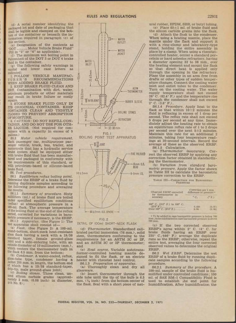
RULES AND REGULATIONS 22931
(d) A serial number identifying the packaged lot and date of packaging that shall be legible and stamped on the bot- tom of the container or beneath the information required in paragraph (c) of this section.
(e) Designation of the contents as“DOT _____ Motor Vehicle Brake Fluid”(Pill, in “3” or “4” as applicable).
(f) The minimum wet boiling point in Fahrenheit of the DOT 3 or DOT 4 brake fluid in the container.
(g) The following safety warnings in capital and lower case letters as indicated:
1. FOLLOW VEHICLE MANUFACTU RER ’ S RECOMMENDATIONS WHEN ADDING BRAKE FLUID.
2. KEEP BRAKE FLUID CLEAN AND DRY. Contamination with dirt, water, petroleum products or other materials may result in brake failure or costly repairs.
3. STORE BRAKE FLUID ONLY IN ITS ORIGINIAL CONTAINER. KEEP CONTAINER CLEAN AND TIGHTLY CLOSED TO PREVENT ABSORPTION OP MOISTURE.
4. CAUTION: DO NOT REFILL CONTAINER, AND DO NOT USE FOR OTHER LIQUIDS. (Not required for containers with a capacity in excess of 5 gallons.)
S5.3 Motor vehicle requirem ent. Each passenger car, multipurpose passenger vehicle, truck, bus, trailer, and motorcycle that has a hydraulic service brake system shall be equipped either with brake fluid that has been manufactured and packaged in conformity with the requirements of this standard, or with petroleum - based or silicone-based brake fluid.
S6. Test procedures.56.1 Equilibrium reflux boiling point.
Determine the ERBP of a brake fluid by running duplicate samples according to the following procedure and averaging the results.
56.1.1 Summary o f procedure. Sixty milliliters (ml.) of brake fluid are boiled under specified equilibrium conditions (reflux) at atmospheric pressure in a 100-ml. flask. The average temperature of the boiling fluid at the end of the reflux period, corrected for variations in barometric pressure if necessary, is the ERBP.
S6.1.2 Apparatus. (See Figure 1) The test apparatus shall consist of—
(a) Flask. (See Figure 2) A 100-ml. round-bottom, short-neck heat-resistant glass flask having a neck with a 19/38 standard taper, female ground-glass Joint and a side-entering tube, with an outside diameter of 10 millimeters (mm.), which centers the thermometer bulb in the flask 6.5 mm. from the bottom;
(b) Condenser. A water-cooled, reflux, glass-tube type, condenser having a Jacket 200 mm. in length, the bottom end or which has a 19/38 standard-taper, onp-tip, male ground-glass joint;
(c) Boiling stones. Three clean, un- hsed silicon carbide grains (approximately 2 mm. (0.08 inch) in diameter, gnt No. 8) •
BOILING POINT TEST APPARATUS
FIG. 2DETAIL OF 100ml SHORT-NECK FLASK
(d) Therm om eter. Standardized calibrated partial immersion (76 m m .), solid stem, thermometers conforming to the requirements for an ASTM 2C or 2F, and an ASTM 3C or 3F thermometer; and
(e) H eat source. Variable autotransformer-controlled heating mantle designed to fit the flask, or an electric heater with rheostat heat control.
S6.1.3 Preparation o f apparatus.(a) Thoroughly clean and dry all
glassware.(b) Insert thermometer through the
side tube until the tip of the bulb is 6.5 mm. (*4 inch) from the bottom center of the flask. Seal with a short piece of nat
ural rubber, EPDM, SBR, or butyl tubing.(c) Place 60±1 ml. of brake fluid and
the silicon carbide grains into the flask.(d) Attach the flask to the condenser.
When using a heating mantle, place the mantle under the flask and support it with a ring-clamp and laboratory-type stand, holding the entire assembly in place by a clamp. When using a rheostat- controlled heater, center a standard porcelain or hard asbestos refractory, having a diameter opening 32 to 38 mm., over the heating element and mount the flask so that direct heat is applied only through the opening in the refractory. Place the assembly in an area free from drafts or other types of sudden temperature changes. Connect the cooling water inlet and outlet tubes to the condenser. Turn on the cooling water. The water supply temperature shall not exceed 28° C. (82.4° F.) and the temperature rise through the condenser shall not exceed 2° C. (3.6° F .) .
56.1.4 Procedure. Apply heat to the flask so that within 10±2 minutes the fluid is refluxing in excess of 1 drop per second. The reflux rate shall not exceed 5 drops per second at any time. Immediately adjust the heating rate to obtain an equilibrium reflux rate of 1 to 2 drops per second over the next 5± 2 minutes. Maintain this rate for an additional 2 minutes, taking four temperature readings at 30-second intervals. Record the average of these as the observed ERBP.
56.1.5 Calculation.(a) T herm om eter inaccuracy. Cor
rect the observed ERBP by applying any correction factor obtained in standardizing the thermometer.
(b) Variation from standard barom etric pressure. Apply the factor shown in Table in to calculate the barometric pressure correction to the ERBP.
T a b l e I I I — C o r r ec t io n fo r B a r o m e t r ic P r e s s o r e
Observed E R B P corrected for thermometer in- accuracy
Correction per 1 mm difference in pressure a
°C ; (° F.)
100° C. (212° F .) to 190° C. (374° F .).................__.............. 0.039 (0.07)
Over 190° C. (374° F.) - ............ 0.04 (0.08)
a To be added in case barometric pressure is below 760 mm.; to be subtracted in case barometric pressure is above 760 mm.
(c) If the two corrected observed ERBP’s agree within 2° C. (4° C. for brake fluids having an ERBP over 230° C./446° F.) average the duplicate runs as the ERBP; otherwise, repeat the entire test, averaging the four corrected observed values to determine the original ERBP.
S6.2 Wet ERBP. Determine the wet ERBP of a brake fluid by running duplicate samples according to the following procedure.
S6.2.I Summ ary o f the procedure. A 100-ml. sample of the brake fluid is humidified under controlled conditions; 100 ml. of SAE RM-1 Compatibility Fluid is used to establish the end point for humidification. After humidification the
FEDERAL REGISTER, VOL. 36, NO. 232— THURSDAY, DECEMBER 2, 1971

22932 RULES AND REGULATIONS
water content and ERBP of the brake fluid are determined.
S6.2.2 Apparatus fo r humidification. (See Figure 3) Test apparatus shall consist of—
(a) Glass jars. Four SAE RM-49 corrosion test jars or equivalent screw-top, straight-sided, round glass jars each having a capacity of about 475 ml. and approximate inner dimensions of 100 mm. in height by 75 mm. in diameter,
56.2.3 Reagents and m aterials.(a) Ammonium sulfate (NH4) ¡¡SO*. Re
agent or A.C.S. grade.(b) Distilled water, see S7.1.(c) SAE RM-1 compatibility fluid.56.2.4 Preparation o f apparatus. Lu
bricate the ground-glass joint of the desiccator. Load each desiccator with 450±25 grams of the ammonium sulfate and add 125±10 ml. of distilled water. The surface of the salt slurry shall lie within 45±7 mm. of the top surface of the desiccator plate. Place the desiccators in an area with temperature controlled at 23°±2° C. (73.4°±3.6° F.) throughout the humidification procedure. Load the desiccators with the slurry and allow to condition with the covers on and stoppers in place at least 12 hours before use. Use a fresh charge of salt slurry for each test.
56.2.5 Procedure. Pour 100±1 ml. of
with matching lids having new, clean inserts providing water-vapor-proof
(b) D esiccator and cover. Four bowl- form glass desiccators, 250-mm, inside diameter, having matching tubulated covers fitted with No. 8 rubber stoppers; and
(c) D esiccator plate. Four 230-mm. diameter, perforated porcelain desiccator plates, without feet, glazed on one side.
the brake fluid into a corrosion test jar. Promptly place the jar into a desiccator. Prepare duplicate test sample, and two duplicate specimens of the SAE RM-1 compatibility fluid. Adjust water content of the SAE RM-1 fluid to 0.50±0.05 percent by weight at the start of the test in accordance with S7.2. At intervals remove the rubber stopper in the top of each desiccator containing SAE RM-1 fluid. Using a long needled hypodermic syringe, take a sample of not more than2 ml. from each jar and determine its water content. Remove no more than 10 ml. of fluid from each SAE RM-1 sample during the humidification procedure. When the water content of the *. SAE fluid reaches 3.50±0.05 percent by weight (average of the duplicates), remove the two test fluid specimens from their desiccators and promptly cap each jar tightly. Measure the water contents
of the test fluid specimens in accordance with S7.2 and determine their ERBP’s in accordance with S6.1 through S6.1.5,If the two ERBP’s agree within 4° c. (8° F .) , average them to determine the wet ER BP; otherwise repeat and average the four individual ERBP’s as the wet ERBP of the brake fluid.
S6.3 K inem atic viscosity. Determine the kinematic viscosity of a brake fluid in centistokes (cSt.) by the following procedure. Rim duplicate samples at each of the specified temperatures, making two timed runs on each sample.
56.2.1 Summary o f the procedure. The time is measured for a fixed volume of the brake fluid to flow through a calibrated glass capillary viscometer under an accurately reproducible head and I at a closely controlled temperature. The kinematic viscosity is then calculated ; from the measured flow time and the calibration constant of the viscometer.
56.3.2 Apparatus.(a) Viscometers. Calibrated glass
capillary-type viscometers, ASTM D2515-66, “Standard Specification for Kinematic Glass Viscometers,” measuring viscosity within the precision limits of S6.4.7. Use suspended level viscometers for viscosity measurements at low temperatures. Use Cannon-Fenske Routine or other modified Ostwald viscometers at ambient temperatures and above.
(b) Viscometer holders and frames. Mount a viscometer in the constant- temperature bath so that the mounting tube is held within 1° of the vertical.
(c) Viscometer bath. A transparent liquid bath of sufficient depth such that at no time during the measurement will any portion of the sample in the viscometer be less than 2 cm. below the surface or less than 2.cm. above the bottom. The bath shall be cylindrical in shape, with turbulent agitation sufficient to meet the temperature control requirements. For measurements within 15° to 100° C. (60° to 212° F.) the temperature of the bath medium shall not vary by more than 0.01° C. (0.02° F.) over the length of the viscometers, or between the positions of the viscometers, or at the locations of the thermometers. Outside this range, the variation shall not exceed 0.03° C. (0.05° F .).
(<D Therm om eters. Liquid-in-Glass Kinematic Viscosity Test Thermometers, covering the range of test temperatures indicated in Table IV an conforming to ASTM El-68, ‘ Specifica tions for ASTM Theromometers,” and in the IP requirements for IP Standard Thermometers. Standardize before use (see S6.3.3(b)). Use two standardized thermometers in the bath.
I.D.------ ;----- -j
HUMIDIFICATION. APPARATUS
FEDERAL REGISTER, V O L 36, NO. 232— THURSDAY, DECEMBER 2, 1971

RULES AND REGULATIONS 22933T able IV—Kinematic Viscosity Thermometers
Temperature range For tests at Subdivisions Thermometer number
« C . ° F . ° C . ° F . ° C. o J?m ASTM IP
Minus 55.3 to minus 52.5. Minus 67.5 to minus Minus 55.... . Minus 67.. . . 0.05 0.1 74 F . 69 F . or C.62.5.
Minus 41.4 to minus 38.6. Minus 42.5 to minus Minus 4 0 ... . Minus 40.. . . 0.05 0.1 73 F . 68 F . or C.
98 6 to 101.4...................207.5 to 212.5------------------ . 100............... . 212............. . . 0.05 0.1 30 F . 32 F . or C.
(e) riming device. Stop watch or other timing device graduated in divisions representing not more than 0.2 second, with an accuracy of at least ±0.05 percent when tested over intervals of 15 minutes. Electrical timing devices may be used when the current frequency is controlled to an accuracy of 0.01 percent or better.
56.3.3 Standardization.(a) Viscometers. Use viscometers cali
brated in accordance with Appendix 1 of ASTM D445-65, “Viscosity of Transparent and Opaque Liquids (Kinematic and Dynamic Viscosities).” The calibration constant, C, is dependent upon the gravitational acceleration at the place of calibration. This must, therefore, be supplied by the standardization laboratory together with the instrument constant. Where the acceleration of gravity, g, in the two locations differs by more than 0.1 percent, correct the calibration constant as follows:
9aC t = — XCi
9iwhere the subscripts 1 and 2 indicate respectively the standardization laboratory and the testing laboratory.
(b) Thermometers. Check liquid-inglass thermometers to the nearest 0.01° C. (0.02° F.) by direct comparison with a standardized thermometer. Kinematic Viscosity Test Thermometers shall be standardized at “total immersion.” The ice point of standardized thermometers shall be determined before use and the official corrections shall be adjusted to conform to the changes in ice points. (See ASTM E77-66, “Verification and Calibration of Liquid-in-Glass Thermometers.”)
(c) Timers. Time signals are broadcast by the National Bureau of Standards, Station WWV, Washington, D.C.-at2.5, 5, 10, 15, 20, 25, 30, and 35 Mc/sec (MHz). Time signals are also broadcast by Station CHU from Ottawa, Canada, at 3.330, 7,335, and 14.670 Mc/sec, and Station MSP at Rugby, United Kingdom, at 2.5,5, and 10 Mc/sec.
56.3.4 Procedure.(a) Set and maintain the bath at the
appropriate test temperature (see S5.1.3) within the limits specified in 86.3.2(c). Apply the necessary corrections, if any, to all thermometer readings., Select a clean, dry, calibrated
viscometer giving a flow time not less than its specified minimum, or 200 seconds, whichever is the greater.
(c) Charge the viscometer in the manner used when the instrument was calibrated. Do not filter or dry the brake nuid, but protect it from contamination
by dirt and moisture during filling and measurements.
(1) Charge the suspended level viscometers by tilting about 30° from the vertical and pouring sufficient brake fluid through the fill tube into the lower reservoir so that when the viscometer is returned to vertical position the meniscus is between the fill marks. For measurements below 0° C. (32° P .) , before placing the filled viscometer into the constant temperature bath, draw the sample into the working capillary and timing bulb and insert small rubber stoppers to suspend the fluid in this position, to prevent accumulation of water condensate on the walls of the critical portions of the viscometer. Alternatively, fit loosely packed drying tubes into the open ends of the viscometer to prevent water condensation, but do not restrict the flow of the sample under test by the pressures created in the instrument.
(2) If a Cannon-Fenske Routine viscometer is used, charge by inverting and immersing the smaller arm into the brake fluid and applying vacuum to the larger arm. Fill the tube to the upper timing mark, and return the viscometer to an upright position.
(d) Mount the viscometer in the bath in a true vertical position (see S6.3.2(b)).
(e) The viscometer shall remain in the bath until it reaches the test temperature.
(f) At temperatures below 0° C. (32° P.) conduct an untimed preliminary run by allowing the brake fluid to drain through the capillary into the lower reservoir after the test temperature has been established.
(g) Adjust the head level of the brake fluid to a position in the capillary arm about 5 mm. above the first timing mark.
(h) With brake fluid flowing freely measure to within 0.2 second the time required for the meniscus to pass from the first timing mark to the second. If this flow time is less than the minimum specified for the viscometer, or 200 seconds, whichever is greater, repeat using a viscometer with a capillary of smaller diameter.
(i) Repeat S6.3.4 (g) and (h ) . If the two timed runs do not agree within 0.2 percent, reject and repeat using a fresh sample of brake fluid.
S6.3.5 Cleaning the viscometers.(a) Periodically dean the instrument
with chromic acid to remove organic deposits. Rinse thoroughly with distilled water and acetone, and dry with clean dry air.
(b) Between successive samples rinse the viscometer with ethanol followed by
an acetone or ether rinse. Pass a slow stream of filtered dry air through the viscometer until the last trace of solvent is removed.
56.3.6 Calculation.(a) The following viscometers have a
fixed volume charged at ambient temperature, and as a consequence C varies with test temperature: Cannon-Fenske Routine, Pinkevitch, Cannon-Manning Semi-Micro, and Cannon Fenske Opaque. To calculate C at test temperatures other than the calibration temperature for these viscometers, see ASTM D2515-66, “Kinematic Glass Viscometers” or follow instructions giyen on the manufacturer’s certificate of calibration.
(b) Average the four timed runs on the duplicate samples to determine the kinematic viscosities.
56.3.7 Precision (.at 95 percent confiden ce lev e l) .
(a) Repeatibility. If results on duplicate samples by the same operator differ by more than 1 percent of their mean, repeat the tests.
S6.4 pH value. Determine the pH value of a brake fluid by running one sample according to the following procedure.
56.4.1 Summ ary o f th e procedure. Brake fluid is diluted with an equal volume of an ethanol-water solution. The pH of the resultant mixture is measured with a prescribed pH meter assembly at 23° C. (73.4° F .).
56.4.2 Apparatus. The pH assembly consists of the pH meter, glass electrode, and calomel electrode, as specified in Appendices Al.l, A1.2, and A1.3 of ASTM D1121-67, “Standard Method of Test for Reserve Alkalinity of Engine Antifreezes and Antirusts.” The glass electrode is a full range type (pH 0-14), with low sodium error.
56.4.3 Reagents. Reagent grade chemicals conforming to the specifications of the Committee on Analytical Reagents of the American Chemical Society.
(a ) . Distilled water. Distilled water (S7.1) shall be boiled'for about 15 minutes to remove carbon dioxide, and protected with a soda-lime tube or its equivalent while cooling and in storage. (Take precautions to prevent contamination by the materials used for protection against carbon dioxide.) The pH of the boiled distilled water shall be between6.2 and 7.2 at 25° C. (77° F .) .
(b) Standard "buffer solutions. Prepare buffer solutions for calibrating the pH meter and electrode pair from salts sold specifically for use, either singly or in combination, as pH standards. Dry salts for 1 hour at 110° C. (230° F.) before use except for borax which shall be used as the decahydrate. Store solutions with pH less than 9.5 in bottles of chemically resistant glass or polyethylene. Store the alkaline phosphate solution in a glass bottle coated inside with paraffin. Do not use a standard with an age exceeding three months.
(1) Potassium hydrogen phthalate buffer solution (0.05 M, pH=4.01 at 25° C. (77° F .) ) . Dissolve 10.21 g. of potas-
FEDERAL REGISTER, VOL. 36, NO. 232— THURSDAY, DECEMBER 2, 1971

22934 RULES AND REGULATIONS
sium hydrogen phthalate (KHCsHXh) in distilled water. Dilute to 1 liter.
(2) Neutral phosphate buffer solution (0.025 M with respect to each phosphate salt, pH=6.86 at 25° C. (77° F.) ) . Dissolve 3.40 g. of pptassium dihydrogen phosphate (KHsPOJ and 3.55 g. of anhydrous disodium hydrogen phosphate (Na2HPO*) in distilled water.
(3) Borax buffer solution (0.01 M, pH=9.18 at 25° C. (77° F.) )v. Dissolve 3.81 g. of disodium tetraborate decahy- drate (Na2B4CV10 H20 ) in distilled water, and dilute to 1 liter. Stopper the bottle except when actually in use.
(4) Alkaline phosphate buffer solution (0.01 M trisodium phosphate, pH=11.72 at 25° C. (77° F.) ). Dissolve 1.42 g. of anhydrous disodium hydrogen phosphate (Na^HPCX) in 100 ml. of a 0.1 M carbonate-free solution of sodium hydroxide. Dilute to 1 liter with distilled water.
(5) Potassium chloride electrolyte. Prepare a saturated solution of potassium chloride (KC1) in distilled water.
(c) Ethanol-w ater mixture. Ter 80 parts by volume of ethanol (S7.3) add 20 parts by volume of distilled water. Adjust the pH of the mixture to 7±Q.l using 0.1 N sodium hydroxide (NaOH) solution. If more than 4 ml. of NaOH solution per liter of mixture is required for neutralization, discard the mixture.
S6.4.4 P r e p a r a t i o n of electrode system.
(a) M aintenance o f electrodes. Cleanthe glass electrode before using by immersing in cold chromic-acid cleaning solution. Drain the calomel electrode and fill with KC1 electrolyte, keeping level above that of the mixture at all times. When not in use, immerse the lower halves of the electrodes in distilled water, and do not immerse in the mixture for any appreciable period of time between determinations. »
(b) Preparation o f electrodes. Condition new glass electrodes and those that have been stored dry as recommended by the manufacturer. Before and after using, wipe the glass electrode thoroughly with a clean cloth, or a soft absorbent tissue, and rinse with distilled water. Before each pH determination, soak the prepared electrode in distilled water for at least 2 minutes. Immediately before use, remove any excess water from the tips of the electrode.
S6.4.5. Standardization o f the pH assem bly and testing o f the electrodes.
(a) Immediately before use, standardize the pH assembly with a standard buffer solution. Then use a second standard buffer solution to check the linearity of the response of the electrodes at different pH values, and to detect a faulty glass electrode or incorrect temperature compensation. The two buffer solutions bracket the anticipated pH value of the test brake fluid.
(b) Allow instrument to warm up, and adjust according to the manufacturer’s instructions. Immerse the tips of the electrodes in a standard buffer solution and allow the temperature of the buffer solution and the electrodes to equalize. Set the temperature knob at the temperature of the buffer solution. Adjust the standardization or asymmetry potential control until the meter registers
a scale reading, in pH units, equal to the known pH of the standardizing buffer solution.
(c) Rinse the electrodes with distilled water and remove excess water from the tips. Immerse the electrodes in a second standard buffer solution. The reading of the meter shall agree with the known pH of the second standard buffer solution within ±0.05 unit without changing the setting of the standardization of asymmetry potential control.
(d) A faulty electrode is indicated by failure to obtain a correct value for the pH of the second standard buffer solution after the meter has been standardized with the first.
S6.4.6 Procedure. To 50 ± 1 ml. of the test brake fluid add 50 ± 1 ml. of the ethanol-water (S6.4.3(c)) and mix thoroughly. Immerse the electrodes in the mixture. Allow the system to come to equilibrium, readjust the temperature compensation if necessary, and take the pH reading.
S6.5 Fluid stability. Evaluate the heat and chemical stability of a brake fluid by the following procedure, running duplicate samples for each test and averaging the results.
56.5.1 Summary o f the procedure. The degradation of the brake fluid at elevated temperature, alone or in a mixture with a reference fluid, is evaluated by determining the change in boiling point after a period of heating under reflux conditions.
56.5.2 Apparatus. Use the apparatus and preparation specified in S6.1.2 andS6.1.3.
56.5.3 High tem perature stability.56.5.3.1 Procedure.(a) Heat a new 60±1 ml. sample of
the brake fluid toT85°±2° C. (365°±3.6° F .) . Hold at this temperature for 120±5 minutes. Bring to a reflux rate in excess of 1 drop per second within 5 minutes. The reflux rate should not exceed 5 drops per second at any time. Over the next 5± 2 minutes adjust the heating rate to obtain an equilibrium reflux rate of 1 to 2 drops per second. Maintain this rate for an additional 2 minutes, taking four temperature readings at 30-second intervals. Average these as the observed ERBP.
56.5.3.2 Calculation. Correct the observed ERBP for thermometer and barometric pressure factors according toS6.1.5 (a) and (b ). Average the corrected ERBP’s of the duplicate samples. The difference between this- average and the original ERBP obtained in S6.1 is the change in ERBP of the fluid.
56.5.4 Chem ical stability.56.5.4.1 M aterials. SAE RM-1 Com
patibility Fluid, as described in Appendix A of SAE Standard J1703b, “Motor Vehicle Brake Fluid,” April 1968.
56.5.4.2 Procedure.(a) Mix 30±1 ml. of the brake fluid
with 30±1 ml. of SAE RM-1 Compatibility Fluid in a boiling point flask (S6.1.2(a)). Determine the initial ERBP of the mixture by applying heat to the flask so that the fluid is refluxing in 10±2 minutes at a rate in excess of 1 drop per second, but not more than 5 drops per second. Note the maximum fluid temperature observed during the
first minute after the fluid begins refluxing at a rate in excess of 1 drop per second. Over the next 15 ± 1 minutes, adjust and maintain the reflux rate at 1 to 2 drops per second. Maintain this rate for an additional 2 minutes, recording the average value of four temperature readings taken at 30-second intervals as the final ERBP.
(b> Thermometer and barometic corrections are not required.
S6.5.4.3 Calculation. The difference between the initial ERBP and the final average temperature is the change in temperature of the refluxing mixture. Average the results of the duplicates to the nearest 0.5° C. (1° F .) .
S6.6 Corrosion. Evaluate the corrosiveness of a brake fluid by running duplicate samples according to the following procedure.
56.6.1 Summary o f the procedure. Six specified metal corrosion test strips are polished, cleaned, and weighed, then assembled as described. Assembly is placed oh a standard wheel cylinder cup in a corrosion test jar, immersed in the water- wet brake fluid, capped and placed in an oven at 100° C. (212° F.) for 120 hours. Upon removal and cooling, the strips, fluid, and cups are examined and tested.
56.6.2 Equipment.(a) Balance. An analytical balance
haying a minimum capacity of 50 grams and capable of weighing to the nearest0.1 mg.
(b) Desiccators. Desiccators containing silica gel or other suitable desiccant.
(c) Oven. Gravity convection oven capable of maintaining the desired set point within 2° C. (3.6° F .) .
(d) M icrometer. A machinist’s micrometer 25 to 50 mm. (1 to 2 inches) capacity, or an optical comparator, capable of measuring the diameter of the SBR wheel cylinder (WC) cups to the nearest0.02 mm. (0.001 inch).
56.6.3 Materials.(a) Corrosion test strips. Two sets of
strips from each of the metals listed in Appendix C of SAE Standard J 1703b. Each strip shall be approximately 8 cm. long, 1.3 cm. wide, not more than 0.6 cm. thick, and have a surface area of 25±5 sq. cm. and a hole 4 to 5 mm. (0.16 to 0.20 inch) in diameter on the centerline about 6 mm. from one end. The hole shall be clean and free from burrs. Tinned iron strips shall be unused. Other strips, if used, shall not be employed if they cannot be polished to a high finish.
(b) SBR cups. Two unused standard SAE SBR wheel cylinder (WC) cups, as specified in S7.6.
(c) Corrosion test jars and lids. Two screw-top straight-sided round glass jars, each having a capacity of approximately 475 ml. and inner dimensions of approximately 100 mm. in height and 7o mm. in diameter, and a tinned steel na (no insert or organic coating) vented with a hole 0.8±0.1 mm. (0.031—0.00 inch) in diameter (No. 68 drill).
(d) M achine screws and nuts. Clean, rust and oil-free, uncoated mild stee round or fillister head machine scr® ’ size 6 or 8-32 UNC-Class 2A, five-eigntns or three-fourths inch long (or equivaie metric sizes), and matching uncoa e nuts.
FEDERAL REGISTER, VOL. 36, NO. 232— THURSDAY, DECEMBER 2, 1971

RULES AND REGULATIONS 22935(e) Supplies fo r polishing strips.
Waterproof silicon carbide paper, grit No. 320 A; grade 00 steel wool, lint-free polishing cloth.
(f) Distilled w ater as specified in S7.1.(g) Ethanol as specified in S7.3.S6.6.4 Preparation.(a) Corrosion test strips. Except for
the tinned iron strips, abrade corrosion test strips on all surface areas with silicon carbide paper wet with ethanol until all surface scratches, cuts and pits are removed. Use a new piece of paper for each different type of metal. Polish the strips with the 00 grade steel wool. Wash all strips, including the tinned iron and the assembly hardware, with ethanol; dry the strips and assembly hardware with a clean lint free cloth or use filtered compressed air and place the strips and hardware in a desiccator containing silica gel or other suitable desiccant and maintained at 23°±5° C. (73.4°±:9° F .) , for at least 1 hour. Handle the strips with forceps after polishing. Weigh and record the weight of each strip to the nearest 0.1 mg. Assemble the strips on a clean dry machine screw, with matching plain nut, in the order of tinned iron, steel, aluminum, cast iron, brass, and copper. Bend the strips, other than the cast iron, so that there is a separation of 3 mm. (^±1/64 inch) between adjacent strips for a distance of about 5 cm. (2 inches) from the free end of the strips. (See Figure 4.) Tighten the screw on each test strip assembly so that the strips are in electrolytic contact, and can be lifted by either of the outer strips (tinned iron or copper) without any of the strips moving relative to the others when held horizontally. Immerse the strip assemblies in 90 percent ethyl alcohol. Dry with dried filtered compressed air, then dessicate at least 1 hour before use.
CORROSION STRIP ASSEMBLY(b) SBR WC cups. Measure the base
ammeters of the two standard SBR cups, “Sing an optical comparator or microm- J®* to the nearest 0.02 mm. (0.001 ®cn) along the centerline of the SAE ■¡“fl rubber-type identifications and at
gnt angles to this centerline. Take the measurements at least 0.4 mm. (0.015
&bove the bottom edge and parallel if nTe ,kase °f the cup. Discard any cup J netwo measured diameters differ by a r® than 0.08 mm. (0.003 inch). Averse the two readings on each cup. Deter
mine the hardness of the cups according to S7.4.
S6.6.5 Procedure. Rinse the cups in ethanol for not more than 30 seconds and wipe dry with a clean lint-free cloth. Place one cup with lip edge facing up, in each jar. Insert a metal strip assembly inside each cup with the fastened end down and the free end extending upward. (See Figure 5.) Mix 760 ml. of brake fluid with 40 ml. of distilled water; using this mixture, cover each strip assembly to a depth of approximately 10 mm. above the tops of the strips. Tighten the lids and place the jars for 120±2 hours in an oven maintained at 100° ±2° C. (212°±3.6° F .) . Allow the jars to cool at 23° ±5° C. (73.4°±9° F.) for 60 to 90 minutes. Immediately remove the strips from the jars using forceps, agitating the strip assembly in the fluid to remove loose adhering sediment. Examine the test strips and jars for adhering crystalline deposits. Disassemble the metal strips, and remove adhering fluid by flushing with water; clean each strip by wiping with a clean cloth wetted with ethanol. Examine the strips for evidence of corrosion and pitting. Disregard staining or discoloration. Place the strips in a desiccator containing silica gel or other suitable desiccant, maintained at 23° ±5° C. (73.4°±9° F .) , for at least 1 hour. Weigh each strip to the nearest 0.1 mg. Determine; the change in weight of each metal strip. Average the results for the two strips of each type of metal. Immediately following the cooling period, remove the cups from the jars with forceps. Remove loose adhering sediment by agitation of the cups in the mixture. Rinse the cups in ethanol and air-dry. Examine the cups for evidence of sloughing, blisters, and other forms of disintegration. Measure the base diameter and hardness of each cup within 15 minutes after removal from the mixture. Examine the mixture for gelling. Agitate the mixture to suspend and uniformly disperse sediment. From each jar, transfer a 100 ml. portion of the mixture to an ASTM cone-shaped centrifuge tube. Determine the percent sediment after centrifuging as described in S7.5. Measure the pH value of the mixture according toS6.4.6.
FIG.5CORROSION TEST
APPARATUS
S6.6.6 Calculation.(a) Measure the area of each type of
test strip to the nearest square centimeter. Divide the average change in weight for each type by the area of that type.
(b) Note other data and evaluations indicating compliance with S5.1:6. In the event of a marginal pass on inspection by attributes, or of a failure in one of the duplicates, run' another set of duplicate samples. Both repeat samples shall meet all requirements of S5.1.6.
S6.7 Fluidity and appearance at low tem peratures. Determine the fluidity and appearance of a sample of brake fluid at each of two selected temperatures by the following procedure.
56.7.1 Summary o f procedure. Brake fluid is chilled to expected minimum exposure temperatures and observed for clarity, gellation, sediment, separation of components, excessive viscosity or thixotropy.
56.7.2 Apparatus.(a) Oil sam ple bottle. Two clear flin t
glass 4-ounce bottles made especially for sampling oil and other liquids, with a capacity of approximately 125 ml., an outside diameter of 37±0.05 mm. and an overall height of 165±2.5 mm.
(b) Cold cham ber. An air bath cold chamber capable of maintaining storage temperatures down to minus 55° C. (minus 67° F.) with an accuracy of ±2° G. (3.6° F .) .
(c) Timing device. A timing device in accordance with S6.3.2(e).
(d) Hiding power test chart. (SAE RM).
56.7.3 Procedure.(a) Place 100±2 ml. of brake fluid at
room temperature in an oil sample bottle. Stopper the bottle with an unused cork and place in the cold chamber at the higher storage temperature specified in Table H (S5.1.7(c)). After 144±4 hours remove the bottle from the chamber, quickly wipe it with a clean, lint- free cloth saturated with ethanol or acetone. Place against a hiding power test chart and observe if the black contrast lines are clearly discernible when viewed through every part of the fluid. Examine the fluid for evidence of stratification or sedimentation. Invert the bottle and determine the number of seconds required for the air bubble to travel to the top of the fluid.
(b) Repeat S6.7.3(a), substituting the lower cold chamber temperature specified in Table n , and a storage period of 6 hours ±12 minutes.
No t e : Test specimens from either storage temperature may be used for the other only after warming up to room temperature.
S6.8 Evaporation. The evaporation residue, and pour point of the evaporation residue of brake fluid, are determined by the following procedure. Four replicate samples are rim.
S6.81 Summary o f th e procedure. The volatile diluent portion of a brake fluid is evaporated in an oven at 100° C. (212° F .) . The nonvolatile lubricant portion (evaporation residue) is measured and examined for grittiness; the residues are then combined and checked to assure fluidity at minus 5° C. (23° F .) .
FEDERAL REGISTER, VOL. 36, NO. 232— THURSDAY, DECEMBER 2, 1971No. 232------6

22936 RULES AND REGULATIONS56.8.2 Apparatus,(a) Petri dishes. Pour covered glass
petri dishes approximately 100 mm. in diameter and 15 mm. in height.
(b) Oven. A top-vented gravity-convection oven capable of maintaining a temperature of 100® ±2" C. (212° ± 3.6° F .) .
(c) Balance. A balance having a capacity of at least 100 grams, capable of weighing to the nearest 0.01 gram, and suitable for weighing the petri dishes.
(d) Oil sam ple bottle. A glass sample bottle as described in S6.7.2(a).
(e) Cold cham ber. Air bath cold chamber capable of maintaining an oil sample bottle at minus 5°±1° C. (23°±2° F .) .
(f) Timing device. A timing device as described in S6.3.2(e).
56.8.3 Procedure. Obtain the tare weight of each of the four covered petri dishes to the nearest 0.01 gram. Place 25±1 ml. of brake fluid in each dish, replace proper covers and reweigh. Determine the weight of each brake fluid test specimen by the difference. Place the four dishes, each inside its inverted cover, in the oven at 100°±2° C. (212°±3.6° F.) for 46±2 hours. (N o t e : D o not simultaneously heat more than one fluid in the same oven.) Remove the dishes from the oven, allow to cool to 23°±5° C. (73.4°±9° F .) , and weigh. Return to the oven for an additional 24±2 hours. If at the end of 72±4 hours the average loss by evaporation is less than 60 percent, discontinue the evaporation procedure and proceed with examination of the residue. Otherwise, continue this procedure either until equilibrium is reached as evidenced by an incremental weight loss of less than 0.25 gram in 24 hours on all individual dishes or for a maximum of 7 days. During the heating and weighing operation, if it is necessary to remove the dishes from the oven for a period of longer than 1 hour, the dishes shall be stored in a desiccator as soon as cooled to room temperature. Calculate the percentage of fluid evaporated from each dish. Examine the residue in the dishes at the end of 1 hour at 23°±5° C. (73.4° ± 9° F .) . Rub any sediment with the fingertip to determine grittiness or abrasiveness. Combine the residues from all four dishes in a 4-ounce oil sample bottle and store vertically in a cold chamber at minus 5°±1° C. (23°±2° F.) for 60±10 minutes. Quickly remove the bottle and place in the horizontal position. The residue must flow at least 5 mm. (0.2 inch) along the tube within 5 seconds.
S6.8.4 Calculation. The average of the percentage evaporated from all four dishes is the loss by evaporation.
S6.9 W ater tolerance. Evaluate the . water tolerance characteristics of a brake
fluid by running one test specimen according to the following procedure.
S6.9.1 Summary o f th e procedure. Brake fluid is diluted with 3.5 percent water, then stored at minus 40° C. (minus 40° F.) for 24 hours. The cold, water-wet fluid is first examined for clarity, stratification, and sedimentation, then placed in an oven at 60° C. (140° F.) for 24 hours.
On removal, it is again examined for stratification, and the volume percent of sediment determined by centrifuging.
56.9.2 Apparatus.(a) Centrifuge tube. See S7.5.1 (a ) .(b) Centrifuge. See S7.5.1(b).(c) Cold cham ber. See S6.7.2(b).(d) Oven. Gravity or forced convec
tion oven.(e) Timing device. See S6.3.2(e).(f) Hiding “power test chart. (SAE
RM).56.9.3 Procedure.(a) At low tem perature. Mix 3.5±0.1
ml. of distilled water with 100±1 ml. of brake fluid and pour into a centrifuge tube. Stopper the tube with a clean cork and place in the cold chamber maintained at minus 40°±2° C. (minus 40°± 3.6° F .) . After 24±2 hours remove tube, quickly wipe with a clean lint-free cloth saturated with ethahol or acetone, and place against a hiding power test chart. Observe whether the black contrast lines are clearly discernible when viewed through every part of the fluid. Examine the fluid for evidence of stratification or sedimentation. Invert the tube and determine the number of seconds required for the air bubble to travel to the top of the fluid. (The air bubble is considered to have reached the top of the fluid when the top of the bubble reaches the 2 ml. graduation of the centrifuge tube.)
(b) At 600 C. (1400 F .) . Place tube and brake fluid from S6.9.3(a) in an oven maintained at 60°±2° C. (140°±3.6° F.) for 24±2 hours. Remove the tube and immediately examine the contents for evidence of stratification. Determine the percent sediment by centrifuging as described in S7.5.
S6.10 Compatibility. The compatibility of a brake fluid with other brake fluids shall be evaluated by running one test sample according to the following procedure.
56.10.1 Summary o f the procedure. Brake fluid is mixed with an equal volume of SAE RM-1 Compatibility Fluid, then tested in the same way as for water tolerance (S6.9.3) except that the bubble flow time is not measured. This test is an indication of the compatibility of the test fluid with other motor vehicle brake fluids at both high and low temperatures.
56.10.2 Apparatus and m aterials.(a) Centrifuge tube. See S I.5 .1 (a).(b) Centrifuge. See S7.5.1 (b ).(c) Cold cham ber. See S6.7.2(b).(d) Oven. See S6.9.2(d).(e) SAE RM-1 Compatibility Fluid.
As described in Appendix A of SAE Standard J1703b.
(f) Hiding power test chart. (SAE RM)
56.10.3 Procedure.\ (a) At low tem perature. Mix 50±0.5
ml. of brake fluid with 50±0.5 ml. of SAE RM-1 Compatibility Fluid. Pour this mixture into a centrifuge tube and stopper with a clean dry cork. Place tube in the cold chamber maintained at minus 40°±2° C. (minus 40°±3.6° F .) . After 24±2 hours, remove tube, quickly wipe
with a clean lint-free cloth saturated with ethanol or acetone. Place tube against a hiding power test chart and observe whether the black contrast lines on the hiding power test chart are clearly discernible when viewed through every I part of the fluid. Examine the fluid for evidence of stratification or sedimentation.
(b) At 60° C. (140° F .) . Place tube and test fluid from S6.10.3(a) for 24±2 hours in an oven maintained at 60°±2° C. (140° ±3.6° F .) . Remove tube and immediately examine the contents for evidence of stratification. Determine percent sediment by centrifuging as described in S7.5.
S6.ll R esistance to oxidation. The stability of a brake fluid under oxidative conditions shall be evaluated by running duplicate samples according to the following procedure.
56.11.1 Summary o f the procedure. Brake fluid is activated with a mixture of approximately 0.2 percent benzoyl peroxide and 5 percent water. A corrosion test strip assembly consisting of cast iron and an aluminum strip separated by tinfoil squares at each end is then rested on a piece of SBR WC cup positioned so that the test strip is half immersed in the fluid, and oven-aged at 70° C. (158“ F.) for 168 hours. At the end of this period the metal strips are examined for pitting, etching, and weight loss.
56.11.2 Equipment.(a) Balance. See S6.6.2(a).(b) Desiccators. See S6.6.2(b).(c) Oven. See S6.6.2(c). -(d) Three glass test tubes approxi
mately 22 mm. outside diameter by 175 mm. in length.
56.11.3 Reagents and materials.(a) Benzoyl peroxide, reagent grade,
96 percent. (Benzoyl peroxide that is brownish, or dusty, or has less than 90 percent purity, must be discarded.) Reagent strength may be evaluated by ASTM E298-68, “Standard Methods for Assay of Organic Peroxides.”
(b) Corrosion test strips. Two sets of cast iron and aluminum metal test strips as described in Appendix C of SAE Standard J1703b.
(c) Tinfoil. Four unusued pieces of tinfoil approximately 12 mm. (xk inch) square and between 0.02 and 0.06 mm. (0.0008 and 0.0024 inch) in thickness. The foil shall be at least 99.9 percent tin and contain not more than 0.u<so percent lead.
(d) SBR cups. Two unused, approximately one-eighth sections of a standard SAE SBR WC cup (as described
l S7.6). . , __ ,„Q_(e) M achine screw and nut. Two clean
il-free, No. 6 or 8-32 X % - or M2-men mg (or equivalent metric size), round r fillister head, uncoated mild steel ma- hine screws, with matching plain nu S6.11.4 Preparation.(a) Corrosion test strips. Prepare two
ets of aluminum and cast iron tes trips according to S6.6.4(a) e epV / ssembly. Weigh each strip to the nau- st 0.1 mg. and assemble a strip of eacn
FEDERAL REGISTER, VOL. 36, NO. 232— THURSDAY, DECEMBER 2, 1971

RULES AND REGULATIONS 22937
metal on a machine screw, separating the strips at each end with a piece of tinfoil. Tighten the nut enough to hold both pieces of foil firmly in place.
(b) Test mixture. Place 30±1 ml. of the brake fluid under test in a 22 by 175 mm. test tube. Add 0.060±0.002 gram of benzoyl peroxide, and 1.50±0.05 ml. of distilled water. Stopper the tube loosely with a clean dry cork, shake, and place in an oven for 2 hours at 70°±2° C. (158°±3.6° F .) . Shake every 15 minutes to effect solution of the peroxide, but do not wet cork. Remove the tube from the oven and allow to cool to 23°±50 C. (73.4°±9° F .) . Begin testing according to paragraph S6.11.5 not later than 24 hours after removal of tubefrom oven.
56.11.5 Procedure. Place a one- eighth SBR cup section in the bottom of each tube. Add 10 ml. of prepared test mixture to each test tube. Place a metal-strip assembly in each, the end of the strip without the screw resting on tire rubber, and the solution covering about one-half the length of the strips. Stopper the tubes with clean dry corks and store upright for 70 ± 2 hours at 23°±5° C. (73.4° ±9° F .) . Loosen the corks and place the tubes for 168±2 hours in an oven maintained at 70°±2° C. (158° ±3.6° F .) . Afterwards remove and disassemble strips. Examine the strips and note any gum deposits. Wipe the strips with a clean cloth wet with ethanol and note any pitting, etching or roughening of surface disregarding stain or discoloration. Place the strips in a desiccator over silica gel or other suitable desiccant, at 23°±5° C. (73.4°±9° F.) for at least 1 hour. Again weigh each strip to the nearest 0.1 mg.
56.11.6 Calculation. Determine corrosion loss by dividing the change in weight of each metal strip by the total surface area of each strip measured in square centimeters, to the nearest square centimeter. Average the results for the two strips of each type of metal, rounding to the nearest 0.05 mg. per square centimeter. If only one of the duplicates fails for any reason, run a second set of duplicate samples. Both repeat samples shall meet all requirements of S5.1.11.
S6.12 Effect on SBR cups. The effects of a brake fluid in swelling, softening, and otherwise affecting standard SBR WC cups shall be evaluated by the following procedure.
56.12.1 Summary o f the procedure. Pour standard SAE SBR WC cups are measured and their hardnesses determined. 'Die cups, two to a jar, are immersed in the test brake fluid. One jar is heated for 120 hours at 70° C (158° F .) , and toe other for 70 hours at 120° C. (248° F.). Afterwards, the cups are washed, examined for disintegration, remeasured and their hardnesses redetermined.
56.12.2 Equipment and supplies.(a) Oven. See S6.6.2(c).(b) Glass jars and lids. Two screw-
top, straight-sided round, glass jars, each navmg a capacity of approximately 250 “h- and inner dimensions of approximately 125 mm. in height and 50 mm. in
diameter, and a tinned steel lid (no insert or organic coating).
(c) SBR cups. See S7.6.56.12.3 Preparation. Measure the base
diameters of the SBR cups as described in S6.6.4(b)r and the hardness of each as described in S7.4.
56.12.4 Procedure. Wash the cups in 90 percent ethanol (see S7.3), for not longer than 30 seconds and quickly dry with a clean, lint-free cloth. Using forceps, place two cups into each of the two jars; add 75 ml. of brake fluid to each jar and cap tightly. Place one jar in an oven held at 70°±2° C. (158±3.6° F.) for 70±2 hours. Place the other jar in an oven held at 120°±2° C. (248°±3.6° F.) for 70 ± 2 hours. Allow each jar to cool for 60 to 90 minutes at 23°±5° C. (73.4° ±9° F .) . Remove cups, wash with ethanol for not longer than 30 seconds, and quickly dry. Examine the cups for disintegration as evidenced by stickiness, blisters, or sloughing. Measure the base diameter and hardness of each cup within 15 minutes after removal from the fluid.
56.12.5 Calculation.(a) Calculate the change in base
diameter for each cup. If the two values, at each temperature, do not differ by more than 0.10 mm. (0.004 inch) average them to the nearest 0.02 mm. (0.001 inch). If the two values differ by more than 0.10 mm., repeat the test at the appropriate temperature and average the four values as the change in base diameter.
(b) Calculate the change in hardness for each cup. The average of the two values for each pair is the change in hardness.
(c) Note disintegration as evidenced by stickiness, blisters, or sloughing.
S6.13 Stroking properties. Evaluate the lubricating properties^ component compatibility, resistance to leakage, and related qualities of a brake fluid by running one sample according to the following procedures.
56.13.1 Summary o f the procedure. Brake fluid is stroked under controlled conditions at an elevated temperature in a simulated motor vehicle hydraulic braking system consisting of four slave wheel Cylinders and an actuating master cylinder connected by steel tubing. Referee standard parts are used. All parts are carefully cleaned, examined, and certain measurements made immediately prior to assembly for test. During the test, temperature, rate of pressure rise, maximum pressure, and rate of stroking, are specified and controlled. The system is examined periodically during stroking to assure that 3xcessive leakage of fluid is not occurring. Afterwards, the system is torn down. Metal parts and SBR cups are examined and remeasured. The brake fluid and any resultant sludge and debris are collected, examined, and tested.
56.13.2 Apparatus and equipment. Either the drum and shoe type of stroking apparatus (see Figure 1 of SAE Standard J1703b), or the stroking fixture type (see Figure 3 of SAE J1703b)
arranged as shown in Figure 2 of J1703b. The following components are required.
(a) B rake assemblies. With the drum and shoe apparatus;, four drum and shoe assembly units (SAE RM-29a) consisting of four forward brake shoes and four reverse brake shoes with linings and four front wheel brake drum assemblies with assembly component parts. With stroking fixture type apparatus: four fixture units including appropriate adapter mounting plates to hold brake wheel cylinder assemblies.
(b) Braking pressure actuation m ech anism. An actuating mechanism for applying a force to the master cylinder pushrod without side thrust. The amount of force applied by the actuating mechanism shall be adjustable and capable of applying sufficient thrust to the master cylinder to create a pressure of at least 70 kg./sq. cm. (1,000 p.s.i.) in the simulated brake system. A hydraulic gage or pressure recorder, having a range of at least 0 to 70 kg./sq. cm. (0 to 1,000 p.s.i.), shall be installed between the master cylinder and the brake assemblies and shall be provided with a shutoff valve and with a bleeding valve for removing air from the connecting tubing. The actuating mechanism shall be designed to permit adjustable stroking rates of approximately 1,000 strokes per hour. Use a mechanical or electrical counter to record the total number of strokes.
(c) H eated air bath cabinet. An insulated cabinet or oven having sufficient capacity to house the four mounted brake assemblies or stroking fixture assemblies, master cylinder, and necessary connections. A thermostatically controlled heating system is required to maintain a temperature of 70°±5° C. (158°dt9° F.) or 120°±5° C. (248°±9° F .) . Heaters shall be shielded to prevent direct radiation to wheel or master cylinder.
(d) M aster cylinder (MC) assembly (SAE R M -15a). One cast iron housing hydraulic brake system cylinder having a diameter of approximately 28 mm. (lVs inch) and fitted for a filler cap and standpipe (see S6.13.2(e)). The MC piston shall be made from SAE CA360 eop- perbase alloy (half hard). A new MC assembly is required for each test.
(e) Filler cap and standpipe. MC filler cap provided with a glass or uncoated steel standpipe. Standpipe must provide adequate volume for thermal expansion, yet permit measurement and adjustment of the fluid level in the system to ± 3 ml. Cap and standpipe may be cleaned and reused.
(f) W heel cylinder (WC) assem blies (SAE R M -14a). Four unused cast iron housing straight bore hydraulic brake WC assemblies having diameters of approximately 28 mm. (1% inch) for each test. Pistons shall be made from unanodized SAE AA2024 aluminum alloy.
(g) M icrometer. Same as S6.6.2(d).S6.13.3 M aterials.(a) Standard SBR brake cups. Eight
standard SAE SBR wheel cylinder test cups, one primary MC test cup, and one secondary MC test cup, all as described in S7.6, for each test.
FEDERAL REGISTER, VOL. 36, NO. 232— THURSDAY, DECEMBER 2, 1971

22938 RULES AND REGULATIONS(b) Steel tubing. Double wall steel tub
ing meeting SAE specification J527. A complete replacement of tubing is essential when visual inspection indicates any corrosion or deposits on inner surface of tubing. Tubing from master cylinder to one wheel cylinder shall be replaced for each test (minimum length 3 feet). Uniformity in tubing size is required between master cylinder and wheel cylinder. The standard master cylinder has two outlets for tubing, both -of which must be used.
S6.13.4 Preparation-of test apparatus.(a) W heel cylinder assem blies. Use
unused wheel cylinder assemblies. Disassemble cylinders and discard cups. Clean all metal parts with ethanol. Inspect the working surfaces of all metal parts for scoring, galling, or pitting and cylinder bore roughness, and discard all defective parts. Remove any stains on cylinder walls with crocus cloth and ethanol. If stains cannot be removed, discard the cylinder. Measure the internal diameter of each cylinder at a location approximately 19 mm. (0.75 inch) from each end of the cylinder bore, taking measurements in line with the hydraulic inlet opening and at right angles to this centerline. Discard the cylinder if any of these four readings exceeds the maximum or minimum limits of 28.66 to 28.60 mm (1.128 to 1.126 inch). Measure the outside diameter of each piston at two points approximately 90° apart. Discard any piston if either reading exceeds the maximum or minimum limits of 28.55 to 28.52 mm. (1.124 to 1.123 inch). Select parts to insure that the clearance between each piston and mating cylinder is within 0.08 to 0.13 mm. (0.003 to 0.005 inch). Use unused SBR cups. To remove dirt and debris, rinse the cups in 90 percent ethyl alcohol for not more than 30 seconds and wipe dry with a clean lint- free cloth. Discard any cups showing defects such as cuts, molding flaws, or blisters. Measure the lip and base diameters of all cups with an optical comparator or micrometer to the nearest 0.02 mm, (0.001 inch) along the centerline of the SAE and rubber-type identifications and at right angles to this centerline. Determine base diameter measurements at least 0.4 mm. (0.015 inch) above the bottom edge and parallel to the base of the cup. Discard any cup if the two measured lip or base diameters differ by more than 0.08 mm. (0.003 inch). Average the lip and base diameters of each cup. Determine the hardness of all cups according to S7.4. Dip the rubber and metal parts of wheel cylinders, except housing and rubber boots, in the fluid to be tested and install them in accordance with the manufacturer’s instructions. Manually stroke the cylinders to insure that they operate easily. Install cylinders in the simulated brake system.
(b) M aster cylinder assembly. Use an unused master cylinder and unused standard SBR primary and secondary MC cups which have been inspected, measured and cleaned in the manner specified in S6.13.4(a), omitting hardness of the secondary MC cup. However, prior to determining the lip and base diameters of the secondary cup, dip the
cup in test brake fluid, assemble on the MC piston, and maintain the assembly in a vertical position at 23°±5° C. (73.4°±9° F.) for at least 12 hours. Inspect the relief and supply ports of the master cylinder; discard the cylinder if ports have burrs or wire edges. Measure the internal diameter of the cylinder at two locations (approximately midway between the relief and supply ports and approximately 19 mm. (0.75 inch) beyond the relief port toward the bottom or discharge end of the bore), taking measurements at each location on the vertical and horizontal centerline of the bore. Discard the cylinder if any reading exceeds the maximum or minimum limits of 28.65 to 28.57 mm. (1.128 to 1.125 inch); Measure the outside diameter of each end of the master cylinder piston at two points approximately 90° apart. Discard the piston if any of these four readings exceed the maximum or minimum limits of 28.55 to 28.52 mm. (1.124 to 1.123 inch). Dip the rubber and metal parts of the master cylinder, except the housing and push rod-boot assembly, in the brake fluid and install in accordance with manufacturer’s instructions. Manually stroke the master cylinder to insure that it operates easily. Install the master cylinder in the simulated brake system.
(c) Assembly and adjustm ent o f test apparatus. When using a shoe and drum type apparatus, adjust the brake shoe toe clearances to lztO.l mm. (0.040±0.004 inch). Fill the system with brake fluid, bleeding all wheel cylinders and the pressure gage to remove entrapped air. Operate the actuator manually to apply a pressure greater than the required operating pressure and inspect the system for leaks. Adjust the actuator and/or pressure relief valve to obtain a pres-, sure of 70±3.5 kg./sq. cm. (1,000±50 p.s.i.). A smooth pressure-stroke pattern is required when using a shoe and drum type apparatus. (Figure 4 of SAE J1703b illustrates the approximate pressure buildup versus the master cylinder piston movement with the stroking fixture apparatus.) The pressure is relatively low during the first part of the stroke and then builds up smoothly to the maximum stroking pressure at the end of the stroke. The stroke length is about 23 mm. (0.9 inch). This permits the primary cup to pass the compensating hole at a relatively low pressure. Using stroking fixtures, the WC piston travel is about 2.5±0.25 mm. (0.100±0.010 inch) when a pressure of 70 kg./sq. cm. is reached. Adjust the stroking rate to 1,000±100 strokes per hour. Record the fluid level in the master cylinder standpipe.
S6.13.5 Procedure. Operate the system for 16,000± 1,000 cycles at 23°±5° C. (73.4°±9° F .) . Repair any leakage, readjust the brake shoe clearances, and add fluid to the master cylinder standpipe to bring to the level originally recorded, if necessary. Start the test again and raise the temperature of the cabinet within 6±2 hours to 120°±5° C. (248°±9° F .). During the test observe operation of wheel cylinders for improper functioning and record the amount of fluid required to replenish any loss, a t intervals
of 24,000 strokes. Stop the test at the end of 85,000 total recorded strokes. These totals shall include the number of strokes ! during operation at 23°±5° C. (73.4°±9° F.) and the number of strokes required to bring the system to the operating température. Allow equipment to cool to room temperature. Examine the wheel cylinders for leakage. Stroke the assembly an additional 100 strokes, examine wheel cylinders for leakage and record volume loss of fluid. Within 16 hours after stopping the test, remove the master and wheel cylinders from the system, retaining the fluid in the cylinders by immediately capping or plugging the ports. Disassemble the cylinders, collecting the fluid from the master cylinder and wheel cylinders in a glass jar. When collecting the stroked fluid, remove all residue which has deposited on rubber and metal internal parts by rinsing and agitating such parts in the stroked fluid and. using a soft brush to assure that all loose adhering sediment is collected. Clean SBR cups in ethanol and dry. Inspect the cups for stickiness, scuffing, blistering, cracking, chipping, and change in shape from original appearance. Within 1 hour after disassembly, measure the lip and base diameters of each cylinder cup by the procedures specified inS6.13.4 (a) and (b) with the exception that lip or base diameters of cups may now differ by more than 0.08 mm. (0.003 inch). Determine the hardness of each cup according to S7.4. Note any sludge or gel present in the test fluid. Within 1 hour after draining the cylinders, agitate the fluid in a glass jar to suspend and uniformly disperse sediment and transfer a 100 ml. portion of this fluid to a centrifuge tube and determine percent sediment as described in S7.5. Allow the tube and fluid to stand for 24 hours, recentrifuge and record any additional sediment recovered. Inspect cylinder parts, note any gumming or any pitting on pistons and cylinder walls. Disregard staining or discoloration. Rub any deposits adhering to cylinder walls with a clean soft cloth wetted with ethanol to determine abrasiveness and removability. Clean cylinder parts in ethanol and dry. Measure and record diameters of pistons and cylinders according to S6.13.4 (a) and (b). Repeat the test if mechanical failure occurs that may affect the evaluation of the brake fluid.
S6.13.6 Calculation.(a) Calculate the changes in diameters
of cylindèrs and pistons (s e e S5.1.13(b) ).(b) Calculate the average decrease in
hardness of the nine cups tested, as well as the individual values (see S5.1.13(c)).
(c) Calculate the increases in base diameters of the ten cups (see S5.1.13(e) ).
(d) Calculate the lip diameter interference set for each of the ten cups by the following formula and average the ten values (see S5.1.13(f) ).
d x- d2--------- X 100= percentage Lip DiameterD —,d 3 Interference Set
Where :Dx=Original lip diameter.Z>2= Final lip diameter.P 3=Original cylinder bore diameter.
FEDERAL REGISTER, VOL. 36, NO. 232— THURSDAY, DECEMBER 2, 1971

S7. Auxiliary test m ethods and reagent standards.
57.1 Distilled water. Nonreferee reagent water as specified in ASTM D1193- 70, “Standard Specifications for Reagent Water,” or water of equal purity.
57.2 Water content o f m otor vehicle brake fluids. Use analytical methods based on ASTM D1123-59, “Standard Method of Test for Water in Concent trated Engine Antifreezes by the Iodine Reagent Method,” for determining the water content of brake fluids, or other methods of analysis yielding comparable results. To be acceptable for use, such other method must measure the weight of water added to samples of the SAE RM-1 Compatability Fluid within ±15 percent of the water added for additions up to 0.8 percent by weight, and within ±5 percent of the water added for additions greater than 0.8 percent by weight. The SAE RM-1 Compatability Fluid used to prepare the samples must have an original ERBP of not less than 182° C. (360° F.) when tested in accordance withS6.1.
57.3 Ethanol. 95 percent (190 proof) ethyl alcohol, USP or ACS, or Formula 3-A Specially Denatured Alcohol of the same concentration (see Part 212 of Title 26, Code of Federal Regulations—U.S. Treasury (Department, I.R.S. Publication No. 368). For pretest washings of equipment use approximately 90 percent ethyl alcohol, obtained by adding 5 parts of distilled water to 95 parts of ethanol.
57.4 Measuring th e hardness o f SBR brake cups. Hardness measurements on SBR wheel cylinder cups and master cylinder primary cups shall be made by using the following apparatus and the following procedure.
57.4.1 Apparatus.(a) Anvil. A rubber anvil having a flat
circular top 20±1 mm. (13Ae±%e inch) in diameter, a thickness of at least 9 mm. (% inch) and a hardness within 5 IRHDs of the SBR test cup.
(b) Hardness tester. A hardness tester meeting the requirements for the standard instrument as described in ASTM D1415—68, “Standard Method of Test for International Hardness of Vulcanized Natural and Synthetic Rubbers,” and graduated directly in IRHD units.
57.4.2 Procedure. Make hardness measurements at 23°±2° C. (73.4°±3.6° P-). Equilibrate the tester and anvils at this temperature prior to use. Center brake cups lip side down on an anvil of appropriate hardness. Following the manufacturer’s operating instructions for the hardness tester, make one measurement at each of four points one- lourth inch from the center of the cup •bd spaced 90° apart. Average the fourirhd’ and round off to 4116 nearest
57.5 Sediment by centrifuging. The °f sediment in the test fluid
all be determined by the following Procedure.
S7.5.1 Apparatus.tube- Cone-shaped
wmtrifuge tubes conforming to the dimensions given in Figure 6, and made of
RULES AND REGULATIONSthoroughly annealed glass. The graduations shall be numbered as shown in Figure 6, and shall be clear and distinct. Scale-error tolerances and smallest graduations between various calibration marks are given in Table V and apply to calibrations made with air-free water at 20° C. (68° F .) .
ASTM 8-in CENTRIFUGE TUBET a b l e V — C a l ib r a t io n T o l e r a n c e s f o r 8 - I n c h
C e n t r i f u g e T u b e
Range, ml Subdivision, ml
Volume tolerance, ml
0 to 0.1................................ 0.05 ±0.02Above 0.1 to 0.3_______ 0.05 ±0.03Above 0.3 to 0.5________ 0.05 ±0.05Above 0.5 to 1................... 0.10 ±0.05Above l t o 2 ___________ 0.10 ±0.10Above 2 to 3 . .................... 0.20 ±0.10Above 3 to 5...................... 0.5 ±0.20Above 6 to 10.................... 1. ±0.50Above 10 to 25............. . 5. ±1.00Above 25 to 100......... ....... 25. ±1.00
(b) Centrifuge. A centrifuge capable of whirling two or more filled centrifuge tubes at a speed which can be controlled to give a relative centrifugal force (r.c.f.) between 600 and 700 at the tip of the tubes. The revolving head, trunnion rings, and trunnion cups, including the rubber cushion, shall withstand the maximum centrifugal force capable of being delivered by the power source. The trunnion cups and cushions shall firmly support the tubes when the centrifuge is in motion. Calculate the speed of the rotating head using this equation:
V r.c.f.—d —
where:r.c.f.= Relative centrifugal force, and
d =Diameter of swing, in inches, measured between tips of opposite tubes when in rotating position.
Table VI shows the relationship between diameter, swing, relative centrifugal force (r.c.f.), and revolutions per minute.
22939
T a b l e VI—-R o t a t i o n S p e e d s f o r C e n t r i f u g e s o f V a r i o u s D i a m e t e r s
Diameter of swing, inches a R.p.m. at 600 r.c.f.
R.p.m. at 700 r.c.f.
19............................................... 1490 161020............................................... 1450 157021............................................... 1420 153022............................................... 1390 1500
a Measured in inches between tips of opposite tubes when in rotating position.
57.5.2 Procedure. Balance the corked centrifuge tubes with their respective trunnion cups in pairs by weight on a scale, according to the centrifuge manufacturer’s instructions, and place them on opposite sides of the centrifuge head. Use a dummy assembly when one sample is tested. Then whirl them for 10 minutes, at a rate sufficient to produce a r.c.f. between 600 and 700 at the tips of the whirling tubes. Repeat until the volume of sediment in each tube remains constant for three consecutive readings.
57.5.3 Calculation. Read the volume of the solid sediment at the bottom of the centrifuge tube and report the percent sediment by volume. Where replicate determinations are specified, report the average value.
S7.6 S t a n d a r d styrene-butadiene rubber (SBR) brake cups. SBR brake cups for testing motor vehicle brake fluids shall be manufactured using the following formulation:
F ormulation o f R ubber Compound
P a r ts byI n g r e d ie n t w e ig h t
SBR type 1503 *____________________ 100Oil furnace black (NBS 378)________ 40Zinc oxide (NBS 370)______________ 5Sulfur (NBS 371)__________________ 0.25Stearic Acid (NBS 372)____________ ln-tertiary butyl-2-benzothiazole sul-
fenamide (NBS 384)_____ ;________ lSymmetrical dibetanaphthyl-p-phen-
ylenediamine ____ ___________ 1.5Dicumyl peroxide (40 percent on pre
cipitated CaC03) b______________;_ 4 . 5
Total _________________ 153.25* Philprene 1503 has been found suitable.b Use only within 90 days of manufacture
and store at temperature below 27* C. (80° F.).
No t e : The ingredients labeled (NBS_i___ )must have properties identical with those supplied by the National Bureau of Standards.
Compounding, vulcanization, physical properties, size of the finished cups, and other details shall be as specified in Appendix B of SAE J1703b. The cups shall be used in testing brake fluids either within 6 months from date of manufacture when stored at room temperature below 30° C. (86° F.) or within 36 months from date of manufacture when stored at temperatures below minus 15° C. (+ 5° F .) . After removal of cups from refrigeration they shall be conditioned base down on a flat surface for at least 12 hours at room temperature in order to allow cups to reach their true configuration before measurement.
FEDERAL REGISTER, VOL. 36, NO. 232— THURSDAY, DECEMBER 2, 1971

22940 RULES AND REGULATIONS
§ 571.117 Standard No. 1 1 7 ; Retreaded pneumatic tires.
51. Scope. This standard specifies performance, labeling, and certification requirements for retreaded pneumatic passenger car tires.
52. Purpose. The purpose of this standard is to require retreaded pneumatic passenger car tires to meet safety criteria similar to those for new pneumatic passenger car tires.
53. Application. This standard applies to retreaded pneumatic tires for use on passenger cars manufactured after 1948.
54. Definitions.54.1 “Casing” means a used tire to
which additional tread may be attached for the purpose of retreading.
“Retreaded” means manufactured by a process in which a tread is attached to a casing.
54.2 All term» defined in §§ 571.109 and 571.110 are used as defined therein.
55. Requirem ents.55.1 R etreaded tires.55.1.1 Except as specified in £>5.1.3,
each retreaded tire, when mounted on a test rim of the width specified for the tire’s size designation in Appendix A of § 571.109, shall comply with the following requirements of § 571.109:
(a) S4.1 (Size and construction).(b) S4.2.1 (General).(c) S4.2.2.3 (Tubeless tire resistance to
bead unseating).(d) S4.2.2.4 (Tire strength).(e) S4.2.2.5 (Tire endurance).(f) S4.2.2.6 (High speed performance),55.1.2 Except as specified in S5.1.3,
each retreaded tire, when mounted on a test rim of the width specified for the tire’s size designation in Appendix A of § 571.109, shall comply with the requirements of S4.2.2.2 of § 571.109, except that the section width shall be not less than 3 percent, nor more than 10 percent, of the section width specified for its size designation and type in Appendix A of § 571.109.
55.1.3 Each retreaded tire shall be capable of meeting the requirement ofS5.1.1. and S5.1.2 when mounted on any rim in accordance with those sections. However, a particular tire need not meet further requirements after having been subjected to, and having met the requirements of, one of the following test groups:
(a) The physical dimension (S5.1.2), bead unseating (S5.1.1 (c ) ), and strength (S5.1.1(d)) tests; or
(b) The endurance test (S5.1.1(e)) ; or
(c) The high speed performance test (85.1.1(f)).
55.1.4 No retreaded tire shall have a recommended maximum load rating or maximum permissible inflation pressure that is greater than that originally specified on the casing pursuant to S4.3 of § 571.109, or specified for the casing in Figure 1.
S5.2 Casings.S5.2.1 No retreaded tire shall be
manufactured with a casing—(a) On which bead wire or cord fabric
is exposed before processing, or
(b) On which bead wire or cord fabric, except for belt material, is exposed during processing.
55.2.2 No retreaded tire shall be manufactured with a casing—
(a) From which a belt or ply, or part thereof, is removed during processing; or
(b) On which a belt or ply, or part thereof, is added or replaced during processing.
55.2.3 Except as specified in S5.2.4, each retreaded tire shall be manufactured with a casing that has been labeled pursuant to S4.3 of § 571.109.
55.2.4 Until January 1, 1974, a retreaded tire may be manufactured with a casing that is for use on rims having diameters of 14 or 15 inches, that has a size designation of either 6.45, 6.85, 6.95, 7.35, 7.75, 8.15, 8.25, 8.45, 8.55, 8.90, 9.00, or 9.15, and that has been permanently labeled on the sidewall with each of the following:
(a) The generic name of the cord material used in the plies of the tire;
(b) The actual number of plies;(c) The size of the tire; and(d) Whether the tire is tubeless or
tube type.S6. Certification and labeling.56.1 Except as specified in S6.2, each
manufacturer of a retreaded tire shall certify that his product complies with this standard, pursuant to section 114 of the National Traffic and Motor Vehicle Safety Act of 1966, by labeling the tire with the symbol DOT in the location specified by § 574.5 of this chapter.
56.2 From January 1,1972, to February 29, 1972, inclusive, a manufacturer may certify compliance by affixing to the tread of the tire, in such a manner that it is not easily removable, a label that states in letters not less than three thirty-seconds of an inch high:
This retreaded tire was manufactured after January 1, 1972, and conforms to all applicable Federal motor vehicle safety standards.
56.3 Perm anent labeling.S6.3.2 Each retreaded tire manufac
tured with a casing that has been labeled pursuant to S4.3 of § 571.109 shall retain enough of its original labeling that each item of information required by § 571.109 is clearly legible in at least one location on the completed retreaded tire.
E6.3.2 Each retreaded tire manufactured with a casing that meets the requirements of S5.2.4 shall—
(a) Retain enough of its original labeling that each item of information specified in S5.2.4 is clearly legible in at least one location on the completed retreaded tire; and
(b) Be permanently labeled during the retreading process with its maximum permissible inflation pressure and maximum load rating as specified in Figure 1, in the location specified in § 574.5 of this chapter for the placement of the tire identification number, in letters not less than one-fourth of an inch high, in the following form:
Max. inflation_____ p.s.i.Max. load____ ~lbs.
Plies
2 ply-4 ply (4 4 ply (6 plyply rating) rating)
4 ply (8 ply rating)
sizeMaximumload
Maximuminflationpressure
Maximumload
Maximuminflationpressure
Maximumload
Maximuminflationpressure
6.45-14- 1,120 32 1,200 36 1,270 406.95-14, 1,230 32 1,310 36 1,390 407.35-14, 1,360 32 1,450 36 1,540 407.75-14. 1,500 32 1,600 36 1,690 408.25-14, 1,620 32 1,730 36 1,830 408.55-14. 1,770 32 1,890 36 2,000 408.85-14. 1,860 32 1,990 36 2,100 406.85-15. 1,230 32 1,320 36 1,390 407.35-15. 1,390 32 1,480 36 1,570 407.75-15. 1,490 32 1,590- 36 1,690 408.15-15. 1,610 32 1,720 36 1,820 408.25-15- 1,620 - 32 1,730 36 li830 408.45-15 1,740 32 1,860 36 1,970 40& 65-15. 1,770 32 1,890 36 2,000 408.85-15. 1,860 32 1,980 36 2,100 409.00-15. 1,900 32 2,030 36 2,150 409.16-15. 1,970 32 2,100 36 2,230 408.90-15. 2j 210 32 2,360 36 2,500 40
F i g u r e 1
§ 571.118 Standard No. 118; Power- operated window systems.
51. Purpose and scope. This standard specifies requirements for power-operated window and partition systems to m inim ize the likelihood of death or injury from their accidental operation.
52. Application. This standard applies to passenger cars and multipurpose passenger vehicles.
53. Requirem ents. When the key thatcontrols activation of the vehicle’s engine is in an off position or is removed from the lock, no power-operated window or partition shall be movable except— ,
(a) By muscular force, unassisted by a power source within the vehicle; or
(b) Upon activation by a key-locking system on the exterior of the vehicle.§ 571.121 Standard No. 121; Air brake
systems. (Effective Jan. 1, 1973)51. Scope. This standard establishes
performance and equipment requirements for braking systems on vehicles equipped with air brake systems.
52. Purpose. The purpose of this standard is to insure safe braking performance under normal and emergency conditions.
53. Application. This standard applies to trucks, buses, and trailers equipped with air brake systems.
54. Definitions.“Air brake system” means a system
that uses air as a medium for transimt- t.ing pressure or force from the driver control to the service brake, but does not include a system that uses compressed air or vacuum only to assist the driver m applying muscular force to hydraulic o mechanical components. ,
“Antilock system” means a portion a service brake system that automatica y controls the degree of wheel slip j® ■ or more road wheels of the vehicle du & braking. A.xrPi
“Gross axle weight rating’ means the value specified by the veh
FEDERAL REGISTER, V O l. 36, NO. 232— THURSDAY, DECEMBER 2 , 1971

RULES AND REGULATIONS 22941manufacturer as the loaded weight on a single axle measured at the tire-ground interfaces.
“Gross vehicle weight rating” (GVWR) means the value specified by the manufacturer as the loaded weight of a single vehicle.
“Skid number” means the frictional resistance of a pavement measured in accordance with American Society for Testing and Materials Method E-274- 65T at 40 m.p.h., omitting water delivery as specified in paragraph 7.1 of thatmethod.
“Unloaded vehicle weight” means the weight of a vehicle with maximum capacity of all fluids necessary for operation of the vehicle, but without cargo or occupants.
S5. Requirements. Each vehicle shall meet the following requirements under the conditions specified in S6. All test requirements shall be met without failure of any part of the brake or suspension systems.
55.1 Required equipment—trucks and buses. Each truck and bus shall have the following equipment:
55.1.1 Air compressor. An air compressor of sufficient capacity to increase air pressure in the service reservoirs from 85 pounds per square inch (p.si.) to 100 p.s.i. in not more than 25 seconds when the engine is operating at the manufacturer’s maximum recommended r.p.m.
55.1.2 Reservoirs. One or more service reservoirs, from which air is delivered to the brake chambers, and either an automatic condensate drain valve for each service reservoir or one or more supply reservoirs between the service reservoir and the source of air pressure.
55.1.2.1 The combined volume of all service reservoirs and supply reservoirs shall be at least twelve times greater than the combined volume of all service brake chambers at maximum travel of the pistons or diaphragms.
55.1.2.2 Each reservoir shall be capable of withstanding an internal hydrostatic pressure five times the compressor cut-out pressure.
55.1.2.3 Each service reservoir shall be protected against loss of air pressure due to failure or leakage in the system between the reservoir and the source of air pressure by check valves or equivalent devices whose proper functioning can be checked without disconnecting any air line or fitting.
®5-1.2.4 Each reservoir shall have a condensate drain valve that can be manually operated.
S5.1.3 Towing vehicle protection valve If the vehicle is intended to tow another vehicle equipped with air brakes,
valve to protect the air pressure in the wing, vehicle from the effects of a loss
oressure ^ the towed vehicle, a, The Protection valve shall
close the air lines to the tho t v.e c e when the air pressure in
r°wui® vehicle’s service reservoir is levpi nln.tlle S o m a tic closing pressure w .,’ , „e, automatic closing pressure ev®* shall be between 20 and 45 p.s.i. sfnmlt Pressure gauge. A pressure
se t°r a service reservoir in each serv
ice brake system, readily visible to a person seated in the normal driving position, that indicates the reservoir air pressure within ± 7 percent of the compressor cut-out pressure.
55.1.5 Warning signal. A signal that gives a continuous warning to a person in the normal driving position when the air pressure in a service reservoir is below 60 p.s.i. The signal shall be either visible within the driver’s forward field of view, or both audible and visible.
55.1.6 Antilock warning signal. A signal on each vehicle equipped with an antilock system that gives a person seated in the normal driving position a continuous audible and visible warning in the event of a total failure of the antilocksystem.
55.1.7 Service "brake stop lamp switch. A switch that lights the stop lamps when the service brake control is statically depressed to a point that produces a pressure of 6 p.s.i. or less in the service brake chambers.
S5.2 Required equipment—trailers. Each trailer shall have the following equipment:
55.2.1 Reservoirs. One or more reservoirs to which the air is delivered from the towing vehicle.
55.2.1.1 Total reservoir capacity shall be at least eight times greater than the combined volume of all service brake chambers at maximum travel of the pistons or diaphragms.
55.2.1.2 Each reservoir shall be capable of withstanding an internal hydrostatic pressure of 500 p.s.i.
55.2.1.3 Each reservoir shall have a condensate drain valve that can be manually operated.
55.3 Service brakes. The service brake system on each truck and bus shall, under the conditions of S6.1, meet the requirements of 85.3.1,-85.3.3, and S5.3.4 when tested in sequence and without adjustments other than those specified in this standard. The service brake system on each trailer shall, under the conditions of S6.1, meet the requirements of S5.3.2, S5.3.3, and S5.3.4 when tested in sequence and without adjustments other than those specified in this standard. Each vehicle shall be capable of meeting the requirements of S5.3.1 or S5.3.2 both (a) when loaded to its gross vehicle weight rating, and (b) at its unloaded vehicle weight plus 500 pounds (including driver and instrumentation). Under the conditions of S6.2, each brake assembly shall meet the requirements of S5.3.5, S5.3.6, and S5.3.7 when tested in sequence and without adjustments other than those specified in this standard. A brake assembly on a vehicle that has undergone a road test need not meet the requirements of S5.3.5, S5.3.6, and S5.3.7.
S5.3.1 Stopping distance—trucks and buses. The service brakes shall be capable of stopping the vehicle from 60 m.p.h. and 20 m.p.h. on a surface with a skid number of 75 and from 20 m.p.h on a wet surface with a skid number of 30 in not more than the distances specified in Table I, measured from the point at which movement of the service brake
control begins, without any part of the vehicle leaving the roadway and without lockup of any wheel at speeds above 10 m.p.h. except for momentary lockup allowed by an antilock system and except for lockup of wheels on nonsteerable axles other than the two rearmost nonsteerable axles. If the speed attainable in 5 miles is less than 60 m.p.h., the ve- liicle shall be capable of stopping from a speed in Table I that is 4 to 8 m.p.h. less than the speed attainable in 5 miles, in not more than the distance specified in Table I.
55.3.2 Stopping capability — trailers. With a service line air pressure of 90 p.s.i., the service brakes shall be capable of stopping the vehicle from 20 and 60 m.p.h. on a surface with a skid number of 75 and from 20 m.p.h. on a wet surface with a skid number of 30, without any part of the vehicle leaving the roadway and without lockup of any wheel at speeds above 10 m.p.h., except for momentary lockup allowed by an antilock system and except for lockup of wheels on nonsteerable axles other than the two rearmost nonsteerable axles.
55.3.3 B rake actuation time. With an initial service reservoir air pressure of 100 p.s.i., the air pressure in each brake chamber shall reach 60 p.s.i. in not more than 0.25 second measured from the first movement of the service brake control. A vehicle designed to tow a vehicle equipped with air brakes shall be capable of meeting the above actuation time requirement with a 50-cubic-inch test reservoir connected to the service line coupling. A trailer shall meet the above actuation time requirement with its brake system connected to the test rig shown in Figure 1.
55.3.4 B rake release time. With an initial brake chamber air pressure of 95 p.s.i., the air pressure in each brake chamber shall fall to 5 p.s.i. in not more than 0.50 second measured from the first movement of the service brake control. A vehicle designed to tow another vehicle equipped with air brakes shall be capable of meeting the above release time requirement with a 50-cubic-inch test reservoir connected to the service line coupling. A trailer shall meet the above release time requirement with its brake system connected to the test rig shown in Figure 1.
55.3.5 B rake retardation force. The retardation force exerted by the brakes on each axle shall be such that the quotient
brake retardation force GA W R
relative to brake chamber air pressure, shall have values not less than those shown in Table II. Retardation force shall be determined as follows:
S5.3.5.1 After burnishing the brake pursuant to S6.2.6, retain the brake assembly on the inertia dynamometer. With an initial brake temperature between 125° F. and 200° F., conduct a stop from 50 m.p.h., maintaining brake chamber air pressure at a constant 20 p.s.i. Measure the average torque exerted by the brake, and divide by the static
FEDERAL REGISTER, VOL. 36, NO. 232— THURSDAY, DECEMBER 2, 1971

22942 RULES AND REGULATIONS
loaded tire radius specified by the tire manufacturer to determine the retardation force. Repeat the procedure she times, increasing the brake chamber air pressure by 10 p.s.i. each time. After each stop, rotate the brake drum until the surface temperature of the brake falls to between 125° F. and 200° P.
55.3.6 B rake power. When mounted on an interia dynamometer, each brake shall be capable of making 10 consecutive decelerations at a rate of at least 9 f.p.s.p.s. from 50 m.pji. to 15 m.p.h., at equal intervals of 72 seconds, and shall be capable of decelerating to a stop from 20 m.p.h. at an average deceleration rate of 14 f.p.s.p.s. one minute after the 10th deceleration. The series of decelerations shall be conducted as follows:
S.5.3.6.1 With the brake temperature between 150° P. and 200° P. and the drum rotating at a speed equivalent to 50 m.p.h., apply the brake and decelerate at a minimum deceleration rate of 9 f.p.s.p.s. to 15 m.p.h. Upon reaching 15 m.ph., accelerate to 50 m.p.h. and apply the brake for a second time 72 seconds after the start of the first application. Repeat the cycle until 10 decelerations have been made. The service line air pressure shall not exceed 90 p.s.i. during any deceleration.
S5.3.6.2 One minute after the end of the last deceleration required by S5.3.6.1 and with the drum rotating at a speed of 20 m.p.h., decelerate to a stop at an average deceleration rate of 14 f.p.s.p.s. The service brake line air pressure shall not exceed 108 p.s.i.
55.3.7 B rake recovery. Two minutes after completing the tests required byS5.3.6, the brake shall be capable of making 20 consecutive stops from 30 m.ph. at an average rate of 12 f.p.s.p.s., at equal intervals of 1 minute measured from the start of each brake application. The service line air pressure needed to attain a rate of 12 f.p.s.p.s. shall not be less than 40 p.s.i. nor more than 75 p.s.i.
55.3.8 Antilock system failure. On a vehicle equipped with an antilock system, the failure of any part of the anti- lock system shall not increase the actuation and release times of the service brakes.
55.3.9 Antilock system power—trailers. On a trailer equipped with an antilock system that requires electrical power for operation, the power shall be obtained from the stop lamp circuit. Additional circuits may also be used to obtain redundant sources of electrical power.
S5.4 Parking brake system. Each vehicle shall have a parking brake system acting on each axle except steerable front axles that under the conditions ofS6.1 meets the following requirements:
S5.4.1 Static retardation force. With all other brakes rendered inoperative, the static retardation force produced by the application of the parking brakes on an axle during a static draw bar pull in a forward direction shall be such that the quotient
static retardation forceG A W B .
is between 0.28 and 0.40.55.4.2 Application and holding. The
parking brakes shall be applied by an energy source that is not affected by air pressure loss in the service brake system. Once applied, the parking brakes shall be held in the applied position solely by mechanical means.
55.4.3 Automatic application. The parking brakes shall be automatically applied when the air pressure in all service reservoirs is less than the automatic application pressure level. The automatic application pressure level shall be between 20 and 45 p.s.i.
55.4.4 R elease a fter autom atic application. After automatic application, the parking brakes shall be releasable at least once by means of a parking brake control. The parking brakes shall be releasable only if they can be automatically reapplied and exert the force required byS5.4.1 immediately after release.
55.4.5 Manual operation. The parking brakes shall be manually operable and releasable by a parking brake control when the air pressure is greater than the automatic application pressure.
55.4.6 Parking brake control—trucks and buses. The parking brake control shall be located to the right of a vertical longitudinal plane tangent to the rightmost edge of the steering wheel and shall be operable by a person seated in the normal driving position. The control shall have a flat red octagonal knob with the word Stop in white letters on its face. The control shall further be identified by the following legend on its escutcheon plate Pull to Apply—Push to Release. The control shall apply the parking brakes when pulled and shall hold the brakes in the applied position until pushed. It shall release the parking brakes after automatic application when pushed and held and shall reapply the parking brakes when released if the air pressure is below the automatic application pressure.
S6. Conditions. The requirements of S5 shall be met under the following conditions. Where a range of conditions is specified, the vehicle must be capable of meeting the requirements at all points within the range.
56.1 Road test conditions.56.1.1 Except as specified in S5.3, the
vehicle is loaded to its gross vehicle weight rating, distributed proportionally to its gross axle weight ratings.
56.1.2 Tire inflation pressure is as specified by the vehicle manufacturer for the gross vehicle weight rating.
56.1.3 Unless otherwise specified, the transmission selector control is in neutral or the clutch is disengaged during all decelerations.
56.1.4 All vehicle openings (doors, windows, hood, trunk, cargo doors, etc.) are in a closed position except as required for instrumentation purposes.
56.1.5 The ambient temperature is between 32° F. and 100° F.
56.1.6 The wind velocity is zero.
56.1.7 Road tests are conducted on a 12-foot wide, level roadway having a skid number of 75, unless otherwise specified. The vehicle is aligned in the center of the roadway at the beginning of a stop.
56.1.8 Brakes are burnished before testing as follows; With the transmission in the highest gear range, make 400 applications from 40 m.pJi. to 20 m.p.h. at 10 f.p.s.p.s. After each brake application accelerate to 40 m.p.h. and maintain that speed until making the next application at a point 1.5 miles from the point of the previous brake application. After burnishing, adjust the brakes as recommended by the brake manufac-turer.
56.2 D ynamometer test conditions.S.6.2.1 The dynamometer inertia for
each wheel is équivalait to the load on the wheel with the axle loaded to its gross axle weight rating.
56.2.2 The ambient temperature is between 85° F. and 95° F.
56.2.3 Air at ambient temperature is directed uniformly and continuously over the brake drum at a rate of 2,200 feet per minute.
55.2.4 The brake temperature is measured by plug-type thermocouples installed according to SAE Recommended Practice J843a, June 1966.
56.2.5 The rate of brake rotation ona dynamometer corresponding to the rate of rotation on a vehicle at a given speed is calculated by assuming a 'tire radius equal to the static loaded radius specified by the tire manufacturer.
S6.2.6 Brakes are burnished before testing as follows: Place the brake assembly on an inertia dynamometer and adjust the brake as recommended by the brake manufacturer. Make 200 stops from 40 m.p.h. at a deceleration of 10 f.p.s.p.s., maintaining a brake temperature on each stop of not less than 315° F. and not more than 385° F. Make 200 additional stops from 40 m.p.h. at a deceleration of 10 f.p.s.p.s. maintaining a brake temperature on each stop of not less than 450° F. and not more than 550° F. After burnishing, the brakes are adjusted as recommended by the brake manufacturer.
S6.2.7 The brake temperature is increased to a specified level by conducting one or more stops from 40 m.p.h. at a deceleration rate of 10 f.p.s.p.s. The brake temperature is decreased to a specified level by rotating the drum at a constant 30 m n.h.
T a b l e I — S t o p p in g D is t a n c e s in F e e t
Stopping distanceVehicle speed (MPH) Skid Wet skid
No. 75 No. 30
20...25...30
334968
54
35-.4 0 ..4 5 ..
90108
60-, 55. _ 60. .
FEDERAL REGISTER, VOL. 36, NO. 232— THURSDAY, DECEMBER 2, 1971

RULES AND REGULATIONS 22943
Table H — B rake R etardation F orce
Brakechamber
Brake Retardation Force pressureGAWR p.s.i.
0.100-------------- ------------------ 200.175_______________________ 300.250 _______________________ 400.325 _______________________ 500.400 _______________ —1------ 600.475 _______________________ 700.550 ________________________800.625 —_____________________ 90
FIGURE 1
TRAILER TEST RIG
RESERVOIR (2000 cu. in.)
TRACTOR PROTECTION VALVE EMERGENCY COUPLING _
RESERVOIR (2000 Cu. In) — Ó J
¿ SERVIC
SERVICE COUPLING° \ LING \
SERVICE BRAKE PEDAL
§ 571.201 Standard No. 201; Occupant protection in interior impact.
51. Purpose and scope. This standard specifies requirements to afford impact protection for occupants.
52. Application. This standard applies to passenger cars.
53. Requirements.53.1 Instrument panels. Except as
provided in S3.1.1, when that area of the instrument panel that is within the head impact area is impacted in accordance with S3.1.2 by a 15-pound, 6.5-inch diameter head form at a relative velocity of 15 miles per hour, the deceleration of the head form shall not exceed 80g continuously for more than 3 milliseconds.
53.1.1 The requirements of S3.1 do not apply to—
(a) Console assemblies;(b) Areas less than 5 inches inboard
from the juncture of the instrument panel attachment to the body side inner structure;
(c) Areas closer to the windshieldjuncture than those statically contact- able by the head form with the windshield in place; /
(d) Areas outboard of any point of tangency on the instrument panel of a 6.5-inch diameter head form tangent to and inboard of a vertical longitudinal plane tangent to the inboard edge of the steering wheel; or
(e) Areas below any point at which a vertical line is tangent to the rearmost surface of the panel.
53.1.2 Demonstration p r o c e d u r e s . Tests shall be performed as described in Society of Automotive Engineers Recommended Practice J921, “Instrument Panel Laboratory Impact Test Procedure,” June 1965, using the specified instrumentation or instrumentation that meets the performance requirements specified in Society of Automotive Engineers Recommended Practice J977, “Instrumentation for Laboratory Impact Tests,” November 1966, except that—tv. < origin of the line tangent to wie instrument panel surface shall be a Point on a transverse horizontal line
through a point 5 inches horizontally forward of the seating reference point of the front outboard passenger designated seating position, displaced vertically an amount equal to the rise which results from a 5-inch forward adjustment of the seat or 0.75 inches; and
(b) Direction of impact shall be either—
(1) In a vertical plane parallel to the vehicle longitudinal axis; or
(2) In a plane normal to the surface at the point of contact.
S3.2 Seat B acks. Except as provided in S3.2.1, when that area of the seat back that is within the head impact area is impacted in accordance with S3.2.2 by a 15-pound, 6.5-inch diameter head form at a relative velocity of 15 miles per hour, the deceleration of the head form shall not exceed 80g continuously for more than 3 milliseconds.
53.2.1 The requirements of S3.2 do not apply to rearmost, side-facing, back- to-back, folding auxiliary jump, and temporary seats.
53.2.2 Dem onstration p r o c e d u r e s . Tests shall be performed as described in Society of Automotive Engineers Recommended Practice J921, “Instrument Panel Laboratory Impact Test Procedure,” June 1965, using the specified instrumentation or instrumentation that meets the performance requirements specified in Society of Automotive Engineers Recommended Practice J977, “In- strumenation for Laboratory Impact Tests,” November 1966, except that—
(a) The origin of the line tangent to the uppermost seat back frame component shall be a point on a transverse horizontal line through the seating reference point of the right rear designated seating position, with adjustable forward seats in their rearmost design driving position and reclinable forward seat backs in their nominal design driving position;
(b) The direction of impact shall be either—
(1) In a vertical plane parallel to the vehicle longitudinal axis; or
(2) In a plane normal to the surface at the point of contact;
(c) For seats without head restraints installed, tests shall be performed for each individual split or bucket seat back at points within 4 inches left and right of its centerline, and for each bench seat back between points 4 inches outboard of the centerline of each outboard designated seating position;
(d) For seats having head restraints installed, each test shall be conducted with the head restraint in place at its lowest adjusted position, at a point on the head restraint centerline; and
(e) For a seat that is installed in more than one body style, tests conducted at the fore and aft extremes identified by application of subparagraph (a) shall be deemed to have demonstrated all intermediate conditions.
S3.3 Interior com partm ent doors. Each interior compartment door assembly located in an instrument panel, console assembly, seat back, or side panel adjacent to a designated seating position
shall remain closed when tested in accordance with either S3.3.1(a) and S3.3.1(b) or S3.3.1(a) and S3.3.1(c). Additionally, any interior compartment door located in an instrument panel or seat back shall remain closed when the instrument panel or seat back is tested in accordance with S3.1 and S3.2. All interior compartment door assemblies with a locking device must be tested with the locking device in an unlocked position.
53.3.1 D em onstration procedures, (a) Subject the interior compartment door latch system to an inertia load of lOg in a horizontal transverse direction and an inertia load of lOg in a vertical direction in accordance with the procedure described in section 5 of SAE Recommended Practice J839b, “Passenger Car Side Door Latch Systems,” May 1965, or an approved equivalent.
(b) Impact the vehicle perpendicularly into a fixed collision barrier at a forward longitudinal velocity of 30 miles per hour.
(c) Subject the interior compartment door latch system to a horizontal inertia load of 30g in a longitudinal direction in accordance with the procedure described in section 5 of SAE Recommended Practice J839b, “Passenger Car Side Door Latch Systems,” May 1965, or an approved equivalent.
53.4 Sun visors.53.4.1 Two sun visors shall be pro
vided that are constructed of or covered with energy-absorbing material.
53.4.2 Each sun visor mounting shall present no rigid material edge radius of less than 0.125 inch that is statically con- tactable by a spherical 6.5-inch diameter head form.
53.5 Armrests.53.5.1 General. Each installed arm
rest shall conform to at least one of the following:
(a) It shall be constructed with energy-absorbing material and shall deflect or collapse laterally at least 2 inches without permitting contact with any underlying rigid material.
(b) It shall be constructed with energy-absorbing material that deflects or collapses to within 1.25 inches of a rigid test panel surface without permitting contact with any rigid material. Any rigid material between 0.5 and 1.25 inches from the panel surface shall have a minimum vertical height of not less than 1 inch.
(c) Along not less than 2 continuous inches of its length, the armrest shall, when measured vertically in side elevation, provide at least 2 inches of coverage within the pelvic impact area.
53.5.2 Folding arm rests. Each armrest that folds into the seat back or between two seat backs shall either—
(a) Meet the requirement of S3.5.1; or(b) Be constructed of or covered with
energy-absorbing material.§ 571.202 Standard No. 2 0 2 ; Head re
straints.SI Purpose and scope. This standard
specifies requirements for head restraints to reduce the frequency and severity of
No. 232------7 FEDERAL REGISTER, VOL. 36, NO. 232— THURSDAY, DECEMBER 2, 1971

22944
neck injury in rear-end and other collisions.
52. Application. This standard applies to passenger cars.
53. Definitions. “ H ead r e s t r a i n t ” means a device that limits rearward angular displacement of the occupant’s head relative to his torso line.
54. Requirem ents. A head restraint that conforms to either (a) or (b) shall be provided at each outboard front designated seating position—
(a) It shall, when tested in accordance with S5.1, during a forward acceleration of at least 8g on the seat supporting structure, limit rearward angular displacement of the head reference line to 45° from the torso reference line; or
(b) It shall, when adjusted to its fully extended design position, conform to each of the following—
(1) When measured parallel to torso line, the top of the head restraint shall not be less than 27.5 inches above the seating reference point;
(2) When measured either 2.5 inches below the top of head restraint or 25 inches above the seating reference point, the lateral width of the head restraint shall be not less than—
(i) 10 inches for use with bench-type seats; and
(ii) 6.75 inches for use with individual seats;
(3) When tested in accordance with55.2, the rearmost portion of the head form shall not be displaced to more than 4 inches perpendicularly rearward of the displaced extended torso reference line during the application of the load specified in S5 .2(c); and
(4) When tested in accordance with55.2, the head restraint shall withstand an increasing load until one of the following occurs—
(i) Failure of the seat or seat back; or(ii) Application of a load of 200
pounds.55. Dem onstration procedures.S5.1 Compliance with S4.(a) shall be
demonstrated in accordance with the following with the head restraint in its fully extended design position:
(a) On the exterior profile of the head and torso of a dummy having the weight and seated height of a 95th percentile adult male with an approved representation of a human, articulated neck structure, or an approved equivalent test device, establish reference lines by the following method:
(1) Position the dummy’s back on a horizonal flat surface with the lumbar joints in a straight line.
(2) Rotate the head of the dummy rearward until the back of the head contacts the same fiat horizontal surface in(1).
(3) Position the SAE J-826 two- dimensional manikin’s back against the fiat surface in (1), alongside the dummy with the h-point of the manikin aligned with the h-point of the dummy.
(4) Establish the torso line of the manikin as defined in SAE Aerospace- Automotive Drawing Standards, sec.2.3.6, P. E l.01, September 1963.
RULES AND REGULATIONS(5) Establish the dummy torso ref
erence line by superimposing the torso line of the manikin on the torso of the dummy.
(6) Establish the head reference line by extending the dummy torso reference line onto the head.
(b) At each designated seating position having a head restraint, place the dummy, snugly restrained by a Type 1 seat belt, in the manufacturer’s recommended design seated position.
(c) During a forward acceleration applied to the structure supporting the seat as described below, measure the maximum rearward angular displacement between the dummy torso reference line and the head reference line. When graphically depicted, the magnitude of the acceleration curve shall not be less than that of a half-sine wave having the amplitude of 8g and a duration of 80 milliseconds and not more than that of a half-sine wave curve having an amplitude of 9.6g and. a duration of 96 milliseconds.
S5.2 Compliance with S4.(b) shall be demonstrated in accordance with the following with the head restraint in its fully extended design position:
(a) Place a test device, having the back pan dimensions and torso line (centerline of the head room probe in full back position), of the three dimensional SAE J826 manikin, at the manufacturer’s recommended design seated position.
(b) Establish the displaced torso reference line by applying a rearward moment of 3,300 in. lb. about the seating reference point to the seat back through the test device back pan located in (a).
(c) After removing the back pan, using a 6.5 inch diameter spherical head form or a cylindrical head form having a 6.5 inch diameter in plan view and a 6-inch height in profile view, apply, perpendicular to the displaced torso reference line, a rearward initial load 2.5 inches below the top of the head restraint that will produce a 3,300 in, lb. moment about the seating reference point.
(d) Gradually increase this initial load to 200 pounds or-until the seat or seat back fails, whichever occurs first.§ 571.203 Standard No. 203; Impact
protection for the driver from the steering control system.
51. Purpose and scope. This standard specifies requirements for steering control systems that will minimize chest, neck, and facial injuries to the driver as a result of impact.
52. Application. This standard applies to passenger cars.
53. Definitions. “Steering control system” means the basic steering mechanism and its associated trim hardware, including any portion of a steering column assembly that provides energy absorption upon impact.
54. Requirem ents.S4.1 Except as provided in S4.2, when
the steering control system is impacted by a body block in accordance with So
ciety of Automotive Engineers Recommended Practice J944, “Steering Wheel Assembly Laboratory Test Procedure," December 1965, or an approved equivalent, at a relative velocity of 15 miles per hour, the impact force developed on the chest of the body block transmitted to the steering control system shall not exceed 2,500 pounds.
54.2 A Type 2 seat belt assembly that conforms to § 571.209 shall be installed for the driver of any vehicle with forward control configuration that does not meet the requirements of S4.1.
54.3 The steering control system shall be so constructed that no components or attachments, including horn actuating mechanisms and trim hardware, can catch the driver’s clothing or jewelry during normal driving maneuvers.
No te : The term jewelry refers to watches, rings, and bracelets without loosely attached or dangling members.
§ 571.204 Standard No. 2 0 4 ; Steering control rearward displacement.
51. Purpose and scope. This standard specifies requirements limiting the rearward displacement of the steering control into the passenger compartment to reduce the likelihood of chest, neck, or head injury.
52. Application. This standard applies to passenger cars.
53. Definitions.“Steering column” means a structural
housing that surrounds a steering shaft.“Steering shaft” means a component
that transmits steering torque from the steering wheel to the steering gear.
54. Requirem ents.54.1 Except as provided in S4.2, the
upper end of the steering column and shaft shall not be displaced horizontally rearward parallel to thé longitudinal axis of the vehicle relative to an undisturbed point on the vehicle more than 5 inches, determined by dynamic measurement, when the vehicle is impacted perpendicularly into a fixed collision barrier at a forward longitudinal velocity of 30 miles per hour.
54.2 A Type 2 seat belt assembly that conforms to § 571.209 shall be installed for the driver of any vehicle with forward control configuration that does not meet the requirements of S4.1.
No te : When conducting the barrier collision test, a driver dummy may be used without measuring the impact force developed on the chest.
In the event that the vehicle im pacts the barrier at a velocity not less than 30 miles per hour nor more than 33 miles per hour, the displacement of the steering column may be corrected to 30 miles per hour by means of the following formula:
3 =Yld2 va*
§ 571.205 Standard No. 205 ; Glazing materials.
SI. Purpose and scope. This standard specifies requirements for glazing materials to reduce lacerations to the face, scalp, and neck, and to minimize the possibility of occupants being thrown
FEDERAL REGISTER, VOL. 36, NO. 232— THURSDAY, DECEMBER 2, 1971

RULES AND REGULATIONS 22945
through the vehicle windows in collisions.52. Application. This standard applies
to glazing materials for use in passenger cars, multipurpose passenger vehicles, motorcycles, trucks, and buses.
53. Requirements.S3.1 M aterials. Except as provided in
S3.2, glazing materials used in windshields, windows, and interior partitions sha.u conform to United States of America Standards Institute “American Standard Safety Code for Safety Glazing Materials for Glazing Motor Vehicles Operating on Land Highways,”, ASA Standard Z26.1—1966, July 15, 1966, (hereinafter referred to in this standard asZ26.1—1966).
53.3 Edges. In vehicles, except school buses, exposed edges shall be treated in accordance with Society of Automotive Engineers Recommended Practice J673a “Automotive Glazing,” August 1967. In . school buses, exposed edges shall be banded.
53.4 Certification alternative. As an alternative to the certification requirements under section 114 of the National Traffic and Motor Vehicle Safety Act of 1966, a prime glazing material manufacturer may use the marking requirements of section 6 of Z26.1— 1966 if the symbol “DOT” and an approved manufacturer’s code mark, in letters and numbers at least 0.070 inch in height, is included in the marking. The approved manufacturer’s code mark is a two-digit number assigned upon request to a prime glazing material manufacturer. A prime glazing material manufacturer, for the purpose of this standard, is one who fabricates, laminates or tempers the glazing material.§571.206 Standard No. 206 ; Door locks
and door retention components.51. Purpose and scope. This standard
specifies requirements for side door locks and side door retention components including latches, hinges, and other supporting means, to minimize the likelihood of occupants being thrown from the vehicle as a result of impact.
52. Application. This standard applies to passenger cars, multipurpose passenger vehicles, and trucks.
53. Definitions. “Cargo-Type Door” means a door designed primarily to accommodate cargo loading including, but not limited to, a two-part door that latches to itself.
54. Requirements. Side door components referred to herein shall conform to this standard if any portion of a 90- percentile two-dimensional manikin as described in SAE Practice J826, when positioned at any seating reference point, projects into the door opening area on the side elevation or profile view. Components on folding doors, roll-up doors, and doors that are designed to be easily attached to or removed from motor vehicles manufactured for operation without doors need not conform to this standard.
54.1 Hinged Doors, Except Cargo- Type Doors.
54.1.1 Door Latches. Each door latch and striker assembly shall be provided with two positions consisting of—
(a) A fully latched position; and(b) A secondary latched position.54.1.1.1 Longitudinal Load. The door
latch and striker assembly, when in the fully latched position, shall not separate when a longitudinal load of 2,500 pounds is applied. When in the secondary latched position, the door latch and striker assembly shall not separate when a longitudinal load of 1,000 pounds is applied.
54.1.1.2 Transverse Load. The door latch and striker assembly, when in the fully latched position, shall not separate when a transverse load of 2,000 pounds is applied. When in the secondary latched position, the door latch and striker-assembly shall not separate when a transverse load of 1,000 pounds is applied.
54.1.1.3 Inertia Load. The door latch shall not disengage from the fully latched position when a longitudinal or transverse inertia load of 30g is applied to the door latch system (including the latch and its actuating mechanism with the locking mechanism disengaged).
54.1.2 Door Hinges. Each door hinge system shall support the door and shall not separate when a longitudinal load of2,500 pounds is applied. Similarly, each door hinge system shall not separate when a transverse load of 2,000 pounds is applied.
54.1.3 Door Locks. Each door shall be equipped with a locking mechanism with an operating means in the interior of the vehicle.
54.1.3.1 Front Door Locks. When the locking mechanism is engaged, the outside door handle or other outside latch release control shall be inoperative.
54.1.3.2 R ear Door Locks. In passenger cars and multipurpose passenger vehicles, when the locking mechanism is engaged, both the outside and inside door handles or other latch release controls shall be inoperative.
54.2 Hinged Cargo-Type Doors.54.2.1 Door Latches.54.2.1.1 Longitudinal Load. Each
latch system, when in the latched position, shall not separate when a longitudinal load of 2,500 pounds is applied.
54.2.1.2 Transverse Load. Each latch system, when in the latched position, shall not separate when a transverse load of 2,000 pounds is applied. When more than one latch system is used on a single door, the load requirement may be divided among the total number of latch systems.
54.2.2 Door Hinges. Each door hinge system shall support the door and shall not separate when a longitudinal load of 2,500 pounds is applied, and when a transverse load of 2,000 pounds is applied.
S4.3 Sliding Doors. The track and slide combination or other supporting means for each sliding door shall not separate when a total transverse load of 4,000 pounds is applied, with the door in the closed position.
S5. Dem onstration Procedures.55.1 Hinged Doors, Except Cargo-
Type Doors.55.1.1 Door Latches.55.1.1.1 Longitudinal and Transverse
Loads. Compliance with paragraphsS4.1.1.1 and S4.1.1.2 shall be demonstrated in accordance with paragraph 4
of Society of Automotive Engineers Recommended Practice J839b, “Passenger Car Side Door Latch Systems,” May 1965. 2
55.1.1.2 Inertia Load. Compliance with S4.1.1.3 shall be demonstrated by approved tests or in accordance with paragraph 5 of SAE Recommended Practice J839b, May 1965.
55.1.2 Door Hinges. Compliance withS4.1.2 shall be demonstrated in accordance with paragraph 4 of SAE Recommended Practice J934, “Vehicle Passenger Door Hinge Systems,” July 1965. For piano-type hinges, the hinge spacing requirements of SAE J934 shall not be applicable and arrangement of the test fixture shall be altered as required so that the test load will be applied to the complete hinge.
55.2 Hinged Cargo-Type Doors.55.2.1 Door L atches. Compliance with
54.2.1 shall be demonstrated in accordance with paragraphs 4.1 and 4.3 of SAE Recommended Practice J839b, “Passenger Car Side Door Latch Systems,” May 1965. An equivalent static test fixture may be substituted for that shown in Figure 2 of SAE J839b, if required.
55.2.2 Door Hinges. Compliance with54.2.2 shall be demonstrated in accordance with paragraph 4 of SAE Recommended Practice J934, “Vehicle Passenger Door Hinge Systems,” July 1965. For piano-type hinges, the hinge spacing requirement of SAE J934 shall not be applicable and arrangement of the test fixture shall be altered as required so that the test load will be applied to the complete hinge.
S5.3 Sliding Doors. Compliance with S4.3 shall be demonstrated by applying an outward transverse load of2,000 pounds to the load bearing members at the opposite edges of the door (4,000 pounds total). The demonstration may be performed either in the vehicle or with the door retention components in a bench test fixture.
E ditorial No t e : The provisions of § 571.206 become effective for trucks on Jan . 1, 1972.§ 5 7 1 .2 0 7 Standard No. 2 0 7 ; Seating
systems. (Effective Jan. 1 ,1 9 7 2 )No te : The standard that appears below is
a revision that is effective with respect to vehicles manufactured on or after January 1, 1972. The standard that is effective before that date appears at 32 F.R. 2415, Feb. 3, 1967 and 33 F.R. 19723, Dec. 25, 1968.
51. Purpose and scope. This standard establishes requirements for seats, their attachment assemblies, and their installation to minimize the possibility of their failure by forces acting on them as a result of vehicle impact.
52. Application. This standard applies to passenger cars, multipurpose passenger vehicles, trucks and buses.
53. Definition. “Occupant seat” means a seat that provides at least one designated seating position.
54. Requirem ents.54.1 Driver’s seat. Each vehicle shall
have an occupant seat for the driver.54.2 G eneral perform ance require
ments. When tested in accordance with S5, each occupant seat, other than a side-facing seat or a passenger seat on a bus, shall withstand the following forces:
FEDERAL REGISTER, VOL. 36? NO. 232— THURSDAY, DECEMBER 2, 1971

22946
(a) In any position to which it can be adjusted—20 times the weight of the seat applied in a forward longitudinal direction;
(b) In any position to which it can be adjusted—20 times the weight of the seat applied in a rearward longitudinal direction;
(c) For a seat belt assembly attached to the seat—the force specified in sub- paragraph (a ) , if it is a forward facing seat, or subparagraph (b), if it is a rearward facing seat, in each case applied simultaneously with the forces imposed on the seat by the seat belt assembly when it is loaded in accordance with section S4.2 of § 571.210; and
(d) In its rearmost position—a force that produces a 3,300 inch-pound moment about the seating reference point for each designated seating position that the seat provides, applied to the upper cross-member of the seat back or the upper seat back, in a rearward longitudinal direction for forward-facing seats and in a forward longitudinal direction for rearward-facing seats.
54.2.1 Seat adjustm ent. Except for vertical movement of nonlocking suspension type occupant seats in trucks or buses, the seat shall remain in its adjusted position during the application of each force specified in S4.2.
S4.3 Restraining device fo r hinged or folding seats or seat hacks. Except for a passenger seat in a bus or a seat having a back that is adjustable only for the comfort of its occupants, a hinged or folding occupant seat or occupant seat back shall be equipped with a self-locking device for restraining the hinged or folding seat or seat back and a control for releasing that restraining device.
54.3.1 Accessibility o f release control. If there is a designated seating position immediately behind a seat equipped with a restraining device, the control for releasing the device shall be readily accessible to the occupant of the seat equipped with the device and, if access to the control is required in order to exit from the vehicle, to the occupant of the designated seating position immediately behind the seat.
54.3.2 P erform ance o f restraining device.
54.3.2.1 Static force.(a) Once engaged, the restraining de
vice for forward-facing seat shall not release or fail when a forward longitudinal force equal to 20 times the weight of the hinged or folding portion of the seat is applied through the center of gravity of that portion of the seat.
(b) Once engaged, the restraining device for a rearward facing seat shall not release or fail when a rearward longitudinal force equal to 8 times the weight of the hinged or folding portion of the seat is applied to the center of gravity of that portion of the seat.
54.3.2.2 Acceleration. Once engaged, the restraining device shall not release or fail when the device is subjected to an acceleration of 20 g. in the longitudinal direction opposite to that in which the seat folds.
RULES AND REGULATIONSS4.4 Labeling. Seats not designated
for occupancy while the vehicle is in motion shall be conspicuously labeled to that effect.
S5. Test procedures.55.1 Apply the forces specified in S4.2
(a) andS4.2(b) as follows:55.1.1 If the seat back and the seat
bench are attached to the vehicle by the same attachments, secure a strut on each side of the seat from a point on the outside of the seat frame in the horizontal plane of the seat’s center of gravity to a point on the frame as far forward as possible of the seat anchorages. Between the upper ends of the struts place a rigid cross-member, in front of the seat back frame for rearward loading and behind the seat back frame for forward loading. Apply the force specified by S4.2(a) or S4.2(b) horizontally through the rigid cross-member as shown in figure 1.
55.1.2 If ¿he seat back and the seat bench are attached to the vehicle by different attachments, attach to each component a fixture capable of transmitting a force to that component. Apply forces equal to 20 times the weight of the seat back horizontally through the center of gravity of the seat back, as shown in figure 2, and apply forces equal to 20 times the weight of the seat bench horizontally through the center of gravity of the seat bench, as shown in figure 3.
55.2 Develop the moment specified in S4.2(d) as shown in figure 4.
55.3 Apply the forces specified inS4.3.2.1 (a) and (b) to a hinged or folding seat as shown in figure 1 and to a hinged or folding seat back as shown in figure 5.
55.4 Determine the center of gravity of a seat or seat component with all cushions and upholstery in place and with the head restraint in its fully extended design position.
FEDERAL REGISTER, VOL. 36, NO. 232— THURSDAY, DECEMBER 2, 1971

RULES AND REGULATIONS 22947
MOMENT IP x D) COMPUTED ABOUT THE SEATING REFEREN CE POINT
'FIGURE 4
§ 571.208 Standard No. 2 0 8 ; Occupant crash protection. (Effective Jan. 1, 1972)
Note: The standard that appears below is a revision that is effective with respect to vehicles manufactured on or after January 1, 1972. The standard that is effective before that date appears at 32 F.R. 2415 Feb. 3, 1967 and 33 F.R. 19723, Dec. 25, 1968.
51. Scope. This standard specifies performance requirements for the protection of vehicle occupants in crashes.
52. Purpose. The purpose of this standard is to reduce the number of deaths of vehicle occupants, and the severity of injuries, by specifying vehicle crashworthiness requirements in terms of forces and accelerations measured on anthropomorphic dummies in test crashes, and by specifying equip
ment requirements for active and passive restraint systems.
53. Application. This standard applies to passenger cars, multipurpose passenger vehicles, trucks, and buses.
54. G eneral requirements.54.1 Passenger cars.54.1.1 Passenger cars m anufactured
from January 1, ¡1972, to August 14, 1973. Each passenger car manufactured from January 1, 1972, to August 14, 1973, inclusive, shall meet the requirements of S4.1.1.1, S4.1.1.2, or S4.1.1.3. A protection system that meets the requirements of S4.1.1.1 or S4.1.1.2 may be installed at one or more designated seating positions of a vehicle that otherwise meets the requirements of S4.1.1.3.
54.1.1.1 First option—com plete passive protection system. The vehicle shall
meet the crash protection requirements of S5 by means that require no action by vehicle occupants.
84.1.1.2 Second option—lap belt protection system w ith belt warning. The vehicle shall—
(a) At each designated seating position have a Type 1 seat belt assembly or a Type 2 seat belt assembly with a detachable upper torso portion that conforms to § 571.209 and to S7.1 and S7.2 of this standard.
(b) At each front outboard designated seating position, have a seat belt warning system that conforms to S7.3; and
(c) Meet the frontal crash protection requirements of S5.1, in a perpendicular impact, with respect to anthropomorphic test devices in each front outboard designated seating position restrained only by Type 1 seat belt assemblies.
54.1.1.3 Third option—lap and shoulder belt protection system with belt warning.
84.1.1.3.1 Except for convertibles and open-body vehicles, the vehicle shall—
(a) At each front outboard designated seating position have a Type 2 seatbelt assembly that conforms to § 571.209 and57.1 and S7.2 of this standard, with either an integral or detachable upper torso portion, and a seatbelt warning system that conforms to S7.3;
(b) At each designated seating position other than the front outboard positions, have a Type 1 or Type 2 seat belt assembly that conforms to § 571.209 and to S7.1 and S7.2 of this standard; and
(c) When it perpendicularly impacts a fixed collision barrier, while moving longitudinally forward at any speed up to and including 30 m.p.h., under the test conditions of S8.1 with anthropomorphic test devices at each front outboard position restrained by Type 2 seat- belt assemblies, experience no complete separation of any load-bearing element of a seatbelt assembly or anchorage.
54 .1.1.3.2 Convertibles and open-body type vehicles shall at each designated seating position have a Type 1 or Type 2 seatbelt assembly that conforms to § 571.209 and to S7.1 and S7.2 of this standard, and at each front outboard designated seating position have a seat- belt warning system that conforms to87.3.
54.1.2 Passenger cars m anufactured from August 15, 1973 to August 14, 1975. Passenger cars manufactured from August 15, 1973, to August 14, 1975, inclusive, shall meet the requirements of54.1.2.1 or S4.1.2.2. A protection system that meets the requirements of S4.1.2.1 may be installed at one or more designated seating positions of a vehicle that otherwise meets the requirements of S4.1.2.2.
54.1.2.1 First option—com plete passive protection system. The vehicle shall meet the crash protection requirements of S5 by means that require no action by vehicle occupants.
54.1.2.2 Second option—head-on passive protection system. The vehicle shall—
(a) At each designated seating position, have a Type 1 seat belt assembly or
FEDERAL REGISTER, VOL. 36, NO. 232— THURSDAY, DECEMBER 2, 1971

22948
a Type 2 seat belt assembly with a detachable upper torso portion that conforms to § 571.209 and to S7.1 and S7.2 of this standard.
(b) At each front designated seating position, meet the frontal crash protection requirements of S5.1, in a perpendicular impact, by means that require no action by vehicle occupants;
(c) At each front designated seating position, meet the frontal crash protection requirements of S5.1, in a perpendicular impact, with a test device restrained by a Type 1 seatbelt assembly; and
(d) At each front outboard designated seating position, have a seatbelt warning system that conforms to S7.3.
S4.1.3 Passenger cars m anufactured on or a fter August 15, 1975. Each passenger car manufactured on or after August 15, 1975, shall meet the occupant crash protection requirements of S5 by means that require no action by vehicle occupants.
S4.2 Trucks and multipurpose passenger vehicles with GVWR o f 10,000 pounds or less.
54.2.1 Trucks and multipurpose passenger vehicles, w ith GVWR o f 10,000 pounds or less, m anufactured from Ja n uary 1, 1972, to August 14, 1975. Each truck and multipurpose passenger vehicle with a gross vehicle weight rating of10,000 pounds or less, manufactured from January 1,1972, to August 14,1975, inclusive, shall meet the requirements ofS4.2.1.1 or S4.2.1.2. A protection system that meets the requirements of S4.2.1.1 may be installed at one or more designated seating positions of a vehicle that, otherwise meets the requirements of S4.2.1.2.
54.2.1.1 First option—com plete passive protection system. The vehicle shall meet the crash protection requirements of S5 by means that require no action by vehicle occupants.
54.2.1.2 Second option—"belt system. The vehicle shall have seat belt assemblies that conform to Standard 209 installed as follows;
(a) A Type 1 or Type 2 seat belt assembly shall be installed for each designated seating position in convertibles, open-body type vehicles, and walk-in van-type trucks.
(b) In all vehicles except those for which requirements are specified in S4.2.1.2(a), a Type 2 seat belt assembly shall be installed for each outboard designated seating position that includes the windshield header within the head impact area, and a Type 1 or Type 2 seat belt assembly shall be installed for each other designated seating position.
54.2.2 Trucks and multipurpose passenger vehicles, with GVWR o f 10,000 pounds or less, m anufactured from August 15, 1975, to August 14, 1977. Each truck and multipurpose passenger vehicle, with a gross vehicle weight rating of 10,000 pounds or less, manufactured from August 15, 1975, to August 14, 1977, inclusive, shall meet the requirements ofS4.1.2 (as specified for passenger cars), except that forward control vehicles,
RULES AND REGULATIONSconvertibles, open-body type vehicles, walk-in van-type trucks, motor homes, and vehicles carrying chassis-mount campers may instead meet the requirements of S4.2.1.2.
54.2.3 Trucks and multipurpose passenger vehicles, with GVWR o f 10,000 pounds or less, m anufactured on or a f t e r , August 15, 1977. Each truck and multipurpose passenger vehicle, with a gross vehicle weight rating of. 10,000 pounds or less, manufactured on or after August 15, 1977, shall meet the occupant crash protection requirements of S5 by means that require no action by vehicle occupants, except that forward control vehicles may instead meet the requirements of S4.2.1.2, and convertibles, open-body vehicles, walk-in van-type trucks, motor homes, and vehicles .carrying chassis- mount Campers may instead meet the requirements of S4.1.2.2.
54.3 Trucks and multipurpose passenger vehicles, with GVWR o f m ore than10,000 pounds. Each truck and multipurpose passenger vehicle, with a gross vehicle weight rating of more than 10,000 pounds, manufactured on or after January 1, 1972, shall meet the requirements of S4.3.1 or S4.3.2. A protection system that meets the requirements of S4.3.1 may be installed at one or more designated seating positions of a vehicle that otherwise meets the requirements ofS4.3.2.
54.3.1 First option— com plete passive protection system. The vehicle shall meet the crash protecton requirements of S5 by means that require no action by vehicle occupants.
54.3.2 Second option—-belt system. The vehicle shall, at each designated seating position, have either a Type 1 or a Type 2 seat belt assembly that conforms to § 571.209.
54.4 Buses. Each bus manufactured on or after January 1, 1972, shall meet the requirements of S4.4.1 or S4.4.2.
54.4.1 First option—com plete passive protection system—driver only. The vehicle shall meet the crash protection requirements of S5, with respect to an anthropomorphic test device in the driver’s designated seating position, by means that require no action by vehicle occupants.
54.4.2 Second option—belt system— driver only. The vehicle shall, at the driver’s designated seating position, have either a Type 1 or a Type 2 seatbelt assembly that conforms to § 571.209.
54.5 Other general requirements.S4.5.1. Labeling and driver’s m anual
inform ation. Each vehicle shall have a label setting forth the manufacturer’s recom m ended schedule, specified by month and year, for the maintenance or replacement, necessary to retain the performance required by this standard, of any crash-deployed occupant protection system. The label shall be permanently affixed to the vehicle within the passenger compartment and lettered in English in block capitals and numerals not less than three thirty-seconds of an inch high. Instructions concerning maintenance or replacement of the system
and a description of the functional operation of the system shall be provided with each vehicle, with an appropriate reference on the label. If a vehicle owner’s manual is provided, this information shall be included in the manual.
54.5.2 Readiness indicator. An occupant protection system that deploys in the event of a crash shall have a monitoring system with a readiness indicator. The indicator shall monitor its own readiness and shall be clearly visible from the driver’s designated seating position. A list of the elements of the system being monitored by the indicator shall be included with the information furnished in accordance with S4.5.1 but need not be included on the label.
54.5.3 Passive seat belt assemblies. A Type 1 or Type 2 seat belt assembly that requires no action by vehicle occupants may be used under S4 to meet the crash protection requirements of any option that requires a seat belt assembly, and in place of a seat belt assembly required to conform to S7.2 and S7.3 of this standard, if :
(a) The seat belt assembly conforms to S7.1 of this standard; and
(b) The seat belt assembly conforms to the webbing, attachment hardware, and assembly performance requirements of § 571.209.
S5. Occupant crash protection re- quirements.
55.1 Frontal barrier crash. When the vehicle, traveling longitudinally forward at any speed up to and including 30 m.p.h., impacts a fixed collision barrier that is perpendicular to the line of travel of the vehicle, or at any angle up to 30° in either direction from the perpendicular to the line of travel of the vehicle, under the applicable conditions of S8, with anthropomorphic test devices at each designated seating position except as otherwise prescribed in S4, it shall meet the injury criteria of S6.
55.2 Lateral moving barrier crash. When the vehicle is impacted laterally on either side by a barrier moving at 20 m.pJh., with test devices at the outboard designated seating positions adjacent to the impacted side, under the applicable conditions of S8, it shall meet the injury criteria of S6.
55.3 Rollover. When the vehicle is subjected to a rollover test in either lateral direction at 30 m.p.h. with test devices in the outboard designated seating positions on its lower side as mounted on the test platform, under the applicable conditions of S8, it shall meet the injury criteria of S6.1.
S.6 Injury criteria.56.1 All portions of the test device
shall be contained within the outer surfaces of the vehicle passenger compartment throughout the test.
56.2 The resultant acceleration at thecenter of gravity of the head shall not exceed a severity index of 1,000, calch- lated by the method described in SAE Information Report J885a, October 1966. ,
56.3 The resultant accleration at tne center of gravity of the upper thorax
FEDERAL REGISTER, VOL. 36, NO. 232— THURSDAY, DECEMBER 2, 1971

RULES AND REGULATIONS 22949
shall not exceed 60g; except for intervals whose cumulative duration is not more than 3 milliseconds.
S6.4 The force transmitted axially through each upper leg shall not exceed 1,400 pounds.
57.1 Adjustment.57.1.1 Except as specified in S7.1.1.1
and S7.1.1.2, the lap belt of any seat belt assembly furnished in accordance withS4.1.1 and S4.1.2 shall adjust by means of an emergency-locking or automaticlocking retractor that conforms to § 571.209 to fit persons whose dimensions range from those of a 50th-percentile 6-year-old child to those of a 95th- percentile adult male and the upper torso restraint shall adjust by means of an emergency-locking retractor or a manual adjusting device that conforms to § 571.209 to fit persons whose dimensions range from those of a 5th- percentile adult female to those of a 95th-percentile adult male, with the seat in any position and the seat back in the manufacturer’s nominal design riding position.
57.1.1.1 A seat belt assembly installed at the driver’s seating position shall adjust to fit persons whose dimensions range from those of a 5th-percentile adult female to those of a 95th-percentile adult male.
57.1.1.2 A seat belt assembly installed at any designated seating position other than the outboard positions of the front and second seats shall adjust either by a retractor as specified in S7.1.1 or by a manual adjusting device that conforms to § 571.209.
57.1.2 The intersection of the upper torso belt with the lap belt in any Type 2 seat belt assembly furnished in accordance with S4.1.1 or S4.1.2, with the upper torso manual adjusting device, if provided, adjusted in accordance with the manufacturer’s instructions, shall be at least 6 inches from the front vertical centerline of a 50th-percentile adult male occupant, measured along the centerline of the lap belt, with the seat in its rearmost and lowest adjustable position and with the seat back in the manufacturer’s nominal design riding position.
57.2 Latch m echanism . A seat belt assembly installed in a passenger car shall have a latch mechanism—
(a) Whose components are accessible to a seated occupant in both the stowed and operational positions;
(b) That releases both the upper torso restraint and the lap belt simultaneously, if the assembly has an upper torso restraint that requires unlatching for release of the occupant; and
(c) That releases at a single point by a pushbutton action.
S7.3 Seat belt warning system.S7.3.1 Seat belt assemblies provided
at the front outboard seating positions in accordance with S4.1.1 or S4.1.2 shall have a warning system that activates, tor at least 1 minute, a continuous or intermittent audible signal and continu-
s or. Aching warning light, visible to the driver, displaying the words “Fasten ^at Belts” or “Fasten Belts” when con
dition (a) exists simultaneously with either of conditions (b) or (c).
(a) The vehicle ignition switch is in the “on” position and the transmission gear selector is in any forward position.
(b) The driver’s lap belt is not extended at least 4 inches from its normally stowed position.
(c) A person of at least the weight of a 50th-percentile 6-year-old child is seated in the right front designated seating position and the lap belt for that position is not extended at least 4 inches from its normally stowed position.
57.3.2 The warning system shalleither— »
(a) Not activate when the lap belt at each occupied front outboard seating position is extended to any length greater than the length necessary to fit a 50th- percentile 6-year-old child when the seat is in the rearmost and lowest adjustment position; or
(b) Not activate when the lap belt at each occupied front outboard position is buckled.
57.3.3 The warning system shall not activate if the vehicle has an automatic transmission and the gear selector is in the “Park” position.
57.3.4 Notwithstanding the provisions of S7.3.1, the warning system on a vehicle that has a manual transmission shall either—
(a) Not activate when the transmission is in neutral; or
(b) Not activate when the parking brake is engaged.
S8. Test conditions.58.1 General conditions. The follow
ing conditions apply to the frontal, lateral, and rollover tests.
58.1.1 The vehicle, including test devices and instrumentation, is loaded as follows:
(a) Passenger cars. A passenger car is loaded to its unloaded vehicle weight plus its rated cargo and luggage capacity weight, sepured in the luggage area, plus the weight of the necessary anthropomorphic test devices.
S8.1.1(b) Multipurpose passenger vehicles, trucks, and buses. A multipurpose passenger vehicle, truck, or bus is loaded to its unloaded vehicle weight plus 300 pounds or its rated cargo and luggage capacity weight, whichever is less, seemed in the load carrying area and distributed as nearly as possible in proportion to its gross axle weight ratings, plus the weight of the necessary anthropomorphic test devices.
58.1.2 Adjustable seats are in the adjustment position midway between the forwardmost and rearmost positions, and if separately adjustable in a vertical direction, are at the lowest position.
58.1.3 Adjustable seat backs are in the manufacturer’s nominal design riding position.
58.1.4 Adjustable steering controls are adjusted so that the steering wheel hub is at the geometric center of the locus it describes when it is moved through its full range of driving positions.
58.1.5 Movable vehicle windows and vents are in the fully closed position.
58.1.6 Convertibles and open-body type vehicles have the top, if any, in place in the closed passenger compartment configuration.
88.1.7 Doors are fully closed and latched but hot locked.
58.1.8 Anthropomorphic test devices conform to the requirements of SAE Recommended Practice J963, June 1968, and have a pelvic structure that conforms to Figure 1. The weights, dimensions and centers of gravity specified in SAE J963 for the test device segments are determined with all instrumentation in place.
58.1.9 Each test device is clothed in form-fitting cotton stretch garments.
58.1.10 Limb joints are set at lg, barely restraining the weight of the limb when extended horizontally. Leg joints are adjusted with the torso in the supine position. Articulated head, neck, and torso joints do not move at a horizontal acceleration load of lg, in the test position, but move at a horizontal acceleration load of 2g.
58.1.11 Each test device is firmly placed in a designated seating position in the following manner.
(a) The head is aligned by placing the test device on its back on a rigid, level surface and by adjusting the head so that it touches the level surface and is laterally centered with respect to the device’s axis of symmetry.
(b) The test device is placed in the vehicle in the normal upright sitting posture, and a rigid roller, 6 inches in diameter and 24 inches long, is placed transversely as low as possible against the front of the torso.
(c) The roller is pressed horizontally against the torso with a force of 50 pounds.
(d) Force is applied at the shoulder level to bend the torso forward over the roller, flexing the lower back, and to return the test device to the upright sitting posture.
(e) The roller is slowly released.58.1.12 Except as otherwise herein
specified, the test devices are not restrained during impacts by any means that require occupant action.
58.1.13 The hands of the test device in the driver’s designated seating position are on the steering wheel rim at the horizontal centerline. The right foot rests on the undepressed accelerator pedal, with the heel in contact with the point where the centerline of the upper surface of the undepressed accelerator pedal intersects the upper surface of the floor covering. The left leg is placed as in S8.1.14.
58.1.14 The hands of each other test device are resting on the seat with the palms touching the legs, and the upper arms are resting against the seat back and flush with the body. Where possible, the legs are outstretched, with the thighs on the seat and the heels touching the floor with the foot at 90° to the tibia. Otherwise, the tibia are vertical with the feet resting on the floor. The left leg of a test device in the center front designated seating position is on the vehicle centerline, and the right leg is in the
FEDERAL REGISTER, VOL. 36, NO. 232— THURSDAY, DECEMBER 2, 1971

22950 RULES AND REGULATIONS
right footwell. The left and right legs of a test device in the center rear designated seating position are in the left and right footwells, respectively.
58.1.15 A load sensing device is installed in each upper leg, 4.25 inches from the knee’s axis of rotation, so that all force transmitted from the knee to the upper leg is measured.
58.1.16 Acceleration sensing devices are installed in each test device to measure orthogonal accelerations at the centers of gravity of the head and upper thorax.
58.1.17 The output of acceleration and load sensing devices is recorded in individual data channels that conform to the requirements of SAE Recommended Practice J211, October 1970, with channel classes as follows:
(a) Head acceleration—1,000 Hz.(b) Upper thorax acceleration—180
Hz.(c) Upper leg force—600 Hz.58.1.18 The sensing devices are rig
idly attached to the test devices by mountings that have no resonance frequency within the frequency-range of the specified channel class.
58.1.19 Instrumentation does not affect the motion of test devices during impact or rollover.
S8.2 Lateral moving "barrier crash test conditions. The following conditions apply to the lateral moving barrier crash test.
58.2.1 The moving barrier, including the impact surface, supporting structure, and carriage, weighs 4,000 pounds.
58.2.2 The impact surface of the barrier is a vertical, rigid, flat rectangle, 78 inches wide and 60 inches high, perpendicular to its direction of movement, with its lower edge horizontal and 5 Inches above the ground surface.
58.2.3 During the entire impact sequence the barrier undergoes no significant amount of dynamic or static deformation, and absorbs no significant portion of the energy resulting from the Impact, except for energy that results in translational rebound movement of the barrier.
58.2.4 During the entire impact sequence the barrier is guided so that it travels in a straight line, with no significant lateral, vertical or rotational movement.
58.2.5 The concrete surface upon which the vehicle is tested is level, rigid and of uniform construction, with a skid number of 75 when measured in accordance with American Society for Testing and Materials Method E-274-65T at 40 m.p.h., omitting water delivery as specified in paragraph 7.1 of that method.
58.2.6 The tested vehicle’s brakes are disengaged and the transmission is in neutral.
58.2.7 The barrier and the test vehicle are positioned so that at impact—
(a) The vehicle is at rest in its normal attitude;
(b) The barrier is traveling in a direction perpendicular to the longitudinal axis of the vehicle at 20 m.p.h.; and
(c) A vertical plane through the geometric center of the barrier impact surface and perpendicular to that surface
passes through the driver’s seating reference point in the tested vehicle.
S8.3 Rollover test conditions. The following conditions apply to the rollover test.
58.3.1 The tested vehicle’s brakes are disengaged and the transmission is in neutral.
58.3.2 The concrete surface on which the test is conducted is level, rigid, of uniform construction, and of a sufficient size that the vehicle remains on it throughout the entire rollover cycle. It has a skid number*of 75 when measured -in accordance with American Society of Testing and Materials Method E-274- 65T at 40 m.p.h. omitting water delivery as specified in paragraph 7.1 of that method.
58.3.3 The vehicle is placed on a device, similar to that illustrated in Figure 2, having a platform in the form of a flat, rigid plane at an angle of 23° from the horizontal. At the lower edge of the platform is an unyielding flange, perpendicular to thè platform with a height of 4 inches and a length sufficient to hold
in place the tires that rest against it. The intersection of the inner face of the flange with the upper face of the platform is 9 inches above the rollover surface. No other restraints are used to hold the vehicle in position during the deceleration of the platform and the departure of the vehicle.
58.3.4 With the vehicle on the test platform, the test devices remain as nearly as possible in the posture specified in S8.1.
58.3.5 Before the deceleration pulse, the platform is moving horizontally, and perpendicularly to the longitudinal axis of the vehicle, at a constant speed of 30 m.p.h. for a sufficient period of time for the vehicle to become motionless relative to the platform.
58.3.6 The platform is . decelerated from 30 to 0 m.p.h. in a distance of not more than 3 feet, without change of direction and without transverse or rotational movement during the deceleration of the platform and the departure of the vehicle. The deceleration rate is at least 20g for a minimum of 0.04 seconds.
FIGURE I
7IC0&E 2 . TYPICAL DEVICE FOR ROLLOVER ZEST
4 In
FEDERAL REGISTER, VOL. 36, NO. 232— THURSDAY, DECEMBER 2, 1971

RULES AND REGULATIONS 22951
No t e : The concept of an occupant protection system that requires “no action by vehicle occupants” as used In Standard No. 208 Is Intended to designate a system that requires no action other than would be required If the protective system were not present in the vehicle. Under this interpretation the concept does not include “forced action” systems as described above.
This interpretation is not intended to rule out the posisibility that further rulemaking action may be taken in the future to permit such systems in certain cases.§571.209 Standard No. 2 0 9 ; Seat belt
assemblies.51. Purpose and Scope. Tfiis standard
specifies requirements for seat belt assemblies.
52. Application. This standard applies to seat belt assemblies for use in passenger cars, multipurpose passenger vehicles, trucks, and buses.
53. Definitions. “Seat belt assembly” means any strap, webbing, or similar device designed to secure a person in a motor vehicle in order to mitigate the results of any accident, including all necessary buckles and other fasteners, and all hardware designed for installing such seat belt assembly in a motor vehicle.
“Pelvic restraint” means a seat belt assembly or portion thereof intended to restrain movement of the pelvis.
“Upper torso restraint” means a portion of a seat belt assembly intended to restrain movement of the chest and shoulder regions.
“Hardware” means any metal or rigid plastic part of a seat belt assembly.
“Buckle” means a quick release con-' nector which fastens a person in a seat belt assembly.
“Attachment hardware” means any or all hardware designed for securing the webbing of a seat belt assembly to a motor vehicle.
“Adjustment hardware” means any or all hardware designed for adjusting the size of a seat belt assembly to fit the user, including such hardware that may be integral with a buckle, attachment hardware, or retractor.
“Retractor” means a device for storing part or all of the webbing in a seat belt assembly.
“Nonlocking retractor” means a retractor from which the webbing is extended to essentially its full length by a small external force, which provides no adjustment for assembly length, and which may or may not be capable of sustaining restraint forces at maximum webbing extension.
“Automatic-locking retractor” means a retractor incorporating adjustment hardware by means of a positive selflocking mechanism which is capable when locked of withstanding restraint forces.
Emergency-locking retractor” means a retractor incorporating adjustment hardware by means of a locking mecha- hism that is activated by vehicle acceleration, webbing movement relative to the vehicle, or other automatic action aunng an emergency and is capable when wcked of withstanding restraint forces.
“Seat back retainer” means the portion of some seat belt assemblies designed to restrict forward movement of a seat back.
“Webbing” means a narrow fabric woven with continuous filling yams and finished selvages.
“Strap” means a narrow nonwoven material used in a seat belt assembly in place of webbing.
“Type 1 seat belt assembly” is a lap belt for pelvic restraint.
“Type 2 seat belt assembly” is a combination of pelvic and upper torso restraints.
“Type 2a shoulder belt” is an upper torso restraint for use only in conjunction with a lap belt as a Type 2 seat belt assembly.
“Type 3 seat belt assembly” is a combination pelvic and upper torso restraint for persons weighing not more than 50 pounds or 23 kilograms and capable of sitting upright by themselves, that is children in the approximate age range of 8 months to 6 years.
S4 Requirem ents.S4.1 (a) Single occupancy. A seat belt
assembly shall be designed for use by one, and only one, person at any one time.
(b) Pelvic restraint. A seat belt assembly shall provide pelvic restraint whether or not upper torso restraint is provided, and the pelvic restraint shall be designed to remain on the pelvis under all conditions, including collision or rollover of the motor vehicle. Pelvic restraint of a Type 2 seat belt assembly that can be used without upper torso restraint shall comply with requirement for Type1 seat belt assembly in S4.1 to S4.4.
(c) Upper torso restraint. A Type 2 or type 3 seat belt assembly shall provide upper torso restraint without shifting the pelvic restraint into the abdominal region. An upper torso restraint shall be designed to minimize vertical forces on the shoulders and spine. Hardware for upper torso restraint shall be so designed and located in the seat belt assembly that the possibility of injury to the occupant is minimized.
A Type 2a shoulder belt shall comply with applicable requirements for a Type2 seat belt assembly in S4.1 to S4.4, inclusive.
(d) Hardware. All. hardware parts which contact under normal usage a person, clothing, or webbing shall be free from burrs and sharp edges.
(e) Release. A Type 1 or Type 2 seat belt assembly shall be provided with a buckle or buckles readily accessible to the occupant to permit his easy and rapid removal from the assembly. A Type 3 seat belt assembly shall be provided with a quickly recognizable and easily operated release arrangement, readily accessible to an adult. Buckle release mechanism shall be designed to minimize the possibility of accidental release. A buckle with release mechanism in the latched position shall have only one opening in which the tongue can be inserted on the end of the buckle designed to receive and latch the tongue.
(f) A ttachm ent hardware. A seat belt assembly shall include all hardware necessary for installation in a motor vehicle in accordance with SAE Recommended Practice J800B, Motor Vehicle Seat Belt Installations, September 1965. However, seat belt assemblies designed for installation in motor vehicles equipped with seat belt assembly anchorages that do not require anchorage nuts, plates, or washers, need not have such hardware, but shall have 7/16-20 UNF-2A or 1/2- 13UNC-2A attachment bolts or equivalent hardware. The hardware shall be designed to prevent attachment bolts and other parts from becoming disengaged from the vehicle while in service. Reinforcing plates or washers furnished for universal floor installations shall be of steel, free from burrs and sharp edges on the peripheral edges adjacent to the vehicle, at least 0.06 inch in thickness and at least 4 square inches in projected area. The distance between any edge of the plate and the edge of the bolt hole shall be at least 0.6 inch. Any comer shall be rounded to a radius of not less than 0.25 inch or cut so that no comer angle is less than 135” and no side is less than 0.25 inch in length.
(g) Adjustment. (1 )A Type 1 or Type 2 seat belt assembly shall be capable of adjustment to fit occupants whose dimensions and weight range from those of a 5th-percentile adult female to those of a 95th-percentile adult male. The seat belt assembly shall have either an automatic-locking retractor, an emergencylocking retractor, or an adjusting device that is within the reach of the occupant. A Type 3 seat belt assembly shall be capable of adjustment to fit any child capable of sitting upright and weighing not more than 50 pounds, unless it is specifically labeled for use on a child in a smaller weight range.
(2) A Type 1 or Type 2 seat belt assembly for use in a vehicle having seats that are adjustable shall conform to the requirements of S4.1(g) (1) regardless of seat position. However, if a seat has a back that is separately adjustable, the requirements of S4.1(g) (1) need be met only with the seat back in the manufacturer’s nominal design riding position.
(3) The adult occupants referred tain S4.1(g)(1) shall have the following measurements:
5th-percentile adult female
95th-percentile adult male
Weight.......... ............... 102 pounds........ .. 215 pounds.Erect sitting height.. 30.9 inches_____. 38 inches.Hip breadth (sitting). 12.8 inches_____. 16.4 inches.Hip circumference 36.4 inches____ . 47.2 inches.
(sitting).Waist circumference 23.6 inches........... 42.5 inches.
(sitting).Chest depth......... ....... 7.5 inches_____ . 10.5 inches.Chest circumference:
(nipple)..................... 30.5 inches____ -1(upper)...................... 29,8 inches........... >44.5 inches.(lower).......... ............ 26.6 inches_____J
(h) S eat back retainer. A Type 3 seat belt assembly designed for attachment to a seat back or for use in a seat with a hinged back shall include a seat back retainer unless such assembly is designed
No. 232-FEDERAL REGISTER, VOL. 36, NO. 232— THURSDAY, DECEMBER 2, 1971

22952 RULES AMD REGULATIONS
and labeled for use in specific models of motor vehicles in which the vehicle manufacturer has provided other adequate restraint for the seat back.
(i) W ebbing. The ends of webbing in a seat belt assembly shall be protected or treated to prevent raveling. The end of webbing in a seat belt assembly having a metal-to-metal buckle that is used by the occupant to adjust the size of the assembly shall not pull out of the adjustment hardware at maximum size adjustment. Provision shall be made for essentially unimpeded movement of webbing routed between a seat back and seat cushion and attached to a retractor located behind the seat.
(j) Strap. A strap used in a seat belt assembly to sustain restraint forces shall comply with the requirements for webbing in S4.2, and if the strap is made from a rigid material, it shall comply with applicable requirements in S4.2, S4.3. andS4.4.
(k) M arking. Each seat belt assembly shall be permanently and legibly marked or labeled with year of manufacture, model, and name or trademark of manufacturer or distributor, or .of importer if manufactured outside the United States. A model shall consist of a single combination of webbing having a specific type of fiber weave and construction, and hardware having a specific design. Webbings of various colors may be included under the same model, but webbing of each color shall comply with the requirements for webbing in S4.2.
(l) Installation instructions. A seat belt assembly or retractor shall be accompanied by an instruction sheet providing sufficient information for installing the assembly in a motor vehicle except for a seat belt assembly installed in a motor vehicle by an automobile manufacturer. The installation instructions shall state whether the assembly is for universal installation or for installation only in specifically stated motor vehicles, and shall include at least those items in SAE Recommended Practice, Motor Vehicle Seat Belt Installations—SAE J800b, published by the Society of Automotive Engineers.
(m) Usage and m aintenance instructions. A seat belt assembly or retractor shall be accompanied by written instructions for the proper use of the assembly, stressing particularly the importance of wearing the assembly snugly and properly located on the body, and on the maintenance of the assembly and periodic inspection of all components. The instructions shall show the proper manner of threading webbing in the hardware of seat belt assemblies in which the webbing is not permanently fastened. Instructions for a nonlocking retractor shall include a caution that the webbing must be fully extended from the retractor during use of the seat belt assembly unless the retractor is attached to the free end of webbing which is not subjected to any tension during restraint of an occupant by the assembly. Instructions for Type 2a shoulder belt shall include a warning that the shoulder belt is not to be used without a lap belt.
(n) W orkmanship. Seat belt assemblies shall have good workmanship in accordance with good commercial practice.
S4.2 Requirem ents fo r webbing.(a) W idth. The webbing in a seat belt
assembly shall be not less in width than the followings dimensions when measured under conditions prescribed in S 5.1(a): Type 1 seat belt assembly—1.8 inches or 46 millimeters; Type 2 seat belt assembly—1.8 inches or 46 millimeters; Type 3 seat belt assembly—0.9 inch or 23 millimeters.
(b) B reaking strength. The webbing in a seat belt assembly shall have not less than the following breaking strength when tested by the procedures specified in S5.1(b): Type 1 seat belt assembly—6,000 pounds or 2,720 kilograms; Type 2 seat belt assembly—5,000 pounds or 2,270 kilograms for webbing in pelvic restraint and 4,000 pounds or 1,810 kilograms for webbing in upper torso restraint; Type 3 seat belt assembly— 1,500 pounds or 680 kilograms for webbing in pelvic and upper torso restraints, 4,000 pounds or 1,810 kilograms for webbing in seat back retainer and for webbing connecting pelvic and upper torso restraints to attachment hardware when assembly has single webbing connection, or 3,000 pounds or 1,360 kilograms for webbing connecting pelvic and upper torso restraint to attachment hardware when assembly has two or more webbing connections.
(c) Elongation. The webbing in a seat belt assembly shall not extend to more than the following elongations when subjected to the specified forces in accordance with the procedure specified in 8 5 .1 (0 : Type 1 seat belt assembly—20 percent at 2,500 pounds or 1,130 kilograms; Type 2 seat belt assembly—30 percent at 2,500 pounds or 1,130 kilograms for webbing in pelvic restraint and 40 percent at 2,500 pounds or 1,130 kilograms for webbing in upper torso restraint; Type 3 seat belt assembly—20 percent at 700 pounds or 320 kilograms for webbing in pelvic and upper torso restraints, and 25 percent at 2,500 pounds or 1,130 kilograms for webbing in seat back retainer and for webbing Connecting pelvic and upper torso restraints to attachment hardware when assembly has single webbing connection, or 25 percent at 1,800 pounds or 820 kilograms for webbing connecting pelvic and upper torso restraints to attachment hardware when assembly has two or more webbing connections.
(d) Resistance to abrasion. The webbing of a seatbelt assembly, after being subjected to abrasion as specified in either S5.1(d) or S5.3(d), shall have a breaking strength of not less than 75 percent of the breaking strength listed in S4.2(b) for that type of belt assembly.
(e) R esistance to light. The webbing in a seat belt assembly after exposure to the light of a carbon arc and tested by the procedure specified in S5.1(e) shall have a breaking strength not less than 60 percent of the strength before exposure to the carbon arc and shall have a color retention not less than No. 2 on the Geo
metric Gray Scale published by the American Association of Textile Chemists and Colorists, Post Office Box 886, ! Durham, N.C.
(f) R esistance to micro-organisms. The webbing in a seat belt assembly after being subjected to micro-organisms and tested by the procedures specified in j S5.1(f) shall have a breaking strength not less than 85 percent of the strength before subjection to micro-organisms.
(g) Colorfastness to crocking. The webbing in a seat belt assembly shall not transfer color to a crock cloth either wet or dry to a greater degree than Class 3 on the AATCC Chart for Measuring Transference of Color published by the American Association of Textile Chemists and Colorists, when tested by the procedure specified in S5.1(g).
(h) Colorfastness to staining. The webbing in a seat belt assembly shall not stain to a greater degree than Class 3 on the AATCC Chart for Measuring Transference of Color published by the American Association of Textile Chemists and Colorists, when tested by the procedure specified in S5.1 (h ).
S4.3 Requirem ents fo r hardware.(a) Corrosion resistance. (1) Attach
ment hardware of a seat belt assembly after being subjected to the conditions specified in S5.2(a) shall be free of ferrous corrosion on significant surfaces except for permissible ferrous corrosion at peripheral edges or edges of holes on underfloor r e i n f o r c i n g plates and washers. Alternatively, such hardware at or near the floor shall be protected against corrosion by at least a Type KS electrodeposited coating of nickel, or copper and nickel, and other attachment hardware shall be protected by a Type QS electrodeposited coating of nickel or copper and nickel, in accordance with Tentative Specifications for Electrodeposited Coatings of Nickel and Chromium on Steel, ASTM Designation: A166-61T, published by the American Society for Testing and Materials, 1916 Race Street, Philadelphia, Pa. 19103, but such hardware shall not be racked for electroplating in locations subjected to maximum stresses.
(2) Surfaces of buckles, re tracto rs and metallic parts, other than attachment hardware, of a seat belt assembly after subjection to the conditions specified in S5.2(a) shall be free of ferrous or non- ferrous corrosion which may be transferred, either directly or by m eans of the webbing, to the occupant or his clothing when the assembly is worn. A fter test, buckles shall conform to applicable requirements in paragraphs (d ) to (g) of this section.
(b) Tem perature resistance. Plastic or other nonmetallic hardware parts of a seat belt assembly when subjected to the conditions specified in S5.2(b) shall not warp or otherwise deteriorate to cause the assembly to operate improperly or fail to comply with applicable requirements in this section and S4.4.
(c) A ttachm ent hardware. <1) bolts, shoulder bolts, or other bolts usea to secure the pelvic restraint of a sea belt assembly to a motor vehicle sna
FEDERAL REGISTER, VOL. 36, NO. 232— THURSDAY, DECEMBER 2, 1971

RULES AND REGULATIONS 22953
withstand a force of 9,000 pounds or 4,080 ¿lograms when tested by the procedure specified in S 5 .2 (c)(l), except that attachment bolts of a seat belt assembly designed for installation in specific models of motor vehicles in which the ends of two or more seat belt assembliès can not be attached to the vehicle by a single bolt shall have a breaking strength of not less than 5.00Û pounds or 2,270 kilograms.
(2) Other attachment hardware designed to receive the ends of two seat belt assemblies shall withstand a'tensile force of at least 6,000 pounds or 2,720 kilograms without fracture of any section when tested by the procedure specified in S5.2(c) (2).
(3) A seat belt assembly having single attachment hooks of the quick-discon- nect type for connecting webbing to an eye bolt shall be provided with a retaining latch or keeper which shall not move more than 0.08 inch or 2 millimeters in either the vertical or horizontal direction when tested by the procedure specified in S5.2(c) (3).
(d) Buckle release. (1) The buckle of a Type 1 or Type 2 seat belt assembly shall release when a force of not more than 30 pounds or 14 kilograms is applied, and the buckle of a Type 3 seat belt assembly shall release when a force of not more than 20 pounds or 9 kilograms is applied as prescribed in S5.2.
(2) A buckle designed for pushbutton application of buckle release force shall have a minimum area of 0.7 square inch or 4.5 square centimeters with a minimum linear dimension of 0.4 inch or 10 millimeters for applying the release force, or a buckle designed for lever application of buckle release force shall permit the insertion of a cylinder 0.4 inch or 10 millimeters in diameter and 1.5 inches or 38 millimeters in length to at least the midpoint of the cylinder along the cylinder’s entire length in the actuation portion of the buckle release. A buckle having other design for release shall have adequate access for two or more fingers to actuate release.
(3) The buckle of a Type 1 or Type 2 seat belt assembly shall not release under a compressive force of 400 pounds applied as prescribed in paragraph S5.2(d) (3). The buckle shall be operable and shall meet the applicable requirements of paragraph S4.4 after the compressive force has been removed.
(e) Adjustment force. The force required to decrease the size of a seat belt assembly shall not exceed 11 pounds or 5 kilograms when measured by the procedure specified in 85.2(e).
(f) Tilt-lock adjustm ent. The buckle of a seat belt assembly having tilt-lock adjustment shall lock the webbing when tested by the procedine specified in 85.2(f) at an angle of not less than 30 degrees between the “base of the buckle and the anchor webbing.
(g) Buckle latch. The buckle latch of a sea-t belt assembly when tested by the Procedure specified in 85.2(g) shall not Ian, nor gall or wear to an extent that normal latching and unlatching is impaired, and a metal-to-metal buckle shall
separate when in any position of partial engagement by a force of not more than 5 pounds or 2.3 kilograms.
(h) Nonlocking retractor. The webbing of a seat belt assembly shall extend from a nonlocking retractor within 0.25 inch or 6 millimeters of maximum length when a tension is applied as prescribed in S5.2(h). A nonlocking retractor on upper- torso restraint shall be attached to the nonadjustable end of the assembly, the reel of the retractor shall be easily visible to an occupant while wearing the assembly, and the maximum retraction force shall not exceed 1.1 pounds or 0.5 kilogram in any strap or webbing that contacts the shoulder when measured by the procedure specified in S5.2(h), unless the retractor is attached to the free end of webbing which is not subjected to any tension during restraint of an occupant by the assembly.
(i) A utom atic-locking retractor. The webbing of a seat belt assembly equipped with an automatic locking retractor, when tested by the procedure specified in S5.2(i), shall not move more than 1 inch or 25 millimeters between locking positions of the retractor, and shall be retracted with a force under zero acceleration of not less than 0.6 pound or 0.27 kilogram when attached to pelvic restraint, and not less than 0.45 pound or 0.2 kilogram nor more than 1.1 pounds or 0.5 kilogram in any strap or webbing that contacts the shoulders of an occupant when the retractor is attached to upper torso restraint. An automatic locking retractor attached to upper torso restraint shall not increase the restraint on the occupant of the seat belt assembly during use in a vehicle traveling over rough roads as prescribed in 85.2 ( i ) .
(j) Em ergency-locking retractor. An emergency-locking retractor of a Type 1 or Type 2 seat belt assembly, when tested in accordance with the procedures specified in paragraph S5.2(j) —
(i) Shall lock before the webbing extends 1 inch when the retractor is subjected to an acceleration of 0.7g;
(ii) Shall not lock before the webbing extends 2 inches when the retractor is subjected to an acceleration of 0.3 g. or less;
(iii) shall exert a retractive force of at least 1.5 pounds under zero acceleration when attached only to the pelvic restraint;
(iv) Shall exert a retractive force of not less than 0.45 pound and not more than 1.1 pounds under zero acceleration upon any strap or webbing that contacts the shoulder when the retractor is attached only to an upper torso restraint; and
(v) Shall exert a retractive force of not less than 0.45 pound and not more than 1.5 pounds under zero acceleration when attached to a strap or webbing that restrains both the upper torso and the pelvis.
(k) Perform ance o f retractor. A retractor used on a seat belt assembly after subjection to the tests specified in S5.2(k) shall comply with applicable requirements in paragraphs (h) to (j) of this section and S4.4, except that the
retraction force shall be not less than 50 percent of its original retraction force.
S4.4 Requirements for assembly performance.
(a) Type 1 seat "belt assembly. The complete seat belt assembly including webbing, straps, buckles, adjustment and attachment hardware, and retractors shall comply with the following requirements when tested by the procedures specified in S 5 .3(a):
(1) The assembly loop shall withstand a force of not less than 5,000 pounds or 2,270 kilograms; that is, each structural component of the assembly shall withstand a force or not less than 2,500 pounds or 1,130 kilograms.
(2) The assembly loop shall extend not more than 7 inches or 18 centimeters when subjected to a force of 5,000 pounds or 2,270 kilograms; that is, the length of the assembly between anchorages shall not increase more than 14 inches or 36 centimeters.
(3) Any webbing cut by the hardware during test shall have a breaking strength at the cut of not less than 4,200 pounds or 1,910 kilograms.
(4) Complete fracture through any solid section of metal attachment hardware shall not occur during test.
(b) Type 2 seat belt assem bly. The components of a Type 2 seat belt assembly including webbing, straps, buckles, adjustment and attachment hardware, and retractors shall comply with the following requirements when tested by the procedure specified in S5.3(b):
(1) The structural components in the pelvic restraint shall withstand a force of not less than 2,500 pounds or 1,130 kilograms.
(2) The structural components in the upper torso restraint shall withstand a force of not less thqn 1,500 pounds or 680 kilograms.
(3) The structural components in the assembly that are common to pelvic and upper torso restraints shall withstand a force of not less than 3,000 pounds or 1,360 kilograms.
(4) The length of the pelvic restraint between anchorages shall not increase more than 20 inches or 50 centimeters when subjected to a force of 2,500 pounds or 1,130 kilograms.
(5) The length of the upper torso restraint between anchorages shall not increase more than 20 inches or 50 centimeters when subjected to a force of1,500 pounds or 680 kilograms.
(6) Any webbing cut by the hardware during test shall have a breaking strength of not less than 3,500 pounds or 1,590 kilograms at a cut in webbing of the pelvic restraint, or not less than 2,800 pounds or 1,270 kilograms at a cut in webbing of the upper torso restraint.
(7) Complete fracture through any solid section of metal attachment hardware shall not occur during test.
(c) Type 3 seat belt assembly. The complete seat belt assembly including webbing, straps, buckles, adjustment and attachment hardware, and retractors shall comply with the following requirements when tested by the procedures specified in S 5 .3(c):
FEDERAL REGISTER, VOL. 36, NO. 232— THURSDAY, DECEMBER 2, 1971
22954
(1) The complete assembly shall withstand a force of 2,000 pounds or 900 kilograms.
(2) The complete assembly shall extend not more than 12 inches or 30 centimeters when subjected to a force of 2,000 pounds or 900 kilograms.
(3) Any webbing cut by the hardware during test shall have a breaking strength of not less than 1,050 pounds or 480 kilograms at a cut in webbing of pelvic or upper torso restraints, or not less than 2,800 pounds or 1,270 kilograms at a cut in webbing of seat back retainer or in webbing connecting pelvic and upper torso restraint at attachment hardware.
(4) Complete fracture through any solid section of metal attachment hardware shall not occur during test.
S5 Dem onstration Procedures.S5.1 Webbing, (a) Width. The width
of webbing from three seat belt assemblies shall be measured after conditioning for at least 24 hours in an atmosphere having relative humidity between 48 and 67 percent and a temperature of 23° ± 2° C. or 73.4±3.6° P. The tension during measurement of width shall be not more than 5 pounds or 2 kilograms on webbing from a Type 1 or Type 3 seat belt assembly, and 2,200±100 pounds or 1,000±50 kilograms on webbing from a Type 2 seat belt assembly. The width of webbing from a Type 2 seat belt assembly may be measured during the breaking strength test described in paragraph (b) of this section.
(b) Breaking strength. Webbing from three seat belt assemblies shall be conditioned in accordance with paragraph (a) of this section and tested for breaking strength in a testing machine of suitable capacity verified to have an error of not more than 1 percent in the range of the breaking strength of the webbing by the Tentative Methods of Verification of Testing Machines, ASTM Designation: E4-64, published by the American Society for Testing and Materials, 1916 Race Street, Philadelphia, Pa. 19103.
The machine shall be equipped with split drum grips illustrated in Figure 1, having a diameter between 2 and 4 inches or 5 and 10 centimeters. The rate of grip separation shall be between 2 and 4 inches per minute or 5 and 10 centimeters per minute. The distance between the centers of the grips at the start of the test shall be between 4 and 10 inches or 10 and 25 centimeters. After placing the specimen in the grips, the webbing shall be stretched continuously at a uniform rate to failure. Each value shall be not less than the applicable breaking strength requirement in S4.2(b), but the median value shall be used for determining the retention of breaking strength in paragraphs (d), (e), and (f) of this section.
(c) Elongation. Elongation shall be measured during the breaking strength test described in paragraph (b) of this section by the following procedure: A preload between 44 and 55 pounds or 20 and 25 kilograms shall be placed on the webbing mounted in the grips of the testing machine and the needle points of an
RULES AND REGULATIONSextensometer, in which the points remain parallel during test, are inserted in the center of the specimen. Initially the points shall be set at a known distance apart between 4 and 8 inches or 10 and 20 centimeters. When the force on the webbing reaches the value specified in S4.2(c), the increase in separation of the points of the extensometer shall be measured and the percent elongation shall be calculated to the nearest 0.5 percent. Each value shall be not more than the appropriate elongation requirement in S4.2(c).
(d) R esistance to abrasion. The webbing from three seat belt assemblies shall be tested for resistance to abrasion by rubbing over the hexagon bar prescribed in Figure 2 in the following manner: The webbing shall be mounted in the apparatus shown schematically in Figure 2. One end of the webbing (A) shall be attached to a weight (B) which has a mass of 5.2+0.1 pounds or 2.35 ±0.05 kilograms, except that a mass of3.3 ±0.1 pounds or 1.50 ±0.05 kilograms shall be used for webbing in pelvic and upper torso restraint of Type 3 seat belt assembly. The webbing shall be passed over the two new abrading edges of the hexagon bar (C) and the other end attached to an oscillating drum (D) which has a stroke of 13 inches or 33 centimeters. Suitable guides shall be used to prevent movement of the webbing along the axis of hexagonal bar C. Drum D shall be oscillated for 5,000 strokes or2,500 cycles at a rate of 60±2 strokes per minute or 30 ± 1 cycles per minute. The abraded webbing shall be conditioned as prescribed in paragraph (a) of this section and tested for breaking strength by the procedure described in paragraph (b) of this section. The median values for the breaking strengths determined on abraded and unabraded specimens shall be used to calculate the percentage of breaking strength retained.
(e) Resistance to light. Webbing at least 20 inches or 50 centimeters in length from three seat belt assemblies shall be suspended vertically on the inside of the specimen rack in a Type E carbon-arc light-exposure apparatus described in recommended Practice for Operation of Light- and Water-Exposure Apparatus (Carbon-Arc Type) for Artificial Weathering Test, ASTM Designation: E42-64, published by the American Society for Testing and Materials. The apparatus shall be operated without water spray at an air temperature of 60°±2° C. or 140°±3.6° F. measured at a point 1±0.2 inch or 25±5 millimeters outside the specimen rack and midway in height. The temperature sensing .element shall be shielded from radiation. The specimens shall be exposed to the light from the carbon arc for 100 hours and then conditioned as prescribed in paragraph (a) of this section. The colorfastness of the exposed and conditioned specimens shall be determined on the Geometric Gray Scale issued by the American Association of Textile Chemists and Colorists. The breaking strength of the specimens shall be determined by the procedure prescribed in paragraph (b) of this section.
The median values for the breaking strengths determined on exposed and un- exposed specimens shall be used to calculate the percentage of breaking strength retained.
(f ). R esistance to micro-organism. Webbing at least 20 inches or 50 centimeters in length from three seat belt assemblies shall be subjected successively to the procedures prescribed in Section ICI—Water Leaching, Section 1C2— Volatilization, and Section 1B3—Soil Burial Test of AATCC Tentative Test Method 30— 1957T, Fungicides, Evaluation of Textiles; Mildew and Rot Resistance of Textiles, published by American Association of Textile Chemists and Colorists. After soil-burial for a period of 2 weeks, the specimen shall be washed in water, dried and conditioned as prescribed in paragraph (a) of this section. The breaking strengths of the specimens shall be determined by the procedure prescribed in paragraph (b) of this section. The median values for the breaking strengths determined on exposed and unexposed specimens shall be used to calculate the percentage of breaking strength retained.
Note: This test shall not be required on webbing made from material which is inherently resistant to micro-organisms.
(g) Colorfastness to crocking. Webbing from three seat belt assemblies shall be tested by the procedure specified in Standard Test Method 8—1961, Colorfastness to Crocking (Rubbing) published by the American Association of Textile Chemists and Colorists.
(h) Colorfastness to staining. Webbing from three seat belt assemblies shall be tested by the procedure specified in Standard Test Method 107—1962, Colorfastness to Water, published by the American Association of Textile Chemists and Colorists, with the following modifications: Distilled water shall be used, perspiration tester shall be used, the drying time in paragraph 4 of procedures shall be 4 hours, and section entitled “Evaluation Method for Staining(3 )” shall be used to determine colorfastness to staining on the AATCC Chart for Measuring Transference of Colors.
S5.2 Hardware— (a) C orrosion resistance. Three seat belt assemblies shall be tested by Standard Method of Salt Spray (Fog) Testing, ASTM Designation: B 117-64, published by the American Society for Testing and Materials. The period of test shall be 50 hours for all attachment hardware at or near the floor, consisting of two periods of 24 hours exposure to salt spray followed by 1 hour drying and 25 hours for all other hardware, consisting of one period of 24 hours exposure to salt spray followed by 1 horn: drying. In the salt spray test chamber, the parts from the three assemblies sha1 be oriented differently, selecting those orientations most likely to develop corrosion on the larger areas. At the test, the seat belt assembly shaUDe washed thoroughly with water to remo the salt. After drying for at least 24 hours under standard laboratory condit specified in S5.1(a) attachment haru-
FEDERAL REGISTER, VOL. 36, NO. 232— THURSDAY, DECEMBER 2, 1971

RULES AND REGULATIONS 22955
ware shall be examined for ferrous corrosion on significant surfaces, that is, all surfaces that can be contacted by a sphere 0.75 inch or 2 centimeters in diameter, and other hardware shall be examined for ferrous and nonferrous corrosion which may be transferred, either directly or by means of the webbing, to a person or his clothing during use of a seat belt assembly incorporating the hardware.
Note: When attachment and other hardware are permanently fastened, by sewing or other means, to the same piece of webbing, separate assemblies shall be used to test the two types of hardware. The test for corrosion resistance shall not be required for attachment hardware made from corrosion-resistant steel containing at least 11.5 percent chromium or for attachment hardware protected with an eleotrodeposited coating of nickel, or copper and nickel, as prescribed in S4.3(a). The assembly that has been used to test the corrosion resistance of the buckle shall be used to measure adjustment force, tilt-lock adjustment, and buckle latch in paragraphs (e), (f ) , and (g), respectively, of this section, assembly performance in S5.3 and buckle release force in paragraph (d) of this section.
(b) Temperature resistance. Three seat belt assemblies having plastic or nonmetallic hardware or having retractors shall be subjected to the conditions prescribed in Procedure IV of Standard Methods of Test for Resistance of Plastics to Accelerated Service Conditions published by the American Society for Testing and Materials, under designation D 756-56. The dimension and weight measurement shall be omitted. Buckles shall be unlatched and retractors shall be fully retracted during conditioning. The hardware parts after conditioning shall be used for all applicable tests inS4.3 and S4.4.
(c) Attachment hardware. (1) Attachment bolts used to secure the pelvic restraint of a seat belt assembly to a motor vehicle shall be tested in a manner similar to that shown in Figure 3. The load shall be applied at an angle of 45° to the axis of the bolt through attachment hardware from the seat belt assembly, or through a special fixture which simulates the loading applied by the attachment hardware. The attachment hardware or simulated fixture shall be fastened by the bolt to the anchorage shown in Figure 3, which has a standard %e-20 UNF-2B or V2-13 UNC-2B threaded hole in a hardened steel plate at least 0.4 inch or 1 centimeter in thickness. The bolt shall be installed with two full threads exposed from the fully seated position. The appropriate force required by S4.3(c) (1) shall be applied. A holt from each of three seat belt assemblies shall be tested.
(2) Attachment hardware, other than bolts, designed to receive the ends of two seat belt assemblies shall be subjected to a tensile force of 6,000 pounds or 2,720 Jdlograms in a manner simulating use. Jhe hardware shall be examined for fracture after the force is released. Attachment hardware from three seat belt assemblies shall be tested.
(3) Single attachment hook for connecting webbing to any eye bolt shall be
tested in the following manner: The hook shall be held rigidly so that the retainer latch or keeper, with cotter pin or other locking device in place, is in a horizontal position as shown in Figure 4. A force of 150±2 pounds or 68=tl kilograms shall be applied vertically as near as possible to the free end of the retainer latch, and the movement of the latch by this force at the point of application shall be measured. The vertical force shall be released, and- a force of 150±2 pounds or 68±1 kilograms shall be applied horizontally as near as possible to the free end of the retainer latch. The movement of the latch by this force at the point of load application shall be measured. Alternatively, the hook may be held in other positions, provided the forces are applied and the movements of the latch are measured at the points indicated in Figure 4. A single attachment hook from each of three seat belt assemblies shall be tested.
(d) Buckle release. (1) Three seatbelt assemblies shall be tested to determine compliance with the maximum buckle release force requirements, following the assembly test in S5.3. After subjection to the force applicable for the assembly being tested, the force shall be reduced and maintained at 150 pounds on the assembly loop of a Type 1 seatbelt assembly, 75 pounds on the components of a Type 2 seatbelt assembly, or 45 pounds on a Type 3 seatbelt assembly. The buckle «release force shall be measured by applying a force on the buckle in a manner and direction typical of those which would be employed by a seatbelt occupant. For pushbutton-release buckles, the force shall be applied at least 0.125 inch from the edge of the pushbutton access opening of the buckle in a direction that produces maximum releasing effect. For lever-release buckles, the force shall be applied on the center- line of the buckle level or finger tab in a direction that produces maximum re- leasing effect.
(2) The area for application of release force on pushbutton actuated buckle shall be measured to the nearest 0.05 square inch or 0.3 square centimeter. The cylinder specified in S4.3(d) shall be inserted in the actuation portion of a lever released buckle for determination of compliance with the requirement. A buckle with other release actuation shall be examined for access of release by fingers.
(3) The buckle of a Type 1 or Type 2 seatbelt assembly shall be subjected to a compressive force of 400 pounds applied anywhere on a test line that is coincident with the centerline of the belt extended through the buckle or on any line that extends over the center of the release mechanism and intersects the extended centerline of the belt at an angle of 60°. The load shall be applied by using a curved cylindrical bar having a cross section diameter of 0.75 inch and a radius of curvature of 6 inches, placed with its longitudinal centerline along the test line and its‘ center directly above the point on the buckle to which the load will be applied. The
buckle shall be latched, and a tensile force of 75 pounds shall be applied to the connected webbing during the application of the compressive force. Buckles from three seatbelt assemblies shall be tested to determine compliance with’ paragraph S4.3(d) (3).
(e) Adjustm ent force. Three seat belt assemblies shall be tested for adjustment force on the webbing at the buckle, or other manual adjusting device normally used to adjust the size of the assembly. With no load on the anchor end, the webbing shall be drawn through the adjusting device at a rate of 20±2 inches per minute or 50±5 centimeters per minute and the maximum force shall be measured to the nearest 0.25 pound or 0.1 kilogram after the first 1 inch or 25 millimeters of webbing movement. The webbing shall be precycled 10 times prior to measurement.
(f) Tilt-lock adjustm ent. This test shall be made on buckles or other manual adjusting devices having tilt-lock adjustment normally used to adjust the size of the assembly. Three buckles or devices shall be tested. The base of'the adjustment mechanism and the anchor end of the webbing shall be oriented in planes normal to each other. The webbing shall be drawn through the adjustment mechanism in a direction to increase belt length at a rate of 20±2 inches per minute or 50±5 centimeters per minute while the plane of the base is slowly rotated in a direction to lock the webbing. Rotation shall be stopped when the webbing locks, but the pull on the webbing shall be continued until there is a resistance of at least 20 pounds or 9 kilograms. The locking angle between the anchor end of the webbing and the base of the adjustment mechanism shall be measured to the nearest degree. The webbing shall be precycled 10 times prior to measurement.
(g) Buckle latch. The buckles from three seat belt assemblies shall be opened fully and closed at least 10 times. Then the buckles shall be clamped or firmly held against a flat surface so to to permit normal movement of buckle parts, but with the metal mating plate (metal-to- metal buckles) or webbing and (metal- to-webbing buckles) withdrawn from the buckle. The release mechanism shall be moved 200 times through the maximum possible travel against its stop with a force of 30±3 pounds or 14±1 kilograms at a rate not to exceed 30 cycles per minute. The buckle shall be examined to determine compliance with the performance requirements of S4.3(g). A metal-to-metal buckle shall be examined to determine whether partial engagement is possible by means of any technique representative of actual use. If partial engagement is possible, the maximum force of separation when in such partial engagement shall be determined.
(h) Nonlocking retractor. After the retractor is cycled 10 times by full extension and retraction of the webbing, the retractor and webbing shall be suspended vertically and a force of 4 pounds or 1.8 kilograms shall be applied to extend the webbing from the retractor.
FEDERAL REGISTER, VOL. 36, NO. 232— THURSDAY, DECEMBER 2, 1971
22956The force shall be reduced to 3 pounds or 1.4 kilograms when attached to a pelvic restraint, or to 1.1 pounds or 0.5 kilogram per strap or webbing that contacts the shoulder of an occupant when retractor is attached to an upper torso restraint. The residual extension of the webbing shall be measured by manual rotation of the retractor drum or by disengaging the retraction mechanism. Measurements shall be made on three retractors. The location of the retractor attached to upper torso restraint shall be examined for visibility of reel during use of seat belt assembly in a vehicle.
Note: This test shall not be required on a nonlocking retractor attached to the free-end of webbing which is not subjected to any tension during restraint of an occupant by the assembly.
(i) Autom atic-locking r e t r a c t o r . Three retractors shall be tested in a manner to permit the retraction force to be determined exclusive of the gravitational forces on hardware or webbing being retracted. The webbing shall be fully extended from the retractor. While the webbing is being retracted, the average force or retraction within plus or minus 2 inches or 5 centimeters of 75 percent extension (25 percent retraction) shall be determined and the webbing movement between adjacent locking segments shall be measured in the same region of extension. A seat belt assembly with automatic locking retractor in upper torso restraint shall be tested in a vehicle in a manner prescribed by the installation and usage instructions. The retraction force on the occupant of the seat belt assembly shall be determined before and after traveling for 10 minutes at a speed of 15 miles per hour or 24 kilometers per hour or more over a rough road (e.g., Belgian block road) where the occupant is subjected to displacement with respect to the vehicle in both horizontal and vertical directions. Measurements shall be made with the vehicle stopped and the occupant in the normal seated position.
(j ) Em ergency-locking retractor. A retractor shall be tested in a manner that permits the retraction force to be determined exclusive of the gravitational forces on hardware or webbing being retracted. The webbing shall be fully extended from the retractor, passing over or through any hardware or other material specified in the installation instructions. While the webbing is being retracted, the lowest force of retraction within plus or minus 2 inches of 75 percent extension shall be determined. The retractor shall be subjected to an acceleration of 0.3 g. within a period of 50 milliseconds, while the webbing is at 75 percent extension, to determine compliance with S4.3(j) (ii). The retractor shall be subjected to an acceleration of 0.7 g. within a period of 50 milliseconds, while the webbing is at 75 percent extension, and the webbing movement before locking shall be measured under the following conditions: For a retractor sensitive to webbing withdrawal, the retractor shall be accelerated in the direction of webbing retraction while the retractor
RULES AND REGULATIONSdrum’s central axis is oriented horizontally and at angles of 45°, 90°, 135°, and 180° to the horizontal plane.. For a retractor sensitive to vehicle acceleration, the retractor shall be—
(1) Accelerated in the horizontal plane in two directions normal to each other, while the retractor drum’s central axis is oriented at the angle at which it is installed in the vehicle; and,
(2) Accelerated in three directions normal to each other while the retractor drum’s central axis is oriented at angles of 45", 90°, 135°, and 180° from the angle at which it is installed in the vehicle, unless the retractor locks by gravitational force when tilted in any direction to any angle greater than 45° from the angle at which it is installed in the vehicle.
(k) Perform ance o f retractor. After completion of the corrosion-resistance test described in paragraph (a) of this section, the webbing shall be fully extended and allowed to dry for ait least 24 hours under standard laboratory conditions specified in S5.1(a). The retractor shall be examined for ferrous and non- ferrous corrosion which may be transferred, either directly or by means of the wedding, to a person or his clothing dur-, ing use of a seat belt assembly incorporating the retractor, and for ferrous corrosion on significant surfaces if the retractor is part of the attachment hardware. The webbing shall be withdrawn manually and allowed to retract for 25 cycles. The retractor shall be mounted in an apparatus capable of extending the webbing fully, applying a force of 20 pounds or 9 kilograms at full extension, and allowing the webbing to retract freely and completely. The webbing shall be withdrawn from the retractor and allowed to retract repeatedly in this apparatus until 2,500 cycles are completed. The retractor and webbing shall then be subjected to the temperature resistance
, test prescribed in paragraph (b) of this ■ section. The retractor shall be subjected
to 2,500 additional cycles of webbing withdrawal and retraction. Then, the retractor and webbing shall be subjected to dust in a chamber similar to one illustrated in Figure 8 containing about 2 pounds or 0.9 kilogram of coarse grade dust conforming to the specification given in SAE Recommended Practice, Air Cleaner Test Code—SAE J726a, published by the Society of Automotive Engineers. The dust shall be agitated every 20 minutes for 5 seconds by compressed air, free of oil and moisture, at a gage pressure of 80 ± 8 pounds per square inch or 5.6±0.6 kilograms per square centimeter entering through an orifice 0.060 ±0.004 inch or 1.5 ±0.1 millimeters in diameter. The webbing shall be extended to the top of the chamber and kept extended at all times except that the webbing shall be subjected to 10 cycles of complete retraction and extension within 1 to 2 minutes after each agitation of the dust. At the end of 5 hours, the assembly shall be removed from the chamber. The webbing shall be fully withdrawn from the retractor manually and allowed to retract completely for 25 cycles. An auto
matic-locking retractor or a nonlocking retractor attached to pelvic restraint shall be subjected to 5,000 additional cycles of webbing withdawal and retrac- tion. An emergency-locking retractor or a nonlocking retractor attached to upper torso restraint shall be subjected to 45,000 additional cycles of webbing withdrawal and retraction between 50 and 100 percent extension. The locking mechanism of an emergency locking retractor shall be actuated at least 10,000 times within 50 to 100 percent extension of webbing during the 50,000 cycles. At the end of test, compliance of the retractors with applicable requirements in S4.3 (h ), (i) , and (j) shall be determined. Three retractors shall be tested for performance.
S5.3 Assembly Perform ance — (a) Type 1 seat belt assembly. Three complete seat belt assemblies, including webbing, straps, buckles, adjustment and attachment hardware, and retractors, arranged in the form of a loop as shown in Figure 5, shall be tested in the following manner:
(1) The testing machine shall conform to the requirements specified in S5.1(b). A double-roller block shall be attacheds to one head of the testing machine. This block shall consist of two rollers 4 inches or 10 centimeters in diameter and sufficiently long so that no part of the seat belt assembly touches parts of the block other than the rollers during test. The rollers shall be mounted on antifriction bearings and spaced 12 inches or 30 centimeters between centers, and shall have sufficient capacity so that there is no brinelling, bending or other distortion of parts which may affect the results. An anchorage bar shall be fastened to the other head of the testing machine.
(2) The attachment hardware furnished with the seat belt assembly shall be attached to the anchorage bar. The anchor points shall be spaced so that the webbing is parallel in the two sides of the loop. The attaching bolts shall be parallel to, or at an angle of 45° or 90° to the webbing, whichever results in an angle nearest to 90° between webbing and attachment hardware except that eye bolts shall be vertical, and attaching bolts or nonthreaded anchorages of a, seat belt assembly designed for use in specific models of motor vehicles shall be installed to produce the maximum angle in use indicated by the installation instructions, utilizing special fixtures if necessary to simulate installation in the motor vehicle. Rigid adapters between anchorage bar and attachment hardware shall be used if necessary to locate and orient the adjustment hardware. The adapters shall have a flat support face perpendicular to the threaded hole for the attaching bolt and adequate in ar®a /° provide full support for the base of the attachment hardware connected to the webbing. If necessary, a washer shall oe used under a swivel plate or other attachment hardware to prevent the webbing from being damaged as the attaching b is tightened.
FEDERAL REGISTER, VOL. 36, NO. 232— THURSDAY, DECEMBER 2, 1971

RULES AND REGULATIONS 22957
(3) The length of the assembly loop from attaching bolt to attaching bolt shall be adjusted to about 51 inches or 130 centimeters, or as near thereto as possible. A force of 55 pounds or 25 kilograms shall be applied to the loop to remove any slack in webbing at hardware. The force shall be removed and the heads of the testing machine shall be adjusted for an assembly loop between 48 and 50 inches or 122 and 127 centimeters in length. The length of the assembly loop shall then be adjusted by applying a force between 20 and 22 pounds or 9 and 10 kilograms to the free end of the webbing at the buckle, or by the retraction force of an automatic-locking or emergencylocking retractor. A seat belt assembly that cannot be adjusted to this length shall be adjusted as closely as possible. An automatic-locking or emergencylocking retractor when included in a seat belt assembly shall be locked at the start of the test with a tension on the webbing slightly in excess of the retractive force in order to keep the retractor locked. The buckle shall be in a location so that it does not touch the rollers during test, but to facilitate making the buckle release test in S5.2(d) the buckle should be between the rollers or near a roller in one leg.
(4) The heads of the testing machine shall be separated at a rate between 2 and 4 inches per minute or 5 and 10 centimeters per minute until a force of5,000 ±50 pounds or 2,270 ±20 kilograms is applied to the assembly loop. The extension of the loop shall be determined from measurements of head separation before and after the force is applied. The force shall be decreased to 150 ± 10 pounds or 68 ±4 kilograms and the buckle release force measured as prescribed in S5.2(d).
(5) After the buckle is released, the webbing shall be examined for cutting by the hardware. If the yams are partially or completely severed in a line for a distance of 10 percent or more of the webbing width, the cut webbing shall be tested for breaking strength as specified in S5.1(b) locating the cut in the free length between grips. If there is insufficient webbing on either side of the cut to make such a test for breaking strength, another seat belt assembly shall be used with the webbing repositioned in the hardware. A tensile force of 2,500±25 pounds or 1,135±10 kilograms shall be applied to the components or a-force of 5,000±50 pounds or 2,270±20 kilograms slmll be applied to an assembly loop. After the force is removed, the breaking strength of the cut webbing shall be determined as prescribed above.
(6) If a Type 1 seat belt assembly includes an automatic-locking retractor or an emergency-locking retractor, the webbing and retractor shall be subjected to a tensile force of 2,500±25 pounds or 1,135±10 kilograms with the webbing iuily extended from the retractor.in ** a sea*' asenibly has a buckle in fche tongue is capable of inverted msertion, one of the three assemblies
tested with the tongue inverted.nt Type 2 seat belt assembly. Compo-
ents of three seat belt assemblies shall be tested in the following manner:
(1) The pelvic restraint between anchorages shall be adjusted to a length between 48 and 50 inches or 122 and 127 centimeters, or as near this length as possible if the design of the pelvic restraint does not permit its adjustment to this length. An automatic-locking or emergency-locking retractor when included in a seat belt assembly shall be locked at the start of the test with a tension on the webbing slightly in excess of the retractive force in order to keep the retractor locked. The attachment hardware shall be oriented to the webbing as specified in paragraph (a) (2) of this section and illustrated in Figure 5. A tensile force of 2,500±25 pounds or 1,135±10 kilograms shall be applied on the components in any convenient manner and the extension between anchorages under this force shall be measured. The force shall be reduced to 75±5 pounds or 34±2 kilograms and the buckle release force measured as prescribed in S5.2 (d ).
(2) The components of the upper torso restraint shall be subjected to a tensile force of 1,500±15 pounds or 680±5 kilograms following the procedure prescribed above for testing pelvic restraint and the extension between anchorages under this force shall be measured. If the testing apparatus permits, the pelvic and upper torso restraints may be tested simultaneously. The force shall be reduced to 75±5 pounds or 34±2 kilograms and the buckle release force measured as prescribed in S5.2(d). '
<3) Any component of the seat belt assembly common to both pelvic and upper torso restraint shall be subjected to a tensile force of 3,000±30 pounds or 1,360±;15 kilograms.
(4) After the buckle is released in tests of pelvic and upper torso restraints, the webbing shall be examined for cutting by the hardware. If the yams are partially or completely severed in a line for a distance of 10 percent or more of the webbing width, the cut webbing shall be tested for breaking strength as specified in S5.1(b) locating the cut in the free length between grips. If there is insufficient webbing on either side of the cut to make such a test for breaking strength, another seat belt assembly shall be used with the webbing repositioned in the hardware. The force applied shall be 2,500±25 pounds or 1,135±10 kilograms for components of pelvic restraint, and 1,500±15 pounds or 680±5 kilograms for components of upper torso restraint. After the force is removed, the breaking strength of the cut webbing shall be determined as prescribed above.
(5) If a Type 2 seat belt assembly includes an automatic-locking retractor or an.emergency-locking retractor, the webbing and retractor shall be subjected to a tensile force of 2,500±25 pounds or 1,135 ±10 kilograms with the webbing fully extended from the retractor, or to a tensile force of 1,500±15 pounds or 680 ± 5 kilograms with the webbing fully extended from the retractor if the design of the assembly permits only upper torso restraint forces on the retractor.
(6) If a seat belt assembly has a buckle in which the tongue is capable of inverted insertion, one of the three assemblies
shall be tested with the tongue inverted.(c) Type 3 seat belt assembly. Three
seat belt assemblies including webbing, straps, buckles, adjustment and attachment hardware, and retractors shall be tested in the following manner:
(1) The testing machine shall conform to the requirements specified in S5.1(b). A torso having the dimensions shown in Figure 6, configured so that it does not contact a buckle in such a way as to affect the buckle release force, shall be attached to one head of the testing machine through a universal joint which is guided in essentially a frictionless manner to minimize lateral forces on the testing machine. An anchorage and simulated seat back shall be attached to the other head as shown in Figure 7.
(2) Attachment hardware for an assembly having single webbing connection shall be fastened at the anchor hole shown in Figure 7 which is centered along the length of the anchorage bar. Attachment hardware for an assembly having two webbing connectors shall be fastened at anchor holes 16 inches or 40 centimeters apart on the anchorage bar, equidistant from the center. Attachment hardware for an assembly whose design precludes such attachment shall be fastened in accordance with the installation instructions. The back of the torso shall be positioned in a plane parallel to and at a distance of 4 inches or 10 centimeters from the plane of the simulated seat back. The seat belt assembly shall be installed on the torso in accordance with installation instructions and the webbing to the attachment hardware shall be adjusted with effectively no slack. The heads of the testing machine shall be separated at a rate of between 2 and 4 inches per minute or 5 and 10 centimeters per minute until a force of 2,000 pounds or 900 kilograms is applied. The extension of the seat belt assembly shall be determined from measurement of head separation in the testing machine before and after the force is applied. The force shall be reduced to 45±5 pounds or 20±2 kilograms and thè release force of the buckle or buckles .measured as prescribed in 85.2(d). A seat back retainer not connected to pelvic or upper torso restraint shall be subjected separately to a force of 2,000 pounds or 900 kilograms.
(3) After the buckle, is released, the webbing shall be examined for cutting by the hardware. If the yams are partially or completely severed in* a line for a distance of 10 percent or more of the webbing width, the cut webbing shall be tested for breaking strength as specified in S5.1(b) locating the cut in the free length between grips. If there is insufficient webbing on either side of the cut to make such a test for breaking strength, another seat belt assembly shall be used with the webbing repositioned in the hardware. A tensile force shall be applied to the components as follows: Webbing in pelvic or upper torso restraint—700±7 pounds or 320±3 kilograms; webbing in seat back retainer or webbing connecting pelvic and upper torso restraint to attachment hard-
FEDERAL REGISTER, VOL. 36, NO. 232— THURSDAY, DECEMBER 2, 1971
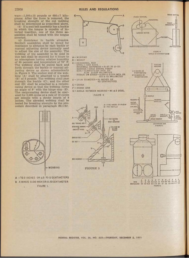
22958 RULES AND REGULATIONSware— 1,500±15 pounds or 680±7 kilograms. After the force is removed, the breaking strength of the cut webbing shall be determined as prescribed above.
(4) If a seat belt assembly has a buckle in which the tongue is capable of inverted insertion, one of the three assemblies shall be tested with the tongue inverted.
(d) Resistance to buckle abrasion. Seatbelt assemblies shall be tested for resistance to abrasion by each buckle or manual adjusting device normally used to adjust the size of the assembly. The webbing of the assembly to be used in this test shall be exposed for 4 hburs to an atmosphere having relative humidity of 65 percent and temperature of 70° P. The webbing shall be pulled back and forth through the buckle or manual adjusting device as shown schematically in Figure 9. The anchor end of the webbing (A) shall be attached to a weight (B) of 3 pounds. The webbing shall pass
.through the buckle (C), and the other end (D) shall be attached to a reciprocating device so that the webbing forms an angle of 8° with the hinge stop (E ) . The reciprocating device shall be operated for 2,500 cycles at a rate of 18 cycles per minute with a stroke length of 8 inches. The abraded webbing shall be tested for breaking strength by the procedure described in paragraph S5.1(b).
A 1 TO 2 INCHES OR 2.5 TO 5 CENTIMETERS B A MINUS 0 .0 6 INCH OR 0.15 CENTIMETER
. FIGURE I.
A - WEBBING 6 - WEIGHTC-H EXA G O N AL ROD
S T E E L - SAE 51416ROCKWELL HARDNESS - B-97 TO B - I0 I SURFACE-CO LD DRAWN FINISH S I Z E - 0 .250 ± 0.001 INCH OR
6 .35 ± 0.03 MILLIMETER RADIUS ON E D G E S -0.020 ± 0 .004 INCH OR
0.5 ± 0.1 MILLIMETERD -D RU M D IA M ET ER -16 INCHES OR
40 CENTIMETERSE -C R A N K F -C R A N K ARMG -A N G L E BETWEEN WEBBING—B5 ± 2 DECS.
FIGURE 2
FORCE VERTICALFORCE VERTICAL
fo rce fc| horizontal" [¡I
»FIXTURES
SINGLE ATTACHMENT HOOK
FEDERAL REGISTER, VOL. 36, NO. 232— THURSDAY, DECEMBER 2, 1971

RULES AND REGULATIONS 22959
th at a Type 1 ar Type 2 seat belt assembly that conforms to § 571.209 shall be installed, in each passenger car seat position, la January 1, 1968, seat belt assemblies installed in passenger cars until that date need not conform to § 571.209 unless the seat belt assemblies have been manufactured after February 28, 1967.
No t e : The standard that appears below is a revision that is effective with respect to vehicles manufactured on or after January 1, 1972. The standard that is effective before that date appears at- 32 F.R. 2408, Feb. 3, 1967, 36 F.R. 4291, March 4, 1971, and 36 F.R. 9869, May 29, 1971.§ 571.210 Standard No. 2 1 0 ; Seat belt
assembly anchorages.51. Purpose and scope. This standard
establishes requirements for seat belt assembly anchorages to insure their proper location for effective occupant restraint and to reduce the likelihood of their failure.
52. Application. This standard applies to passenger cars, multipurpose passenger vehicles, trucks, and buses.
53. Definition. “Seat belt anchorage” means the provision for transferring seat belt assembly loads to the vehicle structure.
54. Requirem ents.54.1 ty p e .54.1.1 Seat belt anchorages for a
Type 2 seat belt assembly shall be installed for each forward-facing outboard designated seating position in passenger cars other than convertibles, and for each designated seating position for which a Type 2 seat belt assembly is required by § 571.208 in vehicles other than passenger cars.
54.1.2 Seat belt anchorages for a Type 1 or a Type 2 seat belt assembly shall be installed for each designated seating position, except a passenger seat in a bus or a designated seating position for which seat belt anchorages for a Type 2 seat belt assembly are required by S4.1.1.
54.2 Strength.54.2.1 Except for side-facing seats,
the anchorage far a Type 1 seat belt assembly or the pelvic portion of a Type 2 seat belt assembly shall withstand a 5,000-pound force when tested in accordance with § 5.1.
54.2.2 The anchorage for a Type 2 seat belt assembly shall withstand 3,000- pound forces when tested in accordance with S5.2.
54.2.3 Permanent deformation or rupture of a seat belt anchorage or its surrounding area is not considered to be a failure, if the required force is sustained for the specified time.
54.2.4 Except for common seat belt anchorages for forward-facing and rearward-facing seats, floor-mounted seat belt anchorages for adjacent designated seating positions shall be tested by simultaneously loading the seat belt assemblies attached to those anchorages.
S4.3 Location. As used in this section, “forward” means in the direction in which the seat faces, and other direc- tiqnal references are to be interpreted accordingly.
S4.3.1 Seat belt anchorages fo r Type 1 seat belt assem blies and th e pelvic portion o f Type 2 seat belt assem blies.
54.3.1.1 In an installation in which the seat belt does not bear upon the seat frame, a line from the seating reference point to the nearest contact point of the belt with the hardware attaching it to the anchorage for a nonadjustable seat, or from a point 2.50 inches forward of and 0.375 inch above the seating reference point to the nearest contact point of the belt with the hardware attaching it to the anchorage for an adjustable seat in its rearmost position, shall extend forward from the anchorage at an angle with the horizontal of not less than 20° and not more than 75°.
54.3.1.2 In an installation in which the belt bears upon the seat frame, the seat belt anchorage, if not on the seat structure, shall be aft of the rearmost belt contact point on the seat frame with the seat in the rearmost position. The line from the seating reference point to the nearest belt contact point chi the seat frame shall extend forward from that contact point at an angle with the horizontal of not less than 20° and not more than 75°.
54.3.1.3 In an installation in which the seat belt anchorage is on the seat structure, the line from the seating reference point to the nearest contact point of the belt with the hardware attaching it to the anchorage shall extend forward from that contact point at an angle with the horizontal of not less than 20° and not more than 75°.
54.3.1.4 Anchorages for an individual seat belt assembly shall be located at least 6.50 inches apart laterally, measured between the vertical centerlines of the bolt holes.
S4.3.2 S eat belt anchorages fo r the upper torso portion o f Type 2 seat belt assem blies. With the seat in its full rearward and downward position and the seat back in its most upright position, the seat belt anchorage for the upper end of the upper torso restraint» shall be located within the acceptable range shown in Figure 1, with reference to a two dimensional manikin described in SAE Standard J826 (November 1962) whose “H” point is at the seating reference point and whose torso line is at the same angle from the vertical as the seat back.
S5. Test procedures. Each vehicle shall meet the requirements of S4.2 when tested according to the following procedures. Where a range of values is specified, the vehicle shalf be able to meet the requirements at all points within the range.
S5.1 Seats with Type 1 or Type 2 seat belt anchorages. With the . seat in its rearmost position, apply a force of 5,000 pounds in the direction in which the seat faces to a pelvic body block as described in Figure 2, restrained by a Type 1 or the pelvic portion of a Type 2 seat belt assembly, as applicable, in a plane parallel to the longitudinal centerline of the vehicle, with an initial force application angle of not less than 5° nor more than 15° above the horizontal. Apply the force at the onset rate of not more than 50,000 pounds per second. Attain the 5,000- pound force in not more than 30 seconds and maintain it for 10 seconds.
No. 232— —9FEDERAL REGISTER, VOL. 36, NO. 232— THURSDAY, DECEMBER 2, 1971

22960 RULES AND REGULATIONS
S5.2 Seats with Type 2 seat belt an chorages. With the seat in its rearmost position, apply forces of 3,000 pounds in the direction in which the seat faces simultaneously to pelvic and upper torso body blocks as described in Figures 2 and 3, restrained by a Type 2 seat belt assembly, in a plane parallel to the longitudinal centerline of the vehicle, with an initial force application angle of not less than 5° nor more than 15° above the horizontal. Apply the forces at. the onset rate of not more than 30,000 pounds per second. Attain the 3,000- pound forces in not more than 30 seconds and maintain them for 10 seconds.
FIGURE 2 - BODY BLOCK FOR LAF BELT ANCHORAGE
-1.00 OPTION«. BUCKLE CUTOUT
40O-|-- 1FIGURE 3 - BODY BLOCK FOR COMBINATION SHOULDER
AND LAP BELT ANCHORAGE
No t e : The effective date for multipurpose passenger vehicles, trucks, and buses shall be January 1,1972, except that the effective date for installation of anchorages for upper torso restraints for seating positions other than front outboard designated seating positions ©hall be January 1,1972.
§ 571.211 Standard No. 2 1 1 ; Wheel nuts, wheel discs, and hub caps.
51. Purpose and scope. This standard precludes the use of wheel nuts, wheel discs, and hub caps that constitute a hazard to pedestrians and cyclists.
52. Application. This standard applies to passenger cars, multipurpose passenger vehicles, and passenger car and multipurpose passenger vehicle equipment.
53. Requirem ents. Wheel nuts, hub caps, and wheel discs for use on passenger cars and multipurpose passenger vehicles shall not Incorporate winged projections.
RUBBER OCR BLOCK
Note: A clarification of the term “wheel nuts” as used in the requirements section S3 of § 571.211 has been requested. This section states that “wheel nuts, hub caps, and wheel discs for use on passenger cars and multipurpose passenger vehicles shall not incorporate winged projections.” A “wheel nut” is an exposed nut that is mounted at the center or hub of a wheel, and not the ordinary small hexagonal nut, one of several which secures a wheel to an axle, and which is normally covered by a hub cap or wheel disc.§ 571.212 Standard No. 2 1 2 ; Windshield
mounting.51. Purpose and scope. This standard
establishes windshield retention requirements for windshield mountings.
52. Application. This standard applies to passenger cars.
53. Requirements'. When tested in accordance with S4, each windshield mounting must retain either—
(a) Not less than 75 percent of the windshield periphery; or
<b) Not less than 50 percent of that portion of the windshield periphery on each side of the vehicle longitudinal centerline, if an unrestrained 95th percentile adult male manikin is seated in each outboard front seating position.
54. Dem onstration procedures. Impact the vehicle perpendicularly into a fixed collision barrier at a forward longitudinal velocity of 30 miles per hour.§ 571.213 Standard No. 2 1 3 ; Child seat
ing systems.51. Purpose and scope. This stand
ard specifics requirements for child seating systems to minimize the likelihood of death and injury to children in vehicle crashes or sudden stops by ejection from the vehicle, contact with the vehicle interior, or contact with a child seating system.
52. Application. This standard applies to child seating systems for use in passenger cars, multipurpose passenger vehicles, trucks and buses. This standard does not apply to Type 3 seat belt assemblies, as defined in § 571.209, or to systems for use only by recumbent or semirecumbent children..
53. Definition. “Child seating system" means an item of motor vehicle equipment for seating and restraining a child being transported in a motor vehicle. \
54. Requirem ents.S4.1 Labeling. Each child seating sys
tem shall have a label permanently affixed to it. The label shall contain the following information in the English language in letters and numerals not less than %2-inch high:
(a) The manufacturer’s name. However, a distributor’s name may be placed on tiie label in place of the manufacturer’s name if the distributor assumes responsibility for'all duties and liabilities imposed on the manufacturer by the National Traffic and Motor Vehicle Safety Act with respect to the system.
(b) Model number or name. ♦.(c) Month and year of manufacture.(d) Place of manufacture (city and
State or foreign country). However, if the label contains the distributor’s name
in place of the name of the manufacturer, the city and State or foreign country of the distributor’s principal offices shall appear on the label.
(e) A statement describing in general terms both the types of motor vehicles and the designated seating positions in those vehicles in which the system is either recommended or not recommended for use. The following, either stated separately or in combination, are examples of acceptable statements:, (1) “Recommended for use only on
bench seats of passenger cars manufactured after January 1, 1968, by the ____________Motor Company.”
(2) v “Recommended for use only on seats that have head restraints on (make or model designation(s)) passenger cars manufactured after January 1, 1969.”
(3) “Not recommended for use in trucks and buses.”
(f) Except as provided in S4.1.1, the following statement: “Not for use oh hinged or folding vehicle seats or seat backs unless the seat or seat back is equipped with a latch.”
(g) Unless the system is a rearwardfacing child seating system, the following statement: “For use only on forward-facing vehicle seats.”
(h) The following statement, inserting in the blank spaces the manufacturer’s recommendations of the maximum height and the minimum and maximum weight of children who can safely occupy the system: “For use onlyby children who weigh between--------a n d ______pounds and whose height is_____ inches or less.’5
S4.1.1 Exemption. A part of the warning required by S4.1(f) relating to use of a child seating system on a hinged or folding vehicle seat or on a vehicle seat having a hinged or folding back, or on both, may be omitted in the following circumstances:
(a) The part of the warning that re-, lates to vehicle seats may be omitted if the child seating system includes a component to restrain a hinged or folding vehicle seat and if, when the system and the component are both installed in the seat in accordance with the recommendation required by S4.1(e) and the instructions required by S4.2, the component will not fail when a forward longitudinal force equal to 20 times the weight of the vehicle seat is applied through the seat’s center of gravity and maintained for 10 seconds.
(b) The part of the warning that relates to seat backs may be omitted if the child seating system includes a component to restrain the hinged or folding seat back and if, when the system and the component are both installed in the vehicle seat in accordance with the recommendation required by S4.1(e) and the instructions required by S4.2, the component will not fail when a forward longitudinal force equal to 20 times the weight of the vehicle seat back is applied through the back’s center of gravity and maintained for 10 seconds.
(c) The entire warning may be omitted if the child seating system m-
FEDERAL REGISTER, VOL. 36, NO. 232— THURSDAY, DECEMBER 2, 1971

RULES AND REGULATIONS 22961eludes the components for restraining the seat and seat back specified in (a) and (b).
54.2 Installation instructions. Each child seating system shall be accompanied by an instruction sheet, providing a step-by-step procedure (which may include diagrams) for installing the system in the vehicles in which it is recommended for use in accordance with S4.1(e), securing the system with a Type 1 or Type 2 seat belt assembly, positioning a child in the system,' and adjusting the system to fit the child.
54.3 Adjustment. The components of each child seating system that directly restrain the child shall be adjustable to fit any child whose weight and height are within the ranges recommended in accordance with S4.1 (h) and who is positioned in the system in accordance with the instructions required by S4.2.
54.4 Attachm ent. Each child seating system shall be designed and constructed so that—
(a) The system has no provision for attachment to a vehicle seat back other than by means of a component that is inserted between the vehicle seat back and the vehicle seat cushion; and
(b) When installed in accordance with the instructions required by S4.2, a system installed on a forward-facing vehicle seat shall be restrained against forward movement, and a system installed on a rearward-facing vehicle seat shall be restrained against rearward movement, by a Type 1 or Type 2 seat belt assembly as defined in § 571.209.
54.5 Distribution o f restraint forces.54.5.1 Forw ard-facing systems. When
a forward-facing child seating system is installed in a vehicle and a child is positioned in the system in accordance with the instructions required by S4.2, components of the child seating system and the vehicle’s seat belt assemblies that apply restraining forces directly to the child shall, during forward movement of. the child relative to the vehicle in which the system is installed, distribute those forces on both the pelvis and thorax of the child. Restraint forces may also be distributed over other areas of the child’s body as long as both the pelvis and thorax are restrained.
54.5.2 R earw ard-facing s y s t e m s . When a rearward-facing child seating system is installed in a vehicle and a child is positioned in the system in accordance with the instructions required by S4.2, the components of the child seating system and the vehicle’s seat belt assemblies that apply restraining forces directly to the child shall—
(a) During forward movement of the child relative to the vehicle in which the system is installed, distribute those forces on both the back of the child’s torso and the back of the child’s head; and
(b) During rearward movement of the child relative to the vehicle in which the system is installed, distribute those forces on both the pelvis and thorax of the child. •Restraint forces may also be distributed over other areas of the child’s body as jong as both the back of the torso and nead are restrained during forward
movement* and both the pelvis and thorax are restrained during rearward movement.
S4.6 H ead restraint.S4.6.1 Except as provided in S4.6.2,
each forward-facing child seating system shall have a head restraint that limits rearward angular displacement of the child’s head relative to the child’s torso line. The height of the head restraint, measured as the straight-line distance between the highest point at the lateral center of the head restraint and the lowest point at the lateral center of the seating surface, shall be as follows:
The height of the head
I f the maximum weight of restraintchildren for whom the shall besystem is recommended at leastiis: (inches)
20 pounds or less__________________ 15More than 20 pounds but not more
than 25 pounds__________________ 16. 2More than 25 pounds taut not more
than 30 pounds__ ______________ 17.9More than 30 pounds but not more
than 35 pounds_________________ 18. 9More than 35 pounds______________ 20
S4.6.2 Subparagraph S4.6.1 does not apply to a child seating system if—
(a) In accordance with 84.1(e), the system is recommended for use only at designated seating positions in makes and models of vehicles at which the vehicle’s seat back or head restraint limits rearward angular displacement of the child’s head relative to the child’s torso line; and
(b) When the system is installed in accordance with the instructions required by S4.2, the distance from the lowest point at the lateral center of the child seating surface to a horizontal plane tangent to the highest point of the vehicle "Seat back or head restraint in its highest adjustable position, at the lateral center of the designated seating position, measured on a line parallel to the rear surface of the vehicle seat back, is at least equal to the seat back height specified for the seating system in S4.6.1.
54.7 Webbing. If a child seating system has webbing to distribute restraint forces as required by S4.5—
(a) The webbing that directly contacts the child’s body shall have a minimum width of iy 2 inches; and
(b) The webbing that sustains restraint forces shall meet the requirements for webbing in a iSnpe 3 seat belt assembly specified in paragraph S4.2(b) through paragraph S4.2(h) of § 571.209.
54.8 Hardware. Attachment hardware of each child seating system that sustains restraint forces shall meet the corrosion resistance requirements for attachment hardware of a seat belt assembly specified in paragraph S4.3(a) of § 571.209. Buckles, retractors, and metallic parts other than attachment hardware that sustain restraint forces shall meet the corrosion resistance requirements for buckles, retractors, and metallic parts other than attachment hardware of a 5eat belt assembly specified in paragraph S4.3(a) of § 571.209.
54.9 R elease m echanism . The mechanism for releasing components of a child seating system that directly restrain the child shall—
(a) Meet the requirements for the buckle of a Type 3 seat belt assembly specified in S4.3(d) of § 571.209, except that the assembly test force specified inS5.3 (c)(2) of § 571.209 shall be 1,000 pounds; or
(b) Release when a force of not more than 20' pounds is applied when tested in accordance with S5.3.
54.10 Im pact protection.54.10.1 Head. Each rigid component
of a child Seating system that, during forward, right-side, left-side or rearward impact, may contact the head of a child within the weight and height range recommended in accordance with S4.1(h) who is positioned in the system in accordance with the instructions required by S4.2, shall—
(a) Have no comer or edge with a radius of less than one-quarter inch; and
(b) Except as provided in S4.10.3, be covered with deformable, nonrecovery, or slow-recovery energy absorbing material having a thickness of at least one-half inch.
54.10.2 Torso. Except as provided inS4.10.3, each rigid component of a child seating system (except restraint belt buckles) that, during forward, right-side, or left-side impact, may contact the torso of a child within the weight and height range recommended in accordance with S4.1(h) shall comply with the requirements of S4.10.1.
54.10.3 Exception. S4.10.1 (b) does not apply to a rigid side of a child seating system if the contactable area of the side that is higher than the system’s seating surface is at least 24 square inches.
54.11 Perform ance.54.11.1 All child seating systerns.(a) When tested in accordance with
S5.1 each child seating system shall—(1) Retain the torso block in the sys
tem;(2) Sustain a static load of 1,000
pounds in the forward direction; and(3) Restrict forward horizontal move
ment of the torso block reference point:(i) When the vehicle seat is in its for-
wardmost adjustment position, to not more than 12 inches;
(ii) When the vehicle seat is rearward of its forwardmost adjustment position, to not more than 12 inches plus the distance, measured horizontally, that the vehicle seat is rearward of its forward- most adjustment position.
(b) A child seating system in which the attitude of the child is adjustable pursuant to the instructions provided in accordance with paragraph S4.2 shall meet these requirements at each designed adjustment position.
54.11.2 R earw ard-facing child sea ting systems.
(a) When tested in accordance withS5.2, each rearward-facing child seating system shall—
(1) Retain the torso block in the system;
(2) Sustain a static load of 500 pounds in the rearward direction; and
FEDERAL REGISTER, VOL. 36, NO. 232— THURSDAY, DECEMBER 2, 1971
RULES AND REGULATIONS\22962
(3) Restrict rearward horizontal movement of the torso block reference point to 12 inches or less.
(b) A child seating system in which the attitude of the child is adjustable pursuant to the instructions provided in accordance with paragraph S4.2 shall meet these requirements at each designed adjustment position.
S5. Test procedures.55.1 AH seating systems. The child
seating system shall be subjected to a static load, using the torso block shown in Figure 6 of Federal Motor Vehicle Safety Standard No. 209, as follows:
(a) Locate the torso block reference point, which is 2.9 inches above the bottom surface of the torso block and 2.1 inches forward of the back surface of the torso block.
(b) Install the system in accordance with the manufacturer’s instructions required by S4.2 on a vehicle seat other than a seat on which the manufacturer does not recommend its installation in the recommendation required by S4.1(e).
(c) Position the torso block in the system in accordance with the manufacturer’s instructions required by S4.2, and adjust the system in accordance with those instructions.
(d) Apply an increasing load to the torso block in a forward direction, not more than 15° and not less than 5° above the horizontal, until a load of1,000 pounds is achieved. The intersection of the load application line and the back surface of the torso block, at the time that the force removes the slack from the load application system, shall not be more than 8 inches or less than 6 inches above the bottom surface of the torso block. Maintain the 1,000-pound load for 10 seconds.
(e) Measure the horizontal movement of the torso block reference point.
55.2 R earw ard-facing child seating systems. The rearward-facing child seating system shall be subjected to the test procedure specified in S5.1, except that—
(a) A load of 500 pounds shall be achieved; and
(b) The load shall be applied in a rearward direction.
55.3 R elease m echanism . Conduct the following tests, for forward-facing and rearward-facing child seating systems, as appropriate, using a torso block configured so that it does not contact the buckle in a manner as to affect the buckle release force.
S5.3.1 For forward-facing child seating systems—
(a) Test the system with a 1,000-pound force as specified in S5.1;
(b) Reduce the force to 45 pounds; and(c) Release the mechanism in a man
ner typical of that employed in actual use.
S5.3.2 For rearward-facing child seating systems—
(a) Test the system with a 500-pound force as specified in S5.2;
(b) Reduce the force to 45 pounds; and
-(c) Release the mechanism in a manner typical of that employed in actual use.§ 571.214 Standard No. 2 1 4 ; Side door
strength.51. Purpose and scope. This standard
specifies strength requirements for side doors of a motor vehicle to minimize the safety hazard caused by intrusion into the passenger compartment in a side impact accident.
52. Application. This standard applies to passenger cars.
53. Requirem ents. Each vehicle shall be able to meet the following requirements when any of its side doors that can be used for occupant egress are tested according to S4.
53.1 In itial crush resistance. The initial crush resistance shall be not less than 2,250 pounds.
53.2 Interm ediate crush resistance. The intermediate crush resistance shall not be less than 3,500 pounds.
53.3 P eak crush resistance. The peak crush resistance shall be not less than two times the curb weight of the vehicle or 7,000 pounds, whichever is less.
54. Test procédures. The following procedures apply to determining compliance with section S3 :
(a) Remove from the vehicle any seats that may affect load upon, or deflection of, the side of the vehicle. Place side windows in their uppermost position and all doors in locked position. Place the sill of the side of the vehicle opposite to the side being tested against a rigid unyielding vertical surface. Fix the vehicle rigidly in position by means of tiedown attachments located at or forward of the front wheel centerline and at or rearward of the rear wheel centerline.
(b) Prepare a loading device consisting of a rigid steel cylinder or semicylinder 12 inches in diameter with an edge radius of one-half inch. The length of the loading device shall be such that the top surface of the loading device is
at least one-half inch above the bottom edge of the door window opening but not of a length that will cause contact with any structure above the bottom edge of the door window opening during the test.
(c) Locate the loading device as shown in Figure I (side view) of this section so that:
(1) Its longitudinal axis is vertical;(2) Its longitudinal axis is laterally
opposite the midpoint of a horizontal line drawn across the outer surface of the door 5 inches above the lowest point of the door;
(3) Its bottom surface is in the same horizontal plane as the horizontal line described in subdivision (2) of this sub- paragraph; and
(4) The cylindrical face of the device is in contact with the outer surface of the door.
(d) Using the loading device, apply a load to the outer surface of the door in an inboard direction normal to a vertical plane along the vehicle’s longitudinal centerline. Apply the load continuously such that the loading device travel rate does not exceed one-half inch per second until the loading device travels 18 inches. Guide the loading device to prevent it from being rotated or displaced from its direction of travel. The test must be completed within 120 seconds.
(e) Record applied load versus displacement of the loading device, either continuously or in increments of not more than 1 inch or 200 pounds for the entire crush distance of 18 inches.
(f) Determine the initial crush resistance, intermediate crush resistance, and peak crush resistance as follows:
(1) From the results recorded in sub- paragraph (e) of this paragraph, plot a curve of load versus displacement and obtain the integral of the applied load with respect to the crush distances specified in subdivisions (2) and (3) of this paragraph. These quantities, expressed in inch-pounds and divided by the specified crush distances, represent the average forces in pounds required to deflect the door those distances.
(2) The initial crush resistance is the average force required to deform the door over the initial 6 inches of crush.
(3) The intermediate crush resistance is the average force required to deform the door over the initial 12 inches of crush.
(4) The peak crush resistance is the largest force recorded over the entire 18-inch crush distance.
P.AL REGISTER, VOL. 36, NO. 232— THURSDAY, DECEMBER 2, 1971

RULES AND REGULATIONS 22963
HORIZONTAL LINE 5 INCHES ABOVE THE LOWEST POINT OF THE DOOR
STRUCTURES ABOVE THE BOTTOM EDGE OF THE DOOR WINDOW OPENING
BOTTOM EDGE OF DOOR WINDOW
OPENING .
MID POINT OF HORIZONTAL LINELOWEST POINT OF THE DOOR
LOADING DEVICE LOCATION AND APPLICATION TO THE DOORFIGURE 1
§571.215 Standard No. 2 1 5 ; Exterior protection.
Note; Effective date. September. 1, 1972, with further requirements effective September 1, 1973, as noted in the text of the rule.
51. Scope. This standard establishes requirements for the impact resistance and the configuration of front and rear vehicle surfaces.52. Purpose. The purpose of this stand
ard is to prevent low-speed collisions from impairing the safe operation of vehicle systems, and to reduce the frequency of override or underride in higher speed collisions.
53. Application. This standard applies to passenger cars.
54. Definition. All terms defined in the Act and the rules and standards issued under its authority are used as defined therein.
55. Requirements.S5.1 vehicle m anufactured on or a fter
September 1,1972.Each vehicle manufactured on or after
September 1, 1972, shall meet the protective criteria of S5.3.1 through S5.3.4 when it impacts a fixed collision barrier that is perpendicular to the line of travel of the vehicle, while traveling longitudinally forward at 5 m.p.h. and while traveling longitudinally rearward at 2 y2 m P h., under the conditions of S6.1.
S5.2 Vehicles M anufactured on or a fter Septem ber 1, 1973. Except as provided in S5.2.1 and S5.2.2, each vehicle manufactured on or after September 1, 1973, shall meet the protective criteria of S5.3.1 through S5.3.6 during and after impacts by a pendulum-type test device in accordance with the procedures of57.1 and S7.2 followed by impacts into a fixed-collision barrier that is perpendicular to the line of travel of the vehicle, while traveling longitudinally forward at 5 m.p.h. an d ‘while traveling longitudinally rearward at 5 m.p.h., under the conditions of S6.
55.2.1 The comer-impact procedure of S7.2.2 shall not apply to any vehicle manufactured from September 1, 1973, to August 31,1975.
55.2.2 The fixed-collision-barrier impact requirements of S5.2 shall apply, but the pendulum-impact requirements of55.2 shall not apply to each vehicle manufactured from September 1,1973 to August 31, 1974, that has a wheelbase of 115 inches or less and that either—
(a) Has a convertible top;(b) Has no roof support structure be
tween the A-pillar and the rear roof support structure; or
(c) Has no designated seating position behind the front designated seating positions.
55.3.1 Each lamp or reflective device, except license plate lamps, shall be free of cracks and shall comply with the applicable requirements of § 571.198.
55.3.2 The vehicle’s hood, trunk, and doors shall operate in the normal manner.
55.3.3 The vehicle’s fuel and cooling systems shall have no leaks or constricted fluid passages and all sealing devices and caps shall operate in the normal manner.
55.3.4 The vehicle’s exhaust system shall have no leaks or constrictions.
55.3.5 The vehicle’s propulsion, suspension, steering, and braking systems shall suffer no damage, shall remain in adjustment and shall operate in the normal manner.
55.3.6 The vehicle shall not touch the test device except on the impact ridge shown in Figures 1 and 2.
56. Conditions. The vehicle shall meet the requirements of S5 under the following conditions.
56.1 General.56.1.1 The vehicle is at unloaded ve
hicle weight.56.1.2 The front wheels are parallel
to the vehicle’s longitudinal centerline.56.1.3 Tires are inflated to the ve
hicle manufacturer’s recommended pressure for the specified loading condition.
56.1.4 Brakes are disengaged and the transmission is in neutral.
S6.2 Pendulum test conditions. The following conditions apply to the pendulum test procedures of S7.1 and S7.2.
56.2.1 The test device consists of a block with one side contoured as specified in figure 1 and figure 2 with the impact ridge made of hardened steel.
56.2.2 With plan A vertical, the impact line shown in figures 1 and 2 is horizontal at the same height as the test device’s center of percussion.
56.2.3 The effective impacting mass of the test device is equal to the mass of the tested vehicle.
56.2.4 When impacted by the test device, the vehicle is at rest on a level, rigid concrete surface.
S6.3 Barrier test condition. At the onset of a barrier impact, the vehicle’s engine is operating at idling speed.
57. Test procedures.57.1 Longitudinal im pact test proce
dures. Impact the vehicle’s front surface and its rear surface three times each with the impact line at the height of 20 inches, and three times each with the impact line at any height between 20 inches and 16 inches, in accordance with the following procedure.
57.1.1 For impacts at a height of 20 inches, place the test device shown in figure 1 so that plane A is vertical and the impact line is horizontal at the specified height.
87.1.2 For impacts at a height between 20 inches and 16 inches, place the test device shown in figure 2 so that plane A is vertical and the impact line is horizontal at a height within the range.
57.1.3 For each impact, position the test device so that the impact line is at least 2 inches apart in vertical direction
FEDERAL REGISTER, VOL. 36, NO. 232— THURSDAY, DECEMBER 2, 1971

RULES AND REGULATIONS22964
from its position in any prior impact, unless the midpoint of the impact line with respect to the vehicle is to be more than 12 inches apart laterally from its position in any prior impact.
57.1.4 For each impact, aline the vehicle so that it touches, but does not move, the test device, with the vehicle’s longitudinal centerline perpendicular to the plane that includes plane A of the test device and with the test device inboard of the vehicle comer test positions specified in S7.2.
57.1.5 Move the test device away from the vehicle, then release it so that plane A remains vertical from release until the onset of rebound, and the arc described by any point on the impact line is constant, with a radius of not less than 11 feet, and lies in a plane parallel to the vertical plane through the vehicle’s longitudinal centerline.
57.1.6 Impact the vehicle at 5 m.p.h.57.1.7 Perform the impacts at inter
vals of not less than 30 minutes.S7.2 Corner im pact test procedure.
Impact a front comer and a rear comer of the vehicle once each with the impact line at a height of 20 inches and impact the other front comer and the other rear comer once each with the impact line at any height between 20 inches and 16 inches in accordance with the following procedure.
57.2.1 For an impact at a height of 20 inches, place the test device shown in figure 1 so that plane A is vertical and the impact line is horizontal at the specified height.
57.2.2 For an impact at a height between 20 inches and 16 inches, place the test device shown in figure 2 so that plane A is vertical and the impact line is horizontal at a height within the range.
57.2.3 Align the vehicle so that a vehicle corner touches, but does not move, the lateral center of the test device, with plane A of the test device forming an angle of 60 degrees with a vertical longitudinal plane.
57.2.4 Move the test device away from the vehicle, then release it so that plane A remains vertical from release until the onset of rebound, and the arc described by any point on the impact line is constant, with a radius of not less than 11 feet, and lies in a vertical plane at an angle of 30° to the vertical plane through the vehicle’s longitudinal centerline.
57.2.5 Impact each comer at 3 m.pJh.
TOP V IE »
FIGURE I TOP VIEW
FIGURE 2Note: Effective date. The amendments to the protective criteria are effective September 1,
1972. The amendments to S5.2, S7.2.5 and Figures 1 and 2 are effective September 1,1973.
FEDERAL REGISTER, VOL. 36 , NO. 232— THURSDAY, DECEMBER 2 , 1971

§ 571.301 Standard No. 3 0 1 ; Fuel tanks, fuel tank filler pipes, and fuel tank connections.
51. Purpose and scope. This standard specifies requirements for the Integrity and security of fuel tanks, fuel tank filler pipes, and fuel tank connections to minimize fire hazard as a result of collision.
52. Application. This standard applies to passenger cars.
53. Requirements. When tested in accordance with S4:
(a) Fuel tank filler pipes, fuel tank connections to fuel lines, and fuel tanks filled to at least 90 percent of capacity with a liquid having substantially the same viscosity as, and specific gravity no less than, the fuel used in the vehicle, shall not discharge fluid at a rate greater than 1 ounce (by weight) per minute after termination of impact.
(b) Fluid losses during impact shall not exceed 1 ounce (by weight).
54. Demonstration procedures. Impact the vehicle perpendicularly into a fixed collision barrier at a forward longitudinal velocity of 30 miles per hour.§ 571.302 Standard No. 3 0 2 ; Flamma
bility of interior materials. (Effective Sept. 1, 1972)
51. Scope. This standard specifies burn resistance requirements for materials used in the occupant compartments of motor vehicles.
52. Purpose. The purpose of this standard is to reduce the deaths and injuries to motor vehicle occupants caused by vehicle fires, especially those originating in the interior of the vehicle from sources such as matches or cigarettes.
53. Application. This standard applies to passenger cars, multipurpose passenger vehicles, trucks, and buses.
54. Requirements.54.1 The portions described in S4.2
of the following components of vehicle occupant compartments shall meet the requirements of S4.3: Seat cushions, seat backs, seat belts, headlining, convertible tops, arm rests, all trim panels including door, front, rear, and side panels, compartment shelves, head restraints, floor coverings, sun visors, curtains, shades, wheel housing covers, engine compartment covers, mattress covers, and any other interior materials, including padding and crash-deployed elements, that are designed to absorb energy on contact by occupants in the event of a crash.
54.2 The portions of the components that shall meet the requirements of S4.3 are all of the following:
(a) The surface material taken separately if it is not bonded, sewed or mechanically attached to underlying material.
(b) a composite consisting of the surface material bonded, sewed or mechani-
RULES AND REGULATIONScally attached to underlying material, if such a composite is used in the component.
(c) Padding and cushioning materials taken separately, if those materials are not bonded, sewed or mechanically attached to surface materials.
S4.3 Material described in S4.1 andS4.2 shall not bum, or transmit a flame front across its surface, at a rate of more than 4 inches per minute. However, if a material stops burning before it has burned for 60 seconds from the start of timing, and has not burned more than 2 inches from the point where timing was started, it shall be considered to meet this requirement.
S5. Test procedure.55.1 Conditions.55.1.1 The test is conducted in a
metal cabinet for protecting the test specimens from drafts. The interior of the cabinet is 15 inches long, 8 inches deep, and 14 inches high. It has a glass observation window in the front, a clos- able opening to permit insertion of the specimen holder, and a hole to accommodate tubing for a gas burner. For ventilation, it has a Vfe-inch clearance space around the top of the cabinet, ten % -inch-diameter holes in the base of the cabinet, and legs to elevate the bottom of the cabinet by three-eighths of an inch, all located as shown in Figure 1.
55.1.2 Prior to testing, each specimen is conditioned for 24 hours at a temperature of 70° F. and a relative humidity of 50 percent, and the testis conducted under those ambient conditions.
55.1.3 The test specimen is inserted between two matching u-shaped frames of metal stock 1-inch wide and % of an inch high. The interior dimensions of the u-shaped frames are 2 inches wide by 13 inches long. A specimen that softens and bends at the flaming end so as to cause erratic burning is kept horizontal by supports consisting of thin, heat-resistant wires, spanning the width of the U-shaped frame under the specimen at 1-inch intervals. A device that may be used for supporting this type of material is an additional U-shaped frame, wider than the U-shaped frame containing the specimen, spanned by 10- mil wires of heat-resistant composition at 1-inch intervals, inserted over the bottom U-shaped frame.
55.1.4 A bunsen burner with a tube of %-inch inside diameter is used. The gas adjusting valve is set to provide a flame, with the tube vertical, of IV2 inches in height. The air inlet to the burner is closed.
55.1.5 The gas supplied to the burner has a flame temperature equivalent to that of natural gas.
S5.2 Preparation o f specimens.
22965
55.2.1 Each specimen of material to be tested is a rectangle 4 inches wide by 14 inches long, wherever possible. The thickness of the specimen is that of the material as used in the vehicle, except that where the material’s thickness exceeds inch the specimen is cut down to that thickness. Where it is not possible to obtain a fiat specimen, because of component configuration, the specimen is cut to not more than y2 inch in thickness at any point, from the area with the least curvature, and in such a manner as to include the face side. The maximum available length or width of a specimen is used where either dimension is less than 14 inches or 4 inches respectively.
55.2.2 Material with directional effects is oriented so as to provide the most adverse results.•» S5.2.3 Material with a napped or
tufted surface is placed on a flat surface and combed twice against the nap with a comb having seven to eight smooth, rounded teeth per inch.
S5.3 Procedure.(a) Mount the specimen so that both
sides and one end are held by the U-shaped frame, and one end is even with the open end of the frame. Where the maximum available width of a specimen is not more than 2 inches, so that the sides of the specimen cannot be held in the U-shaped frame, place the specimen in position on wire supports as described in S5.1.3, with one end held by the closed end of the u-shaped frame.
(b) Place the mounted specimen in a horizontal position, in the center of the cabinet.
(c) With the flame adjusted according to S5.1.4, position the bunsen burner and specimen so that the center of the burner tip is three-fourths of an inch below the center of the bottom edge of the open end of the specimen.
(d) Expose the specimen to the flame for 15 seconds.
(e) Begin timing (without reference to the period of application of the burner flame) when the flame from the burning specimen reaches a point 1 % inches from the open end of the specimen.
(f) Measure the time that it takes the flame to progress to a point l l/z inches from the clamped end of the specimen. If the flame does not reach the specified end point, time its progress to the point where flaming stops.
(g) Calculate the burn rate from the formula
DB = 60X —
TWhere:
B =B urn rate in Inches per minute,•D=Length the flame travels in inches, and T =Tim e in seconds for the flame to travel
D Inches.
FEDERAL REGISTER, VOL. 36, NO. 232— THURSDAY, DECEMBER 2, 1971

22966 RULES AND REGULATIONS
Title 7— AGRICULTUREChapter -VII— Agricultural Stabiliza
tion and Conservation Service (Agricultural Adjustment), Department of Agriculture
SUBCHAPTER B— FARM MARKETING QUOTAS AND ACREAGE ALLOTMENTSPART 722— COTTON
Subpart— 1972 Crop of Upland Cotton; Base Acreage AllotmentsS tate R eser v es and C o u n t y B ase
A creage A llo tm en ts
Section 722.467 is issued pursuant to the Agricultural Adjustment Act of 1938, as amended (7 U.S.C. 1281 et seq.) (referred to as the “act”), with respect to the 1972 crop of upland cotton (referred to as “cotton”) . The purpose of this section is to establish State reserves, allocate the State reserves to counties and establish county base acreage allotments (referred to as “county allotments”). Determinations with respect to the State reserves and county allotments were made initially by the respective State committees and are hereby approved and made effective by the Administrator, ASCS, pursuant to delegated authority (29 F.R. 16210, 35 F.R. 19798, 36 F.R. 6907, 21529).
In order that farmers may be informed as soon as possible of 1972 farm base acreage allotments so that they may make plans for their 1972 farming operations, it is essential that this section be made effective immediately. Accordingly, § 722.467 shall be effective upon
filing this document with the Director, Office of the Federal Register.§ 722 .467 Slate reserve and county al
lotments for the 1972 crop o f cotton.(a) S tate reserves. The total State
reserve for all uses established by the State committee shall not exceed 2 percent of the State allotment available for distribution to counties in the State. The allotment available for distribution shall be the State’s share of the national allotment less the allotment in the State productivity pool attributable to history
State TotalState produc- State
tivity reservepool
acreage pooled as a result of productivity adjustments under section 344a(f) of the act. The State committee may determine that no reserve for any one or more uses, or all uses, specified under section 350 (c) of the act, shall be established. It is hereby determined that no State reserve for abnormal conditions is required, and the reserve for each State shall be established and allocated among uses as shown in the following table. The table also sets forth the allotment in the State productivity pool which shall not be allocated to counties and farms.
Allocations from State reserve for:
TrendsSmallforms
Inequity New formsand and cor-
hardship rection cases of errors
Alabama____ ____________ — ;Arizona_____. . . . ___—— ^—Arkansas___ _____ —California__________ —Florida____________ _____ —•«Georgia_____________ ;
Kansas___ ;________v—---------- -Kentucky__________ ____ ___Louisiana-----------------------------;Mississippi_______________ _Missouri____________________Nevada________________ _____ _New Mexico___________—------ ;North Carolina____—------------ -Oklahoma_________ _____ ___South Carolina___________ — ■Tennessee ____ — -----— -Texas_______________________Virginia_____________________
U.S. total......... ... ...........—
Acre» Acre» Acre» Acres12,043 78 .................................................1,945 8 ------------------------------------
18,659 370 310 ------------------2,913 50 ------------ ------------------
908 199 ..................................................15,488 106 --------------------------- -----
14,295 7,721 7,034 ------------------15,243 21,694 21,669 ------------- -----
328 30 ................................................. -7 ---------------------- -------------------------------- -
271 26 .............................. ...................1,203 293 ------------- ------------------------6 264 10,533 10,383 ------------------4,906 9,447 9,347 ........................-2,608 7,484 7,433 . . . . . ...............
95,603 6,026 5,254 -----------------22 211 ____________ K »
192,804 64,374 61,430 100
Acres A cre s------: g------------- 60-------- 60-------------------- 199------------- 106
.......... ...............98687 ——--------------- 30. . . ------ %
293------ 160----- 100— : 6i
772Ì5Ó- 11788 2>05®
(b) Apportionment o f S tate allotm ent to counties— (1) Computed county allotm ent. The State allotment less the allotment in the State productivity pool and the State reserve is apportioned among
counties in the State on the basis of the acreage planted (including acreage regarded as having been planted) to cotton within the farm acreage allotment during the 5 calendar years 1966 through 1
FEDERAL REGISTER, VOL. 36, NO. 232— THURSDAY, DECEMBER 2, 1971

)
ad
just
ed
for
abn
orm
al
wea
ther
co
nd
iti
on
s o
r o
ther
na
tura
l d
isas
ter.
It
is h
ere
by
det
erm
ined
th
at
no
a
dju
stm
ents
for
ab
norm
al
wea
ther
co
nditi
ons
or
othe
r na
tura
l di
sast
er a
re r
equi
red.
The
acr
eag
e ap
port
ione
d un
der
this
par
agra
ph i
s re
ferr
ed
to
as
the
com
pute
d co
unty
al
lotm
ent.
(2>
C
ount
y al
lotm
ents
. T
he
cou
nty
al
lotm
ent
is
the
sum
o
f th
e co
mp
ute
d
cou
nty
a
llo
tmen
t an
d
all
oca
tio
n
to t
he
cou
nty
from
the
Sta
te r
eser
ve f
or tr
ends
. T
he f
ollo
win
g ta
ble
sets
for
th th
e co
unty
al
lotm
ent
and
allo
catio
ns f
rom
the
Sta
te
rese
rve.
Al
ab
am
a—
Con
tin
ued
Allo
catio
nC
ount
yA
lloca
tion
from
Sta
teC
ompu
ted
from
Sta
teal
lotm
ent
rese
rve
for:
Cou
nty
coun
tyre
serv
es(s
um o
fal
lotm
ent
for
tren
dsco
lum
nsSm
all
Ineq
uity
and
(1)
and
(2))
farm
sha
rdsh
ip! f
V V
case
s
(i)
(2)
(3)
(4)
(6)
Ala
bam
a Allo
catio
nC
ount
yA
lloca
tion
from
Sta
teC
ompu
ted
from
Sta
teal
lotih
ent
rese
rve
for:
Cou
nty
coun
tyre
serv
es(s
um o
fal
lotm
ent
for t
rend
sco
lum
nsSm
all
Ineq
uity
and
(1)
and
(2))
farm
sha
rdsh
ipca
ses
(1)
(2)
(3)
(4)
(5)
St. C
lair
......
......
......
......
......
......
....A
cre*
Acr
esA
cres
Acr
esA
cres
02,
598
00
Shel
by...
......
......
......
......
......
......
. ....
......
......
......
.....
i,
262
04|
262
00
Sum
ter..
......
......
......
......
......
......
......
......
......
......
......
9,
428
09,
428
00
Talla
dega
......
......
......
......
......
......
......
......
......
......
...
8,38
70
8,38
70
0Ta
llapo
osa.
......
.....
......
......
......
......
......
......
......
......
. 4,
806
0i,
806
00
Tusc
aloo
sa...
......
......
......
.....
......
. .....
......
......
......
.....
11,1
260
11,1
260
0W
alke
r.....
......
......
......
......
......
....
......
......
......
......
....
4; 01
40
4; 01
40
0W
ashi
ngto
n....
......
......
......
......
......
......
......
......
......
1,
747
01,
747
00
Wilc
ox...
......
......
......
......
......
......
.. ....
......
......
......
......
7,
697
07,
697
00
Win
ston
......
......
......
......
......
......
......
......
......
......
......
4,
778
04,
778
00
Aut
auga
—¿z
.z-. z
.-.. z
z ..
:Ba
ldw
in__
_..
..._
___
Barb
our_
____
____
____
___
__B
ibb_
____
Blou
nt__
___
i___
____
____
__Bu
llock
____
____
____
____
___
Butl
er__
__a_
___
____
___
____
Cal
houn
____
___
.___
_•___
__„
Cha
mbe
rs__
____
____
____
___
Che
roke
e....
.....
......
.....
......
......
.C
hilto
n___
____
____
__._
____
_C
hoct
aw__
____
__._
____
____
Cla
rke_
___.
____
a___
___
___
Cla
y----
------
------
------
------
---..
Cle
burn
e___
____
____
____
___
Cof
fee_
____
____
____
____
____
Col
bert
......
......
._...
......
......
..C
onec
uh...
____
____
____
__..
.C
oosa
____
____
____
___
:____
__C
ovin
gton
____
____
____
____
_C
rens
haw
____
____
_:_
____
_C
ullm
an__
____
____
____
____
Dal
e....
......
......
......
......
......
......
......
Dal
las_
____
____
____
____
____
DeK
alb.
......
......
......
.....
......
......
.El
mor
e___
____
____
____
____
_Es
cam
bia_
____
____
____
___
;Et
owah
____
____
____
____
___
Faye
tte.
......
.....
......
......
.....
......
..Fr
ankl
in._
____
____
____
____
Gen
eva_
____
___
____
____
___
Gre
ene.
......
..1...
......
......
......
......
...H
ale.
......
......
....
......
......
......
.....
...H
enry
___
____
____
____
___
__H
oust
on__
____
____
____
____
_Ja
ckso
n...
.....
____
____
____
Jeffe
rson
____
____
____
____
___
Lam
ar._
____
____
____
___
___
Lau
derd
ale.
.___
___
____
___
Law
ren
ce...
......
......
......
......
..L
ee...
......
......
.....
......
......
......
.....
Lim
esto
ne__
____
___
____
___
Low
ndes
____
____
____
____
__M
acon
......
........
......
........
......
......
Mad
iso
n...
......
........
......
......
..M
aren
go__
____
____
____
____
_M
ario
n___
___
.___
____
____
__M
arsh
all..
....._
____
____
____
Mob
ile__
____
____
____
____
__M
onro
e___
____
___
____
____
_M
ontg
omer
y....
......
......
......
......
...M
orga
n___
____
____
____
____
_Pe
rry_
____
____
____
____
____
Pic
ken
s....
...__
____
____
____
Pike
____
____
____
____
____
__R
ando
lph_
____
____
____
____
Rus
sell_
____
____
____
____
__
Acr
es 6.74
2 1,
931
9,19
6 2,
661
11,6
65
, 5,
811
6,38
2 4,
644
5,26
4 15
,626
6,
460
4,41
3 3,
948
x 1,
336
1,25
4 11
,895
15
,260
8,
349
715
10,6
54
6,62
1 22
,873
5,
344
18,3
56
21,7
63
10,6
71
7,18
2 8,
184
6,08
7 9,
180
13.1
93
8,98
610
,338
10
,707
17
,899
16
,647
.2
,478
7,
323
18,9
92
27,3
32
6,30
1 37
,564
7,
146
10,7
97
41,8
17
11,1
858.
742
20,2
431,
936
12,1
36
6,84
6 19
,141
7,
493
10.1
93
10,0
354,
034
6,59
1
Acre
sAc
res
Acre
sAc
res
06,
742
00
Ari
zon
a0
1,93
10
00
9,19
50
00
2,66
10
0C
ochi
se...
......
......
......
......
......
......
.... ..
......
......
......
.....
10,6
760
10,6
760
00
11,5
550
0G
ila...
......
......
......
......
......
......
......
.... ..
......
......
......
....
270
270
00
5,81
10
0G
raha
m...
......
......
......
......
......
......
..0
6,32
00
00
6,38
20
0G
reen
lee.
......
......
......
......
......
......
......
......
......
......
...
1,29
20
1,29
20
00
4,64
40
0M
aric
opa.
......
.....
......
......
......
......
.....
......
......
......
...
87,4
900
87,4
900
00
5,26
40
0M
ohav
e....
......
......
......
.....
......
......
. ....
......
......
......
..
203
020
30
00
15,6
260
0Pi
ma.
......
......
......
......
......
......
......
...13
,278
013
,278
00
06,
460
00
Pina
l.....
......
......
......
......
......
......
......
......
......
......
......
94
,168
094
,168
00
04,
413
00
Sant
a C
ruz.
.___
____
____
____
......
......
......
......
32
90
329
00
03,
948
00
Yav
apai
......
......
......
......
......
......
.....
......
......
......
......
9
09
00
01,
336
00
Yum
a___
____
____
____
____
___
......
......
......
......
23
,038
023
,038
00
01,
254
00
15,2
60
8,34
9 71
6 10
,654
6,
621
22,8
73
5,34
4 18
,356
21
,763
10
,671
7,
182
8,18
4 6,
087
9,18
013
.193
8,
986
10,3
38
10,7
07
17,8
99
16,6
47
2,47
8 7,
323
18,9
92
27,3
32
6,30
1 37
,564
7,
146
10,7
97
41,8
17
11,1
85
8,74
2 20
,243
1,
936
12,1
36
6,84
6 19
,141
7,
493
10.1
93
10,0
354,
034
ft 6
91
Ark
ansa
s___
_A
shle
y___
____
Baxt
er__
____
_Br
adle
y___
___
Cal
houn
____
_C
hico
t___
___
_C
lark
____
____
Cla
y....
......
......
..C
lebu
rne.
......
...C
leve
lan
d...
..C
olum
bia _
___
Con
way
____
_C
raig
head
____
Cra
wfo
rd__
__C
ritte
nden
___
Cro
ss__
____
__D
alla
s___
____
Des
ha__
___
__D
rew
......
......
Faul
kner
___
Fran
klin
___
¿..
Fult
on...
......
.....
Gra
nt__
___
...G
reen
e___
___
Hem
pste
ad__
_H
ot S
pri
ng.
...H
owar
d__
....
Inde
pend
ence
.Iz
ard.
......
......
....
Jack
son_
____
_Je
ffers
on__
___
John
son_
____
_La
faye
tte_
___
Law
renc
e___
_Le
e___
____
___
Linc
oln.
......
....
Litt
le H
iver
...
Ar
ka
ns
as
6,84
80
6,84
80
019
,228
219
,230
00
62
70
01,
779
31,
782
00
1,34
74
1,35
10
024
,403
624
,408
00
2,04
30
2,04
30
028
,172
2528
,197
00
467
647
30
01,
097
01,
097
00
2,37
50
2,37
60
03,
902
53,
907
00
58,6
9410
68,6
040
018
119
00
69,3
150
69,3
150
026
,738
026
,738
00
1,13
61
1,13
70
031
,106
1331
,119
00
9,77
00
9,77
00
06,
008
36,
011
00
281
028
10
012
40
124
00
502
620
027
,174
027
,174
00
2,21
90
2,21
90
040
949
00
828
483
20
02,
995
93,
004
00
289
028
90
030
,693
030
,’693
00
61,5
464
51,5
500
055
70
557
00
9,93
69
9,94
50
014
,120
1314
,133
00
41,4
540
41,4
540
022
,780
2322
,803
00
3,28
30
3,28
30
0
No,
232
—1—
10FE
DERA
L RE
GIST
ER,
VOL.
36,
NO.
232—
THUR
SDAY
, DE
CEM
BER
2, 1
971
RULES AND REGULATIONS 22967

fA
rk
an
sas—
^-C
ontin
ued
Allo
catio
ni
Cou
nty
Allo
catio
n fr
om S
tate
Com
pute
dfr
om S
tate
allo
tmen
tre
serv
e fo
r:C
ount
yco
unty
rese
rves
(sum
of
—al
lotm
ent
for t
rend
sco
lum
nsSm
all
Ineq
uity
and
(1)
and
(2))
farm
sha
rdsh
ipca
ses
(1)
(2)
(3)
(4)
(5)
Acr
esA
cres
Acr
esA
cres
Acr
esLo
gan.
......
......
......
......
......
......
......
.....
......
......
......
....
829
483
30
0L
onok
e....
......
......
......
......
......
......
......
......
......
......
. 33
,883
2533
,908
00
Mar
ion .
......
......
......
.....
......
...i.
......
......
......
....
20
20
0M
iller
......
......
......
......
......
......
......
......
......
......
......
....
6,32
50
6,32
50
0M
issi
ssip
pi...
......
......
......
......
......
......
129,
326
1812
9,34
40
0M
onro
e....
......
......
......
......
......
......
......
......
......
......
. 27
,606
027
,606
00
Nev
ada.
......
......
......
......
......
......
......
564
1658
00
0N
ewto
n....
......
......
......
......
......
......
.....
......
......
......
....
240
240
0O
uach
ita...
......
......
......
......
......
......
.....
......
......
......
. 1,
574
0.
1,57
40
0Pe
rry .
......
.....
......
......
......
......
......
.....
......
........
......
.. 59
72
599
00
Phill
ips.
......
......
......
......
......
......
......
.....
......
......
......
58
,483
358
,486
00
Pik
e ....
......
......
......
......
......
...-.
......
......
......
......
......
.. 16
02
162
00
Poin
sett
......
......
......
......
......
......
......
.___
____
____
60
,295
060
,295
00
Pope
......
......
......
......
......
......
......
......
.....
......
......
......
. 1,
646
91,
655
00
Prai
rie .
......
......
......
......
......
......
......
......
......
......
......
. 6,
069
76,
076
00
Pula
ski..
......
......
......
......
.....
......
.....
......
......
......
....
11,9
877
11,9
940
0R
ando
lph .
......
......
......
.....
......
......
.....
.....
......
......
6,
555
76,
562
00
St. F
ranc
is...
.....
......
......
....-
......
.....
......
......
......
...
46,6
840
46,6
840
0Sc
ott ..
......
......
......
......
......
......
......
.....
......
......
......
....
110
110
0Se
arcy
......
......
......
......
......
......
......
......
......
......
......
. 10
00
100
00
Seba
stia
n ....
......
......
......
......
......
......
......
......
......
.....
984
102
00
Sevi
er...
......
.....
......
......
......
......
......
.....
......
......
......
.. 11
50
115
00
Shar
p___
____
____
____
____
____
......
......
..
261
026
10
0U
nio
n...
......
......
......
.....
......
......
......
......
......
......
. 26
14-
400
0V
an B
uren
......
......
......
......
......
......
.....
......
......
......
11
916
135
00
Was
hing
ton_
____
____
____
____
_/
12
30
0W
hite
......
......
......
......
......
.....
......
......
......
......
......
. 9,
821
219,
842
00
Woo
druf
f ___
____
____
___
____
_...
......
......
......
. V
26,
116
026
,116
00
Yel
l.....
......
......
......
......
......
......
....—
......
......
......
....
3,97
60
3,97
60
0
Ca
lifo
rn
ia
Fres
no...
......
......
......
......
......
......
...
......
......
......
......
13
3,08
60
133,
086
00
Impe
rial
......
......
......
......
......
.....—
.......
......
......
.....
34,0
480
34,0
480
0K
ern _
___
i....
.....
......
......
......
......
......
......
....
127,
324
012
7,32
40
0K
ings
......
......
......
......
......
......
......
......
......
......
......
....
68,8
860
68,8
860
0M
ader
a....
......
......
......
......
......
......
...32
,510
032
,510
00
Mer
ced .
......
......
......
......
......
......
......
......
......
......
. 18
,753
018
,753
00
Riv
ersi
de...
......
......
......
......
......
......
.13
,808
013
,808
00
San
Beni
to...
......
......
......
......
......
...10
20
102
00
San
Bern
ardi
no...
......
......
......
......
.26
00
260
00
Sah
Die
go...
......
......
......
......
......
.....
......
.. 46
046
00
Stan
isla
us...
......
......
......
......
......
.....
370
370
0Tu
lare
......
......
......
......
......
......
......
....
99,4
410
99,4
410
0
Flo
rid
a
Ala
chua
......
......
......
......
......
......
......
......
...~
......
.....
450
450
0B
aker
......
.....
......
......
......
......
......
....
20
20
0B
ay
.....
......
......
......
......
......
......
.....
30
30
,0
Cal
houn
......
......
......
......
......
......
......
237
023
70
0C
olum
bia.
.....
......
......
......
......
......
..15
80
158
00
Dix
ie__
____
__;_
___
____
____
_8
08
00
Esca
mbi
a....
......
.....
......
......
......
.....
860
086
00
0G
adsd
en...
......
......
......
......
......
......
..45
045
00
Ham
ilton
......
.....
......
......
......
......
....
785
078
50
0H
olm
es-.
......
......
......
......
......
......
.2,
794
02,
794
00
Jack
son.
......
.....
......
......
......
......
......
5,13
40
5,13
40
0Je
ffer
son.
......
......
......
.....
......
......
.92
80
928
00
Lafa
yette
......
......
......
......
......
......
.14
6u
146
00
Leo
n...
......
......
....
......
......
......
......
159
015
90
0L
evy.
......
......
........
......
......
......
.....
40
40
0Li
bert
y....
......
......
......
......
......
......
.11
011
00
Mad
ison
......
......
......
......
......
......
.....
1,81
10
1,81
10
0
Fl
or
ida
—C
ontin
ued
Allo
catio
nC
ount
yA
lloca
tion
from
Sta
te-
Com
pute
dfr
om S
tate
allo
tmen
tre
serv
e fo
r:C
ount
yco
unty
.re
serv
es(s
um o
f -
allo
tmen
tfo
r tre
nds
colu
mns
Smal
lIn
equi
ty a
nd(1
) ah
d (2
))fa
rms
hard
ship
case
s
(1>
(2)
(3)
(4)
(5)
Acr
esA
cres
Acr
esA
cres
Acr
esO
kalo
osa.
......
......
......
......
......
.....
......
......
......
......
...
655
065
50
0Sa
nta
Ros
a....
......
......
......
......
......
......
......
......
......
.. 4,
847
04,
847
00
Suw
anne
e....
......
......
......
......
......
......
......
......
......
....
460
046
00
0T
aylo
r.. ..
......
......
.....
........
......
.....
......
......
......
......
14
014
00
Uni
on...
.....
......
......
......
......
......
......
......
......
......
......
13
013
00
Wal
ton.
......
........
......
......
......
1,44
20
1,44
20
0W
ashi
ngto
n..'.
......
......
......
......
..48
60
486
00
Ge
or
gia
App
ling—
......
.....
.....
......
....
......
......
.....
.A
tkin
son
......
......
......
......
.....
........
......
......
......
..Ba
con.
.......
......
......
......
......
......
......
......
......
......
....
Bak
er...
......
JL...
......
......
......
•......
......
......
......
......
....
Bald
win
......
......
......
......
......
.....
......
......
......
......
....
Ban
ks.
......
......
.....
......
.....
......
......
......
......
...%_
__•
Barr
ow...
......
...Sa
C^
,....
......
......
......
......
......
......
.Ba
rtow
......
......
......
......
....
......
......
......
......
......
......
.Be
n H
ill...
......
......
......
......
......
......
......
......
......
......
..Be
rrie
n....
....
......
......
......
......
......
......
........
......
...B
ibb
.-i.
..;..
......
.....
......
......
......
......
......
..|...
......
.B
leck
ley
......
.....
......
......
......
......
......
......
......
......
..Br
antl
ey...
.....
......
.....
......
....;.
......
......
......
......
.....-
Broo
ks...
......
......
......
......
......
......
....
......
......
......
......
Bry
an...
......
......
......
......
......
......
.....
......
......
....
...
Bullo
ch...
......
......
......
......
........
......
..f...
......
.....
......
.B
urk
e....
....
......
......
.....
......
......
......
......
.......
......
....
Bu
tts.
......
.....
......
......
......
......
......
......
......
......
......
....
Cal
houn
......
......
......
......
......
......
......
.....
......
......
....
Can
dler
......
.....
......
......
......
......
.........
......
......
......
...C
arro
ll....
......
......
......
......
......
......
......
..jL.
......
......
..C
atoo
sa.
......
......
.....
......
....-
......
......
......
.....
....
Cha
rlto
n___
____
___
___
____
____
____
____
_C
hath
am...
......
......
......
......
.’....
......
......
.....
......
......
.C
hatta
hooc
hee.
.....
......
....
......
..!...
......
......
.....
..C
hatt
ooga
......
......
......
......
.......
......
......
......
......
.....
Che
roke
e ...
......
......
......
7....
......
......
......
......
......
Cla
rke.
......
......
........
......
......
......
......
......
......
......
...
Cla
y....
.....
......
......
......
.....
......
...I.
......
......
......
......
.C
layt
on...
......
......
......
......
.....
......
.....—
-....
.....—
-C
linch
......
......
......
.....
......
...!■!
........
......
.....
......
...
Cob
b....
......
.....
......
......
......
......
......
......
......
.....
......
..C
offe
e ....
......
......
......
......
.....
......
......
.....
......
......
...A
Col
quitt
......
......
......
......
......
......
......
......
......
......
......
Col
umbi
a....
......
......
......
......
......
.....
......
......
......
.....
Coo
k....
......
......
......
....
.......
......
......
......
......
......
.-C
owet
a....
......
......
....—
......
......
......
......
......
......
......
Cra
wfo
rd...
......
......
........
......
......
......
......
......
......
.C
risp
......
......
......
......
......
......
......
......
......
......
......
...D
ade.
......
......
......
......
......
......
......
......
......
.'....
......
.....
Daw
son.
......
......
......
......
......
......
......
......
...■__
_...
Dec
atu
r__
......
......
......
.......
......
......
......
.....
......
...D
e K
alb .
......
......
......
......
......
.....
......
.....
........
......
..D
odge
......
......
......
......
......
......
......
......
......
......
Doo
ly...
......
L-_.
'.....
......
......
......
........
......
......
.....
Dou
gher
ty...
......
......
......
....;
___
-f.-.
......
......
......
..D
ougl
as...
......
.....
......
.....
......
......
......
......
......
......
..E
arly
......
......
......
......
......
......
......
......
.......
......
-___
Ech
ols
......
......
.....
......
......
......
......
......
......
......
......
.Ef
fingh
am__
____
____
____
____
____
____
____
Elb
ert..
......
......
......
......
......
......
......
......
..'__
___
__E
man
uel
^...
......
.....
......
......
......
......
......
......
......
...Ev
ans.
......
......
......
......
......
.....
......
........
......
......
.....
Fay
ette
...__
____
____
____
____
____
____
___
Floy
d___
____
____
____
____
____
____
____
__Fo
rsyt
h....
.....
......
......
......
......
......
......
......
......
......
2,99
30
2,99
30
067
50
675
00
1,55
40
1,55
40
02,
202
02,
202
00
1,55
20
1,55
20
01,
624
01,
624
00
3,71
90
3,71
90
012
,079
012
,079
00
3,55
80
3,65
80
0.2,
451
02,
451
00
525
052
50
05,
111
-0
5, 1
11
.0
030
' 030
. 0
06,
083
06,
083
00
140
014
00
09,
986
09,
986
00
24,4
570
24,4
570
02,
726
02,
726
00
3,89
60
3,89
60
04,
612
04,
612
00
4,37
70
.4,
377
00
250
025
00
09
09
00
230
230
034
034
00
2,97
70
2,97
70
011
40
114
00
1,05
70
1,06
70
02,
347
02,
347
00
198
019
80
094
094
00
115
011
50
04,
903
04,
903
00
15,3
110
15,3
110
01,
086
>0
1,08
60
02,
708
02,
708
00
3,95
70
3,95
70
01,
151
01,
151
00
7,45
10
7,45
10
011
10
111
00
101
010
10
02,
768
02,
768
00
320
320
09,
358
09,
368
00
19,1
87■
019
,187
00
1,32
50
1,32
50
022
022
00
9,41
60
9,41
60
036
036
00
1,06
20
1,06
20
‘ 0
5,94
90
5,94
90
011
,488
011
,488
00
1,78
20
1,78
2Ö
956
50
565
00
5,29
80
5,29
80
050
80
508
00
FED
ERAL
REG
ISTE
R, V
OL.
36,
NO
. 23
2—TH
URSD
AY,
DEC
EMBE
R 2,
19
71
22968 RULES AND REGULATIONS

Ge
or
gia
—C
on
tin
ue
dG
eo
rg
ia—
Co
nti
nu
ed
Allo
catio
nC
ount
yA
lloca
tion
from
Sta
teC
ompu
ted
from
Sta
teal
lotm
ent
rese
rve
for:
Cou
nty
coun
ty
're
serv
es(s
um o
fal
lotm
ent
for
tren
dsco
lum
nsSm
all
Ineq
uity
and
(1)
and
(2))
farm
sha
rdsh
ipca
ses
(1)
(2)
(3)
(4)
(5)
Fran
klin
......
......
......
......
......
......
......
Acr
esA
cres
Acr
esA
cres
,A
cres
05,
081
00
Fulto
n....
......
......
......
......
......
......
......
......
......
......
.....
350
035
00
0G
lasc
ock.
......
......
......
......
......
......
.....
......
......
......
...
3,32
80
3,32
80
0G
ordo
n ....
......
......
......
......
......
......
.... -
-----
L....
......
.. 6,
Ç53
06,
653
00
Gra
dy...
......
......
......
......
......
.....
......
. ....
......
......
......
. 2,
499
02,
499
00
Gre
ene.
......
......
......
..l.
......
......
......
.....
......
......
......
.. 1,
603
01,
603
00
Gw
inne
tt...
......
....s
i___
____
___
......
......
......
.....
1,46
60
1,46
60
0H
aber
sham
...«_
__'_
____
____
_ ....
......
......
......
. 30
030
00
Hal
l.....
......
......
......
......
......
......
......
......
......
......
......
.. 93
40
934
00
Han
cock
____
____
___
____
____
_...
......
......
......
.. 5,
379
06,
379
00
Har
also
n....
......
......
......
......
.....
......
..0
488
00
Har
ris .
......
......
......
......
......
......
.......
951
095
10
0H
art..
......
......
......
......
......
......
......
.....
......
......
......
.....
7,81
40
7,81
40
0H
eard
......
.....
......
......
......
......
......
.....
......
......
......
.....
609
060
90
0H
enry
......
......
......
......
......
......
......
.....
......
......
.....
.....
5,08
90
5,08
90
0H
oust
on...
......
......
......
.. ....
......
......
......
......
.....
......
.. 3,
969
‘0
3,96
90
0Ir
win
......
......
......
......
......
......
......
......
......
......
......
...
6,86
80
6,86
80
0Ja
ckso
n:...
......
......
......
......
......
......
.... .
......
......
......
....
3,96
00
3,96
00
0Ja
sper
......
......
......
......
......
......
......
.....
......
......
......
.....
1,86
40
1,86
40
0Je
ff D
avis
......
......
......
......
......
......
......
......
.....
.—
1,58
80
ll 58
80
0Je
ffers
on...
......
......
......
......
......
......
.... .
......
......
—~
13
,513
013
,513
00
Jenk
ins.
......
......
......
......
......
......
......
.. ....
......
......
......
. 8,
127
08,
127
00
John
son.
......
......
......
......
......
......
......
......
......
......
....
10,7
340
10,7
340
0Jo
nes.
......
......
......
......
......
......
......
......
......
......
......
.....
380
380
0La
mar
......
......
......
......
......
......
......
.. ....
......
......
......
.. 1,
504
01,
504
00
Lam
er...
......
......
......
......
......
......
......
. ....
......
......
......
. 47
30
473
00
Laur
ens.
......
......
......
......
......
......
......
......
......
......
.....
20,0
040
20,0
040
0Le
e....
......
......
......
......
......
......
......
......
......
......
......
....
2,67
80
2,57
80
0Li
bert
y....
......
......
......
......
......
......
.... .
......
......
......
....
870
870
0L
inco
ln...
......
......
......
......
......
......
.... .
......
......
......
...
1,20
20
1,20
20
0Lo
ng...
......
......
......
.....
......
......
......
......
......
......
......
.. 34
80
348
00
Low
ndes
......
......
........
......
......
......
.....
......
......
......
.. 2,
247
02,
247
00
Lum
pkin
......
......
......
......
......
......
.... .
......
......
......
....
290
290
0M
cDuf
fie...
......
.....
......
......
......
......
.....
......
......
......
.. 4,
124
04,
124
00
Mac
on...
.....
......
......
......
......
......
......
.. -i.
......
......
.....
8,43
50
8,43
50
' 0
Mad
ison
......
......
......
......
......
......
.... .
......
......
......
...
6,73
80
6,73
80
0M
ario
n....
......
......
......
......
......
.....
......
......
......
......
.....
2,60
60
2,50
60
9M
eriw
ethe
r....
......
......
......
.....
......
. ....
......
......
......
. 7,
057
07,
067
00
Mill
er...
......
......
......
......
......
......
......
.0
4,04
60
0M
itche
ll....
......
......
......
......
......
......
.....
......
......
......
. 8,
649
08,
649
0.0
Mon
roe.
......
......
......
......
......
.....
......
044
80
0M
ontg
omer
y....
......
......
......
......
......
. ....
......
......
......
. 2,
650
02,
650
0/0
Mor
gan.
......
......
......
......
......
......
......
.. ....
......
......
......
. 9,
664
09,
664
00
Mur
ray.
......
......
......
......
......
......
......
..0
1,73
70
0N
ewto
n....
......
......
.....
......
......
......
......
......
......
......
.. 3,
982
03,
982
00
Oco
nee.
......
......
......
......
......
......
......
.0
5.44
20
i 0O
glet
horp
e....
......
......
......
......
......
.....
......
......
......
.. 4,
503
04,
503
00
Paul
ding
......
......
......
.....
......
......
.... .
......
......
......
....
327
032
70
0Pe
ach.
......
......
......
......
......
......
......
.... .
......
......
......
....
1,58
60
1,58
60
0Pi
cken
s....
......
......
......
......
......
......
.... .
......
......
......
....
90
90
0Pi
erce
......
......
......
......
......
......
......
.....
......
......
......
.....
1,49
80
1,49
80
0Pi
ke...
......
......
......
......
......
......
......
.....
......
......
......
.....
4,03
60
4,03
60
0Po
lk...
......
......
......
......
......
......
......
.... .
......
......
......
....
4,11
40
4,11
40
0Pu
lask
i.....
......
......
........
......
......
......
......
......
......
.....
7,30
90
7,30
90
0Pu
tnam
......
......
......
......
......
......
......
. ....
......
......
......
. 67
10
671
00
Oui
tman
......
......
......
......
......
......
......
......
......
......
.....
808
080
80
0Ra
ndol
ph...
......
......
......
......
......
......
. ....
......
......
......
4,
263
04,
263
00
Ric
hmon
d....
......
......
......
......
......
.....
......
......
......
.....
1,61
30
1,61
30
0R
ockd
ale.
......
......
......
......
......
......
....
01,
284
00
Schl
ey...
......
......
......
.....
......
......
......
. .....
......
......
......
. 2,
499
02,
499
00
Scre
ven.
......
......
......
......
......
......
......
. .....
......
......
......
. 11
,280
011
,280
00
Sem
inol
e....
......
......
......
......
......
......
.......
......
......
......
. 3,
290
,03,
290
00
Spal
ding
____
1....
......
......
......
.....
.... ..
......
......
......
....
1,52
70
1,62
70
0St
ephe
ns...
......
......
......
......
......
......
.......
......
......
......
.1 35
30
353
00
Stew
art..
......
......
......
......
......
......
..... :
......
......
......
.....
2,05
10
2,05
10
0Su
mte
r.....
......
......
....
......
......
......
.... ...
......
......
......
...
8,08
70
8,08
70
0T
albo
t.....
......
......
......
......
....A
____
......
......
......
.....
715
071
50
0
Allo
catio
nC
ount
yA
lloca
tion
from
Sta
teC
ompu
ted
from
Sta
teal
lotm
ent
rese
rve
for:
Cou
nty
coun
tyre
serv
es(s
um o
f —
allo
tmen
tfo
r tr
ends
colu
mns
Smal
lIn
equi
ty a
nd(1
) an
d (2
))fa
rms
hard
ship
case
s
(1)
(2)
(3)
(4)
(6)
Acr
esA
cres
Acr
esA
cres
Acr
esTa
liafe
rro.
......
......
......
......
......
......
.......
......
......
......
.. 47
60
476
00
Tat
tnal
l.....
......
......
......
......
......
......
.......
......
......
......
. 3,
531
03,
531
00
Tayl
or...
......
......
......
......
......
.....
......
.......
......
......
.....
5,15
90
5,15
90
0Te
lfair
____
___
____
____
____
__....
......
......
......
.. 3,
282
03,
282
00
Terr
ell..
......
......
..1...
......
.«---
------
-.....
......
......
......
. 9,
349
09,
349
00
Tho
mas
......
......
......
......
.:...
.......
.......
......
......
.....
4,16
00
4,16
00
0T
ift..
......
......
......
......
......
......
......
......
.......
......
......
.....
4,64
30
4,64
30
0To
ombs
......
......
......
......
......
......
......
......
......
......
......
. 5,
193
05,
193
00
Tre
utle
n....
......
......
......
......
......
......
......
......
......
......
. 2,
310
02,
310
00
Trou
p ....
......
......
......
......
......
......
......
.......
......
......
.....
825
082
50
0Tu
rner
......
......
.....
......
......
......
......
.......
......
......
......
.. 6,
592
05,
592
00
Twig
gs...
......
......
......
......
......
......
.....
.......
......
......
.....
2,19
70
2,19
70
0U
pson
____
____
____
____
____
_....
......
......
......
.. 48
40
484
00
Wal
ker..
......
......
......
........
......
......
......
......
......
......
....
557
055
70
0W
alto
n___
___
____
____
____
___.
......
......
......
.....
13,1
010
13,1
010
0W
are.
......
......
......
......
......
......
......
......
......
......
......
....
564
056
40
0W
arre
n....
......
......
......
......
......
......
......
......
......
......
.....
7,36
00
7,36
00
0W
ashi
ngto
n....
......
......
.....
......
......
......
......
......
......
. 11
,843
011
,843
00
Way
ne...
......
......
......
......
......
......
......
.......
......
......
...
1,46
50
1,46
50
0W
ebst
er...
......
......
......
......
......
......
......
......
......
......
....
1,17
50
1,17
50
0W
heel
er...
......
......
......
......
......
......
.......
......
......
......
....
2,30
40
2,30
40
0W
hite
......
......
......
......
......
......
......
.....
......
......
......
......
23
10
231
00
Whi
tfiel
d....
......
......
......
......
......
......
......
......
......
......
. 44
70
447
00
Wilc
ox...
......
......
......
......
......
......
......
......
......
......
......
. 7,
676
07,
676
00
Wilk
es...
......
......
......
.....
......
......
......
......
......
......
......
. 2,
098
02,
098
00
Wilk
inso
n....
......
......
......
......
......
.....
.......
......
......
.....
1,60
80
1,60
80
0W
orth
......
......
......
......
......
......
......
.......
......
......
...
13,5
310
13,5
310
0
Ill
ino
is
Ale
xand
er...
......
......
......
......
......
......
......
......
......
......
1,
204
01,
204
00
Mas
sac _
____
____
____
____
____
_...
......
......
......
...
20
20
0Pu
lask
i.....
......
......
......
......
......
......
.. ....
......
......
......
.. 80
00
800
00
KA
NSA
S
Mon
tgom
ery.
......
......
......
......
......
.... ..
......
......
......
....
. 8
08
00
K K
EN
TU
CK
Y
Balla
rd...
......
......
......
......
......
......
..... .
......
......
......
.....
30
30
0C
allo
way
____
____
____
____
____
......
......
......
320
320
0C
arlis
le...
.....
......
......
......
......
......
.....
......
......
......
.!..
32
032
00
Fulto
n....
.....
......
......
......
......
......
.... ..
......
......
......
....
4,04
30
4,04
30
0G
rave
s___
_;..
......
......
......
......
......
. ....
......
......
......
.. 96
096
00
Hic
kman
......
......
......
......
......
......
.... ..
......
......
......
....
572
067
20
0M
cCra
cken
____
____
___
____
__...
......
......
......
...
30
30
0M
arsh
all/
____
____
____
____
____
.......
......
......
.....
70
70
0
Lo
uis
ian
a
Aca
dia .
......
......
......
......
......
......
......
. .....
......
......
......
. 6,
773
06,
773
013
7A
llen_
____
____
____
___
____
__...
......
......
......
...
329
032
90
0A
voye
lles.
......
......
......
......
......
......
......
......
......
......
...
15,1
1045
315
,563
00
Beau
rega
rd...
......
......
......
......
......
.....
......
......
......
....
118
011
80
1Bi
envi
lle__
___
____
___
____
__61
70
617
00
Boss
ier
_____
____
___
‘ ■
12,8
4020
413
,044
00
Cad
do__
____
____
___
____
____
......
......
......
......
23
,240
359
23,5
990
0C
ald
wel
l.....
......
......
......
......
......
.... ..
......
......
......
....
6,89
212
96,
021
. 0
0
FEDE
RAL
REGI
STER
, VO
L. 36
, NO
. 23
2—TH
URSD
AY,
DECE
MBE
R 2,
197
1
RULES AND REGULATIONS 22969
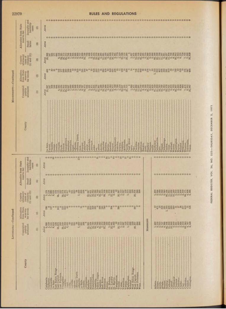
Lo
uis
ian
a—
Con
tinu
ed
Allo
catio
nC
ount
yA
lloca
tion
from
Sta
teC
ompu
ted
from
Sta
teal
lotm
ent
rese
rve
for:
Cou
nty
coun
tyre
serv
es(s
um o
f -
allo
tmen
tfo
r tre
nds
colu
mns
Smal
lIn
equi
ty a
nd-
1(1
) an
d (2
))fa
rms
hard
ship
case
s
\ •
(1)
(2)
(3)
(4)
(5)
Acr
esA
cres
Acr
esA
cres
Acr
esC
atah
oula
......
.....
......
......
......
......
.....
.....
......
......
...
8,88
823
69,
124
00
Cla
ibor
ne__
____
____
____
____
___
_....
......
.....
1,11
80
1,11
80
0C
onco
rdia
......
......
.....
......
......
......
......
...7,
141
197
7,33
80
0D
e So
to__
____
___
—__
____
____
___
......
......
...
3,81
80
. 3,
818
083
East
Bat
on R
ouge
____
___
____
____
......
......
...
125
012
50
0Ea
st C
arro
ll....
......
......
......
.....
......
......
......
......
......
. 24
,574
542
25,1
160
0Ea
st F
elic
iana
____
____
____
____
___.
......
......
.. 18
90
189
00
Evan
gelin
e___
____
____
____
____
__...
......
......
10
,149
122
10,2
730
0ra
nklin
......
......
...i.
......
......
......
......
......
......
......
...
42,3
5284
943
,201
00
rant
......
......
......
......
......
......
......
......
....
......
......
...
3,25
166
3,31
70
0Ib
eria
......
......
......
........
......
......
......
....
......
......
...
490
490
0ib
ervi
lle...
......
......
......
......
......
......
......
.....
......
......
.. 16
10
161
03
Jack
son .
......
......
......
......
......
.....
......
......
.....
......
......
28
90
289
00
Jeffe
rson
Dav
is.. .
......
......
......
......
......
.....
......
......
38
038
09
Laf
ayet
te...
......
......
......
......
......
......
......
..7,
400
a7,
400
0 ,
175
La S
alle
......
......
......
......
......
......
......
......
.35
211
363
00
Linc
oln.
......
......
......
......
......
......
......
......
.....
......
......
16
80
168
00
Livi
ngst
on...
......
>...
......
......
......
......
......
......
......
...
80
80
0M
adis
on...
......
......
......
......
......
......
......
......
......
......
. 16
,355
292
16,6
470
0M
oreh
ouse
......
......
......
......
......
......
......
.....
......
......
.. 27
,108
513
127
,621
00
Nat
chito
ches
......
......
......
......
......
......
.....
......
......
...
15,7
3932
316
,062
0q
Oua
chita
......
......
......
......
......
......
......
......
.....
......
.....
10,7
8620
210
,988
00
Poin
te C
oupe
e....
......
......
......
......
......
....
4,76
30
4,76
30
31R
apid
es...
......
......
......
.....
......
......
......
.....
14,2
8326
814
,551
00
Red
Riv
er...
......
......
......
......
......
......
.....
......
......
...
7,27
224
17,
513
00
Ric
hlan
d....
......
......
......
......
......
......
......
.....
......
......
37
,326
780
38,1
060
0Sa
bine
......
......
......
......
......
......
......
......
......
......
......
...
185
018
50
54St
. Hel
ena.
......
......
......
......
......
......
......
......
......
......
1,
078
01,
078
017
St. L
andr
y....
......
......
......
......
......
......
.....
22,6
4130
422
,945
00
St. M
artin
......
......
......
......
......
......
......
.....
3,66
30
3,66
30
69Ta
ngip
ahoa
......
......
......
......
......
......
......
..93
093
06
Tens
as...
......
......
......
......
.....
......
......
......
..15
,731
356
16,0
870
• 0U
nion
......
.....
......
......
......
......
......
......
......
1,11
90
1,11
90
20V
erm
ilion
......
......
......
......
......
......
......
.....
......
......
...
2,08
70
2,08
70
0V
erno
n....
......
......
......
......
......
......
......
......
115
011
50
27W
ashi
ngto
n ....
......
......
......
......
......
......
....
1,07
90
1,07
90
0W
ebst
er...
......
......
......
......
......
......
......
......
553
055
30
51W
est
Bato
n R
ouge
......
......
......
......
......
.22
30
223
00
Wes
t Car
roll.
......
......
......
......
......
......
......
20,3
0758
720
,894
00
Wes
t Fel
icia
na...
......
......
......
......
......
......
544
054
40
0W
inn.
......
.....
......
......
......
......
......
......
......
.30
00
300
04
Mis
siss
ippi
Ada
ms.
......
......
......
......
......
......
......
......
......
......
......
1,
450
- 10
1,46
00
0A
lcor
n....
......
......
......
......
......
......
......
......
.9,
213
471
9,68
40
0A
mite
....
......
......
......
......
......
......
......
.....
2,01
020
2,03
00
0...
......
......
8,
727
326
9,05
30
0Be
nton
......
......
......
......
......
......
......
......
....
8,38
826
18,
649
00
Boliv
ar...
......
......
......
......
......
......
......
......
.84
,995
1,15
986
,154
00
Cal
houn
......
......
......
......
......
......
.....
......
... *
......
....
11,3
9346
811
,881
00
Car
roll.
......
......
......
......
......
......
......
......
...10
,303
333
10,6
360
0C
hick
asaw
......
......
......
......
......
......
......
......
......
......
9,
890
350
10,2
400
0C
hoct
aw...
.....
......
......
......
......
......
......
.....
......
......
..
2,36
1• J
*
312,
392
00
Cla
ibor
ne...
......
......
......
......
......
......
......
..2,
853
372,
890
00
Cla
rke.
......
......
......
......
......
......
......
......
.....
......
......
2,
558
382,
596
00
Cla
y....
......
......
......
......
......
......
......
......
....
5,01
337
75,
390
00
Coa
hom
a....
........
......
......
......
......
......
....
63,3
4982
264
,171
00
Cop
iah
......
......
......
......
......
......
......
......
.4,
787
214,
808
00
Cov
ingt
on...
......
......
......
......
......
......
......
.......
......
....
5,22
612
85,
354
00
FED
ERAL
REG
ISTE
R, V
OL.
36,
NO
.
Mis
sis
sip
pi—
Con
tinu
ed
Allo
catio
nC
ount
yA
lloca
tion
from
Sta
teC
ompu
ted
from
Sta
teal
lotm
ent
rese
rve
for:
Cou
nty
coun
tyre
serv
es(s
um o
fal
lotm
ent
for
tren
dsco
lum
nsSm
all
Ineq
uity
and
(1)
and
(2))
farm
sha
rdsh
ipca
ses
(1)
(2)
(3)
(4)
(5)
Acr
esD
eSo
to.. .
......
......
......
....1
......
......
.....
....
......
......
. 22
,587
Forr
est.
......
...l.
......
.....i
......
......
......
......
......
.....
24
7Fr
ankl
in...
___i
......
......
....
406
Geo
rge.
..;...
......
......
......
......
......
......
...
'....
___
14
6G
reen
e___
____
____
68
4G
ren
ada.
...—
.. ___
_—...
......
......
......
......
......
......
. 8,
032
Hin
ds__
__..
.....
......
......
......
......
......
..
15,0
54H
olm
es...
......
.....
......
......
......
......
......
......
......
......
....
24,5
92H
umph
reys
...
......
......
......
......
.....
......
....
......
.. 33
,823
Issa
quen
a....
......
.....;
......
......
..1...
......
......
.....
......
....
8,64
7It
awam
ba__
____
____
_
7,00
0Ja
sper
......
......
......
......
......
......
......
......
......
......
3,
886
Jeffe
rson
......
......
......
......
......
......
......
......
..
2,
345
Jeffe
rson
Dav
is...
......
......
......
......
.....
.....
......
......
7,
990
Jone
s....
......
......
......
......
......
......
......
......
......
...;_
___
, 4,
703
Kem
per..
.....
......
......
......
6,76
7La
faye
tte.
......
......
......
......
......
......
......
......
.....
v.__
_ 10
,472
Lam
ar...
......
......
......
......
......
.....
....
......
......
......
.....
64
6La
uder
dale
......
......
......
......
......
......
......
......
......
.....
1,
901
Law
renc
e....
......
......
......
.....
......
......
......
......
.....
......
3,
371
Leak
e....
......
......
......
......
......
......
......
......
......
......
..9,8
01Le
e....
......
......
......
......
......
......
......
.......
......
......
...17
,776
Lef
lore
......
...i.
......
.....
......
......
...
62,5
67Li
ncol
n___
____
____
____
____
____
____
___
__
2,25
5L
own
des
......
......
......
......
......
......
....1
......
......
......
..'__
___
10
,709
Mad
ison
......
......
......
......
......
......
......
.....
......
....
22,8
06M
ario
n....
......
......
...1.
......
......
......
....
......
......
......
..
4,61
9M
arsh
all..
......
......
......
......
......
.
24
,262
Mon
roe_
____
,.1...
......
....
19
,471
Mon
tgom
ery.
......
......
......
.....
I_
__
6,13
3N
esho
ba...
......
......
......
......
.....
......
......
......
......
.....
-
7,76
8N
ewto
n....
......
......
......
......
......
......
......
......
......
......
...
2,21
8N
oxub
ee...
......
......
.
10
,647
Okt
ibbe
ha...
......
.....
2,10
1Pa
nola
......
......
......
.....
27,7
11Pe
arl
Riv
er...
......
......
....
4
Perr
y....
......
......
......
......
......
......
......
..
1,08
3P
ike .
......
......
...1.
......
......
.
1,
471
Pon
toto
c....
......
......
......
_....
......
......
......
......
......
..
13,3
63P
ren
tiss
......
......
......
......
......
......
.....
11
,681
Qu
itm
an.. .
......
......
......
......
......
....
......
......
......
......
41
,799
-R
anki
n___
____
____
____
____
____
____
____
__
5,16
5Sc
ott..
......
.....
......
......
......
......
......
......
......
......
......
....
6,10
0Sh
arke
y....
......
......
......
......
......
..
20,1
13Si
mps
on__
____
____
____
____
_<._
____
..._
___
6,
893
Smit
h ....
......
......
...
5,82
9Su
nflo
wer
......
......
......
......
......
....L
____
____
____
_
87,1
33Ta
llaha
tchi
e....
.....
......
......
.....
41
,603
Tat
e....
......
......
......
......
......
......
......
......
......
......
......
....
16,7
82Ti
ppah
......
....
......
......
......
......
......
......
......
......
......
...
10,7
39Ti
shom
ingo
...__
____
____
____
____
____
____
_
6,28
2Tu
nica
____
____
___
33,9
76U
nion
......
......
...^
......
.....
......
......
......
......
......
......
..
12,0
21W
alth
all..
......
......
......
......
......
......
......
......
......
......
.....
6,67
9W
arre
n___
___
____
4,21
3W
as hi
ngto
n....
......
......
......
......
......
......
......
......
......
58
,807
Way
ne__
____
___
3,68
3W
ebst
er__
____
____
_
5,
894
Wilk
inso
n___
____
____
____
____
___
653
Win
ston
____
____
____
_
7,41
5Y
alob
usha
____
____
_i_
____
____
____
____
__
8,99
2Y
azo
o...
..___
____
____
____
____
____
____
_
30
,067
Acr
esA
cres
Acr
esA
cres
466
23,0
530
00
247
00
3944
50
031
177
00
068
40
019
38,
225
00
177
15,2
310
058
025
,172
00
389
34,2
120
013
88,
785
00
346
7,34
60
010
3,89
60
015
2,36
00
031
38,
303
00
144,
717
00
241
6,00
80
026
410
,736
00
5770
30
02
1,90
30
01
393,
410
00
423
10,2
240
044
218
,218
00
719
53,2
860
014
2,26
90
035
211
,061
00
428
23,2
340
032
4,65
10
054
324
,805
00
631
20,1
020
020
86,
341
00
157,
773
00
112,
229
00
288
10,9
360
018
2,11
90
055
828
,269
0q
04
0q
141,
097
00
41,
475
0 .
072
514
,088
00
514
12,1
960
• 0
603
42,4
020
066
6,23
10
044
6,14
40
027
620
,389
00
276,
920
00
595,
888
00
1,13
388
,266
00
632
42,2
350
040
217
,184
00
558
11,2
970
036
96,
651
00
381
34,3
670
051
312
,534
00
866,
765
00
714,
284
&■■■
00
755
59,5
620
080
3,66
30
033
56,
229
00
7572
80
029
47,
709
00
347
9,33
90
045
830
,625
00
!—TH
URSD
AY,
DEC
EMBE
R 2,
19
71
22970 RULES AND REGULATIONS

Mis
so
ur
iN
or
th
Ca
ro
lin
a—
Con
tinue
d
Cou
nty
Com
pute
dco
unty
allo
tmen
t
Allo
catio
n fr
om S
tate
re
serv
es
for t
rend
s
Cou
nty
allo
tmen
t (s
um o
f co
lum
ns
(1)
and
(2))
Allo
catio
n fr
om S
tate
re
serv
e fo
r:
Smal
lfa
rms
Ineq
uity
and
ha
rdsh
ip
case
s(1
)(2
)#
(3)
(4)
(6)
Bolli
nger
......
......
......
......
......
..B
utl
er...
......
......
......
.....
......
...A
cres
Acr
es0
Acr
es80
12
,977
85
57
,053
118
,901
61
,648
65
,126
1,
540
11,4
45
27,7
08
Acr
es0 0 0 0 0 0 0 0 0 0 0 0
Acr
es0 0 0 0 0 0 0 0 0 0 0 0
Cap
e G
irar
deau
......
......
......
......
.....
Dun
klin
......
......
......
......
;....
......
0H
owel
l___
____
____
____
__M
issi
ssip
pi...
......
......
......
.......
New
Mad
rid.
......
......
......
.....
0 0Pe
mis
cot..
......
......
......
......
......
..R
iple
y....
......
......
......
...Sc
ott..
......
......
......
......
......
......
...0 0 0 0
Stod
dard
......
......
......
......
......
.V
erno
n___
____
____
_\
3
Ne
va
da
Cla
rk...
......
......
......
......
.0 0
0 0N
ye...
......
......
......
......
.....
......
..0
2,51
3
New
Mex
ico
Cha
ves _
_C
urry
___
De
Bac
a...
Don
a A
na.
Eddy
......
..G
ran
t....
Har
ding
..H
idal
go...
.Le
a....
......
...Lu
na...
.....
.O
tero
......
...Q
uay.
......
..fio
ose v
elt.
Sier
ra...
......
Soco
rro _
__
21,8
970
21,8
970
01,
066
01,
066
00
358
035
8 ¡
00
27,4
650
27,4
650
019
,050
019
,050
00
138
013
80
06
06
01
4,44
40
4,44
40
018
,947
018
,947
00
9,70
70
9,70
70
01,
622
01,
622
00
1,98
50
1,98
50
013
,503
013
,503
00
1,81
50
1,81
50
01,
411
01,
411
00
No
rt
h C
ar
ol
ina
Ala
man
ce__
Ale
xand
er...
Ans
on...
......
Beau
fort
___
Bert
ie...
......
...Bl
aden
......
....
Brun
swic
k...
Burk
e....
......
..C
abar
rus_
__C
aldw
ell_
__C
amde
n___
Car
tere
t___
_C
ataw
ba...
....
Cha
tham
___
Cho
wan
......
..C
leve
land
__C
olum
bus.
..C
rave
n....
......
Cum
berl
and.
Cur
ritu
ck__
Dav
idso
n___
Dav
ie__
____
Dup
lin...
......
.
150
150
031
40
314
00
8,47
90
8,47
90
069
90
699
00
5,21
30
5,21
30
02,
326
02,
326
00
163
016
30
040
040
00
2,25
20
2,25
20
010
010
00
194
019
40
026
026
00
792
079
20
022
90
229
00
1,90
90
1,90
90
021
,120
021
,120
00
1,80
70
1,80
70
026
30
263
00
8,67
00
8,67
00
018
80
188
)0
504
050
41
096
50
965
)0
2,20
90
2,20
90
0
Cou
nty
Dut
ham
___
Edge
com
be...
Fors
yth_
____
Fran
klin
____
Gas
ton
......
.G
ates
......
......
...G
ranv
ille.
......
.G
reen
e___
___
Gui
lford
......
....
Hal
ifax.
......
....
Har
nett
......
.....
Her
tford
____
Hok
e....
......
.....
Hyd
e....
.....
Ired
ell..
......
..Jo
hnst
on...
......
Jone
s__
j....
....
Lee.
......
.....
.....
Leno
ir...
......
....
Linc
oln.
......
....
Mar
tin.
......
....
Mec
klen
burg
..M
ontg
omer
y..
Moo
re__
____
_N
ash_
____
__N
orth
ampt
on.
Ons
low
......
......
Ora
nge_
__..
.Pa
mlic
o___
__Pa
squo
tank
...Pe
nder
......
......
Perq
uim
ans.
.Pe
rson
......
....
Pit
t.....
......
...Po
lk...
......
...
Ran
dolp
h___
Ric
hmon
d___
Rob
eson
......
....
Row
an...
......
...R
uthe
rfor
d...
Sam
pson
......
...Sc
otla
nd__
__St
anly
......
......
.T
yrre
ll....
......
..U
nio
n...
____
Van
ce...
.......
Wak
e___
____
War
ren.
......
...W
ashi
ngto
n...
Way
ne...
......
....
Wilk
es.._
____
Wils
on__
____
Yad
kin
......
.
Ad
air.
....
Ato
ka__
_Be
ckha
m.
Blai
ne__
_Br
yan_
__C
addo
___
Can
adia
n.
Car
ter_
__
Allo
catio
nC
ount
yA
lloca
tion
from
Sta
teC
ompu
ted
from
Sta
teal
lotm
ent
rese
rve
fot:
coun
tyre
serv
es(s
um o
fal
lotm
ent
for .
tren
dsco
lum
nsSm
all
Ineq
uity
and
(1)
and
(2))
farm
sha
rdsh
ipca
ses
(1)
(2)
(3)
(4)
(5)
Acr
es'A
cres
Acr
esA
cres
Acr
es78
078
00
9,88
40
9,88
40
048
048
00
6,74
30
6,74
30
01,
723
01,
723
00
1,53
80
1,53
80
027
00
270
00
2,82
30
2,82
30
038
038
00
is; 5
000
18,5
000
09,
626
09,
626
00
3,85
80
3,85
80
010
,912
010
,912
00
124
012
40
04,
850
04,
850
00
14,2
210
14,2
210
017
10
171
00
703
070
30
01,
413
01,
413
00
4,44
40
4,44
40
02,
163
02,
163
00
3,25
00
3,25
00
0.
2,22
70
2,22
70
01,
970
01,
970
00
10,6
900
10,6
900
017
,025
017
,025
00
161
016
10
045
045
00
115
011
50
013
80
138
00
196
019
60
075
80
758
00
20
20
05,
035
05,
035
00
826
082
60
016
016
00
4,29
50
4,29
50
036
,034
036
,034
00
3,37
20
3,37
20
05,
181
05,
181
00
18,2
320
18,2
320
013
,000
013
,000
00
405
040
50
015
60
156
00
9,22
30
9,22
30
02,
820
02,
820
00
3,26
80
3,26
80
05,
653
05,
653
00
384
038
40
07,
565
07,
565
00
400
400
06,
119
06,
119
00
21■
021
00
Ok
lah
om
a
241
250
01,
174
181,
192
00
43,0
4260
743
,649
00
8,47
128
28,
753
00
11,4
2541
311
,838
00
32,8
121,
327
34,1
390
08,
800
179
8,97
90
01,
058
81,
066
00
FEDE
RAL
REGI
STER
, VO
L. 36
, NO
. 23
2—TH
URSD
AY,
DECE
MBE
R 2,
197
1
RULES AND REGULATIONS 22971

Ok
lah
om
a—
Con
tinue
dSo
uth
Ca
roli
na
Allo
catio
nC
ount
yA
lloca
tion
from
Sta
teC
ompu
ted
from
Sta
teal
lotm
ent
rese
rve
for:
Coun
tyco
unty
rese
rves
(sum
of
allo
tmen
tfo
r tre
nds
colu
mns
Smal
lIn
equi
ty a
nd(1
) an
d (2
))fa
rms
hard
ship
case
s
(1)
(2)
(3)
(4)
(5)
Coun
tyC
ompu
ted
coun
tyal
lotm
ent
Allo
catio
n fr
om S
tate
Cou
nty
allo
tmen
tA
lloca
tion
from
Sta
te
rese
rve
for:
for t
rend
sco
lum
ns
(1)
and
(2))
Smal
lfa
rms
Ineq
uity
and
ha
rdsh
ip
case
s
(1)
(2)
(3)
(4)
(5)
Cho
ctaw
__—
Cim
mar
on—
"...
Cle
vela
nd...
..C
oal _
_!„
....
Com
anch
e....
;C
otto
n ___
___
Cra
ig..
....
...
Cre
ek...
.___
Cus
ter_
____
__D
ewey
____
__E
llis.
......
......
....
Gar
field
____
_G
arvi
n___
__’.
Gra
dy
......
..G
rant
......
.....i
tG
reer
......
......
...H
anno
n___
_H
arpe
r___
___
Has
kell_
____
Hug
hes.
......
....
Jack
son—
—
Jefle
rson
—..
.Jo
hnst
on...
.....
Kay
-----
—..
Kin
gfis
her_
__K
iow
a....
—..
Le
Flo
re...
...Li
ncol
n___
__
Lo
gan
.....
...
Lov
e..._
__M
cCla
in..—
—M
cCur
tain
.—.
McI
ntos
h___
_M
ajor
.....
....
Mar
shal
l___
_M
ayes
......
......
..M
urra
y. .1
___
Mus
koge
e....
....
Nob
le...
......
.....
Now
ata.
......
....
• Okf
uske
e__
.1O
klah
oma_
__O
kmul
gee_
__O
sage
....—
—.
Paw
nee.
......
....
Payj
ie__
____
_Pi
ttsb
urg.
......
.P
onto
toc.
.....
Potta
wat
omie
. Pu
shm
atah
a..
Rog
er M
ills-
..R
oger
s....
......
Sem
inol
e__
_Se
quoy
ah__
_;.
Step
hens
......
...Te
xas.
......
....L
.T
illm
an__
___
Tu
lsa
....
....
.W
agon
er__
__
Was
hita
......
.....
Woo
dwar
d___
Acr
esA
cres
Acr
esA
cres
Acr
es94
522
967
00
460
460
01,
037
291,
066
00
2,26
725
2,29
20
08,
135
119
8,25
40
012
,808
318
13,1
260
040
444
00
636
063
60
017
,388
672
17,9
600
06,
504
105
5,60
90
045
826
484
00
50
50
03,
713
124
3,83
70
o'12
,228
530
12,7
580
032
133
00
28,3
7435
528
,729
00
33,0
3143
433
,468
00
lo1
110
01,
216
641,
280
00
2,10
50.
2,10
50
040
,023
545
40,5
680.
011
,814
135
11,9
490
02,
549
572,
606
00
572
590
072
82
730
00
38, b
3977
239
,411
00
1,46
017
1,47
70
053
30
533
00
1,84
986
1,93
50
05,
832
05,
832
00
6,71
016
66,
876
00
4,63
276
.4,
708
00
5,71
210
56,
817
■0
090
60
906
00
3,11
083
3,19
30
020
68
214
00
•213
621
90
011
, 725
247
11,9
720
032
73
330
00
325
132
60
01,
183
01,
183
00
366
537
10
06,
296
224
6,52
00
01,
798,
01,
798
00
2,22
244
2,26
60
01,
483
341,
617
00
1,88
321
1,90
40
070
90
709
00
321
832
90
017
30
173
1 0
014
,727
371
15,0
980
020
69
216
00
724
072
40
070
124
726
00
4,10
886
4,19
40
06
06
00
49,1
0772
049
,827
00
641
064
10
05,
494
05,
494
00
50,9
4294
451
,886
00
469
1848
70
0
Acr
esA
bb
ev
ille
....
....
....
....
....
. .....
.....
....
—
4,21
0A
iken
____
____
____
____
....
____
_,__
___1
3,01
7A
llend
ale_
____
____
____
____
____
___
,___
__—
7,
090
And
erso
n..._
____
____
____
___
____
____
__
15,0
85Ba
mbe
rg__
____
__..
..._
____
____
____
____
_
9,08
3Ba
rnw
ell_
__-_
____
____
____
___
____
____
__
• 9.
697
Beau
fort
......
......
......
......
......
......
......
......
......
......
.....
38
Ber
kel
ey...
____
_!___
____
____
____
____
____
4,
727
Cal
houn
____
____
____
____
____
____
——
....
11
,381
Cha
rles
ton _
____
____
____
____
____
____
28
7C
hero
kee.
......
......
.....
......
......
......
......
..
6,79
2C
hest
er__
____
____
____
____
____
____
____
__
5,97
0C
hest
erfie
ld...
........
......
......
......
......
......
.....
......
...
19,0
61C
lare
ndon
____
____
_..
..__
____
____
____
__
25,0
74C
olle
ton.
......
......
......
......
.....
......
......
......
....
6,06
9D
arlin
gton
___
____
____
____
____
____
____
__
21,9
10D
illo
n...
.___
____
____
____
__\__
____
___
__
16,4
59D
orch
este
r___
____
____
—
5,49
3Ed
gefie
ld...
.....
......
......
....
6,43
2Fa
irfi
eld.
......
......
......
......
.....
......
....
......
.....-
......
...
2,20
4Fl
oren
ce__
___
;.._
___
____
____
____
___
___
22
,599
Geo
rget
own
......
.....
......
......
......
......
....
..__
__
1,44
2G
reen
ville
____
____
____
____
____
____
....
...
6,66
5G
reen
woo
d___
____
____
____
___
____
_-__
__
2,10
2H
amp
ton
......
..___
_
5,
139
Hor
ry__
____
____
____
____
____
___
____
___
\
4,47
8Ja
sper
......
......
......
......
....
1,03
2 -
Ker
shaw
...._
____
____
__—
____
____
____
____
10
,339
Lanc
aste
r___
___
____
-
4,22
2L
aure
ns.
.__
____
9,
776
Lee
......
......
......
......
......
......
......
......
......
......
......
......
.. 26
,683
Lexi
ngto
n___
____
____
____
____
__
..
. 6,
636
McC
orm
ick.
...__
___
____
____
_i_
____
____
1,
805
Mar
ion
....._
____
____
___
___
____
____
____
__
8,11
4M
arlb
oro_
___
____
____
____
____
____
____
___
28,3
49N
ewbe
rry.
......
......
......
......
......
......
......
......
......
......
.. 4,
141
Oco
nee_
____
____
____
3,69
3O
rang
ebur
g___
____
____
_
40
,809
Pick
ens_
____
____
____
____
____
____
____
____
2,
014
Ric
hlan
d___
____
_
...
3.48
2Sa
luda
......
...—
____
____
____
____
____
____
4,
961
Spar
tanb
urg.
..----
-;___
____
____
____
____
___
, H>
323
Su
mte
r....
......
......
. ....
......
....
.___
____
\___
_ 27
,824
Un
ion
....._
____
__..
..__
____
____
____
___
2,
864
W ill
iam
sbur
g___
____
____
____
____
____
____
24
,303
Yor
k....
......
.-...
......
......
......
......
......
......
......
......
......
. 9,
122
Acr
esA
cres
Acr
esA
cres
434
■ 4,
644
00
6013
,077
00
192
7,28
20
060
15,1
450
030
49,
387
00
320
10,0
170
00
380
00
4,72
70
027
311
,654
00
028
70
074
6,86
60
028
5,99
8•
00
632
19,5
830
064
325
,717
00
104
5,17
30
059
822
,508
00
694
17,0
530
013
5,50
60
088
6,62
00
048
2,25
20
00
22,5
990
09
1,45
10
01
6,66
60
033
2,13
50
017
25,
311
00
774,
555
00
211,
053
00
010
,339
00
144,
236
00
399,
815
00
888
27,5
710
017
86,
814
00
691,
874
00
178
8,29
20
072
529
,074
00
294,
170
00
03,
593
00
853
41,6
620
00
2,01
40
028
13,
763
00
104
6,06
50
00
11,3
230
045
728
,281
00
402,
904
00
796
26,0
990
018
9,14
00
0
Ten
nes
see
Bedf
ord .
......
......
......
......
......
......
......
......
......
......
.....
339
039
90
0Be
nton
......
.....
......
......
......
......
.....
......
......
......
......
.. 1,
278
01,
278
00
Brad
ley.
......
......
......
......
......
......
......
......
......
......
.....
711
720
0C
anno
n....
......
......
......
......
......
......
......
......
......
......
.. 6
06
00
Car
roll—
......
......
.....
......
......
......
......
......
......
......
.. 13
,285
241
13,5
260
0C
hest
er...
......
......
......
......
......
......
......
......
......
.....
7,57
5*
162
7,73
70
0C
offe
e....
......
......
......
......
......
......
......
......
......
......
.....
231
023
10
0C
rock
ett—
......
......
......
......
......
—..
......
......
......
......
. 23
,243
755
23,9
980
0D
ecat
ur.
____
____
____
____
_...
......
......
......
.....
1,
993
172,
010
00
Dic
kso
n...
......
.....
......
......
......
60
60
0D
yer_
____
____
____
____
____
22,1
5260
922
,761
00
Faye
tte.
......
......
......
......
......
......
......
......
......
......
.....
29,2
9880
630
,104
00
FED
ERAL
REG
ISTE
R, V
OL.
36
, N
O.
232-
---TH
URSD
AY,
DEC
EMBE
R 2,
19
71
22972 RULES AND REGULATIONS

Te
nn
ess
ee
—Co
ntin
ued
Cou
nty
Com
pute
dA
lloca
tion
from
Sta
teC
ount
yal
lotm
ent
Allo
catio
n fr
om S
tate
re
serv
e fo
r:co
unty
allo
tmen
tre
serv
es
for t
rend
s(s
um o
f co
lum
nsSm
all
Ineq
uity
and
(1)
(2)
(1) a
nd (
2))
(3)
farm
s
(4)
hard
ship
case
s
. (è
)
Fran
klin
...,..
......
......
......
......
......
......
......
......
Gib
son _
____
____
___
____
____
____
____
Gil
es...
____
____
____
____
____
____
____
Gru
ndy.
......
......
......
......
......
......
......
......
......
.H
amilt
on...
......
......
......
.....
......
......
......
......
...H
arde
man
......
......
......
......
......
........
......
......
.H
ardi
n....
......
......
......
......
......
......
......
......
......
.H
ayw
ood.
......
......
......
......
......
......
......
......
......
Hen
ders
on...
......
......
.....
......
.....
......
......
......
Hen
ry...
......
......
......
......
......
......
......
......
......
...H
umph
reys
......
......
......
.......
......
......
......
.....
Lake
......
.....
......
......
......
......
......
......
......
......
..La
uder
dale
......
......
......
......
......
......
......
......
..La
wre
nce.
.___
____
____
____
____
____
__L
ew
is._
____
____
____
____
___
____
_Li
ncol
n....
......
......
......
.....
......
.....
......
......
...Lo
udon
......
.......
......
......
......
......
......
......
......
...M
cMin
n....
......
......
......
......
......
......
......
......
.....
McN
airy
......
......
......
......
......
.....
......
......
.....
Mad
ison
......
......
......
......
......
......
......
......
......
...M
ario
n,...
......
......
......
......
......
......
......
......
......
..M
arsh
all..
......
......
......
........
......
......
......
......
.....
Mau
ry...
......
......
......
......
......
......
......
.....
......
.k,
Mei
gs__
____
____
____
___
____
____
____
_M
oore
......
.....
......
......
......
......
.....
......
......
...O
bion
......
......
......
......
.....
......
......
......
......
......
Perr
y....
......
......
......
......
.....
......
......
......
......
...Po
lk...
......
......
......
......
......
......
......
......
.......
Rhe
a....
.....
......
......
......
......
.....
......
......
......
.....
Rob
erts
on__
____
____
____
____
____
____
Ruth
erfo
rd__
____
____
____
____
____
___
Shel
by__
___
____
____
____
____
____
____
Sum
ner.
......
......
......
......
......
......
......
......
......
.. .Ti
pton
......
......
......
......
......
......
......
......
....._
___
War
ren_
____
____
____
____
____
____
____
Way
ne...
......
......
......
......
......
......
......
......
......
.....
Wea
kley
____
__■._
____
____
___
____
____
_W
ilson
____
____
____
____
____
___
_____
__
.Acr
esA
cres
Acr
esA
cres
Acr
es2,
980
02,
980
00
31,4
2981
932
,248
00
4,81
00
4,81
00
064
3'
570
038
139
00
14,0
8926
914
,358
00
6,41
80
5,41
80
029
,661
787
30,4
480
011
,263
155
11,4
180
02,
969
02,
969
00
10
1.
00
14,8
3542
115
,256
00
24,4
1865
925
,077
00
12,0
510
12,0
510
031
031
00
7,71
20
7,71
20
03
14
00
105
150
012
,540
154
12,6
940
022
,328
554
22,8
820
047
451
00
420
420
016
016
00
106
010
60
01
01
00
6,17
211
46,
286
00
20
20
018
30
183
00
20
20
00
00
00
2,47
90
2,47
90
026
,212
■ 0
26,2
120
02
02
00
32,1
7883
933
,017
00
50
50
01,
401
01,
401
00
6,69
556
6,75
10
034
135
00
Tex
as
And
erso
n ....
.......
And
rew
s___
____
____
___
__
Ang
elin
a___
___
____
____
___
Ara
nsas
......
......
......
.....
......
......
..A
rche
r.....
......
......
.....
......
......
...A
rmst
rong
......
......
......
......
....
Ata
scos
a___
1___
____
___
___
Aus
tin...
......
......
......
......
.....
......
.Ba
iley_
____
____
___
____
___
Bast
rop_
____
____
____
____
_Ba
ylor
......
......
......
......
.....
..__
_Be
e....
......
......
.....
.....
____
....
Bell_
____
____
____
____
____
_Be
xar_
____
____
_
..
....
Blan
co__
____
____
_..
....
....
Bor
den
...__
__..
....
....
....
Bo
squ
e...
....
....
.;__
_..
....
Bow
ie. .
....
..__
Braz
oria
___
....
....
....
.. i.
Braz
os__
....
..i.
..i.
;.i'
.i..
".Br
ewst
er ..
......
......
Bri
scoe
.....
,s;s
isw
sssi
S5Si
£3
Bro
ok
s....
....i
iiii
.i.-
..i.s
r.
1,91
656
1,97
20
05,
224
05,
224
00
948
094
80
091
60
916
00
1,29
00
1,29
00
01,
392
151,
407
00
5,24
10
5,24
10
013
,044
013
,044
00
69,4
3419
, 69
,453
00
, 7,8
340
7,83
40
012
,581
012
,581
00
9,93
20
9,93
20
047
,822
047
,822
00
2,45
00
2,45
00
045
045
00
13,8
680
13,8
580
07,
612
07,
512
00
7,48
680
7,54
80
05,
499
556,
554
00
13,4
230
13,4
230
045
146
00
18,5
300
18,5
300
02,
302
02,
302
00
FEDE
RAL
REGI
STER
, VO
L. 36
, NO
.
Te
xa
s—C
onti
nu
ed
Cou
nty
Brow
n ....
......
...Bu
rles
on...
......
Burn
et...
......
...C
aldw
ell_
___
Cal
houn
.___
_C
alla
han.
......
..C
amer
on__
__C
amp.
......
......
.C
arso
n___
___
Cas
s___
____
'.C
astr
o....
......
...C
hero
kee_
___
Chi
ldre
ss__
__C
lay_
__..
....
Coc
hran
____
_C
oke_
____
___
Col
eman
____
Col
lin
......
......
Col
lings
wor
th.
Col
orad
o....
.....
Com
al._
____
Com
man
che.
.C
onch
o....
......
..C
ooke
____
___
Co
ryel
l....
...C
ottle
......
......
..C
rock
ett..
......
..C
rosb
y___
___
Cul
bers
on__
_D
alla
s___
____
Daw
son_
____
Dea
f Sm
ith
...D
elta
......
......
...D
ento
n....
......
..D
e W
itt...
......
..D
icke
ns__
___
Dim
mit
____
_D
onle
y___
___
Du
val..
......
.....
East
land
......
...E
ctor
......
......
....
Elli
s....
......
......
.E
l Pas
o....
......
.E
tath
......
......
...Fa
lls...
......
......
..Fa
nnin
____
__Fa
yett
e....
......
.Fi
sher
......
......
..Fl
oyd.
......
......
.Fo
ard.
......
......
..Fo
rt B
end_
__Fr
ankl
in__
___
Free
ston
e___
_Fr
io...
......
......
....
Gai
nes_
____
__G
arza
____
___
Gill
espi
e___
__G
lass
cock
......
...G
olia
d....
......
....
Gon
zale
s___
__G
ray_
___
___
Gra
yson
____
_G
regg
......
......
...G
rim
es__
____
Gua
dalu
pe__
_H
ale.
......
......
.....
Com
pute
dco
unty
allo
tmen
t
(1)
Allo
catio
n fr
om S
tate
re
serv
es
for t
rend
s
(2)
Cou
nty
allo
tmen
t (s
um o
f -
colu
mns
(1
) an
d (2
))
(3)
Allo
catio
n fr
om S
tate
re
serv
e fo
r:
Smal
l In
equi
ty a
nd
farm
s ha
rdsh
ip
case
s
(4)
(5)
Acr
esA
cres
Acr
esA
cres
Acr
es3,
349
43,
353
00
19,0
150
19,0
150
01,
933
01,
933
00
13,4
190
13,4
190
012
,108
012
,108
00
5,36
923
5,39
20
011
0,94
01,
485
112,
425
00
6818
860
00
461
461
00
1,80
60
1,80
60
037
,755
037
,755
00
2,16
80
2,15
80
037
,779
137
,780
00
6,84
50
6,84
50
054
,226
6354
,289
00
4,37
50
4,37
50
022
,068
022
,068
00
57,0
300
57,0
300
045
,733
2045
,753
00
6,13
50
6,13
50
012
614
140
00
4,92
30
4,92
30
017
,744
017
,744
00
4,85
10
4,85
10
012
,969
012
,969
00
37,4
010
37,4
010
043
043
00
86,0
250
86,0
250
03,
562
0/
3,56
20
022
,860
022
,860
00
149,
425
014
9,42
50
06,
244
06,
244
00
25,8
840
25,8
840
014
,810
014
,810
00
8,74
60
8,74
60
036
,081
036
,081
00
1,08
36
1,08
90
020
,342
020
,342
00
7,33
33
7,33
60
01,
714
841,
798
00
143
014
30
089
,133
089
,133
00
16,8
3982
16,9
210
04,
081
0i,
081
00
52,7
110
52,7
110
047
,546
047
,546
00
17,9
440
17,9
440
058
,007
158
,008
00
68,6
6120
68,6
810
08,
800
08,
800
00
45,2
5813
45,2
710
099
70
997
00
4,10
217
44,
276
00
3,31
50
3,31
50
088
,196
088
,196
00
27,5
300
27,6
300
075
10
751
00
10,9
750
10,9
750
02,
726
02,
726
00
7,70
90
7,70
90
02,
637
22,
639
00
23,4
680
23,4
680
029
90
299
00
6,09
30
6,09
30
013
,221
013
,221
00
113,
683
011
3,68
30
0
■THU
RSDA
Y, DE
CEM
BER
2, 1
971
RULES AND REGULATIONS 22973

Te
xa
s—
Con
tinu
edT
exa
s—C
onti
nued
Cou
nty
Com
pute
dco
unty
allo
tmen
t
Allo
catio
n fr
om S
tate
re
serv
es
for t
rend
s
Cou
nty
Allo
catio
n fr
om S
tate
al
lotm
ent
rese
rve
for:
(sum
of
------
------
------
-----
------
--—
colu
mns
Sm
all
Ineq
uity
and
(1
) an
d (2
)) fa
rms
hard
ship
ca
ses
Cou
nty
Com
pute
dco
unty
allo
tmen
t
Allo
catio
n C
ount
yfr
om S
tate
al
lotm
ent
rese
rves
(s
um o
ffo
r tre
nds
colu
mns
(1)
and
(2))
Allo
catio
n fr
om S
tate
re
serv
e fo
r:
Smal
l In
equi
ty a
nd
farm
s ha
rdsh
ip
case
s
(1)
(2)
(3)(4
) 00
(1)(2
) (3
) (4
)(5
)
Hal
l.....
......
...H
amilt
on—
H
ansf
ord
...
Har
dem
an..
Har
ris.
......
...H
arris
on__
_H
artl
ey...
..H
aske
ll___
_H
ays.
......
.....
Hem
phill
...H
ende
rson
..H
idal
go__
_H
ill...
......
......
Hoc
kley
___
Hoo
d___
__H
opki
ns__
_H
oust
on. .
..
How
ard
....
Hud
spet
h_H
unt_
____
Hut
chin
son.
Irio
n___
___
Jack
......
....
Jack
son.
......
Jasp
er__
___
Jen
Dav
is..
Jim
Hog
g...
Jim
Wel
ls.-.
John
son_
__Jo
nes
......
...K
arne
s___
_K
aufm
an...
Ken
dall_
__K
ent_
____
_K
imbl
e___
Kin
g....
......
..K
inne
y___
Kle
berg
.....
Kn
ox.__
__La
mar
____
Lam
b....
.....
Lam
pasa
s—La
Sal
le__
_La
vaca
___
Lee.
......
......
.Le
on._
___
Lib
erty
....
Lim
esto
ne.
Live
Oak
..Ll
ano.
......
...Lo
ving
___
Lu
bboc
k...
Lyn
n....
......
McC
ullo
ch.
McL
enna
n.M
cMul
len—
Mad
ison
__M
ario
n....
...M
artin
......
..M
ason
___
:M
atag
orda
.M
aver
ick.
.M
edin
a___
Men
ard_
_M
idla
nd...
Mila
m__
_M
ills..
......
.M
itche
ll..
Mon
tagu
e.
Aer
eaA
cres
Acr
esA
cres
A
cres
66,9
290
65,9
290
7,27
10
7,27
10
312
174
486
022
,946
022
,946
01,
646
01,
646
01,
342
351,
377
010
4969
082
,601
082
,601
04,
894
04,
894
01,
169
01,
159
02,
198
292,
227
013
0,96
90
130,
959
081
,039
081
,039
013
0,27
90
130,
279
01,
867
01,
867
06,
165
486,
213
015
,970
015
,970
051
,341
251
,343
011
,575
011
,575
062
,273
062
,273
026
026
043
34
437
01,
399
71,
406
012
,478
012
,478
073
2194
024
60
246
060
5611
60
15,4
280
15,4
280
24,5
990
24,5
990
74,2
560
74,2
560
19,7
5610
719
,863
037
,584
037
,684
07
07
013
,782
013
,782
027
027
07,
225
07,
225
014
46
150
06,
038
06,
038
040
,257
040
,257
038
,890
038
,890
013
3,99
90
133,
999
088
50
885
01,
387
421,
429
014
,109
014
,109
02,
711
02,
711
07,
141
07,
141
01,
649
01,
549
033
,873
9433
,967
012
,320
012
,320
014
844
192
029
40
294
016
7,10
60
157,
106
013
1,27
40
131,
274
011
,478
711
,485
058
,498
058
,498
086
70
867
01,
330
01,
330
048
838
526
067
,181
067
,181
01,
257
01,
257
012
,332
012
,332
02,
406
02,
405
01,
174
01,
174
048
30
483
019
,266
019
,266
035
,702
036
,702
01,
848
71,
865
048
,463
048
,463
02,
819
02,
819
0
0 M
ontg
omer
y....
......
......
.....
0 M
oore
____
____
___
....
.0
Mor
ris _
____
____
____
__0
Mot
ley_
____
____
____
__0
Nac
ogdo
ches
____
____
__0
Nav
arro
......
......
......
......
..0
New
ton_
____
____
____
_0
Nol
an__
____
____
____
__0
Nu
eces
..___
____
____
_0
Och
iltre
e___
____
____
__0
Old
ham
____
___
____
__0
Palo
Pin
to...
......
......
......
...0
Pano
la__
____
____
____
0 Pa
rker
____
____
____
___
0 Pa
rmer
____
____
____
___
0 Pe
cos.
......
......
......
......
.....
.0
Polk
____
____
____
____
_0
Pott
er...
......
......
......
......
....
0 Pr
esid
io__
____
____
___l
.0
Bai
ns__
____
____
____
0 Ba
ndal
l___
____
____
___
0 Be
agan
____
____
____
__0
Bed
Biv
er...
......
......
......
...0
Beev
es...
......
......
......
..0
Befu
gio_
____
____
____
_0
Bob
erts
......
......
......
.....
....
0 Bo
bert
son_
____
____
___
0 Bo
ckw
all..
.....
......
....
0 B
un
nel
s....
____
____
__0
Bu
sk ..
......
......
......
......
......
0 Sa
bin
e....
......
......
......
......
.0
San
Aug
ustin
e....
......
......
0 Sa
n Ja
cin
to...
____
____
0 Sa
n Pa
tric
io...
......
......
......
.0
San
Saba
......
.....
......
......
...0
Schl
eich
er__
____
____
_0
Scur
ry...
......
......
......
......
..0
Shac
kelf
ord
...._
____
__0
Shel
by...
......
......
......
......
..0
Smit
h....
......
......
......
......
...0
Som
erve
ll....
......
......
......
...0
Star
r.....
......
......
.....
......
.....
0 St
ephe
ns__
____
____
__0
Ster
ling_
____
____
____
_0
Ston
ewal
l.....
......
.....
0 Sw
ishe
r.....
......
......
......
....
0 T
arra
nt...
......
......
......
......
..0
Tay
lor.
......
......
......
.......
0 T
erry
........
......
......
......
....
0 Th
rock
mor
ton-
------
-----
0 T
itu
s....
......
.......
......
......
..0
Tom
Gre
en__
____
....
..0
Tra
vis_
____
___
_..
....
.0
Tri
nity
____
____
___
___
0 T
yler
____
,___
_...
....
..0
Ups
hur_
____
__..
....
...
0 U
pton
........
......
.. ..
..0
Uv
ald
e..
....
....
....
...
0 V
al V
erde
—..
....
....
...
0 V
an Z
andt
.....
......
......
.....
0 V
icto
ria_
____
____
__..
...
0 W
alke
r___
____
___
___
0 W
all
er.
....
....
....
....
.0
W
ard_
____
___.
....
....
..0
Was
hing
ton_
____
—__
_0
Web
b___
___
..._
__..
..0
W
hart
on.._
____
___.
....
0 W
hee
ler.
......
......
....
0 W
ichi
ta—
Acr
esA
cres
Acr
esA
cres
Acr
es12
40
124
00
6689
155
00
100
100
023
,929
623
,935
00
747
177
924
00
74,8
870
74,8
870
013
013
00
30,1
530
80,1
530
068
,719
068
,719
00
264
026
40
033
437
00
2,20
60
2,20
60
01,
192
01,
192
00
1,81
10
1,81
10
031
,924
031
,924
00
16,2
15•0
16,2
150
053
041
571
00
7532
107
00
2,21
00
2,21
00
05,
561
06,
561
00
1,16
872
61,
894
00
2,74
80
2,74
80
018
,732
018
,732
00
38,3
290
38,3
290
09,
012
69,
018
00
120
7619
60
017
,679
017
,679
00
12,4
310
12,4
310
058
,414
068
,414
00
6,41
30
6,41
30
027
339
312
00
1,20
511
1,21
60
039
16
396
00
55,2
230
55,2
230
03,
482
163,
498
00
6,22
50
6,22
50
047
,462
047
,462
00
2,88
50
2,88
50
02,
819
442,
863
00
496
139
635
00
661
123
784
00
15,9
8481
16,0
650
074
10
741
00
271
0.
271
00
18,8
770
18,8
770
037
,196
037
,196
00
6,91
10
6,91
10
023
,880
023
,880
00
103,
071
010
3,07
10
08,
065
08,
065
00
148
2617
40
038
,657
038
,657
00
24,3
870
24,3
870
083
570
905
00
326
380
015
823
181
00
660
166
10
077
60
776
00
921
930
015
,475
015
,475
00
16,9
910
16,9
910
01,
900
271,
927
00
3,35
60
3,35
60
03,
500
03,
500
00
14,9
820
14,9
820
01,
197
71,
204
00
50,5
730
50,5
730
019
,818
019
,318
00
4,30
20
4,30
20
0
FED
ERAL
REG
ISTE
R, V
OL.
36
, N
O.
232—
THUR
SDAY
, D
ECEM
BER
2,
1971
22974 RULES AND REGULATIONS
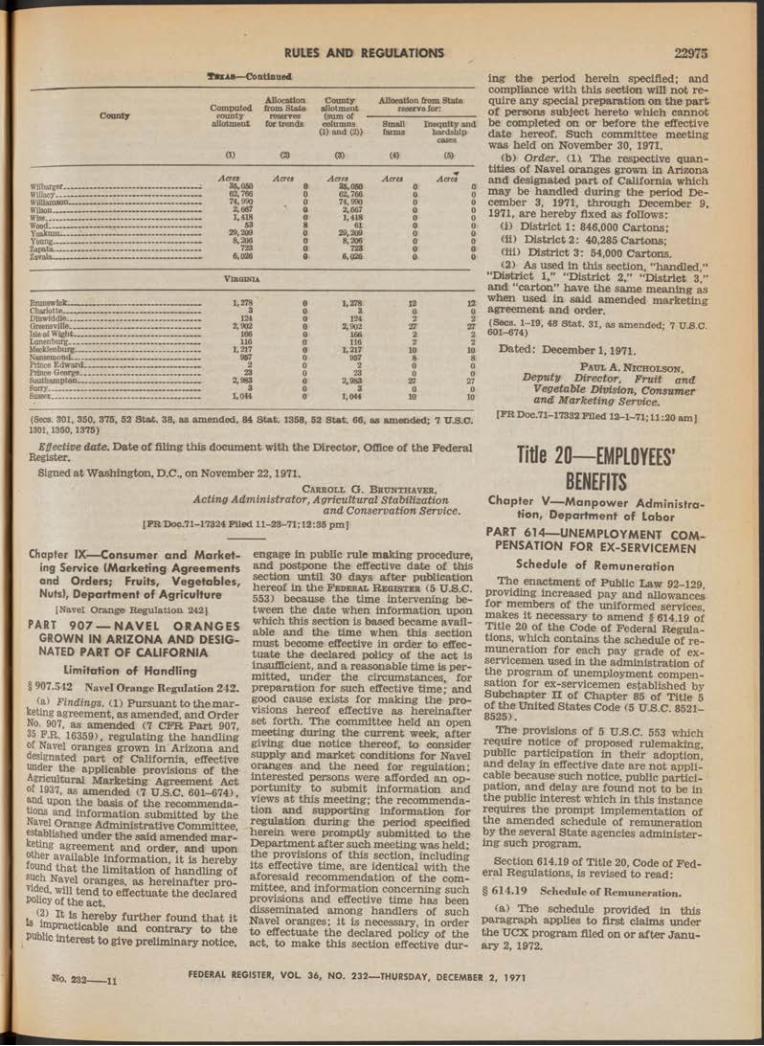
RULES AND REGULATIONS 22975Tu a s — Continued
Allocation County Allocation from StateComputed from State allotment reserve to :
C o u n ty county reserves (sum ofallotment t o trends columns Small Inequity and
(1) and (2)) farms hardshipcases
(1) (2) (3) (4) (5)
AcresWilbarger------- ----- — «a 36,050Willacy___— ----- -— ------ ---------- ------------- 62,766Williamson____________________ . . . ----------- 74,990Wilson__________________________________ 2,667Wise---------------- 1,418Wood---------------------------------------------------- 53Yoakum—___:_________________________ — 29,209Young__________ _____ ________*_________ 8,206Zapata----------------------------------- — 723Zavala.----------- — 6,026
Acres Acres Acres Acres0 35,050 0 00 62,766 0 00 74,990 0 0
> 0 2,667 0 00 1,418 0 08 61 0 00 29,209 0 0© 8,206 0 00 723 0 00 6,026 0 0
Virginia
Brunswick____Charlotte______Dinwiddle...'_Greensville___Isle of Wight__Lunenburg___Mecklenburg__Nansemond____Prince Edward. Prince George.. Southampton—Surry________Sussex_______
1,2783
1242,902
166116
1,217957
223
2,9833
1,044
0 1,278 12 120 3 0 00 124 2 20 2,902 27 270 166 2 20 116 2 20 L217 10 100 957 8 80 2 0 00 23 0 00 2,983 27 270 3 0 00 1,044 10 10
(Secs. 301, 350, 375, 52 Stai. 38, as amended, 84 Stat. 1358, 52 Stat. 66, as amended; 7 U.S.C. 1301,1350,1375)
Effective date. Date of filing this document with the Director, Office of the Federal Register.
Signed at Washington, D.C., on November 22,1971.Carroll G . B runthaver,
Acting Administrator, Agricultural Stabilization and Conservation Service.
[FR Doc.71—17324 Filed. 11-23-71; 12:35 pm]
Chapter IX— Consumer and Marketing Service (Marketing Agreements and Orders; Fruits, Vegetables, Nuts), Department of Agriculture
[Navel Orange Regulation 242]PART 907 — NAVEL ORANGES
GROWN IN ARIZONA AND DESIGNATED PART OF CALIFORNIA
Limitation of Handling § 907.542 Navel Orange Regulation 242.
(a) Findings. (1) Pursuant to the marketing agreement, as amended, and Order No. 907, as amended (7 CFR Part 907, f *®^59), regulating the handling
of Navel oranges grown in Arizona and designated part of California, effective under the applicable provisions of the Agricultural Marketing Agreement Act of 1937, as amended (7 U.S.C. 601-674), and upon the basis of the recommendations and information submitted by the Navel Orange Administrative Committee, established under the said amended mar- eting agreement and order, and upon
owier available information, it is hereby ound that the limitation of handling of
j a el oranges, as hereinafter prodded, will tend to effectuate the declared Policy of the act.
(2) it is hereby further found that it impracticable and contrary to the
I interest to give preliminary notice,
engage in public rule making procedure, and postpone the effective date of this section until 30 days after publication hereof in the F ederal R eg ister (5 U.S.C. 553) because the time intervening between the date when information upon which this section is based became available and the time when this section must become effective in order to effectuate the declared policy of the act is insufficient, and a reasonable time is permitted, under the circumstances, for preparation for such effective time; and good cause exists for making the provisions hereof effective as hereinafter set forth. The committee held an open meeting during the current week, after giving due notice thereof, to consider supply and market conditions for Navel oranges and the need for regulation; interested persons were afforded an opportunity to submit information and views at this meeting; the recommendation and supporting information for regulation during the period specified herein were promptly submitted to the Department after such meeting was held; the provisions of this section, including its effective time, are identical with the aforesaid recommendation of the committee, and information concerning such provisions and effective time has been disseminated among handlers of such Navel oranges; it is necessary, in order to effectuate the declared policy of the act, to make this section effective dur
ing the period herein specified; and compliance with this section will not require any special preparation on the part of persons subject hereto which cannot be completed on or before the effective date hereof. Such committee meeting was held on November 30, 1971.
(b) Order. (IX The respective quantities of Navel oranges grown in Arizona and designated part of California which may be handled during the period December 3, 1971, through December 9, 1971, are hereby fixed as follows:
(1) District 1: 846,000 Cartons;(ii) District 2 : 40,285 Cartons;(iii) District 3; 54,000 Cartons.(2) As used in this section, “handled,”
“District 1,” “District 2,” “District 3,” and “carton” have the same meaning as when used in said amended marketing agreement and order.(Secs. 1-19, 48 Stat. 31, as amended; 7 U.S.C. 601-674)
Dated: December 1,1971.P aul A. Nicholson ,
Deputy Director, Fruit and V egetable Division, Consumer and M arketing Service.
[FR Doc.71-17332 Filed 13-1-71; U :20 am]
Title 20— EMPLOYEES’ BENEFITS
Chapter V— Manpower Administration, Department of Labor
PART 614— UNEMPLOYMENT COMPENSATION FOR EX-SERVICEMEN
Schedule of RemunerationThe enactment of Public Law 92-129,
providing increased pay and allowances for members of the uniformed services, makes it necessary to amend § 614.19 of Title 20 of the Code of Federal Regulations, which contains the schedule of remuneration for each pay grade of ex- servicemen used in the administration of the program of unemployment compensation for ex-servicemen established by Subchapter n of Chapter 85 of Title 5 of the United States Code (5 U.S.C. 8521- 8525).
The provisions of 5 U.S.C. 553 which require notice of proposed rulemaking, public participation in their adoption, and delay in effective date are not applicable because such notice, public participation, and delay are found not to be in the public interest which in this instance requires the prompt implementation of the amended schedule of remuneration by the several State agencies administering such program.
Section 614.19 of Title 20, Code of Federal Regulations, is revised to read;§ 614.19 Schedule of Remuneration.
(a) The schedule provided in this paragraph applies to first claims under the UCX program filed on or after January 2, 1972.
No. 232— —li FEDERAL REGISTER, V O L 36, NO. 232— THURSDAY, DECEMBER 2, 1971

22976 RULES AND REGULATIONSMonthly
Pay grades rate1. Commissioned officer:
0—10 ___________________________ $3,5600-0 ....................................................— 3,1760-8 __________________ _________ 2. 8960_7 ' ____________ __ _ 2, 5570-6 I I I I I I I — ........................... 2,1990 - 5 ______- __________ __________ 1» 7600-4 . . . ______________ _____- ___ 1,4690 - 3 ___________________________ 1» 2080 - 2 ___________________________ 9200 - 1 ................ — 722
2. Warrant officer:W-4 ______________________ - —- 1. 423W -3 _______________________ ! . 10®W - 2 __ - ______ - 988W -l __________________________ 812
8. Enlisted personnel:E - 9 ___________:________________ 1, 206E - 8 ___________________________ 1,035E - 7 _______ 893_____________________________ 770E - 5 ___________ 027ja i __ 523E - 3 --------------------,--------------------- 479E - 2 ____________________ 450E - l _____________ :____________- 413
(b) The deletion from paragraph (a) of this section of schedules of remuneration applicable to periods of time prior to January 2, 1972, and heretofore published in 36 F.R. 3465; 35 F.R. 9000; 34 F.R. 12434; 33 F.R. 10086; 33 F.R. 3635; 32 F.R. 20974; 30 F.R. 13120; 29 F.R. 13102; and 23 F.R. 8699, does not revoke such schedules.(5 TJ.S.C. 8508 and 8521(a) (2))
Signed at Washington, D.C., this 23d day of November 1971.
M alcolm R. L ovell, Jr., Assistant Secretary fo r Manpower.
[FR D o c . 7 1 - 1 7 5 9 5 Piled 12-1-71;8:49 am]
Title 29— LABORChapter V— Wage and Hour Division,
Department of LaborPART 520— EMPLOYMENT OF
STUDENT LEARNERSWork Experience and Career
Exploration ProgramsOn September 23, 1971, a proposal was
published in the F ederal R eg ister at page 18871 to amend Part 520 of Title 29 of the Code of Federal Regulations to provide for the inclusion of temporary certificates for the employment of minors between the ages of 14 to 16 years who are enrolled in and employed pursuant to an experimental school administered work experience and career exploration program within the purview of § 1500.35a of this title.
Interested parties were given 15 days in which to submit written data, views or arguments regarding the proposal. The
time for filing comments has expired, as has the additional time requested by one respondent. After consideration of all relevant matter presented, the proposed amendment is adopted, to become effective upon publication in the F ederal R egist e r (12-2-71).
The new § 520.12, Title 29 of the Code of Federal Regulations, reads as follows:§ 520.12 Work experience and career
exploration programs.(a) Notwithstanding the provisions of
§ 520.2 and paragraphs (a ) , (c ) , (d ), and(e) of I 520.5, applications for student- learner certificates may be made and temporary subminimum wage authority provided and certificates issued pursuant to §§ 520.3 and 520.4 and paragraphs (b) and (f) through (1) of § 520.5, for minors who are 14 or 15 years of age who are enrolled in and employed pursuant to an experimental school supervised and school administered work experience and career exploration program which meets the requirements of § 1500.35a of this title.
(b) This section shall terminate and have no force and effect after August 31, 1972.(Sec. 14, 52 Stat. 1068, as amended; 29 U.S.C. 214)
Signed at Washington, D.C., this 29th day of November 1971.
H orace E. M enasco, Administrator, Wage and Hour
Division, U.S. Departm ent o f Labor.
[FR Doc.71-17608 Filed 12-1-71;8:49 am]
PART 541— DEFINING AND DELIMITING THE TERMS “ANY EMPLOYEE EMPLOYED IN A BONA FIDE EXECUTIVE, ADMINISTRATIVE, OR PROFESSIONAL CAPACITY (INCLUDING ANY EMPLOYEE EMPLOYED IN THE CAPACITY OF ACADEMIC ADMINISTRATIVE PERSONNEL OR TEACHER IN ELEMENTARY OR SECONDARY SCHOOLS), OR IN THE CAPACITY OF OUTSIDE SALESMAN”Classifications and Exemptions
On September 10, 1970, a notice was published in the F ederal R eg ister (35 F.R. 14268) concerning a public hearing to consider amendments to Part 541. On February 2-11, 1971, a public hearing was held to receive oral and written information, views, or arguments from interested persons relative to establishing guidelines for use in determining (1) the status of paramedical and data process-
ing employees under Part 541; (2) whether the term “professional” should be limited to the learned and artistic professions or extended to include certain highly- paid occupations; and (3) whether a minimum weekly earnings test for outside salesmen should be included in the regulations. Interested persons were also given the opportunity to present data, views and arguments in writing.
Part 541 of the Code of Federal Regulations, is published pursuant to the authority granted the Secretary of Labor in section 13(a)(1) of the Fair Labor Standards Act, as amended (29 U.S.C; 201 et seq.) . Section 13(a) (1) of the Act provides a complete exemption from the Act’s monetary requirements for “any employee employed in a bona fide executive, administrative, or professional capacity (including any employee employed in the capacity of academic administrative personnel or teacher in elementary or secondary schools), or in the capacity of outside salesman (as such terms are defined and delimited from time to time by regulations of the Secretary, subject to the provisions of the Administrative Procedure Act, except that an employee of a retail or service establishment shall not be excluded from the definition of employee employed in a bona fide executive or administrative capacity because of the number of hours in his workweek which he devotes to activities not directly or closely related to the performance of executive or administrative activities, if less than 40 per centum of his hours worked in the workweek are devoted to such activities) ; * * * .” Regulations, Part 541, defines these terms in Subpart A and further explains their meaning in Subpart B.
The amendments to Subpart B of Part 541 adopted herein are based upon careful consideration of all information received during these proceedings, both oral and written, the Occupational Outlook Handbook (1970-71 edition) published by the Bureau of Labor Statistics, and the experiences of the Wage and Hour Division’s staff in resolving the problems that have arisen during the course of enforcement and administration of the current regulation.
P aramedical O ccupations
The information presented during the hearing revealed the need for additional guidelines for determining exemption under the regulations. Oral and written testimony was received from hospital representatives and employee groups on medical technologists, therapists, X- ray technologists, medical librarians, and practical nurses.
FEDERAL REGISTER, VOL. 36, NO. 232— THURSDAY, DECEMBER 2, 1971

RULES AND REGULATIONS 22977Whereas physicians, dentists, oculists,
psychiatrists, and others who deal directly with the patient must complete a number of years of preprofessional and professional college and professional graduate education and pass a State licensing examination, others in the field of health service often engage in allied health occupations with little specialized training.
The testimony adduced indicated that many of these paramedical occupations now require a bachelor’s degree, others require 3 years of college with an additional year of training in a specialized school or hospital. In many cases, the employee must then pass an examination given by a recognized board of licensing, certification, or registration.
From an analysis of the data submitted for the record it is clear that the regulations as presently published are still valid in the defining and delimiting of bona fide professional employees. Guidelines to aid in determining exemption of paramedical employees, however, have been added to §§ 541.302(e) and 541.306.
D ata P r o c e s s in g E m p l o y e e s
The employer representatives contended that computer programers and systems analysts should be considered professional employees. Some supporters of this position would include the position of junior programer in this category. The testimony brought out, however, that a college degree is not a requirement for entry into the data processing field, that only a few colleges offer any courses in a field designated as computer science, and that there are presently no licensing, certification, or registration provided as a condition for employment in these occupations.
In order to meet the requirement in the regulations concerning knowledge of an advanced type in a field of science or learning customarily acquired by a prolonged course of specialized intellectual instruction and study, the employer groups recommended that a postsecondary technical course plus on-the-job training and work experience be accepted for the qualification.
On the other hand, employee representatives were opposed to expansion of the regulations to allow the professional exemption for data processing employees. They were in agreement that a prolonged academic background is not essential in this field. They also brought out that this relatively new occupation area is in a state of flux and that job titles and duties are not regularized and overlap and intermix in a confusing manner. They also felt that to expand the exemption was an invitation for employers to work such employees longer hours with no additional compensation.
The review of the record of the hear- htg indicates that at the present time the computer sciences are not generally
recognized by colleges and universities as a bona fide academic discipline with standardized licensing, certification, or registration procedures. There is too much variation in standards and academic achievement to conclude logically that data processing employees are a part of a true profession of the type contemplated by the regulations.
To consider a period of technical training, on-the-job training, or years of experience as an alternative to a prolonged course of intellectual instruction and study would seriously weaken the professional exemption .by allowing employers to claim the exemption for various kinds of paraprofessional and subprofessional groups.
It is in these areas, however, that many systems analysts and high level supervisory programers qualify under the present definitions for exemption as administrative or executive employees. Therefore, certain additions and clarifications of Subpart B in the regulations are proposed in the discussions on executive and administrative employees in §§ 541.103, 541.108, 541.205, 541.207(c) and 541.302.
H i g h l y P a id T e c h n ic ia n s
Testimony and written statements were received from employer and employee groups concerning highly paid technicians in the electronic and aerospace industries; the funeral service industry; the news media; employment placement agencies; and technical artists and writers of the electronics industry. Of the information submitted the greater amount by far was related to technicians in the electronic and aerospace fields.
What salary data was provided indicated that for the most part the technicians for whom consideration as professionals was asked were paid at levels that were not exceptionally high in relation to current salary levels for those occupations which are universally recognized as professional.
For example, data ’ submitted by one group advocating recognition as professionals for the technicians indicated that a technical specialist with a trade school or junior college background and 18 years of experience was paid the same salary as a recently graduated mechanical or electrical engineer.
On the whole, the groups representing employer associations or firms recommended that highly paid technicians (and this would include technicians receiving less than $200 a week) be recognized as professional, and that the regulations be changed so as to qualify them for exemption.
Those groups representing technical employees or professional societies opposed any change in the present regulations. The reasons given included the loss of income that technicians would
suffer from loss of overtime pay; longer working hours and resultant increase in unemployment; and the diluting of the high standards of the true professional who has invested years and money in an education to enter his field. Most highly paid technicians reach that pay level only after years of on-the-job experience and the more valuable move into supervisory or administrative positions where exemption under §§ 541.1 and541.2 is available. Based on the review of the testimony and statements in the record, it is our conclusion that there is no need to change the definition of professional employee as contained in § 541.3.
O u t s id e S a l e s m e n
The hearing did not produce sufficient evidence of a need for an earnings test to warrant a change in the regulations for outside saiesrhen and no action will be taken to amend Part 541 in this regard.
Therefore, pursuant to the Fair Labor Standards Act of 1938 (52 Stat. 1060, as amended, 29 U.S.C. 201 et seq.), Reorganization Plan No. 6 of 1950 (3 CFR 1949-53 Comp., p. 1004) and Secretary’s orders Nos. 13-71 and 15-71 (36 F.R. 8755, 8756), Part 541 of Title 29, Code of Federal Regulations is amended as set forth below.
These changes, which involve interpretative rules, are not subject to the notice, public procedure, and delayed effective date provisions of 5 U.S.C. 553, and accordingly shall be effective immediately upon publication in the F e d e r a l R e g is t e r (12-2-71).
1. Section 541.103 is amended to read as follows:§ 541.103 Primary duty. '
A determination of whether an employee has management as his primary duty must be based on all the facts in a particular case. The amount of tim* spent in the performance of the managerial duties is a useful guide in determining whether management is the primary duty of an employee. In the ordinary case it may be taken as a good rule of thumb that primary duty means the major part, or over 50 percent, of the employee’s time. Thus, an employee who spends over 50 percent of his t.imp in management would have m anagpmpnt-. as his primary duty. Time alone, however, is not the sole test, and in situations where the employee does not spend over 50 percent of his time in managerial duties, he might nevertheless have management as his primary duty if the other pertinent factors support such a conclusion. Some of these pertinent factors are the relative importance of the managerial duties as. compared with other types of duties, the frequency with which the employee exercises discretionary powers, his relative freedom from supervision, and the relationship between his salary and the wages paid
FEDERAL REGISTER, V O L 36, NO. 232— THURSDAY, DECEMBER 2, 1971

22978 RULES AND REGULATIONSother employees for the kind of nonexempt work performed by the supervisor. For example, in some departments, or subdivisions of an establishment, an employee has broad responsibilities similar to those of the owner or manager of the establishment, but generally spends more than 50 percent of his time in production or sales work. While engaged in such work he supervises other employees, directs the work of warehouse and delivery men, approves advertising, orders merchandise, handles customer complaints, authorizes payment of bills, or performs other management duties as the day-to-day operations require. He will be considered to have management as his primary duty. In the data processing field an employee who directs the day-to-day activities of a single group of programers and who performs the more complex or responsible jobs in programing will be considered to have management as his primary duty.
2. Paragraph (d) of § 541.108 is amended to read as follows:§ 541.108 Work directly and closely re
lated.* * * * *
(d) Setup work is another illustration of work which may be exempt under certain circumstances if performed by a supervisor. The nature of setup work differs in various industries and for different operations. Some setup work is typically performed by the same employees who perform the “production” work; that is, the employee who operates the machine also “sets it up” or adjusts it for the particular job at hand. Such setup work is part of the production operation and is not exempt. In other instances the setting up of the work is a highly skilled operation which the ordinary production worker or machine tender typically does not perform. In some plants, particularly large ones, such setup work may be performed by employees whose duties are not supervisory in nature. In other plants, however, particularly small plants, such work is a regular duty of the executive and is directly and closely related to his responsibility for the work performance of his subordinates and for the adequacy of the final product. Under such circumstances it is exempt work. In the data processing field the work of a supervisor when he performs the more complex or more responsible work in a program utilizing several computer programers or computer operators would be exempt activity.
* * * * *
3. A new subparagraph (7) is added to paragraph (c), and paragraph (d) of § 541.205 is amended to read as follows;§ 541.205 Directly related to manage
ment policies or general business operations.* * * * *
(C) * * *(7) In the data processing field some
firms employ persons described as systems analysts and computer programers. If such employees are concerned with the planning, scheduling, and coordination
of activities which are required to develop systems for processing data to obtain solutions to complex business, scientific, or engineering problems of his employer or his employer’s customers, he is clearly doing work directly related to management policies or general business operations.
(d) Under § 541.2 the “management policies or general business operations” may be those of the employer or the employer’s customers. For example, many bona fide administrative employees perform important functions as advisers and consultants but are employed by a concern engaged in furnishing such services for a fee. Typical instances are tax experts, labor relations consultants, financial consultants, systems analysts, or resident buyers. Such employees, if they meet the other requirements of § 541.2, qualify for exemption regardless of whether the management policies or general business operations to which their work is directly related are those of their employer’s clients or customers, or those of their employer.
4. A new subparagraph (7) is added to § 541.207(c) to read as follows:§ 541.207 Discretion and independent
judgment.* * * * *
(C) * * *(7) In the data processing field a sys
tems analyst is exercising discretion and independent judgment when he develops methods to process, for example, accounting, inventory, sales and other business information by using electronic computers. He also exercises discretion and independent judgment when he determines the exact nature of the data processing problem, and analyzes and structures the problem in a logical manner so that a system to solve the problem and obtain the desired results can be developed. Whether a computer pro- gramer is exercising discretion and independent judgment depends on the facts in each particular case. Every problem processed in a computer first must be carefully analyzed so that exact and logical steps for its solution can be worked out. When this preliminary work is done by a computer programer he is exercising discretion and independent judgment. A computer programer would also be using discretion and independent judgment when he determines exactly what information must be used to prepare the necessary documents and by ascertaining the exact form in which the information is to be presented. Examples of work not requiring the level of discretion and judgment contemplated by the regulations are highly technical and mechanical operations such as the preparation of a flow chart or diagram showing the order in which the computer must perform each operation, the preparation of instructions to the console operator who runs the computer or the actual running of the computer by the programer, and the debugging of a program. It is clear that the duties of data processing employees such as tape librarians, key punch operators, computer opera-
tors, junior programers and programer trainees are so closely supervised as to preclude the use of the required discretion and independent judgment.
* * * * *
5. Paragraph (e) is revised and a new paragraph (h) is added to § 541.302 to read as follows:§ 541.302 Learned professions.
* * * * *(e) (1) Generally speaking the pro
fessions which meet the requirement for a prolonged course of specialized intellectual instruction and study include law, medicine, nursing, accountancy, actuarial computation, engineering, architecture, teaching, various types of physical, chemical and biological' sciences, including pharmacy and registered or certified medical technology and so forth. The typical symbol of the professional training and the best prima facie evidence of its possession is, of course, the appropriate academic degree, and in these professions an advanced academic degree is a standard (if not universal) prerequisite. In the case of registered (or certified) medical technologists, successful completion of 3 academic years of preprofessional study in an accredited college or university plus a fourth year of professional course work in a school of medical technology approved by the Council of Medical Education of the American Medical Association will be recognized as a prolonged course of specialized intellectual instruction and study. Registered nurses have traditionally been recognized as professional employees by the Division in its enforcement of the Act. Although, in some cases, the course of study has become shortened (but more concentrated) , nurses who are registered by the appropriate State examining board will continue to be recognized as having met the requirement of § 541.3(a) (1) of the regulations.
(2) The areas in which professional exemptions may be available are expanding. As knowledge is developed, academic training is broadened, degrees are offered in new and diverse fields, specialties are created and the true specialist, so trained, who is given new and greater responsibilities, comes closer to meeting the tests. However, just as an excellent legal stenographer is not a lawyer, these technical specialists must be more than highly skilled technicians. Many employees in industry rise to executive or administrative positions by their natural ability and good common sense, combined with long experience with a company, without the aid of a college education or degree in any area. A college education would perhaps give an executive or administrator a more cultured and polished approach but tne necessary know-how for doing the executive job would depend upon the person own inherent talent. The professional person, on the other hand, attains status after a prolonged course of specialized intellectual instruction a study.
* * * * *
FEDERAL REGISTER, VOL. 36, NO. 232— THURSDAY, DECEMBER 2, 1971

RULES AND REGULATIONS 22979(h) The question arises whether com
puter programers and systems analysts in the data processing field are included, in the learned professions. At the present time there is too great a variation in standards and academic requirements to conclude that employees employed in such occupations are a part of a true profession recognized as such by the academic community with universally accepted standards for employment in the field. Some computer programers and systems analysts may have managerial and administrative duties which may qualify them for exemption under §§541.1 or 541.2 (see §§ 541.205(c) (7) and 541.207(c) (7) of this subpart).
6. Section 541.306 is amended to read as follows :
formed by obviously exempt professional employees.<29 U.S.C. 213(a) (1))
Signed at Washington, D.C., this 29th day of November 1971.
H orace E . M enasco, Administrator, W age and Hour
Division, U.S. D epartm ent o f Labor.
[FR Doc.71-17609 Filed 12-1-71;8:49 am]
Title 12— BANKS AND BANKINGChapter I— Bureau of the Comptroller
of the Currency, Department of the Treasury
§541.306 Predominantly in te l le c tu a l and varied.
(a) Section 541.3 requires that the employee be engaged in work predominantly intellectual and varied in character as opposed to routine mental, manual, mechanical, or physical work. This test applies to the type of thinking which much be performed by the employee in question. While a doctor may make 20 physical examinations in the morning and perform in the course of his examinations essentially similar tests, it requires not only judgment and discretion on his part but a continual variety of interpretation of the tests to perform satisfactory work. Likewise, although a professional chemist may make a series of similar tests, the problems presented will vary as will the deductions to be made therefrom. The work of the true professional is inherently varied even though similar outward actions may be performed.
(b) Another example of this is the professional medical technologist who performs complicated chemical, microscopic, and bacteriological tests and procedures. In a large medical laboratory or clinic, the technologist usually specializes in making several kinds of related tests in areas such as microbiology, parasitology, biochemistry, hematology, histology, cytology, and nuclear medical technology. The technologist also does he Wood banking. He will also conduct tests related to the examination and eatment of patients, or do research on
, Kw drugs, or on the improvement of j oratory techniques, or teach and per- «>rm administrative duties. Thé simple, outine, and preliminary tests are gen- . f ^form ed by laboratory assistants r technicians. However, technologists
° wior in small laboratories may per- ™ that ar© performed by non-
¡ ¡ 5 ? employees in larger establish- 2 ? - T?11*5 type of activity will-not ^noV )7 ^ considered nonexempt (see
niiCQL ° ? the other hand, X-ray tech- ans have only limited opportunity
r the exercise of independent discre- on and judgment, usually performing
L eir duties under the supervision Qf a I °re highly qualified employee. The i re complex duties of interpretation ! judgment in this field are per-
PART 2— NATIONAL BANKS ACTING AS INSURANCE AGENTS AND AS BROKERS OR AGENTS IN MAKING OR PROCURING LOANS OR REAL ESTATE
Rescission of PartThe Comptroller of the Currency has
determined that the regulations contained in this part are obsolete, are not required to implement the powers conferred by statute upon national banks, and should be rescinded. He has also found that notice and public procedure for the rescission of this part are unnecessary and are not in the public interest. The rescission will accordingly become effective upon publication (12-2-71).
Part 2, Chapter I, Title 12 of the Code of Federal Regulations of the United States of America is hereby rescinded.
Dated: November 29, 1971.[ seal] W illia m B . Camp,
Com ptroller o f th e Currency. [FR Doc.71-17630 Filed 12-1-71; 8:51 am]
Chapter V— Federal Home Loan Bank Board
SUBCHAPTER B— FEDERAL HOME LOAN BANK SYSTEM
[No. 71-1224]
PART 524— OPERATIONS OF THE BANK
PART 525— ADVANCESInterest Rates on Time Deposits and
AdvancesNovember 26,1971.
Resolved that the Federal Home Loan Bank Board considers it advisable to amend Parts 524 and 525 of the Regulations for the Federal Home Loan Bank System (12 CFR Parts 524, 525) for the purpose of allowing the board of directors of each Federal Home Loan Bank to name a committee to establish the rates of interest on time deposits and advances between regular meetings of the board of directors. Accordingly, the Federal Home Loan Bank Board, hereby amends said Parts 524 and 525, 4s follows, effective December 2,1971 :
1. By revising paragraph (b) of § 524.4 to read as follows:
§ 524 .4 Deposits from members.* * * * *
(b) Banks may accept time deposits from members but shall reserve the right to require, in writing, at least 30 days’ notice of intention to withdraw such deposits or any part thereof. The rates of interest to be paid on such deposits as remain unwithdrawn for periods of 30 days or more may, within the range established by the Board, be set by the board of directors of a Bank or, between regular meetings of such board, by a committee selected by such board, which shall consist of at least three members, any number of which may be drawn from the members of such board or from the officers'of the Bank.
2. By revising § 525.3 to read as follows:§ 525.3 Interest rates.
The rates of interest on advances to members shall, within the range established by the Board, be set by the board of directors of each Bank or, between regular meetings of such board, by a committee selected by such board, which shall consist of at least three members, any number of which may be drawn from the. members of such board or from the officers of the Bank.(Sec. 17, 47 St&t. 736, as amended; 12 U.S.C. 1437. Reorg. Plan No. 3 of 1947, 12 F.R. 4981,3 CFR, 1943-48 Comp., p. 1071)
Resolved further that, since the above amendment relates to the internal operations of the Federal Home Loan Banks, each of which has received actual notice of such amendment and has had opportunity to comment thereon, the Board ^ hereby finds that notice and public procedure thereon are unnecessary under the provisions of 12 CFR 508.11 and 5 U.S.C. 553(b); and, for the same reason, the Board hereby finds that the requirement regarding publication of art amendment for a minimum 30-day period prior to the effective date thereof, as specified in 12 CFR 508.14 and 5 U.S.C. 553(d), shall not apply to the above amendment; and the Board hereby provides that such amendment shall become effective as hereinbefore set forth.
By the Federal Home Loan Bank Board.
[ seal] E ugene M . Herrin ,Assistant Secretary.
[FR Doc.71-17628 Filed 12-1-71;8:51 am]
Title 41— PUBLIC CONTRACTS AND PROPERTY MANAGEMENT
Chapter 3— Department of Health, Education, and Welfare
PART 3-1— GENERALMiscellaneous Amendments to
ChapterChapter 3, Title 41, Code of Federal
Regulations, is amended as set forth below. The purpose of these amendments is
FEDERAL REGISTER, VOL. 36, NO. 232— THURSDAY, DECEMBER 2, 1971

22980 RULES AND REGULATIONS
to provide current information regarding organizational designations and responsibilities resulting from changes which have occurred since this portion of the chapter was last revised, and to provide clarification in some subject jareas.
It is the general policy of the Department of Health, Education, and Welfare to allow time for interested parties to take part in the rulemaking process. However, the amendments and revisions contained herein are minor and entirely administrative in nature. Therefore, the public rulemaking process is waived in this instance.
1. The table of contents of Part 3-1 is amended to add new sections under Subpart 3-1.3 and to revise Subparts 3-1.1 and 3-1.4 as follows:
Subpart 3-1 .1— Regulation SystemSec.3-1.101 Scope of subpart.3-1.102 Purpose.3-1.103 Authority.3-1.104 Applicability.3-1.105 Exclusions.3-1.106 Issuance.3-1.107 Arrangement.3-1.107-1 General plan.3-1.107-2 Numbering.3-1.107-3 Citation.3-1.108 Implementation.3-1.109 Deviation.3-1.109-1 Description.3-1.109-2 Procedure.3-1.150 Revision.
Subpart 3—1.3— General Policies3-1.302 Procurement sources. ,3r-l .302-1 General.
Subpart 3—1.4— Procurement Responsibility and Authority
3-1.401 Responsibility of the bead of the procuring activity.
3-1.403 Requirements to be met before entering into contracts.
3-1.404 Selection, designation, and termination of designation of contracting officers.
3—1.404—1 Selection.3—1.404r-2 Designation.3-1.404-3 Termination of designation.3-1.405 Ratification of unauthorized
contract awards.3-1.405-50 Ratification procedure.3-1.451 [Reserved].3-1.452 Responsibility of other Gov
ernment personnel.3-1.452-1, General.3-1.452-2 Planning for procurement.3-1.452-3 Precontract support.3-1.452-4 Postaward contract adminis
tration.Au th o r ity : The provisions of this Part
3-1 are issued under 5 U.S.C. 301; 40 U.S.C. 486(c).
2. Section 3-1.000 under Part 3-1 is revised to read as follows:§ 3—1.000 Scope of part.
This part sets forth introductory information concerning the HEW Procurement Regulations, describes the methods by which the Department of Health, Education, and Welfare implements and supplements the Federal Procurement Regulations (FPR ), and contains policies and procedures which implement and supplement Part 1-1 of the FPR.
3. Subpart 3-1.1 is revised to read as follows:Subpart 3—1.1— Regulation System
§ 3—1.101 Scope of subpart.This subpart sets forth introductory
information pertaining to the HEW Procurement Regulations (herein referred to as HEW PR), explains their purpose, authority under which they are issued, their relationship to the FPR System, applicability, method of issuance, exclusions, and arrangement. It also provides procedures for implementing and supplementing the FPR and the HEWPR, and sets forth deviation procedures.§ 3—1.102 Purpose.
The HEWPR are issued to establish uniform policies and procedures which conform with the Federal Procurement Regulations System. The objectives of the Federal Procurement Regulations System are: To provide greater uniformity in Government procurement policies and procedures applicable to the procurement of personal property and nonpersonal services (including construction) ; to provide for codification and publication of policies and procedures; and to make the policies and procedures readily available to procurement officials, and to the public, as applicable.§ 3—1.103 Authority.
The HEWPR are prescribed by the Assistant Secretary for Administration and Management under authority 5 U.S.C. 301 and section 205(c), Federal Property andTAdministrative Services Act of 1949 as amended (40 UJ3.C. 486(c) ) , delegated by the Secretary. All material for issuance at the Department level is the responsibility of, and published by, the Director of Procurement and Materiel Management, OS-OASAM. Original approved and signed manuscripts are retained and filed in the Director’s office.§ 3—1.104 Applicability.
The FPR and HEWPR apply to all HEW procurements of personal property, real property by lease, and nonpersonal services (including construction). Unless specified otherwise, these regulations apply to procurements within and outside the United States. Requests for authority to deviate from the FPR and HEWPR shall comply with procedures set forth in §§ 1-1.009 and 3-1.109.§ 3—1.105 Exclusions.
Certain HEW policies and procedures which come within the scope of this chapter nevertheless may be excluded from HEW Procurement Regulations. The exclusions are categorized as follows :
(a) Policy or procedure which is expected to be effective for a period of less than 6 months which shall be issued in procurement circular format.
(b) When the time will not permit preparation in final codified form, the policy or procedure shall be issued in procurement circular format. Conversion to permanent type HEWPR shall be made
as soon as possible, in most instances, I ] within 180 days. I «
(c) Issuances of a semipermanent na- I I ture which have limited applicability, I 1 such as those pertaining to a specific pro- ■ ] gramj>r geographical area (e.g., metro- I i politan Washington, D.C.), shall be pub- I lished as manual guides. I j§ 3—1.106 Issuance. I ’
(a) HEWPR implement, supplement, I \ and in some instances may deviate from, I the FPR. Implementing material is that I j which expands upon or indicates the I manner of compliance with related FPR I material. Supplementing material is that I for which there is no counterpart in the I N FPR. Deviating material is defined in I l § 1-1.009 of the FPR.
(b) Material published in the FPR I which has Government-wide applicabil- I ity ^becomes effective throughout HEW I , upon the effective date cited in the par- I ticular FPR material. Such material gen- I erally will not be repeated, paraphrased I or otherwise stated in HEWPR except to I the extent necessary to implement or I deviate from the FPR. HEWPR material I will be effective on the date of the trans- I mittal notice by which distributed unless I otherwise indicated in the respective I transmittal notice.
(c) All HEWPR material deemed nec- I essary for the general public to under- I stand basic and significant HEW pro- I curement policies and procedures will be I published in the F e d e r a l R e g ist e r and I codified as Chapter 3 of Title 41, Code ■ of Federal Regulations. The F ederal ■ R e g is t e r and Title 41 of the Code of I Federal Regulations may be purchased ■ from the Superintendent of Documents, ■ Government Printing Office, Washington, ■ D.C. 20402.
(d) HEWPR are issued in looseleaf I form for use by HEW employees. The ■ material published in the F ederal R egis- ■ t e r will be identified by a solid vertical ■ line to the left of the text. The length ■ of the line will coincide with the length ■ of the text to indicate the material ■ published.§ 3—1.107 Arrangement.§ 3—1.107—1 General plan.
(a) The HEWPR conform with the I Federal Procurement Regulations Sys- I tern with respect to divisional arrange- ■ ments into parts, subparts, sections, sub- ■ sections, and further subdivisions as ■ necessary.
(b) As the FPR System pertains to the | Department, it consists of (1) regula- ■ tions published by the Administrator oi ■ General Services in Chapter 1—Federal ■ Procurement Regulations, and (2) com- ■ plementary Departmental regulations ■ published in Chapter 3. In keeping wi I the DHEW Staff Manual System, suen ■ regulations will be published as mtegrs I parts of the HEW Procurement Re&u- I lations.§ 3—1.107—2 Numbering.
(a) The FPR System of numbering I permits the keying of similar sum I matter throughout Chapters 1 an I
FEDERAL REGISTER, VOL. 36, NO. 232— THURSDAY, DECEMBER 2, 1971

Each section number is a combination showing to the left of the decimal point the chapter and part numbers, separated by a dash. To the right of the decimal point the subpart, section, and subsection numbers are indicated in that order. Thus, the Department, to complement the cost-plus-a-fixed-fee contract provisions contained in Chapter 1, Part 1-3, Subpart 1-3.4, Section 04, Subsection 3 of the Federal Procurement Regulations (§ 1—3.404—3), would assign the section number “3-3.404-3” to the complementary provisions.
(b) The first 49 parts of Chapter 3 are reserved for regulations implementing Chapter 1. Part 50 and succeeding parts are reserved for Departmental and agency regulations that are not included in Chapter 1 or elsewhere in Chapter 3.
(c) Where material in the FPR requires no implementation or deviation, there is no corresponding number in the HEWPR. Thus, there are gaps in the HEWPR sequence of numbers where the FPR, as written, are applicable to HEW procurement'.§ 3—1.107—3 Citation.
The HEWPR will be cited in the same manner as the FPR are cited. Thus, this' section, in referring to divisions of the FPR system, should be cited as “§ 3-1.107-3 of Chapter 3.” When the official Code of Federal Regulations citation is used, this section should be cited as “41CFR 3-1.107-3.” Any section of the HEWPR may be identified informally, for purposes of brevity, as “HEWPR” followed by the section number, such as “HEWPR 3-1.107-3.”§ 3—1.108 Implementation.
(a) Procurement policies and procedures which are necessary to implement, supplement, or deviate from the FPR will be issued in the HEWPR by the Director of Procurement and Materiel Management, OS—OASAM, when necessary to accomplish Departmentwide procurement objectives.
(b) Policies and procedures which are necessary to implement and supplement the FPR and the HEWPR at the operating agency level will be issued by the heads of procuring activity (see § 3—75.101) or their designees.§ 3-1.109 Deviation.§ 3—1.109—1 Description.
As used in the HEWPR, the term “deviation” pertains to actions set forth in ,§ 1-1.009-1 of this title.§ 3—1,109—2 Procedure.
the interest of establishing and maintaining uniformity to the greatest extent feasible, deviations from either the Fp r or HEWPR shall be kept to a minimum and controlled as follows:
(a) When a change is considered nec- ssary to a prescribed contract clause,
*or aPPr°val shall be submitted m the manner set forth in § 3-16.5003., TYith the exception of paragraph
. ‘'“is section, the head of each pro-activity or the official he has des-
dpth t- k° ac *or him in authorizing a viation from procurement regulations
RULES AND REGULATIONSshall authorize a deviation from the FPR or HEWPR only after he obtains approval resulting from the submission of a request to the Director of Procurement and Materiel Management, OASAM, prepared in accordance with paragraphs (c) and (d) of this section.
(c) When an agency or staff office determines that a deviation is needed, it shall normally request the deviation in writing as far as possible in advance of need. In an exigency, an agency or staff office may request a deviation verbally, to be confirmed in writing as soon as circumstances permit.
(d) A deviation request shall set forth clearly and precisely:
(1) Nature of the needed deviation;(2) Identification of the FPR or
HEWPR from which the deviation is needed;
(3) Circumstances under which the deviation would be used;
(4) Intended effect of the deviation;(5) Time frame; and(6) Reasons which will contribute to
complete understanding and support of the requested deviation. Copies of pertinent background papers such as forms, or contractor’s request, should accompany the deviation request.
(e) Where deviations from the FPR in classes of cases are considered necessary, requests for authority to deviate shall be submitted through administrative channels to the Director of Procurement and Materiel Management, OASAM, who will consider the submission jointly with the General Services Administration (GSA). Where compelling circumstances preclude the obtaining of prior concurrence of GSA, the Director of Procurement and Materiel Management, OASAM, may authorize a deviation and shall inform GSA of the deviation including the circumstances under which it was required.§ 3—1.150 Revision.
When an operating agency deems it essential that a regulation set forth in HEWPR be changed in the interest of program effectiveness, a proposed revision of the regulation may be submitted to the Director of Procurement and Materiel Management, OASAM, for review and consideration, A detailed statement of justification shall be attached to each proposed revision submitted for review.
4. Sections 3-1.302 and 3-1.302-1 are added to read as follows:§ 3—1.302 Procurement sources.§ 3—1.302—1 General.
(a) Section 103—25.160 of the Materiel Management Manual sets forth the priority by which Department procurement activities shall utilize the various sources of supply, and procedures for requesting waivers to deviate from mandatory sources.
5. Section 3-1.313-1 is amended to change the heading to read as follows:§ 3—1.313—50 General.
* * * * *
6. Subpart 3-1.4 is revised to read as follows:
22981Subpart 3—1.4— Procurement Respon
sibility and Authority§ 3—1.401 Responsibility of the head of
the procuring activity.'The head of the procuring activity (see
§ 3-75.101) is responsible for the conduct of an effective and efficient procurement program. Adequate controls shall be established to assure compliance with applicable laws, regulations, procedures, and the dictates of good management practices. Periodic reviews shall be conducted and evaluated by qualified personnel, preferably assigned to positions other than in the procurement activity being reviewed, to determine the extent of adherence to prescribed policies and regulations, and to detect a need for guidance and/or training. The Procurement and Materiel Checklist, Form HEW 552, available through normal distribution channels, shall be used to assist in conducting such reviews.§ 3—1.403 Requirements to be met be
fore entering into contracts.(a) No contract shall be entered into,
modified, or terminated unless all required reviews, clearances, or approvals have been obtained and all applicable requirements of law, the FPR, the HEWPR, and other applicable regulations have been met.
(b) In addition to the requirements specified in paragraph (a) of this section, no negotiated contract shall be entered into until the determinations and findings required by Parts 1-3 and 3-3 of this title with respect to the circumstances justifying negotiation and use of any special method of contracting have been made. Negotiations, in any form, will not begin with prospective contractors until all required determinations and findings authorizing such negotiations have been, made.§ S'—1.404 Selection, designation, and
terminations of designation of contracting officers.
The selection, designation, and termination of designation of contracting officers shall be made in accordance with
-operating agency procedures. Such agency procedures shall conform to the provisions of § 1-1.404 and this § 3-1.404. § 3—1.404—1 Selection.
Selection of candidates for contracting officer positions shall be based on the following qualifications:
(a) Practical experience in Government or commercial procurement organizations;
(b) Knowledge of procurement law, FPR, HEWPR, other regulations affecting procurement, and procurement practices;
(c) Training in Government or other procurement schools and courses; and
(d) U.S. Civil Service-Standards, Contract and Procurement Series, GS-1102, and Purchasing Series, GS-1105.§ 3—1.404—2 Designation.
(a) Except for those individuals delegated procurement authority by § 3-75.- 101, designation of contracting officers shall be made in writing by the appointing official in accordance with HEW General Administration Manual Chapter
FEDERAL REGISTER, VOL. 36, NO. 232— THURSDAY, DECEMBER 2, 1971

22982 RULES AND REGULATIONS8-75. Designation of an individual by name is the preferred method of appointing contracting officers. Appointments, either by individual or position, shall include, or make specific reference to, any limitations on the scope of authority to be exercised by the contracting officer other than those contained in the FPR and the HEWPR. A file shall be maintained containing all documents necessary to support the appointment of each contracting officer.
(b) A DHEW Certificate of Appointment suitable Jor use in the appointment of Department contracting officers is available on an optional basis on the part of each agency. When utilized, this certificate is to be restricted to individuals of the Department who have been delegated the authority to commit the Government by execution of formal two signature contracting documents. The certificate is not to be issued to employees whose delegation of authority is restricted to open market procurements under $2,500 and procurement from mandatory sources of supply (PSS, GSA, Perry Point, VA, DOD, etc.).
(c) Requests for certificates are to be made to the Director, Procurement and Material Management, OASAM. Requests shall contain the name, current grade, location and extent of authority to be delegated.§ 3—1.404—3 Termination of designa
tion.(a) Automatic term ination. Unless the
appointment of a contracting officer contains provision for automatic termination, the appointment shall remain effective, unless sooner revoked, until the contracting officer is reassigned or his employment is terminated.
(b) Revocation. The appointment of a contracting officer may be revoked at any time by the appointing authority but no such revocation shall operate retroactively. Revocation of the appointment shall be made by letter, reading substantially as follows:
D ate____________Subject: Termination of Appointment as
Contracting Officer.To: Name________________ ________
Your appointment as Contracting Officeris hereby terminated effective--------------- -—,19__
S ig n a t u r e a n d T it le o f A p p o in t in g A u th o r ity .
§ 3—1.405 Ratification of unauthorized contract awards.
(a) The Government is not bound by agreements or contractual commitments made to prospective contractors by persons to whom procurement authority has not been delegated. Such unauthorized acts may be in violation of the Federal Property and Administrative Services Act, other Federal laws, the FPR, the HEWPR, and good procurement practice: e.g., certain requirements of law and regulation necessary for the proper establishment of a contractual obligation may not be met; i.e., certification of the availability of funds, determinations and findings, competition of sources, determination of contractor re
sponsibility, certification of current pricing data, price/cost analysis, administrative approvals, negotiation of appropriate contract clauses, etc.
(b) Contracting officers shall not ratify contractual commitments made by other personnel of HEW without the prior approval of the head of the procuring activity or the Assistant Secretary for Administration and Management in cases involving the Office of the Secretary. This approval authority shall not be redelegated.§ 3 -1 .4 0 5 -5 0 Ratification procedure.
Requests received by contracting officers for ratification of commitments made by personnel lacking contracting authority shall be processed as follows:
(a) The individual who made the unauthorized contractual commitment shall furnish the contracting officer all records and documents concerning the commitment and a complete, written statement of facts, including, but not limited to, a statement as to why the procurement office was not utilized, why the proposed contractor was selected and a list of other sources considered, description of work to be performed or products to be furnished, estimated or agreed contract price, citation of appropriation available, and a statement of whether the contractor has commenced performance.
(b) The contracting officer will review the file and forward it to the head of the procuring activity or the Assistant Secretary for Administration and Management (see § 3—1.405(b)) with any comments or information which should be considered in evaluation of the request for ratification. If legal review is desirable, the head of the procuring activity or the Assistant Secretory for Administration and Management will coordinate the request for ratification with the Office of General Counsel, OS (BAL).
(c) If ratification is authorized by the head of the procuring activity or Assistant Secretary for Administration and Management, the file will be returned to the contracting officer for issuance of a purchase order or contract as appropriate.
(d) Heads of the procuring activities or their designees, the Executive Officer, OS-OASAM, and Director, Office of Regional and Community Development, or their designees, will report quarterly to the Director of Procurement and Materiel Management, OASAM, the number and dollar value of (1) requests for ratification received and (2) ratifications authorized during each calendar quarter. Reports shall be submitted in an original and one copy to the Director of Procurement and Materiel Management, OASAM, to arrive no later than 30 calendar days after the close of each reporting period. Negative reports, where applicable, are required.§ 3—1.451 ' [Reserved]§ 3—1.452 Responsibility of other Gov
ernment personnel.§ 3—1.452—1 General.
(a) Responsibility for the decision of what to buy and when to buy rests with
program and certain staff offices in the operating agencies and the Office of the Secretary. Responsibility for determining how to buy, the conduct of the buying process, and execution of the contract rests with the procurement activity, the contracting officer in particular.
(b) Personnel responsible for making decisions to buy should maintain a close and continuous relationship with their procurement activity to ensure that personnel are made aware of contemplated procurement actions. This will be mutually beneficial in terms of better planning for procurement action and more timely, efficient, and economical procurement.
(c) Personnel not delegated contracting authority may not commit the Government, formally or informally to any type of contractual obligation (see § 3-1.405), However, program personnel who must use the contracting process to accomplish their programs, must support the contracting officer in ensuring that: (1) Requirements are clearly defined and specified; (2) competitive sources are solicited, evaluated, and selected; (3) quality standards are prescribed and met; (4) performance or delivery is timely; (5) prices, estimated costs, and fees are reasonable; (6) contract provisions, procurement régula- I tions, and applicable laws are complied j with; and (7) files are documented to substantiate the judgements, decisions, and actions taken. (See § 1-3.801-3.)
(d) A pamphlet entitled “The Negotiated Contracting Process—A Guide for Project Officers” prepared by the Office of the Secretary, is available for use by all DHEW project officers. The purpose of this pamphlet is to describe the role of the project officer in procurement planning, solicitation and evaluation of proposals, award and administration of contracts. Requests for copies of the pamphlet should be directed to the headquarters office responsible for Administration in the operating agency.; 3 -1 .4 5 2 -2 Planning for procurement.
(a) Program and project plans should nclude a plan for procurement as an
development.(b) Program and project managers
should solicit the advice and assistance of procurement personnel in developing the procurement element of program and project plans so that the following fac- tors can be considered early in the planning process:
(1) Definition of requirements m terms of specifications or work statement for use in invitations for bids, re quests for proposals, and contrae» provisions.
(2) Development of “in-house’ estimates for the cost of property <»• services to be procured, and identification appropriated funds available foriOtttrsLcti
(3) Identifications of factors which ■equire special consideration, i.e.,:ontr acting; contractor fal¡ource evaluation criteria; providing . alities and equipment; quality cont >
FEDERAL REGISTER, VOL. 36, NO. 232— THURSDAY, DECEMBER 2, 1971

RULES AND REGULATIONS 22983product qualification testing and acceptance; patents and copyright reporting requirements; and other approvals or clearances, etc.
(4) Development of lead-time necessary to complete the procurement process, i.e., prepare and process the purchase request, prepare and process the determination and findings, locate and evaluate sources, receive and evaluate bids or proposals, conduct preaward surveys or conferences, and negotiate and/or award the contract or contracts.
(c) It is incumbent upon initiators of procurement requirements to obtain timely approvals from higher authority whenever such approvals are required by regulations of this Department or other Government agencies; e.g., procurement of data processing resources; procurement of management consultant services; clearances by Office of Management and Budget; Government Printing Office, Treasury Department, General Services Administration, etc.§ 3—1.452—3 Precontract support.
(а) After submission of the requirement to the procurement activity, program personnel must continue to support the procurement process by providing advice and assistance to the contracting officer in activities such as:
(1) Formulation of procurement plans.
(2) Conduct preaward or preproposal briefing of prospective contractors.
(3) Conduct of preaward surveys to determine contractor responsibility in accordance with § 1-1.310 of this title.
(4) Evaluation of technical and business proposals submitted by contractors, including requests for Government- furnished facilities and equipment.
(5) Development or evaluation of plans, procedures, and contract provisions relating to quality control, inspection, test and acceptance of products or services.
(б) Establishment of contract requirements concerning packing, packaging, marking, and shipment of products.§ 3—1.452—4 Postaward contract admin-
istradon.,, a-) Upon execution of the contract by the contracting officer and the contractor, the mutual obligations of the Government and the contractor are established by and limited to the written stipulations in the contract instrument, unless authorized by the contracting of- ncer, HEW personnel shall not direct or request the contractor to assume any omigation or take any action not spe- cmcaiiy stated in the contract. Only the contracting officer may impose on the wmtractor any requirement which will
m a chan#e to the contract. All contract changes must be directed in wmmg or confirmed in writing by the contracting officer.atAb) .P 16 role of program, technical,
personnel in postaward administration of the contract is to assist
avise the contracting officer (or act
as his representative when so designated by the contracting officer) in activities such as:
(1) Conduct of conferences to ensure mutual understanding between the Government and the contractor as to scope of the contract, technical and business requirements, and the rights and obligations of the parties.
(2) Technical direction during contract performance and matters relating to product delivery, acceptance, or rejection.
(3) Evaluation of contractor performance, including inspection and testing of products, evaluation of reports and data, subcontract management, utilization of facilities and equipment, cost control, etc.
(4) Contractor systems and procedures evaluation; including accounting policies and procedures, purchasing policy and practices, property accounting and control, wage and salary plans and rate structures, personnel policies and practices, etc.
(5) Modification, renewal, or termination of the contract.
(6) Processing of disputes under the disputes clause and appeals therefrom.
Effective date . These amendments shall be effective upon publication in the F ederal R eg ister (12-2-71).
Dated: November 24, 1971.R obert C. Coulter ,
Acting Deputy Assistant Secretary fo r Administration.
[FR Doc.71-17611 Filed 12-1-71;8:49 am]
Title 50— WILDLIFE AND FISHERIES
Chapter I— Bureau of Sport Fisheriesand Wildlife, Fish and WildlifeService, Department of the Interior
PART 33— SPORT FISHINGKirwin National Wildlife Refuge,
Kans.The following special regulation is is
sued and is effective on date of publication in the F ederal R eg ister (12-2-71).§ 3 3 .5 Special regulations; sport fish
ing; for individual wildlife refuge areas.
K ansas
K IR W IN NATIONAL W IL D L IF E REFUGE
Sport fishing on the Kirwin National Wildlife Refuge, Kans., is permitted from January 1 through December 31, 1972, inclusive, on all areas not designated by signs as closed to fishing. These open areas, comprising 5,000 acres, are delineated on maps'available at refuge headquarters, 5 miles west of Kirwin, Kans., and from the Regional Director, Bureau of Sport Fisheries and Wildlife, Post Office Box 1306, Albuquerque, NM
87103. Sport fishing shall be in accordance with all applicable State regulations. The provisions of this special regulation supplement the regulations which govern fishing on wildlife refuge areas generally which are set forth in Title 50, Code of Federal Regulations, Part 33, and are effective through December 31, 1972.
K e it h S . H ansen, R efuge M anager, Kirwin Na
tional W ildlife R efuge, Kirwin, Kans.
November 17, 1971.[FR Doc.71-17591 Filed 12-1-71;8:48 am]
PART 33— SPORT FISHINGBitter Lake National Wildlife Refuge,
N. Mex.The following special regulation is
issued and is effective on date- of publication in the F ederal R eg ister (12-2- 71).§ 33 .5 Special regulations; sport fish
ing; for individual wildlife refuge areas.
Ne w M exico
B IT T E R LAKE NATIONAL W IL D L IF E REFUGE
Sport fishing on the Bitter Lake National Wildlife Refuge, N. Mex., is permitted from April 1 through October 15, 1972, inclusive, only on the areas designated by signs as open to fishing. These open areas, comprising approximately 600 acres, are delineated on maps available at refuge headquarters, 13 miles northeast of Roswell, N. Mex., and from the Regional Director, Bureau of Sport Fisheries and Wildlife, Post Office Box 1306, Albuquerque NM 87103. Sport fishing shall be in accordance with all applicable State regulations subject to the following special condition:
(1) The use of boats or floating devices is prohibited.
The provisions of this special regulation supplement the regulations which govern fishing on wildlife refuge areas generally which are set forth in Title 50, Code of Federal Regulations, Part 33, and are effective through October 15, 1972.
L awrence G . K l in e , R efuge M anager, B itter L ake
N ational W ildlife Refuge, Roswell, N. Mex.
November 8, 1971.[FR Doc.71-17596 Filed 12-1-71;8:48 am]
PART 33— SPORT FISHINGAudubon National Wildlife Refuge,
N. Dak.The following special regulation Is
issued and is effective on date of publication in the F ederal R eg ister ( 12- 2- 71).
No. 232------12 FEDERAL REGISTER, VOL. 36, NO. 232— THURSDAY, DECEMBER 2, 1971

22984 RULES AND REGULATIONS
§ 33.5 Special regulations; sport fishing; for individual wildlife refuge areas.
North D akota
AUDUBON NATIONAL W IL D L IF E REFUGE
Lake Audubon, within Audubon National Wildlife Refuge, is open to all fishing December 15, 1971, through March 26, 1972, and is closed from March 27 through December 15, 1972.
Sport fishing on the Audubon National Wildlife Refuge, Coleharbor, N. Dak., is permitted on all water areas throughout the refuge. The water area, comprising 5,900 acres is delineated on maps available at refuge headquarters or at the office of the Regional Director, Bureau of Sport Fisheries and Wildlife, Federal Building, Fort Snelling, Twin Cities, Minn. 55111.
Sport fishing shall be in accordance with all applicable State regulations subject to the following conditions:
(1) The open season for sport fishing on the refuge extends from December 15, 1971, through March 26, 1972,inclusive.
The provision of this special regulation supplement the regulations which
govern fishing on wildlife refuge areas generally which are set forth in Title 50, Code of Federal Regulations, Part 33, and are effective through March 26, 1972.
D avid C. M cG lauchlin , R efuge M anager, Audubon Na
tional W ildlife Refuge, Cole- harbor, N. Dak.
Novem ber 23, 1971.[PRDoc.71-17597 Filed 12-1-71:8:48 am]
PART 33— SPORT FISHINGBear River Migratory Bird Refuge,
UtahThe following special regulation is is
sued and is effective on date of publication in the F ederal R eg ister (12-2-71).§ 33.5 Special regulations; sport fish
ing; for individual wildlife refuge areas.
Utah
BEAR RIVER MIGRATORY BIRD REFUGE
Sport fishing on the Bear River Migratory Bird Refuge, Utah, is permitted only on the areas designated by signs as open
to fishing. These open areas, comprising 10 acres, are delineated on maps available at refuge headquarters, Brigham City, Utah, and from the Regional Director, Post Office Box 1306, Albuquerque, NM 87103. Sport fishing extends from January 1 through December 31, 1972, inclusive, in accordance with all applicable State regulations subject to the following special conditions:
(1) The use of, boats is prohibited below the river control gates at refuge headquarters.
(2) Fishermen are required to register at the refuge office upon entering the refuge.
The provisions of this special regulation supplement the regulations which govern fishing on wildlife refuge areas generally which are set forth in Title 50, Code of Federal Regulations, Part 33, and are effective through December 31, 1972.
L loyd F. G unther, R efuge M anager, B ear River
M igratory Bird Refuge, Brigham City, Utah.
November 8, 1971.[FR Doc.71-17598 Filed 12-1-71;8:48 am]
FEDERAL REGISTER, VOL. 36, NO. 232— THURSDAY, DECEMBER 2, 1971

22985
Proposed Rule MakingDEPARTMENT OF THE TREASURY
Fiscal Service [ 31 CFR Part 223 1
SURETY COMPANIES DOING BUSINESS WITH THE UNITED STATES
Schedule of User Fees for Treasury Services
The Department of the Treasury finds that it is necessary to amend its existing regulations at 31 CFR Part 223 (Treasury Department Circular No. 297 Revised) governing surety companies doing business with the United States to establish a schedule of fees to recover costs related to services performed for, and special benefits conferred upon, such companies by the Department’s Fiscal Service. The services are performed and the benefits conferred in connection with the Fiscal Service’s maintenance and publication of the annual listing of surety companies holding certificates of authority from the Secretary of the Treasury as acceptable sureties or reinsurers only on Federal bonds (Treasury Department Circular No. 570), and in connection with the Service’s maintenance and circulation of the annual listing of admitted reinsurers (except on excess risks running to the United States) of certificated companies. The Services performed by the Treasury Fiscal Service include the financial and legal review of applications from surety companies for such certificates or for recognition as admitted reinsurers, and the regular annual or specifically required review of the qualifications of such companies to determine their continuing eligibility for renewals of their authority. Inclusion of a surety company’s name in Circular 570 confers a. special benefit since the Circular constitutes a reliable determination that each such company named is approved by the Secretary, in accord with 6 U.S.C. 6-13, for the securing of bonds required by Federal law. Similarly, inclusion of a company’s name on the annual list of admitted reinsurers confers a special benefit since the list constitutes recognition by the Treasury that each company named is acceptable as a reinsurer of certificated companies (except on ex- cess risks running to the United States).
« scketTule of fees is proposed for adoption to implement 31 U.S.C. 483a, we user charge statute, and the Office of Management and Budget Circular No. A- ¿o, as amended, entitled User Charges.
Accordingly, notice is hereby given Pursuant to 5 U.S.C. 553 that the Secre- - P .. Treasury is considering the ■«option, effective January 1,1972, under authority of 5 UJS.C. 3Ö1 and 31 UJS.C. Patt’ o°of following amendments to
223 of Subchapter A, Chapter H
of Title 31 of the Code of Federal Regulations:
1. A new section heading is added to the table of sections to read:§ 223.19 Schedule of fees.
2. Section 223.2 is amended by adding a new final sentence to read:§ 223 .2 Application for certificate of
authority.* * * A fee of $550 shall be transmit
ted with the application as prescribed in § 223.19(a).
3. Section 223.3 is amended by revising the final sentence to read:§ 2 2 3 .3 Issuance of c e r t i f ic a te s of
authority.* * * A new certificate of authority
shall be issued annually on the first day of July, so long as the company remains qualified under the law and the regulations in this part, and transmits to the Assistant Comptroller (Chief Auditor) by March 1 each year the fee of $365 as prescribed in § 223.19(c).
4. Section 223.12 is amended by revising the introductory text of paragraphs (a) and (b), and by adding a new final sentence to paragraph (c ) . As amended,§ 223.12 reads in pertinent part:§ 223.12 Recognition as reinsurer.
(a) Application by U.S. company. Any company organized under the laws of the United States or of any State thereof, wishing to apply for recognition as an admitted reinsurer (except on excess risks running to the United States) of surety companies doing business with the United States, shall file the following data with the Assistant Comptroller (Chief Auditor) and shall transmit therewith the fee of $50 prescribed by § 223.19(b):
(1) A certified copy of its charter or articles of incorporation, and
* * * * *(b) Application by a U.S. branch. A
U.S. branch of an alien company applying for such recognition shall file the following data with the Assistant Comptroller (Chief Auditor) and shall transmit therewith the fee of $50 prescribed by § 223.19(b):
(1) The submissions listed in sub- paragraphs (1) through (5) of paragraph (a) of this section, except that the financial statement of such branch shall show that it has net assets of not less than $250,000 over and above all liabilities, and
* * * * *(c) Financial reports. * * * A fee of
$25 shall be transmitted with the foregoing data, as prescribed in § 223.19(d).
5. A new section 223.19 is added to read:
§ 223.19 Schedule of fees.Fees shall be imposed and collected for
the following services performed by the Treasury Department, whether the action requested is granted or denied, effective with requests submitted as of January 1, 1972. The payee of the check or other instrument shall be the Treasurer of the United States.
(a) For examining a company’s application for a certificate of authority as an acceptable surety on Federal bonds or as an acceptable reinsuring company on such bonds: $550 (see § 223.2).
(b) For examining a company’s application for recognition as an admitted reinsurer (except on excess risks r unning to the United States) of surety companies doing business with the United States: $50 (see § 223.12 (a) and (b )).
(c) For determining the continuing qualifications for annual renewal of a company’s certificate of authority: $365 (see § 223.3).
(d) For determining the continuing qualifications for annual renewal of a company’s authority as an admitted reinsurer: $25 (see § 223.12(c)).
Prior to the adoption of the proposed amendments, consideration will be given to written data, views or arguments submitted to the Commissioner of Accounts, U.S. Department of the Treasury, Washington, D.C. 20226, and received not later than 30 days from the date of the publication of this notice in the F ederal R egister. In accordance with 31 CFR 1.4(h), 36 F.R. 13835, comments submitted in response to this notice of proposed rule making are available to the public upon request therefor unless confidential status of the submission has been requested and approved.
Dated: November 30, 1971.[ sea l] J ohn K . Carlock,
Fiscal Assistant Secretary.[FR Doc.71-17703 Filed 12-1-71;8:51 am]
DEPARTMENT OF AGRICULTUREConsumer and Marketing Service
E 7 CFR Part 928 1 PAPAYAS GROWN IN HAWAII
Notice of Proposed Rule MakingNotice is hereby given that the Depart
ment is considering a proposal submitted by the Papaya Administrative Committee, established pursuant to the marketing agreement and Order No. 928 (7 CFR Part 928; 36 FJR. 8925) which regulate the handling of papayas grown in Hawaii, hereinafter referred to collectively as the
FEDERAL REGISTER, VOL. 36, NO. 232— THURSDAY, DECEMBER 2, 1971

22986 PROPOSED RULE MAKING
“order”. This is a regulatory program effective under the Agricultural Marketing Agreement Act of 1937, as amended (7 U.S.C. 601-674).
Under the order, intrastate and export shipments of fresh papayas are presently regulated as to minimum grade and size by Papaya Regulation 1 which, by its own provisions, expires on January 1, 1972. The proposal is to continue the same requirements, as hereinafter set forth, from January 1 through December 31, 1972. Therefore, shipments of fresh Hawaiian papayas to destinations within the state would continue to be required to grade at least Hawaii No. 2 and such papayas exported to destinations outside the State would continue to be required to grade at least Hawaii No; 1, be of pyriform shape, and weigh not less than 10 ounces each. The higher minimum grade requirement for exported papayas is proposed because such papayas better justify the higher transportation costs of export shipments and are aimed at fostering expansion of the export market through superior quality fruit. The proposed' m in im u m grade for intrastate shipments will provide Hawaiian markets with fruit of satisfactory quality while providing an outlet for papayas that do not qualify for export shipment.
The proposed regulation reads as follows:§ 928.802 Papaya Regulation 2.
(a) Order: During the period January 1 through December 31, 1972, no handler shall ship any container of papayas: . ' ,
(1) To any destination within the production area unless said papayas grade at least Hawaii No. 2 ;
(2) To any export destination unless said papayas grade at least Hawaii No. 1: Provided, That such papayas shall be of pyriform shape and weigh not less than 10 ounces each.
(b) When used herein “Hawaii No. 1,” “Hawaii No. 2,” and “pyriform shape” shall have the same meaning as set forth in the State of Hawaii Revised Regulation No. 1, Subsection 5.32—Wholesale Standards for Hawaiian Grown Papayas. All other terms shall have the same meaning as when used in the marketing agreement and order.
All persons who desire to submit written data, views, or arguments, for consideration in connection with the proposed regulation shall file the same, in quadruplicate, with the Hearing Clerk, U.S. Department of Agriculture, Room 112, Administration Building, Washington, D.C. 20250, not later than the 10th day after publication of this notice in the F ederal R eg ister . All written submissions made pursuant to this notice will be made available for public inspection at the Office of the Hearing Clerk during regular business hours (7 CFR 1.27(b)).
Dated: November 29, 1971.P aul A. N ich o lso n ,
Deputy Director, Fruit and Vegetable Division, Consumer and M arketing Service.
[FR Doc.71-17603 Filed 12-1-71 ;8 :43 am]
DEPARTMENT OF COMMERCENational Oceanic and Atmospheric
Administration[ 50 CFR Parts 261, 276 3
FROZEN FRIED FISH STICKS, AND PORTIONS
Proposed Standards for GradesN ovem ber 24,1971.
Notice is hereby given that pursuant to the authority vested in the Secretary of Commerce by the Reorganization Plan No. 4 effective October 3, 1970 (35 F.R. 15627), and under the authority of title H of the Agricultural Marketing Act of 1946, as amended (7 U.S.C. 1622 and 1624), transferred from the Department of the Interior to the Department of Commerce, it is proposed to amend the U.S. Standards for Grades of Frozen Fried Fish Sticks (Part 261 of Title 50 CFR) and U.S. Standards for Grades of Frozen Fried Portions (Part 276 of Title 50 CFR) to include an optional alternative method for determining fish flesh content.
The objectives of these proposed amendments are (1) - to standardize the input amount of fish flesh content; (2) to reduce effort required for determining percent fish flesh; (3) to enable the quality control function to effect immediate corrective action during processing when fish flesh varies; and (4) to eliminate penalties for overweight packaged products through the use of the declared net weight and the average input weight of the frozen raw fish flesh material for determining the percent fish flesh. Both the consumers and the processing industry will accrue benefits from this proposal.
Interested persons may submit written comments in regard to the proposed amendments to the regulations to the Director, National Marine Fisheries Service, U.S. Department of Commerce, Washington, D.C.
All relevant material received not later than 30 days after publication of this notice will be considered.
R obert W. S choning ,Acting Director,
National Marine F isheries Service.I. The amendments to Part 261—U.S.
Standards for Grades of Frozen Fried Fish Sticks follow:
1. Section 261.1 Description o f the product is revised to read as follows:
§ 261.1 Description of the product.Frozen fried fish sticks are clean,
wholesome, rectangular-shaped unglazed masses of cohering pieces (not ground) of fish flesh coated with breading and partially cooked. The sticks are cut from frozen fish blocks; are coated with a suitable, wholesome batter and breading; are fried, packaged, and frozen in accordance with good manufacturing practices. They are maintained at- temperatures necessary for preservation of the product. Frozen fried fish sticks weigh up to and including 1% ounces; are at least three-eighths inch thick; and their largest dimension is at least 3 times the next largest dimension. All sticks in an individual package are prepared from the flesh of one species of fish.
2. A new § 261.2 Composition of the product is added as follows:§ 261.2 Composition of the product.
(a) Frozen fried fish sticks shall contain 65 percent by weight of fish flesh when fish flesh content is determined by the on-line method as set forth in § 261.21(g).
(b) Frozen fried fish sticks shall contain 60 percent by weight of fish flesh when fish flesh content is determined by the end-product method as set forth in § 261.21(f).
3. In § 261.21, the introductory text of paragraph (f) and subdivisions (i) and (vii) of subparagraph (2) of paragraph (f) are revised, and paragraph (g) is added to read as follows:§ 261.21 Definitions.
* * * * *(f) “M inim um fish flesh content—end-
product determination” refers to the m inim um percent, by weight, of the average fish flesh content of three frozen fried fish sticks (sample unit for fish flesh determination), as determined by the following method:
* * * * *(2) Procedure, (i) Calculate the weight
of three frozen fried fish sticks by dividing the declared net weight on the label by the number of fish sticks indicated on the label to obtain the weight of an individual fish stick and multiply by 3. If the number of fish sticks contained in the package is not declared on the label, the actual weight of three frozen fried fish sticks shall be used.
* * * * * (vii) Calculate the percent fish flesh in
the sample unit by the following formula.
Weight of fish flesh (vi) v1ftnficV i f l e s h — ___________ ®_________________ ________— ------ r -X 1 0 0/„ nsn nes h e ig h t of three fried fish sticks (i)
(g) “ M in im u m fish flesh content—online determination” refers to the minimum percent fish flesh, by weight, of the average weight of three groups of five fish sticks (sample unit for fish flesh determination), as determined by the following:
(1) Equipment needed—balance accurate to 0.1 gram.
2) Procedure:i) Weight three groups of five raw ►readed fish sticks from the line. Tnese ghts should be recorded and averageerage weight of three groups of five:ks) and percent fish flesh calc^ hte nediately after the average weights determined. . _ . ;n
ii) Calculate the percent fish fleshy sample unit by using the averag
weifivi
[weifles
coi Uhi
shi rui
I fiVi pr( om of
tcaiof
FEDERAL REGISTER, VOL. 36, NO. 232— THURSDAY, DECEMBER 2, 1971

PROPOSED RULE MAKINGweight of three groups of five unbreaded fish sticks and the declared net weight of five fried fish sticks.
E xa m ple
The declared net weight of five 1-ounce fried fish sticks would be 5 ounces. The average weight of three groups of five unbreaded fish sticks would be 3.25 ounces. The percent fish flesh would be 65.
% fish flesh = Weight of flsh flesh (sample unit (1))Declared net weight of fried flsh sticks X 5 (ii)
(iii) Frequency of on-line fish flesh content determination. A minimum of three determinations of fish flesh content shall be carried out for small production runs or lots, i.e., 3 "X (three groups of five unbreaded fish sticks). For larger production runs or lots, a minimum of one determination, i.e, 1 X (three groups of five unbreaded fish sticks), shall be carried out for every hour of production of product units of the same weight.
4. A new § 261.22 is added as follows:§261.22 Use of ^alternate methods for
determining fish flesh content.(a) The end-product method in
5261.21(f) for determining fish flesh content shall be used for lot and appeal inspections and may be used for verification inspection.
Ob) The on-line method in § 261.21) for determining fish flesh content
may be used during processing operations.
n.. The amendments to Part 276— U.S. Standards for Grades of Frozen Pried Fish Portions follow:
1. Section 276.1 Description o f the product is revised to read as follows:
276.1 Description of the product.Frozen fried fish, portions are clean,
wholesome, uniformly shaped, unglazed masses of cohering pieces (not ground) of fish flesh coated with breading and partially cooked. The portions are cut Irom frozen fish blocks; are coated with ? citable, wholesome batter and bread- m§; are fried, packaged, and frozen in accordance with good manufacturing Practices. They are maintained at temperatures necessary for preservation of foe Product. Frozen fried fish portions weigh more than 1 y2 ounces and are at east three-eighths inch thick. All portons in an individual package are pre
pared from the flesh of one species of fish.
2. A new § 276.2 Composition o f the product is added as follows:§ 276.2 . Composition of the product.
(a) Frozen fried fish portions shall contain 70 percent by weight of fish flesh when fish flesh content is determined by the on-line method as set forth in § 276.21(g).
(b) Frozen fried fish portions shall contain 65 percent by weight of fish flesh when fish flesh content is determined by the end-product method as set forth in § 276.21(f).
3. In § 276.21, the introductory text of paragraph (f) and subdivisions (i) and (vii) of subparagraph (2) of paragraph (f) are revised, and paragraph (g) is added to read as follows:
22987(iii) Frequency of on-line fish flesh
content determination shall be minim um of three determinations of fish flesh content for small production runs or lots, i.e., 3 x (three groups of five unbreaded portions) . For larger production runs or lots, a minimum of one determination, i.e., l x (three groups of five unbreaded portions), shall be made for every hour of production of product units of the same weight.
4. A new ,§ 276.22 is added as follows: § 276.22 Use of alternate methods of
§ 276.21 Definitions.* * * * *
(f) “Minimum fish flesh content__end-product determination” refers to the minimum percent, by weight, of the average fish flesh content to three frozen fried portions (sample unit for fish flefeh determination), as determined by the following method:
* * * * *
(2) Procedure, (i) Calculate the weight of three frozen fried portions by dividing the declared net weight on the label by the number of portions indicated on the label to obtain the weight of an individual portion and multiply by 3. If the number of portions contained in the package is not declared on the label, the actual weight of three frozen fried portions shall be used.
* * * * *(vii) Calculate the percent fish flesh
in the sample unit by the following formula:
% flsh flesh = ;___ Weight of flsh flesh (vl)Weight of three fried portions (i) ^
A Minimum fish flesh content-on- ctetermination” refers to the min-
the rcent flesh> by weight, of five Dnft-age y eight of three groups of detef? (samPle unit for fish flesh ffo Z g :tl0n) aS determined by the
needed balance « o '
(2) Procedure l*NbreadSfh t5 iee grouPs of five raw teighfa?fi Potions from the line. These averaJ^01 ! ? 6 recorded and averaged lortiS of three groups of five ns) and Percent fish flesh calcu
lated immediately after the average weights are determined.
(ii) Calculate the percent fish flesh in the sample unit by using the average weight of three groups of five unbreaded portions and the declared net weight of five finished product units.
E xa m ple
The declared net weight of five 4-ounce finished product units would be 20 ounces or 565 grams. The average weight of three groups of five unbreaded portions would be 14 ounces or 397 grams. The percent flsh flesh would be 70.
% flsh flr~ h - Welght of flsU flesh (sample unit i)‘“ Declared net weight of fried portionsX5 (ii) * 100
fish flesh determination.(a) The end-product method in § 276.-
21(f) for determining fish flesh content shall be used for lot and appeal inspections and may be used for verification inspection.
(b) The on-line method in § 276.21(g) for determining fish flesh content may be used during processing operations.
[FR Doc.71-17601 Filed 12-1-71;8:49 am]
DEPARTMENT OF HEALTH, EDUCATION, AND WELFARESocial Security Administration
[ 20 CFR Part 405 1[Reg. No. 5]
FEDERAL HEALTH INSURANCE FOR THE AGED
Principles of Reimbursement for Provider Costs and for Services by Hospital-Based PhysiciansP rovider Apportionment Methods
and Cost F inding
Notice is hereby given pursuant to the Administrative Procedure Act (5 U.S.C. 552 et seq.) that the regulations set forth in tentative form below are proposed by the Commissioner of Social Security, with the approval of the Secretary of Health, Education, and Welfare. The proposed amendments (i) require the use of the Combination Method of apportionment for all extended care facilities and for hospitals having less than 100 beds; (ii) require the use of the Departmental Method of apportionment by all other hospitals; (iii) revise the Departmental Method to require apportionment of routine service costs on an average cost per diem basis; (iv) provide for separate average cost per diem apportionment of the intensive care units, coronary care units, and other special care inpatient hospital units; (v) specifically provide for the nonrecognition of the cost of luxury items or services; (vi) exclude delivery room costs under the Combination Method and the Departmental Method; and (vii) provide for simplified cost finding procedures for providers required to use the Combination Method.
Prior to the final adoption of the proposed amendments, consideration will be given to any data, views, or arguments pertaining thereto which are submitted
FEDERAL REGISTER, VOL. 36, NO. 232— THURSDAY, DECEMBER 2, 1971
22988 PROPOSED RULE MAKING
in writing in triplicate to the Commissioner of Social Security, Department of Health, Education, and Welfare Building, Fourth and Independence Avenue SW., Washington, DC 20201, within a period of 30 days from the date of publication of this notice in the F ederal R eg ister .
Copies of all comments received in response to this notice will be available for public inspection during regular business hours at the Washington Inquiries Sec- * tion, Office of Public Affairs, Social Security Administration, Department of Health, Education, and Welfare, North Building, Room 3193, 330 Independence Avenue SW., Washington, DC 20201.
The proposed amendments are to be issued under the authority contained in sections- 1102, 1814(b), 1815, 1833(a), 1861 (v), and 1871, 49 Stat. 647, as amended, 79 Stat. 296-297, 79 Stat. 302, 79 Stat. 322, 79 Stat. 331; 42 U.S.C. 1302, 1395 et seq.
Dated: November 17,1971.R obert M . B a ll ,
Commissioner o f Social Security.Approved: November 29,1971.
E l l io t L . R ichardson,Secretary o f H ealth,
Education, and W elfare.Subpart D of Part 405 is amended as
follows:It Section 405.404 is revised to read as
follows:§ 405.404 Methods of apportionment
under title XVIII.(a) For cost reporting periods start
ing before January 1,1972, the principles for reimbursement under title X V m of the Act establish two basic methods of apportionment, either of which may be used at the option of a provider, fox the determination of the share of allowable costs for which payment is to be made to the provider.
(1) One alternative method of apportionment is the Departmental Method. Use of the Departmental Method requires cost finding, as defined in § 405. 453(b) Cl), to determine the division of the provider’s costs between routine services and each ancillary department that is revenue producing, i.e., departments furnishing services to patients for which charges are made. See § 405.452(a) (1) for a description of this method.
(2) The second alternative method of apportionment is the Combination Method. Use of the Combination Method necessitates cost finding, as defined in § 405.453(b) (1), to determine the division of the provider’s total allowable costs between routine services and aggregate ancillary services. See § 405.452(a)(2) for a description of this method.
(3) ' It is recognized that prior to the effective date of the health; insurance program many hospitals and other providers did not employ methods for ascertaining the cost of the services they produce, either by departmental or other groupings of services. To avoid an undue burden on providers and to allow ample time for all providers to adopt the
cost-finding methods needed for the apportionment methods under the program, a temporary method has been authorized at the option of the provider, for accounting periods ending before January 1, 1968, and with the approval of the intermediary for accounting periods ending after December 31, 1967, but before January 1, 1969. Under this option, a provider may employ the combination method of apportionment by using an estimated percentage obtained from the intermediary as the basis for arriving at a division of total allowable costs between routine and other services. This estimated percentage basis for division of costs will be accepted in lieu of actual cost finding as the basis for the division in the initial reporting period (s) of any provider of service. Furthermore, where there are special factors which make the apportionment methods difficult to apply, the intermediary may approve appropriate adaptations to accomplish the objective of determining the share of the provider’s allowable costs which is attributable to services rendered to beneficiaries.
(b) For cost reporting periods starting after December 31, 1971, the principles of reimbursement under title XVIII of the Act require certain providers described in § 405.452(c) to use the Departmental Method of apportionment as described in § 405.452(b) (1), and other providers to use the Combination Method of apportionment as described in 1405.452(b) (2). Use of the Departmental Method requires cost finding (see § 405.463) to determine the division of the provider’s costs between routine services and each ancillary department that is revenue producing, i.e., departments furnishing services to patients for which charges are made. Use of the Combination Method necessitates cost finding (see § 405.453) to determine the division of the provider’s total allowable costs between routine services and aggregate ancillary services.
2. In § 405.430, paragraphs (b) (1), (2), (3), (5), and (6) are revised and new paragraph (b) (9) is added to read as follows:§ 405.430 Inpatient routine nursing sal
ary cost differential. * * * * *
(b) Definitions— (1) Aged day. Aged day means a day of care rendered to an inpatient 65 years of age or older. Effective for cost reporting periods starting after December 31, 1971, aged days will not include any days of care rendered to an inpatient 65 years of age or older in an intensive care unit, coronary care unit, or other special care inpatient hospital units.
(2) Pediatric day. Pediatric day means a day of care rendered to an inpatient less than age 14 who is not occupying a bassinet for the newborn in the nursery. Effective for cost reporting periods starting after December 31, 1971, pediatric days will not include any days of care rendered to an inpatient less than 14 years of age in an intensive care unit, coronary care unit, or other special care inpatient hospital units.
(3) M aternity day. Maternity day means a day of care rendered to a female inpatient admitted for delivery of a child. Effective for cost reporting; periods starting after December 31, 1971, maternity days will not include any days of care i rendered to a female inpatient admitted for delivery of a Ghild in an intensive! care unit, coronary care unit, or other ! special care inpatient hospital unite.
* * * * *(5) Inpatient day. Inpatient day
means a day of care rendered to any inpatient (except an individual occupying a bassinet for the newborn in the nursery) . Effective for cost reporting periods starting after December 31, 1971, inpatient days will not include any days of care rendered to inpatients in an intensive care unit, coronary care unit, or other special care inpatient hospital units.
(6) Inpatient routine nursing salary cost. Inpatient routine nursing salary cost includes only the gross salaries and wages of nurses and other personnel for nursing activities performed in nursing units not associated with the nursery and not associated with services for which a separate charge is customarily made. This cost includes gross salaries and! wages of head -nurses, registered nurses, licensed practical and vocational nurses,J aides, orderlies, and ward clerks. It does not include salaries and wages of administrative nursing personnel assigned to the departmental office or nursing personnel who perform their work in surgery, central supply, recovery units, emergency units, delivery rooms, nurseries, employee health service, or any other 'areas not providing general inpatient care, nor does it include the salaries and wages of personnel performing maintenance or other activities that do not directly relate to the care of patients. Effective for cost reporting periods starting after December 31, 1971, inpatient routine nursing salary, cost will not include salaries or wages of nursing personnel assigned to an intensive care unit, coronary care unit, or other special, care inpatient hospital units.
* * * *
(9) Intensive care units, coronary care units, and other special care inpatient hospital units. To be considered an intensive care unit, coronary care umt, or other special care inpatient hospital unn, the unit must be in a hospital, must one in which the care required is extraordinary and on a concentrated anacontinuous basis and must be physical identifiable as separate general pa tient care areas. There shall be P . written policies for each of such desig nated units which include, but are limited to burn, coronary care, pulmonary care, trauma, and intensive ca units but exclude postoperative recover rooms, or post anesthesia recovery rooms.
3. In § 405.451, paragraph (c) (3) revised to- read as follows:§ 405.451 Cost related to patient care-
* * * * *(c) Application. * * *
FEDERAL REGISTER, VOL. 36, NO. 232— THURSDAY, DECEMBER 2, 1971

PROPOSED RULE MAKING 22989(3) The determination of reasonable
cost of services must be based on cost related to the care of beneficiaries of title XVIII of the Act. Reasonable cost includes all necessary and proper exposes incurred in rendering services, such as administrative costs, maintenance costs, and premium payments for employee health and pension plans. It includes both direct and indirect costs and normal standby costs. However, where the provider’s operating costs include amounts not related to patient care, specifically not reimbursable under the program, ; or flowing from the provision of luxury items or services (that is, those items or services substantially in excess of or more expensive than those generally considered necessary for the provision of needed health services), such amounts will not be allowable. The reasonable cost basis of reimbursement contemplates that the providers of services would be reimbursed the actual costs of providing quality care however widely the actual costs may vary from provider to provider and from time to time for the same provider.
4. Section 405.452 is revised to read as follows:§ 405.452 Determination of cost of
services to beneficiaries.(a) Principles fo r cost reporting peri
ods starting before Jan uary 1, 1972. Total allowable costs of a provider shall be apportioned between program beneficiaries and other patients so that the share borne by the program is based upon actual services received by program beneficiaries. To accomplish this apportioh- ment, for cost reporting periods starting before January 1, 1972, the provider shall have the option of either of the two following methods:
(1) Departmental M ethod. The ratio of beneficiary charges to total patient charges for the services of each department is applied to the cost of the department, taking into account, to the extent pertinent, for services provided after June 30, 1969, an inpatient routine nursing salary cost differential. (See H05.43O for definition and application of this differential.)b (2) Combination M ethod. The cost of routine services” for program benefi
ciaries is determined on the basis of average cost per diem of these services, taking into account, to the extent perti- ?or ’ *°r ®erv ces Provided after June JO, 1969, an inpatient routine nursing salary cost differential (see § 405.430 for Definition and application of this differential). To this amount is added the w>st of ancillary services used by bene- flcianes, determined by apportioning the ratal cost of ancillary services on the asis of the ratio of beneficiary charges or ancillary services to tbtal patient ih es suck services.
n , b) Principle fo r cost reporting peri- !JJ starting a fter D ecem ber 31, 1971.
tal allowable costs of a provider shall fipif Por^one<* between program bene- .y.Qarie® and other patients so that the imn»6 k°rne by the program is based pon actual services received by pro-
gram beneficiaries. For cost reporting periods starting after December 31, 1971, the methods of apportionment are defined as follows:
(1) D epdrtm ental M ethod. The ratio of beneficiary charges to total patient charges for the services of each ancillary department is applied to the cost of the department; to this is added the cost of routine services for program beneficiaries, determined on the basis of a separate average cost per diem for general routine patient care areas, taking into account, to the extent pertinent, an inpatient routine nursing salary cost differential (see § 405.430 for definition and application of this differential), and in hospitals, a separate average cost per diem for each intensive care unit, coronary care unit, and other special care inpatient hospital units.
(2) Combination M ethod. The cost of routine services" for program beneficiaries is determined on the basis of a separate average cost per diem fgr general routine patient care areas, taking into account, to the extent pertinent, an inpatient routine nursing salary cost differential (see § 405.430 for definition and application of this differential), and in hospitals, a separate average cost per diem for each intensive care unit, coronary care unit, and other special care inpatient hospital units. To this amount is added the cost of ancillary services used by beneficiaries, determined by apportioning the total cost of ancillary services excluding delivery room costs, on the basis of the ratio of beneficiary charges for ancillary services to total patient charges for such services excluding charges for delivery room.
(c) Availability- o f apportionm ent m ethods fo r cost reporting periods starting a fter D ecem ber 31, 1971. For cost reporting periods starting after December 31, 1971, providers shall use the applicable apportionment method indicated as follows:
(1) Hospitals having less than 100 beds. Any hospital having less tiran 100 beds, certified and noncertified, on the first day of its cost reporting period must use the Combination Method of apportionment. Where the combined bed capacity of a hospital-extended care facility complex is less than 100 beds, the Combination Method shall be used by both components.
(2) Other hospitals. Any hospital or hospital-extended care facility complex having 100 or more beds, certified and noncertified, on the first day of its cost reporting period must use the Departmental Method of apportionment.
(3) Extended care facilities. Extended care facilities, regardless of bed size, must use the Combination Method of apportionment, except as specified in subparagraph (2) of this paragraph.
(d) Definitions— (1) Apportionment. Apportionment means an allocation or distribution of allowable cost between the beneficiaries of the health insurance program and other patients.
(2) Routine services. Routine'services means the regular room, dietary, and nursing services, minor medical and sur
gical supplies, and the use of equipment and facilities for which a separate charge is not customarily made.
(3) Ancillary services. Ancillary services or special services are the services for which charges are customarily made in addition to routine services.
(4) Charges. Charges refer to the regular rates for various services which are charged to both beneficiaries and other paying patients who receive the services. Implicit in the use of charges as the basis for apportionment is the objective that charges for services be related to the cost of the services.
(5) Cost. Cost refers to reasonable cost as described in § 405.451.
(6) R atio o f beneficiary charges to total charges on a departm ental basis. Ratio of beneficiary charges to total charges on a departmental basis, as applied to inpatients, means the ratio of inpatient charges to beneficiaries of the health insurance program for services of a revenue-producing department or center during an accounting period. After each revenue-producing center’s ratio is determined, the cost of services rendered to beneficiaries of the health insurance program is computed by applying the individual ratio for the center to the cost of the related center for the period.
(7) Average cost per diem fo r routine services. With respect to cost reporting periods starting before January 1, 1972', average cost per diem for routine services means the amount computed by dividing the total allowable inpatient cost for routine services by the total number of inpatient days of care (excluding newborn days where nursery costs are excluded from routine service costs) rendered by the provider in the accounting period. With respect to cost reporting periods starting after December 31, 1971, average cost per diem for general routine services means the amount computed by dividing the total allowable inpatient cost for routine services (excluding the cost of services provided in intensive care units, coronary care units, and other special care inpatient hospital units as well as nursery costs) by the total number of inpatient days of care (excluding days of care in intensive care units, coronary care units, and other special care inpatient hospital units and newborn days) rendered by the provider in the accounting period.
(8) Average cost per diem fo r hospital special care units. Average cost per diem for intensive care units, coronary care units, and other special care inpatient hospital units as defined in subparagraph(10) of this paragraph means the amount computed by dividing the total allowable costs for routine services in each of these units by the total number of inpatient days of care rendered in each of these units.
(9) R atio o f beneficiary charges fo r ancillary services to total charges fo r ancillary services. With respect to cost reporting years starting before January 1, 1972, the ratio of beneficiary charges for ancillary services to total charges for ancillary services, as applied to inpatients, means the ratio of the total
FEDERAL REGISTER, VOL. 36, NO. 232— THURSDAY", DECEMBER 2, 1971

2299fr PROPOSED? RULE MAKING
inpatient charges for covered ancillary services rendered to beneficiaries of the health insurance program, to the total inpatient charges for ancillary services to all patients during an accounting period. This ratio is applied to the allowable inpatient ancillary costs for the period to determine the amount of reimbursement to a provider for the covered ancillary services rendered to beneficiaries. With respect to cost reporting periods starting after December 31, 1971, the ratio of beneficiary charges for ancillary services to total charges for ancillary services, as applied to inpatients, means the ratio of the total inpatient, charges for covered ancillary services rendered to beneficiaries of the health insurance program to the total inpatient charges, excluding delivery room charges, for ancillary services to all patients during an accounting period. This ratio is applied to the allowable inpatient ancillary costs for the period, excluding delivery room costs, to determine the amount of reimbursement to a provider for the covered ancillary services rendered to beneficiaries.
(10) Intensive care units, coronary care units, and other special care inpatient hospital units. To be considered an intensive care unit, coronary care unit, or other special care inpatient hospital unit, the unit must be in- a hospital, must be one in which the care required is extraordinary and on a concentrated and continuous basis and must be physically identifiable as separate from general patient, care areas. There shall be specific written policies for each of such designated units which include, but are not limited to bum, coronary care, pulmonary care, trauma, and intensive care units but exclude postoperative recovery rooms, or postanesthesia recovery rooms.
(e) Application— (1) Objective. (1)The law provides that the costs with respect to individuals covered by the health insurance program will not be borne by individuals not so covered, and, conversely, that costs with respect to individuals who are not under the program will not be borne by the program.
(11) The cost of services to beneficiaries of the health insurance program may, for cost reporting periods starting before January 1, 1972, be determined by either of the alternative methods that is selected by a provider; however, the objective of whatever method of apportionment is used will be to approximate as closely as practicable the actual cost of services rendered.
(iii) The two methods of apportionment available for use in determining the cost of services rendered to beneficiaries of the program have as their goal the allocation of the total allowable costs between the beneficiaries and other patients in as equitable a manner as possible. Under these methods, if it is found that beneficiaries receive more than the average amount of services, the providers would receive reimbursement greater than average cost for all patients. Conversely, if the beneficiaries receive less than the average amount of services, the providers would be reim
bursed accordingly for the services rendered.
(2) D epartm ental M ethod—(i) For cost reporting periods starting b efo re Jan uary 1, 1972. The following, illustrates how apportionment based on the
ratio of beneficiary Gharges to total charges applied to cost on a depart* mental basis would be determined for cost reporting periods starting before January 1, 1972, using only inpatient data.
Hospital A
. Charges to Ratio of Cost ofDepartment program Total beneficiary Total beneficiary
beneficiaries charges charges to cost services total charges '
Routine services.X-ray--------------Operating room..Laboratory____Pharmacy_____Others_________
Total........ .
Percent$140,000 $600,000 23** $630,000 $147,000
24,000 100,000 24 75,000 18,00020,000 70,000 28*4 77,000 22,00040,000 140,000 28*4 98,000 28,00020,000 60,000 33*4 45,000 16,0006,000 30,000 20 25,000 5,000
250,000 1,006,000 960,000 236,000
To the total shown in the illustration is added, to the extent pertinent, for services provided after Jttne 30,1969, an inpatient routine nursing salary cost differential adjustment factor as defined and illustrated in § 406.430.
(ii) For cost reporting periods starting a fter D ecem ber 31, 1971. The following illustrates how apportionment based on the average cost per diem for routine services, arid apportionment of the cost of ancillary services on the ratio of beneficiary charges to total charges applied to cost by department taking into ac
count, to the extent pertinent, an inpatient routine nursing salary cost differential (see § 405.430 for definition and application of this differential), would be determined for cost reporting periods starting after December 31,1971, under the Departmental Method, using only inpatient data:
Hospital Y
Department. Charges to
program beneficiaries
Totalcharges
Ratio of beneficiary charges to
total charges
Totalcost
Cost of beneficiary
services
Operating rooms........ ..............................Delivery rooms______-----------------Pharmacy_________________________X-ray-------------....................... — ...........Laboratory____ ____________________Others........................ ;............... ...........
........ $20,0000
20,00024.00040.000
6,000
$70,000 12,000 60,0QQ~
100,000 140,000 30,-000
Percent28*40
33*42428*420
$77,00030.00046.00076.00098.00025.000
$22,0000;
16,00018,00028,0005,000
Total________ i------------------- 110,000 412,000 360 000 88,000
. Total inpatient
days
Totalcost
Averagecost
per diem
Programinpatient
days
Cost of beneficiary
services s
General routine...................................Coronary care unit--------------------------Intensive care unit_________________
............ 30,000600
3,000
$630,00020,000
108,000
$21 40 f 36
8,000200
1,000
$168,0008,000
36,000
33,500 758,000 9,200 212,000300,000
To the cost of general routine services rendered to program beneficiaries andto the total shown.in;the i te h a to re added, to the extent pertinent, an inpatient routine nursing salary cost differential adjustment factor as aeuu
and iUustrated in § 405.430.
(3) Combination Method— (i) Using cost finding fo r cost reporting periods starting before January L, 1972. A provider may, at its option, for cost reporting periods starting before January 1, 1972, elect to be reimbursed for the cost of routine services on the basis of the average cost per diem, taking into account, to the extent pertinent, for services provided after June 30, 1969, an in-- patient routine nursing salary cost differential (as defined and illustrated in § 405.430). To this amount is added the cost of the ancillary services rendered to beneficiaries of the jprogram determined by computing the ratio of total inpatient charges for ancillary services to beneficiaries to the total inpatient ancillary charges to all patients and applying this ratio to the total allowable cost of inpatient ancillary services.
C o m b i n a t i o n M e t h o d E m p l o y e d b y H o s p i t a l B
Statistisai and financial data:Total inpatient days for all pa
tients _______________________Inpatient days applicable to bene
ficiaries )----------- ------------------—Inpatient routine services—total
allowable cost— -------------------Inpatient ancillary services—
total allowable cost----------------Inpatient ancfilary services—
total charges________________
30,000
7,500
$600,000
$320,000
$400,000
Inpatient ancillary services charges for services to beneficiaries _____________________ 80,000
Computation of cost applicable toprogram:
Average cost per diem for routine services: $600,000-4-30,000days=$20 per diem.
FEDERAL REGISTER, VOL. 36, NO. 232— THURSDAY, DECEMBER 2, 1971

PROPOSED RULE MAKING 22991agii p \ ;Com putation of cost applicable to
program—C on tin ued
Cost of routine services (exclusive of any inpatient routine nursing salary cost differential adjustment factor pertinent for services provided after June 30,1969) rendered to beneficiaries:$20 per diem X 7,500 days_____$150,000
Ratio of beneficiary charges to total charges for all ancillary services : $80,000 -e- $400,000=20 percent.
Cost of ancillary services rendered to beneficiaries: 20 percentX $320,000 _____________________ $64, 000
Total cost (exclusive of any inpatient routine nursing salary cost differential adjustm ent factor pertinent for services provided after June 30, 1969) of beneficiary services______________ $214,000
To the cost of routine services and total cost shown in the above illustration are added, to the extent pertinent, for services provided after June 30, 1969, an inpatient routine nursing salary cost differential adjustment factor as defined and illustrated in § 405.430.
(ii) Using estim ated percentage. For periods ending after December 31, 1968, providers are required to use the costfinding methods described in § 405.453 to determine thè costs of routine and ancillary services. Where the intermediary determines, however, that a provider is unable to make the necessary computations by cost-finding methods as indicated in § 405.453, the intermediary will estimate the appropriate percentage of the provider’s allowable cost that represents routine service costs and the appropriate percentage that represents the ancillary service costs. These percentages are to be based upon study, analysis, and judgment by the intermediary and designed to approximate the result that a cost-finding method would have produced for the particular provider. The use of estimated percentages would apply only to cost reports for periods ending before January 1, 1969. For subsequent periods, the use of cost-finding methods as described in § 405.453 will be required for the apportionment of allowable costs.
Estimated P ercentage E m ployed b y Hospital C
Statistical an d fin a n c ia l d a ta :Total Inpatient days for all pa
tients --------------------------------- 35,000In p atien t days applicable to
beneficiaries____ __________ 5 ,000Total allowable inpatient cost- $1, 000, 000
Estimated percent for routine in-patient services______________ 70
Estim ated p erce n t fo r a n cilla ryinpatient services_____________ 30
Inpatient ancillary services :Total charges________________ $400,000Charges for services to benefi
ciaries ------------------------------- $80,000
Computation o f co st ap p licab le to program :
Average cost per diem for routine services:
70 percent X $1,000,000=$700,- 000 (routine service cost).
$700,000=35,000 days=$20 per diem.
Computation of cost applicable to program—Continued
Cost of routine services rendered to beneficiaries: $20 per diem x 5,000 days_______ $100, 000
Ratio of beneficiary charges to total charges for all ancillary services: $80,000=$400,- 000=20 percent.
Cost of anciUary services rendered to beneficiaries:
30 percent X $1,000,000=$300,- 000 (ancillary service costs).
20 percent X $300,000________ $60,000
Total cost of beneficiary services _______________ $160,000
(iii) Combination M ethod fo r cost reporting periods beginning a fter D ecem ber 31, 1971. The following illustrates how apportionment based on the average cost per diem for routine services and apportionment of the cost of ancillary services on the basis of the ratio of total beneficiary ancillary charges to total patient ancillary charges (excluding delivery room charges) applied to the cost of all such ancillary services (excluding delivery room costs) would be determined for cost reporting periods beginning after December 31, 1971, under the Combination Method using only inpatient data.
Hospital Z
Statistical and financial data:Total inpatient days for all pa-
tients—General area__________ 30,000Total inpatient days for all pa
tients—Intensive care unit___ 2, 500Total inpatient days for all pa
tients—Coronary care unit___ 2, 000Inpatient days applicable to pro
gram beneficiaries—Generalarea ________________________ 7, 500
Inpatient days applicable to program beneficiaries—Intensivecare unit____________________ 750
Inpatient days applicable to program beneficiaries—Coronarycare unit____________________ 800
Total allowable costs—Generalinpatient routine area_________$600, 000
Total allowable costs—Intensivecare unit_______________ $95 , 000
Total allowable costs—Coronarycare unit______________ :______ $80,000
Inpatient ancillary services—Total allowable cost excludingdelivery room cost_____________ $320, 000
Inpatient ancillary services—Total charges excluding deliveryroom charges_____ :_____:____ $400, 000
Inpatient ancillary services—Charges for services to program .beneficiaries__________________ $80, 000
Computation of cost applicable to program:
Average cost per diem for general routine services: $600,000 =30,000=$20 per diem.
Cost of routine services (exclusive of any inpatient routine nursing salary cost differential adjustment factor) rendered to program beneficiaries: $20 per diem X 7,500 days____________$150,000
Average cost per diem for intensive care unit services: $95,000 =2,500=$38 per diem.
Cost of intensive care unit services rendered to program beneficiaries : $38 per diem x 750 d a y s ------------------------------------- $28,500
Computation of cost applicable to program—Continued
Average cost per diem for coronary care unit services: $80,000 =2,000 = $40 per diem.
Cost of coronary care unit services rendered to program beneficiaries: $40 per diem X 800 days ------------------------------------- $32,000
Ratio of beneficiary charges to total charges for all ancillary services excluding delivery room charges: $80,000=$400,000 = 20 percent.
Cost of ancillary services rendered to program beneficiaries:20 percent X $320,000________ $64, 000
Total cost (exclusive of any 1 inpatient routine nursing
salary cost differential adjustment factor) of services rendered to program beneficiaries_____________$274, 500
To the cost of general routine services rendered to program beneficiaries and to the total shown in the illustration are added, to the extent pertinent, an inpatient routine nursing salary cost differential adjustment factor as defined and illustrated in § 405.430.
(4) Option to use D epartm ental M ethod or Combination M ethod fo r the first reporting period fo r cost reporting periods beginning before Jan uary 1,1972.(i) The provider has the option of using either the Departmental Method or the Combination Method for the first reporting period. Thereafter, a provider may change from one to the other method provided a written request is made to the intermediary before the end of the fourth month of the period for which the change is to be applied and such request is approved.
(ii) A request to change from one to the other method made by a provider prior to or at the time it submitted an audited cost report for its first reporting period is acceptable and the change may be made if approved by the intermediary provided that the audited report was submitted before the end of the second reporting period. Providers which submit an audited cost report for the first period after the end of the second reporting period must use the same method of apportionment for both the first and second periods.
(iii) The provisions of subdivisions (i) and (ii) of this subparagraph (4) apply to cost reporting periods beginning before January X, 1972.
(5) Tem porary m ethods o f apportionm ent fo r cost reporting periods ending before Jan uary 1, 1969. (i) The intermediary may find that a provider is unable to apply either the Departmental Method or the Combination Method employing cost finding or estimated percentages. In such case, the intermediary can authorize the provider to use, on a temporary basis, an apportionment based on the ratio of beneficiary inpatient charges to total inpatient charges applied to the total cost of all services. This would permit the provider time to establish the records necessary for applying either of the basic alternative methods of apportionment in the next accounting period. This method may not, however,
No. 232----- 13 FEDERAL REGISTER, VOL. 36, NO. 232— THURSDAY, DECEMBER 2, 1971

22992be used by hospitals which have all- inclusive rates, or no-charge structures. In some cases, the intermediary may determine that a provider is unable to employ this temporary method of apportionment based on the ratio of beneficiary inpatient charges to total inpatient charges applied to total inpatient cost. In such a case any other method determined by the intermediary to be reasonable may be used on a temporary basis, however, temporary methods for hospitals having all-inclusive rates or no-charge structures will be developed by the Social Security Administration. Any temporary method of apportionment may not be used to cover cost reporting periods ending on or after January 1, 1969.
E x a m p l e : The following illustration demonstrates the apportionment of cost based on the ratio of beneficiary inpatient charges to all inpatient charges computed on a total basis for aU inpatient services.
H ospital DFinancial data:
Inpatient services :Total allowable cost------------ $950, 000Total charges--------------------- $1. 000* °00Charges for beneficiary
serv ices_________________■ $200,000Computation of cost of benefici
ary inpatient services:Ratio of beneficiary charges
to total charges: $200,000 -f- $1,000,000 =20 percent.
Cost of services rendered to beneficiaries: 20 p e r c e n t X $950,000 ____________ , ____ $190,000
(ii) Whenever authorization is given to apportion costs by a method other than one of the two basic alternative methods, such authorization would be considered to be a temporary expediency to cover only cost reports for periods ending before January 1, 1969. It would be available to a provider only after diligent efforts have been made by the provider to apportion its costs based upon either of the approved methods of apportionment.
5. In paragraph (d) of § 405.453, the material preceding subparagraph Cl) is revised, subparagraph (3) is redesignated (4), and a new subparagraph(d) (3) is added to read as follows:§ 405.453 Adequate cost data and cost
finding.* * * * *
(d) C o s t .finding m ethods. After the close of the accounting period, one of the following methods of cost finding is to be used to determine the actual costs of services rendered during that period. However, for reporting periods beginning after December 31, 1971, providers using the Departmental Method of cost apportionment must use the Step-Down Method described in subparagraph (1) of this paragraph or an “Other Method” described in subparagraph (2) of this paragraph under the conditions provided therein. The modified cost finding method provided in subparagraph (3) of this paragraph must be used for reporting periods beginning after December 31, 1971, by providers which are required to
PROPOSED RULE MAKINGuse the Combination Method of cost apportionment.
* * * * * ,(3) M odified cost finding fo r providers
using the Combination M ethod fo r re porting periods beginning a fte r Decem ber 31, 1971. This method differs from the Step-Down Method in that services rendered by nonrevenue-producing departments or centers are allocated directly to revenue-producing departments or centers even though these services may be utilized by other nonrevenue-producing departments or centers. In the application of this method the cost of nonrevenue-producing centers having a common basis of allocation are combined and the total distributed to revenue producing centers. All nonrevenue-producing centers having significant percentages of cost in relation to total costs will be allocated this way. The combined total costs of remaining nonrevenue-producing cost centers will be allocated to revenue- producing cost centers in the proportion that each bears to total costs, direct and indirect, already allocated. The bases which are to be used and the centers which are to be combined for allocation are not optional, but are identified and incorporated in the cost report forms developed for this method. Providers using this method must use the program cost report forms devised for it. Alternative forms may not be used without prior approval of the Social Security Administration.
[FR Doc.71-17658 Filed 12-1-71;8:51 am]
FEDERAL HOME LOAN BANK BOARD[ 12 CFR Part 545 1
[No. 71-1219]
FEDERAL SAVINGS AND LOAN SYSTEM
Proposal Regarding Real Estate Loans N o v e m b e r 24,1971.
Resolved that the Federal Home Loan Bank Board considers it advisable to amend Part 545 of the Rules and Regulations for the Federal Savings and Loan System (12 CFR Part 545) relating to real estate loans by Federal savings and loan associations for the following purposes:
1. To clarify the authority with respect to investments in real estate loan participations;
2. To restate and clarify the regulations relating to various percentage-of- assets and other percentage limitations, particularly with respect to the interrelationship of various percentage limitations which derive principally from section 5 of the Home Owners’ Loan Act of 1933, as amended; and
3. To require each Federal savings and loan association to maintain control records of all loans which are allocable to percentage limitations to show the allocation to a percentage limitation of each of said loans and the total allocations to each percentage-limitation category.
Accordingly, the Federal Home Loan Bank Board proposes to amend said Part 545 as follows:
1. Revise paragraph (b) of § 545.6-1 by deleting subparagraph (4) thereof.
2. Revise § 545.6-4 to read as follows:§ 545.6—4 Participations.
(a) General— (1) Authority for participations. Subject to the provisions of § 545.6-7, a Federal association may participate in the making of a loan on the security of real estate with, or purchase a participation interest in such a loan from, an approved lender or lenders if the loan qualifies as a loan in which the association is otherwise authorized to invest, but only the amount of the association’s participation interest is required to be counted toward any percentage-of- asset limitation or other percentage limitation in this chapter. A Federalassoci- ation may sell a participation interest in a loan upon the security of real estate to any investing institution, fund, corporation, partnership, or trust. A Federal association shall comply with the provisions of Part 563 of this chapter with respect to the making of loans in participation with other approved lenders and with respect to the purchase and sale of participation interests in loans on the security of real estate.
(2) Exception fo r urban renewal loans. Investments in urban renewal loans pursuant to § 545.6-18 (b) may be made in participation with other than approved lenders, as permitted by § 545.6-18 (e).
(b) Board approval fo r other transactions. A Federal association may engage in a participation transaction other than one permitted by paragraph (a) of this section only if it has obtained the prior written approval of the Board with respect to such transaction. Any loan in which a Federal association participates or in which it purchases a participation interest pursuant to such approval may be repayable on such basis and within such period as the Board may authorize in such approval, without regard to any other provision of this part.
(c) Definition o f approved lender. For the purposes of this section, the term “approved lender” means :
(1) Any lending institution whose accounts or deposits are insured by the Federal Savings and Loan Insurance Corporation or the Federal Deposit Insurance Corporation;
(2) Any agency or instrumentality oi the United States or of any State, including the District of Columbia, the Commonwealth of Puerto Rico, and the possessions of the United States, regularly engaged in the making, pmchasmg, or selling of loans on the security of real estate or in the purchasing or selling oi participation interests in such loans;
(3) Any approved Federal Housing Administration mortgagee meeting the requirements specified in subparagrap(4) of paragraph (a) of § 563.9 of thischapter; and . . . h
(4) Any service corporation in wmon the entire capital stock is held by one or more institutions which are insured
FEDERAL REGISTER, VOL. 36, NO. 232— THURSDAY, DECEMBER 2, 197Ï

PROPOSED RULE MAKING 22993eligible to apply for insurance of accounts under Title IV of the National Housing Act, as amended.
3. Revise § 545.6-7 to read as follows:§ 545.6—7 Percentage limitations on
real estate loan investments.(a) Loan investments not subject to
percentage limitations. The following investments by a Federal association in loans on the security of real estate shall not be subject to any percentage-of- assets or percentage-of-withdrawable- accounts limitation:
(1) A loan, whether made or purchased (other than a loan to facilitate trade-in or exchange made under § 545.6-1 (a) (3) (iii) or a loan on the security of a single-family dwelling made under § 545.6-1 (a) (4) or (5) while such loan is in excess of 80 percent of value), in an amount not in excess of $45,000 on the security of a single-family dwelling, located within the association’s regular lending area;
(2) A loan, whether made or purchased (other than a loan to facilitate trade-in or exchange made under § 545.6- f(a) (3) (iii) or a loan on the security of single-family dwellings made under § 545.6-1 (a) (4 )-or (5) while such loan is in excess of 80 percent of value), on the security of a home or combination of home and business property, located within the association’s regular lending area, in an amount not in excess of $45,- 000 for each single-family dwelling and not in excess of the amount prescribed in or under section 207(c)(3) of the National Housing Act for each dwelling unit in any said home which is not a singlefamily dwelling;
(3) A guaranteed loan, whether made or purchased, in any amount, if at least 20 percent of the loan is guaranteed, wherever the security property is located;
(4) An insured loan, if purchased, in an amount not in excess of $45,000, on the security of a single-family dwelling, home, or combination of home and business property, wherever the security property is located;
(5) An insured loan to finance land development, made or purchased under § 545.4-14a;
(6) A loan guaranteed under the New Communities Act of 1968, made or purchased under § 545.6-22;
(7) A participation interest in any insured or guaranteed loan, or in any loan specified in subparagraphs (1) through(6) of this paragraph.
(b) Percentage lim itations fo r specifictypes o f loans. Real estate loan investments made under the authority of § 545.6-14 (land acquisition and development loans), § 545.6-17 (loans for housing for the aging), § 545.6-18 (urban renewal loans), § 545.6-20 (ForeignAssistance Act loans), § 545.6-3(c) (developed building lot loans), § 545.6-1 (a)(4) and (5) (loans on single-family dwellings in excess of 80 percent of value), or § 545.6-1 (a) (3) (iii) (loans to facilitate trade-in or exchange of homes) shall be subject to the respective percentage limitations contained in such sections. However, whenever the terms of
a loan investment under § 545.6-17 or § 545.6-18 would meet the requirements for a loan under § 545.6-1, it may be released from the percentage-limitation category in § 545.6-17 or § 545.6-18 and, unless it is a loan described in paragraph (a) of this section, allocated within an applicable percentage-limitation category in paragraph (c) of this section. A loan investment under § 545.6-1 (a) (4) or (5) on a single-family dwelling within the association’s regular lending area may be released from any percentage-limitation category when the loan balance has been reduced to not more than 80 percent of value.
(c) Percentage lim itations fo r other loans. Except as specified in paragraphs (a) and (b) of this section, no Federal association may make any investment in a real estate loan unless the amount of such investment can be allocated within one or more of the 3 percentage- limitation categories in this paragraph. All or part of any allocation to any one of such categories may be reallocated at any time within another one of such categories, if applicable.
(1) G eneral 20-percent-of-assets ca te gory. The following investments, not to exceed at any one time an amount equal to 20 percent of the association’s assets, are allocable to this category:
(1) Any loan on the security of other improved real estate, other dwelling units, or a combination of dwelling units, including homes, and business property involving only minor or incidental business use, wherever the security property is located;
(ii) Any loan on the security of a single-family dwelling, if either—
(a) The amount of such loan exceeds $45,000, or
(b) The security property is located beyond the association’s regular lending area;
(iii) Any loan on the security of a home or combination of home and business property if either—
(a) The amount of such loan exceeds, for any dwelling unit in any said home, an amount prescribed in or under section 207(c) (3) of the National Housing Act; or
(b) The security property is located beyond the association’s regular lending area; and
(iv) Any participation interest in any of the loans specified in this subparagraph (1).
(2) Special 20-percent-of-assets ca tegory. The following investments, not to exceed at any one time an amount equal to 20 percent of the association’s assets, are allocable to this category: Any loan, or participation interest in a loan, on the security of other dwelling units or a combination of dwelling units, including homes, and business property involving only minor or incidental business use, if—
(i) The security property is located within the association's regular lending area;
(ii) The amount of such loan does not exceed, for any dwelling unit therein, an amount prescribed in or under section
207(c) (3) of the National Housing Act; and
(iii) At the time of the allocation to this category, the association’s aggregate general reserves, surplus and undivided profits equal or exceed 5 percent of its withdrawable accounts.
(3) Participation 20-percent-of-assets category. The following investments, not to exceed at any one time an amount equal to 20 percent of the association’s assets, are allocable to this category:
(i) Any participation interest in a loan on the security of other dwelling units or a combination of dwelling units, including homes, and business property involving only minor or incidental business use, wherever the security property is located.
(ii) Any participation interest in a loan on the security of a single-family dwelling, if either—
(a) The amount of such loan exceeds $45,000; or
(b) The security property is located beyond the association’s regular lending area; and
(iii) Any participation interest in a loan on the security of a home or combination of home and business property if either—
(a) The amount of such loan exceeds, for any dwelling unit in any said home, an amount prescribed in or under section 207(c) (3) of the National Housing Act, or
(b) The security property is located beyond the association’s regular lending area.
(d) Inclusion o f REO in percentage lim itations. Any real estate security for an investment which is allocated to a percentage-limitation category specified in paragraphs (b) or (c) of this section, or participation interest in such security, which is acquired by a Federal association, by foreclosure or otherwise, shall continue to be allocated to a percentage- limitation category to which the original investment could have been allocated, until it is disposed of for cash. Any investment in an extension of credit in connection with its disposition shall also continue to be allocated to such a percentage-limitation category unless and until such extension of credit constitutes a loan investment specified in paragraph (a) of this section as free from allocation to percentage-limitation categories.
(e) Control records. Each Federal association shall maintain control records of all real estate loan investments, other than loan investments specified in paragraph (a) of this section as free from allocation to percentage-limitation categories, and of the investments in real estate specified in paragraph (d) of this section, which will reveal at all times the allocation of each such investment to a percentage-limitation category specified in paragraph (b) or (c) of this section and the total amount of investments allocated to each such category.
(f) Relationship to Rules and R egulations fo r Insurance o f Accounts. The provisions of this section relate only to requirements for percentage limitations on real estate loans of and under the Home Owners’ Loan Act of 1933, as
FEDERAL REGISTER, VOL. 36, NO. 232— THURSDAY, DECEMBER 2, 1971

22994 PROPOSED RULE MAKING
amended. Each Federal association shallo.isn comply with the provisions of the Buies and Regulations for Insurance of Accounts (Subchapter D of this chapter) with respect to loans on the security of real estate.(Sec. 5. 48 Stat. 132, as amended; 12 U.S.C. 1464. Reorg. Plan No. 3 of 1947, 12 F.R. 4981,3 CFR, 1943-48 Comp., p. 1071)
Resolved further that interested persons are invited to submit written data, views, and arguments to the Office of the Secretary, Federal Home Loan Bank Board, 101 Indiana Avenue NW„ Washington, DC 20552, by February 1,1972, as to whether this proposal should be adopted, rejected, or modified. Written material submitted will be available for public inspection at the above address unless confidential treatment is requested or the material would not be made available to the public or otherwise disclosed under § 505.6 of the general regulations of the Federal Home Loan Bank Board (12 CFR 505.6).
By the Federal Home Loan Bank Board.
[ seal] E ugene M . H errin ,Assistant Secretary.
[FR Doc.71-17629 Filed 12-1-71;8:51 am]
SECURITIES AND EXCHANGE COMMISSION
[ 17 CFR Part 240 1[Releases Nos. 34-9398, 35-17372, IC-6843]
REPORTING OF CHANGES IN BENEFICIAL OWNERSHIP OF SECURITIES
Notice of Proposed Rule MakingNotice is hereby given that the Securi
ties and Exchange Commission has under consideration certain proposed amendments to Rule 16a-6 (17 CFR 240.16a-6) under the Securities Exchange Act of 1934. Section 16(a) of that Act requires directors, officers, and principal equity security holders to report their beneficial ownership of, and changes in the beneficial ownership of, all equity securities of issuers which have any class of equity securities registered pursuant to section 12 of the Act. The Rule also applies, by reference, to similar reports required to be filed by certain persons pursuant to section 17(a) of the Public Utility Holding Company Act of 1935 and section 30(f) of the Investment Company Act of 1940. Notice of the proposed amendments was published for comment January 20, 1966, in Securities Exchange Act Release No. 7794 (31 F.R. 1247). In view of the lapse of time since publication, the Commission desires to have the benefit of the views and comments of all interested persons at the present time before taking definitive action with respect to the proposed amendments.
The amended rule would specifically provide that the granting, acquisition, disposition, expiration or cancellation of any put, call, option or other right or
obligation to buy securities from or sell securities to another person, whether or not it is transferable, shall be deemed a change in the beneficial ownership of the securities to which the right relates. Under the amended rule, both the grantor and the holder of a put, call, option or other right or obligation to buy or sell securities would be deemed to be beneficial owners of the securities subject to such right or obligation. As an illustration of the foregoing, assume that A acquires an option to purchase 15 percent of the outstanding equity securities of X Company from B. A would be required to report under section 16 the acquisition of beneficial ownership of the 15 percent, and B would be required to report the granting of the option as a change in his beneficial ownership. Both A and B would have a sufficient interest in the securities to be considered “beneficial owners” under section 16. In the event the option expires or is canceled without A exercising his right to buy, both A and B would be required to report under section 16 the expiration or cancellation of the option as a change in their beneficial ownership and A would no longer be deemed a beneficial owner of the securities underlying the option. If the option was exercised, A would be required to report under section 16(a) the purchase of the shares and B would be required to report their sale. B would no longer be deemed to be a beneficial owner of the securities.
The reporting of transactions in non- transferable options received from a person’s employer or from an affiliate of his employer under a plan which meets the conditions specified in Rule 16b-3 (17 CFR 240.16b-3) would not be required. This provision would not, however, exempt any person from filing reports with respect to the acquisition of securities through the exercise of such options.
The amended rule would deal only with the reporting of changes in the beneficial ownership of securities pursuant to section 16(a) of the Act. Reporting changes in the beneficial ownership of securities pursuant to that section would not necessarily mean that liability would result therefrom under section 16(b) of the Act. Whether liability under section 16(b) would arise from such transactions would be determined on the basis of the facts in each particular case in an appropriate action brought by the issuer or its security holders.
Section 240.16a—6 of the Code of Federal Regulations would be amended as follows:§ 240.16a—6 Certain transactions sub
ject to section 1 6 (a ) .(a) The granting, acquisition or dis
position of any put, call, option or other right or obligation to buy securities from, or sell securities to, another person, or any expiration or cancellation thereof, shall be deemed to effect such a change in the beneficial ownership .of the securities involved therein as to require the filing of a statement pursuant to section 16(a) of the Act reflecting such change in beneficial ownership.
Ob) For the purpose of section 16(a) of the Act both the grantor and the holder of any put, call, option or other right or obligation to buy or sell securities shall be deemed to be beneficial owners Of the securities subject to such option until it is exercised or canceled or expires.
(c) Notwithstanding the foregoing, a statement need not be filed pursuant to section 16(a) of the Act by any employee with respect to the acquisition, expiration or cancellation of any nontransfer- able stock option granted by the issuer of such securities pursuant to a plan provided for the benefit of its employees or the employees of its affiliates, if such plan meets the conditions specified in § 240.16b-3 of this chapter.
(d) Nothing in this rule shall be deemed to exempt any person from filing the statements required upon the exercise of any put, call, option or other right or obligation to buy or sell securities.
All interested persons are invited to submit their views and comments on the proposed amendments, in writing, to Charles J . Sheppe, Chief, Branch of Regulations and Legislative Matters, Division of Corporation Finance, Securities and Exchange Commission, Washington, D.G. 20549, on or before December 17, 1971.
By the Commission.[ seai*] R onald F . Hunt,
Secretary.November 24, 1971.[FR Doc.71-17483 Filed 12-1-71;8:45 am]
[17 CFR Part 249 ][Releases Nos. 34-9396, 35-17369, 1C-6835]
OWNERSHIP REPORTSNotice of Proposed Rule MakingNotice is hereby given that the Secu
rities and Exchange Commission has under consideration proposed revisions of Forms 3 and 4 which are used for reporting security holdings and transactions pursuant to section 16(a) of the Securities Exchange Act of 1934, section 17(a) of the Public Utility Holding Company Act of 1935 and section 30(f) of the Investment Company Act of 1940. Form 3 (17 CFR 249.103) is prescribed for initial statements of beneficial ownership and Form 4 (17 CFR 249.104) for reporting changes in such ownership. Notice of the proposed revisions was published January 20, 1966 in Securities Exchange Act Release No. 7795 (Public Utility Holding Company Act Release 15382 and Investment Company Act Release 4484) (31 FR 1247). In view of the lapse oi time since the proposed revisions were published for comment, the Commission desires to have the benefit of the views and comments of interested persons thereon. The drafts of the forms published herewith reflect a review of the comments submitted in response to the previous release.
The forms would be amended to require the following additional information: the State of incorporation of the
FEDERAL REGISTER, VOL. 36, NO. 232— THURSDAY, DECEMBER 2, 1971

PROPOSED RULE MAKING 22995company whose securities are reported; if the statement is an amended statement, the date of the original statement amended and the tax identifying number of the reporting person. An additional column is provided for the CTJSIP number, a number which identifies the particular security reported, but this number would be inserted by the staff of the Commission in processing the statement. Form 4 would be further amended to require the date of the last previous statement filed.
The instructions to the forms would be amended to prescribe the forms for use in reporting ownership and changes in ownership of securities of over-the- counter companies registered pursuant to section 12(g) of the Securities Exchange Act of 1934, as well as securities listed and registered on a national securities exchange. In addition, the format of the forms would also be revised and some new instructions added to assist persons in preparing the forms for filing.
The Commission proposes to amend Rule 16a -6 (17 CFR 240.16a^6) to provide that the acquisition or disposition of certain puts, calls, options, etc., is deemed to involve such a change in the beneficial ownership of the subject securities as to require the reporting of such transaction pursuant to section 16(a) of the Act. An additional table would be added to Forms 3 and 4 to provide for the reporting of the ownership of and transactions in such puts, calls, options, etc.
The amended Form 4 would provide that in the case of securities bought or sold for cash the price per share or other unit at which the securities were bought or sold shall be given.
Copies of Forms 3 and 4, as proposed to be amended, are attached hereto.
Fonn 4 requires that in reporting acquisitions or dispositions of securities information shall be given separately as to each transaction. However, in the case of reports by dealers who are making a market in a security, the Commission has heretofore permitted such dealers to report on the face of the form the aggregate purchases and aggregate sales for the month, provided there was attached to the report a schedule (which could be in the form of a photocopy of the dealer’s ledger sheets) showring all transactions in the security during the month. Pending the adoption of a special form for use by such dealers, they should continue to report on Form 4 in accordance with the above-described procedure.
All interested persons are invited to submit their views and comments on theproposed revisions, in writing, to Charles J . Sheppe, Chief, Branch of Regulations and Legislative Matters, Division of Corporation Finance, Securities and Exchange Commission, Washington, d .C. 20549, on or before December 17, 1971.
By the Commission.*-SEAL R onald F . Hunt,
Secretary.November 24, 1971.
Securities and E xchange Commission
WASHINGTON, D.C. 20540
F orm 3. Initial Statement of B eneficial Ownership of Securities
Filed pursuant to section 16(a) of the Securities Exchange Act of 1934, section 17(a) of the Public Utility Holding Company Act of 1935 or section 30(f) of the Investment Company Act of 1940.
1. Name of company
xxxxxxxxxxxxxxxxxxxxx4. Name of reporting person
xxxxx xxxx xxxx(Last) (First) __ (Middle)6. IR S identifying number
of reporting person X X X X X X X X X X X X
2. State of incorporation
X X X X X X X X X X X X
3. If an amended statement, give date of statement amendedX X X X X X X X X X Month Day Year
5. Business address of reporting person _X X X X X X X X X X X X X X X X X
(Street) (City) (State) . (Zip code)7. Relationship of reporting person to company 8. Date of event requiring
(instruction 5) filing of this statementX X X X X X X X X X X X X X X X X X X X X X X X X X X X X X X
Month Day Year
T able I. Securities B enefically Owned
Furnish the information required by the following table as to all securities of the company benefically owned, directly or indirectly, by the reporting person, other than puts, calls, options or other rights or obligations required to be reported in Table II.
1.Title of class of se
curities owned (Instruction 9)
2. 3. 4.CUSIP No. (For Amount owned Nature of beneficial ownership (Instruction 11)
SEC use only) directly or indirectly (Instruction 10)
X X X X X X X X X X X X X X X X X X X X X X X X X X X X X X X X X X X X X X X X X
T able II. Puts, Calls, Options, and Other R ights or Obligations
Furnish the information required by the following table as to all puts, calls, options and other rights or obligations (all hereinafter referred to as “options”) pursuant to which the reporting person may buy or sell, or be required to buy or sell, any securities of the company. However, transferable warrants issued by the company which give the right to buy other securities of the company are to be reported in Table I. Options exempt under Rule 16a-6 need not be reported.
1.Title of class of
securities subject to option
(Instruction 9)
2.
CU SIP No. (For SEC use only)
3.Nature of option
held(Instruction 12)
4.Amount of securities subject to option (Instruc
tion 10)
5.Purchase or sale
price of securities subject to option (Instruction 13)
6.Date of
expiration of option
xxxxxxx X X X X X X X X X X X X X X X X X X X X X X X X X X X
Explanation of items in tables:
xxxxxxxxxxxxxxxDate of statement X X X X X X Signature of reporting person X X X X X X X X X X X X
Note: If the space provided in either table is insufficient, use a continuation sheet which identifies the table andcolumns to which it relates.
I nstructions
1. W h e n s t a t e m e n t s a r e t o b e f i le d , (a) Statements on this form are to be filed within 10 days after the occurrence of any event which requires the filing of such statements. The events which require the filing of statements on this form are set forth in section 16(a) of the Securities Exchange Act of 1934, section 17(a) of the Public Utility Holding Company Act of 1935 and section 30(f) of the Investment Company Act of 1940.
(b) Statements are not deemed to be filed with the Commission or an èxchange until they are actually received by the Commission or exchange.
.2. W h e r e s t a t e m e n t s a r e t o b e f i le d , (a) Three copies of each statement, at least one of which shall be manually signed, shall be filed with the Securities and Exchange Commission, Washington, D.C. 20549. One manually signed copy thereof shall also be filed with each exchange on which any class of equity securities of the company is listed and registered unless the company has, in accordance with Rule 16a-l (17 CFR 240.16a^l), designated a single exchange to receive such statements.
(b) Acknowledgement of receipt of the statement by the Commission may be obtained by enclosing a self-addressed, stamped postal card identifying the statement filed.
3. S e p a r a t e s t a t e m e n t f o r e a c h c o m p a n y — e x c e p t io n . A separate statement shall be filed with respect to the securities of each company, except that a single statement shall be filed with respect to the securities of a registered public utility holding company and of all of its subsidiary companies.
4. D a te a s o f w h ic h in f o r m a t io n is to b e g iv e n . Information as to the amount of securities beneficially owned, including those subject, to puts, calls, options, warrants, etc., shall be given as of the date on which the event occurred which requires the filing of the statement on this form.
5. R e la t i o n s h ip o f r e p o r t in g p e r s o n t o c o m p a n y . Indicate clearly the relationship of the reporting person to the company; for example, “Director”, “Vice President”, “Director and President”, “Beneficial owner .of more than 10 percent of the company’s common stock”, etc.
6. C la ss e s o f s e c u r i t i e s t o b e r e p o r t e d , (a) Persons reporting pursuant to section 16(a) of the Securities Exchange Act of 1934 shall include information as to their beneficial ownership of all classés of equity securities of the company even though one or more of such classes may not be registered pursuant to section 12 of the Act.
(b) Persons reporting pursuant to section 17(a) of the Public Utility Holding Company Act of 1935 shall include information as to their beneficial ownership of all classes of
FEDERAL REGISTER, VOL. 36, NO. 232— THURSDAY, DECEMBER 2, 1971

22996 PROPOSED RULE MAKINGse cu r itie s o f th e reg istered h o ld in g com p any an d o f a ll o f i t s su bsid iary com p anies.
(c ) P erson s rep o rtin g p u rsu a n t to se c tio n 3 0 ( f ) o f th e In v e stm e n t C om pany A ct o f 1940 sh a ll in c lu d e in fo rm a tio n as to th e ir b en efic ia l ow nership o f a ll c lasses o f secu rit ie s o f th e re g istered closed -en d invest» m e n t com p any (o th e r th a n “sh o rt- te r m p ap er” as defined in se c tio n 2 (a ) (36 ) o f th e A c t ) .
7. S t a t e m e n t r e q u ir e d a l t h o u g h n o s e c u r i t i e s a r e o w n ed . I f an y p erson requ ired to file a s ta te m e n t on th is fo rm does n o t own an y secu rities re q u ired to b e rep orted , a s ta te m e n t on th is fo rm sh a ll b e filed to rep o rt t h a t fa c t .
8. R e p o r t in g o f o w n e r s h ip in c e r t a in c a s e s . (a ) W h en tw o or m ore secu rities are ow ned as a u n it (e.g., d eb en tu res an d tra n s fe ra b le w arran ts to p u rch ase m ore com m on sto ck ) e a ch secu r ity sh a ll be tre a te d sep arate ly fo r th e purpose o f rep o rtin g . T h u s in re p o rtin g th e ow nership o f d eb en tu res an d tra n s fe ra b le w arran ts fo r com m on sto ck as u n its , re p o rt th e debenture* an d th e w arran t sep arate ly in T a b le I an d u se th e ex p la n a tio n space o n page 2 to d escribe th e u n it re la tio n sh ip .
(b ) I n rep o rtin g th e ow nership o f a co n v e rtib le secu rity or a tra n s fe ra b le w arran t, th e n u m b er o f sh ares or u n its s u b je c t to th e co n v ersio n priv ilege an d th e con v ersion o r exercise p rice per sh are or u n it sh a ll b e se t fo r th in th e ex p la n a tio n space on page 2. T ra n sfe ra b le w arran ts issued by th e issu er o f th e secu rity s u b je c t to th e w arran ts sh a ll b e rep o rted in T a b le I ( in w h ich case th e exerc ise p rice an d d ate o f ex p ira tio n o f th e w a rra n t sh a ll b e rep orted in th e ex p la n a tio n sp ace o n page 2 ) .
(c ) S e cu ritie s ow ned in d irec tly sh a ll b e re p orted on sep arate lin e s fro m th o se ow ned d irec tly an d also fro m th o se ow ned th ro u g h a d ifferen t ty p e o f in d ire c t ow nership .
9. T it le o f s e c u r it i e s . T h e s ta te m e n t o f th e t i t le o f th e secu rities , co lu m n 1 o f T a b le s I a n d I I , sh a ll c learly id e n tify th e c lass even th o u g h th e r e is on ly one c lass o f secu rities o u ts ta n d in g ; fo r exam ple, “C om m on s to c k ”, “ C lass A com m on s to ck ” , “$6 C on vertib le P referred S to c k ”, “5 p erce n t D eb en tu res due 1985”, e tc . In c lu d e th e n am e o f th e issu er o f th e se cu r itie s i f i t is a p u blic u t ility h o ld in g co m p an y or a su b sid iary th ereo f.
10. S t a t e m e n t o f a m o u n ts o f s e c u r it i e s . I n s ta tin g a m o u n ts o f secu r ities in co lu m n 3 o f T a b le I a n d co lu m n 4 of T a b le n , give th e fa c e a m o u n t o f d e b t secu rities or th e n u m b e r o f sh ares or o th e r u n its o f o th er secu r it ie s . In th e case o f secu r ities in d irec tly ow ned b en efic ia lly th ro u g h a spouse, re la tiv e or o th er n a tu r a l person, or th ro u g h a p a r tn ersh ip , co rp o ratio n , t r u s t or o th e r e n tity , th e e n tire a m o u n t of secu rities owned by su ch n a tu r a l person , p a rtn ersh ip , corp oratio n , t r u s t or o th e r e n tity sh a ll b e sta ted . T h e p erson w hose ow nership is rep orted m ay, i f h e so desires, also in d ica te in a fo o tn o te or o th e r ap p ro p riate m an n er, th e e x te n t o f h is in te re s t in th e h old ing s o f th e p a rtn e rsh ip , corp oration , tr u s t or o th e r e n tity th ro u g h w h ich secu r ities a re b en efic ia lly owned.
11. N a tu r e o f o w n e r s h ip o f s e c u r it i e s — T a b le T. (a ) I n re p o rtin g th e n a tu re o f b en efic ia l ow n ership o f secu r ities in co lu m n 4 o f T a b le I , i f th e secu r ities are ow ned d irectly , so s ta te . I f th e y are ow ned in d irectly , s ta te th e n a tu re of su ch in d ire c t ow nership ; fo r exam p le, “B y se lf as tr u s te e fo r so n s”, “B y w ife”, “B y X T r u s t”, “B y Y C orp oration ”, e tc . I f th e secu r ities are ow ned d irectly an d o th e r se cu r itie s are ow ned in d irectly , th e re qu ired in fo rm a tio n sh a ll b e fu rn ish e d sep arate ly fo r each ty p e o f ow nership ; see In s tru c t io n 8 (c ) above.
(b ) B e n e fic ia lly ow ned secu rities h e ld in th e n am e of th e re p o rtin g p erson o r in th e n a m e o f a b an k , b rok er or n o m in ee fo r th e
a c c o u n t o f t h e re p o rtin g p erson sh a ll b e re p orted as d irec tly ow ned by h im . A p erson is regard ed as th e in d ire c t b en efic ia l ow ner of se cu r itie s h eld in th e n am e o f a n o th e r p erso n i f by re a so n o f an y c o n tra c t , u n d e rstan d in g , re la tio n sh ip , in c lu d in g a fa m ily re la tio n sh ip , o r a rran g em en t, su ch p erson o b ta in s th e re fro m b en efits su b s ta n tia lly e q u iv a len t to th o se o f ow nership . F o r exam p le, a p e rso n m ay b e th e in d ire c t b en efic ia l ow ner o f secu rities h e ld in th e n a m e o f a spouse, a re la tiv e or o th e r n a tu r a l p erson , or h eld in th e n am e o f a p artn ersh ip , corp oration , t r u s t or o th e r e n tity i f su ch person m ay b e n e fit fin a n c ia lly fro m su ch secu rities or m ay exercise a co n tro llin g in flu en ce over th e p u rch ase , sa le or v o tin g o f su ch secu r ities .
12. P u ts , c a l l s , o p t io n s , a n d o t h e r r ig h t s — T a b le IT. T h e te rm s “p u ts” an d “c a lls” in T a b le I I in c lu d e, in a d d itio n to sep ara te p u ts an d ca lls , an y c o m b in a tio n o f th e tw o, su ch a s spreads, strad d les, strip s, an d strap s. In re p o rtin g th e n a tu re o f th e o p tio n in co lu m n 3 o f T a b le I I , s ta te w h eth e r i t re p resen ts a r ig h t to buy, a r ig h t to sell, a n o b lig a tio n to
b u y or a n o b lig a tio n to sen , th e securities s u b je c t to th e op tion .
13. P r ic e a t w h ic h o p t io n s m a y h e exerc is e d . I f a w arran t, p u t, ca ll, or option is exe rc isab le a t various in creasin g prices state th e p rice a t w h ich i t is p resen tly exercisable; or i f i t is n o t p resen tly ''exercisable, state the p rice a t w h ich i t is firs t exercisable .
14. I n c lu s io n o f a d d i t i o n a l in form ation . A s ta te m e n t m ay in clu d e an y additional info rm a tio n or ex p la n a tio n deem ed relevant by th e p erson filin g th e sta te m e n t.
15. S ig n a tu r e . I f th e sta te m e n t is filed for a co rp o ra tio n , p artn ersh ip , tru s t , or other e n tity , th e n am e o f th e organization shall appear over th e s ig n atu re o f th e officer or o th er p erson a u th o rized to sign th e statem e n t. I f th e s ta te m e n t is filed fo r an indiv id u al, i t sh a ll be signed by h im or specifica lly o n h is b e h a lf by a person authorized to s ig n fo r h im . I f s ign ed on h is behalf by a n o th e r person, th e a u th o r ity o f such perso n to sign th e s ta te m e n t sh a ll be confirmed to th e C om m ission in w ritin g as soon as p ra c tica b le by th e in d iv id u al fo r whom the s ta te m e n t is filed .
Securities and E xchange C ommissionWASHINGTON, D.C. 20549
F orm 4. S tatem ent of Changes in B eneficial Ow n ersh ip of Securities
Filed pursuant to section 16(a) of the Securities Exchange Act of 1934, section 17(a) of the Public Utility Holding Company Act of 1936, or section 30(f) of the Investment Company Act of 1940.
1. Name of company
x x x x x x x x x x x x x x x x x x x x x x
2. State of incorporation
x x x x x x x x x x x x
3. I f an amended statement, give date of statement amended
x x x x x x x x x x x xMonth Day Year
4. Name of reporting person
x x x x x x x x x x x x x x x x x x x x x x(Last) (First) (Middle)
5. Business address of reporting person
X X X X X X X X X X X X X X X X X X (Street) (City) (State) (Zip
code)
6. IB S identifying number of report
ing person X X X X X X
7. Statement for calendar month of
x x x x x x x x x xMonth Year
8. Date of last previous statement
X X X X x x x x x x x xMonth Day Year
9. Relationship of reporting person to-company(Instruction 4) _____
x x x x x x x x x x x x x x x x x x x x x x x x
T a b l e I . Securities B ought, Sold or Oth erw ise A cquired .or D isposed of
Furnish the information required by the following table as to all securities of the company bought otherwise acquired or disposed of by the reporting person during, themonth for which thisof each class of securities of the company beneficially owned, directly or indirectly, at the end of tee m ontt. HowevM transactions involving the acquisition or disposition of puts, calls, options or other rights or obligations to buy or sell securities of the company shall be reported in Table II.
1 . 2. 3. 4. 5.Title of CU SIP Date of Amount of Nature of
securities No. transac- securities ownership(Instruc- (For tion acquired or of securitiestion 8) SE C (Instruc- disposed of acquired or
use only) tion 9) (Instruction disposed of 10) (Instruction
11)
6. 7. 8. 9.Character Purchase or Amount Nature 9! of transac- sale price owned at ownership
tion re- per share end of of securities ported (In- or other unit month (In- owned at
struction 12) (Instruction struction 10) end of montn 13) (instruction
11)
x x x x x x x x x x x x x x x x x x x x x x x x x x x x x x x x x x x x x x x x
T a ble I I . Acquisitiqn or D isposition of P u ts, C alls, Options, and Oth er R ights or O bligations
If during themonth for which this statement is filed the reporting person acquired of ^iption, or>ther right or obligation (all hereinafter referred to as options ) pursuant to which^ s u c h person mayOi? >r sell, or be required to buy or sell, any securities of the company, furnish the ^ofp^allon r^urre y oompany ;able. However, transferable warrants issued by the company which give the right to buy securities 01 tne p ire to be reported in Table I. Options exempt under Rule 16a-6 need not be reported.
1.Title of
securities subject to
option (Instruction
8)
CU&IP Date of ' Nature of No. (For transaction optionSEC use (Instruction (Instruction
only) 9) 15)
5.
Amount of. securities
• subject to option
6.Character of transaction
reported(Instruction (Instruction
10) 12)
Purchase or sale
price of securities subject to
option (Instruction
13)
Date ofexpiration of option
X X X X X X X x x x x x x x x x x x x x x x x x x x x x x x x x x x x x x x x x x x
Explanation of items in the tables: .. „„„„„ y y y y x x X XX X X XBate of statement X X X X X X SignatureN ote: If the space provided in either table is insufficient, use a continuation sheet which ide
nlirmn to which it relates.
FEDERAL REGISTER, VOL. 36, NO. 232— THURSDAY, DECEMBER 2, 1971

PROPOSED RULE MAKING 22997I nstructions
1. W h en s t a t e m e n t s a r e t o h e f i le d . S t a te ments are to b e filed on o r b efo re th e 10th day a fter th e en d o f ea ch m o n th In w h ich any change in b en efic ia l ow nership h a s o c curred. S ta te m e n ts are h o t deem ed to be filed w ith th e C om m ission o r a n exch an g e until th ey are a c tu a lly received by th e C om mission or exch an g e.
2. W h ere s t a t e m e n t s a r e t o b e f i le d , (a ) Three copies o f ea ch s ta te m e n t, a t le a s t on e of which sh a ll b e m an u a lly signed , sh a ll be filed w ith th e S e cu r itie s an d E x ch an g e C om mission, W ash in g ton , D.C. 20549. O ne m a n u ally signed copy th e re o f sh a ll also b e filed with each exch an g e on w h ich an y c lass o f equity secu rities o f th e com p any is lis ted and registered u n less th e com p any h as, in accordance w ith R u le 1 6 a - l (17 C F R 2 4 0 .1 6 a - 1), designated a sin g le exch an g e to receiv e statem ents.
(b) A cknow ledgem ent o f re ce ip t o f th e statem ent by th e C om m ission m ay b e o b tained by en closin g a self-ad d ressed , stam p ed postal card id e n tify in g th e s ta te m e n t filed .
3. S e p a ra te s t a t e m e n t f o r e a c h c o m p a n y — exception . A sep ara te s ta te m e n t sh a ll be filed with respect to th e se cu r itie s o f ea ch co m pany, except t h a t a sin g le s ta te m e n t sh a ll be filed w ith re sp ect to th e secu rities o f a registered p u b lic u t i l i ty h o ld in g com p any and all o f i ts su bsid iary com p anies.
4. R e la t io n s h ip o f r e p o r t in g p e r s o n t o c o m pany. In d ica te c lea rly th e re la tio n sh ip o f the reporting p erson to th e com p any ; fo r example, “D irec to r” , “V ice P re s id e n t”, “D irector and P re s id e n t” , “B e n e fic ia l ow ner o f more th a n 10 p erce n t o f th e com p an y’s co m mon stock” .
5. C lasses o f s e c u r i t i e s t o b e r e p o r t e d , (a ) Persons rep ortin g p u rsu a n t to se c tio n 1 6 (a ) of the S e cu rities E x ch an g e A ct o f 1934 sh a ll include in fo rm a tio n as to ch an g es in th e amount o f secu r ities b en efic ia lly ow ned, changes in th e n a tu re o f b en efic ia l ow nership and th e a m o u n t o f th e ir b en efic ia l ow nership a t th e end o f th e m o n th o f a ll c lasses of equity secu rities o f th e com p any even though one or m ore o f su ch classes m ay n o t be registered p u rsu a n t to se c tio n 12 o f th e Act.
(b) Persons re p o rtin g p u rsu a n t to sec tio n 17 (a) of th e P u b lic U tility H olding C om pany Act of 1935 sh all in c lu d e in fo rm a tio n as to changes in th e a m o u n t o f se cu r itie s b en eficially owned, ch an g es in th e n a tu re o f b en eficial ow nership an d th e a m o u n t o f th e ir beneficial ow nership a t th e en d o f th e m o n th of all classes o f se cu r itie s o f th e reg istered bolding com p any an d o f a ll o f i ts su bsid iary companies.
(c) Persons rep o rtin g p u rsu a n t to sec tio n 30(f) of th e In v e s tm e n t C om pany A ct o f 1940 shall in c lu d e in fo rm a tio n as to ch an g es in the am o u n t o f se cu r itie s b en efic ia lly owned, changes in th e n a tu re o f b en efic ia l ownership an d th e a m o u n t o f th e ir b e n e ficial ownership a t th e en d o f th e m o n th o f All classes o f secu rities o f th e reg istered closed-end in v estm e n t com p an y (o th e r th a n ‘short-term pap er”, as defined in .sectio n
2(a) (36) o f th e A c t ) .6. All t r a n s a c t io n s t o b e r e p o r t e d . Every
transaction sh a ll b e rep orted even th o u g h acquisitions an d d isp o sitio n d u rin g th e yoonth are equ al, or th e ch an g e involves on ly the nature o f ow nership , su ch as a ch an g e from ind irect ow nership th ro u g h a tr u s t or corporation to d irec t ow nership by th e re porting person.
7. R ep o r tin g o f t r a n s a c t io n s , (a ) W h en a transaction re la tes to th e a cq u is itio n or d isposition of tw o or m ore secu r ities as a u n it , such as deben tu res an d tra n s fe ra b le w ar- ants to p u rch ase com m on s to ck o f th e
company, each secu r ity sh a ll b e tre a te d sep arately for th e pu rpose o f re p o rtin g th e
tra n s a ctio n . T h u s in re p o rtin g th e p u rch ase o f d e b en tu res an d tra n s fe ra b le w arran ts fo r com m on sto ck as u n its , re p o rt th e d eb en tu res p u rch ase an d th e w arran t p u rch ase sep ara te ly an d use th e ex p la n a tio n sp ace on page 2 to d escribe th e u n it re la tio n sh ip .
(b ) I n re p o rtin g th e a cq u is itio n or d isp o sitio n o f a co n v ertib le se cu r ity o r a t r a n s fe ra b le w arran t, th e n u m b er o f sh ares or u n its s u b je c t to th e con v ersion priv ilege or w a rra n t an d th e con v ersion o r exerc ise p rice p er sh are o r u n it sh a ll b e se t fo r th in th e ex p la n a tio n space o n page 2. W h en a co n v e rtib le se cu r ity is con v erted o r a w arran t is exercised , th e a m o u n t o f se cu r itie s a c qu ired a s a re su lt o f su ch con v ersion or exercise sh a ll b e rep orted an d , in ad d ition , th e d isp o sitio n o f th e co n v ertib le secu r ity or w arran t sh a ll b e rep orted as a sep arate tra n s a c t io n .
(c ) S e cu r itie s ow ned in d ire c tly sh a ll b e rep orted o n sep ara te lin e s fro m th o se ow ned d irec tly an d a lso from th o se ow ned th ro u g h a d iffere n t ty p e o f in d ire c t ow nership .
(d ) T h e a cq u is itio n , d isp osition , exercise or ex p ira tio n o f a p u t, c a ll, o p tio n or o th er r ig h t or o b lig a tio n to bu y or se ll se cu r itie s (a ll h e re in a fte r re ferred to as “o p tio n s” ) in volves a ch an g e in b en efic ia l ow nership o f th e secu r ity s u b je c t to th e o p tio n an d sh a ll be rep orted in T a b le I I . I f su ch o p tio n is exercised , th e ex e rc ise tr a n s a c t io n sh a ll be rep orted in T a b le I I an d th e a cq u is itio n or d isp o sitio n o f th e se cu r ity s u b je c t to th e o p tio n sh a ll b e rep orted in T a b le I. T ra n s fe ra b le w arran ts issued by th e issu er o f th e se cu r ity s u b je c t to th e w arran ts sh a ll b e rep orted in T a b le I ( in w h ich case th e exercise p rice an d d a te o f ex p ira tio n o f th e w arr a n t sh a ll be rep orted in th e ex p la n a tio n sp ace on page 2 ) .
8. T it le o f s e c u r it i e s . T h e s ta te m e n t o f th e t i t le o f th e secu rities , co lu m n 1 o f T a b le s I ap d I I , sh a ll c lea rly id e n tify th e c lass even th o u g h th e re is on ly o n e c lass o f se cu r itie s o u tsta n d in g ; fo r exam p le, "C om m on s to c k ”, “C lass A com m on s to ck ” , “$6 C on v ertib le P referred S to c k ”, “5 P e rce n t D eb en tu res due 1985”, e tc . In c lu d e th e n am e o f th e issu e r o f th e se cu r itie s i f i t is a p u b lic u t i l i ty h o ld in g com p any o r a su bsid iary th ereo f. See In s tr u c tio n 7 w ith re sp ect to th e sep ara te re p o rtin g o f tw o o r m ore se cu r itie s acq u ired as a u n it.
9. S t a t e m e n t o f d a t e s . I n g iv in g th e d ates requ ired by co lu m n 3 o f T ab le s I an d I I , th e m o n th , day an d year sh a ll b e given. D ates m ay b e ab b rev iated ; fo r exam ple Ja n u a r y 8, 1972 m ay b e expressed as 1/8/72. T h e d a te sh a ll b e se t fo r th op p osite th e tra n s a c t io n to w h ich i t re la tes . In th e case o f m a rk e t tr a n s a c tio n s , th e tr a d e d a te sh a ll be g iven an d in th e case o f s to ck sp lits , s to ck dividends, e tc ., th e record d ate sh a ll b e given.
10. S t a t e m e n t o f a m o u n t s o f s e c u r it i e s . In s ta tin g a m o u n ts o f se cu r itie s in co lu m n s 4 an d 8 o f T a b le I an d co lu m n 5 o f T a b le I I , give th e fa c e a m o u n t o f d e b t se cu r itie s or th e n u m b er o f sh ares o r o th e r u n its o f o th e r secu rities . I n th e case o f se cu r itie s in d ire c tly ow ned b en efic ia lly th ro u g h a spou se, re la tiv e or o th e r n a tu r a l person , or th ro u g h a p a r tn ersh ip , co rp o ratio n , t r u s t o r o th e r e n tity , th e e n tire am o u n t o f se cu r itie s involved in th e tr a n s a c t io n o r ow ned by su ch n a tu ra l person , p a rtn ersh ip , co rp o ra tio n , tr u s t or o th er e n tity sh a ll b e sta ted . T h e person w hose ow nership is rep orted m ay, i f h e so desires, a lso in d ica te in a fo o tn o te or o th e r ap p ro p riate m an n er, th e e x te n t o f h is in te re s t in th e tra n s a c t io n o r h o ld in g s o f th e p artn ersh ip , co rp o ratio n , tr u s t o r o th er e n tity th ro u g h w h ich se cu r itie s are b en efic ia lly owned.
11. N a tu r e o f o w n e r s h ip o f s e c u r i t i e s — T a b le I . (a ) I n re p o rtin g th e n a tu re o f ow n ership o f secu r ities in co lu m n s 5 an d 9 o f T a b le I , i f th é se cu r itie s a re ow ned d ire ctly , so s ta te . I f th e y are ow ned in d irec tly , s ta te th e n a tu re o f su ch in d ire c t ow nership ;
fo r exam p le, “B y se lf a s tr u s te e fo r so n s” , “B y w ife”, “B y X T ru s t” , “B y Y C o rp o ra tio n ” , e tc . I f th e se cu r itie s a re ow ned d irec tly an d o th e r se cu r itie s a re ow ned in d ire c tly , th e req u ired in fo rm a tio n sh a ll be fu rn ish e d sep»arately fo r e a ch typo o f ow n ership ; see In s tru c t io n 7 ( c ) above.
(b ) B e n e fic ia lly ow ned se cu r itie s h eld in th e n am e o f th e re p o rtin g p erson or in th e n am e o f a b an k , b ro k er or n o m in ee fo r th e a c co u n t o f th e re p o rtin g p erson sh a ll b e re p orted as d irec tly ow ned by h im . A p erson is regarded as th e in d ire c t b en efic ia l ow ner o f se cu r itie s h eld in th e n am e o f a n o th e r p erson i f by reason o f an y c o n tra c t , u n d e rs ta n d in g , re la tio n sh ip , in c lu d in g a fam ily re la tio n sh ip , or a rra n g em en t, such, p erson o b ta in s th ere fro m b en efits s u b s ta n tia lly eq u iv a len t to th o se o f ow nership . F o r ex am ple, a person m ay be th e in d ire c t b e n e fic ia l ow ner o f se cu r itie s h eld in th e n am e o f a spouse, a re la tiv e or o th e r n a tu r a l p erson , or h eld in th e n am e o f a p a rtn ersh ip , co rp o ra tio n , tr u s t or o th e r e n tity i f su ch p erson m ay b e n e fit fin a n c ia lly fro m su ch se cu r itie s or m ay exercise a c o n tro llin g in flu en ce over th e p u rch ase , sa le or v o tin g o f su ch secu rities .
12. C h a r a c t e r o f t r a n s a c t io n . In re p o rtin g th e c h a ra c te r o f tra n s a ctio n s in co lu m n 6 o f T a b le I , se le c t th e categ ory below w h ich m o st closely s ta te s th e c h a ra c te r o f th e tr a n s a c tio n re p o rte d :
O pen m a rk e t p u rch ase .O pen m a rk e t sa le .P riv a te p u rch ase .P riv a te sale .A cqu ired by in h e r ita n ce .D isposed o f by b eq u est.E x ch an g e or conversion .E x ercise o f*righ ts.A cqu ired by g ift .D isposed o f by g ift .R ed eem ed (called , m atu red , r e t ir e d ) .S to ck d ividend.S to c k sp lit.E x erc ise o f w arran ts.E x ercise o f op tion s.O th e r (s p e c ify ) .
(b ) In re p o rtin g th e c h a ra c te r o f tr a n s a c tio n s in co lu m n 6 o f T a b le I I , se le c t th e ca teg o ry below w h ich m o st closely d escribes th e n a tu re o f th e tra n s a c t io n re p o rte d :
P u rch ase o f p u t or ca ll.S a le o f p u t or ca ll.E x erc ise o f p u t or ca ll.E x p ira tio n o f p u t or ca ll.A cq u isitio n o f o th e r op tion .D isp o sitio n o f o th e r op tion .E x ercise o f o th e r op tion .E x p ira tio n o f o th e r op tion .
13. P u r c h a s e o r s a l e p r ic e o f s e c u r it i e s . (a ) I f an y tra n s a c t io n rep orted in T a b le I involved a p u rch ase or sa le o f se cu r itie s fo r cash , in c lu d in g th e exercise o f a n op tion , s ta te in co lu m n 7 th e p u rch ase or sa le p rice p er sh a re o r o th e r u n it , exclu siv e o f b ro k erage com m ission s or o th e r co sts o f execu tio n .
(b ) W h en tw o o r m ore se cu r itie s are p u rch ased or sold as a u n it (see In s tru c t io n 8 (a ) a b o v e ), th e p u rch ase o r sa le p rice o f th e u n it sh ou ld be s ta te d op p osite on e o f th e se c u r it ie s an d cro ss-referred to opposite th e o th e r se cu r ity or secu rities .
(c ) I f a n o p tio n rep orted in T a b le I I is ex erc iseab le a t v aryin g in crea sin g p rices, s ta te in co lu m n 7 o f th a t ta b le th e p rice a t w h ich i t is p resen tly exe rc isab le or, i f i t is n o t p re sen tly exerc isab le , s ta te th e p rice a t w h ich i t w ill firs t b e exercisab le .
14. B e n e f ic ia l o w n e r s h ip a t e n d o f j n o n t h — T a b le I . B e n e fic ia l ow nership a t th e en d o f th e m o n th (co lu m n s 8 an d 9 ) o f a ll c lasses o f se cu r itie s in a ll a cco u n ts requ ired to be rep orted sh a ll b e sh ow n even th o u g h th e re h a s b een n o ch an g e d u rin g th e m o n th in th e ow nership o f se cu r itie s o f on e o r m ore
FEDERAL REGISTER, VOL. 36, NO. 232— THURSDAY, DECEMBER 2, 197)

22998 PROPOSED RULE MAKINGclasses or a cco u n ts. F o r exam ple, a person re p o rtin g a tra n s a c t io n re la tin g to com m on sto ck sh a ll in ad d itio n to providing a ll th e in fo rm a tio n o n T a b le I re la tin g to su ch tra n s a ctio n , re p o rt th e am o u n t o f p referred sto ck , co n v ertib le d eb en tu res, e tc ., ow ned a t th e en d o f th e m o n th . I n ad d itio n , a n y optio n s ow ned a t th e en d o f th e m o n th sh ou ld b e rep o rted in T a b le I I .
15. P u ts , c a lls , o p t io n s a n d o t h e r r ig h t s —■ T a b le I I . T h e te rm s “p u t” an d “c a ll” in T a b le I I in c lu d e, In ad d itio n to sep ara te p u ts an d ca lls , an y co m b in a tio n p f th e tw o, su ch as
spreads, strad d les, s trip s an d strap s. I n re p o rtin g th e n a tu re o f th e o p tio n in co lu m n 4 o f T a b le I I , s ta te w h eth e r i t rep rese n ts a r ig h t to buy , a r ig h t to sell, a n o b lig a tio n to b u y o r a n o b lig a tio n to se ll, th e secu rities s u b je c t to th e op tion .
16. In c lu s io n o f a d d i t io n a l in f o r m a t io n . A s ta te m e n t m ay in clu d e an y ad d itio n a l in fo rm a tio n or ex p la n a tio n deem ed re le v a n t by th e person filin g th e sta te m e n t.
17. S ig n a tu r e . I f th e s ta te m e n t is filed fo r a co rp o ra tio n , p a rtn ersh ip , tr u s t , e tc ., th e
n am e o f th e o rg an izatio n sh a ll appear over th e s ig n a tu re o f th e officer or o th er person a u th o rized to sig n th e s ta te m e n t. I f the s ta te m e n t is filed fo r a n in d iv id u al, i t shall be sign ed by h im or sp ecifica lly o n h is behalf by a p erson a u th o rized to s ig n fo r him. If s ign ed o n h is b e h a lf by a n o th e r person, the a u th o r ity o f su ch p erson to s ig n th e statem e n t sh a ll b e con firm ed to th e Commission in w ritin g as soon as p ra c tica b le by th e ind iv idual fo r w hom th e s ta te m e n t is filed.
[F R D oc.71-17484 F iled 1 2 -1 -7 1 ;8 :4 5 am]
FEDERAL REGISTER, VOL. 36, NO. 232-— THURSDAY, DECEMBER 2 , 1971

22999
Notices
DEPARTMENT OF THE TREASURYInternal Revenue Service
[Order No. 31 (Rev. 4) ]
ASSISTANT COMMISSIONER (COMPLIANCE ) AND DIRECTOR, ALCOHOL, TOBACCO, AND FIREARMS DIVISION
Delegation of Authority Regarding Administration and Enforcement of Laws
CorrectionIn F.R. Doc. 71-17248 appearing at
page 22607 in the issue for Thursday, November 25, 1971, the agency bracket should read as set forth above.
DEPARTMENT OF THE INTERIORBureau of Land Management
[Serial No. Idaho 04218]
IDAHONotice of Partial Termination of Pro
posed Withdrawal and Reservation of Lands
N o v e m b e r 24, 1971. Notice of an application Serial No.
Idaho 04218, for withdrawal and reservation of lands was published as F.R. Doc. No. 57-9773 on page 9437 of the issue for November 26,1957. The applicant agency has canceled its application insofar as it involved the lands described below. Therefore, pursuant to the regulations contained in 43 CFR 2091.2-5 (b) such lands will be at 10 a.m. on December 9, 1971, relieved of the segregative effect of the above-mentioned application.
The lands involved in this notice of termination are:
B o is e M e r i d i a n , I d a h o
CLEARWATER N A T IO N A L FOREST
Lolo—Eldorado Creek RoadT. 34 N.,R. 6 E.,
Sec. 1, SW ^N E^, W ^ S E ^ ;Sec. 12, W14NE&, NW%SEi4, Wy£SWy4
SEy4.T. 35 N„ R. 6 E..
Sec. 1, N E ^ S E ^ S E ^ ;Sec. 11, NW % SE % NE %, Ey2SWy4NWy4,
. SE i/4 NE 14 SE %, S i/2 SE y4;Sec- 12« Sy2NEi4NE%, NE14NW%NE]4,
Sy2NW %NET4. N E ^ S W % N W % , S &SW14NW&, NW%SW]4.
T. 34 N., R. 7 E.,Sec. 5, SW%NE%, N%SW%NW%, Ey2SE%
NWy4;Sec. 6, Ni/2SEy4NEy4, N W ^ SE ^ SW ^ ,
s % n e /4 SE]4 , n e y isw y 4 s e 14, s y 2sw y4S E ^ ;
Sec. 7, SE 14NE14NW14.T. 35 N., R. 7 E.,
Sec. 4, lot 2, S%NW%, NW%SW|4;Sec. 5, Sy2Ni/2SWi4 , S%SW %, N E ^ SE ^ ,
NEy4Nwy4SEy4, s ^ n w ^ s e ^ , s w y 4 SEy4 ;
Sec. 6, NEJ4NW%SE%, W ^ N W ^ SE ^ ,s e y4 s w y4 s e % , s e % s e %;
Sec. 7, NW14NE14, NE%NW^4.T. 36 N„ R. 7 E„
Sec. 33, NE]4 NE]4 NE]4 . Wy2NE%NEy4 , N W % N E % ,' Ei/2NE^NWi/4> NW %NE% NW1/4, N i/2 SW % NE 1/4 NW % , Ey2NE% S E % , E y2 SW 4 SE y4 > SE % SE % ;
Sec. 34, SE]4NEi4NW%, N ^N W ^N W ^, NE % SE 14 NW %, S y2 SE y4NW $4, Ni/2swy4 .
The following lands are also involved in this notice of termination, except for a strip of land 200 feet wide on each side of Lolo Trail Road No. 500.1, as presently constructed through these subdivisions:T. 34 N„ R. 7 E.,
Sec. 5, lots 1, 2, and 3, S^ SW ^ N W ^ , w y 2SE% N w y4;
Sec. 6, Sy2SEy4NEi4, E& SE% SW & J SW% SE%9Wy4, Ni/aNE^SEi^, NW%SE%, N w y4S w y4 SEy4 ;
Sec. 7, lots 1, 2, and 3, NE^NE^NW yi, WftNEfcNWfc.
The following lands are also involved in this notice of termination, except for a strip of land 200 feet wide on each side of Lolo-Weitas Road No. 103.2, as presently constructed through these subdivisions:T. 35 N., R. 6 E.
sec. 1, sw ^ S E y i, Nwy4 SEy4 SEi4 , sy£ SEV4SEV4;
sec. 11 , Ey,SEy4 NEy4 , s w ^ s e ^ n e ^ , w y 2s w y 4N w y4 , Ny2sw y 4 , n e ^ n e ^ SE14, W y2 NE y4 SE 14, NW y4 SE %;
sec. 12 , N%NEy4 NEy4 , Nwy4 Nwy4 NEy4 , Ny2Nwy4, NW14SW14NW14.
T. 35 N., R. 7 E.,Sec. 4, lot 3;Sec. 5, Ny2Ny2SWy4, NW^NWyiSEi^;Sec. 6, lot 7, SEi4SW % , NEy4SEy4,
SEy4Nwy4SEy4, Ny2sw y4SEy4, sw y4 swy4SEy4;
Sec. 7, lot 1.T. 36 N., R. 7 E.,
sec. 3 3 , SEy4NEy4NEy4, SEy4NEy4, wy^ N E ^ sfcy i, w y 2sw y4SEy4;
sec. 3 4 , NEy4NEy4Nwy4, w % N Ey4N w y4, sy^N wy4N w y4 , sw y4N w y4, Nwy4SEy4 Nwy4 .
The terminated lands aggregate 2,363.71 acres.
R ic h a r d H. P e t r i e ,C hief,
Division o f Technical Services. [PR Doc.71-17592 Filed 12-1-71 ;8 :48 am]
[Serial No. N-5999]
NEVADANotice of Proposed Withdrawal and
Reservation of LandsN o v e m b e r 24, 1971.
The Federal Aviation Administration has filed the above application for the withdrawal of the lands described below, from all forms of appropriation, including the mining laws (30 U.S.C. ch. 2), but not from leasing under the mineral leasing laws.
The applicant desires the land as a radar facility.
For a period of 30 days from the date of publication of this notice, all persons who wish to submit comments, suggestions, or objections in connection with the proposed withdrawal may present their views in writing to the undersigned officer of the Bureau of Land Management, Department of the Interior, 300 Booth Street, Reno, NV 89502.
The Department’s regulations (43 CFR 2351.4(c)) provide that the authorized officer of the Bureau of Land Management will undertake such investigations as are necessary to determine the existing and potential demand for the lands and their resources. He will also undertake negotiations with the applicant agency with the view of adjusting the application to reduce the area to the minimum essential to meet the applicant’s needs, to provide for the maximum concurrent utilization of the lands for purposes other than the applicant’s, to eliminate lands needed for purposes more essential than-the applicant’s, and to reach agreement on the concurrent management of the lands and their resources.
The authorized officer will also prepare a report for consideration by the Secretary of the Interior who will determine whether or not the lands will be withdrawn as requested by the applicant agency.
The determination of the Secretary on the application will be published in the F e d e r a l R e g is t e r . A separate notice will be sent to each interested party of record.
If circumstances warrant, a public hearing will be held at a convenient time and place, which will be announced.
The lands involved in the application are:
""Two parcels of land located in:M o u n t D i a b l o M e r i d i a n
T. 19 S., R. 57 E.,Sec. 10 , SEy4SEy4NEy4Nwy4.
Containing approximately 0.3 of an acre.R o l l a E . C h a n d l e r ,
Chief, Division o f Technical Services.[PR Doc.71-17593 Piled 12-1-71;8:48 am]
No. 232— 14 FEDERAL REGISTER, VOL. 36, NO. 232— THURSDAY, DECEMBER 2, 1971

23000 NOTICES
DEPARTMENT OF COMMERCENational Oceanic and Atmospheric
Administration [D o ck et No. B —525]
ALAN GEORGE Notice of Loan Application
N o v e m b e r 19, 1971. Alan George, 6 Langsford Street,
Gloucester, MA 01930, has applied for a loan from the Fisheries Loan Fund to aid in financing the construction of a new fiber glass vessel, about 34 feet in length, to engage in the fishery for lobsters and groundfish.
Notice is hereby given, pursuant to the provisions of 16 U.S.C. 742c, Fisheries Loan Fund Procedures (50 CFR Part 250, as revised), and Reorganization Plan No.4 of 1970, that the above-entitled application is being considered by the National Marine Fisheries Service, National Oceanic and Atmospheric Administration, Department of Commerce, Interior Building, Washington, D.C. 20235. Any person desiring to submit evidence that the contemplated operation of such vessel will cause economic hardship or injury to efficient vessel operators already operating in that fishery must submit such evidence in writing to the Director, National Marine Fisheries Service, within 30 days from the date of publication of this notice. If such evidence is received it will be evaluated along with such other evidence as may be available before making a determination that the contemplated operation of the vessel will or will not cause such economic hardship or injury.
P h i l i p M. R o e d e l ,Director.
[F R D o c.71-17602 F iled 1 2 -1 -7 1 ;8 :4 8 am ]
DEPARTMENT OF HEALTH, EDUCATION, AND WELFAREFood! and Drug Administration
CELANESE PLASTICS CO.Notice of Filing of Petition for Food
AdditivePursuant to provisions of the Federal
Food, Drug, and Cosmetic Act (sec. 409 (b )(5 ), 72 Stat. 1786; 21 U.S.C. 348(b)(5 )) , notice is given that a petition (FAP 2B2745) has been filed by Celanese Plastics Co., Post Office Box 1000, Summit, N.J. 07901, proposing that § 121.2566 Antioxidants an d /or stabilizers fo r polymers (21 CFR 121.2566) be amended to provide for the safe use of cupric acetate and lithium iodide for heat stabilizing nylon 66 resins complying with § 121.2502 (21 CFR 121.2502).
Dated: November 23, 1971.V ir g il O. W o d ic k a ,
Director, Bureau o f Foods.[F R D o c.71-17580 F ile d 1 2 -1 -7 1 ;8 :4 7 am ]
[D E S I 2855]
CERTAIN MOUTHWASH AND GARGLE PREPARATIONS, AMENDMENT AND FOLLOWUP NOTICE
Drugs for Human Use— Drug Efficacy Study Implementation^
In the F e d e r a l R e g is t e r of August 4 , 1970 (35 F.R. 12423), the Food and Drug Administration published its initial evaluation (DESI 2855) concerning the effectiveness of certain mouthwash and gargle preparations which are subjects of approved new drug applications and which were reviewed by the National Academy of Sciences—National Research Council, Drug Efficacy Study Group. The Administration concluded that there was a lack of substantial evidence that those preparations are effective for any of their labeled claims which relate to antimicrobial, antiseptic, germicidal, or analgesic uses. Also appearing in the August 4, 1970, issue of the F e d e r a l R e g is t e r (35 F.R. 12411), was a proposed statement of policy relating to labeling of mouthwash, mouth freshener, and gargle preparations in general. The announcement and the proposed statement of policy included examples of the types of claims which would be considered to be acceptable for such products.
Since that time the Commissioner of Food and Drugs has determined a need for review of all over-the-counter drugs by the Food and Drug Administration with the assistance of advisory committees. The details of this major study will soon be announced in the F e d e r a l R e g i s t e r . Implementation of the efficacy study as it relates to mouthwash and gargle preparations, and promulgation of a final policy will be deferred pending the results of the OTC study.
In the meantime, the Commissioner, having considered the comments submitted in response to the August 4, 1970, notices, finds it appropriate to amend on an interim basis the list, published therein, of labeling claims considered acceptable for such products. As amended, the list reads as follows: An aromatic mouth freshener (provided the product contains aromatic ingredients); a refreshing mouth rinse; an aid to the daily care of the mouth; to help provide soothing temporary relief of dryness and minor irritations of the mouth and throat; and for causing the mouth to feel clean. Pending the results of the OTC study, supplements to approved or, for pre- 1962 NDA’s, “deemed approved” new drug applications will be approved or “permitted” (21 CFR 130.9(g)) if they provide for labeling in accord with these claims.
The holders of the following new-drug applications, which were among those
.listed in the announcement of August 4, 1970, have revised the labeling of their preparations to be in accord with the acceptable labeling claims:
1. Cepacol Mouthwash/Gargle containing cetylpyridinium chloride and alcohol; the William S. Merrell Co., division of Richardson-Merrell, Inc., Cincinnati, Ohio 45215 (NDA 2-855).
2. Betadine Mouthwash/Gargle containing povidone-iodine and alcohol; the Purdue Frederick Co., 99-101 Saw Mill River Road, Yonkers, N.Y. 10701 (NDA 10-290).
3. Isodine Gargle and Mouthwash containing povidone-iodine complex and alcohol; Isodine Pharmacal Corp., division of International Latex Corp., Dover, Del. 19901 (NDA 10-290).
This notice is issued pursuant to provisions of the Federal Food, Drug, and Cosmetic Abt (secs. 502, 505, 52 Stat. 1050-53, as amended; 21 U.S.C. 352, 355) and under thè authority delegated to the Commissioner of Food and Drugs (21 CFR 2.120).
Dated: November 23,1971.S a m D. F in e ,
Associate Commissioner fo r Compliance.
[F R D oc.71-17579 F ile d 1 2 -1 -7 1 ;8 :4 6 am]
[D E S I 1002]
CETYLPYRIDINIUM CHLORIDE WITH BENZYL ALCOHOL THROAT LOZENGES
Drugs for Human Use— Drug Efficacy Study Implementation
In the F e d e r a l R e g is t e r of September 12, 1969 (34 F.R. 14339), the Food and Drug Administration published its initial evaluation (DESI 1002) concerning the effectiveness of the following preparation which was reviewed by the National Academy of Scienoes-National Research Council, Drug Efficacy Study Group:Cepacol T h ro a t Lozenges, co n ta in in g cetyl-
p y rid in iu m ch lo rid e 1 :1500 and 0.3 percent benzyl a lcoh o l; m ark eted by th e Wm. S. M errell Co., D iv ision o f R ichard son Merre ll, In c ., 110 A m ity R oad, C in cin n ati, Ohio 45215 (NDA 5 -4 2 2 ) .
The Administration concluded that there was a lack of substantial evidence that the preparation is effective for its labeled claims.
Since that time the Commissioner of Food and Drugs has determined a need for review of all over-the-counter drugs by the Food and Drug Administration with the assistance of advisory committees. The details of this major study will soon be announced in the F ederal R e g is t e r . Implementation of the efficacy study as it relates to over-the-counter throat lozenges similar to the preparation described above will be deferred pending the results of the OTC study.
In the meantime, the Commissioner concludes that, on an interim basis, the following labeling claim for such preparations will be acceptable: To stimulate salivation to help provide soothing temporary relief of dryness and minor irritations of the mouth and throat and resulting cough. Pending the results of tn OTC study, supplements to approved or, for pre-1962 NDAs, “deemed approved new drug applications for such prepara, tions will be approved or “permitted (21 CFR 130.9(g)) if they provide tor labeling in accord with this claim. Wm.
FEDERAL REGISTER, VOL. 36, NO. 232— THURSDAY, DECEMBER 2, 1971

NOTICES 23001Merrell Co. has revised the labeling of Cepacol Throat Lozenges to be in accord with this.
This notice is issued pursuant to provisions of the Federal Food, Drug, and Cosmetic Act (secs. 502, 505, 52 Stat. 1050-53, as amended; 21 U.S.C. 352, 355) and under the authority delegated to the Commissioner of Food and Drugs (21 CFR 2.120). %
Dated; November 23, 1971.S a m D . ' F i n e ,
Associate Commissioner fo r Compliance.
[FR Doc.71-17578 Filed 12-1-71; 8:46 ana]
ESSO RESEARCH AND ENGINEERING CO.
Notice of Filing of Petition for Food Additive
Pursuant to the provisions of the Federal Food, Drug, and Cosmetic Act (sec. 409(b)(5), 72 Stat. 1786; 21 UJS.C. 348(b) (5 )) , notice is given that a petition (FAP 2B2752) has been filed by Esso Research and Engineering Co., Post Office Box 111, Linden, N.J. 07036, proposing that § 121.2511 Plasticizers in polymeric substances (21 CFR 121.- 2511) be amended to provide for the safe use of diisononyl phthalate as a plasticizer in vinyl chloride films intended for food contact use.
Dated: November 23,1971.V ir g il O. W o d ic k a ,
Director, Bureau o f Foods. (FR Doc.71-17581 Filed 12-1-71; 8:47 am]
DEPARTMENT OF TRANSPORTATION
Coast Guard[CGFR 71-155]
EQUIPMENT, CONSTRUCTION, AND MATERIALS
Approval Notice1. Certain laws and regulations (46
CFR ch. I) require that various items of lifesaving, firefighting and miscellaneous equipment, construction, and materials used on board vessels subject to Coast Guard inspection, on certain motorboats and other recreational vessels, and on the artificial islands and fixed structures on the outer Continental Shelf be of types approved by the Commandant, U.S. Coast Guard. The purpose of this document is to notify all interested persons that certain approvals have been granted as herein described during the Period from August 11, 1971 to September 20,1971 (Lists Nos. 26-71, 27-71, and 29-71). These actions were taken in accordance with the procedures set forth in 46 CFR 2.75-1 to 2.75-50.
2. The statutory authority for equipment, construction, and material ap
provals is generally set forth in sections 367, 375, 390b, 416, 481, 489, 526p, and 1333 of title 46, United States Code, section 1333 of title 43, United States Code, and section 198 of title 50, United States Code. The Secretary of Transportation has delegated authority to the Commandant, U.S. Coast Guard with respect to these approvals (49 CFR 1.46(b)). The specifications prescribed by the Commandant, U.S. Coast Guard for certain types of equipment, construction, and materials are set forth in 46 CFR Parts 160 to 164.
3. The approvals listed in this document shall be in effect for a period of 5 years from the date of issuance, unless sooner canceled or suspended by proper authority.
No te : Approved for use on all vessels and motorboats.
Approval No. 160.002/110/0, Model 3, adult kapok life preserver, USCG Specification Subpart 160.002, manufactured by Atlantic-Pacific Manufacturing Corp., 124 Atlantic Avenue, Brooklyn, NY 11201, for Elvin Salow Co., 273-285 Congress Street, Boston, MA 02210, effective September 2, 1971. (It is an extension of Approval No. 160.002/110/0 dated November 3, 1966.)
Approval No. 160.002/111/0, Model 5, child kapok life preserver, USCG Specification Subpart 160.002, manufactured by Atlantic-Pacific Manufacturing Corp., 124 Atlantic Avenue, Brooklyn, NY 11201, for Elvin Salow Co., 273-285 Congress Street, Boston, MA 02210, effective September 2, 1971. (It is an extension of Approval No. 160.002/111/0 dated November 3,1966.)
Approval No. 160.002/112/0, Model 3, adult kapok life preserver, USCG Specification Subpart 160.002, manufactured by Atlantic-Pacific Manufacturing Corp., 124 Atlantic Avenue, Brooklyn, NY 11201, for Delgrosso Brothers, Inc., 127 Main Street, Franklin, NJ 07416, effective September 2, 1971. (It is an extension of Approval No. 160.002/112/0 dated November 9, 1966.)
Approval No. 160.002/113/0, Model 5, child kapok life preserver, USCG Specification Subpart 160.002, manufactured by Atlantic-Pacific Manufacturing Corp., 124 Atlantic Avenue, Brooklyn, NY 11201, for Delgrosso Brothers, Inc., 127 Main Street, Franklin, N J 07416, effective September 2,1971. (It is an extension of Approval No. 160.002/113/0 dated November 9,1966.)
L if e b o a t W in c h e s f o r M e r c h a n t V e s s e l s
Approval No. 160.015/89/0, Type W - 70-P lifeboat winch; approval limited to mechanical components only, and for a maximum working load of 7,000 pounds pull at the drums (3,500 pounds per fa ll) ; identified by general arrangement dwg. No. WA-9089, Rev. A dated May 17,1966, and drawing list dated October 4, 1966, manufactured by Carroll Engineering Co., 313 State Street, Box 711, Perth Amboy, N J 08862, effective August 24, 1971.
(It is an extension of Approval No. 160.015/89/0 dated November 2, 1966.)
Approval No. 160.015/90/0, Type CW- 14 lifeboat winch, approval is limited to mechanical components only, and for a maximum working load of 12,500 pounds pull at the drums (6,250 pounds per fa ll) , identified by general arrangement dwg. No WA—9114, Rev. A dated July 22, 1966, or No. WA-9115, Rev. A dated July 25, 1966, and drawing list dated September 23,1966, galvanic protection of aluminum gear case requires assembly with stainless steel bolts, nuts, washers, and threaded inserts, manufactured by Car- roll Engineering Co., 313 State Street, Box 711, Perth Amboy, NJ 08862, effective August 23, 1971. (It is an extension of Approval No. 160.015/90/0 dated October 27, 1966.)
L a d d er s , E m b a r k a t io n - D e b a r k a t io n( F l e x i b l e ) , f o r M e r c h a n t V e s s e l s
Approval No. 160.017/33/1, Model E - 1004D, Type I I embarkation-debarkation ladder, chain suspension, steel ears, dwg. No. LC-104, Rev. 4, dated September 23, 1966, approval limited to ladders 65 feet or less in length, manufactured by Rob- erton and Schwartz, Inc., 480 Potrero Avenue, San Francisco, CA 94110, effective August 31, 1971. (It supersedes Approval No. 160.017/33/1 dated August 13, 1971, to show change of - address of manufacturer.)
Approval No. 160.017/34/1, Model P - 1006-A, Type I embarkation-debarkation ladder, rope suspension, steel ears, dwg. LC-106, Rev. 4, dated September 23, 1966,. manufactured by Roberton and Schwartz, Inc., 480 Potrero Avenue, San Francisco, CA 94110, effective August 31, 1971. (It supersedes Approval No. 160.- 017/34/1 dated August 13, 1971 to show change of address of manufacturer.)
S ea A n c h o r s , L if e b o a t
Approval No. 160.019/15/0, Sea Anchor Model No. 929, USCG dwg. No. MMI-562 and Specification dated November 1, 1943, revised August 24, 1944, and Company drawing dated August 10, 1971, made with a nylon, vinyl-coated fabric conforming to MIL-C-20696, Type II, Class 2, yellow, webbing is 2-inch polypropylene, ultraviolet unhibited conforming to USCG Specifications 160.002, 160.047, 160.052, and 160.060, manufactured by Cal-June Corp., Post Office Box 9551, North Hollywood, CA 91606, effective August 25, 1971.S ig n a l s , D i s t r e s s , H and R ed F l a r e , f o r
M e r c h a n t V e s s e l s
Approval No. 160.021/14/0, Bristol marine hand red flare distress signal, 500 candlepower, 2 minutes burning time, dwg. No. 506 dated August 27, 1971 with label, manufactured by Bristol Flare Corp., State Road, Bristol, Pa. 19007, for Samuel Jackson Fusee Co., Easton, Md. 21601, effective September 14, 1971.
D a v it s f o r M e r c h a n t V e s s e l s
Approval No. 160.032/169/0, gravity davit, Type IG -13-2G , approved for a maximum working load of 13,000 pounds per set (6,500 pounds per arm) using
FEDERAL REGISTER, VOL. 36, NO. 232— THURSDAY, DECEMBER 2, 1971

23002two-part falls; identified by general arrangement dwg. DA-9080, Rev. A dated July 20, 1966, and drawing list dated September 21, 1966, limited to installations with A-frame inboard connection, manufactured by Carroll Engineering Co., 313 State Street, Box 711, Perth Amboy, N J 08862, effective August 23, 1971. (It is an extension of Approval No. 160.032/169/0 dated October 11,1966.)
Approval No. 160.032/172/0, gravity davit, Type LG-125-1G, approved for a maximum working load of 12,500 pounds per set (6,250 pounds per arm) using one- part falls; identified by general arrangement dwg. DA-9099, Rev. B dated August 2,1966, and drawing list dated September 23, 1966, limited to installations with A- frame inboard connection, manufactured by Carroll Engineering Co., 313 State Street, Box 711, Perth Amboy, NJ 08862, effective August 23, 1971. (It is an extension of Approval No. 160.032/172/0 dated October 13, 1966.)
L if e b o a t s
Approval No. 160.035/404/1, 22.0' x 7.5' x 3.17' aluminum, oar-propelled lifeboat, 31-person capacity, identified by general arrangement and construction dwg. No. 22-001-04, Rev. A dated August 20, 1971, this boat is built with a wooden or fibrous glass reinforced plastic (PRP) removable interior, 46 CFR 160.035-13 (c) Marking. Weights: Condition “A”= 1,750 pounds; Condition “B ”= 7,659 pounds, manufactured by Lane Lifeboat Division of Lane Marine Technology, Inc., 150 Sullivan Street, Brooklyn, NY 11231, effective August 31, 1971. (It supersedes Approval No. 160.035/404/0 dated June 30, 1966 to show change in name and construction.)S ig n a l s , D i s t r e s s , H a n d - H e l d R o c k e t -
P r o p e l l e d P a r a c h u t e R ed F l a r e , f o rM e r c h a n t V e s s e l s
Approval No. 160.036/4/0, hand-held red parachute flare manufactured by Kilgore Corp., Kilgore’s general arrangement dwg. and dwg. list No. B-A-14 dated March 18, 1971; parts listNo. B-A -14 dated October 27, 1970; label dwg. No. BM -4078-1-1 dated May 5, 1971 and Kilgore’s process specification dated November 19, 1970, manufactured by Kilgore Corp., Toone, Tenn. 39381, effective September 20,1971.S ig n a l s , D i s t r e s s , H a n d , O ra n g e S m o k e
f o r M e r c h a n t V e s s e l s
Approval No. 160.037/9/0, Bristol marine hand-held orange smoke signal, Bristol Flare dwg. No. 600 dated August 27, 1971, with label dwg., manufactured by Bristol Flare Corp., State Road, Bristol, Pa. 19007, for Samuel Jackson Fusee Co., Easton, Md. 21601, effective September 14, 1971.B u o y a n t C u s h io n s , K a p o k , o r F ib r o u s
G l a s s
For motorboats of classes A, 1, or 2 not carrying passengers for hire.
Approval No. 160.048/256/0, group approval for rectangular and trapezoidal kapok buoyant cushions, USCG Specifl-
NOTICEScation Subpart 160.048, sizes and weights of kapok filling to be as per Table 160.048-4(c) (1) (i), manufactured by Outdoor Supply Co., Inc., Oxford, N.C. 27565, for Tapatco, Inc., Post Office Box 49, Fairfield, Calif. 94533, effective September 10, 1971. (It reinstates Approval No. 160.048/256/0 terminated July 16, 1971.)B u o y a n t C u s h io n s , U n ic e l l u l a r P l a s t ic
F o a m
No t e : Approved for use on motorboats of classes A, 1, or 2 not carrying passengers for hire.
Approval No. 160.049/261/0, group approval for rectangular and trapezoidal unicellular plastic foam buoyant cushions, USCG Specification Subpart 169.049, sizes to be as per Table 160.049- 4(c) (1) , manufactured by Wellington Puritan Mills, Monticello Highway, Madison, Ga. 30650, effective August 30, 1971.B u o y s , L i f e , R in g , U n ic e l l u l a r P l a s t ic
Approval No. 160.050/42/0, 30-inch unicellular plastic ring life buoy, USCG Specification Subpart 160.050 and American Pad & Textile Co. dwg. No. 175-LA-3 dated December 11,1964, manufactured by Tapatco, Inc., Post Office Box 49, Fairfield, CA 94533, for Merma- tec, Inc., 11525 Sorrento Valley Road, San Diego, CA 92121, buoy bodies made by B. F. Goodrich Co., Sponge Products Division, Shelton, Conn., effective August 26, 1971. (It is an extension of Approval No. 160.050/42/0 dated October 25, 1966 and change of address of manufacturer.)
Approval No. 160.050/43/0, 24-inch unicellular plastic ring life buoy, USCG Specification Subpart 160.050 and American Pad & Textile Co. dwg. No. 175-LA-3 dated December 11, 1964, manufactured by Tapatco, Inc., Post Office Box 49, Fair- field, CA 94533, for Mermatec, Inc., 11525 Sorrento Valley Road, San Diego, CA 92121, buoy bodies made by B. F. Goodrich Co., Sponge Products Division,' Shelton, Conn., effective August 26, 1971. (It is an extension of Approval No. 160. 050/43/0 dated October 25, 1966, and change of address of manufacturer.)
Approval No. 160.050/44/0, 20-inch unicellular plastic ring life buoy, USCG Specification Subpart 160.050 and American Pad & Textile Co. dwg. No. 175-LA-3 dated December 11, 1964, manufactured by Tapatco, Inc., Post Office Box 49, Fair- field, CA 94533, for Mermatec, Inc., 11525 Sorrento Valley Road, San Diego, CA 92121, buoy bodies made by B. F. Goodrich Co., Sponge Products Division, Shelton, Conn., effective August 26,1971. (It is an extension of Approval No. 160. 050/44/0 dated October 25, 1966, and change of address of manufacturer.)L i f e P r e s e r v e r s , U n ic e l l u l a r P l a s t ic
F o a m A d u l t and C h il d f o r M e r c h a n t
V e s s e l s
Approval No. 160.055/52/0, Type IB, Model 63, adult cloth-covered unicellular plastic foam life preserver, USCG Specification Subpart 160.055 and dwg. No. 160.055-IB (Sheets 1 and 2), manu
factured by Atlantic-Pacific Manufacturing Corp., 124 Atlantic Avenue, Brooklyn, NY 11201, effective September 3, 1971. (It is an extension of Approval No. 160.055/52/0 dated November 21, 1966.)
Approval No. 160.055/53/0, Type IB, Model 67, child cloth-covered unicellular plastic foam life preserver, USCG Specification Subpart 160.055 and dwg. No. 160.055-IB (Sheets 3 and 4), manufactured by Atlantic-Pacific Manufacturing Corp., 124 Atlantic Avenue, Brooklyn, NY 11201, effective September 3, 1971. (It is an extension of Approval No. 160.055/53/0 dated November 21, 1966.)
Approval No. 160.055/62/0, Type IB, Model 63, adult cloth-covered upicellu- lar plastic foam life preserver, USCG Specification Subpart 160.055 and dwg. No. 160.055-IB (sheets 1 and 2), manufactured by International Cushion Co., 1110 Northeast Eighth Avenue, Fort Lauderdale, FL 33311, effective August 30, 1971. (It is an extension of Approval No. 160.055/62/0 dated November 1, 1966.)
Approval No. 160.055/63/0, Type IB, Model 67, child cloth-covered unicellular plastic foam life preserver, USCG Specification Subpart 160.055 and dwg. No. 160.055-IB (sheets 3 and 4), manufactured by International Cushion Co., 1110 Northeast Eighth Avenue, Fort Lauderdale, FL 33311, effective August 30; 1971. (It is an extension of Approval No. 160.055/63/0 dated November 1, 1966.)
Approval No. 160.055/98/0, Type n, Model No. 501-U-22 (Mariner IH ), adult vinyl dip coated unicellular plastic foam life preserver, USCG Specification Subpart 160.055, Gentex dwg. No. 67F1786 dated September 12, 1967, dwg. No. 67F1785 dated August 15, 1967 and COMDT(MMT-3) letter file No. 5946/ 160.055/98 dated September 13, 1971 to Gentex Corp., approved for use on all vessels and boats operated on waters exclusively within Walt Disney World, Orlando, Fla,, manufactured by Gentex Corp., Carbondale, Pa. 18407, effective September 14, 1971. ■
Approval No. 160.055/99/0, Type II, Model No. 501-U -ll (Mariner Jr .) , child vinyl dip coated unicellular plastic foam life preserver, USCG Specification Subpart 160.055, Gentex dwg. No. 68F5205 dated May 14, 1968, dwg. No. 68F5206 dated May 17, 1968, Bill of Materials dated May 24, 1968 and COMDT(MMT- 3) letter file No. 5946/160.055/99 dated September 13, 1971 to Gentex Corp., approved for use on all vessels and boats operated on waters exclusively within Walt Disney World, Orlando, Fla., manufactured by Gentex Corp., C arbo n d ale , Pa. 18407, effective September 14, 1971.
T e l e p h o n e S y s t e m s , S o u n d - P o w ered
Approval No. 161.005/40/2, telephone station relay, nonlocking type, splash- proof, dwg. 18, Alt. 3 dated July 10,1961, for use with sound powered telephone station to control externally powered audible signal, 115 volts maximum, manufactured by Hose-McCann Telephone Co., Inc., 524 West 23d Street, New York, NY 10011, effective September 3,1971. (It
FEDERAL REGISTER, VOL. 36, NO. 232— THURSDAY, DECEMBER 2, 1971

NOTICESis an extension of Approval No. 161.005/ 40/2 dated November 30,1966.)L ig h ts (W a t e r ) : E l e c t r ic F l o a t in g
(W it h B r a c k e t f o r M o u n t in g ) f o rM erc h a n t V e s s e l s
Approval No. 161.010/2/0, Neo-Flasher Model CG 161.010/2/0 floating electric water light (with mounting bracket); distress marker light assembly dwg. No. CG 161.010/2 Rev. 0 dated June 9, 1971; bracket assembly dwg. No. EWL-102 dated June 17, 1971, manufactured by Neo-Flasher Electronics, Inc., 11975 Sherman Road, North Hollywood, CA 91605, effective September 1, 1971.
S a f e t y R e l i e f V a l v e s , L iq u e f ie d C o m p r e s s e d G a s
Approval No. 162.018/74/0, Lonergan D-10 Series (D-10D through D -10R),D-12 Series (D-12D through I>-12R),D-20 Series (D-20D through D -20R ),D-22 Series (D-22D through D-22R)Safety Relief Valves, manufactured by J. E. Lonergan Co., Post Office Box 6167, Philadelphia, PA 19115, effective September 2,1971.
Approval No. 162.018/75/0, Lonergan DB-30 Series (DB-30F through D B-30R ), DB-32 Series (DB-32F through D B-32R ), DB-33 Series (DB-33F through D B-33R ), DB-50 Series (DB-50F through D B-50R ), DB-52 Series (DB-52F through D B-52R ), DB-53 Series (DB-53F through DB-53R) Safety Relief Valves, manufactured by J. E. Lonergan Co., Post Office Box 6167, Philadelphia, PA 19115, effective September 2, 1971.
Approval No. 162.018/76/0, Lonergan DB-10 Series (DB-10F through D B-10R ), DB-12 Series (DB-12F through D B-12R ), DB-20 Series (DB-20F through D B-20R ), DB-22 Series (DB-22F through DB-22R) Safety Relief Valves, manufactured by J. E. Lonergan Co., Post Office Box 6167, Philadelphia, PA 19115, effective September 2, 1971.
Approval No. 162.018/77/0, Lonergan D-30 Series (D-30D through D -30R),D-32 Series (D-32D through D -32R),D-33 Series (D-33D through D -33R),D-50 Series (I>-50D through D -50R),D-52 Series (D-52D through I>-52R),D-53 Series (D-53D through D -53R),Safety Relief Valves, manufactured by J. E. Lonergan Co., Post Office Box 6167, Philadelphia, PA 19115, effective September 2, 1971.Pire E x t in g u is h in g S y s t e m s , F o a m T y p e
Approval No. 162.033/1/1, National Aer-O-Foam Marine Foam Fire Extinguishing Systems with 6 percent Foam liquids, Instruction Sheet No. 620B revised September 23, 1966, manufactured by National Foam System, Inc., Union and Adams Streets, West Chester, Pa. 19380, effective September 3, 1971. (It is an extension of Approval No. 162.033/1/1 dated November 30, 1966.)Backfire F l a m e C o n t r o l , G a s o l in e E n
g in es ; F l a m e A r r e s t e r s ; f o r M e r chant V e s s e l s and M o t o r b o a t s
Approval No. 162.041/134/0, Volvo- Penta flame control device, stainless steel
cover, brass elements 0.016" thick, Model No. 886662, shown bn Volvo-Penta dwgs. 886662, 886600, 824663, 827004, 824699, 824915 through 824920, and 824734, this approval is for flame arresting elements and housing only, carburetor assembly is not included, identical to USCG Approval No. 162.041/113/0 with air inlet silencer added, inlet air silencer is for dual carburetor engine, manufactured by Volvo, Inc., Rockleigh, N.J. 07647, effective August 11, 1971.
Approval No. 162.041/135/0, Barbron Model No. 57214B flame arrester assembly with brass elements; Model No. 57214A with aluminum elements, testing waived because of similarities to Barbron Model No. 5722B, USCG Approval No. 162.041/70/1, manufactured by Barbron Corp., 14580 Lesure Avenue, Detroit, Mich. 48227, effective August 18, 1971.B u l k h e a d P a n e l s f o r M e r c h a n t V e s s e l s
Approval No. 164.008/55/0, TAC Construction Materials, Ltd., bulkhead panel “Tumall Asbestos Ships Board” identical to that described in the National Bureau of Standards Test Report No. FR3760A dated August 19, 1971 and TAC’s letter dated August 4, 1969; approved as meeting Class B-15 requirements in a density of 36 pounds per cubic foot in a three-fourths-inch thickness, approved dwg. dated September 8, 1971, SB188E forms a part of this certificate, manufactured by TAC Construction Materials, Ltd., Building and Insulation Division, Post Office Box 22, Trafford Park, Manchester M17 1RU, England, Plant: Trafford Park, Manchester 17, England, effective September 8, 1971. (It supersedes Approval No. 164.008/55/0 dated July 12, 1971 to show minor changes.)I n c o m b u s t ib l e M a t e r ia l s f o r M e r c h a n t
V e s s e l s
Approval No. 164.009/94/0, Pittsburgh Corning “Temp-Mat” fibrous glass type incombustible material identical to that described in National Bureau of Standards Test Report No. TG10210-2136: FR3673 dated October 18, 1966, and Pittsburgh Corning Corp. letters dated September 7 and November 3, 1966, approved in a thickness of one-half-inch through 1 inch and a density of 8 through 11V2 pounds per cubic foot, manufactured by J . P. Stevens & Co., Slater, S.C. 29683, for Pittsburgh Corning Corp., One Gateway Center, Pittsburgh, PA 15222, effective September 3, 1971. (It is an extension of Approval No. 164.009/94/0 dated November 4, 1966.)
Approval No. 164.009/96/0, Nicolet “Style No. 801, K Board” asbestos- hydrous calcium silicate type incombustible material, identical to that described in Nicolet Industries, Inc., letter dated October 13, 1966, approved in one- eighth-inch through one-half-inch thickness in a density of 25 pounds per cubic foot, manufactured by Nicolet In dustries, Inc., Wissahicken Avenue, Ambler, Pa. 19002, effective August 24, 1971. (It supersedes Approval No. 164.009/96/0 dated August 13, 1971 to
23003show change of address of manufacturer.)
Dated; November 19,1971.G . H. R ea d ,
Captain, U.S. Coast Guard, Acting C hief, Office o f Merchant M arine Safety.
]FR Doc.71-17606 Filed 12-1-71;8:48 am]
[CGFR 71-156]
EQUIPMENT, CONSTRUCTION, AND MATERIALS
Termination of Approval Notice1. Certain laws and regulations (46
CFR Ch. I)’ require that various items of lifesaving, firefighting and miscellaneous equipment, construction, and materials used on board vessels subject to Coast Guard inspection, on certain motorboats and other recreational vessels, and on the artificial islands and fixed structures on the Outer Continental Shelf be of types approved by the Commandant, U.S. Coast Guard. The purpose of this document is to notify all interested persons that certain approvals have been terminated as herein described during the period from May 25, 1971, to November 1,1971 (last No. 31-71). These actions were taken in accordance with the procedures set forth in 46 CFR 2.75-1 to 2.75-50.
. 2. The statutory authority for equipment, construction, and material approvals is generally set forth in sections 367, 375, 390b, 416, 481, 489, 526p, and 1333 of title 46, United States Code, section 1333 of title 43, United States Code, and section 198 of title 50, United States Code. The Secretary of Transportation has delegated authority to the Commandant, U.S. Coast Guard with respect to these approvals (49 CFR 1.46(b)). The specifications prescribed by the Commandant, U.S. Coast Guard for certain types of equipment, construction, and materials are set forth in 46 CFR Parts 160 to 164.
3. Notwithstanding the termination of approval listed in this document, the equipment affected may be used as long as it remains in good and serviceable condition.
L if e b o a t W in c h e s f o r M e r c h a n t V e s s e l s
The Marine Safety Equipment Corp., Foot of Paynter’s Road, Farmingdale, NJ 07727, Approval No. 160.015/87/1 expired and was terminated effective May 25, 1971.
D a v it s f o r M e r c h a n t V e s s e l s
The C. C. Galbraith & Son, Inc., Maple Place and Manchester Avenue, Post Office Box 185, Keyport, NJ 07735, Approval No. 160.032/128/0 expired and was terminated effective October 17, 1971.
B u o y a n t V e s t s , K a p o k , o r F ib r o u s G l a s s
F o r M o to rb o ats o f G lasses A, 1, o r 2 N ot C arry in g P assen gers fo r H ire.
FEDERAL REGISTER, VOL. 36, NO. 232— THURSDAY, DECEMBER 2, 1971

23004 NOTICES
The Swan Products Co., Inc., 130-30 180th Street, Springfield Gardens, NY 11434, no longer manufactures certain kapok buoyant vests for “Viking Products Co., 130-30 180th Street, Springfield Gardens, NY 11434 and Approvals Nos. 160.047/463/0, 160.047/464/0, and 160.- 047/465/0 were therefore terminated effective November 1,1971.
B u o y a n t V e s t s , U n ic e l l u l a r P l a s t ic F oam
Note : For Motorboats of Classes A, 1, or 2 Not Carrying Passengers for Hire.
The Jones & Yandell Division, American Tent Co., Post Office Box 270, Canton, MS 39046, no longer manufactures certain unicellular plastic foam buoyant vests for Tapatco, Inc., Post Office Box 49, Fairfield, CA 94533 and Approvals Nos. 160.052/180/1, 160.052/181/1, and 160.052/182/1 were therefore terminated effective November 1,1971.B o il e r s , A u x i l i a r y , A u t o m a t ic a l l y C o n
t r o l l e d , P a cka ged , f o r M e r c h a n t V e s s e l s
The Johnston Brothers, Inc., Ferrys- burg, Mich. 49409, Approval No. 162.026/- 8/0 expired and was terminated effective November 1,1971.I n c o m b u s t ib l e M a t e r ia l s f o r M e r c h a n t
V e s s e l s
The Johns-Manville Sales Corp., 22 East 40th Street, New York, NY 10016, Approval No. 164.009/41/0 expired and was terminated effective October 26, 1971.
Dated: November 19, 1971.G. H . R ea d ,
Captain, UJS. Coast Guard, Acting Chief, Office o f M erchant M arine S afety .
]F R Doc.71-17607 Filed 12-1-71; 8 :49 am]
ATOMIC ENERGY COMMISSION[Docket No. 60-313]
ARKANSAS POWER AND LIGHT CO.Determination Not To Suspend Con
struction Activities Pending Completion of NEPA Environmental ReviewThe Arkansas Power and Light Co.
(the licensee) is the holder of Construction Permit No. CPPR-57 (the construction permit),, issued by the Atomic Energy Commission on December 6,1968. The construction permit authorizes the licensee to construct a pressurized water nuclear power reactor designated as Arkansas Nuclear One, Unit 1 (formerly the Russellville Nuclear Unit) at the l i censee’s site In Pope -County, Ark. The facility is designed lo r initial operation at approximately 2,452 megawatts (thermal)*
In accordance with section E.3 of the Commission’s regulations implementing the National Environmental Policy Act of 1969 (NEPA), Appendix D of 18 CFR Part 50 (Appendix D ) , the licensee has furnished to the Commission a written
.statement of reasons, with supporting factual submission, why the construction permit should not be suspended, in whole •or in part, pending completion of the NEPA environmental review. This statement of reasons was furnished to the -Commission on October 18, 1971*
The Director of Regulation has considered the licensee’s submission in light of the criteria set out in section E.2 of appendix D, and has determined, after considering and balancing the criteria to section E.2 of appendix D, that construction activities at Arkansas Nuclear One, Unit 1, authorized pursuant to CPPR^57 should not be suspended pending completion of the NEPA environmental review.
Further details of this determination are set forth in a document entitled “Discussion and Findings by the Division of Reactor Licensing, U.S. Atomic Energy Commission, Relating to Consideration of Suspension Pending NEPA Environmental Review of the Construction Permit for Arkansas Nuclear One, Unit 1, Docket No. 50-313.”
Pending completion of the full NEPA review, the holder of Construction Permit No. CPPR-57 proceeds with construction a t its own risk. The determination herein and the discussion and findings hereinabove referred to do not preclude the •Commission, as a result of its ongoing environmental review, from continuing, modifying or terminating the construction permit or from appropriately conditioning the permit to protect environmental values. •'
Any person whose interest may be affected by this proceeding, other than the licensee, may file a request for a hearing within thirty (30) days after publication of this determination in the F e d e r a l R e g is t e r . Such a request shall set forth the matters, with reference to the factors set out in section E.2 of Appendix D, alleged to warrant a determination other than that made by the Director of Regulation and shall set forth the factual basis for the request. I f the Commission determines th at the matters stated in such request warrant a hearing, a notice of hearing will be published in the F e d e r a l R e g is t e r .
The licensee’s statement of reasons, furnished pursuant to section E.3 of Appendix D, as to why the construction permit should not be suspended pending completion of the NEPA environmental review, and the document entitled “Discussion and Findings by the Division of Reactor Licensing, TJ.S. Atomic Energy Commission, Relating to Consideration of Suspension Pending NEPA Environmental Review of the Construction Permit for Arkansas Nuclear One, Unit 1, Docket No. 50-313,” are available for public inspection a t the Commission’s Public Document Room, 1717 H Street NW., Washington, DC, and a t the Arkansas River Valley Regional Library, D ar- danelle, Aik. 72834. Copies of the “Discussion and Findings” document may be obtained upon'request addressed to the Atomic Energy Commission, Washington, D .C .‘20545, Attention: Director, Division of Reactor Licensing.
Dated at Bethesda, Md., th is 26th day of November 1971.
For the Atomic Energy Commission.L. M a n n in g M u n t z in g ,
Director o f Regulation. [FR Doc.71-17666 Filed I2-l-71 ;8 :45 am]
[Dockets Nos. 50-317, 50-818]
BALTIMORE GAS & ELECTRIC CO.Determination Not To Suspend Con
struction Activities Pending Completion of NEPA Environmental Review
The Baltimore Gas & Electric Oo. (the licensee) is the holder of Construction Permits Nos. CPPR-63 and CPPR-64 (the construction permits), issued by the Atomic Energy Commission on July 7, 1969. The construction permits authorize the licensee to construct a pressurized water nuclear power reactor designated as the Calvert Cliffs Nuclear Power Plant, Units 1 and 2, at the licensee’s site in Calvert County', Md. Each ‘unit is designed for initial operation at approximately 2,570 megawatts (thermal).
In accordance with section E.3 of the •Commission’s regulations implementing the National Environmental Policy Act of 1969 (NEPA), Appendix D of 10 CFR Part 50 (Appendix D ), the licensee has furnished to the Commission a written statement of reasons, with supporting factual submission, why the construction permits should not be suspended. This statement of reasons was furnished to the Commission on October 18, 1971.
The Director of Regulation has considered the licensee’s submission in light of the criteria set out in section E.2 of Appendix D, and has determined, after considering and balancing the criteria in section E.2 of Appendix D, that construction activities at the Calvert Cliffs Nuclear Power Plant, Units 1 and 2, authorized pursuant to CPPR-63 and CPPR-64 should not be suspended pending completion of the NEPA environmentalreview.
Further details of this determination are set forth in a document entitled “Discussion and Findings by the Division of Reactor Licensing, U:S. Atomic Energy Commission, Relating to Consideration of Suspension Pending NEPA Environmental Review of the Construction Permits for the Calvert Cliffs Nuclear Power Plant, Units 1 and 2, D ockets Nos. 50-317 and 50-318, November 13, 1971.”
Pending completion of the full NEPA review, the holder of Construction Permits Nos. CPPR-63 and C P P R - 6 4 proceeds with construction at its own risk. The determination herein .and the discussion and findings hereinabove re" f erred to do not preclude the Commission, as a result of its ongoing environmental review, from continuing, modifying or terminating the construction permits or from appropriately conditioning the permits to proteot environmental values.
A n y person wliose interest may be affected by this proceeding, dther than tne licensee, may file a request for a hearing
FEDERAL REGISTER, VOL. 36, NO. 232— THUR5DAY, DECEMBER 2, 1971

NOTICES 23005within thirty (30) days after publication of this determination in the F e d e r a l R e g is t e r . Such a request shall set forth the matters, with reference to the factors set out in section E.2 of Appendix D, alleged to warrant a determination other than that made by the Director of Regulation and shall set forth the factual basis for the request. I f the Commission determines that the matters stated in such request warrant a hearing, a notice, of hearing will be published in the F e d e r a l R e g is t e r .
The licensee’s statement of reasons, furnished pursuant to section E.3 of Appendix D, as to why the construction permits should not be suspended pending completion of the NEPA environmental review, and the document entitled “Discussion and Fingings by the Division of Reactor Licensing, U.S. Atomic Energy Commission, Relating to Consideration of Suspension Pending NEPA Environmental Review of the Construction Permits for the Calvert Cliffs Nuclear Power Plant, Units 1 and 2, Dockets Nos. 50-317 and 50-318, November 19, 1971”, are available for public inspection at the Commission’s Public Document Room, 1717 H Street NW., Washington, DC, and at the Calvert County Library, Prince Frederick, Md. 20678. Copies of the “Discussion and Findings” document may be obtained upon request’addressed to the Atomic Energy Commission, Washington, D.C. 20545, Attention: Director, Division of Reactor Licensing.
Dated at Bethesda, Md., this 23d day of November 1971.
For the Atomic Energy Commission.L . M a n n in g M u n t z in g ,
Director o f Regulation.[FR D oc.71-17567 F iled 1 2 -1 -7 1 ;8 :4 6 am ]
[D o ck et No. 5 0 -2 9 3 ]
BOSTON EDISON CO.Order Rescheduling Time for
Evidentiary HearingIn the matter of Boston Edison Co.
(Pilgrim Nuclear Power Station).Based on stipulation among counsel,
the Evidentiary Hearing in this proceeding on Monday, December 6, 1971, will convene at 1 p.m., e.s.t., instead of the originally scheduled time.
Dated this 24th day of November 1971, at Washington, D.C.
Atomic Safety and Licensing Board.N a t h a n ie l H . G o o d r ic h ,
Chairm an.[FR D oc.71-17568 F iled 1 2 -1 -7 1 ;8 :4 5 am ]
[D o ck et No. 5 0 -2 4 5 ]
CONNECTICUT LIGHT & POWER CO. ET AL.
Determination Not To Suspend Operation Pending Completion of NEPA Environmental Review
Connecticut Light & Power Co., ne Hartford Electric Light Co., the
Western Massachusetts Electric Co., and the Millstone Point Co. (the licensees) are the holders of Provisional Operating License No. DPR-21 (the license), issued by the Atomic Energy Commission on October 7, 1970. The license authorizes the licensee to operate a boiling water nuclear power reactor designated as the Millstone Nuclear Power Station Unit 1, at the licensees’ site in the town of Waterford, Conn. The facility is designed for initial operation at approximately 2,011 megawatts (thermal).
In accordance with section E.3 of the Commission’s regulations implementing the National Environmental Policy Act of 1969 (NEPA), Appendix D of 10 CFR Part 50 (Appendix D ), the licensees have furnished to the Commission a written statement of reasons, with supporting factual submission, why the license should not be suspended, in whole or in part, pending completion of the NEPA environmental review. This statement of reasons was furnished to the Commission on October 19, 1971.
The Director of Regulation has considered the licensees’ submission in the light of the criteria set out in section E.2 of Appendix D, and has determined, after considering and balancing the criteria in section E.2 of Appendix D, that operation of the Millstone Nuclear Power Station Unit No. 1 authorized pursuant to DPR-21 should not be suspended pending-completion of the NEPA environmental review.
Further details of this determination are set forth in a document entitled “Discussion and Findings by the Division of Reactor Licensing, U.S. Atomic Energy Commission, Relating to Consideration of Suspension Pending NEPA
'Environmental Review (1) of the Provisional Operating License (DPR^-21) for the Millstone Nuclear Power Station Unit No. 1, A EC Docket No. 50-245 and (2) of the Construction Permit (CFPR- 76) for the Millstone Nuclear Power S tation Unit No. 2, AEC Docket No. 50-336.”
The determination herein and the discussion and findings herein above referred to do not preclude the Commission, as a result of its ongoing environmental review, from continuing, modifying or terminating the license or from appropriately conditioning the license to protect environmental values.
Any person whose interest may be affected by this proceeding, other than the licensees, may file a request for a hearing within thirty (30) days after publication of this determination in the F e d e r a l R e g is t e r .
Such a request shall set forth the matters, with reference to the factors set out in section E.2 of Appendix D, alleged to warrant a determination other than that made by the Director of Regulation and shall set forth the factual basis for the request. I f the Commission determines that the matters stated in such request warrant a hearing, a notice of hearing will be published in the F e d e r a l R e g is t e r .
The licensees’ statement of reasons, furnished pursuant to section E.3 of Appendix D, as to why the license should not
be suspended pending completion of the NEPA environmental review, and the document entitled “Discussion and Findings by the Division of Reactor Licensing, U.S. Atomic Energy Commission, Relating to Consideration of Suspension Pending NEPA Environmental Review (1) of the Provisional Operating License (DPR- 21) for the Millstone Nuclear Power S ta tion Unit No. 1, AEC Docket No. 50-245 and (2) of the Construction Permit (CPPR-76) for the Millstone Nuclear Power Station Unit No. 2, AEC Docket No. 50—336” are available for public inspection at the Commission’s Public Document Room, 1717 H Street NW., Washington, DC, and at the Waterford Public Library, Rope Ferry Road, Route 156, Waterford, Conn. 06385. Copies of the “Discussions and Findings” document may be obtained upon request addressed to the Atomic Energy Commission, Washington, D.C. 20545, Attention : Director, Division of Reactor Licensing.
Dated at Bethesda, Md., this 23d day of November 1971.
For the Atomic Energy Commission.L. M a n n in g M u n t z in g ,
Director o f Regulation.[F R D o c.71-17569 F iled 1 2 -1 -7 1 ;8 :4 5 am ]
[D ocket No. 5 0 -3 3 6 ]
CONNECTICUT LIGHT & POWER CO.ET AL.
Determination Not To Suspend Construction Activities Pending Completion of NEPA Environmental Review
The Connecticut Light & Power Co., The Hartford Electric Light Co., The Millstone Point Co., and the Western Massachusetts Electric Co. (the licensees) are the holders of the Construction Permit No. CPPR-76 (the construction permit), issued by the Atomic Energy Commission on December 11, 1970. The construction permit authorizes the licensees to construct a pressurized water nuclear power reactor, designated as the Millstone Nuclear Power Station Unit No. 2, at a site in the town of Waterford, Conn. The facility is designed for initial operation at approximately 2,560 megawatts (therm al).
In accordance with section E.3 of the Commission’s regulations implementing the National Environmental Policy Act of 1969 (NEPA), Appendix D of 10 CFR Part 50 (Appendix D ), the licensees have furnished to the Commission a written statement of reasons, with supporting factual submission, why the construction permit should not be suspended, in whole or in part, pending completion of the NEPA environmental review. This statement of reasons was furnished to the Commission on October 19, 1971.
The Director of Regulation has considered the licensees’ submission in the light of the criteria set out in section E.2 of Appendix D, and has determined, after considering and balancing the criteria in section E.2 of Appendix D, that construction activities at the Millstone Nuclear Power Station Unit No. 2 authorized
No. 232-------i s FEDERAL REGISTER, VOL. 36, NO. 232— THURSDAY, DECEMBER 2, 1971

23006 NOTICES
pursuant to CPPR-76 should not be suspended pending, completition of the NEPA -environmental review.
Further details of this determination are set forth in a document entitled "Discussion and Findings toy the Division of Reactor Licensing, U.S. Atomic Energy Commission, Relating to Consideration of Suspension Pending NEPA Environmental Review (1) of the Provisional Operating License (DFR-21) for the Millstone Nuclear Power Station Unit No.1, AEC Docket No. 50-245, and (2) of the Construction Permit (CPPR-76) for the Millstone Nuclear Power Station Unit No.2, AEC Docket No. 50-336.”
Pending completion of the full NEPA review, the holders of Construction Permit No. CPPR-76 proceed with construction at their own risk. The determination herein and the discussion and findings hereinabove referred to do not preclude the Commission, as a result of its ongoing environmental review, from continuing, modifying or terminating the construction permit or from appropriately conditioning the permit to protect environmental values.
Any person whose interest may be affected by this proceeding, other than the licensees, may file a request for a hearing within thirty (30) days after publication of this determination in the F e d e r a l R e g is t e r . Such a request shall set forth the matters, with reference to the factors set out in section E.2 of Appendix D, alleged to warrant a determination other than that made by the Director of Regulation and shall set forth the factual basis for the request. I f the Commission determines that the matters stated in such request warrant a hearing, a notice of hearing will be published in the F e d e r a l R e g is t e r .
The licensees’ statement of reasons, furnished pursuant to section E.3 of Appendix D, as to why the construction permit should not be suspended pending completion of the NEPA environmental review, and the document entitled "Discussion and Findings by the Division of Reactor Licensing, UJ3. Atomic Energy C o m m is s io n , Relating to Consideration of Suspension Pending NEPA Environmental Review (I) of the Provisional Operating License (DPR-21) for the Millstone Nuclear Power Station Unit No.1, AEC Docket No. 50-245 and (2) of the Construction Permit (CPPR-76) for the Millstone Nuclear Power Station Unit No.2, AEC Docket No. 50-336,” are available for public inspection at the Waterford Public Library, Rope Ferry Road, Route 156, Waterford, Conn. 06385. Copies of the “Discussion and Findings” document may be obtained upon request addressed to the Atomic Energy Commission, Washington, D.C. 20545,, Attention: Director of Reactor Licensing-
Dated at Rethesda, Md., this 23rd day of November 1971.
For the Atomic Energy Commission.L. M a n n in g M t jn t z in g ,
Director o f Regulation.[F R D o c.71 -1757D F ile d 1 2 -1 -7 1 ;8 :4 6 am ]
[D ock ete N os. 5 0 -2 9 5 , 5 0 -3 0 4 ]
COMMONWEALTH EDISON CO.Determination Not To Suspend Con
struction Activities Ponding Completion of NEPA Environmental ReviewThe Commonwealth Edison Co. (the
licensee) is the holder of Construction Permits Nos. CPPR—58 and CPPR—59 (the construction permits), issued by the Atomic Energy Commission on December 26, 1968. The construction permits authorize the licensee to construct two pressurized water nuclear power reactors designated as Zion Station, Units 1 and 2 at the licensee’s site in Zion, Lake County, HI. Each unit is designed for initial operation at approximately 3,250 megawatts (therm al).
In accordance with section E.3 of the Commission’s regulations implementing the National Environmental Policy Act of 1969 (NEPA), Appendix D of 10 CFR Part 50 (Appendix D ), the licensee has furnished to the Commission a written statement of reasons, with supporting factual submission, why the construction permits should not be suspended, in whole or in part, pending completion of the NEPA environmental review. This statement of reasons was furnished to the Commission on October 18, 1971.
The Director of Regulation has considered the licensee’s submission in light of the criteria set out in section E.2 of Appendix D, and has determined, after considering and balancing the criteria in section E.2 of Appendix D, that construction activities at the Zion Station authorized pursuant to CPPR-58 and CFPR-59 should not be suspended pending completion of the NEPA environmental review.
Further details of this determination are set forth in a document entitled “Discussion and Findings by the Division of Reactor Licensing, U.S. Atomic Energy Commission, Relating to Consid- eration of Suspension Pending NEPA Environmental Review of the Construction Permits for the Zion Station, Dockets Nos. 50—295 and 50-304.”
Pending completion of the full NEPA review, the holder o f Construction Permits Nos. CPPR-58 and CFPR-59 proceeds with construction at its own risk. The determination herein and the discussion and findings hereinabove referred to do not preclude the Commission, as a result of its ongoing environmental review, from continuing, modifying or terminating the construction permits or from appropriately conditioning the permits to protect environmental values.
Any person whose interesé may be affected toy this proceeding, other than the licensee, may file a request for a hearing within thirty (30) days after publication of this determination in the F ede r a l R e g is t e r . Such a request shall set forth the matters, with reference to the factors set out in section E.2 of Appendix D, alleged to warrant a determination other than that made by the Director of Regulation and shall set forth the fac-
tual basis for the request. If the Commission determines that the matters stated in such request warrant a hearing, a notice of hearing will be published in the F e d e r a l R e g is t e r .
The licensee’s statement of reasons, furnished pursuant to section E.3 of Appendix D, as to why the construction permits should not be suspended pending completion of the NEPA environmental review, and the document entitled “Discussion and Findings by the Division of Reactor Licensing, U.S. Atomic Energy Commission, Relating to Consideration of Suspension Pending NEPA Environmental Review of the Construction Permits for the Zion Station, Dockets Nos. 50-295 and 50-304,” are available for public inspection at the Commission’s Public Document Room, 1717 H Street NW., Washington, DC, and at the Waukegan Putohc Library, 128 North County Street, Waukegan, IL 60085. Copies of the “Discussion and Findings” document may be obtained upon request addressed to the Atomic Energy Commission, Washington, D.C. 20545, Attention: Director, Division of Reactor Licensing.
Dated at Rethesda, Md., this 26th day, of November 1971.
For the Atomic Energy Commission.L. M a n n in g M u n t z in g ,
Director o f Regulation.[F R D oc.71-17571 F iled 1 2 -1 -7 1 :8 :4 6 am]
[D o ck et No. .50-255]
CONSUMERS POWER CO. Order Canceling Evidentiary Hearing
In the matter of Consumers Power Co. (Palisades Plant).
On November 16, T971, the Regulatory Staff of the Commission informed the Atomic Safety and Licensing Board that there had been a failure in the drive shaft on one control rod drive and that all rod drives were now being inspected. On November 22, 1971, the Board requested information as to the significance of this failure in relation to the request for authority for higher power up to 60 percent of the rated power.
On November 9, 1971, the Board had issued an order authorizing the Director of Regulation to issue a limited license for operations of the nuclear power facility up to a limit of 20 .percent of rated power, and on November 20, 1971, the Director of Regulation issued the license as authorized.
The Board has concluded that it will not be in a position to receive evidence and submit the record to the Commission in support of the request for highe power operation until evidence h as been presented of satisfactory operation the facility as presently authorized, m addition, it is the understanding of tne Board through informal communications from the active parties t® th© P ceeding that 'the environmental discussions and comments from .the Regula
FEDERAL REGISTER, VOL. 36, NO. 232— THURSDAY, DECEMBER 2, 7971

NOTICESStaff may not be available to permit adequate review by the Board before the time of the hearing presently scheduled for December 7, 1971. The Board further concludes that the December 7 hearing should be canceled, but that a further evidentiary hearing will be scheduled on less than 30 days’ notice and on 15 days’ notice, and even convene on a Saturday if necessary, after receipt of the intended proffered evidence which will permit adequate review by the Board prior to a hearing. The additional evidence that the parties intend to adduce will permit a further determination of reasonable assurance that the nuclear power facility can be operated without undue risk to the health and safety of the public. The additional evidence will also be considered in connection with the order requested by applicant to authorize the issuance of further license authority.
Wheref ore, i t is ordered, In accordance with the Atomic Energy Act, as amended, and the rules of practice of the Commission, that the evidentiary hearing previously scheduled to convene at 3 p.m. on Tuesday, December 7,1971, is canceled and the evidentiary hearing requested by applicant in relation to higher power authority will be convened when evidence from the applicant and the regulatory Staff is available respecting satisfactory operation of the nuclear power facility as presently authorized.
Issued: November 26, 1971, Germantown, Md.
Atomic Safety and Licensing Board.S a m u e l W. J e n s c h ,
Chairman.[PR D oc.71-17572 F ile d 1 2 -1 -7 1 ; 8 :46 am ]
JD o c k e t N o .5 0 -2 8 5 ]
OMAHA PUBLIC POWER DISTRICTDetermination Not To Suspend Con
struction Activities Ponding Completion of NEPA Environmental Review
The Omaha Public Power District (the licensee) is the holder of Construction Permit No. CPPR-41 (the construction permit),, issued by the Atomic Energy Commission on June 7,1968. The construction permit authorizes the licensee to construct a pressurized water nuclear power reactor designated as the Port Calhoun Station, Unit 1, at the licensee’s site in Washington County, Nebr. The facility.is designed for initial operation at approximately 1,420 megawatts (thermal)..
In accordance with section E.3 of the Commission’s regulations implementing the National Environmental Policy Act of 1969 (NEPA) ..Appendix D of 10 CFR Part 50 (Appendix D) , the licensee has furnished to the Commission a written statement of reasons, with supporting factual submission, why the construction permit should not be suspended, in whole or in part, «pending completion of the
NEPA environmental review. This statement of reasons was furnished to the Commission on October 15,1971.
The Director of Regulation has considered the licensee's submission in light of the criteria set out in section E.2 of Appendix D, and has determined, after considering and balancing the criteria in section E.2 of Appendix D, that construction activities at the Port Calhoun Station authorized pursuant to CPPR- 41 should not be suspended pending completion of the NEPA environmental review.
Further details of this determination are set forth in a document entitled “Discussion and Findings by the Division of Reactor Licensing, U.S. Atomic Energy Commission, Relating to Consideration of Suspension Pending NEPA Environmental Review of the Construction Permit for the Port Calhoun Station, Docket No. 50-285.”
Pending completion of the full NEPA review, the holder of Construction Permit No. CPPR-41 proceeds with construction at its own risk. The determination herein and the discussion and findings hereinabove referred to do not preclude the Commission, as a result of its ongoing environmental review, from continuing, modifying or terminating the construction permit or from appropriately conditioning the permit to protect environmental values.
Any person whose interest may be affected by this proceeding, other than the licensee, may file a request for a hearing within thirty (30) days after publication of this determination in the F e d e r a l R e g is t e r . Such a request shall set forth the matters, with reference to the factors set out in section E.2 of Appendix D, alleged to warrant a determination other than that made by the Director of Regulation and shall set forth the factual basif for the request. I f the Commission determines that the matters stated in such request warrant a hearing, a notice of hearing will be published in' the F e d e r a l R e g is t e r .
The licensee’s statemerit of reasons, furnished pursuant to section E.3 of Appendix D, as to why the construction permit should not be suspended pending completion of the NEPA environmental review, and the document entitled “Discussion and Findings by the Division of Reactor Licensing, U.S. Atomic Energy Commission, Relating to Consideration of Suspension Pending NEPA Environmental Review of the Construction Permit for the Fort Calhoun Station, Unit 1, Docket No. 50-285,” are available for public inspection at the Commission’s Public Document Room, 1717 H Street NW., Washington, DC, and at the Blair Public Library, 1665 Lincoln Street, Blair, NE 68008.
Copies of th e “Discussion and Findings” document may be obtained upon request addressed to the Atomic Energy Commission, Washington, D.C. 20545, Attention: Director, Division of Reactor Licensing.
23007Dated at Bethesda, Md., this 26th day
of November 1971.For the Atomic Energy Commission.
L. M a n n in g M u n t z in g , D irector o f Regulation.
[F R D o c.71-17573 F ile d 1 2 -1 -7 1 ;8 :4 6 am ]
[D o ck ets Nos. 50 -2 7 7 , 5 0 -2 7 8 ]
PHILADELPHIA ELECTRIC CO. ET AL.Determination Not To Suspend Con
struction Activities Pending Completion of NEPA Environmental Review
The Philadelphia Electric Co., Public Service Electric & Gas Co., Delmarva Power & Light Co. and Atlantic City Eleo- tric Co. (the licensees) are the holders of Construction Permits Nos. CPPR-37 and CPPR-38 (the construction permits) , issued by the Atomic Energy Commission on January 31, 1968. The construction permits authorize the licensees to construct two boiling water nuclear power reactors designated as the Peach Bottom Atomic Power Station Units 2 and 3, at a site in Peach Bottom Township in York County, Pa. Each unit of the facility is designed for initial operation at approximately 3,293 megawatts (thermal).
In accordance with section E.3 of the Commission’s regulations implementing the National Environmental Policy Act of 1969 (NEPA), Appendix D of 10 CFR Part 50 (Appendix D) , the licensees have furnished to the Commission a written statement of reasons, with supporting factual submission, why the construction permits should not be suspended, in whole or in part, pending completion of the NEPA environmental review. This statement of reasons was furnished to the Commission on October 19, 1971.
The Director of Regulation has considered the licensees’ submission in the light of the criteria set out in section E.2 of Appendix D, and has .determined, after considering and balancing the criteria in section E.2 of Appendix D, that construction activities at the Peach Bottom Station authorized pursuant to CPPR-37 and CPPR-38 should not be suspended pending completion of the NEPA environmental review.
Further details of this determination are set forth in a document entitled “Discussion and Findings by the Division of Reactor Licensing, U.S. Atomic Energy Commission, Relating to Consideration of Suspension Pending NEPA Environmental Review of the Construction Permits for the Peach Bottom Atomic Power Station Units 2 and 3, Dockets Nos. 30-277 and 50-278.”
Pending completion of the full NEPA .review, the holders of Construction Permits Nos. CPPR-37 and CPPR-38 proceed with construction at their own risk. The determination herein and the discussion and findings hereinabove referred to do n ot preclude the Commission, as a result of its ongoing environmental review,
FEDERAL REGISTER, VOL. 36, NO. 232— THURSDAY, DECEMBER 2, 1971

23008 NOTICES
from continuing, modifying or terminating the construction permits or from appropriately conditioning the permits to protect environmental values.
A n y person whose interest may be affected by this proceeding, other than the licensees, may file a request for a hearing within thirty (30) days after publication of this determination in the F e d e r a l R e g is t e r . Such a request shall set forth the matters, with reference to the factors set out in section E.2 of Appendix D, alleged to warrant a determination other than that made by the Director of Regulation and shall set forth the factual basis for the request. If the Commission determines that the matters stated in such request warrant a hearing, a notice of hearing will be published in the F e d e r a l R e g is t e r .
The licensees’ statement of reasons, furnished pursuant to section E.3 of Appendix D, as to why the construction permits should not be suspended pending completion of the NEPA environmental review, and the document entitled “Discussion and Findings by the Division of Reactor Licensing, TJ.S. Atomic Energy Commission, Relating to Consideration of Suspension Pending NEPA Environmental Review of the Construction Permits for the Peach Bottom Atomic Power Station Units 2 and 3, Dockets Nos. 50-277 and 50-278,” are available for public inspection at the Commission’s Public Document Room, 1717 H Street NW., Washington, DC, and at the Martin Memorial Library, 159 East Market Street, York, PA 17401. Copies of the “Discussion and Findings” document may be obtained upon request addressed to the Atomic Energy Commission, Washington, D.C. 20545, Attention: Director, Division of Reactor Licensing.
Dated at Bethesda, Md„ this 23d day of November 1971.
For the Atomic Energy CommissionL. M a n n in g M u n t z in g ,
Director o f Regulation.[FR Doc.71-17574 Filed 12-1-71:8:46 am]
[Docket No. 50-301]
WISCONSIN ELECTRIC POWER CO.AND WISCONSIN M ICHIGAN POWER CO.
Order Setting Evidentiary HearingIn the matter of Wisconsin Electric
Power Co. and Wisconsin Michigan Power Co., Point Beach Nuclear Plant, Unit 2.
Pursuant to the notice of hearing in this proceeding, and discussions at the session of the Board held in Washington on November 17,1971, an evidentiary hearing in this proceeding will convene in Manitowoc, Wis., on Tuesday, December 14, 1971, at 10 a.m., c.s.t., at City Council Chambers, 817 Franklin Street, Manitowoc, Wis. 54220.
This order is in response also to the motion of the applicant, dated September 24, 1971, to convene an evidentiary
hearing and establish a schedule for exchange of testimony.
The purpose of the hearing is to receive evidence relating to the applicants’ application for an operating license. Evidence will be heard on the radiological and safety aspects of the application. A hearing on environmental issues will be held at a future session of the Board, and will not be involved in the hearing scheduled for December 14.
The sequence of presentations will generally be the following: opening remarks; limited appearance statements; formal introduction of documents and papers required by regulations; applicants’ evidentiary presentation, to be followed by cross-examination thereon; introduction of the Regulatory Staff Safety Evaluation Report, and related matters; Interveners’ evidentiary presentation on contentions No. 18(c), 18(d), and 22 in opposition to applicant’s case, and cross-examination thereon; Intervenors’ challenge to regulations and criteria, if any, and presentation of rebuttal evidence thereon to the extent that other parties desire to submit rebuttal.
Suggestions for specific items to be included in the agenda for the hearing should be submitted to the Board 10 days prior to the date of the hearing.
The Board anticipates that 2 to 21/2 days will be required for the first five items noted above, excluding time required for cross-examination, and that 1 day should be scheduled for the presentation of the Intervenors’ evidence on their contentions No. 18(c), 18(d), and 22, and cross-examination thereon, and any challenge to regulations and criteria they desire to make. This schedule will be adjusted to meet the requirements of the hearing as they develop; in the meantime, comments by the parties will be welcome.
Written testimony should be submitted 10 days prior to the date of hearing. Witness lists should be exchanged at the same time. Areas of cross-examination should be identified 5 days prior to the hearing. Parties intending to cross- examine should estimate the amount of time they believe they will need for this purpose. Areas in which rebuttal testimony will be offered similarly should be identified 5 days prior to the hearing. Where rebuttal testimony is intended to be presented, copies should be distributed at that time.
In accordance with the Board’s order of November 24, 1971, the Intervenors’ contentions No. 18(c), 18(d), and 22 are the only contentions on which evidence to be presented by the Intervenors will be heard as controverted matters in opposition to the applicants’ evidentiary case. The Joint Intervenors should complete their discovery in relation to these contentions in a timely manner consistent with the hearing schedule indicated herein.
If the Intervenors desire to challenge any regulations or criteria of the Commission under the Calvert Cliffs doc
trine1 the Board will generally follow the procedure formulated by the Atomic Safety and Licensing Appeal Board on October 15,1971."
To paraphrase the procedure prescribed by the Appeal Board, this Board will receive the Intervenors’ testimony as an offer of proof, Provided, That the proposed testimony includes sufficient substantive data, and analysis thereof, which would enable the Board to evaluate the conclusions advocated by the Intervenors’ proposed witnesses. Testimony to be offered by intended witnesses for this purpose, including underlying data and analysis, should be prepared in written form and filed in accordance with schedules applicable to other testimony proposed to be presented in the hearing noticed by this order. The Intervenors’ witnesses will be requested to present a brief oral summary of the written testimony at the hearing, after which they must be available for cross- examination. Other parties may, to the extent they believe appropriate, offer rebuttal testimony.
It is so ordered.Dated at Washington, D.C. this 24th
day of November 1971.Atomic Safety and Licensing Board.
N a t h a n ie l H. G o o d ric h , Chairman.
[FR Doc.71-17575 Filed 12-1-71;8:46 am]
[Docket No. 50-305]
WISCONSIN PUBLIC SERVICE CORP., ET AL.
Determination Not To Suspend Construction Activities Pending Completion of NEPA Environmental ReviewWisconsin Public Service Corp., Wis
consin Power and Light Co., and Madison Gas and Electric Co. (the licensees) are the holders of Provisional Construction Permit No. CPPRr-50 (the construction permit), issued by the Atomic Energy Commission on August 6, 1968. The construction permit authorizes the licensees to construct a pressurized water nuclear power reactor, designated as the Kewaunee Nuclear Power Plant, at the applicants’ site in Kewaunee County, Wis., on the west shore of Lake Michigan about 30 miles east-southeast of Green Bay, Wis. The facility is designed for initial operation at approximately 1,650 megawatts (therm al).
In accordance with section E.3 of the Commission’s regulations implementing the National Environmental Policy Act of 1969 (NEPA), Appendix D of 10 CFR Part 50 (Appendix D ), the licensees have
1 In the matter of Baltimore Gas and Electric Co. (Calvert Cliffs Nuclear Power Plant, Units 1 and 2) Dockets Nos. 50-317, 50-31», memorandum of the Commission, Augus , 1969, p. 3-4. ,
»In the matter of trustees of Columbia University in the city of New York, Doc: No. 50-208, memorandum and order, October 15, 1961, p. 3.
FEDERAL REGISTER, VOL. 36, NO. 232— THURSDAY, DECEMBER 2, 1971

NOTICES 23009furnished to the Commission a written statement of reasons why the construction permit should not be suspended, in whole or in part, pending completion of the NEPA environmental review.
The Director of Regulation has considered the licensees’ submission in light of the criteria set out in section E.2 of Appendix D, and has determined, after considering and balancing the criteria in section E.2 of Appendix D, that construction activities at the Kewaunee Nuclear Power Plant authorized pursuant to CPPR-50 should not be suspended pending completion of the NEPA environmental review.
Further details of this determination are set forth in a document entitled “Discussion and Findings by the Division of Reactor Licensing, U.S. Atomic Energy Commission Relating to Consideration of Suspension Pending NEPA Environmental Review of the Provisional Construction Permit for the Kewaunee Nuclear Power Plant, Wisconsin Public Service Corp., Wisconsin Power and Light Co., and Madison Gas and Electric Co., AEC Docket No. 50-305, November 23, 1971.”
Pending completion of the full NEPA review, the holders of Construction Permit No. CPPR-50 proceed With construction at their own risk. The determination herein and the discussion and findings referred to above do not preclude the Commission, as a result of its ongoing environmental review, from continuing, modifying or terminating the construction permit or from appropriately conditioning the permit to protect environmental values.
Any person whose interest may be affected by this proceeding, other than the licensees, may file a request for a hearing within thirty (30) days after publication of this determination in the F edebal Register. Such a request shall set forth the matters, with reference to the factors set out in section E.2 of Appendix D, alleged to warrant a determination other than that made by the Director of Regulation and shall set forth the factual basis for the request. I f the Commission determines that the matters stated in such request warrant a hearing, a notice of hearing will be published in the F ederal Register.
The licensees’ statement of reasons, furnished pursuant to section E.3 of Appendix D, as to why the construction permit should not be suspended pending completion of the NEPA environmental review, and the document entitled “Discussion and Findings by the Division of Reactor Licensing, U.S. Atomic Energy Commission Relating to Consideration of Suspension Pending NEPA Environmental Review of the Provisional Construction Permit for the Kewaunee Nuclear Power Plant, Wisconsin Public Service Corp., Wisconsin Power and Light Co., ¿and Madison Gas and Electric Co., AEC Docket No. 50-305, November 23, 1971;” are available for public mspection at the Commission’s Public document Room, 7717 H Street NW., Washington,DC, a t theKewaunee Public
Library, 314 Milwaukee Street, Kewaunee, WI 54216. Copies of the “Discussion andPindings” document may be obtained upon request addressed to the U.S. Atomic Energy Commission, Washington, D.C. 20545, Attention: Director, Division of Reactor Licensing.
Dated at Bethesda, Md., this 24th day of November 1971.
.For the Atomic Energy Commission.L. M anning M tjntzing,
Director o f Regulation.[FR ' Doc.71-17576 Filed 12-1-71:8:46 am]
CIVIL SERVICE COMMISSIONDEPARTMENT OF HEALTH,
EDUCATION, AND WELFARENotice of Grant of Authority To Make
Noncareer Executive AssignmentUnder authority of § 9.20 of Civil Serv
ice Rule IX (5 CFR 9.20), the Civil Service Commission authorizes the Department of Health, Education, and Welfare to fill by noncareer executive assignment in the excepted service the position of Special Assistant to the Secretary, Office of the Secretary, Immediate Office.
United S tates C iv il S ervic e Co m m issio n ,
[seal] J ames C. S p r y ,Executive Assistant to
th e Commissioners.[FR Doc.71-17619 Filed 12-1-71;8:50 am]
DEPARTMENT OF HEALTH, EDUCATION, AND WELFARE
Notice of Revocation of Authority To Make Noncareer Executive Assignment
Under authority of § 9.20 of Civil Service Rule IX (5 CFR 9.20), the Civil Service Commission revokes the authority of the Department of Health, Education, and Welfare to fill by nonoareer executive assignment in the excepted service the position of Deputy Assistant Secretary for Legislation, Office of the Secretary.
U nited S tates Civ il S ervic e C o m m issio n ,
[ seal] J ames C. S p r y ,Executive Assistant to
th e Commissioners. [FR Doc.71-17620 Filed 12-1-71 ;8 :51 am]
DEPARTMENT OF JUSTICENotice of Grant of Authority To Make
Noncareer Executive AssignmentUnder authority of § 9.20 of Civil Serv
ice Rule IX (5 CFR 9.20), the Civil Service Commission authorizes the Department of Justice to fill by noncareer executive assignment in the excepted service the position of Executive Direc
tor, Interdepartmental Evaluation Committee, Internal Security Division.
United S tates Civ il S ervic e Co m m issio n ,
[seal] J ames C. S p r y ,Executive Assistant to
th e Commissioners. [FR Doc.71-17623 Filed 12-1-71;8:50 am]
DEPARTMENT OF JUSTICENotice of Revocation of Authority To
Make Noricareer Executive Assignment
Under authority of § 9.20 of Civil Service Rule IX (5 CFR 9.20), the Civil Service Commission revokes the authority of the Department of Justice to fill by noncareer executive assignment in the excepted service the position of Deputy Assistant Attorney General for Analysis and Planning, Internal Security Division.
United S tates Civ il S ervic e C o m m issio n ,
[ seal] J ames C. S p r y ,Executive Assistant to
th e Commissioners. [FRDoc.71-17621 Filed 12-1-71;8:50 am]
VETERANS ADMINISTRATIONNotice of Revocation of Authority
To Make a Noncareer Executive AssignmentUnder authority of § 9.20 of Civil Serv
ice Rule IX (5 CFR 9.20), the Civil Service Commission revokes the authority of Veterans Administration to fill by noncareer executive assignment in the excepted service the position of Chairmafi, Administrator’s Advisory Council, Office of the Administrator.
United S tates C iv il S ervic e C o m m issio n ,
[ seal] J ames C. S p r y ,Executive Assistant to
th e Commissioners. [FR Doc.71-17622 Filed 12-1-71;8:50 am]
FEDERAL POWER COMMISSION[Docket No. R I72-145, etc.]
GULF OIL CORP. ET AL.Order Providing for Hearing 1
November 24,1971.Respondents have filed proposed
changes in rates and charges for jurisdictional sales of natural gas, as set forth below.
The proposed changed rates and charges may be unjust, unreasonable, unduly discriminatory, or preferential, or otherwise unlawful.
The Commission finds: It is in the public interest and consistent with the
1 Does not consolidate for hearing or dispose of the several matters herein.
FEDERAL REGISTER, VOL. 36, NO. 232— THURSDAY, DECEMBER 2, 1971

23010 NOTICESNatural Gas Act that the Commission enter upon hearings regarding the lawfulness of the proposed changes, and that the supplements herein be suspended and their use be deferred as ordered below.
The Commission orders :(A) Under the Natural Gas Act, par
ticularly sections 4 and 15, the regulations pertaining thereto (18 CFR, Chapter I ) , and the Commission’s rules of practice and procedure, public hearings shall be held concerning the lawfulness of the proposed changes.
(B) Pending hearings and decisions thereon, the rate supplements herein are suspended and their use deferred until date shown in the “Date Suspended Until” column. Each of these supplements shall became effective, subject to refund, as of the expiration of the suspension period without any further action by the respondent or by the Commission. Each respondent shall comply with the refunding procedure required by the Natu
ral Gas Act and § 154.102 of the regulations thereunder.
(C) Unless otherwise ordered by the Commission, neither the suspended supplements, nor the rate schedules sought to be altered, shall be changed until disposition of these proceedings or expiration of the suspension period, whichever is earlier.
By the Commission.[ s e a l ] K e n n e t h F . P l u m b ,
Secretary.
Ratesched
uleNo.
Supple
mentNo.
Amountof
annualincrease
Datefiling
tendered
Effectivedate
unlesssuspended
Datesuspended
until—
Cents per Mcf* R ate In effect sub
je c t to refund in
dockets Nos.
DocketNo.
Respondent Purchaser and producing area Ratein
effect
Proposedincreased
rate
RI72-145- . Gulf Oil Corp................. 373 7 Transwestern Pipeline Co. (Worsham Bayer Ellenburger Field, Reeves County, Tex.) (Permian Basin).
$141,480 10-28-71- 1- 2-72 2 15. 9419 » 16.8851 RI69-321.
........ .........................................___ 375 10 Transwestern Pipeline Co. (Waha, West Waha, and Worsham Bayer Fields, Pecos and Reeves Counties, Tex.) (Permian Basin).
157,968 10-28-71 1- 2-72 3 17.1773 « 18.1646 RI69-321.RI71-46.
____ do........ ........................... 376 7 Transwestern Pipeline Co. (Worsham Field, Reeves County, Tex.) (PermianBasin).
6,170 10-28-71 1- 2-71 18. 6814 1 19. 7545 RI70-809.
........ do................................... 389 3 Transwestern Pipeline Co. (West Rojo Caballos Field, Pecos and Reeves Counties, Tex.) (Permian Basin).
483 10-28-71 1- 2-72 4 16.8082 1 17. 7744 RI69-320.
____do................................... 393 7 Transwestern Pipeline Co.(Gomez Ellenburger Field, Pecos County, Tex.) (Permian Basin).
213,444 10-28-71 1-2-72 « 16.8785 1 17.8487 RI69-320.
RI72-146- . Pennzoil United, Inc......... 30 1 Transwestem Pipeline Co. (Aid Area, Eddy County, N. Mex.) (Permian Basin).
78,886 11- 4-71 1- 5-72 22.0 30.645
RI70-781.RI72-147. . Amoco Production Co___ 450 5 Transwestem Pipeline Co. (Kermit Field, Winkler County, Tex.) (Permian Basin).
1,321 10-27-71 1- 2-72 18.16 19.20
____do........................... 496 4 Transwestem Pipeline Co. (West Rojo Caballos Field, Pecos County, Tex.) (Permian Basin).
260 10-27-71 1- 2-72 17.58 18.68 RI70-781.
RI72-148. . Texaco, Inc........ ............... 387 6 Transwestem Pipeline Co. (West Rojo Caballos Field, Pecos and Reeves Counties, Tex.) (Permian Basin).
31,818 10-26-71 1- 2-72 16.8835 17.8477 RI68-411.
RI72-149. . Sun Oil Co.........................
........do................................
95
353
4
11
E l Paso Natural Gas Co. (Aneth Field, San Juan County, Utah).
E l Paso Natural Gas Co. (Twin Mounds Field, La Plata County, Colo.).
2,494
75
10-28-71
10-28-71'
4-28-72
12-29-71
717.7
7 13.0
7 22.0
714.0
‘ Unless otherwise stated, the pressure base is 14.65 p.s.i.a.118.6-cent base rate plus tax reimbursement less treating costs plus or minus B.t.u.
adjustment.2 Previously reported as 15.9394 cents due to rounding ofl to B.t.u. adjustment, s Previously reported as 17.1748 cents due to rounding ofl to B.t.u. adjustment.
4 Previously reported as 16.8032 cents due to rounding ofl of B.t.u. adjustment.* Previously reported as 16.8735 cents due to rounding ofl of B.t.u. adjustment.* Not used.7 Pressure base is 15.025 p.s.i.a.
T h e proposed increased ra te o f 22 c e n ts per M cf o f S u n O il Co. re la te s to a sa le o f gas in th e A n eth Area o f U tah . No fo rm a l ce ilin g ra te is s e t fo r th fo r th is a re a in th e C om m issi o n ’s S ta te m e n t o f G en eral P o licy No. 61—1, as am ended. However, previously th e Com m ission h as suspended ra te s a t th is level in th e A n eth A rea. T h e proposed ra te also ex ceeds th e correspon d ing ra te filin g l im ita tio n s im posed in so u th ern L o u isian a . A ccordingly, th e proposed in crease ra te o f S u n is suspended fo r 5 m o n th s .
All o f th e prod u cers’ proposed ra te s an d ch arges exceed th e ap p licab le area p rice levels fo r in creased ra te s as se.t fo r th in th e C om m issio n ’s S ta te m e n t o f G en eral P o licy No. 61—1, as am en d ed (18 OPR, C h ap ter I , P a r t 2, § 2 .5 6 ) .
T h e proposed ra tes , ex cep t fo r S u n ’s in crease in th e A n eth F ie ld , are a t o r below th e corresp on d ing ra te filin g l im ita tio n s im posed in so u th ern L o u isian a . T h e y are th e re fo re suspended fo r 61 days fro m th e d ate o f filin g or 1 day from th e c o n tra c tu a l effectiv e d ate , w h ichever is la te r .
T h e C om m ission ’s a c tio n h ere in o f p e rm itt in g th e s u b je c t ra te in creases to becom e effective, s u b je c t to re fu n d , a t th e exp iratio n o f th e resp ectiv e su sp en sion periods ordered h ere in p en d in g C o m m issio n -d eterm in a tio n o f th e ju s tn e ss an d reason ab len ess o f su ch in creased ra te s is n o t in c o n s is te n t w ith th e E co n o m ic S ta b iliz a tio n A ct o f 1970, as am ended, an d re g u la tio n s th ereu n d er.
[FR Doc.71—17497 Filed 12-1-71;8:45 am]
[D o ck et No. O S72-66, etc.]
MARTIN YATES III ET AL.Findings and Order After Statutory
HearingNovember 18, 1971.
Each applicant herein has filed an application pursuant to section 7 (c) of tne Natural Gas Act and § 157.40 of the regulations thereunder for small producer certificates of public convenience and necessity authorizing sales of natural gas in interstate commerce, all as more fully set forth in the applications and below.
FEDERAL REGISTER, VOL. 36, NO. 232— THURSDAY, DECEMBER 2, 1971
NOTICES 23011
Certain applicants are presently authorized to sell natural gas pursuant to PPC gas rate schedules on file with the Commission. The certificates authorizing said sales will be terminated and the related rate schedules will be canceled. Some sales made pursuant to the certificates terminated herein and the canceled FPC gas rate schedules were made at rates in effect subject to refund. Certain proceedings in which these increased rates have been collected subject to refund by any of these applicants and were equal to or below area ceiling rates will be terminated.
Margaret Ammermann, Executrix of the Estate of Walter T. Ammermann, applicant in Docket No. CS72-134, proposes to continue in part the sales of natural gas heretofore authorized in Docket No. CI63-1240 made pursuant to Petroleum Consultants, Irxc., FPC Gas Rate Schedule No. 1. Therefore, the certificate of public convenience and necessity heretofore issued to Consultants in Docket No. CI63-1240 will be amended by deleting therefrom authorization to make the sales of natural gas which will be continued by Margaret Ammermann, Executrix of the Estate of Walter T. Ammermann.
Mabee Petroleum Corp., applicant in Docket No. CS72-114, proposed to continue the sales of natural gas heretofore authorized in Docket No. CI69-803 to be made pursuant to Pennzoil United, Inc., PPC Gas Rate Schedule No. 22. The rate at the time of the assignment was effective subject to refund in Dockets Nos. RI70-705 and RI70-706 for sales under Pennzoil’s FPC Gas Rate Schedule No. 22. Therefore, applicant will be made a corespondent in said proceedings and the proceedings will be designated accordingly. The certificate of public convenience and necessity heretofore issued to Pennzoil in Docket No.' CI69-803 will be amended by deleting therefrom authorization to make the sales of natural gas which will be continued by Mabee Petroleum Corp.
After due notice by publication in the Fed eral R egister, no petition to in tervene, notice of intervention or protest to the granting of the applications was filed.
The Commission’s staff has reviewed the applications and recommends each action as consistent with all substantive Commission policies and required by the public convenience and necessity.
At a hearing on October 27, 1971, the Commission on its own motion received and made a part of the record in this Proceeding all evidence, including the applications submitted in support of the authorizations sought herein, and upon consideration of the record,
The Commission finds:Each applicant is or will be en
gaged in the sale-of natural gas in in- cerstate commerce for resale for ultimate Public consumption subject to the juris- uiction of the Commission, and is, there- wh6, V H^ural-gas company” or will be nen the initial delivery is made, within
tne leaning of the Natural Gas Act.
(2) The sales of natural gas hereinbefore described, as more fully described in the applications herein, will be made in interstate commerce subject to the jurisdiction of the Commission, and such sales by applicants are subject to the requirements of subsections (c) and (e) of section 7 of the Natural Gas Act.
(3) Applicants are able and willing properly to do the acts and to perform the service proposed and to conform to the provisions of the Natural Gas Act and the requirements, rules, and regulations of the Commission thereunder.
(4) Each applicant is an independent producer of natural gas which is not affiliated with a natural-gas pipeline company and whose total jurisdictional sales on a nationwide basis, together with sales of affiliated producers, were not in excess of 10,000,000 Mcf at 14.65p.s.i.a. during the preceding calendar year.
(5) The sales of natural gas by applicants, together with the construction and operation of any facilities subject to the jurisdiction of the Commission necessary therefor, are required by the public convenience and necessity, and small producer certificates of public convenience and necessity therefor should be issued as hereinafter ordered and conditioned.
(6) It is necessary and appropriate in carrying out the provisions of the Natural Gas Act that the certificates of public convenience and necessity heretofore issued to applicants should be terminated and that the related FPC gas rate schedules should be canceled.
(7) I t is necessary and appropriate in carrying out the provisions of the Natural Gas Act that the certificate of public convenience and necessity heretofore issued to Petroleum Consultants, Inc., in Docket No. CI63-1240 should be amended by deleting therefrom authorization to make the sales of natural gas which will be continued by Margaret Ammermann, Executrix, of the Estate of Walter T. Ammermann.
(8) It is necessary and appropriate in carrying out the provisions of the Natural Gas Act that the certificate of public convenience and necessity heretofore issued to Pennzoil United, Inc., in Docket No. CI69-803 should be amended by deleting therefrom authorization to make the sales of natural gas which will be continued by Mabee Petroleum Corp.
(9) It is necessary and appropriate in carrying out the provisions of the Natural Gas Act that Mabee Petroleum Corp. should be made a co-respondent in the proceedings pending in Dockets Nos. RI70-705 and RI70-706 and that said proceedings should be redesignated accordingly.
(10) The applications pending in Dockets Nos. CI70-148, CI71-255, and CI71-661 are moot.
The Commission orders:(A) Small producer certificates of
public convenience and necessity are issued upon the terms and conditions of this order authorizing the sale for resale and delivery of natural gas in interstate commerce by applicants, together with
the construction and operation of any facilities subject to the jurisdiction of the Commission necessary therefor, all as hereinbefore described and as more fully described in the applications in this proceeding.
(B) The certificates granted in paragraph (A) above are not transferable and shall be effective only so long as applicants continue the acts or operations hereby authorized in accordance with the provisions of the Natural Gas Act and the applicable rules, regulations, and orders of the Commission and particularly:
(1) The subject certificates shall be applicable only to all small producer sales as defined in § 157.40(a) (3) of the regulations under the Natural Gas Act; and
(2) Applicants shall file annual statements pursuant to § 154.104 of the regulations under the Natural Gas Act.
(C) The certificates granted in paragraph (A) above shall remain in effect for small producer sales until the Commission on its own motion or on application terminates said certificates because applicants no longer qualify as small producers or fail to comply with the requirements of the Natural Gas Act, the regulations thereunder, or the terms of the certificates. Upon such termination, applicants will be required to file separate certificate applications and individual rate schedules for future sales. To the extent compliance with the terms of this order is observed, the small producer certificates, will still be effective as to sales already included thereunder.
(D) The grant of the certificates in paragraph (A) above shall not be construed as a waiver of the requirements of section 7 of the Natural Gas Act or Part 157 of the regulations thereunder and is without prejudice to any findings or orders which have been or may hereafter be made by the Commission in any proceedings now pending or hereafter instituted by or against applicant«. Further, our action in this proceeding shall not foreclose any future proceedings or objections relating to the operation of any price or related provisions in the gas purchase contracts herein involved. The grant of the certificates aforesaid for service to the particular customers involved, shall not imply approval of all of the terms of the contracts, particularly as to the cessation of service upon the termination of said contracts as provided by section 7 (b) of the Natural Gas Act. The grant of the certificates aforesaid shall not be construed to preclude the imposition of any sanctions pursuant to the provisions of the Natural Gas Act for the unauthorized commencement of any sales subject to said certificates.
(E) The certificates heretofore issued to applicants for sales proposed to be continued under small producer certificates are terminated and the related FPC gas rate schedules are canceled as indicated in the appendix hereto.
(F) Certain proceedings in which applicants’ increased rates have been made effective subject to refund and are equal
FEDERAL REGISTER, VOL. 36, NO. 232— THURSDAY, DECEMBER 2, 1971

23012 NOTICESto or below the applicable area base rate are terminated as indicated below.
(G) The certificate of public convenience and necessity heretofore issued to Petroleum Consultants, Inc., in Docket No. CI63-1240 is amended by deleting therefrom authorization to make the sales of natural gas which will be continued by Margaret Ammermann, Executrix, of the Estate of Walter T. Ammermann.
(H) Mabee Petroleum Corp. is made a co-respondent in the proceedings pending in Dockets Nos. RI70-705 and RI70-706 and said proceedings are redesignated accordingly. Mabee Petroleum is not relieved of any refund obligation for sales from June 11, 1970, to August 9, 1971.
(I) The certificate of public convenience and necessity heretofore issued to Pennzoil United, Inc., in Docket No.
Docket No. andfiling date Applicant
CI69-803 is amended by deleting therefrom authorization to make the sales of natural gas which will be continued by Mabee Petroleum Corp.
(J) The applications pending in Dockets Nos. CI70-148, CI71-255, and CI71-661 are dismissed.
(K) This order does not relieve any of the applicants herein of any responsibility imposed by, and is expressly subject to, the Commission’s Statement of Policy Implementing the Economic S tabilization Act of 1970 (Public Law 91- 379, 84 Stat. 799, as amended by Public Law 92-15, 85 Stat. 38), including such amendments as the Commission may require, and Executive Order No. 11615.
By the Commission.[ s e a l ] K e n n e t h P . P l u m b ,
Secretary.
Canceled Terminated certif- Terminated rate FP C gas rate icate docket No. increase docket No.
schedule
CS72-66........................Martin Yates H I............................. ... ................ .......................................7-26-71
CS72-67........................John A. Yates..................................................... .............................7-26-71
CS72-72.... ................... Prudential Funds, Inc_________. _____ 1 CI70-148 17- 26-71
CS72-98— ............. Cayman Corp. (Delaware)__________ 1 CI70-953..8- 4-71
2 CI71-255 t.CS72-114___ ____ _ Mabee Petroleum Corp_____________ 1 G-18044. .
8-9-71CS72-115...................... Grover C. Ellisor................ ......................
8-16-71CS72-119__________ John R . Warren d.b.a. Warren Drill- .
8-11-71 tag Co., Inc.CS72-130................ . Donald E . Trott........................................
8-16-71CS72-131......................Lab OÜ Co. et al_........................................
8-16-71____do___________________________ _____do_______ _________________________do____________________________ _. . . . .d o _______ ______________ ___________do.________________ ___________
CS72-132___________Fred Bowman et al__________________8-16-71
____do__________ _________ _______ _CS72-133......................K . C. Hawkinson et al...............................
8-16-71CS72-134--------- ------ Margaret Ammermann, Executrix of
8-16-71 the Estate of Walter T . Ammermann.CS72-136......................W. Russell Birdwell et al..........................
8-16-71CS72-137................ J . Blair Cherry, Jr. et al...................... .
8-16-71CS72-179....... .......... . Harvey E . Yates.......................................
8-30-71
7 CI61-1148___ ____
8 CI62-1314................9 CI61-1357................
11 C I64-38.................12 CI64-1126................13 CI66-713..................2 0-11692...................
3 CI62-260..................1 CI61-1667............... RI66-340.
1 CI70-232.
2 1 G-9963 ».
.1 CI65-659.
• Temporary certificate.* Certificate and rate schedule on file as Florence S. Cherry et al.
[F R D oc.71-17517 F ile d 1 2 -1 -7 1 ; 8 :4 5 am ]
[D o ck et No. C S72-81 e tc .]
WINDSOR GAS CORP. ET AL.Findings and Order After Statutory
HearingN o v e m b e r 18,1971.
Each applicant herein has filed an application pursuant to section 7(c) of the Natural Gas Act and § 157.40 of the regulations thereunder for small producer certificates of public convenience and necessity authorizing sales of natural gas in interstate commerce, all as more fully set forth in the applications and the appendix hereto.
Certain applicants are presently authorized to sell natural gas pursuant to FPC gas rate schedules on file with the Commission. The certificates authorizing said sales will be terminated and the related rate schedules will be canceled. Some sales made pursuant to the certificates terminated herein and the canceled FPC gas rate schedules were made at rates in effect subject to refund. Certain proceedings in which these increased rates have been collected subject to refund by any of these applicants and were equal to or below area ceiling rates will be terminated.
Argonaut Petroleum Corp., applicant in Docket No. CS72-117, proposes to con- tinue the sales of natural gas heretofore authorized in Docket No. CI69-724 to be made pursuant to J . M. Huber Corp. FPC Gas Rate Schedule No. 85. The rate at the time of the assignment was effective subject to refund in Dockets Nos. RI70- 1413, RI71-536, and RI71-966 for sales under Huber’s FPC Gas Rate Schedule No. 85. Therefore, Applicant will be made a co-respondent in said proceeding and the proceeding will be redesignated accordingly.
After due notice by publication in the F e d e r a l R e g is t e r , no petition to intervene, notice of intervention or protest to the granting of the applications was filed.
The Commission’s staff has reviewed the applications and recommends each action as consistent with all substantive Commission policies and required by the public convenience and necessity.
At a hearing held on October 27,1971, the Commission on its own motion received and made a part of the record in this proceeding all evidence, including the application submitted in support of the authorizations sought herein, and upon consideration of the record,
The Commission finds:(1) Each applicant is or will be en
gaged in the sale of natural gas in interstate commerce for resale for ultimate public consumption subject to the jurisdiction of the Commission, and is, therefore, a “natural-gas company” or will be when the initial delivery is made, within the meaning of the Natural Gas Act.
(2) The sales of natural gas hereinbefore described, as more fully described in the applications herein, will be made in interstate commerce subject to the jurisdiction of the Commission, and such sales by applicants are subject to the requirements of subsections (c) and (e) of section 7 of the Natural Gas Act.
(3) Applicants are able and willing properly to do the acts and to perform the service proposed and to conform to the provisions of the Natural Gas Act and the requirements, rules, and regula-' tions of the Commission thereunder.
(4) Each applicant is an independent producer of natural gas which is not affiliated with a natural gas pipeline company and whose total jurisdictional sales on a nationwide basis, together with sales of affiliated producers, were not in excess of 10,000,000 Mcf at 14.65 p.s.i.a. during the preceding calendar year.
(5) The sales of natural gas by applicants, together with the construction and operation of any facilities subject to the jurisdiction of the Commission necessary therefor, are required by the pubhc convenience and necessity, and small producer certificates of public convenience and necessity therefor should be issued as hereinafter ordered ana conditioned.
(6) I t is necessary and appropriate in carrying out the provisions of the
FEDERAL REGISTER, VOL. 36, NO. 232— THURSDAY, DECEMBER 2, 1971
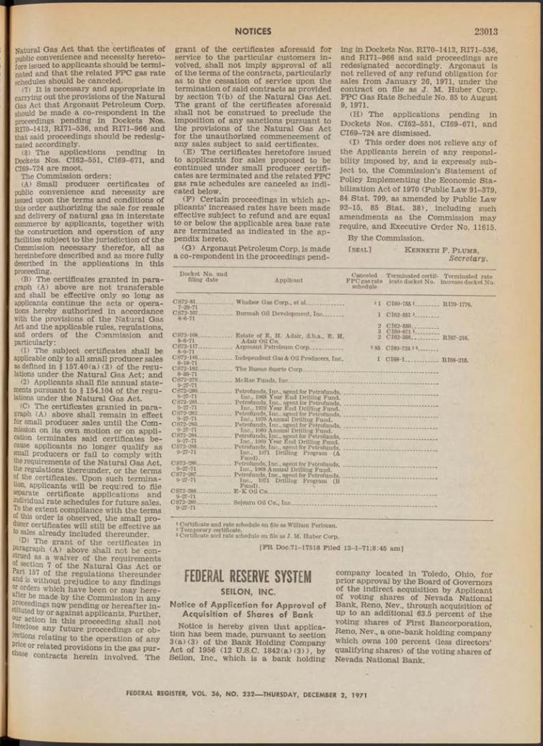
NOTICES 23013
Natural Gas Act that the certificates of public convenience and necessity heretofore issued to applicants should be terminated and that the related FFC gas rate schedules should be canceled.
(7) It is necessary and appropriate in carrying out the provisions of the Natural Gas Act that Argonaut Petroleum Corp. should be made a co-respondent in the proceedings pending in Dockets Nos. RI70-1413, RI71-536, and RI71-966 and that said proceedings should be redesignated accordingly.
(8) The applications pending in Dockets Nos. CI62-551, CI69-671, and CI69-724 are moot.
The Commission orders:(A) Small producer certificates of
public convenience and necessity are issued upon the terms and conditions of this order authorizing the sale for resale and delivery of natural gas in interstate commerce by applicants, together with the construction and operation of any facilities subject to the jurisdiction of the Commission necessary therefor, all as hereinbefore described and as more fully described in the applications in this proceeding.
(B) The certificates granted in paragraph (A) above are not transferable and shall be effective only so long as applicants continue the acts or operations hereby authorized in accordance with the provisions of the Natural Gas Act and the applicable rules, regulations, and orders of the Commission and particularly:
(1) The subject certificates shall be applicable only to all small producer sales as defined in § 157.40(a) (3) of the regulations under the Natural Gas Act; and
(2) Applicants shall file annual statements pursuant to § 154.104 of the regulations under the Natural Gas Act.
(C) The certificates granted in paragraph (A) above shall remain in effect for small producer sales until the Commission on its own motion or on application terminates said certificates because applicants no longer qualify as small producers or fail to comply with the requirements of the Natural Gas Act, the regulations thereunder, or the terms of the certificates. Upon such termination, applicants will be required to file separate certificate applications and individual rate schedules for future sales. To the extent compliance with the terms of this order is observed, the small producer certificates will still be effective as to sales already included thereunder.
(D) The grant of the certificates in Paragraph (A) above shall not be construed as a waiver of the requirementsf section 7 of the Natural Gas Act or
a S • ; T ^ e regulations thereunder and is without prejudice to any findings r orders which have been or may here-ter be made by the Commission in any
Proceedings now pending or hereafter intuited by or against applicants. Further, fivf c^on *n this proceeding shall not
eclose any future proceedings or objections relating to the operation of any Pnce or related provisions in the gas purchase contracts herein involved. The
grant of the certificates aforesaid for service to the particular customers involved, shall not imply approval of all of the terms of the contracts, particularly as to the cessation of service upon the termination of said contracts as provided by section 7(b) of the Natural Gas Act. The grant of the certificates aforesaid shall not be construed to preclude the imposition of any sanctions pursuant to the provisions of the Natural Gas Act for the unauthorized commencement of any sales subject to said certificates.
(E) The certificates heretofore issued to applicants for sales proposed to be continued under small producer certificates are terminated and the related FPC gas rate schedules are canceled as indicated below.
(F) Certain proceedings in which applicants’ increased rates have been made effective subject to refund and are equal to or below the applicable area base rate are terminated as indicated in the appendix hereto.
(G) Argonaut Petroleum Corp. is made a co-respondent in the proceedings pend-
ing in Dockets Nos. RI70-1413, RI71-536, and R I71-966 and said proceedings are redesignated accordingly. Argonaut is not relieved of any refund obligation for sales from January 26, 1971, under the contract on file as J . M. Huber Corp. FPC Gas Rate Schedule No. 85 to August 9, 1971.
(H) The applications pending in Dockets Nos. CI62-551, CI69-671, and CI69-724 are dismissed.
(I) This order does not relieve any of the Applicants herein of any responsibility imposed by, and is expressly subject to, the Commission’s Statement of Policy Implementing the Economic S ta bilization Act of 1970 (Public Law 91-379, 84 Stat. 799, as amended by Public Law 92-15, 85 Stat. 38), including such amendments as the Commission may require, and Executive Order No. 11615.
By the Commission.[ s e a l ] K e n n e t h F . P l u m b ,
Secretary.
Docket No. and filing date Canceled Terminated certif- Terminated rate
Applicant FP C gas rate icate docket No. Increase docket No.schedule
CS72-81-.7- 29-71
CS72-107.8- 6-71
CS72-108-8-6-71
CS72-117.8-9-71
CS72-146.8-18-71
CS72-182.8- 30-71
CS72-279.9- 27-71
CS72-280.9-27-71
CS72-281.9-27-71
CS72-282.9-27-71
CS72-283.9-27-71
CS72-284.9-27-71
CS72-285.9-27-71
CS72-286-9-27-71
CS72-287.9-27-71
CS72-288.9-27-71
CS72-289.9-27-71
Windsor Gas Corp., et al...........
Burmah Oil Development, Inc.
Estate of E . H. Adair, d.b.a., E . H. Adair Oil Co.
Argonaut Petroleum Corp....... ..............
Independent Gas & Oil Producers, Inc.
The Bueno Suerte Corp...........................
McRae Funds, I n c . . ._______________
Petrofunds, Inc., agent for Petrofunds, .Inc., 1968 Year End Drilling Fund.
Petrofunds, Inc., agent for Petrofunds, .Inc., 1970 Year End Drilling Fund.
Petrofunds, Inc., agent for Petrofunds, .Inc., 1970 Annual Drilling Fund.
Petrofunds, Inc., agent for Petrofunds, .Inc., 1969 Annual Drilling Fund.
Petrofunds, Inc., agent for Petrofunds, Inc., 1969 Year End Drilling Fund.
Petrofunds, Inc., agent for Petrofunds, Inc., 1971 Drilling Program (A Fund).
Petrofunds, Inc., agent for Petrofunds, .Inc., 1968 Annual Drilling Fund.
Petrofunds, Inc., agent for Petrofunds, . Inc., 1971 Drilling Program (B Fund). \
E -K Oil Co___________________ _____
Sojourn Oil Co., Inc....... ..........................
11 C169-755 i............... RI70-1776.
1 C162-551 *...............
2 C162-550..................3 C169-671 2...............2 C162-358............. . RI67-216.
8 85 C169-724 2 3 ..........
1 C168-1.................... RI68-215.
1 Certificate and rate schedule on file as William Perlman.2 Temporary certificate.8 Certificate and rate schedule on file as J . M. Huber Corp.
[F R D o c.71-17518 F iled 1 2 -1 -7 1 ;8 :4 5 am ]
FEDERAL RESERVE SYSTEMSEILON, INC.
Notice of Application for Approval of Acquisition of Shares of Bank
Notice is hereby given that application has been made, pursuant to section 3(a)(3) of the Bank Holding Company Act of 1956 (12 U.S.C. 1842(a)(3)), by Seilon, Inc., which is a bank holding
company located in Toledo, Ohio, for prior approval by the Board of Governors of the indirect acquisition by Applicant of voting shares of Nevada National Bank, Reno, Nev., through acquisition of up to an additional 63.5 percent of the voting shares of First Bancorporation, Reno, Nev., a one-bank holding company which owns 100 percent (less directors’ qualifying shares) of the voting shares of Nevada National Bank.
FEDERAL REGISTER, VOL. 36, NO. 232— THURSDAY, DECEMBER 2, 1971

23014 NOTICES
Section 3(c) of the Act provides that the Board shall not approve:
(1) Any acquisition or merger or consolidation under section 3 which would result in a monopoly, or which would be in furtherance of any combination or conspiracy to monopolize or to attempt to monopolize the business of banking in any part of the United States, or
(2) Any other proposed acquisition or merger or consolidation under section 3 whose effect in any section of the country may be substantially to lessen competition, or to tend to create a monopoly, or which in any other manner would be in restraint of trade, unless the Board finds that the anticompetitive effects of the proposed transaction are clearly outweighed in the public interest by the probable effect of the transaction in meeting the convenience and needs of the community to be served.
Section 3(c) further provides that, in every case, the Board shall take into consideration the financial and managerial resources and future prospects of the company or companies and the banks concerned, and the convenience and needs of the community to be served.
Not later than thirty (30) days a f te r . the publication of this notice in the F ederal R egister, comments and views regarding the proposed acquisition may be filed with the Board. Communications should be addressed to thé Secretary, Board of Governors of the Federal Reserve System, Washington, D.C. 20551. The application may be inspected at the office of the Board of Governors or the Federal Reserve Bank of Cleveland.
Board of Governors of the Federal Reserve System, November 24, 1971.
[ sea l] T yn a n S m it h ,Secretary o f the Board.
[F R D o c.71-17599 F iled . 1 2 -1 -7 1 ;8 :4 9 am ]
INTERAGENCY TEXTILE ADMINISTRATIVE COMMITTEE
CERTAIN COTTON TEXTILE PRODUCTSPRODUCED OR MANUFACTUREDIN THAILAND
Entry or Withdrawal From Warehouse for Consumption
D ec em ber 1, 1971.On July 3, 1971, there was published
in the F ederal R egister (36 F.R. 12714) a letter dated June 25, 1971, from the Chairman of the President’s- Cabinet Textile Advisory Committee to the Commissioned of Customs, establishing a level of restraint of 17,372 dozen on cotton textile products in Category 60, produced or manuf actured in Thailand, and exported to the United States during the 12- month period beginning April 30, 1971, and extending through April 29, 1972.
On November 4, 1971, there was published in the F ederal R egister (36 F .R . 21229) a notice dated November 2, 1971, issued by the Chairman of the Inter
agency Textile Administrative Committee indicating that the level of restraint had been exhausted by entries of the cotton textile products in question. This notice, furthermore, indicated that consultations may be held between the Governments of the United States and Thailand to determine the disposition of the cotton textile products that had been denied entry under the terms of the letter of June 25, 1971. Finally, the notice requested all interested persons to report to the Office of Textiles, Trade Analysis Division, Department of Commerce, on any cotton textile products in Category 60 produced or manufactured in Thailand and exported from Thailand prior to October 1,1971, whiçh had been denied entry and were in the United States either in a bonded warehouse general order warehouse or foreign trade zone.
Consultations have been held between the Governments of the United States and Thailand; and as a result of those consultations it has been agreed to increase the level of restraint applicable to cotton textile products in Category 60 produced or manufactured in Thailand and entered or withdrawn from warehouse for consumption in the United States for the 12-month period which began on April 30,1971.
Accordingly, there is published below a letter of November 29, 1971 from the Chairman of the President’s Cabinet Textile Advisory Committee to the Commissioner of Customs amending the directive of June 25, 1971 by increasing the level of restraint.
S tanley Nehmer, Chairm an, Interagency Textile
Administrative Committee, and Deputy Assistant Secretary for Resources.
P resident’s Cabin et T e x t ile Advisory Co m m ittee
Co m m ission er of Cu sto m s ,D e p a r tm e n t o f t h e T r e a s u r y ,W a s h in g to n , D .C. 20226.
November 29, 1971.Dear Mr . Co m m issio n er : T h is d irectiv e
am en d s b u t does n o t can ce l th e d irectiv e issued to you on Ju n e 25, 1971, fro m th e C h airm an o f th e P re s id e n t’s C a b in et T e x tile Advisory C om m ittee , regard ing im p o rts in to th e U n ited S ta te s o f co tto n te x tile p rod u cts in C ategory 60, prod uced o r m a n u fa ctu red in T h a ila n d .
T h e firs t p arag rap h o f th e d irectiv e o f J u n e 25, 1971 is am ended to read as fo llo w s:
“U nder th e te rm s o f th e L o n g -T e rm A rra n g e m e n t R egard in g In te rn a tio n a l T rad e in C o tto n T e x tile s done a t G en ev a o n F e b ru ary 9, 1962, in c lu d in g A rticle 6 (c ) th e re o f re la tin g to n o n p a rtic ip a n ts , an d in acco rd a n ce w ith th e proced ures o u tlin ed in E x ecu tiv e O rder 11052 o f Sep tem b er 28 , 1962, as am en ded by E x ecu tiv e O rder 11214 o f A pril 7, 1965, you are d irected to p ro h ib it, effectiv e as soon as possib le, an d fo r th e 12 -m o n th period b eg in n in g A pril 30, 1971, an d ex ten d in g th ro u g h A pril 29 , 1972, en try in to th e U n ited S ta te s fo r co n su m p tio n an d w ith draw al fro m w arehouse fo r co n su m p tio n o f c o tto n te x tile p rod u cts in C ategory 60, p ro du ced o r m a n u fa ctu red in T h a ila n d , in e x cess o f a level o f re s tra in t fo r th e period o f 35,612 dozen.1 ”
T h e a c tio n s ta k e n w ith resp ect to the Gove rn m e n t o f T h a ila n d an d w ith respect to im p o rts o f c o tto n te x tile s an d co tton textile p ro d u cts fro m T h a ila n d h ave been determ in ed b y th e P resid e n t’s C a b in et Textile Advisory C o m m ittee to involve foreign affairs fu n c tio n s o f th e U n ited S ta te s . Therefore, the d irec tio n s to th e C om m ission er o f Customs, b e in g n ecessary to th e im plem entation oi su ch a c tio n s , fa ll w ith in th e foreign affairs excep tio n to th e n o tice provisions of 5 U.S.C. 553. T h is le t te r w ill be p u blish ed in the Federal R egister .
S in ce re ly yours,J ames T. Lynn ,
A c tin g S e c r e ta r y o f Com m erce, C h a ir m a n , P r e s id e n t ’s Cabinet T e x t i l e A d v isory C om m itte e .
[F R D o c.71-11737 F iled 1 2 -1 -7 1 ; 11:46 am]
SECURITIES AND EXCHANGE COMMISSION[F ile No. 50 0 -1 ]
CONTINENTAL VENDING MACHINE CORP.
Order Suspending TradingNovember 24, 1971.
I t appearing to the Securities and Exchange Commission that the summary suspension of trading in the common stock, 10 cents par value of Continental Vending Machine Corp., and the 6 percent convertible subordinated debentures due September 1, 1976, being traded otherwise on a national securities exchange is required in the public interest and for the protection of investors;
It is ordered, Pursuant to section 15 (c) (5) of the Securities Exchange Act of 1934, that trading in such securities otherwise than on a national securities exchange be summarily suspended, this order to be effective for the period November 27, 1971, through December 6, 1971.
By the Commission..[seal] R onald F. Hunt,
Secretary.[F R D oc.71-17584 F iled 1 2 -1 -7 1 ;8 :4 7 am]
[File No. 1- 484 .7 ]
ECOLOGICAL SCIENCE CORP. Order Suspending Trading
N ovember 24, 1971.The common stock, 2 cents par value,
of Ecological Science Corp. being traded on the American Stock Exchange,the Philadelphia-Baltimore-WashingtonStock Exchange and the Pacific Coast Stock Exchange, pursuant to provisions of the Securities Exchange A ct of h«* and all other securities of Ecological science Corp. being traded otherwise tnan an a national securities exchange; ahd
It appearing to the Securities and ' change Commission that the summary suspension of trading in such security on such exchanges and otherwise than on
FEDERAL REGISTER, V O L 36, NO. 232— THURSDAY, DECEMBER 2, 1971No. 232-------16

NOTICES 23015
a national securities exchange is required in the public interest and for the protection of investors;
It is ordered, Pursuant to sections 15(c) (5) and 19(a) (4) of the Securities Exchange Act of 1934, that trading in such securities on the above mentioned exchanges and otherwise than on a national securities exchange be summarily suspended, this order to be effective for the period November 25, 1971, through December 4,1971.
By the Commission.[seal] R onald P . H u n t ,
Secretary.[PR Doc.71-17585 Piled 12-1-71;8:47 am]
[812.3043]HORNBLOWER & WEEKS—
HEMPHILL, NOYESNotice of Filing of Application for an
Order of ExemptionN ovem ber 23, 1971.
Notice is hereby given that Homblower & Weeks—Hemphill, Noyes (Applicant), 8 Hanover Street, New York, NY 10004, in connection with a proposed public offering of 4 million shares of common stock of Chase Convertible Fund of Boston, Inc. (Company), a registered, closed- end, diversified management investment company, has filed an application pursuant to section 6(c) of the Investment Company Act of 1940 (Act) for an order exempting certain transactions from section 30(f) of the Act to the extent that such section adopts section 16(b) of the Securities Exchange Act of 1934 (Exchange Act). All interested persons are referred to the application on file with the Commission for a statement of the representations therein which are summarized below.
Applicant and W. E. Hutton & Co. are the prospective representatives (Representatives) of a group of underwriters (Underwriters) formed in connection with the above public offering.
Applicant contemplates that each Underwriter, including the Representatives, will execute an agreement among Underwriters and that the Representatives acting both for themselves and as Representatives for the several Underwriters, will execute an underwriting agreement with the Company. I t is also contemplated that one or more dealers will offer and sell certain of the shares Mid in connection therewith will enter into selected dealer agreements. Under the proposed underwriting arrangements, each Underwriter will be obligated to offer to the public, respectively, its expected underwriting commitment. ..Applicant states that it is possible that the underwriting commitment of any one or more of the Underwriters, including each of the Representatives, will exceed io percent of the aggregate number of hares of the Company’s common stock
In f 6 outetanding after the closing of the mitiai public offering of the shares. Since
ction 30(f) of the Act subjects every
person who is directly or indirectly the beneficial owner of more than 10 percent of any class of outstanding securities of the Company to the same duties and liabilities as those imposed by section 16 of the Exchange Act, such Underwriter or Underwriters would become subject to the filing requirements of section 16(a) of the Exchange Act and, upon resale of the shares purchased by them to their customers, subject to the obligations imposed by section 16(b) of the Exchange Act.
Rule 16b-2 under the Exchange Act exempts certain Underwriters from the operation of section 16(b). Applicant states that the purpose of the pinchase of the shares by the Underwriters will be for resale in connection with the initial distribution of the shares. Applicant states that such purchases, therefore, will be transactions effected in connection with a distribution of a substantial block of securities within the purpose and spirit of Rule 16b-2.
Applicant states that although it is anticipated that the requirements of Rule 16b-2(a) (1) and (2) will be met, one or more of the Underwriters, through their participation in the distribution of the shares of the Company, may not be entitled to rely upon Rule 16b-2 to exempt them from section 16(b) of the Exchange Act. The requirement in Rule 16b-2(a) (3) that the aggregate participation of Underwriters not withii) section 16(b) of the Exchange Act be at least equal to the participation of Underwriters exempted therefrom under Rule 16b-2 may not be met because it is possible that one or more of the Underwriters may purchase more than 10 percent of the aggregate number of the shares of the Company’s bommon stock to be outstanding after the closing, as a result of obligations to purchase additional shares due to defaults by other Underwriters. Moreover, one or more of the Underwriters who are obligated through the underwriting agreement to purchase more than 10 percent of the aggregate number of shares of the Company’s common stock to be outstanding after the closing, may, as Underwriters and as selected dealers, distribute more than 50 percent of the aggregate number of shares being offered. Such a distribution would not meet the requirement of Rule 16b-2(a) (3).
In addition to pinchases of shares from the Company and sales of shares to customers, there may be the usual transactions of pinchase or sale incident to a distribution such as stabilizing purchases, purchases to cover overallotments or other short positions created in connection with such distribution, and sales of shares purchased in stabilization.
Applicant states that there is no inside information in existence since the Company, prior to the initial distribution of the shares, will have no assets other than cash, or business of any sort, and all material facts with respect to the Company will be set forth in the prospectus pursuant to which the shares will be offered and sold. No partner, director or officer of Applicant or W. E. Hutton & Co.
is a director or officer of either the Company or John P. Chase, Inc., the Company’s investment adviser (Adviser), and Applicant states that it is not anticipated that any partner, director, or officer of any other Underwriter will be a director or officer of the Company or the Adviser.
Applicant maintains that the requested exemption from the provisions of section 30(f) of the Act is necessary and appropriate in the public interest and consistent with the protection of investors and the purposes fairly intended by the policy and provisions of the Act. I t further asserts that the transactions sought to be exempted cannot lend themselves to the practices to which section 16(b) of the Exchange Act and section 30(f) of the Act were enacted to apply.
Section 6(c) of the Act authorizes the Commission to exempt any person, security or transaction, or any class or classes of persons, securities, or transactions, from any provision of the Act and rules promulgated thereunder if and to the extent that such exemption is necessary or appropriate in the public interest and consistent with the protection of investors and the purposes fairly intended by the policy and provisions of the Act.
Notice is further given that any interested person may, not later than December 14, 1971, at 5:30 p.m., submit to the Commission in writing a request for a hearing on this matter accompanied by a statement as to the nature of his interest, the reason for such request and the issues of fact or law proposed to be controverted, or he may request that he be notified if the Commission shall order a hearing thereon. Any such communication should be addressed: Secretary, Securities and Exchange Commission, Washington, D.C. 26549. A copy of such request shall be served personally or by mail (airmail if the person being served is located more than 500 miles from the point of mailing) upon Applicant at the address stated above. Proof of such service (by affidavit or in case of an attorney at law by certificate) shall be filed contemporaneously with the request. At any time after said date, as provided by Rule 0-5 of the rules and regulations promulgated under the Act, an order disposing of the application herein may be issued by the Commission upon the basis of the information stated in said application, unless an order for hearing upon said application shall be issued upon request or upon the Commission’s own motion. Persons who request a hearing or advice as to whether a hearing is ordered, will receive notice of further developments in this matter, including the date of the hearing (if ordered) and any postponements thereof.
For the Commission, by the Division /Of Corporate Regulation, pursuant to delegated authority.
[ se a l] R onald F . H u n t ,Secretary.
[FR Doc.71-17586 Filed 12-1-71; 8:47 am]
FEDERAL REGISTER, V O L 36, NO. 232— THURSDAY, DECEMBER 2, 1971

23016 NOTICES[812-3012]
KEYSTONE CUSTODIAN FUNDS, INC., AND ERWIN D. CANHAM
Notice of Application for Order Exempting Applicant Canham From the Definition of “ Interested Person”
November 26, 1971.Notice is hereby given that Keystone
Custodian Funds, Inc., a Delaware corporation (the “Trustee”) , 99 HighStreet, Boston, MA 92110, as trustee of nine separate trusts, Keystone Custodian Funds Series B - l , B-2, B-4, S - l , S-2, S-3, S-4, K - l , and K -2 (collectively referred to as the “Funds”) registered as open-end management investment companies under the Investment Company Act of 1940, as amended (the “Act”), and Erwin D. Canham (Canham) (hereinafter referred to collectively as “Applicants”), c/o Christian Science Monitor, 1 Norway Street, Boston, MA, have filed an application pursuant to section 6(c) of the Act for an order exempting Canham from the definition of “interested person” as that term is defined in section 2(a) (19) of the Act with respect to the Funds or any principal underwriter for such Funds solely by reason of his status as a director of John Hancock Mutual Life Insurance Co. (Hancock Life). All interested persons are referred to the application on file with the Commission for a statement of the representations contained therein, which are summarized below.
The nine Funds, created in 1935, are unincorporated common law trusts, and have no boards of directors, officers, or employees. The Trustee, pursuant to the terms of the trust agreements establishing the Funds, performs all of the investment, management and administrative services required by the Funds.
Since 1940 it has been the position of the Trustee that under section 2(a) (12) of the Act the directors of the Trustee should be treated for the purposes of the Act as directors of the Funds. Accordingly, since 1940 the board of directors of the Trustee has been so constituted as to comply with the limitations of section 10 of the Act.
Hancock Life is a Massachusetts life insurance company chartered in 1862 and is among the largest life insurance companies in the United States. I t has registered as a broker-dealer under the Securities Exchange Act of 1934 (1934 Act) and is a member of the National Association of Securities Dealers, Inc., for the purpose of selling its own variable annuities through its independent and employee insurance agents. No such sales have as yet been made but it is anticipated that selling activities may commence late in 1971. No other securities will be sold by these agents as registered representatives of Hancock Life, nor will the Hancock Life variable annuities be sold by anyone other than these agents.
John Hancock Advisers, Inc., a wholly owned subsidiary of Hancock Life, is the investment adviser for John Hancock
Growth Fund, Inc. (Growth Fund), John Hancock Signature Fund (Signature Fund), open-end investment companies and John Hancock Investors, Inc. (Investors In c .), a closed-end investment company.
Shares of Growth Fund and Signature Fund are offered for sale to the public in accordance with the terms of principal underwriting agreements with John Hancock Distributors, Inc. (Distributors), a wholly owned subsidiary of Advisers. To permit it to so act, Distributors has registered as a broker-dealer under the 1934 Act and is an NASD member. Shares are sold to the public only by independent and employee insurance agents of Hancock Life who are registered representatives of Distributors. Applicants assert that Distributors will accept as its registered representatives only individuals who are not registered representatives for another broker-dealer (other than Hancock Life) and will require its registered representatives to sell only shares of the John Hancock funds. Accordingly, no company or individual in the chain of distribution of the John Hancock Funds sells shares of the Keystone Funds or any other securities, nor do Keystone or any other person sell shares of the John Hancock Funds.
Section 2(a) (19) provides in pertinent part that when used with respect to an investment company, an interested person of another person includes “any broker or dealer registered under the Securities Exchange Act of 1934 or any affiliated person of such broker or dealer * * * ” section 2(a) (3) defines an affiliated person of another person to include “(D) any officer, director, partner, copartner, or employee of such other person * * * ”
Canham, as a director of Hancock Life, is an “affiliate” of a broker-dealer and is thus an “interested person” of the Funds. Canham is the Editor-in-Chief of the “Christian Science Monitor.” He has held positions with international and charitable organizations and his work has received recognition from several universities as well as foreign governments. Applicants state that Canham has been a nonafflliated member of the board of directors of the trustee since February 2, 1970. In addition, he is one of 16 “outside” directors of Hancock Life and is not a member of either of the two principal board committees of that company.
Keystone Custodian Funds, Inc., states that Canham is, in its opinion, a man of national stature and demonstrated integrity, experience, and competence. Applicants represent that Canham, through an affiliate of a broker-dealer and thus an interested person of Funds, is in fact in a position to act independently on behalf of the Fund and its shareholders in dealing with the trustee.
Applicants contend that Mr. Canham is subject to no conflicts of interest as a result of his directorship of Hancock Life in acting on behalf of the Funds since the activities of Hancock Life and its affiliated companies are isolated from and independent of any activities of the
Trustee, the Funds and the principal underwriters for the Funds. Further, Trustee represents and warrants that neither it, any of its affiliates or any of the Funds will hereafter engage in any securities transactions through Hancock Life or John Hancock Distributors, Inc.
Notice is further given that any interested person may, not later than December 10, 1971, at 5:30 p.m., submit to the Commission in writing a request for a hearing on the matter accompanied by a statement as to the nature of his interest, the reason for such request and the issues of fact or law proposed to be con-1 troverted, or he may request that he be notified if the Commission shall order a hearing thereon. Any such communication should be addressed: Secretary, Securities and Exchange Commission, Washington, D.C. 20549. A copy of such request shall be served personally or by mail (airmail if the person being served is located more than 500 miles from the point of mailing) upon Applicants at the ; address stated above. Proof of such service (by affidavit or in the case of an attorney at law by certificate) shall be filed contemporaneously with the request. At any time after said date, as provided by Rule 0-5 of the rules and regulations promulgated under the Act, an order disposing of the application herein may be issued by the Commission upon the basis of the information stated in said application, unless an order for hearing thereon shall be issued upon request or upon the Commission’s own motion. Persons who request a hearing or advice as to whether a hearing is ordered will receive notice of further developments in this matter, including the date of the hearing (if ordered) and any postponements thereof.
By the Commission.R onald F. Hunt,
Secretary.[ sea l]
[FR Doc.71-17587 Filed 12-1-71:8:47 am]
[811-1546]
LASALLE STREET CAPITAL CORP.Notice of Filing of Application for
Order of the Act Declaring That Company Has Ceased To Be an Investment Company
November 2 3 ,1971-Notice is hereby given that LaSalle
Street Capital Corp. (Applicant), is« South Wacker Drive, Chicago, IL 6060b, a Delaware corporation registered as a closed-end, nondiversified, management investment company under the laves - ment Company Act of 1940 (A ct) ha» filed an application pursuant to section 8(f) of the Act for an order of the Commission declaring that Applicant ceased to be an investment company defined in the Act. All interested persons are referred to the application on ® with the Commission for a statement oi the representations set forth therein which are summarized below.
FEDERAL REGISTER, VOL. 36, NO. 232— THURSDAY, DECEMBER 2, 1971
\

NOTICES 23017
Applicant, licensed as a small business investment company under the Small Business Investment Act of 1958, was merged on November 1, 1971, into At- lanta/LaSalle Corp. (Atlanta/LaSalle), a closed-end, nondiversified management investment company registered under the Act. The application further states that, thereupon, Atlanta/LaSalle transferred the small business activities (including certain assets and all liabilities) formerly carried on by Applicant to its subsidiary, LSC Corp. (LSC), which has also registered under the Act as a closed-end, nondiversified, management investment company and is licensed as a small business investment company. The certificate of incorporation of LSC was amended on November 1, 1971, to change its name to LaSalle Street Capital Corp.
Applicant represents that under Delaware'law, its corporate existence ceased upon the effectiveness of the aforesaid merger; that it* is not now, and it does not intend to be engaged in any business, and that, therefore, it is not an investment company. .
Section 8(f) of the Act provides, in pertinent part, that when the Commission, upon application, finds that a registered investment company has ceased to be an investment company, it shall so declare by order, and upon the taking effect of such order the registration of such company shall cease to be in effect.
Notice is further given that any interested person may, not later than December 14, 1971, at 5:30 pm., submit to the Commission in writing a request for a hearing on the matter accompanied by a statement as to the nature of his interest, the reason for sudi request and the issues, if any, of fact or law proposed to be controverted or he may request he be notified if the Commission should order a hearing thereon. Any such communication should be addressed: Secretary, Securities and Exchange Commission, Washington, D.C. 20549. A copy of such request shall be served personally or by mail (airmail if the person being served is located more than 500 miles from the point of mailing) upon Applicant at the address stated above. Proof of such service (by affidavit or in case of an attorney at law by certificate) shall be filed contemporaneously with the request. At any time after said date as provided by Rule 0-5 of the rules and regulations promulgated under the Act, an order disposing of the application herein may be issued by the Commission upon the basis of the information stated in said application, unless an order for hearing upon said application shall be issued upon request or upon the Commission’s own motion. Persons who request a hearing or advice as to whether a hearing is ordered will receive notice of further developments m this matter, including the date of the hearing (if ordered) and any postponements thereof.
Por thè Commission, by the Division of Corporate Regulation, pursuant to delegated authority.
*-SEALJ R o nald F . H u n t ,Secretary .
(PR Doc.71-17588 Piled 12-1-71;8:47 am]
„ [7 0 -5 1 1 7 ]
WEST PENN RAILWAYS CO. AND ALLEGHENY POWER SYSTEM, INC.Notice of Proposed Dissolution of
Inactive Subsidiary CompanyN o v e m b e r 26, 1971.
Notice is hereby given that Allegheny Power System, Inc. (Allegheny), 320 Park Avenue, New York, NY 10022, a registered holding company, and its wholly owned inactive subsidiary company, West Penn Railways Co. (Railways), have filed an application-declaration with this Commission pursuant to the Public Utility Holding Company Act of 1935 (A ct), designating sections 11(b), 12(c), 12(d), and 12(f) thereof and Rules 42 and 46 promulgated thereunder as applicable to the proposed transactions. All interested persons are referred to the application- declaration, which is summarized below, for a complete statement of the proposed transactions.
Railways proposes to dissolve and to distribute to Allegheny all of its assets (which consist solely of cash and U.S. Treasury Bills aggregating $372,372), subject to all of its liabilities which aggregate $241,917 and which Allegheny will assume. Allegheny will surrender to Railways for cancellation the certificate for all of its outstanding stock. It is stated that the purpose of the proposed transactions is to effectuate compliance with section 11 (b) of the Act.
I t is stated that expenses are estimated not to exceed $500 and that no State commission and no Federal commission, other than this Commission, has jurisdiction over the proposed transactions.
Notice is further given that any interested person may, not later than December 17, 1971, request in writing that a hearing be held on such matter, stating the nature of his interest, the reasons for such request, and the issues of fact or law raised by said application-declaration which he desires to controvert; or he may request that he be notified if the Commission should order a hearing thereon. Any such request should be addressed: Secretary, Securities and Exchange Commission, Washington, D.C. 20549. A copy of such request should be served personally or by mail (airmail if the person being served is located more than 500 miles from the point of mailing) upon the applicants-declarants at the above-stated address, and proof of service (by affidavit or, in case of an attorney at law, by certificate) should be filed with the request. At any time after said date, the application-declaration, as filed or as it may be amended, may be granted and permitted to become effective as provided in Rule 23 of the general rules and regulations promulgated under the Act, or the Commission may grant exemption from such rules as provided in Rules 20 (a) and 100 thereof or take such other action as it may deem appropriate. Persons who request a hearing or advice as to whether a hearing is ordered will receive notice of further developments in this matter, including the date of the hearing (if ordered) and any postponements thereof.
For the Commission, by the Division of Corporate Regulation, pursuant to delegated authority.
[ s e a l ] R o n a ld F. H u n t ,Secretary.
[P R D o c.71-17589 P iled 1 2 -1 -7 1 ;8 :4 7 am ]
[7 0 -4 7 0 4 ]
WHEELING ELECTRIC CO.Notice of Fourth Post-Effective
Amendment Regarding Issue andSale of Short-Term Notes to Ranks
N o v e m b e r 26, 1971.Notice is hereby given that Wheeling
Electric Co. (Wheeling), 51 16th Street, Wheeling, WV 26003, a public-utility subsidiary company of American Electric Power Co., Inc., a registered holding company, has filed with this Commission a fourth post-effective amendment to its application in this proceeding pursuant to section 6(b) of the Public Utility Holding Company Act at 1935 (Act) regarding the following proposed transactions. All interested persons are referred to the amended application, which is summarized below, for a complete statement of the proposed transactions.
By order dated January 17,1969 (Holding Company Act Release No. 16269), the Commission authorized Wheeling to issue and sell its notes to five commercial banks prior to December 31, 1969, in an aggregate amount not to exceed $4 million outstanding at any one time. By order dated December 15, 1969 (Holding Company Act Release No. 16554), the Commission authorized Wheeling to issue and sell its notes to five commercial banks prior to December 31, 1970, in an aggregate amount not to exceed $4,200,- 000 outstanding at any one time; by order dated March 17, 1970 (Holding Company Act Release No. 16642) , Wheeling was authorized to issue and sell its notes to nine commercial banks prior to December 31, 1970; and by order dated December 30, 1970 (Holding Company Act Release No. 16950), Wheeling was authorized to issue and sell said $4,200,000 of notes to 10 commercial banks prior to December 31, 1971.
Wheeling now proposes that the notes be issued prior to December 31, 1972, to said 10 banks in the aggregate amount of $4,600,000 outstanding at any one time, as follows:M a n u fa ctu rers H anover T ru s t
Co., New Y o rk , N .Y ______________$ l , 500, 000M organ G u a ra n ty T ru s t C om
p an y o f New Y o rk , N .Y ________ 615, 000F ir s t N ation al C ity B a n k , New
Y ork , N .Y ------------------------------------ 600, 000B a n k e rs T r u s t Co., New Y ork ,
N .Y — -------------------------------- 6 0 0 ,0 0 0W h eelin g D o llar Sav in g s & T ru s t
Co., W h eelin g , W . V a ____ _______ 500, 000S e cu rity N ation al B a n k & T ru s t
Co., W h eeling, W . V a_____r ____ 350, 000H alf D oUar T ru s t & Sav in g s
B a n k , W h eelin g, W . V a_________ 250, 000M ercan tile B a n k in g an d T ru s t
Co., M ounds v ille , W . V a_____ 1 1 0 ,0 0 0T h e F irs t N ation al B a n k a t
M oundsville , W . V a___________ _ 50, 000F ir s t N ation al B a n k o f C am eron,
W . V a ------------------------------------------- 25, 000
4 ,6 0 0 , 000
FEDERAL REGISTER, VOL. 36, NO. 232— THURSDAY, DECEMBER 2, 1971

23018 NOTICES
Wheeling requests the Commission’s approval of the issue and sale of such amount of notes not already exempt pursuant to the first sentence of section 6(b) of the Act. The notes-will mature not more than 270 days after the issuance or renewal thereof and bear interest at an annual rate equal to the prime credit rate in effect at the time of the issuance of the notes or in effect from' time to time. I t is stated that no change in compensating balances will be required at the local banks above levels maintained for normal working balance requirements, but if the average balances maintained by Wheeling at the local banks were maintained solely in order to fulfill prevailing compensating balance requirements of those banks, which approximate 15 percent, the effective interest cost to Wheeling of the issuance and sale of its notes to such local banks would be approximately 6.5 percent, based on the current general prime commercial credit rate of 5% percent. In the case of the New York banks, Wheeling will m aintain, compensating balances of 20 percent which are the currently prevailing balance requirements at said banks, and the effective interest cost at such New York banks will be approximately 6.9 percent based on the current general prime commercial credit rate of 5V2 percent. The notes are prepayable at any time, in whole or in part, without premium. As of November 1, 1971, Wheeling had outstanding $4,190,000 of short-term notes to banks.
Wheeling will use the proceeds from the proposed transactions to repay bank loans the proceeds of which were used for past expenditures in connection with its construction program, to pay part of the cost of its future construction program, estimated at $1,700,000 for 1972, and for other corporate purposes. All of Wheeling’s notes payable to banks outstanding at the time of its next permanent financing will be paid and retired from the proceeds of that financing.
I t is represented that no State commission and no Federal commission, other than this Commission, has jurisdiction over the proposed transactions.
Notice is further given that any interested person may, not later than December 16, 1971, request in writing that a hearing be held on such matter, stating the nature of his interest, the reasons for such request, and the issues of fact or law raised by said post-effective amendment to the application which he desires to controvert; or he may request that he be notified if the Commission should order a hearing thereon. Any such request should be addressed: Secretary, Securities and Exchange Commission, Washington, D.C. 20549. A copy of such request should be served personally or by mail (airmail if the person being served is located more than 500 miles from the point of mailing) upon the applicant at the above-stated address, and proof of service (by affidavit or, in case of an attorney at law, by certificate) should be filed with the re
quest. At any time after said date, the application, as now amended or as it may be further amended, may be granted as provided in Rule 23 of the general rules and regulations promulgated under the Act, or the Commission may grant exemption from such rules as provided in Rules 20(a) and 100 thereof or take such other action as it may deem appropriate. Persons who request a hearing or advice as to whether a hearing is ordered will receive notice of further developments in this matter, including the date of the hearing (if ordered) and any postponements thereof.
For the Commission, by the Division of Corporate Regulation, pursuant to delegated authority.
[seal] R onald F. Hunt,Secretary.
[FR Doc.71-17590 Filed 12-1-71;8:48 am]
TARIFF COMMISSION[337-L-46]
CLOSED TOE CIRCULAR HOSIERY KNITTING MACHINES AND DEVICES
Notice of .Complaint ReceivedThe U.S. Tariff Commission hereby
gives notice of the receipt on October 8, 1971, of a complaint under section 337 of the Tariff Act of 1930 (19 U.S.C. 1337), filed by Scott & Williams, Inc., of Laconia, N.H., alleging unfair methods of competition and unfair acts in the unauthorized importation and sale of closed toe circular hosiery knitting machines and devices said to be embraced within the claims of U.S. Patent No. 3,340,706 and Reissue No. 26,580, and knitted stockings said to be embraced within the claims of U.S. Patent No.3,327,500 and Reissue No. 26,581, both of which reissued patents are owned by complainant. The complainant alleges further unfair methods or acts in the form of a conspiracy or combination among the respondents to avoid competition among themselves in the United States and to boycott complainant’s patents.
The following companies have been named as respondents in the case:G. Bill! & Cie, Florence, Italy.Bentley Engineering Co., Ltd., Leicester,
United Kingdom.Faegentaaum Machinery, Inc., 7312 School
Lane, Melrose Park, Philadelphia, PA.Billi America, 514 W est,Green Drive, High . Point, N.C.Bentley Machinery, Inc., 557 Broad Street,
Providence, RI.Bear Brand Hosiery Co., 205 West Monroe
Street, Chicago, IL.
In accordance with the provisions of § 203.3 of its rules of practice and procedure (19 CFR 203.3), the Commission has initiated a preliminary inquiry into the allegations of thè complaint for the purpose of determining whether there is good and sufficient reason for a full in
vestigation, and if so whether the Commission should recommend to the President the issuance of a temporary order of exclusion from entry under section 337 (f ) of the Tariff Act.
A copy of the complaint is available for public inspection at the Office of the Secretary, U.S. Tariff Commission, Eighth and E Streets, NW„ Washington, DC, and at the New York office of the Tariff Commission located in room 437 of the Customhouse.
Information submitted by interested persons which is pertinent to the aforementioned preliminary inquiry will be considered by the Commission if it is received not later than January 10,1972. Such information should be sent to the Secretary, U.S. Tariff Commission, Eighth and E Streets NW., Washington, DC 20436. A signed original and nineteen X19) true copies of each document must be filed.
Issued*: November 26, 1971.By order of the Commission.I seal] K enneth R . Mason,
Secretary.[FR Doc.71-17605 Filed 12-1-71;8:49 am]
[TEA—W—123]
WORKERS’ PETITION FOR DETERMINATION OF ELIGIBILITY TO APPLYFOR ADJUSTMENT ASSISTANCE
Notice of InvestigationOn the basis of a petition filed under
section 301(a) (2) of the Trade Expansion Act of 1962, on behalf of the workers of the General Instrument Corp.’s Newark, N.J., plant, the U.S. Tariff Commission, on November 24,1971, instituted an investigation under section 301(c) (2) of the act to determine whether, as a result in major part of concessions granted under trade agreements, articles like or directly competitive with the diodes produced at said plant are being imported into the United States in such increased quantities as to cause, or threaten to cause, the unemployment or underemployment of a significant number or proportion of the workers of such plant.
The petitioners have not requested a public hearing. A request will be held on request of any other party showing a proper interest in the subject matter of the investigation, provided such request is filed within 10 days after the notice is published in the F ederal R eg iste r .
The petition filed in this case is available for inspection at the Office of the Secretary, U.S. Tariff Commission, 8th and E Streets NW., Washington, DC, and at the New York City office of the Tariff Commission located in room 437 of the Customhouse.
Issued: November 26, 1971.By order of the Commission.[seal] K enneth R . Mason,
Secretary.[FR Doc.71-17604 Filed 12-1-71;8:49 am]
FEDERAL REGISTER, VOL. 36, NO. 232— THURSDAY, DECEMBER 2, 1971

NOTICES 23019
INTERSTATE COMMERCE COMMISSION
[Notice 95]
motor c a r r ier , b r o k e r , w a terCARRIER AND FREIGHT FORWARDER APPLICATIONS
N o v e m b e r 26, 1971. The following applications are gov
erned by special rule 1100.2471 of the Commlissian’s general rules of practice (49 C!FR, as amended), published in the Federal R e g is t e r issue of April 20, 1966, effective May 20, 1966. These rules provide, among other things, that a protest to the granting of an application must be filed with the Commission within 30 days after date of notice of filing of the application is published in the F e d e r a l Register. Failure seasonably to file a protest will be construed as a waiver of opposition and participation in the proceeding. A protest under these rules should comply with section 247(d) (3) of the rules of practice which requires that it set forth specifically the grounds upon which it is made, contain a detailed statement of protestant’s interest in the proceeding (including a copy of the specific portions of its authority which pro- testant believes to be in conflict with that sought in the application, and describing in detail the method— whether by joinder, interline, or other means—by which protestant would use ( such authority to provide all or part of the service proposed), and shall specify with particularity the facts, matters, and things relied upon, but shall not include issues or allegations phrased generally. Protests not in reasonable compliance with the requirements of the rules may be rejected. The original and one copy of the protest shall be filed with the Commission, and a copy shall be served concurrently upon applicant’s representative, or applicant if no representative is named. If the protest includes a request for oral hearing, such requests shall meet the requirements of section 247(d) (4) of the special rules, and shall include the certification required therein.
Section 247(f) of the Commission’s rules of practice further provides that each applicant shall, if protests to its application have been filed, and within 60 !fw the date of. this publication, notify the Commission in writing (1) that it is ready to proceed and prosecute ®»^pplicatipn, or (2) that it wishes to TOharaw the application, failure in rnch the application will be dismissed
oy the Commission.^H^ker processing steps (whether ,?c™e(T Procedure, oral hearing, or „ Procedures) will be determined
generally in accordance with the Com- jnisaon’s General Policy Statement Con-
mmg Motor Carrier Licensing Proce- 6s, published in the F ederal R eg ister
s Peclal Rule 247 (as amended) latent T>taln6cl Py writing to the Secretary, tnm Twf6 C° nunerce Commission, Washlng-
D.C. 20423.
issue of May 3,1966. This assignment will be by Commission order which will be served on each party of record.
The publications hereinafter set forth reflect the scope of the applications as filed by applicants, and may include descriptions, restrictions, or limitations which are not in a form acceptable to the Commission. Authority which ultimately may be granted as a result of the applications here noticed will not necessarily reflect the phraseology set forth in the application as filed, but also will eliminate any restrictions which are not acceptable to the Commission.
No. MC 2359 (Sub-No. 21), filed November 3, 1971. Applicant: DAMEO, INC., 568 Central Avenue, Somerville, NJ 08876. Applicant’s representative: Morton E. Kiel, 140 Cedar Street, New York, NY 10006. Authority sought to operate as a contract carrier, by motor vehicle, over irregular routes, transporting: Conduit, between points in Virginia, Maryland, Delaware, Pennsylvania, New Jersey, New York, Connecticut, Rhode Island, Massachusetts, and the District of Columbia, under contract with Johns- Manville Corp. No t e : Applicant states that the requested authority cannot be tacked with its existing authority. I f a hearing is deemed necessary, applicant requests it be held at New York, N.Y.
No. MC 9325 (Sub-No. 55), filed October 27, 1971. Applicant: K LINES, INC., 341 Foothills Road, Lake Oswego, OR 97034. Applicant’s representative: Norman E. Sutherland, 1200 Jackson Tower, Portland, Oreg. 97205. Authority sought to operate as a com m on carrier, by motor vehicle, over irregular routes, transporting: Dry fertilizer; (a) from points in Spokane County, Wash., to points in Wallowa, Union, Baker, Umatilla, Morrow, Grant, Gilliam, Wheeler, Sherman^ Wasco, Hood River, Jefferson, Deschutes, and Crook Counties, Oreg.; in that part of Idaho on and north of the southern boundary of Idaho County; in that part of Montana west of the eastern boundary of Phillips, Petroleum, Musselshell, Yellowstone, and Carbon Counties; (b) from points in Kootenai County, Idaho, to points in Washington and to points in Wallowa, Union, Baker, Umatilla, Morrow, Grant, Gilliam, Wheeler, Sherman, Wasco, Hood River, Jefferson, Deschutes, and Crook Counties, Oreg.; (c) from points in Shoshone County, Idaho, to points in that part of Washington east of the western boundary of Okanogan, Chelan, Kittitas, Yakima, and Klickitat Counties; in that part of Montana west of the eastern boundary of Phillips, Petroleum, Yellowstone, Musselshell, and Carbon Counties; and points in Wallowa, Union, Baker, Umatilla, Morrow, Grant, Gilliam, Wheeler, Sherman, Wasco, Hood River, Jefferson, Deschutes, and Crook Counties, Oreg.; and (d) from Benton, Franklin, and Walla Walla Counties, Wash., to points in Oregon and Idaho; and in that part of Montana west of the eastern boundary of Phillips, Petroleum, Musselshell, Yellowstone, and Carbon Counties. No t e : Applicant states that the requested authority cannot be tacked with its existing authority. If a hearing
is deemed necessary, applicant requests it be held at Portland, Oreg., or Seattle, Wash.
No. MC 13250 (Sub-No. I l l ) , filed October 28, 1971. Applicant: J . H. ROSE TRUCK LINE, INC., 5003 Jensen Drive, Post Office Box 16190, Houston, T X 77022. Applicant’s representative: James M. Doherty, Suite 401, First National Life Building, Austin, Tex. 78701. Authority sought to operate as a com m on carrier, by motor vehicle, over irregular routes, transporting: (1) A ircraft cargo and passenger handling m achinery and equipm en t; and (2) parts, attachm ents, and accessories for the items named in (1) above, from San Leandro, Calif., to points in the United States (except Hawaii). No t e : Applicant states that it has no present intention to tack, however, tacking would be possible in order to serve on any of the involved commodities which require the use of special equipment, between Washington and Oregon, on the one hand, and, on the other, points in the involved destination area (via San Leandro, C alif.). I f a hearing is deemed necessary, applicant requests it be held at San Francisco, Calif.
No. MC 22254 (Sub-No. 65), filed October 29,1971. Applicant: TRANS-AMERICAN VAN SERVICE, INC., 7540 South Western Avenue, Chicago, IL 60620. Applicant’s representative: Elliott Bunce, 618 Perpetual Building, Washington, D.C. 20004. Authority sought to operate as a com m on carrier, by motor vehicle, over irregular routes, transporting: Carpet padding, from Waterbury, Conn., to points in the United States (including Alaska and Hawaii). No t e : Applicant states that the requested authority cannot be tacked with its existing authority. I f a hearing is deemed necessary, applicant requests it be held at Chicago, 111., or Washington, D.C.
No. MC 22254 (Sub-No. 66), filed November 4, 1971. Applicant: TRANS- AMERICAN VAN SERVICE, INC., 7540 South Western Avenue, Chicago, IL 60620. Applicant’s representative: Elliott Bunce, 618 Perpetual Building, Washington, D.C. 20004. Authority sought to operate as a com m on carrier, by motor vehicle, over irregular routes, transporting: Floor covering, carpet pads, carpet tiles, rugs, carpet and carpeting plastic and rubber matting, rubber sheeting and wadding and padding, from Columbus, Miss., Shelbyville and Dyersburg, Tenn.; Dallas, Tex.; Dalton, Ga.; Pico Rivera and City of Commerce, Calif.; Jeanette and Philadelphia, Pa.; Chicago, 111.; and Trenton, N.J., to points in the United States. No t e : Applicant states that the requested authority cannot be tacked with its existing authority. If a hearing is deemed necessary, applicant requests it be held at Chicago, 111., or Washington, D.C.
No. MC 29910 (Sub-No. 107), filed October 27, 1971. Applicant: ARKANSAS- BEST FREIGHT SYSTEM, INC., 301 South 11th Street, Fort Smith, AR 72901. Applicant’s representative: Thomas Harper or Don A. Smith, Kelley Building,
FEDERAL REGISTER, VOL. 36, NO. 232— THURSDAY, DECEMBER 2, 1971

23020 NOTICESPost Office Box 43, Port Smith, AR 72901. Authority sought to operate as a com m on carrier, by motor vehicle, over irregular routes, transporting: Plastic pipe or tubing with or without fittings, from the plantsite and warehouse facilities or Tex-Tube Division, Detroit Steel Corp., located at or near Houston, Tex., to points in Minnesota, Iowa, Kansas, Oklahoma, Missouri, Arkansas, Louisiana, Wisconsin, Illinois, Michigan, Indiana, Ohio, New York, Pennsylvania, West Virginia, North Carolina, South Carolina, Georgia, Alabama, Mississippi, Tennessee, and Kentucky, restricted to the transportation of traffic originating at the plantsite and warehouse facilities of Tex-Tube Division, Detroit Steel Corp,, located at or near Houston, Tex. No t e : Applicant states that the requsted authority cannot be tacked with its existing authority. If a hearing is deemed necessary, applicant requests it be held at Houston, Tex., or Washington, D.C.
No. MC 30605 (Sub-No. 147) (Clarification) filed September 22, 1971, published in the F ederal R eg ister issue of November 22, 1971, and republished as clarified this issue. Applicant: THE SANTA PE TRAIL TRANSPORTATION COMPANY, a corporation, 433 East Waterman Street, Wichita, K S 67201. Applicant’s representative: F. J . Stein- brecher, 80 East Jackson Boulevard, Chicago, IL 60604. Authority sought to operate as a common carrier, by motor vehicle, over regular routes, transporting general com m odities (except liquid nitroglycerine, commodities of unusual value, household goods as defined by the Commission, commodities in bulk, and commodities requiring special equipment); (A) between Los Angeles International Airport, San Francisco International Airport and points in California as follows: (1) Between Fontana, Calif., and the plant of Kaiser Co., Inc., located 3 miles west of Fontana, serving no intermediate points: (a) From Fontana over Arrow Boulevard to Cherry Street, thence over Cherry Street to the plant of Kaiser Co., Inc., and return over the same route; (b) from Fontana over Foothill Boulevard to Cherry Street, thence over Cherry Street to the plant of Kaiser Co., Inc., and return over the same route; and (c) from Fontana over Merrill Street to Cherry Street, thence over Cherry Street to the plant of Kaiser Co., Inc., and return over the same route. (2) From San Francisco over U.S. Highway 50 to junction California Highway 120 (near Lathrop) and thence over California Highway 120 to Manteca and return over the same route. (3) From San Francisco over Interstate Highway 80 to junction California Highway 4 1 (near Rodeo), thence over California Highway 4 to junction California Highway 99 (near Stockton) and thence over California Highway 99 to Manteca and return over the same route.
i Changed from California Highway 40 to California 4.
(4) From Manteca over California Highway 99 to Los Angeles and return over the same route. (5) From Los Angeles over city streets, through Inglewood, El Segundo, Redondo Beach, and Wilmington, to San Pedro and Long Beach and return over the same route.(6) From Los Angeles over U.S. Highway 66 to Fontana and return over the same route. (7) From Los Angeles over U.S. Highway 66A to junction U.S. Highway 66 (near Arcadia) and return over the same route. (8) From Los Angeles over U.S. Highway 101 or Interstate Highway 5 to San Diego and National City and return over the same route. (9) From Los Angeles over U.S. Highway 101 Bypass or Interstate Highway 5 to junction U.S. Highway 101 (near Orange) and retiun over the same route. (10) From junction U.S. Highway 101 Bypass or Interstate Highway 5 and Commonwealth Avenue, in Buena Park, over Commonwealth Avenue to Fullerton, thence over California Highway 91 to junction California Highways 91 and 55 (east of Olive) and return over the samé route. (11) From Santa Ana over Interstate Highway 5 to Orange, thence over unnumbered highways to Olive and thence over unnumbered highway to junction unnumbered highway and California Highway 55 (east of Olive) and return over the same route.(12) From junction California Highways 91 and 55 (east of Olive) over California Highway 91 to Riverside and thence over U.S. Highway 395 to Colton and return over the same route. (13) From Corona over California Highway 71 to Elsinore and return over the same route. (14) From Riverside over U.S. Highway 395 to Perris, thence over California Highway 74 to Hemet and thence over California Highway 79 to San Jacinto and return over the same route. (15) From Oakland over California Highway 24 jto junction California Highways 4 and 24. (near Concord) and thence over California Highways 4 and 24 to Pittsburg and return over the same route.
(16) From junction U.S. Highway 50 and California Highway 120 (near Lathrop) over U.S. Highway 50 to Stock- ton and return over the same route. (17) From Turner over an unnumbered highway to Simms and return over the same route. (18) From Manteca over California Highway 120 to Oakdale and return over the same route. (19) From Salida over unnumbered highways, through Riverbank to Oakdale and return over the same route. (20) From Modesto over unnumbered highway to Escalón and return over the same route. (21) From Modesto over California Highway 132 to Empire and thence over unnumbered highways through Hughson and Denair to Turlock and return over the same route. (22) From Ceres over an unnum bered highway to Hughson and return over the same route. (23) From Livingston over unnumbered highways, through Winton, to Atwater and return over the same route. (24) From Merced over California Highway 140 to the Planada and thence over unnumbered
highways, through LeGrand, to Minturn and return over the same route. (25)] From LeGrand over unnumbered high, way to junction California Highway 99 and return over the same route. (26) From Fresno over California Highway d to junction unnumbered highway (west! of Conejo) and return over unnumbered] highways, through Conejo, Laton, Hanford, Guernsey, Corcoran, Stoil, and] Allensworth to Earlimart and return over] the same route. (27) From Laton over unnumbered highways to Kingsburg and re-1 turn over the same route. (28) From Hanford over California Highway 198 to] Visalia and return over the same route.! (29) From Corcoran over unnumbered] highways to Tulare and return over the] same route. (30) From Corcoran over un-J numbered highways to Tipton and thence] over California Highway 190 to Porter! ville and return over the same route. (31)1 From Stoil over an unnumbered highway] to Alpaugh and return over the samel route.
(32) From junction California High-] way 99 and an unnumbered highway (south of Delano) over that unnumbered] highway to Pond, thence over unnum-! bered highways, through Wasco, to Shafter and thence over Lerdo Road to Lerdo and return over the same route. (33) From Wasco over an unnumbered highway to junction with California Highway 99, and return over the same route. (34) From Shafter over] an unnumbered highway to junction] California Highway 178, thence over California Highway 178 to Bakersfield] and return over the same route. (35); From Fresno over California Highway] 180 to Minkler, thence over an unnumbered highway to Reedley and return] over the same route. (36) From Minkler] over unnumbered highways to Orange] Cove and return over the same route.] (37) From Cutler over unnumbered] highways to junction California High-] way 65, thence over California Highway]65 to Exeter and return over the same]route. (38) From Porterville over Cali-] fom ia Highway 65 to junction unnum-J bered highway (formerly California] Highway 65) (near Ducor, Calif.),] thence over unnumbered highway to] junction California Highway 99 (near] Famosa) and return over the same route.] (39) From Redondo Beach over city] streets, through Torrance, to Wilming-] ton and return over the same route. (40)r From Azusa over Azusa Avenue to junc-j tion California Highway 99 (near West Covina) and return over the same route.] (41) From junction U.S. Highway 66 ana California Highway 71 (near Clare-j mont) over California Highway 71 1junction California Highway 99 w® Pomona) and return over the same route. (42) From junction U.S. Hignway66 and Archibald Avenue (n e a r Cucamonga) over Archibald Avenue to j tion California Highway 99 Guasti) and return over th e sam e ro - (43) From junction U.S. H ig h w a y 66 mm Cherry Avenue (near plant ofCo., Inc.), over Cherry A ve n u e to Ju n e tion California Highway 99 and retur
FEDERAL REGISTER, VOL. 36, NO. 232—-THURSDAY, DECEMBER 2, 1971

NOTICES 23021
over the same route. (44) From junction U.s. Highway 66 and Sierra Avenue (near Fontana) over Sierra Avenue to junction California Highway 99 and return over the same route.
(45) From Los Angeles over U.S. Highway 101 to junction California Highway 35 (near Pico), thence over California Highway 35 to Santa Fe Springs, thence over Anaheim-Tele- graph Road, LefQngwell Road, and Central Avenue to junction U.S. Highway 101 (near La Habra), thence over U.S. Highway 101 to junction U.S. Highway 101 Bypass (near Anaheim) and return over the same route. (46) From junction U.S. Highway 101 Bypass and California Highway 19 (near Rivera) over unnumbered highway to Santa Fe Springs and thence over California Highway 35 to junction U.S. Highway 101 Bypass (near Norwalk) and return over the same route. (47) From junction Anaheim- Telegraph Road and Valley View Avenue over unnumbered highway to junction U.S. Highway 101 Bypass (near Buena Park) and return over the same route. (48) From Linda Vista over an unnumbered highway to junction with Interstate Highway 5 (near San Diego) and return over the same route. (49) From junction U.S. Highway 101 Bypass and unnumbered highway (near Anaheim) over unnumbered highway to Olive and return over the same route. (50) From junction U.S. Highway 101 and Chapman Avenue (near Fullerton) over Chapman Avenue to junction California Highway 55 (near Atwood) and return over the same route. (51) From junction unnumbered highway and California Highway 55 (near Olive) over California Highway 55 to junction U.S. Highway 101 (near Tustin) and return over the same route. (52) From junction U.S. Highway 395 and Iowa Avenue (near Highgrove) over Iowa Avenue to junction U.S. Highways 395 and 60 (near Riverside) and return over the same route.
(53) From junction California Highway 74 and an unnumbered highway (west of Hemet) over unnumbered highway to Winchester and return over the same route, serving all intermediate Pornts served by thè Atchison, Topeka
Santa Fe Railway Co., on the routes ¿through (53) specified above; and
I?’ ) between Santa Ana, Calif., and the y.8. Army Air Corps Replacement Cenar approximately 6 miles southwest of anta Ana, as an off-route point in con
nection with applicant’s regular route operations, serving no intermediate Mints; and (B) between Houston Intercontinental Airport, Dallas Love Field X ° rr Dallas-Fort Worth Regional Wn now ^ d e r construction), Fort aì™ ('*rea*'er Southwest International S - Amarillo Air Terminal, and
rnts m Texas, Oklahoma, and New WnrH? mS follows: (1) Between Fort hicrVtT* Tex” anc* junction unnumbered matPhf i/1“1-17,8, Hi&hway 77 (approxi- Fmm ““fe® south of Sanger, Tex.) : hiehnraFo1 Worth over unnumbered Knim8 719, ■as e i’ Justin, Ponder, and
Tex-» to junction U.S. Highway 77
and return over the same route. Service is authorized to and from all intermediate points. (2) Between Dallas, Tex., and Lubbock, Tex.: From Dallas over U.S. Highway 80 to Fort Worth, Tex., thence over U.S. Highway 377 to Stephenville, Tex., thence over U.S. Highway 67 to Coleman, Tex., thence over U.S. Highway 84 via Abilene, Tex., to Lubbock and return over the same route. Service is authorized to and from all intermediate points. (3) Between Coleman, Tex., and Ballinger, Tex.: From Coleman over U.S. Highway 67 to Ballinger and return over the same route. Service is authorized to and from all intermediate points.
(4) Between San Angelo, Tex., and junction U.S. Highways 83 and 84 at or near Tuscola, Tex.: From San Angelo over U.S. Highway 67 to Ballinger, Tex., thence over U.S. Highway 83 to junction U.S. Highway 84 and return over the same route. Service is authorized to and from all intermediate points. (5) B etween Snyder, Tex., and Lamesa, Tex.: From Snyder over Texas Highway 15 to Lamesa and return over the same route. Service is authorized to and from all intermediate points. (6) Between Lubbock, Tex., and the site of the Government Bomber Air Field, approximately 9 miles west of Lubbock: From Lubbock over Texas Highway 290 to the site of the Government Bomber Air Field and return over the same route. Service is authorized to and from all intermediate points. (7) Between Galveston, Tex., and Rosenberg, Tex.: From Galveston, over Texas Highway 6 to junction U.S. Highway 90A, thence1 over U.S. Highway 90A to Rosenberg and return over the same route. (8) Between Richmond, Tex., and Thompsons, Tex.: From Richmond over U.S. Highway 90A to junction unnumbered highway, thence over said unnumbered highway via Crabb and Booth, Tex., to Thompsons and return over the same route. (9) Between junction Texas Highway 6 and unnumbered highway east of Duke, Tex., and Duke, Tex.: From junction Texas Highway 6 and unnumbered highway over said unnumbered highway to Duke and return over the same route. (10) Between Texas City, Tex., and junction Texas Highway 6 and U.S. Highway 75: From Texas City over Texas Highway 146 to junction U.S. Highway 75 and thence over U.S. Highway 75 to junction Texas Highway 6 and return over the same route. (11) Between Houston, Tex., and Alvin, Tex.: From Houston over Texas Highway 35 to Alvin and return over the same route. Service is authorized to and from all intermediate points in (7) through (11) above.
(12) Between Houston, Tex., and Bell- ville, Tex.: From Houston over Alternate U.S. Highway 90 to Rosenberg, Tex., and thence over Texas Highway 36 to Bell- ville and return over the same route. Service is authorized to and from the intermediate points between Rosenberg and Bellville. (13) Between Houston, Tex., and Beaumont,' Tex., serving no intermediate points: From Houston over U.S. Highway 90 to Beaumont and return over the same route. (14) Between
Beaumont, Tex., and Longview, Tex., serving all intermediate points: From Beaumont over U.S. Highway 96, via Silsbee, Kirbyville, and San Augustine to Tenaha, Tex., thence over U.S. Highway 59 to Carthage, Tex., thence over Texas Highway 149 to Longview and return over the same route. (15) Between Dallas, Tex., and Longview, Tex., serving no intermediate points: From Dallas over Interstate Highway 20 to Longview and return over the same route. (16) Between Lamesa, Tex., and Slaton, Tex., serving all intermediate points: From Lamesa over U.S. Highway 87 to junction Farm- to-Market Road No. 400 north of Ta- hoka, Tex., thence over Farm-to-Market Road No. 400 to junction U.S. Highway 84, thence over U.S. Highway 84 to Slaton and return over the same route. (17) Between Brownwood, Tex., and Bellville, Tex., serving all intermediate points: From Brownwood, Tex., over U.S. Highways 84 and 183 to Goldthwaite, Tex., thence over U.S. Highway 183 to Lometa, Tex., thence over U.S. Highway 190 to junction U.S. Highway 81, 1 mile south of Belton, Tex., thence over U.S. Highway 81 to Temple, T e x ' thence over Texas Highway 36 to Bellville and return over the same route. (18) Between Houston, Tex., and Brenham, Tex., as an alternate route for operating convenience only; serving no intermediate points: From Houston over U.S. Highway 290 to Brenham and return over the same route. (19) Between Lubbock, Tex., and Amarillo, Tex., serving all intermediate points: From Lubbock over U.S. Highway 87 to Amarillo and return over the same route. (20) Between Lubbock, Tex., and Seagraves, Tex., serving all intermediate points: From Lubbock over U.S. Highway 62 to Seagraves and return over the same route.
(21) Between Fort Worth, Tex., and Temple, Tex., serving all intermediate points: From Fort Worth over U.S. Highway 81 to junction Texas Highway 174, thence over Texas Highway 174 to junction Texas Highway 6, thence over Texas Highway 6 to junction Texas Highway 317, thence over Texas Highway 317 to Texas Highway 36, thence over Texas Highway 36 to Temple and return over the same route. (22) Between Cleburne, Tex., and Dallas, Tex., serving all intermediate points: From Cleburne over U.S. Highway 67 to Dallas and return over the same route. (23) Between junction Texas Highways 67 and 174 and Blum, Tex., serving all intermediate points: From junction Texas Highways 67 and 174 over Texas Highway 174 to junction unnumbered highway, thence over unnumbered highway to Blum and return over the same route. (24) Between junction Texas Highway 174 and Texas Spur Road 1859 and Kopperl, Tex., serving all intermediate points: From junction Texas Highway 174 and Texas Spur Road 1859 over Texas Spur Road 1859 to Kopperl and return over the same route. (25) Between junction U.S. Highway 81 and Texas Farm Road 731 and Crowley, Tex., serving all intermediate points: From junction U.S. Highway 81 and Texas Farm Road 731 over Texas Farm Road
FEDERAL REGISTER, VOL. 36, NO. 232— THURSDAY, DECEMBER 2, 1971

23022 NOTICES731 to Crowley and return over the same route. (26) Between Dallas, Tex., and Sanger, Tex., serving all intermediate points: Prom Dallas over U.S. Highway 77 to junction Interstate Highway-35E (formerly shown as unnumbered highway), thence over Interstate Highway 35E via Denton, Tex., to junction U.S. Highway 77, thence over U.S. Highway 77 to Sanger and return over the same route. (27) Between Denton, Tex., and Krum, Tex., serving all intermediate points: Prom Denton over Texas Highway 24 to junction Texas Highway 156 (formerly shown as unnumbered highway) , thence over Texas Highway 156 to Krum and return over the same route. (28) Between Amarillo, Tex., and Woodward, Okla., serving all intermediate points: From Amarillo, Tex., over U.S. Highway 60 to Texas-Oklahoma State line, thence over Oklahoma Highway 51 and 15 to Woodward and return over the same route.
(29) Between Lubbock, Tex., and Fort Sumner, N. Mex., serving all intermediate points, and the off-route points of the site of the Southwestern Public Service Co. generating plant, located approximately SVz miles north of Amherst, Tex.: From Lubbock over U.S. Highway 84 to Farwell, Tex., thence over U.S. Highway 60 to Fort Sumner and return over the same route. (30) Between Lubbock, Tex., and LeVelland, Tex., serving all intermediate points: From Lubbock over Texas Highway 116 to Levelland and return over the same route. (31) Between Levelland, Tex., and Littlefield, Tex.: From Levelland, Tex., over U.S. Highway 385 to Littlefield, Tex., and return over the same route, serving no intermediate points; and (32) between Canyon, Tex., and Farwell, Tex., serving all intermediate points: From Canyon over U.S. Highway 60 to Farwell and return over the same route. Restriction: The service authorized herein is subject to the following conditions: The service to be performed by carrier shall be limited to those shipments which have a prior or subsequent movement by air, by or on behalf of, Sante Fe Air Freight Co. Note: The purpose of this republication is to redescribe the authority sought in Part (A) and add New Mexico as a destination territory in Part (B) above. I f a hearing is deemed necessary, applicant requests it be held a t Chicago, 111. .
No. MC 30824 (Sub-No. 20), filed November 1, 1971. Applicant: AALCO E X PRESS COMPANY, INC., 3514 Goodfel- low Boulevard, St. Louis, MO 63120. Applicant’s representative: Ernest A. Brooks n, 1301 Ambassador Building, St. Louis, Mo. 63101. Authority sought to operate as a com m on carrier, by motor vehicle, over irregular routes, transporting: (1) Uncrated com m ercial refrigeration cases, checkout counters, shelving, walkin coolers, and parts th ereo f when moving in conjunction therewith, originating at or destined to the plantsites and storage facilities of Hussmann Refrigerator Co. located a t Bridgeton, Mo.; Gloversville, N.Y.; Cherry Hill, and at or near Camden, N.J.; (2) uncrated com m ercial refrigeration cases, checkout
counters, shelving and walkin coolers originating at the plantsites and storage facilities of Hussmann Refrigerator Co. named in (1) above and destined to points in the United States located in and east of the States of Wisconsin, Illinois, Kentucky, Tennessee, and Mississippi; and (3) parts, m aterials, and supplies used or useful in the manufacture of uncrated com m ercial refrigeration cases, checkout counters, shelving and walkin coolers, from points in the United States located in and east of the States of Wisconsin, Illinois, Kentucky, Tennessee, and Mississippi, destined to the plantsites and storage facilities of Hussmann Refrigerator Co. named in (1) above. The above authority is restricted against the transportation of commodities in bulk; iron and steel articles; and, commodities, which because of size or weight require special equipment. Note: Applicant now holds contract carrier authority under its No. MC 127753, therefore dual operations may be involved. No duplicating authority is sought. I f a hearing is deemed necessary, applicant requests it be held at St. Louis, Mo., or Washington, D.C.
No. MC 37578 (Sub-No. 22), filed October 29, 1971. Applicant: JOSEPH W. TREHAN, INCORPORATED, Box 332, North Lima, OH 44452. Applicant’s representative: Joe F. Asher, 88 East Broad Street, Columbus, OH 43215. Authority sought to operate as a common carrier, by motor vehicle, over irregular routes, transporting: Pipe and conduit (other than iron and steel) and attachm ents, parts and fittings therefor, from the plantsite of the Flintkote Co., Pipe Products Group, at or near Ravenna, Portage County, Ohio, to points in Wisconsin, Illinois, Indiana, Michigan, Kentucky, West Virginia, Virginia, Maryland, Pennsylvania, Delaware, New York, New Jersey, and the District of Columbia. Note: Dual operations and common control may be involved. Applicant states that the requested authority cannot be tacked to its existing authority. If a hearing is deemed necessary, applicant requests it be held at Columbus or Cleveland, Ohio.
No. MC 51146 (Sub-No. 236), filed Oc-: tober 8, 1971. Applicant: SCHNEIDER TRANSPORT & STORAGE, INC., 2661 South Broadway, Green Bay, W I 54303. Applicant’s representative: Charles Singer, 33 North Dearborn, Chicago, IL 60602. Authority sought to operate as a com m on carrier, by motor vehicle, over irregular routes, transporting: Paper and paper products, and m aterials and supplies used in the manufacture and distribution of paper and paper products (except" commodities in bulk), between the plantsites and storage facilities of Nekoosa Edwards Paper Co., Inc., located in Little River County, Ark., on the one hand, and, on the other, points in Con*- necticut, Delaware, Maine, Maryland, Massachusetts, New Hampshire, New Jersey, Rhode Island, Vermont, and the District of Columbia. Note: Common control may be involved. Applicant states that the requested authority could be tacked with various subs of MC 51146 and
will tack where feasible. Applicant fur- ther states that no duplicating authority sought. If a hearing is deemed necessary, applicant requests it be held! at Chicago, HI.
No. MC 51146 (Sub-No. 237), filed October 27, 1971. Applicant: SCHNEIDER TRANSPORT & STORAGE, INC., 2661 South Broadway, Green Bay, WI 54304. Applicant’s representative: D. P. j Martin, Post Office Box 2298, Green Bay, | WI 54306. Authority sought to operate as a com m an carrier, by motor vehicle, over] irregular routes, transporting: Concert-; trated fruit juices, labels, fiberboard boxes and fruit juices, from Plymouth,! Ind., to points in Alabama, Arkansas, Delaware, Florida, Georgia, Illinois, Indiana, Iowa, Kansas, Kentucky, Louisiana, Maryland, Michigan, Minnesota, Mississippi, Missouri, New Jersey, New York, North Carolina, Ohio, Oklahoma, Pennsylvania, South Carolina, Tennessee, Texas, Virginia, West Virginia, Wisconsin, and the District of Columbia. Note: Common control may be involved. Applicant states that the requested authority could be tacked with various subs of MC 51146 and applicant will tack with its MC 51146 where feasible, applicant further states it has various duplicative items of authority under various subs, but does not seek duplicative authority. If a hearing is deemed necessary, applicant requests it be held at Chicago, 111.
No. MC 51146 (Sub-No. 238) filed Octo-j ber 27, 1971. Applicant: SCHNEIDER TRANSPORT & STORAGE, INC., 2661 South Broadway, Green Bay, WI 54304. Applicant’s representative: D. F. Martin, Post Office Box 2298, Green Bay, WI 54306. Authority sought to operate as a com m on carrier, by motor vehicle, over irregular routes, transporting: Meats, m eat products, and m eat byproducts, from the plant and warehouse sites of Armour and Co., Green Bay, Wis., to points in Iowa, Minnesota, Illinois, Indiana, Ohio, and the Lower Peninsula of Michigan. Note: Common control may be involved. Applicant States that the requested authority could be tacked with various subs of MC 51146 and applicant will tack with its MC 51146 where feasible, applicant further states it has various duplicative items of authority under various subs, but does not seek duplicative authority. If a hearing is] deemed necessary, applicant requests it] be held at Chicago, 111.
No. MC 51146 (Sub-No. 239), filed Oc-] tober 27, 1971. Applicant: SCHNEIDER TRANSPORT & STORAGE, INC., 2661 South Broadway, Green Bay, WI 54304. Applicant’s representative: D. F. Martin,] Post Office Box 2298, Green Bay, wi 54306. Authority sought to operate as a com m on carrier, by motor vehicle, over irregular routes, transporting: Metal containers and m etal container ends and accessories and equipment, used in connection with the distribution of metal containers and metal container ends when moving with metal containers, from Fort Worth, Tex., to all points in the United States (except Alaska and Hawaii). Note: Common control may be
FEDERAL REGISTER, VOL. 36, NO. 232— THURSDAY, DECEMBER 2, 1971

NOTICES 23023involved. Applicant states that the requested authority could be tacked with various subs of MC 51146 and it will tack with its MC 51146 where feasible, applicant further states it has various duplicative items of authority under various subs, but does not seek duplicative authority. If a hearing' is deemed necessary, applicant requests it be held at Dallas, Tex.
No. MC 51146 (Sub-No. 240), filed October 27, 1971. Applicant: SCHNEIDER TRANSPORT & STORAGE, INC., 2661 South Broadway, Green Bay, WI 54304. Applicant’s representative: D. F. Martin, Post Office Box 2298, Green Bay, WI 54306. Authority sought to operate as a common carrier, by motor vehicle, over irregular routes, transporting: Dairy products-, cheese, cheese foods, yogurt, sour cream, cottage cheese, from points in the following Wisconsin counties: Brown, Green, Dodge, Waukesha, Jefferson, Lafayette, and Oconto, to points in Connecticut, Massachusetts, New York, Ohio, and Pennsylvania. No t e : Common control may be involved. Applicant states that the requested authority could be tacked with its MC 51146 where feasible, applicant also states it has various duplicative items of authority under various subs, but does not seek duplicative authority. If a hearing is deemed necessary, applicant requests it be held at Chicago, 111.
No. MC 51146 (Sub-No. 242), filed November 1, 1971. Applicant: SCHNEIDER TRANSPORT & STORAGE, INC., 2661 South Broadway, Green Bay, W l 54304. Applicants representative: Charles Singer, 33 North Dearborn, Chicago,IL 60602. Authority sought to operate as a common carrier, by motor vehicle, over irregular routes, transporting: (1) Plastic products, an d paper and paper products; and (2) equipment, m aterials and supplies used in the manufacture and distribution of the commodities in (1) above, between the plant and warehouse sites of International Paper Co. at Litchfield, HI., and points in the United States (except Alaska and Hawaii). N o t e : Applicant states that the requested authority could be tacked with
subs and will tack with MC 51146 where feasible. No duplicating authority is sought. Common control may be involved. If a hearing is deemed necessary, applicant requests it be held at Washington, D.C.
No. MC 59680 (Sub-No. 194), filed October 28, 1971. Applicant: STRICKLAND TRANSPORTATION CO., INC., 3011 Gulden Avenue, Post Office Box 5689, Dallas, T X 75222. Applicant’s representative : Oscar P. Peck (same address as applicant). Authority sought to operate as a com m on carrier, by motor vehicle, over irregular routes, transporting: Paper and paper products, m aterials and supplies used in the manufacture or distribution of paper and paper products (except commodities in bulk and commodities which, due to size or weight, require the use of special equipment), between the planfsite and/or storage facilities of Nekoosa Edwards Paper Co., Inc., in Little River County, Ark., on the one hand, and, on the other, points in Delaware, Maryland, Rhode Island, and the District of Columbia. No t e : Applicant states that the requested authority cannot be tacked with its existing authority. If a hearing is deemed necessary, applicant requests it be held at Chicago, Hi., or Washington, D.C.
No. MC 64932 (Sub-No. 498), filed November 1, 1971. Applicant: ROGERS CARTAGE CO., a corporation, 1439 West 103d Street, Chicago, IL 60643. Applicant’s representative: Carl L. Steiner, 39 South La Salle Street, Chicago, IL 60603. Authority sought to operate as a com m on carrier, by motor vehicle, over irregular routes, transporting: (1) F ertilizer, in bulk, from points in Jackson Township, Paulding County, Ohio, to points in Indiana and Michigan; and (2) hydrofluoric acid, in bulk, in tank vehicles, from Joliet, HI., to points in Connecticut. No t e : Applicant states that the requested authority cannot be tacked with its existing authority. If a hearing is deemed necessary, applicant requests it be held at Chicago, HI.
MI 49003. Authority sought to operate as a com m on carrier, by motor vehicle, over irregular routes, transporting: Foodstuffs, from Bridgeport and Imlay City, Mich., to points in Illinois, Wisconsin, and the upper peninsula of Michigan. No t e : Common control may be involved. Applicant states that the requested authority cannot be tacked with its existing authority. If a hearing is deemed necessary, applicant requests it be held at Lansing, Mich.
No. MC 82492 (Sub-No. 63). filed November 4, 1971. Applicant: MICHIGAN & NEBRASKA TRANSIT CO., INC., 2109 Olmstead Road, Kalamazoo, MI 49003. Applicant’s representative: William C. Harris, Post Office Box 2853, Kalamazoo, MI 49003. Authority sought to operate as a com m on carrier, by motor vehicle, over irregular routes, transporting: Foods, foodstuffs and food products (except commodities in bulk), from St. James, Medalia, and Butterfield, M in n , and Estherville, Iowa, to points in Hlinois, Indiana, Iowa, Kansas, Michigan, Missouri, Nebraska, and Ohio, and Covington and Louisville, Ky. No t e : Common control may be involved. Applicant states that the requested authority cannot be tacked with its existing authority. If a hearing is deemed necessary, applicant requests it be held at St. Paul, M inn
No. MC 52465 (Sub-No. 41), filed Oc- rm £ j5’ 1971- Applicant: RICE TRUCK f^NES, a corporation, 1627 Third Street northwest, Great Falls, MT 59403. Ap- ™ t ’s representative: Ray F. Koby, u* M°®tana Building, Great Falls, Mont. 59403. Authority sought to oper- hioi85 a common carrier, by motor ve- w . /?ver irregular routes, transport- nrf«* - es and concentrates between
Montana, Idaho, and Wash- jvTT?*1" Note : Common control may be SJES?*' APPiicant states that tire re- quested authority cannot be tacked with d e * S tmg auth»rity. If a hearing is ^ necessary, applicant does not ^cify a location.
No. MC 76032 (Sub-No. 289), filed October 20, 1971. Applicant: NAVAJO FREIGHT LINES, INC., 1205 South Platte River Drive, Denver, CO 80223. Applicant’s representative: Ira E. Neal (same address as applicant). Authority sought to operate as a com m on carrier, by motor vehicle, over regular routes, transporting: G eneral com m odities (except those of unusual value, classes A and B explosives, household goods as defined by the Commission, commodities in bulk, commodities requiring special equipment, and those injurious or contaminating to other lading), serving Belen, N. Mex., near Albuquerque, N. Mex., as an off-route point in connection with carrier’s existing regular route authority, for the purpose of interchanging with rail carriers in the performance of substituted rail-for-motor carrier service only. No t e : Common control may be involved. If a hearing is deemed necessary, applicant requests it be held at Denver, Colo.
No. MC 82492 (Sub-No. 62), filed November 4, 1971. Applicant: MICHIGAN & NEBRASKA TRANSIT CO., INC., 2109 Olmstead Road, Kalamazoo, MI 49003. Applicant’s representative: William C. Harris, Post Office Box 2853, Kalamazoo,
No. MC 82492 (Sub-No. 64), filed November 4, 1971. Applicant: MICHIGAN & NEBRASKA TRANSIT CO., INC,, 2109 Olmstead Road, Kalamazoo, MI 49003. Applicant’s representative: William C Harris, Post Office 2853, Kalamazoo, MI 49003. Authority sought to operate as a com m on carrier, by motor vehicle, over irregular routes, transporting: Meats, m eat products, m eat byproducts and a rticles distributed by m eat packinghouses, as described in sections A and C of Appendix I to the report in Descriptions in M otor Carrier Certificates, 61 M.C.C. 209 and 766 (except hides and commodities in bulk), from Tama, Iowa, to Covington and Louisville, Ky., and points in Hlinois, Indiana, Michigan, Minnesota, Missouri, Nebraska, Ohio, Kansas, and Wisconsin. No t e : Common control may be involved. Applicant states that the requested authority cannot be tacked with its existing authority. If a hearing is deemed necessary, applicant requests it be held at Des Moines, Iowa.
No. MC 82841 (Sub-No. 88), filed October 26, 1971. Applicant: HUNT TRANSPORTATION, INC., 801 Livestock Exchange Building, Omaha, Nebr. 68107. Applicant’s representative: Donald l ! Stem, 530 Univac Building, 7100 West Center Road, Omaha, NE 68106. Authority sought to operate as a com m on carrier, by motor vehicle, over irregular routes, transporting: M aterials and equipm ent used in the production of eggs and poultry (except commodities in bulk), from the plantsite of Pockman Manufacturing Co., Inc., located in Morgan County, Ala., to points in Arizona, Arkansas, California, Connecticut, Delaware, Florida, Georgia, Idaho, Kentucky, Louisiana, Maine, Maryland, Massachusetts, Mississippi, Montana,
No. 232----- 17 FEDERAL REGISTER, VOL. 36, NO. 232— THURSDAY, DECEMBER 2, 1971

23024
Nevada, New Hampshire, New Jersey, New Mexico, New York, North Carolina, Oklahoma, Oregon, Pennsylvania, Rhode Island, South Carolina, Tennessee, Texas, Vermont, Virginia, Washington, West Virginia, and the District of Columbia. Note: Applicant states that the requested authority cannot be tacked with its existing authority. If a hearing is deemed necessary, applicant requests it be held at Birmingham, Ala., Montgomery, Ala., or Atlanta, Ga.
No. MC 82841 (Sub-No. 89), filed October 29, 1971. Applicant: HUNT TRANSPORTATION, INC., 801 Livestock Exchange Building, Omaha, Nebr. 68107. Applicant’s representative: Donald L. Stern, 530 Univac Building, 7100 West Center Road, Omaha, NE 68106. Authority sought to operate as a com m on carrier, by motor vehicle, over irregular routes, transporting: Paper and paper articles (except paper bags and containers), from Omaha, Nebr., to points in Iowa, Kansas, Minnesota, Missouri, South Dakota, and Nebraska. Note: Applicant states that the requested authority cannot be tacked with its existing authority. If a hearing is deemed neces- sary, applicant requests it be held at Omaha, Nebr.
No. MC 83539 (Sub-No. 321), filed October 28,1971. Applicant: C & H TRANSPORTATION CO., INC., 1936-2010 West Commerce Street, Post Office Box 5976, Dallas, T X 75222. Applicant’s representative: Thomas E. James (same address as applicant). Authority sought to operate as a com m on carrier, by motor vehicle, over irregular routes, transporting: (1) M achinery, equipment, m aterials, and supplies used in, or in connection with, the discovery, development, production, refining, manufacture, processing, storage, transmission and distribution Of natural gas and petroleum and their products and byproducts; m achinery, equipment, m aterials, and supplies used in, or in connection with construction, operation, repair, servicing, maintenance, and dismantling of pipelines, including the stringing and picking up thereof; and (2) earth drilling m achinery and equipment, and m achinery equipment, m aterials, supplies, and pipe, incidental to, used in, or in connection with the transportation, installation, removal, operation, repair, servicing, maintenance, and dismantling of drilling machinery and equipment, the completion of holes or wells drilled, the production, storage, and transmission of commodities resulting from drilling operations at well or hole sites and the injection or removal of commodities into or from holes or well; (a) between points in Arizona and California, on the one hand, and, on the other, points in Nevada, Oregon, Utah, Washington, and Wyoming; and (b) between points in California, on the one hand, and, on the other, points in Arizona, serving points in Arizona for purpose of joinder only. Note: Common control may be involved. Applicant states that the requested authority can be tacked with its existing authority in Washington or Nevada to serve points in Alaska, Utah, Arizona, or Wyoming
NOTICES
to serve all points in the United States within the territory extending westward from the eastern boundary of New York to the eastern boundary of Idaho, Wyoming, Utah, and Arizona (except points in New Hampshire, Delaware, Maryland, Minnesota, Iowa, Missouri, and the District of Columbia) . If a hearing is deemed necessary, applicant requests it be held at Los Angeles, Calif.
No. MC 83835 (Sub-No. 85), filed October 27,1971. Applicant: WALES TRANSPORTATION, INC., Post Office Box 6186, Dallas, TX 75222. Applicant’s representative: James W. Hightower, 136 Wynne- wood Professional Building, Dallas, Tex. 75224. Authority sought to operate as a com m on carrier, by motor vehicle, over irregular routes, transporting: Lumber, from Darby and Missoula, Mont., to points in Colorado. Note: Applicant states that the requested authority cannot be tacked with its existing authority. If a hearing is deemed necessary, applicant requests it be held at Denver, Colo.
No. MC 83835 (Sub-No. 86), filed October 27,1971. Applicant: WALES TRANSPORTATION, INC., Post Office Box 6186, Dallas, T X 75222. Applicant’s representative: James W. Hightower, 136 Wynne- wood Professional Building, Dallas, Tex. 75224. Authority sought to operate as a common carrier, by motor vehicle, over irregular routes, transporting: Lumber, from points in Hot Springs County, Ark., to points in Kansas, Missouri, Oklahoma, and Tennessee. Note: Applicant states that the requested authority cannot be tacked with its existing authority. If a hearing is deemed necessary, applicant requests it be held at Little Rock, Ark., or Dallas, Tex.
No. MC 85465 (Sub-No. 44), filed November 5, 1971. Applicant: WEST NEBRASKA EXPRESS, INC., Post Office Box 952, Scottsbluff, NE 69361. Applicant’s representative: Truman Stockton, Jr., The 1650 Grant Street Building, Denver, Colo. 80203. Authority sought to operate as a common carrier, by motor vehicle, over irregular routes, transporting: Meat, m eat products and m eat byproducts as described in section A of appendix I to the report in Descriptions in Motor Carrier Certificates, 61 M.C.C. 209 and 766, from the plantsite and storage facility of Swift Fresh Meats Co. at Grand Island, Nebr., to points in Jowa, Illinois, Missouri, Minnesota, and Wisconsin. No te : Applicant states that the requested authority cannot be tacked with its existing authority. If a hearing is deemed necessary, applicant requests it be held at Omaha, Nebr., or Chicago, 11 1.
No. MC 87476 (Sub-No. 8), filed September 29, 1971. Applicant: CARL SCHAEFER JR. TRUCK LINE INC., 2600 Willowbum Avenue, Dayton, OH 45427. Applicant’s representative: W. L. Jordan, 2609 Fenwood Avenue, Terre Haute, IN 47803. Authority sought to operate as a com m on carrier, by motor vehicle, over irregular routes, transporting: (1) Meat, m eat products, m eat byproducts, and articles distributed by m eat packinghouses as described in sec
tions A, B, C, and D of appendix I to the report in Description o f Motor Carriers Certificate, 61 M.C.C. 209 and 766, including dairy products and like commodities requiring refrigeration and/or temperature control (excluding commodities in bulk); (a) between points in Franklin County, Ohio, on the one hand, and, on the other, points in Ohio; (b) between points in Franklin County, Ohio, on the one hand, and, points in Boone, Campbell, Gallatin, Grant, Kenton, and Pendleton Counties, Ky., on the other; (c) between points in Marion County (Indianapolis), Ind., on the one hand, and, on the other, points in Indiana on and south of U.S. Highway 24, from Indiana-Ulinois State line east to junction U.S. Highway 224 at Hunting- ton, Ind., and on and south of U.S. Highway 224, from Huntington, Ind. to Indiana-Ohio State line, and between points in Marion County, Ind., on the one hand, and, on the other, points in Anderson, Boone, Bourbon, Boyle, Bracken, Bullitt, Campbell, Carroll, Clark, Fayette, Fleming, Franklin, Gallatin, Garrard, Grant, Greene, Hardin, Harrison, Henry, Jassamine, Jefferson, Kenton, Larue, Lewis, Madison, Mason, Meade, Mercer, Montgomery, Nelson, Nicholas, Oldham, Owen, Pendleton, Powell, Robertson, Scott, Spencer, Triamble, Washington, and Woodford Counties, Ky. Note: Applicant states possible joinder at Dayton, Ohio with service to points in Indiana and Kentucky. Applicant states the above described commodities will be those having a prior out-of-State movement and shipped and consigned to applicant, Carl Schaefer Jr. Truck Line, Inc., with specific delivery instructions by consignor. If a hearing is deemed necessary, applicant requests it be held at Indianapolis, Ind., or Columbus, Ohio.
No. MC 95876 (Sub-No. 120), filed November 4, 1971. Applicant: ANDERSON TRUCKING SERVICE, INC., 203 Cooper Avenue North, St. Cloud, MN 56301. Applicant’s representative: Val M. Higgins, 1000 First National Bank Buiia- ing, Minneapolis, MN 55402. Authority sought to operate as a common earner, by motor vehicle, over irregular routes, transporting: Iron and steel pipe ana tubing an d /or boiler flues and tuoes, from the plantsite and warehouse ia- cilities of Babcock & Wilcox Co. in Milwaukee and Milwaukee County, •> to points in California, Colorado Idaho,. Kansas, Montana, Nebraska, North Dakota, South Dakota, Oregon. Uteh; Washington, and Wyoming, restricted to traffic originating at sa id p la n ta warehouse sites. Note: Applicant states that the requested authority ^ nn? , tacked with its existing authority. Co mon control may be involved. If a hear ing is deemed necessary, applicant requests it be held at Milwaukee, or Chicago, HI.
No. MC 102567 (Sub-No. M5MAm«[ri‘ ment), filed July 26. 1071, P '* Ig '« L £the F ederal R egister lssuesofSepwber 10. 1971. and October 7, 1971, republished as amended ^hisissa^ cant: EARL GIBBON TRANSPORT-,
FEDERAL REGISTER, VOL. 36, NO. 232— THURSDAY, DECEMBER 2, 1971

NOTICESINC., 4295 Meadow Lane, Post Office Drawer 5357, Bossier City, LA 71010. Applicant’s representative: Jo E. Shaw, 816 Houston First Savings Building, Houston, Tex. 77002. Authority sought to operate as a com m on carrier, by motor vehicle, over irregular routes, transporting: Petroleum products, in bulk, in tank vehicles, from Shreveport, La., to points in Illinois, Indiana, Michigan, Ohio, and Pennsylvania. Note: Applicant states that the authority sought can and will be joined with applicant’s existing operating authorities and that the principal origin area that would be involved in such tacking would be points within 150 miles of Henderson, Tex. Common control may be involved. The purpose of this republication is to reflect a change in the tacking information. If a hearing is deemed necessary, applicant requests it be held at Washington, D.C., or Columbus, Ohio.
No. MC 103993 (Sub-No. 644) (Amendment), filed July 4, 1971, published in the F ederal R egister issue of July 29, 1971, and republished asamended this issue. Applicant: MORGAN DRIVE-AWAY, INC., 2800 West Lexington Avenue, Elkhart, IN 46514. Applicant’s representatives: Paul D. Borghesani and Ralph H. Miller (same address as applicant). Authority sought to operate as a common carrier, by motor vehicle, over irregular routes, transporting: Trailers, designed to* be drawn by passenger automobiles in initial movements, and buildings and sections of buildings, mounted on undercarriages, from Orange County, N.C., to points in the United States (except Alaska and Hawaii). Note: Applicant states that the requested authority cannot be tacked with its existing authority. The purpose of this republication is to reflect the correct origin point as Orange County, N.C., in lieu of Alamance County, N.C. If a hearing is deemed necessary, applicant requests it be held at Greensboro, N.C.
No. MC 105566 (Sub-No. 62), filed November 9, 1971. Applicant: SAM TANKSLEY TRUCKING, INC., Post
Box Cape Girardeau, MO ||o701. Applicant’s representative: Thomas F. Kilroy, 2111 Jefferson Davis highway, Arlington, VA 22202. Authority sought to operate as a common carrier, by motor vehicle, over irregular routes, transporting: (1) Meat, m eat products, aairy products and food products, from Charleston, Mo., to points in Arizona, California, Nevada, Utah, Idaho, Oregon, and Washington; and (2) canned goods ana frozen fruits and vegetables, from Points in California, Oregon, Washington, Utah, Nevada, and Idaho to Charles-
Mo. Note: Applicant states that the requested authority cannot be tacked with its existing authority. If a hearing if necessary, applicant requestston DC ^ ^ ■ k°u*s’ Mo., or Washing-
N°. MC 105566 (Sub-No. 63), filed r ® bTerm ,9. 1971. Applicant: SAM T^KSLEY TRUCKING, INC., Post 7¥ini Box 1119, Cape Girardeau, MO
Applicant’s representative:
Thomas F. Kilroy, 2111 Jefferson Davis Highway, Arlington, VA 22202. Authority sought to operate as a common carrier, by motor vehicle, over irregular routes, transporting: M eats, m eat products, dairy products and articles distributed by m eat packinghouses, as described in sections A, B, and C to the report in Descriptions in M otor Carrier Certificates, 61 M.C.C. 209 and 766, from points in Weakley County, Tenn., to points in California. Note: Applicant states that the requested authority cannot be tacked with its existing authority. If a hearing is deemed necessary, applicant requests it be held at Memphis, Tenn., or Washington, D.C.
No. MC 106943 (Sub-No. 103), filed October 29, 1971. Applicant: EASTERN EXPRESS, INC., 1450 Wabash Avenue, Terre Haute, IN 47808. Applicant’s representative: John E. Lesow, 3737 North Meridian Street, Indianapolis, IN 46208. Authority sought to operate as a com m on carrier, by motor vehicle, over regular routes, transporting: G eneral com m odities (except classes A and B explosives, livestock, grain, petroleum products, in bulk, household goods as defined by the Commission, and commodities requiring special equipment), serving the plantsite of PPG Industries, Inc., at or near Mount Holly Springs, Pa., as an off-route point in connection with applicant’s authorized regular route operations to and from Harrisburg, Pa. Note: If a hearing is deemed necessary, applicant requests it be held at Washington, D.C., or Pittsburgh, Pa.
No. MC 107107 (Sub-No. 415), filed October 26, 1971. Applicant: ALTER- MAN TRANSPORT LINES, INC., 12805 Northwest 42d Avenue, Opa Locka, FL 33054. Applicant’s representative: Ford W. Sewell (same address as applicant). Authority sought to operate as a common carrier, by motor vehicle, over irregular routes, transporting: Frozen foods, from points in Glynn and Chatham Counties, Ga., to points in South Carolina, North Carolina, Tennessee, Kentucky, Virginia, West Virginia, Delaware, Maryland, Ohio, Pennsylvania, New Jersey, New York, Connecticut, Rhode Island, Massachusetts, Vermont, New Hampshire, Maine, and the District of Columbia. Note: Applicant states that tacking the requested authority is possible but not to provide a new service over that presently authorized to be operated. If a hearing is deemed necessary, applicant requests it be held at Jacksonville, Fla., Atlanta, Ga., or Washington, D.C.
No. MC 107295 (Sub-No. 595), filed November 4, 1971. Applicant: PRE-FAB TRANSIT CO., a corporation, 100 South Mam Street, Farmer City, IL 61842. Applicant’s representative: Mack Stephenson (same address as applicant). Authority sought to operate as a com mon carrier, by motor vehicle, over irregular routes, transporting: Overhead doors, door sections, and parts and a c cessories used in the installation thereof, from Galesburg, HI., and Tiffin, Ohio, to points in the United States (including Alaska and Hawaii). Note: Applicant
23025
states that the requested authority can be tacked with its existing authority under MC 107295 Sub-Nos. 19, 56, 57, 142, 144, 159, 299, 303, 305, 435, 439, and 477. If a hearing is necessary, applicant requests it be held at Toledo or Columbus, Ohio.
No. MC 107295 (Sub-No. 570), filed November 8, 1971. Applicant: PRE-FAB TRANSIT CO., a corporation, Post Office Box 146, Farmer City, IL 61842. Applicant’s representative: Mack Stephenson (same address as applicant). Authority sought to operate as a com m on carrier, by motor vehicle, over irregular routes, transporting: F abricated m etal products, ventilators and ventilator systems, and heating and cooling equipm ent and a c cessories, from Batavia, Ohio, to points in the United States. Note: Applicant states it has pending with its Subs 366 and 374 authority sought, where tacking possibilities may exist. If a hearing is deemed necessary, applicant requests it be held at Cincinnati or Columbus, Ohio.
No. MC 107496 (Sub-No. 827), filed November 5, 1971. Applicant: RUAN TRANSPORT CORPORATION, Third at Keosauqua Way, Des Moines, IA 50309. Applicant’s representative: H. L. Fabritz (same address as above). Authority sought to operate as a com m on carrier, by motor vehicle, over irregular routes, transporting: Commodities, in bulk, having an immediate prior or subsequent movement over the lines of the Chicago and North Western Railway, between' points in Illinois, Iowa, Kansas, Upper Michigan, Minnesota, Missouri, Nebraska, North Dakota, South Dakota, Wisconsin, and Wyoming. Note: Applicant states that the requested authority can be tacked with its existing authority but indicates that it has no present intention to tack and therefore does not identify the points or territories which can be served through tacking. Persons interested in the tacking possibilities are cautioned that failure to oppose the application may result in an unrestricted grant of authority. Common control may be involved. If a hearing is deemed necessary, applicant requests it be held at Chicago,111., or Des Moines, Iowa.
No. MC 107515 (Sub-No. 783), filed October 28, 1971. Applicant: REFRIGERATED TRANSPORT CO., INC., Post Office Box 308, Forest Park, GA 30050. Applicant’s representative: Paul M. Daniell, Post Office Box 872, Atlanta, GA 30301. Authority sought to operate as a com mon carrier, by motor vehicle, over irregular routes, transporting: Meats, m eat products and m eat byproducts, and articles distributed by m eat packinghouses as described in appendix I, sections A and C to the report in Descriptions in M otor Carrier Certificates, 61 M.C.C. 209 and 766, from the plantsite and storage facility of Swift & Co. at Moultrie, Ga., to points in Arkansas, Connecticut, Delaware, Florida, Kentucky, Illinois, Indiana, Iowa, Louisiana, Maryland, Massachusetts, Michigan, Minnesota, Mississippi, Missouri, New Jersey, New York, North Carolina, Ohio, Oklahoma, Pennsylvania, Rhode Island, South Carolina,
FEDERAL REGISTER, VOL. 36, NO. 232— THURSDAY, DECEMBER 2, 1971

23026
Virginia, West Virginia, and Wisconsin, restricted to products originating at the above-named plantsite and destined to the named States. Note: Applicant now holds contract carrier authority under its No. MC 126436 and subs, therefore dual operations may be involved. Common control may also be involved. If a hearing is deemed necessary, applicant requests it be held at Atlanta, Ga., or Chicago, HI.
No. MC 107743 (Sub-No. 15), filed October 14, 1971. Applicant: SYSTEM TRANSPORT, INC., East 6523 Broadway, Spokane, WA 99206. Applicant’s representative: S. J . Cully, Jr. (same address as applicant). Authority sought to operate as a common carrier, by motor vehicle, over irregular routes, transporting: Lumber, wood pi’oducts, and m ill- work, (a) from points in Oregon to points in Iowa, Wisconsin, Illinois, Missouri, and Indiana; (b) from points in Washington to points in Iowa, Wisconsin, Illinois, Missouri, Indiana, and Colorado; (c) from points in Idaho in and north of Idaho County to points in Colorado; (d) from points in Idaho on and north of the Snake River to points in Iowa, Wisconsin, Illinois, Missouri, and Indiana; and (e) from points in Montana on and west of U.S. Highway 89 to points in Iowa, Wisconsin, Illinois, Missouri, Indiana and Colorado. No te : Applicant states that the requested authority cannot be tacked with its existing authority. Applicant further states no duplicating authority sought. If a hearing is deemed necessary, applicant requests it be'held at Spokane, Wash., or Portland, Oreg.
NOTICES
No. MC 108843 (Sub-No. 9), filed October 29, 1971. Applicant: GLABERN CORPORATION, 305 West Lincoln Highway, Penndel, PA 19047. Applicant’s representative: J . G. Dail, Jr., 1111 E Street NW., Washington, DC 20004. Authority sought to operate as a contract carrier, by motor vehicle, over irregular routes, transporting: Trailers (other than those designed to be drawn by passenger automobiles), chassis and cargo containers, and trailer parts, articles used in the manufacture of trailers, and waste or scrap m aterials when moving in trailers of shippers, between points in Alabama, Connecticut, Delaware, Florida, Georgia, Illinois, Indiana, Kansas, Kentucky, Louisiana, Maine, Maryland, Massachusetts, Michigan, Minnesota, Mississippi, Missouri, New Hampshire, New Jersey, New York, North Carolina, Ohio, Pennsylvania, Rhode Island, South Carolina, Tennessee, Texas, Vermont, Virginia, West Virginia, Wisconsin, and the District of Columbia. Restriction: The operations authorized herein are limited to a transportation service to be performed under a continuing contract, or contracts, with Strick Corp. of Fairless Hills, Pa. Note: Applicant states that it now holds contract carrier authority in Nos. MC-108843 and MC-108843 (Sub- Nos. 5, 7, and 8 TA) to operate between 11 named points, on the one hand, and, on the other, points in the States sought in this application, and that the purpose of this application is to obtain permanent
authority for the two points covered by Sub 8TA and to broaden applicant’s existing authority to permit a complete service for Strick Corp. and thus avoid successive applications whenever new shipping points are added by that shipper. Applicant offers to cancel its existing permits upon a grant of the authority sought. If a hearing is deemed necessary, applicant requests it be held at Philadelphia, Pa., or Washington, D.C.
No. MC 109294 (Sub-No. 18), filed October 28, 1971. Applicant: COMMERCIAL TRUCK CO., LTD., a corporation, 230 Brunette Street, New Westminster, BC, Canada. Applicant’s representative: Joseph O. Earp, 607 Third Avenue, Seattle, WA 98104. Authority sought to operate as a com m on carrier, by motor vehicle, over irregular routes, transporting: (1) Lumber, poles, piling, and building board, between ports of entry on the international boundary line between the United States and Canada at or near Blaine and Sum as, Wash., on the one hand, and, on the other, points in Oregon; and (2) poles and piling, between the ports of entry on the international boundary line between the United States and Canada at or near Blaine and Sum as, Wash., on the one hand, and, on the other, points in Washington (except points in Whatcom, Skagit, Snohomish, King, Pierce, and Island Counties). Note: Applicant states that the requested authority cannot be tacked with its existing authority. If a, hearing is deemed necessary, applicant requests it be held at Seattle, Wash.
No. MC 109564 (Sub-No. 13), filed November 5, 1971. Applicant: LYONS TRANSPORTATION LINES, INC., 1701 Parade Street, Erie, PA 16503. Applicant’s representative: A. Charles Tell, 100 East Broad Street, Columbus, OH 43215. Authority sought to operate as a common carrier, by motor vehicle, over regular routes, transporting: G eneral com m odities (except those of unusual value, classes A and B explosives, household goods as defined by the Commission, commodities in bulk, commodities requiring special equipment, and those injurious or contaminating to other lading), serving
•points in Kentucky within the Cincinnati, Ohio, commercial zone as prescribed by the Commission in connection with presently authorized regular route operations at Cincinnati, Ohio. Note: If a hearing is deemed necessary, applicant requests it be held at Columbus, Ohio, or Pittsburgh, Pa.
Certificates, 61 M.C.C. 209 and 766 (except hides and commodities in bulk), from the plantsites and/or storage facilities utilized by Farmland Foods, Inc., at Denison, Iowa Falls, and Carroll, Iowa, and Omaha, Nebr., to points in Kansas, Oklahoma, Arkansas, Louisiana, Texas, and New Mexico. Note : Applicant states that the requested authority can be tacked with its existing authority but indicates that it has no present intention to tack and therefore does not identify the points or territories which can be served through tacking. If a hearing is deemed necessary, applicant requests it be held at Omaha, Nebr., or San Antonio, Tex.
No. MC 110098 (Sub-No. 122), filed November 4, 1971. Applicant: ZERO REFRIGERATED LINES, a corporation, 1400 Ackerman Road, Post Office Box 20380, San Antonio, TX 78220. Applicant’s representative: Donald L. Stern, 530 Univac Building, 7100 West Center Road, Omaha, NE 68106. Authority sought to operate as a common carrier, by motor vehicle, over irregular routes, transporting: Meats, m eat products and m eat byproducts and articles distributed by m eat packinghouses as described in sections A and C of appendix I to the report in Descriptions in Motor Carrier
No. MC 110525 (Sub-No. 1019), filed October 29, 1971. Applicant: CHEMICAL LEAMAN TANK LINES, INC., 520 East Lancaster Avenue, Dowington, PA 19335. Applicant’s representative: Leonard A. Jaskiewicz, Suite 501, 1730 M Street NW., Washington, DC 20036. Authority sought to operate as a common carrier, by motor vehicle, over irregular routes, transporting: Animal and vegetable oil products, in bulk, in tank vehicles, from Cincinnati, Ohio, to points in Alabama, Georgia, and Mississippi. Note: Applicant states that the requested authority can be tacked with its existing authority but indicates that it has no present intention to tack and therefore does not identify the points or territories which can be served through tacking. Persons interested in the tacking possibilities are cautioned that failure to oppose the application may result in an unrestricted grant of authority. If a hearing is deemed necessary, applicant requests it be held at Columbus, Ohio.
No. MC 110 5 2 5 '(Sub-No. 1020), filed October 29, 1971. Applicant: CHEMICAL TEAMAN TANK LINES, INC., 520 East Lancaster Avenue, Downingtown, PA 19335. Applicant’s representative: Thomas J. O’Brien (same address as above). Authority sought to operate as a common carrier, by motor vehicle, over irregular routes, transporting: Etchants, in bulk, in tank vehicles, from Garland, Tex., to Joplin and Springfield, Mo., and returned spent etchants, from Joplin and Springfield, Mo., to Garland, Tex. Note.
• Applicant states that the requested authority can be tacked with its existing authority but indicates that it has no present intention to tack and therefore does not identify the points or territories which can be served through tacking. Persons interested in the tacking possibilities are cautioned that failure to oppose the application may result in unrestricted grant of authority. It hearing is deemed necessary, applies» requests it be held at Dallas or Houston, Tex.
No. MC 110988 (Sub-No. 280) JdledNc- vember 1, 1971. Applicant: SCHNETOER TANK LINES, INC., 200 West Cecil Street, Neemah, WI 54956. Applicants representative: E. Stephen Heiriey, 11th Street NW., Washington, DC 20uui. Authority sought to operate as , r carrier, by motor vehicle, over n egtu routes, transporting: (1) Encapsu
FEDERAL REGISTER, VOL. 36, NO. 232— THURSDAY, DECEMBER 2, 1971

NOTICES 23027dye, in bulk, in tank vehicles, from Decatur, Ala., to Nekoosa, Wis.; (2) liquid plastics and latex, in bulk, in tank vehicles, from Midland, Mich., to the plant- site of St. Regis Paper Co., Rhinelander Division, Rhinelander, Wis.; and (3) lime, in bulk, in hopper-type vehicles, from Chicago, 111., to points in Iowa, Lafayette, Green, Dane, Jefferson, Rock, Walworth, Waukesha, Milwaukee, Racine, and Kenosha Counties* Wis. No te : Common control may be involved. Applicant states that the requested authority cannot be tacked with its existing authority. No duplicating authority is sought. If a hearing is deemed necessary, applicant requests it be held at Minneapolis, Minn., or Chicago, HI.
No. MC 111383 (Sub-No. 33), filed October 18, 1971. Applicant: BRASWELL MOTOR FREIGHT LINES, INC., 3925 Singleton Boulevard, Dallas,- T X 75208. Applicant’s representative: Ronald R. Slaughter, Post Office Box 4447, 3925 Singleton Boulevard, Dallas, T X 75208. Authority sought to operate as a com mon carrier, by motor vehicle, over regular routes, transporting: G eneral com modities (except those of unusual value, classes A and B explosives, household goods, commodities in bulk, and those requiring special equipment), between Atlanta, Ga., and Norcross, Ga., and points in its commercial zone, from Atlanta over Interstate Highway 85 to junction Georgia Highway 141, thence over Georgia Highway 141 to Norcross, and return over the same route, serving all intermediate points (also return over U.S. Highway 23), serving all intermediate points, and serving Tucker-Stone Mountain Industrial Park, Ga., as an off- route point. Restriction: Applicant does not intend to transport traffic direct of interline between Atlanta, Ga., on the one hand, and, on the other, points within 15 miles thereof, and is willing to accept a restriction to that effect. No te :If a hearing is deemed necessary, applicant requests it be held at Atlanta, Ga« or Dallas, Tex.
No. MC 111812 (Sub-No. 448), filed October 28, 1971. Applicant: MIDWEST COAST TRANSPORT, INC., 405 % East Eighth Street, Post Office Box 1233, Sioux Palls, SD 57101. Applicant’s representative: Donald L. Stern, 530 Univac Building, 7100 West Center Road, Omaha, NE 68106. Authority sought to operate as a common carrier, by motor vehicle, over irregular routes, transporting: Candy, confectionery, chewing gum and related items, from Duryea, Pa., to points in ulmois, Indiana, Iowa, Kansas, Michigan, Minnesota, Nebraska, Missouri, North Dakota, South Dakota, and Wisconsin. Note: Applicant states that the requested authority could be tacked with its Sub-200, at Sioux Falls, S. Dak., to provide a through service to points in ^aiifornia, Arizona, and Salt Lake City,Tf v.Common control may be involved.
a, nearing is deemed necessary, appli- 25* requests it be held at Scranton or Philadelphia, Pa.
No. MC 112713 (Sub-No. 135), filed November 1 , 1971. Applicant: YELLOW
FREIGHT SYSTEM, INC., 92d at State Line, Kansas City, MO 64114. Applicant’s representative; John M. Records (same address as applicant). Authority sought to operate as a com m on carrier, by motor vehicle, over regular routes, transporting: G eneral com m odities (except classes A and B explosives, household goods as defined by the Commission, commodities in bulk, and commodities requiring special equipment), between Owatonna, Minn., and Mankato, Minn.,
''"over U.S. Highway 14; as an alternate route in connection with applicant’s regular route operations, for operating convenience only, serving no intermediate points. Note: If a hearing is deemed necessary, applicant requests it be held at Kansas City, Mo.
No. MC 113495 (Sub-No. 1) (Correction), filed October 12, 1971, published F ederal R egister issue of November 11, 1971, and republished in part as corrected in this issue. Applicant: GREGORY HEAVY HAULERS, INC., 51 Oldham Street, Post Office Box 60628, Nashville, TN 37206. Applicant’s representative: Wilmer B. Hill, 705 McLachlen Bank Building, 666 11th Street NW„ Washington, D.C. 20001. Note: The purpose of this partial republication is to show 666 11th Street NW., in lieu of 666 First Street NW., as was erroneously shown in the previous publication. The rest of the application remains as previously published.
No. MC 113635 (Sub-No. 3), filed October 12, 1971. Applicant: S & S TRUCKING, INC., Alzada Star Route, Belle Fourche, S. Dak. 57717. Applicant’s representative: Gene R. Bushnell, Post Office Box 190, Rapid City, SD 57701. Authority sought to operate as a contract carrier, by motor vehicle, over irregular routes, transporting: (1) Ground lignite coal an d /or ground leonardite, from the American Colloid Plant approximately 5 miles east of Gascoyne, Bowman County, N. Dak., to points in Colony, Crook County, Wyo.; (2) soda ash, from the F M C Plant near West Avco, Wyo., Sweetwater County, to points in Colony, Crook County, Wyo.; and (3) bulk bentonite, between points in Wyoming, Montana, South Dakota, North Dakota, and Minnesota, under contract with Baroid Division, NL Industries, Inc.; and Federal Bentonite. No te :If a hearing is deemed necessary, applicant requests it be held at Belle Fourche or Rapid City, S. Dak.
No. MC 113678 (Sub-No. 442), filed October 27, 1971. Applicant: CURTIS, INC., Post Office Box 16004, Stockyards Station, Denver, CO 80216. Applicant’s representative: Duane W. Acklie, Post Office Box 80806. Lincoln, NE 68501. Authority sought to operate as a common carrier, by motor vehicle, over irregular routes, transporting: Foodstuffs, from points in Maine, New Hampshire, Vermont, Connecticut, Rhode Island, Massachusetts, New York, New Jersey, Pennsylvania, Virginia, West Virginia, Maryland, Delaware, and the District of Columbia to points in Illinois, Indiana, Iowa, Kansas, Kentucky, Michigan, Min
nesota, Missouri, Nebraska, Ohio, Pennsylvania, and Wisconsin. Note : Applicant states that the requested authority cannot be tacked with its existing authority. No duplicating authority is sought. If a hearing is deemed necessary, applicant requests it be held at Washington, D.C., New York, N.Y., or Denver, Colo.
No. MC 115162 (Sub-No. 236), filed October 28, 1971. Applicant: POOLE TRUCK LINE, INC., Post Office Drawer 500, Evergreen, AL 36401. Applicant’s representative: Robert E. Tate (same address as applicant). Authority sought to operate as a com m on carrier, by motor vehicle, over irregular routes, transporting: Ground clay, in containers, from points in Thomas County, Ga., to points in that part of the United States on and east of North Dakota, South Dakota, Nebraska, Kansas, Oklahoma, and Texas. No te : Applicant states that the requested authority cannot be tacked with its existing authority. If a hearing is deemed necessary, applicant requests it be held at Atlanta, Ga., or Birmingham. Ala.
No. MC 115162 (Sub-No. 237), filed October 29, 1971. Applicant: POOLE TRUCK LINE, INC., Post Office Box 500, Evergreen, AL 36401. Applicant’s representative: Robert E. Tate (same address as applicant). Authority sought to operate as a com m on carrier, by motor vehicle, over irregular routes, transporting: Salt (other than in bulk), from points in Eddy County, N. Mex., and Fort Bend and Harris Counties, Tex., to points in Alabama, Florida, Georgia, Kentucky, Louisiana, Mississippi, South Carolina, and Tennessee. Note: Applicant states that the requested authority cannot be tacked with its existing authority. If a hearing is deemed necessary, applicant requests it be held at New Orleans, La., or Houston, Tex.
No. MC 115311 (Sub-No. 125), filed October 29, 1971. Applicant: J & M TRANSPORTATION CO., INC., Post Office Box 488, Milledgeville, GA 31061. Applicant’s representative: Paul M. Daniell, Post Office Box 872, Atlanta, GA 30301. Authority sought to operate as a com mon carrier, by motor vehicle, over irregular routes, transporting: Cement and cem ent products, between points in Chatham County, Ga., on the one hand, and, on the other, points in Florida, Georgia, South Carolina, and North Carolina. Note: Aplicant states that the requested authority can be tacked with its existing authority but indicates that it has no present intention to tack and therefore does not identify the points or territories which can be served through tacking. If a hearing is deemed necessary, applicant requests it be held at Atlanta, Ga.
No. MC 115311 (Sub-No. 126), filed October 29, 1971. Applicant: J & M TRANSPORTATION CO., INC., Post Office Box 488, Milledgeville, GA 31061. Applicant’s representative: Paul M. Daniell, Post Office Box 872, Atlanta, GA 30301! Authority sought to operate as a com mon carrier, by motor vehicle, over irregular routes, transporting: Iron and
FEDERAL REGISTER, VOL. 36, NO. 232— THURSDAY, DECEMBER 2, 1971

23028 NOTICES
steel articles, between Dothan, Ala., on the one hand, and, on the other, points in Georgia, Florida, South Carolina, Tennessee, North Carolina, Mississippi, and Louisiana. Note: Applicant states that the requested authority cannot be tacked with its existing authority. If a hearing is deemed necessary, applicant requests it be held at Montgomery, Ala.
No. MC 115691 (Sub-No. 22), filed November 1, 1971. Applicant: MURPHY TRANSPORTATION, INC., Post Office Box 1090, Anniston, AL 36201. Applicant’s representative: Maurice F. Bishop, 327 Frank Nelson Building, Birmingham, Ala. 35203. Authority sought to operate as a com m on carrier, by motor vehicle, over irregular routes, transporting: Conduit, pipe and cable and fittings and attachm ents therefor, unloaded by mechanical devices furnished by the carrier, from Glendale, Marshall County, W. Va., to points in Illinois, Indiana, Iowa, Kansas, Kentucky, Maryland, Minnesota,
♦Missouri, Nebraska, North Carolina, North Dakota, Oklahoma, South Carolina, South Dakota, Tennessee, Texas, Virginia, Wisconsin, and the District of Columbia. Note: Applicant states that the requested authority cannot be tacked with its existing authority. If a hearing is deemed necessary, applicant requests it be held at Washington, D.C.
No. MC 115840 (Sub-No. 74), filed November 4, 1971. Applicant: COLONIAL FAST FREIGHT LINES, INC., 1215 West Bankhead Highway, Post Office Box 10327, Birmingham, AL 35202. Applicant’s representative: C. E. Wesley (same address as applicant). Authority sought to operate as a com m on carrier, by motor vehicle, over irregular routes, transporting: Canned and bottled goods, and an im al feedstuffs (except in bulk), from ¡points at or near Alma, Van Buren, Gentry, Siloam Springs, Ark., and Proctor and Kansas, Okla., to points in Louisiana and Texas and to points in the United States on and east of a line beginning at the mouth of the Mississippi River, and extending along the Mississippi River to its junction with the western boundary of Itasca County, Minn., thence northward along the western boundaries of Itasca and Koochiching Counties, Minn., to the international boundary line between the United States and Canada, restricted to traffic originating at the plantsites and warehouses of Allen Canning Co. Note: Common control may be involved. Applicant states that the requested authority cannot be tacked with its existing authority. If a hearing is deemed necessary, applicant requests it be held at Birmingham, Ala., or Memphis, Tenn.
No. MC 116763 (Sub-No. 212), filed October 29,1971. Applicant: CARL SUB- LER TRUCKING, INC., North West Street, Versailles, Ohio 45380. Applicant’s representative: H. M. Richters (same address as applicant). Authority sought to operate as a common carrier, by motor vehicle, over irregular routes, transporting: Automobiles, trucks and busses, in driveaway and truckaway, in secondary movements; and trailers de
signed to be drawn by passenger automobiles, in initial movements, from points in Drake County, Ohio, to points in the United States (except Alaska, Hawaii, and Ohio). Note : Applicant states that the requested authority cannot be tacked with its existing authority. Applicant further states that no duplicating authority is being sought. If a hearing is deemed necessary, applicant requests it be held at Columbus, Ohio.
No. MC 117574 (Sub-No. 211), filed October 22, 1971. Applicant: DAILY EXPRESS, INC., Post Office Box 39, Carlisle, PA 17013. Applicant’s representative: James W. Hagar, 100 Pine Street, Post Office Box 869, Harrisburg, PA 17108. Authority sought to operate as a common carrier, by motor vehicle, over irregular routes, transporting: (1) Unpackaged glass and glass in packages, which because of size or weight require the use of special equipment and (2) unpackaged glass and glass in packages, which because of size or weight do not require the use of special equipment, when moving in mixed shipments with the items in (1) above, between the plantsite of PPG Industries, Inc., at or near Mount Holly Springs, Pa., on the one hand, and, on the other, points in the United States (except Alaska and Hawaii). Note: Applicant states that the requested authority can be tacked with its existing authority, but indicates that it has no present intention to tack and therefore does not identify the points or territories which can be served through tacking. Persons interested in the tacking possibilities are cautioned that failure to oppose the application may result in an unrestricted grant of authority. No duplicating authority is sought. Common control may be involved. If a hearing is deemed necessary, applicant requests it be held at Washington, D.C.
No. MC 117610 (Sub-No. 8), filed October 29, 1971. Applicant: DERRICO TRUCKING CORP., 907 East 141st Street, Bronx, NY 10454. Applicant’s representative: Bert Collins, 140 Cedar Street, New York, NY 10006. Authority sought to operate as a contract carrier, by motor vehicle, over irregular routes, transporting: Paperboard, boxboard,kraftboard , corrugated and paper containers, cartons, boxes, umstepaper, rags and m aterials and supplies used in the manufacture and distribution thereof (except in bulk), between Whippany and Clifton, N.J.; and Durham, Pa.; on the one hand, and, on the other, points in Nassau, Suffolk, Westchester, Orange, and Rockland Counties, N.Y.; New York, N.Y.; points in New Jersey, Delaware, Maryland, Connecticut, Massachusetts, Rhode Island, and Pennsylvania on and east of U.S. Highway 15, under contract with Whippany Paper Board Co., Inc. No te: If a hearing is deemed necessary, applicant requests it be held at New York, N.Y.
No. MC 118529 (Sub-No. 4), filed November 3, 1971. Applicant: I & M, INC., 2525 Euclid Avenue, Des Moines, IA. Applicant's representative: William L. Fair- bank, 900 Hubbell Building, Des Moines, Iowa 50903. Authority sought to operate
as a common carrier, by motor vehicle, over irregular routes, transporting: (l) Crushed lim estone and limestone products, (a) between points in Union, Clarke, Lucas, Taylor, Ringgold, Decatur, Wayne, and Appanoose Counties, Iowa, on the one hand, and, on the other, points in Putnam, Schuyler, Sullivan, and Adair Counties, Mo.; (b) between points in Appanoose County, Iowa, on the one hand, and, on the other, points in Mercer, Harrison, and Worth Counties, Mo., and (2) sand and gravel, between points in Union, Clarke, Lucas, Taylor, Ring- gold, Decatur, Wayne, and Appanoose Counties, Iowa, on the one hand, and, on the other, points in Mercer, Harrison, Worth, Putnam, Schuyler, Sullivan, and Adair Counties, Mo. No t e : Applicant states that the "requested authority cannot be tacked with its existing authority. If . a hearing is deemed necessary, applicant requests it be held at Des Moines, Iowa, or Omaha, Nebr.
No. MC 119493 (Sub-No. 84), filed October 28, 1971. Applicant: MONKEM ' COMPANY, INC., West 20th Street Road, Post Office Box 1196, Joplin, MO 64801. Applicant’s representative: Ray F. Kempt (same address as applicant). Authority sought to operate as a common carrier, by motor vehicle, over irregular routes, transporting: Polystyrene, expanded or extruded, from points in Missouri, Arkansas, and Oklahoma to Oswego, Kans. No t e : Applicant states that the requested authority cannot be tacked with its existing authority. If a bearing is deemed necessary, applicant requests it be held a t Kansas City, Mo.
No. MC 119493 (Sub-No. 85), filed October 28, 1971. Applicant: MONKEM COMPANY, INC., West 20th Street Road, Post Office Box 1196, Joplin, MO 64801. Applicant’s representative: Ray F. Kempt (same address as applicant). Authority sought to operate as a common carrier, by motor vehicle, over irregular routes, transporting: Dry feed ingredients, from plant and warehouse facilities of Farmland Industries, Inc., and/or Farmers Chemical Co., located in Jasper County, Mo., to points in Kansas, Missouri, Mississippi, North Dakota, South Dakota, Wisconsin, Colorado, Nebraska, Oklahoma, Texas, Minnesota, Iowa, Arkansas, Louisiana, Illinois, Kentucky, Indiana, Tennessee, and Alabama, restricted to traffic originating at plant and warehouse facilities of Farmland Industries, Inc., and/or Farmers Chemical Co., in Jasper County, Mo. Note: Applicant states that the requested authority cannot be tacked with its existing authority. If a hearing is deemed necessary, applicant requests it be held at Kansas City, Mo.
No. MC 119493 (Sub-No. 86), flledOc- tober 28, 1971. Applicant: MONKEM COMPANY, INC., West 20th Street Road, Post Office Box 1196, Joplin, MO 64801. Applicant’s representative: Ray • Kempt (same address as applicant). a thority sought to operate as a common carrier, by motor vehicle, over irreg a routes, transporting: (1) Sheet stee, from Granite City and South C h icag o ,
FEDERAL REGISTER, VOL. 36, NO. 232— THURSDAY, DECEMBER 2, 1971

NOTICES 23029HI., Gary, Ind., and Houston, Tex., to Oswego, Bans.; and (2) steel panels, from Warren, Mo., to Oswego, Kans. Note: Applicant states that the requested authority cannot be tacked with its existing authority. If a hearing is deemed necessary, applicant requests it be held at Kansas City, Mo.
No. MC 119991 (Sub-No. 3), filed October 25, 1971. Applicant: YOUNG TRANSPORT, INC., 1915 East Broadway, Logansport, IN 46947. Applicant’s representative: Warren C. Moberly, 777 Chamber of Commerce Building, Indianapolis, Ind. 46204. Authority sought to operate as a com m on carrier, by motor vehicle, over irregular routes, transporting: (1) Hides and skins, from Chester, Fort Plain, Buffalo, and New York, N.Y.; Newark and Trenton, N.J.; West Chester, Boyertown, and Philadelphia, Pa.; Wilmington, Del.; Baltimore, Md.; and Springfield, Mass.; to Girard, Ohio; Chicago, I1L; Racine, Milwaukee, South Milwaukee, Sheboygan, and Pond du Lac, Wis.; St. Louis, Mo.; and Grand Rapids and Grand Haven, Mich.; (2) hides, from the facilities of M. Aschheim Co., Inc., at Chicago, HI., to the facilities of M. Aschheim Co., Inc., at New York, N.Y.; (3) chemicals, used in the tanning of hides and skins, in containers, when transported in the same vehicle with hides and skins (otherwise authorized), from New York, N.Y.; Newark, N.J.; Philadelphia, Pa., to Milwaukee, Wis.; (4) hides, from Chester, Buffalo, and New York, N.Y.; Newark and Trenton, N.J.; West Chester, Boyertown and Philadelphia, Pa.; and Baltimore, Md.; to Girard, Ohio; and (5) scrap leather, from Girard, Ohio, to Oak Creek, Wis. Note: Applicant states that the requested authority cannot be tacked with its existing authority. The purpose of this application is to convert the contract carrier authority of Tanners Transportation, Inc., under MC 127614 and Subs thereunder, being purchased by applicant, into common carrier authority. If a hearing is deemed necessary, applicant requests it be held at Indianapolis, Ind., or Washington, D.C.
No. MC 120673 (Sub-No. 5), filed October 27, 1971. Applicant: ACME TRANSPORT COMPANY, a corporation, Oity Park Road, Post Office Box 605, Oelwein, IA 50662. Applicant’s representative: A. R. Fowler, 2288 University Avenue, St. Paul, MN 55114. Authority sought to operate as a com m on carrier, by motor vehicle, over irregular routes, transporting: Nitrogen fertilizer solutions and anhydrous am monia, in bulk, in tank vehicles, from the plantsite of Hawkeye Chemical Co., at or near Clinton, Iowa, to points in Indiana. Note: Applicant states that the requested authority can- hot be tacked with its existing authority, common control may be involved. If a hearing is deemed necessary, applicant equests it be held at Des Moines, Iowa.No. MC 120316 (Sub-No. 3), filed
S£VAe«J?er 3> 1971 • Applicant: WALTON TRANSPORTATION CO., INC., 13020 oarah Lane, Post Office Box 9787, Hous-
a, TX 77015. Applicant’s representative: Joe G. Fender, 802 Houston First
Savings Building, Houston, Tex. 77002. Authority sought to operate as a common carrier, by motor vehicle, over irregular routes, transporting: Newsprint, groundwood and printing paper having prior movement by barge or rail carrier, from the terminal and warehouse facilities of Walton and Son Stevedoring and Contracting Co. at Houston, Tex., to points in Texas. Note: Applicant states that the requested authority cannot be tacked with its existing authority. No duplicating authority is sought. If a hearing is deemed necessary, applicant requests it be held at Houston, Tex.
No. MC 123255 (Sub-No. 16), filed October 29, 1971. Applicant: B&LMOTOR FREIGHT, INC., 140 Everett Avenue, Newark, OH 43055. Applicant’s representative: Charles W. Singer, 33 North Dearborn Street, Chicago, IL 60602. Authority sought to operate as a com m on carrier, by motor vehicle, over irregular routes, transporting: ( l) Plastic products, and paper and paper products, and (2) equipment, m aterials and supplies used in the manufacture and distribution of the commodities in (1) above, between the plant and warehouse of International Paper Co. at Litchfield, 111., and points in the United States (except Alaska and Hawaii). Note : Applicant states that the requested authority cannot be tacked with its existing authority. Applicant holds contract carrier authority under MC 81968 and Subs thereunder, therefore, dual operations and common control may be involved. If a hearing is deemed necessary, applicant requests it be held at Washington, D.C.
No. MC 123405 (Sub-No. 30), filed October 28, 1971. Applicant: FOOD TRANSPORT, INC., Past Office Box 1041, York, PA 17405. Applicant’s representative: Christian V. Graf, 407 North Front Street, Harrisburg, PA 17101. Authority sought to operate as a common carrier, by motor vehicle, over irregular routes, transporting: Petroleum products, vehicle body sealer and sound deadening compounds, from Congo, Hancock County, W. Va., to points in Florida and Georgia. Note: Applicant states that the requested authority cannot be tacked with its existing authority. Common control may be involved. If a hearing is deemed necessary, applicant requests it be held at Washington, D.C., or Rochester, N.Y.
No. MC 123476 (Sub-No. 13), filed October 28, 1971. Applicant: CURTIS TRANSPORT, INC., 1334 Lonedell Road, Arnold, MO 63010. Applicant’s representative: O. E. Mueller (same address as above). Authority sought to operate as. a com m on carrier, by motor vehicle, over irregular routes, transporting: Liquefied petroleum gas, in bulk, in tank vehicles, from the Phillips Petroleum Co. pipeline terminal located at or near Jefferson City, Mo., to points in. Arkansas and Illinois. Note: Applicant states that the requested authority cannot be tacked with its existing authority. If a hearing is deemed necessary, applicant requests it be held at St. Louis or Jefferson City, Mo.
No. MC 124078 (Sub-No. 501), filed November 1,1971. Applicant: SCHWER- MAN TRUCKING CO., a corporation, 611 South 28 Street, Milwaukee, WI 53246. Applicant’s representative: Richard H. Prevette (same addess as applicant) . Authority sought to operate as as com m on carrier, by motor vehicle, over irregular routes, transporting: (1) Cement, from Greencastle Township, Putnam County, Ind., to points in Berrien, Branch, Calhoun, Cass, Kalamazoo, St. Joseph, and Van Buren Counties, Mich; (2) soybean products, dry (except soybean flour), from Danville, HI., to points in Indiana, Ohio, and Michigan, and (3) potassium perm anganate, dry, in bulk, from La Salle, HI., to Kansas City, Mo. Note: Applicant states that the requested authority in Part (1) could be tacked, but indicates that it has no present intention to tack and therefore does not identify the points or territories which could be served through tacking. Person interested in the tacking possibilities are cautioned that failure to oppose the application may result in an unrestricted grant of authority. Common control may be involved. If a hearing is deemed necessary, applicant requests it be held at Chicago, HI.
No. MC 124154 (Sub-No. 48), filed October 25, 1971. Applicant: WINGATE TRUCKING COMPANY, INC., Post Office Box 645, Albany, GA 31702. Applicant’s representative: W. D. Wingate (same address as applicant). Authority sought to operate as a common carrier, by motor vehicle, over irregular routes, transporting: Fuller’s earth (ground clay) from points in Gadsden County, Fla., to points in Alabama, Arkansas, Colorado, Connecticut, Delaware, Florida, Georgia, Hlinois, Indiana, Iowa, Kansas, Kentucky, Louisiana, Maine, Maryland, Massachusetts, Michigan, Minnesota, Mississippi, Missouri, Nebraska, New Hampshire, New Jersey, New York, North Carolina, North Dakota, Ohio, Oklahoma, Pennsylvania, Rhode Island, South Carolina, South Dakota, Tennessee, Texas, Vermont, Virginia, West Virginia, Wisconsin, and the District of Columbia. Note : Applicant states that the requested authority cannot be tacked with its existing authority. If a hearing is deemed necessary, applicant requests it be held at Atlanta, Ga., or Washington, D.C.
No. MC 124213 (Sub-No. 6), filed November 3, 1971. Applicant: SWIFTLINES, INC., 7878 I Street, Omaha, NE 68127. Applicant’s representative: Val M. Higgins, 1000 First National Bank Building, Minneapolis, Minn. 55402. Authority sought to operate as a com m on carrier, by motor vehicle, over irregular routes, transporting: Meats, m eat products, m eat byproducts, dairy products and articles distributed by m eat packinghouses, as described in sections A, B, and C of appendix 1 to the report in Descriptions in M otor Carrier Certificates, 61 M.C.C. 209 and 766 (except hides and commodities in bulk), from Spencer and Hartley, Iowa, to Detroit, Mich., and points in Illinois. Note: Applicant states that the requested authority cannot be tacked with its existing authority. If a hearing is
FEDERAL REGISTER, VOL. 36, NO. 232— THURSDAY, DECEMBER 2, 1971

23030 NOTICES
deem ed n e c e ssa ry , a p p lic a n t req u e sts i t b e h e ld a t M in n e a p o lis , M in n .
No. MC 124671 (Sub-No. 4), filed November 5, 1971. Applicant: JOHN KLEFFNER, doing business as IBERIA TRANSFER COMPANY, Post Office Box 44, Iberia, MO 65486. Applicant’s representative: Herman W. Huber, 101 East High Street, Jefferson City, MO 65101. Authority sought to operate as a com m on carrier, by motor vehicle, over regular routes, transporting: G eneral com m odities (except those of unusual value, classes A and B explosives, household goods as defined by the Commission, commodities in bulk, commodities requiring special equipment, and those injurious or contaminating to other lading), between Kansas City, Mo., on the one hand, and Iberia, Brumley, Ulman, Crocker, Swedeborg, Richland, Hancock, and Dixon, on the other; from Kansas City, Mo., over U.S. Highway 50 east to its junction with U.S. Highway 54, thence over U.S. Highway 54 south to its junction with Missouri Highway 17, thence over Missouri Highway 17 to its junction with Missouri Highway 133, thence over Missouri Highway 133 to Richland, Mo., and return; also from the junction of Missouri Highways 17 and 133 over Missouri Highway 133 to its junction with County Route C, thence over County Route C to Dixon, Mo., and return; also from the junction of Missouri Highways 17 and 42 at Iberia, Mo., over Missouri Highway 42 to its junction with County Route C at Brumley, Mo., thence over County Route C at Brumley, Mo., thence over County Route C to its junction with Missouri Highway 17 and return over the above-described regular routes. Note: If a hearing is deemed necessary, applicant requests it be held at Jefferson City, Mo.
No. MC 124774 (Sub-No. 82), filed November 5, 1971. Applicant: MIDWEST REFRIGERATED EXPRESS, INC., 3200 Highway 75 North, Post Office Box 536, Sioux City, IA 51101. Applicant’s representative: William J. Hanlon, 4423 South 67th Street, Omaha, NE 68117. Authority sought to operate as a com m on carrier, by motor vehicle, over irregular routes, transporting: Dairy products, as described in section B of appendix I to the report in Descriptions in M otor Carrier Certificates, 61 M.C.C. 209 and 766, from Sabetha, Kans., to points in Connecticut, Maryland, Massachusetts, New Jersey, New York, Pennsylvania, and the District of Columbia. No te : Applicant states that the requested authority cannot be tacked with its existing authority. If a hearing is deemed necessary, applicant requests it be held at Omaha, Nebr., or Philadelphia, Pa.
No. MC 124839 (Sub-No. • 10), filed October 29,1971. Applicant: BUILDERS TRANSPORT, INC., Post Office Box 7057, Savannah, GA 31408. Applicant’s representative: William P. Sullivan, 1819 H Street NW„ Washington, DC 20006. Authority sought to operate as a contract carrier, by motor vehicle, over irregular routes, transporting: (1)
Gypsum, gypsum products, "building m aterials and m aterials, equipment, and supplies used in the manufacture, distribution, installation and application thereof, between the plantsite and storage facilities of the Flintkote Co. in Chatham County, Ga., on the one hand, and, on the other, points in Florida, Kentucky, Mississippi, Virginia, and West Virginia; and (2) m aterials, supplies, and accessories used in the manufacture, installation, and distribution of gypsum, gypsum products, wallboard, insulating materials, building materials, and scrap paper, from points in Alabama, Georgia, North Carolina, South Carolina, and Tennessee to the plantsites and storage facilities of the Flintkote Co. in Chatham County, Ga., under contract with The Flintkote Co. Note: If a hearing is deemed necessary, applicant requests it be held at Washington, D.C., or Atlanta, Ga.
No. MC 126844 (Sub-No. 14), filed November 4, 1971. Applicant: R.D.S.TRUCKING CO., INC., 1713 North Main Road, Drawer S, Vineland, NJ 08360. Applicant’s representative: Jack H. Blanshan, 29 South La Salle Street, Chicago, IL 60603. Authority sought to operate as a com m on carrier, by motor vehicle, over irregular routes, transporting: Frozen foods, from Mattoon, HI., to points in Connecticut, Delaware, Maryland, Massachusetts, New Jersey, New York, Pennsylvania, Rhode Island, Virginia, and the District of Columbia. Note : Applicant states that the requested authority cannot be tacked with its existing authority. If a hearing is deemed necessary, applicant requests it be held at Chicago, HI.
No. MC 127028 (Sub-No. 14), filed October 26, 1971. Applicant: BREDE- HOEFT PRODUCE COMPANY, INC., Post Office Box 7, Decatur, AR 72722. Applicant’s representative: Edward T. Lyons, 420 Denver Club Building, Denver, Colo. 80202. Authority sought to operate as a com m on carrier, by motor vehicle, over irregular routes, transporting: Citrus products and tom ato juice, from Weslaco, Tex., to points in Arkansas, Illinois, Iowa, Kansas, Minnesota, Missouri, Oklahoma, and Wisconsin. Note: Applicant states that the requested authority can be tacked with its existing authority, but indicates that it has no present intention to tack and therefore does not identify the points or territories which can be served through tacking. Persons interested in the tacking possibilities are cautioned that failure to oppose the application may result in an unrestricted grant of authority. If a hearing is deemed necessary, applicant requests it be held at Dallas, Tex.
No. MC 127527 (Sub-No. 11), filed November 1, 1971. Applicant: CARL W. REAGAN, doing business as SOUTHEAST TRUCKING CO., 8372 State Route 18, Rural Route No. 6, Ravenna, OH 44266. Applicant’s representative: Robert N. Krier, 88 East Broad Street, Suite 1680, Columbus, OH 43215. Authority sought to operate as a contract carrier, by motor vehicle, over irregular
routes, transporting: Machinery and equipment and attachm ents and parts therefor, used in the manufacture of concrete pipe; (1) between points in Delaware, Hlinois, Indiana, Iowa, Kentucky, Maryland, Michigan, Minnesota, New Jersey, New York, Ohio, Pennsylvania, West Virginia, and the District of Columbia, on the one hand, and, on the other, the plantsites of United States Concrete Pipe Co. located at or near Magadore, in Summit and Portage Counties, Ohio; Palmyra, Portage County, Ohio; Uhrichsville, Tuscarawas County, Ohio; New Town, Hamilton County, Ohio; Portage, Mich.; Croydon, Bucks County, and Oakdale, Allegheny County, Pa., and Relay, Md.; and (2) between the plantsites of United States Concrete Pipe Co., located at or near the plantsite points as set forth in (1) above. No te: Applicant proposes to conduct operations under the applied for authority under continuing contract with United States Concrete Pipe Co. If a hearing is deemed necessary, applicant requests it be held at Cleveland, Ohio, or Washington, D.C.
No. MC 127832 (Sub-No. 10), filed October 26, 1971. Applicant: C & S TRANSFER, INC., Post Office Box 5249, Macon, GA 31208. Applicant’s representative: William Addams, Suite 527, 1776 Peachtree Street NW., Atlanta, GA 30309. Authority sought to operate as a contract carrier, by motor vehicle, over irregular routes, transporting: Foodstuffs, supplies, and equipment used in the operation of cafeterias and restaurants, between the storage facilities of State Wholesale Foods, Inc., a t or near Macon, Ga., on the one hand, and, on the other, Asheville, N.C. Note: Applicant states that the requested authority cannot be tacked with its existing authority. If a hearing is deemed necessary, applicant requests it be held at Atlanta, Ga.
No. MC 128247 (Sub-No. 22), filed November 1, 1971. Applicant: BURSAL TRANSPORT, INC., Rural Route 1, Bunker Hill, IN 46914. Applicant’s representative: Michael V. Gooch, 777 Chamber of Commerce Building, Indianapolis, Ind. 46204. Authority sought to operate as a contract carrier, by motor vehicle, over irregular routes, transporting: Iron and steel and iron and steel articles, from the plantsite of Mesker Steel, Inc., located at New Albany, Miss., to points m Alabama, Arkansas, Delaware, Florida, Georgia, Illinois, Indiana, Iowa, Kansas. Kentucky, Louisiana, Maryland, Michigan, Minnesota, Pennsylvania, South Carolina, Tennessee, Texas, Virginia, Washington, D.C., West Virginia, and Wisconsin, under contract with Mesker Steel, Inc. Note: If a hearing is deemed necessary, applicant requests it be held at Indianapolis, Ind., or Washington, D.C.
No. MC 128343 (Sub-No. 19)»T®w November 4, 1971. Applicant: C-Lim, INC., Tourtellot Hill Road, Chepachet, R.I. 02814. Applicant’s representative: Ronald N. Cobert, 1730 M Street NW., Suite 501, Washington, DC 20036. Authority sought to operate as a contrac
FEDERAL REGISTER, VOL. 36, NO. 232— THURSDAY, DECEMBER 2, 1971
NOTICES 23031carrier, by motor vehicle, over irregular routes, transporting: Plastic m aterials, plastic products, and supplies used in the manufacture _and distribution thereof, between Jerome, Idaho, on the one hand, and, on the other, North Smithfield, R J., Halls, Tenn., and ports of entry on the international boundary line between the United States and Canada in Michigan, New York, and Vermont, under contract with The Tupperware Co. Note: If a hearing is deemed necessary, applicant requests it be held at Washington, D.C., or Providence, R.I.
No. MC 128866 (Sub-No. 28), filed November 5, 1971. Applicant: B & B TRUCKING, INC., Post Office Box 128, Cherry Hill, NJ 08034. Applicant’s representative: J . Michael Farrell, 1815 H Street NW., No. 512, Washington, DC 20006. Authority sought to operate as a contract carrier, by motor vehicle, over irregular routes, transporting: Aluminum food containers, from Searcy, Ark., to the plantsite of J . M. Smucker Co., Salinas, Calif., for the account of Penny Plate, Inc., Cherry Hill, N.J. Note: If a hearing is deemed necessary, applicant requests it be held at Washington, D.C., or Philadelphia, Pa.
No. MC 128988 (Sub-No. 16), filed October 26, 1971. Applicant: JO/KEL, INC., Post Office Box 22265, Los Angeles, CA 90022. Applicant’s representative: J . Max Harding, Post Office Box 82028, Lincoln, NE 68501. Authority sought to operate as a contract carrier, by motor vehicle, over irregular routes, transporting: (1) Heating and cooling equipment and component parts and accessories therefor, from Centraiia, 111., to Atlanta, Ga.; Charlotte, N.C.; Richmond, Va.; Portland, Oreg.; Minneapolis, Minn.; Kansas City, Mo.; Oklahoma City, Okla.; and South Gate, Calif.; (2) furniture, hardware, from Louisville, Ky., to Los Angeles, Calif.; (3) vehicle parts (a) from Muskegon, Mich., to Los Angeles and San Francisco, Calif., and (b) from Wausau, Wis., to Los Angeles, San Francisco, and Whittier, Calif.; Fort Worth, Tex.; and Forsyth, Ga., and (4) Refused, returned, or rejected shipm ents o f the commodities described in (1), (2), and (3) above, from the destinations shown to their respective origins. Restriction: The operations authorized are restricted against the transportation of commodities which by reason of size or weight require the use of special equipment and are further restricted to shipments which originate and/or terminate at the Plantsites or facilities utilized by Lear Siegler, Inc., its divisions and affiliates. Said operations are limited a transportation service to be performed under a continuing contract, or contracts, with Lear Siegler, Inc., its divisions and affiliates. Note: If a hearing is deemed necessary, applicant requests it be held at Chicago, ■ui., or Washington, D.C.
No MC 129350 (Sub-No. 16), filed October 26, 1971. Applicant: CHARLES ^ WOLFE, doing business as EVERGREEN EXPRESS, Post Office Box 212,
stings, MT 59103. Applicant’s representative: J . F. Meglen, Post Office Box
1581, Billings, MT 59103. Authority sought to operate as a com m on carrier, by motor vehicle, over irregular routes, transporting: Chem icals, feed ingredients and feed supplements, in containers, from points in California, Colorado, Illinois, Iowa, Minnesota, Missouri, Oregon, Pennsylvania, and Tennessee, to points in Colorado, Idaho, Montana, North Dakota, South Dakota, and Wyoming. No te : Applicant states that the requested authority cannot be tacked with its existing authority. If a hearing is deemed necessary, applicant requests it be held at Billings, Mont.
No. MC 129350 (Sub-No. 17), filed October 29, 1971. Applicant: CHARLES E. WOLFE, doing business as EVERGREEN EXPRESS, Post Office Box 212, Billings, MT 59103. Applicant’s representative: J . F . Meglen, Post Office Box 1581, Billings, MT 59103. Authority sought to operate as a com m on carrier, by motor vehicle, over irregular routes, transporting: Lum ber and lum ber products, from points in Rosebud County, Mont., to points in Colorado. Note: Applicant states that the requested authority cannot be tacked with its existing authority. If a hearing is deemed necessary, applicant requests it be held at Billings, Mont.
No. MC 129350 (Sub-No. 18), filed November 8, 1971. Applicant: CHARLES E. WOLFE, doing business as EVERQREEN EXPRESS, Post Office Box 212, Billings, MT 59103. Applicant’s representative: J . F. Meglen, Post Office Box 1581, Billings, MT 59103. Authority sought to operate as a com m on carrier, by motor vehicle, over irregular routes, transporting: Lum ber and lum ber products, from points in Musselshell County, Mont., to points in Colorado, Illinois, Iowa, Minnesota, Nebraska, North Dakota, and Wisconsin. No te : Applicant states that the requested authority cannot be tacked with its existing authority. If a hearing is deemed necessary, applicant requests it be held at Billings, Mont.
No. MC 129802 (Sub-No. 4), filed November 1, 1971. Applicant: GAIL R. KALDENBERG, doing business as ABC CARTAGE, 2704 Wedgewood Road, Des Moines, IA 50317. Applicant’s representative: William L. Fairbank, 900 Hubbell Building, Des Moines, Iowa 50309. Authority sought to operate as a com m on carrier, by motor vehicle, over regular routes, transporting: G eneral com m odities (except those of unusual value, classes A and B explosives, household goods as defined by the Commission, commodities in bulk, and those requiring special equipment), (1) between Des Moines, Iowa, and Bedford, Iowa, (a) from Des Moines over Interstate Highway 35 to junction Iowa Highway 92, thence over Iowa Highway 92 to junction U.S. Highway 169, thence over UJS. Highway 169 to junction Iowa Highway 2, thence over Iowa Highway 2 to Bedford, and return over the same route, and (b) from Des Moines over Interstate Highway 35 to junction Iowa Highway 2, thence over Iowa Highway 2 to Bedford, and return over the same route, serving
the intermediate and off-route points of Lorimor, Afton, Tingley, Mount Ayr, Diagonal, Clearfield, and Lenox in (a) and (b) above, and (2) between Mount Ayr, Iowa, and Leon, Iowa, from Mount Ayr over Iowa Highway 2 to Leon, and return over the same route, serving the intermediate point of KeUerton, Iowa. No te: If a hearing is deemed necessary, applicant requests it be held at Des Moines, Iowa.
No. MC 129972 (Sub-No. 3) (Correction), filed October 12, 1971, published in the F ederal R egister issue of November 4, 1971, and republished as corrected this issue. Applicant: GERALD D. WRIGHT, 1303 10th Street SE., Jamestown, ND 58401. Applicant’s representative: Thomas J . Van Osdel, 502 First National Bank Building, Fargo, N.D. 58102. Authority sought to operate as a com m on carrier, by motor vehicle, over irregular routes, transporting: Alcoholic beverages or alcoholic liquors (except beer or malt beverages and commodities in bulk), from Mont La Salle, LacJac Station, Reedley, Lodi, Menlo Park, St. Helena, and Saratoga, Calif.; Chicago, Peoria, and Pekin, 111.; Lawrenceburg, Ind.; Allen Park, Mich.; Duluth, Minn.; Louisville, Clermont, and Owensboro, Ky.; and Philadelphia, Pa., to Bismarck, Fargo, and Grand Forks, N. Dak. No te : Applicant states that the requested authority cannot be tacked with its existing authority. The purpose of this repuiblica- tion is to add the origin points of Clermont and Owensboro, Ky., which were Emitted in previous publication. If a hearing is deemed necessary, applicant requests it be held at Fargo, N. Dak., or Minneapolis, Minn.
No. MC 129974 (Sub-No. 4) (Correction) , filed August 20, 1971, published in the F ederal R egister issue of November 4,1971, and republished as corrected, this issue. Applicant: THOMPSON BROS., INC., Post Office Box 457, Toronto, SD 57268. Applicant’s representative: A. R. Fowler, 2288 University Avenue, St. Paul, MN 55114. Authority sought to operate as a contract carrier, by motor vehicle, over irregular routes, transporting: (l) Twine, from New Orleans, La., Houston, Tex., and Milwaukee, Wis., to points in Colorado, Illinois, Iowa, Kansas, Minnesota, Missouri, Montana, Nebraska, North Dakota, South Dakota, Wisconsin, and Wyoming; (2) and when in trucking equipment transporting twine, from New Orleans, La., Houston, Tex., and Milwaukee, Wis., between points in Colorado, Illinois, Iowa, Kansas, Minnesota, Missouri, Montana, Nebraska, North Dakota, South Dakota, Wisconsin, and Wyoming, under contract with Paul Dee Co., Marshalltown, Iowa. Note: The purpose of this republication is to correctly set forth the authority as sought. If a hearing is deemed necessary, applicant requests it be held at Minneapolis, Minn., or Des Moines, Iowa.
No. MC 129974 (Sub-No. 7), filed November 5, 1971. Applicant: THOMPSON BROS., INC., Post Office Box 457, Toronto, SD 57268. Applicant’s repre-
No. 23i 18 FEDERAL REGISTER, VOL. 36, NO. 232— THURSDAY, DECEMBER 2, 1971

23032 NOTICES
sentative: A. R. Fowler, 2288 University Avenue, St. Paul, MN 55114. Authority sought to operate as a contract carrier, by motor vehicle, over irregular routes, transporting: Frozen potatoes, in vehicles equipped with mechanical refrigeration, from Clark, S. Dak., to points in Alabama, Arkansas, California, Connecticut, Florida, Georgia, Illinois, Iowa, Indiana, Kansas, Kentucky, Louisiana, Maryland, Massachusetts, Michigan, Minnesota, Mississippi, Missouri, New Jersey, New York, North Carolina, Ohio, Oklahoma, Pennsylvania, South Carolina, Tennessee, Texas, Virginia, West Virginia, and Wisconsin, under contract with Fairfield Products, Inc., Clark,S. Dak. Note: Applicant has common carrier authority under MC 124408 and subs, therefore dual operations may be involved. If a hearing is deemed necessary, applicant requests it be held at Minneapolis, Minn.
No. MC 133082 (Sub-No. 3), filed October 29, 1971. Applicant: JAMES E. MOORE, doing business as MOORE’S HAULING, Broad Street and Sumney- town Pike, Lansdale, PA 19446. Applicant’s representative: Raymond A. Thistle, Jr., Suite 1012, 4 Penn Center Plaza, Philadelphia, PA 19103. Authority sought to operate as a com m on carrier, by motor vehicle, over irregular routes, transporting: G eneral com m odities (except classes A and B explosives, household goods as defined by the Commission, commodities in bulk and those requiring special equipment), restricted to shipments having an immediate prior or subsequent movement by aircraft, between the Philadelphia International Airport, Philadelphia, Pa., on the one hand, and, on the other, points in Berks, Chester, and Schuylkill Counties, Pa. Note: Applicant states that the requested authority cannot be tacked with its existing authority. If a hearing is deemed necessary, applicant requests it be held at Philadelphia, Pa.
No. MC 133221 (Sub-No. 5), filed November 1, 1971. Applicant: OVERLAND CO., INC., Route 1, Box 406A, Lawrence- ville, GA 30245. Applicant’s representative: Paul M. Daniell, Post Office Box 872, Atlanta, GA 30301. Authority sought to operate as a com m on carrier, by motor vehicle, over irregular routes, transporting: Polystyrene shapes and form s from plantsite and warehouse facilities of Dolco Packaging Corp., at Pico Rivera, Calif., to points in the United States in and west of Louisiana, Arkansas, Missouri, Illinois, and Wisconsin (except Alaska and Hawaii). No te : Applicant states that the requested authority cannot be tacked with its existing authority. If a hearing is deemed necessary, applicant requests it be held at Los Angeles, Calif.
No. MC 133221 (Sub-No. 6), filed November 1, 1971. Applicant: OVERLAND CO., INC., Route 1, Box 406A, Lawrence- ville, GA 30245. Applicant’s representative: Paul M. Daniell, Post Office Box 872, Atlanta, GA 30301. Authority sought to operate as a common carrier, by motor
vehicle, over irregular routes, transporting: Polystyrene shapes and form s, from the plantsite and warehouse facilities of Dolco Packaging Corp., at Decatur, hid., to points in the United States on and east of U.S. Highway 85. No te : Applicant states that the requested authority cannot be tacked with its existing authority.If a hearing is deemed necessary, applicant requests it be held at Los Angeles, Calif.
No. MC 133240 (Sub-No. 27), filed November 11, 1971. Applicant: WEST END TRUCKING CO., INC., 530 Duncan Avenue, Jersey City, NJ 07306. Applicant’s representative: George A. Olsen, 69 Tonnele Avenue, Jersey City, NJ 07306. Authority sought to operate as a contract carrier, by motor vehicle, over irregular routes, transporting: Such com m odities as are dealt in or used by discount or department stores, between the facilities of Holly Stores, Inc., their divisions dr subsidiaries, located at Atlanta, Ga., on the one hand, and, on the other, points in California, Illinois, Colorado, Louisiana, Tennessee, and Alabama, under contract with Holly Stores, Inc. Note : If a hearing is deemed necessary, applicant requests it be held at Washington, D.C., or New York, N.Y.
No. MC 133566 (Sub-No. 14), filed November 5, 1971. Applicant: ROBERT GANGLOFF AND ROBERT DOWN- HAM, a partnership, doing business as GANGLOFF & DOWNHAM, Post Office Box 676, Logansport, IN 46947. Applicant’s representative: Jack H. Blanshan, 29 South La Salle Street, Chicago, IL 60603. Authority sought to operate as a common carrier, by motor vehicle, over irregular routes, transporting: Meats, m eat products, m eat byproducts and articles distributed by m eat packinghouses, as described in sections A and C of appendix I to the report in Descriptions in M otor Carrier Certificates, 61 M.C.C. 209 and 766 (except commodities in bulk, in tank vehicles, and hides), from the plantsite or storage facilities utilized by Ulini Beef Packers, Inc., at or near Joslin, 111., to points in Delaware, Indiana, Kentucky, Maine, Maryland, Massachusetts, Michigan, New Hampshire, New Jersey, New York, Ohio, Pennsylvania, Rhode Island, Vermont, Virginia, West Virginia, and the District of Columbia, restricted to traffic originating at the named origins and destined to the named destinations. No te : If a hearing is deemed necessary, applicant requests it be held at Chicago, 111.
No. MC 134068 (Sub-No. 7), filed November 5, 1971. Applicant: KODIAK REFRIGERATED LINES, INC., 4510 Seville Avenue, Vernon, CA 90058. Applicant’s representative: Duane W. Acklie, Box 80806, Lincoln, NE 68501. Authority sought to operate as a common carrier, by motor vehicle, over irregular routes, transporting: Swimming and wading pools, parts, accessories, and attach ments, from West Helena, Ark., to points in Arizona, California, Nevada, New Mexico, Oregon, and Washington. No te : Applicant states that the requested au
thority cannot be tacked with its existing authority. If a hearing is deemed necessary, applicant requests it be held at Los Angeles, Calif.
No. MC 134145 (Sub-No. 13), filed November 8, 1971. Applicant: NORTH STAR TRANSPORT, INC., Post Office Box 51, Thief River Falls, MN 56701, Applicant’s representative: Jon Miller (same address as applicant). Authority sought to operate as a contract carrier, by motor vehicle, over irregular routes, transporting: Raw m aterials, supplies, and equipm ent used in the manufacture of snowmobiles, boats, motor bikes, and racing vehicles, from points in Kansas and South Dakota to Karlstad, Minneapolis, Moorhead, Roseau, and Thief River Falls, Minn., under contract with Arctic Enterprises, Inc., and Polaris Industries, Inc. Note: If a hearing is deemed necessary, applicant requests it be held at Minneapolis-St. Paul, Minn.
No. MC 134375 (Sub-No. 6), filed November 5, 1971. Applicant: ELDON GRAVES, doing business as ELDON GRAVES TRUCKING, 17 West Washington Avenue, Yakima, WA 98903. Applicant's representative: Philip G. Skof- stad, 4410 Northeast Fremont Street, Portland, OR 97213. Authority sought to operate as a com m on carrier, by motor vehicle, over irregular routes, transporting: Paper products, from points in Yakima County, Wash., to points in Hood River and Jackson Counties, Oreg., and points in Idaho. Note: Applicant states that the requested authority cannot be tacked with its existing authority. If a hearing is deemed necessary, applicant requests it be held at Portland, Oreg.
No. MC 134452 (Sub-No. 3), filed October 29, 1971. Applicant: EUREKA CARTAGE COMPANY, INC., 5821 West Ogden Avenue, Cicero, IL 60650. Applicant’s representative: William H. Towle, 127 North Dearborn Street, Chicago, IL 60602. Authority sought to operate as a contract carrier, by motor vehicle, over irregular routes, transporting: (1) Steel tubing and articles fabricated from steel tubing, from the plant and warehouse sites of Michigan Tube Co. fit Eau Claire, Mich., to points in Indiana, Kentucky, Ohio, on and west of Interstate Highway 96; Illinois, St. Louis, Mo., and Des Moines, Iowa; (2) steel tubing and articles fabricated from steel tubing, from the plant and warehouse sites of Continental Tube Co. at Bellwood, HI., points in Indiana, Kentucky, Ohio, on and west of Interstate Highway 71, Michigan, on and south of Interstate Highway 96, St. Louis, Mo., and Des Moines, Iowa; returned shipments of steel tubing and articles fabricated from steel tubing, from the destinations named in (1 ) ana(2) above to the named origins; ana(3) m aterials, equipment, and supplies used in the manufacture and distribution of steel tubing (a) from the plan and warehouse sites of Continental Tub Co. at Bellwood, HI., to Eau Claire, Mien., and (b) from the plant and warehouse sites of Michigan Tube Co. at Eau CTaue, Mich., to Bellwood, 111., under contract
FEDERAL REGISTER, VOL. 36, NO. 232— THURSDAY, DECEMBER 2, 1971
NOTICES 23033with Continental Tube Co. and Michigan Tube Co. Note: If a hearing is deemed necessary, applicant requests it be held at Chicago, HI.
No. MC 134776 (Sub-No. 16), filed November 3, 1971. Applicant: MILTON TRUCKING, INC., Post Office Box 207, Milton, PA 17847. Applicant’s representative: George A. Olsen, 69 Tonnele Avenue, Jersey City, NJ 07306. Authority sought to operate as a contract carrier, by motor vehicle, over irregular routes, transporting: Foodstuffs, canned or preserved, not cold or frozen; (1) from the plantsites and storage facilities of Comstock Poods, Borden, Inc., Division, located at Waterloo, Rushville, Egypt, Fairport, Red Creek, Newark, Lyons, and Syracuse, N.Y., to points in Pennsylvania, Ohio, Indiana, Michigan, Maryland, Delaware, and the District of Columbia; and (2) from the plantsites and storage facilities located at Crosswell, Edmore, Lexington, and Saginaw, Mich., to points in Pennsylvania, New York,-New Jersey, Ohio, Maryland, Delaware, and the District of Columbia, under contract with Comstock Foods, Borden, Inc., Division. Note: If a hearing is deemed necessary, applicant requests i t be held at Washington, D.C., or New York, N.Y.
No. MC 134906 (Sub-No. 4), filed November 10,1971. Applicant: CAPE AIR FREIGHT, INC., Post Office Box 905, Cape Girardeau, MO 63701. Applicant’s representative: R. Connor Wiggins j r ., Suite 909, 100 North Main Building, Memphis, TN 38103. Authority sought to operate as a com m on carrier, by motor vehicle, over irregular routes, transporting: General com m odities (except classes A and B explosives, household goods as defined by the Commission, commodities in bulk, and those requiring special equipment), restricted to traffic having a prior or subsequent movement by air, between Outlaw Field, near Clarksville, Tenn., and points in Ohio, Ashland, South Shore, Maysville, and Covington, Ky., and New Albany, Ind. Note: Applicant states that the requested authority can be tacked with its existing authority but indicates that it has no present intention to tack and therefore does not identify the points or territories which can be served through tacking. Persons interested in the tacking possibilities are cautioned that failure to oppose the application may result in an unrestricted grant of authority. If a hearing is deemed necessary, applicant requests it be held at Nashville, Tenn., or Louisville, Ky.
No. MC 135233 (Sub-No. 2), filed October 26, 1971. Applicant: JOYCE H. MORTON AND ROYCE C. MORTON, a partnership, doing business as MORTON BROTHERS, Route 1, Box 2000, Las Cruces, NM 88001. Applicant’s represent-
Edwin E* Piper, Jr., 715 Simms n.g’ - ibUQuerque, N. Mex. 87101.
Authority sought to operate as a common carrier, by motor vehicle, over irregular routes, transporting: Clay products, cin- aer stone, grain, landscaping, aggregates, ana building m aterials, between points in Dona Ana, Chaves, Otero, Lincoln, Sierra, Buna, Grant, Catron, Hidalgo, Lee, Curry,
Roosevelt, and Eddy Counties, N. Mex.; El Paso, Culberson, Hudspeth, Andrews, Gaines, Yoakum, Terry, Cochran, Hockley, Bailey, Lamb, Parmer, and Castro Counties, Tex.; and Apache, Greenlee, Cochise, Pinal, Pima, Maricopa, and Yavapai Counties, Ariz. Note: Applicant states that the requested authority cannot be tacked with its existing-authority. If a hearing is deemed necessary, applicant requests it be held at Las Cruces or Albuquerque, N. Mex.
No. MC 135282 (Sub-No. 2), filed October 26, 1971. Applicant: JOSEPH E. DAVIS, Route U.S. 309, Mountaintop, PA 18707. Applicant’s representative: Kenneth R. Davis, 999 Union Street, Taylor, PA 18517. Authority sought to operate as a com m on carrier, by motor vehicle, over irregular routes, transporting: Meats, m eat products and m eat byproducts and articles distributed by m eat packinghouses, as described in sections A and C of appendix I to the report in Descriptions in M otor Carrier Certificates, 61 M.C.C. 208 and 766, except hides and commodities, in bulk, in tank vehicles, from Pittsburgh, Pa., to points in New York, New Jersey, Maryland, and the District of Columbia. Note: Applicant states that the requested authority cannot be tacked with its existing authority. If a hearing is deemed necessary, applicant requests it be held at Pittsburgh, Pa.
No. MC 135609 (Sub-No. 2), filed November 1, 1971. Applicant: FRED W. MOHOLLAND, Box 98, Princeton, ME 04668. Applicant’s representative: Frederick T. McGonagle, 36 Main Street, Gorham, ME 04038. Authority sought to operate as a contract carrier, by motor vehicle, over irregular routes, transporting: (1 ) Cardboard corrugating medium, from the port of entry on the international boundary line between the United States and Canada located at or near Calais, Maine, to points in Maine, New Hampshire, Vermont, Connecticut, Massachusetts, Rhode Island, New York, New Jersey, and Pennsylvania; and (2) waste cardboard, from points in Maine, New Hampshire, Vermont, Connecticut, Massachusetts, Rhode Island, New York, New Jersey, and Pennsylvania to ports of entry on the international boundary line between the United States and Canada located at or near Calais, Maine, under contract with Fundy Forest Industries Ltd. Note : If a hearing is deemed necessary, applicant requests it be held at Augusta or Portland, Maine, or Boston, l^ass.
No. MC 135773 (Sub-No. 1), filed October 29, 1971. Applicant: DONALD E. SEARS, Route 1, Box 477, Woodland, WA 98674. Applicant’s representative: Thomas G. Karter, 4410 Northeast Fremont Street, Portland, OR 97213. Authority sought to operate as a contract carrier, by motor vehicle, over irregular routes, transporting: Building m aterials, from points in California to Vancouver, Wash., for the account of Builder’s Materials, Inc. Note : If a hearing is deemed necessary, applicant requests it be held at Portland, Oreg.
No. MC 135852 (Sub-No. 2), filed November 8, 1971. Applicant: CHARLES A. FISHEL, 517 West Eighth Street, Beards- town, IL 62618. Applicant’s representative: Robert Lawley, 300 Reisch Building, Springfield, 111. 62701. Authority sought to operate as a com m on carrier, by motor vehicle, over irregular routes, transporting: Plate steel, from Beardstown, HI., to Springfield, 111., on traffic having a prior out-of-town movement by water. No te : Applicant states that the requested authority cannot be tacked with its existing authority. If a hearing is deemed necessary, applicant requests it be held at Chicago, 111.
No. MC 136047, filed September 21, 1971. Applicant: MARSHALL DELIVERY SERVICE, INCORPORATED, 1700 North Scott Street, Wilmington, DE 19806. Applicant’s representative: Byron G. Rogers, 918 16th Street NW., Suite 501, Washington, DC 20006. Authority sought to operate as a contract carrier, by motor vehicle, over irregular routes, transporting: (1) Business papers, records, documents, written instruments, audit and accounting m edia (except currency, coin, bullion, and negotiable instruments), but ordinarily used in carrying on computer operations, between the site of Sci-Tec, Inc., located at Wilmington, Del., on the one hand, and, on the other, Baltimore, Md„ and Washington, D.C., under contract with Sci-Tec., Inc.; and (2) such com m odities and m erchandise that is normally bought and sold at retail specialty shops, antique shops or warehouses, located in New Castle County, Del., between points in Maryland, Delaware, New Jersey, the District of Columbia, points in the northern portion of Virginia located in Arlington, Fairfax, Prince William, Fauquier, and Loudoun Counties, Va., and Alexandria, Fairfax, and Fails Chuch, Va., points in that portion of Pennsylvania on and east of a line beginning at the Pennsylvania-Mary- land State line and extending along U.S. Highway 83 to and including all of York, Pa., thence return along U.S. Highway 83 to junction Interstate Highway 76, thence along Interstate Highway 76 to junction Interstate Highway 276, and thence along Interstate Highway 276 to the Pennsylvania-New Jersey State line. No te : Applicant states the operations proposed sin (2) above are under contract with Plain & Fancy, Inc., LaCocina, The Horse, and The Four Seasons, all of Centerville, Del., and whose business is buying and selling the commodities indicated in (2) above. If a hearing is deemed necessary, applicant requests it be held at Wilmington, Del., or Washington, D.C.
No. MC 136052 (Sub-No. 1), filed October 25, 1971. Applicant: SECURITY CARRIERS, INC., 4228 West 11th, Post Office Box 3091, Amarillo, T X 79106. Applicant’s representative: Frederick J. Coffman, 521 South 14th Street, Post Office Box 80806, Lincoln, NE 68501. Authority sought to operate as a common carrier, by motor vehicle, over irregular routes, transporting: Meats, m eat products, m eat byproducts and articles d istributed by m eat packinghouses as described in sections A and C of appendix I
FEDERAL REGISTER, VOL. 36, NO. 232— THURSDAY, DECEMBER 2, 1971

23034 NOTICES
to the report in Descriptions in Motor Carrier Certificates, 61 M.C.C. 209 and 766, from the plantsites and facilities used by Missouri Beef Packers, Inc., at or near Friona and Plainview Tex., to points in Connecticut, Delaware, Maine, Maryland, Massachusetts, New Hampshire, New Jersey, New York, Pennsylvania, Rhode Island, Vermont, Virginia, and the District of Columbia, restricted to the transportation of traffic originating at the plantsites and facilities used by Missouri Beef Packers, Inc. Note: If a hearing is deemed necessary, applicant requests it be held at Lincoln, Ndbr., or Dallas, Tex.
No. MC 136055 (Sub-No. 2), filed October 29, 1971, Applicant: THEO KELLY, doing business as HODGEN BUTANE COMPANY, Post Office Box 7, Hodgen, OK 74939. Applicant’s representative: Don A. Smith, Post Office Box 43, Fort Smith, AR 72901. Authority sought to operate as a com m on carrier, by motor vehicle, over irregular routes, transporting: Sand, gravel, crushed stone, and coated aggregates, between points in Crawford, Sebastian, Scott, and Polk Counties, Ark., and Le Flore, Latimer, Sequoyah, Pushmataha, McCurtain, Adair, and Haskell Counties, Okla. Note: If a hearing is deemed necessary, applicant requests it-be held at Fort Smith, Ark., or Muskogee, Okla.
No. MC 136121, filed October 21, 1971. Applicant: MIN YARD TRUCKINGCOMPANY, INC., Post Office Box 45388, Tulsa, OK 74145. Applicant’s representative: Wilburn L. Williamson, 280 National Foundation Life Center, 3535 Northwest 58th Street, Oklahoma City, OK 73112. Authority sought to operate as a com m on carrier, by motor vehicle, over irregular routes, transporting: B ed springs, bedstead rails, cots and cot fram es, unupholstered daybeds, bed fram es, springs and spring assemblies, m etal sleeper fixtures and m aterials used in the manufacture of the foregoing commodities, from Carthage, Mo., to points in Colorado and Arizona. No t e : Applicant states that the requested authority cannot be tacked with its existing authority. If a hearing is deemed necessary, applicant requests it be held at Tulsa or Oklahoma City, Okla.
No. MC 136126, filed July 27, 1971. Applicant: ROBERT H. MILLER TRUCKING, INC., Route 1, Grantsville, Md. 21536. Applicant’s representative: John F. Somerville, Jr., 71 Prospect Square, Cumberland, MD 21502. Authority sought to operate as a contract carrier, by motor vehicle, over irregular routes, transporting: Coal, lime, sand, fertilizer, clay and lim estone chips and related general com m odities, between Somerset, Kittanning, York, and Hanover, Pa., Baltimore, Hagerstown, Cumberland and Grantsville, Md., Clarksburg, Morgantown and Mount Stom, W. Va., under contract with Agway, Inc., Ace Drilling Coal Co., Inc., Rodamer Concrete Co., and Keystone Lime Co. No t e : If a hearing is deemed necessary, applicant requests it be held at Washington, D.C., or Hagerstown, Md.
No. MC 136128 (Sub-No. 1), filed November 4, 1971. Applicant: DELBERT HOFER, doing business as DELTA TRUCKING, 516 Gertrude Street, Elgin, IL 60120. Applicant’s representative: Carl L. Steiner, 39 South La Salle Street, Chicago, IL 60603. Authority sought to operate as a contract carrier, by motor vehicle, over irregular routes, transporting: Lumber, millwork, building m aterials (except sand, gravel, brick, masonry, cement, lightweight aggregates and commodities in bulk), from the yards of Wickes Lumber and Building Supplies at Gumes, 111., to points in Racine, Kenosha, Milwaukee, Ozaukee, Waukesha, and Washington Counties, Wis., under contract with Wickes Lumber and Building Supplies, Division of Wickes Corp. Note: If a hearing is deemed necessary, applicant requests it be held at Chicago, 111.
No. MC 136134, filed October 14, 1971. Applicant: CASEY NEWBERRY, doing business as DRYDEN ROAD WRECKER SERVICE, 2993 Dryden Road, Moraine, OH 45439. Applicant’s representative: Earl N. Merwin, 85 East Gay Street, Columbus, OH 43215. Authority sought to operate as a com m on carrier, by motor vehicle, over irregular routes, transporting: W recked, disabled, abandoned, or refused m otor vehicles, replacem ent m otor vehicles, replacem ent and repair parts, and equipm ent for wrecked, disabled, abandoned, or refused motor vehicles, between points in Montgomery, Preble, Greene, Butler, Warren, and Hamilton Counties, Ohio, on the one hand, and, on the other, points in Indiana, Illinois, Kentucky, Michigan, Pennsylvania, and West Virginia, restricted to the use of wrecker equipment only. No t e : If a hearing is deemed necessary, applicant requests it be held at Colum- 1 bus, Ohio, or Washington, D.C.
No. MC 136136, filed October 26, 1971. Applicant: ARNOLD J. KELLOS, doing business as A. J . KELLOS CONSTRUCTION COMPANY, 2445 Old Savannah Road, Post Office Box 3617, Augusta, GA 30904. Applicant’s representative: Rodney S. Cohen, Jr., Georgia Railroad Bank Building, 699 Broad Street, Suite 1116, Augusta, GA. Authority sought to operate as a com m on carrier, by motor vehicle, over irregular routes, transporting: Heavy m achinery, heavy construction equipment, tanks and fittings, structural and rein forcem ent steel, and pipe, between Augusta, Ga., on the one hand, and, on the other, points in South Carolina, North Carolina, Alabama, and Florida. No t e : If a hearing is deemed necessary, applicant requests it be held at Augusta or Atlanta, Ga., or Columbia, S.C.
No. MC 136137, filed October 20, 1971. Applicant: JAMES D. JOHNSON, doing business as JOHNSON MOVING & STORAGE, No. 2 Maysville Avenue, Mount Sterling, KY 40353. Applicant’s representative: Robert H. Kinker, Box 464, Frankfort, KY 40601. Authority sought to operate as a com m on carrier, by motor vehicle, over irregular routes, transporting: Used household goods, be
tween points in Montgomery County, Ky., on the one hand, and, cm the other, points in that part of Kentucky in and east of Anderson, Boyle, Franklin, Gallatin, Lincoln, McCreary, Mercer, Owen, and Pulaski Counties, Ky., restricted to the transportation of traffic having a prior or subsequent movement, in containers, beyond the points authorized, and further restricted to the performance of pickup and delivery service in connection with packing, crating, and containerization or unpacking, uncrating and decontainerization of such traffic. Note : If a hearing is deemed necessary, applicant requests it be held at Lexington or Louisville, Ky.
No. MC 136148, filed November 3,1971. Applicant: BI-STATE WAREHOUSE CO., INC., Prince Road, Whippany, NJ 07981. Applicant’s representative: George A. Olsen, 69 Tonnele Avenue, Jersey City, NJ 07306. Authority sought to operate as a contract carrier, by motor vehicle, over irregular routes, transporting: Household appliances and furniture, uncrated, from the facilities of Bi-State Warehouse Co., Inc., Whippany, N.J., to points in New York, Pennsylvania, and Connecticut, under contract with Prince Range Co., Inc. No t e : If a hearing is deemed necessary, applicant requests it be held at New York, N.Y., or Washington, D.C.
No. MC 136149, filed November 5,1971. Applicant: OVERLAND M A R IN ETRANSPORTATION, INC., Post Office Box 304, Rural Route No. 1, Gilbertsville, KY 42044. Applicant’s representative: Frank H. Byers, 1200 East Pershing Road, Decator, IL 62526. Authority sought to operate as a common carrier, by motor vehicle, over irregular routes1, transporting: Boats, boat trailers, and boat accessories (except shipments from manufacturers of new boats), between points in Alabama (except those south and east of Interstate Highway 85 and Interstate Highway 65), Illinois (except those north of Interstate Higwhay 80 and west of Interstate Highway 55), Kentucky (except those east of Interstate Highway 75), Missouri (except those points north of U.S. Highway 36), and Tennessee. Note: If a hearing is deemed necessary, applicant requests it be held at Louisville, Ky., St. Louis Mo., or Memphis, Tenn.
No. MC 136151, filed November 8, 1971. Applicant: TITAN TRANSPORT CORP., 45 Church Street, Franklin, NJ 07416. Applicant’s representative: George A. Olsen, 69 Tonnele Avenue, Jersey City, NJ 07306. Authority sought to operate as a contract carrier, by motor vehicle, over irregular routes, transporting: Aluminum windows and boat trailers and materials and supplies used or useful in the sale and manufacture of the above items, from Hialeah and Miami, Fla-, w points in Connecticut, Delaware, Georgia, Illinois, Indiana, Maine, Maryland, Massachusetts, New Hampshire, New Jersey, New York, North Carolina, Kentucky, Ohio, Pennsylvania, Rhode Island, South Carolina, Tennessee, Vermont, Virginia, West Virginia, and the District of Columbia, under contract with instrument Systems Corp. No t e : Common control
FEDERAL REGISTER, VOL. 367 NO. 232— THURSDAY, DECEMBER 2 , 1971
NOTICES 23035
may be involved. If a hearing is deemed necessary, applicant requests it be held at Washington, D.C., or New York, N.Y.
No. MC 136152, filed November 9,1971. Applicant: TED’S SERVICE AND TOWING SYSTEM, INC., 4175 William Penn Highway, Monroeville, PA 15146. Applicant’s representative: Brenda P. Murray, 530 Grant Building, Pittsburgh, Pa. 15219. Authority sought to operate as a common carrier, by motor vehicle, over irregular routes, transporting: W recked, disabled or repossessed m otor vehicles and r e placement vehicles fo r such w recked or disabled vehicles, between points in Pennsylvania on and west of U.S. Highway 15 from the Pennsylvania-New York State line to junction U.S. Highway 220, thence on and west of U.S. Highway 220 to the Pennsylvania-Maryland State line, on the one hand, and on the other, points in Ohio, West Virginia, Maryland, and New York. Note: If a hearing is deemed necessary, applicant requests it be held at Pittsburgh, Pa., or Washington, D.C.
No. MC 136153, filed November 11, 1971. Applicant: FRANKLIN A. MILLER, doing business as FRANKLIN A. MILLER TRUCKING, 49 North 6th West, St. Anthony, ID 83445. Applicant’s representative : Dennis M. Olsen, 485 E Street, Idaho Falls, ID 83401. Authority sought to operate as a com m on carrier, by motor vehicle, over irregular routes, transporting: (1) P refabricated buildings in sections, knocked down flat, and the fittings and component parts thereo f, including but not limited to air ducts, fans, air conditioning units, refrigeration units, heating units, and smiliar items; lumber, laminated beam s, lam inated wooden shapes, particle board, and sim ilar items from points in Fremont County, Idaho, to points in Grant, Franklin, Benton, and Walla Walla Counties, Wash., Box Elder, Cache, Weber, Utah, and Salt Lake Counties, Utah, and points in Illinois, Oregon, Colorado, Montana, and Wisconsin; (2) iron and steel used in th e construction and m anufacture o f buildings, from points in California, Illinois, and Washington, to points in Fremont County, Idaho; (3) insulating m aterials, in blocks, sheets,, or other forms and shapes, backed or not backed with paper or foil, also loose in packages, from points in California and Washington, to points in Fremont County, Idaho; and(4) lumber, from points in Montana to points in Fremont County, Idaho. Note : If a hearing is deemed necessary, applicant requests it be held at Idaho Falls, or Boise, Idaho, or Salt Lake City, Utah.
Motor Carrier op P assengers
No. MC 3700 (Sub-No. 66), filed October 26, 1971. Applicant: MANHATTAN TRANSIT COMPANY, a corporation, Route 46, East Paterson, N.J. 07407. Applicant’s representative: Robert E. Goldstein, 8 West 40th Street, New York, NY 10018. Authority sought to operate as a common carrier, by motor vehicle, over regular routes, transporting: Passengers and their baggage, express and newspapers in the same vehicle with passen
gers, (1) Between Paterson, N.J., and New York, N.Y., from Paterson, N.J., over Interstate Highway 80 to Junction of Interstate Highway 95 in Teaneck; thence over Interstate Highway 95 to New York, N.Y., over the George Washington Bridge and return over the same route, serving no intermediate points except for the purpose of joinder; (2) Between Tea- neck, N.J., and New York, N.Y., in Tea- neck, N.J., from junction of Interstate Highway 80 and Interstate Highway 95, over Interstate Highway 95 to junction of Interstate Highway 495 in Secaucus; thence over Interstate Highway 495 to New York, N.Y., thru the Lincoln Tunnel and return over the same route, serving no intermediate points except for the purpose of joinder; (3) In Paterson, N.J., from junction Lake view Avenue and Interstate Highway 80 access road, over access road to Interstate Highway 80. Return from Interstate Highway 80, over access road to junction of Market Street, serving all intermediate points;
(4) In Paterson, N.J., from junction of Lakeview Avenue and Interstate Highway 80 Access Road, over access road to junction of New Jersey Highway 20 Access Road, thence over access road to junction of Market Street Access Road, thence over access road to Market Street. Return from junction of Market Street and Market Street Access Road over access road to Market Street, serving all intermediate points: (5) In East Paterson, N.J., from Interstate Highway 80 over access road to junction of River Drive and Locust Street, thence over Locust Street and access road to Inter-" state Highway 80. Return from Interstate Highway 80 over access road and River Drive to junction of Market Street, serving all intermediate points: (6) Between East Paterson and Saddle Brook, N.J., from junction of U.S. Highway 46 and Boulevard, East Paterson, over Boulevard to junction Linden Avenue, thence over Linden Avenue to junction Molnar Drive, thence over Molnar Drive to junction Midland Avenue, thence over Midland Avenue to junction Pehle Avenue, thence over Pehle Avenue and access road to Interstate Highway 80 and return over the same route, serving all intermediate points: (7) Between Has- brouck Heights and Hackensack, N.J., (a) from junction of Williams Avenue and Terrace Avenue, Hasbrouck Heights, over Terrace Avenue to junction Polifly Road, thence over Polifly Road and access road to Interstate Highway 80, and return over the same route, serving all intermediate points; and
(b) From U.S. Highway 46 over access road to Terrace Avenue, thence over Terrace Avenue to junction Polifly Road, thence over Polifly Road and access road to Interstate Highway 80 and return from Interstate Highway 80 over access road to Polifly Road, thence over Polifly Road to junction Terrace Avenue, thence over Terrace Avenue to junction of Charlton Avenue, thence over Charlton Avenue to junction U.S. Highway 46, serving all intermediate points: (8) Between Hackensack and South Hackensack, N.J., from junction of State Street
and Mercer Street, Hackensack, over State Street to junction Huyler Street, thence over Huyler Street to junction Leuning Street and return over the same route, serving all intermediate points:(9) Between Little Ferry and Hackensack, N.J., from junction Main Street and Liberty Street (Moonachie Avenue), Little Ferry, over Liberty Street (Moo- nachie Avenue) and Moonachie Road to junction Hudson Street, thence over Hudson Street to junction Kennedy Street, thence over Kennedy Street and access road to Interstate Highway 80 and return over the same route, serving all intermediate points in Little Ferry, N.J., South Hackensack, N.J., and in Hackensack, N.J. All points on Moonachie Road and Interstate Highway 80 for the purpose of joinder: (10) In Ridgefield Park, N.J., from Interstate Highway 80 over access road to junction North Avenue and return over the same route, serving all intermediate poin ts :. (11) Between Bogota and Teaneck, N.J., from junction of Palisade Avenue and East Main Street in Bogota, over East Main Street to junction De Graw Avenue in Teaneck; thence over De Graw Avenue and access road to Interstate Highway 80 and return over the same route, serving all intermediate points: (12) In Saddle Brook, N.J., from Interstate Highway 80 over access road to Pehle Avenue, thence over Pehle Avenue and access road to Interstate Highway 80 and return from Interstate Highway 80 over access road to Pehle Avenue, thence over Pehle Avenue to Junction Midland Avenue, thence over Midland Avenue to junction Molnar Drive, thence over Molnar Drive and access road to Interstate Highway 80, serving all intermediate points: (13) In Lodi, N.J., from Interstate Highway 80, over access road to Midland Street; from Midland Street over access road to Interstate Highway 80 and return over the same route, serving all intermediate points: and (14) Between South Hackensack and Teterboro, N.J., from Interstate Highway 80, over access road to North Avenue, Teterboro; from North Avenue over access road to Interstate Highway 80 and return from Interstate Highway 80 over access road to Westley Street, access road to Interstate Highway 80, serving all intermediate points, Note : Applicant states that it intends to take the above described routes to its existing routes. Common control may be involved. If a hearing is deemed necessary, applicant requests it be held at Newark, N.J.
No. MC 59238 (Sub-No. 66) (Clarification), filed October 6, 1971, published in the F ederal R egister of November 18, 1971, and republished as clarified, this issue. Applicant: VIRGINIA STAGE LINES, INCORPORATED, 114 Fourth Street SE., Charlottesville, VA. Applicant’s representative: James E. Wilson, 1032 Pennsylvania Building, Pennsylvania Avenue and 13th Street NW., Washington, DC 20004. Authority sought to operate as a com m on carrier, by motor vehicle, over regular routes, transporting: Passengers and their baggage, and
FEDERAL REGISTER, VOL. 36, NO. 232— THURSDAY, DECEMBER 2, 1971

23036 NOTICES
express and newspapers in the same vehicle with passengers, between the junction of Interstate Highway 64 and Interstate Highway 81 and the junction of Interstate Highway 81 and U.S. Highway 340 at or near Greenville, Va., serving the latter junction for the purpose of joinder only. Note: The purpose of this republication is to clarify the route description. Applicant has'pending an application for contract carrier authority under its No. M C135567 Sub-No. 2, therefore dual operations may be involved. Common control may also be involved. If a hearing is deemed necessary, applicant does not specify a location.Application in W hich Handling W ith out Oral Hearing Has B een R equested
No. MC 37918 (Sub-No. 10), filed November 4, 1971. Applicant: DIRECT WINTERS TRANSPORT LIMITED, a corporation, 235 Queen's Quay West, Toronto 1, ON. Applicant’s representative: Richard H. Strodel, Southern Building, 15th and H Streets NW., Washington, DC 20005. Authority sought to operate as a com m on carrier, by motor vehicle, over regular routes, transporting: G eneral com m odities (except those of unusual value, classes A and B explosives, household goods as defined by the Commission, commodities in bulk, and those requiring special equipment), between Buffalo, N.Y., and the International bridge at Ivy Lea, Wellesley Island, Jefferson County, N.Y., (a) from Buffalo over U.S. Highway 20 to junction Interstate Highway 81, thence over Interstate Highway 81 to junction unnumbered highway, thence over unnumbered highway to the international boundary, and return over the same route, and (b) from Buffalo over Interstate Highway 90 to junction Interstate Highway 81, thence over Interstate Highway 81 to junction unnumbered highway, thence over unnumbered highway to the international boundary, and return over the same route, including the right to interline traffic with other carriers at Syracuse, N.Y., but restricted against traffic originating at or destined to Syracuse, N.Y., and restricted to traffic originating at or destined to points in Canada, as alternate routes for operating convenience only, in connection with applicant’s presently authorized regular route authority. No te : Common control may be involved.
No. MC 94201 (Sub-No. 100), filed November 12, 1971. Applicant: BOWMAN TRANSPORTATION, INC., 1010 Stroud Avenue, Gadsden, AL 35903. Applicant’s representative: Charles Ephraim, 1250 Connecticut Avenue NW., Suite 600, Washington, DC 20036. Authority sought to operate as a com m on carrier, by motor vehicle, over regular routes, transporting: G eneral com m odities; Route 1: Between Atlanta, Ga., and Orlando, Fla.; (a) from Atlanta over Interstate Highway 75 to junction Florida Highway 44 near Wildwood, Fla., thence over Florida Highway 44 to junction U.S. Highways 27 and 441 at or near Leesburg, Fla., thence over U.S. Highway 441 to Orlando and return over the same route; (b)
from Atlanta over U.S. Highway 41 to Bamesville, Ga., thence over U.S. Highway 341 to junction Interstate Highway 75, at or near Perry, Ga., thence over the above-described route in 1(a) to Orlando and return over the same route; (c) from Atlanta over U.S. Highway 41 to junction U.S. Highway 441 in or near Lake City, Fla., thence over U.S. Highway 441 to Orlando and return over the same route; (d) from Atlanta over U.S. Highway 41 to Williston, Fla., thence over U.S. Highway 27 to junction U.S. Highways 27 and 441 at or near Leesburg, Fla., thence over U.S. Highway 441 to Orlando and return over the same route; (e) from Atlanta over U.S. Highways 23,41, and/or Interstate Highway 75 to Macon, Ga., thence over U.S. Highway 23 to Jacksonville, Fla., thence over Interstate Highway 95 to junction Interstate Highway 4 near Daytona Beach, Fla., thence over Interstate Highway 4 to Orlando and return over the same route; (f) from Atlanta to Jacksonville, Fla., over the above-described routes in 1(e), thence over U.S. Highway 1 to junction Interstate Highway 4 pear Daytona Beach, Fla., thence over Interstate Highway 4 to Orlando and return over the same route; and (g) from Atlanta over the above- described routes in 1(e) to Jacksonville, thence over U.S. Highway 17 to junction Interstate Highway 4 near De Land, Fla., thence over Interstate Highway 4 to Orlando and return over the same route. Route 2: Between Atlanta, Ga., and Tampa, Fla.;
(a) From Atlanta over U.S. Highway 41 and/or Interstate Highway 75 to Tampa and return over the same route;(b) from Atlanta to Orlando over the above-described routes in 1(a) through 1(g), inclusive, thence over Interstate Highway 4 to Tampa and return over the same route; and (c) from Atlanta over Interstate Highway 75 to junction U.S. Highway 301 at or near Bushnell, Fla., thence over UJS. Highway 301 to Tampa and return over the same route. Route 3: Between Atlanta, Ga., and Miami, Fla.; (a) from Atlanta over Interstate Highway 75 to junction Florida Highway 44 near Wildwood, Fla., thence over Florida Highway 44 to junction U.S. Highway 27 at or near Leesburg, Fla., thence over U.S. Highway 27 to Miami and return over the same route; (b) from Atlanta over UJS. Highway 41 to Bamesville, Ga., thence over U.S. Highway 341 to junction Interstate Highway 75, at or near Perry, Ga., thence over the above-described routes in 3(a) to Miami and return over the same route;(c) from Atlanta over U.S. Highway 41 to junction U.S. Highway 441 at or near Lake City, Fla., thence over U.S. Highway 441 to Miami and return over the same route; (d) from Atlanta to Jacksonville over the above-described routes in 1(e) through 1(g), inclusive, thence oyer U.S. Highway 1 and/or Interstate Highway 95 to Miami and return over the same route; and (e) from Atlanta to Tampa over the above-described routes in 2(a) through 2(c), inclusive, to Tampa, thence over U.S. Highway 41 to Miami and return over the .«amp route. In connection with routes 1
through 3, inclusive, service is authorized to and from all intermediate and off-route points: (a) Within 15 miles of Atlanta, Ga.; (b) in Volusia County, Fla.; and (c) those in Florida on and south of Florida Highway 44. Note: The purpose of this application is to shorten applicant’s routes between the points involved. Applicant presently holds authority to provide all involved service (including all points involved) over regular routes, but its presently authorized routes in the involved Florida area require service via Cedartowp, T.inr(a]e Mount Berry, Rome, or Sommerville! Ga. The routes here sought would eliminate the requirement of operating via one of these five Georgia points, thereby shortening existing mileage between Atlanta and the involved Florida area by approximately 100 miles.
No. MC 113067 (Sub-No. 11), filed October 26, 1971. Applicant: HELMS MOTOR EXPRESS, INC., Post Office Drawer 700, Albemarle, NC 28001. Applicant’s representative: Carl M. Leslie (same address as applicant). Authority sought to operate as a common carrier, by motor vehicle, over regular routes, transporting: (1) G eneral commodities (except those requiring special equipment) (A) from Mocksville over U.S. Highway 64 to its intersection with County Road 1306, 5.6 miles to Iredell County line,, thence over County Road 2126, 3.6 miles to its intersection with North Carolina Highway 901, 1.4 miles south of Harmony, thence over North Carolina Highway 901 to Harmony and return over the same route, serving all intermediate points; (B) from Harmony over North Carolina Highway 901 to its intersection with North Carolina Highway 115, thence over North Carolina Highway 115 to North Wilkesboro, and return over the same route, serving all intermediate points; (C) from North Wilkesboro over North Carolina Highway 268 to its intersection with U.S. Highway 321, 6 miles north of Lenoir and return over the same route, serving all intermediate points; (D) from the intersection of U.S. Highway 601 and North Carolina Highway 801, 2 miles east of Cooleemee, over North Carolina Highway 801 to its intersection with U.S. Highway 158, approximately 12 miles west of Winston-Salem and return over the same route, serving all intermediate points; (E) from intersection of U.S. Highway 64 and County Road 1605, 4 miles east of Mocksville over County Road 1605, 3 miles to its intersection with County Road 1616, 4.7 miles to its intersection with North Carolina Highway 801 at Advance, and return over the same route, serving sill intermediate points; (F) from the intersection of North Carolina Highway 901 in Iredell County with County Road 1862, thence over County Road 1862 to its intersection with County Road 1896, and return over the same route, serving all intermediate points; and (2) G eneral com m odities (except those requiring special equipment) as set forth in Group 1 of Rule 37 of the Commission’s Rules and Regulations for the Administration and Enforcem ent o f the
FEDERAL REGISTER, V O L 36, NO. 232— THURSDAY, DECEMBER 2, 1971

NOTICES 23037
North Carolina Truck Act, from the intersection of North Carolina Highway 268 and Wilkes County Road 1957, 5.2 miles northeast of North Wilkesboro, thence over County Road 1957 to County Road 1002 in the community of Hays, thence over County Road 1002 to its intersection with U.S. Highway 21, and return over the same route, serving all intermediate points. Note: Applicant holds the above-mentioned authority in its certificate of registration.
By the Commission.[seal! R obert L. Oswald,
Secretary.[PR Doc.71-17553 Piled 12-1-71;8:45 am]
[Fourth Sec. App. No. 42312]
CORN STEEPWATER SEDIMENT TO MOBILE, ALA.
Fourth Section Application for Relief November 29, 1971.
The Commission is in receipt of the above-entitled and numbered application for relief from the long-and-short-haul provision of section 4(1) of the Interstate Commerce Act.
Piled by: Illinois Freight Association, agent (No. 371), for and on behalf of the Gulf, Mobile and Ohio Railroad Co. and Illinois Central Railroad Co.
Commodities involved: Peed, animal or poultry, viz.: corn steepwater sediment, wet, in tank carloads.
Prom: Chicago, 111., and points taking same rates.
To: Mobile, Ala.Grounds for relief: Water competition.Schedules filed containing proposed rates:
Supplement 183 to Illinois Freight Association, agent tariff ICC 1044. Rates are published to become effective on January 3,1972.
Protests against the granting of an application must be prepared in accordance with Rule 1100.40 of the general rules of practice (49 CPR 1100.40) and filed within 15 days from the date of publication of this notice in the F ederal Register.
By the Commission.[seal] R obert L. Oswald,
Secretary.[PR Doc.71-17627 Piled 12-1-71;8:51 am]
[Fourth Sec. App. No. 42311]
HOMINY FEED FROM AND TO POINTS IN VARIOUS TERRITORIES
F o u r t h Section Application for ReliefNovember 29, 1971.
The Commission is in receipt of the above-entitled and numbered application for relief from the long-and-short-haul Provision of section 4(1) of the Interstate Commerce Act.
Piled by: Southwestern Freight Bureai agent (No. B-270), for and on behalf < Kansas City Southern Railway Co. and oth< carriers named in the application.
Commodities involved: Hominy Feed.Prom: Points in southwestern and wester
trunkline territories.
To: Points in southwestern and western trunkline territories, and also Memphis, Term.
Grounds for relief: Motor Competition and Rate Relationship.
Schedules filed containing proposed rates: Supplement 67 to Southwestern Freight Bureau, agent tariff ICC 4901 and other publications named in the application. Rates are published to become effective January 3, 1972.
Protests against the granting of an application must be prepared in accordance with Rule 1100.40 of the general rules of practice (49 CFR 1100.40) and filed within 15 days from the date of publication of this notice in the F ederal R egister.
By the Commission.[seal] R obert L. Oswald,
Secretary.[FR Doc.71-17626 Filed 12-1-71;8:51 am]
[Notice 403]
MOTOR CARRIER TEMPORARY AUTHORITY APPLICATIONS
November 26, 1971.The following are notices of filing of
applications for temporary authority under section 210a(a) of the Interstate Commerce Act provided for under the new rules of Ex Parte No. MC-67 (49 C FR Part 1131), published in the F ederal R egister, issue of April 27, 1965, effective July 1,1965. These rules provide that protests to the granting of an application must be filed with the field official named in the F ederal R egister publication, within 15 calendar days after the date of notice of the filing of the application is published in the F ederal R egister. One copy of such protests must be served on the applicant, or its. authorized representative, if any, and the protests must certify that such service has been made. The protests must be specific as to the service which such Protestant can and will offer, and must consist of a signed original and six copies.
A copy of the aplication is on file, and can be examined at the Office of the Secretary, Interstate Commerce Commission, Washington, D.C., and also in field office to which protests are to be transmitted.
Motor Carriers op P roperty
No. MC 42487 (Sub-No. 777 TA ), filed November 18, 1971. Applicant: CONSOLIDATED FREIGHTWAYS CORPORATION OF DELAWARE, 175 Lin- field Drive, Menlo Park, CA 94025. Applicant’s representatives: William C. Evans, Suite 1100, 1660 L Street NW., Washington, DC 20036, and V. R. Oldenburg, Post Office Box 5138, Chicago, IL 60680. Authority sought to operate as a com m on carrier, by motor vehicle, over regular routes, transporting: G eneral com m odities, except those of unusual value, classes A and B explosives, household goods as defined by the Commission, commodities in bulk and commodities requiring special equipment, serving Red
Lion, Pa., as an off-route point in connection with carrier’s regular route operations to and from York, Pa., authorized herein, for 180 days. Supporting shippers: T. E. Brooks & Co., Red Lion, Pa. 17356; Flinchbaugh Products, Post Office Box 127, Red Lion, PA 17356; Guy Hobbs, Inc., Red Lion, Pa. 17356; Colonial Products Co., Red Lion, Pa. 17356; Davey Products Co., Inc., Post Office Box 18686, Red Lion, PA 17356; J . C. Winter & Co., Inc., Red Lion Pa. 17356; Redco Corp, Red Lion, Pa. 17356. Send protests to : Claud W. Reeves, District Supervisor, Bureau of Operations, Interstate Commerce Commission, 450 Golden Gate Avenue, Box 36004, San Francisco, CA 94102. No te : Applicant will tack with its other outstanding authorities in Docket MC 42487 at York, Pa., and will interline at York, Pa.
No. MC 99680 (Sub-No. 3 TA), filed November 12, 1971. Applicant: NORTH SHORE & CENTRAL ILLINOIS FREIGHT CO., 7701 West 95th Street, Hickory Hills, IL 60457. Applicants representative: Carl L. Steiner, 39 South La Salle Street, Chicago, IL 60603. Authority sought to operate as a common carrier, by motor vehicle, over irregular routes, transporting: G eneral com m odities (except those of unusual value, classes A and B explosives, household goods as defined by the Commission, commodities in bulk, and those requiring special equipment), between Gary, Ind., on the one hand, and, on the other, points in Illinois, serving points in Indiana in the Gary commercial zone, for 180 days. Supporting shippers: American Maize-Products Co., 113th Street and Indianapolis Boulevard, Roby (Hammond), IN 46326; E. I. du Pont de Nemours & Co., 1007 Market Street, Wilmington, DE; American Oil Co., 500 North Michigan Avenue, Chicago, IL 60680; Rand McNally & Co., 601 Conkey Street, Hammond, IN 46320; Modulus Corp., Screw and Bolt Division, Post Office Box 270, Gary, IN 46401; Franklin Supply Co., 1620 East Chicagb Avenue, East Chicago, IN 46312. Send protests to: District Supervisor Robert G. Anderson, Interstate Commerce Commission, Bureau of Operations, Everett McKinley Dirksen Building, 219 South Dearborn Street, Room 1086, Chicago, IL 60604.
No. MC 107295 (Sub-No. 573 TA ), filed November 19, 1971. Applicant: PREFAB TRANSIT COMPANY, 100 South Main Street, Post Office Box 146, Farmer City, IL 61842. Applicant’s representative: Bruce J. Kinne (same address as above). Authority sought to operate as a com m on carrier, by motor vehicle, over irregular routes, transporting: M etal deck and accessories, from Oregon, Ohio, to points in Iowa, for 180 days. Supporting shipper: Kenneth E. Grandstaff, Production and Shipping Supervisor, Metal Deck, Inc., Oregon, Ohio 43616. Send protests to: Harold C. Jolliff, District Supervisor, Bureau of Operations, Interstate Commerce Commission, 325 West Adams Street, Room 476, Spring- field, IL 62704.
FEDERAL REGISTER, VOL. 36, NO. 232— THURSDAY, DECEMBER 2, 1971
23038 NOTICES
No. MC 114533 (Sub-No. 240 TA ), filed November 17, 1971. Applicant: BANKERS DISPATCH CORPORATION, 4970 South Archer Avenue, Chicago, Hi 60632. Applicant’s representative: Stanley Komosa (same address as above). Authority sought to operate as a com mon carrier, by motor vehicle, over irregular routes, transporting: (1) Exposed and processed film and prints, com plim entary replacem ent film and incidental dealer handling supplies (except motion picture films and materials and supplies used in connection with commercial and television motion pictures), between St. Louis, Mo., on the one hand, and, on the other, points in the counties of Riley, Leavenworth, and Wyandotte in the State of Kansas; and (2) proofs, cuts, copy, and other graphic arts m aterial, between Hillsboro, EL, on the one hand, and, on the other, Kansas City, Mo., for 180 days. Supporting shippers: Michael Anton, Plant Manager, Stanley Photo Service, 2838 Market Street, St. Louis, MO 63103; Thomas D. Harris, Editor, RX Sports and Travel Magazine, 447 South Main Street, Hillsboro, IL 62049. Send protests to: Robert G. Anderson, District Supervisor, Interstate Commerce Commission, Bureau of Operations, 219 South Dearborn Street, Room 1086, Chicago, IL 60604.
No. MC 119988 (Sub-No. 46 TA), filed November 19, 1971. Applicant: GREAT WESTERN TRUCKING CO., INC., Highway 103 East, Post Office Box 1384, Lufkin, T X 75901. Applicant’s representative: Bennie W. Haskins (same address as above). Authority sought to operate as a common carrier, by motor vehicle, over irregular routes, transporting: Anim al and poultry feed and feed ingredients, except in tank vehicles; (1) between points in Arkansas, Louisiana, and Texas; (2) between points in Mississippi, on the one hand, and, on the other, points in Texas; and (3) from points in Arkansas to points in Mississippi, for 180 days. Supporting shipper: J . Paul Smith Co. (B. G. Byas, Trader and Traffic Manager), 518 Fort Worth Building, Fort Worth, TX 76102. Send protests to: District Supervisor John C. Redus, Bureau of Operations, Interstate Commerce Commission, Post Office Box 61212, Houston, T X 77061.
No. MC 125420 (Sub-No. 21 TA ), filed November 15, 1971. Applicant: MERCURY TANKLINES LIMITED, Office: 12th Avenue and Sixth Street SW., Mailing: Post Office Box 3500, Calgary, AB Canada. Applicant’s representative: Ray F. Koby, 314 Montana Building, Great Falls, Mont. 59401. Authority sought to operate as a contract carrier, by motor vehicle, over irregular routes, transporting: Alcoholic beverages, in bulk, between Louisville and Bardstown, Ky., on the one hand, and, on the other, ports of entry on the United States- Canada international boundary at or near Detroit and Port Huron, Mich., for 180 days. Supporting shipper: Brown- Forman Distillers Corp., Post Office Box 1080, Louisville, KY 40201. Send protests
to: Paul J . Labane, District Supervisor, Interstate Commerce Commission, Bureau of Operations, Room 251, U.SP.O. Building, Billings, Mont. 59101.
No. MC 127476 (Sub-No. 1 TA ), filed November 15, 1971. Applicant: J . D. Mc- CLYMONDS, INC., Rural Delivery No. 1, Portersville, PA 16051. Applicant’s representative: George E. McCandless. (same address as above). Authority sought to operate as a com m on carrier, by motor vehicle, over irregular routes, transporting: G) Steel buildings, m achinery used or new fabricated com ponents wood or steel, from the plantsite of Flex O Span Steel Buildings, Inc., Sandy Lake, Pa., to points in Alabama, Arkansas, Colorado, Connecticut, Delaware, Florida, Georgia, Illinois, Indiana, Iowa, Kansas, Kentucky, Louisiana, Maine, Maryland, Massachusetts, Michigan, Minnesota, Mississippi, Missouri, Nebraska, New Hampshire, New Mexico, New York, North Carolina, North Dakota, Ohio, Oklahoma, Rhode Island, South Carolina, South Dakota, Tennessee, Texas, Vermont, Virginia, West Virginia, Wisconsin, and the District of Columbia, and (2) on the return, insulation fiber glass foam concrete, nuts, bolts, screws, fasteners, iron or steel, aluminum, steel, sheet, plate, bars, angle, aluminum sheets, strip coil, wood, lumber, paneling, products used in the manufacture of steel buildings, used and new m achinery, from points in Alabama, Arkansas, Colorado, Connecticut, Delaware, Florida, Georgia, Illinois, Indiana, Iowa, Kansas, Kentucky, Louisiana, Maine, Maryland, Massachusetts, Michigan, Misisissippi, Missouri, Nebraska, New Hampshire, New Jersey, New Mexico, New York, North Carolina, North Dakota, Ohio, Oklahoma, Rhode Island, South Carolina, South Dakota, Tennessee, Texas, Vermont, Virginia, West Virginia, Wisconsin, and the District of Columbia to Sandy Lake, Pa., for 180 days. Note: Applicant states it does intend to tack the authority in MC 127476. Supporting shippers: Flexospan Steel Buildings Inc., Post Office Box 515, Sandy Lake, PA 16145; McQuiston & Co., Inc., Box 515, Railroad Street, Sandy Lake, PA 16145. Send protests to: John J . England, District Supervisor, Interstate Commerce Commission, Bureau of Operations, 2111 Federal Building, 1000 Liberty Avenue, Pittsburgh, PA 15222.
No. MC 128988 (Sub-No. 17 TA), filed November 18, 1971. Applicant: JO/KEL, INC., Post Office Box 22265, Los Angeles, CA 90022. Applicant’s representative: Louis C. Currier (same address as above). Authority sought to operate as a contract carrier, by motor vehicle, over irregular routes, transporting: F ab rics and such m erchandise as is sold by fabric stores and m aterials, supplies, and equipment utilized in the installation and operation of retail fabric stores, (1) from the facilities utilized by House of Fabrics of South Carolina, Inc., and its affiliates near Montclair, San Bernardino County, Calif., to retail stores utilized by House of Fabrics of South Carolina, Inc., and its affiliates at or near Norwalk, Conn., Deerfield, HI., West Des
Moines, Iowa; Baltimore, Md., Madison Heights, Mich., Columbia and Gladstone, Mo., Missoula, Mont., Lyndhurst, N.J Rome, N.Y., Allentown, Bensalem (Bucks County), Camp Hill, and Philadelphia, Pa., Newport News, Va., Everett, Wash., and Racine, Wis.; and (2) from the distribution facilities of House of Fabrics of South Carolina, Inc., at or near Mauldin, S.C., to points in the United States west of a line beginning at the mouth of the Mississippi River and extending along the west bank of the Mississippi River to its junction with the western boundary of Itasca County, Minn., thence northward along the western boundaries of Itasca and Koochiching Counties, Minn., to the United States-Canada boundary line (except Alaska and Hawaii). Restriction: The transportation authorized is restricted against the transportation of commodities which by reason of size or weight require the use of special equipment or handling; and further restricted to a transportation service to be performed under a continuing contract, or contracts, with House of Fabrics of South Carolina, Inc., for 180 days. Supporting shipper: House of Fabrics of South Carolina, Inc., U.S. 276 South, Mauldin, S.C. 29662. Send protests to: Walter W. Strakosch, District Supervisor, Interstate Commerce Commission, Bureau of Operations, Room 7708 Federal Building, 300 North Los Angeles Street, Los Angeles, CA 90012.
No. MC 129823 (Sub-No. 1 TA), filed November 16, 1971. Applicant: EASTON MOTOR LINES, INC, doing business as MARSHALL’S EXPRESS, Route 2, Box 28-C, Easton, MD 21601. Applicant’s representative: T. J . Healy (same address as above). Authority sought to operate as a com m on carrier, by motor vehicle, over irregular routes, transporting: G eneral commodities, with the usual exceptions, between the Terminal Facilities of Roadway Express, Inc., at Laurel, Md., and points in Caroline, Dorchester, Somerset, Talbot, Wicomico, and Worcester Counties, Md., for 180 days. Supporting shippers: D. W. Paris, V. P., Roadway Express, Inc., Post Office Box 471, Akron, OH 44309.; Elwood West, Branch Manager, Westinghouse Electric Supply Co. Box 2198, Salisbury, MD 21801.; Harvey R. Travers, Purchasing Agent, Cambridge Scientific Industries, 101 Virginia Avenue, Cambridge, MD 21613; W. H. Callaway, Salisbury Automotive, Inc., Downing and Roland Streets, Salisbury, Md. 21801.; Ralph Hicks, Traffic Manager, Western Publishing Co., Inc., Woods Road, Cambridge, Md. 21613. Send protests to: William L. Hughes, District Supervisor, Interstate Commerce Commission, Bureau of Operations, 814-B Federal Building, Baltimore, Md. 21201.
No. MC 135234 (Sub-No. 3 TA), filed November 15, 1971. Applicant: COMMERCIAL CARTAGE, INC., Post Office Box 8477, South Charleston, WV 25305. Applicant’s representative: Marvin L. Meadows (same address as above). Authority sought to operate as a contract
FEDERAL REGISTER, VOL. 36, NO. 232— -THURSDAY, DECEMBER 2, 1971
NOTICES 23039
carrier, by motor vehicle, over irregular ¡routes, transporting: Electric cable, copper coils and em pty reels, between Decatur, ¿1.. and Chester, S.C., on the one ■hand, and on the other, points in Indiana, Illinois, New York, North Carolina, Ohio, Pennsylvania. South Carolina, Virginia, and West Virginia, for 180 days. Supporting shipper: Essex International, Inc., 1601 Wall Street, Port Wayne, IN. Attention: J. J. Phillips, Corporate Traffic Manager. Send protests to: H. R. White, District Supervisor, Interstate Commerce Commission, Bureau of Operations, 3108 Federal Office Building, 500 Quarrier Street, Charleston, WV 25301.
No. MC 136157 TA, filed November 16, 1971. Applicant: . CONTINENTAL E X PRESS, INC., Post Office Box 74, Rich will, MO 64779. Applicant's representative: Oliver Ison (same address as above). Authority sought to operate as a com m on carrier, by motor vehicle, over irregular routes, transporting: G reen salted cattle hides, furs, and pelts, (1) from Phelps City, Mo., to Los Angeles, Calif.; Pond du Lac, Milwaukee, and Kenosha, Wis.; Chicago, HI.; New Orleans, La.; Houston, Laredo, and Brownsville, Tex.; Detroit, Mich.; Petersburg, W. Va.; Curwensville, Pa.; Grand Have, Mich.; Seattle, Wash.; Oakland and San Francisco, Calif.; and(2) from Butter, Mo., to Los Angeles, Calif.; Pond du Lac, Milwaukee, Kenosha, Hartford, and Sheboygan, Wis.; Chicago and Hampshire, HI.; New Orleans, La.; Houston, Laredo, and Brownsville, Tex.; Davensport, Salem, Peabody, and Woburn, Mass.; Manchester and Penacook, N.H.; Brooklyn, N.Y.; Newark, N.J.; Dover-Foxcroft, Maine; Nashau, N.H.; South Paris, Maine; Somesworth, N.H.; Wilmington, Del.; Norfolk, Va.; New York, N.Y.; and Baltimore, Md.; and(3) to Phelps City and Butter, Mo., from Greeley, Stratton, Denver, and Monte Vista, Colo.; McCook, Omaha, and Fair- bury, Nebr.; Minot, Jamestown, Willis- ton, Hettinger, Garrison, Bismarck, and Fargo, N. Dak.; Sioux Falls, Mitchell, and Rapid City, S. Dak.; Wichita, Garden City, and Solomon, Kans.; Hyrum, Itah, San Antonio, Fort Worth, Paris, Hamilton, San Angelo, Amarillo, and Houston, Tex.; Enid, Okla.; Fort Smith and Little Rock, Ark., for 150 days. Supporting shipper: Cox Bros. & Co., Butter, Mo.
64730. Send protests to: John V. Barry, District Supervisor, Interstate Commerce Commission, Bureau of Operations, 1100 Federal Office Building, 911 Walnut Street, Kansas City, Mo. 64106.
By the Commission.[seal] R obert L. Oswald,
Secretary.[PR Doc.71—17624 Piled 12-1-71;8:51 am]
[N o tice 790]
MOTOR CARRIER TRANSFER PROCEEDINGS
November 29, 1971.Synopses of orders entered pursuant
to section 212(b) of the Interstate Commerce Act, and rules and regulations prescribed thereunder (49 CFR Part 1132), appear below:
As provided in-the Commission’s special rules of practice any interested person may file a petition seeking reconsideration of the following numbered proceedings within 20 days from the date of publication of this notice. Pursuant to section 17(8) of the Interstate Commerce Act, the filing of such a petition will postpone the effective date of the order in that proceeding pending its disposition. The matters relied upon by petitioners must be specified in their petitions with particularity.
No. MC-FC-35440. By order of November 26, 1971, the Motor Carrier Board approved the lease for a period of 4 years to James G. Creel, doing business as Creel Trucking and Construction Company, Daisetta, Tex., of the Certificate in No. MC-19922 and the Certificate of Registration in No. MC-19922 (Sub-No. 3) issued September 9,1957, and June 1,1964, respectively, to E. A. Johnson & Sons, Inc., Daisetta, Tex., the former authorizing the transportation of machinery, materials, supplies, and equipment incidental to, or used in, the construction, development, operation, and maintenance of facilities for the discovery, development, and production of natural gas and petroleum, between points in Texas, and the latter evidencing a right of the holder to engage in transportation in interstate or foreign commerce within the
limits of Certificate No. 5245, dated June 5, 1957, issued by the Railroad Commission of Texas. J . C. Zbranek, Post Office Box 151, Liberty, T X 77575, attorney for applicants.
No. MC-FC-73231. By order of November 24, 1971, the Motor Carrier Board approved the transfer to Jack Armas and Jean Armas, a partnership, doing business as Mariposa Express, Merced, Calif., of the operating rights in Certificate No. MC-109045 (Sub-No. 1), issued January 4, 1957, to Yosemite Park and Curry Co., a corporation, Yosemite National Park, Calif., authorizing the transportation of general commodities, with exceptions, between Merced, Calif., and points in Yosemite National Park, Calif., serving specified intermediate points in California. Robert N. Lowry, 111 Sutter Street, San Francisco, CA 94104, attorney for applicants.
No. MC-FC-73293. By order of November 24, 1971, the Motor Carrier Board approved the transfer to Gerald F. Wuebben, doing business as Jerry's Repair Shop, Gayville, S. Dak., of Certificate No. MC-20867 issued March 14,1968, to Lowell L. Stewart, Judith K. Stewart, and Elizabeth Larsen, doing business as Stewart Trucking, Gayville, S. Dak„ authorizing the transportation of: Livestock, grain, hay, farm machinery, and parts, lubricating oil, and fencing, between Gayville, S. Dak., and Sioux City, Iowa, and a 10- and 15-mile radius thereof. Richard D. Hagerty, attorney, 322 Walnut Street, Yankton, SD 57078.
No. MC-FC-73302. By order of November 29, 1971, the Motor Carrier Board approved the transfer to Eugene J. Seib, doing business as G. S. Trucking, San Francisco, Calif., of Certificate of Registration No. MC-87273 (Sub-No. 2), issued April 27, 1964, evidencing a right to engage in transportation of new household goods, office, store and institution furniture and fixtures, between a designated area solely within the State of California, issued to Berkeley Transfer & Storage Co., Inc., Berkeley, Calif. E. H. Griffiths, Practitioner, 433 Turk Street, San Francisco, CA 94102.
[seal] R obert L. Oswald,Secretary.
[PR Doc.71-17625 Piled 12-1-71;8:51 am]
No. 28S ■19FEDERAL REGISTER, VOL. 36, NO. 232— THURSDAY, DECEMBER 2, 1971

23040 FEDERAL REGISTER
CUMULATIVE LIST OF PARTS ÂFFECTED— DECEMBER
The following numerical guide is a list of parts of each title of the Code of , Federal Regulations affected by documents published to date during December.
5 CFR213,_................................... 22899
7 CFR500____________________________ 22807722____________________________ 22966907________________________ 22975910_____________________________ 22808913____ ____________ ________-___ 22808929__________* _____ ____________ 22808P r o p o s e d B o l e s :
928_______________ 22985966________________________ 22831987________________________ 228311004................ 22831
9 CFR445 ___________ 22810446 ____________________________22810447 ____________________________22810
10 CFRP r o p o s e d R o l e s :
30__ ___________40_____________50 (2 documents)70____ _________115____________
12 CFR2___________________________ 22979226________ 22809524 __________________________ 22979525 ____ 22979P r o p o s e d R o l e s :
207________________________ 22855220 ________________ 22855221 ____________ 22855545________________________ 22992
14 CFR39______________________________ 2280971 (3 documents)_________ 22809, 22810
14 CFR— Continued PageP r o p o s e d R o l e s :
71 (5 documents)____ 22846-2284875_____________ 22848
16 CFR1 ___ _____________ —____________ 2281413 (11 documents)_______ 22815-22825
17 CFR1_______________________________ 22810270_____________ 22900P r o p o se d R o l e s :
240________________ 22994249___________ 22994259 __________ 22994274_____________________ 22994
18 CFR304____________ 22901P r o p o s e d R o l e s :
11_________________________ 22854101________________________ 22855104 ___________*____________ 22855105 ______________________ 22855141_________________________ 22855154________________________ 22855201_____ 22855204 ______________________ 22855205 _________ 22855260 __________________ 22855
20 CFR614____________________ 22975P r o p o s e d R o l e s :
405__________ 22987
21 CFR2 ------------------------------------------- 22826121 (2 documents)________ 22827, 22900135________ 22829135a___________________ 22829135g----------------------------------- 22827141a______________________ 22827
21 CFR— Continued Pa**146a--------------- ---------------- ,---------- 22827146b----------------------------- 22829146c--------------------------------------------22827146e------------------------------------------- 22827308------------ 22830
26 CFR25------ 22899
29 CFR520______ _________ _____________ 22976541-------------------------------------- 22976
31 CFRP r o p o s e d R u l e s :
223__________________ 22985
39 CFR619-------------------------------------------- 22810
41 CFR3-1_____ __________ :____ _____ 22979114-25_______________________ 22812114-26_____ *_________________ _ 22812114-47_____________________ 22812
46 CFRP r o p o s e d R o l e s :
283.............. 22839
49 CFR7_______________________________ 22812571____________________________ 22902
50 CFR17______________________________ 2281332 ____________________________2281433 _____________ 22814, 22983, 22984P r o p o s e d R o l e s :
240________________________ 22841261________________________ 22986276________________________ 22986
___________ 22848___________ 22848_____ 22848, 22851___________ 22848___________ 22848
LIST OF FEDERAL REGISTER PAGES AND DATES— DECEMBERPages Date22801-22894___________________ Dec. 122895-23040_____ _____________ 2


Know your Government...
UNITEDC T A T C O
GOVERNMENTORGANIZATION
MANUAL1971/72
OSce of ft* Federal Register ■ National AreMves and Records SanteeCentral Services MiqinisMtM
The Manual describes the creation and authority, organization, and functions of the agencies in the legislative, judicial, and executive branches.
Most agency statements include new "Sources of Information” listings which tell you what offices to contact for information on such matters as:
• Consumer activities• Environmental programs• Government contracts• Employment• Services to smalt businesses• Availability of speakers and
films for educational and civic groups
This handbook is an indispensable reference tool for teachers, students, librarians, researchers, businessmen, and lawyers who need current official information about the U.S. Government.
Order fromSUPERINTENDENT OF DOCUMENTS U .S. GOVERNMENT PRINTING OFFICE WASHINGTON, D.C. 20402
.00 per copy.Paperbound, with charts