FP2000 Reference Guide V6.1 - PrimPrekyba.LT
209
FP2000 Analogue addressable Fire Panel Reference Guide LKFP2503 Revision 6.1: January 2001
-
Upload
khangminh22 -
Category
Documents
-
view
0 -
download
0
Transcript of FP2000 Reference Guide V6.1 - PrimPrekyba.LT

FP2000Analogue addressable Fire Panel
Reference Guide
LKFP2503
Revision 6.1: January 2001


Copyright
© Aritech 2001. All rights reserved. No part of this publication may be reproduced, transmitted, stored in a retrieval system, ortransmitted in any form, or by any means – electronic, photocopying, recording, or otherwise – without the prior written permission ofAritech.


CONTENTS
Description......................................................................................................................................... 7Special features ................................................................................................................................. 7User friendliness................................................................................................................................. 7Powerful maintenance features .......................................................................................................... 8Networking......................................................................................................................................... 8General features ................................................................................................................................ 8Standard I/O facilities ......................................................................................................................... 9Mechanical data ................................................................................................................................. 9Led indications and controls ............................................................................................................. 11General indicators ............................................................................................................................ 11Controls ........................................................................................................................................... 13Sounders.......................................................................................................................................... 13Fire brigade...................................................................................................................................... 14Other................................................................................................................................................ 15Zone indicators................................................................................................................................. 15LCD and Keypad.............................................................................................................................. 16Start-up screens............................................................................................................................... 18Alarm line......................................................................................................................................... 18Valid entries line............................................................................................................................... 20Status line ........................................................................................................................................ 21System status menu......................................................................................................................... 21Access to main menu ....................................................................................................................... 22
Main menu ............................................................................................................................. 23System menu ......................................................................................................................... 25Configuration menu ................................................................................................................ 26Hardware configuration 1........................................................................................................ 27Version................................................................................................................................... 29Site Version............................................................................................................................ 30Hardware configuration 2........................................................................................................ 31Board information ................................................................................................................... 32Memory allocation 1 ............................................................................................................... 33Memory allocation 2 ............................................................................................................... 34Panel ID ................................................................................................................................. 35Communication menu............................................................................................................. 37Port setup............................................................................................................................... 38Network menu ........................................................................................................................ 41Panels.................................................................................................................................... 42Local repeaters....................................................................................................................... 43Global repeaters..................................................................................................................... 44Modem menu ......................................................................................................................... 45Modem alarm report 1 ............................................................................................................ 46Modem alarm report 2 ............................................................................................................ 47Modem maintenance .............................................................................................................. 48Modem setup 1....................................................................................................................... 49Modem setup 2....................................................................................................................... 50Modem setup 3....................................................................................................................... 51CL devices ............................................................................................................................. 52LON Devices .......................................................................................................................... 53Step-by-step LON device installation walkthru ........................................................................ 55System Setup......................................................................................................................... 56System information................................................................................................................. 58System information 2.............................................................................................................. 58Access menu.......................................................................................................................... 59Access codes ......................................................................................................................... 60Field access ........................................................................................................................... 61Clear site data 1 ..................................................................................................................... 62Clear site data 2 ..................................................................................................................... 64Set default.............................................................................................................................. 65

Set times menu ...................................................................................................................... 68Set date and time ................................................................................................................... 69Output delays ......................................................................................................................... 70Fire brigade delay off times..................................................................................................... 71Sounder delay off times.......................................................................................................... 72Zone off times ........................................................................................................................ 73Zone on times ........................................................................................................................ 74Day mode times ..................................................................................................................... 75Night mode times ................................................................................................................... 76Restart menu.......................................................................................................................... 77Device menu .......................................................................................................................... 78General setup and view (all types) .......................................................................................... 79Smoke and Heat detectors ..................................................................................................... 83Manual Call Point ................................................................................................................... 85Sounder ................................................................................................................................. 87Indicating circuit controller ...................................................................................................... 89Monitor units........................................................................................................................... 90Input/output units.................................................................................................................... 92Gas unit I/O (GCU 1) .............................................................................................................. 94Zone menu............................................................................................................................. 96Area menu ............................................................................................................................. 99Zone graphics .......................................................................................................................101Zone graphic screen..............................................................................................................102Graphic device statistics ........................................................................................................103Device graphics.....................................................................................................................104Device graphic screen ...........................................................................................................106Graphic device setup.............................................................................................................107Zone range............................................................................................................................108
Input/output.....................................................................................................................................109Common facilities – all input types.........................................................................................111Input definition – type General ...............................................................................................114Input definition – type Zone....................................................................................................116Input definition – type Area ....................................................................................................117Input definition – type Adjacent Area......................................................................................118Input definition – type Internal................................................................................................119Input definition – type Time....................................................................................................120Input definition – type Device Input ........................................................................................122Input definition – type Device.................................................................................................123Input definition – type Network...............................................................................................124Input definition – type Action..................................................................................................125Input definition – type Current Loop Device............................................................................126Input definition – type Date ....................................................................................................127Common facilities – all output types.......................................................................................128Output definition – type General ............................................................................................131Output definition – type Zone.................................................................................................132Output definition – type Area .................................................................................................133Output definition – type Internal .............................................................................................134Output definition – type Device Output...................................................................................135Output definition – type Supervised Internal...........................................................................136Output definition – type Supervised Device Output ................................................................137Output definition – type Network ............................................................................................138Output definition – type Current Loop Device.........................................................................139Output definition – type Supervised Current Loop ..................................................................140Output definition – type Event................................................................................................141Output definition – type Action ...............................................................................................142Output definition – link to equipment ......................................................................................143Logic .....................................................................................................................................145CL devices ............................................................................................................................148Timers...................................................................................................................................150Markers .................................................................................................................................151
Event menu.....................................................................................................................................152Display events.......................................................................................................................153Clear event menu ..................................................................................................................155
Clear all events menu............................................................................................................156Maintenance menu..........................................................................................................................157
Maintenance report menu......................................................................................................158Device values........................................................................................................................159Device values [LCD] ..............................................................................................................160Maintenance device...............................................................................................................161Clear device statistics............................................................................................................162Hardware test........................................................................................................................163Maintenance times menu.......................................................................................................164Options menu........................................................................................................................165Language menu ....................................................................................................................166Operation menu.....................................................................................................................167Device protocol .....................................................................................................................168Loop test 1 ............................................................................................................................169Loop test 2 ............................................................................................................................169Loop test 1 – parameter screen 1 ..........................................................................................170Loop test 2 – parameter screen 2 ..........................................................................................171Loop test 3 – parameter screen 1 ..........................................................................................172Fast Compensation ...............................................................................................................173Main menu ............................................................................................................................174
Test menu.......................................................................................................................................175Zone test menu .....................................................................................................................176Zone test ...............................................................................................................................177Full test report .......................................................................................................................178Test report [LCD]...................................................................................................................179Clear test results ...................................................................................................................180Exception test report..............................................................................................................181Exception test report [LCD]....................................................................................................182Test devices..........................................................................................................................183Output test ............................................................................................................................184Lamp test ..............................................................................................................................185Alarm count...........................................................................................................................186User log.................................................................................................................................187
Disable menu ..................................................................................................................................188Zone disable..........................................................................................................................189Device disable menu .............................................................................................................190Alarm device disable .............................................................................................................191Manual device disable ...........................................................................................................192Area disable ..........................................................................................................................193Disabled report menu ............................................................................................................194Disabled zones report............................................................................................................195Disabled device report...........................................................................................................196Disabled areas report ............................................................................................................197Output disable .......................................................................................................................198
FP2000 panel menus ......................................................................................................................199Description......................................................................................................................................199
INTRODUCTION
The purpose of this manual is to provide assistance during the installation andcommissioning of the FP2000 Series Fire Panels.
Please note that the manual is intended as a guide only and is not to be used to replaceany local building and/or wiring codes.
Other manuals available are:
Product Code
F2000 Installation and Commissioning Manual LKFP2003Series 950 Installation Guide LKFP21032000 Series Sensors Installation Guide LKFP2203FP2000 Series Network Configuration Guide LKFP2303FP2000 End User Instruction Manual LKFP2403
1. PANEL DEFINITION
DescriptionThe FP2000 series of analogue addressable fire panels revolutionizes fire detection usingstate of the art electronic technology.
Designed to meet the European Standard EN54 Parts 2 and 4, and tested to therequirements of IEC801 Part 1-4, the FP2000 series provides one of the most versatileand flexible systems available.
Special emphasis is placed on the design of the FP2000 in terms of aesthetics andergonomics, as well as technical features.
Special features• False alarm checking on smoke and heat detectors.
• Fast scan algorithms for manual call points and pre-alarm.
• Memory allocation of the system is configurable to suit individual applications.
• Powerful I/O programming including Boolean functions.
• Service/commission mode switch.
• Day/night zone operation.
• Zone on/off operation (for security applications).
• Selectable alarm level per device as well as automatic contamination adjustment.
• Event buffer to store up to 999 events.
• Extensive error checking.
• Coincidence mode for zones and areas.
User friendlinessThe system is designed for ease of installation, operation and maintenance. A fullyimplemented EN54 display and control lexan panel is provided. The display is an 8-line x40-character backlit LCD display. Up to 2 lines x 40-character text is provided for fielddevices, zones and areas; and 1 line x 40 characters of text for I/O.

Powerful maintenance featuresExtensive facilities are provided to help with the general use and maintenance of thesystem.
• Separate ID codes to access maintenance menus.
• One-man-walk test for up to 4 zones simultaneously.
• Statistics per device:
− Maximum and minimum value with date and time− Average value− Number of alarms− Communication quality
• Graphics screen for zones and individual sensors
− Actual value− Average value− Test values− Maximum and minimum values− Contamination levels− Communication quality
• Self-test and sensor test
• Soak test per device
• Reporting to printer or modem
• Print screen facility
NetworkingThe FP2000 offers, as an option, unsurpassed networking capabilities with Arcnet usingRS485 for rugged, reliable and peerless operation. Devices can be added and removedfrom the network, which allows for easy expansion of a system.
• RS485 nodes are available from the network for connection to building managementsystems
• Remote maintenance
• Inter-panel I/O
• Remote upload/download capability
General featuresThe system is completely modular offering:
• Front end processor with separate host computer for high level functions
• 2, 4, 6 or 8 loops (Class A)
• 4 or 8 loops (Class B)
• 16/64, 32/128 48/192 or 64/255 zones indicating fire and fault
Each two-wire loop is capable of addressing up to 126 addressable devices. Systemconfiguration is easily achievable using menus, the RS232 ports, or by means of anoptional network. A default configuration is provided for instant programming.
Standard I/O facilities• Rugged loop driver optimised for
− EMC/EMI regulations− Operation in worst case conditions of high capacitance and resistance which
makes it ideal for retrofit market.• Current loop to drive up to 15 fireman’s panels
• 4x Programmable inputs and 1x Supervised input
• 4x Programmable relays
• Monitored alarm bell, fire brigade, fire protection and fault routing
• 3x Supervised inputs for fire brigade feedback, fire protection fault and fault routingfault.
• Dual RS232 ports assigned to text, graphics, external printer or modem.
Mechanical dataDimensions H W D
16/64 Zone Cabinet 609 441 109
64/255 Zone Cabinet 804 441 109
Mass (without batteries)
16/64 Zone Cabinet 11kg
64/255 Zone Cabinet 15kg

2. PANEL OPERATION
A view of the front of a typical FP2000 Series Fire panel is shown in Figure 1 below.
Figure 1: Fire Panel Front View
In order to describe the operation of a FP2000 series fire panel, the front panel has beendivided into two sections, these being:
• LED indicators and controls
• LCD and keypad
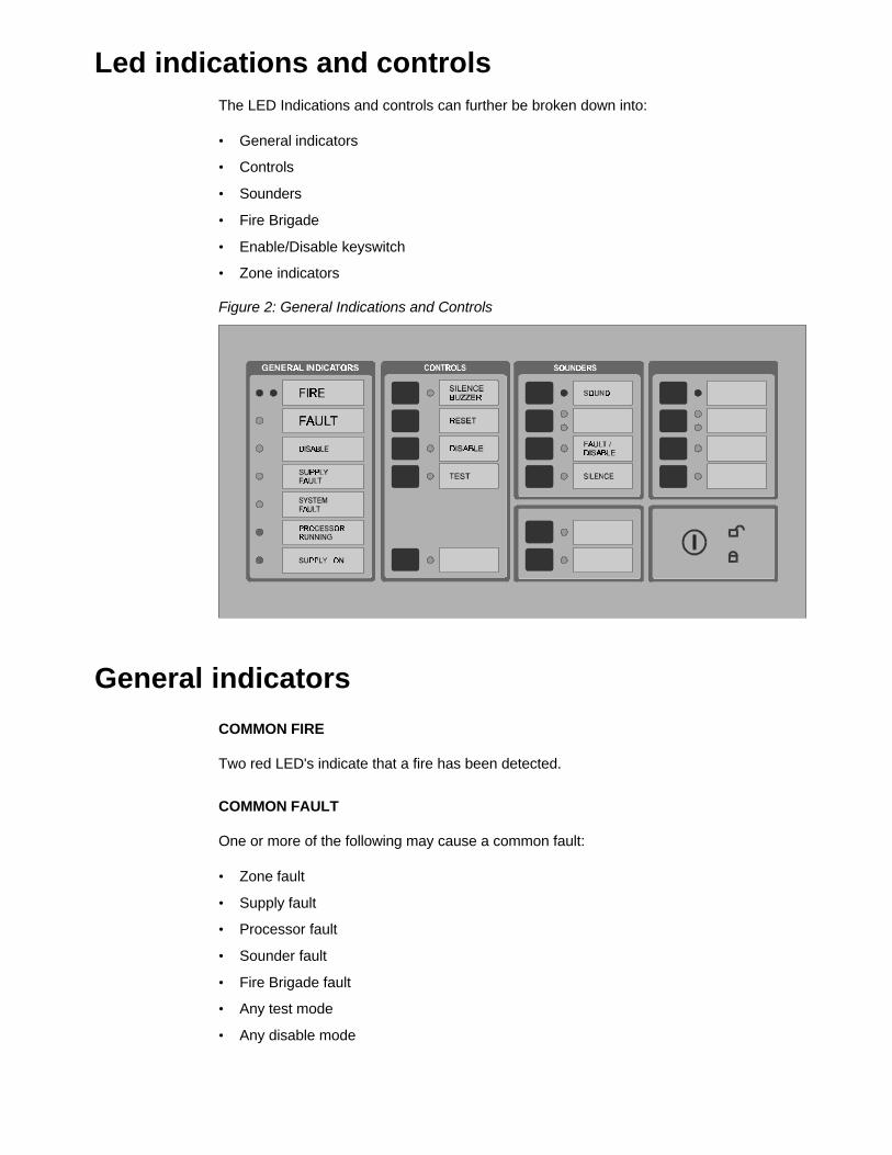
Led indications and controlsThe LED Indications and controls can further be broken down into:
• General indicators
• Controls
• Sounders
• Fire Brigade
• Enable/Disable keyswitch
• Zone indicators
Figure 2: General Indications and Controls
General indicators
COMMON FIRE
Two red LED's indicate that a fire has been detected.
COMMON FAULT
One or more of the following may cause a common fault:
• Zone fault
• Supply fault
• Processor fault
• Sounder fault
• Fire Brigade fault
• Any test mode
• Any disable mode
COMMON DISABLE
A yellow LED indicates that one or more of the following have been disabled:
• Devices on the loop
• Zone
• Sounders
• Fire Brigade
SUPPLY FAULT
A yellow LED will illuminate for:
• Mains failure
• Battery disconnect or not charging
SYSTEM FAULT
A yellow LED indicates that a system fault has occurred. A system failure can be one ormore of:
• Tamper switch
• Service switch
• Logic error
• Memory lock
• No checksums calculated
• Hardware test fault
• Fireman’s panel down
• Repeater down
• Panel down
• Global repeater down
• Input fault
• Output fault
• Configuration fault
• Checksum fault
• Protected memory overwritten
• Time date wrong
• Access fault
• FEP fault
• Watchdog time-out
PROCESSOR RUNNING
A flashing green LED indicates normal operation.
SUPPLY ON
A green LED indicates that the system is receiving 24V power.

Controls
SILENCE BUZZER (Keyswitch Enabled or Disabled)
The internal panel buzzer is activated for any new condition. The buzzer will becontinuous for a fire alarm condition, intermittent for a fault warning and slow intermittentfor a condition warning.
The buzzer is silenced by pressing the Silence Buzzer Key. The yellow silence buzzerLED will illuminate to indicate that the buzzer has been silenced.
RESET (Keyswitch Enabled)
This pushbutton will reset the fire panel.
DISABLE (Keyswitch Enabled)
This pushbutton calls up the Disable Menu (see Page 188). The yellow LED will indicate ifanything is disabled.
TEST (Keyswitch Enabled)
This pushbutton calls up the Test Menu (see Page 175). The yellow LED under GeneralIndicators will illuminate if the panel is put into a test mode.
Sounders
SOUND
Depends on operation selected by bits 5 and 6 of DIP switch on HOST PSU board. (*SeeAppendix B of the FP2000 Installation and Commissioning Manual: LKFP2003). A redLED indicates that the sounders have been activated.
DELAY ON/OFF
The programmed Sounder Delay (see Output Delays, Page 70) may be toggled ON orOFF. Two LEDs indicate the state.
Depends also on operation selected by bits 5 and 6 of DIP switch on HOST PSU board.(*See Appendix B of the FP2000 Installation and Commissioning Manual: LKFP2003).
FAULT/DISABLE (Keyswitch Enabled)
The Sounder Fault/Disable pushbutton allows the sounders to be disabled. Theassociated LED indicates that the sounders have been disabled or that a sounder fault ispresent.
The sounder fault can be:
• Sounder circuit open circuit
• Sounder circuit short circuit
• Bell fuse failure
SILENCE (Keyswitch Enabled)
Depends on operation selected by bits 5 and 6 of DIP switch on HOST PSU board. (*SeeAppendix B of the FP2000 Installation and Commissioning Manual: LKFP2003). A yellowLED indicates that the sounders have been silenced.
Fire brigade
SIGNAL (Keyswitch Enabled)
Depends on operation selected by bits 5 and 6 of DIP switch on HOST PSU board. (*SeeAppendix B of the FP2000 Installation and Commissioning Manual). A red LED willindicate that the signal has been activated.
DELAY ON/OFF
The programmed Fire Brigade Signal Delay (see Output Delays, Page 70) may betoggled ON or OFF. Two LEDs indicate the state.
Depends also on operation selected by bits 5 and 6 of DIP switch on HOST PSU board.
FAULT/DISABLE (Keyswitch Enabled)
The Fire Brigade output may be disabled by using this pushbutton. When the signal isdisabled, then the disable LED will be illuminated.
The Fire Brigade circuit is supervised. The Fire Brigade fault LED will flash when a fault isdetected in the circuit.
STOP FIRE BRIGADE (Keyswitch Enabled)
Depends on operation selected by bits 5 and 6 of DIP switch on HOST PSU board. (*SeeAppendix B of the FP2000 Installation and Commissioning Manual). A yellow LED willindicate that the Fire Brigade signal has been deactivated.
ENABLE/DISABLE KEYSWITCH
An Enable/Disable keyswitch is provided to either allow or prevent operation of the firepanel controls. The Silence Buzzer and Test keys will operate with the keyswitch in anyposition.
The different Sounder and Fire Brigade keys' operation depend on the operation selectedby bits 5 and 6 of the DIP switch on the HOST PSU board. (*See Appendix B of theFP2000 Installation and Commissioning Manual).
- Level 1 for Disable and level 2 for Enable must not be confused with access levels 1 and2. There is no relation between the Enable/Disable keyswitch and the allocated accesslevels.
Other
PANEL
This button is used by global and local repeaters for panel emulation. Emulation mode isactivated with a global repeater by pressing the Panel key, then entering the number of
the panel to be emulated, and Enter ( ).
To stop emulation, the Panel key is pressed and then "0" and Enter ( ).
When a global repeater is emulating a panel it is not necessary to stop emulation beforeemulating another panel. The global repeater will automatically stop the emulation beforetrying to emulate another panel.
With a local repeater, pressing the Panel key will start emulation of the panel. If the panelis already emulated, pressing the Panel key will stop emulation.
The yellow LED indicates whether a panel is emulated or not.
ALL
Used by the global repeater panel to send a command to all the panels the globalrepeater is communicating with. The yellow LED indicates that the key was pressed,meaning that the following command button to be pressed will be sent to all the relevantpanels.
THIRD SOURCE TEST
This key tests the third source battery when the panel is powered. Pressing the key willsound the buzzer.
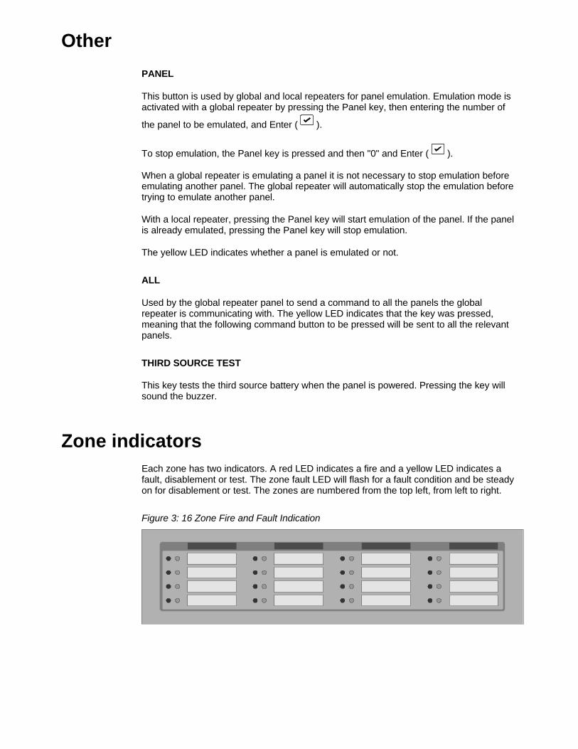
Zone indicatorsEach zone has two indicators. A red LED indicates a fire and a yellow LED indicates afault, disablement or test. The zone fault LED will flash for a fault condition and be steadyon for disablement or test. The zones are numbered from the top left, from left to right.
Figure 3: 16 Zone Fire and Fault Indication
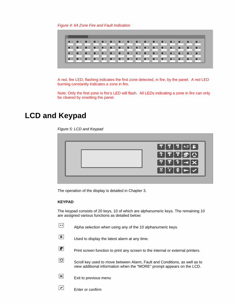
Figure 4: 64 Zone Fire and Fault Indication
A red, fire LED, flashing indicates the first zone detected, in fire, by the panel. A red LEDburning constantly indicates a zone in fire.
Note: Only the first zone in fire’s LED will flash. All LEDs indicating a zone in fire can onlybe cleared by resetting the panel.
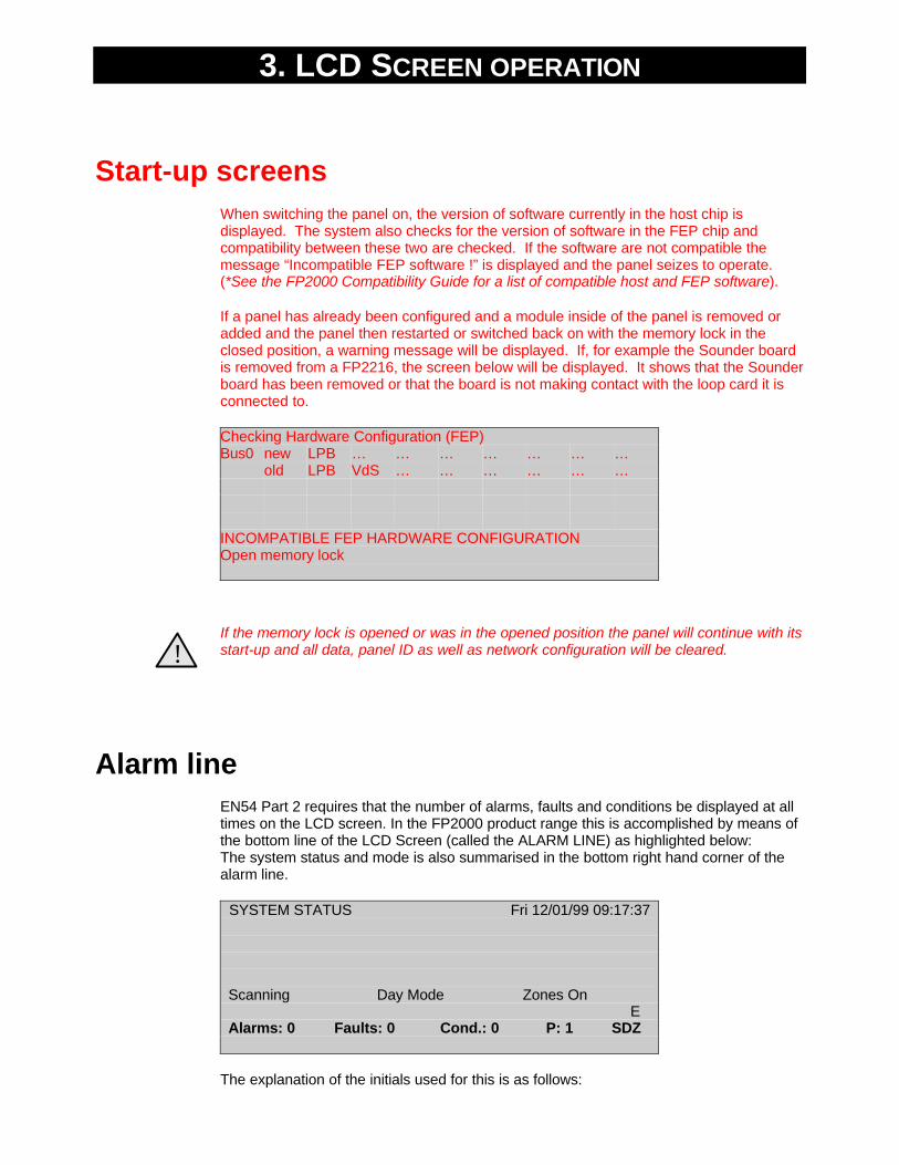
LCD and Keypad
Figure 5: LCD and Keypad
The operation of the display is detailed in Chapter 3.
KEYPAD
The keypad consists of 20 keys, 10 of which are alphanumeric keys. The remaining 10are assigned various functions as detailed below:
Alpha selection when using any of the 10 alphanumeric keys.
Used to display the latest alarm at any time.
Print screen function to print any screen to the internal or external printers.
Scroll key used to move between Alarm, Fault and Conditions, as well as to view additional information when the "MORE" prompt appears on the LCD.
Exit to previous menu
Enter or confirm

Move to the next field in the display
Move to the previous field in the display
Increment
Decrement
3. LCD SCREEN OPERATION
Start-up screensWhen switching the panel on, the version of software currently in the host chip isdisplayed. The system also checks for the version of software in the FEP chip andcompatibility between these two are checked. If the software are not compatible themessage “Incompatible FEP software !” is displayed and the panel seizes to operate.(*See the FP2000 Compatibility Guide for a list of compatible host and FEP software).
If a panel has already been configured and a module inside of the panel is removed oradded and the panel then restarted or switched back on with the memory lock in theclosed position, a warning message will be displayed. If, for example the Sounder boardis removed from a FP2216, the screen below will be displayed. It shows that the Sounderboard has been removed or that the board is not making contact with the loop card it isconnected to.
Checking Hardware Configuration (FEP)Bus0 new LPB … … … … … … …
old LPB VdS … … … … … …
INCOMPATIBLE FEP HARDWARE CONFIGURATIONOpen memory lock
!If the memory lock is opened or was in the opened position the panel will continue with itsstart-up and all data, panel ID as well as network configuration will be cleared.
Alarm lineEN54 Part 2 requires that the number of alarms, faults and conditions be displayed at alltimes on the LCD screen. In the FP2000 product range this is accomplished by means ofthe bottom line of the LCD Screen (called the ALARM LINE) as highlighted below:The system status and mode is also summarised in the bottom right hand corner of thealarm line.
SYSTEM STATUS Fri 12/01/99 09:17:37
Scanning Day Mode Zones On E
Alarms: 0 Faults: 0 Cond.: 0 P: 1 SDZ
The explanation of the initials used for this is as follows:
System Status System ModeIdle I Day Mode DPowerup P Night Mode NScanning S Security Zones On ZAutosetup A Security Zones Off OSensor test T
For exampleSDZ - Scanning, Day Mode, Zones OnSDO - Scanning, Day Mode, Zones OffSNZ - Scanning, Night Mode, Zones Onetc.
If the panel is assigned a number, the number is displayed as part of the alarm line:P - Fire panelG - Global repeater or master panelL - Local repeater panel
For exampleP: 1 - Fire panel number 1G: 1 - Global repeater panel number 1L: 1/1 - Local repeater panel number 1 of fire panel 1
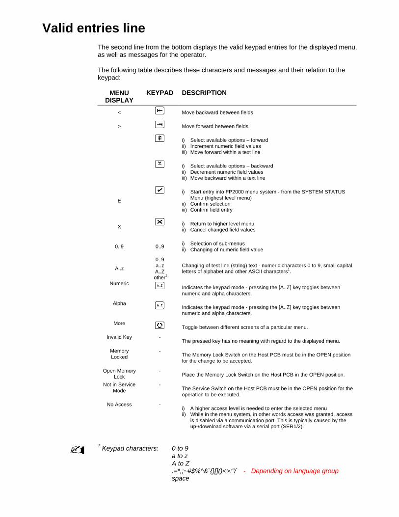
Valid entries lineThe second line from the bottom displays the valid keypad entries for the displayed menu,as well as messages for the operator.
The following table describes these characters and messages and their relation to thekeypad:
MENUDISPLAY
KEYPAD DESCRIPTION
< Move backward between fields
> Move forward between fields
∧i) Select available options – forwardii) Increment numeric field valuesiii) Move forward within a text line
∨i) Select available options – backwardii) Decrement numeric field valuesiii) Move backward within a text line
E
i) Start entry into FP2000 menu system - from the SYSTEM STATUS Menu (highest level menu)
ii) Confirm selectioniii) Confirm field entry
X i) Return to higher level menuii) Cancel changed field values
0..9 0..9 i) Selection of sub-menusii) Changing of numeric field value
A..z
0..9a..zA..Z
other1
Changing of test line (string) text - numeric characters 0 to 9, small capitalletters of alphabet and other ASCII characters1.
NumericIndicates the keypad mode - pressing the [A..Z] key toggles betweennumeric and alpha characters.
AlphaIndicates the keypad mode - pressing the [A..Z] key toggles betweennumeric and alpha characters.
MoreToggle between different screens of a particular menu.
Invalid Key -The pressed key has no meaning with regard to the displayed menu.
MemoryLocked
-The Memory Lock Switch on the Host PCB must be in the OPEN positionfor the change to be accepted.
Open MemoryLock
-Place the Memory Lock Switch on the Host PCB in the OPEN position.
Not in ServiceMode
-The Service Switch on the Host PCB must be in the OPEN position for theoperation to be executed.
No Access -i) A higher access level is needed to enter the selected menuii) While in the menu system, in other words access was granted, access
is disabled via a communication port. This is typically caused by the up-/download software via a serial port (SER1/2).
- 1 Keypad characters: 0 to 9a to zA to Z.=*,;~#$%^&`{}[]()<>:"/ - Depending on language groupspace
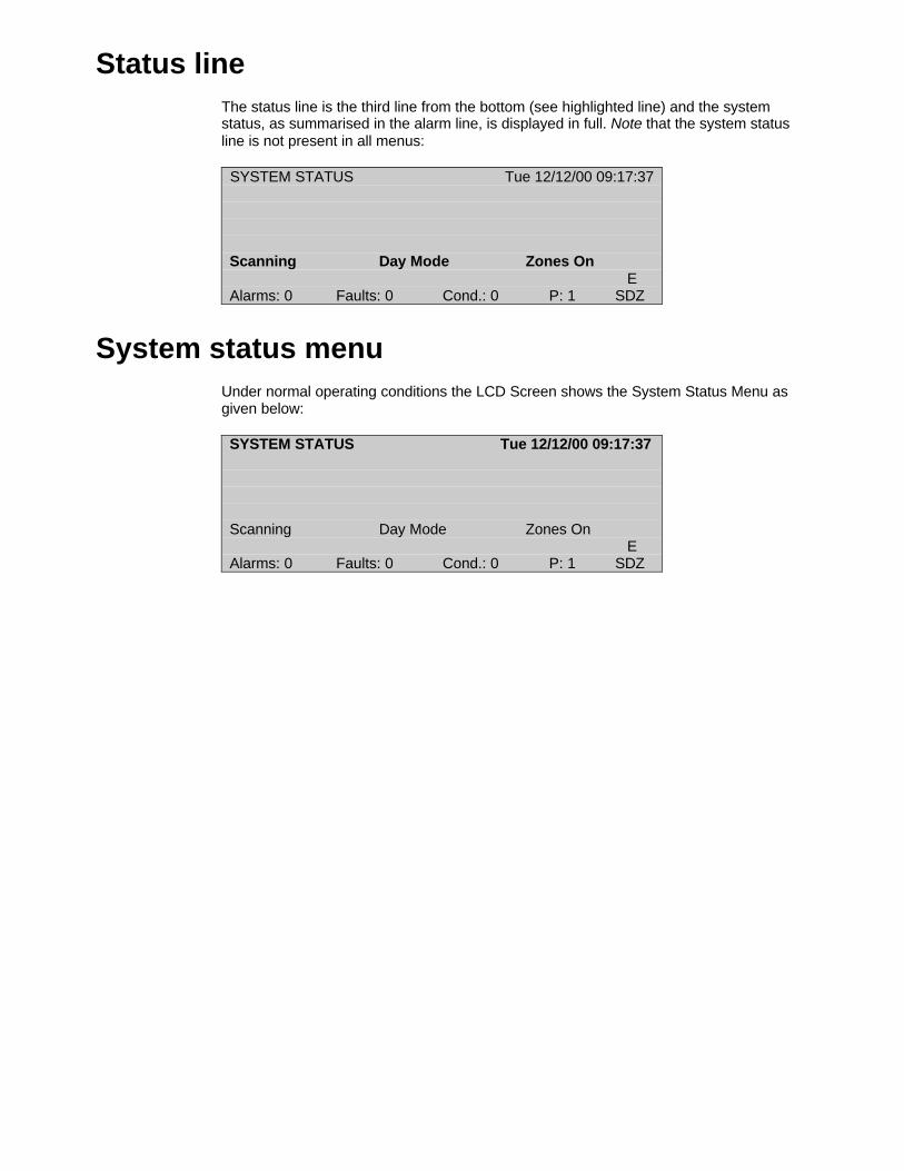
Status lineThe status line is the third line from the bottom (see highlighted line) and the systemstatus, as summarised in the alarm line, is displayed in full. Note that the system statusline is not present in all menus:
SYSTEM STATUS Tue 12/12/00 09:17:37
Scanning Day Mode Zones On E
Alarms: 0 Faults: 0 Cond.: 0 P: 1 SDZ
System status menuUnder normal operating conditions the LCD Screen shows the System Status Menu asgiven below:
SYSTEM STATUS Tue 12/12/00 09:17:37
Scanning Day Mode Zones On E
Alarms: 0 Faults: 0 Cond.: 0 P: 1 SDZ

4. PROGRAMMING MENUS
Access to main menuMain Menu obtained from the System Status Screen after entering an access code.
If the fire panel is currently displaying alarms, faults, or conditions on the screen, then
press to obtain the System Status Screen.
SYSTEM STATUS Tue 12/12/00 09:17:37
Scanning Day Mode Zones On E
Alarms: 0 Faults: 0 Cond.: 0 P: 1 SDZ
Press to obtain the access code prompt.
Enter Access Code:
0. .9, <>, E, XAlarms: 0 Faults: 0 Cond.: 0 P: 1 SDZ
Enter a one to four digit code and press .
The Main Menu will be displayed, provided one of six correct codes has been entered.Different codes may have different access levels. This means that some facilities maynot be available to users with a code of lower access level.
*See Access Menu, Page 59
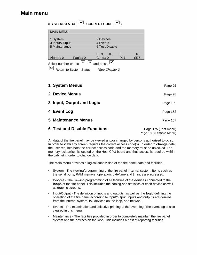
Main menu
(SYSTEM STATUS, , CORRECT CODE, )
MAIN MENU
1 System 2 Devices3 Input/Output 4 Events5 Maintenance 6 Test/Disable
0. .9, <>, E, XAlarms: 0 Faults: 0 Cond.: 0 P: 1 SDZ
Select number or use and press
Return to System Status *See Chapter 3.
1 System Menus Page 25
2 Device Menus Page 78
3 Input, Output and Logic Page 109
4 Event Log Page 152
5 Maintenance Menus Page 157
6 Test and Disable Functions Page 175 (Test menu)Page 188 (Disable Menu)
All data of the fire panel may be viewed and/or changed by persons authorised to do so.In order to view any screen requires the correct access code(s). In order to change data,the user requires both the correct access code and the memory must be unlocked. Thememory lock switch is located on the Host CPU board and thus access is required withinthe cabinet in order to change data.
The Main Menu provides a logical subdivision of the fire panel data and facilities.
• System - The viewing/programming of the fire panel internal system. Items such asthe serial ports, RAM memory, operation, date/time and timings are accessed.
• Devices - The viewing/programming of all facilities of the devices connected to theloops of the fire panel. This includes the zoning and statistics of each device as wellas graphic screens.
• Input/Output - The definition of inputs and outputs, as well as the logic defining theoperation of the fire panel according to input/output. Inputs and outputs are derivedfrom the internal system, I/O devices on the loop, and network.
• Events - The examination and selective printing of the event log. The event log is alsocleared in this menu.
• Maintenance - The facilities provided in order to completely maintain the fire panelsystem and the devices on the loop. This includes a host of reporting facilities.

• Test/Disable - Zones and individual devices can be selectively tested and disabled.Test features include one-man test of zones and soak test of individual devices. TheTest and Disable Menus are not directly available from the Main Menu, but areaccessed by using the Test and Disable keys on the front panel. These menus do notrequire any access code, but do require that the enable/disable keyswitch is enabled.Selecting Test/Disable from the Main Menu causes a prompt to operate the desiredkeyswitch.
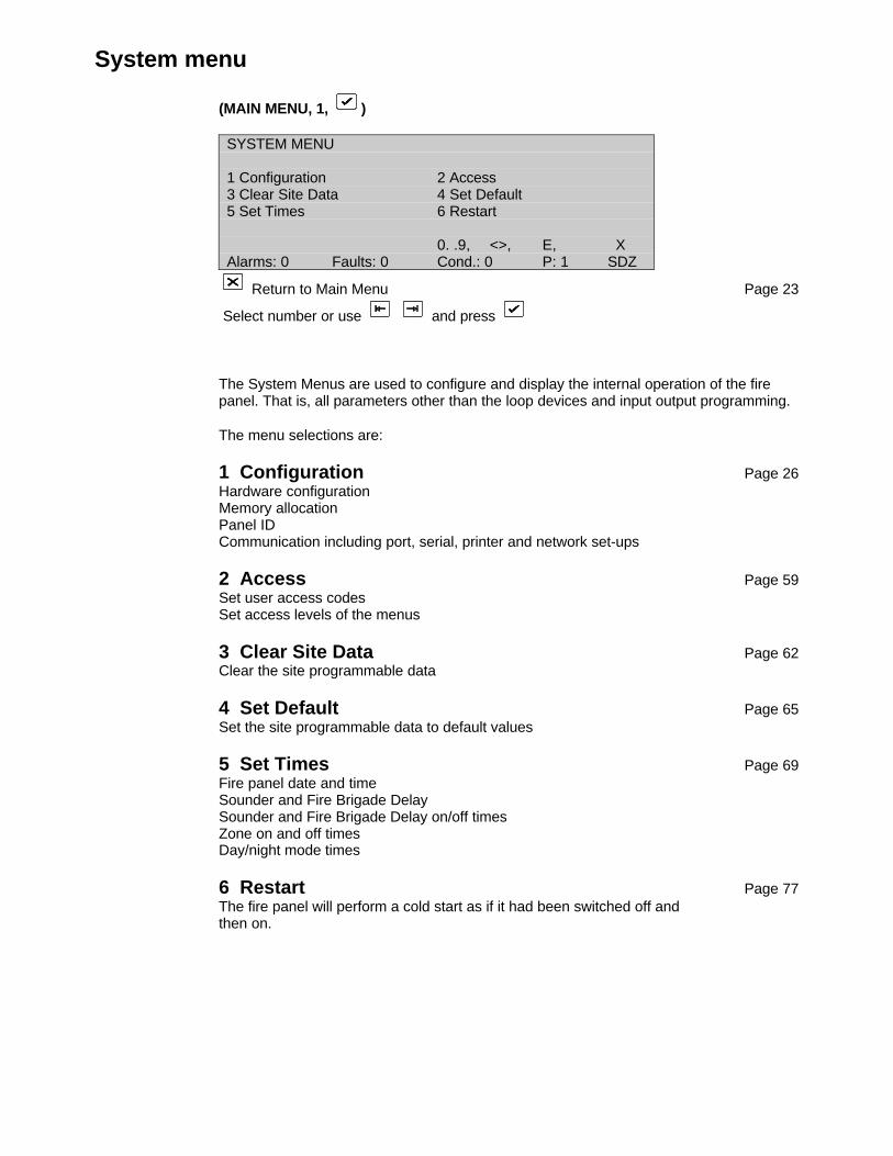
System menu
(MAIN MENU, 1, )
SYSTEM MENU
1 Configuration 2 Access3 Clear Site Data 4 Set Default5 Set Times 6 Restart
0. .9, <>, E, XAlarms: 0 Faults: 0 Cond.: 0 P: 1 SDZ
Return to Main Menu Page 23
Select number or use and press
The System Menus are used to configure and display the internal operation of the firepanel. That is, all parameters other than the loop devices and input output programming.
The menu selections are:
1 Configuration Page 26Hardware configurationMemory allocationPanel IDCommunication including port, serial, printer and network set-ups
2 Access Page 59Set user access codesSet access levels of the menus
3 Clear Site Data Page 62Clear the site programmable data
4 Set Default Page 65Set the site programmable data to default values
5 Set Times Page 69Fire panel date and timeSounder and Fire Brigade DelaySounder and Fire Brigade Delay on/off timesZone on and off timesDay/night mode times
6 Restart Page 77The fire panel will perform a cold start as if it had been switched off andthen on.

Configuration menu
(SYSTEM MENU, 1, )
CONFIGURATION MENU
1 Hardware 2 Allocation3 ID 4 Communication5 System Setup 6 System Information
0. .9, <>, E, XAlarms: 0 Faults: 0 Cond.: 0 P: 1 SDZ
Return to System Menu Page 25
Select number or use and press
1 Hardware Page 27View the fire panel internal configuration, software version, site data version, ports andPCB's.
2 Allocation Page 33Memory allocation for field devices, I/O and logic, text, and event buffer
3 Panel ID Page 35Set the ID number of the fire panel
4 Communication Page 37Port setupNetworkModemCurrent loop devicesLON Devices
5 System Setup Page 56Configuration of externally connected interfaces: Fire Brigade (Hauptmelder), FSK Heaterand FBF (Bedienfeld).Language, protocol and mode of operation settings. (Only for the FP11xx & FP12xx.)
6 System Information Page 58AllocationPanelsL-RepeatersG-RepeatersSystemStackSpecial CharactersText DebuggingFEPSERModemARC0ARC1LONLON Characters
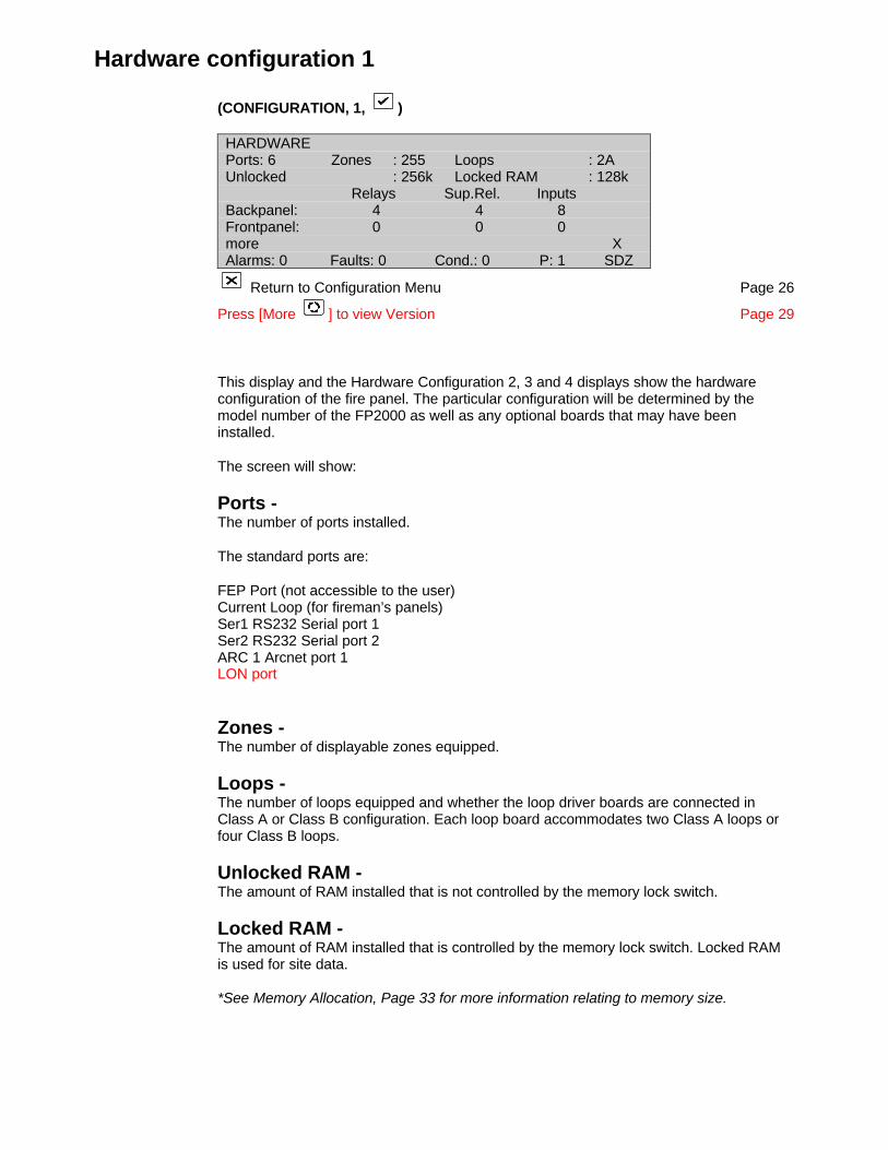
Hardware configuration 1
(CONFIGURATION, 1, )
HARDWARE Ports: 6 Zones : 255 Loops : 2AUnlocked : 256k Locked RAM : 128k
Relays Sup.Rel. InputsBackpanel: 4 4 8Frontpanel: 0 0 0more XAlarms: 0 Faults: 0 Cond.: 0 P: 1 SDZ
Return to Configuration Menu Page 26
Press [More ] to view Version Page 29
This display and the Hardware Configuration 2, 3 and 4 displays show the hardwareconfiguration of the fire panel. The particular configuration will be determined by themodel number of the FP2000 as well as any optional boards that may have beeninstalled.
The screen will show:
Ports -The number of ports installed.
The standard ports are:
FEP Port (not accessible to the user)Current Loop (for fireman’s panels)Ser1 RS232 Serial port 1Ser2 RS232 Serial port 2ARC 1 Arcnet port 1LON port
Zones -The number of displayable zones equipped.
Loops -The number of loops equipped and whether the loop driver boards are connected inClass A or Class B configuration. Each loop board accommodates two Class A loops orfour Class B loops.
Unlocked RAM -The amount of RAM installed that is not controlled by the memory lock switch.
Locked RAM -The amount of RAM installed that is controlled by the memory lock switch. Locked RAMis used for site data.
*See Memory Allocation, Page 33 for more information relating to memory size.
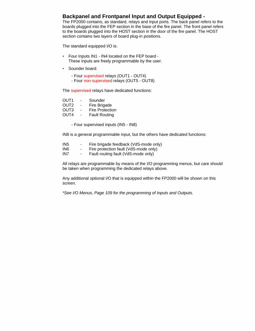
Backpanel and Frontpanel Input and Output Equipped -The FP2000 contains, as standard, relays and input ports. The back panel refers to theboards plugged into the FEP section in the base of the fire panel. The front panel refersto the boards plugged into the HOST section in the door of the fire panel. The HOSTsection contains two layers of board plug-in positions.
The standard equipped I/O is:
• Four Inputs IN1 - IN4 located on the FEP board -These inputs are freely programmable by the user.
• Sounder board:
- Four supervised relays (OUT1 - OUT4)- Four non-supervised relays (OUT5 - OUT8)
The supervised relays have dedicated functions:
OUT1 - SounderOUT2 - Fire BrigadeOUT3 - Fire ProtectionOUT4 - Fault Routing
- Four supervised inputs (IN5 - IN8)
IN8 is a general programmable input, but the others have dedicated functions:
IN5 - Fire brigade feedback (VdS-mode only)IN6 - Fire protection fault (VdS-mode only)IN7 - Fault routing fault (VdS-mode only)
All relays are programmable by means of the I/O programming menus, but care shouldbe taken when programming the dedicated relays above.
Any additional optional I/O that is equipped within the FP2000 will be shown on thisscreen.
*See I/O Menus, Page 109 for the programming of Inputs and Outputs.

Version
(CONFIGURATION 1, )
VERSION
Product :FP2000Host :6.10 2000-00 09.11.00 7196HFEP :6.10 0000-00 20.11.00 796EH
more <>, E, XAlarms: 0 Faults: 0 Cond.: 0 P: 1 SDZ
Return to Configuration Menu Page 26
Press [More ] to view Site Version Page 30
This menu is used to display the version number and the compilation date of the installedHOST and FEP software as well as their checksums in hex format.
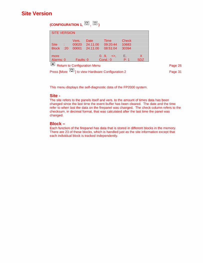
Site Version
(CONFIGURATION 1, , )
SITE VERSION
Vers. Date Time CheckSite : 00020 24.11.00 09:20:44 10683Block :20 00001 24.11.00 08:51:04 30394
more 0. .9, <>, E, XAlarms: 0 Faults: 0 Cond.: 0 P: 1 SDZ
Return to Configuration Menu Page 26
Press [More ] to view Hardware Configuration 2 Page 31
This menu displays the self-diagnostic data of the FP2000 system.
Site -The site refers to the panels itself and vers. to the amount of times data has beenchanged since the last time the event buffer has been cleared. The date and the timerefer to when last the data on the firepanel was changed. The check column refers to thechecksum, in decimal format, that was calculated after the last time the panel waschanged.
Block –Each function of the firepanel has data that is stored in different blocks in the memory.There are 23 of these blocks, which is handled just as the site information except thateach individual block is tracked independently.
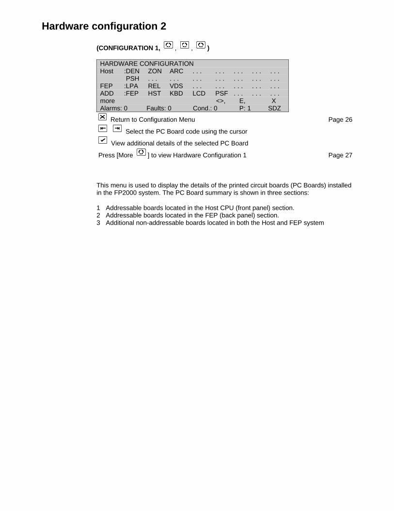
Hardware configuration 2
(CONFIGURATION 1, , , )
HARDWARE CONFIGURATIONHost :DEN ZON ARC . . . . . . . . . . . . . . .
PSH . . . . . . . . . . . . . . . . . . . . .FEP :LPA REL VDS . . . . . . . . . . . . . . .ADD :FEP HST KBD LCD PSF . . . . . . . . .more <>, E, XAlarms: 0 Faults: 0 Cond.: 0 P: 1 SDZ
Return to Configuration Menu Page 26
Select the PC Board code using the cursor
View additional details of the selected PC Board
Press [More ] to view Hardware Configuration 1 Page 27
This menu is used to display the details of the printed circuit boards (PC Boards) installedin the FP2000 system. The PC Board summary is shown in three sections:
1 Addressable boards located in the Host CPU (front panel) section.2 Addressable boards located in the FEP (back panel) section.3 Additional non-addressable boards located in both the Host and FEP system
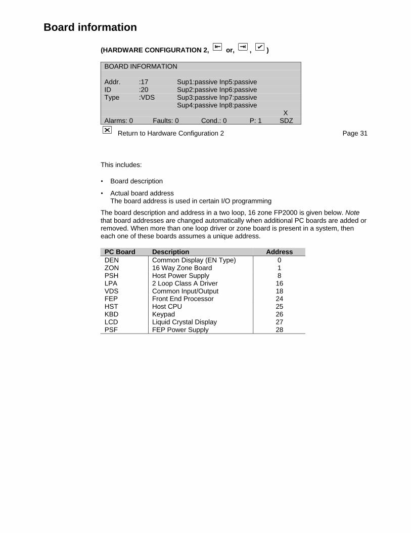
Board information
(HARDWARE CONFIGURATION 2, or, , )
BOARD INFORMATION
Addr. :17 Sup1:passive Inp5:passiveID :20 Sup2:passive Inp6:passiveType :VDS Sup3:passive Inp7:passive
Sup4:passive Inp8:passive X
Alarms: 0 Faults: 0 Cond.: 0 P: 1 SDZ
Return to Hardware Configuration 2 Page 31
This includes:
• Board description
• Actual board addressThe board address is used in certain I/O programming
The board description and address in a two loop, 16 zone FP2000 is given below. Notethat board addresses are changed automatically when additional PC boards are added orremoved. When more than one loop driver or zone board is present in a system, theneach one of these boards assumes a unique address.
PC Board Description AddressDEN Common Display (EN Type) 0ZON 16 Way Zone Board 1PSH Host Power Supply 8LPA 2 Loop Class A Driver 16VDS Common Input/Output 18FEP Front End Processor 24HST Host CPU 25KBD Keypad 26LCD Liquid Crystal Display 27PSF FEP Power Supply 28
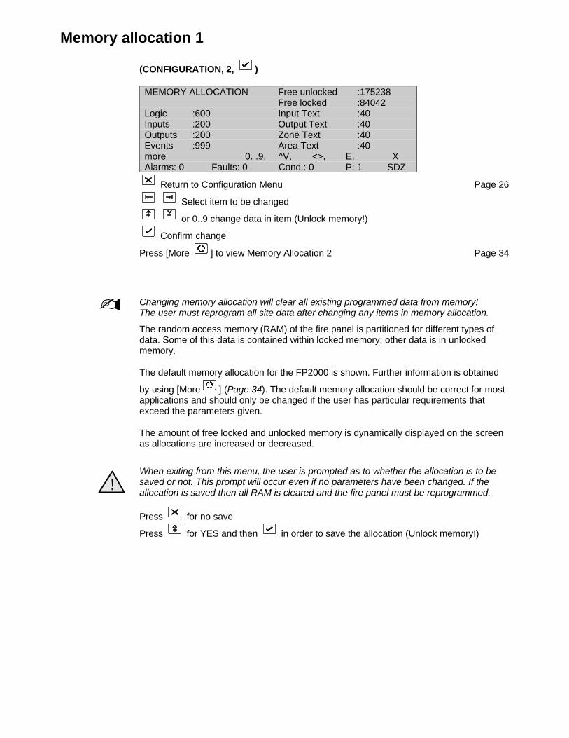
Memory allocation 1
(CONFIGURATION, 2, )
MEMORY ALLOCATION Free unlocked :175238Free locked :84042
Logic :600 Input Text :40Inputs :200 Output Text :40Outputs :200 Zone Text :40Events :999 Area Text :40more 0. .9, ^V, <>, E, XAlarms: 0 Faults: 0 Cond.: 0 P: 1 SDZ
Return to Configuration Menu Page 26
Select item to be changed
or 0..9 change data in item (Unlock memory!)
Confirm change
Press [More ] to view Memory Allocation 2 Page 34
- Changing memory allocation will clear all existing programmed data from memory!The user must reprogram all site data after changing any items in memory allocation.
The random access memory (RAM) of the fire panel is partitioned for different types ofdata. Some of this data is contained within locked memory; other data is in unlockedmemory.
The default memory allocation for the FP2000 is shown. Further information is obtained
by using [More ] (Page 34). The default memory allocation should be correct for mostapplications and should only be changed if the user has particular requirements thatexceed the parameters given.
The amount of free locked and unlocked memory is dynamically displayed on the screenas allocations are increased or decreased.
!When exiting from this menu, the user is prompted as to whether the allocation is to besaved or not. This prompt will occur even if no parameters have been changed. If theallocation is saved then all RAM is cleared and the fire panel must be reprogrammed.
Press for no save
Press for YES and then in order to save the allocation (Unlock memory!)
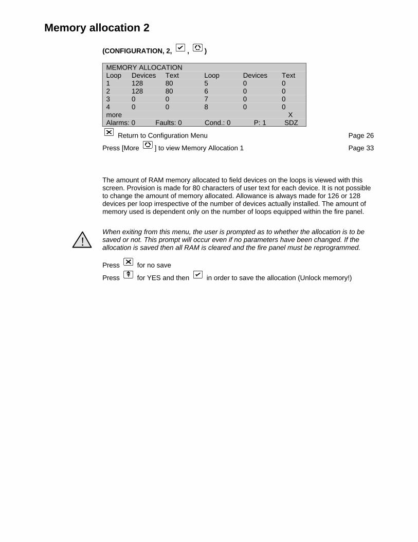
Memory allocation 2
(CONFIGURATION, 2, , )
MEMORY ALLOCATIONLoop Devices Text Loop Devices Text1 128 80 5 0 02 128 80 6 0 03 0 0 7 0 04 0 0 8 0 0more XAlarms: 0 Faults: 0 Cond.: 0 P: 1 SDZ
Return to Configuration Menu Page 26
Press [More ] to view Memory Allocation 1 Page 33
The amount of RAM memory allocated to field devices on the loops is viewed with thisscreen. Provision is made for 80 characters of user text for each device. It is not possibleto change the amount of memory allocated. Allowance is always made for 126 or 128devices per loop irrespective of the number of devices actually installed. The amount ofmemory used is dependent only on the number of loops equipped within the fire panel.
!When exiting from this menu, the user is prompted as to whether the allocation is to besaved or not. This prompt will occur even if no parameters have been changed. If theallocation is saved then all RAM is cleared and the fire panel must be reprogrammed.
Press for no save
Press for YES and then in order to save the allocation (Unlock memory!)

Panel ID
(CONFIGURATION, 3, )
IDENTIFICATIONChange of Node ID Clears Eventbuffer!Node : 1 / 0 Max. Config.:15/15Panel : 1
0. . 9, ^V, E, XAlarms: 0 Faults: 0 Cond.: 0 P: 1 SDZ
Return to Configuration Menu Page 26
Select item to be changed
or 0..9 change data in item (Unlock memory!)
Confirm change
Return to Configuration Menu Page 26
For Panel ID Text Fields (2 lines x 40 characters):
Use to obtain the text line to be changed
Press (Unlock memory!)
Use to toggle between alpha and numeric textPress the alpha/numeric button required
Use to move the cursor within the line
Press when completed
Default:ID: 1/0Panel: 1Max. Config.: 15/15
Each FP2000 fire panel, as well as global repeaters, global zone repeaters and localrepeaters in a network system, can be uniquely identified by means of the panel ID. Thepanel ID is used for the upload/download of data via the serial ports, as well asinformation transfer on the network. In addition to the panel ID, two lines of user text canbe assigned to each fire panel or repeater. The user text is displayed on the SystemStatus Screen and for the logging of all system (general) fault warnings of the panel.
The Panel ID consists of two digits: fire panel number/repeater number (p/r).
For fire panels the repeater number is always Øe.g.: 0/0 - fire panel Ø
12/0 - fire panel 12
For global repeaters or global zone repeaters (network systems only) the fire panelnumber is zero, and the repeater number defines the global repeatere.g.: 0/1 - global repeater number 1
0/3 - global repeater number
For local repeaters attached to a particular fire panel on the network, the fire panelnumber and the repeater number defines the repeatere.g.: 1/3 - repeater 3 of fire panel 1
3/1 - repeater 1 of fire panel 3

The field "Panel" confirms the fire panel number. The panel ID is also shown on line 8 ofthe display: P:p. For global repeaters the word "Panel" becomes "G-Repeater" and line 8displays G:r. For local repeaters the display is "repeater" and L:p/r is displayed on line 8.
The field Max. Config. : Panel/repeater show the maximum number of panels andrepeaters, local or global that can be configured. Theoptions are: 7/31
15/1531/7
When transferring data from a computer to the fire panel, the fire panel ID of the data filemust match the fire panel ID.
When setup as a Global Repeater or Global Zone Repeater, additional Universal Nodesettings are possible:
un-n for a Universal Node on the Setup/NET1/NET2 Portun-m for a Universal Node on the Modem Port
• If set to 0/0, the Universal Node ID will automatically assume the ID of the connectedPC or Panel.
• If set to 0/x (x = valid repeater number) then the Universal Node functions will onlywork if the connected PC or Panel will have the same ID.
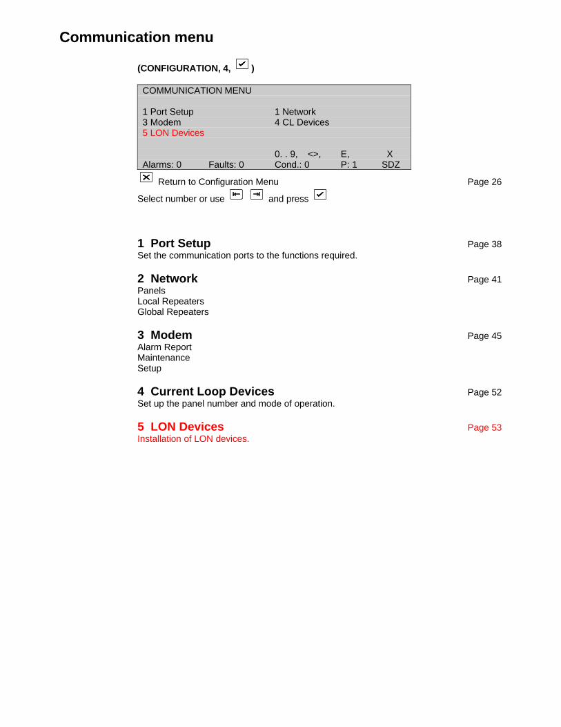
Communication menu
(CONFIGURATION, 4, )
COMMUNICATION MENU
1 Port Setup 1 Network3 Modem 4 CL Devices5 LON Devices
0. . 9, <>, E, XAlarms: 0 Faults: 0 Cond.: 0 P: 1 SDZ
Return to Configuration Menu Page 26
Select number or use and press
1 Port Setup Page 38Set the communication ports to the functions required.
2 Network Page 41PanelsLocal RepeatersGlobal Repeaters
3 Modem Page 45Alarm ReportMaintenanceSetup
4 Current Loop Devices Page 52Set up the panel number and mode of operation.
5 LON Devices Page 53Installation of LON devices.
Port setup
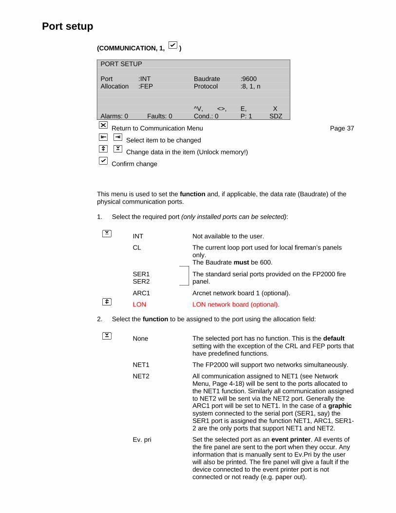
(COMMUNICATION, 1, )
PORT SETUP
Port :INT Baudrate :9600Allocation :FEP Protocol :8, 1, n
^V, <>, E, XAlarms: 0 Faults: 0 Cond.: 0 P: 1 SDZ
Return to Communication Menu Page 37
Select item to be changed
Change data in the item (Unlock memory!)
Confirm change
This menu is used to set the function and, if applicable, the data rate (Baudrate) of thephysical communication ports.
1. Select the required port (only installed ports can be selected):
INT Not available to the user.
CL The current loop port used for local fireman’s panelsonly.The Baudrate must be 600.
SER1SER2
The standard serial ports provided on the FP2000 firepanel.
ARC1 Arcnet network board 1 (optional).
LON LON network board (optional).
2. Select the function to be assigned to the port using the allocation field:
None The selected port has no function. This is the defaultsetting with the exception of the CRL and FEP ports thathave predefined functions.
NET1 The FP2000 will support two networks simultaneously.
NET2 All communication assigned to NET1 (see NetworkMenu, Page 4-18) will be sent to the ports allocated tothe NET1 function. Similarly all communication assignedto NET2 will be sent via the NET2 port. Generally theARC1 port will be set to NET1. In the case of a graphicsystem connected to the serial port (SER1, say) theSER1 port is assigned the function NET1, ARC1, SER1-2 are the only ports that support NET1 and NET2.
Ev. pri Set the selected port as an event printer. All events ofthe fire panel are sent to the port when they occur. Anyinformation that is manually sent to Ev.Pri by the userwill also be printed. The fire panel will give a fault if thedevice connected to the event printer port is notconnected or not ready (e.g. paper out).

Rp.Pri Set the selected port as a report printer. The reportprinter port is used to manually sent report to a devicesuch as a printer or laptop computer. It is primarily usedfor selected printing of the event buffer, test reports andsuch. No fault is given if a report printer is off line or notplugged in. Thus, a report printer can be removed at anytime. Reports are held in a buffer when the deviceconnected to the port is not on-line. The type of printer(e.g. internal) can be defined.
VDU This function operates in the same manner as Rp.Priabove, except that the report is halted every 20 lines(one VDU screen). Pressing any character on the VDUdevice will allow the report to be continued for a further20 lines. This function is particularly useful for viewingreports on the screen of a laptop computer. Only theserial ports support VDU.
EMU The port is set to emulation mode. Only the serial portssupport EMU. This allows the fire panel to be operatedremotely by means of a computer. The entire fire panelfront panel keyboard and display is accessible via theserial port in this mode. Special software (PC2000series) is required at the computer to operate inemulation mode.
CL Device This is the default function for the current loop port. It isused to communicate to fireman’s panels connected tothe current loop port. This function should not beassigned to any other port.
Setup Allows remote upload and download of site via the serialport. This function is used to program site data into thefire panel. Upload/download software is required at thecomputer. Only the serial ports support Setup.
FEP The FEP function is used for the INT port only.
Modem This function assigns one of the serial ports as aninterface to a modem.
CMSI Allows communication to a French CMSI panel.Although both serial ports can be set up to communicateto a CMSI panel, a PE2485 CMSI interface card canonly be connected to SER2. SER1 will need an externalinterface. When the CMSI function is selected the SDIaddresses can be configured. Up to a maximum of 15firepanels can be connected to a CMSI panel. Twodifferent SDI addresses can be configured per firepanelso that one panel can be seen by the CMSI panel at twodifferent SDI’s. If both SDI’s are set up for a 255-zonepanel, SDI-A is assigned to zones 1-127 and SDI-Bzones 128-254. Only the first 45 zones in fire per SDIwill be displayed by the CMSI. The baudrate for theCMSI is fixed at 4800 baud.
3. Select the Baudrate for the serial ports (default 9600)
300
600
1200
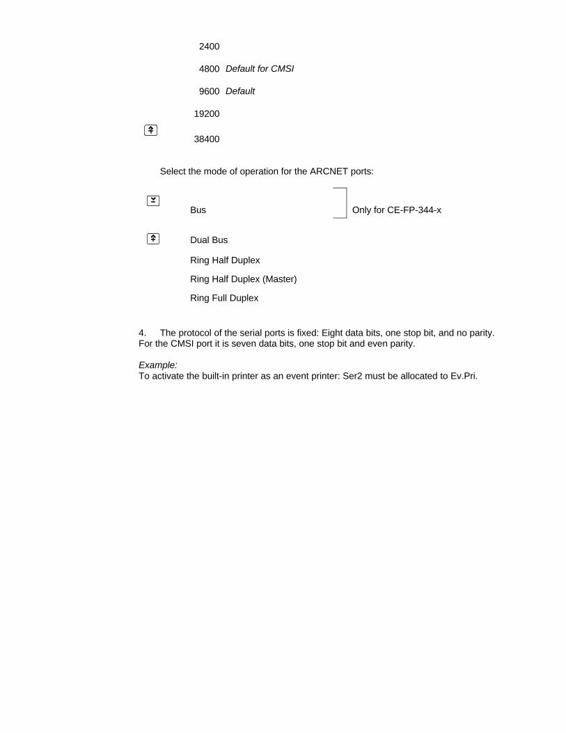
2400
4800 Default for CMSI
9600 Default
19200
38400
Select the mode of operation for the ARCNET ports:
Bus Only for CE-FP-344-x
Dual Bus
Ring Half Duplex
Ring Half Duplex (Master)
Ring Full Duplex
4. The protocol of the serial ports is fixed: Eight data bits, one stop bit, and no parity.For the CMSI port it is seven data bits, one stop bit and even parity.
Example:To activate the built-in printer as an event printer: Ser2 must be allocated to Ev.Pri.
Network menu
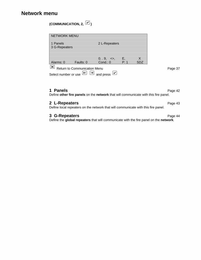
(COMMUNICATION, 2, )
NETWORK MENU
1 Panels 2 L-Repeaters3 G-Repeaters
0. . 9, <>, E, XAlarms: 0 Faults: 0 Cond.: 0 P: 1 SDZ
Return to Communication Menu Page 37
Select number or use and press
1 Panels Page 42Define other fire panels on the network that will communicate with this fire panel.
2 L-Repeaters Page 43Define local repeaters on the network that will communicate with this fire panel.
3 G-Repeaters Page 44Define the global repeaters that will communicate with the fire panel on the network.
Panels
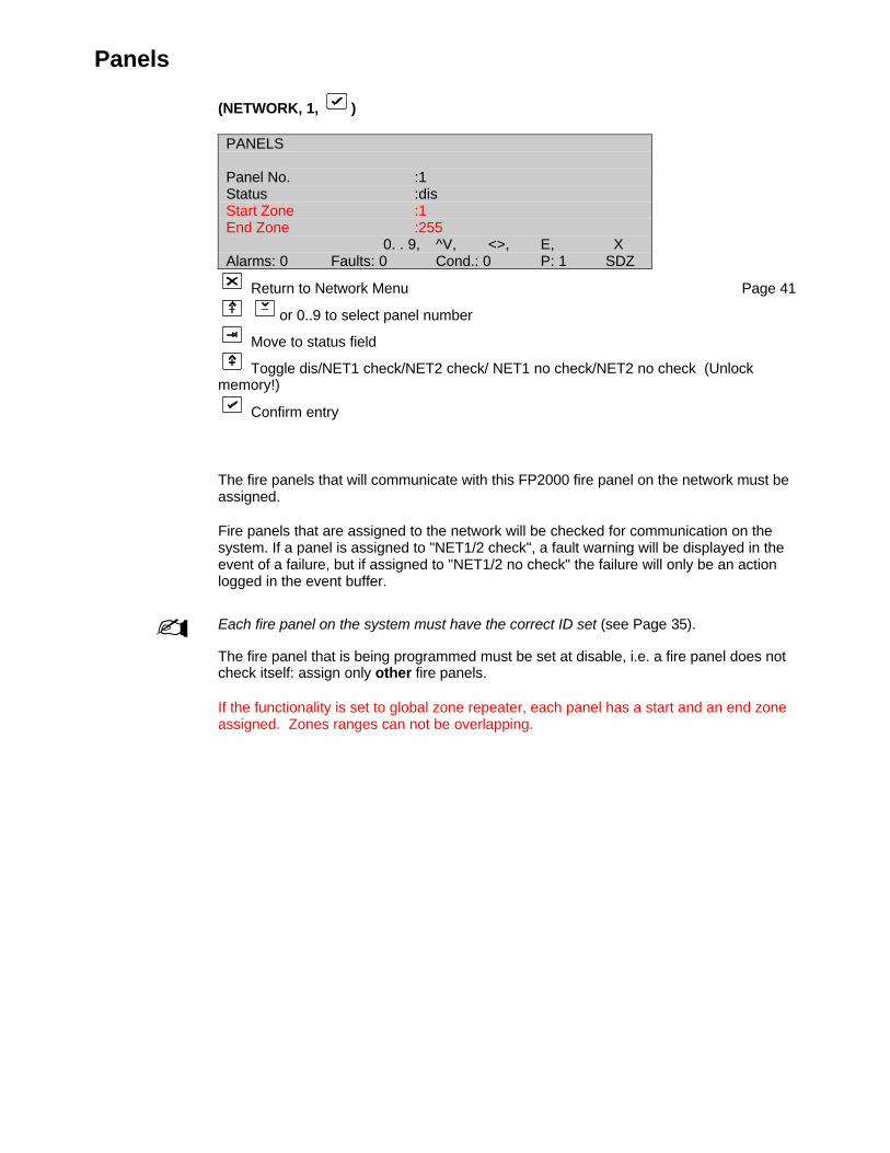
(NETWORK, 1, )
PANELS
Panel No. :1Status :disStart Zone :1End Zone :255
0. . 9, ^V, <>, E, XAlarms: 0 Faults: 0 Cond.: 0 P: 1 SDZ
Return to Network Menu Page 41
or 0..9 to select panel number
Move to status field
Toggle dis/NET1 check/NET2 check/ NET1 no check/NET2 no check (Unlockmemory!)
Confirm entry
The fire panels that will communicate with this FP2000 fire panel on the network must beassigned.
Fire panels that are assigned to the network will be checked for communication on thesystem. If a panel is assigned to "NET1/2 check", a fault warning will be displayed in theevent of a failure, but if assigned to "NET1/2 no check" the failure will only be an actionlogged in the event buffer.
- Each fire panel on the system must have the correct ID set (see Page 35).
The fire panel that is being programmed must be set at disable, i.e. a fire panel does notcheck itself: assign only other fire panels.
If the functionality is set to global zone repeater, each panel has a start and an end zoneassigned. Zones ranges can not be overlapping.

Local repeaters
(NETWORK, 2, )
LOCAL REPEATERS
L-Repeater No. :1Status :dis
^V, <>, E, XAlarms: 0 Faults: 1 Cond.: 0 P: 1 SDZ
Return to Network Menu Page 41
or 0..9 to select repeater number
Move to status field
Toggle dis/NET1 check/NET2 check/NET1 no check/NET2 no check (Unlockmemory!)
Confirm entry
The local repeater that will communicate with this FP2000 panel on the network, must beassigned.
Local repeaters that are assigned to the network will be checked for communication onthe system. If a local repeater is assigned to "NET1/2 check", a fault warning will bedisplayed in the event of a failure, but if assigned to "NET1/2 no check", the failure willonly be an action logged in the event buffer.
Global repeaters
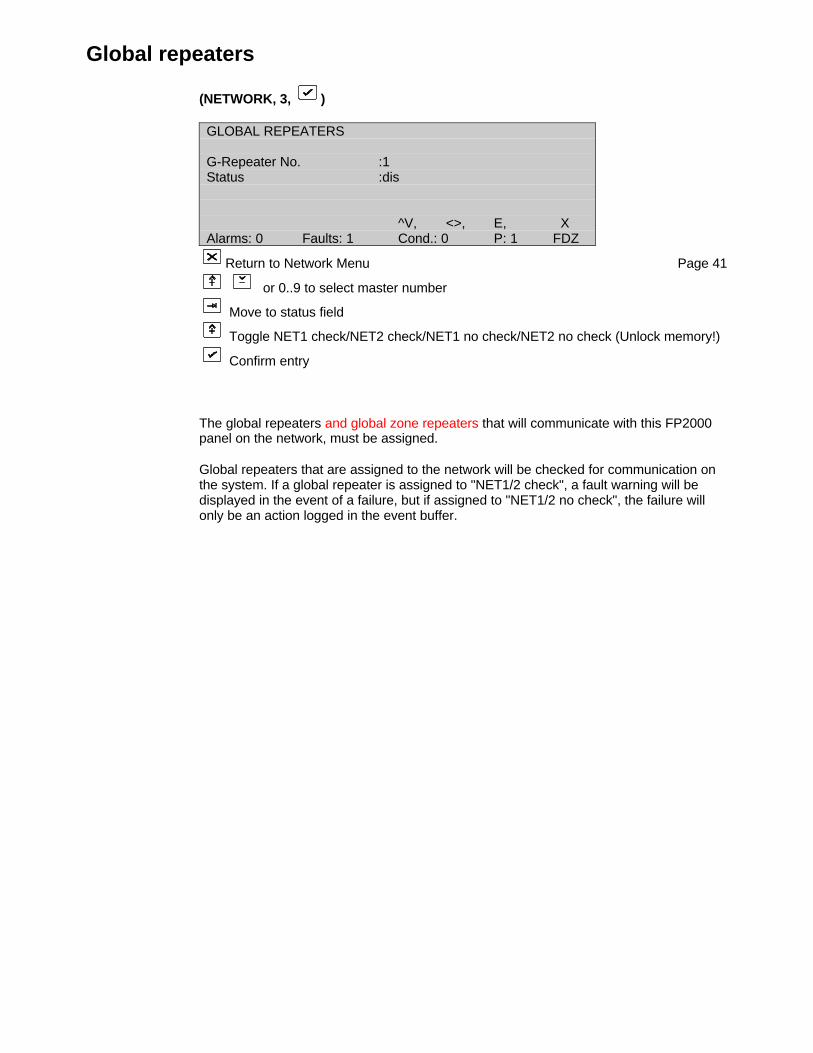
(NETWORK, 3, )
GLOBAL REPEATERS
G-Repeater No. :1Status :dis
^V, <>, E, XAlarms: 0 Faults: 1 Cond.: 0 P: 1 FDZ
Return to Network Menu Page 41
or 0..9 to select master number
Move to status field
Toggle NET1 check/NET2 check/NET1 no check/NET2 no check (Unlock memory!)
Confirm entry
The global repeaters and global zone repeaters that will communicate with this FP2000panel on the network, must be assigned.
Global repeaters that are assigned to the network will be checked for communication onthe system. If a global repeater is assigned to "NET1/2 check", a fault warning will bedisplayed in the event of a failure, but if assigned to "NET1/2 no check", the failure willonly be an action logged in the event buffer.
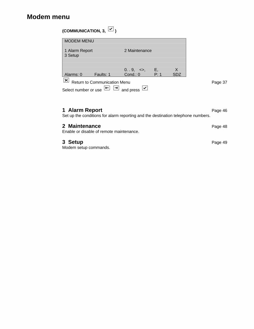
Modem menu
(COMMUNICATION, 3, )
MODEM MENU
1 Alarm Report 2 Maintenance3 Setup
0. . 9, <>, E, XAlarms: 0 Faults: 1 Cond.: 0 P: 1 SDZ
Return to Communication Menu Page 37
Select number or use and press
1 Alarm Report Page 46Set up the conditions for alarm reporting and the destination telephone numbers.
2 Maintenance Page 48Enable or disable of remote maintenance.
3 Setup Page 49Modem setup commands.
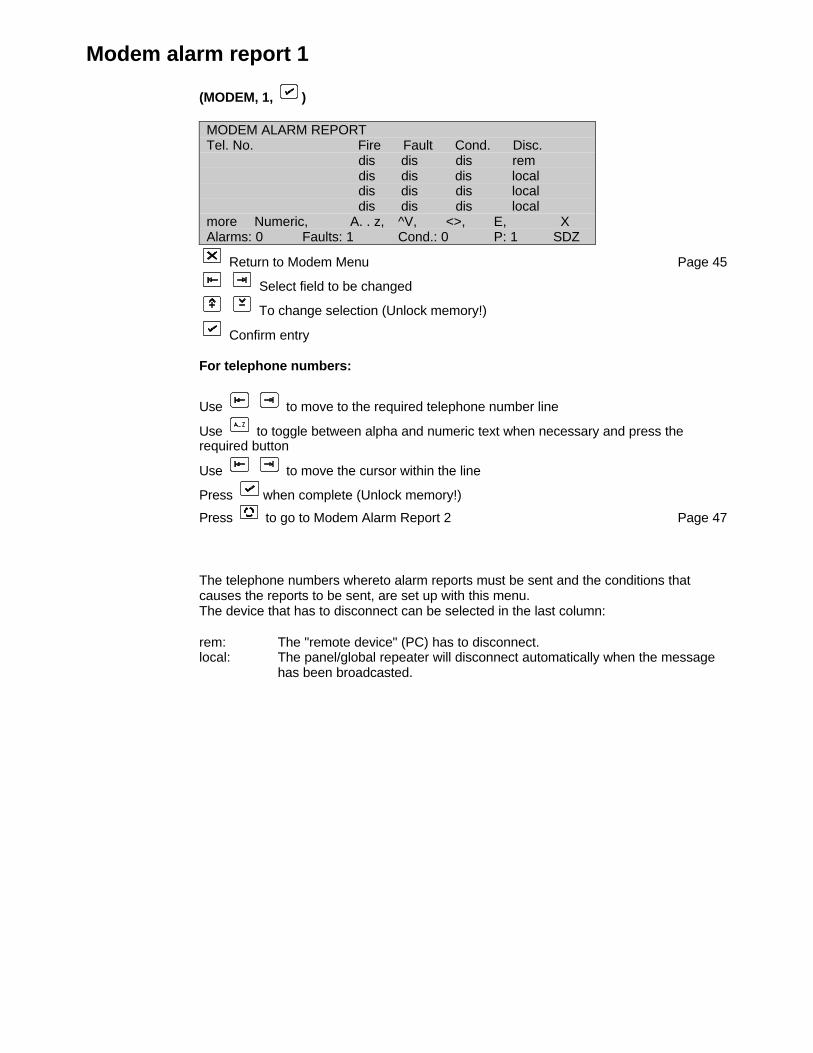
Modem alarm report 1
(MODEM, 1, )
MODEM ALARM REPORTTel. No. Fire Fault Cond. Disc.
dis dis dis rem dis dis dis local dis dis dis local dis dis dis local
more Numeric, A. . z, ^V, <>, E, XAlarms: 0 Faults: 1 Cond.: 0 P: 1 SDZ
Return to Modem Menu Page 45
Select field to be changed
To change selection (Unlock memory!)
Confirm entry
For telephone numbers:
Use to move to the required telephone number line
Use to toggle between alpha and numeric text when necessary and press therequired button
Use to move the cursor within the line
Press when complete (Unlock memory!)
Press to go to Modem Alarm Report 2 Page 47
The telephone numbers whereto alarm reports must be sent and the conditions thatcauses the reports to be sent, are set up with this menu.The device that has to disconnect can be selected in the last column:
rem: The "remote device" (PC) has to disconnect.local: The panel/global repeater will disconnect automatically when the message
has been broadcasted.
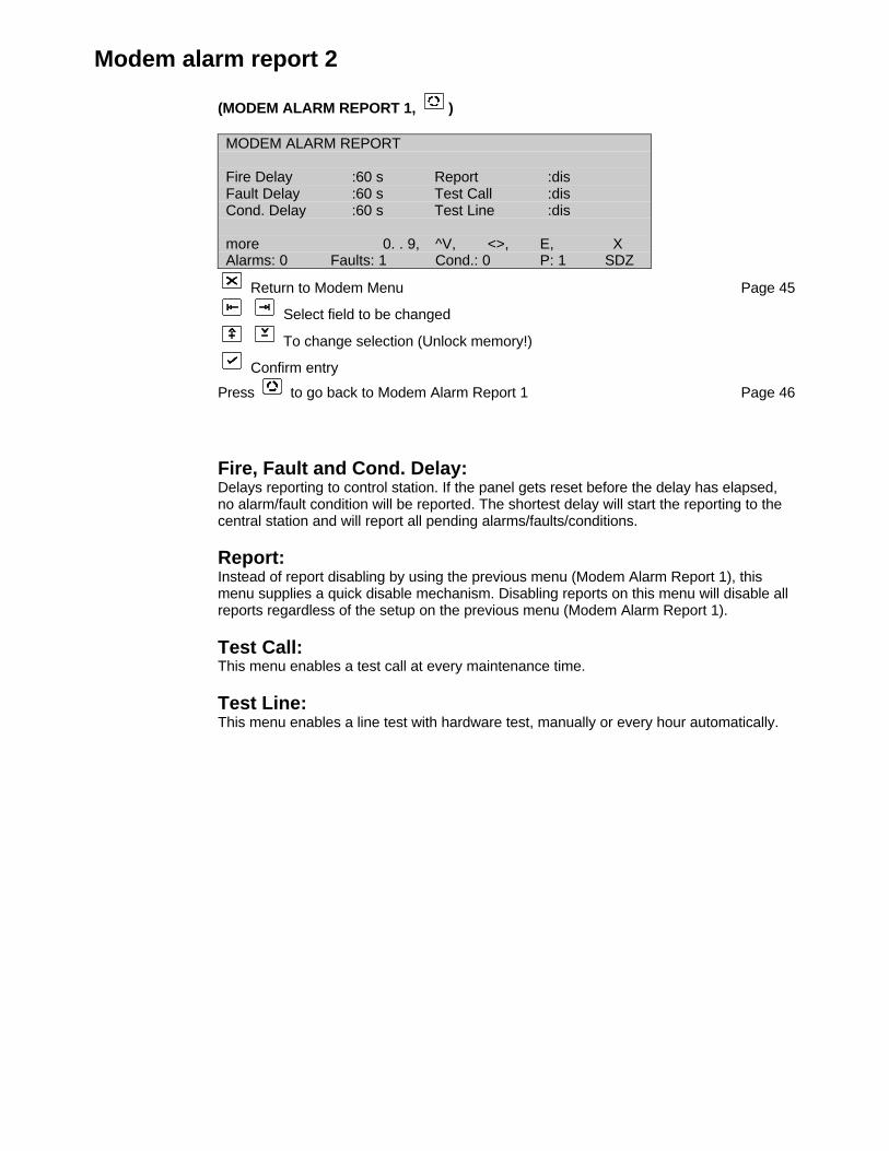
Modem alarm report 2
(MODEM ALARM REPORT 1, )
MODEM ALARM REPORT
Fire Delay :60 s Report :disFault Delay :60 s Test Call :disCond. Delay :60 s Test Line :dis
more 0. . 9, ^V, <>, E, XAlarms: 0 Faults: 1 Cond.: 0 P: 1 SDZ
Return to Modem Menu Page 45
Select field to be changed
To change selection (Unlock memory!)
Confirm entry
Press to go back to Modem Alarm Report 1 Page 46
Fire, Fault and Cond. Delay:Delays reporting to control station. If the panel gets reset before the delay has elapsed,no alarm/fault condition will be reported. The shortest delay will start the reporting to thecentral station and will report all pending alarms/faults/conditions.
Report:Instead of report disabling by using the previous menu (Modem Alarm Report 1), thismenu supplies a quick disable mechanism. Disabling reports on this menu will disable allreports regardless of the setup on the previous menu (Modem Alarm Report 1).
Test Call:This menu enables a test call at every maintenance time.
Test Line:This menu enables a line test with hardware test, manually or every hour automatically.
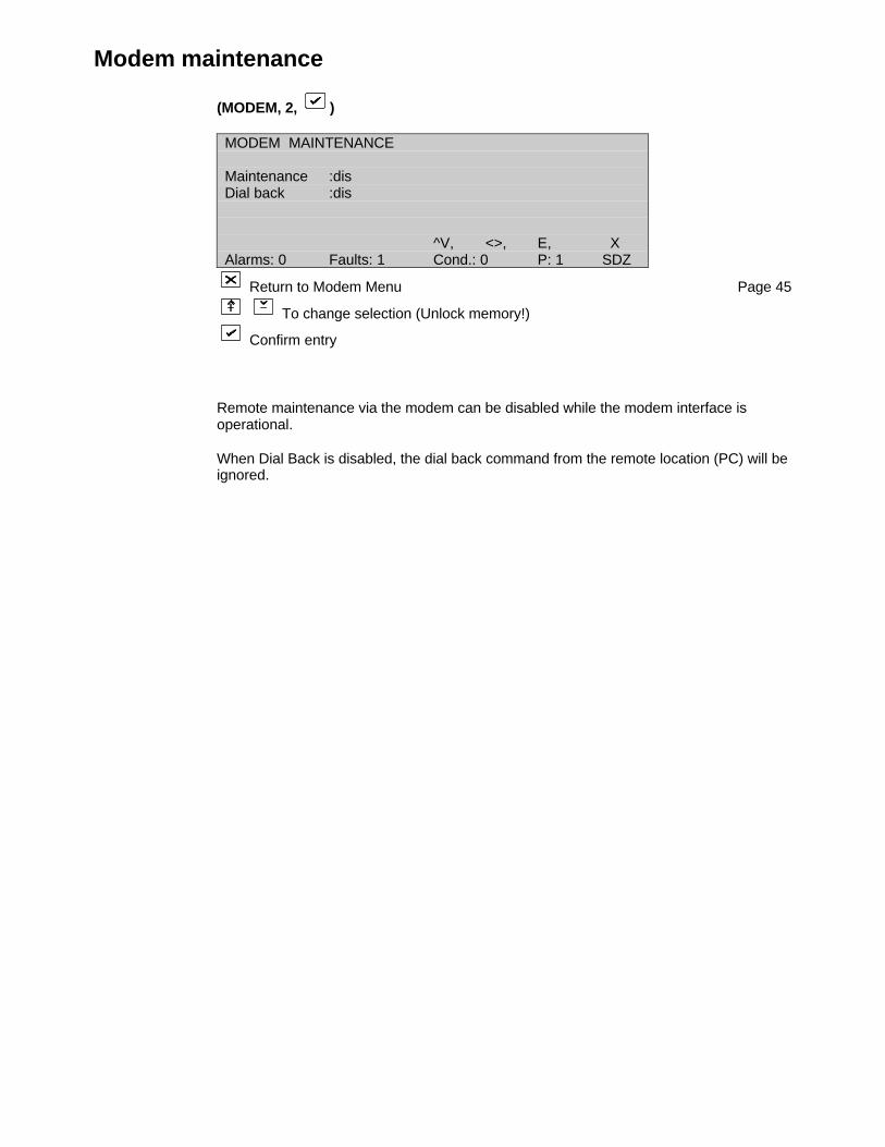
Modem maintenance
(MODEM, 2, )
MODEM MAINTENANCE
Maintenance :disDial back :dis
^V, <>, E, XAlarms: 0 Faults: 1 Cond.: 0 P: 1 SDZ
Return to Modem Menu Page 45
To change selection (Unlock memory!)
Confirm entry
Remote maintenance via the modem can be disabled while the modem interface isoperational.
When Dial Back is disabled, the dial back command from the remote location (PC) will beignored.
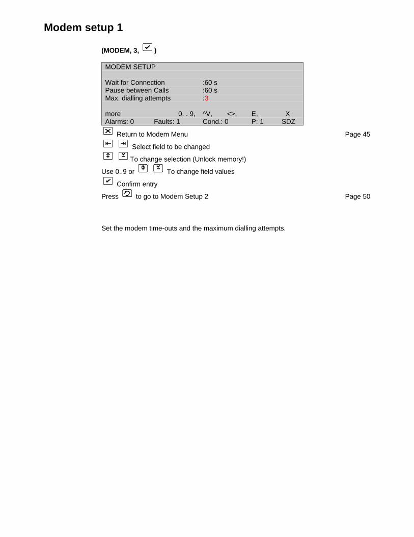
Modem setup 1
(MODEM, 3, )
MODEM SETUP
Wait for Connection :60 sPause between Calls :60 sMax. dialling attempts :3
more 0. . 9, ^V, <>, E, XAlarms: 0 Faults: 1 Cond.: 0 P: 1 SDZ
Return to Modem Menu Page 45
Select field to be changed
To change selection (Unlock memory!)
Use 0..9 or To change field values
Confirm entry
Press to go to Modem Setup 2 Page 50
Set the modem time-outs and the maximum dialling attempts.

Modem setup 2
(MODEM SETUP 1, )
MODEM SETUP
Init :AT&FØMØL1\NØ\JØ\Q3&QØ SØ=1&WØ
Dial :ATDWTEscape :+++more Numeric, A. . z, ^V, <>, E, XAlarms: 0 Faults: 0 Cond.: 0 P: 1 SDZ
Return to Modem Menu Page 45
Select field to be changed
Use to toggle between alpha and numeric text when necessary andpress the required button
Press to confirm (Unlock memory!)
Press to go to Modem Setup 3 Page 51
Set up the modem command strings.
Refer to your Modem manual for detailed description of the commands:Init: Initialisation string for modem
for US Robotics: AT& F1MØL1&MØ&KØSØ=1&WØ
Fast link: AT&FØMØL1\NØ\JØ\Q3&QØ%CØSØ=1&WØ
Datasystems: AT&FØMØL1\NØ\JØ\Q3&QØ%CØSØ=1&WØ
Bausch: AT&F1M1L1\NØ&QØ%CØSØ=1&WØ
Dial: Dial prefix for modemEscape: Escape sequence for modem

Modem setup 3
(MODEM SETUP 2, )
MODEM SETUP
Hangup :ATHØTest :ATDWT,ID :
more Numeric, A. . z, ^V, <>, E, XAlarms: 0 Faults: 1 Cond.: 0 P: 1 SDZ
Return to Modem Menu Page 45
Select field to be changed
Use to toggle between alpha and numeric text when necessary andpress the required button
Press to confirm (Unlock memory!)
Pre Press to go to Modem Setup 1 Page 49
Set up the modem command strings
Hangup: Puts the modem on hookTest: Test string for line testID: A String to identify the modem to the maintenance programs.
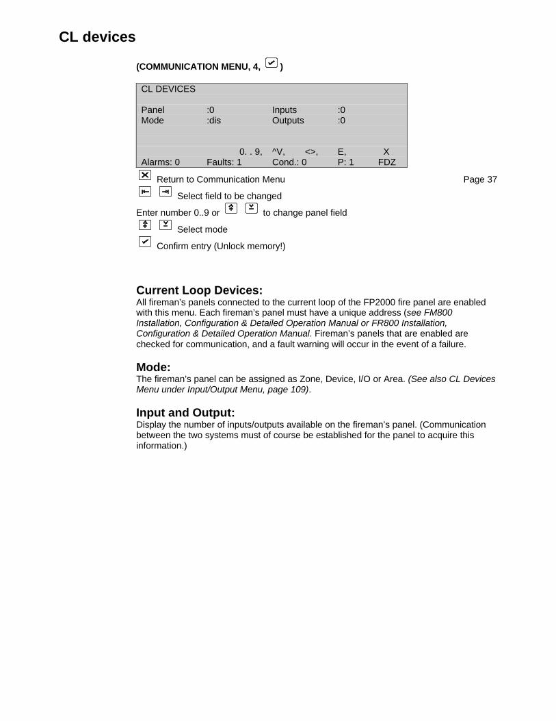
CL devices
(COMMUNICATION MENU, 4, )
CL DEVICES
Panel :0 Inputs :0Mode :dis Outputs :0
0. . 9, ^V, <>, E, XAlarms: 0 Faults: 1 Cond.: 0 P: 1 FDZ
Return to Communication Menu Page 37
Select field to be changed
Enter number 0..9 or to change panel field
Select mode
Confirm entry (Unlock memory!)
Current Loop Devices:All fireman’s panels connected to the current loop of the FP2000 fire panel are enabledwith this menu. Each fireman’s panel must have a unique address (see FM800Installation, Configuration & Detailed Operation Manual or FR800 Installation,Configuration & Detailed Operation Manual. Fireman’s panels that are enabled arechecked for communication, and a fault warning will occur in the event of a failure.
Mode:The fireman’s panel can be assigned as Zone, Device, I/O or Area. (See also CL DevicesMenu under Input/Output Menu, page 109).
Input and Output:Display the number of inputs/outputs available on the fireman’s panel. (Communicationbetween the two systems must of course be established for the panel to acquire thisinformation.)
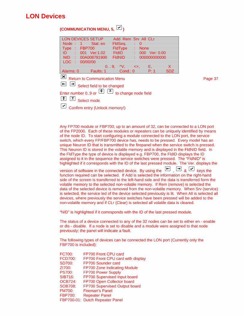
LON Devices
(COMMUNICATION MENU, 5, )
LON DEVICES SETUP Add Rem Srv All CLrNode : 1 Stat: en FldSeq. : 0Type : FBP700 FldType : NoneID : 001 Ver:1.02 FldID : 000 Ver: 0.00NID : 00A008781900 FldNID : 000000000000LOC : 00/00/00
0. . 9, ^V, <>, E, XAlarms: 0 Faults: 1 Cond.: 0 P: 1 SDZ
Return to Communication Menu Page 37
Select field to be changed
Enter number 0..9 or to change node field
Select mode
Confirm entry (Unlock memory!)
Any FP700 module or FBP700, up to an amount of 32, can be connected to a LON portof the FP2000. Each of these modules or repeaters can be uniquely identified by meansof the node ID. To start configuring a module connected to the LON port, the serviceswitch, which every FP/FBP700 device has, needs to be pressed. Every model has anunique Neuron ID that is transmitted to the firepanel when the service switch is pressed.This Neuron ID is stored in the volatile memory and is displayed in the FldNID field. Inthe FldType the type of device is displayed e.g. FBP700, the FldID displays the IDassigned to it in the sequence the service switches were pressed. The “FldNID” ishighlighted if it corresponds with the ID of the last pressed module. The Ver. displays the
version of software in the connected device. By using the , & keys thefunction required can be selected. If Add is selected the information on the right-handside of the screen is transferred to the left-hand side and the data is transferred form thevolatile memory to the selected non-volatile memory. If Rem (remove) is selected thedata of the selected device is removed from the non-volatile memory. When Srv (service)is selected, the service led of the device selected previously is lit. When All is selected alldevices, where previously the service switches have been pressed will be added to thenon-volatile memory and if CLr (Clear) is selected all volatile data is cleared.
“NID” is highlighted if it corresponds with the ID of the last pressed module.
The status of a device connected to any of the 32 nodes can be set to either en - enableor dis - disable. If a node is set to disable and a module were assigned to that nodepreviously; the panel will indicate a fault.
The following types of devices can be connected the LON port (Currently only theFBP700 is included):
FC700: FP700 Front CPU cardFCD700: FP700 Front CPU card with displaySD700: FP700 Sounder cardZI700: FP700 Zone Indicating ModulePS700: FP700 Power SupplySIB716: FP700 Supervised Input boardOCB724: FP700 Open Collector boardSOB708: FP700 Supervised Output boardFM700: Fireman’s PanelFBP700: Repeater PanelFBP700-01: Dutch Repeater Panel
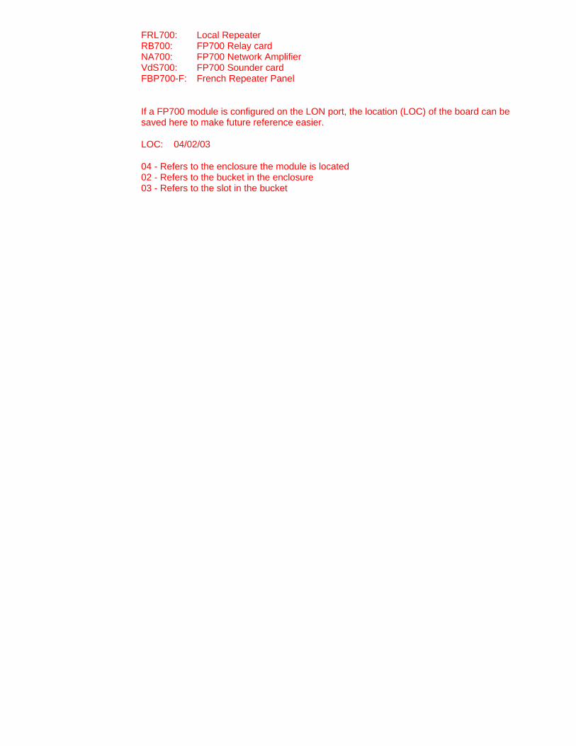
FRL700: Local RepeaterRB700: FP700 Relay cardNA700: FP700 Network AmplifierVdS700: FP700 Sounder cardFBP700-F: French Repeater Panel
If a FP700 module is configured on the LON port, the location (LOC) of the board can besaved here to make future reference easier.
LOC: 04/02/03
04 - Refers to the enclosure the module is located02 - Refers to the bucket in the enclosure03 - Refers to the slot in the bucket
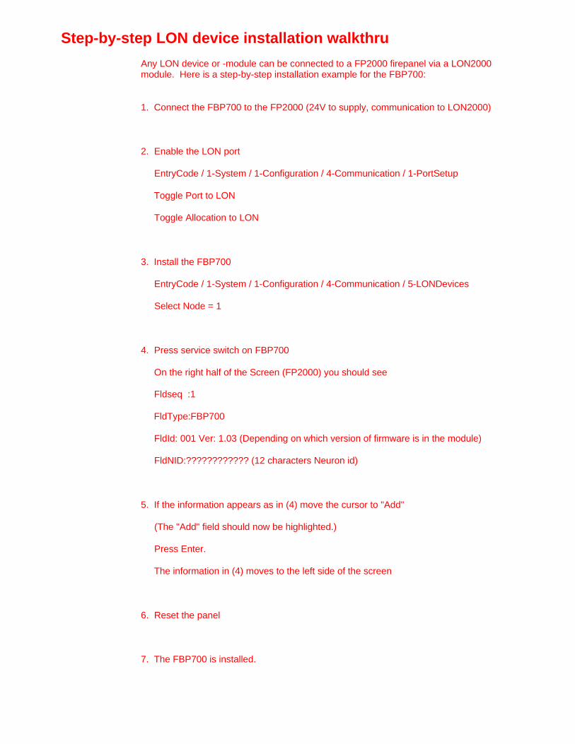
Step-by-step LON device installation walkthru
Any LON device or -module can be connected to a FP2000 firepanel via a LON2000module. Here is a step-by-step installation example for the FBP700:
1. Connect the FBP700 to the FP2000 (24V to supply, communication to LON2000)
2. Enable the LON port
EntryCode / 1-System / 1-Configuration / 4-Communication / 1-PortSetup
Toggle Port to LON
Toggle Allocation to LON
3. Install the FBP700
EntryCode / 1-System / 1-Configuration / 4-Communication / 5-LONDevices
Select Node = 1
4. Press service switch on FBP700
On the right half of the Screen (FP2000) you should see
Fldseq :1
FldType:FBP700
FldId: 001 Ver: 1.03 (Depending on which version of firmware is in the module)
FldNID:???????????? (12 characters Neuron id)
5. If the information appears as in (4) move the cursor to "Add"
(The "Add" field should now be highlighted.)
Press Enter.
The information in (4) moves to the left side of the screen
6. Reset the panel
7. The FBP700 is installed.

System Setup
(SYSTEM MENU, 5, )
SYSTEM SETUPFbrig : continuous FSK Heater : offFBF : noneLanguage : EnglishOperation : ENProtocol : Aritech 900
^v, <>, E, XAlarms: 0 Faults: 0 Cond.: 0 P: 1 SDZ
Return to Configuration Menu Page 26
Select field to be changed
Select mode
Confirm entry (Unlock memory!)
Fbrig:The Fbrig function can only be assigned to a firepanel with a VdS2000 German Sounderboard with a connected Hauptmelder.
continuous – one continuous pulse is send to the hauptmelder to check its status
pulse – every three seconds a pulse of one second is transmitted to the hauptmelder tocheck its status
none – no hauptmelder is connected to the firepanel
FBF:The FBF function can only be assigned to a firepanel with a VdS2000 German Sounderboard with a connected Bedienfeld to it. The types of Bedienfelds which can beconnected to it is the:
FBF 800 BedienfeldFBF 800B Berlin BedienfeldDIN 2000-00 Bedienfeld
FSK Heater:The FSK Heater function can only be assigned to a firepanel with a VdS2000 GermanSounder board with a FSK Heater connected to it. The types of FSK Heaters which canbe connected are:
FSK700 (Note: Needs to be modified to work from 24V)FSK800
Language:The operating language of the firepanel is set here. This applies only to the FP11xx/12xxrange of products. The FP2xxx range of products language is set by the dip switchsituated on the host power supply (*See Appendix A of the FP2000 Installation andCommissioning Manual for dip switch settings as well as languages).
The switch is read at restart, and cannot be changed during operation.
Operation:The mode of operation of the firepanel is set here. This applies only to the FP11xx/12xx

range of products. The FP2xxx range of products language is set by the dip switchsituated on the host power supply (*See Appendix A of the FP2000 Installation andCommissioning Manual for dip switch settings as well as modes of operation).
The switch is read at restart, and cannot be changed during operation.
Protocol:The protocol used by the firepanel is set here. This applies only to the FP11xx/12xxrange of products. The FP2xxx range of products language is set by the dip switchsituated on the host power supply (*See Appendix A of the FP2000 Installation andCommissioning Manual for dip settings as well as types of protocol).
The switch is read at restart, and cannot be changed during operation.

System information
(SYSTEM MENU, 6, )
SYSTEM INFORMATION
1 Allocation 2 Panels3 L-Repeaters 4 G-Repeaters5 System 6 Stack7 SpecialCharacters 8 Text Debuggingmore 0. .9, <>, E, XAlarms: 0 Faults: 0 Cond.: 0 P: 1 SDZ
Return to Configuration Menu Page 26
Select number or use and press
Press [More ] to view System information 2 Page 58
System information 2
(SYSTEM MENU, 6, , )
SYSTEM INFORMATION
1 FEP 2 SER3 Modem 4 ARC05 ARC1 6 LON7 LON Charactersmore 0. .9, <>, E, XAlarms: 0 Faults: 0 Cond.: 0 P: 1 SDZ
Return to Configuration Menu Page 26
Select number or use and press
Press [More ] to view System information Page 58
! The information used in these two sets of menus is used for programming verificationonly and has no user defined functions. All information in these menus can change atany time and without prior notification to the end user.
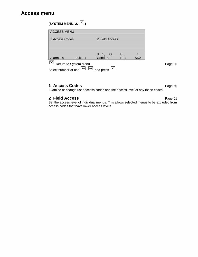
Access menu
(SYSTEM MENU, 2, )
ACCESS MENU
1 Access Codes 2 Field Access
0. . 9, <>, E, XAlarms: 0 Faults: 1 Cond.: 0 P: 1 SDZ
Return to System Menu Page 25
Select number or use and press
1 Access Codes Page 60Examine or change user access codes and the access level of any these codes.
2 Field Access Page 61Set the access level of individual menus. This allows selected menus to be excluded fromaccess codes that have lower access levels.
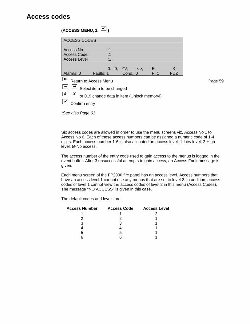
Access codes
(ACCESS MENU, 1, )
ACCESS CODES
Access No. :1Access Code :1Access Level :1
0. . 9, ^V, <>, E, XAlarms: 0 Faults: 1 Cond.: 0 P: 1 FDZ
Return to Access Menu Page 59
Select item to be changed
or 0..9 change data in item (Unlock memory!)
Confirm entry
*See also Page 61
Six access codes are allowed in order to use the menu screens viz. Access No 1 toAccess No 6. Each of these access numbers can be assigned a numeric code of 1-4digits. Each access number 1-6 is also allocated an access level: 1-Low level; 2-Highlevel; Ø-No access.
The access number of the entry code used to gain access to the menus is logged in theevent buffer. After 3 unsuccessful attempts to gain access, an Access Fault message isgiven.
Each menu screen of the FP2000 fire panel has an access level. Access numbers thathave an access level 1 cannot use any menus that are set to level 2. In addition, accesscodes of level 1 cannot view the access codes of level 2 in this menu (Access Codes).The message "NO ACCESS" is given in this case.
The default codes and levels are:
Access Number Access Code Access Level1 1 22 2 13 3 14 4 15 5 16 6 1
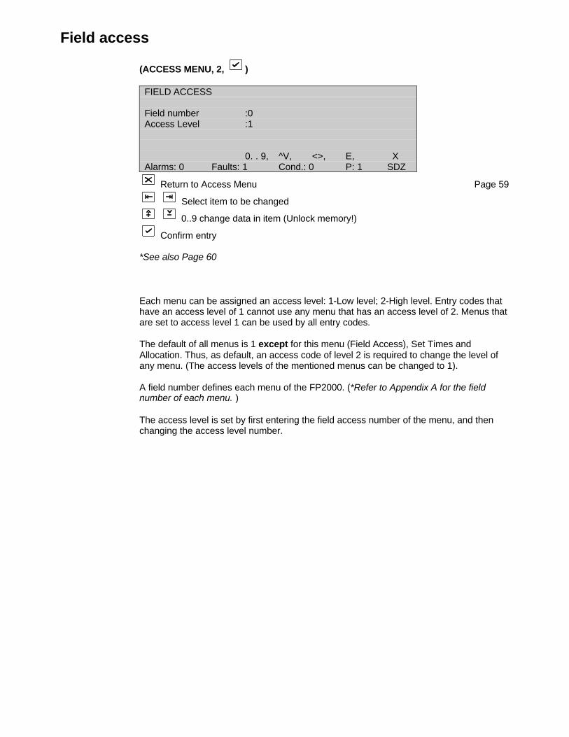
Field access
(ACCESS MENU, 2, )
FIELD ACCESS
Field number :0Access Level :1
0. . 9, ^V, <>, E, XAlarms: 0 Faults: 1 Cond.: 0 P: 1 SDZ
Return to Access Menu Page 59
Select item to be changed
0..9 change data in item (Unlock memory!)
Confirm entry
*See also Page 60
Each menu can be assigned an access level: 1-Low level; 2-High level. Entry codes thathave an access level of 1 cannot use any menu that has an access level of 2. Menus thatare set to access level 1 can be used by all entry codes.
The default of all menus is 1 except for this menu (Field Access), Set Times andAllocation. Thus, as default, an access code of level 2 is required to change the level ofany menu. (The access levels of the mentioned menus can be changed to 1).
A field number defines each menu of the FP2000. (*Refer to Appendix A for the fieldnumber of each menu. )
The access level is set by first entering the field access number of the menu, and thenchanging the access level number.

Clear site data 1
(SYSTEM MENU, 3, )
CLEAR SITE DATA
1 Devices 2 Zones3 Areas 4 Inputs5 Outputs 6 System7 Loops 8 Logic Tablemore 0. . 9, <>, E, XAlarms: 0 Faults: 1 Cond.: 0 P: 1 SDZ
Select number or use and press (Unlock memory!)
When prompted for confirmation:
For Devices select loop number or use and press
All other selections use for YES and press
Return to System Menu Page 25
*See also Set Default, Page 65
All or parts of the RAM memory can be cleared of data. Certain data is also pre-set asshown below. The data blocks that can be cleared (initialised) are:
1 Devices – Select the loop number (for all loops)The devices of the selected loop(s) are set to:Status: DisabledType: NoneZone: ØDay level: 3Soak test: DisabledTest value: ØContamination: ØStatistics: Cleared
2 Zones – All zones are set to:Status: EnabledMode: NormalArea: 0Safe Zone: DisabledOn/Off: DisabledDay/Night: DisabledSounder Delay: DisabledFire Brigade Delay: Disabled
3 Areas – All areas are set to:Status: EnabledCoincidence: UnloggedAdjacent area 1-5: Ø
4 Inputs – All inputs are set to:Type: None

5 Outputs – All outputs are set to:Type: None
6 SystemPanel ID: Ø/ ØPort: INT - set to FEP; Baudrate 9600
CL - set to CL Device; Baudrate 600SER1 - set to Setup; Baudrate 9600SER2 - set to None; Baudrate 9600
Other ports - function: NoneNetwork: Panels disabled
Repeaters disabledMasters disabled
Access codes: *See Page 54Field access: All menus have access level 1 except Field Access, Set
Times and Allocation have access level 2Sounder/Fire Brigade Delay: 0 sAll times: 00h00Sounder off time, Zones ontime and day mode time: Linked to none
7 Loops – loop data set to: Enabled
8 Logic tableAll logic instructions are cleared and an “END” is placed in line 1.

Clear site data 2
(CLEAR SITE DATA 1, )
CLEAR SITE DATA
1 Modem 2 CL Devices3 LON Devices 4 All
more 0. . 9, <>, E, XAlarms: 0 Faults: 1 Cond.: 0 P: 1 SDZ
Select number or use and press (Unlock memory!)
When prompted for confirmation:
For Devices select loop number or use and press
All other selections use for YES and press
Return to System Menu Page 25
*See also Set Default, Page 65
1 ModemAll times to ØClear all telephone numbersClear all modem command strings
2 CL DevicesDisable all Fireman's panels
3 LON DevicesClear all LON devices and LON device data
4 AllAll of the above selections (1-8 of the first menu and 1-2 of the second menu) clearedsimultaneously.
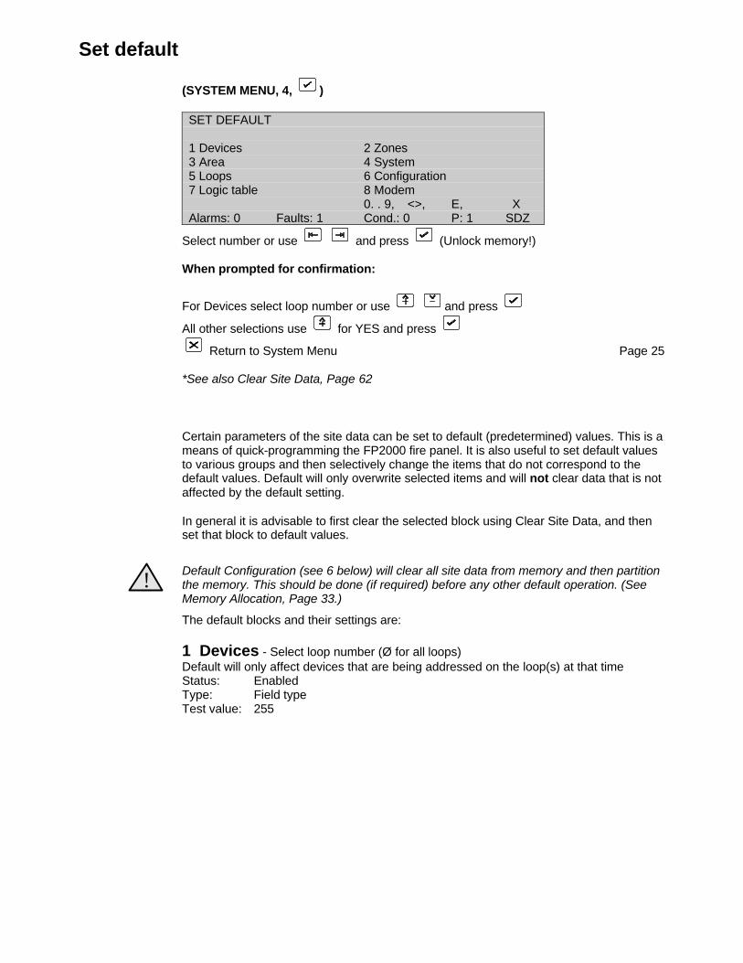
Set default
(SYSTEM MENU, 4, )
SET DEFAULT
1 Devices 2 Zones3 Area 4 System5 Loops 6 Configuration7 Logic table 8 Modem
0. . 9, <>, E, XAlarms: 0 Faults: 1 Cond.: 0 P: 1 SDZ
Select number or use and press (Unlock memory!)
When prompted for confirmation:
For Devices select loop number or use and press
All other selections use for YES and press
Return to System Menu Page 25
*See also Clear Site Data, Page 62
Certain parameters of the site data can be set to default (predetermined) values. This is ameans of quick-programming the FP2000 fire panel. It is also useful to set default valuesto various groups and then selectively change the items that do not correspond to thedefault values. Default will only overwrite selected items and will not clear data that is notaffected by the default setting.
In general it is advisable to first clear the selected block using Clear Site Data, and thenset that block to default values.
!Default Configuration (see 6 below) will clear all site data from memory and then partitionthe memory. This should be done (if required) before any other default operation. (SeeMemory Allocation, Page 33.)
The default blocks and their settings are:
1 Devices - Select loop number (Ø for all loops)Default will only affect devices that are being addressed on the loop(s) at that timeStatus: EnabledType: Field typeTest value: 255

2 ZonesThe total number of zones equipped on the FP2000 fire panel are proportioned amongstthe total number of devices that can be addressed by the fire panel.
E.g.: 16 zone 2 loop fire panelmaximum number of devices = 2 x 128 = 256zone distribution = 256 / 16 = 16Loop 1/1 to Loop 1/16 is assigned zone 1Loop 1/17 to Loop 1/32 is assigned zone 2 etc.Loop 2/1 to Loop 2/16 is assigned zone 9 etc.Loop 2/113 to Loop 2/128 is assigned zone 16
64 zone 4 loops (devices = 512)zone distribution = 8 devices/zone
3 AreasThe sixteen areas are equally distributed amongst the zones that are equipped on theFP2000 fire panel.
e.g.: 16 zone fire panelZone 1 = Area 1Zone 2 = Area 2, etc.
64 zone fire panelZone 1-4 = Area 1Zone 5-8 = Area 2, etc.
4 SystemReserved
5 LoopsEnabled
6 ConfigurationThe memory is partitioned to the default configuration (see Memory Allocation, Page 33).
7 LogicThe logic table is set to a standard equation:Input 1 = Output 1Input 2 = Output 2, etc.
This equation is extended to the lower of:- halve (see note) of the maximum number of logic lines allowed by the memory
allocation for logic- the maximum number of inputs- the maximum numbers of outputs
- One equation comprises two logic lines. An allocation for logic of 300 would allow theequation to be extended to: Input 150 = Output 150; provided that the number of inputsand outputs are 150 or more.
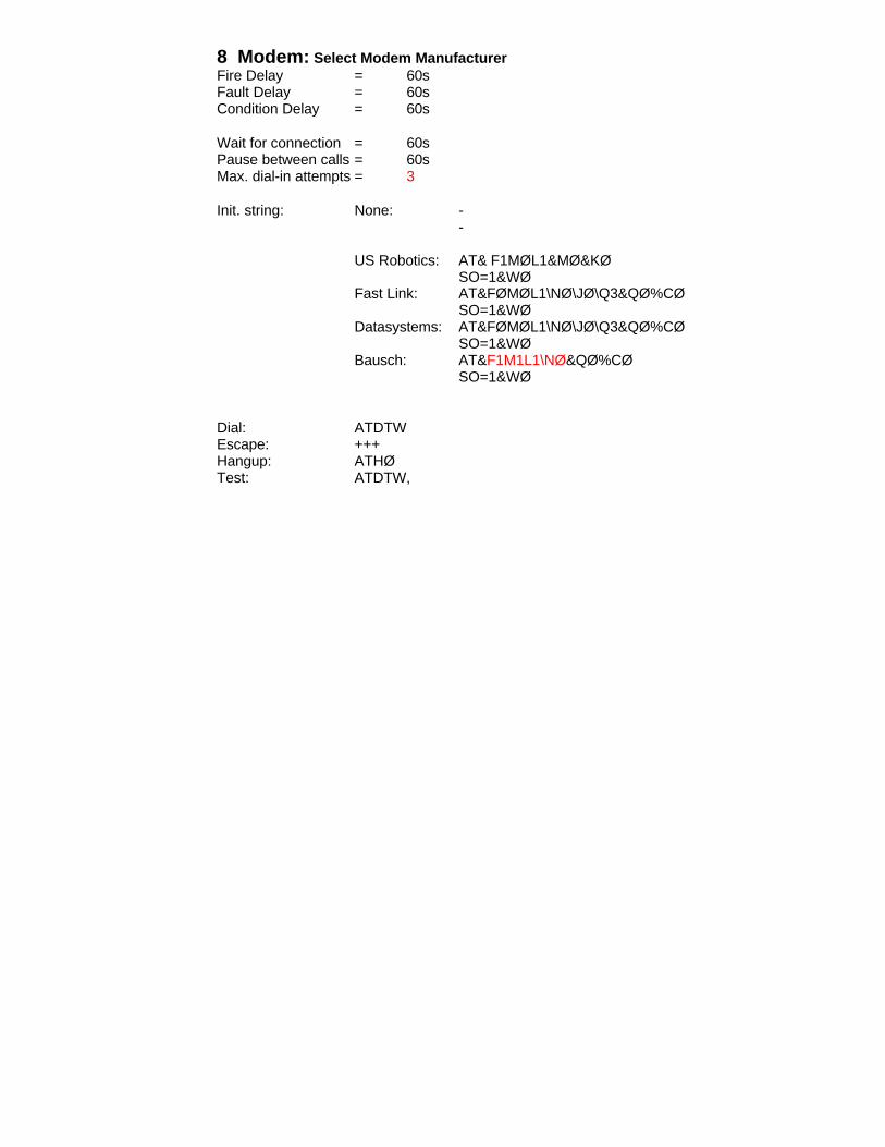
8 Modem: Select Modem ManufacturerFire Delay = 60sFault Delay = 60sCondition Delay = 60s
Wait for connection = 60sPause between calls = 60sMax. dial-in attempts = 3
Init. string: None: --
US Robotics: AT& F1MØL1&MØ&KØSO=1&WØ
Fast Link: AT&FØMØL1\NØ\JØ\Q3&QØ%CØSO=1&WØ
Datasystems: AT&FØMØL1\NØ\JØ\Q3&QØ%CØSO=1&WØ
Bausch: AT&F1M1L1\NØ&QØ%CØSO=1&WØ
Dial: ATDTWEscape: +++Hangup: ATHØTest: ATDTW,
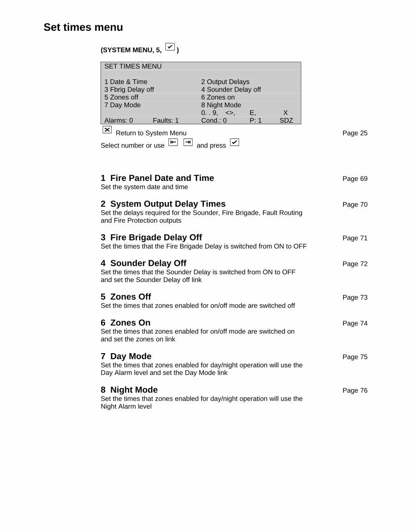
Set times menu
(SYSTEM MENU, 5, )
SET TIMES MENU
1 Date & Time 2 Output Delays3 Fbrig Delay off 4 Sounder Delay off5 Zones off 6 Zones on7 Day Mode 8 Night Mode
0. . 9, <>, E, XAlarms: 0 Faults: 1 Cond.: 0 P: 1 SDZ
Return to System Menu Page 25
Select number or use and press
1 Fire Panel Date and Time Page 69Set the system date and time
2 System Output Delay Times Page 70Set the delays required for the Sounder, Fire Brigade, Fault Routingand Fire Protection outputs
3 Fire Brigade Delay Off Page 71Set the times that the Fire Brigade Delay is switched from ON to OFF
4 Sounder Delay Off Page 72Set the times that the Sounder Delay is switched from ON to OFFand set the Sounder Delay off link
5 Zones Off Page 73Set the times that zones enabled for on/off mode are switched off
6 Zones On Page 74Set the times that zones enabled for on/off mode are switched onand set the zones on link
7 Day Mode Page 75Set the times that zones enabled for day/night operation will use theDay Alarm level and set the Day Mode link
8 Night Mode Page 76Set the times that zones enabled for day/night operation will use theNight Alarm level
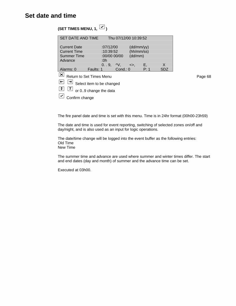
Set date and time
(SET TIMES MENU, 1, )
SET DATE AND TIME Thu 07/12/00 10:39:52
Current Date :07/12/00 (dd/mm/yy)Current Time :10:39:52 (hh/mm/ss)Summer Time :00/00 00/00 (dd/mm)Advance :0h
0. . 9, ^V, <>, E, XAlarms: 0 Faults: 1 Cond.: 0 P: 1 SDZ
Return to Set Times Menu Page 68
Select item to be changed
or 0..9 change the data
Confirm change
The fire panel date and time is set with this menu. Time is in 24hr format (00h00-23h59)
The date and time is used for event reporting, switching of selected zones on/off andday/night, and is also used as an input for logic operations.
The date/time change will be logged into the event buffer as the following entries:Old TimeNew Time
The summer time and advance are used where summer and winter times differ. The startand end dates (day and month) of summer and the advance time can be set.
Executed at 03h00.
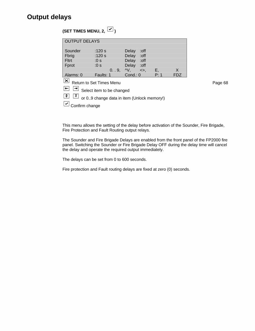
Output delays
(SET TIMES MENU, 2, )
OUTPUT DELAYS
Sounder :120 s Delay :offFbrig :120 s Delay :offFltrt :0 s Delay :offFprot :0 s Delay :off
0. . 9, ^V, <>, E, XAlarms: 0 Faults: 1 Cond.: 0 P: 1 FDZ
Return to Set Times Menu Page 68
Select item to be changed
or 0..9 change data in item (Unlock memory!)
Confirm change
This menu allows the setting of the delay before activation of the Sounder, Fire Brigade,Fire Protection and Fault Routing output relays.
The Sounder and Fire Brigade Delays are enabled from the front panel of the FP2000 firepanel. Switching the Sounder or Fire Brigade Delay OFF during the delay time will cancelthe delay and operate the required output immediately.
The delays can be set from 0 to 600 seconds.
Fire protection and Fault routing delays are fixed at zero (0) seconds.
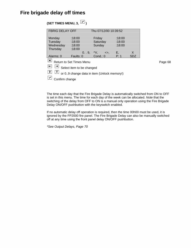
Fire brigade delay off times
(SET TIMES MENU, 3, )
FBRIG DELAY OFF Thu 07/12/00 10:39:52
Monday :18:00 Friday :18:00Tuesday :18:00 Saturday :18:00Wednesday :18:00 Sunday :18:00Thursday :18:00
0. . 9, ^V, <>, E, XAlarms: 0 Faults: 0 Cond.: 0 P: 1 SDZ
Return to Set Times Menu Page 68
Select item to be changed
or 0..9 change data in item (Unlock memory!)
Confirm change
The time each day that the Fire Brigade Delay is automatically switched from ON to OFFis set in this menu. The time for each day of the week can be allocated. Note that theswitching of the delay from OFF to ON is a manual only operation using the Fire BrigadeDelay ON/OFF pushbutton with the keyswitch enabled.
If no automatic delay off operation is required, then the time 00h00 must be used, it isignored by the FP2000 fire panel. The Fire Brigade Delay can also be manually switchedoff at any time using the front panel delay ON/OFF pushbutton.
*See Output Delays, Page 70
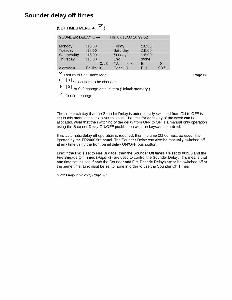
Sounder delay off times
(SET TIMES MENU, 4, )
SOUNDER DELAY OFF Thu 07/12/00 10:39:52
Monday :18:00 Friday :18:00Tuesday :18:00 Saturday :18:00Wednesday :18:00 Sunday :18:00Thursday :18:00 Lnk :none
0. . 9, ^V, <>, E, XAlarms: 0 Faults: 0 Cond.: 0 P: 1 SDZ
Return to Set Times Menu Page 68
Select item to be changed
or 0..9 change data in item (Unlock memory!)
Confirm change
The time each day that the Sounder Delay is automatically switched from ON to OFF isset in this menu if the link is set to None. The time for each day of the week can beallocated. Note that the switching of the delay from OFF to ON is a manual only operationusing the Sounder Delay ON/OFF pushbutton with the keyswitch enabled.
If no automatic delay off operation is required, then the time 00h00 must be used, it isignored by the FP2000 fire panel. The Sounder Delay can also be manually switched offat any time using the front panel delay ON/OFF pushbutton.
Link: If the link is set to Fire Brigade, then the Sounder Off times are set to 00h00 and theFire Brigade Off Times (Page 71) are used to control the Sounder Delay. This means thatone time set is used if both the Sounder and Fire Brigade Delays are to be switched off atthe same time. Link must be set to none in order to use the Sounder Off Times.
*See Output Delays, Page 70
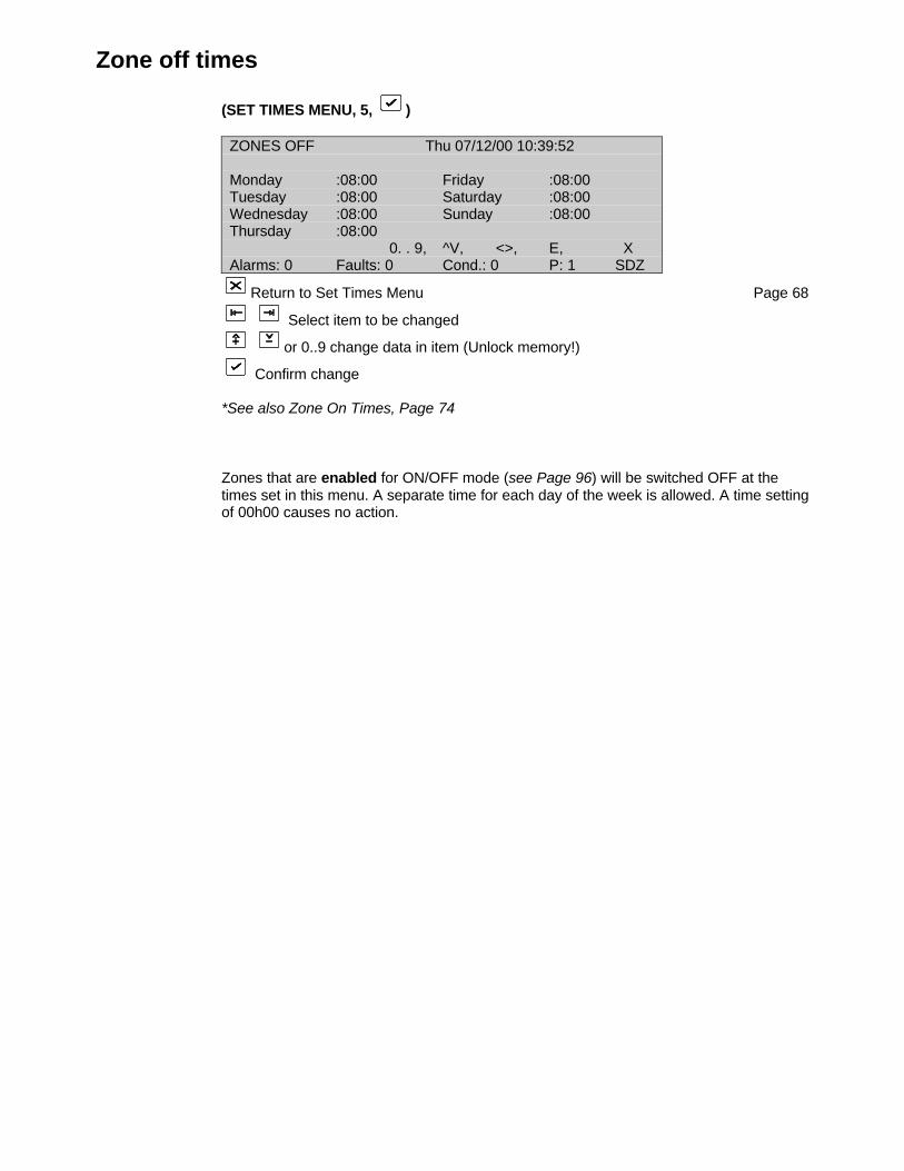
Zone off times
(SET TIMES MENU, 5, )
ZONES OFF Thu 07/12/00 10:39:52
Monday :08:00 Friday :08:00Tuesday :08:00 Saturday :08:00Wednesday :08:00 Sunday :08:00Thursday :08:00
0. . 9, ^V, <>, E, XAlarms: 0 Faults: 0 Cond.: 0 P: 1 SDZ
Return to Set Times Menu Page 68
Select item to be changed
or 0..9 change data in item (Unlock memory!)
Confirm change
*See also Zone On Times, Page 74
Zones that are enabled for ON/OFF mode (see Page 96) will be switched OFF at thetimes set in this menu. A separate time for each day of the week is allowed. A time settingof 00h00 causes no action.
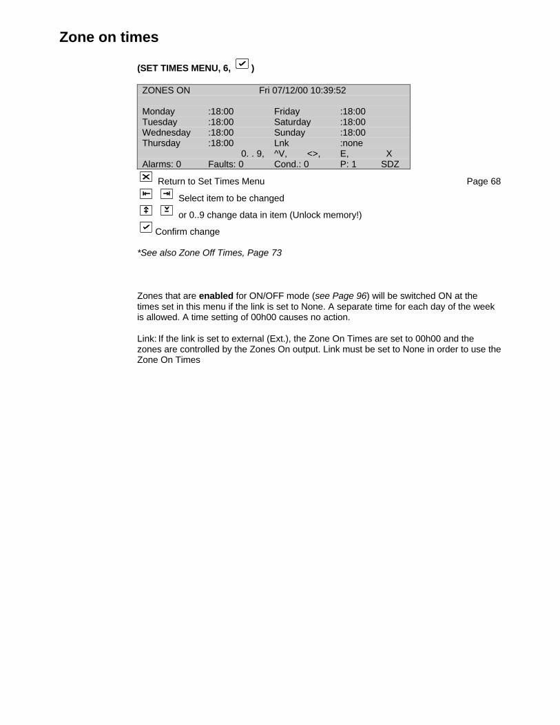
Zone on times
(SET TIMES MENU, 6, )
ZONES ON Fri 07/12/00 10:39:52
Monday :18:00 Friday :18:00Tuesday :18:00 Saturday :18:00Wednesday :18:00 Sunday :18:00Thursday :18:00 Lnk :none
0. . 9, ^V, <>, E, XAlarms: 0 Faults: 0 Cond.: 0 P: 1 SDZ
Return to Set Times Menu Page 68
Select item to be changed
or 0..9 change data in item (Unlock memory!)
Confirm change
*See also Zone Off Times, Page 73
Zones that are enabled for ON/OFF mode (see Page 96) will be switched ON at thetimes set in this menu if the link is set to None. A separate time for each day of the weekis allowed. A time setting of 00h00 causes no action.
Link: If the link is set to external (Ext.), the Zone On Times are set to 00h00 and thezones are controlled by the Zones On output. Link must be set to None in order to use theZone On Times
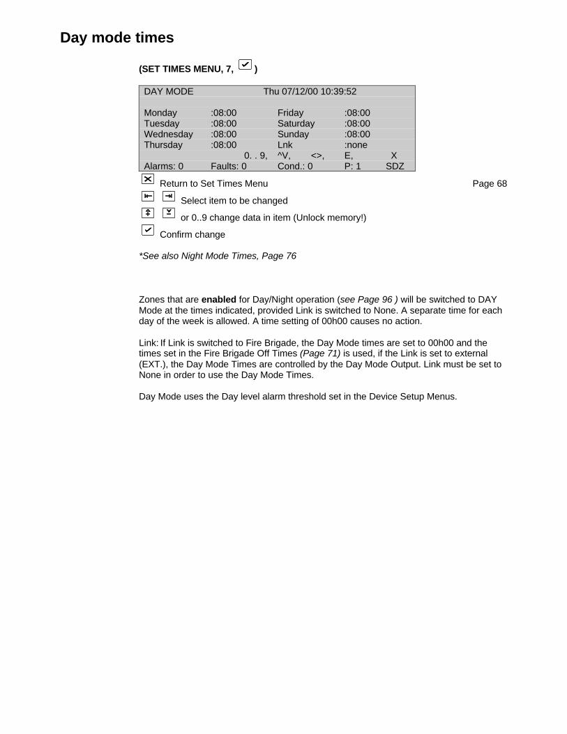
Day mode times
(SET TIMES MENU, 7, )
DAY MODE Thu 07/12/00 10:39:52
Monday :08:00 Friday :08:00Tuesday :08:00 Saturday :08:00Wednesday :08:00 Sunday :08:00Thursday :08:00 Lnk :none
0. . 9, ^V, <>, E, XAlarms: 0 Faults: 0 Cond.: 0 P: 1 SDZ
Return to Set Times Menu Page 68
Select item to be changed
or 0..9 change data in item (Unlock memory!)
Confirm change
*See also Night Mode Times, Page 76
Zones that are enabled for Day/Night operation (see Page 96 ) will be switched to DAYMode at the times indicated, provided Link is switched to None. A separate time for eachday of the week is allowed. A time setting of 00h00 causes no action.
Link: If Link is switched to Fire Brigade, the Day Mode times are set to 00h00 and thetimes set in the Fire Brigade Off Times (Page 71) is used, if the Link is set to external(EXT.), the Day Mode Times are controlled by the Day Mode Output. Link must be set toNone in order to use the Day Mode Times.
Day Mode uses the Day level alarm threshold set in the Device Setup Menus.
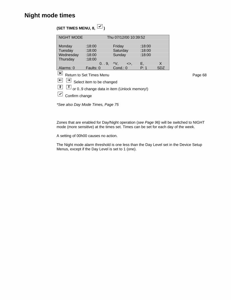
Night mode times
(SET TIMES MENU, 8, )
NIGHT MODE Thu 07/12/00 10:39:52
Monday :18:00 Friday :18:00Tuesday :18:00 Saturday :18:00Wednesday :18:00 Sunday :18:00Thursday :18:00
0. . 9, ^V, <>, E, XAlarms: 0 Faults: 0 Cond.: 0 P: 1 SDZ
Return to Set Times Menu Page 68
Select item to be changed
or 0..9 change data in item (Unlock memory!)
Confirm change
*See also Day Mode Times, Page 75
Zones that are enabled for Day/Night operation (see Page 96) will be switched to NIGHTmode (more sensitive) at the times set. Times can be set for each day of the week.
A setting of 00h00 causes no action.
The Night mode alarm threshold is one less than the Day Level set in the Device SetupMenus, except if the Day Level is set to 1 (one).
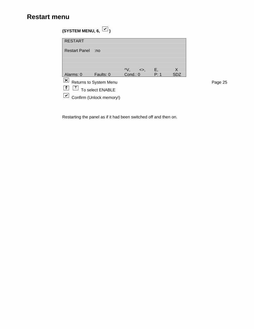
Restart menu
(SYSTEM MENU, 6, )
RESTART
Restart Panel :no
^V, <>, E, XAlarms: 0 Faults: 0 Cond.: 0 P: 1 SDZ
Returns to System Menu Page 25
To select ENABLE
Confirm (Unlock memory!)
Restarting the panel as if it had been switched off and then on.
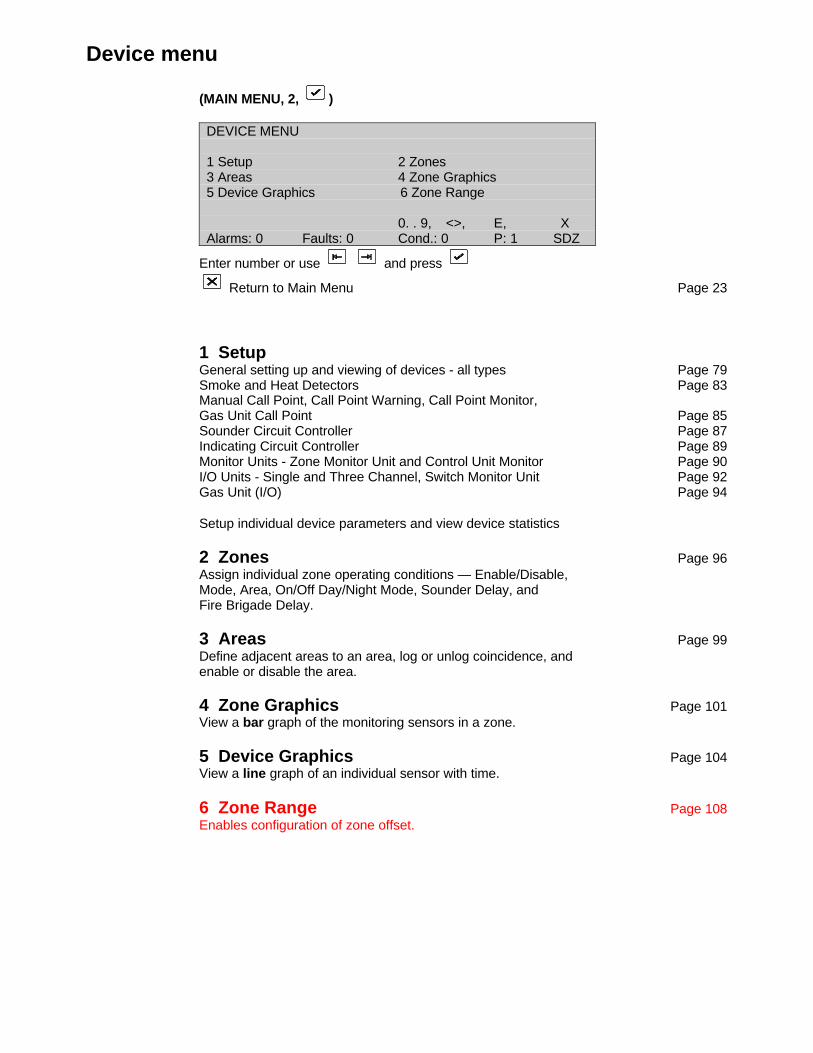
Device menu
(MAIN MENU, 2, )
DEVICE MENU
1 Setup 2 Zones3 Areas 4 Zone Graphics5 Device Graphics 6 Zone Range
0. . 9, <>, E, XAlarms: 0 Faults: 0 Cond.: 0 P: 1 SDZ
Enter number or use and press
Return to Main Menu Page 23
1 SetupGeneral setting up and viewing of devices - all types Page 79Smoke and Heat Detectors Page 83Manual Call Point, Call Point Warning, Call Point Monitor,Gas Unit Call Point Page 85Sounder Circuit Controller Page 87Indicating Circuit Controller Page 89Monitor Units - Zone Monitor Unit and Control Unit Monitor Page 90I/O Units - Single and Three Channel, Switch Monitor Unit Page 92Gas Unit (I/O) Page 94
Setup individual device parameters and view device statistics
2 Zones Page 96Assign individual zone operating conditions — Enable/Disable,Mode, Area, On/Off Day/Night Mode, Sounder Delay, andFire Brigade Delay.
3 Areas Page 99Define adjacent areas to an area, log or unlog coincidence, andenable or disable the area.
4 Zone Graphics Page 101View a bar graph of the monitoring sensors in a zone.
5 Device Graphics Page 104View a line graph of an individual sensor with time.
6 Zone Range Page 108Enables configuration of zone offset.

General setup and view (all types)
(DEVICE MENU, 1, )
SCREEN 1
DEVICE SETUPAddress :1/4 Status :en State :NMLZone :1 Type :OPT Value :38Day Lvl :3 PreLvl :90 AlarmLvl :110
more ^V, <>, E, XAlarms: 0 Faults: 0 Cond.: 0 P: 1 SDZ
Return to Device Menu Page 78
Select field to be changed
Enter number 0..9 or to change the data (Unlock memory!)
Confirm entry
Press [More ] to view additional device data (Screen 2)
*See Page 78 for the particular device type
For Device Text Fields (2 lines x 40 characters):
Use to obtain the text line to be changed
Press (Unlock memory!)
Use to toggle between alpha and numeric text Press the alpha/numeric buttonrequired
Use to move the cursor within the line
Press üü when completed
*See Page 62 to CLEAR device data
*See Page 65 for DEFAULT device setup
Each addressable device requires certain parameters to be set before the fire panel canproperly function. In addition to these parameters the status and statistics of each device
can be viewed on two screens. The [More ] button toggles between these twoscreens.
Screen 1 is common to all devices with the exception of smoke and heat detectors thathave alarm level and day level settings. The Screen 2 display is dependent on the devicetype and is individually described on the following pages.
Setup parameters are best set as a group by using upload/download from a computer. Adefault setup can also be obtained from the System Menus.
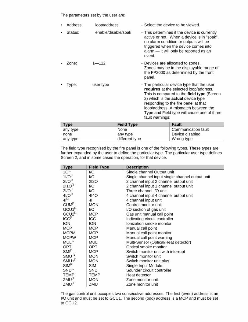
The parameters set by the user are:
• Address: loop/address - Select the device to be viewed.
• Status: enable/disable/soak - This determines if the device is currently active or not. When a device is in "soak", no alarm condition or outputs will be triggered when the device comes into alarm — it will only be reported as an event.
• Zone: 1—112 - Devices are allocated to zones.Zones may be in the displayable range of the FP2000 as determined by the front panel.
• Type: user type - The particular device type that the user requires at the selected loop/address. This is compared to the field type (Screen 2) which is the actual device type responding to the fire panel at that loop/address. A mismatch between the Type and Field type will cause one of threefault warnings:
Type Field Type Faultany type None Communication faultnone any type Device disabledany type different type Wrong type
The field type recognised by the fire panel is one of the following types. These types arefurther expanded by the user to define the particular type. The particular user type definesScreen 2, and in some cases the operation, for that device.
Type Field Type Description1O[1 I/O Single channel Output unit1I/O[1 I/O Single channel input single channel output unit2I/O[2 2I2O 2 channel input 2 channel output unit2I1O[1 I/O 2 channel input 1 channel output unit3I/O[1 I/O Three channel I/O unit4I/O[2 4I4O 4 channel input 4 channel output unit4I[2 4I 4 channel input unitCUM[1 MON Control monitor unitGCU1[1 I/O I/O section of gas unitGCU2[1 MCP Gas unit manual call pointICC[2 ICC Indicating circuit controllerION ION Ionization smoke monitorMCP MCP Manual call pointMCPM MCP Manual call point monitorMCPW MCP Manual call point warningMUL[1 MUL Multi-Sensor (Optical/Heat detector)OPT OPT Optical smoke monitorSMI[1 MCP Switch monitor unit with interruptSMU [1 MON Switch monitor unitSMU+[1 MON Switch monitor unit plusSIM[2 SIM Single Input ModuleSND[1 SND Sounder circuit controllerTEMP TEMP Heat detectorZMU[1 MON Zone monitor unitZMU[2 ZMU Zone monitor unit
The gas control unit occupies two consecutive addresses. The first (even) address is anI/O unit and must be set to GCU1. The second (odd) address is a MCP and must be setto GCU2.

- Depending on the communication protocol, not all of these types are available.
[1 Aritech Series 900 onlySee the Gas Control Unit Manual (GC900 Operating Manual) for further details
[2 Aritech Series 2000 only
• Day Level: 1 — 5 - Default 3 (Smoke and heat detectors only)The fire alarm and precondition threshold for smoke and heat detectors is set. The level entered (1-5) results in an initial alarm level. Values received from the monitoring device are compared to its current alarm level. When the alarm level is exceeded a fire alarm occurs. This level also defines a precondition threshold — *See table below. The alarm level is furthermodified by the compensation applied to the device. Where zones are enabled for day/night operation the night level is always one less than the day level except when the day level is set to one. Day level 3 is the recommended EN54 threshold for ionisation and optical smoke detectors.
SMOKE DETECTORS HEAT DETECTORS
0% Compensation Maximum Compensation °°C
Level Fire Alarm Precondition Fire Alarm Precondition Fire Alarm Precondition
1 80 60 170 150 40 30
2 95 75 170 150 55 45
3 110 90 170 150 70 60
4 125 105 170 150 85 75
5 145 120 170 150 100 90
• Device Text: - Up to 80 characters (2 lines x 40characters) of user definablealphanumeric text can be assigned toeach device. In the case of I/O devicesthe text in these menus will be used forfault warning of those devices. Theactual inputs and outputs of each I/O unitcan have further text defined in the I/OProgramming Menus (see Page 92). It isstrongly recommended that theupload/download program be used fortext. The keypad is generally used tomodify text that has already beendownloaded.

• State: - The alarm or fault state of the device can be viewed. The state is latched when it occurs and is only cleared upon reset. The state that a device can be is:
NML - normalCOMM - communication faultFLT - faultDIS - disabledWTY - wrong typeDBL - double addressPRE - pre-(alarm) conditionMNT - maintenance conditionNTY - no type
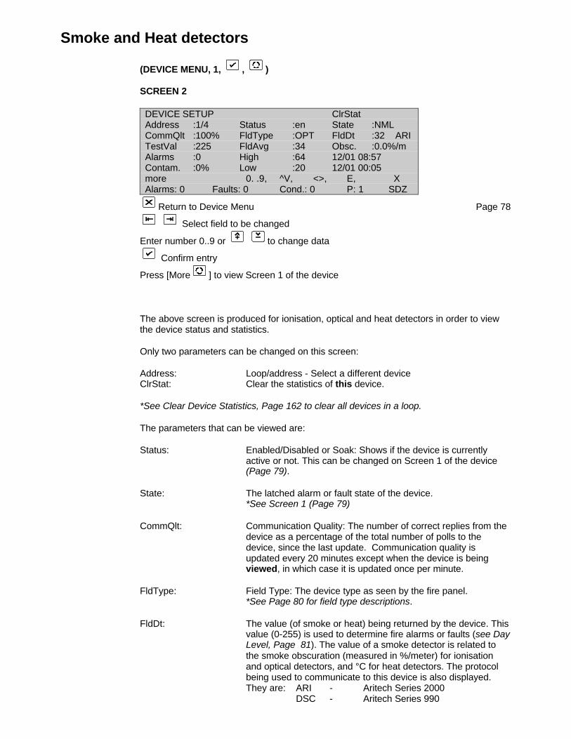
Smoke and Heat detectors
(DEVICE MENU, 1, , )
SCREEN 2
DEVICE SETUP ClrStatAddress :1/4 Status :en State :NMLCommQlt :100% FldType :OPT FldDt :32 ARITestVal :225 FldAvg :34 Obsc. :0.0%/mAlarms :0 High :64 12/01 08:57Contam. :0% Low :20 12/01 00:05more 0. .9, ^V, <>, E, XAlarms: 0 Faults: 0 Cond.: 0 P: 1 SDZ
Return to Device Menu Page 78
Select field to be changed
Enter number 0..9 or to change data
Confirm entry
Press [More ] to view Screen 1 of the device
The above screen is produced for ionisation, optical and heat detectors in order to viewthe device status and statistics.
Only two parameters can be changed on this screen:
Address: Loop/address - Select a different deviceClrStat: Clear the statistics of this device.
*See Clear Device Statistics, Page 162 to clear all devices in a loop.
The parameters that can be viewed are:
Status: Enabled/Disabled or Soak: Shows if the device is currently active or not. This can be changed on Screen 1 of the device (Page 79).
State: The latched alarm or fault state of the device.*See Screen 1 (Page 79)
CommQlt: Communication Quality: The number of correct replies from the device as a percentage of the total number of polls to the device, since the last update. Communication quality is updated every 20 minutes except when the device is being viewed, in which case it is updated once per minute.
FldType: Field Type: The device type as seen by the fire panel.*See Page 80 for field type descriptions.
FldDt: The value (of smoke or heat) being returned by the device. Thisvalue (0-255) is used to determine fire alarms or faults (see DayLevel, Page 81). The value of a smoke detector is related tothe smoke obscuration (measured in %/meter) for ionisationand optical detectors, and °C for heat detectors. The protocolbeing used to communicate to this device is also displayed.They are: ARI - Aritech Series 2000
DSC - Aritech Series 990
X90 - Aritech Series 900X95 - Aritech Series 950
TestVal: The value returned during Device Self-Test. A value that is less than the alarm threshold will result in a maintenance condition.
FldAvg: The average value of the device measured over a 20-minute period.
Obsc: % Obscuration (Smoke Detectors):
Temp: Temperature °C (Heat Detectors): An estimate of the smoke obscuration expressed as %/meter or the heat °C. This is calculated from the value returned by the device and is given forinformation purposes only. The fire panel uses the value for alarm and fault determination.
Alarms: The number of fire alarms produced by the device since the lastclear statistics operation.
High: The highest value achieved by the device and the date (dd/mm)and time (hh:mm) that this occurred.
Low: The lowest value achieved by the device and the date (dd/mm) and time (hh:mm) that this occurred.
Contam: Contamination: The amount of contamination is calculated fromthe long-term drift of the detector, and indicates the cleanlinessof the detector. The long-term drift is generally caused bycontamination, but is also affected by day/night effectsespecially where a zone is occupied during the day and emptyat night. *See Day Level, Page 81.
Manual Call Point
(DEVICE MENU, 1, , )
SCREEN 2
DEVICE SETUP ClrStatAddress :1/2 Status :en State :NMLCommQlt :100% FldType :MCP FldDt :32 ARITestVal :225Alarms :0
more 0. .9, ^V, <>, E, XAlarms: 0 Faults: 0 Cond.: 0 P: 1 SDZ
Return to Device Menu Page 78
Select field to be changed
Enter number 0..9 or to change data
Confirm entry
Press [More ] to view Screen 1 of the device
The above screen is produced for manual call points, call point warning, call pointmonitors, gas unit call points, as well as Mini Switch Monitoring Units with Interrupt inorder to view the device status and statistics.
Only two parameters can be changed on this screen:
Address: Loop/address - Select a different deviceClrStat: Clear the statistics of this device.
*See Clear Device Statistics, Page 162 to clear all devices on a loop.
The parameters that can be viewed are:
Status: Enabled, Disabled or Soak: Shows if the device is currently active or not. This can be changed on Screen 1 of the device (Page 79).
State: The latched alarm or fault state of the device. *See Screen 1 (Page 79).
CommQlt: Communication Quality: The number of correct replies from the device as a percentage of the total number of polls to the device. Communication quality is updated every 20 minutes except when the device is being viewed, in which case it is updated once per minute.
FldType: Field Type: The device type as seen by the fire panel. *See Page 80 for field type descriptions.
FldDt: The value returned by a manual call point is one of three:16 - Fault32 - Normal128 - Fire Alarm
The protocol being used to communicate to this device is alsodisplayed. They are: ARI - Aritech Series 2000

X90 - Aritech Series 900X95 - Aritech Series 950
TestVal: The value returned during Device Self-Test. A value that is less than the alarm threshold will result in a maintenance condition.
Alarms: The number of fire alarms produced by the device since the lastclear statistics operation.
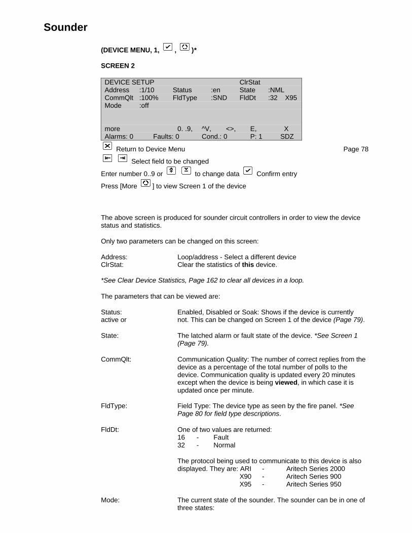
Sounder
(DEVICE MENU, 1, , )*
SCREEN 2
DEVICE SETUP ClrStatAddress :1/10 Status :en State :NMLCommQlt :100% FldType :SND FldDt :32 X95Mode :off
more 0. .9, ^V, <>, E, XAlarms: 0 Faults: 0 Cond.: 0 P: 1 SDZ
Return to Device Menu Page 78
Select field to be changed
Enter number 0..9 or to change data Confirm entry
Press [More ] to view Screen 1 of the device
The above screen is produced for sounder circuit controllers in order to view the devicestatus and statistics.
Only two parameters can be changed on this screen:
Address: Loop/address - Select a different deviceClrStat: Clear the statistics of this device.
*See Clear Device Statistics, Page 162 to clear all devices in a loop.
The parameters that can be viewed are:
Status: Enabled, Disabled or Soak: Shows if the device is currentlyactive or not. This can be changed on Screen 1 of the device (Page 79).
State: The latched alarm or fault state of the device. *See Screen 1 (Page 79).
CommQlt: Communication Quality: The number of correct replies from the device as a percentage of the total number of polls to the device. Communication quality is updated every 20 minutes except when the device is being viewed, in which case it is updated once per minute.
FldType: Field Type: The device type as seen by the fire panel. *See Page 80 for field type descriptions.
FldDt: One of two values are returned:16 - Fault32 - Normal
The protocol being used to communicate to this device is alsodisplayed. They are: ARI - Aritech Series 2000
X90 - Aritech Series 900X95 - Aritech Series 950
Mode: The current state of the sounder. The sounder can be in one ofthree states:

off - sounder offWarning Pls. - sounder operating intermittentlyAlarm Pls. - sounder operating intermittentlyAlarm cont. - the sounder is continuously operating
- Depending on the communication protocol, this device is not always available.
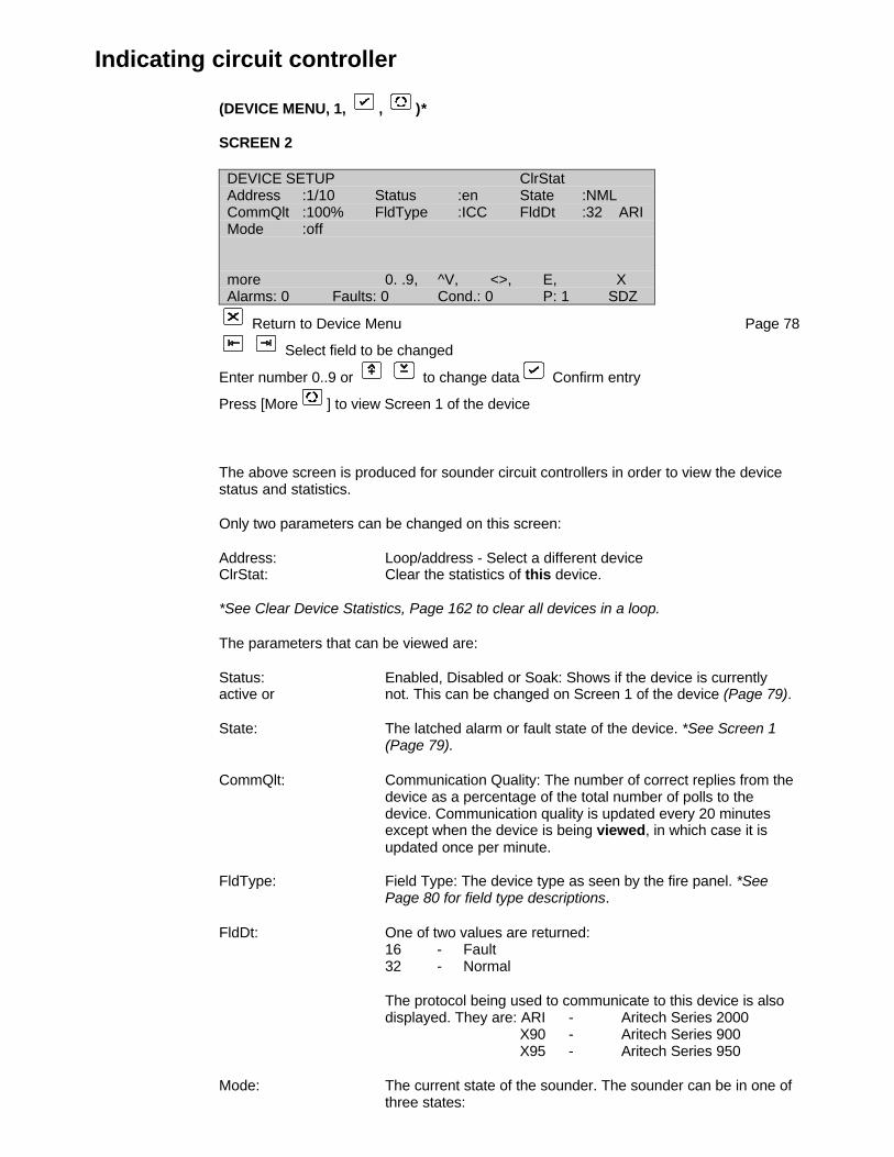
Indicating circuit controller
(DEVICE MENU, 1, , )*
SCREEN 2
DEVICE SETUP ClrStatAddress :1/10 Status :en State :NMLCommQlt :100% FldType :ICC FldDt :32 ARIMode :off
more 0. .9, ^V, <>, E, XAlarms: 0 Faults: 0 Cond.: 0 P: 1 SDZ
Return to Device Menu Page 78
Select field to be changed
Enter number 0..9 or to change data Confirm entry
Press [More ] to view Screen 1 of the device
The above screen is produced for sounder circuit controllers in order to view the devicestatus and statistics.
Only two parameters can be changed on this screen:
Address: Loop/address - Select a different deviceClrStat: Clear the statistics of this device.
*See Clear Device Statistics, Page 162 to clear all devices in a loop.
The parameters that can be viewed are:
Status: Enabled, Disabled or Soak: Shows if the device is currentlyactive or not. This can be changed on Screen 1 of the device (Page 79).
State: The latched alarm or fault state of the device. *See Screen 1 (Page 79).
CommQlt: Communication Quality: The number of correct replies from the device as a percentage of the total number of polls to the device. Communication quality is updated every 20 minutes except when the device is being viewed, in which case it is updated once per minute.
FldType: Field Type: The device type as seen by the fire panel. *See Page 80 for field type descriptions.
FldDt: One of two values are returned:16 - Fault32 - Normal
The protocol being used to communicate to this device is alsodisplayed. They are: ARI - Aritech Series 2000
X90 - Aritech Series 900X95 - Aritech Series 950
Mode: The current state of the sounder. The sounder can be in one ofthree states:

off - ICC offWarning Pls. - ICC operating intermittentlyAlarm Pls. - ICC operating intermittentlyAlarm cont. - the ICC is continuously operating
- Depending on the communications protocol, this device is not always available.
Monitor units
(DEVICE MENU, 1, , )
SCREEN 2
DEVICE SETUP ClrStatAddress :1/7 Status :en State :NMLCommQlt :100% FldType :MON Value :32 S90TestVal :225Alarms :0
More 0. .9, ^V, <>, E, XAlarms: 0 Faults: 0 Cond.: 0 P: 1 SDZ
Return to Device Menu Page 78
Select field to be changed
Enter number 0..9 or to change data Confirm entry
Press [More ] to view Screen 1 of the device
The above screen is produced for zone monitor units, control unit monitors, SwitchMonitor and the Switch Monitor Plus in order to view the device status and statistics.
- Note that the field type can be either "MON" or "ZMU", depending on the communicationprotocol.
Only two parameters can be changed on this screen:
Address: Loop/address - Select a different deviceClrStat: Clear the statistics of this device.
*See Clear Device Statistics Page 162 to clear all devices in a loop.
The parameters that can be viewed are:
Status: Enabled, Disabled or Soak: Shows if the device is currentlyactive or not. This can be changed on Screen 1 of the device(Page 79).
State: The latched alarm or fault state of the device. *See Screen 1 (Page 79).
CommQlt: Communication Quality: The number of correct replies from the device as a percentage of the total number of polls to the device. Communication quality is updated every 20 minutes

except when the device is being viewed, in which case it is updated once per minute.
FldType: Field Type: The device type as seen by the fire panel. *See Page 80 for field type descriptions.
FldDt: The value returned by a manual call point is one of three:16 - Fault32 - Normal128 - Fire Alarm
The protocol being used to communicate to this device is alsodisplayed. They are: ARI - Aritech Series 2000
X90 - Aritech Series 900X95 - Aritech Series 950
TestVal: The value returned during Device Self-Test. A value that is less than the alarm threshold will result in a maintenance condition.
Alarms: The number of fire alarms produced by the device since the lastclear statistics operation.

Input/output units
(DEVICE MENU, 1, , )
SCREEN 2
DEVICE SETUP ClrStatAddress :1/6 Status :en State :NMLCommQlt :100% FldType :I/O FldDt :0 S90Channel :1 2 3 4Inputs :passive - - -Outputs :off - - -more 0. .9, ^V, <>, E, XAlarms: 0 Faults: 0 Cond.: 0 P: 1 SDZ
Return to Device Menu Page 78
Select field to be changed
Enter number 0..9 or to change data Confirm entry
Press [More ] to view Screen 1 of the device
The above screen is produced for all input/output (I/O) units, in order to view the devicestatus and statistics.
- Note that the field type indicated can be one of the following (depending on thecommunication protocol): SIM, 1O, I/O, 2I1O, 2I/O, 4I, 4I/O
For an overview of the devices supported by the FP2000 in a specific protocol, pleaserefer to the appropriate Detector Installation & Commissioning Manual.
Only two parameters can be changed on this screen:
Address: Loop/address - Select a different deviceClrStat: Clear the statistics of this device.
*See Clear Device Statistics, Page 162 to clear all devices in a loop.
The parameters that can be viewed are:
Status: Enabled, Disabled or Soak: Shows if the device is currentlyactive or not. This can be changed on Screen 1 of the device (Page 79 ).
State: The latched alarm or fault sate of the device. *See Screen 1 (Page 79).
CommQlt: Communication Quality: The number of correct replies from the device as a percentage of the total number of polls to the device. Communication quality is updated every 20 minutes except when the device is being viewed, in which case it is updated once per minute.
FldType: Field Type: The device type as seen by the fire panel. *See Page 80 for field type descriptions.
FldDt: The value returned by an I/O unit depends on the state of the input.

The protocol being used to communicate to this device is alsodisplayed. They are: X90 - Aritech Series 900
X95 - Aritech Series 950
Channel: The status of the input channels and output channels is shown
Inputs: The input status can be Active or Passive, Open or Short."Open" & "Short" are valid statements only for units with supervised inputs.
Outputs: The output status can be either On or Off.
- When units with supervised inputs are being used, Screen 1 will slightly change: (Alsosee Page 69)
SCREEN 1
DEVICE SETUPAddress :1/4 Status :en State :NMLZone :1 Type :4I/O Value :38Fault :1 :dis 2 :open 3 :short 4 :abn
more 0. .9, ^V, <>, E, XAlarms: 0 Faults: 0 Cond.: 0 P: 1 SDZ
The last line determines if a fault will be reported automatically or not. Every supervisedinput can be programmed as follows:
dis: no automatic fault reporting for that specific input.abn: a device fault will be reported if the input is open or short (abnormal).open: a device fault will be reported if the input is open.short: a device fault will be reported if the input is in short circuit.
Units, which do not distinguish between open and short circuit, can only be set to abn.
If fault reporting is disabled, every fault condition must be programmed through I/O Logic.
Gas unit I/O (GCU 1)
(DEVICE MENU, 1, , ) *
SCREEN 2
DEVICE SETUP ClrStatAddress :1/22 Status :en State :NMLCommQlt :100% FldType :I/O FldDt :1 S90Fire1 :off Isol. :normalFire2 :off Mode :automatic Gas :normalmore 0. .9, ^V, <>, E, XAlarms: 0 Faults: 0 Cond.: 0 P: 1 SDZ
Return to Device Menu Page 78
Select field to be changed
Enter number 0..9 or to change data Confirm entry
Press [More ] to view Screen 1 of the device
*See Manual Call Point (GCU 2), Page 85*See Gas Control Unit Manual
The above screen is produced for the Input/Output Section of a Gas Control Unit in orderto view the device status and statistics.
Only two parameters can be changed on this screen:
Address: Loop/address - Select a different deviceClrStat: Clear the statistics of this device.
*See Clear Device Statistics, Page 162 to clear all devices in a loop.
The parameters that can be viewed are:
Status: Enabled, Disabled or Soak: Shows if the device is currentlyactive or not. This can be changed on Screen 1 of the device (Page 79).
State: The latched alarm or fault sate of the device. *See Screen 1 (Page 79).
CommQlt: Communication Quality: The number of correct replies from the device as a percentage of the total number of polls to the device. Communication quality is updated every 20 minutes except when the device is being viewed, in which case it is updated once per minute.
FldType: Field Type: The device type as seen by the fire panel. *See Page 80 for field type descriptions.
FldDt: The value returned depends on the state of Isolation Mode andGas Discharge.
The protocol being used to communicate to this device is alsodisplayed. This is: X90 - Aritech Series 900

The screen will also show the status of the gas control unit.
Fire 1, Fire 2 - Fire zones allocated to the unit by means of I/O programming OFF or ON
Isol - Isolated key normal or isolated
Mode - Automatic or manual
Gas - Normal or discharged
- Depending on the communication protocol, this device is not always available.
Zone menu
(DEVICE MENU, 2, )
ZONE Coincidence I.S. Zone :disZone :1 on/off :disStatus :en Day/Night :disMode :normal Sounder Delay :disArea :1 Fbrig Delay :dis
0. .9, ^V, <>, E, XAlarms: 1 Faults: 0 Cond.: 0 P: 1 SDZ
Return to Device Menu Page 78
Select field to be changed
Enter number 0..9 or to change data (Unlock memory!)
Confirm entry
For Zone Text Field (1 line x 40 characters):
Use to obtain the text line to be changed
Press (Unlock memory!)
Use to toggle between alpha and numeric textPress the alpha/numeric button required
Use to move the cursor within the line
Press when completed
The operation of each zone can be viewed and modified using this menu.
The functions of the screen are:
• Zone: 1—112 - Select the zone to be viewed or modified.
• Status: enable/disable - Zones can be enabled or disabled. Whendisabled, the zone fault LED remainssteady on. In addition, the common faultand common disable LED’s are active.Fires and faults occurring in a disabledzone are not reported. If fires or faults existat the time of disabling, the panel must bereset to clear these conditions. Note thatall devices in the disabled zone remainelectrically active and can still be viewedin the Device Menus. (See Page 78).Zones can also be disabled using theDISABLE function key. (See Page 188)
A report of disabled zones can beobtained. (See Page 194)

• Mode: - A coincidence condition is logged in the event buffer when twoor more fire monitoring devices of the zone are in alarm. Acoincidence condition can also be used as an input for I/O logicswitching. When viewing the display alarm screen, theabbreviation "COI" is displayed next to the status of devicescontributing to the coincidence condition of the zone. Also,when viewing this zone menu, the word "COINCIDENCE"flashes if the zone currently has a coincidence condition.
"Mode" determines the operation –
: normal – Coincidence only: confirmed – Alarm is raised only if fire ispresent for more than 60s as well as for acoincidence.: two devices – When first fire detected, thepanel goes into pre-alarm. During 2nd fire,alarm is raised. This applies to acoincidence as well.
• Area: 1—99 - The selected zone can be assigned to any one of 99 areas. An area (being a group of zones) can be used for I/O switching and evacuation control. (See Page 99).
• On/Off: disable/enable - Zones that have on/off enabled areswitched on and off each day according tothe times set in the Set Times Menu (seePage 68). This feature is intended forsecurity type applications (Door and I/Omonitoring) and not for fire zones. Any firemonitoring device or sounder output unitthat exists in a zone that is switched off inthis manner, will cause a zonedisablement.
• Day/Night: disable/enable - Zones that are enabled for day/night operation will switch between Day Mode and Night Mode according to the times set in the Set Times Menu (see Page 68). The devices in these zones operate at one level more sensitive during Night Mode than the level set for Day Mode. (See Page 75).
• Text: 40 chars - Each zone can have 40 characters of user text assigned. This text is used in the reporting of zone faults and conditions.
• Sounder Delay: enable/disable - Enables/disables the Sounder Delay (see Output Delays Menu and Front Panel Keys) for each individual zone.
This selection must be Enabled and the front panel Sounder Delay key ON for the delay to be enabled.
• Fire Brigade Delay: enable/disable - Enables/disables the Fire Brigade Delay (see Output Delays Menu and Front PanelKeys) for each individual zone.
This selection must be Enabled and the front panel Fire Brigade Delay key ON for the delay to be enabled.
• I.S. Zone*: enable/disable - Enables/disables an intrinsically safe zone.(The number of device LED's for this zone is limited to 2).
• Coincidence: - Indicates that two or more devices have triggered a fire alarm.
- 112 Zones are provided for control purposes.
Depending on the configuration, 16/64, 32/128, 48/192 or 64/255 zones can bedisplayed on the FP2000 front panel. It might happen that devices are allocated tozones outside the "visible" range of the fire panel, and no zone LED will illuminate whenthese devices go into alarm! Therefore, these zones should not be used for fire sensors,unless remote zone indicators are used.
*Depending on the communications protocol, this option is not always available.
Area menu
(DEVICE MENU, 3, )
AREAS CoincidenceArea :1 Adj 2 :0Status :en Adj 3 :0Coincidence unlogged Adj 4 :0Adj 1 :0 Adj 5 :0
0. .9, ^V, <>, E, XAlarms: 1 Faults: 0 Cond.: 0 P: 1 SDZ
Return to Device Menu Page 78
Select field to be changed
Enter number 0..9 or to change data (Unlock memory!)
Confirm entry
For Area Text Field (1 line x 40 characters):
Use to obtain the text line to be changed
Press (Unlock memory!)
Use to toggle between alpha and numeric textPress the alpha/numeric button required
Use to move the cursor within the line
Press when completed
An area is defined as a group of zones. Ninety-nine areas are provided. Zones areassigned to areas using the Zone Menu Screen (see Page 96).
An area will be in a fire alarm or fault warning state if any of the zones assigned to thearea are in a fire alarm or a fault warning state. The Area status can be used as an inputfor I/O switching and is particularly useful for evacuation type operation. Area fire andfault status is not logged in the event buffer. Area coincidence, if enabled, will be loggedwhen the condition occurs.
Each Area can have five adjacent areas assigned to it. Output switching can beprogrammed for adjacent areas of the area in fire or fault. For example: An evacuationsignal can be sent to an Area in fire and a warning signal can be sent to the AdjacentAreas.
The functions of the screen are:
• Area: 1—99 - Select the area to be viewed or modified
• Status: enable/disable - An area disabled will cause no action in the I/O logic, event buffer, and adjacent area operation.
• Coincidence: logged/unlogged - Area coincidence occurs if two or more zones assigned to the area have a fire alarm. The area coincidence can be used as an input for I/O switching. When viewingthis menu, the word COINCIDENCE will flash if the area is in a coincidence state. When logged, the coincidence is reported in the Event Buffer.
• Adj1 - Adj5: 0—99 - Up to five other areas can be defined as being adjacent to the area.
• Text: 40 Chars - Each area can have 40 characters of user text assigned. This text is used with any reports or logs generated.
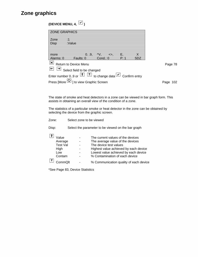
Zone graphics
(DEVICE MENU, 4, )
ZONE GRAPHICS
Zone :1Disp :Value
more 0. .9, ^V, <>, E, XAlarms: 0 Faults: 0 Cond.: 0 P: 1 SDZ
Return to Device Menu Page 78
Select field to be changed
Enter number 0..9 or to change data Confirm entry
Press [More ] to view Graphic Screen Page 102
The state of smoke and heat detectors in a zone can be viewed in bar graph form. Thisassists in obtaining an overall view of the condition of a zone.
The statistics of a particular smoke or heat detector in the zone can be obtained byselecting the device from the graphic screen.
Zone: Select zone to be viewed
Disp: Select the parameter to be viewed on the bar graph
Value - The current values of the devicesAverage - The average value of the devicesTest Val - The device test valuesHigh - Highest value achieved by each deviceLow - Lowest value achieved by each deviceContam - % Contamination of each device
CommQlt - % Communication quality of each device
*See Page 83, Device Statistics

Zone graphic screen
(ZONE GRAPHICS, )
128
64
0more ^V, <>, XAlarms: 0 Faults: 0 Cond.: 0 P: 1 SDZ
Return to Device Menu Page 78
Select bar in bar graph
Select scale of bar graph
Press [More ] to view statistics of selected bar Page 103
Press [More ], [More ] to return to the Zone Graphics Screen Page 102
A bar graph of the smoke and heat detectors is displayed for the zone and parameterselected. The bar graph is dynamically updated once per loop scan.
The statistics of a device can be viewed by selecting the bar of the device and pressing
[More ]. The selected bar is displayed with the bar "coloured in".
The scale of the graph for compensation and communication quality is fixed at 0-100%.
The scale for other values can be selected by pressing or :
0—128 0— 6432— 64
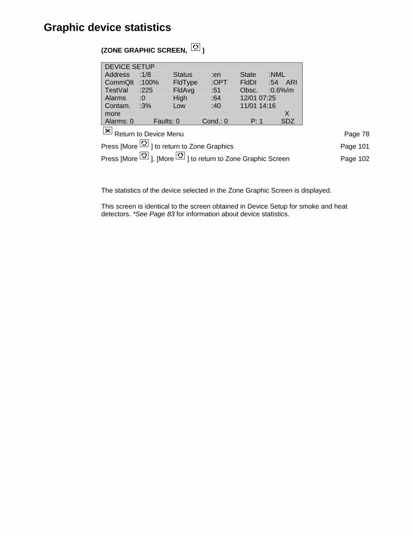
Graphic device statistics
(ZONE GRAPHIC SCREEN, )
DEVICE SETUPAddress :1/8 Status :en State :NMLCommQlt :100% FldType :OPT FldDt :54 ARITestVal :225 FldAvg :51 Obsc. :0.6%/mAlarms :0 High :64 12/01 07:25Contam. :3% Low :40 11/01 14:16more XAlarms: 0 Faults: 0 Cond.: 0 P: 1 SDZ
Return to Device Menu Page 78
Press [More ] to return to Zone Graphics Page 101
Press [More ], [More ] to return to Zone Graphic Screen Page 102
The statistics of the device selected in the Zone Graphic Screen is displayed.
This screen is identical to the screen obtained in Device Setup for smoke and heatdetectors. *See Page 83 for information about device statistics.

Device graphics
(DEVICE MENU, 5, )
DEVICE GRAPHICSAddr. :1/1 Time :11/01/9910:24:06Sample :1/10 s Value :0 Average :0Disp :Value High :0 TestVal :0
Low :0 Contam :0%CommQlt :0%
more ^V, <>, E, XAlarms: 0 Faults: 0 Cond.: 0 P: 1 SDZ
Return to Device Menu Page 78
Select field to be changed
Enter number 0..9 or to change data Confirm entry
Press [More ] to view the Device Graphic Screen Page 106
A line graph plotting a value with time can be obtained for any smoke or heat device. TheY-axis of the graph can be selected for any of the device statistics listed below. The X-axis time scale is determined by the sample rate chosen.
Once the device, display type, and sample rate is set, a recording is begun. Thisrecording is updated continuously at the sample rate set — even when the user is notin the Device Graphics Menu. Changing any of the above three parameters requires thecurrent recording to be cleared, and a new recording to begin. The user is prompted for
confirmation that the recording is to be cleared. Toggle to Y (yes) and press toconfirm the change.
Statistics of the device as well as date and time is displayed. The date and time isdetermined by the cursor position selected in the Device Graphic Screen (Page 106).This facility allows the user to view the statistics of the device at a particular time on thegraph.
• Addr: loop/address - Select the device to be recorded. Only smoke and heat detectors that are enabledmay be selected.
• Sample: - Select the sample rate (time scale) required (See note below)
1/10 second1/min1/20 min
1/day - at maintenance time set in the maintenance menu (maintenance time must not be 00:00)
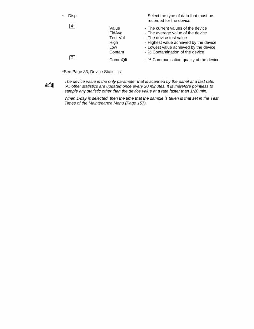
• Disp: Select the type of data that must be recorded for the device
Value - The current values of the deviceFldAvg - The average value of the deviceTest Val - The device test valueHigh - Highest value achieved by the deviceLow - Lowest value achieved by the deviceContam - % Contamination of the device
CommQlt - % Communication quality of the device
*See Page 83, Device Statistics
- The device value is the only parameter that is scanned by the panel at a fast rate. All other statistics are updated once every 20 minutes. It is therefore pointless tosample any statistic other than the device value at a rate faster than 1/20 min.
When 1/day is selected, then the time that the sample is taken is that set in the TestTimes of the Maintenance Menu (Page 157).

Device graphic screen
(DEVICE GRAPHICS, )
128
64
0more ^V, <>, XAlarms: 0 Faults: 0 Cond.: 0 P: 1 SDZ
Return to Device Menu Page 78
Select a time position in the graph
Select the scale of the graph
Press [More ] to view statistics of the selected device Page 103
Press [More ], [More ] to return to the Device Graphic Screen Page 106
A line graph of the selected device recording is displayed. (See Page 104).
The graph is drawn from left to right. Once the screen is full, the graph line is "rolled" fromright to left. Thus, the right most point of the graph represents the present time and eachpoint to the left is one sample time previous. The graph will display 217 time samples.
The time window for the various sample rates is thus:1/10 second: 36 minutes1/min: 3.6 hours1/20 min: 72 hours1/day: 217 days
A cursor is used to select a particular time in the graph. The device statistics at that time
is displayed on the Device Graphics Screen (Page 106) by pressing , .
The scale of the graph for compensation and communication quality is fixed at 0-100%.
The scale for other values can be selected by pressing or :
0—128 0— 6432— 64
Graphic device setup
(DEVICE GRAPHIC SCREEN, )
DEVICE SETUP grapAddress :1/4 Status :en State :NMLCommQlt :100% FldType :OPT FldDt :30 ARITestVal :255 FldAvg :35 Obsc. :0.0%/mAlarms :0 High :64 12/01 08:57Contam. :0% Low :20 12/01 00:05more XAlarms: 0 Faults: 0 Cond.: 0 P: 1 SDZ
Return to Device Menu Page 78
Press [More ] to return to Device Graphics Page 103
Press [More ], [More ] to return to the Device Graphic Screen Page 106
The statistics of the device selected in the Device Graphic screen is displayed.
This screen is identical to the screen obtained in Device Setup for smoke and heatdetectors. *See Page 83 for information about device statistics.
Zone range
(DEVICE MENU, 6, )
ZONE RANGE
Start :1End :255Changing the zone range will clear allZone relations !
0. .9, ^V, <>, E, XAlarms: 0 Faults: 0 Cond.: 0 P: 1 SDZ
Return to Device Menu Page 78
Press [More ] to return to Device Graphics Page 104
Press [More ], [More ] to return to the Device Graphic Screen Page 106
Note: If connected to a global zone repeater the zone ranges of the different panels mustnot overlap!
Input/output
(MAIN MENU, 3, )
INPUT/OUTPUT
1 Inputs 2 Outputs3 Logic 4 CL Devices5 Timers 6 Markers
0. .9, <>, E, XAlarms: 0 Faults: 0 Cond.: 0 P: 1 SDZ
Select number or use and press
Return to Main Menu Page 23
1 InputsView and Define System InputsCommon Facilities - All Input Types Page 111General Page 114Zone Page 116Area Page 117Adjacent Area Page 118Internal Page 119Time Page 120Device Input Page 122Device Page 123Network Page 124Action Page 125Current Loop Device Page 126Date Page 127
2 OutputsView and Define System OutputsCommon Facilities - All Output Types Page 128General Page 131Zone Page 132Area Page 133Internal Page 134Device Output Page 135Supervised Internal Page 136Supervised Device Output Page 137Network Page 138Current Loop Device Page 139Supervised Current Loop Device Page 140Event Page 141Action Page 142
3 LogicView and define the logic programming that determines the switching of outputsaccording inputs and expressions. Page 145

4 CL DevicesView and define the programming that determines the switching of current loop outputsaccording to the settings of the current loop devices. Page 148
5 TimersMonitoring of Timer status. Page 150
6 MarkersMonitoring of Marker status. Page 151
Common facilities – all input types
* See Input Description in the Serial Communication Format
Input: number
Enter number or use to view/change the existing defined inputs, or create a new input. Each input required for the I/O logic system must be defined by a unique input number.
Unused inputs have type None. The maximum number of inputs (default 100) may be set in Memory Allocation (Page 33).
Type: type
Inputs can be set true or false by the following types and functions that are specifically described in the following pages.
None no input defined (default)General Page 114
Zone Page 116 Area Page 117 Adjacent Area Page 118 Internal Page 119 Time Page 120 Device Input Page 122 Device Page 123 Network Page 124 Action Page 125 Current Loop Device Page 126 Date Page 127
Fct: function
The functions available depend on the input type selected. Refer to the page of the specific function for further details.
State: true/false
This view field shows the state of the input. The input state is the physical input (on or off) conditioned by the Trigger and Mode of the input definition.
Trig: latched/unlatched
LatchedThe input state, once switched true, will remain true until the fire panel is reset, even though the input conditions may become false before the reset.
UnlatchedThe input state will become true or false according to the physicalinput state and the mode.
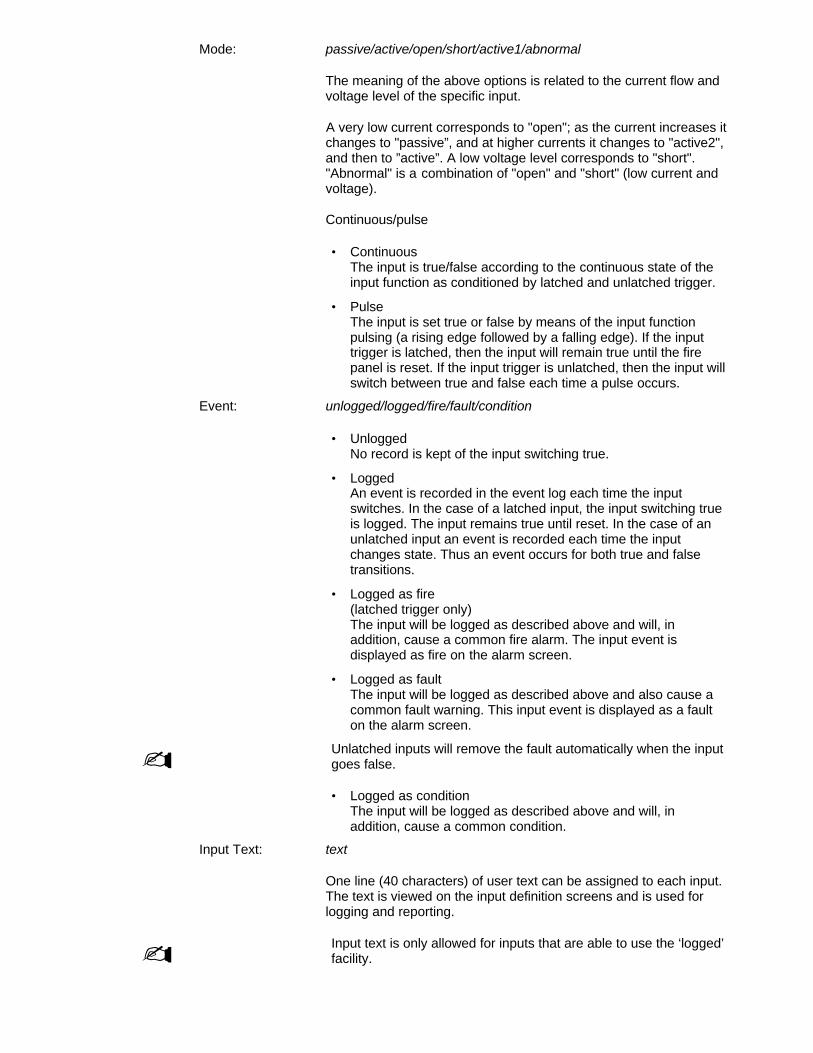
Mode: passive/active/open/short/active1/abnormal
The meaning of the above options is related to the current flow and voltage level of the specific input.
A very low current corresponds to "open"; as the current increases itchanges to "passive”, and at higher currents it changes to "active2",and then to ”active”. A low voltage level corresponds to "short"."Abnormal" is a combination of "open" and "short" (low current andvoltage).
Continuous/pulse
• ContinuousThe input is true/false according to the continuous state of theinput function as conditioned by latched and unlatched trigger.
• PulseThe input is set true or false by means of the input functionpulsing (a rising edge followed by a falling edge). If the inputtrigger is latched, then the input will remain true until the firepanel is reset. If the input trigger is unlatched, then the input willswitch between true and false each time a pulse occurs.
Event: unlogged/logged/fire/fault/condition
• UnloggedNo record is kept of the input switching true.
• LoggedAn event is recorded in the event log each time the inputswitches. In the case of a latched input, the input switching trueis logged. The input remains true until reset. In the case of anunlatched input an event is recorded each time the inputchanges state. Thus an event occurs for both true and falsetransitions.
• Logged as fire(latched trigger only)The input will be logged as described above and will, inaddition, cause a common fire alarm. The input event isdisplayed as fire on the alarm screen.
• Logged as faultThe input will be logged as described above and also cause acommon fault warning. This input event is displayed as a faulton the alarm screen.
- Unlatched inputs will remove the fault automatically when the inputgoes false.
• Logged as conditionThe input will be logged as described above and will, inaddition, cause a common condition.
Input Text: text
One line (40 characters) of user text can be assigned to each input. The text is viewed on the input definition screens and is used for logging and reporting.
- Input text is only allowed for inputs that are able to use the ‘logged’facility.

The procedure for entering text is as follows:
Use or to obtain the text line
Toggle for alpha or numeric characters
0..9 For alpha characters press key repeatedly until desired upper or lower casecharacter or key is obtained.
Advance cursor to next position
Mover cursor back one position
Confirm end of text input
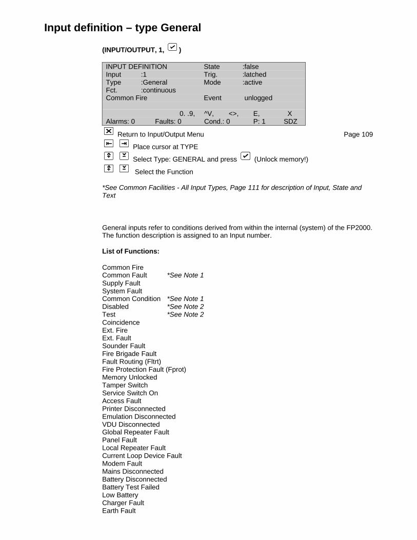
Input definition – type General
(INPUT/OUTPUT, 1, )
INPUT DEFINITION State :falseInput :1 Trig. :latchedType :General Mode :activeFct. :continuousCommon Fire Event unlogged
0. .9, ^V, <>, E, XAlarms: 0 Faults: 0 Cond.: 0 P: 1 SDZ
Return to Input/Output Menu Page 109
Place cursor at TYPE
Select Type: GENERAL and press (Unlock memory!)
Select the Function
*See Common Facilities - All Input Types, Page 111 for description of Input, State andText
General inputs refer to conditions derived from within the internal (system) of the FP2000.The function description is assigned to an Input number.
List of Functions:
Common FireCommon Fault *See Note 1Supply FaultSystem FaultCommon Condition *See Note 1Disabled *See Note 2Test *See Note 2CoincidenceExt. FireExt. FaultSounder FaultFire Brigade FaultFault Routing (Fltrt)Fire Protection Fault (Fprot)Memory UnlockedTamper SwitchService Switch OnAccess FaultPrinter DisconnectedEmulation DisconnectedVDU DisconnectedGlobal Repeater FaultPanel FaultLocal Repeater FaultCurrent Loop Device FaultModem FaultMains DisconnectedBattery DisconnectedBattery Test FailedLow BatteryCharger FaultEarth Fault
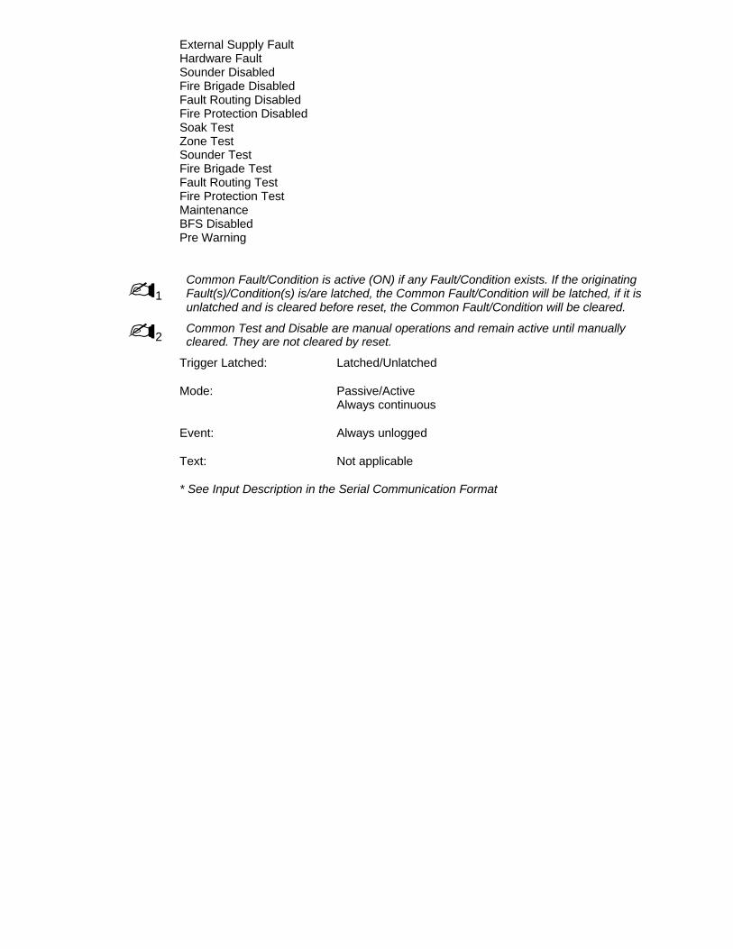
External Supply FaultHardware FaultSounder DisabledFire Brigade DisabledFault Routing DisabledFire Protection DisabledSoak TestZone TestSounder TestFire Brigade TestFault Routing TestFire Protection TestMaintenanceBFS DisabledPre Warning
-1Common Fault/Condition is active (ON) if any Fault/Condition exists. If the originatingFault(s)/Condition(s) is/are latched, the Common Fault/Condition will be latched, if it isunlatched and is cleared before reset, the Common Fault/Condition will be cleared.
-2Common Test and Disable are manual operations and remain active until manuallycleared. They are not cleared by reset.
Trigger Latched: Latched/Unlatched
Mode: Passive/ActiveAlways continuous
Event: Always unlogged
Text: Not applicable
* See Input Description in the Serial Communication Format
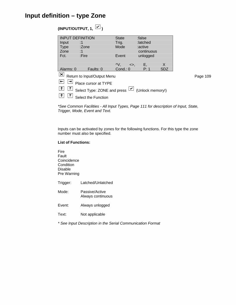
Input definition – type Zone
(INPUT/OUTPUT, 1, )
INPUT DEFINITION State :falseInput :1 Trig. :latchedType :Zone Mode :activeZone :1 continuousFct. :Fire Event unlogged
^V, <>, E, XAlarms: 0 Faults: 0 Cond.: 0 P: 1 SDZ
Return to Input/Output Menu Page 109
Place cursor at TYPE
Select Type: ZONE and press (Unlock memory!)
Select the Function
*See Common Facilities - All Input Types, Page 111 for description of Input, State,Trigger, Mode, Event and Text.
Inputs can be activated by zones for the following functions. For this type the zonenumber must also be specified.
List of Functions:
FireFaultCoincidenceConditionDisablePre Warning
Trigger: Latched/Unlatched
Mode: Passive/ActiveAlways continuous
Event: Always unlogged
Text: Not applicable
* See Input Description in the Serial Communication Format

Input definition – type Area
(INPUT/OUTPUT, 1, )
INPUT DEFINITION State :falseInput :1 Trig. :latchedType :Area Mode :activeArea :1 continuousFct. :Fire Event unlogged
0. .9, ^V, <>, E, XAlarms: 0 Faults: 0 Cond.: 0 P: 1 SDZ
Return to Input/Output Menu Page 109
Place cursor at TYPE
Select Type: AREA and press (Unlock memory!)
Select the Function
*See Common Facilities - All Input Types, Page 111 for description of Input, State,Trigger, Mode, Event and Text
An area is defined as a group of zones (see Page 99). An input can be assigned to anarea by specifying the area number and the function.
List of Functions:
FireFaultCoincidenceConditionDisablePre Warning
- An area coincidence is two or more zones allocated to the area in a fire alarm condition.It is independent of zones in coincidence. *See Page 99
Trigger: Latched/Unlatched
Mode: Passive/ActiveAlways continuous
Event: Always unlogged
Text: Not applicable
* See Input Description in the Serial Communication Format

Input definition – type Adjacent Area
(INPUT/OUTPUT, 1, )
INPUT DEFINITION State :falseInput :1 Trig. :latchedType :Adj. Area Mode :activeArea :1 continuousFct. :Fire Event unlogged
0. .9, ^V, <>, E, XAlarms: 0 Faults: 0 Cond.: 0 P: 1 SDZ
Return to Input/Output Menu Page 109
Place cursor at TYPE
Select Type: ADJ AREA and press (Unlock memory!)
Select the Function
*See Common Facilities - All Input Types, Page 111 for description of Input, State,Trigger, Mode, Event and Text
Adjacent areas are assigned to areas using the Area Setup Menu, Page 99. An input canbe activated by an adjacent area by specifying the area number and function. Adjacentareas have significance in PA evacuation systems where an area in fire is evacuated andthe adjacent areas have warning alarms.
List of Functions:
FireFaultCoincidenceConditionDisablePre Warning
The adjacent areas of the specified area will activate the input.
Trigger: Latched/Unlatched
Mode: Passive/ActiveAlways continuous
Event: Always unlogged
Text: Not applicable
* See Input Description in the Serial Communication Format

Input definition – type Internal
(INPUT/OUTPUT, 1, )
INPUT DEFINITION State :falseInput :1 Trig. :latchedType :Internal Mode :activeBoard :24:FEP continuousInput :1 Event unlogged
0. .9, ^V, <>, E, XAlarms: 0 Faults: 0 Cond.: 0 P: 1 SDZ
Return to Input/Output Menu Page 109
Place cursor at TYPE
Select Type: INTERNAL and press (Unlock memory!)
Use number 0..9 or to select PC Board address and press
Use number 0..9 or to select PC Board input number and press
*See Common Facilities - All Input Types, Page 111 for a description of Input, State,Trigger, Mode, Event and Text
The input number selected is assigned to a physical electrical input provided on a printedcircuit board within the FP2000 fire panel. In order to assign a physical input, the PCBoard address (see Page 32 for board addressing) as well as the input number on thatboard must be defined. For example: the FP2000 provides four inputs on the FEP board(address 24) as standard.
This screen confirms the PC Board type when the board address is entered.
Trigger: Latched/Unlatched
Mode: Passive/Active/Open/Short/Active1/AbnormalContinuous/Pulse
Event: Unlogged/Logged/Fire/Fault/Condition
Text: Allowed
* See Input Description in the Serial Communication Format
Input definition – type Time
(INPUT/OUTPUT, 1, )
INPUT DEFINITION State :falseInput :1 Trig. :latchedType :Time Mode :activeTime :03:25 continuousDay :Every Day Event unlogged
^V, <>, E, XAlarms: 0 Faults: 0 Cond.: 0 P: 1 SDZ
Return to Input/Output Menu Page 109
Place cursor at TYPE
Select Type: TIME and press (Unlock memory!)
Use number 0..9 or to set time and press (Unlock memory!)
to select Day and press
*See Common Facilities - All Input Types, Page 111 for description of Input, State,Trigger, Mode, Event, and Test
Inputs may be activated at a specified time on any day of the week or every day of theweek.
The time function may be considered as a contact that closes at the specified time andday and remains closed for one minute. The input can be made to latch or pulse byselecting different trigger and mode. Using the set and reset functions of LOGIC with twoor more time inputs can create more complex time waveforms.
Time: Time of day in 24hr format:hh:mm hh 0-23 mm 0-59
The input will switch at the selected hour (hh) and minute (mm)
- Time 00h00 has no action
Day: Every dayMondayTuesdayWednesdayThursdayFridaySaturdaySunday
Trigger: Latched/UnlatchedIf the trigger condition is latched and the mode is set to continuous, the statewill change once on the set time and day and will remain so until the panel is reset. If the mode is set to pulse, the state will change on the set time and day, i.e. if it was true, it will change to false and vice versa.If the trigger condition is unlatched, the state will change for one minute on the set day and time.

Mode: Passive/ActiveContinuous/Pulse
Event: Unlogged/Logged/Fire/Fault/Condition
Text: Allowed
* See Input Description in the Serial Communication Format

Input definition – type Device Input
(INPUT/OUTPUT, 1, )
INPUT DEFINITION State :falseInput :1 Trig. :latchedType :Device Input Mode :activeAddr. :1/1 :1I/O continuousChan. :1 Event unlogged
0. .9, ^V, <>, E, XAlarms: 0 Faults: 0 Cond.: 0 P: 1 SDZ
Return to Input/Output Menu Page 109
Place cursor at TYPE
Select Type: DEVICE INPUT and press (Unlock memory!)
Use number or and press to select the device loop/address and inputchannel number
*See Common Facilities - All Input Types, Page 111 for description of Input, State,Trigger, Mode, Event, and Test
The selected input number is controlled by the input of a field (loop) device of theI/O type. The device is defined by its loop/address as well as the input channel number ofthe device. The device type is confirmed on the screen when the loop/address is entered.
- The pre-assigned inputs of a Gas Control Unit (type GCU1) can also be used in thismenu. *See Gas Control Unit Manual
Trigger: Latched/Unlatched
Mode: Passive/ActiveAlways continuous
Event: Unlogged/Logged/Fire/Fault/Condition
Text: Allowed
Input definition – type Device
(INPUT/OUTPUT, 1, )
INPUT DEFINITION State :falseInput :1 Trig. :latchedType :Device Mode :activeAddr. :1/4 :OPT continuousFct. :Fire Event unlogged
^V, <>, E, XAlarms: 0 Faults: 0 Cond.: 0 P: 1 SDZ
Return to Input/Output Menu Page 109
Place cursor at TYPE
Select Type: DEVICE and press (Unlock memory!)
Use number or and press to select the function and input channel number
*See Common Facilities - All Input Types, Page 111 for description of Input, State,Trigger, Mode, Event, and Test
The selected input number is activated by a field (loop) device fire, fault or condition. Afire function is only valid for devices that would normally create a fire alarm (e.g. smokedetector, manual call point or zone monitor unit).
The device is defined by its loop/address as well as the function (fire, fault or condition).The device type is confirmed on the screen when the loop/address is entered.
List of Functions:
FireFaultCondition
Trigger: Latched/Unlatched
Mode: Passive/ActiveAlways continuous
Event: Unlogged
Text: Not applicable
* See Input Description in the Serial Communication Format
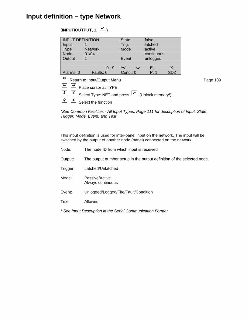
Input definition – type Network
(INPUT/OUTPUT, 1, )
INPUT DEFINITION State :falseInput :1 Trig. :latchedType :Network Mode :activeNode :01/04 continuousOutput :1 Event unlogged
0. .9, ^V, <>, E, XAlarms: 0 Faults: 0 Cond.: 0 P: 1 SDZ
Return to Input/Output Menu Page 109
Place cursor at TYPE
Select Type: NET and press (Unlock memory!)
Select the function
*See Common Facilities - All Input Types, Page 111 for description of Input, State,Trigger, Mode, Event, and Test
This input definition is used for inter-panel input on the network. The input will beswitched by the output of another node (panel) connected on the network.
Node: The node ID from which input is received
Output: The output number setup in the output definition of the selected node.
Trigger: Latched/Unlatched
Mode: Passive/ActiveAlways continuous
Event: Unlogged/Logged/Fire/Fault/Condition
Text: Allowed
* See Input Description in the Serial Communication Format

Input definition – type Action
(INPUT/OUTPUT, 1, )
INPUT DEFINITION State :falseInput :1 Trig. :latchedType :Action Mode :activeFct. : continuousDay Mode Event unlogged
^V, <>, E, XAlarms: 0 Faults: 0 Cond.: 0 P: 1 SDZ
Return to Input/Output Menu Page 109
Place cursor at TYPE
Select Type: ACTION and press (Unlock memory!)
Select the Function
*See Common Facilities - All Input Types, Page 111 for description of Input, State andTest
Inputs are set according to actions performed by either the user or by the panel itself. Thetype of actions is defined by the function set and is described below. Since all actions arelogged in their own right, the log and text are not available in this menu.
The action functions available are:Day ModeZones ONSchool Bells OnSilence BuzzerKeyswitch unlockedSounder OnSounder SilencedSounder Delay OnFire Brigade SignalledFire Brigade StoppedFire Brigade Delay OnFault Routing OnFault Routing Delay OnFire Protection OnFire Protection Delay OnRestartResetAccess EnabledEvent Log FullEvent Log ClearedMaintenance Reminder
Trigger: Latched/Unlatched
Mode: Passive/ActiveAlways continuous
Event: Unlogged
Text: Not applicable
* See Input Description in the Serial Communication Format

Input definition – type Current Loop Device
(INPUT/OUTPUT, 1, )
INPUT DEFINITION State :falseInput :1 Trig. :latchedType :CL Dev. Mode :active 1CL Adr :1 continuousInput :1 Event unlogged
0. .9, ^V, <>, E, XAlarms: 0 Faults: 0 Cond.: 0 P: 1 SDZ
Return to Input/Output Menu Page 109
Place cursor at TYPE
Select Type: ACTION and press (Unlock memory!)
Select function
*See Common Facilities - All Input Types, Page 111 for description of Input, State andTest
The inputs on a current loop device (FM800/FR800 Series) can be used for furtherprocessing through I/O Logic. The inputs are numbered as per the Input Description inthe Serial Communication Format.
For the I/O to work, the common must be disabled in the CL Device Menu (see page 52).
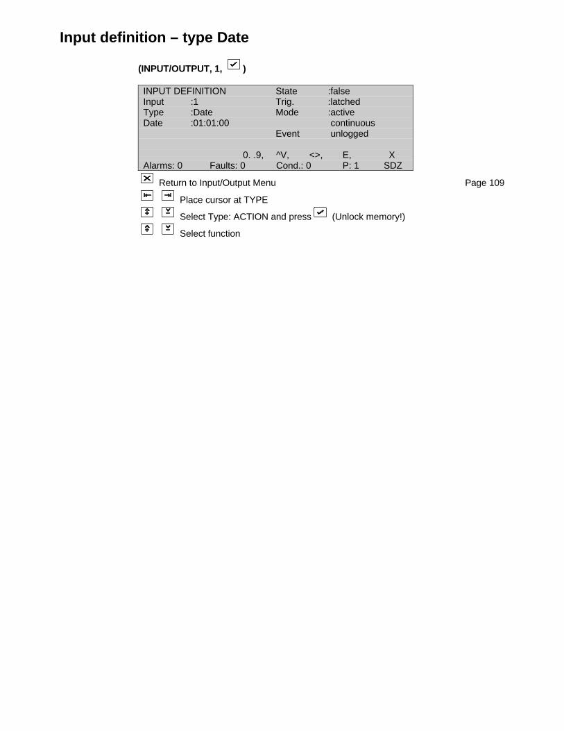
Input definition – type Date
(INPUT/OUTPUT, 1, )
INPUT DEFINITION State :falseInput :1 Trig. :latchedType :Date Mode :activeDate :01:01:00 continuous Event unlogged
0. .9, ^V, <>, E, XAlarms: 0 Faults: 0 Cond.: 0 P: 1 SDZ
Return to Input/Output Menu Page 109
Place cursor at TYPE
Select Type: ACTION and press (Unlock memory!)
Select function
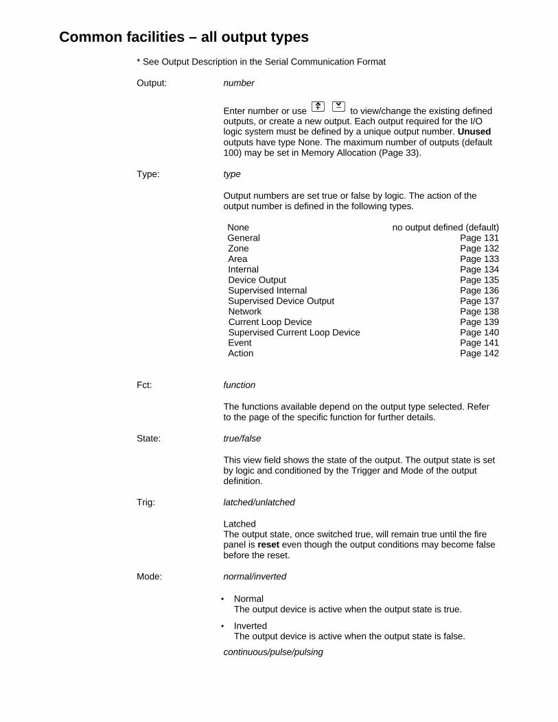
Common facilities – all output types
* See Output Description in the Serial Communication Format
Output: number
Enter number or use to view/change the existing defined outputs, or create a new output. Each output required for the I/O logic system must be defined by a unique output number. Unusedoutputs have type None. The maximum number of outputs (default 100) may be set in Memory Allocation (Page 33).
Type: type
Output numbers are set true or false by logic. The action of the output number is defined in the following types.
None no output defined (default)General Page 131
Zone Page 132 Area Page 133 Internal Page 134 Device Output Page 135 Supervised Internal Page 136 Supervised Device Output Page 137 Network Page 138 Current Loop Device Page 139 Supervised Current Loop Device Page 140 Event Page 141 Action Page 142
Fct: function
The functions available depend on the output type selected. Refer to the page of the specific function for further details.
State: true/false
This view field shows the state of the output. The output state is set by logic and conditioned by the Trigger and Mode of the output definition.
Trig: latched/unlatched
LatchedThe output state, once switched true, will remain true until the fire panel is reset even though the output conditions may become false before the reset.
Mode: normal/inverted
• NormalThe output device is active when the output state is true.
• InvertedThe output device is active when the output state is false.
continuous/pulse/pulsing
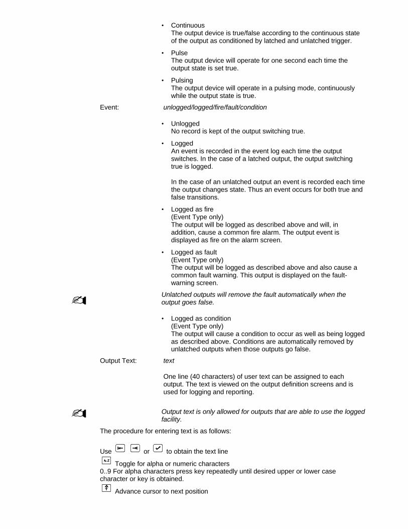
• ContinuousThe output device is true/false according to the continuous stateof the output as conditioned by latched and unlatched trigger.
• PulseThe output device will operate for one second each time theoutput state is set true.
• PulsingThe output device will operate in a pulsing mode, continuouslywhile the output state is true.
Event: unlogged/logged/fire/fault/condition
• UnloggedNo record is kept of the output switching true.
• LoggedAn event is recorded in the event log each time the outputswitches. In the case of a latched output, the output switchingtrue is logged.
In the case of an unlatched output an event is recorded each timethe output changes state. Thus an event occurs for both true andfalse transitions.
• Logged as fire(Event Type only)The output will be logged as described above and will, inaddition, cause a common fire alarm. The output event isdisplayed as fire on the alarm screen.
• Logged as fault(Event Type only)The output will be logged as described above and also cause acommon fault warning. This output is displayed on the fault-warning screen.
- Unlatched outputs will remove the fault automatically when theoutput goes false.
• Logged as condition(Event Type only)The output will cause a condition to occur as well as being loggedas described above. Conditions are automatically removed byunlatched outputs when those outputs go false.
Output Text: text
One line (40 characters) of user text can be assigned to each output. The text is viewed on the output definition screens and is used for logging and reporting.
- Output text is only allowed for outputs that are able to use the loggedfacility.
The procedure for entering text is as follows:
Use or to obtain the text line
Toggle for alpha or numeric characters0..9 For alpha characters press key repeatedly until desired upper or lower casecharacter or key is obtained.
Advance cursor to next position

Mover cursor back one position
Confirm end of text input
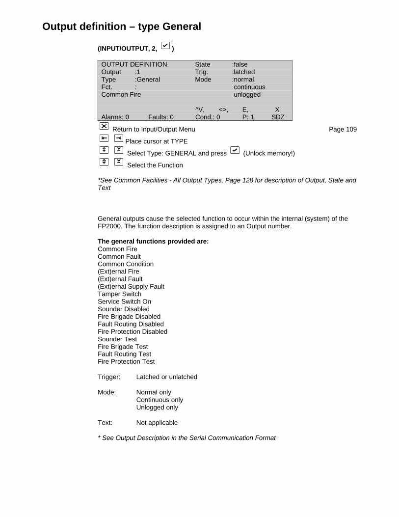
Output definition – type General
(INPUT/OUTPUT, 2, )
OUTPUT DEFINITION State :falseOutput :1 Trig. :latchedType :General Mode :normalFct. : continuousCommon Fire unlogged
^V, <>, E, XAlarms: 0 Faults: 0 Cond.: 0 P: 1 SDZ
Return to Input/Output Menu Page 109
Place cursor at TYPE
Select Type: GENERAL and press (Unlock memory!)
Select the Function
*See Common Facilities - All Output Types, Page 128 for description of Output, State andText
General outputs cause the selected function to occur within the internal (system) of theFP2000. The function description is assigned to an Output number.
The general functions provided are:Common FireCommon FaultCommon Condition(Ext)ernal Fire(Ext)ernal Fault(Ext)ernal Supply FaultTamper SwitchService Switch OnSounder DisabledFire Brigade DisabledFault Routing DisabledFire Protection DisabledSounder TestFire Brigade TestFault Routing TestFire Protection Test
Trigger: Latched or unlatched
Mode: Normal onlyContinuous onlyUnlogged only
Text: Not applicable
* See Output Description in the Serial Communication Format

Output definition – type Zone
(INPUT/OUTPUT, 2, )
OUTPUT DEFINITION State :falseOutput :1 Trig. :latchedType :Zone Mode :normalZone :1 continuousFct. :Fire MCP unlogged
0. .9, ^V, <>, E, XAlarms: 0 Faults: 0 Cond.: 0 P: 1 SDZ
Return to Input/Output Menu Page 109
Place cursor at TYPE
Select Type: ZONE and press (Unlock memory!)
Select the Function
*See Common Facilities - All Output Types, Page 128 for description of Output, State,Trigger, Mode, Event and Text
Outputs can activate zones for the following functions. For this type the zone numbermust also be specified.
List of Functions:Fire MCP (manual call point)Fire AutoFaultCoincidenceConditionDisable
Trigger: Latched/unlatched
Mode: Normal onlyContinuous onlyUnlogged only
Text: Not applicable
* See Output Description in the Serial Communication Format
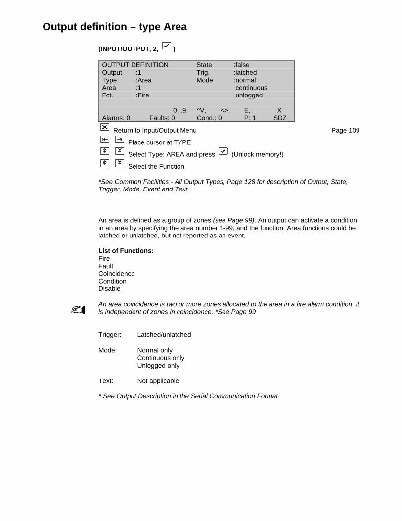
Output definition – type Area
(INPUT/OUTPUT, 2, )
OUTPUT DEFINITION State :falseOutput :1 Trig. :latchedType :Area Mode :normalArea :1 continuousFct. :Fire unlogged
0. .9, ^V, <>, E, XAlarms: 0 Faults: 0 Cond.: 0 P: 1 SDZ
Return to Input/Output Menu Page 109
Place cursor at TYPE
Select Type: AREA and press (Unlock memory!)
Select the Function
*See Common Facilities - All Output Types, Page 128 for description of Output, State,Trigger, Mode, Event and Text
An area is defined as a group of zones (see Page 99). An output can activate a conditionin an area by specifying the area number 1-99, and the function. Area functions could belatched or unlatched, but not reported as an event.
List of Functions:FireFaultCoincidenceConditionDisable
- An area coincidence is two or more zones allocated to the area in a fire alarm condition. Itis independent of zones in coincidence. *See Page 99
Trigger: Latched/unlatched
Mode: Normal onlyContinuous onlyUnlogged only
Text: Not applicable
* See Output Description in the Serial Communication Format
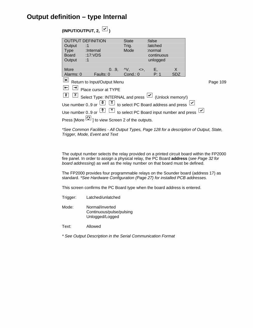
Output definition – type Internal
(INPUT/OUTPUT, 2, )
OUTPUT DEFINITION State :falseOutput :1 Trig. :latchedType :Internal Mode :normalBoard :17:VDS continuousOutput :1 unlogged
More 0. .9, ^V, <>, E, XAlarms: 0 Faults: 0 Cond.: 0 P: 1 SDZ
Return to Input/Output Menu Page 109
Place cursor at TYPE
Select Type: INTERNAL and press (Unlock memory!)
Use number 0..9 or to select PC Board address and press
Use number 0..9 or to select PC Board input number and press
Press [More ] to view Screen 2 of the outputs.
*See Common Facilities - All Output Types, Page 128 for a description of Output, State,Trigger, Mode, Event and Text
The output number selects the relay provided on a printed circuit board within the FP2000fire panel. In order to assign a physical relay, the PC Board address (see Page 32 forboard addressing) as well as the relay number on that board must be defined.
The FP2000 provides four programmable relays on the Sounder board (address 17) asstandard. *See Hardware Configuration (Page 27) for installed PCB addresses.
This screen confirms the PC Board type when the board address is entered.
Trigger: Latched/unlatched
Mode: Normal/invertedContinuous/pulse/pulsingUnlogged/Logged
Text: Allowed
* See Output Description in the Serial Communication Format
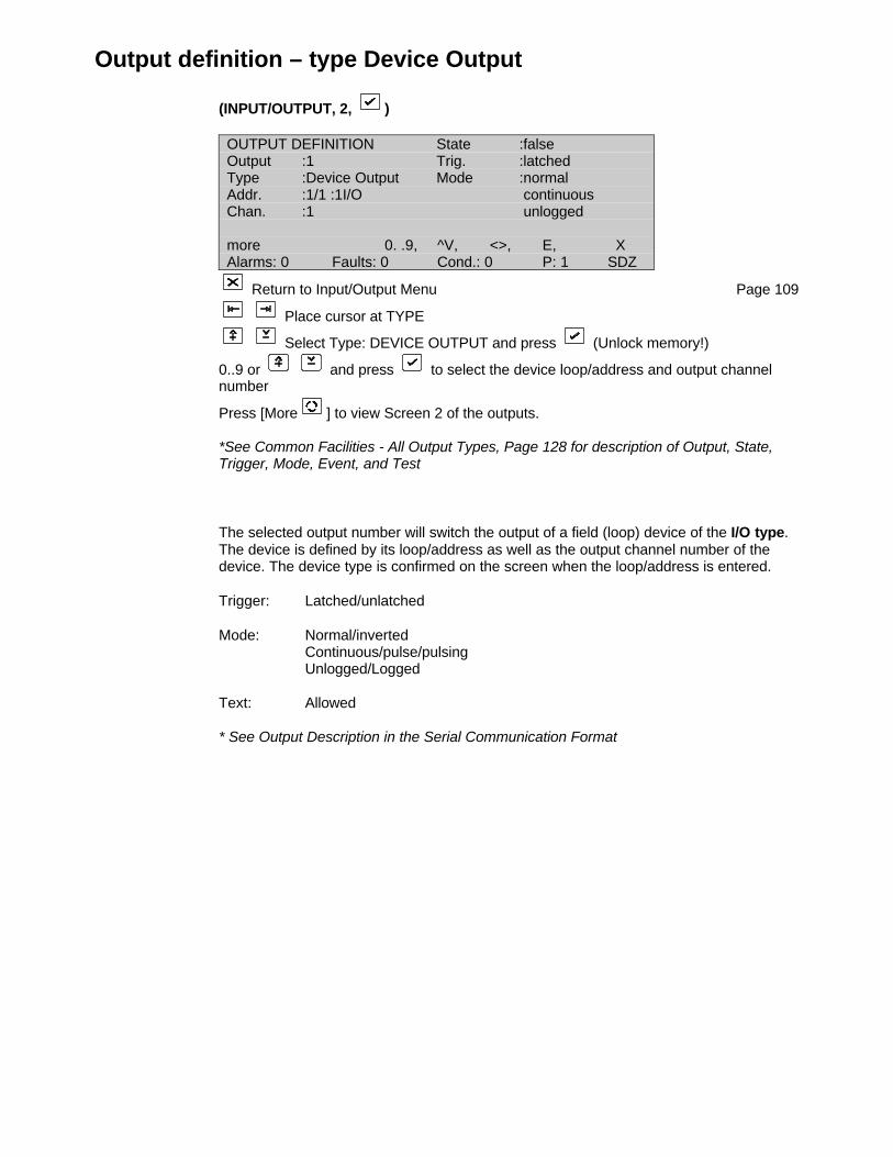
Output definition – type Device Output
(INPUT/OUTPUT, 2, )
OUTPUT DEFINITION State :falseOutput :1 Trig. :latchedType :Device Output Mode :normalAddr. :1/1 :1I/O continuousChan. :1 unlogged
more 0. .9, ^V, <>, E, XAlarms: 0 Faults: 0 Cond.: 0 P: 1 SDZ
Return to Input/Output Menu Page 109
Place cursor at TYPE
Select Type: DEVICE OUTPUT and press (Unlock memory!)
0..9 or and press to select the device loop/address and output channelnumber
Press [More ] to view Screen 2 of the outputs.
*See Common Facilities - All Output Types, Page 128 for description of Output, State,Trigger, Mode, Event, and Test
The selected output number will switch the output of a field (loop) device of the I/O type.The device is defined by its loop/address as well as the output channel number of thedevice. The device type is confirmed on the screen when the loop/address is entered.
Trigger: Latched/unlatched
Mode: Normal/invertedContinuous/pulse/pulsingUnlogged/Logged
Text: Allowed
* See Output Description in the Serial Communication Format

Output definition – type Supervised Internal
(INPUT/OUTPUT, 2, )
OUTPUT DEFINITION State :falseOutput :1 Trig. :latchedType :Sup Internal Mode :normalBoard :17:VDS continuousOutput :1 unlogged
more 0. .9, ^V, <>, E, XAlarms: 0 Faults: 0 Cond.: 0 P: 1 SDZ
Return to Input/Output Menu Page 109
Select Type: SUP INTERNAL and press
0..9 or Select board address and press
0..9 or Select relay number and press
Press [More ] to view Screen 2 of the outputs.
The selected relay is operated by the logic that assigns the output true or false.
Trigger: Latched/unlatched
Mode: Normal/invertedContinuous/pulse/pulsingUnlogged/Logged
Text: Allowed
* See Output Description in the Serial Communication Format
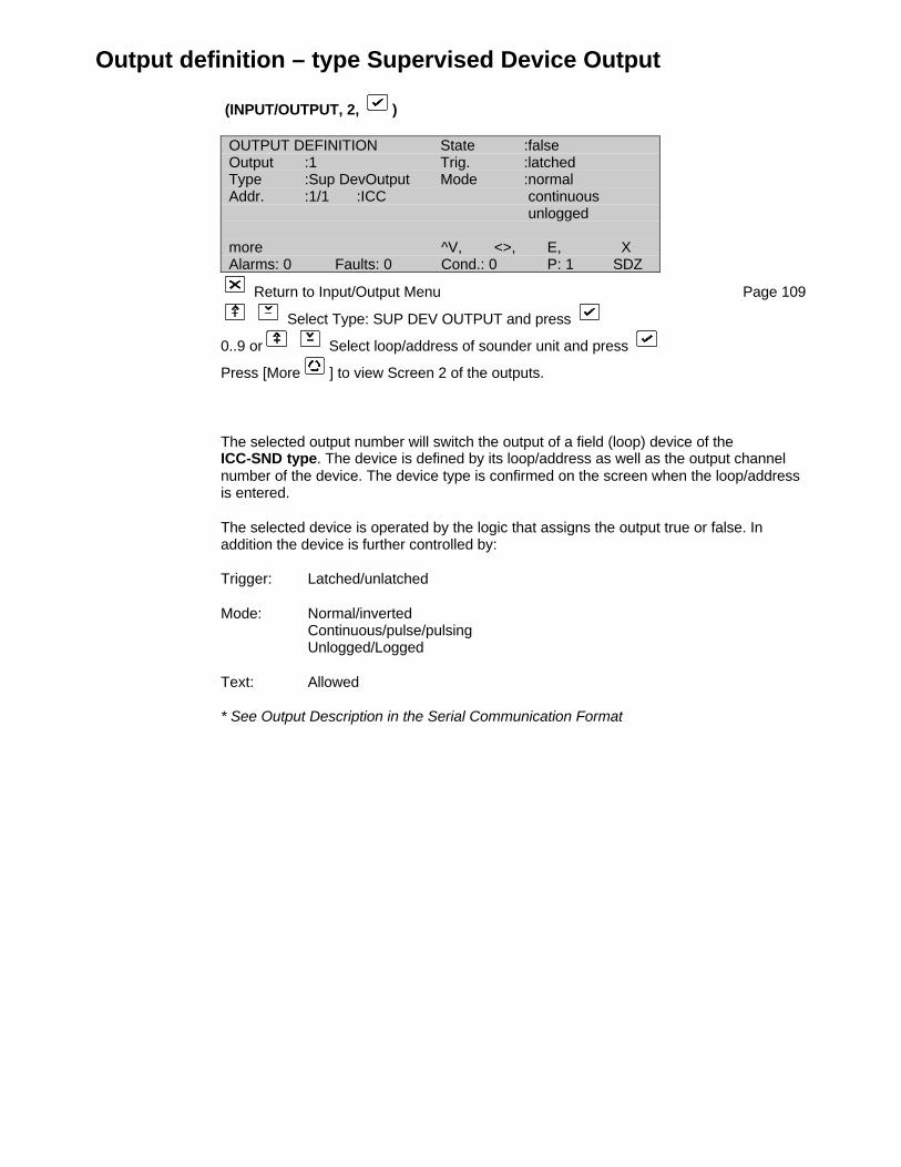
Output definition – type Supervised Device Output
(INPUT/OUTPUT, 2, )
OUTPUT DEFINITION State :falseOutput :1 Trig. :latchedType :Sup DevOutput Mode :normalAddr. :1/1 :ICC continuous
unlogged
more ^V, <>, E, XAlarms: 0 Faults: 0 Cond.: 0 P: 1 SDZ
Return to Input/Output Menu Page 109
Select Type: SUP DEV OUTPUT and press
0..9 or Select loop/address of sounder unit and press
Press [More ] to view Screen 2 of the outputs.
The selected output number will switch the output of a field (loop) device of theICC-SND type. The device is defined by its loop/address as well as the output channelnumber of the device. The device type is confirmed on the screen when the loop/addressis entered.
The selected device is operated by the logic that assigns the output true or false. Inaddition the device is further controlled by:
Trigger: Latched/unlatched
Mode: Normal/invertedContinuous/pulse/pulsingUnlogged/Logged
Text: Allowed
* See Output Description in the Serial Communication Format
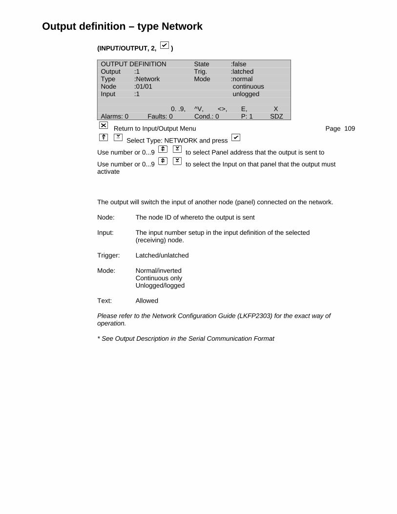
Output definition – type Network
(INPUT/OUTPUT, 2, )
OUTPUT DEFINITION State :falseOutput :1 Trig. :latchedType :Network Mode :normalNode :01/01 continuousInput :1 unlogged
0. .9, ^V, <>, E, XAlarms: 0 Faults: 0 Cond.: 0 P: 1 SDZ
Return to Input/Output Menu Page 109
Select Type: NETWORK and press
Use number or 0...9 to select Panel address that the output is sent to
Use number or 0...9 to select the Input on that panel that the output mustactivate
The output will switch the input of another node (panel) connected on the network.
Node: The node ID of whereto the output is sent
Input: The input number setup in the input definition of the selected (receiving) node.
Trigger: Latched/unlatched
Mode: Normal/invertedContinuous onlyUnlogged/logged
Text: Allowed
Please refer to the Network Configuration Guide (LKFP2303) for the exact way ofoperation.
* See Output Description in the Serial Communication Format
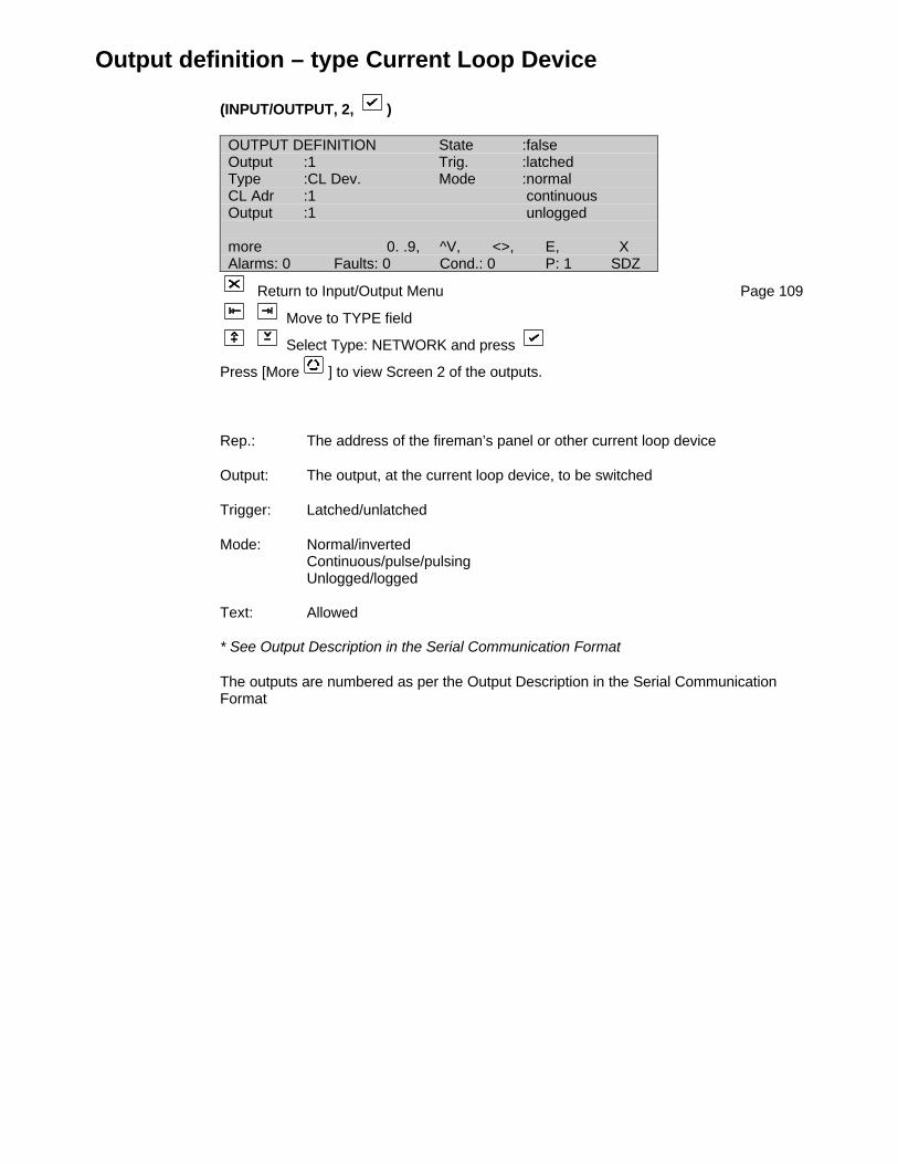
Output definition – type Current Loop Device
(INPUT/OUTPUT, 2, )
OUTPUT DEFINITION State :falseOutput :1 Trig. :latchedType :CL Dev. Mode :normalCL Adr :1 continuousOutput :1 unlogged
more 0. .9, ^V, <>, E, XAlarms: 0 Faults: 0 Cond.: 0 P: 1 SDZ
Return to Input/Output Menu Page 109
Move to TYPE field
Select Type: NETWORK and press
Press [More ] to view Screen 2 of the outputs.
Rep.: The address of the fireman’s panel or other current loop device
Output: The output, at the current loop device, to be switched
Trigger: Latched/unlatched
Mode: Normal/invertedContinuous/pulse/pulsingUnlogged/logged
Text: Allowed
* See Output Description in the Serial Communication Format
The outputs are numbered as per the Output Description in the Serial CommunicationFormat
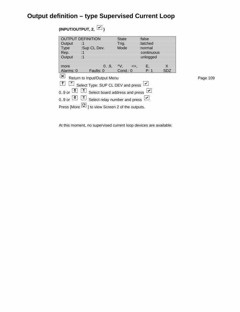
Output definition – type Supervised Current Loop
(INPUT/OUTPUT, 2, )
OUTPUT DEFINITION State :falseOutput :1 Trig. :latchedType :Sup CL Dev. Mode :normalRep. :1 continuousOutput :1 unlogged
more 0. .9, ^V, <>, E, XAlarms: 0 Faults: 0 Cond.: 0 P: 1 SDZ
Return to Input/Output Menu Page 109
Select Type: SUP CL DEV and press
0..9 or Select board address and press
0..9 or Select relay number and press
Press [More ] to view Screen 2 of the outputs.
At this moment, no supervised current loop devices are available.
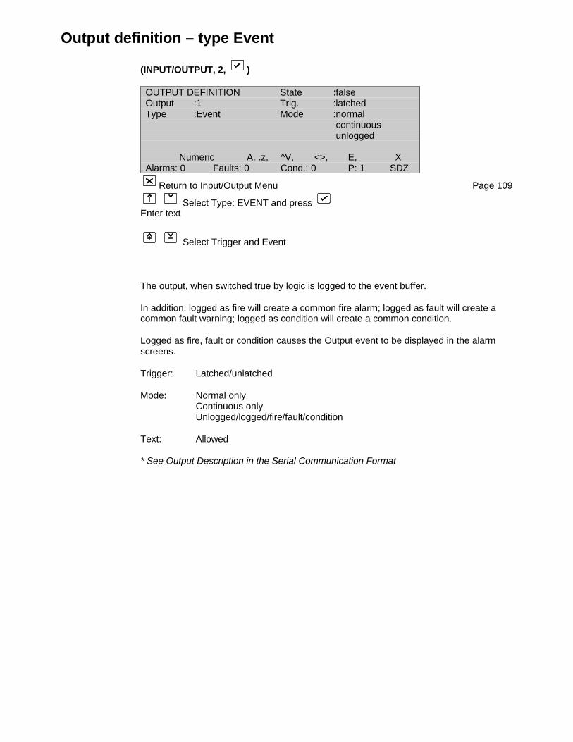
Output definition – type Event
(INPUT/OUTPUT, 2, )
OUTPUT DEFINITION State :falseOutput :1 Trig. :latchedType :Event Mode :normal
continuous unlogged
Numeric A. .z, ^V, <>, E, XAlarms: 0 Faults: 0 Cond.: 0 P: 1 SDZ
Return to Input/Output Menu Page 109
Select Type: EVENT and press Enter text
Select Trigger and Event
The output, when switched true by logic is logged to the event buffer.
In addition, logged as fire will create a common fire alarm; logged as fault will create acommon fault warning; logged as condition will create a common condition.
Logged as fire, fault or condition causes the Output event to be displayed in the alarmscreens.
Trigger: Latched/unlatched
Mode: Normal onlyContinuous onlyUnlogged/logged/fire/fault/condition
Text: Allowed
* See Output Description in the Serial Communication Format
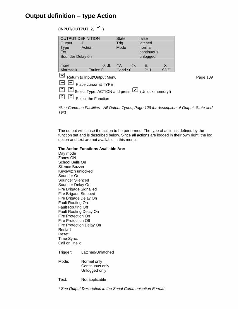
Output definition – type Action
(INPUT/OUTPUT, 2, )
OUTPUT DEFINITION State :falseOutput :1 Trig. :latchedType :Action Mode :normalFct. : continuousSounder Delay on unlogged
more 0. .9, ^V, <>, E, XAlarms: 0 Faults: 0 Cond.: 0 P: 1 SDZ
Return to Input/Output Menu Page 109
Place cursor at TYPE
Select Type: ACTION and press (Unlock memory!)
Select the Function
*See Common Facilities - All Output Types, Page 128 for description of Output, State andText
The output will cause the action to be performed. The type of action is defined by thefunction set and is described below. Since all actions are logged in their own right, the logoption and text are not available in this menu.
The Action Functions Available Are:Day modeZones ONSchool Bells OnSilence BuzzerKeyswitch unlockedSounder OnSounder SilencedSounder Delay OnFire Brigade SignalledFire Brigade StoppedFire Brigade Delay OnFault Routing OnFault Routing OffFault Routing Delay OnFire Protection OnFire Protection OffFire Protection Delay OnRestartResetTime Sync.Call on line x
Trigger: Latched/Unlatched
Mode: Normal onlyContinuous onlyUnlogged only
Text: Not applicable
* See Output Description in the Serial Communication Format
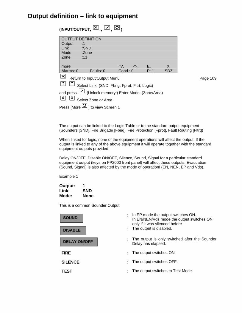
Output definition – link to equipment
(INPUT/OUTPUT, , , )
OUTPUT DEFINITIONOutput :1Link :SNDMode :ZoneZone :11
more ^V, <>, E, XAlarms: 0 Faults: 0 Cond.: 0 P: 1 SDZ
Return to Input/Output Menu Page 109
Select Link: (SND, Fbrig, Fprot, Fltrt, Logic)
and press (Unlock memory!) Enter Mode: (Zone/Area)
Select Zone or Area
Press [More ] to view Screen 1
The output can be linked to the Logic Table or to the standard output equipment(Sounders [SND], Fire Brigade [Fbrig], Fire Protection [Fprot], Fault Routing [Fltrt])
When linked for logic, none of the equipment operations will affect the output. If theoutput is linked to any of the above equipment it will operate together with the standardequipment outputs provided.
Delay ON/OFF, Disable ON/OFF, Silence, Sound, Signal for a particular standardequipment output (keys on FP2000 front panel) will affect these outputs. Evacuation(Sound, Signal) is also affected by the mode of operation! (EN, NEN, EP and Vds).
Example 1
Output: 1Link: SNDMode: None
This is a common Sounder Output.
: In EP mode the output switches ON.In EN/NEN/Vds mode the output switches ONonly if it was silenced before.
: The output is disabled.
: The output is only switched after the SounderDelay has elapsed.
FIRE : The output switches ON.
SILENCE : The output switches OFF.
TEST : The output switches to Test Mode.
SOUND
DISABLE
DELAY ON/OFF
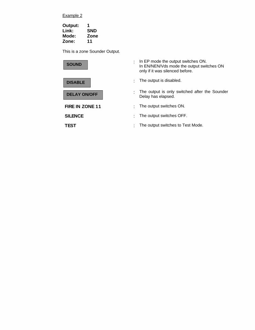
Example 2
Output: 1Link: SNDMode: ZoneZone: 11
This is a zone Sounder Output.
: In EP mode the output switches ON.In EN/NEN/Vds mode the output switches ONonly if it was silenced before.
: The output is disabled.
: The output is only switched after the SounderDelay has elapsed.
FIRE IN ZONE 11 : The output switches ON.
SILENCE : The output switches OFF.
TEST : The output switches to Test Mode.
SOUND
DISABLE
DELAY ON/OFF

Logic
(INPUT/OUTPUT, 3, )
LOGIC TABLE5996001 ( Input 12 )= Output 13 ( Input 2
0. .9, ^V, <>, E, XAlarms: 0 Faults: 0 Cond.: 0 P: 1 SDZ
Return to Input/Output Menu Page 109
Place cursor over field to be changed and press (Unlock memory!)
Either: Select the function and press
or: 0..9 or select a number and press
Logic sets outputs assigned in the Output Table true or false according to expressions.An expression in general will contain inputs, outputs, markers and timers connected byBoolean operators.
All expressions in the logic table are evaluated once per second and the true/false stateis transferred to the assigned output, marker or timer. Logic is the link between the inputsdefined in the Input Table and the outputs defined in the Output Table.
The simplest logic statement requires two steps in the logic table. More complexexpressions require more steps depending on the number of terms in the expression. Themaximum size of the logic table (default 300 steps) can be set in Memory Allocation 1(see Page 33). The logic table entered by the user should have an END statement as thelast step. The END statement terminates evaluation of the table at that point. Anystatements after the END statement will never be evaluated.
The logic steps are evaluated sequentially from step 1 to the END step. This means thatoutputs, markers or timers set in previous steps may be used as part of expressions inlater steps. The true/false value used will be the state that exists at the time of evaluatingthe expression. The physical outputs are only set at the END of the table. Thus if anoutput is set at the beginning of the table, and then reset later in the table, no physicaloutput will occur.
The logic table menu contains limited editing features. An INSERT and DELETE functionis provided and NULL statements are allowed. The user is advised to make use of theFPCONF Download Program to construct lengthy logic tables. A default logic table linkinginputs to outputs can be used. (See Set Default, Page 65). Thus simple I/O operationscan be performed without any logic programming. The default mode is described below.
The general form of a logic statement is:
field 1 field 2 field 3 field 4 field 5Step m ( Term xxStep m+1 Operator Term xx
| | || | |
Step m+n )= Assignment xx yy
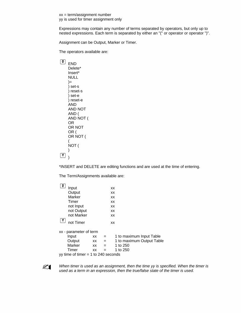
xx = term/assignment numberyy is used for timer assignment only
Expressions may contain any number of terms separated by operators, but only up tonested expressions. Each term is separated by either an "(" or operator or operator ")".
Assignment can be Output, Marker or Timer.
The operators available are:
ENDDelete*Insert*NULL)=) set-s) reset-s) set-e) reset-eANDAND NOTAND (AND NOT (OROR NOTOR (OR NOT ((NOT ()
)
*INSERT and DELETE are editing functions and are used at the time of entering.
The Term/Assignments available are:
Input xxOutput xxMarker xxTimer xxnot Input xxnot Output xxnot Marker xx
not Timer xx
xx - parameter of termInput xx = 1 to maximum Input TableOutput xx = 1 to maximum Output TableMarker xx = 1 to 250Timer xx = 1 to 250
yy time of timer = 1 to 240 seconds
- When timer is used as an assignment, then the time yy is specified. When the timer isused as a term in an expression, then the true/false state of the timer is used.

The simplest logic statement (which is also the default statement) is:Step m ( Input nStep m+1 ) = Output n
Output n will be set true or false if Input n is true or false.
An example of a multiple term statement not using nesting is:Step 1 ( Input 1
2 AND Input 23 OR Input 34 AND not Input 1005 OR Timer 26 AND Marker 37 ) = Output 7
An example of multiple term nested expressions (Nesting = 4) is:Step 1 ( Input 1
2 AND ( Input 23 OR ( Marker 1004 AND NOT ( Timer 25 )6 )7 )8 ) = OUTPUT 6
Using MarkersA marker is an internal memory bit that can be assigned true or false. Unlike Outputs,markers can never be physically output from the panel. Markers are generally used tohold intermediate values that will be reused in an expression.
Using Timers(expression) = Timer xx yy
When expression is true then Timer xx will begin timing. The value of Timer xx is false. Aslong as expression remains true, then timer xx will go true after time yy. If expressiongoes false before time yy then the timer is stopped. If expression goes false after time yythen the timer is reset to false and stopped. If expression true again the timer is restartedand times out as long as expression remains true. The timer will restart each timeexpression goes false and then true.
Special operators:
)Set-e Set on leading edge of input trigger pulse)reset-e Reset on leading edge of input trigger pulse)Set-s Set on state of input trigger pulse)reset-s Reset on state of input trigger pulse
Outputs, Markers and timers can be set and reset by two independent expressions.
Set-e Sets the output or marker or starts a timer. The output will remain set even if the expression returns to false. A timer will continue timing.
reset-e Resets the output or stops the timer.Set-s Sets the output or marker or starts a timer. The output will remain set even
if the expression returns to false. A timer will continue timing.reset-s Resets the output or stops the timer.
Editing
INSERT - Selecting Insert and pressing in the operator field will insert a blank line above the current line.
DELETE - Deletes the current line.
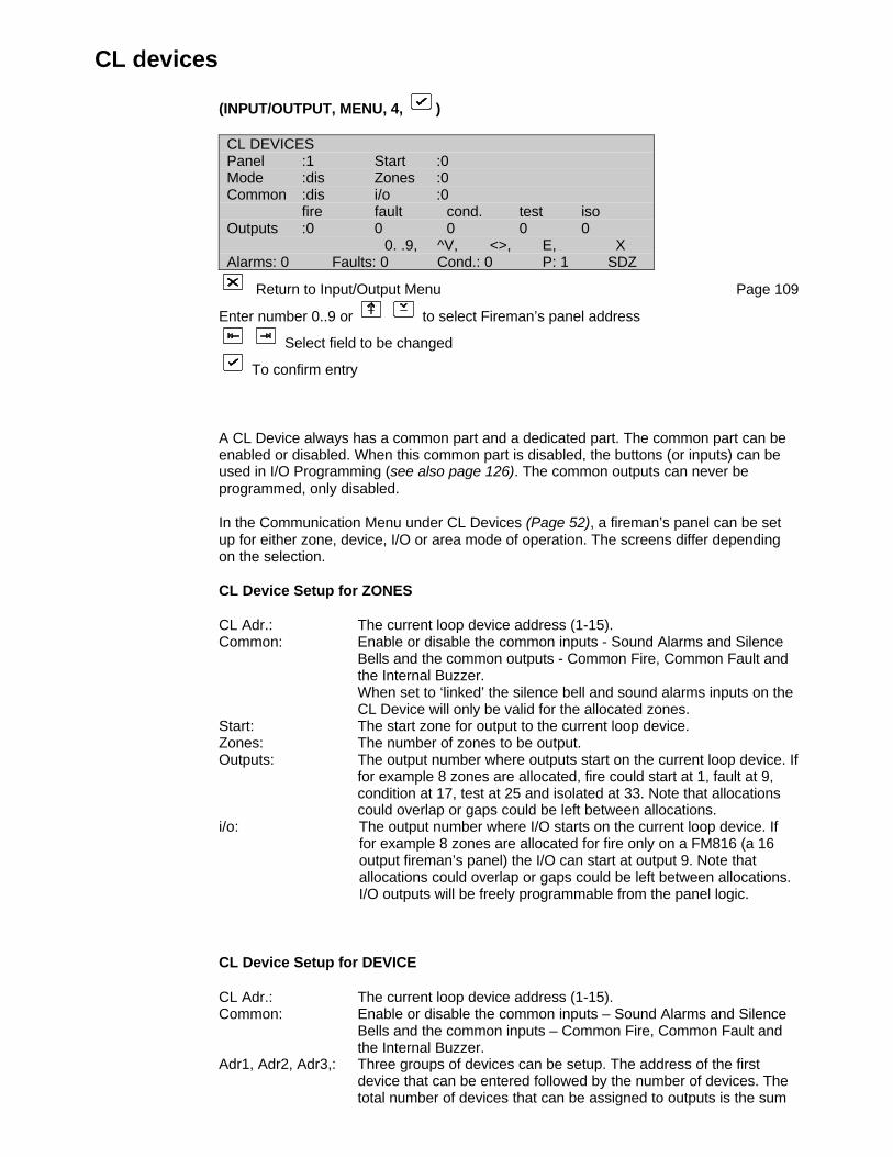
CL devices
(INPUT/OUTPUT, MENU, 4, )
CL DEVICESPanel :1 Start :0Mode :dis Zones :0Common :dis i/o :0
fire fault cond. test isoOutputs :0 0 0 0 0
0. .9, ^V, <>, E, XAlarms: 0 Faults: 0 Cond.: 0 P: 1 SDZ
Return to Input/Output Menu Page 109
Enter number 0..9 or to select Fireman’s panel address
Select field to be changed
To confirm entry
A CL Device always has a common part and a dedicated part. The common part can beenabled or disabled. When this common part is disabled, the buttons (or inputs) can beused in I/O Programming (see also page 126). The common outputs can never beprogrammed, only disabled.
In the Communication Menu under CL Devices (Page 52), a fireman’s panel can be setup for either zone, device, I/O or area mode of operation. The screens differ dependingon the selection.
CL Device Setup for ZONES
CL Adr.: The current loop device address (1-15).Common: Enable or disable the common inputs - Sound Alarms and Silence
Bells and the common outputs - Common Fire, Common Fault and the Internal Buzzer.When set to ‘linked’ the silence bell and sound alarms inputs on the CL Device will only be valid for the allocated zones.
Start: The start zone for output to the current loop device.Zones: The number of zones to be output.Outputs: The output number where outputs start on the current loop device. If
for example 8 zones are allocated, fire could start at 1, fault at 9, condition at 17, test at 25 and isolated at 33. Note that allocations could overlap or gaps could be left between allocations.
i/o: The output number where I/O starts on the current loop device. Iffor example 8 zones are allocated for fire only on a FM816 (a 16output fireman’s panel) the I/O can start at output 9. Note thatallocations could overlap or gaps could be left between allocations.I/O outputs will be freely programmable from the panel logic.
CL Device Setup for DEVICE
CL Adr.: The current loop device address (1-15).Common: Enable or disable the common inputs – Sound Alarms and Silence
Bells and the common inputs – Common Fire, Common Fault and the Internal Buzzer.
Adr1, Adr2, Adr3,: Three groups of devices can be setup. The address of the first device that can be entered followed by the number of devices. The total number of devices that can be assigned to outputs is the sum
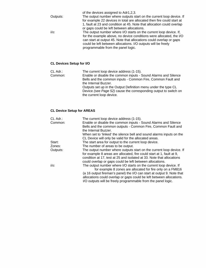
of the devices assigned to Adr1,2,3.Outputs: The output number where outputs start on the current loop device. If
for example 22 devices in total are allocated then fire could start at 1, fault at 23 and condition at 45. Note that allocation could overlap or gaps could be left between allocations.
i/o: The output number where I/O starts on the current loop device. If,for the example above, no device conditions were allocated, the I/Ocan start at output 45. Note that allocations could overlap or gapscould be left between allocations. I/O outputs will be freelyprogrammable from the panel logic.
CL Devices Setup for I/O
CL Adr.: The current loop device address (1-15).Common: Enable or disable the common inputs - Sound Alarms and Silence
Bells and the common inputs - Common Fire, Common Fault and the Internal Buzzer.Outputs set up in the Output Definition menu under the type CL Device (see Page 52) cause the corresponding output to switch on the current loop device.
CL Device Setup for AREAS
CL Adr.: The current loop device address (1-15).Common: Enable or disable the common inputs - Sound Alarms and Silence
Bells and the common outputs - Common Fire, Common Fault and the Internal Buzzer.When set to ‘linked’ the silence bell and sound alarms inputs on the CL Device will only be valid for the allocated areas.
Start: The start area for output to the current loop device.Zones: The number of areas to be output.Outputs: The output number where outputs start on the current loop device. If
for example 8 areas are allocated, fire could start at 1, fault at 9, condition at 17, test at 25 and isolated at 33. Note that allocations could overlap or gaps could be left between allocations.
i/o: The output number where I/O starts on the current loop device. If for example 8 zones are allocated for fire only on a FM816
(a 16 output fireman’s panel) the I/O can start at output 9. Note thatallocations could overlap or gaps could be left between allocations.I/O outputs will be freely programmable from the panel logic.
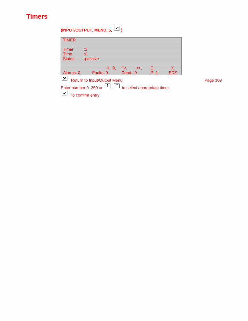
Timers
(INPUT/OUTPUT, MENU, 5, )
TIMER
Timer :2Time :0Status :passive
0. .9, ^V, <>, E, XAlarms: 0 Faults: 0 Cond.: 0 P: 1 SDZ
Return to Input/Output Menu Page 109
Enter number 0..250 or to select appropriate timer
To confirm entry
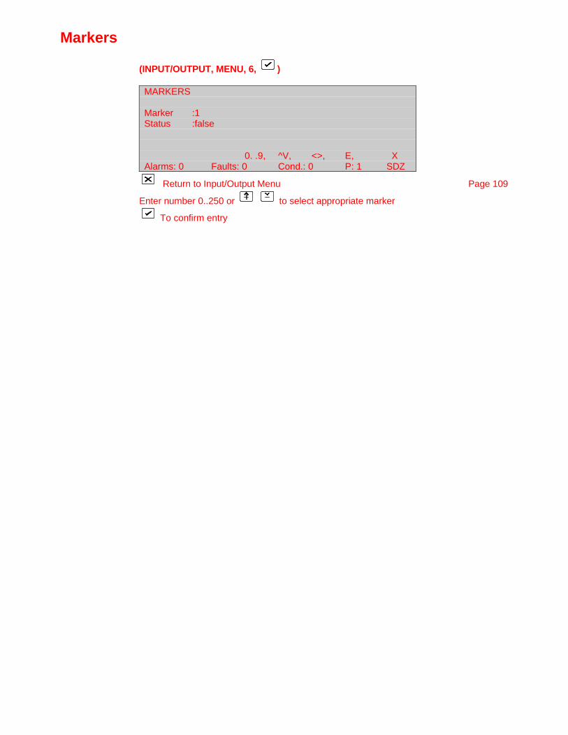
Markers
(INPUT/OUTPUT, MENU, 6, )
MARKERS
Marker :1Status :false
0. .9, ^V, <>, E, XAlarms: 0 Faults: 0 Cond.: 0 P: 1 SDZ
Return to Input/Output Menu Page 109
Enter number 0..250 or to select appropriate marker
To confirm entry
Event menu
(MAIN MENU, 4, )
EVENT MENU
1 Display Events 2 Clear Events3 Clear All Events
0. .9, <>, E, XAlarms: 0 Faults: 0 Cond.: 0 P: 1 SDZ
Enter number or use and press
Return to Main Menu Page 23
1 Display Events Page 153Selectively display or print the event buffer to the specified device.
2 Clear Events Page 155Clear the event buffer.
3 Clear All Events Page 156Clears own event buffer and additionally:
• If the Node ID is set to represent a Global Repeater the event buffers of all connectedPanels and the Local Repeaters will be cleared.
• If the Node ID is set to represent a Panel the event buffers of all connected LocalRepeaters will be cleared.

Display events
(EVENT MENU, 1, )
DISPLAY EVENTSExecute
Destination :LCDEvent Type :All AllLatest Events :999After :07/12/00 08:05
<>, E, XAlarms: 0 Faults: 0 Cond.: 0 P: 1 SDZ
Return to Event Menu Page 152
Select item to be altered
or 0..9 enter data
Confirm entry
After setting up data, use to place cursor over "EXECUTE".
Press to display/print the event buffer.
All events that occur within the FP2000 fire panel are stored in the event log. The size ofthe event log (default: 999 events) can be set in the Memory Allocation (Page 33).
All events are given a unique event number 1-9999 which, with the date and time, servesas a reference. Should the event log be filled, an "EVENT LOG FULL" fault will be raised.All events are then "rolled" in the event log such that the latest events are always stored.
The destination to which the fire panel will report events is:
LCD screenReport printerEvent printer
None
In the case of LCD screen, the events are scrolled using the keys.
Events can be selectively reported by specifying the event class and type:
• Event Class:
All typesFire alarmsFault warningsConditions - e.g.: coincidence, maintenance, etc.
Actions - e.g.: reset, memory locked, etc.

• Event Type:
All typesSoakAreaZoneDeviceGeneralOutputInputActionLoop
Input and Output
The number of events to be displayed is controlled by "Latest Events" after the specifieddate and time.
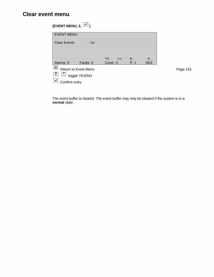
Clear event menu
(EVENT MENU, 2, )
EVENT MENU
Clear Events :no
^V, <>, E, XAlarms: 0 Faults: 0 Cond.: 0 P: 1 SDZ
Return to Event Menu Page 152
toggle YES/NO
Confirm entry
The event buffer is cleared. The event buffer may only be cleared if the system is in anormal state.
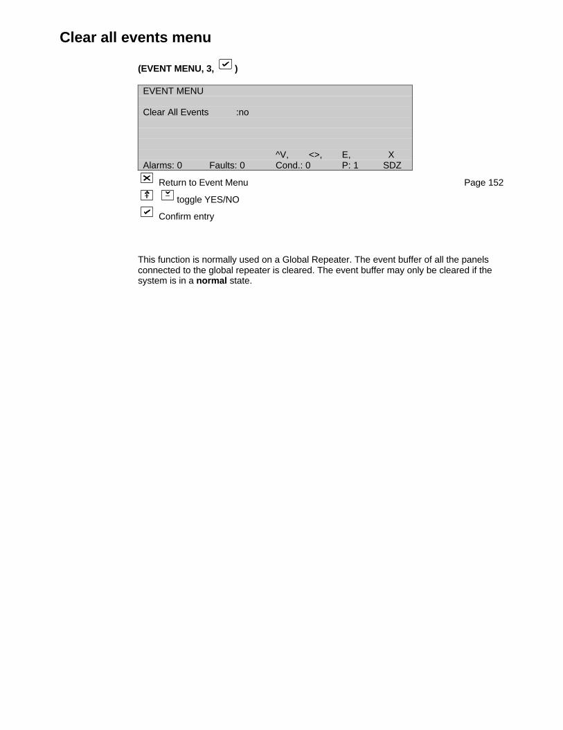
Clear all events menu
(EVENT MENU, 3, )
EVENT MENU
Clear All Events :no
^V, <>, E, XAlarms: 0 Faults: 0 Cond.: 0 P: 1 SDZ
Return to Event Menu Page 152
toggle YES/NO
Confirm entry
This function is normally used on a Global Repeater. The event buffer of all the panelsconnected to the global repeater is cleared. The event buffer may only be cleared if thesystem is in a normal state.
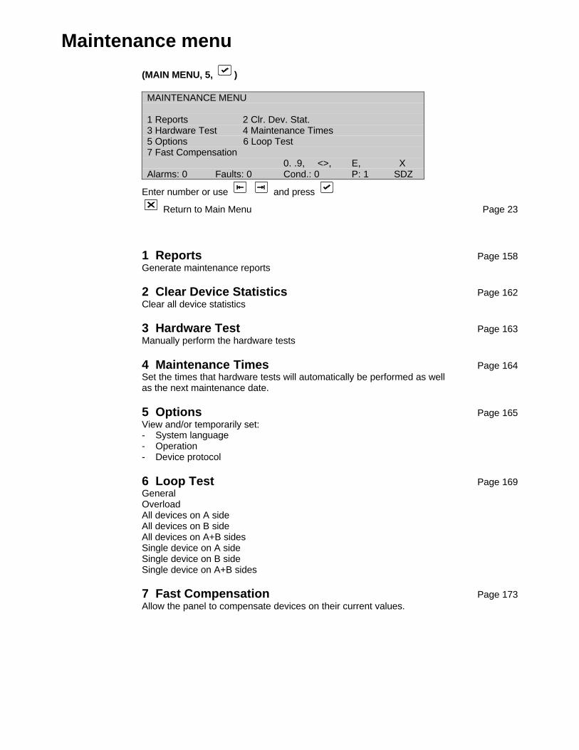
Maintenance menu
(MAIN MENU, 5, )
MAINTENANCE MENU
1 Reports 2 Clr. Dev. Stat.3 Hardware Test 4 Maintenance Times5 Options 6 Loop Test7 Fast Compensation
0. .9, <>, E, XAlarms: 0 Faults: 0 Cond.: 0 P: 1 SDZ
Enter number or use and press
Return to Main Menu Page 23
1 Reports Page 158Generate maintenance reports
2 Clear Device Statistics Page 162Clear all device statistics
3 Hardware Test Page 163Manually perform the hardware tests
4 Maintenance Times Page 164Set the times that hardware tests will automatically be performed as wellas the next maintenance date.
5 Options Page 165View and/or temporarily set:- System language- Operation- Device protocol
6 Loop Test Page 169GeneralOverloadAll devices on A sideAll devices on B sideAll devices on A+B sidesSingle device on A sideSingle device on B sideSingle device on A+B sides
7 Fast Compensation Page 173Allow the panel to compensate devices on their current values.
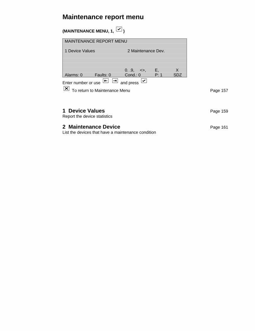
Maintenance report menu
(MAINTENANCE MENU, 1, )
MAINTENANCE REPORT MENU
1 Device Values 2 Maintenance Dev.
0. .9, <>, E, XAlarms: 0 Faults: 0 Cond.: 0 P: 1 SDZ
Enter number or use and press
To return to Maintenance Menu Page 157
1 Device Values Page 159Report the device statistics
2 Maintenance Device Page 161List the devices that have a maintenance condition
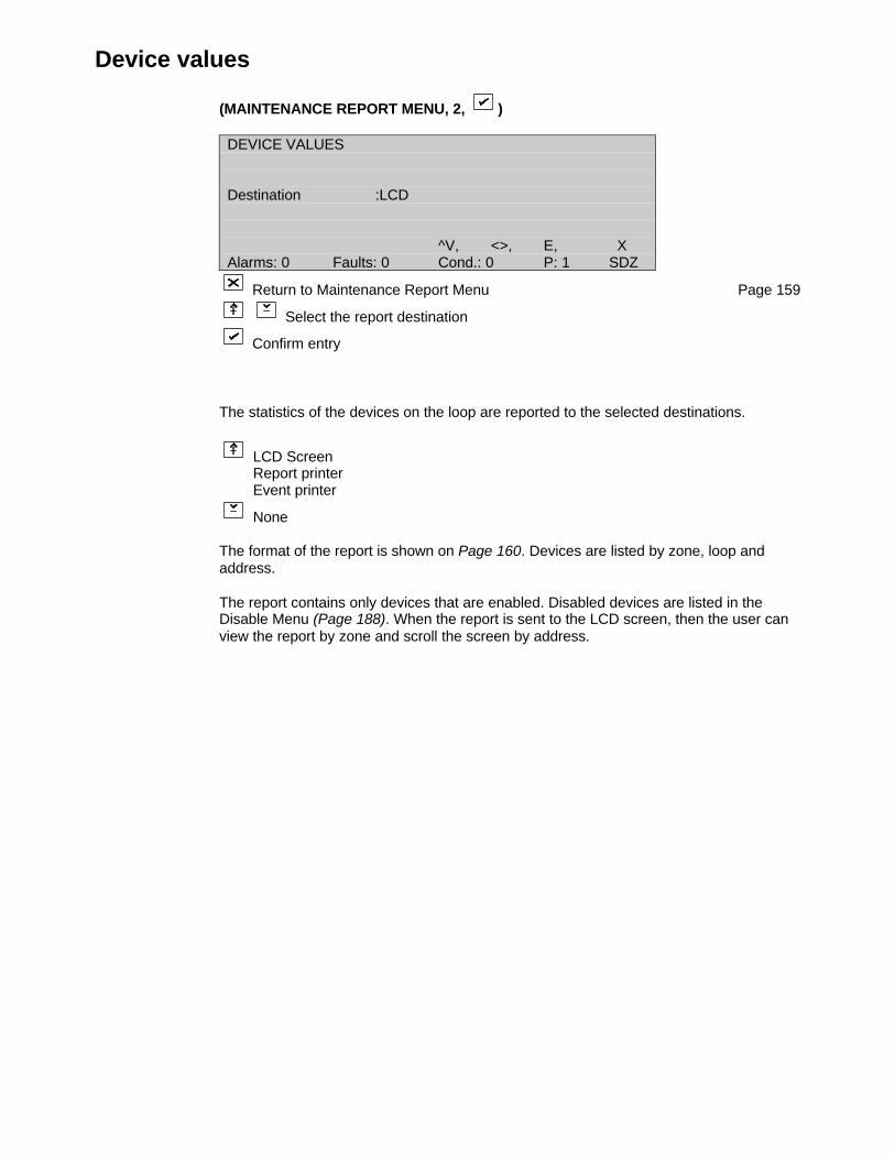
Device values
(MAINTENANCE REPORT MENU, 2, )
DEVICE VALUES
Destination :LCD
^V, <>, E, XAlarms: 0 Faults: 0 Cond.: 0 P: 1 SDZ
Return to Maintenance Report Menu Page 159
Select the report destination
Confirm entry
The statistics of the devices on the loop are reported to the selected destinations.
LCD ScreenReport printerEvent printer
None
The format of the report is shown on Page 160. Devices are listed by zone, loop andaddress.
The report contains only devices that are enabled. Disabled devices are listed in theDisable Menu (Page 188). When the report is sent to the LCD screen, then the user canview the report by zone and scroll the screen by address.
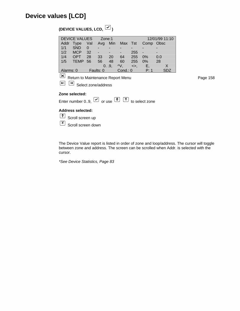
Device values [LCD]
(DEVICE VALUES, LCD, )
DEVICE VALUES Zone:1 12/01/99 11:10Addr Type Val Avg Min Max Tst Comp Obsc1/1 SND 0 - - - - - -1/2 MCP 32 - - - 255 - -1/4 OPT 28 33 20 64 255 0% 0.01/5 TEMP 56 56 48 60 255 0% 28
0. .9, ^V, <>, E, XAlarms: 0 Faults: 0 Cond.: 0 P: 1 SDZ
Return to Maintenance Report Menu Page 158
Select zone/address
Zone selected:
Enter number 0..9, or use to select zone
Address selected:
Scroll screen up
Scroll screen down
The Device Value report is listed in order of zone and loop/address. The cursor will togglebetween zone and address. The screen can be scrolled when Addr. is selected with thecursor.
*See Device Statistics, Page 83
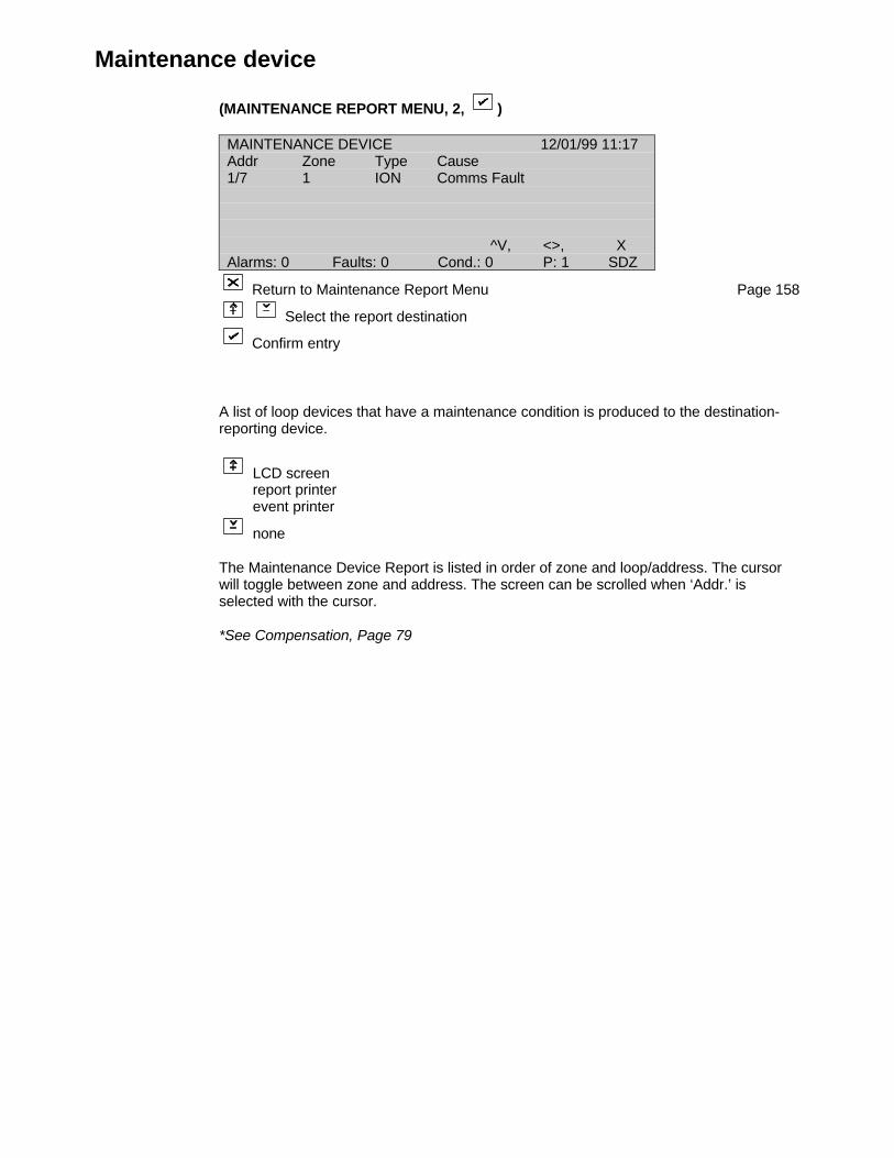
Maintenance device
(MAINTENANCE REPORT MENU, 2, )
MAINTENANCE DEVICE 12/01/99 11:17Addr Zone Type Cause1/7 1 ION Comms Fault
^V, <>, XAlarms: 0 Faults: 0 Cond.: 0 P: 1 SDZ
Return to Maintenance Report Menu Page 158
Select the report destination
Confirm entry
A list of loop devices that have a maintenance condition is produced to the destination-reporting device.
LCD screenreport printerevent printer
none
The Maintenance Device Report is listed in order of zone and loop/address. The cursorwill toggle between zone and address. The screen can be scrolled when ‘Addr.’ isselected with the cursor.
*See Compensation, Page 79
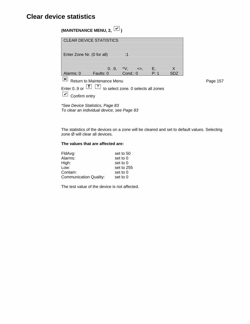
Clear device statistics
(MAINTENANCE MENU, 2, )
CLEAR DEVICE STATISTICS
Enter Zone Nr. (0 for all) :1
0. .9, ^V, <>, E, XAlarms: 0 Faults: 0 Cond.: 0 P: 1 SDZ
Return to Maintenance Menu Page 157
Enter 0..9 or to select zone. 0 selects all zones
Confirm entry
*See Device Statistics, Page 83To clear an individual device, see Page 83
The statistics of the devices on a zone will be cleared and set to default values. Selectingzone Ø will clear all devices.
The values that are affected are:
FldAvg: set to 50Alarms: set to 0High: set to 0Low: set to 255Contam: set to 0Communication Quality: set to 0
The test value of the device is not affected.

Hardware test
(MAINTENANCE MENU, 3, )
The FP2000 performs system tests once per hour. These tests check the memoryintegrity of the host CPU system including the locked site data memory, as well as theFEP memory system.
Invoking the hardware test from the maintenance menu causes a system test to beimmediately performed.
Any failure during the automatic tests or manual test will be reported as a hardware faultidentifying the problem area.
A checksum fault indicates that the memory block is corrupted or faulty. The block shouldbe cleared using "Clear Site Data" (see Page 62) and the data reloaded. If the faultpersists it is probable that the memory is faulty. Note carefully the faults reported by thepanel and contact your supplier.
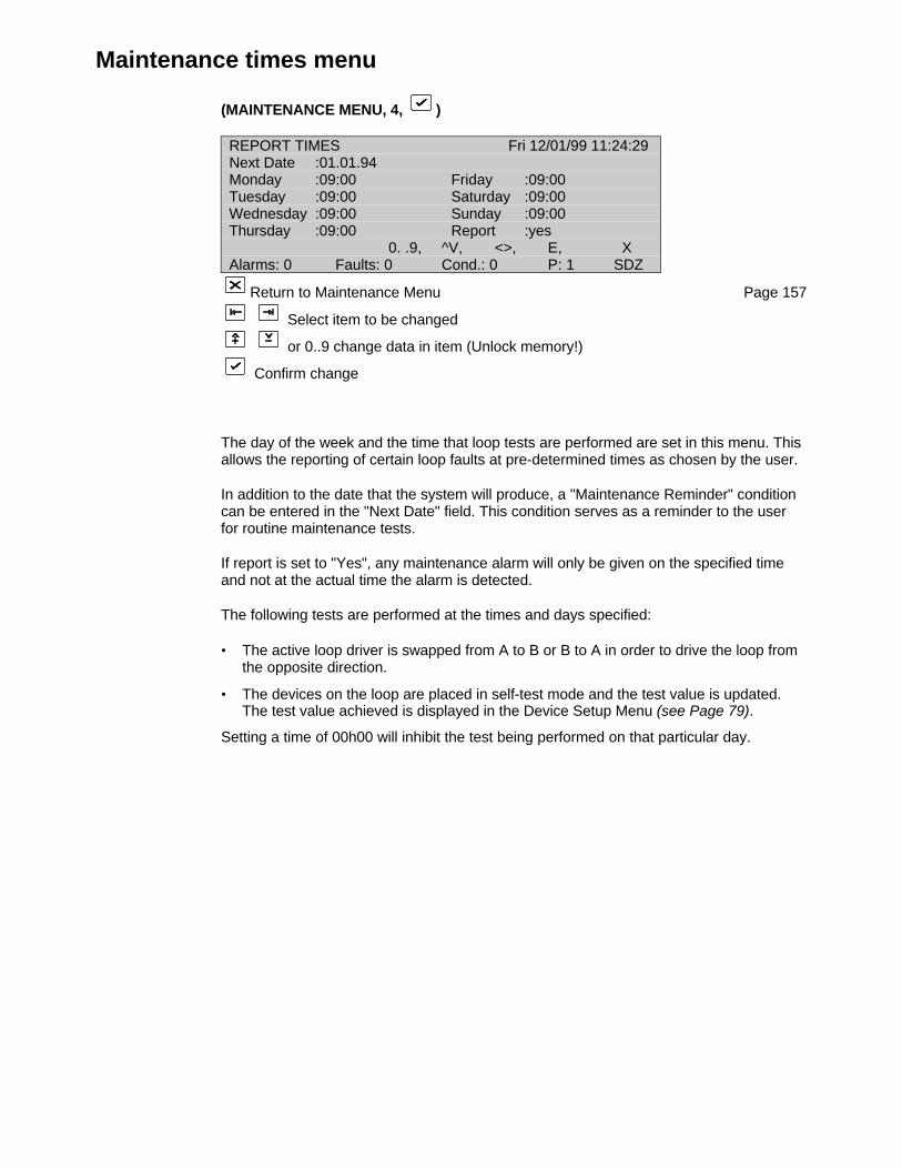
Maintenance times menu
(MAINTENANCE MENU, 4, )
REPORT TIMES Fri 12/01/99 11:24:29Next Date :01.01.94Monday :09:00 Friday :09:00Tuesday :09:00 Saturday :09:00Wednesday :09:00 Sunday :09:00Thursday :09:00 Report :yes
0. .9, ^V, <>, E, XAlarms: 0 Faults: 0 Cond.: 0 P: 1 SDZ
Return to Maintenance Menu Page 157
Select item to be changed
or 0..9 change data in item (Unlock memory!)
Confirm change
The day of the week and the time that loop tests are performed are set in this menu. Thisallows the reporting of certain loop faults at pre-determined times as chosen by the user.
In addition to the date that the system will produce, a "Maintenance Reminder" conditioncan be entered in the "Next Date" field. This condition serves as a reminder to the userfor routine maintenance tests.
If report is set to "Yes", any maintenance alarm will only be given on the specified timeand not at the actual time the alarm is detected.
The following tests are performed at the times and days specified:
• The active loop driver is swapped from A to B or B to A in order to drive the loop fromthe opposite direction.
• The devices on the loop are placed in self-test mode and the test value is updated.The test value achieved is displayed in the Device Setup Menu (see Page 79).
Setting a time of 00h00 will inhibit the test being performed on that particular day.

Options menu
(MAINTENANCE MENU, 5, )
OPTIONS
1 Language 2 Operation3 Protocol
0. .9, <>, E, XAlarms: 0 Faults: 0 Cond.: 0 P: 1 SDZ
Enter number or use and press
Return to Maintenance Menu Page 157
1 Language Page 166View the language of operation and temporarily change this language.
2 Operation Page 167View the operation mode and temporarily change this operation.
3 Protocol Page 168View the device protocol set.
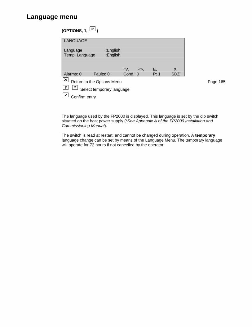
Language menu
(OPTIONS, 1, )
LANGUAGE
Language :EnglishTemp. Language :English
^V, <>, E, XAlarms: 0 Faults: 0 Cond.: 0 P: 1 SDZ
Return to the Options Menu Page 165
Select temporary language
Confirm entry
The language used by the FP2000 is displayed. This language is set by the dip switchsituated on the host power supply (*See Appendix A of the FP2000 Installation andCommissioning Manual).
The switch is read at restart, and cannot be changed during operation. A temporarylanguage change can be set by means of the Language Menu. The temporary languagewill operate for 72 hours if not cancelled by the operator.
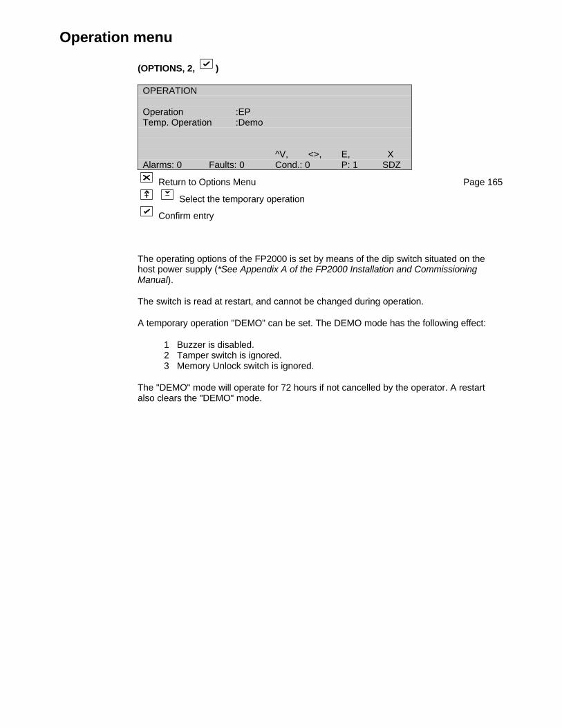
Operation menu
(OPTIONS, 2, )
OPERATION
Operation :EPTemp. Operation :Demo
^V, <>, E, XAlarms: 0 Faults: 0 Cond.: 0 P: 1 SDZ
Return to Options Menu Page 165
Select the temporary operation
Confirm entry
The operating options of the FP2000 is set by means of the dip switch situated on thehost power supply (*See Appendix A of the FP2000 Installation and CommissioningManual).
The switch is read at restart, and cannot be changed during operation.
A temporary operation "DEMO" can be set. The DEMO mode has the following effect:
1 Buzzer is disabled.2 Tamper switch is ignored.3 Memory Unlock switch is ignored.
The "DEMO" mode will operate for 72 hours if not cancelled by the operator. A restartalso clears the "DEMO" mode.
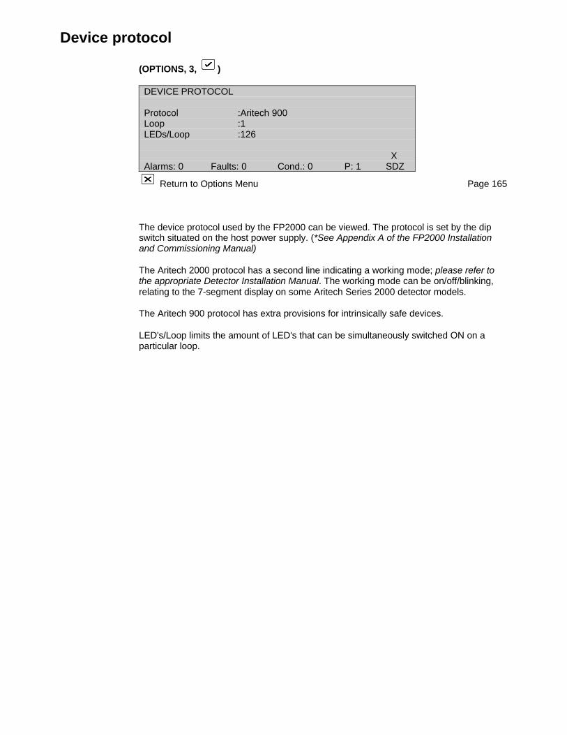
Device protocol
(OPTIONS, 3, )
DEVICE PROTOCOL
Protocol :Aritech 900Loop :1LEDs/Loop :126
XAlarms: 0 Faults: 0 Cond.: 0 P: 1 SDZ
Return to Options Menu Page 165
The device protocol used by the FP2000 can be viewed. The protocol is set by the dipswitch situated on the host power supply. (*See Appendix A of the FP2000 Installationand Commissioning Manual)
The Aritech 2000 protocol has a second line indicating a working mode; please refer tothe appropriate Detector Installation Manual. The working mode can be on/off/blinking,relating to the 7-segment display on some Aritech Series 2000 detector models.
The Aritech 900 protocol has extra provisions for intrinsically safe devices.
LED's/Loop limits the amount of LED's that can be simultaneously switched ON on aparticular loop.
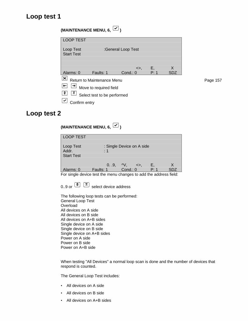
Loop test 1
(MAINTENANCE MENU, 6, )
LOOP TEST
Loop Test :General Loop TestStart Test
<>, E, XAlarms: 0 Faults: 1 Cond.: 0 P: 1 SDZ
Return to Maintenance Menu Page 157
Move to required field
Select test to be performed
Confirm entry
Loop test 2
(MAINTENANCE MENU, 6, )
LOOP TEST
Loop Test : Single Device on A sideAddr. : 1Start Test
0. .9, ^V, <>, E, XAlarms: 0 Faults: 1 Cond.: 0 P: 1 SDZ
For single device test the menu changes to add the address field:
0..9 or select device address
The following loop tests can be performed:General Loop TestOverloadAll devices on A sideAll devices on B sideAll devices on A+B sidesSingle device on A sideSingle device on B sideSingle device on A+B sidesPower on A sidePower on B sidePower on A+B side
When testing "All Devices" a normal loop scan is done and the number of devices thatrespond is counted.
The General Loop Test includes:
• All devices on A side
• All devices on B side
• All devices on A+B sides
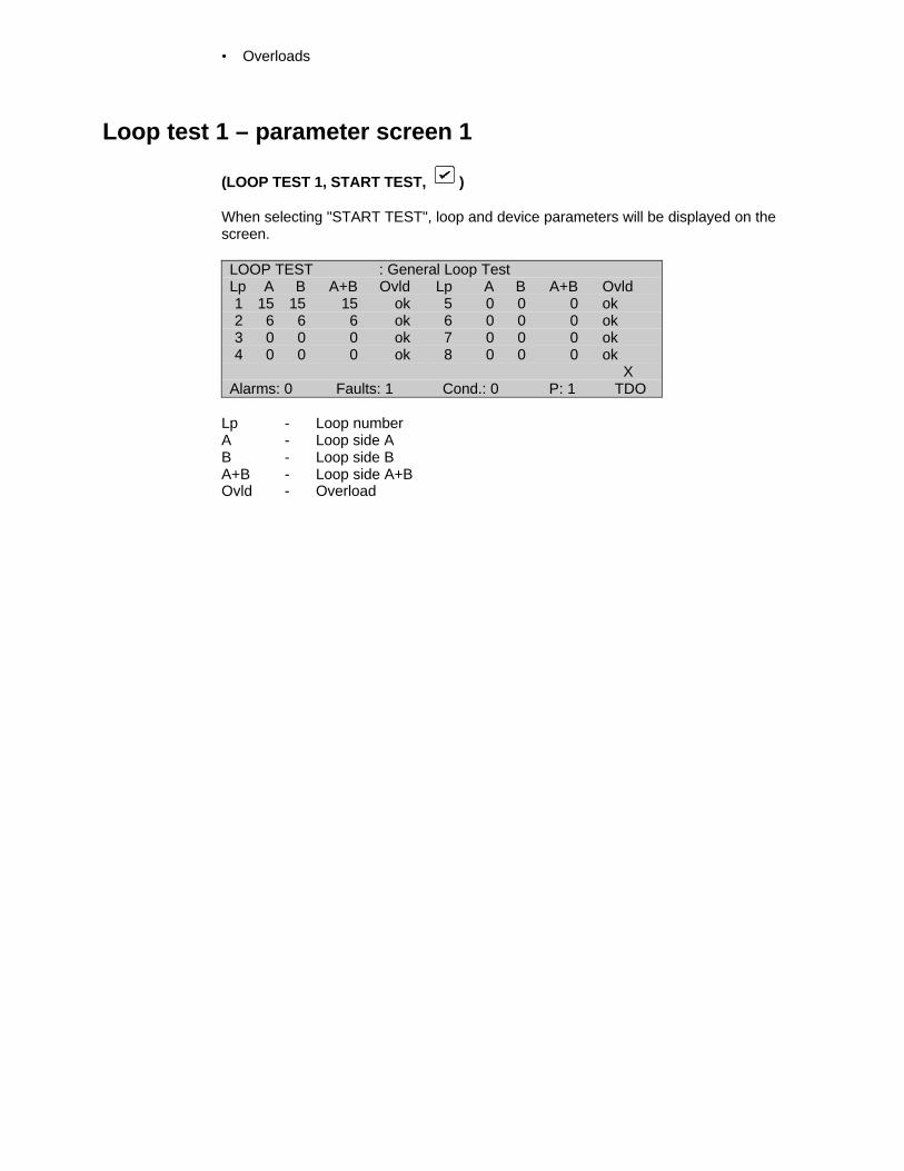
• Overloads
Loop test 1 – parameter screen 1
(LOOP TEST 1, START TEST, )
When selecting "START TEST", loop and device parameters will be displayed on thescreen.
LOOP TEST : General Loop TestLp A B A+B Ovld Lp A B A+B Ovld1 15 15 15 ok 5 0 0 0 ok2 6 6 6 ok 6 0 0 0 ok3 0 0 0 ok 7 0 0 0 ok4 0 0 0 ok 8 0 0 0 ok
XAlarms: 0 Faults: 1 Cond.: 0 P: 1 TDO
Lp - Loop numberA - Loop side AB - Loop side BA+B - Loop side A+BOvld - Overload
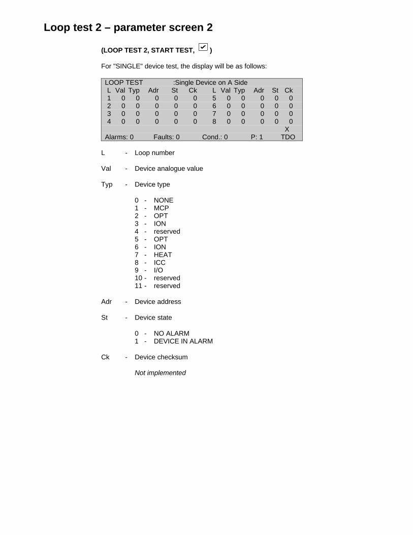
Loop test 2 – parameter screen 2
(LOOP TEST 2, START TEST, )
For "SINGLE" device test, the display will be as follows:
LOOP TEST :Single Device on A SideL Val Typ Adr St Ck L Val Typ Adr St Ck1 0 0 0 0 0 5 0 0 0 0 02 0 0 0 0 0 6 0 0 0 0 03 0 0 0 0 0 7 0 0 0 0 04 0 0 0 0 0 8 0 0 0 0 0
XAlarms: 0 Faults: 0 Cond.: 0 P: 1 TDO
L - Loop number
Val - Device analogue value
Typ - Device type
0 - NONE1 - MCP2 - OPT3 - ION4 - reserved5 - OPT6 - ION7 - HEAT8 - ICC9 - I/O10 - reserved11 - reserved
Adr - Device address
St - Device state
0 - NO ALARM1 - DEVICE IN ALARM
Ck - Device checksum
Not implemented
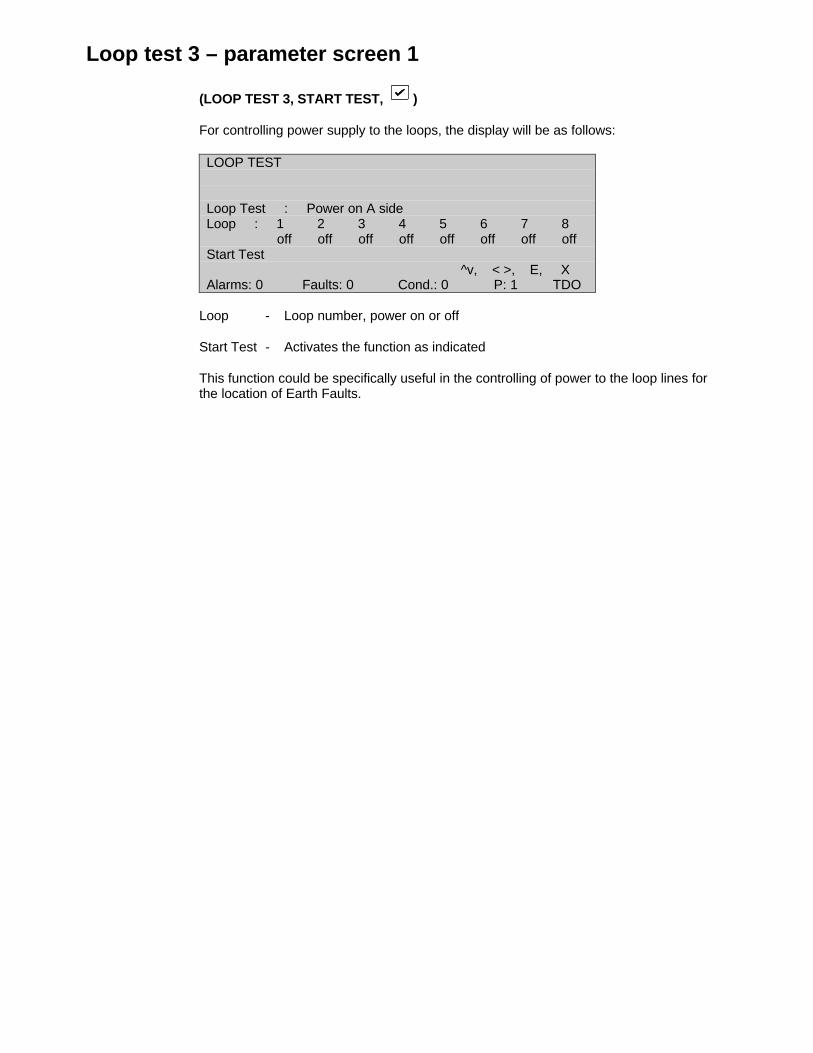
Loop test 3 – parameter screen 1
(LOOP TEST 3, START TEST, )
For controlling power supply to the loops, the display will be as follows:
LOOP TEST
Loop Test : Power on A sideLoop : 1 2 3 4 5 6 7 8 off off off off off off off offStart Test
^v, < >, E, XAlarms: 0 Faults: 0 Cond.: 0 P: 1 TDO
Loop - Loop number, power on or off
Start Test - Activates the function as indicated
This function could be specifically useful in the controlling of power to the loop lines forthe location of Earth Faults.

Fast Compensation
(MAINTENANCE MENU, 7, )
Returns Automatically to Maintenance Menu Page 157
This function will allow the panel to use a fast compensation algorithm to compensatequickly according to the current analogue values of the smoke detectors. It may beparticularly useful in the event of clearing all device statistics when there may already bedevices that are highly compensated. With no compensation applied, these devices maybe very sensitive and prone to nuisance alarms.

Main menu
(MAIN MENU, 6, )
MAIN MENU
1 System 2 Devices3 Input/Output 4 Events5 Maintenance 6 Test/Disable
Use dedicated Test and Disable KeysAlarms: 0 Faults: 0 Cond.: 0 P: 1 SDZ
Selecting OPTION 6 (Test/Disable) on the Main Menu will display the message "Usededicated Test and Disable Keys".
By pressing the corresponding key on the front panel, one enters the Test and DisableMenus.

Test menu
Push front panel TEST button
TEST MENU
1 Zone Test 2 Test Devices3 Output test 4 Lamptest5 Alarm Count 6 User Log
0. .9, <>, E, XAlarms: 0 Faults: 0 Cond.: 0 P: 1 SDZ
Select number or use and press
Return to menu that was displayed prior to Test being pushed.
1 Zone Test Page 177Zone testTest reportClear test resultsException report
2 Test Devices Page 183Perform Device Self Test
3 Output Test Page 184Test the Sounder, Fire Brigade, Fault Routing and Fire Protection outputs
4 Lamp Test Page 185Test the front panel LEDs
5 Alarm Count Page 186Displays the number of recorded alarms
6 User Log Page 187Allows the user to enter a code between 1 and 9999
Zone test menu
(TEST MENU, 1, )
ZONE TEST MENU
1 Zone Test 2 Test Report3 Clr. Testresults 4 Exception Report
0. .9, <>, E, XAlarms: 0 Faults: 0 Cond.: 0 P: 1 SDZ
Select number or use and press
Return to Test Menu Page 175
1 Zone Test Page 177Select up to four zones to test
2 Test Report Page 178Generate a test report of zones that have been tested
3 Clr. Test Results Page 180Clear the zone test results
4 Exception Report Page 181Generate a report of devices that have failed the zone test or devices that were nottested.
Zone test
(ZONE TEST MENU, 1, )
ZONE TESTStart: dd/mm hh:mm
Zone :1 12/01 11:29Zone :2 12/01 11:29Zone :3 00/00 00:00Zone :4 00/00 00:00
0. .9, ^V, <>, E, XAlarms: 0 Faults: 1 Cond.: 0 P: 1 SDZ
Return to Zone Test Menu Page 176
Select a new zone entry to start test or to cancel test
or 0..9 to select the zone number
Confirm entry
Up to four zones can be simultaneously tested. The test is performed as a "one man walktest", whereby the device being tested will indicate a fire condition and then automaticallyreset when the fire condition is cleared. No operator intervention is required at the panel.A single person can test each device in the zone by simply observing the device LED.
To cancel a test, enter Ø for the zone being tested. It is possible to cancel the test if anydevice in the zone is in a fire condition. The devices that are still in fire can be observed inthe exception report.
Zones that are in test are indicated by the fault lamp of the zone being steady on. Thecommon test lamp is also illuminated. The zone is effectively isolated and no outputswitching will occur for any fire condition in the zone.
Devices that can be tested in a zone are:
Smoke and heat detectorsManual call pointsZone monitor units and control unit monitors
A full report of the tested zone or an exception report (those devices that were nottested or failed the test) can be obtained from the panel.
When a zone is enabled for test, the previously held test report for that zone is cancelled,and the new report is begun.
Full test report
(ZONE TEST MENU, 2, )
FULL TEST REPORT
Destination :LCD
0. .9, ^V, <>, E, XAlarms: 0 Faults: 1 Cond.: 0 P: 1 SDZ
Return to Zone Test Menu Page 176
Select the report destination
Confirm entry
The full test report is displayed/printed to the selected device. The test report shows alltestable devices (see Page 176) and the pass/fail result of the device.
The test report of each zone of the fire panel is held indefinitely unless it is cleared byClear Test Results (Page 180) or the report is superseded by a new zone test report.
*See Page 179 for the report format of the LCD screen.
The devices where the report can be generated are:
LCD screenReport printerEvent printer
none
Test report [LCD]
(FULL TEST REPORT, LCD, )
FULL TEST REPORT 12/01/99 11:31Zone :1 on :12/01 11:29 off :12/01 11:30Addr Type Fire on Fire off1/2 MCP flt flt1/4 OPT flt flt1/5 TEMP flt flt
0. .9, ^V, <>, E, XAlarms: 0 Faults: 0 Cond.: 0 P: 1 SDZ
Return to Zone Test Menu Page 176
Select zone/Addr.
Zone selected:
Enter 0..9, or use to select zone
Address selected:
Scroll screen up
Scroll screen down
The full test report is listed in order of zone and loop/address. The cursor will togglebetween zone and address. The screen can be scrolled when ‘Addr.’ is selected with thecursor.
The screen will show the following:
• The zone number of the test report
• The date and time the test was started
• The date and time the test was finished
• A list of the testable devices
The devices that successfully entered into a fire condition are marked "OK" under the"FIRE ON" column, otherwise they are marked as "FLT". When the device returns tonormal from the fire condition, it is flagged "OK" under the "FIRE OFF" column.
The LCD screen is not a dynamic display and shows the conditions at the time ofacquiring the report. To obtain an update of the screen, the user should exit and re-enterthis menu.
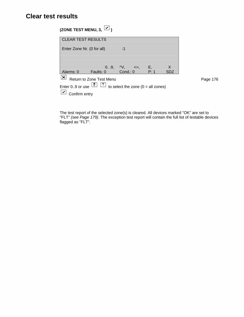
Clear test results
(ZONE TEST MENU, 3, )
CLEAR TEST RESULTS
Enter Zone Nr. (0 for all) :1
0. .9, ^V, <>, E, XAlarms: 0 Faults: 0 Cond.: 0 P: 1 SDZ
Return to Zone Test Menu Page 176
Enter 0..9 or use to select the zone (0 = all zones)
Confirm entry
The test report of the selected zone(s) is cleared. All devices marked "OK" are set to"FLT" (see Page 179). The exception test report will contain the full list of testable devicesflagged as "FLT".

Exception test report
(ZONE TEST MENU, 4, )
EXCEPTION TEST REPORT
Destination :LCD
^V, <>, E, XAlarms: 0 Faults: 1 Cond.: 0 P: 1 SDZ
Return to Zone Test Menu Page 176
Select the report destination
Confirm entry
The exception report is displayed/printed to the selected device. The test report shows allthat have either not been tested or failed the test.
The exception test report of each zone of the fire panel is held indefinitely unless it iscleared by Clear Test Results (Page 180) or the report is superseded by a new zone testreport.
*See Page 182 for the report format of the LCD screen.
The destinations to where the report can be generated are:
LCD screenReport printerEvent printer
none

Exception test report [LCD]
(EXCEPTION TEST REPORT, LCD, )
EXCEPTION TEST REPORT 12/01/99 11:31Zone :1 on :00/00 00:00 off :00/00 00:00Addr Type Fire on Fire off1/2 MCP flt flt1/4 OPT flt flt1/5 TEMP flt flt
0. .9, ^V, <>, E, XAlarms: 0 Faults: 0 Cond.: 0 P: 1 SDZ
The exception test report is listed in order of zone and loop/address. The cursor willtoggle between zone and address. The screen can be scrolled when the ‘Addr.’ isselected with the cursor.
The screen will show the following:
• The zone number of the test report
• The date and time the test was started
• The date and time the test was finished
• A list of the testable devices that have failed or had not been tested
The LCD screen is not a dynamic display and shows the conditions at the time ofaccessing the screen. To obtain an update of the screen, the user should exit and re-enter the menu.
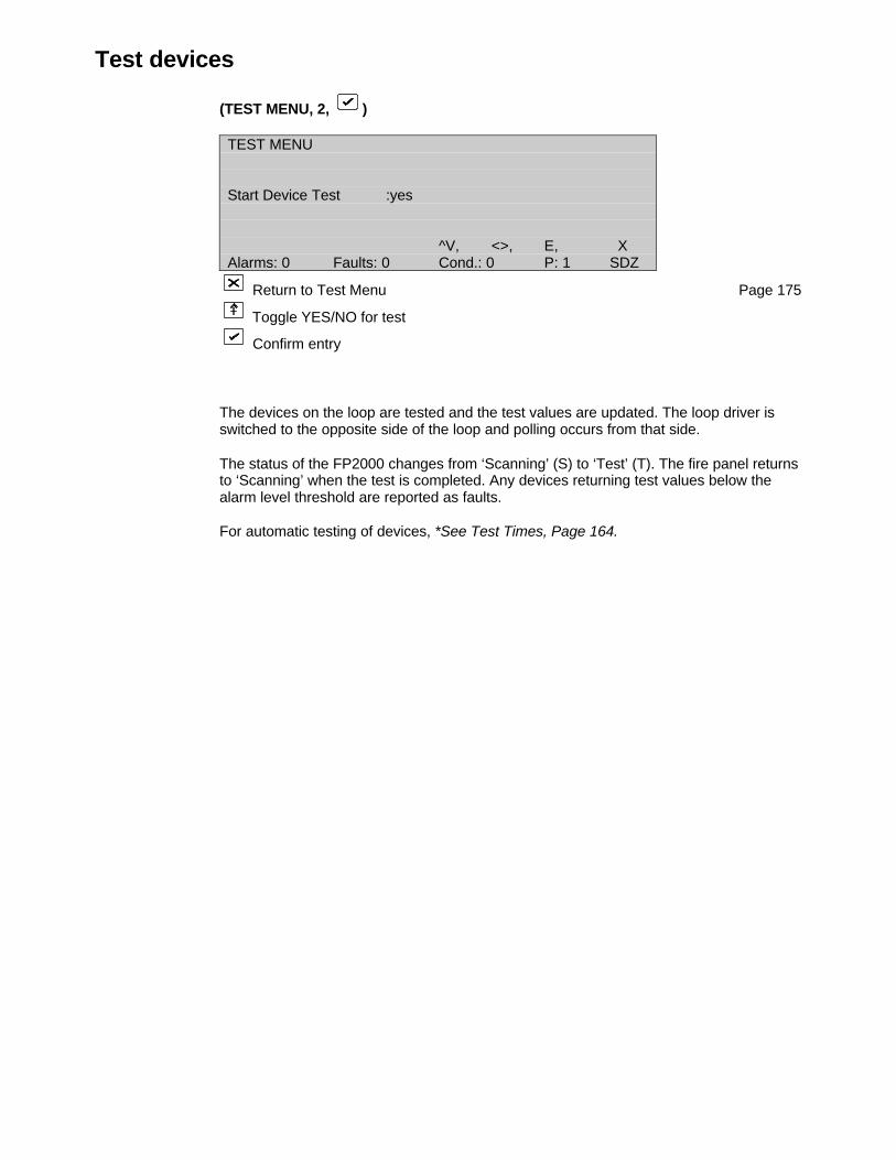
Test devices
(TEST MENU, 2, )
TEST MENU
Start Device Test :yes
^V, <>, E, XAlarms: 0 Faults: 0 Cond.: 0 P: 1 SDZ
Return to Test Menu Page 175
Toggle YES/NO for test
Confirm entry
The devices on the loop are tested and the test values are updated. The loop driver isswitched to the opposite side of the loop and polling occurs from that side.
The status of the FP2000 changes from ‘Scanning’ (S) to ‘Test’ (T). The fire panel returnsto ‘Scanning’ when the test is completed. Any devices returning test values below thealarm level threshold are reported as faults.
For automatic testing of devices, *See Test Times, Page 164.
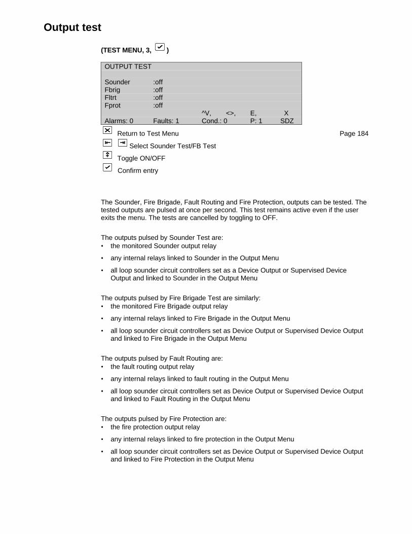
Output test
(TEST MENU, 3, )
OUTPUT TEST
Sounder :offFbrig :offFltrt :offFprot :off
^V, <>, E, XAlarms: 0 Faults: 1 Cond.: 0 P: 1 SDZ
Return to Test Menu Page 184
Select Sounder Test/FB Test
Toggle ON/OFF
Confirm entry
The Sounder, Fire Brigade, Fault Routing and Fire Protection, outputs can be tested. Thetested outputs are pulsed at once per second. This test remains active even if the userexits the menu. The tests are cancelled by toggling to OFF.
The outputs pulsed by Sounder Test are:• the monitored Sounder output relay
• any internal relays linked to Sounder in the Output Menu
• all loop sounder circuit controllers set as a Device Output or Supervised DeviceOutput and linked to Sounder in the Output Menu
The outputs pulsed by Fire Brigade Test are similarly:• the monitored Fire Brigade output relay
• any internal relays linked to Fire Brigade in the Output Menu
• all loop sounder circuit controllers set as Device Output or Supervised Device Outputand linked to Fire Brigade in the Output Menu
The outputs pulsed by Fault Routing are:• the fault routing output relay
• any internal relays linked to fault routing in the Output Menu
• all loop sounder circuit controllers set as Device Output or Supervised Device Outputand linked to Fault Routing in the Output Menu
The outputs pulsed by Fire Protection are:• the fire protection output relay
• any internal relays linked to fire protection in the Output Menu
• all loop sounder circuit controllers set as Device Output or Supervised Device Outputand linked to Fire Protection in the Output Menu

Lamp test
TEST MENU, 4, )
The LED lamps of the front panel are illuminated. The lamps are illuminated in blockswhere each block is tested for one second.
Each time the button is pushed, the test is repeated.
- The "Test 3rd Source" LED will not go on during Lamp Test, it has to be tested separatelyby means of pushing the appropriate button.
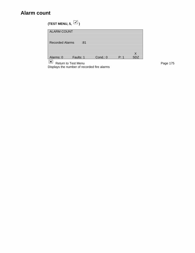
Alarm count
(TEST MENU, 5, )
ALARM COUNT
Recorded Alarms :81
XAlarms: 0 Faults: 1 Cond.: 0 P: 1 SDZ
Return to Test Menu Page 175Displays the number of recorded fire alarms
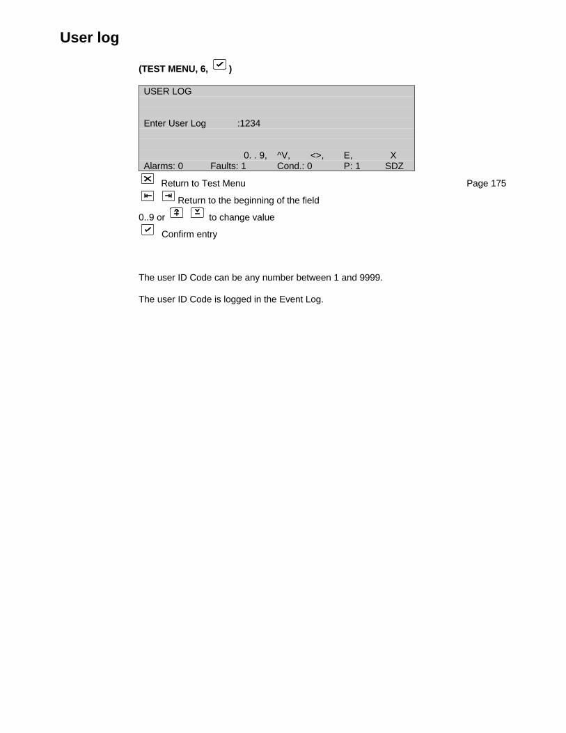
User log
(TEST MENU, 6, )
USER LOG
Enter User Log :1234
0. . 9, ^V, <>, E, XAlarms: 0 Faults: 1 Cond.: 0 P: 1 SDZ
Return to Test Menu Page 175
Return to the beginning of the field
0..9 or to change value
Confirm entry
The user ID Code can be any number between 1 and 9999.
The user ID Code is logged in the Event Log.

Disable menu
Push front panel DISABLE button
DISABLE MENU
1 Zones 2 Devices3 Areas 4 Report5 Outputs
0. . 9, <>, E, XAlarms: 0 Faults: 1 Cond.: 0 P: 1 SDZ
Select number or use and press
Return to menu that was displayed prior to DISABLE button being pushed
1 Zones Page 189Disable/Enable selected zones
2 Devices Page 190Disable/Enable individual devices by- alarm select- manual select
3 Areas Page 193Disable/Enable Areas
4 Reports Page 194Obtain reports of disabled zones, devices and areas
5 Outputs Page 198Disable/Enable fault routing and fire protection
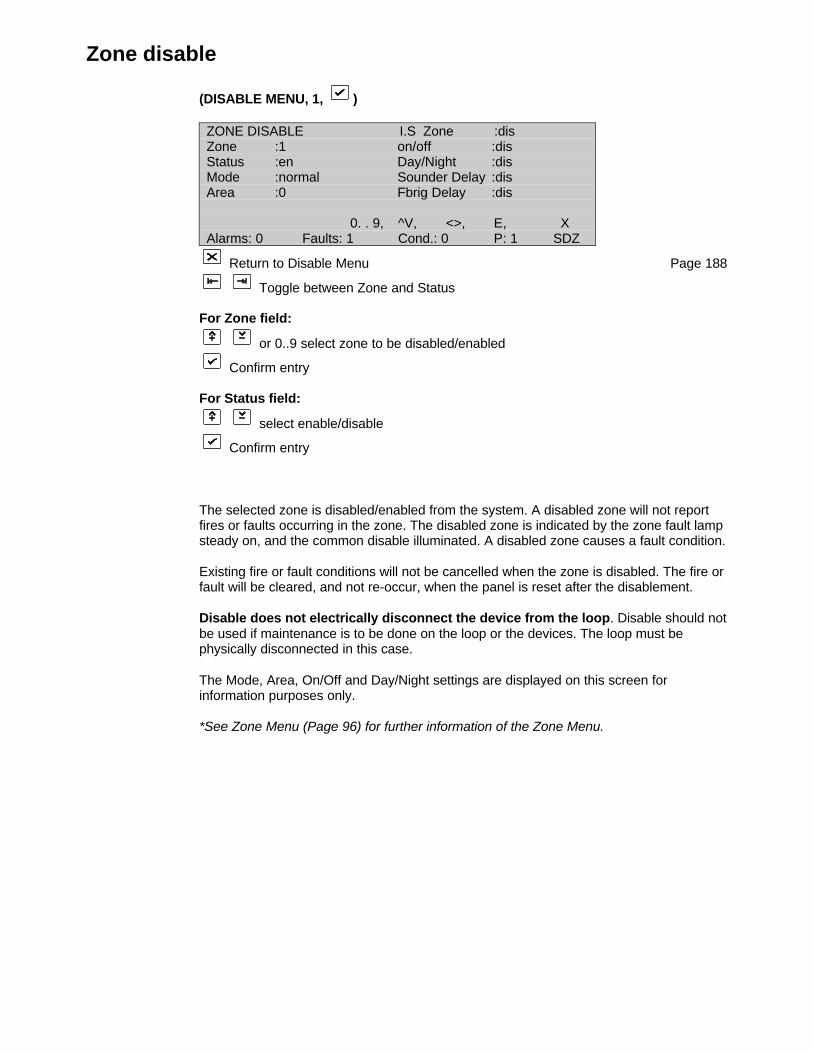
Zone disable
(DISABLE MENU, 1, )
ZONE DISABLE I.S Zone :disZone :1 on/off :disStatus :en Day/Night :disMode :normal Sounder Delay :disArea :0 Fbrig Delay :dis
0. . 9, ^V, <>, E, XAlarms: 0 Faults: 1 Cond.: 0 P: 1 SDZ
Return to Disable Menu Page 188
Toggle between Zone and Status
For Zone field:
or 0..9 select zone to be disabled/enabled
Confirm entry
For Status field:
select enable/disable
Confirm entry
The selected zone is disabled/enabled from the system. A disabled zone will not reportfires or faults occurring in the zone. The disabled zone is indicated by the zone fault lampsteady on, and the common disable illuminated. A disabled zone causes a fault condition.
Existing fire or fault conditions will not be cancelled when the zone is disabled. The fire orfault will be cleared, and not re-occur, when the panel is reset after the disablement.
Disable does not electrically disconnect the device from the loop. Disable should notbe used if maintenance is to be done on the loop or the devices. The loop must bephysically disconnected in this case.
The Mode, Area, On/Off and Day/Night settings are displayed on this screen forinformation purposes only.
*See Zone Menu (Page 96) for further information of the Zone Menu.
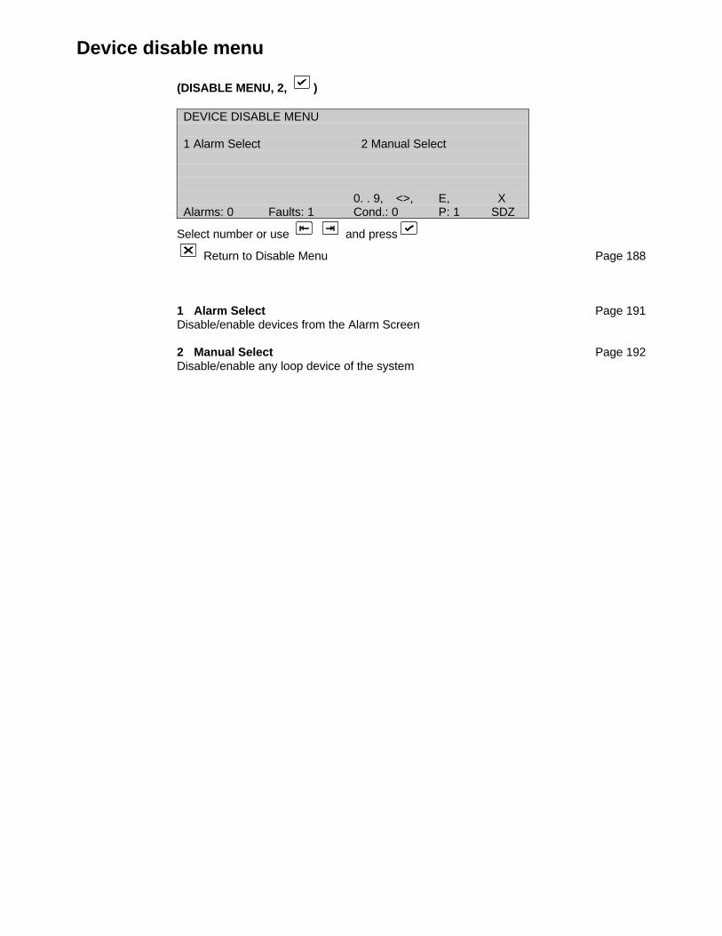
Device disable menu
(DISABLE MENU, 2, )
DEVICE DISABLE MENU
1 Alarm Select 2 Manual Select
0. . 9, <>, E, XAlarms: 0 Faults: 1 Cond.: 0 P: 1 SDZ
Select number or use and press
Return to Disable Menu Page 188
1 Alarm Select Page 191Disable/enable devices from the Alarm Screen
2 Manual Select Page 192Disable/enable any loop device of the system
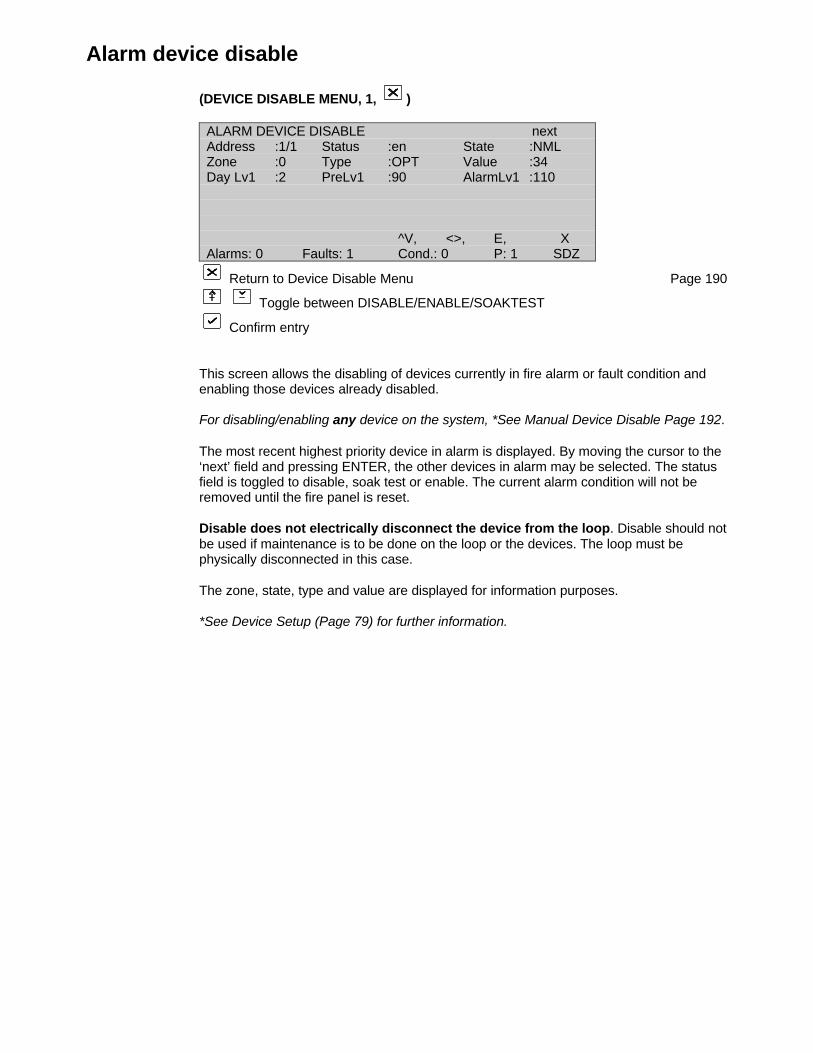
Alarm device disable
(DEVICE DISABLE MENU, 1, )
ALARM DEVICE DISABLE nextAddress :1/1 Status :en State :NMLZone :0 Type :OPT Value :34Day Lv1 :2 PreLv1 :90 AlarmLv1 :110
^V, <>, E, XAlarms: 0 Faults: 1 Cond.: 0 P: 1 SDZ
Return to Device Disable Menu Page 190
Toggle between DISABLE/ENABLE/SOAKTEST
Confirm entry
This screen allows the disabling of devices currently in fire alarm or fault condition andenabling those devices already disabled.
For disabling/enabling any device on the system, *See Manual Device Disable Page 192.
The most recent highest priority device in alarm is displayed. By moving the cursor to the‘next’ field and pressing ENTER, the other devices in alarm may be selected. The statusfield is toggled to disable, soak test or enable. The current alarm condition will not beremoved until the fire panel is reset.
Disable does not electrically disconnect the device from the loop. Disable should notbe used if maintenance is to be done on the loop or the devices. The loop must bephysically disconnected in this case.
The zone, state, type and value are displayed for information purposes.
*See Device Setup (Page 79) for further information.

Manual device disable
(DEVICE DISABLE MENU, 2, )
MANUAL DEVICE DISABLEAddress :1/1 Status :en State :NMLZone :0 Type :OPT Value :0Day Lv1 :2 PreLv1 :90 AlarmLv1 :110
^V, <>, E, XAlarms: 0 Faults: 1 Cond.: 0 P: 1 SDZ
Return to Device Disable Menu Page 190
Toggle Address and Status field
For Address field:
or 0..9 select loop and address of device
Confirm entry
For Status field:
Toggle Disable/Soaktest/Enable
Confirm entry
Individual devices can be disabled, enabled, or placed in soak test mode.
A disabled device will cause a disabled condition. A zone disable condition occurs if alldevices in that zone are disabled or if all but one are disabled when the zone is set tocoincidence mode.
The current alarm condition of a device is not cleared until the panel is reset.
Disable does not electrically disconnect the device from the loop. Disable should notbe used if maintenance is to be done on the loop or the devices. The loop must bephysically disconnected in this case.
The zone, state, type and value are displayed for information purposes.
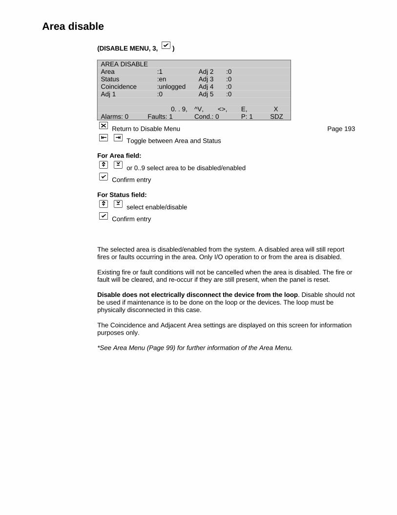
Area disable
(DISABLE MENU, 3, )
AREA DISABLEArea :1 Adj 2 :0Status :en Adj 3 :0Coincidence :unlogged Adj 4 :0Adj 1 :0 Adj 5 :0
0. . 9, ^V, <>, E, XAlarms: 0 Faults: 1 Cond.: 0 P: 1 SDZ
Return to Disable Menu Page 193
Toggle between Area and Status
For Area field:
or 0..9 select area to be disabled/enabled
Confirm entry
For Status field:
select enable/disable
Confirm entry
The selected area is disabled/enabled from the system. A disabled area will still reportfires or faults occurring in the area. Only I/O operation to or from the area is disabled.
Existing fire or fault conditions will not be cancelled when the area is disabled. The fire orfault will be cleared, and re-occur if they are still present, when the panel is reset.
Disable does not electrically disconnect the device from the loop. Disable should notbe used if maintenance is to be done on the loop or the devices. The loop must bephysically disconnected in this case.
The Coincidence and Adjacent Area settings are displayed on this screen for informationpurposes only.
*See Area Menu (Page 99) for further information of the Area Menu.
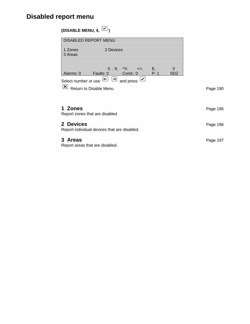
Disabled report menu
(DISABLE MENU, 4, )
DISABLED REPORT MENU
1 Zones 2 Devices3 Areas
0. . 9, ^V, <>, E, XAlarms: 0 Faults: 0 Cond.: 0 P: 1 SDZ
Select number or use and press
Return to Disable Menu Page 190
1 Zones Page 195Report zones that are disabled
2 Devices Page 196Report individual devices that are disabled.
3 Areas Page 197Report areas that are disabled.
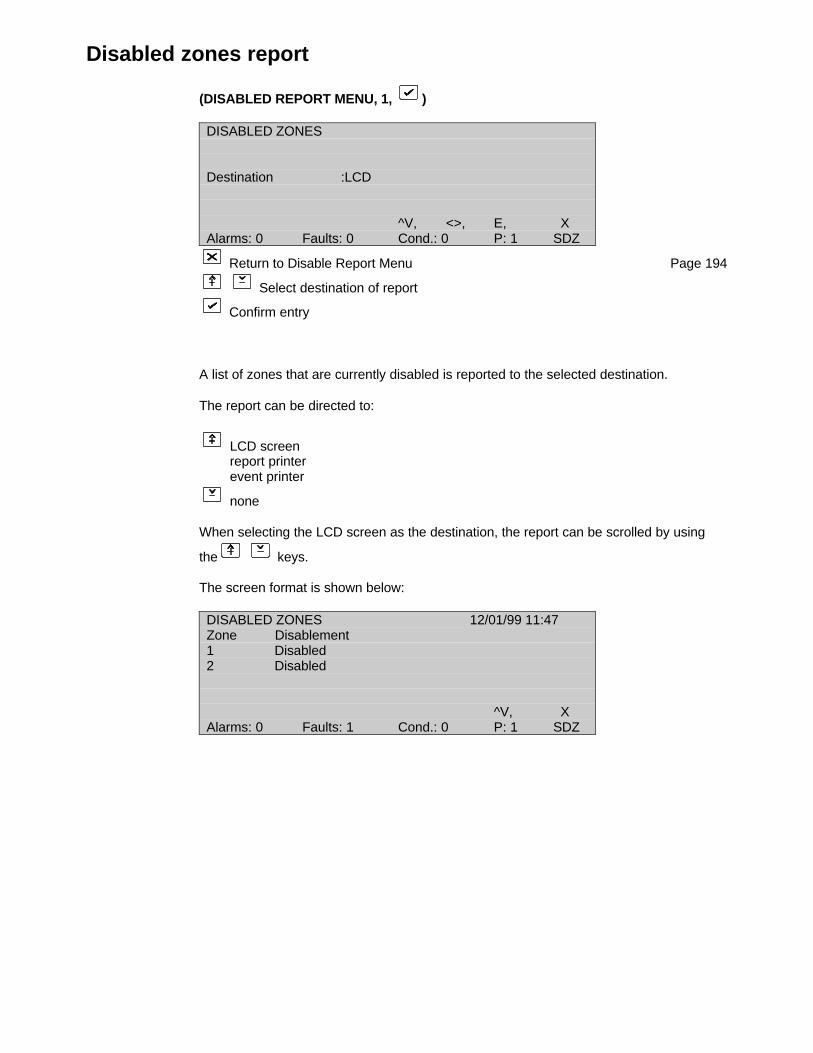
Disabled zones report
(DISABLED REPORT MENU, 1, )
DISABLED ZONES
Destination :LCD
^V, <>, E, XAlarms: 0 Faults: 0 Cond.: 0 P: 1 SDZ
Return to Disable Report Menu Page 194
Select destination of report
Confirm entry
A list of zones that are currently disabled is reported to the selected destination.
The report can be directed to:
LCD screenreport printerevent printer
none
When selecting the LCD screen as the destination, the report can be scrolled by using
the keys.
The screen format is shown below:
DISABLED ZONES 12/01/99 11:47Zone Disablement1 Disabled2 Disabled
^V, XAlarms: 0 Faults: 1 Cond.: 0 P: 1 SDZ
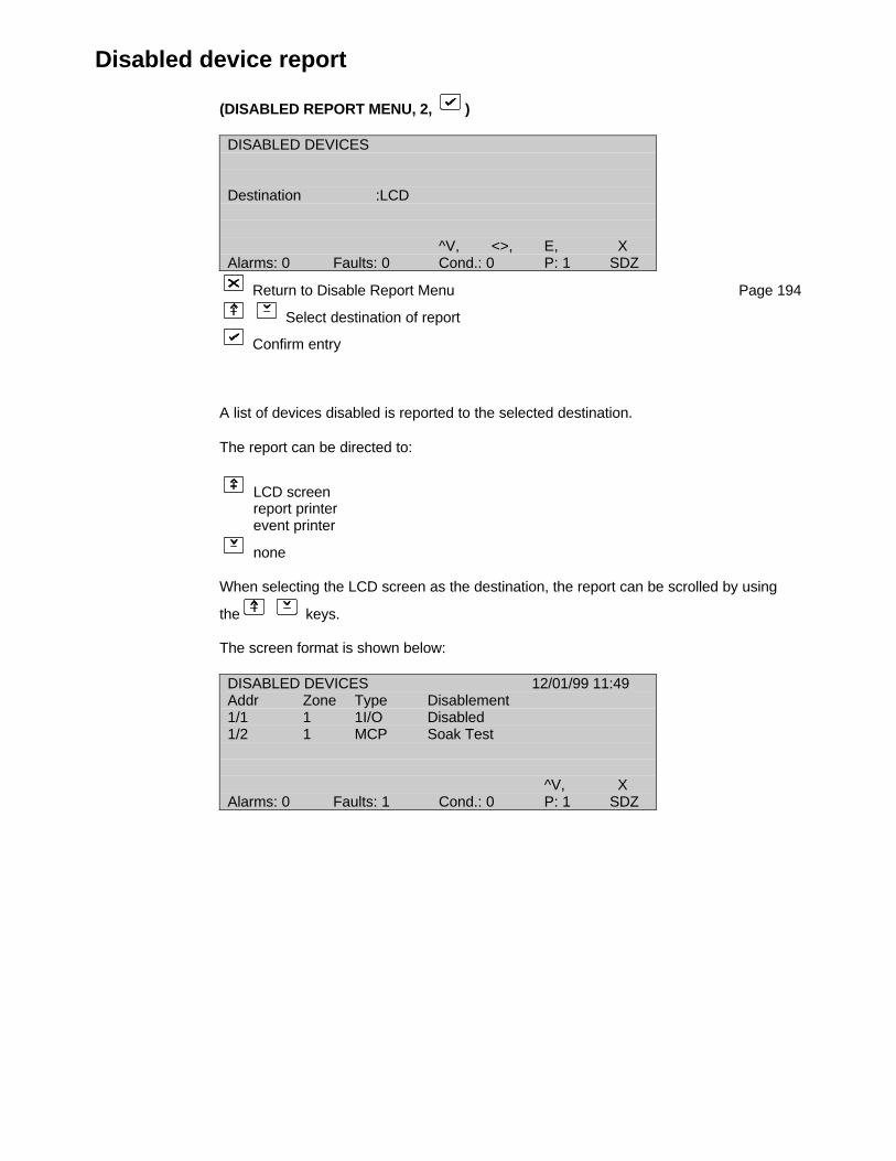
Disabled device report
(DISABLED REPORT MENU, 2, )
DISABLED DEVICES
Destination :LCD
^V, <>, E, XAlarms: 0 Faults: 0 Cond.: 0 P: 1 SDZ
Return to Disable Report Menu Page 194
Select destination of report
Confirm entry
A list of devices disabled is reported to the selected destination.
The report can be directed to:
LCD screenreport printerevent printer
none
When selecting the LCD screen as the destination, the report can be scrolled by using
the keys.
The screen format is shown below:
DISABLED DEVICES 12/01/99 11:49Addr Zone Type Disablement1/1 1 1I/O Disabled1/2 1 MCP Soak Test
^V, XAlarms: 0 Faults: 1 Cond.: 0 P: 1 SDZ
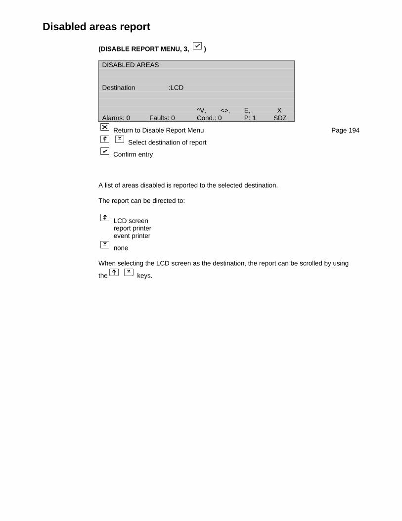
Disabled areas report
(DISABLE REPORT MENU, 3, )
DISABLED AREAS
Destination :LCD
^V, <>, E, XAlarms: 0 Faults: 0 Cond.: 0 P: 1 SDZ
Return to Disable Report Menu Page 194
Select destination of report
Confirm entry
A list of areas disabled is reported to the selected destination.
The report can be directed to:
LCD screenreport printerevent printer
none
When selecting the LCD screen as the destination, the report can be scrolled by using
the keys.
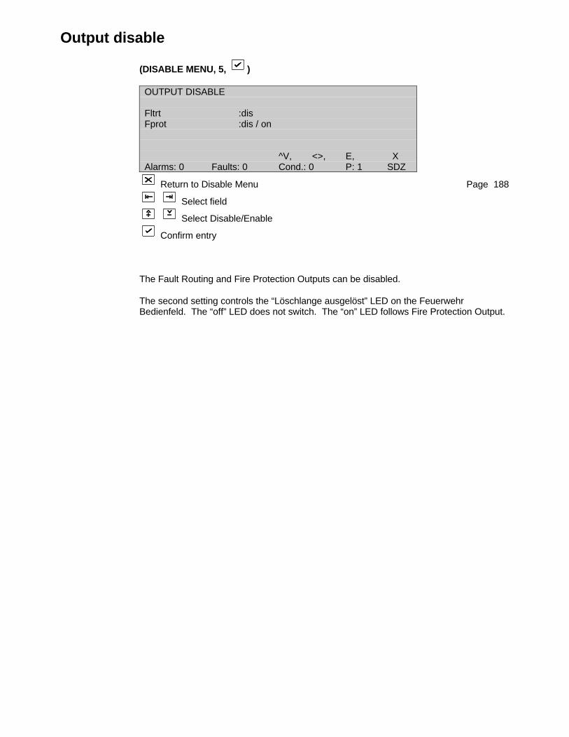
Output disable
(DISABLE MENU, 5, )
OUTPUT DISABLE
Fltrt :disFprot :dis / on
^V, <>, E, XAlarms: 0 Faults: 0 Cond.: 0 P: 1 SDZ
Return to Disable Menu Page 188
Select field
Select Disable/Enable
Confirm entry
The Fault Routing and Fire Protection Outputs can be disabled.
The second setting controls the “Löschlange ausgelöst” LED on the FeuerwehrBedienfeld. The “off” LED does not switch. The “on” LED follows Fire Protection Output.

APPENDIX A
FP2000 panel menusThe following table gives the field numbers (access field) of the FP2000 Panel's menus.The table also shows what FP2000 Panel configuration is required for a specific menu toexist.
DescriptionField Number or Access Field:
This is a word value (two bytes) that is used to distinguish between the different menus.This is also the value that is used by FP2000 Communication Format message number16 to change or read the access level of a specific menu remotely.
The field numbers in the table is intended to show the menu hierarchy.
Existence Option:
The existence of the different menus for four FP2000 Panel configurations is shown. Theconfigurations are:
• Absence of Field Loops
• Local Repeater
• Global Repeater
• Panel
- All the menus exist for a standard FP2000 Panel (the "Panel" configuration above).
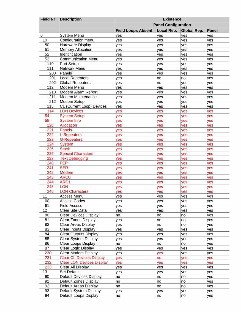
Field Nr Description ExistencePanel Configuration
Field Loops Absent Local Rep. Global Rep. Panel0 System Menu yes yes yes yes 10 Configuration menu yes yes yes yes 50 Hardware Display yes yes yes yes 51 Memory Allocation yes yes yes yes 52 Identification yes yes yes yes 53 Communication Menu yes yes yes yes 110 Port Setup yes yes yes yes 111 Network Menu yes yes yes yes 200 Panels yes yes yes yes 201 Local Repeaters yes no no yes 202 Global Repeaters yes no yes yes 112 Modem Menu yes yes yes yes 210 Modem Alarm Report yes yes yes yes 211 Modem Maintenance yes yes yes yes 212 Modem Setup yes yes yes yes 113 CL (Current Loop) Devices yes yes yes yes 114 LON Devices yes yes yes yes 54 System Setup yes yes yes yes 55 System Info yes yes yes yes 220 Allocation yes yes yes yes 221 Panels yes yes yes yes 222 L-Repeaters yes yes yes yes 223 G-Repeaters yes yes yes yes 224 System yes yes yes yes 225 Stack yes yes yes yes 226 Special Characters yes yes yes yes 227 Text Debugging yes yes yes yes 240 FEP yes yes yes yes 241 SER yes yes yes yes 242 Modem yes yes yes yes 243 ARC0 yes yes yes yes 244 ARC1 yes yes yes yes 245 LON yes yes yes yes 246 LON Characters yes yes yes yes 11 Access Menu yes yes yes yes 60 Access Codes yes yes yes yes 61 Field Access yes yes yes yes 12 Clear Site Data yes yes yes yes 80 Clear Devices Display no no no yes 81 Clear Zones Display yes no no yes 82 Clear Areas Display yes no no yes 83 Clear Inputs Display yes yes yes yes 84 Clear Outputs Display yes yes yes yes 85 Clear System Display yes yes yes yes 86 Clear Loops Display no no no yes 87 Clear Logic Display yes yes yes yes 230 Clear Modem Display yes yes yes yes 231 Clear CL Devices Display yes no yes yes 232 Clear LON Devices Display yes yes yes yes 233 Clear All Display yes yes yes yes 13 Set Default yes yes yes yes 90 Default Devices Display no no no yes 91 Default Zones Display no no no yes 92 Default Areas Display no no no yes 93 Default System Display yes yes yes yes 94 Default Loops Display no no no yes

Field Nr Description ExistencePanel Configuration
Field Loops Absent Local Rep. Global Rep. Panel 95 Default Configuration Display yes yes yes yes 96 Default Logic Display yes yes yes yes 97 Default Modem Display yes no yes yes 14 Set Times Menu yes yes yes yes 100 Set Date and Time yes yes yes yes 101 Output Delays yes no no yes 102 FBrig (Fire Brigade) Delay Off yes no no yes 103 Sounder Delay Off yes no no yes 104 Zones Off yes no no yes 105 Zones On yes no no yes 106 Day Mode yes no no yes 107 Night Mode yes no no yes 15 Restart yes yes yes yes1 Device Menu yes yes yes yes 20 Device Setup no no no yes 21 Zone yes no no yes 22 Areas yes no no yes 23 Zone Graphics no no no yes 24 Device Graphics no no no yes 25 Zone Range yes yes yes yes2 Input / Output yes yes yes yes 140 Input Definition yes yes yes yes 141 Output Definition yes yes yes yes 142 Logic Table yes yes yes yes 143 CL (Current Loop) Devices yes yes yes yes 144 Timers yes yes yes yes 145 Markers yes yes yes yes3 Event Menu yes yes yes yes 30 Display Events yes yes yes yes 31 Clear Events Display yes yes yes yes 32 Clear All Events yes no yes yes4 Maintenance Menu yes yes yes yes 40 Maintenance Report Menu no no no yes 130 Device Values no no no yes 131 Maintenance Device no no no yes 41 Clear Device Statistics no no no yes 42 Hardware Test Display yes yes yes yes 43 Report (Maintenance) Times yes yes yes yes 44 Options yes yes yes yes 170 Language yes yes yes yes 171 Operation yes yes yes yes 172 Device Protocol no no no yes 45 Loop Test no no no yes 46 Fast Compensation no no no yes5 Test Menu yes yes yes yes 150 Zone Test Menu no no no yes 160 Zone Test no no no yes 161 Full Test Report no no no yes 162 Clear Test Results no no no yes 163 Exception Test Report no no no yes 151 Test Devices Display no no no yes 152 Output Test yes yes no yes 153 Lamptest Display yes yes yes yes 154 Alarm Count yes yes yes yes 155 User Log yes yes yes yes6 Disable Menu no no no yes 120 Zone Disable no no no yes

Field Nr Description ExistencePanel Configuration
Field Loops Absent Local Rep. Global Rep. Panel 121 Device Disable Menu no no no yes 180 Alarm Device Disable no no no yes 181 Manual Device Disable no no no yes 122 Area Disable no no no yes 123 Disabled Report Menu no no no yes 190 Disabled Zones no no no yes 191 Disabled Devices no no no yes 192 Disabled Areas no no no yes 124 Output Disable no no no yes

APPENDIX B
UPGRADE: VER3.XX TO VER 4.00 VER 3.00 VER 4.00HARDWARE CONFIGURATION 1 4-6 27COMMUNICATIONS MENU 4-15 37MODEM ALARM REPORT 2 4-25 47RD6000 MENU 4-30 -CLEAR SITE DATA 1 4-35 62DEVICE MENU 4-51 78GENERAL SETUP AND VIEW (ALL TYPES) 4-53 79GENERAL SETUP AND VIEW (ALL TYPES) 4-54 79INDICATING CIRCUIT CONTROLLER - 89INDICATING CIRCUIT CONTROLLER - 89I/O UNITS 4-64 92I/O UNITS 4-65 92ZONE MENU 4-68 96INPUT DEFINITION 4-98 114OUTPUT ASSIGNMENTS - 131TYPE INTERNAL 4-106 134TYPE DEVICE OUTPUT 4-108 135TYPE SUPERVISED INTERNAL 4-109 136TYPE SUPERVISED DEVICE OUTPUT 4-110 137TYPE CURRENT LOOP DEVICE 4-112 139TYPE SUPERVISED CURRENT LOOP 4-113 140LINK TO EQUIPMENT - 143CL DEVICE SETUP 4-121 148HARDWARE TEST 4-133 163DEVICE PROTOCOL 4-138 168INPUT DESCRIPTION A-5 -OUTPUT DESCRIPTION B-1 to B-4 -PANEL MENUS C-2 A-1UPGRADE - B-1MEMORY ALLOCATION - 33
UPGRADE: VER5.00 TO VER 6.10 VER 5.00 VER 6.1064-ZONE LEXAN LAYOUT (255 ZONES MAX) - 16START-UP SCREENS - 18VERSION - 29SITE VERSION - 30GLOBAL ZONE REPEATERS & ID TEXT - 35CMSI PORT SETUP - 39PANEL START & END ZONE - 42MAX DIALLING ATTEMPTS CHANGED FROM 99 TO 3 45 & 57 49 & 67BAUSCH MODEM INIT STRING 46 50LON DEVICES - 53STEP-BY-STEP LON DEVICE INSTALL. WALKTHRU - 55SYSTEM SETUP - 56SYSTEM INFORMATION - 58OPERATING MODES IO UNITS CORRECTED 82 & 110 93 & 122MODE CHANGES 87 97ZONE RANGE - 108TIMERS - 150MARKERS - 151PANEL MENUS A-1 A-1