Formal Requirements-Based Programming for Complex ...
10
Formal Requirements-Based Programming for Complex Systems James L. Rash, Michael G. Hinchey NASA Goddard Space Flight Center Information Systems Division Greenbelt, MD 20771, USA {james.l.rash, michael.g.hinchey}@nasa.gov Christopher A. Rouff SAIC Advanced Concepts Business Unit McLean, VA 22102, USA [email protected] Denis Graˇ canin Department of Computer Science Virginia Tech Blacksburg, VA 24061, USA [email protected] Abstract Computer science as a field has not yet produced a gen- eral method to mechanically transform complex computer system requirements into a provably equivalent implemen- tation. Such a method would be one major step towards dealing with complexity in computing, yet it remains the elu- sive “holy grail” of system development. Currently avail- able tools and methods that start with a formal model of a system and mechanically produce a provably equivalent implementation are valuable but not sufficient. The “gap” that such tools and methods leave unfilled is that the formal models cannot be proven to be equivalent to the system re- quirements as originated by the customer. For the classes of complex systems whose behavior can be described as a fi- nite (but significant) set of scenarios, we offer a method for mechanically transforming requirements (expressed in re- stricted natural language, or appropriate graphical nota- tions) into a provably equivalent formal model that can be used as the basis for code generation and other transforma- tions. While other techniques are available, this method is unique in offering full mathematical tractability while us- ing notations and techniques that are well known and well trusted. We illustrate the application of the method to an ex- ample procedure from the Hubble Robotic Servicing Mis- sion currently under study and preliminary formulation at NASA Goddard Space Flight Center. Key Words: Validation, verification, formal methods 1. Introduction The development of complex systems that have high lev- els of dependability and reliability requires the developer to represent the system as a formal model that can be proven to be correct. Through the use of currently available tools, the model can then be automatically transformed into code with minimal, or no, human intervention and with a cor- respondingly minimized chance of introducing errors. Au- tomatically producing the formal model from customer re- quirements would further reduce the chance of introduction of errors by developers and would result in highly depend- able complex systems. We will not critique currently available system develop- ment tools and methods that are based on formal models here; but, to the best of our knowledge, they provide nei- ther automated generation of the models from requirements nor automated proof of correctness of the models. There- fore, currently there is no automated means of producing a system—or a complex procedure—that is a provably cor- rect implementation of the customer’s requirements. Fur- ther, requirements engineering as a discipline has yet to pro- duce an automated, mathematics-based process for require- ments validation. 2. Problem Statement Automatic code generation from requirements has been the ultimate objective of software engineering almost since the advent of high-level programming languages. The need for “requirements-based programming”, whereby require- ments can be transformed into an implementation in a man- ner that supports the entire lifecycle of the development pro-
-
Upload
khangminh22 -
Category
Documents
-
view
0 -
download
0
Transcript of Formal Requirements-Based Programming for Complex ...

Formal Requirements-Based Programming for Complex Systems
James L. Rash, Michael G. HincheyNASA Goddard Space Flight Center
Information Systems DivisionGreenbelt, MD 20771, USA
{james.l.rash, michael.g.hinchey}@nasa.gov
Christopher A. RouffSAIC
Advanced Concepts Business UnitMcLean, VA 22102, USA
Denis GracaninDepartment of Computer Science
Virginia TechBlacksburg, VA 24061, USA
Abstract
Computer science as a field has not yet produced a gen-eral method to mechanically transform complex computersystem requirements into a provably equivalent implemen-tation. Such a method would be one major step towardsdealing with complexity in computing, yet it remains the elu-sive “holy grail” of system development. Currently avail-able tools and methods that start with a formal model ofa system and mechanically produce a provably equivalentimplementation are valuable but not sufficient. The “gap”that such tools and methods leave unfilled is that the formalmodels cannot be proven to be equivalent to the system re-quirements as originated by the customer. For the classes ofcomplex systems whose behavior can be described as a fi-nite (but significant) set of scenarios, we offer a method formechanically transforming requirements (expressed in re-stricted natural language, or appropriate graphical nota-tions) into a provably equivalent formal model that can beused as the basis for code generation and other transforma-tions. While other techniques are available, this method isunique in offering full mathematical tractability while us-ing notations and techniques that are well known and welltrusted. We illustrate the application of the method to an ex-ample procedure from the Hubble Robotic Servicing Mis-sion currently under study and preliminary formulation atNASA Goddard Space Flight Center.
Key Words: Validation, verification, formal methods
1. Introduction
The development of complex systems that have high lev-els of dependability and reliability requires the developer torepresent the system as a formal model that can be provento be correct. Through the use of currently available tools,the model can then be automatically transformed into codewith minimal, or no, human intervention and with a cor-respondingly minimized chance of introducing errors. Au-tomatically producing the formal model from customer re-quirements would further reduce the chance of introductionof errors by developers and would result in highly depend-able complex systems.
We will not critique currently available system develop-ment tools and methods that are based on formal modelshere; but, to the best of our knowledge, they provide nei-ther automated generation of the models from requirementsnor automated proof of correctness of the models. There-fore, currently there is no automated means of producing asystem—or a complex procedure—that is a provably cor-rect implementation of the customer’s requirements. Fur-ther, requirements engineering as a discipline has yet to pro-duce an automated, mathematics-based process for require-ments validation.
2. Problem Statement
Automatic code generation from requirements has beenthe ultimate objective of software engineering almost sincethe advent of high-level programming languages. The needfor “requirements-based programming”, whereby require-ments can be transformed into an implementation in a man-ner that supports the entire lifecycle of the development pro-
cess, cannot be exaggerated [7]. Several tools and productsexist in the marketplace to automate code generation froma given model expressed in a particular notation. However,typically the code they generate includes portions that ei-ther are never executed or cannot be justified from eitherthe requirements or the model. Moreover, existing tools donot and cannot overcome the fundamental inadequacy ofall currently available automated development approaches,which is that they include no means to establish a provableequivalence between the requirements stated at the outsetand either the model or the code they generate.
Traditional approaches to automatic code generation pre-suppose the existence of an explicit (formal) model of real-ity that can be used as the basis for subsequent code genera-tion. While such an approach is reasonable, the advantagesand disadvantages of the various modeling approaches usedin computing are well known and certain models can servewell to highlight certain issues while suppressing other lessrelevant details [16]. It is clear that the converse is also true.Certain models of reality, while successfully detailing manyof the issues of interest to developers, can fail to capturesome important issues, or perhaps even the most importantissues.
2.1. Our Approach
Without a formal specification of the system under con-sideration, there is no possibility of determining any levelof confidence in the correctness of an implementation of acomplex system. The formal specification must fully, com-pletely, and consistently capture the requirements set out.Clearly, we cannot expect requirements to be perfect, com-plete, and consistent from the outset, which is why it iseven more important to have a formal specification, throughwhich errors, omissions, and conflicts can be identified. Theformal specification must also reflect changes and updatesfrom system maintenance as well as changes and compro-mises in requirements, so that it remains an accurate repre-sentation of the system throughout the lifecycle.
The Requirements-to-Design-to-Code (R2D2C) methoddescribed in this paper is unique in that it allows for full for-mal development from the outset, and maintains mathemat-ical soundness through all phases of the development pro-cess, from requirements through to automatic code gener-ation. In this approach, engineers (or others) may expresssystem requirements as scenarios in constrained (domain-specific) natural language, or in a range of other notations(including UML use cases). These will be used to derive aformal model that is guaranteed to be equivalent to the re-quirements stated at the outset, and that will subsequentlybe used as a basis for code generation. The formal modelcan be expressed using a variety of formal methods. Cur-rently we are using CSP, Hoare’s language of Communi-
cating Sequential Processes [11, 12], which is suitable forvarious types of analysis and investigation, and as the ba-sis for fully formal implementations as well as automatedtest-case generation, etc.
The approach may be used to reverse engineer systems(that is, to retrieve models and formal specifications fromexisting code, and to “paraphrase” in natural language, etc.)formal descriptions of existing systems. Not limited to gen-erating high-level code, it may also be used to generate busi-ness processes and procedures, and we are currently experi-menting with using it to generate instructions for robotic de-vices to be used on the Hubble Robotic Servicing Mission(HRSM) (see Section 4). Further, we are exploring its po-tential as a basis for an expert system verification tool, andas a means of capturing expert knowledge for expert sys-tems.
3. Requirements to Design to Code
3.1. R2D2C Method
The R2D2C approach involves a number of phases,which are reflected in the system architecture shown in Fig-ure 1. The following describes each of these phases.
D1 Scenarios Capture: Engineers, end users, and otherswrite scenarios describing intended system operation.The input scenarios may be represented in a con-strained natural language using a syntax-directed ed-itor, or may be represented in other textual or graphi-cal forms.
D2 Traces Generator: Traces and sequences of atomicevents are derived from the scenarios defined in D1.
D3 Model Inference: A formal model, or formal specifica-tion expressed in CSP is inferred by an automatic theo-rem prover—in this case, ACL2 [14]—using the tracesderived in D2. A deep1 embedding of the laws of con-currency [9] in the theorem prover gives it sufficientknowledge of concurrency and of CSP to perform theinference. The embedding will be the topic of a futurepaper.
D4 Analysis: Based on the formal model, various analy-ses can be performed using currently available com-mercial or public domain tools and specialized toolsthat are planned for development. Because of the na-ture of CSP, the model may be analyzed at differentlevels of abstraction using a variety of possible imple-mentation environments. This will be the subject of afuture paper.
1 “Deep” in the sense that the embedding is semantic rather than merelysyntactic.

D5 Code Generator: The techniques of automatic code gen-eration from a suitable model are reasonably well un-derstood. The present modeling approach is suitablefor the application of existing code generation tech-niques, whether using a tool specifically developed forthe purpose, or existing tools such as FDR [3], or con-verting to other notations suitable for code generation(e.g., converting CSP to B [4]) and then using the codegenerating capabilities of the B Toolkit.
It should be re-emphasized that the “code” that is gen-erated may be code in a high-level programming lan-guage, low-level instructions for (electro-) mechanicaldevices, natural-language business procedures and instruc-tions, or the like.
Paraphrasing, whereby more understandable descrip-tions (above and beyond existing documentation) of ex-isting systems or system components are extracted, islikely to have useful application in future system mainte-nance for complex systems where the original design docu-ments have been lost or modified so much that the originaldesign and requirements documents do not reflect the cur-rent system.
3.2. R2D2C Implementation
The current R2D2C implementation translates the CSPmodel into Java code [5]; the derived design is transformedinto an equivalent software representation. The Java pro-gramming language was selected both for tool implementa-tion and for the target platform for the following reasons.
• Java is a general-purpose concurrent class-basedobject-oriented programming language, with very fewimplementation and hardware dependencies.
• An off-the-shelf implementation (library) of CSP forJava [2] is available. While it does not provide directCSP-to-Java mapping, it conforms to the CSP model ofcommunicating systems for Java multi-threaded appli-cations [15]. There is also support for distributed JCSPcomponents using JCSP.net [19].
• Java Swing [18], in combination with some Java IDEs,greatly simplifies user interface development.
• Availability of many Java based translator develop-ment tools.
The translators are implemented using the ANTLR [1]tool that provides a framework for constructing recogniz-ers, compilers, and translators from grammatical descrip-tions. A discussion of ANTLR and some related tools canbe found in [17].
A planned front end tool, a scenario editor, will sup-port this process. An additional planned tool will enablean automated translation of constraints and restrictions into
a propositional form that can be subjected to formal proofbased on the CSP model. Appropriate algorithms will be de-veloped to analyze properties of distributed systems that usea CSP-like communication infrastructure [13]. CSP modelsfor a specific programming language implementation fur-ther increase modeling capabilities (e.g., for Java [20]).
4. Example from NASA Hubble Robotic Ser-vicing Mission
To illustrate the application of R2D2C in the verificationof complex robotic operations procedures, we select a ser-vicing procedure from the Hubble Robotic Servicing Mis-sion (HRSM)—which is in the planning phase of develop-ment at NASA Goddard Space Flight Center (GSFC).
4.1. Background
As one of history’s most productive and significant sci-entific instruments, the Hubble Space Telescope (HST) hasbrought about new knowledge in astronomy and astro-physics as well as increased public interest in those fields.US Congressional recognition of its value resulted in the al-location of funding to begin preparation toward saving thetelescope from destruction when it falls back to Earth dueto orbital decay over the next decade.
One possible approach to saving HST involves a SpaceShuttle flight to enable astronauts to refurbish the instru-ment. Since the HST does not have its own propulsion sys-tem, it would have to have one installed to enable it to boostitself back to a safe orbit. This strap-on propulsion system,delivered by the Shuttle and attached to HST by the astro-nauts, would also enable the HST to safely de-orbit at theeventual end of its life.
Another possible approach to saving the HST wouldinvolve a robotic mission that would perform the sametasks—refurbishment and attachment of a propulsion sys-tem. NASA Goddard Space Flight Center has been studyingthis alternative approach under the name “Hubble RoboticServicing Mission” (HRSM). The final decision on whichapproach (or indeed whether any approach) will be carriedout has yet to be made, at the time of writing.
Originally designed to be serviced by astronauts, theHST presents challenges to developing a servicing mis-sion based on robotics. For example, safe robotic accessto replaceable internal components and safe manipula-tion of those components and their connections requiredevelopment of unique tools, fixtures, techniques, and pro-cedures. The satisfaction of power, communications, andphysical/thermal/electrical constraints and restrictions en-tails a significant level of complexity in any proceduresthat might be used by either robotic or human servic-ing agents. In the following sections, we focus on the pro-

D4Analyze
D5Code
Generator
D3Model
Inference
D1ScenariosCapture
existing prototype
future enhancement
commercially available
D2Traces
Generator
Laws ofConcurrency
TheoremProver
Existing CSPTools
VisualizationTools
FutureBespoke Tools
Scenarios Traces CSP Spec(Modified)CSP Spec
RequirementsDocumentation
Figure 1. The R2D2C method.
cedures that are being formulated for robotic agents tocarry out for this servicing mission. However, it is to be un-derstood that even if human astronauts, instead of robots,conduct the same servicing activities, the necessary proce-dures would be similar, and in any case would have to beformulated generally with the same level of detail and sub-jected to the same overall mission constraints (thermalrestrictions, communications windows, etc.).
The robotic servicing mission under study assumesthe use of the Dextrous Robot (DR) “Dextre” built origi-nally as the Special Purpose Dextrous Manipulator by MDRobotics, Brampton, Ontario, Canada, for exterior mainte-nance of the International Space Station.
The procedures currently under development are provingto be extremely complex. Several of the procedures (such asthe example in Section 4.3) will take several days to com-plete. The robots can only run for 8 hours per day, for a vari-ety of reasons: battery life, availability of real-time commu-nications with the ground operations center, etc. The leadtime from procedure planning to ultimate implementation(if the servicing mission gets the go-ahead) is over 2 years.Even then, it is anticipated that the mission will be underpressure to prepare all of the necessary hardware and get allof the procedures in place.
An additional level of complexity arises from the need tocompletely regenerate the time-line for all of the proceduresonce the robotic equipment is in orbit in proximity to thetelescope. To enable real-time video of the servicing mis-sion, two Tracking and Date Relay Satellites (TDRS) willbe used to relay high-rate video data to the mission con-trol center on the ground. However, one of the TDRS satel-lites will be unavailable for 12 minutes every 90 minutes,thus preventing a few of the operations for that time period.Some parts of the procedures may continue (e.g., returningthe grapple arm to the ejection module), while others mustbe halted until the operations are once again visible to mis-sion controllers on the ground. Although the blackout pe-riods can be calculated, their occurrence is based on the fi-
nal orbit of the robotic devices. Therefore, the exact black-out times can only be calculated after launch, at which pointsome of the procedures, especially those with tasks that ex-ceed 78 minutes, may need to be regenerated.
4.2. Procedures
Figure 2, consisting of two screen shots from a run ofthe prototype R2D2C tool, illustrates the use of R2D2C fora simple procedure fragment. Figure 2(a) shows the naturallanguage input stage, while Figure 2(b) illustrates the gen-erated CSP equivalent.
4.3. Specification of a possible procedure to re-place the Wide Field Camera (WFC)
We will consider a portion of one possible version of aprocedure for robotic replacement of the Wide Field Cam-era (WFC), chosen from an early version of the vast col-lection of servicing procedures that have been developed todate. We use this example to show, for one hypotheticallypossible case, how an error in the procedure could be foundautomatically by the R2D2C tool. We will illustrate its map-ping from a natural language description to a formal modelupon which to perform reasoning and analysis to detect er-rors (e.g., deadlocked actions or violations of constraints orrestrictions). An additional possible result (not illustratedhere) would be to transform the formal model into an imple-mentation consisting of appropriate code that would, for ex-ample, represent actual instructions that could be executedby the robot.
The robotic elements involved in the procedure are theGrapple Arm (GA), Dextrous Robot #1 (DR1), and Dex-trous Robot #2 (DR2), along with a collection of specialtools, tool caddies, fixtures, etc. The other relevant items forthe procedure include the ejection module (EM), the newWFC, and the HST itself with the old WFC that is to be re-placed.

Figure 2. Snapshots of the R2D2C tools. (a) Natural language input; (b) generated CSP specification.
A sample procedure description is provided in Table 1.This is the actual procedure description that will be usedin the HRSM (currently, the descriptions are written in thisformat in MS Word with XML).
The procedure describes how to remove the WFC ToolCaddy from stowage. Initially, GA, DR1, and DR2 are pow-ered up, checked, and readied to perform the retrieval of theWFC Tool Caddy. Only one of GA, DR1, and DR2 shouldmove at any time in order to avoid possible collision anddamage to the robot. This “mutual exclusion” rule must bemaintained in the procedure specifications. The GA then po-sitions the robot in front of the EM. One of the dextrous
robots is then stabilized, while the other dextrous robot re-moves the WFC Tool Caddy.
The fragment starts when GA sets the brakes. DR1 thenreleases the brakes, stabilizes, and sets the brakes. DR2 thenreleases the brakes, acquires the WFC Tool Caddy and setsthe brakes. The fragment of the procedure that we addresshere can be stated in restricted natural language (Figure 3).
R2D2C then translates the fragment into CSP (Figure 4).The CSP notation used is limited to the ACII character setto insure compatibility with the other tools used.
This specification is very simple and does not capture thesequential operation of GA, DR1, and DR2 and the “mu-

GA DR1 DR2001:00:00 Daily GA/DR Power Up and
Checkout (00:15)Daily GA/DR Power Up andCheckout (00:15)
Daily GA/DR Power Up andCheckout (00:15)
001:00:15 Retrieve WFC Tool Caddy(01:33)
Retrieve WFC Tool Caddy(01:33)
Retrieve WFC Tool Caddy(01:33)
Command EM tool stowagedoor open:
• Release Brakes (00:01)
• Maneuver to EM toolstowage location (00:10)
• Set Brakes (00:01)
• Release Brakes (00:01)
• Stabilize (00:15)
• Set Brakes (00:01) • Release Brakes (00:01)
• Acquire WFC Tool CaddyMicro-Fixture (00:20)
• Release WFC Tool Caddystowage bolt (00:10)
• Remove WFC Tool Caddyfrom stowage (00:20)
• Set Brakes (00:01)
• Release Brakes (00:01)
• Release from Stabilization(00:10)
• Set Brakes (00:01)
Table 1. Sample WFC procedure
GA sends brakeset.
DRone receives brakeset then sends brakerelease then sends stabilize then sends brakeset.
DRtwo receives brakeset then sends wfctoolaquire then sends brakeset.
Figure 3. A simplified procedure fragment
tual exclusion” requirement. Additionally, some steps forthe DR2 operation are omitted.
The next step is to add sequential constraints (Figure 5).DR2 cannot continue until it receives a sequence of mes-sages (brakerelease, brakeset) which is possible only when
DR1 completes its task.The corresponding CSP is shown in Figure 6.Constraints incorporated into the prototype R2D2C tool
are, at this stage, minimal in number, but serve to demon-strate the potential of the R2D2C method in verifying

channel brakerelease, brakeset, stabilize, wfctoolaquire : T ;GA = brakeset ! 0 -> GA ;\\DRone = brakeset ? x -> brakerelease ! 0 -> stabilize ! 0 -> brakeset ! 0
-> DRone ;DRtwo = brakeset ? x -> wfctoolaquire ! 0 -> brakeset ! 0 -> DRtwo ;System = DRone [| {| |} |] DRtwo [| {| |} |] GA ;
processGA = brakeset!0 → GA
processDRone = brakeset?x → brakerelease!0 → stabilize!0 → brakeset!0 → DRone
processDRtwo = brakeset?x → wfctoolaquire!0 → brakeset!0 → DRtwo
processSystem = DRone ‖ DRtwo ‖ GA
Figure 4. An example fragment of the Wide Field Camera replacement procedure, as translated intoCSP, (a) in plain text, (b) prettyprinted.
GA sends brakeset.
DRone receives brakeset then sends brakerelease then sends stabilize then sends brakeset.
DRtwo receives brakerelease then receives brakeset then sends wfctoolaquire then sends brakeset.
Figure 5. A simplified sequential procedure fragment
robotic servicing procedures for the Hubble. To pro-vide an illustration of the capability for automatic errordiscover, we imagine that a real-time repair mission oper-ations contingency has occurred and that the above proce-dure fragment is proposed to be changed.
DR2, due (in this imagined contingency) to some techni-cal problems, cannot release the WFC Tool Caddy stowagebolt. As a consequence, DR1 now has to release the bolt toenable DR2 to acquire the WFC Tool Caddy (Figure 7).
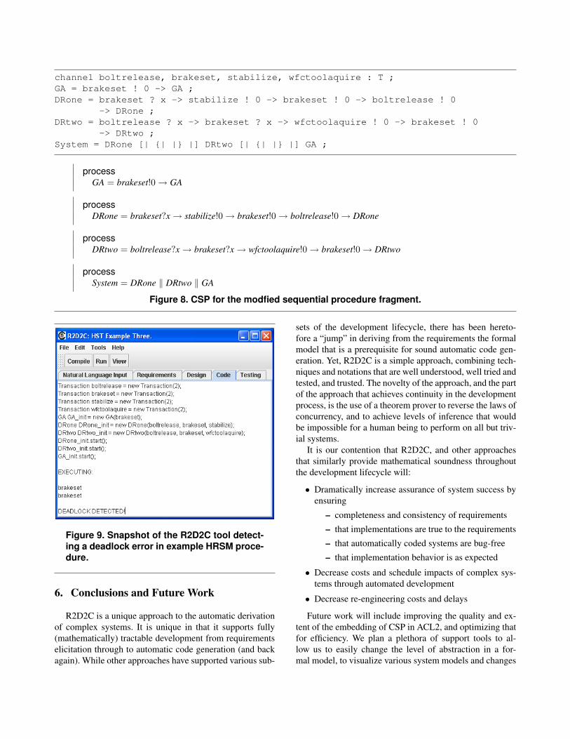
The prototype R2D2C tool transforms this scenario intothe CSP model in Figure 8. The tool automatically per-forms a range of analysis and verification steps on this for-mal model, resulting in the detection of a violation of aservicing-mission constraint 9.
The violation is a deadlock that will cause DR2 to block.Adding the bolt release at the end of the sequence, ratherthan before setting the brakes, will give the result that thetrace (or sequence of messages) (boltrelease, brakeset) willnot be generated. Instead the sequence will be (brakeset,boltrelease).
Although very simple, this error has a degree of sub-tlety and might easily occur in the planning of the proce-dures. DR2 releases the brakes at the same time DR1 setsthe brakes, thus violating the sequentiality requirement—anerror automatically detected by the R2D2C tool.
The full body of constraints and restrictions number inthe many hundreds, and have been formulated and docu-mented for the HRSM. Compiled into the Constraints andRestrictions Document (CARD), they embody a great dealof complexity and become very demanding to apply man-ually to validate a procedure, which provides considerablejustification for developing an automated means for proce-dure verification.
The R2D2C tool can incorporate, and automates the ap-plication of, arbitrarily many HRSM constraints and restric-tions as well as other kinds of verification analysis to detecterrors and problems such as omissions, deadlock, livelock,and unreachable steps.

channel brakerelease, brakeset, stabilize, wfctoolaquire : T ;GA = brakeset ! 0 -> GA ;DRone = brakeset ? x -> brakerelease ! 0 -> stabilize ! 0 -> brakeset ! 0
-> DRone ;DRtwo = brakerelease ? x -> brakeset ? x -> wfctoolaquire ! 0 -> brakeset ! 0
-> DRtwo ;System = DRone [| {| |} |] DRtwo [| {| |} |] GA ;
processGA = brakeset!0 → GA
processDRone = brakeset?x → brakerelease!0 → stabilize!0 → brakeset!0 → DRone
processDRtwo = brakerelease?x → brakeset?x → wfctoolaquire!0 → brakeset!0 → DRtwo
processSystem = DRone ‖ DRtwo ‖ GA
Figure 6. CSP for the sequential procedure fragment, (a) in plain text, (b) prettyprinted.
GA sends brakeset.
DRone receives brakeset then sends stabilize then sends brakeset then sends boltrelease .
DRtwo receives boltrelease then receives brakeset then sends wfctoolaquire then sends brakeset.
Figure 7. Modified sequential procedure fragment
4.4. Results and Future Tool Support
The application of the prototype R2D2C tool to the ex-ample described above shows the potential benefit of an au-tomated, mathematically sound method for verifying theHubble robotic servicing procedures. Demonstrating thatit can automatically detect violations of the documentedHRSM constraints and restrictions was an important steptowards establishing that the benefits existed for HRSM.
To move forward, it will be necessary to augment theprototype R2D2C tool to ease the process of expressingHRSM procedures in a form that can be automatically trans-lated into a formal CSP model.
5. Related Work
Harel [6] [8] has advocated scenario-based programmingthrough UML use cases and play-in scenarios. The presentwork differs in that it uses scenarios in the form of struc-tured text that is easily understandable by engineers and
non-engineers. In addition, the results of converting thestructured text to traces and then from traces to a formalmodel allows us to use a wide range of formal methods tools(e.g., model checkers), which can be used to verify and val-idate the system [10].
NASA Ames has been working on the automatic trans-lation of UML use cases to executable code, and report suc-cess in using the approach on large applications [21]. Ourapproach is different, however, in that we are not limitedto UML use cases, nor to natural language. R2D2C accom-modates any input mechanism whereby requirements can berepresented as scenarios, and traces extracted. Our approachworks equally well with graphical, mathematical, and tex-tual requirements representations.
More importantly, the key to our approach and whatmakes it invaluable for high-dependability applications isthe full formal basis, and complete mathematical tractabilityfrom requirements through to code. To our knowledge, noother currently available automated development methodol-ogy can make this claim [10].
channel boltrelease, brakeset, stabilize, wfctoolaquire : T ;GA = brakeset ! 0 -> GA ;DRone = brakeset ? x -> stabilize ! 0 -> brakeset ! 0 -> boltrelease ! 0
-> DRone ;DRtwo = boltrelease ? x -> brakeset ? x -> wfctoolaquire ! 0 -> brakeset ! 0
-> DRtwo ;System = DRone [| {| |} |] DRtwo [| {| |} |] GA ;
processGA = brakeset!0 → GA
processDRone = brakeset?x → stabilize!0 → brakeset!0 → boltrelease!0 → DRone
processDRtwo = boltrelease?x → brakeset?x → wfctoolaquire!0 → brakeset!0 → DRtwo
processSystem = DRone ‖ DRtwo ‖ GA
Figure 8. CSP for the modfied sequential procedure fragment.
Figure 9. Snapshot of the R2D2C tool detect-ing a deadlock error in example HRSM proce-dure.
6. Conclusions and Future Work
R2D2C is a unique approach to the automatic derivationof complex systems. It is unique in that it supports fully(mathematically) tractable development from requirementselicitation through to automatic code generation (and backagain). While other approaches have supported various sub-
sets of the development lifecycle, there has been hereto-fore a “jump” in deriving from the requirements the formalmodel that is a prerequisite for sound automatic code gen-eration. Yet, R2D2C is a simple approach, combining tech-niques and notations that are well understood, well tried andtested, and trusted. The novelty of the approach, and the partof the approach that achieves continuity in the developmentprocess, is the use of a theorem prover to reverse the laws ofconcurrency, and to achieve levels of inference that wouldbe impossible for a human being to perform on all but triv-ial systems.
It is our contention that R2D2C, and other approachesthat similarly provide mathematical soundness throughoutthe development lifecycle will:
• Dramatically increase assurance of system success byensuring
– completeness and consistency of requirements
– that implementations are true to the requirements
– that automatically coded systems are bug-free
– that implementation behavior is as expected
• Decrease costs and schedule impacts of complex sys-tems through automated development
• Decrease re-engineering costs and delays
Future work will include improving the quality and ex-tent of the embedding of CSP in ACL2, and optimizing thatfor efficiency. We plan a plethora of support tools to al-low us to easily change the level of abstraction in a for-mal model, to visualize various system models and changes

in those models, and to aid in tracking changes through thedevelopment process (or the reverse engineering process).We plan to enhance our existing prototype to support thefull version of R2D2C, to make it into a fully functional ro-bust prototype, and to apply it to more significant examplesthan the one presented in this paper.
Acknowledgements
This work was encouraged and funded in part by NASAGoddard Space Flight Center (GSFC) Information SystemsDivision and the GSFC Technology Transfer Office. We aregrateful to Joe Hennessy, Ted Mecum, Nona Cheeks, ChrisKirkman, Diana Cox, Yvette Conwell-Brown, and KeithDixon for their support and encouragement. John Erickson(University of Texas at Austin) worked with us and pro-vided invaluable expertise on the prototype R2D2C environ-ment. We are grateful to the HRSM team, particularly RudMoe and Richard Strafella, for their support and collabora-tion. The approach described in this paper is protected un-der United States and international Patent Applications as-signed to the United States government.
References
[1] ANTLR: ANother Tool for Language Recognition.http://www.antlr.org/.
[2] Communicating sequential processes for Java (JCSP).http://www.cs.kent.ac.uk/projects/ofa/jcsp/.
[3] Failures-Divergences Refinement: User Manual and Tuto-rial. Formal Systems (Europe), Ltd., 1999.
[4] M. J. Butler. csp2B : A Practical Approach To CombiningCSP and B. Declarative Systems and Software Engineer-ing Group, Department of Electronics and Computer Sci-ence, University of Southampton, February 1999.
[5] J. Gosling, B. Joy, G. Steele, and G. Bracha. JavaTM Lan-guage Specification. Addison Wesley, Boston, second edi-tion, 2000.
[6] D. Harel. From play-in scenarios to code: An achievabledream. IEEE Computer, 34(1):53–60, 2001.
[7] D. Harel. Comments made during presentation at “FormalApproaches to Complex Software Systems” panel session.ISoLA-04 First International Conference on Leveraging Ap-plications of Formal Methods, Paphos, Cyprus. 31 October2004.
[8] D. Harel and R. Marelly. Come, Let’s Play: Scenario-BasedProgramming Using LSCs and the Play-Engine. Springer-Verlag, 2003.
[9] M. G. Hinchey and S. A. Jarvis. Concurrent Systems: FormalDevelopment in CSP. International Series in Software Engi-neering. McGraw-Hill International, London, UK, 1995.
[10] M. G. Hinchey, J. L. Rash, and C. A. Rouff. A formal ap-proach to requirements-based programming. In Proc. IEEEInternational Conference and Workshop on the Engineeringof Computer Based Systems, ECBS-2005, Greenbelt, Mary-land, USA, 4–5 April 2005. IEEE Computer Society.
[11] C. A. R. Hoare. Communicating sequential processes. Com-munications of the ACM, 21(8):666–677, 1978.
[12] C. A. R. Hoare. Communicating Sequential Processes. Pren-tice Hall International Series in Computer Science. PrenticeHall International, Englewood Cliffs, NJ, 1985.
[13] S. T. Huang. A distributed deadlock detection algorithm forCSP-like communication. ACM Transactions on Program-ming Languages and Systems, 12(1):102–122, 1990.
[14] M. Kaufmann and Panagiotis Manolios and J StrotherMoore. Computer-Aided Reasoning: An Approach. Ad-vances in Formal Methods Series. Kluwer Academic Pub-lishers, Boston, 2000.
[15] D. Lea. Concurrent Programming in JavaTM: Design Princi-ples and Patterns. The JavaTM Series. Addison-Wesley Pro-fessional, Reading, Massachusetts, second edition, 2000.
[16] D. L. Parnas. Using mathematical models in the inspectionof critical software. In Applications of Formal Methods, In-ternational Series in Computer Science, pages 17–31. Pren-tice Hall, Englewood Cliffs, NJ, 1995.
[17] Y. Smaragdakis, S. S. Huang, and D. Zook. Program genera-tors and the tools to make them. In PEPM ’04: Proceedingsof the 2004 ACM SIGPLAN Symposium on Partial Evalua-tion and Semantics-Based Program Manipulation, pages 92–100. ACM Press, 2004.
[18] K. Walrath, M. Campione, A. Huml, and S. Zakhour. JFCSwing Tutorial, The: A Guide to Constructing GUIs. Addi-son Wesley, Boston, second edition, 2004.
[19] P. H. Welch, J. R. Aldous, and J. Foster. CSP network-ing for Java (JCSP.net). In Proceedings of the Global andCollaborative Computing Workshop (ICCS 2002), volume2330 of Lecture Notes in Computer Science, pages 695–708.Springer-Verlag, 2002.
[20] P. H. Welch and J. M. R. Martin. A CSP model for Java mul-tithreading. In Proc. International Symposium on SoftwareEngineering for Parallel and Distributed Systems, pages114–122, June 2000.
[21] J. Whittle, J. Saboo, and R. Kwan. From scenarios to code:An air traffic control case study. In Proc. ICSE-25, 25thIEEE/ACM International Conference on Software Engineer-ing, pages 490–495, Portland, Oregon, 2003. IEEE Com-puter Society Press.